Fig. 144: View Of Wiper Blade Position Courtesy of VOLVO ...
943
Fig. 144: View Of Wiper Blade Position Courtesy of VOLVO CARS CORPORATION WIPER MECHANISM, WINDSHIELD REMOVAL Fig. 145: Remove Key From Ignition Courtesy of VOLVO CARS CORPORATION Remove the plenum cover, see PLENUM CHAMBER NOTE: Removal steps in this procedure may contain installation details. CAUTION: Make sure that the motor is in the park position. 2012 Volvo C30 T-5 ACCESSORIES AND BODY, CAB Other Electrical Equipment - Removal, replacement and installation
-
Upload
khangminh22 -
Category
Documents
-
view
1 -
download
0
Transcript of Fig. 144: View Of Wiper Blade Position Courtesy of VOLVO ...

Fig. 144: View Of Wiper Blade Position Courtesy of VOLVO CARS CORPORATION
WIPER MECHANISM, WINDSHIELD
REMOVAL
Fig. 145: Remove Key From Ignition Courtesy of VOLVO CARS CORPORATION
Remove the plenum cover, see PLENUM CHAMBER
NOTE: Removal steps in this procedure may contain installation details.
CAUTION: Make sure that the motor is in the park position.
2012 Volvo C30 T-5
ACCESSORIES AND BODY, CAB Other Electrical Equipment - Removal, replacement and installation

Fig. 146: Identifying Wiper Mechanism Bolts Courtesy of VOLVO CARS CORPORATION
Torque: M6
10 Nm
INSTALLATION
To install, reverse the removal procedure.
WIPER MOTOR FRONT
REMOVAL
NOTE: Removal steps in this procedure may contain installation details.
CAUTION: Make sure that the motor is in the park position.
2012 Volvo C30 T-5
ACCESSORIES AND BODY, CAB Other Electrical Equipment - Removal, replacement and installation

Fig. 147: Remove Key From Ignition Courtesy of VOLVO CARS CORPORATION
Remove the wiper mechanism, windscreen, see WIPER MECHANISM, WINDSHIELD
Fig. 148: Identifying Wiper Motor Front Components Courtesy of VOLVO CARS CORPORATION
2012 Volvo C30 T-5
ACCESSORIES AND BODY, CAB Other Electrical Equipment - Removal, replacement and installation

Fig. 149: Identifying Wiper Motor Front Position Courtesy of VOLVO CARS CORPORATION
Fig. 150: Identifying Wiper Motor Front Screws Courtesy of VOLVO CARS CORPORATION
Torque: M6
10 Nm
INSTALLATION
To install, reverse the removal procedure.
NOTE: Note the position of the component before removal.
NOTE: Make sure that this component is installed to the noted removal position.
2012 Volvo C30 T-5
ACCESSORIES AND BODY, CAB Other Electrical Equipment - Removal, replacement and installation

General Information
DTC Index
ACCESSORY ELECTRONIC MODULE (AEM) DTCS
ACCESSORY ELECTRONIC MODULE (AEM) - DTC INDEX
AUDIO MODULE (AUD) DTCS
AUDIO MODULE (AUD) - DTC INDEX
Volvo Code DescriptionAEM-1D01 Control module. Internal faultAEM-1D02 Control module, software. Internal faultAEM-1D03 Control module not fully programmed. Internal faultAEM-1D07 Control module. Internal faultAEM-1D08 Control module. Internal faultAEM-1D0A Control module. Internal faultAEM-5F10 Relay, engine block heater. Signal too lowAEM-5F11 Relay, engine block heater. Signal too high/Signal missingAEM-6C50 Alarm output P0. Signal too low or signal missingAEM-6C51 Alarm output P0. Signal too highAEM-6C52 Alarm output P1. Signal too low or signal missingAEM-6C53 Alarm output P1. Signal too highAEM-6C54 Alarm output S0. Signal too low or signal missingAEM-6C55 Alarm output S0. Signal too highAEM-6C56 Alarm output S1. Signal too lowAEM-6C57 Alarm output S1. Signal too high/Signal missingAEM-E001 Control module communication. Faulty communicationAEM-E003 Control module communication Faulty communicationAEM-E010 Power supply. Signal too lowAEM-XXXX Unknown diagnostic trouble code (DTC) for the current control module
version
Volvo Code DescriptionAUD-0001 Control module. Internal faultAUD-0002 Loudspeaker left front. Signal missingAUD-0003 Loudspeaker right front. Signal missingAUD-0004 Loudspeaker left rear. Signal missingAUD-0005 Loudspeaker right rear. Signal missingAUD-0006 Loudspeaker left front. Short-circuit to groundAUD-0007 Center loudspeaker. Short-circuit to ground
2012 Volvo C30 T-5
General Information DTC Index
2012 Volvo C30 T-5
General Information DTC Index

ACCESSORY USB UNIT (AUU) DTCS
ACCESSORY USB UNIT (AUU) - DTC INDEX
BRAKE CONTROL MODULE (BCM) DTCS
BRAKE CONTROL MODULE (BCM) - DTC INDEX
AUD-0009 Loudspeaker left rear. Short-circuit to groundAUD-000A Loudspeaker right rear. Short-circuit to groundAUD-000D Control module. Over heatedAUD-000E Microphone terminal. Signal missingAUD-000F Microphone terminal. Signal too highAUD-0010 Microphone terminal. Signal too lowAUD-001B Configuration fault. Software faultAUD-001C Center loudspeaker. Signal missingAUD-001D Control module. Internal faultAUD-001E Control module. Internal faultAUD-001F Control module. Internal faultAUD-0020 Control module. Internal faultAUD-0021 Control module. Internal faultAUD-0022 Control module. Internal faultAUD-0023 Loudspeaker front. ShortedAUD-0024 Loudspeaker rear. ShortedAUD-0025 Control module. Internal faultAUD-0025 Loudspeaker left front. Faulty signalAUD-0026 Loudspeaker right front. Faulty signalAUD-0027 Loudspeaker left rear. Faulty signalAUD-0028 Loudspeaker right rear. Faulty signalAUD-0029 Loudspeaker left front. Signal too highAUD-002A Loudspeaker right front. Signal too lowAUD-002B Loudspeaker left rear. Signal too lowAUD-002C Loudspeaker right rear. Signal too lowAUD-002D Loudspeaker left front. Signal too highAUD-002E Loudspeaker right front. Signal too highAUD-002F Loudspeaker left rear. Signal too highAUD-0030 Loudspeaker right rear. Signal too high
Volvo Code DescriptionAUU-0001 Battery Voltage. Algorithm Based FailuresAUU-0002 Control Module. System Programming Failures
Volvo Code Description
2012 Volvo C30 T-5
General Information DTC Index

BCM-0010 Wheel sensor left front. Faulty signal (B5254T7)BCM-0011 Wheel sensor left front. Faulty signal (B5254T7)BCM-0012 Wheel sensor left front. Mechanical fault (B5254T7)BCM-0030 Wheel sensor left rear. Faulty signal (B5254T7)BCM-0050 Control module. Faulty signal (B5254T7)BCM-0052 Control module. Internal fault (B5254T7)BCM-0057 Power supply. Voltage too low (B5254T7)BCM-0058 Power supply. Voltage too high (B5254T7)BCM-0061 Brake discs. Temperature too high (B5254T7)BCM-0068 Sensor power supply. Faulty signal (B5254T7)BCM-0070 Power supply for the pump motor. Faulty signal (B5254T7)BCM-0071 Pump motor. Signal missing (B5254T7)BCM-0072 Pump motor. Mechanical fault (B5254T7)BCM-0074 Hydraulic valves. Faulty signal (B5254T7)BCM-0076 Control module. Faulty configuration (B5254T7)BCM-0080 Lateral accelerometer. Incorrect offset value (B5254T7)BCM-0090 Lateral accelerometer. Faulty signal (B5254T7)BCM-0091 Accelerometer. Faulty signal (B5254T7)BCM-0094 Communication between control modules. Communication problems
with the differential electronic module (DEM) (B5254T7)BCM-0095 Communication between control modules. Communication problems
with the differential electronic module (DEM) (B5254T7)BCM-0096 Sensor cluster. Faulty signal (B5254T7)BCM-0097 Communication between control modules. Communication problems
with the central electronic module (CEM) (B5254T7)BCM-0100 Communication between control modules. Communication problems
with the engine control module (ECM) (B5254T7)BCM-0101 Communication between control modules. Communication problems
with the engine control module (ECM) (B5254T7)BCM-0103 Pedal position sensor. Faulty signal (B5254T7)BCM-0105 Steering wheel, wheel alignment. Signal outside its permitted range
(B5254T7)BCM-0106 Steering wheel, wheel alignment. Incorrect steering wheel or wheel
alignment (B5254T7)BCM-0108 Communication between control modules. Communication problems
with the steering wheel module (SWM), control module not initiated (B5254T7)
BCM-0109 Communication between control modules. Steering wheel module (SWM), internal fault (B5254T7)
BCM-0111 Communication between control modules. AYC stability control active for too long (B5254T7)
BCM-0112 Body sensor cluster stability sensor (BSC). Sensor not calibrated
2012 Volvo C30 T-5
General Information DTC Index

BLUETOOTH PHONE MODULE (BPM) DTCS
(B5254T7)BCM-0113 Back-up (reversing) signal. Signal missing (B5254T7)BCM-0114 Communication with the body sensor cluster stability sensor (BSC).
Signal missing (B5254T7)BCM-0115 Communication between control modules. Communication with the
steering wheel module (SWM), signal missing (B5254T7)BCM-0116 Communication with the body sensor cluster stability sensor (BSC).
Communication problems (B5254T7)BCM-0117 Communication with the body sensor cluster stability sensor (BSC).
Incorrect body sensor cluster stability sensor (BSC) installed (B5254T7)BCM-0118 Power supply for the body sensor cluster stability sensor (BSC). Voltage
too high (B5254T7)BCM-0119 Power supply for the body sensor cluster stability sensor (BSC). Voltage
too low (B5254T7)BCM-0121 Yaw rate sensor. Signal outside its permitted range (B5254T7)BCM-0123 Body sensor cluster stability sensor (BSC). Internal fault (B5254T7)BCM-0130 Brake pressure sensor. Signal missing (B5254T7)BCM-0134 Brake pressure sensor. Incorrect offset value (B5254T7)BCM-0135 Brake pressure sensor. Signal outside its permitted range (B5254T7)BCM-0138 Power supply for the body sensor cluster stability sensor (BSC). Faulty
voltage (B5254T7)BCM-0145 Stability control. Stability control has been active for too long (B5254T7)BCM-0146 Factory test, dynamic stability and traction control (DSTC). Test cycle
not approved (B5254T7)BCM-0147 Pedal position sensor. Signal outside its permitted range (B5254T7)BCM-0148 Communication between control modules. Faulty configuration ID
(B5254T7)BCM-0150 Stop lamp switch. Signal outside its permitted rangeBCM-0150 Stop lamp switch. Signal outside its permitted range (B5254T7)BCM-0151 Control module. Internal memory fault (B5254T7)BCM-A030 Communication between control modules. The initialization check has
not been run (B5254T7)BCM-A031 Communication between control modules. The tolerance check has not
been run (B5254T7)BCM-A032 Communication between control modules. Stability control has been
active for too long (B5254T7)BCM-E000 Control module communication. Faulty communication (B5254T7)BCM-E003 Control module. Faulty configuration (B5254T7)BCM-XXXX Unknown diagnostic trouble code (DTC) for the current control module
version (B5254T7)
2012 Volvo C30 T-5
General Information DTC Index

BLUETOOTH PHONE MODULE (BPM) - DTC INDEX
CLIMATE CONTROL MODULE (CCM) DTCS
CLIMATE CONTROL MODULE (CCM) - DTC INDEX
Volvo Code DescriptionBPM-1101 Control module Configuration faultBPM-1102 Control module Internal faultBPM-1103 Control module Internal faultBPM-1105 Control module Configuration faultBPM-1106 Control module OverheatedBPM-1301 Microphone input. Signal too lowBPM-1401 Control module Internal faultBPM-B100 Control module Configuration faultBPM-B101 Control module Configuration faultBPM-E010 Battery voltage Faulty signal
Volvo Code DescriptionCCM-0001 Configuration fault. Non-approved valueCCM-0002 Evaporator temperature sensor. Signal too high or signal missingCCM-0003 Evaporator temperature sensor. Signal too lowCCM-0004 Passenger compartment temperature sensor. Signal too high or signal
missingCCM-0005 Passenger compartment temperature sensor. Signal too lowCCM-0006 Blower fan motor passenger compartment temperature sensor. Signal too
high or signal missingCCM-0008 Blower fan motor passenger compartment temperature sensor. Signal too
lowCCM-0009 Blower fan motor passenger compartment temperature sensor. BlockedCCM-0011 Control module. Internal faultCCM-0012 Climate control module. Internal faultCCM-0020 Function button. Activated too longCCM-0021 Tunnel Control Switch Activated too longCCM-0030 Left heater pad. Faulty signalCCM-0031 Sensor left-hand seat heater. Faulty signalCCM-0032 Left-hand seat heater. Internal faultCCM-0033 Left-hand seat heater. Internal faultCCM-0034 Right heater pad. Faulty signalCCM-0035 Sensor right-hand seat heater. Faulty signalCCM-0036 Right-hand seat heater. Internal faultCCM-0037 Right-hand seat heater. Internal faultCCM-0040 Air quality sensor. Internal fault
2012 Volvo C30 T-5
General Information DTC Index

CCM-0060 Damper motor defroster. Faulty signalCCM-0061 Recirculation damper motor. Faulty signalCCM-0062 Left temperature damper motor. Faulty signalCCM-0063 Right temperature damper motor. Faulty signalCCM-0064 Air distribution damper motor. Faulty signal (L.H.D)CCM-006A Tunnel Control Switch 1 Internal FaultCCM-006B Tunnel Control Switch 2 Internal FaultCCM-0070 Configuration fault. Faulty identification (L.H.D)CCM-0071 Damper motor. Faulty positionCCM-0071 Damper motor. Faulty position (L.H.D)CCM-0072 Damper motor. Initiation faultCCM-0073 Configuration fault. Calibration not doneCCM-0074 Damper motor, defroster. Internal faultCCM-0075 Damper motor. Internal faultCCM-0076 Damper motor, temperature left. Internal faultCCM-0077 Damper motor, temperature right. Internal faultCCM-0078 Damper motor distribution. Internal faultCCM-0090 Lower switch. Faulty IDCCM-0091 Lower switch. ID missingCCM-DD00 LIN bus 1. Incorrect dataCCM-DD01 LIN bus 1. Signal too high/Signal too lowCCM-DD02 LIN bus 1. Incorrect check sum (L.H.D)CCM-DD12 Left seat heater. No communicationCCM-DD15 Left temperature damper motor. No communicationCCM-DD16 Damper motor air distribution. No communication (L.H.D)CCM-DD18 Tunnel Control Switch 1 No CommunicationCCM-DD19 Tunnel Control Switch 2 No CommunicationCCM-DD20 LIN bus 2. Incorrect dataCCM-DD21 LIN bus 2. Signal too high/Signal too lowCCM-DD22 LIN bus 2. Incorrect check sum (L.H.D)CCM-DD30 Right-hand seat heater. No communicationCCM-DD31 Recirculation damper motor. No communication (L.H.D)CCM-DD32 Right temperature damper motor. No communicationCCM-DD33 Damper motor defroster. No communicationCCM-DD34 Air quality sensor (AQS). No communication (L.H.D)CCM-E001 Control module communication. Internal faultCCM-E003 Configuration fault. Software faultCCM-E010 Power supply. Faulty signalCCM-XXXX Unknown diagnostic trouble code (DTC) for the current control module
version
2012 Volvo C30 T-5
General Information DTC Index

CENTRAL ELECTRONIC MODULE (CEM) DTCS
CENTRAL ELECTRONIC MODULE (CEM) - DTC INDEX Volvo Code Description
CEM-1011 Control module, memory fault. Internal faultCEM-1012 Control module, memory fault. Internal faultCEM-101A Control module, memory fault. Internal faultCEM-101B Control module, memory fault. Internal faultCEM-1201 Control module. Configuration faultCEM-1A21 Engine control module (ECM). Signal too lowCEM-1A22 Engine control module (ECM). Signal too highCEM-1A40 50-power supply. Activated too longCEM-1A41 Ignition switch. Faulty signalCEM-1A42 Real time clock. Faulty signalCEM-1B01 Main Battery Diode, General electrical failureCEM-1B02 Main Battery Relay, General electrical failureCEM-1B03 Main Battery Diode Or Relay, General electrical failureCEM-1C04 30-power supply. Signal too highCEM-1C10 Control module. Configuration faultCEM-1D08 Control module. Internal faultCEM-1D09 Control module. Internal faultCEM-2E01 Relay, horn Signal too lowCEM-2E02 Relay, horn Signal too highCEM-2E03 Comfort Relay, Signal too lowCEM-2E04 Comfort Relay, Signal too highCEM-2F60 Twilight sensor. Signal too highCEM-2F61 Twilight sensor. Signal too lowCEM-3A00 ECM software. Faulty signalCEM-3A04 Fuel pump (FP). Signal too highCEM-3A05 Fuel pump (FP). Signal too lowCEM-3A07 Fuel pump (FP). Faulty signalCEM-3A08 Fuel pump (FP). Signal too highCEM-3F01 Clutch pedal sensor. Signal too lowCEM-3F02 Clutch pedal sensor. Faulty signalCEM-3F03 Clutch pedal sensor. Signal too high (B5254T7, M66)CEM-3F0A Reverse gear inhibit. Faulty signal (M66)CEM-3F0B Reverse gear inhibit. Signal too low (M66)CEM-3F41 Supply pedal sensor. Signal too lowCEM-3F42 Supply pedal sensor. Signal too highCEM-3F92 Accelerator pedal (AP) position sensor. Signal too highCEM-3F93 Accelerator pedal (AP) position sensor. Signal too low
2012 Volvo C30 T-5
General Information DTC Index

CEM-4A33 Fuel level sensor. Faulty signal (B5254T7)CEM-4A34 Fuel level sensor. Signal too low (B5254T7)CEM-4C01 Outside temperature sensor. Signal too highCEM-4C02 Outside temperature sensor. Signal too lowCEM-4E24 Malfunction indicator lamp (MIL). Faulty signalCEM-4E25 Malfunction indicator lamp (MIL). Signal too highCEM-4F30 Battery temperature. Signal too highCEM-4F31 Battery temperature. Signal too lowCEM-4F32 Battery temperature. Faulty signalCEM-4F33 Battery Temperature Faulty SignalCEM-4F40 Seat belt buckle, right rear seat. Signal too lowCEM-4F41 Seat belt buckle, right rear seat. Signal too highCEM-4F42 Seat belt buckle, rear right-hand. Faulty signalCEM-4F44 Seat belt buckle, rear center. Signal too lowCEM-4F45 Seat belt buckle, rear center. Signal too highCEM-4F46 Seat belt buckle, rear center. Faulty signalCEM-4F48 Seat belt buckle, rear left-hand. Signal too lowCEM-4F49 Seat belt buckle, rear left-hand. Signal too highCEM-4F4A Seat belt buckle, rear left-hand. Faulty signalCEM-4F81 Lamp, seat belt reminder. Signal too lowCEM-4F82 Lamp, seat belt reminder. Faulty signalCEM-5A10 Blower fan motor. BlockedCEM-5A10 Blower fan motor. Blocked (B5254T7, L.H.D)CEM-5A12 Blower fan motor. Over heatedCEM-5A12 Blower fan motor. Over heated (B5254T7, L.H.D)CEM-5A13 Blower fan motor. Voltage too highCEM-5A13 Blower fan motor. Voltage too high (B5254T7, L.H.D)CEM-5A15 Blower fan motor. Current too highCEM-5A15 Blower fan motor. Current too high (B5254T7, L.H.D)CEM-5A17 Blower fan motor Signal too high/Signal missingCEM-5E01 Sun sensor. Faulty signalCEM-5E02 Sun sensor. Signal too lowCEM-5E03 Sun sensor Signal too highCEM-5E04 Sun sensor Signal too lowCEM-6C05 Central locking driver's door. No lockingCEM-6C06 Central locking passenger door. No lockingCEM-6C13 Deadlock, driver's door. No lockingCEM-6C14 Deadlock, passenger door. No lockingCEM-6C28 Alarm LED. Faulty signalCEM-6C29 Alarm LED. Signal too lowCEM-6C31 Siren. Internal fault
2012 Volvo C30 T-5
General Information DTC Index

Movement sensor. Signal missingCEM-6C33 Movement sensor. Signal missingCEM-6C34 Switch reduced alarm. Activated too longCEM-6C3A Glass break wire. Signal too highCEM-6C3B Glass break wire manipulation protectionCEM-6C41 Start control module (SCU). Incorrect key IDCEM-6C42 Start control module (SCU). Signal missingCEM-6C43 Start control module (SCU). Faulty signalCEM-6C54 Engine control module (ECM) communication. Incorrect valueCEM-6C55 KVM communication. Faulty valueCEM-6C57 Phone module (PHM) not valid. Faulty signalCEM-6F10 Sun roof. Signal too highCEM-6F11 Sun roof. Faulty signalCEM-6F12 Sun roof. Faulty signalCEM-6F13 Sun roof. Signal too highCEM-6F51 Tailgate handle. Faulty signalCEM-6F52 Tailgate handle. Signal too lowCEM-6F53 Tailgate handle. Activated too longCEM-6F83 Dimmer Faulty signalCEM-6F84 Fuel Flap Driver Faulty SignalCEM-6F85 Dimmer. Signal too lowCEM-6F86 Fuel tank filler cap. Signal too lowCEM-6F87 Fuel tank filler cap. Activated too longCEM-8A02 Relay, high beam. Internal faultCEM-8A03 Relay, high beam. Internal faultCEM-8A04 LED Light Switch, Automatic Bending Light Signal too HighCEM-8A05 LED Light Switch, Automatic Bending Light Faulty SignalCEM-8A08 Low beam right. Signal too lowCEM-8A09 Low beam right. Faulty signalCEM-8A11 Low beam left. Signal too lowCEM-8A12 Low beam left. Faulty signalCEM-8B02 Left parking lamps. Signal too lowCEM-8B03 Left parking lamps. Faulty signalCEM-8B05 Right parking lamps. Faulty signalCEM-8B06 Right parking lamps. Signal too lowCEM-8B08 Light switch module (LSM). Signal too lowCEM-8B09 Light switch module (LSM). Faulty signalCEM-8C10 Relay, front fog lamps. Signal too highCEM-8C11 Relay, front fog lamps. Faulty signalCEM-8C20 Rear fog lamp. Faulty signalCEM-8C21 Rear fog lamp. Signal too low
2012 Volvo C30 T-5
General Information DTC Index

Stop lamp switch. Comparison faultCEM-8D03 High level stop lamp. Signal too highCEM-8D04 High level stop lamp. Signal too lowCEM-8D05 Right-hand stop lamp. Signal too lowCEM-8D06 Right-hand stop lamp. Faulty signalCEM-8D07 Left-hand stop lamp. Signal too lowCEM-8D08 Left-hand stop lamp. Faulty signalCEM-8D09 Brake lamp left. Faulty signalCEM-8D0A Brake lamp left. Faulty signalCEM-8D10 Brake light switch Compare errorCEM-8F01 Switch, hazard warning signal flashers. Faulty signalCEM-8F02 Switch, hazard warning signal flashers. Signal too lowCEM-8F21 Wiper motor module (WMM). Internal faultCEM-8F22 Wiper motor module (WMM). Voltage too lowCEM-8F23 Wiper motor module (WMM). Voltage too highCEM-8F24 Wiper motor module (WMM). JammedCEM-8F26 Relay, front windshield washer motor. Internal faultCEM-8F27 Relay, front windshield washer motor. Internal faultCEM-8F28 Tailgate washer motor relay. Internal faultCEM-8F29 Tailgate washer motor relay. Internal faultCEM-8F30 Relay, headlamp wash/wipe. Faulty signalCEM-8F31 Relay, headlamp wash/wipe. Signal too highCEM-8F33 Right-hand turn signal lamp. Faulty signalCEM-8F34 Right-hand turn signal lamp. Signal too lowCEM-8F37 Left-hand turn signal lamp. Faulty signalCEM-8F38 Left-hand turn signal lamp. Signal too lowCEM-8F61 Relay, heated rear windshield. Faulty signalCEM-8F62 Relay, heated rear windshield. Signal too highCEM-8FA2 Relay, horn. Activated too longCEM-8FB1 Rain sensor module (RSM). Internal faultCEM-8FB2 Rain sensor module (RSM). Faulty functionCEM-9A01 Interior lighting. Signal too highCEM-9A02 Interior lighting. Signal too lowCEM-9D01 Communication with RRX control module. Comminicational problemsCEM-9F31 Dimmer. Signal too highCEM-9F32 Dimmer. Faulty signalCEM-9F33 Brake fluid level too lowCEM-AFE0 TPMS Default Values in Local ConfigurationCEM-AFE1 TPMS Incorrect ConfigurationCEM-AFF1 Localization failedCEM-AFF2 Tire pressurement sensor. Faulty signal
2012 Volvo C30 T-5
General Information DTC Index

Tire pressurement sensor. Signal missingCEM-AFFE Missing tire pressure sensor Signal missingCEM-CFF0 MMS Communication Faulty SignalCEM-DD00 LIN-bus 2. Communication faultCEM-DD00 LIN-bus 3. Communication faultCEM-DD01 LIN-bus 2. Communication missingCEM-DD01 LIN-bus 3. Communication missingCEM-DD02 LIN-bus 2. Communication faultCEM-DD02 LIN-bus 3. Communication faultCEM-DD03 LIN-bus 14 Communication faultCEM-DD04 LIN-bus 14 Communication missingCEM-DD05 LIN-bus 14 Communication faultCEM-DD06 Communication with Battery Monitoring Sensor (BMS) Signal missingCEM-DD07 Battery Monitoring Sensor (BMS) faulty hardwareCEM-DD0A LIN-bus 3. Communication faultCEM-DD0B LIN-bus 3. Communication missingCEM-DD0C LIN-bus 3. Communication faultCEM-DD11 Communication with SCU control module. Signal missingCEM-DD12 Communication with the left-hand gas discharge lamp module (GDL).
Signal missingCEM-DD13 Communication with the right-hand gas discharge lamp module (GDL).
Signal missingCEM-DD1A Communication with RRX control module. Signal missingCEM-DD1B Communication with SCM control module. Signal missingCEM-DD1C Communication with SCM control module Faulty signalCEM-DD21 LIN bus 9. No communicationCEM-DD22 LIN bus 9. Communication faultCEM-DD30 Communication with the wiper motor module (WMM). Signal missingCEM-DD31 Communication with the rain sensor module (RSM). Signal missingCEM-DD32 Communication with Humidity Sensor (HUS) Signal MissingCEM-DD40 Humidity Sensor (HUS) Internal FaultCEM-DE01 Communication with the brake control module (BCM). Signal missingCEM-DE11 Communication with ECM control module. Signal missingCEM-DE11 Communication with ECM control module. Signal missing (B5254T7)CEM-DE18 Communication with the combustion preheater module (CPM). Signal
missingCEM-DE1A Communication with DEM control module. Signal missingCEM-DE23 Communication with the trailer module (TRM). Signal missingCEM-DE29 Communication with the climate control module (CCM). Signal missingCEM-DE2D Communication with KVM control module. Signal missingCEM-DE2E Communication with the power seat module (PSM). Signal missing
2012 Volvo C30 T-5
General Information DTC Index

COMBUSTION PREHEATER MODULE (CPM) DTCS
COMBUSTION PREHEATER MODULE (CPM) - DTC INDEX
CEM-DE30 Communication with the electric power steering module (EPS). Signal missing
CEM-DE43 Communication with the driver door module (DDM). Signal missingCEM-DE45 Communication with the passenger door module (PDM). Signal missingCEM-DE49 Communication with the steering wheel module (SWM). Signal missingCEM-DE51 Communication with the driver information module (DIM). Signal
missingCEM-DE52 Communication with the Accessory Electronic Module (AEM). Signal
missingCEM-DE54 Communication with the infotainment control module (ICM). Signal
missingCEM-DE58 Communication with the supplemental restraint system module (SRS).
Signal missingCEM-DE63 communication with the parking assistance module (PAM). Signal
missingCEM-DE64 Communication with the phone module (PHM). Signal missingCEM-DE6E Communication with the transmission control module (TCM). Signal
missingCEM-DE70 Communication with Headlamp Control Module (HCM) Signal MissingCEM-DF01 CAN-H, low speed network. Signal missingCEM-DF03 CAN-H, low speed network. Signal too highCEM-DF04 CAN-L, low speed network. Signal too lowCEM-DF05 CAN-H, low speed network. Signal too lowCEM-DF06 CAN-L, low speed network. Signal too highCEM-DF07 CAN-L, low speed network. Faulty signalCEM-DF11 CAN-H, high speed network. Signal missingCEM-DF13 CAN-H, high speed network. Signal too highCEM-DF14 CAN-L, high speed network. Signal too lowCEM-DF15 CAN-H, high speed network. Signal too lowCEM-DF16 CAN-L, high speed network. Signal too highCEM-DF17 CAN-L, high speed network. Faulty signalCEM-E000 Communication with control module. Faulty communicationCEM-E001 Communication with control module. Faulty communicationCEM-E00A Communication with control module. Faulty communicationCEM-XXXX (A) Unknown diagnostic trouble code (DTC) for the current control
module versionCEM-XXXX (B) Unknown diagnostic trouble code (DTC) for the current control
module version
2012 Volvo C30 T-5
General Information DTC Index

Volvo Code DescriptionCPM-0018 Glow plugs. Signal too highCPM-0102 Glow plugs. Signal too lowCPM-0204 Glow plugs. Signal missingCPM-0318 Fuel pump. Signal too highCPM-0402 Fuel pump. Signal too lowCPM-0504 Fuel pump. Signal missingCPM-1001 Combustion fan. Signal too highCPM-1128 Combustion fan. Signal too lowCPM-1204 Combustion fan. Signal missingCPM-1308 Combustion fan. Faulty functionCPM-1418 Water pump. Signal too highCPM-1502 Water pump. Signal too lowCPM-1604 Water pump. Signal missingCPM-2308 Control module. Internal faultCPM-3002 Engine coolant temperature (ECT) sensor. Signal too lowCPM-3141 Engine coolant temperature (ECT) sensor. Signal too high/Signal missingCPM-3202 Overheat protection thermostat. Signal too lowCPM-3341 Overheat protection thermostat. Signal too high/Signal missingCPM-3402 Flame sensor. Signal too lowCPM-3541 Flame sensor. Signal too high/Signal missingCPM-3601 Control module. Supply voltage too highCPM-3702 Control module. Supply voltage too lowCPM-4001 Engine coolant heater. Activated too longCPM-4101 Engine coolant heater. Too many unsuccessful attemptsCPM-4208 Engine coolant heater. Extinguished flameCPM-4308 Engine coolant heater. Extinguished flameCPM-4501 Combustion fan. Activated too longCPM-5001 Control module. Over heatedCPM-5101 Control module. Over heatedCPM-5201 Control module. Over heatedCPM-5301 Control module. Over heatedCPM-5401 Control module. Internal faultCPM-5601 Control module. Internal faultCPM-5701 Control module. Collision signal receivedCPM-6008 Control module. Internal faultCPM-6108 Control module. Internal faultCPM-6208 Control module. Internal faultCPM-6301 Control module. Internal faultCPM-6408 Control module. Internal faultCPM-6508 Control module. Internal fault
2012 Volvo C30 T-5
General Information DTC Index

DRIVER DOOR MODULE (DDM) DTCS
DRIVER DOOR MODULE (DDM) - DTC INDEX
Control module. Internal faultCPM-8704 Control module. Internal faultCPM-E001 Control module communication. Faulty communicationCPM-E003 Configuration fault. Faulty configurationCPM-E010 Control module. Supply voltage too lowCPM-XXXX Unknown diagnostic trouble code (DTC) for the current control module
version
Volvo Code DescriptionDDM-0012 Control, driver's window. Stuck in the active positionDDM-0013 Control, passenger window. Stuck in the active positionDDM-0020 Control, door mirror. Stuck in the active positionDDM-0022 Control, door mirror selector. Stuck in the active positionDDM-0024 Central locking switch. Faulty signalDDM-0025 LED, camera module Signal too lowDDM-0026 LED, camera module Signal too highDDM-0027 LED, camera module Open circuitDDM-002B Camera module Internal failureDDM-002F Camera module voltage supply Signal too lowDDM-003A Camera module voltage supply Signal too highDDM-6E01 Mirror motor. Shorted to supplyDDM-6E02 Mirror motor. Ground (GND) shortDDM-6E03 Mirror motor. Open circuitDDM-6E04 Mirror motor. Shorted to supplyDDM-6E05 Mirror motor. Ground (GND) shortDDM-6E06 Mirror motor. Open circuitDDM-6E07 Mirror motor. Shorted to supplyDDM-6E08 Mirror motor. Ground (GND) shortDDM-6E09 Mirror motor. Open circuitDDM-8002 Mirror heater. Ground (GND) shortDDM-8003 Mirror heater. Shorted to supplyDDM-8021 Side turn indicator. Ground (GND) shortDDM-8022 Side turn indicator. Open circuitDDM-DD11 Communication with switch pack Internal FaultDDM-DD20 LIN communication camera module Internal faultDDM-DD21 LIN communication camera module ShortedDDM-DD22 LIN communication camera module Internal faultDDM-DD30 Communication with camera module Internal Fault
2012 Volvo C30 T-5
General Information DTC Index

DRIVER DOOR MODULE/PASSENGER DOOR MODULE (DDM/PDM) DTCS
DRIVER DOOR MODULE/PASSENGER DOOR MODULE (DDM/PDM) DTCS - DIAGNOSTIC TROUBLE CODE (DTC) INDEX
DDM-E001 Control module communication. Faulty communicationDDM-XXXX Unknown diagnostic trouble code (DTC) for the current control module
version
Volvo Code DescriptionDDM/PDM-0002 Central Locking Button. Stuck In The Active PositionDDM/PDM-0003 Central Locking Button, Unlocking. Stuck In The Active
PositionDDM/PDM-0010 Control Panel. Open-CircuitDDM/PDM-1000 Control Module. Internal FaultDDM/PDM-6C02 Central Locking Motor M1. Stuck In The Active PositionDDM/PDM-6C03 Central Locking Motor M1. Stuck In The Inactive PositionDDM/PDM-6C05 Central Locking Motor M2. Stuck In The Active PositionDDM/PDM-6C06 Central Locking Motor M2. Stuck In The Inactive PositionDDM/PDM-6C08 Central Locking Motor M3. Stuck In The Active PositionDDM/PDM-6C09 Central Locking Motor M3. Stuck In The Inactive PositionDDM/PDM-6D01 Power Window Mechanism. Internal FaultDDM/PDM-6D02 Power Window Up Relay. Stuck In The Active PositionDDM/PDM-6D03 Power Window Up Relay. Stuck In The Inactive PositionDDM/PDM-6D04 Power Window Down Relay. Stuck In The Active PositionDDM/PDM-6D05 Power Window Down Relay. Stuck In The Inactive PositionDDM/PDM-6D0C Control Module. Internal FaultDDM/PDM-6D0D Control Module. Internal FaultDDM/PDM-6E0A Mirror Motor. Short-Circuit To Supply VoltageDDM/PDM-6E0B Mirror Motor. Short-Circuit To GroundDDM/PDM-6E0C Mirror Motor. Open-CircuitDDM/PDM-6E41 Position Sensor, Mirror. Short-Circuit To Supply Voltage/Open-
CircuitDDM/PDM-6E42 Position Sensor, Mirror. Short-Circuit To GroundDDM/PDM-6E43 Position Sensor, Mirror. Short-Circuit To Supply Voltage/Open-
CircuitDDM/PDM-6E44 Position Sensor, Mirror. Short-Circuit To GroundDDM/PDM-6E45 Power Supply. Open-CircuitDDM/PDM-8010 Mirror Lamp. Short-Circuit To Supply VoltageDDM/PDM-8011 Mirror Lamp. Short-Circuit To GroundDDM/PDM-8012 Mirror Lamp. Open-CircuitDDM/PDM-E003 Configuration Fault. Faulty Communication
2012 Volvo C30 T-5
General Information DTC Index

DRIVER INFORMATION MODULE (DIM) DTCS
DRIVER INFORMATION MODULE (DIM) - DTC INDEX
ENGINE CONTROL MODULE (ECM) DTCS - B5254T7
ENGINE CONTROL MODULE (ECM) - DTC INDEX
DDM/PDM-E010 Control Module. Internal Fault
Volvo Code DescriptionDIM-0001 Mileage. ManipulatedDIM-0002 ABS warning lamp. Faulty circuitDIM-0003 SRS warning lamp. Faulty circuitDIM-0005 Red warning lamp. Faulty circuitDIM-0006 Information lamp. Faulty circuitDIM-0008 Fuel level sensor. JammedDIM-0009 Fuel ejector. Internal faultDIM-000C Control module. Internal faultDIM-E001 Control module communication. Faulty communicationDIM-E003 Software fault. Faulty communicationDIM-XXXX Unknown diagnostic trouble code (DTC) for the current control module
version
DTC Volvo Code DescriptionP2229 ECM-112C Atmospheric pressure sensor. Signal too highP2228 ECM-112D Atmospheric pressure sensor. Signal too lowP2227 ECM-1130 Atmospheric pressure sensor. Faulty signalP2227 ECM-113B Atmospheric pressure sensor. Signal missingP2227 ECM-113C Atmospheric pressure sensor. Signal too highP2227 ECM-113D Atmospheric pressure sensor. Signal too lowP0103 ECM-122C Mass air flow (MAF) sensor. Flow too highP0102 ECM-122D Mass air flow (MAF) sensor. Flow too lowP0101 ECM-1230 Air mass. Signal too lowP0101 ECM-123B Air mass. Signal too highP0101 ECM-123C Air mass. Signal too highP0101 ECM-123D Air mass. Signal too lowP0238 ECM-125C Boost pressure sensor. Signal too highP0237 ECM-125D Boost pressure sensor. Signal too lowP0236 ECM-1260 Boost pressure sensor. Signal too highP0236 ECM-126B Boost pressure sensor. Signal too lowP0236 ECM-126C Boost pressure sensor. Signal too highP0236 ECM-126D Boost pressure sensor. Signal too low
2012 Volvo C30 T-5
General Information DTC Index
P0113 ECM-131C Intake air temperature (IAT) sensor. Signal too highP0112 ECM-131D Intake air temperature (IAT) sensor. Signal too lowP0110 ECM-1320 Intake Air Temperature (IAT) Sensor. Faulty signal- ECM-132C Intake air temperature (IAT) sensor. Signal too highP0111 ECM-133C Intake air temperature (IAT) sensor inlet. Signal too
highP0111 ECM-133D Intake air temperature (IAT) sensor inlet. Signal too
low- ECM-1410 Outside temperature sensor. Signal missing- ECM-141B Outside temperature sensor. Signal missing- ECM-142B Outside temperature sensor. Signal missing- ECM-142C Outside temperature sensor. Signal too high- ECM-142D Outside temperature sensor. Signal too low- ECM-143C Outside temperature sensor. Signal too high- ECM-143D Outside temperature sensor. Signal too lowP0201 ECM-200B Injector cyl 1. Signal missing- ECM-200C Injector cyl 1. Signal too high- ECM-200D Injector cyl 1. Signal too lowP2177 ECM-21AC Long-term fuel trim load, bank1. Upper limitP2178 ECM-21AD Long-term fuel trim load, bank1. Lower limitP2187 ECM-21CC Long-term fuel trim, idling, bank 1. Upper limitP2188 ECM-21CD Long-term fuel trim, idling, bank 1. Lower limitP0141 ECM-2200 Rear heated oxygen sensor (HO2S), bank 1, heating.
Faulty signalP0140 ECM-221B Rear heated oxygen sensor (HO2S) ageing, bank 1.
Signal missingP0140 ECM-221C Rear heated oxygen sensor (HO2S) ageing, bank 1.
Signal too highP0140 ECM-221D Rear heated oxygen sensor (HO2S) ageing, bank 1.
Signal too lowP2232 ECM-2220 Rear heated oxygen sensor (HO2S), bank 1. Faulty
signalP0136 ECM-222B Rear heated oxygen sensor (HO2S), bank 1. Signal
missingP0138 ECM-222C Rear heated oxygen sensor (HO2S), bank 1. Signal
too highP0137 ECM-222D Rear heated oxygen sensor (HO2S), bank 1. Signal
too lowP0036 ECM-223B Rear heated oxygen sensor (HO2S), bank 1. Signal
missingP0038 ECM-223C Rear heated oxygen sensor (HO2S), bank 1. Signal
too high
2012 Volvo C30 T-5
General Information DTC Index

P0037 ECM-223D Rear heated oxygen sensor (HO2S), bank 1. Signal too low
P0136 ECM-2250 Rear heated oxygen sensor (HO2S), bank 1- ECM-2400 Front heated oxygen sensor (HO2S), bank 1, heating.
Faulty signalP0053 ECM-240B Front heated oxygen sensor (HO2S), bank 1, heating.
Signal missingP0053 ECM-240C Front heated oxygen sensor (HO2S), bank 1, heating.
Signal too highP0133 ECM-242D Front heated oxygen sensor (HO2S), bank 1. Slow
regulation- ECM-243B Front heated oxygen sensor (HO2S), bank 1. Signal
missingP0135 ECM-243C Front heated oxygen sensor (HO2S). Signal too highP0030 ECM-244B Front heated oxygen sensor (HO2S), bank 1, heating.
Signal missingP0032 ECM-244C Front heated oxygen sensor (HO2S), bank 1, heating.
Signal too highP0031 ECM-244D Front heated oxygen sensor (HO2S), bank 1, heating.
Signal too lowP1646 ECM-2450 Front heated oxygen sensor (HO2S), bank 1. Faulty
signalP1646 ECM-245B Front heated oxygen sensor (HO2S), bank 1. Signal
missingP1646 ECM-245C Front heated oxygen sensor (HO2S), bank 1. Signal
too highP1646 ECM-245D Front heated oxygen sensor (HO2S), bank 1. Signal
too lowP2626 ECM-246B Front heated oxygen sensor (HO2S), bank 1. Signal
missingP2238 ECM-2470 Front heated oxygen sensor (HO2S), bank 1. Faulty
signalP2237 ECM-247B Front heated oxygen sensor (HO2S), bank 1. Signal
missingP2239 ECM-247C Front heated oxygen sensor (HO2S), bank 1. Signal
too highP0132 ECM-248C Front heated oxygen sensor (HO2S), bank 1. Signal
too highP0133 ECM-248D Front heated oxygen sensor (HO2S), bank 1. Signal
too lowP2243 ECM-249B Front heated oxygen sensor (HO2S), bank 1. Signal
missingP2251 ECM-24AB Front heated oxygen sensor (HO2S), bank 1. Signal
missing
2012 Volvo C30 T-5
General Information DTC Index

P2195 ECM-24C0 Front heated oxygen sensor (HO2S), bank 1. Faulty signal
P2196 ECM-24CB Front heated oxygen sensor (HO2S), bank 1. Signal missing
P2195 ECM-24CC Front heated oxygen sensor (HO2S), bank 1. Signal too high
P2097 ECM-24CD Front heated oxygen sensor (HO2S), bank 1. Signal too low
P2414 ECM-24D0 Front heated oxygen sensor (HO2S), bank 1. Faulty signal
P013E ECM-24EB Rear heated oxygen sensor (HO2S). Slow regulationP013A ECM-24EC Rear heated oxygen sensor (HO2S). Slow regulationP0118 ECM-273C Engine coolant temperature (ECT) sensor. Signal too
highP0117 ECM-273D Engine coolant temperature (ECT) sensor. Signal too
lowP0116 ECM-2740 Engine coolant temperature (ECT) sensor. Faulty
signalP0116 ECM-274C Engine coolant temperature (ECT) sensor. Signal too
highP0116 ECM-274D Engine coolant temperature (ECT) sensor. Signal too
lowP0116 ECM-275C Engine coolant temperature (ECT) sensor. Signal too
highP0116 ECM-275D Engine coolant temperature (ECT) sensor. Signal too
lowP0191 ECM-2800 Fuel pressure sensor. Faulty signalP0190 ECM-280B Fuel pressure sensor. Signal missingP0193 ECM-280C Fuel pressure sensor. Signal too highP0192 ECM-280D Fuel pressure sensor. Signal too lowP0230 ECM-281C Text message. Pressure too highP0089 ECM-2900 Fuel pressure. Faulty signalP0090 ECM-290B Fuel pressure. Signal missingP0088 ECM-290C Fuel pressure. Signal too highP0087 ECM-290D Fuel pressure. Signal too lowP0627 ECM-291B Fuel pump control module. Signal missingP0629 ECM-291C Fuel pump control module. Signal too highP0628 ECM-291D Fuel pump control module. Signal too low- ECM-2A00 Fuel temperature sensor. Faulty signal- ECM-2A0B Fuel temperature sensor. Signal missingP0183 ECM-2A0C Fuel temperature sensor. Signal too highP0182 ECM-2A0D Fuel temperature sensor. Signal too low
2012 Volvo C30 T-5
General Information DTC Index

P0181 ECM-2A10 Fuel temperature sensor. Signal too high- ECM-2A1B Fuel temperature sensor. Signal too lowP0181 ECM-2A1C Fuel temperature sensor. Signal too highP0181 ECM-2A1D Fuel temperature sensor. Signal too lowP0128 ECM-2B00 Thermostat. Faulty signalP0328 ECM-303C Front knock sensor (KS). Signal too highP0327 ECM-303D Front knock sensor (KS). Signal too lowP0333 ECM-304C Rear knock sensor (KS). Signal too highP0332 ECM-304D Rear knock sensor (KS). Signal too lowP0324 ECM-3050 Knock control. Internal faultP0324 ECM-3060 Knock control. Internal fault- ECM-3100 Misfire, at least one cylinder. Start upP0300 ECM-310C Misfire, at least one cylinder. Catalytic converter
damageP0300 ECM-310D Misfire, at least one cylinder. Affects emissionsP0301 ECM-3110 Misfire cylinder 1. Start upP0301 ECM-311C Misfire cylinder 1. Catalytic converter damageP0301 ECM-311D Misfire cylinder 1. Emissions impactP0728 ECM-3300 Engine speed (RPM) sensor. Signal missingP0727 ECM-330B Engine speed (RPM) sensor. Signal missingP0344 ECM-3400 Camshaft position (CMP) sensor, intake. Faulty
signalP0340 ECM-340B Camshaft position (CMP) sensor, intake. Signal
missingP0343 ECM-340C Camshaft position sensor, intake. Signal too highP0342 ECM-340D Camshaft position sensor, intake. Signal too lowP0369 ECM-3410 Camshaft position (CMP) sensor, exhaust. Faulty
signalP0365 ECM-341B Camshaft position (CMP) sensor, exhaust. Signal
missingP0368 ECM-341C Camshaft position sensor, exhaust. Signal too highP0367 ECM-341D Camshaft position sensor, exhaust. Signal too lowP2614 ECM-342B Camshaft position (CMP) sensor. Signal missingP0351 ECM-360B Ignition coil cylinder 1. Signal missingP2301 ECM-360C Ignition coil cylinder 1. Signal too highP2300 ECM-360D Ignition coil cylinder 1. Signal too lowP050B ECM-365C Ignition timing control during cold startP0420 ECM-400D Three-way catalytic converter (TWC) efficiency,
bank 1. Signal too lowP0496 ECM-420C Evaporative emission system (EVAP) valve. OpenP0497 ECM-420D Evaporative emission system (EVAP). Closed
2012 Volvo C30 T-5
General Information DTC Index

P0443 ECM-421B Canister purge (CP) valve. Signal missingP0444 ECM-421C Evaporative emission system (EVAP) valve. Signal
too highP0445 ECM-421D Evaporative emission system (EVAP) valve. Signal
too lowP0457 ECM-430C Fuel tank system, leakage. Fuel tank filler cap
missingP240A ECM-431B Leak diagnostic unit, preheating. Signal missingP240C ECM-431C Leak diagnostic unit, preheating. Signal too highP240B ECM-431D Leak diagnostic unit, preheating. Signal too low- ECM-432B Leak diagnostic unit, valve. Signal missingP2420 ECM-432C Leak diagnostic unit, preheating. Signal too highP2419 ECM-432D Leak diagnostic unit, preheating. Signal too lowP2400 ECM-433B Leak diagnostic unit, pump. Signal missingP2402 ECM-433C Leak diagnostic unit, pump. Signal too highP2401 ECM-433D Leak diagnostic unit, pump. Signal too lowP0456 ECM-434C Fuel tank system, leakage. Minor leakP2404 ECM-4360 Leak diagnostic unit. Faulty signalP2407 ECM-436B Leak diagnostic unit. Signal missingP2406 ECM-436C Leak diagnostic unit. Signal too highP2405 ECM-436D Leak diagnostic unit. Signal too lowP0457 ECM-4380 Fuel tank filler cap missing. Faulty signalP0442 ECM-439C Fuel tank system, leakage. Major leak- ECM-442B Fuel level sensor. Signal missing- ECM-442C Fuel level sensor. Signal too high- ECM-442D Fuel level sensor. Signal too low- ECM-4430 Fuel level sensor. Faulty signalP0336 ECM-5000 Engine speed (RPM) sensor signal. Faulty signalP0335 ECM-500B Engine speed (RPM) sensor signal. Signal missingP0338 ECM-500C Engine speed (RPM) sensor signal. Signal too highP0700 ECM-5100 Malfunction indicator lamp (MIL), transmission
control module (TCM). Faulty signalP0863 ECM-512B Malfunction indicator lamp (MIL) communication.
Signal missingP0531 ECM-5200 Air conditioning (A/C) pressure sensor. Faulty signalP0530 ECM-520B Air conditioning (A/C) pressure sensor. Signal
missingP0533 ECM-520C Air conditioning (A/C) pressure sensor. Signal too
highP0532 ECM-520D Air conditioning (A/C) pressure sensor. Signal too
lowP0501 ECM-5320 Vehicle speed signal (VSS). Faulty signal
2012 Volvo C30 T-5
General Information DTC Index

P250A ECM-540B Oil quality, level and temp sensor. Signal missingP250D ECM-540C Oil quality, level and temp sensor. Signal too highP250C ECM-540D Oil quality, level and temp sensor. Signal too lowP250B ECM-5500 Oil level sensor. FaultyP0197 ECM-552C Oil temperature sensor. Signal too highP0198 ECM-552D Oil temperature sensor. Signal too lowP0243 ECM-600B Turbocharger (TC) control valve. Signal missingP0246 ECM-600C Turbocharger (TC) control valve. Signal too highP0245 ECM-600D Turbocharger (TC) control valve. Signal too lowP0234 ECM-603C Turbocharger (TC) control system. Signal too highP0299 ECM-603D Turbocharger (TC) control system. Signal too lowP000A ECM-6110 Camshaft position control, intake. SlowP000A ECM-611B Camshaft control, intake. FaultyP0075 ECM-612B Camshaft reset valve, intake. Signal missingP0077 ECM-612C Camshaft reset valve, intake. Signal too highP0076 ECM-612D Camshaft reset valve, intake. Signal too lowP000B ECM-6140 Camshaft control, exhaust. SlowP000B ECM-614B Camshaft control, exhaust. FaultyP0078 ECM-616B Exhaust camshaft reset valve. Signal missingP0080 ECM-616C Camshaft reset valve, intake. Signal too highP0079 ECM-616D Camshaft reset valve, intake. Signal too lowP054A ECM-618C Exhaust camshaft control during cold startP052A ECM-619C Inlet camshaft control during cold startP0485 ECM-620B Engine cooling fan control module. Signal missingP0484 ECM-620C Engine cooling fan (FC) control module. Signal too
highP0480 ECM-621B Engine cooling fan (FC). Signal missingP0692 ECM-621C Engine cooling fan (FC). Signal too highP0691 ECM-621D Engine cooling fan (FC). Signal too lowP0494 ECM-6220 Engine cooling fan (FC). Faulty signalP0645 ECM-630B A/C relay. Signal missingP0647 ECM-630C A/C relay. Signal too highP0646 ECM-630D A/C relay. Signal too lowP2281 ECM-640C Turbocharger (TC) control system. Signal too highP2281 ECM-640D Turbocharger (TC) control system. Signal too lowP0017 ECM-673C Camshaft position, exhaust. HighP0017 ECM-673D Camshaft position, exhaust. LowP0016 ECM-674C Camshaft position, intake. HighP0016 ECM-674D Camshaft position, intake. LowP0669 ECM-700C Engine control module (ECM), internal fault. Signal
too high
2012 Volvo C30 T-5
General Information DTC Index

P0668 ECM-700D Engine control module (ECM), internal fault. Signal too low
P0634 ECM-7010 Engine control module (ECM), temperature. Faulty signal
P0634 ECM-7020 Engine control module (ECM), temperature. Faulty signal
P0634 ECM-7100 Immobilizer communication. Faulty signalU0167 ECM-710B Immobilizer communication. Signal missingP0633 ECM-710C Immobilizer Communication. Signal too highU0326 ECM-710D Immobilizer Communication. Signal too lowU0415 ECM-7110 Immobilizer. Faulty signalU0129 ECM-711B Immobilizer. Signal missingU0415 ECM-711C Immobilizer. Signal too highP0607 ECM-7300 Gear position sensor. Faulty signalP0850 ECM-730B Gear position sensor. Signal missingP0850 ECM-740B Communication, central electronic module (CEM).
Signal missingU0301 ECM-740C Communication, central electronic module (CEM).
Signal too high- ECM-800C System relay. Signal too high- ECM-800D System relay. Signal too low- ECM-801B System relay. Signal missing- ECM-801C System relay. Signal too high- ECM-801D System relay. Signal too lowP0563 ECM-820C Battery voltage. Signal too highP0562 ECM-820D Battery voltage. Signal too lowP2510 ECM-8210 System relay. Faulty signalP0620 ECM-8300 Alternator control module (ACM). FaultyP2502 ECM-830B Alternator control module (ACM). Faulty
communicationP2504 ECM-830C Alternator control module (ACM). Faulty signalP2503 ECM-830D Alternator control module (ACM). Signal too highP0512 ECM-8410 Autostarting, engine speed. Signal too lowP0512 ECM-841B Autostarting, power supply. Signal too lowP0617 ECM-842C Starter motor relay. Signal too highP0617 ECM-842D Starter motor relay. Signal too lowP0616 ECM-843B Starter motor relay. OpenP0616 ECM-843C Starter motor relay. Signal too highP0616 ECM-843D Starter motor relay. Signal too lowP0641 ECM-8500 5 volt power supply. Faulty signalP0641 ECM-851D 5 volt power supply. Signal too low
2012 Volvo C30 T-5
General Information DTC Index

P0571 ECM-9000 Brake pedal sensor. Faulty signalP0573 ECM-900C Brake pedal sensor. Signal too high- ECM-900D Brake pedal sensor. Signal too lowP0571 ECM-9011 Brake pedal sensor, signal via CAN. Faulty signalP0571 ECM-901B Brake pedal sensor, signal via CAN. Signal missingP0571 ECM-901D Brake pedal sensor, signal via CAN. Signal too lowP0573 ECM-9100 Clutch pedal switch. Faulty signalP0808 ECM-910C Clutch pedal switch. Signal too highP0807 ECM-910D Clutch pedal switch. Signal too lowP0805 ECM-9110 Clutch pedal position sensor. Faulty signalP0805 ECM-911B Clutch pedal sensor. Signal missingP0805 ECM-911C Clutch pedal sensor. Signal too highP0805 ECM-911D Clutch pedal sensor. Signal too lowP2135 ECM-9200 Throttle position (TP) sensor. Faulty signalP0121 ECM-9210 Electronic throttle unit, potentiometer 1. Faulty
signalP0123 ECM-921C Electronic throttle unit, potentiometer 1. Signal too
highP0122 ECM-921D Electronic throttle unit, potentiometer 1. Signal too
lowP0122 ECM-9220 Electronic throttle unit, potentiometer 2. Faulty
signalP0223 ECM-922C Electronic throttle unit, potentiometer 2. Signal too
highP0223 ECM-922D Electronic throttle unit, potentiometer 2. Signal too
lowP2101 ECM-9240 Engine control module (ECM). Faulty signalP2111 P2112 ECM-925C Electronic throttle unit. Signal too highP2111 ECM-925D Electronic throttle unit. Signal too lowP2112 ECM-926C Electronic throttle unit. Signal too highP2112 ECM-926D Electronic throttle unit. Signal too lowP0638 ECM-9270 Throttle unit. Faulty signalP2119 ECM-9280 Throttle unit. Faulty signalP2108 ECM-929C Engine control module (ECM). Signal too highP2108 ECM-929D Engine control module (ECM). Signal too lowP1124 ECM-92B0 Electronic throttle unit. Faulty signalP1167 ECM-92CC Electronic throttle unit. Signal too highP1167 ECM-92CD Electronic throttle unit. Signal too lowP1124 ECM-92D0 Electronic throttle unit. Faulty signalP2109 ECM-92E0 Engine control module (ECM). Internal faultP0579 ECM-9300 Control module communication problems. Faulty
signal
2012 Volvo C30 T-5
General Information DTC Index

P0564 ECM-930B Control module communication problems. Signal missing
P0581 ECM-930C Control module, communication problems. Signal too high
P0580 ECM-930D Control module communication problems. Signal too low
P2138 ECM-9400 Accelerator pedal (AP) position sensor, digital signal. Faulty signal
P2123 ECM-940C Accelerator pedal (AP) position sensor, digital signal. Signal too high
P2122 ECM-940D Accelerator pedal (AP) position sensor, digital signal. Signal too low
P2128 ECM-941C Accelerator pedal (AP) position sensor, analog signal. Signal too high
P2127 ECM-941D Accelerator pedal (AP) position sensor, analog signal. Signal too low
P2125 ECM-9430 Accelerator pedal (AP) position sensor, analog signal. Faulty signal
P2125 ECM-943B Accelerator pedal (AP) position sensor, analog signal. Signal missing
P2125 ECM-943C Accelerator pedal (AP) position sensor, analog signal. Signal too high
P2125 ECM-943D Accelerator pedal (AP) position sensor, analog signal. Signal too low
P0507 ECM-950C Engine control module (ECM), idle speed control. Signal too high
P0506 ECM-950D Engine control module (ECM), idle speed control. Signal too low
P2122 ECM-951C Engine control module (ECM), idle speed control. Signal too high
P0506 P0507 ECM-951D Engine control module (ECM), idle speed control. Signal too low
P2121 ECM-9700 Accelerator pedal (AP) position sensor, digital signal. Faulty signal
P2121 ECM-970B Accelerator pedal (AP) position sensor, digital signal. Signal missing
P2121 ECM-970C Accelerator pedal (AP) position sensor, digital signal. Signal too high
P2121 ECM-970D Accelerator pedal (AP) position sensor, digital signal. Signal too low
P0607 ECM-9800 Engine control module (ECM), torque signal. Internal fault
P0607 ECM-9810 Engine control module (ECM), engine speed (RPM). Internal fault
2012 Volvo C30 T-5
General Information DTC Index

ELECTRONIC POWER STEERING (EPS) DTCS
ELECTRONIC POWER STEERING (EPS) - DTC INDEX
P0607 ECM-9820 Engine control module (ECM), load signal. Internal fault
P0607 ECM-9830 Engine control module (ECM). Internal faultP0607 ECM-983C Engine control module (ECM). Internal faultP0607 ECM-983D Engine control module (ECM). Internal faultP0607 ECM-9840 Engine control module (ECM). Internal faultP0607 ECM-985C Engine control module (ECM), fuel shut-off system.
Internal faultP0607 ECM-9860 Engine control module (ECM). Internal faultP0604 ECM-9970 Memory fault in RAM. Faulty signalP0605 ECM-9980 Memory fault in ROM. Faulty signalP0605 ECM-9990 engine control module (ECM). Faulty signalP0606 ECM-999B Engine control module (ECM). Signal missingP0606 ECM-999D Engine control module (ECM). Signal too lowP0607 ECM-9A0B Engine control module (ECM). Internal faultU0401 ECM-A020 Configuration fault. Signal missingP0503 ECM-A12B Speed signal. Signal missingP0503 ECM-A12C Speed signal. Signal too highP0503 ECM-A130 Control module communication. Faulty signalP2610 ECM-A20B Engine control module (ECM). Signal missingP2610 ECM-A20C Engine control module (ECM). Signal too highU0001 ECM-E000 Control module communication. Faulty signalU0300 ECM-E003 Configuration fault. Software fault- ECM-XXXX Unknown diagnostic trouble code (DTC) for the
current control module version
Volvo Code DescriptionEPS-0020 Pump motor. Signal too high (B5254T7)EPS-0021 Pump motor. Faulty signal (B5254T7)EPS-0022 Control module, internal fault (B5254T7)EPS-0030 Temperature sensor. Signal missing (B5254T7)EPS-0040 High temperature. Signal too high (B5254T7)EPS-0041 High temperature. Signal too high (B5254T7)EPS-0050 Memory fault in ROM. Internal fault (B5254T7)EPS-0051 Memory fault in ROM. Internal fault (B5254T7)EPS-0053 Memory fault in ROM. Internal fault (B5254T7)EPS-0060 Control module. Internal fault (B5254T7)EPS-0070 Power supply. Signal too high (B5254T7)
2012 Volvo C30 T-5
General Information DTC Index

HEADLAMP CONTROL MODULE (HCM) DTCS
HEADLAMP CONTROL MODULE (HCM) - DTC INDEX
EPS-0071 Power supply. Signal too low (B5254T7)EPS-0080 Steering wheel angle sensor. Faulty signal (B5254T7)EPS-0081 Speed. Faulty signal (B5254T7)EPS-0082 Engine status. Faulty signal (B5254T7)EPS-0084 Engine status. Faulty signal (B5254T7)EPS-E000 CAN communication. Faulty communication (B5254T7)EPS-E003 Configuration fault. Faulty configuration (B5254T7)EPS-XXXX Unknown diagnostic trouble code (DTC) for the present control module
version (B5254T7)
Volvo Code DescriptionHCM-0142 Control module. Internal fault (B5254T7)HCM-2281 Control module. Communication fault (B5254T7)HCM-2283 Control module. Communication fault (B5254T7)HCM-2285 Control module. Incorrect software (B5254T7)HCM-2287 Control module. Communication fault (B5254T7)HCM-2289 Control module. Communication fault (B5254T7)HCM-2291 Control module Faulty signal (B5254T7)HCM-2293 Control module. Communication fault (B5254T7)HCM-2295 Control module. Communication fault (B5254T7)HCM-2297 Control module. Communication fault (B5254T7)HCM-2687 Control module. Communication fault (B5254T7)HCM-2987 Control module. Communication fault (B5254T7)HCM-6401 Left headlamp Faulty Signal (B5254T7)HCM-6402 Left headlamp Faulty Signal (B5254T7)HCM-6403 Left headlamp Faulty Signal (B5254T7)HCM-6501 Right headlamp Faulty signal (B5254T7)HCM-6502 Right headlamp Faulty signal (B5254T7)HCM-6503 Right headlamp Faulty signal (B5254T7)HCM-8F20 Position sensor rear Signal too high (B5254T7)HCM-8F21 Position sensor rear Signal too low (B5254T7)HCM-8F22 Position sensor, calibration Not completed (B5254T7)HCM-8F30 Position sensor front Signal too high (B5254T7)HCM-8F31 Position sensor front Signal too low (B5254T7)HCM-8F40 Power supply sensor Faulty signal (B5254T7)HCM-8F41 Power supply sensor Faulty signal (B5254T7)HCM-DD00 LIN Communication fault (B5254T7)HCM-DD01 LIN Communication fault (B5254T7)
2012 Volvo C30 T-5
General Information DTC Index

INTEGRATED AUDIO MODULE (IAM) DTCS
INTEGRATED AUDIO MODULE (IAM) - DTC INDEX
HCM-DD02 LIN Communication fault (B5254T7)HCM-DD10 LIN Communication fault (B5254T7)HCM-DD11 LIN Communication fault (B5254T7)HCM-E000 Control module Communication fault (B5254T7)HCM-E003 Configuration fault Faulty configuration (B5254T7)HCM-E010 Control module Voltage too low (B5254T7)
Volvo Code DescriptionIAM-1001 AM/FM antenna. No signalIAM-1002 AM/FM antenna. Faulty signalIAM-2001 Control module. Internal faultIAM-2002 Control module. Internal faultIAM-2003 Control module. Internal faultIAM-2004 Control module. Internal faultIAM-2005 Control module. Internal faultIAM-3001 Front left speaker. Signal too lowIAM-3002 Front left speaker. Signal too highIAM-3003 Front left speaker. Faulty signalIAM-3004 Front left speaker. No signalIAM-3005 Front left speaker. Faulty signalIAM-3011 Front right speaker. Signal too lowIAM-3012 Front right speaker. Signal too highIAM-3013 Front right speaker. Faulty signalIAM-3014 Front right speaker. No signalIAM-3015 Front right speaker. Faulty signalIAM-3021 Rear left speaker. Signal too lowIAM-3022 Rear left speaker. Signal too highIAM-3023 Rear left speaker. Faulty signalIAM-3024 Rear left speaker. No signalIAM-3025 Rear left speaker. Faulty signalIAM-3031 Rear right speaker. Signal too lowIAM-3032 Rear right speaker. Signal too highIAM-3033 Rear right speaker. Faulty signalIAM-3034 Rear right speaker. No signalIAM-3035 Rear right speaker. Faulty signalIAM-4001 Microphone input. Signal missingIAM-4002 Microphone input. Signal too lowIAM-4003 Microphone input. Signal too high
2012 Volvo C30 T-5
General Information DTC Index

INFOTAINMENT CONTROL MODULE (ICM) DTCS
INFOTAINMENT CONTROL MODULE (ICM) - DTC INDEX
IAM-5001 USB port. Signal too lowIAM-5002 USB port. Signal too highIAM-9001 Control module. Configuration faultIAM-9002 Control module. Overheated
Volvo Code DescriptionICM-1A02 Control module. Faulty voltageICM-1A05 Display. Faulty voltageICM-1A06 Relay, infotainment not deactivatedICM-1A51 Communication with the audio module (AUD). Signal missingICM-1A53 Communication with the multimedia module (MMM). Signal missingICM-1A57 Communication with the phone module (PHM). Signal missingICM-1A58 Communication with the global positioning system module (GPS). Signal
missingICM-1A59 Communication with the traffic message channel module (TMC). Signal
missingICM-1A5A Communication with integrated audio module (IAM). Signal missingICM-1A5B Communication with Remote Digital Audio Receiver (RDAR) Signal
missingICM-1A5C Communication with bluetooth phone module (BPM) Signal missingICM-1A5D Communication With Accessory USB Unit (AUU) Signal missingICM-1D03 Control module, not fully programmed. Internal faultICM-1D07 Control module. Internal faultICM-1F36 Heating, display. Signal missingICM-1F37 Display. Signal missingICM-1F38 Temperature sensor. Faulty signalICM-1F40 Receiver remote control. Short-circuit to groundICM-6C71 Audio module (AUD) not approved. Faulty signalICM-6C72 Multimedia module (MMM) not approved. Faulty signalICM-6C76 Phone module (PHM) not approved. Faulty signalICM-6C77 Global positioning system module (GPS) not approved. Faulty signalICM-6C78 Traffic message channel module (TMC) not approved. Faulty signalICM-6C79 Infotainment control module (ICM) not approved. Faulty signalICM-6C7A Integrated audio module (IAM) not valid. Faulty signalICM-6C7B Remote Digital Audio Receiver (RDAR) not valid Faulty signalICM-6C7C Bluetooth phone module (BPM) not valid Faulty signalICM-6C7D Accessory USB Unit (AUU) not valid Faulty signalICM-DC00 Control module communication. Internal fault
2012 Volvo C30 T-5
General Information DTC Index

KEYLESS VEHICLE MODULE (KVM) DTCS
KEYLESS VEHICLE MODULE (KVM) - DTC INDEX
ICM-DC01 Communication module. Faulty signalICM-DC02 Control module communication. No communicationICM-E001 Control module communication. Faulty communicationICM-E003 Configuration fault. Faulty configurationICM-E010 Power supply. Signal too lowICM-XXXX Unknown diagnostic trouble code (DTC) for the current control module
version
Volvo Code DescriptionKVM-0001 Receiver. No communicationKVM-0004 Remote control receiver. No communicationKVM-0010 Inner antenna. Signal too lowKVM-0011 Inner antenna. Signal too highKVM-0012 Inner antenna. Signal missingKVM-001C Outer antenna rear. Signal too highKVM-001D Outer antenna rear. Signal missingKVM-001E Outer antenna rear. Faulty signalKVM-0020 Switch unlocking left front. Signal missingKVM-0021 Switch unlocking right front. Signal missingKVM-0030 Outer lock button left front. Activated too longKVM-0031 Outer lock button right front. Activated too longKVM-0040 Switch unlocking left front. Activated too longKVM-0041 Switch unlocking right front. Activated too longKVM-0050 Switch quick lock left front. Activated too longKVM-0051 Switch quick lock right front. Activated too longKVM-0060 Switch unlocking tailgate. Activated too longKVM-0080 Control module. Internal memory faultKVM-0081 Control module. Internal memory faultKVM-0100 Interior antennas. Signal too lowKVM-0103 Exterior left antennas. Signal too lowKVM-0104 Exterior right antennas. Signal too lowKVM-0105 Exterior trunk antenna. Signal too lowKVM-0110 Remote control invalid key codeKVM-0115 RFR Part&Serial Number conversion errorKVM-E001 Control module communication. Faulty communicationKVM-E003 Incorrect configuration. Faulty configurationKVM-E010 Power supply. Signal too lowKVM-XXXX Unknown diagnostic trouble code (DTC) for the current control module
2012 Volvo C30 T-5
General Information DTC Index

MULTIMEDIA MODULE (MMM) DTCS
MULTI MEDIA MODULE (MMM) - DTC INDEX
PARKING ASSIST MODULE (PAM) DTCS
PARKING ASSIST MODULE (PAM) - DTC INDEX
version
Volvo Code DescriptionMMM-1000 Control module. Internal faultMMM-1010 Control module. Internal faultMMM-1020 Control module. Internal faultMMM-2000 Control module. Internal faultMMM-2010 Control module. Internal faultMMM-2100 Control module. Internal faultMMM-2110 Control module. Internal faultMMM-3100 GPS-antenna. Open circuitMMM-3110 GPS-antenna. Ground (GND) shortMMM-4000 Control module. Internal faultMMM-5000 Control module. Internal faultMMM-5010 Control module. Internal faultMMM-5020 Control module. Internal faultMMM-6000 Control module Faulty configuration
Volvo Code DescriptionPAM-0001 Control module. Internal faultPAM-0002 Parking sensor 1. Signal too highPAM-0003 Parking sensor 1. Signal too low/Signal missingPAM-0004 Parking sensor 2. Signal too highPAM-0005 Parking sensor 2. Signal too low/Signal missingPAM-0006 Parking sensor 3. Signal too highPAM-0007 Parking sensor 3. Signal too low/Signal missingPAM-0008 Parking sensor 4. Signal too highPAM-0009 Parking sensor 4. Signal too low/Signal missingPAM-0010 Parking sensor 5. Signal too high (L.H.D)PAM-0011 Parking sensor 5. Signal too low/Signal missing (L.H.D)PAM-0012 Parking sensor 6. Signal too high (L.H.D)PAM-0013 Parking sensor 6. Signal too low/Signal missing (L.H.D)PAM-0014 Parking sensor 7. Signal too high (L.H.D)PAM-0015 Parking sensor 7. Signal too low/Signal missing (L.H.D)PAM-0016 Parking sensor 8. Signal too high (L.H.D)
2012 Volvo C30 T-5
General Information DTC Index

PASSENGER DOOR MODULE (PDM) DTCS
PASSENGER DOOR MODULE (PDM) - DTC INDEX
PHONE MODULE (PHM) DTCS
PHONE MODULE (PHM) - DTC INDEX
PAM-0017 Parking sensor 8. Signal too low/Signal missing (L.H.D)PAM-0018 Configuration faultPAM-E001 Control module communication. Faulty communicationPAM-E003 Configuration fault. Faulty configurationPAM-E010 Power supply. Voltage difference too greatPAM-XXXX Unknown diagnostic trouble code (DTC) for the current control module
version
Volvo Code DescriptionPDM-0012 Control, passenger window. Stuck in the active positionPDM-0024 Central locking switch. Faulty signalPDM-0025 LED, camera module Signal too lowPDM-0026 LED, camera module Signal too highPDM-0027 LED, camera module Open circuitPDM-002B Camera module Internal failurePDM-002F Camera module voltage supply Signal too lowPDM-003A Camera module voltage supply Signal too highPDM-DD20 LIN communication camera module Internal faultPDM-DD21 LIN communication camera module ShortedPDM-DD22 LIN communication camera module Internal faultPDM-DD30 Communication with camera module Internal FaultPDM-XXXX Unknown diagnostic trouble code (DTC) for the current control module
version
Volvo Code DescriptionPHM-0008 Emergency microphone Signal too highPHM-000A Emergency microphone Signal too low/Signal missingPHM-0013 Control module Internal faultPHM-0015 Control module Internal faultPHM-0030 Reserv battery Voltage too lowPHM-0040 SIM-card Internal faultPHM-0049 Control module Internal faultPHM-0063 Illumination buttons Signal too high/Signal missingPHM-0064 Illumination buttons Signal too lowPHM-0065 Volvo On Call buttons Signal too low
2012 Volvo C30 T-5
General Information DTC Index
POWER SEATS (PSL) DTCS
POWER SEATS (PSL) - DTC INDEX
PHM-0066 Volvo On Call buttons Signal too high/Signal missingPHM-0067 Reserv battery Not connectedPHM-0068 SIM card holder Signal missingPHM-006B Memory fault control module Internal faultPHM-0080 Volvo On Call buttons Wrong switches mountedPHM-0082 Volvo On Call buttons Activated too longPHM-0100 Control module Configuration faultPHM-0211 Internal Backup speaker Signal too lowPHM-0215 Emergency microphone Signal too high/Signal missingPHM-1A51 Control module Incorrect softwarePHM-1A54 Control module Incorrect softwarePHM-4E96 Control module Internal faultPHM-5529 Internal backup antenna Invalid signalPHM-5611 Telephone antenna Signal too lowPHM-5615 Telephone antenna Signal too high/Signal missingPHM-6911 Handset hook Signal too lowPHM-6915 Handset hook Signal too high/Signal missingPHM-6A11 Handset microphone Signal too lowPHM-6A15 Handset microphone Signal too high/Signal missingPHM-6B11 Handset speaker Signal too lowPHM-6B15 Handset speaker Signal too high/Signal missingPHM-7B11 Handset supply Signal too lowPHM-7B12 Handset supply Signal too highPHM-9F11 GPS-antenna Signal too lowPHM-9F13 GPS-antenna Signal missingPHM-A211 Crash signal Signal too lowPHM-A215 Crash signal Signal too high/Signal missingPHM-A238 Crash signal Faulty signalPHM-C000 Control module Software faultPHM-E001 Control module communication Software errorPHM-E003 Configuration fault Software faultPHM-E010 Power supply Faulty signal
Volvo Code DescriptionPSL-0001 Hall sensor 1. Faulty signalPSL-0002 Hall sensor 2. Faulty signalPSL-0003 Hall sensor 3. Faulty signalPSL-0004 Hall sensor 4. Faulty signal
2012 Volvo C30 T-5
General Information DTC Index

PSL-0007 M1, M2, M3, M4 or MC. Shorted to supplyPSL-0008 M1, M2, M3, M4 or MC. Ground (GND) shortPSL-0019 Memory function 1. Internal faultPSL-001A Memory function 2. Internal faultPSL-001B Memory function 3. Internal faultPSL-0020 Front-rear adjustment control, M1+. Activated too longPSL-0021 Front-rear adjustment control, M1-. Activated too longPSL-0022 Backrest adjustment control, M2+. Activated too longPSL-0023 Backrest adjustment control, M2-. Activated too longPSL-0024 Rear edge adjustment control, M3+. Activated too longPSL-0025 Rear edge adjustment control, M3-.. Activated too longPSL-0026 Front edge adjustment control, M4+. Activated too longPSL-0027 Front edge adjustment control, M4-. Activated too longPSL-0028 Operating button, memory 1. Activated too longPSL-0029 Operating button, memory 2. Activated too longPSL-002A Operating button, memory 3. Activated too longPSL-002B Operating button. Activated too longPSL-002C Front-rear adjustment, M1+ and M1-. Faulty signalPSL-002D Backrest, M2+ and M2-.. Faulty signalPSL-002E Seat rear edge, M3+ and M3-. Faulty signalPSL-002F Seat front edge, M4+ and M4-. Faulty signalPSL-0030 Front-rear adjustment, Motor 1 (M1+). Signal missingPSL-0032 Backrest, Motor 2 (M2+). Signal missingPSL-0034 Seat rear edge, Motor 3 (M3+). Signal missingPSL-0036 Seat front edge, Motor 4 (M4+). Signal missingPSL-0038 Control module. Software errorPSL-0040 Easy-entry switch forward. Activated too longPSL-0041 Easy-entry switch backward. Activated too longPSL-0042 Easy-Entry switch. Invalid combinationPSL-0044 Control module. Initialisation of power seat lost or not donePSL-0045 Control module. Initialisation of power seat lost or not donePSL-0047 Hall sensor ground backrest. Short to supplyPSL-0048 Hall sensor signal backrest. Short to supplyPSL-0049 Hall sensor signal backrest. Short to groundPSL-004A Hall sensor backrest. Open circuitPSL-004B Hall sensor backrest. Abnormal currentPSL-0050 Control module. Incorrect softwarePSL-E001 Control module communication. Faulty communicationPSL-E003 Configuration fault. Faulty configurationPSL-E010 Power supply. Signal too low
2012 Volvo C30 T-5
General Information DTC Index

POWER SEATS (PSR) DTCS
POWER SEATS (PSR) - DTC INDEX Volvo Code Description
PSR-0001 Hall sensor 1. Faulty signalPSR-0002 Hall sensor 2. Faulty signalPSR-0003 Hall sensor 3. Faulty signalPSR-0004 Hall sensor 4. Faulty signalPSR-0007 M1, M2, M3, M4 or MC. Shorted to supplyPSR-0008 M1, M2, M3, M4 or MC. Ground (GND) shortPSR-0019 Memory function 1. Internal faultPSR-001A Memory function 2. Internal faultPSR-001B Memory function 3. Internal faultPSR-0020 Front-rear adjustment control, M1+. Activated too longPSR-0021 Front-rear adjustment control, M1-. Activated too longPSR-0022 Backrest adjustment control, M2+. Activated too longPSR-0023 Backrest adjustment control, M2-. Activated too longPSR-0024 Rear edge adjustment control, M3+. Activated too longPSR-0025 Rear edge adjustment control, M3-.. Activated too longPSR-0026 Front edge adjustment control, M4+. Activated too longPSR-0027 Front edge adjustment control, M4-. Activated too longPSR-0028 Operating button, memory 1. Activated too longPSR-0029 Operating button, memory 2. Activated too longPSR-002A Operating button, memory 3. Activated too longPSR-002B Operating button. Activated too longPSR-002C Front-rear adjustment, M1+ and M1-. Faulty signalPSR-002D Backrest, M2+ and M2-.. Faulty signalPSR-002E Seat rear edge, M3+ and M3-. Faulty signalPSR-002F Seat front edge, M4+ and M4-. Faulty signalPSR-0030 Front-rear adjustment, Motor 1 (M1+). Signal missingPSR-0032 Backrest, Motor 2 (M2+). Signal missingPSR-0034 Seat rear edge, Motor 3 (M3+). Signal missingPSR-0036 Seat front edge, Motor 4 (M4+). Signal missingPSR-0038 Control module. Software errorPSR-0040 Easy-entry switch forward. Activated too longPSR-0041 Easy-entry switch backward. Activated too longPSR-0042 Easy-Entry switch. Invalid combinationPSR-0044 Control module. Initialisation of power seat lost or not donePSR-0045 Control module. Initialisation of power seat lost or not donePSR-0047 Hall sensor ground backrest. Short to supplyPSR-0048 Hall sensor signal backrest. Short to supply
2012 Volvo C30 T-5
General Information DTC Index

REAR ELECTRONIC MODULE (REM) DTCS
REAR ELECTRONIC MODULE (REM) - DTC INDEX
SRS DTC CODES
DTC INDEX
PSR-0049 Hall sensor signal backrest. Short to groundPSR-004A Hall sensor backrest. Open circuitPSR-004B Hall sensor backrest. Abnormal currentPSR-0050 Control module. Incorrect softwarePSR-E001 Control module communication. Faulty communicationPSR-E003 Configuration fault. Faulty configurationPSR-E010 Power supply. Signal too low
Volvo Code DescriptionREM-8E01 Relay, back-up (reversing) lamp. Internal faultREM-8E02 Relay, back-up (reversing) lamp. Internal fault
Volvo Code DescriptionSRS-0001 SRS indicator lamp. Faulty functionSRS-0002 SRS indicator lamp. Signal missingSRS-0003 PAD/PAE lamp Faulty functionSRS-0004 PAD lamp. Signal missingSRS-0005 Power supply from the battery. Voltage too lowSRS-0006 Power supply from the battery. Voltage too highSRS-0010 Driver airbag stage 1. Signal too lowSRS-0011 Driver airbag stage 1. Signal too highSRS-0012 Driver airbag stage 1. Resistance too lowSRS-0013 Driver airbag stage 1. Resistance too highSRS-0014 Driver airbag stage 1. Short-circuit to adjacent SRS ignition cableSRS-0015 Driver's airbag stage 1. Configuration faultSRS-0016 Driver airbag stage 2. Signal too lowSRS-0017 Driver airbag stage 2. Signal too highSRS-0018 Driver airbag stage 2. Resistance too lowSRS-0019 Driver airbag stage 2. Resistance too highSRS-001A Driver airbag stage 2. Short-circuit to adjacent SRS ignition cableSRS-001B Driver's airbag stage 2. Configuration faultSRS-001C Driver's seat belt tensioner. Signal too lowSRS-001D Driver's seat belt tensioner. Signal too highSRS-001E Driver's seat belt tensioner. Resistance too lowSRS-001F Driver's seat belt tensioner. Resistance too high
2012 Volvo C30 T-5
General Information DTC Index

SRS-0020 Driver's seat belt tensioner. Short-circuit to adjacent SRS ignition cableSRS-0021 Driver's seat belt tensioner. Configuration faultSRS-0022 Driver's lap belt tensioner. Signal too lowSRS-0023 Driver's lap belt tensioner. Signal too highSRS-0024 Driver's lap belt tensioner. Resistance too lowSRS-0025 Driver's lap belt tensioner. Resistance too highSRS-0026 Driver's lap belt tensioner. Short-circuit to adjacent SRS ignition cableSRS-0027 Driver's lap belt tensioner. Configuration faultSRS-0028 Driver's seat belt force limiter. Signal too lowSRS-0029 Driver's seat belt force limiter. Signal too highSRS-002A Driver's seat belt force limiter. Resistance too lowSRS-002B Driver's seat belt force limiter. Resistance too highSRS-002C Driver's seat belt force limiter. Short-circuit to adjacent SRS ignition cableSRS-002D Driver's seat belt force limiter. Configuration faultSRS-002E Adaptive steering column. Signal too lowSRS-002F Adaptive steering column. Signal too highSRS-0030 Adaptive steering column. Resistance too lowSRS-0031 Adaptive steering column. Resistance too highSRS-0032 Adaptive steering column. Short-circuit to adjacent SRS ignition cableSRS-0033 Adaptive steering column. Configuration faultSRS-0034 Passenger airbag stage 1. Signal too lowSRS-0035 Passenger airbag stage 1. Signal too highSRS-0036 Passenger airbag stage 1. Resistance too lowSRS-0037 Passenger airbag stage 1. Resistance too highSRS-0038 Passenger airbag stage 1. Short-circuit to adjacent SRS ignition cableSRS-0039 Passenger airbag stage 1. Configuration faultSRS-003A Passenger airbag stage 2. Signal too lowSRS-003B Passenger airbag stage 2. Signal too highSRS-003C Passenger airbag stage 2. Resistance too lowSRS-003D Passenger airbag stage 2. Resistance too highSRS-003E Passenger airbag stage 2. Short-circuit to adjacent SRS ignition cableSRS-003F Passenger airbag stage 2. Configuration faultSRS-0040 Passenger seat belt tensioner. Signal too lowSRS-0041 Passenger seat belt tensioner. Signal too highSRS-0042 Passenger seat belt tensioner. Resistance too lowSRS-0043 Passenger seat belt tensioner. Resistance too highSRS-0044 Passenger seat belt tensioner. Short-circuit to adjacent SRS ignition cableSRS-0045 Passenger seat belt tensioner. Configuration faultSRS-004A Passenger lap belt tensioner. Short-circuit to adjacent SRS ignition cableSRS-004B Passenger lap belt tensioner. Configuration faultSRS-004C Passenger seat belt force limiter. Signal too low
2012 Volvo C30 T-5
General Information DTC Index

Passenger seat belt force limiter. Signal too highSRS-004E Passenger seat belt force limiter. Resistance too lowSRS-004F Passenger seat belt force limiter. Resistance too highSRS-0050 Passenger seat belt force limiter. Short-circuit to adjacent SRS ignition
cableSRS-0051 Passenger seat belt force limiter. Configuration faultSRS-0052 Front left side impact protection (SIPS) bag. Signal too lowSRS-0053 Front left side impact protection (SIPS) bag. Signal too highSRS-0054 Front left side impact protection (SIPS) bag. Resistance too lowSRS-0055 Front left side impact protection (SIPS) bag. Resistance too highSRS-0056 Front left side impact protection (SIPS) bag. Short-circuit to adjacent SRS
ignition cableSRS-0057 Front left side impact protection (SIPS) bag. Configuration faultSRS-0058 Front right side impact protection (SIPS) bag. Signal too lowSRS-0059 Front right-hand side impact protection (SIPS) bag. Signal too highSRS-005A Front right-hand side impact protection (SIPS) bag. Resistance too lowSRS-005B Front right-hand side impact protection (SIPS) bag. Resistance too highSRS-005C Front right-hand side impact protection (SIPS) bag. Short-circuit to
adjacent SRS ignition cableSRS-005D Front right-hand side impact protection (SIPS) bag. Configuration faultSRS-005E Left-hand inflatable curtain. Signal too lowSRS-005F Left-hand inflatable curtain. Signal too highSRS-0060 Left-hand inflatable curtain. Resistance too lowSRS-0061 Left-hand inflatable curtain. Resistance too highSRS-0062 Left-hand inflatable curtain. Short-circuit to adjacent SRS ignition cableSRS-0063 Left-hand inflatable curtain. Configuration faultSRS-0064 Right-hand inflatable curtain. Signal too lowSRS-0065 Right-hand inflatable curtain. Signal too highSRS-0066 Right-hand inflatable curtain. Resistance too lowSRS-0067 Right-hand inflatable curtain. Resistance too highSRS-0068 Right-hand inflatable curtain. Short-circuit to adjacent SRS ignition cableSRS-0069 Right-hand inflatable curtain. Configuration faultSRS-006A Rear left-hand seat belt tensioner. Signal too lowSRS-006B Rear left-hand seat belt tensioner. Signal too highSRS-006C Rear left-hand seat belt tensioner. Resistance too lowSRS-006D Rear left-hand seat belt tensioner. Resistance too highSRS-006E Rear left-hand seat belt tensioner. Short-circuit to adjacent SRS ignition
cableSRS-006F Rear left-hand seat belt tensioner. Configuration faultSRS-0076 Rear right-hand seat belt tensioner. Signal too lowSRS-0077 Rear right-hand seat belt tensioner. Signal too high
2012 Volvo C30 T-5
General Information DTC Index

SRS-0078 Rear right-hand seat belt tensioner. Resistance too lowSRS-0079 Rear right-hand seat belt tensioner. Resistance too highSRS-007A Rear right-hand seat belt tensioner. Short-circuit to adjacent SRS ignition
cableSRS-007B Rear right-hand seat belt tensioner. Configuration faultSRS-0090 Driver's seat belt buckle. Signal too highSRS-0091 Driver's seat belt buckle. Current outside the permitted rangeSRS-0092 Driver's seat belt buckle. Signal too lowSRS-0093 Driver's seat belt buckle. Configuration faultSRS-0094 Passenger seat belt buckle. Signal too highSRS-0095 Passenger seat belt buckle. Current outside the permitted rangeSRS-0096 Passenger seat belt buckle. Signal too lowSRS-0097 Passenger seat belt buckle. Configuration faultSRS-0098 Seat belt buckle, front. ShortedSRS-009A Rear seat belt buckle. Signal missingSRS-009C Driver's seat position sensor. Signal too highSRS-009D Driver's seat position sensor. Current outside the permitted rangeSRS-009E Driver's seat position sensor. Signal too lowSRS-009F Driver's seat position sensor. Configuration faultSRS-00A0 Passenger seat position sensor. Signal too highSRS-00A1 Passenger seat position sensor. Current outside the permitted rangeSRS-00A2 Passenger seat position sensor. Signal too lowSRS-00A3 Passenger seat position sensor. Configuration faultSRS-00A4 Switch for airbag in the On position. Signal too highSRS-00A5 Switch for airbag in the On position. Current outside the permitted rangeSRS-00A6 Switch for airbag in the On position. Signal too lowSRS-00A7 Switch for airbag in the On/Off position. Configuration faultSRS-00A8 Switch for airbag in the Off position. Signal too highSRS-00A9 Switch for airbag in the Off position. Current outside the permitted rangeSRS-00AA Switch for airbag in the Off position. Signal too lowSRS-00AB Switch for passenger airbag. Faulty functionSRS-00B0 Front left side impact sensor. Communication faultSRS-00B1 Front left side impact sensor. Signal too lowSRS-00B2 Front left side impact sensor. Signal too highSRS-00B3 Front left side impact sensor. Internal faultSRS-00B4 Front left side impact sensor. Incorrect measurement rangeSRS-00B5 Front left side impact sensor. Configuration faultSRS-00B9 Rear left side impact sensor. Communication faultSRS-00BA Rear left side impact sensor. Signal too lowSRS-00BB Rear left side impact sensor. Signal too highSRS-00BC Rear left side impact sensor. Internal fault
2012 Volvo C30 T-5
General Information DTC Index

SRS-00BD Rear left side impact sensor. Incorrect measurement rangeSRS-00BE Rear left side impact sensor. Configuration faultSRS-00C2 Front right side impact sensor. Communication faultSRS-00C3 Front right side impact sensor. Signal too lowSRS-00C4 Front right side impact sensor. Signal too highSRS-00C5 Front right side impact sensor. Internal faultSRS-00C6 Front right side impact sensor. Incorrect measurement rangeSRS-00C7 Front right side impact sensor. Configuration faultSRS-00CB Rear right side impact sensor. Communication faultSRS-00CC Rear right side impact sensor. Signal too lowSRS-00CD Rear right side impact sensor. Signal too highSRS-00CE Rear right side impact sensor. Internal faultSRS-00CF Rear right side impact sensor. Incorrect measurement rangeSRS-00D0 Rear right side impact sensor. Configuration faultSRS-00D4 Front left front impact sensor. Communication faultSRS-00D5 Front left front impact sensor. Signal too lowSRS-00D6 Front left front impact sensor. Signal too highSRS-00D7 Front left front impact sensor. Internal faultSRS-00D8 Front left front impact sensor. Incorrect measurement rangeSRS-00D9 Front left front impact sensor. Configuration faultSRS-00DD Front right front impact sensor. Communication faultSRS-00DE Front right front impact sensor. Signal too lowSRS-00DF Front right front impact sensor. Signal too highSRS-00E0 Front right front impact sensor. Internal faultSRS-00E1 Front right front impact sensor. Incorrect measurement rangeSRS-00E2 Front right front impact sensor. Configuration faultSRS-00E6 Driver's seat belt (inertia) reel sensor. Signal too lowSRS-00E7 Driver's seat belt (inertia) reel sensor. Signal too highSRS-00E8 Driver's seat belt (inertia) reel sensor. Configuration faultSRS-00E9 Driver's seat belt (inertia) reel sensor. Communication faultSRS-00EA Driver's seat belt (inertia) reel sensor. Internal faultSRS-00EB Driver's seat belt (inertia) reel sensor. Internal faultSRS-00EC Driver's seat belt (inertia) reel sensor. Internal faultSRS-00ED Driver's seat belt (inertia) reel sensor. Internal faultSRS-00EF Passenger seat belt (inertia) reel sensor. Signal too lowSRS-00F0 Passenger seat belt (inertia) reel sensor. Signal too highSRS-00F1 Passenger seat belt (inertia) reel sensor. Configuration faultSRS-00F2 Passenger seat belt (inertia) reel sensor. Communication faultSRS-00F3 Passenger seat belt (inertia) reel sensor. Internal faultSRS-00F4 Passenger seat belt (inertia) reel sensor. Internal faultSRS-00F5 Passenger seat belt (inertia) reel sensor. Internal fault
2012 Volvo C30 T-5
General Information DTC Index

STEERING WHEEL MODULE (SWM) DTCS
STEERING WHEEL MODULE (SWM) - DTC INDEX
Passenger seat belt (inertia) reel sensor. Internal faultSRS-0120 Local CAN network, SRS. Communication faultSRS-0128 CAN signal. Signal missingSRS-0129 CAN signal. Signal missingSRS-012A CAN signal. Signal missingSRS-012B CAN signal. Configuration faultSRS-012C CAN signal. Configuration faultSRS-012D CAN signal. Signal missingSRS-0131 Control module. Internal faultSRS-0132 Control module. Internal faultSRS-013A Collision signal. Communication faultSRS-013B Control module. Collision memory fullSRS-014A Weight sensor/Passenger airbag switch. Invalid combinationSRS-014B Force limiter/lap tensioner. Invalid combinationSRS-CFFF Control module. Internal faultSRS-E001 Control module communication. Faulty communicationSRS-E003 Configuration fault. Faulty configurationSRS-E010 Power supply. Voltage difference too greatSRS-XXXX Unknown diagnostic trouble code (DTC) for the current control module
version
Volvo Code DescriptionSWM-0001 Reset button. Activated too long (B5254T7)SWM-0002 Read button. Activated too long (B5254T7)SWM-0003 Headlamp flash. Activated too long (B5254T7)SWM-0004 Turn signal lamp stalk. Invalid combination (B5254T7)SWM-0005 Windshield wiper lever. Invalid combination (B5254T7)SWM-0006 Rain sensor button. Activated too long (B5254T7)SWM-000C Windshield wiper lever. Invalid combination (B5254T7)SWM-000D Windshield wiper lever. Invalid combination (B5254T7)SWM-000E Windshield wiper lever. Invalid combination (B5254T7)SWM-000F Windshield wiper lever. Invalid combination (B5254T7)SWM-0014 RTI multi-button. Invalid combination (B5254T7)SWM-0016 Cruise control ON/OFF button. Activated too long (B5254T7)SWM-0017 Cruise control Resume button. Activated too long (B5254T7)SWM-0018 Cruise control Cancel button. Activated too long (B5254T7)SWM-0019 Cruise control Set+ button. Activated too long (B5254T7)SWM-001A Cruise control Set- button. Activated too long (B5254T7)
2012 Volvo C30 T-5
General Information DTC Index

SWM-001B Carphone YES-button. Activated too long (B5254T7)SWM-001C Carphone NO button. Activated too long (B5254T7)SWM-001D Volume+ button. Activated too long (B5254T7)SWM-001E Volume- button. Activated too long (B5254T7)SWM-0020 Scan+ button. Activated too long (B5254T7)SWM-0021 Scan- button. Activated too long (B5254T7)SWM-0022 RTI Enter button. Activated too long (B5254T7)SWM-0023 RTI Reset button. Activated too long (B5254T7)SWM-0024 RTI Up button. Activated too long (B5254T7)SWM-0025 RTI Down button. Activated too long (B5254T7)SWM-0026 RTI Left button. Activated too long (B5254T7)SWM-0027 RTI Right button. Activated too long (B5254T7)SWM-0031 Cruise control. Communication problems (B5254T7)SWM-0032 Cruise control. Initiation fault (B5254T7)SWM-0033 Windshield wiper lever. Faulty signal (B5254T7)SWM-0200 Steering wheel angle sensor. Faulty signal (B5254T7)SWM-0201 Steering wheel angle sensor. Faulty signal (B5254T7)SWM-0202 Steering wheel angle sensor. Faulty signal (B5254T7)SWM-0203 Steering wheel angle sensor. Faulty signal (B5254T7)SWM-0204 Steering wheel angle sensor. Current too low (B5254T7)SWM-0206 Steering wheel module (SWM). Internal fault (B5254T7)SWM-0207 Steering wheel module (SWM). Internal fault (B5254T7)SWM-0208 Steering wheel module (SWM). Internal fault (B5254T7)SWM-0209 Steering wheel module (SWM). Internal fault (B5254T7)SWM-020A Steering wheel module (SWM). Calibration fault (B5254T7)SWM-0A01 Steering wheel module (SWM). Internal fault (B5254T7)SWM-0A03 Rear windshield wiper. No function (B5254T7)SWM-0A04 Rear windshield wiper. No function (B5254T7)SWM-0A06 Cruise control. No function (B5254T7)SWM-0A07 Reset button. No function (B5254T7)SWM-0A08 Reset button. No function (B5254T7)SWM-0A09 Rain sensor button. No function (B5254T7)SWM-0A0A Rain sensor. No function (B5254T7)SWM-0A0B Steering wheel switch right (SWSR). No function (B5254T7)SWM-0A0C Steering wheel switches. Invalid combination (B5254T7)SWM-0A0D Steering wheel switches. Incorrect keypad installed (B5254T7)SWM-0A0E Steering wheel module (SWM). Wrong version mounted (B5254T7)SWM-0A10 Communication with control modules. Signal missing (B5254T7)SWM-0A11 Communication with control modules. Signal missing (B5254T7)SWM-0A12 Communication with control modules. Faulty signal (B5254T7)SWM-DD00 Communication with control modules. Communication problems
2012 Volvo C30 T-5
General Information DTC Index

TRANSMISSION CONTROL MODULE (TCM) DTCS
TRANSMISSION CONTROL MODULE (TCM) - DTC INDEX
(B5254T7)SWM-DD01 Communication with control modules. Communication problems
(B5254T7)SWM-DD02 Communication with control modules. Communication problems
(B5254T7)SWM-DD10 Communication with control modules. Communication problems
(B5254T7)SWM-DD11 Communication with control modules. Communication problems
(B5254T7)SWM-E001 Communication with control module. Faulty communication (B5254T7)SWM-E003 Configuration fault. Faulty configuration (B5254T7)SWM-E010 Steering wheel module (SWM). Voltage too low (B5254T7)SWM-XXXX Unknown diagnostic trouble code (DTC) for the current control module
version (B5254T7)
Volvo Code DescriptionTCM-0002 Shift solenoid S1. Signal missing (AW55-50/51SN)TCM-0003 Shift solenoid S1. Signal too low (AW55-50/51SN)TCM-0008 Shift solenoid S2. Signal missing (AW55-50/51SN)TCM-0009 Shift solenoid S2. Signal too low (AW55-50/51SN)TCM-001E Transmission output speed sensor. Signal missing (AW55-50/51SN)TCM-001F Vehicle speed sensor (VSS). Signal missing (AW55-50/51SN)TCM-0020 Transmission output speed sensor. Faulty signal (AW55-50/51SN)TCM-0022 Transmission speed sensor. Signal missing (AW55-50/51SN)TCM-0023 Transmission input speed sensor. Signal missing (AW55-50/51SN)TCM-0024 Transmission speed sensor. Faulty signal (AW55-50/51SN)TCM-0027 Back-up gear. Incorrect gear ratio (AW55-50/51SN)TCM-0028 1st gear. Incorrect gear ratio (AW55-50/51SN)TCM-002E Lock-up function. Jerks or does not engage (AW55-50/51SN)TCM-002F Lock-up function. Slips or does not engage (AW55-50/51SN)TCM-0039 Gear-shift position sensor. Faulty signal (AW55-50/51SN)TCM-0042 Counter, oil quality. The counter exceeds the limit value (AW55-
50/51SN)TCM-0043 Oil temperature sensor. Temperature too high (AW55-50/51SN)TCM-0044 Oil temperature sensor. Temperature too low (AW55-50/51SN)TCM-0045 Oil temperature sensor. Faulty signal (AW55-50/51SN)TCM-0046 Oil temperature sensor. Temperature too high (AW55-50/51SN)TCM-0048 Transmission control module (TCM). Faulty software (AW55-50/51SN)TCM-0049 Transmission control module (TCM). Internal fault (AW55-50/51SN)
2012 Volvo C30 T-5
General Information DTC Index

TCM-0070 Function, immobilizer. Signal missing (AW55-50/51SN)TCM-0071 Function, immobilizer. Faulty signal (AW55-50/51SN)TCM-0075 Function, Shift-lock. Signal missing (AW55-50/51SN)TCM-0076 Function, Shift-lock. Faulty signal (AW55-50/51SN)TCM-0081 Transmission output speed sensor. Signal missing (AW55-50/51SN)TCM-0082 Transmission output speed sensor. Signal missing (AW55-50/51SN)TCM-0087 Transmission speed sensor. Signal missing (AW55-50/51SN)TCM-0088 Transmission speed sensor. Signal missing (AW55-50/51SN)TCM-0090 Shift lock solenoid. Signal too high (AW55-50/51SN)TCM-0091 Shift-lock solenoid. Signal missing (AW55-50/51SN)TCM-0092 Shift-lock solenoid. Signal too low (AW55-50/51SN)TCM-0096 Gear selector module (GSM). Signal missing (AW55-50/51SN)TCM-0099 Transmission control module (TCM). Internal fault (AW55-50/51SN)TCM-009A Power supply. Faulty voltage (AW55-50/51SN)TCM-009B Power supply. Signal too high (AW55-50/51SN)TCM-0100 Transmission. Poor gear shifting quality (AW55-50/51SN)TCM-0102 Shift solenoid S3. Signal missing (AW55-50/51SN)TCM-0103 Shift solenoid S3. Signal too low (AW55-50/51SN)TCM-0108 Shift solenoid S4. Signal missing (AW55-50/51SN)TCM-0109 Shift solenoid S4. Signal too low (AW55-50/51SN)TCM-010B Shift solenoid S5. Signal missing (AW55-50/51SN)TCM-010C Shift solenoid S5. Signal too low (AW55-50/51SN)TCM-010F Lock-up solenoid SLU. Signal missing (AW55-50/51SN)TCM-0113 Linear pressure solenoid SLS. Signal missing (AW55-50/51SN)TCM-0117 Linear pressure solenoid SLT. Signal missing (AW55-50/51SN)TCM-0122 Linear pressure solenoid SLS. Faulty signal (AW55-50/51SN)TCM-0123 Lock-up solenoid SLU. Faulty signal (AW55-50/51SN)TCM-0124 Linear pressure solenoid SLT. Faulty signal (AW55-50/51SN)TCM-0190 Gear selector module (GSM). Internal fault (AW55-50/51SN)TCM-0191 Gear selector module (GSM). Internal fault (AW55-50/51SN)TCM-0192 Gear selector module (GSM). Faulty signal (AW55-50/51SN)TCM-0194 Gear selector module (GSM). Faulty signal (AW55-50/51SN)TCM-019B Gear selector module (GSM). Signal too low (AW55-50/51SN)TCM-019C Gear selector module (GSM). Signal missing (AW55-50/51SN)TCM-0212 Shift solenoid S3. Hydraulic fault (AW55-50/51SN)TCM-0286 Hall sensor in gear selector. Internal fault (AW55-50/51SN)TCM-0287 Hall sensor in the gear selector. Internal fault (AW55-50/51SN)TCM-0291 Hall sensor in the gear selector. Internal fault (AW55-50/51SN)TCM-0292 Hall sensor in the gear selector. Internal fault (AW55-50/51SN)TCM-029A Transmission control module (TCM). Internal fault (AW55-50/51SN)TCM-0A01 Communication control module. Signal missing (AW55-50/51SN)
2012 Volvo C30 T-5
General Information DTC Index

TRAILER MODULE (TRM) DTCS
TRAILER MODULE (TRM) - DTC INDEX
Gear position sensor. Calibration fault (AW55-50/51SN)TCM-0A12 Gear-shift position sensor. Calibration fault (AW55-50/51SN)TCM-0A30 Control module communication. Signal missing from Engine Control
Module (ECM) (AW55-50/51SN)TCM-0A31 Control module communication. Signal missing from Engine Control
Module (ECM) (AW55-50/51SN)TCM-DD00 Control module communication. Communication fault (AW55-50/51SN)TCM-DD01 Control module communication. Communication fault (AW55-50/51SN)TCM-DD02 Control module communication. Communication fault (AW55-50/51SN)TCM-DD10 Control module communication. Communication fault (AW55-50/51SN)TCM-E000 Control module communication. Faulty communication (AW55-
50/51SN)TCM-E003 Control module communication. Faulty configuration (AW55-50/51SN)TCM-E010 Power supply. Faulty voltage (AW55-50/51SN)TCM-XXXX Unknown diagnostic trouble code (DTC) for the current control module
version (AW55-50/51SN)
Volvo Code DescriptionTRM-1A03 Control module. Internal faultTRM-1A04 Control module. Internal faultTRM-8D05 Stop lamps. Faulty signalTRM-E001 Control module communication. Faulty communicationTRM-E003 Configuration fault. Faulty configurationTRM-E010 Power supply. Voltage difference too greatTRM-XXXX Unknown diagnostic trouble code (DTC) for the current control module
version
2012 Volvo C30 T-5
General Information DTC Index

ACCESSORIES AND EQUIPMENT
Other Electrical Equipment - Installation Instructions, Accessories
ALARM, BASIC KIT
Turn the ignition key to position 0.
Fig. 1: Identifying Windshield Wipers Courtesy of VOLVO CARS CORPORATION
Remove the windshield wipers.
Fig. 2: Identifying Clips Courtesy of VOLVO CARS CORPORATION
NOTE: This accessory is connected to the car's electrical system. It requires software unique to the car.
2012 Volvo C30 T-5
ACCESSORIES AND EQUIPMENT Other Electrical Equipment - Installation Instructions, Accessories
2012 Volvo C30 T-5
ACCESSORIES AND EQUIPMENT Other Electrical Equipment - Installation Instructions, Accessories

Remove the four clips (1) in the panel over the wiper motor.
Rotate the two clips (2) 90° towards each other.
Detach the panel over the wiper motor on the right side and pull it up from the right wiper shaft.
Pull the panel up from the left-hand wiper shaft.
Remove the panel carefully. Pull it up at the front edge and then pull it forwards.
Fig. 3: Identifying Alarm Siren Nuts (Newer Model) Courtesy of VOLVO CARS CORPORATION
Fig. 4: Identifying Alarm Siren Nuts (Older Model) Courtesy of VOLVO CARS CORPORATION
NOTE: The panel has little space on the left-hand side. Pull carefully so that the clips on the underneath/rear edge do not break.
2012 Volvo C30 T-5
ACCESSORIES AND EQUIPMENT Other Electrical Equipment - Installation Instructions, Accessories

Take two nuts from the kit and install the alarm siren at the windshield's leading edge. The alarm siren should be installed on the right side for left-hand drive cars.
Slide the alarm siren as far as possible in the bracket's groove.
Torque-tighten the nuts with 10 Nm (7 lbf. ft.) .
Plug in the pre-wired connector to the alarm siren.
Reinstall the panel above the wiper motor.
Reinstall the windscreen wipers and set them in the correct position.
Fig. 5: Identifying Clips And Screws Courtesy of VOLVO CARS CORPORATION
Remove the five clips (1) by pressing in their center and pull.
Remove the two screws (2).
Fig. 6: Identifying Front Bumper Cover Screws Courtesy of VOLVO CARS CORPORATION
2012 Volvo C30 T-5
ACCESSORIES AND EQUIPMENT Other Electrical Equipment - Installation Instructions, Accessories

Remove the five screws securing the bumper casing and air baffle at the wheel housing's leading edge, on right and left sides.
Fig. 7: Identifying Cover For Nozzles For Headlamp Washers Courtesy of VOLVO CARS CORPORATION
Carefully remove the cover for the nozzle for the headlights' high-pressure washer, and pull it out until its lock catch is accessible, on right and left side.
Fig. 8: Identifying Catch Pressed Up Courtesy of VOLVO CARS CORPORATION
Press up the catches and remove the covers. Do not damage the painted surfaces or the high-pressure washer nozzles.
2012 Volvo C30 T-5
ACCESSORIES AND EQUIPMENT Other Electrical Equipment - Installation Instructions, Accessories

Fig. 9: Identifying Bumper Cover And Air Baffle Courtesy of VOLVO CARS CORPORATION
Detach the ends of the bumper casing on the left and right sides, by grabbing the end of the bumper casing inside the wing liner. Pull carefully so that the two catches on the inside release.
Remove the bumper casing with air baffle, by pulling them forward until the remaining catch under the lights release.
Disconnect the connectors for the fog lamps if applicable.
Fig. 10: Identifying Intake Manifold Screws Courtesy of VOLVO CARS CORPORATION
Remove the two screws in the intake manifold.
Remove the intake manifold.
2012 Volvo C30 T-5
ACCESSORIES AND EQUIPMENT Other Electrical Equipment - Installation Instructions, Accessories

Fig. 11: Identifying Removal Of Bonnet Catch Cover Courtesy of VOLVO CARS CORPORATION
Remove the two screws for the panel over the bonnet catch.
Remove the panel. Lift it up at the rear edge and then pull it backwards.
Fig. 12: Identifying Removal Of Wire Sleeve From Hood Lock Courtesy of VOLVO CARS CORPORATION
Pull loose the wire sleeve and the wire from the mounting in the hood lock.
2012 Volvo C30 T-5
ACCESSORIES AND EQUIPMENT Other Electrical Equipment - Installation Instructions, Accessories

Fig. 13: Locating Bonnet Catch Screws Courtesy of VOLVO CARS CORPORATION
Remove the bonnet catch screws
Remove the bonnet catch.
Fig. 14: Identifying Pre-Routed Connector Courtesy of VOLVO CARS CORPORATION
Unplug the pre-routed connector from the parking module in the bonnet catch by pressing in the catch and pulling.
Place the bonnet catch to one side, it shall not be used again.
2012 Volvo C30 T-5
ACCESSORIES AND EQUIPMENT Other Electrical Equipment - Installation Instructions, Accessories

Fig. 15: Identifying Connectors Courtesy of VOLVO CARS CORPORATION
Take the new bonnet catch from the kit and secure it with the existing screws.
Torque tighten the screws to 24 Nm (18 lbf. ft.) .
Plug the bonnet catch's connector (1) into the pre-routed connector (2).
Secure the wire and the sleeve in the new bonnet catch.
Reinstall the panel above the bonnet catch.
Reinstall the intake manifold.
Reinstall the bumper cover using the five clips and the two screws in the upper edge.
Reconnect the connectors for the fog lamps if applicable.
Make sure that the air baffle ends up correctly in its mounting.
Press the end faces for the bumper cover into the body and reinstall the five screws at the front edge of the wheel housing (on the right and left-hand sides).
Program the software in accordance with the service information in VIDA (Volvo Scan Tool).
ALARM, MOVEMENT SENSOR
Turn the ignition switch to position 0.
NOTE: This accessory is connected to the car's electrical system. It requires software unique to the car.
NOTE: Wait at least five minutes before disconnecting the connectors or removing other electrical equipment.
2012 Volvo C30 T-5
ACCESSORIES AND EQUIPMENT Other Electrical Equipment - Installation Instructions, Accessories

Fig. 16: Identifying Headlining Cover Panel Courtesy of VOLVO CARS CORPORATION
Carefully pry off the cover panel (1) from the headlining with a weatherstrip tool.
The pre-routed connector is attached to the inside of the cover panel.
Fig. 17: Identifying Installation Of Movement Sensor Courtesy of VOLVO CARS CORPORATION
Take the sensor with the green connection from the kit.
Loosen the connector from its position on the inside of the cover panel.
Press the movement sensor onto the cover panel and ensure that all the fasteners take hold.
Plug in the connector to the movement sensor.
Replace the cover panel with the movement sensor in the headlining.
Program the function with VCT 2000 in VIDA (Volvo Scan Tool).
2012 Volvo C30 T-5
ACCESSORIES AND EQUIPMENT Other Electrical Equipment - Installation Instructions, Accessories

Fig. 18: Identifying Tailgate Sill Trim Panel Clips Courtesy of VOLVO CARS CORPORATION
Removing the sill trim panel from the tailgate:
Pry off the four external clips at the front edge/bottom edge of the sill trim panel on the tailgate.
Pry up one of the corners of the sill trim panel so that the two clips at that end release. Use a weatherstrip tool.
Pull up the sill trim panel so the remaining six clips release. Remove the panel.
Detach the rubber strip where it covers the right-hand side panel in the boot opening.
Fig. 19: Identifying Removal Of Rear Roof Panel Courtesy of VOLVO CARS CORPORATION
Removing the rear roof panel:
Grip the edges of the rear roof panel and pull downwards, so that the nine clips release. Pry using a
2012 Volvo C30 T-5
ACCESSORIES AND EQUIPMENT Other Electrical Equipment - Installation Instructions, Accessories

Disconnect the connector from the lighting and move the roof panel to one side.
Fig. 20: Identifying Folded Seat Cushion And Backrest Courtesy of VOLVO CARS CORPORATION
Fold the seat cushion and backrest on the right-hand side of the rear seat forward.
Fig. 21: Identifying Removal Of Side Cushion Courtesy of VOLVO CARS CORPORATION
Removing the side cushion:
Grip the upper edge of the right-hand side cushion (A). Pull the side cushion backwards so that the clip on the reverse releases.
Slide the side cushion upwards.
NOTE: Do not damage the panels.
2012 Volvo C30 T-5
ACCESSORIES AND EQUIPMENT Other Electrical Equipment - Installation Instructions, Accessories

Removing the panel at the front/top of the side panel:
Remove the screw (B) at the rear edge of the panel at the front/top of the right-hand side panel.
Pull the panel upwards so that the four clips on the inside release.
Fig. 22: Identifying Rubber Strip Courtesy of VOLVO CARS CORPORATION
Pull off the rubber strip (A) at the rear of the opening for the right-hand rear door.
Removing the lower panel on the C-post:
Carefully pry off the lower panel on the C-post (B) on the right-hand side. Carefully pry at the top edge. Use a plastic weatherstrip tool.
Pull the panel on the C-post so that the two upper clips release. Then continue pulling downwards until the last two clips release.
Removing the upper panel on the C-post:
Repeat for the panel on the lower C-post (C), but now three clips should release.
2012 Volvo C30 T-5
ACCESSORIES AND EQUIPMENT Other Electrical Equipment - Installation Instructions, Accessories

Fig. 23: Identifying Anchorage Eyelet Screws Courtesy of VOLVO CARS CORPORATION
Removing the side panel:
Fold out the load securing eyelets on the right-hand side panel.
Insert a scriber with an angled tip into the holes in the top of the covers (1). Turn the scriber so that the tip engages the reverse of the cover. Pull the covers off.
Remove the screws in the load securing eyelets.
Remove the screw (2) at the front/top edge of the side panel.
Pull off the side panel at the top so that the two clips at the rear/bottom of the side window and the clip at the bottom of the D-post release.
Lift out the side panel.
Fig. 24: Identifying Removal Of Panel On D-Post Courtesy of VOLVO CARS CORPORATION
2012 Volvo C30 T-5
ACCESSORIES AND EQUIPMENT Other Electrical Equipment - Installation Instructions, Accessories

Removing the panel on the D-post:
Carefully pry off the right-hand panel on the D-post at the lower edge. Use a plastic weatherstrip tool.
Pull the panel on the D-post forwards so that the two clips on the lower edge release. Continue to pull forwards, until the two clips further up release.
Unhook the panel on the D-post backwards from the roof panel.
Fig. 25: Identifying Removal Of Screw Courtesy of VOLVO CARS CORPORATION
Pry up the cover on the attachment over the cargo compartment's right-hand side window and remove the screw beneath.
Fig. 26: Identifying Removal Of Rear Door's Courtesy Handle Courtesy of VOLVO CARS CORPORATION
NOTE: Do not damage the panels.
2012 Volvo C30 T-5
ACCESSORIES AND EQUIPMENT Other Electrical Equipment - Installation Instructions, Accessories

Removing the rear door courtesy handle:
Hold down the courtesy handle over the right-hand rear door. Pry loose the screw cover using a small screwdriver and remove the screws.
Carefully pull off the handle (some force is required to remove it).
Lowering the roof panel:
Turn the clip in the center of the roof panel 90° and pull off.
Loosen the rubber strip on the top edge of the right-hand rear door.
Carefully lower the roof panel.
Hang up the roof panel by the rear edge if necessary.
Fig. 27: Identifying Installation Of Sensor Courtesy of VOLVO CARS CORPORATION
Installing the sensor
Take the sensor with the blue connection from the kit.
Loosen the ready routed, taped connector from the roof panel.
Plug in the connector to the sensor.
Remove the protective paper from the tape on the sensor.
NOTE: Do not damage the roof panel.
NOTE: Exercise care so that the roof panel does not break further forward in its fasteners.
NOTE: Do not damage the roof panel or the rear window washer hose.
2012 Volvo C30 T-5
ACCESSORIES AND EQUIPMENT Other Electrical Equipment - Installation Instructions, Accessories

Place the sensor in the four recesses in the roof panel, where the blue connector was located. Ensure the senor is straight.
Hold the underside of the roof panel and push on the sensor.
Reinstall:
clip in the center of the roof panel.
the screws in the attachment above the rear side window. Tighten with 50 Nm (37 lbf. ft.) and push on the cover.
courtesy handle over the rear door. Tighten the screws with 8 ± 2 Nm (6 ± 1.5 lbf. ft.) and push on the cover.
side panel and tighten. Tighten the screws on the load securing eyelets with 24 Nm (18 lbf. ft.) and push on the cover.
panels on the C and D-posts and connect the connector if necessary.
the rubber strip at the rear edge of the opening for the rear door.
the panel at the front/top of the side panel.
side cushion.
Fold back the backrest and seat cushion on the rear seat.
Connect the connector for the lighting in the rear roof panel.
Reinstall:
the rear headlining
the sill trim panel for the tailgate.
the rubber strip in the cargo compartment opening.
Download the software for the accessory's function following the service information in VIDA (Volvo Scan Tool).
ACCESSORY ELECTRONIC MODULE (AEM), INSTALLATION KIT
NOTE: In order for the sensor to work correctly, it must be located within the corner markings and must not be misaligned by more than 5 degrees.
2012 Volvo C30 T-5
ACCESSORIES AND EQUIPMENT Other Electrical Equipment - Installation Instructions, Accessories

Fig. 28: Identifying Ignition Switch Turned To Position 0 Courtesy of VOLVO CARS CORPORATION
Fig. 29: Identifying Trunk Cover Courtesy of VOLVO CARS CORPORATION
NOTE: Wait at least three minutes before unplugging the connectors or removing other electrical equipment.
2012 Volvo C30 T-5
ACCESSORIES AND EQUIPMENT Other Electrical Equipment - Installation Instructions, Accessories

Fig. 30: Identifying Trunk Floor Cover Courtesy of VOLVO CARS CORPORATION
Fig. 31: Identifying Tailgate's Sill Panel Courtesy of VOLVO CARS CORPORATION
Remove the tailgate sill panel by pulling it up until the four clips on the upper side and the eight catches at the lower edge release.
2012 Volvo C30 T-5
ACCESSORIES AND EQUIPMENT Other Electrical Equipment - Installation Instructions, Accessories

Fig. 32: Identifying Spare Tire Courtesy of VOLVO CARS CORPORATION
Fig. 33: Identifying Rear Seat Cushion Courtesy of VOLVO CARS CORPORATION
Pull off the rear seat's seat cushion by first pulling it at the rear edge where it is positioned with a holder, then at the front edge where it is positioned with two holders.
Remove the seat cushion.
2012 Volvo C30 T-5
ACCESSORIES AND EQUIPMENT Other Electrical Equipment - Installation Instructions, Accessories

Fig. 34: Identifying Central Arm Rest Courtesy of VOLVO CARS CORPORATION
Fold the central arm rest forward.
Remove the central arm rest by grasping each end and pulling upwards until it releases at the rear edge from the backrest's lugs (1).
Then pull forwards until the holders (2) on the sides of the backrest have slid out of the corresponding cut-out (3) in the central arm rest.
Fig. 35: Identifying Backrest Cover Courtesy of VOLVO CARS CORPORATION
Fold the backrest forward.
Remove the cover for the backrest's right-hand mounting.
2012 Volvo C30 T-5
ACCESSORIES AND EQUIPMENT Other Electrical Equipment - Installation Instructions, Accessories

Fig. 36: Identifying Locking Sleeve And Screw Courtesy of VOLVO CARS CORPORATION
Remove the screws and the locking sleeve. Tightening torque 15 Nm (11.0 lbf. ft.) .
Fig. 37: View Of Backrest Stowed Courtesy of VOLVO CARS CORPORATION
Fold the backrest away from the right-hand mounting.
Pull the backrest out from the mounting at the arm rest and remove it.
NOTE: The backrest may be securely attached.
2012 Volvo C30 T-5
ACCESSORIES AND EQUIPMENT Other Electrical Equipment - Installation Instructions, Accessories

Fig. 38: Identifying Rubber Door Molding RH Courtesy of VOLVO CARS CORPORATION
Pull off the rubber molding at the rear edge of the right-hand door opening.
Fig. 39: Identifying B Pillar Panel Courtesy of VOLVO CARS CORPORATION
Detach the B pillar panel at the rear edge by prying the sides using a weatherstrip tool until the two clips release.
2012 Volvo C30 T-5
ACCESSORIES AND EQUIPMENT Other Electrical Equipment - Installation Instructions, Accessories

Fig. 40: View Of Safety Clip Strap Courtesy of VOLVO CARS CORPORATION
Unhook the safety clip from the panel.
Angle out the panel at the lower edge, and unhook it at the upper edge so that the upper clip releases.
Fig. 41: Identifying Rear Seat RH Panel Courtesy of VOLVO CARS CORPORATION
Remove the screw from the right-hand panel in the rear seat.
Carefully pull the panel from the body side and unhook it from the sill panel at the front edge. It is secured by eleven clips on the inside.
2012 Volvo C30 T-5
ACCESSORIES AND EQUIPMENT Other Electrical Equipment - Installation Instructions, Accessories

Fig. 42: Identifying Right-Hand Rear Side Panel Courtesy of VOLVO CARS CORPORATION
Remove the clips at the rear edge on the right-hand rear side panel.
Carefully pull the side panel off, starting at the front edge of the upper edge and then straight back until all clips at the top edge have released.
Fold the panel inwards. Release it from the anchorage eyelets and lift it out of the spare wheel well.
Fig. 43: Identifying Square Sound Insulation Courtesy of VOLVO CARS CORPORATION
Remove the square sound insulation.
2012 Volvo C30 T-5
ACCESSORIES AND EQUIPMENT Other Electrical Equipment - Installation Instructions, Accessories

Fig. 44: Identifying Sound Insulation Courtesy of VOLVO CARS CORPORATION
Remove the sound insulation.
APPLIES TO CARS WITHOUT A TRAILER MODULE (TRM) AND PARKING ASSISTANCE (PAS)
Fig. 45: Identifying Grey 2-Pin And Green 5-Pin Connector Courtesy of VOLVO CARS CORPORATION
Locate the grey 2-pin and green 5-pin connector under the corner of the spare wheel well.
Then pull up the spare wheel well as far as possible for better access.
2012 Volvo C30 T-5
ACCESSORIES AND EQUIPMENT Other Electrical Equipment - Installation Instructions, Accessories

Fig. 46: Identifying Adapter Wiring And Routed Cables Courtesy of VOLVO CARS CORPORATION
Connect the adapter wiring to the car's routed cables.
APPLIES TO CARS WITH A TRAILER MODULE (TRM)
Fig. 47: Identifying Green 5-Pin And Grey 2-Pin Connectors Courtesy of VOLVO CARS CORPORATION
Disconnect the green 5-pin and grey 2-pin connectors from the control module and connect these to the adapter wiring.
2012 Volvo C30 T-5
ACCESSORIES AND EQUIPMENT Other Electrical Equipment - Installation Instructions, Accessories

Fig. 48: Connecting Adapter Wiring Courtesy of VOLVO CARS CORPORATION
Connect the adapter wiring to the TRM.
APPLIES TO CARS WITH PARKING ASSISTANCE (PAS) WITHOUT TRAILER MODULE (TRM)
Fig. 49: Locating 5-Pin Green Connector Taped Onto Parking Assistance Cable Harness Courtesy of VOLVO CARS CORPORATION
Locate the 5-pin green connector that is taped onto the parking assistance cable harness. Connect this to the adapter wiring (B).
NOTE: It is important that parking assistance (PAS) is connected the same way as the first unit.
2012 Volvo C30 T-5
ACCESSORIES AND EQUIPMENT Other Electrical Equipment - Installation Instructions, Accessories
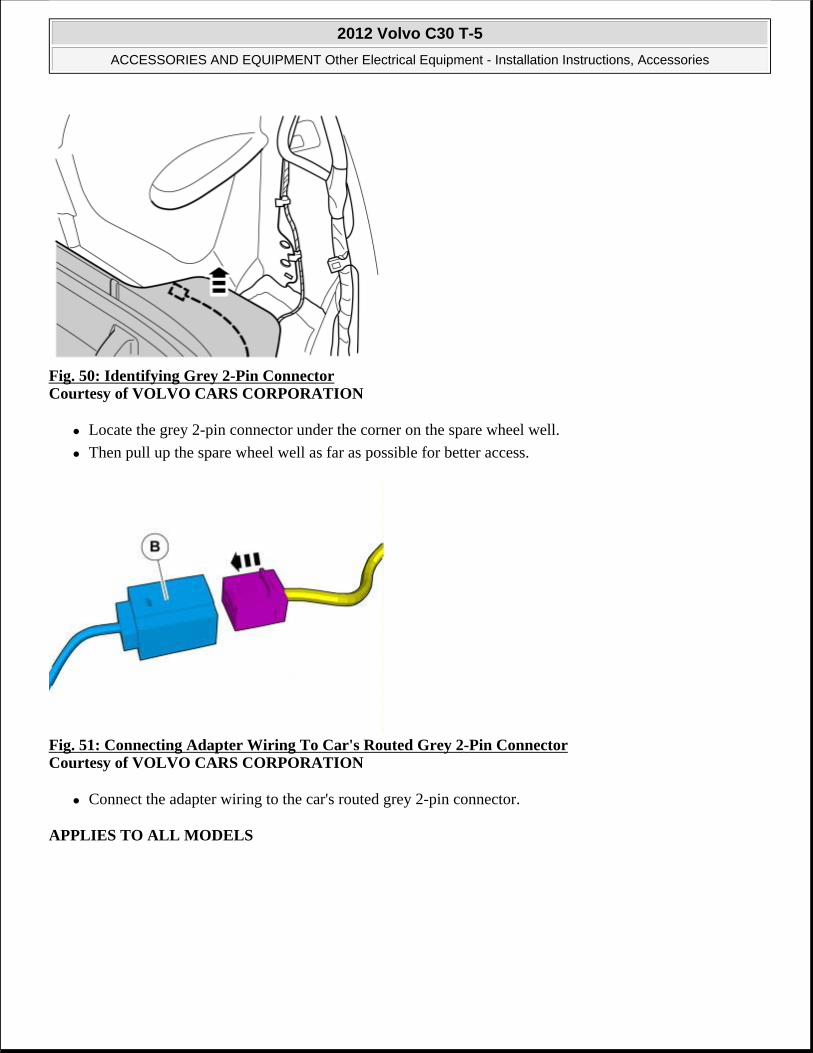
Fig. 50: Identifying Grey 2-Pin Connector Courtesy of VOLVO CARS CORPORATION
Locate the grey 2-pin connector under the corner on the spare wheel well.
Then pull up the spare wheel well as far as possible for better access.
Fig. 51: Connecting Adapter Wiring To Car's Routed Grey 2-Pin Connector Courtesy of VOLVO CARS CORPORATION
Connect the adapter wiring to the car's routed grey 2-pin connector.
APPLIES TO ALL MODELS
2012 Volvo C30 T-5
ACCESSORIES AND EQUIPMENT Other Electrical Equipment - Installation Instructions, Accessories

Fig. 52: Applying Foam Tape To Adapter Wiring's Connectors Courtesy of VOLVO CARS CORPORATION
Apply foam tape to the adapter wiring connectors.
Cut off any foam tape excess.
Fig. 53: Identifying Screw For Ground Terminal Under Rear Light Courtesy of VOLVO CARS CORPORATION
Remove the screw for the ground terminal under the rear light.
2012 Volvo C30 T-5
ACCESSORIES AND EQUIPMENT Other Electrical Equipment - Installation Instructions, Accessories

Fig. 54: Connecting Ground Terminal From Adapter Wiring To Ground Terminal And Tightening Screw Courtesy of VOLVO CARS CORPORATION
Connect the ground terminal from the adapter wiring to the ground terminal.
Tighten the screw. Tightening torque 10 Nm (7.3 lbf. ft.) .
Fig. 55: Cleaning Marked Surface On Body Panel Courtesy of VOLVO CARS CORPORATION
Clean the marked surface on the body panel using isopropanol and wipe dry.
2012 Volvo C30 T-5
ACCESSORIES AND EQUIPMENT Other Electrical Equipment - Installation Instructions, Accessories

Fig. 56: Cleaning Marked Surface On Control Module Courtesy of VOLVO CARS CORPORATION
Clean the marked surface on the control module using isopropanol and wipe dry.
Fig. 57: Identifying Velcro Pieces Courtesy of VOLVO CARS CORPORATION
Take the Velcro pieces from the kit and attach them edge to edge with each other.
2012 Volvo C30 T-5
ACCESSORIES AND EQUIPMENT Other Electrical Equipment - Installation Instructions, Accessories

Fig. 58: Cutting Tape Courtesy of VOLVO CARS CORPORATION
Fig. 59: Identifying Protective Backing Tape Courtesy of VOLVO CARS CORPORATION
Remove the protective backing tape from one side of the Velcro pieces.
2012 Volvo C30 T-5
ACCESSORIES AND EQUIPMENT Other Electrical Equipment - Installation Instructions, Accessories

Fig. 60: Identifying Velcro Courtesy of VOLVO CARS CORPORATION
Secure the Velcro onto the control module properly.
Fig. 61: Identifying Protective Film Courtesy of VOLVO CARS CORPORATION
Remove the protective film.
2012 Volvo C30 T-5
ACCESSORIES AND EQUIPMENT Other Electrical Equipment - Installation Instructions, Accessories

Fig. 62: Identifying Control Module Courtesy of VOLVO CARS CORPORATION
Position the control module along the rear edge of the rectangular storage compartment in the spare wheel well (dotted line 1).
Position the control module vertically with the lower panel edge on the wheel housing (dotted line 2).
Press the control module into place properly.
Fig. 63: Positioning Control Module Along Spare Wheel Well And Wheel Housing Courtesy of VOLVO CARS CORPORATION
2012 Volvo C30 T-5
ACCESSORIES AND EQUIPMENT Other Electrical Equipment - Installation Instructions, Accessories

Fig. 64: Identifying 4-Pin Black Connector Courtesy of VOLVO CARS CORPORATION
Plug the 4-pin black connector from adapter wiring (B) into the control module.
Fig. 65: Identifying 50-Pin Black Connector Courtesy of VOLVO CARS CORPORATION
Install the 50-pin black connector in the control module.
APPLIES TO CARS WITH CHASSIS NUMBERS FROM 39000->
2012 Volvo C30 T-5
ACCESSORIES AND EQUIPMENT Other Electrical Equipment - Installation Instructions, Accessories
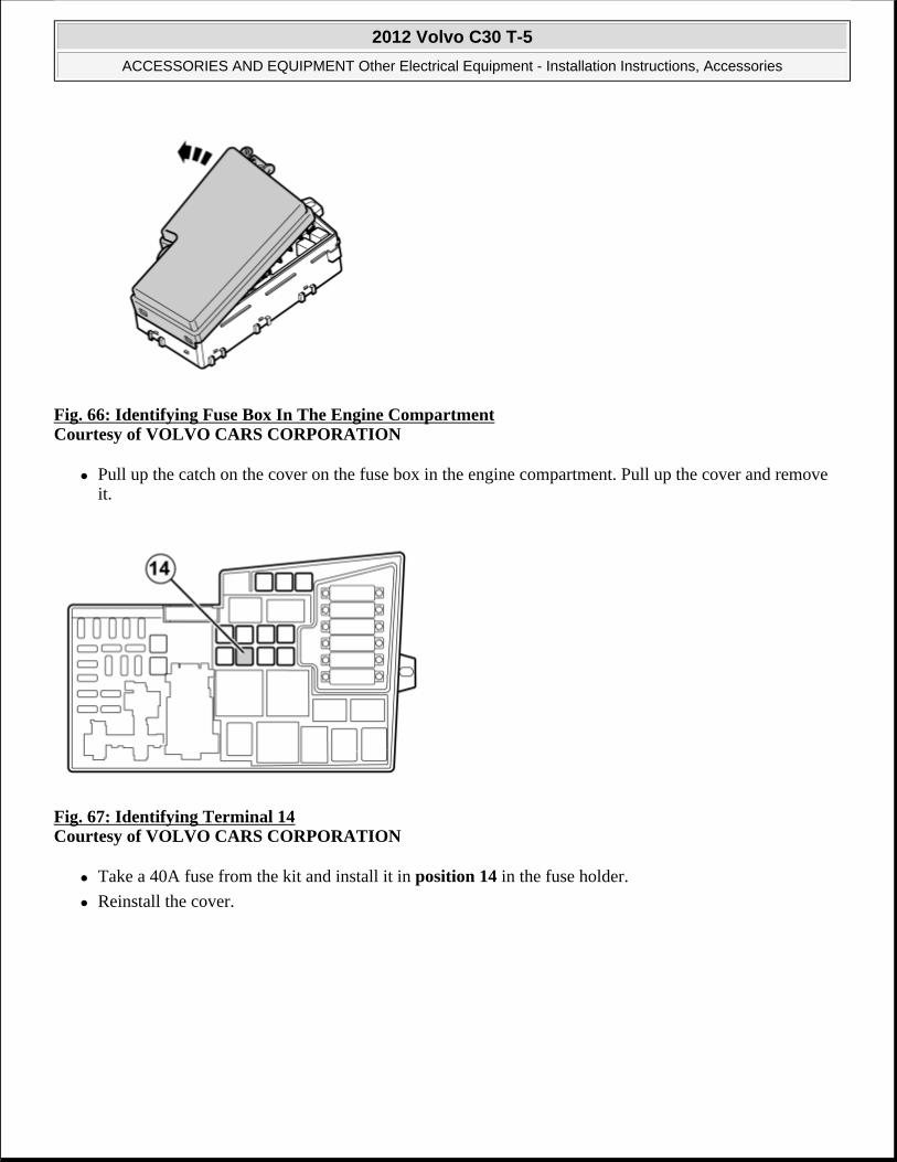
Fig. 66: Identifying Fuse Box In The Engine Compartment Courtesy of VOLVO CARS CORPORATION
Pull up the catch on the cover on the fuse box in the engine compartment. Pull up the cover and remove it.
Fig. 67: Identifying Terminal 14 Courtesy of VOLVO CARS CORPORATION
Take a 40A fuse from the kit and install it in position 14 in the fuse holder.
Reinstall the cover.
2012 Volvo C30 T-5
ACCESSORIES AND EQUIPMENT Other Electrical Equipment - Installation Instructions, Accessories

Fig. 68: Identifying VIDA (Service Information) To Program Software Courtesy of VOLVO CARS CORPORATION
Reinstall the removed components in reverse order.
Download the software for the accessory's function following the service information in VIDA (Volvo Scan Tool).
PARKING ASSISTANCE, FRONT, SWITCH
PARKING ASSISTANCE, FRONT, SWITCH
PREPARATIONS
Fig. 69: Identifying Ignition Key In 0 Position Courtesy of VOLVO CARS CORPORATION
Set the ignition key to position 0.
2012 Volvo C30 T-5
ACCESSORIES AND EQUIPMENT Other Electrical Equipment - Installation Instructions, Accessories

Fig. 70: Identifying Rear Center CONSOLE Panel Courtesy of VOLVO CARS CORPORATION
Remove the panel inside the center console. It is secured by four hidden clips.
Fig. 71: Identifying Display And Media Player Surround Courtesy of VOLVO CARS CORPORATION
Remove the surround from around the display and media player. Use a small screwdriver and press in the catch in one of the surround's upper corners. Carefully bend loose the surround on the same side with a plastic weatherstrip tool.
NOTE: Wait at least one minute before unplugging the connectors or removing other electrical equipment
NOTE: Do not damage the panel and dashboard.
2012 Volvo C30 T-5
ACCESSORIES AND EQUIPMENT Other Electrical Equipment - Installation Instructions, Accessories

HINT: If the panel is difficult to remove, press the panel on both sides again and repeat the procedure starting at the other side.
Fold the surround backwards. Remove by pulling upwards.
Fig. 72: Identifying Display Module Courtesy of VOLVO CARS CORPORATION
Remove the infotainment control module (ICM). It is secured by two hidden clips. Disconnect the connectors.
HINT: Grip the control module with both hands. Pull the control module straight out of the center console.
Fig. 73: Identifying Hand Brake Panel Courtesy of VOLVO CARS CORPORATION
Detach the panel by pulling it carefully sideways.
2012 Volvo C30 T-5
ACCESSORIES AND EQUIPMENT Other Electrical Equipment - Installation Instructions, Accessories
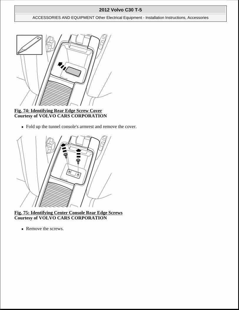
Fig. 74: Identifying Rear Edge Screw Cover Courtesy of VOLVO CARS CORPORATION
Fold up the tunnel console's armrest and remove the cover.
Fig. 75: Identifying Center Console Rear Edge Screws Courtesy of VOLVO CARS CORPORATION
Remove the screws.
2012 Volvo C30 T-5
ACCESSORIES AND EQUIPMENT Other Electrical Equipment - Installation Instructions, Accessories

Fig. 76: View Of Storage Compartment Prying Courtesy of VOLVO CARS CORPORATION
Remove the front storage compartment by prying it off at the front edge using a weatherstrip tool and lifting it out.
Fig. 77: Identifying Front Edge Tunnel Console Screws Courtesy of VOLVO CARS CORPORATION
Remove the two screws along the front edge of the tunnel console.
2012 Volvo C30 T-5
ACCESSORIES AND EQUIPMENT Other Electrical Equipment - Installation Instructions, Accessories

Fig. 78: Identifying Tunnel Console Lock Catch Courtesy of VOLVO CARS CORPORATION
Carefully lift the catches at the front edge of the tunnel console.
HINT: Use special tool: P/N 9995919.
Fig. 79: Identifying Console Pulled Backwards Courtesy of VOLVO CARS CORPORATION
At the same time pull the console backwards approximately 20 mm.
2012 Volvo C30 T-5
ACCESSORIES AND EQUIPMENT Other Electrical Equipment - Installation Instructions, Accessories

Fig. 80: Identifying Center Console Screws Courtesy of VOLVO CARS CORPORATION
Remove the screws.
Fig. 81: Identifying Gear Selector Lever Boot Courtesy of VOLVO CARS CORPORATION
Applies to cars with manual gearbox
Remove the gear selector lever boot from the center console. First pry it off at the front edge using a weatherstrip tool and then unhook it at the rear edge.
2012 Volvo C30 T-5
ACCESSORIES AND EQUIPMENT Other Electrical Equipment - Installation Instructions, Accessories

Fig. 82: Identifying Center Console Screws Courtesy of VOLVO CARS CORPORATION
Remove:
the two screws.
the connector to the center console at the rear.
the center console.
Fig. 83: Identifying Big Gray Connector At Front Courtesy of VOLVO CARS CORPORATION
Lift up the tunnel console and pull it back slightly.
Unplug the big gray connector at the front.
2012 Volvo C30 T-5
ACCESSORIES AND EQUIPMENT Other Electrical Equipment - Installation Instructions, Accessories

Fig. 84: Identifying Direction To Lift Out Tunnel Console Courtesy of VOLVO CARS CORPORATION
Lift out the tunnel console and turn it upside down.
Fig. 85: Identifying Installing Switch Courtesy of VOLVO CARS CORPORATION
Take the switch housing, switch and blind cover plug from the kit. Install the switch (1) and the blind cover plug (2) in the switch housing.
NOTE: Protect hand brake and gear lever when removing and installing the tunnel console.
2012 Volvo C30 T-5
ACCESSORIES AND EQUIPMENT Other Electrical Equipment - Installation Instructions, Accessories

Fig. 86: Identifying Installing Switch Housing Courtesy of VOLVO CARS CORPORATION
Install the switch housing on the tunnel console by first hooking it at the rear edge.
Fig. 87: Identifying Green Connector Attached To Switch Housing Courtesy of VOLVO CARS CORPORATION
Take the cable harness from the kit and connect the green connector to the switch housing.
2012 Volvo C30 T-5
ACCESSORIES AND EQUIPMENT Other Electrical Equipment - Installation Instructions, Accessories

Fig. 88: Identifying Secured Cable Harness Courtesy of VOLVO CARS CORPORATION
Secure the cable harness using four cable ties at the existing cable harness.
Fig. 89: Identifying Attachment Of Connectors Courtesy of VOLVO CARS CORPORATION
Connect the connector (1) from the tunnel console's cable harness to the connector (2) on the prerouted cable harness.
Take a piece of foam tape from the kit and wrap it around the connected connectors.
INSTALLING THE SWITCH
APPLIES TO VEHICLES WITH BLIS OR DRIVE (NOT BOTH)
2012 Volvo C30 T-5
ACCESSORIES AND EQUIPMENT Other Electrical Equipment - Installation Instructions, Accessories

Fig. 90: Identifying Switch Housing Catches Courtesy of VOLVO CARS CORPORATION
Release the catches holding the switch housing and lift out.
Fig. 91: Identifying Blind Cover Plug Courtesy of VOLVO CARS CORPORATION
Remove the blind cover plug by pulling it straight out.
2012 Volvo C30 T-5
ACCESSORIES AND EQUIPMENT Other Electrical Equipment - Installation Instructions, Accessories

Fig. 92: Identifying Installation Of Switch Courtesy of VOLVO CARS CORPORATION
Install the switch from the kit.
Reinstall the switch housing on the tunnel console.
APPLIES TO VEHICLES WITH BOTH BLIS AND DRIVE, AS WELL AS VEHICLES WITHOUT BLIS OR DRIVE
Fig. 93: Identifying Removal Of Storage Compartment Courtesy of VOLVO CARS CORPORATION
Remove the storage compartment from the tunnel console by releasing the catches.
FINISHING WORK
2012 Volvo C30 T-5
ACCESSORIES AND EQUIPMENT Other Electrical Equipment - Installation Instructions, Accessories

Fig. 94: Identifying VIDA (Service Information) To Program Software Courtesy of VOLVO CARS CORPORATION
Reinstall:
the tunnel console and the large connector.
the center console with its screws, two up and two down.
gear lever gaiter, starting at the trailing edge.
and slide the tunnel console forward so that the lugs secure it. At the same time align the floor carpet on the right and left-hand sides.
the two screws at the front edge of the tunnel console.
the cover at the parking brake.
the panel at the parking brake.
the two screws and the cover under the armrest.
the ignition control module (ICM) with the connectors, screws and panel.
front storage compartment inside of the center console.
the panel inside the center console.
Applies to vehicles with both BLIS and DRIVe, as well as vehicles without BLIS or DRIVe
Run the identification and configuration procedure for the accessory's function according to the service information in VIDA (Volvo Scan Tool).
Applies to vehicles with BLIS or DRIVe (not both)
Run the configuration procedure for the accessory's function according to the service information in VIDA (Volvo Scan Tool).
ALCOGUARD (2008-09)
2012 Volvo C30 T-5
ACCESSORIES AND EQUIPMENT Other Electrical Equipment - Installation Instructions, Accessories

ALCOGUARD
Fig. 95: Identifying Application Of Alcohol Lock Courtesy of VOLVO CARS CORPORATION
Activate (and calibrate) the alcohol lock
After installing the software on the PC according to TJ, connect the alcohol lock to the PC using the communication cable.
Fig. 96: Identifying Ignition Switch Turned To Position 0 Courtesy of VOLVO CARS CORPORATION
Turn the ignition switch to position 0.
NOTE: The work is carried out the same way on left-hand drive cars. Left-hand drive car shown.
2012 Volvo C30 T-5
ACCESSORIES AND EQUIPMENT Other Electrical Equipment - Installation Instructions, Accessories

Fig. 97: Locating Cradle Courtesy of VOLVO CARS CORPORATION
Place the cradle centrally between the two vertical lines at the front edge of the tunnel console and parallel with the panel at the upper edge.
Mark out for drilling holes.
Fig. 98: Identifying Rear Center Console Panel Courtesy of VOLVO CARS CORPORATION
Open the glovebox.
Carefully pry off the panel inside the center console. Use a plastic weatherstrip tool. The panel is secured by two clips on each of the short sides.
NOTE: Wait at least three minutes before unplugging the connectors or removing other electrical equipment.
2012 Volvo C30 T-5
ACCESSORIES AND EQUIPMENT Other Electrical Equipment - Installation Instructions, Accessories

Fig. 99: Identifying Screws Courtesy of VOLVO CARS CORPORATION
Remove the screws.
Fig. 100: Identifying Folded Back Front Edge Of Tunnel Console Courtesy of VOLVO CARS CORPORATION
Carefully fold back the front edge on the tunnel console and ensure that no cable harnesses or anything else is in the way when drilling.
2012 Volvo C30 T-5
ACCESSORIES AND EQUIPMENT Other Electrical Equipment - Installation Instructions, Accessories

Fig. 101: Identifying Tools And Location Of Holes Courtesy of VOLVO CARS CORPORATION
Drill out the holes.
Remove any shavings.
Fig. 102: Identifying Panel Courtesy of VOLVO CARS CORPORATION
Remove the panel on the right end of the dashboard. Carefully pry it loose all around with a weatherstrip tool, until the three legs release.
NOTE: Do not damage the dashboard.
2012 Volvo C30 T-5
ACCESSORIES AND EQUIPMENT Other Electrical Equipment - Installation Instructions, Accessories

Fig. 103: Identifying Vent Clip Courtesy of VOLVO CARS CORPORATION
Detach the clip holding the vent from the glove compartment.
Fig. 104: Locating Glovebox Screws Courtesy of VOLVO CARS CORPORATION
Remove the glove compartment's rubber mat.
Remove the five screws in the opening to the glovebox.
Pull the glove compartment straight back to loosen the two hidden clips in the upper edge.
Remove the outer section of the glovebox.
2012 Volvo C30 T-5
ACCESSORIES AND EQUIPMENT Other Electrical Equipment - Installation Instructions, Accessories

Fig. 105: Identifying Connectors Courtesy of VOLVO CARS CORPORATION
Unplug the connectors on the top.
Fig. 106: Identifying Cut Out For Cable In Panel Courtesy of VOLVO CARS CORPORATION
Make a cut out for the cable in the panel. Do not cut out more than necessary so that the cable can be secured slightly.
2012 Volvo C30 T-5
ACCESSORIES AND EQUIPMENT Other Electrical Equipment - Installation Instructions, Accessories

Fig. 107: Identifying Hole Dimensions Courtesy of VOLVO CARS CORPORATION
Drill a 10 mm (25/64") hole on the left side of the glove compartment's outer part.
Remove any shavings.
Fig. 108: Identifying Plugged In Connector Courtesy of VOLVO CARS CORPORATION
Get the adapter wire from the kit and plug in one connector to the connection for the glove compartment lighting.
Route the wires at the lower edge to the other side.
2012 Volvo C30 T-5
ACCESSORIES AND EQUIPMENT Other Electrical Equipment - Installation Instructions, Accessories

Fig. 109: Identifying Wires And Connector Fastened With Butyl Tape Courtesy of VOLVO CARS CORPORATION
Fasten the wires and the little green connector with pieces of butyl tape.
Fig. 110: Identifying Insertion Of Small Connector And Cable Courtesy of VOLVO CARS CORPORATION
Insert the small connector and the whole cable in the glove compartment's outer part.
2012 Volvo C30 T-5
ACCESSORIES AND EQUIPMENT Other Electrical Equipment - Installation Instructions, Accessories

Fig. 111: Identifying Wire Fastened With Butyl Tape Courtesy of VOLVO CARS CORPORATION
Fasten the wire at the hole with a piece of butyl tape.
Fig. 112: Identifying Attachment Of Connector To Courtesy Lighting Courtesy of VOLVO CARS CORPORATION
Get the outer glove compartment and plug in the connector from the glove compartment lighting to the corresponding in the new adapter wire.
Connect the remaining connector to the courtesy lighting.
2012 Volvo C30 T-5
ACCESSORIES AND EQUIPMENT Other Electrical Equipment - Installation Instructions, Accessories

Fig. 113: Identifying Cable Secured With Ties Courtesy of VOLVO CARS CORPORATION
Take the cradle with cable and connect the green connector to the corresponding one that was secured in the glove compartment.
Secure the cable at the existing cable harness using cable ties. The cable must run along the right-hand mounting of the tunnel console.
Secure the grey connector in the glove compartment.
Fig. 114: Locating Glovebox Screws Courtesy of VOLVO CARS CORPORATION
Reinstall and tighten down the glove compartment's outer part.
Roll up the wire in the glove compartment and fasten it with the Velcro strap.
2012 Volvo C30 T-5
ACCESSORIES AND EQUIPMENT Other Electrical Equipment - Installation Instructions, Accessories

Fig. 115: Identifying Excess Cable Storage Behind Tunnel Console Courtesy of VOLVO CARS CORPORATION
Pull in the cable to the cradle and place it on the right-hand side of the tunnel console inside the carpet. If it is a tight fit, carefully cut off a piece from the glove compartment's left-hand corner.
Tighten the tunnel console at the front edge.
Fig. 116: Identifying Re-Attachment Of Panel Courtesy of VOLVO CARS CORPORATION
Place the cable in the cut out in the panel and secure.
Fold back the carpet.
Tighten the cradle. Ensure that the cable is correctly routed in the cut out.
2012 Volvo C30 T-5
ACCESSORIES AND EQUIPMENT Other Electrical Equipment - Installation Instructions, Accessories

Fig. 117: Locating And Orienting Cradle Courtesy of VOLVO CARS CORPORATION
Fig. 118: Identifying Vent Clip Courtesy of VOLVO CARS CORPORATION
2012 Volvo C30 T-5
ACCESSORIES AND EQUIPMENT Other Electrical Equipment - Installation Instructions, Accessories

Fig. 119: Identifying Dashboard Side Panel Courtesy of VOLVO CARS CORPORATION
Fig. 120: Identifying VIDA (Service Information) To Program Software Courtesy of VOLVO CARS CORPORATION
Download the software for the accessory's function following the service information in VIDA (Volvo Scan Tool).
ALCOGUARD, KIT NUMBER 30756979 (2009-12)
ALCOGUARD, KIT NUMBER 30756979
2012 Volvo C30 T-5
ACCESSORIES AND EQUIPMENT Other Electrical Equipment - Installation Instructions, Accessories

Fig. 121: Identifying Application Of Alcohol Lock Courtesy of VOLVO CARS CORPORATION
Activate (and calibrate) the alcohol lock.
The necessary software can also be found there.
After installing the software on a PC according to the TJ, connect the alcohol lock to the PC using the supplied communication cable. A question asking whether to activate appears automatically (if the lock is not activated), otherwise nothing special happens.
Fig. 122: Identifying Ignition Switch Turned To Position 0 Courtesy of VOLVO CARS CORPORATION
Turn the ignition switch to position 0.
NOTE: Wait at least three minutes before unplugging the connectors or removing other electrical equipment.
2012 Volvo C30 T-5
ACCESSORIES AND EQUIPMENT Other Electrical Equipment - Installation Instructions, Accessories

Fig. 123: Identifying Rear Center CONSOLE Panel Courtesy of VOLVO CARS CORPORATION
Open the glovebox.
Carefully pry off the panel inside the center console. Use a plastic weatherstrip tool. The panel is secured by two clips on each of the short sides.
Pull the panel off downwards.
Fig. 124: Identifying Panel Courtesy of VOLVO CARS CORPORATION
Remove the panel on the right end of the dashboard. Carefully pry it loose all around with a weatherstrip tool, until the three legs release.
NOTE: Do not damage the dashboard.
2012 Volvo C30 T-5
ACCESSORIES AND EQUIPMENT Other Electrical Equipment - Installation Instructions, Accessories

Fig. 125: Identifying Vent Clip Courtesy of VOLVO CARS CORPORATION
Detach the clip holding the nozzle from the glove compartment.
Fig. 126: Locating Glovebox Screws Courtesy of VOLVO CARS CORPORATION
Remove the glove compartment's rubber mat.
Remove the five screws in the opening to the glovebox.
Pull the glove compartment straight back to loosen the two hidden clips in the upper edge.
Remove the outer section of the glovebox.
2012 Volvo C30 T-5
ACCESSORIES AND EQUIPMENT Other Electrical Equipment - Installation Instructions, Accessories
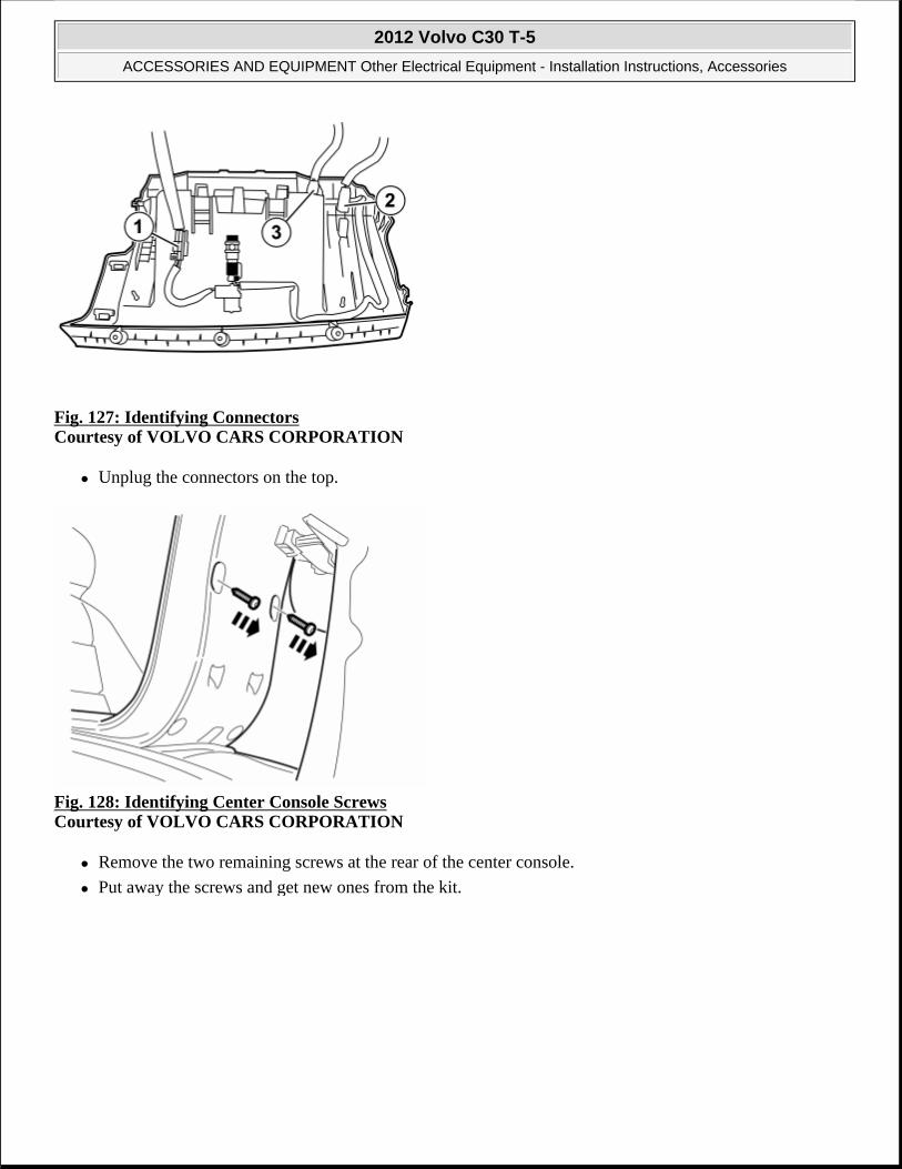
Fig. 127: Identifying Connectors Courtesy of VOLVO CARS CORPORATION
Unplug the connectors on the top.
Fig. 128: Identifying Center Console Screws Courtesy of VOLVO CARS CORPORATION
Remove the two remaining screws at the rear of the center console.
Put away the screws and get new ones from the kit.
2012 Volvo C30 T-5
ACCESSORIES AND EQUIPMENT Other Electrical Equipment - Installation Instructions, Accessories

Fig. 129: Identifying Wire Hooked And Routed To Slot Courtesy of VOLVO CARS CORPORATION
Take the holder from the kit and insert the green connector in the lower hole and pull through the whole wire.
Hook on the wire around the lip in the upper hole and place it in the slot at the top.
Fig. 130: Identifying Secured Wire Courtesy of VOLVO CARS CORPORATION
2012 Volvo C30 T-5
ACCESSORIES AND EQUIPMENT Other Electrical Equipment - Installation Instructions, Accessories

Fig. 131: Identifying Installation Of Holder With Screws Courtesy of VOLVO CARS CORPORATION
Take the two longer screws from the kit.
Install the holder with the two screws in the upper edge and tighten.
Tighten the bolts so that the head just has contact against the holder.
Then tighten the bolts slightly more.
Check that the holder is fastened at the top.
Fig. 132: Identifying Adjustment Of Holder Courtesy of VOLVO CARS CORPORATION
NOTE: Be careful when tightening the bolts, as it is easy to tighten them in too far.
NOTE: The lower holes are angled 45° .
2012 Volvo C30 T-5
ACCESSORIES AND EQUIPMENT Other Electrical Equipment - Installation Instructions, Accessories

middle of the hole in the holder with a scribe to get the self-tapping screw to center better.
Repeat the operation on the other side.
Fig. 133: Identifying Installment Of Screws Courtesy of VOLVO CARS CORPORATION
Take the self-tapping screws from the kit and tighten them.
Fig. 134: Identifying Filed Slot Courtesy of VOLVO CARS CORPORATION
File a slot in the panel for the holder's wire as shown.
2012 Volvo C30 T-5
ACCESSORIES AND EQUIPMENT Other Electrical Equipment - Installation Instructions, Accessories

Fig. 135: Identifying Wire Secured With Tie Courtesy of VOLVO CARS CORPORATION
Pull up the wire from the holder to the green connector for the display.
Clamp the wire to the connector's cable harness so that the wire reaches down to the holder and so that it fits in the slot in the panel.
Fig. 136: Identifying Wire Secured With Tie Courtesy of VOLVO CARS CORPORATION
Get the wire coming from the holder and attach it on the right side of the center console. The wire shall be attached to the existing cable harness with a cable tie from the kit.
2012 Volvo C30 T-5
ACCESSORIES AND EQUIPMENT Other Electrical Equipment - Installation Instructions, Accessories

Fig. 137: Identifying Hole Dimensions Courtesy of VOLVO CARS CORPORATION
Drill a 10 mm (25/64") hole on the left side of the glove compartment's outer part.
Remove any shavings.
Fig. 138: Identifying Plugged In Connector Courtesy of VOLVO CARS CORPORATION
Get the adapter wire from the kit and plug in one connector to the connection for the glove compartment lighting.
Route the wires at the lower edge to the other side.
2012 Volvo C30 T-5
ACCESSORIES AND EQUIPMENT Other Electrical Equipment - Installation Instructions, Accessories

Fig. 139: Identifying Wires And Connector Fastened With Butyl Tape Courtesy of VOLVO CARS CORPORATION
Fasten the wires and the little green connector with pieces of butyl tape.
Fig. 140: Identifying Insertion Of Small Connector And Cable Courtesy of VOLVO CARS CORPORATION
Insert the little green connector and the whole wire in the glove compartment's outer part.
2012 Volvo C30 T-5
ACCESSORIES AND EQUIPMENT Other Electrical Equipment - Installation Instructions, Accessories

Fig. 141: Identifying Wire Fastened With Butyl Tape Courtesy of VOLVO CARS CORPORATION
Fasten the wire at the hole with a piece of butyl tape.
Fig. 142: Identifying Attachment Of Connector To Courtesy Lighting Courtesy of VOLVO CARS CORPORATION
Get the outer glove compartment and plug in the connector from the glove compartment lighting to the corresponding in the new adapter wire.
Plug in remaining connector in the adapter wire for the glove compartment lighting.
2012 Volvo C30 T-5
ACCESSORIES AND EQUIPMENT Other Electrical Equipment - Installation Instructions, Accessories
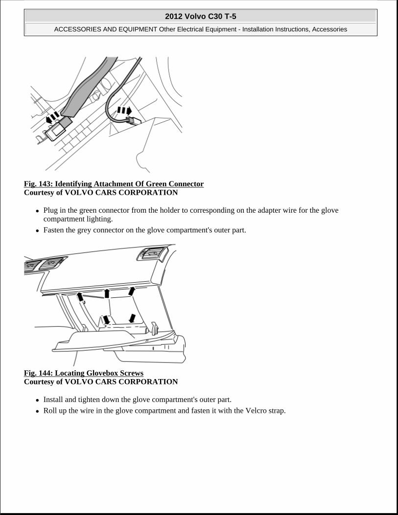
Fig. 143: Identifying Attachment Of Green Connector Courtesy of VOLVO CARS CORPORATION
Plug in the green connector from the holder to corresponding on the adapter wire for the glove compartment lighting.
Fasten the grey connector on the glove compartment's outer part.
Fig. 144: Locating Glovebox Screws Courtesy of VOLVO CARS CORPORATION
Install and tighten down the glove compartment's outer part.
Roll up the wire in the glove compartment and fasten it with the Velcro strap.
2012 Volvo C30 T-5
ACCESSORIES AND EQUIPMENT Other Electrical Equipment - Installation Instructions, Accessories

Fig. 145: Identifying Rear Center Panel Courtesy of VOLVO CARS CORPORATION
Fit the wire from the holder in the slot on the panel and press to fasten.
Fig. 146: Identifying Routed Cable Courtesy of VOLVO CARS CORPORATION
2012 Volvo C30 T-5
ACCESSORIES AND EQUIPMENT Other Electrical Equipment - Installation Instructions, Accessories

Fig. 147: Identifying Vent Clip Courtesy of VOLVO CARS CORPORATION
Fig. 148: Identifying Dashboard Side Panel Courtesy of VOLVO CARS CORPORATION
2012 Volvo C30 T-5
ACCESSORIES AND EQUIPMENT Other Electrical Equipment - Installation Instructions, Accessories

Fig. 149: Identifying VIDA (Service Information) To Program Software Courtesy of VOLVO CARS CORPORATION
Download the software for the accessory's function following the service information in VIDA (Volvo Scan Tool).
ALCOLOCK, INSTALLATION KIT
ALCOLOCK, INSTALLATION KIT
PREPARATIONS
Fig. 150: Disconnect Battery Negative Lead Courtesy of VOLVO CARS CORPORATION
Turn the ignition key to position 0.
Disconnect the battery negative lead.
2012 Volvo C30 T-5
ACCESSORIES AND EQUIPMENT Other Electrical Equipment - Installation Instructions, Accessories

Fig. 151: Locating Screws In Soundproofing Panel Courtesy of VOLVO CARS CORPORATION
Remove the three screws in the soundproofing panel on the left-hand side.
Push the carpet on the left-hand side of the center console to one side.
Carefully pry off the soundproofing panel from the top edge of the dashboard. Use a weatherstrip tool. The panel is secured by two clips at the top edge.
Fig. 152: Identifying Lighting Connectors Courtesy of VOLVO CARS CORPORATION
Disconnect the connector for lighting (1) and remove the soundproofing panel.
NOTE: Wait at least five minutes before disconnecting the connectors or removing other electrical equipment.
2012 Volvo C30 T-5
ACCESSORIES AND EQUIPMENT Other Electrical Equipment - Installation Instructions, Accessories
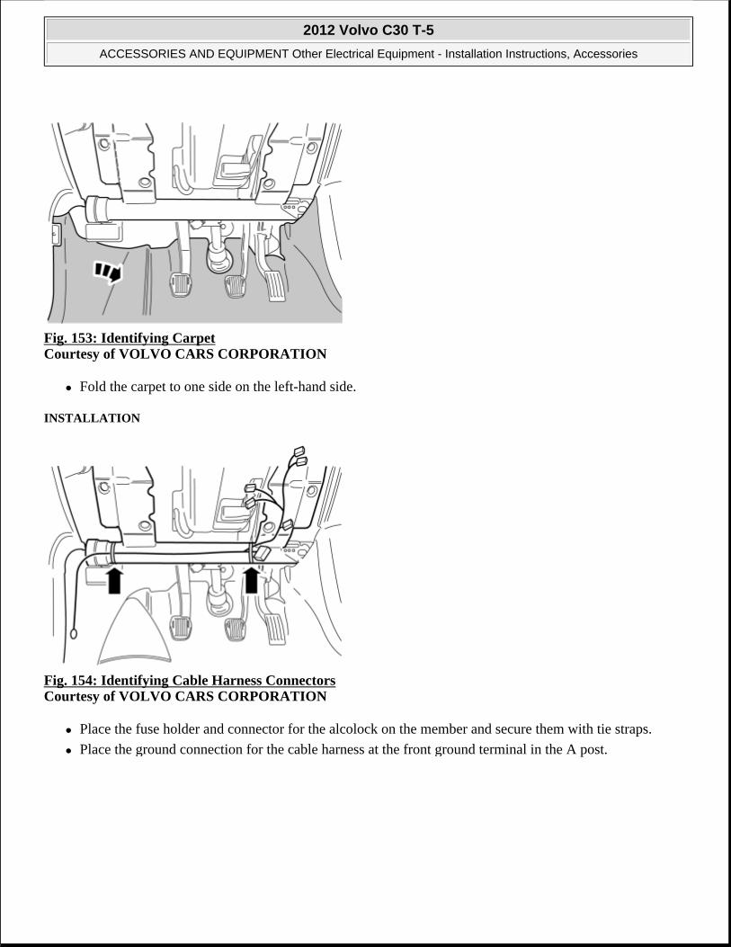
Fig. 153: Identifying Carpet Courtesy of VOLVO CARS CORPORATION
Fold the carpet to one side on the left-hand side.
INSTALLATION
Fig. 154: Identifying Cable Harness Connectors Courtesy of VOLVO CARS CORPORATION
Place the fuse holder and connector for the alcolock on the member and secure them with tie straps.
Place the ground connection for the cable harness at the front ground terminal in the A post.
2012 Volvo C30 T-5
ACCESSORIES AND EQUIPMENT Other Electrical Equipment - Installation Instructions, Accessories

Fig. 155: Identifying Installation Of Ground Lead Courtesy of VOLVO CARS CORPORATION
Install the ground lead, use new screws from the kit.
Tighten the M6 screw to 10 Nm .
Fold back the carpet.
Fig. 156: Identifying Ignition Switch Cable And Connector Courtesy of VOLVO CARS CORPORATION
Disconnect the existing connector from the ignition switch.
Connect the connectors from the new cable harness to the corresponding connector in the ignition switch and the existing disconnected cable.
2012 Volvo C30 T-5
ACCESSORIES AND EQUIPMENT Other Electrical Equipment - Installation Instructions, Accessories

Fig. 157: Identifying Lighting Connectors Courtesy of VOLVO CARS CORPORATION
Connect the connectors from the new cable harness to the corresponding connector for lighting (1), which was previously disconnected.
Reinstall the soundproofing panel.
Fig. 158: Connecting Negative Battery Lead Courtesy of VOLVO CARS CORPORATION
2012 Volvo C30 T-5
ACCESSORIES AND EQUIPMENT Other Electrical Equipment - Installation Instructions, Accessories

Fig. 159: Identifying Alcolock Connector Terminals Courtesy of VOLVO CARS CORPORATION
Connector for alcolock
1. 30+ feed (battery supply)
2. 15+ feed (ignition supply)
3. Start-in (kl50)
4. Start-out (kl50)
5. Preheat, act-low
6. Ground-, (31)
7. 30+ feed, controlled
NOTE: 30+ battery supply (1) must only be used in exceptional cases when log function for disconnection of the alcolock is required. In all other cases, 30+ battery supply (7) should be used, to prevent shortening the service life of the battery.
2012 Volvo C30 T-5
ACCESSORIES AND EQUIPMENT Other Electrical Equipment - Installation Instructions, Accessories

ENGINE
Engine Mechanical
ENGINE MECHANICAL
RELAY ELECTRICAL ENGINE BLOCK HEATER, REPLACING
REMOVAL
PREPARATORY WORK
Fig. 1: Pulling Locking Plate Straight Up Courtesy of VOLVO CARS CORPORATION
Remove the locking plate for the headlamp as shown in the illustration.
Disconnect the connector.
NOTE: As the illustrations in this service information are used for different model years and / or models, some variation may occur. However, the essential information in the illustrations is always correct.
2012 Volvo C30 T-5
ENGINE Engine Mechanical
2012 Volvo C30 T-5
ENGINE Engine Mechanical

Remove the headlamp.
REMOVING THE RELAY FOR THE ELECTRIC ENGINE BLOCK HEATER
Fig. 2: Removing Relay For Electric Engine Block Heater Courtesy of VOLVO CARS CORPORATION
Remove:
the tie straps
2 screws. Pull out the engine block heater relay
the locking sleeves for the cable splices. Disconnect the wiring
the engine block heater relay.
INSTALLATION
INSTALLING THE RELAY FOR THE ELECTRIC ENGINE BLOCK HEATER
2012 Volvo C30 T-5
ENGINE Engine Mechanical

Fig. 3: Installing Relay For Electric Engine Block Heater (1 Of 2) Courtesy of VOLVO CARS CORPORATION
Connect the wiring:
front engine block heater socket (1)
engine block heater (2)
passenger compartment socket (3) if applicable.
2012 Volvo C30 T-5
ENGINE Engine Mechanical

Fig. 4: Installing Relay For Electric Engine Block Heater (2 Of 2) Courtesy of VOLVO CARS CORPORATION
Connect the ground lead (4).
Install locking sleeves for the cable splices.
Position the engine block heater relay under the plate (1).
Install the screws (2). Clamp the cables (3, 4).
FINISHING WORK
Connect the connector for the headlamp.
Install the headlamp.
Install the locking plate for the headlamp.
Test the function.
2012 Volvo C30 T-5
ENGINE Engine Mechanical

ENGINE
Cooling System (Mechanical)
COOLING SYSTEM
ENGINE COOLING FAN (FC)
PREPARATORY WORK
Remove the expansion tank cap.
Block the 2 coolant hoses using lock grip pliers.
Install a hose on the nipple at the radiator.
Feed the hose down to a container.
Open the nipple and drain off the coolant.
REMOVAL
REMOVING THE OIL COOLER FOR AUTOMATIC TRANSMISSIONS
Remove the oil cooler. See: OIL COOLER, ENGINE .
REMOVING THE RADIATOR HOSES
Remove the 2 radiator hoses.
REMOVING THE ENGINE COOLING FAN (FC)
NOTE: The illustrations in this service information are used for different model years and/or models. Some variation may occur. However, the essential information in the illustrations is always correct.
NOTE: Applies only to cars with automatic transmissions
2012 Volvo C30 T-5
ENGINE Cooling System (Mechanical)
2012 Volvo C30 T-5
ENGINE Cooling System (Mechanical)

Fig. 1: Removing Engine Cooling Fan Courtesy of VOLVO CARS CORPORATION
Remove the 2 connectors for the engine cooling fan.
Press in the two retaining clips. Lift the engine cooling fan from the catches.
Remove the fan downwards.
INSTALLATION
INSTALLING THE ENGINE COOLANT FAN (FC)
NOTE: For tightening torques, see: TIGHTENING TORQUE .
2012 Volvo C30 T-5
ENGINE Cooling System (Mechanical)

Fig. 2: Installing Engine Cooling Fan Courtesy of VOLVO CARS CORPORATION
Press the fan shroud into the mounting points.
Install the 2 radiator hoses on both sides. Remove the lock grip pliers from the radiator hoses.
INSTALLING THE OIL COOLER FOR AUTOMATIC TRANSMISSIONS
Install the oil cooler for the automatic transmission. See: OIL COOLER, ENGINE .
FINISHING
Fill with coolant and run the engine until the thermostat opens. Top up as necessary.
NOTE: Ensure that the 2 retaining clips secure the fan shroud.
NOTE: Applies only to cars with automatic transmissions.
NOTE: Automatic cars only. Check the oil level in the transmission. Top up if required.
2012 Volvo C30 T-5
ENGINE Cooling System (Mechanical)

ENGINE PERFORMANCE
General - Specifications, Mechanical
LUBRICANTS, ENGINE
USA AND CDN
C30
SPECIFICATIONS, MECHANICAL (B5244S4; 2007-10)
GENERAL DATA
ENGINE MANUFACTURE NUMBER, ENGINE SERIAL NUMBER AND TYPE
Engine Service interval (km/miles)
Volume (liters)
Grade Viscosity Part number
Petrol 12.000/7.500 Approx. 5.8 ILSAC GF-4 API SL/ACEA A1/B1
SAE 5W-30 1161754, -755, -756
- B5244S4 B5244S5 B5244S7 Engine code 38 66 39Power (kw/rpm) 125/6000 103/6000 123/6000Max torque (Nm/rpm) 230/1500-4800 220/4000 230/4000Max rpm 6500/6800 6500/6800 6500/6800Idling (rpm) 720 720 720Cylinder bore (mm) 83 83 83Stroke (mm) 90 90 90Swept volume (liters) 2, 435 2, 435 2, 435Firing sequence 1-2-4-5-3 1-2-4-5-3 1-2-4-5-3Engine control system Denso Denso DensoWeight, complete, including oil (kg) 150 150 150
2012 Volvo C30 T-5
ENGINE PERFORMANCE General - Specifications, Mechanical
2012 Volvo C30 T-5
ENGINE PERFORMANCE General - Specifications, Mechanical

Fig. 1: Engine Manufacture Number, Engine Serial Number & Type Courtesy of VOLVO CARS CORPORATION
The engine serial number and type are stamped on the left side of the cylinder block at the top of the mounting for the water pump.
There is also a decal on the timing casing with the engine type, manufacturing number, and serial number.
CLASSIFICATION OF MAIN BEARINGS
The marking is stamped in the engine block and crankshaft. The classification marking is in the engine block above the oil cooler and crankshaft. The classification shall be read from the digit 1 to 7.
The first letter after the digit 1 is the classification of main bearing 1. The bearing positions are numbered starting at the engine's leading edge.
MAIN BEARING - Class A
block small diameter
- Class B block average diameter
- Class C block large diameter
-
- block intermediate section
block intermediate section
block intermediate section
2012 Volvo C30 T-5
ENGINE PERFORMANCE General - Specifications, Mechanical
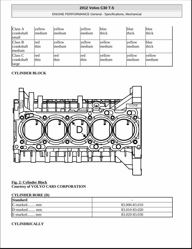
CYLINDER BLOCK
Fig. 2: Cylinder Block Courtesy of VOLVO CARS CORPORATION
CYLINDER BORE (D)
CYLINDRICALLY
Class A crankshaft small
yellow medium
yellow medium
yellow medium
blue thick
blue thick
blue thick
Class B crankshaft medium
red thin
yellow medium
yellow medium
yellow medium
yellow medium
blue thick
Class C crankshaft large
red thin
red thin
red thin
yellow medium
yellow medium
yellow medium
Standard -C-marked........ mm 83.000-83.010D-marked........ mm 83.010-83.020E-marked........ mm 83.020-83.030
2012 Volvo C30 T-5
ENGINE PERFORMANCE General - Specifications, Mechanical

PISTONS
Fig. 3: Identifying Piston Courtesy of VOLVO CARS CORPORATION
PISTONS
PISTON RUNNING CLEARANCE
PISTON RINGS
PISTON PIN
VALVES
Maximum deviation -Cylinder bore........ mm 0.013
Standard The diameter is measured 12 mm from the bottom of the piston
C-marked1 ........ mm 82.950-82.960
D-marked1 ........ mm 82.960-82.970
E-marked1 ........ mm 82.970-82.9801 Classification is marked on the top of the piston.
Tolerance piston/cylinder - top........ mm 0.010 - 0.030
Top ring........ mm 1.2 -0.01/-0.031st ring........ mm 1.5 -0.01/-0.03Oil ring........ mm 2 -0.01/-0.136
Diameter........ mm 21.000 0.000/-0.004Length........ mm 57.0 0.0/+0.2
2012 Volvo C30 T-5
ENGINE PERFORMANCE General - Specifications, Mechanical

Fig. 4: Identifying Valve Courtesy of VOLVO CARS CORPORATION
VALVES
VALVE SEATS
TAPPETS
CAMSHAFTS
Intake Length (A)........ mm 102.00 ± 0.07Diameter on crown (B)........ mm 31 ± 0.15Diameter on shaft (C)........ mm 5.94 ± 0.07Valve angle (D)........° 45.5 ± 0.17Clearance in guide........µm 50 - 70Valve clearance........ mm 0.20 ± 0.03Exhaust Length (A)........ mm 101.05 ± 0.07Diameter on crown (B)........ mm 27 ± 0.15Diameter on shaft (C)........ mm 5.94 ± 0.07Valve angle (D)........° 45.5 ± 0.17Clearance in guide........µm 50 - 70Valve clearance........ mm 0.40 ± 0.03
Seat angle........° 45.5 ± 0.17
Diameter........ mm 32 -0.025/-0.040Length........ mm 2.950 - 3.685 ± 0.01
Max. lift height inlet........ mm 8.68Max. lift height exhaust........ mm 9.05
2012 Volvo C30 T-5
ENGINE PERFORMANCE General - Specifications, Mechanical
CYLINDER HEAD
CYLINDER HEAD
CRANKSHAFT
BIG END JOURNALS
MAIN BEARING JOURNALS
CONNECTING RODS
OIL PRESSURE
Max. distortion........ mm 0.5Max. distortion, transverse........ mm 0.2Height........ mm 149.4 ± 0.15
Radial run-out main bearing journal........ mm max. 0.040Axial play (Measured in the engine with the intermediate section tightened)........ mm
0.08-0.19
Main bearing journal, radial runout........ mm 0.020-0.043
Diameter, standard1 ........ mm 50.000 0.000/-0.016
Bearing recess width........ mm 26.0 ± 0.1Maximum out-of-round........ mm 0.004Maximum taper........ mm 0.0041 The variation in diameter for each bearing journal must not exceed 0.008 mm.
Diameter, standard 1 ........ mm 65.000 +0.003/-0.016
Axial bearing width........ mm 26.00 0.00/-0.04Maximum out-of-round........ mm 0.004Maximum taper........ mm 0.0041 The variation in diameter for each bearing journal must not exceed 0.008 mm.
Diameter, bearing recesses Big end........ mm 53.000 0.000/+0.013Small-end........ mm 21.000 +0.005/+0.011Maximum ovality in the bearing recesses........ mm 0.006Length Big end - Small end........ mm 147
Oil pressure (min.)
13.3 r/s (800 rpm)........ Mpa 1 0.10
14.2 r/s (850 rpm)........ Mpa 1 0.10
66.7 r/s (4000 rpm)........ Mpa 1 0.35
2012 Volvo C30 T-5
ENGINE PERFORMANCE General - Specifications, Mechanical

FUEL LINE PRESSURE
THERMOSTAT
TIGHTENING TORQUE (B5244S4; 2007-10, B5254T7; 2008-12)
GENERAL TIGHTENING TORQUES
See the table below to find the tightening torques for components not included in the summary.
Nuts and bolts which are not self-locking can be reused provided that they are in good condition.
SUMMARY OF TIGHTENING TORQUES FOR SPECIFIC COMPONENTS
Always use new bolts and nuts when angle tightening. Any exceptions to this rule will be indicated in the method.
Maximum oil pressure (the relief valve opens)........ Mpa 1
0.48
1 The oil pressure given is for an oil temperature of 100°C, which is reached after 10-15 minutes driving.
Desired value relative pressure 380 kPaabsolute pressure 480 kPa
Begins to open at 90°CFully open at 105°C
NOTE: Screws coated with a locking fluid or self locking nuts must be replaced with new when reinstalled.
Applies to bolted joints with tensile strength class 8.8.Thread Tightening Torque (Nm)M5 5M6 10M7 17M8 24M10 50M12 80M14 130
NOTE: Screws coated with locking fluid or sealant must be replaced with new ones when reinstalled.
2012 Volvo C30 T-5
ENGINE PERFORMANCE General - Specifications, Mechanical

Angle tightening in tight spaces, see SCREWED JOINT, TORQUE/ANGLE TIGHTENING .
Exhaust system (turbocharger/manifold) 24 Nm Center nut/Vibration damper (crankshaft's front end)
180 Nm
Cylinder head
NOTE:
Tighten the screws in sequence from the center and outwards.
Step 1........20 Nm Step 2........60 Nm Step 3 angle tightening 130°
Fuel pump, plastic nut 70 Nm Fuel filter (D5244Tx) 35 Nm Manifold (against cylinder head) 24 Nm Stay (Manifold/Engine block) M8x16........20 Nm
M10x16........40 Nm Subframe front, front screw 120 NmSubframe front, rear screw Step 1 140 Nm
Step 2 angle tightening 120° Hollow screw M14x1.5 (coolant pipe/turbo) 38 Nm Hollow screw M12x1.5 (water-heated crankcase ventilation)
26 Nm
Hollow screw M12x1.5 (oil pressure pipe/turbo) 26 Nm Hollow screw M14x1.5 (oil pressure pipe/engine block)
38 Nm
Intake manifold (lower section, against cylinder head) (upper section)
19 Nm 10 Nm
Camshaft bearing housing/valve cover 14 Nm Knock sensor Turned to the 8 o'clock position.
Tighten to 20 Nm Piston cooling valve (piston cooling oil channel, in block)
32 Nm
Piston ring nozzle 17 Nm Timing belt gear (camshafts without variable valve timing)
20 Nm
Timing belt gear (camshafts with variable valve timing)
10 Nm
Heated oxygen sensor (HO2S) 45 Nm Temperature and/or pressure sensor for intake air 2 Nm Carrier plate Step 1 45 Nm
Step 2 angle tightening 50° Intermediate section M10 Step 1........20 Nm
M10 Step 2........45 Nm
2012 Volvo C30 T-5
ENGINE PERFORMANCE General - Specifications, Mechanical

NOTE:
Tighten the screws in sequence from the center and outwards.
M8 Step 3........24 Nm M7 Step 4........17 Nm M10 Step 5 angle tightening 90°
Oscillating bracket, engine mounting (M10 for cylinder head)
Step 1........35 Nm Step 2 angle tightening 75°
Engine pad for the oscillating bracket right hand side (M12)
Step 1........70 Nm Step 2 angle tightening 90 °
Engine pad to cylinder block (M12) Step 1........70 Nm Step 2 angle tightening 50 °
Engine pad to frame member, right-hand, (M12). Applies to D5244Tx.
Step 1........90 Nm
Engine pad, right side (2 screws in frame member M12)
90 Nm
Engine pad, right-hand side (2 nuts to the mounting in the engine M12)
65 Nm 90°
Engine pad, left side (screw M12) 80 Nm Engine pad, right-hand side (2 nuts to the mounting in the engine M14)
133 Nm
Engine pad, left side (screw M14) Step 1........60 Nm Step 2........50°
Engine pad, left side (4 nuts M10) 35 Nm 60° Torque rod, lower (screw M12) Step 1........30 Nm
Step 2........80 Nm Torque rod, lower (screw M12) 80 Nm Torque rod, lower (screw M10) 60 Nm Torque rod, upper to frame member (screw M12) 130 Nm Oil filter (environmental filter) 35 Nm Oil trap 16 Nm Oil plug 38 Nm Oil pump (countersunk Allen, M6x20, holds the pump housing together)
6 Nm
Oil return line (turbocharger) 12 Nm Stud (at exhaust port, manifold, turbocharger) 20 Nm Plug (gauge hole/crankshaft adjustment) 38 Nm Plug (Oil pressure line, engine block) 38 Nm Belt tensioner (mechanical) 20 Nm Belt tensioner accessory drive belt 42 Nm Throttle body Tighten the screws crosswise. Tighten to 8 Nm Flywheel Step 1........45 Nm
Step 2 angle tightening 65° Vibration damper (flange bolt M8x25) Step 1........25
Step 2 angle tightening 60°
2012 Volvo C30 T-5
ENGINE PERFORMANCE General - Specifications, Mechanical

SPECIFICATIONS, MECHANICAL (B5254T3; 2007-08, B5254T7; 2008-12)
GENERAL DATA
ENGINE MANUFACTURE NUMBER, ENGINE SERIAL NUMBER AND TYPE
Timing gear casing (rear) 2 X M7x20........12 Nm M8x30........25 Nm
Timing gear casing (upper) 10 Nm Timing gear casing (front) 8 Nm Spark plugs 28 Nm Connecting rod cap Step 1........15 Nm
Step 2........25 Nm Step 3 angle tightening 100°
VVT-module (center screw) 120 Nm VVT-module (center plug) 35 Nm
- B5254T3 Engine code 68Power (kw/rpm) 162/5000Max torque (Nm/rpm) 320/1500-4800Max rpm 6500/6800Idling (rpm) 720Cylinder bore (mm) 83Stroke (mm) 93, 2Swept volume (liters) 2, 521Firing sequence 1-2-4-5-3Engine control system Bosch ME 9Weight, complete, including oil (kg) 170
2012 Volvo C30 T-5
ENGINE PERFORMANCE General - Specifications, Mechanical

Fig. 5: Engine Manufacture Number, Engine Serial Number & Type Courtesy of VOLVO CARS CORPORATION
The engine serial number and type are stamped on the left side of the cylinder block at the top of the mounting for the water pump.
There is also a decal on the timing casing with the engine type, manufacturing number, and serial number.
CLASSIFICATION OF MAIN BEARINGS
The marking is stamped in the engine block and crankshaft. The classification marking is in the engine block above the oil cooler and crankshaft. The classification shall be read from the digit 1 to 7.
The first letter after the digit 1 is the classification of main bearing 1. The bearing positions are numbered starting at the engine's leading edge.
MAIN BEARING - Class A
block small
diameter
- Class B block
average diameter
- Class C block large
diameter
-
- block intermediate section
block intermediate section
block intermediate section
2012 Volvo C30 T-5
ENGINE PERFORMANCE General - Specifications, Mechanical

CYLINDER BLOCK
Fig. 6: Cylinder Block Courtesy of VOLVO CARS CORPORATION
CYLINDER BORE (D)
CYLINDRICALLY
Class A crankshaft small
yellow medium
yellow medium
yellow medium
blue thick
blue thick
blue thick
Class B crankshaft medium
red thin
yellow medium
yellow medium
yellow medium
yellow medium
blue thick
Class C crankshaft large
red thin
red thin
red thin
yellow medium
yellow medium
yellow medium
Standard -C-marked........ mm 83.000-83.010D-marked........ mm 83.010-83.020E-marked........ mm 83.020-83.030
2012 Volvo C30 T-5
ENGINE PERFORMANCE General - Specifications, Mechanical

PISTONS
Fig. 7: Identifying Piston Courtesy of VOLVO CARS CORPORATION
PISTONS
PISTON RUNNING CLEARANCE
PISTON RINGS
PISTON PIN
VALVES
Maximum deviation -Cylinder bore........ mm 0.013
Standard The diameter is measured 12 mm from the bottom of the piston
C-marked 1 ........ mm 82.950-82.960
D-marked 1 ........ mm 82.960-82.970
E-marked 1 ........ mm 82.970-82.9801 Classification is marked on the top of the piston.
Tolerance piston/cylinder - top........ mm 0.010 - 0.030
Top ring........ mm 1.2 -0.01/-0.031st ring........ mm 1.5 -0.01/-0.03Oil ring........ mm 2 -0.01/-0.136
Diameter........ mm 21.000 0.000/-0.004Length........ mm 57.0 0.0/+0.2
2012 Volvo C30 T-5
ENGINE PERFORMANCE General - Specifications, Mechanical

Fig. 8: Identifying Valve Courtesy of VOLVO CARS CORPORATION
VALVES
VALVE SEATS
TAPPETS
CAMSHAFTS
Intake Length (A)........ mm 102.00 ± 0.07Diameter on crown (B)........ mm 31 ± 0.15Diameter on shaft (C)........ mm 5.94 ± 0.07Valve angle (D)........° 45.5 ± 0.17Clearance in guide........µm 50 - 70Valve clearance........ mm 0.20 ± 0.03Exhaust Length (A)........ mm 101.05 ± 0.07Diameter on crown (B)........ mm 27 ± 0.15Diameter on shaft (C)........ mm 5.94 ± 0.07Valve angle (D)........° 45.5 ± 0.17Clearance in guide........µm 50 - 70Valve clearance........ mm 0.40 ± 0.03
Seat angle........° 45.5 ± 0.17
Diameter........ mm 32 -0.025/-0.040Length........ mm 2.950 - 3.685 ±0.010
Max. lift height inlet........ mm 8.68Max. lift height exhaust........ mm 9.05
2012 Volvo C30 T-5
ENGINE PERFORMANCE General - Specifications, Mechanical

CYLINDER HEAD
CYLINDER HEAD
CRANKSHAFT
BIG END JOURNALS
MAIN BEARING JOURNALS
CONNECTING RODS
OIL PRESSURE
Max. distortion........ mm 0.5Max. distortion, transverse........ mm 0.2Height........ mm 149.4 ± 0.15
Radial run-out main bearing journal........ mm max. 0.040Axial play (Measured in the engine with the intermediate section tightened)........ mm
0.08-0.19
Main bearing journal, radial runout........ mm 0.020-0.043
Diameter, standard1 ........ mm 50.000 0.000/-0.016
Bearing recess width........ mm 26.0 ± 0.1Maximum out-of-round........ mm 0.004Maximum taper........ mm 0.0041 The variation in diameter for each bearing journal must not exceed 0.008 mm.
Diameter, standard1 ........ mm 65.000 +0.003/-0.016
Axial bearing width........ mm 26.00 0.00/-0.04Maximum out-of-round........ mm 0.004Maximum taper........ mm 0.0041 The variation in diameter for each bearing journal must not exceed 0.008 mm.
Diameter, Bearing Recesses Big end........ mm 53.000 0.000/+0.013Small-end........ mm 21.000 +0.005/+0.011Maximum ovality in the bearing recesses........ mm 0.006Length Big end - Small end........ mm 147
Oil pressure (min.)
13.3 r/s (800 rpm)........ Mpa1 0.10
14.2 r/s (850 rpm)........ Mpa1 0.10
66.7 r/s (4000 rpm)........ Mpa1 0.35
2012 Volvo C30 T-5
ENGINE PERFORMANCE General - Specifications, Mechanical
FUEL LINE PRESSURE
THERMOSTAT
Maximum oil pressure (the relief valve opens)........ Mpa1
0.48
1 The oil pressure given is for an oil temperature of 100°C, which is reached after 10-15 minutes driving.
Desired Value relative pressure 300 kPaabsolute pressure 400 kPa
Begins to open at 90°CFully open at 105°C
2012 Volvo C30 T-5
ENGINE PERFORMANCE General - Specifications, Mechanical

ENGINE
Engine - Overhaul Instructions
ENGINE
CAULKING
Operation Number(s):
Fig. 1: Bearing Housing, Cylinder Block And Intermediate Section Courtesy of VOLVO CARS CORPORATION
On engines manufactured of aluminum the camshaft bearing housing (1) cylinder block (2) and the intermediate section (3) may be caulked.
Each individual case is assessed as to whether caulking can be carried out or not depending on the location of the oil leakage.
NOTE: The cylinder heads that are chill-cast may not be caulked.
2012 Volvo C30 T-5
ENGINE Engine - Overhaul Instructions
2012 Volvo C30 T-5
ENGINE Engine - Overhaul Instructions

Fig. 2: Identifying Center Punch And Rounded Tips Courtesy of VOLVO CARS CORPORATION
Caulking involves in the event of leakage knocking the material together using a special caulking tool.
Two caulking tools are required. Use center punches (1). Grind down the tips so they become round. One is to be ground so the rounded tip (A) is 2 mm. The other is ground so the rounded tip (B) is 4 mm.
Use: Isopropanol, 1161721
Use an UV light to localize the pore. Carefully wash round the pore with Isopropanol. Check with a UV light that all the oil has been removed.
Fig. 3: Identifying Tool Angle And Pores Courtesy of VOLVO CARS CORPORATION
NOTE: Use the protective goggles supplied with the leak tracing kit.
WARNING: Use protective goggles.
2012 Volvo C30 T-5
ENGINE Engine - Overhaul Instructions

If the pore is small, it is sufficient to place the tool (2 mm) directly on the pore and hit it with a copper or plastic hammer. If the pore is larger, angle the tool (2 mm) and drive the material in a circle toward the pore (2). If there is a lip around the pore, caulking (tool 4 mm) should be carried out in a spiral form toward the pore (3).
Fig. 4: Driving Material Toward Pore Using 2 mm Tool Courtesy of VOLVO CARS CORPORATION
Drive the material toward the pore (1) using the 2 mm tool. Seal using the 4 mm tool (2).
Use: Isopropanol, 1161721
Wash with Isopropanol. Check with a UV lamp that there is no oil around the leakage point.
Test drive for 45 minutes as set out below to reach an oil temperature of about 80°C.
1. Allow the engine to idle for 20 minutes.
2. Test drive the car for 15 minutes.
3. Allow the engine to idle for a further 10 minutes.
Check using a UV light that the sealed area no long leaks. If leakage remains, repeat the caulking.
ENGINE BLOCK, INSTALLING COMPONENTS (B5244S4, 2007-10)
INSTALLATION
INFORMATION
NOTE: As the graphics in this service information are used for different model years and / or models, some variation may occur. However, the essential information in the graphics is always correct.
2012 Volvo C30 T-5
ENGINE Engine - Overhaul Instructions

Fig. 5: Identifying Ignition Coil Harness Routing Courtesy of VOLVO CARS CORPORATION
The ignition coils' direction and the routing of the cables are shown.
INSTALLING PARTS ON ENGINE BLOCK
Fig. 6: Identifying Engine Components Courtesy of VOLVO CARS CORPORATION
Install:
the alternator, alternator bracket and auxiliary unit bracket
the thermostat housing with coolant hose
the oil filter housing
the knock sensors
the ignition coils
2012 Volvo C30 T-5
ENGINE Engine - Overhaul Instructions

the camshaft sensor
the oil filler cap and the VVT-unit's control valve
the crankcase ventilation hose
cable harness engine, complete
the upper and lower intake pipe
the dipstick tube
INSTALLING PARTS ON ENGINE BLOCK, CONTINUED
Fig. 7: Identifying Engine Block Components Courtesy of VOLVO CARS CORPORATION
Install:
the oil cooler and the rubber seals
the coolant pipe (inlet water pump), including hoses, parted at the hoses to the oil cooler
the bearing carrier for the right drive shaft
the heat shield plate and exhaust manifold
the upper and front timing gear casing
Fill oil.
INSTALLING THE FLYWHEEL AND CARRIER PLATE
Install:
the flywheel according to FLYWHEEL
the carrier plate according to CARRIER PLATE
ENGINE BLOCK, INSTALLING COMPONENTS (B5254T7, 2008-12)
2012 Volvo C30 T-5
ENGINE Engine - Overhaul Instructions

INSTALLATION
INSTALLING PARTS ON ENGINE BLOCK
Fig. 8: Identifying Ignition Coil Harness Routing Courtesy of VOLVO CARS CORPORATION
The ignition coils' direction and the routing of the cables are shown in the sketch.
INSTALLING PARTS ON ENGINE BLOCK, CONTINUED
Fig. 9: Locating Components
NOTE: As the graphics in this service information are used for different model years and/or models, some variation may occur. However, the essential information in the graphics is always correct.
NOTE: For tightening torques, see Tightening torques
2012 Volvo C30 T-5
ENGINE Engine - Overhaul Instructions

Courtesy of VOLVO CARS CORPORATION
Install:
alternator, alternator bracket and auxiliary unit bracket
thermostat housing with coolant hose
the oil filter housing
the knock sensors
the ignition coils
the camshaft sensor
oil filler cap and the VVT-unit's control valves
the crankcase ventilation hose
complete cable harness engine
the intake pipe
oil dipstick tube
INSTALLING PARTS ON ENGINE BLOCK, CONTINUED
Fig. 10: Locating Components Courtesy of VOLVO CARS CORPORATION
Install:
the oil cooler and the rubber seals.
the coolant pipe (inlet to water pump) including hoses
the bearing carrier for the right drive shaft.
exhaust manifold including turbo with control hoses and valve
Oil delivery pipe and coolant pipe (outlet to turbo)
oil delivery pipe and coolant pipe (inlet to turbo)
2012 Volvo C30 T-5
ENGINE Engine - Overhaul Instructions

the lifting eyes
upper and front timing gear casing
Fill oil.
INSTALLING THE FLYWHEEL/CARRIER PLATE
Install, see FLYWHEEL
Install, see CARRIER PLATE
ENGINE BODY, EXPOSING (B5244S4, 2007-10)
Special tools:
see 9989721
see 9992520
see 9995112
see 9995297
REMOVAL
REMOVING THE GEARBOX
HINT: Suitably, loosen the lower hard-to-reach screws in the transmission/engine before the engine/transmission unit is placed on a suitable surface.
Relieve the transmission.
Loose the remaining screws and carefully remove the transmission.
Remove the clutch, according to CLUTCH DISC AND PRESSURE PLATE
REMOVING THE FLYWHEEL AND CARRIER PLATE
NOTE: The graphics in this service information are used for different model years and/or models. Some variation may occur. However, the essential information in the graphics is always correct.
2012 Volvo C30 T-5
ENGINE Engine - Overhaul Instructions

Fig. 11: Identifying Flywheel Courtesy of VOLVO CARS CORPORATION
Remove the impulse sensor.
Install: see 9995112 .
Remove all screws, except the top screw which holds the flywheel to the crankshaft. Loose the top screw and leave it in place, screwed in a few revolutions.
It is suitable to use two screwdrivers. Fit these between the engine block and the flywheel/carrier plate.
Hold the flywheel/carrier plate, and screw out the last screw.
Install the engine in a stand. Use: see 9992520 , see 9995297 and see 9989721 .
Drain the engine oil.
EXPOSING THE ENGINE
2012 Volvo C30 T-5
ENGINE Engine - Overhaul Instructions

Fig. 12: Identifying Engine Block Components Courtesy of VOLVO CARS CORPORATION
Remove:
the heat shield plate and exhaust manifold
the coolant pipe (inlet water pump), including hoses, parted at the hoses to the oil cooler
the oil cooler and the rubber seals
the bearing carrier for the right drive shaft
the lifting eyes
the upper and front timing gear casing.
Fig. 13: Identifying Engine Components Courtesy of VOLVO CARS CORPORATION
Remove:
2012 Volvo C30 T-5
ENGINE Engine - Overhaul Instructions

the alternator, alternator bracket and auxiliary unit bracket
the upper and lower intake pipe
the dipstick tube
the knock sensors
the thermostat housing with coolant hose
the crankcase ventilation hose
cable harness engine, complete
the oil filter housing
the ignition coils
the camshaft sensor
the oil filler cap and the VVT-unit's control valve.
ENGINE BODY, EXPOSING (B5254T3, 2007-08; B5254T7, 2008-12)
Special tools:
see 9989721
see 9992520
see 9995112
see 9995297
REMOVAL
REMOVING THE GEARBOX
HINT: Suitably, loosen the lower hard-to-reach screws in the transmission/engine before the engine/transmission unit is placed on a suitable surface.
HINT: Relieve the transmission. Loose the remaining screws and carefully remove the transmission.
HINT: Remove the clutch according to CLUTCH DISC AND PRESSURE PLATE .
REMOVING FLYWHEEL AND CARRIER PLATE
NOTE: The graphics in this service information are used for different model years and/or models. Some variation may occur. However, the essential information in the graphics is always correct.
2012 Volvo C30 T-5
ENGINE Engine - Overhaul Instructions

Fig. 14: Identifying Flywheel Courtesy of VOLVO CARS CORPORATION
Remove the impulse sensor.
Install: see 9995112
Remove all screws except the top screw which holds the flywheel to the crankshaft. Loose the top screw and leave it in place, screwed in a few revolutions.
Carefully wiggle loose the flywheel and the carrier plate. It is suitable to use 2 screwdrivers. Fit these between the engine block and the flywheel/carrier plate.
Hold the flywheel and carrier plate, and screw out the last screw.
TRANSFERRING ENGINE
INSTALLING ENGINE IN STAND
Use: see 9992520 , see 9995297 and see 9989721
Drain the engine oil.
REMOVAL
EXPOSING THE ENGINE
2012 Volvo C30 T-5
ENGINE Engine - Overhaul Instructions

Fig. 15: Locating Components Courtesy of VOLVO CARS CORPORATION
Remove:
the oil delivery pipe and the coolant pipe (at the outlet to the turbo)
the oil delivery pipe and coolant pipe (at the inlet to the turbo)
the exhaust manifold including turbo with control hoses and valves
the coolant pipe (at the inlet to the water pump) including hoses. The hoses are parted at the oil cooler
the oil cooler and the rubber seals
the lifting eyes
upper and front timing gear casing as well as the cover over the ignition coils.
EXPOSING THE ENGINE, CONTINUED
Fig. 16: Locating Components Courtesy of VOLVO CARS CORPORATION
2012 Volvo C30 T-5
ENGINE Engine - Overhaul Instructions

Remove:
the alternator, alternator bracket and auxiliary unit bracket
the intake pipe
the dipstick tube
the knock sensors
the thermostat housing with the coolant hose
the crankcase ventilation hose
complete engine cable harness
the oil filter housing
the ignition coils
the camshaft sensor
the oil filler cap and the VVT-unit's control valves.
CYLINDER HEAD
CYLINDER HEAD, DISASSEMBLY/ASSEMBLY
Special tools:
see 9986052
see 9995219
see 9995748
see 9997012
REMOVING TAPPETS
NOTE: The graphics in this service information are used for different model years and / or models. Therefore there may be some variation. However, the essential information in the graphics is always correct.
2012 Volvo C30 T-5
ENGINE Engine - Overhaul Instructions

Fig. 17: Arranging/Tagging Removed Valve Lifters For Re-Installation Courtesy of VOLVO CARS CORPORATION
Lift out the tappets. Mark up the tappets so that the original positions can be established.
Use a suction cup to remove the tappets.
Check for wear on the tappets.
REMOVING VALVES
Fig. 18: 998 6052-0 - Valve Spring B21 D16 D24 Courtesy of VOLVO CARS CORPORATION
Use valve spring compressor see 9986052 with attachment claw see 9995748 .
Remove:
NOTE: Magnets must not be used when lifting out the tappets.
2012 Volvo C30 T-5
ENGINE Engine - Overhaul Instructions

the valve locks
the upper valve collars
the valve springs
the valves.
REMOVING VALVE STEM SEALS
Fig. 19: Identifying Valve Stem Seal Special Tool 999 5219 Courtesy of VOLVO CARS CORPORATION
Use tool see 9995219 .
Remove the valve stem seals and the lower valve collars.
Clean the cylinder head:
the gasket faces
the combustion chambers
the inlet and exhaust ports
the valve seats.
CHECKING THE CYLINDER HEAD
NOTE: Keep careful track of the position of the moving parts.
2012 Volvo C30 T-5
ENGINE Engine - Overhaul Instructions

Fig. 20: Identifying Combustion Chamber Courtesy of VOLVO CARS CORPORATION
Clean the spark plug threads (tap M14 x 1.25).
Clean the valves, valve springs and collars.
Visually check for damage.
If you are unsure, replace the cylinder head.
CHECKING FOR WEAR IN THE VALVE GUIDES
Fig. 21: Identifying Measurement Of Wear In Valve Guides Using A Dial Indicator And Magnetic HolderCourtesy of VOLVO CARS CORPORATION
Measure the wear in the valve guides. Use a dial indicator and magnetic holder. Lift the valve approximately 2-3 mm from the seat when carrying out the check.
Clearance between the valve and valve guide:
2012 Volvo C30 T-5
ENGINE Engine - Overhaul Instructions

Clearance between new components: Inlet/Exhaust: 0.03 -0.06 mm .
Maximum play for used components: Inlet/Exhaust: 0.15 mm .
INSTALLING VALVE STEM SEALS
Fig. 22: Identifying Valve Stem Seal Courtesy of VOLVO CARS CORPORATION
Lubricate:
the upper end of the valve guides
the valve stem seal.
Install:
the lower valve spring collars
the valve stem seal.
Press down the seal. Use tool see 9997012 . Press with hand force until the tool stops against the lower valve spring washer. Remove the tool.
Repeat the procedure with the remaining valve stem seals.
INSTALLING THE VALVE/VALVE SPRINGS
2012 Volvo C30 T-5
ENGINE Engine - Overhaul Instructions

Fig. 23: Compressing Valve Spring Using Valve Spring Compressor (9986052) and Adapter (9995748) Courtesy of VOLVO CARS CORPORATION
Lubricate the valve stem.
Install:
the valve
the valve spring
the upper valve spring washer.
Compress the valve spring so that the three valve lock tracks are visible.
Use valve spring compressor see 9986052 and press foot see 9995748 . Install the valve collets. Check that valve collets are in the correct position when the spring is not loaded.
Repeat the procedure with the remaining valves.
REMOVING THE CYLINDER HEAD (B5244S4, 2007-10)
REMOVAL
Remove the cylinder head. See CYLINDER HEAD
INSTALLING THE CYLINDER HEAD (B5244S4, 2007-10)
INSTALLATION
Install cylinder head. See CYLINDER HEAD
CAUTION: Do not compress more than is absolutely necessary, the valve stem seal may be damaged.
2012 Volvo C30 T-5
ENGINE Engine - Overhaul Instructions

REMOVING THE CYLINDER HEAD (B5254T3, 2007-08; B5254T7, 2008-12)
REMOVAL
Remove the cylinder head. See CYLINDER HEAD
INSTALLING THE CYLINDER HEAD (B5254T3, 2007-08; B5254T7, 2008-12)
INSTALLATION
Install cylinder head. See CYLINDER HEAD
CYLINDER BLOCK
CYLINDER BLOCK, MEASUREMENT (B5244S4, 2007-10)
RECONDITIONING
For information about specifications. See ENGINE
Fig. 24: Identifying Cylinder Measurement Courtesy of VOLVO CARS CORPORATION
CAUTION: Make sure that the area around the component is clean and free of foreign material.
NOTE: If the specified value is exceeded, a new component must be installed.
2012 Volvo C30 T-5
ENGINE Engine - Overhaul Instructions

Fig. 25: Identifying Cooling Duct Courtesy of VOLVO CARS CORPORATION
CYLINDER BLOCK, MEASUREMENT (B5254T3, 2007-08; B5254T7, 2008-12)
RECONDITIONING
For information about specifications. See ENGINE
Fig. 26: Identifying Cylinder Measurement Courtesy of VOLVO CARS CORPORATION
CAUTION: Make sure that the area around the component is clean and free of foreign material.
NOTE: If the specified value is exceeded, a new component must be installed.
2012 Volvo C30 T-5
ENGINE Engine - Overhaul Instructions

Fig. 27: Identifying Cooling Duct Courtesy of VOLVO CARS CORPORATION
TRANSMISSION
TIMING BELT, DISMANTLING (B5244S4, 2007-10)
REMOVAL
Remove timing belt. See TIMING BELT
TIMING BELT, ASSEMBLING (B5244S4, 2007-10)
INSTALLATION
Install timing belt. See TIMING BELT
TIMING BELT, DISMANTLING (B5254T3, 2007-08; B5254T7, 2008-12)
REMOVAL
Remove timing belt. See TIMING BELT
TIMING BELT, ASSEMBLING (B5254T3, 2007-08; B5254T7, 2008-12)
INSTALLATION
Install timing belt. See TIMING BELT
CRANK MECHANISM
CRANK MECHANISM, DISMANTLING (B5244S4, 2007-10)
2012 Volvo C30 T-5
ENGINE Engine - Overhaul Instructions

REMOVAL
Fig. 28: Identifying 9995651 Courtesy of VOLVO CARS CORPORATION
Special Tools 999 5746 Holder remove. piston/connecting rod) B 200-B 6304 Tool number: 999 5746 Tool description: Holder remove. piston/connecting rod) B 200-B 6304 Tool boards: 21
CAUTION: Take extra care not to damage the mating faces.
2012 Volvo C30 T-5
ENGINE Engine - Overhaul Instructions

Fig. 29: Axle Support Installed Courtesy of VOLVO CARS CORPORATION
Fig. 30: Identifying Oil Cooler Bolts Courtesy of VOLVO CARS CORPORATION
Fig. 31: Identifying Oil Pan Bolts
2012 Volvo C30 T-5
ENGINE Engine - Overhaul Instructions

Courtesy of VOLVO CARS CORPORATION
Fig. 32: Identifying Pick-Up Tube Bolts Courtesy of VOLVO CARS CORPORATION
Fig. 33: Installing Connecting Rod Cap And Bolts Courtesy of VOLVO CARS CORPORATION
CAUTION: Note the position of the components before removal.
2012 Volvo C30 T-5
ENGINE Engine - Overhaul Instructions

Fig. 34: Identifying Connecting Rod Special Tool (9995746) Courtesy of VOLVO CARS CORPORATION
see 9995746
Fig. 35: Locating Intermediate Section Bolts Courtesy of VOLVO CARS CORPORATION
CAUTION: Take extra care when handling the components.
2012 Volvo C30 T-5
ENGINE Engine - Overhaul Instructions

Fig. 36: 1st Step Loosening Bolts in Sequence Courtesy of VOLVO CARS CORPORATION
Fig. 37: 2nd Step-Loosening Bolts in Sequence Courtesy of VOLVO CARS CORPORATION
2012 Volvo C30 T-5
ENGINE Engine - Overhaul Instructions

Fig. 38: Gently Removing Intermediate SectionCourtesy of VOLVO CARS CORPORATION
Fig. 39: Identifying Lower Bearing Halves Courtesy of VOLVO CARS CORPORATION
Fig. 40: Handling the Crankshaft Courtesy of VOLVO CARS CORPORATION
CAUTION: Take extra care not to damage the mating faces.
CAUTION: Take extra care when handling the components.
NOTE: Only use moderate force.
2012 Volvo C30 T-5
ENGINE Engine - Overhaul Instructions

Fig. 41: Identifying Upper Bearing Halves Courtesy of VOLVO CARS CORPORATION
Fig. 42: Locating Nozzle Bolt Courtesy of VOLVO CARS CORPORATION
CAUTION: Take extra care when handling the components.
2012 Volvo C30 T-5
ENGINE Engine - Overhaul Instructions

Fig. 43: Locating Sprayer Bolts Courtesy of VOLVO CARS CORPORATION
CRANK MECHANISM, ASSEMBLING (B5244S4, 2007-10)
Special Tools 951 2767 Roller (Applying liquid gasket) B234, 5234, 6304 Tool number: 951 2767 Tool description: Roller (Applying liquid gasket) B234, 5234, 6304 Tool boards: 08
999 5746 Holder remove. piston/connecting rod) B 200-B 6304 Tool number: 999 5746 Tool description: Holder remove. piston/connecting rod) B 200-B 6304 Tool boards: 21
999 7273 Guide pin Tool number: 999 7273 Tool description: Guide pin Tool boards: 21
2012 Volvo C30 T-5
ENGINE Engine - Overhaul Instructions

INSTALLATION
Fig. 44: Locating Sprayer Bolts Courtesy of VOLVO CARS CORPORATION
999 7174 Drift Tool number: 999 7174 Tool description: Drift Tool boards: 23
Materials Designation Part Number Cleaning agent 1161721Chemical gasket 1161059
2012 Volvo C30 T-5
ENGINE Engine - Overhaul Instructions

Torque: M7
17 Nm
Fig. 45: Locating Nozzle Bolt Courtesy of VOLVO CARS CORPORATION
Torque: Piston cooling nozzle
32 Nm
Fig. 46: Identifying Main Bearing Classification
CAUTION: Make sure that the area around the component is clean and free of foreign material.
CAUTION: Make sure that the area around the component is clean and free of foreign material.
2012 Volvo C30 T-5
ENGINE Engine - Overhaul Instructions

Courtesy of VOLVO CARS CORPORATION
For information about engine. See ENGINE
Fig. 47: Identifying Main Bearing Classification On Crankshaft Courtesy of VOLVO CARS CORPORATION
For information about engine. See ENGINE
Fig. 48: Identifying Upper Main Bearing Halves Courtesy of VOLVO CARS CORPORATION
NOTE: Make sure that the classification of the components correspond with each other.
NOTE: Make sure that the classification of the components correspond with each other.
CAUTION: Make sure that the area around the component is clean and free of foreign material.
2012 Volvo C30 T-5
ENGINE Engine - Overhaul Instructions

Fig. 49: Identifying Crankshaft Courtesy of VOLVO CARS CORPORATION
Fig. 50: Identifying Lower Main Bearing Halves Courtesy of VOLVO CARS CORPORATION
CAUTION: Take extra care when handling the components.
CAUTION: Make sure that the crankshaft is not rotated.
CAUTION: Make sure that the area around the component is clean and free of foreign material.
2012 Volvo C30 T-5
ENGINE Engine - Overhaul Instructions

Fig. 51: Cleaning Agent, 1161721 Courtesy of VOLVO CARS CORPORATION
Use: Cleaning agent, 1161721
see 9512767
Use: Chemical gasket, 1161059
Fig. 52: Identifying Torque Sequence Courtesy of VOLVO CARS CORPORATION
Torque: Intermediate section for engine block step 1
20 Nm
NOTE: Make sure that the component is clean, free of foreign material and lubricant.
2012 Volvo C30 T-5
ENGINE Engine - Overhaul Instructions

Fig. 53: Identifying Torque Sequence Courtesy of VOLVO CARS CORPORATION
Torque: Intermediate section for engine block step 2
40 Nm
Fig. 54: Identifying Torque Sequence, 3rd Step Courtesy of VOLVO CARS CORPORATION
Torque: Intermediate section for engine block step 3
24 Nm
2012 Volvo C30 T-5
ENGINE Engine - Overhaul Instructions

Fig. 55: Identifying Torque Sequence, 4th Step Courtesy of VOLVO CARS CORPORATION
Torque: Intermediate section for engine block step 4
17 Nm
Fig. 56: Identifying Torque Sequence Courtesy of VOLVO CARS CORPORATION
Torque: Intermediate section for engine block step 5
90°
2012 Volvo C30 T-5
ENGINE Engine - Overhaul Instructions
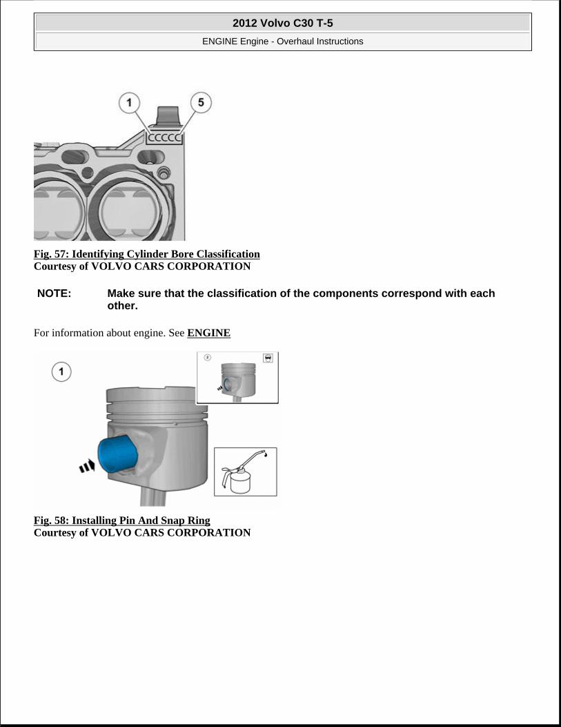
Fig. 57: Identifying Cylinder Bore Classification Courtesy of VOLVO CARS CORPORATION
For information about engine. See ENGINE
Fig. 58: Installing Pin And Snap Ring Courtesy of VOLVO CARS CORPORATION
NOTE: Make sure that the classification of the components correspond with each other.
2012 Volvo C30 T-5
ENGINE Engine - Overhaul Instructions

Fig. 59: Identifying Piston Ring Arrangement Courtesy of VOLVO CARS CORPORATION
For information about engine. See ENGINE
Fig. 60: Locating Direction of Arrow Courtesy of VOLVO CARS CORPORATION
2012 Volvo C30 T-5
ENGINE Engine - Overhaul Instructions

Fig. 61: Identifying Connecting Rod Bearing Halves Installed Courtesy of VOLVO CARS CORPORATION
Fig. 62: Identifying Ring Compressor Tool Courtesy of VOLVO CARS CORPORATION
NOTE: Make sure that the classification of the components correspond with each other.
2012 Volvo C30 T-5
ENGINE Engine - Overhaul Instructions

Fig. 63: Identifying Connecting Rod Special Tool (9995746) Courtesy of VOLVO CARS CORPORATION
see 9995746
Fig. 64: Installing Connecting Rod Cap And Bolts Courtesy of VOLVO CARS CORPORATION
Torque: Cap connecting rod
• Stage 1: 30 Nm
• Stage 2: 90°
NOTE: Make sure that the classification of the components correspond with each other.
2012 Volvo C30 T-5
ENGINE Engine - Overhaul Instructions

Fig. 65: Identifying Pick-Up Tube Bolts Courtesy of VOLVO CARS CORPORATION
Torque: M7
17 Nm
Fig. 66: Guide Pins (9997273) Courtesy of VOLVO CARS CORPORATION
see 9997273
2012 Volvo C30 T-5
ENGINE Engine - Overhaul Instructions

Fig. 67: Identifying Gasket Locations Courtesy of VOLVO CARS CORPORATION
Fig. 68: Cleaning Agent, 1161721 And (Applying Liquid Gasket) Courtesy of VOLVO CARS CORPORATION
Use: Cleaning agent, 1161721
see 9512767
Use: Chemical gasket, 1161059
CAUTION: Make sure that the gaskets are correctly located.
NOTE: Make sure that the component is clean, free of foreign material and lubricant.
2012 Volvo C30 T-5
ENGINE Engine - Overhaul Instructions

Fig. 69: Identifying Oil Pan Bolts Courtesy of VOLVO CARS CORPORATION
Torque: M7
17 Nm
Fig. 70: Identifying Oil Cooler Bolts Courtesy of VOLVO CARS CORPORATION
Torque: M7
17 Nm
2012 Volvo C30 T-5
ENGINE Engine - Overhaul Instructions

Fig. 71: Axle Support Installed Courtesy of VOLVO CARS CORPORATION
Torque: M10
50 Nm
Fig. 72: Identifying Rear Main Seal Tool 9997174 Courtesy of VOLVO CARS CORPORATION
see 9997174
CRANK MECHANISM, DISMANTLING (B5254T3, 2007-08; B5254T7, 2008-12)
Special Tools 999 5651 Extractor (crankshaft rear seal) D5252T Tool number: 999 5651 Tool description: Extractor (crankshaft rear seal) D5252T Tool boards: 21
2012 Volvo C30 T-5
ENGINE Engine - Overhaul Instructions

REMOVAL
Fig. 73: Identifying 9995651
999 5746 Holder remove. piston/connecting rod) B 200-B 6304 Tool number: 999 5746 Tool description: Holder remove. piston/connecting rod) B 200-B 6304 Tool boards: 21
2012 Volvo C30 T-5
ENGINE Engine - Overhaul Instructions

see 9995651
Fig. 74: Axle Support Installed Courtesy of VOLVO CARS CORPORATION
Fig. 75: Identifying Oil Cooler Bolts Courtesy of VOLVO CARS CORPORATION
CAUTION: Take extra care not to damage the mating faces.
2012 Volvo C30 T-5
ENGINE Engine - Overhaul Instructions

Fig. 76: Identifying Oil Pan Bolts Courtesy of VOLVO CARS CORPORATION
Fig. 77: Identifying Pick-Up Tube Bolts Courtesy of VOLVO CARS CORPORATION
Fig. 78: Installing Connecting Rod Cap And Bolts
2012 Volvo C30 T-5
ENGINE Engine - Overhaul Instructions

Fig. 79: Identifying Connecting Rod Special Tool (9995746) Courtesy of VOLVO CARS CORPORATION
see 9995746
Fig. 80: Locating Intermediate Section Bolts Courtesy of VOLVO CARS CORPORATION
CAUTION: Note the position of the components before removal.
CAUTION: Take extra care when handling the components.
2012 Volvo C30 T-5
ENGINE Engine - Overhaul Instructions

Fig. 81: 1st Step Loosening Bolts in Sequence Courtesy of VOLVO CARS CORPORATION
Fig. 82: 2nd Step-Loosening Bolts in Sequence Courtesy of VOLVO CARS CORPORATION
2012 Volvo C30 T-5
ENGINE Engine - Overhaul Instructions

Fig. 83: Gently Removing Intermediate SectionCourtesy of VOLVO CARS CORPORATION
Fig. 84: Identifying Lower Bearing Halves Courtesy of VOLVO CARS CORPORATION
Fig. 85: Handling the Crankshaft Courtesy of VOLVO CARS CORPORATION
CAUTION: Take extra care not to damage the mating faces.
CAUTION: Take extra care when handling the components.
NOTE: Only use moderate force.
2012 Volvo C30 T-5
ENGINE Engine - Overhaul Instructions

Fig. 86: Identifying Upper Bearing Halves Courtesy of VOLVO CARS CORPORATION
Fig. 87: Locating Nozzle Bolt Courtesy of VOLVO CARS CORPORATION
CAUTION: Take extra care when handling the components.
2012 Volvo C30 T-5
ENGINE Engine - Overhaul Instructions

Fig. 88: Locating Sprayer Bolts Courtesy of VOLVO CARS CORPORATION
CRANK MECHANISM, ASSEMBLING (B5254T7, 2008-12)
Special Tools 951 2767 Roller (Applying liquid gasket) B234, 5234, 6304 Tool number: 951 2767 Tool description: Roller (Applying liquid gasket) B234, 5234, 6304 Tool boards: 08
999 5746 Holder remove. piston/connecting rod) B 200-B 6304 Tool number: 999 5746 Tool description: Holder remove. piston/connecting rod) B 200-B 6304 Tool boards: 21
999 7273 Guide pin Tool number: 999 7273 Tool description: Guide pin Tool boards: 21
2012 Volvo C30 T-5
ENGINE Engine - Overhaul Instructions

INSTALLATION
Fig. 89: Locating Sprayer Bolts Courtesy of VOLVO CARS CORPORATION
999 7174 Drift Tool number: 999 7174 Tool description: Drift Tool boards: 23
Materials Designation Part Number Cleaning agent 1161721Chemical gasket 1161059
2012 Volvo C30 T-5
ENGINE Engine - Overhaul Instructions

Torque: M7
17 Nm
Fig. 90: Locating Nozzle Bolt Courtesy of VOLVO CARS CORPORATION
Torque: M7
17 Nm
Fig. 91: Identifying Main Bearing Classification
CAUTION: Make sure that the area around the component is clean and free of foreign material.
CAUTION: Make sure that the area around the component is clean and free of foreign material.
2012 Volvo C30 T-5
ENGINE Engine - Overhaul Instructions

Courtesy of VOLVO CARS CORPORATION
For information about engine. See ENGINE
Fig. 92: Identifying Main Bearing Classification On Crankshaft Courtesy of VOLVO CARS CORPORATION
For information about engine. See ENGINE
Fig. 93: Identifying Upper Main Bearing Halves Courtesy of VOLVO CARS CORPORATION
NOTE: Make sure that the classification of the components correspond with each other.
NOTE: Make sure that the classification of the components correspond with each other.
CAUTION: Make sure that the area around the component is clean and free of foreign material.
2012 Volvo C30 T-5
ENGINE Engine - Overhaul Instructions

Fig. 94: Identifying Crankshaft Courtesy of VOLVO CARS CORPORATION
Fig. 95: Identifying Lower Main Bearing Halves Courtesy of VOLVO CARS CORPORATION
CAUTION: Take extra care when handling the components.
CAUTION: Make sure that the crankshaft is not rotated.
CAUTION: Make sure that the area around the component is clean and free of foreign material.
2012 Volvo C30 T-5
ENGINE Engine - Overhaul Instructions

Fig. 96: Cleaning agent, 1161721 Courtesy of VOLVO CARS CORPORATION
Use: Cleaning agent, 1161721
see 9512767
Use: Chemical gasket, 1161059
Fig. 97: Identifying Torque Sequence Courtesy of VOLVO CARS CORPORATION
Torque: Intermediate section for engine block step 1
20 Nm
NOTE: Make sure that the component is clean, free of foreign material and lubricant.
2012 Volvo C30 T-5
ENGINE Engine - Overhaul Instructions

Fig. 98: Identifying Torque Sequence Courtesy of VOLVO CARS CORPORATION
Torque: Intermediate section for engine block step 2
40 Nm
Fig. 99: Identifying Torque Sequence, 3rd Step Courtesy of VOLVO CARS CORPORATION
Torque: Intermediate section for engine block step 3
24 Nm
2012 Volvo C30 T-5
ENGINE Engine - Overhaul Instructions

Fig. 100: Identifying Torque Sequence, 4th Step Courtesy of VOLVO CARS CORPORATION
Torque: Intermediate section for engine block step 4
17 Nm
Fig. 101: Identifying Torque Sequence Courtesy of VOLVO CARS CORPORATION
Torque: Intermediate section for engine block step 5
90°
2012 Volvo C30 T-5
ENGINE Engine - Overhaul Instructions

Fig. 102: Identifying Cylinder Bore Classification Courtesy of VOLVO CARS CORPORATION
For information about engine. See ENGINE
Fig. 103: Installing Pin And Snap Ring Courtesy of VOLVO CARS CORPORATION
NOTE: Make sure that the classification of the components correspond with each other.
2012 Volvo C30 T-5
ENGINE Engine - Overhaul Instructions

Fig. 104: Arrangement of Piston Ring Assembly Courtesy of VOLVO CARS CORPORATION
For information about engine. See ENGINE
Fig. 105: Locating Direction of Arrow Courtesy of VOLVO CARS CORPORATION
2012 Volvo C30 T-5
ENGINE Engine - Overhaul Instructions
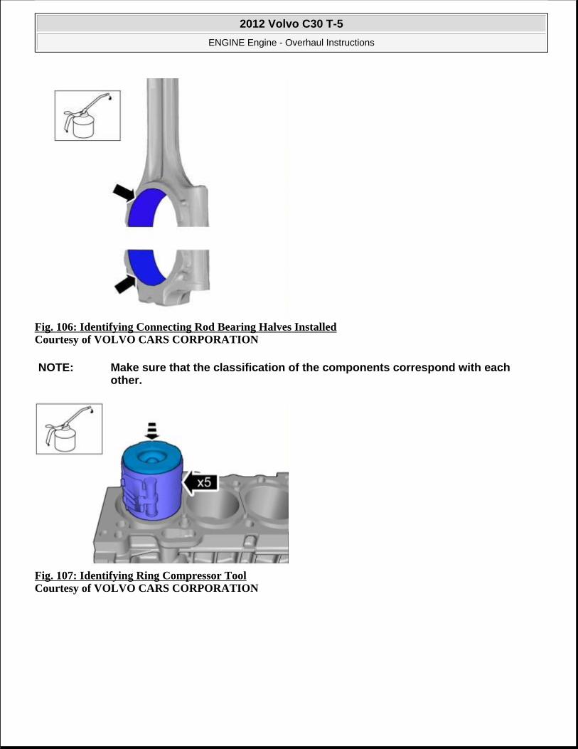
Fig. 106: Identifying Connecting Rod Bearing Halves Installed Courtesy of VOLVO CARS CORPORATION
Fig. 107: Identifying Ring Compressor Tool Courtesy of VOLVO CARS CORPORATION
NOTE: Make sure that the classification of the components correspond with each other.
2012 Volvo C30 T-5
ENGINE Engine - Overhaul Instructions

Fig. 108: Identifying Connecting Rod Special Tool (9995746) Courtesy of VOLVO CARS CORPORATION
see 9995746
Fig. 109: Installing Connecting Rod Cap And Bolts Courtesy of VOLVO CARS CORPORATION
Torque: Cap connecting rod
• Stage 1: 30 Nm
• Stage 2: 90°
NOTE: Make sure that the classification of the components correspond with each other.
2012 Volvo C30 T-5
ENGINE Engine - Overhaul Instructions

Fig. 110: Identifying Pick-Up Tube Bolts Courtesy of VOLVO CARS CORPORATION
Torque: M7
17 Nm
Fig. 111: Guide Pins (9997273) Courtesy of VOLVO CARS CORPORATION
see 9997273
2012 Volvo C30 T-5
ENGINE Engine - Overhaul Instructions

Fig. 112: Identifying Gasket Locations Courtesy of VOLVO CARS CORPORATION
Fig. 113: Cleaning Agent, 1161721 And (Applying liquid gasket) Courtesy of VOLVO CARS CORPORATION
Use: Cleaning agent, 1161721
see 9512767
Use: Chemical gasket, 1161059
CAUTION: Make sure that the gaskets are correctly located.
NOTE: Make sure that the component is clean, free of foreign material and lubricant.
2012 Volvo C30 T-5
ENGINE Engine - Overhaul Instructions

Fig. 114: Identifying Oil Pan Bolts Courtesy of VOLVO CARS CORPORATION
Torque: M7
17 Nm
Fig. 115: Identifying Oil Cooler Bolts Courtesy of VOLVO CARS CORPORATION
Torque: M7
17 Nm
2012 Volvo C30 T-5
ENGINE Engine - Overhaul Instructions

Fig. 116: Axle Support Installed Courtesy of VOLVO CARS CORPORATION
Torque: M10
50 Nm
Fig. 117: Identifying Rear Main Seal Tool 9997174 Courtesy of VOLVO CARS CORPORATION
see 9997174
MEASURING CRANKSHAFT ASSEMBLY (B5244S4, 2007-10; B5254T7, 2008-12)
MEASURING THE CRANKSHAFT
NOTE: The graphics in this service information are used for different model years and/or models. Therefore there may be some variation. However, the essential information in the graphics is always correct.
2012 Volvo C30 T-5
ENGINE Engine - Overhaul Instructions

Fig. 118: Identifying Measurement Of Bearing Journal Courtesy of VOLVO CARS CORPORATION
Use a micrometer.
Measure the out-of-round and taper of the bearing journal. Measure at a number of points laterally and longitudinally.
Fig. 119: Checking Taper and Out-of-Round Courtesy of VOLVO CARS CORPORATION
2012 Volvo C30 T-5
ENGINE Engine - Overhaul Instructions

For the correct values for the connecting rod bearing journals and main bearing journals, see ENGINE (B5254T3; 2007-08, B5254T7; 2008-12) or ENGINE (B5244S4; 2007-10) .
CHECK THE OUT-OF-TRUE OF THE CRANKSHAFT
Fig. 120: Identifying Measurement Of Radial Runout Using A Dial Indicator And Magnetic Holder Courtesy of VOLVO CARS CORPORATION
Use a dial indicator and magnetic holder.
Position the crankshaft with the two outer main bearings in the V block.
Turn the crankshaft and measure the radial runout on the other main bearing journals.
For the correct values, see ENGINE (B5254T3; 2007-08, B5254T7; 2008-12) or ENGINE (B5244S4; 2007-10) .
REMOVING THE PISTON RINGS
Fig. 121: Identifying Piston Rings And Piston Ring Pliers
2012 Volvo C30 T-5
ENGINE Engine - Overhaul Instructions

Courtesy of VOLVO CARS CORPORATION
Use piston ring pliers.
Remove coke deposits. Scrape the piston ring grooves clean with a groove cleaner or a broken and filed piston ring.
Check for damage, wear and cracks.
CHECKING PISTON RING AXIAL CLEARANCE
Fig. 122: Checking Piston Ring Axial Clearance Courtesy of VOLVO CARS CORPORATION
Use new piston rings.
For the correct values, see ENGINE (B5254T3; 2007-08, B5254T7; 2008-12) or ENGINE (B5244S4; 2007-10) .
CHECKING THE PISTON DIAMETER
2012 Volvo C30 T-5
ENGINE Engine - Overhaul Instructions

Fig. 123: Checking Piston Diameter Courtesy of VOLVO CARS CORPORATION
Use a micrometer and vernier calliper.
For the correct values, see ENGINE (B5254T3; 2007-08, B5254T7; 2008-12) or ENGINE (B5244S4; 2007-10) .
CALCULATING THE RUNNING CLEARANCE OF THE PISTON
2012 Volvo C30 T-5
ENGINE Engine - Overhaul Instructions

Fig. 124: Calculating Running Clearance Of Piston Courtesy of VOLVO CARS CORPORATION
For the correct values, see ENGINE (B5254T3; 2007-08, B5254T7; 2008-12) or ENGINE (B5244S4; 2007-10) .
DISASSEMBLING CONNECTING RODS AND PISTONS
Fig. 125: Identifying Lock-Ring And Groove-Cut Chisel Courtesy of VOLVO CARS CORPORATION
2012 Volvo C30 T-5
ENGINE Engine - Overhaul Instructions

Check first that the piston and connecting rod are marked.
Piston marking: Scrape the piston pin clean. If the marking is unclear, mark the piston with the cylinder number and an arrow pointing to the front of the engine. Use a marker pen.
Connecting rod marking: See ENGINE (B5254T3; 2007-08, B5254T7; 2008-12) or ENGINE (B5244S4; 2007-10) .
Carefully push out the lock-ring using a groove-cut chisel.
Press out the piston pin with your thumb.
Clean and check the connecting rods, caps and screws for damage, signs of wear or cracks.
CHECKING THE ALIGNMENT OF THE PISTON PINS IN THE PISTONS
Fig. 126: Checking Alignment Of Piston Pin With Piston Courtesy of VOLVO CARS CORPORATION
The piston pin must not be loose. It should be possible to push it through the hole using thumb pressure.
Replace the piston if the play is too great.
CHECKING THE ALIGNMENT OF THE PISTON PINS IN THE CONNECTING RODS
WARNING: The lock ring can easily fly off. Wear protective goggles
2012 Volvo C30 T-5
ENGINE Engine - Overhaul Instructions

Fig. 127: Checking Alignment Of Piston Pin With Connecting Rod Courtesy of VOLVO CARS CORPORATION
The piston pin should slide through the hole with light thumb pressure.
If the play is too great measure the piston pin.
Use a micrometer.
See ENGINE (B5244S4; 2007-10) or ENGINE (B5254T3; 2007-08, B5254T7; 2008-12) for the correct diameter of the gudgeon pin.
NEW CONNECTING ROD
Fig. 128: Connecting Rod Courtesy of VOLVO CARS CORPORATION
A new connecting rod has been introduced on certain engines.
The mating surface between the cap and the connecting rod is not machined. It is aligned through a dedicated
2012 Volvo C30 T-5
ENGINE Engine - Overhaul Instructions

fracture surface.
CHECKING THE BEARING RECESS IN THE CONNECTING ROD BIG END
Fig. 129: Bearing Shells Courtesy of VOLVO CARS CORPORATION
Visually check the bearing shells.
CAUTION: If the cap is turned the wrong way and tightened, the structure of the fracture surface will be damaged and the connecting rod must be discarded.
NOTE: Blow clean the fracture surfaces with compressed air before reinstalling caps.
2012 Volvo C30 T-5
ENGINE Engine - Overhaul Instructions

If in doubt measure out-of-round. Use a bore gauge.
For the correct diameter of the bearing recess, see ENGINE (B5244S4; 2007-10) or ENGINE (B5254T3; 2007-08, B5254T7; 2008-12) .
CHECKING THE CONNECTING ROD IN A CONNECTING ROD ALIGNER
Check for out-of-true and twisting.
CAUTION: Check that the aligner fork is unburred and round at the handle. Loosen and apply the expander at the big-end between each alignment operation.
2012 Volvo C30 T-5
ENGINE Engine - Overhaul Instructions

ENGINE
Engine - Removal, replacement and installation
ACCESSORY DRIVE BELT AND VARIABLE VALVE TIMING (VVT)
ACCESSORY DRIVE BELT
REMOVAL
Remove right front wheel, see WHEELS
Fig. 1: Removing Fender Liner Courtesy of VOLVO CARS CORPORATION
Fig. 2: Identifying Splash Panel Screws Courtesy of VOLVO CARS CORPORATION
2012 Volvo C30 T-5
ENGINE Engine - Removal, replacement and installation
2012 Volvo C30 T-5
ENGINE Engine - Removal, replacement and installation

Fig. 3: Loosening Belt Tension Courtesy of VOLVO CARS CORPORATION
Fig. 4: Removing Belt Courtesy of VOLVO CARS CORPORATION
2012 Volvo C30 T-5
ENGINE Engine - Removal, replacement and installation

Fig. 5: Loosening Belt Tension Courtesy of VOLVO CARS CORPORATION
Fig. 6: Removing Belt Courtesy of VOLVO CARS CORPORATION
INSTALLATION
To install, reverse the removal procedure.
ACCESSORY DRIVE BELT TENSIONER
REMOVAL
Remove the auxiliaries belt, see ACCESSORY DRIVE BELT
Fig. 7: Removing/Installing Tensioner Bolt Courtesy of VOLVO CARS CORPORATION
2012 Volvo C30 T-5
ENGINE Engine - Removal, replacement and installation

Fig. 8: Removing Tensioner Bolt Courtesy of VOLVO CARS CORPORATION
INSTALLATION
Fig. 9: Removing Tensioner Bolt Courtesy of VOLVO CARS CORPORATION
Torque: Belt tensioner accessory drive belt
42 Nm
2012 Volvo C30 T-5
ENGINE Engine - Removal, replacement and installation

Fig. 10: Removing/Installing Tensioner Bolt Courtesy of VOLVO CARS CORPORATION
Fig. 11: Installing Tensioner Bolt Courtesy of VOLVO CARS CORPORATION
Torque: Accessory drive belt tensioner
42 Nm
NOTE: Only tighten the bolt finger tight at this stage.
2012 Volvo C30 T-5
ENGINE Engine - Removal, replacement and installation

Fig. 12: Identifying Gap at Tensioner Courtesy of VOLVO CARS CORPORATION
Install the auxiliaries belt, see ACCESSORY DRIVE BELT
CAMSHAFT SEAL (TURBO)
Special tools 999 5651 Extractor (crankshaft rear seal) D5252T Tool number: 999 5651 Tool description: Extractor (crankshaft rear seal) D5252T Tool boards: 21
999 5718 Drift (installing/sealing camshaft with VVT) Tool number: 999 5718
2012 Volvo C30 T-5
ENGINE Engine - Removal, replacement and installation

REMOVAL
Remove the variable valve timing unit, see VVT UNIT (TURBO)
Fig. 13: Removing Cam Seal with Special Tool (9995651) Courtesy of VOLVO CARS CORPORATION
see 9995651
INSTALLATION
Tool description: Drift (installing/sealing camshaft with VVT) Tool boards: 21
2012 Volvo C30 T-5
ENGINE Engine - Removal, replacement and installation

Fig. 14: Installing Cam Seal with VVT-Special Tool (9995718) Courtesy of VOLVO CARS CORPORATION
see 9995718
Fig. 15: Installing Cam Seal with VVT-Special Tool (9995718) Courtesy of VOLVO CARS CORPORATION
To install, reverse the removal procedure.
CAMSHAFT SEAL (NON-TURBO)
Special tools 999 5651 Extractor (crankshaft rear seal) D5252T Tool number: 999 5651 Tool description: Extractor (crankshaft rear seal) D5252T Tool boards: 21
2012 Volvo C30 T-5
ENGINE Engine - Removal, replacement and installation

999 7364 Drift Tool number: 999 7364 Tool description: Drift Tool boards: 21
999 5718 Drift (installing/sealing camshaft with VVT) Tool number: 999 5718 Tool description: Drift (installing/sealing
2012 Volvo C30 T-5
ENGINE Engine - Removal, replacement and installation

REMOVAL
Remove the variable valve timing unit, see VVT UNIT (NON-TURBO).
Fig. 16: Removing Cam Seal with Special Tool (9995651) Courtesy of VOLVO CARS CORPORATION
see 9995651
INSTALLATION
camshaft with VVT) Tool boards: 21
2012 Volvo C30 T-5
ENGINE Engine - Removal, replacement and installation

Fig. 17: Installing Cam Seal without VVT using Special Tool (9997364) Courtesy of VOLVO CARS CORPORATION
see 9997364
Fig. 18: Installing Cam Seal with VVT-Special Tool (9995718) Courtesy of VOLVO CARS CORPORATION
see 9995718
To install, reverse the removal procedure.
CAMSHAFTS
Special tools 999 7107 Support Tool number: 999 7107 Tool description: Support Tool boards: 21
2012 Volvo C30 T-5
ENGINE Engine - Removal, replacement and installation

999 5454 PRESS TOOL (2) (CYLINDER HEAD) B6304/B5254 Tool number: 999 5454 Tool description: PRESS TOOL (2) (CYLINDER HEAD) B6304/B5254 Tool boards: 21
999 5670 Pliers (removing valve/camshaft cover) B4184-B6304 Tool number: 999 5670 Tool description: Pliers (removing
2012 Volvo C30 T-5
ENGINE Engine - Removal, replacement and installation

valve/camshaft cover) B4184-B6304 Tool boards: 21
951 2767 Roller (Applying liquid gasket) B234, 5234, 6304 Tool number: 951 2767 Tool description: Roller (Applying liquid gasket) B234, 5234, 6304 Tool boards: 08
Materials Designation Part number Engine oil
2012 Volvo C30 T-5
ENGINE Engine - Removal, replacement and installation
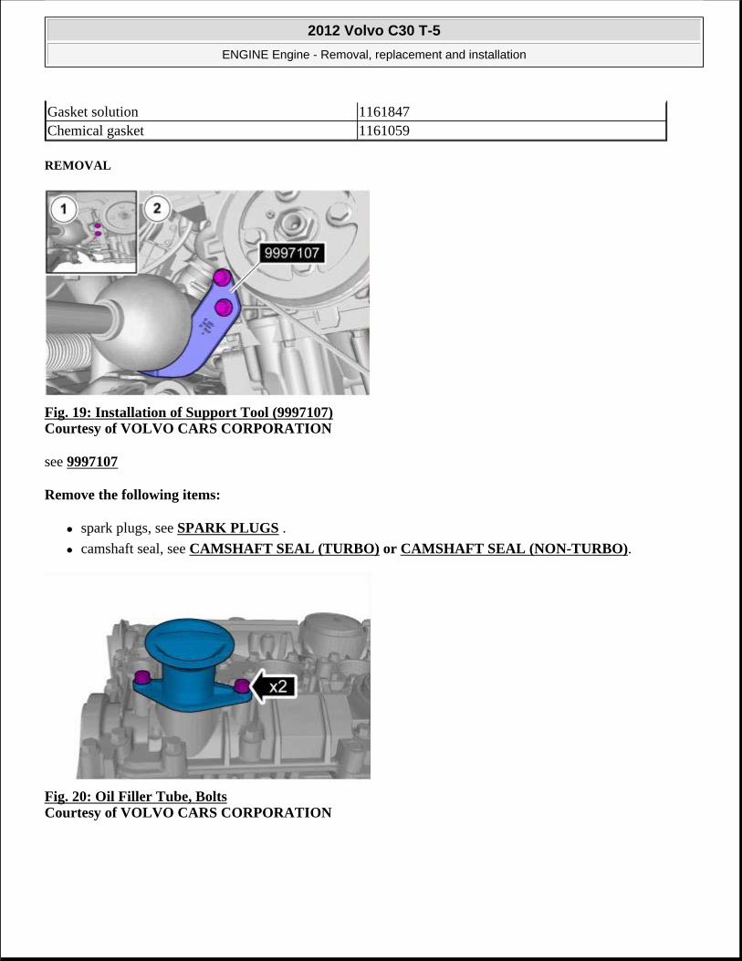
REMOVAL
Fig. 19: Installation of Support Tool (9997107) Courtesy of VOLVO CARS CORPORATION
see 9997107
Remove the following items:
spark plugs, see SPARK PLUGS .
camshaft seal, see CAMSHAFT SEAL (TURBO) or CAMSHAFT SEAL (NON-TURBO).
Fig. 20: Oil Filler Tube, Bolts Courtesy of VOLVO CARS CORPORATION
Gasket solution 1161847Chemical gasket 1161059
2012 Volvo C30 T-5
ENGINE Engine - Removal, replacement and installation

Fig. 21: Special Tools (9995454) Courtesy of VOLVO CARS CORPORATION
see 9995454
Fig. 22: Press Tools Installed Courtesy of VOLVO CARS CORPORATION
see 9995454
2012 Volvo C30 T-5
ENGINE Engine - Removal, replacement and installation

Fig. 23: Install 46 Bolts Courtesy of VOLVO CARS CORPORATION
Fig. 24: Loosening Press Tools, Use Special Pliers (9995670) Remove Cam Cover Evenly Courtesy of VOLVO CARS CORPORATION
see 9995670
CAUTION: Take extra care when handling the components.
2012 Volvo C30 T-5
ENGINE Engine - Removal, replacement and installation

Fig. 25: Lifting Cam Cover, Tools Removed Courtesy of VOLVO CARS CORPORATION
Fig. 26: Gently Lift Out Camshafts Courtesy of VOLVO CARS CORPORATION
INSTALLATION
Perform valve clearance, see VALVE CLEARANCE .
CAUTION: Take extra care when handling the components.
CAUTION: Note the position of the components before removal.
NOTE: This step is only necessary if adjustment is required
2012 Volvo C30 T-5
ENGINE Engine - Removal, replacement and installation

Fig. 27: Apply Engine Oil to Camshafts Courtesy of VOLVO CARS CORPORATION
Use: Engine oil,
Fig. 28: Identifying Positions of Camshafts Courtesy of VOLVO CARS CORPORATION
NOTE: Make sure that these components are installed to the noted removal position.
2012 Volvo C30 T-5
ENGINE Engine - Removal, replacement and installation

Fig. 29: Gasket Solution, 1161847 Courtesy of VOLVO CARS CORPORATION
Use: Gasket solution, 1161847
see 9512767
Use: Chemical gasket, 1161059
Fig. 30: Installing Press Tools (9995454) Courtesy of VOLVO CARS CORPORATION
CAUTION: Make sure that the mating faces are clean and free of foreign material.
CAUTION: Take extra care when handling the components.
2012 Volvo C30 T-5
ENGINE Engine - Removal, replacement and installation

Fig. 31: Install 46 Bolts Courtesy of VOLVO CARS CORPORATION
Torque: M7
17 Nm
Fig. 32: Oil Filler Tube, Bolts Courtesy of VOLVO CARS CORPORATION
Torque: M6
10 Nm
Install the following items:
camshaft seal, see CAMSHAFT SEAL (TURBO) or CAMSHAFT SEAL (NON-TURBO).
VVT unit, see VVT UNIT (TURBO) or VVT UNIT (NON-TURBO)
timing belt, see TIMING BELT
spark plugs, see SPARK PLUGS
2012 Volvo C30 T-5
ENGINE Engine - Removal, replacement and installation

ignition coil, see IGNITION COIL (TURBO) or IGNITION COIL (NON-TURBO) .
TIMING BELT
REMOVAL
Remove the following items:
the auxiliaries belt, see ACCESSORY DRIVE BELT TENSIONER
Engine support insulator, right, see ENGINE SUPPORT INSULATOR, RIGHT
Special tools 999 5433 COUNTERHOLD (VIBRATION DAMPENER)B6304 B5254 Tool number: 999 5433 Tool description: COUNTERHOLD (VIBRATION DAMPENER)B6304 B5254 Tool boards: 21
NOTE: Removal steps in this procedure may contain installation details.
2012 Volvo C30 T-5
ENGINE Engine - Removal, replacement and installation

Fig. 33: Hose and Bracket Courtesy of VOLVO CARS CORPORATION
Torque: M6
10 Nm
Fig. 34: Timing Belt Cover Bolt Courtesy of VOLVO CARS CORPORATION
Torque: M6
10 Nm
2012 Volvo C30 T-5
ENGINE Engine - Removal, replacement and installation

Fig. 35: Install Special Tool (9995433) Courtesy of VOLVO CARS CORPORATION
see 9995433
Fig. 36: Remove/Install Crank Nut Using Special Tool (9995433) Courtesy of VOLVO CARS CORPORATION
1. Torque: Center nut vibration damper (crankshaft)
2012 Volvo C30 T-5
ENGINE Engine - Removal, replacement and installation

180 Nm
2. Torque: Oscillation damper, flange screw
• Stage 1: 25 Nm
• Stage 2: 60 degree
Fig. 37: Remove Vibration Damper Pulley Courtesy of VOLVO CARS CORPORATION
Fig. 38: Identifying Position of Crank Sprocket at TDC #1 Courtesy of VOLVO CARS CORPORATION
2012 Volvo C30 T-5
ENGINE Engine - Removal, replacement and installation

Fig. 39: Mark Position of Cam Sprockets at TDC #1 Courtesy of VOLVO CARS CORPORATION
Fig. 40: Loosening Tensioner Courtesy of VOLVO CARS CORPORATION
2012 Volvo C30 T-5
ENGINE Engine - Removal, replacement and installation

Fig. 41: Idler Pulley Bolts Courtesy of VOLVO CARS CORPORATION
Torque: M8
24 Nm
Fig. 42: Remove/Install Timing Belt
2012 Volvo C30 T-5
ENGINE Engine - Removal, replacement and installation

Courtesy of VOLVO CARS CORPORATION
INSTALLATION
To install, reverse the removal procedure.
VVT SOLENOID
REMOVAL
Fig. 43: Identifying Engine Cover And Screws Courtesy of VOLVO CARS CORPORATION
Torque: M6
10 Nm
NOTE: The component can be reused unless it has been subjected to abnormal mechanical stress, damage or oil contamination.
NOTE: Removal steps in this procedure may contain installation details.
2012 Volvo C30 T-5
ENGINE Engine - Removal, replacement and installation

Fig. 44: Identifying Timing Case Cover Courtesy of VOLVO CARS CORPORATION
Fig. 45: Bolts and Connectors Courtesy of VOLVO CARS CORPORATION
Torque: M6
10 Nm
INSTALLATION
To install, reverse the removal procedure.
VVT UNIT (TURBO)
Special tools 999 5452 CAMSHAFT ADJUSTMENT TOOL(alignment-camshaft)B6304 Tool number: 999 5452
2012 Volvo C30 T-5
ENGINE Engine - Removal, replacement and installation

REMOVAL
Remove the following items:
Tool description: CAMSHAFT ADJUSTMENT TOOL(alignment-camshaft)B6304 Tool boards: 21
999 5451 ADJUSTMENT TOOL(ALIGNMENT-CRANKSHAFT) B6304 B5254 Tool number: 999 5451 Tool description: ADJUSTMENT TOOL(ALIGNMENT-CRANKSHAFT) B6304 B5254 Tool boards: 21
2012 Volvo C30 T-5
ENGINE Engine - Removal, replacement and installation

air cleaner (ACL) housing, see AIR CLEANER HOUSING
timing belt, see TIMING BELT
starter motor, see STARTER MOTOR
Fig. 46: Removing Turbocharger Inlet Courtesy of VOLVO CARS CORPORATION
2012 Volvo C30 T-5
ENGINE Engine - Removal, replacement and installation

Fig. 47: Lift Hook Bolts Courtesy of VOLVO CARS CORPORATION
Fig. 48: Cam Plugs Courtesy of VOLVO CARS CORPORATION
2012 Volvo C30 T-5
ENGINE Engine - Removal, replacement and installation

Fig. 49: Cam Alignment Tool (9995452) Installed Courtesy of VOLVO CARS CORPORATION
see 9995452
Fig. 50: Installing VVT Units Courtesy of VOLVO CARS CORPORATION
INSTALLATION
2012 Volvo C30 T-5
ENGINE Engine - Removal, replacement and installation

Fig. 51: Installing VVT Units Courtesy of VOLVO CARS CORPORATION
Fig. 52: Crankshaft Holder Tool (9995451) Installed Courtesy of VOLVO CARS CORPORATION
see 9995451
Install timing belt, see TIMING BELT
NOTE: Only tighten the bolts finger tight at this stage.
2012 Volvo C30 T-5
ENGINE Engine - Removal, replacement and installation

Fig. 53: Torque VVT Unit Bolts to Specification Courtesy of VOLVO CARS CORPORATION
Torque: VVT unit, center screw
120 Nm
2012 Volvo C30 T-5
ENGINE Engine - Removal, replacement and installation

Fig. 54: Install Lift Hook, Bolts Courtesy of VOLVO CARS CORPORATION
1. Torque: M10
50 Nm
2. Torque: M6
10 Nm
Install the following items:
starter motor, see STARTER MOTOR
timing belt, see TIMING BELT
Fig. 55: Removing Turbocharger Inlet Courtesy of VOLVO CARS CORPORATION
Torque: M6
10 Nm
CAUTION: Make sure that the inside of the pipe ends are clean and free of oil residue.
2012 Volvo C30 T-5
ENGINE Engine - Removal, replacement and installation

Install the air filter housing, see AIR CLEANER HOUSING
VVT UNIT (NON-TURBO)
Special tools 999 5452 CAMSHAFT ADJUSTMENT TOOL(alignment-camshaft)B6304 Tool number: 999 5452 Tool description: CAMSHAFT ADJUSTMENT TOOL(alignment-camshaft)B6304 Tool boards: 21
999 5451 ADJUSTMENT TOOL(ALIGNMENT-CRANKSHAFT) B6304 B5254 Tool number: 999 5451 Tool description: ADJUSTMENT TOOL(ALIGNMENT-CRANKSHAFT) B6304 B5254 Tool boards: 21
2012 Volvo C30 T-5
ENGINE Engine - Removal, replacement and installation

REMOVAL
Remove the following items:
air cleaner (ACL) housing, see AIR CLEANER HOUSING
timing belt, see TIMING BELT
starter motor, see STARTER MOTOR
2012 Volvo C30 T-5
ENGINE Engine - Removal, replacement and installation

Fig. 56: Intake Plenum, Rear View Courtesy of VOLVO CARS CORPORATION
Fig. 57: Intake Plenum, Front View Courtesy of VOLVO CARS CORPORATION
2012 Volvo C30 T-5
ENGINE Engine - Removal, replacement and installation
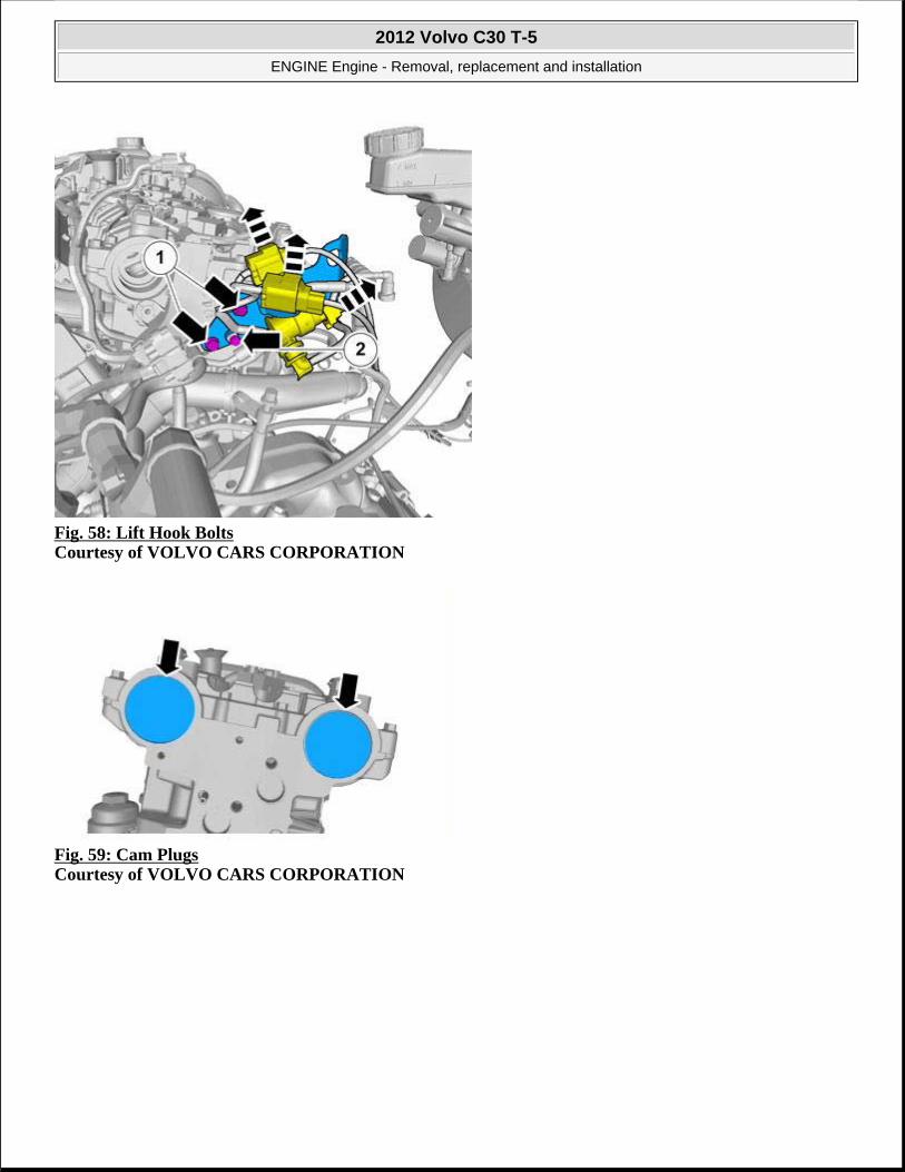
Fig. 58: Lift Hook Bolts Courtesy of VOLVO CARS CORPORATION
Fig. 59: Cam Plugs Courtesy of VOLVO CARS CORPORATION
2012 Volvo C30 T-5
ENGINE Engine - Removal, replacement and installation

Fig. 60: Cam Alignment Tool (9995452) Installed Courtesy of VOLVO CARS CORPORATION
see 9995452
Fig. 61: Remove/Install Sprocket Bolts Courtesy of VOLVO CARS CORPORATION
INSTALLATION
2012 Volvo C30 T-5
ENGINE Engine - Removal, replacement and installation

Fig. 62: Remove/Install Sprocket Bolts Courtesy of VOLVO CARS CORPORATION
Fig. 63: Crankshaft Holder Tool (9995451) Installed Courtesy of VOLVO CARS CORPORATION
see 9995451
Install timing belt, see TIMING BELT.
NOTE: Only tighten the bolts finger tight at this stage.
2012 Volvo C30 T-5
ENGINE Engine - Removal, replacement and installation

Fig. 64: Torque Bolts to Specification Courtesy of VOLVO CARS CORPORATION
1. Torque: M6
10 Nm
2. Torque: VVT unit, center screw
120 Nm
Fig. 65: Install Lift Hook, Bolts Courtesy of VOLVO CARS CORPORATION
2012 Volvo C30 T-5
ENGINE Engine - Removal, replacement and installation

1. Torque: M10
50 Nm
2. Torque: M6
10 Nm
Install the following items:
starter motor, see STARTER MOTOR
timing belt, see TIMING BELT
Fig. 66: Installing Intake Plenum, Front View Courtesy of VOLVO CARS CORPORATION
Torque: M6
10 Nm
2012 Volvo C30 T-5
ENGINE Engine - Removal, replacement and installation

Fig. 67: Installing Intake Plenum, Rear View Courtesy of VOLVO CARS CORPORATION
Torque: M6
10 Nm
Install the air filter housing, see AIR CLEANER HOUSING
COMPLETE ENGINE (TURBO)
ENGINE, REMOVAL (TURBO)
ENGINE, REMOVAL
Special tools 981 4123 Spanner Tool number: 981 4123 Tool description: Spanner Tool boards: 23
2012 Volvo C30 T-5
ENGINE Engine - Removal, replacement and installation

REMOVAL
Perform depressurizing fuel system, see FUEL SYSTEM PRESSURE RELEASE
999 7077 Jimmy bar Tool number: 999 7077 Tool description: Jimmy bar Tool boards: 43
2012 Volvo C30 T-5
ENGINE Engine - Removal, replacement and installation

Drain cooling system, draining, filling, and bleeding, see COOLING SYSTEM - DRAINING, CHARGING AND BLEEDING
Remove the following items:
battery, see BATTERY
air cleaner (ACL) housing, see AIR CLEANER HOUSING
Tensioner accessory drive belt, see ACCESSORY DRIVE BELT TENSIONER
Bracket lower torque rod, see BRACKET LOWER TORQUE ROD
Front subframe
the catalytic converter, see CATALYTIC CONVERTER
Drive shaft right, see DRIVE SHAFT RIGHT
Driveshaft left, see DRIVESHAFT LEFT
right-hand side fog lamp front, see FRONT EXTERIOR LIGHTS .
Fig. 68: Removing Battery Box and Sensor Courtesy of VOLVO CARS CORPORATION
2012 Volvo C30 T-5
ENGINE Engine - Removal, replacement and installation

Fig. 69: Removing Cover, Fuse Box Courtesy of VOLVO CARS CORPORATION
Fig. 70: Removing Battery Cable to Fuse Box Courtesy of VOLVO CARS CORPORATION
2012 Volvo C30 T-5
ENGINE Engine - Removal, replacement and installation

Fig. 71: Removing Grounding Cables Courtesy of VOLVO CARS CORPORATION
Fig. 72: Battery Lead Terminal and Harness Courtesy of VOLVO CARS CORPORATION
Fig. 73: Locating Wiring Harness Bracket Bolt Courtesy of VOLVO CARS CORPORATION
2012 Volvo C30 T-5
ENGINE Engine - Removal, replacement and installation

Fig. 74: Removing Quick Release Connector With Tool (9814123) Courtesy of VOLVO CARS CORPORATION
see 9814123
Fig. 75: Identifying Vacuum Connections Courtesy of VOLVO CARS CORPORATION
2012 Volvo C30 T-5
ENGINE Engine - Removal, replacement and installation

Fig. 76: Viewing Dipstick Tube And Radiator Hose Courtesy of VOLVO CARS CORPORATION
Fig. 77: View Of Radiator Hose And Clamp, Lower Courtesy of VOLVO CARS CORPORATION
NOTE: Use suitable paper to absorb any escaping fluid.
NOTE: Use suitable paper to absorb any escaping fluid.
2012 Volvo C30 T-5
ENGINE Engine - Removal, replacement and installation

Fig. 78: Identifying 9997077 Courtesy of VOLVO CARS CORPORATION
see 9997077
Fig. 79: Identifying Gear Selector Cable Clips Courtesy of VOLVO CARS CORPORATION
2012 Volvo C30 T-5
ENGINE Engine - Removal, replacement and installation
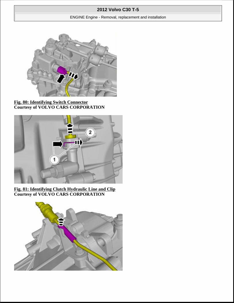
Fig. 80: Identifying Switch Connector Courtesy of VOLVO CARS CORPORATION
Fig. 81: Identifying Clutch Hydraulic Line and Clip Courtesy of VOLVO CARS CORPORATION
2012 Volvo C30 T-5
ENGINE Engine - Removal, replacement and installation

Fig. 82: Removing Line Courtesy of VOLVO CARS CORPORATION
Fig. 83: Identifying Air Tube And Attachments Courtesy of VOLVO CARS CORPORATION
Fig. 84: Heater Hose Couplings Courtesy of VOLVO CARS CORPORATION
NOTE: Use suitable paper to absorb any escaping fluid.
2012 Volvo C30 T-5
ENGINE Engine - Removal, replacement and installation

Fig. 85: Pressure Sensor Connector Courtesy of VOLVO CARS CORPORATION
Fig. 86: Locating Ground Wire Courtesy of VOLVO CARS CORPORATION
2012 Volvo C30 T-5
ENGINE Engine - Removal, replacement and installation

Fig. 87: Coolant Hose at Reservoir Courtesy of VOLVO CARS CORPORATION
Fig. 88: Coolant Reservoir Courtesy of VOLVO CARS CORPORATION
Fig. 89: Identifying Bracket Bolts And Clip Courtesy of VOLVO CARS CORPORATION
2012 Volvo C30 T-5
ENGINE Engine - Removal, replacement and installation

Fig. 90: Power Steering Lines and Bracket Courtesy of VOLVO CARS CORPORATION
Fig. 91: Identifying A/C Compressor Bolts Courtesy of VOLVO CARS CORPORATION
WARNING: Be prepared to collect escaping fluid.
2012 Volvo C30 T-5
ENGINE Engine - Removal, replacement and installation

Fig. 92: Removing/Installing Engine with Adaptable Lift Unit Courtesy of VOLVO CARS CORPORATION
Remove the following items:
Engine support insulator, right, see ENGINE SUPPORT INSULATOR, RIGHT
Engine support insulator left, see ENGINE SUPPORT INSULATOR LEFT
Fig. 93: Removing/Installing Engine With Adaptable Lift Unit Courtesy of VOLVO CARS CORPORATION
ENGINE, INSTALLATION (TURBO)
CAUTION: Take extra care when handling the components.
NOTE: Make sure that no components catch.
2012 Volvo C30 T-5
ENGINE Engine - Removal, replacement and installation

INSTALLATION
Fig. 94: Removing/Installing Engine With Adaptable Lift Unit Courtesy of VOLVO CARS CORPORATION
Install the following items:
Engine support insulator left, see ENGINE SUPPORT INSULATOR LEFT
Engine support insulator, right, see ENGINE SUPPORT INSULATOR, RIGHT
Fig. 95: Identifying A/C Compressor Bolts Courtesy of VOLVO CARS CORPORATION
Torque: M8
CAUTION: Make sure that no components catch.
2012 Volvo C30 T-5
ENGINE Engine - Removal, replacement and installation

24 Nm
Fig. 96: Identifying Power Steering Lines, Bolts and Clamps Courtesy of VOLVO CARS CORPORATION
1. Torque: M10
50 Nm
2. Torque: Pressure line to power steering pump
30 Nm
Fig. 97: Identifying Bracket Bolts And Clip Courtesy of VOLVO CARS CORPORATION
Torque: M6
10 Nm
2012 Volvo C30 T-5
ENGINE Engine - Removal, replacement and installation

Fig. 98: Identifying Air Tube And Attachments Courtesy of VOLVO CARS CORPORATION
Torque: M6
10 Nm
Fig. 99: Pressure Sensor Connector Courtesy of VOLVO CARS CORPORATION
2012 Volvo C30 T-5
ENGINE Engine - Removal, replacement and installation

Fig. 100: Remove/Install Coolant Reservoir Courtesy of VOLVO CARS CORPORATION
Fig. 101: Remove/Install Coolant Hose Courtesy of VOLVO CARS CORPORATION
2012 Volvo C30 T-5
ENGINE Engine - Removal, replacement and installation

Fig. 102: Locating Ground Wire Courtesy of VOLVO CARS CORPORATION
Torque: M6
10 Nm
Fig. 103: Installing Heater Hoses with Quick Connects Courtesy of VOLVO CARS CORPORATION
Fig. 104: Installing Tubes With Quick Connects Courtesy of VOLVO CARS CORPORATION
CAUTION: Make sure that the quick release couplings are correctly engaged.
2012 Volvo C30 T-5
ENGINE Engine - Removal, replacement and installation

Fig. 105: Identifying Vacuum Connections Courtesy of VOLVO CARS CORPORATION
Fig. 106: Installation of Gear Selector Cable Courtesy of VOLVO CARS CORPORATION
2012 Volvo C30 T-5
ENGINE Engine - Removal, replacement and installation

Fig. 107: Cooler and Connections Courtesy of VOLVO CARS CORPORATION
Fig. 108: Viewing Dipstick Tube And Radiator Hose Courtesy of VOLVO CARS CORPORATION
Torque: M6
10 Nm
Fig. 109: Locating Wiring Harness Bracket Bolt Courtesy of VOLVO CARS CORPORATION
Torque: M6
10 Nm
2012 Volvo C30 T-5
ENGINE Engine - Removal, replacement and installation

Fig. 110: Installing Battery Lead Terminal Courtesy of VOLVO CARS CORPORATION
1. Torque: M8
24 Nm
2. Torque: M6
10 Nm
Fig. 111: View of Grounding Cables Courtesy of VOLVO CARS CORPORATION
1. Torque: M8
24 Nm
2. Torque: M6
2012 Volvo C30 T-5
ENGINE Engine - Removal, replacement and installation

10 Nm
Fig. 112: View of Battery Cable to Fuse Box Courtesy of VOLVO CARS CORPORATION
Fig. 113: Refitting Cover Courtesy of VOLVO CARS CORPORATION
2012 Volvo C30 T-5
ENGINE Engine - Removal, replacement and installation

Fig. 114: Installing Battery Box and Sensor Courtesy of VOLVO CARS CORPORATION
Torque: M6
10 Nm
Assemble the following items:
right-hand side fog lamp front, see FRONT EXTERIOR LIGHTS
Driveshaft left, see DRIVESHAFT LEFT
Drive shaft right, see DRIVE SHAFT RIGHT
the catalytic converter, see CATALYTIC CONVERTER
Front subframe
Bracket lower torque rod, see BRACKET LOWER TORQUE ROD
Tensioner accessory drive belt, see ACCESSORY DRIVE BELT TENSIONER
air cleaner (ACL) housing, see AIR CLEANER HOUSING
battery, see BATTERY
Fill cooling system, draining, filling, and bleeding, see COOLING SYSTEM - DRAINING, CHARGING AND BLEEDING
Perform oil level power steering, check, see OIL LEVEL, POWER STEERING, CHECKING
Top up the engine oil, see ENGINE OIL
COMPLETE ENGINE (NON-TURBO)
ENGINE, REMOVAL (NON-TURBO)
2012 Volvo C30 T-5
ENGINE Engine - Removal, replacement and installation

REMOVAL
Special tools 999 7077 Jimmy bar Tool number: 999 7077 Tool description: Jimmy bar Tool boards: 43
981 4123 Spanner Tool number: 981 4123 Tool description: Spanner Tool boards: 23
2012 Volvo C30 T-5
ENGINE Engine - Removal, replacement and installation

Perform depressurizing fuel system, see FUEL SYSTEM PRESSURE RELEASE
Drain cooling system, draining, filling, and bleeding, see COOLING SYSTEM - DRAINING, CHARGING AND BLEEDING
Remove the following items:
battery, see BATTERY
air cleaner (ACL) housing, see AIR CLEANER HOUSING
Tensioner accessory drive belt, see ACCESSORY DRIVE BELT TENSIONER
Bracket lower torque rod, see BRACKET LOWER TORQUE ROD
Front subframe
the catalytic converter, see CATALYTIC CONVERTER
Drive shaft right, see DRIVE SHAFT RIGHT
Driveshaft left, see DRIVESHAFT LEFT
Fig. 115: Removing Battery Box and Sensor Courtesy of VOLVO CARS CORPORATION
2012 Volvo C30 T-5
ENGINE Engine - Removal, replacement and installation

Fig. 116: Removing Cover, Fuse Box Courtesy of VOLVO CARS CORPORATION
Fig. 117: Removing Battery Cable to Fuse Box Courtesy of VOLVO CARS CORPORATION
2012 Volvo C30 T-5
ENGINE Engine - Removal, replacement and installation

Fig. 118: Removing Grounding Cables Courtesy of VOLVO CARS CORPORATION
Fig. 119: Battery Lead Terminal and Harness Courtesy of VOLVO CARS CORPORATION
Fig. 120: Locating Wiring Harness Bracket Bolt Courtesy of VOLVO CARS CORPORATION
2012 Volvo C30 T-5
ENGINE Engine - Removal, replacement and installation

Fig. 121: Identifying Vacuum Hose Connections Courtesy of VOLVO CARS CORPORATION
Fig. 122: Viewing Dipstick Tube And Radiator Hose Courtesy of VOLVO CARS CORPORATION
NOTE: Use suitable paper to absorb any escaping fluid.
2012 Volvo C30 T-5
ENGINE Engine - Removal, replacement and installation

Fig. 123: View Of Radiator Hose And Clamp, Lower Courtesy of VOLVO CARS CORPORATION
Fig. 124: Identifying 9997077 Courtesy of VOLVO CARS CORPORATION
see 9997077
NOTE: Use suitable paper to absorb any escaping fluid.
2012 Volvo C30 T-5
ENGINE Engine - Removal, replacement and installation

Fig. 125: Identifying Gear Selector Cable Clips Courtesy of VOLVO CARS CORPORATION
Fig. 126: Identifying Switch Connector Courtesy of VOLVO CARS CORPORATION
2012 Volvo C30 T-5
ENGINE Engine - Removal, replacement and installation

Fig. 127: Identifying Clutch Hydraulic Line and Clip Courtesy of VOLVO CARS CORPORATION
Fig. 128: Removing Line Courtesy of VOLVO CARS CORPORATION
2012 Volvo C30 T-5
ENGINE Engine - Removal, replacement and installation

Fig. 129: Heater Hose Couplings Courtesy of VOLVO CARS CORPORATION
Fig. 130: Removing Quick Release Connector With Tool (9814123) Courtesy of VOLVO CARS CORPORATION
see 9814123
Fig. 131: Locating Ground Wire Courtesy of VOLVO CARS CORPORATION
NOTE: Use suitable paper to absorb any escaping fluid.
NOTE: Use suitable paper to absorb any escaping fluid.
2012 Volvo C30 T-5
ENGINE Engine - Removal, replacement and installation

Fig. 132: Removing Coolant Hose at Reservoir Courtesy of VOLVO CARS CORPORATION
Fig. 133: Removing Reservoir Courtesy of VOLVO CARS CORPORATION
2012 Volvo C30 T-5
ENGINE Engine - Removal, replacement and installation

Fig. 134: Identifying Bracket Bolts And ClipCourtesy of VOLVO CARS CORPORATION
Fig. 135: Power Steering Lines and Bracket Courtesy of VOLVO CARS CORPORATION
Fig. 136: Identifying A/C Compressor Bolts Courtesy of VOLVO CARS CORPORATION
WARNING: Be prepared to collect escaping fluid.
2012 Volvo C30 T-5
ENGINE Engine - Removal, replacement and installation

Fig. 137: Removing/Installing Engine with Adaptable Lift Unit Courtesy of VOLVO CARS CORPORATION
Remove the following items:
Engine support insulator, right, see ENGINE SUPPORT INSULATOR, RIGHT
Engine support insulator left, see ENGINE SUPPORT INSULATOR LEFT
Fig. 138: Removing/Installing Engine With Adaptable Lift Unit Courtesy of VOLVO CARS CORPORATION
ENGINE, INSTALLATION (NON-TURBO)
CAUTION: Take extra care when handling the component.
NOTE: Make sure that no components catch.
2012 Volvo C30 T-5
ENGINE Engine - Removal, replacement and installation

INSTALLATION
Fig. 139: Removing/Installing Engine With Adaptable Lift Unit Courtesy of VOLVO CARS CORPORATION
Install the following items:
Engine support insulator left, see ENGINE SUPPORT INSULATOR LEFT
Engine support insulator, right, see ENGINE SUPPORT INSULATOR, RIGHT
Fig. 140: Identifying A/C Compressor Bolts Courtesy of VOLVO CARS CORPORATION
Torque: M8
CAUTION: Make sure that no components catch.
2012 Volvo C30 T-5
ENGINE Engine - Removal, replacement and installation

24 Nm
Fig. 141: Identifying Power Steering Lines, Bolts and Clamps Courtesy of VOLVO CARS CORPORATION
1. Torque: M10
50 Nm
2. Torque: Pressure line to power steering pump
30 Nm
Fig. 142: Identifying Bracket Bolts And Clip Courtesy of VOLVO CARS CORPORATION
Torque: M6
10 Nm
2012 Volvo C30 T-5
ENGINE Engine - Removal, replacement and installation

Fig. 143: Remove/Install Coolant Reservoir Courtesy of VOLVO CARS CORPORATION
Fig. 144: Remove/Install Coolant Hose Courtesy of VOLVO CARS CORPORATION
2012 Volvo C30 T-5
ENGINE Engine - Removal, replacement and installation

Fig. 145: Locating Ground Wire Courtesy of VOLVO CARS CORPORATION
Torque: M6
10 Nm
Fig. 146: Installing Tubes With Quick Connects Courtesy of VOLVO CARS CORPORATION
Fig. 147: Installing Heater Hoses with Quick Connects Courtesy of VOLVO CARS CORPORATION
CAUTION: Make sure that the quick release couplings are correctly engaged.
2012 Volvo C30 T-5
ENGINE Engine - Removal, replacement and installation

Fig. 148: Cooler and Connections Courtesy of VOLVO CARS CORPORATION
Fig. 149: Installation of Gear Selector Cable Courtesy of VOLVO CARS CORPORATION
2012 Volvo C30 T-5
ENGINE Engine - Removal, replacement and installation

Fig. 150: Viewing Dipstick Tube And Radiator HoseCourtesy of VOLVO CARS CORPORATION
Torque: M6
10 Nm
Fig. 151: Identifying Vacuum Hose Connections Courtesy of VOLVO CARS CORPORATION
Fig. 152: Locating Wiring Harness Bracket Bolt Courtesy of VOLVO CARS CORPORATION
Torque: M6
10 Nm
2012 Volvo C30 T-5
ENGINE Engine - Removal, replacement and installation

Fig. 153: Installing Battery Lead Terminal Courtesy of VOLVO CARS CORPORATION
1. Torque: M8
24 Nm
2. Torque: M6
10 Nm
Fig. 154: View of Grounding Cables Courtesy of VOLVO CARS CORPORATION
1. Torque: M8
24 Nm
2. Torque: M6
2012 Volvo C30 T-5
ENGINE Engine - Removal, replacement and installation

10 Nm
Fig. 155: View of Battery Cable to Fuse Box Courtesy of VOLVO CARS CORPORATION
Fig. 156: Refitting Cover Courtesy of VOLVO CARS CORPORATION
2012 Volvo C30 T-5
ENGINE Engine - Removal, replacement and installation

Fig. 157: Installing Battery Box and Sensor Courtesy of VOLVO CARS CORPORATION
Torque: M6
10 Nm
Install the following items:
Driveshaft left, see DRIVESHAFT LEFT
Drive shaft right, see DRIVE SHAFT RIGHT
the catalytic converter, see CATALYTIC CONVERTER
Front subframe
Bracket lower torque rod, see BRACKET LOWER TORQUE ROD
Tensioner accessory drive belt, see ACCESSORY DRIVE BELT TENSIONER
air cleaner (ACL) housing, see AIR CLEANER HOUSING
battery, see BATTERY
Fill cooling system, draining, filling, and bleeding, see COOLING SYSTEM - DRAINING, CHARGING AND BLEEDING
Perform oil level power steering, check, see OIL LEVEL, POWER STEERING, CHECKING
Top up the engine oil, see ENGINE OIL
CRANK MECHANISM
CARRIER PLATE
REPLACEMENT
2012 Volvo C30 T-5
ENGINE Engine - Removal, replacement and installation

Special tools:
see 9995112
see 9995678
PREPARATORY WORK
REMOVING THE TRANSMISSION
Remove the transmission according to: TRANSMISSION, REMOVING .
REMOVAL
REMOVING THE CARRIER PLATE
Remove the engine speed (RPM) sensor together with the bracket. Place the engine speed (RPM) sensor to one side.
Fig. 158: Blocking Carrier Plate Using Gear Sector 999 5112 Courtesy of VOLVO CARS CORPORATION
Block the carrier plate using gear sector see 9995112 .
Remove:
all screws
the carrier plate
gear sector see 9995112 .
NOTE: As the illustrations in this service information are used for different model years and / or models, some variation may occur. However, the essential information is always correct.
2012 Volvo C30 T-5
ENGINE Engine - Removal, replacement and installation

Fig. 159: Check Crankshaft Seal For Leakage Courtesy of VOLVO CARS CORPORATION
Check the crankshaft seal for leakage.
To replace the crankshaft seal, refer to CRANKSHAFT SEAL, REAR.
INSTALLATION
INSTALLING THE CARRIER PLATE
Fig. 160: Carrier Plate, Studs And Gear Sector Courtesy of VOLVO CARS CORPORATION
Use: see 9995678 , which consists of 3 x clevis pins with nuts.
NOTE: For tightening torques, see: TIGHTENING TORQUE .
NOTE: Check that the contact surfaces on the crankshaft and drive flange plate are completely clean.
2012 Volvo C30 T-5
ENGINE Engine - Removal, replacement and installation

Install:
the 3 x clevis pins belonging to: see 9995678 distributed as shown in the illustration.
the carrier plate.
Locate the gear sector see 9995112 against the flexplate.
Pull the flexplate against the crankshaft using the 3 x nuts belonging to: see 9995678 .
Install 7 x new screws. Tighten. See: TIGHTENING TORQUE
Remove the 3 nuts and the studs.
Install:
the remaining 3 x new screws. Tighten. See: TIGHTENING TORQUE
the engine speed (RPM) sensor and bracket. Tighten.
FINISHING
INSTALLING THE TRANSMISSION
Install the gearbox. See: TRANSMISSION, INSTALLING .
CRANKSHAFT FRONT SEAL
NOTE: Check that the guide pin on the crankshaft is positioned directly opposite the hole in the drive flange plate.
CAUTION: The drive flange plate must have contact against the crankshaft flange before the screws are installed. There is a risk that excess locking fluid on the screws will end up between the contact surfaces.
Special tools 999 5304 SEPARATOR (DRIVE FLANGE) M45-M47 II. Tool number: 999 5304 Tool description: SEPARATOR (DRIVE FLANGE) M45-M47 II. Tool boards: 43
2012 Volvo C30 T-5
ENGINE Engine - Removal, replacement and installation

999 5919 PULLER (SEAL-PINION, CAM-CRANKSHAFT)B200-6304 Tool number: 999 5919 Tool description: PULLER (SEAL-PINION, CAM-CRANKSHAFT)B200-6304 Tool boards: 46
999 5747 Socket (remov./inst. oil pump/crankshaft) B 4164- Tool number: 999 5747 Tool description: Socket (remov./inst. oil
2012 Volvo C30 T-5
ENGINE Engine - Removal, replacement and installation

REMOVAL
Remove timing belt, see TIMING BELT.
Fig. 161: Identifying Special Tool (9995304) Courtesy of VOLVO CARS CORPORATION
see 9995304
pump/crankshaft) B 4164- Tool boards: 21
2012 Volvo C30 T-5
ENGINE Engine - Removal, replacement and installation

Fig. 162: Removing Crankshaft Seal with Special Tool (9995919) Courtesy of VOLVO CARS CORPORATION
see 9995919
INSTALLATION
Fig. 163: Identifying Special Tool (9995747) Courtesy of VOLVO CARS CORPORATION
see 9995747
CAUTION: Take extra care not to damage the seal.
2012 Volvo C30 T-5
ENGINE Engine - Removal, replacement and installation

Fig. 164: Identifying Crankshaft Sprocket Courtesy of VOLVO CARS CORPORATION
Install timing belt, see TIMING BELT.
CRANKSHAFT SEAL, REAR
NOTE: The component can only be installed in 1 position.
Special tools 999 5651 Extractor (crankshaft rear seal) D5252T Tool number: 999 5651 Tool description: Extractor (crankshaft rear seal) D5252T Tool boards: 21
999 7174 Drift
2012 Volvo C30 T-5
ENGINE Engine - Removal, replacement and installation

REMOVAL
Remove flywheel, see FLYWHEEL.
Fig. 165: Identifying 9995651
Tool number: 999 7174 Tool description: Drift Tool boards: 23
2012 Volvo C30 T-5
ENGINE Engine - Removal, replacement and installation

Courtesy of VOLVO CARS CORPORATION
see 9995651
INSTALLATION
Fig. 166: Identifying Rear Main Seal Tool 9997174 Courtesy of VOLVO CARS CORPORATION
see 9997174
Install flywheel, see FLYWHEEL.
FLYWHEEL
CAUTION: Take extra care not to damage the mating faces.
CAUTION: Make sure that the mating faces are clean and free of foreign material.
Special tools 999 5678 Special screw (flywheel) B4184-B6304 Tool number: 999 5678 Tool description: Special screw (flywheel) B4184-B6304 Tool boards: 21
2012 Volvo C30 T-5
ENGINE Engine - Removal, replacement and installation

REMOVAL
Remove clutch plate and pressure plate, see CLUTCH DISC AND PRESSURE PLATE
Fig. 167: Remove Crankshaft Position Sensor Courtesy of VOLVO CARS CORPORATION
Torque: M7
NOTE: Removal steps in this procedure may contain installation details.
2012 Volvo C30 T-5
ENGINE Engine - Removal, replacement and installation

17 Nm
Fig. 168: Flywheel Bolts (10) Courtesy of VOLVO CARS CORPORATION
INSTALLATION
Fig. 169: Installing Locating Pins (9995678) Courtesy of VOLVO CARS CORPORATION
see 9995678
CAUTION: Make sure that the flywheel is in full contact with the crankshaft flange before installing the flywheel bolts.
NOTE: Make sure that the locating pin on the crankshaft is aligned with the guide hole in the flywheel or flexplate.
2012 Volvo C30 T-5
ENGINE Engine - Removal, replacement and installation

Fig. 170: Flywheel Bolt Torque Sequence Courtesy of VOLVO CARS CORPORATION
Torque: Flywheel
• Stage 1: 45 Nm
• Stage 2: 65 degree
Fig. 171: Guide Pins Removed, Torque Remaining Bolts Courtesy of VOLVO CARS CORPORATION
Torque: Flywheel
• Stage 1: 45 Nm
• Stage 2: 65 degree
To install, reverse the removal procedure.
2012 Volvo C30 T-5
ENGINE Engine - Removal, replacement and installation

CYLINDER HEAD
CYLINDER HEAD (TURBO)
Special tools 999 7107 Support Tool number: 999 7107 Tool description: Support Tool boards: 21
999 5454 PRESS TOOL (2) (CYLINDER HEAD) B6304/B5254 Tool number: 999 5454 Tool description: PRESS TOOL (2) (CYLINDER HEAD) B6304/B5254 Tool boards: 21
2012 Volvo C30 T-5
ENGINE Engine - Removal, replacement and installation

999 5670 Pliers (removing valve/camshaft cover) B4184-B6304 Tool number: 999 5670 Tool description: Pliers (removing valve/camshaft cover) B4184-B6304 Tool boards: 21
951 2050 BEVEL PROTRACTOR Tool number: 951 2050 Tool description: BEVEL PROTRACTOR Tool boards: 08
2012 Volvo C30 T-5
ENGINE Engine - Removal, replacement and installation

951 2767 Roller (Applying liquid gasket) B234, 5234, 6304 Tool number: 951 2767 Tool description: Roller (Applying liquid gasket) B234, 5234, 6304 Tool boards: 08
Materials Designation Part number Gasket solution 1161847
2012 Volvo C30 T-5
ENGINE Engine - Removal, replacement and installation

REMOVAL
Drain cooling system, draining, filling, and bleeding, see COOLING SYSTEM - DRAINING, CHARGING AND BLEEDING
Fig. 172: Installation of Support Tool (9997107) Courtesy of VOLVO CARS CORPORATION
see 9997107
Remove the following items:
air cleaner (ACL) housing, see AIR CLEANER HOUSING
VVT unit, see VVT UNIT (TURBO)
fuel injector, see FUEL INJECTOR
exhaust manifold, see EXHAUST MANIFOLD
the intake manifold, see INDUCTION PIPE
VVT solenoid, see VVT SOLENOID
spark plugs, see SPARK PLUGS
Engine oil Chemical gasket 1161059
2012 Volvo C30 T-5
ENGINE Engine - Removal, replacement and installation

Fig. 173: Quick Release Connector Courtesy of VOLVO CARS CORPORATION
Fig. 174: Timing Belt Rear Cover Bolt Courtesy of VOLVO CARS CORPORATION
Fig. 175: Engine Mount Bracket and Lift Hook
2012 Volvo C30 T-5
ENGINE Engine - Removal, replacement and installation
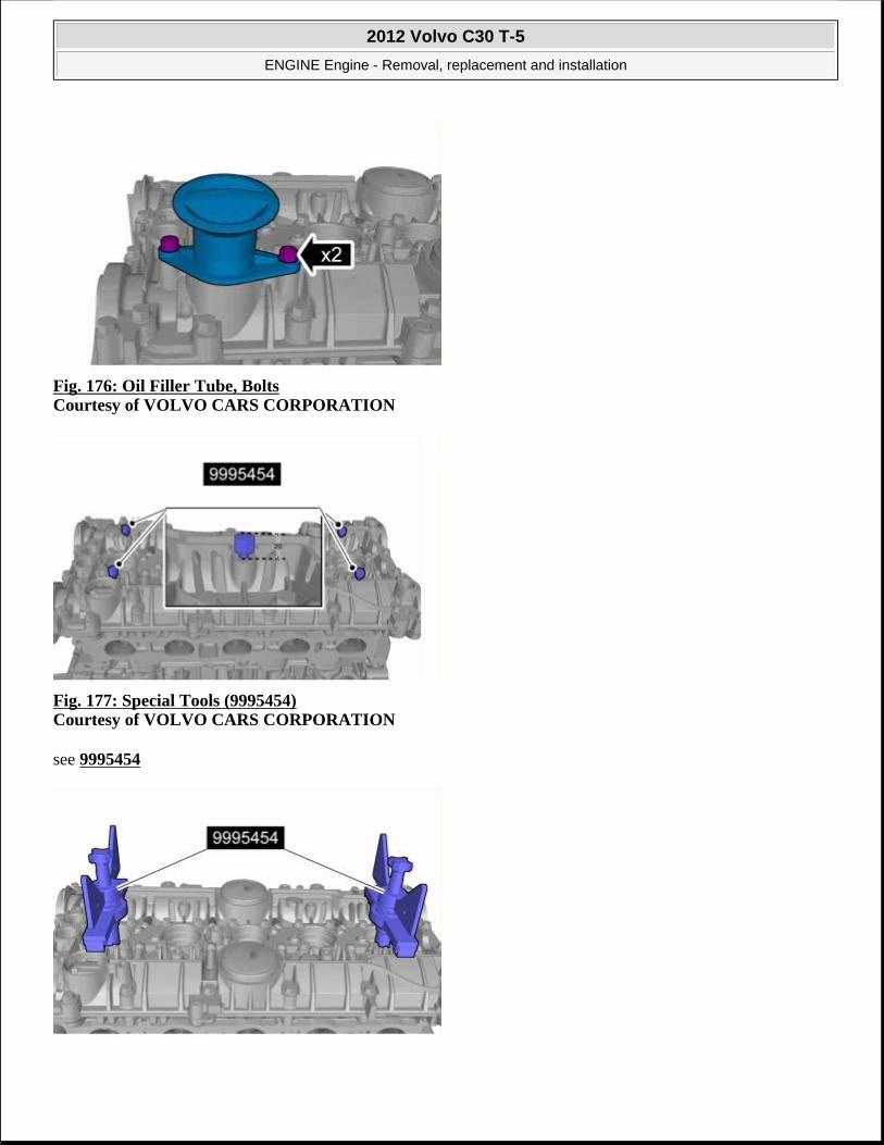
Fig. 176: Oil Filler Tube, Bolts Courtesy of VOLVO CARS CORPORATION
Fig. 177: Special Tools (9995454) Courtesy of VOLVO CARS CORPORATION
see 9995454
2012 Volvo C30 T-5
ENGINE Engine - Removal, replacement and installation

Fig. 178: Press Tools Installed Courtesy of VOLVO CARS CORPORATION
see 9995454
Fig. 179: Install 46 Bolts Courtesy of VOLVO CARS CORPORATION
Fig. 180: Loosening Press Tools, Use Special Pliers (9995670) Remove Cam Cover Evenly Courtesy of VOLVO CARS CORPORATION
see 9995670
CAUTION: Take extra care when handling the component.
2012 Volvo C30 T-5
ENGINE Engine - Removal, replacement and installation

Fig. 181: Lifting Cam Cover, Tools Removed Courtesy of VOLVO CARS CORPORATION
Fig. 182: Gently Lift Out Camshafts Courtesy of VOLVO CARS CORPORATION
CAUTION: Take extra care when handling the component.
NOTE: Note the position of each component before removal.
2012 Volvo C30 T-5
ENGINE Engine - Removal, replacement and installation

Fig. 183: Identifying Camshaft Lifters Courtesy of VOLVO CARS CORPORATION
Fig. 184: Head Bolt Removal Sequence Courtesy of VOLVO CARS CORPORATION
INSTALLATION
NOTE: Note the position of each component before removal.
CAUTION: Take extra care not to damage the mating faces.
2012 Volvo C30 T-5
ENGINE Engine - Removal, replacement and installation

Fig. 185: Gasket Solution, 1161847 Courtesy of VOLVO CARS CORPORATION
Use: Gasket solution, 1161847
Fig. 186: Head Bolt Torque Sequence Courtesy of VOLVO CARS CORPORATION
see 9512050
CAUTION: Take extra care when handling the component.
CAUTION: Make sure that the mating faces are clean and free of foreign material.
CAUTION: Make sure that no fluids are present in the cylinder head bolt threaded bores.
2012 Volvo C30 T-5
ENGINE Engine - Removal, replacement and installation

Torque: Cylinder head
• Stage 1: 20 Nm
• Stage 2: 60 Nm
• Stage 3: 130 degree
Fig. 187: Apply Engine Oil to Cam Followers, Install at Original Location Courtesy of VOLVO CARS CORPORATION
Use: Engine oil,
Perform valve clearance, see VALVE CLEARANCE
CAUTION: Only use the specified lubricant.
NOTE: Make sure that these components are installed to the noted removal position.
NOTE: This step is only necessary if adjustment is required
2012 Volvo C30 T-5
ENGINE Engine - Removal, replacement and installation

Fig. 188: Apply Engine Oil to Camshafts Courtesy of VOLVO CARS CORPORATION
Use: Engine oil,
Fig. 189: Identifying Positions of Camshafts Courtesy of VOLVO CARS CORPORATION
CAUTION: Only use the specified lubricant.
NOTE: Make sure that these components are installed to the noted removal position.
2012 Volvo C30 T-5
ENGINE Engine - Removal, replacement and installation

Fig. 190: Gasket Solution, 1161847 Courtesy of VOLVO CARS CORPORATION
Use: Gasket solution, 1161847
see 9512767
Use: Chemical gasket, 1161059
Fig. 191: Installing Press Tools (9995454) Courtesy of VOLVO CARS CORPORATION
NOTE: Make sure that the mating faces are clean and free of foreign material.
CAUTION: Take extra care when handling the component.
2012 Volvo C30 T-5
ENGINE Engine - Removal, replacement and installation

Fig. 192: Install 46 Bolts Courtesy of VOLVO CARS CORPORATION
Torque: M7
17 Nm
Fig. 193: Oil Filler Tube, Bolts Courtesy of VOLVO CARS CORPORATION
Torque: M6
10 Nm
2012 Volvo C30 T-5
ENGINE Engine - Removal, replacement and installation

Fig. 194: Remove Pipe Courtesy of VOLVO CARS CORPORATION
Fig. 195: Engine Mounting Bracket and Lift Hooks Courtesy of VOLVO CARS CORPORATION
1. Torque: M10
50 Nm
2. Torque: M8
24 Nm
2012 Volvo C30 T-5
ENGINE Engine - Removal, replacement and installation

Fig. 196: Timing Belt Rear Cover Bolt Courtesy of VOLVO CARS CORPORATION
Torque: M6
10 Nm
Fig. 197: Quick Release Connector Courtesy of VOLVO CARS CORPORATION
Install the following items:
VVT unit, see VVT UNIT (TURBO)
exhaust manifold, see EXHAUST MANIFOLD
air cleaner (ACL) housing, see AIR CLEANER HOUSING
fuel injector, see FUEL INJECTOR
spark plugs, see SPARK PLUGS
the intake manifold, see INDUCTION PIPE
VVT solenoid, see VVT SOLENOID
2012 Volvo C30 T-5
ENGINE Engine - Removal, replacement and installation

Fig. 198: Support Tool (9997107) Installed Courtesy of VOLVO CARS CORPORATION
Torque: M10
50 Nm
Fill cooling system, draining, filling, and bleeding, see COOLING SYSTEM - DRAINING, CHARGING AND BLEEDING
CYLINDER HEAD (NON-TURBO)
Special tools 999 7107 Support Tool number: 999 7107 Tool description: Support Tool boards: 21
2012 Volvo C30 T-5
ENGINE Engine - Removal, replacement and installation

999 5454 PRESS TOOL (2) (CYLINDER HEAD) B6304/B5254 Tool number: 999 5454 Tool description: PRESS TOOL (2) (CYLINDER HEAD) B6304/B5254 Tool boards: 21
999 5670 Pliers (removing valve/camshaft cover) B4184-B6304 Tool number: 999 5670 Tool description: Pliers (removing
2012 Volvo C30 T-5
ENGINE Engine - Removal, replacement and installation

valve/camshaft cover) B4184-B6304 Tool boards: 21
951 2050 BEVEL PROTRACTOR Tool number: 951 2050 Tool description: BEVEL PROTRACTOR Tool boards: 08
951 2767 Roller (Applying liquid gasket) B234, 5234, 6304 Tool number: 951 2767 Tool description: Roller (Applying liquid
2012 Volvo C30 T-5
ENGINE Engine - Removal, replacement and installation

REMOVAL
Perform cooling system draining, charging and bleeding, see COOLING SYSTEM - DRAINING, CHARGING AND BLEEDING
gasket) B234, 5234, 6304 Tool boards: 08
Materials Designation Part number Gasket solution 1161847Engine oil Chemical gasket 1161059
2012 Volvo C30 T-5
ENGINE Engine - Removal, replacement and installation

Fig. 199: Installation of Support Tool (9997107)Courtesy of VOLVO CARS CORPORATION
see 9997107
Remove the following items:
air cleaner (ACL) housing, see AIR CLEANER HOUSING
spark plugs, see SPARK PLUGS
VVT unit, see VVT UNIT (NON-TURBO)
fuel injector, see FUEL INJECTOR
exhaust manifold, see EXHAUST MANIFOLD
the intake manifold, see INDUCTION PIPE
VVT solenoid, see VVT SOLENOID
Fig. 200: Quick Release Connector Courtesy of VOLVO CARS CORPORATION
Fig. 201: Timing Belt Rear Cover Bolt
2012 Volvo C30 T-5
ENGINE Engine - Removal, replacement and installation

Courtesy of VOLVO CARS CORPORATION
Fig. 202: Engine Mount Bracket and Lift Hook Courtesy of VOLVO CARS CORPORATION
Fig. 203: Remove Pipe Courtesy of VOLVO CARS CORPORATION
2012 Volvo C30 T-5
ENGINE Engine - Removal, replacement and installation

Fig. 204: Oil Filler Tube, Bolts Courtesy of VOLVO CARS CORPORATION
Fig. 205: Special Tools (9995454) Courtesy of VOLVO CARS CORPORATION
see 9995454
Fig. 206: Press Tools Installed Courtesy of VOLVO CARS CORPORATION
see 9995454
2012 Volvo C30 T-5
ENGINE Engine - Removal, replacement and installation

Fig. 207: Install 46 Bolts Courtesy of VOLVO CARS CORPORATION
Fig. 208: Loosening Press Tools, Use Special Pliers (9995670) Remove Cam Cover Evenly Courtesy of VOLVO CARS CORPORATION
see 9995670
CAUTION: Take extra care when handling the component.
2012 Volvo C30 T-5
ENGINE Engine - Removal, replacement and installation

Fig. 209: Lifting Cam Cover, Tools Removed Courtesy of VOLVO CARS CORPORATION
Fig. 210: Gently Lift Out Camshafts Courtesy of VOLVO CARS CORPORATION
CAUTION: Take extra care when handling the component.
NOTE: Note the position of each component before removal.
2012 Volvo C30 T-5
ENGINE Engine - Removal, replacement and installation

Fig. 211: Identifying Camshaft Lifters Courtesy of VOLVO CARS CORPORATION
Fig. 212: Head Bolt Removal Sequence Courtesy of VOLVO CARS CORPORATION
INSTALLATION
NOTE: Note the position of the component before removal.
CAUTION: Take extra care not to damage the mating faces.
2012 Volvo C30 T-5
ENGINE Engine - Removal, replacement and installation

Fig. 213: Gasket Solution, 1161847 Courtesy of VOLVO CARS CORPORATION
Use: Gasket solution, 1161847
Fig. 214: Head Bolt Torque Sequence Courtesy of VOLVO CARS CORPORATION
Torque: Cylinder head
CAUTION: Take extra care when handling the component.
CAUTION: Make sure that the mating faces are clean and free of foreign material.
CAUTION: Make sure that no fluids are present in the cylinder head bolt threaded bores.
2012 Volvo C30 T-5
ENGINE Engine - Removal, replacement and installation

• Stage 1: 20 Nm
• Stage 2: 60 Nm
• Stage 3: 130 degree
see 9512050
Fig. 215: Apply Engine Oil to Cam Followers, Install at Original Location Courtesy of VOLVO CARS CORPORATION
Use: Engine oil,
Perform valve clearance, see VALVE CLEARANCE
CAUTION: Only use the specified lubricant.
NOTE: Make sure that this component is installed to the noted removal position.
NOTE: This step is only necessary if adjustment is required
2012 Volvo C30 T-5
ENGINE Engine - Removal, replacement and installation

Fig. 216: Apply Engine Oil to Camshafts Courtesy of VOLVO CARS CORPORATION
Use: Engine oil,
Fig. 217: Identifying Positions of Camshafts Courtesy of VOLVO CARS CORPORATION
CAUTION: Only use the specified lubricant.
NOTE: Make sure that this component is installed to the noted removal position.
2012 Volvo C30 T-5
ENGINE Engine - Removal, replacement and installation

Fig. 218: Gasket Solution, 1161847 Courtesy of VOLVO CARS CORPORATION
Use: Gasket solution, 1161847
see 9512767
Use: Chemical gasket, 1161059
Fig. 219: Installing Press Tools (9995454) Courtesy of VOLVO CARS CORPORATION
NOTE: Make sure that the mating faces are clean and free of foreign material.
CAUTION: Take extra care when handling the component.
2012 Volvo C30 T-5
ENGINE Engine - Removal, replacement and installation
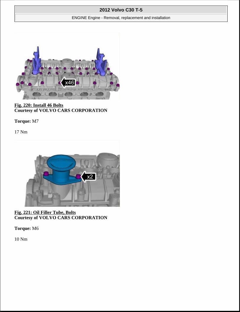
Fig. 220: Install 46 Bolts Courtesy of VOLVO CARS CORPORATION
Torque: M7
17 Nm
Fig. 221: Oil Filler Tube, Bolts Courtesy of VOLVO CARS CORPORATION
Torque: M6
10 Nm
2012 Volvo C30 T-5
ENGINE Engine - Removal, replacement and installation

Fig. 222: Remove Pipe Courtesy of VOLVO CARS CORPORATION
Fig. 223: Engine Mounting Bracket and Lift Hooks Courtesy of VOLVO CARS CORPORATION
1. Torque: M10
50 Nm
2. Torque: M8
24 Nm
2012 Volvo C30 T-5
ENGINE Engine - Removal, replacement and installation

Fig. 224: Timing Belt Rear Cover Bolt Courtesy of VOLVO CARS CORPORATION
Torque: M6
10 Nm
Fig. 225: Quick Release Connector Courtesy of VOLVO CARS CORPORATION
Install the following items:
VVT unit, see VVT UNIT (NON-TURBO)
exhaust manifold, see EXHAUST MANIFOLD
air cleaner (ACL) housing, see AIR CLEANER HOUSING
fuel injector, see FUEL INJECTOR
spark plugs, see SPARK PLUGS
the intake manifold, see INDUCTION PIPE
VVT solenoid, see VVT SOLENOID
2012 Volvo C30 T-5
ENGINE Engine - Removal, replacement and installation

Fig. 226: Support Tool (9997107) Installed Courtesy of VOLVO CARS CORPORATION
Torque: M10
50 Nm
Perform cooling system draining, charging and bleeding, see COOLING SYSTEM - DRAINING, CHARGING AND BLEEDING .
ENGINE OIL PAN
OIL PAN (TURBO)
Special tools 999 7273 Guide pin Tool number: 999 7273 Tool description: Guide pin Tool boards: 21
2012 Volvo C30 T-5
ENGINE Engine - Removal, replacement and installation

951 2767 Roller (Applying liquid gasket) B234, 5234, 6304 Tool number: 951 2767 Tool description: Roller (Applying liquid gasket) B234, 5234, 6304 Tool boards: 08
Materials Designation Part number Cleaning agent 1161721
2012 Volvo C30 T-5
ENGINE Engine - Removal, replacement and installation

REMOVAL
Remove the auxiliaries belt, see ACCESSORY DRIVE BELT.
Fig. 227: A/C Compressor Bolts Courtesy of VOLVO CARS CORPORATION
Fig. 228: Air Tube, Turbocharger Courtesy of VOLVO CARS CORPORATION
Chemical gasket 1161059
2012 Volvo C30 T-5
ENGINE Engine - Removal, replacement and installation

Fig. 229: Remove/Install Bolt Courtesy of VOLVO CARS CORPORATION
Fig. 230: Remove/Install Bolt Courtesy of VOLVO CARS CORPORATION
Fig. 231: Dipstick Tube Bolt
2012 Volvo C30 T-5
ENGINE Engine - Removal, replacement and installation

Fig. 232: Oil Cooler Bolts Courtesy of VOLVO CARS CORPORATION
Fig. 233: 29 Oil Pan Bolts Courtesy of VOLVO CARS CORPORATION
INSTALLATION
2012 Volvo C30 T-5
ENGINE Engine - Removal, replacement and installation

Fig. 234: Guide Pins (9997273) Courtesy of VOLVO CARS CORPORATION
see 9997273
Fig. 235: Identifying Gasket Locations Courtesy of VOLVO CARS CORPORATION
Fig. 236: Cleaning Agent, 1161721 And (Applying liquid gasket) Courtesy of VOLVO CARS CORPORATION
Use: Cleaning agent, 1161721
CAUTION: Make sure that the gaskets are correctly located.
CAUTION: Make sure that the mating faces are clean and free of foreign material.
2012 Volvo C30 T-5
ENGINE Engine - Removal, replacement and installation

see 9512767
Use: Chemical gasket, 1161059
Fig. 237: Identifying Oil Pan Bolts Courtesy of VOLVO CARS CORPORATION
Torque: M7
17 Nm
To install, reverse the removal procedure.
OIL PAN (NON-TURBO)
Special tools 999 7273 Guide pin Tool number: 999 7273 Tool description: Guide pin Tool boards: 21
2012 Volvo C30 T-5
ENGINE Engine - Removal, replacement and installation

951 2767 Roller (Applying liquid gasket) B234, 5234, 6304 Tool number: 951 2767 Tool description: Roller (Applying liquid gasket) B234, 5234, 6304 Tool boards: 08
Materials Designation Part number Cleaning agent 1161721
2012 Volvo C30 T-5
ENGINE Engine - Removal, replacement and installation
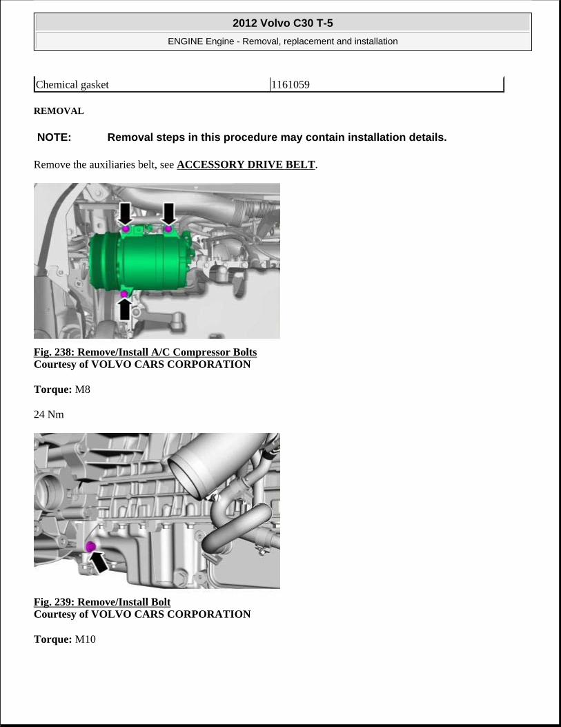
REMOVAL
Remove the auxiliaries belt, see ACCESSORY DRIVE BELT.
Fig. 238: Remove/Install A/C Compressor Bolts Courtesy of VOLVO CARS CORPORATION
Torque: M8
24 Nm
Fig. 239: Remove/Install Bolt Courtesy of VOLVO CARS CORPORATION
Torque: M10
Chemical gasket 1161059
NOTE: Removal steps in this procedure may contain installation details.
2012 Volvo C30 T-5
ENGINE Engine - Removal, replacement and installation

50 Nm
Fig. 240: Remove/Install Bolt Courtesy of VOLVO CARS CORPORATION
Torque: M10
50 Nm
Fig. 241: Dipstick Tube Bolt Courtesy of VOLVO CARS CORPORATION
Torque: M6
10 Nm
2012 Volvo C30 T-5
ENGINE Engine - Removal, replacement and installation

Fig. 242: Oil Cooler Bolts Courtesy of VOLVO CARS CORPORATION
Torque: M7
17 Nm
Fig. 243: 29 Oil Pan Bolts Courtesy of VOLVO CARS CORPORATION
INSTALLATION
2012 Volvo C30 T-5
ENGINE Engine - Removal, replacement and installation

Fig. 244: Guide Pins (9997273) Courtesy of VOLVO CARS CORPORATION
see 9997273
Fig. 245: Identifying Gasket Locations Courtesy of VOLVO CARS CORPORATION
CAUTION: Make sure that the gaskets are correctly located.
2012 Volvo C30 T-5
ENGINE Engine - Removal, replacement and installation

Fig. 246: Cleaning Agent, 1161721 And (Applying liquid gasket) Courtesy of VOLVO CARS CORPORATION
Use: Cleaning agent, 1161721
see 9512767
Use: Chemical gasket, 1161059
Fig. 247: Identifying Oil Pan Bolts Courtesy of VOLVO CARS CORPORATION
Torque: M7
17 Nm
CAUTION: Make sure that the mating faces are clean and free of foreign material.
2012 Volvo C30 T-5
ENGINE Engine - Removal, replacement and installation

To install, reverse the removal procedure.
ENGINE MOUNTING
ENGINE SUPPORT INSULATOR, RIGHT
REMOVAL
Fig. 248: Installing Engine Support Beam and Hook (9995185, 997103) Courtesy of VOLVO CARS CORPORATION
Fig. 249: Removing Coolant Reservoir Courtesy of VOLVO CARS CORPORATION
NOTE: Removal steps in this procedure may contain installation details.
WARNING: Be prepared to collect escaping fluid.
2012 Volvo C30 T-5
ENGINE Engine - Removal, replacement and installation

Fig. 250: Remove/Install Engine Pad, Right Courtesy of VOLVO CARS CORPORATION
Torque: Engine pad to frame member
90 Nm
Fig. 251: Engine Pad Bolts to Engine Courtesy of VOLVO CARS CORPORATION
Torque: Engine pad to engine, screw
133 Nm
INSTALLATION
To install, reverse the removal procedure.
ENGINE SUPPORT INSULATOR LEFT
2012 Volvo C30 T-5
ENGINE Engine - Removal, replacement and installation

REPLACEMENT
Special tools 999 7103 Lifting beam Tool number: 999 7103 Tool description: Lifting beam Tool boards: 21
999 5185 HOOK (LIFTING OUT ENGINE-TO 2810) Tool number: 999 5185 Tool description: HOOK (LIFTING OUT ENGINE-TO 2810) Tool boards: 21
999 7102 Lifting yoke
2012 Volvo C30 T-5
ENGINE Engine - Removal, replacement and installation

REMOVAL
Remove the air filter housing, see AIR CLEANER HOUSING
Remove battery, see BATTERY
Fig. 252: Installing Engine Support Beam and Hook (9995185, 997103) Courtesy of VOLVO CARS CORPORATION
Tool number: 999 7102 Tool description: Lifting yoke Tool boards: 21
NOTE: Removal steps in this procedure may contain installation details.
2012 Volvo C30 T-5
ENGINE Engine - Removal, replacement and installation

see 9997103 see 9995185
Fig. 253: Lifting Yoke (9997102) Installed Courtesy of VOLVO CARS CORPORATION
see 9997102
Fig. 254: Removing/Installing Engine Pad, Left Courtesy of VOLVO CARS CORPORATION
Remove the following items:
1. Torque: Engine pad, left side (4 nuts M10)
• Stage 1: 34 Nm
• Stage 2: 60 degree
2. Torque: M8
2012 Volvo C30 T-5
ENGINE Engine - Removal, replacement and installation

24 Nm
3. Torque: M6
10 Nm
Fig. 255: Removing/Installing Engine Pad, Left Courtesy of VOLVO CARS CORPORATION
Fig. 256: Removing/Installing Engine Pad, Left Courtesy of VOLVO CARS CORPORATION
Torque: Engine pad, left side (screw M12)
80 Nm
INSTALLATION
To install, reverse the removal procedure.
2012 Volvo C30 T-5
ENGINE Engine - Removal, replacement and installation

FRONT BUSHING, SUBFRAME FRONT
Special tools:
see 9997054
see 9997034
see 9997132
see 9997131
see 9997130
see 9997134
see 9997133
see 9997138
see 9997137
PREPARATORY WORK
Remove the wheel.
Remove the sub-frame.
REMOVAL
REMOVING FRONT SUB-FRAME BUSHING
NOTE: The illustrations in this service information are used for different model years and/or models. Some variation may occur. However, the essential information in the illustrations is always correct.
2012 Volvo C30 T-5
ENGINE Engine - Removal, replacement and installation

Fig. 257: Identifying Tools 9997054, 9997034, 9997132, 9997131 And 9997130 Courtesy of VOLVO CARS CORPORATION
Press the control arm into place.
Install the hydraulic cylinder.
Use: see 9997054 with: see 9997034 , nut M12: see 9997132 , socket: see 9997131 and drift: see 9997130 .
Pull the bushing out.
REMOVING REAR SUB-FRAME BUSHING
2012 Volvo C30 T-5
ENGINE Engine - Removal, replacement and installation

Fig. 258: Identifying Hydraulic Cylinder Courtesy of VOLVO CARS CORPORATION
Press the control arm into place.
Install the hydraulic cylinder.
Use: see 9997054 with: see 9997034 , nut M12: see 9997132 , socket: see 9997136 and drift: see 9997135 .
Pull the bushing out.
INSTALLATION
INSTALLING THE FRONT SUB-FRAME BUSHING
2012 Volvo C30 T-5
ENGINE Engine - Removal, replacement and installation

Fig. 259: Identifying Hydraulic Cylinder Courtesy of VOLVO CARS CORPORATION
Install the hydraulic cylinder.
Use: see 9997054 with: see 9997034 , nut: see 9997132 , socket: see 9997134 , lock ring: see 9997134 and ring: see 9997133 .
Pull in the bushing until it is centered in the link arm. Pull the bushing in approximately half-way and then remove: see 9997134 .
Then pull the bushing in so that it bottoms out against the flange
INSTALLING REAR SUB-FRAME BUSHING
2012 Volvo C30 T-5
ENGINE Engine - Removal, replacement and installation

Fig. 260: Identifying Control Arm Courtesy of VOLVO CARS CORPORATION
Install the control arm.
Use: see 9997054 with: see 9997034 , nut: see 9997132 , socket: see 9997138 , drift: see 9997135 lock ring: see 9997138 and ring: see 9997137 .
Pull the bushing in approximately half-way and then remove: see 9997138 .
Then pull the bushing in so that it bottoms out against the flange.
FINISHING
INSTALLING THE SUB-FRAME
Install the sub-frame.
Install the wheel according to: WHEELS .
NOTE: The bushings shall be installed with the markings in line across the length of the car.
2012 Volvo C30 T-5
ENGINE Engine - Removal, replacement and installation

LOWER TORQUE ROD
REMOVAL
Fig. 261: Identifying Splash Panel Screws Courtesy of VOLVO CARS CORPORATION
Fig. 262: Removing/Installing Torque Rod Courtesy of VOLVO CARS CORPORATION
Remove the following items:
1. Torque: M12
80 Nm
2. Torque: M12
NOTE: Removal steps in this procedure may contain installation details.
2012 Volvo C30 T-5
ENGINE Engine - Removal, replacement and installation

80 Nm
INSTALLATION
To install, reverse the removal procedure.
LOWER TORQUE ROD BRACKET
REMOVAL
Fig. 263: Identifying Splash Panel Screws Courtesy of VOLVO CARS CORPORATION
Fig. 264: Bracket Bolts Courtesy of VOLVO CARS CORPORATION
Remove the following items:
NOTE: Removal steps in this procedure may contain installation details.
2012 Volvo C30 T-5
ENGINE Engine - Removal, replacement and installation

1. Torque: M12
80 Nm
2. Torque: Bottom torque rod (screw M10)
60 Nm
INSTALLATION
To install, reverse the removal procedure.
2012 Volvo C30 T-5
ENGINE Engine - Removal, replacement and installation

ACCESSORIES AND BODY, CAB
Exterior Trim, Glass, Weatherstrips - Installation Instructions, Accessories
MIRROR, COVER
MIRROR, COVER (STYLE 1)
REMOVE
Fig. 1: Identifying Removal Of Mirror Cover Courtesy of VOLVO CARS CORPORATION
Pry/twist off the mirror cover using a weatherstrip tool (1). Fold it forward (2) and unhook it at the front edge.
Fig. 2: Pressing The Cover Down Courtesy of VOLVO CARS CORPORATION
2012 Volvo C30 T-5
ACCESSORIES AND BODY, CAB Exterior Trim, Glass, Weatherstrips - Installation Instructions, Accessories
2012 Volvo C30 T-5
ACCESSORIES AND BODY, CAB Exterior Trim, Glass, Weatherstrips - Installation Instructions, Accessories

Fig. 3: Aligning The Cover Courtesy of VOLVO CARS CORPORATION
Take a new cover from the kit, push it down towards the mirror housing and align the covers three lugs in the corresponding recesses in the housing.
Align the covers inner end in the housing.
Fig. 4: Identifying Alignment Of Mirror Cover Courtesy of VOLVO CARS CORPORATION
Check that the cover is parallel to the housing.
INSTALL
2012 Volvo C30 T-5
ACCESSORIES AND BODY, CAB Exterior Trim, Glass, Weatherstrips - Installation Instructions, Accessories

Fig. 5: Installation Of Mirror Cover Courtesy of VOLVO CARS CORPORATION
First press the cover on the inside and then on the outside.
Check that the cover is secured correctly.
Repeat the steps for the other mirror.
MIRROR, COVER (STYLE 2)
REMOVE
Fig. 6: Identifying Pry Tool To Remove Mirror Glass Courtesy of VOLVO CARS CORPORATION
Carefully pry off the mirror glass.
2012 Volvo C30 T-5
ACCESSORIES AND BODY, CAB Exterior Trim, Glass, Weatherstrips - Installation Instructions, Accessories

Fig. 7: Identifying Removal Of Mirror Cover Courtesy of VOLVO CARS CORPORATION
Press out the mirror's cover using a small screwdriver.
Remove the cover. New cover is included in the kit.
INSTALLING
Fig. 8: Identifying Mirror Glass Courtesy of VOLVO CARS CORPORATION
Make sure that the damper blades end up in their grooves.
Carefully press the mirror glass into place.
2012 Volvo C30 T-5
ACCESSORIES AND BODY, CAB Exterior Trim, Glass, Weatherstrips - Installation Instructions, Accessories

Fig. 9: Pressing In Cover Courtesy of VOLVO CARS CORPORATION
Press the new cover on the mirror. Press all the way around so that all catches engage.
Repeat on the car's other side.
Fig. 10: Identifying Catches Courtesy of VOLVO CARS CORPORATION
2012 Volvo C30 T-5
ACCESSORIES AND BODY, CAB Exterior Trim, Glass, Weatherstrips - Installation Instructions, Accessories

Fig. 11: Installation Of Mirror Cover Courtesy of VOLVO CARS CORPORATION
SILL MOULDING, DECOR PROTECTION (2010-2011)
SILL MOULDING, DECOR PROTECTION
PREPARATION
Fig. 12: Clean The Dirt From Sill Courtesy of VOLVO CARS CORPORATION
NOTE: Do not carry out the work at temperatures below 20 °C (68°F).
Do not use the car within two hours after carrying out the work.
Do not wash the car within 48 hours.
2012 Volvo C30 T-5
ACCESSORIES AND BODY, CAB Exterior Trim, Glass, Weatherstrips - Installation Instructions, Accessories

Clean the sill from dirt and wipe dry.
Fig. 13: Clean The Sill Using Isopropanol Courtesy of VOLVO CARS CORPORATION
Clean the sill using isopropanol and wipe dry.
INSTALLATION
Fig. 14: Identifying Decor Tape Courtesy of VOLVO CARS CORPORATION
Carefully attach the decor tape's long straight side approximately in the center (1) of the radius for the longer part of the sill, at the same time as the cutout in the decor tape is opposite the joint on the sill panel.
Attach tape at the sides and in the center of the decor strip.
2012 Volvo C30 T-5
ACCESSORIES AND BODY, CAB Exterior Trim, Glass, Weatherstrips - Installation Instructions, Accessories

Fig. 15: Attach Tape At Sides And In Center Of Decor Strip Courtesy of VOLVO CARS CORPORATION
Fig. 16: Remove Protective Tape From Center Of Decor Tape Courtesy of VOLVO CARS CORPORATION
Remove the protective tape from the center of the decor tape.
2012 Volvo C30 T-5
ACCESSORIES AND BODY, CAB Exterior Trim, Glass, Weatherstrips - Installation Instructions, Accessories

Fig. 17: Check For Air Bubbles Courtesy of VOLVO CARS CORPORATION
Apply the decor tape starting from the middle, first the flat part of the sill, then inwards towards the embossing in the sill and then along the sill.
Check for air bubbles. If there are any, carefully prick them using a pin and rub along the decor tape using the plastic scraper.
Fig. 18: Remove Protective Tape Courtesy of VOLVO CARS CORPORATION
Remove the protective tape from the outer part of the decor tape.
2012 Volvo C30 T-5
ACCESSORIES AND BODY, CAB Exterior Trim, Glass, Weatherstrips - Installation Instructions, Accessories

Fig. 19: Check For Air Bubbles Courtesy of VOLVO CARS CORPORATION
Apply the decor tape to the outer part starting from the middle and working outwards, and then along.
Check for air bubbles. If there are any, carefully prick them using a pin and rub along the decor tape using the plastic scraper.
Fig. 20: Remove Protective Tape From Inner Part Courtesy of VOLVO CARS CORPORATION
Remove the protective tape from the inner part of the decor tape.
2012 Volvo C30 T-5
ACCESSORIES AND BODY, CAB Exterior Trim, Glass, Weatherstrips - Installation Instructions, Accessories

Fig. 21: Check For Air Bubbles Courtesy of VOLVO CARS CORPORATION
Apply the decor tape to the inner part, working inwards towards the flat part of the sill, then the vertical part of the sill and then along the sill.
Check for air bubbles. If there are any, carefully prick them using a pin and rub along the decor tape using the plastic scraper.
Repeat the above steps for the other side.
2012 Volvo C30 T-5
ACCESSORIES AND BODY, CAB Exterior Trim, Glass, Weatherstrips - Installation Instructions, Accessories

ACCESSORIES AND BODY, CAB
Exterior Trim, Glass, Weatherstrips - Removal, replacement and installation
OUTSIDE TRIM PARTS, EMBLEM, REFLECTOR
EMBLEM FRONT FENDER (2009-2012)
REMOVAL
Fig. 1: Identifying Front Fender Emblem And Removal/Installation Tools Courtesy of VOLVO CARS CORPORATION
INSTALLATION
Follow the instructions regarding components with double-sided adhesive tape, see COMPONENTS WITH DOUBLE-SIDED TAPE
2012 Volvo C30 T-5
ACCESSORIES AND BODY, CAB Exterior Trim, Glass, Weatherstrips - Removal, replacement and installation
2012 Volvo C30 T-5
ACCESSORIES AND BODY, CAB Exterior Trim, Glass, Weatherstrips - Removal, replacement and installation

Fig. 2: Identifying Front Fender Emblem Area (Left Fender) Courtesy of VOLVO CARS CORPORATION
Fig. 3: Identifying Front Fender Emblem Area (Right Fender) Courtesy of VOLVO CARS CORPORATION
2012 Volvo C30 T-5
ACCESSORIES AND BODY, CAB Exterior Trim, Glass, Weatherstrips - Removal, replacement and installation

EMBLEM RADIATOR MASKING (2009-2012)
REMOVAL
Remove the bumper. See COVER BUMPER FRONT (2007-2011 EARLY) or COVER BUMPER FRONT (2011 LATE -2012) .
Fig. 4: Identifying Removal Of Radiator Grill Emblem (1 Of 2) Courtesy of VOLVO CARS CORPORATION
Fig. 5: Identifying Removal Of Radiator Grill Emblem (2 Of 2) Courtesy of VOLVO CARS CORPORATION
NOTE: Removal steps in this procedure may contain installation details.
2012 Volvo C30 T-5
ACCESSORIES AND BODY, CAB Exterior Trim, Glass, Weatherstrips - Removal, replacement and installation

INSTALLATION
To install, reverse the removal procedure.
FRONT FENDER WIDENER
Fig. 6: Wheel Arch Lining Retainers Courtesy of VOLVO CARS CORPORATION
Fig. 7: Identifying Fender Panel Retainers Courtesy of VOLVO CARS CORPORATION
LOWER TRIM STRIP, FRONT DOOR
REMOVAL
NOTE: The illustrations in this service information are used for different model years and/or models. Some variation may occur. However, the essential information in the illustrations is always correct.
2012 Volvo C30 T-5
ACCESSORIES AND BODY, CAB Exterior Trim, Glass, Weatherstrips - Removal, replacement and installation

Fig. 8: Identifying Lower Trim Strip, Front Door Courtesy of VOLVO CARS CORPORATION
Remove the 2 screws (1).
Remove the 2 hidden clips (4).
HINT: Use a weatherstrip tool to disconnect the trim and the clips.
INSTALLATION
INSTALLING THE LOWER FRONT DOOR TRIM
2012 Volvo C30 T-5
ACCESSORIES AND BODY, CAB Exterior Trim, Glass, Weatherstrips - Removal, replacement and installation

Fig. 9: Identifying Installation Of Lower Front Door Trim Courtesy of VOLVO CARS CORPORATION
Guide the door trim into place using the locating pin in the center and the 4 clips. Press into place.
Install the 2 screws (1). Tighten.
LOWER TRIM STRIP, REAR DOOR
REMOVAL
REMOVING THE LOWER REAR DOOR TRIM
NOTE: The illustrations in this service information are used for different model years and/or models. Some variation may occur. However, the essential information in the illustrations is always correct.
2012 Volvo C30 T-5
ACCESSORIES AND BODY, CAB Exterior Trim, Glass, Weatherstrips - Removal, replacement and installation

Fig. 10: Identifying Removal Of Lower Rear Door Trim Courtesy of VOLVO CARS CORPORATION
Remove the 2 screws (1).
Remove the 2 hidden clips (2).
HINT: Use a weatherstrip tool to disconnect the trim and the clips.
INSTALLATION
INSTALLING THE LOWER REAR DOOR TRIM
2012 Volvo C30 T-5
ACCESSORIES AND BODY, CAB Exterior Trim, Glass, Weatherstrips - Removal, replacement and installation

Fig. 11: Identifying Installation Of Lower Front Door Trim Courtesy of VOLVO CARS CORPORATION
Guide the door trim into place using the locating pin in the center and the 2 clips. Press into place.
Install the 2 screws (1). Tighten.
LUGGAGE COMPARTMENT LID BADGES (2007-08)
REMOVAL
Materials: Designation Part number Cleaning agent 9192678-2
NOTE: Removal steps in this procedure may contain installation details.
2012 Volvo C30 T-5
ACCESSORIES AND BODY, CAB Exterior Trim, Glass, Weatherstrips - Removal, replacement and installation

Fig. 12: Removing Emblem With Heat Gun Courtesy of VOLVO CARS CORPORATION
INSTALLATION
Use: Cleaning agent, 9192678-2
CAUTION: Do not damage the vehicle paintwork.
CAUTION: Make sure that the mating faces are at a minimum temperature of +20 °C.
CAUTION: Make sure that the mating faces are clean and free of foreign material.
CAUTION: Make sure that the mating surfaces are dry.
CAUTION: Apply even pressure along the entire component.
2012 Volvo C30 T-5
ACCESSORIES AND BODY, CAB Exterior Trim, Glass, Weatherstrips - Removal, replacement and installation

Fig. 13: Aligning Rear Emblem (1 Of 4) Courtesy of VOLVO CARS CORPORATION
Fig. 14: Aligning Rear Emblem (2 Of 4) Courtesy of VOLVO CARS CORPORATION
Fig. 15: Aligning Rear Emblem (3 Of 4)
2012 Volvo C30 T-5
ACCESSORIES AND BODY, CAB Exterior Trim, Glass, Weatherstrips - Removal, replacement and installation
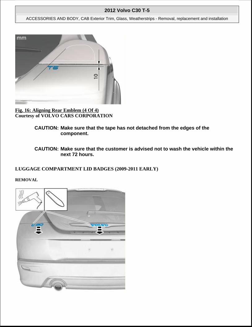
Fig. 16: Aligning Rear Emblem (4 Of 4) Courtesy of VOLVO CARS CORPORATION
LUGGAGE COMPARTMENT LID BADGES (2009-2011 EARLY)
REMOVAL
CAUTION: Make sure that the tape has not detached from the edges of the component.
CAUTION: Make sure that the customer is advised not to wash the vehicle within the next 72 hours.
2012 Volvo C30 T-5
ACCESSORIES AND BODY, CAB Exterior Trim, Glass, Weatherstrips - Removal, replacement and installation

Fig. 17: Removing Emblem With Heat GunCourtesy of VOLVO CARS CORPORATION
INSTALLATION
Follow the instructions regarding components with double-sided adhesive tape, see COMPONENTS WITH DOUBLE-SIDED TAPE
Fig. 18: Aligning Rear Emblem (1 Of 4) Courtesy of VOLVO CARS CORPORATION
Fig. 19: Aligning Rear Emblem (2 Of 4) Courtesy of VOLVO CARS CORPORATION
2012 Volvo C30 T-5
ACCESSORIES AND BODY, CAB Exterior Trim, Glass, Weatherstrips - Removal, replacement and installation

Fig. 20: Aligning Rear Emblem (3 Of 4) Courtesy of VOLVO CARS CORPORATION
Fig. 21: Aligning Rear Emblem (4 Of 4) Courtesy of VOLVO CARS CORPORATION
LUGGAGE COMPARTMENT LID BADGES (2011 LATE -2012)
REMOVAL
2012 Volvo C30 T-5
ACCESSORIES AND BODY, CAB Exterior Trim, Glass, Weatherstrips - Removal, replacement and installation

Fig. 22: Removing Emblem With Heat Gun Courtesy of VOLVO CARS CORPORATION
INSTALLATION
Follow the instructions regarding components with double-sided adhesive tape, see COMPONENTS WITH DOUBLE-SIDED TAPE
Fig. 23: Aligning Rear Emblem (1 Of 4)
2012 Volvo C30 T-5
ACCESSORIES AND BODY, CAB Exterior Trim, Glass, Weatherstrips - Removal, replacement and installation

Courtesy of VOLVO CARS CORPORATION
Fig. 24: Aligning Rear Emblem (2 Of 4) Courtesy of VOLVO CARS CORPORATION
Fig. 25: Aligning Rear Emblem (3 Of 4) Courtesy of VOLVO CARS CORPORATION
2012 Volvo C30 T-5
ACCESSORIES AND BODY, CAB Exterior Trim, Glass, Weatherstrips - Removal, replacement and installation

Fig. 26: Aligning Rear Emblem (4 Of 4) Courtesy of VOLVO CARS CORPORATION
REAR FENDER WIDENER
Fig. 27: Identifying Fender Fastener Courtesy of VOLVO CARS CORPORATION
2012 Volvo C30 T-5
ACCESSORIES AND BODY, CAB Exterior Trim, Glass, Weatherstrips - Removal, replacement and installation

Fig. 28: Locating Fender Widener Fasteners (5) Courtesy of VOLVO CARS CORPORATION
SILL PANEL
Fig. 29: Sill Panel Removal And Installation Procedure (1 Of 6) Courtesy of VOLVO CARS CORPORATION
2012 Volvo C30 T-5
ACCESSORIES AND BODY, CAB Exterior Trim, Glass, Weatherstrips - Removal, replacement and installation

Fig. 30: Sill Panel Removal And Installation Procedure (2 Of 6)Courtesy of VOLVO CARS CORPORATION
Fig. 31: Sill Panel Removal And Installation Procedure (3 Of 6) Courtesy of VOLVO CARS CORPORATION
Fig. 32: Sill Panel Removal And Installation Procedure (4 Of 6) Courtesy of VOLVO CARS CORPORATION
2012 Volvo C30 T-5
ACCESSORIES AND BODY, CAB Exterior Trim, Glass, Weatherstrips - Removal, replacement and installation

Fig. 33: Sill Panel Removal And Installation Procedure (5 Of 6) Courtesy of VOLVO CARS CORPORATION
Fig. 34: Sill Panel Removal And Installation Procedure (6 Of 6) Courtesy of VOLVO CARS CORPORATION
GLASS AND SEALING MOLDING FOR WINDSHIELD
WINDSHIELD
Special tools
951 2925 Rollout 2000 (For window removal) Tool number: 951 2925 Tool description: Rollout 2000 (For window removal) Tool boards: 80
951 2335 Window lifter 2 pieces (replaces 9986030)
2012 Volvo C30 T-5
ACCESSORIES AND BODY, CAB Exterior Trim, Glass, Weatherstrips - Removal, replacement and installation

Tool description: Window lifter 2 pieces (replaces 9986030) Tool boards:
981 4022 Oven 220V SHUKO Tool number: 981 4022 Tool description: Oven 220V SHUKO Tool boards: US99
981 4023 Oven 220V UK Tool number: 981 4023 Tool description: Oven 220V UK Tool boards: US99
981 4024 Oven 110V US Tool number: 981 4024 Tool description: Oven 110V US Tool boards: US99
981 4019 Glue gun 220V SHUKO Tool number: 981 4019 Tool description: Glue gun 220V SHUKO Tool boards: US99
981 4020 Glue gun 220V UK Tool number: 981 4020 Tool description: Glue gun 220V UK Tool boards: US99
981 4021 Glue gun 110V US Tool number: 981 4021 Tool description: Glue gun 110V US Tool boards: US99
Materials Designation Part number H Cleaner 1161436-9Adhesive kit 31299177
2012 Volvo C30 T-5
ACCESSORIES AND BODY, CAB Exterior Trim, Glass, Weatherstrips - Removal, replacement and installation

REMOVAL
See information about bonded windows, general information, see BONDED WINDOW GENERAL, INFORMATION
Remove the following items:
Plenum chamber, see PLENUM CHAMBER
Rain sensor, see RAIN SENSOR
inner rear view mirror, see INNER REAR VIEW MIRROR
Fig. 35: Cutting Cable Courtesy of VOLVO CARS CORPORATION
see 9512925
NOTE: Make sure that the vehicle is standing on a level surface.
WARNING: Wear safety goggles.
2012 Volvo C30 T-5
ACCESSORIES AND BODY, CAB Exterior Trim, Glass, Weatherstrips - Removal, replacement and installation

Fig. 36: Inserting Cable with Special Tool Courtesy of VOLVO CARS CORPORATION
Fig. 37: Identifying Cable Pulled Through Gap Under Windshield Courtesy of VOLVO CARS CORPORATION
Fig. 38: Identifying Cable Taped On Surface Of Windshield
2012 Volvo C30 T-5
ACCESSORIES AND BODY, CAB Exterior Trim, Glass, Weatherstrips - Removal, replacement and installation

Fig. 39: Identifying Excess Cable Pulled Through Gap Under Windshield Courtesy of VOLVO CARS CORPORATION
Fig. 40: Identifying Placement Of Cable Under Windshield Courtesy of VOLVO CARS CORPORATION
Fig. 41: Identifying Cable Placed Under Windshield
2012 Volvo C30 T-5
ACCESSORIES AND BODY, CAB Exterior Trim, Glass, Weatherstrips - Removal, replacement and installation

Fig. 42: Identifying Application Of #1 Suction Cup Glass Lifter / Roll Out Tool 9512925 Courtesy of VOLVO CARS CORPORATION
Fig. 43: Ensuring Components Are Protected Courtesy of VOLVO CARS CORPORATION
CAUTION: Make sure that the components are protected.
2012 Volvo C30 T-5
ACCESSORIES AND BODY, CAB Exterior Trim, Glass, Weatherstrips - Removal, replacement and installation

Fig. 44: Identifying Cable End Pulled Under Weatherstrip And Around Windshield With Roll Out Tool 9512925 Courtesy of VOLVO CARS CORPORATION
Fig. 45: Applying Roll Out Tool 9512925 Courtesy of VOLVO CARS CORPORATION
WARNING: Wear safety goggles.
2012 Volvo C30 T-5
ACCESSORIES AND BODY, CAB Exterior Trim, Glass, Weatherstrips - Removal, replacement and installation

Fig. 46: Identifying Repositioned #1 Roll Out Tool 9512925 Around Windshield Courtesy of VOLVO CARS CORPORATION
Fig. 47: Identifying Application Of Second Roll Out Tool 9512925 Courtesy of VOLVO CARS CORPORATION
Fig. 48: Identifying Repositioned #2 Roll Out Tool 9512925 Around Windshield
2012 Volvo C30 T-5
ACCESSORIES AND BODY, CAB Exterior Trim, Glass, Weatherstrips - Removal, replacement and installation

Fig. 49: Identifying Repositioned #1 Roll Out Tool 9512925 Around Windshield Courtesy of VOLVO CARS CORPORATION
Fig. 50: Lifting Glass with Assistant Courtesy of VOLVO CARS CORPORATION
see 9512335
INSTALLATION
See information about bonded windows, general safety information, see BONDED WINDOW, GENERAL SAFETY INFORMATION
See information about bonded windows, general information, see BONDED WINDOW GENERAL, INFORMATION
2012 Volvo C30 T-5
ACCESSORIES AND BODY, CAB Exterior Trim, Glass, Weatherstrips - Removal, replacement and installation

Fig. 51: Applying H Cleaner, 1161436-9 (1 Of 4) Courtesy of VOLVO CARS CORPORATION
Use: H Cleaner, 1161436-9
Fig. 52: Applying H Cleaner, 1161436-9 (2 Of 4) Courtesy of VOLVO CARS CORPORATION
Use: H Cleaner, 1161436-9
2012 Volvo C30 T-5
ACCESSORIES AND BODY, CAB Exterior Trim, Glass, Weatherstrips - Removal, replacement and installation

Fig. 53: Applying H Cleaner, 1161436-9 (3 Of 4) Courtesy of VOLVO CARS CORPORATION
Fig. 54: Applying H Cleaner, 1161436-9 (4 Of 4) Courtesy of VOLVO CARS CORPORATION
2012 Volvo C30 T-5
ACCESSORIES AND BODY, CAB Exterior Trim, Glass, Weatherstrips - Removal, replacement and installation

Fig. 55: Drying Time 10 Min. Courtesy of VOLVO CARS CORPORATION
Fig. 56: Applying Adhesive (Kit, 31299177) Courtesy of VOLVO CARS CORPORATION
see 9814022 see 9814023 see 9814024 see 9814019 see 9814020 see 9814021
Use: Adhesive kit, 31299177
Fig. 57: Identifying Ten Minute Requirement To Allow Cleaner To Evaporate Courtesy of VOLVO CARS CORPORATION
2012 Volvo C30 T-5
ACCESSORIES AND BODY, CAB Exterior Trim, Glass, Weatherstrips - Removal, replacement and installation

Fig. 58: Lifting Out Windshield With Roll Out Tools 9512925 Courtesy of VOLVO CARS CORPORATION
Fig. 59: Identifying Time And Temperature Requirements For Adhesive To Dry Courtesy of VOLVO CARS CORPORATION
Install the following items:
Plenum chamber, see PLENUM CHAMBER
Rain sensor, see RAIN SENSOR
inner rear view mirror, see INNER REAR VIEW MIRROR
GLASS FOR SIDE DOORS AND WINDOW
FIXED SIDE WINDOW
WARNING: Wait for the specified time at the specified temperature before moving the car.
2012 Volvo C30 T-5
ACCESSORIES AND BODY, CAB Exterior Trim, Glass, Weatherstrips - Removal, replacement and installation

Special tools
951 2925 Rollout 2000 (For window removal) Tool number: 951 2925 Tool description: Rollout 2000 (For window removal) Tool boards: 80
951 2335 Window lifter 2 pieces (replaces 9986030) Tool number: 951 2335 Tool description: Window lifter 2 pieces (replaces 9986030) Tool boards:
981 4022 Oven 220V SHUKO Tool number: 981 4022 Tool description: Oven 220V SHUKO Tool boards: US99
981 4023 Oven 220V UK Tool number: 981 4023 Tool description: Oven 220V UK Tool boards: US99
981 4024 Oven 110V US Tool number: 981 4024 Tool description: Oven 110V US Tool boards: US99
981 4019 Glue gun 220V SHUKO Tool number: 981 4019 Tool description: Glue gun 220V SHUKO Tool boards: US99
981 4020 Glue gun 220V UK Tool number: 981 4020 Tool description: Glue gun 220V UK Tool boards: US99
981 4021 Glue gun 110V US Tool number: 981 4021 Tool description: Glue gun 110V US Tool boards: US99
2012 Volvo C30 T-5
ACCESSORIES AND BODY, CAB Exterior Trim, Glass, Weatherstrips - Removal, replacement and installation

REMOVAL
Remove the following items:
B-pillar trim panel, see B-PILLAR TRIM PANEL
C-pillar trim panel, see C-PILLAR TRIM PANEL
Fig. 60: Identifying Length Of Roll Out Cable Courtesy of VOLVO CARS CORPORATION
see 9512925
Materials Designation Part number H Cleaner 1161436-9Adhesive kit 31299177
WARNING: Wear safety goggles.
2012 Volvo C30 T-5
ACCESSORIES AND BODY, CAB Exterior Trim, Glass, Weatherstrips - Removal, replacement and installation

Fig. 61: Applying Tape and Threading Cable In Window Seal Area Courtesy of VOLVO CARS CORPORATION
Fig. 62: Cable In Window Seal Area Courtesy of VOLVO CARS CORPORATION
Fig. 63: Cable In Window Seal Area Removal Direction (1 Of 2)
2012 Volvo C30 T-5
ACCESSORIES AND BODY, CAB Exterior Trim, Glass, Weatherstrips - Removal, replacement and installation

Fig. 64: Cable In Window Seal Area Removal Direction (2 Of 2) Courtesy of VOLVO CARS CORPORATION
Fig. 65: Applying Roll Out Tool 9512925 Courtesy of VOLVO CARS CORPORATION
Fig. 66: Using Roll Out Tool On Rear Part Of Side Window
2012 Volvo C30 T-5
ACCESSORIES AND BODY, CAB Exterior Trim, Glass, Weatherstrips - Removal, replacement and installation

Fig. 67: Applying Roll Out Tool 9512925 Courtesy of VOLVO CARS CORPORATION
Fig. 68: Using Roll Out Tool On Front Part Of Side Window Courtesy of VOLVO CARS CORPORATION
Fig. 69: Lifting Glass With Assistant
2012 Volvo C30 T-5
ACCESSORIES AND BODY, CAB Exterior Trim, Glass, Weatherstrips - Removal, replacement and installation

see 9512335
INSTALLATION
Fig. 70: H Cleaner, 1161436-9 Courtesy of VOLVO CARS CORPORATION
Use: H Cleaner, 1161436-9
Fig. 71: H Cleaner, 1161436-9 Courtesy of VOLVO CARS CORPORATION
Use: H Cleaner, 1161436-9
2012 Volvo C30 T-5
ACCESSORIES AND BODY, CAB Exterior Trim, Glass, Weatherstrips - Removal, replacement and installation

Fig. 72: Applying H Cleaner, 1161436-9 (1 Of 2) Courtesy of VOLVO CARS CORPORATION
Fig. 73: Applying H Cleaner, 1161436-9 (2 Of 2) Courtesy of VOLVO CARS CORPORATION
2012 Volvo C30 T-5
ACCESSORIES AND BODY, CAB Exterior Trim, Glass, Weatherstrips - Removal, replacement and installation

Fig. 74: Drying Time 10 Min. Courtesy of VOLVO CARS CORPORATION
Fig. 75: Applying Adhesive (Kit, 31299177) Courtesy of VOLVO CARS CORPORATION
see 9814022 see 9814023 see 9814024 see 9814019 see 9814020 see 9814021
Use: Adhesive kit, 31299177
Fig. 76: Identifying Ten Minute Requirement To Allow Cleaner To Evaporate Courtesy of VOLVO CARS CORPORATION
2012 Volvo C30 T-5
ACCESSORIES AND BODY, CAB Exterior Trim, Glass, Weatherstrips - Removal, replacement and installation

Fig. 77: Identifying Time And Temperature Requirements For Adhesive To Dry Courtesy of VOLVO CARS CORPORATION
Assemble the following items:
B-pillar trim panel, see B-PILLAR TRIM PANEL
C-pillar trim panel, see C-PILLAR TRIM PANEL
RUBBER PROTECTION GLASS CLAMP
Special tools:
see 9995723
REMOVAL
REMOVING THE RUBBER LIP
WARNING: Wait for the specified time at the specified temperature before moving the car.
NOTE: The illustrations in this service information are used for different model years and/or models. Some variation may occur. However, the essential information in the illustrations is always correct.
2012 Volvo C30 T-5
ACCESSORIES AND BODY, CAB Exterior Trim, Glass, Weatherstrips - Removal, replacement and installation

Fig. 78: Identifying Removal Of Rubber Lip Courtesy of VOLVO CARS CORPORATION
Remove the rubber lip located in the glass clamp. Use a pair of bent pliers and pull it out through the rear hole of the door module.
INSTALLATION
INSTALLING THE RUBBER LIP
Fig. 79: Identifying Installation Of Rubber Lip Courtesy of VOLVO CARS CORPORATION
Install the new rubber lip through the hole in the door module and hold in place using the pliers.
Use see 9995723 or a similar long flat tool to insert between the inner and outer door panel.
Then press the rubber lip into position in the glass clamp.
2012 Volvo C30 T-5
ACCESSORIES AND BODY, CAB Exterior Trim, Glass, Weatherstrips - Removal, replacement and installation

Fig. 80: Identifying Clamp Centered Courtesy of VOLVO CARS CORPORATION
WINDOW, FRONT DOOR.
Operation Number(s): 84406-2
REMOVAL
Fig. 81: Roll Window Up 160 mm Courtesy of VOLVO CARS CORPORATION
Remove door panel. See PANEL FRONT DOOR
NOTE: Ensure that the glass is centered in the clamp.
NOTE: Removal steps in this procedure may contain installation details.
2012 Volvo C30 T-5
ACCESSORIES AND BODY, CAB Exterior Trim, Glass, Weatherstrips - Removal, replacement and installation

Fig. 82: Do Not Loosen Bolts More Than 2 Turns Courtesy of VOLVO CARS CORPORATION
Torque: Window to power window mechanism (front side door)
8 Nm
Fig. 83: Identifying Rotation Arrows Courtesy of VOLVO CARS CORPORATION
INSTALLATION
Install in reverse order.
Initiate window lift. See VIDA car communication. VIDA is Volvo-specific scan tool.
SILL TRIM PANEL
NOTE: Do not loosen the bolts more than 2 turns.
2012 Volvo C30 T-5
ACCESSORIES AND BODY, CAB Exterior Trim, Glass, Weatherstrips - Removal, replacement and installation

FRONT SILL TRIM PANEL
Fig. 84: Identifying Front Sill Trim Panel Courtesy of VOLVO CARS CORPORATION
REAR SILL TRIM PANEL
Fig. 85: Identifying Rear Sill Trim Panel Courtesy of VOLVO CARS CORPORATION
OUTSIDE MIRRORS
COVER, EXTERNAL MIRROR
REMOVAL
Remove mirror rear-view mirror external, see MIRROR, REAR VIEW MIRROR
2012 Volvo C30 T-5
ACCESSORIES AND BODY, CAB Exterior Trim, Glass, Weatherstrips - Removal, replacement and installation

Fig. 86: Identifying Rear View Mirror Cover Removal Courtesy of VOLVO CARS CORPORATION
INSTALLATION
Fig. 87: Identifying Rear View Mirror Cover Installation Courtesy of VOLVO CARS CORPORATION
2012 Volvo C30 T-5
ACCESSORIES AND BODY, CAB Exterior Trim, Glass, Weatherstrips - Removal, replacement and installation

Fig. 88: Identifying Rear View Mirror Cover Installation (1 Of 2) Courtesy of VOLVO CARS CORPORATION
Fig. 89: Identifying Rear View Mirror Cover Installation (2 Of 2) Courtesy of VOLVO CARS CORPORATION
Install external rearview mirror, see MIRROR, REAR VIEW MIRROR
MIRROR, REAR VIEW MIRROR
2012 Volvo C30 T-5
ACCESSORIES AND BODY, CAB Exterior Trim, Glass, Weatherstrips - Removal, replacement and installation

Fig. 90: Identifying Removal Of Rear View Mirror Glass (1 Of 2) Courtesy of VOLVO CARS CORPORATION
Fig. 91: Identifying Removal Of Rear View Mirror Glass (2 Of 2) Courtesy of VOLVO CARS CORPORATION
MOTOR, EXTERNAL MIRROR
REMOVAL
Remove the mirror glass. See MIRROR, REAR VIEW MIRROR.
2012 Volvo C30 T-5
ACCESSORIES AND BODY, CAB Exterior Trim, Glass, Weatherstrips - Removal, replacement and installation

Fig. 92: Identifying Rear View Mirror Motor Courtesy of VOLVO CARS CORPORATION
REAR VIEW MIRROR EXTERNAL
Operation Number(s): 84622-2
REMOVAL
Remove the panel. See PANEL FRONT DOOR
Fig. 93: Removing External Rear View Mirror (1 Of 2)
NOTE: Removal steps in this procedure may contain installation details.
2012 Volvo C30 T-5
ACCESSORIES AND BODY, CAB Exterior Trim, Glass, Weatherstrips - Removal, replacement and installation

Courtesy of VOLVO CARS CORPORATION
Fig. 94: Removing External Rear View Mirror (2 Of 2) Courtesy of VOLVO CARS CORPORATION
Torque: Rear view mirror to front door
8 Nm
INSTALLATION
To install, reverse the removal procedure
NOTE: Use a new seal.
2012 Volvo C30 T-5
ACCESSORIES AND BODY, CAB Exterior Trim, Glass, Weatherstrips - Removal, replacement and installation

ELECTRICAL
Body Electrical
BODY ELECTRICAL
FIBER OPTIC CABLE HARNESS, REPAIRING
Fig. 1: MOST Bus (Media Oriented System Transportation) Communication Diagram Courtesy of VOLVO CARS CORPORATION
The components in the infotainment system are part of an optical network, known as the MOST bus. (Media Oriented System Transportation). The network consists of fiber optics (POF = Polymer Optical Fibers), special connectors for fiber optics and MOST nodes, i. e. control modules which are connected to the MOST bus.
Data is transmitted via the fiber optics, for example music, in the form of light signals. The MOST bus is a ring which must be unbroken for it to work. None of the infotainment system will work if an optical fiber breaks or if a connector is disconnected. The ends of the fibers must also be clean to allow the light to pass.
NOTE: As the illustrations in this service information are used for different model years and / or models, some variation may occur. However, the essential information in the illustrations is always correct.
2012 Volvo C30 T-5
ELECTRICAL Body Electrical
2012 Volvo C30 T-5
ELECTRICAL Body Electrical

Fig. 2: Identifying Maximum Bend Radius Of Optic Cable Courtesy of VOLVO CARS CORPORATION
A fiber requires a larger bend radius than a copper cable. The bend radius must not be less than 25 mm . If the fiber bends too much, not enough light will be let through.
DISASSEMBLING THE CONNECTOR
NOTE: Fiber optics must not be spliced.
Damaged fiber optics can be repaired if there is sufficient length remaining to install a new ferrule (4). If the remaining fiber is not long enough, a new fiber optic must be routed parallel to the damaged fiber.
NOTE: Fiber optics are sensitive to bending and pinching. Be careful when routing and securing.
2012 Volvo C30 T-5
ELECTRICAL Body Electrical

Fig. 3: Identifying Catch Pressed Out With Screwdriver Courtesy of VOLVO CARS CORPORATION
Press out the catch (1) using a screwdriver.
NOTE: There is one fiber for the input and one for the output signal. The system will not work if the are interchanged.
2012 Volvo C30 T-5
ELECTRICAL Body Electrical

Fig. 4: Identifying Catches Opened With Screwdriver To Pull Out Ferrule Courtesy of VOLVO CARS CORPORATION
Open the catches (3) using a screwdriver.
Pull out the ferrule (1). Make a note of its location.
DISASSEMBLING THE COMBINED CONNECTOR (OPTIC AND ELECTRICAL CONDUCTOR) (1)
2012 Volvo C30 T-5
ELECTRICAL Body Electrical

Fig. 5: Disassembling Combined Connector Courtesy of VOLVO CARS CORPORATION
Release the lock using a screwdriver. Remove the inner section (2).
Remove the ferrule. See DISASSEMBLING THE CONNECTOR
INSTALLING THE FERRULE
2012 Volvo C30 T-5
ELECTRICAL Body Electrical

Fig. 6: Identifying Fiber Optic Cable Stripped With Tool 9512868 (1 Of 2) Courtesy of VOLVO CARS CORPORATION
Cut the required length (+10 mm) of fiber optic.
Strip the fiber optic. Use tool see 9512868 as shown in the illustration
2012 Volvo C30 T-5
ELECTRICAL Body Electrical

Fig. 7: Identifying Fiber Optic Cable Stripped With Tool 9512868 (2 Of 2) Courtesy of VOLVO CARS CORPORATION
Strip the fiber optic. Use tool see 9512868 as shown in the illustration.
2012 Volvo C30 T-5
ELECTRICAL Body Electrical

Fig. 8: Aligning Ferrule Using Tool 9512869 Courtesy of VOLVO CARS CORPORATION
Align the ferrule. Use tool see 9512869 as shown in the illustration.
2012 Volvo C30 T-5
ELECTRICAL Body Electrical

Fig. 9: Ensuring Ferrule Is Edge To Edge With Fiber Courtesy of VOLVO CARS CORPORATION
Check that the ferrule is secure and is edge to edge with the fiber.
ASSEMBLING THE CONNECTOR
2012 Volvo C30 T-5
ELECTRICAL Body Electrical

Fig. 10: Identifying Ferrule Pressed Into Place In Connector Courtesy of VOLVO CARS CORPORATION
Press the ferrule (1) into place in the connector (2).
NOTE: There is one fiber for the input and one for the output signal. If they are mixed up the system will not work.
2012 Volvo C30 T-5
ELECTRICAL Body Electrical

Fig. 11: Identifying Installation Of Catch Courtesy of VOLVO CARS CORPORATION
Install the catch (1).
ASSEMBLING THE COMBINED CONNECTOR (2 OPTIC AND 4 ELECTRICAL CONDUCTORS)
Install the ferrule. See ASSEMBLING THE CONNECTOR.
2012 Volvo C30 T-5
ELECTRICAL Body Electrical

Fig. 12: Identifying Inner Section Pressed Into Place In Combined Connector Courtesy of VOLVO CARS CORPORATION
Press the inner section into place in the combined connector.
FINISHING WORK
Check the repair. See DIAGNOSTIC INSTRUCTIONS - FIBRE OPTIC CABLE .
2012 Volvo C30 T-5
ELECTRICAL Body Electrical

ACCESSORIES & EQUIPMENT
Seats
SEATS
SIDE PANEL FRONT SEAT
Fig. 1: Removing Front Seat Side Panel - Vehicle With Manual Seat (1 Of 2) Courtesy of VOLVO CARS CORPORATION
Vehicle with manual seat.
Fig. 2: Removing Front Seat Side Panel - Vehicle With Manual Seat (2 Of 2) Courtesy of VOLVO CARS CORPORATION
2012 Volvo C30 T-5
ACCESSORIES & EQUIPMENT Seats
2012 Volvo C30 T-5
ACCESSORIES & EQUIPMENT Seats

Fig. 3: Removing Front Seat Side Panel - Vehicle With Electric Seat (1 Of 2) Courtesy of VOLVO CARS CORPORATION
Vehicle with electric seat.
Fig. 4: Removing Front Seat Side Panel - Vehicle With Electric Seat (2 Of 2) Courtesy of VOLVO CARS CORPORATION
Remove the control module in the front seat. See CONTROL MODULE FRONT SEAT .
To install, reverse the removal procedure
2012 Volvo C30 T-5
ACCESSORIES & EQUIPMENT Seats

ENGINE PERFORMANCE
Ignition And Control Systems - Removal, replacement and installation
IGNITION COIL AND SPARK PLUG
IGNITION COIL (TURBO)
REMOVAL
Fig. 1: Identifying Air Intake Hose And Fasteners Courtesy of VOLVO CARS CORPORATION
Torque: M7
17 Nm
Fig. 2: Identifying Engine Cover And Screws
NOTE: Removal steps in this procedure may contain installation details.
2012 Volvo C30 T-5
ENGINE PERFORMANCE Ignition And Control Systems - Removal, replacement and installation
2012 Volvo C30 T-5
ENGINE PERFORMANCE Ignition And Control Systems - Removal, replacement and installation

Courtesy of VOLVO CARS CORPORATION
Torque: M6
10 Nm
Fig. 3: Identifying Timing Case Cover Courtesy of VOLVO CARS CORPORATION
Fig. 4: Identifying Ignition Coils, Connectors And Screws Courtesy of VOLVO CARS CORPORATION
Torque: M6
10 Nm
INSTALLATION
To install, reverse the removal procedure.
IGNITION COIL (NON-TURBO)
2012 Volvo C30 T-5
ENGINE PERFORMANCE Ignition And Control Systems - Removal, replacement and installation

REMOVAL
Fig. 5: Identifying Air Intake Hose Clamp And Electrical Connector With Cable Clamp Courtesy of VOLVO CARS CORPORATION
Fig. 6: Identifying Intake Plenum and Bolts Courtesy of VOLVO CARS CORPORATION
Torque: M6
10 Nm
NOTE: Removal steps in this procedure may contain installation details.
2012 Volvo C30 T-5
ENGINE PERFORMANCE Ignition And Control Systems - Removal, replacement and installation

Fig. 7: Moving Plenum Out of the Way Courtesy of VOLVO CARS CORPORATION
Fig. 8: Sealing Off Openings Courtesy of VOLVO CARS CORPORATION
CAUTION: Make sure that all openings are sealed. Use new blanking caps.
2012 Volvo C30 T-5
ENGINE PERFORMANCE Ignition And Control Systems - Removal, replacement and installation

Fig. 9: Identifying Engine Cover End Piece And Screws Courtesy of VOLVO CARS CORPORATION
Torque: M6
10 Nm
Fig. 10: Identifying Ignition Coil Connectors Courtesy of VOLVO CARS CORPORATION
2012 Volvo C30 T-5
ENGINE PERFORMANCE Ignition And Control Systems - Removal, replacement and installation

Fig. 11: Identifying Ignition Coil Screws Courtesy of VOLVO CARS CORPORATION
Torque: M6
10 Nm
INSTALLATION
To install, reverse the removal procedure.
SPARK PLUGS
REPLACEMENT
REMOVAL
Remove ignition coil, see IGNITION COIL
NOTE: Removal steps in this procedure may contain installation details.
2012 Volvo C30 T-5
ENGINE PERFORMANCE Ignition And Control Systems - Removal, replacement and installation

Fig. 12: Identifying Spark Plug Locations Courtesy of VOLVO CARS CORPORATION
Torque: Spark plug
25 Nm
INSTALLATION
To install, reverse the removal procedure.
ENGINE CONTROL SYSTEM
CRANKSHAFT POSITION SENSOR (CKP)
REPLACEMENT
REMOVAL
Remove the air filter housing, see AIR CLEANER HOUSING
NOTE: Removal steps in this procedure may contain installation details.
2012 Volvo C30 T-5
ENGINE PERFORMANCE Ignition And Control Systems - Removal, replacement and installation

Fig. 13: Identifying Pipe Courtesy of VOLVO CARS CORPORATION
Fig. 14: Identifying Crankshaft Position Sensor Courtesy of VOLVO CARS CORPORATION
Torque: M6
10 Nm
INSTALLATION
To install, reverse the removal procedure.
CAMSHAFT POSITION SENSOR (CMP) (TURBO)
REMOVAL
NOTE: Removal steps in this procedure may contain installation details.
2012 Volvo C30 T-5
ENGINE PERFORMANCE Ignition And Control Systems - Removal, replacement and installation

Fig. 15: Identifying Air Intake Hoses And Fasteners Courtesy of VOLVO CARS CORPORATION
Torque: M6
10 Nm
Fig. 16: Identifying Engine Cover And Screws Courtesy of VOLVO CARS CORPORATION
Torque: M6
10 Nm
2012 Volvo C30 T-5
ENGINE PERFORMANCE Ignition And Control Systems - Removal, replacement and installation

Fig. 17: Identifying Camshaft Position Sensor Connector And Screw Courtesy of VOLVO CARS CORPORATION
Torque: M6
10 Nm
INSTALLATION
To install, reverse the removal procedure.
CAMSHAFT POSITION SENSOR (CMP) (NON-TURBO)
REMOVAL
REMOVING UPPER INTAKE MANIFOLD
NOTE: The illustrations in this service information are used for different model years and/or models. Some variation may occur. However, the essential information in the illustrations is always correct.
2012 Volvo C30 T-5
ENGINE PERFORMANCE Ignition And Control Systems - Removal, replacement and installation

Fig. 18: Identifying Upper Intake Manifold And Screws Courtesy of VOLVO CARS CORPORATION
Remove/slacken off:
the hose clamp for the hose between the intake manifold and the mass air flow (MAF) sensor
the 6 screws for the upper intake manifold closest to the front cover plate. Remove/slacken off the 2 screws against the firewall. Lift up the intake manifold and place to one side. Disconnect the connector for the pressure sensor on the intake manifold. Cut the tie strap.
REMOVING THE CAMSHAFT POSITION (CMP) SENSOR
CAUTION: Seal the openings in the lower part of the intake manifold. Use tape or similar.
2012 Volvo C30 T-5
ENGINE PERFORMANCE Ignition And Control Systems - Removal, replacement and installation

Fig. 19: Identifying Camshaft Position Sensors And Screws Courtesy of VOLVO CARS CORPORATION
Disconnect the connector for the position sensor on the camshaft.
Remove:
the screw for the position sensor
the position sensor on the camshaft.
INSTALLATION
INSTALLING THE CAMSHAFT POSITION (CMP) SENSOR
Install:
the position sensor on the camshaft
the screw for the position sensor. Tighten.
Connect the connector for the position sensor on the camshaft.
NOTE: For tightening torques, see: TIGHTENING TORQUE .
2012 Volvo C30 T-5
ENGINE PERFORMANCE Ignition And Control Systems - Removal, replacement and installation

INSTALLING UPPER INTAKE MANIFOLD
Fig. 20: Identifying Upper Intake Manifold And Screws Courtesy of VOLVO CARS CORPORATION
Install:
a new gasket for the upper section of the intake manifold
the upper intake manifold. Tighten the screws alternately. Tighten. See: TIGHTENING TORQUE . Tighten the hose clamp to the mass air flow (MAF) sensor. Connect the connector for the pressure sensor on the intake manifold
new tie strap for the cable harness.
FINISHING
CHECKING INJECTORS AND PULSATION DAMPERS
Start the engine. Check the function of the engine. Check for leakage.
CAUTION: Make sure that the guides for the lower section are in the correct position.
2012 Volvo C30 T-5
ENGINE PERFORMANCE Ignition And Control Systems - Removal, replacement and installation

ENGINE CONTROL MODULE (ECM)
REMOVAL
Fig. 21: Identifying Ignition In OFF Position Courtesy of VOLVO CARS CORPORATION
Fig. 22: Removing Engine Control Module Cover Courtesy of VOLVO CARS CORPORATION
2012 Volvo C30 T-5
ENGINE PERFORMANCE Ignition And Control Systems - Removal, replacement and installation

Fig. 23: Removing Engine Control Module Courtesy of VOLVO CARS CORPORATION
INSTALLATION
To install, reverse the removal procedure.
Order and download software according to: 30668285
Reset according to "Adapting throttle unit" using VIDA (Volvo scan tool).
ENGINE COOLANT TEMPERATURE SENSOR (ECT)
REPLACEMENT
REMOVAL
Drain cooling system, draining, filling, and bleeding, see COOLING SYSTEM - DRAINING, CHARGING AND BLEEDING
Remove the air filter housing, see AIR CLEANER HOUSING
NOTE: Make sure that the component terminals are not bent or damaged.
NOTE: Make sure that the seal is correctly located.
2012 Volvo C30 T-5
ENGINE PERFORMANCE Ignition And Control Systems - Removal, replacement and installation

Fig. 24: Identifying Engine Coolant Temperature Sensor Connector Courtesy of VOLVO CARS CORPORATION
Fig. 25: Removing Engine Coolant Temperature Sensor Courtesy of VOLVO CARS CORPORATION
INSTALLATION
To install, reverse the removal procedure.
FUEL PUMP DRIVER MODULE
REMOVAL AND INSTALLATION
Remove the seat cushion, rear seat, see SEAT CUSHION, REAR SEAT .
2012 Volvo C30 T-5
ENGINE PERFORMANCE Ignition And Control Systems - Removal, replacement and installation

Fig. 26: Identifying Clip Courtesy of VOLVO CARS CORPORATION
Fig. 27: Identifying Fuel Pump Driver Module, Connector, And Metal Tabs Courtesy of VOLVO CARS CORPORATION
KNOCK SENSOR (KS)
REPLACEMENT
REMOVAL
Remove the air filter housing, see AIR CLEANER HOUSING
NOTE: Removal steps in this procedure may contain installation details.
2012 Volvo C30 T-5
ENGINE PERFORMANCE Ignition And Control Systems - Removal, replacement and installation

Fig. 28: Identifying Knock Sensor Connector Courtesy of VOLVO CARS CORPORATION
Fig. 29: Identifying Body Ground Cables Courtesy of VOLVO CARS CORPORATION
Torque: Knock sensor
20 Nm
INSTALLATION
To install, reverse the removal procedure.
MANIFOLD ABSOLUTE PRESSURE (MAP) SENSOR
CAUTION: Note the position of the components before removal.
2012 Volvo C30 T-5
ENGINE PERFORMANCE Ignition And Control Systems - Removal, replacement and installation

REMOVAL
Fig. 30: Identifying Manifold Absolute Pressure Sensor Connector And Screws Courtesy of VOLVO CARS CORPORATION
INSTALLATION
To install, reverse the removal procedure.
PRESSURE SENSOR, FUEL RAIL (FRP)
PREPARATORY WORK
DRAINING THE FUEL SYSTEM
Remove:
the screws for the upper timing cover
the upper timing cover.
Drain the fuel system. See: FUEL SYSTEM PRESSURE RELEASE .
REMOVAL
REMOVING THE FUEL PRESSURE SENSOR
NOTE: The illustrations in this service information are used for different model years and/or models. Some variation may occur. However, the essential information in the illustrations is always correct.
2012 Volvo C30 T-5
ENGINE PERFORMANCE Ignition And Control Systems - Removal, replacement and installation

Fig. 31: Identifying Fuel Pressure Sensor Connector And Screw Courtesy of VOLVO CARS CORPORATION
Disconnect the connector for the sensor.
Remove:
the screw for the fuel pressure sensor
the sensor.
INSTALLATION
INSTALLING THE FUEL PRESSURE SENSOR
CAUTION: Place paper on top of the generator.
NOTE: For tightening torque, see: TIGHTENING TORQUE .
2012 Volvo C30 T-5
ENGINE PERFORMANCE Ignition And Control Systems - Removal, replacement and installation

Fig. 32: Identifying Fuel Pressure Sensor Connector And Screw Courtesy of VOLVO CARS CORPORATION
Install:
the sensor
the screw for the sensor. Tighten. Connect the connector for the sensor
the upper timing cover
the screws for the cover. Tighten.
FINISHING
CHECKS
Start the engine. Check for leakage. Check the engine function.
TEMPERATURE AND MANIFOLD ABSOLUTE PRESSURE SENSOR (MAPT)
REMOVAL
Remove right-hand cover, see FRONT EXTERIOR LIGHTS .
2012 Volvo C30 T-5
ENGINE PERFORMANCE Ignition And Control Systems - Removal, replacement and installation
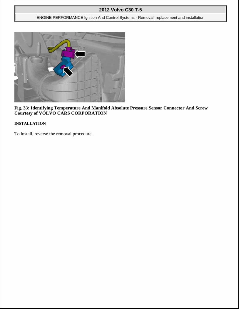
Fig. 33: Identifying Temperature And Manifold Absolute Pressure Sensor Connector And Screw Courtesy of VOLVO CARS CORPORATION
INSTALLATION
To install, reverse the removal procedure.
2012 Volvo C30 T-5
ENGINE PERFORMANCE Ignition And Control Systems - Removal, replacement and installation

ENGINE
Fuel System - Removal, Replacement And Installation
FUEL PUMP AND STRAINER
LEVEL SENSOR FUEL TANK
Special tools:
see 9997093
PREPARATORY WORK
Remove the fuel tank. See FUEL TANK.
REMOVAL
REMOVING THE LEVEL SENSOR
NOTE: The graphics in this service information are used for different model years and/or models. Some variation may occur. However, the essential information in the graphics is always correct.
2012 Volvo C30 T-5
ENGINE Fuel System - Removal, Replacement And Installation
2012 Volvo C30 T-5
ENGINE Fuel System - Removal, Replacement And Installation

Fig. 1: Removing Threaded Ring with Tool (9997093) Courtesy of VOLVO CARS CORPORATION
Remove:
the large plastic nut. Use tool see 9997093
the level sensor.
TRANSFERRING COMPONENTS
TRANSFERRING SUCTION LINE
CAUTION: Ensure that the lever on the level sensor is not damaged when removing the pump.
2012 Volvo C30 T-5
ENGINE Fuel System - Removal, Replacement And Installation

Fig. 2: Transferring Suction Line Courtesy of VOLVO CARS CORPORATION
Remove the plug for the suction line from the underside of the level sensor, use a 9 mm socket.
Transfer the suction line to the new fuel pump.
INSTALLATION
INSTALLING THE LEVEL SENSOR
NOTE: Applies to vehicles equipped with auxiliary heater.
NOTE: For tightening torques, see TIGHTENING TORQUE .
2012 Volvo C30 T-5
ENGINE Fuel System - Removal, Replacement And Installation

Fig. 3: Lining Up The Match Marks Courtesy of VOLVO CARS CORPORATION
Install the level sensor.
Install the large plastic nut. Use tool see 9997093 . Tighten acc. to TIGHTENING TORQUE .
FINISHING
Install the fuel tank. See FUEL TANK.
FUEL FILTER (B5254T7; 2008-12)
CAUTION: Ensure that the lever on the level sensor is not damaged when removing the pump.
NOTE: Ensure that the level sensor marking is opposite the marking on the tank.
Special tools
981 4098 Spanner
2012 Volvo C30 T-5
ENGINE Fuel System - Removal, Replacement And Installation

REMOVAL
Fig. 4: Verify Less Than 3/4 Full Courtesy of VOLVO CARS CORPORATION
Tool description: Spanner Tool boards: 23
NOTE: Removal steps in this procedure may contain installation details.
WARNING: Make sure that the fuel tank is no more than 3/4 full.
2012 Volvo C30 T-5
ENGINE Fuel System - Removal, Replacement And Installation

Fig. 5: Identifying Fuel Filter Drain Courtesy of VOLVO CARS CORPORATION
Torque: Draining screw to fuel filter
2 Nm
Fig. 6: Using Special Tool (9814098) Courtesy of VOLVO CARS CORPORATION
see 9814098
Torque: Fuel filter
WARNING: Be prepared to collect escaping fluid.
NOTE: Do not loosen the bolt more than 4 turns.
2012 Volvo C30 T-5
ENGINE Fuel System - Removal, Replacement And Installation

INSTALLATION
To install, reverse the removal procedure.
EXTRA FUEL FILTER
PREPARATORY WORK
Drain the fuel injection system. See FUEL SYSTEM PRESSURE RELEASE .
HINT: Place a tray or similar under the filter to capture any spillage.
REMOVAL
REMOVING THE FUEL FILTER
Fig. 7: Fuel Filter Retaining Bolt And Quick-Release Connector Courtesy of VOLVO CARS CORPORATION
NOTE: The graphics in this service information are used for different model years and/or models. Some variation may occur. However, the essential information in the graphics is always correct.
2012 Volvo C30 T-5
ENGINE Fuel System - Removal, Replacement And Installation

Remove:
the screw for the clamp around the filter
the quick-release connectors for the pipes
the filter.
INSTALLATION
INSTALLING THE FUEL FILTER
Install:
the filter
the pipes
the M8 screw for the clamp around the filter (M8)
the fuel pump fuse. See FUEL SYSTEM PRESSURE RELEASE .
FUEL FILTER IN TANK
REMOVAL AND INSTALLATION
Remove fuel filter. See FUEL PUMP AND LEVEL SENSOR UNIT
FUEL PUMP (B5254T7; 2008-12)
Special tools:
see 9997111
PREPARATORY WORK
Remove:
the fuel tank. See FUEL TANK.
the level sensor on the left-hand side. See LEVEL SENSOR FUEL TANK .
CAUTION: Extreme cleanliness must be exercised when handling these components.
NOTE: For tightening torques, see TIGHTENING TORQUE .
NOTE: The graphics in this service information are used for different model years and/or models. Some variation may occur. However, the essential information in the graphics is always correct.
2012 Volvo C30 T-5
ENGINE Fuel System - Removal, Replacement And Installation

REMOVAL
REMOVING THE FUEL PUMP (FP)
Fig. 8: Removing Ring with Special Tool 9997111 Courtesy of VOLVO CARS CORPORATION
Release the 2 catches. Remove the plastic nut. Use see 9997111 .
Remove the pump.
TRANSFERRING PARTS
TRANSFERRING SUCTION LINE
CAUTION: Do not damage the lever on the level sensor during removal.
CAUTION: When removing the plastic nut ensure that the level sensor is not turned with it.
2012 Volvo C30 T-5
ENGINE Fuel System - Removal, Replacement And Installation

Fig. 9: Transferring Suction Line Courtesy of VOLVO CARS CORPORATION
Remove the plug for the suction line from the underside of the level sensor, use a 9 mm socket.
Transfer the suction line to the new fuel pump.
INSTALLATION
INSTALLING THE FUEL PUMP (FP)
NOTE: Applies to vehicles equipped with auxiliary heater.
NOTE: For tightening torques, see TIGHTENING TORQUE .
2012 Volvo C30 T-5
ENGINE Fuel System - Removal, Replacement And Installation

Fig. 10: Image of Pump Module Courtesy of VOLVO CARS CORPORATION
Install a new O-ring.
Insert the hose for the fuel pump (FP) from the right-hand to the left-hand side of the tank.
Install the fuel pump (FP).
CAUTION: Do not damage the lever on the level sensor during installation.
CAUTION: When installing the plastic nut ensure that the level sensor is not turned with it.
2012 Volvo C30 T-5
ENGINE Fuel System - Removal, Replacement And Installation

Fig. 11: Keep Aware of Alignment Marks Courtesy of VOLVO CARS CORPORATION
Tighten the plastic nut. See TIGHTENING TORQUE . Use see 9997111
FINISHING
Install:
the level sensor on the left-hand side. See LEVEL SENSOR FUEL TANK
the fuel tank, USA. See FUEL TANK
FUEL PUMP AND LEVEL SENSOR UNIT
REMOVING
NOTE: The marking on the fuel pump (FP) must be opposite the marking on the fuel tank.
NOTE: Some variation may occur. However, the essential information in the graphics is always correct.
2012 Volvo C30 T-5
ENGINE Fuel System - Removal, Replacement And Installation

Remove the fuel tank. See FUEL TANK.
Fig. 12: Removing the Threaded Ring With Tool (9997111) Courtesy of VOLVO CARS CORPORATION
Remove:
the large plastic nut, 1 pc. Use 9997111
the pump.
TRANSFER OF SUCTION LINE (FOR VEHICLES EQUIPPED WITH AUXILIARY HEATER)
Fig. 13: Transferring Suction Line Courtesy of VOLVO CARS CORPORATION
NOTE: Ensure that the lever on the level sensor is not damaged when removing the pump.
2012 Volvo C30 T-5
ENGINE Fuel System - Removal, Replacement And Installation

Remove the plug for the suction line from the underside of the level sensor, use a 9 mm socket.
Transfer the suction line to the new fuel pump.
INSTALLING
Fig. 14: Aligning The Match Marks Courtesy of VOLVO CARS CORPORATION
Install:
new O-ring
the level sensor
the 1 large plastic nut. Use see 9997111 .
Install the fuel tank. See FUEL TANK.
FUEL TANK, FUEL LINES, EVAPORATOR SYSTEM
EVAPORATIVE EMISSION
NOTE: For tightening torques, see TIGHTENING TORQUE .
NOTE: Ensure that the lever on the level sensor is not damaged when installing the pump.
NOTE: The marking on the level sensor must be aligned with the marking on the fuel tank.
NOTE: See EVAPORATION SYSTEM AND FUEL SYSTEM PRESSURE - INSPECTION
2012 Volvo C30 T-5
ENGINE Fuel System - Removal, Replacement And Installation

CHARCOAL FILTER
Special tools:
see 9985972
see 9995972
PREPARATORY WORK
REMOVING THE SHOCK ABSORBER
Fig. 15: Identifying Lower Shock Mounting Courtesy of VOLVO CARS CORPORATION
Remove the following on both sides:
article.
NOTE: The graphics in this service information are used for different model years and/or models. Some variation may occur. However, the essential information in the graphics is always correct.
2012 Volvo C30 T-5
ENGINE Fuel System - Removal, Replacement And Installation

1 screw
the shock absorber from the lateral link.
REMOVAL
REMOVING THE EXHAUST
Fig. 16: Installing The Exhaust Bracket Courtesy of VOLVO CARS CORPORATION
Remove the rubber mounting from the center muffler.
2012 Volvo C30 T-5
ENGINE Fuel System - Removal, Replacement And Installation

Fig. 17: Identifying Rear Muffler And Rubber Mountings Courtesy of VOLVO CARS CORPORATION
Remove the 2 rubber mountings from the rear muffler.
LOWERING THE SUB-FRAME
2012 Volvo C30 T-5
ENGINE Fuel System - Removal, Replacement And Installation

Fig. 18: Supporting Subframe With Mobile Jack (9985972) Courtesy of VOLVO CARS CORPORATION
Use mobile jack: see 9985972 and see 9995972 .
Position the mobile jack against the sub-frame.
Pull the brake hose out of its bracket on both sides.
Remove the screws on both sides.
NOTE: Make sure that no cables/hoses are loaded or trapped when lowering the sub-frame.
2012 Volvo C30 T-5
ENGINE Fuel System - Removal, Replacement And Installation
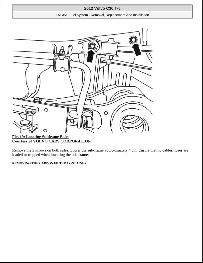
Fig. 19: Locating Subframe Bolts Courtesy of VOLVO CARS CORPORATION
Remove the 2 screws on both sides. Lower the sub-frame approximately 4 cm. Ensure that no cables/hoses are loaded or trapped when lowering the sub-frame.
REMOVING THE CARBON FILTER CONTAINER
2012 Volvo C30 T-5
ENGINE Fuel System - Removal, Replacement And Installation

Fig. 20: Removing Carbon Canister Courtesy of VOLVO CARS CORPORATION
Remove:
the 2 M5 screws securing the carbon filter container to the sub-frame
the 2 pipes, secured using quick-release connectors (1)
the hose (2).
Pull the carbon filter container out of the mounting. Take out the carbon filter container over the rear muffler. Remove the container.
INSTALLATION
INSTALLING THE CARBON FILTER CONTAINER
NOTE: When removing the carbon filter canister, make sure that the pipe sleeve (2) is not loaded.
NOTE: For tightening torques, see TIGHTENING TORQUE .
2012 Volvo C30 T-5
ENGINE Fuel System - Removal, Replacement And Installation
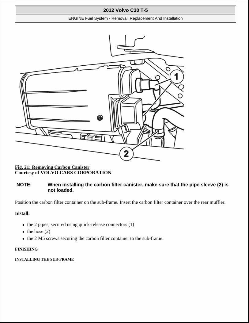
Fig. 21: Removing Carbon Canister Courtesy of VOLVO CARS CORPORATION
Position the carbon filter container on the sub-frame. Insert the carbon filter container over the rear muffler.
Install:
the 2 pipes, secured using quick-release connectors (1)
the hose (2)
the 2 M5 screws securing the carbon filter container to the sub-frame.
FINISHING
INSTALLING THE SUB-FRAME
NOTE: When installing the carbon filter canister, make sure that the pipe sleeve (2) is not loaded.
2012 Volvo C30 T-5
ENGINE Fuel System - Removal, Replacement And Installation

Fig. 22: Locating Subframe Bolts Courtesy of VOLVO CARS CORPORATION
Lift up the sub-frame. Ensure that the locating pins engage in their holes in the bodywork.
NOTE: Make sure that no cables/hoses are loaded or trapped when installing the sub-frame. Install the 2 screws on both sides. Tighten, see TIGHTENING TORQUE .
2012 Volvo C30 T-5
ENGINE Fuel System - Removal, Replacement And Installation

Fig. 23: Supporting Subframe With Mobile Jack (9985972) Courtesy of VOLVO CARS CORPORATION
Install the screw on both sides.
Tighten, see TIGHTENING TORQUE .
Remove the lifting table.
INSTALLING THE SHOCK ABSORBER
2012 Volvo C30 T-5
ENGINE Fuel System - Removal, Replacement And Installation

Fig. 24: Identifying Lower Shock Mounting Courtesy of VOLVO CARS CORPORATION
Install on both sides:
the shock absorber
the screw. Tighten. See TIGHTENING TORQUE
the brake hose in its bracket on both sides.
INSTALLING THE EXHAUST BRACKET
2012 Volvo C30 T-5
ENGINE Fuel System - Removal, Replacement And Installation

Fig. 25: Installing The Exhaust Bracket Courtesy of VOLVO CARS CORPORATION
Install the rubber mounting.
2012 Volvo C30 T-5
ENGINE Fuel System - Removal, Replacement And Installation
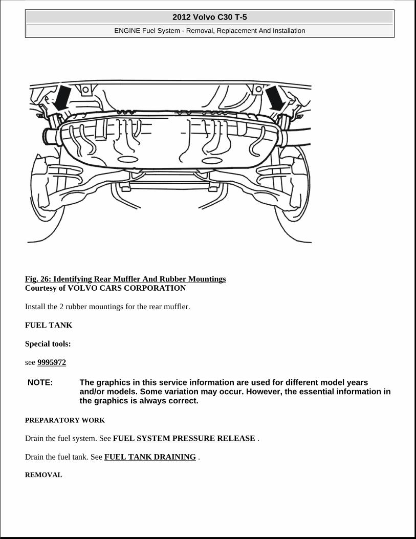
Fig. 26: Identifying Rear Muffler And Rubber Mountings Courtesy of VOLVO CARS CORPORATION
Install the 2 rubber mountings for the rear muffler.
FUEL TANK
Special tools:
see 9995972
PREPARATORY WORK
Drain the fuel system. See FUEL SYSTEM PRESSURE RELEASE .
Drain the fuel tank. See FUEL TANK DRAINING .
REMOVAL
NOTE: The graphics in this service information are used for different model years and/or models. Some variation may occur. However, the essential information in the graphics is always correct.
2012 Volvo C30 T-5
ENGINE Fuel System - Removal, Replacement And Installation
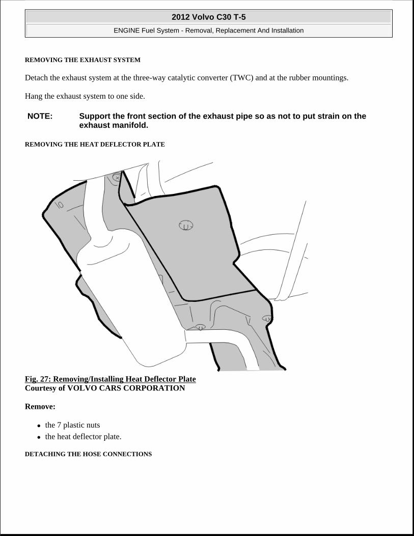
REMOVING THE EXHAUST SYSTEM
Detach the exhaust system at the three-way catalytic converter (TWC) and at the rubber mountings.
Hang the exhaust system to one side.
REMOVING THE HEAT DEFLECTOR PLATE
Fig. 27: Removing/Installing Heat Deflector Plate Courtesy of VOLVO CARS CORPORATION
Remove:
the 7 plastic nuts
the heat deflector plate.
DETACHING THE HOSE CONNECTIONS
NOTE: Support the front section of the exhaust pipe so as not to put strain on the exhaust manifold.
2012 Volvo C30 T-5
ENGINE Fuel System - Removal, Replacement And Installation

Fig. 28: Removing Hoses Courtesy of VOLVO CARS CORPORATION
Remove:
the hose clamp for the evacuation pipe at the fuel tank
the hose clamp for the hose to the fuel filler pipe.
REMOVING THE CARBON FILTER CONTAINER
NOTE: Carefully detach the hose from the fuel filler pipe, there may be fuel left in the tank.
2012 Volvo C30 T-5
ENGINE Fuel System - Removal, Replacement And Installation

Fig. 29: Removing Carbon Canister Courtesy of VOLVO CARS CORPORATION
Remove:
the hose (1)
the 2 pipes, secured using quick-release connectors (2).
REMOVING THE FUEL TANK
2012 Volvo C30 T-5
ENGINE Fuel System - Removal, Replacement And Installation

Fig. 30: Supporting Fuel Tank With Mobile Jack Courtesy of VOLVO CARS CORPORATION
Install a mobile jack with fixture see 9995972 under the fuel tank.
Disconnect the fuel connection (1).
Remove the screws for the fuel tank straps, x 3.
Remove the tank retaining straps. Lower the tank slightly.
Disconnect the level sensor connector.
Lower the tank.
REMOVING THE FUEL PUMP (FP)
Remove:
the fuel connection for the fuel pump (FP)
the fuel pump (FP). See FUEL PUMP AND LEVEL SENSOR UNIT.
INSTALLATION
2012 Volvo C30 T-5
ENGINE Fuel System - Removal, Replacement And Installation

INSTALLING THE FUEL PUMP (FP)
Install:
the fuel pump (FP). See FUEL PUMP AND LEVEL SENSOR UNIT.
the fuel connection for the fuel pump (FP).
INSTALLING THE FUEL TANK
Place the tank on the mobile jack together with fixture: see 9995972 .
Raise the tank so that it is 30 cm from the top.
Connect the connector for the level sensor.
Lift up the fuel tank.
Install:
the tank retaining straps. Use the 3 x M8 screws
the fuel connection.
INSTALLING THE HOSE CONNECTORS
Install:
the hose clamp for the evacuation pipe at the fuel tank
the hose clamp on the hose for the fuel filler pipe.
INSTALLING THE CARBON FILTER CONTAINER
2012 Volvo C30 T-5
ENGINE Fuel System - Removal, Replacement And Installation

Fig. 31: Removing Carbon Canister Courtesy of VOLVO CARS CORPORATION
Install:
the hose
the 2 pipes, secured using quick-release connectors.
INSTALLING THE HEAT DEFLECTOR PLATE
Install:
the 7 plastic nuts
the heat deflector plate.
INSTALLING THE EXHAUST SYSTEM
Install:
NOTE: To ensure that there is no exhaust leakage, see FLANGED JOINT, ASSEMBLING .
2012 Volvo C30 T-5
ENGINE Fuel System - Removal, Replacement And Installation

the rubber mountings.
FINISHING
Top up the fuel.
Install the fuse for the fuel pump (FP).
LEAK DIAGNOSTIC PUMP (B5244S4; 2007-10, B5254T7; 2008-12)
Special tools:
see 9985972
see 9995972
PREPARATORY WORK
REMOVING THE SHOCK ABSORBER
NOTE: As the graphics in this service information are used for different model years and / or models, some variation may occur. However, the essential information in the graphics is always correct.
2012 Volvo C30 T-5
ENGINE Fuel System - Removal, Replacement And Installation

Fig. 32: Identifying Lower Shock Mounting Courtesy of VOLVO CARS CORPORATION
Remove the following on both sides:
1 screw
the shock absorber from the lateral link.
LOWERING THE SUB-FRAME
2012 Volvo C30 T-5
ENGINE Fuel System - Removal, Replacement And Installation

Fig. 33: Supporting Subframe With Mobile Jack (9985972) Courtesy of VOLVO CARS CORPORATION
Use mobile jack: see 9985972 and see 9995972 . Position the mobile jack against the sub-frame.
Pull the brake hose out of its bracket on both sides
Remove the screw on both sides
NOTE: Ensure that no cables/hoses are loaded or trapped when lowering the sub-frame.
2012 Volvo C30 T-5
ENGINE Fuel System - Removal, Replacement And Installation
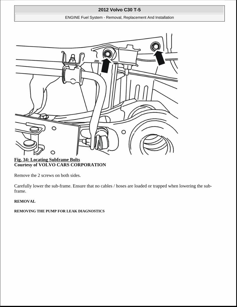
Fig. 34: Locating Subframe Bolts Courtesy of VOLVO CARS CORPORATION
Remove the 2 screws on both sides.
Carefully lower the sub-frame. Ensure that no cables / hoses are loaded or trapped when lowering the sub-frame.
REMOVAL
REMOVING THE PUMP FOR LEAK DIAGNOSTICS
2012 Volvo C30 T-5
ENGINE Fuel System - Removal, Replacement And Installation

Fig. 35: View Of Leak Detection Pump Courtesy of VOLVO CARS CORPORATION
Remove:
the M6 screw securing the pump mounting to the sub-frame
the connector (1) from the pump
the hose from the carbon filter container
the pump for leak diagnostics.
TRANSFERRING THE BRACKET
2012 Volvo C30 T-5
ENGINE Fuel System - Removal, Replacement And Installation

Fig. 36: Transferring Bracket Courtesy of VOLVO CARS CORPORATION
Remove:
the hose
the 3 screws
the bracket.
INSTALLATION
INSTALLING THE PUMP FOR LEAK DIAGNOSTICS
NOTE: For tightening torques, see TIGHTENING TORQUE .
2012 Volvo C30 T-5
ENGINE Fuel System - Removal, Replacement And Installation
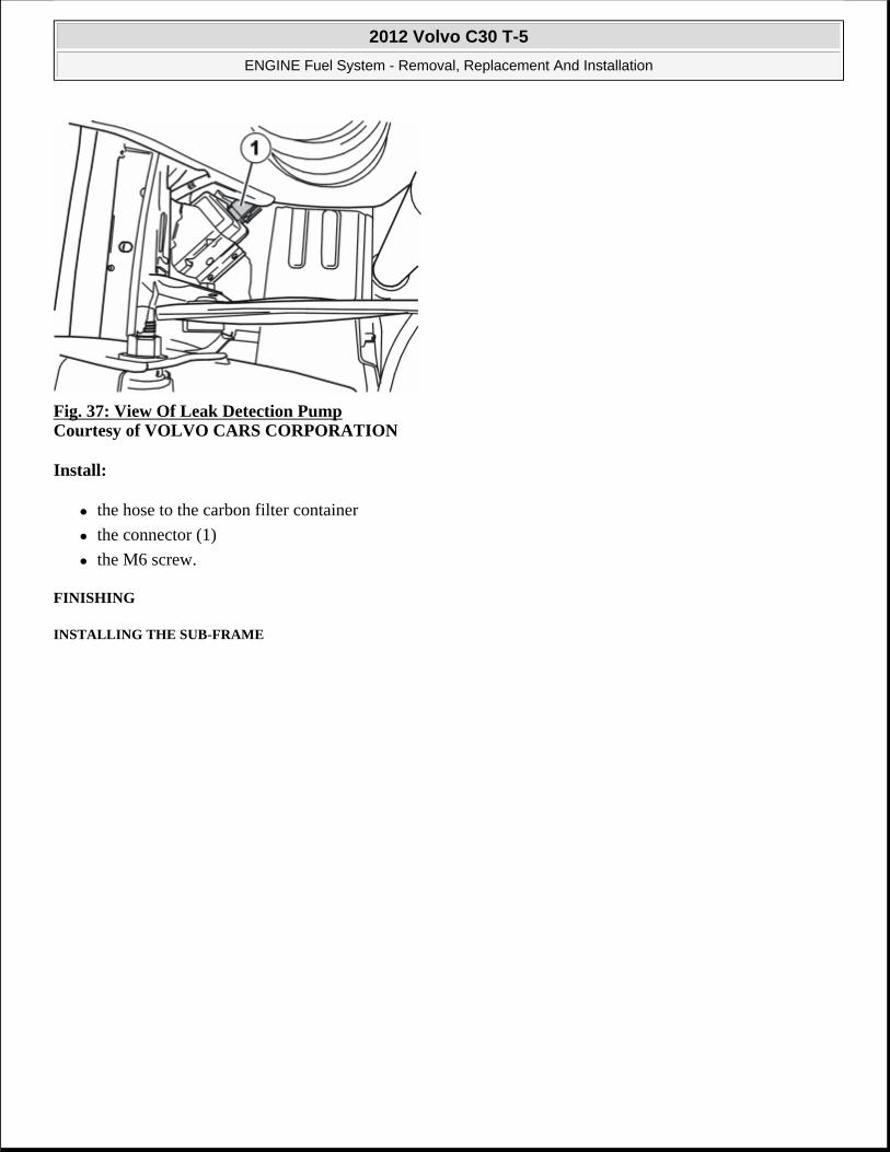
Fig. 37: View Of Leak Detection Pump Courtesy of VOLVO CARS CORPORATION
Install:
the hose to the carbon filter container
the connector (1)
the M6 screw.
FINISHING
INSTALLING THE SUB-FRAME
2012 Volvo C30 T-5
ENGINE Fuel System - Removal, Replacement And Installation

Fig. 38: Locating Subframe Bolts Courtesy of VOLVO CARS CORPORATION
Lift up the sub-frame. Ensure that the locating pins engage in their holes in the bodywork.
Install the 2 screws on both sides. Tighten. See TIGHTENING TORQUE .
NOTE: Ensure that no cables/hoses are loaded or trapped when installing the sub-frame.
2012 Volvo C30 T-5
ENGINE Fuel System - Removal, Replacement And Installation

Fig. 39: Supporting Subframe With Mobile Jack (9985972) Courtesy of VOLVO CARS CORPORATION
Install the screw on both sides. Tighten. See TIGHTENING TORQUE .
Remove the lifting table.
INSTALLING THE SHOCK ABSORBER
2012 Volvo C30 T-5
ENGINE Fuel System - Removal, Replacement And Installation

Fig. 40: Identifying Lower Shock Mounting Courtesy of VOLVO CARS CORPORATION
Install on both sides:
the shock absorber
the screw. Tighten. See TIGHTENING TORQUE .
the brake hose in its bracket on both sides.
INJECTOR AND DELIVERY PIPE
FUEL INJECTOR (B5244S4; 2007-10)
REMOVAL
Drain depressurizing fuel system. See FUEL SYSTEM PRESSURE RELEASE
NOTE: Removal steps in this procedure may contain installation details.
2012 Volvo C30 T-5
ENGINE Fuel System - Removal, Replacement And Installation

Fig. 41: Identifying Air Intake Hose Clamp And Electrical Connector With Cable Clamp Courtesy of VOLVO CARS CORPORATION
Fig. 42: Identifying Intake Plenum and Bolts Courtesy of VOLVO CARS CORPORATION
Torque: M6
10 Nm
2012 Volvo C30 T-5
ENGINE Fuel System - Removal, Replacement And Installation

Fig. 43: Moving Plenum Out Of Way Courtesy of VOLVO CARS CORPORATION
Fig. 44: Sealing Off Openings Courtesy of VOLVO CARS CORPORATION
CAUTION: Make sure that all openings are sealed. Use new blanking caps.
2012 Volvo C30 T-5
ENGINE Fuel System - Removal, Replacement And Installation

Fig. 45: Identifying Engine Cover End Piece And Screws Courtesy of VOLVO CARS CORPORATION
Torque: M7
17 Nm
Fig. 46: Removing/Installing Injector Connectors Courtesy of VOLVO CARS CORPORATION
2012 Volvo C30 T-5
ENGINE Fuel System - Removal, Replacement And Installation

Fig. 47: Remove/Install Injector Rail Bolts Courtesy of VOLVO CARS CORPORATION
Torque: M6
10 Nm
Fig. 48: Clear Away Dirt and Remove Injector Assembly Courtesy of VOLVO CARS CORPORATION
NOTE: Use suitable paper to absorb any escaping fluid.
2012 Volvo C30 T-5
ENGINE Fuel System - Removal, Replacement And Installation

Fig. 49: Identifying Bolts and Retaining Plate Courtesy of VOLVO CARS CORPORATION
Torque: M6
10 Nm
INSTALLATION
To install, reverse the removal procedure.
FUEL INJECTOR (B5254T3; 2007-08, B5254T7; 2008-12)
REMOVAL
Drain depressurising fuel system. See FUEL SYSTEM PRESSURE RELEASE
Remove the air filter housing. See AIR CLEANER HOUSING
NOTE: Removal steps in this procedure may contain installation details.
2012 Volvo C30 T-5
ENGINE Fuel System - Removal, Replacement And Installation

Fig. 50: Identifying Engine Cover And Screws Courtesy of VOLVO CARS CORPORATION
Torque: M6
10 Nm
Fig. 51: Removing/Installing Timing Belt Cover Courtesy of VOLVO CARS CORPORATION
Torque: M6
10 Nm
2012 Volvo C30 T-5
ENGINE Fuel System - Removal, Replacement And Installation

Fig. 52: Remove/Install Inlet Tube Courtesy of VOLVO CARS CORPORATION
Fig. 53: View Of Fuel Delivery Pipe Courtesy of VOLVO CARS CORPORATION
Fig. 54: View Of Throttle Control Harness Connector
2012 Volvo C30 T-5
ENGINE Fuel System - Removal, Replacement And Installation

Fig. 55: View of Intake Plenum, Underside Courtesy of VOLVO CARS CORPORATION
Torque: M7
17 Nm
Fig. 56: View Of Injector Harness And Fuel Rail Bolts Courtesy of VOLVO CARS CORPORATION
NOTE: Make sure that the mating faces are clean and free of foreign material.
2012 Volvo C30 T-5
ENGINE Fuel System - Removal, Replacement And Installation

Fig. 57: Identifying Bolts And Retaining Plate Courtesy of VOLVO CARS CORPORATION
Torque: M6
10 Nm
INSTALLATION
To install, reverse the removal procedure.
CONTROL SYSTEM
MASS AIR FLOW (MAF) SENSOR (B5244S4; 2007-10)
REMOVAL AND INSTALLATION
Fig. 58: Viewing Mass Air Flow (MAF) Sensor and Connector Courtesy of VOLVO CARS CORPORATION
2012 Volvo C30 T-5
ENGINE Fuel System - Removal, Replacement And Installation

MASS AIR FLOW (MAF) SENSOR (B5254T3; 2007-08, B5254T7; 2008-12)
REMOVAL
Fig. 59: Identifying Air Intake Hoses And Fasteners Courtesy of VOLVO CARS CORPORATION
Torque: M6
10 Nm
Fig. 60: Remove/Install Vent Tube Courtesy of VOLVO CARS CORPORATION
NOTE: Removal steps in this procedure may contain installation details.
2012 Volvo C30 T-5
ENGINE Fuel System - Removal, Replacement And Installation

Fig. 61: Viewing Mass Air Flow Sensor Courtesy of VOLVO CARS CORPORATION
INSTALLATION
To install, reverse the removal procedure.
2012 Volvo C30 T-5
ENGINE Fuel System - Removal, Replacement And Installation

ACCESSORIES AND BODY, CAB
Lighting - Component Location
COMPONENT LOCATION, HEADLAMP CONTROL MODULE (HCM)
LOCATION OF COMPONENTS
Fig. 1: Locating Headlamp Control Module Components Courtesy of VOLVO CARS CORPORATION
Overview
1. Headlamp Control Module (HCM)
2. Left headlamp control unit (LHCU)
3. Right headlamp control unit (RHCU)
4. Front position sensor
5. Rear position sensor
COMPONENT POSITION, HEADLIGHT
COMPONENT POSITION
POSITION OF BULBS
2012 Volvo C30 T-5
ACCESSORIES AND BODY, CAB Lighting - Component Location
2012 Volvo C30 T-5
ACCESSORIES AND BODY, CAB Lighting - Component Location

Fig. 2: Locating Bulbs Courtesy of VOLVO CARS CORPORATION
1. Low beam
2. High beam
3. Parking lights
4. Direction indicators.
5. Side marker lights
LIGHTING, FRONT
COMPONENT POSITION HEADLIGHTS (2007)
LOCATION OF COMPONENTS
2012 Volvo C30 T-5
ACCESSORIES AND BODY, CAB Lighting - Component Location

Fig. 3: Locating Headlight Components Courtesy of VOLVO CARS CORPORATION
1. side running lights
2. direction indicator
3. Dipped beam
4. Parking lights
5. High beam.
COMPONENT POSITION HEADLIGHTS (2008-2009)
LOCATION OF COMPONENTS
2012 Volvo C30 T-5
ACCESSORIES AND BODY, CAB Lighting - Component Location

Fig. 4: Identifying Early Version Headlight ComponentsCourtesy of VOLVO CARS CORPORATION
1. Dipped beam
2. High beam.
3. Parking lights
4. direction indicator
5. direction indicator
COMPONENT POSITION HEADLIGHTS (2010-2012)
LOCATION OF COMPONENTS
VEHICLES EARLY VERSION
Fig. 5: Identifying Early Version Headlight Components Courtesy of VOLVO CARS CORPORATION
1. Dipped beam
2. High beam.
3. Parking lights
4. direction indicator
5. direction indicator
VEHICLES LATE VERSION
2012 Volvo C30 T-5
ACCESSORIES AND BODY, CAB Lighting - Component Location

Fig. 6: Identifying Late Version Headlight Components Courtesy of VOLVO CARS CORPORATION
1. side running lights
2. direction indicator
3. Dipped beam
4. High beam.
5. Parking lights
LOCATION OF COMPONENTS, HEADLIGHTS (BI-XENON) (2010-2012)
LOCATION OF COMPONENTS
VEHICLES EARLY VERSION
2012 Volvo C30 T-5
ACCESSORIES AND BODY, CAB Lighting - Component Location

Fig. 7: Identifying Early Version Headlight Components Courtesy of VOLVO CARS CORPORATION
1. Dipped beam
2. High beam.
3. Parking lights
4. direction indicator
5. direction indicator
VEHICLES LATE VERSION
2012 Volvo C30 T-5
ACCESSORIES AND BODY, CAB Lighting - Component Location

Fig. 8: Identifying Headlights (Bi-Xenon) Components Courtesy of VOLVO CARS CORPORATION
1. side running lights
2. direction indicator
3. Dipped beam
4. High beam.
5. Parking lights
LIGHTING, REAR
LOCATION OF COMPONENTS, TAIL LAMP.
LOCATION OF COMPONENTS
2012 Volvo C30 T-5
ACCESSORIES AND BODY, CAB Lighting - Component Location

Fig. 9: Identifying Tail Lamp Component Location Courtesy of VOLVO CARS CORPORATION
1. brake light
2. back-up light
3. fog lights
4. direction indicator
5. back-up light
LOCATION OF COMPONENTS, TAIL LAMP
COMPONENT POSITION
2012 Volvo C30 T-5
ACCESSORIES AND BODY, CAB Lighting - Component Location

Fig. 10: Identifying Tail Lamp Component Location Courtesy of VOLVO CARS CORPORATION
1. Brake light
2. Tail lamps
3. Rear fog light
4. Turn signal lamps
5. Back-up (reversing) lamps
NOTE: A fog tail lamp bulb is only used in the left tail lamp.
2012 Volvo C30 T-5
ACCESSORIES AND BODY, CAB Lighting - Component Location

ACCESSORIES AND EQUIPMENT
Exterior Trim, Glass, Weatherstrips - Overhaul Instructions
HEATED WINDOW GRID WIRE
RECONDITIONING
Fig. 1: Identifying Heated Window Grid Wire Measurements Courtesy of VOLVO CARS CORPORATION
Materials Designation Part Number Window cleaner -Conductive paint 1161441
NOTE: If the specified value is exceeded, a new component must be installed.
2012 Volvo C30 T-5
ACCESSORIES AND EQUIPMENT Exterior Trim, Glass, Weatherstrips - Overhaul Instructions
2012 Volvo C30 T-5
ACCESSORIES AND EQUIPMENT Exterior Trim, Glass, Weatherstrips - Overhaul Instructions

Fig. 2: Cleaning Heated Window Grid Wire Courtesy of VOLVO CARS CORPORATION
Use: Window cleaner,
Fig. 3: Identifying Repair Tape Courtesy of VOLVO CARS CORPORATION
Use: Conductive paint, 1161441
2012 Volvo C30 T-5
ACCESSORIES AND EQUIPMENT Exterior Trim, Glass, Weatherstrips - Overhaul Instructions

Fig. 4: Shake Conductive Paint At Least One Minute Courtesy of VOLVO CARS CORPORATION
Fig. 5: Reconditioning Heated Window Grid Wire Courtesy of VOLVO CARS CORPORATION
Use: Conductive paint, 1161441
2012 Volvo C30 T-5
ACCESSORIES AND EQUIPMENT Exterior Trim, Glass, Weatherstrips - Overhaul Instructions

Fig. 6: Identifying Repair Tape Removal Courtesy of VOLVO CARS CORPORATION
Fig. 7: Identifying Wire Repair Precaution Courtesy of VOLVO CARS CORPORATION
2012 Volvo C30 T-5
ACCESSORIES AND EQUIPMENT Exterior Trim, Glass, Weatherstrips - Overhaul Instructions
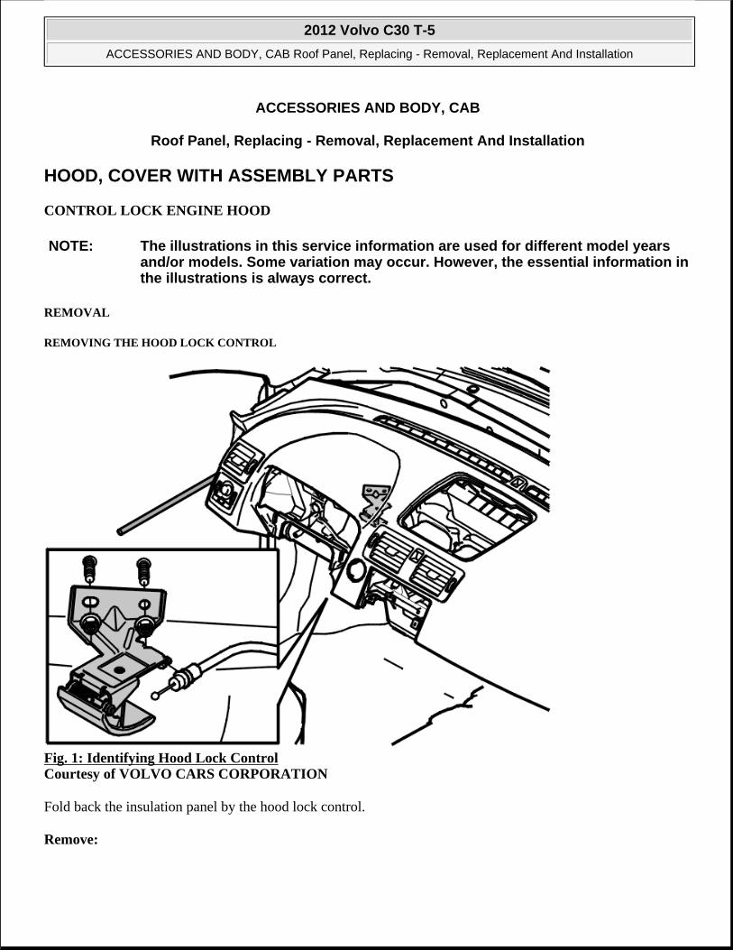
ACCESSORIES AND BODY, CAB
Roof Panel, Replacing - Removal, Replacement And Installation
HOOD, COVER WITH ASSEMBLY PARTS
CONTROL LOCK ENGINE HOOD
REMOVAL
REMOVING THE HOOD LOCK CONTROL
Fig. 1: Identifying Hood Lock Control Courtesy of VOLVO CARS CORPORATION
Fold back the insulation panel by the hood lock control.
Remove:
NOTE: The illustrations in this service information are used for different model years and/or models. Some variation may occur. However, the essential information in the illustrations is always correct.
2012 Volvo C30 T-5
ACCESSORIES AND BODY, CAB Roof Panel, Replacing - Removal, Replacement And Installation
2012 Volvo C30 T-5
ACCESSORIES AND BODY, CAB Roof Panel, Replacing - Removal, Replacement And Installation

the 2 nuts
the mechanical cable from the control
control.
INSTALLATION
INSTALLING THE HOOD LOCK CONTROL
Install:
the control
the cable
2 M6 nuts. Tighten.
Ensure that the insulation panel is in the correct position.
Check the function of the control.
DOOR LATCH HOOD
REMOVAL
REMOVING HOOD CATCH
NOTE: For tightening torques, see: TIGHTENING TORQUE .
NOTE: The illustrations in this service information are used for different model years and/or models. Some variation may occur. However, the essential information in the illustrations is always correct
2012 Volvo C30 T-5
ACCESSORIES AND BODY, CAB Roof Panel, Replacing - Removal, Replacement And Installation

Fig. 2: Identifying Air Intake Screws Courtesy of VOLVO CARS CORPORATION
Open the hood.
Remove:
the bumper cover. See: BUMPERS AND MUDFLAPS
the 2 screws on the air intake
the air intake. Pull the air intake away from the upper mounting. Then bend the air intake upwards.
2012 Volvo C30 T-5
ACCESSORIES AND BODY, CAB Roof Panel, Replacing - Removal, Replacement And Installation

Fig. 3: Identifying Engine Compartment Panel Screws Courtesy of VOLVO CARS CORPORATION
Remove:
the 2 screws holding the engine compartment panel
the engine compartment panel.
2012 Volvo C30 T-5
ACCESSORIES AND BODY, CAB Roof Panel, Replacing - Removal, Replacement And Installation

Fig. 4: Identifying Airtight Seal Nuts Courtesy of VOLVO CARS CORPORATION
Remove the 3 nuts holding the airtight seal.
Fold the airtight seal down.
2012 Volvo C30 T-5
ACCESSORIES AND BODY, CAB Roof Panel, Replacing - Removal, Replacement And Installation

Fig. 5: Identifying Hood Catch Screws Courtesy of VOLVO CARS CORPORATION
Remove the 2 screws holding the hood catch.
2012 Volvo C30 T-5
ACCESSORIES AND BODY, CAB Roof Panel, Replacing - Removal, Replacement And Installation

Fig. 6: View Of Hood Catch And Cable Courtesy of VOLVO CARS CORPORATION
Disconnect the connector.
Unhook the cable and remove the hood catch.
INSTALLATION
INSTALLING HOOD CATCH
Install:
the hood catch and the 2 M8 screws. Tighten
the connector
the cable on the hood catch
the airtight seal and the 3 plastic nuts. Tighten
the engine compartment panel together with the 2 M6 screws. Tighten
the air intake together with the 2 M6 screws. Tighten
NOTE: For tightening torques, see TIGHTENING TORQUE
2012 Volvo C30 T-5
ACCESSORIES AND BODY, CAB Roof Panel, Replacing - Removal, Replacement And Installation

the bumper cover. See: BUMPERS AND MUDFLAPS
HOOD HINGE
REMOVAL
REMOVING HINGES HOOD
Fig. 7: Identifying Front Fender Screws Courtesy of VOLVO CARS CORPORATION
Remove:
the hood
the 4 M6 screws at the top edge of the front fender.
Carefully bend in the fender to access the 2 hinge screws.
NOTE: The illustrations in this service information are used for different model years and/or models. Some variation may occur. However, the essential information in the illustrations is always correct.
2012 Volvo C30 T-5
ACCESSORIES AND BODY, CAB Roof Panel, Replacing - Removal, Replacement And Installation

Remove the 2 M8 screws and remove the hinge.
INSTALLATION
INSTALLING HINGES HOOD
Fig. 8: Identifying Hood Hinges Courtesy of VOLVO CARS CORPORATION
Install:
the hinge together with the 2 M8 screws. Tighten
the front fender using the 4 M6 screws. Tighten
the hood.
HOOD INSULATION
REMOVAL AND INSTALLATION
NOTE: For tightening torques, see: TIGHTENING TORQUE
2012 Volvo C30 T-5
ACCESSORIES AND BODY, CAB Roof Panel, Replacing - Removal, Replacement And Installation

Fig. 9: Identifying Hood Insulation Courtesy of VOLVO CARS CORPORATION
WIRE LOCK ENGINE HOOD
REMOVAL
REMOVING THE MECHANICAL CABLE
NOTE: The illustrations in this service information are used for different model years and/or models. Some variation may occur. However, the essential information in the illustrations is always correct.
2012 Volvo C30 T-5
ACCESSORIES AND BODY, CAB Roof Panel, Replacing - Removal, Replacement And Installation

Fig. 10: Removing Mechanical Cable Courtesy of VOLVO CARS CORPORATION
Remove:
the 2 screws for the cover above the hood latch
the cover.
Unhook the mechanical cable at the hood catch.
2012 Volvo C30 T-5
ACCESSORIES AND BODY, CAB Roof Panel, Replacing - Removal, Replacement And Installation

Fig. 11: Identifying Mechanical Cable At The Hood Catch Courtesy of VOLVO CARS CORPORATION
Remove the soundproofing panel on the driver's side in accordance with: INSTRUMENT PANEL LOWER .
Unhook the cable from the hood catch mechanism.
2012 Volvo C30 T-5
ACCESSORIES AND BODY, CAB Roof Panel, Replacing - Removal, Replacement And Installation

Fig. 12: Identifying Brake Fluid Reservoir Protective Cover Courtesy of VOLVO CARS CORPORATION
Remove:
the battery. See: BATTERY
the 3 M6 screws for the bottom of the battery box. Remove the battery box
the connector
the 2 clips securing the plastic cover in front of the power brake booster. Carefully fold the plastic cover forwards.
Remove the cable.
INSTALLATION
INSTALLING THE MECHANICAL CABLE
Insert the mechanical cable as noted previously.
NOTE: Note the routing of the wire.
NOTE: For tightening torques, see: TIGHTENING TORQUE .
2012 Volvo C30 T-5
ACCESSORIES AND BODY, CAB Roof Panel, Replacing - Removal, Replacement And Installation

Hook the mechanical cable into the hood catch and the hood catch control.
Install:
the soundproofing panel on the driver's side. See: INSTRUMENT PANEL LOWER
the 2 clips
the bottom of the battery box
the connector
the 3 M6 screws. Tighten
the battery. See: BATTERY
the cover over the hood catch using the 2 screws.
HINT: Test the function before closing the hood.
RADIATOR GRILLE
PLENUM CHAMBER
REMOVAL
REMOVING THE PLENUM CHAMBER
Fig. 13: Identifying Cowl Clips Courtesy of VOLVO CARS CORPORATION
Remove:
NOTE: The illustrations in this service information are used for different model years and/or models. Some variation may occur. However, the essential information in the illustrations is always correct.
2012 Volvo C30 T-5
ACCESSORIES AND BODY, CAB Roof Panel, Replacing - Removal, Replacement And Installation

the windshield wipers. See WIPER ARM
the 4 clips
Press the center pin down onto the clips.
Turn the 2 catches (1) anti-clockwise 1/4 turn.
Lift out the cowl.
REMOVING THE SPLASH GUARD
Fig. 14: Remove Old Protective Cover Under Cowl Courtesy of VOLVO CARS CORPORATION
Remove the old protective cover from under the cowl using a screwdriver or similar.
Fig. 15: Identifying Protective Cover's Plastic Welds Courtesy of VOLVO CARS CORPORATION
2012 Volvo C30 T-5
ACCESSORIES AND BODY, CAB Roof Panel, Replacing - Removal, Replacement And Installation

Remove the remains from the protective covers plastic welds using a small chisel.
INSTALLATION
INSTALLING BUTYL TAPE
Fig. 16: Installing Butyl Tape Courtesy of VOLVO CARS CORPORATION
Apply butyl tape to the protective cover. Press the tape out slightly before securing to the vehicle.
INSTALLING PROTECTIVE COVER
Fig. 17: Installing Protective Cover Courtesy of VOLVO CARS CORPORATION
Install the protective cover by sliding it towards and under the windshield (1).
Press the front edge of the protective cover firmly so that the butyl tape adheres to the plate (2).
2012 Volvo C30 T-5
ACCESSORIES AND BODY, CAB Roof Panel, Replacing - Removal, Replacement And Installation

INSTALLING THE PLENUM CHAMBER
Install the cowl in the correct position. Ensure that the rubber seals against the fenders and the windshield are correctly located. Check that the guide clips underneath the cowl are in the correct position in relation to the windshield.
Turn the 2 catches clockwise 1/4 turn. Check that the marking on the relevant catch is turned toward the windshield.
Install the 4 clips.
Fig. 18: Correctly Checking Cowl Position Courtesy of VOLVO CARS CORPORATION
Use a thin plastic film (transparent). Check that the cowl is correctly positioned against the windshield.
Install the windshield wipers. See WIPER ARM.
WIPER ARM
NOTE: Start with the outer clips.
CAUTION: To prevent water leaks, the corners of the plastic film must not be between the cowl and the windshield.
Special tools
981 4088 Puller Tool number: 981 4088 Tool description: Puller Tool boards: 80
2012 Volvo C30 T-5
ACCESSORIES AND BODY, CAB Roof Panel, Replacing - Removal, Replacement And Installation

REMOVAL
Fig. 19: Identifying Ignition In OFF Position Courtesy of VOLVO CARS CORPORATION
Fig. 20: Identifying Windshield Wiper Arm Screws Courtesy of VOLVO CARS CORPORATION
CAUTION: Make sure that the motor is in the park position.
2012 Volvo C30 T-5
ACCESSORIES AND BODY, CAB Roof Panel, Replacing - Removal, Replacement And Installation

Fig. 21: View Of Special Tool 9814088 Courtesy of VOLVO CARS CORPORATION
see 9814088
Fig. 22: View Of Windshield Wiper Arm Removal Courtesy of VOLVO CARS CORPORATION
INSTALLATION
2012 Volvo C30 T-5
ACCESSORIES AND BODY, CAB Roof Panel, Replacing - Removal, Replacement And Installation

Fig. 23: View Of Windshield Wiper Arm Position Courtesy of VOLVO CARS CORPORATION
Torque: Windshield wiper arm
30 Nm
RADIATOR GRILLE (2007-2009)
REMOVAL
Special tools
999 7390 Key Tool number: 999 7390 Tool description: Key Tool boards: 80
2012 Volvo C30 T-5
ACCESSORIES AND BODY, CAB Roof Panel, Replacing - Removal, Replacement And Installation
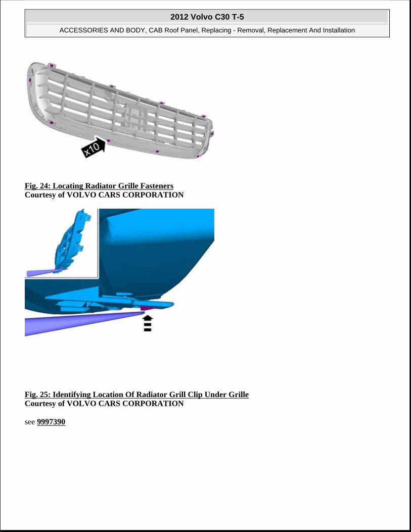
Fig. 24: Locating Radiator Grille Fasteners Courtesy of VOLVO CARS CORPORATION
Fig. 25: Identifying Location Of Radiator Grill Clip Under Grille Courtesy of VOLVO CARS CORPORATION
see 9997390
2012 Volvo C30 T-5
ACCESSORIES AND BODY, CAB Roof Panel, Replacing - Removal, Replacement And Installation

Fig. 26: Locating Radiator Grille Clip Area Courtesy of VOLVO CARS CORPORATION
CAUTION: Make sure that the components are protected.
2012 Volvo C30 T-5
ACCESSORIES AND BODY, CAB Roof Panel, Replacing - Removal, Replacement And Installation

Fig. 27: Removing Radiator Grill - 1 Of 8Courtesy of VOLVO CARS CORPORATION
Fig. 28: Removing Radiator Grill - 2 Of 8 Courtesy of VOLVO CARS CORPORATION
Fig. 29: Removing Radiator Grill - 3 Of 8
2012 Volvo C30 T-5
ACCESSORIES AND BODY, CAB Roof Panel, Replacing - Removal, Replacement And Installation

Courtesy of VOLVO CARS CORPORATION
Fig. 30: Removing Radiator Grille - 4 Of 8 Courtesy of VOLVO CARS CORPORATION
Fig. 31: Removing Radiator Grille - 5 Of 8 Courtesy of VOLVO CARS CORPORATION
2012 Volvo C30 T-5
ACCESSORIES AND BODY, CAB Roof Panel, Replacing - Removal, Replacement And Installation

Fig. 32: Removing Radiator Grille - 6 Of 8 Courtesy of VOLVO CARS CORPORATION
Fig. 33: Removing Radiator Grille - 7 Of 8 Courtesy of VOLVO CARS CORPORATION
2012 Volvo C30 T-5
ACCESSORIES AND BODY, CAB Roof Panel, Replacing - Removal, Replacement And Installation

Fig. 34: Removing Radiator Grille - 8 Of 8 Courtesy of VOLVO CARS CORPORATION
INSTALLATION
Fig. 35: Installation Of Radiator Grille Courtesy of VOLVO CARS CORPORATION
2012 Volvo C30 T-5
ACCESSORIES AND BODY, CAB Roof Panel, Replacing - Removal, Replacement And Installation

RADIATOR GRILLE (2010-2011 EARLY)
REMOVAL
Fig. 36: Locating Radiator Grille Fasteners Courtesy of VOLVO CARS CORPORATION
Special tools
999 7390 Key Tool number: 999 7390 Tool description: Key Tool boards: 80
2012 Volvo C30 T-5
ACCESSORIES AND BODY, CAB Roof Panel, Replacing - Removal, Replacement And Installation

Fig. 37: Removing Radiator Grille (1 Of 9) Courtesy of VOLVO CARS CORPORATION
CAUTION: Make sure that the components are protected.
2012 Volvo C30 T-5
ACCESSORIES AND BODY, CAB Roof Panel, Replacing - Removal, Replacement And Installation

Fig. 38: Removing Radiator Grille (2 Of 9)Courtesy of VOLVO CARS CORPORATION
see 9997390
Fig. 39: Removing Radiator Grille (3 Of 9) Courtesy of VOLVO CARS CORPORATION
2012 Volvo C30 T-5
ACCESSORIES AND BODY, CAB Roof Panel, Replacing - Removal, Replacement And Installation

Fig. 40: Removing Radiator Grille (4 Of 9) Courtesy of VOLVO CARS CORPORATION
Fig. 41: Removing Radiator Grille (5 Of 9) Courtesy of VOLVO CARS CORPORATION
2012 Volvo C30 T-5
ACCESSORIES AND BODY, CAB Roof Panel, Replacing - Removal, Replacement And Installation

Fig. 42: Removing Radiator Grille (6 Of 9) Courtesy of VOLVO CARS CORPORATION
Fig. 43: Removing Radiator Grille (7 Of 9) Courtesy of VOLVO CARS CORPORATION
2012 Volvo C30 T-5
ACCESSORIES AND BODY, CAB Roof Panel, Replacing - Removal, Replacement And Installation

Fig. 44: Removing Radiator Grille (8 Of 9) Courtesy of VOLVO CARS CORPORATION
Fig. 45: Removing Radiator Grille (9 Of 9) Courtesy of VOLVO CARS CORPORATION
2012 Volvo C30 T-5
ACCESSORIES AND BODY, CAB Roof Panel, Replacing - Removal, Replacement And Installation

Fig. 46: Removing Radiator Grille Emblem Courtesy of VOLVO CARS CORPORATION
INSTALLATION
To install, reverse the removal procedure.
RADIATOR GRILLE (2011 LATE-2012)
REMOVAL
Remove casing bumper front, see COVER BUMPER FRONT
2012 Volvo C30 T-5
ACCESSORIES AND BODY, CAB Roof Panel, Replacing - Removal, Replacement And Installation

Fig. 47: Identifying Radiator Grille ClipsCourtesy of VOLVO CARS CORPORATION
Fig. 48: Identifying Direction To Remove Radiator Grille Courtesy of VOLVO CARS CORPORATION
Fig. 49: Identifying Emblem Interlocking Clips Courtesy of VOLVO CARS CORPORATION
INSTALLATION
To install, reverse the removal procedure.
FRONT SECTION
2012 Volvo C30 T-5
ACCESSORIES AND BODY, CAB Roof Panel, Replacing - Removal, Replacement And Installation

FRONT END
FRONT END
REMOVAL
REMOVING THE FRONT SECTION
Fig. 50: Identifying Front Section Screws Courtesy of VOLVO CARS CORPORATION
Remove:
the headlights
the bumper. See: COVER BUMPER FRONT (2011 LATE - 2012)
the washer jets on the left and right side
the cover plate
the air guides
hood catch cable
hood catch
radiator mounting
power steering fluid reservoir
Disconnect:
2 impact sensors
NOTE: The illustrations in this service information are used for different model years and/or models. Some variation may occur. However, the essential information in the illustrations is always correct.
2012 Volvo C30 T-5
ACCESSORIES AND BODY, CAB Roof Panel, Replacing - Removal, Replacement And Installation
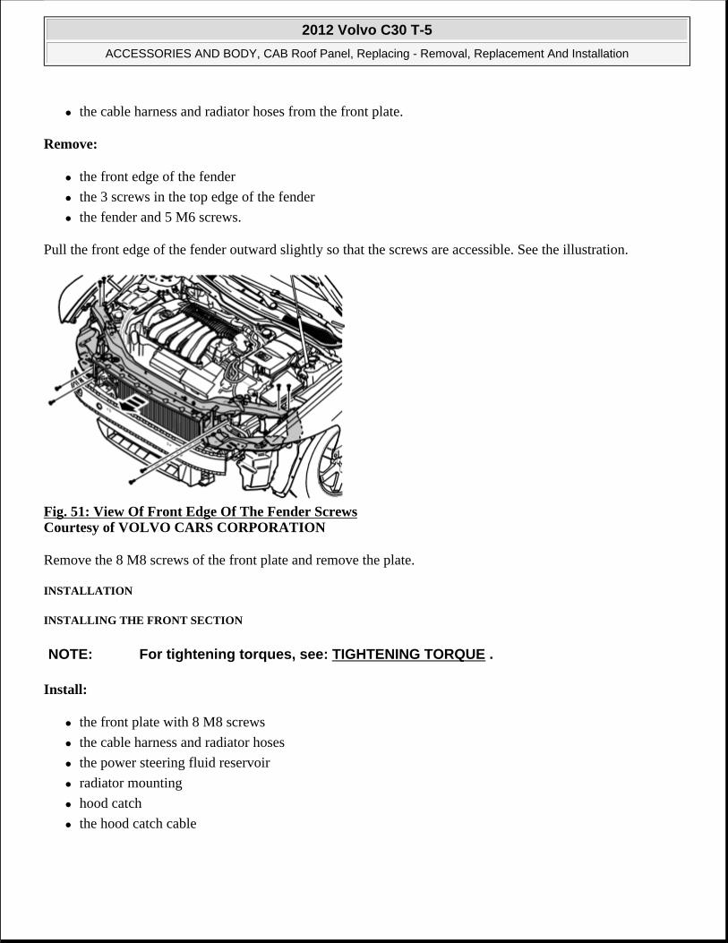
the cable harness and radiator hoses from the front plate.
Remove:
the front edge of the fender
the 3 screws in the top edge of the fender
the fender and 5 M6 screws.
Pull the front edge of the fender outward slightly so that the screws are accessible. See the illustration.
Fig. 51: View Of Front Edge Of The Fender Screws Courtesy of VOLVO CARS CORPORATION
Remove the 8 M8 screws of the front plate and remove the plate.
INSTALLATION
INSTALLING THE FRONT SECTION
Install:
the front plate with 8 M8 screws
the cable harness and radiator hoses
the power steering fluid reservoir
radiator mounting
hood catch
the hood catch cable
NOTE: For tightening torques, see: TIGHTENING TORQUE .
2012 Volvo C30 T-5
ACCESSORIES AND BODY, CAB Roof Panel, Replacing - Removal, Replacement And Installation

Check that the hood catch engages and disengages.
Install:
2 impact sensors
the air guides
the cover plate
2 washer jets.
Adjust the front fenders and screw them into place.
Install:
the headlights
the bumper. See COVER BUMPER FRONT (2007 - 2011 EARLY) or COVER BUMPER FRONT (2011 LATE - 2012) .
BRACKET FRONT PIECE (2012)
REMOVAL
REMOVING FRONT SIDE PANEL
NOTE: The illustrations in this service information are used for different model years and/or models. Some variation may occur. However, the essential information in the illustrations is always correct.
2012 Volvo C30 T-5
ACCESSORIES AND BODY, CAB Roof Panel, Replacing - Removal, Replacement And Installation

Fig. 52: Removing Front Side Panel Courtesy of VOLVO CARS CORPORATION
Remove components. See: FRONT SECTION, EXPOSING .
Remove the welds using a drill.
Grind clean.
Apply welding primer.
INSTALLATION
INSTALLING FRONT SIDE PANEL
Spot-weld the front side panel. Tip diameter: 4.5 mm.
When welding body components, see: WELDING, GENERAL (2007-2011) or WELDING, GENERAL (2012) .
Rust-proof. See: RUSTPROOFING .
Install components. See: FRONT SECTION, EXPOSING .
2012 Volvo C30 T-5
ACCESSORIES AND BODY, CAB Roof Panel, Replacing - Removal, Replacement And Installation

FRONT MUDGUARD
FENDER (2007-2011 EARLY)
REMOVAL
Remove fender widener front, see FRONT FENDER WIDENER
Fig. 53: Identifying Wheel Arch Lining Retaining Clips Courtesy of VOLVO CARS CORPORATION
Fig. 54: Identifying M10 Bolts Courtesy of VOLVO CARS CORPORATION
NOTE: Removal steps in this procedure may contain installation details.
2012 Volvo C30 T-5
ACCESSORIES AND BODY, CAB Roof Panel, Replacing - Removal, Replacement And Installation

Fig. 55: Removing Bumper And Rocker Courtesy of VOLVO CARS CORPORATION
Fig. 56: View Of Wheel Arc Screws Courtesy of VOLVO CARS CORPORATION
Fig. 57: Locating Fender Screws
2012 Volvo C30 T-5
ACCESSORIES AND BODY, CAB Roof Panel, Replacing - Removal, Replacement And Installation

Torque: M6
10 Nm
INSTALLATION
To install, reverse the removal procedure.
Follow the instructions regarding corrosion protection, see RUSTPROOFING
FENDER (2011 LATE - 2012)
REMOVAL
Remove fender widener front, see FRONT FENDER WIDENER
Fig. 58: Identifying Wheel Arch Lining Retaining Clips (1 of 2) Courtesy of VOLVO CARS CORPORATION
NOTE: Removal steps in this procedure may contain installation details.
2012 Volvo C30 T-5
ACCESSORIES AND BODY, CAB Roof Panel, Replacing - Removal, Replacement And Installation

Fig. 59: Identifying Wheel Arch Lining Retaining Clips (2 of 2) Courtesy of VOLVO CARS CORPORATION
Fig. 60: Identifying Removal Of Panels (1 Of 2) Courtesy of VOLVO CARS CORPORATION
2012 Volvo C30 T-5
ACCESSORIES AND BODY, CAB Roof Panel, Replacing - Removal, Replacement And Installation

Fig. 61: Identifying Removal Of Panels (2 Of 2)Courtesy of VOLVO CARS CORPORATION
Fig. 62: Identifying Fender Panel Screws Courtesy of VOLVO CARS CORPORATION
Torque: M6
10 Nm
INSTALLATION
To install, reverse the removal procedure.
Follow the instructions regarding corrosion protection, see RUSTPROOFING
REAR MUDGUARD
FENDER
REMOVAL
Welding body components. See WELDING, GENERAL (2007-2011) or WELDING, GENERAL (2011-2012)
Remove the following items:
Materials: Designation Part number 2-component foam 3M 08463
NOTE: Removal steps in this procedure may contain installation details.
2012 Volvo C30 T-5
ACCESSORIES AND BODY, CAB Roof Panel, Replacing - Removal, Replacement And Installation

side section. See SIDE SECTION, EXPOSING
rear section. See REAR SECTION, EXPOSING (2007-2009) or REAR SECTION, EXPOSING (2010-2012)
Determine the extent of the damage on the body side. See BODY SIDE .
Determine the extent of the damage on the rear section. See REAR SECTION .
Fig. 63: 2-Component Foam, 3M 08463 Courtesy of VOLVO CARS CORPORATION
Attach the following items:
1. Use: 2-component foam, 3M 08463
2. Use: 2-component foam, 3M 08463
2012 Volvo C30 T-5
ACCESSORIES AND BODY, CAB Roof Panel, Replacing - Removal, Replacement And Installation

Fig. 64: Identifying Fender Cut Points Courtesy of VOLVO CARS CORPORATION
Seal fender. See BODY SEAL, SEALING DIAGRAM .
Rustproof fender. See RUSTPROOFING .
INSTALL
Install in reverse order.
2012 Volvo C30 T-5
ACCESSORIES AND BODY, CAB Roof Panel, Replacing - Removal, Replacement And Installation

BRAKES
Hydraulic-Vacuum-Hydraulic Brakes - Removal, Replacement And Installation
BRAKE PIPES AND CONNECTIONS (2007-09)
BRAKE LINES ABS UNIT/PIPE COUPLING REAR, REPLACING
PREPARATORY WORK
Fig. 1: Bleeding Brakes Courtesy of VOLVO CARS CORPORATION
Remove the wheel.
Secure the pedal in the depressed position. Use a pedal jack.
Remove the protective cap from the bleed nipple at the left front wheel.
NOTE: The graphics in this service information are used for different model years and/or models. Some variation may occur. However, the essential information in the graphics is always correct.
2012 Volvo C30 T-5
BRAKES Hydraulic-Vacuum-Hydraulic Brakes - Removal, Replacement And Installation
2012 Volvo C30 T-5
BRAKES Hydraulic-Vacuum-Hydraulic Brakes - Removal, Replacement And Installation

Install a plastic hose on the nipple. Open the bleed nipple.
Collect the brake fluid in a container.
Shut the bleed nipple.
REMOVAL
REMOVING THE BATTERY BOX
Fig. 2: Identifying Battery Box Courtesy of VOLVO CARS CORPORATION
Ignition off.
Remove:
the battery. See BATTERY
the 3 screws (1)
the battery box (2).
REMOVING SPLASH GUARDS
2012 Volvo C30 T-5
BRAKES Hydraulic-Vacuum-Hydraulic Brakes - Removal, Replacement And Installation

Fig. 3: Identifying Cowl Fasteners Courtesy of VOLVO CARS CORPORATION
Remove the 3 clips holding the cowl.
2012 Volvo C30 T-5
BRAKES Hydraulic-Vacuum-Hydraulic Brakes - Removal, Replacement And Installation

Fig. 4: Identifying Brake Fluid Reservoir Protective Cover Courtesy of VOLVO CARS CORPORATION
Carefully lift up the cowl. Remove the 2 clips for the protective cover.
Remove the protective cover over the brake fluid reservoir.
2012 Volvo C30 T-5
BRAKES Hydraulic-Vacuum-Hydraulic Brakes - Removal, Replacement And Installation
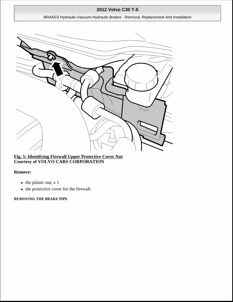
Fig. 5: Identifying Firewall Upper Protective Cover Nut Courtesy of VOLVO CARS CORPORATION
Remove:
the plastic nut, x 1
the protective cover for the firewall.
REMOVING THE BRAKE PIPE
2012 Volvo C30 T-5
BRAKES Hydraulic-Vacuum-Hydraulic Brakes - Removal, Replacement And Installation

Fig. 6: Identifying Protective Cover Courtesy of VOLVO CARS CORPORATION
Remove:
the two brake pipes from the ABS unit (1)
the two brake pipes from the front-rear brake pipe (2)
the brake pipe from the clips.
INSTALLATION
INSTALLING THE BRAKE PIPES
NOTE: Clean the brake pipe terminals. Place paper under the hydraulic modulator to avoid brake fluid spillage.
NOTE: For tightening torques, see TIGHTENING TORQUE .
2012 Volvo C30 T-5
BRAKES Hydraulic-Vacuum-Hydraulic Brakes - Removal, Replacement And Installation

Fig. 7: Identifying Protective Cover Courtesy of VOLVO CARS CORPORATION
Install:
the brake pipe (1). Tighten. See TIGHTENING TORQUE
the brake pipe (2). Tighten. See TIGHTENING TORQUE
the brake pipe in the clips.
BLEEDING BRAKE SYSTEMS
Remove the pedal jack.
Bleed the brake system. See BRAKE SYSTEM BLEEDING .
Check that the brake pipe connections are sealed.
Check the brake fluid level.
INSTALLING THE PROTECTIVE COVERS
2012 Volvo C30 T-5
BRAKES Hydraulic-Vacuum-Hydraulic Brakes - Removal, Replacement And Installation

Fig. 8: Identifying Firewall Upper Protective Cover Nut Courtesy of VOLVO CARS CORPORATION
Install:
the upper protective cover for the firewall
the plastic nut, x 1.
2012 Volvo C30 T-5
BRAKES Hydraulic-Vacuum-Hydraulic Brakes - Removal, Replacement And Installation

Fig. 9: Identifying Brake Fluid Reservoir Protective Cover Courtesy of VOLVO CARS CORPORATION
Install the protective cover over the brake fluid reservoir. Carefully lift up the cowl. Install the 2 clips for the protective cover.
2012 Volvo C30 T-5
BRAKES Hydraulic-Vacuum-Hydraulic Brakes - Removal, Replacement And Installation

Fig. 10: Identifying Cowl Fasteners Courtesy of VOLVO CARS CORPORATION
Install the 3 clips holding the cowl.
FINISHING
INSTALLING THE BATTERY BOX
2012 Volvo C30 T-5
BRAKES Hydraulic-Vacuum-Hydraulic Brakes - Removal, Replacement And Installation

Fig. 11: Identifying Battery Box Courtesy of VOLVO CARS CORPORATION
Install:
the battery box (2)
the 1 M6 screws (3)
the battery. See BATTERY .
BRAKE LINES ABS UNIT/PIPE COUPLING RIGHT FRONT WHEEL, REPLACING
PREPARATORY WORK
NOTE: The graphics in this service information are used for different model years and/or models. Some variation may occur. However, the essential information in the graphics is always correct.
2012 Volvo C30 T-5
BRAKES Hydraulic-Vacuum-Hydraulic Brakes - Removal, Replacement And Installation

Fig. 12: Bleeding Brakes Courtesy of VOLVO CARS CORPORATION
Remove the wheel.
Secure the pedal in the depressed position. Use a pedal jack.
Remove the protective cap from the bleed nipple at the left front wheel.
Install a plastic hose on the nipple. Open the bleed nipple.
Collect the brake fluid in a container.
Shut the bleed nipple.
REMOVAL
REMOVING THE BATTERY BOX
2012 Volvo C30 T-5
BRAKES Hydraulic-Vacuum-Hydraulic Brakes - Removal, Replacement And Installation

Fig. 13: Identifying Battery Box Courtesy of VOLVO CARS CORPORATION
Ignition off.
Remove:
the battery. See BATTERY
the 3 screws (1)
the battery box (2).
REMOVING SPLASH GUARDS
2012 Volvo C30 T-5
BRAKES Hydraulic-Vacuum-Hydraulic Brakes - Removal, Replacement And Installation

Fig. 14: Identifying Cowl Fasteners Courtesy of VOLVO CARS CORPORATION
Remove the 3 clips holding the cowl.
2012 Volvo C30 T-5
BRAKES Hydraulic-Vacuum-Hydraulic Brakes - Removal, Replacement And Installation

Fig. 15: Identifying Brake Fluid Reservoir Protective Cover Courtesy of VOLVO CARS CORPORATION
Carefully lift up the cowl. Remove the 2 clips for the protective cover.
Remove the protective cover over the brake fluid reservoir.
2012 Volvo C30 T-5
BRAKES Hydraulic-Vacuum-Hydraulic Brakes - Removal, Replacement And Installation

Fig. 16: Identifying Firewall Upper Protective Cover Nut Courtesy of VOLVO CARS CORPORATION
Remove:
the plastic nut, x 1
the protective cover for the firewall.
REMOVING THE HEAT DEFLECTOR PLATE
2012 Volvo C30 T-5
BRAKES Hydraulic-Vacuum-Hydraulic Brakes - Removal, Replacement And Installation

Fig. 17: Identifying Heat Deflector Plate Courtesy of VOLVO CARS CORPORATION
Remove:
the heat deflector plate. Pull straight out
the hoses from the clip.
REMOVING THE BRAKE PIPE
2012 Volvo C30 T-5
BRAKES Hydraulic-Vacuum-Hydraulic Brakes - Removal, Replacement And Installation

Fig. 18: Brake Lines ABS Unit/Pipe Coupling Rear Courtesy of VOLVO CARS CORPORATION
Remove:
the two brake pipes (1). See BRAKE LINES ABS UNIT/PIPE COUPLING REAR, REPLACING
the 3 nuts (2)
the lower protective cover for the firewall.
NOTE: Clean the brake pipe terminals. Place paper under the hydraulic modulator to avoid brake fluid spillage.
2012 Volvo C30 T-5
BRAKES Hydraulic-Vacuum-Hydraulic Brakes - Removal, Replacement And Installation

Fig. 19: Brake Pipe Courtesy of VOLVO CARS CORPORATION
Remove:
the brake pipe (3) from the ABS unit. Install the plug
the brake pipe (4)
the brake pipe from the clips.
INSTALLATION
INSTALLING THE BRAKE PIPES
NOTE: For tightening torques, see TIGHTENING TORQUE .
2012 Volvo C30 T-5
BRAKES Hydraulic-Vacuum-Hydraulic Brakes - Removal, Replacement And Installation

Fig. 20: Brake Pipe Courtesy of VOLVO CARS CORPORATION
Install:
the brake pipe (3). Tighten. See TIGHTENING TORQUE
the brake pipe (4). Tighten. See TIGHTENING TORQUE
the brake pipe in the clips.
2012 Volvo C30 T-5
BRAKES Hydraulic-Vacuum-Hydraulic Brakes - Removal, Replacement And Installation

Fig. 21: Brake Lines ABS Unit/Pipe Coupling Rear Courtesy of VOLVO CARS CORPORATION
Install:
the lower protective cover for the firewall
the 3 nuts (2)
the two brake pipes (1). See BRAKE LINES ABS UNIT/PIPE COUPLING REAR, REPLACING.
BLEEDING BRAKE SYSTEMS
Remove the pedal jack.
Bleed the brake system. See BRAKE SYSTEM BLEEDING .
Check that the brake pipe connections are sealed.
Check the brake fluid level.
INSTALLING THE HEAT DEFLECTOR PLATE
2012 Volvo C30 T-5
BRAKES Hydraulic-Vacuum-Hydraulic Brakes - Removal, Replacement And Installation

Fig. 22: Identifying Heat Deflector Plate Courtesy of VOLVO CARS CORPORATION
Install:
the heat deflector plate
the hoses
the 1 clip.
INSTALLING THE PROTECTIVE COVERS
2012 Volvo C30 T-5
BRAKES Hydraulic-Vacuum-Hydraulic Brakes - Removal, Replacement And Installation

Fig. 23: Identifying Firewall Upper Protective Cover Nut Courtesy of VOLVO CARS CORPORATION
Install:
the upper protective cover for the firewall
the plastic nut, x1.
2012 Volvo C30 T-5
BRAKES Hydraulic-Vacuum-Hydraulic Brakes - Removal, Replacement And Installation

Fig. 24: Identifying Brake Fluid Reservoir Protective Cover Courtesy of VOLVO CARS CORPORATION
Install the protective cover over the brake fluid reservoir. Carefully lift up the cowl. Install the 2 clips for the protective cover.
2012 Volvo C30 T-5
BRAKES Hydraulic-Vacuum-Hydraulic Brakes - Removal, Replacement And Installation

Fig. 25: Identifying Cowl Fasteners Courtesy of VOLVO CARS CORPORATION
Install the 3 clips holding the cowl.
FINISHING
INSTALLING THE BATTERY BOX
2012 Volvo C30 T-5
BRAKES Hydraulic-Vacuum-Hydraulic Brakes - Removal, Replacement And Installation

Fig. 26: Identifying Battery Box Courtesy of VOLVO CARS CORPORATION
Install:
the battery box (2)
the 1 M6 screws (3)
the battery. See BATTERY .
BRAKE PIPE LEFT-HAND FRONT WHEEL, REPLACING
PREPARATORY WORK
NOTE: The graphics in this service information are used for different model years and/or models. Some variation may occur. However, the essential information in the graphics is always correct.
2012 Volvo C30 T-5
BRAKES Hydraulic-Vacuum-Hydraulic Brakes - Removal, Replacement And Installation

Fig. 27: Bleeding Brakes Courtesy of VOLVO CARS CORPORATION
Remove the wheel.
Secure the pedal in the depressed position. Use a pedal jack.
Remove the protective cap from the bleed nipple at the left front wheel.
Install a plastic hose on the nipple. Open the bleed nipple.
Collect the brake fluid in a container.
Shut the bleed nipple.
REMOVAL
REMOVING THE BATTERY BOX
2012 Volvo C30 T-5
BRAKES Hydraulic-Vacuum-Hydraulic Brakes - Removal, Replacement And Installation

Fig. 28: Identifying Battery Box Courtesy of VOLVO CARS CORPORATION
Ignition off.
Remove:
the battery. See BATTERY
the 3 screws (1)
the battery box (2).
REMOVING SPLASH GUARDS
2012 Volvo C30 T-5
BRAKES Hydraulic-Vacuum-Hydraulic Brakes - Removal, Replacement And Installation

Fig. 29: Identifying Cowl Fasteners Courtesy of VOLVO CARS CORPORATION
Remove the 3 clips holding the cowl.
2012 Volvo C30 T-5
BRAKES Hydraulic-Vacuum-Hydraulic Brakes - Removal, Replacement And Installation

Fig. 30: Identifying Brake Fluid Reservoir Protective Cover Courtesy of VOLVO CARS CORPORATION
Carefully lift up the cowl. Remove the 2 clips for the protective cover.
Remove the protective cover over the brake fluid reservoir.
2012 Volvo C30 T-5
BRAKES Hydraulic-Vacuum-Hydraulic Brakes - Removal, Replacement And Installation

Fig. 31: Identifying Firewall Upper Protective Cover Nut Courtesy of VOLVO CARS CORPORATION
Remove:
the plastic nut
the protective cover for the firewall.
REMOVING THE BRAKE PIPE
2012 Volvo C30 T-5
BRAKES Hydraulic-Vacuum-Hydraulic Brakes - Removal, Replacement And Installation

Fig. 32: Identifying Protective Cover Courtesy of VOLVO CARS CORPORATION
Remove the nut for the lower protective cover for the firewall.
Remove the brake pipe from the ABS unit. Install the plug.
NOTE: Clean the brake pipe terminals. Place paper under the hydraulic modulator to avoid brake fluid spillage.
2012 Volvo C30 T-5
BRAKES Hydraulic-Vacuum-Hydraulic Brakes - Removal, Replacement And Installation

Fig. 33: Identifying Brake Hose/Pipe And Clip Courtesy of VOLVO CARS CORPORATION
Remove:
the brake pipe from the brake hose
the brake pipe from the clips.
INSTALLATION
INSTALLING THE BRAKE PIPES
Install:
the brake pipe on the ABS unit. Tighten. See TIGHTENING TORQUE
the brake pipe on the brake hose. Tighten. See TIGHTENING TORQUE
the brake pipe in the clips.
BLEEDING BRAKE SYSTEMS
NOTE: For tightening torques, see TIGHTENING TORQUE .
2012 Volvo C30 T-5
BRAKES Hydraulic-Vacuum-Hydraulic Brakes - Removal, Replacement And Installation

Remove the pedal jack.
Bleed the brake system. See BRAKE SYSTEM BLEEDING .
Check that the brake pipe connections are sealed.
Check the brake fluid level.
INSTALLING THE PROTECTIVE COVERS
Fig. 34: Identifying Firewall Upper Protective Cover Nut Courtesy of VOLVO CARS CORPORATION
Install:
the nut for the lower protective cover for the firewall. Tighten. See TIGHTENING TORQUE
the upper protective cover for the firewall
the plastic nut, x 1.
2012 Volvo C30 T-5
BRAKES Hydraulic-Vacuum-Hydraulic Brakes - Removal, Replacement And Installation

Fig. 35: Identifying Brake Fluid Reservoir Protective Cover Courtesy of VOLVO CARS CORPORATION
Install the protective cover over the brake fluid reservoir. Carefully lift up the cowl. Install the 2 clips for the protective cover.
2012 Volvo C30 T-5
BRAKES Hydraulic-Vacuum-Hydraulic Brakes - Removal, Replacement And Installation

Fig. 36: Identifying Cowl Fasteners Courtesy of VOLVO CARS CORPORATION
Install the 3 clips holding the cowl.
INSTALLING THE BATTERY BOX
2012 Volvo C30 T-5
BRAKES Hydraulic-Vacuum-Hydraulic Brakes - Removal, Replacement And Installation

Fig. 37: Identifying Battery Box Courtesy of VOLVO CARS CORPORATION
Install:
the battery box (2)
the 1 M6 screws (3)
the battery. See BATTERY .
FINISHING
Install the wheel. See WHEELS .
BRAKE PIPE MASTER CYLINDER/ABS UNIT, REPLACING
PREPARATORY WORK
NOTE: The graphics in this service information are used for different model years and/or models. Some variation may occur. However, the essential information in the graphics is always correct.
2012 Volvo C30 T-5
BRAKES Hydraulic-Vacuum-Hydraulic Brakes - Removal, Replacement And Installation

Fig. 38: Identifying Battery Box Courtesy of VOLVO CARS CORPORATION
Switch off the ignition.
Remove:
the battery. See BATTERY
the 3x screws (1)
the battery box (2).
REMOVAL
REMOVING SPLASH GUARDS
2012 Volvo C30 T-5
BRAKES Hydraulic-Vacuum-Hydraulic Brakes - Removal, Replacement And Installation
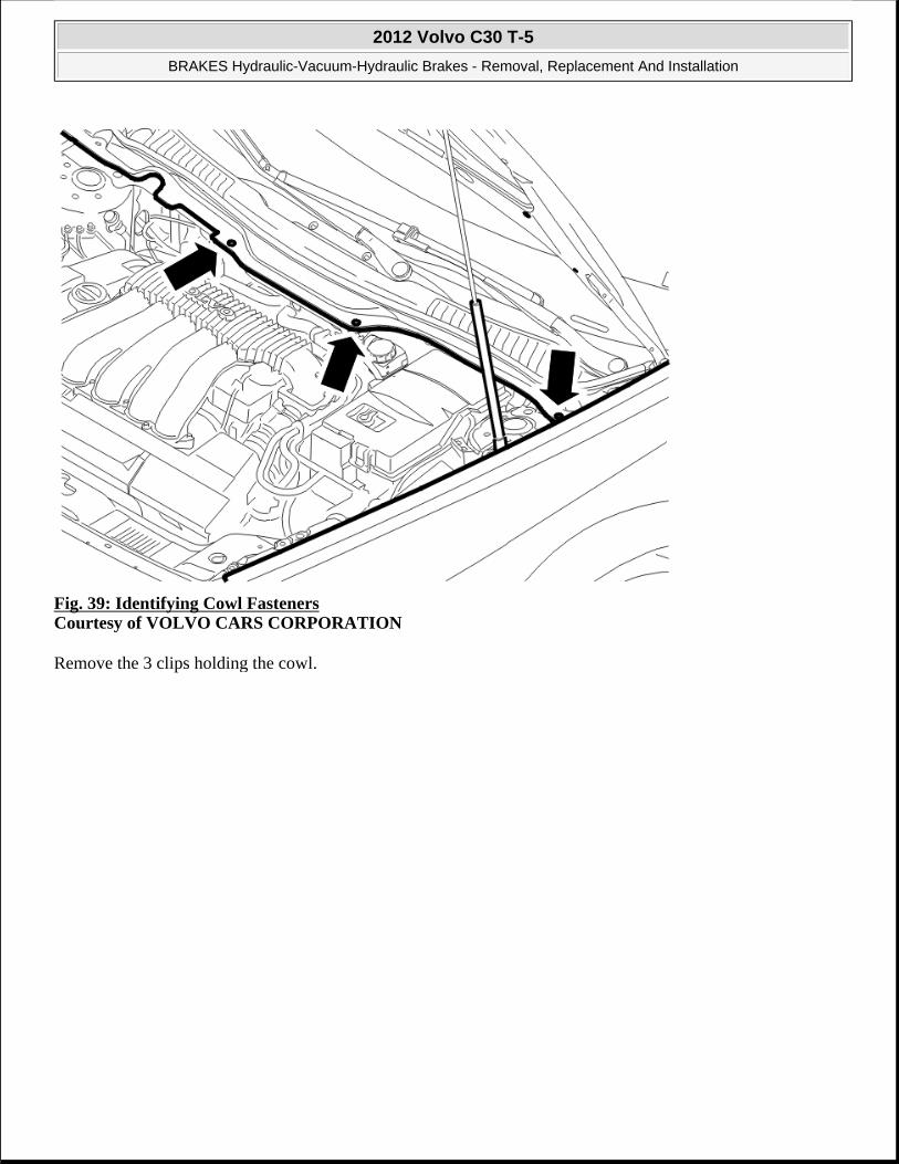
Fig. 39: Identifying Cowl Fasteners Courtesy of VOLVO CARS CORPORATION
Remove the 3 clips holding the cowl.
2012 Volvo C30 T-5
BRAKES Hydraulic-Vacuum-Hydraulic Brakes - Removal, Replacement And Installation

Fig. 40: Identifying Brake Fluid Reservoir Protective Cover Courtesy of VOLVO CARS CORPORATION
Carefully lift up the cowl. Remove the 2 clips for the protective cover. Remove the protective cover over the brake fluid reservoir.
2012 Volvo C30 T-5
BRAKES Hydraulic-Vacuum-Hydraulic Brakes - Removal, Replacement And Installation

Fig. 41: Identifying Firewall Upper Protective Cover Nut Courtesy of VOLVO CARS CORPORATION
Remove:
the plastic nut, x1
the upper protective cover for the firewall.
REMOVING THE BRAKE PIPES BETWEEN THE MASTER CYLINDER AND ABS UNIT
2012 Volvo C30 T-5
BRAKES Hydraulic-Vacuum-Hydraulic Brakes - Removal, Replacement And Installation

Fig. 42: Brake Piping/ABS Unit Courtesy of VOLVO CARS CORPORATION
Clean the brake pipes terminals at the master cylinder and ABS unit.
Place paper under the master cylinder to avoid brake fluid spillage.
Remove the brake pipes between the master cylinder and the ABS unit.
INSTALLATION
INSTALLING THE BRAKE PIPES
Install the brake pipes between the master cylinder and the ABS unit. Tighten. See TIGHTENING TORQUE .
BLEEDING BRAKE SYSTEMS
Bleed the brake system. See BRAKE SYSTEM BLEEDING .
Check that the brake pipe connections are sealed.
NOTE: For tightening torques, see TIGHTENING TORQUE .
2012 Volvo C30 T-5
BRAKES Hydraulic-Vacuum-Hydraulic Brakes - Removal, Replacement And Installation

Check the brake fluid level.
INSTALLING THE PROTECTIVE COVERS
Fig. 43: Identifying Firewall Upper Protective Cover Nut Courtesy of VOLVO CARS CORPORATION
Install:
the protective cover for the firewall
the plastic nut.
2012 Volvo C30 T-5
BRAKES Hydraulic-Vacuum-Hydraulic Brakes - Removal, Replacement And Installation

Fig. 44: Identifying Brake Fluid Reservoir Protective Cover Courtesy of VOLVO CARS CORPORATION
Install the protective cover over the brake fluid reservoir.
Carefully lift up the cowl. Install the 2 clips for the protective cover.
2012 Volvo C30 T-5
BRAKES Hydraulic-Vacuum-Hydraulic Brakes - Removal, Replacement And Installation

Fig. 45: Identifying Cowl Fasteners Courtesy of VOLVO CARS CORPORATION
Install the 3x clips holding the cowl.
FINISHING
2012 Volvo C30 T-5
BRAKES Hydraulic-Vacuum-Hydraulic Brakes - Removal, Replacement And Installation

Fig. 46: Identifying Battery Box Courtesy of VOLVO CARS CORPORATION
Install:
the battery box (2)
the 1 M6 screws (3)
the battery. See BATTERY .
BRAKE PIPE RIGHT FRONT WHEEL, REPLACING
PREPARATORY WORK
NOTE: The graphics in this service information are used for different model years and/or models. Some variation may occur. However, the essential information in the graphics is always correct.
2012 Volvo C30 T-5
BRAKES Hydraulic-Vacuum-Hydraulic Brakes - Removal, Replacement And Installation

Fig. 47: Bleeding Brakes Courtesy of VOLVO CARS CORPORATION
Remove the wheel.
Secure the pedal in the depressed position. Use a pedal jack.
Remove the protective cap from the bleed nipple at the left front wheel.
Install a plastic hose on the nipple. Open the bleed nipple.
Collect the brake fluid in a container.
Shut the bleed nipple.
REMOVAL
REMOVING THE BATTERY BOX
2012 Volvo C30 T-5
BRAKES Hydraulic-Vacuum-Hydraulic Brakes - Removal, Replacement And Installation

Fig. 48: Identifying Battery Box Courtesy of VOLVO CARS CORPORATION
Ignition off.
Remove:
the battery. See BATTERY
the 3 screws (1)
the battery box (2).
REMOVING SPLASH GUARDS
2012 Volvo C30 T-5
BRAKES Hydraulic-Vacuum-Hydraulic Brakes - Removal, Replacement And Installation

Fig. 49: Identifying Cowl Fasteners Courtesy of VOLVO CARS CORPORATION
Remove the 3 clips holding the cowl.
2012 Volvo C30 T-5
BRAKES Hydraulic-Vacuum-Hydraulic Brakes - Removal, Replacement And Installation

Fig. 50: Identifying Brake Fluid Reservoir Protective Cover Courtesy of VOLVO CARS CORPORATION
Carefully lift up the cowl. Remove the 2 clips for the protective cover.
Remove the protective cover over the brake fluid reservoir.
2012 Volvo C30 T-5
BRAKES Hydraulic-Vacuum-Hydraulic Brakes - Removal, Replacement And Installation

Fig. 51: Identifying Firewall Upper Protective Cover Nut Courtesy of VOLVO CARS CORPORATION
Remove:
the plastic nut, x1
the protective cover for the firewall.
REMOVING THE HEAT DEFLECTOR PLATE
2012 Volvo C30 T-5
BRAKES Hydraulic-Vacuum-Hydraulic Brakes - Removal, Replacement And Installation

Fig. 52: Identifying Heat Deflector Plate Courtesy of VOLVO CARS CORPORATION
Remove:
the heat deflector plate. Pull straight out
the hoses from the clip.
REMOVING THE BRAKE PIPE
2012 Volvo C30 T-5
BRAKES Hydraulic-Vacuum-Hydraulic Brakes - Removal, Replacement And Installation

Fig. 53: Brake Lines ABS Unit/Pipe Coupling Rear Courtesy of VOLVO CARS CORPORATION
Remove:
the two brake pipes (1). See BRAKE LINES ABS UNIT/PIPE COUPLING REAR, REPLACING
the 3 nuts (2)
the lower protective cover for the firewall.
NOTE: Clean the brake pipe terminals. Place paper under the hydraulic modulator to avoid brake fluid spillage.
2012 Volvo C30 T-5
BRAKES Hydraulic-Vacuum-Hydraulic Brakes - Removal, Replacement And Installation
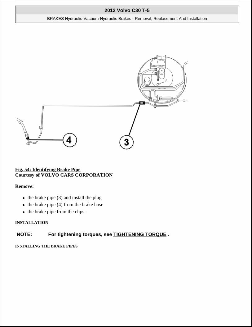
Fig. 54: Identifying Brake Pipe Courtesy of VOLVO CARS CORPORATION
Remove:
the brake pipe (3) and install the plug
the brake pipe (4) from the brake hose
the brake pipe from the clips.
INSTALLATION
INSTALLING THE BRAKE PIPES
NOTE: For tightening torques, see TIGHTENING TORQUE .
2012 Volvo C30 T-5
BRAKES Hydraulic-Vacuum-Hydraulic Brakes - Removal, Replacement And Installation

Fig. 55: Identifying Brake Pipe Courtesy of VOLVO CARS CORPORATION
Install:
the brake pipe (3). Tighten. See TIGHTENING TORQUE
the brake pipe (4). Tighten. See TIGHTENING TORQUE
the brake pipe in the clips.
2012 Volvo C30 T-5
BRAKES Hydraulic-Vacuum-Hydraulic Brakes - Removal, Replacement And Installation

Fig. 56: Brake Lines ABS Unit/Pipe Coupling Rear Courtesy of VOLVO CARS CORPORATION
Install:
the lower protective cover for the firewall
the 3 nuts (2)
the two brake pipes (1): BRAKE LINES ABS UNIT/PIPE COUPLING REAR, REPLACING.
BLEEDING BRAKE SYSTEMS
Remove the pedal jack.
Bleed the brake system. See BRAKE SYSTEM BLEEDING .
Check that the brake pipe connections are sealed.
Check the brake fluid level.
INSTALLING THE HEAT DEFLECTOR PLATE
2012 Volvo C30 T-5
BRAKES Hydraulic-Vacuum-Hydraulic Brakes - Removal, Replacement And Installation

Fig. 57: Identifying Heat Deflector Plate Courtesy of VOLVO CARS CORPORATION
Install:
the heat deflector plate
the hoses
the 1 clip.
INSTALLING THE PROTECTIVE COVERS
2012 Volvo C30 T-5
BRAKES Hydraulic-Vacuum-Hydraulic Brakes - Removal, Replacement And Installation

Fig. 58: Identifying Firewall Upper Protective Cover Nut Courtesy of VOLVO CARS CORPORATION
Install:
the upper protective cover for the firewall
the plastic nut, x1.
2012 Volvo C30 T-5
BRAKES Hydraulic-Vacuum-Hydraulic Brakes - Removal, Replacement And Installation

Fig. 59: Identifying Brake Fluid Reservoir Protective Cover Courtesy of VOLVO CARS CORPORATION
Install the protective cover over the brake fluid reservoir. Carefully lift up the cowl. Install the 2 clips for the protective cover.
2012 Volvo C30 T-5
BRAKES Hydraulic-Vacuum-Hydraulic Brakes - Removal, Replacement And Installation

Fig. 60: Identifying Cowl Fasteners Courtesy of VOLVO CARS CORPORATION
Install the 3 clips holding the cowl.
INSTALLING THE BATTERY BOX
2012 Volvo C30 T-5
BRAKES Hydraulic-Vacuum-Hydraulic Brakes - Removal, Replacement And Installation

Fig. 61: Identifying Battery Box Courtesy of VOLVO CARS CORPORATION
Install:
the battery box (2)
the 1 M6 screws (3)
the battery. See BATTERY .
FINISHING
Install the wheel. See WHEELS .
BRAKE PIPES LONGITUDINAL, REPLACING
PREPARATORY WORK
NOTE: The graphics in this service information are used for different model years and/or models. Some variation may occur. However, the essential information in the graphics is always correct.
2012 Volvo C30 T-5
BRAKES Hydraulic-Vacuum-Hydraulic Brakes - Removal, Replacement And Installation

Fig. 62: Bleeding Brakes Courtesy of VOLVO CARS CORPORATION
Secure the pedal in the depressed position. Use a pedal jack.
Remove the protective cap from the bleed nipple.
Install a plastic hose on the nipple.
Open the bleed nipple. Collect the brake fluid in a container (bottle). Shut the bleed nipple
REMOVAL
REMOVING THE SIPS MEMBER
2012 Volvo C30 T-5
BRAKES Hydraulic-Vacuum-Hydraulic Brakes - Removal, Replacement And Installation

Fig. 63: Identifying SIPS Member Courtesy of VOLVO CARS CORPORATION
Remove:
the clips for the heated oxygen sensor (HO2S) wiring (1)
the plastic nut (2)
the two screws (3)
the SIPS member.
REMOVING THE HEAT DEFLECTOR PLATE FOR THE COWL PANEL
2012 Volvo C30 T-5
BRAKES Hydraulic-Vacuum-Hydraulic Brakes - Removal, Replacement And Installation

Fig. 64: Identifying Heat Deflector Plate Courtesy of VOLVO CARS CORPORATION
Remove the heat deflector plate by pulling it out.
REMOVING THE FRONT-REAR BRAKE PIPE
2012 Volvo C30 T-5
BRAKES Hydraulic-Vacuum-Hydraulic Brakes - Removal, Replacement And Installation

Fig. 65: Brake Lines ABS Unit/Pipe Coupling Rear Courtesy of VOLVO CARS CORPORATION
Detach the two brake pipes (4).
2012 Volvo C30 T-5
BRAKES Hydraulic-Vacuum-Hydraulic Brakes - Removal, Replacement And Installation

Fig. 66: Identifying Brake Pipes And Clips Courtesy of VOLVO CARS CORPORATION
Detach the two brake pipes (5).
Remove all six clips (6).
INSTALLATION
INSTALLING THE FRONT-REAR BRAKE PIPE
NOTE: For tightening torques, see TIGHTENING TORQUE .
2012 Volvo C30 T-5
BRAKES Hydraulic-Vacuum-Hydraulic Brakes - Removal, Replacement And Installation

Fig. 67: Brake Lines ABS Unit/Pipe Coupling Rear Courtesy of VOLVO CARS CORPORATION
Install the two brake pipes (4).
2012 Volvo C30 T-5
BRAKES Hydraulic-Vacuum-Hydraulic Brakes - Removal, Replacement And Installation

Fig. 68: Identifying Brake Pipes And Clips Courtesy of VOLVO CARS CORPORATION
Install:
the two brake pipes (5)
the six clips.
BLEEDING BRAKE SYSTEMS
Remove the pedal jack.
Bleed the brake system. See BRAKE SYSTEM BLEEDING
Check that the brake pipe connections are sealed.
Check the brake fluid level
INSTALLING THE SIPS MEMBER
2012 Volvo C30 T-5
BRAKES Hydraulic-Vacuum-Hydraulic Brakes - Removal, Replacement And Installation

Fig. 69: Identifying SIPS Member Courtesy of VOLVO CARS CORPORATION
Install:
the SIPS member
the two M10 screws (3)
the plastic nut (2)
the clips for the heated oxygen sensor (HO2S) wiring (1).
INSTALLING THE HEAT DEFLECTOR PLATE FOR THE COWL PANEL
Install the heat deflector plate
BRAKE PIPES REAR WHEEL, REPLACING
PREPARATORY WORK
NOTE: The graphics in this service information are used for different model years and/or models. Some variation may occur. However, the essential information in the graphics is always correct.
2012 Volvo C30 T-5
BRAKES Hydraulic-Vacuum-Hydraulic Brakes - Removal, Replacement And Installation

Fig. 70: Bleeding Brakes Courtesy of VOLVO CARS CORPORATION
Remove the wheel.
Secure the pedal in the depressed position. Use a pedal jack.
Remove the protective cap from the bleed nipple.
Install a plastic hose on the nipple. Open the bleed nipple.
Collect the brake fluid in a container.
Shut the bleed nipple.
REMOVAL
REMOVING THE AIR BAFFLE
2012 Volvo C30 T-5
BRAKES Hydraulic-Vacuum-Hydraulic Brakes - Removal, Replacement And Installation

Fig. 71: Identifying Air Baffle Courtesy of VOLVO CARS CORPORATION
Applies to the left-hand side.
Remove:
the 2 plastic nuts (1)
the 1 screw (2)
the air baffle.
REMOVING THE HEAT DEFLECTOR PLATE
2012 Volvo C30 T-5
BRAKES Hydraulic-Vacuum-Hydraulic Brakes - Removal, Replacement And Installation

Fig. 72: Identifying Heat Deflector Plate Courtesy of VOLVO CARS CORPORATION
Applies to the left-hand side.
Remove:
the 5 plastic nuts
the heat deflector plate. Hang the heat deflector plate on the exhaust system.
REMOVING THE LEFT REAR BRAKE PIPE
2012 Volvo C30 T-5
BRAKES Hydraulic-Vacuum-Hydraulic Brakes - Removal, Replacement And Installation

Fig. 73: Identifying Brake Hose/Pipe And Clip Courtesy of VOLVO CARS CORPORATION
Remove the brake pipe from the brake hose.
2012 Volvo C30 T-5
BRAKES Hydraulic-Vacuum-Hydraulic Brakes - Removal, Replacement And Installation

Fig. 74: Identifying Brake Pipe Coupling Courtesy of VOLVO CARS CORPORATION
Remove:
the brake pipe from the front-rear pipe
the brake pipe from the clips.
REMOVING THE RIGHT REAR BRAKE PIPE
2012 Volvo C30 T-5
BRAKES Hydraulic-Vacuum-Hydraulic Brakes - Removal, Replacement And Installation

Fig. 75: Identifying Brake Pipe And Connector Courtesy of VOLVO CARS CORPORATION
Remove:
the connector (1)
the brake pipe from the brake hose (2).
2012 Volvo C30 T-5
BRAKES Hydraulic-Vacuum-Hydraulic Brakes - Removal, Replacement And Installation

Fig. 76: Identifying Brake Pipe And Clips Courtesy of VOLVO CARS CORPORATION
Remove:
the brake pipe from the front-rear pipe
the brake pipe from the clips.
INSTALLATION
INSTALLING THE LEFT REAR BRAKE PIPE
NOTE: For tightening torques, see TIGHTENING TORQUE .
2012 Volvo C30 T-5
BRAKES Hydraulic-Vacuum-Hydraulic Brakes - Removal, Replacement And Installation

Fig. 77: Identifying Brake Pipe Coupling Courtesy of VOLVO CARS CORPORATION
Install the brake pipe in the front-rear pipe. Tighten. See TIGHTENING TORQUE .
2012 Volvo C30 T-5
BRAKES Hydraulic-Vacuum-Hydraulic Brakes - Removal, Replacement And Installation

Fig. 78: Identifying Brake Hose/Pipe And Clip Courtesy of VOLVO CARS CORPORATION
Install:
the brake pipe in the brake hose. Tighten. See TIGHTENING TORQUE
the brake pipe in the clips.
INSTALLING THE RIGHT REAR BRAKE PIPE
2012 Volvo C30 T-5
BRAKES Hydraulic-Vacuum-Hydraulic Brakes - Removal, Replacement And Installation

Fig. 79: Identifying Brake Pipe And Clips Courtesy of VOLVO CARS CORPORATION
Install the brake pipe in the front-rear brake pipe. Tighten. See TIGHTENING TORQUE .
2012 Volvo C30 T-5
BRAKES Hydraulic-Vacuum-Hydraulic Brakes - Removal, Replacement And Installation

Fig. 80: Identifying Brake Pipe And Connector Courtesy of VOLVO CARS CORPORATION
Install:
the brake pipe in the brake hose (2). Tighten. See TIGHTENING TORQUE
the connector (1)
the brake pipe in the clips.
BLEEDING BRAKE SYSTEMS
Remove the pedal jack.
Bleed the brake system. See BRAKE SYSTEM BLEEDING .
Check that the brake pipe connections are sealed.
Check the brake fluid level.
INSTALLING THE HEAT DEFLECTOR PLATE
2012 Volvo C30 T-5
BRAKES Hydraulic-Vacuum-Hydraulic Brakes - Removal, Replacement And Installation

Fig. 81: Identifying Heat Deflector Plate Courtesy of VOLVO CARS CORPORATION
Applies to the left-hand side.
Install:
the heat deflector plate
the 5 plastic nuts.
INSTALLING THE AIR BAFFLE
2012 Volvo C30 T-5
BRAKES Hydraulic-Vacuum-Hydraulic Brakes - Removal, Replacement And Installation

Fig. 82: Identifying Air Baffle Courtesy of VOLVO CARS CORPORATION
Applies to the left-hand side.
Install:
the air baffle
the 2 plastic nuts (1)
1 screw (2).
FINISHING
Install the wheel. See WHEELS .
MASTER CYLINDER, BRAKE SERVO
BRAKE FLUID
NOTE: The graphics in this service information are used for different model years and/or models. Some variation may occur. However, the essential information in the graphics is always correct.
2012 Volvo C30 T-5
BRAKES Hydraulic-Vacuum-Hydraulic Brakes - Removal, Replacement And Installation

GUIDELINES AND BACKGROUND
GUIDELINES FOR BRAKE FLUID REPLACEMENT
It is recommended that brake fluid is changed every other year. On cars that are exposed to heavy and frequent braking, for example, mountain driving or driving in tropical climates with high humidity, the brake fluid must be changed every year.
BACKGROUND
Fig. 83: Brake Fluid And Reservoir Courtesy of VOLVO CARS CORPORATION
The oil must be replaced because it is hygroscopic (the fluid absorbs water molecules from the air). This absorption of water occurs through the brake hoses and brake fluid reservoir. These components are rubber and plastic respectively and are not completely sealed against water molecules. An increased water content in the brake fluid dramatically reduces its boiling point and causes corrosion in the brake system components. This results in damage to the brake system. Braking performance deteriorates markedly.
NOTE: Use only Volvo Genuine Parts brake fluid designated DOT 4+. Never reuse brake fluid. Always keep the brake fluid sealed in the original packaging.
NOTE: Continually check that there is sufficient brake fluid in the brake fluid reservoir
2012 Volvo C30 T-5
BRAKES Hydraulic-Vacuum-Hydraulic Brakes - Removal, Replacement And Installation

PREPARATORY WORK
Switch off the ignition.
Remove all four wheels.
REPLACEMENT
CHANGING THE BRAKE FLUID, FRONT
Fig. 84: Collecting Bottle, Hose And G-Clamp Courtesy of VOLVO CARS CORPORATION
Remove the protective cap from the bleed nipple.
Install a plastic hose on the nipple.
Open the bleed nipple.
Collect the brake fluid in a container.
when changing brake fluid.
2012 Volvo C30 T-5
BRAKES Hydraulic-Vacuum-Hydraulic Brakes - Removal, Replacement And Installation

Press the brake caliper piston to the bottom of the caliper.
Use G-clamp as shown.
Leave the G-clamp in pushed in position.
Fig. 85: Bleeding Brake System Courtesy of VOLVO CARS CORPORATION
Alternative 1:
Connect the bleeding unit. See BRAKE SYSTEM BLEEDING .
Open the bleed nipple on the caliper. Wait until there is new oil in the plastic hose.
Close the bleed nipple
Alternative 2:
Press down the brake pedal to the limit position.
Keep it pressed down for approximately 2 seconds before releasing it.
2012 Volvo C30 T-5
BRAKES Hydraulic-Vacuum-Hydraulic Brakes - Removal, Replacement And Installation

Repeat until there is new brake fluid in the plastic hose.
Close the bleed nipple when the brake pedal is fully depressed.
Remove the hose. Install the protective cap.
Remove the G-clamp from the brake caliper.
Repeat the process on the other front wheel. Install the wheel. See WHEELS .
REPLACING BRAKE FLUID, REAR
Fig. 86: Identifying Special Tool 9995782 Courtesy of VOLVO CARS CORPORATION
Remove the brake caliper. See BRAKE PADS REAR .
Press the piston into the brake caliper. Use: see 9995782 replace 5782-1 with: see 9997091 .
Remove the protective cap from the bleed nipple.
Install the plastic hose on the nipple. Open the bleed nipple.
2012 Volvo C30 T-5
BRAKES Hydraulic-Vacuum-Hydraulic Brakes - Removal, Replacement And Installation

Collect the brake fluid in a container.
Alternative 1:
Connect the bleeding unit. See BRAKE SYSTEM BLEEDING .
Open the bleed nipple on the caliper. Wait until there is new oil in the plastic hose.
Close the bleed nipple.
Alternative 2:
Press down the brake pedal to the limit position. Keep it pressed down for approximately 2 seconds before releasing it.
Repeat until there is new brake fluid in the plastic hose.
Close the bleed nipple when the brake pedal is fully depressed.
Remove the hose and install the protective cap.
Remove the tool.
Install the brake caliper. See BRAKE PADS REAR . Repeat the process on the other rear wheel.
Install the wheel. See WHEELS .
BRAKE BOOSTER
PREPARATORY WORK
NOTE: The graphics in this service information are used for different model years and/or models. Some variation may occur. However, the essential information in the graphics is always correct.
2012 Volvo C30 T-5
BRAKES Hydraulic-Vacuum-Hydraulic Brakes - Removal, Replacement And Installation

Fig. 87: Identifying Battery Box Courtesy of VOLVO CARS CORPORATION
Ignition off.
Remove:
the battery. See BATTERY
the 3 screws
the battery box.
Remove the windshield wiper motor. See WIPER MECHANISM, WINDSHIELD
REMOVAL
REMOVING SPLASH GUARDS
2012 Volvo C30 T-5
BRAKES Hydraulic-Vacuum-Hydraulic Brakes - Removal, Replacement And Installation

Fig. 88: Identifying Protective Cover Courtesy of VOLVO CARS CORPORATION
Remove:
the 2 clips
the protective cover over the brake fluid reservoir.
2012 Volvo C30 T-5
BRAKES Hydraulic-Vacuum-Hydraulic Brakes - Removal, Replacement And Installation
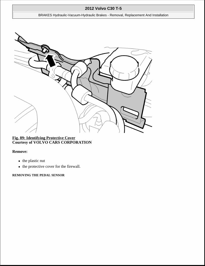
Fig. 89: Identifying Protective Cover Courtesy of VOLVO CARS CORPORATION
Remove:
the plastic nut
the protective cover for the firewall.
REMOVING THE PEDAL SENSOR
2012 Volvo C30 T-5
BRAKES Hydraulic-Vacuum-Hydraulic Brakes - Removal, Replacement And Installation

Fig. 90: Identifying Pedal Sensor Connector Courtesy of VOLVO CARS CORPORATION
Remove:
the pressure sensor (1)
the connector (2).
2012 Volvo C30 T-5
BRAKES Hydraulic-Vacuum-Hydraulic Brakes - Removal, Replacement And Installation

Fig. 91: Identifying Pedal Sensor Courtesy of VOLVO CARS CORPORATION
Remove the pedal sensor. Widen the snap ring and pull out the pedal sensor.
HINT: The opening on the snap ring points straight down. The snap ring does not need to be completely removed, just opened.
REMOVING THE HEAT DEFLECTOR PLATE
NOTE: Ensure that the O-ring is also removed.
2012 Volvo C30 T-5
BRAKES Hydraulic-Vacuum-Hydraulic Brakes - Removal, Replacement And Installation

Fig. 92: Identifying Heat Deflector Plate Courtesy of VOLVO CARS CORPORATION
Remove:
the heat deflector plate. Pull straight out
the hoses from the clip.
REMOVING THE BRAKE PIPE
2012 Volvo C30 T-5
BRAKES Hydraulic-Vacuum-Hydraulic Brakes - Removal, Replacement And Installation

Fig. 93: Brake Lines ABS Unit/Pipe Coupling Rear Courtesy of VOLVO CARS CORPORATION
Remove:
the two brake tubes (3) between the master cylinder and the control module.
the two brake tubes (4)
the 3 nuts (5)
the lower protective cover for the firewall.
REMOVING THE MASTER CYLINDER
Remove the master cylinder. See MASTER CYLINDER, BRAKE.
REMOVING SOUNDPROOFING PANELS
Remove the soundproofing panel. See INSTRUMENT PANEL LOWER .
REMOVING THE POWER BRAKE BOOSTER
2012 Volvo C30 T-5
BRAKES Hydraulic-Vacuum-Hydraulic Brakes - Removal, Replacement And Installation

Fig. 94: Identifying Brake Booster Push Rod Courtesy of VOLVO CARS CORPORATION
Remove the pin for the power brake booster.
NOTE: The pin cannot be entirely removed. It must be replaced with a new pin on installation.
2012 Volvo C30 T-5
BRAKES Hydraulic-Vacuum-Hydraulic Brakes - Removal, Replacement And Installation

Fig. 95: 4 Nuts Holding Power Brake Booster Courtesy of VOLVO CARS CORPORATION
Remove:
the 4 nuts
the power brake booster.
INSTALLATION
INSTALLING THE POWER BRAKE BOOSTER
Install:
the new power brake booster
the 4 M8 nuts
the new pin for the push rod.
INSTALLING THE PEDAL SENSOR
NOTE: For tightening torques, see TIGHTENING TORQUE .
2012 Volvo C30 T-5
BRAKES Hydraulic-Vacuum-Hydraulic Brakes - Removal, Replacement And Installation

Fig. 96: Identifying Pedal Sensor Connector Courtesy of VOLVO CARS CORPORATION
Press in the new pedal sensor.
Lubricate with soap solution and install the pressure sensor (1).
Connect the electrical connector (2).
INSTALLING MASTER CYLINDER
Install the master cylinder. See MASTER CYLINDER, BRAKE
INSTALLING THE BRAKE PIPES
NOTE: Use a new O-ring. The pedal sensor can only be installed in one position, i. e. with the locating pin pointing straight up.
2012 Volvo C30 T-5
BRAKES Hydraulic-Vacuum-Hydraulic Brakes - Removal, Replacement And Installation

Fig. 97: Brake Lines ABS Unit/Pipe Coupling Rear Courtesy of VOLVO CARS CORPORATION
Install:
the two brake tubes (3)
the lower protective cover for the firewall
the 3 nuts (5)
the two brake tubes (4).
BLEEDING BRAKE SYSTEMS
Bleed the brake system. See BRAKE SYSTEM BLEEDING .
Check that the brake pipe connections are sealed.
Check the brake fluid level.
INSTALLING THE HEAT DEFLECTOR PLATE
2012 Volvo C30 T-5
BRAKES Hydraulic-Vacuum-Hydraulic Brakes - Removal, Replacement And Installation

Fig. 98: Identifying Heat Deflector Plate Courtesy of VOLVO CARS CORPORATION
Install:
the heat deflector plate
the hoses
the clip.
INSTALLING THE SOUNDPROOFING PANEL
Install the soundproofing panel. See INSTRUMENT PANEL LOWER .
INSTALLING THE PROTECTIVE COVERS
2012 Volvo C30 T-5
BRAKES Hydraulic-Vacuum-Hydraulic Brakes - Removal, Replacement And Installation

Fig. 99: Identifying Protective Cover Courtesy of VOLVO CARS CORPORATION
install:
the protective cover for the firewall
the plastic nut.
2012 Volvo C30 T-5
BRAKES Hydraulic-Vacuum-Hydraulic Brakes - Removal, Replacement And Installation

Fig. 100: Identifying Protective Cover Courtesy of VOLVO CARS CORPORATION
Install:
the protective cover over the brake fluid reservoir
the 2 clips.
FINISHING
Install:
the windshield wiper motor. See WIPER MECHANISM, WINDSHIELD .
the battery box
the 3 M6 screws
the battery as shown: BATTERY .
MASTER CYLINDER, BRAKE
NOTE: The graphics in this service information are used for different model years and/or models. Some variation may occur. However, the essential information in the graphics is always correct.
2012 Volvo C30 T-5
BRAKES Hydraulic-Vacuum-Hydraulic Brakes - Removal, Replacement And Installation

PREPARATORY WORK
Fig. 101: Identifying Battery Box Courtesy of VOLVO CARS CORPORATION
Ignition off.
Remove:
the battery. See BATTERY
the 3 screws (1)
the battery box (2).
REMOVAL
REMOVING SPLASH GUARDS
2012 Volvo C30 T-5
BRAKES Hydraulic-Vacuum-Hydraulic Brakes - Removal, Replacement And Installation

Fig. 102: Identifying Cowl Fasteners Courtesy of VOLVO CARS CORPORATION
Remove the 3 clips holding the cowl.
2012 Volvo C30 T-5
BRAKES Hydraulic-Vacuum-Hydraulic Brakes - Removal, Replacement And Installation

Fig. 103: Identifying Brake Fluid Reservoir Protective Cover Courtesy of VOLVO CARS CORPORATION
Carefully lift up the cowl. Remove the 2 clips for the protective cover. Remove the protective cover over the brake fluid reservoir.
2012 Volvo C30 T-5
BRAKES Hydraulic-Vacuum-Hydraulic Brakes - Removal, Replacement And Installation

Fig. 104: Identifying Firewall Upper Protective Cover Nut Courtesy of VOLVO CARS CORPORATION
Remove:
the plastic nut, x 1
the upper protective cover for the firewall.
REMOVING THE MASTER CYLINDER
2012 Volvo C30 T-5
BRAKES Hydraulic-Vacuum-Hydraulic Brakes - Removal, Replacement And Installation

Fig. 105: Identifying Brake Master Cylinder Connections Courtesy of VOLVO CARS CORPORATION
Remove:
the connector on the brake fluid reservoir
the 2 nuts
the 2 brake pipes from the master cylinder. Install the sealing plugs
the feeder hose for the clutch cylinder. Install the sealing plugs
the master cylinder.
TRANSFERRING COMPONENTS
Transfer the brake fluid reservoir to the new master cylinder. See RESERVOIR, BRAKE FLUID.
NOTE: Clean the brake tube terminals at the master cylinder and anti-lock brake system unit. Place paper under the master cylinder. This is to protect the paintwork from damage if brake fluid is spilled.
NOTE: Only use brake fluid to lubricate the O-rings in the brake system.
2012 Volvo C30 T-5
BRAKES Hydraulic-Vacuum-Hydraulic Brakes - Removal, Replacement And Installation

INSTALLING MASTER CYLINDER
Install:
the 2 brake pipes. Tighten. See TIGHTENING TORQUE
the 2 M8 nuts
the connector on the brake fluid reservoir
the feeder hose for the clutch cylinder.
BLEEDING BRAKE SYSTEMS
Bleed the brake system. See BRAKE SYSTEM BLEEDING .
Check that the brake pipe connections are sealed.
Check the brake fluid level.
INSTALLING THE PROTECTIVE COVERS
Fig. 106: Identifying Firewall Upper Protective Cover Nut
NOTE: For tightening torques, see TIGHTENING TORQUE .
2012 Volvo C30 T-5
BRAKES Hydraulic-Vacuum-Hydraulic Brakes - Removal, Replacement And Installation

Courtesy of VOLVO CARS CORPORATION
Install:
the protective cover for the firewall
the plastic nut, x 1.
Fig. 107: Identifying Brake Fluid Reservoir Protective Cover Courtesy of VOLVO CARS CORPORATION
Install the protective cover over the brake fluid reservoir. Carefully lift up the cowl. Install the 2 clips for the protective cover.
2012 Volvo C30 T-5
BRAKES Hydraulic-Vacuum-Hydraulic Brakes - Removal, Replacement And Installation
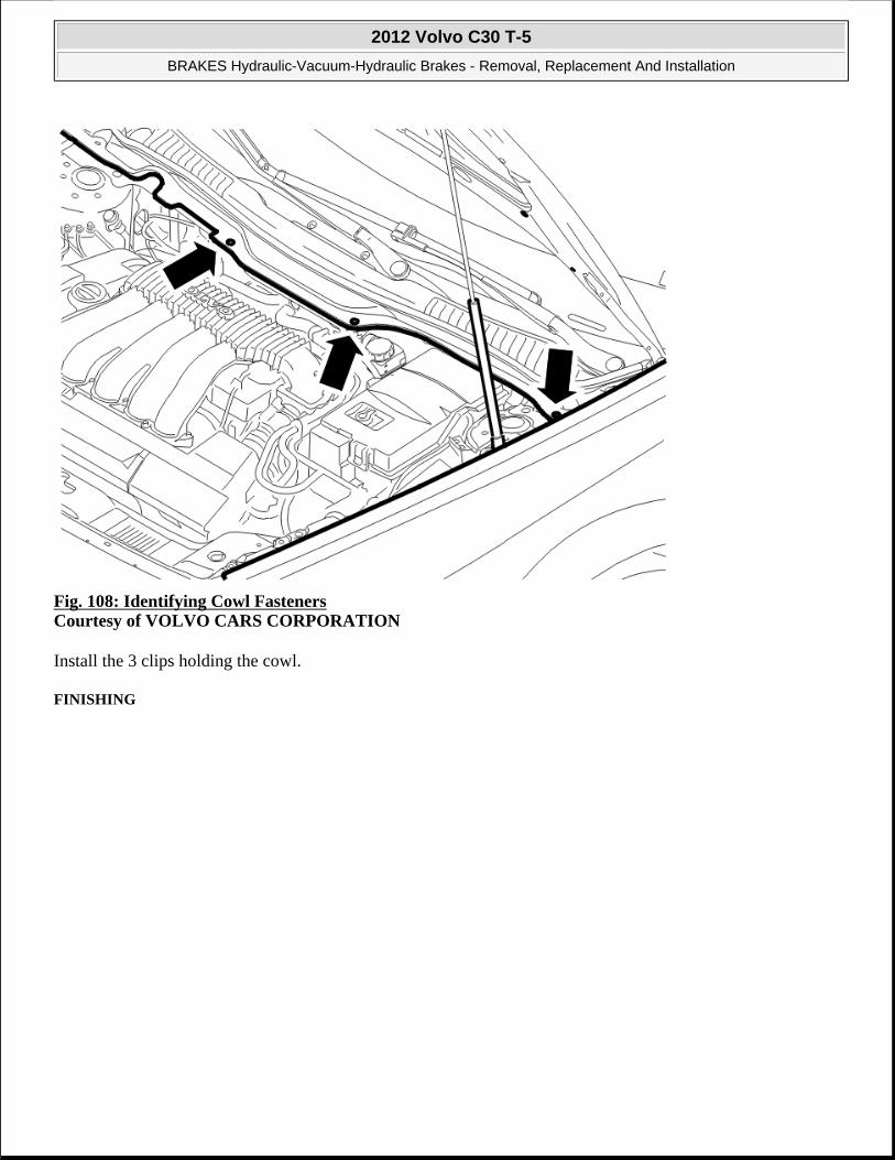
Fig. 108: Identifying Cowl Fasteners Courtesy of VOLVO CARS CORPORATION
Install the 3 clips holding the cowl.
FINISHING
2012 Volvo C30 T-5
BRAKES Hydraulic-Vacuum-Hydraulic Brakes - Removal, Replacement And Installation

Fig. 109: Identifying Battery Box Courtesy of VOLVO CARS CORPORATION
Install:
the battery box (2)
the 1 M6 screws (3)
the battery as shown: BATTERY .
RESERVOIR, BRAKE FLUID
REMOVAL
NOTE: Removal steps in this procedure may contain installation details.
2012 Volvo C30 T-5
BRAKES Hydraulic-Vacuum-Hydraulic Brakes - Removal, Replacement And Installation

Fig. 110: Locating Brake Master Cylinder Reservoir Courtesy of VOLVO CARS CORPORATION
Remove master cylinder brake. See MASTER CYLINDER, BRAKE
Fig. 111: Identifying Brake Master Cylinder Reservoir Retaining Bolt Courtesy of VOLVO CARS CORPORATION
Torque: Brake fluid reservoir in master cylinder
3.5 Nm
2012 Volvo C30 T-5
BRAKES Hydraulic-Vacuum-Hydraulic Brakes - Removal, Replacement And Installation

Fig. 112: Identifying Mating Surfaces Courtesy of VOLVO CARS CORPORATION
INSTALLATION
To install, reverse the removal procedure.
BRAKE LINE WITH CONNECTIONS
FRONT BRAKE FLEXIBLE HOSE
PREPARATORY WORK
CAUTION: Make sure that the mating faces are clean and free of foreign material.
NOTE: The graphics in this service information are used for different model years and/or models. Some variation may occur. However, the essential information in the graphics is always correct.
2012 Volvo C30 T-5
BRAKES Hydraulic-Vacuum-Hydraulic Brakes - Removal, Replacement And Installation

Fig. 113: Bleeding Brakes Courtesy of VOLVO CARS CORPORATION
Remove the wheel.
Secure the pedal in the depressed position. Use a pedal jack.
Remove the protective cap from the bleed nipple.
Install a plastic hose on the nipple.
Open the bleed nipple. Collect the brake fluid in a container.
Shut the bleed nipple.
REMOVAL
REMOVING THE BRAKE HOSE
2012 Volvo C30 T-5
BRAKES Hydraulic-Vacuum-Hydraulic Brakes - Removal, Replacement And Installation

Fig. 114: Identifying Brake Hose/Pipe And Clip Courtesy of VOLVO CARS CORPORATION
Remove:
the brake pipe from the brake hose (1)
the retaining clip (2).
Pull the brake hose out of the mounting (3).
Remove the brake hose from the brake caliper (4).
INSTALLATION
INSTALLING THE BRAKE HOSE
NOTE: For tightening torques, see TIGHTENING TORQUE .
2012 Volvo C30 T-5
BRAKES Hydraulic-Vacuum-Hydraulic Brakes - Removal, Replacement And Installation

Fig. 115: Identifying Brake Hose/Pipe And Clip Courtesy of VOLVO CARS CORPORATION
Install:
the brake hose (4) to the caliper. Tighten. See TIGHTENING TORQUE
the brake hose (3) in the mounting
the retaining clip (2).
brake pipe in the hose (1). Tighten. See TIGHTENING TORQUE .
FINISHING
Remove the pedal jack.
Fill and bleed the brake system. To bleed the brake system, see BRAKE SYSTEM BLEEDING .
Check:
NOTE: Ensure that the brake hose is not twisted. If the brake hose is twisted, there is a risk of circuit failure.
NOTE: Use only Volvo Genuine parts brake fluid (Volvo DOT 4+).
2012 Volvo C30 T-5
BRAKES Hydraulic-Vacuum-Hydraulic Brakes - Removal, Replacement And Installation
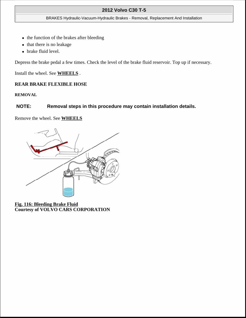
the function of the brakes after bleeding
that there is no leakage
brake fluid level.
Depress the brake pedal a few times. Check the level of the brake fluid reservoir. Top up if necessary.
Install the wheel. See WHEELS .
REAR BRAKE FLEXIBLE HOSE
REMOVAL
Remove the wheel. See WHEELS
Fig. 116: Bleeding Brake Fluid Courtesy of VOLVO CARS CORPORATION
NOTE: Removal steps in this procedure may contain installation details.
2012 Volvo C30 T-5
BRAKES Hydraulic-Vacuum-Hydraulic Brakes - Removal, Replacement And Installation

Fig. 117: Removing/Installing Clip Courtesy of VOLVO CARS CORPORATION
Fig. 118: Removing/Installing Pipe to Hose with Clip Courtesy of VOLVO CARS CORPORATION
Torque: Ø6 mm diameter brake line
14 Nm
2012 Volvo C30 T-5
BRAKES Hydraulic-Vacuum-Hydraulic Brakes - Removal, Replacement And Installation

Fig. 119: Removing/Installing Rear Brake Flexible Hose Courtesy of VOLVO CARS CORPORATION
Torque: Rear Brake Flexible Hose
23 Nm
INSTALLATION
To install, reverse the removal procedure.
Perform bleeding air brake system. See BRAKE SYSTEM BLEEDING
BRAKE CONTROL
BUSHING PUSH ROD
PREPARATORY WORK
Remove the soundproofing panel. See INSTRUMENT PANEL LOWER .
REMOVAL
REMOVING THE BUSHING
NOTE: The graphics in this service information are used for different model years and/or models. Some variation may occur. However, the essential information in the graphics is always correct.
2012 Volvo C30 T-5
BRAKES Hydraulic-Vacuum-Hydraulic Brakes - Removal, Replacement And Installation

Fig. 120: Identifying Brake Booster Push Rod Courtesy of VOLVO CARS CORPORATION
Break off the bushing together with the pin from the push rod.
INSTALLATION
INSTALLING THE BUSHING
Press in the bushing together with the pin into the push rod.
PEDAL BOX, BRAKE
REMOVAL
Remove the following items:
NOTE: The pin cannot be separated entirely. It must be replaced with a new pin on installation.
NOTE: The pin cannot be separated entirely. It must be replaced with a new pin on installation.
2012 Volvo C30 T-5
BRAKES Hydraulic-Vacuum-Hydraulic Brakes - Removal, Replacement And Installation

See STEERING COLUMN
See ACCELERATOR PEDAL
Fig. 121: Locating Brake Pedal Pin Courtesy of VOLVO CARS CORPORATION
Fig. 122: Identifying Brake Pedal Switch Connector Courtesy of VOLVO CARS CORPORATION
2012 Volvo C30 T-5
BRAKES Hydraulic-Vacuum-Hydraulic Brakes - Removal, Replacement And Installation

Fig. 123: Identifying Brake Pedal Switch Courtesy of VOLVO CARS CORPORATION
Fig. 124: Identifying Brake Pedal Assembly Nuts Courtesy of VOLVO CARS CORPORATION
2012 Volvo C30 T-5
BRAKES Hydraulic-Vacuum-Hydraulic Brakes - Removal, Replacement And Installation

INSTALLATION
To install, reverse the removal procedure.
VACUUM PUMP, TANK, LINE AND VALVE
BRAKE BOOSTER VACUUM HOSE
PREPARATORY WORK
Fig. 125: Identifying Battery Box Courtesy of VOLVO CARS CORPORATION
Ignition off.
Remove:
the battery. See BATTERY
NOTE: The graphics in this service information are used for different model years and/or models. Some variation may occur. However, the essential information in the graphics is always correct.
2012 Volvo C30 T-5
BRAKES Hydraulic-Vacuum-Hydraulic Brakes - Removal, Replacement And Installation

the 3 screws
the battery box.
REMOVAL
REMOVING SPLASH GUARDS
Fig. 126: Identifying Cowl Fasteners Courtesy of VOLVO CARS CORPORATION
Remove the 3 clips holding the cowl.
2012 Volvo C30 T-5
BRAKES Hydraulic-Vacuum-Hydraulic Brakes - Removal, Replacement And Installation

Fig. 127: Identifying Brake Fluid Reservoir Protective Cover Courtesy of VOLVO CARS CORPORATION
Carefully lift up the cowl. Remove the 2 clips for the protective cover.
Remove the protective cover over the brake fluid reservoir.
2012 Volvo C30 T-5
BRAKES Hydraulic-Vacuum-Hydraulic Brakes - Removal, Replacement And Installation

Fig. 128: Identifying Firewall Upper Protective Cover Nut Courtesy of VOLVO CARS CORPORATION
Remove:
the plastic nut
the upper protective cover for the firewall.
REMOVING THE MASTER CYLINDER
2012 Volvo C30 T-5
BRAKES Hydraulic-Vacuum-Hydraulic Brakes - Removal, Replacement And Installation

Fig. 129: Identifying Brake Master Cylinder Fasteners Courtesy of VOLVO CARS CORPORATION
Remove the 2 nuts. Pull the master cylinder out from the studs. Allow the master cylinder to hang from the brake pipes.
REMOVING THE VACUUM HOSE
NOTE: Do not damage the brake pipes when removing the master cylinder.
2012 Volvo C30 T-5
BRAKES Hydraulic-Vacuum-Hydraulic Brakes - Removal, Replacement And Installation

Fig. 130: Identifying Brake Booster Vacuum Valve and Connector Courtesy of VOLVO CARS CORPORATION
Remove:
the connector (1)
the control valve (2).
2012 Volvo C30 T-5
BRAKES Hydraulic-Vacuum-Hydraulic Brakes - Removal, Replacement And Installation

Fig. 131: Identifying Brake Booster Vacuum Hose Courtesy of VOLVO CARS CORPORATION
Remove:
the clamp (1)
the vacuum hose from the hose for the intake manifold
the vacuum hose from the pump (2)
the vacuum hose.
INSTALLATION
INSTALLING THE VACUUM HOSE
NOTE: For tightening torques, see TIGHTENING TORQUE .
2012 Volvo C30 T-5
BRAKES Hydraulic-Vacuum-Hydraulic Brakes - Removal, Replacement And Installation

Fig. 132: Identifying Brake Booster Vacuum Hose Courtesy of VOLVO CARS CORPORATION
Install:
the vacuum hose
the vacuum hose on the pump (2)
the vacuum hose on the hose for the intake manifold
the clamp (1).
2012 Volvo C30 T-5
BRAKES Hydraulic-Vacuum-Hydraulic Brakes - Removal, Replacement And Installation

Fig. 133: Identifying Brake Booster Vacuum Valve and Connector Courtesy of VOLVO CARS CORPORATION
Install:
the connector (1)
the control valve (2).
HINT: Lubricate the control valve using soap solution for easier installation.
INSTALLING THE PROTECTIVE COVERS
2012 Volvo C30 T-5
BRAKES Hydraulic-Vacuum-Hydraulic Brakes - Removal, Replacement And Installation
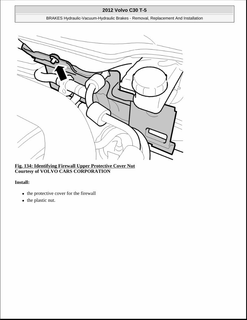
Fig. 134: Identifying Firewall Upper Protective Cover Nut Courtesy of VOLVO CARS CORPORATION
Install:
the protective cover for the firewall
the plastic nut.
2012 Volvo C30 T-5
BRAKES Hydraulic-Vacuum-Hydraulic Brakes - Removal, Replacement And Installation

Fig. 135: Identifying Brake Fluid Reservoir Protective Cover Courtesy of VOLVO CARS CORPORATION
Install the protective cover over the brake fluid reservoir. Carefully lift up the cowl. Install the 2 clips for the protective cover.
2012 Volvo C30 T-5
BRAKES Hydraulic-Vacuum-Hydraulic Brakes - Removal, Replacement And Installation

Fig. 136: Identifying Cowl Fasteners Courtesy of VOLVO CARS CORPORATION
Install the 3 clips holding the cowl.
FINISHING
2012 Volvo C30 T-5
BRAKES Hydraulic-Vacuum-Hydraulic Brakes - Removal, Replacement And Installation

Fig. 137: Identifying Battery Box Courtesy of VOLVO CARS CORPORATION
Install:
the battery box
the 3 M6 screws
the battery. See BATTERY .
VACUUM PUMP, BRAKE BOOSTER
REMOVAL
NOTE: Removal steps in this procedure may contain installation details.
2012 Volvo C30 T-5
BRAKES Hydraulic-Vacuum-Hydraulic Brakes - Removal, Replacement And Installation

Fig. 138: Locating Brake Booster Vacuum Pump (Inset Removing Vacuum Lines) Courtesy of VOLVO CARS CORPORATION
Torque: M6
10 Nm
INSTALLATION
To install, reverse the removal procedure.
2012 Volvo C30 T-5
BRAKES Hydraulic-Vacuum-Hydraulic Brakes - Removal, Replacement And Installation

ACCESSORIES AND EQUIPMENT
Instrumentation - Installation Instructions, Accessories
TRIP COMPUTER
TRIP COMPUTER
Turn the ignition key to position 0
Move the steering wheel to its rearmost position.
Fig. 1: Identifying Upper Steering Column Cover Courtesy of VOLVO CARS CORPORATION
Carefully pry the upper steering column cover off the lower cover. Using a plastic weatherstrip tool, pry at the rear edge in the join between the steering column covers. The steering column covers are secured to each other by catches (1) on the inside
Fold the upper steering column cover towards the combined instrument panel. Secure it in the folded up position.
2012 Volvo C30 T-5
ACCESSORIES AND EQUIPMENT Instrumentation - Installation Instructions, Accessories
2012 Volvo C30 T-5
ACCESSORIES AND EQUIPMENT Instrumentation - Installation Instructions, Accessories

Fig. 2: Identifying Steering Column Cover Screws Courtesy of VOLVO CARS CORPORATION
Remove the upper screws (1) from the lower steering column cover
Unscrew the lower screw (2) a few turns
Fold the lower steering column cover down slightly, so that the mounting point for the left-hand control stalk is exposed.
Fig. 3: View Of Left-Hand Control Stalk Screws Courtesy of VOLVO CARS CORPORATION
Remove the left-hand control stalk. First remove the two screws. Then carefully pull the stalk outwards until it releases from the connector on the inside.
Press the new stalk into place where the old one was positioned. Tighten the stalk using the existing screws
Reinstall the lower steering column cover. Tighten
2012 Volvo C30 T-5
ACCESSORIES AND EQUIPMENT Instrumentation - Installation Instructions, Accessories

Reinstall the upper steering column cover.
Program the function using VIDA (Volvo scan tool).
COMBINED INSTRUMENT PANEL, R-DESIGN
COMBINED INSTRUMENT PANEL, R-DESIGN
Fig. 4: Identifying Ignition Switch Turned To Position 0 Courtesy of VOLVO CARS CORPORATION
Turn the ignition switch to position 0.
Fig. 5: Identifying Steering Wheel In Lowest Position
NOTE: Wait at least three minutes before unplugging the connectors or removing other electrical equipment.
2012 Volvo C30 T-5
ACCESSORIES AND EQUIPMENT Instrumentation - Installation Instructions, Accessories

Courtesy of VOLVO CARS CORPORATION
Adjust the steering wheel to the outermost and lowermost position.
Remove the two screws at the upper edge of the surround for the combined instrument panel.
Remove the surround.
Fig. 6: View Of Instrument Panel Screws Courtesy of VOLVO CARS CORPORATION
Remove the two screws at the sides of the instrument panel.
Raise it slightly and unhook it from the holder on the inside of the instrument panel.
Lift the instrument panel out and disconnect the connector.
Place the instrument panel to one side.
NOTE: Do not damage the instrument panel. The glass is easily scratched.
2012 Volvo C30 T-5
ACCESSORIES AND EQUIPMENT Instrumentation - Installation Instructions, Accessories

Fig. 7: Installing Instrument Panel ConnectorCourtesy of VOLVO CARS CORPORATION
Take the new instrument panel and connect the connector.
Insert it in position and hook it onto the holder on the inside.
Tighten using the two screws.
Fig. 8: View Of Instrument Panel Surround Screws Courtesy of VOLVO CARS CORPORATION
Fig. 9: Identifying VIDA (Volvo Scan Tool) To Program Software Courtesy of VOLVO CARS CORPORATION
Download software for the relevant vehicle type in accordance with the service information in VIDA (Volvo scan tool).
PARKING ASSISTANCE, FRONT
2012 Volvo C30 T-5
ACCESSORIES AND EQUIPMENT Instrumentation - Installation Instructions, Accessories
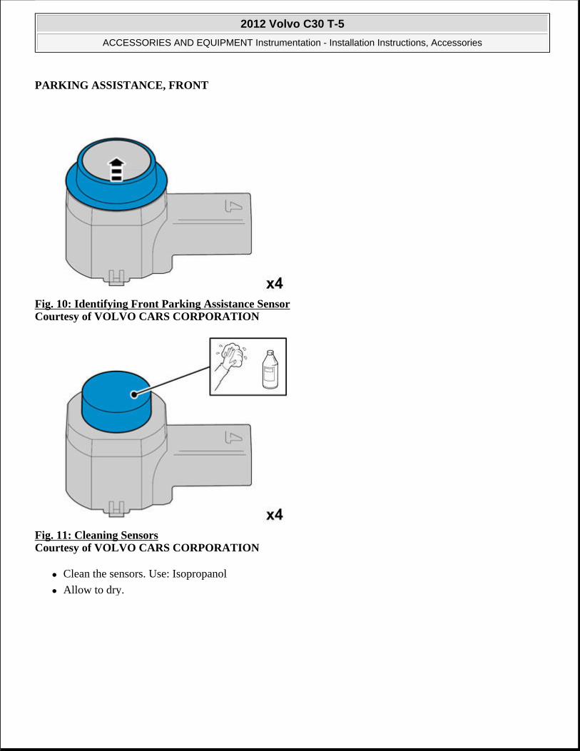
PARKING ASSISTANCE, FRONT
Fig. 10: Identifying Front Parking Assistance Sensor Courtesy of VOLVO CARS CORPORATION
Fig. 11: Cleaning Sensors Courtesy of VOLVO CARS CORPORATION
Clean the sensors. Use: Isopropanol
Allow to dry.
2012 Volvo C30 T-5
ACCESSORIES AND EQUIPMENT Instrumentation - Installation Instructions, Accessories

Fig. 12: Matting Surface Down Courtesy of VOLVO CARS CORPORATION
Carefully mat the surface down. Use: Glasspaper, grade P1000
Fig. 13: Cleaning Sensors Courtesy of VOLVO CARS CORPORATION
Clean the sensors again.
Use: Isopropanol
Allow to dry.
Avoid contact with the cleaned surfaces.
2012 Volvo C30 T-5
ACCESSORIES AND EQUIPMENT Instrumentation - Installation Instructions, Accessories

Fig. 14: View Of Painting Sensors Courtesy of VOLVO CARS CORPORATION
Paint the sensors in the same color code as the vehicle.
Use Volvo Touch-up paint. (Only use base coat.)
Use: Volvo 2-K Varnish. P/N: 31335447
Fig. 15: Installing Rear Parking Assistance Sensor Bezel Courtesy of VOLVO CARS CORPORATION
CAUTION: Protect the connections' contact surfaces against paint.
NOTE: Also read the instructions on the spray can.
2012 Volvo C30 T-5
ACCESSORIES AND EQUIPMENT Instrumentation - Installation Instructions, Accessories

Fig. 16: Identifying Ignition Switch Turned To Position 0 Courtesy of VOLVO CARS CORPORATION
Turn the ignition switch to position 0.
Fig. 17: Identifying Screws Holding Engine Splash Guard Courtesy of VOLVO CARS CORPORATION
Raise the car
Remove the screws and the engine splash guard.
CAUTION: The paint must have dried after the first application.
NOTE: Wait at least one minute before unplugging the connectors or removing other electrical equipment.
2012 Volvo C30 T-5
ACCESSORIES AND EQUIPMENT Instrumentation - Installation Instructions, Accessories

Fig. 18: Identifying Removal Of Nozzle Covers Courtesy of VOLVO CARS CORPORATION
Lower the car
Carefully grasp the cover for the high pressure washing for the headlamps and pull until the catches are accessible.
Fig. 19: Identifying Catch Pressed Up Courtesy of VOLVO CARS CORPORATION
Press the catch up. Remove the cover. Do not damage the painted surfaces or the washer nozzles.
Carry out on both sides
2012 Volvo C30 T-5
ACCESSORIES AND EQUIPMENT Instrumentation - Installation Instructions, Accessories

Fig. 20: Identifying Clips And Screws Courtesy of VOLVO CARS CORPORATION
Push in the center of the five clips (1). Remove the clips.
Remove the two screws (2)
Fig. 21: Removing Inner Wing Screws Courtesy of VOLVO CARS CORPORATION
Remove the screws for the inner wing.
2012 Volvo C30 T-5
ACCESSORIES AND EQUIPMENT Instrumentation - Installation Instructions, Accessories

Fig. 22: Identifying Prying Points Courtesy of VOLVO CARS CORPORATION
Take a weatherstrip tool and pry between the headlamp bumper cover (1)
Then insert the weatherstrip tool in the cut-out (2) and pull straight out until the hooks (3) release
Repeat the operation on the other side
Fig. 23: Pulling Bumper Cover Straight Out Courtesy of VOLVO CARS CORPORATION
HINT: Removal of the bumper is facilitated if carried out by 2 people.
Pull the ends of the bumper cover straight out so that the release from the wing liner.
Pull the bumper cover straight out until the hooks under the headlamps release, detach the connectors for the fog lamps and place the bumper cover on a surface that will not damage the paint.
2012 Volvo C30 T-5
ACCESSORIES AND EQUIPMENT Instrumentation - Installation Instructions, Accessories

Fig. 24: Locating Markings Inside Bumper Cover Courtesy of VOLVO CARS CORPORATION
Locate the 4 markings on the inside of the bumper cover.
Mark the center with a scribe.
Fig. 25: Drilling Holes In Centers Of Markings Courtesy of VOLVO CARS CORPORATION
Drill holes in the centers of the markings using a Ø 3 mm (7/64) diameter drill bit.
Drill out the holes. Use a Ø10 mm (25/64") diameter drill bit.
2012 Volvo C30 T-5
ACCESSORIES AND EQUIPMENT Instrumentation - Installation Instructions, Accessories
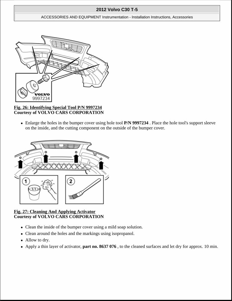
Fig. 26: Identifying Special Tool P/N 9997234 Courtesy of VOLVO CARS CORPORATION
Enlarge the holes in the bumper cover using hole tool P/N 9997234 . Place the hole tool's support sleeve on the inside, and the cutting component on the outside of the bumper cover.
Fig. 27: Cleaning And Applying Activator Courtesy of VOLVO CARS CORPORATION
Clean the inside of the bumper cover using a mild soap solution.
Clean around the holes and the markings using isopropanol.
Allow to dry.
Apply a thin layer of activator, part no. 8637 076 , to the cleaned surfaces and let dry for approx. 10 min.
2012 Volvo C30 T-5
ACCESSORIES AND EQUIPMENT Instrumentation - Installation Instructions, Accessories

Fig. 28: Identifying Holder Courtesy of VOLVO CARS CORPORATION
Take the 4 holders from the kit.
Clean the surfaces as shown in the illustration. Use: Isopropanol
Allow to dry.
Apply a thin layer and even layer of activator. art. no.. 8637076 .
Fig. 29: Identifying Markings In Member Courtesy of VOLVO CARS CORPORATION
Plastic member:
Saw along the 2 markings, only through the outer part.
NOTE: There are two types of member (energy absorbing).
2012 Volvo C30 T-5
ACCESSORIES AND EQUIPMENT Instrumentation - Installation Instructions, Accessories

Foam member (EPS):
Remove the foam member from the collision member.
Saw along the 2 markings.
Reinstall the foam member.
Fig. 30: Identifying Panel Courtesy of VOLVO CARS CORPORATION
Remove the panel.
Fig. 31: Identifying Soundproofing Panel Clips Courtesy of VOLVO CARS CORPORATION
Remove the 2 clips and the soundproofing panel.
2012 Volvo C30 T-5
ACCESSORIES AND EQUIPMENT Instrumentation - Installation Instructions, Accessories

Fig. 32: Identifying Front Sill Molding Courtesy of VOLVO CARS CORPORATION
Detach the front sill molding by first pulling it backwards at the front edge and then straight up so that the clips release.
Fig. 33: Removing Rear Sill Molding Courtesy of VOLVO CARS CORPORATION
Detach the rear sill molding by first pulling it up at the front edge, and then unhooking it at the rear edge.
2012 Volvo C30 T-5
ACCESSORIES AND EQUIPMENT Instrumentation - Installation Instructions, Accessories

Fig. 34: Identifying Rear Seat Cushion Courtesy of VOLVO CARS CORPORATION
Pull off the seat cushion for the rear seat, first at the rear edge where it is secured by one holder. Then at the front edge where it is secured by two holders.
Remove the seat cushion.
Fig. 35: Identifying Central Arm Rest Courtesy of VOLVO CARS CORPORATION
Fold the central arm rest forward.
Remove the central arm rest by grasping each end and pulling upwards until it releases at the rear edge from the backrest's lugs (1).
Then pull forwards until the holders (2) on the sides of the backrest have slid out of the corresponding cut-out (3) in the central arm rest.
2012 Volvo C30 T-5
ACCESSORIES AND EQUIPMENT Instrumentation - Installation Instructions, Accessories

Fig. 36: Identifying Backrest Cover Courtesy of VOLVO CARS CORPORATION
Fold the backrest forward.
Remove the cover for the backrest's right-hand mounting.
Fig. 37: Identifying Locking Sleeve And Screw Courtesy of VOLVO CARS CORPORATION
Remove the screw and the locking sleeve.
NOTE: Applies to right-hand drive cars. Must not be mirrored.
2012 Volvo C30 T-5
ACCESSORIES AND EQUIPMENT Instrumentation - Installation Instructions, Accessories

Fig. 38: View Of Backrest Stowed Courtesy of VOLVO CARS CORPORATION
Fold the backrest away from the right-hand mounting.
Pull it out from the mounting at the arm rest and remove it.
Fig. 39: Identifying Rubber Door Molding RH Courtesy of VOLVO CARS CORPORATION
Pull off the rubber molding at the rear edge of the right-hand door opening.
2012 Volvo C30 T-5
ACCESSORIES AND EQUIPMENT Instrumentation - Installation Instructions, Accessories

Fig. 40: Identifying B Pillar Panel Courtesy of VOLVO CARS CORPORATION
Detach the B pillar panel at the rear edge by prying the sides using a weatherstrip tool until the 2 clips release.
Fig. 41: View Of Safety Clip Strap Courtesy of VOLVO CARS CORPORATION
Unhook the safety clip from the panel.
Angle out the panel at the lower edge, and then unhook it at the upper edge so that the upper clip releases.
2012 Volvo C30 T-5
ACCESSORIES AND EQUIPMENT Instrumentation - Installation Instructions, Accessories

Fig. 42: Identifying Rear Seat RH Panel Courtesy of VOLVO CARS CORPORATION
Remove the screw from the right-hand panel.
Carefully pull off the panel from the body side. It is secured by eleven clips on the inside.
Fig. 43: Identifying Trunk Floor Cover Courtesy of VOLVO CARS CORPORATION
Lift up the floor hatch at the rear edge.
Pull it backwards so that it detaches at the front edge.
Turn the cover and lift out.
2012 Volvo C30 T-5
ACCESSORIES AND EQUIPMENT Instrumentation - Installation Instructions, Accessories
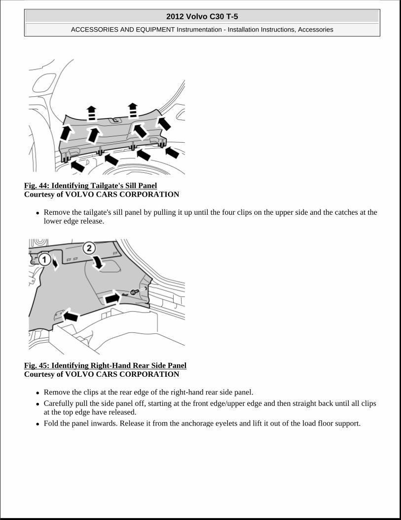
Fig. 44: Identifying Tailgate's Sill Panel Courtesy of VOLVO CARS CORPORATION
Remove the tailgate's sill panel by pulling it up until the four clips on the upper side and the catches at the lower edge release.
Fig. 45: Identifying Right-Hand Rear Side Panel Courtesy of VOLVO CARS CORPORATION
Remove the clips at the rear edge of the right-hand rear side panel.
Carefully pull the side panel off, starting at the front edge/upper edge and then straight back until all clips at the top edge have released.
Fold the panel inwards. Release it from the anchorage eyelets and lift it out of the load floor support.
2012 Volvo C30 T-5
ACCESSORIES AND EQUIPMENT Instrumentation - Installation Instructions, Accessories

Fig. 46: View Of Spare Wheel, Jack And Other Parts From Storage Compartment Courtesy of VOLVO CARS CORPORATION
Lift out the spare wheel, jack and other parts from the storage compartment in the cargo floor support.
Fig. 47: Identifying Spare Wheel Compartment Screws Courtesy of VOLVO CARS CORPORATION
Remove the 4 screw clips.
2012 Volvo C30 T-5
ACCESSORIES AND EQUIPMENT Instrumentation - Installation Instructions, Accessories

Fig. 48: Identifying Cable Routing In Engine Bay Courtesy of VOLVO CARS CORPORATION
Take the short cable harness from the kit.
Remove the taped connector from the cable harness.
Pull the end with the loose terminals in under the headlamp
Continue to pull the cable harness (1) along the right-hand side of the car, under the expansion tank down to the cowl panel.
Route the cable so that it is concealed and cannot be damaged or worn. Secure the cable harness using tie straps so that it does not move.
Fig. 49: Identifying Floor Mat Courtesy of VOLVO CARS CORPORATION
NOTE: Ensure that the cable harness does not lie against any moving components or too close to heat sources.
2012 Volvo C30 T-5
ACCESSORIES AND EQUIPMENT Instrumentation - Installation Instructions, Accessories

Unscrew the clips holding the floor carpet.
Push the floor carpet to one side to access the cowl panel inside.
Take care not to create folds in the carpet.
Fig. 50: Locating Hole Under Insulation Panel For Rubber Grommet Courtesy of VOLVO CARS CORPORATION
Locate the hole for the rubber grommet under the insulation panel.
Make a small cut in the insulation panel starting just above the hole, continue to the center of the hole and then straight down.
Fig. 51: Pushing Carpet Tabs To One Side Courtesy of VOLVO CARS CORPORATION
Push the carpet tabs to one side to access the rubber grommet in the cowl panel.
Remove the rubber grommet.
2012 Volvo C30 T-5
ACCESSORIES AND EQUIPMENT Instrumentation - Installation Instructions, Accessories

Fig. 52: Removing Rubber Grommet Courtesy of VOLVO CARS CORPORATION
Pierce holes through the heat insulation panel and out into the engine compartment, for hole-marking in the heat insulation panel in the engine compartment.
Fig. 53: Cutting Out Hole In Heat Insulation Courtesy of VOLVO CARS CORPORATION
Raise the car.
Cut out a hole in the heat insulation that is approx. 20 mm (25/32".) larger than the size of the rubber grommet.
NOTE: Applies to cars with parking heaters Protect the coolant hose on the horizontal connection of the water pump when making the markings for holes.
2012 Volvo C30 T-5
ACCESSORIES AND EQUIPMENT Instrumentation - Installation Instructions, Accessories

Fig. 54: Cutting Top Off Smaller Rubber Nipples Courtesy of VOLVO CARS CORPORATION
Take the rubber grommet from the kit and cut the top off the smaller rubber nipples
Lubricate the rubber grommet. Use low temperature grease (P/N 1161417).
Thread the rubber grommet on the cable harness.
Route the cable harness in through the hole and press the rubber grommet into the hole so that it seals properly.
Pull the cable harness so that the correct length remains in the engine compartment.
Make sure that the heating hose for the cable harness is in contact against the rubber grommet and secure it with a tie strap.
Fig. 55: Identifying Connector Courtesy of VOLVO CARS CORPORATION
Lower the car.
1. 1 Blue (BL)
2012 Volvo C30 T-5
ACCESSORIES AND EQUIPMENT Instrumentation - Installation Instructions, Accessories

2. 2 Green (GN)
3. 3 Violet (VO)
4. 4 Yellow (Y)
5. 5 White (W)
6. 6 Black (SB)
Release the catch on the connector that was taped.
1. 1 Blue (BL)
2. 2 Green (GN)
3. 3 Violet (VO)
4. 4 Yellow (Y)
5. 5 White (W)
6. 6 Black (SB)
Connect the pre-routed cable harness terminals in the connector as follows.
1. 1 Blue (BL)
2. 2 Green (GN)
3. 3 Violet (VO)
4. 4 Yellow (Y)
5. 5 White (W)
6. 6 Black (SB)
Press back the connector's catch.
Fig. 56: Identifying Connection Of Long Cable
2012 Volvo C30 T-5
ACCESSORIES AND EQUIPMENT Instrumentation - Installation Instructions, Accessories

Courtesy of VOLVO CARS CORPORATION
Take the long cable harness from the kit. Connect it to the connector which has just been prepared.
Route the cable harness from the lower edge of the A pillar and further back at the sill and under the carpet.
Fold back the carpet and screw the clip into place.
Fig. 57: View Of Routed Cable Harness Courtesy of VOLVO CARS CORPORATION
Route the cable harness further back and under the seat support and backwards and into the cargo compartment, along the existing cable harnesses.
Position the cable harness so that it does not get trapped or damaged.
Fig. 58: Routing Cable To Right Rear Corner Of Cargo Floor Support Courtesy of VOLVO CARS CORPORATION
2012 Volvo C30 T-5
ACCESSORIES AND EQUIPMENT Instrumentation - Installation Instructions, Accessories

the right rear corner of the cargo floor support.
Position the cable so that is does not get trapped or damaged.
Fig. 59: Locating Parking Assistance Module (PAM) Courtesy of VOLVO CARS CORPORATION
Lift up the right-hand side cargo floor support.
Locate the parking assistance module (PAM). It is secured on the right-hand side of the cargo compartment floor, under the cargo floor support.
Fig. 60: Connecting Pre-Routed Cable To Vacant Connection (Middle) On Parking Assistance Module (PAM) Courtesy of VOLVO CARS CORPORATION
Connect the pre-routed cable to the vacant connection (middle) on the parking assistance module (PAM).
NOTE: Ensure that the connector's catch clicks and is securely positioned.
2012 Volvo C30 T-5
ACCESSORIES AND EQUIPMENT Instrumentation - Installation Instructions, Accessories

Fig. 61: Securing Double-Backed Tape On Holder Courtesy of VOLVO CARS CORPORATION
Remove the protective film from one side of the double-backed tape.
Secure the tape on the holder.
Fig. 62: Installing Centering Tool In Holder Courtesy of VOLVO CARS CORPORATION
Remove the remaining protective film on the holder.
Install the centering tool in the holder according to the illustration.
2012 Volvo C30 T-5
ACCESSORIES AND EQUIPMENT Instrumentation - Installation Instructions, Accessories

Fig. 63: Locating Holders On Bumper Cover Courtesy of VOLVO CARS CORPORATION
Press in the holder on the bumper cover.
Repeat the steps for the other holders.
Fig. 64: Connect Cable Harness Connectors To Sensors Courtesy of VOLVO CARS CORPORATION
Connect the cable harness connectors to the sensors.
Install the sensors in their holders.
NOTE: The holders must be mounted turned against the holes as shown in the illustration. The holders must also be horizontal and in line with the bumper cover.
NOTE: The large gray connector must be on the right-hand side.
2012 Volvo C30 T-5
ACCESSORIES AND EQUIPMENT Instrumentation - Installation Instructions, Accessories

Fig. 65: Securing End Of Cable Harness At Sensor To Bumper Cover Courtesy of VOLVO CARS CORPORATION
Secure the end of the cable harness at the sensors to the bumper cover using butyl tape.
Fig. 66: Securing Cable Harness To Bumper Cover Courtesy of VOLVO CARS CORPORATION
Secure the cable harness to the bumper cover using butyl tape in the locations shown in the illustration.
NOTE: The large gray connector must be on the right-hand side.
2012 Volvo C30 T-5
ACCESSORIES AND EQUIPMENT Instrumentation - Installation Instructions, Accessories

Fig. 67: Securing Assembled Connector On Member Courtesy of VOLVO CARS CORPORATION
Hold the bumper up against the car and connect the connector for the sensor cable to the connector at the car.
Secure the assembled connector on the member (1) . Use a tie strap on each side of the connector.
Connect the connectors to any foglamps.
Slide the bumper cover into the correct position
Fig. 68: Guiding Lower Edge Of Bumper Cover Into Guides Courtesy of VOLVO CARS CORPORATION
Guide the lower edge of the bumper cover into the guides.
Reinstall the bumper cover by repeating points in reverse order.
Reinstall the engine splash guard.
2012 Volvo C30 T-5
ACCESSORIES AND EQUIPMENT Instrumentation - Installation Instructions, Accessories

Fig. 69: Identifying Panel Screw Courtesy of VOLVO CARS CORPORATION
Reinstall the side panel.
Reinstall the clip for the cargo floor support.
Reinstall the sill trim panel.
Fig. 70: Locating Ten Panel Clips Courtesy of VOLVO CARS CORPORATION
NOTE: There are ten clips on the reverse of the panel that must all engage in the body. Take care when aligning so that the clips do not break. Broken clips must be replaced with new ones.
2012 Volvo C30 T-5
ACCESSORIES AND EQUIPMENT Instrumentation - Installation Instructions, Accessories

Fig. 71: Identifying Panel Clips And Screws Courtesy of VOLVO CARS CORPORATION
Reinstall the side panel, ensure that all clips engage.
Tighten the panel using existing screws.
Fig. 72: View Of B Pillar Panel Clips Courtesy of VOLVO CARS CORPORATION
Reinstall the panel with the safety clip and the weatherstrip.
2012 Volvo C30 T-5
ACCESSORIES AND EQUIPMENT Instrumentation - Installation Instructions, Accessories

Fig. 73: View Of Rear Sill Trim Panel Courtesy of VOLVO CARS CORPORATION
Reinstall the rear sill trim panel, the 2 guides must be in the corresponding cut-outs in the side panel.
Reinstall the front sill trim panel.
Reinstall the backrest. Tighten the screws to 15 Nm (11 lbf. ft.) .
Reinstall the arm rest.
Reinstall the seat cushion.
Fig. 74: Identifying VIDA (Volvo Scan Tool) To Program Software Courtesy of VOLVO CARS CORPORATION
Download software (application) for the accessory's function using VIDA (Volvo scan tool).
PARKING ASSISTANCE, FRONT, CHASSIS NUMBER 190000- (2010-2012)
PARKING ASSISTANCE, FRONT, CHASSIS NUMBER 190000-
2012 Volvo C30 T-5
ACCESSORIES AND EQUIPMENT Instrumentation - Installation Instructions, Accessories

Fig. 75: Identifying Front Parking Assistance Sensor Courtesy of VOLVO CARS CORPORATION
Fig. 76: Cleaning Sensors Courtesy of VOLVO CARS CORPORATION
Clean the sensors. Use: Isopropanol.
Allow to dry.
2012 Volvo C30 T-5
ACCESSORIES AND EQUIPMENT Instrumentation - Installation Instructions, Accessories

Fig. 77: Matting Surface Down Courtesy of VOLVO CARS CORPORATION
Carefully mat the surface down. Use: Glasspaper, grade P1000
Fig. 78: Cleaning Sensors Courtesy of VOLVO CARS CORPORATION
Clean the sensors again. Use: Isopropanol
Allow to dry.
Avoid contact with the cleaned surfaces.
2012 Volvo C30 T-5
ACCESSORIES AND EQUIPMENT Instrumentation - Installation Instructions, Accessories

Fig. 79: View Of Painting Sensors Courtesy of VOLVO CARS CORPORATION
Paint the sensors in the same color code as the vehicle.
Use Volvo Touch-up paint. (Only use base coat.)
Use: Volvo 2-K Varnish. P/N: 31335447
Fig. 80: Installing Rear Parking Assistance Sensor Bezel Courtesy of VOLVO CARS CORPORATION
CAUTION: Protect the connections' contact surfaces against paint.
NOTE: Also read the instructions on the spray can.
2012 Volvo C30 T-5
ACCESSORIES AND EQUIPMENT Instrumentation - Installation Instructions, Accessories

Fig. 81: Locating Engine Splash Guard Screws Courtesy of VOLVO CARS CORPORATION
Raise the car.
Remove the screws and the engine splash guard.
APPLIES TO VEHICLES WITH HEADLAMP WASHING
Fig. 82: Pulling Out Cover Courtesy of VOLVO CARS CORPORATION
Pull out the cover so that the nozzle is visible.
CAUTION: The paint must have dried after the first application.
2012 Volvo C30 T-5
ACCESSORIES AND EQUIPMENT Instrumentation - Installation Instructions, Accessories

APPLIES TO VEHICLES WITH HEADLAMP WASHING
Fig. 83: Removing Headlamp Washer Nozzle Cover Courtesy of VOLVO CARS CORPORATION
Repeat on the other side.
APPLIES TO ALL VEHICLES
Fig. 84: View Of Front Bumper Cover Upper Mounting Screws Courtesy of VOLVO CARS CORPORATION
CAUTION: Do not damage painted surfaces and high pressure washer nozzles.
2012 Volvo C30 T-5
ACCESSORIES AND EQUIPMENT Instrumentation - Installation Instructions, Accessories

Fig. 85: Identifying Fender Liner Screws Courtesy of VOLVO CARS CORPORATION
Carry out on both sides.
Fig. 86: Prying Between Headlamp Bumper Cover Courtesy of VOLVO CARS CORPORATION
Take a weatherstrip tool and pry between the headlamp bumper cover.
Pull straight out until the catches release.
Repeat the operation on the other side.
2012 Volvo C30 T-5
ACCESSORIES AND EQUIPMENT Instrumentation - Installation Instructions, Accessories

Fig. 87: Removing Front Bumper Cover Courtesy of VOLVO CARS CORPORATION
HINT: Removal of the bumper is facilitated if carried out by 2 people.
APPLIES TO VEHICLES WITH FOG LAMPS
Fig. 88: Removing Fog Lamp Connector Courtesy of VOLVO CARS CORPORATION
2012 Volvo C30 T-5
ACCESSORIES AND EQUIPMENT Instrumentation - Installation Instructions, Accessories

Fig. 89: Locating Markings Inside Bumper Cover Courtesy of VOLVO CARS CORPORATION
Locate the 4 markings on the inside of the bumper cover.
Fig. 90: Marking Centers With Scribe Courtesy of VOLVO CARS CORPORATION
Mark the center with a scribe.
2012 Volvo C30 T-5
ACCESSORIES AND EQUIPMENT Instrumentation - Installation Instructions, Accessories

Fig. 91: Drilling Through Center Markings Courtesy of VOLVO CARS CORPORATION
1. Ø 3 mm (7/64")
2. Ø 10 mm (25/64")
Fig. 92: Identifying Special Tool 9997234 Courtesy of VOLVO CARS CORPORATION
Use special tool: 9997234
NOTE: The hole tool's support sleeve must be on the inside, and the cutting part on the outside of the bumper casing.
2012 Volvo C30 T-5
ACCESSORIES AND EQUIPMENT Instrumentation - Installation Instructions, Accessories

Fig. 93: Cleaning With Isopropanol Courtesy of VOLVO CARS CORPORATION
Use: Isopropanol
Allow to dry.
Fig. 94: Applying Activator Courtesy of VOLVO CARS CORPORATION
Use: 8637076 - Activator
Apply a thin and even layer.
CAUTION: Allow to dry for at least 10 minutes.
2012 Volvo C30 T-5
ACCESSORIES AND EQUIPMENT Instrumentation - Installation Instructions, Accessories

Fig. 95: Identifying Cleaned Cradle Area Courtesy of VOLVO CARS CORPORATION
Use: Isopropanol
Allow to dry.
Fig. 96: Applying Activator To Cradle Courtesy of VOLVO CARS CORPORATION
Use: 8637076 - Activator
Apply a thin and even layer.
CAUTION: Allow to dry for at least 10 minutes.
2012 Volvo C30 T-5
ACCESSORIES AND EQUIPMENT Instrumentation - Installation Instructions, Accessories

Fig. 97: Sawing Along Markings In Member Courtesy of VOLVO CARS CORPORATION
Plastic member:
Saw along the 2 markings, only through the outer part.
Foam member (EPS):
Remove the foam member from the collision member.
Saw along the 2 markings.
Reinstall the foam member.
Fig. 98: Identifying Panel
NOTE: There are two types of member (energy absorbing).
2012 Volvo C30 T-5
ACCESSORIES AND EQUIPMENT Instrumentation - Installation Instructions, Accessories

Remove the panel.
Fig. 99: Identifying Soundproofing Panel Clips Courtesy of VOLVO CARS CORPORATION
Remove the 2 clips and the soundproofing panel.
Fig. 100: Identifying Front Sill Molding Courtesy of VOLVO CARS CORPORATION
Detach the front sill molding by first pulling it backwards at the front edge and then straight up so that the clips release.
2012 Volvo C30 T-5
ACCESSORIES AND EQUIPMENT Instrumentation - Installation Instructions, Accessories

Fig. 101: Removing Rear Sill Molding Courtesy of VOLVO CARS CORPORATION
Detach the rear sill molding by first pulling it up at the front edge, and then unhooking it at the rear edge.
Fig. 102: Identifying Rear Seat Cushion Courtesy of VOLVO CARS CORPORATION
Pull off the seat cushion for the rear seat, first at the rear edge where it is secured by one holder. Then at the front edge where it is secured by two holders.
Remove the seat cushion.
2012 Volvo C30 T-5
ACCESSORIES AND EQUIPMENT Instrumentation - Installation Instructions, Accessories

Fig. 103: Identifying Central Arm Rest Courtesy of VOLVO CARS CORPORATION
Fold the central arm rest forward.
Remove the central arm rest by grasping each end and pulling upwards until it releases at the rear edge from the backrest's lugs (1) .
Then pull forwards until the holders (2) on the sides of the backrest have slid out of the corresponding cut-out (3) in the central arm rest.
APPLIES TO ALL VEHICLES
Fig. 104: View Of Routed Cable Harness Courtesy of VOLVO CARS CORPORATION
Route the cable harness further back and under the seat support and backwards and into the cargo compartment, along the existing cable harnesses.
Position the cable harness so that it does not get trapped or damaged.
2012 Volvo C30 T-5
ACCESSORIES AND EQUIPMENT Instrumentation - Installation Instructions, Accessories

PARKING ASSISTANCE, REAR
PARKING ASSISTANCE, REAR
Fig. 105: Identifying Front Parking Assistance Sensor Courtesy of VOLVO CARS CORPORATION
Fig. 106: Cleaning Sensors Courtesy of VOLVO CARS CORPORATION
Clean the sensors. Use: Isopropanol
Allow to dry.
2012 Volvo C30 T-5
ACCESSORIES AND EQUIPMENT Instrumentation - Installation Instructions, Accessories

Fig. 107: Matting Surface Down Courtesy of VOLVO CARS CORPORATION
Carefully mat down the surface. Use Glasspaper, grade P1000.
Fig. 108: Cleaning Sensors Courtesy of VOLVO CARS CORPORATION
Clean the sensors again. Use: Isopropanol.
Allow to dry.
Avoid contact with the cleaned surfaces.
2012 Volvo C30 T-5
ACCESSORIES AND EQUIPMENT Instrumentation - Installation Instructions, Accessories

Fig. 109: View Of Painting Sensors Courtesy of VOLVO CARS CORPORATION
Paint the sensors in the same color code as the vehicle.
Use Volvo Touch-up paint. (Only use base coat.)
use Volvo 2-K Varnish. P/N: 31335447 .
Fig. 110: Installing Rear Parking Assistance Sensor Bezel Courtesy of VOLVO CARS CORPORATION
CAUTION: Protect the connections' contact surfaces against paint.
NOTE: Also read the instructions on the spray can.
2012 Volvo C30 T-5
ACCESSORIES AND EQUIPMENT Instrumentation - Installation Instructions, Accessories

Fig. 111: Identifying Ignition Switch Turned To Position 0 Courtesy of VOLVO CARS CORPORATION
Turn the ignition key to position 0.
Fig. 112: Identifying Screws On Rear Bumper Cover End Courtesy of VOLVO CARS CORPORATION
Remove the 3 x screws on the rear bumper cover's end.
Repeat the operation on the other side.
CAUTION: The paint must have dried after the first application.
NOTE: Wait at least three minutes before unplugging the connectors or removing other electrical equipment.
2012 Volvo C30 T-5
ACCESSORIES AND EQUIPMENT Instrumentation - Installation Instructions, Accessories

Fig. 113: Identifying Lower Bumper Cover Screws Courtesy of VOLVO CARS CORPORATION
Remove the 2 x screws on the underneath of the bumper cover.
Fig. 114: Removing Tailgate Stops Courtesy of VOLVO CARS CORPORATION
Remove the tailgate's 2 x stops by turning them a quarter turn and pulling straight up.
2012 Volvo C30 T-5
ACCESSORIES AND EQUIPMENT Instrumentation - Installation Instructions, Accessories

Fig. 115: Applying Piece Of Tape To Wing Edge Courtesy of VOLVO CARS CORPORATION
Apply a piece of tape to the wing edge on the right and left-hand side to protect the edge when the corner of the bumper cover is removed.
Fig. 116: Removing Rear Bumper Cover From Body Courtesy of VOLVO CARS CORPORATION
Remove the bumper cover from the body by carefully prying off the ends using a weatherstrip tool.
Pull the cover from the tail lamp and rear edge of the wing on each side. It is secured by four catches at the tail lamp and four at the rear edge of the rear wing.
Pull the bumper cover straight back.
2012 Volvo C30 T-5
ACCESSORIES AND EQUIPMENT Instrumentation - Installation Instructions, Accessories

Fig. 117: Identifying License Plate Lighting Connector Courtesy of VOLVO CARS CORPORATION
Disconnect the connector for the license plate lighting on the left-hand side.
Place the bumper cover on a protective surface.
Remove the pieces of tape.
Fig. 118: Locating Markings On Inside Of Bumper Cover Courtesy of VOLVO CARS CORPORATION
Locate the 4 x markings on the inside of the bumper cover.
Mark center with a scribe.
2012 Volvo C30 T-5
ACCESSORIES AND EQUIPMENT Instrumentation - Installation Instructions, Accessories

Fig. 119: Drilling Holes In Centers Of Markings Courtesy of VOLVO CARS CORPORATION
Drill holes in the centers of the markings using a Ø 3 mm (7/64) diameter drill bit.
Drill out the holes. Use a Ø10 mm (25/64") diameter drill bit.
Fig. 120: Identifying Special Tool P/N 9997234 Courtesy of VOLVO CARS CORPORATION
Enlarge the holes in the bumper cover using hole tool P/N 9997234 . Place the hole tool's support sleeve on the inside, and the cutting component on the outside of the bumper cover.
2012 Volvo C30 T-5
ACCESSORIES AND EQUIPMENT Instrumentation - Installation Instructions, Accessories

Fig. 121: Cleaning Inside Of Bumper Cover And Applying Activator Courtesy of VOLVO CARS CORPORATION
Clean the inside of the bumper cover using a mild soap solution.
Clean around the holes and the markings using isopropanol.
Allow to dry.
Apply a thin layer of activator, part no. 8637076 , to the cleaned surfaces and let dry for approx. 10 min.
Fig. 122: Identifying Holder Courtesy of VOLVO CARS CORPORATION
Take the 4 holders from the kit.
Clean the surfaces as shown in the illustration using isopropanol.
Allow to dry.
Apply a thin and even layer of activator part no. 8637076 , on the cleaned surfaces and let dry for at least 10 min.
2012 Volvo C30 T-5
ACCESSORIES AND EQUIPMENT Instrumentation - Installation Instructions, Accessories

Fig. 123: Identifying Rear Seat Cushion Courtesy of VOLVO CARS CORPORATION
Pull off the seat cushion for the rear seat, first at the rear edge where it is secured by one holder. Then at the front edge where it is secured by two holders.
Remove the seat cushion.
Fig. 124: Identifying Central Arm Rest Courtesy of VOLVO CARS CORPORATION
Fold the central arm rest forward.
Remove the central arm rest by grasping each end and pulling upwards until it releases at the rear edge from the backrest's lugs (1).
Then pull forwards until the holders (2) on the sides of the backrest have slid out of the corresponding cut-out (3) in the central arm rest.
2012 Volvo C30 T-5
ACCESSORIES AND EQUIPMENT Instrumentation - Installation Instructions, Accessories

Fig. 125: Identifying Backrest Cover Courtesy of VOLVO CARS CORPORATION
Fold the backrest forward.
Remove the cover for the backrest's right-hand mounting.
Fig. 126: Identifying Locking Sleeve And Screw Courtesy of VOLVO CARS CORPORATION
Remove the screw and the locking sleeve.
2012 Volvo C30 T-5
ACCESSORIES AND EQUIPMENT Instrumentation - Installation Instructions, Accessories

Fig. 127: View Of Backrest Stowed Courtesy of VOLVO CARS CORPORATION
Fold the backrest away from the right-hand mounting.
Pull it out from the mounting at the arm rest and remove it.
Fig. 128: Identifying Rubber Door Molding RH Courtesy of VOLVO CARS CORPORATION
Pull off the rubber molding at the rear edge of the right-hand door opening.
2012 Volvo C30 T-5
ACCESSORIES AND EQUIPMENT Instrumentation - Installation Instructions, Accessories

Fig. 129: Identifying B Pillar Panel Courtesy of VOLVO CARS CORPORATION
Detach the B pillar panel at the rear edge by prying the sides using a weatherstrip tool until the 2 x clips release
Fig. 130: View Of Safety Clip Strap Courtesy of VOLVO CARS CORPORATION
Unhook the safety clip from the panel.
Angle out the panel at the lower edge, and then unhook it at the upper edge so that the upper clip releases.
2012 Volvo C30 T-5
ACCESSORIES AND EQUIPMENT Instrumentation - Installation Instructions, Accessories

Fig. 131: Identifying Rear Seat RH Panel Courtesy of VOLVO CARS CORPORATION
Remove the screw from the right-hand panel in the rear seat.
Carefully pull off the panel from the body side. It is secured by ten clips on the inside.
Unhook it from the sill at the front edge.
Fig. 132: Identifying Trunk Floor Cover Courtesy of VOLVO CARS CORPORATION
Lift up the floor hatch at the rear edge.
Pull it backwards so that it detaches at the front edge.
Turn the cover and lift out.
2012 Volvo C30 T-5
ACCESSORIES AND EQUIPMENT Instrumentation - Installation Instructions, Accessories

Fig. 133: Identifying Tailgate's Sill Panel Courtesy of VOLVO CARS CORPORATION
Remove the tailgate's sill panel by pulling it up until the four clips on the upper side and the catches at the lower edge release.
Fig. 134: Identifying Right-Hand Rear Side Panel Courtesy of VOLVO CARS CORPORATION
Remove the clips at the rear edge of the right-hand rear side panel.
Carefully pull the side panel off, starting at the front edge/upper edge and then straight back until all clips at the top edge have released.
Fold the panel inwards. Release it from the anchorage eyelets and lift it out of the load floor support.
2012 Volvo C30 T-5
ACCESSORIES AND EQUIPMENT Instrumentation - Installation Instructions, Accessories

Fig. 135: View Of Spare Wheel, Jack And Other Parts From Storage Compartment Courtesy of VOLVO CARS CORPORATION
Lift out the spare wheel, jack and other parts from the storage compartment in the cargo floor support.
Fig. 136: Identifying Spare Wheel Compartment Screws Courtesy of VOLVO CARS CORPORATION
Remove the 4 x screw clips in the cargo floor support.
2012 Volvo C30 T-5
ACCESSORIES AND EQUIPMENT Instrumentation - Installation Instructions, Accessories

Fig. 137: Installing Tape On Holders Courtesy of VOLVO CARS CORPORATION
Remove the protective film from one side of the double-backed tape.
Secure the tape on the holder.
Fig. 138: Installing Centering Tool In Holder Courtesy of VOLVO CARS CORPORATION
Remove the remaining protective film.
Install the centering tool in the holder as shown in the illustration.
2012 Volvo C30 T-5
ACCESSORIES AND EQUIPMENT Instrumentation - Installation Instructions, Accessories

Fig. 139: Mounting Holders In Bumper Cover Courtesy of VOLVO CARS CORPORATION
Press in the cradle on the bumper cover.
Repeat the steps for the other holders.
Fig. 140: Connect Cable Harness Connectors To Sensors Courtesy of VOLVO CARS CORPORATION
Connect the cable harness connectors to the sensors.
Install the sensors in their holders.
NOTE: The holders must be mounted turned against the holes as shown in the illustration. The holders must also be horizontal and in line with the bumper cover.
2012 Volvo C30 T-5
ACCESSORIES AND EQUIPMENT Instrumentation - Installation Instructions, Accessories

Fig. 141: Securing Cable Harness Courtesy of VOLVO CARS CORPORATION
Press the cable harness holder onto the flanges of the bumper cover.
Fig. 142: Identifying Rubber Seal Below Right-Hand Tailgate Stop Courtesy of VOLVO CARS CORPORATION
Remove the rubber seal that is below the right-hand tailgate stop.
NOTE: The large grey connector must be on the right-hand side.
2012 Volvo C30 T-5
ACCESSORIES AND EQUIPMENT Instrumentation - Installation Instructions, Accessories

Fig. 143: Pulling Cable Through Hole In Cargo Compartment Courtesy of VOLVO CARS CORPORATION
Take the cable harness with the rubber grommet from the kit.
Pull the cable harness through the hole in the cargo compartment.
Place the rubber grommet in position.
Press the connector on the plastic bracket.
Fig. 144: Identifying Control Module And Holder Courtesy of VOLVO CARS CORPORATION
Take the control module and holder from the kit.
Press the holder onto the reverse of the control module.
2012 Volvo C30 T-5
ACCESSORIES AND EQUIPMENT Instrumentation - Installation Instructions, Accessories

Fig. 145: Connecting Pre-Routed Cable Harness Connector To Control Module Courtesy of VOLVO CARS CORPORATION
Connect the pre-routed cable harness connector to the control module.
Fig. 146: Lifting Right-Hand Side Cargo Floor Support Courtesy of VOLVO CARS CORPORATION
Raise the right-hand side cargo floor support.
NOTE: Ensure that the connector's catches click and are properly secured.
2012 Volvo C30 T-5
ACCESSORIES AND EQUIPMENT Instrumentation - Installation Instructions, Accessories

Fig. 147: Identifying Green 5 Pin Connector Courtesy of VOLVO CARS CORPORATION
Locate the green 5 pin connector that is taped to the ordinary cable harness on the vehicle.
Remove the tape and connect the connector to the control module's cable harness.
Fig. 148: Pressing Control Module Onto Floor Studs With Connections Facing Forward In Vehicle Courtesy of VOLVO CARS CORPORATION
Locate the 2 studs on the floor.
Press the control module onto these with the connections facing forward in the vehicle.
2012 Volvo C30 T-5
ACCESSORIES AND EQUIPMENT Instrumentation - Installation Instructions, Accessories

Fig. 149: Securing Cable Harness Using Tie Straps Courtesy of VOLVO CARS CORPORATION
Secure the cable harness using 3 x tie straps.
Fig. 150: Identifying Trailer Module Connector And Ground Lead Courtesy of VOLVO CARS CORPORATION
Applies to vehicles with tow bar wiring.
Detach the towbar wiring connector from the Trailer Module (TRM).
Disconnect the ground lead.
2012 Volvo C30 T-5
ACCESSORIES AND EQUIPMENT Instrumentation - Installation Instructions, Accessories

Fig. 151: Identifying Secondary Lock Courtesy of VOLVO CARS CORPORATION
Release the terminal locking by pressing the catch down and pulling the locking straight out.
Fig. 152: View Of Cable Lug From Connector Courtesy of VOLVO CARS CORPORATION
Applies to vehicles with tow bar wiring.
Disconnect all terminals from the connector.
Use special tool 9512810 or 9512632.
Insert the tool in the connector and release the locking.
Pull out the cable with terminal.
NOTE: Note the location of the cables in the connector.
2012 Volvo C30 T-5
ACCESSORIES AND EQUIPMENT Instrumentation - Installation Instructions, Accessories
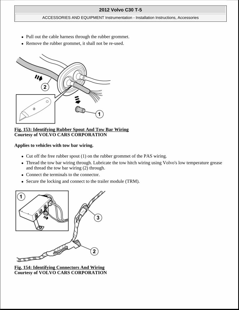
Pull out the cable harness through the rubber grommet.
Remove the rubber grommet, it shall not be re-used.
Fig. 153: Identifying Rubber Spout And Tow Bar Wiring Courtesy of VOLVO CARS CORPORATION
Applies to vehicles with tow bar wiring.
Cut off the free rubber spout (1) on the rubber grommet of the PAS wiring.
Thread the tow bar wiring through. Lubricate the tow hitch wiring using Volvo's low temperature grease and thread the tow bar wiring (2) through.
Connect the terminals to the connector.
Secure the locking and connect to the trailer module (TRM).
Fig. 154: Identifying Connectors And Wiring Courtesy of VOLVO CARS CORPORATION
2012 Volvo C30 T-5
ACCESSORIES AND EQUIPMENT Instrumentation - Installation Instructions, Accessories

The existing 5 pin green connector is connected to the trailer module (TRM) (1).
Detach the connector to the control module and connect it to the PAS wiring (2).
Disconnect the 5 pin green connector (3) that is taped to the wiring and connect it to the trailer module (TRM).
Fig. 155: Connecting Parking Assistance Connector And License Plate Lighting Connector And Re-Installing Bumper Cover Courtesy of VOLVO CARS CORPORATION
Raise the bumper cover to the car.
Connect the connectors for parking assistance and license plate lighting.
Reinstall the bumper cover with its screws.
Reinstall the stops for the tailgate.
Fig. 156: Identifying Panel Screw Courtesy of VOLVO CARS CORPORATION
2012 Volvo C30 T-5
ACCESSORIES AND EQUIPMENT Instrumentation - Installation Instructions, Accessories

Reinstall in the cargo compartment:
side panel
clips for the cargo floor support
sill molding
sill trim panel
applicable spare wheel
jack and other parts in the cargo floor support
the floor hatch
Fig. 157: Locating Ten Panel Clips Courtesy of VOLVO CARS CORPORATION
NOTE: There are 10 clips on the reverse of the panel that must engage in the body. Take care when aligning so that the clips do not break. Broken clips must be replaced with new ones.
2012 Volvo C30 T-5
ACCESSORIES AND EQUIPMENT Instrumentation - Installation Instructions, Accessories

Fig. 158: Identifying Panel Clips And Screws Courtesy of VOLVO CARS CORPORATION
Reinstall the side panel by first aligning it on the sill at the front edge and then pressing it against the body side, ensure that all clips engage.
Tighten the panel using existing screws.
Fig. 159: View Of B Pillar Panel Clips Courtesy of VOLVO CARS CORPORATION
Reinstall the panel with the safety clip.
Reinstall the weatherstrip.
Reinstall:
backrest - tighten the screw to 15 Nm (11 lbf. ft) .
the armrest
2012 Volvo C30 T-5
ACCESSORIES AND EQUIPMENT Instrumentation - Installation Instructions, Accessories

cushion
Fig. 160: Identifying VIDA (Volvo Scan Tool) To Program Software Courtesy of VOLVO CARS CORPORATION
Download software (application) for the accessory's function using VIDA (Volvo scan tool).
PARKING ASSISTANCE, REAR, CHASSIS NUMBER 190000- (2010-2012)
PARKING ASSISTANCE, REAR, CHASSIS NUMBER 190000-
Fig. 161: Identifying Rear Parking Assistance Sensor Courtesy of VOLVO CARS CORPORATION
2012 Volvo C30 T-5
ACCESSORIES AND EQUIPMENT Instrumentation - Installation Instructions, Accessories
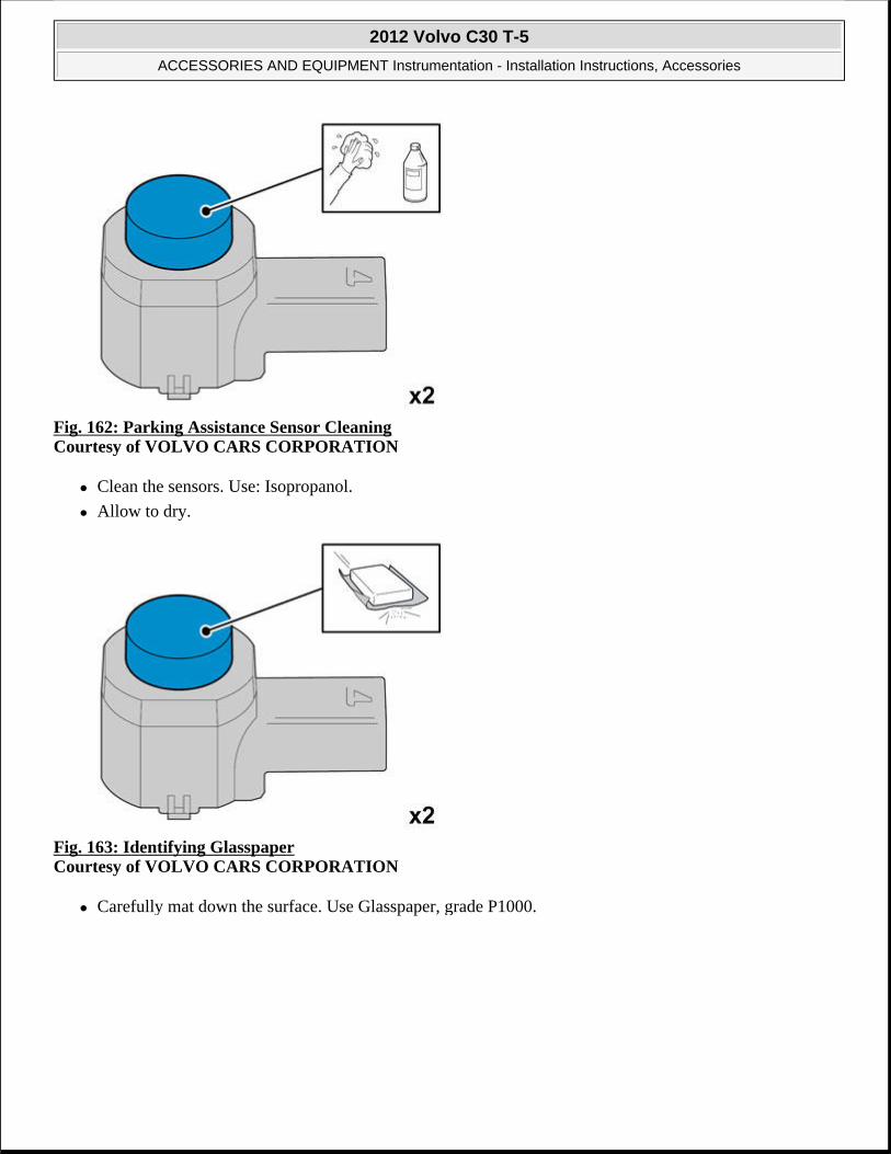
Fig. 162: Parking Assistance Sensor Cleaning Courtesy of VOLVO CARS CORPORATION
Clean the sensors. Use: Isopropanol.
Allow to dry.
Fig. 163: Identifying Glasspaper Courtesy of VOLVO CARS CORPORATION
Carefully mat down the surface. Use Glasspaper, grade P1000.
2012 Volvo C30 T-5
ACCESSORIES AND EQUIPMENT Instrumentation - Installation Instructions, Accessories

Fig. 164: Parking Assistance Sensor Cleaning Courtesy of VOLVO CARS CORPORATION
Clean the sensors again. Use: Isopropanol.
Allow to dry.
Avoid contact with the cleaned surfaces.
Fig. 165: Cleaning Cradles Using Isopropanol Courtesy of VOLVO CARS CORPORATION
Clean the cradles. Use: Isopropanol.
Allow to dry.
Avoid contact with the cleaned surfaces.
2012 Volvo C30 T-5
ACCESSORIES AND EQUIPMENT Instrumentation - Installation Instructions, Accessories

Fig. 166: Applying Bonding Primer P/N 31335448 To Cleaned Surface Courtesy of VOLVO CARS CORPORATION
Apply primer to the cleaned surface. Use: Bonding primer for plastic. P/N: 31335448 .
Fig. 167: Protect Electrical Connectors Courtesy of VOLVO CARS CORPORATION
CAUTION: Allow to dry at a temperature of at least +20°C for 10 min, before painting.
NOTE: Also read the instructions on the spray can.
CAUTION: protect the connections' contact surface against paint.
2012 Volvo C30 T-5
ACCESSORIES AND EQUIPMENT Instrumentation - Installation Instructions, Accessories

Paint the sensors in the same color code as the vehicle.
use Volvo Touch-up paint. (Only use base coat.)
Use: Volvo 2-K Varnish. P/N: 31335447 .
Fig. 168: Applying Bonding Primer P/N 31335448 To Cleaned Surface Courtesy of VOLVO CARS CORPORATION
Paint the holders in the same color code as the vehicle.
Use Volvo Touch-up paint (Only use base coat.)
Use: Volvo 2-K Varnish. P/N: 31335447 .
NOTE: Also read the instructions on the spray can.
NOTE: Also read the instructions on the spray can.
2012 Volvo C30 T-5
ACCESSORIES AND EQUIPMENT Instrumentation - Installation Instructions, Accessories

Fig. 169: Installing Sensor Bezel Courtesy of VOLVO CARS CORPORATION
Fig. 170: Installing Rear Parking Assistance Sensors Courtesy of VOLVO CARS CORPORATION
Fig. 171: Identifying Fender Liner Screws Courtesy of VOLVO CARS CORPORATION
Applies to both discs.
CAUTION: The paint must have dried after the first application.
2012 Volvo C30 T-5
ACCESSORIES AND EQUIPMENT Instrumentation - Installation Instructions, Accessories

Fig. 172: Identifying Underside Screws Courtesy of VOLVO CARS CORPORATION
Fig. 173: Identifying Area For Applying Tape Courtesy of VOLVO CARS CORPORATION
Applies to both sides.
2012 Volvo C30 T-5
ACCESSORIES AND EQUIPMENT Instrumentation - Installation Instructions, Accessories

Fig. 174: Prying Edge Of Rear Bumper Cover Courtesy of VOLVO CARS CORPORATION
Applies to both sides.
Fig. 175: Removing Rear Bumper Cover Courtesy of VOLVO CARS CORPORATION
2012 Volvo C30 T-5
ACCESSORIES AND EQUIPMENT Instrumentation - Installation Instructions, Accessories

Fig. 176: Removing Connector Courtesy of VOLVO CARS CORPORATION
Fig. 177: Locating Markings Inside Bumper Cover Courtesy of VOLVO CARS CORPORATION
Locate the 4 markings on the inside of the bumper cover.
2012 Volvo C30 T-5
ACCESSORIES AND EQUIPMENT Instrumentation - Installation Instructions, Accessories

Fig. 178: Marking Centers With Scribe Courtesy of VOLVO CARS CORPORATION
Mark center with a scribe.
Fig. 179: Drilling Through Centers Courtesy of VOLVO CARS CORPORATION
1. Ø 3 mm (7/64")
2. Ø 10 mm (25/64")
2012 Volvo C30 T-5
ACCESSORIES AND EQUIPMENT Instrumentation - Installation Instructions, Accessories

Fig. 180: Identifying Special Tool P/N 9997234 Courtesy of VOLVO CARS CORPORATION
Use special tool: P/N 9997234
Fig. 181: Identifying Special Tool P/N 9997392 Courtesy of VOLVO CARS CORPORATION
Use special tool: P/N 9997392 Hole tool
NOTE: The hole tool's support sleeve must be on the inside, and the cutting part on the outside of the bumper casing.
NOTE: The hole tool's support sleeve must be on the inside, and the cutting part on the outside of the bumper casing.
2012 Volvo C30 T-5
ACCESSORIES AND EQUIPMENT Instrumentation - Installation Instructions, Accessories

Fig. 182: Cleaning Surfaces Using Isopropanol (1 Of 3) Courtesy of VOLVO CARS CORPORATION
Clean the surfaces. Allow to dry.
Use: Isopropanol
Fig. 183: Cleaning Surfaces Using Isopropanol (2 Of 3) Courtesy of VOLVO CARS CORPORATION
Clean the surfaces. Allow to dry.
Use: Isopropanol
2012 Volvo C30 T-5
ACCESSORIES AND EQUIPMENT Instrumentation - Installation Instructions, Accessories

Fig. 184: Cleaning Surfaces Using Isopropanol (3 Of 3) Courtesy of VOLVO CARS CORPORATION
Clean the surfaces. Allow to dry.
Use: Isopropanol
Fig. 185: Applying Activator P/N 8637076 (1 Of 3) Courtesy of VOLVO CARS CORPORATION
Apply a thin and even layer of activator. Allow to dry for at least 10 minutes.
Use:P/N 8637076 Activator
2012 Volvo C30 T-5
ACCESSORIES AND EQUIPMENT Instrumentation - Installation Instructions, Accessories

Fig. 186: Applying Activator P/N 8637076 (2 Of 3) Courtesy of VOLVO CARS CORPORATION
Apply a thin and even layer of activator. Allow to dry for at least 10 minutes.
Use:P/N 8637076 Activator
Fig. 187: Applying Activator P/N 8637076 (3 Of 3) Courtesy of VOLVO CARS CORPORATION
Apply a thin and even layer of activator. Allow to dry for at least 10 minutes.
Use: P/N 8637076 Activator.
2012 Volvo C30 T-5
ACCESSORIES AND EQUIPMENT Instrumentation - Installation Instructions, Accessories

Fig. 188: Identifying Rear Seat Cushion Courtesy of VOLVO CARS CORPORATION
Pull off the seat cushion for the rear seat, first at the front edge where it is secured by two cradles. Then at the rear edge where it is secured by one cradle.
Remove the seat cushion.
Fig. 189: Identifying Central Arm Rest Courtesy of VOLVO CARS CORPORATION
Fold the central arm rest forward.
Remove the central arm rest by grasping each end and pulling upwards until it releases at the rear edge from the backrest's lugs (1).
Then pull forwards until the holders (2) on the sides of the backrest have slid out of the corresponding cut-out (3) in the central arm rest.
2012 Volvo C30 T-5
ACCESSORIES AND EQUIPMENT Instrumentation - Installation Instructions, Accessories
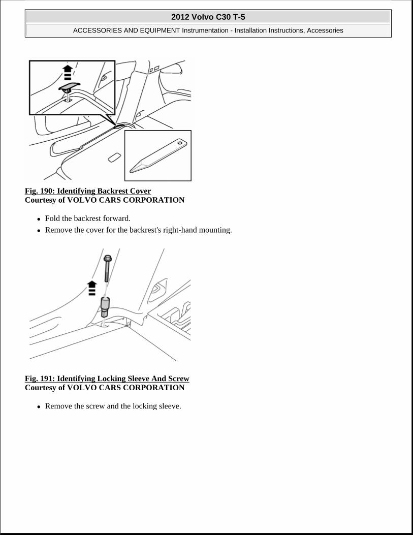
Fig. 190: Identifying Backrest Cover Courtesy of VOLVO CARS CORPORATION
Fold the backrest forward.
Remove the cover for the backrest's right-hand mounting.
Fig. 191: Identifying Locking Sleeve And Screw Courtesy of VOLVO CARS CORPORATION
Remove the screw and the locking sleeve.
2012 Volvo C30 T-5
ACCESSORIES AND EQUIPMENT Instrumentation - Installation Instructions, Accessories
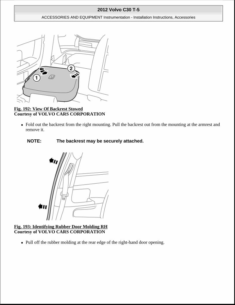
Fig. 192: View Of Backrest Stowed Courtesy of VOLVO CARS CORPORATION
Fold out the backrest from the right mounting. Pull the backrest out from the mounting at the armrest and remove it.
Fig. 193: Identifying Rubber Door Molding RH Courtesy of VOLVO CARS CORPORATION
Pull off the rubber molding at the rear edge of the right-hand door opening.
NOTE: The backrest may be securely attached.
2012 Volvo C30 T-5
ACCESSORIES AND EQUIPMENT Instrumentation - Installation Instructions, Accessories

Fig. 194: Identifying B Pillar Panel Courtesy of VOLVO CARS CORPORATION
Detach the B pillar panel at the lower edge by prying the sides using a weatherstrip tool until the 2 x clips release
Fig. 195: View Of Safety Clip Strap Courtesy of VOLVO CARS CORPORATION
Unhook the safety clip from the panel.
Angle out the panel at the lower edge, and then unhook it at the upper edge so that the upper clip releases.
2012 Volvo C30 T-5
ACCESSORIES AND EQUIPMENT Instrumentation - Installation Instructions, Accessories

Fig. 196: Identifying Rear Seat RH Panel Courtesy of VOLVO CARS CORPORATION
Remove the screw from the right-hand panel in the rear seat.
Carefully pull off the panel from the body side. It is secured by 11 clips on the inside.
Unhook it from the sill at the front edge.
Fig. 197: Identifying Trunk Floor Cover Courtesy of VOLVO CARS CORPORATION
Lift up the floor hatch at the rear edge.
Pull it backwards so that it detaches at the front edge.
Turn the cover and lift out.
2012 Volvo C30 T-5
ACCESSORIES AND EQUIPMENT Instrumentation - Installation Instructions, Accessories

Fig. 198: Identifying Tailgate's Sill Panel Courtesy of VOLVO CARS CORPORATION
Remove the tailgate's sill panel by pulling it up until the 4 clips on the upper side and the catches at the lower edge release.
Fig. 199: Identifying Right-Hand Rear Side Panel Courtesy of VOLVO CARS CORPORATION
Remove the clips at the rear edge of the right-hand rear side panel.
Carefully pull the side panel off, starting at the front edge/upper edge and then straight back until all clips at the top edge have released.
Fold the panel inwards. Release it from the anchorage eyelets and lift it out of the load floor support.
2012 Volvo C30 T-5
ACCESSORIES AND EQUIPMENT Instrumentation - Installation Instructions, Accessories

Fig. 200: View Of Spare Wheel, Jack And Other Parts From Storage Compartment Courtesy of VOLVO CARS CORPORATION
Lift out the spare wheel, jack and other parts from the storage compartment in the cargo floor support.
Fig. 201: Identifying Spare Wheel Compartment Screws Courtesy of VOLVO CARS CORPORATION
Remove the 4 screw clips from the cargo floor support.
2012 Volvo C30 T-5
ACCESSORIES AND EQUIPMENT Instrumentation - Installation Instructions, Accessories

Fig. 202: Installing Cradle Courtesy of VOLVO CARS CORPORATION
Fig. 203: Applying Tape P/N 1161347 Courtesy of VOLVO CARS CORPORATION
Use: 1161347 Tape.
NOTE: Prepare and install one cradle at a time.
2012 Volvo C30 T-5
ACCESSORIES AND EQUIPMENT Instrumentation - Installation Instructions, Accessories

Fig. 204: Peeling Backing From Tape Courtesy of VOLVO CARS CORPORATION
Fig. 205: Applying Adhesive Courtesy of VOLVO CARS CORPORATION
Apply a thin layer and even layer of adhesive.
Use special tool P/N 9512767 Adhesive gun
Use P/N 116173 Mixing pipe
Use P/N 9511027 Adhesive
CAUTION: The adhesive must not come into contact with the tape.
2012 Volvo C30 T-5
ACCESSORIES AND EQUIPMENT Instrumentation - Installation Instructions, Accessories
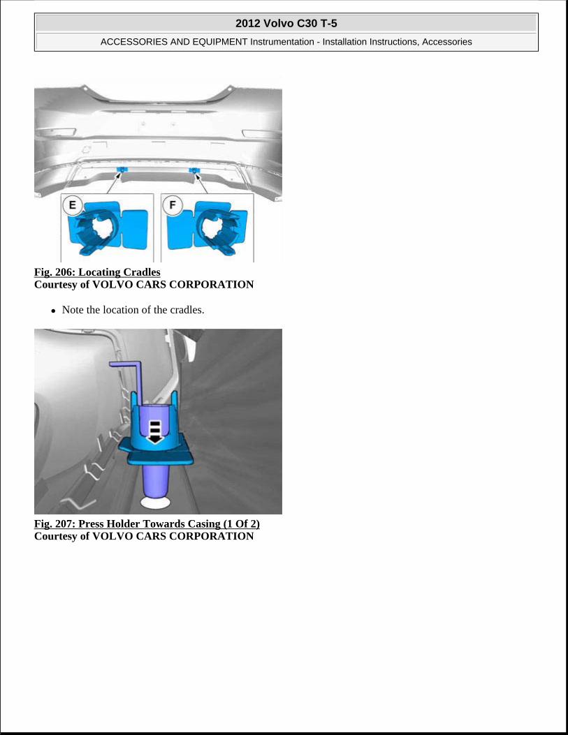
Fig. 206: Locating Cradles Courtesy of VOLVO CARS CORPORATION
Note the location of the cradles.
Fig. 207: Press Holder Towards Casing (1 Of 2) Courtesy of VOLVO CARS CORPORATION
2012 Volvo C30 T-5
ACCESSORIES AND EQUIPMENT Instrumentation - Installation Instructions, Accessories

Fig. 208: Press Holder Towards Casing (2 Of 2) Courtesy of VOLVO CARS CORPORATION
Press the holder towards the casing, but only at the places where there is tape.
Fig. 209: Removing Centering Tool From Cradle Courtesy of VOLVO CARS CORPORATION
Hold the cradle securely when removing the centering tool.
Repeat the method steps on the other cradle.
2012 Volvo C30 T-5
ACCESSORIES AND EQUIPMENT Instrumentation - Installation Instructions, Accessories

Fig. 210: Applying Tape P/N 1161347 Courtesy of VOLVO CARS CORPORATION
Use: 1161347 Tape.
Fig. 211: Peeling Backing From Tape Courtesy of VOLVO CARS CORPORATION
2012 Volvo C30 T-5
ACCESSORIES AND EQUIPMENT Instrumentation - Installation Instructions, Accessories

Fig. 212: Applying Adhesive Courtesy of VOLVO CARS CORPORATION
Apply a thin layer and even layer of adhesive.
Use special tool P/N 9512767 Adhesive gun
Use P/N 116173 Mixing pipe
Use P/N 9511027 Adhesive
Fig. 213: Locating Cradles Courtesy of VOLVO CARS CORPORATION
CAUTION: The adhesive must not come into contact with the tape.
2012 Volvo C30 T-5
ACCESSORIES AND EQUIPMENT Instrumentation - Installation Instructions, Accessories

Fig. 214: Installing Cradle (1 Of 2) Courtesy of VOLVO CARS CORPORATION
Fig. 215: Installing Cradle (2 Of 2) Courtesy of VOLVO CARS CORPORATION
Press the holder towards the casing, but only at the places where there is tape.
Repeat the method steps on the other cradle.
2012 Volvo C30 T-5
ACCESSORIES AND EQUIPMENT Instrumentation - Installation Instructions, Accessories

Fig. 216: Pressing Cable Harness Clips Into Flanges Of Bumper Cover Courtesy of VOLVO CARS CORPORATION
Press the cable harness clips onto the flanges of the bumper cover.
Fig. 217: Identifying Sensor Connector Courtesy of VOLVO CARS CORPORATION
Connect the two painted sensors to the two outer connections.
2012 Volvo C30 T-5
ACCESSORIES AND EQUIPMENT Instrumentation - Installation Instructions, Accessories

Fig. 218: Installing Sensor To Cradle Courtesy of VOLVO CARS CORPORATION
Fig. 219: Identifying Rubber Seal Below Right-Hand Tailgate Stop Courtesy of VOLVO CARS CORPORATION
Remove the rubber seal that is below the right-hand tailgate stop.
2012 Volvo C30 T-5
ACCESSORIES AND EQUIPMENT Instrumentation - Installation Instructions, Accessories

Fig. 220: Pulling Cable Through Hole In Cargo Compartment Courtesy of VOLVO CARS CORPORATION
Take the cable harness with the rubber grommet from the kit.
Pull the cable harness through the hole in the cargo compartment.
Place the rubber grommet in position.
Press the connector on the plastic bracket.
Fig. 221: Identifying Control Module And Holder Courtesy of VOLVO CARS CORPORATION
Take the control module and holder from the kit.
Press the holder onto the reverse of the control module.
2012 Volvo C30 T-5
ACCESSORIES AND EQUIPMENT Instrumentation - Installation Instructions, Accessories

Fig. 222: Connecting Pre-Routed Cable Harness Connector To Control Module Courtesy of VOLVO CARS CORPORATION
Connect the pre-routed cable harness connector to the control module.
Fig. 223: Lifting Right-Hand Side Cargo Floor Support Courtesy of VOLVO CARS CORPORATION
Raise the right-hand side cargo floor support.
NOTE: Ensure that the connector's catches click and are properly secured.
2012 Volvo C30 T-5
ACCESSORIES AND EQUIPMENT Instrumentation - Installation Instructions, Accessories

Fig. 224: Identifying Green 5 Pin Connector Courtesy of VOLVO CARS CORPORATION
Locate the green 5 pin connector that is taped to the ordinary cable harness on the vehicle.
Remove the tape and connect the connector to the control module's cable harness.
Fig. 225: Pressing Control Module Onto Floor Studs With Connections Facing Forward In Vehicle Courtesy of VOLVO CARS CORPORATION
Locate the 2 studs on the floor.
Press the control module onto these with the connections facing forwards in the vehicle.
2012 Volvo C30 T-5
ACCESSORIES AND EQUIPMENT Instrumentation - Installation Instructions, Accessories

Fig. 226: Securing Cable Harness Using Tie Straps Courtesy of VOLVO CARS CORPORATION
Secure the cable harness using 3 x tie straps.
Fig. 227: Identifying Secondary Lock Courtesy of VOLVO CARS CORPORATION
Applies to vehicles with tow bar wiring.
Detach the towbar wiring connector from the Trailer Module (TRM).
Release the terminal locking by pressing the catch down and pulling the locking straight out.
2012 Volvo C30 T-5
ACCESSORIES AND EQUIPMENT Instrumentation - Installation Instructions, Accessories

Fig. 228: View Of Cable Lug From Connector Courtesy of VOLVO CARS CORPORATION
Applies to vehicles with tow bar wiring.
Disconnect all terminals from the connector.
Use special tool P/N 9512810 or P/N 9512632 .
Insert the tool in the connector and release the locking.
Pull out the cable with terminal.
Pull out the cable harness through the rubber grommet.
Remove the rubber grommet, it shall not be re-used.
Fig. 229: Identifying Rubber Spout And Tow Bar Wiring Courtesy of VOLVO CARS CORPORATION
NOTE: Note the location of the cables in the connector.
2012 Volvo C30 T-5
ACCESSORIES AND EQUIPMENT Instrumentation - Installation Instructions, Accessories

Applies to vehicles with tow bar wiring.
Cut off the free rubber spout (1) on the rubber grommet of the PAS wiring.
Lubricate the tow hitch wiring using Volvo's low temperature grease and thread the tow bar wiring (2) through.
Connect the terminals to the connector.
Secure the locking and connect to the trailer module (TRM).
Fig. 230: Identifying Connectors And Wiring Courtesy of VOLVO CARS CORPORATION
Applies to vehicles with tow bar wiring.
The existing 5 pin green connector is connected to the trailer module (TRM) (1).
Disconnect the connector for the control module and connect it to the cable harness of parking assistance (2).
Disconnect the 5 pin green connector (3) that is taped to the cable harness and connect it to the trailer module (TRM).
2012 Volvo C30 T-5
ACCESSORIES AND EQUIPMENT Instrumentation - Installation Instructions, Accessories

Fig. 231: Connecting Parking Assistance Connector And License Plate Lighting Connector And Re-Installing Bumper Cover Courtesy of VOLVO CARS CORPORATION
Applies to all models
Raise the bumper cover to the car.
Connect the connectors for parking assistance and license plate lighting.
Reinstall the bumper cover with its screws.
Reinstall the stops for the tailgate.
Fig. 232: Identifying Panel Screw Courtesy of VOLVO CARS CORPORATION
Reinstall in the cargo compartment:
side panel
2012 Volvo C30 T-5
ACCESSORIES AND EQUIPMENT Instrumentation - Installation Instructions, Accessories

clips for the cargo floor support
sill molding
sill trim panel
applicable spare wheel
jack and other parts in the cargo floor support
the floor hatch
Fig. 233: Locating Ten Panel Clips Courtesy of VOLVO CARS CORPORATION
NOTE: There are 10 clips on the reverse of the panel that must engage in the body. Take care when aligning so that the clips do not break. Broken clips must be replaced with new ones.
2012 Volvo C30 T-5
ACCESSORIES AND EQUIPMENT Instrumentation - Installation Instructions, Accessories

Fig. 234: Identifying Panel Clips And ScrewsCourtesy of VOLVO CARS CORPORATION
Reinstall the side panel by first aligning it on the sill at the front edge and then pressing it against the body side, ensure that all clips engage.
Tighten the panel using existing screws.
Fig. 235: View Of B Pillar Panel Clips Courtesy of VOLVO CARS CORPORATION
Reinstall:
the panel with the safety clip and sill molding.
backrest, tighten the screw to 15 Nm (11 lbf. ft) .
the armrest
cushion
2012 Volvo C30 T-5
ACCESSORIES AND EQUIPMENT Instrumentation - Installation Instructions, Accessories

Fig. 236: Identifying VIDA (Volvo Scan Tool) To Program SoftwareCourtesy of VOLVO CARS CORPORATION
Download software (application) for the accessory's function using VIDA (Volvo scan tool).
PARKING ASSISTANCE, REAR, START/STOP (2010-2012)
PARKING ASSISTANCE, REAR, START/STOP
Fig. 237: Identifying Front Parking Assistance Sensor Courtesy of VOLVO CARS CORPORATION
Fig. 238: Cleaning Sensors
NOTE: There may be components in the accessories kit that are not used for this installation.
2012 Volvo C30 T-5
ACCESSORIES AND EQUIPMENT Instrumentation - Installation Instructions, Accessories

Courtesy of VOLVO CARS CORPORATION
Clean the sensors. Use: Isopropanol.
Allow to dry.
Fig. 239: Matting Surface Down Courtesy of VOLVO CARS CORPORATION
Carefully mat down the surface. Use Glasspaper, grade P1000.
Fig. 240: Cleaning Sensors Courtesy of VOLVO CARS CORPORATION
Clean the sensors again. Use: Isopropanol.
Allow to dry.
Avoid contact with the cleaned surfaces.
2012 Volvo C30 T-5
ACCESSORIES AND EQUIPMENT Instrumentation - Installation Instructions, Accessories
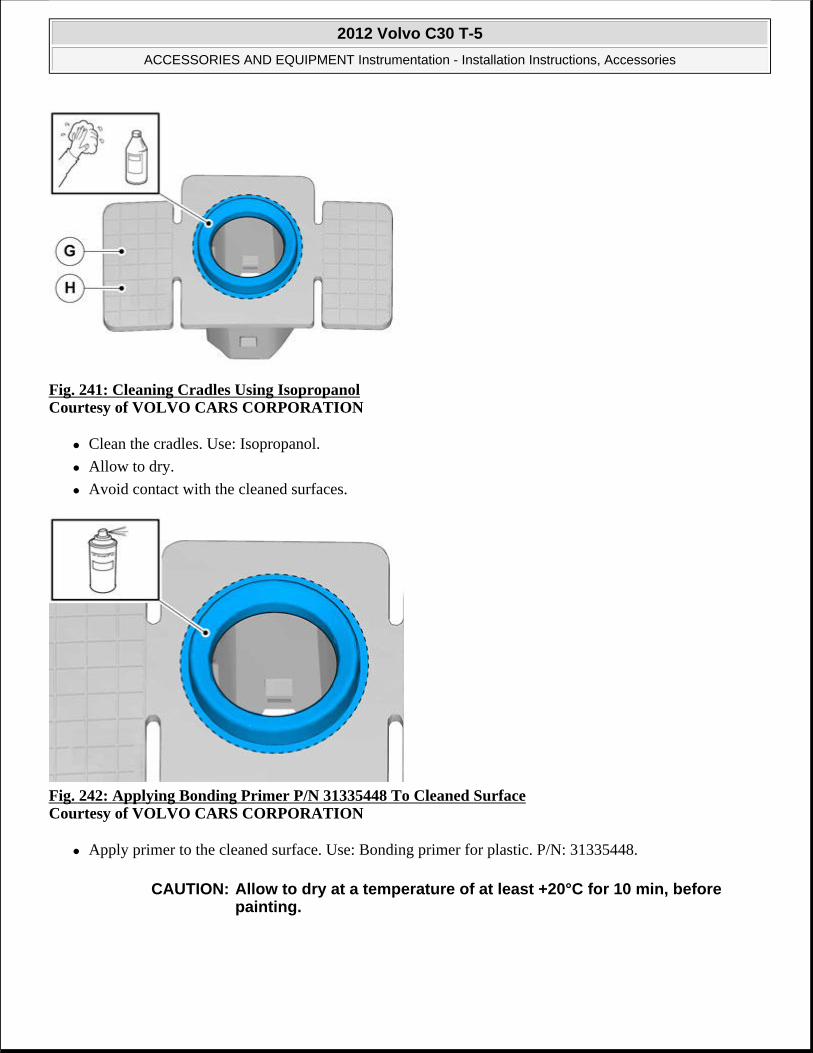
Fig. 241: Cleaning Cradles Using Isopropanol Courtesy of VOLVO CARS CORPORATION
Clean the cradles. Use: Isopropanol.
Allow to dry.
Avoid contact with the cleaned surfaces.
Fig. 242: Applying Bonding Primer P/N 31335448 To Cleaned Surface Courtesy of VOLVO CARS CORPORATION
Apply primer to the cleaned surface. Use: Bonding primer for plastic. P/N: 31335448.
CAUTION: Allow to dry at a temperature of at least +20°C for 10 min, before painting.
2012 Volvo C30 T-5
ACCESSORIES AND EQUIPMENT Instrumentation - Installation Instructions, Accessories

Fig. 243: Protect Electrical Connectors Courtesy of VOLVO CARS CORPORATION
Paint the sensors in color code 426 .
Use Volvo Touch-up paint. (Only use base coat.)
Use: Volvo 2-K Varnish. P/N: 31335447.
Fig. 244: Protect Electrical Connectors
NOTE: Also read the instructions on the spray can.
CAUTION: Protect the connections' contact surfaces against paint.
NOTE: Also read the instructions on the spray can.
2012 Volvo C30 T-5
ACCESSORIES AND EQUIPMENT Instrumentation - Installation Instructions, Accessories

Courtesy of VOLVO CARS CORPORATION
Paint the sensors in the same color code as the vehicle.
Use Volvo Touch-up paint. (Only use base coat.)
Use: Volvo 2-K Varnish. P/N: 31335447.
Fig. 245: Applying Bonding Primer P/N 31335448 To Cleaned Surface Courtesy of VOLVO CARS CORPORATION
Paint the holders in the same color code as the vehicle.
Use Volvo Touch-up paint. (Only use base coat.)
Use: Volvo 2-K Varnish. P/N: 31335447.
CAUTION: Protect the connections' contact surfaces against paint.
NOTE: Also read the instructions on the spray can.
NOTE: Also read the instructions on the spray can.
2012 Volvo C30 T-5
ACCESSORIES AND EQUIPMENT Instrumentation - Installation Instructions, Accessories
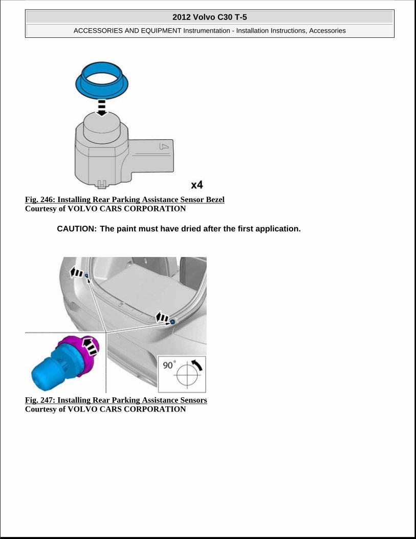
Fig. 246: Installing Rear Parking Assistance Sensor Bezel Courtesy of VOLVO CARS CORPORATION
Fig. 247: Installing Rear Parking Assistance Sensors Courtesy of VOLVO CARS CORPORATION
CAUTION: The paint must have dried after the first application.
2012 Volvo C30 T-5
ACCESSORIES AND EQUIPMENT Instrumentation - Installation Instructions, Accessories

Fig. 248: Identifying Fender Liner Screws Courtesy of VOLVO CARS CORPORATION
Carry out on both sides.
Fig. 249: Identifying Underside Screws Courtesy of VOLVO CARS CORPORATION
Remove the screws.
2012 Volvo C30 T-5
ACCESSORIES AND EQUIPMENT Instrumentation - Installation Instructions, Accessories

Fig. 250: Identifying Area For Applying Tape Courtesy of VOLVO CARS CORPORATION
Carry out on both sides.
Fig. 251: Prying Edge Of Rear Bumper Cover Courtesy of VOLVO CARS CORPORATION
Carry out on both sides.
2012 Volvo C30 T-5
ACCESSORIES AND EQUIPMENT Instrumentation - Installation Instructions, Accessories

Fig. 252: Removing Rear Bumper Cover Courtesy of VOLVO CARS CORPORATION
Fig. 253: Removing Connector Courtesy of VOLVO CARS CORPORATION
2012 Volvo C30 T-5
ACCESSORIES AND EQUIPMENT Instrumentation - Installation Instructions, Accessories

Fig. 254: Locating Markings On Inside Of Bumper Cover (1 Of 2) Courtesy of VOLVO CARS CORPORATION
Locate the 2 x markings on the inside of the bumper cover.
Fig. 255: Locating Markings On Inside Of Bumper Cover (2 Of 2) Courtesy of VOLVO CARS CORPORATION
Locate the 2 markings on the inside of the bumper cover.
2012 Volvo C30 T-5
ACCESSORIES AND EQUIPMENT Instrumentation - Installation Instructions, Accessories

Fig. 256: Marking Centers With Scribe Courtesy of VOLVO CARS CORPORATION
Mark center with a scribe.
Fig. 257: Drilling Through Centers Courtesy of VOLVO CARS CORPORATION
1. Ø 3 mm (7/64")
2. Ø 10 mm (25/64")
2012 Volvo C30 T-5
ACCESSORIES AND EQUIPMENT Instrumentation - Installation Instructions, Accessories

Fig. 258: Identifying Special Tool P/N 9997234 Courtesy of VOLVO CARS CORPORATION
Use special tool: P/N 9997234
Fig. 259: Identifying Special Tool P/N 9997392 Courtesy of VOLVO CARS CORPORATION
Use special tool:P/N 9997392 Hole tool
NOTE: The hole tool's support sleeve must be on the inside, and the cutting part on the outside of the bumper casing.
NOTE: The hole tool's support sleeve must be on the inside, and the cutting part on the outside of the bumper casing.
2012 Volvo C30 T-5
ACCESSORIES AND EQUIPMENT Instrumentation - Installation Instructions, Accessories

Fig. 260: Cleaning Surfaces Using Isopropanol (1 Of 3) Courtesy of VOLVO CARS CORPORATION
Clean the surfaces. Allow to dry.
Use:Isopropanol
Fig. 261: Cleaning Surfaces Using Isopropanol (2 Of 3) Courtesy of VOLVO CARS CORPORATION
Clean the surfaces. Allow to dry.
Use: Isopropanol
2012 Volvo C30 T-5
ACCESSORIES AND EQUIPMENT Instrumentation - Installation Instructions, Accessories

Fig. 262: Cleaning Surfaces Using Isopropanol (3 Of 3) Courtesy of VOLVO CARS CORPORATION
Clean the surfaces. Allow to dry.
Use:Isopropanol
Fig. 263: Applying Activator P/N 8637076 Courtesy of VOLVO CARS CORPORATION
Apply a thin and even layer of activator. Allow to dry for at least 10 minutes.
Use: P/N 8637076 Activator
2012 Volvo C30 T-5
ACCESSORIES AND EQUIPMENT Instrumentation - Installation Instructions, Accessories

Fig. 264: Applying Activator P/N 8637076 (1 Of 3) Courtesy of VOLVO CARS CORPORATION
Apply a thin and even layer of activator. Allow to dry for at least 10 minutes.
Use: P/N 8637076 Activator
Fig. 265: Applying Activator P/N 8637076 (2 Of 3) Courtesy of VOLVO CARS CORPORATION
Apply a thin and even layer of activator. Allow to dry for at least 10 minutes.
Use: P/N 8637076 Activator .
2012 Volvo C30 T-5
ACCESSORIES AND EQUIPMENT Instrumentation - Installation Instructions, Accessories

Fig. 266: Applying Activator P/N 8637076 (3 Of 3) Courtesy of VOLVO CARS CORPORATION
Apply a thin and even layer of activator. Allow to dry for at least 10 minutes.
Use: P/N 8637076 Activator .
Fig. 267: Identifying Rear Seat Cushion Courtesy of VOLVO CARS CORPORATION
Pull off the seat cushion for the rear seat, first at the front edge where it is secured by two cradles. Then at the rear edge where it is secured by one cradle.
Remove the seat cushion.
2012 Volvo C30 T-5
ACCESSORIES AND EQUIPMENT Instrumentation - Installation Instructions, Accessories

Fig. 268: Identifying Central Arm Rest Courtesy of VOLVO CARS CORPORATION
Fold the central arm rest forward.
Remove the central arm rest by grasping each end and pulling upwards until it releases at the rear edge from the backrest's lugs (1).
Then pull forwards until the holders (2) on the sides of the backrest have slid out of the corresponding cut-out (3) in the central arm rest.
Fig. 269: Identifying Backrest Cover Courtesy of VOLVO CARS CORPORATION
Fold the backrest forward.
Remove the cover for the backrest's right-hand mounting.
2012 Volvo C30 T-5
ACCESSORIES AND EQUIPMENT Instrumentation - Installation Instructions, Accessories

Fig. 270: Identifying Locking Sleeve And Screw Courtesy of VOLVO CARS CORPORATION
Remove the screw and the locking sleeve.
Fig. 271: View Of Backrest Stowed Courtesy of VOLVO CARS CORPORATION
Fold out the backrest from the right mounting. Pull the backrest out from the mounting at the armrest and remove it.
NOTE: The backrest may be securely attached.
2012 Volvo C30 T-5
ACCESSORIES AND EQUIPMENT Instrumentation - Installation Instructions, Accessories

Fig. 272: Identifying Rubber Door Molding RH Courtesy of VOLVO CARS CORPORATION
Pull off the rubber molding at the rear edge of the right-hand door opening.
Fig. 273: Identifying B Pillar Panel Courtesy of VOLVO CARS CORPORATION
Detach the B pillar panel at the lower edge by prying the sides using a weatherstrip tool until the 2 x clips release
2012 Volvo C30 T-5
ACCESSORIES AND EQUIPMENT Instrumentation - Installation Instructions, Accessories

Fig. 274: View Of Safety Clip Strap Courtesy of VOLVO CARS CORPORATION
Unhook the safety clip from the panel.
Angle out the panel at the lower edge, and then unhook it at the upper edge so that the upper clip releases.
Fig. 275: Identifying Rear Seat RH Panel Courtesy of VOLVO CARS CORPORATION
Remove the screw from the right-hand panel in the rear seat.
Carefully pull off the panel from the body side. It is secured by 11 clips on the inside.
Unhook it from the sill at the front edge.
2012 Volvo C30 T-5
ACCESSORIES AND EQUIPMENT Instrumentation - Installation Instructions, Accessories

Fig. 276: Identifying Trunk Floor Cover Courtesy of VOLVO CARS CORPORATION
Lift up the floor hatch at the rear edge.
Pull it backwards so that it detaches at the front edge.
Turn the cover and lift out.
Fig. 277: Identifying Tailgate's Sill Panel Courtesy of VOLVO CARS CORPORATION
Remove the tailgate's sill panel by pulling it up until the 4 clips on the upper side and the catches at the lower edge release.
2012 Volvo C30 T-5
ACCESSORIES AND EQUIPMENT Instrumentation - Installation Instructions, Accessories

Fig. 278: Identifying Right-Hand Rear Side Panel Courtesy of VOLVO CARS CORPORATION
Remove the clips at the rear edge of the right-hand rear side panel.
Carefully pull the side panel off, starting at the front edge/upper edge and then straight back until all clips at the top edge have released.
Fold the panel inwards. Release it from the anchorage eyelets and lift it out of the load floor support.
Fig. 279: View Of Spare Wheel, Jack And Other Parts From Storage Compartment Courtesy of VOLVO CARS CORPORATION
Lift out the spare wheel, jack and other parts from the storage compartment in the cargo floor support.
2012 Volvo C30 T-5
ACCESSORIES AND EQUIPMENT Instrumentation - Installation Instructions, Accessories

Fig. 280: Identifying Spare Wheel Compartment Screws Courtesy of VOLVO CARS CORPORATION
Remove the 4 screw clips from the cargo floor support.
Fig. 281: Peeling Backing From Tape Courtesy of VOLVO CARS CORPORATION
2012 Volvo C30 T-5
ACCESSORIES AND EQUIPMENT Instrumentation - Installation Instructions, Accessories

Fig. 282: Installing Tape Courtesy of VOLVO CARS CORPORATION
Fig. 283: Identifying Cutting Dimensions (1 Of 2) Courtesy of VOLVO CARS CORPORATION
2012 Volvo C30 T-5
ACCESSORIES AND EQUIPMENT Instrumentation - Installation Instructions, Accessories

Fig. 284: Identifying Cutting Dimensions (2 Of 2) Courtesy of VOLVO CARS CORPORATION
Fig. 285: Installing Cradle Courtesy of VOLVO CARS CORPORATION
NOTE: Prepare and install one cradle at a time.
2012 Volvo C30 T-5
ACCESSORIES AND EQUIPMENT Instrumentation - Installation Instructions, Accessories

Fig. 286: Peeling Backing From Tape Courtesy of VOLVO CARS CORPORATION
Fig. 287: Locating Cradles Courtesy of VOLVO CARS CORPORATION
Note the location of the cradles.
2012 Volvo C30 T-5
ACCESSORIES AND EQUIPMENT Instrumentation - Installation Instructions, Accessories

Fig. 288: Installing Cradle (1 Of 2) Courtesy of VOLVO CARS CORPORATION
Fig. 289: Installing Cradle (2 Of 2) Courtesy of VOLVO CARS CORPORATION
Press the cradle against the cover.
2012 Volvo C30 T-5
ACCESSORIES AND EQUIPMENT Instrumentation - Installation Instructions, Accessories
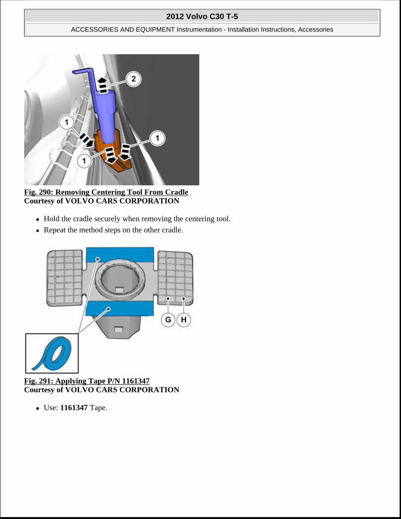
Fig. 290: Removing Centering Tool From Cradle Courtesy of VOLVO CARS CORPORATION
Hold the cradle securely when removing the centering tool.
Repeat the method steps on the other cradle.
Fig. 291: Applying Tape P/N 1161347 Courtesy of VOLVO CARS CORPORATION
Use: 1161347 Tape.
2012 Volvo C30 T-5
ACCESSORIES AND EQUIPMENT Instrumentation - Installation Instructions, Accessories

Fig. 292: Peeling Backing From Tape Courtesy of VOLVO CARS CORPORATION
Fig. 293: Applying Adhesive Courtesy of VOLVO CARS CORPORATION
Apply a thin layer and even layer of adhesive.
Use special tool P/N 9512767 Adhesive gun
Use P/N 116173 Mixing pipe
Use P/N 9511027 Adhesive
CAUTION: The adhesive must not come into contact with the tape.
2012 Volvo C30 T-5
ACCESSORIES AND EQUIPMENT Instrumentation - Installation Instructions, Accessories

Fig. 294: Locating Cradles Courtesy of VOLVO CARS CORPORATION
Note the location of the cradles.
Fig. 295: Installing Cradle (1 Of 2) Courtesy of VOLVO CARS CORPORATION
2012 Volvo C30 T-5
ACCESSORIES AND EQUIPMENT Instrumentation - Installation Instructions, Accessories
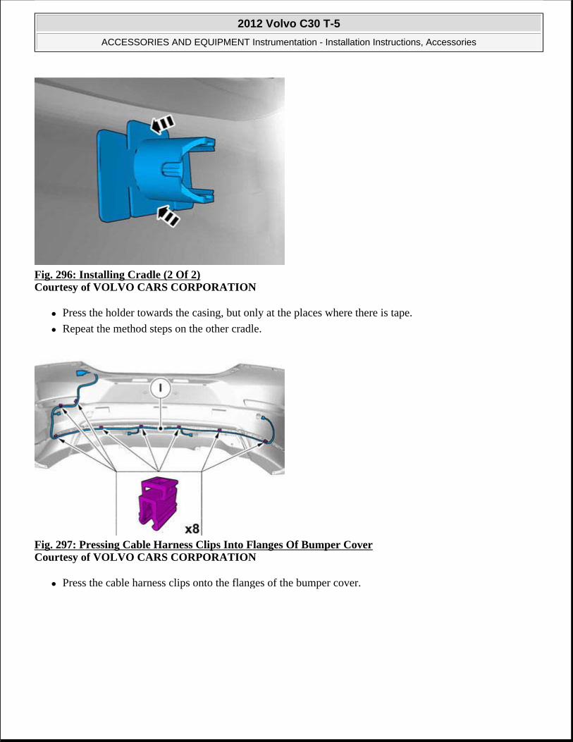
Fig. 296: Installing Cradle (2 Of 2) Courtesy of VOLVO CARS CORPORATION
Press the holder towards the casing, but only at the places where there is tape.
Repeat the method steps on the other cradle.
Fig. 297: Pressing Cable Harness Clips Into Flanges Of Bumper Cover Courtesy of VOLVO CARS CORPORATION
Press the cable harness clips onto the flanges of the bumper cover.
2012 Volvo C30 T-5
ACCESSORIES AND EQUIPMENT Instrumentation - Installation Instructions, Accessories

Fig. 298: Identifying Sensor Connector Courtesy of VOLVO CARS CORPORATION
Connect the two silver sensors to the two center connections.
Fig. 299: Installing Sensor To Cradle Courtesy of VOLVO CARS CORPORATION
2012 Volvo C30 T-5
ACCESSORIES AND EQUIPMENT Instrumentation - Installation Instructions, Accessories

Fig. 300: Identifying Rubber Seal Below Right-Hand Tailgate Stop Courtesy of VOLVO CARS CORPORATION
Remove the rubber seal that is below the right-hand tailgate stop.
Fig. 301: Pulling Cable Through Hole In Cargo Compartment Courtesy of VOLVO CARS CORPORATION
Take the cable harness with the rubber grommet from the kit.
Pull the cable harness through the hole in the cargo compartment.
Place the rubber grommet in position.
Press the connector on the plastic bracket.
2012 Volvo C30 T-5
ACCESSORIES AND EQUIPMENT Instrumentation - Installation Instructions, Accessories

Fig. 302: Identifying Control Module And Holder Courtesy of VOLVO CARS CORPORATION
Take the control module and holder from the kit.
Press the holder onto the reverse of the control module.
Fig. 303: Connecting Pre-Routed Cable Harness Connector To Control Module Courtesy of VOLVO CARS CORPORATION
Connect the pre-routed cable harness connector to the control module.
NOTE: Ensure that the connector's catches click and are properly secured.
2012 Volvo C30 T-5
ACCESSORIES AND EQUIPMENT Instrumentation - Installation Instructions, Accessories

Fig. 304: Lifting Right-Hand Side Cargo Floor Support Courtesy of VOLVO CARS CORPORATION
Raise the right-hand side cargo floor support.
Fig. 305: Identifying Green 5 Pin Connector Courtesy of VOLVO CARS CORPORATION
Locate the green 5 pin connector that is taped to the ordinary cable harness on the vehicle.
Remove the tape and connect the connector to the control module's cable harness.
2012 Volvo C30 T-5
ACCESSORIES AND EQUIPMENT Instrumentation - Installation Instructions, Accessories

Fig. 306: Pressing Control Module Onto Floor Studs With Connections Facing Forward In Vehicle Courtesy of VOLVO CARS CORPORATION
Locate the 2 studs on the floor.
Press the control module onto these with the connections facing forwards in the vehicle.
Fig. 307: Securing Cable Harness Using Tie Straps Courtesy of VOLVO CARS CORPORATION
Secure the cable harness using 3 x tie straps.
2012 Volvo C30 T-5
ACCESSORIES AND EQUIPMENT Instrumentation - Installation Instructions, Accessories

Fig. 308: Identifying Secondary Lock Courtesy of VOLVO CARS CORPORATION
Applies to vehicles with tow bar wiring.
Detach the towbar wiring connector from the Trailer Module (TRM).
Release the terminal locking by pressing the catch down and pulling the locking straight out.
Fig. 309: View Of Cable Lug From Connector Courtesy of VOLVO CARS CORPORATION
Disconnect all terminals from the connector.
Use special tool P/N 9512810 or P/N 9512632 .
Insert the tool in the connector and release the locking.
NOTE: Note the location of the cables in the connector.
2012 Volvo C30 T-5
ACCESSORIES AND EQUIPMENT Instrumentation - Installation Instructions, Accessories

Pull out the cable with terminal.
Pull out the cable harness through the rubber grommet.
Remove the rubber grommet, it shall not be re-used.
Fig. 310: Identifying Rubber Spout And Tow Bar Wiring Courtesy of VOLVO CARS CORPORATION
Cut off the free rubber spout (1) on the rubber grommet of the PAS wiring.
Lubricate the tow hitch wiring using Volvo's low temperature grease and thread the tow bar wiring (2) through.
Connect the terminals to the connector.
Secure the locking and connect to the trailer module (TRM).
Fig. 311: Identifying Connectors And Wiring Courtesy of VOLVO CARS CORPORATION
The existing 5 pin green connector is connected to the trailer module (TRM) (1).
2012 Volvo C30 T-5
ACCESSORIES AND EQUIPMENT Instrumentation - Installation Instructions, Accessories

Disconnect the connector for the control module and connect it to the cable harness of parking assistance (2).
Disconnect the 5 pin green connector (3) that is taped to the cable harness and connect it to the trailer module (TRM).
APPLIES TO ALL MODELS
Fig. 312: Connecting Parking Assistance Connector And License Plate Lighting Connector And Re-Installing Bumper Cover Courtesy of VOLVO CARS CORPORATION
Raise the bumper cover to the car.
Connect the connectors for parking assistance and license plate lighting.
Reinstall the bumper cover with its screws.
Reinstall the stops for the tailgate.
Fig. 313: Identifying Panel Screw
2012 Volvo C30 T-5
ACCESSORIES AND EQUIPMENT Instrumentation - Installation Instructions, Accessories

Courtesy of VOLVO CARS CORPORATION
Reinstall in the cargo compartment:
side panel
clips for the cargo floor support
sill molding
sill trim panel
applicable spare wheel
jack and other parts in the cargo floor support
the floor hatch
Fig. 314: Locating Ten Panel Clips Courtesy of VOLVO CARS CORPORATION
NOTE: There are 10 clips on the reverse of the panel that must engage in the body. Take care when aligning so that the clips do not break. Broken clips must be replaced with new ones.
2012 Volvo C30 T-5
ACCESSORIES AND EQUIPMENT Instrumentation - Installation Instructions, Accessories

Fig. 315: Identifying Panel Clips And Screws Courtesy of VOLVO CARS CORPORATION
Reinstall the side panel by first aligning it on the sill at the front edge and then pressing it against the body side, ensure that all clips engage.
Tighten the panel using existing screws.
Fig. 316: View Of B Pillar Panel Clips Courtesy of VOLVO CARS CORPORATION
Reinstall:
the panel with the safety clip and sill molding.
backrest, tighten the screw to 15 Nm (11 lbf. ft) .
the armrest
cushion
2012 Volvo C30 T-5
ACCESSORIES AND EQUIPMENT Instrumentation - Installation Instructions, Accessories
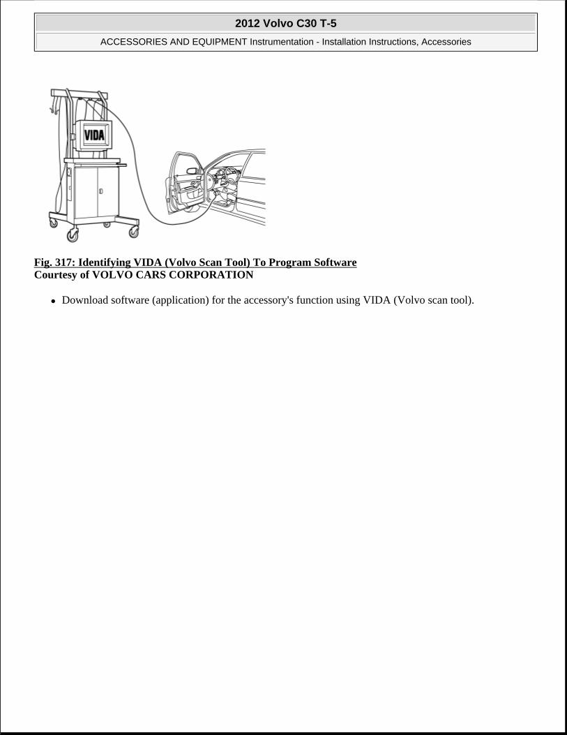
Fig. 317: Identifying VIDA (Volvo Scan Tool) To Program Software Courtesy of VOLVO CARS CORPORATION
Download software (application) for the accessory's function using VIDA (Volvo scan tool).
2012 Volvo C30 T-5
ACCESSORIES AND EQUIPMENT Instrumentation - Installation Instructions, Accessories

ACCESSORIES AND EQUIPMENT
Instrumentation - Removal, Replacement And Installation
COMBINED INSTRUMENT
COMBINED INSTRUMENT PANEL
REMOVAL
Fig. 1: Identifying Ignition In OFF Position Courtesy of VOLVO CARS CORPORATION
Fig. 2: Removing/Installing Air Bag Courtesy of VOLVO CARS CORPORATION
CAUTION: The control module must be removed, reinstalled and downloaded with software before the control module is replaced.
2012 Volvo C30 T-5
ACCESSORIES AND EQUIPMENT Instrumentation - Removal, Replacement And Installation
2012 Volvo C30 T-5
ACCESSORIES AND EQUIPMENT Instrumentation - Removal, Replacement And Installation

Fig. 3: Identifying Instrument Panel Bezel Screws Courtesy of VOLVO CARS CORPORATION
Fig. 4: Identifying Instrument Panel Screws Courtesy of VOLVO CARS CORPORATION
2012 Volvo C30 T-5
ACCESSORIES AND EQUIPMENT Instrumentation - Removal, Replacement And Installation

Fig. 5: View Of Instrument Panel ConnectorCourtesy of VOLVO CARS CORPORATION
INSTALLATION
To install, reverse the removal procedure.
Order and download software according to 30668197
Set the clock.
WARNING SYSTEM
POSITION SENSOR, BRAKE PEDAL
PREPARATORY WORK
CAUTION: Take extra care when handling the component.
NOTE: The graphics in this service information are used for different model years and/or models. Some variation may occur. However, the essential information in the graphics is always correct.
2012 Volvo C30 T-5
ACCESSORIES AND EQUIPMENT Instrumentation - Removal, Replacement And Installation

Fig. 6: Identifying Battery Box Courtesy of VOLVO CARS CORPORATION
Remove:
the battery. See BATTERY
the 3 screws
the battery box.
REMOVAL
REMOVING SPLASH GUARDS
2012 Volvo C30 T-5
ACCESSORIES AND EQUIPMENT Instrumentation - Removal, Replacement And Installation

Fig. 7: Identifying Cowl Fasteners Courtesy of VOLVO CARS CORPORATION
Remove the 3 clips holding the cowl.
2012 Volvo C30 T-5
ACCESSORIES AND EQUIPMENT Instrumentation - Removal, Replacement And Installation

Fig. 8: Identifying Brake Fluid Reservoir Protective Cover Courtesy of VOLVO CARS CORPORATION
Carefully lift up the cowl. Remove the 2 clips for the protective cover. Remove the protective cover over the brake fluid reservoir.
2012 Volvo C30 T-5
ACCESSORIES AND EQUIPMENT Instrumentation - Removal, Replacement And Installation

Fig. 9: Identifying Firewall Upper Protective Cover Nut Courtesy of VOLVO CARS CORPORATION
Remove
the plastic nut, x1
the upper protective cover for the firewall.
REMOVING THE PEDAL SENSOR
2012 Volvo C30 T-5
ACCESSORIES AND EQUIPMENT Instrumentation - Removal, Replacement And Installation

Fig. 10: Identifying Pressure Sensor Courtesy of VOLVO CARS CORPORATION
Pull out the pressure sensor (1) to eliminate any vacuum in the power brake booster. Disconnect the connector (2).
2012 Volvo C30 T-5
ACCESSORIES AND EQUIPMENT Instrumentation - Removal, Replacement And Installation

Fig. 11: Identifying Pedal Sensor Courtesy of VOLVO CARS CORPORATION
Open the snap ring and pull out the pedal sensor.
HINT: The opening on the snap ring points straight down. The snap ring does not need to be completely removed, just opened.
INSTALLATION
INSTALLING THE PEDAL SENSOR
Press in the new pedal sensor.
NOTE: Make sure that the O-ring is also removed.
NOTE: For tightening torques, see TIGHTENING TORQUE .
NOTE: Use new O-ring. The pedal sensor can only be installed in one position, i. e. with the guide pin pointing straight up.
2012 Volvo C30 T-5
ACCESSORIES AND EQUIPMENT Instrumentation - Removal, Replacement And Installation

Fig. 12: Identifying Pressure Sensor Courtesy of VOLVO CARS CORPORATION
Lubricate with soap solution and install the pressure sensor (1). Connect the connector (2).
INSTALLING THE PROTECTIVE COVERS
2012 Volvo C30 T-5
ACCESSORIES AND EQUIPMENT Instrumentation - Removal, Replacement And Installation

Fig. 13: Identifying Firewall Upper Protective Cover Nut Courtesy of VOLVO CARS CORPORATION
Install:
the protective cover for the firewall
the plastic nut, x1.
2012 Volvo C30 T-5
ACCESSORIES AND EQUIPMENT Instrumentation - Removal, Replacement And Installation

Fig. 14: Identifying Brake Fluid Reservoir Protective Cover Courtesy of VOLVO CARS CORPORATION
Install the protective cover over the brake fluid reservoir. Carefully lift up the cowl. Install the 2 clips for the protective cover.
2012 Volvo C30 T-5
ACCESSORIES AND EQUIPMENT Instrumentation - Removal, Replacement And Installation

Fig. 15: Identifying Cowl Fasteners Courtesy of VOLVO CARS CORPORATION
Install the 3 clips holding the cowl.
FINISHING
Install:
the battery box
the 3 M6 screws
the battery as shown. See BATTERY .
SENSOR FOR INDICATOR AND WARNING SYSTEMS (2007-12)
ACCELEROMETER AND YAW ANGLE SENSOR
PREPARATORY WORK
NOTE: The graphics in this service information are used for different model years and/or models. Some variation may occur. However, the essential information in the graphics is always correct.
2012 Volvo C30 T-5
ACCESSORIES AND EQUIPMENT Instrumentation - Removal, Replacement And Installation

IGNITION OFF
Fig. 16: Identifying Ignition In OFF Position Courtesy of VOLVO CARS CORPORATION
Ignition off.
REMOVAL
REMOVING PANEL AND SEAT RAIL
2012 Volvo C30 T-5
ACCESSORIES AND EQUIPMENT Instrumentation - Removal, Replacement And Installation

Fig. 17: Identifying Seat Rail Screws Courtesy of VOLVO CARS CORPORATION
Remove:
the panels over the screws for the seat rails
the 4 M10 screws for the seat rails.
2012 Volvo C30 T-5
ACCESSORIES AND EQUIPMENT Instrumentation - Removal, Replacement And Installation

Fig. 18: Slide Seat Back And Fold Carpet Aside Courtesy of VOLVO CARS CORPORATION
Slide the seat back and fold the carpet to one side.
REMOVING BODY SENSOR CLUSTER (BSC)
2012 Volvo C30 T-5
ACCESSORIES AND EQUIPMENT Instrumentation - Removal, Replacement And Installation

Fig. 19: Identifying Body Sensor Cluster Bracket Screws Courtesy of VOLVO CARS CORPORATION
Remove:
the 2 screws for the bracket
the connector
the body sensor cluster (BSC).
Replace the sensor assembly together with the bracket.
INSTALLATION
INSTALLING BODY SENSOR CLUSTER (BSC)
Install:
NOTE: Handle the body sensor cluster (BSC) with care as it is sensitive to mechanical damage.
NOTE: For tightening torques, see TIGHTENING TORQUE
2012 Volvo C30 T-5
ACCESSORIES AND EQUIPMENT Instrumentation - Removal, Replacement And Installation

body sensor cluster (BSC)
the 2 screws for the bracket. Tighten. See TIGHTENING TORQUE
the connector.
INSTALLING PANEL AND SEAT RAIL
Fold the carpet back into position. Slide the seat back into position.
Install:
the 4 M10 screws for the seat rails
the panels over the screws for the seat rails.
FINISHING
CHECKING AND ADJUSTING
Perform calibration. See VIDA, Vehicle communication, calibration.
Fig. 20: Identifying Cluster Warning Symbol Courtesy of VOLVO CARS CORPORATION
2012 Volvo C30 T-5
ACCESSORIES AND EQUIPMENT Instrumentation - Removal, Replacement And Installation

Turn on the ignition.
In the event of a fault in the sensor, the warning symbol is constantly lit and a fault message appears in the display on the driver information module (DIM).
Test drive the car after repair. See TEST DRIVE FORM (DSTC (DYNAMIC STABILITY AND TRACTION CONTROL) /BRAKE CONTROL MODULE), DESCRIPTION
HANDBRAKE SWITCH (2007)
PREPARATORY WORK
Remove center console. See FLOOR CONSOLE .
REMOVAL
REMOVING THE PARKING BRAKE SWITCH
Fig. 21: Removing Parking Brake Switch
NOTE: As the graphics in this service information are used for different model years and/or models, some variation may occur. However, the essential information in the graphics is always correct.
2012 Volvo C30 T-5
ACCESSORIES AND EQUIPMENT Instrumentation - Removal, Replacement And Installation

Courtesy of VOLVO CARS CORPORATION
Remove:
1 screw
the connector
the brake switch.
INSTALLATION
INSTALLING THE PARKING BRAKE SWITCH
Install:
the brake switch
the 1 M6 screw
the connector.
FINISHING
Install the center console. See FLOOR CONSOLE .
HANDBRAKE SWITCH (2008-12)
PREPARATORY WORK
Remove center console. See FLOOR CONSOLE .
REMOVAL
REMOVING THE PARKING BRAKE SWITCH
NOTE: As the graphics in this service information are used for different model years and/or models, some variation may occur. However, the essential information in the graphics is always correct.
2012 Volvo C30 T-5
ACCESSORIES AND EQUIPMENT Instrumentation - Removal, Replacement And Installation

Fig. 22: Removing Parking Brake Switch Courtesy of VOLVO CARS CORPORATION
Remove:
1 screw
the connector
the brake switch.
INSTALLATION
INSTALLING THE PARKING BRAKE SWITCH
Install:
the brake switch
the 1 M6 screw
the connector.
FINISHING
Install the center console. See FLOOR CONSOLE .
2012 Volvo C30 T-5
ACCESSORIES AND EQUIPMENT Instrumentation - Removal, Replacement And Installation

LEVEL SENSOR BRAKE FLUID
On this car, the level sensor for the brake fluid is integrated in the brake fluid reservoir.
To replace the brake fluid reservoir, see RESERVOIR, BRAKE FLUID .
OUTSIDE TEMPERATURE SENSOR (2007-11)
Operation Number(s): 38414-2
REMOVAL
Remove the following items:
Rear view mirror's electric motor. See MOTOR, EXTERNAL MIRROR
Rear view mirror cover. See COVER, EXTERNAL MIRROR .
Fig. 23: Identifying Outside Temperature Sensor Connector Courtesy of VOLVO CARS CORPORATION
INSTALLATION
To install, reverse the removal procedure.
OUTSIDE TEMPERATURE SENSOR (2011 LATE -12)
REMOVAL
Remove mirror rear-view mirror external. See MIRROR, REAR VIEW MIRROR
NOTE: The graphics in this service information are used for different model years and/or models. Some variation may occur. However, the essential information in the graphics is always correct.
2012 Volvo C30 T-5
ACCESSORIES AND EQUIPMENT Instrumentation - Removal, Replacement And Installation

Fig. 24: Identifying Outside Temperature Sensor (1 Of 3) Courtesy of VOLVO CARS CORPORATION
Fig. 25: Identifying Outside Temperature Sensor (2 Of 3) Courtesy of VOLVO CARS CORPORATION
2012 Volvo C30 T-5
ACCESSORIES AND EQUIPMENT Instrumentation - Removal, Replacement And Installation

Fig. 26: Identifying Outside Temperature Sensor (3 Of 3) Courtesy of VOLVO CARS CORPORATION
Carry out splicing of wire. See JOINING CABLES
INSTALLATION
To install, reverse the removal procedure.
PRESSURE SENSOR TIRE
REMOVAL
Remove the wheel.
NOTE: Removal steps in this procedure may contain installation details.
2012 Volvo C30 T-5
ACCESSORIES AND EQUIPMENT Instrumentation - Removal, Replacement And Installation
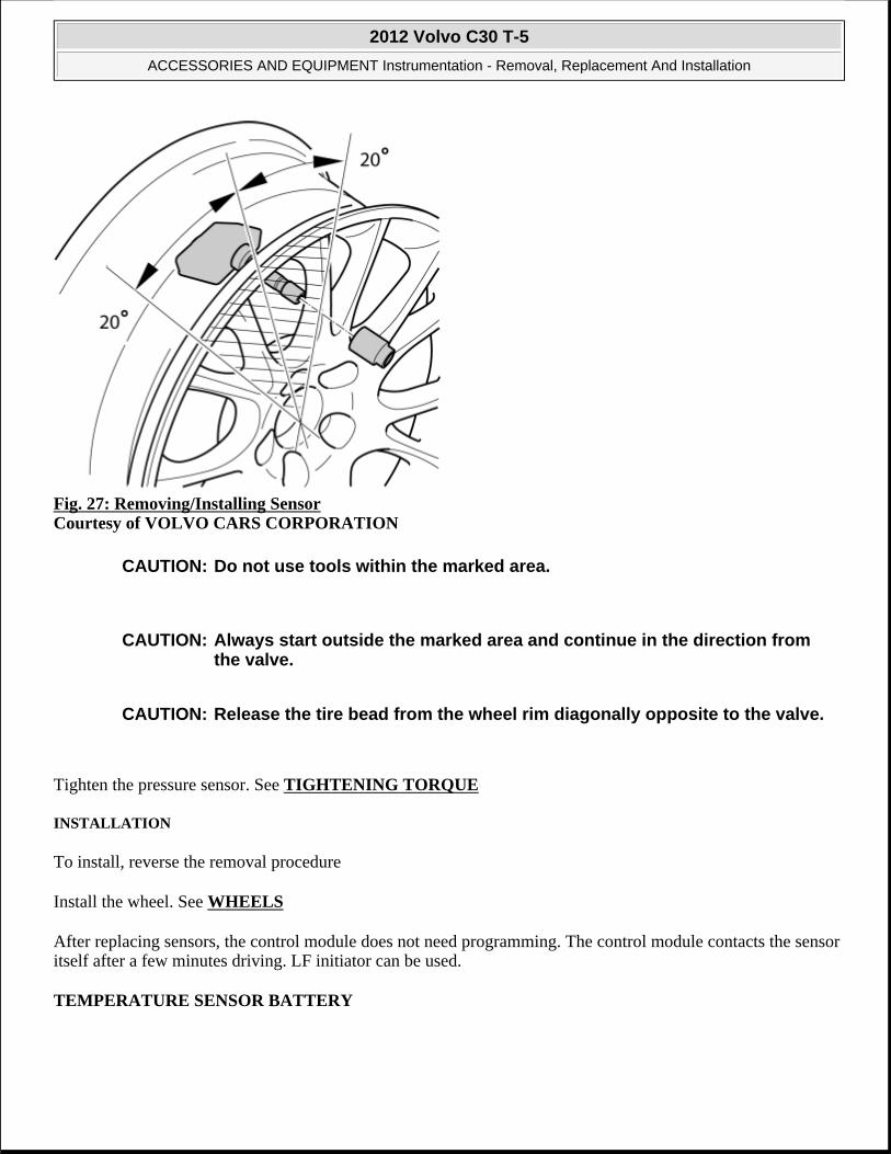
Fig. 27: Removing/Installing Sensor Courtesy of VOLVO CARS CORPORATION
Tighten the pressure sensor. See TIGHTENING TORQUE
INSTALLATION
To install, reverse the removal procedure
Install the wheel. See WHEELS
After replacing sensors, the control module does not need programming. The control module contacts the sensor itself after a few minutes driving. LF initiator can be used.
TEMPERATURE SENSOR BATTERY
CAUTION: Do not use tools within the marked area.
CAUTION: Always start outside the marked area and continue in the direction from the valve.
CAUTION: Release the tire bead from the wheel rim diagonally opposite to the valve.
2012 Volvo C30 T-5
ACCESSORIES AND EQUIPMENT Instrumentation - Removal, Replacement And Installation

PREPARATORY WORK
IGNITION OFF
Fig. 28: Identifying Ignition In OFF Position Courtesy of VOLVO CARS CORPORATION
Ignition off.
Open the hood.
Remove the battery. See BATTERY .
REMOVAL
REMOVING THE TEMPERATURE SENSOR
NOTE: The graphics in this service information are used for different model years and/or models. Some variation may occur. However, the essential information in the graphics is always correct.
2012 Volvo C30 T-5
ACCESSORIES AND EQUIPMENT Instrumentation - Removal, Replacement And Installation

Fig. 29: Identifying Temperature Sensor Courtesy of VOLVO CARS CORPORATION
Remove:
the connector
the temperature sensor. Press in the locking catch on one side. Press up and press in the other locking catch.
INSTALLATION
INSTALLING THE TEMPERATURE SENSOR
Install:
the temperature sensor
the connector
the battery as shown: BATTERY .
TRANSMISSION INPUT SPEED SENSOR, REAR WHEELS
NOTE: The graphics in this service information are used for different model years
2012 Volvo C30 T-5
ACCESSORIES AND EQUIPMENT Instrumentation - Removal, Replacement And Installation

PREPARATORY WORK
Ignition off.
REMOVAL
REMOVING THE SHOCK ABSORBER FOR VEHICLES EQUIPPED WITH NIVOMAT
Fig. 30: Identifying Lower Shock Mounting Courtesy of VOLVO CARS CORPORATION
Remove:
the M5 screw
the shock absorber from the lateral link.
REMOVING THE WHEEL SENSOR
and/or models. Some variation may occur. However, the essential information in the graphics is always correct.
2012 Volvo C30 T-5
ACCESSORIES AND EQUIPMENT Instrumentation - Removal, Replacement And Installation

Fig. 31: Identifying Sensor Mounting Screw Courtesy of VOLVO CARS CORPORATION
Remove the sensor mounting screw. Pull out the connector.
NOTE: Blow clean around the sensor using compressed air before removing.
2012 Volvo C30 T-5
ACCESSORIES AND EQUIPMENT Instrumentation - Removal, Replacement And Installation
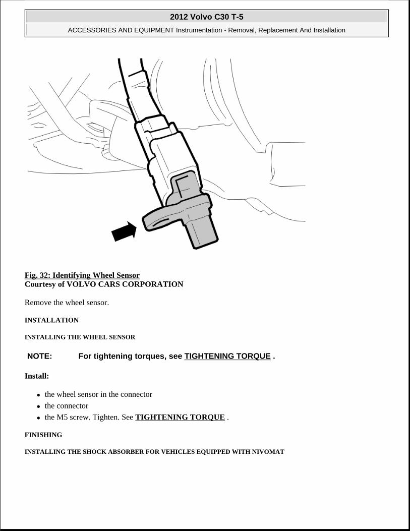
Fig. 32: Identifying Wheel Sensor Courtesy of VOLVO CARS CORPORATION
Remove the wheel sensor.
INSTALLATION
INSTALLING THE WHEEL SENSOR
Install:
the wheel sensor in the connector
the connector
the M5 screw. Tighten. See TIGHTENING TORQUE .
FINISHING
INSTALLING THE SHOCK ABSORBER FOR VEHICLES EQUIPPED WITH NIVOMAT
NOTE: For tightening torques, see TIGHTENING TORQUE .
2012 Volvo C30 T-5
ACCESSORIES AND EQUIPMENT Instrumentation - Removal, Replacement And Installation

Fig. 33: Identifying Lower Shock Mounting Courtesy of VOLVO CARS CORPORATION
Install:
the shock absorber from the lateral link
the M5 screw. Tighten. See TIGHTENING TORQUE .
FUNCTION TEST
Read off any diagnostic trouble codes (DTCs) stored in the control module.
Erase.
Interrupt the diagnostic function by turning off the ignition.
Test drive the vehicle. See TEST DRIVE FORM (ABS), DESCRIPTION .
Check that no diagnostic trouble codes (DTCs) are stored. Interrupt the diagnostic function by turning off the ignition.
TRANSMISSION INPUT SPEED SENSOR, FRONT WHEELS
2012 Volvo C30 T-5
ACCESSORIES AND EQUIPMENT Instrumentation - Removal, Replacement And Installation

PREPARATORY WORK
Switch off the ignition.
Remove the wheel.
REMOVAL
REMOVING THE WHEEL SENSOR
Fig. 34: Identifying Wheel Sensor Connector Courtesy of VOLVO CARS CORPORATION
Remove the connector from the wheel sensor.
NOTE: The graphics in this service information are used for different model years and/or models. Some variation may occur. However, the essential information in the graphics is always correct.
NOTE: Blow clean around the sensor using compressed air before removing.
2012 Volvo C30 T-5
ACCESSORIES AND EQUIPMENT Instrumentation - Removal, Replacement And Installation

Fig. 35: Identifying Wheel Sensor Mounting Screw Courtesy of VOLVO CARS CORPORATION
Remove:
the M5 mounting screw for the wheel sensor
the wheel sensor.
INSTALLATION
INSTALLING THE WHEEL SENSOR
Install:
the wheel sensor
the M5 screw. Tighten. See TIGHTENING TORQUE
the connector.
NOTE: For tightening torques, see TIGHTENING TORQUE .
2012 Volvo C30 T-5
ACCESSORIES AND EQUIPMENT Instrumentation - Removal, Replacement And Installation

Fig. 36: View Of Wheel Sensor Cable Routing Courtesy of VOLVO CARS CORPORATION
Thoroughly check that the wheel sensor cable is routed as shown.
FINISHING
Install the wheel according to WHEELS .
FUNCTION TEST
Read off any diagnostic trouble codes (DTCs) stored in the control module.
Erase.
Interrupt the diagnostic function by turning off the ignition.
Test drive the car. See TEST DRIVE FORM (ABS), DESCRIPTION .
Check that no diagnostic trouble codes (DTCs) are stored. Interrupt the diagnostic function by turning off the ignition.
TRANSMISSION INPUT SPEED SENSOR, INPUT SHAFT, TRANSAXLE (TSS) (B5244S4; 2007-10, B5254T3; 2007, B5254T7; 2008-12)
PREPARATORY WORK
DISCONNECTING THE BATTERY LEAD
NOTE: The graphics in this service information are used for different model years and/or models. Some variation may occur. However, the essential information in the graphics is always correct.
2012 Volvo C30 T-5
ACCESSORIES AND EQUIPMENT Instrumentation - Removal, Replacement And Installation

Fig. 37: Identifying Battery Box Courtesy of VOLVO CARS CORPORATION
Remove:
the battery negative cable. See BATTERY DISCONNECTING AND CONNECTING
the box for the battery.
REMOVAL
REMOVING THE SENSORS AND CABLE HARNESS
Fig. 38: View Of Sensors and Cable Harness Courtesy of VOLVO CARS CORPORATION
Disconnect the cable harness connector from the transmission control module (TCM).
Clean thoroughly around the sensors. Remove the sensors and the cable harness.
NOTE: Make a note of the routing of the cable harness.
2012 Volvo C30 T-5
ACCESSORIES AND EQUIPMENT Instrumentation - Removal, Replacement And Installation

INSTALLATION
INSTALLING THE SENSORS AND CABLE HARNESS
Fig. 39: View Of Sensors and Cable Harness Courtesy of VOLVO CARS CORPORATION
Install:
the new sensors. Apply a little automatic transmission fluid to the O-rings for the sensors. Tighten. See TIGHTENING TORQUE
the cable harness connector to the transmission control module (TCM).
FINISHING
INSTALLING THE BATTERY LEAD
Fig. 40: Identifying Battery Box Courtesy of VOLVO CARS CORPORATION
2012 Volvo C30 T-5
ACCESSORIES AND EQUIPMENT Instrumentation - Removal, Replacement And Installation

the box for the battery
the battery negative lead. See BATTERY DISCONNECTING AND CONNECTING .
PRESSURE SENSOR, ENGINE OIL (B5244S4; B5254T3; 2007)
REMOVAL
See information about lifting points body. See JACKING POINTS BODY
Fig. 41: Identifying Skid Plate Screws Courtesy of VOLVO CARS CORPORATION
Fig. 42: View Of Oil Pressure Switch Courtesy of VOLVO CARS CORPORATION
Torque: Oil pressure switch
NOTE: Removal steps in this procedure may contain installation details.
2012 Volvo C30 T-5
ACCESSORIES AND EQUIPMENT Instrumentation - Removal, Replacement And Installation

15 Nm
INSTALLATION
To install, reverse the removal procedure.
SENSORS FOR CHECK AND WARNING SYSTEM
LEVEL SENSOR FUEL TANK (B5244S4; 2007-10, B5254T3; 2007, B5254T7; 2008-12)
On these models, the level sensor is integrated in the fuel pump (FP).
To replace on AWD, see FUEL PUMP (B5254T7; 2008-12) .
To replace on FWD, see FUEL PUMP AND LEVEL SENSOR UNIT (B5244S4; 2007-10, B5254T3; 2007, B5254T7; 2008-12) .
NOTE: The graphics in this service information are used for different model years and/or models. Some variation may occur. However, the essential information in the graphics is always correct.
2012 Volvo C30 T-5
ACCESSORIES AND EQUIPMENT Instrumentation - Removal, Replacement And Installation

ENGINE
Intake And Exhaust System - Installation Instructions, Accessories
END PIPES, 4 CYL (2010-12)
END PIPES, 4 CYL
Fig. 1: Identifying End Pipe Courtesy of VOLVO CARS CORPORATION
APPLIES TO 4-CYL. PETROL
Fig. 2: Cutting Off Pipe Courtesy of VOLVO CARS CORPORATION
2012 Volvo C30 T-5
ENGINE Intake And Exhaust System - Installation Instructions, Accessories
2012 Volvo C30 T-5
ENGINE Intake And Exhaust System - Installation Instructions, Accessories

Fig. 3: Installing End Pipe Components - 4-Cyl. (1 Of 2) Courtesy of VOLVO CARS CORPORATION
Fig. 4: Installing End Pipe Components - 4-Cyl. (2 Of 2) Courtesy of VOLVO CARS CORPORATION
2012 Volvo C30 T-5
ENGINE Intake And Exhaust System - Installation Instructions, Accessories

Fig. 5: Identifying Lateral Distance Courtesy of VOLVO CARS CORPORATION
Fig. 6: Tightening Clamp On End Pipe Courtesy of VOLVO CARS CORPORATION
END PIPES, 5 CYL (2010-12)
END PIPES, 5 CYL
2012 Volvo C30 T-5
ENGINE Intake And Exhaust System - Installation Instructions, Accessories

Fig. 7: Installing End Pipe Components - 5-Cyl. (1 Of 8) Courtesy of VOLVO CARS CORPORATION
Fig. 8: Installing End Pipe Components - 5-Cyl. (2 Of 8) Courtesy of VOLVO CARS CORPORATION
2012 Volvo C30 T-5
ENGINE Intake And Exhaust System - Installation Instructions, Accessories

Fig. 9: Installing End Pipe Components - 5-Cyl. (3 Of 8) Courtesy of VOLVO CARS CORPORATION
Fig. 10: Installing End Pipe Components - 5-Cyl. (4 Of 8) Courtesy of VOLVO CARS CORPORATION
2012 Volvo C30 T-5
ENGINE Intake And Exhaust System - Installation Instructions, Accessories

Fig. 11: Installing End Pipe Components - 5-Cyl. (5 Of 8) Courtesy of VOLVO CARS CORPORATION
Fig. 12: Installing End Pipe Components - 5-Cyl. (6 Of 8) Courtesy of VOLVO CARS CORPORATION
2012 Volvo C30 T-5
ENGINE Intake And Exhaust System - Installation Instructions, Accessories

Fig. 13: Installing End Pipe Components - 5-Cyl. (7 Of 8) Courtesy of VOLVO CARS CORPORATION
Fig. 14: Installing End Pipe Components - 5-Cyl. (8 Of 8) Courtesy of VOLVO CARS CORPORATION
2012 Volvo C30 T-5
ENGINE Intake And Exhaust System - Installation Instructions, Accessories
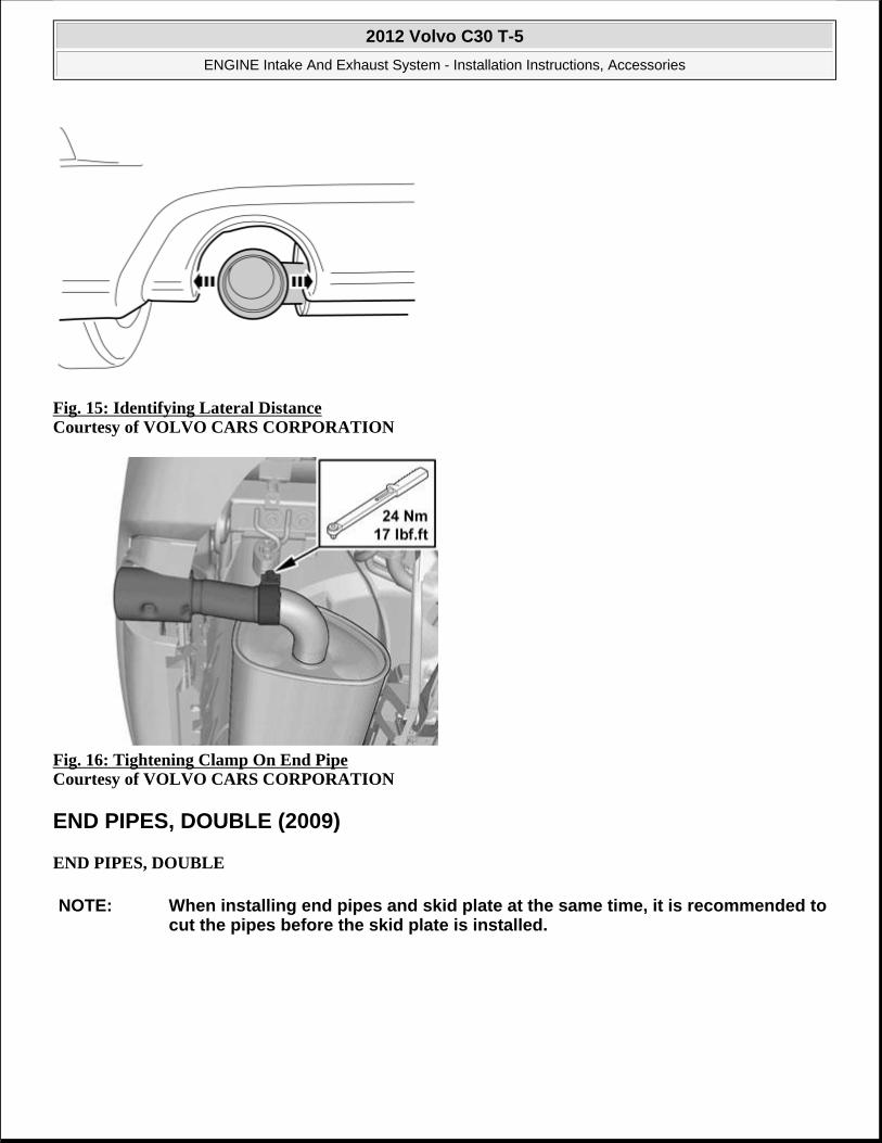
Fig. 15: Identifying Lateral Distance Courtesy of VOLVO CARS CORPORATION
Fig. 16: Tightening Clamp On End Pipe Courtesy of VOLVO CARS CORPORATION
END PIPES, DOUBLE (2009)
END PIPES, DOUBLE
NOTE: When installing end pipes and skid plate at the same time, it is recommended to cut the pipes before the skid plate is installed.
2012 Volvo C30 T-5
ENGINE Intake And Exhaust System - Installation Instructions, Accessories

Fig. 17: Cutting Off End Pipe Courtesy of VOLVO CARS CORPORATION
Use a pipe cutter and cut off the end pipe where it starts to widen, as close to the line as possible.
File down the edges.
Fig. 18: Identifying End Pipe Courtesy of VOLVO CARS CORPORATION
Take the end pipe from the kit and insert it approx. 20 mm over the cut pipe, turned approximately as shown.
2012 Volvo C30 T-5
ENGINE Intake And Exhaust System - Installation Instructions, Accessories