Field Evaluation of Self-Lubricated Mechanical Components ...
173
Q) >* LU O =3 P o © O 0£ Approved for public release; distribution is unlimited. i>ii US Army Corps of Engineers» Engineer Research and Development Center Field Evaluation of Self-Lubricated Mechanical Components for Civil Works Navigation Structures Timothy D. Race, Ashok Kumar, and L.D. Stephenson June 2004 20050118 006 BEST AVAILABLE COPY
-
Upload
khangminh22 -
Category
Documents
-
view
3 -
download
0
Transcript of Field Evaluation of Self-Lubricated Mechanical Components ...

Q) >*
LU O
=3 P
o © O 0£
Approved for public release; distribution is unlimited.
i>ii
US Army Corps of Engineers» Engineer Research and Development Center
Field Evaluation of Self-Lubricated Mechanical Components for Civil Works Navigation Structures Timothy D. Race, Ashok Kumar, and L.D. Stephenson
June 2004
20050118 006
BEST AVAILABLE COPY
<D >»
i\»j
LU O
3 9
O 0
US Army Corps of Engineers® Engineer Research and Development Center
Field Evaluation of Self-Lubricated Mechanical Components for Civil Works Navigation Structures Timothy D. Race, Ashok Kumar, and L.D. Stephenson
June 2004
Approved for public release; distribution is unlimited.

High Performance Materials and Systems ERDC/CERL SR-04-8 Research Program June 2004
Field Evaluation of Self-Lubricated Mechanical Components for Civil Works Navigation Structures
Timothy D. Race
Corrosion Control Consultants & Labs, Inc. 135 N. Addison Avenue, Suite 108 Elmhurst, IL 60126-2800
Ashok Kumar and L.D. Stephenson
Construction Engineering Research Laboratory PO Box 9005 Champaign, IL 61826-9005
Final Report Approved for public release; distribution is unlimited.
Prepared for U.S. Army Corps of Engineers Washington, DC 20314-1000
Under Civil Works Work Unit #33238

ABSTRACT: It is operationally and environmentally desirable to replace greased bronze bushings used in naviga- tion lock machinery with self-lubricating bushings. Bronze bushings must be greased manually or with automatic lubricating machines. Grease lines are subject to damage from ice and debris. If the grease line breaks, the lubricat- ing system fails, which may lead to component failure and delays in navigation. Introduction of grease into the river- ine environment is also a concern.
The Corps of Engineers has been using self-lubricating bushings in navigation locks for the past 20 years. The pur- pose of this study was to evaluate mechanical properties and durability of emerging advanced self-lubricating bush- ing/bearing materials in the laboratory and under field conditions, and to provide additional knowledge, needed guidelines, and standard specifications for the proper selection and use of self-lubricating bushing materials for locks based on local environmental conditions and applications. The results of accelerated testing of quarter-scale model self-lubricating pintle bushings in simulated river are also reported.
DISCLAIMER: The contents of this report are not to be used for advertising, publication, or promotional purposes. Citation of trade names does not constitute an official endorsement or approval of the use of such commercial products. All product names and trademarks cited are the property of their respective owners. The findings of this report are not to be construed as an official Department of the Army position unless so designated by other authorized documents. DESTROY THIS REPORT WHEN IT IS NO LONGER NEEDED. DO NOT RETURN IT TO THE ORIGINATOR.

iv ERDC/CERL SR-04-8
Contents
List of Figures and Tables Vl
Conversion Factors v"
Preface viii
1 Introduction 1
Background — 1
Objective 2
Approach 2
Scope 2
2 Applications and Product Descriptions ■ 3
Applications 3
Product Descriptions 3
GartockDU 3
Tenmat Feroform T814 3
Kamatics KAron V 3
Oiles500 4
ThordonSXLandHPSXL • 4
LubriteG10andG12 ■■■'■ 4
Lubron AQ30, AQ100, and TF400 * 4
OrkotTXM Marine 4
3 Product Specifications 5
4 Field Performance 10
Markland Locks and Dam 10
McAlpine Locks and Dam 10
Smithland Locks and Dam 11
Cannelton and Newburgh Locks and Dams 11
Cascade Locks 11
John Day Lock and Dam 12
Little Goose Lock and Dam 12
Colorado River Locks 13
Locksand Dam No. 27 13
ERDC/CERL SR-04-8
Melvin Price Locks and Dam 13
Kentucky Lock 14
BarkleyLock 14
Old Hickory Lock 14
Chicago Harbor Lock 15
5 Olmsted Prototype Field Experiments .". 16
6 Powertech Laboratory Evaluation of Self-Lubricating Pintle Bearings 17
7 Field Experience With Self-Lubricating Pintle Bearing Materials 18
8 Self-Lubricated Mechanical Components: Field Performance vs Properties 20
9 Conclusions 21
Salient Characteristics 21
Problems Encountered in Service 21
Installation Techniques 21
Cost Relative to Greased Bronze Bushings 21
10 Commercial Availability 22
Engineering Support 22
Overall Ratings of Products 22
Recommended Products 22
Appendix A: Questionnaires on Self-Lubricating Bushings 24
Appendix B: Manufacturers' Literature ■ 76
Attachment 1: Powertech Report on Scale Model Testing of Navigation Lock Pintle Self-Lubricating Bushings for the Corps of Engineers 111
Report Documentation Page 172

^ ERDC/CERL SR-04-8
List of Figures and Tables
Figures
1 Self-lubricating pintle bearing with Thordon SXL material installed at Cannelton Lock in 1994; removed/replaced in July 2002; pintle shows very little wear after 8 years 19
2 Self-lubricating pintle bearing with Thordon SXL material installed at Cannelton Lock in 1994; removed/replaced in July 2002. Self-lubricating Thordon material about 80 percent eroded after 8 years 19
Tables
1 GarlockDU Bearings 6
2 Orkot-TXM Marine 6
3 Lubron-TF400 ■ 7
4 Kamatics KAron V 7
5 TenmatFeroformT814 8
6 Thordon-SXL 8
7 Thordon-HPSXL 9
8 LubriteG10andG12 9
9 Self-lubricating material vs. performance ■. 16
10 Pintle busing material costs/performance data (20/24-inch diameter) 18

ERDC/CERL SR-04-8 VII
Conversion Factors
Non-SI* units of measurement used in this report can be converted to SI units as
follows: Multiply By To Obtain
degrees (angle) 0.01745329 radians
degrees Fahrenheit (5/9) x (°F - 32) degrees Celsius
inches 0.0254 meters
pounds (force) per square inch 0.006894757 megapascals
Systeme International d'Unites ("International System of Measurement"), commonly known as the "metric system.'
yjjj ERDC/CERL SR-04-8
Preface
This study was authorized by Headquarters, U.S. Army Corps of Engineers (HQUSACE) as part of the High Performance Materials and Systems (HPM&S) Research Program. This work was performed under Work Unit 33238, "Civil Works Advanced Materials Selection Guide," for which Dr. Ashok Kumar, U.S. Army Engineer Research and Development Center (ERDC), Construction Engi- neering Research Laboratory (CERL), was the Principal Investigator.
Dr. Tony Liu was the HPM&S Coordinator at the Directorate of Research and Development; the Research Area Manager was Mr. Roy Braden, and the Pro- gram Monitor was Mr. Andy Wu, HQUSACE. Dr. Mary Ellen Hynes, ERDC Geotechnical and Structures Laboratory (GSL) was the ERDC Lead Technical Director, Infrastructure Engineering and Management. Dr. William Grogan, GSL, was the HPM&S Program Manager.
This work was performed by the Materials and Structures Branch (CF-M) of the Facilities Division (CF), CERL. The report was prepared by Mr. Timothy D. Race (Corrosion Control Consultants & Labs, Inc.), under contract DACW42-03- P-0173, and Drs. Ashok Kumar and L.D. Stephenson (CERL). A portion of the work was performed by Powertech Laboratory, Surrey, BC, Canada, under con- tract DACW42-02-P-0187. The technical editor was Linda L. Wheatley, Informa- tion Technology Laboratory. Mr. Martin J. Savoie was Chief, CF-M, and Mr. L. Michael Golish was Chief, CF. Dr. Paul Howdyshell was the Technical Director for this work unit, and Dr. Alan Moore was Director of CERL.
At the time of preparation of this report, COL James R. Rowan, EN, was the Commander and Executive Director of ERDC, and Dr. James R. Houston was
the Director.

ERDC/CERL SR-04-8
1 Introduction
Background
The purpose of a lubricant is to prevent wear and damage of equipment compo- nents as they move relative to one another. Lubricants are broadly classified as either fluids or solids. Fluid lubricants include oils and greases and may be ei- ther synthetic or natural products. Solid lubricants are powders or thin films. Some solid lubricants, such as molybdenum disulfide, graphite, and zinc oxide, are used as additives in conjunction with fluid lubricants.
Solid lubricants are effective at high loads and speeds and resist deterioration over prolonged periods. They are more stable than fluid lubricants at high tem- peratures and pressures. Solid lubricants may simplify design because they do not require a means of introducing and sealing them in as do fluid lubricants. Solid lubricants, however, have poor self-healing properties relative to fluids as well as poor heat dissipation, especially in the case of polymeric bearings. In general, solid-lubricated bearings have a higher coefficient of friction and wear than fluid-lubricated bearings.
Types of solid lubricants include lamellar solids, soft metal films, surface-treated metals, and polymers. Solid lubricants may be used as a powder, bonded coat- ings, and self-lubricated composites. Bonded coatings and self-lubricating com- posites of the metal-solid type are of particular interest to this work.
Interest in self-lubricated wear components is driven by environmental and eco- nomic considerations. Self-lubricated bearings eliminate the undesirable intro- duction of fluid lubricants into the ecosystem. Self-lubricated bearings also re- duce operating costs by eliminating the need for periodic application of the fluid lubricant. For navigation projects, periodic lubrication can be labor intensive and greases inevitably are introduced to the riverine environment.
Short-term laboratory testing of self-lubricated materials has been performed by the U.S. Army Corps of Engineers (USACE). However, the long-term field per- formance of these products under real-world operating conditions has not been evaluated.
ERDC/CERL SR-04-8
Objective
The objectives of this research were to evaluate the field performance of self- lubricating materials at USACE navigation projects and to compile descriptive material and design specifications for these products.
Approach
Field performance of self-lubricated components was evaluated empirically by surveying USACE field and design personnel. Materials and design criteria were derived from data provided by manufacturers of self-lubricated bushings. Field performance and manufacturer data were also compared with the results of laboratory research on greaseless bushings in hydropower and navigation ap-
plications.
Scope
The results of this investigation apply to Civil Works navigation facilities. To the extent that similarities exist between navigation and other Civil Works in- stallations, including hydropower and flood control faculties, the information contained herein may also be applicable to these other facilities. It may also ap- ply to other similar facilities including, but not limited to, those operated by the Tennessee Valley Authority and the U.S. Bureau of Reclamation.
ERDC/CERL SR-04-8
2 Applications and Product Descriptions
Applications
The surveyed navigation installations are using self-lubricated materials for a variety of applications including: guide rollers, reaction rollers, and thrust wash- ers in floating mooring bitts; lock gate guide pins; tainter valve strut arm com- ponents; sector gear bearings; and pintle bearings. Some facilities have replaced the conventional lower roller assembly of floating mooring bitts with a simple self-lubricated guide block assembly.
Product Descriptions
Self-lubricating materials (e.g., lamellar solids, soft metal films, surface-treated metals, and polymers) may be used as powders, bonded coatings, and self- lubricated composites. Bonded coatings and self-lubricating composites of the metal-solid type are of particular interest to this work. Products in use on USACE navigation projects were identified and are described below.
Garlock DU
Garlock DU is a bonded coating product consisting of a 1-mil film of polytetraflu- ouroethylene (PTFE) mixed with lead on a porous 10-mil sintered copper-tin bronze coating over a steel substrate.
Tenmat Feroform T814
Feroform T814 is a self-lubricating composite product consisting of PTFE uni- formly dispersed in a woven synthetic polyester fabric reinforced thermoset phe- nolic resin matrix.
Kamatics KAron V
KAron V is a bonded polyester coating incorporating PTFE particles. The coat- ing is applied at various thicknesses to stainless steel, fiberglass, bronze, tita- nium, aluminum, phenolic, inconel, and other substrates.
ERDC/CERL SR-04-8
Oiles 500
Oiles 500 bearings are dispersed-powder products consisting of either PTFE or
graphite plugs in metal alloy substrates.
Thordon SXL and HPSXL
Thordon SXL and HPSXL are bonded-coating products consisting of thermoset- ting elastomeric resin on various backings. High-pressure TRAXL bearings are bronze-backed products coated with SXL or HPSXL.
Lubrite G10 and G12
Lubrite G10 and G12 lubricant are epoxy-base graphite-free materials extruded into recesses on the bearing surface. The bearings are available in a variety of
alloys.
Lubron AQ30, AQ100, and TF400
Information has not been provided by the manufacturer. The Louisville District describes TF400 as a PTFE lubricant film on a metal alloy bearing.
Orkot TXM Marine
Orkot TXM Marine consists of a medium weave fabric backing impregnated with PTFE and lubricated with an evenly dispersed solid film lubricant (molybdenum
disulphide).
ERDC/CERL SR-04-8
3 Product Specifications
Product data were gathered from two primary sources. Most of the data were reported in CERL Technical Report 99/104, "Greaseless Bushings for Hydro- power Applications: Program, Testing, and Results" (December 1999). Materials evaluated in this research program include Tenmat Feraform T814, Kamatics KAron V, Orkot TXM Marine, Thordon TRAXL SXL and HPSXL, and Lubron TF400. The remainder of the bearing data is compiled from manufacturers' lit- erature (Garlock DU and Lubrite G10 and G12). Coefficients of linear expansion are in all cases taken from the manufacturer's literature.
The coefficient of friction is perhaps the most important physical property of greaseless bushings. Static and dynamic coefficients of friction, measured under dry and wet conditions, are important to determine the friction torque and stick- slip characteristics of the bearing system. Stick-slip or "stiction" is caused by the difference between static and dynamic coefficients of friction when a system is moved from rest. The more nearly equal the coefficients are, the smoother the system will operate, usually even if actual friction is high.
Other parameters important to system design include load bearing capacities, coefficient of liner expansion, and swell. Properties of these self-lubricating ma- terials are summarized in Tables 1 through 8. Appendix B contains manufac- turers' literature for the evaluated products.

ERDC/CERL SR-04-8
Table 1. Garlock DU Bearings.
Attribute Value
Load Bearing Capacity: Static 36,000 psi
Load Bearing Capacity: Dynamic 20,000 psi
Load Bearing Capacity: Compressive 44,000 psi
Wear Rate: Dry < 0.2 mils/100 hours
Wear Rate: Wet NA
Coefficient of Static Friction: Dry 0.02 - 0.20
Coefficient of Static Friction: Wet NA
Coefficient of Dynamic Friction: Dry 0.02 - 0.20
Coefficient of Dynamic Friction: Wet NA
Delta* Coefficient of Friction: Dry 0-0.18
Delta* Coefficient of Friction: Wet NA
Coefficient of Linear Expansion: Normal 30x^J°C
Coefficient of Linear Expansion: Parallel nxicrVc Swell: Water NA
Swell: Oil NA
* Delta is the difference between static and dynamic coefficients of friction. All data supplied by manufacturer. Delta values are inferred.
Table 2. Orkot - TXM Marine.
Attribute Value
Load Bearing Capacity: Static 11,600 psi
Load Bearing Capacity: Dynamic 5800 psi
Load Bearing Capacity: Compressive Normal to Laminate >40,700 psi
Parallel to Laminate >13,000 psi
Wear Rate: Dry 0.199 mils/100 hours
Wear Rate: Wet 0.504 mils/100 hours
Coefficient of Static Friction: Dry 0.088 (0.05 to 0.10)
Coefficient of Static Friction: Wet 0.068
Coefficient of Dynamic Friction: Dry 0.061
Coefficient of Dynamic Friction: Wet 0.060
Delta* Coefficient of Friction: Dry 0.027
Delta* Coefficient of Friction: Wet 0.028
Coefficient of Linear Expansion: Normal 90toiooxio"6/°c Coefficient of Linear Expansion: Parallel SOtoöOxIO^C
Swell: Water Zero (< 0.1%)
Swell: Oil Zero
' Delta is the difference between static and dynamic coefficients of friction.
ERDC/CERL SR-04-8
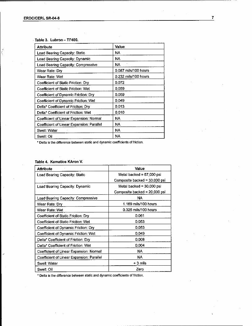
Table 3. Lubron - TF400.
Attribute Value
Load Bearing Capacity: Static NA
Load Bearing Capacity: Dynamic NA
Load Bearing Capacity: Compressive NA
Wear Rate: Dry 0.087 mils/100 hours
Wear Rate: Wet 0.232 mils/100 hours
Coefficient of Static Friction: Dry 0.072
Coefficient of Static Friction: Wet 0.059
Coefficient of Dynamic Friction: Dry 0.059
Coefficient of Dynamic Friction: Wet 0.049
Delta* Coefficient of Friction: Dry 0.013
Delta* Coefficient of Friction: Wet 0.010
Coefficient of Linear Expansion: Normal NA
Coefficient of Linear Expansion: Parallel NA
Swell: Water NA
Swell: Oil NA
' Delta is the difference between static and dynamic coefficients of friction.
Table 4. Kamatics KAron V.
Attribute Value
Load Bearing Capacity: Static Metal backed = 67,000 psi
Composite backed = 33,000 psi
Load Bearing Capacity: Dynamic Metal backed = 30,000 psi
Composite backed = 20,000 psi
Load Bearing Capacity: Compressive NA
Wear Rate: Dry 1.169 mils/100 hours
Wear Rate: Wet 0.325 mils/100 hours
Coefficient of Static Friction: Dry 0.061
Coefficient of Static Friction: Wet 0.053
Coefficient of Dynamic Friction: Dry 0.053
Coefficient of Dynamic Friction: Wet 0.049
Delta* Coefficient of Friction: Dry 0.008
Delta* Coefficient of Friction: Wet 0.004
Coefficient of Linear Expansion: Normal NA
Coefficient of Linear Expansion: Parallel NA
Swell: Water + 3 mils
Swell: Oil Zero
* Delta is the difference between static and dynamic coefficients of friction.
ERDC/CERL SR-04-8
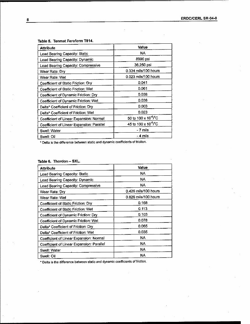
Table 5. Tenmat Feroform T814.
Attribute Value
Load Bearing Capacity: Static NA
Load Bearing Capacity: Dynamic 8990 psi
Load Bearing Capacity: Compressive 36,250 psi
Wear Rate: Dry 0.334 mils/100 hours
Wear Rate: Wet 0.023 mils/100 hours
Coefficient of Static Friction: Dry 0.041
Coefficient of Static Friction: Wet 0.061
Coefficient of Dynamic Friction: Dry 0.038
Coefficient of Dynamic Friction: Wet 0.038
Delta* Coefficient of Friction: Dry 0.003
Delta* Coefficient of Friction: Wet 0.023
Coefficient of Linear Expansion: Normal 50to100x10"6/°C
Coefficient of Linear Expansion: Parallel 45to100x10_6/°C
Swell: Water - 7 mils
Swell: Oil - 4 mils
' Delta is the difference between static and dynamic coefficients of friction.
Table 6. Thordon-SXL.
Attribute Value
Load Bearing Capacity: Static NA
Load Bearing Capacity: Dynamic NA
Load Bearing Capacity: Compressive NA
Wear Rate: Dry 0.426 mils/100 hours
Wear Rate: Wet 0.826 mils/100 hours
Coefficient of Static Friction: Dry 0.168
Coefficient of Static Friction: Wet 0.113
Coefficient of Dynamic Friction: Dry 0.103
Coefficient of Dynamic Friction: Wet 0.078
Delta* Coefficient of Friction: Dry 0.065
Delta* Coefficient of Friction: Wet 0.035
Coefficient of Linear Expansion: Normal NA
Coefficient of Linear Expansion: Parallel NA
Swell: Water NA
Swell: Oil NA
* Delta is the difference between static and dynamic coefficients of friction.
ERDC/CERL SR-04-8
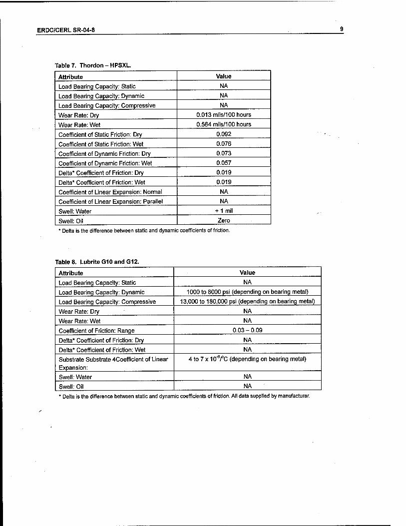
Table 7. Thordon - HPSXL
Attribute Value
Load Bearing Capacity: Static NA
Load Bearing Capacity: Dynamic NA
Load Bearing Capacity: Compressive NA
Wear Rate: Dry 0.013 mils/100 hours
Wear Rate: Wet 0.564 mils/100 hours
Coefficient of Static Friction: Dry 0.092
Coefficient of Static Friction: Wet 0.076
Coefficient of Dynamic Friction: Dry 0.073
Coefficient of Dynamic Friction: Wet 0.057
Delta* Coefficient of Friction: Dry 0.019
Delta* Coefficient of Friction: Wet 0.019
Coefficient of Linear Expansion: Normal NA
Coefficient of Linear Expansion: Parallel NA
Swell: Water + 1 mil
Swell: Oil Zero
' Delta is the difference between static and dynamic coefficients of friction.
Table 8. LubriteGIO and G12.
Attribute Value
Load Bearing Capacity: Static NA
Load Bearing Capacity: Dynamic 1000 to 8000 psi (depending on bearing metal)
Load Bearing Capacity: Compressive 13,000 to 180,000 psi (depending on bearing metal)
Wear Rate: Dry NA
Wear Rate: Wet NA
Coefficient of Friction: Range 0.03 - 0.09
Delta* Coefficient of Friction: Dry NA
Delta* Coefficient of Friction: Wet NA
Substrate Substrate 4Coefficient of Linear Expansion:
4 to 7 x lO'V'C (depending on bearing metal)
Swell: Water NA
Swell: Oil NA
' Delta is the difference between static and dynamic coefficients of friction. All data supplied by manufacturer.

10 ERDC/CERL SR-04-8
4 Field Performance
This section describes specific applications of self-lubricating bushings, including information on products used, application parameters, duration of service, instal- lation methods, problems, manufacturer support, and product performance.
Markland Locks and Dam
Markland Locks and Dam are on the Ohio River in the Louisville District. The upper and lower gates of the 1,200-ft main and 600-ft auxiliary chambers were outfitted in September 1992 with self-lubricated vertical and horizontal rack bar rollers manufactured by Garlock. Some of the vertical rollers that receive higher loads failed and were replaced shortly after with greased bushings. No other in- formation is available on this application.
Bushings for lock filling and emptying culvert valve trunnion pins, crosshead pins, lower connecting rod pins, fulcrum pins, upper strut spindle pins, and lower strut pins are self-lubricating. These bushings are Feroform T814, a stan- dard product manufactured by Tenmat. Loads are either 3,500 or 7,000 psi and the arc of rotation is 45 degrees. Hard-chromed 17-4 stainless steel pins were shrink fitted using liquid nitrogen. Bushings were installed in 2000 and 2001. The field engineer rates these self-lubricated bushings as excellent and recom-
mends them for similar applications.
McAlpine Locks and Dam
McAlpine Locks and Dam are on the Ohio River in the Louisville District. Lock filling and emptying culvert valve trunnion pins are self-lubricating. These bushings are Feroform T814, a standard product manufactured by Tenmat. Loads are 7,000 psi and the arc of rotation is 45 degrees. Hard-chromed 17-4 stainless steel pins were shrink fit using liquid nitrogen. Bushings were in- stalled in February 2000. The field engineer rates these self-lubricated bushings as excellent and recommends them for similar applications.

ERDC/CERL SR-04-8 11
Smithland Locks and Dam
Smithland Locks and Dam are on the Ohio River in the Louisville District. Lock filling and emptying culvert valve upper strut spindle pins and lower strut pins are self-lubricating. These bushings are Feroform T814, a standard product manufactured by Tenmat. Loads are 3,500 psi and the arc of rotation is 45 de- grees. Hard-chromed 17-4 stainless steel pins were shrink fitted using liquid nitrogen. Bushings were installed in 1997, 1998, and 2000. The field engineer rates these self-lubricated bushings as excellent and recommends them for simi- lar applications.
Cannelton and Newburgh Locks and Dams
The Louisville District also reports applications of Tenmat T814 and Thordon TRAXL self-lubricating bearings at Cannelton and Newburgh Locks and Dam on the Ohio River. Thordon pintle, gudgeon pin, and strut pin applications were installed on one leaf of one lock gate in 1994. At Cannelton, lock filling and emp- tying culvert valve trunnion pins, crosshead pins, lower connecting rod pins, ful- crum pins, upper strut spindle pins, lower strut pins, and hydraulic cylinder trunions are self-lubricating using Thordon TRAXL. This installation dates to 1992 or 1993. Cannelton also uses Kamatics crosshead pin and hydraulic cylin- der trunion bushings on one gate leaf. At Newburgh, Thordon TRAXL bushings are used on the 600-ft lock chamber gate culvert strut spindle pins and lower strut pins. This application dates to 1991. No other information or ratings are available for applications at Cannelton and Newburgh.
Cascade Locks
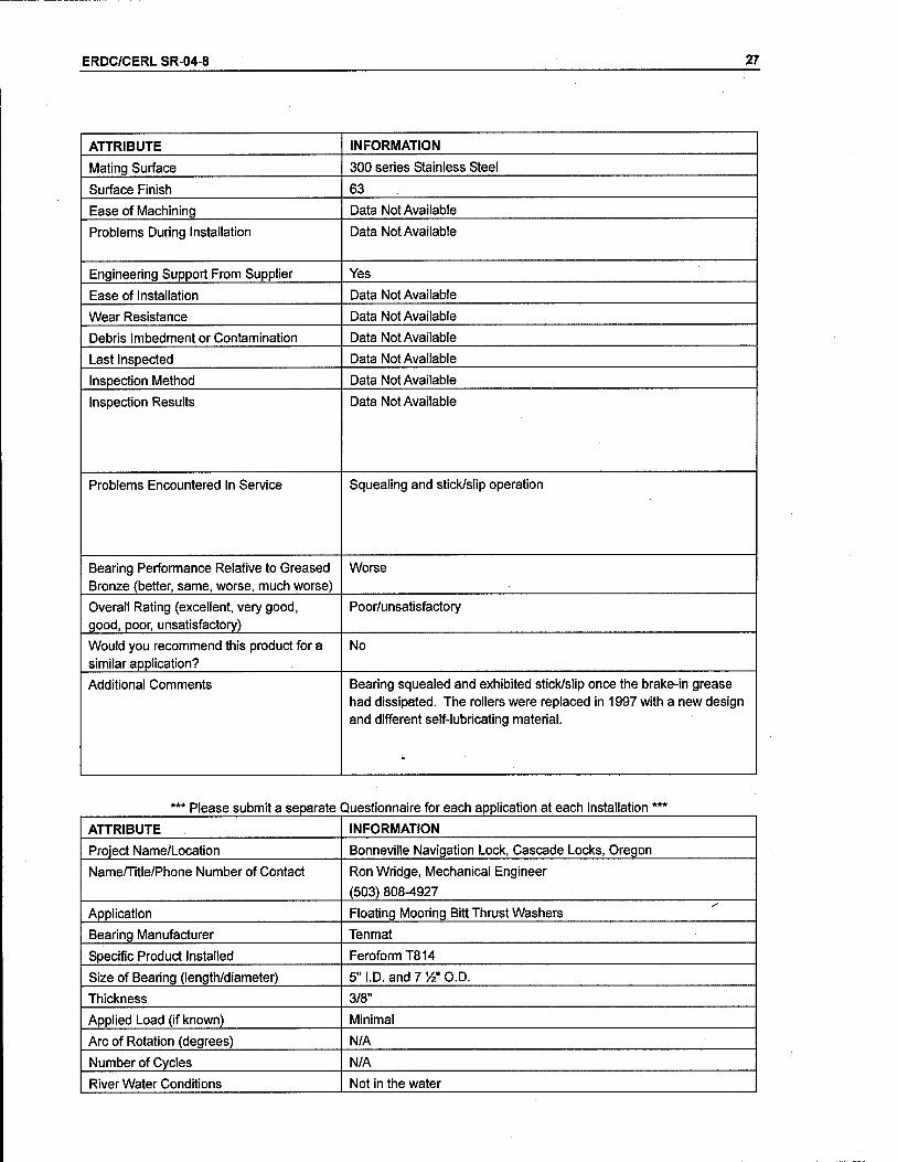
The Cascade Locks are on the Columbia River above Bonneville Dam in the Port- land District. The locks use self-lubricating bushings on floating mooring bitts. Roller bearings are KAron V manufactured by Kamatics. The applied load is ap- proximately 2,500 psi and the arc of rotation 360 degrees. The number of cycles averages about 240 full revolutions per day. The bearings were installed in 1997, and no problems have been reported to date. The District rates the KAron V roller bearings as "better" than greased bronze with an overall rating of "excel- lent." Lubron AQ 100 bearings were previously used for this application, but were replaced after only 2 years. Squealing and stick/slip (stiction) were re- ported as problems. The District rates the AQ 100 roller bearings as "worse" than greased bronze with an overall rating of "poor." Thrust washer bearings are Tenmat Feroform T814. The applied load is minimal. The bearings were

12 ERDC/CERL SR-04-8
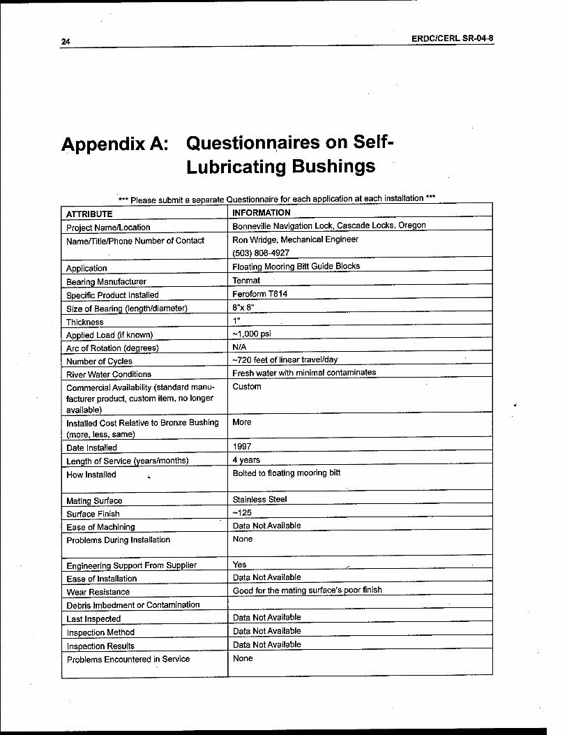
installed in 1997 and no problems have been reported to date. The District rates the Feroform T814 bearings as "better" than greased bronze with an overall rat- ing of "excellent." Floating mooring bitt guide blocks are Tenmat Feroform T814. The applied load is about 1,000 psi and the blocks experience about 720 feet of linear movement per day. The blocks were installed in 1997 and no problems have been reported to date. The District rates the T814 guide blocks as "better" than greased bronze bushings with an overall rating of "excellent."
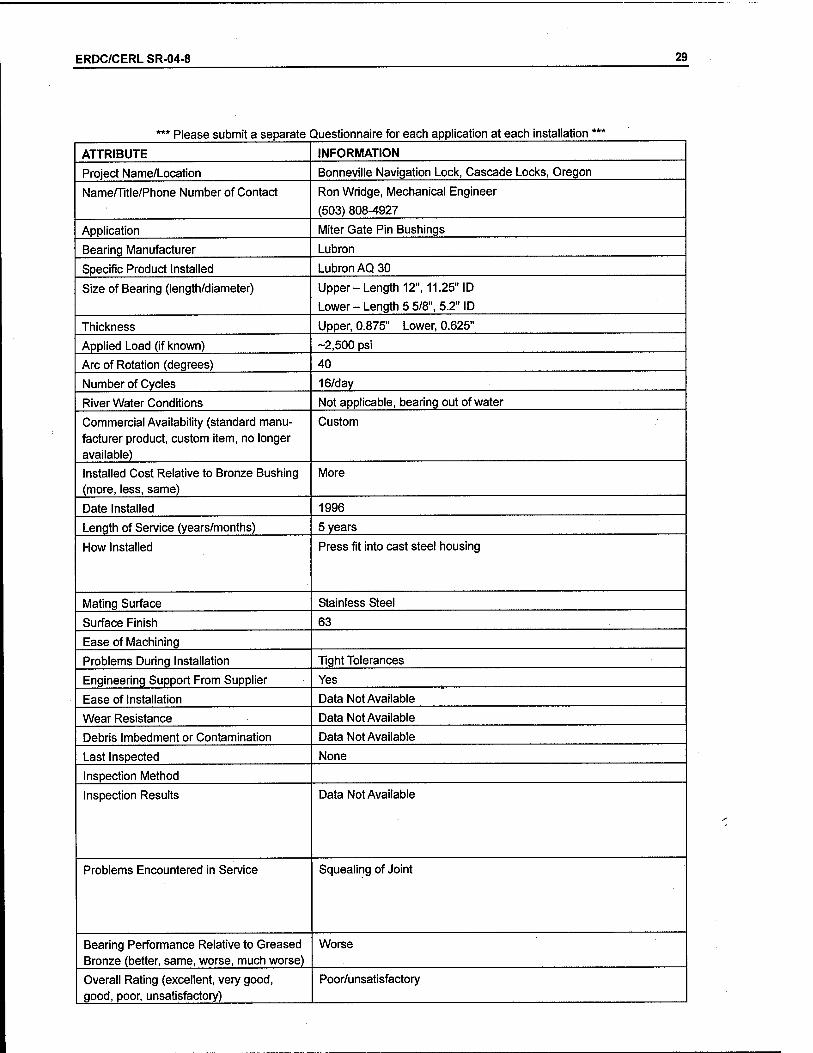
The Cascade Locks also use self-lubricating Lubron AQ 30 miter gate pin bush- ings. The bearings were installed in 1996 by press fitting into a cast-steel hous- ing. The approximated load is 2,500 psi and the arc of rotation is 40 degrees. The average number of cycles per day is 16. The District reports a problem with squealing and rates the AQ 30 miter gate pin bushings as "worse" than greased
bronze with an overall rating of "poor."
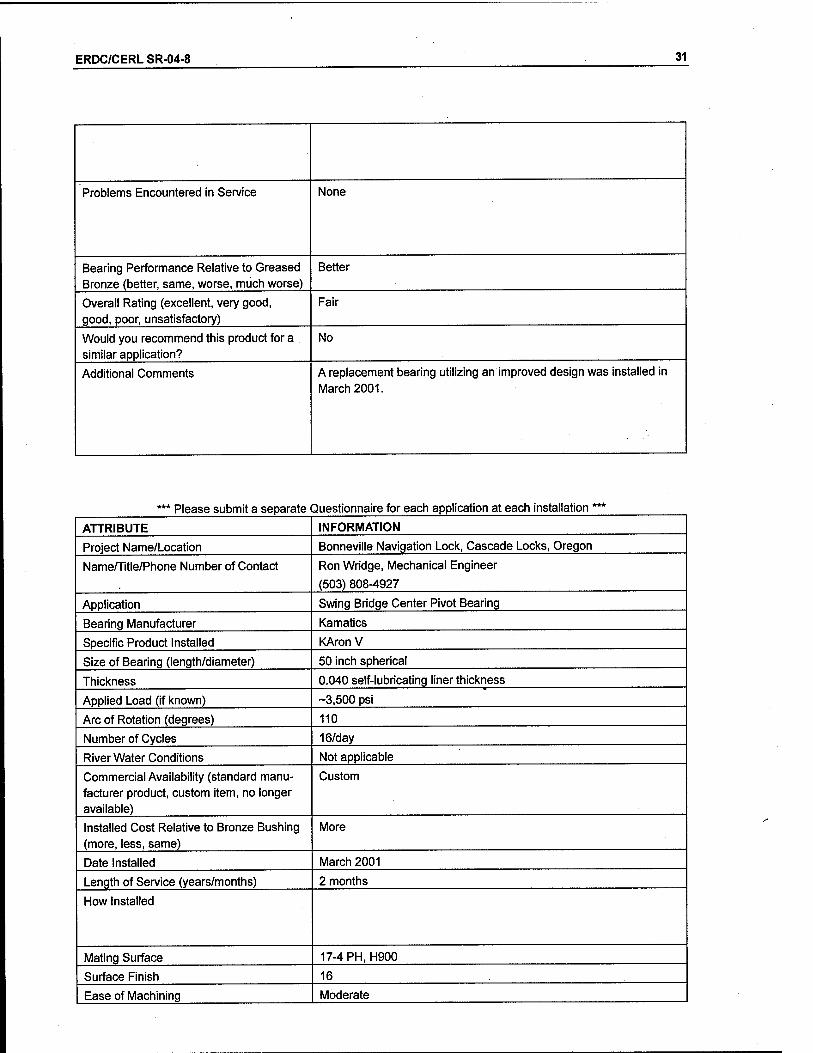
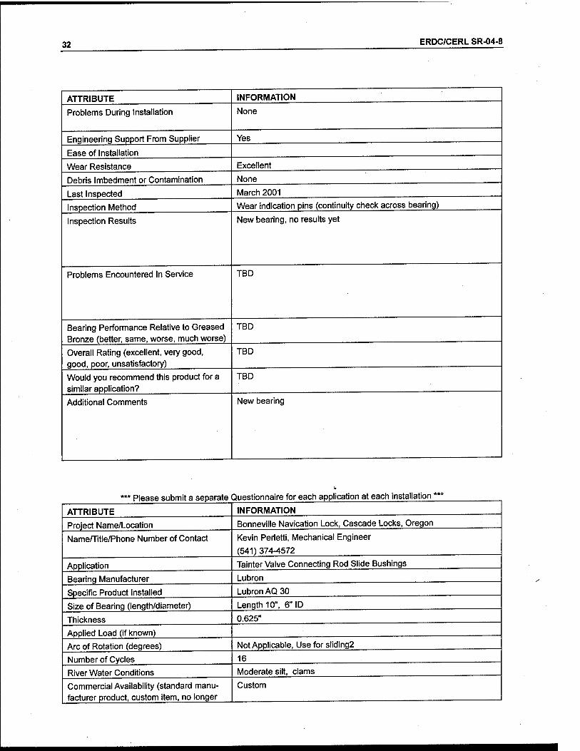
The swing bridge center pivot bearing at Cascade Locks is Lubron TF 400. The applied load is about 2,500 psi and the arc of rotation is 110 degrees. The aver- age number of cycles is 16 per day. The bearing was installed in 1994 and was replaced due to wear in 2001. The District rated wear resistance as fair, but considers the product to be better than greased bronze for this application, giv- ing it an overall rating of only "fair." The year 2001 replacement bearing is a Kamatics KAron V with a smaller diameter and a somewhat higher load of about 3,500 psi. The District reports no problems with the new product.
John Day Lock and Dam
The John Day Lock and Dam are on the Columbia River in the Portland District. The lock uses self-lubricating bushings on the tainter valve trunnions. Bushings are TXM-Marine manufactured by Orkot. The applied load is 250 kips and the arc of rotation 40 degrees. The number of cycles averages about 1,000 per day. The bearings were installed in 2000 using an adhesive. The District has not yet rated the Orkot bushing for this application.
Little Goose Lock and Dam
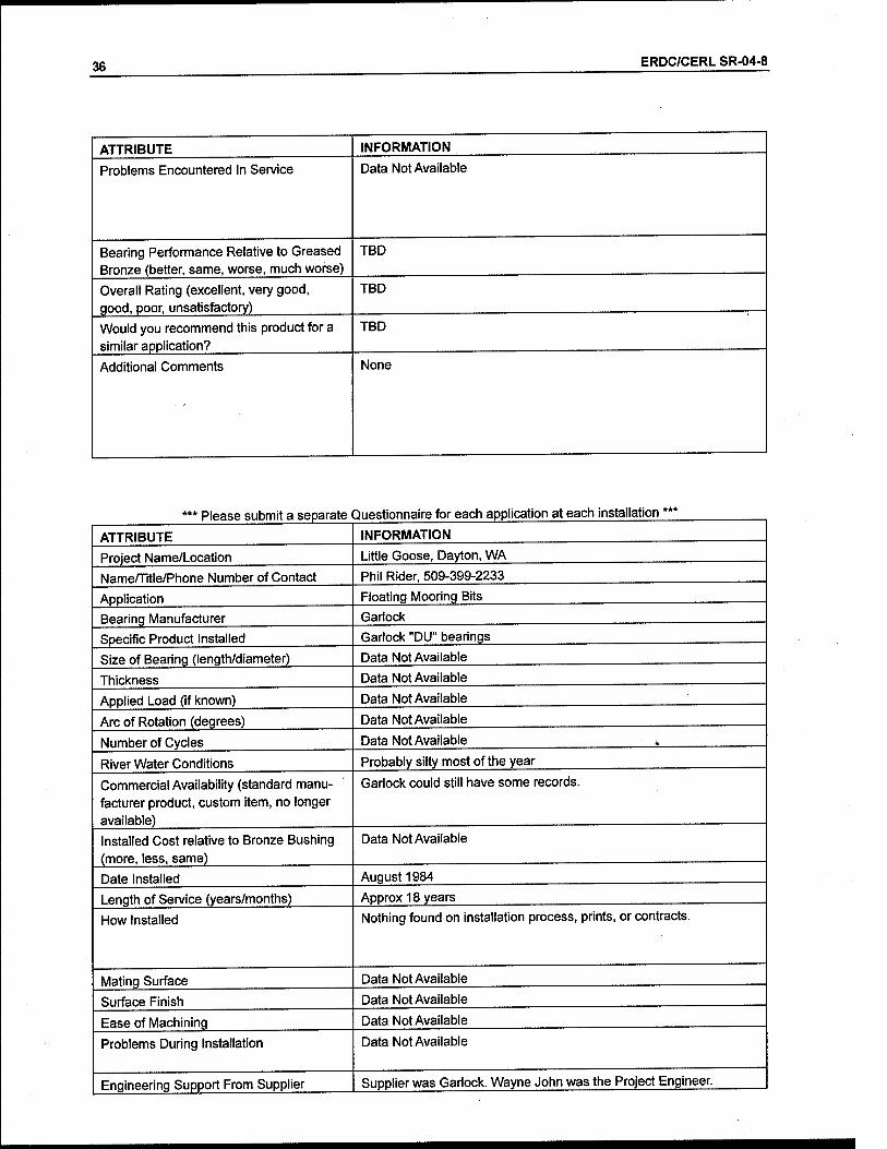
The Little Goose Lock is on the Snake River in the Portland District. The Dis- trict has reportedly used Garlock DU bearings in floating mooring bitts since 1984. The installation is an old one and records are sketchy. The District does not report any problems, however, and the bearings continue to function.

ERDC/CERL SR-04-8 13
Colorado River Locks
The Colorado River Locks are on the Colorado River in the Galveston District. The top and bottom hinge pin bushings and thrust washer on the east lock are self-lubricating products manufactured by Thordon. The loads on the top, bot- tom, and thrust bearings are 285.9 kips, 809.5 kips, and 255.6 kips respectively. The arc of rotation is 60 degrees. Bearings were installed in 1998 and 1999. Top hinge pin bushings and thrust washers are HPSXL, and bottom hinge pin bush- ings are SXL. The District rates these self-lubricating products "equal" to greased bronze and "good" overall. Since this rating was assigned, however, the upper hinge bushing failed on the North River side sector of the East Lock. The cause of the failure is not known. The hinge has been temporarily repaired by supplying grease between the bushing and pin.
Locks and Dam No. 27
Locks and Dam No. 27 is on the Mississippi River in the St. Louis District. Mi- ter gate hydraulic cylinder cardanic ring pillow blocks have Oiles 500 bearings manufactured by Oiles. The bearings, installed in 1998, see 60,000 cycles per year with a 20-degree arc of rotation. The District reports no problems and rates the bearing performance as "better" than greased bronze with an overall rating of "very good."
Melvin Price Locks and Dam
The Melvin Price Locks and Dam are on the Mississippi River in the St. Louis District. The dam's tainter gate trunnion bushings are Lubrite. The bushings were installed in 1982. The average number of cycles is estimated at greater than 1,000 per year with an 89-degree arc of rotation. Although the bushings have never been inspected, the District rates them "equal" to greased bronze bushings with an overall rating of "good."
Melvin Price culvert valve pivot bushings are also Lubrite. The bushings were installed in 1992 and see 60,000 cycles per year with a 60-degree arc of rotation. Some of the bushings were incorrectly sized and were cut to resize for installa- tion. These bushings subsequently failed due to loss of lubricant plugs. The premature failure was not the fault of Lubrite or the bearing. The correctly sized bushings remain in service and are rated "equal" to greased bronze bushings with an overall rating of "good."

14 ERDC/CERL SR-04-8
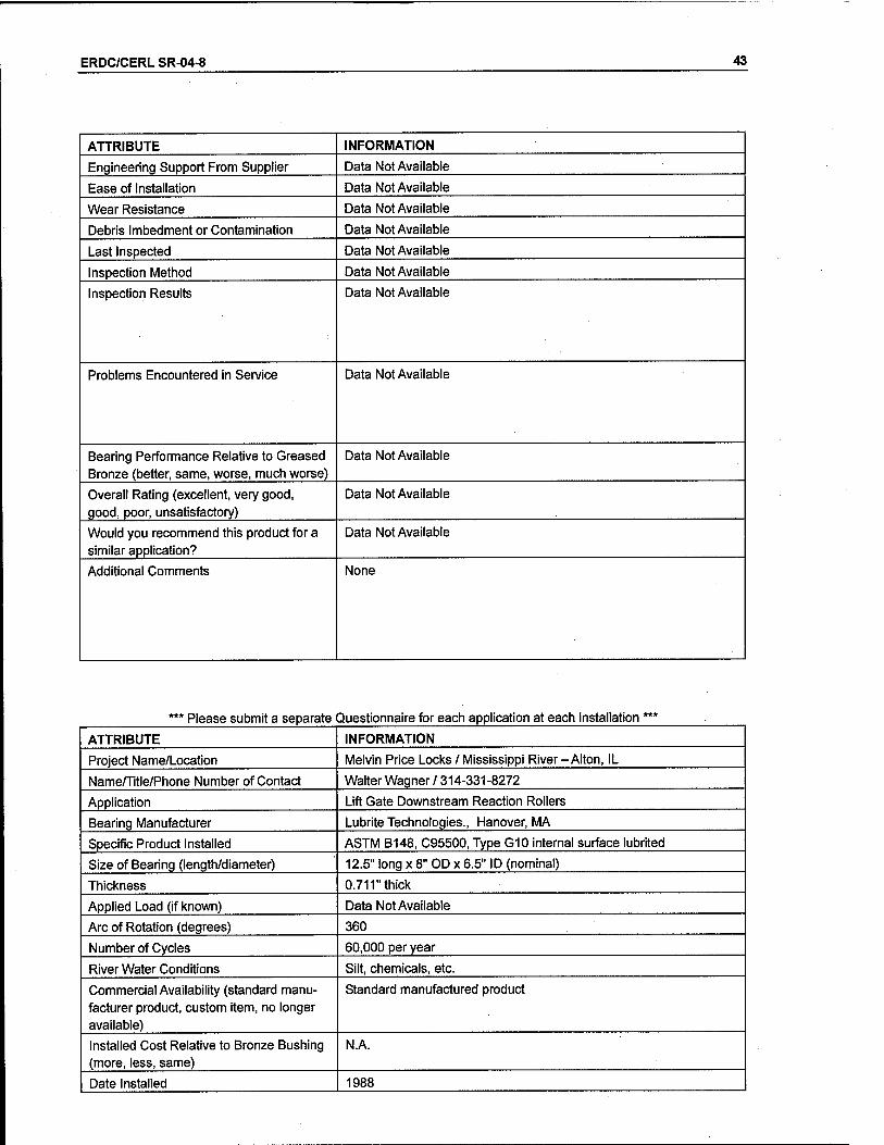
The lift gate downstream reaction roller bushings at Melvin Price are also Lu- brite. The average number of cycles is 60,000 per year with a 360-degree arc of rotation. The bushings were installed in 1988 and the District reports no prob- lems to date. The District rates the bushings as "better" than greased bronze bushings with an overall rating of "very good."
Kentucky Lock
The Kentucky Lock is on the Tennessee River in the Nashville District. Eight floating mooring bitts have been retrofit with self-lubricating roller bushings. Seven of these are TRAXL bushings manufactured by Thordon and one is KAron V manufactured by Kamatics. All of the retrofit mooring bitts use ultra-high mo- lecular weight polyethylene guide blocks in place of the lower roller assembly. The bushings were installed by pressure fitting. The District has had no prob- lems with the self-lubricating bushings, and they rate them as "better" than greased bronze and "excellent" overall.
Kentucky Lock also uses Thordon strut pin and sector gear bushings on the lower river gates. No other information is available from the District on this ap-
plication.
Barkley Lock
Barkley Lock is on the Cumberland River in the Nashville District. A number of floating mooring bitts have been retrofit with self-lubricating roller bushings manufactured by Thordon. The retrofit mooring bitts use ultra-high molecular weight polyethylene guide blocks in place of the lower roller assembly. The bushings were installed by pressure fitting. The District has had no problems with the self-lubricating bushings, and they rate them as "better" than greased bronze and "excellent" overall.
Old Hickory Lock
Old Hickory Lock is on the Cumberland River in the Nashville District. A num- ber of floating mooring bitts have been retrofit with Thordon SXL self- lubricating roller bushings. The retrofit mooring bitts use ultra-high molecular weight polyethylene guide blocks in place of the lower roller assembly. The bushings were installed by interference freeze fitting using liquid nitrogen. The applied loads on the parallel and perpendicular roller bushings are 17,333 psi
ERDC/CERL SR-04-8 15
and 14,225 psi, respectively. The arc of rotation is 360 degrees. The District has had no problems with the self-lubricating bushings, and they rate them as "bet- ter" than greased bronze and "excellent" overall.
The upper and lower strut pin bearings on the upper gate at Old Hickory are Thordon TRAXL. The District has had no problems with the self-lubricating bushings, and they rate them as "better" than greased bronze and "excellent"
overall.
Chicago Harbor Lock
Chicago Harbor Lock is on the Chicago River in the Chicago District. Lock sector gate rollers are equipped with Kamatics KAron V bushings. Two gates each were retrofit in 1998 and 1999. The bushings experience about 10,000 cycles per year with 360-degree arc of rotation. They were friction fitted and have snap-in side seals to prevent silt infiltration and subsequent particulate imbedment. No problems have been encountered in service. The District rates the bushings as "better" than greased bronze and gives them an overall rating of "excellent."
Sector gate upper hinge pins at Chicago Harbor Lock are also KAron V. Two gates each were retrofit in 1998 and 1999. The bushings experience about 10,000 cycles per year. No problems have been encountered in service. The Dis- trict rates the bushings as "better" than greased bronze and gives them an over- all rating of "excellent."

16 ERDC/CERL SR-04-8
5 Olmsted Prototype Field Experiments
Experimental hydraulic-operated wicket gates were constructed in 1995 at Smithland Locks and Dam as a part of the design decision process for the Olm- sted Locks and Dam project. Various materials, including greaseless bushings, were evaluated as a part of this prototype project. The wicket gate design was not used, but the data gathered on self-lubricating bushings are useful nonethe-
less.
Five types of self-lubricating bearings were tested and evaluated. Table 9 sum- marizes the products and their performance as reported by the Louisville Dis- trict. According to the District, the Lubron and Thordon products were superior in performance, with Lubrite third, Rowend fourth, and Kamatics last.
Table 9. Self-lubricating material vs. performance.
Product Performance
Lubron Bearing Systems -AQ100 The Lubron bearing showed no wear on either the main hinges of the gate or the prop bearing.
Kamatics - KAron V Kamatics bearing failed dramatically. The inner lu- bricating material flaked off the housing of the bear- ing. The manufacturer stated they made a mistake in the design of the bearing for the test. The lubricant material also flaked off the inside of the prop bearing race.
Lubrite G12, on Bronze Alloy #424, ASTM B22-C86300 (manganese bronze)
Lubrite had begun to lose its inner lubricating sur- face.
Thordon SXL TRAXL on bronze - C93200 The bearings were in good condition.
Rowend R-8 - CDA 8630 (manganese bronze) with an inner lubricating material R-8.
The Rowend bearing experienced severe pitting of its base metal due to galvanic corrosion.
ERDC/CERL SR-04-8 17
6 Powertech Laboratory Evaluation of Self-Lubricating Pintle Bearings
The U.S. Army Engineer Research and Development Center-Construction Engi- neering Research Laboratory (ERDC/CERL) contracted Powertech Labs, Inc. to perform scale model accelerated wear tests of navigation lock pintles. A scale model test frame was built to perform accelerated wear tests of current pintle bushing configurations, which serve as benchmark references, and on alternative self-lubricating pintle bushings. The experiments simulated the mechanical and environmental stresses of a lock miter gate pintle over an anticipated service life of 200,000 cycles.
Products tested were Thordon HPSXL, Tenmat T814, and Kamatics KAron V. All three products survived the tests using silt laden river water as the test me-
dium.
Powertech observed that wear rates and even total displacement should not be used as part of the comparison criteria as each pintle/bushing combination is unique and the best criteria for assessing performance are friction levels and product appearance after the tests and, to a lesser extent, actual wear.
Based on the appearance and friction criteria, Kamatics KAron V and the Ten- mat T814 survived the tests with little indication of stress. Performance levels were similar with relation to friction and appearance. However, Thordon HPSXL started showing the initial stages of material breakdown with wear de- bris observed clumped towards the bushing edge.
For further information on theseiaboratory tests, see Attachment 1.

18 ERDC/CERL SR-04-8
7 Field Experience With Self-Lubricating Pintle Bearing Materials
The only self-lubricating bearing material used in an actual pintle application was for one of the upper miter gate leafs for Cannelton Lock on the Ohio River, Tell City, IN (Louisville District). The bushing material was Thordon SXL. Al- though it performed well, after 8 years of service it was 80 percent eroded and was removed and replaced with a similar material. Figure 1 shows that the pintle bushing displayed signs of severe wear and was completely worn away in several places. Note, however, that the pintle was undamaged (Figure 2).
Table 10 shows typical cost of miter gate pintle bushings materials, as reported by manufacturers, along with accelerated wear test results for a simulated 200,000 open/close cycles (see Attachment 1), and field experience in pintle ap-
plications.
Table 10. Pintle busing material costs/performance data (20/24-inch diameter).
Manufacturer Product Cost
(US$) Material Accelerated
Testing Results*
Field Experience (as of August
2003)
Thordon HPSXL
SXL
9,000 to 11,000
Polyurethane Thordon HPSXL survived 200,000 cycles; clumping of wear debris shows signs of impending breakdown
Thordon SXL mate- rial performed well up to 7 yr in Ohio River (Cannelton Lock, Tell City, IN; Louisville District); 80% eroded after 8 vr
Tenmat T814 12,000 to 14,500
Woven Phenolic Survived 200,000 cycles; some evidence of over- heating
None
Kamatics KAronV 11,500 to 14,000
Glass flake epoxy with polytetrafluoroethylene (PTFE)
Survived 200,000 cycles; contact areas uniformly coated with lubricant; bushing contact areas polished smooth.
None
* Please see Attachment 1.

ERDC/CERL SR-04-8 19
Ell^^^^l
WMpVW&fi
MB Hj^^^~
ilgH Hi'ä'^H
^T^lni
33B
Figure 1. Self-lubricating pintle bearing with Thordon SXL material installed at Cannelton Lock in 1994; removed/replaced in July 2002; self-lubricating Thordon SXL material was approximately 80% eroded after 8 years.
mß
ea^s^-^«*"' '"i^ \£ " "*' ^v' 'A' \ - ■ ly^-^.^w^c.i^', • •£■■•-',' r ■ - v r' '•-■ "*«* -,» \ N- -
ftfeWi
Kfc* i»% 1 ^
1 N&.«*. ■<« IP Figure 2. Pintle that mated with bearing shown in Figure 1 shows very little wear after 8 years.
20 ERDC/CERL SR-04-8
8 Self-Lubricated Mechanical Components: Field Performance vs Properties
No correlation was noted between material properties and actual field perform- ance. This is not surprising given that the available data are fairly limited. There are some inconsistencies such as the unfavorable rating of KAron V by the Louisville District in the Olmsted prototype investigation. Granted the bearing did fail. This product has shown well in laboratory tests, however, and was rated excellent by field users. These discrepancies serve to highlight the relative importance of engineering design.
Another issue is that field ratings are subjective rather than analytical. For ex- ample, it is difficult to compare a subjective rating of "good" for a bearing that has provided trouble-free service for 18 years versus a bearing rated "excellent" after only 2 years of service. This may in fact merely represent pride in engi- neering rather than true excellence of performance.

ERDC/CERL SR-04-8 21
9 Conclusions
Salient Characteristics
Important characteristics of self-lubricating bushings for navigation projects in- clude load bearing capacity, wear rate, and coefficients of friction. Perhaps one of the most important characteristics is the difference between static and dy- namic coefficients of friction. The smaller the difference in these values, the less likely it is that stick-slip will be a problem. Aside from the properties of the self- lubricating bushings, engineering design considerations are also important, par- ticularly specifying proper clearances and mating surfaces.
Problems Encountered in Service
Stick-slip phenomena were the most frequently noted problems encountered in service. In one case, a bearing failed in service due to loss of lubricant plugs. In some cases, bearings were replaced due to wear.
Installation Techniques
The most common means of installing self-lubricating bushings is by press- fitting. Shrinking prior to installation by means of liquid nitrogen is also a com- mon practice.
Cost Relative to Greased Bronze Bushings
Many users reported higher costs for self-lubricating bushings. In some cases, however, equal or lower cost was reported.

22 ERDC/CERL SR-04-8
10 Commercial Availability
In general, all of the products found in use at USACE navigation facilities are commercially available. In some cases, bushings were not standard items and were custom fabricated due to unusual dimensions.
Engineering Support
Questionnaire respondents generally provided little information on the issue of engineering support from suppliers. The Portland District indicated that they did receive support from Kamatics and Tenmat. The Louisville District reported that Tenmat supplied them with an Microsoft Excel™ spreadsheet design tool. Garlock and Orkot both have extensive engineering literature available to cus- tomers over the Internet. None of the respondents indicated that engineering support was a problem. Lubrite Technologies reports that they offer technical design assistance and have a testing capability.
Overall Ratings of Products
It is not possible to rank order self-lubricating bushings in a meaningful manner using the available data. Bearing physical properties data vary in a nonlinear fashion. This fact complicates any simple rating scheme. It terms of making de- cisions about specific materials and applications, it is recommended that the specifier learn and borrow from the experience of the USACE engineering com- munity as a whole. The information compiled herein is a useful starting point for those who wish to use self-lubricating products.
Recommended Products
Most of the bearings were found to be suitable for most of the applications where they have been employed. Most users reported performance equal to or better than greased bronze bushings. Garlock DU and Kamatics KAron V bushings are distinguished by their low coefficients of friction and smaller than average dif- ferences between static and dynamic coefficients of friction. Garlock and Orkot

ERDC/CERL SR-04-8 23
provide extensive engineering data on their websites. The specification and en- gineering of other product installations requires significant input from the manufacturer. Garlock provides enough information to specify and design an installation without input from the supplier. This is beneficial to the extent that product selection is based on unbiased data rather than sales engineering. Al- though user experience is limited for Garlock DU, this product is highly recom- mended because of its properties, engineering data, and materials. Tenmat Feroform T814 and Kamatics KAron V are also highly recommended because of their properties and the extensive positive field experience with these products. Tenmat also provides a software design program. Thordon TRAXL bearings are also recommended. Lubrite products have been used with uniform success. Lim- ited field data are available at this time on the use of Orkot products within USACE.
24 ERDC/CERL SR-04-8
Appendix A: Questionnaires on Self- Lubricating Bushings
*** Please submit a separate Questionnaire for each application at each installation'
ATTRIBUTE
Project Name/Location
Name/Title/Phone Number of Contact
Application
Bearing Manufacturer
Specific Product Installed
Size of Bearing (length/diameter)
Thickness
Applied Load (if known)
Arc of Rotation (degrees)
Number of Cycles
River Water Conditions
Commercial Availability (standard manu- facturer product, custom item, no longer available)
Installed Cost Relative to Bronze Bushing (more, less, same)
Date Installed
Length of Service (years/months)
How Installed
Mating Surface
Surface Finish
Ease of Machining
Problems During Installation
Engineering Support From Supplier
Ease of Installation
Wear Resistance
Debris Imbedment or Contamination
Last Inspected
Inspection Method
Inspection Results
Problems Encountered in Service
INFORMATION
Bonneville Navigation Lock, Cascade Locks, Oregon
Ron Wridge, Mechanical Engineer
(503) 808-4927
Floating Mooring Bitt Guide Blocks
Tenmat
FeroformT814
8"x 8"
1"
~1,000 psi
N/A
-720 feet of linear travel/day
Fresh water with minimal contaminates
Custom
More
1997
4 years
Bolted to floating mooring bitt
Stainless Steel
-125 Data Not Available
None
Yes
Data Not Available
Good for the mating surface's poor finish
Data Not Available
Data Not Available
Data Not Available
None

ERDC/CERL SR-04-8 25
ATTRIBUTE INFORMATION
Bearing Performance Relative to Greased Bronze (better, same, worse, much worse)
Better
Overall Rating (excellent, very good, good, poor, unsatisfactory)
Excellent
Would you recommend this product for a similar application?
Yes
Additional Comments The floating mooring bitts continue to operate as intended with no operational or maintenance issues.
*** Please submit a separate Questionnaire for each application at each installation ***
ATTRIBUTE INFORMATION
Project Name/Location Bonneville Navigation Lock, Cascade Locks, Oregon
Name/Title/Phone Number of Contact Ron Wridge, Mechanical Engineer
(503) 808-4927
Application Floating Mooring Bitt Rollers
Bearing Manufacturer Kamatics
Specific Product Installed KAron V
Size of Bearing (length/diameter) 5" I.D.
Thickness 0.625"
Applied Load (if known) -2,500 psi
Arc of Rotation (degrees) 360
Number of Cycles 240 revolutions/day
River Water Conditions Not applicable, bearing out of water
Commercial Availability (standard manu- facturer product, custom item, no longer available)
Custom
Installed Cost Relative to Bronze Bushing (more, less, same)
More
Date Installed 1997
Length of Service (years/months) 4 years
How Installed Data Not Available
Mating Surface 300 series Stainless Steel with chrome overlay
Surface Finish 8
Ease of Machining Data Not Available
Problems During Installation Data Not Available
Engineering Support From Supplier Yes
Ease of Installation Data Not Available
Wear Resistance Excellent
Debris Imbedment or Contamination Data Not Available

26 ERDC/CERL SR-04-8
ATTRIBUTE INFORMATION
Last Inspected Data Not Available
Inspection Method Data Not Available
Inspection Results Data Not Available
Problems Encountered in Service None
Bearing Performance Relative to Greased Bronze (better, same, worse, much worse)
Better
Overall Rating (excellent, very good, good, poor, unsatisfactory)
Excellent
Would you recommend this product for a similar application?
Yes
Additional Comments Rollers continue to operate as intended with tenance issues.
no operational or main-
*** Please submit a separate Questionnaire for each application at each installation ***
ATTRIBUTE INFORMATION
Project Name/Location Bonneville Navigation Lock, Cascade Locks, Oregon
Name/Title/Phone Number of Contact Ron Wridge, Mechanical Engineer
(503) 808-4927
Application Floating Mooring Bitt Rollers
Bearing Manufacturer Lubron
Specific Product Installed AQ100
Size of Bearing (length/diameter) 5" I.D.
Thickness 0.625"
Applied Load (if known) -2,500 psi
Arc of Rotation (degrees) 360
Number of Cycles 240 revolutions/day
River Water Conditions Not applicable, bearing out of water
Commercial Availability (standard manu- facturer product, custom item, no longer available)
Custom
Installed Cost Relative to Bronze Bushing (more, less, same)
More
Date Installed 1995
Length of Service (years/months) 2 years
How Installed Press fit into stainless steel roller
ERDC/CERL SR-04-8 27
ATTRIBUTE INFORMATION
Mating Surface 300 series Stainless Steel
Surface Finish 63
Ease of Machining Data Not Available
Problems During Installation Data Not Available
Engineering Support From Supplier Yes
Ease of Installation Data Not Available
Wear Resistance Data Not Available
Debris Imbedment or Contamination Data Not Available
Last Inspected Data Not Available
Inspection Method Data Not Available
Inspection Results Data Not Available
Problems Encountered In Service Squealing and stick/slip operation
Bearing Performance Relative to Greased Bronze (better, same, worse, much worse)
Worse
Overall Rating (excellent, very good, good, poor, unsatisfactory)
Poor/unsatisfactory
Would you recommend this product for a similar application?
No
Additional Comments Bearing squealed and exhibited stick/slip once the brake-in grease had dissipated. The rollers were replaced in 1997 with a new design and different self-lubricating material.
Please submit a separate Questionnaire for each application at each installation'
ATTRIBUTE INFORMATION
Project Name/Location Bonneville Navigation Lock, Cascade Locks, Oregon
Name/Title/Phone Number of Contact Ron Wridge, Mechanical Engineer
(503) 808-4927
Application Floating Mooring Bitt Thrust Washers
Bearing Manufacturer Tenmat
Specific Product Installed FeroformT814
Size of Bearing (length/diameter) 5" I.D. and 7 V/ O.D.
Thickness 3/8"
Applied Load (if known) Minimal
Arc of Rotation (degrees) N/A
Number of Cycles N/A
River Water Conditions Not in the water

28 ERDC/CERL SR-04-8
ATTRIBUTE
Commercial Availability (standard manu- facturer product, custom item, no longer available)
Installed Cost Relative to Bronze Bushing (more, less, same)
Date Installed
Length of Service (years/months)
How Installed
Mating Surface
Surface Finish
Ease of Machining
Problems During Installation
Engineering Support From Supplier
Ease of Installation
Wear Resistance
Debris Imbedment or Contamination
Last Inspected
Inspection Method
Inspection Results
Problems Encountered in Service
Bearing Performance Relative to Greased Bronze (better, same, worse, much worse)
Overall Rating (excellent, very good, good, poor, unsatisfactory)
Would you recommend this product for a similar application?
Additional Comments
INFORMATION
Custom
More
1997
4 years
Stainless Steel
32
Yes
Data Not Available
Data Not Available
Data Not Available
Data Not Available
Data Not Available
Data Not Available
None
Better
Excellent
Yes
The floating mooring bitts continue to operate as intended with no operational or maintenance issues. '
ERDC/CERL SR-04-8 29
*** Please submit a separate Questionnaire for each application at each installation ***
ATTRIBUTE INFORMATION
Project Name/Location Bonneville Navigation Lock, Cascade Locks, Oregon
Name/Title/Phone Number of Contact Ron Wridge, Mechanical Engineer
(503) 808-4927
Application Miter Gate Pin Bushings
Bearing Manufacturer Lubron
Specific Product Installed LubronAQ30
Size of Bearing (length/diameter) Upper-Length 12", 11.25" ID
Lower - Length 5 5/8", 5.2" ID
Thickness Upper, 0.875" Lower, 0.625"
Applied Load (if known) ~2,500 psi
Arc of Rotation (degrees) 40
Number of Cycles 16/day
River Water Conditions Not applicable, bearing out of water
Commercial Availability (standard manu- facturer product, custom item, no longer available)
Custom
Installed Cost Relative to Bronze Bushing (more, less, same)
More
Date Installed 1996
Length of Service (years/months) 5 years
How Installed Press fit into cast steel housing
Mating Surface Stainless Steel
Surface Finish 63
Ease of Machining
Problems During Installation Tight Tolerances
Engineering Support From Supplier Yes
Ease of Installation Data Not Available
Wear Resistance Data Not Available
Debris Imbedment or Contamination Data Not Available
Last Inspected None
Inspection Method
Inspection Results Data Not Available
Problems Encountered in Service Squealing of Joint
Bearing Performance Relative to Greased Bronze (better, same, worse, much worse)
Worse
Overall Rating (excellent, very good, good, poor, unsatisfactory)
Poor/unsatisfactory

30 ERDC/CERL SR-04-8
ATTRIBUTE
Would you recommend this product for a similar application?
Additional Comments
INFORMATION
No
Bearing squeals once the brake-in grease has dissipated.
*** Please submit a separate Questionnaire for each application at each installation ***
ATTRIBUTE INFORMATION
Project Name/Location Bonneville Navigation Lock, Cascade Locks Oregon
Name/Title/Phone Number of Contact Ron Wridge, Mechanical Engineer
(503) 808-4927
Application Swing Bridge Center Pivot Bearing
Bearing Manufacturer Lubron
Specific Product Installed TF400
Size of Bearing (length/diameter) 60" spherical
Thickness -0.060 PTFE with fiberglass backing
Applied Load (if known) -2,500 psi
Arc of Rotation (degrees) 110
Number of Cycles 16/day
River Water Conditions Not applicable
Commercial Availability (standard manu- facturer product, custom item, no longer available)
Custom
Installed Cost Relative to Bronze Bushing (more, less, same)
More
Date Installed March 1994
Length of Service (years/months) 7 years
How Installed ■
Mating Surface 304 stainless steel
Surface Finish 16
Ease of Machining Moderate Problems During Installation None
Engineering Support From Supplier Yes
Ease of Installation
Wear Resistance Fair
Debris Imbedment or Contamination None
Last Inspected March 2001
Inspection Method Periodically analyze wear debris for fiberglass
Inspection Results Fiberglass bundles mixed in wear debris after 6 Vi years of use.
ERDC/CERL SR-04-8 31
Problems Encountered in Service None
Bearing Performance Relative to Greased Bronze (better, same, worse, much worse)
Better
Overall Rating (excellent, very good, good, poor, unsatisfactory)
Fair
Would you recommend this product for a similar application?
No
Additional Comments A replacement bearing utilizing an improved design was installed in March 2001.
*** Please submit a separate Questionnaire for each application at each installation ***
ATTRIBUTE INFORMATION
Project Name/Location Bonneville Navigation Lock, Cascade Locks, Oregon
Name/Title/Phone Number of Contact Ron Wridge, Mechanical Engineer
(503) 808-4927
Application Swing Bridge Center Pivot Bearing
Bearing Manufacturer Kamatics
Specific Product Installed KAron V
Size of Bearing (length/diameter) 50 inch spherical
Thickness 0.040 self-lubricating liner thickness
Applied Load (if known) -3,500 psi
Arc of Rotation (degrees) 110
Number of Cycles 16/day
River Water Conditions Not applicable
Commercial Availability (standard manu- facturer product, custom item, no longer available)
Custom
Installed Cost Relative to Bronze Bushing (more, less, same)
More
Date Installed March 2001
Length of Service (years/months) 2 months
How Installed
Mating Surface 17-4 PH, H900
Surface Finish 16
Ease of Machining Moderate
32 ERDC/CERL SR-04-8
ATTRIBUTE
Problems During Installation
Engineering Support From Supplier
Ease of Installation
Wear Resistance
Debris Imbedment or Contamination
Last Inspected
Inspection Method
Inspection Results
Problems Encountered In Service
Bearing Performance Relative to Greased Bronze (better, same, worse, much worse)
Overall Rating (excellent, very good, good, poor, unsatisfactory)
Would you recommend this product for a similar application?
Additional Comments
INFORMATION
None
Yes
Excellent
None
March 2001
Wear indication pins (continuity check across bearing)
New bearing, no results yet
TBD
TBD
TBD
TBD
New bearing
Please submit a separate Questionnaire for each application at each installation
ATTRIBUTE
Project Name/Location
Name/Title/Phone Number of Contact
Application
Bearing Manufacturer
Specific Product Installed
Size of Bearing (length/diameter)
Thickness
Applied Load (if known)
Arc of Rotation (degrees)
Number of Cycles
River Water Conditions
Commercial Availability (standard manu- facturer product, custom item, no longer
INFORMATION
Bonneville Navication Lock, Cascade Locks, Oregon
Kevin Perletti, Mechanical Engineer
(541) 374-4572
Tainter Valve Connecting Rod Slide Bushings
Lubron
LubronAQ30
Length 10", 6" ID
0.625"
Not Applicable, Use for sliding2
16 Moderate silt, clams
Custom

ERDC/CERL SR-04-8 33
ATTRIBUTE INFORMATION
available)
Installed Cost Relative to Bronze Bushing (more, less, same)
More
Date Installed 1993
Length of Service (years/months) 8
How Installed Force fit, FN2
Mating Surface 17400 PH
Surface Finish 63
Ease of Machining
Problems During Installation
Engineering Support From Supplier
Ease of Installation
Wear Resistance
Debris Imbedment or Contamination
Last Inspected
Inspection Method Removal of connecting rods
Inspection Results Never inspected
Problems Encountered in Service None
Bearing Performance Relative to Greased Bronze (better, same, worse, much worse)
Same
Overall Rating (excellent, very good, good, poor, unsatisfactory)
Very good
Would you recommend this product for a similar application?
Yes
Additional Comments No known problems to date

34 ERDC/CERL SR-04-8
*** Please submit a separate Questionnaire for each application at each installation ***
ATTRIBUTE INFORMATION
Project Name/Location Bonneville Navigation Lock, Cascade Locks, Oregon
Name/Title/Phone Number of Contact Kevin Perletti, Mechanical Engineer
(541) 374-4572
Application Tainter Valve Trunnion Bushings
Bearing Manufacturer Lubron
Specific Product Installed LubronAQ30
Size of Bearing (length/diameter) Length 20", 15" ID
Thickness 0.75"
Applied Load (if known)
Arc of Rotation (degrees) 52
Number of Cycles 16
River Water Conditions Moderate silt, clams
Commercial Availability (standard manu- facturer product, custom item, no longer available)
Custom
Installed Cost Relative to Bronze Bushing (more, less, same)
More
Date Installed 1993
Length of Service (years/months) 8
How Installed Force fit
Mating Surface A668
Surface Finish 63
Ease of Machining Data Not Available
Problems During Installation Data Not Available
Engineering Support From Supplier Data Not Available
Ease of Installation Data Not Available
Wear Resistance Data Not Available
Debris Imbedment or Contamination Data Not Available
Last Inspected 1994
Inspection Method Removal of Trunnion pins
Inspection Results Corrosion was occurring on pins. Pin material was changed in 1994 from 668 to 8620
Problems Encountered in Service Corrosion between A668 and Lubron bushing. Pin material replaced.
Bearing Performance Relative to Greased Bronze (better, same, worse, much worse)
Same
Overall Rating (excellent, very good, good, poor, unsatisfactory)
Good

ERDC/CERL SR-04-8 35
ATTRIBUTE INFORMATION
Would you recommend this product for a similar application?
Yes with correct pin material
Additional Comments None
*** Please submit a separate Questionnaire for each application at each installation ***
ATTRIBUTE INFORMATION
Project Name/Location John Day Lock & Dam, Columbia River, OR-WA
Name/Title/Phone Number of Contact Mike Colesar, Mechanical Engineer, 541-298-7567
Application Navlock tainter valve trunnion bushings
Bearing Manufacturer Orkot
Specific Product Installed TXM-Marine
Size of Bearing (length/diameter) 14" ID x 20" long, 2 bushings per valve
Thickness 0.84"
Applied Load (if known) 250 kip
Arc of Rotation (degrees) 40
Number of Cycles 1,000
River Water Conditions Data Not Available
Commercial Availability (standard manu- facturer product, custom item, no longer available)
Standard material, custom machined
Installed Cost Relative to Bronze Bushing (more, less, same)
Same
Date Installed June 2000
Length of Service (years/months) 1 year
How Installed Adhesive
Mating Surface 17-4 PHSS
Surface Finish 32
Ease of Machining Fairly hard
Problems During Installation
Engineering Support From Supplier Data Not Available
Ease of Installation Data Not Available
Wear Resistance Data Not Available
Debris Imbedment or Contamination Data Not Available
Last Inspected Data Not Available
Inspection Method Data Not Available
Inspection Results Data Not Available
36 ERDC/CERL SR-04-8
ATTRIBUTE
Problems Encountered In Service
Bearing Performance Relative to Greased Bronze (better, same, worse, much worse)
Overall Rating (excellent, very good, good, poor, unsatisfactory)
Would you recommend this product for a similar application?
Additional Comments
INFORMATION
Data Not Available
TBD
TBD
TBD
None
* Please submit a separate Questionnaire for each application at each installation '
ATTRIBUTE INFORMATION
Project Name/Location Little Goose, Dayton, WA
Nameffltle/Phone Number of Contact Phil Rider, 509-399-2233
Application Floating Mooring Bits
Bearing Manufacturer Garlock
Specific Product Installed Garlock "DU" bearings
Size of Bearing (length/diameter) Data Not Available
Thickness Data Not Available
Applied Load (if known) Data Not Available
Arc of Rotation (degrees) Data Not Available
Number of Cycles Data Not Available i
River Water Conditions Probably silty most of the year
Commercial Availability (standard manu- facturer product, custom item, no longer available)
Garlock could still have some records.
Installed Cost relative to Bronze Bushing (more, less, same)
Data Not Available
Date Installed August 1984
Length of Service (years/months) Approx 18 years
How Installed Nothing found on installation process, prints, or contracts.
Mating Surface Data Not Available
Surface Finish Data Not Available
Ease of Machining Data Not Available
Problems During Installation Data Not Available
Engineering Support From Supplier Supplier was Garlock. Wayne John was the Project Engineer.

ERDC/CERL SR-04-8 37
ATTRIBUTE INFORMATION
Ease of Installation Data Not Available
Wear Resistance Appeared to be good.
Debris Imbedment or Contamination Silt.
Last Inspected Approx. 1994 or 5 (mooring bitt pulled because of other problem)
Inspection Method Visual if problem reported (no problems reported)
Inspection Results Didn't appear to be any major problems. They were a little tight be- cause of silt, if I remember correct, but did move.
Problems Encountered in Service None as yet »
Bearing Performance Relative to Greased Bronze (better, same, worse, much worse)
Appears to be doing good.
Overall Rating (excellent, very good, good, poor, unsatisfactory)
We have had no problems with the mooring bitts.
Would you recommend this product for a similar application?
It did seem to be in pretty good shape.
Additional Comments We had a bitt sinking, which was unrelated but while it was out we did some inspections and repairs (i.e., gaskets, anode replacement, guide repair, etc.).
Mech. Foreman in 84 was Ken Weeks and the Project Engineer was Wayne John.
I could not find any prints other than orig. inst. -LGN-1-5-10/1&2
Please submit a separate Questionnaire for each application at each installation '
ATTRIBUTE INFORMATION
Project Name/Location Barkley Lock - Nashville District
Name/Title/Phone Number of Contact Rick Williams - 615-736-7824
Application Floating mooring bitt rollers
Bearing Manufacturer Data Not Available
Specific Product Installed Data Not Available
Size of Bearing (length/diameter) Data Not Available
Liner Thickness Data Not Available
Applied Load and Pressure Data Not Available
Arc of Rotation (degrees) Data Not Available
Number of Cycles Data Not Available
River Water Conditions Data Not Available
Commercial Availability (standard manu- facturer product, custom item, no longer available)
Data Not Available
Installed Cost Relative to Bronze Bushing (more, less, same)
Data Not Available
Date Installed Data Not Available

38 ERDC/CERL SR-04-8
Length of Service (years/months)
How Installed
Mating Surface
Surface Finish
Ease of Machining
Problems During Installation
Engineering Support From Supplier
Ease of Installation
Wear Resistance
Debris Imbedment or Contamination
Last Inspected
Inspection Method
Inspection Results
Problems Encountered In Service
Bearing Performance Relative to Greased Bronze (better, same, worse, much worse)
Overall Rating (excellent, very good, good, poor, unsatisfactory)
Would you recommend this product for a similar application?
Additional Comments
Data Not Available
Data Not Available
Data Not Available
Data Not Available
Data Not Available
Data Not Available
Data Not Available
Data Not Available
Data Not Available
Data Not Available
Data Not Available
Data Not Available
Data Not Available
Data Not Available
Data Not Available
Data Not Available
Data Not Available
Data Not Available

ERDC/CERL SR-04-8 39
*** Please submit a separate Questionnaire for each application at each installation ***
ATTRIBUTE INFORMATION
Project Name and Location: Rehabilitate East and West Locks, Colorado River Locks
Name and Phone Number of Contact: Simon DeSoto - 979-863-2318 (office) - 979-863-2127 (fax)
Bearing Manufacturer: Thordon Bearings, Inc.
Specific Bearing Product (Company Name,
etc.):
Upper Bushing - HPSXL on Bronze
Lower Bushing - SXL on Bronze
Top Thrust Washer - SXL on Bronze
Lower Thrust Washer - HPSXL on Bronze
Where Used, (Ex: "mooring bitt bushings"): Top and Bottom Hinge Pin Bushings and Middle Thrust Washer on the East Lock-West Gate and East Lock-East Gate
Size of bearing, (Ex: "3.5" I.D. x 2.5" Long"): Top Bushing -10.0124" I.D. X 10" long
Bottom Bushing -12.0156" I.D. X 25.75" long
Thrust Washer -12.0156" I.D. X 24" O.D. X 0.75" thick
Applied load, if known: Top Bushing 285.9 kips
Bottom Bushing 809.5 kips
Thrust Washer 255.6 kips
Date installed: East Lock - West Gate June 1998
East Lock - East Gate February 1999
Length of service, in Years and Months: East Lock - West Gate - 2 years and 8 months
East Lock - East Gate - 2 years
Arc of Rotation, in Degrees: 60 degrees
Number of Cycles to date (or to failure, if failed): Give best estimate:
East Lock -West Gate - 100,000 cycles
East Lock - East Gate - 36,000 cycles
Problems encountered: a. During Installation
Vibration initially noted on 1 (East Lock, West Gate, North Sec- tor) of 4 sectors. Vibration eventually subsided after approxi- mately 2 - 4 weeks; suspect bushings finally seated.
b. In service
The upper hinge bushing failed on the North River side sector of the East Lock (January 2004). The cause for failure is not known. The hinge has been temporarily repaired by supplying grease between the bushing and pin.
c. Engineering Support from bearing manufacturer
None
Bearing Performance: a. Relative to greased bronze:
1) Better than
2) Equal to
3) Poorer than
4) Much poorer than
b. Overall rating as a bearing:
1) Outstanding
2) Very Good
3) Good
4) Poor
5) Totally Unsatisfactory

40 ERDC/CERL SR-04-8
Please submit a separate Questionnaire for each application at each installation
ATTRIBUTE
Project Name/Location
Name/Title/Phone Number of Contact
Application
Bearing Manufacturer
Specific Product Installed
Size of Bearing (length/diameter)
Liner Thickness
Applied Load and Pressure
Arc of Rotation (degrees)
Number of Cycles
River Water Conditions
Commercial Availability (standard manu- facturer product, custom item, no longer available)
Installed Cost Relative to Bronze Bushing (more, less, same)
Date Installed
Length of Service (years/months)
How Installed
Mating Surface
Surface Finish
Ease of Machining
Problems During Installation
Engineering Support From Supplier
Ease of Installation
Wear Resistance
Debris Imbedment or Contamination
Last Inspected
Inspection Method
Inspection Results
Problems Encountered in Service
Bearing Performance Relative to Greased Bronze (better, same, worse, much worse)
Overall Rating (excellent, very good, good, poor, unsatisfactory)
Would you recommend this product for a similar application?
INFORMATION
Kentucky Lock - Nashville District
Rick Williams -• 615-736-7824
Sector Gear
Thordon
L-7.25 inch, ID=12.500 inch
Dry

ERDC/CERL SR-04-8 41
ATTRIBUTE INFORMATION
Additional Comments
*** Please submit a separate Questionnaire for each application at each installation ***
ATTRIBUTE INFORMATION
Project Name/Location Kentucky Lock - Nashville District
Name/Title/Phone Number of Contact Rick Williams - 615-736-7824
Application Strut Pins
Bearing Manufacturer Thordon
Specific Product Installed Data Not Available
Size of Bearing (length/diameter) Data Not Available
Liner Thickness Data Not Available
Applied Load and Pressure Data Not Available
Arc of Rotation (degrees) Data Not Available
Number of Cycles Data Not Available
River Water Conditions Data Not Available
Commercial Availability (standard manu- facturer product, custom item, no longer available)
Data Not Available
Installed Cost Relative to Bronze Bushing (more, less, same)
Data Not Available
Date Installed Data Not Available
Length of Service (years/months) Data Not Available
How Installed Data Not Available
Mating Surface Data Not Available
Surface Finish Data Not Available
Ease of Machining Data Not Available
Problems during Installation Data Not Available
Engineering Support from Supplier Data Not Available
Ease of Installation Data Not Available
Wear Resistance Data Not Available
Debris Imbedment or Contamination Data Not Available
Last Inspected Data Not Available
Inspection Method Data Not Available
Inspection Results Data Not Available

42 ERDC/CERL SR-04-8
ATTRIBUTE
Problems Encountered in Service
Bearing Performance Relative to Greased Bronze (better, same, worse, much worse)
Overall Rating (excellent, very good, good, poor, unsatisfactory)
Would you recommend this product for a similar application?
Additional Comments
INFORMATION
Data Not Available
Data Not Available
Data Not Available
Data Not Available
Data Not Available
" Please submit a separate Questionnaire for each application at each installation
ATTRIBUTE INFORMATION
Project Name/Location Kentucky Lock - Nashville District
Name/Title/Phone Number of Contact Rick Williams - 615-736-7824
Application Floating mooring bitt rollers
Bearing Manufacturer Thordon (7); Kamatics (1)
Specific Product Installed Thordon TRAXL; KAron V (on 304 or 316 stainless steel)
Size of Bearing (length/diameter) ?? ; parallel rollers L=1.50 inch, ID=2.75 inch and perpendicular L=3.00 inch, ID=2.00 inch
roller
Liner Thickness ??; 0.040 inch minimum
Applied Load and Pressure Data Not Available
Arc of Rotation (degrees) 360
Number of Cycles Data Not Available
River Water Conditions Data Not Available
Commercial Availability (standard manu- facturer product, custom item, no longer available)
Data Not Available
Installed Cost Relative to Bronze Bushing (more, less, same)
Data Not Available
Date Installed Data Not Available
Length of Service (years/months) Data Not Available
How Installed Pressure fitted
Mating Surface 304 or 316 stainless
Surface Finish 32 RMS or better (shafts)
Ease of Machining
Problems During Installation Data Not Available
ERDC/CERL SR-04-8 43
ATTRIBUTE INFORMATION
Engineering Support From Supplier Data Not Available
Ease of Installation Data Not Available
Wear Resistance Data Not Available
Debris Imbedment or Contamination Data Not Available
Last Inspected Data Not Available
Inspection Method Data Not Available
Inspection Results Data Not Available
Problems Encountered in Service Data Not Available
Bearing Performance Relative to Greased Bronze (better, same, worse, much worse)
Data Not Available
Overall Rating (excellent, very good, good, poor, unsatisfactory)
Data Not Available
Would you recommend this product for a similar application?
Data Not Available
Additional Comments None
*** Please submit a separate Questionnaire for each application at each installation ***
ATTRIBUTE INFORMATION
Project Name/Location Melvin Price Locks / Mississippi River-Alton, IL
Name/Title/Phone Number of Contact Walter Wagner / 314-331-8272
Application Lift Gate Downstream Reaction Rollers
Bearing Manufacturer Lubrite Technologies., Hanover, MA
Specific Product Installed ASTM B148, C95500, Type G10 internal surface lubrited
Size of Bearing (length/diameter) 12.5" long x 8" OD x 6.5" ID (nominal)
Thickness 0.711" thick
Applied Load (if known) Data Not Available
Arc of Rotation (degrees) 360
Number of Cycles 60,000 per year
River Water Conditions Silt, chemicals, etc.
Commercial Availability (standard manu- facturer product, custom item, no longer available)
Standard manufactured product
Installed Cost Relative to Bronze Bushing (more, less, same)
N.A.
Date Installed 1988
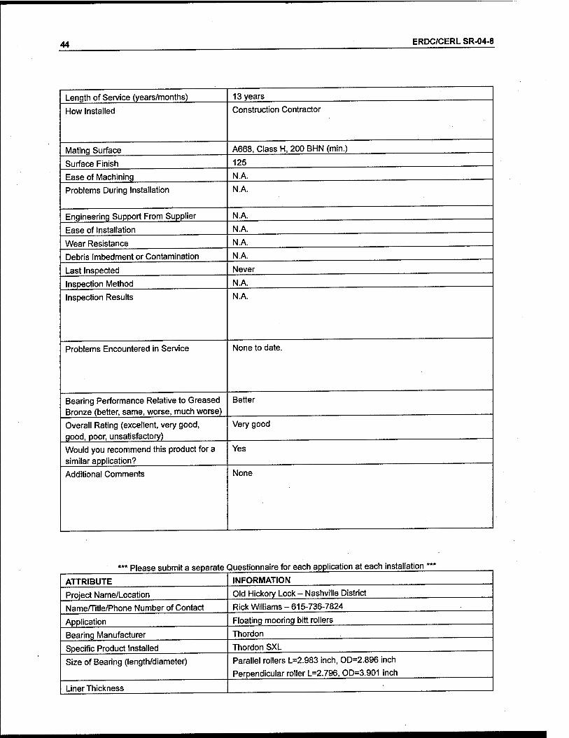
44 ERDC/CERL SR-04-8
Length of Service (years/months) 13 years
How Installed Construction Contractor
Mating Surface A668, Class H, 200 BHN (min.)
Surface Finish 125
Ease of Machining N.A.
Problems During Installation N.A.
Engineering Support From Supplier N.A.
Ease of Installation N.A.
Wear Resistance N.A.
Debris Imbedment or Contamination N.A.
Last Inspected Never
Inspection Method N.A.
Inspection Results N.A.
Problems Encountered in Service None to date.
Bearing Performance Relative to Greased Bronze (better, same, worse, much worse)
Better
Overall Rating (excellent, very good, good, poor, unsatisfactory)
Very good
Would you recommend this product for a similar application?
Yes
Additional Comments None
Please submit a separate Questionnaire for each application at each installation
ATTRIBUTE
Project Name/Location
Name/Title/Phone Number of Contact
Application
Bearing Manufacturer
Specific Product Installed
Size of Bearing (length/diameter)
Liner Thickness
INFORMATION
Old Hickory Lock - Nashville District
Rick Williams - 615-736-7824
Floating mooring bitt rollers
Thordon
Thordon SXL
Parallel rollers L=2.983 inch, OD=2.896 inch
Perpendicular roller L=2.796, OD=3.901 inch

ERDC/CERL SR-04-8 45
ATTRIBUTE INFORMATION
Applied Load and Pressure Parallel rollers 130,000 pounds and 17,333.33 PSI
Perpendicular roller 130,000 pounds and 14,224.751 PSI
Arc of Rotation (degrees) 360
Number of Cycles Data Not Available
River Water Conditions Data Not Available
Commercial Availability (standard manu- facturer product, custom item, no longer available)
Data Not Available
Installed Cost relative to Bronze Bushing (more, less, same)
Data Not Available
Date Installed Data Not Available
Length of Service (years/months) Data Not Available
How installed Interference freeze fit
Mating Surface Stainless steel
Surface Finish Data Not Available
Ease of Machining Data Not Available
Problems During Installation Data Not Available
Engineering Support From Supplier Data Not Available
Ease of Installation Data Not Available
Wear Resistance Data Not Available
Debris Imbedment or Contamination Data Not Available
Last Inspected Data Not Available
Inspection Method Data Not Available
Inspection Results Data Not Available
Problems Encountered in Service Data Not Available
Bearing Performance Relative to Greased Bronze (better, same, worse, much worse)
Data Not Available
Overall Rating (excellent, very good, good, poor, unsatisfactory)
Data Not Available
Would you recommend this product for a similar application?
Data Not Available
Additional Comments None

46 ERDC/CERL SR-04-8
*** Please submit a separate Questionnaire for each application at each installation ***
ATTRIBUTE INFORMATION
Project Name/Location Old Hickory - Nashville District
Name/Title/Phone Number of Contact Rick Williams - 615-736-7824
Application Strut Pin Bearings, Upper and Lower
Bearing Manufacturer Thordon
Specific Product Installed Thordon TRAXL on ASTM B148 Bronze
Size of Bearing (length/diameter) Upper L=6.5 inch, ID=9.011 inch
Lower L=4.5 inch, ID=4.006 inch
Liner Thickness 0.125 inch
Applied Load and Pressure Data Not Available
Arc of Rotation (degrees) Data Not Available
Number of Cycles Data Not Available
River Water Conditions Data Not Available
Commercial Availability (standard manu- facturer product, custom item, no longer available)
Data Not Available
Installed Cost Relative to Bronze Bushing (more, less, same)
Data Not Available
Date Installed Data Not Available
Length of Service (years/months) Data Not Available
How Installed Data Not Available
Mating Surface Data Not Available
Surface Finish Data Not Available
Ease of Machining Data Not Available
Problems During Installation Data Not Available
Engineering Support From Supplier Data Not Available
Ease of Installation Data Not Available
Wear Resistance Data Not Available
Debris Imbedment or Contamination Data Not Available
Last Inspected Data Not Available
Inspection Method Data Not Available
Inspection Results Data Not Available
Problems Encountered in Service Data Not Available
Bearing Performance Relative to Greased Bronze (better, same, worse, much worse)
Data Not Available
Overall Rating (excellent, very good, good, poor, unsatisfactory)
Data Not Available
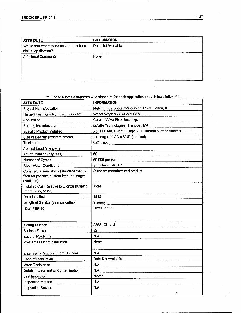
ERDC/CERL SR-04-8 47
ATTRIBUTE INFORMATION
Would you recommend this product for a similar application?
Data Not Available
Additional Comments None
*** Please submit a separate Questionnaire for each application at each installation ***
ATTRIBUTE INFORMATION
Project Name/Location Melvin Price Locks / Mississippi River-Alton, IL
Name/Title/Phone Number of Contact Walter Wagner/314-331-8272
Application Culvert Valve Pivot Bushings
Bearing Manufacturer Lubrite Technologies, Hanover, MA
Specific Product Installed ASTM B148, C95500, Type G10 internal surface lubrited
Size of Bearing (length/diameter) 21" long x 9" OD x 8" ID (nominal)
Thickness 0.5" thick
Applied Load (if known)
Arc of Rotation (degrees) 60
Number of Cycles 60,000 per year
River Water Conditions Silt, chemicals, etc.
Commercial Availability (standard manu- facturer product, custom item, no longer available)
Standard manufactured product
Installed Cost Relative to Bronze Bushing (more, less, same)
More
Date Installed 1992
Length of Service (years/months) 9 years
How Installed Hired Labor
Mating Surface A668, Class J
Surface Finish 32
Ease of Machining N.A.
Problems During Installation None
Engineering Support From Supplier N.A.
Ease of Installation Data Not Available
Wear Resistance N.A.
Debris Imbedment or Contamination N.A.
Last Inspected Never
Inspection Method N.A.
Inspection Results N.A.
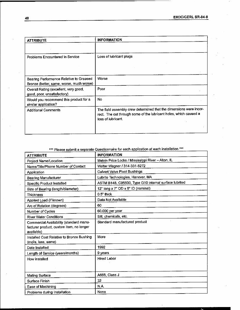
48 ERDC/CERL SR-04-8
ATTRIBUTE INFORMATION
Problems Encountered in Service Loss of lubricant plugs
Bearing Performance Relative to Greased Bronze (better, same, worse, much worse)
Worse
Overall Rating (excellent, very good, qood, poor, unsatisfactory)
Poor
Would you recommend this product for a similar application?
No
Additional Comments The field assembly crew determined that the dimensions were incor- rect. The cut through some of the lubricant holes, which caused a loss of lubricant.
' Please submit a separate Questionnaire for each application at each installation
ATTRIBUTE INFORMATION
Project Name/Location Melvin Price Locks / Mississippi River-Alton, IL
Name/Title/Phone Number of Contact Walter Wagner / 314-331-8272
Application Culvert Valve Pivot Bushings
Bearing Manufacturer Lubrite Technologies, Hanover, MA
Specific Product Installed ASTM B148, C95500, Type G10 internal surface lubrited
Size of Bearing (length/diameter) 12" long x 7" OD x 6" ID (nominal)
Thickness 0.5" thick
Applied Load (if known) Data Not Available
Arc of Rotation (degrees) 60
Number of Cycles 60,000 per year
River Water Conditions Silt, chemicals, etc.
Commercial Availability (standard manu- facturer product, custom item, no longer available)
Standard manufactured product
Installed Cost Relative to Bronze Bushing (mo"fe, less, same)
More
Date Installed 1992
Length of Service (years/months) 9 years
How installed Hired Labor
Mating Surface A668, Class J
Surface Finish 32
Ease of Machining N.A.
Problems during Installation None

ERDC/CERL SR-04-8 49
Engineering Support from Supplier N.A.
Ease of installation
Wear Resistance N.A.
Debris Imbedment or Contamination N.A.
Last Inspected Never
Inspection Method N.A.
Inspection Results N.A.
Problems Encountered In Service Data Not Available
Bearing Performance Relative to Greased Bronze (better, same, worse, much worse)
Same
Overall Rating (excellent, very good, good, poor, unsatisfactory)
Good
Would you recommend this product for a similar application?
Yes
Additional Comments None
Please submit a separate Questionnaire for each application at each installation:
ATTRIBUTE INFORMATION
Project Name/Location Locks No. 27 / Mississippi River - Granite City, IL
Name/Title/Phone Number of Contact Walter Wagner/ 314-331-8272
Application Miter Gate Hydraulic Cylinder Cardanic Ring Pillow Blocks
Bearing Manufacturer Oiles 500, Orebro, Sweden
Specific Product Installed Johnson Metal JM3-15
Size of Bearing (length/diameter) 162 mm long x 225 mm OD x 200 mm ID (nominal)
Thickness 12.5 mm thick
Applied Load (if known) Data Not Available
Arc of Rotation (degrees) 20
Number of Cycles 60,000 per year
River Water Conditions Silt, chemicals, etc.
Commercial Availability (standard manu- facturer product, custom item, no longer available)
Standard manufactured product
Installed Cost Relative to Bronze Bushing (more, less, same)
N.A.
Date Installed 1998
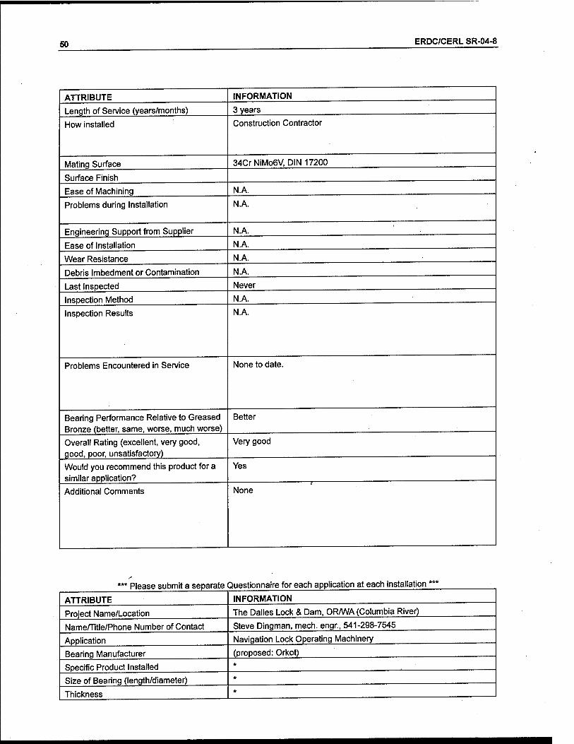
50 ERDC/CERL SR-04-8
ATTRIBUTE INFORMATION
Length of Service (years/months) 3 years
How installed Construction Contractor
Mating Surface 34CrNiMo6V, DIN 17200
Surface Finish
Ease of Machining N.A.
Problems during Installation N.A.
Engineering Support from Supplier N.A.
Ease of Installation N.A.
Wear Resistance N.A.
Debris Imbedment or Contamination N.A.
Last Inspected Never
Inspection Method N.A.
Inspection Results N.A.
Problems Encountered in Service None to date.
Bearing Performance Relative to Greased Bronze (better, same, worse, much worse)
Better
Overall Rating (excellent, very good, good, poor, unsatisfactory)
Very good
Would you recommend this product for a similar application?
Yes
Additional Comments None
Please submit a separate Questionnaire for each application at each installation
ATTRIBUTE
Project Name/Location
Name/Title/Phone Number of Contact
Application
Bearing Manufacturer
Specific Product Installed
Size of Bearing (length/diameter)
Thickness
INFORMATION
The Dalles Lock & Dam, OR/WA (Columbia River)
Steve Dingman, mech. engr., 541-298-7545
Navigation Lock Operating Machinery
(proposed: Orkot)

ERDC/CERL SR-04-8 51
Applied Load (if known) (Upper Gate) 705K horiz. max.; (valves) unknown
Arc of Rotation (degrees) (Upper Gate) ~ 80 deg.; (valve) ~ 56 deg.
Number of Cycles ~ 10 lockages per day
River Water Conditions Fresh water, moderate silt; temp, range ~ 30-70 °F
Commercial Availability (standard manu- facturer product, custom item, no longer available)
*
Installed Cost Relative to Bronze Bushing (more, less, same)
*
Date Installed *
Length of Service (years/months) 0
How Installed *
Mating Surface *
Surface Finish *
Ease of Machining *
Problems During Installation (This page: see "Additional Comments", below)
Engineering Support From Supplier
Ease of Installation
Wear Resistance
Debris Imbedment or Contamination
Last Inspected
Inspection Method
Inspection Results
•
Problems Encountered in Service
Bearing Performance Relative to Greased Bronze (better, same, worse, much worse)
Overall Rating (excellent, very good, good, poor, unsatisfactory)
Would you recommend this product for a similar application?
Additional Comments * No non-metallic bushings have been installed at The Dalles Dam yet. They are planning to do so on Navlock Drain Valve No. 2 in 2003, and we will replace both trunnion bushings and all operator guide bushings. Also, we are preparing to replace original bronze bushings with non-metallic bushings at the trunnions of Spill Gate No. 9.
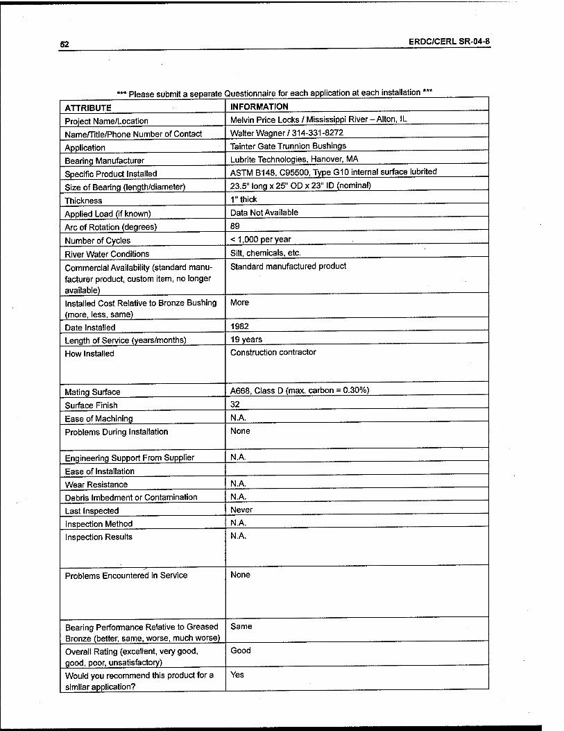
52 ERDC/CERL SR-04-8
Please submit a separate Questionnaire for each application at each installation
ATTRIBUTE
Project Name/Location
Name/Title/Phone Number of Contact
Application
Bearing Manufacturer
Specific Product Installed
Size of Bearing (length/diameter)
Thickness
Applied Load (if known)
Arc of Rotation (degrees)
Number of Cycles
River Water Conditions
Commercial Availability (standard manu- facturer product, custom item, no longer available)
Installed Cost Relative to Bronze Bushing (more, less, same)
Date Installed
Length of Service (years/months)
How Installed
Mating Surface
Surface Finish
Ease of Machining
Problems During Installation
Engineering Support From Supplier
Ease of Installation
Wear Resistance
Debris Imbedment or Contamination
Last Inspected
Inspection Method
Inspection Results
Problems Encountered in Service
Bearing Performance Relative to Greased Bronze (better, same, worse, much worse)
Overall Rating (excellent, very good, good, poor, unsatisfactory)
Would you recommend this product for a similar application?
INFORMATION
Melvin Price Locks / Mississippi River-Alton, IL
Walter Wagner / 314-331-8272
Tainter Gate Trunnion Bushings
Lubrite Technologies, Hanover, MA
ASTM B148, C95500, Type G10 internal surface lubrited
23.5" long x 25" OP x 23" ID (nominal)
1" thick
Data Not Available
89
< 1,000 per year
Silt, chemicals, etc.
Standard manufactured product
More
1982
19 years
Construction contractor
A668, Class D (max. carbon = 0.30%)
32
N.A.
None
N.A.
N.A.
N.A.
Never
N.A.
N.A.
None
Same
Good
Yes
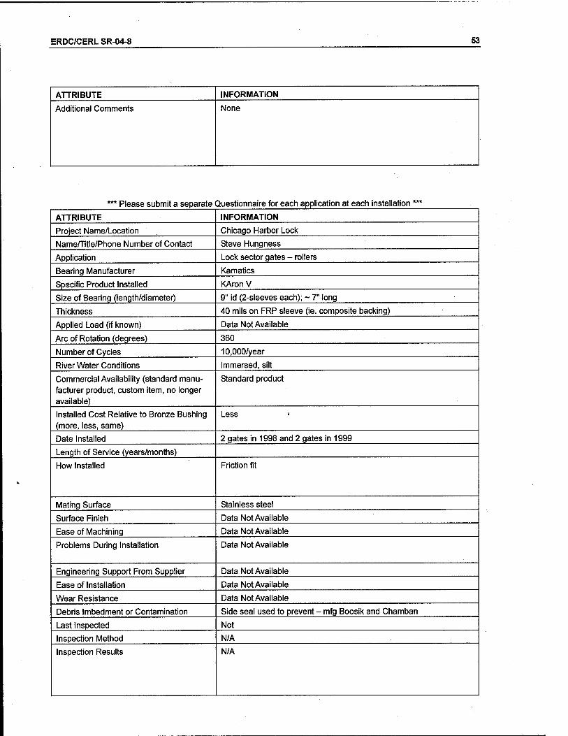
ERDC/CERL SR-04-8 53
ATTRIBUTE INFORMATION
Additional Comments None
Please submit a separate Questionnaire for each application at each installation'
ATTRIBUTE INFORMATION
Project Name/Location Chicago Harbor Lock
Name/Title/Phone Number of Contact Steve Hungness
Application Lock sector gates - rollers
Bearing Manufacturer Kamatics
Specific Product Installed KAronV
Size of Bearing (length/diameter) 9" id (2-sleeves each); ~ 7" long
Thickness 40 mils on FRP sleeve (ie. composite backing)
Applied Load (if known) Data Not Available
Arc of Rotation (degrees) 360
Number of Cycles 10,000/year
River Water Conditions Immersed, silt
Commercial Availability (standard manu- facturer product, custom item, no longer available)
Standard product
Installed Cost Relative to Bronze Bushing (more, less, same)
Less *
Date Installed 2 gates in 1998 and 2 gates in 1999
Length of Service (years/months)
How Installed Friction fit
Mating Surface Stainless steel
Surface Finish Data Not Available
Ease of Machining Data Not Available
Problems During Installation Data Not Available
Engineering Support From Supplier Data Not Available
Ease of Installation Data Not Available
Wear Resistance Data Not Available
Debris Imbedment or Contamination Side seal used to prevent - mfg Boosik and Chamban
Last Inspected Not
Inspection Method N/A
Inspection Results N/A

54 ERDC/CERL SR-04-8
ATTRIBUTE
Problems Encountered in Service
Bearing Performance Relative to Greased Bronze (better, same, worse, much worse)
Overall Rating (excellent, very good, good, poor, unsatisfactory)
Would you recommend this product for a similar application?
Additional Comments
INFORMATION
None
Better
Excellent
Yes
None
*** Please submit a separate Questionnaire for each application at each installation ***
ATTRIBUTE INFORMATION
Project Name/Location Chicago Harbor Lock
Name/Title/Phone Number of Contact Steve Hungness
Application Upper hinge pin
Bearing Manufacturer Kamatics
Specific Product Installed KAronV
Size of Bearing (length/diameter)
Thickness
Applied Load (if known) Low load
Arc of Rotation (degrees)
Number of Cycles 10,000/year
River Water Conditions In the dry
Commercial Availability (standard manu- facturer product, custom item, no longer available)
Data Not Available
Installed Cost Relative to Bronze Bushing (more, less, same)
Data Not Available
Date Installed 2 gates in 1998 and 2 gates in 1999
Length of Service (years/months)' Data Not Available
How Installed Data Not Available
Mating Surface Data Not Available
Surface Finish Data Not Available
Ease of Machining Data Not Available
Problems During Installation None reported
Engineering Support From Supplier Data Not Available

ERDC/CERL SR-04-8 55
ATTRIBUTE INFORMATION
Ease of Installation Data Not Available
Wear Resistance Data Not Available
Debris Imbedment or Contamination Data Not Available
Last Inspected Data Not Available
Inspection Method Data Not Available
Inspection Results Data Not Available
Problems Encountered in Service None
Bearing Performance Relative to Greased Bronze (better, same, worse, much worse)
Data Not Available
Overall Rating (excellent, very good, good, poor, unsatisfactory)
Data Not Available
Would you recommend this product for a similar application?
Data Not Available
Additional Comments Data Not Available
*** Please submit a separate Questionnaire for each application at each installation ***
ATTRIBUTE INFORMATION
Project Name/Location Markland
Name/Title/Phone Number of Contact Todd Crutchfield - 859-567-7444
Application Culvert valve trunnion pins 2 each per valve
Bearing Manufacturer Tenmat
Specific Product Installed Feroform T814
Size of Bearing (length/diameter) 13.625" idax 24.125" L
Thickness 0.8"
Applied Load (if known) 7,000 psi
Arc of Rotation (degrees) 45
Number of Cycles
River Water Conditions Immersed, silt
Commercial Availability (standard manu- facturer product, custom item, no longer available)
Standard item
Installed Cost Relative to Bronze Bushing (more, less, same)
About the same
Date Installed April 2000
Length of Service (years/months) Data Not Available

56 ERDC/CERL SR-04-8
ATTRIBUTE INFORMATION
How Installed Data Not Available
Mating Surface Data Not Available
Surface Finish Data Not Available
Ease of Machining Excellent
Problems During Installation None
Engineering Support From Supplier Yes, Excel spreadsheet
Ease of Installation Very easy
Wear Resistance Data Not Available
Debris Imbedment or Contamination Data Not Available
Last Inspected Data Not Available
Inspection Method Data Not Available
Inspection Results Data Not Available
Problems Encountered in Service *
Data Not Available
Bearing Performance Relative to Greased Bronze (better, same, worse, much worse)
Not enough data
Overall Rating (excellent, very good, good, poor, unsatisfactory)
Excellent
Would you recommend this product for a similar application?
Yes
Additional Comments Very happy with installation and performance of this product to date. Installed with hard-chromed stainless steel pins, 17-4.
' Please submit a separate Questionnaire for each application at each installation
ATTRIBUTE INFORMATION
Project Name/Location McAlpine
Name/Title/Phone Number of Contact Todd Crutchfield - 859-567-7444
Application Culvert valve trunnion pins 2 each per valve
Bearing Manufacturer Tenmat
Specific Product Installed Feroform T814
Size of Bearing (length/diameter) 13.625" idax 24.125" L
Thickness 0.8"
Applied Load (if known) 7,000 psi
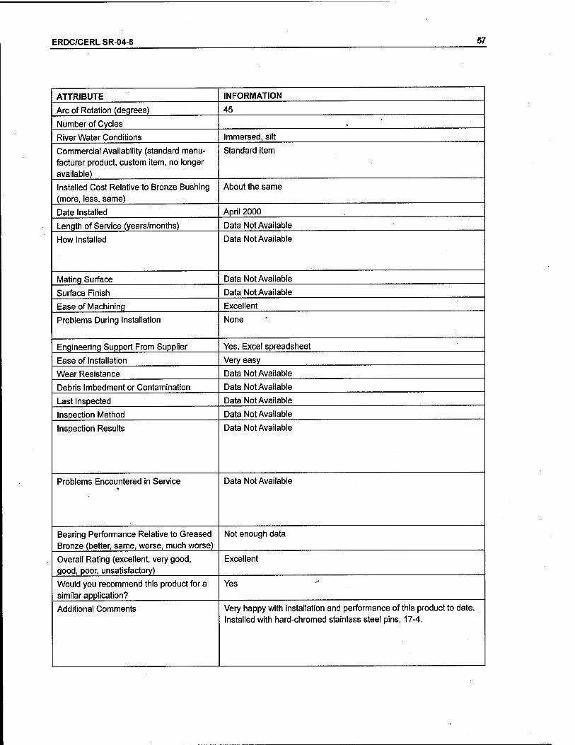
ERDC/CERL SR-04-8 57
ATTRIBUTE INFORMATION
Arc of Rotation (degrees) 45
Number of Cycles ,
River Water Conditions Immersed, silt
Commercial Availability (standard manu- facturer product, custom item, no longer available)
Standard item
Installed Cost Relative to Bronze Bushing (more, less, same)
About the same
Date Installed April 2000
Length of Service (years/months) Data Not Available
How Installed Data Not Available
Mating Surface Data Not Available
Surface Finish Data Not Available
Ease of Machining Excellent
Problems During Installation None
Engineering Support From Supplier Yes, Excel spreadsheet
Ease of Installation Very easy
Wear Resistance Data Not Available
Debris Imbedment or Contamination Data Not Available
Last Inspected Data Not Available
Inspection Method Data Not Available
Inspection Results Data Not Available
Problems Encountered in Service Data Not Available
Bearing Performance Relative to Greased Bronze (better, same, worse, much worse)
Not enough data
Overall Rating (excellent, very good, good, poor, unsatisfactory)
Excellent
Would you recommend this product for a similar application?
Yes
Additional Comments Very happy with installation and performance of this product to date. Installed with hard-chromed stainless steel pins, 17-4.
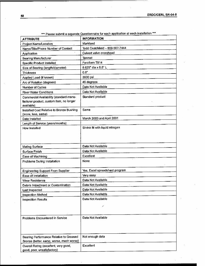
58 ERDC/CERL SR-04-8
Please submit a separate Questionnaire for each application at each installation:
ATTRIBUTE
Project Name/Location
Name/Title/Phone Number of Contact
Application
Bearing Manufacturer
Specific Product Installed
Size of Bearing (length/diameter)
Thickness
Applied Load (if known)
Arc of Rotation (degrees)
Number of Cycles
River Water Conditions
Commercial Availability (standard manu- facturer product, custom item, no longer available) .
Installed Cost Relative to Bronze Bushing (more, less, same)
Date Installed
Length of Service (years/months)
How Installed
Mating Surface
Surface Finish
Ease of Machining
Problems During Installation
Engineering Support From Supplier
Ease of Installation
Wear Resistance
Debris Imbedment or Contamination
Last Inspected
Inspection Method
Inspection Results
Problems Encountered in Service
Bearing Performance Relative to Greased Bronze (better, same, worse, much worse)
Overall Rating (excellent, very good, good, poor, unsatisfactory)
INFORMATION
Markland
Todd Crutchfield - 859-567-7444
Culvert valve crosshead
Tenmat
FeroformT814
8.625" dia x 6.5" L
0.8"
3500 psi
45 degrees
Data Not Available
Data Not Available
Standard product
Same
March 2000 and April 2001
Shrink fit with liquid nitrogen
Data Not Available
Data Not Available
Excellent
None
Yes, Excel spreadsheet program
Very easy
Data Not Available
Data Not Available
Data Not Available
Data Not Available
Data Not Available
Data Not Available
Not enough data
Excellent

ERDC/CERL SR-04-8 59
ATTRIBUTE INFORMATION
Would you recommend this product for a similar application?
Yes
Additional Comments Very happy with installation and performance of this product to date. Installed with hard-chromed stainless steel pins, 17-4.
*** Please submit a separate Questionnaire for each application at each installation ***
ATTRIBUTE INFORMATION
Project Name/Location Markland
Name/Title/Phone Number of Contact Todd Crutchfield - 859-567-7444
Application Culvert valve lower connecting rod
Bearing Manufacturer Tenmat
Specific Product Installed Feroform T814
Size of Bearing (length/diameter) 8.625'diax 12.968" L
Thickness 0.8"
Applied Load (if known) 3500 psi
Arc of Rotation (degrees) 45
Number of Cycles Data Not Available
River Water Conditions Data Not Available
Commercial Availability (standard manu- facturer product, custom item, no longer available)
Standard product
Installed Cost Relative to Bronze Bushing (more, less, same)
Same
Date Installed April 2000 and April 2001
Length of Service (years/months)
How Installed Shrink fit with liquid nitrogen
Mating Surface Data Not Available
Surface Finish Data Not Available
Ease of Machining Excellent
Problems During Installation None
Engineering Support From Supplier Yes, Excel spreadsheet program
Ease of Installation Very easy
Wear Resistance Data Not Available
Debris Imbedment or Contamination Data Not Available
Last Inspected Data Not Available
Inspection Method Data Not Available
Inspection Results Data Not Available

60 ERDC/CERL SR-04-8
ATTRIBUTE
Problems Encountered in Service
Bearing Performance Relative to Greased Bronze (better, same, worse, much worse)
Overall Rating (excellent, very good, good, poor, unsatisfactory)
Would you recommend this product for a similar application?
Additional Comments
INFORMATION
Data Not Available
Not enough data
Execellent
Yes
Very happy with installation and performance of this product to date. Installed with hard-chromed stainless steel pins, 17-4.
*** Please submit a separate Questionnaire for each application at each installation ***
ATTRIBUTE INFORMATION
Project Name/Location Markland
Name/Title/Phone Number of Contact Todd Crutchfield - 859-567-7444
Application Culvert valve fulcrum
Bearing Manufacturer Tenmat
Specific Product Installed FeroformT814
Size of Bearing (length/diameter) 9.125" diax 12.344" L
Thickness 0.8"
Applied Load (if known) 3,500 psi
Arc of Rotation (degrees) 45
Number of Cycles ^ Data Not Available
River Water Conditions Data Not Available
Commercial Availability (standard manu- facturer product, custom item, no longer available)
Standard product
Installed Cost Relative to Bronze Bushing (more, less, same)
Same
Date Installed April 2000 and April 2001
Length of Service (years/months) Data Not Available
How Installed Data Not Available
Mating Surface Data Not Available
Surface Finish Data Not Available
Ease of Machining Excellent
Problems During Installation None
Engineering Support From Supplier Yes, Excel spreadsheet program

ERDC/CERL SR-04-8 61
Ease of Installation Very easy
Wear Resistance Data Not Available
Debris Imbedment or Contamination Data Not Available
Last Inspected Data Not Available
Inspection Method Data Not Available
Inspection Results Data Not Available
Problems Encountered in Service Data Not Available
Bearing Performance Relative to Greased Bronze (better, same, worse, much worse)
Not enough data
Overall Rating (excellent, very good, good, poor, unsatisfactory)
Excellent
Would you recommend this product for a similar application?
Yes
Additional Comments Very happy with installation and performance of this product to date. Installed with hard-chromed stainless steel pins, 17-4.
*** Please submit a separate Questionnaire for each application at each installation ***
ATTRIBUTE INFORMATION
Project Name/Location Markland
Name/Title/Phone Number of Contact Todd Crutchfield - 859-567-7444
Application Culvert valve upper strut spindle
Bearing Manufacturer Tenmat
Specific Product Installed FeroformT814
Size of Bearing (length/diameter) 9.125" diax 11.219" L
Thickness 0.8"
Applied Load (if known) 3,500 psi
Arc of Rotation (degrees) 45
Number of Cycles Data Not Available
River Water Conditions Immersed, silt
Commercial Availability (standard manu- facturer product, custom item, no longer available)
Standard product
Installed Cost Relative to Bronze Bushing (more, less, same)
Same
Date Installed March/April 2000 and 2001
Length of Service (years/months)
How Installed Shrink fit with liquid nitrogen

62 ERDC/CERL SR-04-8
ATTRIBUTE INFORMATION
Mating Surface Data Not Available
Surface Finish
Ease of Machining Excellent
Problems During Installation None
Engineering Support from Supplier Yes, Excel spreadsheet program
Ease of Installation Very easy
Wear Resistance Data Not Available
Debris Imbedment or Contamination Data Not Available
Last Inspected Data Not Available
Inspection Method Data Not Available
Inspection Results Data Not Available
Problems Encountered In Service Data Not Available
Bearing Performance Relative to Greased Bronze (better, same, worse, much worse)
Not enough data
Overall Rating (excellent, very good, good, poor, unsatisfactory)
Excellent
Would you recommend this product for a similar application?
Yes
Additional Comments Very happy with installation and performance of this product Installed with hard-chromed stainless steel pins, 17-4.
to date.
*** Please submit a separate Questionnaire for each application at each installation ***
ATTRIBUTE INFORMATION
Project Name/Location Smithland
Name/Title/Phone Number of Contact Todd Crutchfield - 859-567-7444
Application Culvert valve upper strut spindle
Bearing Manufacturer Tenmat
Specific Product Installed FeroformT814
Size of Bearing (length/diameter) 9.125" diax 11.219" L
Thickness 0.8"
Applied Load (if known) 3500 psi
Arc of Rotation (degrees) 45
Number of Cycles Data Not Available
River Water Conditions Immersed, silt

ERDC/CERL SR-04-8 63
ATTRIBUTE INFORMATION
Commercial Availability (standard manu- facturer product, custom item, no longer available)
Standard product
Installed Cost Relative to Bronze Bushing (more, less, same)
Same
Date Installed October 2000
Length of Service (years/months)
How Installed Shrink fit with liquid nitrogen
Mating Surface Data Not Available
Surface Finish Data Not Available
Ease of Machining Excellent
Problems During Installation None
Engineering Support From Supplier Yes, Excel spreadsheet program
Ease of Installation Very easy
Wear Resistance Data Not Available
Debris Imbedment or Contamination Data Not Available
Last Inspected Data Not Available
Inspection Method Data Not Available
Inspection Results Data Not Available
Problems Encountered in Service Data Not Available
Bearing Performance Relative to Greased Bronze (better, same, worse, much worse)
Not enough data
Overall Rating (excellent, very good, good, poor, unsatisfactory)
Excellent
Would you recommend this product for a similar application?
Yes
Additional Comments Very happy with installation and performance of this product to date. Installed with hard-chromed stainless steel pins, 17-4. Replaced failed Thodon TRAXL bushings with Tenmat.
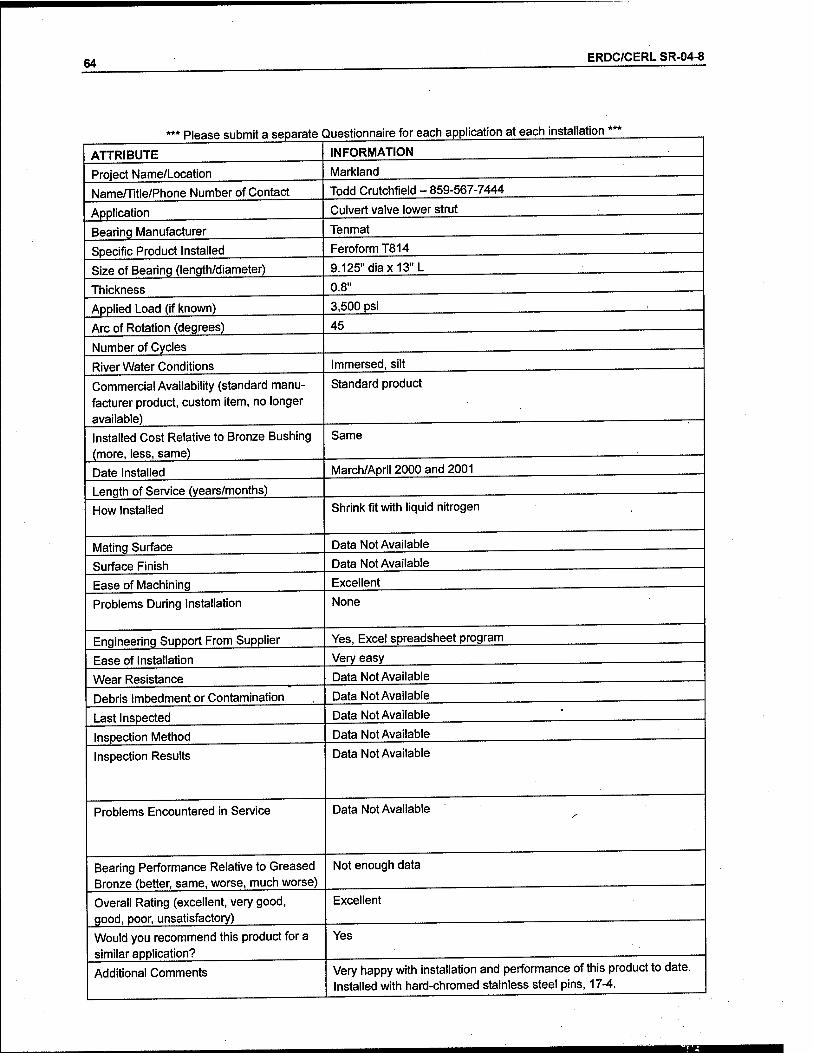
64 ERDC/CERL SR-04-8
ATTRIBUTE
' Please submit a separate Questionnaire for each application at each installation
INFORMATION
Project Name/Location
NameHltle/Phone Number of Contact
Application
Bearing Manufacturer
Specific Product Installed
Size of Bearing (length/diameter)
Thickness
Applied Load (if known)
Arc of Rotation (degrees)
Number of Cycles
River Water Conditions
Commercial Availability (standard manu- facturer product, custom item, no longer available)
Installed Cost Relative to Bronze Bushing (more, less, same)
Date Installed
Length of Service (years/months)
How Installed
Mating Surface
Surface Finish
Ease of Machining
Problems During Installation
Engineering Support From Supplier
Ease of Installation
Wear Resistance
Debris Imbedment or Contamination
Last Inspected
Inspection Method
Inspection Results
Problems Encountered in Service
Bearing Performance Relative to Greased Bronze (better, same, worse, much worse)
Overall Rating (excellent, very good, good, poor, unsatisfactory)
Would you recommend this product for a similar application?
Additional Comments
Markland
Todd Crutchfield - 859-567-7444
Culvert valve lower strut
Tenmat
FeroformT814
9.125" diax 13" L
0.8"
3,500 psi
45
Immersed, silt
Standard product
Same
March/April 2000 and 2001
Shrink fit with liquid nitrogen
Data Not Available
Data Not Available
Excellent
None
Yes, Excel spreadsheet program
Very easy
Data Not Available
Data Not Available
Data Not Available
Data Not Available
Data Not Available
Data Not Available
Not enough data
Excellent
Yes
Very happy with installation and performance of this product to date. Installed with hard-chromed stainless steel pins, 17-4.

ERDC/CERL SR-04-8 65
*** Please submit a separate Questionnaire for each application at each installation ***
ATTRIBUTE INFORMATION
Project Name/Location Smithland
Name/Title/Phone Number of Contact Todd Crutchfield - 859-567-7444
Application Culvert valve lower strut
Bearing Manufacturer Tenmat
Specific Product Installed Feroform T814
Size of Bearing (length/diameter) 9.125" diax 13" L
Thickness 0.8"
Applied Load (if known) 3500 psi
Arc of Rotation (degrees) 45
Number of Cycles Data Not Available
River Water Conditions Immersed, silt
Commercial Availability (standard manu- facturer product, custom item, no longer available)
Standard product
Installed Cost Relative to Bronze Bushing (more, less, same)
Same
Date Installed November 1997, November 1998, October 2000
Length of Service (years/months)
How Installed Shrink fit with liquid nitrogen
Mating Surface Data Not Available
Surface Finish Data Not Available
Ease of Machining Excellent
Problems During Installation None
Engineering Support From Supplier Yes, Excel spreadsheet program
Ease of Installation Very easy
Wear Resistance Data Not Available
Debris Imbedment or Contamination Data Not Available
Last Inspected Data Not Available
Inspection Method Data Not Available
Inspection Results Data Not Available
Problems Encountered In Service Data Not Available
Bearing Performance Relative to Greased Bronze (better, same, worse, much worse)
Not enough data
Overall Rating (excellent, very good, good, poor, unsatisfactory)
Excellent
Would you recommend this product for a similar application?
Yes
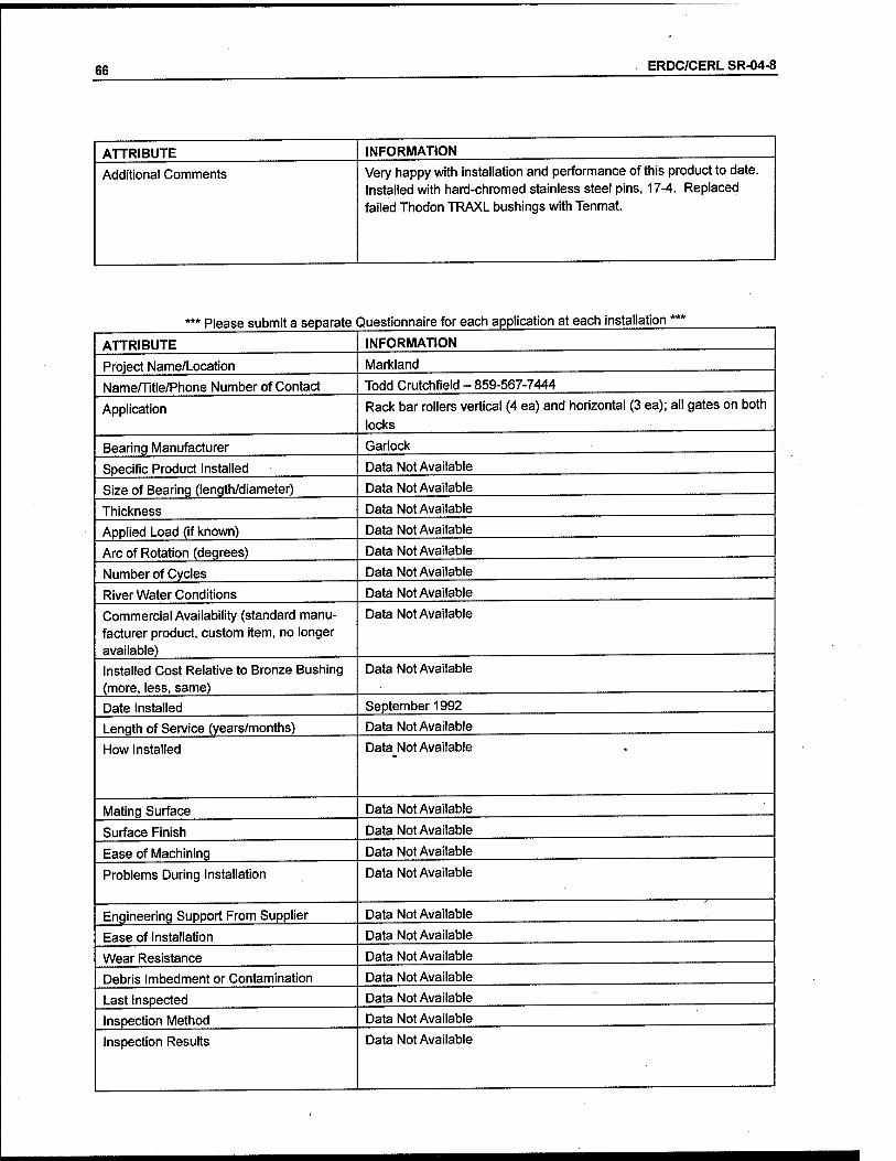
66 ERDC/CERL SR-04-8
ATTRIBUTE
Additional Comments
INFORMATION
Very happy with installation and performance of this product to date. Installed with hard-chromed stainless steel pins, 17-4. Replaced failed Thodon TRAXL bushings with Tenmat.
Please submit a separate Questionnaire for each application at each installation'
ATTRIBUTE
Project Name/Location
Natne/Title/Phone Number of Contact
Application
Bearing Manufacturer
Specific Product Installed
Size of Bearing (length/diameter)
Thickness
Applied Load (if known)
Arc of Rotation (degrees)
Number of Cycles
River Water Conditions
Commercial Availability (standard manu- facturer product, custom item, no longer available) .
Installed Cost Relative to Bronze Bushing (more, less, same)
Date Installed
Length of Service (years/months)
How Installed
Mating Surface
Surface Finish
Ease of Machining
Problems During Installation
Engineering Support From Supplier
Ease of Installation
Wear Resistance
Debris Imbedment or Contamination
Last Inspected
Inspection Method
Inspection Results
INFORMATION
Markland
Todd Crutchfield - 859-567-7444
Rack bar rollers vertical (4 ea) and horizontal (3 ea); all gates on both
locks
Garlock
Data Not Available
Data Not Available
Data Not Available
Data Not Available
Data Not Available
Data Not Available
Data Not Available
Data Not Available
Data Not Available
September 1992
Data Not Available
Data Not Available
Data Not Available
Data Not Available
Data Not Available
Data Not Available
Data Not Available
Data Not Available
Data Not Available
Data Not Available
Data Not Available
Data Not Available
Data Not Available

ERDC/CERL SR-04-8 67
ATTRIBUTE INFORMATION
Problems Encountered in Service Data Not Available
Bearing Performance Relative to Greased Bronze (better, same, worse, much worse)
Data Not Available
Overall Rating (excellent, very good, good, poor, unsatisfactory)
Data Not Available
Would you recommend this product for a similar application?
Data Not Available
Additional Comments Data Not Available
' Please submit a separate Questionnaire for each application at each installation '
ATTRIBUTE INFORMATION
Project Name/Location Markland
Name/Title/Phone Number of Contact Todd Crutchfield - 859-567-7444
Application Crosshead pin, lower connecting rod pin, fulcrum pin, strut spindle pin, and trunnion pins
Bearing Manufacturer Thordon
Specific Product Installed TRAXL
Size of Bearing (length/diameter) Data Not Available
Thickness Data Not Available
Applied Load (if known) Data Not Available
Arc of Rotation (degrees) Data Not Available
Number of Cycles Data Not Available
River Water Conditions Data Not Available
Commercial Availability (standard manu- facturer product, custom item, no longer available)
Data Not Available
Installed Cost Relative to Bronze Bushing (more, less, same)
Data Not Available
Date Installed May 1998
Length of Service (years/months) Data Not Available
How Installed Data Not Available
Mating Surface Data Not Available
Surface Finish Data Not Available
Ease of Machining Data Not Available
Problems During Installation Data Not Available

68 ERDC/CERL SR-04-8
Engineering Support From Supplier
Ease of Installation
Wear Resistance
Debris Imbedment or Contamination
Last Inspected
Inspection Method
Inspection Results
Problems Encountered in Service
Bearing Performance Relative to Greased Bronze (better, same, worse, much worse)
Overall Rating (excellent, very good, good, poor, unsatisfactory)
Would you recommend this product for a similar application?
Additional Comments
Data Not Available
Data Not Available
Data Not Available
Data Not Available
Data Not Available
Data Not Available
Data Not Available
Data Not Available
Data Not Available
Data Not Available
Data Not Available
Data Not Available
Please submit a separate Questionnaire for each application at each installation
ATTRIBUTE
Project Name/Location
Name/Title/Phone Number of Contact
Application
Bearing Manufacturer
Specific Product Installed
Size of Bearing (length/diameter)
Thickness
Applied Load (if known)
Arc of Rotation (degrees)
Number of Cycles
River Water Conditions
Commercial Availability (standard manu- facturer product, custom item, no longer available)
Installed Cost Relative to Bronze Bushing (more, less, same)
Date Installed
INFORMATION
McAlpine
Todd Crutchfield - 859-567-7444
Crosshead pin, lower connecting rod pin, fulcrum pin, strut spindle pin, lower strut pin, and trunnion pins
Thordon
TRAXL
Data Not Available
Data Not Available
Data Not Available
Data Not Available
Data Not Available
Data Not Available
Data Not Available
Data Not Available
June 1998 and April 1999

ERDC/CERL SR-04-8 69
Length of Service (years/months) Data Not Available
How Installed Data Not Available
Mating Surface Data Not Available
Surface Finish Data Not Available
Ease of Machining Data Not Available
Problems During Installation Data Not Available
Engineering Support From Supplier Data Not Available
Ease of Installation Data Not Available
Wear Resistance Data Not Available
Debris Imbedment or Contamination Data Not Available
Last Inspected Data Not Available
Inspection Method Data Not Available
Inspection Results Data Not Available
Problems Encountered in Service Data Not Available
Bearing Performance Relative to Greased Bronze (better, same, worse, much worse)
Data Not Available
Overall Rating (excellent, very good, good, poor, unsatisfactory)
Data Not Available
Would you recommend this product for a similar application?
Data Not Available
Additional Comments None
*** Please submit a separate Questionnaire for each application at each installation ***
ATTRIBUTE INFORMATION
Project Name/Location Cannelton
Nameffitle/Phone Number of Contact Todd Crutchfield - 859-567-7444
Application Gates - pintle, gudgeon pin, strut pin at gate
Bearing Manufacturer Thordon
Specific Product Installed Data Not Available
Size of Bearing (length/diameter) Data Not Available
Thickness Data Not Available
Applied Load (if known) Data Not Available

70 ERDC/CERL SR-04-8
ATTRIBUTE INFORMATION
Arc of Rotation (degrees) Data Not Available
Number of Cycles Data Not Available
River Water Conditions Data Not Available
Commercial Availability (standard manu- facturer product, custom item, no longer available)
Data Not Available
Installed Cost Relative to Bronze Bushing (more, less, same)
Data Not Available
Date Installed June 1994
Length of Service (years/months) Data Not Available
How Installed Data Not Available
Mating Surface Data Not Available
Surface Finish Data Not Available
Ease of Machining Data Not Available
Problems During Installation Data Not Available
Engineering Support From Supplier Data Not Available
Ease of Installation Data Not Available
Wear Resistance Data Not Available
Debris Imbedment or Contamination Data Not Available
Last Inspected Data Not Available
Inspection Method Data Not Available
Inspection Results Data Not Available
Problems Encountered in Service Data Not Available
Bearing Performance Relative to Greased Bronze (better, same, worse, much worse)
Data Not Available
Overall Rating (excellent, very good, good, poor, unsatisfactory)
Data Not Available
Would you recommend this product for a similar application?
Data Not Available
Additional Comments None

ERDC/CERL SR-04-8 71
Please submit a separate Questionnaire for each application at each installation:
ATTRIBUTE INFORMATION
Project Name/Location Cannelton
Name/Title/Phone Number of Contact Todd Crutchfield - 859-567-7444
Application Crosshead pin, lower connecting rod pin, fulcrum pin, strut spindle pin, lower strut pin, trunnion pins, and hydraulic cylinder trunnion
Bearing Manufacturer Thordon
Specific Product Installed TRAXL
Size of Bearing (length/diameter) Data Not Available
Thickness Data Not Available
Applied Load (if known) Data Not Available
Arc of Rotation (degrees) Data Not Available
Number of Cycles Data Not Available
River Water Conditions Data Not Available
Commercial Availability (standard manu- facturer product, custom item, no longer available)
Data Not Available
Installed Cost Relative to Bronze Bushing (more, less, same)
Data Not Available
Date Installed 1992 or 1993
Length of Service (years/months) Data Not Available
How Installed Data Not Available
Mating Surface Data Not Available
Surface Finish Data Not Available
Ease of Machining Data Not Available
Problems During Installation Data Not Available
Engineering Support From Supplier Data Not Available
Ease of Installation Data Not Available *"
Wear Resistance Data Not Available
Debris Imbedment or Contamination Data Not Available
Last Inspected Data Not Available
Inspection Method Data Not Available
Inspection Results Data Not Available
Problems Encountered in Service Data Not Available
Bearing Performance Relative to Greased Bronze (better, same, worse, much worse)
Data Not Available
Overall Rating (excellent, very good, good, poor, unsatisfactory)
Data Not Available

72 ERDC/CERL SR-04-8
ATTRIBUTE
Would you recommend this product for a similar application?
Additional Comments
INFORMATION
Data Not Available
None
Please submit a separate Questionnaire for each application at each installation
ATTRIBUTE
Project Name/Location
Name/Title/Phone Number of Contact
Application
Bearing Manufacturer
Specific Product Installed
Size of Bearing (length/diameter)
Thickness
Applied Load (if known)
Arc of Rotation (degrees)
Number of Cycles
River Water Conditions
Commercial Availability (standard manu- facturer product, custom item, no longer available)
Installed Cost Relative to Bronze Bushing (more, less, same)
Date Installed
Length of Service (years/months)
How Installed
Mating Surface
Surface Finish
Ease of Machining
Problems During Installation
Engineering Support From Supplier
Ease of Installation
Wear Resistance
Debris Imbedment or Contamination
INFORMATION
Cannelton
Todd Crutchfield - 859-567-7444
Crosshead pin and hydraulic cylinder trunnion
Kamatics
Data Not Available
Data Not Available
Data Not Available
Data Not Available
Data Not Available
Data Not Available
Data Not Available
Data Not Available
Data Not Available
1992 or 1993
Data Not Available
Data Not Available
Data Not Available
Data Not Available
Data Not Available
Data Not Available
Data Not Available
Data Not Available
Data Not Available
Data Not Available
Last Inspected
Inspection Method
Inspection Results
Data Not Available
Data Not Available
Data Not Available

ERDC/CERL SR-04-8 73
ATTRIBUTE INFORMATION
Problems Encountered In Service Data Not Available
Bearing Performance Relative to Greased Bronze (better, same, worse, much worse)
Data Not Available
Overall Rating (excellent, very good, good, poor, unsatisfactory)
Data Not Available
Would you recommend this product for a similar application?
Data Not Available
Additional Comments None
*** Please submit a separate Questionnaire for each application at each installation ***
ATTRIBUTE INFORMATION
Project Name/Location Newburgh
Name/Title/Phone Number of Contact Todd Crutchfield - 859-567-7444
Application strut spindle pin and lower strut pin
Bearing Manufacturer Thordon
Specific Product Installed TRAXL
Size of Bearing (length/diameter) Data Not Available
Thickness Data Not Available
Applied Load (if known) Data Not Available
Arc of Rotation (degrees) Data Not Available
Number of Cycles Data Not Available
River Water Conditions Data Not Available
Commercial Availability (standard manu- facturer product, custom item, no longer available)
Data Not Available
Installed Cost Relative to Bronze Bushing (more, less, same)
Data Not Available
Date Installed July 1991
Length of Service (years/months) Data Not Available
How Installed Data Not Available
Mating Surface Data Not Available
Surface Finish Data Not Available
Ease of Machining Data Not Available
Problems During Installation Data Not Available
Engineering Support From Supplier Data Not Available
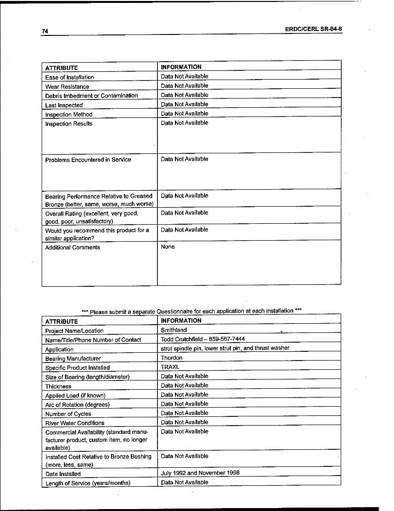
74 ERDC/CERL SR-04-8
ATTRIBUTE
Ease of Installation
Wear Resistance
Debris Imbedment or Contamination
Last Inspected
Inspection Method
Inspection Results
Problems Encountered in Service
Bearing Performance Relative to Greased Bronze (better, same, worse, much worse)
Overall Rating (excellent, very good, good, poor, unsatisfactory)
Would you recommend this product for a similar application?
Additional Comments
INFORMATION
Data Not Available
Data Not Available
Data Not Available
Data Not Available
Data Not Available
Data Not Available
Data Not Available
Data Not Available
Data Not Available
Data Not Available
None
Please submit a separate Questionnaire for each application at each installation
ATTRIBUTE
Project Name/Location
Name/Title/Phone Number of Contact
Application
Bearing Manufacturer
Specific Product Installed
Size of Bearing (length/diameter)
Thickness
Applied Load (if known)
Arc of Rotation (degrees)
Number of Cycles
River Water Conditions
Commercial Availability (standard manu- facturer product, custom item, no longer available)
Installed Cost Relative to Bronze Bushing (more, less, same)
Date Installed
Length of Service (years/months)
INFORMATION
Smithland
Todd Crutchfield - 859-567-7444
strut spindle pin, lower strut pin, and thrust washer
Thordon
TRAXL
Data Not Available
Data Not Available
Data Not Available
Data Not Available
Data Not Available
Data Not Available
Data Not Available
Data Not Available
July 1992 and November 1998
Data Not Available

ERDC/CERL SR-04-8 75
How Installed Data Not Available
Mating Surface Data Not Available
Surface Finish Data Not Available
Ease of Machining Data Not Available
Problems During Installation Data Not Available
Engineering Support From Supplier Data Not Available
Ease of Installation Data Not Available
Wear Resistance Data Not Available
Debris Imbedment or Contamination Data Not Available
Last Inspected Data Not Available
Inspection Method Data Not Available
Inspection Results Data Not Available
Problems Encountered in Service Data Not Available
Bearing Performance Relative to Greased Bronze (better, same, worse, much worse)
Data Not Available
Overall Rating (excellent, very good, good, poor, unsatisfactory)
Data Not Available
Would you recommend this product for a similar application?
Data Not Available
Additional Comments None

76 ERDC/CERL SR-04-8
Appendix B: Manufacturers' Literature
1. Orkot TXM Marine 77
2. Lubrite Technologies G10 and G12 82
3. GarlockDU 88
4. Tenmat Feroform T814 90
5. Thordon SXL and HPSXL 93
6. Kamatics KAron V 100

ERDC/CERL SR-04-8 77
Orkot Composites
Orkot® TXM Marine
Orftot* TXM Marine is manufactured from medium weave fabrics with excellent mechanical strength. Additionally it has a unique low friction bearing surface incorporating molybdenum disulphide and PTFE. Orkot85 TXM Marine is recommended for all bearings where a combination of strength and very low friction is required. Dye to these properties TXM Marine can eliminate stick-slip in many applications.
Mechanical Properties IMPERIAL METRIC :
TENSILE STRENGTH >8500 IbMn* >55 N/mm' :
TENSILE MODULUS 46.5 x 10* Ibf/in* 0.3Zx 10* N/rrmT2
COMPRE5SIVE STRENGTH
Normal to laminate »40700 IbW >280 N/mm2
Parallel to Laminate >13000 Ibf/in2 J»90 N/mm1
FLEXURAL STRENGTH . >9400 Ibf/in* ^SSN/mm2
FLEXURAL MODULUS 27.6 x'1.0* Ibf/in* ■Q.19X.1Ö" N/mm2
SHEAR STRENGTH 11600 tbffin2 eON/mm*
HARDNESS ROCKWELL M 100 100 ...
IMPACT STRENGTH - >120kJ?m2
DENSITY . . ■ - 0.047 Ibf/in3 1.3gfcmä
SWELL IN WATER : '<0.1% «0.1%
STATIC COEFFICIENT OF FRICTION DRY AT 15 N/mffl* 0.05-0.10
Thermal Properties LINEAR EXPANSION COEFFICIENTS , 6S-212*F (per'F x 10*5) 20-10Q°C(perCx1Ö'V.v
Normal to Laminate 5.0-5,5 .9-10
Parallel to Laminate 2.7 - 3.3 ..', 5-6 ■
THE ABOVE VALUES ARE TYPICAL For further information visit: www.orkot.us
North & South America Oikot Composites 2535 Prairie Road Eugens Oregon, S7402
,Tet +1(541)6885529 fax: +1(541)5082079 Email: [email protected]
Europe. Africa, Asia Orkot Composites Bracimsrsh Business Pa* Rotterdam SB01BX Tel: «W (0)1709769800 Fax: +44 (0)1709 374819 Ema!: [email protected]
TileinfcmiaSort*) Ssseteojracri! is B3**xf an tnuvf yearsol aapcrism*tetta Ki*!«£Kk*c str^t 3£a3ca!iart ofOfkctOs«w£te5 SKÖ&K3A K&ftftwjr, SWW JSSrsMeSef* wxS etxxfi£or.s maytcsi.^l aener;« s«3!om®*!!8 riijjSrta u9a£8. R is V353J ^ies öÄtonwsSstfeiV tho<«s«**S3 8S & tr* sy*!3t«% GT*>#**&*# is******* S*c«3ri adosua» lealwg. r-cf tHs reaaors, ans öye to a™ wa« wng* 05 a©BlK*«te03 of cur pre&srf*. Sotrss Grawp Bk: 3rd Ofekct Cstioasis« Ban acteiS naüaa'&iy as to S» sa{Sat<%or ca*Tccs-«Ba; cSaür cartitfa? faexmtönSatiaris t-1 äriSjiYMitnisaSßa Fö* ÄfXtfsfi?
© Polymer Sealing Satabns 2002
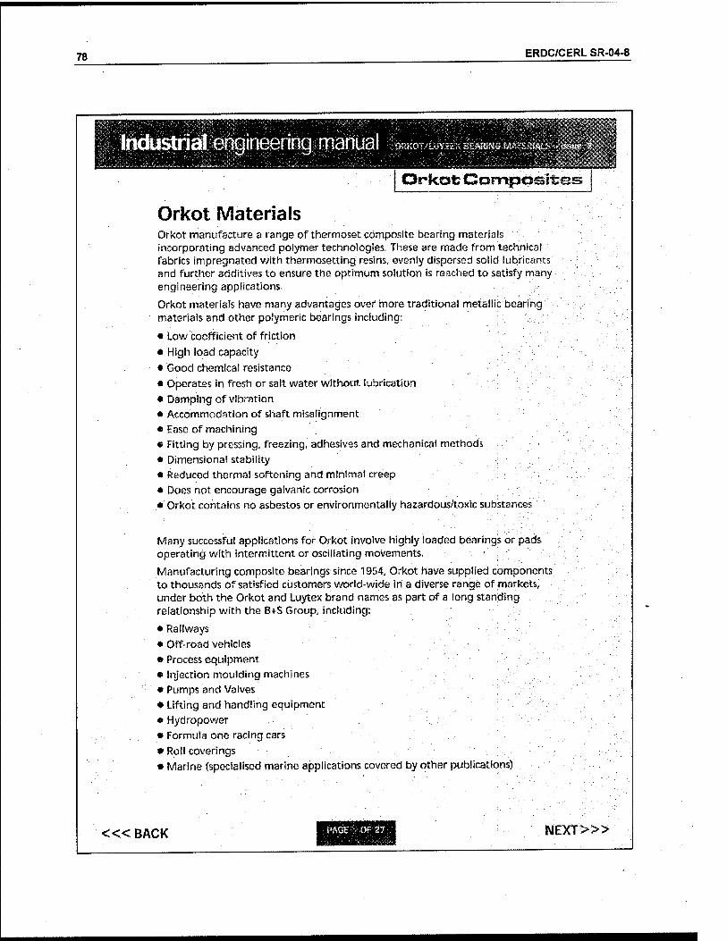
78 ERDC/CERL SR-04-8
industrial engineering manual ^or^^Btmmmi $U
Orkot Composites
Orkot Materials Orkot manufacture a range of thermoset composite bearing materials incorporating advanced polymer technologies. These are made from technical fabrics impregnated with thermosetting resins, evenly dispersed solid lubricants and further additives to ensure the optimum solution is reached to satisfy many engineering applications,
Orkot materials have many advantages over more traditional metallic bearing materials and other pofymeric bearings including:
• Low coefficient of friction
• High load capacity
• Good chemical resistance • Operates in fresh or salt water without lubrication
• Damping of vibration • Accommodation of shaft misalignment • Ease of machining • Fitting by pressing, freezing, adhesives and mechanical methods
• Dimensional stability • Reduced thermal softening and minima! creep
• Does not encourage galvanic corrosion • Orkot contains no asbestos or environmentally hazardous/toxic substances
Many successful applications for Orkot involve highly loaded bearings or pads operating with intermittent or oscillating movements. '■'■■':'
Manufacturing composite bearings since 1954, Orkot have supplied components to thousands of satisfied customers world-wide in a diverse range of markets, under both the Orkot and Luytex brand names as part of a iong standing relationship with the B*S Group, including:
• Railways • Off-road vehicles
• Process equipment • Injection moulding machines • Pumps and Valves • Lifting and handling equipment « Hydropower • Formula one racing cars
• Roll coverings • Marine (specialised marine applications covered by other publications)
«< BACK NEXT>»

ERDC/CERL SR-04-8 79
industrial engineering manual
Properties / Specification
rtRKOT/LUYJ-.K SHARING «AT '■"""w^-j
8?iM
Orkefc Cornptasites
C32Ö/1/2
C335/C361
>300 80 60 2800 85 1.25
C324
C33S >350 80 60 3400 85 1.25
C363 ■ >200 80 60 2800 85 1.25 ..
C369
C378 :
>280 80 60 2800 85 1,25
Note, alf data based on tests to BS EN 150604:1997, BS EN ISO 178:1997, B$ 2782:1993 and Orkot standard methods.
Mechanical Under compressive load, standard Orkot grades behave in an elastic manner up to a yield point. Beyond this, permanent deformation may occur
For most static applications, a maximum design load of SONfrnm* should be used, with 40N/mm? maximum for dynamic applications. However, dynamic application is also dependant on the PV (pressure x velocity) value (see page 12). ; ■
These values are with fully supported bearing surfaces and forces perpendicular to the laminations. For forces applied parallel to the laminations, such as on the end face of a flanged bush, only light loads should be used, typically to a maximum of 40N/mnf for static loading and 20N/mmJ for dynamic. Higher loads may require the use of, for example, separate thrust washers made from a flat laminate sheet.
Higher load values than those indicated above have been used for specific applications. Please contact Orkot Product Management for assistance if your application exceeds these values.
<« BACK NEXT>»
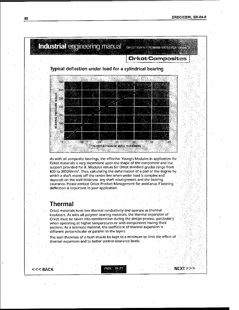
80 ERDC/CERL SR-04-8
Industrial enqineerinq manual äiiMSH
0SKÜT/fJJYU>< 0£»N& M&?£RSA15 *
Orkot; Composited
Typical deflection under load for a cylindrical bearing
As with ail composite bearings, the effective Young's Modulus in application for Orkot materials is very dependent upon the shape of the component and the support provided for it. Modulus values for Orkot standard grades range from 800 to 30QON/mm'. Thus, calculating the deformation of a pad or the degree by which a shaft moves off the centre line when under load is complex and depends on the wall thickness, any shaft misalignment and the bearing clearance. Please contact Orkot Product Management for assistance if bearing deflection is important in your application.
Thermal Orkot materials have low thermal conductivity and operate as thermal insulators. As with ali polymer bearing materials, the thermal expansion of Orkot must be taken into consideration during the design process, particularly when operating at higher temperatures or with components having thick sections. As a laminate material, the coefficient of thermal expansion is different perpendicular or parallel to the layers.
The wall thickness of a bush should be kept to a minimum to limit the effect of thermal expansion and to better control clearance levels.
«< BACK :-.PAGE v.:m£& NEXT>»
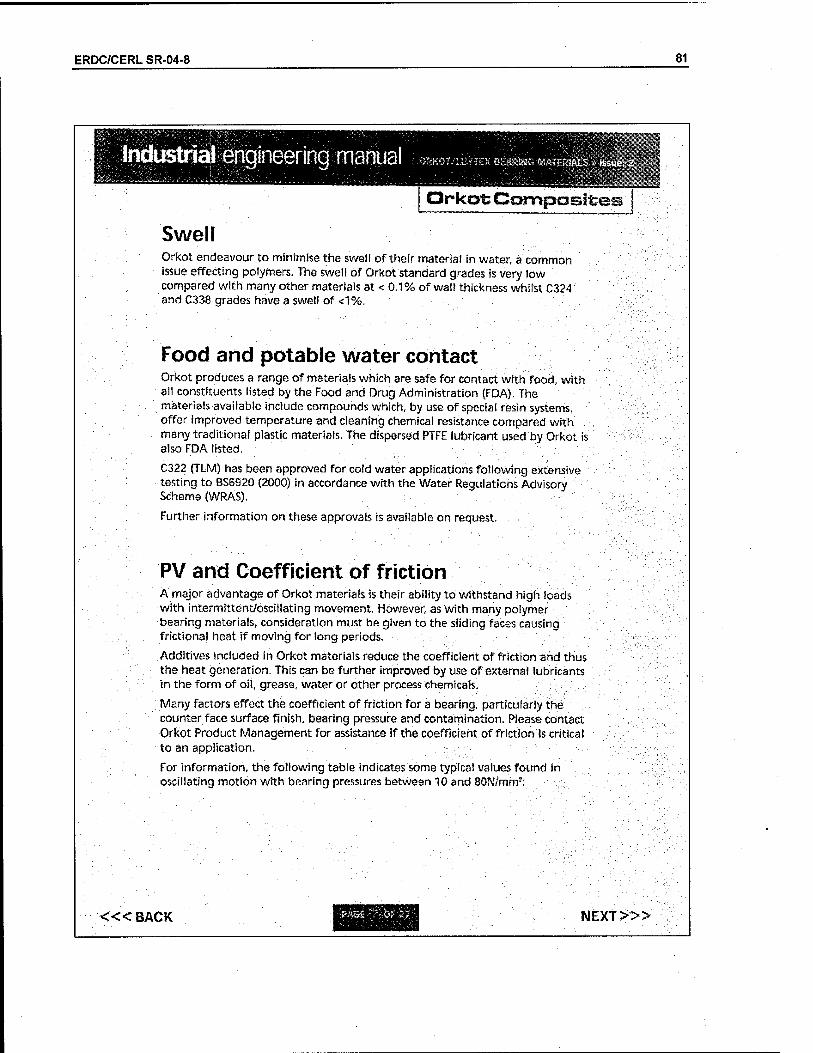
ERDC/CERL SR-04-8 81
Industrial engineering manual "ÖRKOT/LÜffEX BS*ÄG*iA?rTBALS »
Or kot Composites
Swell Orkot endeavour to minimise the swell of their material in water, a common issue effecting polymers. The swell of Orkot standard grades is very low compared with many other materials at < 0.1% of wall thickness whilst C324 and C338 grades have a swell of <1%,
Food and potable water contact Orkot produces a range of materials which are safe for contact with food, with all constituents listed by the Food and Drug Administration (FDA). The materials available include compounds which, by use of special resin systems, offer improved temperature and cleaning chemical resistance compared with many traditional plastic materials. The dispersed PTFE lubricant used by Orkot is also FDA listed,
C322 (TLM) has been approved for cold water applications following extensive testing to BS6S20 (2000) in accordance with the Water Regulations Advisory v Scheme (WRAS).
Further information on these approvals is available on request. •
PV and Coefficient of friction A major advantage of Orkot materials is their ability to withstand high loads with intermittent/oscillating movement. However, as with many polymer bearing materials, consideration must be given to the sliding faces causing frictional heat if moving for long periods.
Additives included in Orkot materials reduce the coefficient of friction and thus the heat generation. This can be further improved by use of external lubricants in the form of oil, grease, water or other process chemicals.
Many factors effect the coefficient of friction for a bearing, particularly the counter face surface finish, bearing pressure and contamination, Please contact Orkot Product Management for assistance if the coefficient of friction Is critical to an application.
For information, the following table indicates some typical values found in oscillating motion with bearing pressures between 10 and 80N/mm'::
<«BACK IMEXT:>»
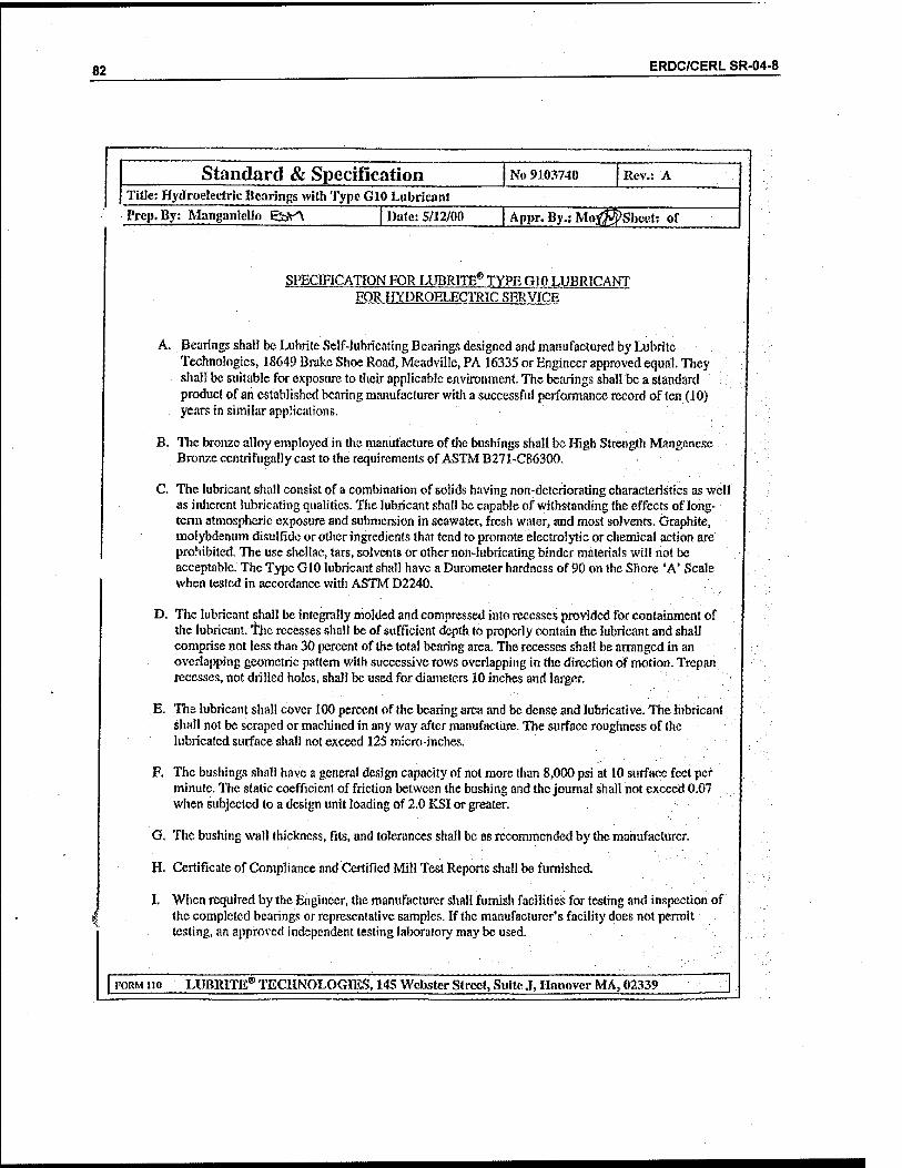
82 ERDC/CERL SR-04-8
Standard & Specification No 9103740 Rev.: A Title: Hydroelectric Bearings with Type G10 Lubricant
Prep. By: ManganieUo gbV^V | Date: 5/12/00 | Appr. By.; MofffiSheet: of
SPECIFICATION FOR LUBRITE® TYPE GIO LUBRfCANT FOR HYDROELECTRIC SERVICE
A. Bearings shall be Lubrite Self-lubricating Bearings designed and manufactured by Lubrite Technologies, 18649 Brake Shoe Road, Meadville, PA 16335 or Engineer approved equal. They shall be suitable for exposure to their applicable environment. The bearings shall be a standard product of an established tearing manufacturer with a successful performance record of ten (10) years in similar applications.
B. The bronze alloy employed in the manufacture of the bushings shall be High Strength Manganese Bronze ccntrifugally cast to the requirements of ASTM B271-CS6300.
C. The lubricant shall consist of a combination of solids having non:deteriorating characteristics as well as inherent lubricating qualities. The lubricant shall be capable of withstanding the effects of long- term atmospheric exposure and submersion in scawater, fresh water, and most solvents. Graphite, molybdenum disulfide or other ingredients that tend to promote electrolytic or chemical action are prohibited. The use shellac, tars, solvents or other non-lubricating binder materials will not be acceptable. The Type G10 lubricant shall have a Durometer hardness of 90 on the Shore "A* Scale when tested in accordance with ASTM D2240.
D. The lubricant shall be integrally molded and compressed into recesses provided for containment of the lubricant, the recesses shall be of sufficient depth to properly contain the lubricant and shall comprise not less than 30 percent of the total bearing area. The recesses shall be arranged in an overlapping geometric pattern with successive rows overlapping in the direction of motion. Trepan recesses, not drilled holes, shall be used for diameters 10 inches and larger.
E. The lubricant shall cover 100 percent of the bearing area and be dense and lubricative. The lubricant shall not be scraped or machined in any way after manufacture. The surface roughness of the lubricated surface shall not exceed 125 micro-inches.
F. The bushings shall have a general design capacity of not more than 8,000 psi at 10 surface feet per minute. The static coefficient of friction between the bushing and the journal shall not exceed 0.07 when subjected to a design unit loading of 2.0 KSI or greater.
G. The bushing wall thickness, fits, and tolerances shall be as recommended by the manufacturer.
H. Certificate of Compliance and Certified Mill Test Reports shall be furnished.
I. When required by the Engineer, the manufacturer shall furnish facilities for testing and inspection of the completed bearings or representative samples. If the manufacturer's facility does not permit testing, an approved independent testing laboratory may be used.
TORM no LUBRITE® TECHNOLOGIES, 145 Webster Street, Suite J, Hanover MA, 02339

ERDC/CERL SR-04-8 83
Standard & Specification No 9103403 Rev,: E
'Hüe: Lubrite^ Bearings with Type G12 Lubricant Ircp. By: Manganlello B$A »ate: 8/24/00 Appr.By.! Moyjfw^) Sheet: of
SPECIFICATION FOR LUBRITE® BEARINGS USING TYPE G12 LUBRICANT
Page 1 of 2
1.0 PURPOSE:
This specification is intended to provide genera! requirements and information for use in the design of Lubrite Bearings utilizing the Type G12 Lubrication System.
■2.0 SCOPE: "'■
This specification applies to all types of Lubrite Bearings that may be in a Bushing, Plat, Radial or Spherical configuration. Information contained in this specification should be used only as a guide. Design specific requirements and operating parameters should be forwarded to Lubrite's Design Engineering Group for review and recommendations.
3.0 DESCRIPTION:
Type GI2 Lubricant is a self-lubricating, reinforced polymeric composite system that is highly wear- resistant and capable of excellent performance under extreme operating conditions. The lubricant may be re-mach"med or left as applied dependent upon design and/or operational requirements. This material contains no metallic or other components that may cause electrolytic or other chemical action. Due to its polymeric nature the lubricant is unaffected by many solvents and petroleum based compounds including most greases and oils commonly encountered in structural or machine environments. Lubrite should approve ariy specific materials »hat may come in contact with the lubricated surface.
4.0 SPECIFICATIONS:
4.1 Design Bearing Pressures: Up to 40,000 psi 4.2 Coefficient of Friction Range: 0.03-0.10 4.3 Operating Temperature Range: -40°F <-40°C) to 500°F <260°C) 4.4 Intermittent Temperature: Up to 600oF (315°C) 4.5 Volume Resistivity: lx 10,<f ohm-cm (# 27">C) 4.6 Thermal Conductivity: 8.2 x 10 ~" Cal - cm/sec - cm2 - °C 4.7 Hardness: ASTM D2240, "D": 70-90 4.8 Density: 0.043 Lbs./In3
5.0 APPLICATIONS:
5.1 Bushings {Radial and Spherical):
A 6
5.1.1 Unless otherwise specified the lubricant shall be applied to the substrate and re-machined to obtain a minimum clearance between mating surface and lubricant of .004 inch (.10mm). The minimum lubricant film thickness shall be .009 inch (.23mm) after final machining.
FORM no LUBRITE® TECHNOLOGIES, 145 Webster Street, Suite J, Hanover MA, 02339

84 ERDC/CERL SR-04-8
Standard & Specification No 9103403 Rev.: E
Title: Lubrite® Bearings with Type G12 Lubricant "•rep. By: Manganiello ^>v\ | Date: 8/24/00 Appr. By.: Moy«^ Sheet: of
Page2of2
5.1.2 Clearances and lubricant thickness may vary dependent upon bearing size, configuration and operating conditions.
5.1.3 The substrate material shall conform to alloys UNS C95500 or UNS C95800 Nickel Aluminum Bronze. For Hydroelectric applications use Alloy UNS C86300 High Strength Manganese Bronze.
5.1.4 The bearing substrate surface shall contain retention cavities comprising not Jess than 25% nor more than 35% open area. Unless otherwise specified, the lubricant shall cover 100% of the lubricated surface and shall completely fill and cover all cavities to the specified minimum film thickness.
5.1.5 The mating surface of the bearing should be a corrosion resistant material such as Type 304/316 stainless steel or Inconcl 625. For optimum lubricant performance the surface should be finished to a roughness no greater than 63 micro-inch RMS (1.6 micro-meter). A ground or polished surface is preferable to a finish that has been achieved through a single point tool operation.
5.2 Flat or Spherical Plates: All the preceding specifications shall apply except that lubricant film thickness shall be maintained to 0.010 inch (0.254mm) minimum and for certain applications may not necessitate re-machining.
V 6.0 Installation: ■ \
During installation of Lubritc Bearings, the following recommendations should be followed to avoid possible damage to the lubricant or substrate material.
1. For bushing applications designed with a press fit should be inserted into the housing bore using smooth even pressure. Do not impact in any way. Do not shrink fit the bushing by means of dry ice or other cooling methods. When handling the bushing care should be exercised to avoid contact with the lubricated surface. Do not use metallic cable slings or clamps, if possible. If required, lifting eyes may be incorporated into the bearing.
Bushings are shipped complete and ready for installation when received and therefore no further machining or alterations should be done prior to or after installation. The bushing should be clean and free of dirt, dust or other foreign material prior to installation - a clean damp cloth should be used. Do not use solvents of any kind.
2. For other bearing configurations the above requirements shall also apply. In addition, if any welding is to be performed in the vicinity of the bearing, care must be taken to avoid temperatures above 350°F (1766C). Temperature indicating pencils or other suitable means should be used.
TORM no LUBRITE® TECHNOLOGIES, 145 Webster Street, Suite J, Hanover MA, 02339

ERDC/CERL SR-04-8 85
Standard & Specification No 9103398 Rev.: H Title: Hydroelectric Bearings with Type GI2 Lubricant
rep. By: Mangamelio ^5vA [ Date: 5/12/00 Appr.By.iMo; Sheet: of
SPECIFICATION FOR LUBRITE® TYPE Gl 2 LUBRICANT FOR HYDROELECTRTC SERVICE
A. Bearings shall be Lnhrite Self-lubricating Bearings designed and manufactured by Ltibrite Technologies, 18649 Brake Shoe Road, Meadville, PA 16335 or Engineer approved equal. They shall be suitable for exposure to their applicable environment. The bearings shall be a standard product of ah established bearing manufacturer with a successful performance record of ten (10) years in similar applications.
B. The bronze alloy employed in the manufacture of the bushings shall be High Strength Manganese Bronze ecntrifugally cast to the requirements of ASTM B271-C8630O,
C. The lubricant shall consist of a combination of solids having non-deteriorating characteristics as well as inherent lubricating qualities. The lubricant shall be capable of withstanding the effects of long- term atmospheric exposure and submersion in seawater, fresh water, and most solvents. Graphite, molybdenum disulfide or other ingredients that tend to promote electrolytic or chemical action are prohibited. The use shellac, tars, solvents or other non-lubricating binder materials will not be acceptable. The Type G12 lubricant shall have a Durometer hardness of between 70"- 90 on the Shore 'D' Scale when tested in accordance with ASTM D2240.
D. The lubricant shall be integrally molded and compressed into recesses provided for containment of the lubricant. The recesses shall be of sufficient depth to properly contain the lubricant and shall comprise not less than 30 percent of the total bearing area. The recesses shall be arranged in an overlapping geometric pattern with successive rows overlapping in the direction of motion. Trepan recesses, not drilled holes, shall be used for diameters 10 inches and larger.
E. The lubricant shall cover 100 percent of the bearing area and be dense and lubricative. The lubricant shall not be scraped or machined in any vvay after manufacture. The surface roughness of the lubricated surface shall not exceed 125 micro-inches.
F. The bushings shall have a general design capacity of not more than 8,000 pst at 10 surface feet per minute. The static coefficient of friction between the bushing and the journal shall not exceed 0.07 when subjected to a design unit loading of 2.0 KSI or greater.
G. The bushing wall thickness, fits, and tolerances shall be as recommended by the manufacturer.
H. Certificate ofCompliance and Certified Mill Test Reports shall be furnished.
I. When required by the Engineer, the manufacturer shall furnish facilities for testing and inspection of the completed bearings or representative samples. If the manufacturer's facility does not permit testing, an approved independent testing laboratory may be used.
FORM no LUBRITE^ TECHNOLOGIES, 145 Webster Street, Suite J, Hanover MA, 02339

86 ERDC/CERL SR-04-8
Standard & Specification No 9103454 Rev.: C
Title: Hydroelectric Bearings with Type G12 Lubricant _ Vcp.By: Manganicllo E£>VA Date: 5/12/00 Appr. By.: Moj^ * > Sheet: of
SPECIFICATION FOR LUBRITE* TYPE G12 LUBRICANT FOR HYDROELECTRrC SERVICE
A. Bearings shall be Lubrite Self-lubricating Bearings designed and manufactured by Lubrite Technologies, 18649 Brake Shoe Road, Meadville, PA 16335 or Engineer approved equal. They shall be suitable for expostire to their applicable environment. The bearings shall be a standard product of ah established bearing manufacturer with a successful performance record of ten (10) years in similar applications,
B. The bronze alloy employed in the manufacture of the bushings shall be Nickel Aluminum Bronze ccntrifugally cast to the requirements of ASTM B271-C95500 or C958G0.
C. The lubricant shall consist of a combination of solids having non-deteriorating characteristics as well as inherent lubricating qualities. The lubricant shall be capable of withstanding the effects of long- term atmospheric exposure and submersion in seawafer, fresh water, and most solvents. Graphite, molybdenum disulfide or other ingredients that tend to promote electrolytic or chemical action arc prohibited. The use shellac, tars, solvents or other non-lubricating binder materials will not be acceptable. The Type G12 lubricant shall have a Durometer hardness of between 70 - 90 on the Shore'D'Scale when tested in accordance with ASTM D2240.
D. The lubricant shall be integrally molded and compressed into recesses provided for containment of the lubricant. Tjie recesses shall be of sufficient depth to properly contain the lubricant and shall comprise not less than 30 percent of the total bearing area. The recesses shall be arranged in an overlapping geometric pattern with successive rows overlapping in the direction of motion. Trepan recesses, not drilled holes, shall be used for diameters 10 inches and larger.
E. The lubricant shall cover 100 percent of the bearing area and be dense and lubricative. The lubricant shall not be scraped or machined in any way after manufacture. The surface roughness of the lubricated surface shall not exceed 125 micro-inches.
F. The bushings shall have a general design capacity of not more than 5,000 psi at 10 surface feet per minute. The static coefficient of friction between the bushing and the journal shall not exceed 0.07 when subjected to a design unit loading of 2.0 KSI or greater.
G. The bushing wall thickness, fits, and tolerances shall be as recommended by the manufacturer.
H. Certificate of Compliance and Certified Mill Test Reports shall be furnished.
1. When required by the Engineer, the manufacturer shall furnish facilities for testing and inspection of the completed bearings or representative samples. If the manufacturer's facility does not permit testing, an approved independent testing laboratory may be used.
FORM no LUBRITE® TECHNOLOGIES, 145 Webster Street, Suite J, Hanover MA 102339

ERDC/CERL SR-04-8 87
Standard & Specification Title: Hydroelectric Bearings with Type G10 Lubricant
No 9103165 Rev.: F
tcp. By: Manganielio jgtbV^ Date: 5/12/00 [ Appr. By.: Moj^PShcet: of
SPECIFICATION FOR LUBRITfi® TYPR P, m LUBRICANT FOR HYDROELECTRIC SERVICE
A. Bearings shall be Lubrite Self-lubricating Bearings designed and manufactured by'Lubrite Technologies, 18649 Brake Shoe Road, Meadville, PA 16335 or Engineer approved equal. They shall be suitable for exposure to their applicable environment. The bearings shall be a standard product of an established bearing manufacturer with a successful performance record of ten (10) years in similar applications.
B. The bronze alloy employed in the manufacture of the bushings shall be Nickel Aluminum Bronze ' centrifugally cast to the requirements of ASTM B271-C95500 or C95800.
C. The lubricant shall consist of a combination of solids having non-deteriorating characteristics as well as inherent lubricating qualities. The lubricant shall be capable of withstanding the effects of long- term atmospheric exposure and submersion in seawater, fresh water, and most solvents. Graphite, molybdenum disulfide or other ingredients that tend to promote electrolytic or chemical action are prohibited. The use of shellac, tars, solvents or other non-lubricating binder materials will not "be acceptable. The Type G10 lubricant shall have a Durometer hardness of 90 on the Shore 'A' Scale when tested in accordance with ASTM D224Ö.
D. The lubricant shall be integrally molded and compressed into recesses provided for containment of the lubricant, the recesses shall be of sufficient depth to property contain the lubricant and shall comprise not less dian 30 percent of the total bearing area. The recesses shall be arranged in an overlapping geometric pattern with successive rows overlapping in the direction of motion. Trepan recesses, not drilled holes, shall be used for diameters 10 inches and larger.
E. The lubricant shall cover 100 percent of the bearing area and be dense and lubricative. The lubricant shall not be scraped or machined in any way after manufacture. The surface roughness of the lubricated surface shall not exceed 125 micro-inches.
F. The bushings shall have a general design capacity of not more than 5,000 psi at 10 surface feet per minute. The static coefficient of friction between the bushing and the journal shall not exceed 0.07 when subjected to a design unit loading of 2.0 KSI or greater.
G. The bushing wall thickness, fits, and tolerances shall be as recommended by the manufacturer
H. Certificate of Compliance and Certified Mill Test Reports shall be furnished.
I. When required by the Engineer, the manufacturer shall furnish facilities for testing and inspection of the completed bearings or representative samples. If the manufacturer's facility does not permit testing, an approved independent testing laboratory may be used.
FORM no LUBRITE18 TECHNOLOGIES, 1.45 Webster Street, Suite J, Hanover MA, 02339

88 ERDC/CERL SR-04-8
Glacier Garlock Bearings - Home Page Page 1 ofl
o GLACIER GARLOCK BEARINGS
Languages: P?P**
Home J Contact Us ; SSteMap \ Scare
Glacier Gartock Bearings
Self-lubricating and Prelubricated Bearings Glacier Garlock Bearings is proud to be the world's largest manufacturer of metal-polymer plain bearings.
More than 50,000 customers worldwide use products from our full line of saif-tubricated, marginally lubricated and fully lubricated plain bearings. Our products are available in a variety of forms such as cylindrical wrapped bushes» flanged bushes, thrust washers, or as special parts manufactured to customer requirements. Whatever your project requires, our experts will work with you to find the perfect bearings solution.
To meet your bearings needs, we offer:
• an extensive product range including fead-free, self- lubricated bearings compliant with EtV legislation
• sophisticated R&D facilities and test centers » superior Application Engineering support » flexible manufacturing for diverse applications • 20 locations In 17 countries • a comprehensive network of distributors
News
»29/2003 New hydropower bearings brochure for U.S.
S/2'J#0>M AUMA names Glacier Garlock Bearings supplier of the year
mwsm Fischer named president of Glacier Garlock Bearings :
En>ro Industries
Glacisr Gartock Bearings is m operation of £.«Ä.todÄrfes.Jfifc(NYSE;NPG},a :
feader in sealing products, mafal polymer besAigs, compfas«w systems arid other ongirsaBied products for uss in critical epoiicatiofis By Industries worttjwtde.
«S003 Glacier Gsräoc* Bearings. A!I rights rasefved.
j^sMBssriMamc I lßy)jpnnisBiaLMaEaaeBBntß*'i«..S!MsBSM
http://www.garlockbearings.com/ 12/2/2003

ERDC/CERL SR-04-8 89
Glacier Gartoek Bearings - Products
O GLACIER GARLOCK BEARINGS
Metal-Polymer Materials
Sotia* Polymer
Fiore-Relnforeed Plastic Composite Materials
Monometallic Matertals
: Page 1 of I
Home \ Contact Üs [ SWMap s'Searc
Products
Products
Other Products
■ o
MJÄRolymerMMtüals Bearing materials for non-lubricated applications (DU®, DÜ™-B, DP41*1 DP20* DM™), marginally lubricated (OX®, OS», HX«) and lubricate« applications (DP4™,DP30™,DP31m). .
Compound materials processed using injection-mouldingtechniques, these engineering polymers include PBT (Polyester) based {MF,'*4l, MF™31, MF™38), POM (Acefal) based (Glacetai KA»*, MF™52), PA (Nylon) based (EPmJ, PPS-based {MF1*^) and high temperature based materials (Torton®, MF™15 and EP1»72). These materials are available as special parts and ':: geometries including co-injected forms (HP), :
BbmTMnfercMMasacXjRHmasitfiJlalexial?' Various fibre-reinforced thermosefting plastic "bearings, including high- performance, filament-wound products such as GAR-FIL"™, GAR-MAX® High Strength GAR-MAX®, deva,tex®.
BasmsmeMlicMaterjaM. A range of oil-impregnated sintered bronze bearings, solid brorize bushes. Products include sintered bronze (DIN 1850) and solid bronze (LBS-Machfned Bronze, MBZ-BG9™, ID™, LDD™),
fithar_EtodiKts Additional product families to complement She above GQB product portfolio, e,g. specialized housings and assemblies, bi-metailic bearings.
EP™, KA™, MUlTI-niw,Dli®. DU'x-S, DP4™, DP20™, OP30'", DP31 *", DM™, OX®, DS^.and HX™ are ; i!
trademarks of Gastier Gsrta* Beerircgs. ...-'■■ . MF™ end HP™ are trademarks of L+S KunsJsiofftechnologie GmbH, Germany. Torton® is a registered trauma* OS Solvay Advanced Polymers, LLC.
■-MBZ-B09™, ID™, IDD™" are trademarks ofWietad Werke Gr*H, Germany. DEVA™, <tera.bm®, dava.maäa», devs.ojide® and deva.tex® are tradem3fks of Federal Mopjl Oevs'GmbH, Gemsny. Exa%rt ™ S3 a product of Cryptic Arsis Ltd, England. Mini™ and UN!*" are trademarks of EnPro Industries Inc., USA.
©2003 Glacier Garfodt Bsarlrtgs. AB rights reserved.
tSSBUJSclairnec j Envtronnrantat Management Policy Statement
http://www.garlockbearings.com/products.asp .12/2/2003'

90 ERDC/CERL SR-04-8
FEROFORM HYDRO INDUSTRY COMPOSITES
o CONTENTS
A World of Materials from TENMAT Introduction Benefits Applications Technical Data Availability Treatments Machining Quality Assurance
'Health's Safety TENMAT Companies
Page
2 3 4 5 6 6 6 7 7 7 8
FEROFORM The FEROFORM range of materials has been developed by TENMAT to offer the design engineer the chance
af replacing metallic, rubber and sbestos based materials with
unique, non-asbestos, wearing and bearing composites capable of duplicating, and in some cases exceeding, the performance of asbestos composites. FEROFORM materials possess strength, durability, dimensional stability and excellent wear characteristics besides exhibiting good resistance to attack by many chemicals.
The resins used have been selected for their good mechanical properties and high thermal and dimensional stability. Both organic and synthetic fibres employed for reinforcement of the resins have been selected from the many types available for their high modulus and stability In water and various chemicals. The addition of selected friction modifiers such as PTFE (T814) or oil, graphite and molybdenum disulphide
Jnhanees the wear properties and life f the materials, enabling them to be
operated at higher speeds and loads.
Tenmat Feroform
The U.S. Army Corps of Engineers identified a need for a self lubricating bearing material to replace its existing grease lubricating bronze bearings in some 300 large hydro- turbines in the USA when they come up for rehabilitation. However, there was a lack of any detailed historical data regarding performance and life span, so an extensive laboratory test program was set up which simulated worst case conditions, carried out at Powertech tabs in Vancouver, a subsidiary of BC Hydro. TENMAT FEROFORM T814 proved itself capable of operating in both dry and wet conditions of shaft mis-alignment
or deflection underload. Extremely low wear rates indicating long life projection were recorded and the journal showed no sign of wear throughout the test.

ERDC/CERL SR-04-8 91
BENEFITS
ADVANTAGES
FEROFORM composites are extremely versatile materials which have the following advantages over conventional materials fn wearing and bearfna applications.
Excellent resistance to wear - FEROFORM materials show consistently tow wear rates in all application areas.
Excellent abrasion resistance - FEROFORM materials can be used in environments where abrasive particles are present.
tow coefficient of friction - enabling higher speeds to be used and heavier payloads to be carried. This minimises inertia! problems (stick slip) and affords lower power requirements. FEROFORM shows consistently lower friction rates than ail other competitive materials.
A degree of elasticity - enabling misalignment to be taken up without damage or fracturing.
User friendly - the lubricant is evenly dispersed throughout the matrix. Bearings can be machined In situ or modified on site without loss of lubricational properties.
Excellent resilience - FEROFORM has the ability to absorb high shock loading and Impact which would extrude other materials.
Lightweight - approximately 1/5 to 1/8 the weight of phosphor bronze making refurbishment work easier.
Good chemical resistance - all FEROFORM grades perform satisfactorily in the presence of most mineral and organic acids, solvents., organic bases and non-caustic alkali.
Easy Installation - Can be installed by press, draw bar or freeze (dry ice or liquid nitrogen) fitting.
PERFORMANCE
FEROFORM T814 PERFORMANCE-STATIC FRICTION
eoEFROENT of mcnon 0.3 f —
0.25 - a.!3
02 - ' O.gg
0,15
■■0.1 .'■.'■■Äjji
.0.1? 0.1? ■ j^f11
0.05
0
j»»B
Sf ■' ifl / jM8jM 1
WST DRY MISAUSJCD
FEROFORM T814 PERFORMANCE-WEAR
WE« RATE (mWlOOTEST hre.)
2.5
FEROFORM T814 PERFORMANCE-DYNAMIC FRICTION
COEFFICIENT OF FRICTION
0£S
Test «suits taten from Powertech Labs INC. A subsidiary of B.C. Hydro, Canada

92 ERDC/CERL SR-04-8
TECHNICAL DATA
Properties
''. Ultimate Gbmpressive Strength
Normal Maximum Working Pressure
_Co™pff ssive Yield » 68.9 MPa {©10.ÖOOpsi)
Fiexüral Strength
Shear Strength''
Wer Laminae Bond Streng*
Den it>
* Brihefl Hardness-
;% Swell in vVater (Normal to Urnlriae)
T814 TU Units
MPa (ps -_M , -ijyi' llrlf^tg))
•■82
T12 T14
62(8,990) J 65(55)'
'2J2V
, Cosfficiertlof Friction
Coefficient of Linear Expansion (Normal to laminae) x10«
_^_„ ; Parallel to Laminae) x10
Jyfcximum Working Temperature
Intermittent Temperature Capability
* Due to the flexibility of T grades it is not possible to measure flexural strength but no fracturing occurred.
Ultimate Compressive strengths of tube wrapped materials are typically •- T814 220 MPa, T11 240 MPa, T12 240 MPa, T14 250 MPa Friction levels in hydrodynamic conditions have been recorded at 0.01 with water and 0 016 with oil \ Tests above conducted generally In accordance with BS2782 and ASTM test methods. The values above are typical test results on sheet material and should not be taten as guaranteed, tor specifications or primary selection of maSs Th» information herein Is presented m good faith but TENMAT does not warrant the conformity of te mSeriais to thelisSr]
.properties or the suitability of rts materials for any particular purpose. In the event of any uncertainty regardinq suitability for any application please contact our technical staff on Tel: +44 (0)161 8722181 Fax:+44 (0) 161 872 7596 &5unaD""yTOr
o
AVAILABILITY FEROFORM can be supplied in tubs, sheet or rod form and as fully machined components. Tube
2Ö-200mm 0ä"- 750 ID & 30-250mm (124 - 101 OD Minimum Wail Thickness 5mm (Ks"> Tolerance +0/-1mm (+0/-0.04") ID :200-600mm (T - 235«") ID & 26O-7O0mm (10" - 27JTS OD • Minimum Wall Thickness 10mm (JT) up to 400mm (15 Y") OD and 20mm (^thereafter. Tolerance +0/-2mm (+0/-0.08") ID All OD is sanded to +M W of nominal OD
Rod ■ . ■ 19-111mm (?£•- AW) OD x 1220mm (48") long Tolerance +0/-1 mm 117 - 158nim (4«"- 67.")OD x 3Ö5mm (12T long Tolerance +0/-1mm
Sheet 1.6 - 100mm (Ä,*- A") thickness 1220 x 1220mm (4S"x48") Tolerance thickness 1.25 -10mm (0.05"- %") unsanded, +/-0.1mm (+/-0.00-1") sanded; -0/+3mm (-0/+Ü*) length & width Larger sizes and special mouldings available on request
TREATMENTS For applications above 70=C {160°F) WE
recommend that FEROFORM is heat stabilised prior to machining to maintain their required dimensions. Heat treatment is denoted by suffix 7 e.g. T127. Oil impregnation (suffix 1) can reduce running friction and aid bedding in. MoSt (suffix 8) treatment can be used instead of oil for dusty environments. Special TENMAT bedding in paste is recommended forTB14 to reduce friction and minimise wear.
o-

ERDC/CERL SR-04-8 93
Thordon Bearings Applications
CoppedgeMarine Inc. Business Partners
Thordon Industrial Bearing Grades and Related Products
Thordon Bearings offer many proven user benefits:
• Self-lubricating • Long Life • High Resilience/Impact Resistance • Low Operating Friction • High Abrasion Resistance
• Easily Machined and Installed
» Corrosion Resistance • Accommodates Edge Loading • Pollution-Free • Noise Reduction
Industrial Bearing Grades and Associated Products
The XL Grade is the standard grade for pump bearing applications. These bearings are available in a wide range of sized in both grooved and un-grooved configurations.
The SXL Grade is the preferred choice for dry start-np operation, the SXL offers a lower dry coefficient of friction and similar wear life and abrasive resistance when compared to the XL graded
http:/Av\vw.coppedgemarine.com/tbi-i.htai 12/4/2003

94 ERDC/CERL SR-04-8
Thordon Bearings Applications
Thordon Composite Bearings are specifically formulated to provide outstanding wear life in abrasive operating conditions. These bearings out lasts other bearings by a factor of several times and are available in a wide range of sizes in a grooved configuration only.
Thordon Metal Backed Bearings are produced by polymerizing any of the three Thordon Grades into a metallic housing. Orgmtally developed to meet the needs of the nuclear power industry, this design is now specified in many other applications.
Thordon HPSXL is a harder, suffer polymer compared to SXL, can be specified to higher design pressures and has a lower dry coefficient of friction than SXL.
Thordon TRAXL refers to a special bearing configuration developed for high pressure applications with slow speed oscillating or full rotation motion where frietional heat generation is minimal.
Thordon Wear Strips: The SXL or HPSXL can be supplied in strip or sheet form, or molded to the exact requirements of the application.
Thor-tape: Thordon SXL is also available as Thor-tape, a,product supplied in a range of thicknesses up to 0.125" (3.2mm) and widths up to 12" (300mm). Ask us about other applications of this product.
http://www.coppedgemarine.com/tbi-i.htm 12/4/2003

ERDC/CERL SR-04-8 95
The Recognized Choice For Long Life, Low Friction Bearing Systems
Reliability,'long Itfe and superior customer service have macfe Thordon Bearings Inc.-the standard with hydro-electric power producers for pollution free, low friction bearing systems. When specifying operating mechanism bearings, water-lubricated turbine main shaft guide bearings and pomp bearings; Thordon is the
. proven choice for value and performance for both . rehabilitation and new turbine projects.
Thordon Searings'design engineers provide customers with bearing system designs that meet or exceed their specifications. Depending on the application, the optimum bearing can be selected from several Thordon grades and configurations.
Recently, concern over down-stream pollution caused by grease and oil lubricated bearings has placed
. increased emphasis on non-polluting bearing systems. Thordon Bearings, a pioneer in the development of grease-free bearing designs, supplied bearings in 1974 for installation at Ontario Hydro's Niagara Fall's station. Today, these bearings continue to perform well.
Originally developed over 2$ years ago as a high performance pump bearing, Thordon is an elastomeric polymer alloy that provides exceptional wear Be, Thordon SXL, with its inherent low coefficient of friction and grease-free operation, is particularly well suited for high pressure hydro-turbine applications. Thordon's
proven performance in vertical pumps led to Its use in water-lubricated turbine main shaft guide bearings, with shaft diameters ranging from mini-turbines to the : largest units in service.
Today, with trouble free installations around the world, Thordon Bearings Inc. is a recognized leader in the design, manufacture and supply of hydro-turbine bearing systems. All Thordon bearings are manufactured to ISO 9002 Quality System requirements ensuring high quality and consistency.:
For power utilities and turbine manufacturers who demand the best in value, performance and service; - Thordon hydro-electric turbine bearing systems are tie proven, reliable solution.
Thordon Features Offer Proven User Benefits
Thordon Bearings' field proven hydro-turbine . bearing systems offer significant technical and customer benefits:
•low Friction
• Long life
• Pollution Free
• Sizing Flexibility Easily Machined • High Abrasion Resistance
• High Resilience/Impact Resistance
•No Need for Hardened, Ground Journals • High Pressure Capacity
• Accommodate Edge Loading
• Wet Or Dry Operation
•Lip Seal Availability''
• Extensive Application References

96 ERDC/CERL SR-04-8
low Friction: Thordon SXL bearings exhibit a very tow coefficient of friction, This is true whether the bearing is operating dry or submerged in water. A low bearing coefficient of friction is essential in the smooth and reliable functioning of hydro-turbine operatina mechanisms.
Tests conducted by an independent hvdro-turbsne laboratory determined that the dry coefficient of friction Of Thordon SXL TRAXt. bearings falls in a range from 0.09 to 0.05 tested at pressures ranging from 18 to 70 MPa (2,600 to 10,000 psi). Thordon's coefficient of friction decreases as bearing operating pressures increase, whereas metallic bearings experience dramatic increases in the coefficient of friction and tend to gal!
as operating pressures rise. This characteristic makes Thordon an ideal choice for high head installations where pressures are high and smooth precise operation
■'of the gates is vital. Thordon performs well as an un-sealed wicket gate bearing because the coefficient of friction of Thordon wet is lower than dry.
Wet or dry; low or high pressure; static or dynamic; Thordon SXL TRAXL bearings operate smoothly and without stick-slip in hydro-turbine operating mechanisms.
Long Life: Since 1974, Thordon bearings have been fitted to hydro-turbine operating mechanisms. The bearings of the first installation remain in operation today as a testament to Thordon's exceptional wear life. Thordon continues to provide outstanding iife in a large and growing number of installations since that time.
Only 0.13 mm (0.005") wear on an 88.9 mm (3.500") I.D. Thordon SXL TRAXL bearing was predicted In'25 years of simulated operation in a pump-turbine wicket gate application when tested by an independent hydro-turbine laboratory. Test pressures were 20.7 MPa (3000 psi) with operational parameters appropriate for a highly utilized pump storage turbine. Self-lubricated jnetallic bearings in the same test were predicted to show the same wear after less than nine years. Bearing journal wear was also examined and there was no significant wear of the shaft running against Thordon whereas the metallic bearings tested wore the journal proportionally to their own wear rate.
In the field, Thordon bearings have earned a reputation for performing particularly well in abrasive environments and in the extreme duty cycles of pump turbine applications. Thordon SXL TRAXL bearings were chosen over competitive metallic bearings in a recent test in a pump storage turbine experiencing accelerated bearing wear. Thordon was selected after less than one year's operation showed negligible wear compared to
'■significant wear on the metallic bearings.
Evaluation of Bearing Mction and "Stick Slip"
r,.l£":Sn the,liank>" tea"9s T«! f **y evalwitaä the frictions! SÄSSf»^ ?TPf'^ "^"3* «*"?*'*< t° THanfenV-Th* tests * *t«t«J acted ita*-d,p vibration, lot mm (<f,0*) diameter fe,AiW wee loafed to a «nsam pressure of 24.0 MPa ßsco mi) and ädtSLh:
*n «Kitten of «5> äl a «ferity rfO.OM r*/s8i. (062 ftS \°iS9
run tor 8 hours with «etWerU of «akin, temperaU andpmmitmtipL Uton 20 times per s«ond for a 60 SKoad pa fed «fte sterUl 0 5 iSSSri «hen or, the tar for the bate pf fto K«'WrS wiu5 were rrtömred at the shaft immcdlsteh- arffaixm 16 the bearing, Tb? test lisota an? summrtzed in the graphs below. ■ >rara3ii««iwane
THORDON SXl TRAXL BEARINC
£ 053- t*2-
Avn. *ri«ion:
Tempf/C): 25«
0 hours
Avff. fVKtion: MM
TtmpfC), 3J.S
Avg. Fttethm O.0SJ
Tientj» ("<£ . 58.»
04 hours
I Av^.trictjfmi i O-flSi
I -T«m''CC): !■■■ «.!
Time 4foours £ hmin
. Tfl75?,0.,"^? SXLTIWXL tearing had MsM rfyramic ftfetton öf 0.07? but q«ckiy bsdderj in, decreased to 0.0SS aft«,' 30 minutes ami to 0 051 fey te end of (he test, The temperature rose from 2S.TC to 40.a»C, rising only 1 J'C ourmjrthe tost <J hours. No evidence of slictMtip was observed. ■ ■
NON-METALLIC BEARING
Avg. friction: 0.073
temp t'O: »JS
A*5- Frtcttortr <M»1
Temp ('£}: M.7
Av«. frksf«*! tt.esj
tfw*qK'Cj: \ 45»* ■
0 hours 3 hours
* Test was ■
MrmirsA«
vibrjsiaftcif t*K m*<tsrs5.
0.5 hours '■Time
A iwn.mmBic bearing tested trad initial dynamic friction of 0.07? anci temperature of 2?£'t. Over a 3 hour period the coefficient, of friction increased to 0. WS and the tesnperiSa» rose to 4«.8«C. Sy th* end of the first half hotrr rapid fluctuations in friction were «curring; (sfek-sfi». The magnitude of these ftaaaflons irmtisjed until the test was rafted after 3 due to e*cess-Ve vibration of th* test machine,;
METALLIC BEARING
r 3 hows
Avg. Mrtton: «.07«
T«ttp fCfc Zl.2
Avg. Friction: 0.079
»HUB (t)c 21.»
Avg, frktt»m 0-*B
T*mp<*CJ; > I7J ■
*ttg..¥fktik»i: ».to*
Twnpfq:
0 hours 04 hours ; 4 hours Time
8 hours
A mäJlUc bearing test«) fad initial dynamic frlaian of 0.078; Over the Cdurst! of the test the coeffiMrst of friction roseto 0.106 arsd tte temperature rose to 42.,5'C tin evidencse of stick-slip wss obsftMed.
The Thordon SXI TRAXL btiring operated with thi lowest toeffUi«srrt of friction of the group «fid was the tmty bearing to exhibit a decrease in friction *« the test progressed, Operation was smooth »ltd quiet, collaborating the performance history of Thordon bearings in th« field.

ERDC/CERL SR-04-8 97
low Friction: Thordon SXt bearings exhibit a very low coefficient of friction, This is true whether the bearmg is operating dry or submerged in water; A low bearing coefficient of friction is essential in the smooth and reliable functioning of hydro-turbine operatino mechanisms. . ,
Tests conducted by an independent hvdro-turbine laboratory determined that the dry coefficient of friction
Ä n 5Jf* at PreSSUreS ran9!n9 fro^S to 70 MPa {2,600 to 10,000 psi). Thordon's coefficient of
friction decreases as bearing operating pressures increase, whereas metallic bearings experience dramatic increases in the coefficient of friction and tend to qall
as operating pressures rise. This characteristic mates Thordon an ideal choice for high head installations where pressures are high and smooth precise operation of the gates is vital. Thordon performs well as an
■urwealed wicket gate bearing because the coefficient Oi friction of Thordon wet is lower than dry.
. Wet or dry; low or high pressure; static or dynamic;
Thordon SXL TRAXL bearings operate smoothly and without stick-slip in hydro-turbine operating mechanisms.
■v. Long Life; Since 1974, Thordon bearings have been fitted to hydro-turbine operating mechanisms The bearings of the first installation remain in operation today as a testament to Thordon's exceptional wear life Thordon continues to provide outstanding life in a large and growing number of installations since that time.
Only 0.13 mm (0.005') wear on an 88.9 mm ■.(3.500") i.D. Thordon SXL TRAXL bearing was predicted in 25 years of simulated operation in a pump-turbine wicket gate application when tested by an independent hydro-turbine laboratory. Test pressures were 20,7 MPa (3000 psi) with operational parameters appropriate for a highly utilized pump storage turbine. Self-iubricated metallic bearings in the same test were predicted to show the same wear after less than nine years. Bearing journal wear was also examined and there was no significant wear of the shaft running against Thordon
whereas the metallic bearings tested wore the Journal proportionally to their own wear rate.
In the field, Thordon bearings have earned a reputation for performing particularly well in abrasive environments and in the extreme duty cycles of pump turbine applications. Thordon SXL TRAXL bearings were chosen over competitive metallic bearings in a recent test in a pump storage turbine experiencing accelerated bearing wear: Thordon was selected after less than one year's operation showed negligible wear compared to significant wear on the metallic bearings.
Evaluation of Bearing Friction and "Stick Slip"
an «»I«™ olUS'MaS //StA!?Äfc?*•**' run «or* tours with «rffc«u of «cfioStoiu }'Tt* ""I* tata, 20 times PSr second for a,Ks«5fS^"fjr^! ?a ■%' Ww on the hour forth» batw.«i »SI/? fe st3rt',$ °-s to«s ami
THORDON SXL TBAXIRCA^^,
ea*. 637.
$ «s; A»g. ftktim:
turn Tempf«;
25.9
Oheurs
Avg. Ftfttitm: «toss
M.2
0.S hours
Avg. fmiletc 0.O5J
Tempf/C); IS.»
Time «liüurj:
Mil ttmpra:
■'• mi ■
Shew
end of the tea, Tpe temperature roue from 25.S-C to 40 2X ffeh» or* 1 IT
NON METALLIC BEARING
§
A*g. Friction: 0.071
— JL T«1»J> t'Q: »5'3 »JS Wüi.—™
i Avg. frtctlent 0.0*1
M.7
A*g. Friction:
temp (*£): «I*
0 hours 3 hours
«cpjseälK
to ex««*** vjfcräfiäsnel tftsrrasfcfe&
0.5 hours
A non-mwalk bearing tested had SnKa! dynamic friction oJ 0 073 «rirj SI?«» "CO»» 5 h«r period ktMHIckMtftUc; ' ■■-: '- ha»w £Si a?« Ilfe «"Pf*"* ™« to «^c- % ft« end of the tot nail hoe.' rapid fluctuations infrktai wereoecaTitao (stWe-sIp) The magnitude of Uws* fluctuations increased unffl the test was rafted ate 3 hours due tDe»c«SfWv!bra&iri of the tet machine. ■ ™."w,in™0
METALLIC BEARING
Avti fcrfcsloQ: O.0?«
T«m> (t): 2J.J
A*s- friction: 0.0»
Tisrnaf«;
Av«. fylttinn: 0.6W
Temp <*C)t
Ofeurs
Avg. Ffiction: ,0.tOS
ferapCQ:
0.S hours time
% 8 hours
A Ririatec tearing tested had Initial dynamic frsÄB of 0 G7S Ow:r the ' course of tt» test the coefficient of Sriction rose to 0.106 arsd the temperate* tose to 42.SX. No ei'Mence of s&St-sSp was observed.
TtM Thordon SXt TRAXL bearing operated with the lowest eoeffMsntof friction^of the group and wastheonry bearing to exhlblt a decrease In friction «s the test progressed. Operation was smooth srnd quiet, collaborating the perfonnanw hittonr of Thordon bearingjJn the Held. '

ERDC/CERL SR-04-8
Poflution Free: Thordon SXL is a homogenous fow friction polymer alloy. Crease or other lubrication techniques are not required to lower the coefficient of friction or reduce the wear of a Thordon SXL bearing. Thordon eliminates both the pollution concerns associated with grease lubrication and the lubricant dispersion problems of other "self- lubricating" bearings. Bearings equipped with lubrication plugs require significant rotation of the shaft to spread the lubricant over the bearing surface, in actual operation many of the shaft movements are very minor • only a few degrees either way. Other "self-lubricating" bearings require wear to occur before internal lubricants are accessed. Special coatings to lower friction and minimize wear are often specified, but these can disappear over time resulting in dramatically increased friction and wear.
Thordon SXL's inherent low coefficient of friction does not change. It remains unchanged over many years of operation.
Sizing Flexibility - Easily Machined: Thordon bearings are typically supplied finish machined to
specifications engineered for the rehabilitation project; but are often also supplied with overbuild on the inside and outside dimensions to facilitate finish machining on site. Sizing problems resulting from misalignment and dimensional inconsistencies that are often encountered with "standard" sized bearings during turbine rehabilitation are not a problem for Thordon. Optimum alignment and custom si2ing of the bearings is possible with Thordon. Bearings that are only supplied in standard sizes and a re difficult to machine to dose tolerances make custom sizing impossible or extremely expensive. Thordon bearings, while available in
Special tool, are mt rtqOnd to a ran9e of standard sizes, kataiisxLTRAKLbtarinas. can be easily sized at the
factory, or in the field, to meet the dimensional : requirements of the project. ■ ':■
Quick turnaround can be achieved by pre- manufacturing bearings to a semi-finished state
and then finish machining them during the outage after exact size requirements are known. A free machining elastomer, . Thordon contains no asbestos or other hazardous materials, machines cleanly and quickly and is free of nuisance dust. An instructional video providing information on quick accurate machining of Thordon is available.
High Abrasion Resistance: Thordon's .. superior wear life when operating in abrasives is a
direct result of its elastomeric nature. An elastomer, Thordon tends to deflect and then reject abrasive particles. This is not the case with other non-metallic or metallic bearing surfaces. Non-metaflies that are not elastomers tend to deform plastically, allowing abrasives to bed into the bearing acting as a permanent abrasive on the shaft Metallic bearings experience accelerated wear on both the bearing and the mating shaft surface. ' Grooves to allow abrasive particles and wear debris to clear the bearing are not required with Tnofdon.
High Resilience/Impact Resistance: In high head hydro-electric and pump turbine installations shorter operating mechanism bearing life is often expected. Higher wear rates and occasional tearing failures are. often a result of the impact loading and high frequency low amplitude oscillations encountered. "Pounding out" can occur even though the loads and pressures are below the theoretical yield point of the material
When a load is applied to a bearing relatively smoothly, the bearing deflects a given amount for each :.- unit of load. As long as the loading does not exceed the yield point of the bearing it will efastically return to'its original position when the load is removed. If, however, . the load is applied rapidly the bearing may lack the resilience to absorb the energy and completely release it . before the next loading cycle. Permanent deformation can occur, even though the theoretical yield point does not appear to have been exceeded. The higher the ; Modulus of Resilience of a bearing, the greater the bearing's ability to absorb impact and high frequency oscillatory loading without permanent deformation, ;
Although the yield point of bronze is almost 6 times :
that of SXL as shown in Table 1, the Modulus of : Resilience of bronze is only 5% that of SXL. Metallic ; bearings, as a result, can tend to "pound out" and transmit impact loading into the operating system whereas Thordon tends to absorb impact toads and

ERDC/CERL SR-04-8 99
Higher tensile strength
lower tensile strength
R2
Strain figure ]; rmpact Rsäähmte Comparison
«teuSMmg the in» wnd« the elastic portion of the stress/Sah <orw up to the jMd point. The e«n^ in F^* TfanSLv 8 l«gh tensile «nngtSiratsia hs » mucs, towf „J ™?
SSf? •* ?e ^ 3rea R1>-*"• s *™X~ mate»! witr, mih&nx (repreent«! by the shaded ares ffi).
Table 1
Material
Resilience Comparison Yield Stress
Modulus of Modulus of Elasticity Resilience
P5f _MPa psf MPa
Thorsten SXt 3,500 24.1 20,000 US 305.Q 2.11
BtorgeC932Q0 20,000 U«,Q 14.5X10» 100X10» 13,8 0.10
Leaded Bran» 7,500 51.7 7.3 «W 50x10» with graphite
3.9 0,03
Mote: -field »ess tor the graphite (Bled toon» Es based on 55« of the maximum tensile strericth.
cushion the operating system from shock. Tensfle streng^ although a good indication of a beard's phys.ca! properties, is of less importance in sele ctL an optimum bearing. Thordon SXL TRAXL bearrngS" been proven to resist Impact loading and provide superior wearfffe in highly loaded hydro turbines.
No Need for Hardened, Ground Journals: Hard journals are required for hard bearings. With Thordon
than 304 or 316 stainless steel with no bardeninq Surface smoothness should be 0.8 MM (32 u inches).
High Pressure Capacity;.AW»ugh:typicairV loaded to pressures of 20 to 2.5 MPa (3,000 to 3,600 psf) in a hydro-turbine, Thordon TRAXL bearings are performing we« in many industrial applications at pressures as hiqh as 70 MPa (10,000 psi) or higher. .
Accommodate Edge Loading: Under the edge loading conditions that can occur as a result of minor mts-alignment or wicket gate deflection, Thordon deflects slightly, effectively spreading, and thereby reducing, the pressure. The galling of metafile bearings that often occurs due to edge loading under these conditions is eliminated with Thordon.
Wet Or Dry Operation: Thordon operating mechanism bearings function wei! either sealed and dry; or immersed in water, in fact, Thordori's coefficient of ' friction immersed is less than operating dry,
Lip Sea! Availability: In the event that sealed wickei gate bearings are preferred, Thordon SXL TRAXL bearings can be supplied from the factory with high quality Thorseaf lip seals installed. Formulated from a ■' high strength polymer with internal lubricants, Thorseals provide effective sealing, tew friction and long life.
Creased operating mechanism before Installation of SXL TtWCl bearings.
Operating mechanism after installation of SXL TRAXL bearing!
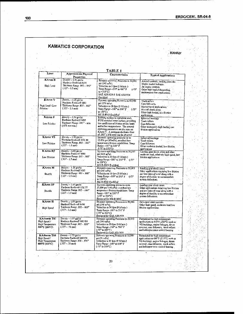
100 ERDC/CERL SR-04-8
KAMATICS CORPORATION fKRMHSr
Liner
KAron B
High Load
Approximate Physic»! grgpmies
KAron V
High Load i LOK Friction
:■ KAron F
Low Friction
Di'nsm'-l.SljEia'ct: Bartes Rockweü M95 Tiikämess Rani>c .005 - .060" {.12?-.].5IBBI)
TABLE 1 Characteristics
Density-1.36 gm'« Haidaess Rockwell M85 Tistcbiess Ranee .005 - .050" (.12?-1.5 BOT")
Dyaarttic operating PtKsurts to 50,000 psi (343 mfti). Velocities lo 3 fpni (1 M'oiin ) Terap Range -JCKFiaWF (.73° to>205T> SAH AS81820 & SAE ASS1934 Qualified
KAron VS
Lmv Frieden
KAron RP
Low Frieden
Density — }..3i5 gjti'cc Hardness RoA-weil M8S Thickness Range MT'-min (.07$ tun nun.)
Dynamic operating Pressures to 40,000 psi (276 mPa). Vc!oc«ö=i to 10 fpre (3 MM».) taapRansH-II>Os'to3<}0',F (.73' to 150*C) Mfl-MMS Oaalifisd
Typical Applications
Aircraft controls, 1 mdiruj gears etc"" Highly loaded Imfca&es. Jet engine Controls. Other high loafed demanding, mamienance free applications.
Density - 1.56 gm/cc Hardcess RockweH 15X SS Thictaess Rar.^c .005 - ,06&'* (.127-1.5 mnl
Density ~1.60 gai/cc Hardness Roetavct! MB0 Thicfasiss Raasse .005 - .OfiO" (.127~1.5imu")
KAron M
: Ductile
KAron SP
Ductile
KAron H
High Speed
KAtherm T«7 High Speed/ High Temperature 500<F(2600Q
KAtherm T88 It%h Speed I High Temperature 61OTr<31<>°Q
Density-1,36 gm'ec Hrotes Rockwell MSO Thickness Range .005 - .0*0" (.127-1.5 TOB)
Dertsrry -1.44 gm/ee Hardness Rockwell 15X 77 Thickness Range .005 - .0W" (.127-1.5 nan)
Rubbing surface is a prsfotsiiaicly PTFE enriched cater surface, providing tow coefficient of friction at low loads andatla-A'teaioeratia-es Tiie general operating parameters arc the sense as KAron V. Aininimuaöicteess liner of .003" C07& mm) can be obtained.
Traekrofes. Cam followers. ävfarine/navßl application. Aircraft shoe* strats, Other high loaded, tew friction applications.
Dynamic openätiag pressures irp to 12,000 psi (B3nA), excellent low tempcranire friction capabilities. Temp Rang*-10(1* to 300° F (-73° to 130T) Dynamic operotinc Pressures to 30stK)0- pst (20J ttPa). Velocities to 10 fpm (3 MAnin.) Temp Rasge-100= to 253'F, {-71° to 120'C) tfil-B-SS« Qualified
Spherical beatings .' Track rollers. Cam followers Other moderately high loaded, low friction applications :
Spherical bearings Tracfc rollers; Cam followers Other moderate loaded, low friction applications
Djaanie operating ftressm-es to 35,000 psi(240mPa). Velocities to 10 fpm (3 MAnin.) Temp Range -100» to 250* F (-73* iol20"C) Mil-B-894.3 Qualified .
Density^1.(5 gmfcc Hardness Rockwell MW Thicknsss Ranne .005 - MT (.127-1.5 mm)
Density- t.37gtst'ec Hardness Rockwell MS0.W Tliictaisss Range ,005 - .030" (.127-/75 am)
Dcasir<--!.30gm'cc Hardness Rockwell MSO/90 Thickness Range ,005 - .030" (,127-.75Bim)
Dynamic operating pressures up to 25,000 psi (145mT>a), excellent low tcrup4rat>rrc frictioa capabilities. Temp Range -109° to 250° F (-73' to !21*C)
DesieiBriforMi.l-B-8943 Dynamic operating Pressures to 20,000 psi(140inPa). Velocities to 30 fpm (9 Wrem) TcEipRanro-100e io250*'F (-73'to!20"Q Designed for SAE AS8i81S> Dynamic operating Pressures to 20,C psi(140mFa). Velocities to 30 fpm {<> M/toin.) Temp Ranjc -VXf to 500» F (-73"!ö260«C> Designed ttxSA£ AS81819
LejJdwg gear sliock s-ras and ether moderate load, rclatiwly h%h speed, low feiction app^i cations.
landing gear shodi struts. Other applications requiring low ffiction and leu- rate* of wear along with a degree of ductility to aoconnmodate Sj^tctss deflections'.
Landing gear shock struts. Oihcr application» requiring low fricüon and imv rates of-wear danx with a degree of duaility to acconajodate $>"stcm deflections.
Helicopter rotor controls, Oilier high speed, moderate load iow friction applicEtiwts.
l^naättic operating Pressures to 10,D0(J psi<70sttFa). Velocities to 30 fps> (9 M^inia.) Temp Rsnec-lOO" to 600° F (-73'to 31ST)
20
Formulated for high tenrperaturc applications to 503T (260aC) «ueh as VO bushings, engine linkages, (hrast rei»crs«r, cam-followers, track rollers and helicopter rotor control bearing
Formulated for high temperature applications to 6O0°F (31 S°C) sadt as VG bushings, engine linVages, thrust reverse?, cam followers, track rolle« and helicopter rotor control bearing
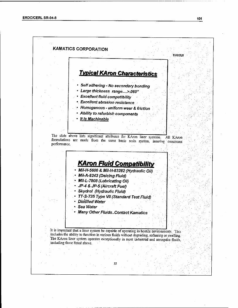
ERDC/CERL SR-04-8 101
KAMATICS CORPORATION KAMAN
Typical KAron Characteristic
Self adhering -No secondary bonding Large thickness range....>.060" Excellent fluid compatibility Excellent abrasion resistance Homogenous - uniform wear & friction Ability to refurbish components It is Machinable
The slide above lists significant attributes for KAron liner svstems. All KAron formulations are made from the same basic resin svstcm," insuring consistent performance.
KAron Fluid Compatibility Mil-H-5606 & Mil-H-83282 (Hydraulic Oil) Mil-A-8243 (Deicing Fluid) Mil-L-7808 (Lubricating Oil) JP-4 & JP-5 (Aircraft Fuel) Skydrol (Hydraulic Fluid) TT-S-735 Type VII (Standard Test Fluid) Distilled Water Sea Water Many Other Fluids..Contact Kamatics
It is important that a liner system be capable of operating in hostile environments. This includes the ability to function in various fluids without degrading, softening or swelling. The KAron liner system operates exceptionally in most industrial and aerospace fluids, including those listed above.
32

102 ERDC/CERL SR-04-8
KAMATICS CORPORATION BÄMäN
CUSTOMER CONDUCTED HUMtDTTY TESTING
Comparative Relative Humidity Effects on Self-Lube (PTFE) Bearings for Seven (7) Manufacturers
(A Minimum of 3 Bearings per Supplier)
Comparison Testing Shows Superior Results ofKamatics Karon Bearings
w>
MSU101-9 Size Spherical Bearing ('10 Size for Supplier CJ
. m.^B ,!'» -w 'M ^-'" ' *'
j j»Js<ssr Measurement
Main l&ty e iy>M tf«
»'> 0 » * t
Supplier* 48Houn
The results shown above were obtained from testing conducted by a major aerospace company. It clearly shows that the KAron liner system was affected the least of the seven suppliers submitting specimens.
Karo« V Coefficient of Friction vs. Temperature
*Sütntt>*ü £ &m&*3 ftfcdibfT Tfcsrf FoOxite*
The slide above offers typical coefficient of friction values for the KAron, V liner system at various temperatures and bearing pressures, tf information as to the coefficients of other KAron liners is required., contact a Kamaties representative at 860-243-9704
33

ERDC/CERL SR-04-8 103
KAMATICS CORPORATION KftMAN
Journal Bearing Comparison
»Wo Cmstenr FnctkitT
(Qrit&Emii)
'AtryT&f-cknesx ''
ßwjtfäwg Presste txmßgtaatioh affer foj&sitett.
The slide show above graphically depicts the difference in the manufacture of a KAron Imed journal bearing and that of a fabric lined journal bearing. It is readily apparent that a KAron lined bearing will.allow trouble-free installation and provide constant operatin« perfoimance TlMae is no the concern the realistic possibility of raised and/or fravcd liner edges to interfere with the shaft/pin installation. • '
fBheri0*1 Bearing Comparison
•rCMfwIMC&ity
Fabric
"#<? Consia«[ frte^WJ
'tfot 'Any TRfcteeas "
•8iMMK*g *M»*jiure RHfuirwi
K4ro/?
'Twxnte COM/O/ *00*MS&MH KrfctMff
♦Aft) »WS«« ÄKjtt&»tf
Similar to the slide above, this slide also depicts the differences in manufacture between a RAron lined spherical bearing and a fabric lined spherical bearma. '■The Kamatics cathedral cavity and no requirement for bonding pressure sets the KAron bearing apart
34

104 ERDC/CERL SR-04-8
KAMATICS CORPORATION KAMftN
Kamatics DaiaShcct 13!
HONING, MACHINING, CLEANING & MEASUREING KARON and KATIIERM
Honing: The following information is supplied as an aid in KARON or KATHERM honing operations- A honing machine, Sunnen or similar, should be used and the finished ID be sized with standard GO\NO-GQ plug gages. Tooling may be required to properly position the part being honed lo insuring alignment, squareness, and/or position. • Stone - Sunnen K6-A63 or K6-A65 or similar (280 grit medium hard atantaum oxide). • Speed - 300 tolOOO rpm, depending upon the diameter of the bushing being honed. • Coolant- Sunnen MB30 (oil base) or similar. After honing, ultrasonic clean the bushing in any of the cleaners noted below, to remove honing stone debris.
Machining: The following information is supplied as an aid in KARON or KATHERM machining operations. The finished ID should be sized with standard GO\NO-GO plug gages, Tooling may be required to properly position the location of the ID. • Inserts - Diamond inserts for best results, Carbide inserts acceptable. 0.030" nose radius minimum. • Speed - 1000 surface feet pet minute (300 meters per minute) minimum. • Depth of Cut - as required. • Feed Rate- 0.001/. 003 inches (0.025/0.075 mm) per revolution. • Coolant- water-soluble coolant (if necessary). Depending on size and the degree of accuracy reqtsired, special fixtures and/or holding devices may be required (as would be the case for machining any material). KAron is easily machined and therefore the use of a coolant is not necessary. The machining debris will be in the form of small chips and powder.
Cleaning: Cleaning of the Kamafics bearings can be accomplished with practically any normal factory cleaner or solvent. Obviously those that do not leave a undesirable residue are preferred. Suggested is Turco 4215 alkaline detergent followed with a fresh water rinse, or Citriklcen XPC citric based solvent followed with a methanol rinse. Nitrosol, alcohol, acetone, acid Tri-chlor 111 (when/if environmentally acceptable) can also be used. Avoid acids (hot or cold) and caustic "paint removers" as these can be a problem if left on the liner for an extended period of time (over 3 minutes).
Dimensional Inspection: Dimensional inspection of KAron and KAtberm lined surfaces requires special consideration. Because or the fibrous nature of the material and its hardness relative to metals, we suggest lie use of "GO-NO GO" gages when inspecting inside diameters. Light pressure on micrometer measurements on external surfaces readily measured with this type of instrument, should be used.
If conventional dial bore indicators are used, where there are several small pressure probes employed, it has been established that the reading on the gage should allow .00015 inches (0,0038 mm) for the probe penetration, into the liner.
For example, if the high limit dimension on an inside diameter is 1.0000 inches (25.40 mm), a "dial bore" reading of 1.0003 inches (25.40S mm) would be an acceptable reading. The low limit value would be similarly affected,
35

ERDC/CERL SR-04-8 105
KAMAT.CS CORPORATION ■■•' KJMMSI
■ Kamatics'Datasheet 134
'KAroQ®V Wear Strip" Product Data Sheet
Description:
Kamatics KAron® VWear Strip consists of standard KAron Grade V self-robricatwg 'bearing material
to medium duty rubbing pressure, or as a fretting resistant barrier.
Physical "Properties;*1* Coefficient of friction: .04-.OS
■ Oppressive strength: 30,000 psi (207 mPa) .Max dynamic load: 10,000 psi (69mPa) Max operating temp: 250°F 02O°C)
Available Sires:
Stodard KAron V Wear Strip material is available in cut sheets of 12" x 48" (305 x 1219 nun) 3/4" and I" (Item and 2».4iam) wide strips, wafers of various sizes, and custom die cm shapes. The natsrisl is available in two thicknesses: 5
KAron V Wear Strip Grade t Product Descrinti/m "KWS100 KWS200
Light Duty Wear Strip Mediiao Duty Wear Strip j .036" ± .003 (.91 mm a .073)
.018"±.003(At mm±.075)
Standard Part Numbering System: For standard rat strip dmfcnsion parts, Kamatics uses the following part numbering 'system:
■ ■ FWS00CO/77-.W-«* Where: M- Metric dimensions
^ tÄf^fi0, ^ T?100 = Light ^ Wear S,riP- -0lr <"46mm> n<>^ «Web«« i - 3/S (A5mm) pull tab included along edge (putl-tab allows for easy removal of oeel olv . backing) • r r J
yyy= Part width in 1/8" increments up to 12", i.e. 024 = 3" wide (Metric: 5mm increments up to 300mm, i.e. 020 = 100mm wide)
zzz = Part length in 1/4" increments up to "48", i.e. 096 - 24" long ."- ■, (Metric: 10mm increments tip to 1200mm, i.e. 050 = 500mm long)
Bonding Procedure: KAron V Wear Strip comes with a woven nylon peel-ply on the back of the fiberglass to protect the bonding surface from dirt: and debris. When the pull-tab (T) option is cdled out in the part number a 3/8" (9 Jmm) long breakaway tab will be provided for easy removal of the peel ply backing. With the peel-plv removed and the back surface exposed, the KAron V Wear Strip is prepared for bonding onto a suitable' surface. A room temperature curing structural epoxy adhesive «is recommended for bondine KAron V Wear Strip material.
Notes: "'■''. 1. Above reported values based on wear strip only: Physical properties in service will be largely
dependent upon the adhesive bond integrity, the substrate material, and surface preparation of the substrate.
2. Suggested structural adhesives: EA9460, EA9309, EA9394 (Dexter Hysol), Scotchweld 460 (3M Co) Araldite 2011 (Ciba Specialty Polymers).
36
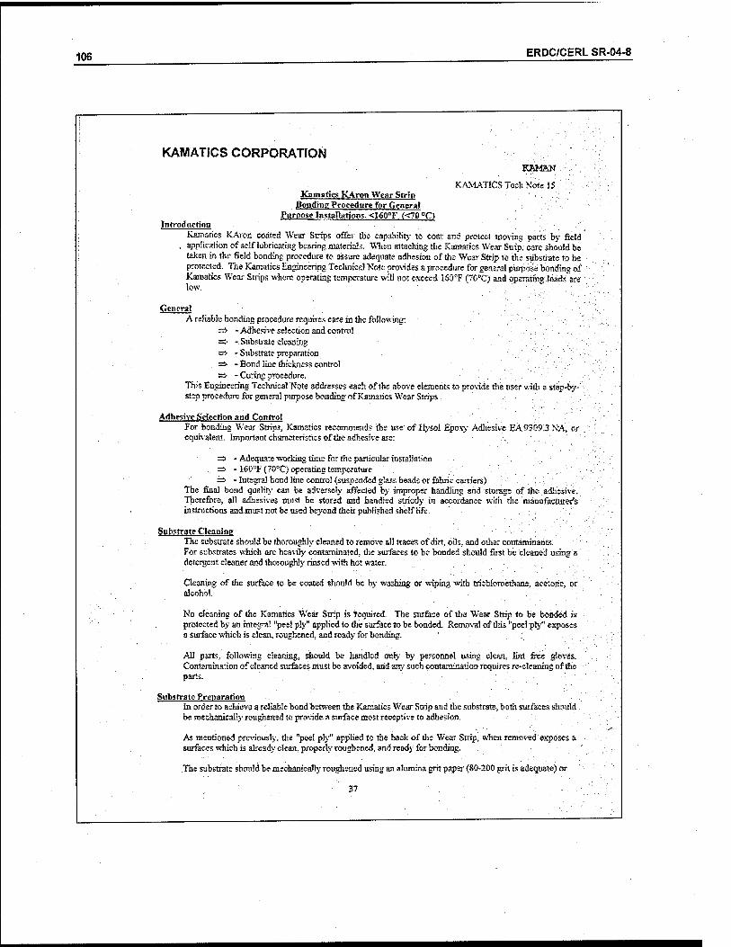
106 ERDC/CERL SR-04-8
KAMATICS CORPORATION KÄMAN ■
KAMATICS Tech Note 15 Kamatics KAron Wear Strin
Bonding Procedure for General Purpose Installation;, <I60°F «70 °C)
Introduction Kamatics KAron coated We» Strips offer the capability to coat and protect moving parts by field
, application of self lubricating bearing materials. When attaching the Kamatics Wear Strip, care should be taken in the field bonding procedure to assure adequate adhesion of the Wear Strip to the substrate to be protected. The Kamatics Engineering Technical Note provides a procedure for general purpose bonding of Kamatics Wear Strips where operating temperature will not exceed I60°F (70°C) and operating loads*"are low. , ', .*■' .
General A reliable bonding procedure requires care in the following:
=> -Adhesi%-e selection and control =s> -Substrate cleaning => - Substrate preparation => - Bond line thickness control => - Curing procedure,
This Engineering Technical "Note addresses each of the above elements to provide the user with a step-by- / step procedure for general purpose bonding of Kamatics Wear Strips .
Adhesive Selection and Control For bonding Wear Strips, Kamatics recommends the use of Hysol Epoxy Adhesive EÄ9309.3 NÄ, or equivalent. Important characteristics of the adhesive are:
=> - Adequate -working time for the particular installation =s> - 160T (70°C) operating temperature
.. => • Integra! bond line control (suspended glass beads or fabric carriers) The final bond quality can be adversely affected by improper handling and storage of the adhesive.' Therefore., all adhesives must be stored and handled strictly in accordance with the manufacturer's instructions and must not be used beyond their published shelf life.
Substrate Cleaning The substrate should be thorou^dy cleaned to remove all traces of dirt, oils, and other contaminants: For substrates which are heavily contaminated, the surfaces to be bonded should first be cleaned using a detergent cleaner and thoroughly rinsed -with hot water.
Cleaning of the surface to be coated should be by washing or wiping with trichioroethane, acetone,- or alcohol.
No cleaning of the Kamatics Wear Strip is required. The surface of the Wear Strip to be bonded i$ protected by an integral "peel ply" applied to the surface to be bonded. Removal of this "peel ply" exposes a surface which is clean, roughened, and ready for bonding.
All parts, following cleaning, should be handled only by personnel using clean, lint free gloves. Contamination of cleaned surfaces must be avoided, and any such contamination requires re-cleaning of the parts.
Substrate Preparation In order to achieve a reliable bond between the Kamatics Wear Strip and the substrate, both surfaces should. be mechanically roughened to provide a surface most receptive to adhesion.
As mentioned previously, the "peel ply" applied to the back of the Wear Strip, when removed exposes a surfaces which is already clean, properly roughened, and ready for bonding.
The substrate should be mechanically roughened using an alumina grit paper (80-200 grit is adequate) or
37
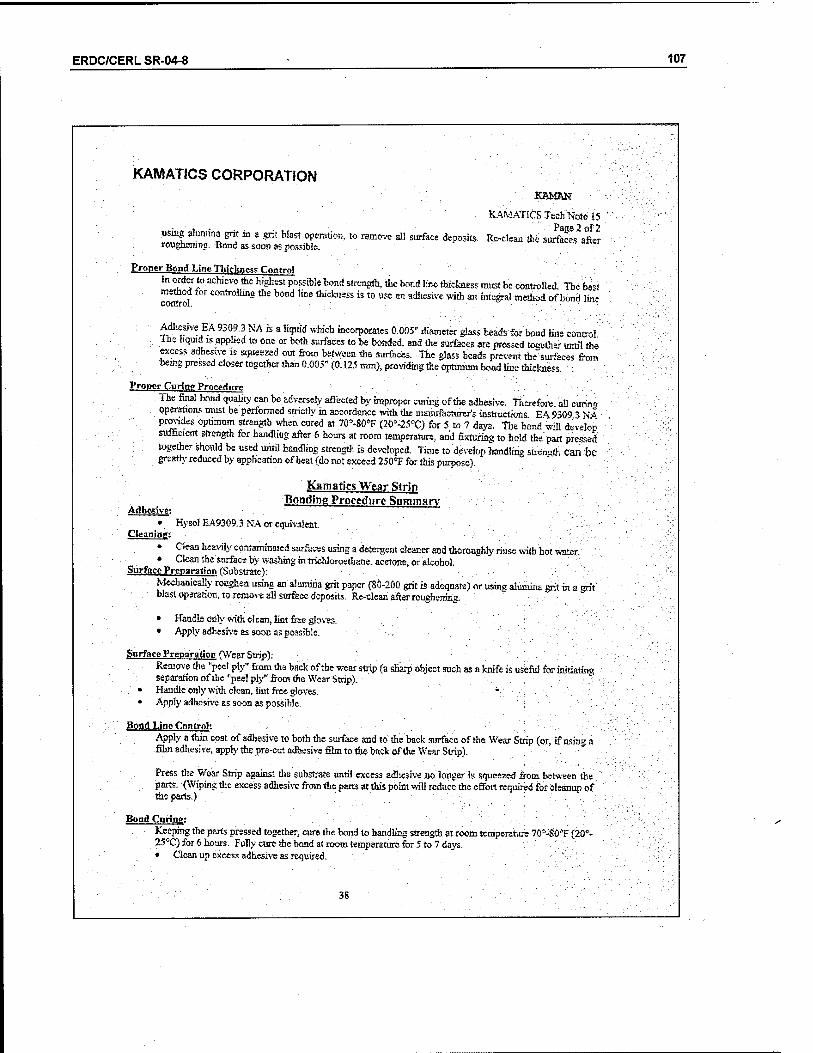
ERDC/CERL SR-04-8 107
KAMATICS CORPORATION
using alumina grit in a grit Wast operation, to remove all surface deposits roughening: Bond as soon as possible.
."■/: KäMM?
'KAMATICS Tech Note 15 ; Page 2.of2
Rc-clean the surfaces after
Proper Bond Line Thickness Control in order to achieve the highest possible bond strength, the bond line thickness must be controlled! ThVbest
SSrol C g *e b0"d !be thickness is «o «se =n adhesive with an integral method of bond line
Adhesive EA 9309.3 NA is a liquid which incorporates 0.005" diameter glass beads forbad line control ,. Lhe liquid is applied to one or both surfaces to be bonded, and the surfaces are pressed together until the
excess adhesive'« squeezed out from between the surfaces. The glass beads prevent the surfaces from being pressed closer together than 0.005" (0. .125 mm), providing the optimum bond line thickness. : :
Proper Curing Procedure
The final bond quality can be adversely affected by improper curing of the adhesive. Therefore, all curing operations must be.performed strictly in accordance with the manufacturer's instructions EA9309 3NA provides optimum strength when cured at 70"-80'F (20'-25°C) for 5 to 7 days'. The bond will develop sufficient strength for handling after 6 hours at room temperature, and ■'featuring to hold the part pressed together should be used until handling strength is developed. Time to 'develop handling stasratfh can be greatly reduced by application of heat (do not exceed 250<T for this purpose),
Adhesive:
Cleaning;
Kama tics Wear Strip Bonding Procedure Summary
Hysol EA9309.3 NA or equivalent
• Clean heavily contaminated surfaces using a detergent cleaner and thoroughly rinse with hot waten • Clean the surface by washing in trichloroetbane, acetone, or alcohol.
Surface Preparation f Substrate'): Mechanically roughen using an alumina grit paper (80-200 grit.'is adequate) or uring alumina tyit in a grit
: blast operation, to remove all surface deposits. Re-clean after roughening, :: .■*
• Handle orily with clean, lint free gloves. • Apply adhesive as soon as possible.
Surface Preparation (Wear StripV . ■ ■ ■ Remove the "peel ply" from the bade of the wear strip (a sharp object such as a knife is useful for initiating
separation of the "pee! ply" from the Wear Strip). ■ ■.-'■• Handle only with clean, lint free gloves. - '■'■'■;;
* Apply adhesive as soon as possible.
Bond Line Control: Apply a thin coat of adhesive to both the surface and tothe back surface of the Wear Strip (or, if using ä'■ film adhesive, apply the pre-cut adhesive film to the back of die Wear Strip).
Press the Wear Strip against the substrate until excess adhesive no longer is squeezed from between the . parts. (Wiping the excess adhesive from the parts at tbispoktwill reduce the effort required for cleanup of
the parts.) "
Band Curing: Keeping the parts pressed together, cure the bond to handling strength at room temperature 7G°-§0°F (20°- 25°C) for 6 hours. Fully cure the bond at room temperature for 5 to 7 days.
. • Clean up excess adhesive as required.
38
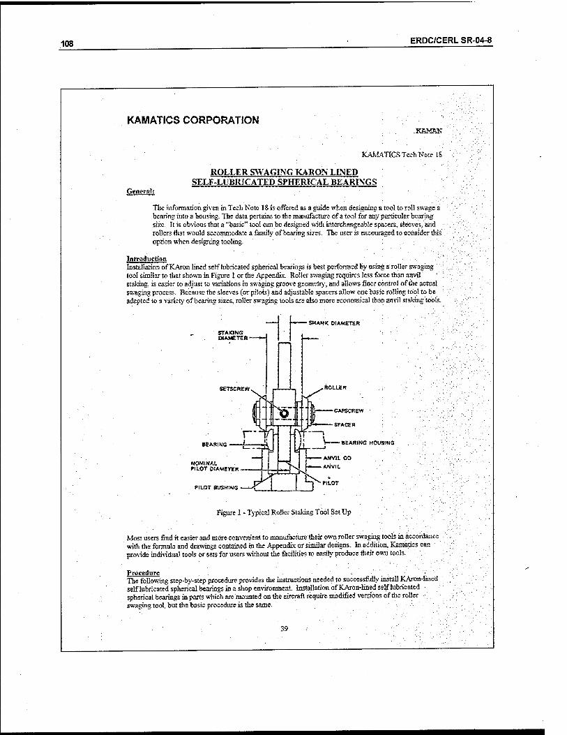
108 ERDC/CERL SR-04-8
KAMATICS CORPORATION KÄMAN
KAMATICS Tech Note IS
ROLLER SWAGING KARON LINED SELF-LUBRICATED SPHERICAL BEARINGS
General:
The information given in Tech Note 18 is offered as a guide when designing 8 tool to roll swags a bearing into a housing. The data pertains to the manufacture of a too! for any particular bearing size. It is obvious that a "basic" tool can be designed with interchangeable spacers, sleeves, and rollers that would accommodate a family of bearing sizes. The user is encouraged to consider this option when designing tooling.
Introduction Installation of KAron lined self lubricated spherical bearings is best performed by using a roller swaging tool similar to that shown in Figure 1 or the Appendix. Roller swaging requires less force than anvil staking, is easier to adjust to variations in swaging groove geometry, and allows finer control of the actual swaging process. Because the sleeves (or pilots) and adjustable spacers allow one basic rolling too! to be adapted to a variety of bearing sizes, roller swaging tools are also more economical than anvil staking tools
SHAN« OlAMETE«
BSARINO
NOMINAL «LOT DIAMETER
PILOT BUSHING
BEARING HOUSING
Figure 1 - Typical Roller Staking Tool Set Up
Most users find it easier and more convenient to manufacture their own roUer swaging tools in accordance with the formula and drawings contained in the Appendix or similar designs. In addition, Kamatics can provide individual tools or sets for users without the facilities to easily produce their own tools.
Procedure The following step-by-step procedure provides the instructions needed to successfully install KAron-lincd self lubricated spherical bearings in a shop environment Installation of KAron-lined self lubricated spherical bearings in parts which are mounted on the aircraft require modified versions of the roller swaging tool, but the basic procedure is the same.
39

ERDC/CERL SR-04-8 109
W
(2)
KAMATICS CORPORATION : KÄMÄN
".■■■-■:,: KAMATICSTechNote 18 She« 2 of 4';
Ü?wTT tn ml S^r* * quffl *ametar of no£ tess *** 2 toch«-md Karins ftat will give not less than200 pounds offeree at the chuck with usual operator inpH. Set the drill press for
beaSS" ^ for ' I"nCh °r Sim"er b0W diameters>OT Proportionately slower for larger
Set the rollers of die swaging tool to agree with the diameter of the bearing swage groove The' :
tT^T*™ K 'nSidC Ed8eS °f **"*"* Sh0u,d bc -005-01 °" 1«^» than the diameter of d» center ofthe groove, as a sta^g point Tighten all the parts, making sure ^ r0Uers ^ freelv, Tb« St ofthe pilot m the gwdes of Üiepri Dlßairtg, ■
(3) Install the swaging too! in the chuck ofthe drill press.
(4) Apply die specified installation finish (primer, sealant, etc.) to the ID of the housins and the OD of the bearing, ~ '..-;". '
; (5) fastall the bearkig centered in housing. MakesuretheonterraceofthebearingisflttshtoOOlO meh above the housing surface, or as specified on. the installation drawing. ;
(6) Apply a dim layer ofgeneral purpose grease to theswaging groove to prevent gaflihe Trvnottolet the grease get on the KLAron surfaces ofthe inner race
CAUTION:
m 0)
MINIMIZE THE AMOUNT OF GREASE OR OTHER LUBRICANTS WHICH MIGHT GET INTO KARON-LINED BEARINGS. LUBRICANTS CAN COLLECT' CONTAMINATION AND THUS SHOULD BE AVOIDED. \ ■<:■■■"■',
Set the surface to be swaged perpendicular to the axis of the spindle.
Swage the first side of until the lip is swaged out into the swasring groove. Inspect the swaging lip to insure that sufficient swagkg has occurred. There should be less than .005" gap between the outside of the hp «d the housing, which can be checked with a wire feeler gage. Ifthe lip has nofswaged over adequately after two attempts, increase the distance between the inside edges ofthe rollers an additional .005" and re-swage. "■■'.■'..:
(9) Turn the assembly over and swage the second side.
NOTE;
(10)
(12)
(13)
Do not let the rollers touch the bottom or the inner face ofthe swaging groove in the bearing outer race. This can cause binding of the bearing to the extent that the ball cannot be turned in the housing, i
Clean the lubricant from the bearing with a rag wet with a small amount of methyl ethyl ketone, acetone, or similar solvent Protect the inner race from the solvent and all lubricants.
(11) Examine the swaged lip for clearance and galling. Gall marks should be avoided, and is caused when the rollers did not turn or the roller lubrication was insufficient. The stake is completed when the swaged lip touches the housing chamfer and the gap at the outer edge is less than .005". Unless specified by the overhaul instructions, the no-load breakaway torque of an installed KAron- hned spherical bearing must not be more than two times the uninstalled maximum breakaway torque specified in the bearing specification or standard.
(14) If required, give the bearing a push-out load test Apply the load only to the outer race. The bearing must not move in the housing or come loose.
DIMENSIONS FOR ROLLER SUPPORT. A DIA = AS REQ TO FIT DRILL OR MILL CHUCK (BEARING I.D. MIN) B DIA = SLIP FITIN BEARING I.D.(PRESS FIT ON SUPPORT) C MIN = (BALL WIDTH - RACE WIDTHS + MAX BRG GROOVE DEPTH ■*• .020
40 •"■■■..'■■"

110 ERDC/CERL SR-04-8
KAMATICS CORPORATION KAMAN
KAMATICS Tech Note 18 Slieet 3 of «1
C MAX = C MIN + .005 D DIA = B-.06 (PRESS FIT WITH SLEEVE I.D.) E MIN = NOMINAL BOLT DIA E MAX «E MIN+ .010 F MIN « C MAX + E MAX {2 ROLLERS REQUIRED, O.D. MUST BE WITHIN O01 OF EACH
OTHER} F MAX = F MIN+ .010 G MIN = MAX'BRG GROOVE DIA + .005 G MAX = GMIN+ .005 H DIA = SLIP FIT MTH BOLT DIA L MIN - C + (1.5 x BRG BALL WIDTH) L MAX = L MIN + .030 WMAX = GMIN - .06 (ALLOWS 2 .030 THICK SPACERS) SEE NÖTE 3
DIMENSIONS FOR ROLLER BASE J MIN = MAX BRG I.D.+ .005 J MAX = J MIN +.005 K MIN = GMIN K MAX = MIN BRG O.D. M MIN = SUGGEST ] .00 MIN (TO SUIT USER EQUIPMENT) N MIN = {(BRG BALL WIDTH - RACE WIDTH)/2) + .030 N MAX = N MIN+ .030
: P MIN = (2 x V(BRGB ALLDImf @(RACE WIDTHS)*) + .020 P MAX = P MIN+ .010 R MIN = K MAX + .25 (MAX = TO SUIT CUSTOMERS EQUIPMENT)
NOTES;
1. REFER TO MIL-STD-1595 REQUIREMENT 202, PARA.6 FOR INSTALLATION AND SUBSEQUENT INSPECTION OF INSTALLED BEARINGS.
2. ASSEMBLE NUT AND BOLT AS SHOWN. TIGHTEN THE NUT SUCH THAT THERE IS APPROXIMATELY .005* LOOSENESS TO ALLOW THE ROLLERS TO ROTATE WITHOUT CATCH OR BINDING.
3. SPACER THICKNESS *AS REQUIRED TO OBTAIN PROPER WIDTH TO MATCH DIM. "G" (BEARING GROOVE DIAMETER). THE SUPPORT CAN BE MANUFACTURED WITHOUT THE NEED FOR SPACERS BUT THE TOOL IS THEN LIMITED TO THAT ONE SIZE UNLESS MODIFIED LATER.
4. THE UNDERCUT IS NOT MANDATORY BUT THE POTENTIAL FOR INTERFERENCE WITH MATING HOUSING WILL EXIST.
ROLL SWAGING TOOL - MATERIAL
ROLLER SUPPORT-STEEL Jlc40 MIN ROLLER (2) - TOOL STEEL.RC55 MIN SLEEVE- ACETAL RESIN., PTFE, NYLON. ETC SPACER (AS NEEDED, 2 MIN)-ST£ELitc25 MIN BOLT- .250 DJA.CLOSE TOLERANCE. HARDENED (Rc35 MIN) (SUGGESTED) NUT-.250 THREAD (SELF-LOCKING SUGGESTED) ROLLER BASE-STEEL,Rc40 MIN
41
ERDC/CERL SR-04-8 111
Attachment 1: Powertech Report on Scale Model Testing of Navigation Lock Pintle Self-Lubricating Bushings for USACE
POWERTECH LABS INC.
Project Report
SCALE MODEL TESTING OF NAVIGATION LOCK PEVTLE
BUSHINGS FOR CORPS OF ENGINEERS Project: 13608-36-00
August 2003
Prepared for: Dr. L. David Stephenson
ERDC-CERL
Keywords: Self-lubricating bushings, pintles, navigation locks
Prepared by:
R. A. Palylyk Sr. Project Specialist II Materials Engineering
Approved by:
Avaral Rao Director Materials Engineering

Scale Model Testing of Navigation Lock ' Pintle Bushines-Additional Tests . Powertech Labs, Inc.
TABLE OF CONTENTS
Page
1.0 INTRODUCTION 4
2.0 OBJECTIVE AND WORK PROGRAM 4
2.1 Tasks 4
2.1.1 Task 1: Scale Model Test Frame 4 2.1.2 Task 2: Scale Model Pintle/bushing Combinations 4 2.1.3 Test Conditions - Loading and Operating Rate 5
3.0 SCALE MODEL ASSEMBLY • 5
4.0 INSTRUMENTATION 6
5.0 TEST PINTLES AND BUSHINGS 6 5.1 Bushing Test Sleeves 6
5.2 Bushing Requirements 6
6.0 TEST RESULTS 7
6.1 ThordonHPSXL 7
6.2 Kamatics KAron V 7
6.3 TenmatT814 (retaining collar type) 7
7.0 DISCUSSION • 9
8.0 CONCLUSIONS 9
APPENDIX A MODEL CONSTRUCTION AND ASSEMBLY 11 APPENDIX B THORDON HPSXL TEST RESULTS 17 APPENDIX C KAMATICS KARON V SELF-LUBRICATING BUSHINGS/PINTLE TEST 29 APPENDIX D TENMAT SELF-LUBRICATING BUSHING (RETAINING COLLAR) TEST
RESULTS 41
This project report shall not be reproduced, except in full, without the written approval of Powertech Labs, Inc. Project: 13608-36 14-Aug-03 Page 2
Scale Model Testing of Navigation Lock Pintle Bushines-Additional Tests Powertech Labs, Inc.
LIST OF FIGURES
Page Figure Al: Schematic overview of scale model pintle bearing test frame 12 Figure A2: Location of displacement transducers for wear measurements 13 Figure A3: Location of torque transducer for measuring frictional load 14 Figure A4: Top and bottom actuators assembly 14 Figure A5: Overview of test set-up 15 Figure A6: Close-up view of 6" pintle side 15 Figure A7: Close-up view of 5" pintle side 16 Figure Bl: Close-up view 5" pintle contact side. There is marked scoring towards stepped edge
of the pintle 19 Figure B2: Thordon HPSXL 5" pintle bushing 20 Figure B3: Close-up view of loaded side of bushing. Note accumulated wear debris 20 Figure B4: Pintle bearing tests 5" pintle/bushing coefficient of friction.. 21 Figure B5: Pintle bearing tests 5" pintle/bushing wear 22 Figure B6: Pintle bearing tests 5" pintle/bushing wear and temperature 23 Figure B7: Overview of Thordon HPSXL 6" pintle. Note staining of pintle on loaded side 24 Figure B8: Close-up view of Thordon HPSXL 6" pintle bushing. Primary contact area is at top
of image 24 Figure B9: Close-up view above image on loaded side. Note accumulation of wear debris above
darker contact area 25 Figure BIO: Pintle bearing tests 6" pintle/bushing coefficient of friction 26 Figure Bll: Pintle bearing tests 6" pintle/bushing wear 27 Figure B12: Pintle bearing tests 6" pintle/bushing wear and temperature 28 Figure Cl: Close-up view of 5" pintle from Kamatics KAron V test 31 Figure C2: Close-up view of 5" KAron V bushing. Note uniform polished contact areas 31 Figure C3: Close-up view of 5" KAron V bushing. Note highly polished contact area. There is
no indication of stress to the lubricant layer 32 Figure C4: Pintle bearing tests 5" pintle/bushing coefficient of friction 33 Figure C5: Pintle bearing tests 5" pintle/bushing wear 34 Figure C6: Pintle bearing tests 5" pintle/bushing wear and temperature 35 Figure C7: View of 6" Kamatics KAron V pintle 36 Figure C8: View of Kamatics KAron V bushing. Note dark band, which is next to top edge.
This is the pintle contact area 37 Figure C9: Close-up view of above image on loaded side. Note polished contact area. There
does not appear to be any stress to this area 37 Figure CIO: Pintle bearing tests 6" pintle/bushing coefficient of friction 38 Figure Cll: Pintle bearing tests 6" pintle/bushing wear 39 Figure C12: Pintle bearing tests 6" pintle/bushing wear and temperature 40 Figure Dl: Overview of 5" Tenmat T814 pintle. Due to the thickness of the bushing-retaining
ring, the first row of pintle anchoring holes had to be machined away 43 Figure D2: Close-up view of 5" Tenmat T814 bushing 44 Figure D3: Close-up view of Tenmat T814 5" bushing. Note darker contact areas 44 Figure D4: Pintle bearing tests 5" pintle/bushing coefficient of friction 45 Figure D5: Pintle bearing tests 5" pintle/bushing wear 46 Figure D6: Pintle bearing tests 5" pintle/bushing wear and temperature 47 Figure D7: Overview of 6" T814 pintle. Note transferred lubricant material on side of pintle
contact surface 48 Figure D8: Close-up view 6" bushing. There is no indication damage to the bushing. Contact is
over 95% of the bushing surface 49 Figure D9: Pintle bearing tests 6" pintle/bushing coefficient of friction 50 Figure D10: Pintle bearing tests 6" pintle/bushing wear 51 Figure Dll: Pintle bearing tests 6" pintle/bushing wear and temperature : 52
This project report shall not be reproduced, except in full, without the written approval of Powertech Labs, Inc. Project: 13608-36 14-Aug-03 Page 3

Scale Model Testing of Navigation Lock Pintle Bushines-Additional Tests . Powertech Labs, Inc.
INTRODUCTION
The U.S. Army Engineering Research and Development Center-Construction Engineering Research Laboratory (ERDC-CERL) had contracted Powertech Labs Inc. to perform scale model accelerated wear tests of navigation lock pintles and pintle lubricating methods for the Panama Canal Authority (Project 13568-36-00). Powertech designed and built a scale model (1/4-scale) test frame to perform accelerated wear tests of existing pintle bushing configurations, which would be benchmark refer- ences, and on alternative self-lubricating pintle bushings, in a simulated brackish Panama Canal water environment.
CERL contracted Powertech Labs Inc. to perform additional pintle bushing tests following the same format as the Panama Canal tests with two differences: (1) silt laden river water was used instead of brackish water; (2) the horizontal loadings and vertical loadings on the quarter-scale model pintle were 870.9 psi. and 665.8 psi, respectively.
The following is a report of the test results on three bushing materials tested for the Corps of Engineers navigation lock gates.
OBJECTIVE AND WORK PROGRAM
The objective was to simulate the mechanical and environmental stresses of a typical Corps of Engi- neers lock miter gate pintle over its anticipated service life of 200,000 cycles.
Accelerated testing and analysis was conducted on 6 lock gate pintle/bushing assemblies, constructed to V* scale, placed in brackish water. Two of the test sets simulated the existing configuration, while a third set used a self-lubricating composite material. It was anticipated that each test would require ap- proximately 35 days of testing time to complete the tasks described below.
TASKS
Task 1: Scale Model Test Frame
A device was designed and constructed to test the 6 scale model pintle/bushing assemblies that would be built in Task 2. Three of the assemblies were to be 5 inches in diameter and the other three were to be 6 inches in diameter. These pintle/bushing assemblies were % of the ac- tual size of typical Corps of Engineer lock gate pintles. Instrumentation was incorporated to monitor pintle rotation for torque and from this data a value for the coefficient of friction every four (4) hours. Wear was to be monitored on a continuous basis with eddy current probes for both the vertical and horizontal directions. Bushing temperature was monitored ad- jacent to the loaded contact surface. All data was recorded with a data logger and a personal computer.
Task 2: Scale Model Pintle/bushing Combinations
Three scale model pintle/bushing assemblies, each 5 inches in diameter, and three scale model pintle/bushing assemblies, each 6 inches in diameter, were designed and constructed. All the scale model pintles were made of 316 stainless steel (ASTM A473) with a 16 RMS finish. The bushings were self-lubricating products from three different manufacturers. The pintles and bushings were assembled and tested in silt laden river water to simulate typical conditions found in Corps projects. The water, for these tests was taken directly from the Fräser River across from the city of New Westminster, BC.
This project report shall not be reproduced, except infill, without the written approval of Powertech Labs, Inc. Project: 13608-36 14-Aug-03 Page 4
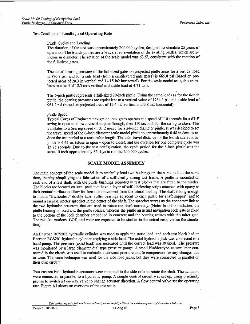
Scale Mode! Testing of Navigation Lock Pintle Bushines - Additional Tests Powertech Labs, Inc.
Test Conditions - Loading and Operating Rate
Pintle Cycles and Loading The duration of the test was approximately 200,000 cycles, designed to simulate 25 years of operation. The 6-inch pintles are a % scale representation of the existing pintles, which are 24 inches in diameter. The rotation of the scale model was 63.5°, consistent with the rotation of the full-sized gates.
The actual bearing pressure of the full-sized gates on projected pintle areas for a vertical load is 870.9 psi, and for a side load (from a cantilevered gate mass) is 665.8 psi (based on pro- jected areas of 28.3 in vertical and 14.15 in2 horizontal). For the scale model tests, this trans- lates to a load of 12.3 tons vertical and a side load of 4.71 tons.
The 5-inch pintle represents a full-sized 20-inch pintle. Using the same loads as for the 6-inch pintle, the bearing pressures are equivalent to a vertical value of 1254.1 psi and a side load of 961.2 psi (based on projected areas of 19.6 in2 vertical and 9.8 in2 horizontal).
Pintle Speed Typical Corps of Engineers navigation lock gates operate at a speed of 110 seconds for a 63.5° swing to open to allow a vessel to pass through, then 110 seconds for the swing to close. This translates to a bearing speed of 0.12 in/sec for a 24-inch diameter pintle. It was decided to set the travel speed of the 6-inch diameter scale model pintle to approximately 0.48 in./sec. to re- duce the test period to a reasonable length. The total travel distance for the 6-inch scale model pintle is 6.65 in. (close to open - open to close), and the duration for one complete cycle was 13.75 seconds. Due to the test configuration, the cycle period for the 5-inch pintle was the same. It took approximately 35 days to run the 200,000 cycles.
SCALE MODEL ASSEMBLY
The main concept of the scale model is to statically load two bushings on the same axis at the same time, thereby simplifying the fabrication of a sufficiently strong test frame. A pintle is mounted on each end of a test shaft, with the pintle bushings mounted in test blocks that are fitted to the pintles. The blocks are located on steel pads that have a layer of self-lubricating strips attached with epoxy to their contact surface to allow for free side movement from the lateral loading. The shaft is long enough to mount "frictionless" double taper roller bearings adjacent to each pintle for shaft support, and to mount a large diameter sprocket in the center of the shaft. The sprocket serves as the connector link to the two hydraulic actuators that are used to rotate the shaft correctly. (Note: In this simulation, the pintle bearing is fixed and the pintle rotates, whereas the pintle an actual navigation lock gate is fixed to the bottom of the lock chamber embedded in concrete and the bearing rotates with the miter gate. The relative motions, COF, and wear are expected to be similar in the actual case, versus the simula- tion).
An Enerpac RCS502 hydraulic cylinder was used to apply the static load, and each test block had an Enerpac RCS201 hydraulic cylinder applying a side load. The axial hydraulic jack was connected to a hand pump. The pressure (axial load) was increased until the correct load was attained. The pressure was monitored by a large diameter dial type pressure gauge. A small bladder-type accumulator con- nected in the circuit was used to maintain a constant pressure and to compensate for any changes due to wear. The same technique was used for the side load jacks, but they were connected in parallel on their own circuit.
Two custom-built hydraulic actuators were mounted to the side rails to rotate the shaft. The actuators were connected in parallel to a hydraulic pump. A simple control circuit was set up, using proximity probes to switch a two-way valve to change actuator direction. A flow control valve set the operating rate. Figure Al shows an overview of the test setup.
This project report shall not be reproduced, except in fit!!, without the written approval of Powertech Labs, Inc. Project: 13608-36 14-Aug-03 Page 5

Scale Model Testing of Navigation Lock Pintle Bushines - Additional Tests Powertech Labs, Inc.
A critical part of the test environment was to simulate immersing the pintle/bushing combination in brackish water. Powertech's Applied Chemistry Unit prepared the brackish water, and its oxygen con- tent was maintained by bubbling dry nitrogen through the water reservoir until the required level was reached. The oxygen level was measured with an Oakton Dissolved Oxygen Series DO 300 meter. Tanks were built around the test block and shaft, and the brackish water was pumped into the tanks from a main reservoir. A cooling coil was installed in the reservoir to maintain the water at the correct temperature.
Appendix A shows details of the scale model.
INSTRUMENTATION
The test program required monitoring of three critical parameters: frictional load, wear and tempera- ture.
Frictional load values were derived from the output of the strain gauges that measured shaft torque at each pintle (on the inside of the support bearings - Figure A3). There were two torque outputs, one for each pintle. A Vishay 2100 strain amplifier was used to monitor the torque output. Each torque chan- nel was calibrated in a special test frame.
Wear was monitored with Dymac eddy current probes and drivers. The axial probes were mounted on the top of the test block to measure the gap between the block and a plate mounted on the shaft (Fig- ures A2 and A6). The lateral or side load wear probes were mounted on the support plate to measure the gap between the test block and the static probe mount (Figures A2 and A6).
Bushing temperature was measured by a thermocouple mounted in a drill hole on the loaded side of the bushing. The hole was drilled at an angle such that the bottom was close to the bushing's internal edge.
All voltage outputs were connected to an Agilent 34970A Data Acquisition/Switch Unit linked to a desktop computer. On the first day of testing, data were logged hourly. For the remainder of the test, data were logged once every four hours.
TEST PINTLES AND BUSHINGS
The test pintles and bushing were installed as described below:
Bushing Test Sleeves Radius Material Hardness Surface finish Pintle replacement
2.500/2.499 inches and 3.000/2.999 inches 316 stainless steel, ASTM A473 RB = 83 16 RMS finish A new test pintle was used for each test
Bushing Requirements Specifications were given to the suppliers that the self-lubricating test bushings should have a mini- mum clearance of approximately O.OOOin/0.001 in and no grooving.
TEST SET
1
TESTA (6-inch scale model pintle-bushing) Thordon HPSXL Kamatics KAron V TENMATT814 (retaining collar)
TESTB (5-inch scale model pintle-bushing)
Thordon HPSXL Kamatics KAron V TENMAT T814 (retaining collar type)
This project report shall not be reproduced, except in full, without the written approval of Powertech Labs, Inc. Project: 13608-36 14-Aug-03 Page 6

Scale Model Testing of Navigation Lock Pintle Bushines - Additional Tests Powertech Labs, Inc.
TEST RESULTS
Thordon HPSXL The Thordon HPSXL bushings started the test with significant audible noise (vibration). Relatively high friction levels contributed to this vibration (Figures B4 and B9). This vibration decreased as the test proceeded and disappeared by the 50,000 cycle point along with lower friction levels and lower temperatures.
The bushings and pintles survived the test regime; the self-lubricating HPSXL was intact and contin- ued to function. However, both bushings (more so with the five (5) inch bushing) had bands of built up wear debris. These bands were forming into clumps and beneath the clumps the lubricant layer was showing signs of breaking down (Figure B3). The six (6) inch bushing just started showing the signs of clumping of the wear debris. Direct wear measurements on both sides indicate initial seating in period of approximately 50,000 cycles. This is most likely a combination of the HPSXL and the degree of fit to the pintle profile. The five (5) inch bushing had, at the end of the test, an approximate 80-90% fit (contact) to the pintle. The six (6) inch bushing is estimated to have about a 30-40% contact fit to the pintle at the end of the test.
The five (5) inch pintle, due to the greater contact was coated with transferred lubricant material. The location where the debris was clumping left some scoring. The six (6) inch pintle was coated in the small areas where there was contact with the bushing.
In general, there was high friction at the start of the test reducing down to a lower constant level by mid point. Direct wear, after seating in, was not significant in either direction (axial and lateral) (Table
D-
By the end of the test, both bushings were showing signs of lubricant layer breakdown as evidenced by the clumping of the wear debris.
Kamatics Karon V The Kamatics Karon V started at a relatively high friction level but rapidly dropped down to much lower levels (< 0.1)within the first 20,000 cycles (Figures C4 and C10). They functioned quietly and smoothly without any apparent stress. Direct wear measurements indicated little wear taking place other than from the initial seating in period. Where the pintles contacted the bushings, they were coated with transferred lubricant material.
The six (6) inch bushing direct wear did not appear to seat in. After the initial wearing in period, and possibly due to the small contact area, there was a constant indicated increase in the direct wear meas- urement suggesting a wear rate. It appears this maybe a combination of seating in and wearing taking place. This did not occur with the five (5) inch bushing and could be an artifact of the lower per unit bearing load. Table 2 provides details of the friction and wear levels.
The Kamatics Karon V bushings performed well in the tests. This performance was good despite the fact the contact areas in both bushings were small. This self-lubricating material is tolerant of high bearing loads (small contact area). This lubricant layer is thin and can accommodate minor deforma- tion for seating the pintle. However, a different protocol may be necessary (such as different bushing radii) to permit more contact with the pintle.
Tenmat T814 (retaining collar type) The Tenmat T814 bushings did not operate at the designated static axial load. The dial gauge used to monitor the pressure was found to be reading higher than actual values by 10 %. The friction values have been corrected for this reduced axial load. The bushings have survived the tests without any ap- parent damage. In general, the five (5) inch pintle/bushing operated quietly with little apparent vibra-
This project report shall not be reproduced, except in full, -without the written approval of Powertech Labs, Inc. Project: 13608-36 14-Aug-03 Page 7

Scale Model Testing of Navigation Lock Pintle Bushines - Additional Tests Powertech Labs, Inc.
tion (low friction levels throughout the test). The six (6) inch pintle/bushing combination started with relatively high friction levels as evidenced by audible noise and vibration. This continued for approxi- mately 115,000 cycles. After this break-in period the friction levels and temperatures dropped along with reduced noise levels.
The direct wear measurements on the five (5) inch bushing indicated little wear taking place from side loading. The axial load indicated a net wear of approximately 0.5 mils. The six (6) inch had performed somewhat differently. After the 115,000 cycle point, friction started to increase and at the same time the axial wear also increased. At approximately the 167,000 cycle point, the side load direct wear sud- denly jumped to a lower value (dropped 3 mils), this suggests the pintle may be seating in possibly due to wear material shifting around in the interface. The amount of transferred lubricant material and the black colour on the pintle edge (Figure D7) suggests a major event had occurred. The texture of this dark area is unlike the five (5) inch pintle. The dark colour also suggests heating is occurring. The amount of lubricant film was sufficient to appear to be smeared over the pintle surface and thick enough to not be able to see the pintle surface.
These are the only self-lubricating bushings, which due to their wall thickness and resilient properties, had virtually 100 % contact on the pintles.
Table 1 Summary of Test Results - Five (5) inch
«4-» CO
I2.
Sta
tic C
OF
(Ste
ady
Sta
te)
Dyn
amic
CO
F (S
tead
y S
tate
)
Sea
ting
In D
ispl
ace-
m
ent -
Axi
al (
mils
)
Tota
l D
irect
-A
xial
Wea
r (a
fter
seat
ing
in)
(mils
)
Sea
ting
In D
ispl
ace-
m
ent -
Sid
e (m
ils)
Tota
l D
irect
-S
ide
W
ear
(afte
r se
atin
g in
) (m
ils)
Thordon HPSXL 0.10 0.075 2.5 0.8 0 0
Kamatics Karon V 0.07 0.05 2.25 0.45 0 -0.25
TenmatT814 (retaining collar)
0.11 0.065 -0.5 0.5 2.6 0.1
Table 2 Summary of Test Results - Six (6) inch
CO
F (S
tead
y ,
täte
)
o .55. "en
i O) o
OF
(Ste
a tä
te)
In D
ispl
a t -
Axi
al
mils
)
irect
-A
x er
sea
tin
mils
)
In D
ispl
a t -
Sid
e
mils
)
irect
-S
i er
sea
tin
mils
)
o w E B E
to
B tr O) d) B E
□ 0= *-' _ to to —'
to to to o to to O to *H c tD h- tD Q) H tD CO
Q CO 1 CO 5
Thordon HPSXL 0.13 0.11 3.5 0.9 0 1.0
Kamatics Karon V 0.135 0.125 -0.5 1.0 0 0
TenmatT814 0.16 0.135 -4.5 5.0 5.5 -3.0* (retaining collar)
* Anomaly in the test results as the side wear dropped suddenly possibly due to material shift or test setup shift.
Project: 13608-36
This protect report shall not be reproduced, except in full, without the written approval of Powertech Labs, uns.afi 14-Aue-03
Inc. 14-Aug-03 Page 8

Scale Model Testing of Navigation Lock Pintle Bushinss - Additional Tests Powertech Labs, Inc.
The COF values were derived from the last half of the test period, when friction was stable and no drastic changes occurred
DISCUSSION
Coefficients of friction and direct wear measurements methodology were discussed in the Powertech Lab Inc. Report 13568-36-00 "Scale Model Testing of Navigation Lock Pintle Bushings". However, the testing of these self-lubricating materials has introduced a set of different criteria to assess the vari- ous products performance.
All three products essentially survived the tests using silt laden river water as the test medium. First of all, two of the products, Thordon HPSXL and Kamatic Karon V, have thin lubricant layers bonded to a metallic backing. Tenmat T814 is a much thicker material. The Tenmat T814 generated almost one hundred percent (100%) contact to the pintle surface. The other two materials had contact areas (physical change to the bushing surface from the pintle contact) ranging from approximately twenty percent (20%) to eighty percent (80%). The difference is due to the Tenmat T814 being able to allow some flexing to shape to the pintle. The other two products have limited flexing to shape to the pintle surface.
Thus, the smaller the contact area, the greater the unit loading on the bushing. In the case of the Thor- don HPSXL and Kamatics Karon V, the pintles were contacting the bushing edges initially instead of a more uniform contact. This makes it difficult to assign a wear rate to the bushings as both wear and seating into the bushings are simultaneously taking place in a manner unique to the individual pintle/bushing combination (slight but significant differences in pintle/bushing radii). It is estimated the pintle/bushing should have at least a ninety percent (90%) contact area to generate a measured wear rate. Wear rates and even total displacement should not be used as part of the comparison criteria as it appears each pintle/bushing combination is unique. Possibly a different method should be speci- fied when ordering pintle bushings to provide a better fit to the pintles. This has not been an issue with traditional bronze bushings and pintles. The bushings have usually been lapped in place to fit the pintle.
Therefore the criteria for assessing the performance of these three products are friction levels and product appearance after the tests and to a lesser extent actual wear. Using appearance and friction, the Thordon HPSXL started showing the initial stages of material breakdown where wear debris was clumping towards the bushing edge. Once this occurs, the lubricant layer underneath appears to be breaking down compounding the clumping. This occurred in both six (6) inch and five (5) inch pintles.
The Kamatics Karon V and the Tenmat T814 survived the tests with little indication of stress. Perform- ance levels were similar with relation to friction and appearance. The Tenmat T814 was showing typi- cal darkening of the lubricant material in all contact areas although there did appear to be a build-up of wear debris on the side loaded area of the bushing. It also had a significant break-in period on the six (6) inch bushing as evidenced by the audible noise and shaft vibration. The Kamatics Karon V ap- peared to show the least amount of stress on the contact areas (smaller contact areas - higher unit load- ing), and operated with little or no vibration in the initial stages.
CONCLUSIONS
Three accelerated wear tests were performed on self-lubricating bushing/pintle combinations in silt laden river water. All three products essentially survived the tests with no total destruction of the lubri- cant layers. Thordon HPSXL had started to show signs of the lubricant layer breaking down (clumping of wear debris) with fluctuating friction levels. The Tenmat T814 operated at an axial load ten (10) percent lower than the other two tests, however, the six (6) inch side required over half the test time to settle in (as indicated by audible noise and vibration). Upon conclusion of the test, the lubricant liner
This project report shall not be reproduced, except in full, without the written approval of Powertech Labs, Inc. Project: 13608-36 14-Aug-03 Page 9

Scale Model Testing of Navigation Lock Pintle Bushines-Additional Tests Powertech Labs, Inc.
had turned black particularly on the side load area, an indication of over heating. In spite of this, the bushings did survive the test.
The Kamatics Karon V had the least amount of contact area with the pintle (thus the highest unit load- ing), however, the contact areas were uniformly coated with lubricant and the bushing contact areas were polished smooth. This product appears to have performed in the tests with the least amount of stress.
There is another issue with self-lubricating bushings fitting the pintle profile. This appears to be a problematic issue as two of the products (thin lubricant layers) had relatively low percentage of contact with the pintle (particularly the Kamatics Karon V). There is limited flexibility with thin layered bush- ings to adapt to the pintle profile whereas the Tenmat T814 provided virtually 100% contact. Perhaps a different protocol for specifying fit could be developed and/or a different design could be employed to provide a greater contact with the pintle.
This project report shall not be reproduced, except in full, without the written approval of Powertech Labs, Inc. Project: 13608-36 14-Aug-03 Page 10

Scale Model Testing of Navigation Lock Pintle Bushings-Additional Tests Powertech Labs, Inc.
APPENDIX A MODEL CONSTRUCTION AND ASSEMBLY
This project report shall not be reproduced, except in full, without the written approval of Powertech Labs, Inc. Project: 13608-36 14-Aug-03 Page 11

Scale Model Testing of Navigation Lock Pintle Bushines - Additional Tests Powertech Labs, Inc.
Axial Static Load Cylinder
Support Bearings
Side Load Cylinder
Test Block with
Bushing 5" ide
Test Block with Bushing 6" side
Top Actuator Test Frame
Main Shaft
Figure A1. Schematic overview of scale model pintle bearing test frame.
This project report shall not be reproduced, except in full, without the written approval of Powertech Labs, Inc. Project: 13608-36 14-Aug-03 Page 12

Scale Model Testing of Navigation Lock Pintle Bushims - Additional Tests Powertech Labs, Inc.
Position of displacement sensors (4 in total
Figure A2. Location of displacement transducers for wear measurements.
This project report shall not be reproduced, except in full, without the written approval of Powertech Labs, Inc. Project: 13608-36 14-Aug-03 Page 13

Scale Model Testing of Navigation Lock Pintle Bushinss - Additional Tests Powertech Labs, Inc.
-Placement of torque transducers (2 in total)
Figure A3. Location of torque transducer for measuring frictional load.
Cylinder ml Toque Ann Alterably
Figure A4. Top and bottom actuators assembly.
This project report shall not be reproduced, except in full, without the written approval of Powertech Labs, Inc.
Project: 13608-36 14-Aug-03 Page 14

Scale Model Testing of Navigation Lock Pintle Bushines - Additional Tests Powertech Labs, Inc.
Static Load Cylinder
Sjupport'SfiHBjgs Water T
ftu i 6" pintle,
end
Side Load Cylinder
5" pintle end
<*«**äWKKi3JSiS ^ü£ i
.Top Actuator
Figure A5. Overview of test set-up.
■•■■".■';■■ _L_ CäV -
f- " '~~~~ ^>
t'.Dz- l'''"' Axja|
Displacement ^ Probe
J —
§ik—• L.„ .....
1 Side ' j 1 Displacement '
• iWa Probe
~
\ u
Figure A6. Close-up view of 6" pintle side.
This project report shall not be reproduced, except in full, without the written approval of Powertech Labs, Inc. Project: 13608-36 14-Aug-03 Page 15

Scale Model Testing of Navigation Lock Pintle Bushines - Additional Tests Powertech Labs, Inc.
Figure A7. Close-up view of 5" pintle side.
This project report shall not be reproduced, except in full, without the written approval of Powertech Labs, Inc. Project: 13608-36 14-Aug-03 Page 16

Scale Model Testing of Navigation Lock Pintle Bushines - Additional Tests Powertech Labs, Inc.
APPENDIX B THORDON HPSXL TEST RESULTS
This project report shall not be reproduced, except in full, without the written approval of Powertech Labs, Inc. Project: 13608-36 14-Aug-03 Page 17
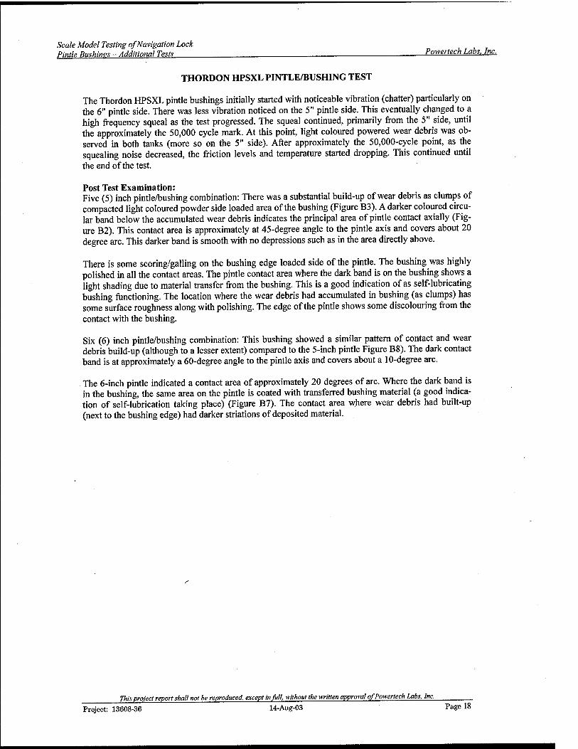
Scale Model Testing of Navigation Lock Pintle Bushines-Additional Tests Powertech Labs, Inc.
THORDON HPSXL PINTLE/BUSHING TEST
The Thordon HPSXL pintle bushings initially started with noticeable vibration (chatter) particularly on the 6" pintle side. There was less vibration noticed on the 5" pintle side. This eventually changed to a high frequency squeal as the test progressed. The squeal continued, primarily from the 5" side, until the approximately the 50,000 cycle mark. At this point, light coloured powered wear debris was ob- served in both tanks (more so on the 5" side). After approximately the 50,000-cycle point, as the squealing noise decreased, the friction levels and temperature started dropping. This continued until the end of the test.
Post Test Examination: Five (5) inch pintle/bushing combination: There was a substantial build-up of wear debris as clumps of compacted light coloured powder side loaded area of the bushing (Figure B3). A darker coloured circu- lar band below the accumulated wear debris indicates the principal area of pintle contact axially (Fig- ure B2). This contact area is approximately at 45-degree angle to the pintle axis and covers about 20 degree arc. This darker band is smooth with no depressions such as in the area directly above.
There is some scoring/galling on the bushing edge loaded side of the pintle. The bushing was highly polished in all the contact areas. The pintle contact area where the dark band is on the bushing shows a light shading due to material transfer from the bushing. This is a good indication of as self-lubricating bushing functioning. The location where the wear debris had accumulated in bushing (as clumps) has some surface roughness along with polishing. The edge of the pintle shows some discolouring from the contact with the bushing.
Six (6) inch pintle/bushing combination: This bushing showed a similar pattern of contact and wear debris build-up (although to a lesser extent) compared to the 5-inch pintle Figure B8). The dark contact band is at approximately a 60-degree angle to the pintle axis and covers about a 10-degree arc.
The 6-inch pintle indicated a contact area of approximately 20 degrees of arc. Where the dark band is in the bushing, the same area on the pintle is coated with transferred bushing material (a good indica- tion of self-lubrication taking place) (Figure B7). The contact area where wear debris had built-up (next to the bushing edge) had darker striations of deposited material.
This project report shall not be reproduced, except in Ml without the written approval of Powertech Labs, Inc. Project: 13608-36 14-Aug-03 Page 18

Scale Model Testing of Navigation Lock Pintle Bushines - Additional Tests Powertech Labs. Inc.
iiiifiiiiiji
Figure B1. Close-up view of 5" pintle contact side. There is marked scoring towards stepped edge of the pintle.
This project report shall not be reproduced, except in fall, without the -written approval of Powertech Labs, Inc. Project: 13608-36 14-Aug-03 Page 19

Scale Model Testing of Navigation Lock Pintle Bushines - Additional Tests Powertech Labs. Inc.
Figure B2. Thordon HPSXL 5" pintle bushing.
Ih»..
1 «.- t • '. ;
Figure B3. Close-up view of loaded side of bushing. Note accumulated wear debris.
This project report shall not be reproduced, except in full, without the written approval of Powertech Labs, Inc. Project: 13608-36 14-Aug-03 Page 20

Scale Model Testing of Navigation Lock Pintle Bushings - Additional Tests Powertech Labs. Inc.
CO » o >% Ü
a
E
m 3 D)
o CO Ö
m CM
3 tO O M T- T- 3 Ö O
uoifouj jo juepijjaoQ
o o o d
Project: 13608-36
This project report shall not be reproduced, except in full, without the written approval of Powertech Labs, Inc. 14-Aug-03 Page 21

Scale Model Testing of Navigation Lock Pintle Bushines - Additional Tests Powertech Labs. Inc.
Q) Ü IO
o m 0>
o 3 h- O) a> A Li.
E £
(s|!iu)yv3M103yia
This project report shall not be reproduced, except in full, without the written approval of Powertech Labs, Inc. Project: 13608-36 14-Aug-03 Page 22
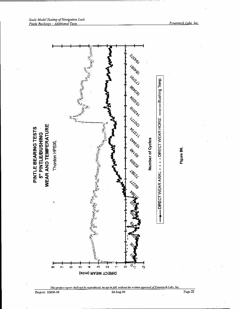
Scale Model Testing of Navigation Lock Pintle Bushines - Additional Tests Powertech Labs, Inc.
UJ w a: to CD E
« i en CD co ill
_J
CO 5 => £ n a: on S X < UJ UJ UJ _i i-
c o TI
DQ i- a Ir. o r UJ z z 1-
t = * Z IO < Q. UJ
£
0) © u
a>
E
Q. E
c !c
m
(O CO
3 a>
oo
(sum) HV3M103« IQ
Project: 13608-36
77IM project report shall not be reproduced, except in full, without the written approval of Powertech Labs, Inc. 14-Aug-03 Page 23
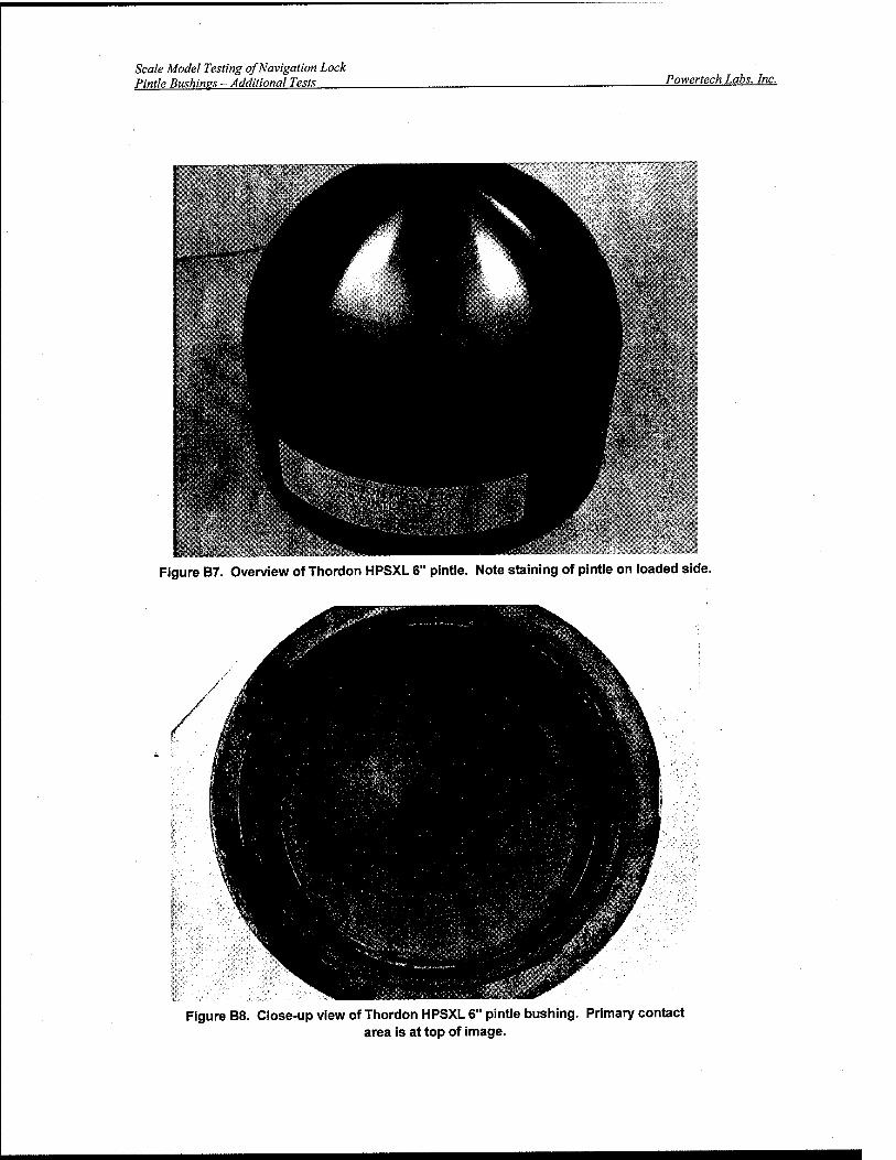
Scale Model Testing of Navigation Lock Pintle Bushings - Additional Tests Powertech Labs, Inc.
Figure B7. Overview of Thordon HPSXL 6" pintle. Note staining of pintle on loaded side.
Figure B8. Close-up view of Thordon HPSXL 6" pintle bushing. Primary contact area is at top of image.

Scale Model Testing of Navigation Lock Pintle Bushines - Additional Tests Powertech Labs, Inc.
mmmmmmwmmmmM$mm^ Figure B9. Close-up view above image on loaded side. Note accumulation of wear debris above
darker contact area.
This project report shall not be reproduced, except in full, without the written approval of Powertech Labs, Inc. Project: 13608-36 14-Aug-03 Page 25
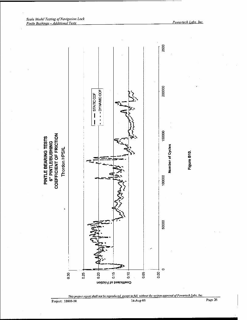
Scale Model Testing of Navigation Lock Pintle Bushines - Additional Tests Powertech Labs, Inc.
Ö u o
m £ 3 D) il
o d ö
uoipuj jo luejOjjjaoo
ra» prq/ecf report shall not be reproduced, except in full, without the written approval of Powertech Labs, Inc.
Project: 13608-36 14-Aug-03 Page 26

Scale Model Testing of Navigation Lock Pintle Bushines - Additional Tests Powertech Labs. Inc.
UJ z ■-X O (0 S 2 *
ig5
_i a- H : Z U>
to Q. X c o
T3
(0
0)
E 3 Z
ffi
3 O)
■«fr CO CM
(s|!Ui)av3M
This project report shall not be reproduced, except in full, without the written approval of Powertech Labs, Inc.
Project: 13608-36 14-Aug-03 Page 27
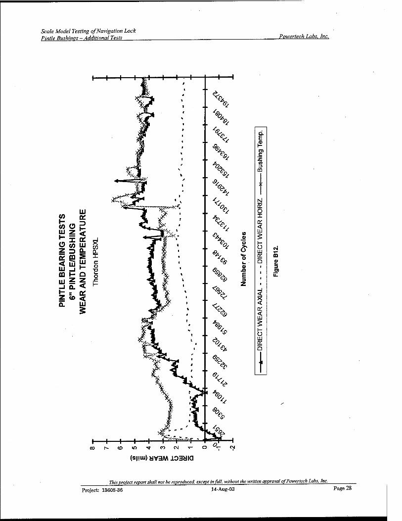
Scale Model Testing of Navigation Lock Pintle Bushines - Additional Tests Powertech Labs. Inc.
LU w Q: to o 2 w z < £ 3C 0£ O CO UJ CO Z D Q. n * e ^ X < S UJ QJ _| H
e o TJ
00 h- Q o UJ z z JZ
J E < 1—
t = * Z to < Q. LU
o Ö «5*
o
E 3
CO
m £ 3
(D lO "* CO CM T-
(s|iuJ)yv3M103yia
This project report shall not be reproduced, except in full, without the written approval of Powertech Labs, Inc. Project: 13608-36 14-Aug-03 Page 28

Scale Model Testing of Navigation Lock Pintle Bushims-Additional Tests Powertech Labs, Inc.
APPENDIX C KAMATICS KARON SELF-LUBRICATING BUSHINGS/PINTLE TEST
This project report shall not be reproduced, except in full, without the written approval of Powertech Labs, Inc. Project: 13608-36 14-Aug-03 Page 29

Scale Model Testing of Navigation Lock Pintle Bushinps- Additional Tests Powertech Labs, Inc.
KAMATICS KARON V SELF-LUBRICATING BUSHINGS/PINTLE TEST
The Kamatics Karon V bushing/pintle combinations operated throughout the test without any indica- tion of stress. The test ran quietly with low friction and low temperatures after the pintles had settled in.
Post Test Examination: Five (5) inch pintle/bushing combination. The test started with relatively high friction (no audible indi- cations the stress was excessive). As the pintle settled into the bushing, the friction levels and operating temperatures dropped. The pintle contact area was next to the top and extended over an arc of ap- proximately 30 degrees (Figure Cl). The area was uniformly coated with transferred lubricant material indicating the self-lubricating bushing was performing, as it should.
The bushing contact area was limited to the top of the bushing over an arc of approximately 30 de- grees. A dark highly polished band evidenced this, which was slightly wider on the side-loaded area of the bushings (Figure C2). This contact area did not show any signs of stress although there were small amounts of wear debris on the edges of the contact areas.
Six (6) inch pintle/bushing combination. The six (6) inch bushing followed a similar pattern as in the five (5) inch greased bushing test. The contact areas were highly polished and next to the top edge of the bushing (Figures C8 and C9). The pintle contact area was over approximately 20 degrees of arc (at right angles to the pintle axis) and had a uniform light colour from the transfer of lubricant material from the bushing (Figure C7).

Scale Model Testing of Navigation Lock Pintle Bushines - Additional Tests Powertech Labs, Inc.
Figure C1. Close-up view of 5" pintle from Kamatics Karon V test.
tffll^»^»^—
\ ^
Figure C2. Close-up view of 5" Karon V bushing. Note uniform polished contact areas.
This project report shall not be reproduced, except in full, without the written approval of Powertech Labs, Inc. Project: 13608-36 14-Aug-03 Page 31

Scale Model Testing of Navigation Lock Pintle Bushinss - Additional Tests Powertech Labs. Inc.
Figure C3. Close-up view of 5" Karon V bushing. Note highly polished contact area. There is no indication of stress to the lubricant layer.

Scale Model Testing of Navigation Lock Pintle Bushines - Additional Tests Powertech Labs. Inc.
(0
S ° ,s tu z o
O (0
o O
9E UJ DO UJ
3 CQ UJ _J I- Z Q.
Co
O H Z UJ Ü
UJ O o
o o o o CM
O O O O co
o o o o CD
O O O o
o o o o CM
10
o Ü S x- 8 ? 5 o
o o o o 00
o o o o CO
o o o o rr
o o o o CM
Ü £ 3 O) il
o lO O If) o m o CO CM CM x— T— o o o O O o o o o
UOJJOUJ jo juapijjaoo
77»> project report shall not be reproduced, except infill, without the written approval of Powertech Labs, Inc.
Project: 13608-36 14-Aug-03 Page 33
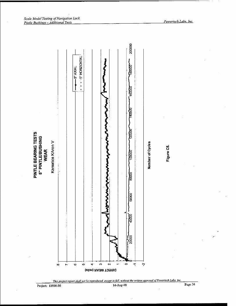
Scale Model Testing of Navigation Lock Pintle Bushings - Additional Tests Powertech Labs, Inc.
V) a o ■o >■ O Ü
£ o 3 k O) 01 XI LL
E 3
(S|.IUJ)HV3M ±03810
rafe pro/ect report shall not be reproduced, except in full without the -written approval of Powertech Labs, Inc. Project: 13608-36 14-Aug-03 Page 34

Scale Model Testing of Navigation Lock Pintle Bushines - Additional Tests Powertech Labs. Inc.
a> u
a> n E 3
Q. E ß D) c jz CO 3
CO
to Ü
2 3 D)
(SMUi) yv3M JLOSHia
77HJ project report shall not be reproduced, except in full, without the written approval of Powertech Labs, Inc.
Project: 13608-36 14-Aug-03 Page 35

Scale Model Testing of Navigation Lock Pintle Bushines - Additional Tests Powertech Labs, Inc.
Figure C7. View of 6" Kamatics Karon V pintle.

Scale Model Testing of Navigation Lock Pintle Bushines - Additional Tests Powertech Labs, Inc.
Figure C8. View of Kamatics Karon V bushing. Note dark band, which is next to top edge. This is the pintle contact area.
Figure C9. Close-up view of above image on loaded side. Note polished contact area. There does not appear to be any stress to this area.
This project report shall not be reproduced, except in full, without the written approval of Powertech Labs, Inc. Project: 13608-36 14-Aug-03 Page 37

Aodel Testing of Navigation Lock Bushines - Additional Tests Powertech Labs. Inc.
c o
CO Ü
3
o o e 3 O) iZ
o CO
10 CM
O CM
o O O
10 o
d d uojjoud jo juepüjeoo
in o d
o o
This project report shall not be reproduced, except in full, without the written approval of Powertech Labs, Inc. Project: 13608-36 14-Aug-03 Page 38

Scale Model Testing of Navigation Lock Pintle Bushines - Additional Tests Powertech Labs. Inc.
CO O eg K GO
mz 111 s _J Q.
0£
55 5
z Q. Z to
c p
(0 o TO E
^- <D m ■* to rg
(0 . a> ^™
v» >> ü a o
L.
o 3 t_ D> <D U.
(sijiu) yv3M
rafa project report shall not be reproduced, except in full, -without the written approval of Powertech Labs, Inc.
Project: 13608-36 14-Aug-03 Page 39

rfodel Testing of Navigation Lock Bushines - Additional Tests Powertech Labs. Inc.
V)
V) O m z
S < m m UJ
3
UJ
z (O Q.
Ill a:
5 tu UJ 0. S UJ
Q Z <
< 111
(0
o
n- O i_ 0)
E z
Q. E
U) c IE w 3
CO
o UJ
a
I
£ 3 D) il
CD in <* co CM T-
(S|!Ui)yV3M103yia
This project report shall not be reproduced, except infill, without the written approval of Powertech Labs, Inc.
Project: 13608-36 14-Aug-03 Page 40

Scale Model Testing of Navigation Lock Pintle Bushines-Additional Tests Powertech Labs, Inc.
APPENDIX D
TENMAT SELF-LUBRICATING BUSHING (RETAINING COLLAR) TEST RESULTS
This project report shall not be reproduced, except in fill, without the written approval of Powertech Labs, Inc. Project: 13608-36 14-Aug-03 Page 41

Scale Model Testing of Navigation Lock Pintle Bushinss- Additional Tests Powertech Labs, Inc.
TENMAT T814 (Retaining Collar) PINTLE/BUSHING TEST
The bushings were composed of a lubricant layer 0.1875 inch thick (Tenmat T814) mounted on a bronze backing. The lubricant layer has a light brown colour showing fabric like texture. These par- ticular bushings were held in place with a stainless steel collar compressing the Tenmat T814 into the bronze backing. The test initially started with significant vibration (loud noise). This continued for
'approximately 100,000 cycles reducing in volume as the pintles seated into the bushings. At approxi- mately the 140,000 cycle point, the water had run out in the reservoir due to spillage. The temperature increased for a short period of time (50 deg C for the 6 inch pintle and 35 deg C for the 5 inch pintle). The water was replaced and the test continued quietly until the end.
Post Test Examination: Five (5) inch pintle/bushing combination: Pintle contact on the bushing was virtually 100%. The pintle was highly polished with bands of transferred bushing lubricant material. The bands, particularly on the side-loaded area, are an indication of a functioning self-lubricating bushing Figure Dl).
The bushing contact surfaces were polished. There were darker bands towards the bottom of the bush- ing (Figure D2). There was some build-up of wear debris at the bottom of the bushing. The bushing did not appear to have been stressed by the test, as it was 100% intact.
Six (6) inch pintle/bushing combination: pintle contact was approximately 95%. The pintle was highly polished over most of its contact surface. The edge of the pintle where the main side load was applied had a darkened deposit of transferred bushing material (Figure D7). This was adhering well to the sur- face and was rough in texture.
The bushing contact surface was polished smooth. The loaded side of the bushings was darker in col- our and corresponded to the same area on the pintle (Figure D8). The bottom of the bushing appears to have a build-up of dark wear material. Otherwise, the bushing is similar in appearance to the five (5) inch combination and does not appear to be stressed by the test regime.

Scale Model Testing of Navigation Lock Pintle Bushines - Additional Tests Powertech Labs, Inc.
Figure D1. Overview of 5" Tenmat T814 pintle. Due to the thickness of the bushing-retaining ring, the first row of pintle anchoring holes had to be machined away.
This project report shall not be reproduced, except in full, without the written approval of Powertech Labs, Inc.
Project: 13608-36 14-Aug-03 Page 43

Scale Model Testing of Navigation Lock Pintle Bushines - Additional Tests Powertech Labs, Inc.
Retaining ring
Figure D2. Close-up view of 5" Tenmat T814 bushing.
Figure D3. Close-up view of Tenmat T814 5" bushing. Note darker contact areas.

Scale Model Testing of Navigation Lock Pintle Bushines - Additional Tests Powertech Labs, Inc.
P CO O
H |l
z o
a OH UJ S
z 0.
io
LL I—
> U. rv O c 1- — 7 ■<*
UJ CO Ü 1- Li.
-*-« li. c UJ c o (0 Ü h-
o o o m CM
O o o o o CM
o o o o IT)
®
o
0)
E
D £ 3
il
o o o o o
o o o o IO
o CO
in CM
Ö m o T— T—
ö d U01JOUJ JO )U3I3!JJ303
o CM
d o o
Project: 13608-36
This project report shall not be reproduced, except in full, without the written approval of Powertech Labs, Inc.
14-Aug-03 Page 45

Aodel Testing of Navigation Lock Bushines - Additional Tests Powertech Labs. Inc.
O
2 e
(0 <u "5 >i Ü
a xi E
IO Q
O)
(si!iu) MV3M loaaia
O •«- CM
77»,; project report shall not be reproduced except in full, without the written approval of Powertech Labs, Inc. Project: 13608-36 14-Aug-03 Page 46

Scale Model Testing of Navigation Lock Pintle Bushims - Additional Tests Powertech Labs, Inc.
LU CO o? u_
.TE
ST
H
ING
R
ATU
I
<a £
u to w 5- 5 => £: CE fc CD S c
LU _| r- ■<fr
CQ H Q UJZZ
1-
IO
rf (0
s s 2 |2
% & Q.
\%* E ' &* a>
<f h1
c (0 3
CO
*% i X
NJ
<*>
>
DC O X a: <
^
(0 0) 5 u i-
J*> fr ü in CO
1 *- o oc a
Q
jK i 3 O)
E u. 3
r^ z > 5 <fe <
K DC < III K 5
k UJ DC a
5« ^ I ife
(s|!iu) yv3M JL03Uia
77IK project report shall not be reproduced, except infiill, without the written approval of Powertech Labs, Inc.
Project: 13608-36 14-Aug-03 Page 47

Scale Model Testing of Navigation Lock Pintle Bushines - Additional Tests Powertech Labs. Inc.
Figure D7. Overview of 6" Tenmat T814 pintle. Note transferred lubricant material on side of pintle contact surface.

Scale Model Testing of Navigation Lock Pintle Bushines - Additional Tests Powertech Labs, Inc.
Figure D8. Close-up view of 6" bushing. There is no indication damage to the bushing. Contact is over 95% of the bushing surface.
This project report shall not be reproduced, except in full, without the written approval of Powertech Labs, Inc. Project: 13608-36 14-Aug-03 Page 49
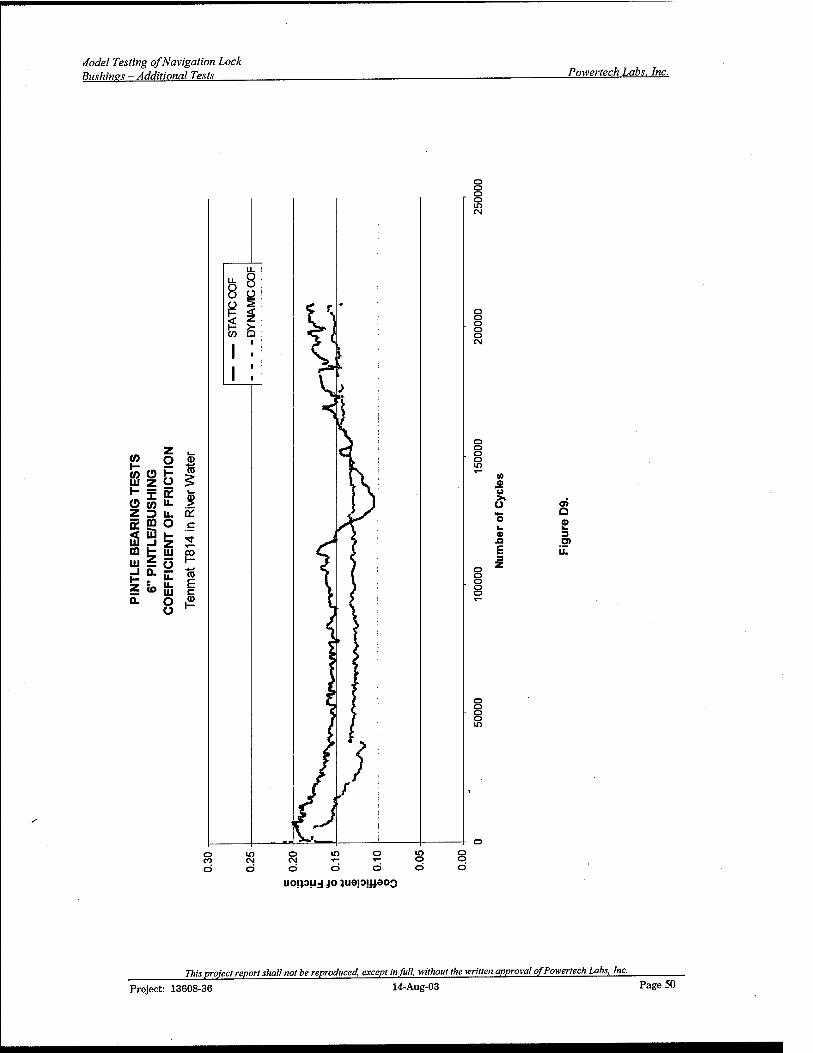
viodel Testing of Navigation Lock Bushines - Additional Tests Powertech Labs. Inc.
(0
w o h
O OT
IS m LU
z Q.
O a>
Ü UJZ« > K- 3: fV 1-
3 u. Q: ffi O r
_J £ ■*-
— ü P °-ü: CD
7n U- r- <o m c O 0 £
o o o o 10 eg
o o o o o CM
o o o o m
© o o o o
10 0) "5 >» Ü
E
Q £ 3 O)
o o o o in
0 in 0 m O m 0 CO CM CM T- ^~ 0 0 0 0 0 O O 0 0
UOJJOUJ jo luapjjjaoQ
This project report shall not be reproduced, except in full, without the written approval of Powertech Labs, Inc. Project: 13608-36 14-Aug-03 Page 50

Scale Model Testing of Navigation Lock Pintle Bushines - Additional Tests Powertech Labs, Inc.
P CO O
a: ~ ss CO HI
DO <
(O
> be
CO
c CD
in » ü >> O
a .o E
o 5 3
(M O CM •* i i
(s|!Ui) yv3M
77»,; project report shall not be reproduced, except in full, without the written approval of Powertech Labs, Inc.
Project: 13608-36 14-Aug-03 Page 51

Aodel Testing of Navigation Lock Bushines - Additional Tests Powertech Labs, Inc.
D. E
.<D H O) c .c (0 3
00
* t
rsi Q: o X Q: < in (0
0) § Ü H $ O
III o a: l_ Q 0> i n E 3 z t
_i
DC < LU 5 1- o UJ Q: a
• i
a
D> il
CO ■«fr CM O ~ C\l xj-
(s|!Ui)yv3M103Mia
<? H co
77»,s project report shall not be reproduced, except in full, without the written approval of Powertech Labs, Inc.
Project: 13608-36 14-Aug-03 Page 52

REPORT DOCUMENTATION PAGE Form Approved
OMB No. 0704-0188 Public reporting burden for this collection of information is estimated to average 1 hour per response, including the time for reviewing instructions, searching existing data sources, gathering and maintaining the data needed, and completing and reviewing this collection of information. Send comments regarding this burden estimate or any other aspect of this collection of information, including suggestions for reducing this burden to Department of Defense, Washington Headquarters Services, Directorate for Information Operations and Reports (0704-0188), 1215 Jefferson Davis Highway, Suite 1204, Arlington, VA 22202- 4302. Respondents should be aware that notwithstanding any other provision of law, no person shall be subject to any penalty for failing to comply with a collection of information if it does not display a currently valid OMB control number. PLEASE DO NOT RETURN YOUR FORM TO THE ABOVE ADDRESS.
1. REPORT DATE (DD-MM-YYYY) 06-2004
2. REPORT TYPE Final
3. DATES COVERED (From - To)
4. TITLE AND SUBTITLE Field Evaluation of Self-Lubricated Mechanical Components for Civil Works Navigation Structures
5a. CONTRACT NUMBER
5b. GRANT NUMBER
5c. PROGRAM ELEMENT NUMBER
6. AUTHOR(S) Timothy D. Race, Ashok Kumar, and L.D. Stephenson
5d. PROJECT NUMBER CW 5e. TASK NUMBER
5f. WORK UNIT NUMBER 33238
7. PERFORMING ORGANIZATION NAME(S) AND ADDRESS(ES) U.S. Army Engineer Research and Development Center (ERDC) Construction Engineering Research Laboratory (CERL) PO Box 9005 Champaign, IL 61826-9005
8. PERFORMING ORGANIZATION REPORT NUMBER
ERDC/CERL SR-04-8
9. SPONSORING / MONITORING AGENCY NAME(S) AND ADDRESS(ES)
U.S. Army Corps of Engineers 441 G Street, NW. Washington, DC 20314-1000
10. SPONSOR/MONITOR'S ACRONYM(S) HQ02
11. SPONSOR/MONITOR'S REPORT NUMBER(S)
12. DISTRIBUTION / AVAILABILITY STATEMENT Approved for public release; distribution is unlimited.
13. SUPPLEMENTARY NOTES Copies are available from the National Technical Information Service, 5285 Port Royal Road, Springfield, VA 22161.
14. ABSTRACT
It is operationally and environmentally desirable to replace greased bronze bushings used in navigation lock machinery with self- lubricating bushings. Bronze bushings must be greased manually or with automatic lubricating machines. Grease lines are subject to damage from ice and debris. If the grease line breaks, the lubricating system fails, which may lead to component failure and delays in navigation. Introduction of grease into the riverine environment is also a concern.
The Corps of Engineers has been using self-lubricating bushings in navigation locks for the past 20 years. The purpose of this study was to evaluate mechanical properties and durability of emerging advanced self-lubricating bushing/bearing materials in the laboratory and under field conditions, and to provide additional knowledge, needed guidelines, and standard specifications for the proper selection and use of self-lubricating bushing materials for locks based on local environmental conditions and applications. The results of accel- erated testing of quarter-scale model self-lubricating pintle bushings in simulated river are also reported.
15. SUBJECT TERMS evaluation, civil works, navigation structures, mechanical systems, self-lubricating
16. SECURITY CLASSIFICATION OF:
a. REPORT Unclassified
b. ABSTRACT Unclassified
c. THIS PAGE Unclassified
17. LIMITATION OF ABSTRACT
SAR
18. NUMBER OF PAGES
172
19a. NAME OF RESPONSIBLE PERSON Ashok Kumar
19b. TELEPHONE NUMBER (in- clude area code)
(217)373-7235 NSN 7540-01-280-5500 Standard Form 298 (Rev. 8-98)
Prescribed by ANSI Std. 239.18