FEASIBILITY STUDY REPORT OCCIDENTAL CHEMICAL ...
201
FEASIBILITY STUDY REPORT OCCIDENTAL CHEMICAL CORPORTION Pottstown, Pennsylvania March 1993 BCM Engineers, Planners, Scientists and Laboratory Services jj 1 oj ffl fc^ ! A \, D JO C aR3Q7800
-
Upload
khangminh22 -
Category
Documents
-
view
0 -
download
0
Transcript of FEASIBILITY STUDY REPORT OCCIDENTAL CHEMICAL ...

FEASIBILITY STUDY REPORT
OCCIDENTAL CHEMICAL CORPORTIONPottstown, Pennsylvania
March 1993
BCMEngineers, Planners, Scientists
and Laboratory Services
jj1ojfflfc^ ! A
\,
DJO
C
aR3Q7800

TABLE OF CONTENTS
EXECUTIVE SUMMARY xiii
1.0 INTRODUCTION 1-1
1.1 Site Location and Ownership 1-11.2 Project Background 1-11.3 Summary of RI Results 1-21.4 Remedial Programs 1-3
1.4.1 Bedrock Aquifer Remediation 1-31.4.2 Removal of Earthen Lagoons from Floodplain 1-4
2.0 IDENTIFICATION AND SCREENING OF TECHNOLOGIESFOR GROUNDWATER 2-1
2.1 Overview 2-12.2 Remedial Action Objectives 2-1
2.2.1 Objectives 2-12.2.2 Applicable or Relevant and Appropriate
Requirements (ARARs) 2-2
2.2.2.1 ARARs and TBCs 2-22.2.2.2 Chemical-Specific ARARs 2-32.2.2.3 Location-Specific ARARs 2-52.2.2.4 Action-Specific ARARs 2-6
2.3 General Response Actions for Groundwater 2-9
2.3.1 Volume Estimation and Chemical Identification 2-92.3.2 Response Actions for Groundwater 2-102.3.3 Identification of Technologies for Screening 2-11
2.3.3.1 No Action/Institutional Controls 2-112.3.3.2 Containment Technologies 2-122.3.3.3 Collection Technologies 2-132.3.3.4 Treatment Technologies 2-14
AR30780I

TABLE OF CONTENTS(Continued)
2.3.3.5 Discharge Options 2-21
2.3.4 Evaluation of Technologies and Selection ofRepresentative Technologies and Process Options 2-22
3.0 ALTERNATIVES DEVELOPMENT FOR GROUNDWATER 3-1
3.1 Bedrock Aquifer Remediation 3-1
3.1.1 Chemical Plume Characterization and RecoveryModelDesign 3-1
3.1.2 Modeling Results 3-23.1.3 Preliminary Remediation Goals 3 -33.1.4 Recovery Program Implementation 3-3
3.1.4.1 Start-up 3-33.1.4.2 Pump Rate Adjustments 3-53.1.4.3 Performance Monitoring 3-5
3.2 Groundwater Treatment 3-6
3.2.1 Influent Characterization 3-63.2.2 Discharge Limits 3-7
3.2.2.1 Indirect Discharge Limits 3-73.2.2.2 Direct Discharge Limits 3-8
3.2.3 Chemicals Requiring Treatment 3-113.2.4 Existing Treatment System 3-123.2.5 Groundwater Remediation Alternatives 3-12
3.2.5.1 Technologies Retained 3-123.2.5.2 Alternative 1A - No Action/
Institutional Controls 3-133.2.5.3 Alternative IB - Groundwater Collection
Using Production Wells and Treatmentby Air Stripping 3-13
3.2.5.4 Alternative 2A and 2B - Air Stripping 3-133.2.5.5 Alternative 3A and 3B - Steam Stripping 3-14
3.2.6 Technical Evaluation of Alternatives 3-15
111
SR307802

TABLE OF CONTENTS(Continued)
3.2.6.1 Alternative IB - Groundwater CollectionUsing Production Wells and Treatment byAir Stripping 3-15
3.2.6.2 Volatile Organics to be Removed 3-163.2.6.3 Alternative 2A - Air Stripping Before
the PVC Production Process 3-163.2.6.4 Alternative 2B - Air Stripping After
the PVC Production Process 3-173.2.6.5 Vapor Phase Carbon 3-173.2.6.6 Alternatives 3A and 3B - Steam Stripping , 3-173.2.6.7 Summary of Remaining Alternatives 3-1,8
4.0 DETAILED ANALYSIS OF ALTERNATIVES FOR GROUNDWATER 4-1
4.1 Overview 4-14.2 Analysis of Groundwater Remediation Alternatives 4-1
4.2.1 Alternative 1A - No Action/InstitutionalControls 4-2
4.2.1.1 Description 4-24.2.1.2 Compliance with ARARs 4-24.2.1.3 Long-Term Effectiveness and Permanence 4-24.2.1.4 Short-Term Effectiveness 4-24.2.1.5 Reduction of Mobility and Volume 4-34.2.1.6 Implementability 4-34.2.1.7 Overall Protection of Human Health and
the Environment 4-34.2.1.8 Cost 4-34.2.1.9 Regulatory Acceptance 4-34.2.1.10 Community Acceptance 4-3
4.2.2 Alternative IB - Groundwater CollectionUsing Production Wells and Treatment by AirStripping 4-3
4.2.2.1 Description 4-34.2.2.2 Compliance with ARARs 4-44.2.2.3 Long-Term Effectiveness and Permanence 4-44.2.2.4 Short-Term Effectiveness 4-44.2.2.5 Reduction of Mobility and Volume 4-44.2.2.6 Implementability 4-4
IV

TABLE OF CONTENTS(Continued)
4.2.2.7 Overall Protection of Human Health andthe Environment 4-4
4.2.2.8 Cost 4-44.2.2.9 Regulatory Acceptance 4-54.2.2.10 Community Acceptance 4-5
4.2.3 Alternative 2A - Groundwater Collection UsingRecovery Wells and Treatment by Air StrippingBefore the Process 4-5
4.2.3.1 Description 4-54.2.3.2 Compliance with ARARs 4-54.2.3.3 Long-Term Effectiveness and Permanence 4-64.2.3.4 Short-Term Effectiveness 4-74.2.3.5 Reduction of Mobility and Volume 4-74.2.3.6 Implementability 4-74.2.3.7 Overall Protection of Human Health and
the Environment 4-74.2.3.8 Cost 4-74.2.3.9 .Regulatory Acceptance 4-84.2.3.10 Community Acceptance 4-8
4.2.4 Alternative 2B - Groundwater Collection UsingRecovery Wells and Treatment by Air StrippingAfter the Process 4-8
4.2.4.1 Description 4-84.2.4.2 Compliance with ARARs 4-84.2.4.3 Long-Term Effectiveness and Permanence 4-94.2.4.4 Short-Term Effectiveness 4-94.2.4.5 Reduction of Mobility and Volume 4-94.2.4.6 Implementability 4-94.2.4.7 Overall Protection of Human Health and
the Environment 4-94.2.4.8 Cost 4-94.2.4.9 Regulatory Acceptance 4-94.2.4.10 Community Acceptance 4-9
4.2.5 Alternative 3A - Groundwater Collection UsingRecovery Wells and Treatment by Steam StrippingBefore the Process 4-10
AR3Q78Q14

TABLE OF CONTENTS(Continued)
4.2.5.1 Description 4-104.2.5.2 Compliance with ARARs 4-104.2.5.3 Long-Term Effectiveness and Permanence 4-104.2.5.4 Short-Term Effectiveness 4-104.2.5.5 Reduction of Mobility and Volume 4-104.2.5.6 Implementability 4-10
4.2.5.7 Overall Protection of Human Health andthe Environment 4-10
4.2.5.8 Cost 4-104.2.5.9 Regulatory Acceptance 4-114.2.5.10 Community Acceptance 4-11
4.2.6 Alternative 3B - Groundwater Collection UsingRecovery Wells and Treatment by Steam StrippingAfter the Process 4-11
4.2.6.1 Description 4-114.2.6.2 Compliance with ARARs 4-114.2.6.3 Long-Term Effectiveness and Permanence 4-114.2.6.4 Short-Term Effectiveness 4-124.2.6.5 Reduction of Mobility and Volume 4-124.2.6.6 Implementability 4-124.2.6.7 Overall Protection of Human Health and
the Environment 4-124.2.6.8 Cost 4-124.2.6.9 Regulatory Acceptance 4-124.2.6.10 Community Acceptance 4-12
4.3 Comparison of Alternatives 4-12
4.3.1 Compliance with ARARs 4-134.3.2 Long-Term Effectiveness and Permanence 4-134.3.3 Reduction of Mobility and Volume 4-134.3.4 Short-Term Effectiveness 4-134.3.5 Implementability 4-134.3.6 Overall Protection of Human Health and the
Environment 4-134.3.7 Cost 4-144.3.8 Regulatory Acceptance 4-144.3.9 Community Acceptance 4-14
VI
AR307805

TABLE OF CONTENTS(Continued)
4.4 Selection of Preferred Remedy 4-14
5.0 IDENTIFICATION AND SCREENING OF TECHNOLOGIES FOR EARTHENLAGOONS 5-1
5.1 Overview 5-15.2 Remedial Action Objectives 5-1
5.2.1 Objective 5-15.2.2 Applicable or Relevant and Appropriate
Requirements (ARARs) 5-2
5.2.2.1 ARARs and TBCs 5-25.2.2.2 Location-Specific ARARs 5-35.2.2.3 Action-Specific ARARs 5-4
5.3 General Response Actions for Earthen Lagoons 5-5
5.3.1 Overview 5-65.3.2 Response Actions for Earthen Lagoons 5-65.3.3 Identification of Technologies for Screening 5-6
5.3.3.1 No Action/Institutional Controls 5-65.3.3.2 Containment Technologies 5-75.3.3.3 Removal Technologies 5-85.3.3.4 Treatment Technologies 5-8
5.3.4 Evaluation of Technologies and Selection ofRepresentative Technologies and Process Optionsfor Earthen Lagoons 5-10
6.0 LAGOON MATERIAL TREATABHJDrY STUDIES AND ALTERNATIVESDEVELOPMENT 6-1
6.1 Earthen Lagoon Characterization 6-16.2 Reclamation Investigation of Lagoon Material 6-26.3 Identification of Drying Mechanisms 6-36.4 Onsite Drying 6-36.5 Offsite Drying 6-56.6 Development of Alternatives for Remediation
of the Earthen Lagoons 6-5
Ml
AR3078Q6

TABLE OF CONTENTS(Continued)
7.0 DETAILED ANALYSIS OF ALTERNATIVES FOR EARTHEN LAGOONS 7-1
7.1 Overview 7-17.2 Analysis of Earthen Lagoon Remediation Alternatives 7-1
7.2.1 Alternative 1 - No Action with Deed/Land UseRestriction 7-2
7.2.1.1 Description 7-27.2.1.2 Compliance with ARARs 7-27.2.1.3 Long-Term Effectiveness and Permanence 7-27.2.1.4 Short-Term Effectiveness 7-37.2.1.5 Reduction of Mobility and Volume _ 7-37.2.1.6 Implementability 7-37.2.1.7 Overall Protection of Human Health
and the Environment 7-37.2.1.8 Cost 7-37.2.1.9 Regulatory Acceptance 7-37.2.1.10 Community Acceptance 7-3
7.2.2 Alternative 2 - Onsite Drying of the White andGray Layers and Landfilling of the Coal FinesLayer 7-4
7.2.2.1 Description 7-47.2.2.2 Compliance with ARARs 7-47.2.2.3 Long-Term Effectiveness and Permanence 7-57.2.2.4 Short-Term Effectiveness 7-57.2.2.5 Reduction of Mobility and Volume 7-57.2.2.6 Implementability 7-67.2.2.7 Overall Protection of Human Health
and the Environment 7-67.2.2.8 Cost 7-67.2.2.9 Regulatory Acceptance 7-77.2.2.10 Community Acceptance 7-7
7.2.3 Alternative 3 - Offsite Drying of the White andGray Layers and Landfilling of the Coal FinesLayer 7-7
7.2.3.1 Description 7-77.2.3.2 Compliance with ARARs 7-7
Vlll
TABLE OF CONTENTS(Continued)
7.2.3.3 Long-Term Effectiveness and Permanence 7-77.2.3.4 Short-Term Effectiveness 7-77.2.3.5 Reduction of Mobility and Volume 7-87.2.3.6 Implementability 7-87.2.3.7 Overall Protection of Human Health
and the Environment 7-87.2.3.8 Cost 7-87.2.3.9 Regulatory Acceptance 7-87.2.3.10 Community Acceptance 7-9
7.2.4 Alternative 4-Landfilling of the Lagoon Materials 7-9
7.2.4.1 Description 7-97.2.4.2 Compliance with ARARs 7-97.2.4.3 Long-Term Effectiveness and Permanence 7-97.2.4.4 Short-Term Effectiveness 7-107.2.4.5 Reduction of Mobility and Volume 7-107.2.4.6 Implementability 7-107.2.4.7 Overall Protection of Human Health
and the Environment 7-107.2.4.8 Cost 7-107.2.4.9 Regulatory Acceptance 7-107.2.4.10 Community Acceptance 7-11
7.3 Comparison of Alternatives 7-11
7.3.1 Compliance with ARARs 7-117.3.2 Long-Term Effectiveness and Permanence 7-117.3.3 Short-Term Effectiveness 7-117.3.4 Reduction of Mobility and Volume 7-117.3.5 Implementability 7-127,3.6 Overall Protection of Human Health and the
Environment 7-127.3.7 Cost 7-127.3.8 Regulatory Acceptance 7-127.3.9 Community Acceptance 7-12
7.4 Selection of the Preferred Remedy 7-12
IX
HR3078Q8

TABLE OF CONTENTS(Continued)
APPENDICES
Appendix A Modeling of Potential Groundwater Recovery Scenarios
Appendix B Cost Calculations for Groundwater
Appendix C Earthen Lagoon Evaluation
Appendix D Cost Calculations for Earthen Lagoons
TABLES
Table 1-1 Bedrock Aquifer Groundwater Concentrations
Table 1-2 Earthen Lagoon Sediment Concentrations for Groundwater
Table 2-1 ARARs for Groundwater
Table 2-2 Federal MCLs and MCLGs
Table 2-3 Ambient Water Quality Criteria
Table 2-4 OCPSF Standards
Table 2-5 Water Quality Toxics Management Standards (PA Chapter 16)
Table 2-6 Initial Screening of Technologies for Groundwater
Table 2-7 Evaluation of Technologies for Remediation of Groundwater
Table 2-8 Groundwater Technology Screening Results
Table 3-1 Summary of Remediation Requirements
Table 3-2 Bedrock Aquifer Chemical Threshold Depths
Table 3-3 Groundwater Recovery Wells and Construction Specifications
Table 3-4 Potential Maximum Groundwater Recovery NetworkFlow Rates and Drawdowns

TABLE OF CONTENTS(Continued)
Table 3-5 Influent Characterization for Remediation Wells(average concentrations before production process)
Table 3-6 Influent Characterization for Remediation Wells(maximum concentrations before production process)
Table 3-7 Influent Characterization for Remediation Wells(average concentrations after production process)
Table 3-8 Influent Characterization for Remediation Wells(maximum concentrations after production process)
Table 3-9 Indirect Discharge Limits
Table 3-10 Direct Discharge Standards Calculations(Biological Treatment)
Table 3-11 Direct Discharge Standards Calculations(Non-biological Treatment)
Table 3-12 Direct Discharge Limits(Biological Treatment)
Table 3-13 Direct Discharge Limits(Non-biological Treatment)
Table 3-14 Chemicals Requiring Treatment Summary Table
Table 3-15 Summary of Discharge Limits
Table 3-16 Stripper Model Input Data
Table 3-17 Vapor Phase Carbon Usage for Air Stripping
Table 5-1 ARARs for Earthen Lagoons
Table 5-2 Initial Screening of Technologies for Earthen Lagoons
Table 5-3 Evaluation of Technologies for Remediation ofGroundwater
Table 5-4 Earthen Lagoon Technology Screening Results
XI
flR3078IO

TABLE OF CONTENTS(Continued)
Table 6-1 Volatile Emissions from Dryer
FIGURES
Figure 1-1 Site Location
Figure 1-2 Site Sketch
Figure 1-3 Boring Locations in Earthen Lagoons
Figure 1-4 Schematic Cross Section of Earthen Lagoons
Figure 3-1 Recovery Well Locations
Figure 3-2 Air Stripping Treatment Train
Figure 3-3 Air Stripper with Carbon Regeneration
Figure 3-4 Steam Stripping Treatment Train
Figure 3-5 Steam Stripper Schematic Diagram
Figure 3-6 Air Stripping Before Production Process
Figure 3-7 Air Stripping After Production Process
Figure 3-8 Steam Stripping Before Production Process
Figure 3-9 Steam Stripping After Production Process
Figure 6-1 Onsite Drying
Figure 6-2 Offsite Drying
Xll

EXECUTIVE SUMMARY
This Feasibility Study (FS) report presents an evaluation of remedial alternatives for thetwo areas of concern identified through the Remedial Investigation (RI). These are: (1)the bedrock aquifer and (2) the earthen lagoon area.
Chapter 1 includes a summary of the RI results and an overview of the planned remedialprograms. With respect to the bedrock aquifer, the following are presented:
• There are no current risks, and no current receptors, associated with thebedrock aquifer. The only significant potential health risk identifiedthrough the RI and Risk Assessment is that of a future scenario where it
- was assumed that the currently existing controls on plume migration wereterminated, and the plume was allowed to migrate off-site resulting in aresidential exposure to groundwater.
• The distributions of the volatile organic compounds (VOCs) in thebedrock aquifer were used to determine the targeted zone of groundwaterremediation. The most widespread of the bedrock chemicals (TCE)established the geometry of the targeted remediation zone, or capture zone,that will be recovered from a series of pumping wells.
• The alternatives evaluated for groundwater remediation considered thatthe Site will continue to incorporate groundwater pumped from thecapture zone in the process water stream. The plant has initiated a majormodernization program which will result in an upgraded onsitewastewater treatment system. Treatment of VOCs of concern in theremediation program may be conducted before or as part of treatment ofthe production process water stream.
With respect to the earthen lagoons, the following are presented in Chapter 1:
• The RI results indicate that the 38,000 cubic yards of lagoon material isnot a hazardous waste; nor are there any unacceptable risks to habitat orwildlife resulting from releases from the lagoons.
• Although the RI did not indicate a requirement for remediation of theearthen lagoons, OxyChem plans to remove the contents of the earthenlagoon from the 100-year floodplain to eliminate any future concerns withrespect to flooding and/or leachate release.
Vlll
HR3078I2
Chapter 2 includes the preliminary FS screening steps as related to the bedrock aquifer.Identified are the remedial action objectives, which are to:
1. Restore groundwater in the bedrock aquifer to ARARs, and to a level that isprotective of human health and the environment, where restoration to theselevels is technically practical.
2. Prevent contact with, and ingestion of, the chemicals in the bedrockaquifer; and,
3. Protect offsite groundwater and surface water from impact.
The MCLs of the 5 VOCs of concern have been adopted as the preliminary remediation goals(PRGs), as they represent acceptable levels of risk reduction and an achievable concentration levelwithin a reasonable timeframe.
Based on the remedial objectives, and the identification of ARARs (also presented inChapter 2), technologies for detailed screening were identified in the categories of: (1) noaction/institutional controls, (2) containment technologies, (3) collection technologies, and(4) treatment technologies. The specific technologies were screened considering"effectiveness, implementability, and cost.
The alternatives for groundwater remediation are further developed in Chapter 3. Thegeneral concept of recovery and treatment within the defined capture zone was developedwith the use of groundwater modeling. The model showed that the effective recoveryprogram will require nine recovery wells concentrated in the center of the Site, at bothshallow depths to recover the shallow styrene plume and deeper depths to recover the morewidespread plumes of other VOCs. The model also shows the need to terminate theexisting production well pumping system (other than those wells planned for modificationand incorporation into the recovery program) which could otherwise interfere with therecovery well program.
Characterization of the remediation groundwater which will be influent to a treatmentsystem was accomplished by using analytical data from wells close to, and at the samedepth, as the proposed remediation wells. The alternatives considered for groundwaterremediation included the following:
• No Action/Institutional Controls. This "baseline" alternative assumedthat the current, plume-controlling, production wells were turned off, andno groundwater was collected. It also involved deed/land use restrictions.
• Continuation of the present pumping scenario and treatment via theexisting air stripper.
IX
flR3078{3
• Air stripping of the VOCs with a new unit, located either before or afterthe water is used in the production process.
• Steam stripping, applied either before the water enters the productionprocess or after the water leaves the production process.
All of the above alternatives were retained for detailed analysis in Chapter 4. Alternativeswhich appeared not to be effective, not implementable, or cost-effective as compared withthe others were screened out. The results of this phase of the FS were as follows:
• The No Action/Institutional Control alternative (Alternative 1A) waseliminated because of several factors related to effectiveness andagency/community acceptability.
• The current collection and treatment alternative (Alternative IB) wasfound to be acceptable, but is not preferred, because it fails to optimizeschemical collection, relative to a recovery program, based on themodeling results.
• Collection of groundwater from the modeled recovery program, andtreatment by air stripping either before or separate from the processwater stream (Alternative 2A), or after the water is used for productionpurposes (Alternative 2B) were retained as remediation alternatives.
• Treatment using steam stripping (Alternatives 3A and 3B) was screenedout based on potentially prohibitive costs compared with air strippingand the fact that additional organic waste streams requiring offsitedisposal would be generated.
Chapter 5 presents the preliminary FS screening steps for the earthen lagoons. Theearthen lagoons are included in the FS even though their removal is not a requirementunder CERCLA. The evaluation of alternatives is presented on the assumption that thePennsylvania Clean Stream Law and the Pennsylvania Residual Waste Regulations may beARARs for the earthen lagoons. The remedial action objective, in effect, is OxyChem'sown desire to remove the material from the lloodplain. The technologies retained afterinitial screening involve, therefore, only treatment/disposal options associated withremoval, and the baseline "no action/institutional control" option for comparison.
1R3078IU

Chapter 6 presents the results of treatability studies conducted on the lagoon material, andalternatives developed on the basis of those studies. The results indicate thatapproximately 31,000 cubic yards of lagoon material can be excavated, dried in either anonsite or off-site drier, and marketed as product; this is a process similar to that practicedat this plant for reclaiming the contents of the lined lagoons as part of their closure. Theapproximate 7,000 cubic yards of coal fines in the bottom of the earthen lagoons weredetermined to be a nonhazardous waste based on the RI analytical results; landfilling of the coalfines will be in accordance with applicable regulations.
Chapter 7 provides a detailed analysis of the earthen lagoon alternatives. Either the onsiteor offsite drier alternative, coupled with landfilling the coal fines layer is an acceptablealternative. The baseline "no-action" alternative is discounted because it may not complywith all ARARs. Landfilling of all of the lagoon material is screened out because of thegreater acceptability with the recycling options.
XI
ttR3078!5

1.0 INTRODUCTION
1.1 SITE LOCATION AND OWNERSHIP
The Occidental Chemical Corporation (OxyChem) site (Site) is located within a meanderloop of the Schuylkill River approximately 1/2-mile southeast of the Borough of Pottstown,Pennsylvania. The general location of the Site is shown in Figure 1-1.
The Site consists of approximately 250 acres and contains an active chemicalmanufacturing plant. OxyChem owns the Site and the plant and also about 60 acreslocated to the northeast of the active plant. This land is vacant and has not been used forplant operations. OxyChem is the active operator of the Pottstown plant. Figure 1-2 is asite sketch.
The plant was first owned by the Department of Defense (DOD) and operated by theJacobs Aircraft Engine Company (JAEC) in 1942. JAEC manufactured aircraft engines atthis location until 1945 when the facilities were leased to Firestone, who subsequentlypurchased the Site in 1950. Firestone manufactured tires and PVC plastic resins at the Siteuntil 1980, when the facilities were sold to Hooker Chemical Corporation. Shortlythereafter, Hooker Chemical became the Occidental Chemical Corporation. OxyChem hascontinued to manufacture PVC plastic resins at the site, but has not manufactured tires.
1.2 PROJECT BACKGROUND
The Site was placed on the National Priority List (NPL) in 1988 as a result of the presenceof trichloroethene (TCE) and related volatile organic compounds (VOCs) in the bedrockaquifer. The use of TCE began in the 1940s and continued when Firestone began PVCproduction. TCE was phased out of the PVC process in 1987. During its use at the Site,the transfer of TCE from tank cars to a holding tank resulted in small releases of thechemical onto surface soils in the center of the facility.
In 1985, the United States Environmental Protection Agency (EPA) Field InvestigationTeam (FIT) from Region HI investigated the Site to characterize existing Site conditions.Groundwater and sediment samples were collected and analyzed. In 1988, the EPAevaluated the Site using the Hazard Ranking System. The evaluation identified theprimary concern at the Site to be TCE, trans-l,2-dichloroethene (trans-l,2-DCE), and vinylchloride monomer (VCM) in the bedrock aquifer. The EPA requested OxyChem toperform an RI/FS. On December 2, 1989, the Consent Order (Docket No. IH-89-20-DC)was signed between EPA and OxyChem.
1-1 JIR3078I6

Additional project background information is provided in the Work Plan (November 1990)and the Remedial Investigation Report (draft, March 1992). The Work Plan presents adetailed summary of pre-RI investigations and analytical data generated at the OxyChemfacility between 1979 and 1983. The RI report presents the results of all work required inthe Work Plan. Both the Work Plan and RI Report provide discussions of the significantSite features considered in the RI.
1.3 SUMMARY OF RI RESULTS
The physical and chemical characterization, and the human health, environmental, andecological assessments completed for the RI indicate that the majority of the investigatedareas/media do not require remediation. The RI identifies the bedrock aquifer and theearthen lagoons as the areas of focus for the FS.
Conclusions from the RI regarding the characterization of the bedrock aquifer include thefollowing:
• Groundwater flow in the bedrock is controlled primarily by fractures inthe rock comprising the aquifer; the sandstone units are more permeablethan the shale and siltstone.
• The gradient in the bedrock aquifer is from the Schuylkill River radiallyinward to the center of the Site; this is an induced gradient resulting fromthe continual pumping of the plant's production wells near the center ofthe Site.
• There is no migration of the chemicals offsite. No offsite wellshydraulically downgradient of the Site are impacted as a result of theinduced gradient. A well inventory indicates there are no residentialwells within a 1/2-mile radius of the Site.
• The identified chemicals of concern are five VOCs, and the extent of each(both areal extent and in depth) varies. These compounds are TCE,trans-l,2-DCE, VCM, styrene, and ethylbenzene. All five VOCs arefound at their highest concentrations in the shallow portion of thebedrock aquifer in the center of the Site. Table 1-1 is a summary ofchemical concentrations in the bedrock aquifer.
• TCE is the compound with the most widespread distribution in theaquifer.
Conclusions from the RI regarding the characterization of the earthen lagoon area includethe following:
1-2 /IR3078I7

• The results of TCLP analyses indicate that the material is not a RCRAhazardous waste. Table 1-2 presents concentrations of chemicals in theearthen lagoons.
• The earthen lagoons are located within the 100-year floodplain andcontain about 38,000 cubic yards of material associated primarily withPVC manufacturing.
• The lagoon material is generally stratified into 3 layers: an upper layer ofwhite material, a middle layer of gray material, and a basal layer of coalfines. Figures 1-3 and 1-4 present a schematic cross-section of the layeredmaterial in the lagoons.
The Human Health and Environmental Risk Assessment concluded that the onlysignificant potential health risk was associated with residential exposure to groundwater.This risk was not identified with existing conditions because existing conditions includecontinual pumping of Site wells, which controls the migration of the chemical plume andprevents the chemicals from migrating offsite. Rather, the potential health risk existed onlyin a future exposure scenario in which it was assumed that the existing controls onmigration were terminated (i.e., the production wells are turned off). Appendix M to theRI report is the Human Health and Environmental Risk Assessment; a detailed summaryof the Risk Assessment is presented in Chapter 5 of the RI report.
The ecological assessments concluded that there were no unacceptable risks to terrestrialhabitat or wildlife resulting from the Site. These assessments suggested a marginal risk toaquatic receptors from one chemical (antimony), but this substance was not associated withplant operations. This risk was considered to be the result of the model over-estimatingleachate generation and migration from the earthen lagoons. The ecological assessmentsindicated that none of the wetlands or habitats have been impaired by chemical releasesfrom the Site.
1.4 REMEDIAL PROGRAMS
1.4.1 Bedrock Aquifer Remediation
The bedrock aquifer remediation was considered based on the findings of the riskassessment and RI. The distribution of the VOC chemicals in the bedrock aquifer definedthe extent of the capture zone that is targeted for remediation. The most widespread of thebedrock chemicals (TCE) established the geometry of the remediation capture zone.Redirection of pumping from the current pumping scenario results in more effectivecapture of chemicals as is explained in detail in Chapter 3.
The alternatives evaluated for groundwater remediation considered that the Site is anactive facility which currently uses groundwater pumped from the bedrock aquifer for
1-3 flR3078i8

production purposes. The present treatment system consists of settling, clarification, andair stripping. Water is discharged to the Pottstown POTW. The plant has initiated amajor modernization program which will result in an upgraded onsite wastewatertreatment system. The new wastewater treatment system will replace the operating unitsincluding the RCRA lined lagoons, which OxyChem will close in 1994.
The operating facility will incorporate groundwater pumped from the capture zone in theprocess water stream. Treatment of VOCs of concern to the remediation program willoccur either during treatment of the process water stream or before use of the water in theprocess. The plant process adds constituents to the water (such as ammonia and BOD)which are not constituents of the groundwater, but which will be treated in the upgradedwastewater treatment system. The remediation cost estimates developed in this FS reportare based primarily on the VOC treatment steps integrated in the overall wastewatertreatment steps.
The plant's new wastewater treatment system will involve treated water discharge eitherdirectly to the Schuylkill River or to the Pottstown POTW. When the plant selects itsdischarge option, the wastewater treatment plant detailed design will consider theappropriate treatment levels required prior to discharge. This will influence the level ofVOC treatment required in conjunction with the remediation program, and the finaltreatment system design plans will be developed accordingly. For estimating purposes inthe FS, the treatment systems are designed to treat to 50 percent of the most stringentdischarge limit (whether it be discharge to surface water or discharge to the POTW) forchemicals requiring treatment. The treatment system is thus flexible and will adapt toeither discharge option selected by the plant.
1.4.2 Removal of Earthen Lagoons from Floodplain
Although the risks evaluated in the RI did not indicate a requirement for remediation ofthe earthen lagoons, OxyChem plans to remove the contents of the earthen lagoons fromthe 100-year floodplain. Removal eliminates any future concerns about the contents of thelagoons with respect to flooding and/or leachate release to the river.
1-4 flR3078i9

2.0 IDENTIFICATION AND SCREENING OF TECHNOLOGIESFOR GROUNDWATER
2.1 OVERVIEW __
The preliminary screening steps of the FS for the bedrock aquifer are presented in thischapter and include: (1) the definition of remedial action objectives and general responseactions, (2) identification of potential, applicable remedial technologies, and (3) screeningof those technologies for subsequent incorporation into alternatives.
2.2 REMEDIAL ACTION OBJECTIVES
The remedial action objectives for the bedrock aquifer remediation are based on:(1) CERCLA and NCP requirements to protect human health and the environment, (2) theSuperfund Amendments and Reauthorization Act of 1986 (SARA), and (3) the specificfindings of the Site RI and risk assessment. Site and regional conditions were considered inthe selection of remedial objectives. The remedial action objectives have been establishedTiased on chemicals and media of concern, potential exposure pathways, and remediationgoals.
2.2.1 Objectives
Based on the groundwater risk and characterization of the aquifer, the following remedialaction objectives have been established:
• Restore groundwater in the bedrock aquifer to Federal and StateApplicable, Relevant, and Appropriate Requirements (ARARs), includingdrinking water standards, and to a level that is protective of humanhealth and the environment, where restoration to these levels is technicallypractical.
• Prevent ingestion of groundwater having either concentrations ofcarcinogens in excess of drinking water standards or a total carcinogeniccancer risk for all chemicals of greater than 10"4.
• Prevent ingestion of groundwater having concentrations of non-carcinogens in excess of drinking water standards or having a total HIindex of greater than 1.
• Protect non-impacted groundwater and surface water for current andfuture use.
ftR3Q7820

The remedial action objective for the bedrock aquifer considers reduction of the concentrations ofthe 5 volatile organic chemicals of concern to levels considered achievable in the given subsurfaceenvironment with available technology. The MCLs have been adopted as the preliminaryremediation goals (PRGs), as they represent acceptable levels of risk reduction and an achievableconcentration level within a reasonable timeframe. The TCE plume is the most widespread andtime-consuming to remediate of the plumes present in the bedrock aquifer. Acceptable risk fordomestic groundwater use is between 1.0 x 10"4 and 1.0 x 10~6. Based on modeling performedfor the FS, the remedial program will reach this risk range within 25 years, but cannot reduce theconcentration of TCE to a Method 601/602 MDL within 100 years of operation. Within thatpredicted timeframe, however, TCE will be reduced to a level below its PRG (its current MCL),and the other 4 VOCs will be nondetect.
The groundwater recovery program developed with the use of modeling (Appendix A) representsthe most time-efficient and technically implementable alternative for groundwater remediation atthis site, regardless of whether an MDL or the MCL is considered as the remedial objective. Thegoal of the modeled groundwater recovery program can be considered as the MDL, and themodel predicts that the best effort remedial alternative will achieve MDLs for 4 of the 5 VOCsbefore 50 years of operation.
2.2.2 Applicable or Relevant and Appropriate Requirements (ARARs)
2.2.2.1 ARARs and TBCs
Primary consideration was given to remedial alternatives that attain Applicable orRelevant and Appropriate Requirements (ARARs). ARARs considered for the Siteincluded the following:
• Federal standards, requirements, criteria, or limitations
• Promulgated standards, requirements, criteria, and limitations understate environmental or facility-siting law that are more stringent than theassociated federal standards, requirements, criteria, and limitations.
The ARARs are divided into three broad categories. These categories are as follows:
• Chemical-specific requirements which are generally health- or risk-basednumerical values or methodologies which, when applied to site-specificconditions, result in the establishment of numerical standards. Thesevalues establish the acceptable amount or concentration of a chemicalthat may be found in, or discharged to, the ambient environment.
• Location-specific requirements which are restrictions placed on theconcentration of hazardous substances or the conduct of activities solelybecause they occur in special locations.
HR3Q782J

• Action-specific requirements which are technology- or activity-basedrequirements or limitations on actions taken with respect to specificwastes.
In addition to ARARs, To-Be-Considered (TBC) information was used in establishingcleanup levels and in designing the remedial actions. TBCs are non-promulgatedadvisories or guidance issued by the federal or state government that are not legallybinding and do not have the status of potential ARARs.
A summary of ARARs with potential to affect remedy selection or design at the Site fromeach of these three categories is presented in the following paragraphs and on Table 2-1.
2.2.2.2 Chemical-Specific ARARs
These ARARs provide some specific guidance on concentrations of chemicals in water. Thechemical standards are applicable to restoration of the bedrock aq[uifer and to dischargepoints for groundwater, such as surface water.
Safe Drinking Water Act fSDWA) MCLs and MCLGs
"The promulgated National Primary Drinking Water Standard Maximum Contaminant Levels(MCLs) (40 CFR Part 141) provide standards for at least 60 compounds, which are enforceablefor public drinking-water supply systems. The basic jurisdictional prerequisite for MCLs is thatthey apply to "public water systems," defined as systems for the provision of piped water forhuman consumption with at least 15 service connections or serving at least 25 persons. Inaddition to health considerations, MCLs are derived based on "feasibility" factors, such as bestavailable technology and cost of implementation.
MCL Goals (MCLGs) are nonenforceable guidelines for public water systems, which are set atlevels that would not result in known or anticipated adverse health effects considering an adequatemargin of safety. MCLGs for chemicals that are probable human carcinogens are set at zero,while MCLGs for chemicals that are probably not carcinogenic are set based on chronic toxicityor other data.
MCLs and nonzero MCLGs would be considered relevant and appropriate for remedial actionsinvolving groundwater at the Pottstown site because the groundwater could potentially be usedfor drinking water and other uses. The Superfund Amendments and Reauthorization Act (SARA)specifically requires that MCLs be considered applicable. Table 2-2 lists MCLs and MCLGs forchemicals in groundwater identified during the baseline risk assessment for the Pottstown site.
Safe Drinking Water Act Secondary Maximum Contaminant Levels
National Secondary Drinking Water Regulations are established pursuant to section 1412of the Safe Drinking Water Act, as amended (42 U.S.C. 300g-l). These regulations concernchemicals in drinking water that primarily affect the aesthetic qualities relating to the
2-3
ftR3Q7822

public acceptance of drinking water. At considerably higher concentrations of thesechemicals, health implications may exist as well as aesthetic degradation. The regulationsare not federally enforceable but are intended as guidelines for the states.
Clean Water Act Federal Water Quality Criteria (FWOO
This Act establishes non-enforceable guidance developed under Clean Water Act (CWA)304 which is used by the Commonwealth of Pennsylvania, in conjunction with a designateduse for a stream segment, to establish water quality standards under CWA 303. CERCLA121 states that remedial actions shall attain federal water quality criteria where they arerelevant and appropriate under the circumstances of the release or threatened release. Thisdetermination is based on the designated or potential use of the water, the media affected,the purposes of the criteria, and current information. In determining the applicability orrelevance and appropriateness of water quality criteria, the more important factors are thedesignated uses of the water and the purposes for which the potential requirements areintended. A water quality criteria component for aquatic life may be found relevant andappropriate when there are environmental factors that are being considered at a site, suchas protection of aquatic organisms. With respect to the use of water quality criteria forprotection of human health, levels are provided for exposure from drinking the water, andfrom consuming aquatic organisms (primarily fish), and from fish consumption alone.Whether a water quality criterion is relevant and appropriate and which form of thecriterion is appropriate depends on the likely route(s) of exposure. Such criteria areconsidered for surface water discharge options.
EPA Ambient Water Quality Criteria (AWOO
The AWQC establishes limits for 64 chemicals, pursuant to Section 304(a)(I) of the CleanWater Act. AWQC are not legally enforceable but have been used by many states todevelop enforceable water quality standards. AWQC consider the protection of humanhealth from exposure to chemicals in drinking water and from ingestion of aquatic biotaand for the protection of freshwater and saltwater aquatic life. AWQC are considered foractions that involve groundwater treatment and discharge to surface water. A summary ofthe criteria applicable to the Site is found on Table 2-3.
EPA Health Advisories
EPA Health Advisories are non-enforceable guidelines, developed by the EPA Office ofDrinking Water, for chemicals that may be intermittently encountered in public watersupply systems. Health advisories are available for short-term, longer-term, and lifetimeexposures for a 10 kg child and/or a 70 kg adult. Health advisories are considered forremedial actions involving groundwater monitoring, recovery, and treatment, especially forchemicals that are not regulated under the SDWA. Each of the chemicals of concern at theSite have Health Advisories, which are higher than the MCLs chosen as the RGs for thebedrock aquifer.
2-4
AR307823

Pennsylvania Water Quality Standards
These standards are based upon water uses which are to be protected and will beconsidered by the Pennsylvania Department of Environmental Resources (PADER) in itsregulation of discharges.
2.2.2.3 Location-Specific ARARs
Location-specific ARARs are restrictions placed on the concentration of specific chemicalsubstances or the conduct of activities solely because they are in specific locations.Examples of these locations at the Site include naturally occurring wetlands and the 100-year floodplain of the Schuylkill River.
RCRA Location Requirements
RCRA contains a number of limitations on where onsite storage, treatment, or disposal ofhazardous waste may occur. Wastes that potentially may be generated during remediationinclude treatment residuals such as wastewater treatment sludges, and liquid and vaporphase carbon. In addition to the location criteria already contained in RCRA regulations,the Hazardous and Solid Waste Amendments of 1984 (HSWA) also mandate the"development of location requirements concerning vulnerable hydrogeology.
EPA Groundwater Protection Standard
These standards are intended to protect groundwater for its highest present or potentialbeneficial use. This policy was published in final draft in December 1986. This policy willbe considered when determining groundwater classification. The strategy designates threecategories of groundwater:
• Class I: Special Groundwaters - Waters that are highly vulnerable tochemicals of concern and are either irreplaceable or an ecologically vitalsource of drinking water.
• Class II: Current and Potential Sources of Drinking Water and WatersHaving Other Beneficial Use - Includes all other groundwaters that are(A) currently used or are (B) potentially available for drinking water orother beneficial use.
• Class HI: Groundwater Not Considered Potential Sources of DrinkingWater and of Limited Beneficial Use - Waters that are highly saline, i.e.,they have total dissolved solids (TDS) levels over 10,000 mg/1, or are soaffected by naturally occurring chemicals or the effects of broad scale humanactivity (unrelated to a specific activity) that they cannot be cleaned up usingtreatment methods reasonably employed in public-water supply systems.
Since the bedrock aquifer would be considered a Class IIB aquifer, the Groundwater ProtectionStrategy Policy should be considered for site remedial actions.
Pennsylvania Wild and Scenic River Act of December 5,1972
The Act provides that no department or agency of the United States shall assist in thedevelopment of any water resources project that would have a direct adverse affect on theriver. The Schuylkill River is on the list of wild and scenic rivers in Pennsylvania.
Delaware River Basin Commission (DRBQ
The DRBC was formed to regulate all water uses within the Delaware River Basin, whichincludes the Schuylkill River. Withdrawal of groundwater for purposes of remediation isalso governed by the DRBC.
2.2.2.4 Action-Specific ARARs
Action-specific ARARs are technology- or activity-based requirements or limitations onactions taken with respect to hazardous wastes. These requirements are triggered by theparticular remedial activities that are selected to accomplish a remedy. Since there areusually several alternative actions for any remedial site, very different requirements cancome into play. These action-specific requirements do not in themselves determine theremedial alternative; rather, they indicate how a selected alternative can be achieved.
Proposed technologies for groundwater remedial alternatives involve treatment, storage,and discharge of groundwater. Some of the technologies may also require offsite disposalof treatment residuals. Action-specific ARARs considered for these remediation techniquesinclude: (1) standards for operation of a water treatment system; (2) standards fordischarge of a treated effluent to surface or groundwater; (3) standards for transport anddisposal of treatment system byproducts; (4) standards for temporary storage of untreatedgroundwater; (5) standards for discharge to publicly-owned treatment works;(6) standards for air emissions from treatment systems.
RCRA Hazardous Waste Requirements
These requirements govern the generation, transportation, storage, and disposal ofhazardous wastes. RCRA 40 CFR Parts 260 through 268 standards are used for remedialactions including offsite hauling and treatment/disposal of hazardous wastes, incineration,and temporary storage. This applies to treatment residuals from wastewater processes ingroundwater remediation.
RCRA Land Disposal Restrictions
These restrictions identify wastes that are restricted from land disposal and define thoselimited circumstances under which an otherwise prohibited waste may continue to be land
2-6AR3Q7825

disposed. At the Site, such restrictions may impact disposal of treatment residuals such aswastewater treatment sludges and incinerator ash.
Clean Water Act NPDES Permit
NPDES permit requirements set effluent limitations and monitoring requirements whichmust be met, if treated water is to be discharged to a body of water as part of NPDES.Periodic discharge monitoring reports (DMRs) showing proof of compliance with set limitsmust be submitted to both federal and state agencies.
Clean Air Act
The Act regulates air emissions from remedial actions. Periodic monitoring and potentialdischarge treatment requirements have been authorized for volatile organic emissions in1990, in addition to those authorized in 1977. Air emissions may result during air or steamstripping of VOCs from groundwater.
Occupational Health and Safety Act (QSHA) Regulations (29 CFR Parts 1904, 1910, and1926)
OSHA regulations provide occupational safety and health requirements applicable toworkers engaged in onsite field activities. The regulations are applicable to onsite workperformed during implementation of a remedial action.
DOT Rules for Hazardous Materials Transport (49 CFR Parts 107 and 171-179)
The DOT rules regulate the transport of hazardous materials, including packaging, shipperequipment, and placarding. These rules are applicable to wastes such as those shippedoffsite for treatment or disposal. Potential applications of the DOT rules apply to the Site iftreatment residuals are transported for disposal offsite.
General Pretreatment Regulations (POTW)
These regulations promulgate enforceable standards under 40 CFR Part 403 for dischargeto publicly-owned treatment works (POTW). These regulations are applicable if recoveredgroundwater is discharged to a POTW.
OCPSF (Organic Chen kals. Plastics, and Synthetic Fibers)
OCPSF regulations promulgate enforceable standards under 40 CFR Part 414 for indirectdischarge to a POTW or direct discharge to a receiving stream, which are considered asdischarge alternatives later in this report. Standards applicable to chemicals found in thegroundwater are summarized on Table 2-4.
/IR307826

Pennsylvania Solid Waste Management Act
This Act regulates the storage, treatment, disposal, and transportation of solid andhazardous wastes, which may be applicable to wastewater treatment residuals fromgroundwater remediation.
Pennsylvania Solid Waste Regulations
The regulations govern the generation, transportation, storage, and disposal of hazardousand nonhazardous solid wastes. Regulations are applicable to remedial actions, includingoffsite hauling and disposal, incineration, and temporary storage. These may be applicableto the Site for wastewater treatment residual disposal.
Pennsylvania Clean Streams Act
The Pennsylvania Clean Streams Law provides for the protection of streams and water qualitycontrol. The objective of the law is to protect streams and other "waters of the Commonwealth,"including groundwater. Pennsylvania's groundwater quality protection program is described inthe Pennsylvania Department of Environmental Resources (PADER) Ground Water QualityProtection Strategy dated February 1992. The ultimate goal of this program is nondegradation ofgroundwater. Accordingly, this program will seek the highest level of groundwater remediationachievable with current resources and technology.
Pennsylvania Pollutant Discharge Elimination System (NPDES) Rules PA Code Title 25,Chapter 92
The PA NPDES rules regulate all point source discharges into navigable waters except asauthorized by appropriate permit, which may occur if surface water is chosen as thedischarge option for treated groundwater.
Pennsylvania Wastewater Treatment Requirements PA Code Title 25, Chapter 95
The requirements specify treatment and effluent limitations for wastewaters discharged toeither a POTW or surface water.
Pennsylvania Industrial Waste Regulations PA Code Title 25, Chapter 97
These regulations govern the discharge of industrial wastes to waters of the state, eitherdirectly, or indirectly by means of discharge to a POTW.
Water Quality Toxics Management Strategy (Statement of Policy) PA Code Title 25,Chapter 16
This policy provides receiving stream water quality criteria for toxic substances which mustbe maintained. These criteria are used as a guide to set limits for discharge into a receiving
20-O
HR3G7827

stream. Discharge limitations based on these water quality criteria are summarized onTable 2-5.
Water Quality Standards PA Code Title 25. Chapter 93
The standards apply to water quality standards for surface water discharge.
Pretreatment Regulations PA Code Title 25, Chapter 94
The regulations provide requirements for pretreatment programs prior to discharge to aPOTW.
Pennsylvania Air Pollution Control Regulations PA Code Title 25, Chapter 121 through143
These regulations govern air emissions from remedial actions and provide for the control ofair pollutants and guidance for the design and operation of air pollution sources. Airemissions may occur during groundwater treatment processes.
Pennsylvania Hazardous Substances Transportation Regulations
These regulate the transport of flammable liquids and solids, oxidizing materials, poisons,corrosive liquids or other regulated materials. These requirements may be applicable towastes shipped offsite for treatment or disposal.
2.3 GENERAL RESPONSE ACTIONS FOR GROUNDWATER
The general response actions described here, are consistent with the remedial actionobjectives established in Section 2.2.1 of this report.
2.3.1 Volume Estimation and Chemical Identification
Groundwater, centered around the former TCE storage handling area, was identified inthe future scenario of the Risk Assessment as presenting a potential risk to human health.The primary constituents identified in the groundwater are TCE, styrene, ethylbenzene,trans-l,2-DCE, and VCM.
2-9
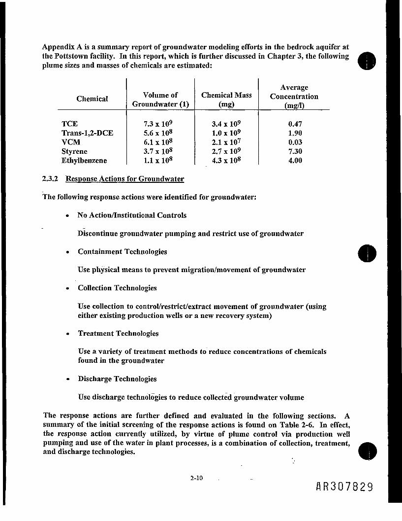
Appendix A is a summary report of groundwater modeling efforts in the bedrock aquifer atthe Pottstown facility. In this report, which is further discussed in Chapter 3, the followingplume sizes and masses of chemicals are estimated:
Chemical
TCETrans-l,2-DCEVCMStyreneEthylbenzene
Volume ofGroundwater (1)
7.3 x 1095.6 x 1086.1 x 1083.7 x 1081.1 x 108
Chemical Mass(mg)
3.4 x 1091.0 x 1092.1 x 1072.7 x 1094.3 x 108
AverageConcentration
(mg/I)
0.471.900.037.304.00
2.3.2 Response Actions for Groundwater
The following response actions were identified for groundwater:
• No Action/Institutional Controls
Discontinue groundwater pumping and restrict use of groundwater
• Containment Technologies
Use physical means to prevent migration/movement of groundwater
• Collection Technologies
Use collection to control/restrict/extract movement of groundwater (usingeither existing production wells or a new recovery system)
• Treatment Technologies
Use a variety of treatment methods to reduce concentrations of chemicalsfound in the groundwater
• Discharge Technologies
Use discharge technologies to reduce collected groundwater volume
The response actions are further defined and evaluated in the following sections. Asummary of the initial screening of the response actions is found on Table 2-6. In effect,the response action currently utilized, by virtue of plume control via production wellpumping and use of the water in plant processes, is a combination of collection, treatment,and discharge technologies.
2-10flR307829

2.3.3 Identification of Technologies for Screening
2.3.3.1 No Action/Institutional Controls
The no action scenario is typically carried through the FS as a baseline for comparison. Itinvolves no actions being taken to change the groundwater quality or to prevent movementof the chemical plume. Production pumps are turned off under this scenario andgroundwater flow direction reverses to the Schuylkill River.
The no action alternative has been combined with institutional controls as the baselinealternative in the FS. Under the no-action/institutional action alternative, the Site is left inits present condition, and the only additional action is to conduct a groundwatermonitoring program and/or impose institutional actions.
Additionally, a second baseline alternative is carried through the FS. There is currently agroundwater collection system in place which provides the plant with process water forPVC production. After use in the process, groundwater is treated in the plant's wastewatertreatment system and is discharged to the Pottstown POTW. As was shown in the RI, thecurrent collection system has controlled the offsite migration of groundwater in the bedrock•aquifer. It also has reversed the flow direction of groundwater, away from the SchuylkillRiver. Therefore, continued use of the present system is included in the evaluation ofalternatives.
The technologies considered under the institutional actions section included: accessrestrictions for groundwater uses and groundwater monitoring. Access restrictions includeregulatory restrictions on construction and use of private wells, acquisition of propertyaffected by the plume, deed restrictions, and regulatory restrictions involving zoning.Groundwater monitoring is periodic sampling and analysis of groundwater to monitor themigration of the chemical plume and groundwater quality.
Access Restrictions
This technology uses regulatory means to restrict use of the impacted aquifer until it hasbeen restored. Types of use constraints include deed restrictions, easements, well drillingpermit restrictions, well use advisories, and zoning restrictions for future use ofgroundwater. Groundwater in the vicinity of the Site is not used for drinking waterpurposes and there are no downgradient wells impacted. OxyChem is the owner of theproperty so deed restrictions are easily placed on the property deed. This technology isimplementable and is considered further.
Groundwater Monitoring Technologies
The monitoring wells are oriented to provide groundwater samples from the bedrockaquifer and are positioned to detect migration of the chemical plume. Groundwater
HR307830

monitoring is used to evaluate the success of remediation by quantifying the reduction ofchemical concentration in the bedrock aquifer. This technology is established at the Siteand is considered further.
2.3.3.2 Containment Technologies
Plume containment actions refer to minimizing the spread of the chemicals of concernthrough hydraulic gradient control. These controls are either active or passive. Activecontrols involve the use of extraction and/or injection wells or use of subsurface drains.Passive controls include the following vertical barriers: slurry wall, grouted barriers, andsheet piling. The usability of these controls is contingent on hydrogeological conditions,other subsurface conditions, applicability of available construction techniques, andchemical characteristics.
PHYSICAL CONTAINMENT BARRIERS
Physical containment barriers refer to a variety of methods whereby low-permeabilitycutoff walls or diversions are installed below ground to contain, capture, or redirectgroundwater flow. Three types of containment barriers are considered: slurry walls,grouted barriers, and sheet piling. These technologies are described below.
Slurry Walls
Slurry walls are the most common subsurface barriers for many sites because they are arelatively inexpensive means of reducing groundwater flow in unconsolidated earthmaterials. The term slurry wall is applied to a variety of barriers that are constructed in avertical trench excavated under a slurry.
The economic feasibility of a barrier is dependent upon the depth to the confining layer.Much of the groundwater exceeding the MCLs at the Site is located in the fracturedbedrock aquifer at depths from 30 to 150 feet. Slurry walls are not practical in bedrockapplications. This technology is not considered further because the depth of groundwaterrequiring containment is exclusively in the fractured bedrock aquifer.
Grouted Barriers
Grouting refers to a process whereby one or a variety of fluids are injected into a rock orsoil mass. The grout sets in place, strengthens the formation, and forms a barrier to waterflow.
Cement grouts use hydraulic cement which sets, hardens, and does not disintegrate inwater. Cement grouts are more suitable for fractured rock than for soil applications,because of their large particle size.
2-12
flR30783

Clays have been widely used as grouts, either alone or in formulations, because they areinexpensive. Clay characteristics include the ability to swell in the presence of water and toform a gel structure.
The use of grouted barriers at the Site is not considered feasible because the barrier cuts offthe primary source of recharge for groundwater (the Schuylkill River) and leads to reducedpumping rates, which in turn, lengthens remediation time. Therefore, this technology isnot considered further.
Sheet Piling
Sheet piling is used at some sites to form a groundwater barrier. Sheet piles can be made ofwood, precast concrete, or steel. Wood is an ineffective water barrier and concrete is usedprimarily where great strength is required. Sheet piling cut-off walls consist of interlockingsteel piles which are driven to the desired depth. Sheet piling is not practical in bedrock asexists at the Site. This technology is not considered further.
2.3.3.3 Collection Technologies
Collection technologies involve the active manipulation and management of groundwater to'contain or remove a plume or to adjust groundwater levels to prevent formation of aplume. These technologies include extraction wells and subsurface drains.
EXTRACTION WELLS
Extraction wells may be used for groundwater recovery and/or control. Withdrawal-typewells, used in managing chemical migration in groundwater, include well points, suctionwells, ejector wells, and deep-wells. The selection of the appropriate well type dependsupon the depth of chemicals and the hydrologic and geologic characteristics of the aquifer.Based on the conditions prevailing at the Site (including the existence of an operatingsystem), deep-wells are identified as the most appropriate technology for pumping.
Deep-wells are currently being used for groundwater collection for process needs. Specificwells are targeted to maximize capture of chemicals during remediation. This is discussedin the groundwater modeling report enclosed as Appendix A. Either new recovery wells orthe existing production wells may be used to capture chemicals. This recovery method isconsidered technically feasible and is retained for further consideration.
SUBSURFACE DRAINS
Subsurface drains include any type of buried conduit used to convey and collect aqueousdischarge by gravity flow. Subsurface drains essentially function as an infinite line ofextraction wells. T'ley create a continuous zone of influence in which groundwater flowstoward the drains.
2-13
RR307832
The depth necessary to install the drains is prohibitive and is not practical for use inbedrock as is required at the Site. This technology is not technically feasible and is notconsidered further.
AIR SPARGING/SOIL VAPOR EXTRACTION
Air sparging introduces air into an aquifer, forcing strippable chemicals to partition into the vaporphase from the water or saturated soil. This technology is often applied to shallow, unconfinedaquifers comprised of unconsolidated soils through which the air and biodegradable chemicals cantravel upward to an unsaturated zone where the chemicals are then captured by a soil vaporextraction system.
The key requirements for applicability of this technology to the bedrock aquifer are absent at thissite. There is no water table aquifer of unconsolidated soils that require remediation; theoverburden soils throughout the plant area are generally dry. The bedrock aquifer is confined tosemiconfined, and migration of chemicals in the groundwater is primarily through fractures in thebedrock; if air were to be injected into the fracture zones, there is no unimpeded passages upwardand into the unsaturated soil zone where capture by a vapor extraction system could occur. Thistechnology is not technically feasible and is not considered further for this system.
-2.3.3.4 Treatment Technologies
The chemical characterization of the bedrock aquifer is presented in the RI report and inAppendix A of this FS report. Appendix A identifies wells currently used to collect processwater and wells considered in the remediation program. From the presumed pumpingrates of the remediation wells and the RI characterization, the concentrations of thegroundwater constituents expected in the influent to the treatment system have beenestimated. These properties of the influent have been considered in the evaluation ofpotential treatment technologies.
Ex situ groundwater treatment technologies include:
• Biological treatment• Physical/chemical treatment• Air stripping• Steam strinping• Vapor phase carbon adsorption• Liquid phase carbon adsorption• UV/Peroxide• Offsite treatment
These technologies are discussed below.
2-14
flR307833

BIOLOGICAL TREATMENT
The function of biological treatment is to remove organic matter from the waste streamthrough microbial degradation. Aerobic and anaerobic treatment are the two biologicaloptions considered. The most prevalent form of biological treatment is aerobic. Anaerobicbiological treatment is not an effective method of treating large volumes of water with lowchemical concentrations and is not considered further.
Several aerobic biological treatment processes may be applicable to the treatment ofaqueous wastes. These include the conventional activated sludge process and variousmodifications of the activated sludge process, including pure oxygen activated sludge,extended aeration, contact stabilization, and fixed film systems (rotating biological discsand trickling filters).
Groundwater at the Site does not contain enough BOD or nutrients to support biologicalgrowth. This technology is considered feasible only if such a system is needed to treatwastewater discharges in the plant in addition to groundwater. If the groundwaterpumped for remediation purposes is used as process water in place of the production wellwater, enough BOD will be assimilated to support a biological treatment system. Thistechnology will not be discussed further as an option for treatment of groundwater in theTS. Biological treatment is necessary only if the remediation water is combined with theprocess water flow and is not necessary when considering groundwater remediation.
PHYSICAL/CHEMICAL TREATMENT
In the treatment of groundwater, solids must often be removed as a pretreatment step toprevent the fouling of adsorbent beds. Removal of metals may be necessary as a result ofdischarge standards or because metals interfere with the operation of water treatmentunits. Two types of physical/chemical unit treatment processes were considered: filtrationand precipitation/flocculation.
Filtration
Filtration is a physical process in which suspended solids are removed from solution byforcing the fluid through a porous medium. Granular media filtration is typically used fortreating aqueous waste streams.
Filtration is a reliable and effective means of removing low levels of solids from wastes,provided that the solids content does not vary greatly and the filter is backwashed atappropriate intervals. Filtration equipment is relatively simple, readily available in a widerange of sizes, and easy to operate and control. Filtration is also easily integrated withother treatment steps.
One operating consideration of filtration is the handling of the backwash. The backwashwill generally contain high concentrations of chemicals and require subsequent treatment.
This technology is considered feasible for inclusion as a treatment step or a polishing stepprior to discharge. Evaluation of this treatment step is not discussed further as part of thisFS because metals treatment will be provided by the plant in its process water treatmentsystem.
Precipitation/Flocculation
Precipitation is a physiochemical process in which some or all of a substance in solution istransformed into a solid waste. It is based on alteration of the chemical equilibriumrelationships affecting the solubility of inorganic species. Removal of metals as hydroxides,sulfides, chlorides, phosphates, or carbonates is a common precipitation application inwastewater treatment. Generally, lime or caustic is added to the wastewater to adjust pHand drive the reaction by providing the hydroxide ion. A reacting agent such as ferroussulfate, phosphates, sodium sulfide, or ferric chloride might be used to form the insolublespecies.
Precipitation is applicable to the removal of most metals from wastewater, including zinc,cadmium, trivalent chromium, copper, fluoride, lead, manganese, and mercury. Also,certain anionic species can be removed by precipitation, such as phosphate, sulfate, andfluoride.
Flocculation is the process by which small, unsettleable particles suspended in a liquidmedium are made to agglomerate into larger, more settleable particles. Chemicals typicallyused to cause flocculation include alum, lime, various iron salts (ferric chloride, ferroussulfate), and organic flocculating agents, often referred to as "polyelectrolytes."
Flocculation is applicable to any aqueous waste stream where precipitation alone does notform a settleable solid and particles must be agglomerated into larger, more settleableparticles prior to sedimentation or other types of treatment.
Precipitation and flocculation are well-established technologies and the operatingparameters are well defined. Precipitation and flocculation can be easily integrated intomore complex treatment systems. Precipitation is nonselective, i.e., compounds other thanthose targeted may be removed. Both precipitation and flocculation are nondestructiveand generate a large volume of sludge, which requires disposal. These technologies are notevaluated further as part of this FS because metals treatment will be provided by the plantin its process water treatment system.
AIR STRIPPING
Air stripping is a mass transfer process in which VOCs in water or soil are transferred togas. Air stripping is frequently accomplished in a packed tower. The water to be treated isdistributed over the packing material and air is blown upward through the packingestablishing intimate contact with the volatile material.
AR3Q7835

Air stripping is used to remove volatile organics from aqueous waste streams. TCE andI other volatile compounds are identified as being chemicals of concern and can be removedeffectively by air stripping.
The off-gas from air stripping may also be sent to a vapor-phase carbon unit for adsorptionof volatile organics. However, groundwater at the Site contains several compounds whichare not well suited to carbon adsorption, such as vinyl chloride or methylene chloride.Adsorption of these compounds will consume carbon at an extremely high rate, makingoffsite carbon regeneration very expensive. To remain economical, an onsite carbonregeneration system would also be needed.
An onsite carbon regeneration system employs an activated carbon bed to adsorb thevapors from the air stripper vent stream. In one scheme, the carbon is regenerated bypassing steam through the bed. The organics are vaporized and carried away with thesteam. This organic laden stream passes through condensers in which the VOCs arecondensed and separated from the water stream.
The boiling point of vinyl chloride is below the freezing point of water. This means two-stage condensing is required. The first stage condenses the liquid at a temperature close tofreezing (slightly above 0°C), and the second condenser operates below the boiling point ofthe vinyl chloride (-13.4°C).
second method used to regenerate carbon uses a small vapor incineration unit whichreheats ambient air in a heat exchanger. This preheated air is passed through the carbon
bed, adsorbs the organics from the carbon, thereby regenerating the carbon. The organicvapor stream is introduced into the combustion chamber of the incineration unit, wherethe high combustion temperatures destroy the organic compounds allowing the "organicfree" gas to be discharged to the atmosphere. A scrubber is required to remove thechlorine from the gas stream. This stream can be neutralized and discharged to thePOTW. There is no liquid organic steam to be disposed after incineration. A smallamount of ash may be generated, which requires offsite disposal.
Styrene is the only parameter which may not be amenable to air stripping in a packedcolumn. The potential may exist for styrene to polymerize in the column and causeplugging. The diffused air stripper or plate-type column are not as prone to plugging as apacked column. Either one of these could be used to treat the total groundwater flowstream or the flow from the recovery wells containing styrene.
Air stripping technology is implementable and effective for the chemicals at the Site and isretained for further evaluation, along with an air stripper vent treatment system andcarbon regeneration.
AR3Q7836

VAPOR PHASE CARBON ADSORPTION (FOR AIR STRIPPER VENT STREAM)
The process of adsorption onto activated carbon involves the stripper vent streamcontacting the carbon. The activated carbon absorbs organic constituents by a surfaceattraction phenomenon in which organic molecules are attracted to the internal pores ofthe carbon granules.
Activated carbon treatment is an effective and reliable means of removing a wide range oforganics over a broad concentration range. Upon depiction of the carbon, it is eitherregenerated onsite or sent offsite for regeneration. If usage is very low, the carbon can bedisposed and replaced with fresh carbon. The spent carbon is typically a characteristicRCRA hazardous waste and must be disposed as such. Operation and maintenance costsfor carbon regeneration or disposal as a RCRA hazardous waste are significant. Thedecision as to whether to utilize onsite versus offsite regeneration or disposal is aneconomics evaluation and is driven by the carbon usage rate.
This technology is widely used and is effective in removing the volatile organics found atthis site. This technology is implementable and is retained for further consideration.
STEAM STRIPPING
Steam stripping offers an effective method of removing VOCs from groundwater. Withthis form of treatment, steam is used to boil off the chemicals in the groundwater. Thesteam stripping column is very similar to an air stripping column. A steam stripper is veryeffective in removing a wide range of organic chemicals to very low concentrations becauseit runs at higher temperatures than an air stripper.
One possible limitation for steam stripping is that a steam stripper column is more prone toplugging than an air stripping column, because it operates at higher temperatures. In thisapplication, styrene may cause plugging. A pilot test would show if the plugging occurs. Ifplugging by styrene occurs, a separate styrene treatment system would be designed, amethod would be found to inhibit the polymerization of the styrene, or a plate type strippercolumn would be employed.
The effectiveness of steam stripping and the fact that steam is available at this Site makessteam stripping a promising option. This technology is retained for further consideration.
UV/PEROXIDE
UV/Peroxide is another versatile treatment system for groundwater. It works on a widevariety of organic chemicals and treats water with low to very low concentrations oforganics. The peroxide is injected into influent water streams and significantly increasesthe effectiveness of UV light. The system requires little attention and is reliable. Thetreated chemicals normally decompose into water and CO2. It is most effective at low flowrates and with clear water. Cloudy water blocks the UV light's penetration and decreases
2-18
8R3Q7837

its effectiveness. Styrene polymerization on the UV light may be a problem. Metals mayplate out on the UV light, reducing its effectiveness. The cost of the peroxide and theelectrical costs for operating the UV lights vary with the make-up of the stream to betreated. This technology is retained for further consideration.
LIQUID PHASE CARBON ADSORPTION
Liquid phase carbon adsorption technology is the use of activated carbon in a granularform for adsorption of organics directly from the water stream being treated. Highmolecular weight chemicals are most easily adsorbed. The compounds for which it iseffective are similar to vapor phase carbon. The organic holding capacity, compared tovapor phase carbon, is reduced, because the water depletes the capacity of the carbon, andthe carbon must overcome the water solubility of the organic compounds in order to adsorbthem. Liquid phase retention is generally less than half the capacity of vapor phasecarbon.
Total carbon usage is estimated to be nearly 4 tons per day to treat the volume ofgroundwater collected at the Site. If the cost of carbon regenerated offsite is $0.80/Ib, thetotal cost of the carbon is over $2.3 million per year. This is approximately three times thetotal operating cost of steam or air stripping and represents only part of the operating"costs.
Onsite regeneration of liquid phase carbon is not feasible because of the complexity of theequipment required. The carbon must be transferred, dewatered, and brought to veryhigh temperatures to dry and activate the carbon. This requires storage, conveyors,dewatering tanks, a multiple hearth furnace or rotary kiln, a quench system, more storage,another transfer system, and scrubbers on the furnace or kiln. A temperature of 1,700°F isrequired for activation of the carbon. This makes onsite regeneration manpower andenergy intensive, and very expensive.
Liquid phase carbon may be used as a polishing step for treatment of the productionprocess water. This may be a unit step in the plant treatment system design, but is notconsidered further for treatment of the groundwater because of the high usage rate andexpense of purchasing offsite regenerated carbon.
OFFSITE TREATMENT
Offsite treatment of recovered groundwater can be performed at a private wastewatertreatment facility.
Private Wastewater Treatment Facility
This technology uses a private wastewater treatment facility for treatment of collectedgroundwater. There is no private wastewater treatment facility within a reasonabledistance to make this feasible. The cost of disposal at such a facility is high considering the
2-19
flR307838

high volume of discharge required. This technology is not retained for furtherconsideration.
IN SITU TREATMENT TECHNOLOGIES
In situ treatment methods treat groundwater in place. In situ treatment eliminates theneed for groundwater extraction.
In Situ Bioreclamation
In situ bioreclamation involves the purposeful alteration of subsurface environmentalfactors to accommodate a specifically chosen colony of microbes, which then break downand detoxify organic wastes through metabolic means. Indigenous microbes are normallyused because they have been naturally acclimated to subsurface conditions.
Specific environmental factors that affect the feasibility of in situ bioreclamation include:
• Types and concentration of chemicals• Types and concentrations of other groundwater constituents, such as
metals, which may interfere with the effectiveness of treatment• Adequate presence of organic and inorganic nutrients• Oxygen concentration• Redox potential• pH• Degree of water saturation of the soils• Temperature• Osmotic pressure• Predator species of microbes• Competition for available nutrients
In addition, the hydrogeology must be suitable. The hydraulic conductivity must be greatenough and the residence time short enough so that added substances, such as oxygen andnutrients, are not used up before reaching all portions of the treatment zone. Sandy sitesare therefore easier to treat than those with a predominance of clay. The use of thistechnology has been typically applied to soils; its use in fractured bedrock is unproven.Therefore, in situ bioreclamation is not a suitable candidate for this application and is notconsidered further.
Clean Water Injection Only (Without Collection)
This technology involves the injection of clean water to the subsurface via wells locatedupgradient of the plume, thereby creating a mounding effect. As a result, the groundwatergradient and the natural chemical transport rate are increased. The increased gradientalters the plume characteristics and areal extent of the plume. Injection of groundwater
2"2° AR307839
without collection drives chemicals of concern towards the Schuylkill River. For thesereasons, this technology is not considered implementable and is not considered further.
2.3.3.5 Discharge Options
Discharge options screened for the FS may be subdivided into onsite and offsitetechnologies. Onsite discharge technologies include injection wells and infiltration vialagoon/pond. Offsite discharge technologies include POTW and local surface water.Onsite and offsite technologies are discussed below.
ONSITE DISCHARGE
Infiltration via Lagoon/Pond
This onsite discharge technology involves the discharge of treated water to a lagoon/pondconstructed for infiltration to the groundwater. The size of this lagoon/pond depends onthe permeability of the overburden material and the quantity of water to be assimilated.
The Schuylkill River surrounds three sides of the plant. The remaining fourth side of theplant is "high ground" and covered by buildings, roadways, and parking areas, leavingInadequate space for ponds or lagoons. If injection of water is necessary, injection wellswould be the more feasible technology. Infiltration is not considered further as a dischargeoption.
Infection Wells
This technology re-injects treated groundwater to the subsurface. To use this technology,discharge criteria is established for chemical and physical parameters. Flow quantity islimited according to the hydrogeology of the site.
There are no federal standards for discharge into the ground and EPA defers to the statesfor such matters. PADER has not developed a specific standard for injection of water intothe ground. A conservative assumption is that standards for concentrations of inorganicmaterials are at or below background levels, and standards for concentrations of manmadeorganic materials are at non-detectable levels or method detection limits (MDLs). MDLsare dependent on the analytical method and equipment used and are expected tocontinually decrease as analytical capabilities increase. Injection standards are dynamic ifMDLs are used as discharge criteria.
There is also a concern with determining an effective location for water reinjection so itreplenishes the groundwater supply and does not spread the chemical plume furtheroutward. There is no recognized benefit in terms of promoting aquifer restoration byapplying the use of injection wells into a remedial program at this particular site. For thisreason and as a result of the difficulty of defining applicable standards and consistentlymeeting MDL limits, this technology is not retained for further consideration.
OFFSITE DISCHARGE
Surface Water Discharge
This technology involves the discharge of treated water directly to the Schuylkill River.Permitting requirements must be met and all discharges of treated water must bemonitored regularly.
Ambient water quality data for compounds of concern at the Site are found on Table 2-3.Surface water discharge is feasible. This technology is retained for further consideration.
POTW
Under this option, treatment of pumped groundwater is performed at a local POTW. Thelocal POTW is the Pottstown Municipal Authority. To use this technology, the POTWlimits would have to be met, which include organic chemicals, plastics, and synthetic fibers(OCPSF) indirect discharge limits. Pretreatment using the technologies discussed in thisdocument would be required. Process water is currently discharged to the PottstownPOTW after pretreatment which includes settling, clarification, and air stripping. Offsitesecondary treatment by the local POTW is implementable and is retained for furtherconsideration.
2.3.4 Evaluation of Technologies and Selection of Representative Technologies andProcess Options
The technologies for bedrock aquifer remediation retained after initial screening are:
• No Action/Institutional Controls
Groundwater MonitoringAccess/Use Restrictions
• Collection
Extraction Wells (either by current production wells or new recoverywells)
• Treatment
Air StrippingSteam StrippingVapor Phase Carbon AdsorptionU/V Peroxide
2-22
BR3078l*l

• Discharge
POTWSurface Water
These technologies were then screened considering effectiveness, implementability, riskreduction, and cost. The summary of this screening is found on Table 2-7. The effectivenessevaluation focused on:
1. The effectiveness of the technology in handling the anticipated volumesof groundwater and meeting remedial design objectives;
2. The effectiveness of long-term and short-term risk reduction duringimplementation of the remedial action;
3. The reliability of the process to address the chemicals and conditions atthe Site.
The implementability evaluation focused on:
1. The technical feasibility of implementing the technology and
2. The administrative feasibility of implementing the technology.
The cost analysis focused on capital and operation and maintenance costs based onengineering judgment.
Table 2-7 indicates that institutional controls are effective, easily implemented, and cost-effective and, therefore, are retained for incorporation into alternatives.
Extraction wells were found to be effective, implementable, and cost-effective for collectionof groundwater.
Air stripping and steam stripping were retained for organics treatment over UV/Peroxidetreatment, which was screened out based on high energy costs of that technology. Vaporphase carbon adsorption was retained as polishing steps for air emissions.
Both discharge to the POTW and to surface water (the Schuylkill River) were retainedbased on the effectiveness and implementability of both options. Treatment of thegroundwater to standards applicable to either discharge option is feasible. The dischargeoption selected will be dependent on the selection of the treatment technology anddischarge option best suited for the plant production process water. A summary of thetechnologies and process options to be incorporated into alternatives for groundwatertreatment are found on Table 2-8.
flR3078i42

3.0 ALTERNATIVES DEVELOPMENT FOR GROUNDWATER
3.1 BEDROCK AQUIFER REMEDIATION
3.1.1 Chemical Plume Characterization and Recovery Model Design
The remediation of the bedrock aquifer will involve recovery and treatment of groundwaterwithin the defined remediation capture zone. Groundwater modeling was performed toassist in developing a recovery program. The modeling was used to identify feasiblerecovery pumping scenarios considered in the remediation of the bedrock aquifer.Appendix A (Modeling of Potential Groundwater Recovery Scenarios) presents themethodology and results of the modeling efforts.
Concentration gradients and cross-sections showing the distributions of the 5 VOCs ofconcern are presented in Appendix A (Figures 2-1 through 2-10). These figures illustratethat the concentrations of the chemicals are higher in the shallow portion of the bedrockaquifer in the center of the Site, and at depths corresponding to the more fracturedsandstone units as opposed to the more impermeable shale and siltstone units. Theconcentration gradients were used in determining chemical plume (solute) volumes and thetotal chemical mass required to be remediated. Calculated chemical volume and mass dataare presented on Table 3-1.
Table 3-1 also shows the calculated number of aquifer flush volume;? required to remediatethe bedrock aquifer. One aquifer flush volume is the replacement of the volume of onebedrock aquifer plume via pumping.
Aquifer restoration times were then calculated for a number of theoretical removal(pumping volume) rates. The aquifer restoration times were calculated in accordance withEPA/540/G-88-003 (Guidance on Remedial Actions For Contaminated Groundwater atSuperfund Sites, Interim Final, December 1988). The concentrations of the given chemicals arecalculated as weighted averages in accordance with the formula in the guidance, and therestoration time for a chemical at a particular removal rate is the product of the flush time for oneplume volume times the number of required flush volumes. Chapter 3.0 of the FS Appendix A(Modeling of Potential Recovery Scenarios) describes the recovery model and calculations of themodel parameters (e.g., chemical concentrations and restoration times) in greater detail. Therestoration time is the time required to reduce the concentration of the given chemical to itsRG.
Table 3-1 includes the projected restoration times of the 5 VOCs at three theoreticalpumping rates. As indicated, TCE is the chemical with the longest expected restorationtime at any given removal rate. Thus, the subsequent modeling efforts considered wellplacement and pumping scenarios that result in the shortest length of time required toremediate TCE to its PRG.
3-1

It was also recognized that the modeling efforts would have to consider the need to controlcross-migration of the chemicals beyond their respective plumes. The remediation programmust avoid spreading chemicals to a portion of the aquifer not currently affected by thatchemical, a situation which would only increase the overall restoration time of the bedrockaquifer. Each chemical has a threshold depth or elevation below which the concentrationdrops off markedly over a short distance. The figures in Appendix A show the verticalconcentration gradients in the bedrock aquifer in the center of the site, where crosschemical migration is of greatest concern. Table 3-2 lists the chemical and area specificthreshold ranges as determined from Packer testing results for central site boreholes TB-1,TB-2, and TB-3. The threshold depths dictate the maximum permissible drawdown thatcan occur in the central bedrock aquifer as a result of recovery well pumping, before crosschemical migration occurs deeper into less impacted portions of the aquifer.
The Walton WELFLO model was used for groundwater recovery analysis because of itscapability to predict drawdowns from multiple pumping wells, which is the recoveryscenario anticipated for this Site. The model was calibrated using a known static waterlevel, measured during the 1989 plant maintenance period and a current production wellpumping water level measured in November 1991.
Eleven wells were utilized in the modeling efforts as potential recovery wells. Theirlocations, depths, and completion specifications were based on the geology and hydraulicproperties of the aquifer, the threshold depths of each plume, and the configuration of eachchemical plume. These 11 wells consist of existing wells, modifications to existing wells, andproposed new wells. Each well was targeted to optimize the removal of one or morechemical of concern.
3.1.2 Modeling Results
Two different groundwater recovery scenarios were modeled. First, a minimumgroundwater recovery scenario was modeled, which identified the minimum number ofrecovery wells and the minimum combined flow rate required to capture the total chemicalplume. The model identified 5 wells at a combined flow rate of 160 gpm to meet the aboveobjective. Second, a potential maximum groundwater recovery scenario was modeled,which identified the minimum number of recovery wells required to attain the maximumcombined flow rate that optimized restoration of the bedrock aquifer, without drawing thewater level in the aquifer below the chemical threshold depths. The model identified 9 ofthe 11 wells at a combined flow rate of 410 gpm.
Figure 3-1 shows the locations of the wells required for both the minimum and potentialmaximum recovery scenarios. Table 3-3 lists the construction specifications and rationalefor the selected wells.
Both modeling scenarios show that the effective recovery program will require wellsconcentrated in the center of the Site, at both shallow and deeper depths to recover the
AR3078UI*

styrene plume and other VOC plumes. Both scenarios require one well (RW-11) to recoverVOCs on the northern fringe of the capture zone where the pumping of central Site wellsdoes not control groundwater flow.
3.1.3 Preliminary Remediation Goals
The achievable detection limits associated with the CLP analyses used on RI/FS projects arehigher than the MDLs achievable by other analytical protocol. Lower detection levels arepossible using non-CLP methods, such as Method 601/602. EPA (40 CFR, Part 136) givesMDLs in reagent grade water for the 5 VOCs of concern at this site, and also provides formula tocalculate expected MDLs on nonreagent grade aqueous samples, such as would be encountered ingroundwater at this site. A comparison of these MDLs with the Preliminary Remediation Goals(PRGs) considered for this project are shown on the table below. The PRGs are the MCLs forthe chemicals listed.
MDL (ug/1)
PRGs(ug/1)
510027010
601/602Reagent Water
0.120.100.180.200.27
601/602Environmental
Sample
0.331.620.440.28NA
TCEtrans-l,2-DCEVCMEthylbenzeneStyrene
The groundwater recovery program developed with the use of modeling, and presented inAppendix A to this FS report, represents the most time-efficient and technically implementablealternative for groundwater remediation at this site, regardless of whether an MDL or the MCL isconsidered as a remedial objective. The goal of the modeled groundwater recovery program canbe considered as the MDL, though the model predicts that this best effort remedial alternative willnot achieve the MDL for TCE (the most widespread chemical in the groundwater) within a 100-year timeframe. The table below shows the anticipated concentrations for each of the 5 VOCs at25 year intervals during the remedial program.
Concentrations (ug/1)
TCEtrans-l,l-DCEVCMEthylbenzeneStyrene
25 Years
148NDNDND17
50 Years
43NDNDNDND
75 Years
13NDNDNDND-,.
100 Years
4.10NDNDNDND
HR3078145

The above concentrations were calculated using the methodology described in the Appendix AModeling Report. The concentrations calculated for all chemicals except TCE are below theMDL at 50 years. At 25 years of pumping, only styrene and TCE are expected to be detectable.
The associated residual risks with the concentrations calculated above are shown on the tablebelow at 25-year intervals during the remedial program.
Residual Risks During Remediation
25 Years
7.2 x lO-56.2 x 10⁻⁵
50 Years
1.8xlO-51.8xlO-5
75 Years
5.5 x 10-65.5 x 10'6
100 Years
UxlO-6UxlO-6
Residual Risk (total)TCE (only)
Acceptable risk for domestic groundwater use is between 1.0 x 10"4 and 1.0 x 10'6. Based onmodeling predictions, the remedial program will reach this risk range within 25 years, but cannotj-edue the concentration of TCE to a Method 601/602 MDL within 100 years of operation.Within that predicted timeframe, however, TCE will be reduced to a level below its current MCL,and the other 4 VOCs will be nondetect.
3.1.4 Recovery Program Implementation
3.1.4.1 Start-up
The bedrock aquifer restoration program will be a phased program, with monitoring andmodification of the individual well pumping rates as the remediation progresses. Theprogram start-up will involve the 9 wells listed on Table 3-4 (see Figure 3-1 for welllocations).
One remediation approach is to use the groundwater recovered from the bedrock aquiferin the plant process. The anticipated average groundwater need for plant productionpurposes is close to the design flow rate for the recovery program. The plant is undergoingan upgrade of its process wastewater treatment system, and some integration of the processand remediation technologies is an important consideration in the alternative developmentand evaluation.
The plant currently utilizes as many as 5 existing production wells to obtain bedrockgroundwater for plant production needs. Although most of these are located in the centerof the Site, the existing production wells are not ideally located/constructed to maximizechemical recovery. An additional component of the recovery program is to terminate theexisting production well pumping system (other than those wells planned for modification
3-4

and incorporation into the recovery program) which could interfere with the recovery wellprogram.
The recovery program may involve treatment before or after the groundwater enters theplant production process system. In either case, if the plant is to use the remediation waterin the PVC production process, the first source of water is water from the recovery wellswithin the capture zone. If additional production water is required, it will be obtainedfrom wells outside the capture zone which will be located and pumped at rates which willnot interfere with the recovery program. Groundwater modeling indicates that an existingproduction well (PW-1R) can pump a sustained yield of 25 gpm without interfering withthe efficiency of the recovery program. Modeling also indicates that 3 wells can be locatedon OxyChem property about 1,000 to 4,000 feet north of well TB-7 and be pumped at acombined flowrate of up to 300 gpm without interfering with the efficiency of the recoveryprogram. -
The initial recovery program will involve pumping the wells at the design flow rates shownon Table 3-3. Water levels will be monitored in each well to assure that drawdown does notexceed the threshold depths of specific chemicals.
3.1.4.2 Pump Rate Adjustments
I The long-term rates will be dependent on the maximum yields of the individual recoverywells which can be maintained without drawing down water levels below threshold depths.When the bedrock aquifer groundwater has stabilized, pumping rates may be increasedfrom design flow rates. The objective of any pump rate adjustment will be to minimize theoverall restoration time.
The efficiency of the pumping rates established for the recovery program will be evaluatedperiodically during the aquifer restoration. As wells on the fringes of the capture zoneclean up, for example, they may be dropped from the program. This will allow for higherpumping rates from wells in the center of the Site.
3.1.4.3 Performance Monitoring
Groundwater monitoring will be conducted to track the performance of the recoveryprogram. The monitoring will be conducted throughout the groundwater remediationprogram.
The anticipated 9 wells in the recovery program, and 3 existing wells (TB-1, TB-7, and TB-10)will constitute the groundwater monitoring well network. The 3 existing wells are screened at thelateral and vertical limits of the capture zone and will be used to ascertain that cleanup isoccurring throughout the remediation zone. The 9 recovery wells will be constructed with asampling port that allows direct withdrawal (i.e., precludes open discharge and potential
1 volatilization). The recovery wells will be sampled after a specified shutdown time and purging.Potentiometric data (e.g., water level readings) will be obtained at all wells in the monitoring
network at the time of sampling. There are additional existing wells within the plume which couldbe used for evaluating the progress of the remediation. Details of the performance monitoringwill be developed as part of the remedial design.
The groundwater monitoring program will be conducted on a semi-annual basis for thefirst 2 years, on an annual basis for the third through fifth year, and at 5-year intervalsthereafter. Initially, the parameters analyzed will be the 5 VOCs of concern in the bedrockaquifer (i.e., TCE, trans-l,2-DCE, VCM, ethylbenzene, and styrene). This is the anticipatedgroundwater monitoring program used to develop cost estimates in this FS report; thegroundwater monitoring plan will be presented in a greater detail during Remedial Design. Themonitoring well network and the parameter list will be re-evaluated after each round ofresults. As the extent of the plume diminishes with time as the result of remediation, wellson the edges of the capture zone will clean up first and then be eliminated from theremediation and monitoring program.
3.2 GROUNDWATER TREATMENT
3.2.1 Influent Characterization
Groundwater sampling was performed from 1990 to 1992 as part of the RI. Analyticalresults from the sampling of the bedrock aquifer, overburden aquifer, production wells,and packer testing provide the data used to characterize the groundwater. This data isincluded in Appendix K of the RI Report.
Characterization of the influent was accomplished by using analytical data from wells closeto, and at the same depth, as the proposed remediation wells. These wells are located in thecenter of the Site and the concentrations of each of the chemicals of concern are in thehigher end of the range. The characterization is summarized on Tables 3-5, 3-6, 3-7, and 3-8, which show the average and maximum concentrations expected for each parameterbefore and after the PVC production process. The maximum concentration for eachparameter was used in the stripping calculations to be sure the treatment systems willhandle maximum levels expected.
In the proposed remediation scheme, there are 7 deep and 2 shallow remediation wells.The concentrations from these wells are mathematically modeled to determine the influentfor the treatment system. The concentration for each parameter which was detected isshown in a column under its associated well. The resulting concentration for eachparameter is calculated using the flow and concentrations for each well. The followingexplains the calculation using flows from two hypothetical wells Wl and W2:
3-6AR3Q78J48

Flow (F)
Fj = 70 GPMF2 = 30 GPMFt = 100 GPM
Concentration (X)
Xt= 10 PPMX2 = 100 PPMXt = ?
where 1 refers to Well 1, 2 refers to Well 2, and t refers to combinedflow.
The following equation calculates Xt, the concentration of a given parameter in thecombined flow:
Table 3-6 shows the flows, and maximum concentrations of chemicals for all the wells andthe resulting calculated maximum concentration, (maximum Xt), which will be the influentto the treatment system located before the PVC production process. Table 3-5 wasdeveloped the same way using average concentrations in each well. Tables 3-5 and 3-6calculate the influent for air and steam stripping before the PVC production process.These are Alternatives 2A and 3A where the stripping unit is sized for 410 gpm. Tables 3-7and 3-8 calculate the influent for the air and steam stripping after the PVC productionprocess. These are Alternatives 2B and 3B where the stripping unit is sized for 620 gpm.
3.2.2 Discharge Limits
Standards for treatment were estimated based on two different discharge scenarios,indirect and direct discharge. The standard used to evaluate treatment technologiesassumes the lower limit of discharge standards for each parameter requiring treatment.
3.2.2.1 Indirect Discharge Limits
The indirect discharge option would involve pretreatment of the groundwater anddischarge to the Pottstown Borough Authority (POTW). The Pottstown POTW presentlypermits OxyChem's discharge. The presently permitted levels are shown on Table 3-9along with some possible future lower limits, under the column labeled "Estimated LowestFuture". In addition, OCPSF categorical limits are listed on Table 3-9. These Federallymandated standards will have to be met for this indirect discharge. These standards will beused as the discharge requirement for treatment system evaluations whether or not theremedial groundwater is pretreated and/or combined with plant process water anddischarged as a common stream.
3-7

3.2.2.2 Direct Discharge Limits
EPA OCPSF limits and Pennsylvania Chapter 16 limits are used to develop directdischarge limits. There are two sets of OCPSF standards: One for biological treatmentand one for non-biological treatment.
Pennsylvania standards for direct discharge to the Schuylkill River are based onPennsylvania Chapter 16. Chapter 16 referred to, herein, is Pennsylvania Chapter 16,Water Quality Toxics Management Strategy Appendix C and D - Statement of Policyunder Title 25, Part I, Subpart A, Article H. At the present time, PennsylvaniaDepartment of Environmental Resources (PADER) uses this water quality standard todetermine river discharge standards.
Tables 3-10 and 3-11 use Chapter 16 and OCPSF Limits to approximate the standardswhich might be imposed by PADER. The following are the assumptions for thiscalculation:
1. Q_7_io flow for the Schuylkill River upstream of OxyChem.
2. A peak flow rate of 700 gpm for OxyChem's discharge. The 700 gpm isbased on a maximum gpm periodic requirement for plant process water.
3. Target water quality is assumed to be Pa. Chapter 16 with appropriatefactors, called Coefficients of Variability, for fish and aquatic life andhuman health. These factors change from time to time and the mostrecent factors are used. The factors being applied at the present timeare:
Coefficient of Variability for Fish and Aquatic Life:Criteria Continuous Concentrations (CCC) = 0.83Criteria Maximum Concentrations (CMC) = 0.32
Coefficients of Variability for Human Health;Human Health = 1.16
4. The upstream water is assumed to contain zero levels of chemicals.
There are three factors which the calculation does not take into account:
• There may be some upstream discharge of chemicals which may exhaustthe available loading of an individual parameter. Therefore, theallowable mass loading to OxyChem may be lower than the value shownin the calculation.
flR3078503-8

• The PADER watershed study for the Schuylkill River and the results willnot be available until the end of 1992, at the earliest.
• The calculation does not include mixing, stripping, or biodegradationbecause zero upstream loading is assumed. The PADER watershed studywill evaluate the chemical loading of the Schuylkill River.
Explanation of Calculations for Direct Discharge Limits in Table 3-10:
1. Column 1 - Parameter
List of parameters which were analyzed for the study
Example - Trichloroethene (TCE)
2. Column 2 - Instant. Max
For parameters, where Chapter 16 determines the limit, theinstantaneous maximum value is 2.5 times the Xo value (Outfall Limit)
Example - TCE = NA, This is not applicable, because OCPSF was thedetermining lower limit.
3. Column 3 - Daily Maximum
For parameters where Chapter 16 determines the lower limit, thisnumber is 2 times the Xo value (Outfall Limit), otherwise OCPSFdictates.
Example - For TCE the value is 0.054 mg/1, OCPSF was the determininglimit, so the Daily Maximum is the OCPSF Daily Maximum.
4. Column 4 - Monthly Average
For parameters where Chapter 16 determines the lower limit, thisnumber is equal to the Xo value (Outfall Limit), otherwise OCPSFdictates.
Example - For TCE, the value is 0.021 mg/1, OCPSF was the determininglimit, so the Monthly Average is the OCPSF Monthly Average.
3-9 38307851

5. Column 5 - Determining Limit
This states whether OCPSF or Chapter 16 determined the lowest limit
Example - For TCE, OCPSF limits were the lowest limits
6. Column 6 - Pa. Chapter 16, aquatic life, CMC
Example - For TCE, 2.25 mg/1 is the criteria maximum concentration.
7. Column 7 - Pa. Chapter 16, aquatic life, CCC
Example - For TCE, 0.45 mg/l is the criteria continuous concentration.
8. Column 8 - Pa. Chapter 16, Human Health Criteria
Example - TCE = 0.003 mg/1
9. Columns 9, 10 & 11 - Pa. Chapter 16, Aquatic life, CMC & CCC andHuman Health with factors
Example - TCE (CMC) = 2.25 mg/1 x 0.32 = 0.7200
TCE (CCC) = 0.45 mg/1 x 0.83 = 0.3735
TCE Human Health = 0.003 mg/1 x 1.16 = 0.0035
10. Column 12, - Xd Limiting Concentration
Choose the lowest value from Columns 4,5 and 6
Example - TCE = 0.0035 mg/1 (human health) is the lowestconcentration.
11. Column 13 - Xo Outfall Limit
Equation:
(Qu * Xu) + (Qo * Xo) = Qd * Xd
where: Q = Flow (cfs)X = Concentration (mg/1)u = upstream rivero = OxyChem outfalld = downstream river '"'•'
3-10 AR3Q7852

Assume Xu = O for no upstream concentrationThen Qu * Xu = OAnd Qo * Xo = Qd * Xd
Rearranging this equation:
Xo = (Qd * Xd)/Qo
where: Qd = Q7-10 River Flow (250 cfs) plus OxyChem Flow (1.56 cfs)Xd = Value from Column 7Qo = OxyChem's Flow (1.56 cfs)Xo = OxyChem's outfall (discharge) limit
The Calculation of Qd is as follows:
CFS = 700 gpm/(7.48 g/cf * 60 s/m) = 1.56 cfs
Example for TCE:
Solving for Xo:
Xo = (251.56 * .0035)/1.56 = 0.561 mg/l
12. Columns 14 and 15, OCPSF Limits
These columns contain the Daily Maximum and the Monthly Averagefor OCPSF direct dischargers using biological treatment.
Example: OCPSF Daily Maximum for TCE = 0.054 mg/lOCPSF Monthly Avg for TCE = 0.021 mg/l
3.2.3 Chemicals Requiring Treatment
The influent to the treatment system was simulated, as described in the first part of thissection under Groundwater Characterization, and is included im Tables 3-12 and 3-13,which compare the influent with the effluent standards for direct and indirect discharge.Influent chemicals above the effluent standards which require treatment are noted onTable 3-14. There are additional chemicals that may need treatment but for which thereare no existing standards. These are listed as "May Require Treatment" on Table 3-14.Table 3-15 is a summary of the lowest discharge standards for each of the chemicals ofconcern.
3-11 1*307853

,2.4 Existing Treatment System
ive production wells are used at the present time to pump groundwater for process use.Three of the wells, PW-5, PW-8 and PW-10, operate continuously. Production well PW-6generally operates for daily peak demands, 4 to 8 hours per day. Production well PW-9)perates only occasionally.
Water from the production wells is used for product washing and as cooling water.Chemicals from the process are introduced into this process water and treatment isrequired before discharge.
The existing treatment system consists of coarse-screening, equalization, clarification, andair stripping. The clarification removes PVC solids, which are recovered, and the airstripper removes TCE and VCM before discharge to the Pottstown POTW.
There is one air stripping unit in the existing treatment system. The purpose of the air stripper isremoval of TCE and VCM from the production process effluent water before discharge to thePottstown POTW. The normal sampling and analytical work performed on the influent andeffluent of the air stripper is for TCE and VCM. The influent and the effluent of the air stripperwere sampled and analyzed for styrene which was not detected. This is not unexpected becausethe production water is from the deep wells which have no detectable styrene.
Remediation will involve groundwater recovery from the shallow portion of the aquifer in thecenter of the Site where styrene concentrations are elevated. The styrene could affect processingor product quality. Groundwater from the styrene remediation wells will either bypass theprocess or be treated prior to being used in the process.
3.2.5 Groundwater Remediation Alternatives
3.2.5.1 Technologies Retained
The following is a summary of the technologies retained for integration into thealternatives:
Direct orIndirect Position in Treatment
Treatment______Discharge_____Type of Removal_______Train
Air StrippingSteam StrippingVapor Phase CarbonIncineration
BothBothBothBoth
OrganicsOrganicsOrganic VaporsOrganic Vapors
PrimaryPrimaryAir Stripper VentCarbonRegeneration
3-12
fiR3Q785l.

3.2.5.2 Alternative 1A - No Action/Institutional Controls
Alternative 1A involves no active remediation. Deed/land use restrictions are placed on thePottstown facility property. All production wells are turned off and no groundwater iscollected. This results in the Pottstown plant collecting its process water from theSchuylkill River and removes the containment barrier which prevents groundwater fromdischarging to the Schuylkill River. This alternative is carried through the FS as a baselinecomparison for the other alternatives.
3.2.5.3 Alternative IB - Groundwater Collection Using Production Wells and Treatmentby Air Stripping
Alternative IB allows the present pumping scenario to continue without alteration. Theplant continues to collect its process water from existing production wells. Groundwater istreated in the existing air stripper.
3.2.5.4 Alternative 2A and 2B - Air Stripping
Air stripping the VOCs in the groundwater can be accomplished before the water entersthe production process or after the water leaves the production process. These locations forthe air stripper are shown in Figure 3-2. The basic stripper configuration and operation(will be the same for either location. The water flow and the influent concentrations will bedifferent.
Alternative 2A will treat groundwater before the production process. Alternative 2B will involveplacement of the air stripper in the treatment train after the suspended solids have been removed;this alternative will treat the groundwater after the production process. Groundwater will beobtained from 9 recovery wells. The locations of those wells are shown on Figure 3-1. AppendixA (Modeling of Potential Groundwater Recovery Scenarios) provides the rationale for selectingthe well locations and the construction and anticipated pumping rate of each well.
The concentrations of chemicals to be stripped from the groundwater will be different forAlternatives 2A and 2B. As shown in Figure 3-2, water from clean wells is pumped into theprocess to supplement the remediation well water flow. This increases the flow, but lowersthe concentration of volatile organics to be treated by the air stripper. Other volatileorganic materials introduced into the remediation well water as it passes through theproduction process are not considered in the evaluations performed in this FS. These willbe treated to acceptable levels for discharge by additional treatment systems or bymodification of the air stripper. Therefore, the calculations assume no change in mass as thegroundwater passes through the production process.
Figure 3-3 shows the air stripping process in detail. The air stripper will be a packedcolumn or tray column stripper. A tray column or diffused air stripper may be necessary.because of the styrene from the shallow wells. The styrene may polymerize and plug the
3-13/IR307855

packing. The trays in a tray column or a diffused air stripper are much less prone toplugging than the packing in a packed column.
The vent gases leave the air stripping column and enter vapor phase carbon columns wherethe organics are removed before the vent gas is discharged to the atmosphere. Two carboncolumns will be used; one will be on-line for adsorption while the other is beingregenerated. The carbon columns are regenerated using hot air, which is provided by asmall vapor incineration unit. This unit burns a fuel such as natural gas or propane. Theheat from the combustion process elevates the air temperature in a heat exchangersurrounding the combustion chamber. This hot air is used for regeneration of the carbon.The organics picked up by the air stream, during regeneration of the carbon, are ventedinto the combustion chamber of the incinerator where they supplement the fuel and attainhigh enough temperatures in the combustion process to destroy all the organic materialbefore discharge to the atmosphere.
The advantage of this system compared to direct incineration of the air stream from the airstripper is that the size of the incinerator for regeneration is much smaller than the size ofan incinerator needed for the incineration of the vent gas from the air stripper. The reasonfor this is that gas flow rate determines the size of the incinerator and the gas flow ratefrom the air stripper is much higher than the hot air flow required for regeneration.Operating costs for fuel are also proportionally lower for the air flow rate required forregeneration.
3.2.5.5 Alternatives 3A and 3B - Steam Stripping
Steam stripping the volatile organics in the groundwater can be accomplished before thewater enters the production process or after the water leaves the production process.Steam stripping can also be applied even if the remediation groundwater is not laterentered into the process water stream. These locations for the steam stripper are shown inFigure 3-4. The basic stripper configuration and operation will be the same for eitherlocation. The water flow and the influent concentrations will be different.
Alternative 3A will treat the groundwater prior to the production process. Alternative 3Bwill treat the groundwater after the production process.
The concentration levels of chemicals to be stripped from the groundwater will be differentfor Alternatives 3A and 3B. As shown in Figure 3-4, water from clean wells is pumped intothe process to supplement the remediation well water flow. This increases the flow, butlowers the concentration of volatile organics to be treated by the steam stripper. Otherorganics absorbed by the remediation well water as it passes through the productionprocess are not considered in the evaluations performed in this FS. These will be treated toacceptable levels for discharge by additional treatment systems or by modification of thesteam stripper.
3-14 3R307856

Figure 3-5 is a diagram of the steam stripping system. The water to be treated (influent)enters a heat exchanger and is preheated by the clean water stream leaving the bottom ofthe stripper column. Steam is introduced into the bottom of the steam stripping columnand rises up through the packing carrying with it the organic material stripped from theinfluent water entering the top. The hot, treated, influent water falls to the bottom of thecolumn and runs through the preheat heat exchanger before discharge.
The steam and organic vapors which exit the top of the steam stripper column enter aseries of two condensers. The first condenser will condense the vapor to near freezing(about 35°F) which removes the water and organics with boiling points above freezing.The organics will float or sink and can be separated out and disposed offsite. The waterwill return to the top of the stripper because it will have some soluble organics. A secondcondenser which operates at a very low temperature is required to remove the remaininglow boiling point organic materials such as vinyl chloride. These have to be collected underpressure and disposed offsite. There is not enough water left in the vapor stream enteringthe second condenser to cause plugging. Figure 3-4 shows the stream stripping process indetail.
3.2.6 Technical Evaluation of Alternatives
Alternative 1A was not evaluated because it involves no remedial action.
.2.6.1 Alternative IB - Groundwater Collection Using Production Wells and Treatmentby Air Stripping
As was described in Appendix A, the present collection system provides groundwater asplant process water. The system also contains movement of groundwater. Groundwater isnot migrating offsite or discharging to surface water as a result of the reversal ofgroundwater flow direction caused by the pumping. The present wells are screened atdepths which result in chemicals in the groundwater being drawn deeper in the aquifer bythe pumping action. The groundwater containing these chemicals is captured by thepumping system, used as process water, and subsequently is treated in the plantwastewater treatment system.
The plant wastewater treatment system consists of clarification and! settling for PVC andmetal removal, air stripping for VOC removal, and discharge to the Pottstown POTW forfurther treatment of BOD. The plant wastewater treatment system is scheduled forupgrading in 1994. The lined lagoons, which contain PVC material precipitated duringtreatment of wastewater, are being removed in this upgrade. Concrete basins used insettling and clarification are to be replaced with tanks. The plant is evaluating alternativesfor VOC treatment and discharge options; however, no decision! is expected prior tosubmittalofthisFS.
3-15

3.2.6.2 Volatile Organics to be Removed Jlfe
There are two groups of volatile organics involved in the evaluation:
A. Volatiles of concern
1. Trichloroethene (TCE)2. 1,2-trans-dichloroethylene (trans-l,2-DCE)3. Vinyl Chloride Monomer (VCM)4. Styrene5. Ethylbenzene
B. Other volatiles that must be treated to allow discharge to the POTW orthe Schuylkill River
1. 1,1-DichIoroethene2. 1,2-DichIoroethene3. Chloroform4. Methylene Chloride5. Toluene
These are the volatile organic chemicals modeled for treatment by air and steam stripping.Table 3-16 shows the influent, effluent, and physical constants used in the strippingcomputer model to obtain the stripper design. The effluent concentrations assumed for themodel are half of the estimated limit for discharge as were found in Table 3-15.
3.2.6.3 Alternative 2A - Air Stripping Before the PVC Production Process
Figure 3-6 shows the effectiveness of air stripping on the chemicals requiring treatment foran air stripper located before the PVC production process. The packing height vs. theAir/Water ratio is also shown. The curves were calculated from an air stripper programusing the input as shown on Table 3-16. The assumed influent are based on maximums.The effluent standard used was assumed to be the lowest standard for all the dischargeoptions for each of the parameters. Table 3-14 summarized these chemicals which requiretreatment. Referring to Figure 3-6, styrene is the most difficult to strip of all the organicsand will require a column packing height and air/water ratio which is above and to theright of any point on the styrene curve. One point which satisfies this requirement is 30 ft.of packing and air/water ratio of 150. This size stripper would also strip the othercomponents because this point is above and to the right of at least one point on any of theother curves.
The total height of the stripper would be about 40 feet high, the diameter would be 7.2 feetand the air flow would be about 6,800 standard cubic fee: per minute (SCFM). This is alarge but feasible air stripping unit.
aR307858

3.2.6.4 Alternative 2B - Air Stripping After the PVC Production Process
Figure 3-7 shows the effectiveness of air stripping on the chemicals requiring treatment foran air stripper located after the PVC Production Process. The Packing Height versus theAir/Water Ratio is also shown. The curves were calculated from an air stripper programusing the input as shown on Table 3-16. The assumed influent are based on maximums.The effluent standard used was assumed to be the lowest standard for all the dischargeoptions for each of the parameters to be treated. Table 3-14 summarizes the parameterswhich require treatment. Referring to Figure 3-7, styrene is the most difficult to strip of allthe organics and will require a column packing height and air/water ratio which is aboveand to the right of any point on the styrene curve. One point which satisfies thisrequirement is 28 feet of packing and an air/water ratio of 150. This size stripper wouldalso strip the other components because this point is above and to the right of at least onepoint on any of the other curves.
The following table summarizes the design of the air stripper for both locations, before andafter the PVC Production Process.
Item
Air/Water Ratio (lbs./l,000 Ibs.)Water Flow (gpm)Air Flow (CFM)Diameter (Ft.)Packing Height (Ft.)Approx. Total Height (Ft.)
Before Process
150410
6,8007.23040
After Process
150620
10,3008.92838
3.2.6.5 Vapor Phase Carbon
Table 3-17 shows the carbon usage for each of the components and the total expected usageof the carbon. Carbon usage is high enough so that offsite regeneration of the carbonwould be very expensive. Onsite regeneration would require having two containers ofcarbon. One container would be regenerated while the other is being used. The carbonusage rate is based on the average influent concentrations and is the same whethergroundwater is remediated before or after the process.
3.2.6.6 Alternatives 3A and 3B - Steam Stripping
Figures 3-8 and 3-9 show the effectiveness of steam stripping on the chemicals requiringtreatment for steam stripping before and after the PVC production process. The packingheight vs. the Steam/Water ratio is shown. The curves were calculated from a steamstripper program using the input as shown on Table 3-16. The assumed influents are basedon maximums. The effluent standard use was assumed to be one half of the lowestdischarge effluent standard. These curves are used the same way the air stripper curvesre used. The following table summarizes the design of this air stripper:
3-17 ^307859

Item
Steam/Water Ratio (Ibs./l,000Ibs.)Water Flow (gpm)Steam Flow (Ibs/hr)Diameter (Ft.)Packing Height (Ft.)Approx. Total Height (Ft.)
Before Process
3
4105,600
7.21220
After Process
3
6208,500
8.911.119.1
3.2.6.7 Summary of Remaining Alternatives
The following alternatives remain for screening:
Alternative 1A: No Action/Institutional Controls
Alternative IB: Groundwater Collection Using Production Wells and Treatment by AirStripping
Alternative 2A: Groundwater Collection Using Recovery Wells and Treatment by AirStripping Before the Process
Alternative 2B: Groundwater Collection Using Recovery Wells and Treatment by AirStripping After the Process
Alternative 3A: Groundwater Collection Using Recovery Wells and Treatment by SteamStripping Before the Process
Alternative 3B: Groundwater Collection Using Recovery Wells and Treatment by SteamStripping After the Process
AR307860

4.0 DETAILED ANALYSIS OF ALTERNATIVES FOR GROUNDWATER
4.1 OVERVIEW
The remediation alternatives developed in Chapter 3 for groundwater were analyzed indetail. The detailed analyses of alternatives were conducted using the following ninecriteria:
• Compliance with ARARs• Long-term effectiveness and performance• Reduction of mobility, toxicity, and volume• Short-term effectiveness• Implementability• Overall protection of human health and the environment• Cost (based on a present worth analysis over 30 years)• Regulatory acceptance• Community acceptance
Section 4.2 presents a detailed analysis of the groundwater remediation alternatives. Acomparison of these alternatives appears in Section 4.3. Section 4.4 presents a discussion ofpreferred remedies.
4.2 ANALYSIS OF GROUNDWATER REMEDIATION ALTERNATIVES
The alternatives for groundwater in the bedrock aquifer retained for detailed analysis are:
Alternative 1A: No Action/Institutional Controls
Alternative IB: Groundwater Collection Using Production Wells and Treatment by AirStripping
Alternative 2A: Groundwater Collection Using Recovery Wells and Treatment by AirStripping Before the Process
Alternative 2B: Groundwater Collection Using Recovery Wells and Treatment by AirStripping After the Process
Alternative 3A: Groundwater Collection Using Recovery Wells and Treatment by SteamStripping Before the Process
Alternative 3B: Groundwater Collection Using Recovery Wells and Treatment by SteamStripping After the Process
-4-1 AR30786

4.2.1 Alternative 1A - No Action/Institutional Controls
4.2.1.1 Description
The no action alternative is included as a baseline for comparison of the other alternatives.It consists of the following:
• Plant production wells cease pumping; no groundwater is collected
• Deed/land use restrictions are placed on the property to prevent use ofgroundwater
4.2.1.2 Compliance with ARARs
The ARARs applicable to this alternative are:
1. The Safe Drinking Water Act2. Clean Water Act3. Pennsylvania Water Quality Standards4. EPA Groundwater Protection Standard5. Pennsylvania Clean Stream Law6. Pennsylvania Wild and Scenic Rivers Act7. Pennsylvania Water Quality Toxics Management Standards
Alternative 1A complies with Safe Drinking Water Act requirements because it limits, bydeed/land use restrictions, use of groundwater containing chemicals exceeding standardsset forth in the act. Alternative 1A fails to comply with the remaining ARARs because itfails to control discharge of chemicals to surface water which would occur by loss ofcontainment and reversal of groundwater flow to the Schuylkill River.
4.2.1.3 Long-Term Effectiveness and Permanence
Alternative 1A does not provide a long-term remedial solution for groundwater at the Sitebecause it relies on natural attenuation through groundwater discharge to surface waterand dilution within the aquifer to restore groundwater quality.
4.2.1.4 Short-Term Effectiveness
No remediation actions are involved in Alternative 1A, so no potential health and safetyimpacts on workers are expected.
Alternative 1A does not minimize short-term impacts because discharge of chemicals to theSchuylkill River could occur within a few years after production wells cease operating.
SR3Q7862
4.2.1.5 Reduction of Mobility, Toxicity, and Volume
Alternative 1A relies on natural attenuation to reduce the volume of groundwater impactedby chemicals. Alternative 1A increases the mobility of chemicals by effectively removingthe existing controls which prevent groundwater from impacting sutface water.
4.2.1.6 Implementability
Alternative 1A is implementable. Deed/land restrictions are easily implemented becauseOxyChem is the property owner.
4.2.1.7 Overall Protection of Human Health and the Environment
Alternative 1A is not overall protective of human health and the environment because itallows groundwater containing chemicals to impact surface water and because of theuncontrolled migration of chemicals through the bedrock aquifer while natural attenuationprocesses are occurring.
4.2.1.8 Cost
No active remediation costs are associated with this alternative. Only the cost ofinstitutional controls are included. The cost of Alternative 1A is estimated to be $600 for adeed restriction.
4.2.1.9 Regulatory Acceptance
The agencies probably will not accept this alternative for remediation of groundwater.
4.2.1.10 Community Acceptance
The community probably will not accept this alternative for remediation of groundwater.
4.2.2 Alternative IB - Groundwater Collection Using Production Wells and Treatment byAir Stripping
4.2.2.1 Description
Alternative IB allows the existing collection and treatment system, which is in place at theplant to provide process water, to continue to operate without change. The system in-placeprevents movement of groundwater offsite, as is described in Appendix A. It thereforeprovides containment of the chemicals of concern. However, it does not optimize thecollection of chemicals in groundwater, as a result of well locations and screening depths.Groundwater monitoring is incorporated to document reduction of chemicalconcentrations. Pumping is expected to continue until concentrations of chemicals in thegroundwater in the bedrock aquifer reach PRGs.
SR307863

4.2.2.2 Compliance with ARARs
The ARARs applicable to this alternative are the same as those found in Section 4.2.3.2 andcomplies with the ARARs for similar reasons as presented in Section 4.2.3.2.
4.2.2.3 Long-Term Effectiveness and Permanence
Alternative IB provides a long-term remedial solution because it removes chemicals ofconcern from groundwater. Groundwater monitoring is to be conducted to documentremediation progress and reduction of chemical concentration.
4.2.2.4 Short-Term Effectiveness
Alternative IB is effective in the short-term because it is currently in-place and requires noadditional construction or implementation.
4.2.2.5 Reduction of Mobility, Toxicity, and Volume
Concentrations of VOCs in groundwater have been reduced by removal through collectionand treatment by air stripping. Groundwater sampling conducted during the RI indicatedthat the production pumping has controlled mobility of chemicals in the bedrock aquifer,preventing offsite migration.
4.2.2.6 Implementability
Alternative IB is implementable because it is already operating at the Site.
4.2.2.7 Overall Protection of Human Health and the Environment
Alternative IB adequately protects human health and the environment by collectinggroundwater and treating VOCs. It prevents groundwater impact on surface water. Itdoes not optimize collection of chemicals from the bedrock aquifer because the pumpingsystem was designed to provide process water, not to remediate groundwater. It also doesnot minimize discharge of VOCs to the air because the air stripper is permitted to operatewithout VOC controls.
4.2.2.8 Cost
The only cost associated with this alternative is that of groundwater monitoring. Costs arepresented in Appendix B, Table B-l. Groundwater monitoring costs are estimated to beapproximately $69,000 over a 30-year period.
4-4 RR3Q78614

4.2.2.9 Regulatory Acceptance
Agency acceptance of the collection system in this alternative is expected because thecurrent pumping scenario provides containment of chemicals in groundwater in thebedrock aquifer. Upgrades of the present treatment system must be incorporated for thisalternative to continue to be acceptable to the regulatory agencies.
4.2.2.10 Community Acceptance
Community acceptance of this alternative is expected because the current pumpingscenario provides containment of chemicals in groundwater in the bedrock aquifer.
4.2.3 Alternative 2A - Groundwater Collection Using Recovery Wells and Treatment byAir Stripping Before the Process
4.2.3.1 Description
Alternative 2A is described in detail in Sections 3.2.5.4 and 3.2.6.3 of this report.Groundwater collection rates were established in Section 3.1 of this report.
4.2.3.2 Compliance with ARARs
ARARs and TBCs associated with this alternative are categorized by their applicability toeither the collection, treatment, or discharge steps:
A. Collection
1. The Safe Drinking Water Act2. EPA Health Advisories3. Health Effects Assessments4. Delaware River Basin Commission5. Pennsylvania Clean Stream Law6. Pennsylvania Wild and Scenic Rivers Act7. Pennsylvania Water Quality Toxics Management Standards
B. Treatment
1. RCRA Location Requirements2. RCRA Hazardous Waste Requirements3. RCRA Land Disposal Restrictions4. Clean Air Act5. Pennsylvania Air Pollution Control Requirements6. Occupational Safety and Health Act Requirements7. DOT Rules for Hazardous Materials Transport8. Pennsylvania Hazardous Substance Transportation Regulations
HR307865

C. Discharge
1. General Pretreatment Regulations for Existing and New Sourcesof Pollution
2. OCPSF Regulations3. Pennsylvania Pretreatment Regulations4. Pennsylvania Industrial Waste Regulations5. Clean Water Act/NPDES Permit Requirements6. Pennsylvania Water Quality Standards7. Pennsylvania Clean Stream Law8. Pennsylvania Wild and Scenic Rivers Act9. Pennsylvania Water Quality Toxics Management Strategy10. Pennsylvania Pollutant Discharge Elimination System Rules11. Pennsylvania Wastewater Treatment Standards
Alternative 2A complies with Collection ARARs by maximizing groundwater collection andminimizing drawdown from the bedrock aquifer as described in Section 3.1 of this report.Alternative 2A complies with the Treatment and Discharge ARARs by developingdischarge limitations based on the most stringent regulations available, using maximumconcentrations as influent concentrations for the design basis and designing the treatmentsystems to discharge at 50 percent of the discharge standard developed. Furthercompliance with discharge ARARs will be incorporated in plant treatment and dischargesteps.
4.2.3.3 Long-Term Effectiveness and Permanence
Alternative 2A is effective in the long-term because of the conservative design of thetreatment system, which can handle fluctuations of concentrations of chemicals ingroundwater and dynamic discharge regulations. Groundwater monitoring is to beconducted to document the progress of remediation. At the end of remediation,concentrations of chemicals remaining in the groundwater are expected to be minimal.
Long-term effectiveness can be determined from estimation of risk from residualconcentrations of chemicals. TCE is the chemical of concern found at the highestconcentrations and present over the most widespread area. Thus, the remediation programis targeted largely to TCE removal and treatment with the realization that the otherchemicals of concern will be reduced to residual levels in the process before the remediationof TCE is complete. TCE concentration is expected to be at its MCL of 5 ug/1 at the end ofremediation. The total (inhalation, ingestion, and dermal contact) cancer risk associated withreducing the TCE plume to its preliminary remediation goal (PRG) level of 5 ug/1 TCE is 1.7 x10'6. The risk calculation is in accordance with the protocol used in the Risk Assessment report(Appendix M of the RI report). The time to reduce the concentrations of the other 4 VOCs arel/20th to l/5th that of TCE. By the time that the TCE concentration is reduced to its PRG, theother VOCs will be reduced to a nondetectable level. No unacceptable residual risks are therefon
4-6ftR307866

expected and no long-term maintenance is required for this alternative after the PRG for TCE isachieved.
4.2.3.4 Short-Term Effectiveness
Alternative 2A is effective in the short-term because remedial actions are designed tominimize discharge of chemicals either to air or to water. Impacts to the environment areminimized by control of the groundwater plume through collection. Workers are protectedfrom VOC emissions during recovery well installation by use of personal protectionequipment, if necessary.
4.2.3.5 Reduction of Mobility, Toxicity, and Volume
VOCs in the groundwater are reduced by removal during air stripping. Treated water isthen discharged to the POTW for further treatment. VOCs are adsorbed onto carbon, andsubsequently destroyed in the incinerator. The quantity of VOCs is reduced as a result ofincineration of VOCs in the vapor stream from the air stripper, requiring disposal of ashonly.
Mobility of groundwater within the capture zone to offsite locations is eliminated becausegroundwater collection draws into the center of the Site, opposite its natural gradient.Constant pumping of groundwater prevents impact to surface water.
4.2.3.6 Implementability
Alternative 2A is implementable at the Site because it is essentially an upgrade of thecollection and treatment system currently operating at the Pottstown plant. The plant isupgrading its wastewater treatment. Remediation actions can be incorporated into thisupgrade. Collection of groundwater using recovery wells is feasible based on groundwatermodeling. Air stripping is an established treatment technology for VOCs in water. Carbonadsorption, followed by incineration of VOCs, are two established technologies for VOCremoval.
4.2.3.7 Overall Protection of Human Health and the Environment
Alternative 2A adequately protects human health by reducing concentrations of chemicalsin groundwater to MCLs, and by eliminating air discharges of VOCs. It protects theenvironment because it minimizes waste streams to be disposed during remediation andprevents groundwater from discharging offsite and to surface water.
4.2.3.8 Cost
Groundwater monitoring costs are presented in Appendix B, Table B-l. The capital cost ofAlternative 2A is estimated to be $1,400,000. Operations and maintenance costs (O&M)are estimated to be $340,000 per year. The total present worth cost for this alternative is
4-7
aR3Q78G7

estimated to be $7,100,000. Cost calculations are provided in Appendix B, Tables B-2 andB-3.
Capital costs for the air stripping unit include the following:
• Air stripper (See Section 3.2.6.4 for sizing information.)• Onsite carbon regeneration using a CADRE system• Carbon units which are part of the CADRE system and which will contain
about 12,000 Ibs of carbon• Wells and well pumps
Table 3-2 in Appendix B summarizes the O&M costs. The assumption behind the costs breakoutare as follows:
• Electrical unit cost at $3.50/CHWH• The average power consumption for pumps, fans, and other electrical
equipment at 9,942 kW• Propane fuel cost for CADRE regeneration system at $0.128/lb• Propane consumption at 102.24 Ibs/hr
4.2.3.9 Regulatory Acceptance
Agency acceptance of this alternative is expected, based on the effectiveness of collection,treatment, and minimization of chemical discharges to air and water.
4.2.3.10 Community Acceptance
Community acceptance of this alternative is expected, based on the effectiveness ofcollection and treatment and minimization of chemical discharges to both water and air.
4.2.4 Alternative 2B - Groundwater Collection Using Recovery Wells and Treatment byAir Stripping After the Process
4.2.4.1 Description
Alternative 2B is described in detail in Section 3.2.5.4 and 3.2.6.4. Groundwater collectionrates were established in Section 3.1 of this report.
4.2.4.2 Compliance with ARARs
ARARs for this alternative are the same as those found in Section 4.2.3.2. Alternative 2Bcomplies with the ARARs for the same reasons listed in that section.
4-8
ftR3Q7868

4.2.4.3 Long-Term Effectiveness and Permanence
Alternative 2B is effective in the long-term for the reasons listed in Section 4.2.3.3.
4.2.4.4 Short-Term Effectiveness
Alternative 2B is effective in the short-term for the reasons stated in Section 4.2.3.4.
4.2.4.5 Reduction of Mobility, Toxicity, and Volume
Alternative 2B reduces the volume of VOCs and mobility of groundwater for the reasonsstated in Section 4.2.3.5.
4.2.4.6 Implementability
Alternative 2B is implementable for the reasons listed in Section 4.2.3.6.
4.2.4.7 Overall Protection of Human Health and the Environment
Alternative 2B is protective of human health and the environment for the reasons stated inSection 4.2.3.7.
4.2.4.8 Cost
Groundwater monitoring costs are presented in Appendix B, Table B-l. This capital costof Alternative 2B is estimated to be $1,600,000. O&M costs are estimated to be $430,000per year. The total present worth cost of this alternative is estimated to be $8,700,000.Cost calculations are provided in Appendix B, Tables B-2 and B-3.
4.2.4.9 Regulatory Acceptance
Regulatory acceptance is expected for this alternative, based on the effectiveness ofcollection, treatment, and minimization of chemical discharges to air and water.
4.2.4.10 Community Acceptance
Community acceptance for this alternative is expected based on the reasons stated inSection 4.2.4.9.
4-9
HR307869

4.2.5 Alternative 3A - Groundwater Collection Using Recovery Wells and Treatment bySteam Stripping Before the Process
4.2.5.1 Description
Alternative 3A is fully described in Sections 3.2.5.5 and 3.2.6.6 of this report. Groundwatercollection is described in Section 3.1 of this report. Treatment is accomplished using steamas the stripping medium. Several waste streams are generated during treatment whichrequire offsite disposal.
4.2.5.2 Compliance with ARARs
ARARs and TBCs applicable to Alternative 3A are the same as those specified inSection 4.2.3.2 and are satisfied by Alternative 3A for the same reasons.
4.2.5.3 Long-Term Effectiveness and Permanence
Alternative 3A is effective in the long-term for the same reasons stated in Section 4.2.3.3.
4.2.5.4 Short-Term Effectiveness
Alternative 3A is effective in the short-term for the same reasons stated in Section 4.2.3.4.
4.2.5.5 Reduction of Mobility, Toxicity, and Volume
VOC volume and groundwater mobility and toxicity are reduced for the same reasons asstated in Section 4.2.3.5.
4.2.5.6 Implementability
Alternative 3A is implementable at the Site. Groundwater modeling indicates collectionusing recovery wells is feasible. Steam required for steam stripping is available at theplant. It is possible to incorporate steam stripping into upgrades of the Pottstown facilitywastewater treatment plant. Disposal of the liquid organic waste stream from thecondensers is feasible at an offsite incinerator.
4.2.5.7 Overall Protection of Human Health and the Environment
Alternative 3A adequately protects human health for the same reasons stated in Section4.2.3.7.
4.2.5.8 Cost
Groundwater monitoring costs are provided in Appendix B, Table B-l. The capital cost ofAlternative 3A is estimated to be $1,400,000. O&M costs are estimated to be $560,000,
4-10
AR307870

year. Total present worth cost for this alternative is estimated to be $11,000,000. Costcalculations are provided in Appendix B, Table B-2 and B-3.
Provision of steam by the plant is critical to this alternative. At some time in the future, theplant may not be able to provide steam for use in removal of VOCs from groundwater.This may occur during the remediation as a result of discontinuation of operations at theplant or a significant change in the type of operations conducted at the plant. The steamboilers and the steam distribution system would not be available for use in groundwatertreatment. Use of the present boilers is not practical because they are large coal-fired units,which are manpower intensive and do not operate efficiently at small loads. The steamstripper alone would require only 15 percent of the capacity of the present boilers.Therefore, an additional $900,000 must be added to the cost of the steam stripping optionto replace the system presently used by the plant to generate and distribute steam with amuch smaller unit.
4.2.5.9 Regulatory Acceptance
Agency acceptance of this alternative is expected, based on the effectiveness of collectionand treatment proposed.
4.2.5.10 Community Acceptance
Community acceptance of this alternative is expected, based on the effectiveness ofcollection and treatment proposed.
4.2.6 Alternative 3B - Groundwater Collection Using Recovery Wells and Treatment bySteam Stripping After the Process
4.2.6.1 Description
Alternative 3B is described in Sections 3.2.5.5 and 3.2.6.6. Groundwater collection isdescribed in Section 3.1. Steam is used to treat groundwater after it has been used asprocess water. Several waste streams are generated during treatment which require offsitedisposal.
4.2.6.2 Compliance with ARARs
ARARs applicable to Alternative 3B are the same as those listed in Section 4.2.3.2 and aresatisfied by Alternative 3B for the same reasons.
4.2.6.3 Long-Term Effectiveness and Permanence
Alternative 3B is effective in the long-term for the reasons listed in Section 4.2.3.3.
4-11
fl(?30787

4.2.6.4 Short-Term Effectiveness
Alternative 3B is effective in the short-term for the reasons stated in Section 4.2.3.4.
4.2.6.5 Reduction in Mobility, Toxicity, and Volume
VOC volume and groundwater mobility and toxicity are reduced for the reasons stated inSection 4.2.3.5.
4.2.6.6 Implementability
Alternative 3B is implementable at the Site for the same reasons stated in Section 4.2.5.6.
4.2.6.7 Overall Protection of Human Health and the Environment
Alternative 3B adequately protects human health and the environment for the reasonsstated in Section 4.2.3.7.
4.2.6.8 Cost
Groundwater monitoring cost is provided in Appendix B, Table B-l. The capital cost isestimated to be $1,800,000. O&M costs are estimated to be $720,000 per year. Totalpresent worth cost is estimated to be $14,000,000. Cost calculations are provided inAppendix B, Tables B-2 and B-3. An additional $900,000 must be added to the capital costof this alternative to replace the steam distribution system as described in Section 4.2.5.8.
4.2.6.9 Regulatory Acceptance
Agency acceptance of this alternative is expected based on the effectiveness of the collectionand treatment proposed.
4.2.6.10 Community Acceptance
Community acceptance of this alternative is expected based on the effectiveness ofcollection and treatment proposed.
4.3 COMPARISON OF ALTERNATIVES
Alternatives 1A, IB, 2A, 2B, 3A, and 3B are compared on each of the screening criterionpresented in Section 4.1. Any alternative which appeared not to be effective, notimplementable, or not cost-effective as compared with the others is screened out. Theremaining alternative is selected as the preferred remedy for the groundwater.
4-12
HR307S72
4.3.1 Compliance with ARARs
Alternative 1A does not comply with the ARARs; Alternatives IB, 2A, 2B, 3A, and 3B docomply with the ARARs.
4.3.2 Long-Term Effectiveness and Permanence
Alternative 1A does not provide long-term effectiveness; Alternatives IB, 2A, 2B, 3A, and3B do provide long-term effectiveness.
4.3.3 Reduction of Mobility. Toxicitv. and Volume
Alternative 1A does not reduce mobility, toxicity, or volume of gromndwater. AlternativesIB, 2A, 2B, 3A, and 3B reduce volume of chemicals through physical and chemicaltreatment. Alternatives 2A, 2B, and 3B reduce mobility of groundwater through collection.Alternatives IB, 2A, and 2B minimize organic waste streams requiring offsite disposal ascompared to Alternatives 3A and 3B.
4.3.4 Short-Term Effectiveness
Alternative 1A provides no short-term effectiveness because it allows offsite migration ofchemicals in groundwater. Alternative IB is already in-place at the Site and is effective inthe short-term. Alternatives 2A, 2B, 3A, and 3B provide short-term effectiveness becausecollection of groundwater (for production purposes) will continue while remediation actionsare being implemented.
Worker health and safety during implementation will be protected under Alternatives 2A,2B, 3A, and 3B by use of personal protective equipment, if required.
4.3.5 Implementabilitv
All of the alternatives are implementable. Alternative IB is already in-place.Implementation of Alternatives 2A and 2B is less complex than Alternatives 3A and 3Bbecause they are very similar to the collection and treatment system currently in place atthe plant, and do not require the contingency of replacement of the steam generation anddistribution system.
4.3.6 Overall Protection of Human Health and the Environment
Alternative 1A is not protective of human health and the environment because it providesfor no remedial action. Alternatives IB, 2B, and 3B are protective of human healthbecause they involve remediation of chemicals in groundwater to MCL concentrations.
flR307873

Alternatives IB, 2A, 2B, 3A, and 3B are protective of the environment because theyprevent offsite migration of chemicals in groundwater and prevent impact of chemicals ingroundwater on surface water. Alternatives IB, 2A, and 2B minimize offsite disposal.
4.3.7 Cost
The lowest costs are associated with Alternative 1A; however, this alternative includes noremediation activities. Of the other remediation alternatives, Alternatives IB, 2A, and 2Bappear more cost-effective. Alternatives 3A and 3B appear least cost-effective.
4.3.8 Regulatory Acceptance
Alternative 1A will probably not be acceptable to the regulatory agencies. Alternatives IB,2A, 2B, 3A, and 3B probably will be acceptable to the regulatory agencies.
4.3.9 Community Acceptance
Alternative 1A will probably not be accepted by the community. Alternatives IB, 2A, 2B,3A, and 3B probably will be acceptable to the community.
4.4 SELECTION OF PREFERRED REMEDY
Alternative 1A is screened out based on its failure to meet ARARs; its lack of short- and'long-term effectiveness; its failure to reduce toxicity, mobility and volume throughtreatment of groundwater; and its overall failure to protect human health and theenvironment.
Alternative IB is not preferred because it does not optimize collection of chemicals fromgroundwater. However, it is acceptable and can be retained as a remediation alternative.
Alternatives 3A and 3B are screened out, based on the number of organic waste streamsgenerated which require offsite disposal. Alternatives 2A and 2B generate only ashrequiring landfilling, whereas Alternatives 3A and 3B generate several organic liquid wastestreams requiring incineration. The cost of Alternatives 3A and 3B are prohibitive becauseof the requirement of a steam generation system if the plant is not available to supplysteam.
The remaining Alternatives 2A and 2B are retained as remedies for remediation ofgroundwater in the bedrock aquifer. These alternatives satisfy each of the screeningcriteria and meet the response objectives.

5.0 IDENTIFICATION AND SCREENING OF TECHNOLOGIESFOR EARTHEN LAGOONS
5.1 OVERVIEW
The preliminary screening steps of the FS presented in this chapter include: (1) thedefinition of remedial action objectives and general response actions, (2) identification ofpotential, applicable remedial technologies, and (3) screening of those technologies forsubsequent incorporation into alternatives.
The earthen lagoons are included in this Feasibility Study (FS), even though the lagoonmaterial is not hazardous and is not of significant risk to either human health or theenvironment. The lagoons are not in service and have been closed since 1974. The earthenlagoons are located in the 100-year floodplain of the Schuylkill River. Removal of theearthen lagoons is not a requirement under CERCLA. However, OxyChem desiresremoval of the earthen lagoon material from the floodplain to prevent the potentialmigration of lagoon material in the event of flooding of the Schuylkill River. ThePennsylvania Clean Streams Law prohibits placement of industrial materials in an area,such as a floodplain, where there is potential for discharge of the materials to surface water.
In addition, under Pennsylvania Residual Waste Regulations, the earthen lagoon materialmay be considered a residual waste, because it is a discarded material resulting from anindustrial operation and sludge from a wastewater treatment facility. The lagoons wouldbe classifiable as residual waste surface impoundments if material meeting the definition ofresidual waste has been stored in the lagoons for longer than one year. These regulations,which will go into effect in July 1992, propose a broad definition of residual waste but alsoinclude a general exclusion from regulation for wastes generated prior to September 18,1980. Although the Residual Waste Regulations are currently untested and not in effect,OxyChem will consider the possible application of these regulations in addition toOxyChem's own desire to remove this material from the floodplain as reasons forevaluating remedial alternatives. This chapter discusses general response actions andtechnology evaluations in a manner which assumes that the Residual Waste Regulationsmay be applicable.
5.2 REMEDIAL ACTION OBJECTIVES
5.2.1 Objective
The remedial objective for the earthen lagoons is to prevent migration of chemicals fromthe lagoons to groundwater or to surface water, and to prevent direct contact with the lagoonmaterial. This is based on OxyChem's desire to remove the material from the floodplain,
5-1
AR307875

potentially the Pennsylvania Residual Waste Regulations, and the Pennsylvania CleanStreams Law.
5.2.2 Applicable or Relevant and Appropriate Requirements (ARARs)
5.2.2.1 ARARs and TBCs
Primary consideration was given to remedial alternatives that attain or exceed Applicableor Relevant and Appropriate Requirements (ARARs). ARARs considered for the Siteincluded the following:
• Federal standards, requirements, criteria, or limitations
• Promulgated standards, requirements, criteria, and limitations understate environmental or facility-siting law that are more stringent than theassociated federal standards, requirements, criteria, and limitations.
The ARARs are divided into three categories. These categories are as follows:
• Chemical-specific requirements which are generally health- or risk-basednumerical values or methodologies which, when applied to site-specificconditions, result in the establishment of numerical standards. Thesevalues establish the acceptable amount or concentration of a chemicalthat may be found in, or discharged to, the ambient environment. Thereare no chemical-specific ARARs for the earthen lagoons.
• Location-specific requirements which are restrictions placed on theconcentration of chemicals or the conduct of activities solely because theyoccur in special locations.
• Action-specific requirements which are technology- or activity-basedrequirements or limitations on actions taken with respect to specificwastes.
In addition to ARARs, which were established based on federal or state laws, To-Be-Considered (TBC) information was used in establishing cleanup levels and in designing theremedial actions. TBCs are non-promulgated advisories or guidance issued by the federalor state government that are not legally binding and do not have the status of potentialARARs.
A summary of ARARs with potential to affect remedy selection or design at the Site ispresented in the following paragraphs and on Table 5-1.
AR307876

5.2.2.2 Location-Specific ARARs
Location-specific ARARs are restrictions placed on the concentration of chemicals or theconduct of activities solely because they are in specific locations. Examples of theselocations at the Site include naturally occurring wetlands and the 100-year floodplain of theSchuylkill River.
Clean Water Act (Section 404) and Implementing Regulation 40 CFR Part 230
The CWA prohibits the discharge of dredged or fill material into waters of the UnitedStates, including wetlands, where there exists a practical alternative to the proposeddischarge that would have a less adverse impact on the aquatic ecosystem so long as thealternative does not have other significant adverse environmental consequences. This isapplicable to the Site for earthen lagoon material excavation.
Regulations of Activities Affecting Waters of the U.S.
The regulations require that activities being conducted on waters of the United States,including wetlands, be subjected to appropriate Corps of Engineers permittingrequirements. Removal of the earthen lagoons will involve excavation adjacent to naturallyoccurring wetlands.
Proposal to Amend Nationwide Permit Program Regulations (33 CFR, Part 330)
The U.S. Army Corps of Engineers, DOD proposed this rule to amend the nationwidepermit (NWP) program. NWPs regulate certain activities having impacts on waters of theU.S., including wetlands. The permit program requires delineation and mitigation ofwetlands that may be impacted by remediation activities. Removal of the earthen lagoonswill involve construction activity adjacent to naturally occurring wetlands.
Pennsylvania Clean Streams Law
This establishes an enforceable law intended to reclaim and restore polluted streamsthrough water quality control. Flooding of the earthen lagoons may be considereddischarge of industrial materials to a receiving water body under this law.
Dam Safety and Waterway Management Regulation
This regulation concerns dams, water obstructions, and encroachments located in, along,across, or projecting into the regulated waters of Pennsylvania, including wetlands. Theregulation sets requirements for remediation activities that may impact wetlands, such asremoval of the earthen lagoons.

5.2.2.3 Action-Specific ARARs
Action-specific ARARs are technology- or activity-based requirements or limitations onactions taken with respect to wastes. These requirements are triggered by the particularremedial activities that are selected to accomplish a remedy. Since there are usually severalalternative actions for any remedial site, very different requirements can come into play.These action-specific requirements do not in themselves determine the remedial alternative;rather, they indicate how a selected alternative must be achieved.
During the RI, the inactive earthen lagoons were sampled and determined not to meet theRCRA definition of hazardous waste by characteristics or listing. The material in thelagoons meets the definition of residual waste as defined in Pennsylvania law. Action-specific ARARs for proposed technologies for remediation of the inactive lagoons include:1) standards for transport and/or offsite disposal of the material, 2) standards fortemporary storage of the material, 3) standards for any onsite treatment system, and 4)standards for air emissions of the treatment system. The ARARs which provide thesestandards are discussed below.
Clean Air Act
The Act regulates air emissions from remedial actions. Periodic monitoring and potentialdischarge treatment requirements were authorized for volatile organic emissions in 1990, inaddition to those authorized in 1977. Air emissions may result during excavation anddrying of earthen lagoon materials.
Occupational Health and Safety Act (OSHA) Regulations (29 CFR Parts 1904. 1910. and1926)
OSHA regulations provide occupational safety and health requirements applicable toworkers engaged in onsite field activities. The regulations are applicable to onsite workperformed during implementation of a remedial action.
DOT Rules for Hazardous Materials Transport (49 CFR Parts 107 and 171-179)
The DOT rules regulate the transport of hazardous materials, including packaging, shipperequipment, and placarding. These rules are applicable to wastes such as those shippedoffsite for treatment or disposal. Potential applications of the DOT rules apply to the Site ifoffsite drying occurs or offsite disposal of lagoon materials occurs.
Pennsylvania Solid Waste Management Act
This Act regulates the storage, treatment, disposal, and transportation of solid wastes,which may be applicable to earthen lagoon materials.
SR307878

Pennsylvania Solid Waste Regulations
The regulations govern the generation, transportation, storage, and disposal of hazardousand nonhazardous solid wastes. Regulations are applicable to remedial actions, includingoffsite hauling and disposal, incineration, and temporary storage. These may be applicableto the Site for the disposal of earthen lagoon material.
Final Pennsylvania Residual Waste Regulations PA Code Title 25, Chapters 287, 289, 291,297. and 299
These regulations set requirements for residual waste processing, disposal, transport,collection, and storage. Residual waste regulations were enacted to identify and addressmaterials that did not meet the definitions of hazardous waste but are also not municipalwastes. The earthen lagoon material may be classifiable as residual waste.
Pennsylvania Hazardous Substances Transportation Regulations
These regulate the transport of flammable liquids and solids, oxidizing materials, poisons,corrosive liquids, and other regulated materials. These requirements may be applicable toearthen lagoon materials shipped offsite for treatment or disposal.
Pennsylvania Air Pollution Control Regulations PA Code Title 25, Chapter 212 through293
These regulations govern air emissions from remedial actions and provide for the control ofair pollutants and guidance for the design and operation of air pollution sources. Airemissions may occur during excavation and drying of earthen lagoon materials.
Pennsylvania Storm Water Management Act of October 4,1978 Act No. 167
The act regulates migration of storm water from industrial sites either as point or non-point sources, which may be applicable during excavation of the earthen lagoons.
Pennsylvania Erosion Control Regulations PA Code Title 25, Chapter 102
These regulations apply to excavation and regarding activities to control erosion.
5.3 GENERAL RESPONSE ACTIONS FOR EARTHEN LAGOONS
The general response actions described here are consistent with the remedial actionobjectives established in Section 5.2.1 of this report.
HR3Q7879

5.3.1 Overview
The four earthen lagoons are similar and are addressed here as one unit. Each lagoon isgenerally composed of three layers; a white, wet material, a gray to black wet material, anda coal fines layer. The total volume of lagoon material is estimated at 38,000 cubic yards(cy); 18,500 cy of white material, 12,500 cy of gray material, and 7,000 cy of coal fines. Thelevel of total volatile organics (TVO) in the lagoon material is less than 1 ppm in Lagoons 2,3, and 4. Material in Lagoon 1 has a TVO concentration of 24 ppm. Semi-volatiles appearto be concentrated in the white layer. Metals are not at elevated levels compared tobackground soils. TCLP analyses did not indicate leaching of listed metals, volatileorganics, semi-volatile organics, or pesticides.
The white layer was evaluated and is 87 percent polymer; the gray layer is 77 percentpolymer. The coal fines layer is not believed to contain any significant amounts of polymer.
5.3.2 Response Actions for Earthen Lagoons
General response actions for the earthen lagoons include:
• No Action Scenario - i.e., leave lagoon material in place• Institutional Actions - i.e., restrict access and land use of lagoons• Containment Actions - i.e., prevent flooding and/or storm water
infiltration• Removal Actions - i.e., excavate and recycle and/or dispose of lagoon
material• Treatment Actions - i.e., treat lagoon material either by in situ or ex situ
methods
5.3.3 Identification of Technologies for Screening
Remedial technologies were identified based on applicability to the general responseactions. Preliminary screening of technologies was based on the technical implementabilityof the response actions and onsite specific concerns. Table 5-2 provides a summary of theinitial screening presented below.
5.3.3.1 No Action/Institutional Controls
Under the No Action/Institutional Control alternative, the Site would be left in its presentcondition and the only additional action would be to continue the groundwater monitoringprogram utilized in the past at the earthen lagoons and/or implement institutional controls.
GROUNDWATER MONITORING
Groundwater monitoring in the vicinity of the earthen lagoons would be implemented as aform of groundwater quality surveillance. Monitoring wells are already in place and the
5-6
AR307880

cost of continued periodic sampling is low. Groundwater monitoring is part of the otherremediation activities at the Site and, therefore, is included under groundwaterremediation alternatives. This option is considered further in Chapters 2, 3, and 4.
INSTITUTIONAL CONTROLS
Two forms of institutional controls could be implemented. One is to enclose the earthenlagoon area with fencing. However, this control is effectively already in place at the Sitebecause of a security gate and guard at the entrance to the plant. There is no increasedbenefit realized from fencing this area, as onsite workers do not frequent this area of theplant. Therefore, additional fencing at the Site is not considered further.
A second institutional control is the use of deed restrictions. This form of control is readilyimplementable in that groundwater and land uses are currently controlled by OxyChem.This form of control is inexpensive. Deed restrictions do not provide any remedial benefitsfor Site conditions but restrict access to the lagoons. This institutional control is a low-costoption which is easily implemented and considered further.
5.3.3.2 Containment Technologies
CAPPING AND FLOOD WALLS
Capping is a common type of surface containment barrier which prevents precipitationfrom entering the earthen lagoons and is a low to medium cost option. As a result of theSite's location in the 100-year floodplain of the Schuylkill River, flooding may threaten theintegrity of a cap and cause migration of material from the earthen lagoons.
Flood walls provide a barrier from river flooding. Walls are built so they extend deepenough below the soil surface to prevent flood waters from horizontally migrating throughthe lagoon material and high enough to prevent washout of lagoon material. At the Site, aflood wall designed to adequately control the rise of 100-year flood waters, is required to be15 feet.
The beneficial effects of a cap and flood walls could be combined to prevent 100-year floodwaters and storm water from impacting the earthen lagoons. Capping reduces storm waterinfiltration and eliminates contact with lagoon materials; flood walls prevent wash out oflagoon material and horizontal migration of flood water into the lagoons. However, neithertechnology includes removal of the material from its present location. PennsylvaniaResidual Waste Regulations, which may apply to the earthen lagoons, prohibitestablishment of lagoons in the floodplain and where groundwater is less than 8 feet belowthe lagoon bottom. OxyChem desires removal of the earthen lagoons from the 100-yearfloodplain. Pennsylvania Clean Streams Law prohibits discharge of industrial materials insurface water, which may occur during a flood of the lagoons. For these reasons, cappingand flood walls are not considered further.
5-7

5.3.3.3 Removal Technologies
The removal of the lagoon material held in the earthen lagoons is the most effective meansof preventing materials from migrating. Two alternatives for removal are materialreclamation (for resale as a product) and material disposal. The treatability studydiscussed in Chapter 6 indicates that the reclaimed lagoon material may be marketed afterdrying. Discussions of removal technologies are presented below.
ONSITE DRYING
Most of the material filling the earthen lagoons is reclaimable. The viability of this optionis discussed in Chapter 6. One option is construction of an onsite system for drying thelagoon material. Advantages of this method of reclamation include the complete removal ofthe lagoons. This technology is considered medium cost and is retained for furtherevaluation.
OFFSITE DRYING
Reclamation of the lagoon material is also possible by excavation and transport offsite to adrying facility. The reclaimed PVC would then be marketed. This technology isimplementable, is considered medium cost, and is retained for further evaluation.
LANDFILLING
Disposal of the lagoon material at an offsite landfill is an effective way of remediating theearthen lagoons. The material was determined to be nonhazardous and would be sent to anonhazardous landfill. Although the material is nonhazardous, it is a chemical sludge andwould be disposed as a residual waste. This requires a Module 1 evaluation of the materialas required by the Pennsylvania Solid Waste Regulations. The analytical data needed tocomplete the Module 1 was accumulated during the RI. Landfilling is a medium costoption and is retained for further consideration.
INCINERATION
Incineration is a high cost method for destruction of the organic constituents of the earthenlagoon material. Since the lagoon material is nonhazardous and not subject to landdisposal restrictions, incineration of the material is unnecessarily costly and is notconsidered further.
5.3.3.4 Treatment Technologies
Under treatment technologies, no in situ remediation techniques are included because theyare inconsistent with removal of the lagoon material from the 100-year floodplain.
5-8 RR307882

SOLIDIFICATION
Solidification is a technology which, by addition of materials, physically immobilizeschemicals in a medium to prevent leaching. Such technology includes, for example, cementbased additives. These additives are best suited for immobilization of non-organicconstituents such as metals. Ex situ solidification is possible but not beneficial because thelagoon material may be landfilled directly without solidification. This technology is notconsidered further.
IMMOBILIZATION
Immobilization is a technology similar to solidification; however, it uses chemical reactionto immobilize chemicals. Both inorganic and organic additives are commercially availablefor immobilization; most of the organic additives are proprietary and are licensed to users.Immobilization is not considered further because of the high cost and quantity of additivesnecessary to immobilize the lagoon materials and because the material may be landfilleddirectly.
BIOLOGICAL TREATMENT
The purpose of biological treatment of solids and sludges is removal of organic materialthrough microbial degradation. Both aerobic and anaerobic treatment are available.Influences, such as variable waste composition, moisture content, potential flooding,chlorinated compounds present, and the presence of metals in the lagoon materials, causechanges in biological activity. Therefore, biodegradation is not considered practical forremediation of the lagoons and is not considered further.
LOW-TEMPERATURE THERMAL TREATMENT
Low-temperature thermal treatment involves volatilizing organics from soils or sludges attemperature between 500 to 800° Fahrenheit. The thermal treatment requires excavationof the material. Water and organics removed from the solids are usually collected, treated,and discharged. Treated solids are typically replaced in the excavation.
Both organic concentrations and moisture content are driving factors when consideringlow-temperature thermal treatment. Non-volatile metals and semi-volatile organics remainin the solids. Other constituents present in the lagoon may be captured along with theorganics and complicate treatment processes. The white and gray layers of the lagoonmaterial are known to contain high concentrations of PVC polymer which degrades at350°F. The reaction of PVC at temperatures of 500°F to 800°F is unknown. For thesereasons, low-temperature thermal treatment is not considered further.
flR3Q7883

5.3.4 Evaluation of Technologies and Selection of Representative Technologies andProcess Options for Earthen Lagoons
The technologies for remediation of the earthen lagoons retained after the initial screeningare:
• No Action/Institutional Controls
Deed restrictions
• Removal Technologies
Onsite dryingOffsite dryingLandfilling
A summary of the evaluation of technologies and process options is given on Table 5-3.Approximately 38,000 cy of lagoon material are addressed by these technologies.Evaluation criteria for technologies to be retained after the initial screening areeffectiveness, implementability, and cost.
The effectiveness evaluation focuses on:
1. The potential effectiveness of the technology in handling the estimatedvolume of lagoon material and meeting the remedial action objectives;
2. The potential impact to human health and the environment during theconstruction and implementation phase;
3. The reliability of the process with respect to the chemicals andconditions at the site.
The implementability evaluation encompasses both the technical and administrativefeasibility of implementing a technology. These include the ability to obtain necessarypermits for offsite actions, the availability of treatment and disposal services, and theavailability of necessary equipment.
The cost analysis is based on engineering judgment. Each technology is evaluated forrelative costs compared with the other process options in the same technology type.Capital cost and operations and maintenance costs are the determining factors inevaluating cost effectiveness at the Site in this phase of the FS.
The summary found on Table 5-3 indicates that both institutional controls and removaltechnologies are effective, implementable, and cost effective. The institutional controls areeasily implemented and are low-cost options.
5-10AR3Q7881*

Each of the removal technologies are found to be effective and implementable with relativecost varying from medium to high. Both reclamation options include drying a majority ofthe earthen lagoon material and processing of the dried product into a marketable product.Both are feasible; offsite drying has inherent additional costs for transportation from theSite. Onsite drying requires purchase or rental of drying equipment. The disposal option,landfilling, is estimated to have relatively medium costs, due to transportation and disposalcosts. Table 5-4 lists technologies retained for integration into alternatives.
flft30788S

6.0 LAGOON MATERIAL TREATABHJTY STUDIES ANDALTERNATIVES DEVELOPMENT
6.1 EARTHEN LAGOONS CHARACTERIZATION
The four inactive earthen lagoons, located in the 100-year floodplain of the SchuylkillRiver, are characterized in the report entitled Results of Earthen Lagoon Investigation andIdentification of Potential Remediation Technologies submitted to EPA in March 1991.
The unlined lagoons were used as a temporary storage facility for PVC solids. Wastewaterfrom the PVC process was collected in basins and PVC solids were allowed to settle. Thesolids were cleaned from the basins periodically and stored temporarily in the lagoons priorto being landfilled. The practice of using the earthen lagoons was discontinued in 1973 andreplaced by lined, concrete lagoons.
The lagoons were sampled during the RI for a number of constituents including TCLorganics, TAL inorganics and TCLP organics and inorganics. The analyses indicated that:
1. The volatile organics in the lagoons were those associated with theproduction of PVC. The total volatile organic concentration (TVOC) ineach of Lagoons 2, 3, and 4 was less than 1 ppm; the TVOCconcentration in Lagoon 1 was 24 ppm.
2. The semivolatile organic compounds identified in the lagoon materialwere also those associated with production of PVC, but concentrations ofthese compounds were minimal and concentrated in the upper four feetof the lagoon material.
3. The metal concentrations varied widely but were not different fromthose observed in basal soils.
4. Neither PCBs nor pesticides were identified as a concern.
5. TCLP analyses indicated that organics and inorganics are not leaching fromthe lagoon material. These results, and the results of the TCL and TALanalyses, eliminate the concern of migration into the soils and groundwater.
Interpretation of the analytical results and review of process information indicated that thelagoon material is neither a characteristic nor a listed hazardous waste. However, thelagoon material may meet the definition in 25 PA Code Chapter 287.1 of a residual waste inthat the lagoon material is discarded material from industrial operations.
6-1 flR307886

The risk assessment in the RI indicated that the risk from the earthen lagoons is negligible;however, removal of the lagoons is preferred because of potential flooding and the possibleapplicability of Pennsylvania Residual Waste Regulations. A number of remediationtechnologies for the earthen lagoons were evaluated in Chapter 5 of this report. One of themost promising was that of reclamation or recycling of the earthen lagoon material.
6.2 RECLAMATION INVESTIGATION OF LAGOON MATERIAL
The contents of the lined lagoons are being reclaimed as part of the closure of thoselagoons. PVC solids are periodically removed from the lined lagoons, dried, and bagged.The reclaimed materials are then marketed for use in such applications as sewer pipe andelectrical conduit.
The PVC material in the lined and the earthen lagoons are very similar. The earthenlagoon and lined lagoon materials are dispersion polymers, in which the particle size is 10microns. The primary difference between the earthen lagoon material and the lined lagoonmaterial is percentage of polymer.
To evaluate the potential recovery of the material from the earthen lagoons, the material isdried and analyzed for polymer and moisture content. The minimum polymer content of thematerial to be reclaimed is 65 percent. The maximum moisture content of the reclaimable materialafter drying will be 0.5 percent. Other parameters of importance are alcohol, ash and acetatecontent. During the treatability study, 1200 Ibs of the white layer and 1200 Ibs of the graylayer were dried and evaluated.
Enclosed in Appendix C are the results of the evaluation of the lagoon materials. Visualobservation of the coal fines layer indicated that little of this material is reclaimable.Therefore, reclamation focuses on only the white and gray layers of the earthen lagoons.The coal fines layer will be landfilled offsite if recycling is selected as the Site remedy.
The following is a summary of the information generated on the material in the earthenlagoons:
Layer
White
Gray
PolymerContent
87
77
% MoistureContent
40-50
40-50
% Ash
5
12
% Alcohol
1
2
Density(Ibs/cy)
1,000-1,200
1,000-1,200
Both layers appear to be usable after drying. Such material can be sold at a cost of $0.02 toSO.lO/lb, depending on market location and material demand. An average of $0.06/Ib wasused for resale value in the FS for cost estimating purposes.
6"2 AR307887

The coal fines layer found at the bottom of the lagoons is not reclaimable. Therefore, thematerial is to be landfilled as a nonhazardous waste, based on its characteristics.Approximately 7000 cy of coal fines are present in the lagoons. For conservative purposes,an additional 20 percent of material has been added to that quantity to account for any soilremoval incidental to removal of the coal fines layer. A basal soil sampling program will bedeveloped in the Remedial Design phase of the project to document that soil remaining afterremoval of the lagoons does not contain chemicals at concentrations of concern. After samplinghas shown concentrations of chemicals in soil to be acceptable, the lagoon berms are to becollapsed to fill in the area, along with additional clean backfill to regrade the area.
6.3 D3ENTD7ICATION OF DRYING MECHANISMS
Reclamation of the white and gray layers of the lagoon material appeared extremelypromising at the completion of the treatability study. The white and gray layers compriseapproximately 31,000 cy of lagoon materials. At a density of 1,200 Ibs/cy, this is 37.2million Ibs of lagoon material. Drying the lagoon material results in a 50 percent weightreduction. The material when dried is less than 0.5 percent moisture and is a fine talc-likejpowder.
Two mechanisms for drying of the lagoon materials were investigated; 1) purchase/rental ofdrying equipment and bagging and warehousing the material at the OxyChem facility and2) having the lagoon material dried offsite and stored onsite.
The material is excavated from the lagoons and transported out of the floodplain where it isprocessed or transported offsite for processing. There is no easy access path to the earthenlagoons at this time. Prior to the start of removal of the material, an access road is to bebuilt which supports the weight of loaded dump trucks and excavation equipment.Vegetation which has grown on the lagoon surface is to be removed prior to excavation ofthe white layer.
6.4 ONSITE DRYING
Onsite reclamation of the earthen lagoon material is feasible. The applicability of anumber of types of dryers were investigated as part of the treatability study, includingrotary dryers, flash dryers, spray dryers and grinders/dryers. It appears that ahammermill dryer is appropriate to dry the earthen lagoon material in a one step process.Figure 6-1 is a process diagram for the hammermill dryer.
The dryer has a capacity of 2,000 Ibs/hr of wet material. It was assumed that such a unit isoperated three 8-hour shifts per day 250 days per year. Completion of the remediation isestimated to be within 3 years of the start of excavation of the material.
6-3 AR307888

Experience with reclamation of the lined lagoon material indicated that 3 years wererequired to develop a market for the PVC. Similar time requirements are estimated forestablishing a market for earthen lagoon PVC. Therefore, 3 years was chosen as theoperating time for onsite recycling.
The drying system requires housing (from weather), raw material, and product storagebins. A 2,000 Ib/hr system occupies approximately 500 square feet of floor space.
VOCs present in the dryer are discharged with the hot air and water vapor. Theconcentrations of VOCs that may be discharged are found on Table 6-1. The assumptionmade to arrive at these discharge values are that 100 percent of the VOCs identified inTable 1-2 are vaporized and discharged. The total VOC emissions are calculated to be lessthan 0.01 Ibs/hr or less than 60 Ibs/year.
The sludge material from the earthen lagoons will be put through a coarse screening step beforeentering the dryer. Silt and other small inert particles which enter the dryer will be present in thedried material as inert ash. As long as the polymer content is 65 percent or greater, this smallamount of inert material is acceptable.
The water vapor which results from the drying process will be discharged to the atmosphere forthe case in which the dryer emissions can be permitted with no VOC controls. The case for whichGAC is preceded by a water condensing unit assumes that the condensed water will be sent to theplant wastewater treatment system, and the remaining vapors will be discharged to theatmosphere.
The concentrations of VOCs discharged are low; however, PADER requires that airmodeling of the impact of the dryer on ambient air be performed because the dryer is anew source of emissions discharging substances designated as air toxics. Air modeling ofemissions considers several parameters including height of discharge stack and ambient airquality data. After the dryer emissions are added to the those present in the ambient air,concentrations of VOCs in ambient air must remain below those concentrations listed inthe Pennsylvania Operating Guidelines for Air Toxic Substances. The VOC emissions fromthe dryer appear not to impact ambient air quality.
A Determination of Requirement for Plan Approval/Operating Permit Application will besubmitted to PADER prior to installation and permitting of the unit. At that time, PADERmay indicate that the unit, because the discharges are low and because the unit is onlyexpected to operate 3 years, does not need VOC emission controls.
Vapor phase carbon adsorption was evaluated as a VOC emission control and found not tobe economically feasible as treatment for the vapor stream. This was a result of the hightemperature of the vapor discharge from the dryer. Carbon adsorption rates are inverselyproportional to temperature.
6-4AR307889
A condenser/chiller, which uses plant cooling water, placed between the dryer and thecarbon, reduces temperature of the vapor stream and increases retention of VOCs on thecarbon. Water and organics condensed by the chiller are sent to the wastewater treatmentplant at the Site. Use of the condenser will make use of carbon for VOC controleconomical.
6.5 OFFSITE DRYING
Offsite drying was also investigated. The Model 5 dryer proposed to dry the lagoonmaterial has the capability to dry 10,000 Ibs/hr of the lagoon material in an 8-hour shift,which would complete remediation of the lagoons in approximately 2 years. The Model 5dryer is a mechanical mill with a flash dryer, which operates at an inlet air temperature of500to600°F.
Appropriate delivery methods include either bulk shipments in rolloffs, in supersaks orgaylord boxes. The most likely method of delivery from the Site is in bulk. After delivery,the material is screened for large pieces of debris and augered into the dryer. After dryingto the appropriate moisture content, the dry powder is collected in a cyclone and augeredinto a packaging system. The material is typically packaged in 50 Ib bags. The material isthen returned to the Site for storage prior to sale. Figure 6-2 is a process diagram for thesystem proposed to dry the earthen lagoon material.
1,200 Ibs of lagoon material were dried from the white layer as part of the treatabilitystudy. It was found that little screening of the material was necessary because the lagoonmaterial contained no large pieces of debris. The cost of drying the lagoon material isestimated at $0.075/lb wet weight, with another $0.01/lb for packaging the dried material.
6.6 DEVELOPMENT OF ALTERNATIVES FOR REMEDIATION OF THE EARTHENLAGOONS
Both onsite and offsite drying are feasible and cost effective technologies based on theresults of the treatability study. Therefore, four alternatives were developed from thetechnologies remaining after the effectiveness, implementability and cost evaluationperformed in Chapter 5. The alternatives are:
Alternative 1: No action with deed/land use restrictions
This alternative provides for no remedial action; however, it uses deed/landuse restrictions to prevent use of the Site as a residential property andnotifies the buyer that the earthen lagoons remain on the property. Noresidence can be built in the earthen lagoon area because it is in the 100-yearfloodplain of the Schuylkill River.
^307890

Alternative 2: Onsite Drying
This alternative provides for onsite drying of the white and gray layers of theearthen lagoons and landfilling of the coal fines layer. This alternativerequires that a road be constructed to the lagoons, that the layers of lagoonmaterials be excavated, that the white and gray layers be dried in an onsitedryer, that vapors from the dryer be treated to reduce VOC emissions priorto discharge, that the white and gray layers of reclaimed material bemarketed as reclaimed product and that the coal fines layer be transportedoffsite to be disposed at a landfill.
Alternative 3; Offsite Drying
This alternative provides for offsite drying of the white and gray layers of theearthen lagoons and landfilling of the coal fines layer. The alternativerequires building an access road to the lagoons, excavating each of the layersof material, transporting the white and gray material to an offsite dryer,where it is dried and bagged, transport of the packaged material back toOxyChem for marketing as reclaimed product, and transport of the coal fineslayer to an offsite disposal facility.
Alternative 4: Landfilling
This alternative provides for landfilling of all material in the earthen lagoons.This alternative requires that an access road be built to the earthen lagoonsarea, that all of the earthen lagoon material is excavated from the lagoonsand is transported offsite for disposal at a landfill.
Each of the excavation alternatives includes a post-excavation sampling program todocument complete removal of the chemicals of concern. All of the lagoon material, includingthe underlying basal soils and coal fines, are classified as nonhazardous in accordance with theTCLP analyses performed during the RI. Specifications developed during the Remedial Designphase of this project will include sampling of the basal soils and coal fines as may be required bythe disposal facility to further confirm its classification as nonhazardous, and the material will bedisposed accordingly.
AR3Q7891

7.0 DETAILED ANALYSIS OF ALTERNATIVES FOR EARTHEN LAGOONS
7.1 OVERVIEW
The remedial alternatives developed in Chapter 6 for earthen lagoons were analyzed indetail. Initial screening of the alternatives for effectiveness, implementability, and cost wasnot necessary because of the limited number of alternatives to be screened. The detailedanalyses of alternatives were conducted using the following nine criteria:
• Compliance with ARARs• Long-term effectiveness and performance• Reduction of mobility and volume• Short-term effectiveness• Implementability• Overall protection of human health and the environment• Cost• Regulatory acceptance• Community acceptance
Section 7.2 presents a detailed analysis of the alternatives for the earthen lagoons. Acomparison of these alternatives appears in Section 7.3. Section 7.4 presents therecommended alternative for the earthen lagoons.
7.2 ANALYSIS OF EARTHEN LAGOON REMEDIATION ALTERNATIVES
The alternatives for detailed analysis are listed below:
Alternative 1: No action with deed/land restriction
Alternative 2: Onsite drying of the white and gray layers and landfilling of the coal fineslayer
Alternative 3: Offsite drying of the white and gray layers and landfilling of the coal fineslayer
Alternative 4: Landfilling of the lagoon materials
7-1
RR307832
7.2.1 Alternative 1: No Further Action with Deed/Land Use Restriction
7.2.1.1 Description
The no action alternative is included as a baseline for comparison with other alternatives.It consists of the following:
• No remedial actions• Deed/land use restrictions on the Pottstown property in the area of the
earthen lagoons
The material in the earthen lagoons has been determined to be nonhazardous, not to beleaching into groundwater, and not to be of significant risk to either human health or theenvironment. The lagoon material is at risk of being disturbed by natural forces (i.e.,flooding) because of its location within the 100-year flood plain of the Schuylkill River.Deed/land use restrictions in the earthen lagoon area will prevent any future willfuldisturbances of the lagoons. OxyChem is the present property owner and therefore,implementation of a deed restriction for future property use is easily implemented.
7.2.1.2 Compliance with ARARs
ARARs applicable to this alternative include the following:
1. Pennsylvania Solid Waste Regulations
2. Pennsylvania Residual Waste Regulations
3. Pennsylvania Clean Streams Law
Alternative 1 may not achieve compliance with ARARs because the earthen lagoons are inthe 100-year floodplain and groundwater is located less than 8 feet from the lagoonbottoms. Maintaining the earthen lagoons in their present form does not prevent thematerial in the lagoons from being disturbed in the event of a significant flood event.
7.2.1.3 Long-Term Effectiveness and Permanence
Alternative 1 does not provide either a long-term or permanent remedial solution becausethe earthen lagoons remain in the 100-year floodplain. Protection of the earthen lagoonsfrom a significant flood is not addressed in this alternative.
7.2.1.4 Short-Term Effectiveness
No facility construction or operation is considered under Alternative 1, so no impact onworker safety and health is expected.
HR3G7893

Alternative 1 does not minimize short-term impacts since it does not prevent or minimizethe potential for migration of the earthen lagoon material in the event of a significant floodevent.
7.2.1.5 Reduction of Mobility and Volume
Alternative 1 does not employ recycling or treatment to reduce mobility or volume.Mobility of the lagoon material may occur as a result of flooding, which is not preventedunder Alternative 1. Significant biodegradation of the lagoon material has not occurred inthe 20 years that the lagoons have been closed so an acceptable reduction in volume withtime is not expected. Reduction in the volume of the lagoon material does not occurwithout treatment.
7.2.1.6 Implementability
Implementing Alternative 1 prevents the earthen lagoons from being disturbed byconstruction, but no remedial benefits are realized. Deed/land use restrictions are easilyimplemented because OxyChem is the property owner.
7.2.1.7 Overall Protection of Human Health and the Environment
The deed/land use restrictions included in Alternative 1 help prevent the potential forexposure of individuals to the lagoon material. This alternative does not address asignificant flood event which may cause migration of the earthen lagoon material.
7.2.1.8 Cost
No active remedial costs are necessary for the no further action alternative. The cost ofobtaining deed/land use restrictions is estimated to be $600. Cost calculations are found inAppendix D, Table D-l.
7.2.1.9 Regulatory Acceptance
This alternative may not be acceptable to the regulatory agencies due to the PennsylvaniaResidual Waste Regulations and the Clean Streams Law, even though CERCLA couldaccept the no action alternative based on the RI findings.
7.2.1.10 Community Acceptance
The community may not be concerned with this alternative for remediation of the earthenlagoons.
flR30789-i*

7.2.2 Alternative 2 - Qnsite Drying of the White and Gray Layers and Landfilling of theCoal Fines Layer
7.2.2.1 Description
Alternative 2 presents an onsite method for remediating the reclaimable materials in theearthen lagoons by removing most of the moisture from the materials and reclaiming thePVC. The coal fines layer present in each lagoon contains minimal quantities of PVC andis to be excavated and disposed as residual waste. Moisture removal, or drying, system canbe installed at the OxyChem facility and can process 2,000 pounds of wet lagoon materialper hour yielding 1,000 pounds of reclaimed PVC per hour, three shifts per day. Thisrecycling process is estimated to continue for 3 years, following the installation of thenecessary equipment. Sampling and analysis of the earthen lagoons' basal soils will takeplace, following the removal of the lagoon materials to document complete removal of thelagoon contents. Finally, the earthen lagoons will be backfilled with clean fill in order toreturn the land occupied by the earthen lagoons to original grade prior to lagoonconstruction.
7.2.2.2 Compliance with ARARs
ARARs applicable to this alternative include the following:
1. Pennsylvania Solid Waste Regulations2. Pennsylvania Residual Waste Regulations3. Pennsylvania Clean Streams Law4. Wetlands Protection Act5. EPA/Pennsylvania Air Pollution Control Regulations6. Pennsylvania Erosion Control Regulations7. Pennsylvania Storm Water Management Act of October 4,19788. Occupational Safety and Health Act Requirements9. DOT/Pennsylvania Regulations for Hazardous Materials Transport
Alternative 2 satisfies the Pennsylvania Solid and Residual Waste Regulations, and thePennsylvania Clean Streams Law because it removes the lagoon material from thefloodplain. The coal fines layer will be appropriately disposed at a solid waste landfill.
To satisfy the Wetlands Protection Act, any potential disturbance (by remedial actions) ofwetlands adjacent to the lagoons will be considered. EP A/Pennsylvania Air PollutionControl Regulations requirements will be satisfied by air modeling and if necessary, VOCemission controls during drying. The Occupational Safety and Health Act Requirementswill be satisfied through appropriate controls during excavation and handling of the lagoonmaterial. If VOC emissions are shown to exhibit risk to workers during excavation of thelagoon material, engineering controls for VOC emissions and potentially the use of personalprotective equipment will be incorporated into operations. Pennsylvania Erosion ControlRegulations and the Storm Water Management Act requirements will be incorporated in
7"4 SR307895

design specifications for excavation, backfilling, and regrading of the lagoons. Storm waterwill be directed away from the excavations during removal of the -earthen lagoons.DOT/PA Regulations for Hazardous Materials Transport will be satisfied by controlsimplemented during transportation of the coal fines layer for offsite disposal.
Alternative 2 will achieve compliance with ARARs within 3 years.
7.2.2.3 Long-Term Effectiveness and Permanence
Alternative 2 provides for the complete removal of the lagoon materials, including post-excavation verification sampling of basal soils, and backfilling the excavations to grade.Residual risk is not considered a concern because the basal soil sampling results willdetermine if additional excavation is necessary to document complete removal of theearthen lagoon materials. Controls are not required after the earthen lagoons have beenbackfilled.
Alternative 2 is effective and permanent in the long-term. The threat of a significant floodevent causing the migration of the earthen lagoon materials is no longer an issue of concernonce the material is removed.
7.2.2.4 Short-Term Effectiveness
The materials in the earthen lagoons contain approximately 50 percent moisture and havea moist, clay-like consistency. Excavation of these materials will not create an appreciableamount of dust which could migrate offsite.
The earthen lagoon materials are nonhazardous and are not a significant risk to humanhealth or the environment. During excavation, potential health risks to the workers whoperform the remedial actions include release of VOCs. If required, a VOC controlmeasure, such as foam blanketing, will be used during remediation.
The earthen lagoons are located in the 100-year floodplain of the Schuylkill River, andwetlands are in the vicinity. The potential wetland disturbance will! be evaluated prior toimplementing construction activities.
The remedial response objectives will be achieved once all of the materials in the earthenlagoons have been removed. This process will take approximately 3 years.
7,2.2.5 Reduction of Mobility and Volume
Alternative 2 incorporates the complete removal of the earthen lagoon materials, therebyreducing the mobility of the lagoon material. Lagoon material will be recycled and used asproduct. No residuals will remain in the underlying soils; sampling and analysis will beconducted to confirm this. The coal fines layer will be landfilled in a secure facility. Massof material is reduced by 50 percent because of moisture removal.
BR3Q7896

7.2.2.6 Implementability
The alternative is readily implementable. Adequate space exists at the OxyChem site toinstall the necessary equipment for drying and recycling the lagoon materials. Drying of thecoal fines may be completed on site, if required or to reduce volume/weight, as a conditioningstep before offsite disposal. A temporary roadway will be constructed to enable theexcavation equipment to gain access to the earthen lagoons area. The drying process willgenerate an exhaust stream which may require pollution control equipment.
An air emissions permit to operate this equipment may be required if indicated by airmodeling. Prior to purchase and installation of VOC emission control equipment, aDetermination of Requirement for Plan Approval/Operating Permit will be submitted toPADER. _
7.2.2.7 Overall Protection of Human Health and the Environment
Alternative 2 will adequately protect human health and the environment. The alternativeincludes the complete removal of the materials in the earthen lagoons. The risk ofmigration of lagoon materials is minimized as greater amounts are excavated and recycled.
The earthen lagoon materials do not present a significant risk to human health.Excavation may release some amount of volatiles. However, personnel handling theremoval of the lagoon materials will not need to rely upon excessive health and safetyprecautions due to engineering controls, if required by VOC air monitoring results.
7.2.2.8 Cost
The costs of implementing Alternative 2 include the following:
• Construction of an access road to the earthen lagoons• Excavation of lagoon materials• Storage hopper for excavated materials• Recycling system (including pollution control equipment)• A building to house the recycling system• Transportation and disposal of the bottom (coal fines) layer of the
lagoons, including residuals• Sampling and analysis of basal soils to document removal of material and
residuals• Backfilling the excavations with clean fill• Twenty percent cost contingency
The estimated cost of implementing this remedial program is between $5,000,000 and55,200,000. Income from the sale of the recycled PVC, estimated at $0.06 per pound, couldtotal $1,100,000. The estimated net cost of recycling the lagoon materials onsite and
7"6 SR307897

disposing the non-reclaimable materials offsite is between $3,900,000 and $4,100,000. Costcalculations are provided in Appendix D, Tables D-2 and D-3.
7.2.2.9 Regulatory Acceptance
Agency acceptance is expected because recycling is waste reduction.
7.2.2.10 Community Acceptance
Community acceptance is expected because recycling is waste reduction.
7.2.3 Alternative 3 - Offsite Drying of the White and Gray Layers and Landfilling of theCoal Fines Layer
7.2.3.1 Description
Alternative 3 presents an offsite method for remediating the materials in the earthenlagoons by removing most of the moisture from the materials and reclaiming the PVC. Thecoal fines layer present in each lagoon contains minimal quantities of PVC and will beexcavated and disposed as residual waste.
7.2.3.2 Compliance with ARARs
ARARs applicable to this alternative include those stated in Section 4.2.2.2, except for theAir Pollution Control regulations.
The ARARs will be satisfied for the same reasons as stated in Section 7.2.2.2. DOT/PARegulations for Hazardous Materials Transport will be satisfied by controls implementedduring transport of the lagoon materials to the recycling facility and to offsite disposal.
Alternative 3 will achieve compliance with ARARs within 2 years.
7.2.3.3. Long-Term Effectiveness and Permanence
Alternative 3 is effective and permanent in the long-term for the same reasons as stated inSection 7.2.2.3.
7.2.3.4 Short-Term Effectiveness
Alternative 3 is effective in the short-term for the same reasons stated in Section 7.2.2.4.The response action objectives will be achieved once all of the materials in the earthenlagoons have been removed. This process will take approximately 2 years.
7-7
7.2.3.5 Reduction of Mobility and Volume
Alternative 3 reduces mobility and volume of the earthen lagoon materials for the samereasons stated in Section 7.2.2.5.
7.2.3.6 Implementability
This alternative is readily implementable. A temporary roadway will be constructed toenable the excavation equipment to gain access to the earthen lagoons. Once excavated,the material will be placed into roll-off dumpsters and trucked to the recycler. The recyclerwill process and package the material. The material will then be transported back to theOxyChem facility for storage and marketing.
7.2.3.7 Overall Protection of Human Health and the Environment
Alternative 3 will adequately protect human health and the environment for the reasonsstated in Section 7.2.2.7.
7.2.3.8 Cost
The costs of implementing Alternative 3 include the following:
• Construction of an access road to the earthen lagoons• Excavation of the lagoon materials• Transportation of the excavated materials to the recycler• Recycling the lagoon materials• Transportation of the recycled product to OxyChem• Transportation and disposal of the bottom (coal fines) layer of the
lagoons, including residuals• Sampling and analysis of basal soils to document removal of material and
residuals• Backfilling the excavations with clean fill• 20 percent cost contingency
The estimated cost of implementing this remedial program is $7,000,000. Potential incomefrom the sale of the recycled PVC, estimated at $0.06 per pound, is $1,100,000. Theestimated net cost of recycling the lagoon materials offsite and disposing of the non-reclaimable materials is $5,900,000. Cost calculations are provided in Appendix D, TableD,4.
7.2.3.9 Regulatory Acceptance
Agency acceptance is expected because recycling is waste reduction.
AR3Q7899

7.2.3.10 Community Acceptance
Community acceptance of this alternative is expected because recycling is waste reduction.
7.2.4 Alternative 4 - Landfilling of the Lagoon Materials
7.2.4.1 Description
Alternative 4 presents an effective method for remediating the earthen lagoons. Thematerials in the earthen lagoons are nonhazardous and are not leaching into thegroundwater. For these reasons, the materials may be landfilled at a competitive cost. Apermitted landfill is a short distance away, minimizing transportation costs. Anotheradvantage of this alternative is that it eliminates the requirement of separating the PVCmaterial from the coal fines layer, as is required in the onsite and offsite recycling
" alternatives. This excavation/landfill option is estimated to continue for 1 year. Samplingand analysis of the earthen lagoons' basal soils will take place following the removal of thelagoon materials to document removal of the lagoon contents. Finally, the earthen lagoonswill be backfilled with clean fill in order to return the land occupied by the earthen lagoonsto its original grade.
7.2.4.2 Compliance with ARARs
ARARs applicable to this alternative are the same as those found in Section 7.2.3.2 and aresatisfied for the same reasons by Alternative 4.
Alternative 4 will achieve compliance with ARARs within 1 year.
7.2.4.3 Long-Term Effectiveness and Permanence
Alternative 4 is effective and permanent in the long-term for the same reasons as stated inSection 7.2.2.3.
4R307900

7.2.4.4 Short-Term Effectiveness
Alternative 4 is effective in the short-term for the same reasons as stated in Section 7.2.2.4.The response action objectives will be achieved once all of the materials in the earthenlagoons have been removed. This process will take approximately 1 year.
7.2.4.5 Reduction of Mobility and Volume
Alternative 4 incorporates the complete removal of the earthen lagoon materials, therebyreducing mobility of the lagoon materials. The lagoon material will be landfilled in a securesolid waste landfill. No residuals will remain in the underlying soils; sampling and analysiswill be conducted to confirm this. No recycling is associated with this alternative so there isno reduction in volume of lagoon material.
7.2.4.6 Implementability
The alternative is readily implementable. A temporary roadway will be constructed toenable the excavation equipment to gain access to the earthen lagoons. Analytical resultsfor Module 1 parameters will be submitted to the landfill before disposal operationscommence.
7.2.4.7 Overall Protection of Human Health and the Environment
Alternative 4 will adequately protect human health and the environment for the reasonsstated in Section 4.2.2.7.
7.2.4.8 Cost
The costs of implementing Alternative 4 include the following:
• Construction of an access road to the earthen lagoons• Excavation of lagoon materials• Transportation and disposal of the lagoon contents, including residuals• Sampling and analysis of basal soils to document removal of material and
residuals• Backfilling the excavations with clean fill• 20 percent cost contingency
The estimated cost of this remedial program is $5,300,000. Cost calculations are found inAppendix D, Table D-5.
7.2.4.9 Regulatory Acceptance
Agency acceptance of this alternative is expected because landfilling is a common disposalmethod.
7-10
AR3Q79QI
7.2.4.10 Community Acceptance
Community acceptance of this alternative is expected because landfilling is a commondisposal method.
7.3 COMPARISON OF ALTERNATIVES
Alternatives 1 through 4 are compared on each of the screening criteria presented inSection 4.1. Any alternative which appears not to be effective, implementable, or cost-effective as compared with the others is screened out. The remaining alternative is selectedas the preferred remedy for the remediation of the earthen lagoons.
7.3.1 Compliance with the ARARs
Alternative 1 may not comply with all applicable ARARs; Alternatives 2, 3, and 4 docomply with applicable ARARs.
7.3.2 Long-Term Effectiveness and Permanence
Alternative 1 does not provide long-term effectiveness and permanence; Alternatives 2, 3,and 4 provide long-term effectiveness and permanence. Alternatives 2 and 3 provide morelong-term effectiveness and permanence than Alternative 4 because they minimize theamount of material that is landfilled.
7.3.3 Short-Term Effectiveness
Alternative 1 provides no short-term effectiveness because it involves no remedial actions.Alternative 4 provides more short-term effectiveness than Alternatives 2 and 3 because it isproposed to take less time than either alternative. Alternatives 3 and 4 require less time fordesign and installation of remediation equipment than Alternative 2. Worker health andsafety will be protected under Alternatives 2, 3, and 4 by use of engineering controls and, ifnecessary, personal protective equipment.
7.3.4 Reduction of Mobility and Volume
Alternative 1 does not reduce mobility or volume of the lagoon materials throughtreatment. Alternatives 2 and 3 reduce mobility and volume by recycling the majority ofthe lagoon materials. Alternative 4 reduces mobility of the lagoon materials by placementinto a secure landfill; Alternative 4 does not reduce volume.
3R307902

7.3.5 Implementability
Each of the alternatives is implementable. Alternative 1 has no remediation activitiesassociated with it. Alternative 2 is anticipated to be more complicated to implementbecause equipment is to be designed, installed, and started-up. Alternatives 3 and 4require excavation, material loading, transport offsite, and backfilling activities. Disposaland reclamation activities occur offsite with Alternatives 3 and 4.
7.3.6 Overall Protection of Human Health and the Environment
Alternative 1 may not be overall protective of human health and the environment.Alternatives 2 and 3 may be considered more protective than Alternative 4 of humanhealth and the environment because recycling of the majority of lagoon materials occursunder these alternatives. Alternative 2 includes onsite drying which may require,treatmentof VOC emissions.
7.3.7 Cost
The lowest costs are associated with Alternative 1; however, Alternative 1 includes noremediation activities. Of the remedial alternatives, Alternative 2 appears most cost-effective, followed by Alternative 4. Alternative 3 is the least cost-effective of the threeremediation alternatives.
7.3.8 Regulatory Acceptance
Alternative 1 may not be acceptable to regulatory authorities. Alternatives 2 and 3 willprobably be preferred over Alternative 4 because of the inclusion of recycling andminimization of offsite disposal.
7.3.9 Community Acceptance
Alternative 1 may be acceptable to the community. Alternatives 2 and 3 will probably bepreferred over Alternative 4 because of the inclusion of recycling and minimization ofoffsite disposal.
7.4 SELECTION OF THE PREFERRED REMEDY
Alternative 1 is not preferred as a remediation alternative because it may not meet ARARs;its lack of short- and long-term effectiveness; its lack of r .iuction of mobility and volume oflagoon materials; and its failure to provide overall protectiveness of human health and theenvironment.
Alternative 4 may be less acceptable as a remediation alternative because of its failure toreduce mass of lagoon material by recycling.
7-12

Alternative 3 is equivalent with Alternative 2 in compliance with ARARs; long-termeffectiveness; reduction of mobility and volume; and overall protection of human healthand the environment. It is superior to Alternative 2 with respect to implementability andshort-term effectiveness. All recycling under Alternative 2 is conducted onsite; Alternative3 requires offsite recycling of lagoon material.
Alternatives 2 and 3 are viable options for selection as remedies for removal of the earthenlagoons. Both alternatives satisfy the screening criteria and meet the response objectives.
HR3Q79QI*

APPENDIX A
MODELING OF POTENTIAL GROUNDWATER RECOVERY SCENARIOS(submitted as separate report in May 1992)
HR307905

APPENDIX B
COST CALCULATIONS FOR GROUNDWATER
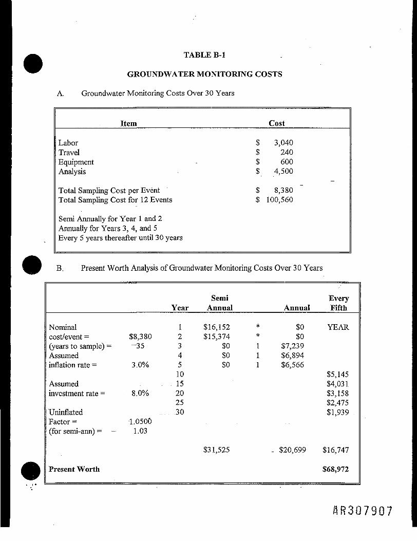
TABLE B-l
GROUNDWATER MONITORING COSTS
A. Groundwater Monitoring Costs Over 30 Years
Item
LaborTravelEquipmentAnalysis
Total Sampling Cost per EventTotal Sampling Cost for 12 Events
Semi Annually for Year 1 and 2Annually for Years 3, 4, and 5Every 5 years thereafter until 30 years
$$$$
$$
Cost
3,040240600
4,500
8,380100,560
B. Present Worth Analysis of Groundwater Monitoring Costs Over 30 Years
Nominalcost/event = $8,380(years to sample) = — 35Assumedinflation rate = 3.0%
Assumedinvestment rate = 8.0%
UninflatedFactor = 1.0500(for semi-arm) = =- 1.03
Present Worth
Year
123451015202530
SemiAnnual
$16,152$15,374
$0$0$0
$31,525
Annual
* $0* $01 $7,2391 $6,8941 $6,566
$20,699
EveryFifth
YEAR
$5,145$4,031$3,158$2,475$1,939
$16,747
$68,972
HR307907
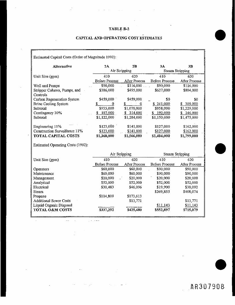
TABLE B-2
CAPITAL AND OPERATING COST ESTIMATES
Estimated Capital Costs (Order of Magnitude 1992):
Alternative 2A 2B 3A 3BAir Stripping Steam Stripping
Unit Size (gpm) 410 620 410 620Before Process After Process Before Process After Process
Well and Pumps $90,000 $116,000 $90,000 $116,000Stripper Column, Pumps, and $386,000 $495,000 $627,000 $804,000ControlsCarbon Regeneration System $459,000 ' ~ $459,000 _ $0 $0Brine Cooling System $_____0 $ - 0 $ 241.000 $ 309.000Subtotal $935,000 $1,070,000 $958,000 $1,229,000Contingency 20% ...'. $ 187.000 $ 214.000 $ 192.000 $ 246.000Subtotal $1,122,000 $1,284,000 $1,150,000 $1,475,000
Engineering 11% "" " $123,000 $141,000 $127,000 $162,000Construction Surveillance 11% $123.000 $141.000 $127.000 $162.000TOTAL CAPITAL COSTS $1,368,000 $1,566,000 $1,404,000 $1,799,000
Estimated Operating Costs (1992):
Air Stripping Steam StrippingUnit Size (gpm) 410 620 410 620
Before Process After Process Before Process After ProcessOperators $60,000 $60,000 $90,000 $90,000Maintenance $60,000 $60,000 $90,000 $90,000Management _.. $20,000 - $20,000 $20,000 $20,000Analytical $52,000 $52,000 $52,000 $52,000Electrical $30,483 $46,096 $19,900 $30,092Steam $269,855 $408,074Propane $114,809 $173,613Additional Sewer Costs $13,771 $13,771Liquid Organic Disposal _____ ______ $11.143 $11.143TOTAL O&M COSTS $337,292 $425,480 $552,897 8715,079
ftR30790S

TABLE B-3
PRESENT WORTH COMPARISON
Alternative 2A 2B 3A 3BAir Stripping Steam Stripping
Unit Size (gpm) 410 620 410 620Before Process After Process Before Process After Process
Total Present Worth = $7,069,000 $8,697,000 $10,433,000 $13,470,000
Operating Costs:
Interest = - — 5% 5% 5% 5%No. Years = 30 30 30 30Annual Operating Costs = $337,292 $425,480 $552,897 $715,079
Present Worth = --- -=• $5,185,004 $6,540,678 $8,499,389 $10,992,519
Capital Costs:
Interest = - 5% 5% 5% 5%p/f factor = 105% 105% 105% 105%Present day capital = $1,368,000 $1,566,000 $1,404,000 $1,799,000Equipment life (years) 20 20 20 20
Year Present Worth Present Worth Present Worth Present Worth
20 _- $1,368,000 $1,566,000 $1,404,000 $1,799,000$1,883,585 $2,156,209 $1,933,153 $2,477,024
$1,368,000 $1,566,000 $1,404,000 $1,799,000$515,585 $590,209 $529,153 $678,024
AR307909
APPENDIX C
EARTHEN LAGOON EVALUATION
flR3079lO

DEC 23 1991*Z Occidental Chemical Corporation ,
V •'-_———- December 18, 1991
Ms. Rita M. Samrnons, Project Engineer Ref: Letter of RMS toBCM Engineers Inc. CWE, 11-26-91One Plymouth MeetingPlymouth Meeting, PA 19462
Subject: Earthen Lagoons Treatability StudyBCM Project #00-4064-13-01-05
"Dear Rita:
The following are our best estimates to the questions you "raised in the reference letter:
1. Polymer Content of each layer:The top layer is 85-95% PVC and the middle layer is 75-85% PVC. OurR & D department is still working on the analysis of this material and may havesome definite results shortly.
2. Minimum Poly Content:We believe the polymer in the top two layers would be usable.
3. Moisture content of each layer - 40 to 50% moisture.4. Maximum Moisture Content - <0.5%5. Market Price - 2 to lOC/lb.6. 1992-1993 Sales - Unknown7. Density - 1000 to 1200 lbs/yd3 at 50% moisture.
If there are any further questions, please contact me.
OCCIDENTAL CHEMICAL CORPORATION
C. W. EngblomTechnical Manager
CC:A. Weston, Niagara Falls J. V. Interrante, BCMJ. W. Lessig C. P. Collier, BCMJ. R. Hilt B. Moyer, BCMR. S. Schuster " D. E. Erdman, BCM
OxyChemPVC Resins and Compounds/PVC Fabricated Products Divisions HR3079 I IA manor hammer 5c_-e*.ara. Box 699, Pottstown. Pennsylvania 19464 215/327-6400

OXT Occidental Chemical Corporation JAN 221992
January 20, 1992
Ms. Rita M. Sammons, Project EngineerBCM Engineering Inc.One Plymouth MeetingPlymouth Meeting, PA 19462
Subject: Earthen Lagoon Treatability StudyBCM Project #00-4064-13-01-05
Ref: . Letter of RMS to CWE, 11-26-91Letter of CWE to RMS, 12-18-91
Dear Rita:
Attached is a copy of the report on the analysis of our Earthen Lagoon Solids done byour R&D group. If there are any further questions, please contact me.
Sincerely,
OCCIDENTAL CHEMICAL CORPORATION
C. W. EngblomTechnical Manager
J. V. Interrante, BCMC. P. Collier, BCMB. Moyer, BCMD. E. Erdman, BCMA. Weston, Niagara FallsJ. W. LessigJ. R. HiltR. S. Schuster
OxyChemPVC Resins and Compounds/PVC Fabricated Products Divisions « n o n 7 Q I 9-Armano Hammer Bouievara. Box 699. Pottstown. Pennsylvania 1946- 215/327-5 00 " **

CJXY
Occidental Chemical CorporationPVC Reslns/PVC Fabricated Products
C. W. ENGBLOM JANUARY 16, 1992To——————————————————————————————— Date _________
D. J. BRANDTFrom _______________________________
EARTHEN LAGOON SLUDGESubject ___________________________________
The analysis of the "Top" and "Middle" lagoon sludge samples you supplied has been completed.The analysis turned out to be jarmore challenging then we had anticipated.
Our analysis procedures have been able to account for only 91-93% of the material in the driedsludge. The reason for the low accountability is the presence of substantial quantities ofdegraded/crosslinked PVC. This leads to low values for % PVC when determined'by % chlorineanalysis, which is the only suitable method for PVC when insoluble polymer is present.
The determination of the % Ash in the "Middle" sample also presented problems due to thepresence of inorganic carbonate which decomposes upon ashing.
Neither sample contained significant amounts of methanol extractable material and theproposition was similar for each.
What follows is a tabulation of the analysis results:
EARTHEN LAGOON SLUDGE
% Ash
% MeOHExtract
% PVC by% Chlorine
TOP
5%
1%
87%
Fe + Silica
C16-Clg AlcoholsUnknowns
PVC - Small AcetateContent
MIDDLE
12%
2%
77%
Fe + CaCO3
C16-Clg AlcoholsUnknowns
PVC - Small AcetateContent
DJB:djs
SR3079I3|P 4-002 fS/89)

APPENDIX D
COST CALCULATIONS FOR EARTHEN LAGOONS

3
I
>/">
»l 11 1 -I§ 3 £ 1I_ i t; .«
^
g SP U
AR3079I5

%
•-
3O >O O t- VO CS OO CS C- OP- >O O •* fl
C*~ t—• OO OS i—' O V) *""1 VI CN *""* O C** t1"* OS . , -
>o ot- »-(00 OOC<1 O
OS>nOCM
cs g1 ££' § a • § •§ gif{ii }j j|.,,
a s l l -s-s'>-~°
i §> I I - - « s a l s l ' a S S l 8 •? s IlS|*l?|»j|8Bl«5ft?Slll»?
gio HS o-3-°rS,-^-^ £<"€1siaj!£8,!g§ig • & 2 ' ' i . . .
6C.1 miimmiii *""flR3079!6
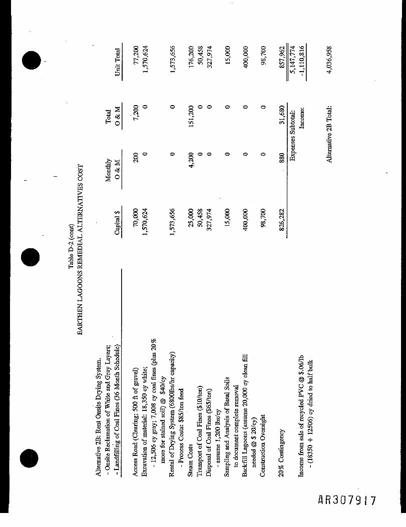
H
8
H
3
oes <n o <o t— Q o o >«oc^ \o^ ^ cs _^ as o o f~ asf-^o" en" vo" o" t- in" O os t-~ot> j> o m c<) 1-1 o os xo>n >n i—: en •* oo
°°00
c~ o"
v8
S o o p o o o o o oO 00
<n en
O O ' Q O O O O O Oq - ooes oo•<j-
3°!
§ • * v o O O O t O Q Q c NCS V) O*ot^- O O O oo^VO^ V£3 O^^OS O O t- CN
oo en «not-^ vT o" oo" vd~r~c-~ t- es<ocs »-• o os es«o in en •* oo
/—s ; oo P c3 O1||8 .§ «4IfS-^^ ^ t ©
i o ^ g n 3 f l J i . ^^s^o-S.« .. « o S m M v ^ o ° ^ 3~ « « 0 0 O TO -S; 05. ^ . .
S g1 1 * a SEb'S'BAge ^ og&U1I3 3i§3i55l !
S So1 !§o S "-1S "—'^ I '
SR307917

2
40-
o
8TJ- p P VO P P 00 •* P O P a< M .ics cs •* en •-< o »n t— o Q o Os inoo vo P o_ os c~ oo os o q\ c~x "•*" o" T* f a\ in" •<*" o" c- m" o" oo" >-< II c~-t>t> en r~oo*-i <ncs *-* p os - " ~«in cs c-- i—i i—i en ^
oo$VD
1•*
o o o o o o o o o o o
o o o o o o o o o
in" o" t-T >n p oo oo^< incN ~* Oi— i en Men c--oo^< incN ~* O Oscs c~cs
S gf I B
_ -S- U®?-s> S ! § El
^ 5 S O O S * j V « ' ^ ^ a ^ t « ' ^ J t i H ^ M e S g &• »J
i !H Q
HR3Q7918

>,
I O
3
ICO1oo
.a13
-O
I1
§•* ^ ^ Th p p i—i in cseS os oo f- O o •"*• en in' ~ Os O p f~- CSen o v$ en t- in o" c~f in" - •*t*^ en P cs *—' P P so osin esc^en • * o o c ~ - —
in
§o o o o o o o o 4Jcs 3vo t- oen H
o o o o o oes
p
oes o s o o t - p o •*q^vc^ inen^os^p^ q^ c~^o"o" in"en"t-^m" c" Oin cs es en •* oo
^ S° 2W tJ*.jb - *
. fi" §5 fe '
«13 <
illilllillia I!l§llllllil! |ICN
flR3079(9

•9 IP S
.§£•s °H .£2
<U _ cs es t—_ ( en en osO }G oo oo oooooo to- oo.
So o osoos enoo to- oo osen en enm into- to-
s 3- vo oo en_ in •* <-i cs osP vo •*_ 00 vq vovo °» o" o" os" in"^ VO i—< *-^ OS i—I
OO - i—i O i—I 00 OS*** ¥Z> t-T r-4" m" ~ in"
£> •* vo oo eno !2 os I-H t-~ cS<n S in ^ °°, °°» "t.° en *\. M" i> o vo oso g g sqs S
*0- tO- J- ,_, (Tl Tt^ to oo- to- to-
_ C?§ I
in vo os
s.9
•
*« 1? ••a s I «a
m
flR307920

03mCO
AR3Q792I

TABLE 1-1
BEDROCK AQUIFER GROUNDNATER CONCENTRATIONS
OCCIDENTAL CHEMICAL CORPORATION SITE REMEDIAL INVESTIGATIONPOTTSTONN, PENNSYLVANIA
:- 95% UpperMaximum GN Confidence Limit
Chemical Concentration (mg/D* GW Concentration (mg/L)**
Antimony 3.0E-2 - 1.4E-2Arsenic 6.0E-2 1.6E-2Chromium 2.8E-1 7.1E-2Manganese . 1.9E+0 5.3E-12-Butanone (MEK) 2.7E+0 5.6E-1Carbon Tetrachloride 1.4E-1 2.7E-2Chloroform 1.3E-1 . 2.6E-21,1-Dichloroethene 1.9E-2 1.6E-2Toluene 9.8E-1 2.2E-1Benzyl Alcohol 2.0E-3 1.3E-3Di-n-octyl phthalate 4.0E-3 1.8E-3Phenol 1.6E-1 4.2E-2
Maximum GW Average GWChemical Concentration (mg/L)*** Concentration (mg/L)****
1,2-Dichloroethene(Total) 2.5E+1 1.9E+0
Ethylbenzene 2.0E+1 4.0E+0Styrene 1.1E+2 7.3E+0Trichloroethene 9.1E+1 4.7E-1Vinyl Chloride 2.6E+0 3.0E-2
* Maximum values from CLP analysis** Values derived from concentrations measured in all bedrock wells*** Maximum values from CLP analysis or Packer Tests**** Values derived from concentrations measured in all bedrock wells
within the delineated plume using both CLP and Packer Test data
6735y

TABLE 1-2
EARTHEN LAGOON SEDIMENT CONCENTRATIONS
OCCIDENTAL CHEMICAL CORPORATION SITE REMEDIAL INVESTIGATIONPOTTSTOWN, PENNSYLVANIA
95% UCL Earthen LagoonCompounds of Sediment Concentration
Concern (nig/kg)
Antimony 1.5E+01Arsenic 2.1E+01Barium 1.4E+02Chromium 7.1E+01Mercury 2.7E-01Silver 6.IE-01
Acenaphthylene 3.6E-01Benzo (a) anthracene 3.9E-01Benzo (a) pyrene 3.7E-01Benzo (b) fluoranthene 3.7E-01Benzoic Acid l.OE+01Bis (2-ethylhexyl) phthalate 8.6E+01Chrysene 4.0E-01Diethyl phthalate 3.6E-01Di-n-butyl phthalate 6.8E-012-Methylnaphthalene 3.4E-01Naphthalene 1.4E+00Phenanthrene 3.4E-01
AcetoneBenzene2-Butanone (MEK)Carbon disulfide1,2-Dichloroethane1 ,2-Dichloroethene (Total)Methyl ene ChlorideStyreneTetrachloroetheneToluene1 ,1 ,2-TrichloroethaneTrichloroetheneVinyl ChlorideXylene
Aldrinal pha-BHC4,4'-DDE
3.7E-016.7E-021.2E-025.6E-019.5E-021.4E+004. IE-014.9E-012.0E-013.8E-012.9E-034.0E-014.7E-011.8E+00
1.0E-017.8E-021.2E-01
6735y
AR3Q7923

TABLE 2-1 -
APPLICABLE OR RELEVANT AND APPROPRIATE REQUIREMENTS (ARARs)AND TO BE CONSIDERED (TBC) STANDARDS FOR GROUNDWATER
- OCCIDENTAL CHEMICAL CORPORATIONPOTTSTOWN, PENNSYLVANIA
Potential Legal Explanation of Applicability to_____ARAR_____________Legal Citation__________Classification_________Classification_________FS Options____
| Federal-Contaminant1. Safe Drinking Water Act
a. Maximum Contaminant 40 CFR 141.11-12 Applicable Enforceable standards for Applicable as clean upLevels (MCLs) public drinking water levels to be achieved by
supply systems (at least 25 CERCLA remedialpersons) actions.
b. Maximum Contaminant 40 CFR. 141.50-51 Applicable Non-enforceable health Non-zero MCLGs areLevel Goals (MCLGs) goals for public water applicable as clean up
levels to be achieved- byCERCLA remedialactions.
c. Secondary Maximum 40 CFR 143 To be considered Non-enforceable guidelines Secondary MCLs areContaminant Levels _ _ _ _ _ for public drinking water relevant and appropriate
— systems standards for drinking~~ water sources: are
primarily aesthetic waterquality standards.
2. Clean Water Acta. Federal Water Quality Criteria EPA 44/5-86-001 To be considered Non-enforceable guidance To be considered if there is(FWQC) for Protection of 33 U.S.C. ' developed under Clean a discharge to a stream thatHuman Health S.1314(a)(l) Water Act and used by the may affect aquatic
(as amended) state, in conjunction with a organisms or humandesignated use for a stream exposure from drinking thesegment to establish water water and from consumingquality standards. aquatic organisms.
b. Ambient Water Quality 33 U.S.C. To be considered Non-enforceable criteria To be considered forCriteria for Protection of S.1314(a)(l) used to develop standards. actions that involveAquatic Life " -" ~ (as amended) groundwater treatment and
discharge to surface water.
3. EPA Health Advisories EPA Office of Drinking To be considered Non-enforceable guidelines To be considered forWater for public water supply remedial actions involving
system groundwater monitoring,recovery, and treatment.
State-Contaminant .___._.. ^ - - -1. Pennsylvania Water Quality PA Code Title 25, Chapter 93 Applicable Sets quality for the waters Remedial actions may
Standards in the state include discharge togroundwater and/orsurface waters.
2. Pennsylvania Hazardous PA Code Title 13 (Flammable Applicable Regulates shipments of Applicable to wastesSubstances Transportation Liquids and Flammable hazardous wastes. shipped offsite for analysis,Regulations Solids) and Title 15 treatment, or disposal
(Oxidizing Materials, Poisons, during remediation.and Corrosive Liquids)
Federal-Location1. RCRA Location Requirements 40 CFR Part 264 To be considered Limitations on onsite To be considered when
storage, treatment or remedial actions involvedisposal of hazardous onsite actions.waste
2. EPA Groundwater Protection Final Draft 1986 To be considered EPA policy regarding Remedial actions mustStrategy protection of groundwater consider EPA classification
resources for its highest of groundwater conditionspresent or beneficial use. at the site.
i'ABLE 2-1 (Continued)
Potential Legal Explanation of Applicability to______________ARAR_____________Legal Citation__________Classification _______Classification_________FS Options
rtate-Location1. Pennsylvania Wild and Scenic Act No. 283 Applicable Provides that no depart- Remedial actions
Rivers Act of December 5, 1972 ment or agency of the include discharge to theUnited States shall assist in Schuylkill River.the development of anywater resources project thatwould have a directadverse affect on the river.
2. Delaware River Basin Resolution 80-18 Applicable Governs withdrawal of Applicable to remedialCommission " groundwater in cojunction actions involving a with-
with state regulatory drawal of groundwater.agency.
'ederal Action1. RCRA
a Hazardous Waste 40 CFR Part 261,264, Applicable Standards applicable to Remedial actions mayand 270 . treating, storing, and include offsite disposal of
Requirements disposing of hazardous treatment residuals.— waste.
b. Land Disposal Restrictions 40 CFR 268 To be considered Imposes land disposal Remedial actions mayrestrictions on all involve land disposal ofcharacteristic and listed treatment residuals.hazardous wastes.
2. Clean Water Act NPDES 33USC1251 " To be considered Regulates _ concentrations To be considered forPermit of listed contaminants in remedial actions that
treated wastewaters involve discharge oftreated water to surfacewater.
3. General Pretreatment Regulations 40 CFR 403 Applicable Standard for discharge to To be consideredfor Existing and New Sources of Publicly-Owned Treatment remedial actionsPollution Works (POTW) discharge to POTW.
4. OCPSF Regulations 40 CFR 414 Applicable Enforceable standards for Applicable to thedischarge to a POTW for Pottstown facility fororganic chemicals, plastics, POTW discharge.and synthetic fibersmanufacturers.
5. Clean Air Act 42 U.S.C. S.7401 Relevant and Appropriate Regulates concentration of Relevant and appropriatelisted chemicals in air for remedial actions thatdischarges involve releases to the
ambient environment.
6. Occupational Safety and 29 CFR, Parts 1904, 1910, Applicable Provides occupational Applicable to onsite workHealth Act (OSHA) and 1926 safety and health performed duringRequirements requirements for workers implementation of
engaged in onsite field remedial actions.activities
7. DOT Rules for Hazardous 49 CFR, Parts 107 and 171- Applicable Regulations for transport Applicable to wastesMaterials Transport 179 of hazardous materials. shipped offsite for
treatment or disposal.
State-Action1. Pennsylvania Solid Waste Act 97 Applicable Regulations for proper Applicable to remedial
Management Act management of solid actions involving storage,wastes collection, transportation,
processing, treatment anddisposal of solid waste.
2. Pennsylvania Solid Waste PA Code Title 25, Chapter 75 Applicable Regulations for the plan- Applicable to remedialRegulations ning and management of actions involving ban
solid waste and hazardous of solid and/or hazwaste waste.
AR3Q7925

TABLE 2-1 (Continued)
Potential Legal Explanation of Applicability to______ARAR - - - -^.-_____Legal Citation___________Classification_________Classification__________FS Options____•
| Pennsylvania Clean Streams Act PA Code Title 35, Chapter 5 Applicable Provides protection of Applicable to remedialstreams and waters of the actions involving ground-Commonwealth including water and surface water.groundwater.
4. Water Quality Toxics PA Code Title 25, Chapter 16 Applicable Provides receiving stream Applicable to surface waterManagement Strategy water quality criteria for discharges from treatment
toxic substances. systems.
5. Pennsylvania Pollutant PA Code Title 25, Chapter 92 Applicable Regulates all point source Remedial actions mayDischarge Elimination System discharges into navigable include discharge to(NPDES) Rules waters except as authorized surface waters.
by the appropriate permit.
3R3Q7926

TABLE 2-2
FEDERAL MCLs AND MCLGs
Chemical
AntimonyArsenicChromiumManganese2-Butanone (MEK)Carbon TetrachlorideChloroform (THM)1 , 1 -DichloroetheneTolueneBenzyl AlcoholDi-n-octyl phthalatePhenol1 ,2-DichloroetheneEthylbenzeneStyreneTrichloroetheneVinyl Chloride
MCL (mg/L)
6.0 x lO-3S.OxlO'21.0 x 10'1——
5.0 x lO-31.0 xlO'17.0 x ID'31.0xlO+0———
1.0 xlO'17.0X10⁻¹l.OxlO-15.0x10-32.0 x lO-3
MCLG (mg/L)
6.0xlO-3—
1.0x10"!——zero—
7.0 x lO-31.0xlO+0———
1.0x10-17.0x10-11.0 x 10⁻¹zerozero
3R307927
§|2jO
11
1iPM
i1 s g1 § 1§Q CO
63 3"E ^ "i?
£ 0
s§ SP HO •<!
1 i ?8Ts-
S B
| i IOO
2. 2
sis» 201 0u
5* Qo p
<_ S •§•2 §u
y
u
4.3E+00
•a;
1
j
1— •
I<n
(Antimony
SW
SCO
OW
1\O
8S—
SU0vo
a"2S
tU}
o
enCO
1ts
IW
sUl
r-
3HICOoi
jChromium
1
'
i
1
1u-l
8
,_;
[Manganese
i
'
i
i
IVO»n
8IX)
IS
p-Butanone (MEK)
9•*
1
i
i
c-<s
1-«
u•o
(Carbon Tetrachlori
Sr-Tf
vi
1
(
1(S
1m-*
(Chloroform
1en
vi
i
,
1T— <
I———
0)cu
u9
2.0E+02
6.8E+00
1
,
1cs0)
ioo0\
[Toluene
i
i
i
i
I—
0IN
1
t
m
1
i
i
i
§oo~
O•*
™"5.ccu
tcp
4.6E+03
oWri
IN•<«•
1"•
1
CO
< 2 "g)0 0 §§
Q co
!i*ed z s;S < MS C3 J§^ g
2co OD Po 51 1 5III8i1
S 1 5| i I82^ 2
O h *
!l&i i i^ o0
a. Z^ 2
i z S ou
_1y
su
1
i
1
j
g[U_;
O
idm
fob
|l ,2-Dichloroethene
2.9E+01
S
!
,
8o
o+o
(Ethylbenzene
|
i
i
i
8CO
+«
1W
1CO
CS
i
i
ic—•*
oWoC
[Trichloroethene
1m
2.0E-03
1
!
oen
g
CN
[Vinyl Chloride
•g•o
U•So
_3"a.
•o<u
c
S .u
s sM 2
'E oB -2§ I
"8J 1 1 -1 I a -8I ! 1 11 1 'S "3•a -I | >03 *T: i jts > * *
flf?307928

TABLE 2-4OCPSF Standards
Direct DichargeBiological
Treatment FacilitiesAcenaphtheneAcrylonitrileBenzeneCarbon TetrachlorideChlorobenzene,2,4-Trichlorobenzenelexachlorobenzene,2-Dichloroethane
1 , 1 ,2-Trichloroethaneiexachloroethane,2-Dichloroethane, 1 , 1-Trichloroethane
ChloroethaneChloroform
2-Chlorophenol,2-Dichlorobenzene,3-Dichlorobenzene
. ,4-Dichlorobenzene
. , 1-Dichloroethylene,2-Trans-Dichloroethylene
1,4-Dichlorophenol1 ,2-Dichloropropane1 ,3-Dichloropropylene2,4-Dimethylphenol2,4-Dinitrotoluene2,6-D'tnitrotolueneEthylbenzene
FluorantheneBis (2-Chloroisopropyl) EtherMethylene ChlorideMethyl ChlorideHexachlorobutadiene
NaphthaleneNitrobenzene2-Nitrophenol4-Nitrophenol2 , 4-Dinitrophenol
4,6-Dinitro-o-cresol
PhenolBis (2-ethylhexyl) Phthalate
MaximumOne Day
(ug/L)
5924213638281402821154545954268469816344282554112230443628564110868757891904959686912412327726279
MaximumMonthly Average
(ug/D22963718156815682121222110421317731151621391532918113255322530140862022274172717815103
Indirect DischargePriority Pollutant
Pretreatment StandardsAcenaphthene
lenzeneCarbon TetrachlorideChlorobenzene,2,4-Trichlorobenzenelexachlorobenzene,2-Dichloroethane,1,1 -Trichloroethane
Hexachloroethane, 1-Dichloroethane, 1 ,2-Trichloroethane
ChloroethaneChloroform,2-Dichlorobenzene,3-Dichlorobenzene,4-Dichlorobenzene, 1-Dichloroethylene. ,2-Trans-Dichloroethylene. ,2-Dichloropropane,3-Dichloropropylene2,4-DimethyIphenolithylbenzene?luoranthenevlethylene ChlorideMethyl ChlorideHexachlorobutadieneMaphthalene
Nitrobenzene2-Nitrophenol4-Nitrophenol4,6-Dinitro-o-cresol
PhenolBis (2-ethylhexyl) PhthalateDi-n-butyl PhthalateDiethyl PhthalateDimethyl PhthalateAnthraceneFluorenePhenanthrenePyrene
MaximumOne Day
(ug/L)4713438038079479457459794591272953257943803806066794794473805417029538047640223157627747258431134747474748
MaximumMonthly Average
(ug/L)195714214219619618022196223211011119614214222251961961914222361101421922376516278199520461919191920
AR307929

TABLE 2-4 (continued)
OCPSF Standards
Direct Dicharge
Biological
Treatment Facilities
Di-n-butyl PhthalateDiethyl Phthalate
Dimethyl PhthalateBenzo(a) AnthraceneBenzo(a) Pyrene3 ,4-BenzofluorantheneBenzo(k) FluorantheneChryseneAcenaphthyleneAnthraceneFluorenePhenanthrenePyrene[TetrachloroethyleneE;ne
loroethyleneChloride
Total ChromiumTotal CopperTotal CyanideTotal LeadTotal Nickel
Total Zinc(2)
Maximum
One Day(ug/L)
57203
4759616159 ~59595959596756805426827703380120069039802610
MaximumMonthly Average
(ug/L)
2781
19222323222222222222252226211041110145042032016901050
Indirect Discharge
Priority PollutantPretreatment Standards
TetrachloroethyleneToluene
TrichloroethyleneVinyl ChlorideTotal CyanideTotal LeadTotal Zinc(2)
MaximumOne Day
(ug/L)164746917212006902610
Maximum
Monthly Average(ug/L)5228
26974203201050
HR307930
|33
1HJy
CDaJQ
FISH AN
1 1 is o
g2
S 3 _.*ti M ^
§ § if2 ^ *"^20U
13 2D P
U OU
* 1-J M *
^ U ji
Ou
^ 2? Oo p
1 § &u
Jy5
u
Iin
8m,,4
2.2E-01
1-.
pen
c
'c
puS
9UlVOm
__
3Ov
StoVO^
1Ovo"
0
1
S
8wen
oW00en
1t -
2.8E-01
(Chromium
j
,!
1
3envn
1.9E+00
(Manganese
,
i
i
Ivoin
8+01
c?
E-Butanone (MEl
ioen
8wCOoi
Ivq>n
1r-01
1
•c•n
barbon
Tetrachlc
i01
8uOvJ
IOven
vo01
1en
bhloroform
Sovd
8xn(~_
1.5E+00
8wVO""
Ov
Uc:
1,1-Dichloroethe
4E+01
8P!I-M
1enen
10101
1COOv
(Toluene
i
i
1
1*-*
2.0E-03
"c£
*>,KCtc
i
j
i
1OO
*— '
4.0E-03
5:a;"a.C
C
ITc5
3oen
-_
p'•
2.0E-02
i01Tt-
1
"cc4
R § 5D- ij
CO
„ 21 B ___5; p^ Jx g 12 W ^^^
gou
COZ
co O
ONTINUOU
ICENTRATI
(mg/L)
u Su
z^ o° «. *
I | IOu
^ 2^ 2o p
1 1 1S gu
1
y
u
1fO
8uoovd
8+
8+Ov
2.5E+01
's<oc
1,2-DichIoroethe
8
8uOvoi
otiOO
8Wo
2.0E+01
Ethylbenzene
j
i
1
8wen
1.1E+02
[Sryrene
S0
8COoi
Sin
I•d-
oWo\
_c
inSo01
i
-
8iaoen
8tdvooi
k/inyl Chloride
as
T3
D
1O
•a
U
o
SW3
S3D*
1.s"ua)
c1-2
*4) •*
* oAX Q
1 -8II!"2 0 3
g W »
CA W ^ O
1 -S 1 1S«J 5> Bis c_ 52 s ri =- c U SU o E cr- " P Cc c (P pO C 1^3^ .u 1) -oW **• 3 S«> -o -S >3 5. > 'C" 1 | -8S -3 i S^ o •- —
s > * **• * * ** * * *
AR30793
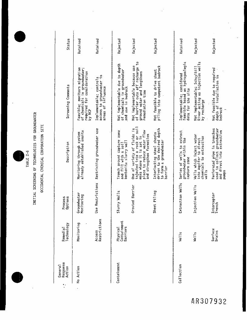
UJia§ UJo jljCD -—
K o£ Sf) fyf. . O3 °~
ct | SJ 0 <CO UJ t_|•=t r— £2*~ u- u0 5
2 <-5 H~
UJ g
t/> yQ
. — \
r-41 —3S' — '
to4->id4-1I/)
toc1ooD)cca>Olj_u01
co.1-10-°jloto01a
V) V)to c01 OU -,-0 4Js- a.O-O
>D)
t— OIdr-• i- 0"O C.Ol -Ce ooi oior i—
aird c c!- O OOl O.-1-C 10 4-1Ol OJ UC9 OX <
•aaic•r-.id4JOl04
c •-o s.•i- OJ C
id rd-r-i. £ 4Jova id•r- C J-E 3 01o "ato !- .1-t- a> too c4-1 C O•r- -r- UCo to t-Sr- 0. *. ooi -r- -ai— E Oi_Q aj s- a.•r- .C -T- OtO 0 3 ZId CTam_ o> >-,u. o s- .a
OlE4J01. r-4-1 tOto c>> oto •aj: oi3 VIO •!-S- r—-C.J34J m
4-1O) tOc tuC >,o-a4J rd•r- OJc t.O r—s: id
s-01 en4J CId-r-3: !--a oC 4-1
o cS- 0
D)C
!_o4-1
coz:
c04-1U
OZ
•aaic•r~Id4-1OlOX
CtO -r-
O S-1- CU
c id tuO _£ Ou-a cc tu•-33ttl Or-S O) c(0 -r-4-1 0
01 OE tooi to toi — • oj idO- U OlE 0 !.1-1 id id
Ol3tOJ
J;•QC3O
-I.O)encui.to01o;
toc04-1oi."pWOJC£OJ(/)
=tocou
tO -r-to i.01 4->U 100 01< ox
T3Ol4-1UOl«r-jOl^
^0-01 S.-a tuo id4J _E•ooi c3 3•a os. juoi en oi— OJ3 C i.Id -r- T34J <_)c to jaE ''O cOl O *r-
D.E 0)E oi to•r- _C 3O
4J -0O M- CZ o rd
OlcoN
Ol r—S. r— r-
4J O So~ toid >iu id i.s.•o j: 3C 4-1 1 —3 -r- V)O SS- 1)Id r— 4-1
i — •*-
U t^ Ooi -a cs- c atI— id-Q
tonj3:>*,1_s_Z5r—o->
•f-*cOli — E viid c t-
O T- Ol•r- Id -r-10 4J S-
jc o nin- o to
4-1COlEc• r-id4Jcoo
"aOl4-1OOJ•*-.OlDi
O
Olto oi3 ens- totu id c10 JZ OI3 U-Cid tu 4-1U S- D)tu c.Q H- Ol
"4- r—tu oi— -a oiJ3 10 C Erd 4-1 id -i-C 0 t-eu OJ cE !- 4J OOJ Q) fd *r-
a. i. n)•r- id c -aja 3 oi4J O EO M- S- OlZ O D) !-
W) -r-
to otO r— C-a s- c M- o•r- O-r- -r-3 t- 4J
1 — £ 4-1 Ol Idt.- 0 OJ 4J Eo vi id i-H- 1- .COo to t-
Id -r- OJ>. 0 C4-1 O 4J 3 OlOJ 4-1 T- "O -C•r- C 01 4-1I- .r- 01 S- D)Id S- C> *O Ol O OJ
o u tu toOl tO U
01 T-s V) Id T3C C Id r— Co ••- E n. id
QJJ_.S-id03
•o013os.U3
•a01j *uOl«r-jOlox
^u
4J 001 S-01 -aj: 01to -Q
(D 4->> C• r- QJS- 4-1-O Ol
D.0 E4-1 O0
Ol.1— 0J2 4J•i- CtO •!-mOl O)t- c4-1 rO -r-Z Q.
jrto d.4J Oloi -aaij: x> t-to Ol Olj— _ir— *i— IdOl to %oi oi-a4 "O Ctfl 3
Ol O
c 4-1 en!£ o idU 4-10 E !-i — c s- aiS- Ol O «-Ol > 4- S-4-1-1- S-c s- o idM-04J .0
D)cr—a.4Jai01en
•oOlc>r-id4-1Ol
U
O)o'o
TD Olttl O)S- 0Ol t-T3 T3•r- >,
CO C OlO O 4-1
•-•a vt01 01i— Wl OJ.0 id .cid ja 4J.4-1c tu i-Ol r— OE J3 t-OJ.r-r— w ido- id 4-1E oi idM t.- T_J
uidS-4-1 OJx_cOl 4-1
o c4-1 -r-
f~tO 4-1
Ol Ol? s- cttl O
M- 4-1 No ids ttlto -o s-OJ C 3•r- 3 4-1S. 0 Q.oi s- idon cr> u
I/Ir—^
co4-1oid4-1XUJ
to1 —ai
co4-1UOl
i —
'oo
TJai4JuOJ•i — jtuQL
to1 — '
i — Ol•>— ^\i — C
3-r--C 4-10 0t/J OJ
. n COJ -t-
J3 10<d id4-1c OiOl C OlE-r- Cnttl 4J'J-r— 0 IdQ-nJ x;E o-r- J- OJttl t-4-1 >O-r- >,za: ja
S-01 C4-1 4-1 Oid o T-3: Oi 4-1
J- U4-1-r- 10u -a i-ttl 4J•r-> 0 XC 4-1 O)
"~ !- 0x: oi 4-1UM-•r- -i- to.C 3 r—S CT Idid oto T- to1— 0 Er-1 — 4-1 Ol 1 —Ol C .C QJ3: -r- 0 S
to
ico4-1utucI—I
I/I^ai3:
-aOluOJ«r-jttlDX
•atti
3 Ccr-r-01J- CoO -1-
id0)r-3 r—•o id
4->Ol tOS -r-'tO M-fO O-V01 O ~M- -C O
4-1 i4-1 O_"OO Ol tuZ T3 -Q
10 S-01 Ol CJ= 4-1 OO Id -r-C S 4Joi -a ot- c rd4J 3 i-
O 4-1C I. X• r- O) tu
Ol 4J Oa. u 4-1•r- Ol CO-r— -i-
-a "o 4Jtu u u4-1 O)id o !-!- 4-1 -r-O T3 104- -a o-s- ana EOl tO C 3a. 3 rd a.
^oa.OlU r-S- 0Ol C4-1 aic s-
01U 00rd cs- 53 i.in a
flR307932
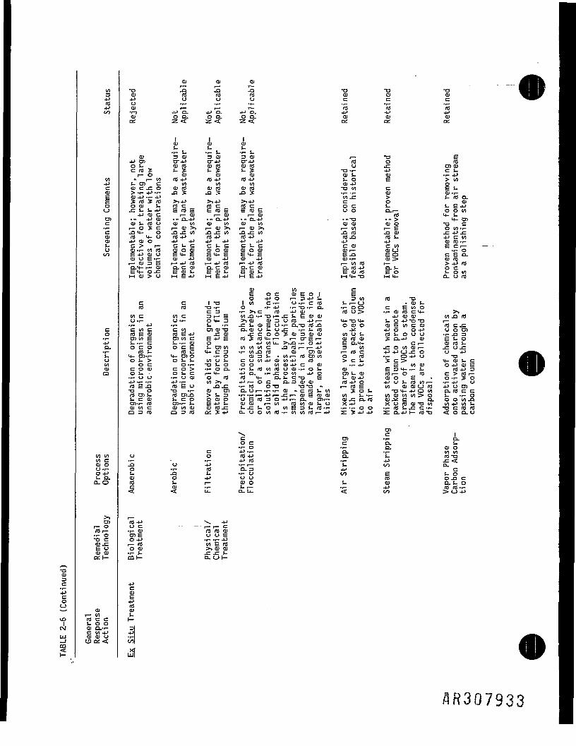
0034Jid
co4Ja.-r-1.U00tua
to toto cai ou -i-o 4-1s- a.Q.O
enr— Oro i—•r- O-a cttl _C
OX r-
XIai3C
4-1rdoi
r- toid c ci- o oCM QJ D--r-
C to 4-1ii I 01 Ol tj
CO OX <§
_ O ttlOl QJ
oj id id ro tu tu cu4-1 u o o c c cOl r— r— r— Id Id rd-r-. 4 J O . 4 - l a . 4 - l a . 4-1 4-1 4-1tu o o . o a . o a . tu 01 01ox z < z < z <t ox DX ox
oi ai ois- s- i--r- S- -r- i. -r- I.
O I 3 O I 3 O I 3 0 ) r— XI E4J 01 0-4J CT4J CT4-i rd o rdOl- Q i r O Q i r d Q i r o u -C O1QJC l d 4 C i - ; C S - 2 c i - _ £ X> -i- 4-1 CS-
r— O CD CU ttl 01 i. 01 -r-4J" i — o o i d 4 J r d 4 J i d 4 J j - o E > o oi- en c to 01 to 014-1 oo j c - c o o i r d oiid oird xito c E S-> -1- 4J -r- .J3 ? -O ? J3 3: -1- -r- ttl <U -1-oj 4_>..- j-> </_ _e > i- rd a._s rd ? id >>4-i >>4-i >i4-i co tuo a> I- rd c rd c rd c oc J- £-£4-1jc J- i- 4J E idE E r d E E r d E uo o.r— o o to4 J Q j C r — o i l — o i l — a > r d 4-1-4-1 tu •- a.4-1 •" a.4-> •- o-4-i .-x> •" > 4- 01O J S - l d O Q J t O Q J t O Q J l O QJQJ O J O X 1 Ci— o _£ c i— o i > > i — t u > ) i — oi>> i— oo i— E oto-i-r 0 4 - u r 0 4 - > rd4J rd4J rd^a rdS- 4-icoo4 - 1 O I O 4 - 1 4 - 1 4 - 1 4 - 1 4 - 1 4 - 1 4-1 4-1 ttlrd-r-C > r — C l - C C — C C S - C C t U Ctfl ECr—tU -r- t O r d t U O O J O J O C U O J O C U Oil— Ol O - -r- O
Q J t - I E - r - O J 4 - l O I 4 - l t U 4 - l OJ -1— CU _> Ol rdi— Q J 3 E i — 4 J r O r - - P l d i — 4Jld r— Olid r— >4->Ida.4- r— t u a . c a i o - c o j a . c o i a.id4J a.!- ocE 4— O - C E Q J S - E Q I J — E Q J J - EOiid EO i-oooM O I > O I - l E 4 - l r - l E 4 J r H £ 4 - l M4-X1 I-H4- Q- U ft!
ty to cE" o c oi £ o I EO 4-1 O r— 3 4-1 S- 300 rd XI
C C IX! I t O C - i - U - r - C r d I-i— C_> .tUL.Oi 10 XJ-r- O -r-4-l'(--O-r-a. -r-OO C E t O O
C3 -i->,C I 0 4 - 1 0 J IdO> T-tUIOC4- >,OOC 00 C 3 r— E OOXl-r-XIi—JZS-SttJttl 4-> O) QJ 00-aidO-i- O-i- O4-3 >iOI OI3UIO 4->r— 4-x>4- S-O4JX)X1 r—•r- 4J .1- s- -r- jz i- oi £ o •!- O.X! iOJ3 ocuo c u E t o c c u rdcj;ctoc cto cntuxi o-ojos-ojc .f-s.nl ^. 4-10 04-1 uocnlO £ Ol rd E 4-1 f— Ol r- C O O ? f l J 3 Q J Q J OOt-JI— I d l — O U U -r- ^ 3DiioE cntoc £4-i£ id_cr04-i— i— cr£i— ajrooi _EO-4-i QJ £*-oj-.r-c i--i-qj o 4Jtou_ >,ja -r- o 4-1 E D-4- c i— oi rd J-OCO OCE 1-O101 O O O O t O C ^irOr—r— 4-1 3 10 .COlOOJr— _COJ=rdl- rdc 4-C3 -i-tojard oi oiaj i— rd c 4J4JCJ-CO o 4-14- Ol-r- 4-O1O -|-O t U 3 t - - t O r — IdOlOO O Id -r- O4-1O XIOS-> OJ-1- too!- CUt04-lCUt04J Id >CS- _CC> 4-OIS-C
OC O - r - X J S - O OO OOOI4-1C QJ -r-4J E IOOI O4-lttl£C O O J CO> T - O O - ' r - S - l d t O r O O a j - r - O i - OJ £34--r-S- 104-13os- os-c r—4- 4-ia.-i-.cooi 4JO oit-tu rdr— o rd c > r d r —.r-OO .i-UOJ O rO r d 4 - O-J-CX) £ !_OJ4J OIO E • O-r-¥o4J-r--r- 4-1 -r- 00>> 4-> 1— O C O. 3 01 01 r04-IO -PUS-lOOIr— -1-4J OrdE-a r d £ o jaj; -r-rd ox> x;xj- r— rd £ oo Qjcuurd -p u tnX) O XJ -i- CU Ol O-Ui— - r - - r - O I « C r d J - t O 3:OL. XJ4-4-IO01 CLIdCCrd en t- rd O)JD >L.3 -r--i-i— 4J|— -Cr— tUE O I Q I tO S--r- tOO)tOtO>O J- -I-Os-coi uco ocuo OEid3O4-ii— cu o>i— ai.ca.ro oi^^c a, oooo-aoi-f- id cn-r- i. s 4-> J- tuoi i— to ra w QJ (- o X4J xoidoixioi _i 4-1 to s_tutoc O J O O O J aird^: i--c J- o ooEsi-ro-r- -r--r-oo -r-rot-jcc-r- xicrordO3id O3id oxS-p o-ooooid-r-ootordr—4-1 z:S4-i4-i s o. 4-1 h— rd x) <oo.o
en. cc en -r-o c c a,•r- O -f- O.
C 4-1 -r- O. -r-o o ro 4J a. s-ja o 4-> -r-1— t- t_oO -i- Id O. 3 4Ji- .a s- -i- o 01 EOl O 4J U O 10rd I- r- Q) o S- cuC Ol -r- 4- 1— -r- 4-1< <C u- a. u- < v)
u cOl EO 4J
r8
CO I—
4-1
/5R307933
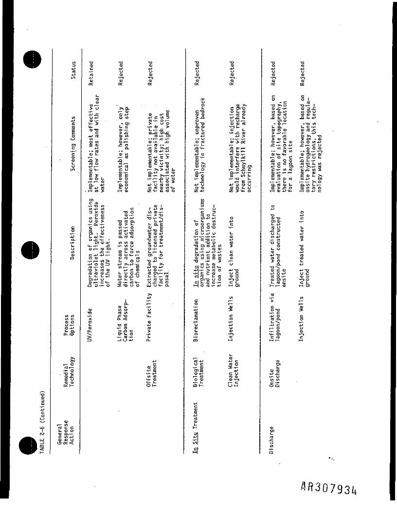
,
-oQJ_3C
-*->co»»_
fCMUU
§1—
0134-1rd4-1OO
to4-1Ce:
0
enccQJttlS-Oen
co4JO_-r-S_0toOJo
01 0101 COl OO-i-O 4-1s- a.a- o
01t— Ordi—•i- 0
. XI CQJ *"-£ oOJ 01QL H-
ttl1— 10rd c cs- O OQJ O.-1-c to 4-1OJ ttl UIS OX <
XIOlc'fo4-1QJox
i.rdtu
CUi—> u•P -CO 4-1OJ-r-4- S4-OIXJc4-1 roto§to
tti4-1
• - roQj i.S?ro OC t
E SOl O f-
i — i — QJn -pE 4-1 rdi-i ro 5
OlC OJ•r- "O Ol10 -1- 013 X ttlO C
10 I- QJ0 OJ >•r- O. -r-C 4J10 UOl • OJ!_ 4-J 4-0 -C 4- •
Ol ttl 4J4- -p- jrOr— OJ Ol
-C -t-C 4-1 4-1 r—O OJ-r-l— tO>4-J O CU 310 -r- to-o > ro <Urd ro OJ .c!- i. i. 4-1O14-J 0QJr— C 4-O 3 -r- O
01-oXoi.OJO-
1:3
XJOJuttl•r-5tuOX
>, Q_r— OlC 4-1o to- 01
S- CQJ -r-
tu ooO I —J= 0
Q.
OJ 00r— rojQrdi—4J rdc oOJ -r-£ EOJ O
i — CD. OE 0M CU
c-o oOl -r-4-1 4-Jxi rd o.
Ql > !-01 -i- o00 4-1 01rd ox>a. to roto to tti• r- 01 U0 S.E s- o oord 04- r-QJ id id
S. O 04-1 >14-J -r-01 i— E
4-1 C CUi- 0 0 -CQJ Ol J3 O4-1 S- !-Id -r- Id 4-"f X) U O
i01 S-01 ord to-cxiO- <
X) C• r- Oa ja ctr s- o• f- lO-r-
XIOJotu•r-5CUOX
OJOl 4^ E4-1 C 01 310 »r- O l —> O O•1- ttl >S-r— J=
id -1— Oi• -(— -C-i-QJ -i- J=i — id • *rd rd 4J 4J4J -r- -r-C 4J C SOJ O-t-E C OXJOJ -i- QJ1— >> > 4-J J-0.4-1 id oj£ -1- >V1- 4J•i- 1— ja u id
• r- t- O f-p u ro too ro QJ oo 4-Z4- c ro o
01 I1 4-1 COto id -i-
•r- > -0
C 4-JS- Q- Cttl Q)-PXJ Erd oi 4-13c to n!
-XJ C OlC 01 S-3 U 4JO-r-Ur— !-Ol OO 4-
01 >>4-1 XI 4-1U tt) T-10 Oil— f— '!- (- .r- rO4J 10 O 00x -c re ouj o 4- a..._,4J
tr-Urou.OJ4-Jidtr-s-Q.
4-1C
ttl QJ4-1 £• r- 4Jto id4- 014- i-Ot—
XJQJ4J0Ol•r-501DX
,.>•»;
U£
CXlOl OJ>. jaoS-Xla. ajC !_3 3
4-1.- UOJ Idr— • f—-a 4-rd4J CC-i-aiE >,QJ Oli— OO-i —E o•r- C
4-J OO QJZ 4-1
g01 1• l- OC 3id o s-I314J 4-1
4- !- 01O O C OlO OX3
C !- -r-O O 4-1 O-r- -l— -i— -r-4J S XI r—rd x) oX) O) Id J3 00id c ns oiL. -1- 4-J 4-J 4-1O) tO c ttl 01Oi 3 OJ E rdXJ -r- ?
01 S- ttl3| U 4J to 4-4-1-1- 3 10 O•1- C C QJoil ro S- c, OlXJ O O
C !- C C -r-Ml o rd -i- 4J
c04-1idrdi —u01om
i —rd 4-1u c• r— QJOl £O 4->f— roO OJ• r- J-aa i—
cg4-1rdttij_r—
I *l
en|cir~t|
XI014-10QJ-1-5 •tu&.
QJ >iC OTOO s- rd•r- rO OJU O r—CU OJ rO•0 S-C t-•i- .c OJ
4J >QJ ;£ fV
I — "-Q QJ i—ro s. i—4-1 CU -r-C 4- 24.
E QJ iQJ 4-1 3 .Olr- C JC CO--r- 0 ••-E oo s.•r-XJ l-
f— E 34J 3 0 0o o S- oZ S4- 0
04JC(f—
J-tu4-1§crtf(Ur—upfj 13u cOJ 3•r-50C. i.M Ol
011 —r—
CO•r-4JUCU•r-5ChH
CU4-1 C10 O
4JC U10 01CU -r-5
l — Cl_J l-l
XJOl.pottl•r-JOlC£
Co - cXJ >) O01 JZ-r-10 O.4-Jro ro rO.Q S- (J
Ol O- Or-S. 0.Ol O ttl> 4-1 1—QJ fi? QJ rd0 4J J- OJ.C -1- O 4J
tO > -r-rO toOl 4- 4-r— O C-D O Oro c c O.p o 01c -i- to roOl 4-1-r- r—E rooi 3 OJ rdr— i— S-o-ro tu l-E >-C 0M 01 4J 4-
O.p
XJOl XJOl OlL- 4-1rO ou t-10 4J-r- tOXI Cos- uOJ•PX>ro cS Oo.XJ "ttl C ttl.p O 4-Jro o -r-Ql Ol 01!- rO ci-r— 0
ro>cO XJ• r- C•P Oro a.•P Cf— O•r- O4- OlC rO1-4 1 —
OlOl
oi rO-P.C• r- Uto toC •!-o a
OlOlrO-Coto• 1-a
XIOl4J0QJ•r-5OJDX
CO 1
rdXlr— 101 3 J=01 Ol Oid at tu.Q i- 4J
-XI 011. C-r-eu id -c> 4JCD >. XJ3: en - ajo o to 4-1J=i— C Oo o oi• - 01 -r- -r-5QJ O14-1 QJr— O O S-ja s.-r-rd xi !- oo4-1 >,4J rdc -c to SQJ OJS <u s. >,aj 4J enr-.r- >, 0O- 00 !- p—E C O OM O 4-1 C
o4-1c
!-OJ4-1
§
XItu4-1ro
4-1
4-1 XIU COJ 3•r-5 OC !-H Oj
00
ico-r-4JUCU-r-5Cr-.

XI013C-pC0o
10
CMUJ
1
to34-1rd4-1oo
to4-1COl
oCJ
O)ccOJCUs.u00
co4JCL
'CutoOla
to 01to c01 0O-r-O 4-1s- a.o- o
5!r— OlOr-•f- OXJ CCU *~_E cj01 01C£t—
tul— 00id c cs. o o01 O.T-C 00 4-1ttl ttl Oen ox <c
XJajcrd4-JOJox
1
01 S-rO oOJ4-4- C
-!-XJOil—S- rottl CJ
5T00 OC 4-1O toU-r--C
ttl Cr— O.Ord XJ4J QJc toai rdE-QOJr— Ol Ci-s.°r-I -f- 4-1
O4-1
XJQJens_rd_c001
XJJ-014-1
g|O
XJ Q-014-1 1—rd idcu u>- 0I— 1—
3:feo_
OJOl
ttl S-4-1 id•r- .Cto o4- to4- •!-oa
XJcucrd4-1cuox
4JCOlI s.
C S-ro 34-J 0to c4J rd 3:C .C r-OJ 4-1 O£ O—4-1 4-1ro c oQJ QJ 4-1S. 014-1 C tfl
•I- 4-J
aT-p'i1— 01 -r-n , —rO CU4J S- ttlc o 01
cu to -ci— XJ 0CL J- tO£ rfl.r-1—1 XJ XI
o4-1
XJ01 t-Ol OlJ- 4Jrd n!-C _EUto oi• r- OXJ 10
4-S- S-ai 34J 00
Sr-rOXJ Otu o4Jp—id01 01S- J=1— 4-J
OJOrd4-!_3cni— !_rd oiO 4Jo ro-J3:
>iinror-vO
/1R3Q7935

»
DXUJ
cQZSox0 UJu- to £;
2 oL_ 1-4
< &HH *O A
s 27 1 °CM °
Oi iUJ O ^
<C oo ti*~ M S
cn S0 <->— 1 I
1 ^5 zUJ UJL_ Qr HHLU y^ <zof— ;r.~j•— J*UJ
to4J104-100
4-1COot-J
>4-1
1 — •
"IS104-1CcuECU
tM
totocuccu
4-JUtu4-4-UJ
to ooto cOJ OU -i-O 4-1S- 0.o- o
>O)
r™ Ord i—•i- OXJ CQJ JCE ucu cuOX (-
co-p
l — Ord <QJ OlC 0101 Ce> oa.to
01DX
XJ01crd-pOJDX
ttlCoz
OJ1—-Qrd —4-1c£=OJ
a.EI-H
Ol(4-1i— curd4-
XI r—CUE cOl -r-!- -C
4-J
$•*cu•r- 01
u rdrd 0
O14J4J Co c idC Oi—
• r- O.*>4-lrd O4-s: id o
01t —-aidoi — •a.a.rd4J0z
01coz
co4-1Ur.0z
xi ~a01 tuc c'ro ro4-J -Pcu atDX OX
n,
rO4-J•i- 4-10.2: tons 08 ou o ej3: 3: 3:O O O—If- —1
co4-Jro
OX 1—UJ ro0-P< toa- c
•1-. —
tu cu i —1 — 1 — 1 —_a — J3 turo rd 3: Cn4-J 4J CC C 01 -r-
E E O 4-1OJ tU S- -r-
"a. "a. c !-E S O Q)M MOD.
rd4-101 c
C C QJ-i— o E4-1 QJC tot—tu xi a.S c E3 CU-r-o a.o cu cuXI XI S-
3t. 01 4-1O 01 34- CU 4-
01 Ccu c cu xi> O > 01• I- -i- -r- 34-J 4-1 -PCO-i- O -i-Ol XI Ol 4J C4-C 4- C O4- O 4- O -t-UJ O UJ O 4-J
COc0-ps- ocu en •!-
4-1 C S-rd -r- 4-1? S- 00XI O CUC 4-1 OX3 •!-o c cui-O IOczi s: rj
tocen oC •!--r- 4-Js- uO 10-r-4-> 00 S--r- CU 4-Jc o toO 0 QJs: < ox
"rdco4-13 014-1 C• r- O4J -r-tfl 4-1C 0M <
" -attlC'rd4Jtua:
, — .rd4-1
a.roo3:o- '
1c co oO-r-
4-1r- o4^ 3• r- J-3:-PtoOl Cr— O.a ord to4J l— 01C 10 3cu c o-E O -i-OJ-r- C1— 4J -Ca. c oE Ol OlM > 4J
-1
XJ OOl C 3 ttl!- 10 t- l—
4- 3 XJ 4-J J3O 4-1 CU .C CO rO
O.4J 4J C -r-i — rd U i — o i —rd o oi rd o ai> -r-s Ol S-§oj o jz en-C !- C XJ
Ol 4-J O. C -r- Cs- rd s- rdS- -i- rd 3 XI C0 E -c tti4- J- -1- 4J >
01 C O C 0ttl 4 -r- 4-1 Ol i-> rdS ED- ••r-5 tfl c to4JXJ 4-1 O 010 C - O S - . OJttl 3 QJ rd -r- C O4- o c a, > o o4- S- 0 E C ••- J-LU Oj N •!- Ol 4-J O-
eo1 —
3c0
4-10
£4-1XUJ
coIf—4-1oidS-4-1XUJ
co,f—4-1oQJp— .f—.oo
XJ XJOJ OJc cm to4-J 4JOJ tUDX OX
1 1'a. s: 'a. 2:id o o25 id o 08O .p O O 4-1 O
cu 5 cu ai f ai4J O 4-1 4J O 4-1ro i — fO rd i — n.S- J- i. !_cu - cu oi - ajXI r— XI XJ l— XJo rO o o id oZ: -P E Z 4J E
1 1 C4-1 4-1 C CU StO ro -r- 01 DOJ CU ttl 3 r—J-.-O1 S-.-OJlOO4-JXIS-4-J 4 JXJCOOCU QJ 10 C QJ OJ OlS-L--CQJ J- S- S- OXJD- -i- U E D. .r- >,4J QJ
3 Ol 4-1 3 4-1 -XCT-r- rO O" to s- o• tti xi ai • tu cu roOIL. S- QJt-t-4-lC..,— J. 4-1 to r— O 10J30J-I- ai _aai4-_c4-ro_ardxjto id-a XJO4-J C 10 4-J r— Cc>>tordOJ c>^r03Cnairdai 1 tum-i-ocEES-4J4- ££4J!-.r-aj -r- -r- 4- QJ c 01 eni — -P3EO i — 4->tu -CnO-CO-t 0-C4-lttl3E OJ tU QJ 4— E QJ O i— r»i— i E s- a, o ME O.4-J a.
I I I I-a xi o XJ xi o4-C C3 4-C C303 idi-cu 03 ids-cu
OXJ 4-Jf— O XI 4-1 r—4JI-CUJZIOJ-. 4-ii-cuj:to-ac OJ4-1 4-1 c rd c 014-1 4-1 c rdOJ Ui — O-r- QJ Oi — O-t-E4-ttirdOi— EH-QirOOi—4J O -1-5 QJ QJ 4-1 O -r-) QJ OJrd o^rois- rd O-ceni-ttitos- c ai to l- ci-ajo-c-r-xi 1-aja.c-r-xi4-JE rdt-c 4J£ rdi-c
3 r— E 3 rd 3 r— £ 3 rOs- t — rd3xi j-i — rooxjo o E -c c ooE^: c4->-r- 4-1QJ 4->-r- 4-1QJc o c > c o c >QJ XJ -r- 4-J OJ O Ol XJ -i- 4-J Ol O> ai E El- >tti£ S i-•r- -p to c a. -i- 4-> to c a.4-J Id --4-J O 4-J Id -«4-l Ou E s- u s- -r, OES-OS..-oi -r- cu rd -r- c cu -i- cu id -r- c4--P4-ia.>o 4-4J4Ja.>o4-oirdEC-r- 4-torOEC-i-1. 1 QJ7-1— OI4-1 UJQJ;S -t— Ol 4^
O)C
Ol •!-c a.•r- O.D. -i-0. S.•I- 4-JJ- 00oo EI- 01•r- 4-J<r oo
• 4Ji— r- CrO 10 OiCJ 0 £-r- -r- 4-Jto E rO>i tti CUJ=.c S-O_ C J r—
cOJE4-1rdcui-1—
AR307936

XJttl3C
4-1C0o
7CMUJ_Joat—
0134Jid4-1OO
4-101Ou
J4J
•i_-Ore4-1 ,C
QJ1 — -o.r-1
toto01cOl
•po014-4-UJ
01 toOl COl OO •!-0 4JS- 0.D- O
OlI— Ordi—•r- OXJ COl -CE 0Ol OlOi r-
co4-J
l — Ore<tu cuc tocu cCfl 0
O-V)Oloi
-oOlclr.re4-JOJOi
ttl- >. jar— i— rere c s-4-J o 01 eo
•1- C -r- XJO-ZI QJ QJre os en E >io o cu eo o
S- 4-1 1—SS oo a.0 04- >iE— 1 l — -i- to QJ
> lviXJ CU
5 OXI >crdr—oCU J-t— 4J_o cre o4-1 Oc£ 4-101 01I— XJ Ca. tu oE to -r-M 3 tO
1 1-01 OJ•i- a.xi a.oi'CC 4-1•l- tO4-Jre s-CU •!-j- re4-1 cs- re04- go01 !-> 4-4J ttlo en01 >-4- re4- .cUJ U
atto cre o.E -i-O- 4-1C 0.
1- 0 5-o -a o0.1- V)ro rexi>o<
XJtuottl•1-5cuoi
i- -01 r—xi re0 4-J
o re o en4-J O S- tO
-C Ol -PS oi en c toO 4-1 -r- QJ O—i re j= • — • o
EC CU 3 4JO-Q E -C•I- •!- Ol4J >-| X •!-
s- E E Z3 xj re4-J > C-r-i— E C =3 4- rd 4-1•i- re-r- o c4- 01 184- CU CUt- 4-1 o en c 4-1•-4->-Q C CU OCU CO O 10 -r- S- CLI— tflf— >._a 4^ o QJ 3 4-J rere c 4-1 c a to4-1 ai oi 4- toC 3XJ > >vr-§r_ Ol -i- ---Q E
4- 1- 4J Ol tfl OJQJ C-r- O O 4-J r— r—O. O-4- 3 OJ4-1 OE 4- CU 4— O -i- OJ S-1-IOS.CUVIi— ECL
1 O 4-JXI 4-J C C
4-C QJ Ol03 CO E >
O -- 4-J C O4-J s- a. o o s-c en oi re t- a.Ol 4-1 O.T-£ 4- oo E > - - to4J O -1- C C 00re 01 cu o cuOl 01 C XJ -r- OS- OJ -r- Ol XJ 4-1 O4-1 E J= 4-1 C O J-3 oo o re 3 a.t. i— -r- Ol J-O Or— T-JJ= 4-J Ol4- > o O 4J oil—
0, S-i— C.Oaj xi a, ro o re> Ol 00 OJ O -r-•i- 4-J ro i— .c r—4-j ro re 01 ojo E J- E c c s^OJ -r- QJ -r- re -1—4- 4-J 4J C E !- XJ4- 01 re -r- 3 3 CUJ OJ _£ E -c xi ro
aiXJxoJ-ttla.>
=
XJcuc.'re4-101ai
-21i—o3rod4-1•r- cua. 4-Jro ro0 S.,_ OJ3: XIo o—1 E
4JCOl 00EXJ4J !-re ro xiOl XI Oli- C 4J-P re, re•- 00 Ooi a.r-3: t-ja i— oroo u4-1 O- Cc ••-01 4-J£ cu ttlQ> Q) -Or- £0- >.E o re1— 1 4-1 E
4-1C tfl
4- i- OJ 00o QJ to E oi4-1 4-J C 0oi re o o oen f re s- !-i_ Q.-1- a.re4- E >
.C O -i- C QJo ai i—to oo xi -a•r- oi at xj reXJ E 4-J C -r-3 o ro r—i- r— Q. OJO O 'i-j-C S-4- > O 4-J
S- t— XJQJ XJ a. ro c> ai cu ro.r- 4J r— _C4-1 re re co E E c cuOJ -r- -r- « >4- 4-1 C E O4- 10 -i- 3 S~UJ QJ £ jc a.
3:r—Oa.
aio>ttl !-4J re-i— i—M O4- tO
o a
OlOls-re-CuVI
0
XItuc-r-re4-JOlai
^j— -re•I—c -Sf_ OODO
II>.i — •
4J4-JCCS-§OJ O
i- 4-J-J i-re 3 coi o res- J=3:4J CU 4J|—
!- O• » ro 4-1 o-cu cr— VI Ol O.a 4-J O14Jre c c-p QJ -i— QJc £ !_ enaj oi 4-J i-E s- to reOl -i- .CI— 3 ttl 0a. a- >- ooE QJ O M-M J_ EXJ
.-.- IT to4- S- Ol 010 01 4J QJ4-1 re ocu re S oOl f i-s- 4- a.r04- oJC O CUO 4J r—to vi c ja•r- cu tu reXJ E £ -r-
3 4Jl—i-r- re oiO O ttl S.4- > J-
4-1 XJQJXJ C> tu to re•r- 4J Ol4J ro s- cU E-r- OJOl-r- 3 >4- 4-J O" O4- IO QJ J-UJ Ol i- O-
01
£
r—y*
1 —
f--Ut/>
jLDrovTJ
AR307937

ITABLE 2-8
GROUNDNATER TECHNOLOGY SCREENING RESULTS
OCCIDENTAL CHEMICAL CORPORATION SITE
The following technologies were retained for integration intoalternatives:
No Action
Institutional Action
- Groundwater monitoring- Access restrictions
Collection _.__ _
- Extraction wells (either production or recovery wells)Treatment
- Air stripping- Steam stripping- Vapor phase carbon adsorption
Pi scharge
- Offsite discharge to POTH- Offsite discharge to local surface water
6735y
HR3Q7938
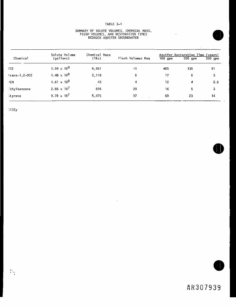
TABLE 3-1
SUMMARY OF SOLUTE VOLUMES, CHEMICAL MASS,FLUSH VOLUMES, AND RESTORATION TIMES
BEDROCK AQUIFER GROUNDWATER
Chemi cal
rcEh,rans-l,2-DCE
/CM
Tthyl benzene
ityrene
Solute Volume(gallons)
1.94 x
1.48 x
1.61 x
2.86 x
9.78 x
109
108
108
10?
10?
Chemi cal Mass(Ibs)
6,951
2,110
43
876
5,475
Flush Volumes Req
11
6
4
29
37
Aquifer Restoration Time (years!100 gpm 300 gpm 500 gpm
405
17
12
16
69
135
6
4
5
23
81
3
2.5
3
14
>735y
AR3Q7939

TABLE 3-2
BEDROCK AQUIFER CHEMICAL THRESHOLD DEPTHS
OCCIDENTAL CHEMICAL CORPORATIONPOTTSTOWN, PENNSYLVANIA
Threshold Depth Range (feet bgs)Concentration Concentration Concentration
Target Range __ Range Rangejiemical TB-1 Area (mg/l) TB-2 Area (mg/1) TB-3 Area (mg/1)
132 - 158 20.0 - 1.0 130 - 190 2.9 - 0.11 135 - 140 8.3 - 0.63
ns-l,2-DCE ,100 - 132 8.1 - ND 100 - 130 1.5 - 0.27 95 - 110 17.0 - 0.01
132 - 158 ND - 0.005 130 - 190 2.6 - 0.07 —— ND
ylbenzene 100-132 10.5 - 0.74 —— ND 100 26.0 - ND
Irene 100-132 81.6-0.38 100-130 0.23 - ND 77-95 6.0 - ND

OJ'reco4-Jreai
in c•z. oO -1-011-4 O14J 4-1r— CUC
O to t- Et-i re 4-1 SU- O 10 O1-1 coo oLU OO-cozoH-.H-O
aih- ——t/i toZ OJ.C Olo c 4J _aO -r- O.to oi -a re o -Ps: o 4-< —
UJ3: S- —cu to>- 4J Olai cu-ci.i E tj> ro cO -r- -r-O O —— •LUai
UJ CU|_ jj*i c re *— • *3: Oiai EO -r- O.z to 3 ai• — 3 fll Q ^^
0 Or-a: u_
i — Olro E4J-r- 3 re —4J EO; Ec -i- a.Ol X _C O)4-J re o •— 0 Sir-a. u.
co —•r- tO4J_c enOl 4—* 1-*i— a.a. cu •E O 4-JO 4-O v_-
i — OJ•s-i3: 3Z
00 1C l—ro :>iS- -C4-1 4J
Ol
LU XJo ci- re4- -O OlC
1— OJre s-§4Jtoaij- -
LU OJ4J O Caj a oiOl 1 Nt. CM CI— i— .a1j.4-1CLCUXJ
O4J
"?aiCO4-13O
r_-•r-S-o1
LO<?C3CM
CO
LO
r~-
o
00
1—iDi
t .to 1 4-J to 1 |c r— xi re c i— rere >-> c ro >~, i.T3 j— i— -^ xj *o re — J J— _c o
S- 4 - J 4 - J & - C C O 4-14^4-1re t u r e r e re LU 2: 01 vi^ . _s o cuC 3 E L U X J C LU UJ 1—0 LUXJS-S O O C S O O 4 - J O Co > r - r d o i — |— u I— ro EXJ C XJ C CU C 3
0 4 - 4 - - 0 4 - . 4- >S 4 - - E1 — - r - O O C U l — - i - O O O O OOl-i-re4J c re -P cjxj C4Ju r e i — i— o i u r o i — r— oi i— ai a.> r - t - r e r e s - - i - u r e u j rotvu uuj ret-oS - - i - O O 4 - J L . - r - O O OO XJO O4-JL.O i E E E t o o i E E l E l c t E t o 0> oi aj > QJ CM CUCM ro CM cu 4-
r— I- S- - i— i- - S-- - i- --pro L U Q J 4 - i r e i — r— Cr— LUOJC O 4 J 4 - J O C C U 4 J I 4 J | - r - l 4JOCa i . r - o i a i o o i o i - i - a i v i oi v> ro to x: tuadi> E C n o i i N > E o i c d i e 4->C4-J D I I N Ca i a i i - S - o j c a i a i s - r o s- ro c rd a. U C M C Ot - j c r o r e - o j t - j c r e > - m t- 01.01 re-ai-i-O L U . — r— •— - a O - O I — 4-1 .— 4-J O4JXJ 1— 1— JO4J
l 1 t 1 l l 1 1
JC i— V) r— • 4-1 JC4 - 1 a i a j o i a j a j 4 - J 1 0 4 - 1a. 3: toja 2 104- o at a.o i r e - r d 4 - i - o L - o j< t x i c - a o c - a o O4Jrfl xiCM O VO O CO CU r— CM CUl o - i - o i — - r - o i — r — recMcuc oC Q 4 - J - 4 J 4 J 4 - 1 4 J O C l — 4 - 1r- U 4JU 4 J J C -r-OO4-< 3— oi re 3— . oj re ai E4-Jjco or— 1 XJ •!— XI • l— S. O Ol 1i— ai O4JOCU O4-JQQI o coii-ai aiQjm I-4-.CCS-4-.CCJQ COIO COi a . o j o a . o i o =-r-_are
4-J r J— 4-1 UD J— 4-J S 00 tO t*i Q) 4-J01 3 0100 o vi 0100 o oo CM re s c 3c o crojaxj croxixi r— r— uvoi^o o•r- -i- •— C -i- — C r— O 4-J01 i— IOCO310 10VO310 r— - 4-1 CU 1— - XI 1—•<- -t- -i- 1 O ••- 1 O -i- O 10 CU -I- O C -i-X s- X31-4- x3:s-4- S-c\4 C4JJ-^:re S-UJ a UJO.C.O LUO-U3O OCM &-4VJOLOV1 O
1 1 1 1 1 1 1 t 1 1
LO LOO CM LO LO O CMoi ro ro CM 1i— 0 CM O
CM CM
co co o o co coi— r—
LO
o r-~ co LO o oro vo 'fr o ro
O O O CJ O O• r •— o% 10 a 'a"
o o o o o oCO O VO CO ^sT VOr- r— r— r- LO i—
CM ro •sr in ,VQ. t>-i -i i i i io: ai ai ai oi ai
AR30791.!
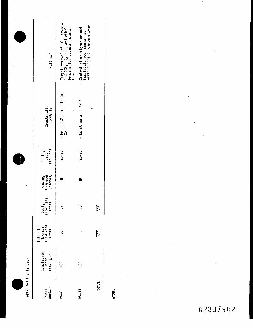
.-x>013C
4-1Coo
ro1roUJ_ iCOr-
Ol1 — •reco4-1reQi
c.o•l- VI4-1 4Ju c3 01
4-1 Ctfl OC Ooo
toDljC OlC 4-1 JO•r- O.00 Ol *ro a 4JO 4-
OJ Ol toC -P CU•-— OJ r-to S oro re cO-r- ••-o --^
014-1c re — -DID; E
•r- O.to _K O)Ol O -— •Ot—
U-
i— 01re E 4-J•r- 3 re - — .4J E oi Ec -r- a.Oi X S Ol4-j ro o «— •0 Si—Q- U,
c0 ——-r- V)4Jj= cncu -P _aa. ai •E O 4J0 4-0 -— •
r- CU
'cu E3: 3
to 1re >-i reS- -C >--4-1 4J O
Ol 4-101
LU XJ !-0 Ci- re E4- - EO OJ -r-C 4J
r— Ol Q.re s- oO 4-J S-E vi oOl 4-JV. -
LU 014-J O CQ) Q OJOl 1 N CS- CM C 0re -01-1-1— r— JO 4-1
1
o4-J
OJ
. "o-COls- _o.a—CM
1 — .
-r- —S- LOO CM
1
LO
OCM
co
ro
oLO
ovo
CO
i
OlXJ Cc ore 4-1 Nrec aiOr--" S-•i- re 34-1 > 4-1m o CLs- s re01 tu u•r- i-E 4-O iOcuoS > 01
3 Oli— QJ Ca.4-1 -r-ro s-1—4-14-O •!-
I- I- JC4-1-1-4-1C U S-o re oO 4- Cl
2D_
,__r~~O
cnc• r-4Jto
'xLU
'
inCMoCM
Or—
O
O
oco
, —r—
i LO00r—vo
HR3079U2
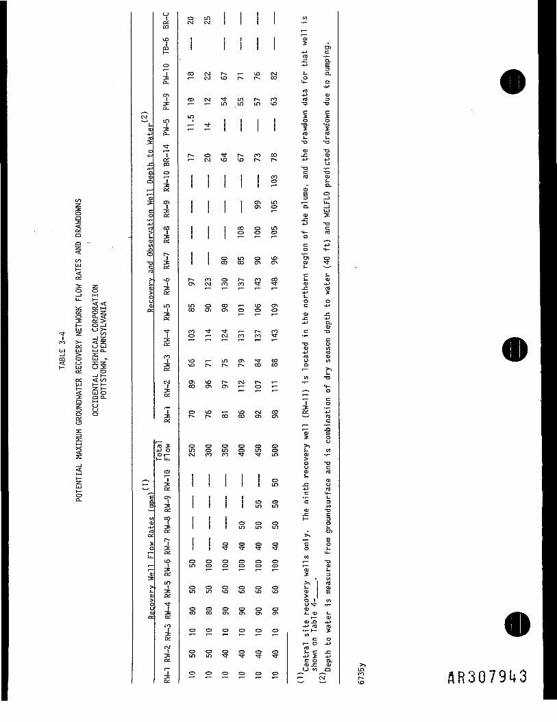
oo
oia
COLU
«1 Oi r-4Oi OZO O- <£3: Oi >LU O >-
•* Z 001 —I Zro >- < zoi o UJLU LU 1-4 O-
§O t_j:Oi O_11—o; < toLU r- I—I— Z I—< LUO3: O O-a nz o-D Oo ooi
•z.LU
OD.
o1aiCO
vo1COr-
o
5a.CM3:a.
LO•a.
ToiCOoT
ON
a.
CO
*
7Oi
vo31Oi
iniOi
^l
ro§
7Oi
1Oi
'id S4-J 0Or-r- U-
Or—
g
CJN13:aicoI3:oir -13-ai
VO1
Oi
LOC
o.:i j-i ^: o-
IOi
CM;&.
I
O LOCM CM
\
CO CMr— CM
O CM
in1 — I —
r-- or- CM
\ \\ \\ \\ \
r-- roCTV CM
r—
LO OCO ON
oo ^O r—
VD i—vo r-
01 voCO ON
o vo
o oin oCM 00
! 1\\\
o oin o
o oin in
o oCO OO
0 0
o oLO LO
O O
1
\
r-.vo
-j.in
1
,_,.vo
1
1
•1
oCO
oroi — •
COON
J.CM
LO
^ON
co
oinro
1
1
o
o0
ovo
o
o
f
0
r-
LOLO
1r-.vo
11ooo
inCO
ror — •
j—O
! __
00
ON
CM
vooo
of
\oLO
0•"3-
0o
ovo
ch
o
o
CD
11vo
f .in
rop«H
\
ONON
OO
oON
roi—
voo
r—00
S"co
^o
CMON
oLO•sT
\oin
oin
o•vT
Oo
ovo
oON
o
"
o
\1CMco
rovo
COp-ni,
00oI —
ino
LOO
VDON
-Sr-*
C-T0
ro
cooo
f_•—
coON
O0in
oin
oin
oLO
o••a-oo
oVD
OON
0
XT
0
o,4-J Cro -r-.c o.4-1 E
J-. O.o4- O
4-1ro4-1 Olro 3
o1re res- s-XI XJ
CU XJ-C CU4-1 4-1oXI •!-C XJre 01
S-o.OlE O3 _ll— U-
CO0101
XIcre
o oC 4-1
01 -C-C 4-J4J O.
OlC XJ
Ol to4-1 rore oio 01o"~ !-tO XJ
4-*—s o
roc
ai res-QJ
-C U4-1 reC 4-• r- S-C 3
tflOJ XIJ= CI— 3
O
C OO i-
reOJi-
Ol
cuS- OJ
to c o1— O 4-1reS- C JC4J3: 4-1CO O-ttl -C CUo to o inro
S AR3Q79ii3

Table 3-5
Influent Characterization for Remediation WellsAverage Concentrations before Production Process
Well TB-2A TB-1B PW-6 TB-1/TB-2- TB-1B TB7-1 BRB TB-3 (top) All WellsSimulates RW-2 RW-4 RW-5 RW-6/8 RW-7 RW-11 RW-1 RW-3
Flow (gpm) 40 90 60 150 40 10 10 10 410.0_______Parameters_______(ug/l) (ug/l) (ug'/l) (ug/l) (ug/l) (ug/l) (ug/l) (ug/l) (ug/l)
1 1,1,1-Trichloroethane2 1,1,2-Trichloroethane3 1,1-Dichloroethane 1.2 0.44 1,1-Dichloroethene 19 21.7 9.85 1,2-Dichloroethane 4 2 1.16 1,2-Dichloroethene (total) 3300 8500 120 1868.5 8500 3300 1800 3,842.67 1,2-Dichloropropane8 1,2-Dichlorobenzene9 1,3-Dichloropropylene10 1,3-Dichlorobenzene11 1,4-Dichlorobenzene12 1,2,4-Trichlorobenzene13 1,2-Trans-Dichioroethylene " 1386.8 2.7 507.414 2-Butanone (MEK) 2600 2500 2600 2700 1,804.915 2-Chlorophenol16 2-Nitrophenol17 4-Nitrophenol18 2,4-DinotrophenoI19 A6-Dinitro-o-cresol
pichlorophenolDimethylphenol
22 ,4-Dinitrotoluene23 2,6-DinitrotoIuene24 3,4-Benzofluoranthene25 Acrylonitrile26 Acenaphthylene27 Anthracene28 Benzene29 Benzo (a)anthracene30 Benzo(a)pyrene31 Benzo(k)fluoranthene32 Benzyl Alcohol 2 0.033 Bis(2-ethylhexyl) phthalate 19 20 17 20 17 14.834 Bromoform 2 0.73 5 Butylbenzylphthalate 2 3 2 1 . 736 Carbon Tetrachloride 2 0.737 Chlorobenzene 52 19.038 Chloroethane39 Chloroform 110 6.3 110 37.240 Chloromethane (Methyl Chlorid41 Chrysene42 Cyanide (free)43 Cyanide (total)44 Di-n-butyl phthalate 1 0.045 Diethyl phthalate46 Dimethyl phthalate•octylphthalate 4 1.5
Ibenzene 1 1056 1891.5 1056 1 20000 260 1,521.1
Page 1
flft3079H

Table 3-5
Influent Characterization for Remediation WellsAverage Concentrations before Production Process
Well TB-2A TB-1B PW-6 TB-1/TB-2 TB-1B TB7-1 BRB TB-3 (top) All WellsSimulates RW-2 RW-4 RW-5 RW-6/8 RW-7 RW-11 RW-1 RW-3
Flow (gpm) 40 90 60 150 40 10 10 10 410.0______Parameters_______(ug/l) (ug/l) (ug/l) (ug/l) (ug/l) (ug/l) (ug/l) (ug/l) (ug/l)
49 Ruoranthene50 Fluorene51 Hexachlorobenzene52 Hexachlorobutadiene53 Hexachloroethane54 Methylene Chloride 3947.5 1,444.255 Naphthalene56 Nitrobenzene57 Phenanthrene ' _58 Phenol 160 15.659 Phenolics (total)60 Pyrene61 Styrene 869 16443 869 110000 23225 9,540.762 Surfactants (MBAS) 350 740 350 420 392.063 Tetrachloroethene (PCE)64 Toluene 81 133 106.8 133 1 1300 120.965 Trichloroethene (TCE) 350 26500 480 3379.5 26500 88.6 3500 46400 10,962.566 Trichlorofluoromethane67 Vinyl Chloride 1500 140 446.8 140 354.268 Xylenes (total) 2000 2000 634.169 Aluminum 1100 53 406.7 53 370 138000 3,647.870 Antimony71 Arsenic 76.4 8.5 9.4 26.4 11.472 Barium 83.5 81.7 54.7 4220 142.373 Beryllium 0.8 13.6 0.674 Boron75 Cadmium76 Calcium 9260 11700 54025 11700 40050 312000 32,965.077 Chromium (hex)78 Chromium (total) 12.1 8.8 92 8.8 33.1 469 49.979 Cobalt 23.1 21.8 18.8 21.8 170 20.280 Copper 30.7 11.2 37.7 11.2 13.2 782 39.781 Iron 8240 116 201 885.7 116 556.5 319 1,215.582 Lead 14.4 7.8 12.5 135 7.983 Magnesium 725 15900 27025 15900 9240 78100 17,129.684 Manganese 145 215 81 314 215 32 21700 739.185 Mercury 0.2 0.4 0.2 0.286 Nickel 46.1 43.7 31.4 43.7 397 39.587 Potassium 2790 142000 66675 142000 27812.5 30400 71,109,788 Selenium 0.6 1.6 0.6 1.4 0.889 Silver90 Sodium 329000 86500 49625 86500 31570 65000 80,035.291 Sulfide (total)92 Thallium 2 1.6 0.893 Vanadium 5 6.5 294 10.094 Zinc 40 33.2 283.5 33.2 223.4 1140 151.4
Page 2

Table 3-6
Characterization for Remediation WellsMaximum Concentrations before Production Process
Well TB-2A TB-1B PW-6 TB-1/TB-2 TB-1B TB7-1 BRB TB-3 (top) All WellsSimulates RW-2 RW-4 RW-5 RW-6/8 RW-7 RW-11 RW-1 RW-3
Row (gpm) 40 90 " 60 150 40 10 10 10 410______Parameters_______(ug/l) (ug/l) (ug/l) (ug/l) (ug/l) (ug/l) (ug/l) (ug/l) (ug/l)
1 1,1.1-Trichloroethane2 1,1,2-Trichloroethane3 1,1-Dichloroethane 1.2 0.4390244 1,1-Dichloroethene 19 21 48 21 3 26.146345 1,2-Dichloroethane 4 3 1.4878056 1,2-Dichloroethene (total) 3300 9000 120 3700 9000 3300 1800 4671.227 1,2-Dichloropropane8 1,2-Dichlorobenzene9 1,3-Dichloropropylene10 1,3-Dichlorobenzene11 1,4-Dichlorobenzene12 1,2,4-Trichlorobenzene13 1,2-Trans-Dichloroethylene 8100 3.8 25000 3573.26314 2-Butanone (MEK) 2600 2500 2600 2700 1804.87815 2-Chlorophenol16 2-Nitrophenol _17 4-Nitrophenol18 2,4-Dinotrophenol19 4.6-Dinitro-o-cresol
pichlorophenolDimethylphenol "
22 274-Dinitrotoluene23 2,6-Dinitrotoluene24 3,4-Benzofluoranthene25 Acrylonitrile26 Acenaphthylene27 Anthracene28 Benzene29 Benzo (a)anthracene30 Benzo(a)pyrene31 Benzo (k)fiuoranthene32 Benzyl Alcohol 2 0.0487833 Bis(2-ethy!hexyl) phthalate 19 20 17 20 14.4146334 Bromoform 4 24 9800 241.02443 5 Butylbenzylphthalate 2 3 2 1.73170736 Carbon Tetrachloride 2 0.73170737 Chlorobenzene 52 19.0243938 Chloroethane39 Chloroform 110 8 110 37.8048840 Chloromethane (Methyl Chlorid41 Chrysene42 Cyanide (free)43 Cyanide (total)44 Di-n-butyl phthalate 1 0.0243945 Diethyl phthalate46 Dimethyl phthalate
i-octylphthalate 4 1.463415F/lbenzene 1 2100 10500 2100 1 20000 260 5001.585
Pagel
HR3Q79U6
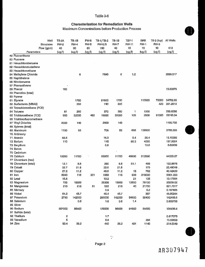
Table 3-6
Characterization for Remediation WellsMaximum Concentrations before Production Process
Well TB-2A TB-1B PW-6 TB-1/TB-2 TB-1B TB7-1 BRB TB-3 (top) All WellsSimulates RW-2 RW-4 RW-5 RW-6/8 RW-7 RW-11 RW-1 RW-3
Row (gpm) 40 90 60 150 40 10 10 10 410______Parameters_______(ug/l) (ug/l) (ug/l) (ug/l) (ug/l) (ug/l) (ug/l) (ug/l) (ug/l)
49 Ruoranthene50 Ruorene51 Hexachlorobenzene52 Hexachlorobutadiene53 Hexachloroethane54 Methylene Chloride 6 7890 6 1.2 2888.51755 Naphthalene56 Nitrobenzene57 Phenanthrene58 Phenol 160 15.6097659 Phenolics (total)60 Pyrene61 Styrene 1700 81600 1700 110000 70000 34782.9362 Surfactants (MBAS) 350 740 350 420 391.951263 Tetrachloroethene (PCE)64 Toluene 81 260 570 260 1 1300 330.609865 Trichloroethene (TCE) 500 32000 480 19600 32000 105 3500 91000 19743.5466 Trichlorofluoromethane67 Vinyl Chloride 2000 140 2600 140 1190.73268 Xylenes (total)69 Aluminum 1100 53 708 53 668 138000 3765.29370 Antimony71 Arsenic 68.5 15.3 9.4 26.4 13.1536672 Barium 110 115 60.3 4220 157.202473 Beryllium 0.8 13.6 0.6243974 Boron75 Cadmium76 Calcium 12000 11700 83500 11700 48800 312000 44229.2777 Chromium (hex)78 Chromium (total) 12.1 8.8 290 8.8 61.1 469 122.997679 Cobalt 32.7 21.8 22.5 21.8 170 22.48049 ,80 Copper 27.2 11.2 48.6 11.2 15 782 43.4243981 Iron 8240 116 201 1880 116 939 319000 9361.29382 Lead 15.8 13.2 21 135 10.1756183 Magnesium 725 15900 35300 15900 12600 78100 20239.0284 Manganese 210 215 81 522 215 40 21700 821.731785 Mercury 0.5 0.2 0.18780586 Nickel 54.2 43.7 46.4 43.7 397 45.8024487 Potassium 2790 142000 260000 142000 54800 30400 142496.688 Selenium 0.6 1.6 0.6 1.4 0.80975689 Silver90 Sodium 287000 86500 129000 86500 54500 65000 105536.691 Sulfide (total)92 Thallium 2 1.7 0.81707393 Vanadium 5 6.5 294 10.0365994 Zinc 50.4 33.2 440 33.2 401 1140 214.0049
Page 2
1.R3Q79U
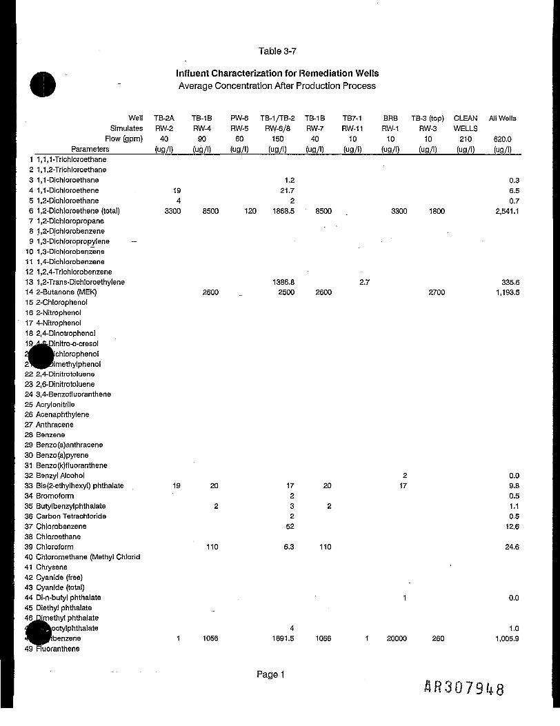
Table 3-7
Influent Characterization for Remediation WellsAverage Concentration After Production Process
Well TB-2A TB-1B PW-6 TB-1/TB-2 TB-1B TB7-1 BRB TB-3 (top) CLEAN All WellsSimulates RW-2 RW-4 RW-5 RW-6/8 RW-7 RW-11 RW-1 RW-3 WELLS
Flow (gpm) 40 90 60 150 40 10 10 10 210 620.0_____Parameters_______(ug/l) (ug/l) (ug/l) (ug/l) (ug/l) (ug/l) (ug/l) (ug/l) (ug/l) (ug/l)
1 1,1,1-Trichloroethane2 1,1,2-Trichloroethane3 1,1-Dichloroethane 1.2 0.34 1,1-Dichloroethene 19 21.7 6.55 1,2-Dichloroethane 4 2 0.76 1,2-Dichloroethene (total) 3300 8500 120 1868.5 8500 3300 1800 2,541.17 1,2-Dichloropropane8 1,2-Dichlorobenzene9 1,3-Dichloropropylene — -10 1,3-Dichlorobenzene11 1,4-Dichlorobenzene12 1,2,4-Trichlorobenzene13 1,2-Trans-DichIoroethylene 1386.8 2.7 335.614 2-Butanone (MEK) 2600 _ 2500 2600 2700 1,193.515 2-Chlorophenol16 2-Nitrophenol17 4-Nitrophenol18 2,4-Dinotrophenol
22 2,4-Dinitrotoluene23 2,6-Dinitrotoluene24 3,4-Benzofluoranthene25 Acrylonitrile26 Acenaphthylene27 Anthracene28 Benzene29 Benzo(a)anthracene30 Benzo(a)pyrene31 Benzo (k)fluoranthene32 Benzyl Alcohol 2 0.033 Bis(2-ethylhexyl) phthalate 19 20 17 20 17 9.834 Bromoform 2 0.53 5 Butylbenzylphthalate 2 3 2 1 . 136 Carbon Tetrachloride 2 0.537 Chlorobenzene 52 12.638 Chloroethane39 Chloroform 110 6.3 110 24.640 Chloromethane (Methyl Chlorid41 Chrysene42 Cyanide (free)43 Cyanide (total)44 Di-n-butyl phthalate 1 0.045 Diethyl phthalate46 d'methvl phthalate
octylphthalate 4 1.0Cibenzene 1 1056 1891.5 1056 1 20000 260 1,005.9
49 FTuoranthene
Pagel

Table 3-7
Influent Characterization for Remediation WellsAverage Concentration After Production Process
Well TB-2A TB-1B PW-6 TB-1/TB-2 TB-1B TB7-1 BRB TB-3 (top) CLEAN All WellsSimulates RW-2 RW-4 RW-5 RW-6/8 RW-7 RW-11 RW-1 RW-3 WELLS
Row (gpm) 40 90 60 150 40 10 10 10 210 620.0______Parameters_______(ug/l) (ug/l) (ug/l) (ug/l) (ug/l) (ug/l) (ug/l) (ug/l) (ug/l) (ug/l)
50 Ruorene51 Hexachlorobenzene52 Hexachlorobutadiene53 Hexachloroethane54 Methylene Chloride 3947.5 955.055 Naphthalene56 Nitrobenzene57 Phenanthrene58 Phenol ~" 160 10.359 Phenolics (total)60 Pyrene61 Styrene 869 16443 869 110000 23225 6,309.162 Surfactants (MBAS) 350 740 350 420 259.263 Tetrachloroethene (PCE)64 Toluene 81 133 106.8 133 1 1300 79.965 Trichloroethene (ICE) 350 26500 480 3379.5 26500 88.6 3500 46400 7,249.466 Trichlorofluoromethane67 Vinyl Chloride 1500 140 446.8 140 234.268 Xylenes (total) 2000 2000 469 Aluminum 1100 53 406.7 53 370 138000 2,4'70 Antimony71 Arsenic 76.4 8.5 9.4 26.4 7.672 Barium 83.5 81.7 54.7 4220 94.173 Beryllium 0.8 13.6 0.474 Boron75 Cadmium76 Calcium . 9260 11700 54025 11700 40050 312000 21,799.477 Chromium (hex)78 Chromium (total) 12.1 8.8 92 8.8 33.1 469 33.079 Cobalt 23.1 21.8 18.8 21.8 170 13.480 Copper 30.7 11.2 37.7 11.2 13.2 782 26.381 Iron 8240 116 201 885.7 116 556.5 319 803.882 Lead 14.4 7.8 12.5 135 5.283 Magnesium 725 15900 27025 15900 9240 78100 11,327.784 Manganese 145 215 81 314 215 32 21700 488.885 Mercury 0.2 0.4 0.2 0.186 Nickel 46.1 43.7 31.4 43.7 397 26.187 Potassium 2790 142000 66675 142000 27812.5 30400 47,024.288 Selenium 0.6 1.6 0.6 1.4 0.589 Silver90 Sodium 329000 86500 49625 86500 31570 65000 52,926.591 Suifide (total)92 Thallium 2 1.6 0.593 Vanadium 5 6.5 294 6.694 Zinc 40 33.2 283.5 33.2 223.4 1140 100.1
Page2

Table 3-8
Influent Characterization for Remediation WellsMaximum Concentration After Production Process
Well TB-2A " TB-1B PW-6 TB-1/TB-2 TB-1B TB7-1 BRB TB-3 (top) CLEAN All WellsSimulates RW-2 RW-4 RW-5 RW-6/8 RW-7 RW-11 RW-1 RW-3 WELLS
Row (gpm) 40 90 60 150 40 10 10 10 210 620.0______ Parameters _______ (ug/l) (ug/l) .ug/l) (ug/l) (ug/l) (ug/l) (ug/l) (ug/l) (ug/l) (ug/l)
1 1,1,1-Trichloroethane . , _ . . " . -2 1,1,2-Trichloroethane3 1,1-Dichloroethane 1.2 0.34 1,1-Dichloroethene 19 21 48 21 3 17.35 1,2-DichIoroethane 4 3 1.06 1,2-Dichloroethene (total) 3300 9000 120 3700 9000 3300 1800 3,089.07 1 ,2-Dichloropropane8 1,2-Dichlorobenzene9 1,3-Dichloropropylene —10 1,3-Dichlorobenzene11 1 ,4-Dichlorobenzene12 1,2,4-Trichlorobenzene . - . _13 1,2-Trans-Dichloroethylene 8100 3.8 25000 2,363.014 2-Butanone (MEK) 2600 2500 2600 2700 1,193.515 2-Chlorophenol16 2-Nitrophenol17 4-Nitrophenol18 2,4-Dinotrophenol19 j|jDinitro-o-cresol2 HH|chlorophenol
22 2,4-Dinitrotoluene23 2,6-Dinitrotoluene24 3,4-Benzofluoranthene25 Acrylonitrile26 Acenaphthylene27 Anthracene28 Benzene29 Benzo (a)anthracene30 Benzo (a)pyrene31 Benzo(k)fluoranthene32 Benzyl Alcohol 2 0.033 Bis(2-ethylhexyl) phthalate 19 20 17 20 9.534 Bromoform 4 _ ._.. 2 4 9800 159.435 Butylbenzylphthalate 2 _3 2 1.136 Carbon Tetrachloride 2 0.537 Chlorobenzene 52 12.638 Chloroethane39 Chloroform 110 8 110 25.040 Chloromethane (Methyl Chlorid41 Chrysene42 Cyanide (free)43 Cyanide (total)44 Di-n-butyl phthalate 1 0.045 Diethyl phthalate46 Qfrnethvl phthalate
pctylphthalate 4 1 .0Hbenzene 1 2100 10500 2100 1 20000 260 3,307.5
49 Ruoranttiene
PagelAR3Q795Q
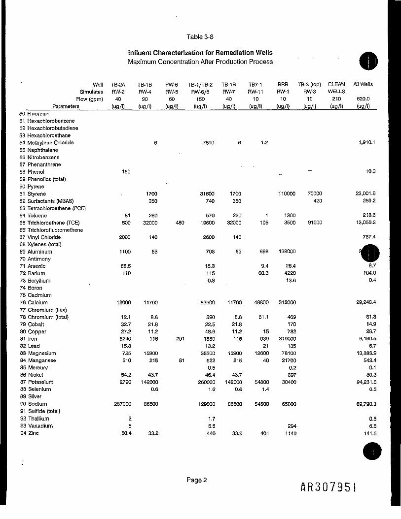
Table 3-8
Influent Characterization for Remediation WellsMaximum Concentration After Production Process
Well TB-2A TB-1B PW-6 TB-1/TB-2 TB-1B TB7-1 BRB TB-3 (top) CLEAN All WellsSimulates RW-2 RW-4 RW-5 RW-6/8 RW-7 RW-11 RW-1 RW-3 WELLS
Flow (gpm) 40 90 60 150 40 10 10 10 210 620.0______Parameters_______(ug/l) (ug/l) (ug/l) (ug/l) (ug/l) (ug/l) (ug/l) (ug/l) (ug/l) (ug/l)
50 Ruorene51 Hexachlorobenzene52 Hexachlorobutadiene53 Hexachloroethane54 Methylene Chloride • 6 7890 6 1.2 1,910.155 Naphthalene56 Nitrobenzene57 Phenanthrene58 Phenol 160 _ 10.359 Phenolics (total)60 Pyrene61 Styrene - 1700 81600 1700 110000 70000 23,001.662 Surfactants (MBAS) 350 740 350 420 259.263 Tetrachloroethene (PCE)64 Toluene 81 260 570 260 1 1300 218.665 Trichloroethene (TCE) 500 32000 480 19600 32000 105 3500 91000 13,056.266 Trichlorofluoromethane67 Vinyl Chloride 2000 140 2600 140 787.468 Xylenes (total)69 Aluminum 1100 53 708 53 668 13800070 Antimony71 Arsenic 68.5 15.3 9.4 26.4 8.772 Barium 110 115 60.3 4220 104.073 Beryllium 0.8 13.6 0.474 Boron75 Cadmium76 Calcium 12000 11700 83500 11700 48800 312000 29,248.477 Chromium (hex)78 Chromium (total) 12.1 8.8 290 8.8 61.1 469 81.379 Cobalt 32.7 21.8 22.5 21.8 170 14.980 Copper 27.2 11.2 48.6 11.2 15 782 28.781 Iron 8240 116 201 1880 116 939 319000 6,190.582 Lead 15.8 13.2 21 135 6.783 Magnesium 725 15900 35300 15900 12600 78100 13,383.984 Manganese 210 215 81 522 215 40 21700 543.485 Mercury 0.5 0.2 0.186 Nickel 54.2 43.7 46.4 43.7 397 30.387 Potassium 2790 142000 260000 142000 54800 30400 94,231.688 Selenium 0.6 1.6 0.6 1.4 0.589 Silver90 Sodium 287000 86500 129000 86500 54500 65000 69,790.391 Sulfide (total)92 Thallium 2 1.7 0.593 Vanadium 5 6.5 294 6.694 Zinc 50.4 33.2 440 33.2 401 1140 141.5
SR30795I

Tables-9
Indirect Discharge Limits
______ Pottstown POTW (INDIRECT DISCHARGE)Estimated Exist Exist EstimatedInfluent Daily Monthly Lowest DetectionMax Low Maximum Average Determining Future Limits
_______Parameter________mg/l Treat? Limit mg/l____mg/l____Limit____mg/l____mg/l____Comment1 1,1,1-Trichloroethane ND Yes 0.0220 0.0590 0.0220 OCPSF 0.00502 1,1,2-Trichloroethane ND Yesf 0.0320 0.1270 0.0320 OCPSF 0.00503 1,1-Dichloroethane 0.0003 No 0.0220 0.0590 0.0220 OCPSF 0.00504 1,1-Dichloroethene 0.0173 No 0.0220 0.0600 0.0220 OCPSF 0.00505 1,2-Dichloroethane 0.0010 No 0.1800 0.5740 0.1800 OCPSF 0.00506 1,2-Dichloroethene (total) 3.0890 No NA NA NA NA 0.00507 1,2-Dichloropropane ND Yes 0.1960 0.7940 0.1960 OCPSF 0.00508 1,2-Dichlorobenzene ND Yes 0.1960 0.7940 0.1960 OCPSF 0.01009 1,3-Dichloropropylene ND Yes 0.1960 0.7940 0.1960 OCPSF 0.005010 1,3-Dichlorobenzene ND Yes 0.1420 0.3800 0.1420 OCPSF 0.010011 1,4-Dichlorobenzene ND Yes 0.1420 0.3800 0.1420 OCPSF 0.010012 1,2,4-Trichlorobenzene" ND Yes 0.1960 0.7940 0.1960 OCPSF 0.010013 1,2-Trans-Dichloroethylene 2.3630 Yes 0.0250 0.0660 0.0250 OCPSF 0.001014 2-Butanone (MEK) 1.1935 No NA NA NA NA 0.0100«lorophenol ND Yes ~NA NA NA NA 0.0100
rophenol ND Yes 0.0650 0.2310 0.0650 OCPSF 0.0100rophenol ND Yes 0.1620 0.5760 0.1620 OCPSF 0.0500
18 2,4-DinotrophenoI ND Yes NA NA NA NA 0.050019 4,6-Dinitro-o-cresol ND Yes 0.0780 0.2770 0.0780 OCPSF 0.050020 2,4-Dichlorophenol ND Yes NA NA NA NA 0.010021 2,4-Dimethylphenol ND Yes 0.0190 0.0470 0.0190 OCPSF 0.010022 2,4-Dinitrotoluene ND Yes NA NA NA NA 0.010023 2,6-Dinitrotoluene ND Yes NA NA NA NA 0.010024 3,4-Benzofluoranthene ND Yes NA NA NA NA 0.010025 Aoryionitrile ND ~ Yes NA NA~ NA NA 0.004026 Acenaphthylene ND Yes 0.0190 0.0470 0.0190 OCPSF 0.010027 Anthracene ND Yes 0.0190 0.0470 0.0190 OCPSF 0.010028 Benzene ND Yes 0.0570 0.1340 0.0570 OCPSF 0.005029 Benzo(a)anthracene ND Yes NA NA NA NA 0.010030 Benzo(a)pyrene ND Yes NA NA NA NA 0.010031 Benzo (k)fluoranthene ND Yes NA NA NA NA 0.010032 Benzyl Alcohol 0.00003 No NA NA NA NA 0.010033 Bis(2-ethylhexyl) phthalate 0.0095 No 0.0950 0.2580 0.0950 OCPSF 0.010034 Bromoform 0.1594 No NA NA NA NA 0.005035 Butylbenzylphthalate 0.0011 No NA NA NA NA 0.010036 Carbon Tetrachloride 0.0005 No 0.1420 0.3800 0.1420 OCPSF 0.005037 Chlorobenzene 0.0126 No 0.1420 0.3800 0.1420 OCPSF 0.0050
«oroethane ND Yes 0.1100 0.2950 0.1100 OCPSF 0.0100oroform 0.0250 No 0.1110 0.3250 0.1110 OCPSF 0.0050
SR307952

Table 3-9
Indirect Discharge Limits
Pottstown POTW (INDIRECT DISCHARGE)Estimated Exist Exist EstimatedInfluent Daily Monthly Lowest DetectionMax Low Maximum Average Determining Future Limits
_________Parameter________mg/l Treat? Limit mg/l____mg/l____Limit______mg/l______mg/l___Comment40 Chloromethane (Methyl Chloride) ND Yes 0.1100 0.2950 0.1100 OCPSF 0.010041 Chrysene ND Yes NA NA NA NA 0.010042 Cyanide (free) No 0.0050 0.2000 0.2000 POTW 0.0050 interim43 Cyanide (total) ND Yes 0.4200 1.2000 0.4200 OCPSF 0.002044 Di-n-butyl phthalate 0.00002 No 0.0200 0.0430 0.0200 OCPSF 0.010045 Diethyl phthalate ND Yes 0.0460 0.1130 0.0460 OCPSF 0.010046 Dimethyl phthalate , ND Yes 0.0190 0.0470 0.0190 OCPSF 0.010047 Di-n-octylphthalate 0.0010 No NA NA NA NA 0.010048 Ethylbenzene 3.3075 Yes 0.1420 0.3800 0.1420 OCPSF 0.005049 Ruoranthene ND Yes 0.0220 0.0540 0.0220 OCPSF 0.010050 Ruorene ND Yes 0.0190 0.0470 0.0190 OCPSF 0.010051 Hexachlorobenzene ND Yes 0.1960 0.7940 0.1960 OCPSF 0.010052 Hexachlorobutadiene ND Yes 0.1420 0.3800 0.1420 OCPSF 0.010053 Hexachloroethane ND Yes 0.1960 0.7940 0.1960 OCPSF 0.010054 Methylene Chloride 1.9101 Yes 0.0360 0.1700 0.0360 OCPSF 0.010055 Naphthalene ND Yes 0.0190 0.0470 0.0190 OCPSF 0.010056 Nitrobenzene ND Yes 2.2370 6.4020 2.2370 OCPSF 0.010057 Phenanthrene ND Yes 0.0190 0.0470 0.0190 OCPSF 0.010058 Phenol 0.0103 No 0.0190 0.0470 0.0190 OCPSF 0.010059 Phenolics (Total) No NA NA NA NA 0.010060 Pyrene ND Yes 0.0200 0.0480 0.0200 OCPSF 0.010061 Styrene 23.0016 Yes 0.1000 NA NA NA 0.1000 0.005062 Surfactants (MBAS) 0.2592 No NA NA NA NA63 Tetrachloroethene (PCE) ND Yes 0.0520 0.1640 0.0520 OCPSF 0.005064 Toluene 0.2186 Yes 0.0280 0.0740 0.0280 OCPSF 0.005065 Trichloroethene (TCE) 13.0562 Yes 0.0260 0.0690 0.0260 OCPSF 0.005066 Trichlorofluoromethane ND Yes NA NA NA NA 0.001067 Vinyl Chloride 0.7874 Yes 0.0970 0.1720 0.0970 OCPSF 0.010068 Xylenes (total) ND Yes NA NA NA NA 0.005069 Aluminum 2.4900 No NA NA NA NA 0.050070 Antimony ND Yes 5.0000 5.0000 5.0000 POTW 0.021071 Arsenic 0.0087 No 0.0500 0.1000 0.1000 POTW 0.0500 0.0009 Interim72 Barium 0.1040 No 2.0000 2.0000 2.0000 POTW 0.047073 Beryllium 0.0004 No NA NA NA NA 0.001474 Boron No 1.0000 1.0000 1.0000 POTW75 Cadmium ND Yes 0.0100 0.0100 0.0100 POTW 0.0100 0.0028 Interim76 Calcium 29.2484 No NA NA NA NA 0.460077 Chromium (hex) No 0.1000 0.1000 0.1000 POTW78 Chromium (total) 0.0813 No 0.2300 2.0000 2.0000 POTW 0.2300 0.0100 Interiim J
Page 2AR307953

Table 3-9
Indirect Discharge Limits
_______Pottstown POTW (INDIRECT DISCHARGE)Estimated Exist Exist EstimatedInfluent Daily Monthly Lowest DetectionMax Low Maximum Average Determining Future Limits
_______Parameter__________mg/l Treat? Limit ., mg/l____mg/l____Limit____mg/l____mg/l____Comment79 Cobalt 0.0149 No _NA NA NA NA 0.013080 Copper 0.0287 No 0.0400 1.0000 1.0000 POTW 0.0400 0.0040 Interim81 Iron 6.1905 Yes 5.0000 5.0000 5.0000 POTW .P-°18082 Lead 0.0067 No" "0.1600 0.5000 ~ 0.3200 POTW 0.1600 0.0010 Interim83 Magnesium * 13.3839 No NA NA NA NA 0.380084 Manganese 0.5434' No 1.0000 1.0000 1.0000 POTW 0.001085 Mercury _ 0.0001" No 0.0020 0.0020 0.0020 POTW ' 0.002086 Nickel 0.0303 Yes 0.0100 0.2000 0.2000 POTW 0.0100" 0.0110 Interim87 Potassium 94.2316 No NA NA NA NA 0.690088 Selenium 0.0005 No 0.0400 0.0400 0.0400 POTW 0.001089 Silver ND Yes 0.0020 0.0020 0.0020 POTW 0.0020 0.0070 Interim90 Sodium 69.7903 No NA NA NA NA 0.510091 Sulfide (total) No 5.0000 5.0000 5.0000 POTW92 Thallium 0.0005" No 0.1000 0.1000 0.1000 POTW 0.001393J&nadium 0.0066 No 1.0000 1.0000 1.0000 POTW 0.0130
0.1415 Yes 0.0700 0.5000 0.5000 POTW 0.0700 0.0040 Interim
96 BODS --- 250 250 POTW Compat.97 TSS 250 250 POTW Compat.98 TDS 2,000 2,000 POTW 1,00099TKN(asN) 100 100 POTW Compat.100 Ammonia (as N) see Note 4. 80 80 POTW Compat.101 pH 5 to 9 5 to 9 POTW102 Oil and Grease " NA NA NA103 Phosphorus as P 10 10 POTW Compat.104 Total Toxic Organics (TTO) 1 1 POTW105 Any Single Toxic Organic 0.5 0.5 POTW
Key:Compat. = Pottstown POTW Compatible PollutantsND = Not DetectedNA = Not Applicableinterim = Pottstown POTW interim limits which may be negociable
NOTES:
Indirect Discharge Limits:1. Daily Maximums for OCPSF parameters are based on an average daily concentration.2. Pottstown POTW maximum allowable discharge is 5 times the daily average, no longer that 15 min., 5 times per day.3. Pottstown daily maximum limits are based on a 24 hour average concentration.
The ammonia limit is schduled to increased to about 150 mg/l in the near future with a surcharge above 25 mg/l.
Pages
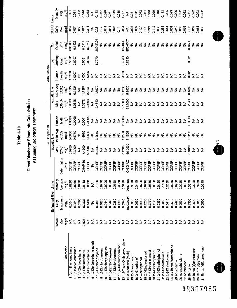
j - _ ^ _ T - T - O J C D C O 00 iS O> T- in CO t- i - T - C \ j T - C O O ) C O C O l O C O C D C J O J N . O J^ 5> TT? C V l O J C \ ] t - C D < C l n r ^ C \ l C O t - C Q O 4 < C C O ' * l s * - r x . h * C O i — i - l O C V l C i O C v i C v C O C VC p ~~' O O O O O 2: 't~° CD O O O O O ?* O O CD O O O O T~ CXJ O O O O O O
• 2 * . § ^ d d d d d d d d d d d c> d d d d d d d d d d d d d d d d dE
|tJtl§lljqi8*S3§ZggggS«3j3;:ggss.J5§§5gSQ L t a ^ E d d d d d ° d d d d o d d d d d d d d d d d d d d d d d d
5O
13
MC
3 O
u 8w t
e "2 -s 5S511 I.2 n o ^.a co o oI™ a> 5 #
Iffo E.2 3
t> <CD
C3)
< o® i- OS O
O)c"c *-*E Em 13
i c?§ s2 \
E>.--= E roa a E
go do
(^ T- m o o o CMorj o
O O O O - r - O 1 O O
t^ T- LO p CVI
T- d d d d d
r^ ^i* o o . 1 0 0 CM^7^7^77777^S*7777777777777^^^7^
o d ^ c v i i - 1 -r^io d
d r ^ C M ' ^ C O t^lO °'
8 < < < < < < < < < < < < < s <!ol?8§2§§§§§S°§§SSl§§§l§lll?i§O O T- CO
LLLJ-Ll-^LL. LLLLU-L1.1ULUL1.QL1-LL.U-LULL.11.U.LULLLLLULULULL.U,IJ,LLcn cn cn „ c n ^ . c n c n c n c n c n c n c n * ^ c n c n c n c n c n c n c n c n c n c n c n c n c n c n c n c n c nD r ^ p . o ? D L < c i r n r p r r j ? p r t i r p T o P ^ P ? ^ P T P r 9 r r x Q r p r i i o r p r 9 r p r p r a . a .o oo o„ c n ^ . c n c n c n c n c n c n c n ' T - c n c n c n c n c n c n c n c n c n c n c n c n c n c n c n c n c n^Q_<CLn.O-a.n.L^Q.OL^r^a.Q.Q.Q-a.L^O-CLQ-Q.txo-ixo-a.g8 8888888g888o8888888oo8o8o
^ — o o o w o o o o o o o o f eIO
O O O O O O O'S g g 5 8 i ^ f e g § 5 g S S § S f e c 5 o 8 5 ^ S g g g S 8 o
O O O O O O O O O O O O I O O O O O O O O O O O O O O O O O O
3 _ O O O L O h . O O O O O O O ™ O O O O O O O O O O O O^S:ffi?lc2*i-ort3:Scoc)'^Scop)5-coNCMCoini-'r-cMO)LO CM 1-o o c o - a - « a - c M ' a - i o u ! c n c o c M C M K ~ T - c r ) c o ^ i - c o . ^ i - L o i r i c o u t 3 C o
O O O O O O O O O O O O S O O O O O O O C3 O O O O O O O O O
ZpZZZZZZZZZZZZZd
l l s i s l l l l ^ osll. i IHI• - 'SS2S- c °D.D.o.-S .•«.• p.-^^ ffl-ro"rt-2-o o o o o o o t a | 5 o g c .c o E c c § g §- § g -5- -5- -5-
C l Q Q Q a ± - -
SR307955

u.r? - % §2li
silt0 J3 E
<?>n? »; W IO 0
B i g gCO
1U- c -m D)
E
5 roO E
1 ^jr x o< 3 5S Q
_
P'So
f I'
d d d d d d °ddd d d d d ° d o d d d d
ro co co co co m o> N. co N- c o c o o > c o c j > v f o > c j > c o o > c o r«-N - < < c o c M C D ' * ; : 2 L o < c M L O O ' * < o c D i o c M < a - i o c o i o c o m c M < c o' N Z Z P P ' N C D ^ q z - r ^ P ' S q z T - q q q q q q q q q q z Pd d d d d ° d odd d d d d d d d d d d d d
f~ 8 K?S l s i § g S § k < 8 < < < < < s < < < < < § < < <f; 4 d co d d d £; d
CM 1" P8 CO IQ
^ q q q q S q ™ 8 8 p ^d d d d d d d d d odd
CMCM ff *f f *f ff I*< < < < 8 ^ < § 8 < ^ < < < < < 5 i < < < < < g < < < < g < < <ZZZZqqZqSzSzZZZZcoZZZZZpZZZZqZZZ
d d d d d *- d d
O T - L O O C W O C M ^ * " * ^ O L O< < § § ! 5 S < ^ c 8 < S < < < < < 5 < < < < < S < < < < S < ^ <Z Z c q q ^ i - Z c o i q Z q Z Z Z Z Z r f Z Z Z Z Z c n Z Z Z Z q Z q Z
d d d d d ' s r d d . T - : d o
§ C O C O C O * 3 " O O O C O " ^ * O O
q c q c o Z c q c o Z q Z Z Z Z Z r o Z Z Z Z § P 2 z Z Z Z q Z 5 Sd d d d d c o d d c o o d d
< < < § C M < 8 8 < 8 < < < < < § < < < < 5 S §<<<<§<:<<5,«<*l.«^(-)r\l«*.QO";»,O*:*.«l,«^,^,";l-f-j'<":1-^-**-*J-O*5.**-^*-*;l.rS*;*-*;*-ZZZZqqZq8.ZcMZZZZZ°ZZZZz8zZZz8zZd d d d d i-1 d d
< < i « i ! < i § < § < < < < < i < < < < < ! < < < < i < , ! <Z Z q q i o c M Z c o i o Z q Z Z Z Z Z i o Z Z Z Z Z c o Z Z Z Z r ^ Z q ZW d d d d u i d d C M d o CM
0 Q)
gillllilii|gzgnllggigs|gig|il| I^ d c v J T - ^ ^ ^ j d C M £ d W d
U.Q{ELLLL.U.U.^LL.^LI.U.LL.LL i i _ u _ t i . L L . u _ L f _ i i _ i i _ u - U - u . ^ i i _ Q QCO i" CO CO CO CO CO CO CO CO CO __.. CO CO CO CO CO CO CO CO CO CO CO CO r i*^C n ^\ CL Q_ Q_ o Q_ OL Q_ Q_ n n, p p ^C Q_ Q_ n.n p, fi Q_ n n Q_ Q_ Q_ CL Q_ r^ ^^
O § Q O O O O § O § O O O O O O O O O O O O O O O ^ O ^ Q
d j ^ ' f d d d d d d d d d d d d d d d d d d d d d d d d s ^ J Q
C M ^ j I C O O O C M O C - J t - J p j v M t J C M t — i ^ - t — t _ j t j ( _ j t _ J t J t _ j t - J t J t — i v j c u u — ; — id i o o i d d d d d d T ^ T ^ d d d d d d d d d d d d d d T ^ d ^ ^
55 in co CDZZ^ZZZZqZcqZZZZZZZZZZZZZZZZwZZZ
JI O r^ CM
o_1 ICO >.
if f 1 1 « I •s-fllll-. 11 * « « g 1
,,slillllliilllilllllllllllllllll!C M C O ' a - L O C O S . C C I O > O ' - C M C O ' * i n C O N O O O > O T - C M C < ) r f l O C O N C O a ) O T - C Mr o c o T O r t c o C T c o r o v ^ M - t f ^ ^ f ' t f ' 3 - i n L o i O L O i o i o L O L O i o i o c o c o c o
ftR307956

(0o1 s3 Q)
IIo t: •=
i '«— m _ocoo> CQE D)
.g o < EE S
I±;^°co2-coi; £ c n M ^ c o S o
— l
= •? E
> —IS§|o «- ti c| 3• sSf
D) Q-. — .< o
«s O
o
U) 3
SI0)
fS
LL,
roc
I I
>> <D
5 c?
<0 3 CT« 5 -
coc>ji^•'-cod
CO O) IO O CMO O CO T-N. CM O ^£ O O CO CNJCM O>
odd d do d d do odd odd do d
iilzizz^lzizlzi^z^ziziilzllizid^d d do d d d o> ^ d odd do d
o d d d o d d d d d d d d d d d
•tOO •* CM O5 T- O CM »- C O N - ' * - LO _ COCMCOO«:T'<r1-:f--.f-OLO<i-<.,-rf--f-rT-tOr^rf'CO-.f-CO------ocorf-CQCM«.r'-r'CO
o d d d o d d d d d d d d d d
d^d d do d d ON. -^ d odd do d
OOO OO l O O C O ' t O C M O 3 O CM O
d d d d - r ^ d d d d d
IOCM
SLOio^^^^mco^^^oST-2J;:52i^TO;5;5HK^S>JH5i^S( C q c M Z Z Z Z d c o Z Z Z p Z p c o Z p Z T - ; Z Z p O ) Z q q Z Z pi—i T— CM T— O O O CM O O O ^— O O O
CO CO CO CO CO CO I, CO 0 ^ CO CD CO CDcn cn cn T~ cn ^ co ^ cn _-. *n_ n n ^C rN ^^ n IN f n ^r, n ^ n p ^ n .-L ^^ .-L n n ^L n n ^ ^^ n
000 o oo o o o° 00° 00° oo o
O O O iN- S CD CO IO CO O C\I Is* O (D CD CD CO CO CD
odd d c\i^ ® ^ d i— -r-cod did-*- do CM
OOO ITS 1§ rn ^ CD (DO *4*^*O ™ CM O ^^2 CM
odd d S?^ c3 ° *- csi C M C D O °2dco" -r^d ^
HTCiT
<D <D £ *X* SI iiil. t! e, E i|8Sls¥sl.2El=|||l=s i 1 !• _ i J E t i 1
cocu
flR307957

•
(00
* E11(3S0 -SH2 {5 «T -S °
" CD).0) wo
•S w °|L o> mw It.2 =5 52
Is
-
^*
CO
1i
CO
1CO.cO
S.
CO
1LLWo.oo
g"DX
3o"•sCflf
3otoZJ
E
Estimated
Rivei
£ O ^r- > CTo < E
>^ X ^CL"S w O)Q S E
lie!3 •— i Co -1 bO> ..C 0 .
E r? E™i "cE "eo ro5 x Ero i- O ro5 a ESi
JS ro9, E
E "eo roDel) c-j- C
•55"=^•^ 8 £
IIIrpi
eterminine
Limit
Q
>. 0
IP1
_>» r; -
73 -| |
pi
5CO
1
82
T-CO
V-
TOCO
ro5od
g00id
roCM
d
0)
id
10
82d
d
LLCOa.8o
1§COcvi
3
0
RcS
O5* O oCM "3- V
CD
"o ro
j CO C3*~ CD
ZZ ZZZZZZZ
<< < < < < C < t < £ <ZZ ZZZZZZZ
zz zzzzzzz
i! iliilll
z z zzzzzzz
< < < < < < <zz zzzzzzz
LL LL ,, LLco co o (nD_ a. JQ D.o o S oO 0 Q 0
00 0)q § s.
§ § § a,S- o g 2
CO JjJ •**
zz zzzzzzz
^ _
2 .2(3, *E
lo10 s=- °- M .2„, Z a) eo ro x
o> z .2 O o 's "raCO CO C _ ^ O ?Jw J2.J2.0 ^0.1-^
gcocoz 1 ... 2 o" >•CD(-l-l-< Q.OaLl-5
\n CD f*- co o> d T- CM m ^ 100 ) c n o > o > o > o o o d o o
sntrat
ion.
0
|
T3
on an
averag
are 2 t
imes Xc
•c eo
11£ =6CO <D2 Iffl aj
CO .Ci oD. DCLL LUf/N Q
ximums
for OCP!
ximum where Pal
it"5 'coQ D•i-1 CM
LU
LUO
CO
%Z
_-
6 ro
1 i-LO CO HCM ".yo
•*"" 3 CO•Jo « --ZJ jj- CDST1&<D 1~ i>Prt < co•o ."C C CCO O COco -5 5• .2 a»- c *-B r= °Q. E ECO O ..
LU CO Pjased on PaD
aware
River B
background
1
„ "55 O)•12 Q C'E X 's1" Q ~co -^ c^ "ro o
III
leous maximum!
rmally
limited t
oto be negotiated
i g §c eo j2
CO •*
:> s s coCL Q- Q. LLCD CD CD OO) T- o LCco co r ,.
ii n uo o >5P 5= 'C
co 3 5 =
W ASSUMPTION
Remediation
Production
Total outfa
9LL
CDO
_ roCO '<-c -eo co
c a.S E
paDtK-N'orrisic
From
flow as
su
. — . COcn Q co inLL. 10 in T-:O, CM T-: 10
CO II II IIZ = to -jgO > - P •£?5 §" « »2^ M w
3*1o 3-5!£§>^°s
II*
O .O Coj cj c
Iffs s sW TO CO
( Ctf (tf
"o "o "oC C CCO CO CO
~ PaDER Coeffici
PaDER Coe
ffici
PaDER Coe
ffici
1 % s s(0 O O i—
II IIo os o9.0,X ;
^ CM
0
|1
8"cOc'roCD
.1
1±UJaa.
E
^
nCOCDC•o03
0D5CX5D-
HR3G7958
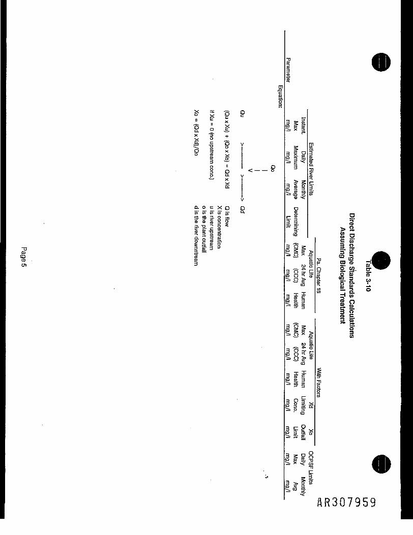
§ ;? £•3 " xQ. s—-x '=" +
Do
8 113 Oo o.
O-- °
Q- o c x O Oeo' co" co" co" 5- °-
? f I 1 o§• 1- = §5 S-g 3- <g WtIf e " 2O S 5; C 5)C m (-1 -—. M _
j H11 III* II(Q S — .2 * -° (Q -
1iop
gaCD-l
CO
CO
CQ
C3r*
3co
3(0
CO
CQ
CO
CO
3CQ**-
3CQ
-
CO
3CO
isaximum
|COCD
CD"35"3"CQ
"6S* — '
f)jfj
a£.31
00
8Q
CDE.31
o3O
C3
f
^CO
Instant.
I
oDS
"*
^
g
ho3"
iCO
II§
f1>CO
X1CO
3ZK3(O
0
1
DS.
_o§
g
1Q.
-icc?
>go'LT.CD
_rc§-.oC3"
££
£>
2?•§CO*p,^ro
0E?S1ao
8n3§•'
g
OJ ro H1S' .- 8>O. CO tT
t| Ss| s3 o= I•* S;
S'(0
SR307959

^ ra "raI E
EaLL
oCM
LL
ro .E o•- S. TO
cCO *:E 1o
O ro" E
« S -HEro•SO-
5 roo E
ro
,f y)•£20o > ~2
cSI f
CM c. » !< < g gjjli-t^t-t-T^T^pz P T ^ C M O q q q q q d _ q ° . qdodo'0 d d d d d d d d d W d d o d d d d d ° d
T- to f— h-cot^ror^C M I O C M C Md d ^ r d d d d d d d d d d
r; !S P PS CM*.>* w O O r» COCO T-g 8 8 8 £ § § 8d d d d - r - d LO d
o<oo<<<!<T-oZoozz2z <<5zzSo
CM i>- TJ- o o 100 CMiOLoZcMiqZN.ZZZZZi-cqZZZZZZZZZZZZZT-d d i ^ c M ' - r - -t-io d
CM co o o §coroZ?rZZZZz£2cMCM ^ co c\i ?Z.
O CO t- Tf O OI : < : < < < < < L O < < < < < < < < < < < < < < 0 < <ZZZZZZ mZZZZZZZZZZZZZZoZZ
COCD^^-O^T-;^^.^^^CO<r-d d T-^ co CM »^ K
j - ^ L L L L U - J S ^ L L L L L L L L L L L L L L ^ L L L L L L L L L L L L L L L L L L L L L L I J L L L L L L L L L L L
l ^ o o o ^ ^ z o o o o o o o ^ o o o o o o o o o b o b o o o o offl o o o g g o o o o o o o g o o o o o o o o o o o o o o o o o
o.P.cMcg o o o g o o o f e o g p g o g g g o p o o o
d d d d d d d d d d d d i o d d r ^ d d __ d d d d d d d d
00101^ g o o o o o p ™ o o o o or ^ - r o c M r o - ^ - ^ ^ ^ o o ^ r c o s ; T-COT-I^ i^- QQ! cot^roS- •*o C M L O C M C M qd d d d d d d d d d d d g o d T f d d
zzzZ^zzzzzzzzzzzzzzzzzzzzzzd d
~§ 5
II s s still | | its? o i i l c o c o l 1 Iiiiiu ° li-iiiii o__ §§if § § i i isi-11 ° §g i §-1 §-f _|gf|g If ? g-fiii*|. f S §Iliiiliiiiilsl tttslifl J nil g§f i-H 5 i5 (5 S 5 5 'I i§ iS S "•§ £ g 2 ~ g g •- •- •- S J n 2 S "o" 'o"o'
_ _ Y-. Y_I _ _ Y~ .— _ Y_ _ _ yj £y| j y] J. * J j J jj J ^ £ ^ ^ 0] Q|] £(Q £Q
O T~ CVl CO " IO CO h*« CO O) O ~( N o j o a c k j o j c u o v i o j c ^ o a c o c o _ _ — _aR307960
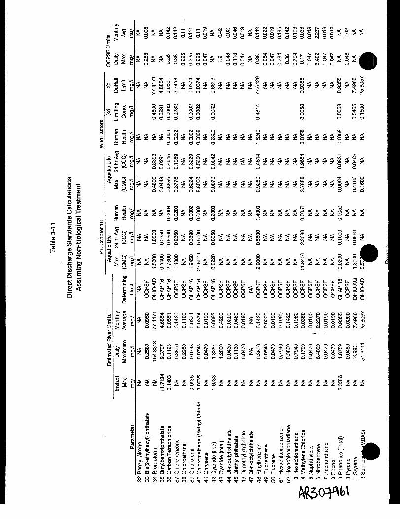
cn
O H
_i « .2•8 « •?I2 <" S0,0
ra zo c
"5 w2 <cQ
•B ra =§5J2 | % EE 5nu. _Q_ S r*n !P.
TO .C O
SI
E ea ro'
ro< O
f
U (0« £
CD
Q. < o
o& '«
a O
ra
O E
"O
.E .t;E E
CD
* Et!-
|ii
c o c o r o h - r o r o
O O O O O O O O C M O O
CMpd
o o o o o o o ooo Oooo0o'-'ocooo o
jd t T- CO •* I" CO °j LO IO CO [J,
f; •* d co o o o $~ o d N £J
8 ro 8 ?. Si 8! 3 5 £8 8 cS SO O00
cooooo o o
co CM O CO COT «-f* f* *f ff *rf* ^ *f f *f <f ^
Sz<l8z$zzzzz$zzzzz8zzzzSd d d d d T- d d
d d d d d ^ r d d i - d o
co co co i-< < 8 3 g f c < c M l 8 < e l < < < < < c iZ Z T f p c q c o Z c o c q Z p Z Z Z Z Z o )
d d d d d c o d d
co o— o S < <Sz88z%zzzzz$zzzzz8z%%2Szzzd d
co co f ro o < < S < < < < < S < < < <10 rS^.rt'^^^.^^en^^^^^co^1-^^^-SzSzzzzzSzzzzzwzzzz
O O O O 1 O O O Cvl
g z g m s s s g a g g g i g i g g g g i c s g g i _ .. .- d c\i T-: *-: fc d oj £ d r ^ o,WJ ^ ^
S 5*" L L 2 < 2 $ 2 L L L L < 2 < ° L L < 2 L L L L L L L L L L L L L L L L L L L L L L I J L U . L L L L 2 L L 9 Qw 5 r r c p c p r r c p r c p c p c » c / > ^ w w c p c o c p c p c p w c p c p w n «•$<:
•4'*IJ i~ .» n w " n A w-' « " ^ u' w w"' _**• u w'' V '-' VJ \JJ \JJ \JJ \JJ VJ UJ — \fj f fn rS LL u- n n D- PL n P- n n n n ^. n n n n n_ CL n_ n^ n, n, n, LL n, rS rS2 o ^ < < o o < < o < o o o o 2 o o o o o o o o o o o ^ o y ^ooooooooooooo° o o o o o o o o o o o g o g g
s t s s a s s i t g a s g s g ^ a a g g a g g g s g s i s g s irn v m*t 11-1 »*• _ .-rt rvt __ /X /M /NI v _. <L t- r\I «. rr\ «-+• /-r\ 1 -1 « ro «_ — m i\t rt\ '—'8 ^ _ _ .d j i i ^ d d d d d d d d d d d
~ T— co co — ,- ,-T - T - O O O C D ^ O
- -. _ o ^ i > . c o o o c o c p o t ^ o o o o o o o o o o o o o o o r o O r r t ^P. ^r2=c.rfcocoocMoio:g!:S;r:coOCTcoK,..o^;r~*o-*ON.cMi^h-&aK^SLocQi^i-cgrot?r^M-cop^:'r--3-<cQio-*roc)jroi^'3-o^--*t;5S5•i •* CO
^_ ^ i d i o o J d d d d d d T ^ i ^ d d d d d d d d d d d a J d d i ^ d ^ i ^
JI d d d T^ CM
» Ocoto ><•C cn t—
"o. S -c 5 •§ S ffl= - 5 5 ° *• -S P. 55.

CO
§ c'•S «>IEo rara 2O HCO
rara
•» g
I* 6LU03 > X
Ollcf
«lltO h
TO .•£ 2 -la"
co < O2 Ti o TO—• .c /-\ c
£si raP. E
05° ° oi0' ° ° ° S -^rod oj d gj do CM
ro 10 g ^ JS " ^ ^ *— N- cMo^f ooco CMCM ro
Sod d do d d do odd ddd do d
o g l O O CMO O CO ° § ° ° O CM i- COO T-
S u ? 8 z 8 z z 2 q Z q Z p Z q N : z 2 z e § Z q p r - : Z q q Z Z pd^d d do d d dro ^ d odd do d
o d d d o d d d d d d d d d d d
o d d d o d d d d d d d d d
» •%<>® « .2 ^
in •? o
'1B *- ii ?5 Q£ O)O C.2 eQ I8 8cu <-r
?-1.0^» .= O TOa
roc*CI i •
E 1I"Q
t
•s;10
CM CO CO h- m CM m
d d d d i - T - o T -
Isli^S^^^^^^^^^^^^s^s^^^gs^ss^^^. . . <£~ . . A. ^ — J~ - — _ ^ f.\ L u rf .—- — A. _ .y. « . <£. 4W . > rf£>odd d
S P co t-. m co co in co2 cMi^ro aaco
O Q Q o O O O O O O O CD T— O O P O
Q * d d do d d d i~- ^ d ddd do d
LO OCO <t O CM O •* OCM<SS¥zzzzcqSzzz8258jzqSSzz8cMZ§Szzqz
o d d d o d d d d d d d d d d dCD
o o o o o *•- o Is*- 10 LO " t* i^ o ro o t_u
OI-CM t ^ d d d c M o d d ^ d d d
LLLLLL £ £ < ° < E ^ ^LL ^9u. ?£u. 22 2CO CO CO ,-. _Q. a. a. < Q?O O O OOO g
:c *-Z Z < < Z < Z < Z < Q Z < Q Q Z Q < Q Z < < Z Z < Z
oo o o o° 00° bo° oo o
eo co 10 coo C M N O<< t o * t < I - ™ i o S o S o < I - c M ; ^ S ; ^ c o c MZ q Z Z ^ c o Z q Z c M Z c q t ^ Z c O p j C O coodd d CM^' CD d d^— T— cod rod^— do CM
ooo 10S•^oizSzzWNzgz^leofczS^izhorozSSodd d SS2 d d T^CM C M C O O JSdco -^duj T- CM '
Si
co !i gjEC t|CO (D Q) C
S"^" IO CO t « CO O5 O ~ C\] CO IO CO CO O5 O ~ Cvl CO IO (D IN- CO O) O ~ CM COe o c o c D C D C D C D N - K r - - N i - . N N - r - - N i ^ c o c o c o c o i x > c o c o c o c o c o r o r o r o r o
HR307962

42EIL
Q-
°
0%
1
'
(0
1 =— i=
S
S
to"
osf
3 £u rara S.0 Hw ra
,_ T3 _0 $°
° 1 -2 i.o> BJ ,O jo.•O (/) -Q O[_ <U C ra"
ra x: 0)0 C
5 1
0••g
fQ 3fi WK CO2 <Q
.•§E
— ' CD>(E1CO
s
~
t U% . U M H
.cS
5_>,"ra°
1O
ro_c
3
cE3X
roL.
^
CM
1
Human
•5TJ-CM
S^
>,.cc0
>.'aQ
c
£
ro "is$ I
__TO O)
5 E
1 13 E
CJ 'ST.
!!J=CO O)
x E
CT =O TOo, E
5 "«9- e
If
o" = .O TO• — -
O" \o, £rofc
E I•gQCD
IS
!E
|
£ "ro
I E
J> t?
S'IDEra1
8
COCM
T—
co
ro8d
cli
/n
<
5
CO
< < g
rooeo
ro3CO
< < < < <
•
|1
5 S 2 cnQ. 0. 0. LLCD O C3 O
0
10
roCM
d
roLOod
id
roCO
d
CMCO
d
LLQ.OO
1q
85CM"
Z
oc
ro
z
^
z
2<<
Ifo
o
1
64.0000
*
Q
mto coro ro
<
^
<
Z
<
<
1O
|
1
d
Z
C7D
I-
fe
z
^
s
s<
<
m0
1
z
ir?CD
°o Z"<D CO
CO
1- 1-
g §
S
^
g
S
<
<
^
^ ^
CO-2-_«"coE|8
S
^
i
S
<
<
U.cn
O
ro
cS
eo
Z
a.5
O O O CC
•S c?*^ cS g . ii ii ii
»««^ ^ " s o o >S ra i — — ~o •§ co .. "S "S S"ra co *- Z c c >§
zzzz I'll- £ i i °c | < | | 1 1 |
| ra ¥ ra < rfrfrfrf c co *o? •£ >•^•^•^•^ 0) T - W _
c SE£ °8 a. E E "-= g £
< < < < ^ ii .E 05ro N? Q CQ 0 g CL CO "=
< < < < g | | f Ic fl> w > aj
| | 1 o Sco "o. Q .c S £
| |[ S f c g ".=E 2 "g ro o •§, a>
£ g | | | ||Q_ ro* c O *O ^ D
H m 3 *O "S ~ «
° | "i 1 1 1 1g | E f g £ "pC C </) j^* QJ Q C2 2 3 otj -3 cd 2|| | | o n- u-
**** iiiil P-li-1 CM' co Ii c/j ii ii n[f Ol TO^
0 o Z b & j| |2E- « ^ a OT .2M ro Q ^ a— O ^ £ pC <!. CCL ra o O S~
CD eo TO x ~» ?- SS * n ,° > ii L« 0) U r- O £=• x"£ 3 o a) ri O fi0 ° g ro °-nj w *jg (i)
6 £ 1 5 1CM CO Tf lOo o o o
' ' - ' fif
_ __ _ __ __ ^
y o flJ?l 5 ™— — -^ o•S - § "3
??l|
.•S1 .-§" .-§• Ila la Iq 'g
1111
||||'5 "5 "5 Ol"m *S M5O QO Oa: cc DCLU LU LU 5ra to to ga. a. a. E
<tl o o i^ T~
II II II° 0 ">y. °- •§II ^
CM^ ^J!5 1 ^31 I^f 1
^307963

Q-oo
*i 0)•§ E•« 2
•p- "2 .0 £
oro
litro
£ < o =^.5 S= O. roo 5°-EI w
••DO f« .2 5o) -9 5
Op>raJ= O)u c.- ea §82 <
o = .S roO E
roc"c «±1 e
* "*~* 1U o)
tig,
U5mCT
co S ? S•^= CO S O2^c^g §•! S§0 ^ Q, -CC J) <» <]>
«= 8 -g £ £S.2 .« « .co .co
O X 3 O -O
•n
*7- t-raX
0) O
o I §:S = 3
O ^1•*• c x
-* -3 v?o a £

Table 3-1 2
Direct Discharge Limitsfor Biological Treatment
Estimated Estimated River Limits ________ GuessInfluent Daily Monthly Detection LowMax Low Maximum Average Determining Limits Limit
______ Parameter ________ mg/l Treat? Limit ___ mg/l ______ mg/l ____ Limit ____ mg/l mg/l1 1,1,1-Trichloroethane ND No 0.0210 0.0540 0.0210 OCPSF 0.00502 1,1,2-Trichloroethane ND No 0.0210 0.0540 0.0210 OCPSF 0.00503 1,1-Dichloroethane 0.0003 No 0.0220 0.0590 0.0220 OCPSF 0.00504 1,1-Dichloroethene 0.0173 Yes 0.0112 0.0225 0.0112 CHAP 16 0.00505 1,2-Dichloroethane 0.0010 No 0.0680 0.1497 0.0680 OCPSF 0.00506 1,2-Dichloroethene (total) 3.0890 Yes 0.2000 NA NA NA 0.0050 " 0.20007 1,2-Dichioropropane ND _No 0.1530 0.2300 0.1530 OCPSF 0.00508 1,2-Dichlorobenzene ND No 0.0770 0.1630 0.0770 OCPSF ' 0.01009 1,3-Dichloropropylene ND No 0.0290 0.0440 0.0290 OCPSF 0.005010 1,3-Dichlorobenzene ND No 0.0310 0.0440 0.0310 OCPSF 0.010011 1,4-Dichlorobenzene ND No 0.0150 0.0280 0.0150 OCPSF 0.010012 1,2,4-Trichlorobenzene ND No 0.0880 0.1400 0.0880 OCPSF 0.010013 1,2-Trans-Dichloroethylene 2.3630 Yes 0.0210 0.0540 0.0210 OCPSF 0.001014 2-Butanone (MEK) 1.1935 No 950.4567 1900.9134 950.4567 OHIO-AQ 0.010015 2-Chlorophenol ND No 0.0310 0.0980 0.0310 OCPSF 0.010016 2-Nitrophenol ND No 0.0410 0.0690 0.0410 OCPSF 0.010017 4-Nitrophenol ND No 0.0720 0.1240 0.0720 OCPSF 0.050018 2,4-Dinotrophenol ND No 0.0710 0.1230 0.0710 OCPSF 0.050019 4,6-Dinitro-o-oresoI ~~ ND No 0.0780 0.2770 0.0780 OCPSF 0.050020 2,4-Dichiorophenol ND No 0.0390 0.1120 0.0390 OCPSF 0.010021 2,4-Dimethylphenol ND No 0.0180 0.0360 0.0180 OCPSF 0.010022 2,4-Dinitrotoluene ND No 0.1130 0.2850 0.1130 OCPSF 0.010023 2,6-Dinitrotoluene ND No 0.2550 0.6410 0.2550 OCPSF 0.010024 3,4-Benzofluoranthene ND No 0.0230 0.0610 0.0230 OCPSF 0.010025 Acrylonitriie ND No 0.0960 0.2420 0.0960 OCPSF 0.004026 Acenaphthylene ND No 0.0220 0.0590 0.0220 OCPSF 0.010027 Anthracene ND No 0.0220 0.0590 0.0220 OCPSF 0.010028 Benzene ND No 0.0370 0.1360 0.0370 OCPSF 0.005029 Benzo(a)anthracene ND No 0.0220 0.0590 0.0220 OCPSF 0.010030 Benzo(a)pyrene ND No 0.0230 0.0610 0.0230 OCPSF 0.010031 Benzo (k)fluoranthene ND No 0.0220 0.0590 0.0220 OCPSF 0.010032 Benzyl Alcohol 0.00003 No NA NA NA NA 0.010033 Bis(2-ethylhexyi) phthalate 0.0095 No 0.1030 0.2790 0.1030 OCPSF 0.010034 Bromoform 0.1594 No 77.4171 154.8343 77.4171 OHIO-AQ 0.005035 Butylbenzylphthalate 0.0011 No 4.6854 9.3707 4.6854 CHAP 16 0.010036 Carbon Tetrachloride 0.0005 No 0.0180 0.0380 0.0180 OCPSF 0.005037 Chlorobenzene 0.0126 No 0.0150 0.0280 0.0150 OCPSF 0.005038 Chloroethane ND No 0.1040 0.2680 0.1040 OCPSF 0.010039 Chloroform 0.0250 Yes 0.0210 0.0460 0.0210 OCPSF 0.005040 Chloromethane (Methyl Chloride) ND No 0.0374 0.0748 0.0374 CHAP 16 0.0100
Pafle' flR,307965

Table 3-1 2
Direct Discharge Limitsfor Biological Treatment
Estimated Estimated River Limits _________ GuessInfluent Daily Monthly Detection LowMax Low Maximum Average Determining Limits Limit
______ Parameter ________ mg/l Treat? Limit ___ mg/l ____ mg/l ____ Limit ____ mg/l mg/l41 Chrysene ND No 0.0220 0.0590 0.0220 OCPSF 0.010042 Cyanide (free) No 0.6693 1.3387 0.6693 CHAP 1643 Cyanide (total) ND No 0.4200 1.2000 0.4200 OCPSF 0.002044 Di-n-butyl phthalate 0.00002 No 0.0270 0.0570 0.0270 OCPSF 0.010045 Diethyl phthaiate ND No 0.0810 0.2030 0.0810 OCPSF 0.010046 Dimethyl phthalate . . ND No 0.0190 0.0470 0.0190 OCPSF 0.010047 Di-n-octylphthalate .0.0010 No NA NA NA NA 0.010048 Ethylbenzene 3.3075 Yes 0.0320 0.1080 0.0320 OCPSF 0.005049 Fluoranthene ND No 0.0250 0.0680 0.0250 OCPSF 0.010050 Ruorene ND No 0.0220 0.0590 0.0220 OCPSF 0.010051 Hexachlorobenzene ND No 0.0150 0.0280 0.0150 OCPSF 0.010052 Hexachlorobutadiene ND No 0.0200 0.0490 0.0200 OCPSF 0.010053 Hexachloroethane ND No 0.0210 0.0540 0.0210 OCPSF 0.010054 Methylene Chloride 1.9101 Yes 0.0400 0.0890 0.0400 OCPSF 0.010055 Naphthalene ND No 0.0220 0.0590 0.0220 OCPSF 0.010056 Nitrobenzene ND No 0.0270 0.0680 0.0270 OCPSF 0.010057 Phenanthrene ND No 0.0220 0.0590 0.0220 OCPSF 0.010058 Phenol 0.0103 No 0.0150 0.0260 0.0150 OCPSF 0.010059 Phenolics (Total) No 0.9355 1.8709 0.9355 CHAP 16 0.010060 Pyrene ND No 0.0250 0.0670 0.0250 OCPSF 0.010061 Styrene 23.0016 Yes 0.1000 14.9931 7.4966 OHiO-AQ 0.0050 0.100062 Surfactants (MBAS) 0.2592 No 25.8057 51.6114 25.8057 OHIO-AQ63 Tetrachloroethene (PCE) ND No 0.0220 0.0560 0.0220 OCPSF 0.005064 Toluene 0.2186 Yes 0.0260 0.0800 0.0260 OCPSF 0.005065 Trichloroethene (TCE) 13.0562 Yes 0.0210 0.0540 0.0210 OCPSF 0.005066 Trichlorofluoromethane ND No NA NA NA NA 0.001067 Vinyl Chloride 0.7874 Yes 0.0037 0.0075 0.0037 CHAP 16 0.010068 Xylenes (total) ND No NA NA NA NA 0.005069 Aluminum 2.4900 No NA NA NA NA 0.050070 Antimony ND No 27.1283 54.2565 27.1283 CHAP 16 0.021071 Arsenic 0.0087 No 9.3546 18.7091 9.3546 CHAP 16 0.000972 Barium 0.1040 No NA NA NA NA 0.047073 Beryllium 0.0004 No 0.0013 0.0026 0.0013 CHAP 16 0.001474 Boron No NA NA NA NA75 Cadmium ND No 0.2055 0.4110 0.2055 CHAP 16 0.002876 Calcium 29.2484 No NA NA NA NA 0.460077 Chromium (hex) No 0.8258 1.6516 0.8258 CHAP 1678 Chromium (total) 0.0813 No 1.1100 2.7700 1.1100 OCPSF 0.010079 Cobalt 0.0149 No NA NA NA NA 0.013080 Copper 0.0287 No 1.3152 2.6304 1.3152 CHAP 16 0.0040
SR307966

Table 3-12
Direct Discharge Limitsfor Biological Treatment
Estimated Estimated River Limits________ GuessInfluent Daily Monthly Detection LowMax Low Maximum Average Determining Limits Limit
______Parameter________mg/l Treat? Limit___mg/l____mg/l____Limit______mg/l mg/l81 Iron 6.1905 No 133.8671 267.7343 133.8671 OHIO-AQ 0.018082 Lead 0.0067 No 0.3200 0.6900 0.3200 OCPSF 0.001083 Magnesium 13.3839 No NA NA NA NA 0.380084 Manganese 0.5434 No 9.3546 18.7091 9.3546 OHIO-HU 0.001085 Mercury 0.0001 No 0.0016 0.0032 0.0016 CHAP 16 0.002086 Nickel 0.0303 No 1.6900 3.9800 1.6900 OCPSF 0.011087 Potassium 94.2316 No NA NA NA NA 0.690088 Selenium 0.0005 No 0.6693 1.3387 0.6693 CHAP 16 0.001089 Silver ND No 0.0268 0.0535 0.0268 CHAP 16 0.007090 Sodium 69.7903 No NA NA NA NA 0.510091 Sulfide (total) No NA NA NA NA92 Thallium 0.0005 No 2.4096 4.8192 2.4096 CHAP 16 0.001393 Vanadium 0.0066 No NA NA NA NA 0.013094 Zinc 0.1415 No 1.0500 2.6100 1.0500 OCPSF 0.004095 "96 BODS 64 24 OCPSF97 TSS 130 40 OCPSF98 TDS (see Note 5.) 2,500 DRBC99 TKN (as N)100 Ammonia (as N)101 pH 6 to 9 6 to 9 OCPSF102 Oil and Grease103 Phosphorus as P104 Total Toxic Organics (TTO)105 Any Single Toxic Organic
Key:Compat. = Pottstown POTW Compatible PollutantsND = Not DetectedNA = Not ApplicableOHIO-AQ = Ohio Water Quality Standards for 30 Aquatic Life ExposureOHIO-HU = Ohio Water Quality Standards for 30 Human Health Exposure
NOTES:Direct Discharge Limits:1. Daily Maximums for OCPSF parameters are based on an average daily concentration.2. Daily Maximum where PaDER Chapter 16 dictates are 2 times Xo.3. Instantaineous maximums are grab sample limits based on PaDER Chapter 16 and are equal to 2.5 times Xo.4. TDS is normally limited to 1000 mg/l by DRBC (Delaware River Basin Commission). A limit, such as 2500 mg/l,
will have to be negotiated based on not increasing background TDS by more than 33% (the 133% rule).
PageSflR307967

TableS-13
Direct Discharge Limitsfor Non-biological Treatment
Estimated Estimated River Limits_________ GuessInfluent Daily Monthly Detection LowMax Low Maximum Average Determining Limits Limit
______Parameter________mg/l Treat? Limit___mg/l____mg/l____Limit____mg/l mg/l1 1,1,1-Trichloroethane ND No 0.022 0.059 0.022 OCPSF 0.0052 1,1,2-Trichloroethane ND No 0.032 0.127 0.032 OCPSF 0.0053 1,1-Dichloroethane 0.0003 No 0.022 0.059 0.022 OCPSF 0.0054 1,1-Dichloroethene 0.0173 Yes 0.01123 0.02245097 0.01122549 CHAP 16 0.0055 1,2-Dichloroethane 0.0010 No 0.07484 0.14967314 0.07483657 CHAP 16 0.0056 1,2-Dichloroethene (total) 3.0890 Yes 0.2 NA NA NA 0.005 0.2007 1,2-Dichloropropane ND No 0.196 0.794 0.196 OCPSF 0.0058 1,2-Dichlorobenzene ND No 0.196 0.794 0.196 OCPSF 0.019 1,3-DichIoropropylene ND No 0.196 0.794 0.196 OCPSF 0.00510 1,3-DichIorobenzene ND No 0.142 0.38 0.142 OCPSF 0.0111 1,4-Dichiorobenzene ND No 0.142 0.38 0.142 OCPSF 0.0112 1,2,4-Trichlorobenzene ND No 0.196 0.794 0.196 OCPSF 0.0113 1,2-Trans-Dichloroethylene 2.3630 Yes 0.025 0.066 0.025 OCPSF 0.00114 2-Butanone (MEK) 1.1935 No 950.457 1900.91343 950.456714 OHIO-AQ 0.0115 2-Chlorophenol ND No NA OCPSF 0.0116 2-Nitrophenol ND No 0.065 0.231 0.065 OCPSF 0.0117 4-Nitrophenol ND No 0.162 0.576 0.162 OCPSF 0.0518 2,4-Dinotrophenol ND No 1.207 4.291 1.207 OCPSF 0.0519 4,6-Dinitro-o-cresol ND No 0.078 0.277 0.078 OCPSF 0.0520 2,4-Dichlorophenol ND No NA OCPSF 0.0121 2,4-Dimethylphenol ND No 0.019 0.047 0.019 OCPSF 0.0122 2,4-Dinitrotoluene ND No NA OCPSF 0.0123 2,6-DinitrotoIuene ND No NA OCPSF 0.0124 3,4-Benzofluoranthene ND No 0.02 0.048 0.02 OCPSF 0.0125 Acrylonitrile ND No 0.094 0.232 0.094 OCPSF 0.00426 Acenaphthylene ND No 0.019 0.047 0.019 OCPSF 0.0127 Anthracene ND No 0.019 0.047 0.019 OCPSF 0.0128 Benzene ND No 0.057 0.134 0.057 OCPSF 0.00529 Benzo(a)anthracene ND No 0.019 0.047 0.019 OCPSF 0.0130 Benzo(a)pyrene ND No 0.02 0.048 0.02 OCPSF 0.0131 Benzo(k)fiuoranthene ND No 0.019 0.047 0.019 OCPSF 0.0132 Benzyl Alcohol 0.0000 No NA NA NA 0.0133 Bis(2-ethylhexyl) phthalate 0.0095 No 0.095 0.258 0.095 OCPSF 0.0134 Bromoform 0.1594 No 77.4171 154.834286 77.4171429 OHIO-AQ 0.00535 Butylbenzylphthalate 0.0011 No 4.68535 9.3707 4.68535 CHAP 16 0.0136 Carbon Tetrachloride 0.0005 No 0.05613 0.11225486 0.05612743 CHAP 16 0.00537 Chlorobenzene 0.0126 No 0.142 0.38 0.142 OCPSF 0.00538 Chloroethane ND No 0.11 0.295 0.11 OCPSF 0.0139 Chloroform 0.0250 No 0.03742 0.07483657 0.03741829 CHAP 16 0.00540 Chloromethane (Methyl Chloride) ND No 0.03742 0.07483657 0.03741829 CHAP 16 0.0141 Chrysene ND No 0.019 0.047 0.019 OCPSF 0.0142 Cyanide (free) No 0.66934 1.33867143 0.66933571 CHAP 1643 Cyanide (total) ND No 0.42 1.2 0.42 OCPSF 0.00244 Di-n-butyl phthalate 0.0000 No 0.02 0.043 0.02 OCPSF 0.0145 Diethyl phthalate ND No 0.046 0.113 0.046 OCPSF 0.0146 Dimethyl phthalate ND No 0.019 0.047 0.019 OCPSF 0.0147 Di-n-octylphthalate 0.0010 No NA NA NA 0.01
PagelM fl

Table 3-13
Direct Discharge Limitsfor Non-biological Treatment
Estimated Estimated River Limits__________ GuessInfluent Daily Monthly Detection LowMax Low Maximum Average Determining Limits Limit
<-.,- ..Parameter'_________ mg/l Treat? Limit mg/l______mg/l____Limit____mg/l mg/l48 Ethylbenzene 3.3075 Yes 0.142 0.38 0.142 OCPSF 0.00549 Ruoranthene ND No 0.022 0.054 0.022 OCPSF 0.0150 Ruorene ND No 0.019 0.047 0.019 OCPSF 0.0151 Hexachiorobenzene ND No 0.196 0.794 0.196 OCPSF 0.0152 Hexachlorobutadiene ND No 0.142 0.38 0.142 OCPSF 0.0153 Hexachloroethane ND No 0.196 0.794 0.196 OCPSF 0.0154 Methylene Chloride 1.9101 ' Yes 0.036 0.17 0.036 OCPSF 0.0155 Naphthalene ND No 0.019 0.047 0.019 OCPSF 0.0156 Nitrobenzene ND No 2.237 6.402 2.237 OCPSF 0.0157 Phenanthrene ND No 0.019 0.047 0.019 OCPSF 0.0158 Phenol 0.0103 No 0.019 0.047 0.019 OCPSF 0.0159 Phenolics (Total) No 0.93546 1.87091429 0.93545714 CHAP 16 0.0160 Pyrene ND No 0.02 0.048 0.02 OCPSF 0.0161 Styrene 23.0016 Yes 0.1 14.99312 7.49656 OHIO-AQ 0.005 0.10062 Surfactants (MBAS) 0.2592 No 25.8057 51.6114286 25.8057143 OHIO-AQ63 Tetrachioroethene (PCE) ND No 0.052 0.164 0.052 OCPSF 0.00564 Toluene 0.2186 Yes 0.028 0.074 0.028 OCPSF 0.005
Trichloroethene (TCE) 13.0562 Yes 0.026 0.069 0.026 OCPSF 0.005Trichlorofluoromethane ND No NA NA NA 0.001
r.' Vinyl Chloride 0.7874 Yes 0.00374 0.00748366 0.00374183 CHAP 16 0.0168 Xylenes (total) ND No NA NA NA 0.00569 Aluminum 2.4900 No NA NA NA 0.0570 Antimony ND No 27.1283 54.2565143 27.1282571 CHAP 16 0.02171 Arsenic 0.0087 No 9.35457 18.7091429 9.35457143 CHAP 16 0.000972 Barium 0.1040 No NA NA NA 0.04773 Beryllium 0.0004 No 0.00131 0.00261928 0.00130964 CHAP 16 0.001474 Boron No NA NA NA75 Cadmium ND No 0.20548 0.41095457 0.20547729 CHAP 16 0.002876 Calcium 29.2484 No NA NA NA 0.4677 Chromium (hex) No 0.82578 1.65156571 0.82578286 CHAP 1678 Chromium (total) 0.0813 No 1.11 2.77 1.11 OCPSF 0.0179 Cobalt 0.0149 No NA NA NA 0.01380 Copper 0.0287 No 1.31518 2.63035973 1.31517987 CHAP 16 0.00481 Iron 6.1905 No 133.867 267.734286 133.867143 OHIO-AQ 0.01882 Lead 0.0067 No 0.32 0.69 0.32 OCPSF 0.00183 Magnesium 13.3839 No NA NA NA 0.3884 Manganese 0.5434 No 9.35457 18.7091429 9.35457143 OHIO-HU 0.00185 Mercury 0.0001 No 0.00161 0.00321281 0.00160641 CHAP 16 0.00286 Nickel 0.0303 No 1.69 3.98 1.69 OCPSF 0.01187 Potassium 94.2316 No NA NA NA 0.6988 Selenium 0.0005 No 0.66934 1.33867143 0.66933571 CHAP 16 0.00189 Silver ND No 0.02677 0.05354686 0.02677343 CHAP 16 0.00790 Sodium 69.7903 No NA NA NA 0.5191 Sulfide (total) No NA NA NA92 Thallium 0.0005 No 2.40961 4.81921714 2.40960857 CHAP 16 0.0013'?, Vanadium 0.0066 No NA NA NA 0.013Zinc 0.1415 No 1.05 2.61 1.05 OCPSF 0.004
flR3Q7969
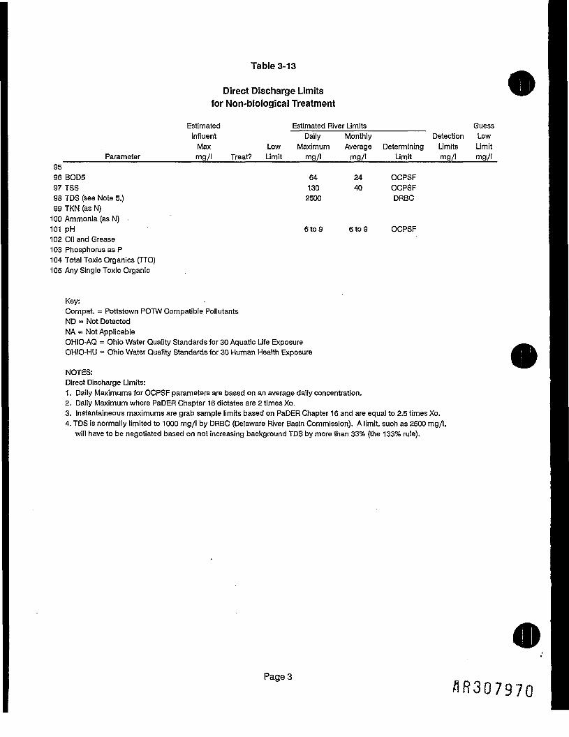
Table 3-13
Direct Discharge Limitsfor Non-biological Treatment
Estimated Estimated River Limits_________ GuessInfluent Daily Monthly Detection LowMax Low Maximum Average Determining Limits Limit
______Parameter________mg/l Treat? Limit___mg/l____mg/l____Limit____mg/l mg/l9596 BODS 64 24 OCPSF97TSS 130 40 OCPSF98 TDS (see Note 5.) 2500 DRBC99 TKN (as N)100 Ammonia (as N) .101 pH 6 to 9 6 to 9 OCPSF102 Oil and Grease103 Phosphorus as P104 Total Toxic Organics (TTO)105 Any Single Toxic Organic
Key:Compat. = Pottstown POTW Compatible PollutantsND = Not DetectedNA = Not ApplicableOHIO-AQ = Ohio Water Quality Standards for 30 Aquatic Life ExposureOHIO-HU = Ohio Water Quality Standards for 30 Human Health Exposure
NOTES:Direct Discharge Limits:1. Daily Maximums for OCPSF parameters are based on an average daily concentration.2. Daily Maximum where PaDER Chapter 16 dictates are 2 times Xo.3. Instantaineous maximums are grab sample limits based on PaDER Chapter 16 and are equal to 2.5 times Xo.4. TDS is normally limited to 1000 mg/l by DRBC (Delaware River Basin Commission). A limit, such as 2500 mg/l,
will have to be negotiated based on not increasing background TDS by more than 33% (the 133% rule).
Page 3flR307970

Table 3-14
Chemicals Requiring Treatment Summary Table
Chemical1, 1-Dichloroethene1,2-Dichloroethene1,2-Trans-DichloroethyleneChloroformEthylbenzeneMethylene ChlorideStyreneTolueneTrichloroethene (TCE)Vinyl ChlorideIronNickelZinc
Above directDischargeLimitsYesYesYesYes'YesYes
YesYesYes
AbovePOTWLimits
Yes
YesYes
YesYesYesYesYesYes
MayRequireTreatment
Yes-
HR30797I
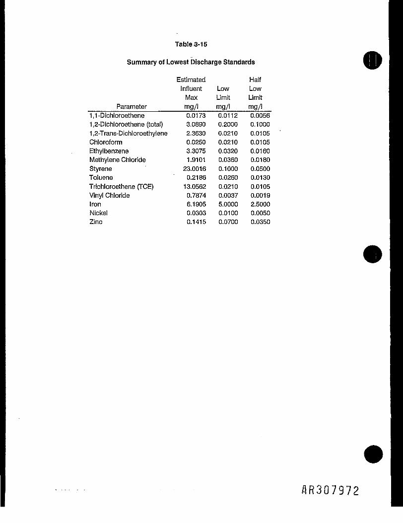
TableS-15
Summary of Lowest Discharge Standards
Estimated HalfInfluent Low LowMax Limit Limit
_____Parameter______mg/l mg/l mg/l1,1-Dichloroethene 0.0173 0.0112 0.00561,2-Dichloroethene (total) 3.0890 0.2000 0.10001,2-Trans-DichloroethyIene 2.3630 0.0210 0.0105Chloroform 0.0250 0.0210 0.0105Ethylbenzene 3.3075 0.0320 0.0160Methylene Chloride 1.9101 0.0360 0.0180Styrene 23.0016 0.1000 0.0500Toluene ~ 0.2186 0.0260 0.0130Trichloroethene (TCE) 13.0562 0.0210 0.0105Vinyl Chloride 0.7874 0.0037 0.0019Iron 6.1905 5.0000 2.5000Nickel 0.0303 0.0100 0.0050Zinc 0.1415 0.0700 0.0350
AR307972
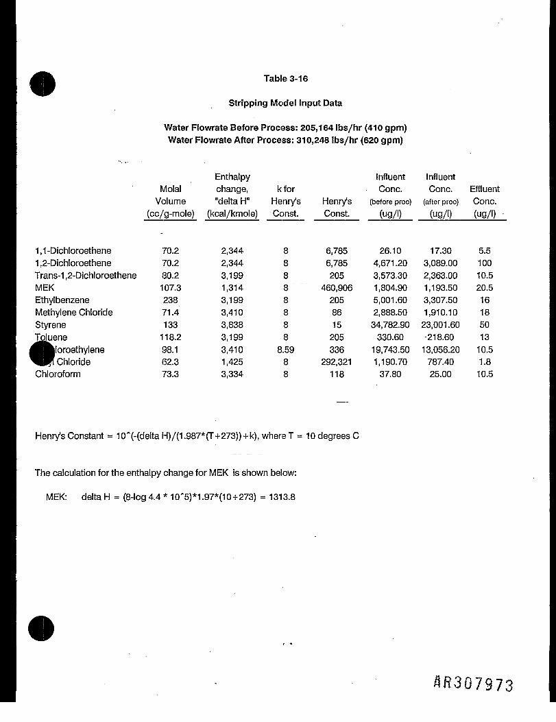
Table 3-16
Stripping Model Input Data
Water Flowrate Before Process: 205,164 Ibs/hr (410 gpm)Water Flowrate After Process: 310,248 Ibs/hr (620 gpm)
Enthalpy Influent InfluentMolal change, kfor Cone. Cone. EffluentVolume "delta H" Henry's Henry's (before proc) (after proc) Cone.
(cc/g-mole) (kcal/kmole) Const. Const. (ug/l) (ug/l) (ug/l)
1,1-Dichloroethene 70.2 2,344 8 6,785 26.10 17.30 5.51,2-Dichloroethene 70.2 2,344 8 6,785 4,671.20 3,089.00 100Trans-1,2-Dichloroethene 80.2 3,199 8 205 3,573.30 2,363.00 10.5MEK 107.3 1,314 8 460,906 1,804.90 1,193.50 20.5Ethylbenzene 238 3,199 8 205 5,001.60 3,307.50 16Methylene Chloride 71.4 3,410 8 86 2,888.50 1,910.10 18Styrene 133 3,838 8 15 34,782.90 23,001.60 50«~ ' me 118.2 3,199 8 205 330.60 -218.60 13
loroethylene 98.1 3,410 8.59 336 19,743.50 13,056.20 10.5Chloride 62.3 1,425 8 292,321 1,190.70 787.40 1.8
Chloroform 73.3 3,334 8 118 37.80 25.00 10.5
Henry's Constant = 10*(-(delta H)/(1.987*(T+273))+k), whereT = 10 degrees C
The calculation for the enthalpy change for MEK is shown below:
MEK: delta H = (8-log 4.4 * 10'5)*1.97*(10+273) = 1313.8
^307973

CD -C-OJ3 COCO too z>
w i:co -CD :9
o o-a 2CO 3 -^'.j= co .2f CD CL"-£-
D)
'5.Q.
2Q.
- $ ^c. S ^0) =3 g5 = v£ 5 £H- -S aco
O
I &
§ E^,O)
6 = ,C D)O ~i-
"gcoCD
HCO
•a3Oa.oO
coojincoddd co
cp co in o q q oco co
ooof f** ff f f *1 t~\ f f l C t f t f t f (*~lo o o o o o o o o o o
ooooooooooo
CD CM ro ro t co ** *»— tf" in co in *sf oocqinincotco T-;roi-;i-;cqT-_a),_:cqcoco co co co co co CM j - oo o CM co CM t ro o co CD d* j* t in CM CDcocoromroa>T- orom m i- co i- 10 r«- ocoroocororoCO CM T- T- i- CM
r--cnoooco'i-r--iocviLOcoo<*OT-i-'*a>N.<Moo>r--T-oojCDom ooooo-i-ot- in ooocooco mcooo ^t-OOCD t^-Oi-OOOO OJ OOi-COi-N- OJ'd-CO OJr - - c v i c - O O J O I O •*-&_
C3C3C3CM T-^C3C3C3C3C)
* I CD .1 1 |o - I o «gf ^•§s« S §5 | iii«S S§ p o So S ^tg?.ilgls II .1.881^8lUll || llUllif
m OOLUO^ OS COO^bHHl.*1^
a>^ S*3 <D ® -C c5
^^ ^S •§ S * I—. to 5 J5 to ? -9> ° ^— "> £ -n o 053.5 o S.'^cufc-£& ^§Sg §f f gfi f o|§-ai-SfifSglii^SSs g sill
CD
§§^^gS^||sl^f§C O m C M §Ss^ts-isJs-SS'SsSSs^-Kg^g'fs o,.I2S2SSS?.:?'§|g«S'§§fflST5gSST-SSS8--«{L99999S|%.iE|.|&&fe&-g9f,tiSESg22.5.g- - - - w CM. wi m I g s i o £ S s 2= -I .S ,g » J « o S •= £ ,3."H 0-22 cs « x: x: j= jc .± .± is «« £ ^
CMCQCQCQCQOOOOOQQilJSQ.03
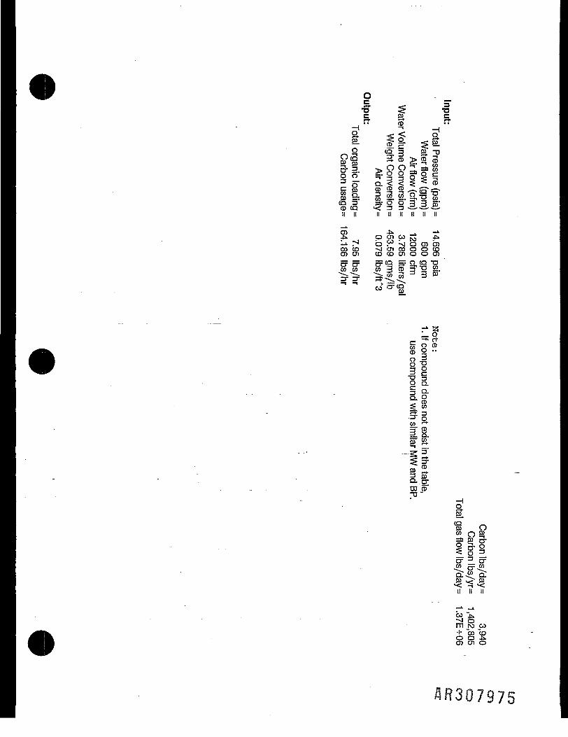
< =< T3I rl-
"^ ,0(gll IfffilCm CD to ® — J^* <•— »*S 9: 1 Ba-QiS-g'g (g t § § e
I! II II II II II II II
OOCD -slOlCOOOCQrow CD co w o o o>5=0= 5= <° S Q, <g "Sco co co '3 CD q j3 22.- - = "^ m Tf. = 3 »
ftCD
-=• oCO •-»
i §
Q. CTCD CD"0 "
I
» Oco o mas 93 5-i-3-0°T4S. CLEO > JU•< ^ •<II II II
oo ji.->i om ro w+ ~OD "coo o *kO5 CJl O

TABLE 5-1
APPLICABLE OR RELEVANT AND APPROPRIATE REQUIREMENTS (ARARS)AND TO BE CONSIDERED (TBC) STANDARDS
FOR EARTHEN LAGOONS
OCCIDENTAL CHEMICAL CORPORATIONPOTTSTOWN, PENNSYLVANIA
Potential Legal Explanation of Applicability toARAR Legal Citation Classification Classification FS Options
Federal-Location
1. Clean Water Act Section 404(1)(b) Relevant and Guidelines for discharging Relevant and appro-(1) Appropriate dredged or fill material private if wetlands40 CFR, Part 230 into waters of the U.S., to be affected.
including wetlands
2. Regulations of 33 CFR, Parts Applicable Requires that activities Applicable if remedijActivities Affect- 320-330 being conducted on waters actions affect wet-ing Waters of the US of the United States be lands. The earthen
subjected to appropriate lagoons are locatedCorps of Engineers permit- in the vicinity ofting requirements. undisturbed propertyI
containing wetlands.]
3. Proposal to Amend 33 CFR, Part 330 To Be Considered U.S. Army Corps of En- To be considered for!Nationwide Permit gineers, DOD proposed rule remedial actions whijProgram Regulations to amend nationwide permit may affect wetlands.
(NWP) program. NWPs The earthen "regulate certain activities are located,having impacts on waters vicinity ofof the U.S., including turbed |wetlands. taining wetlands.
State-Location „ _ _
1. Pennsylvania Clean PA Code Title 35, Applicable Enforceable law intended to Applicable if thereStreams Law Chapter 5 reclaim and restore pol- a discharge of indusJ
luted streams through trial waste to surfalwater quality control. " water as a result of|
flooding.
2. Dam Safety and PA Code Title 25, Applicable Regulates dams, water Applicable to remedijWaterway Manage- Chapter 105 obstructions and encroach- actions that may afflment/Wetlands ments located in, along, wetlands. The earthfProtection Act across, or projecting into lagoons are located
the regulated waters of in the vicinity ofthe Commonwealth, including undisturbed property!wetlands. containing wetlands.j
Federal Action
1. Clean Air Act 42 U.S.C. S.7401 Relevant and Regulates concentrations Relevant and appro-Appropriate of listed chemicals in priate for remedial
air discharges actions that involve!releases to the ambifent environment.
2. Occupational Safety 29 CFR, Parts Applicable Provides occupational Applicable to onsitel& Health Act (OSHA) 1904, 1910, 1926 safety and health require- work performed durinfRequirements ments for workers engaged implementation of
in onsite field activities remedial actij:t u
flR307976

[ABLE 5-1 (Continued)
Potential Legal Explanation of Applicability toLegal Citation Classification Classification FS Options
DOT Rules for Haz- 49 CFR, Parts Applicable Regulations for transport Applicable to wastesardous Materials 107 and 171-179 of hazardous materials. shipped offsite forTransport . . _ treatment or disposal.
ttate-Action
Pennsylvania Solid Act 97 Applicable Regulations for proper Applicable to remedialWaste Management management of solid wastes actions involving stor-A c t . " . . . " _ age, collection, trans-
portation, processing,treatment and disposalof solid waste
Pennsylvania Solid PA Code Title 25, Applicable Regulations for the plan- Applicable to remedialWaste Regulations Chapter 75 ning and management actions involving
of solid waste and haz- handling of solid and/ardous waste or hazardous waste.
Pennsylvania PA Code Title 25, To Be Considered Specifies requirements for To be consideredResidual Waste Chapters 287, 288, residual waste processing, because earthen lagoonRegulations 291, 297, and 299 disposal, transporting, materials meet the
collection and storage. definition of residualwaste.
Pennsylvania PA Code Title 13 Applicable Regulates shipments of Applicable to wastesHazardous Substances (Flammable Liquids hazardous wastes. shipped offsite forTransportation Reg- and Flammable treatment or disposal«" ' ' )ns . Solids) and Title during remediation.
15 (OxidizingMaterials, Poisons,and CorrosiveLi quids)
Pennsylvania Air PA Code Title 25, Applicable Provides for the control Applicable for potent-Pollution Control Chapters 121 and prevention of air pol- ial air releasesRegulations through 143 lution within the state. resulting from remedial
actions.
Pennsylvania Storm- Act No. 167 Applicable Regulates migration of Remedial actions maywater Management contaminated stormwater require stormwaterAct of October 4, from industrial sites. management systems.1978
Pennsylvania Eros- PA Code Title 25, Applicable Sets requirements on earth Soil disturbancesion Control Regu- Chapter 102 moving activities which during proposed re-lations create accelerated erosion medial actions may
or a danger of accelerated require erosion anderosion. sedimentation control
measures.
&735y
M307977
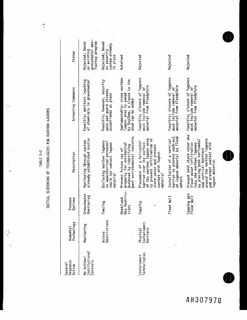
t/1•z.0oto_ 1zUJ
I—Oi
UJ
atoU-
10UJ
CM M1 CS3in ouj o
§ 1|_ UJ1—
u.oin•z.•z.LULU
O
1<£
r-t— i•z.1— f
VI3
ro
VI-Pcc
o
cncc0101I.oV)
co-pa.
uVI01Q
VI V)V) C01 O<J .r-O JJs- a.Q.O
cnr— OrOr-•r- O-o c01 -XZE uai 01Oil—
OJl — VIrO c cS. 0 001 Q.T-C VI 4J01 01 UI3a;<:
1 _•o c E "a01 Q rO ai >»V) E s- vi -ato Cn to ro
c ai s. *J J-..••I-.PCL .«.. i —•O-PrO. " O i - r 0 0 1 T 3 T3 ~O T3a i w s e n a i s u a i ai ai aj• p - i - - a c - P U E r O c 4-> *J 4Jo x c - r - o a i a i t — -i- u u ua i 0 1 3 S . a i V ) 4 J C L f O 01 01 01•r-) O O 'r-J V) -P *r-3 T. •!-)O J C S - 4 - > O J C ? . C 0 1 Ql 01 01Oi O O)-r- OS O V) -r- ai Oi Oi Oi
C V) VI VIcn J- >. a i o i c c cc ai -P -c -c o o o• r- *» V- +J 4J O O O.cro s. s. Die cn c cn cU? 3 rOO ro M- »r- rOH-»r- rO H- •.-ro-a o>, o i - p i— oro i— o ro r- o ra01 C 01 -a r— r— r—
l — 3 VlfO-P 01T301 H-i — CL <f- l — CL M-i — CLo aic oaivi orO"o oro-o oro-aMS. -S.IO CC3 >O >O >Ol. D) S-i— r- T-StO-O OIOO O J O O 01OOO OlrOO. vi Or— 01 S. E r— S-Et— S-Er—4->o > O - O 3 0 1 M - 3dm- 3flm-.r-4J OJT3-P " « V ) - O V ) l - V)S- V)S-c 3:s-rO o i - r - r O r o o E o E O EOV) OtO r— r— Ol O i— 01 O r— 01 OEi — ^Z3*a jaro ^ o i u-at- o-oi- u-oS-ro cnoi raaiE^a 34- 3<t- 34-.- U _C -P J- 01 --i — •-! — --I —oi T- oi-av) c ro -c c oiur— aiur— aior—i— E i— c-r- a i O r O i — cm r— crO r— crO.a ai 3 ro i — E c >i u jd T- •!- ja •.- .r- _a ..- •!-•t- JZ •-- J3 01 O X . r - l - T- U . r - l .V)U VlOlrO 1 — OO~O V)4->01 V).^01 V)4^01to rO-P-P Q . D ) O l r o V ) 4 J rOv)4-> rOv)aJam- airov) Eto>.ai 01310 aisro aigrou_o u.cnaj Mr— J 3 - O U - E E U.EE U.EE
^v) .->-a c
01 C nj<4- r— 3 O rO r— V)E4-> MI— s - i — 010 rooo rocoj.r- coic i — a i r o o i t - uii — S.cv)4^ojz4JV) OCO lOCnU 4JOrOC4J -r-JTM- O J O C C O4JV)C OCO T- C C CrO OC 4JV> JJ'i-OO Cn-i->iO cnocn 4_4j.r-o ot-c-i-oi S-ro>> roj->ONv)nJ3:v) roviro oc>iO NS - O 4 J > aj S -Q SrO D)-r- I. r—
-a r-S-i— 0)4- T- 3 O t O O I C > 1- rfl S- OJ 4-1jraj ai ai-o-r-i — t-v)D)S-$-o 4j| — £.->i — OT-COcnj: c Q-4-> v)T-4Jrfl o r04->a.o rocro t-r— -C )- OJ rd3V) 01 U 3WC4J ^COli — i — D) Ol-r- O-i-C t-^C-Po-i- jziaro aiaic -c T--aro 4~>s- ,Ji.-ajj:rO.JCr—s-i — 4-»ai4-> ais-Tjai ro4-ic4-ci — oaioi v)cj^4J^s-oro_c _a s- N c !-.r-E ojcto t- 4-1 -.- 4-1 o rd u .1-j->to to-r-a 3S. c 4-S-.CT- j: co.ro x: t-j3r— 01 s.4-1 ais-o 4-> o >, o o aj .-> !- 4-1 o E 4-1 !- rd rd 4-1 ojD) V) O 3 M— 3S- >!_>pai>r- *i-O OOlOlOtJOlC^c ai cn.c 4-> 4- -r- j->orOC4J3: jjj-ic J3JJ c-r-j:oirfl•r- C4->Or— >1V)> C O l O i r O r — rO O rflOlT-4->4->>ES->. > i-3CrO 4^4-irjlc OJS- >3:4->rO i — S.O 4->^J^Ut- 01o~o v)ro »r- cs.v)0i Eoioioi o.r- i — aiCDV) c -Prisaj-os-c4->ra OCT3S- aiaio ai.r-.es-Eros_ m-r-ras- ai-a r->cQ-o•r-OJ r— 3 r— 01 >Q. Q.4J US.-PQ-E.paj JJl-i— 01 > O O O - 3 6CS. U 34-) OJOS.V) rOS. O C 4-> V)S. 4-1 OJ O 4-1 -a O TD CJ)Or— c o o r o s-s.3ro r-tOM-O4->orfl crOM-ro s-r-c>.cl.crs£:rO UJv)UE Q.O.O.CL a.jDO4->v)UE HH-QO? a-M-'i-^irOrOrOi —
1s_ u -a01 Cn •!- r— C r—4J C -OS- i — rO r—rO ••- c 4-1 rO rflS s. O) to vi cn 3: D)3:T3 O C — 1 01 C CC 4-> «r- * * ai VI 'r- — "O -I- T33-i- U T 3 C O - O D.OOC C 0 1 O 1 O Q - O OuOS.O OJ O l V ) . r ~ r O i — rOi —CDS u- a Z3 4-> o u_ o u.
V)C 4-»Cn o c
C -I- 01•r- 4J r— E V)!- o ro c !-O V) T- U -i- 01•P v) s. • •.- ro T-•r- 01 4J V) -P S-C O V) >1 C S-O U 01 JC O fOs: <t o£ a_ c_> co
rO v)C 4-1 01
•v, 0 C -r-C -r- 01 CJ)0 4-1 VI E 0•r- 3 1— C r—4-1 4J O -l- OU -r- S. fO C• 4J 4-) 4-1 ;
V) C C UOCO O 01
AR307978

s—-uQJ3C
Co^(M1un
LUCOt—
VI3-pn)4-1OO
V)-pc01
oD)cc(U01i.u
co4_»D.
s.oV)01o
V) VIV) C01 OU-i-0 4-1S- 0.Q-O
cnr— Orfli—•r- O-a c01 -cE o01 Olon—
01i — VIro c cS- O OOl Q-.r-C VI 4-101 01 uCD oi <C
•a01cm+101
T334-1 >>vi rO>> cn4-1 01• i- -a i—r— c -a•r- rd rflrfl 01 U4-1 -P >!rfl .1- u2-f £.. 0)
..-a s.Oi ai ror-. cJ3 S- V)• r- O J-V) 4. OJra !- >i01 01 10U. O_i—
O)c.. 0) C
C >i-C 010 S. r-_Co-a 4JD)ro >> --a•—.a Ei-ai 3 4J01 "O 4-1 O O-C 01 V) S 3.j 5 >, -a
O VI l — O4-i— ra S-O r— 01 T- CL
O 4-> S.C 4- -i- 01 V)O V) 4-1 rfl••- i— c rfl4J IO O E "Oro T- r-> !_ C-O 0to ai rfl ai viU 4-> -1-X rfl c s- aiLU E •!- -a -Q
0) D)4-1 C
c s_O a
co4Jrflj
i —001oi
D)O
rtf o> cE o01 01Oi r-
-a01cto-paioi
•a3
V) rfl!_
>i cn4-1 01•r- t> r—i— c -a••- rtf rfl-Q i—rd 01 u4-1 4-1 >,rd-r- oOJ -C OJS-? S-
.. 01..-a s.01 ai raV)
.1-01-VI 4- 01TO S- >>01 01 rflU. Q-t—
1 • OJC 4- 4->O 0 -r-r- I-O r— r— OO)4J -r" •!- 4-rfl C 0 Si— 01 IO E
E 4-r- 01aj a. ra j=j: .1- cn-i- o*P r* C S— ?*i i *
V) -i- 01 X U4- >i4-l O 3O "o S- ro -ac -a E o oc ro 4-> s-O IOT3 a.•r- r— 01 -O-p rO O •!- 01 VIid -i- 4-> t- c ra> S- T3 S.rfl 01 01 3 01O 4-1 -P 01 4-1 l—x to ••- .r: 01 raLU E v)l— S- vi
014-> D)•l- CVI T-4- *i4- J-o a
- _ - —
_
•a01cto4J0)Oi
•a01>r-
V) t-•r- O 01
V) 4-11 — OJ VIto -a rfl•r- 3:S- V)01 rflr—4-1 rOrfl 01 3E 4J-O
V) «!-Ol rfl v)J= ? 014J a: v>
i— C• •> rfl <£ oai 3 o, .1-1— T3 4JJ3 -i- 01 reV) 0) 4J 3to s- cn01 C 01LJ- ro-i- oi
c: Or—O 4Jp-0 ••-OI4-1 4-rtf CT3r— 01 C
E rflOJ Q-r— 01_C >l- 4-14J JZ V) V)
t/1 3 rO4- OSO T3 T3C S-i—
C rfl to rfl0 N 3•r- r— ra -O4J ro .c T-rfl -r- 1 v)> s. c airfl ai o S-U 4-> CX ro viLU E rtf rfl
cncrr-i — •.1—4-T3Cro
i —rflV)Oa.VI• r-a
•a01
u01•r-)(UC£
I/I C3 OO-i--a 4Js- ra
01 TO S.-C N 014J TO CJ= ••-01 u0 S- CC 111 ••-
V) 4-1 -.,- -a
.- 01 01 >>01 C C !-i— C 10ja v) ro vitO •1- -O V)4-> | 01C r- 13 U01 id c 01EM- TO C01 S- i— Cr— 01 3O.-P S-E i-O 0 viM e c-i-
c oO 4J |O V)cn+i ojtO C T3r—0) 0
E S--r-01 Q- O C-C •!- 4- TO-P.C cn
VI S- !-H- 00O ~O 4-1c ro 4-c ro S- oO 01 I/I•r- r— C C i—4-1 ro T- o rotO T- <J -1- -t-> t- C 4-1 S-ra 01 -r- o 01U -P 34-1X rO C S- TOLU E tO 4J S
co4J10s.01cocI—I
T3014Ju01
01ai
•o01<(_3a-01S. r—
TO4J V)0 0c a.
VIC T-OT3
4J 01tO 4->OT-.1- V)4-4-•f- 4-•a o. s-o o
..-4-V) O S->! 01JI O) 4-1o a. c rd4J -. 3;o .c -a
4J 4-1 U Cc rd 301 VI 01 OEr-r- S.ai TO cn0-1-4-1
S- C 04- 01 01 4-10 4-1 >
TO 01 V)c E s- i —0 Q.TO-i- C O4-1 O 9..1-•r- o i— E•a Cni— ai-a TO TO .c< r— O O
1tO0•r- XI4- UJI•a *-.•r- C 31—04-1O -r- -i-OO 4-1 V)|
^ 4JI— 1— CTO TO 01o o E•l- -r- 4Jvi E td>i 01 a>x: j= s-a. i_> t—
V)ttl4-1 D)c oOJ i —E o-P Crfl J=01 OS- 01r- r-
-a014->u01
01a£
4-o s- aiVI O >01 4- •!-•r- -p•P >.•!-•i- i-.O4-1 rd .r-C V) JCTO VI O3 01 <-er u a.
0)•acec oro 01 T-01 -P
v) > ro•P •!- NVI -P •!-O T-l——o -a -i-f. TO o
•?4- iX O-i-
. TOr^r— rfl 400 C
O •!- 014-> E >
01 01V) .C S-4-1 O O.caj o oO--P 4-1rO01 VI V)S-i — r—
TO ro4- ••- OO I- •!-
01 Ec 4-1 aj cno to .c c•p f-•i- c -a o•a o c rtf-a o -i- ai
1n}N
!__ |j _|jtp- w*
0 C 31E 0 -Pr-l 4-1 Vl|
flft307979

«-s-o013C
4JCoo"-CM1LO
UJ_1m<1—
VI34-1TO4.JOO
VI4-1C01
oCJ
cncc01011-o00
co'•pa.'£.oV)01a
VI VIVI C01 OO •!-0 4J>- CLQ-O
>1cnr— OTO r-•r- O-a c01 -CE oai atai t-
01r— VITO C Ci- o o01 CL-t-C VI 4-101 01 OCD a: <
-a0)4-1o01•r-l01ai
014-1
V)
01.c4-1
4JTO01.a>r-VITO014-4JOZ
J= 4-D) 03O • r—J_ V) V) O --C 01 O t. 014J XI -r- JJ 1-O C C 3
V) S. TO O 4-1O O D) O TO•r- -1- S- J-C E Or— 01TO 3 CLa> >.4- 4- ES- J3 O 01 010 S- 4-> XC C TO 3
4-000 -t—O •!- "i- V) 4-
4-1 4J VI 4-1 Ci— ro ro ai c •!-TOT3 T3 1- 01> ro TO ••-••- s.gS- S. 3 S- 01
Ol Ol D--P 4J01 01 01 01 3 TOoi -o Q s- c S
T3CTO OU-Q•r- 0-Q 5-O 01S. TOOJ C«
r—TO -PO C•r— 01cn EO 4-Jr- TOO 01•r- S.CQ 1—
VI01 —-i- -O
4-1 D) 01C 0 3Oil— CE 0 -r-4J C 4-1TO-C C01 0 0S. 01 O
T3014-1O01•r~301Qi
"TOV) -i-01 S- C•o 01 ••-TO -P TOcn E'CL0) T3•a c oo oCJ Oi—> D)4-Q- TO
i— C01 13r— C C.Q rd'r-•t— TOv) U- ETO o OJ01 0 S-4- IDm i—•P i—O 4-1 •!-
z TO 3:
VIO U-.1- OC 4JOTO TOOcn coS- i— 1O TO O
•r- O4- S- IDO 01
4->4-C TO Oo E•i- VI4-> C 01TO 0 S.M 0 3•1- DI4Ji— TO TO•i-r- !-4-1 01TO E 0-i— o Eo s- ai
TO TOL. E01 S- 4->Q. 01 CE J= aiait- Et— 4-1
01 TOS s- aj0 3 S-— 1 4->l—
4-1c§£:•PTO
01 01.C S.
fiR307980

CO
ID
UJ— 1fr—
_
OOzoo<£— 1
53Cr-Oi
UJ
u.oit-i1—I—IQ
£LUOi
Oiou.o.UJMtoo_ IozXoUJ1—u.o
r-l1—=3—I1
V)34-1re4JO.
4-1WoCJ
>4-1
-OTO-PCQJE01Q.Et— i
V)VI01c01
-poOJ4-H-LU
V) V)V) C01 OO .1-0 4J1- 0.Q-O
,cn
r— OTOr—•r- O13 COJ .1—E o01 01Oi 1—
0)r— VITO C C1-0001 CL-r-C V) 4J01 01 OCD Oi <
1301C
TO4-101Oi
£O_I
,O VI•i- -a1. 014J 01V>T3ai1- !-O
13 0101 V)4-J 3COl "O •E c "O01 TO 01i—i—oa. reE S- r--r- 0 CL
4->, 01i— VI J3• i- CV) O CTO-r- TOUJ 4-> 0
01i— -ai— r— 1 -C -O Cre re •!- -P re re-r- -1- E 1 — -1-1 —13 S- <31 TO i — i —aiD)oi-cooioi4-reEC4JOZ-CS.O.I-ai-i- re s.S-4JE4- CTOOI4J
C O • TO V) V)4-J01C S- E VI 3 30)>oca)3i-i -aaiaioo4-i_E D>Cg !- O)-r- TO C ••-
CL TO -P S O • ••-r- r— 10 13 -P 4-1 4-1 Ci— >i S- C C C TO.r- _a j; cn 3 -p 01 ai j=3: 4J.1-OOE>4-11 v) -i- E s. re c oiaiai3: cno.os.s->> c E s. a. ai v).r- .r- 4-J 3 O T- •!- J= <U4->4-)OO4-J > 4- 4J V)oorec c c o o o01 01 4-1 £ V) S O) CL4- M-S C r— O >i J- S-4-jaoordcs.reo3
1o13 '$!C 4-1re vi—1 01
-a c01 01 O01 VI -r-
V)co4Jo
V) -r-v) S-01 4-1O V)O 01< Oi
"recC •!-O 4J V)•r- 3 r—4-14-100-r-l.<C 4-1 4-1
VI CO C OZl-l O
13 -a01 01c c*r- *i—43 JS01 01oi oi
E E3 3
13 -a01 01s s
>>4-1 1-• i— 13 iC 4J 013 O -i- 4-1 i —
4->r- -I- rtfS- .r- V) -r-TO aua 4- j.r— 4-1 rO 4-0)3 «r- 4J O 4-113 I/I TO TO§c 01 c E
OS- TO4J 01
.-4J ..j;OJ j: D) O) 4Jr- D) C i— > .ja 3 •!- ja -o i—re o i- re oji—4-11-3 4-1 -1- 3C -Q 13 C S- 4-01 01 -o viE Oi 13 E viQJ -Q OJ >•, 01 S. 01I— > 13 I— 0) OQ. C O 3 Q. >i UE TO I. 4J E J- 3.H O Q- V) t— 1 13 V)
-C 1S- 4J 13 C
1 0)r— 1 r— 1 CO 1i — s. 4-)to>iTO res. T O S . I J Z T Ore 01 re 01 4-1 4-1 *f— O) '1— *r* 4-1 * i | *•r-4-1 C • - O5J=.r-re "a-P C • - > S r— 4-1 TO13 ra o v) y ta i — ai oro ooic s-TO-t-aia)E os- cc'i-s- EE o i - a i c o a i i — s.E OD101 3TOJ44-) 0) OO)OJ 3s J^«r-4Ja) D)4J TO 4-1 13 • o E re t- cn4-i re 4-1 -a o i- jaS-C r-reC4JS.3-r-C C r— T O C C O J C r t f C
-t- V) S re O O)_C 1 — -r- 4-1 "1- V) S TO i£ 4-1 TO -1- "1-4-l>CH- TO 01 01>C4- TOEl —0)OOOT3C4-)OCQi-O 0)OOO13CO730J-OO l E O OTOC4-1O 01 EEC) OTOS"T3JZS-0)E 01 D)4J O E O >i- 01 U)4J O E C -r-
t. TO 3 r— 3OC4J -13 i— 1-TO3.— 3.-3C--"Or— t— O 4- J= 004J3 r— i— O4-JZ.POO4J3i—>i 1 •— T- TO C -P .i->, 1 OS- C4J•r- JQ 01 J >>4-i TO4Ja.01V)>. 3: 0)J= >.4-> TO D.4-) 01 V) >i3: j=vuaC4-iTOEE 13 -CV)jQC4j oE T3I V I 4 - 1 T O 0)CS--i-CV)3 .-VI4-1TO a i C O T O C V ) 30101 SV)>OlO) OV)4-1 0)0) ;EV)>O4->Q.OV)4-1>>E r— aiE-r-cs-oiv) >>E r— 010 ES-aivi•r- -r- o 4-) re s_ c E S •<- o T- ••- o 4-1 re i- c -r- -i- o4J4-1S-C.1-Q-O O>O>! 4-1 4-1 S.. C •!- O.1— O > O >1OO4-0)t- S-CCCS-4J OO4-01S- TOT-CCI-4Jaiai > ai i— .. 3 -x <u Q.T- a>a> >aii— 4J4JSai o--r-4- •!->.— 0) 4J r - > o i— 4- •!->!— 0) 4-) i— C TO O i—4-jaTOl.TO.i-CCS-S-4-.r- 4-jardS-re'r-0>S-CS-4-T-UJO.r-Q. ESQJ^:OOO-Q UJO-r- O - E S E Ol £ O O -Q
010) cn 4-1 cn4-1 C -i- C.... - V) •!-VI >i • 4- >iC J- 4-1.o a o a
co4Jre13£0)Oi
>-,enoi — i —re o> c
O -CE o01 01Oi r-

13Ol3C
-pCOCJ
nID
LU
CQ1—
I/I34-1TO4-1IO
4-1VIOCJ
>,4-1
jare4-1cg01
D.E*""*
VIVI01cO).1—4-1o0)4-4-LU
VI VIVI C01 OO -t-0 4-1S- 0.Q-O
cn•— oTOr—•r- 013 C0) J=E o01 <UOir-
011 — VITO C CJ- O O01 Q.-I-C V) 4JOJ OJ O
1301cTO4-101Oi
E3
•5013E
1C V) 130 TO S.O TOO14- NTO O TOi— .C
13 101 01 C-C W O4-1 O C
CL•- VI TO13 •«-01 -a c4-1 •!-C 01ai ja ojE 4J0) C Vlr—•— TO TOr-Q- O S-r-E 4-•i-r—i—13
TO TO C>vr- 3 TOr— S- T3r—• r- 0) •!-VI -p V) I/ITO TO 0) 3UJ E S- O
S-C 13 01
1— O C 4JTO O TO O TO•r- CJ) C C S13 TO TO 4J "O 4J0)i— E O 4 - - - C C CE 3 T O O V ) 3 T O O J0) D1-C 4-1 S- O E E 0)S-C C4JOJS-3C1—
•r- 4-1 O 34-1 O1.C o XI4 J > c o o r e S-TO01 o 01 I s o c .i- -i-0) E >r— -C 4JO>1—EO)Q)TOV)13 CO)s-i-4-iTOoc4-ia>i-
i — Q- C S O O Oi— >. a) i— T- re a) -a•r- ja o E 4J 4- 4-) Q.J: c1 VI O « >>(-•!-0)0)i/is.>^acn 1-c> > i— -r-Ol -i-COO)-r-T-TO>S.V)ES >V)4-14-1 •i-CQ.C O-COV1OO5-0) OCC4-1UO)0)0)0) i— o ?-*: r— CL o4-*r->4-i-Oi — D) O TO O4-jarec.i-recs-o)v)i-iuoETO3:i— -^O-c.r-CL
Dlc1 — •
4--ocTO— 1
_TOVIoCLVI
a
__^
cn 01O 3
1— t— Cre o ••-> C 4-1
i"5 §01 01 Ooif- —
>ID00U3
flR307982
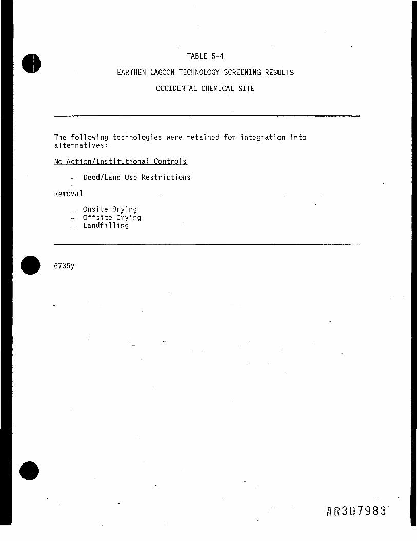
TABLE 5-4
EARTHEN LAGOON TECHNOLOGY SCREENING RESULTS
OCCIDENTAL CHEMICAL SITE
The following technologies were retained for integration intoalternatives:
No Action/Institutional Controls
- Deed/Land Use Restrictions
Removal
- Onsite Drying- Offsite Drying
Landfilling
6735y
HR3Q7983

Isa oE £2 ii
*•" "co mCD 0 §•§8""- E IiLU m
S |>
5= CO~
O "a!•. 13
< 0.c .£•s -Q 73E '5< CD
Eo _o co§ .E
O
_jO "3=5
C. 3cS " — '
OO
^
z"
CO
i
[Acetone
1000
5
fe
[Benzene^5r
oCOcvi
eg
2-UJS.c0
J3ffi
S
^
z"
00
oCOIO
<Q
"5CObco.gCOO
fz"
D;a
inc>
roethane
_oobOJ
fz"
o
8
roethene
|l,2Dichloi
oo
..COCO
o
i Chloride
| Me
thylene
^z"
..§
O
^
z"
o>o8
ocn
—
01c
1
<£2
0>o8
1
inco
co
o
(Uc10)o
Tetrac
hlori
£
z"
..ooooCO
0COCO
[Toluene
^z"
Sd
cnoo
loroethan
i:.0H
0)CO..
8COCO
8
c3
|Trich
loroe'
00
CO
5
1
(DT3•c
(Vinyl
Ohio
^
z"
389.70
1
i0)c(U
^
z"
s5-
1
1
•aCD
T3o
•gCC1cn O)CD LO OJ,
to '—'.a CM23 ""CO |<_o ^JO Q>
t o5 °T- <O Q.CD J£o o"
l|'5 oCD -am 0>c 2
Iin «O a)E |aj o
CDe3OCO•X
AR30798U

I
flR307985

Occidental Chemical CorporationPottstown, PA Facility'
Feasibilty Study
.-.'•• Figure 1-1Site Location Map
NORTH
SR307986
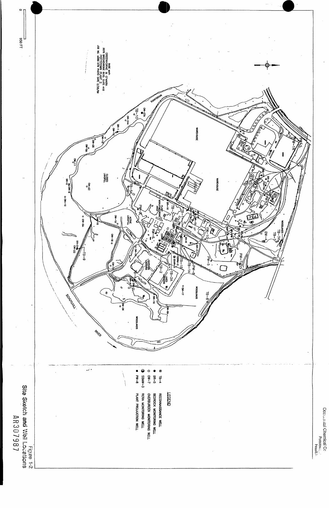
eg®m-I"
9f
\
m * -vi oi *•
.0 O CD
-aio
SCO
z o3 g-T ' SCK*
•*** ft* ^. _ _ _2
CO
UDCO.•-J
ro
Oro
1 c? —

Occidental Chemical CorporationPottstown, PA Facility
Earthen Lagoon Feasibility Study
B
B1
LEGEND
9 Test BoringTB-13
NOTE: Cross sections AA' and BB1 are shown of Figure 1-4
n -. Figure 1-3100 * Boring Locations In Earthen Lagoons
HR3Q798S

mo
.3ro'o
oo
3£0C/S
pUT* J
•• 3>co ITCD _>
S »CD ,r
soOCD
0
7 F •—pioLP o

OCCIDENTAL CHEMICAL,, PA Facility
&sibility Study
LEGEND1TB—4 Reconnaissance Borehole Location
233•33co RW—T Recovery Well Location
«JDCD
3 Figure 3-1500 FT Proposed Recovery Well Locations

Occidental Chemical CorporationPottstown, PA Facility
Feasibility Study
Figure 3-2Proposed Treatment Train for Air Stripping
J
Alternative 2A
Air Stripper ————[> BmH, „*,,„, 600 gpmAlternative
2A
_ V390 gpm 20 gpm 190 gpm - Discharge
Remediation °utfeWells C*ptureZone
Alternative 2B
390 gpm
Wells OutsideWells CaptureZone
Remediation RemediationWells
Figure 3-2HR3Q799! Mr Stripping Treatment Train

Occidental Chemical CorporationPottstown, PA Facility
Feasibility Study
Air Stripper with Carbon Regeneration
Air and VOCs
Groundwater
4To Atmosphere
To Regenerator
AirStrippingColumn
f
TreatedGroundwater
V
Carbon Regenerator Propane
Carbon Adsorber#1
Regenerating
Carbon Adsorber#2
In Use
Heated Regeneration Gas._._._._........... ... Clean Air
Figure 3-3Air Stripper
with Carbon Regeneration
•AR307992

Occidental Chemical CorporationPottstown, PA Facility
Feasibility Study
Figure 3-4Proposed Treatment Train for Steam Stripping
Alternative 3A
jSteam Stripper]————L> „„,_,„,,,.,,„ 600 gpmi Alternative! 3A,_........... ...
390 gpm 20 gpm 190 gpm Discharge
Remediation °utfecr:e
Alternative 3B
390 gpm 210 gpm
600gpm
'Steam Stripper„. . Alternative
H> 3B
20 gpm
Remediation . . .. RemediationWells Outslde Wells
Zone
Figure 3-4HR307993 Steam Stripping Treatment Train

-fa 2.£f co pfa a .ag isa sJ <uaucw
AR30799**

"• 3?•** ~ i =— w* _
.1= O** I732a.
ca > CQ•§ I £c «
Ia>T3'5UO
-
CDcCD5CD 0) CD ®
i 1 | S 11 1 1 1 1 I ! Eei, 0 N 0 0 CD 2 £
S . v S j j g - l g S f I§ g 9 t ^ 9 l l * £ 5o S csi £ c - £. £ W m sH 1 - T - U J > T - C . 3 . - S S O
M l I I i! 0 .. .. 1.1C3
(0U)ooo
0)0-• c ca. .2.S-t5COJ3
3T3OaoI_o«J-CQ
«'
e/
d,
s
'»fr/
(a/
-r1i
^
...J L/ ': i
p
•
-n---
-HFiirn
i
- i
r fLt »•
T 1
•i '5--IJ.-1..
M ' '< >
S (V
J ,- : FL^j
.( n|
o m o in o in«tf CO CO CM <N r-
>• s- H i - - - - - :
T!!
-- ,----|
I I
n-i ------
t'"
\
CO
o-- 10Cvl
C3OOJ
&1(0•Q
o o-- LO O
"- 0
w™JJ
o-- CD
1—
-. O
o to o
('}]) }l]6|3H Bui^ODj-j
«0 TO WA £ $
CDS3
AR307995

c >• >•O *! 73
I'llg^u. >»
5*1_. c «8 1 S•— 2 u-Q> ISJ= 0O a-S<o•o'5oO
-
CDc
CD <]) CD ^
•g S CD 0> ft •§, S:p P C 2 0 -E O _
CQJc" '
§
j— j.
B I
(/>oo
= 1aic o5*4|
0)§
^ *— rii j__ k« ^_i i_
\i .2 N .0 .0 g c^7 " o Q ) Q " o £ o ^ 2 * gr ' Q 1 ! , ? ; ^ £ S ^ £ oo ^i f™ p** _M ^>> .y IM fli *— •— i ^ •— — «*— * i— g , j* "
i •• I I< S o
7/j
P
(
(
«
/r
^
-1
/
1 >
1> I 1
, „:
\ \ ' r
. I < 1
--F-1 1
•1'*( ., .,
II.UCJ
1 I 1 1 1 1 1 1 M I C3CO
oCM
oCM
0>*-^
1 I-l 1*- L SO- ----| r-- in S
n— OT-
(01 IJ «JO
o- .---- — ~j- — - (^3
i i 1 : 1
41- --s - - O1 « *. no
i • i:
1 • 13
- — _ ——————— ! ——————— ( ——————— - ——— _ ——— - _ - ———— -_. ——— ^_^
O I O O L O O L O O U 5 Ot* co co oj c\i T— T-
^ a> coco .E S<!) g- 03 % 2.5* Pn CLiZ ii c~ O
** 373OoZ0>(0
ftR3Q7996

O U. >,
o Q- HO - =« 1 8o § «E S
CU73'5OO
01caaV._-•c/>ro0)CO
—— l ——
Toluene
—— Q —— Trans-1 ,
2-dichloroethene
-
(0<oa)o2a.cos3•aoa.cu£0)DQ
C1T3
•—
PT-
CDCD
HOcx:cb2
< ••
^
f -
j
-6
->
VTT
I
-
t;cii
i
H-
"
—
C
Di5».LJ
>
H
f
i
"
y
i
]
"ff
•*
{.-
Jr
i/7*:--.
•«.
D
>»
>
~
r-- •
[ 'Jr 1-< -:U^ ..
)W6
ccc
|
if*
1
^
!3
Bj3>
3i
-
— i
— n—— 1!
4— -H--It-
fi-
i---
--i
H 6"!
CD
ICO
J
•
1- -
I-o
f
8-0I-o
n -N
>|ODd
.
4
|
/
h
S1-a,1
3z
•
0
kLLS
4 >
—— \
V
-!i
-1-1-
-!Q]J
i
-1
j
f
i
I[i;ri-•M
C
-
CD•g!Z
6a hS St 11 6
I I- CD
"* SIco£3OO
- « o.
E-co0)cn(0.Q
- CJ
- C33
00 D> W" f 82 £ §
CQ0)CO I
Q.OO"5
AR307997

.t; 73
o u.-
05ol0) J2JC OO a-
CD73"3UO
CO»s••— LI-
CO
CD4_l
CD CD CD2 C C a)
CD CD Ei o, o .i •§,2 g 1 2 £O N O O CD
_O
1 ! I I 3 I s 13 C Q ^ . - > , Q Si ^ X.o 2 <. £ £ T^_ >^ o wI— H T- - UJ > -i- CO h- S
9
C!.
U.
I — — f i 1 1 1 I I 1 1 j 1 1 1 1 1 M 1 1 | " a_ i ......?!:....._.....-—._ s•|_ a. ———LJ-LUJ—LU—.,———U4J 55.0. = ——^————^__HHp_Hh—^_ gto '"O I I I I«N I I I I I I 111 LULJ.LI HIM <UU- «, o
i ! 1 1 1 1 1 1 1 1 1 1 1 itffllfftTtttltl s "g o ——I I M I I I I I—hirt—m-WiH «?35 a 1111 i i i i i i i i ff htfir1 III f I I I fltl *' fc _________I__JJL,._.__!__ «
^ i i i i i i i i i i i i »i H KI ii i m\ i i g++ w
C3
cn o> w« .E 8<D Q. OD-S-2.2>5; Q-u. •" cE .2
g tS™ 3W 73
O
flR307998

OCCIDENTAL CHEMICAL CORPORATIONPottstown, PA Facility
____________Earthen Lagoon Feasibility Study
START OFSYSTEMi
BAGCOLLECTOR
SPINNER/SEPARATOR
. EXHAUSTAIR
2500 Cfm240° F
D
FEED BIN
>
C
\ /( MILL J
/
J
I
1
PRODUCTPACKAGING
NATURAL GASHEATER
if ") ~~+™__ _._... __ AIR INTAKE(or steam)
Feed Rate = 2000 Ibs/hrEvaporation Rate = 985 Ibs/hrDry Solids = 1005 Ibs/hrInitial Moisture Content = 40% - 50%Final Moisture Content = 0.5%
Figure 6-1Onsite Process Flow Diagram
HR307999

OCCIDENTAL CHEMICAL CORPORATIONPottstown, PA Facility
Earthen Lagoon Feasibility Study
START OFSYSTEM
PRODUCTCOLLECTOR
PRODUCTPACKAGING
AIR
ULTRA-ROTOR
NOTE: This device has a 10,000 Ibs/hourfeed rate
Figure 6-2Offsite Process Flow Diagram
QR308000