Failures Related to Metalworking
305
Failures Related to Metalworking Introduction WROUGHT FORMS are produced by a wide variety of metalworking operations that can be roughly divided into bulk-working operations and sheet-forming operations (Ref 1). The general distinction here is that bulk working imposes material flow in all directions, while sheet-forming operations are typically limited to two- dimensional deformation. Metalworking operations are also classified as either primary metalworking (where mill forms such as bar, plate, tube, sheet, and wire are worked from ingot or other cast forms) or secondary metalworking (where mill products are further formed into finished products by hot forging, cold forging, drawing, extrusion, straightening, sizing, etc.). These metalworking operations have a two-fold purpose. First, they are obviously designed to produce parts with the desired configuration. Secondly, metalworking can develop a final shape with internal soundness and improved mechanical properties by: • Improved internal quality due to compressive deformation • Grain refinement • Uniform grain structure • Elimination of casting porosity and breakup of macrosegregation patterns • Beneficial grain-flow pattern for improved part performance • Improved toughness and/or fatigue resistance due to grain flow and fibering • Burnished surface and controlled surface quality However, the beneficial factors of deformation processing can become a potential problem if the process is not carefully understood. Potential problems of the deformation process also include: • Fracture-related problems: for example, internal bursts or chevron cracks, cracks on free surfaces, cracks on die-contacted surfaces • Metal-flow-related problems: for example, end grain and poor surface performance; inhomogeneous grain size; shear bands and locally weakened structures; cold shuts, folds, and laps; flow-through defects • Control, materials selection, and use problems: for example, underfill, part distortion, and poor dimensional control; tool overload and breakage; excessive tool wear; high initial investment due to equipment cost; poor material use and high scrap loss The movement of metal during these processes, whether performed at room temperature or at elevated temperatures, makes them common sources of surface discontinuities, such as laps, seams, and cold shuts. Oxides, slivers or chips of the base material, or foreign material also can be embedded into the surface during working. These surface imperfections produce a notch of unknown severity that acts as a stress raiser, which may adversely affect strength under load. Subsurface and core discontinuities may also occur. Subsurface flaws often (but not always) originate from the as-cast ingot due to shrinkage, voids, and porosity that form during solidification. For example, this is shown schematically in Fig. 1 for rolled bar that contains ingot porosity and pipe imperfections (discussed later in the section, “Imperfections from the Ingot”). These imperfections can also serve as sites for crack initiation during fabrication or in service. The file is downloaded from www.bzfxw.com
-
Upload
khangminh22 -
Category
Documents
-
view
1 -
download
0
Transcript of Failures Related to Metalworking

Failures Related to Metalworking
Introduction
WROUGHT FORMS are produced by a wide variety of metalworking operations that can be roughly divided into bulk-working operations and sheet-forming operations (Ref 1). The general distinction here is that bulk working imposes material flow in all directions, while sheet-forming operations are typically limited to two-dimensional deformation. Metalworking operations are also classified as either primary metalworking (where mill forms such as bar, plate, tube, sheet, and wire are worked from ingot or other cast forms) or secondary metalworking (where mill products are further formed into finished products by hot forging, cold forging, drawing, extrusion, straightening, sizing, etc.). These metalworking operations have a two-fold purpose. First, they are obviously designed to produce parts with the desired configuration. Secondly, metalworking can develop a final shape with internal soundness and improved mechanical properties by:
• Improved internal quality due to compressive deformation • Grain refinement • Uniform grain structure • Elimination of casting porosity and breakup of macrosegregation patterns • Beneficial grain-flow pattern for improved part performance • Improved toughness and/or fatigue resistance due to grain flow and fibering • Burnished surface and controlled surface quality
However, the beneficial factors of deformation processing can become a potential problem if the process is not carefully understood. Potential problems of the deformation process also include:
• Fracture-related problems: for example, internal bursts or chevron cracks, cracks on free surfaces, cracks on die-contacted surfaces
• Metal-flow-related problems: for example, end grain and poor surface performance; inhomogeneous grain size; shear bands and locally weakened structures; cold shuts, folds, and laps; flow-through defects
• Control, materials selection, and use problems: for example, underfill, part distortion, and poor dimensional control; tool overload and breakage; excessive tool wear; high initial investment due to equipment cost; poor material use and high scrap loss
The movement of metal during these processes, whether performed at room temperature or at elevated temperatures, makes them common sources of surface discontinuities, such as laps, seams, and cold shuts. Oxides, slivers or chips of the base material, or foreign material also can be embedded into the surface during working. These surface imperfections produce a notch of unknown severity that acts as a stress raiser, which may adversely affect strength under load. Subsurface and core discontinuities may also occur. Subsurface flaws often (but not always) originate from the as-cast ingot due to shrinkage, voids, and porosity that form during solidification. For example, this is shown schematically in Fig. 1 for rolled bar that contains ingot porosity and pipe imperfections (discussed later in the section, “Imperfections from the Ingot”). These imperfections can also serve as sites for crack initiation during fabrication or in service.
The file is downloaded from www.bzfxw.com

Fig. 1 Longitudinal sections of two types of ingots showing typical pipe and porosity. When the ingots are rolled into bars, these flaws become elongated throughout the center of the bars.
Metalforming and fabrication of wrought forms also involve other manufacturing operations, such as electroplating, heat treatment, machining, or welding. These operations may also introduce possible defects (Table 1) that may be considered in conjunction with possible defects from metalworking. Failures can also occur from a complex series of manufacturing factors. For example, the level of residual hoop and bending stresses can occur in a tube produced by drawing, heat treating, and straightening operations. By varying the severity of these operations, it is possible to produce tubes with very low residual stresses or with very high residual stresses that are near the yield strength of the metal. In other words, parts are made by a rather complex series of operations, which thus requires a broad understanding not only in the context of failure analysis but also in the organizational traditions for failure prevention.
Table 1 Defects that may result from postforming processes
Process Possible defects Electroplating Hydrogen embrittlement, galvanic corrosion Heat treatment Excessive grain growth, burning of grain boundaries, brittle structure,
carburization, decarburization, quench cracks Electrolytic cleaning Pitting Surface hardening, nitriding, carburizing, anodic hard coating
Excessive case thickness, microcracks, embrittled material at stress raisers
Machining Tool marks, grinding cracks Welding Weld-metal defects, hydrogen-induced cracking, inclusions, improper
structure The primary purpose of this article is to describe general root causes of failure that are associated with wrought metals and metalworking. This includes a brief review of the discontinuities or imperfections that may be

common sources of failure-inducing defects in bulk working of wrought products. This article does not address powder metallurgy (P/M). A good review of powder metallurgy with coverage relevant to failure analysis of P/M forms is in Ref 2.
References cited in this section
1. J. Schey, Manufacturing Processes and Their Selection, Materials Selection and Design, Vol. 20, ASM Handbook, ASM International, 1997, p 687–704
2. L. Pease III and W. West, Fundamentals of Powder Metallurgy, Metal Powder Industries Federation, 2002
Failures Related to Metalworking
Imperfections in Wrought Forms
Various terms are used to describe surface and subsurface imperfections in wrought product. The meaning of terms can vary by location and industry, but Fig. 2 is a schematic illustration of some terms used to describe flaws in rolled bar stock. This schematic is not a complete summary of possible imperfections; for example, die scratches of cold-worked product are not included. However, the schematic of Fig. 2 shows typical terms for surface and subsurface flaws that may occur in wrought products. For example, inclusions (Fig. 2a) and seams (Fig. 2h) are commonly used terms to describe imperfections in wrought form, as discussed in more detail in this section. These imperfections, whether at or the below the surface, can adversely affect performance of a part by creating a notch of unknown severity and serve as a crack-initiation site during fabrication or in service. Corrosion and wear damage can also be assisted by discontinuities, especially at the surface. These flaws may occur from the melting practices and solidification of ingot, the primary or secondary working of the material, or the metallurgical characteristic of a particular alloy system.
Fig. 2 Ten different types of flaws that may be found in rolled bars. (a) Inclusions. (b) Laminations from spatter (entrapped splashes) during the pouring. (c) Slivers. (d) Scabs are caused by splashing liquid metal in the mold. (e) Pits and blisters caused by gaseous pockets in the ingot. (f) Embedded scale from excessive scaling during prior heating operations. (g) Cracks with little or no oxide present on their edges when the metal cools in the mold, setting up highly stressed areas. (h) Seams that develop from elongated trapped-gas pockets or from cracks during working. (j) Laps when excessive material is squeezed out and turned back into the material. (k) Chevron or internal bursts. See text for additional discussions.
It must be clearly recognized that manufactured materials always have some imperfections or discontinuities that can be acceptable, if they do not interfere with the utility or service of a part. Laps, seams, bursts, hot tears, and thermal cracks are typically considered to be manufacturing defects. However, whether these manufacturing defects are a contributing factor in an in-service failure is a separate question that would need to be confirmed during a failure analysis. A discontinuity or flaw only becomes a service defect when it interferes
The file is downloaded from www.bzfxw.com

with the intended function and expected life of a part. This distinction is important in failure analysis, because a discontinuity or imperfection may be present, even though the failure is attributed to a different root cause. The distinction between a manufacturing imperfection and a manufacturing flaw is thus critical in determination of root cause. Manufactured components typically contain geometric and material imperfections, but whether the imperfection caused failure and could therefore be a defect should be determined in many situations by analysis. In a cylindrical section under axial load, for example, imperfections along the centerline or at the surface are the most likely locations of crack initiation. In the absence of stress raisers at the surface, crack initiation from manufacturing imperfections is most likely along the centerline of an unnotched bar under tensile loading. In this case, if cracking initiates in another location, it has to do so because the local stress (residual and/or applied) was higher than along the centerline, although there may be exceptions. Some exceptions include the random distribution of fine quench cracks in steels at locations where martensite formed after quenching or the cracking of divorced cementite in the grain boundaries of low-carbon steel after cold working. Similar arguments can be used to predict initiation sites for various kinds of bending loading and torsion loading. For example, for a three-point loaded beam, cracking is expected to initiate at the location of maximum bending moment. If it is not at that location, the implication is that a geometric or material imperfection has moved the location of the local maximum stress. Another example is rolling-contact fatigue, where maximum stress develops below the surface and is thus expected to cause subsurface crack initiation. Additionally, residual stresses may be distributed in the component as a result of prior mechanical/thermal processing. In this way, the significance of a material imperfection must be carefully evaluated in terms of stresses created by applied loads and part configuration.
Imperfections from the Ingot
Many flaws in wrought products can be traced back to the pouring and solidification of hot metal in molds during production of ingot. Except for forged powder metal components, the starting material in bulk working is a slab, ingot, billet, and so forth produced by casting into stationary molds or by continuous casting techniques. Primary deformation processes, such as hot rolling, tube piercing, extrusion, and open-die forging, are then used for converting the cast structure. Many large open-die forgings are forged directly from ingots, while most closed-die and upset forgings are produced from billets, bar stock, or a preform that has received some previous mechanical working. The product may be suitable for immediate application, but in many cases, it serves as the starting material for another (so-called secondary) deformation process, such as drawing, hot forging, cold forging, and sheet metalworking. The major problems associated with melting and casting practice are the development of porosity and a condition known as scabs. Porosity is developed in cast ingots when they solidify and is of two types: pipe and blow holes. Factors that work against obtaining a perfect homogeneous product include:
• The fast shrinkage as the molten metals cools (roughly 5% in volume for steel) • The gaseous products that are trapped by the solidifying metal as they try to escape from the liquid and
semisolid metal • Small crevices in the mold walls, which cause the metal to tear during the stripping operation • Spatter during pouring, which produces globs of metal frozen on the mold walls because of the great
difference in temperature of the mold surfaces and the liquid metal
Scabs are caused by improper ingot pouring, in which metal is splashed against the side of the mold wall. The splashed material, or scab, tends to stick to the wall and become oxidized. Scabs usually show up only after rolling or working and, as can be expected, give poor surface finish. Ingot imperfections can seriously affect the performance and reliability of wrought products, and the types of the imperfections that can be traced to the original ingot product include:
• Chemical segregation • Ingot pipe, porosity, and centerline shrinkage • High hydrogen content
• Nonmetallic inclusions • Unmelted electrodes and shelf • Cracks, laminations, seams, pits, blisters, and scabs
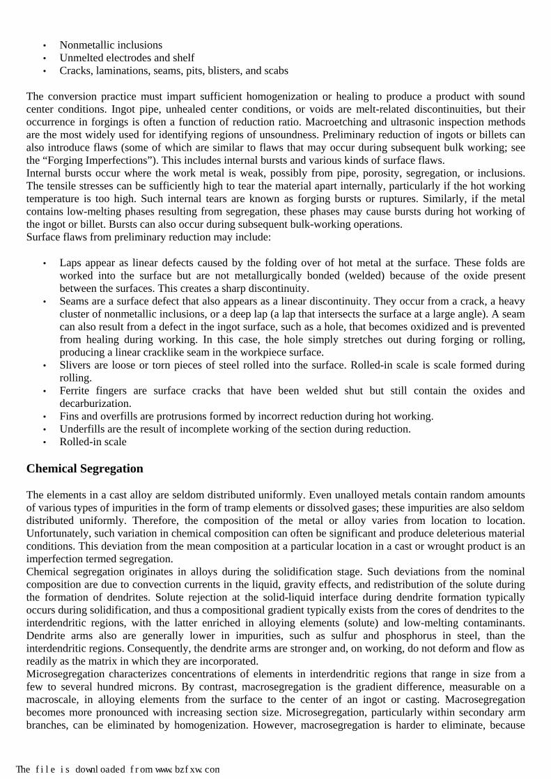
The conversion practice must impart sufficient homogenization or healing to produce a product with sound center conditions. Ingot pipe, unhealed center conditions, or voids are melt-related discontinuities, but their occurrence in forgings is often a function of reduction ratio. Macroetching and ultrasonic inspection methods are the most widely used for identifying regions of unsoundness. Preliminary reduction of ingots or billets can also introduce flaws (some of which are similar to flaws that may occur during subsequent bulk working; see the “Forging Imperfections”). This includes internal bursts and various kinds of surface flaws. Internal bursts occur where the work metal is weak, possibly from pipe, porosity, segregation, or inclusions. The tensile stresses can be sufficiently high to tear the material apart internally, particularly if the hot working temperature is too high. Such internal tears are known as forging bursts or ruptures. Similarly, if the metal contains low-melting phases resulting from segregation, these phases may cause bursts during hot working of the ingot or billet. Bursts can also occur during subsequent bulk-working operations. Surface flaws from preliminary reduction may include:
• Laps appear as linear defects caused by the folding over of hot metal at the surface. These folds are worked into the surface but are not metallurgically bonded (welded) because of the oxide present between the surfaces. This creates a sharp discontinuity.
• Seams are a surface defect that also appears as a linear discontinuity. They occur from a crack, a heavy cluster of nonmetallic inclusions, or a deep lap (a lap that intersects the surface at a large angle). A seam can also result from a defect in the ingot surface, such as a hole, that becomes oxidized and is prevented from healing during working. In this case, the hole simply stretches out during forging or rolling, producing a linear cracklike seam in the workpiece surface.
• Slivers are loose or torn pieces of steel rolled into the surface. Rolled-in scale is scale formed during rolling.
• Ferrite fingers are surface cracks that have been welded shut but still contain the oxides and decarburization.
• Fins and overfills are protrusions formed by incorrect reduction during hot working. • Underfills are the result of incomplete working of the section during reduction. • Rolled-in scale
Chemical Segregation
The elements in a cast alloy are seldom distributed uniformly. Even unalloyed metals contain random amounts of various types of impurities in the form of tramp elements or dissolved gases; these impurities are also seldom distributed uniformly. Therefore, the composition of the metal or alloy varies from location to location. Unfortunately, such variation in chemical composition can often be significant and produce deleterious material conditions. This deviation from the mean composition at a particular location in a cast or wrought product is an imperfection termed segregation. Chemical segregation originates in alloys during the solidification stage. Such deviations from the nominal composition are due to convection currents in the liquid, gravity effects, and redistribution of the solute during the formation of dendrites. Solute rejection at the solid-liquid interface during dendrite formation typically occurs during solidification, and thus a compositional gradient typically exists from the cores of dendrites to the interdendritic regions, with the latter enriched in alloying elements (solute) and low-melting contaminants. Dendrite arms also are generally lower in impurities, such as sulfur and phosphorus in steel, than the interdendritic regions. Consequently, the dendrite arms are stronger and, on working, do not deform and flow as readily as the matrix in which they are incorporated. Microsegregation characterizes concentrations of elements in interdendritic regions that range in size from a few to several hundred microns. By contrast, macrosegregation is the gradient difference, measurable on a macroscale, in alloying elements from the surface to the center of an ingot or casting. Macrosegregation becomes more pronounced with increasing section size. Microsegregation, particularly within secondary arm branches, can be eliminated by homogenization. However, macrosegregation is harder to eliminate, because
The file is downloaded from www.bzfxw.com

complete homogenization would require longer times than are economically acceptable under production conditions. Therefore, in very large sections, gross differences in alloy concentration sometimes persist and are carried into the final product. One function of hot working is to break up the cast (dendritic) structure and promote chemical homogeneity, and a minimum amount of cross-sectional reduction is usually required from the cast ingot to the billet. Hot working can partially correct the results of segregation by recrystallizing or breaking up the grain structure to promote a more homogeneous substructure. Initial working first causes flow in the weaker matrix (interdendritic) regions and tends to reorient the stronger dendrites in the direction of working. With increased mechanical working, the dendrites deform and fracture, thus becoming increasingly elongated. A certain degree of alloy segregation occurs in all wrought products, and hot working can alleviate some of the inhomogeneity. However, if the ingot is badly segregated, hot working just tends to alter the shape of the segregation region into a banded structure. Figure 3 shows banding from a carbon-rich centerline condition in a hot-rolled 1041 steel. Figure 4 shows an extreme example of banding in a hot-rolled plain carbon steel (1022) in which alternate layers of ferrite and pearlite have formed along the rolling direction. The relationship between increasing percentages of reduction by hot rolling and the intensity of banding in type 430 stainless steel is demonstrated by Fig. 5.
Fig. 3 Longitudinal section through a hot-rolled 1041 steel bar showing a carbon-rich centerline (dark horizontal bands) that resulted from segregation in the ingot. Picral. 3×. Courtesy of J.R. Kilpatrick

Fig. 4 Hot-rolled 1022 steel showing severe banding. Bands of pearlite (dark) and ferrite were caused by segregation of carbon and other elements during solidification and later decomposition of austenite. Nital. 250×. Courtesy of J.R. Kilpatrick
The file is downloaded from www.bzfxw.com

Fig. 5 Type 430 stainless steel hot rolled to various percentages of reduction showing development of a banded structure consisting of alternate layers of ferrite (light) and martensite (dark) as the amount of hot work is increased. (a) 63% reduction. (b) 81% reduction. (c) 94% reduction. 55 mL 35% HCl, 1 to 2 g potassium metabisulfite, 275 mL H2O (Beraha's tint reagent No. 2). 500×
Depending on the kind and degree of segregation that develops during solidification, some degree of banding carries over to the wrought form. If banding is severe, it can lead to discontinuities that cause premature failure. For example, Fig. 6 shows the fatigue fracture of a carburized and hardened steel roller. Banded alloy segregation in the metal used for the rollers resulted in heavy, banded retained austenite, particularly in the carburized case, after heat treatment. When the roller was subjected to service loads, the delayed transformation of the retained austenite to martensite caused microcracks near the case-core interface. These internal microcracks nucleated a fatigue fracture that progressed around the circumference of the roller, following the interface between case and core.

Fig. 6 Fracture surface of a carburized and hardened steel roller. As a result of banded alloy segregation, circumferential fatigue fracture initiated at a subsurface origin near the case-core interface (arrow).
Excessive segregation also can have an adverse effect on subsequent fabrication and heat treatment. In heat treatable alloys, variations in composition can produce unexpected responses to heat treatments, which result in hard or soft spots, quench cracks, or other flaws. Excessive segregation that leads to significant variations in hardness can lead to premature failure and extreme difficulties during cold working or forming. In this case, one of the simplest and most effective tests for incoming material is a simple standard upset test. The details of such a test can be worked out between the supplier and the cold forger. The methods to reveal the presence of segregation may depend on the alloy and expected impurities. Macroetching is commonly used, and the American Society for Testing and Materials (ASTM) has established a graded series (ASTM E 381) of macroetchings for center segregation in steel product. Segregations are revealed by differences in the severity of the etchant attack; segregations at the center may appear as a pipe or may be grouped in some fairly regular form about the center, depending on the shape of the ingot and the mechanical work done on it. Segregation as revealed by macroetching does not always indicate defective metal. A polished specimen should also be examined under the microscope to determine whether the revealed segregation is metallic or a concentration of nonmetallic impurities. Sulfur Print Test. The microscopic identification of segregation may be supplemented by chemical or other means of testing. For regions with expected regions of sulfide sulfur-rich segregation, the sulfur print test (Ref 3) can be used. An example of a failure of a steel I-beam with high levels of carbon, sulfur, and phosphorus segregation in the middle of the section is given in Ref 4. The beam was lying flat on the ground near the seacoast under normal weather conditions. It was flame cut into two sections, as required for construction, and
approximately 12
h after cutting, a violent sound was heard. The shorter section of the cut beam had split
catastrophically into two portions along the entire length and approximately through the middle of the web. Various samples were taken from both the broken and unbroken sections of the beam for analysis (chemistry, metallography, macroetching, impact testing, tensile testing) and sulfur printing. Sulfur prints taken at various locations indicated segregation of sulfides within a central zone approximately 2 mm (0.08 in.) wide in the thickness direction of the web that extended throughout the length of the beam. The breadth of the segregation zone varied from 60 mm (2.4 in.) at the end face of the unfractured section of the I-beam to almost the total width of the web in most of the fractured section. Sulfide segregation was not found in the flanges of the beam. Failures similar to the one investigated have occasionally occurred in structural beams in the shop under no load, and a contributing factor was the presence of residual stresses in the material. Flame cutting caused a change in the distribution of the residual stresses, which, aided by low fracture toughness due to the poor quality of the beam, resulted in failure. The failure of the I-beam was probably caused by segregation of carbon, sulfur, and phosphorus within its web section, which resulted in decreased notch sensitivity and low fracture toughness with respect to crack propagation through the web. The detailed investigation (Ref 4) revealed segregation of high levels of carbon, sulfur, and phosphorus in the middle of the web and high residual stresses attributed to rolling during fabrication.
The file is downloaded from www.bzfxw.com

Example 1: Fracture of a Forging Die Caused by Segregation (Ref 5). A cross-recessed die of D5 tool steel fractured in service. The die face was subjected to shear and tensile stresses as a result of the forging pressures from the material being worked. Figure 7(a) illustrates the fractured die.
Fig. 7 A D5 tool steel forging die that failed in service because of segregation. (a) Hardness traverse correlated with the microstructure of the die. (b) Section through one arm of the cross on the recessed die face showing a severely segregated (banded) structure. Etched with 5% nital. (c) Micrograph of the segregated area. Etched with 5% nital. 200×
Investigation. A longitudinal section was taken through the die to include one arm of the cross on the recessed die face. The specimen was polished and examined in the unetched condition. Examination revealed the presence of numerous slag stringers. The polished specimen was then etched with 5% nital. A marked banded structure was evident even macroscopically (Fig. 7b). Microscopic examination revealed that the pattern was due to severe chemical segregation or banding (Fig. 7c).

Hardness measurements were then conducted across the face of the specimen in locations corresponding to the banded and nonbanded regions. These results (Fig. 7a) showed that the segregated region is considerably harder than the neighboring material. The reason is that the increased carbon content of the segregated region, together with its higher alloy content, makes the region more responsive to what would have been normal heat treatment for this grade of tool steel. The high-hardness material is also subject to microcracking on quenching; microcracks can act as nuclei for subsequent fatigue cracks. Examination of the fracture surface revealed that the fracture originated near the high-stress region of the die face; however, no indications of fatigue marks were found on either a macroscale or a microscale. Conclusions. Failure of the die was the result of fracture that originated in an area of abnormally high hardness. Although fatigue marks were not observed, the fact was that the fracture did not occur in a single cycle but required several cycles to cause failure. Example 2: Fatigue Fracture that Originated on the Ground Surface of a Medium- Carbon Steel Forging with a Notch-Sensitive Band Structure. The broken connecting end of a forged medium-carbon steel rod used in an application in which it was subjected to severe low-frequency loading is illustrated in Fig. 8(a); the part shown is from one of two identical rods that failed in service by fracture. In each instance, fracture extended completely through the connecting end in two places. The two fractured rods, together with two similar unused forged rods, were examined to determine the mechanism and cause of fracture.
Fig. 8 Connecting end of forged rod, with banded structure from excessive segregation in the billet (Example 2). (a) Rod end showing locations of fractures at rough-ground areas at the parting line; in view A-A, dashed lines denote a rough-ground area, arrow points to a liquid-penetrant indication of an incipient crack. (b) Fracture surface, with beach marks indicating fracture origin at rough-ground surface. (c) Normal, homogeneous structure of an unused rod examined for comparison; this structure contains equal amounts of ferrite (light) and pearlite (dark). (d) Unsatisfactory structure of the fractured rod, which contains alternating bands of ferrite and pearlite.
The file is downloaded from www.bzfxw.com

Preliminary Examination. The material of the four forged rods was found by spectrographic analysis to be within the normal limits for the specified medium-carbon steel. Except for the fractures on the connecting ends of the two failed rods, no significant imperfections or evidence of damage were found by visual examination. Surface hardness of the four rods, as measured at various points with a Rockwell tester, was equivalent to 140 HB—substantially lower than the specified hardness of 160 to 205 HB. The fractures in the two failed rods were in areas of the transition regions that had been rough ground to remove flash along the parting line (see Fig. 8a). The fracture surfaces were fairly flat and were radial with respect to the annular connecting ends. Low-magnification examination of the fracture surfaces revealed the presence of beach marks, indicating that the fractures had originated and propagated by fatigue. The location and curvature of the beach marks on the fracture surfaces of the two broken rods (see Fig. 8b) established that the fracture origin in each rod was at the rough-ground surface. The fatigue region of the fracture surface, which was quite smooth, extended approximately halfway through the thickness of the rod end. The remainder of the area of the fracture surfaces, corresponding to final, fast fracture, had the typical appearance of brittle fracture, exhibiting little or no evidence of plastic deformation. Liquid-Penetrant Examination. The four rods were checked for the presence of imperfections in the general vicinity of rough-ground areas, using liquid-penetrant inspection. This examination revealed an incipient crack
9.5 mm approximately ( 38
in.) long (see view A-A in Fig. 8) on one of the fractured rods. The crack was
apparently a fatigue crack in the initiation stage and was located at a rough-ground area. Liquid-penetrant indications of several other incipient cracks that were smaller in size were also detected on the fractured rods in this examination; several were on rough-ground areas. Metallographic Examination. Cross sections for metallographic examination were taken through the annular connecting ends of the two fractured rods and of the two unused rods and were polished and then etched with nital. At a magnification of 80 diameters, the microstructure of the unused rods (Fig. 8c) and that of the fractured rods (Fig. 8d) appeared greatly different. The two unused rods has a fairly fine-grained, homogeneous structure containing approximately equal amounts of ferrite and pearlite—a normal structure for good-quality medium-carbon steel forgings of this composition that had been properly heat treated after forging. The two fractured rods had a banded structure consisting of zones of ferrite (light) and pearlite (dark). Microhardness of the banded region was 140 HB in the light areas and 145 HB in the dark areas (converted from Vickers hardness readings, 100 g load). Examination at 320 diameters of sections through the rough-ground areas of the fractured rods established that the incipient cracks found in liquid-penetrant inspection had originated at the surface in the banded region, in areas of ferrite where this constituent had been visibly deformed by grinding. Discussion. The loads applied to the annular connecting ends of the rods were apparently complex, consisting of torsional, bending, and axial loads from the forged rods; these loads caused cyclic tensile circumferential stresses and bending stresses in the connecting ends. The microhardness readings on the ferrite and pearlite bands were not considered to represent true hardness values because of the small size and shallowness of the bands. However, the following observations were considered to be significant with respect to the failures:
• The forged rods that had a normal microstructure (see Fig. 8c) did not fail. • The forged rods that had a banded microstructure (see Fig. 8d) did fail. • The hardness of all four rods, as measured on the surface using a Rockwell hardness tester, was the
same and was equivalent to 140 HB—substantially below the specified range of 160 to 205 HB. • The fractures originated in rough-ground areas, and incipient cracks were found in an area of ferrite that
had been visibly deformed by grinding.
Conclusions. The rod-end fractures had originated and propagated by fatigue during continued exposure of the rods to severe cyclic loads in service. The loads on the rods developed tensile and bending stresses in the connecting ends. Contributory factors were:

• The presence of a notch-sensitive banded structure containing alternately soft (ferrite) and hard (pearlite) layers
• The presence of stress raisers produced by rough grinding to remove the forging flash along the highly stressed transition area between the rods and the connecting end
• Hardness (and, accordingly, strength) below the range specified for the part
The banded microstructure of the two fractured rods apparently resulted from severe segregation in the billet from which they were forged. Corrective Action. It was recommended that:
• Closer control be exercised over the microstructure and hardness of the forgings • The connecting end be finished more smoothly in the critical area • Consideration be given to increasing the thickness (diametral with respect to the ring) of the connecting
end in the transition area
Ingot Pipe, Porosity, and Centerline Shrinkage
A common imperfection in ingots is pipe, which is an internal shrinkage cavity formed during solidification of ingots. It occurs in the upper central portion of the ingot (Fig. 1) during solidification and contraction of the metal, when there may eventually be insufficient liquid metal to feed the last remaining portions as they contract. A concave cavity thus forms at the top of the ingot because of metal shrinkage during solidification. The cavity usually forms in the shape of a cone, hence the term pipe. If not completely cropped before subsequent working, pipe may be carried through the various manufacturing processes to the finished product. The pipe becomes elongated and is found in the center of the final product, as shown in ingot B in Fig. 1. The pipe also can form internal lamination in rolled products (Fig. 9). These laminations may not be immediately evident following rolling but may become apparent during a subsequent forming operation. The occurrence of laminations is most prevalent in flat-rolled sheet products.
Fig. 9 Laminations in rolled steel sheet resulting from insufficient cropping of the pipe from the top of a conventionally cast ingot. Courtesy of V. Demski, Teledyne Rodney Metals
In addition to the primary pipe near the top of the ingot, secondary regions of piping and centerline shrinkage may extend deeper into an ingot (Fig. 10). Primary piping is generally an economic concern, but if it extends sufficiently deep into the ingot body and goes undetected, it can eventually result in a defective product. Detection of the pipe can be obscured in some cases, if bridging has occurred.
The file is downloaded from www.bzfxw.com

Fig. 10 Longitudinal section through an ingot showing extensive centerline shrinkage
Piping can be minimized by pouring ingots with the big end up, providing risers in the ingot top, and applying sufficient hot-top material (insulating refractories or exothermic materials) immediately after pouring. These techniques extend the time that the metal in the top regions of the ingot remains liquid, thereby minimizing the shrinkage cavity produced in this portion of the ingot. On the other hand, secondary piping and centerline

shrinkage can be very detrimental, because they are harder to detect in the mill and may subsequently produce centerline defects in bar and wrought products. Such a material condition may indeed provide the flaw or stress concentrator for a forging burst in some later processing operation or for a future product failure. Pipe in steel products invariably is associated with segregated impurities, which are deeply attacked by the acid during macroetching. Cavities in the center that are not associated with deeply etched impurities often are mistaken for pipe, but such cavities usually can be traced to bursts caused by incorrect processing of the steel during forging or rolling. Pipe should be visible after deep etching; it usually can be distinguished from bursts by the degree of sponginess surrounding the defect. Piped metal usually exhibits considerably more sponginess than burst metal. The micrograph of Fig. 11 is an example of secondary pipe, and the micrograph in Fig. 12 is an example of a cavity that appears to be a pipelike flaw.
Fig. 11 1038 steel bar, as-forged. Longitudinal section displays secondary pipe (black areas) that was carried along from the original bar stock into the forged piece. Gray areas are pearlite; white areas, ferrite. 2% nital. 50×
Fig. 12 Inclusions and a pipelike cavity in tempered martensite of AISI E4340 steel (Example 4). (a) 100×. (b) 600×. Courtesy of Mohan Chaudhari, Columbus Metallurgical Services
The file is downloaded from www.bzfxw.com

Example 3: Fatigue Fracture of Alloy Steel Valve Springs Because of Pipe. Two outer valve springs broke during production engine testing and were submitted for laboratory analysis. The springs were from a current production lot and had been made from air-melted 6150 pretempered steel wire. The springs were 50 mm (2 in.) in outside diameter and 64 mm (2.5 in.) in free length, had five coils and squared-and-ground ends, and were made of 5.5 mm (0.2 in.) diameter wire. Because both failures were similar, the analysis of only one is discussed. Investigation. The spring (Fig. 13a) broke approximately one turn from the end. Fracture was nucleated by an apparent longitudinal subsurface defect. Magnetic-particle inspection did not reveal any additional cracks or defects.
Fig. 13 Valve-spring failure due to residual shrinkage pipe. (a) Macrograph showing fracture, as indicated by arrow. (b) Fracture surface; pipe is indicated by arrow.
Microscopic examination of transverse sections of the spring adjacent to the fracture surfaces revealed that the defect was a large pocket of nonmetallic inclusions at the origin of the fracture. The inclusions were alumina and silicate particles. Partial decarburization of the steel was evident at the periphery of the pocket of inclusions. The composition and appearance of the inclusions and the presence of the partial decarburization indicated that the inclusions could have been associated with ingot defects. The defect was 0.8 mm (0.03 in.) in diameter (max), 25 mm (1 in.) long, and 1.3 mm (0.05 in.) below the surface (Fig. 13b). The steel had a hardness of 45 to 46 HRC, a microstructure of tempered martensite, and a grain size of ASTM 6 or 7, all of which were satisfactory for the application. The fracture surface contained beach marks typical of fatigue and was at a 45° angle to the wire axis, which indicated torsional fracture.

Conclusions. The spring fractured by fatigue; fatigue cracking was nucleated at a subsurface defect that was longitudinal to the wire axis. The stress-raising effect of the defect was responsible for the fracture.
High Hydrogen Content
A major source of hydrogen in certain metals and alloys is the reaction of water vapor with the liquid metal at high temperatures. The water vapor may originate from the charge materials, slag ingredients and alloy additions, refractory linings, ingot molds, or even the atmosphere itself, if steps are not taken to prevent such contamination. The resulting hydrogen goes into solution at elevated temperatures; but as the metal solidifies after pouring, the solubility of hydrogen decreases, and it becomes entrapped in the metal lattice. Hydrogen can be absorbed many places during primary and secondary manufacturing. It can be picked up during melting, teeming, welding, pickling, or electroplating. If hydrogen is absorbed into the base metal, it must be removed by a bake-out heat treatment. Otherwise, severe embrittlement of the base metal may occur, especially in steels with hardnesses above approximately 35 HRC. High-strength, highly stressed parts can crack and fracture as a result of hydrogen embrittlement. Failure by hydrogen embrittlement is even more likely to occur if high residual tensile stresses are present. The deleterious effects of hydrogen depend on the alloy and the concentration of hydrogen. Hydrogen concentrations in excess of only 1 ppm have been related to the degradation of mechanical properties in high-strength steels, especially ductility, impact behavior, and fracture toughness. Hydrogen concentration in excess of approximately 5 ppm has been associated with hydrogen flakes, which are small cracks produced by hydrogen that has diffused to grain boundaries and other preferred sites (such as inclusions or matrix interfaces). Flaking or hairline cracking in steels, particularly in forgings, heavy-section alloy plate steels, and railroad rails, has been an ongoing problem since the beginning of steelmaking and is reviewed in Ref 6. At still higher concentrations of hydrogen in metal, blistering can occur (e.g., see Fig. 18 of “Visual Examination and Light Microscopy” in Fractography, Volume 12 of ASM Handbook). Excessive gas contents in ingots are most serious when oxide inclusions are present. Inclusions provide sites for the agglomeration of gas, and thus molten alloys are often treated to reduce the hydrogen content and alkali element concentration as well as to remove nonmetallic inclusions. For example, vacuum degassing is used to remove dissolved oxygen and hydrogen from steel, thus reducing the number and size of indigenous nonmetallic inclusions and the likelihood of internal fissures or flakes caused when hydrogen content is higher than desired. Despite these methods of producing high-quality metal, problems sometimes arise, particularly if there are no methods available for continuously monitoring metal quality. Hydrogen flaking also is a potential problem for carbon tool steels and for some of the medium-carbon low-alloy steels, such as those used as prehardened plastic-mold alloys. Figure 14(a) shows a die made from AISI O1 tool steel that was found to be cracked after heat treatment. When opened (Fig. 14b), these cracks exhibited a coarse, shiny, faceted appearance. The cracks in this part were longitudinally oriented and were confined to the center of the section. Flakes are not observed in the outer region of sections, because there is apparently more time for the hydrogen in the outer region to diffuse to a safe level. Flakes that were close to the surface of the die exhibited temper color, but some of the deeper flakes did not. The temper-colored flakes apparently opened during quenching.
Fig. 14 Die made from AISI O1 tool steel that was found to be cracked after heat treatment. (a) Longitudinal cracks after the surface was swabbed with 5% nital. (b) One of the cracks opened, revealing features typical of hydrogen flakes. 6.5×
Nonmetallic Inclusions
The file is downloaded from www.bzfxw.com

Nonmetallic inclusions are an inevitable consequence of commercial alloys and their respective melting or casting practices. Inclusions that originate in the ingot are carried onto wrought products, even though their shapes may be appreciably altered. Furthermore, additional nonmetallic matter, such as oxides, may develop during intermediate hot working stages and also end up in the finished form. Two categories of nonmetallic inclusions in metals are:
• Those that are entrapped inadvertently and originate almost exclusively from foreign matter, such as refractory linings, that is occluded in the metal while it is molten or being cast
• Those that form in the metal because of a change in temperature or composition
Inclusions of the latter type are produced by separation from the metal when it is in either the liquid or the solid state. Some nonmetallic inclusions form in the liquid before solidification; others form during solidification. In steels, for example, aluminates and silicates generally form before solidification, while sulfides form during solidification. Manganese sulfide inclusions frequently form in the interdendritic regions and primary grain boundaries of steel, where the last of the liquid freezes. Depending on the alloy, oxides, sulfides, nitrides, or other nonmetallic compounds may occur when solubility limits in the matrix are exceeded. Because these compounds are products of reactions within the metal, they are normal constituents of the metal, and conventional melting practices cannot completely eliminate such inclusions. However, it is desirable to keep the type and amount of inclusions to a minimum, so that the metal is relatively free from those inclusions that may cause unwanted discontinuities. Air-melted alloys commonly contain inclusions. Vacuum- or electroslag-remelted alloys more commonly contain nonmetallic inclusions, such as titanium carbonitrides or carbides, when carbon or the hardening element form precipitate during stabilization and aging cycles. Homogenizing cycles prior to conversion or at an early stage of conversion can be done for re-solution of some precipitates, but not all nonmetallic inclusions are affected by homogenization. In steels, manganese sulfides can be homogenized. Nonmetallic inclusions are unquestionably one of the most common imperfections involved in problems or failures. Nonmetallic inclusions can easily become stress concentrators because of their discontinuous nature and incompatibility with the surrounding composition. This combination may very well yield flaws of critical size that, under appropriate loading conditions, result in fracture. Inclusions that are very brittle and tend to fracture and fragment during working operations also can be very detrimental. In fact, with certain refractory and slag inclusions, fragmentation frequently occurs when the amount of cross-sectional reduction in the workpiece is large. The deleterious nature of nonmetallic inclusions depends on several factors, including chemical composition of the inclusion, volume percentage, shape, orientation, and the mechanical/physical properties of the inclusion as compared to its surrounding matrix (Ref 7). One study has demonstrated that the local constraint of the matrix by hard inclusions during tensile loading can produce severe stress concentrations that depend on the elastic moduli, size, shape, and orientation of the inclusions (Ref 8). For example, inclusions such as manganese sulfide, which are very deformable at hot working temperatures, elongate in the direction of working. This results in an anisotropic material condition, which, depending on its severity, can produce substantial decreases in transverse mechanical properties, such as ductility, fatigue life, and fracture toughness. The metal-producing industry attempts to control nonmetallic inclusions, but inclusions cannot be removed with complete assurance. In demanding applications, inclusion shape-control methods are used to produce inclusions predominately with a spherical shape, which is less of a stress concentrator with the surrounding matrix and less damaging than inclusions with more angular shapes. The principle of inclusion shape control is to reduce the surface energy between the inclusion and the metal—normally through suitable chemistry modification of the metal. Sulfide inclusions, for example, have been shape controlled by the addition of calcium or rare earth metal treatments. These inclusions are not plastic or deformable at typical hot working temperatures and retain their globular shape. Therefore, they are less injurious with respect to ductility, toughness, and fatigue life in finished wrought products. With the number and size of inclusions held roughly constant, inclusion shape control reduces the likelihood of crack initiation from an inclusion. This is shown in Fig. 15 (Ref 9) for a rolled constructional steel with calcium treatment, which provides longer life under cyclic loading due to inclusion shape modification. The advantage of a spherical inclusion shape is also evident in Charpy V-notch impact data for constructional steels (Fig. 16)(Ref 10). Scanning electron microscope (SEM) fractographs also show a pronounced difference in

deformation mode with an inclusion shape modification (Fig. 17). Local ductility increases adjacent to the inclusions when the shape is spherical.
Fig. 15 Comparison of axial fatigue data for untreated and calcium-treated rolled ASTM A516 steel. 51 mm (2 in.) thick plates tested with alternating stress ratio of 0.1. Source: Ref 9
The file is downloaded from www.bzfxw.com

Fig. 16 Comparison of Charpy V-notch upper-shelf energies (USEs) for several grades and thicknesses of untreated and calcium-treated steel. Source: Ref 10
Fig. 17 Scanning electron microscope fractographs showing the effect of calcium treatment on the fracture morphology of ASTM A633C steel impact specimens. (a) Untreated steel with type II manganese sulfide inclusions showing evidence of brittle fracture. (b) Calcium-treated steel with spherical inclusions; the fracture is ductile. Courtesy of A.D. Wilson, Lukens Steel Company
Macroetching can provide a good indication of cleanliness, but further metallography is desirable if information is needed on the character of nonmetallic inclusions. Nonmetallic inclusions, although they usually appear as pits or pinholes after macroetching, must not be confused with pits that result from etching out metallic segregations or from variations in etching procedure. When nonmetallic inclusions are suspected in highly alloyed steels that may contain metallic segregations, an annealed specimen should be compared with a hardened and tempered specimen etched in the same way. If the etching pits are the result of nonmetallic inclusions, they appear similar in the annealed and the hardened specimens. If they are the result of metallic segregation, they differ in appearance, being more prominent in the hardened specimen. Example 4: Failure Analysis of a Helicopter Main Rotor Bolt (Ref 11). During assembly, a helicopter main rotor made of AISI E4340 steel failed while being torqued. The torque being applied reached approximately 100 N · m (900 lbf · in.) when the pitch horn bolt sheared and shot across the hangar. No other bolts were reported to have failed during assembly. The rotor bolt fractured in the black-coated region between the threads and the taper section of the shank. The head, the straight portion of the shank, and the nut were gold colored. The fracture surfaces were first cleaned with soap and water and were then ultrasonically cleaned to remove surface debris. Longitudinal and transverse sections were prepared for optical microscopy. The bolt surface was also inspected for identification of coatings and surface treatments. Figure 18 shows the two mating halves of the fracture. The bolt had been heated to obtain a tempered martensitic microstructure. The metallographic specimen showed a significant amount of nonmetallic inclusions (Fig. 12). Figure 12 also shows a pore, probably a pipe defect in the original bar stock.

Fig. 18 Macrograph of failed bolt
Figure 19 shows a SEM view of the fracture initiation region. The white inclusions were nonmetallic particles that were high in calcium. Various spectra and x-ray maps were collected. The x-ray maps illustrated the presence of calcium in the white spots. These spots were thus interpreted to be slag inclusions in the steel. Areas containing the inclusions were cleaned with a soft brush several times to ascertain that the x-ray indications were not debris that collected on the fracture surface during storage and handling after the failure. The gold-colored areas of the bolt were found to have been cadmium plated, followed by a chromate treatment. The black-coated surfaces contained molybdenum and sulfur, indicating a MoS2 treatment. Specimen composition, as determined by optical emission spectrometry, was in agreement with nominal specifications for AISI E4340 steel.
Fig. 19 Scanning electron microscope micrographs showing segregation of inclusions along the edge where fracture apears to have initiated.
The file is downloaded from www.bzfxw.com

Conclusion and Remedial Action. It was initially suspected that hydrogen embrittlement caused crack initiation. It was concluded, however, that the failure was caused by a high concentration of nonmetallic inclusions. Inspection of other bolts from the same shipment was recommended.
Other Ingot-Related Imperfections
Laminations in wrought products may occur from various types of discontinuities introduced during the ingot stage. As previously noted, pipe can form into laminations in rolled products (Fig. 9). Laminations may also form spatter (entrapped splashes) during the pouring of the molten metal into the ingot mold. These imperfections are elongated during rolling or other working and are usually subsurface, as shown in Fig. 2(b) for bar stock. Figure 2(b) illustrates a lamellar structure opened up by a chipping tool. Slivers are most often caused by a rough mold surface, overheating prior to rolling, or abrasion during rolling. Very often, slivers are found with seams. Slivers usually have raised edges, as shown in Fig. 2(c). Scabs are caused by improper ingot pouring, in which metal is splashed against the side of the mold wall. The splashed material, or scab, tends to stick to the wall and become oxidized. The metal first freezes to the wall of the mold, then becomes attached to the ingot, and finally becomes embedded in the surface of the wrought product (e.g., Fig. 2d). Scabs usually show up only after rolling and, as can be expected, give poor surface finish. Scabs thus bear some similarity to laminations. Pits and Blisters. Gaseous pockets in the ingot often become pits or blisters on the surface or slightly below the surface of bar products. Other pits may be caused by overpickling to remove scale or rust. Pits and blisters are both illustrated in Fig. 2(e). Embedded scale may result from the rolling or drawing of bars that have become excessively scaled during prior heating operations. The pattern illustrated in Fig. 2(f) is typical. Cracks and seams are often confused with each other. Cracks with little or no oxide present on their edges may occur when the metal cools in the mold, setting up highly stressed areas. Seams develop from these cracks during rolling as the reheated outer skin of the billet becomes heavily oxidized, transforms into scale, and flakes off the part during further rolling operations. Cracks also result from highly stressed planes in cold-drawn bars or from improper quenching during heat treatment. Cracks created from these latter two causes show no evidence of oxidized surfaces. A typical crack in a bar is shown in Fig. 2(g). Unmelted electrodes and shelf are two other types of ingot flaws that can impair forgeability. Unmelted electrodes are caused by chunks of electrodes being eroded away during consumable melting and dropping down into the molten material as a solid. Shelf is a condition resulting from uneven solidification or cooling rates at the ingot surfaces. The consumable-melting operation has occasionally been continued to a point where a portion of the stinger rod is melted into the ingot, which may be undesirable, because the composition of the stinger rod may differ from that of the alloy being melted. To prevent this occurrence, one practice is to weld a wire to the stinger rod, bend the wire down in tension, and weld the other end of the wire to the surface of the electrode a few inches below the junction of the stinger rod and the electrode. When the electrode has been consumed to where the wire is attached to it, the wire is released and springs out against the side of the crucible, thus serving as an alarm to stop the melting. A disadvantage of this practice is that the wire may become detached and contaminate the melt. Unmelted pieces of electrode or shelf conditions appear infrequently in vacuum-melted alloys. Either of these conditions can seriously degrade forgeability. Macroetching or another appropriate type of surface inspection of the machined forging or the billet is the most effective method of detecting unmelted electrodes or shelf conditions.
References cited in this section
3. G.F. Vander Voort, Metallography: Principles and Practice, McGraw-Hill, 1984 (out of print), reprinted 1999 ASM International
4. R.K. Dayal, J.B. Gnanamoorthy, and P. Rodriguez, Failure of an I-Beam, Handbook of Case Histories in Failure Analysis, Vol 1, ASM International, 1992, p 378–381
5. E. Kauczor, Prakt. Metallogr. Vol 8, July 1971, p 443–446

6. G. Vander Voort, Embrittlement of Steels, Properties and Selection: Iron, Steels, and High-Performance Alloys, Vol 1, ASM Handbook, ASM International, 1990, p 689–736
7. P.A. Thornton, J. Mater. Sci., Vol 6, 1971, p 347
8. D.V. Edmonds and C.J. Beevers, J. Mater. Sci., Vol 3, 1968, p 457
9. A.D. Wilson, Calcium Treatment of Plate Steels and Its Effect on Fatigue and Toughness Properties, Proc. 11th Annual Offshore Technology Conference, OTC 3465, May 1979, p 939–948
10. A.D. Wilson, Effect of Calcium Treatment on Inclusions in Constructional Steels, Met. Prog., Vol 121 (No. 5), April 1982, p 41–46
11. M.D. Chaudhari, Failure Analysis of a Helicopter Main Rotor Bolt, Handbook of Case Histories in Failure Analysis, Vol 2, ASM International, 1993, p 392
Forging Imperfections
In many cases, the internal and surface imperfections that occur during forging are the same as, or at least similar to, those that may occur during hot working of the ingots or billets, as briefly introduced in the previous section. The inspection of forgings and the types of flaws for specific alloy forgings (steel, nickel, aluminum, and titanium alloys) are described in more detail in the article “Nondestructive Inspection of Forgings” in Nondestructive Evaluation and Quality Control, Volume 17 of ASM Handbook. A brief review for nonferrous alloys follows:
• Nickel-base heat-resistant alloys: Most of the flaws found in forgings of heat-resistant alloys can be categorized as those related to scrap selection, melting, or primary conversion to bar or billet or those that occur during forging or heat treatment. Nickel-base superalloys are highly susceptible to surface contamination during heating for forging. Fuel oils containing sulfur induce a grain-boundary attack, which causes subsequent rupturing during forging. Paint or marking crayons with high levels of similar contaminants cause similar areas of grain-boundary contamination.
• Aluminum alloys: The internal discontinuities that occur in aluminum alloy forgings are ruptures, cracks, inclusions, segregation, and occasionally porosity. Ruptures and cracks are associated with temperature control during preheating or forging or with excessive reduction during a single forging operation. Cracks can also occur in stock that has been excessively reduced in one operation. Inclusions, segregation, and porosity result from forging stock that contains these types of discontinuities.
• Titanium alloys: Discontinuities that are most likely to occur in titanium alloy forgings are usually carried over in the bar or billet. Typical discontinuities in titanium alloy forgings are alpha-stabilized voids, macrostructural defects, unsealed center conditions, clean voids, and forging imperfections. Alpha-stabilized voids are among the most common discontinuities found in forgings of titanium alloys. Three principal macrodefects are commonly found in ingot, forged billet, or other semifinished product forms. These include high-aluminum defects (type II defects), high-interstitial defects (type I defects or low-density interstitial defects), and beta flecks.
The most common internal imperfections found in steel forgings are pipe, segregation, nonmetallic inclusions, and stringers. Internal flaws caused by forgings also include cracks or tears, which may result either from forging with too light a hammer or from continuing forging after the metal has cooled down below a safe forging temperature. Other flaws in steel forgings that can be produced by improper die design or maintenance are internal cracks and splits. If the material is moved abnormally during forging, these flaws may be formed without any evidence on the surface of the forging. Bursts, as described in the preceding section, may also occur. A number of surface flaws also can be produced by the forging operation. These flaws are often caused by the movement of metal over or on another surface without actual welding or fusing of the surfaces. The most common surface flaws in steel forgings are seams, laps, and slivers. Laps and seams are surface discontinuities
The file is downloaded from www.bzfxw.com

that are caused by folding over of metal without fusion. They are usually filled with scale and, on steel components, are enclosed by a layer of decarburized metal. Laps, seams, and other surface defects formed during manufacture of the blanks can also lead to major problems during cold forming of the actual parts. Once any surface defect is exposed to the atmosphere, its surfaces become oxidized, providing an initiation point for failure during future operations. Other surface flaws include rolled-in scale, ferrite fingers, fins, overfills, and underfills. Surface flaws weaken forgings and can usually be eliminated by correct die design, proper heating, and correct sequencing and positioning of the workpieces in the dies. When such cracks form early in the steel manufacturing process, the surfaces of such breaks can become completely decarburized, forming what is known as a ferrite finger. Even if the original crack about which they formed is then removed by conditioning, the remaining ferrite is extremely low in tensile strength and often splits during the metal movement necessary during cold forming. Cold shuts often occur in closed-die forgings. They are junctures of two adjoining surfaces caused by incomplete metal fill and incomplete fusion of the surfaces. Shear cracks often occur in steel forgings; they are diagonal cracks occurring on the trimmed edges and are caused by shear stresses. Proper design and condition of trimming dies to remove forging flash are required for the prevention of shear cracks.
Control of Heating
In addition to flow-related imperfections, proper control of heating in hot forging is necessary to prevent excessive scale, decarburization, overheating, or burning. Excessive scale, in addition to causing excessive metal loss, can result in forgings with pitted surfaces. The pitted surfaces are caused by the scale being hammered into the surface and may result in unacceptable forgings. The development of scale during preheating of ingots, slabs, or blooms is almost inevitable, particularly for steels. Sometimes descaling operations involving hydraulic sprays or preliminary light passes in rolling operations are not totally successful; scale may get rolled into the metal surface and become elongated into streaks during subsequent rolling. Severe overheating causes burning, which is the melting of the lower-melting-point constituents. This melting action severely reduces the mechanical properties of the metal, and the damage is irreparable. Detection and sorting of forgings that have been burned during heating can be extremely difficult. Another defect related to heating practice is blistering, which is a raised spot on the surface caused by expansion of subsurface gas during heating. Blisters may break open and produce a defect that looks similar to a gouge or surface lamination. Hot tears in forgings are surface cracks that are often ragged in appearance. They result from rupture of the material during forging and are often caused by the presence of low-melting or brittle phases. Thermal cracks occur as a result of nonuniform temperatures in the forging. Quench cracks are one example of such thermal cracks (see the section “Quench Cracks” in this article). Internal cracks, another type of thermal crack, may occur when forgings are heated too rapidly. These occur as a result of unequal temperatures of the surface relative to the center of the mass, and the resulting differences in the degree of thermal expansion produce tensile stresses near the center. The formation of such cracks depends on both the section size and the thermal conductivity of the material. Large section sizes and poor thermal conductivity promote thermal gradients and favor crack formation.
Flow-Related Factors
Several kinds of forging imperfections are related to metal flow, which is influenced by the workability of the material (discussed later) and the details of component and die design. This section discusses some of the flow-related imperfections that might constitute a manufacturing flaw during inspection or a potential problem during service. It is also important to keep in mind the effects of design on the overall process. Forging load increases very rapidly as the sharpness of details is increased, and die wear increases directly with die pressure. Flash geometry also directly influences the amount of back pressure experienced by the metal in the die cavity. These defects described in this section are related to the distribution of metal. They can be avoided by proper die design, preform design, and choice of lubrication system. Strictly speaking, these defects are not fundamental to the workability of the material. However, knowledge of these common forging defects is necessary for a practical understanding of workability. These are the defects that commonly limit deformation in the forging process.

Most of the defects occur in hot forging, which is most common for impression-die forging. Therefore, defect formation may also involve entrapment of oxides and lubricant. When this occurs, the metal is incapable of rewelding under the high forging pressures; the term cold shut is frequently applied in conjunction with laps, flow-through defects, and so on to describe the flaws generated. Underfill may not seem like a flow-related defect, but aside from simple insufficient starting mass, the reasons for underfill are flow related. These include improper fill sequence, insufficient forging pressure, insufficient preheat temperature, lubricant build up in die corners, poor or uneven lubrication, and excessive die chill. An improper fill sequence may result in excessive flash loss, or it may be the result of extraordinary pressure requirements to fill a particular section. Sometimes, venting may eliminate the problem; more often than not, a change in the incoming workpiece shape or a change in the deformation sequence is required. Laps and Folds. Laps are surface irregularities that appear as linear defects and are caused by the folding over of hot metal at the surface. These folds are forged into the surface but are not metallurgically bonded (welded) because of the oxide present between the surfaces (Fig. 20). Thus, a discontinuity with a sharp notch is created.
Fig. 20 Micrograph of a forging lap. Note the included oxide material in the lap. 20×
A lap or fold results from an improper progression in fill sequence. Normally, a lap or fold is associated with flow around a die corner, as in the case of an upper rib or lower rib, or with a reversal in metal-flow direction. A general rule of thumb is to keep metal moving in the same direction. The die corner radius is a critical tool dimension, and it should be as generous as possible. In progressing through a forging sequence, the die corners should become tighter, so that the workpiece fillets are initially large and progressively become smaller as the forging steps are completed. Figure 21 shows schematically a lap forming as metal flows around a die corner.
The file is downloaded from www.bzfxw.com

Fig. 21 Lap formation in a rib-web forging caused by improper radius in the preform die
Extrusion-Type Defects. The tail of an extrusion is unusable because of nonuniform flow through the extrusion die. This results in a center-to-surface-velocity gradient, with metal from the workpiece interior moving through the die at a slightly higher velocity than the outer material. The result shows up at the tail of the extrusion as a suck-in or pipe, and, for extrusions, the tail is simply cut off and discarded. Alternatively, a follower block of cheaper material may be added so that most of the defect falls in the cheaper material, and less length of the extruded workpiece is lost.

For forgings that involve forward or backward extrusion to fill a part section, the same situation can develop. Metal flow into a rib or hub can result in a suck-in defect, which, in a worst-case scenario, would show up as a fold on the face opposite to the rib, and a best case would be a depression on what otherwise should be a flat surface. One method of eliminating this type of defect is to position more material on the back face initially. Another method is to change the rib geometry (aspect ratio and/or angles). If neither of these changes can be accomplished, an extra forging step may be needed to limit the amount of extrusion that is done in any one step. Extrusion-type defects are formed when centrally located ribs formed by extrusion-type flow draw too much metal from the main body or web of the forging. A defect similar to a pipe cavity is thus formed (Fig. 22). Methods of minimizing the occurrence of these defects include increasing the thickness of the web or designing the forging with a small rib opposite the larger rib, as shown in Fig. 22.
Fig. 22 Extrusion-type defect in (a) centrally located rib and (b) die-design modification used to avoid defect
Shear-Related or Flow-Through Defects. Shearing defects are also known as flow-through defects, because they result from excessive metal flow past a filled detail of the part. Flow-through defects form when metal is forced to flow past a recess after the recess has filled or when material in the recess has ceased to deform because of chilling. An example of this is shown in Fig. 23 for a trapped-die forging that has a rib on the top surface. The rib denoted by “2” is filled early in the forging sequence, and significant mass must flow past the rib in order to fill the inner hub, zone “4.” The result can be a complete shearing-off of the rib in the worst case, with a lesser case being the formation of a shear-type crack.
The file is downloaded from www.bzfxw.com

Fig. 23 Schematic of a flow-through crack at the base of a rib in a trapped-die forging. Excessive metal flow past region 2 causes a shear crack to form at A and propagate toward B.
Similar to laps in appearance, flow-through defects can be shallow, but they are indicative of an undesirable grain flow pattern or shear band that extends much deeper into the forging. An example is shown in Fig. 24. Flow-through defects can also occur when trapped lubricant forces metal to flow past an impression.
Fig. 24 Flow-through defect in Ti-6Al-4V rib-web structural part

Seams are crevices in the surface of the metal that have been closed, but not welded, by working the metal. Seams result from elongated trapped-gas pockets or from cracks. The surfaces are generally heavily oxidized and decarburized in steels. Depth varies widely, and surface areas sometimes may be welded together in spots. Seams may be continuous or intermittent, as indicated in Fig. 2(h). A micrograph of a typical seam is shown in Fig. 25. Oxides in a seam can be the result of exposure to elevated temperatures during processing.
Fig. 25 Micrograph of a seam in a cross section of a 19 mm (0.75 in.) diameter medium-carbon steel bar showing oxide and decarburization in the seam. 350×
Seams seldom penetrate to the core of bar stock. The incomplete removal of seams from forging stock may cause additional cracking in hot forging and quench cracking during heat treatment. Seams are sometimes difficult to detect in an unused fastener, but they are readily apparent after a fastener has been subjected to installation and service stresses. Seams have a large number of possible origins, some mechanical and some metallurgical. Seams can develop from cracks caused by working, or seams can develop from an imperfection in the ingot surface, such as a hole, that becomes oxidized and is prevented from healing during working. In this case, the hole simply stretches out during forging or rolling, producing a linear seam in the workpiece surface. Seams also result from trapped-gas pockets, cracks, a heavy cluster of nonmetallic inclusions, or a deep lap. Seams are normally closed tight enough that no actual opening can be visually detected without some nondestructive inspection techniques, such as magnetic-particle inspection (see Nondestructive Evaluation and Quality Control, Volume 17 of ASM Handbook) Seams can be difficult to detect, because they may appear as scratches on the forging, or because a machining process may obliterate them. Seams may not become evident until the part has been subjected to installation and service stresses, or when the constraint exerted by the bulk of material is removed from the neighborhood of a seam. Figure 26 is an example of a seam detected by routine magnetic-particle inspection of a hot-rolled 4130 steel bar. No stringer-type inclusions were observed in the region of the flaw, but it did contain a substantial amount of oxide (Fig. 26b).
The file is downloaded from www.bzfxw.com

Fig. 26 Seam in rolled 4130 steel bar (a) Closeup of seam. Note the linear characteristics of this flaw. (b) Micrograph showing cross section of the bar. Seam is normal to the surface and filled with oxide. 30×
Central or Internal Bursts (Chevron Cracking). Chevrons are internal flaws named for their shape (Fig. 2k). A central burst, or chevron crack, is most commonly associated with extrusion and drawing operations, although it can be generated by forging and rolling processes as well. Central bursts are internal fractures caused by high hydrostatic tension. The severe stresses that build up internally cause transverse subsurface cracks. Some of the factors that can contribute to the formation of chevrons are incorrect die angles; either too great or too small a reduction of cross-sectional area; incomplete annealing of slug material; excessive work hardenability of the slug material; the presence of an excessive amount of seams and other imperfections in the slug materials; segregation in a steel slug that results in hard martensitic particles in the center of the slug, which act as barriers to material flow; and insufficient die lubrication. Internal bursts in rolled and forged metals result from the use of equipment that has insufficient capacity to work the metal throughout its cross section. If the working force is not sufficient, the outer layers of the metal are deformed more than the inside metal, sometimes causing wholly internal, intergranular fissures that can act as initiation sites for further crack propagation during service loads. In forward cold extrusion, the occurrence

of central bursts or chevrons is nearly always restricted to isolated lots of material and usually to only a small percentage of the pieces extruded in any particular production run. A change in deformation-zone geometry is usually sufficient to eliminate the problem. The conservative design approach is to ensure that no hydrostatic tension develops. Often, however, the part or tooling design cannot be changed sufficiently to eliminate hydrostatic tension. If the level of hydrostatic tension can be kept below a critical level, bursting can likely be avoided. This may be accomplished by a change in lubricant, die profile, temperature, deformation level, or process rate. Internal bursts may also occur where the material is weak. For example, with ingot imperfections (such as pipe, porosity, segregation, or inclusions), tensile stresses can be sufficiently high to tear the material apart internally, particularly if the forging temperature is too high (Ref 12). Similarly, if the metal contains low-melting phases resulting from segregation, these phases may rupture during forging. Ingot pipe, unhealed center conditions, or voids associated with melt-related discontinuities may also induce center bursts if reduction rates are too severe or temperatures are incorrect during working. The conversion practice to bar or billet must impart sufficient homogenization or healing to produce a product with sound center conditions. An example of an unsound condition that did not heal is shown in Fig. 27.
The file is downloaded from www.bzfxw.com
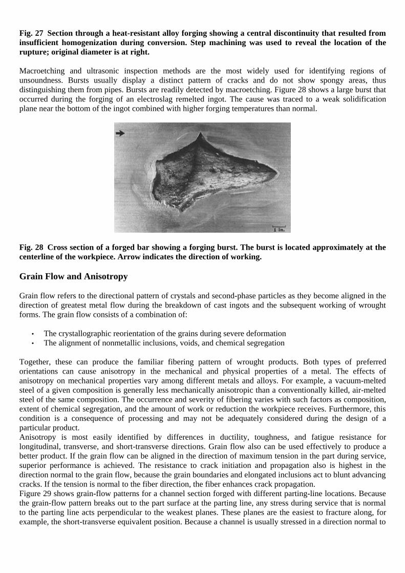
Fig. 27 Section through a heat-resistant alloy forging showing a central discontinuity that resulted from insufficient homogenization during conversion. Step machining was used to reveal the location of the rupture; original diameter is at right.
Macroetching and ultrasonic inspection methods are the most widely used for identifying regions of unsoundness. Bursts usually display a distinct pattern of cracks and do not show spongy areas, thus distinguishing them from pipes. Bursts are readily detected by macroetching. Figure 28 shows a large burst that occurred during the forging of an electroslag remelted ingot. The cause was traced to a weak solidification plane near the bottom of the ingot combined with higher forging temperatures than normal.
Fig. 28 Cross section of a forged bar showing a forging burst. The burst is located approximately at the centerline of the workpiece. Arrow indicates the direction of working.
Grain Flow and Anisotropy
Grain flow refers to the directional pattern of crystals and second-phase particles as they become aligned in the direction of greatest metal flow during the breakdown of cast ingots and the subsequent working of wrought forms. The grain flow consists of a combination of:
• The crystallographic reorientation of the grains during severe deformation • The alignment of nonmetallic inclusions, voids, and chemical segregation
Together, these can produce the familiar fibering pattern of wrought products. Both types of preferred orientations can cause anisotropy in the mechanical and physical properties of a metal. The effects of anisotropy on mechanical properties vary among different metals and alloys. For example, a vacuum-melted steel of a given composition is generally less mechanically anisotropic than a conventionally killed, air-melted steel of the same composition. The occurrence and severity of fibering varies with such factors as composition, extent of chemical segregation, and the amount of work or reduction the workpiece receives. Furthermore, this condition is a consequence of processing and may not be adequately considered during the design of a particular product. Anisotropy is most easily identified by differences in ductility, toughness, and fatigue resistance for longitudinal, transverse, and short-transverse directions. Grain flow also can be used effectively to produce a better product. If the grain flow can be aligned in the direction of maximum tension in the part during service, superior performance is achieved. The resistance to crack initiation and propagation also is highest in the direction normal to the grain flow, because the grain boundaries and elongated inclusions act to blunt advancing cracks. If the tension is normal to the fiber direction, the fiber enhances crack propagation. Figure 29 shows grain-flow patterns for a channel section forged with different parting-line locations. Because the grain-flow pattern breaks out to the part surface at the parting line, any stress during service that is normal to the parting line acts perpendicular to the weakest planes. These planes are the easiest to fracture along, for example, the short-transverse equivalent position. Because a channel is usually stressed in a direction normal to
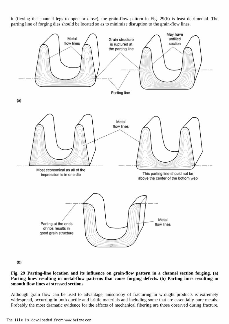
it (flexing the channel legs to open or close), the grain-flow pattern in Fig. 29(b) is least detrimental. The parting line of forging dies should be located so as to minimize disruption to the grain-flow lines.
Fig. 29 Parting-line location and its influence on grain-flow pattern in a channel section forging. (a) Parting lines resulting in metal-flow patterns that cause forging defects. (b) Parting lines resulting in smooth flow lines at stressed sections
Although grain flow can be used to advantage, anisotropy of fracturing in wrought products is extremely widespread, occurring in both ductile and brittle materials and including some that are essentially pure metals. Probably the most dramatic evidence for the effects of mechanical fibering are those observed during fracture,
The file is downloaded from www.bzfxw.com

either in service or during laboratory testing or process deformation. When the stress direction is perpendicular to the lay of the stringer, the fracture direction that is parallel to the lay of the stringer results in a woody appearance to the fracture (e.g., see Fig. 21 in the “Atlas of Fractographs” in Fractography, Volume 12 of ASM Handbook.)
Thermal Effects and Heat Treatment
Improper heat treatment can result in failure to attain the desired microstructure in the metal and therefore the desired levels of mechanical or physical properties. Such deficiencies can cause failures in service. Overheating. As alloys are heated above their recrystallization temperatures, grain growth occurs. As the temperature increases, so does grain growth, becoming quite rapid and resulting in large grains, often accompanied by many undesirable characteristics. The impairment that usually accompanies large grains is caused not only by the size of the grains but also by the more continuous films that are formed on larger grains by grain-boundary impurities, such as preferential precipitates and evolved gases. Finer grains, on the other hand, present a greater amount of total grain-boundary area over which the impurities may be distributed. The detrimental effects of overheating depend on the temperature and the time of exposure as well as on the chemical composition of the alloy. For example, a short exposure of a high-speed tool steel to temperatures at approximately 1250 °C (2280 °F) is required to dissolve the carbides, but prolonged heating at that temperature causes grain growth and loss of mechanical properties. The damage caused by overheating is particularly significant in the high-carbon and medium-carbon steels, in which both strength and ductility are affected. One of the most conspicuous indications that a metal has been overheated is the coarse-grain fracture surface that results. Usually, examination with a stereoscopic microscope shows the characteristic faceted surface of an intergranular fracture. Microscopically, the large grain size resulting from overheating is quite evident and can be measured and compared to a similar metal with a normal grain size. In addition to large grain size, fine oxide particles are often found dispersed throughout the grains, particularly near the surface. A Widmanstätten structure is often associated with coarse grains in an overheated steel forging with a controlled rate of cooling (neither extremely fast nor extremely slow). Burning is a term applied when a metal is grossly overheated and permanent irreversible damage to the structure occurs as a result of intergranular penetration of oxidizing gas or incipient melting. The micrograph in Fig. 30(b) shows burning at the grain boundaries in a specimen of copper C11000 (electrolytic tough-pitch copper) heated to 1065 °C (1950 °F). Copper oxide migrated to grain boundaries, forming a continuous network that severely reduced strength and ductility.

Fig. 30 Micrographs showing the effects of overheating and burning on microstructures of copper forgings. (a) Overheated copper C10200 forging showing oxides (black particles). The forging was heated to 1025 °C (1875 °F). (b) Burning (black outlines) at grain boundaries of a copper C11000 forging heated to 1065 °C (1950 °F)
In steels, burning may manifest itself with the formation of extremely large grains and incipient melting at the grain boundaries. Melting is particularly evident where segregation has occurred, with the marked formation of low-melting phases in the interdendritic regions and at the grain boundaries. Burning cannot be readily detected by visual examination. However, a metallographic examination of the structure shows the enlarged grains and the pronounced grain-boundary network. The typical causes of burning include excessive furnace temperatures; welding and flame-cutting operations that are not properly controlled; and operations involving the direct heating of a workpiece surface, such as flame hardening, induction hardening, shrink fitting, and so on, that are inadequately controlled. Occasionally, burning occurs in adequately controlled furnaces simply because the flame is allowed to impinge on the metal surface, causing localized overheating. Another source of overheating, though less common, can be the conversion of mechanical energy into heat. If there are segregated areas near the center of the billet, and if the initial forging temperature is close to the melting point of the segregated regions, the additional heat supplied by the transformation of work into heat can cause localized burning during the forging operation. Burned material cannot be salvaged and should be scrapped, because the metallurgical changes that have occurred are irreversible. Quench cracks are often the cause of failure in steel forgings. These cracks may be obvious and may prompt the removal of a component during production, or they may be obscured during manufacture and may be present in the shipped component. Quench cracks in steel result from stresses produced by the volume increase accompanying the austenite-to-martensite transformation. When a steel forging is quenched, untempered (hard and brittle) martensite is formed at the outer surfaces first. As cooling continues, the austenite-transformation reaction progresses toward the center of the workpiece, accompanied by a volumetric expansion that can place the center portions of the part in tension. When the workpiece cannot adjust to the strains produced by this process, cracking generally occurs. Such cracking may take place during or after the quench, because the transformation product is hard and brittle before tempering.
The file is downloaded from www.bzfxw.com

This susceptibility to cracking is increased by the presence of stress raisers, such as sharp fillets, tool marks or other notches, massive inclusions, or voids. Quench cracks in forgings may also occur near the trim line of a closed-die forging, where some localized burning may have occurred. Other factors that affect quench cracking are the hardenability of the steel, the rate of cooling, and elapsed time between quenching and tempering. In general, an increase in any of these factors increases the likelihood of quench cracking. Quench cracks have several recognizable features. Macroscopically, they are usually straight and extend from the surface (often initiating from a fillet or tool mark) toward the center of the component. The margins of the crack may have scale present if the part was tempered after quenching. The cracks are open to the surface and may be detected by magnetic-particle, ultrasonic, or eddy-current inspection. Microscopically, quench cracks are invariably intergranular and may be free of decarburization. Carburization and Decarburization. Although surface treatment by carburization is commonly used to improve the wear resistance and overall strength characteristics of many forged steel components, particularly axles, the accidental alteration of the surface structure during heat treatment can produce disastrous results. Heating a metal surface that is contaminated with oil or carbon or heating in a carbon-rich atmosphere can produce a surface with a high carbon content. The mechanical properties of a carburized surface layer are different from those of the core, and cracking problems can arise, because a carburized surface was not considered in the original design. The opposite condition (decarburization) can occur by heating in an oxidizing atmosphere such as air. The result in this case is a surface layer with a lower carbon content than that of the core.
Reference cited in this section
12. V.N. Whittacker, Nondestr. Test., Oct 1971, p 320
Workability
The term workability refers to the ability to deform and shape metals by bulk deformation without fracture. This ability to deform without fracture is highly variable, and the limits of plastic deformation for a given material are greatly affected by the prevailing state of stress, strain rate, and temperature in the metalworking process. Deformation is also variable among different alloys and conditions, and thus, the design or specification of metalworking operations is a basic factor during both the conceptual and detailed stages of design and materials selection. Most metals and alloys can be worked over a wide range of temperatures, and hot working requires less force for plastic deformation. However, dimensional control of the workpiece often can be difficult in hot working operations, because the metal contracts nonuniformly during cooling. This particular problem is not encountered in the cold working temperature range; thus, cold working has advantages, even though workability is less than that of hot working. The term cold forming can have broad meaning, depending largely on the product forms to which it is applied. Cold forming is frequently defined as forming that occurs below the recrystallization temperature of the specific metal being deformed, and it usually begins at or near room temperature. Depending mainly on the severity of the forming, the temperature of the work metal may increase as much as several hundred degrees Fahrenheit during the deformation process. Bulk working is commonly in the hot working regime, where metallic materials are more workable (Fig. 31) (Ref 13). In hot working (typically carried out at temperatures in excess of ~60% of the absolute melting point of the metal), individual grains are deformed; the deformed grains then immediately begin to recrystallize, that is, nucleate new stress-free grains that are roughly equiaxed in morphology. The hotter the metal, the more plastic it behaves, and the more easily it deforms. At excessively high temperatures, however, grain growth, incipient melting, phase transformation, and changes in composition can occur, which may cause degradation of the properties in the forging. At lower hot working temperatures, the metal is more difficult to work, yet the resultant grain size may be finer, and the product may have better mechanical properties.
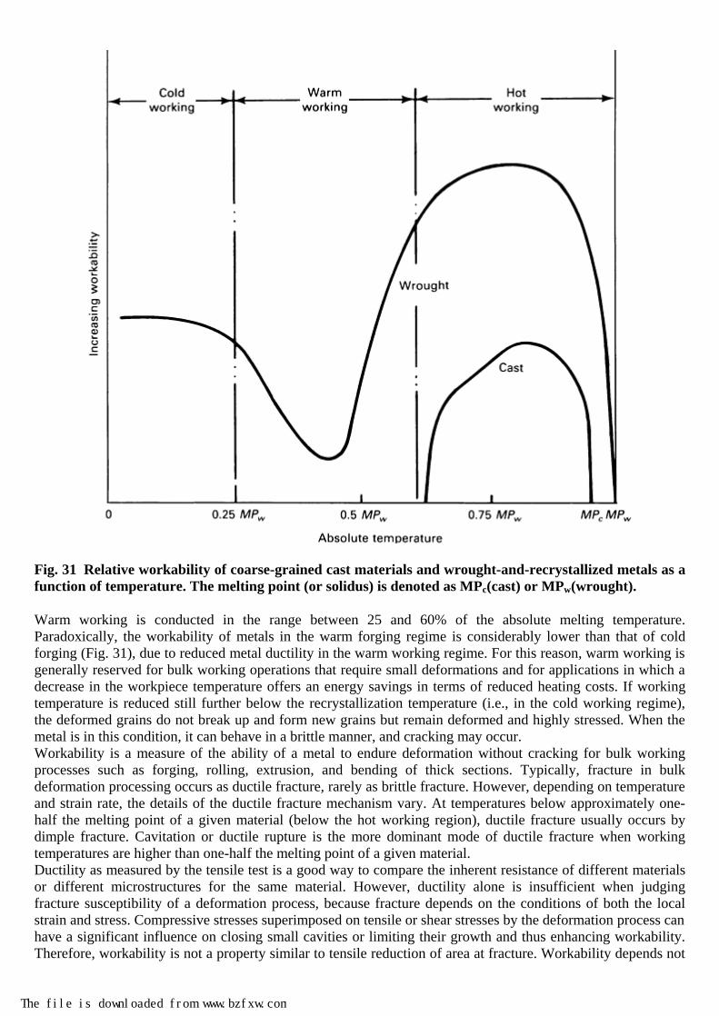
Fig. 31 Relative workability of coarse-grained cast materials and wrought-and-recrystallized metals as a function of temperature. The melting point (or solidus) is denoted as MPc(cast) or MPw(wrought).
Warm working is conducted in the range between 25 and 60% of the absolute melting temperature. Paradoxically, the workability of metals in the warm forging regime is considerably lower than that of cold forging (Fig. 31), due to reduced metal ductility in the warm working regime. For this reason, warm working is generally reserved for bulk working operations that require small deformations and for applications in which a decrease in the workpiece temperature offers an energy savings in terms of reduced heating costs. If working temperature is reduced still further below the recrystallization temperature (i.e., in the cold working regime), the deformed grains do not break up and form new grains but remain deformed and highly stressed. When the metal is in this condition, it can behave in a brittle manner, and cracking may occur. Workability is a measure of the ability of a metal to endure deformation without cracking for bulk working processes such as forging, rolling, extrusion, and bending of thick sections. Typically, fracture in bulk deformation processing occurs as ductile fracture, rarely as brittle fracture. However, depending on temperature and strain rate, the details of the ductile fracture mechanism vary. At temperatures below approximately one-half the melting point of a given material (below the hot working region), ductile fracture usually occurs by dimple fracture. Cavitation or ductile rupture is the more dominant mode of ductile fracture when working temperatures are higher than one-half the melting point of a given material. Ductility as measured by the tensile test is a good way to compare the inherent resistance of different materials or different microstructures for the same material. However, ductility alone is insufficient when judging fracture susceptibility of a deformation process, because fracture depends on the conditions of both the local strain and stress. Compressive stresses superimposed on tensile or shear stresses by the deformation process can have a significant influence on closing small cavities or limiting their growth and thus enhancing workability. Therefore, workability is not a property similar to tensile reduction of area at fracture. Workability depends not
The file is downloaded from www.bzfxw.com

only on material characteristics but also on process variables, such as strain, strain rate, temperature, and stress state. Flow Localization. Workability problems can arise when metal deformation is localized to a narrow zone. This results in a region of different structures and properties that can be the site of failure in service. Localization of deformation can also be so severe that it leads to failure in the deformation process. In either mode, the presence of flow localization needs to be recognized. Flow localization is commonly caused by the formation of a dead-metal zone between the workpiece and the tooling. This can arise from poor lubrication at the workpiece-tool interface. When the workpiece is constrained from sliding at the interface, it barrels, and the friction-hill pressure distribution is created over the interface. The inhomogeneity of deformation throughout the cross section leads to a dead zone at the tool interface and a region of intense shear deformation. A similar situation can arise when the processing tools are cooler than the workpiece; in this case, heat is extracted at the tools. Consequently, the flow stress of the metal near the interface is higher because of the lower temperature. However, flow localization may occur during hot working in the absence of frictional or chilling effects. In this case, localization results from flow softening (negative strain hardening). Flow softening arises during hot working as a result of structural instabilities, such as adiabatic heating, generation of a softer texture during deformation, grain coarsening, or spheroidization. Flow softening has been correlated with materials properties (Ref 14) by the parameter:
( 1)m
γα
−= −
(Eq 1)
for upset compression and:
mγ
α−
=
(Eq 2)
for plane-strain compression, where γ = (1/σ)dσ/dε is the normalized flow-softening rate, and where the strain-rate sensitivity, m, is the differential relation of stress and strain rate:
m = d log σ/d log ε In alpha-beta titanium alloys and other materials that exhibit a strong tendency toward flow localization, this phenomenon is likely to occur when the parameter α is greater than 5. Figure 32 (Ref 15) shows a crack that initiated in a shear band during the high-energy-rate forging of a complex austenitic stainless steel.
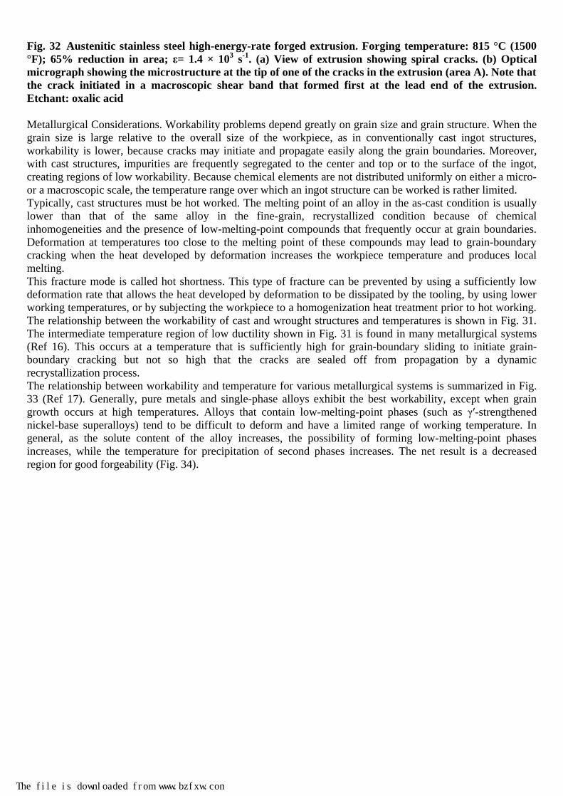
Fig. 32 Austenitic stainless steel high-energy-rate forged extrusion. Forging temperature: 815 °C (1500 °F); 65% reduction in area; ε= 1.4 × 10³ s-1. (a) View of extrusion showing spiral cracks. (b) Optical micrograph showing the microstructure at the tip of one of the cracks in the extrusion (area A). Note that the crack initiated in a macroscopic shear band that formed first at the lead end of the extrusion. Etchant: oxalic acid
Metallurgical Considerations. Workability problems depend greatly on grain size and grain structure. When the grain size is large relative to the overall size of the workpiece, as in conventionally cast ingot structures, workability is lower, because cracks may initiate and propagate easily along the grain boundaries. Moreover, with cast structures, impurities are frequently segregated to the center and top or to the surface of the ingot, creating regions of low workability. Because chemical elements are not distributed uniformly on either a micro- or a macroscopic scale, the temperature range over which an ingot structure can be worked is rather limited. Typically, cast structures must be hot worked. The melting point of an alloy in the as-cast condition is usually lower than that of the same alloy in the fine-grain, recrystallized condition because of chemical inhomogeneities and the presence of low-melting-point compounds that frequently occur at grain boundaries. Deformation at temperatures too close to the melting point of these compounds may lead to grain-boundary cracking when the heat developed by deformation increases the workpiece temperature and produces local melting. This fracture mode is called hot shortness. This type of fracture can be prevented by using a sufficiently low deformation rate that allows the heat developed by deformation to be dissipated by the tooling, by using lower working temperatures, or by subjecting the workpiece to a homogenization heat treatment prior to hot working. The relationship between the workability of cast and wrought structures and temperatures is shown in Fig. 31. The intermediate temperature region of low ductility shown in Fig. 31 is found in many metallurgical systems (Ref 16). This occurs at a temperature that is sufficiently high for grain-boundary sliding to initiate grain-boundary cracking but not so high that the cracks are sealed off from propagation by a dynamic recrystallization process. The relationship between workability and temperature for various metallurgical systems is summarized in Fig. 33 (Ref 17). Generally, pure metals and single-phase alloys exhibit the best workability, except when grain growth occurs at high temperatures. Alloys that contain low-melting-point phases (such as γ′-strengthened nickel-base superalloys) tend to be difficult to deform and have a limited range of working temperature. In general, as the solute content of the alloy increases, the possibility of forming low-melting-point phases increases, while the temperature for precipitation of second phases increases. The net result is a decreased region for good forgeability (Fig. 34).
The file is downloaded from www.bzfxw.com

Fig. 33 Typical workability behavior exhibited by different alloy systems. TM, absolute melting temperature. Source: Ref 17

Fig. 34 Influence of solute content on melting and solution temperatures and therefore on forgeability
References cited in this section
13. S.L. Semiatin and J.J. Jonas, Formability and Workability of Metals: Plastic Instability and Flow Localization, American Society for Metals, 1984, p 3
14. S.L. Semiatin and G.D. Lahoti, The Occurrence of Shear Bands in Isothermal Hot Forging, Metall. Trans. A, Vol 13, 1982, p 275–288
15. M.C. Mataya and G. Krauss, A Test to Evaluate Flow Localization during Forging, J. Appl. Metalwork., Vol 2, 1981, p 28–37
16. F.N. Rhines and P.J. Wray, Investigation of the Intermediate Temperature Ductility Minimum in Metals, Trans. ASM, Vol 54, 1961, p 117
17. A.M. Sabroff, F.W. Boulger, and H.J. Henning, Forging Materials and Practices, Reinhold, 1968
Cracking in Bulk Working
The common failure modes occurring in deformation processing are summarized in Table 2. Three temperature regions are common: cold working, warm working, and hot working. The general types of fracture in bulk working are:
• Free-surface fracture • Die-contact surface fracture • Internal fracture
Table 2 Common failure modes in deformation processing
Metallurgical defects in: Temperature regime Cast grain structure Wrought (recrystallized) grain structure Cold working (a) Free surface fracture, dead metal zones
(shear bands, shear cracks), centerbursts, galling
Warm working (b) Triple-point cracks/fractures, grain-boundary cavitation/fracture
The file is downloaded from www.bzfxw.com

Metallurgical defects in: Temperature regime Cast grain structure Wrought (recrystallized) grain structure Hot working Hot shortness, centerbursts, triple-point
cracks/fractures, grain-boundary cavitation/fracture, shear bands/fractures
Shear bands/fractures, triple-point cracks/fractures, grain-boundary cavitation/fracture, hot shortness
(a) Cold working of cast structures is typically performed only for very ductile metals (such as dental alloys) and usually involves many stages of working with intermediate recrystallization anneals. (b) Warm working of cast structures is rare. The most common types of failures in bulk working are free-surface fracture (at cold working temperatures) or triple-point cracking/cavitation (at hot working temperatures), but internal cracking (i.e., central bursts or chevron cracking, previously discussed) can be an extremely dangerous type of defect, because it cannot be seen visually. This section reviews the first two. A vast array of mechanical tests and theoretical analyses have been developed for predicting failures of these and other types during forging, extrusion, rolling, and other bulk forming operations. These tests and analyses are summarized in the Section “Evaluation of Workability” of Forming and Forging, Volume 14 of ASM Handbook. Other common test techniques used to gage bulk workability include the uniaxial upset, flanged or tapered compression, notched-bar upset, and wedge tests. The types of cracks that develop in cold forging by upsetting-type processes are discussed in Ref 18 and are shown in Fig. 35. Table 3 provides a detailed description of each type of crack.

Fig. 35 Classification of cracks. Greek letters indicate type of cracking. See also Table 3. Source: Ref 18
The file is downloaded from www.bzfxw.com
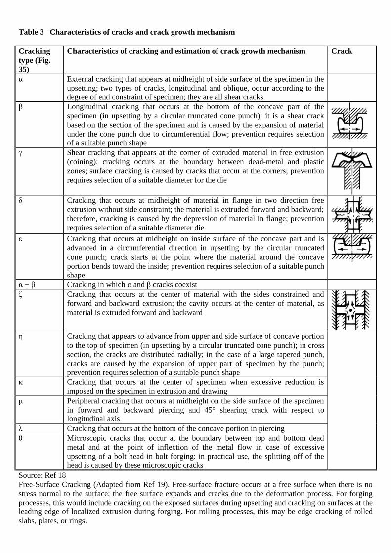
Table 3 Characteristics of cracks and crack growth mechanism
Cracking type (Fig. 35)
Characteristics of cracking and estimation of crack growth mechanism Crack
α External cracking that appears at midheight of side surface of the specimen in the upsetting; two types of cracks, longitudinal and oblique, occur according to the degree of end constraint of specimen; they are all shear cracks
β Longitudinal cracking that occurs at the bottom of the concave part of the specimen (in upsetting by a circular truncated cone punch): it is a shear crack based on the section of the specimen and is caused by the expansion of material under the cone punch due to circumferential flow; prevention requires selection of a suitable punch shape
γ Shear cracking that appears at the corner of extruded material in free extrusion (coining); cracking occurs at the boundary between dead-metal and plastic zones; surface cracking is caused by cracks that occur at the corners; prevention requires selection of a suitable diameter for the die
δ Cracking that occurs at midheight of material in flange in two direction free
extrusion without side constraint; the material is extruded forward and backward; therefore, cracking is caused by the depression of material in flange; prevention requires selection of a suitable diameter die
ε Cracking that occurs at midheight on inside surface of the concave part and is advanced in a circumferential direction in upsetting by the circular truncated cone punch; crack starts at the point where the material around the concave portion bends toward the inside; prevention requires selection of a suitable punch shape
α + β Cracking in which α and β cracks coexist ζ Cracking that occurs at the center of material with the sides constrained and
forward and backward extrusion; the cavity occurs at the center of material, as material is extruded forward and backward
η Cracking that appears to advance from upper and side surface of concave portion
to the top of specimen (in upsetting by a circular truncated cone punch); in cross section, the cracks are distributed radially; in the case of a large tapered punch, cracks are caused by the expansion of upper part of specimen by the punch; prevention requires selection of a suitable punch shape
κ Cracking that occurs at the center of specimen when excessive reduction is imposed on the specimen in extrusion and drawing
μ Peripheral cracking that occurs at midheight on the side surface of the specimen in forward and backward piercing and 45° shearing crack with respect to longitudinal axis
λ Cracking that occurs at the bottom of the concave portion in piercing θ Microscopic cracks that occur at the boundary between top and bottom dead
metal and at the point of inflection of the metal flow in case of excessive upsetting of a bolt head in bolt forging: in practical use, the splitting off of the head is caused by these microscopic cracks
Source: Ref 18 Free-Surface Cracking (Adapted from Ref 19). Free-surface fracture occurs at a free surface when there is no stress normal to the surface; the free surface expands and cracks due to the deformation process. For forging processes, this would include cracking on the exposed surfaces during upsetting and cracking on surfaces at the leading edge of localized extrusion during forging. For rolling processes, this may be edge cracking of rolled slabs, plates, or rings.

One of the most successful and useful design tools to come from bulk workability research is the workability diagram for free-surface fracture during the cold working of wrought and powder metals. An example of a workability diagram of this type is shown in Fig. 36 (Ref 20). The graph indicates the locus of free-surface normal strains (one tensile and one compressive) that cause fracture. The workability diagrams are used during process design by plotting calculated or estimated surface strain paths that are to be imposed during forming on the fracture locus diagram (Fig. 36). If the final strains lie above the locus, part failure is likely, and changes are necessary in preform design, lubrication, and/or material. The fracture locus concept has been used to prevent free-surface cracking in forging and to prevent edge cracking in rolling. With modifications, the fracture locus approach has also provided insight into such failure modes as center bursting in extrusion and forging and die-workpiece contact fractures in forging. These limits change with chemistry, grain size, temperature, second-phase content, and possibly with strain rate.
Fig. 36 Schematic workability diagrams for bulk forming processes. Strain path (a) would lead to failure for material A. Both strain paths (a and b) can be used for the successful forming of material B.
The concept of a working limit for free-surface fracture is important, because the workability of a metal may be characterized for a particular set of process conditions. In general, as the working temperature is increased, the location of the fracture line moves upward, indicating that higher deformation can be accommodated before fracture. However, higher temperatures are not always beneficial, as in the case of IN718 nickel-base superalloy, which has a temperature limit of approximately 1120 °C (2050 °F) for hot working. (Ref 21). Experimental observations have shown that the slope of the line increases with strain rate for some metals, most notably some brasses and austenitic stainless steels (Ref 22). The position of the line drops (lower workability) as the second-phase content increases, much like the tensile ductility decreases with second phase. The fracture line location is also sensitive to the microstructure. For example, a spheroidized structure for a high-carbon steel has a higher fracture line position than a pearlitic microstructure. More details and references on workability in terms of free-surface cracking are in Ref 19. Die-Contact Surface Cracking (Ref 19). Cracking on surfaces in contact with a die is a common problem. Frequently, cracks occur during forging on surfaces that are in contact with the dies. One common location of
The file is downloaded from www.bzfxw.com

such defects is the vicinity of a die or punch corner. A combination of shear deformation with tension or low values of hydrostatic pressure in the vicinity of a die corner are responsible for surface cracking (Ref 23). From the observation of a variety of such defects, it appears that a common characteristic is an abrupt change in frictional shear traction distribution in the region of the crack. High friction to retard metal flow in advance of the crack location is one method for preventing such defects. These cracks usually do not propagate deeply into the workpiece but instead result in unacceptable surface quality or unacceptable machining depths if that surface was to be finish machined. As the forging community has moved closer to net-shape forming, this type of defect has become an increasing problem. Causes of this problem include nonuniform lubrication, flow around die corners, and an improper starting workpiece surface.
References cited in this section
18. T. Okamoto, T. Fukuda, and H. Hagita, “Material Fracture in Cold Forging—Systematic Classification of Working Methods and Types of Cracking in Cold Forging,” Sumitomo Search, No. 9, May 1973, p 46; Source Book on Cold Forming, American Society for Metals, 1975, p 216–226
19. B.L. Ferguson, Design for Deformation Processes, Materials Selection and Design, Vol 20, ASM Handbook, 1997, p 730–744
20. P.W. Lee and H.A. Kuhn, Cold Upset Testing, Workability Testing Techniques, G.E. Dieter, Ed., American Society for Metals, 1984, p 37
21. S.L. Semiatin, Workability in Forging, Workability Testing Techniques, G.E. Dieter, Ed., American Society for Metals, 1984, p 197–247
22. H.A. Kuhn and G.E. Dieter, Workability in Bulk Forming Processes, Fracture 1977, Vol 1, ICF4, (Waterloo, Canada), 1977, p 307–324
23. H.A. Kuhn and B.L. Ferguson, Powder Forging, Metal Powder Industries Federation, 1990
Sheet Forming
The major problems encountered in sheet metal forming are fracturing, buckling and wrinkling, shape distortion, loose metal, and undesirable surface textures. The occurrence of any one or a combination of these conditions can render the sheet metal part unusable. The effects of these problems are discussed subsequently. Fracturing occurs when a sheet metal blank is subjected to stretching or shearing (drawing) forces that exceed the failure limits of the material for a given strain history, strain state, strain rate, and temperature. In stretching, the sheet initially thins uniformly, at least in a local area. Eventually, a point is reached at which deformation concentrates and causes a band of localized thinning known as a neck, which ultimately fractures. The formation of a neck is generally regarded as failure, because it produces a visible defect and a structural weakness. Most current formability tests are concerned with fracture occurring in stretching operations. In shearing, fracture can take place without prior thinning. The most common examples of this type of fracture occur in slitting, blanking, and trimming. In these operations, sheets are sheared by knife edges that apply forces normal to the plane of the sheet. Shearing failures are sometimes produced in stamping operations by shearing forces in the plane of the sheet, but they are much less common than stretching failures. Buckling and Wrinkling. In a typical stamping operation, the punch contacts the blank, stretches it, and starts to pull it through the blankholder ring. The edges of the blank are pulled into regions with progressively smaller perimeters. This produces compressive stresses in the circumferential direction. If these stresses reach a critical level characteristic of the material and its thickness, they cause slight undulations known as buckles. Buckles may develop into more pronounced undulations or waves, known as wrinkles, if the blankholder pressure is not sufficiently high. This effect can also cause wrinkles in other locations, particularly in regions with abrupt changes in section and in regions where the metal is unsupported or contacted on one side only. In extreme cases, folds and double or

triple metal may develop. These may, in turn, lead to splitting in another location by preventing metal flow or by locking the metal out. Therefore, increasing the blankholder pressure often corrects a splitting problem. Shape Distortion. On removal of the external forces, the internal elastic stresses relax. In some locations, they can relax completely, with only a very slight change in the dimensions of the part. However, in areas subjected to bending, through-thickness gradients in the elastic stresses occur; that is, the stresses on the outer surfaces are different from those on the inner surfaces. If these stresses are not constrained or locked in by the geometry of the part, relaxation causes a change in the part shape known as shape distortion or springback. Springback can be compensated for in die design for a specific set of material properties but may still be a problem if there are large material property or process variations from blank to blank. Loose metal occurs in undeformed regions and is undesirable, because it can be easily deflected. A phenomenon usually referred to as oil canning, in which a local area can be either concave or convex, can also be encountered. In stampings with two or more sharp bends of the same sign in roughly the same direction, such as a pair of feature lines, a tendency exists for the metal between them to be loose because of the difficulty involved in pulling metal across a sharp radius. It is sometimes possible to avoid the problem by ensuring that the metal is not contacted by both lines at the same time; thus, some stretching can occur before the second line is contacted. There is a tendency for loose metal to occur toward the center of large, flat, or slightly curved parts. Increasing the restraining forces on the blank edges usually improves this condition. Undesirable Surface Textures. Heavily deformed sheet metal, particularly if it is coarse grained, often develops a rough surface texture commonly known as “orange-peel.” This is usually unacceptable in parts that are visible in service. Another source of surface problems occurs in metals that have a pronounced yield point elongation, that is, materials that stretch several percent without an increase in load after yielding. In these metals, deformation at low strain levels is concentrated in irregular bands known as Lüders lines (or bands) or stretcher strains. These defects disappear at moderate and high strain levels. However, almost all parts have some low-strain regions. These defects are unsightly and are not concealed by painting. Aged rimmed steels and some aluminum-magnesium alloys develop severe Lüders lines.
Cold Formed Parts
In general, parts produced by cold forming are susceptible to the same causes of failure as parts of the same metal composition and function produced by other forming processes. There are, however, some unique characteristics of cold formed parts that may influence their susceptibility to failure. Similar to parts formed by other metalworking methods, the prevention of failures in cold formed parts generally involves well-known preventive or corrective measures that may include changes in alloy composition, design, and/or process conditions (tooling, lubricant, heat treatment, etc.) or the elimination of surface discontinuities. However, various metals have their own specific peculiarities. For example, in the forming of certain stainless steels or iron-base heat-resisting alloys, severe forming encourages grain-boundary carbide precipitation if the metal is reheated to a temperature within the sensitizing-temperature range (400 to 870 °C, or 750 to 1600 °F). In the sensitized condition, the metal is extremely vulnerable to stress-corrosion cracking. Such a condition can be corrected only by the use of a recrystallizing anneal after forming, or it can be avoided by using a grade of stainless steel that is less susceptible to sensitization. In some cases, limited heat is applied to the work metal before forming begins in order to increase its formability. Some metals—for example, certain magnesium alloys—can be difficult to form at room temperature. Preheating to temperatures as low as 120 °C (250 °F) makes these alloys much more formable. The practice of applying some heat to the material being formed without surpassing or closely approaching the recrystallization temperature is known as warm forming. Regardless of the initial temperature, forming must be performed within the boundaries set by the material and tooling used. It is obviously possible to exceed the strength or elastic limits of a given material during a drastic deformation process. Care must therefore be taken to ensure that material specifications are accurately and realistically prepared in order to provide a product that fulfills the desired expectations. Designing a process that operates at the extreme upper limit of the capability of any material leads to an unacceptably high level of part failure because of the inevitable variations that occur from heat to heat or lot to lot.
The file is downloaded from www.bzfxw.com

Grain Deformation. Cold forming of any metal part deforms the grains; the amount of deformation depends on the severity of forming. Severe deformation of the grains in locations of sharp bends or where the metal has become stretched, as in deep-drawn parts, results in a condition that is more vulnerable to failure from such mechanisms as corrosion and fatigue. Susceptibility to corrosion is easily demonstrated by observing simple parts formed from low-carbon steel and exposed to the weather. It is often observed that the severely deformed areas rust before areas on the same part that have been subjected to little or no deformation. This condition prevails even when there are no signs of cracks in severely deformed areas. Frequently, there are fine cracks in certain areas of formed parts where deformation was severe. Although such cracks are harmless in many applications, they help to accelerate any type of corrosion, and they also initiate fatigue cracks if the part is subjected to repeated stress. Grain Size Variation in Thin-Section Product. Formability and grain size generally become more important as the metal being formed becomes thinner. As a rule, finer grain size improves formability. In some instances of coarse-grain metal, the locations where forming was the most severe may have only a very few highly deformed grains in a given cross section. It is important to select a fine-grain metal to accommodate the tendency of grains of varying orientation to deform in preferential directions, but this is not always sufficient; it may be necessary to follow forming with full annealing (recrystallization) or at least with a stress-relieving heat treatment. Precautions are also needed in specifying a recrystallization-annealing treatment because of the possibility of producing very large grains, which may result in undesirable properties for some applications. Subcritical strain for recrystallization can be achieved in the transition region from a bend radius to a straight section in parts formed from sheet, strip, or wire; near the neutral axis in some bent structural shapes, such as I-beams or channels; and in some deep-drawn parts. Precautions should also be taken regarding grain growth during other heat treating operations after forming. The following is an example of this for an aluminum connector tube that was solution treated after bending. Solution treatment induced excessive grain growth. Other characteristics that are generally unique to cold-formed parts include certain types of tool marks, particularly indentations at inside bend radii, scoring that may occur during deep drawing or forming, and scoring on outer surfaces such as often occurs when forming in a press brake using V-dies. Orange-peel results when a very coarse-grain metal is stressed beyond its yield strength, increasing vulnerability to corrosion and helping to initiate fatigue cracks if the part is subjected to repeated stress. Corner Thinning causes concentration of stress flow lines at corners, which may help to cause failure by one or more mechanisms. Work Hardening. Another unique characteristic of cold-formed parts involves local areas that have become severely work hardened, such as those areas that have been thinned by stretching or localized compression. Such areas are vulnerable to stress cracking. Plating. Many formed parts are plated to protect them from corrosion. This often causes difficulties, because the open areas of the part where there was little or no deformation usually receive the thickest plating, whereas severely formed areas may be plating-starved—for example, the inside corners of a box-shaped part. Thus, some formed parts are more susceptible to various forms of corrosion simply because the more vulnerable areas were not sufficiently protected. Spangles in Zinc-Coated Steel Sheet. In some cases, zinc-coated steels exhibit surface defects known as spangles. This phenomenon occurs only in hot-dipped products and is caused by the development of a coarse grain size in the galvanic coating, which makes the individual grains clearly visible. This problem can be corrected in the coating process. In addition to the previously mentioned occurrences, handling damage, dents caused by dirt or slivers in the die, and scoring or galling caused by a rough die surface or inadequate lubrication sometimes produce unacceptable surfaces.
References
1. J. Schey, Manufacturing Processes and Their Selection, Materials Selection and Design, Vol. 20, ASM Handbook, ASM International, 1997, p 687–704
2. L. Pease III and W. West, Fundamentals of Powder Metallurgy, Metal Powder Industries Federation, 2002

3. G.F. Vander Voort, Metallography: Principles and Practice, McGraw-Hill, 1984 (out of print), reprinted 1999 ASM International
4. R.K. Dayal, J.B. Gnanamoorthy, and P. Rodriguez, Failure of an I-Beam, Handbook of Case Histories in Failure Analysis, Vol 1, ASM International, 1992, p 378–381
5. E. Kauczor, Prakt. Metallogr. Vol 8, July 1971, p 443–446
6. G. Vander Voort, Embrittlement of Steels, Properties and Selection: Iron, Steels, and High-Performance Alloys, Vol 1, ASM Handbook, ASM International, 1990, p 689–736
7. P.A. Thornton, J. Mater. Sci., Vol 6, 1971, p 347
8. D.V. Edmonds and C.J. Beevers, J. Mater. Sci., Vol 3, 1968, p 457
9. A.D. Wilson, Calcium Treatment of Plate Steels and Its Effect on Fatigue and Toughness Properties, Proc. 11th Annual Offshore Technology Conference, OTC 3465, May 1979, p 939–948
10. A.D. Wilson, Effect of Calcium Treatment on Inclusions in Constructional Steels, Met. Prog., Vol 121 (No. 5), April 1982, p 41–46
11. M.D. Chaudhari, Failure Analysis of a Helicopter Main Rotor Bolt, Handbook of Case Histories in Failure Analysis, Vol 2, ASM International, 1993, p 392
12. V.N. Whittacker, Nondestr. Test., Oct 1971, p 320
13. S.L. Semiatin and J.J. Jonas, Formability and Workability of Metals: Plastic Instability and Flow Localization, American Society for Metals, 1984, p 3
14. S.L. Semiatin and G.D. Lahoti, The Occurrence of Shear Bands in Isothermal Hot Forging, Metall. Trans. A, Vol 13, 1982, p 275–288
15. M.C. Mataya and G. Krauss, A Test to Evaluate Flow Localization during Forging, J. Appl. Metalwork., Vol 2, 1981, p 28–37
16. F.N. Rhines and P.J. Wray, Investigation of the Intermediate Temperature Ductility Minimum in Metals, Trans. ASM, Vol 54, 1961, p 117
17. A.M. Sabroff, F.W. Boulger, and H.J. Henning, Forging Materials and Practices, Reinhold, 1968
18. T. Okamoto, T. Fukuda, and H. Hagita, “Material Fracture in Cold Forging—Systematic Classification of Working Methods and Types of Cracking in Cold Forging,” Sumitomo Search, No. 9, May 1973, p 46; Source Book on Cold Forming, American Society for Metals, 1975, p 216–226
19. B.L. Ferguson, Design for Deformation Processes, Materials Selection and Design, Vol 20, ASM Handbook, 1997, p 730–744
20. P.W. Lee and H.A. Kuhn, Cold Upset Testing, Workability Testing Techniques, G.E. Dieter, Ed., American Society for Metals, 1984, p 37
21. S.L. Semiatin, Workability in Forging, Workability Testing Techniques, G.E. Dieter, Ed., American Society for Metals, 1984, p 197–247
The file is downloaded from www.bzfxw.com

22. H.A. Kuhn and G.E. Dieter, Workability in Bulk Forming Processes, Fracture 1977, Vol 1, ICF4, (Waterloo, Canada), 1977, p 307–324
23. H.A. Kuhn and B.L. Ferguson, Powder Forging, Metal Powder Industries Federation, 1990
Failures Related to Casting
Introduction
FAILURES OF CASTINGS, like the failures of wrought materials, can occur from service conditions, improper design and/or materials selection, manufacturing deficiencies, or a combination of these. A design-related failure is one in which even a perfect casting (free from unexpected deficiencies and meeting specified requirements) does not perform to the requirements of the application. Correspondingly, a defect-related failure is one resulting from a condition that falls outside of the established acceptance criteria that the designer did not or could not anticipate. In many instances, both design and manufacture of the casting contribute to premature failure. Clearly, both types of failure are preventable. On first inspection, it seems clear that the designer must accept responsibility for failures of the first type, and the founder the second. No such distinction should be drawn. The key to serviceable castings is communication between the designer and the foundry engineers. Foundrymen are an invaluable source of information on just what can be produced in cast form, both in terms of geometry and materials selection. This input should be sought early in the design process, to incorporate the suggestions where practical. This can also have a dramatic impact on the manufacturability of the final part, influencing the ultimate quality of the casting and thus reducing the likelihood of failure due to defective parts. Included in the design process is the determination of specifications to which the foundry must work. Here, too, the foundry can be invaluable in providing the designer with input as to what materials should be used, what specifications are called out, what nondestructive testing techniques are applicable, what level of metallurgical testing should be performed, and, finally, what quality-assurance documentation is needed. A teamwork approach between the designer and foundry (and, where possible, the ultimate user) is the best (and lowest-cost) method of avoiding casting failures. This article describes the general root causes of failure attributed to the casting process, casting material, and/or design. In failure analysis, it is fundamental to establish the objectives of the designer by reviewing drawings, specifications, and purchase orders. It is also important to determine what was manufactured, delivered, and installed, and to find if it agrees with the drawings. It is then necessary to ascertain what happened to the component before and at the time of failure (history, performance, environment, and so on). The evidence and investigation should lead to determination of the cause of the failure, in terms of faulty design or materials selection, faulty material or processing, and/or service conditions. To determine the true cause of failure, the investigator must fully consider the interplay among design, fabrication, material properties, environment, and service conditions. Once the failure is accurately classified, corrective action and recommendations can be made. Appropriate solutions can involve redesign, change in materials selection or processing, quality control, changes in maintenance or inspection schedules, protection against environment, or restrictions on service loads or service life.
Casting Discontinuities
Discontinuities are interruptions in the physical continuity of a casting, and the engineering community tends to make specific distinctions between the terms discontinuity (or flaw) and defect. By definition, a defect is a condition that must be removed or corrected. The word defect, therefore, should be carefully used, because it

implies that a casting is defective and requires corrective measures or rejection. An imperfection also may be a manufacturing defect, in the sense of being an unacceptable condition during an inspection regime, but not a functional defect. Critical engineering assessment of discontinuities is therefore necessary to define whether an imperfection is a defect or a harmless discontinuity that does not sacrifice the reliability or intended function of the casting. Although the term discontinuity or imperfection is preferred when referring to deviations in less-than-perfect castings, the term casting defect is sometimes used for general imperfections as well. Unfavorable foundry practice can result in various casting imperfections that are detrimental in service and that may contribute to failure. However, many of the common causes of failures of castings occur from one or more aspects of design, materials selection, casting imperfections, faulty processing, improper assembly, or service conditions not initially anticipated. Some casting imperfections have no effect on the function or the service life of cast components, but will give an unsatisfactory appearance or will make further processing, such as machining, more costly. Many such imperfections can be easily corrected by shotblast cleaning or grinding. Other imperfections or defects that can be more difficult to remove can be acceptable in some locations. Moreover, many castings (especially iron and steel castings) generally lend themselves to being weld repaired, with proper attention to the details of weld repair procedures. Imperfections and defects can be removed and a suitable weld deposit substituted to give a finished product fit for the intended service, although many failures of castings also result from improper repair or rework of casting defects (see the section “Welding” in this article). In summary, it is most critical that the casting designer specify the true design needs. Poor casting design can interfere with the ability of the foundry to use the best techniques to produce reliable castings. Defect-free castings can be produced at a price. The multitude of process variables, such as molding mediums, binder, gating and risering, melting and ladle practice, pouring technique, and heat treatment, that must be controlled to produce such sound castings requires a thorough understanding of the processes used and strict engineering supervision. The price of a casting often reflects the cost of such efforts. The attention to detail necessary to make good castings can reduce total cost of a manufactured part by significantly reducing machining, repair, and fit problems later in the assembly. Proper specification, as opposed to overspecification or underspecification, is the key to the successful application, that is, freedom from failure, of castings. International Classification of Casting Defects. Foundrymen have traditionally used rather unique names, such as rattail, scab, buckle, and shut, to describe various casting imperfections. Some of these terms have been used to describe imperfections in cast iron and steels, as noted in the following section “Imperfections That Can Occur in Iron and Steel Castings.” However, because foundrymen sometimes use different nomenclature to describe imperfections or defects, the International Committee of Foundry Technical Associations (ICFTA) has standardized the nomenclature, starting with the identification of seven basic categories of casting imperfections (or defects, in the terminology used by the ICFTA classification scheme, Table 1):
• Metallic projections • Cavities • Discontinuities • Defects • Incomplete casting • Incorrect dimension • Inclusions or structural anomalies
Table 1 International classification of common casting defects
No. Description Common
name
Sketch
Metallic Projections A 100:
Metallic projections in the form of fins or flash
A Metallic projections in the form of fins (or flash) without change in principal casting dimensions
The file is downloaded from www.bzfxw.com
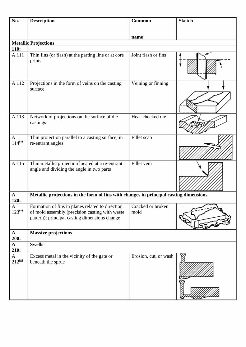
No. Description Common
name
Sketch
Metallic Projections 110: A 111 Thin fins (or flash) at the parting line or at core
prints Joint flash or fins
A 112 Projections in the form of veins on the casting
surface Veining or finning
A 113 Network of projections on the surface of die
castings Heat-checked die
A 114(a)
Thin projection parallel to a casting surface, in re-entrant angles
Fillet scab
A 115 Thin metallic projection located at a re-entrant
angle and dividing the angle in two parts Fillet vein
A 120:
Metallic projections in the form of fins with changes in principal casting dimensions
A 123(a)
Formation of fins in planes related to direction of mold assembly (precision casting with waste pattern); principal casting dimensions change
Cracked or broken mold
A 200:
Massive projections
A 210:
Swells
A 212(a)
Excess metal in the vicinity of the gate or beneath the sprue
Erosion, cut, or wash

No. Description Common
name
Sketch
Metallic Projections A 213(a)
Metal projections in the form of elongated areas in the direction of mold assembly
Crush
A 220:
Projections with rough surfaces
A 221(a)
Projections with rough surfaces on the cope surface of the casting
Mold drop or sticker
A 222(a)
Projections with rough surfaces on the drag surface of the casting (massive projections)
Raised core or mold element cutoff
A 223(a)
Projections with rough surfaces on the drag surface of the casting (in dispersed areas)
Raised sand
A 224(a)
Projections with rough surfaces on other parts of the casting
Mold drop
A 225(a)
Projections with rough surfaces over extensive areas of the casting
Corner scab
A 226(a)
Projections with rough surfaces in an area formed by a core
Broken or crushed core
Cavities B 100: Cavities with generally rounded, smooth walls perceptible to the naked eye (blowholes, pinholes) B 110: Class B 100 cavities internal to the casting, not extending to the surface, discernible only by
special methods, machining, or fracture of the casting B 111(a)
Internal, rounded cavities, usually smooth-walled, of varied size, isolated or grouped irregularly in all areas of the casting
Blowholes, pinholes
The file is downloaded from www.bzfxw.com
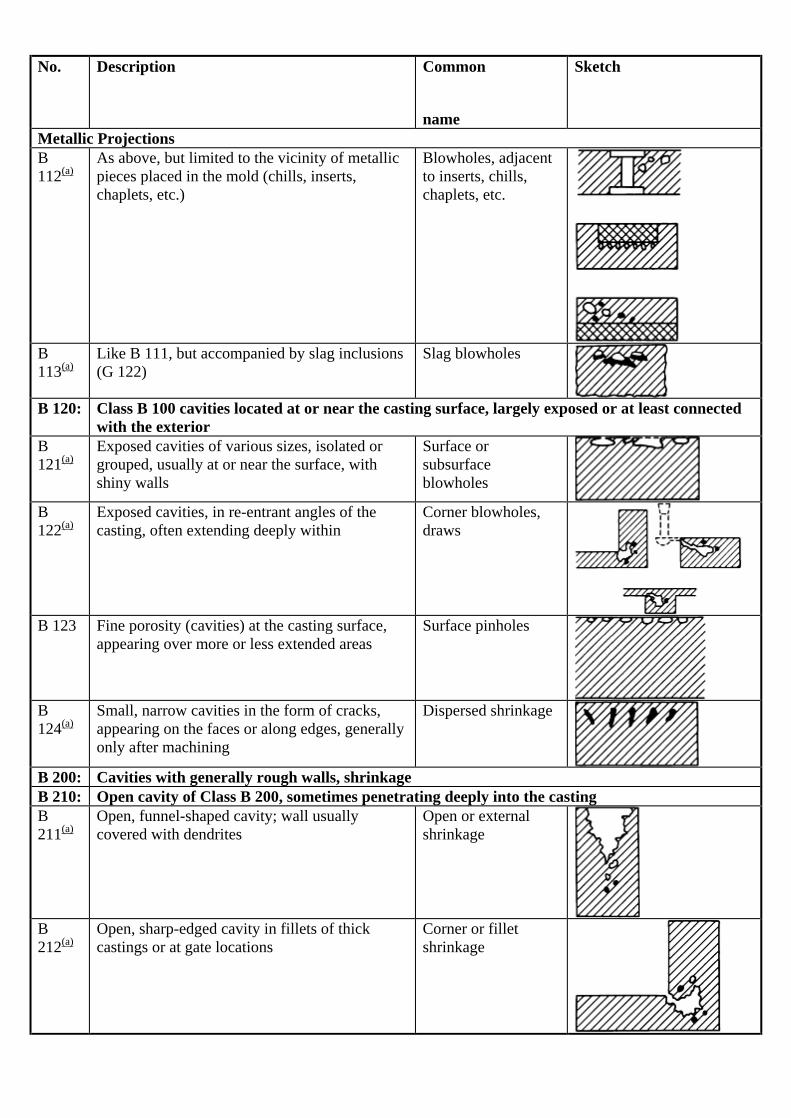
No. Description Common
name
Sketch
Metallic Projections B 112(a)
As above, but limited to the vicinity of metallic pieces placed in the mold (chills, inserts, chaplets, etc.)
Blowholes, adjacent to inserts, chills, chaplets, etc.
B 113(a)
Like B 111, but accompanied by slag inclusions (G 122)
Slag blowholes
B 120: Class B 100 cavities located at or near the casting surface, largely exposed or at least connected
with the exterior B 121(a)
Exposed cavities of various sizes, isolated or grouped, usually at or near the surface, with shiny walls
Surface or subsurface blowholes
B 122(a)
Exposed cavities, in re-entrant angles of the casting, often extending deeply within
Corner blowholes, draws
B 123 Fine porosity (cavities) at the casting surface,
appearing over more or less extended areas Surface pinholes
B 124(a)
Small, narrow cavities in the form of cracks, appearing on the faces or along edges, generally only after machining
Dispersed shrinkage
B 200: Cavities with generally rough walls, shrinkage B 210: Open cavity of Class B 200, sometimes penetrating deeply into the casting B 211(a)
Open, funnel-shaped cavity; wall usually covered with dendrites
Open or external shrinkage
B 212(a)
Open, sharp-edged cavity in fillets of thick castings or at gate locations
Corner or fillet shrinkage

No. Description Common
name
Sketch
Metallic Projections B 213(a)
Open cavity extending from a core Core shrinkage
B 220: Class B 200 cavity located completely internal to the casting B 221(a)
Internal, irregularly shaped cavity; wall often dendritic
Internal or blind shrinkage
B 222(a)
Internal cavity or porous area along central axis Centerline or axial shrinkage
B 300: Porous structures caused by numerous small cavities B 310: Cavities according to B 300, scarcely perceptible to the naked eye B 311(a)
Dispersed, spongy dendritic shrinkage within walls of casting; barely perceptible to the naked eye
Macro- or micro- shrinkage, shrinkage porosity, leakers
Discontinuities C 100:
Discontinuities, generally at intersections, caused by mechanical effects (rupture)
C 110:
Normal cracking
C 111(a)
Normal fracture appearance, sometimes with adjacent indentation marks
Breakage (cold)
C 120:
Cracking with oxidation
C 121(a)
Fracture surface oxidized completely around edges
Hot cracking
C 200:
Discontinuities caused by internal tension and restraints to contraction (cracks and tears)
C 210:
Cold cracking or tearing
C 211(a)
Discontinuities with squared edges in areas susceptible to tensile stresses during cooling; surface not oxidized
Cold tearing
C 220:
Hot cracking and tearing
The file is downloaded from www.bzfxw.com

No. Description Common
name
Sketch
Metallic Projections C 221(a)
Irregularly shaped discontinuities in areas susceptible to tension; oxidized fracture surface showing dendritic pattern
Hot tearing
C 222(a)
Rupture after complete solidification, either during cooling or heat treatment
Quench cracking
C 300:
Discontinuities caused by lack of fusion (cold shuts); edges generally rounded, indicating poor contact between various metal streams during filling of the mold
C 310:
Lack of complete fusion in the last portion of the casting to fill
C 311(a)
Complete or partial separation of casting wall, often in a vertical plane
Cold shut or cold lap
C 320:
Lack of fusion between two parts of casting
C 321(a)
Separation of the casting in a horizontal plane Interrupted pour
C 330:
Lack of fusion around chaplets, internal chills, and inserts
C 331(a)
Local discontinuity in vicinity of metallic insert Chaplet or insert cold shut, unfused chaplet
C 400:
Discontinuities caused by metallurgical defects
C 410:
Separation along grain boundaries
C 411(a)
Separation along grain boundaries of primary crystallization
Conchoidal or “rock candy” fracture
C 412(a)
Network of cracks over entire cross section Intergranular corrosion
Defective Surface D 100:
Casting surface irregularities
D 110:
Fold markings on the skin of the casting

No. Description Common
name
Sketch
Metallic Projections D 111 Fold markings over rather large areas of the
casting Surface folds, gas runs
D 112 Surface shows a network of jagged folds or wrinkles (ductile iron)
Cope defect, elephant skin, laps
D 113 Wavy fold markings without discontinuities;
edges of folds at same level, casting surface is smooth
Seams or scars
D 114 Casting surface markings showing direction of
liquid metal flow (light alloys) Flow marks
D 120:
Surface roughness
D 121 Depth of surface roughness is approximately that of the dimensions of the sand grains
Rough casting surface
D 122 Depth of surface roughness is greater than that
of the sand grain dimensions Severe roughness, high pressure molding defect
D 130:
Grooves on the casting surface
D 131 Grooves of various lengths, often branched, with smooth bottoms and edges
Buckle
D 132 Grooves up to 5.1 mm (0.2 in.) in depth, one
edge forming a fold which more or less completely covers the groove
Rat tail
D 133 Irregularly distributed depressions of various
dimensions extending over the casting surface, usually along the path of metal flow (cast steel)
Flow marks, crow's feet
D 134 Casting surface entirely pitted or pock-marked Orange peel, metal
mold reaction, alligator skin
D 135 Grooves and roughness in the vicinity of re-
entrant angles on die castings Soldering, die erosion
D 140:
Depressions in the casting surface
The file is downloaded from www.bzfxw.com

No. Description Common
name
Sketch
Metallic Projections D 141 Casting surface depressions in the vicinity of a
hot spot Sink marks, draw or suck-in
D 142 Small, superficial cavities in the form of
droplets of shallow spots, generally gray-green in color
Slag inclusions
D 200:
Serious surface defects
D 210:
Deep indentation of the casting surface
D 211 Deep indentation, often over large area of drag half of casting
Push-up, clamp-off
D 220:
Adherence of sand, more or less vitrified
D 221 Sand layer strongly adhering to the casting surface
Burn on
D 222 Very adherent layer of partially fused sand Burn in
D 223 Conglomeration of strongly adhering sand and
metal at the hottest points of the casting (re-entrant angles and cores)
Metal penetration
D 224 Fragment of mold material embedded in casting
surface Dip coat spall, scab
D 230:
Plate-like metallic projections with rough surfaces, usually parallel to casting surface
D 231(a)
Plate-like metallic projections with rough surfaces parallel to casting surface; removable by burr or chisel
Scabs, expansion scabs

No. Description Common
name
Sketch
Metallic Projections D 232(a)
As above, but impossible to eliminate except by machining or grinding
Cope spall, boil scab, erosion scab
D 233(a)
Flat, metallic projections on the casting where mold or core washes or dressings are used
Blacking scab, wash scab
D 240:
Oxides adhering after heat treatment (annealing, tempering, malleablizing) by decarburization
D 241 Adherence of oxide after annealing Oxide scale
D 242 Adherence of ore after malleablizing (white
heart malleable Adherent packing material
D 243 Scaling after anneal Scaling
Incomplete Casting E 100: Missing portion of casting (no fracture) E 110: Superficial variations from pattern shape E 111 Casting is essentially complete except for more
or less rounded edges and corners Misrun
E 112 Deformed edges or contours due to poor mold
repair or careless application of wash coatings Defective coating (tear-dropping) or poor mold repair
E 120: Serious variations from pattern shape E 121 Casting incomplete due to premature
solidification Misrun
E 122 Casting incomplete due to insufficient metal
poured Poured short
The file is downloaded from www.bzfxw.com
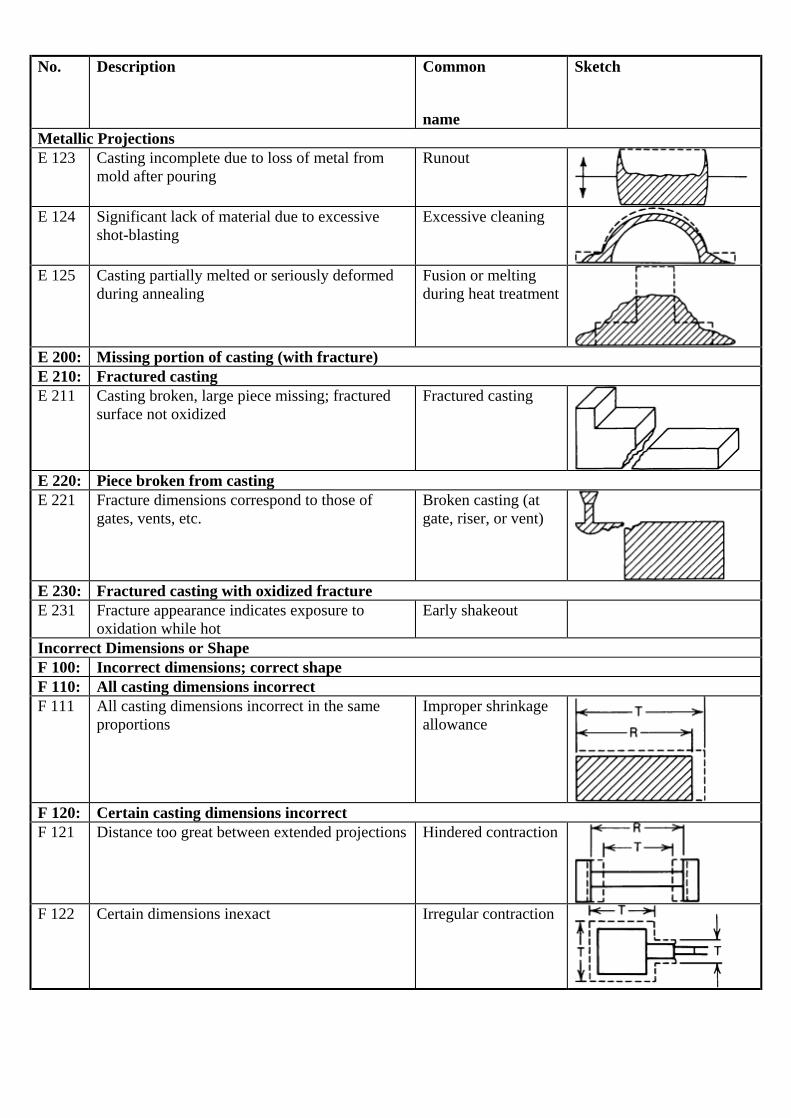
No. Description Common
name
Sketch
Metallic Projections E 123 Casting incomplete due to loss of metal from
mold after pouring Runout
E 124 Significant lack of material due to excessive
shot-blasting Excessive cleaning
E 125 Casting partially melted or seriously deformed
during annealing Fusion or melting during heat treatment
E 200: Missing portion of casting (with fracture) E 210: Fractured casting E 211 Casting broken, large piece missing; fractured
surface not oxidized Fractured casting
E 220: Piece broken from casting E 221 Fracture dimensions correspond to those of
gates, vents, etc. Broken casting (at gate, riser, or vent)
E 230: Fractured casting with oxidized fracture E 231 Fracture appearance indicates exposure to
oxidation while hot Early shakeout
Incorrect Dimensions or Shape F 100: Incorrect dimensions; correct shape F 110: All casting dimensions incorrect F 111 All casting dimensions incorrect in the same
proportions Improper shrinkage allowance
F 120: Certain casting dimensions incorrect F 121 Distance too great between extended projections Hindered contraction
F 122 Certain dimensions inexact Irregular contraction

No. Description Common
name
Sketch
Metallic Projections F 123 Dimensions too great in the direction of rapping
of pattern Excess rapping of pattern
F 124 Dimensions too great in direction perpendicular
to parting line Mold expansion during baking
F 125 Excessive metal thickness at irregular locations
on casting exterior Soft or insufficient ramming, mold-wall movement
F 126 Thin casting walls over general area, especially
on horizontal surfaces Distorted casting
F 200: Casting shape incorrect overall or in certain locations F 210: Pattern incorrect F 211 Casting does not conform to the drawing shape
in some or many respects; same is true of pattern
Pattern error
F 212 Casting shape is different from drawing in a
particular area; pattern is correct Pattern mounting error
F 220: Shift or Mismatch F 221 Casting appears to have been subjected to a
shearling action in the plane of the parting line Shift
F 222 Variation in shape of an internal casting cavity
along the parting line of the core Shifted core
F 223 Irregular projections on vertical surfaces,
generally on one side only in the vicinity of the parting line
Ramoff, ramaway
F 230: Deformations from correct shape
The file is downloaded from www.bzfxw.com

No. Description Common
name
Sketch
Metallic Projections F 231 Deformation with respect to drawing
proportional for casting, mold, and pattern Deformed pattern
F 232 Deformation with respect to drawing
proportional for casting and mold; pattern conforms to drawing
Deformed mold, mold creep, springback
F 233 Casting deformed with respect to drawing;
pattern and mold conform to drawing Casting distortion
F 234 Casting deformed with respect to drawing after
storage, annealing, machining Warped casting
Inclusions or Structural Anomalies G 100:
Inclusions
G 110:
Metallic inclusions
G 111(a)
Metallic inclusions whose appearance, chemical analysis or structural examination show to be caused by an element foreign to the alloy
Metallic inclusions
G 112(a)
Metallic inclusions of the same chemical composition as the base metal; generally spherical and often coated with oxide
Cold shot
G 113 Spherical metallic inclusions inside blowholes
or other cavities or in surface depressions (see A 311). Composition approximates that of the alloy cast but nearer to that of a eutectic
Internal sweating, phosphide sweat
G 120:
Nonmetallic inclusions; slag, dross, flux
G 121(a)
Nonmetallic inclusions whose appearance or analysis shows they arise from melting slags, products of metal treatment or fluxes
Slag, dross or flux inclusions, ceroxides

No. Description Common
name
Sketch
Metallic Projections G 122(a)
Nonmetallic inclusions generally impregnated with gas and accompanied by blowholes (B 113)
Slag blowhole defect
G 130:
Nonmetallic inclusions; mold or core materials
G 131(a)
Sand inclusions, generally very close to the surface of the casting
Sand inclusions
G 132(a)
Inclusions of mold blacking or dressing, generally very close to the casting surface
Blacking or refractory coating inclusions
G 140:
Nonmetallic inclusions; oxides and reaction products
G 141 Clearly defined, irregular black spots on the fractured surface of ductile cast iron
Black spots
G 142(a)
Inclusions in the form of oxide skins, most often causing a localized seam
Oxide inclusion or skins, seams
G 143(a)
Folded films of graphitic luster in the wall of the casting
Lustrous carbon films, or kish tracks
G 144 Hard inclusions in permanent molded and die
cast aluminum alloys Hard spots
(a) Defects that under some circumstances could contribute, either directly or indirectly, to casting failures. Adapted from International Atlas of Casting Defects, American Foundrymen's Society, Des Plaines, IL In this scheme, the term discontinuity has the specific meaning of a planar separation of the metal, that is, a crack. Table 1 presents some of the common defects in each category. In general, defects that can serve as stress raisers or crack promoters are the most serious. These include preexisting cracks, internal voids, and nonmetallic inclusions. Imperfections That Can Occur in Iron and Steel Castings. This section presents definitions of the imperfections and discontinuities that can occur in iron and steel castings and that may be the basis for rejection during inspection. Some of these imperfections, if undetected, can serve as initiation points of casting failures during service. The effects of these imperfections on casting performance depend largely on their severity and location. buckle.
An indentation in a sand casting resulting from expansion of the sand. cold shot.
The file is downloaded from www.bzfxw.com
A small globule of metal that has solidified prematurely and that is embedded in, but not entirely fused with, the surface of the casting.
cold shut. A discontinuity on, or immediately beneath, the surface of a casting, caused by the meeting of two streams of liquid metal that failed to merge. A cold shut may have the appearance of a crack or seam with smooth, rounded edges.
gas porosity. Voids caused by entrapped gas, such as air or steam, or by the expulsion of dissolved gases during solidification.
hot crack. A crack or fracture caused by internal stresses that develop after solidification and during cooling from an elevated temperature (above 650 °C, or 1200 °F, for gray iron). A hot crack is less visible (less open) than a hot tear and usually exhibits less evidence of oxidation and decarburization.
hot tear. A crack or fracture formed prior to completion of solidification because of hindered contraction. A hot tear frequently is open to the surface of the casting and thus, exposed to the atmosphere. This may result in oxidation, decarburization, or other metal-atmosphere reactions at the tear surface.
inclusions. Nonmetallic materials in a solid metallic matrix. In castings, common inclusions include particles of refractory, slag, deoxidation products, or oxides of the casting metal.
mechanical (cold) crack. A crack or fracture resulting from rough handling or from thermal shock, such as may occur at shakeout or during heat treatment.
metal penetration. An imperfection on the surface of a casting caused by the penetration of molten metal into voids between refractory particles of the mold—usually the result of excessive pouring temperatures or overly coarse refractory.
misrun. A casting not fully formed because of solidification of metal before the mold is filled.
off-dimension casting. A casting of the wrong size or containing an error in shape as a result of a dimensional error in the pattern, incorrect design of the pattern and the mold equipment, mismatch between cope and drag, or shifting of a core during pouring.
rattail. In a sand casting, a minor buckle occurring as a small irregular line on the surface.
sand hole. A pit in the surface of a sand casting resulting from a deposit of loose sand on the surface of the mold.
scab. An imperfection consisting of a flat volume of metal joined to a casting through a small area. Usually, a scab is set in a depression in the casting and is separated from the metal of the casting proper by a thin layer of sand.
seam. An unfused fold or lap on a cast surface that appears as a crack. See also cold shut.
shrinkage porosity. Voids resulting from solidification shrinkage. The growth of dendrites during the freezing process may isolate local regions, preventing complete feeding from the risers. Shrinkage cavities or depressions are the result of shrinkage porosity.
stress cracks. Cracks that result from high residual stresses after the casting has cooled to below 650 °C (1200 °F). Stress cracks may form at room temperature several days after casting.
Effect of Casting Discontinuities (Adapted from Ref 1)

Because the designer must specify the quality requirements that ensure that the cast component will perform as desired, the effect of discontinuities on properties is important. As previously noted, over-specification causes needless expense and can be avoided by understanding the effect of discontinuities on casting performance and the effect of casting design on the tendency for discontinuities to form during the casting process. The existence of casting discontinuities does not, in and of itself, indicate that casting performance in service will be affected. Equally important are the size, location, and distribution of these discontinuities. Those discontinuities that are small and located near the center of the casting have little effect, while those located at or near the surface of the casting are usually damaging. Clustered discontinuities and those that occur in a regular array have a greater effect on properties than those that are isolated and randomly distributed. The extent, cause, and type of imperfections or defects vary, to some extent, on the method of casting, depending on whether casting is done with the more traditional expendable (e.g., sand) mold or by die casting with a permanent mold. This section focuses on the general types of discontinuities or imperfections for traditional casting with sand molds. Permanent-mold methods are discussed in the next section. The important types of casting discontinuities discussed in this section are:
• Porosity • Inclusions • Oxide films • Second phases • Hot tears • Metal penetration • Surface defects
Each is discussed briefly in terms of cause, prevention, and effects on properties. In specifying acceptable levels of discontinuities, such as microporosity and inclusion sizes and distribution, the designer should determine the critical flaw size that deleteriously affects performance in service. This permits the foundry to design a casting practice that eliminates such discontinuities at minimum cost.
Porosity
Porosity is a common defect (imperfection) in castings and takes many forms. Pores may be connected to the surface, where they can be detected by dye-penetrant techniques, or they may be wholly internal, where they require radiographic techniques to discover. Macroporosity refers to pores that are large enough to see with the unaided eye on radiographic inspection, while microporosity refers to pores that are not visible without magnification. Microporosity is found not only in castings but also in heavy section forgings that have not been worked sufficiently to close it up. Both macroporosity and microporosity are caused by the combined action of metal shrinkage and gas evolution during solidification. It has been shown (Ref 2, 3) that nucleation of pores is difficult in the absence of some sort of substrate, such as a nonmetallic inclusion, a grain refiner, or a second-phase particle. This is why numerous investigations have shown that clean castings, those castings that are free from inclusions, have fewer pores than castings that contain inclusions. Porosity and casting costs also are minimized in casting designs that emphasize progressive solidification toward a gate or riser, tapered walls, and the avoidance of hot spots. Static properties are mostly unaffected by microporosity. Microporosity is found between dendrites and, similar to macroporosity, is caused by the inability of feed metal to reach the interdendritic areas of the casting where shrinkage is occurring and where gas is being evolved. However, because this type of porosity occurs late in solidification, particularly in long-range freezing (mushy-freezing) alloys, it is particularly difficult to eliminate. The most effective method is to increase the thermal gradient (often accomplished by increasing the solidification rate), which decreases the length of the mushy zone. This technique can be limited by alloy and mold thermal properties and by casting geometry, that is, the design of the casting. The fatigue strength of cast alloys is only slightly reduced by the presence of shrinkage or gas porosity but is much reduced when the porosity extends to the surface, regardless of severity, because of the notch effect. If micropores are less than 0.2 mm (0.008 in.) in length, there is little or no effect on dynamic properties; fatigue properties of castings with pores that size or smaller are in the same range as those of castings where no micropores were found (Ref 4, 5, 6). The shape of the micropore is as important as its size, with elongated
The file is downloaded from www.bzfxw.com

pores having a greater effect than round pores (Ref 7). Areas where microporosity is expected can be predicted by solidification modeling, similar to the prediction of macroporosity. When the shrinkage and the gas combine to form macroporosity, properties are deleteriously affected. Static properties are reduced at least by the portion of the cross-sectional area that is taken up with the pores (because there is no metal in the pores, there is no metal to support the load there, and the section acts as though its area was reduced). Because the pores also cause a stress concentration in the remaining material (Ref 8, 9), static properties can be reduced by more than the percentage of cross-sectional area that is caused by the macroporosity. Dynamic properties are also affected. A study of aluminum alloys showed that fatigue properties in some were reduced 11% when specimens having x-ray quality equivalent to ASTM E 155 level 4 were tested, and that they were reduced 17% when specimens having quality of ASTM E 155 level 8 were tested (Ref 10). Example 1: Cracking in a Gray-Iron Cylinder Head Caused by Microporosity. A cracked cylinder head was removed from an engine after approximately 16,000 km (10,000 miles) of service. This cylinder head was submitted for failure analysis to determine the cause of cracking. Investigation. The cylinder head was magnetic-particle inspected by both the head and coil methods. No indications were present on the cylinder head, except those shown in Fig. 1 and 2. The head was cracked on the rocker-arm pan rail next to the No. 3 intake port. The crack extends into the water jacket on the rocker-arm side of the head. Visual inspection did not reveal any indication of material deformation or mishandling. The crack was opened for examination, and no indication of internal discontinuities could be seen during optical examination. Wall thickness at the thinnest section of failure measured 5.3 mm (0.210 in.). The specification minimum is 4.6 mm (0.180 in.).
Fig. 1 Crack in a gray-iron cylinder head. (a) Crack on side of head next to manifold No. 3. (b) Another view of the same crack, which ends at the water jacket vent plug. Both 0.5×
Fig. 2 Additional views of the failed cylinder head shown in Fig. 1. (a) Fracture surface observed when the crack shown in Fig. 1 was opened. 0.5×. (b) Specimen taken from area adjacent to the vent plug showing microporosity. Etched with 2% nital. 100×. (c) Same as (b), but at a higher magnification. 400×
The file is downloaded from www.bzfxw.com

The hardness at the bottom deck of the cylinder head was 217 HB. The hardness at the pan rail adjacent to the crack was 217 HB. This hardness is within the specified range of 192 to 241 HB. The chemical composition of this cylinder head, as determined by spectrographic analysis, was within the specified range. Three specimens for metallographic examination were taken from the crack: one from the rocker-arm pan rail, one from the area next to the plug in the water jacket, and one from the area next to the No. 3 intake port. All sections were made perpendicular to the fracture plane. Microporosity was found intersecting the crack in the sections taken from the water jacket next to the plug and the area next to the No. 3 intake port. Figures 2(b) and (c) show the microstructure of the specimen taken from near the plug. A wave of microporosity travels midway between the inner and outer surfaces of the casting. It varies in width from 3.8 mm (0.150 in.) at the fracture to 7.6 mm (0.30 in.) at the specimen section edge on the sample taken next to the plug. There was no indication of microporosity in the specimen taken from the rocker-arm rail. The microstructures consist of predominantly types A and B graphite, flake size 4 to 6, in a matrix of medium-to-fine lamellar pearlite. The specimen taken near the No. 3 intake port has a higher-than-usual amount of free ferrite, approximately 5 to 10%. Conclusion. The cracking is attributed to microporosity in the casting material. The high operational stresses of the engine acting on a material discontinuity, such as microporosity in a web member, can produce cracking. Shrinkage porosity can result from use of an insufficient number of pouring gates, inadequate gate cross section, excessive pouring temperature, or inadequate feeding. Unless the casting is of simple design, the use of only one pouring gate often results in shrinkage near the gate. Shrinkage may be caused by too much metal passing over one area in the mold, which results in localized overheating of the mold wall and a slowdown in the solidification rate of the metal in that area of the casting. This type of shrinkage can usually be eliminated by use of two or more gates. Use of only one gate may be satisfactory when a lower pouring temperature can be used. A lower pouring temperature results in an improvement in the surface appearance of the casting. Shrinkage is often aggravated by high pouring temperatures. If the casting does not run with a moderate pouring temperature, it may be because of back pressure due to inadequate venting, use of low-permeability molding material, or inadequate gating. Correction of one or more of these factors allows the pouring temperature to be lowered and alleviates the shrinkage difficulty. In some instances, surface shrinkage cavities may be caused by inadequate feeding at the junction of a thin section and a thick section, where risering is insufficient to feed the shrinkage occurring in the thick section. The shape, location, and size of the risers govern the degree to which they feed the casting. Small errors in designing the risers often cause great differences in the results. Gating can often affect the efficiency of a riser. A riser must contain hot metal, and the metal must remain liquid until after the casting has been adequately fed and has solidified. Where possible, it is generally good practice to gate through a riser into the casting, causing the riser to be the last portion of the mold to be filled. Risers that are located on the side of a casting opposite the gates are usually ineffective (or less effective), because they contain the coldest metal in the mold and are unable to feed the casting adequately. Chills are an effective tool in controlling shrinkage. One function of a chill is to equalize the solidification rates of a thick section and an adjacent thin section, minimizing the likelihood of shrinkage. Chills also are useful in promoting directional solidification, so that a riser can act more effectively. Depending on casting shape and size, variations in section thickness, and types of junctions between component members, dendritic growth during solidification may generate dendrite arms that isolate local internal regions, preventing complete feeding by the risers. Generally, the microscopic voids that may form between the dendrite arms do not significantly reduce density or adversely affect mechanical properties. However, even a small amount of shrinkage porosity formed near the surface can sometimes lead to failure. Consider, for example, a Y-shaped casting with a small included angle. If a small fillet is used between the arms of the casting, there is a thin, sharp edge of sand at the junction, which is heated to a high temperature by the contacting molten metal. This wedge of hot sand then acts as a thermal insulator, retarding solidification of the metal around it. As a result, a region is isolated from the risers by solid metal, and a shrinkage cavity forms just under the skin of the Y-junction. This cavity may remain undetected and become a site for crack initiation or corrosion penetration in service. Use of a larger-radius fillet could eliminate this problem. Figure 3 illustrates shrinkage porosity at bolt-boss sites of an alloy ductile-iron cylinder head. This defect was detected by a leak test after completion of machining operations. If this porosity goes undetected, contamination of oil in the engine can result. Other examples are given subsequently.

Fig. 3 Shrinkage porosity at bolt-hole bosses in a ductile-iron cylinder head
Example 2: Tensile Fracture That Originated at Shrinkage Porosity in a Cast Low- Alloy Steel Connector. A sand-cast steel eye connector (Fig. 4a) used to link together two 54,430 kg (120,000 lb) capacity floating-bridge pontoons broke prematurely in service. The pontoons were coupled by upper and lower eye and clevis connectors that were pinned together.
The file is downloaded from www.bzfxw.com
Fig. 4 Sand-cast low-alloy steel eye connector from a floating-bridge pontoon that broke under static tensile loading. (a) Schematic illustration of pontoon bridge and enlarged view of eye and clevis connectors showing location of fracture in eye connector. (b) A fracture surface of the eye connector.

Fracture origin is arrow O, area containing shrinkage porosity is at region A, area of sound metal is at region B, and the shear lip is at region C.
The eye connector was 8.9 × 12.7 cm (3 12
× 5 in.) in cross section and was cast from low-alloy steel
conforming to ASTM A 148, grade 150-125. Expected life of such connectors was 5000 or more load cycles. Investigation. Examination of the fracture surface established that the crack had originated along the lower surface (arrow O, Fig. 4b), initially penetrating a region of shrinkage porosity (region A, Fig. 4b) that extended over the lower-right quarter of the fracture surface. Cracking then propagated in tension through sound metal (region B, Fig. 4b) and terminated in a shear lip at the top of the eye (region C, Fig. 4b). The stress state that produced the fracture approximated simple tension. Conclusions. Fracture of the eye connector occurred by tensile overload because of shrinkage porosity in the lower surface of the casting. The design of the connector was adequate, because normal service life was more than 5000 load cycles. Corrective Measures. Subsequent castings were inspected radiographically to ensure sound metal. Example 3: Brittle Fracture of Cast Low- Alloy Steel Jaws Because of Shrinkage Porosity and Low Ductility of Case and Core. Eight pairs of specially designed sand-cast low-alloy steel jaws that had fractured were submitted for laboratory examination. The jaws were implemented to stretch the wire used in prestressed concrete beams. The wire was gripped at one end of the stretching machine between stationary semicylindrical jaws and at the other end between movable wedge-shaped jaws that were fitted in a block in a manner that forced them together as tension was applied to the wire. Figure 5(a) shows two pairs of movable jaws; Fig. 5(b), two pairs of stationary jaws.
The file is downloaded from www.bzfxw.com
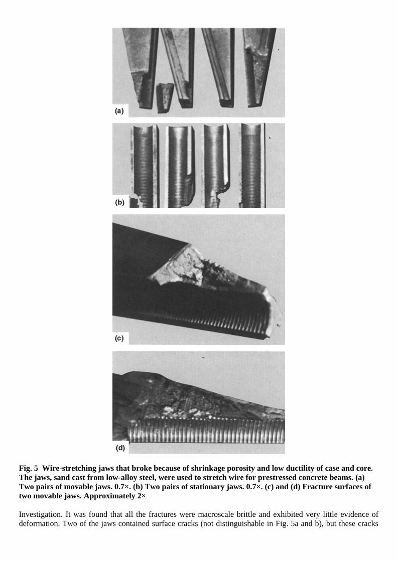
Fig. 5 Wire-stretching jaws that broke because of shrinkage porosity and low ductility of case and core. The jaws, sand cast from low-alloy steel, were used to stretch wire for prestressed concrete beams. (a) Two pairs of movable jaws. 0.7×. (b) Two pairs of stationary jaws. 0.7×. (c) and (d) Fracture surfaces of two movable jaws. Approximately 2×
Investigation. It was found that all the fractures were macroscale brittle and exhibited very little evidence of deformation. Two of the jaws contained surface cracks (not distinguishable in Fig. 5a and b), but these cracks

did not appear to be related to the main fractures. Figures 5(c) and (d) show fracture surfaces of two individual movable jaws (from different pairs). Little is known about the possible variations of stress that might have existed in this application. For example, the fit of the jaws in the block might have been imperfect, or there might have been too large an opening in the block, allowing the tips of the jaws to emerge without support. In such circumstances, the section of wire within the jaws might not have been in axial alignment with the wire under tension, which would have resulted in one jaw being subjected to a side thrust at the tip. All surfaces of the jaws had been case carburized and heat treated to a surface hardness of 62 to 64 HRC and a core hardness of 36 to 39 HRC. Metallographic examination of a specimen prepared from a jaw established that
the surface had been case carburized to a depth of 0.8 to 1.6 mm ( 132
to 116
in.), the case structure was
martensite containing small spheroidal carbides but no carbide network, the structure of the core consisted of martensite plus some ferrite, and the fracture appeared to be related to shrinkage porosity. Chemical analysis of the core showed that the composition corresponded to 3310 steel except for low manganese, slightly high chromium, and lower silicon than would normally be expected in a cast steel. The hardness range of the core conforms to data in end-quench hardenability curves for 3310 steel. It represents, in fact, essentially the maximum hardness values attainable and, as such, indicates that tempering was probably limited to about 150 °C (300 °F). In view of the hardenability of the core and assuming that the tapered slot in the block had a hardened surface, the low tempering temperature used may have contributed to the brittleness. Conclusions. Failure of the jaws was primarily attributed to the presence of internal microshrinkage, although the brittleness of case and core probably contributed to failure. Recommendations. The procedures used for casting the jaws should be revised to eliminate the internal shrinkage porosity. Tempering at a slightly higher temperature to reduce surface and core hardness would be desirable. Finally, the fit of the jaws in the block should be checked to ensure proper alignment and loading. Example 4: Damaged Austenitic Cast Iron Impellers in a Rotary Pump Caused by Cracks Initiated at Zones of Localized Shrinkage Porosity (Ref 11). Two damaged impellers manufactured from austenitic cast iron came from a rotary pump used for pumping brine mixed with drifting sand. On impeller 1, pieces were broken out of the back wall in four places at the junction of the blades. Impeller 2 had cracks at the same location but did not yet break apart. Investigation. Figure 6(a) shows the fractured edges following the shape of the blade. Numerous cavitation pits on the inner surface of the front wall are visible. Impeller 2, which did not exhibit such deep cavitation pits, was cracked in places along the line of the blades (Fig. 6b).
Fig. 6 Photographs of a damaged cast iron pump impeller. (a) Breaks in the back wall of impeller 1 and cavitation pits on the front wall. (b) Cracks following the shape of the blades on the back wall of impeller 2. Both 0.7×. Source: Ref 11
The microstructure shown in Fig. 7, illustrating lamellar graphite and carbides in an austenitic matrix, can be considered normal for the specified material (GGL NiCuCr 15 6 2). A specimen for metallographic examination was taken from one of the fracture edges. The material in this region was found to be in the final stages of disintegration (Fig. 8). A further section was taken through an as yet unbroken region, the essential
The file is downloaded from www.bzfxw.com

portion of which is shown at low magnification in Fig. 9(a). Cavitation pits can be seen on the internal surface of the front wall (arrow at top left), and casting pores (arrow at bottom right) are visible in the region corresponding to Fig. 8. It should be mentioned that even when the specimens were cut carefully with a water-cooled cutting wheel, the stem in the brittle porous zone crumbled away, and only on the third attempt was it possible to obtain a suitable whole specimen for examination. A section through a cracked region of impeller 2 revealed a porous zone in the corresponding position. Figure 9(b) shows a section of a cavitation region. The absence of corrosion products confirms that the surface has been damaged by cavitation.
Fig. 7 Micrograph of impeller specimen. This structure, which consists of lamellar carbides in an austenitic matrix, is considered normal for this material. Etched with V2A reagent. 500×. Source: Ref 11
Fig. 8 Porous zone under a fracture edge of impeller 1. See also Fig. 9(a). 20×. Source: Ref 11

Fig. 9 Impeller specimen showing cavitation damage and porous zones. (a) Cavitation pits (top-left arrow) and porous zones (bottom-right arrow) in an unetched transverse section of impeller 1. 2.5×. (b) Microsection from a cavitation zone. Etched with V2A reagent. 100×. Source: Ref 11
Conclusions. The cause of impeller damage from cracking is attributed, in part, to the shrinkage porosity at the junction between the back wall and blades. Cavitation could have led to long-term damage even in a sound casting, although it did not appear to contribute to the fracture. Recommendations. Casting practices should be implemented to avoid porosity, and an alloy austenitic cast iron (GGL NiCuCr 15 6 3) that has a higher chromium content and is more resistant to cavitation should be used. Gas Porosity. Formation of cavities resulting from the presence of gas is influenced by many factors, including melting practice, pouring practice, and type of mold to be used. Three common causes of gas holes during solidification of castings are:
• Exceeding the solubility necessary to keep the gas in solution • Reaction-type pinhole formed by segregation during solidification • Reaction product between the metal and mold material
Gas solubility limits and gas porosity are some of the most serious problems in the casting of cast iron, aluminum, and copper. In determining if gas evolution can cause porosity, the thermodynamics for the reactions must be evaluated, as discussed in the article “Gases in Metals” in Casting, Volume 15 of ASM Handbook. The gases in cast iron that can cause porosity are hydrogen and nitrogen. Aluminum and copper are very susceptible to porosity from hydrogen. The most common method for removing hydrogen from aluminum and copper, which can also be used for removing hydrogen and nitrogen from cast iron, is inert gas flushing.
Hydrogen pinholes in cast iron are small, spherical, or pear-shaped cavities about 3 mm ( 18
in.) or less in
diameter. A continuous graphite film is often found in these holes, although an iron oxide layer may be present if the castings are heat treated. Nonmetallic inclusions are not present in the voids, but some have been found to contain a small bead of metal. Pinholes are typically subsurface in nature and are therefore not visible until after heavy shotblasting or, more likely, after machining. Thin sections are more susceptible to this defect than thick sections, as are areas remote from the ingates. A number of mold and metal factors have been associated with hydrogen pinhole formation. It is likely that these factors function in combination rather than individually. Aluminum levels in gray cast iron as low as 0.005% have been found to encourage dissociation of the water vapor arising from the mold, thus increasing the hydrogen content of the metal. Aluminum sources include ferroalloys used in iron treatment and scrap. Excessive moisture in the mold and lack of active carbonaceous mold additions also favor pinholing.
The file is downloaded from www.bzfxw.com

In the cast iron family, the susceptibility to form pinholes is related to the rate of solidification. Ductile iron, having the slowest solidification rate, is most susceptible, while white iron, having the most rapid rate, is least susceptible. By analyzing the pinhole shape and chemistry, it can be learned which gases are present. For example, a hydrogen-reaction pinhole has a graphite-free layer and a graphite film. A carbon monoxide (CO) reaction type has no graphite film and no graphite-free layer. Pinholes resulting from insufficiently dried sand molds may lower the endurance limit of steel castings, or they may cause only poor surface appearance; however, if the number of pinholes is high, the casting may corrode in service. Internal gas cavities may reduce the effective cross section appreciably and may therefore impair load-carrying ability, depending on loading conditions but also stress concentration. In general, however, internal gas cavities have smooth surfaces that do not act as severe stress concentrators as a sharp, linear discontinuity. Example 5: Retrieved Bone Screw Made From Co-Cr-Mo Alloy with Casting Defects. Portions of the threads of the screw shown in Fig. 10(a) had broken off, and other threads had cracked. The screw was made from a cast Co-Cr-Mo alloy. A longitudinal section through the screw revealed gas porosity, segregation of primary inclusions, and oxides (Fig. 10b, c). The screw threads broke because of mechanical weakness from gas holes, brittleness, and dissolution of oxides. With today's advanced casting techniques and testing methods, such implant defects can be avoided and eliminated.

Fig. 10 Retrieved screw of cast Co-Cr-Mo alloy (type ASTM F75). (a) Defective screw threads from casting deficiencies. (b) Longitudinal section through threads showing porosity. 15×. (c) Enlarged thread of section shown in (b) with gas holes, segregation of primary phases, and dissolved oxides. 155×
Steam bubbles result from exposure of any liquid metal to moisture. Moisture in the air, in gases of combustion, in furnace and ladle linings, and in mold materials provides sources of steam bubbles. Whatever the source, the entrained water is released as steam bubbles on freezing of the molten metal, resulting in porosity in the castings that varies with the manner in which the water was entrained. If the water content in a molding sand is
The file is downloaded from www.bzfxw.com

too high or if water exists as condensate on the mold surface, porosity forms at the surface of the casting. If a slight amount of moisture is entrained in the melting furnace, it may be dissipated during cooling in the ladle, and the castings may be free of porosity. If a ladle lining is inadequately dried, the entire heat can be ruined by gross gas evolution during freezing in the molds, which causes all the risers to puff and overrun, creating large cavities throughout the casting. Air bubbles as a cause of casting porosity are less detrimental than steam bubbles. Air bubbles usually arise when the conditions of pouring and the nature of the ingate passages combine to produce a turbulent flow that sucks air into the mold cavity. The amount of air in the cavity is sometimes low enough for all of it to be carried to the topmost riser, causing no porosity in the casting proper. In most instances, smoother pouring and a more streamlined ingate system will minimize air bubbles.
Inclusions
Inclusions are nonmetallic and sometimes intermetallic phases embedded in a metallic matrix. They are usually simple oxides, sulfides, nitrides, or their complexes in ferrous alloys and can include intermetallic phases in nonferrous alloys. There are essentially two classifications for inclusions:
• Exogenous: Those derived from external causes • Indigenous: Those that are native, innate, or inherent in the molten metal treatment process
Examples of exogenous inclusions include slag, dross, entrapped mold materials, and refractories. In most cases, these inclusions would be macroscopic or visible to the naked eye at the casting surface (Fig. 11). When the casting is sectioned, they may also appear beneath the external casting surface, if they have had insufficient time to float out or settle due to density differences with respect to the molten metal. Exogenous inclusions are mostly oxides or mixtures of oxides and are primarily slag or dross particles, which are the oxides that result when the metal reacts with oxygen in the air during melting. These are removed from the melt by filtration before pouring.

Fig. 11 Ductile-iron crankshaft segment essentially free of exogenous inclusions (1, left) and with numerous exogenous inclusions (2, right). Low pouring temperature and poor mold filling practice were the cause of the inclusions in part 2.
Inclusions of refractory, slag, sand, oxides, and other compounds in the casting metal can affect the service life of the casting. Some of these, such as refractory and sand, are inadvertently introduced and can be minimized by proper maintenance of linings and by good housekeeping. The presence of slag can be controlled by careful pouring and the use of more effective skimming techniques. Oxides of the casting metal are formed largely during melting and can be avoided by thorough deoxidation. Some elements, for example, chromium in some steels, oxidize preferentially on the surface of the pouring stream. Skillful skimming is the only means of preventing this oxidized metal from entering the mold. Indigenous inclusions include sulfides, nitrides, and oxides derived from the chemical reaction of the molten metal with the local environment. Such inclusions are usually small and require microscopic magnification for identification. They can be uniformly distributed on a macroscopic scale, but they are often in the last regions to solidity and therefore are typically interdendritic in the microstructure. Grain-boundary inclusions can be particularly damaging to mechanical properties. For example, grain-boundary sulfide films (type II sulfide inclusions) are detrimental to the ductility and toughness of cast steel and cause increased susceptibility to hot tearing. Other compounds, such as phosphides and sulfides, are detrimental to mechanical properties unless kept to a minimum. Globular manganese sulfides are beneficial as replacements of iron sulfides, which can form deleterious films at grain-boundary junctions and can result in incipient melting if the casting is heat treated. There are cases in which indigenous inclusions such as oxides may react with mold materials to promote an exogenous inclusions variety that otherwise might not appear in the absence of the indigenous oxide. To circumvent the strict definition as indigenous or exogenous, a number of investigators prefer to catalog all inclusions as either macroinclusions of microinclusions. Although such definitions describe the anticipated effect on mechanical properties, there can be a loss in source identification of the inclusion. Whatever definition is used, control of inclusions requires an understanding of their origin and the associated physical chemistry. For example, nonmetallic inclusions that form during solidification of cast steel depend on the oxygen and sulfur contents of the casting. Deoxidation decreases the amount of nonmetallic inclusions by eliminating the oxides, and it affects the shape of the sulfide inclusions. High levels of oxygen (>0.012% in the metal) form FeO, which decreases the solubility of manganese sulfides and causes the manganese sulfides to freeze early in solidification as globules. The use of silicon deoxidation alone normally causes the formation of globular (type I) sulfides. Decreasing the oxygen to between 0.008 and 0.012% in the metal, through the use of aluminum, titanium, or zirconium, increases the solubility of the manganese sulfides so that they solidify last as grain-boundary films. These grain-boundary sulfide films are classified as type II inclusions. If the oxygen content is very low (<0.008% in the metal), then the deoxidizer forms complex sulfides that are crystalline and form early in solidification. These type III inclusions are less harmful than type II but are more harmful than type I. Most inclusions found in steel castings arise from the oxidation of metal during the pouring operation (Ref 12). This is known as reoxidation and takes place when the turbulent flow of the metal in the gating system causes the metal to break up into small droplets, which then react with the oxygen in the air in the gating system or casting cavity to form oxides. Metal casters use computer analysis of gating systems to indicate when reoxidation can be expected in a gating system and to eliminate them. However, casting designs that require molten metal to “jet” through a section of the casting to fill other sections recreates these inclusions and should be avoided. Although it is preferable to minimize undesirable inclusions in cast structures, for most applications there is an added expense in preparing castings that are essentially inclusion-free. Methods of reducing inclusions to very low levels include the use of special ceramic filters. Small inclusions that are located well within the center of the cross section of the casting have little effect, whereas larger inclusions and those located near the surface of the casting can be particularly detrimental to properties. Inclusions can also be a problem when machining surfaces, causing excessive tool wear and tool breakage. In addition, because inclusions and the surrounding metal have different coefficients of thermal expansion, thermally induced stresses may appear in the metal surrounding the inclusion during solidification (Ref 13). As a result, an inclusion might act as a stress raiser and
The file is downloaded from www.bzfxw.com

reduce properties. As in the case of microporosity, the size of the inclusion and its location determine its effect (Ref 14). Figure 12 is an optical micrograph of a subsurface region with inclusions that played a major role in thread defects that occurred in ductile-iron tire-mold castings. In this case, the defect was found to be caused by stringers of magnesium-silicate inclusions, which are known to be hard and detrimental to tool life. This resulted in poor machinability and improper finish in a localized area of the tire-mold castings. Figure 12 illustrates optical micrographs of subsurface areas immediately beneath the defective casting surface. These micrographs show the presence of inclusion stringers adjacent to the surface (Fig. 12a) and the deterioration of the graphite nodule shape in the metal below (Fig. 12b, c). The long stringers of inclusions are very similar to film-type magnesium-silicate inclusions.
Fig. 12 Internal discontinuities in a tire-mold casting. (a) Stringer-type inclusions adjacent to the surface. As-polished. (b) Structure below the surface. Note the change in graphite shape. Unetched. (c) Ferrite matrix with degenerate vermicular graphite nodules. Etched with 2% nital. All 135×
Oxide Films
Oxide films are similar to inclusions and are related to the pouring characteristics (Ref 15, 16, 17). These form on the surface of the molten metal as it fills the mold. If this surface film is trapped within the casting instead of being carried into a riser, it is a linear discontinuity and an obvious site for crack initiation. It has been shown (Ref 18, 19) that elimination of oxide films, in addition to substantially improving static properties, results in a five-fold improvement of fatigue life in axial tension-tension tests. Oxide films are of particular concern in nonferrous castings, although they also must be controlled in steel and stainless steel castings. (Because of the high carbon content of cast iron, oxide films do not form on that metal.) If the film folds over on itself as a result of turbulent flow or “waterfalling” (when molten metal falls to a lower level in the casting during mold filling), the effects are particularly damaging. Casting design influences how the metal fills the mold, and features of the design that require the metal to fall from one level to another while the mold is filling should be avoided so that waterfalls are eliminated. Oxide films are avoided by filling the casting from the bottom, in a controlled manner, by pumping the metal into the mold using pneumatic or electromagnetic pumps. If the casting is poorly designed, waterfalling results. An example is given in Fig. 13.

Fig. 13 Redesign of a casting to avoid waterfalling. (a) In this design, waterfalling results when casting is filled from the bottom. (b) Improved design provides a path for the metal to follow as it fills the mold.
Segregation
All metallic materials contain solute elements or impurities that can segregate during solidification. The variable distribution of chemical composition on the microscopic level in a microstructure, such as dendrites and grains, is referred to as microsegregation. Variation on the macroscopic level is called macrosegregation. Microsegregation characterizes concentrations of elements in interdendritic regions that range in size from a few to several hundred microns. Microsegregation is present in the as-cast casting and may be removed by various degrees, depending on subsequent heat treatment. By contrast, macrosegregation is the gradient difference, measurable on a macroscale, in alloying elements from the surface to the center of an ingot or casting. Macrosegregation becomes more pronounced with increasing section size. Macrosegregation cannot be reduced by homogenization heat treatment. Segregation generally deteriorates the physical and chemical properties of materials and should be kept to a minimum, as discussed further in the article “Microsegregation and Macrosegregation” in Casting, Volume 15 of ASM Handbook. An example of segregation is also given in Example 14 in this article. Macroetching is the most common method used to reveal the dendritic structure of an ingot or casting.
Second Phases
Second phases that form during solidification may also nucleate cracks, if they have the proper size and morphology. An example is aluminum-silicon alloys, where the silicon eutectic is present as large platelets, which nucleate cracks and provide a path for crack propagation (Ref 20, 21). The size of these platelets may be significantly reduced by modifying the alloy with additions of sodium or strontium. These modifications also change the platelets to a spheroid shape. However, such additions increase the size of micropores (Ref 22), and for this reason, many foundrymen rely on accelerated solidification of the casting to refine the silicon, because higher solidification rates refine the structure. Heavy sections are to be avoided if a fine structure is desired. Generally speaking, however, secondary phases in the structure of castings become important in limiting mechanical behavior of castings only in the absence of nonmetallic inclusions and microporosity (Ref 23, 24).
Hot Tears and Hot Cracking
Tearing or hot cracking can occur during solidification, when the greatest amount of shrinkage occurs and when the casting is least resistant to stresses imposed by the geometrical constraints of the mold. This type of cracking, sometimes termed hot shortness, is always intergranular and is a feature, to some extent, of all casting alloys. As previously noted in the section “Imperfections That Can Occur in Iron and Steel Castings,” a hot crack is defined as “a crack or fracture caused by internal stresses that develop after solidification and during cooling from an elevated temperature (above 650 °C, or 1200 °F, for gray iron).” A hot tear is defined as “a crack or fracture formed prior to completion of solidification because of hindered contraction.” Both of these definitions apply equally well to a casting or a weldment.
The file is downloaded from www.bzfxw.com

A hot crack is less visible (less open) than a hot tear and usually exhibits less evidence of oxidation and decarburization. Because hot cracking is related to grain-boundary liquation, hot cracks are generally intergranular or interdendritic (similar to the appearance of the impeller fracture faces in Example 4 of this article). A hot tear frequently is open to the surface of the casting and thus exposed to the atmosphere. This can result in oxidation, decarburization, or other metal-atmosphere reactions at the tear surface. Hot tears form when casting sections are constrained by the mold from shrinking as they cool near the end of solidification. They are sometimes produced in external surfaces, such as in the fillet of a flange or a rib, where overall contraction of the casting is hindered by the mold. Hot cracking problems can be minimized by proper selection of casting process, alloy selection, part and mold design, solidification control, and grain refinement. Hot strength (resistance to cracking at solidification temperature) is alloy-dependent. Casting alloys demonstrate varying degrees of resistance to cracking; therefore, the cracking sensitivity of alloys capable of meeting part requirements should be an important criterion in final alloy selection. Effective grain refinement to ensure a fine, equiaxed grain structure is especially important in hot-short alloys or in casting designs with features that aggravate cracking tendencies. Fine grain size reduces local stress concentrations by minimizing grain-boundary effects. Improper mold design is a frequent cause of hot cracking. It is important to avoid abrupt changes in cross-sectional area and inadequately radiused or filleted angles or corners. These are design features that can sharply increase and concentrate stresses resulting from restrained contraction during and following solidification. The intelligent use of chills and/or antichills can also be beneficial in preventing hot cracks. An extensive discussion on how to prevent hot tears through casting design is provided in Ref 25. Hot tears and hot cracks should normally be discovered during inspection. Hot tears are fairly large and are most often weld repaired. If not repaired, their effect is not readily predictable (Ref 26). While, generally, they are detrimental to casting properties, under some circumstances they do not affect them. Hot tears are caused by a combination of factors, including alloy type, metal cleanliness, and mold and core hardness. However, poor casting design is the primary cause. Castings should be designed so that solidifying sections are not subjected to tensile forces caused by shrinkage during solidification, because the solidifying alloy has little strength before it solidifies. Example 6: Fatigue Fracture of a Sand-Cast Steel Axle Housing That Originated at a Hot Tear. A sand-cast medium-carbon steel (Fe-0.25C-1Mn-0.40Cr-0.35Mo) heavy-duty axle housing, which had been quenched and tempered to about 30 HRC, fractured after almost 5000 h of service. Investigation. Figure 14 shows the fracture surface of the axle housing. Study of the casting revealed that the fracture had been initiated by a hot tear (region A, Fig. 14) about 10 cm (4 in.) long that had completely penetrated the 2.5 cm (1 in.) thick wall; this tear formed during solidification of the casting. The mass of a feeder-riser system located near the tear retarded cooling in this region, creating a hot spot.

Fig. 14 Fracture surface of a sand-cast medium-carbon steel heavy-duty axle housing. Failure originated at a hot tear (region A), which propagated in fatigue (region B) until final fracture occurred by overload. 0.4×
Because this tear formed at a high temperature and was open to the surface, it was subject to oxidation, as indicated by the dark scale in region A in Fig. 14. Exposure to air also resulted in decarburization below the oxide scale and penetration of oxide along secondary cracks. Both the size of the hot tear and the long service life of the housing indicated that the service stresses in the region of the tear had been relatively low. Stress concentrations at the tip of the tear, however, were sufficient to initiate the formation of two fatigue cracks (note the beach marks visible in regions B in Fig. 14). Ultimately, the effective thickness of the housing wall was reduced sufficiently for the applied load to cause final fracture. In this instance, the hot tear was located at an area of low stress, and the casting served a satisfactory life. However, had the local stress been high, even a very small discontinuity could have generated an early fracture. Conclusions. Fracture of the axle housing originated at a hot tear that formed during solidification by hindered contraction and was enlarged in service by fatigue. Corrective Measures. Changing the feeder location eliminated the hot spot and thus the occurrence of hot tearing.
Metal Penetration and Mold-Wall Deficiencies
The file is downloaded from www.bzfxw.com

Molten metal may penetrate the surface of the mold, forming a rough surface or, in extreme cases, actually becoming intimately mixed with the sand in the mold. Mold-wall deficiencies are common problems in gray-iron castings. They result in surface flaws such as scabs, rattails, cuts, washes, buckles, drops, and excessive metal penetration into space between sand grains. These flaws are generally detected by visual inspection. In iron castings, metal penetration is normally the result of the combination of metallostatic head (the pressure exerted on the molten iron at the bottom of the mold by the weight of the metal on top of it) and the surface tension relationships between the liquid iron and molding materials (Ref 27). In cast iron, it is frequently also the result of the expansion of graphite at the end of solidification, forcing liquid metal into the mold if the casting is not properly designed with a tapered wall to promote directional solidification and to avoid hot spots.
Surface Condition
Several types of surface discontinuities can occur in castings, such as misruns, cold shots, scabs, buckles, rattails, pulldowns, pits, sand holes, and mechanical (cold) cracks. Hot tears and hot cracks also are sometimes produced on the external surface. Some of these imperfections contribute only to the poor appearance of a casting. A surface discontinuity is unlikely to decrease the service life of the casting, unless it is of critical size or is located at a portion of the casting surface that is subjected to major stress. The most damaging types of surface discontinuities are those that are linear in nature, those that generate notch-type stress raisers, and combinations of these. Among these are hot tears, cold cracks, and cold shuts (also surface porosity, inclusions, or shrinkage porosity extending to the surface). Spikes are a form of surface shrinkage not normally visible to the naked eye, but they appear as a multitude of short, discontinuous surface cracks when subjected to fluorescent magnetic-particle inspection. Unlike true fractures, spikes do not propagate, but they are not acceptable where cyclic loading could result in fatigue
failure. Spikes are usually seen as short indications approximately 1.6 mm ( 116
in.) long or less and never more
than 75 μm (0.003 in.) deep. These defects do not have a preferred orientation but a random pattern that may or may not follow the direction of solidification. Misruns, cold shots, scabs, buckles, pulldowns, pits, and sand holes are among those imperfections that contribute only to poor casting appearance and that rarely initiate failure. Misruns usually do not result in rejection of castings, unless good surface appearance is of primary importance. If a misrun is not severe, it should offer little difficulty in service, provided it is not in a highly stressed region of the casting. Cold shots, which are the result of turbulence, occur when metal splatters during pouring, adheres to the mold wall, and fails to fuse with the metal that engulfs it as the mold is filled. Thus, cold shots are globules embedded in the casting and normally produce no ill effect except for appearance. Under certain conditions, however, the interface between the cold shot and the casting can serve as a corrosion cell that leads to pitting and the initiation of fatigue cracks. Scabs, buckles, rattails, and pulldowns are surface discontinuities that result from local expansion of a sand mold. A scab is a thin, flat layer of metal formed behind a thin layer of sand and held in place by a thin ligament of metal. When the scab is removed (readily done by chipping), an indentation called a buckle is exposed. Rattails are minor buckles in the form of small irregular lines on the casting surface. A pulldown is a buckle in the cope portion of the casting. All these discontinuities affect casting appearance but usually have no influence on service life. Pits and sand holes are dirt or sand inclusions in the surface of a casting and are generally removed in cleaning. The resulting cavities affect appearance but generally do not affect performance in service, unless they are larger and are in a critical area. Mechanical (cold) cracks can be generated by rough treatment or by thermal shock in cooling, either at shakeout or during heat treatment. These cracks can be very difficult to detect without the aid of nondestructive testing. Magnetic-particle or liquid-penetrant inspection should reveal them clearly. Depending on the value and weldability of the casting, mechanical cracks should be removed and repair welded, unless they are large enough to warrant scrapping of the casting. Removal by grinding, chipping, or other methods must be complete, or the remaining portion of the crack will be a stress raiser beneath the weld. Magnetic-particle or liquid-penetrant inspection after grinding is effective in determining if a crack has been completely removed. Surface Finish and Dimensional Tolerances. Ultimately, surface finish and dimensional tolerances are the important specification. Obviously, smoother surfaces are superior to rough surfaces in terms of dimensional

accuracy and surface integrity. Designers should be certain that fatigue data used in design calculations have been taken from as-cast surfaces rather than machined surfaces, because most surfaces on castings where stress concentrations might be expected are not machined. The influence of surface discontinuities on properties is reviewed in Ref 28, and 29. The surface finish of casting is controlled ultimately by the molding. If the dimensional accuracy and surface finish requirements of the casting exceed the limits of the green sand molding process, other processes, such as shell molding, chemical bond molding, and permanent molding, can be used. Mold coatings are frequently applied to cores to enhance the casting surface finish and to reduce casting defects at the mold/metal interface. Ceramic molding is intended for the production of castings of high quality, not only in terms of their dimensional accuracy and surface finish but also in terms of soundness and freedom from nonmetallic inclusions. Mold coatings are frequently applied to cores to enhance the casting surface finish and to reduce casting defects at the mold/metal interface. Coatings accomplish this by having a higher refractory value than the sand and/or by forming an impermeable barrier between the metal and the core. Most coatings are formulated with five major components:
• Refractory materials • Carrier system • Suspension system • Binder system • Chemical modifiers
Cold Shuts
Cold shuts, or laps, are seams that form when two streams of molten metal meet but do not completely merge. Cold shuts can occur in all types of castings and can be serious sources of stress concentration. In general, cold shuts are caused when molten metal is poured at too low a temperature or run over too long a distance. Isolated heavy sections completely surrounded by thin areas should be avoided. Thin, deep ribs also are likely to cause cold shuts and misruns. Example 7: Fracture of a Cast Stainless Steel Lever Because of a Cold Shut. The lever shown in Fig. 15 was a component of the main fuel-control linkage of an aircraft engine. After a service life of less than 50 h, the lever fractured in flight. The lever had been machined from a casting made of AISI type 410 stainless steel, then surface hardened by nitriding.
Fig. 15 Cast type 410 stainless steel fuel-control lever that fractured at a cold shut. Dimensions in inches
Investigation. Examination revealed that the lever had broken at a cold shut (Fig. 15) that extended through about 95% of the cross section of the lever arm. The remaining 5% of the cross section appeared to be sound metal. Specifications for both the casting and the finished lever required radiographic inspection. This inspection method reveals internal voids, such as gas porosity or shrinkage porosity, but does not detect a crack or a cold shut, unless the plane of the imperfection is nearly parallel to the x-ray beam and unless there is a finite opening; a cold shut that has its faces in contact is rarely revealed by radiography.
The file is downloaded from www.bzfxw.com

Conclusions. The lever broke at a cold shut extending through approximately 95% of the cross section. The normally applied load constituted an overload of the remainder of the lever. Corrective Measures. Magnetic-particle inspection was added to the inspection procedures for this cast lever. Because cold shuts extend to the surface of a casting, magnetic-particle inspection is a relatively reliable method of detecting them in ferromagnetic materials. Example 8: Gray-Iron Paper-Drier Head Removed from Service. A paper-drier head manufactured from gray cast iron was removed from service as a result of nondestructive evaluation (NDE) detection of cracklike surface discontinuities. These imperfections were not removed by grinding. This component is subjected to internal steam pressure to provide heat energy for drying. Because the vessel is under pressure, a crack could present a safety hazard; therefore, it was removed from service for evaluation. The material specification of this cast iron was not known. Investigation. Figure 16 shows close-up views of the surface casting defects. Sections of this casting at the area designated as 12 o'clock were removed and subjected to magnetic-particle inspection, which provided cracklike indications. These sections were further studied by chemical analysis, mechanical testing, and metallography.

The file is downloaded from www.bzfxw.com
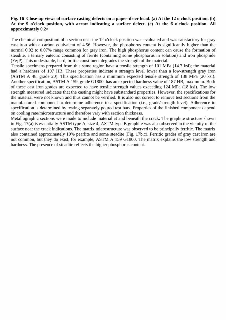
Fig. 16 Close-up views of surface casting defects on a paper-drier head. (a) At the 12 o'clock position. (b) At the 9 o'clock position, with arrow indicating a surface defect. (c) At the 6 o'clock position. All approximately 0.2×
The chemical composition of a section near the 12 o'clock position was evaluated and was satisfactory for gray cast iron with a carbon equivalent of 4.56. However, the phosphorus content is significantly higher than the normal 0.02 to 0.07% range common for gray iron. The high phosphorus content can cause the formation of steadite, a ternary eutectic consisting of ferrite (containing some phosphorus in solution) and iron phosphide (Fe3P). This undesirable, hard, brittle constituent degrades the strength of the material. Tensile specimens prepared from this same region have a tensile strength of 101 MPa (14.7 ksi); the material had a hardness of 107 HB. These properties indicate a strength level lower than a low-strength gray iron (ASTM A 48, grade 20). This specification has a minimum expected tensile strength of 138 MPa (20 ksi). Another specification, ASTM A 159, grade G1800, has an expected hardness value of 187 HB, maximum. Both of these cast iron grades are expected to have tensile strength values exceeding 124 MPa (18 ksi). The low strength measured indicates that the casting might have substandard properties. However, the specifications for the material were not known and thus cannot be verified. It is also not correct to remove test sections from the manufactured component to determine adherence to a specification (i.e., grade/strength level). Adherence to specification is determined by testing separately poured test bars. Properties of the finished component depend on cooling rate/microstructure and therefore vary with section thickness. Metallographic sections were made to include material at and beneath the crack. The graphite structure shown in Fig. 17(a) is essentially ASTM type A, size 4; ASTM type B graphite was also observed in the vicinity of the surface near the crack indications. The matrix microstructure was observed to be principally ferritic. The matrix also contained approximately 10% pearlite and some steadite (Fig. 17b,c). Ferritic grades of gray cast iron are not common, but they do exist, for example, ASTM A 159 G1800. The matrix explains the low strength and hardness. The presence of steadite reflects the higher phosphorus content.

Fig. 17 Microstructures of the gray-iron drier head shown in Fig. 16. (a) Typical graphite distribution in the casting—type A, size 4 graphite. As-polished. 54×. (b) The matrix microstructure consists of ferrite with approximately 10% pearlite and 15% steadite. Etched with nital. 54×. (c) Higher magnification view of (b). Etched with nital. 215×
At the crack-indication site revealed by NDE, a demarcation line was observed progressing from the surface of the casting to the interior. Figure 18 shows this demarcation line for the condition and revealed that the structure of the metal on one side of the demarcation line was different than that observed on the other side
The file is downloaded from www.bzfxw.com

(Fig. 19). This condition generally results when a cold shut forms during the casting process. A cold shut reflects two different solidification fronts in the mold, which explains the reason for the structure variances observed on either side of the demarcation line. Although not a crack, the demarcation can serve as a site for crack initiation. In this instance, however, the demarcation line had not propagated beyond the point at which the structure was different. The demarcation line terminates at approximately the same area where the difference in structure terminates (Fig. 19). This condition further indicates that the demarcation had not propagated beyond the original condition that occurred during the casting operation.
Fig. 18 Demarcation line at the crack, showing the differences in graphite type and distribution on either side of the crack. Etched with nital. 33×
Fig. 19 Higher magnification view of Fig. 18 showing the two different solidification structures. Etched with nital. 230×
Conclusions. The NDE indications were the consequence of a cold-shut condition in the casting. This conclusion is based on the presence of two significantly different microstructures representing two separate solidification fronts that met but did not merge. The cold shut serves as a stress-concentration site and is therefore a potential source of crack initiation. The combination of low material strength and a casting defect is a potential source of unexpected fracture during service, because the component is under pressure from steam. Recommendations. Other dryer heads exhibiting similar discontinuities and/or material quality should be removed from service.

Example 9: Fracture of Cast Steel Equalizer Beams. Two sand-cast low-alloy steel equalizer beams designed to distribute the load to the axles of a highway truck broke after an unreported length of service. Normal service life would have been about 805,000 km (500,000 miles) of truck operation. The cast equalizer beams were made according to ASTM A 148, grade 105–85, which specifies that all castings be heat treated (either fully annealed, normalized, normalized and tempered, or quenched and tempered, usually at the option of the foundry). Investigation. Figure 20(a) shows a fracture surface of one of the beams. Internal shrinkage porosity and evidence of a cold shut were found near the tip of one flange (detail A, Fig. 20). Decarburization of the fracture surface indicates that the initial crack (region B, detail A, Fig. 20) was formed before heat treatment—most likely as a mechanical crack resulting from rough handling during shakeout. The crack originated in a region of internal shrinkage porosity and entrapped oxides.
The file is downloaded from www.bzfxw.com
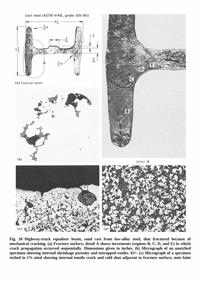
Fig. 20 Highway-truck equalizer beam, sand cast from low-alloy steel, that fractured because of mechanical cracking. (a) Fracture surface; detail A shows increments (regions B, C, D, and E) in which crack propagation occurred sequentially. Dimensions given in inches. (b) Micrograph of an unetched specimen showing internal shrinkage porosity and entrapped oxides. 65×. (c) Micrograph of a specimen etched in 1% nital showing internal tensile crack and cold shut adjacent to fracture surface; note faint

evidence of dendritic segregation at lower left. 65×. (d) Micrograph showing nonhomogenized microstructure consisting of transformation products and ferrite. 65×
The appearance of the fracture surface suggests that propagation of the crack occurred in a sequence of four large increments (regions B, C, D, and E, detail A, Fig. 20). The detectable difference in darkening of these fracture segments indicates that they existed in turn for sufficient lengths of times to undergo different cumulative amounts of surface oxidation. This behavior indicates infrequent but high loads. The fracture segment indicated as region E in detail A in Fig. 20 shows a band of fatigue beach marks that nearly penetrated the fillet between the upper portion of the left flange and the web of the beam. Final fracture occurred at this stage, because the remaining section of the beam was unable to sustain the applied load or as the result of a high load, such as those that caused earlier crack advances. Examination of the fracture surface of the second beam showed that only two increments of crack propagation occurred before final fracture and that there was no fatigue cracking. Failure in the second beam occurred after far less crack penetration than in the companion beam, indicating that a high load, rather than a uniform load, caused final fracture. Both beams exhibited evidence of internal shrinkage porosity and entrapped oxides; a typical condition is shown in Fig. 20(b). Areas of decarburization were found below the fracture surfaces of both beams. Internal cracking and cold shuts, such as those shown in Fig. 20(c), were evident adjacent to the fracture surfaces. The microstructure of the beams consisted of transformation products and ferrite (Fig. 20d). The microconstituents exhibited some evidence of dendritic segregation. Chemical analysis of the two beams, which were cast from separate heats of steel, showed close agreement in composition. A tensile specimen and a Charpy V-notch test bar were machined from one flange of each beam. The properties of the two beams were in close agreement. Average values were tensile strength, 712 MPa (103.25 ksi); yield strength (0.2% offset), 381 MPa (55.25 ksi); elongation in 5 cm (2 in.), 20%; reduction of area, 48%; and room-temperature impact strength, 32.5 J (24 ft · lbf). These properties indicated that the steel was too soft for the application—probably due to improper heat treatment. Conclusions. Fracture of the equalizer beams resulted from growth of mechanical cracks in one flange that were formed before the castings were heat treated. The pattern of crack growth suggested a service condition involving many relatively low applied stresses and occasional high loads. Recommendations. Three changes in processing were recommended: better gating and risering in the foundry to achieve sounder castings, better shakeout practice to avoid mechanical damage and better inspection to detect imperfections, and normalizing and tempering to achieve better mechanical properties.
References cited in this section
1. T. Piwonka, Design for Casting, Materials, Selection and Design, Vol 20, ASM Handbook, ASM International, 1997, p 723
2. E.L. Rooy, Hydrogen: The One-Third Solution, AFS Trans., Vol 101, 1993, p 961
3. N. Roy, A.M. Samuel, and F.H. Samuel, Porosity Formation in Al-9 Wt Pct Mg—3 Wt Pct Cu Alloy Systems: Metallographic Observations, Met. Mater. Trans., Vol 27A, Feb 1996, p 415
4. B. Skallerud, T. Iveland, and G. Härkegård, Fatigue Life Assessment of Aluminum Alloys with Casting Defects, Eng. Fract. Mech., Vol 44 (No. 6), 1993, p 857
5. M.J. Couper, A.E. Neeson, and J.R. Griffiths, Casting Defects and the Fatigue Behaviour of an Aluminium Casting Alloy, Fatigue Fract. Eng. Mater. Struct., Vol 13 (No. 3), 1990, p 213
6. J.C. Ting and F.V. Lawrence, Jr., Modeling the Long-Life Fatigue Behavior of a Cast Aluminum Alloy, Fatigue Fract. Eng. Mater. Struct., Vol 16 (No. 6), 1993, p 631
7. J.T. Berry, Linking Solidification Conditions and Mechanical Behavior in Al Castings—A Quarter Century of Evolving Evidence, AFS Trans., Vol 103, 1995, p 837
The file is downloaded from www.bzfxw.com

8. M.K. Surappa, E. Blank, and J.C. Jaquet, Effect of Macro-Porosity on the Strength and Ductility of Cast Al-7Si-0.3Mg Alloy, Scr. Metall., Vol 20, 1986, p 1281
9. C.H. Cáceres, On the Effect of Macroporosity on the Tensile Properties of the Al-7%Si-0.4%Mg Casting Alloy, Scr. Metall., 1994, submitted for publication
10. C.M. Sonsino and K. Dietrich, Einflub der Porosität auf das Schwingfestigkeitverhalten von Aluminium-Gubwerkstoffen, Giessereiforschung, Vol 43 (No. 3 and 4), 1992, p 119–140
11. P.M. Unterweiser, Ed., Case Histories in Failure Analysis, American Society for Metals, 1979
12. C.E. Bates and C. Wanstall, Clean Steel Castings, “Metalcasting Competitiveness Research,” final report, DOE/ID/13163-1 (DE95016652), Department of Energy, Aug 1994, p 51
13. I.P. Volchok, Non-Metallic Inclusions and the Failure of Ferritic-Pearlitic Cast Steel, Cast Met., Vol 6 (No. 3), 1993, p 162
14. P. Heuler, C. Berger, and J. Motz, Fatigue Behaviour of Steel Casting Containing Near-Surface Defects, Fatigue Fract. Eng. Mater. Struct., Vol 16 (No. 1), 1992, p 115
15. J. Campbell, J. Runyoro, and S.M.A. Boutorabi, Critical Gate Velocities for Film-Forming Alloys, AFS Trans., Vol 100, 1992, p 225
16. N.R. Green and J. Campbell, Proc. Spring 1993 Meeting 4–7 May, 1993 (Strasbourg, France), European Division Materials Research Society
17. N.R. Green and J. Campbell, The Influence of Oxide Film Filling Defects on the Strength of Al-7Si-Mg Alloy Castings, AFS Trans., Vol 102, 1994, p 341
18. C. Nyahumwa, N.R. Green, and J. Campbell, “The Effect of Oxide Film Filling Defects on the Fatigue Life Distributions of Al-7Si-Mg Alloy Castings,” presented at the International Symposium on Solidification Science and Processing, Dec 1995 (Honolulu, HI), Japan Institute of Metals and TMS
19. J. Campbell, The Mechanical Strength of Non-Ferrous Castings, Proc. 61st World Foundry Cong. (Beijing), 1995, p 104; available from the American Foundrymen's Society, Des Plaines, IL
20. F.T. Lee, J.F. Major, and F.H. Samuel, Effect of Silicon Particles on the Fatigue Crack Growth Characteristics of Al-12 Wt Pct-0.35 Wt Pct Mg-(0 to 0.02) Wt Pct Sr Casting Alloys, Met. Mater. Trans., Vol 26A (No. 6), June 1995, p 1553
21. J.F. Major, F.T. Lee, and F.H. Samuel, “Fatigue Crack Growth and Fracture Behavior of Al-12 wt% Si-0.35 wt% Mg (0–0.02) wt% Sr Casting Alloys,” Paper 96-027, AFS Trans., Vol 104, 1996
22. D. Argo and J.E. Gruzleski, Porosity in Modified Aluminum Alloy Castings, AFS Trans., Vol 96, 1988, p 65
23. T.L. Reinhart, Fatigue and Fracture Properties of Aluminum Alloy Castings, Fatigue and Fracture, Vol 19, ASM Handbook, 1996, p 813
24. T.L. Reinhart, “The Influence of Microstructure on the Fatigue and Fracture Properties of Aluminum Alloy Castings,” presented at Aeromat '96, June 1996 (Dayton, OH), ASM International
25. A.L. Kearney and J. Raffin, Heat Tear Control Handbook for Aluminum Foundrymen and Casting Designers, American Foundrymen's Society, 1987

26. M.J. Couper, A.E. Neeson, and J.R. Griffiths, Casting Defects and the Fatigue Behaviour of an Aluminium Casting Alloy, Fatigue Fract. Eng. Mater. Struct., Vol 13 (No. 3), 1990, p 213
27. D.M. Stefanescu et al., “Cast Iron Penetration in Sand Molds, Part I: Physics of Penetration Defects and Penetration Model,” Paper 96-206, AFS Trans., Vol 104, 1996
28. R.L. Naro and J.F. Wallace, Effect of Mold-Steel Interface Reactions on Casting Surface and Properties, AFS Trans., Vol 75, 1967, p 741
29. R.L. Naro and J.F. Wallace, Effect of Mold-Steel Interface Reactions on Casting Surfaces, AFS Trans., Vol 100, 1992, p 797
Casting Design
Good casting design and communication with the foundry are essential in the ability to use the best techniques to produce reliable and economical castings. Good design practice also requires attention to stress concentration from surface details, depending on the materials. Many cast materials are less notch sensitive in fatigue loading than comparable wrought alloys. However, notch sensitivity of castings depends on the material. For example, very little allowance need be made for a reduction in fatigue strength caused by notches or abrupt changes of section in gray cast iron, because the graphite flakes in gray iron act as internal notches. In contrast, the notch sensitivity of ductile iron may be more important. In one case, for example, the minimum fillet in the crankpin of a ductile-iron crankshaft was set at 1.65 mm (0.065 in.) thick, in contrast to 1.14 mm (0.045 in.) for the pearlitic malleable iron that it replaced. Figure 31 shows a fracture of an anchor link that rides on a post with a spherical surface. No bevel or radius was called for, leaving an extremely sharp edge. A fatigue crack grew from the top sharp edge (note beach marks in Fig. 31). The casting had good toughness and strength (1448 MPa, or 210 ksi, tensile strength), but this fatigue failure was the result of poor design. A generous radius was recommended to avoid similar failures.
Fig. 31 Fatigue failure of an anchor link. The arrow indicates the sharp edge that acted as the stress concentrator that led to fatigue crack growth.
Process Design and Properties (Adapted from Ref 1). In terms of the casting process, design details of castings depend on the particular combination of material and casting process. In designing a casting, the designer should use properties from test bars that have solidified at the actual cooling rate in critical sections of the casting. The properties of a cast component depend on microstructure, which is determined by cooling rate and therefore also section size. This cooling rate can be determined by instrumenting a casting and measuring the cooling rate in various sections or by simulating its solidification using a commercial solidification simulation program.
The file is downloaded from www.bzfxw.com

Section size, of course, is an important factor in design. However, cooling rate depends not only on section size but also on pouring temperature, mold material, gating system, the presence or absence of chills in the mold, mold coatings, and insulation. Thus, within limits (some very broad), the properties can be controlled by the metal caster to produce those which the designer desires. Typically, the design phase may initially consider the “section size” effect, a factor by which the local casting properties are adjusted based on local dimensions. Bulky sections cool slower, while thin sections solidify faster than the thick sections. Certain other geometric features also influence solidification rate. For instance, concave sections, or reentrant angles, solidify more slowly than fins or protrusions, again affecting the resultant local structure and the properties. In other words, property variation within a casting is caused by local differences in cooling rate that can be influenced by several factors in addition to section size. The overarching principle of good casting design is that casting sections should freeze progressively, allowing the risers to supply liquid metal to feed shrinkage that occurs during solidification. Designing for progressive solidification requires tapering walls, so that they freeze from one end to the other, as shown in Fig. 32 (Ref 31), and avoiding situations where two heavy sections are separated by a thin section. Junctions also concentrate heat, leading to areas in the casting where heat is retained. Concave corners concentrate heat, while convex corners lose heat faster. There are a number of excellent summaries of principles of good casting design (Ref 31, 32, 33), and a comprehensive booklet was published on design of premium-quality aluminum alloy castings (Ref 34). Product and process design of castings is also described in more detail in Casting Volume 15 of ASM Handbook.
Fig. 32 Redesign of castings to provide progressive solidification through the use of tapered walls. (a) Elbow design. (b) Valve fitting design. Source: Ref 31
Stress Concentration from Residual Stresses. The presence of significant residual internal stresses in a casting can occur from local plastic deformation imposed by thermal gradients created during processing. These gradients may be caused by local cooling when the casting is very hot (in the mold or during shakeout, or in quenching from heat treatment) or by local heating, such as in repair or assembly welding. The effect is plastic stretching (or compression) of the weakest (hottest) portion of the casting. By the time the temperature has equalized, the stretched or compressed region is too long or too short to match the size of the other portion of the casting. The result may be a sizable residual internal stress that may be compressive or tensile. The behavior in service then depends on whether these residual internal stresses are added to or subtracted from the applied service loads. Predicting residual stresses in casting designs is a relatively recent development, because finite-element simulation is now sufficiently advanced to enable the study of the effect of various process and design parameters on the residual stresses in castings. A current reference on this topic is (Ref 35). In general, the shape of a casting can contribute to residual stresses if it entails sections of markedly different thicknesses,

which can undergo different cooling rates in the mold. This effect can be minimized if the thinner sections are well insulated, so that they cool at a lower rate. The use of chills to accelerate cooling of heavy sections can also be helpful. Stress relief can diminish internal stresses, if the cast alloy is amenable to such treatment. Example 11: Cracking in Gray-Iron Cylinder Blocks Caused by Casting Stresses (Ref 11). During the operation of tractors with cantilevered bodies, the lateral wall of the cylinder blocks cracked repeatedly. Three of the blocks were examined. Investigation. Figures 33(a) and Figures 33(b) exhibit one of the failures, as seen from the outside and inside of the cylinder block. The crack was always located at the approximate center of the sidewall, and it ran in a horizontal direction. The sectional view (Fig. 34a) shows more clearly that the thin case wall is reinforced at this location by a thicker rib. The crack was located in the thin-wall portion next to the transition to the rib, as shown in the larger scale view in Fig. 34(c). At this location, high residual stresses might be expected, due to the earlier solidification in the thin wall compared with the heavier secondary sections during cooling of the casting. The stresses reduced wall thickness at this point by stretching the iron while at a high temperature. The arrow in Fig. 34(a) indicates this reduced section.
Fig. 33 Gray-iron cylinder block that cracked due to casting stresses. (a) External view. (b) Internal view showing crack site (arrow). 0.25×. Source: Ref 11
The file is downloaded from www.bzfxw.com

Fig. 34 Sections through gray-iron cylinder block. (a) Original design. 0.25×. (b) Improved design. 0.25×. (c) Enlarged section from (a). Actual size. Source: Ref 11
Chemical analysis of the three failed blocks gave the following compositions: Composition, % Block
C Mn P S Si Fe 1 3.30 0.66 0.104 0.054 2.48 bal 2 3.29 … 0.100 … 2.44 bal 3 3.30 … 0.168 … 2.28 bal Note: Manganese and sulfur were not determined for blocks 2 and 3. From these data, the carbon-saturation values were determined. (Methods of determining carbon saturation are discussed later in this article in the section “Cast Irons.”) The three values were less than 1 (0.96, 0.96, and 0.95), demonstrating that the cast iron was hypoeutectic. The composition was acceptable for the specified gray iron. Metallographic examination was performed on sections from these castings to determine if cracking was promoted by material defects. The microstructure of the thick-wall portion consisted of uniformly distributed, medium flake size, type A graphite in a matrix of pearlite with little ferrite (Fig. 35a). The thin-wall part had a structure of type D graphite, with dendrites of austenite forming and later transforming to a pearlitic-ferritic structure; the interdendritic residual liquid formed the type D graphite with a ferritic matrix (Fig. 35b). The structure is formed by supercooling of the molten iron before solidification. In this case, it is promoted by fast cooling of the thin wall.

Fig. 35 Micrographs of the gray-iron cylinder block. (a) Section from the thick-wall part. (b) Section from the thin-wall part. (c) Thin-wall part of reinforced case. All etched in picral. 100×. Source: Ref 11
Corrective Measure. The material for the stuffing box, ASTM A 536 ductile iron, was changed from grade 60-45-10 to grade 86-60-03. This eliminated subsequent failures, except those that occurred in extremely corrosive applications. Conclusions. Fracture in the cylinder blocks can be attributed primarily to casting stresses, which could be alleviated by better filleting of the transition cross section. Recommendations. The case wall at the thin-wall section should be reinforced. Shrinkage stresses and supercooling could be alleviated or avoided by prolonged cooling of the casting inside the mold. Based on these recommendations, the design was changed with slower cooling (Fig. 34b). Figure 35(c) shows the microstructure of the reinforced wall with the revised design. This is a clear improvement over the previous design (Fig. 35b). Example 12: Cracked Gray-Iron Crankcases Caused by Casting Stresses (Ref 11). The front wall of a gray cast iron crankcase cracked at the transition from the comparatively minor wall thickness to the thick bosses for the drilling of the bolt holes (Fig. 36). The dark coloration of a part of the fracture plane indicated that the crack originated in the thin-wall part. Four failed crankcases were examined to determine the cause of failure.
Fig. 36 Failed gray-iron crankcase. (a) Fragments of crankcase. (b) Fracture surface of crankcase. 1×. Source: Ref 11
Investigation. Figure 36(b) shows the abrupt change in section thickness. These adjoining thick- and thin-wall sections solidify and shrink at different rates. Metallographic examination indicates a differential structure at the thick- and thin-wall sections (Fig. 37). The thick-wall section of the first sample (Fig. 37a) has a more favorable graphite size and shape, while the thin-wall section (Fig. 37b) has a rosette-type graphite. Crankcase 2 also had the differential graphite condition at thick- and thin-wall sections, which can be observed by comparing Fig. 38(a) (thick-wall) with Fig. 38(b) (thin-wall).
The file is downloaded from www.bzfxw.com

Fig. 37 Microstructures of failed crankcase shown in Fig. 36. (a) Normal flake graphite from a thick-wall section. (b) Type B rosette graphite from a thin-wall section. Both etched with picral. 200×. Source: Ref 11
Fig. 38 Microstructures of crankcase 2. (a) Section through the thick-wall part. (b) Section through the thin-wall part with crack. Both etched with picral. 100×
Crankcase 3 had fractures at the frontal end wall and at the thinnest point between two bore holes. The fracture occurred at the point at which the crankcase is only 5 mm (0.2 in.) thick. The structure of this thin-wall part of crankcase 2 consisted of pearlitic dendrites and a connecting enveloping network of ferrite and fine type D graphite. Crankcase 4 had cracked in the borehole of the frontal face. One crack was so narrow that it was discernible only by magnetic-particle inspection. The structure of this casting was permeated with clusters of types B and D graphite surrounded by ferrite near the surface as well as in the interior (Fig. 39).

Fig. 39 Microstructures of crankcase 4. (a) Specimen taken from near the surface. (b) The internal structure. Both etched with picral. 100×. Source: Ref 11
Conclusions. In the first three cases, excessive thermal stresses created by the casting process (rapid cooling) as well as pour geometry were responsible for the crack formation. In the fourth case, the cause of the fracture is considered to be thermal stresses at the bore hole. Crack propagation led to the conclusions that shrinkage stresses were the cause of the cracks, because the adjoining thick- and thin-wall cast parts solidify and shrink at different rates. The faster a piece cools, the more damage is caused by differential shrinkage, that is, the higher the stresses at the cross-sectional transition. The amount of stress built up at the transition is also proportional to the abruptness of the change in section thickness. These stresses may add to crack formation during cooling, or they may remain in the piece as residual stresses, which are later superimposed on operating stresses and thus favor the fracture at this particular point. Example 13: Fatigue Fracture of a Stuffing Box That Originated at the Inner End of a Lubrication Hole. The stuffing box shown in Fig. 40(a) was sand cast from ASTM A 536, grade 60-45-10, ductile iron and began leaking water after two weeks of service. The machine was operating at 326 rpm, with discharge water pressure of 21.4 MPa (3100 psi). The stuffing box was removed from the machine after a crack was discovered in the sidewall.
The file is downloaded from www.bzfxw.com
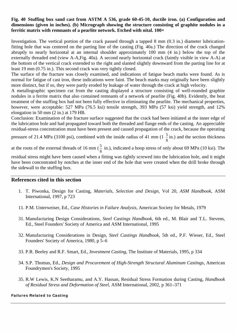
Fig. 40 Stuffing box sand cast from ASTM A 536, grade 60-45-10, ductile iron. (a) Configuration and dimensions (given in inches). (b) Micrograph showing the structure consisting of graphite nodules in a ferritic matrix with remnants of a pearlite network. Etched with nital. 100×
Investigation. The vertical portion of the crack passed through a tapped 8 mm (0.3 in.) diameter lubrication-fitting hole that was centered on the parting line of the casting (Fig. 40a.) The direction of the crack changed abruptly to nearly horizontal at an internal shoulder approximately 100 mm (4 in.) below the top of the externally threaded end (view A-A,Fig. 40a). A second nearly horizontal crack (faintly visible in view A-A) at the bottom of the vertical crack extended to the right and slanted slightly downward from the parting line for at least 19 mm (0.75 in.). This second crack was very tightly closed. The surface of the fracture was closely examined, and indications of fatigue beach marks were found. As is normal for fatigue of cast iron, these indications were faint. The beach marks may originally have been slightly more distinct, but if so, they were partly eroded by leakage of water through the crack at high velocity. A metallographic specimen cut from the casting displayed a structure consisting of well-rounded graphite nodules in a ferrite matrix that also contained remnants of a network of pearlite (Fig. 40b). Evidently, the heat treatment of the stuffing box had not been fully effective in eliminating the pearlite. The mechanical properties, however, were acceptable: 527 MPa (76.5 ksi) tensile strength, 393 MPa (57 ksi) yield strength, and 12% elongation in 50 mm (2 in.) at 179 HB. Conclusion: Examination of the fracture surface suggested that the crack had been initiated at the inner edge of the lubrication hole and had propagated toward both the threaded and flange ends of the casting. An appreciable residual-stress concentration must have been present and caused propagation of the crack, because the operating
pressure of 21.4 MPa (3100 psi), combined with the inside radius of 41 mm (1 58
in.) and the section thickness
at the roots of the external threads of 16 mm ( 58
in.), indicated a hoop stress of only about 69 MPa (10 ksi). The
residual stress might have been caused when a fitting was tightly screwed into the lubrication hole, and it might have been concentrated by notches at the inner end of the hole that were created when the drill broke through the sidewall to the stuffing box.
References cited in this section
1. T. Piwonka, Design for Casting, Materials, Selection and Design, Vol 20, ASM Handbook, ASM International, 1997, p 723
11. P.M. Unterweiser, Ed., Case Histories in Failure Analysis, American Society for Metals, 1979
31. Manufacturing Design Considerations, Steel Castings Handbook, 6th ed., M. Blair and T.L. Stevens, Ed., Steel Founders' Society of America and ASM International, 1995
32. Manufacturing Considerations in Design, Steel Castings Handbook, 5th ed., P.F. Wieser, Ed., Steel Founders' Society of America, 1980, p 5–6
33. P.R. Beeley and R.F. Smart, Ed., Investment Casting, The Institute of Materials, 1995, p 334
34. S.P. Thomas, Ed., Design and Procurement of High-Strength Structural Aluminum Castings, American Foundrymen's Society, 1995
35. R.W Lewis, K.N Seetharamu, and A.Y. Hassan, Residual Stress Formation during Casting, Handbook of Residual Stress and Deformation of Steel, ASM International, 2002, p 361–371
Failures Related to Casting

Cast Irons
The type of material and manufacturing method is developed during the process of design and materials selection, and this, of course, requires several steps in the review of the process/operating conditions and evaluation of materials (as briefly outlined in the article “Materials Selection for Failure Prevention” in this Volume). However, each material has unique processing aspects and quality-control factors that influence the variability in chemical composition, material condition, and properties. Improper chemical composition and mechanical properties, although not ordinarily considered to be casting “imperfections,” may result in unsatisfactory performance in service. For example, segregation in castings can result in improper microstructure and deviations from specified hardness or mechanical-property requirements. Other microstructural features that influence the performance of iron castings in service include:
• Graphite of unfavorable shape, size, or distribution • Embrittling intergranular networks (carbides) • Surface-structure gradients, such as accidental carburization or decarburization • Unsatisfactory microstructures resulting from improper materials selection, improper compositions for
section size (in gray and ductile irons), or incorrect heat treatment
One problem unique to cast iron is pull-out of graphite particles, which impart a pock-marked finish. Pull-out is a function of the graphite flake size and force applied on the surface by the tool. The presence of carbides in microstructure can also have a deleterious effect on surface finish.
Cast Iron Composition and Microstructure
Carbon Equivalent and Carbon Saturation. Carbon equivalent (CE) is a simplified method of evaluating the effect of composition. Several equations are used; Eq 1 is the most common:
% %3
Si PCE TC += +
(Eq 1)
where TC is total carbon content. This value is important, because it can be compared with the eutectic composition (4.3% C) to indicate whether the cast iron will behave as a hypoeutectic or hypereutectic alloy during solidification. Carbon saturation, SC, can be calculated as:
% %4.33
TCSCSi P
=+ −
(Eq 2)
This value is important, because it is a measure of the tendency toward carbide decomposition, and it can be used to estimate the tensile strength for a given composition and section size of cast iron. Hypereutectic irons tend to form graphite, while hypoeutectic irons tend to form carbides during solidification (Ref 36, 37). Eutectic constituents in gray irons can be revealed by etching to exhibit cell boundaries. Graphite. The size, shape, orientation, and distribution of graphite in castings of gray iron, ductile iron, and malleable iron determine the mechanical properties of the castings. For any given gray-iron composition, the rate of cooling from the solidification temperature to below approximately 650 °C (1200 °F) determines the ratio of combined-carbon to graphitic-carbon phases; this ratio controls the hardness and strength of the iron. Therefore, the effect of section size is considerably greater for gray-iron castings than it is for castings made of more homogeneous ferrous metals, for which the rate of cooling does not affect the form of the carbon content on a macroscopic scale. Ductile cast iron, previously known as nodular iron or spheroidal-graphite cast iron, is cast iron in which the graphite grows as spheres, rather than as flakes of any of the forms characteristic of gray iron, from additives introduced in the molten iron before casting. Malleable iron is a type of cast iron that has most of its carbon in the form of irregularly shaped graphite. Malleable iron, similar to ductile iron, possesses considerable ductility and toughness, because of its combination of nodular graphite and a low-carbon ferrite matrix. Consequently, malleable iron and ductile iron are suitable for some of the same applications requiring good ductility and toughness.
The file is downloaded from www.bzfxw.com

Malleable iron is produced by first casting the iron as a white iron and then heat treating the white cast iron to convert the iron carbide into the irregularly shaped nodules of graphite. This form of graphite in malleable iron is called temper carbon, because it is formed in the solid state during heat treatment. Because solidification of white iron throughout a section is essential in the production of malleable iron, ductile iron has a clear advantage when the section is too thick to permit solidification as white iron. Malleable iron castings are
produced in section thicknesses ranging from about 1.5 to 100 mm ( 116
to 4 in.) and in weights from less than
0.03 to 180 kg ( 116
to 400 lb) or more. Malleable iron in the United States is principally produced as ferritic
malleable, while some pearlitic malleable is produced in Europe. Higher strength and lower ductility are achieved for pearlitic malleable than for ferritic matrix. Ductile iron also has clear advantages over malleable iron when low solidification shrinkage is needed. Malleable iron cannot tolerate porosity, because voids migrate to the surface of hot spots, such as fillets, and appear as cracks. Also, because ductile iron does not require heat treatment to produce graphite nodules (as does malleable iron to produce temper-carbon nodules), it can compete with malleable iron even though it requires a treatment and inoculation process. The mold yield with ductile iron is normally higher than with malleable iron. Strength and elongation of ferritic ductile cast iron also tend to be higher than ferritic malleable iron (because irregular nodules do not have the same extent of benefit as graphite spherulites in ductile iron). In other applications, however, malleable iron has a distinct advantage over ductile iron. Malleable iron is preferred in the following applications:
• Thin-section casting • Parts that are to be pierced, coined, or cold formed • Parts requiring maximum machinability • Parts that must retain good impact resistance at low temperatures • Parts requiring wear resistance (martensitic malleable iron only)
Intergranular Networks. Grain-boundary networks of either proeutectoid ferrite (in hypoeutectic alloys) or iron carbide (in hypereutectic alloys) are sometimes encountered in as-cast iron castings that have been cooled through the austenite temperature range at a slow rate. The carbide network can also result in in situ graphitization of the carbide during malleableizing heat treatment, resulting in a grain-boundary network of graphite. Such networks impart low ductility and low toughness to castings and constitute paths of weakness because of the brittleness of the carbides. The presence of such networks is indicated by low impact energy in a Charpy V-notch test and can be detected by metallographic examination. A normalizing treatment can eliminate networks, provided that austenitizing has been done at the proper temperature and time. The casting can then be tempered to the desired hardness or, if higher strength is desired, can be quenched from just above the critical temperature and tempered appropriately. Inverse chill is a condition in gray iron, ductile iron, or malleable iron in which the interior is chilled or white, while the outer sections are mottled or gray. This condition is observable on fracture casting specimens and generally occurs in lighter casting sections. Some of the causes of inverse chill are sulfur content not balanced by manganese; too low of a degree of nucleation for the section, arising from high melting and pouring temperatures; and the presence of tellurium, chromium, and other severe carbide stabilizers (Ref 38, 39). Excess Ferrite. A generally acceptable microstructure occasionally may not perform satisfactorily because of some particular aspect. Figure 41 shows a micrograph of a section through the tip of a gray-iron cam lobe that sustained rapid lubricated wear because of an excessive amount of ferrite. The microstructure contained a dendritic network of pearlite and islands of free ferrite in a field consisting of type D graphite in a ferrite matrix. The large amount of free ferrite present was detrimental to wear resistance, although the cam surface was well lubricated. A lower silicon content and a slightly higher chromium content would reduce the amount of free ferrite and suppress the formation of type D graphite in the gray iron.

Fig. 41 Section through the worn tip of a gray-iron cam lobe. The white islands are free ferrite in a field of type D graphite. The matrix is ferritic. Etched with 2% nital. 235×
Carburization and Decarburization. Meticulous control of the furnace atmosphere is needed to prevent unintentional carburization and decarburization. Such control is not difficult with properly instrumented heat treating equipment. In shell-mold castings of gray iron, the high thermal conductivity of the mold produces an initial chill of the iron surface. Subsequent annealing of the surface by the heat of the casting results in a skin that is almost 100% ferrite; such a skin has poor wear properties and should be removed by machining for applications requiring wear resistance.
Gray Cast Iron
The typical microstructure of gray iron is a matrix of pearlite with graphite flakes dispersed throughout. Too-rapid cooling (relative to carbon and silicon contents) produces mottled iron, which consists of a pearlite matrix with both primary cementite (iron carbide) and graphite. Very slow cooling of irons that contain larger percentages of silicon and carbon is likely to produce considerable ferrite as well as pearlite throughout the matrix, together with coarse graphite flakes. Under some conditions, very fine graphite (type D) can be formed near casting surfaces or in thin sections. Frequently, such graphite is surrounded by a ferrite matrix; therefore, soft areas result. Type D graphite is usually associated with a ferrite matrix. This structure occurs due to a lack of nucleation sites, a large undercooling, and usually at thin casting sections. Dimensional configuration resembles the shape of sea coral. Gray-iron castings are susceptible to most of the imperfections generally associated with castings, with additional problems resulting from the relatively high pouring temperatures. These additional problems result in a higher incidence of gas entrapment, inclusions, poor metal structure, interrupted metal walls, and mold-wall deficiencies. Macroetching of cast iron is used to reveal such phenomena as chill formation and segregation. Carbon flotation, sometimes called kish graphite, is another type of internal discontinuity in cast irons. This form of segregation appears at and near the upper surfaces of a casting, always in the cope portion. This is caused by the carbon equivalent being too high. Carbon flotation is free graphite separated from molten iron during solidification. This gross segregation occurs in spheroidal graphite metal (ductile iron). Carbon flotation is remedied by increasing the pouring temperature, by lowering the carbon equivalent value by closer chemistry control, and by increasing the cooling rate (Ref 39, 40). Example 14: Premature Engine Failure Due to Improper Surface Finish Caused by Carbon Flotation. Premature failures were occurring in an engine within the first 1600 km (1000 miles) of operation. The failures involved the nodular cast iron crankshaft and its main-bearing inserts. These failures were indicated by internal noise, operation at low pressure, and total seizing. Concurrent with the incidence of engine field failures was a manufacturing problem: the inability to maintain a similar microfinish on the cope and drag sides of a cast
The file is downloaded from www.bzfxw.com

main-bearing journal. The failure analysis and investigation of the manufacturing problem showed that the cause was related to this manufacturing problem. Investigation. During the in-plant investigation, it was found that the surface finish of the cope side was rougher than that of the drag side. The surface roughnesses of the 50 sample crankshaft main bearings checked ranged from 0.4 to 0.8 mm (15 to 30 mils) on the cope side and from 0.25 to 0.5 mm (10 to 20 mils) on the drag side. The requirement was 0.5 mm (20 mils) maximum. Surface micrographs were taken for comparison purposes at the cope and drag sides of the main-bearing journals to identify the cause of the nonuniform surface finish. Figure 42 illustrates the finishes on the cope and drag sides. The cope side had areas where the surface was broken open, and it showed some raised areas. The drag side indicated fewer raised areas and almost none of the broken-open surface areas.
Fig. 42 Micrographs of a failed crankshaft main-bearing journal. (a) Cope side showing the surface broken open with raised areas. (b) Drag side, with fewer raised areas and almost no broken-open surface. Both 50×
Longitudinal metallographic sections were made of the cope and drag portions of the main-bearing journal. Figure 43 shows that the cope portion had larger and more numerous graphite nodules and ferrite envelopes than the drag portion. At the higher magnification shown in Fig. 44, the areas of the cope side that had the appearance of a broken-open surface in Fig. 42(a) were confirmed. The broken-open areas are called ferrite caps. Due to the pressure and heat of polishing during manufacture, the larger graphite nodules break open, and the ferrite envelopes (caps) become actual burrs. These burrs rise 4 to 13 μm above the normal surface (Fig. 44).

Fig. 43 Longitudinal sections from the main-bearing journal. (a) From the cope side. (b) From the drag side. Note the more numerous graphite nodules in (a). Both etched with nital. 60×
Fig. 44 Micrograph from the cope side of the main-bearing journal. Ferrite caps, which partially cover the graphite nodules and cause the broken-open surface condition, are shown. The burrs rise above the surface from 4 to 13 μm. Etched with nital. 220×
The height of these protrusions above the normal surfaces explains the variance in surface finish of cope versus drag areas. This evidence confirms the cause of crankshaft and crankshaft-bearing failures. The ferrite caps (burrs) can shear the lubricating oil film. Also, the burrs can actually penetrate the bearing-insert material. In either case, the net result is failure of the crankshaft and crankshaft-bearing insert interface due to heat generation or physical damage. Conclusions. The root cause of the failure is carbon flotation. Chemical analysis of the crankshafts involved in the failures showed a higher-than-normal carbon content and/or carbon equivalent. Therefore, during the casting process, the carbon or graphite would tend to rise in the mold to the cope side, resulting in larger and more numerous graphite nodules in that area and in the presence of more ferrite and less pearlite on the cope side. This layer could be 2.5 mm (0.1 in.) below the surface. The larger nodules break open, causing the ferrite caps or burrs. They then become the mechanism of failure by breaking down the oil film and eroding the beating material. A by-product is heat, which assists the failure.
The file is downloaded from www.bzfxw.com

Recommendations. Steps were taken to establish closer control of chemical composition and foundry casting practices to alleviate the carbon-flotation form of segregation. Additionally, some nonmetallurgical practices in journal-finishing techniques were modified to ensure optimal surface finish.
Malleable Irons
Blowholes and spikes are defects often found in malleable iron castings. Shrinkage or open structure in the gated area is a defect often found in malleable iron castings that may be overlooked by visual inspection, although it is readily detected by either liquid penetrant or magnetic-particle inspection. Example 15: Fatigue Failure of Malleable Iron Diesel-Engine Rocker Levers Originating at Spiking Defects. Several diesel-engine rocker levers failed at low hours in overspeed, overfuel, highly loaded developmental engine tests. The sand-cast rocker levers were malleable iron similar to ASTM A 602, grade M7002. Identical rocker levers had performed acceptably in normal engine tests. Investigation. The rocker levers were failing through the radius of an adjusting screw arm (Fig. 45a). The typical fracture face exhibited two distinct modes of crack propagation (Fig. 45b). The upper portion, extending approximately 6.4 mm (0.25 in.) from the top surface, appeared very dark and rough, which would indicate overload at final fracture. The majority of the fracture face was very light gray and smooth in appearance. The fanlike fracture surface would be characteristic of the brittle, transgranular propagation of a fatigue fracture.
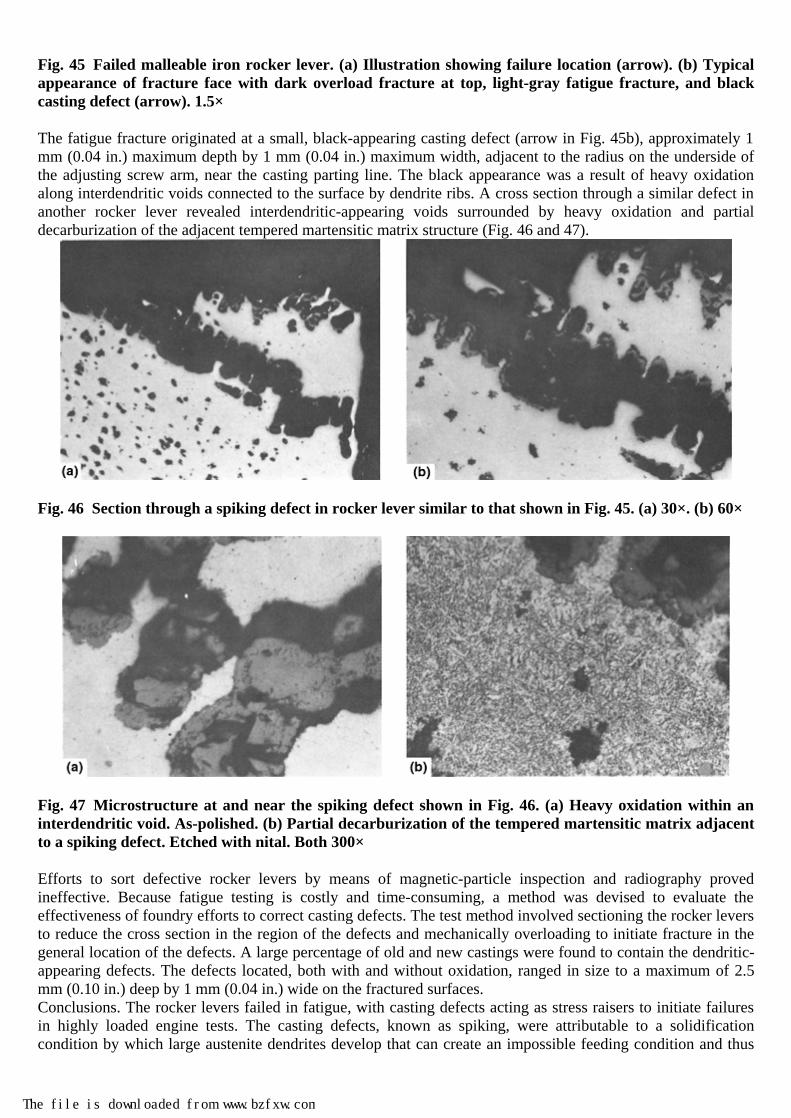
Fig. 45 Failed malleable iron rocker lever. (a) Illustration showing failure location (arrow). (b) Typical appearance of fracture face with dark overload fracture at top, light-gray fatigue fracture, and black casting defect (arrow). 1.5×
The fatigue fracture originated at a small, black-appearing casting defect (arrow in Fig. 45b), approximately 1 mm (0.04 in.) maximum depth by 1 mm (0.04 in.) maximum width, adjacent to the radius on the underside of the adjusting screw arm, near the casting parting line. The black appearance was a result of heavy oxidation along interdendritic voids connected to the surface by dendrite ribs. A cross section through a similar defect in another rocker lever revealed interdendritic-appearing voids surrounded by heavy oxidation and partial decarburization of the adjacent tempered martensitic matrix structure (Fig. 46 and 47).
Fig. 46 Section through a spiking defect in rocker lever similar to that shown in Fig. 45. (a) 30×. (b) 60×
Fig. 47 Microstructure at and near the spiking defect shown in Fig. 46. (a) Heavy oxidation within an interdendritic void. As-polished. (b) Partial decarburization of the tempered martensitic matrix adjacent to a spiking defect. Etched with nital. Both 300×
Efforts to sort defective rocker levers by means of magnetic-particle inspection and radiography proved ineffective. Because fatigue testing is costly and time-consuming, a method was devised to evaluate the effectiveness of foundry efforts to correct casting defects. The test method involved sectioning the rocker levers to reduce the cross section in the region of the defects and mechanically overloading to initiate fracture in the general location of the defects. A large percentage of old and new castings were found to contain the dendritic-appearing defects. The defects located, both with and without oxidation, ranged in size to a maximum of 2.5 mm (0.10 in.) deep by 1 mm (0.04 in.) wide on the fractured surfaces. Conclusions. The rocker levers failed in fatigue, with casting defects acting as stress raisers to initiate failures in highly loaded engine tests. The casting defects, known as spiking, were attributable to a solidification condition by which large austenite dendrites develop that can create an impossible feeding condition and thus
The file is downloaded from www.bzfxw.com

the interdendritic voids. Limiting the size of austenite dendrites by increased nucleation should eliminate the spiking defects. Corrective Measures. Because initial foundry efforts to eliminate the spiking condition were not totally effective, shot peening of the levers was introduced as an interim measure to reduce the possibility of failure. Redesign to increase the cross-sectional area of the levers has since eliminated failures through the adjusting screw arm, as verified by fatigue testing.
Ductile Iron
Effect of Composition. The properties of ductile iron depend first on composition. Composition should be uniform within each casting and among all castings poured from the same melt. Many elements influence casting properties, but those of greatest importance are the elements that influence the matrix structure or the shape and distribution of graphite nodules. Carbon influences the fluidity of the molten iron and the shrinkage characteristics of the cast metal. Excess carbon not in solution but in suspension reduces fluidity. The volume of graphite is 3.5 times the volume of iron. As ductile iron solidifies, the carbon in solution precipitates out as graphite and causes an expansion of the iron, which can offset the shrinkage of the iron as it cools from liquid to solid. The amount of carbon needed to offset shrinkage and porosity is indicated in the following formula:
%C + 17
%Si ≥ 3.9% Carbon contents greater than this amount begin to decrease fatigue strength and impact strength before the effect is noticed on tensile strength. The size and the number of graphite nodules formed during solidification are influenced by the amount of carbon, the number of graphite nuclei, and the choice of inoculation practice. Normal graphite-containing ductile iron has 10% less weight than steel of the same section size. In ductile iron, all properties relating to strength and ductility decrease as the proportion of nonnodular graphite increases, and those relating to failure, such as tensile strength and fatigue strength, are more affected by small amounts of such graphite than properties not involving failure, such as proof strength. This is illustrated in Fig. 48 (Ref 41), which shows the typical effects of graphite form on tensile and offset yield (proof) strength. The form of nonnodular graphite is important, because thin flakes of graphite with sharp edges have a more adverse effect on crack initiation.

Fig. 48 Tensile and yield strength of ductile iron versus visually assessed nodularity. Source: Ref 41
Example 16: Fracture of Ductile-Iron Pistons for a Gun Recoil Mechanism as Affected by Type of Graphite. The gun mount used for two types of self-propelled artillery (175 mm guns and 205 mm howitzers) involved a recoil cylinder and a sand-cast ductile-iron piston containing orifices through which oil was forced in order to absorb the recoil energy of the gun. A rod attached to the gun tube engaged a thread inside the small end of the piston. The piston was stressed in tension by oil pressure on the flange at the large end, opposing the direction of motion of the rod. Several pistons that had cracked or fractured in service were submitted for analysis. Investigation. Figures 49(a) and (b) show two views of a piston, illustrating the orifices specially designed to control oil flow and the pattern of cracks that developed. In Fig. 49(c), which shows a composite of the fractures found in several pistons, the piston surface has been developed as a flat-plan view. Orifices A and B correspond to those in Fig. 49(a) and (b), respectively; orifices A′ and B′ are 180° from orifices A and B. The vertical fracture (arrow) shown in Fig. 49(a) is unusual in origin and direction of propagation; most of the fractures originated at the upper right-hand corners of the large orifices (A and A′, Fig. 49c) and propagated in an approximately horizontal direction. Some of these nearly horizontal cracks intersected the small orifices (B and B′, Fig. 49c); others propagated around the piston to the opposite large orifice, joining it at the left side of the narrow opening at top left.
The file is downloaded from www.bzfxw.com

Fig. 49 Piston for a gun-recoil mechanism, sand cast from ductile iron conforming to MIL-I-11466, grade D7003, that fractured in fatigue because of vermicularity of graphite. (a) and (b) Two different views of the piston showing fractures; A and B indicate orifices (see text). Approximately 0.35×. (c) Flat-plan view showing composite pattern of fractures in several pistons. (d) Fracture surface showing mottled structure caused by vermicular graphite; arrow points to a fatigue zone. Approximately 0.25×. (e) to (h) Micrographs showing graphite with nodularity of rank 2, at 50× (e); rank 8, at approximately 60× (f); rank 13, at 50× (g); rank 16, at approximately 65× (h). Specimens in (e) and (g) were not etched; specimens in (f) and (h) were etched with 2% nital.
Figure 49(d) shows the surface of one of the horizontal fractures, which has a blotchy, mottled appearance. The pattern was created by the graphite present; there was relatively little of the massive, hypereutectic carbide that is, by definition, present in iron with a mottled structure. The arrow in Fig. 49(d) indicates a location that exhibits the characteristics of a fatigue zone. The uppermost fracture shown in Fig. 49(a) is met by the more or less vertical break at virtually a right angle. This signifies that the upper fracture took place earlier. Because some of the pistons exhibited regions with an appearance suggesting fatigue (Fig. 49d), SEM fractographs were prepared to attempt to locate fatigue striations and to estimate the number of cycles to failure. These fractographs showed configurations similar in appearance to fatigue striations, but it was concluded that they were pearlite lamellae, because the spacings agreed with pearlite dimensions observed in optical micrographs. Scanning electron microscope views of the area of final fracture revealed dimples in some regions and features resembling cleavage facets in others. However, what appeared to be facets may have been interfaces of pearlite lamellae oriented nearly parallel to the direction of crack propagation. The castings were made according to the specifications of MIL-I-11466, grade D7003, which requires minimum properties of 690 MPa (100 ksi) tensile strength, 483 MPa (70 ksi) yield strength, and 3% elongation in 50 mm (2 in.); these properties are usually acquired by heat treatment (normalizing for these castings). The

specification stipulated that the graphite be substantially nodular and required a metallographic test for each lot of castings. There was no requirement concerning the matrix. Of 17 pistons that were sectioned for testing (2 or more test specimens per piston), 11 averaged 814 MPa (118 ksi) tensile strength, but the remaining 6 averaged only 535 MPa (77.6 ksi); 13 met the yield strength requirement, averaging 552 MPa (80 ksi), while 4 did not, averaging 399 MPa (58 ksi); in elongation, 9 pistons were satisfactory, averaging 4.7%, but 8 averaged only 2.1%. However, depending on how the 690 MPa (100 ksi) specification is defined (i.e., from separately poured test bars or specimens cuts from casting), those variances may be expected. Examination of the microstructures of these 17 pistons, along with those of additional pistons, revealed that 77% of those that failed did not contain the required nodular graphite. The range in nodularity was sufficient for establishment of a microstructure rating system in which quality of graphite was ranked from 1 (nodular) to 16 (vermicular with essentially no nodules). Structures containing graphite ranked 2, 8, 13, and 16 are shown in Fig. 49(e) through (h), respectively. Figure 49(h), which shows the structure of the piston with the mottled surface in Fig. 49(d), exhibits massive carbides but not enough to form a mottled structure in the usual sense of the term. For this application, graphite ranked from 1 to 7 was considered acceptable, graphite ranked from 8 to 12 borderline, and graphite ranked from 13 to 16 unacceptable. The degree of nodularity of the graphite was correlated with the results obtained in ultrasonic testing in order to appraise the quality of pistons that had already been installed. It was found that vermicular graphite damped the back-reflection signal to a significantly greater degree than nodular graphite did. Comparison of the results obtained in the ultrasonic tests and in the metallographic examinations yielded a correlation coefficient of 0.84—an indication of a high degree of correlation. Smooth-bar rotating beam tests were performed on specimens prepared from pistons specifically selected for a comparison of fatigue test behavior and graphite structure. Fatigue tests in simple tensile loading were conducted on new, complete pistons containing nodular graphite. Four tests at a stress corresponding to the gun recoil load produced fatigue fractures at 20,000 to 35,000 cycles. All these fractures, unlike most of those observed in service, occurred at the base of the threads in the top of the piston, which is the region of the upper crack shown in Fig. 49(a) and (b). The section through the threads had been calculated during design as the location of maximum stress under simple tension. Because nearly all service fatigue cracks did not occur at the threads but initiated from the oil orifices, cracking can likely be attributed to slight misalignment that caused bending as well as tension and to the force of the oil on the surface immediately above and below the large orifices, increasing the stresses at the corners of these orifices. These tests showed that the life of the pistons was about 20,000 recoil loadings instead of the indefinite service life that had been anticipated. Conclusions. Fracture of the pistons occurred under high strain-rate axial tension modified by superimposed bending loads from oil pressure and/or normal alignment tolerance. Most of the service fractures occurred in pistons containing vermicular graphite instead of the specified nodular graphite. Brittleness caused by massive carbides might have shortened the service lives of a few pistons. Corrective Measures. Ultrasonic testing was adopted for inspection of pistons already in the field to identify and reject those containing vermicular graphite. Metallographic control standards were applied to a production of new pistons to ensure structures containing substantially nodular graphite and no massive carbides.
References cited in this section
36. H.T. Angus, Cast Iron: Physical and Engineering Properties, 2nd ed., Butterworths, 1976
37. C.F. Walton, Gray and Ductile Iron Castings Handbook, Iron Founder's Society, Des Plaines, IL, 1971
38. S.I. Karsay, Ductile Iron-Production Practices, American Foundrymen's Society, Des Plaines, IL, 1975, p 167
39. G.W.S. Anselman et al., Analysis of Casting Defects, 2nd ed., American Foundrymen's Society, Des Plaines, IL, 1966
40. F. Hudson et al., Atlas of Defects in Castings, Institute of British Foundrymen, London, 1961
The file is downloaded from www.bzfxw.com
41. A.G. Fuller, Evaluation of the Graphite Form in Pearlitic Ductile Iron by Ultrasonic and Sonic Testing and the Effect of Graphite Form on Mechanical Properties, Trans. AFS, Vol 85, 1977, p 509–526
Cast Steels
Carbon steel parts are normally supplied in the normalized or normalized-and-tempered condition but can be quenched and tempered or annealed. Some are also used in the as-cast condition. Heat treating of carbon steel should be selected to ensure adequate toughness and weldability. Carbon steel castings, if they fail due to improper heat treatment, most often fail in a service that requires high impact toughness, particularly at low temperatures.
Low-Alloy Steel Castings
Low-alloy steel castings are susceptible to heat treating problems. In addition to toughness and ductility, strength is also determined by the heat treat cycles, and these can be varied over a wide range. The best combinations of mechanical properties are developed in the quenched-and-tempered condition, with the tempering conditions (temperature, time at temperature, and quenching temperature) controlling the hardness, ductility, strength, and toughness. Many failures in low-alloy steel castings are due to lack of strength or a combination of factors leading to fatigue or overload fractures. A combination of cyclic loading (thermal fatigue), an aggressive service environment (steam), and internal defects resulted in gradual crack propagation in Example 17. Low hardness can also lead to premature wear of wear-resistant low-alloy castings. Low strength can be caused by several heat treating errors. A slack quench caused by lack of good tank circulation, over-loaded heat treat baskets, or early (hot) removal from the quench will lead to low strength. This is due to the lower-hardness bainitic microstructures that are formed instead of the harder martensitic ones. Low strength can occur with a good quench when it is followed by tempering at too high a temperature. An extended hold time in the heat treat furnace at the tempering temperature may produce the same result. Example 17: Failure of a Thick-Wall Casing for a Steam Turbine by Cracking. When a crack developed in a cast steel steam-turbine casing, a small section of the casing was removed by torch cutting to examine the crack completely and to determine its origin. The crack was discovered during normal overhaul of the turbine. The chemical composition and processing of the casting were in accordance with ASTM A 356, grade 6 (1.25%Cr-0.5%Mo). The mechanical properties of the casting were yield strength, 352 MPa (51 ksi); tensile strength, 490 MPa (71 ksi); elongation, 29.5%; and reduction of area, 70.5%, all of which exceeded the requirements of the specification. Charpy V-notch impact energy values for specimens taken from the casting were 14.6 J (10.75 ft · lbf) at 25 °C (75 °F), 88 J (65 ft · lbf) at 0 °C (32 °F), and 5.4 J (4.0 ft · lbf) at -18 °C (0 °F). When the fracture surface was examined visually, an internal-porosity defect was observed adjoining the tapped hole. A second, much larger cavity was also detected (upper right portion, Fig. 50a).

Fig. 50 ASTM A 356, grade 6 (1.25%Cr-0.5%Mo), cast steel turbine casing that failed by cracking. (a) Segment removed from the casing, showing the fracture surface at right. A large porosity defect can be seen at the upper right corner, near the broken-open tapped hole. (b) to (e) Transmission electron microscopy fractographs of four locations on the fracture surface. 7500×. Intergranular modes of fracture are shown in (b) and (c); a transgranular mode, typical of corrosion fatigue, is shown in (d). The fractograph in (e) was taken in the region of crack arrest and indicates an intergranular mode of fracture.
Metallographic Examination. An examination of the microstructure revealed a concentration of precipitates on slip planes within grain boundaries. Fatigue loading increases the concentration of point and line defects, and these defects assist diffusion. Therefore, precipitation, which is a diffusion-controlled process, is more advanced in the slip bands of a material subjected to fatigue. In this case, the fatigue was thermal fatigue caused by repeated temperature changes in the turbine over a period of about ten years. These temperature changes were more frequent than usual, because the turbine was on standby service for several years. In regions near the main fracture surface, small subsidiary cracks—both transgranular and intergranular—were noted. At surfaces contacted by steam, there was evidence of stress-corrosion cracking (SCC) and intergranular attack. Electron Fractography. Replica impressions were taken at eight locations on the main fracture surface for examination in an electron microscope. Depending on location, there was evidence of intergranular and transgranular cracking. For example, Fig. 50(b) and (c) indicate an intergranular crack propagation; however,
The file is downloaded from www.bzfxw.com

Fig. 50(d), taken farther down the fracture surface, indicates a transgranular cracking. Figure 50(e), which was taken from the region of crack arrest, indicates a completely intergranular mode. Conclusions. Failure occurred through a zone of structural weakness that was caused by internal casting defects and a tapped hole. The combination of cyclic loading (thermal fatigue), an aggressive service environment (steam), and internal defects resulted in gradual crack propagation, which was, at times, intergranular—with or without corrosive attack—and, at other times, was transgranular. Temper Embrittlement. Low-alloy steel castings can suffer from temper embrittlement when they are tempered in the region of 260 to 540 °C (500 to 1000 °F). Slow cooling through this region from a higher temperature can also lead to the problem. It is advisable to specify a water quench from the tempering temperature whenever practical to avoid this. The low toughness caused by temper embrittlement can lead to brittle fractures. More highly alloyed steels, such as the 4300 series and the HY steels, tend to be more susceptible to the problem. Temper embrittlement, similar to any type of embrittlement that occurs from heat treating, is not detected by the common acceptance criteria of hardness testing. Annealed steels also differ from normalized-and-tempered steels in toughness but not in hardness. Data in Table 4 illustrate this. Two heats of 0.22C-0.12Mo steel were treated and tested. One was annealed at 925 °C (1700 °F) and furnace cooled. The other was normalized at 925 °C (1700 °F), air cooled, then tempered at 670 °C (1240 °F). While the tensile strengths of approximately 483 MPa (70 ksi) and the hardnesses of approximately 140 HB were the same, the impact results were quite different. The annealed material exhibited only 41 to 46 J (30 to 34 ft · lbf) Charpy V-notch impact toughness, while the normalized-and-tempered heat had 83 to 87 J (61 to 64 ft · lbf) impact toughness. Toughness testing is a good method of ensuring correct heat treatment.

Table 4 Composition and typical mechanical properties of 12 heats of closely similar cast carbon-molybdenum steel(a)
Composition, % Tensile strength
Yield strength
Item
C Mn Si Ni Cr Mo Mpa ksi MPa ksi
Elongation, %
Reduction of area, %
Hardness, HB
Charpy V-notch, J (f · lbf) at 21°C (70 °F)
1(b) 0.24 0.54 0.41 0.70 0.11 0.15 507 73.5 276 40.0 28.0 46.0 143 60, 54, 46, 53 (44, 40, 34, 39)
2(b) 0.26 0.59 0.45 0.09 0.14 0.14 528 76.6 293 42.5 27.0 46.3 149 46, 49, 46, 47 (34, 36, 34, 35)
3(c) 0.23 0.55 0.43 0.18 0.10 0.11 486 70.5 286 41.5 27.5 43.5 140 57, 54 (42, 40)
4(b) 0.23 0.55 0.43 0.18 0.10 0.11 467 67.8 255 37.0 28.0 39.5 138 41, 38 (30, 28)
5(c) 0.21 0.56 0.50 0.16 0.10 0.14 470 68.2 296 43.0 35.0 53.3 140 64, 76 (47, 56)
6(b) 0.21 0.56 0.50 0.16 0.10 0.14 452 65.5 248 36.0 32.0 48.5 138 41, 38 (30, 28)
7(c) 0.22 0.52 0.50 0.15 0.10 0.12 496 72.0 300 43.5 33.0 49.0 141 87, 83 (64, 61)
8(b) 0.22 0.52 0.50 0.15 0.10 0.12 474 68.7 256 37.2 27.5 40.0 138 46, 41 (34, 30)
9(c) 0.21 0.57 0.34 0.14 0.16 0.13 476 69.0 292 42.3 33.0 53.0 138 79, 62 (58, 46)
10(b) 0.21 0.57 0.34 0.14 0.16 0.13 462 67.0 256 37.2 35.0 46.3 136 47, 43 (35, 32)
11(b) 0.20 0.56 0.42 0.07 0.11 0.07 455 66.0 259 37.5 28.0 54.1 … 54 (40)
12(b) 0.20 0.58 0.49 0.06 0.05 0.06 483 70.0 276 40.0 33.0 55.2 … 56, 54 (41, 40)
The file is downloaded from www.bzfxw.com

(a) Equivalent to ASTM A27, grade 65–35; properties from a 8 by 13 by 18 cm (3 by 5 by 7 in.) keel block; basic electric steel, deoxidized with 1.1 kg (2.5 lb) of aluminum per ton of molten metal. (b) Annealed at 925 °C (1700 °F) for 12 h. furnace cooled. Microstructure, 30% fine pearlite, 70% primary ferrite. (c) Normalized 925 °C (1700 °F), 8 h. air cooled, tempered 670 °C (1240 °F) 2 h. air cooled. Structure, 25% fine pearlite, 75% primary ferrite Temper embrittlement does not occur in plain carbon steels, only in alloy steels. The degree of embrittlement varies with alloy steel composition, and certain impurity elements must be present if temper embrittlement is to occur. The embrittling impurities are, in decreasing order of influence on a weight percent basis, antimony, phosphorus, tin, and arsenic. Of these elements, phosphorus is most commonly present in alloy steels, and it has captured the most attention in research studies. Manganese and silicon also increase the susceptibility to embrittlement. Little or no temper embrittlement occurs if manganese is kept below ~0.5 wt%. Although alloy steels are ferritic in the tempered condition, fracture below the ductile-brittle transition temperature occurs along prior-austenite grain boundaries, where both alloying elements and impurity elements are concentrated. Section Size. The effect of section size on mechanical properties must be understood by those responsible for the design and specification of castings, but it is particularly important when considering low-alloy steels. Mechanical properties of a part also are determined by the quench rate during the hardening cycle and the hardenability of the specified alloy. It is standard practice in the foundry industry to use separately cast keel blocks, for example, ASTM A 370 dimensions, to determine the mechanical properties of a heat of steel. Where a historical relationship exists, tying test bar properties to field service, this approach is a sound one. There is always a danger, however, that the assumption is made that the mechanical properties obtained from a 3.8 cm (1.5 in.) thick test bar are equivalent to those found in a casting with a much greater thickness. In the vast majority of the cases, this is not true. When no experience exists in correlating heat treatment/alloy/section size/service/test bar properties, it is prudent to request mechanical properties from test bars roughly equivalent in section thickness to the critical sections of the castings. Alternatively, this relationship should be established through field trials under controlled conditions or by destructively testing actual castings. In many cases, the foundry may have established this information. Failures Due to Composition. While improper chemical composition would not appear to be a defect, many problems can be traced back to composition. Errors in chemical composition can occur in three ways. The first involves selecting an inappropriate nominal (as per specification) composition for a part and the service conditions it will encounter. Off-analysis is the second way. It involves making an error in manufacturing, leading to the part or casting being produced to improper chemistry. Fortunately, with foundries reasonably equipped to produce castings, off-analysis heats are rarely a major problem. Still, they do occur. Probably the most severe problems arise with deviations in carbon content (low or high), but difficulties can occur with other elements, such as nickel, chromium, or manganese. These are generally less severe. Also, standard specifications permit a composition range or, in some instances, a maximum value for a given element. Slightly exceeding a nominal limit for a given element seldom results in root cause failure. Exceeding the limit of maximum value element—for example, phosphorus—can cause significantly more trouble. Finally, trace elements, such as arsenic, tin, antimony, aluminum, nitrogen, and hydrogen, which are not a part of most specifications, can lead to unexpected failures. Unspecified elements and trace elements of importance include the gases nitrogen, oxygen, and hydrogen and the residuals, such as sulfur, phosphorus, aluminum, antimony, arsenic, and tin. Copper routinely shows up more often in analysis and may be a concern. It is well documented that high nitrogen contents in low-alloy steels can be very detrimental in combination with aluminum (which is used for deoxidation) through the formation of aluminum nitride along grain boundaries. The intergranular fracture that results is the so-called rock candy structure, which can cause catastrophic failures under severe conditions of embrittlement if not detected. A high-resolution SEM image shows the relics of the rodlike precipitate responsible for the embrittlement (Fig. 51). Scanning electron microscopy analysis for this mode of embrittlement is one way to differentiate this mode of failure from temper embrittlement or grain-boundary ferrite. In the case shown, a Ni-Cr-Mo low-alloy steel was embrittled by very high levels of aluminum (0.23%) combined with good low-nitrogen (36 ppm) content. Nitrogen also can result in strain-age embrittlement.

Fig. 51 Scanning electron micrograph illustrating the characteristic rodlike artifacts associated with aluminum nitride embrittlement. This characteristic appearance is confirmation of aluminum nitride embrittlement as opposed to ferrite films or temper embrittlement, which also lead to intergranular failure.
As in wrought products, hydrogen can be a cause of failure in low-alloy steel castings. Hydrogen-related defects can vary from open flakes to fisheyes that appear on fractured surfaces. This can be extremely detrimental in heavy section castings and particularly in those heat treated to high strength (yield strengths above approximately 690 MPa, or 100 ksi). Oxygen, although not such a potentially dangerous residual, can be cause for dirty steel and low mechanical properties when care is not taken in the manufacturing process to keep oxygen under control. The effect of high sulfur contents on mechanical properties is well known and should be of decreasing importance as a defect cause. Relatively little is known of the effect of arsenic, tin, and antimony on castings, except that it is generally agreed that low levels, that is, 0.005% or lower, are important to minimize failures due to toughness degradation in heat treated high-strength castings. High-Temperature Corrosion. Many castings are produced for high-temperature service. The control of composition inherent in castings, coupled with the ability to increase the carbon contents of standard high-temperature alloys beyond the wrought steel levels, has led to a significant number of specialty cast grades. The techniques used for analysis and the general types of cast steel failure at high-temperature modes are similar to wrought alloys, but high-temperature corrosion of low-alloy cast steels is briefly described for general oxidation, sulfidation, metallic oxide attack, and carburization. Many alloys are developed specifically for elevated temperature, and it is beyond the scope of this article to develop the reasoning for each alloy and its appropriate applications. The main intent is to examine the types of failures caused by high-temperature environments. General Oxidation. The rate of general oxidation is one of the primary concerns of extended high-temperature service. The first endeavor in examining a high-temperature failure should be to determine what portion of the original section is left unaffected by the general oxidation. If the oxidation rate is found to be excessive, the alloy should be replaced with an alloy of greater oxidation resistance. Temperature limits for low-alloy steels depend on various exposure and application factors. For example, short-time service may be limited to 510 °C (950 °F), while long-time service may be limited to 400 °C (750 °F). Many things begin to happen in low-alloy steels when the temperature reaches 400 °C (750 °F), such as significant loss in modulus, rapid oxidation, no scaling resistance, graphitization of cementite and pearlite, and so on. At temperatures above 540 to 650 °C (1000 to 1200 °F), general oxidation increases to rates that become unacceptable. A fluffy oxide or scale occurs and sloughs off, leading to decreased service life. A whole series
The file is downloaded from www.bzfxw.com

of alloys have been developed to cover a wide range of elevated-temperature applications. Most of these alloys contain chromium or chromium and nickel plus other elements, depending on the application requirements. Chromium stabilizes the carbides so that no in situ graphitization occurs and also provides scaling resistance. There also are nickel- and cobalt-base alloys used in critical high-temperature applications. Sulfidation and Preferential Oxidation. Not all oxidation or corrosion is uniform, because oxidation and corrosion can also result in preferential attack and premature failure. Sulfidation is one form of attack at the grain boundaries. Sulfidation attack is a preferential deterioration at the grain boundaries due to a combination of sulfur with nickel in high-nickel alloys. This type of attack can be found in the stack areas of systems burning fuel oils or coal high in sulfur. This type of preferential attack may be confirmed by electron microprobe analysis of the products found in the attacked grain boundary. One must be careful to differentiate between this type of attack enhanced by sulfur in the environment and preferential oxidation of the grain boundaries. Because most high-temperature alloys contain higher carbon than can be dissolved in the structure, these alloys tend to form eutectic carbides in grain boundaries and can show preferential oxidation of this area even in the absence of sulfur (Fig. 52).
Fig. 52 Example of preferential oxidation of the grain boundaries in a cast high-temperature alloy steel
Preferential oxidation can also be interdendritic in nature and is primarily due to the chemistry gradients across the dendrites (Fig. 53). While sulfidation attack can be intergranular and very rapid in high-nickel alloys, sulfidation also takes on rapid scaling or exfoliation characteristics in low alloys and some other alloys. This is attributed to the modification of the protective film produced on the alloy. In most cases, sulfidation resistance is improved by increasing chromium content, and aluminum and silicon have also been shown to be beneficial. Where hydrogen sulfide is the primary environmental factor, it has been found that intermediate amounts of chromium (5 to 12%) are actually deleterious and increase the rate of sulfidation. Chromium contents greater than 17% have been found to be adequate in hydrogen sulfide atmospheres, and protective layers of aluminum have been found to protect chromium steels totally from hydrogen sulfide attack.
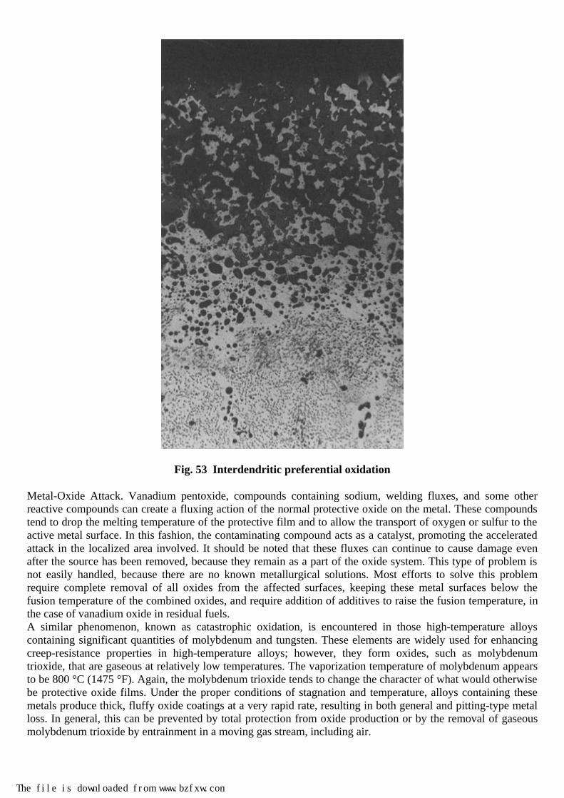
Fig. 53 Interdendritic preferential oxidation
Metal-Oxide Attack. Vanadium pentoxide, compounds containing sodium, welding fluxes, and some other reactive compounds can create a fluxing action of the normal protective oxide on the metal. These compounds tend to drop the melting temperature of the protective film and to allow the transport of oxygen or sulfur to the active metal surface. In this fashion, the contaminating compound acts as a catalyst, promoting the accelerated attack in the localized area involved. It should be noted that these fluxes can continue to cause damage even after the source has been removed, because they remain as a part of the oxide system. This type of problem is not easily handled, because there are no known metallurgical solutions. Most efforts to solve this problem require complete removal of all oxides from the affected surfaces, keeping these metal surfaces below the fusion temperature of the combined oxides, and require addition of additives to raise the fusion temperature, in the case of vanadium oxide in residual fuels. A similar phenomenon, known as catastrophic oxidation, is encountered in those high-temperature alloys containing significant quantities of molybdenum and tungsten. These elements are widely used for enhancing creep-resistance properties in high-temperature alloys; however, they form oxides, such as molybdenum trioxide, that are gaseous at relatively low temperatures. The vaporization temperature of molybdenum appears to be 800 °C (1475 °F). Again, the molybdenum trioxide tends to change the character of what would otherwise be protective oxide films. Under the proper conditions of stagnation and temperature, alloys containing these metals produce thick, fluffy oxide coatings at a very rapid rate, resulting in both general and pitting-type metal loss. In general, this can be prevented by total protection from oxide production or by the removal of gaseous molybdenum trioxide by entrainment in a moving gas stream, including air.
The file is downloaded from www.bzfxw.com

Carburization is another mode of surface deterioration. At elevated temperatures, carbon in contact with the surface metal can react to form chromium carbides and, to a lesser degree, iron carbides, resulting in carbide enrichment of the surface layer of metal. This enrichment can go quite deep into the metal, with resulting increases in creep strength and decreases in metal ductility and toughness. Surface oxidation is not a primary concern under carburizing-type conditions. A reducing atmosphere that produces carburization can remove significant amounts of chromium, allowing such phenomena as sulfidation to become significant. Also, the depletion of chromium can allow normal corrosion to occur during shutdown periods; during these cooling-down periods, liquids can wet and therefore corrode these surfaces. While the corrosion properties of these carburized surfaces are important, a loss of ductility in heavily carburized parts has been the cause of many failed parts. Increasing chromium content has been shown to slow the diffusion rate of carbon into the metal. Increasing nickel content has also been found to be beneficial. There are several alloys designed for carburizing service.
Austenitic Steels
Care is essential in heat treating more highly alloyed steel castings, especially those used for elevated-temperature service. Low-carbon austenitic stainless steels have some usefulness at elevated temperatures due to their oxidation resistance, but most of the alloys designed for elevated-temperature service have higher carbon contents than the typical 304 type of austenitic stainless steel and are thus susceptible to precipitation of grain-boundary carbides and embrittlement (see “Precipitation Embrittlement at Elevated Temperatures” in this section). An improperly heat treated stainless steel, such as Alloy Casting Institute (ACI) CF-8, corrodes faster in service due to carbide precipitate in grain boundaries, leaving other areas depleted of the chromium that gives the steel its corrosion resistance. This sensitization is frequently the cause of intergranular corrosion (see Example in this article). Too low a temperature or slow cooling from the solution-annealing temperature can produce the same detrimental effect. Austenitic manganese (Hadfield) steels can suffer from a similar problem microstructurally, but in this case, poor wear resistance and decreased ductility are the results. Austenitic manganese steel exhibits its best properties when it gets a good water quench from 1095 °C (2000 °F). Otherwise, carbides precipitate heavily at the grain boundaries or, in severe cases, within the austenite, reducing the work-hardening capability of the matrix and lowering overall toughness and ductility. Reheating manganese steel can give a similar effect, as shown in the following example. Example 18: Brittle Fracture of a Cast Austenitic Manganese Steel Chain Link. The chain link shown in Fig. 54(a), a part of a mechanism for transferring hot or cold steel blooms into and out of a reheating furnace, broke after approximately four months of service. The link was cast from 2% Cr austenitic manganese steel and was subjected to repeated heating to temperatures of 455 to 595 °C (850 to 1100 °F).

Fig. 54 Reheating-furnace chain link, sand cast from austenitic manganese steel, that failed by brittle fracture, because material was not stable at operating temperatures. (a) Chain link showing location of fracture. Dimensions given in inches. (b) Macrograph of a nital-etched specimen from an as-received chain link. 1.85×. (c) and (d) Micrographs of a nital-etched specimen from an as-received chain link. 100 and 600×, respectively. (e) Normal microstructure of as-cast standard austenitic manganese steel. 100×. (f) Micrograph of a nital-etched specimen that had been austenitized 20 min at 1095 °C (2000 °F) and air cooled. 315×. (g) Micrograph of the specimen in (f) after annealing 68 h at 480 °C (900 °F). 1000×. (h) Chart showing time at temperature needed to embrittle austenitic manganese steel after heat treating for 2 h at 1095 °C (2000 °F) and water quenching
Investigation. Chemical analysis revealed that the link had been cast from 13% Mn austenitic manganese steel to which 1.5 to 2.0% Cr was added to improve wear resistance by forming chromium carbides. Examination with a hand magnet indicated that the entire link was magnetically responsive. When properly heat treated, austenitic manganese steel is a tough, nonmagnetic alloy; however, composition changes that occur at the surface during heating may produce a magnetic skin. Further examination of the magnetic properties of the link was performed with the aid of a Tinsley thickness gage, which is normally used for measuring the thickness of nonmagnetic coatings on ferritic steel surfaces. With this instrument, a completely nonmagnetic substance is given a rating of 10, and a magnetic material, such as plain carbon steel, is assigned a rating of 0. Specimens cut from the link were tested for magnetism after various heat treatments with the following results: Condition(a) Tinsley reading Degree of magnetism Web (as-received) 4.5 Partial Flange (as-received) 4.65 Partial
The file is downloaded from www.bzfxw.com

Condition(a) Tinsley reading Degree of magnetism 1095 °C (2000 °F), WQ 10.0 Nonmagnetic 1095 °C (2000 °F), AC 10.0 Nonmagnetic 1095 °C (2000 °F), WQ; 4 h at 455 °C (850 °F) 9.0–9.6 Trace at edges 1095 °C (2000 °F), FC 8.0 Partial 1095 °C (2000 °F), FC; 68 h at 480 °C (900 °F) 4.8 Partial 1095 °C (2000 °F), AC; 68 h at 480 °C (900 °F) 4.75 Partial (a) WQ, water quenched; AC, air cooled; FC, furnace cooled Micrographs of specimens from the as-received link (Fig. 54c and d) display a segregated structure of complex carbides (black needlelike phase), (FeMn)3C carbides (white-on-white area), and pearlite (gray areas) in an austenite matrix, which accounts for the macrostructure shown in Fig. 54(b). Figure 54(b) is a macrograph of a polished and nital-etched specimen from the link as received at the laboratory, showing dendritic segregation and microshrinkage pores (dark spots at upper left). The segregation follows the grain boundaries, but the appearance is modified by dark oxide patches left by the nital etch. The effects of the repeated heating of the link on the carbides can be observed by comparing the micrographs shown in Fig. 54(c) and (d) with that shown in Fig. 54(e) for a normal microstructure of as-cast standard austenitic manganese steel (1.15C-12.8Mn-0.50Si). Figure 54(e) displays a pearlite and/or martensite matrix, with carbide precipitation at grain boundaries and along crystallographic planes. Figure 54(f) shows the microstructure of a specimen from the chain link that was austenitized for 20 min at 1095 °C (2000 °F) and air cooled. In this small specimen, the cooling rate from the austenitizing temperature was sufficient to retain the austenitic structure. The globular carbides did not dissolve at this temperature. The effect of reheating this structure to 480 °C (900 °F) for 68 h is illustrated in the micrograph shown in Fig. 54(g), which depicts carbides and austenite decomposed to pearlite in an austenite matrix. Many patches of fine pearlite formed both along the grain boundaries and within the grains. Note the similarity of the microstructure in Fig. 54(g) to that in Fig. 54(d). Brinell hardness tests performed on the link adjacent to the fracture surface yielded values of 415 HB for the web section and 363 HB for the flange; many fine cracks were found in the hardness indentations that attested to a brittle condition. These hardness values were in distinct contrast to the normal level of 180 to 200 HB expected in as-quenched austenitic manganese steel. One question arising from the data on magnetism and from the results of metallographic analysis was whether the broken link had been properly heat treated before installation in service and magnetized as the result of service temperatures, or whether it had inadvertently been shipped from the foundry as-cast and thus partly magnetic. This question was resolved by the pronounced dendritic segregation observed in the microstructure shown in Fig. 54c. The presence of the dendritic pattern indicates that the link was not heat treated after casting, because austenitizing followed by rapid cooling would have homogenized the microstructure and largely eliminated the dendritic pattern. Although quantitative data are lacking concerning the mechanical-property changes that result from tempering of austenitic manganese steel, metallographic data do exist that predict when embrittlement may be expected during reheating at various temperatures. Figure 54(h) shows a graph of the time at temperature needed to embrittle austenitic manganese steel after an initial heat treatment of 2 h at 1095 °C (2000 °F), followed by water quenching. The data used to plot this curve are based on the first evidences of transformation products visible under the microscope. Conclusions. The chain link failed in a brittle manner, because the austenitic manganese steel from which it was cast became embrittled after being reheated in the temperature range of 455 to 595 °C (850 to 1100 °F) for prolonged periods of time. The alloy was not suitable for this application, because of its metallurgical instability under service conditions. The chain links had not been solution annealed after casting. This was not as significant a factor in the failure as reheating above 425 °C (800 °F). Precipitation Embrittlement at Elevated Temperatures. Most austenitic steels for elevated-temperature service have higher carbon contents than the typical 304 type, and they often contain such carbide-stabilizing elements as titanium or niobium to intentionally precipitate carbides for increased creep resistance. Other elements, such as molybdenum and tungsten, are often added to increase the creep resistance, and the matrix microstructure is usually austenitic for greater strength and stability.

The amount of carbides, the size, and the distribution are dependent on the operating temperature and time. However, there is a general tendency for a semicontinuous carbide film to be present in the grain boundaries (Fig. 55). This carbide film also tends to influence the overall toughness of these materials and the general fracture mode both at elevated temperatures and at ambient temperature (Fig. 56). Weld repair of these alloys can become difficult, especially if the surface material has become contaminated, and they often require a high-temperature heat treatment to dissolve carbides (1095 °C, or 2000 °F, or higher), with relatively fast cooling to improve the ductility to allow for acceptable welding characteristics.
Fig. 55 Cast heat-resistant alloy HH, type II, showing the effects of long-term exposure to temperatures between 705 and 925 °C (1300 and 1700 °F)
The file is downloaded from www.bzfxw.com

Fig. 56 Cast heat-resistant alloy HH, type II, showing cracking through intergranular carbides
Intermetallics, such as σ phase, are important sources of failures in high-temperature materials. This phase is a particular combination of iron and chromium that produces a hard, brittle second phase in the temperature range of 480 to 955 °C (900 to 1750 °F). Chromium contents above 20%, especially with the addition of significant amounts of silicon, molybdenum, or tungsten in an iron-base material, tend to allow the formation of this phase. It tends to precipitate after long exposures at the indicated temperature range, and, most of the time, it can be eliminated by reasonable cooling rates from a heat treatment at or above 995 °C (1850 °F). Sigma phase tends to precipitate in those regions of high chromium content, such as the chromium carbides in the grain boundaries and (where present) within ferrite pools. A relatively small quantity of σ phase, when it is nearly continuous in a grain boundary, can lead to very early failure of high-temperature parts. It is important to understand that σ phase cannot undergo any significant plastic deformation; instead, it fractures even at relatively low strain levels. This is true at elevated temperatures but even more so at ambient temperatures. Where toughness and ductility are an important part of the system design, σ phase cannot be tolerated (Fig. 57). However, there are applications where σ phase has been present and has not played a significant role regarding failure.

Fig. 57 Sigma (σ) phase in cast heat-resistant alloy HH, type II. Intermetallic phases, such as σ, can greatly reduce the ductility of many high-temperature alloys in service at temperatures from 480 to 955 °C (900 to 1750 °F).
Corrosion-Resistant Castings
The fundamentals of corrosion problems are the same for both cast and wrought components with a few exceptions, although casting defects can play a major role in corrosion-related failures. Porosity can easily act as an initiation site for localized corrosion or as a stress concentrator leading to SCC. The same is true for other defects, such as hot tears, cold laps, oxide laps, and inclusions. Although wrought materials have their own weaknesses, they are free of many of the defects that may be associated with a casting. It is significant to note that castings also have some striking advantages over comparable alloys in wrought form. Cast 18-8-type stainless steels—for example, ACI CF-8 and CFR-8M—contain small amounts of ferrite in cast form (typically 5 to 15%), while their nearest wrought equivalents (AISI type 304 and 316, respectively) do not. This yields a material with enhanced resistance to chloride SCC due to the crack-arrest (blunting) properties of this duplex microstructure. Inclusions in cast alloys tend to be spherical; these may be less harmful in terms of stress concentration than the planar or elongated inclusions characteristic of wrought materials. Finally, foundries offer relatively small heat sizes, which allow considerable freedom to modify the composition of an alloy to meet a specific application. A survey from the 1980s (Ref 42) documents responses from surveyed foundries, pump and valve manufacturers, and others on the causes of premature failure in castings. The following causes were noted:
• Intergranular corrosion accounts for about 50% of the premature service failures of chromium-bearing corrosion-resistant castings.
The file is downloaded from www.bzfxw.com

• Solidification-type discontinuities (hot tears, porosity, and shrinkage) account for about 30 to 40% of the premature service failures of corrosion-resistant castings.
• Some premature service failures have been associated with repair welds. • Hot tears and cracks in CN-7M, CD-4MCu, and some of the nickel-base alloys are particularly
troublesome to the producing foundries and may be responsible for some premature service failures. Although information is available on the cause of hot tearing, improvements in the technology are probably required to produce acceptable castings more consistently.
• Crevice corrosion and SCC were seldom cited as the cause of premature service failures.
Intergranular corrosion is one of the most common causes of failure in cast corrosion-resistant components. In most cases, its cause is some step in its thermal history that leaves it susceptible. This could include missing the essential solution-annealing heat treatment or the heat associated with an un-heat-treated weld. Both welding and improper heat treatment can give rise to sensitization. This involves chromium-rich carbide precipitation at grain boundaries, accompanied by depletion of chromium in the adjacent region. The low-chromium area is then preferentially attacked by the corrosive solution. Intermetallic second phases, such as σ phase, can also give rise to preferential grain-boundary corrosion. Example 19: Corrosion of a Neck Fitting. A neck fitting exhibiting extreme corrosion with large, deeply pitted areas was examined. It had been in service in a sulfite digester at 140 °C (285 °F) and 689 kPa (100 psi). The liquor was calcium bisulfite, with 9% total weight of SO2 at a pH of 1.5 to 1.8. Chloride content was reported to be low. The composition was a cast equivalent of AISI type 317 (18Cr-10Ni-3.2Mo). A sample was taken from the deeply attacked area (Fig. 58). The corrosion was occurring along grain boundaries. Micrographs from these regions showed σ phase present in the ferrite (Fig. 58b) and also carbides (Fig. 58c). A 10 N KOH electrolytic etch was used to bring out the σ phase, while Murakami's reagent showed the carbides at the grain boundaries.

The file is downloaded from www.bzfxw.com

Fig. 58 Intergranular corrosion. (a) Sample from a cast stainless steel neck fitting. (b) Region adjacent to the intergranular corrosion revealing extensive σ-phase precipitation at grain boundaries; electrolytic etching using 10 N KOH. (c) Same area as (b) after repolishing and etching with Murakami's reagent to reveal substantial grain-boundary carbide precipitation
Conclusions. It appears that this casting never received a proper solution anneal. Solution treating is essential for CF-8M castings to avoid both carbide and intermetallic precipitates. Corrosion-screening tests in accordance with ASTM A 262 may be needed to ensure adequate corrosion resistance.
Reference cited in this section
42. D.B. Roach and F.H. Beck, Performance and Reliability of Corrosion-Resistant Alloy Castings, MTI Manual No. 5, The Materials Technology Institute at The Chemical Process Industries, Inc., Columbus, OH, 1981
Cast Aluminum Alloys
Aluminum alloy castings are affected by discontinuities such as gas porosity, microinterdendritic shrinkage, surface oxide concentrations, hot tears, and dross inclusions such as ferrous castings. For example, discontinuities provide sites for early crack initiation and thus shorter fatigue life than for wrought forms of aluminum. Casting imperfections can also lead to brittle fracture, as illustrated in Example 20 at the end of this section. However, aluminum cast alloys have specific concerns, such as gas porosity from hydrogen and other compositional factors, as briefly described subsequently. Hydrogen Porosity. Two types or forms of hydrogen porosity may occur in cast aluminum. Of greater importance is interdendritic porosity, which is encountered when hydrogen contents are sufficiently high that hydrogen rejected at the solidification front results in solution pressures above atmospheric. Secondary (micron-sized) porosity occurs when dissolved hydrogen contents are low, and void formation is characteristically subcritical. During a high-temperature heat treatment, macroscopic interdendritic porosity may become rounded. Finely distributed hydrogen porosity may not always be undesirable. Hydrogen precipitation may alter the form and distribution of shrinkage porosity in poorly fed parts or part sections. Shrinkage is generally more harmful to casting properties. In isolated cases, hydrogen may actually be intentionally introduced and controlled in specific concentrations compatible with the application requirements of the casting in order to promote superficial soundness. Nevertheless, hydrogen porosity adversely affects mechanical properties in a manner that varies with the alloy. It is often assumed that hydrogen may be desirable or tolerable in pressure-tight applications. The assumption is that hydrogen porosity is always present in the cast structure as integrally enclosed, rounded voids. In fact, hydrogen porosity may occur as rounded or elongated voids and, in the presence of shrinkage, may decrease rather than increase resistance to pressure leakage. Gravity Casting. Regardless of the types of melting and holding furnaces and the particular gravity casting process used, there is great concern for reducing or eliminating dissolved hydrogen and entrained oxides. These procedures are less frequently employed for pressure die casting, in which concerns are focused on the dominant process-related causes of casting unsoundness, namely, entrapped gas and pouring injection-associated inclusions. Sensitivity to melt quality varies with the casting process and part design and necessitates special consideration of relevant criteria for each application. In general, the melt is processed to achieve hydrogen reductions and the removal of oxides to meet specific casting requirements. Modification and grain-refiner additions are made as appropriate to the given alloy and end product. Die Casting. Different melt preparation practices are employed in die casting operations, because process-related conditions are more dominant in the control of product quality than those controlled by melt treatment. For this reason, degassing for the removal of hydrogen, grain refinement, and modification or silicon refinement in the case of hypereutectic silicon alloys are often intentionally neglected. The movement toward

higher-integrity die castings has brought into focus the importance of the same melt quality parameters established and used in the gravity casting of aluminum alloys. In high-production die casting operations, the consumption of internal and external scrap is of primary importance in reducing base metal costs for the predominantly secondary alloy compositions that are consumed. Scrap crushing, shredding, and pretreatment of various types precede melting, often in efficient induction systems. Oxides entrained in the melt as a result of this sequence of operations are dealt with through the use of salts and/or reactive gas fluxing. Melt treatment is typically confined to this and to rudimentary fluxing in holding furnaces to remove gross oxide and to facilitate the maintenance of minimum furnace cleanliness. A concern in die casting is the formation of complex intermetallics that are insoluble at melt-holding temperatures and/or precipitate under holding conditions or during transfer to and injection from the hot or cold chamber. These intermetallics (sludge) affect furnaces, transfer systems, and, by inclusion, the quality of the castings produced. Die casters are familiar with composition limits that prevent sludge formation. A common rule is that iron content plus two times manganese content plus three times chromium content should not exceed the sum of 1.7%. This limit is arbitrary and inexact, it is often assigned values from 1.5 through 1.9%, and it is subject to the specific composition and actual minimum process temperature. The corrosion resistance of aluminum casting alloys in service depends on such factors as alloy composition and the environment to which the alloy is exposed. Corrosion can be minimized by designing the application to include protective measures and by selecting the alloy that economically meets all design requirements, including those pertaining to corrosion. In many applications, the corrosion resistance of various casting alloys is similar enough that alloy selection can be based on other factors. Only in severe environments, such as marine atmospheres or heavily polluted urban industrial atmospheres, do differences in the general corrosion resistances of various aluminum casting alloys become apparent. Example 20: Premature Torquing Failures of Cast A356 Aluminum Actuators Due to Hot Tear (Ref 43). Two investment-cast A356 aluminum alloy actuators used for handles on passenger doors of commercial aircraft fractured during torquing at less than the design load. The actuator castings were being torque tested to a torque of 365 N · m (3240 lbf · in.) during static quality-control testing but failed prematurely at 180 and 200 N · m (1600 and 1800 lbf · in.), respectively. The cracks in both castings were at similar locations, through a machined side hole (Fig. 59). Fractography revealed that the cracks originated in hot tear locations in the castings.
Fig. 59 Crack (arrows) in casting that developed during torque testing. ~1.1×
Investigation. The actuator castings were manufactured in accordance with Aerospace Material Specification 4218, class 2, grade C and were not 100% radiographically inspected. The chemical composition requirements
The file is downloaded from www.bzfxw.com

for A356 aluminum alloy were met (nominal composition, Al-7.0Si-0.35Mg). Visual examination showed that cracking had occurred through a machined side hole. The cracks were opened to expose the fracture surfaces. The crack origin areas were slightly dull in appearance compared with the remainder of the fracture surface, and they were present on the inner-diameter surfaces of the large-diameter hole along the length of the actuator casting. The exposed fracture surfaces were examined in a SEM, and both samples revealed similar fractographic features. The dull crack origin areas revealed an as-solidified free surface with a wavy appearance and some ligaments at the subgrain boundaries that fractured during the torquing process (Fig. 60, 61, 62). These features indicate the presence of a hot tear. Microporosity was also observed at random locations on the fracture surface (Fig. 60b), which is typical in this type of aluminum casting. The fracture features away from the hot tear locations revealed a typical macroscale brittle overload fracture (Fig. 63).
Fig. 60 SEM micrograph showing (a) overall fracture surface in crack initiation area and (b) detail at area C in (a), showing shrinkage porosity
Fig. 61 SEM of hot tear in region A of Fig. 60

Fig. 62 SEM of hot tear in region B of Fig. 60
Fig. 63 SEM micrograph from overload region showing typical surface of brittle fracture
An energy-dispersive x-ray (EDX) microprobe module attached to the SEM microscope analyzed the elemental chemical composition in the hot tear regions and in the brittle overload areas. The EDX microprobe spectra (Fig. 64) obtained in a hot tear area and in an overload fracture area revealed the presence of aluminum and silicon, the principal constituents of A356 aluminum alloy. However, the hot tear area (Fig. 64a) exhibited a much higher silicon-to-aluminum ratio compared with the overload fracture area (Fig. 64b). The liquid in the interdendritic and grain-boundary regions becomes silicon enriched during solidification, and hot tears form in these regions by the stresses generated by solidification shrinkage. The overload fracture also follows the silicon-rich low-toughness phase and exhibits a higher silicon-to-aluminum ratio than expected from the base alloy composition.
The file is downloaded from www.bzfxw.com

Fig. 64 Energy-dispersive x-ray spectra (windowless detector, 20kV electron beam) for (a) hot tear zone and (b) overload fracture zone
Metallographic examination of a section obtained through the origin area adjacent to the hot tear revealed no microstructural differences compared with the rest of the casting. The metallurgical microstructure contained a network of silicon particles that formed in the interdendritic aluminum-silicon eutectic, typical of A356-T61 castings. Normal amounts of shrinkage pores were also present. In summary, no microstructural anomalies were found that could be related to the observed failure. Conclusion. The strength of the casting was compromised by the presence of hot tear casting defects that occurred during the solidification process. In both failed samples, the hot tears were present near the inner-diameter surface of the large-diameter longitudinal hole. The presence of a machined side hole (through which the crack had propagated) rendered this area mechanically weaker, causing the overload fracture to initiate because of the already present hot tear defects. Example 21: Failure of a Sprocket Drive Wheel in a Tracked All-Terrain Vehicle (Ref 44). A sprocket drive wheel in a tracked all-terrain vehicle failed. The part was sand cast in alloy LM6M of British Standard (BS) 1490 (alloy A413.0). The wheel, approximately 380 mm (15 in.) in diameter, showed extensive cracking around each of the six bolt holes and evidence of considerable deformation in this region of the wheel. Sections were taken from the cracked region and prepared for metallographic examination, and the structures were typical of modified aluminum-silicon alloys. Some variations in the fineness of the silicon eutectic were apparent, presumably as a result of various chilling rates. The structure also contained a relatively high concentration of a thin, platelike constituent (appearing as needles in the cross sections shown in Fig. 65). Attempts were made to establish its composition but were not conclusive. The usual platelike constituent found in these alloys is known as β(Al-Fe-Si), and the amount present is proportional to the iron content. In this case, the etching reaction of the needles did not correspond to that of β(Al-Fe-Si), and it was presumed that other minor impurities, such as copper and manganese, were also present. In fact, many of the plates had a duplex structure, as shown at higher magnification in Fig. 66, which is from a section through a crack. Figure 66 also shows the strong influence that the plates had on the path of the fracture. Most of the fracture surfaces shown are either through a plate or at the interface between a plate and the aluminum matrix. Also, several incipient cracks are associated with plates.

Fig. 65 Section showing comparatively coarse eutectic structure and (dark) platelike constituents. Etched in 20% H2SO4 at 70 °C (160 °F) at 134×
Fig. 66 Section through fracture showing influence of platelike constituent. Etched in 20% H2SO4 at 70 °C (160 °F) at ~235×
Drillings were taken from the wheel and submitted for chemical analysis, and the composition of the wheel was within specification limits. The iron content, although below the specified maximum, was higher than usual for this class of material and may have had a deleterious effect on the ductility of the alloy. Four tensile test pieces,
75 mm (3 in.) long and 6.4 mm ( 14
in.) in diameter, were taken from the flange between the bolt holes, and the
results of tensile tests are shown in Table 5, together with the minimum specified properties for separately cast test bars of alloy LM6M.
Table 5 Tensile test results for alloy LM6M (BS 1490) from failed sprocket drive wheel
Yield strength Ultimate tensile strength 0.2% 0.1%
Specimen
MPa ksi MPa ksi MPa ksi
Elongation (4D), %
A 154.4 22.4 85.5 12.4 84.1 12.2 1.0 B 172.4 25.0 93.8 13.6 80.7 11.7 2.0 C 156.5 22.7 91.7 13.3 82.0 11.9 2.0 D 155.8 22.6 86.9 12.6 75.8 11.0 2.0
The file is downloaded from www.bzfxw.com

Yield strength Ultimate tensile strength 0.2% 0.1%
Specimen
MPa ksi MPa ksi MPa ksi
Elongation (4D), %
Average 160.0 23.2 88.3 12.8 80.7 11.7 2.0 BS 1490:1963 (LM6M) minimum specification
162.0 23.5 … … 53.8 7.8(a) 5.0
(a) Minimum not specified: for information only There is no provision in BS 1490 for testing bars from castings, but, in North America, it is common for the minimum specifications in the casting to be 75% of the ultimate strength and 25% of the elongation of the corresponding separately cast test bars. Using that criterion, the properties of the sprocket wheel would be considered satisfactory in alloy LM6M. Tensile testing showed that the casting was as strong as could be expected for this alloy. However, somewhat better ductility might have resulted if the iron content had been lower and, consequently, less of the embrittling, platelike constituent had been present. However, the extensive cracking and evidence of substantial deformation in the region around each of the six bolt holes indicated that failure of the part resulted from gross overload. More extensive deformation before fracture would have been of little or no value. Conclusion and Recommendations. Most probable cause is that overload resulted in considerable deformation and cracking and thus ultimate failure, although iron contents may have contributed to crack susceptibility (Ref 44). However, several other elements have low solubility and result in acicular phases in the microstructure. In addition, when the β(Al-Fe-Si) phase was not indicated, the specimens were not repolished and etched with different etchants, as part of standard phase-identification procedure for aluminum alloys. Also, the possibility of energy-dispersive spectroscopy or wavelength-dispersive spectroscopy analysis in the SEM should have been considered. It is not clear that a cleaner alloy, based on the incomplete analysis, is a conclusive recommendation.
References cited in this section
43. S. Ensha and A. Kumar, Premature Torquing Failures of Cast A356 Aluminum Actuators, Handbook of Failure Analysis Case Histories, Vol 1, ASM International, 1992 p 47–50
44. W.A. Pollard, Failure of a Sprocket Drive Wheel in a Tracked All-Terrain Vehicle, Handbook of Failure Analysis Case Histories, Vol 2, ASM International, 1993 p 58–60
Welding
In addition to casting defects, failures can occur from various secondary or postcasting operations such as machining, grinding, heat treatment, and surface treatment. Machining of castings, for example, can introduce stress raisers; tool marks, notches, and sharp edges such as those around drill holes are among the most common stress raisers produced during machining. After machining, these cast parts are hardened by heat treatment, then ground to close tolerances. Cracks can result from grinding burns caused by localized frictional heat during grinding. The effects of machining and grinding, however, also apply to wrought products and are not peculiar to castings. Welding is an integral part of casting production. Foundries often perform modest amounts of welding on castings (always prior to heat treatment) to correct surface defects. This action returns the casting to the “drawing-specified” condition and is thus called “rework” (as opposed to “weld repair”). Weld repair differs from rework in that postweld heat treatment is not done; it is sometimes done for maintenance to render damaged castings usable. Of course, mechanical properties can be greatly affected as a result. For example, in alloy A357-T6, yield strength may be reduced by 50% or more by repair welding. Consequently, weld repairs are performed only in cases where service stresses are low. Welding rework of castings is common for iron, steels, and nonferrous alloy such as aluminum. Virtually all of the fusion-welding processes are used for welding steel castings. However, casting failures resulting from welding defects are not uncommon. Such welding defects as porosity, trapped slag, undercut, cracks, and lack

of fusion often act as fracture-initiation sites because of their stress-concentration effects. Methods of combating these types of failure include welding with qualified procedures and welders as well as various forms of nondestructive examination. Postweld heat treatment should include a proper stress-relief heat treatment to relieve welding stresses and improve resistance to cracking. A common error in postweld heat treatment of some alloy steels is to air cool from the postweld heat treatment temperature. When this is done, stresses are lowered, but the material may also suffer temper embrittlement. Because temper embrittlement greatly increases susceptibility to hydrogen-assisted cracking, the net result of air cooling from the postweld heat treatment temperature can be increased risk of failure. Example 22: Hot Cracking of a Pump Impeller from a Nuclear Plant (Ref 45). Liquid penetrant inspection of an ASTM A 296 grade CA-15 residual heat-removal pump impeller from a nuclear plant revealed a cracklike indication approximately 125 mm (5 in.) long near the upper wear ring (Fig. 67). The direction of this indication approximated the outer contour of the wear ring. There was no evidence of crack indications on the wear rings. The crack and three hardness specimens were then removed from the impeller.
Fig. 67 Close-up view of penetrant-enhanced crack in impeller
The cracking was predominantly interdendritic and was associated almost entirely with areas of weld repair. The observation of cracks in the repair area, but not on the exterior surfaces of a weld repair, led to the conclusion that failure was caused by hot cracking related to original weld repairs performed on the impeller casting. The failure might have been avoided if dye-penetrant inspection had been performed after repair welding. Example 23: Failure Analysis of a Cast- Steel Crosshead (Ref 46). An ASTM A 48 grade 105-85 cast-steel crosshead of an industrial compressor, which represented a new design, was in service for less than two years. It was returned by the end user when a crack was detected during routine maintenance. The manufacturing sequence that the foundry used before shipping the castings consisted of casting, normalizing, preheating for weld repairing of areas of shrinkage porosity, normalizing, quenching and tempering, drawing to the required Brinell hardness, and nondestructive testing (dry magnetic-particle inspection), and machining. Investigation. The fracture surface from one side of the failed crosshead was sawed off to obtain specimens for optical microstructural examination. Figure 68 clearly shows the dark region where the crack initiated and propagated radially away from this region. Figure 69 shows an enlarged fractograph from the other side of the crosshead. Beach marks appear to radiate from the weld-repair region. The cracks initiated at multiple sites and finally formed a single front. The twisted region at the left end of the specimen appears to be where mating surfaces were separated to retrieve the samples for this investigation.
The file is downloaded from www.bzfxw.com

Fig. 68 Fracture surface of failed crosshead showing slag inclusions (dark) and fatigue beach marks
Fig. 69 Close-up view of fracture surface at the other web. Note beach marks.
The fracture surface was examined by SEM. Figure 70 is a SEM fractograph showing a crack-initiation site and a slag inclusion (dark area). Standard energy-dispersive spectroscopy showed one of the slag inclusions to contain a high titanium content (Fig. 71), which was suspected to have come from the welding flux.

Fig. 70 Close-up view of the crack-initiation area in Fig. 69, showing slag inclusions (dark spots). ~10×
Fig. 71 Energy-dispersive spectroscopy spectrum indicating presence of slag
Conclusions. On the basis of the observations reported and available background information, it was concluded that failure began with the initiation of cracks at slag inclusions and sharp fillets in weld-repair areas in the casting. The weld-repair procedures were unsatisfactory. The cracks propagated by fatigue, as determined by the observation of beach marks. The casting quality was judged unacceptable because of the presence of excessive shrinkage porosity and slag inclusions. Recommendations. It was recommended that crosshead castings be properly inspected before machining. Revision of foundry practice to improve the weld-repair technique and to reduce or eliminate porosity was also recommended.
The file is downloaded from www.bzfxw.com

References cited in this section
45. C. Czajkowski, Hot Cracking of a Pump Impeller from a Nuclear Plant, Handbook of Case Histories in Failure Analysis, Vol 1, ASM International, 1992 p 273–277
46. M. Chaudhari, Failure Analysis of Cast Steel Crosshead, Handbook of Case Histories in Failure Analysis, Vol 1, ASM International, 1992 p 291
Acknowledgments
The following contributors provided case histories or other useful information: Charles O. Cambridge, Navistar International, Inc.; George M. Goodrich, Taussig Associates, Inc.; Renita G. King, Cummins Engine Company; Dilip K. Subramanyam, Abex Corporation; John F. Wallace, Case Western Reserve University; Charles F. Walton, professional engineer; Peter F. Wieser, Case Western Reserve University; Frank J. Worzala, University of Wisconsin; Carl J. Czajkowski, Department of Nuclear Energy, Brookhaven National Laboratory, Upton, New York; and Mohan D. Chaundhari, Columbus Metallurgical Services, Inc., Columbus, Ohio.
References
1. T. Piwonka, Design for Casting, Materials, Selection and Design, Vol 20, ASM Handbook, ASM International, 1997, p 723
2. E.L. Rooy, Hydrogen: The One-Third Solution, AFS Trans., Vol 101, 1993, p 961
3. N. Roy, A.M. Samuel, and F.H. Samuel, Porosity Formation in Al-9 Wt Pct Mg—3 Wt Pct Cu Alloy Systems: Metallographic Observations, Met. Mater. Trans., Vol 27A, Feb 1996, p 415
4. B. Skallerud, T. Iveland, and G. Härkegård, Fatigue Life Assessment of Aluminum Alloys with Casting Defects, Eng. Fract. Mech., Vol 44 (No. 6), 1993, p 857
5. M.J. Couper, A.E. Neeson, and J.R. Griffiths, Casting Defects and the Fatigue Behaviour of an Aluminium Casting Alloy, Fatigue Fract. Eng. Mater. Struct., Vol 13 (No. 3), 1990, p 213
6. J.C. Ting and F.V. Lawrence, Jr., Modeling the Long-Life Fatigue Behavior of a Cast Aluminum Alloy, Fatigue Fract. Eng. Mater. Struct., Vol 16 (No. 6), 1993, p 631
7. J.T. Berry, Linking Solidification Conditions and Mechanical Behavior in Al Castings—A Quarter Century of Evolving Evidence, AFS Trans., Vol 103, 1995, p 837
8. M.K. Surappa, E. Blank, and J.C. Jaquet, Effect of Macro-Porosity on the Strength and Ductility of Cast Al-7Si-0.3Mg Alloy, Scr. Metall., Vol 20, 1986, p 1281
9. C.H. Cáceres, On the Effect of Macroporosity on the Tensile Properties of the Al-7%Si-0.4%Mg Casting Alloy, Scr. Metall., 1994, submitted for publication
10. C.M. Sonsino and K. Dietrich, Einflub der Porosität auf das Schwingfestigkeitverhalten von Aluminium-Gubwerkstoffen, Giessereiforschung, Vol 43 (No. 3 and 4), 1992, p 119–140
11. P.M. Unterweiser, Ed., Case Histories in Failure Analysis, American Society for Metals, 1979
12. C.E. Bates and C. Wanstall, Clean Steel Castings, “Metalcasting Competitiveness Research,” final report, DOE/ID/13163-1 (DE95016652), Department of Energy, Aug 1994, p 51

13. I.P. Volchok, Non-Metallic Inclusions and the Failure of Ferritic-Pearlitic Cast Steel, Cast Met., Vol 6 (No. 3), 1993, p 162
14. P. Heuler, C. Berger, and J. Motz, Fatigue Behaviour of Steel Casting Containing Near-Surface Defects, Fatigue Fract. Eng. Mater. Struct., Vol 16 (No. 1), 1992, p 115
15. J. Campbell, J. Runyoro, and S.M.A. Boutorabi, Critical Gate Velocities for Film-Forming Alloys, AFS Trans., Vol 100, 1992, p 225
16. N.R. Green and J. Campbell, Proc. Spring 1993 Meeting 4–7 May, 1993 (Strasbourg, France), European Division Materials Research Society
17. N.R. Green and J. Campbell, The Influence of Oxide Film Filling Defects on the Strength of Al-7Si-Mg Alloy Castings, AFS Trans., Vol 102, 1994, p 341
18. C. Nyahumwa, N.R. Green, and J. Campbell, “The Effect of Oxide Film Filling Defects on the Fatigue Life Distributions of Al-7Si-Mg Alloy Castings,” presented at the International Symposium on Solidification Science and Processing, Dec 1995 (Honolulu, HI), Japan Institute of Metals and TMS
19. J. Campbell, The Mechanical Strength of Non-Ferrous Castings, Proc. 61st World Foundry Cong. (Beijing), 1995, p 104; available from the American Foundrymen's Society, Des Plaines, IL
20. F.T. Lee, J.F. Major, and F.H. Samuel, Effect of Silicon Particles on the Fatigue Crack Growth Characteristics of Al-12 Wt Pct-0.35 Wt Pct Mg-(0 to 0.02) Wt Pct Sr Casting Alloys, Met. Mater. Trans., Vol 26A (No. 6), June 1995, p 1553
21. J.F. Major, F.T. Lee, and F.H. Samuel, “Fatigue Crack Growth and Fracture Behavior of Al-12 wt% Si-0.35 wt% Mg (0–0.02) wt% Sr Casting Alloys,” Paper 96-027, AFS Trans., Vol 104, 1996
22. D. Argo and J.E. Gruzleski, Porosity in Modified Aluminum Alloy Castings, AFS Trans., Vol 96, 1988, p 65
23. T.L. Reinhart, Fatigue and Fracture Properties of Aluminum Alloy Castings, Fatigue and Fracture, Vol 19, ASM Handbook, 1996, p 813
24. T.L. Reinhart, “The Influence of Microstructure on the Fatigue and Fracture Properties of Aluminum Alloy Castings,” presented at Aeromat '96, June 1996 (Dayton, OH), ASM International
25. A.L. Kearney and J. Raffin, Heat Tear Control Handbook for Aluminum Foundrymen and Casting Designers, American Foundrymen's Society, 1987
26. M.J. Couper, A.E. Neeson, and J.R. Griffiths, Casting Defects and the Fatigue Behaviour of an Aluminium Casting Alloy, Fatigue Fract. Eng. Mater. Struct., Vol 13 (No. 3), 1990, p 213
27. D.M. Stefanescu et al., “Cast Iron Penetration in Sand Molds, Part I: Physics of Penetration Defects and Penetration Model,” Paper 96-206, AFS Trans., Vol 104, 1996
28. R.L. Naro and J.F. Wallace, Effect of Mold-Steel Interface Reactions on Casting Surface and Properties, AFS Trans., Vol 75, 1967, p 741
29. R.L. Naro and J.F. Wallace, Effect of Mold-Steel Interface Reactions on Casting Surfaces, AFS Trans., Vol 100, 1992, p 797
30. J.A. Schey, Introduction to Manufacturing Processes, 2nd ed., McGraw-Hill, 1987
The file is downloaded from www.bzfxw.com
31. Manufacturing Design Considerations, Steel Castings Handbook, 6th ed., M. Blair and T.L. Stevens, Ed., Steel Founders' Society of America and ASM International, 1995
32. Manufacturing Considerations in Design, Steel Castings Handbook, 5th ed., P.F. Wieser, Ed., Steel Founders' Society of America, 1980, p 5–6
33. P.R. Beeley and R.F. Smart, Ed., Investment Casting, The Institute of Materials, 1995, p 334
34. S.P. Thomas, Ed., Design and Procurement of High-Strength Structural Aluminum Castings, American Foundrymen's Society, 1995
35. R.W Lewis, K.N Seetharamu, and A.Y. Hassan, Residual Stress Formation during Casting, Handbook of Residual Stress and Deformation of Steel, ASM International, 2002, p 361–371
36. H.T. Angus, Cast Iron: Physical and Engineering Properties, 2nd ed., Butterworths, 1976
37. C.F. Walton, Gray and Ductile Iron Castings Handbook, Iron Founder's Society, Des Plaines, IL, 1971
38. S.I. Karsay, Ductile Iron-Production Practices, American Foundrymen's Society, Des Plaines, IL, 1975, p 167
39. G.W.S. Anselman et al., Analysis of Casting Defects, 2nd ed., American Foundrymen's Society, Des Plaines, IL, 1966
40. F. Hudson et al., Atlas of Defects in Castings, Institute of British Foundrymen, London, 1961
41. A.G. Fuller, Evaluation of the Graphite Form in Pearlitic Ductile Iron by Ultrasonic and Sonic Testing and the Effect of Graphite Form on Mechanical Properties, Trans. AFS, Vol 85, 1977, p 509–526
42. D.B. Roach and F.H. Beck, Performance and Reliability of Corrosion-Resistant Alloy Castings, MTI Manual No. 5, The Materials Technology Institute at The Chemical Process Industries, Inc., Columbus, OH, 1981
43. S. Ensha and A. Kumar, Premature Torquing Failures of Cast A356 Aluminum Actuators, Handbook of Failure Analysis Case Histories, Vol 1, ASM International, 1992 p 47–50
44. W.A. Pollard, Failure of a Sprocket Drive Wheel in a Tracked All-Terrain Vehicle, Handbook of Failure Analysis Case Histories, Vol 2, ASM International, 1993 p 58–60
45. C. Czajkowski, Hot Cracking of a Pump Impeller from a Nuclear Plant, Handbook of Case Histories in Failure Analysis, Vol 1, ASM International, 1992 p 273–277
46. M. Chaudhari, Failure Analysis of Cast Steel Crosshead, Handbook of Case Histories in Failure Analysis, Vol 1, ASM International, 1992 p 291
Failures Related to WeldingIntroduction
WELDMENT FAILURES may be divided into two classes: those rejected after inspection and mechanical testing, and failures in service that may arise from fracture, wear, corrosion, or deformation (distortion). Causes for rejection during inspection may be either features visible on the weldment surface or subsurface indications that are found by nondestructive testing methods. Surface features that are causes for rejection include:

• Excessive mismatch at the weld joint • Excessive bead convexity and bead reinforcement • Excessive bead concavity, underfill, and undersized welds • Sharp undercut and overlap at the weld toe • Cracks—hot or cold, longitudinal or transverse, crater and at weld toe • Gas porosity • Arc strike • Spatter • Backing piece left on: failure to remove material placed at the root of a weld joint to support molten
weld metal
Subsurface features that are causes for rejection include:
• Underbead cracks • Gas porosity • Inclusions—slag, oxides, or tungsten metal • Incomplete fusion • Inadequate penetration • Solidification cracks, liquation cracks
Failure to meet strength, ductility, or toughness requirements is another cause for rejection of weldments. Details of test methods for welds are provided in the standards of the American Welding Society (AWS), particularly American National Standards Institute (ANSI)/AWS B4.0, “Standard Methods for Mechanical Testing of Welds.” A general treatment of mechanical testing of welds is also given in Ref 1. Evaluation and nondestructive inspection of welds is also described in Welding, Brazing, and Soldering, Volume 6 of ASM Handbook. Service failures of welds, similar to those of any other structural component, depend on the operating environment and the nature of the applied load and may include failures from:
• Overload failure by brittle cracking mechanisms • Overload failure by ductile cracking mechanisms • Plastic collapse • Buckling • Fatigue • Corrosion fatigue • Corrosion • Stress-corrosion cracking • Hydrogen-induced cracking
If elevated temperatures were involved, then creep deformation and stress rupture should be added to this list. The first four modes of failure occur under static load. Ductile fracture, plastic collapse, and buckling are often preceded by significant plastic deformation, which may provide some warning or indication before final fracture. In contrast, brittle crack propagation is preceded by negligible macroscopic deformation and can lead to rapid (unstable) crack growth and catastrophic failure without warning. Failure of welded structures by brittle fracture is rare, but it can be dramatic, often leading to serious consequences. Perhaps the most dramatic and well-known example is the brittle failure of the World War II Liberty ships, which split in half while still at dockside (Fig. 1, Ref 2). The fractures originated at weld discontinuities and propagated through carbon-steel plate, which had coarse pearlite formed by furnace cooling. The existence of a coarse pearlitic structure was a key condition for the brittle failures experienced by the welded Liberty ships of World War II. In this case, cracking was minimized by the use of normalized plate, which has fine-grain pearlite that is much more tolerant of crack initiation at weld discontinuities.
The file is downloaded from www.bzfxw.com

Fig. 1 Example of brittle fracture of welded ship structure. S.S. Schenectady, which fractured at its outfitting dock, was one of 19 Liberty ships that experienced brittle cracking of the welded structure. Source: Ref 2
Fatigue of welds is an important concern, because the joint itself is a discontinuity and a potential site for initiation of fatigue cracks. Joint design is one of the most critical factors of fatigue behavior, and this article devotes attention to the effects of joint design on weldment integrity. In terms of corrosion, it is also not unusual to find that, although the wrought form of a metal or alloy is resistant to corrosion in a particular environment, the welded counterpart is not. Conversely, there are also many instances in which the weld exhibits corrosion resistance superior to that of the unwelded base metal. There also are times when the weld behaves in an erratic manner, displaying both resistance and susceptibility to corrosive attack. Corrosion of weldments is discussed in more detail in Corrosion, Volume 13 of ASM Handbook. There are many reasons why in-service failures can occur, including:
• Lack of knowledge of service loads and cycles • Lack of knowledge of the operating environment • Improper specification of the design parameters • Improper use of the design method and lack of consideration of key failure modes • Use of incorrect material properties for design • Improper selection of materials and welding procedures • Lack of inspection during fabrication and variability in fabrication practice • Operation of equipment/component beyond design specification
Poor workmanship and improper selection of welding procedures and filler-metal composition account for numerous arc-weld failures. Other reasons for weldment failure include:
• Inappropriate joint design • Improper weld size

• Unfavorable heat input • Improper preweld and postweld heating • Improper fit-up • Incorrect parent (base) material composition • Incorrect filler composition • Embrittlement during welding • Unfavorable cooling rate in the weld metal or heat-affected zone (HAZ) • High residual stresses • Environmental conditions not contemplated in the design of the weld. These comprise accidental
overload, continual loads higher than intended, fatigue, abnormal temperatures, and marine or other corrosive atmospheres.
This article briefly reviews the general factors of weldment failures, which may arise from rejection after inspection or failure to pass mechanical testing as well as loss of function in service. The general factors to consider in the analysis of a service failure are briefly reviewed first. However, causes for rejection during inspection are just as important as a failure in service, and the principles of failure analysis certainly apply to the process failures in the fabrication of welded structures. Therefore, a major portion of this article focuses on the general discontinuities observed in welds, how some imperfections may be tolerable, and how other imperfections may be root-cause defects in service failures. The intent is to focus on the common origins of discontinuities in typical welds and some of the discontinuities that can serve as failure origins in welds made by a particular process.
References cited in this section
1. W. Moyer, Mechanical Testing of Welded Joints, Mechanical Testing and Evaluation, Vol 8, ASM Handbook, 2000, p 845–852
2. E.R. Barker, Brittle Behavior of Engineering Structures, John Wiley & Sons, 1957
Weld Discontinuities and Service Conditions
Discontinuities are interruptions in the physical continuity of a part and or structure, and a weld is an inherent discontinuity. Critical engineering assessment of weld discontinuities is therefore necessary to define whether it is a harmless imperfection that does not sacrifice weldment reliability or if it is a defect (which, by definition here, is a condition that must be removed or corrected). A discontinuity is not necessarily a defect until it either affects the fitness-for-service of a weld or is defined as such by an acceptance/rejection criteria related to an examination. As such, the engineering community now tends to make specific distinctions between the terms discontinuity and defect (or flaw). Neither construction materials nor engineered structures are free from imperfections, and welds and weld repairs are not exceptions. All welded structures contain imperfections, to some level of examination. Since the early 1980s, a number of fracture-mechanics-based assessment procedures have been developed that enable the significance of weld discontinuities to be assessed on a “fitness-for-service” basis. The adoption of fitness-for-service concepts in several codes has resulted in the development of more-rational flaw-acceptance criteria. Fitness-for-service is a concept of weld evaluation that seeks a balance between quality, reliability, and economy of welding procedure. Fitness-for-service is not a constant. It varies, depending on the service requirements of a particular welded structure as well as on the properties of the material involved. A number of different fitness-for-service assessment methodologies for calculating allowable or critical flaw sizes are currently in use, as described in the section “Fitness-for-Service Codes” in this article. The discontinuities found in welds vary considerably in their importance as failure origins. Their location (surface or subsurface) and geometry must be considered in evaluating the significance of weld discontinuities. The spatial location and shape of welding imperfections (Fig. 2) can be classified into three broad categories: planar imperfections, volumetric imperfections, and geometrical imperfections. These spatial categories, as
The file is downloaded from www.bzfxw.com

discussed subsequently, all have distinct mechanical characteristics in terms of weld reliability and performance.
Fig. 2 Schematic of defects and discontinuities in welded joints
General Types of Weld Discontinuities
Weld discontinuities (or imperfections) can be caused by various design, processing, or metallurgical factors. Joint design, edge preparation, fit-up, cleanness of base metal and filler metal, shielding, and welding technique all affect weld quality and must be carefully controlled to prevent porosity, cracks, fissures, undercuts, incomplete fusion, and other weld imperfections. The sources of weld imperfections (or defects) are also discussed in this article, as they relate to service failures or rejection during inspection. This section briefly discusses only the general characteristics and types of weld discontinuities. The roles of cooling rate (base metal thickness and joint configuration), composition of the base metal (carbon equivalent), level of hydrogen in the welding process, pre-heat and post-heating, as well as the heat input of the process are not addressed in detail. Planar imperfections are sharp cracklike features that can substantially reduce the fatigue strength of a welded joint or cause initiation of brittle fractures. Examples include hydrogen cracks, lamellar tears, lack of fusion, reheat cracks, solidification cracks, and weld-toe intrusions. The last group are intrusions at the weld-toe region that act as crack starters for fatigue. They are present on a microscopic level, and, on average, they are typically 0.1 mm (0.004 in.) in depth and can be as much as 0.4 mm (0.016 in.) deep for steels (Ref 3). These features are the primary reason why fatigue in welds is a dominant failure mechanisms. Volumetric imperfections include porosity and slag inclusions. Because these types of imperfections tend to be nearly spherical in form, their notch effect is minor, and they usually have little or no influence on the fatigue behavior. However, they do reduce the load-bearing area of the weld and hence reduce the static strength of the joint. Geometrical imperfections include misalignment, overfill, stop/starts, undercut, and weld ripples. Geometric imperfections have the effect of locally elevating the stress over and above the nominal stress due to stress concentration from the joint geometry. Methods for calculating the stress concentration factor due to misalignment are readily available (Ref 4). However, unintentional misalignment that occurs during fabrication cannot be allowed for during design, and this can only lead to early failures. Guidance is also available on acceptable levels for undercut, overfill, and location of stop/starts (Ref 5). Weld ripples become stress concentrators for fatigue only when the weld is loaded axially. Weld Cracks. Cracks are the most detrimental of all weld discontinuities because of their sharp extremities. They have a high probability of initiating brittle fracture. Cracks generally should not be tolerated in welded constructions and are considered defects, especially during manufacture. However, if a crack is detected in the welded product during service, the fitness-for-purpose concept based on fracture mechanics principles still can be used to determine the most appropriate course of action.

Cracks caused by welding essentially always form within the weld zone. In terms of location, surface cracks are most harmful, partly because they are exposed to environmental effects. This exposure amplifies the adverse influence of cracks on the structure, particularly in low-toughness materials. The formation of weld cracks is discussed in more detail in the section “Metallurgical Discontinuities of Welds” in this article. Cracks can occur in a wide variety of shapes and types and can be located in numerous positions in and around a welded joint (Fig. 3). Cracks associated with welding can be categorized according to whether they originate in the weld itself or in the base metal by either hot or cold cracking. Hot cracking occurs during cooling near the solidus temperature and is characterized by interdendritic or intergranular cracking as the result of hot shortness or localized planar shrinkage. Cold cracking is due to transgranular separations produced by stresses exceeding the strength of the material.
Fig. 3 Identification of cracks according to location in weld and base metal. 1, crater crack in weld metal; 2, transverse crack in weld metal; 3, transverse crack in HAZ; 4, longitudinal crack in weld metal; 5, toe crack in base metal; 6, underbead crack in base metal; 7, fusion-line crack; 8, root crack in weld metal; 9, hat cracks in weld metal
Four types commonly occur in the weld metal: transverse, longitudinal, crater, and hat cracks. Base metal cracks can be divided into seven categories: transverse cracks, underbead cracks, toe cracks, root cracks, lamellar tearing, delaminations, and fusion-line cracks. Transverse cracks in weld metal (No. 2, Fig. 3) are formed when the predominant contraction stresses are in the direction of the weld axis. Transverse cracks lie in a plane normal to the axis of the weld and are usually open to the surface. They usually extend across the entire face of the weld and sometimes propagate into the base metal. Transverse cracks in the HAZ (No. 3, Fig. 3) occur on the surface in or near the HAZ. They are the result of the high residual stresses induced by thermal cycling during welding. High hardness, excessive restraint, and the presence of hydrogen promote their formation in ferritic steels. Such cold cracks can propagate into the weld or beyond the HAZ into the base metal as far as is needed to relieve the residual stresses. Underbead cracks (No. 6, Fig. 3) are similar to transverse cracks in that they form in the HAZ but are not open to the surface. In ferritic steels, they also are caused by high hardness, excessive restraint, and the presence of hydrogen. Their orientation follows the contour of the HAZ. Longitudinal cracks (No. 4, Fig. 3) may exist in three forms, depending on their positions in the weld. Check cracks are open to the surface and extend only partway through the weld. Root cracks extend from the root to some point within the weld. Full centerline cracks may extend from the root to the face of the weld metal. Check cracks are caused either by high contraction stresses in the final passes applied to a weld joint due to cold cracking, or by a hot-cracking mechanism. Root cracks are the most common form of longitudinal weld metal crack, because of the relatively small size of the root pass. If such cracks are not removed, they can propagate through the weld as subsequent passes are applied. This is the usual mechanism by which full centerline cracks are formed, and they can be formed by either a hot or cold cracking mechanism.
The file is downloaded from www.bzfxw.com
Centerline cracks may occur at either high or low temperatures. At low temperatures, cracking is generally the result of poor fit-up, overly rigid fit-up, or a small ratio of weld metal to base metal. At high temperatures, the cracking is generally the result of a large depth-to-width ratio of the weld bead. All three types of longitudinal cracks are usually oriented perpendicular to the weld face and run along the plane that bisects the welded joint. Seldom are they found at the edge of the joint face. Crater cracks (No. 1, Fig. 3) are related to centerline cracks. As the name implies, crater cracks occur in the weld crater formed at the end of a welding pass. Crater cracks, formed in the residual puddle after the arc has been broken, are caused by failure to fill the crater before breaking the arc. When this happens, the outer edges of the crater cool rapidly, producing stresses sufficient to crack the interior of the crater. This type of crack may be oriented longitudinally or transversely or may occur as a number of intersecting cracks forming the shape of a star. Longitudinal crater cracks can propagate along the axis of the weld to form a centerline crack. In addition, such cracks may propagate upward through the weld if they are not removed before subsequent passes are applied. Crater cracks are potential sources of failure because, although frequently small, they usually exist at the end of the weld where stress concentration is greatest. Their occurrence may be minimized by pausing before breaking the arc, by breaking and restarting the arc several times to feed the shrinkage pipe, or by terminating welding on runoff tabs that are cut away later. If crater cracks are found, they should be chipped out and the area rewelded, because it is very difficult to melt out a crater crack. Hat cracks (No. 9, Fig. 3) derive their name from the shape of the weld cross section with which they are usually associated. This type of weld flares out near the weld face, resembling an inverted top hat. Hat cracks are the result of excessive voltage or welding speed. The cracks are located about halfway up through the weld and extend into the weld metal from the fusion line of the joint. These cracks are formed by a hot cracking mechanism. Toe and root cracks (No. 5 and 8, Fig. 3) can occur at the notches present at notch locations in the weld when high residual stresses are present. Both toe and root cracks propagate through the brittle HAZ before they are arrested in more ductile regions of the base metal. Characteristically, they are oriented almost perpendicular to the base metal surface and run parallel to the weld axis. These cracks are typically formed by a cold cracking mechanism. Fusion-line cracks (No. 7, Fig. 3) can be classified as either weld metal cracks or base metal cracks, because they occur along the fusion line between the two. There are no limitations as to where along the fusion line these cracks can occur or how far around the weld they can extend, and they can form by either a hot or cold cracking mechanism. Occurrence of weld metal cracking in steel is likely if combinations of the following conditions are present:
• Incompatible composition and microstructure (high hardenability or carbon equivalent) • High restraint • High hydrogen content in the weld zone • High tensile stress (residual or applied) • High weld travel speed • Absence of preheat or postheat • Low interpass temperature • Poor weld profile • Poor electrode manipulation • Thin weld-bead cross section (particularly in the first pass) • Improper fit-up • Low weld current • Small electrode diameter • Improper polarity • Improper joint geometry (included angle or root opening too small) • Improper backgouging (narrow or shallow) • Unbalanced heat input
To prevent cracking in multiple-pass groove or fillet welds:

• Increase bead size of the first pass by using lower travel speed, a short arc, and an uphill (~5°) welding mode.
• Change weld profile to flat or convex. • Control interpass temperature and weld while the base metal is hot. (Also postheat, which is more
effective than preheat) • Use filler metal and/or slag compositions that promote good wettability with the base metal.
To prevent cracking in craters:
• Fill crater sufficiently before breaking the arc. • Employ a backstepping technique (terminate each weld on the crater of the previous weld).
To prevent cracking under restraint conditions:
• Eliminate or decrease the degree of restraint. • Leave a gap between plates to permit shrinkage. • Weld in the direction of no restraint. • Peen the passes while hot. Caution: avoid peening first and final passes, due to the danger of either
causing or covering cracks or of interfering with inspection.
Analysis of In-Service Failures
The initial task of the failure analyst is to seek out and compile as complete a history as possible of the failed weldment and its preparation. The success in arriving at a correct determination of the cause of failure may be greatly influenced by the amount of background information obtained as early as possible. There are no set rules as to the sequence in which the details are sought, but it is important to secure promptly all oral reports of the failure while the event is still fresh in the minds of the observers. The following is a suggested checklist of information that will be useful later in the analysis:
• Determine when, where, and how the failure occurred. Interview all operators involved. How was the part treated after failure? Was it protected? How was the fracture handled? Did the failure involve any fire, which could have altered the microstructure of the weld or of the base metal?
• Establish the service history—loads, atmospheric exposure, service temperature, and length of service. Was an accident involved? Have there been other similar failures? Is the service history consistent with design criteria? Were operating parameters exceeded? Obtain inspection records if they exist.
• Obtain drawings of the weldment design, calculations of service stresses, and estimation of service life. What were the specified and actual base metal and filler metal? Obtain, if possible, the actual chemical composition, heat treatment and mechanical properties of the base metal, and the actual chemical composition of the filler metal. Gather as much information as possible on the function of the welded part that failed.
• Ascertain the cleaning and fit-up procedures specified and those actually used. Obtain details of the welding procedures, specified and used, and any repairs made. Was preweld or postweld heating applied?
• Establish how the weldment was finished and what tests were performed. How long was the weldment stored, and under what conditions? When and how was it shipped for installation? Was it promptly and properly installed? Request copies of inspection procedures and inspection reports.
After the background information relating to the failed weldment has been secured, the analyst is ready to undertake the study of the failed part itself. Examination Procedures. The study should begin with visual examination or detailed assessment of the weldment and fracture-surface features, accompanied by preparation of sketches and photographs (both general and closeups) to provide complete documentation of the work performed and the results. This should be followed by careful examination under a low-power (5 to 30×) stereomicroscope. These procedures should be followed for all failures, regardless of whether the failure is caused by fracture, wear, corrosion, or deformation.
The file is downloaded from www.bzfxw.com

The analyst should determine whether the failure was located in the weld, the HAZ, or the base metal; whether the weld met specifications; and whether those specifications were appropriate for the service conditions encountered. The subsequent steps used for identifying the exact cause of the failure are greatly influenced by the outcome of these early observations. One of the most important aspects of this early examination is the determination of origin location(s) that lead to failure. If the failure is not a fracture, it may be necessary to follow low-power microscopic examination with examination at higher magnification. If so, this should be undertaken before chemical analysis of the weldment surface alters the surface characteristics. Examination of the weldment surface at high magnification should reveal whether there has been selective attack of the part by corrosion, erosion, or other failure mechanisms and may provide clues as to its nature. If the failure is a fracture, much can be learned from the location of fracture origins, the mechanisms and directions of crack propagation, and the types of loading that were involved, by replica or direct examination in a scanning electron microscope. Once the macroscopic and microscopic examinations are completed, analysis of the material and of the weldment surface may include chemical analysis, mechanical testing, metallography, or examination of the topology and/or chemical constituents of the fracture surface. These methods are discussed in more detail in the Section “Tools and Techniques in Failure Analysis” in this Volume. Nondestructive Testing. Certain nondestructive tests must be used with caution to avoid altering evidence or creating confusing evidence. For example, liquid penetrant tests are very effective in revealing fine cracks, but if stress-corrosion cracking (SCC) is a potential cause for evaluation, the use of a penetrant might provide false clues, for example, by introducing the penetrant or a corrodent into the crack. Application of the penetrant should be delayed until after completion of the pertinent chemical analyses and metallographic examination. Magnetic-particle testing can also create problems. In one instance, welds were being made successfully on a steel containing more than 0.35% C, but because the normal borderline weldability of this material made it susceptible to cracking, a magnetic-particle test was done to check for cracks. No cracks were found, but a few weeks later, the weldments were returned, because cracks had initiated at minute arc strikes that were caused by the prods used to make electrical contact for the magnetic-particle test. Due to their small size, the arc strikes cooled rapidly and created a hard, untempered martensitic structure that was susceptible to cracking. Magnetic-particle tests conducted with a magnetic field induced by a yoke that does not pass current through the part avoids this difficulty. With proper precautions, NDE can provide important information in a failure analysis. Radiography, liquid penetrant inspection, and magnetic-particle examination can give very significant information both at and near the failure as well as on other representative welded joints. Ultrasonic inspection is also valuable not only for thickness measurements but also for analysis of volumetric discontinuities. More detailed information on the NDE of welds is provided in Nondestructive Evaluation and Quality Control, Volume 17 of ASM Handbook. Metallographic Sectioning. When study of the fracture surface is complete, sectioning may be performed. The weld profile microstructure of each zone of the weldment can be revealed and compared to that expected for the welding procedure reported and the composition of base and filler metals. Sectioning also permits appraisals of inclusion distributions and shapes, disclosure of whether the fracture and any secondary cracks were transgranular or intergranular, and observation as to whether the weld fusion was incomplete or the penetration was inadequate. Such a microscopic examination of a distorted but unfractured weldment would also be appropriate as a means of discovering if the distortion was caused by loading at an excessively high temperature. Microhardness traverses of the weld zones could yield valuable corroborative data as to whether or not the microstructure had acceptable properties. Additional information on sectioning of welded joints can be found in the article “Weldments: Metallographic Techniques and Microstructures” in Metallography and Microstructures, Volume 9 of ASM Handbook, formerly 9th edition Metals Handbook. Analysis of Information. The final stage in analysis of a weldment failure consists of comparing and integrating all of the information that has been gathered. It is particularly important to avoid arriving at a decision concerning the cause of failure before this final stage. This is because nearly all welds contain discontinuities of one type or another that, at initial investigation, might be considered to be a contributing factor to the failure. Therefore, it is important for the analyst to keep in mind that many welds containing discontinuities may have given satisfactory performance based on fitness-for-service assessments. Fractography can be used to focus on the origin or origins of fracture, the mechanisms of crack propagation, and the paths that the propagating crack followed. The fracture origin should reveal whether a stress concentrator might have contributed to failure. The metallographic specimens should disclose the existence of
any improper microstructures, such as decarburized layers, carburized skin, alloy segregation, high-strength martensite in the HAZ, and inadequate weld penetration, as well as excessive oxides or porosity within the weld zone. Any one of these items might prove to be the critical contributing factor in a particular instance, but generally, the two most important items of information are the location of the fracture origin and the fine details of the fracture surface. From these two items it may be deduced how the fracture began and how it propagated; whether it was generated by a single overload or by repetitive stresses; whether the loading was in tension, torsion, bending, shear, or some combination; whether or not environmental effects or corrosion played a role; whether fracture was ductile by microvoid coalescence, brittle cleavage, or by integranular separation. However, all of the other data are necessary to ensure that a less common or less obvious causes of failure are not missed. The outcome of the failure analysis should provide a root cause for the failure. Usually a recommendation that avoids recurrence is also provided. Such recommendations necessarily differ according to the identified root cause(s). The procedure may consist of using a better weld contour, a more favorable filler metal, a more appropriate heat input (a different cooling rate for the weld metal and the HAZ), a more accurate fit-up, a higher-quality base metal, or different service or maintenance conditions.
Fitness-for-Service Codes
A number of different fitness-for-service assessment methodologies for calculating allowable or critical flaw sizes are currently in use throughout the world. A comprehensive review can be found in Ref 6. Common methodologies in use today include:
• British Standard (BS) 7608:1993 (Ref 7) • BS PD 6493:1991 (Ref 8) • BS 7910:1999 (Ref 9) • Central Electricity Generating Board (CEGB) R6 (Ref 10) • Electric Power Research Institute (EPRI) GE J and crack tip opening displacement (CTOD) estimation
scheme (Ref 11) • Deformation plasticity failure assessment diagram (Ref 12) • Welding Engineering Society (WES) 2805 (Ref 13) • International Institute of Welding (IIW) approach (Ref 14) • American Petroleum Institute (API) 579 approach (Ref 15) • American Society of Mechanical Engineers (ASME) IX approach (American Society of Mechanical
Engineers, Boiler & Pressure Vessel Code, Section IX)
Of these methods, BS PD 6493:1991 (Ref 8) has been widely used, and a brief description of it is provided subsequently. Additional information on fitness-for-purpose evaluation is given in the article “Failure Assessment Diagrams” in this Volume. BS PD 6493:1991 includes three different fracture assessment routes to enable structures to be assessed at a level of complexity appropriate to the problem under consideration. The level 1 approach is based on the CTOD design curve method, which forms the basis of the elastic-plastic fracture assessment procedure. This approach has a deliberate safety factor built into the calculations, and it results in computation of “tolerable” crack sizes. In BS PD 6493:1991, the level 1 approach is presented as a method for performing preliminary assessments. The level 2 approach is based on a plane-stress plastic collapse modified strip yield model, and there is no inherent safety factor. This method is the preferred assessment level for the majority of applications. The level 3 method is the most sophisticated assessment level in the proposed revisions and would normally be used only for the assessment of high-work-hardening materials when the level 2 approach has proved too restrictive or when a tearing instability analysis is required. The fracture assessment model adopted in the level 3 approach requires extensive material characterization data, including details of the stress-strain behavior of the material in which the defect is located. This presents a challenge for the HAZ. All three levels can be undertaken in terms of the stress-intensity factor, K (or K derived from fracture resistance, J), or the CTOD fracture mechanics parameters. The level 2 approach is based on procedures similar to CEGB R6 Rev. 2, and the level 3 approach is based on CEGB R6 Rev. 3. These codes have been extensively used in the electric utilities industry in the United Kingdom.
The file is downloaded from www.bzfxw.com

In all three levels of fracture assessment, the resistance of a structure to failure is determined by using a failure assessment diagram (FAD). The y-axis of the FAD indicates the resistance of the structure to brittle fracture, while the x-axis assesses its resistance to plastic collapse. The failure assessment curve interpolates between these two limiting failure modes. The level 2 assessment procedure, which is recommended as the primary method, has a FAD that is defined by:
8, ln sec² 2r r r rk S Sπ
δπ
=
(Eq 1)
where:
• Kr is the ratio of the applied stress-intensity factor to the fracture toughness, K. • δr is the ratio of the applied CTOD to the material CTOD. • Sr is the stress ratio that is taken as the ratio between the net-section stress created by the applied loads
and the flow strength of the material. • ln is the natural logarithm.
For a given flaw, both Kr or rδ and Sr are determined using appropriate solutions, and these are plotted as shown in the FADs (Fig. 4). If the point falls within the envelope of the failure locus, the flaw is considered safe. If the point falls outside the locus, the flaw is unacceptable.
Fig. 4 Failure assessment diagram concept for assessing cracked components for brittle fracture and plastic collapse
The FAD to assess the integrity of a structure assumes that the size of the flaw is known. In order to compute limiting flaw size, for example, for inspection purposes, a point that lies on the failure assessment line and corresponds to the applied loading conditions has to be determined. This is achieved using iterative techniques by plotting a series of assessment points as a function of flaw size. The point that intersects the failure line gives the limiting size of a flaw. By performing these calculations for a series of crack aspect ratios, tolerable flaw size plots can be generated. The plots can be used either to set inspection levels or to allow known flaws to be assessed. In the same way, an iterative process has to be used to generate the critical fracture toughness for some hypothetical (or assumed) flaw size and assumed loading conditions. This computed value can then be directly used for materials selection. Another approach that is sometimes used to ensure that catastrophic failure does not occur is leak-before-break. This design philosophy has been developed primarily for applications where the crack extends in a stable manner by such mechanisms as stable tearing or fatigue crack growth and is employed in the ASME Section VIII Boiler and Pressure Vessel Code. This approach can be invoked only if the crack shape at breakthrough can be precisely predicted. In most cases, it is generally assumed that the defect length at breakthrough is 2 to 3

times the plate thickness. However, there have been instances where defects up to 10 times the plate thickness have been found during inspection of petrochemical plants. Leak-before-break becomes less likely as the defect length increases, so it should be invoked with great caution.
Brittle Fracture
The occurrence of unstable fractures initiating at weld discontinuities is governed primarily by material toughness, level of tensile stress, rate of loading, and severity of stress intensity for a discontinuity type. The problem of macroscale brittle fracture of steel structures can be greatly reduced by selecting steels that have sufficient toughness at the lowest anticipated service temperatures. Unfortunately, the thermal process of welding may accentuate some undesirable characteristics, such as reducing the toughness of steel welds, and raise its ductile-brittle transition temperature in the HAZ. Welding also introduces residual stresses that can approach yield point levels. The largest residual stress usually occurs in regions near the weld parallel to the weld axis (longitudinal stress), while the amount of transverse stress is not as high (unless lateral movement of the joint is severely restrained). However, transverse residual stresses can be of significance, because the orientation of many common planar discontinuities (incomplete penetration, incomplete fusion) is normal to this stress. Residual stresses are therefore important, because they can have a significant effect on the initiation of fractures from planar discontinuities. The deleterious effect of residual stress on the performance of welded constructions can be significant, even when the external load is rather low, if the weldment is of low toughness, subject to adverse environmental degradation (e.g., SCC or high-temperature damage), or if significant discontinuities are present. In one case of a catastrophic brittle fracture of a pressure vessel (Ref 16), the cause of failure was felt to be cracking that developed during the installation of a new shroud ring. From reconstruction of the brittle fracture and subsequent metallographic examination of the fracture origin, the indications revealed lamellar tears that originated at nonmetallic inclusions on planes parallel to the plate surface, caused by weld shrinkage stresses. The cracks caused by the root weld pass were not by themselves large enough to initiate fracture, but subsequent thermomechanical cycling during the remainder of the welding process caused dynamic strain aging and localized embrittlement at the crack tips. The recommendation from this analysis was to perform stress-relief heat treatments to reduce residual-stress levels after welding non-pressure-retaining components to certain pressure shells. This treatment should reduce residual stresses and lessen the embrittlement effects of strain aging. Preweld and postweld heating are used for relief of internal stress and elimination of hydrogen. However, temperatures to which parts are heated should be selected with care; carbon steels and many alloy steels may undergo a decrease in toughness from embrittlement phenomena when heated in certain critical temperature ranges, such as the blue brittleness temperature around 260 °C (500 °F). In many cases of brittle fracture of welded steel structures, the recommendation may be the use of tougher steel. It may also involve a re-design of the welded components to eliminate sharp corners. The classic case of the Liberty ships is an example of this, as previously mentioned at the beginning of this article. Another example subsequently follows. Example 1: Low-Temperature Brittle Fracture in a Steel Tank Car Because of Weld Imperfections. A railway tank car developed a fracture in the region of the sill and shell attachment during operation at -34 °C (-30 °F).
On either side of the sill-support member, cracking initiated at the weld between a 6.4 mm ( 14
in.) thick frontal
cover plate and a 1.6 mm ( 58
in.) thick side support plate. The crack then propagated in a brittle manner upward
through the side plate, through the welds attaching the side plate to the 25 mm (1 in.) thick shell plate, and continued for several millimeters in the shell plate before terminating. The fracture surfaces displayed chevron marks pointing back to the weld between the frontal cover and side support plates at the point of fracture origin. Investigation. Examination of the weld at the fracture origin revealed imperfections, including small root cracks, unfused regions, and small hard spots on the surfaces of the weld and adjacent plates. Metallographic specimen and hardness values (up to 45 HRC) showed that the hard spots had been rapidly cooled, but why they formed was not ascertained. The presence of these hard spots indicated that the assembly had not been adequately stress relieved after structural modifications that involved welding in the region of the sill and shell attachment.
The file is downloaded from www.bzfxw.com

The shell plate met the chemical-composition requirements of ASTM A212, grade B, steel. Other plates involved were not positively identified but were generally classified as semikilled carbon steels. The toughness of the shell and side support plates were measured and were found to be inadequate for the service conditions in the presence of weld imperfections. Charpy V-notch testing gave a 20 J (15 ft · lbf) transition temperature of -7 to 5 °C (20 to 40 °F) for the shell plate and -1 to 5 °C (30 to 40 °F) for the side support plates. Drop-weight tests on the shell plate gave a nil-ductility temperature of 5 to 10 °C (40 to 50 °F). Conclusions. The fracture was initiated by weld imperfections and propagated in a brittle manner as a result of service stresses acting on plate having low toughness at the low service temperatures encountered. Recommendations. On the basis of fracture toughness studies, it was suggested that the specifications for the steel plates be modified to include a toughness requirement: the Charpy V-notch requirement of 20 J (15 ft · lbf) at -46 °C (-50 °F), which is specified in ASTM A 300 for ASTM A212, grade B, steel, should be adequate for this application. In addition, improved welding and inspection practices were recommended to reduce the incidence of weld imperfections. It should be noted that ASTM A212, grade B, steel has been superseded by ASTM A516, grade 70, steel, which has a low-temperature requirement of 20 J (15 ft · lbf) at -34 °C (-30 °F), as specified in ASTM A 20/A 20M.
References cited in this section
3. J. Signes, R.G. Baker, J.D. Harrison, and F.M. Burdekin, Factors Affecting the Fatigue Strength of Welded High Strength Steels, Br. Weld. J., Vol 14 (No. 3), 1967, p 108–116
4. S.J. Maddox, “Fitness-for-Purpose Assessment of Misalignment in Transverse Butt Welds Subject to Fatigue Loading,” Document XIII-1180–85, International Institute of Welding, 1985
5. S.J. Maddox, Recent Advances in the Fatigue Assessment of Weld Imperfections, Weld. J., July 1993, p 42–51
6. J.R. Gordon, “A Review of Currently Available Fracture Analysis Methods and Their Applicability to Welded Structures,” paper presented at Sixth Annual North American Welding Research Conference, Edison Welding Institute and American Welding Society, Oct 1990
7. “Code of Practice for Fatigue Design and Assessment of Steel Structures,” BS 7608, British Standards Institution, 1993
8. “Guidance on Methods for Assessing the Acceptability of Flaws in Fusion Welded Structures,” BS PD 6493:1991, British Standards Institution, Aug 1991 (superseded by BS 7910)
9. “Guide on Methods for Assessing the Acceptability of Flaws in Fusion Welded Structures,” BS 7910, British Standards Institute, 1999
10. I. Milne, R.A. Ainsworth, A.R. Dowling, and A.T. Stewart, “Assessment of the Integrity of Structures Containing Defects,” R/H/R6-Rev. 3, Central Electricity Generating Board (United Kingdom), 1987
11. V. Kumar, M.D. German, and C.F. Shih, “An Engineering Approach for Elastic-Plastic Fracture Analysis,” Technical Report NP 1931, Electric Power Research Institute, July 1981
12. J.M. Bloom, Validation of a Deformation Plasticity Failure Assessment Diagram Approach to Flaw Evaluation, STP 803, Vol II, ASTM, 1983, p 206
13. “The Method of Assessment for Defects in Fusion Welded Joints with Respect to Brittle Fracture,” WES 2805, Japan Welding Engineering Society
14. “IIW Guidance on Assessment of the Fitness for Purpose of Welded Structures,” Draft for Development, IIW/IIS-SST-1157-90, International Institute of Welding, 1990

15. “Recommended Practice for Fitness-for-Service of Refinery Equipment,” API 579, American Petroleum Institute
16. A.R. Cuiffreda and R.D. Merrick, Brittle Fracture of a Pressure Vessel: Study Results and Recommendations, Proceedings of the American Petroleum Institute, Vol 62, 1983
Joint Design (Adapted from Ref 17)
The term joint design refers to the product-related considerations of a joint based on structural design requirements. An ideal joint is one that effectively transmits forces among the joint members and throughout the assembly, meets all structural design requirements, and can still be produced. Problems with design or structural details include choice of the wrong type of weld joint for a given application, introduction of areas of stress concentrations, or undesirable changes in cross section. The first consideration, of course, is the ability of the joint to transfer load, usually within a substantial safety margin. Joint type is selected on the basis of product configuration and loading. The types of joints (Fig. 5) are:
• Butt joints between two members lying approximately in the same plane where continuity of section is desired. Although they may be welded with no preparation, butt joints are often grooved, especially with
thicker and heavier plate. Generally, when the metal thickness exceeds approximately 5 mm ( 316
in.),
the butt joint requires grooving to prevent a lack of fusion from weakening the weld. Welding from both sides may also be employed.
• T-joints, which are frequently used in fabricated forms. T-joints are well suited for no-preparation fillet welds, but preparation (such as a bevel) may be necessary in welding thick materials. Fillet-welded T-joints should not be used for fusion welding with ordinary gas or arc welding of containers, because corrosive solids may be trapped.
• Corner joints with members located at approximately right angles to each other in various ways (Fig. 6). The corner-to-corner joint (Fig. 6a) is difficult to assemble, and a small electrode with low welding current must be used to prevent the first welding pass from melting through. Simple corner with fillet welds (Fig. 6b and c) are easy to assemble, do not melt through easily, and require half the amount of weld metal of the corner-to-corner joint of Fig. 6(a). With thick plates, a partial-penetration groove weld with beveling (Fig. 6d) is often used in a corner joint. For a deeper weld, a J-groove preparation may be chosen instead of a bevel (Fig. 6e).
• Lap joints with two overlapping members. Lap joints do not require edge preparation and are necessary for use in seam and spot welding of sheet metals.
• Edge joints between the edges of two or more parallel or nearly parallel members. Edge joints may not require the addition of filler metal for welding and are frequently used to joint thin turned-out edges, such as those formed where the sides of a container meet.
The file is downloaded from www.bzfxw.com

Fig. 5 Types of joints
Fig. 6 Corner joints. (a) Corner-to-corner joint. (b) Simple corner joint with single fillet weld. (c) Simple corner joint with double fillet welds. (d) V-groove weld. (e) J-groove weld. (f) Inconspicuous fillet weld in a corner
The design or selection of appropriate joint type is determined primarily from the type of service loading. For example, butt joints are preferred over tee, corner, lap, or edge joints in components subjected to fatigue loading. The specific joint design aspects, such as the size, length, and relative orientation of the joint, are based on a formal stress analysis. Location of welds and their start and finish point are also an important part of joint design. Location should be chosen such that they are not in regions subjected to high stress. The starting point of the weld, which may act as a more pronounced stress raiser, may also be a factor. In one case, for example, failures caused by bending were occurring in the circumferential welds of two tubular members. The failures were prevented when the weld was started on the neutral axis for the intended load condition. Joint design also includes many factors for the economical production of welds. Joints must be placed in locations that allow operators to readily make the joints. Weld joint designs also employ bevel angles and root openings to enhance accessibility to the welding torch (or electrode) and provide adequate weld penetration. Joint and weld types are also designed to reduce the required amount of filler metal to avoid unnecessary

expense. For example, single-bevel groove or double-bevel groove welds (Fig. 7) are used to provide adequate accessibility and reduce the amount of weld metal required for completion of the joint. Double-groove weld joints reduce the amount of weld filler metal required for single-groove preparations by about half. The decreased welding of double-groove weld also reduces distortion and facilitates alternating weld passes on each side of the joint, which further reduces distortion. Double bevel joints are typically used in thicker plates.
Fig. 7 Types of welds
The types of welds are illustrated in Fig. 7. Cost is the major consideration in the choice between fillet or groove welds. Although simple fillet-welded joints are the easiest to make, they may require excessive weld filler metal for larger sizes. For example, the fillet welds in Fig. 8(a) are easy to apply and require no special plate preparation. The welds also can be made with large-diameter electrodes using higher welding current. However, the amount of weld metal increases in relation to the square of the leg size (ω). In contrast, double-bevel groove welds (Fig. 8b) have about one-half the weld area of the fillet welds (Fig. 8a) but require extra preparation and the use of smaller-diameter electrodes with lower welding currents to place the initial pass without melt-through. As plate thickness increases, this initial low-deposition region becomes a less important factor, and the higher cost factor (preparation and operation expenses) decreases in significance.
The file is downloaded from www.bzfxw.com
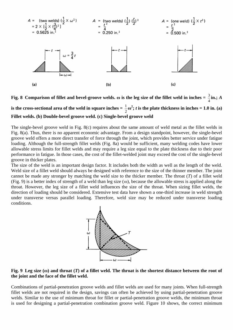
Fig. 8 Comparison of fillet and bevel-groove welds. ω is the leg size of the fillet weld in inches = 34
in.; A
is the cross-sectional area of the weld in square inches = 12ω2; t is the plate thickness in inches = 1.0 in. (a)
Fillet welds. (b) Double-bevel groove weld. (c) Single-bevel groove weld
The single-bevel groove weld in Fig. 8(c) requires about the same amount of weld metal as the fillet welds in Fig. 8(a). Thus, there is no apparent economic advantage. From a design standpoint, however, the single-bevel groove weld offers a more direct transfer of force through the joint, which provides better service under fatigue loading. Although the full-strength fillet welds (Fig. 8a) would be sufficient, many welding codes have lower allowable stress limits for fillet welds and may require a leg size equal to the plate thickness due to their poor performance in fatigue. In those cases, the cost of the fillet-welded joint may exceed the cost of the single-bevel groove in thicker plates. The size of the weld is an important design factor. It includes both the width as well as the length of the weld. Weld size of a fillet weld should always be designed with reference to the size of the thinner member. The joint cannot be made any stronger by matching the weld size to the thicker member. The throat (T) of a fillet weld (Fig. 9) is a better index of strength of a weld than leg size (ω), because the allowable stress is applied along the throat. However, the leg size of a fillet weld influences the size of the throat. When sizing fillet welds, the direction of loading should be considered. Extensive test data have shown a one-third increase in weld strength under transverse versus parallel loading. Therefore, weld size may be reduced under transverse loading conditions.
Fig. 9 Leg size (ω) and throat (T) of a fillet weld. The throat is the shortest distance between the root of the joint and the face of the fillet weld.
Combinations of partial-penetration groove welds and fillet welds are used for many joints. When full-strength fillet welds are not required in the design, savings can often be achieved by using partial-penetration groove welds. Similar to the use of minimum throat for fillet or partial-penetration groove welds, the minimum throat is used for designing a partial-penetration combination groove weld. Figure 10 shows, the correct minimum

throat for a combination weld. Figure 11 illustrates the faulty calculations that result when the incorrect throat is used to determine the allowable unit force on a combination weld.
Fig. 10 Determination of minimum throat
Fig. 11 Determination of allowable load on a combination weld. (a) Weld allowable load incorrectly figured adding each weld separately. (b) Weld allowable load correctly figured using minimum throat
Effect of Joint Design on Fatigue
The conventional approach to designing a multimember structure for fatigue resistance is to consider the members as first in importance and the joints as inevitable complications. However, of equal importance is the shape of the parts within the joint, because the shape and size of the members may multiply the external loading, or transform it into a different mode, causing possible stress concentrations. The importance of the effect of joint design on fatigue behavior cannot be overemphasized. Detail geometry and joint configuration
The file is downloaded from www.bzfxw.com
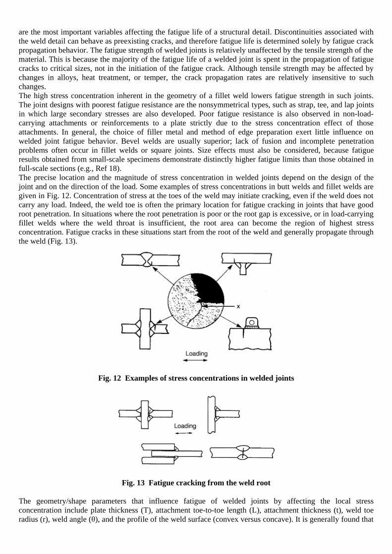
are the most important variables affecting the fatigue life of a structural detail. Discontinuities associated with the weld detail can behave as preexisting cracks, and therefore fatigue life is determined solely by fatigue crack propagation behavior. The fatigue strength of welded joints is relatively unaffected by the tensile strength of the material. This is because the majority of the fatigue life of a welded joint is spent in the propagation of fatigue cracks to critical sizes, not in the initiation of the fatigue crack. Although tensile strength may be affected by changes in alloys, heat treatment, or temper, the crack propagation rates are relatively insensitive to such changes. The high stress concentration inherent in the geometry of a fillet weld lowers fatigue strength in such joints. The joint designs with poorest fatigue resistance are the nonsymmetrical types, such as strap, tee, and lap joints in which large secondary stresses are also developed. Poor fatigue resistance is also observed in non-load-carrying attachments or reinforcements to a plate strictly due to the stress concentration effect of those attachments. In general, the choice of filler metal and method of edge preparation exert little influence on welded joint fatigue behavior. Bevel welds are usually superior; lack of fusion and incomplete penetration problems often occur in fillet welds or square joints. Size effects must also be considered, because fatigue results obtained from small-scale specimens demonstrate distinctly higher fatigue limits than those obtained in full-scale sections (e.g., Ref 18). The precise location and the magnitude of stress concentration in welded joints depend on the design of the joint and on the direction of the load. Some examples of stress concentrations in butt welds and fillet welds are given in Fig. 12. Concentration of stress at the toes of the weld may initiate cracking, even if the weld does not carry any load. Indeed, the weld toe is often the primary location for fatigue cracking in joints that have good root penetration. In situations where the root penetration is poor or the root gap is excessive, or in load-carrying fillet welds where the weld throat is insufficient, the root area can become the region of highest stress concentration. Fatigue cracks in these situations start from the root of the weld and generally propagate through the weld (Fig. 13).
Fig. 12 Examples of stress concentrations in welded joints
Fig. 13 Fatigue cracking from the weld root
The geometry/shape parameters that influence fatigue of welded joints by affecting the local stress concentration include plate thickness (T), attachment toe-to-toe length (L), attachment thickness (t), weld toe radius (r), weld angle (θ), and the profile of the weld surface (convex versus concave). It is generally found that

the fatigue strength of a welded joint decreases with increasing attachment length, increasing plate thickness, increasing weld angle, decreasing toe radius, and misalignment. By far, the most significant parameter is the weld toe radius. The weld toe stress-concentration factor, Kt, is a function of all these geometry variables, and a number of formulas are available for butt welds and cruciform joints subjected to bending or tensile load (Ref 19, 20). Misalignment is another geometry-related parameter that can influence the fatigue performance of a welded joint. Misalignment can manifest itself in several ways, angular and axial misalignments being the most common. Generally, fatigue strength decreases with increasing misalignment. Formulas to calculate the local weld stress-concentration factor due to misalignment are now well established (Ref 4). The degree of influence of the geometry parameters cited previously can vary significantly with the loading condition (e.g., tension versus bending) and the joint type. The following are a few examples of fatigue failures related to joint design or preparation. Example 2: Fatigue Cracking of a Stainless Steel Elbow Assembly at a Welded Joint in a High-Stress Region. The welded elbow assembly shown in Fig. 14 was part of a hydraulic-pump pressure line for a jet aircraft. The other end of the tube was attached to a flexible metal hose, which provided no support and offered no resistance to vibration. The components of the elbow were made of American Iron and Steel Institute (AISI) type 321 stainless steel and were joined with ER347 stainless steel filler metal by gas tungsten arc welding. The line was leaking hydraulic fluid at the nut end of the elbow, and the assembly was returned to the manufacturer to determine the cause of failure.
Fig. 14 Welded stainless steel elbow assembly that, as originally designed, cracked at the root of the weld under cyclic loading. The improved design moved the weld out of the high-stress area. Dimensions given in inches
Investigation. Visual examination of the elbow assembly revealed a crack in the fillet weld that joined the tube to the shoulder fitting. In assembly, the tube was inserted into a counterbore in the shoulder fitting (original design, section A-A, Fig. 14), then welded by the gas tungsten arc process. The fitting was separated from the tubing so that the surfaces of the cracked area could be examined. Stains on the fracture surface indicated that fatigue cracks had initiated at the root of the weld, at that stress concentrator inherent in the design of the joint. Cracking in the weld metal had progressed partway around the joint, thus producing a leakage path through which pressurized hydraulic fluid had escaped. Conclusion. Failure was by fatigue cracking initiated from a notch at the root of the weld and was propagated by cyclic loading of the tubing as the result of vibration and inadequate support of the hose assembly. Corrective Measures. The joint design was changed from a cylindrical lap joint (tube inserted into a counterbore) to a square-groove butt joint (improved design, section A-A, Fig. 14). The new joint design
The file is downloaded from www.bzfxw.com

provided a more flexible joint by eliminating the notch and by moving the weld out of the high-stress area. An additional support was provided for the hose assembly to minimize vibration at the elbow. Example 3: Fatigue Fracture of a Gas-Turbine Inner-Combustion-Chamber Case Assembly Because of Unfused Weld Metal and Undercuts. The case and stiffener of an inner-combustion-chamber case assembly failed by completely fracturing circumferentially around the edge of a groove arc weld joining the case and stiffener to the flange (Fig. 15a). The assembly consisted of a cylindrical stiffener inserted into a cylindrical case that were both welded to a flange. The case, stiffener, flange, and weld deposit were all of nickel-base alloy 718. It was observed that a manual arc weld repair had been made along almost the entire circumference of the original weld.
Fig. 15 Alloy 718 inner-combustion-chamber case assembly that fractured by fatigue in the weld joining the flange to the case and stiffener. (a) Exterior surface of the assembly showing the circumferential fracture of the case (arrow). 0.5×. (b) Section through the fracture showing the weld (region A) that originally joined the flange to the case (region B) and the stiffener (region C). The external repair weld (region D) had only partial fusion with the earlier bead. The arrow shows a film of oxide slag at the interface. Etched with 2% chromic acid plus HCl. 10×
Investigation. Microscopic examination of the fracture site revealed unfused weld metal surfaces and severe undercutting of the base material of the stiffener in many areas. The thickness of the case had also been undercut in several areas. Fatigue cracks had originated at multiple sites along the weld interfaces of the case and stiffener. Also, the groove weld contained areas of mismatch that were greater than those allowed by the specifications. Metallographic specimens from sections of the fracture site showed the two weld beads that were deposited by a repair weld contained many regions of partial fusion as evidenced by oxide films and slag at the weld interface (Fig. 15b). Conclusions. Failure was by fatigue from multiple origins caused by welding defects. The combined effects of undercutting the case wall, weld mismatch, and unfused weld interfaces contributed to high stress concentrations that generated the fatigue cracks. Ultimate failure was by tensile overload of the sections partly separated by the fatigue cracks. Recommendation. Correct fit-up of the case, stiffener, and flange is essential, and more skillful welding techniques should be used to avoid undercutting and unfused interfaces. Example 4: Fatigue Fracture of Welded Type 321 Stainless Steel Liners for a Bellows- Type Expansion Joint. The liners for bellows-type expansion joints in a duct assembly (Fig. 16a) failed in service. The duct assembly, used in a low-pressure nitrogen gas system, consisted of two expansion joints (bellows) connected by a 32 cm (12 in.) outside diameter (OD) pipe of ASTM A106, grade B, steel. Elbows of ASTM A234, grade B, steel, 180° to each other, were attached to each end of the assembly. A liner with an OD of 29 cm (11 in.) was welded inside each expansion joint. The liners were 1.3 mm (0.050 in.) thick and made of AISI type 321 stainless steel.

The upstream end of one liner was welded to an elbow, and the upstream end of the other liner was welded to the pipe; this allowed the downstream ends of the liners to remain free and permitted the components to move with expansion and contraction of the bellows.
Fig. 16 Duct assembly of medium-carbon steels in which welded bellows liners of type 321 stainless steel fractured in fatigue. (a) Configuration and dimensions (given in inches). (b) Light fractograph showing fracture origin (top edge). 30×
Investigation. In field inspection, portions of the two failed liners were found downstream in the duct assembly. These were removed and sent to the laboratory for failure analysis. Many of the fracture surfaces had undergone extreme deformation, making it difficult to obtain detailed and complete information from the fracture surface. Fortunately, however, some fracture areas were protected from damage, making it possible to identify one fracture origin. Laboratory inspection showed that the origin of failure in the portion of the fracture surface studied was in an area where two welds intersected—the longitudinal or seam weld forming the liner and the circumferential weld attaching the liner to the pipe. Figure 16(b) shows a fractograph of the fracture surface at the weld intersection, indicating the fracture origin. Metallographic examination of a cross section containing the longitudinal weld revealed that the microstructure of the weld area contained no irregularities. Metallurgical evaluation of the cross section in the transverse plane of the fractured piece containing the intersection of the longitudinal and circumferential welds exhibited extreme banding within the microstructure. The banding was the result of chromium and nickel dilution in one area and the enrichment of the same elements in areas adjacent to that area. In addition, the intersection of the two welds contained cracks similar in appearance to those normally formed when variations in thermal expansion and contraction are encountered when welding dissimilar metals.
The file is downloaded from www.bzfxw.com

A microhardness traverse across the weld area revealed a base metal average hardness of 89 HRB. The hardness of the HAZ on both sides of the weld was 87 HRB, and the weld metal had a hardness of 93 to 98.5 HRB. Conclusions. The liners failed in fatigue that was initiated at the intersection of the longitudinal weld forming the liner and the circumferential weld that joined the liner to the bellows assembly. Because the liners were welded at one end and the other end was free, the components moved with expansion and contraction of the joints and were subjected to vibrational stresses imposed by the transfer of nitrogen gas. The stresses, created by cyclic loading, were concentrated mainly at the metallurgical notches formed at the weld metal/base metal interface. Differences in composition caused a variation in strength at the critical region of high residual stresses. Vibrational stresses were concentrated at the circumferential weld metal/base metal interface and at the intersection of the circumferential and longitudinal welds. The origin of the failure was at the intersection of the two welds—the region containing the most severe stress raisers. The design allowed the two liners to be cantilevered in a dynamic system subjected to both thermal stresses and vibrations from gaseous flow. Corrective Measure. The thickness of the liners was increased from 1.3 to 1.9 mm (0.050 to 0.075 in.), which successfully damped some of the stress-producing vibrations. Example 5: Fatigue Cracking of Headers for Superheated Water Because of Notches at Welds. A system of carbon steel headers, handling superheated water of 188 °C (370 °F) at 2 MPa (300 psi) for automobile-tire curing presses, developed a number of leaks within about 4 months after 2 to 3 years of leak-free service. All the leaks were in shielded metal arc butt welds joining 200 mm (8 in.) diameter 90° elbows and pipe to 200 mm (8 in.) diameter welding-neck flanges. A flange-elbow-flange assembly and a flange-pipe assembly that had leaked were removed for examination. Investigation. Magnetic-particle tests confirmed the existence of the cracks in the welds through which leaking had occurred and revealed the presence of other cracks that had not yet penetrated to the weld surface. Radiographic inspection was conducted, with the source at the centerline of each flange and the film wrapped around the weld bead on the outside. The film showed the cracks indicated by the magnetic-particle inspection as well as additional, incipient cracks and regions of incomplete weld penetration that could not be correlated with the major crack locations. The butt welds were sectioned, with some cuts being made through regions of pronounced magnetic-particle indication and others at regions where no indications were found. The polished-and-etched surfaces of two such sections from the flange-pipe weld are shown in Fig. 17.
Fig. 17 Flange-to-pipe assembly of a carbon steel header, used for handling superheated water, that cracked by fatigue because of notches at welds. (a) Section through butt-welded joint showing crack (arrow A) that originated at toe of weld on inner surface, incomplete weld penetration (arrow B), and difference in thickness of flange (left) and pipe. Etched with 2% nital. Approximately 1.7×. (b) Section through same weld as in (a), but showing no crack indications. Etched with 2% nital. Approximately 1.7×
It was immediately apparent on sectioning that, although the OD of the flanges matched those of the elbows and pipe (nominal 220 mm, or 8 in.), there was a considerable difference in the inside diameters (IDs). Actually, only the elbows had been of schedule 80 wall (194 mm, or 7 in., nominal ID), as called for in the

specification for flanges, elbows, and pipe. The welding flanges that were used had been bored to 202.5 mm (7.975 in.) ID (for use with schedule 40 pipe), and the pipe had been of schedule 100, with a 189 mm (7.437 in.) nominal ID. The result was a disparity in ID of about 8.9 mm (0.350 in.) between flange and elbow and about 13.7 mm (0.538 in.) between flange and pipe. This was the reason for depositing an internal fillet weld, which created a stress-concentrating notch at the toe of the weld against the flange inner surface. The welding procedure had been as follows. The edges were prepared by machining a 6.4 mm (0.25 in.) deep groove with a 75° included angle at the outside surface. The initial weld deposit was a root pass applied from the outside. Second and third passes were laid on top of this, the latter depositing a wide, weave-type bead. Finally, an attempt was made to reconcile the difference in wall thickness by depositing a fillet weld bead on the inside. In some instances, penetration was deep enough so that the fillet weld merged with the root pass of the exterior weld. In others, as in Fig. 17, this did not occur; as a result, a short span existed where there was incomplete penetration, and the original edges of the flange and elbow were still visibly in contact. Such a region of incomplete penetration is normally considered a site for stress concentration, but it can be seen in Fig. 17 that there was no crack growth at this point. All the major cracks found in either elbow or pipe welds originated at the toe of the fillet weld in the inner surface of the flange (Fig. 17a). As illustrated in Fig. 17(b), some fillet weld toes did not produce such cracks. A hardness survey was taken across weld joint. The results showed that the weld beads and the HAZs were similar in hardness to the base metal and that there was no evidence of hard spots. The welds were sound, fine grained, and free from slag inclusions and porosity. Chemical analysis of the five components of the two assemblies confirmed that these headers conformed to the requirements of the applicable specifications (flanges and elbow of ASTM A 105, grade II, and pipe of ASTM A 106, grade B; similarly numbered ASME SA specifications also apply). A powdery, green deposit found in the interior of an iron-body gate valve of the system was determined by chemical analysis to consist of a trivalent chromium oxide or salt plus iron oxide or salt and 22% combined water. No organic matter was detected, and no copper was found. Conclusions. The failures of the butt welds were the result of fatigue cracks caused by cyclic thermal stresses that initiated at stress-concentrating notches at the toes of the interior fillet welds on the surfaces of the flanges. Several of these penetrated to the exterior surface and caused leaks, but others existed that were still in an incipient growth stage. Incomplete penetration existed in some of the welds, but no evidence was found of cracks originating from these sites, and they were not a factor in the failures. The powdery, green deposit was attributed to reduction of some of the chromate used as a corrosion inhibitor in the superheated water. It was not regarded as a contributing cause of the failures. Recommendations. It was concluded that all other joints of the system possessing the same mismatch in wall thickness, and thus in all probability the same stress raiser at the toe of the interior fillet weld, could be expected to fail by the same mechanisms. Repair of such joints was not considered feasible, and it was recommended that they be replaced. Ultrasonic testing should be used to identify the joints by detecting the differences between the wall thicknesses of the flange and the pipe and of the flange and the elbow. Special attention to accuracy of fit-up in the replacement joints was also recommended to achieve smooth, notchfree contours on the interior surfaces. Example 6: Fatigue Failure of an Inlet Header Because of Poor Welding Technique and Unfavorable Weld-Joint Design. While undergoing vibration testing, a type 347 stainless steel inlet header for a fuel-to-air heat exchanger cracked in the header tube adjacent to the weld bead between the tube and header duct (Fig. 18).
The file is downloaded from www.bzfxw.com

Fig. 18 Type 347 stainless steel inlet header for fuel-to-air heat exchanger that cracked due to poor welding technique and unfavorable joint design. Dimensions given in inches
Investigation. The weld was relatively massive, which was apparently necessary to fill large clearances between the mating parts. Collapse of the base metal in several areas adjacent to the weld indicated that there was plastic deformation from excessive heat. Liquid penetrant inspection of the weld between the header tube and the header duct revealed a 29 mm (1.14 in.) long crack in the weld on the tube side. Several weld bead undercuts were visible, and the crack appeared to propagate through each of these small imperfections. The header was sectioned to open the crack and expose the fracture surface for examination. The tube and duct were initially welded together (weld 1, original design, section A-A, Fig. 18). A doubler collar, 16 mm (0.63 in.) wide and of the same material and thickness as the duct, was then welded to the duct along the outer edge of the collar (weld 2). A third weld joined the inner edge of the collar to the header tube, thus creating an area of twice the normal header thickness adjacent to the joint. This third weld, throughout much of the collar circumference, penetrated the original tube-to-duct weld (weld 1), but in the area of the fracture, there was a gap between the two sheets of stainless steel, and the third weld was separate (weld 3). Examination of the underside of the joint showed incomplete fusion of the weld between the tube and duct. Distortion of the base metal adjacent to the weld was also visible from this side. Examination of the surface of the opened crack revealed the origin of the crack at a weld undercut at the toe of weld 3. The crack then progressed through the HAZ of the base metal.

Conclusions. The crack in the header tube was the result of a stress concentration at the toe of the weld joining the doubler collar to the tube. The stress concentration was caused by undercutting from poor welding technique and an unfavorable joint design that did not permit a good fit-up. Corrective Measures. The doubler collar was made so that it could be placed in intimate contact with the header duct (improved design, section A-A, Fig. 18). The two sheets were beveled, where necessary, to form a V-groove joint with the tube. Two weld passes in the V-groove were used to join the two sheets to the tube. This procedure resulted in a smaller, controlled, homogeneous weld joint with less distortion.
Other Failures Related to Joint Design
Discontinuities can be introduced during the welding process due to poor joint design. Joint design may contribute to excessive shrinkage stresses, increasing the risk of both solidification cracking and cold cracking, especially for high-strength materials. Special care must be taken to generate proper bead shape, preheat temperatures, and interpass temperatures in addition to correct electrode and flux combinations when welding high-strength materials. Care must also be taken to reduce hydrogen pick up in these welds. Dirt, grease, oil, moisture, and all hydrocarbons must be removed from the weld zone. A low-hydrogen welding process must be used. The magnitude of the induced stresses also depends on the joint design, the degree of restraint imposed on the joint, the plate thickness, the orientation of the weld, and the size of the weld. Restrained corner or T-joints are the most susceptible to lamellar tearing, because the fusion boundary is roughly parallel to the plate surface (Fig. 19) (Ref 21) and through-thickness contraction stresses are high. Lamellar tearing in butt welds is rare. Thick-plate, high-imposed restraint (for example, rigid clamping) and large weld beads all increase residual stresses and the likelihood of this form of tearing.
The file is downloaded from www.bzfxw.com

Fig. 19 Methods used to reduce lamellar tearing. (a) Angling the weld fusion line to avoid shrinkage stresses in the through-thickness direction. (b) Use of smaller partial-penetration welds to reduce joint restraint. (c) Placement of welding beads on the thinner plate (when welding plates of different thicknesses) so that smaller beads can be used. Source: Ref 21
Problems with joint penetration and incomplete root fusion can also be due to the use of a joint design that is not proper for the welding process being used, or to a disregard for the procedures that are intended to provide adequate penetration. A joint design developed for one metal is also not necessarily suitable for other alloys and should not be used unless it proves to be satisfactory, based on either experience or tests. Choosing the best process and design depends on many factors including:
• Material characteristics (sensitivity to porosity or cracking and the required mechanical properties)

• Details of the joint (plate thickness, joint design, restraint, welding position, heat input, and location) • Weld economics (deposition rates and efficiencies, cost of labor, cost of consumables, capital cost of
equipment, number of spare parts required, operator skills or training needed, setup, clean-up cost, and so on)
All these factors are considered in design and are covered in numerous other publications on welding, such as Welding, Brazing, and Soldering, Volume 6 of ASM Handbook. The following are just a few examples of failures related to weld design. Example 7: Incomplete Fusion due to Poor Accessibility. A void caused by incomplete fusion is illustrated in Fig. 20 from a gas tungsten arc weld between a nickel alloy and an alloy steel. Special care must be taken when welding with nickel alloy filler metal in order to avoid this problem of incomplete fusion. The primary factor is weld-joint design. Molten nickel alloy weld metal is sluggish and has low fluidity; it does not wet or flow as well as steel weld metal. Therefore, joint accessibility must be sufficient to allow proper manipulation of the welding arc.
The file is downloaded from www.bzfxw.com

Fig. 20 Section through an automatic gas tungsten arc weld containing voids caused by incomplete fusion. (a) Base metal at left is Incoloy 800 nickel alloy, that at right is 2.25Cr-1.0Mo alloy steel. Filler metal was ERNiCr-3, used with cold wire feed. Macrograph. 1×. (b) Micrograph of the area circled in (a) showing void. 75×. Both etched with 2% nital
Example 8: Cracking of a Weld That Joined the Head to the Shell of a Steam Preheater Because of Poor Root Penetration. A weld that attached the head to the shell of a preheater containing steam at 1.4 MPa (200 psi) and was used in the manufacture of paper cracked in service. The length of service was not reported. A section of the failed preheater, plus a section of proposed new design, were selected for examination. Investigation. The preheater was approximately 0.9 m (3 ft) in diameter and approximately 1.2 m (4 ft) long.
The original joint (Fig. 21a) contained a 6.4 by 50 mm ( 14
by 2 in.) backing ring that had been tack welded to

the inside surface of the shell in a position to project approximately 16 mm ( 58
in.) beyond the fully beveled top
edge of the shell. The ring served the dual purpose of backing up the weld and positioning the head; the
projecting edge of the ring fitted against a 9.5 mm ( 38
in.) wide, 3.2 mm ( 18
in.) deep undercut on the inner
corner of the rim of the head. The internal 90° angle in this undercut was sharp, with almost no fillet. A bevel from the lower edge of the undercut to the outside of the head completed the groove for the circumferential attachment weld.
Fig. 21 Weld attaching the head to the shell of a steam preheater that cracked because of poor root penetration in original and first replacement joint designs. (a) and (b) Sections taken through the head-to-shell joint. Etched in hot 50% hydrochloric acid. Actual size. The section in (a) is the original design; (b) shows the first replacement design. (c) The final design, which achieved full root penetration
The head was joined to the shell by arc welding in three passes. In all sections that were taken through the welded joint and examined, the fusion was found to range from poor to none at the root of the weld and at the backing ring. The weld did not penetrate to the undercut rim of the head, and in some locations, the weld bead was standing free (not fused with the backing ring). In all sections of the joint examined, there was a crack beginning at the sharp, internal 90° angle of the undercut and extending toward the outer surface of the head. This crack had to penetrate only 50% of the full thickness of the head before final fracture occurred. The first proposed replacement design (Fig. 21b) was more or less the reverse of the failed joint. A deep offset had been machined in the exterior of the rim of the head, reducing the wall thickness by 65%. The outer portion of the offset had been beveled to receive the weld deposit; below the offset, a horizontal step, approximately 2.5 mm (0.10 in.) deep, had been cut to align the head against the square-cut shell edge. Below the step was a long taper almost to the inner surface of the head. A number of sections through the proposed replacement joint showed incomplete root penetration of the weld, and in one section, a crack was discovered extending from the outer edge of the positioning step through the root-pass weld bead. Conclusions. Cracking occurred in the HAZ in the head of the original design, originating in the sharp corner of the undercut, which was an inherent stress raiser. In the first replacement design, beveling of the head and shell was insufficient to permit full root-weld penetration, thus creating an inherent stress raiser. In both designs, the stress raisers would not have been present had full root-weld penetration been obtained.
The file is downloaded from www.bzfxw.com

Corrective Measures. To ensure full root penetration, the joint design shown in Fig. 21(c) was adopted. This joint retained the full thickness of both the head and the shell and, with the gap between the root edges, made it possible to obtain full root penetration, thereby reducing any notch effect to a minimum. A suggested alternative that would avoid the possibility of crevice corrosion was the use of a single-V-groove joint without a backing ring, with welding being done from the outside in two or more passes, ensuring that the root pass attained full penetration. Example 9: Fracture of a Carbon Steel Pipe in a Cooling Tower. Joint design was responsible for mechanical
notches at welds in a heat-exchanger component (Fig. 22). A 455 mm (18 in.) diameter, 8 mm ( 516
in.) wall
carbon steel discharge line for a circulating-water system at a cooling tower fractured in service; a manifold section cracked where a Y-shaped connection had been welded. The steel pipe was made to ASTM A 53 specifications.

Fig. 22 Carbon steel discharge line at a cooling tower that failed because of poor fit-up at Y-joint and poor-quality welds. (a) Original joint design of pipe connection and location of cracks. Photograph is an oblique view of a section through the weldment, showing the abrupt intersection of pipe walls and the voids and crevices in the weld metal. (b) Improved joint design. Dimensions given in inches
Investigation. Examination of the pipe revealed that cracking occurred in the HAZ both transverse and parallel to the weld, as shown in Fig. 22(a). The end of the branch pipe was prepared for welding by making a transverse cut; a second cut was then made at about 15° to the longitudinal axis of the pipe, resulting in a sharp corner (Fig. 22a). The main pipe was then notched to fit the end of the branch pipe. Fitting of the saddle connection was poor, and no backing strips were used even though the pipe wall was thin; as a result, the
The file is downloaded from www.bzfxw.com

condition of the root-weld bead was below standard, and numerous deep crevices and pits were in the weld area exposed to the inner surfaces of the manifold (sectional view, Fig. 22a). Conclusions. The pipe failed by fatigue. Cracks originated at crevices and pits in the weld area that acted as stress raisers, producing high localized stresses because of the sharp-radius corner design. Abnormally high structural stresses and alternating stresses resulting from the pump vibrations contributed to the failure. Corrective Measures. The joint design was changed to incorporate a large-radius corner (Fig. 22b), and fitting of the components was improved to permit full weld penetration. Backing strips were used to increase weld
quality. Also, the pipe wall thickness was increased from 8 to 9.5 mm ( 516
to 38
in.).
Example 10: Failure of Welds in an Aqueduct Caused by Poor Welding Techniques. A 208 cm (82 in.) ID steel aqueduct fractured circumferentially at two points 152 m (500 ft) apart in a section above ground. A year later, another fracture occurred in a buried section 6.4 km (4 miles) away. Both pipes fractured during January at
similar temperatures and pressures. The pipe had a 24 mm ( 1516
in.) wall thickness, and the hydrostatic head was
331 m (1085 ft). The air temperature was approximately −13 °C (9 °F), the water temperature approximately 0.6 °C (33 °F), and the steel temperature approximately −4 °C (25 °F). The fractures occurred at bell-and-spigot slip joints (Fig. 23a) that, at the two initial fractures, had been fillet welded both inside and out; at the third break, the joints had been fillet welded only on the inside. The pipe had been shop fabricated of ASTM A572, grade 42, type 2, steel in 12 m (40 ft) lengths, then shop welded into 24 m (80 ft) lengths. Field assembly was with the bell-and-spigot joints.
Fig. 23 Bell-and-spigot joint used in an aqueduct of steel pipe. (a) The original design cracked because of poor welding technique and poor choice of metal. (b) Improved design showing modification of weld beads. Dimensions given in inches
Investigation. All three fractures occurred at a bell section and initiated at the toe of the inside fillet weld (Fig. 23a). The welds in the first two fractures had been made in the field; the third weld that failed had been made in the shop. Also, both of the original inside welds at the early fractures had been gouged out to permit relocation of the pipe to maintain the supporting ring girder legs in a vertical position. The joints had then been rewelded on the inside. This had not been done in the third weld that failed later. Charpy V-notch impact tests on the steel used for this pipeline revealed a ductile-to-brittle transition temperature that was unfavorably high—approximately 10 °C (50 °F). At the temperatures existing at the time of the failures, the impact strength of the steel was approximately 13.5 J (10 ft · lbf), which is considered to be dangerously brittle. Inspection of the interior field welds showed that instead of using continuous circumferential stringer beads, the welder had used a wash-pass technique, depositing a heavy bead from toe to crown. This permitted faster welding but gave inconsistent penetration and a considerable number of slag inclusions and imperfections, such as deep valleys, grooves, and undercuts, which served as notches and stress raisers, at the toe of the weld. Examination of the third fracture at the shop weld disclosed that areas in the HAZ and at the toe of the weld had hardness levels as high as 34 HRC. When test welds were made on metal preheated to 95 °C (200 °F) before welding, the hardness of the HAZ was 22 HRC.

Conclusions. Brittle fracture of the aqueduct pipe was attributed to a combination of stress concentrations at the toes of the fillet welds due to poor welding technique, including shop welds made without preheat, and a brittle condition of the steel at winter temperatures caused by a relatively high ductile-to-brittle transition temperature. Corrective Measures. The following changes were made to eliminate welding and material problems:
• Any area to be welded was preheated to at least 65 °C (150 °F). • In any weld having an undercut or abrupt transition to the base metal at the toe, an additional contour
weld bead was deposited at the toe (Fig. 23b). • Tensile loadings of above-ground sections were reduced by the installation of expansion joints. • Where the pipe was buried and pipe temperatures varied considerably, butt welds were used. • All ASTM A572 steel plate used was rolled from fully killed ingots made with a grain-refining practice
and normalized after rolling, which provided a ductile-to-brittle transition temperature of approximately -32 °C (-25 °F).
References cited in this section
4. S.J. Maddox, “Fitness-for-Purpose Assessment of Misalignment in Transverse Butt Welds Subject to Fatigue Loading,” Document XIII-1180–85, International Institute of Welding, 1985
17. O.W. Blodgett, Joint Design and Preparation, Welding, Brazing, and Soldering, Vol 6, Metals Handbook (9th ed.), 1983, p 60–72
18. S.J. Maddox, “Scale Effect in Fatigue of Fillet-Welded Aluminum Alloys,” presented at Sixth Int. Conf. Aluminum Weldments (Cleveland), American Welding Society, 1995
19. V.I. Makhnenko and R.Y. Mosenkis, Calculating the Coefficient of Concentration of Stresses in Welded Joints with Butt and Fillet Welds, Automat. Weld., Aug 1985
20. K. Iida, Y. Kho, J. Fukakura, M. Nihei, T. Iwadate, and M. Nagai, “Bending Fatigue Strength of Butt Welded Plate with Uranami Bead,” IIW/IIS-XIII-1202–86, International Institute of Welding, 1986
21. “Welded Steel Construction (Metal Arc Welding),” CSA W59, Canadian Standards Association, 1989
Failure Origins in Arc Welds
The general types of process-related discontinuities in arc welds include:
• Porosity formed by gas entrapment during solidification • Inclusions: slag inclusions, tungsten inclusions, oxide inclusions • Lack of fusion (LOF) and lack of penetration (LOP) • Geometric discontinuities, such as poor weld contours, undercut, underfill, overlap, excessive
reinforcement, fillet shape, melt-through, misalignment, and distortion • Shrinkage voids formed during solidification • Craters or depressions that form at the termination of a weld bead or in the molten weld pool • Spatter that forms when metal particles are expelled during welding • Arc strikes (or arc burns) that form from any localized remelted metal, heat-affected metal, or change in
the surface profile of any part of a weld or base metal resulting from an arc • Metallurgical discontinuities, such as cracks, fissures, segregation, and lamellar tearing
In addition, localized embrittlement in welded regions can occur by a number of mechanisms. The three most common mechanisms are hydrogen embrittlement, strain aging, and temper embrittlement of steels. Each of these mechanisms can reduce the toughness of the material, either soon after welding or during service.
The file is downloaded from www.bzfxw.com

Most discontinuities may be produced by any of the welding processes, although some are found only in welds made by a particular process. The observed occurrence of discontinuities and their relative amounts depend largely on the welding process used, the inspection method applied, the type of weld made, the joint design and fit-up obtained, the material used, and the working and environmental conditions. Weld acceptance standards also are used when a discontinuity has been clearly located, identified, sized, its orientation determined, and its structural significance evaluated. For example, the API standard 1104 (Ref 22) includes criteria for acceptance of steel welds based on a number of imperfections, including inadequate penetration, incomplete fusion, internal concavity, burn-through, slag inclusions, and porosity. Acceptance criteria depends on the inspection method and the effects of the discontinuity on service fitness. As previously noted, moderate amounts of volumetric discontinuities, such as slag inclusions and porosity, typically do not reduce the fatigue strength of the weld sufficiently to warrant their classification as potential causes of fracture. In fact, fatigue cracks that initiate at the toe of a weld will propagate around areas of gas porosity or slag inclusions as often as through them (Fig. 24). Nonetheless, welders must still be constantly encouraged to make sound (perfect) welds independent of prevailing acceptance standards.
Fig. 24 Cracking from weld toe around volumetric discontinuities in butt welds. (a) Slag inclusion. (b) Porosity
Discontinuities such as hot (liquation or solidification) cracks, cold (hydrogen-induced) cracks, and lamellar tears are much more serious, because they are severe stress raisers and affect fatigue strength to a degree that cannot be compensated for in design. Hot cracks and lamellar tears normally occur during or immediately after welding and can be detected by nondestructive testing and eliminated from finished weldments. However, the formation of cold cracks resulting from the presence of hydrogen may be significantly delayed. For this reason, inspection is usually delayed at least 48 h (and, in many cases, several weeks) after welding. This section briefly reviews the general types of process-related discontinuities and metallurgical-related cracking of arc welds. Failure origins related to other types of welding processes are described in subsequent sections of this article. Additional information on the engineering performance and properties of weldments for specific types of common structural alloys (e.g., carbon and low-alloy steels, stainless steels, aluminum alloys, titanium alloys) is in Ref 23.
Porosity
Porosity consists of cavities or pores that form in the weld metal as a result of entrapment of gases evolved or air occluded during the welding process, as evidenced by Fig. 25 and 26. Porosity in welds is caused by gas entrapment in the molten metal, by too much moisture on the base or filler metal, or by improper cleaning of the joint during preparation for welding. Elements such as sulfur, lead, and selenium in the base metal, and foreign contaminants such as oil, grease, paint, rust, and moisture in the welding area also can increase porosity in the weld metal. Porosity in aluminum is primarily caused by the entrapment of hydrogen during the solidification process from sources such as filler metal, base metal, surface contamination, and shielding gas.

Fig. 25 Porosity in GMAW core-plated silicon steel laminations. 100×
Fig. 26 Pulsed GMAW spot weld showing porosity in dissimilar metal weldment; a copper-nickel alloy to a carbon-manganese steel using an ERNiCu-7 (Monel 60) electrode. Etchant, 50% nitric-50% acetic acid. 4×
Pores can take many shapes and sizes—from pinholes to large voids, from spherical to elongated or pear-shaped, with constrictions or expansions. Gas porosity can occur on or just below the surface of a weld and have a rounded or elongated teardrop shape with or without a sharp point. Distribution of porosity in welds may be aligned, clustered, or uniformly scattered. Pores can be uniformly distributed throughout the weld or isolated in small groups; they can also be concentrated at the root or toe of the weld.
The file is downloaded from www.bzfxw.com

Gas porosity is usually well distributed in overhead-position welds. It is frequently found along the top edge of welds made in the horizontal position and is least likely to be encountered in welds made in the vertical-up position unless there is a problem with shielding the molten puddle. Linear porosity is most often found in welds where the root-pass penetration is inadequate. Aligned or layered porosity exerts a much greater effect on mechanical properties than does uniformly distributed porosity. Microporosity, too fine to be detected by radiographic procedures, typically occurs in layers along the weld fusion line and at weld-pass interfaces. This type of porosity can lower mechanical properties appreciably, if it is extensive enough to lower static strength. Microporosity is typically found in aluminum alloy weldments. Two common types of porosity are wormholes and blowholes. Wormholes are elongated voids with a definite worm-type shape and texture (Fig. 27). Blowholes may form on the surface of the weld if porosity cannot fully escape before the weld metal solidifies. “Herringbone” porosity (Fig. 28a) can form when the gas shield in an automated GMAW process is interrupted. Its appearance is due to the formation of highly elongated pores inclined to the direction of welding.
Fig. 27 Wormhole porosity in a weld bead. Longitudinal cut. ~20×
Fig. 28 Radiograph showing herringbone porosity in automatic weld due to disruption of gas shield
Causes of Weld Porosity. The most common cause of porosity is the result of gas-producing contaminants in the joint, but several other factors can influence the occurrence of porosity. For example, porosity may be associated with welding practice. Scattered surface porosity may result in submerged arc welding when the arc flashes through, due to insufficient flux. Insufficient flux also is more likely to occur in circumferential welds

than flat welds. Arc blow also can cause porosity, particularly in high-speed welds on light-gage sheet. Wherever there is an opportunity for flux to become trapped, there is the possibility of porosity. Also, even though base metal composition generally has little effect on porosity, there are circumstances when composition of the base metal may influence porosity. For example, very high or very low carbon contents in steel can cause porosity. Segregation of impurities, such as sulfur in steel, may also be a factor. Instances of severe segregation, which appear as laminations, may cause large holes in welds (see Example 11 in this article). The interrelationship of factors that may cause or control porosity is illustrated in Fig. 29. To minimize porosity:
• Remove scale, rust, paint, grease, oil, and moisture from the surface of the joint. • Eliminate moisture from the flux or the shielding gas. • Use short arc length (particularly with low-hydrogen electrodes). • Keep the weld molten long enough (use preheating) to allow the gas to escape. • Provide sufficient shielding (flux or gas). • Improve fit-up. • In steel, remove slag residue that may cause porosity, particularly in butt welds (fluxes on certain types
of electrodes are worse than others in this respect). To control slag residue, allow weld penetration into
the backup strip or maintain a clearance of at least 4 mm ( 532
in.) above the backup.
• Use low-hydrogen electrodes when welding steels that are low in carbon and manganese and high in sulfur and phosphorus. Control admixture of the weld and the workpiece by using low current and fast travel speed to obtain less penetration.
• Keep the sulfur content low in the base metal, thus minimizing formation of hydrogen sulfide (H2S). • Decrease surface tension and viscosity of both the liquid weld metal and the molten flux. • Prevent contamination of GMAW filler-metal wire.
Fig. 29 Factors influencing porosity in weldments
The occurrence of porosity in aluminum alloy welds is almost always caused by entrapment of hydrogen gas. Hydrogen has high solubility in molten aluminum, but its solubility in solid aluminum is only a small fraction of its solubility in solid steel or solid titanium. Thus, hydrogen dissolves very rapidly in molten aluminum and
The file is downloaded from www.bzfxw.com
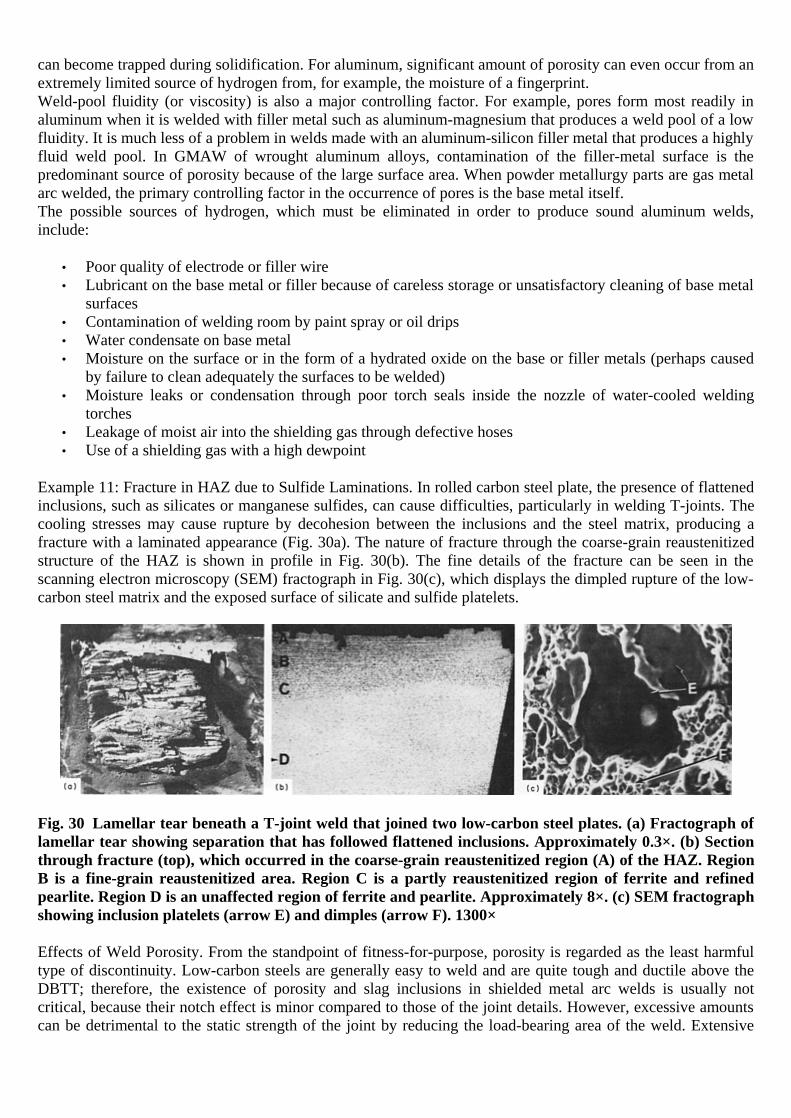
can become trapped during solidification. For aluminum, significant amount of porosity can even occur from an extremely limited source of hydrogen from, for example, the moisture of a fingerprint. Weld-pool fluidity (or viscosity) is also a major controlling factor. For example, pores form most readily in aluminum when it is welded with filler metal such as aluminum-magnesium that produces a weld pool of a low fluidity. It is much less of a problem in welds made with an aluminum-silicon filler metal that produces a highly fluid weld pool. In GMAW of wrought aluminum alloys, contamination of the filler-metal surface is the predominant source of porosity because of the large surface area. When powder metallurgy parts are gas metal arc welded, the primary controlling factor in the occurrence of pores is the base metal itself. The possible sources of hydrogen, which must be eliminated in order to produce sound aluminum welds, include:
• Poor quality of electrode or filler wire • Lubricant on the base metal or filler because of careless storage or unsatisfactory cleaning of base metal
surfaces • Contamination of welding room by paint spray or oil drips • Water condensate on base metal • Moisture on the surface or in the form of a hydrated oxide on the base or filler metals (perhaps caused
by failure to clean adequately the surfaces to be welded) • Moisture leaks or condensation through poor torch seals inside the nozzle of water-cooled welding
torches • Leakage of moist air into the shielding gas through defective hoses • Use of a shielding gas with a high dewpoint
Example 11: Fracture in HAZ due to Sulfide Laminations. In rolled carbon steel plate, the presence of flattened inclusions, such as silicates or manganese sulfides, can cause difficulties, particularly in welding T-joints. The cooling stresses may cause rupture by decohesion between the inclusions and the steel matrix, producing a fracture with a laminated appearance (Fig. 30a). The nature of fracture through the coarse-grain reaustenitized structure of the HAZ is shown in profile in Fig. 30(b). The fine details of the fracture can be seen in the scanning electron microscopy (SEM) fractograph in Fig. 30(c), which displays the dimpled rupture of the low-carbon steel matrix and the exposed surface of silicate and sulfide platelets.
Fig. 30 Lamellar tear beneath a T-joint weld that joined two low-carbon steel plates. (a) Fractograph of lamellar tear showing separation that has followed flattened inclusions. Approximately 0.3×. (b) Section through fracture (top), which occurred in the coarse-grain reaustenitized region (A) of the HAZ. Region B is a fine-grain reaustenitized area. Region C is a partly reaustenitized region of ferrite and refined pearlite. Region D is an unaffected region of ferrite and pearlite. Approximately 8×. (c) SEM fractograph showing inclusion platelets (arrow E) and dimples (arrow F). 1300×
Effects of Weld Porosity. From the standpoint of fitness-for-purpose, porosity is regarded as the least harmful type of discontinuity. Low-carbon steels are generally easy to weld and are quite tough and ductile above the DBTT; therefore, the existence of porosity and slag inclusions in shielded metal arc welds is usually not critical, because their notch effect is minor compared to those of the joint details. However, excessive amounts can be detrimental to the static strength of the joint by reducing the load-bearing area of the weld. Extensive

porosity also can interfere with detection of the more harmful planar discontinuities, such as undercut, LOF, and LOP, by obscuring their presence. The influence of porosity is evaluated according to its location, that is, surface or internal. Surface porosity has a detrimental effect on fatigue strength, especially when weld reinforcement is removed or the weld is undermatched. In high-cycle fatigue, porosity is least harmful, as long as weld buildup is not removed. If it is removed, the rate of decrease in fatigue strength initially is appreciable (up to 50% at 8% porosity); after reaching about 8% porosity, fatigue strength reduction rate decreases. To improve fatigue life of welds with surface porosity, the weld root should be dressed to minimize stress concentration. Fatigue failure originates at surface porosity rather than at buried slag inclusions. Pores in the surface are more harmful than internal pores of the same size and amount over a given weld length. Shape of the porosity is relatively unimportant. The presence of porosity in butt welds is structurally more significant than in fillet welds, because butt welds usually see more critical applications than fillet welds, and the stress concentrations at the toes of fillet welds are generally quite large.
Inclusions
Nonmetallic inclusions form as a result of reactions between metallic alloy elements and nonmetallic tramp elements, or by mechanical entrapment of nonmetallic slag or refractory particles. Extraneous inclusions may include:
• Oxides • Sulfides • Nitrides • Carbides • Other compounds • Multiple phases
Among these nonmetallic inclusions, oxides and complex oxides occur most frequently in the size range known to influence weld metal microstructure. In some cases, alloys contain intermetallic compounds and/or second phases for strength and hardness, such as precipitation-hardened aluminum alloys. These microconstituent particles are integral parts of the alloys and are not considered as extraneous inclusions. Metallic inclusions also occur. Metallic inclusions consist principally of particles of tungsten and copper. In gas tungsten arc welding, for example, the use of excessive current for a specific electrode size causes melting and deposition of tungsten in the weld. When present as fine, uniformly scattered particles, tungsten has little effect on the mechanical properties of the weld. Many codes, however, require that the welds be essentially free of such inclusions. Copper inclusions may be found in gas metal arc welding if the electrode suffers burn-back to the contact tube. Such inclusions produce a brittle weld and can be a serious corrosion hazard; therefore, they should be removed from the weld deposit. Both tungsten and copper inclusions can be identified visually, and x-ray inspection detects tungsten particles because of their high density. A third type of metallic inclusion can be caused by wire-brush bristles that become caught in the weld groove in preweld cleaning or in cleaning between weld passes. Slag inclusions are nonmetallic materials formed by the slag reaction that are trapped in the weld (Fig. 31). Entrapment can occur when slag becomes mixed in the weld pool or when surface slag is not completely removed and is covered by subsequent weld passes. Slag may originate as pieces of unfused fluxes, which are trapped in a joint or allowed to flow ahead of the arc and be covered by the weld. Slag may also occur from heavy mill scale that has not been removed from a joint prior to welding. The presence of slag or inclusions can be anticipated when welding over highly crowned or rough welds, because their edges are extremely difficult to clean between passes or to penetrate during subsequent welding.
The file is downloaded from www.bzfxw.com

Fig. 31 Slag in steel metal. (a) Oblong. Etchant, 2% nital. 165×. (b) Lamellar. Etchant, 2% nital. 165×. (c) Jagged irregular. Fatigue fractograph as-is. ~15×

Slag inclusions can be found near the surface and in the root of a weld, between weld beads in multiple-pass welds, and at the side of a weld near the root. Multiple-pass welds are more prone to slag inclusions than single-pass welded joints. In multiple-pass welds, slag may be entrapped in any number of places in the weld between passes. This type of discontinuity can occur randomly as isolated foreign particles or as continuous or intermittent lines of inclusions parallel to the axis of the weld. Slag inclusions are generally oriented along the direction of welding. They frequently are nonplanar in shape and can range in size from very small globules to large bands extending for several inches along the axis of the weld. In location, elongated slag deposits are often found between the first root pass and subsequent passes or along the weld-joint interface, while spherical slag inclusions can be distributed anywhere in the weld. Slag inclusions occur in steel welds made by welding processes producing a flux—namely, SMAW, SAW, GMAW, and FCAW. Slag results from chemical reactions among the elements present in the molten weld pool and the protective flux. The problem is most common with the SMAW process, because it can be aggravated by poor manipulative techniques on the part of the welder. Slag may spill ahead of the welding arc and subsequently be covered by the weld pool because of poor joint fit-up, incorrect electrode manipulation, or forward arc blow. Slag trapped in this manner is generally located near the root. Radical motions of the electrode, such as wide weaving, may also cause slag entrapment on the sides or near the top of the weld after the slag spills into a portion of the joint that has not been filled by the molten pool. Incomplete removal of the slag from the previous pass in multiple-pass welding is another common cause of entrapment. The general factors that affect slag entrapment are:
• Cooling rate: The faster the rate of solidification, the greater the chance of slag entrapment. • Temperature: The lower the temperature of the weld pool, the less likely that slag will rise to the surface
of the weld pool. • Viscosity: The more viscous the molten weld, the slower the coalescence of foreign particles and their
rise to the surface. • Stirring: The more vigorous the agitation of the liquid metal, the higher the probability of slag
entrapment. • Geometry: The more undesirable the shape of the bead and the joint, the more difficult the removal of
slag.
To avoid slag inclusions, the slag must be removed from the weld surface by chipping, wire brushing, grinding, or air arc gouging. To eliminate slag that becomes entrapped within the weld bead, extra time must be allowed for the slag to rise to the surface. This can be accomplished by adjusting cooling rate, weld-pool temperature, melt viscosity, weld-pool quiescence, and the geometry of the bead and joint. Figure 32 indicates the relationship among many of the factors that cause or prevent slag inclusions.
The file is downloaded from www.bzfxw.com

Fig. 32 Causes and remedies of slag inclusions in weldments
Fluxes exert a pronounced influence on the properties and soundness of the resultant weld. The type of flux used influences the quantity and type of foreign particles that may form in the weld bead. Basic fluxes promote low oxygen and/or sulfur contents in the weld metal, thereby minimizing the formation of slag inclusions. Effect of Slag Inclusions. Acceptable limits on the size and prevalence of slag inclusions depend on the product specifications or standards. Slag inclusions between weld beads reduce the strength of the weld. The structural importance of the presence of slag inclusions in a weld is evaluated in terms of their size, shape, amount, distribution, and location. Tensile strength of the weld is reduced in proportion to the projected area of the slag; yield strength is affected to a lesser extent. Tensile ductility is reduced appreciably. Slag inclusions occurring along the fusion line, which is the weakest part of most welds, are more significant than porosity. Quality band fatigue curves (e.g., Fig. 33) are usually plotted on a stress-number of cycles (S-N) diagram and are structured in order of increasing length of slag inclusions, where S denotes the stress range and N signifies endurance (number of cycles). Each band corresponds to a specific size range of discontinuity, which is permitted in conformance with the design criteria for a given structure. For a given length of slag, the number of cycles decreases as the stress range increases. Quality categories can be established on the basis of as-welded and stress-relieved structures. The methods used for the detection of slag below the surface of single-pass or multiple-pass welds are limited primarily to, radiographic and ultrasonic inspection, as described further in Nondestructive Evaluation and Quality Control, Volume 17, and Welding, Brazing, and Soldering, Volume 6 of ASM Handbook.
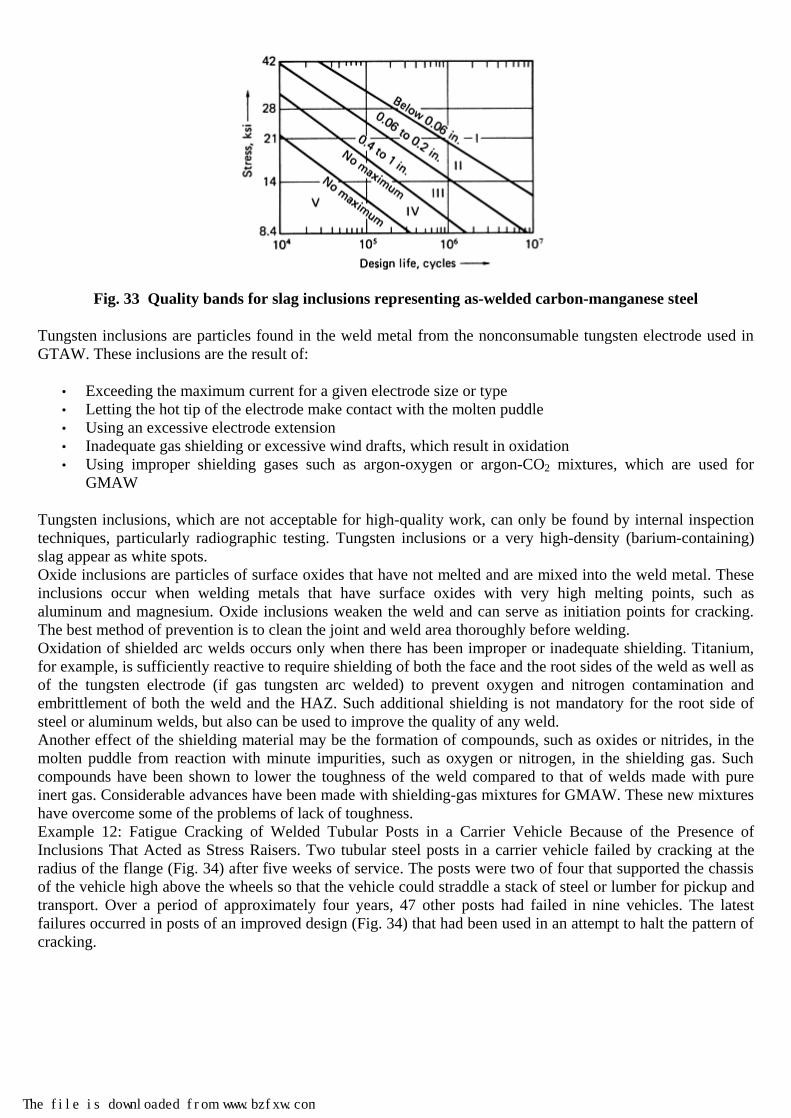
Fig. 33 Quality bands for slag inclusions representing as-welded carbon-manganese steel
Tungsten inclusions are particles found in the weld metal from the nonconsumable tungsten electrode used in GTAW. These inclusions are the result of:
• Exceeding the maximum current for a given electrode size or type • Letting the hot tip of the electrode make contact with the molten puddle • Using an excessive electrode extension • Inadequate gas shielding or excessive wind drafts, which result in oxidation • Using improper shielding gases such as argon-oxygen or argon-CO2 mixtures, which are used for
GMAW
Tungsten inclusions, which are not acceptable for high-quality work, can only be found by internal inspection techniques, particularly radiographic testing. Tungsten inclusions or a very high-density (barium-containing) slag appear as white spots. Oxide inclusions are particles of surface oxides that have not melted and are mixed into the weld metal. These inclusions occur when welding metals that have surface oxides with very high melting points, such as aluminum and magnesium. Oxide inclusions weaken the weld and can serve as initiation points for cracking. The best method of prevention is to clean the joint and weld area thoroughly before welding. Oxidation of shielded arc welds occurs only when there has been improper or inadequate shielding. Titanium, for example, is sufficiently reactive to require shielding of both the face and the root sides of the weld as well as of the tungsten electrode (if gas tungsten arc welded) to prevent oxygen and nitrogen contamination and embrittlement of both the weld and the HAZ. Such additional shielding is not mandatory for the root side of steel or aluminum welds, but also can be used to improve the quality of any weld. Another effect of the shielding material may be the formation of compounds, such as oxides or nitrides, in the molten puddle from reaction with minute impurities, such as oxygen or nitrogen, in the shielding gas. Such compounds have been shown to lower the toughness of the weld compared to that of welds made with pure inert gas. Considerable advances have been made with shielding-gas mixtures for GMAW. These new mixtures have overcome some of the problems of lack of toughness. Example 12: Fatigue Cracking of Welded Tubular Posts in a Carrier Vehicle Because of the Presence of Inclusions That Acted as Stress Raisers. Two tubular steel posts in a carrier vehicle failed by cracking at the radius of the flange (Fig. 34) after five weeks of service. The posts were two of four that supported the chassis of the vehicle high above the wheels so that the vehicle could straddle a stack of steel or lumber for pickup and transport. Over a period of approximately four years, 47 other posts had failed in nine vehicles. The latest failures occurred in posts of an improved design (Fig. 34) that had been used in an attempt to halt the pattern of cracking.
The file is downloaded from www.bzfxw.com

Fig. 34 AISI 1025 steel tube post for a carrier vehicle. The post failed in fatigue because of improper design and choice of flange metal. Dimensions given in inches
The original design involved a flat flange of low-carbon low-alloy steel that was welded to an AISI 1025 steel
tube with a wall thickness of 22 mm ( 78
in.) as shown in Fig. 34. The fillet portion of the weld was machined to
a smooth radius, but this region was highly stressed, and fatigue accounted for the numerous failures of posts. In an effort to improve the strength of the joint, an improved design was adopted. The improvement was associated with the flange, which was machined from a 100 mm (4 in.) thick plate of normalized low-carbon low-alloy steel so that the welded joint would be approximately 50 mm (2 in.) away from the flange fillet. However, after the brief service of five weeks, the two posts showed the same fatigue cracks in the fillet as the original design. Investigation. Chemical analysis of the flange metal showed that it met specification requirements. Examination of a metallographic specimen from the fracture area revealed a banded structure in the direction of rolling and aluminum oxide stringers at the fillet surface, which undoubtedly served as stress raisers, in the direction of crack extension. Conclusions. The failures in the flanges of improved design were attributed to fatigue cracks initiating at the aluminum oxide inclusions in the flange fillet. It was concluded that a higher-strength flange was necessary. Corrective Measures. The design of the flange with the weld approximately 50 mm (2 in.) from the fillet was retained, but the metal was changed to a forging of AISI 4140 steel, oil quenched and tempered to a hardness of 241 to 285 HB. Preheating to 370 °C (700 °F) before and during welding with AISI 4130 steel wire was specified. The weld was subjected to magnetic-particle inspection and was then stress relieved at 595 °C (1100 °F), followed by final machining. No further failures of posts were reported in four years of service after the changes.
Geometric Discontinuities

The most common geometric weld discontinuities are those associated with imperfect shape or unacceptable weld bead contour. Geometric discontinuities shown schematically in Fig. 35 include:
• Overlap: The protrusion of weld metal beyond the toe, face, or root of the weld • Undercut: A groove melted into the base metal adjacent to the toe or root of a weld and left unfilled by
weld metal • Underfill: A depression on the face of the weld or root surface extending below the surface of the
adjacent base metal
Fig. 35 Weld discontinuities affecting weld shape and contour. (a) Undercut and overlapping in a fillet weld. (b) Undercut and overlapping in a groove weld. (c) and (d) Underfill in groove welds
Another type of geometric discontinuity is melt-through, where the arc melts through the bottom of a joint welded from one side. To prevent melt-through, the welding current and the width of the root opening should be reduced, and travel speed should be increased. Excessive reinforcement is the opposite of underfill. It too is an imperfection because its shape leads to a high stress concentration. Overlaps are the protrusion of the weld metal over the edge or toe of the weld bead. It occurs when the weld puddle is too cold for fusion or when the puddle is too hot and solidifies after protruding beyond the toe or root of the weld. This defect can cause an area of incomplete fusion, which creates a notch and can lead to crack initiation. To minimize overlapping:
• Use a higher travel speed. • Use a higher welding current. • Reduce the amount of filler metal added. • Change the electrode angle so that the force of the arc does not push molten weld metal over unfused
sections of the base metal.
The file is downloaded from www.bzfxw.com

Underfill is defined as a depression or loss of metal on the face of a weld extending below the surface of the adjacent base metal. Underfill reduces the cross-sectional area of the weld below the designed amount and therefore is a point of weakness and creates an increased stress concentration where failure may initiate. To minimize underfill, the voltage, travel speed, and root opening should be reduced. Figure 36 shows underfill in a pulsed gas metal arc spot weld joining carbon steel to a 90Cu-10Ni alloy using ERNiCu-7 filler metal.
Fig. 36 Pulsed GMAW spot weld showing a lack of fill-in. Etchant, 50% nitric-50% acetic acid. 4×
Undercutting (Fig. 37a) is a notching of the base metal located at the toe of a weld that occurs when the weld metal does not completely fill in the molten surface of base metal at the toe to form a smooth junction at the weld toe. Undercutting is particularly troublesome, because it produces stress raisers that create problems under impact, fatigue, or low-temperature service. Fatigue strength is markedly reduced by even small undercut depths. The critical size of a geometric discontinuity, such as undercut in fillet welds for a given leg length, decreases as the plate thickness increases.

Fig. 37 Two types of poor contours in arc welds. (a) Fillet weld showing two forms of undercut plus weld spatter and uneven leg length. (b) Butt weld showing a high, sharp crown
To minimize undercut:
• Decrease current, travel speed, and electrode diameter, which controls weld-pool size. • Change electrode angle so that the arc force holds the weld metal in the corners. • Avoid weaving. • Maintain constant travel speed. • Change the surface tension and viscosity of the molten weld metal where possible.
Undercut actually refers primarily to the base metal adjacent to the weld, whereas imperfect shape is an imperfection of the weld itself. This can include such things as excessive reinforcement on the face of a weld, which can occur on groove welds as well as fillet welds. There is also the problem with excessive reinforcement on the root of the weld, primarily open-root groove welds. Excessive reinforcement is economically unsound. It can also be a stress raiser and is objectionable from an appearance point of view. It is normally a factor involved with fit-up, welder technique, welding current, and type of electrode. Undercut results from too high a welding current or too slow a welding speed. Conversely, excessive reinforcement (Fig. 37b) may occur from too low a current or too fast a travel speed. In addition to proper control of welding current, the use of a weave type of bead may be helpful in contour control. However, the
The file is downloaded from www.bzfxw.com
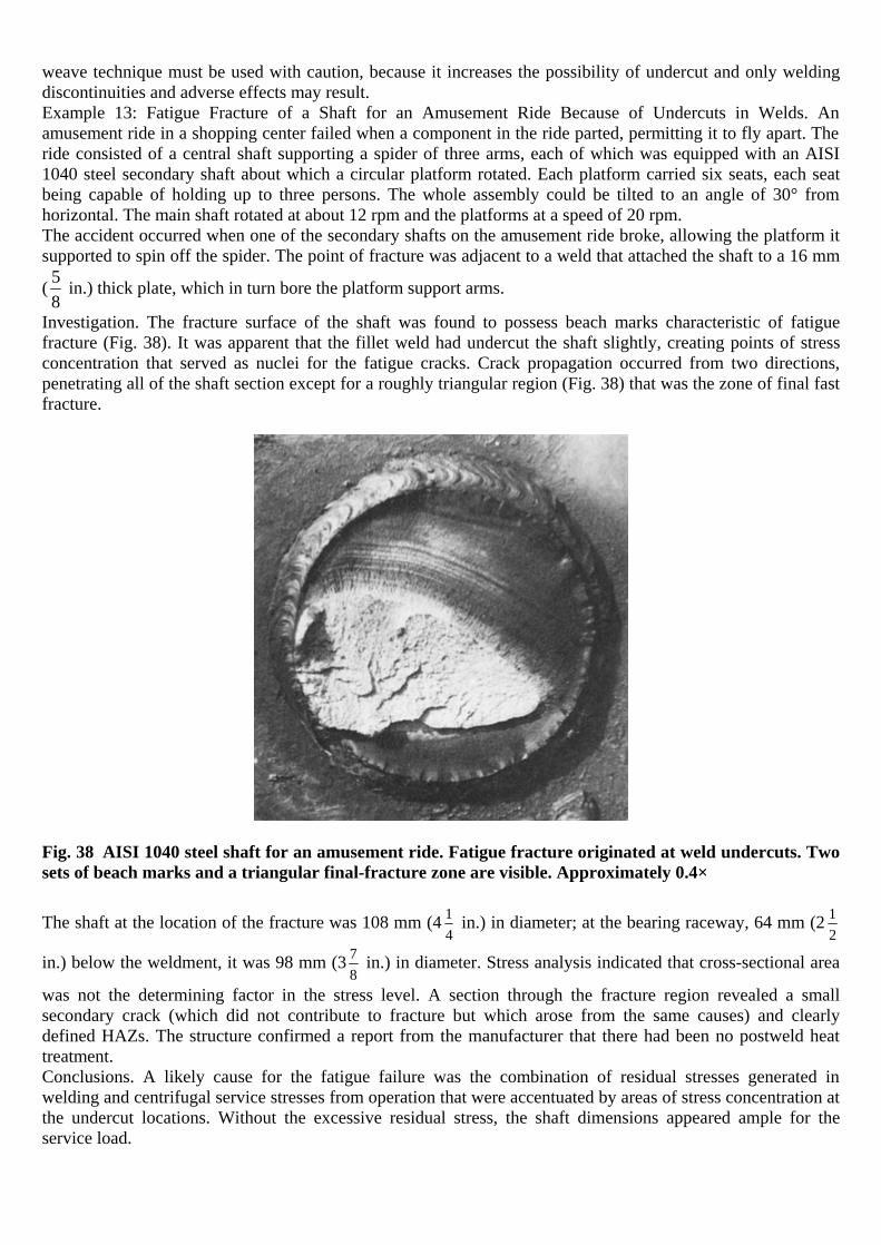
weave technique must be used with caution, because it increases the possibility of undercut and only welding discontinuities and adverse effects may result. Example 13: Fatigue Fracture of a Shaft for an Amusement Ride Because of Undercuts in Welds. An amusement ride in a shopping center failed when a component in the ride parted, permitting it to fly apart. The ride consisted of a central shaft supporting a spider of three arms, each of which was equipped with an AISI 1040 steel secondary shaft about which a circular platform rotated. Each platform carried six seats, each seat being capable of holding up to three persons. The whole assembly could be tilted to an angle of 30° from horizontal. The main shaft rotated at about 12 rpm and the platforms at a speed of 20 rpm. The accident occurred when one of the secondary shafts on the amusement ride broke, allowing the platform it supported to spin off the spider. The point of fracture was adjacent to a weld that attached the shaft to a 16 mm
( 58
in.) thick plate, which in turn bore the platform support arms.
Investigation. The fracture surface of the shaft was found to possess beach marks characteristic of fatigue fracture (Fig. 38). It was apparent that the fillet weld had undercut the shaft slightly, creating points of stress concentration that served as nuclei for the fatigue cracks. Crack propagation occurred from two directions, penetrating all of the shaft section except for a roughly triangular region (Fig. 38) that was the zone of final fast fracture.
Fig. 38 AISI 1040 steel shaft for an amusement ride. Fatigue fracture originated at weld undercuts. Two sets of beach marks and a triangular final-fracture zone are visible. Approximately 0.4×
The shaft at the location of the fracture was 108 mm (4 14
in.) in diameter; at the bearing raceway, 64 mm (2 12
in.) below the weldment, it was 98 mm (3 78
in.) in diameter. Stress analysis indicated that cross-sectional area
was not the determining factor in the stress level. A section through the fracture region revealed a small secondary crack (which did not contribute to fracture but which arose from the same causes) and clearly defined HAZs. The structure confirmed a report from the manufacturer that there had been no postweld heat treatment. Conclusions. A likely cause for the fatigue failure was the combination of residual stresses generated in welding and centrifugal service stresses from operation that were accentuated by areas of stress concentration at the undercut locations. Without the excessive residual stress, the shaft dimensions appeared ample for the service load.

Recommendations. The fillet weld should be applied with more care to avoid undercutting. The residual stresses should be minimized by preweld and postweld heat application. Example 14: Fatigue Failure of a Carbon Steel Water-Wall Tube Because of an Undercut at a Welded Joint. In a new stationary boiler, furnace water-wall tubes were welded to the top of a dust bin for rigid support (Fig. 39a). The tubes measured 64 mm (2.5 in.) outside diameter by 3.2 mm (0.125 in.) wall thickness and were made of carbon steel to ASME SA-226 specifications. Shortly after start-up, one of the tubes broke at the welded joint.
Fig. 39 Stationary boiler in which a carbon steel water-wall tube failed by fatigue fracture at the weld joining the tube to a dust bin. (a) Illustration of a portion of the boiler showing location of failure. Dimensions given in inches. (b) Photograph of fractured tube. Fatigue crack is at arrow A, and ductile fracture is at arrow B.
Investigation. The portion of the fracture surface adjacent to the attachment weld around the bottom half of the tube had a flat, brittle appearance. Over the remainder of the tube wall, the fracture was ductile, with a noticeable shear lip and necking. Beach marks were evident on the fracture surface, indicating that fatigue was the fracture mechanism. The origin was identified as a small crevicelike undercut at the edge of the weld bead, shown by arrow A in Fig. 39(b). Conclusion. Cracking began by fatigue from a severe stress raiser. As the fracture progressed out of the region of high restraint where the tube was welded to the dust bin, the fracture changed from fatigue to ductile overload, as evidenced by necking opposite the origin. It was concluded that the crevicelike undercut was likely the primary cause of the fracture and that the source of the necessary fluctuating stress was tube vibration inherent in boiler operation. Recommendations. The remaining water-wall tubes in the row were inspected by the magnetic-particle method; several other tubes were found to have small fatigue cracks adjacent to the welds attaching the tubes to the dust bin. The broken tube was replaced, cracks in other tubes were repaired by welding, and the attachment welds
The file is downloaded from www.bzfxw.com

were blended smoothly into the tube surfaces for the entire length of the dust bin. No further failures occurred after the severe undercut was eliminated.
Incomplete Fusion and Incomplete Penetration
Incomplete fusion (IF) (formerly known as lack of fusion, or LOF) refers to the degree to which the original base metal surfaces have been fused to the filler metal. Incomplete penetration (IP) (formerly known as lack of penetration, or LOP) refers to the degree to which the base metal has been melted and resolidified to result in a deeper throat that was present in the joint before welding. In effect, a joint can be completely fused but have incomplete root penetration to obtain the throat size specified. Based on these definitions, IF discontinuities are located on the sidewalls of a joint, and IP discontinuities are located near the root (Fig. 40). With some joint configurations, such as butt joints, the two terms can be used interchangeably.
Fig. 40 Incomplete fusion in (a) a single-V-groove weld and (b) a double-V-groove weld. Incomplete penetration in (c) a single-V-groove weld and (d) a double-V-groove weld
Causes of IF and IP. Inadequate joint penetration and incomplete fusion in arc welds usually result from:
• Improper fit-up or groove design, where the joint design does not afford proper torch accessibility and there is an unsuitable angle of impingement between the base metal and the welding arc
• Too low a welding current • Poor welding techniques, such as improper electrode manipulation and unfavorable torch angle for the
travel speed and current being used • Poor preparation of the base metal surface, such as inadequate wire brushing between weld passes or
poor fit-up in preparing the joint
To prevent IF and IP, heat input must be increased to allow complete fusion between the weld deposits and the workpiece as well as between successive passes in multipass joints. The weldment surface must be cleaned of all contaminants. Figure 41 illustrates many of the causes of and methods of prevention for IF. Typical causes and methods of prevention for IP are illustrated in Fig. 42. Joint geometry must permit proper arc control and access for the electrode. If the gap is excessive, weave manipulation should be adjusted accordingly.

Fig. 41 Causes and cures of incomplete fusion in welds
The file is downloaded from www.bzfxw.com
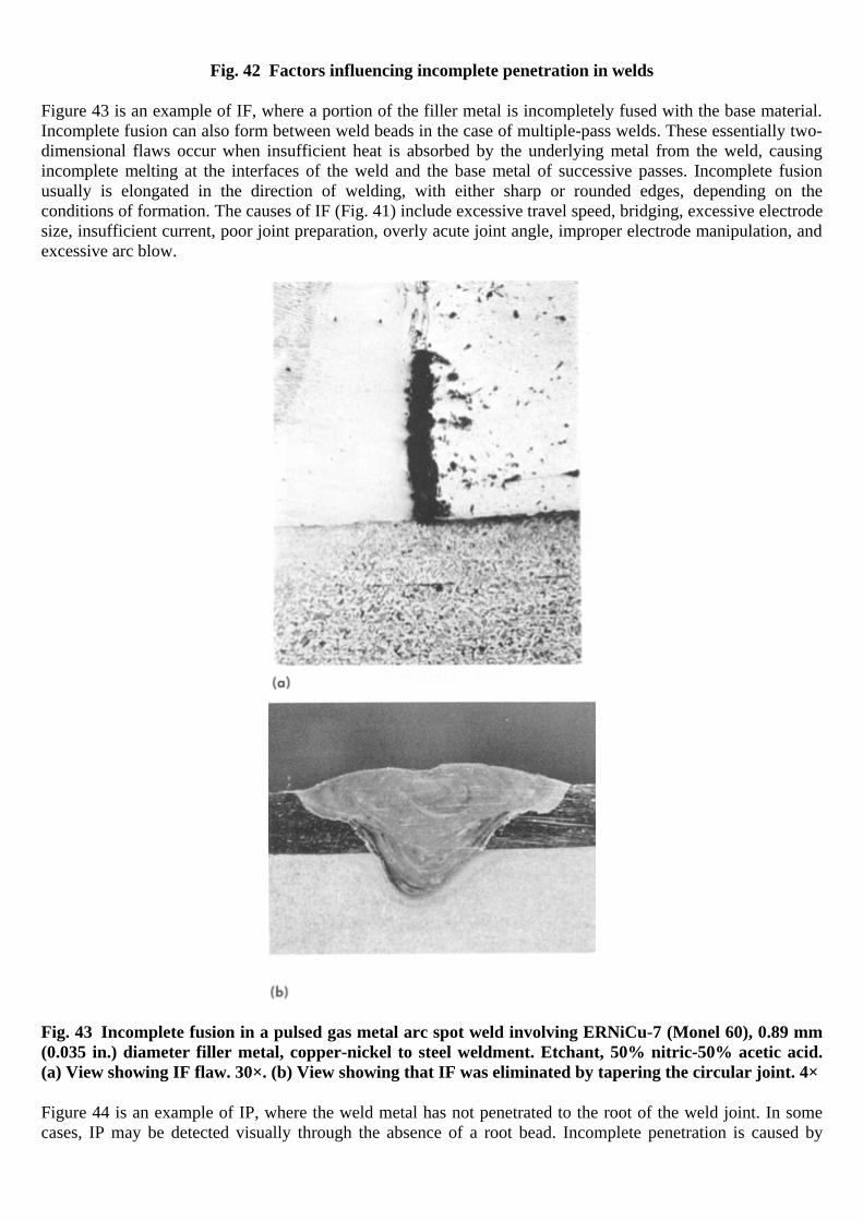
Fig. 42 Factors influencing incomplete penetration in welds
Figure 43 is an example of IF, where a portion of the filler metal is incompletely fused with the base material. Incomplete fusion can also form between weld beads in the case of multiple-pass welds. These essentially two-dimensional flaws occur when insufficient heat is absorbed by the underlying metal from the weld, causing incomplete melting at the interfaces of the weld and the base metal of successive passes. Incomplete fusion usually is elongated in the direction of welding, with either sharp or rounded edges, depending on the conditions of formation. The causes of IF (Fig. 41) include excessive travel speed, bridging, excessive electrode size, insufficient current, poor joint preparation, overly acute joint angle, improper electrode manipulation, and excessive arc blow.
Fig. 43 Incomplete fusion in a pulsed gas metal arc spot weld involving ERNiCu-7 (Monel 60), 0.89 mm (0.035 in.) diameter filler metal, copper-nickel to steel weldment. Etchant, 50% nitric-50% acetic acid. (a) View showing IF flaw. 30×. (b) View showing that IF was eliminated by tapering the circular joint. 4×
Figure 44 is an example of IP, where the weld metal has not penetrated to the root of the weld joint. In some cases, IP may be detected visually through the absence of a root bead. Incomplete penetration is caused by

incorrect welding technique or by improper root gap. Incorrect welding techniques (shown graphically in Fig. 42) include:
• Low amperage • Oversized electrode diameter • High travel speed • Wrong electrode angle • Incorrect joint cleaning, where surface contaminants such as oxide, oil, or dirt prevent full melting of
the underlying metal • Improper work position • Misalignment of back side weld • Excessive inductance in the dip transfer mode of GMAW • Insufficient backgouging • Too large a flat land in a groove weld, and undesirable arc manipulation by the welder, particularly in
the vertical position
Fig. 44 Incomplete penetration in a butt welded joint in steel. Original plate thickness, 19 mm ( 34
in.).
As-polished. 1.4×
Radiographic methods may be unable to detect IF and IP discontinuities in certain cases, because of the small effect they have on x-ray absorption, although lack of sidewall fusion is readily detected by radiography. Ultrasonically, both types of discontinuities often appear as severe, almost continuous, linear porosity because of the nature of the unbonded areas of the joint. Except in thin sheet or plate, these discontinuities may be too deep-lying to be detected by magnetic-particle inspection. Effects of IF and IP. The presence of incomplete fusion and incomplete penetration can be critical, because, in addition to reducing the effective cross-sectional area, it can produce discontinuities that can be almost as sharp as cracks and can even display crack-extended tips. In welding some alloys, incomplete fusion and incomplete penetration can result from an oxide layer on the joint sidewall. The fitness-for-purpose analysis of IF and IP, when present in carbon steels, is typically related to the ductile-to-brittle transition temperature, because the significance of these discontinuities can change. When material is below its transition temperature, IF and IP are potentially harmful and can trigger brittle fracture. If, on the other hand, the steel is above its transition temperature, these discontinuities may be only slightly worse than slag inclusions or porosity. Consequently, it is essential to define the exact transition temperature and conditions that will be encountered in service.
The file is downloaded from www.bzfxw.com

The effect of IF and IP can be masked by weld metal overmatching and reinforcement. The direction of the applied alternating stress with respect to IF and IP is also important. When the applied load is parallel to these discontinuities, the effect is minimal; the reverse is true when the direction of stress is perpendicular. The significance of IF and IP, however, also depends on their “aspect ratio,” which indicates the sharpness of the discontinuity (ratio of width-to-depth), and location. Few experimental studies have been conducted to examine the effect of IF on fatigue strength. However, fatigue behavior of weldments with IF discontinuities can be estimated using the mathematical models for fatigue crack propagation. In an investigation of the significance of IF and IP in an Al-4.4Mg alloy welded by GMAW, it was found that both IF and IP were more serious than undercut, surface irregularity, and macro- and microporosity (Ref 24). The fatigue strength of this aluminum alloy in a 12 mm (0.47 in.) thick test sample was reduced 60% by the presence of IF and/or IP. Example 15: Fracture of a Chip-Conveyor Pipe at a Flange Weld as a Result of Poor Fit- Up. A pipe in a chip conveyor cracked at the toe of an exterior fillet weld connecting a flange to the pipe.
The chip conveyor consisted of several spool sections. Each section was made up of a length of 560 mm (22 116
in.) OD by 546 mm (21 12
in.) ID low-alloy steel pipe and two 713 mm (28 116
in.) OD by 562 mm (22 964
in.)
ID flanges of 13 mm ( 12
in.) thick low-carbon steel, which were welded to the two ends of the pipe. The wall
thickness of the pipe was 7 mm (0.275 in.). The composition specified for the pipe steel was 0.25C-0.98Mn-3.52Ni-1.34Cr-0.24Mo, which approximates a 9300 steel with high molybdenum. The hardness of the pipe was reported as 495 HB, and of the flange as 170 HB. The flanges were joined to the pipe by SMAW, using E7018 electrodes. Investigation. It was found that one end of the pipe had been cut before assembly at an angle of 76° and 39 minutes to its axis, which presented an ellipse (Fig. 45) over which the flange was forced to fit by hydraulic pressure. A 90° angle would have given a radial clearance between the pipe and flange of approximately 1.1
mm ( 364
in.), but the long OD of the elliptical pipe was 576 mm (22.7 in.) compared to the ID of the flange of
562 mm (22.1 in.), which placed both components in a condition of severe stress.

Fig. 45 Low-alloy steel conveyor pipe that cracked at fillet welds securing a carbon steel flange because of poor fit-up. Dimensions given in inches
A schematic illustration of a section cut through the weld in the area of maximum interference is shown in detail A in Fig. 45. Underbead cracking began at the toe on the pipe wall of the first fillet-weld pass at a point where there was incomplete fusion and inadequate penetration of the third and final pass. Several cracks initiated at the toe of the third pass on the pipe wall, where there was a slight undercut. Conclusions. The conveyor pipe failed by brittle fracture, which was attributed to the stresses induced in forcing the circular flange over the elliptical section of the pipe. The toe of the weld and the adjacent undercut were stress raisers that determined the point of major crack origin. Under residual stress, the internal point of incomplete fusion also initiated additional cracks. Recommendation. A proper fit between an elliptical flange and pipe end would eliminate the cracking.
Metallurgical Discontinuities of Welds
Metallurgical discontinuities include a variety of weld cracks that are severe stress concentrators characterized by sharp tips and high length-to-width ratios. Weld and base metal cracks (as described in the section “Weld Cracks” in this article) are generally considered to be defects, especially during manufacturing, although some, such as fisheyes and microfissures, are perhaps better characterized as anomalies or imperfections. The types of weld cracking include:
The file is downloaded from www.bzfxw.com

• Fisheye: A discontinuity found on the fracture surface of a weld in steel that consists of a small pore or inclusion surrounded by a bright, round area
• Microfissures: Small, cracklike discontinuities with only a slight separation (opening displacement) of the fracture surfaces
• Lamellar tearing: A type of cracking that occurs in the base metal or HAZ of restrained weld joints that is the result of inadequate ductility in the through-thickness direction of steel plate
• Hydrogen-induced cold cracking • Hot cracking
Weldability is often influenced by the susceptibility of a material to cracking. The weldability of martensitic steels is greatly affected by hardenability that can result in cold cracking. Welded joints in ferritic steels may have low ductility as a result of grain coarsening. The weldability of austenitic steels is governed by their susceptibility to hot cracking. With precipitation-hardening steels, weldability is related to the mechanisms associated with the precipitation-hardening transformation. Cold cracking is usually not encountered in aluminum alloy welds, except when a bead has been laid down that is too small to resist the shrinkage cooling stresses. However, both crater cracks and longitudinal hot cracks can occur in aluminum alloy welds if the welding technique is not favorable. In wrought heat treatable aluminum alloys, the relation between working and weld direction influences cracking. Welds made in the short-transverse direction often develop grain-boundary microcracks in the HAZ. Fisheyes are cracks surrounding porosity or slag in the microstructure of a weld. Fisheyes are a form of hydrogen embrittlement cracking caused by the presence of hydrogen that collects at these locations and embrittles the surrounding metal in a manner similar to (but less severe than) cold cracking. What distinguishes a fisheye is the characteristically shiny appearance when viewed optically (Fig. 46 and 47); it only appears as the result of tensile fracture, such as in a tensile test.
Fig. 46 Fisheyes in E7018 weld metal. (a) Fisheyes in as-welded tensile specimen tested at room temperature. Optical macrograph. (b) Mixed-mode fracture in as-welded three-point bend test specimen at room temperature (SEM). Optical fractograph

Fig. 47 Formation of fisheyes. (a) At pore, in as-welded E6010 tensile specimen tested at room temperature. (b) Slag/IF in as-welded E11018 tensile specimen strained at 1.0% at room temperature (SEM)
Fisheyes, also termed flakes, blisters, and halos, are predominantly found in ferritic steels, welded with high-hydrogen electrodes. Complete understanding of the conditions for the formation of this type of crack is still evolving. Because they were first observed during bend testing, it is frequently assumed that stressing of the weldment beyond its yield strength is required to form fisheyes, but this has not been confirmed. The overall fracture appearance of fisheyes usually indicates a mixed or quasicleavage fracture mechanism, as seen in Fig. 46(b). When a halo is examined at high magnification, a fracture surface with a pattern radiating from a nucleating discontinuity is revealed. Small, buried microfissures also have been noted to nucleate fisheyes in as-welded E6010 weld metal. Elevated-temperature aging or postweld heat treatment can effectively eliminate fisheyes. Other factors that help prevent the occurrence of this type of discontinuity include high preheat, good joint design, low-hydrogen electrodes, and reduction in restraint. Note that use of low-hydrogen electrodes alone is apparently insufficient to eliminate fisheye formation. However, low-hydrogen electrodes are susceptible to moisture pick up; other low-high welding processes can suffer from shielding difficulties. In Charpy V-notch testing, fisheyes did not form, apparently because the deformation rate is too high to permit the required diffusion of hydrogen. Microfissures are metallurgically related flaws formed during weld metal solidification. They are frequently found in austenitic stainless steel welds where the weld metal has an inadequate ferrite content. Microfissures can be of the hot or cold type of cracking, induced by small strain. Applied strain is needed to produce cracking; the amount needed to initiate cracking depends on material toughness. Because material is always subject to some type of strain, either from external or internal sources, the occurrence of cracking is therefore controlled by the conditions of welding, during which material toughness may be decreased. A micrograph example of microcracking (microfissures) is shown in Fig. 48.
The file is downloaded from www.bzfxw.com

Fig. 48 Micrograph of weld metal microcrack. Etchant, 2% nital. 215×
As an example of hot fissuring, a transfer line in a pressure vessel system carrying 73% sodium hydroxide developed a leak at a weld joining a cast Monel coupling to wrought Monel pipe. Metallographic examination disclosed many small microfissures in the weld metal, but no microfissures were found in the HAZs of the wrought Monel. This section of line contained high thermal stresses that resulted from injection of steam a short distance upstream from the coupling. Chemical analysis revealed that the cast Monel coupling had a silicon content of 1.97%, whereas the wrought Monel piping had a silicon content of 0.10%. Castings of high-silicon Monel generally have poor weldability and are often hot short, or sensitive to cracking in the weld HAZ. Fissures in the cast coupling were formed during welding and subsequently penetrated the section when the coupling was subjected to the thermal shock of steam injection. In this case, a weldable-grade casting should be specified to ensure freedom from hot fissuring. Detection of microfissures is difficult by conventional nondestructive techniques; usually, metallographic preparation is necessary. However, if microfissures are produced by forming operations, and if such microfissures lie close to or in the HAZ, they may grow to macrofissures that can be detected by visual inspection or by examination using magnetic-particle, liquid penetrant, or radiographic methods. Lamellar tearing is a form of base metal cold cracking that occurs parallel to the plate surface adjacent to the welds. This is shown schematically in Fig. 49 for a T-joint that is fillet welded on both sides. It may occur in the base metal or the HAZ of restrained weld joints and is characterized by a steplike crack parallel to the rolling plane. The crack originates internally because of tensile strains produced by the cooling contraction of the weld zone.
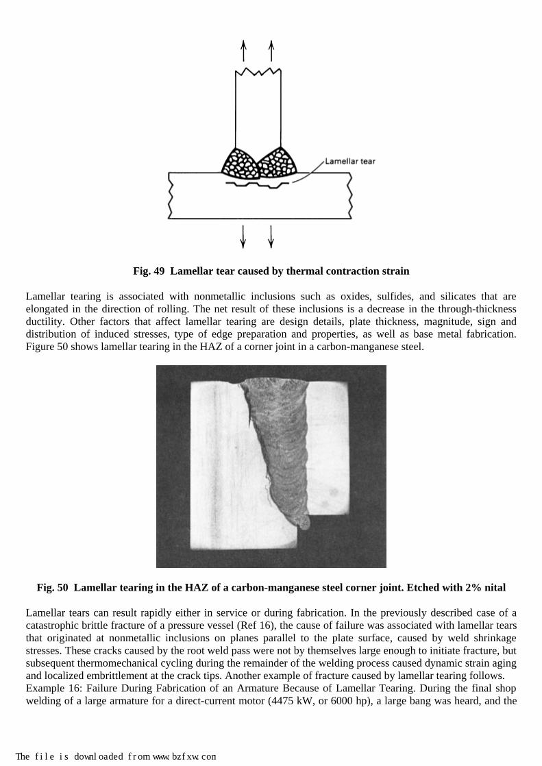
Fig. 49 Lamellar tear caused by thermal contraction strain
Lamellar tearing is associated with nonmetallic inclusions such as oxides, sulfides, and silicates that are elongated in the direction of rolling. The net result of these inclusions is a decrease in the through-thickness ductility. Other factors that affect lamellar tearing are design details, plate thickness, magnitude, sign and distribution of induced stresses, type of edge preparation and properties, as well as base metal fabrication. Figure 50 shows lamellar tearing in the HAZ of a corner joint in a carbon-manganese steel.
Fig. 50 Lamellar tearing in the HAZ of a carbon-manganese steel corner joint. Etched with 2% nital
Lamellar tears can result rapidly either in service or during fabrication. In the previously described case of a catastrophic brittle fracture of a pressure vessel (Ref 16), the cause of failure was associated with lamellar tears that originated at nonmetallic inclusions on planes parallel to the plate surface, caused by weld shrinkage stresses. These cracks caused by the root weld pass were not by themselves large enough to initiate fracture, but subsequent thermomechanical cycling during the remainder of the welding process caused dynamic strain aging and localized embrittlement at the crack tips. Another example of fracture caused by lamellar tearing follows. Example 16: Failure During Fabrication of an Armature Because of Lamellar Tearing. During the final shop welding of a large armature for a direct-current motor (4475 kW, or 6000 hp), a large bang was heard, and the
The file is downloaded from www.bzfxw.com

welding operation stopped. When the weld was cold, nondestructive evaluation revealed a large crack adjacent to the root weld. Investigation. Figure 51(a) shows the design of the weld and the region where cracking occurred. The 100 mm (4 in.) thick plate had a chemical composition of 0.21C-0.77Mn; composition of the 125 mm (5 in.) plate was 0.19C-0.76Mn, giving carbon equivalents (CE) of 0.34 and 0.32, respectively (CE = C + Mn/6 + (Cr + Mo + V)/5 + (Ni + Cu)/15); these CE levels are indications of good weldability and resistance to weld cracking. The welds were made with a preheat of 65 °C (150 °F), with the heat applied only on the outside wall at point B. The weld was deposited using a single-head submerged arc process, and the failure occurred when 32 mm (1.25 in.) of weld depth had been laid. Sections through the failure revealed that the cracking had initiated at the root of the weld at the intersection of the plate and backing bar. The crack had then propagated at right angles to the fusion zone through the HAZ in a series of steps. The main crack had propagated parallel to the fusion boundary along the subcritical HAZ and was associated with long stringers of type II manganese sulfide (MnS) inclusions (Fig. 51b).
Fig. 51 Armature for a large electric motor that failed during fabrication. The cause of failure was lamellar tearing. (a) Schematic diagram of the weld preparation and the position of the failed weld. (b) Schematic of crack initiation and propagation from the root of the weld
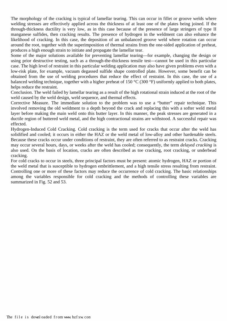
The morphology of the cracking is typical of lamellar tearing. This can occur in fillet or groove welds where welding stresses are effectively applied across the thickness of at least one of the plates being joined. If the through-thickness ductility is very low, as in this case because of the presence of large stringers of type II manganese sulfides, then cracking results. The presence of hydrogen in the weldment can also enhance the likelihood of cracking. In this case, the deposition of an unbalanced groove weld where rotation can occur around the root, together with the superimposition of thermal strains from the one-sided application of preheat, produces a high enough strain to initiate and propagate the lamellar tear. Some of the major solutions available for preventing lamellar tearing—for example, changing the design or using prior destructive testing, such as a through-the-thickness tensile test—cannot be used in this particular case. The high level of restraint in this particular welding application may also have given problems even with a low-risk plate, for example, vacuum degassed sulfide shape controlled plate. However, some benefit can be obtained from the use of welding procedures that reduce the effect of restraint. In this case, the use of a balanced welding technique, together with a higher preheat of 150 °C (300 °F) uniformly applied to both plates, helps reduce the restraint. Conclusion. The weld failed by lamellar tearing as a result of the high rotational strain induced at the root of the weld caused by the weld design, weld sequence, and thermal effects. Corrective Measure. The immediate solution to the problem was to use a “butter” repair technique. This involved removing the old weldment to a depth beyond the crack and replacing this with a softer weld metal layer before making the main weld onto this butter layer. In this manner, the peak stresses are generated in a ductile region of buttered weld metal, and the high contractional strains are withstood. A successful repair was effected. Hydrogen-Induced Cold Cracking. Cold cracking is the term used for cracks that occur after the weld has solidified and cooled; it occurs in either the HAZ or the weld metal of low-alloy and other hardenable steels. Because these cracks occur under conditions of restraint, they are often referred to as restraint cracks. Cracking may occur several hours, days, or weeks after the weld has cooled; consequently, the term delayed cracking is also used. On the basis of location, cracks are often described as toe cracking, root cracking, or underbead cracking. For cold cracks to occur in steels, three principal factors must be present: atomic hydrogen, HAZ or portion of the weld metal that is susceptible to hydrogen embrittlement, and a high tensile stress resulting from restraint. Controlling one or more of these factors may reduce the occurrence of cold cracking. The basic relationships among the variables responsible for cold cracking and the methods of controlling these variables are summarized in Fig. 52 and 53.
The file is downloaded from www.bzfxw.com
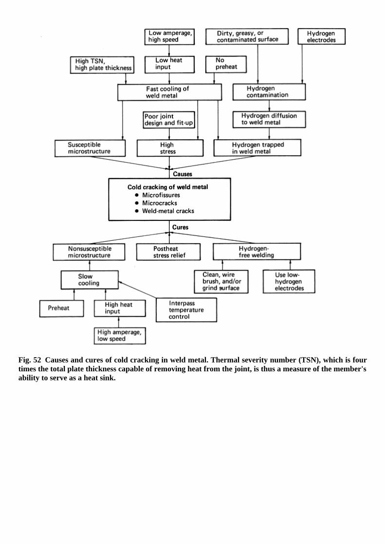
Fig. 52 Causes and cures of cold cracking in weld metal. Thermal severity number (TSN), which is four times the total plate thickness capable of removing heat from the joint, is thus a measure of the member's ability to serve as a heat sink.

Fig. 53 Causes and cures of cold cracking in base metal
In steels, cracking in the base metal is often attributed to high carbon, alloy, or sulfur content. Control of this cracking requires the use of low-hydrogen electrodes, high preheat, sufficient interpass temperature, and greater penetration through the use of higher currents and larger electrodes. The susceptibility of the microstructure to cold cracking relates to the solubility of hydrogen and the possibility of supersaturation. Austenite, in which hydrogen is highly soluble, is least susceptible to cold cracking, and martensite, in which the solubility of hydrogen is lower, is most susceptible, because the rapid cooling necessary for the austenite-to-martensite transformation traps the hydrogen in a state of supersaturation in the martensite. For this reason rapid cooling rates must be avoided. Cold cracks, or hydrogen cracks, form in welds after solidification is complete. In steel, cold cracks depend on the presence of a tensile stress, a susceptible microstructure, and dissolved hydrogen (Ref 25, 26). The stress may arise from restraint by other components of a weldment or from the thermal stresses created by welding in a butt, groove, or T-joint. The process of HAZ cracking in steels is usually described as follows (Ref 27):
• Hydrogen is introduced into the hot weld metal and dissolves into the weld pool as atomic or ionized hydrogen.
• As the weld metal cools, it becomes supersaturated with hydrogen, and some hydrogen diffuses into the HAZ.
The file is downloaded from www.bzfxw.com

• Under rapid cooling, hydrogen has insufficient time to diffuse from the HAZ. Also, rapid cooling increases the chance for the HAZ to transform from austenite to martensite.
• Atomic hydrogen is insoluble in martensite and seeks rifts and discontinuities in the lattice, where it collects.
• External stress caused by thermal contraction, combined with the effects of the trapped hydrogen, causes discontinuities to enlarge to crack size.
• In time, hydrogen diffuses to the new crack root and causes the crack to enlarge, thus the occurrence of delayed cracking.
This process repeats itself until the stress in the weld has been relieved. Hydrogen and stress also play an important role in weld metal cracking. Microcracks in the weld metal are often associated with small, nonmetallic inclusions that provide points of initiation. Hydrogen cracking can occur in either the HAZ or the weld metal and can be either transverse or longitudinal to the weld axis. The level of preheat or other precautions necessary to avoid cracking depends on which region, weld metal or HAZ, is the more sensitive. In the older carbon-manganese medium-strength structural steels, the HAZ was usually the more critical region, and weld metal rarely caused a problem. Modern steels with low carbon are now very resistant to hydrogen cracking; therefore, the weld metal may be the controlling factor. Hydrogen cracking in the weld metal depends on the same fundamental factors as in the HAZ, that is, hydrogen content, microstructure, and stress. The controlling variables in practice are usually strength level, hydrogen content, restraint, and tensile stress level. In single-pass welds and the root run of multiple-pass welds, the root gap provides a stress concentration to the transverse stress; this leads to longitudinal cracks in the weld metal. The higher dilution of the root run may result in a harder weld bead that is more likely to crack. This is the predominant form of cracking in such applications as pipelines. In cases where transverse notches exist—for example, an unspliced backing bar (that is, where the backing bar has not been splice-welded into one continuous piece)—the longitudinal stress becomes the controlling factor, and transverse cracks may occur. In heavy multiple-pass welds, cracking is generally in the transverse direction, either normal to the surface or at an angle of about 45°. The latter type has been called chevron cracking. The solution to these cracking problems rests with proper control of hydrogen through such practices as handling of electrodes, drying of fluxes and electrodes, and adequate preheat. The presence of hydrogen in a weld is generally due to moisture that is introduced in the shielding gas, dissociated by the arc to form elemental hydrogen, and dissolved by the molten weld puddle and by the adjacent region in the HAZ. In the supersaturated state, the hydrogen diffuses to regions of high stress where it can initiate a crack. Continued diffusion of the hydrogen to the region of stress concentration at the crack tip extends the crack. This behavior means that hydrogen-induced cold cracking is time dependent, that is, time is needed for hydrogen diffusion, and the appearance of detectable cracks can be delayed until long after the weld has passed inspection. The redistribution of hydrogen, however, does not depend only on the thermal history of the weld and the diffusion coefficient of hydrogen. The stresses in the weld area also affect the redistribution behavior and thus the cold-cracking tendency. The remedy is to eliminate as far as possible the sources of hydrogen—water, oils, greases, waxes, paint, and rust that contains hydrogen or hydrates. Preweld and postweld heating promote the escape of hydrogen by diffusion and reduce the level of residual tensile stress that may be present. Hydrogen damage to weld deposits (either as porosity or as cracking) can be avoided simply by proper control of hydrogen through handling of electrodes, drying of fluxes and electrodes, and adequate preheat. For low-hydrogen shielded metal arc electrodes, this means storing in holding ovens to prevent moisture from reentering the electrode coating from the air. Normally, such ovens should be controlled between 120 and 175 °C (250 and 350 °F). Electrodes may require baking to remove moisture at temperatures as high as 425 °C (800 °F) before storing, but excessive baking can oxidize ferroadditions in the electrode coating and affect deoxidation of the weld pool. The most common approach for eliminating hydrogen cold cracking—after ensuring that a low-hydrogen process is being used and that the base metal and filler metals are properly cleaned—is to employ preheating. The use of carbon equivalent (CE) formulas in conjunction with the degree of restraint help to define the level of preheat required when joining different steels. As both the CE and degree of restraint increase, the need for and the level to which preheat is applied also increase. For steels, when preheat does not act as an effective way to stop hydrogen cracking—and if increasing the preheat temperature does not work—applying a postheat for 3

to 4 h after welding has finished may be effective. Postheating in conjunction with preheating is far more effective than preheating alone in solving cold cracking problems. Hot cracking may be caused by joint design and the restraint imposed on the weld, by bead shape, or by the presence of low-melting constituents that extend the temperature range of low hot strength and low ductility to temperatures below that of the alloy. In steels, these constituents are compounds, such as phosphides and sulfides, and elements, such as copper, which can segregate at grain boundaries and cause grain-boundary tearing under thermal-contraction stresses. Hot cracks can be minimized or eliminated through residual-element control and control of the weld pool shape. Weld beads with a high depth-to-width ratio can promote the buildup of low-melting phases at the pool centerline and thus lead to centerline hot cracking. The same type of hot crack is a crater crack. The material in the crater region is richer in solutes than the remainder of the weld, because of the directional nature of the weld metal solidification, and is very prone to cracking. The best method of control is to use welding materials with minimal contents of residual elements, such as phosphorus, sulfur, and copper in steel, thus reducing the possibility of segregation. If this is not feasible, the next best procedure is to avoid the slow cooling rates that favor segregation between the liquidus and solidus temperatures and accelerate cooling until the crater has solidified. In some hot-cracking situations, a reduction in travel speed can alter the solidification directions in the weld deposit and thus reduce susceptibility to hot cracking. Hot cracking is the most common form of weld metal cracking in steels, especially stainless steels. The term encompasses cracks that form while a weld is solidifying or when a weldment is reheated. As noted, it is often caused by excessive sulfur, phosphorus, or lead content in the base metal. It can also be caused by an improper method of breaking the arc or in a root pass when the cross-sectional area of the weld is small, compared to the mass of the base metal. Solidification cracking, liquation cracking, ductility-dip cracking, and reheat cracking are types of hot cracking. Such cracks are normally intergranular and interdendritic in nature and can occur in either the weld metal or the base metal HAZ. Solidification cracking occurs within a few hundred degrees of the nominal liquidus temperature of the weld metal and is induced by welding stresses and the presence of low-melting-point constituents that form as a result of segregation during the liquid-to-solid-phase transformation process. Liquation cracking (often called hot tearing or HAZ burning) is another type of high-temperature cracking that may occur in welds of all metals. Localized liquation of low-melting-point constituents, such as foreign inclusions, carbide phases, or local segregations of certain alloying elements in the solid, may form liquid grain-boundary films. Welding shrinkage strains may, in turn, be sufficiently high to open liquation cracks. Ductility-dip cracking may occur in either the weld metal or the HAZ of austenitic stainless steels and nickel-base superalloys. This type of crack forms while the weld cools through a range of temperatures where the ductility of the particular metal is inherently low. The ductility-dip temperature for austenitic stainless steel falls just below the recrystallization temperature. If sufficient strain is present as the metal cools through the ductility-dip temperature range, cracking occurs. Reheat cracking or stress-relief cracking may form in the HAZ of welds in ferritic and austenitic steels. Postweld heat treatment may be specified for weldments to reduce (or eliminate) residual stresses and/or to restore toughness in the HAZ and weld metal. Reheat cracking may take place during this postweld heat treatment as a result of pre-postweld heat treatment microstructure of the HAZ brought about by welding. Welding heat input induces an elevated temperature solution treatment in the HAZ, which leads to dissolution of metallic carbides. Upon reheating, interstitial carbon precipitation hardening may strengthen the grains sufficiently so that relaxation of internal stresses may occur only by grain-boundary sliding, with little or no intergrain deformation; hence, reheat cracking occurs. Reheat cracking has also been linked to temper embrittlement and the presence of trace elements, such as boron, arsenic, antimony, and tin, in steels. Remedies for reheat cracking include changes in metal composition (use of less-susceptible steel), reduction in thickness, decrease in sulfur content, slower heating rate to avoid thermal shock, controlled cooling rate to prevent precipitation of carbides, higher creep ductility, good joint design, decrease in constraint, high preheat, elimination of stress concentration at welds, and use of weld metal with low hot strength. Causes and Prevention of Hot Cracking. The factors affecting the formation of hot cracks include metallurgical properties, welding variables, and mechanical properties. The basic relationships among these factors and methods for controlling hot cracking in steels are shown in Fig. 54 and 55.
The file is downloaded from www.bzfxw.com
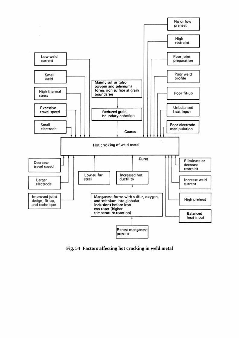
Fig. 54 Factors affecting hot cracking in weld metal

Fig. 55 Factors affecting hot cracking in the base metal HAZ
During solidification of weld metal, several compounds form whose presence, in their liquid phase, at grain boundaries contributes to hot cracking. Sulfur is considered the most detrimental element, because it reacts to form many low-freezing-temperature compounds such as iron sulfide. Sulfur compounds have the greatest effect on hot cracking in weldments stressed in the through-thickness direction of the base metal. Therefore, sulfur content in the base and filler metals should be kept low. Carbon is another detrimental element, because it affects the liquid phase of the weld metal and tends to decrease high-temperature ductility of the weld metal. The level of carbon present in the base metal cannot be altered to any great extent, but the effects of carbon can be offset by high manganese-to-sulfur ratios. With a carbon content of 0.06 to 0.11 wt% in the weld metal, hot cracks can be eliminated completely when the manganese-to-sulfur ratio is >22. For carbon contents between 0.11 to 0.13%, a ratio of over 30 is required to avoid hot cracking. When the carbon content exceeds 0.13%, the effect of the manganese-to-sulfur ratio is nullified. For this reason, the carbon content of most deposited steel weld metal is kept low (that is, 0.06% C or below). Silicon and phosphorus do not affect the liquid phase of the weld metal directly; however, they promote segregation of the sulfur and thereby aid sulfur reactions. Nickel has a more direct effect on the liquid phase, but its effects on crack formation are not completely understood. No matter how pronounced the liquid phase in the weld metal is, hot cracks do not form unless tensile stresses are imposed on the weld. Unfortunately, stresses are impossible to avoid. Consequently, the greater the stresses imposed during solidification or reheating, the more severe the cracking. The size and thickness of the base metal, the joint design and its restraints, and the size and shape of the weld bead influence the mechanical stresses in a weld. Furthermore, different welding processes produce different amounts of heat input, thus producing variations in microstructural changes and levels of residual stresses. Joint design should provide a good fit-up. Excessive amounts of weld metal should be avoided. Welding procedures that minimize weld restraint should be specified.
Failure Origins Related to Specific Arc Welding Methods
The file is downloaded from www.bzfxw.com

Shielded Metal Arc Welding. The condition of the electrode coating is important to the quality of shielded metal arc welds. There are two general types of coatings: one is a cellulose-type, which breaks down in the arc to produce hydrogen; the other is a cellulose-free coating that produces very low hydrogen levels. The first type of electrode coating is used for welds on noncritical structures in which hydrogen in moderate amounts is acceptable or in situations where its fast-freeze and good penetration characteristics are desirable and hydrogen is controlled by preheat requirements. The second type of electrode coating is used for welds on structures for which even small amounts of hydrogen are not tolerable. The low-hydrogen electrode coatings are hygroscopic and pick up moisture from the atmosphere, particularly if the relative humidity is high. This occurs especially if the electrodes are exposed to the air for more than 2 to 4 h. Moisture or other hydrogen-containing compounds in the coating are dissociated by the arc temperature, and the resulting atomic hydrogen is readily dissolved in the weld puddle. Water vapor may also be directly dissolved by the molten steel with very little dissociation. The solubility for hydrogen in the steel decreases abruptly and drastically (as much as 4 to 1) when the molten phase freezes (Ref 28). A further, significant decrease in solubility occurs when the austenite transforms to either ferrite or martensite. During freezing, the hydrogen may escape by diffusion or formation of bubbles, but a portion remains in the austenite in a supersaturated state. Any dissolved water is largely ejected as bubbles during the freezing process, which may form a “picture frame” of wormholes if the quantity of dissolved water and the rate of freezing are both moderate. If a great deal of vapor has been dissolved, the metal puffs seriously, resulting in an extremely porous structure. Flux Cored Arc Welding. In this method, the operating characteristics of the electrodes vary with the core composition and the shielding gas (if used). Care should be taken to remove the slag, in some cases, and to maintain the low-hydrogen characteristics of the tubular electrodes. Adequate shielding must be maintained through either an external source or a self-shielding type of electrode. Gas Metal Arc Welding. Typical problems that can occur in this type of welding are IF defects caused during short-circuit transfer and porosity from shielding-gas problems. Adequate deoxidizers are required in the electrode to prevent porosity in the weld. The low-hydrogen nature of the process is lost if the filler metal or shielding gas are contaminated. Electrodes must be properly stored and cleaned. Submerged Arc Welding. Factors that contribute to the formation of discontinuities in other arc welding processes generally also prevail for the submerged arc process. However, in SAW, flux is separate from the electrode, and the quantity of the flux layer can affect results. For example, if the flux layer is too deep, it produces a ropey reinforcement, whereas too shallow a layer contributes to the formation of porosity and gas pockets. Also, a flux layer that is too narrow causes a narrow reinforcement. Flux must be kept dry to maintain low-hydrogen characteristics. Gas Tungsten Arc Welding. A potential but infrequent problem in GTAW is the pickup of tungsten particles from the electrode, caused by excessive welding current or physical contact of the electrode with the weld puddle. Tungsten inclusions are extremely brittle and fracture readily under stress and can thus act as failure origins. Tungsten inclusions can be caused by excessively high welding currents, incorrectly sized or shaped electrodes, and oxygen contamination of the shielding gas. Tungsten particles are easily detected in radiographs. Plasma arc welding is closely related to GTAW. A principal difference between these two welding processes is the keyhole effect produced by the constricted arc column of a plasma arc weld. This effect is created by displacement of molten metal by the forceful plasma jet, permitting the arc column to pass completely through the workpiece. If the welding current is turned off abruptly at the end of a welding pass, the keyhole does not close, and a hole or a large region of subsurface porosity is produced. This is not a problem, however, if the weld can be terminated on a runoff tab.
References cited in this section
16. A.R. Cuiffreda and R.D. Merrick, Brittle Fracture of a Pressure Vessel: Study Results and Recommendations, Proceedings of the American Petroleum Institute, Vol 62, 1983
22. “Welding Pipelines and Related Facilities,” API STD 1104, 19th ed., American Petroleum Institute, 1999

23. Weld Integrity and Performance, ASM International, 1997
24. G. Screm et al., The effects of Weld Defects in Reducing the Fatigue Strength of Welded Joints, Alluminio, Vol 44 (No. 3), 1975
25. B.A. Graville, The Principles of Cold Cracking Control in Welds, Dominion Bridge, Hanover, 1975
26. F. Coe, Welding Steels Without Hydrogen Cracking, The Welding Institute, Abington, Cambridge, U.K., 1973
27. R.D. Stout, Weldability of Steels, 3rd ed., Welding Research Council, 1978
28. D.J. Carney, Gases in Liquid Iron and Steel, Gases in Metals, American Society for Metals, 1953, p 69–118
Other Welding Processes
Previous sections have outlined some of the general origins of failure associated with the inherent discontinuity of welds and the imperfections that might be introduced from arc welding processes. The remaining portion of this article describes failure origins in other welding processes. More detailed information on the these welding processes is provided in Welding, Brazing, and Soldering, Volume 6 of ASM Handbook.
Failure Origins in Electroslag Welds
Electroslag welding is most commonly used for joining relatively thick sections of low-carbon steels, but it can also be used to weld medium-carbon steels, such as AISI 1045 and 1050, and, to a lesser extent, for welding high-strength structural steels, high-strength alloy steels (such as D-6AC), stainless steels, and nickel alloys. Because an arc is used to start the welding in the electroslag process and is used until a pool of molten flux (slag) has been formed that is deep enough to quench the arc, the discontinuities typical of arc welds are usually present in the initial deposit. These potential discontinuities, however, can be isolated from the welded joint by the use of a starting lug that can be cut away later, leaving only metal deposited by electrical resistance heating of the molten flux. This heat serves to melt both the filler metal and the surface of the base metal that are in contact. Once the metal has been deposited by resistance heating of the flux, welding must be continuous until the joint has been completely formed, if welding defects are to be avoided. A halt at any intermediate stage in completing the joint weld probably results in a region containing porosity, nonmetallic inclusions, cracks, and undercuts when welding is restarted. In welds completed without interruption, discontinuities can be detected visually or by nondestructive testing. Inclusions. Slag inclusions derived from the flux pool may be found at the weld interface. These inclusions can be best avoided by making certain that the guide tube (if used) for the electrode wire is centered between the base metal surfaces and between the dams. Other inclusions may result from melting of nonmetallic laminations in the steel being welded. When located by nondestructive evaluation, the laminations should be gouged to a depth greater than the expected weld penetration, and the cavities filled by repair welds using low-hydrogen electrodes. Porosity. Because electroslag welding is basically a low-hydrogen process, gas porosity is usually not encountered. However, if gas porosity should be detected and if the flux used is of the composite or bonded type, the flux should be prebaked. Electroslag welding establishes directional solidification in the welds, which is favorable for the production of welds that are free of shrinkage porosity. Poor Weld Contour. The weld-face contours are formed by the copper dams or shoes that bridge the gap between the plates being welded. If the clamping pressure on the shoes is too great, the resulting flexure causes an improper weld contour. In some circumstances, the weld face may contain some undercutting, which should be easily detected by visual, magnetic-particle, or liquid penetrant inspection and repaired by grinding or by arc welding plus grinding.
The file is downloaded from www.bzfxw.com
Excessive Grain Growth. Because of their slow cooling rates, electroslag welds usually have a large grain size in the weld fusion zone. This can lead to lower toughness, particularly at low temperatures, and may make electroslag welds more sensitive to contamination than other types of weldments.
Failure Origins in Electrogas Welds
Many aspects of electrogas welding resemble electroslag welding, and similar failure origins may occur. Poor weld contour, cold cracking, IF, IP, porosity, and hot cracking are similar in nature. Because a flux is not employed in electrogas welding (except in flux cored electrodes or perhaps a small amount to start the process), this possible source of inclusions is frequently absent in electrogas welds. Nonmetallic inclusions introduced by base metal laminations are similar to that in electroslag welding. Gas porosity in electrogas welding is almost always the result of an inadequate volume of shielding gas or because air was aspirated into the shielding gas hose. A large gas flow and an increased height to gas coverage should correct this condition. Highly directional solidification exists in electrogas welding to the same degree as in the electroslag process. Thus, the welds should be free of shrinkage porosity. The occurrence of hot cracks usually can be related to the alloy content of the electrode filler metal and can be eliminated by selection of the proper combination of filler metal and shielding gas. A filler metal should be similar to the base metal in composition, tensile strength, and elongation. Selection of the shielding gas depends somewhat on the composition of the base metal.
Failures in Resistance Welds
The general term resistance welding includes resistance spot welding, resistance seam welding, and projection welding, which are all closely related. Flash welding (a resistance butt welding process) is dealt with separately in this article, predominantly because the extensive arcing and plastic upsetting that characterize this process make it appreciably different from conventional resistance welding processes. The qualities of resistance welds are affected by many variables, including the properties of the material to be welded, the surface smoothness and cleanness, the presence of any surface coatings, the electrode size and shape, and the welding machine settings that determine welding time, pressure, and current. Successful welding depends on consistent weld properties, which in turn require uniform welding conditions. Experience has shown that a change in any single variable of more than 10% is sufficient to make the weld unacceptable. Unacceptability may represent failure to meet a specified property limit, such as a minimum tensile or impact strength, or it may indicate actual fracture of the weld. Some possible causes of resistance weld failures are described subsequently. Inclusions. The sources of inclusions in a resistance weld include the surfaces of the parts being joined and their internal structures. Surface contaminants that may cause inclusions are dirt, rust, scale, certain types of coatings, and sometimes oil and grease. These may be between the surfaces to be joined or may be between a part and the electrode contacting the part. Whether or not the inclusions cause failure depends on their quantity, size, location within the weld microstructure, and such properties as melting point or softening range. An inclusion that is likely to become fluid enough at the nugget-fusion temperature to penetrate a grain boundary would be particularly damaging. Porosity. Some inclusions may cause weld porosity, which is generally considered undesirable but is totally unacceptable if certain size limitations are exceeded. Other inclusions may generate blowholes, usually a cause for immediate rejection. Improper machine settings, particularly those causing excessive current and insufficient pressure, can cause porosity or blowholes. These defects at the weld surface can cause part rejection, but moderate porosity near the center of the weld nugget is usually acceptable. Inadequate Penetration. Except in aircraft-quality spot welding, limits of nugget penetration in welded parts are commonly not specified. Even for aircraft quality, the range may be from 20 to 80%. Inadequate penetration results from too low a current density in the weld, perhaps from a malfunction or improper setting of the machine or other cause, such as mushroomed electrodes, partial shunt of welding current through adjacent welds, excess pressure, or improper material. The effect of inadequate current density was observed when a bench-type resistance spot welder was being used to join two crossed wires by direct-current welding for an electronic assembly. The measured weld strength was 4 kg (9 lb). After maintenance on the weld head, the cables to the electrodes were accidentally reversed, and the

subsequent welds showed a strength of 1.4 to 2 kg (3 to 4 lb). This was due to the effect of polarity in welding dissimilar metals with direct current. This effect can also be observed in very short-time welds (1 to 2 cycles) made with alternating current. In another instance in which inadequate current density prevented satisfactory welding of a crossed-wire junction, a tinned-copper wire was to be welded to a nickel wire. The welding operation, in which power input was 25 watt-seconds, was unsuccessful in producing a weld. Inspection of the wires for cleanness with emery paper revealed a copper color beneath the surfaces of both wires, and a hand magnet showed that both wires were nonmagnetic. Another tinned-copper wire had been accidentally substituted for the nickel wire; a power input as high as 65 watt-seconds would have been necessary to weld together the two copper wires. Insufficient current density resulted in inadequate joint penetration when three spot welds were made in
attaching a small angle to a sheet; both the angle and the sheet were of cold rolled steel 1.6 mm ( 116
in.) thick.
The spot welds were made 13 mm ( 12
in.) apart. However, welds 2 and 3 were often weak. Because shunting
was suspected as the cause of the weak welds, tests were performed, which showed that weld 1 was always good, while welds 2 and 3, when made in that order, were both weak, because part of their current passed through the earlier-made welds. Conversely, it was shown that if weld 3 was made after weld 1, they were both strong, whereas if weld 2 was made last, it was extremely weak. It was decided to eliminate weld 2 and to use two welds 25 mm (1 in.) apart, which would minimize shunting, ensure adequate current density, and provide two strong welds consistently. Poor weld shape encompasses a variety of defects that may result from part configurations causing undersized nuggets that can lead to failure. Examples of these conditions include poor fits, inadequate flange width or contacting overlap, edge bulges, cracks, burn-throughs, and distortion. In many such instances, the defects are often the result of carelessness on the part of the machine operator. Less frequently, the fault may be the result of an improper design, such as the insufficient flange width of the bracket shown in Fig. 56.
Fig. 56 Schematic of the failure of spot welds to join a bracket to a baseplate assembly. The failure was caused by inadequate welding current density resulting from extension of the electrode beyond the edge of the bracket flange.
The bracket shown in Fig. 56 had been difficult to spot weld to the baseplate. The size of the welding electrode was determined by the bracket thickness, which required that the electrode be of a specific size that related to the electrode-face diameter and to the electrode-shank diameter. The narrowing flange caused the electrode used to extend over the edge of the bracket, producing a bulge and crack at spot weld 2 and an unsound weld at position 3 because of metal expulsion. The operator could have selected a smaller-diameter electrode, but then the spot welds, although sound, would have been smaller and perhaps unable to carry the load on the bracket. The correct solution is to redesign the bracket with a wider flange or to emboss the flange with projections to concentrate the current flow at proper distances from the flange edge. Poor weld surfaces that can cause weld failure, usually because of unsatisfactory nugget formation, are often the result of poor machine operations or adjustments that lead to weld spatter, blowholes, electrode pickup, or excessive indentation. Cracks. Welds containing cracks usually result from overheating, improper loading during the welding cycle, or the use of welding programs that are unfavorable for crack-sensitive metals. Hot cracks are uncommon in
The file is downloaded from www.bzfxw.com

resistance welding, because the time at high temperature is so brief. Cold cracks may occur, because the weld metal froze under insufficient pressure and was therefore forced to undergo thermal contraction relative to the surrounding matrix that demanded more deformation than the metal could tolerate. Such cracks weaken the weld considerably if they are at the weld rim but are innocuous if at the weld center. These cracks may be avoided by proper pressure control, especially by application of forging pressure at the end of the weld cycle. Unfavorable fabrication procedures or inadequate bend radii sometimes cause cracks that propagate in parts to induce failures that can be confused with weld-crack failures. There is a clear need to determine the true crack origin before assigning the cause of failure in such circumstances. Water quenching during resistance seam welding can lead to quench cracks from the transformation to martensite and thermal contraction stresses. Inadequate Weld Properties. Conditions that affect nugget formation include surface coatings, preweld cleaning, electrode overlap, spot-weld-to-edge distance, sheet thickness, and wall thickness of embossed projections. Any variation in properties that influences the electrical resistance between the parts influences the weld quality. Intermittent weld failures can result from variations in surface conditions that are not machine controlled. Examples include the presence of rust or of die casting flash or mold-release compound in layers of varying thickness. Careful surface cleaning and inspection before welding are the only preventatives. Parts made of hardenable alloys may be hardened by the high heat and rapid quench of a typical resistance welding cycle. Such parts may have inadequate ductility or toughness, and the welds can easily be broken unless they are tempered, either as an added portion of the weld cycle or in a separate operation outside the welding machine.
Failure Origins in Flash Welds
Flash welding is a variation of resistance welding, in which arcing (flashing) is used to supply the major portion of the initial heat for the formation of a butt weld. Preweld cleaning of the workpieces at the die contact area is important to ensure proper current flow and prevent local overheating of the workpiece surface. No surface coating (plated metal, conversion coating, or anodized coating) should be present before welding, because it results in weld-area contamination or die burns. Oxides and foreign particles can cause small pits in the surface as they overheat and burn into the workpiece. During the flashing action, craters are formed that contain molten metal and possibly oxides. If the energy input that produces the flashing is properly controlled, these oxides should be expelled with the flashing molten-metal particles that give the process its name. When the upsetting force is then applied, most of the impurities not expelled by the flashing are expelled with plastically deformed upset metal. Any nonmetallics that are not expelled usually remain at the fusion line, with little apparent depth back into the base metal on either side. Most static and fatigue failures that occur in flash welds originate at such discontinuities. These discontinuities normally have little effect on static strength but can measurably reduce fatigue life. Excessive energy input and insufficient upsetting force or travel speed are the most common causes of such inclusions. Porosity. Insufficient upsetting force or travel may leave porous areas of cast metal in the weld. Excessive electrical energy input can also lead to porosity by the formation of large craters by the expulsion of molten metal. Where large-diameter pieces are to be joined, one end face should be slightly chamfered so as to start the flashing at the center of the cross section. This helps to avoid trapping of particles in the weld. Incomplete Fusion. Inadequate heating results in incomplete fusion, but it may also result from an upsetting travel that is so slow that the metal does not become sufficiently plastic to forge properly during upsetting. Another cause of inadequate heating can be the shunting of electrical current around the closed side of a ring to be flash welded; sufficient current may be bypassed to make flashing difficult, even resulting in a melt-through of the closed side of the ring. Poor Weld Contours. Whenever heating is not uniform over the intended joint, an unfavorable temperature gradient is established that contributes to misalignment after welding. If parts are not properly aligned by the dies, they may slip past each other during upsetting, creating a lap instead of a proper weld. Workpieces of different cross sections that have not been adjusted in design to achieve a good heat balance, such as tubes of different diameters or wall thicknesses, may slide (telescope) over each other and create a poor-quality weld. The internal flash and upset metal formed in flash welding of tubes or pipe are normally not removed (often, they cannot be), which leaves a reinforcement with two sharp notches adjacent to the fusion line. These notches act as stress raisers that, under cyclic loading, reduce the fatigue strength. They also restrict fluid flow and can serve as barriers to streamline fluid movement concentration-cell sites for corrosion.

Hot Cracks. Alloys that possess low ductility over a temperature range below the melting point may be susceptible to hot cracking. Such alloys are more difficult to flash weld but can usually be welded if the most favorable welding conditions are selected. Tension obviously should be avoided, and because the rim of the upset metal is in circumferential tension as upsetting progresses, it may be necessary to keep the upsetting force to the minimum acceptable. In such an operation, some cracks are likely to form that are shallow enough to allow complete removal when the upset metal is machined away. Precise coordination of current cessation and upsetting travel are important, and the joint should be under moderate compression during cooling. Cold Cracks. Insufficient heat during upsetting or excessive upsetting travel causes colder metal to be forced into the weld zone. The metal cracks transversely to the weld line in the upset zone. This effect is also encountered in the flash welding of hardenable steels, because of the mass quench provided by the remainder of the workpiece. The use of a slow cooling rate, as well as heat treatment following welding, alleviates transformation stresses that could cause cracking under service loads.
Failure Origins in Upset Butt Welds
Upset resistance butt welding is similar to flash welding but is less widely used. The advantages of resistance butt welding are:
• There is little weld spatter, because there is no flashing. • Less metal is used in the weld upset. • The upset is usually smooth and symmetrical, although it may be pronounced.
Upset butt welding is used in joining small ferrous and nonferrous strips, wires, tubes, and pipes end to end. Because there is no flashing of abutting workpieces, joint preparation for upset butt welding is more critical than for flash welding. Shearing to provide clean, flat, parallel ends is the usual procedure for small parts and wire. Beveled or other special shapes, such as spherical, are used to restrict the area of initial contact in butt welding larger parts, especially if they have oxidized ends. Wires are sometimes pinch cut in wedge shapes and the opposing ends rotated 90°. Unlike a flash weld, for which the proper upset slope is 45 to 80°, the slope of the burr of an upset butt weld is normally 80 to 90°, quite thin, and often split into two, three, or even four petal-shaped segments (Fig. 57); the burr diameter should be at least twice the wire diameter. A split burr with a diameter three to four times the wire diameter is a better burr. The burr can be easily removed by hand or by cutting pliers.
Fig. 57 Upset butt welded steel wire showing typical acceptable burrs on the welds. Dimensions given in inches
Failure Origins in Friction Welds
The file is downloaded from www.bzfxw.com
Welding by the direct conversion of mechanical energy to thermal energy at the interface of the workpieces without heat from other sources is called friction welding. The types of defects that may lead to failure of friction welds are described subsequently. Center Defects. A small unwelded area that can occur in friction (inertia) welding at the center of the interface of the workpieces is called a center defect. It can range from 0.25 to 6.4 mm (0.010 to 0.250 in.) in diameter, depending on the size of the workpiece. Center defects are more common in low-carbon and medium-carbon steels than in high-carbon or high-strength alloy steels. Their cause is insufficient friction at the center of the interface, giving rise to heat generation that is inadequate to achieve a complete weld. An increase in peripheral velocity or a decrease in axial pressure avoids creation of a center defect. Another remedy is to provide either a center projection or a slight chamfer to one of the workpieces. Restraint Cracks. A type of crack that is most commonly encountered in friction welding a bar to a larger bar or plate is called a restraint crack. This type of crack, which is usually observed in medium-carbon, high-carbon, and alloy steels, occurs during cooling and is caused by thermal stresses, particularly if the HAZ is thicker at the center than at the periphery. Decreasing the peripheral velocity or increasing the axial pressure to gain a thinner HAZ at the center eliminates this type of crack, but care must be exercised to avoid overcompensation, which would create a center defect. Weld-Interface Carbides. Carbide particles may be present in a friction weld interface in tool steels or heat-resisting alloys. In both metals, the particles impair weld strength. If a friction weld of tool steel is fractured, circumferential shiny spots are seen in the weld interface. The formation of these spots is attributed to the lack of adequate time and temperature of the process to take the carbide particles into solution. In welding of heat-resisting alloys, precipitation of carbide particles at the interface at welding temperature can be prevented by increasing the amount of upset. Poor Weld Cleanup. If the exterior surface of a friction weld does not clean up completely in machining to final diameter, it is the result of hot tearing at or near the surface. In ferrous metals, this usually happens when welding two alloys of different forgeability. The best procedure to avoid this is to increase the section size of the workpiece that has the better forgeability. If the workpieces must be of the same size, an increase in surface velocity and in axial pressure is helpful. For instance, in welding of a low-alloy steel engine-valve stem to a heat-resisting alloy head (using the flywheel method), a stepped pressure cycle has proved useful. The second pressure is applied to the end of the weld cycle to stop the flywheel rapidly, thereby eliminating the hot tearing. In friction welding of nonferrous alloys, poor weld cleanup is usually caused by hot tearing at the back edge of the HAZ, especially in copper alloys. An increase in speed helps avoid this condition. For aluminum alloys, an increase in speed plus an increase in axial pressure normally eliminates such hot tearing. Hot-Shortness Cracks. Brittleness in the hot-forging temperature range requires special precautions if friction welds free of hot-shortness cracks are to be made in a hot-short metal. The welding conditions must be adjusted to keep the weld temperature to a minimum, using high axial pressures and very low surface velocities. Trapped oxide occurs occasionally. Oxide entrapment is usually caused by a concave initial weld interface or a remnant of a hole for a machine center in one or both workpieces. As welding starts, the pieces behave like tubes, with flash flowing inward toward the axis. In normal circumstances, the trapped air is not able to escape and remains either under pressure as gas pores or combines with the metal as oxide and nitride. If pieces with machine-center holes must be used, the cavities should be large enough so that the air is not compressed more than 90%. Concave surfaces should be avoided. Porosity. If cast workpieces that contain shrinkage or gas porosity at or near the weld interface are friction welded, the porosity is normally evident in the final interface. These defects are usually gray or black, but differ in appearance from center defects, which have a metallic appearance. Porosity cannot be eliminated, but careful inspection of the workpieces reveals the defect.
Failure Origins in Electron Beam Welds
Electron beam welding (vacuum and nonvacuum) is used to weld essentially any metal that can be arc welded, and the weld quality in most metals is either equivalent to or better than that achieved in the best gas tungsten arc or plasma arc welding. The advantages of vacuum electron beam welding include the capability of making deeper, narrower, and less tapered welds with less total heat input than is possible with arc welding and a superior control of depth of penetration and other weld dimensions and properties. Discontinuities that may cause difficulties in electron beam welds are described subsequently.

Inclusions are minimal in vacuum electron beam welds because of the protection from oxidation and because many impurities are vaporized at high temperature and very low pressure. If foreign metal is inadvertently positioned in the path of the electron beam, it is added to the melt in a dispersed form. If this occurs, that portion of the weld should be gouged out and rewelded. Porosity. Electron beam welds are particularly susceptible to the formation of porosity resulting from the release of gases dissolved or trapped in the base metal or from impurities remaining on the metal surface because of inadequate cleaning. To a limited extent, welding conditions, such as the power input, can influence the degree of porosity created. In the welding of carbon steels, for example, aluminum-killed or silicon-killed grades should be selected to minimize internal porosity. The porosity that can occur in an electron beam weld in a rimmed low-carbon steel is illustrated in Fig. 58(a). The material was AISI 1010 steel welded at a speed of 25 mm/s (1 in./s) at 150 kV · A with a current of 4.3 mA.
Fig. 58 Gas porosity in electron beam welds of low-carbon steel and titanium alloy. (a) Gas porosity in a weld in rimmed AISI 1010 steel. Etched with 5% nital. 30×. (b) Massive voids in weld centerline of 50 mm (2 in.) thick titanium alloy Ti-6Al-4V. 1.2×
An unusual variety of porosity called massive voids is sometimes found in electron beam welded joints that are thicker than 25 mm (1 in.). These cavities are similar to wormhole porosity in steel and may result from gas evolution from the base metal during welding or from the presence of an inverted V-shape gap in the joint before final welding. This inverted V-shape (joint edges in contact at weld-face surface, separated by perhaps 0.8 mm, or 0.03 in., at root surface) may be caused by poor fit-up or may be produced when partial-penetration tack welds or locking passes are used before full-penetration passes in 50 mm (2 in.) thick material. The appearance of massive voids in a centerline section of an electron beam weld in 50 mm (2 in.) thick titanium alloy Ti-6Al-4V is shown in Fig. 58(b). These defects are readily detected by x-ray inspection. Corrective measures to avoid their occurrence include more careful check of joint fit-up and the procedures cited previously for general porosity. Incomplete fusion and inadequate penetration are caused either by insufficient power input or by misalignment between the electron beam and the seam. Two types of missed-seam defects include angular misalignment and positional misalignment, where a beam parallel to the seam is sufficiently displaced to one side to miss the seam. Such a defect may be eliminated by rewelding the area with increased power or a more accurate alignment.
The file is downloaded from www.bzfxw.com
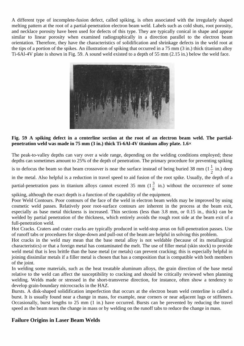
A different type of incomplete-fusion defect, called spiking, is often associated with the irregularly shaped melting pattern at the root of a partial-penetration electron beam weld. Labels such as cold shuts, root porosity, and necklace porosity have been used for defects of this type. They are typically conical in shape and appear similar to linear porosity when examined radiographically in a direction parallel to the electron beam orientation. Therefore, they have the characteristics of solidification and shrinkage defects in the weld root at the tips of a portion of the spikes. An illustration of spiking that occurred in a 75 mm (3 in.) thick titanium alloy Ti-6Al-4V plate is shown in Fig. 59. A sound weld existed to a depth of 55 mm (2.15 in.) below the weld face.
Fig. 59 A spiking defect in a centerline section at the root of an electron beam weld. The partial-penetration weld was made in 75 mm (3 in.) thick Ti-6Al-4V titanium alloy plate. 1.6×
The peak-to-valley depths can vary over a wide range, depending on the welding conditions employed; these depths can sometimes amount to 25% of the depth of penetration. The primary procedure for preventing spiking
is to defocus the beam so that beam crossover is near the surface instead of being buried 38 mm (1 12
in.) deep
in the metal. Also helpful is a reduction in travel speed to aid fusion of the root spike. Usually, the depth of a
partial-penetration pass in titanium alloys cannot exceed 35 mm (1 38
in.) without the occurrence of some
spiking, although the exact depth is a function of the capability of the equipment. Poor Weld Contours. Poor contours of the face of the weld in electron beam welds may be improved by using cosmetic weld passes. Relatively poor root-surface contours are inherent in the process at the beam exit, especially as base metal thickness is increased. Thin sections (less than 3.8 mm, or 0.15 in., thick) can be welded by partial penetration of the thickness, which entirely avoids the rough root side at the beam exit of a full-penetration weld. Hot Cracks. Craters and crater cracks are typically produced in weld-stop areas on full-penetration passes. Use of runoff tabs or procedures for slope-down and pull-out of the beam are helpful in solving this problem. Hot cracks in the weld may mean that the base metal alloy is not weldable (because of its metallurgical characteristics) or that a foreign metal has contaminated the melt. The use of filler metal (skin stock) to provide weld metal that is less brittle than the base metal (or metals) can prevent cracking; this is especially helpful in joining dissimilar metals if a filler metal is chosen that has a composition that is compatible with both members of the joint. In welding some materials, such as the heat treatable aluminum alloys, the grain direction of the base metal relative to the weld can affect the susceptibility to cracking and should be critically reviewed when planning welding. Welds made or stressed in the short-transverse direction, for instance, often show a tendency to develop grain-boundary microcracks in the HAZ. Bursts. A disk-shaped solidification imperfection that occurs at the electron beam weld centerline is called a burst. It is usually found near a change in mass, for example, near corners or near adjacent lugs or stiffeners. Occasionally, burst lengths to 25 mm (1 in.) have occurred. Bursts can be prevented by reducing the travel speed as the beam nears the change in mass or by welding on the runoff tabs to reduce the change in mass.
Failure Origins in Laser Beam Welds

Laser beam welding is used in the automotive, electronics, consumer products, and aerospace industries to join wire to wire, wire to sheet, tube to sheet, and for stud welding. Problems experienced in continuous-wave high-power laser beam welding are very similar to those in electron beam welding processes. Several discontinuities that may cause difficulties in pulsed laser beam welds are discussed subsequently. Inclusions. Because the laser equipment itself does not contact the workpieces, the presence of any inclusions that could affect the quality of a laser beam weld would be due to foreign materials either on the surface or within the structure of the metal being joined. In most instances, any foreign substances on the workpiece surfaces are vaporized by the high heat of welding. Careful selection, cleaning, and preparation of materials are the best means of minimizing failures from inclusions of any type. Porosity. Weld pulse-time schedules must be very carefully developed to avoid the formation of voids and porosity. Cleanness of workpiece surfaces and avoidance of low-boiling alloy constituents, such as zinc, are also important in minimizing voids. Inadequate Penetration. Generally, the penetration that can be achieved with a laser beam increases with the square root of the available pulse time and of the thermal diffusivity of the metal being welded. However, at the same time, high surface reflectivity may be a cause of reduced energy input and inadequate penetration. Simply raising the energy level to compensate for high reflectivity may exceed the intensity limits and produce vaporization and holes. One technique to overcome this difficulty is to apply a suitable thin, absorptive coating, such as an anodize or black oxide, that decreases the surface reflection without affecting the metallurgy of the weld. Metal surfaces can sometimes be roughened to obtain lower reflectivity. An ideal technique when the workpiece shape permits, however, is to arrange the surfaces to be joined so that the weld is in a crevice or hole that can act as a black body, which is a perfect absorber. In this case, the high reflectivity is an advantage, guaranteeing that melting occurs only at the intended area. Poor Weld Shape. The most favorable joint configuration for pulsed laser beam welding is probably the lap joint, although sound welds can also be made with other types of joints. In any configuration, the important factors are process variations, because these have a definite influence on weld quality. At the desired laser energy output, for example, a 10% change in output produces a 4% change in weld strength. Focusing distance is likewise important to weld strength. For a 50 mm (2 in.) focal length, variations in position of up to ±1.3 mm (±0.05 in.) still produce acceptable welds. Even though no separation between wires in a lap joint is recommended, some degree of separation can be tolerated. Poor welds can also be caused by variations in alignment of the axis of the joint with respect to the axis of the laser beam; weld failures may thus be attributed to the use of fixtures that were inadequate to position and hold the workpieces with the necessary precision. The use of tandem laser beams can help prevent this problem. A further factor influencing weld shape and weld strength is the environment in which the laser functions. The laser beam is modified by any condition that absorbs radiant energy, such as smoke, weld spatter, water vapor, or condensates on the ruby, lens, or mirror surfaces of the equipment. Clean, deionized cooling water through the optical cavity, dry nitrogen gas flow through the laser chamber, an exhaust fan for the welding chamber, and regular replacement of the glass slide over the objective lens all represent desirable procedures to maintain constant laser beam input energy to the weld joint. Base Metal Cracking. When laser beam energy is put into the weld at too high a rate, the surface may not only suffer from vaporization, but base metal cracking may also occur from thermal shock. This relates to the limitations of thickness that can be welded, which in turn depend on the thermal properties of the metal, its vaporization characteristics, and reflectivity. Generally, longer pulse times are needed to weld the lower-thermal-conductivity metals, and higher pulse-energy densities are necessary in welding high-reflectivity and high-melting-point alloys.
Failure Origins in High-Frequency Induction Welds
Pipes for high-pressure service, pipes for well casings, and structural beams have been welded by the high-frequency induction process. Hook cracks are a type of discontinuity associated with these welds. They are difficult to detect and require extremely careful inspection for assurance that they are not present. Delamination of the pipe wall just outside of the narrow weld zone can be the cause of hook cracks. The slight upset of the metal at the weld acts to turn the ends of these usually very small subsurface cracks in the direction of the metal flow (Fig. 60). Because the metal flow of the upset is toward both surfaces, the “hook” of the hook crack may turn toward either the outside or the inside surface, depending on which is closer to the delamination and in
The file is downloaded from www.bzfxw.com

which direction the greatest amount of upset occurs. Generally, upset is greater toward the outer surface, thus causing hooking to turn outward. Use of the cleanest steel available and the lowest possible heat input greatly reduces the possibility of hook cracks.
Fig. 60 Schematic of a hook crack in a pipe caused by pipe-wall delamination after high-frequency welding. The “hook” has turned outward to follow the direction of metal flow in the outer portion of the upset weld zone.
Depending on the materials and welding parameters used, high-frequency weldments are susceptible to other forms of cracking. In one case, weld-centerline cracking was encountered during flaring and flattening tests of high-frequency induction-welded type 409 stainless steel tubing for automobile exhaust systems. Simulation of the welding process and metallographic examinations of simulated and actual welds from several different heat compositions demonstrated that the heat composition, which controlled the type of phase transformations occurring during cooling, determined whether weld cracking occurred. Compositions having a high nickel equivalent (Ref 29) or low chromium equivalent contained martensite at and adjacent to the weld, which strengthened the welds and forced plastic straining to occur in the ductile sheet outside the weld during testing. On the other hand, compositions having a lower nickel equivalent or higher chromium equivalent transformed to weaker ferrite at the weld centerline, which permitted bondline defects to initiate fracture.
Reference cited in this section
29. J. LeFevre, R. Tricot, and R. Castro, Nouveaux Aciers Inoxydables a 12% Chrome (New Stainless Steels with 12% Chromium), Rev. Métall., Vol 70, April 1973, p 259–268
Acknowledgments
The following authors and contributors of previous editions provided substantial content used in this article. Appreciation is expressed to: Tarsem Jutla, Caterpillar Inc.; Alan G. Glover, Welding Institute of Canada; Daniel Hauser, Edison Welding Institute; Edward A. Metzbower, Naval Research Laboratory; O.W. Blodgett, Lincoln Electric; the ASM Committee on Weld Discontinuities (for Welding, Brazing, and Soldering, Volume 6 of Metals Handbook (9th ed.), 1983), and the ASM Committee on Failure Analysis of Weldments (for Failure Analysis and Prevention, Volume 10 of Metals Handbook (8th ed.), 1975).
References
1. W. Moyer, Mechanical Testing of Welded Joints, Mechanical Testing and Evaluation, Vol 8, ASM Handbook, 2000, p 845–852
2. E.R. Barker, Brittle Behavior of Engineering Structures, John Wiley & Sons, 1957

3. J. Signes, R.G. Baker, J.D. Harrison, and F.M. Burdekin, Factors Affecting the Fatigue Strength of Welded High Strength Steels, Br. Weld. J., Vol 14 (No. 3), 1967, p 108–116
4. S.J. Maddox, “Fitness-for-Purpose Assessment of Misalignment in Transverse Butt Welds Subject to Fatigue Loading,” Document XIII-1180–85, International Institute of Welding, 1985
5. S.J. Maddox, Recent Advances in the Fatigue Assessment of Weld Imperfections, Weld. J., July 1993, p 42–51
6. J.R. Gordon, “A Review of Currently Available Fracture Analysis Methods and Their Applicability to Welded Structures,” paper presented at Sixth Annual North American Welding Research Conference, Edison Welding Institute and American Welding Society, Oct 1990
7. “Code of Practice for Fatigue Design and Assessment of Steel Structures,” BS 7608, British Standards Institution, 1993
8. “Guidance on Methods for Assessing the Acceptability of Flaws in Fusion Welded Structures,” BS PD 6493:1991, British Standards Institution, Aug 1991 (superseded by BS 7910)
9. “Guide on Methods for Assessing the Acceptability of Flaws in Fusion Welded Structures,” BS 7910, British Standards Institute, 1999
10. I. Milne, R.A. Ainsworth, A.R. Dowling, and A.T. Stewart, “Assessment of the Integrity of Structures Containing Defects,” R/H/R6-Rev. 3, Central Electricity Generating Board (United Kingdom), 1987
11. V. Kumar, M.D. German, and C.F. Shih, “An Engineering Approach for Elastic-Plastic Fracture Analysis,” Technical Report NP 1931, Electric Power Research Institute, July 1981
12. J.M. Bloom, Validation of a Deformation Plasticity Failure Assessment Diagram Approach to Flaw Evaluation, STP 803, Vol II, ASTM, 1983, p 206
13. “The Method of Assessment for Defects in Fusion Welded Joints with Respect to Brittle Fracture,” WES 2805, Japan Welding Engineering Society
14. “IIW Guidance on Assessment of the Fitness for Purpose of Welded Structures,” Draft for Development, IIW/IIS-SST-1157-90, International Institute of Welding, 1990
15. “Recommended Practice for Fitness-for-Service of Refinery Equipment,” API 579, American Petroleum Institute
16. A.R. Cuiffreda and R.D. Merrick, Brittle Fracture of a Pressure Vessel: Study Results and Recommendations, Proceedings of the American Petroleum Institute, Vol 62, 1983
17. O.W. Blodgett, Joint Design and Preparation, Welding, Brazing, and Soldering, Vol 6, Metals Handbook (9th ed.), 1983, p 60–72
18. S.J. Maddox, “Scale Effect in Fatigue of Fillet-Welded Aluminum Alloys,” presented at Sixth Int. Conf. Aluminum Weldments (Cleveland), American Welding Society, 1995
19. V.I. Makhnenko and R.Y. Mosenkis, Calculating the Coefficient of Concentration of Stresses in Welded Joints with Butt and Fillet Welds, Automat. Weld., Aug 1985
20. K. Iida, Y. Kho, J. Fukakura, M. Nihei, T. Iwadate, and M. Nagai, “Bending Fatigue Strength of Butt Welded Plate with Uranami Bead,” IIW/IIS-XIII-1202–86, International Institute of Welding, 1986
The file is downloaded from www.bzfxw.com

21. “Welded Steel Construction (Metal Arc Welding),” CSA W59, Canadian Standards Association, 1989
22. “Welding Pipelines and Related Facilities,” API STD 1104, 19th ed., American Petroleum Institute, 1999
23. Weld Integrity and Performance, ASM International, 1997
24. G. Screm et al., The effects of Weld Defects in Reducing the Fatigue Strength of Welded Joints, Alluminio, Vol 44 (No. 3), 1975
25. B.A. Graville, The Principles of Cold Cracking Control in Welds, Dominion Bridge, Hanover, 1975
26. F. Coe, Welding Steels Without Hydrogen Cracking, The Welding Institute, Abington, Cambridge, U.K., 1973
27. R.D. Stout, Weldability of Steels, 3rd ed., Welding Research Council, 1978
28. D.J. Carney, Gases in Liquid Iron and Steel, Gases in Metals, American Society for Metals, 1953, p 69–118
29. J. LeFevre, R. Tricot, and R. Castro, Nouveaux Aciers Inoxydables a 12% Chrome (New Stainless Steels with 12% Chromium), Rev. Métall., Vol 70, April 1973, p 259–268
Introduction
HEAT TREATING—of all the various steel processing methods—has the greatest overall impact on control of microstructure, properties, residual stresses, and dimensional control. This article provides an overview of the effects of various material and process-related parameters on residual stress, distortion control, cracking, and microstructure/property relationships as they relate to various types of failure. The subjects that are discussed include:
• Phase transformations during heat treating • Metallurgical sources of stress and distortion during heating and cooling • Effect of materials and quench-process design on distortion and cracking • Quenchant selection • Effect of cooling characteristics on residual stress and distortion • Methods of minimizing distortion • Tempering • Effect of the heat treatment process on microstructure/property-related failures, such as cracking
Failures Related to Heat Treating Operations
G.E. Totten, G.E. Totten & Associates, LLC; M. Narazaki, Utsunomiya University (Japan); R.R. Blackwood and L.M. Jarvis, Tenaxol Inc.
Phase Transformation during Heating and Cooling
Steel Transformation

Properties such as hardness, strength, ductility, and toughness are dependent on the microstructural products that are present in steel. The first step in the transformation process is to heat the steel to its austenitizing temperature. The steel is then cooled rapidly to avoid the formation of pearlite, which is a relatively soft transformation product; to maximize the formation of martensite, a relatively hard transformation product; and to achieve the desired as-quenched hardness. The most common transformational products that may be formed from austenite in quench-hardenable steels are, in order of formation with decreasing cooling rate: martensite, bainite, pearlite, ferrite, and cementite. The formation of these products and the proportions of each are dependent on the time and temperature cooling history of the particular alloy and the elemental composition of that alloy. The transformation products formed are typically illustrated with the use of transformation diagrams, which show the temperature-time dependence of the microstructure formation process for the alloy being studied. Two of the most commonly used transformation diagrams are time-temperature-transformation (TTT) and continuous cooling transformation (CCT) diagrams. Time-temperature-transformation diagrams, also called isothermal transformation diagrams, are developed by heating small samples of steel to the temperature where austenite transformation structure is completely formed, that is, the austenitizing temperature (TA), and then rapidly cooling to a temperature intermediate between the austenitizing and the martensite start (Ms) temperature and then holding for a fixed period of time until the transformation is complete, at which point the transformation products are determined. This is done repeatedly until a TTT diagram is constructed, such as that shown for an unalloyed steel (American Iron and Steel Institute, or AISI, 1045) in Fig. 1. Time-temperature-transformation diagrams can only be read along the isotherms. The temperature A1 is where transformation to austenite begins, and temperature A3 is where the transformation to austenite is complete.
Fig. 1 Time-temperature-transformation diagram of an unalloyed steel containing 0.45% C. Austenitization temperature, 880 °C (1620 °F). The temperature A1 is where transformation to austenite begins, and temperature A3 is where the transformation to austenite is complete. Courtesy of Verlag Stahlessen mbH Dusseldorf
The file is downloaded from www.bzfxw.com

Continuous Cooling Transformation Diagrams. Alternatively, samples of a given steel may be continuously cooled at different specified rates, and the proportion of transformation products formed after cooling to various temperatures intermediate between the austenitizing temperature and the Ms may be determined in order to construct a CCT diagram, such as the one shown for an unalloyed carbon steel (AISI 1045) in Fig. 2. Continuous cooling transformation curves provide data on the temperatures for each phase transformation, the amount of transformation product obtained for a given cooling rate with time, and the cooling rate necessary to obtain martensite. The critical cooling rate is dictated by the time required to avoid formation of pearlite for the particular steel being quenched. As a general rule, a quenchant must produce a cooling rate equivalent to, or faster than, that indicated by the “nose” of the pearlite transformation curve in order to maximize martensite transformation product. Continuous cooling transformation diagrams can only be read along the curves of different cooling rates.
Fig. 2 Continuous cooling transformation diagram of an unalloyed steel containing 0.45% C. Austenitization temperature, 880 °C (1620 °F). Courtesy of Verlag Stahlessen mbH Dusseldorf
Caution: Although it is becoming increasingly common to see cooling curves (temperature-time profiles) for different quenchants, such as oil, water, air, and others, superimposed on either TTT or CCT diagrams, this is not a rigorously correct practice, and various errors are introduced into such analysis due to the inherently different kinetics of cooling used to obtain the TTT or CCT diagrams (described previously) versus the quenchants being represented. If a cooling curve is to be superimposed on a transformation diagram, a CCT, not a TTT, diagram should be used.
Metallurgical Crystal Structure
When steel is slowly cooled, it undergoes a crystal structure (size) change as it transforms from a less densely packed austenite (face-centered cubic, or fcc) to a more densely packed body-centered cubic (bcc) structure of ferrite. At faster cooling rates, the formation of ferrite is suppressed, and martensite, which is an even less

densely packed body-centered tetragonal (bct) structure than austenite, is formed. Illustrations of these crystal structures are provided in Fig. 3. This results in a volumetric expansion at the Ms temperature, as shown in Fig. 4.
Fig. 3 Crystal structures. (a) Austenite (fcc). (b) Ferrite (bcc). (c) Martensite (bct)
The file is downloaded from www.bzfxw.com

Fig. 4 Steel expansion and contraction on heating and cooling
Figure 5 shows that the crystal lattice of austenite expands with increasing carbon content (Ref 1). It has been reported that, typically, when a carbide-ferrite mixture is converted to martensite, the resulting expansion due to increasing carbon content is approximately 0.002 in./in. at 0.25% C and 0.007 in./in. at 1.2% C (Ref 1). The fractional increase in size when austenite is converted to martensite is approximately 0.014 in./in. for eutectoid compositions. This illustrates the effect of carbon structure and steel transformation on residual stresses and distortion leading to dimensional changes.

Fig. 5 Carbon content versus lattice parameters of (retained) austenite and martensite at room temperature. a at the top of the graph is the lattice parameter of fcc austenite. a and c in the lower half of the graph are the lattice parameters for tetragonal martensite. The ratio of c/a for martensite as a function of carbon content is also given.
Estimation of Volumetric Change due to Steel Transformation
In the previous discussion, it has been shown that there are various microstructures possible on heating and cooling of steel, and that the potential microstructural transformations that are possible for a given steel are illustrated by their CCT or TTT diagrams. Furthermore, dimensional changes are possible, depending on the carbon content and microstructural transformation product formed. Table 1 summarizes the atomic volumes of different microstructural components as a function of carbon content (Ref 2). Table 2 provides an estimate of volumetric changes as a function of carbon content for different metallurgical transformations (Ref 3, 4).
Table 1 Atomic volumes of selected microstructural constituents of ferrous alloys
Phase Apparent atomic volume, Å3 Ferrite 11.789 Cementite 12.769 Ferrite + carbides 11.786 + 0.163 C(a) Pearlite 11.916 Austenite 11.401 + 0.329 C(a) Martensite 11.789 + 0.370 C(a) (a) C = % carbon
Table 2 Size changes during hardening of carbon tool steels
Reaction Volume change, % Dimensional change, in./in. Spheroidite → austenite -4.64 + 2.21 (%C) 0.0155 + 0.0074 (%C) Austenite → martensite 4.64 - 0.53 (%C) 0.0155 - 0.00118 (%C) Spheroidite → martensite 1.68 (%C) 0.0056 (%C) Austenite → lower bainite (a) 4.64 - 1.43 (%C) 0.0156 - 0.0048 (%C) Spheroidite → lower bainite (a) 0.78 (%C) 0.0026 (%C)
The file is downloaded from www.bzfxw.com
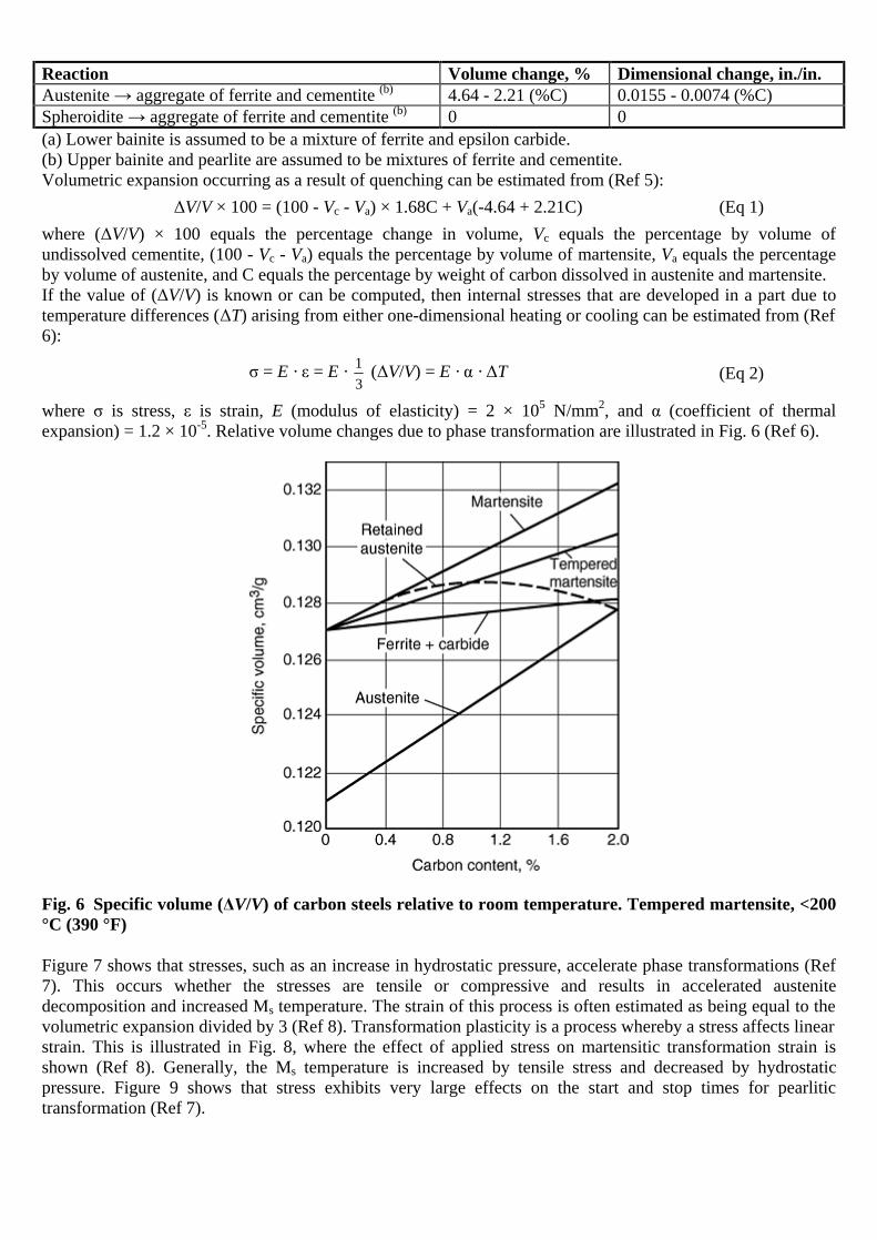
Reaction Volume change, % Dimensional change, in./in. Austenite → aggregate of ferrite and cementite (b) 4.64 - 2.21 (%C) 0.0155 - 0.0074 (%C) Spheroidite → aggregate of ferrite and cementite (b) 0 0 (a) Lower bainite is assumed to be a mixture of ferrite and epsilon carbide. (b) Upper bainite and pearlite are assumed to be mixtures of ferrite and cementite. Volumetric expansion occurring as a result of quenching can be estimated from (Ref 5):
ΔV/V × 100 = (100 - Vc - Va) × 1.68C + Va(-4.64 + 2.21C) (Eq 1) where (ΔV/V) × 100 equals the percentage change in volume, Vc equals the percentage by volume of undissolved cementite, (100 - Vc - Va) equals the percentage by volume of martensite, Va equals the percentage by volume of austenite, and C equals the percentage by weight of carbon dissolved in austenite and martensite. If the value of (ΔV/V) is known or can be computed, then internal stresses that are developed in a part due to temperature differences (ΔT) arising from either one-dimensional heating or cooling can be estimated from (Ref 6):
σ = E · ε = E · 13
(ΔV/V) = E · α · ΔT
(Eq 2)
where σ is stress, ε is strain, E (modulus of elasticity) = 2 × 10⁵ N/mm2, and α (coefficient of thermal expansion) = 1.2 × 10⁻⁵. Relative volume changes due to phase transformation are illustrated in Fig. 6 (Ref 6).
Fig. 6 Specific volume (ΔV/V) of carbon steels relative to room temperature. Tempered martensite, <200 °C (390 °F)
Figure 7 shows that stresses, such as an increase in hydrostatic pressure, accelerate phase transformations (Ref 7). This occurs whether the stresses are tensile or compressive and results in accelerated austenite decomposition and increased Ms temperature. The strain of this process is often estimated as being equal to the volumetric expansion divided by 3 (Ref 8). Transformation plasticity is a process whereby a stress affects linear strain. This is illustrated in Fig. 8, where the effect of applied stress on martensitic transformation strain is shown (Ref 8). Generally, the Ms temperature is increased by tensile stress and decreased by hydrostatic pressure. Figure 9 shows that stress exhibits very large effects on the start and stop times for pearlitic transformation (Ref 7).

Fig. 7 Effect of hydrostatic pressure on the transformation kinetics of 50CV4 steel. B, bainite; F. P., ferrite-pearlite transformation; Ms, martensite start temperature. Source: Ref 7
Fig. 8 Dilatometer curves for a 0.6% carbon steel (60NCD11) for different applied stresses
The file is downloaded from www.bzfxw.com

Fig. 9 Effect of tensile stress on pearlite transformation starting and ending times. Isothermal transformation at 673°C (1243 °F), eutectoid steel. The tD and tF times are transformation starting and ending times, respectively.
Cooling and Steel Metallurgical Transformation
Cooling without Transformation (Ref 6, 7). If steel is cooled sufficiently fast, cooling is not accompanied with microstructural transformation changes. Under these conditions, the surface of the component cooled much more quickly than the core at first, as illustrated in Fig. 10 (Ref 9). At this point, the specific volume in the core is greater than that of the surface, and the reduction in volume at the surface (due to lower temperature) is resisted by the greater volume in the core, resulting in the surface being in tension and the core in compression.

Fig. 10 Development of thermal stresses within steel on cooling. T, time instant at maximum temperature difference; 0, time instant of stress reversal; curve A, stress variation at the surface under elastic conditions. B and C are actual thermal stress variations at the surface and the core under elastic-plastic conditions.
At the point of maximum temperature difference between the surface and the core (point T), the core cools (shrinks) more quickly than the surface, leading to an elastic dimensional reduction of the surface until a point of stress conversion is obtained, at which point the surface is in compression relative to the core. After the cooling processes have been completed, the residual stress distribution between the surface and the core, shown at the bottom right in Fig. 10 (Ref 9), is obtained. If the surface stresses exceed the hot yield strength of the material, it plastically deforms, resulting in thermally induced dimensional changes. Cooling with Transformation (Ref 6, 7). When steels that may undergo transformational changes are quenched, the possibility of the formation of both thermal and transformational stresses must be considered. Figure 11 illustrates three different examples of this process (Ref 8).
The file is downloaded from www.bzfxw.com

Fig. 11 Comparison of thermal and transformational stresses for three different quenching conditions. See text for details. tu, time instant of stress reversal
Example 1, illustrated in Fig. 11(a), occurs when phase transformation of both the surface and the core occurs before the thermal stresses change sign. Above the Ms transformation temperature, the stresses that are formed are thermal. On further cooling, the stresses in the core exceed the yield strength, and plastic deformation (elongation) occurs. Subsequent martensitic transformation at the core provides a substantial stress component, due to volumetric increases from martensitic phase transformation. This causes the core to be in compression and the surface to be in tension simultaneously. Example 2 (Fig. 11b) illustrates the case that begins after the thermal stresses change sign. The transformation-induced volume increase of the surface layer adds to the compressive stresses at the surface. Because the stresses are balanced, there is a corresponding increase in the tensile stresses in the core. Example 3 is a case where, although the transformation of the core starts later, it finishes before the surface (Fig. 11c). During the cooling process, the sign of the stresses changes three times. There are important consequences whether the core transforms before or after the stress reversal, because thermal stresses may be counteracted, and tensile surface residual stresses may result when the core transforms after the surface and before the stress reversal (Ref 8). This is illustrated, in Fig. 12. If the steel transformation occurs before the thermal stress maximum (sequence 4 in Fig. 12), the ferrite/pearlite structure of a cylindrical test specimen is distorted into a barrel shape (Ref 6). If the transformation occurs after the thermal stress maximum (sequence 1 in Fig. 12), the austenite is pressed into a barrel shape, followed by a volumetric increase due to martensitic transformation. This results in high tensile residual stresses on the surface. If the steel transformation occurs simultaneously with the maximum thermal stresses, transformation in the core occurs prior to surface transformation (sequence 3 in Fig. 12), and a barrel shape appears with high compressive stresses on the surface. If the surface is transformed prior to the core (sequence 2 in Fig. 12), the transformational stresses decrease or possibly even reverse the thermal stresses. If this occurs, a spool shape is formed.

Fig. 12 Size change due to thermal changes and phase transformation. K, core; R, surface
These data show that the position of cooling curves for both the surface and the core for the quenching process must be considered with the appropriate TTT curve for the steel of interest, and that there are numerous mixtures of thermal and transformational stresses possible. Table 3 provides a summary of these processes (Ref 6).
Table 3 Size change and residual stress caused by heat treatment of prismatic parts
(ΔT)(a) (ΔV/V)(b) Dimensional dependency
(Δε)(c) (σE)(d) Example
Change of microstructure Small ≠0 ε1 = ε11 = ε111 0 0 Tempering, precipitation hardening, isotropic material
Thermal stress Big 0 ε1 < ε11 < ε111 >0 <0 Quenching of austenitic steels
Thermal and transformation stress
Small >0 ε1 ~ ε11 ~ ε111 0 >>0 In air; full hardness penetration
Transformation R + K after thermal stress maximum
Big >>0 ε1 < ε11 < ε111 >0 >>0 In water; full hardness penetration
Transformation R before K after thermal stress maximum
Big >0 ε1 > ε11 > ε111 <0 >0 Medium hardness penetration
The file is downloaded from www.bzfxw.com
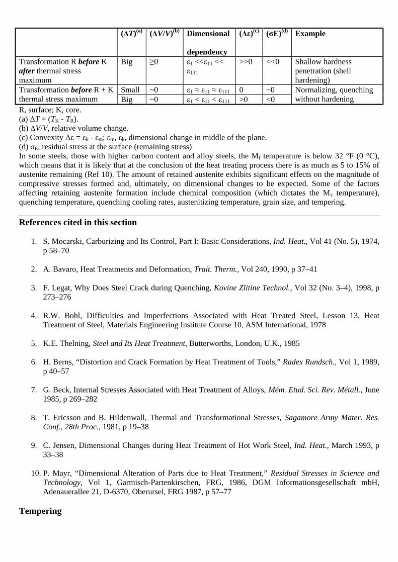
(ΔT)(a) (ΔV/V)(b) Dimensional dependency
(Δε)(c) (σE)(d) Example
Transformation R before K after thermal stress maximum
Big ≥0 ε1 <<ε11 << ε111
>>0 <<0 Shallow hardness penetration (shell hardening)
Small ~0 ε1 ≈ ε11 ≈ ε111 0 ~0 Transformation before R + K thermal stress maximum Big ~0 ε1 < ε11 < ε111 >0 <0
Normalizing, quenching without hardening
R, surface; K, core. (a) ΔT = (TK - TR). (b) ΔV/V, relative volume change. (c) Convexity Δε = εk - εm; εm, εk, dimensional change in middle of the plane. (d) σE, residual stress at the surface (remaining stress) In some steels, those with higher carbon content and alloy steels, the Mf temperature is below 32 °F (0 °C), which means that it is likely that at the conclusion of the heat treating process there is as much as 5 to 15% of austenite remaining (Ref 10). The amount of retained austenite exhibits significant effects on the magnitude of compressive stresses formed and, ultimately, on dimensional changes to be expected. Some of the factors affecting retaining austenite formation include chemical composition (which dictates the Ms temperature), quenching temperature, quenching cooling rates, austenitizing temperature, grain size, and tempering.
References cited in this section
1. S. Mocarski, Carburizing and Its Control, Part I: Basic Considerations, Ind. Heat., Vol 41 (No. 5), 1974, p 58–70
2. A. Bavaro, Heat Treatments and Deformation, Trait. Therm., Vol 240, 1990, p 37–41
3. F. Legat, Why Does Steel Crack during Quenching, Kovine Zlitine Technol., Vol 32 (No. 3–4), 1998, p 273–276
4. R.W. Bohl, Difficulties and Imperfections Associated with Heat Treated Steel, Lesson 13, Heat Treatment of Steel, Materials Engineering Institute Course 10, ASM International, 1978
5. K.E. Thelning, Steel and Its Heat Treatment, Butterworths, London, U.K., 1985
6. H. Berns, “Distortion and Crack Formation by Heat Treatment of Tools,” Radex Rundsch., Vol 1, 1989, p 40–57
7. G. Beck, Internal Stresses Associated with Heat Treatment of Alloys, Mém. Etud. Sci. Rev. Métall., June 1985, p 269–282
8. T. Ericsson and B. Hildenwall, Thermal and Transformational Stresses, Sagamore Army Mater. Res. Conf., 28th Proc., 1981, p 19–38
9. C. Jensen, Dimensional Changes during Heat Treatment of Hot Work Steel, Ind. Heat., March 1993, p 33–38
10. P. Mayr, “Dimensional Alteration of Parts due to Heat Treatment,” Residual Stresses in Science and Technology, Vol 1, Garmisch-Partenkirschen, FRG, 1986, DGM Informationsgesellschaft mbH, Adenauerallee 21, D-6370, Oberursel, FRG 1987, p 57–77
Tempering

Steel parts are often tempered by reheating after quench hardening to obtain specific values of mechanical properties. Tempering of steel increases ductility and toughness of quench-hardened steel and also relieves quench stresses and ensures dimensional stability. The tempering process involves heating hardened steel to some temperature below the eutectoid temperature for the purposes of decreasing hardness and increasing toughness. In general, the tempering process is divided into four stages, which are summarized in Table 4 (Ref 9). These include (Ref 11, 12):
1. Tempering of martensite structure 2. Transformation of retained austenite to martensite 3. Tempering of the decomposition products of martensite and at temperatures above 480 °C (900 °F) 4. Decomposition of retained austenite to martensite
Table 4 Metallurgical reactions occurring at various temperature ranges and related physical changes of steel during tempering
Temperature range Stage °C °F
Metallurgical reaction Expansion/contraction
1 0–200 32–392 Precipitation of ε-carbide. Loss of tetragonality Contraction 2 200–300 392–572 Decomposition of retained austenite Expansion 3 230–350 446–662 ε-carbides decompose to cementite Contraction 4 350–700 662–1292 Precipitation of alloy carbides. Grain coarsening Expansion Source: Ref 9 Figure 13 illustrates the effect of microstructural variation during tempering on the volume changes occurring during the tempering of hardened steel (Ref 9).
Fig. 13 Effect of microstructural constitutional variation on volume changes during tempering
Figure 14 illustrates the effect of dimensional variation and retained austenite content of a bearing steel (100Cr6) as a function of tempering temperature (Ref 10). Tempering may also lead to dimensional variation due to relaxation of residual stresses and plastic deformation, which is due to the temperature dependence of yield strength (Ref 11).
The file is downloaded from www.bzfxw.com

Fig. 14 Dimensional variation and retained austenite content of 100Cr6 steel as a function of tempering temperature
In addition to dimensional change by microstructural variation, tempering may also lead to dimensional variation due to relaxation of residual stresses and plastic distortion, which is due to the temperature dependence of yield strength (Ref 13). Figure 15 shows the distortion of round steel bars (200 mm, or 8 in., in diameter and 500 mm, or 20 in., in length) by quenching and by stress relieving by tempering. A medium-carbon steel bar (upper diagrams) and a hardenable steel bar (lower diagrams) are used in this experiment. Figures 15(a) and (d) are the results of quenching from 650 °C (1200 °F) without phase transformation. The distortion in each case is almost the same, regardless of the different quenchants and the different chemical compositions. These convex distortions are caused by nonuniform thermal contraction and resultant thermal stress during cooling. Figures 15(b) and (e) are the results of quenching from 850 °C (1560 °F) with phase transformation. The distortion in Fig. 15(e) (hardenable steel) shows a convex configuration, but the distortion in Fig. 15(b) (medium-carbon steel of poor hardenability) shows a configuration that combines convex and concave distortion. In addition, water quenching has a greater effect on distortion than oil quenching. Figures 15(c) and (f) show the configurations after tempering. These results show that tempering after quenching results in not only volumetric changes but also convex distortions. Such distortions seem to be related to relieving of residual stresses by tempering.

Fig. 15 Deformation of medium-carbon and hardenable steel bars by quenching from below and above the transformation temperature and by stress relieving. lc, change of length; WQ, water quench; OQ, oil quench. (a) to (c) JIS S38C steel (0.38% C). (d) to (f) JIS SNCM 439 steel (0.39% C, 1.8% Ni, 0.8% Cr, 0.2% Mo). (a) and (d) Quenched from 650 °C (1200 °F). (b) and (e) Quenched from 850 °C (1560 °F). (c) and (f) Tempered at 650 °C (1200 °F)
Figure 16 and 17 (Ref 14) show the example of stress relief by tempering. A solid cylinder, 40 mm (1.6 in.) in diameter and 100 mm (4 in.) in length, was examined for analyses and experiments of tempering performed after water quenching. Calculated residual stress distributions after water quenching are illustrated in Fig. 16. Open and solid circles in the figure correspond to measured stresses on the surface of the cylinder by x-ray diffraction technique. Residual stress distributions after tempering at 400 °C (750 °F) are shown in Fig. 17(a) and (b) for typical elapsed times of 2 and 50 h, with measured values on the surface. These results show that the stresses in all directions decrease with elapsed time in tempering.
Fig. 16 Stress distribution in a cylinder after quenching
The file is downloaded from www.bzfxw.com

Fig. 17 Stress distribution in a cylinder after tempering. (a) t = 2 h. (b) Assume t = ∞.
The following are recommendations with respect to the tempering process (Ref 4):
• Generally, the higher the tempering temperature, the greater the resulting ductility and toughness. However, this is at the expense of strength and hardness.
• High-carbon steels that contain appreciable amounts of retained austenite undergo an increase in hardness when tempered at approximately 230 °C (450 °F) as a result of decomposition of the austenite.
• Steel tempered at approximately 260 °C (500 °F) undergoes a loss of toughness (Fig. 18) that is associated with the formation of carbide films around prior martensite plates.
• Alloy steels undergo temper brittleness or a reduction in toughness that occurs when the steel is tempered in (or slowly cooled through) the temperature range of 510 to 593 °C (950 to 1100 °F). This phenomenon does not occur in plain carbon steels, but the degree of embrittlement is enhanced by nickel, manganese, and chromium content. Tempering should be carried out below this range for steels susceptible to this embrittlement or above the range, followed by rapid quenching through the range. Molybdenum additions minimize the susceptibility of steels to this form of embrittlement.
• Highly alloyed steels, for example, high-speed steels, many contain large amounts of retained austenite that is stable during tempering but transforms to brittle martensite on cooling from tempering. A second temper is then necessary to temper this brittle secondary martensite.
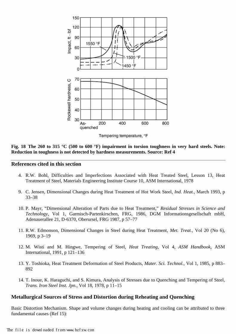
Fig. 18 The 260 to 315 °C (500 to 600 °F) impairment in torsion toughness in very hard steels. Note: Reduction in toughness is not detected by hardness measurements. Source: Ref 4
References cited in this section
4. R.W. Bohl, Difficulties and Imperfections Associated with Heat Treated Steel, Lesson 13, Heat Treatment of Steel, Materials Engineering Institute Course 10, ASM International, 1978
9. C. Jensen, Dimensional Changes during Heat Treatment of Hot Work Steel, Ind. Heat., March 1993, p 33–38
10. P. Mayr, “Dimensional Alteration of Parts due to Heat Treatment,” Residual Stresses in Science and Technology, Vol 1, Garmisch-Partenkirschen, FRG, 1986, DGM Informationsgesellschaft mbH, Adenauerallee 21, D-6370, Oberursel, FRG 1987, p 57–77
11. R.W. Edmonson, Dimensional Changes in Steel during Heat Treatment, Met. Treat., Vol 20 (No 6), 1969, p 3–19
12. M. Wisti and M. Hingwe, Tempering of Steel, Heat Treating, Vol 4, ASM Handbook, ASM International, 1991, p 121–136
13. Y. Toshioka, Heat Treatment Deformation of Steel Products, Mater. Sci. Technol., Vol 1, 1985, p 883–892
14. T. Inoue, K. Haraguchi, and S. Kimura, Analysis of Stresses due to Quenching and Tempering of Steel, Trans. Iron Steel Inst. Jpn., Vol 18, 1978, p 11–15
Metallurgical Sources of Stress and Distortion during Reheating and Quenching
Basic Distortion Mechanism. Shape and volume changes during heating and cooling can be attributed to three fundamental causes (Ref 15):
The file is downloaded from www.bzfxw.com

• Residual stresses that cause shape change when they exceed material yield strength. This occurs on heating when the strength properties decline.
• Stresses caused by differential expansion due to thermal gradients. These stresses increase with the thermal gradient and cause plastic deformation as the yield strength is exceeded.
• Volume changes due to transformational phase change. These volume changes are contained as residual stress systems until the yield strength is exceeded.
Relief of Residual Stresses. If a part has locked-in residual stresses, these stresses can be relieved by heating the part until the locked-in stresses exceed the strength of the material. A typical stress-strain curve obtained from a tension test is shown in Fig. 19 (Ref 15). Initial changes in shape are elastic, but under increased stress, they occur in the plastic zone and are permanent. On heating, the stresses are gradually relieved by changes in the shape of the part due to plastic flow. This is a continuous process, and as the temperature of the part is increased, the material yield stress decreases, as shown in Fig. 20 (Ref 16). It is a function not only of temperature but also of time, because the material creeps under lower applied stresses. It is apparent that the stresses can never be reduced to zero, because the material always possesses some level of yield strength below which residual stresses cannot be reduced.
Fig. 19 Various features of a typical stress-strain curve obtained from a tension test
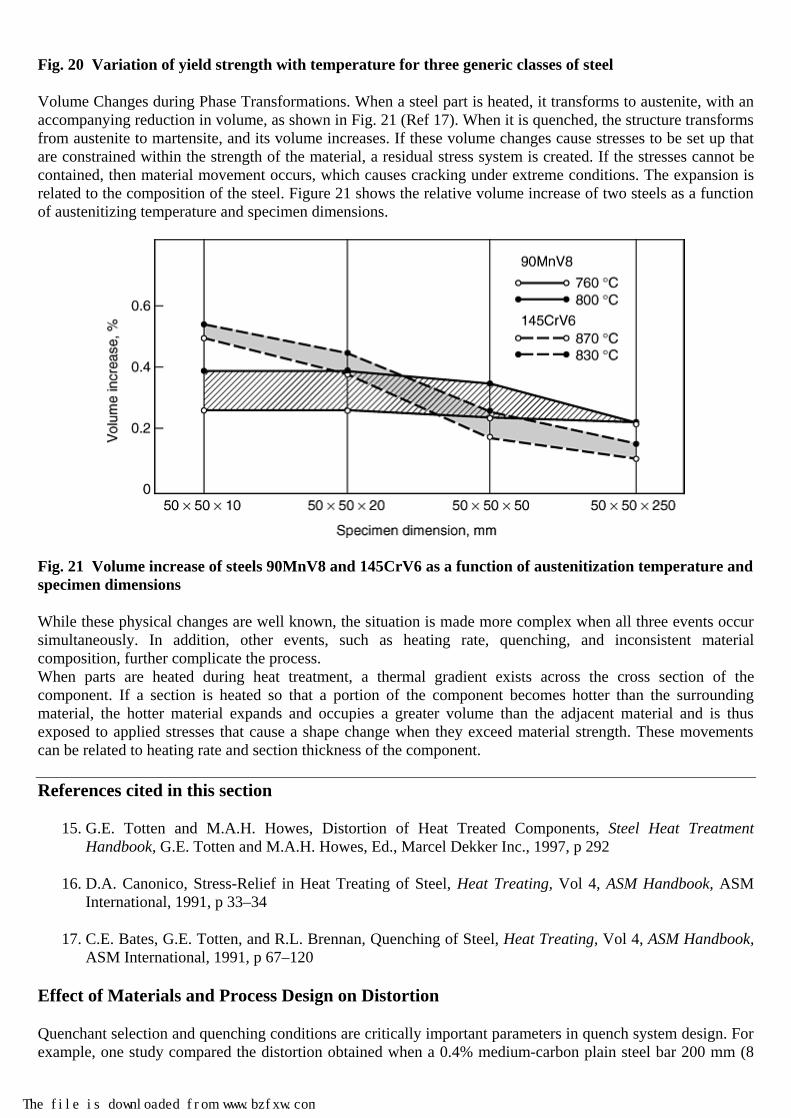
Fig. 20 Variation of yield strength with temperature for three generic classes of steel
Volume Changes during Phase Transformations. When a steel part is heated, it transforms to austenite, with an accompanying reduction in volume, as shown in Fig. 21 (Ref 17). When it is quenched, the structure transforms from austenite to martensite, and its volume increases. If these volume changes cause stresses to be set up that are constrained within the strength of the material, a residual stress system is created. If the stresses cannot be contained, then material movement occurs, which causes cracking under extreme conditions. The expansion is related to the composition of the steel. Figure 21 shows the relative volume increase of two steels as a function of austenitizing temperature and specimen dimensions.
Fig. 21 Volume increase of steels 90MnV8 and 145CrV6 as a function of austenitization temperature and specimen dimensions
While these physical changes are well known, the situation is made more complex when all three events occur simultaneously. In addition, other events, such as heating rate, quenching, and inconsistent material composition, further complicate the process. When parts are heated during heat treatment, a thermal gradient exists across the cross section of the component. If a section is heated so that a portion of the component becomes hotter than the surrounding material, the hotter material expands and occupies a greater volume than the adjacent material and is thus exposed to applied stresses that cause a shape change when they exceed material strength. These movements can be related to heating rate and section thickness of the component.
References cited in this section
15. G.E. Totten and M.A.H. Howes, Distortion of Heat Treated Components, Steel Heat Treatment Handbook, G.E. Totten and M.A.H. Howes, Ed., Marcel Dekker Inc., 1997, p 292
16. D.A. Canonico, Stress-Relief in Heat Treating of Steel, Heat Treating, Vol 4, ASM Handbook, ASM International, 1991, p 33–34
17. C.E. Bates, G.E. Totten, and R.L. Brennan, Quenching of Steel, Heat Treating, Vol 4, ASM Handbook, ASM International, 1991, p 67–120
Effect of Materials and Process Design on Distortion
Quenchant selection and quenching conditions are critically important parameters in quench system design. For example, one study compared the distortion obtained when a 0.4% medium-carbon plain steel bar 200 mm (8
The file is downloaded from www.bzfxw.com

in.) in diameter by 500 mm (20 in.) long is quenched in water or oil from 680 °C (1260 °F) (Ref 18, 19). The results, Fig. 22(a) and (c), show that essentially equivalent variation in diameter and length with both cooling processes was obtained, which was due to thermal strains within the steel. Interestingly, the well-known diameter variations at the end of the bar, known as the “end-effect,” were observed, which is attributable to heat extraction from both the sides and ends of the bar.
Fig. 22 Dimensional variation of a medium-carbon (0.4%) steel bar (200 mm, or 8 in., diam × 500 mm, or 20 in.) after the indicated heat treatments. These bars were quenched vertically with one end down (marked “0” in the figure). (a) and (c) show no transformation, thermal strain only after water quenching from 680 °C (1260 °F). (b) and (d) show thermal and transformation strains after quenching from 850 °C (1560 °C). OQ, oil quench; WQ, water quench
If the same steel bars of the same dimensions are heated to 850 °C (1560 °F) to austenitize the steel and then quenched in water or oil, the results shown in Fig. 22(b) and (d), respectively, were obtained (Ref 18, 19). Considerably greater dimensional variation and lengthening of the bar (for the oil quench) was obtained due to both thermal and transformational strains with the steel. The dimensional changes of a 70 mm (2.75 in.) steel (0.15% C, 1% Mn, 0.75% Cr, 0.85% Ni) cube were modeled after austenitizing and then quenching in water and oil (Ref 18, 20). The results of this work are shown in Fig. 23. As seen in the figure, the edges and faces shrink (becoming concave), and the effects are greater when the steel is quenched in water than when it is quenched in oil.

Fig. 23 Dimensional changes in a 70 mm (2.75 in.) steel (0.15% C, 1% Mn, 0.75% Cr, 0.85% Ni) bar after austenitizing and then quenching in water or oil
There are various factors that can affect distortion and growth of steel in heat treating. These include component design, steel grade and condition, machining, component support and loading, surface condition, heating and atmosphere control, retained austenite, and the quenching process (Ref 21). Component Design. One of the overwhelming causes of steel cracking and unacceptable distortion control is component design. Poor component design promotes distortion and cracking by accentuating nonuniform and nonsymmetrical heat transfer during heating and cooling. Component design characteristics that are common to distortion and cracking problems include (Ref 22, 23):
• Parts that are long, with thin cross sections. Long and thin parts are defined as those greater than L = 5d for water quenching, L = 8d for oil quenching, and L = 10d for austempering, where L is the length of the parts, and d is the thickness or diameter. Long and thin parts may be quenched using a support mechanism, such as that illustrated in Fig. 24.
• Parts that possess large cross-sectional area (A) and are thin (t), which are defined as A = 50t.
The file is downloaded from www.bzfxw.com

Fig. 24 Die quenching system. Courtesy of Gleason Tooling Products Group
Parts that exceed these dimensions often must be straightened or press quenched to maintain dimensional stability (Ref 23). If possible, materials with sufficient hardenability should be oil or salt quenched. A schematic illustration of a press quenching system is provided in Fig. 25.
Fig. 25 Schematic of a press quench system. Courtesy of Gleason Tooling Products Group
The following are additional guidelines (Ref 4):
• Balance the areas of mass. • Avoid sharp corners and reentrant angles. • Avoid sharp corners between heavy and thin sections. • Avoid single internal or external keys, keyways, or splines. • Provide adequate fillet or radius at the base of gear teeth, splines, and serrations. • Do not have holes in direct line with the sharp angles of cutouts. • Avoid a sharp corner at the bottom of small openings, such as in drawing or piercing dies, because
spalling or flaking is likely to result at these points. • Keep hubs of gears, cutters, and so on as near the same thickness as possible, because dishing is likely
to occur.
Additional design considerations to reduce the probability of distortion, cracking, and soft spots include (Ref 4):

• Order stock large enough to allow for machining to remove decarburized surfaces and surface imperfections, such as laps and seams.
• Do not drill screw holes closer than 6.35 mm (0.25 in.) from edges of die blocks or large parts, where possible. Cracking may be avoided by using steel that may be hardened by using lower quench severity, or if possible, pack the bolt hole to reduce thermal stresses arising due to quenching.
• Avoid blind holes, if possible. • All parts should be designed with round corners and fillets wherever possible. • Use air-hardening or high-carbon (oil- and air-hardening) tool steel on unbalanced and intricately
shaped dies. • Add extra holes, if possible, on heavy, unbalanced sections to allow for faster and more uniform cooling
when quenched. • Do not machine knife blades to a sharp cutting edge before hardening. • Avoid deep scratches and tool marks. • On long, delicate parallels, shafts, and so on, rough out and have pieces annealed to remove stresses
before finish machining. • Always use the grade or composition of steel most suitable for the work that the part has to perform.
A well-designed part is the best ensurance against breakage in hardening. Design symmetry is also an important variable to minimize distortion. For example, the unsymmetrical gear design shown in the upper diagram of Fig. 26 typically may undergo distortion, as shown in the lower diagram of Fig. 26 (Ref 22). (The load on a gear tooth increases as a power of 4.3 with the taper [Ref 22]). The solution to the gear design problem shown in Fig. 26 is to provide greater symmetry, as shown in Fig. 27. If this is not possible, press quenching or tooth-by-tooth induction hardening may be the best alternative (Ref 22, 23).
Fig. 26 Schematic of a gear that is difficult to harden without the distortion shown
Fig. 27 Design solutions to the distortion problem shown in Fig. 26
Another common design problem occurs with parts having holes, deep keyways, and grooves. One illustration of this problem is hardening of a shaft over a lubrication cross hole, as illustrated in Fig. 28 (Ref 22). Preferred
The file is downloaded from www.bzfxw.com

alternative designs are also shown in Fig. 28. If a radial cross hole is mandatory, the use of carburized steel with oil quenching would be preferred.
Fig. 28 Design solutions to the quench-cracking problem often encountered in shaft hardening over a cross hole
The distortion encountered when quenching a notched part, such as a shaft with a milled slot, is illustrated in Fig. 29 (Ref 23). In this case, nonuniform heat transfer results. The metal within the notch is affected by the shrinkage of the metal around it, due to slower cooling within the slot caused by vaporization of the quenchant. Therefore, on cooling, the metal on the side with the shaft is “too short,” pulling the shaft out of alignment. A general rule for solving such quench distortion problems is that the “short side is the hot side,” which means that the inside of the bowed metal was quenched more slowly than the opposite side (Ref 23).
Fig. 29 Distortion often encountered when quenching a notch

Figure 30 provides an illustration of recommended design corrections that reduce the possibility of quench-cracking (Ref 4). If it is unavoidable that quench crack-sensitive designs be used, then two possible design modifications should be considered. The first is to consider a two-piece assembly that is mechanically joined or shrunk-fitted together. The second is to manufacture the part from steel that can be hardened by martempering or by air cooling. These alternative design strategies produce lower stress and minimize cracking.
Fig. 30 Part design recommendations for minimal internal stresses. Source: Ref 4
Steel Grade and Condition. Although steel cracking is most often due to nonuniform heating and cooling, material problems may be encountered. Some typical material problems include (Ref 22):
The file is downloaded from www.bzfxw.com
• The compositional tolerances should be checked to ensure that the alloy is within specification. • Some alloys are particularly problematic. For example, some steel grades must be water quenched when
the alloy composition is on the low side of the specification limit. Conversely, if the alloy composition is on the high side, cracking is more common. Steel grades that exhibit this problem include: 1040, 1045, 1536, 1541, 1137, 1141, and 1144. As a rule, steels with carbon contents and hardenability greater than 1037 are difficult to water quench (Ref 22).
• Some steel grades with high manganese are prone to microsegregation of manganese, gross segregation of chromium, and thus are prone to cracking. These include 1340, 1345, 1536, 1541, 4140, and 4150. If possible, it is often a good choice to replace the 4100 series with the 8600 series of steels (Ref 24).
• “Dirty” steels, those containing greater than 0.05% S (such as 1141 and 1144), are more prone to cracking. One reason for this is the greater alloy segregation in dirty steels, leading to alloy-rich and alloy-lean regions. Another reason is that these steels typically have a greater number of surface seams, which act as stress raisers. Also, dirty steels and steels with higher sulfur levels are often manufactured to coarse-grain practice for improved machinability; this also imparts greater brittleness and propensity for cracking.
• Decarburization of up to 0.06 mm (0.0025 in.) per 1.6 mm (1/16 in.) diameter may be present.
It is well known that cracking propensity increases with carbon content. Therefore, the carbon content of the steel is one of the determining factors for quenchant selection. Table 5 summarizes some average carbon-content concentration limits for quenching steel into water, brine, or caustic (Ref 24).
Table 5 Suggested carbon-content limits for water, brine, and caustic quenching
Shapes Maximum carbon content, % Furnace hardening General use 0.30 Simple shapes 0.35 Very simple shapes (e.g., bars) 0.40 Induction hardening Simple shapes 0.50 Complex shapes 0.33 Higher-carbon steels undergo greater expansion on hardening, and because the Ms temperature decreases with carbon content, expansion that does occur during martensitic transformation does so at a lower temperature, where the cracking of the steel is more likely than distortion. Therefore, cracking is more likely when hardening high-carbon steels than when heat treating low- or medium-carbon steels. As a rule of thumb, plain carbon steels with less than 0.35% C rarely crack on hardening, even under severe quenching conditions (Ref 4). The carbon content of a steel should never be greater than necessary for the specific application of the part. It is well known that regions containing high concentrations of coarse carbide microstructure as a result of improper forging may become the initiation point for subsequent quench cracking, particularly with parts of complex shape (Ref 25). It is important to provide a sufficient forging reduction ratio to allow the carbide formation to become fine and uniform (Ref 26). Because part manufacture, such as gear production, often requires machining, the condition of the steel that is going to be machined is critically important. Some workers have recommended that normalized and subcritical annealed steel is the ideal condition (Ref 21). Subcritical annealing is performed to relieve stresses incurred during normalization without softening or homogenizing the steel. The subcritical annealing process reduces the carbon content and alloy carbide content in the austenite, allowing the production of more lath martensite in the microstructure, which provides higher fracture toughness and higher impact toughness (Ref 25). Improper Steel Chemistry. Steel hardenability is determined by its chemistry. The quench conditions required to obtain the desired properties are a function of the hardenability. Therefore, if the steel chemistry is incorrect, the selected quench process conditions may, if too severe, lead to cracking. Unfortunately, this problem is not uncommon. An example of this problem is quench cracking that occurred in AISI 1070 steel bearing raceways. Metallographic analysis confirmed the presence of quench cracking. However, the steel chemistry (Table 6) was incorrect for a plain AISI 1070 steel (Ref 27). The higher-carbon, higher-hardenability steel with a high

manganese content, which was found in this example, would be more susceptible to quench cracking, using the normally specified quenchant for the 1070 steel bearing raceways.
Table 6 Comparison of steel obtained and specification range of steel chemistry of AISI 1070 steel used for bearing raceway problem
Element Specification range for AISI 1070, %
Content in steel obtained, %
Carbon 0.65–0.75 0.74 Manganese 0.60–0.90 0.97 Phosphorus 0.11 0.04 Sulfur 0.026 0.05 Silicon 0.10–0.20 0.23 Nickel … 0.07 Chromium … 0.11 Molybdenum … 0.22 Copper … 0.10 Prior Steel Structure. The structure of the steel prior to hardening, for example, extruded, cast, forged, cold formed, and so on, may enhance the potential for cracking during the quench. Each as-formed structure requires a specific time and temperature cycle to condition the material for proper hardening. For example, cast structures must be homogeneous, cold-formed structures require normalization and annealing, and forged structures must be grain-refined by normalization. Cracking may be caused by microstructures, resulting in nonuniform heating or cooling. In Fig. 31 (Ref 27), microstructures obtained on forged AISI 403 stainless steel valve stems exhibited longitudinal cracking after quenching. Microstructural analysis suggested that cracking was caused by thermal stresses during forging or during heating prior to forging. Figure 31 also shows a coarse-grain condition associated with high-temperature surface oxidation. Further examination revealed evidence of high- and low-thermal oxidation within the crack profile. The presence of this condition suggests cracking occurred prior to or during forging.
The file is downloaded from www.bzfxw.com

Fig. 31 Micrograph of type 403 stainless steel as-forged. The microstructure is predominantly a mixture of carbide particles in a matrix of ferrite. No evidence of quenching and tempering was observed. High- and low-temperature oxidation can be observed on the surface of the sample and within the crack profile. 100×; Villela's reagent. Source: Ref 27
Excessive overheating is called “burning,” which refers to incipient melting of low-melting constituents into liquid films that concentrate embrittling components in the grain boundaries, as illustrated in Fig. 32 (Ref 4). The problem of the brittle nature of these films is exacerbated by accompanying void formation, which is caused by contraction shrinkage when the liquid film cools. Although burning usually occurs during rolling or forging, it may not be observed until after heat treatment.

Fig. 32 Severely overheated 1038 steel showing initial stage of burning. Ferrite (white) outlines prior coarse austenite grain boundaries; matrix consists of ferrite (white) and pearlite (black). Source: Ref 4
A mixed-grain-size microstructure may be formed when a steel was heated in its coarsening range during austenitization. The hardening response of this mixed microstructure, which is illustrated in Fig. 33, is unpredictable (Ref 4).
Fig. 33 AISI 1040 steel bar austenitized at 913 °C (1675 °F) for 30 min, then cooled slowly in a furnace. White areas are ferrite; dark areas are pearlite. Mixed grain size due to heating into the coarsening range is also observed. Source: Ref 4
When the carbon content of a steel is greater than the eutectoid concentration, it is usually quenched from below the Accm temperature (the temperature at which cementite completes solution in austenite), resulting in the presence of undissolved carbides just prior to quenching. This reduces the amount of retained austenite that often accompanies excessive heating temperatures. As is shown subsequently, problems of increased distortion and cracking increase with the retained austenite content. It is important that undissolved carbides be in the dispersed form of spheroids and not in the form of grain-boundary films, which produce a brittle structure after tempering (Ref 4). The steel austenitizing temperature is a compromise between achieving rapid solution and diffusion of carbon, and minimizing grain growth. A fine-grained steel may be heated to a temperature for rapid austenitization with little danger of grain growth. However, quenched structures formed from large austenite grains exhibit poor toughness and are crack sensitive. The quench cracking illustrated in Fig. 34 occurred because of excessively large austenite grains due to an excessively high austenitizing temperature (Ref 4).
The file is downloaded from www.bzfxw.com

Fig. 34 Quench cracks due to excessively large grain boundaries resulting from excessively high austenitizing temperature. Note cracking patterns associated with prior coarse austenite grain boundaries. Source: Ref 4
The optimal austenitizing time is determined by dividing the total time in the furnace between heating time (time necessary to bring the part to the austenitizing temperature) and transformation time (the time required to produce the desired microstructural transformation or to complete the desired diffusion process). Excessive heating times to provide for transformation may result in undesirable grain growth. Heating and Atmosphere Control. Localized overheating is particularly a potential problem for inductively heated parts (Ref 28, 29). Subsequent quenching of the part leads to quench cracks at sharp corners and areas with sudden changes in cross-sectional area (stress raisers). Cracking is due to increases of residual stresses at the stress raisers during the quenching process. The solution to the problem is to increase the heating speed by increasing the power density of the inductor. The temperature difference across the heated zone is decreased by continuous heating or scanning of several pistons together on a single bar (Ref 29). For heat treating problems related to furnace design and operation, it is usually suggested that (Ref 28):
• The vestibules of atmosphere-hardening furnaces should be loaded and unloaded with purging. Load transfer for belt and shaker hearth furnaces should only occur with thorough purging to minimize atmosphere contamination.
• Hardening furnaces typically contain excessive loads prior to quenching. If the steel at quenching temperature is greater than 20% of the distance from discharge to charge door, it is too much. Either the production rate can be increased or some of the burners can be turned off.
One source of cracking, which may appear similar to quench cracking, can also occur due to excessive heating rate to the austenitizing temperature. This is illustrated for AISI 4140 steel in Fig. 35 (Ref 27). In this case, surface oxidation and decarburization within the crack, which would not have been obtained if the cracking occurred during the quench, was observed.

Fig. 35 Micrograph of AISI 4140 steel as quenched and tempered. The microstructure is tempered martensite with evidence of decarburization and high-temperature oxidation on the surface of the crack profile. 50×; 2% nital etch. Source: Ref 27
Cracking may also be due to localized overheating (nonuniform heating), shown in Fig. 36, which is a microstructure of AISI 4140 tube end sections (Ref 27). Circumferential cracking at a mid-thickness location of the sample was reported on the tube end. The tubes were reportedly austenitized and then spray quenched. Microstructural examination of the steel revealed a coarse-grain condition due to overheating during austenitization prior to quenching. The cracking occurred along the coarse-grain boundary, as illustrated in Fig. 36. However, microstructural analysis of samples from other regions of the tube indicated fine-grain martensite. Taken together, these data suggest that the austenitization furnace contained hot spots that caused localized overheating and grain coarsening. The overheated locations cracked in the presence of quench stresses. Cracking occurred in the midthickness locations due to the inherent weakness of the material centers carried over from the original billet or casting.
The file is downloaded from www.bzfxw.com
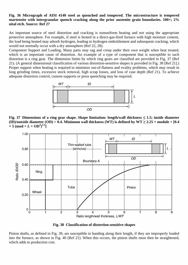
Fig. 36 Micrograph of AISI 4140 steel as quenched and tempered. The microstructure is tempered martensite with intergranular quench cracking along the prior austenite grain boundaries. 100×; 2% nital etch. Source: Ref 27
An important source of steel distortion and cracking is nonuniform heating and not using the appropriate protective atmosphere. For example, if steel is heated in a direct-gas-fired furnace with high moisture content, the load being heated may adsorb hydrogen, leading to hydrogen embrittlement and subsequent cracking, which would not normally occur with a dry atmosphere (Ref 22, 28). Component Support and Loading. Many parts may sag and creep under their own weight when heat treated, which is an important cause of distortion. An example of a type of component that is susceptible to such distortion is a ring gear. The dimension limits by which ring gears are classified are provided in Fig. 37 (Ref 21). (A general dimensional classification of various distortion-sensitive shapes is provided in Fig. 38 [Ref 21].) Proper support when heating is required to minimize out-of-flatness and ovality problems, which may result in long grinding times, excessive stock removal, high scrap losses, and loss of case depth (Ref 21). To achieve adequate distortion control, custom supports or press quenching may be required.
Fig. 37 Dimensions of a ring gear shape. Shape limitation: length/wall thickness ≤ 1.5; inside diameter (ID)/outside diameter (OD) > 0.4. Minimum wall thickness (WT) is defined by WT ≥ 2.25 × module + [0.4 × 5 (mod × L × OD3)1/2]
Fig. 38 Classification of distortion-sensitive shapes
Pinion shafts, as defined in Fig. 39, are susceptible to banding along their length, if they are improperly loaded into the furnace, as shown in Fig. 40 (Ref 21). When this occurs, the pinion shafts must then be straightened, which adds to production cost.

Fig. 39 Distortion of JIS SCM 440 (0.4% C, 1.05% Cr, 0.22% Mo) steel pinion shafts after oil quenching from 850 °C (1560 °F) while vertically suspended and tempering at 600 °C (1110 °F)
Fig. 40 Example of pinion shaft distortion due to furnace loading
Surface Condition. Quench cracking may be due to various steel-related problems that are only observable after the quench, but the root cause is not the quenching process itself. These prior conditions include prior steel structure, stress raisers from prior machining, laps and seams, alloy inclusion defects, grinding cracks, chemical segregation (bonding), and alloy depletion (Ref 27). One prior-condition problem is tight scale, which is encountered with forgings hardened from direct-fired gas furnaces with high-pressure burners (Ref 23, 24). The effect of tight scale on the quenching properties of two steels, 1095 carbon steel and 18-8 stainless steel, is illustrated in Fig. 41 (Ref 25). These cooling curves were obtained by still quenching into fast oil. A scale of not more than 0.08 mm (0.003 in.) increases the rate of cooling of 1095 steel as compared to the rate obtained on a specimen without scale. However, a heavy scale (0.13 mm, or 0.005 in.) deep retards the cooling rate. A very light scale, 0.013 mm (0.0005 in.) deep, also increased the cooling rate of the 18-8 steel over that obtained with the specimen without scale.
The file is downloaded from www.bzfxw.com

Fig. 41 Centerline cooling curves showing the effect of scale on the cooling curves of two different steels quenched in fast oil without agitation. (a) 1095 steel; oil temperature, 50 °C (125 °F). (b) 18-8 stainless steel; oil temperature, 25 °C (75 °F). Test specimens were 13 mm (0.5 in.) diam by 64 mm (2.5 in.) long
In practice, the formation of tight scale varies in depth over the surface of the part, resulting in thermal gradients due to differences in cooling rates. This problem may yield soft spots and uncontrolled distortion and is particularly a problem with nickel-containing steels. Surface oxide formation can be minimized by the use of an appropriate protective atmosphere. The second surface-related condition is decarburization, which may lead to increased distortion or cracking (Ref 26). At a given depth within the decarburized layer, the part does not harden as completely as it would at the same point below the surface if there were no decarburization. This leads to nonuniform hardness, which may contribute to increased distortion and cracking, because (Ref 23):
• The decarburized surface transforms at a higher temperature than the core (the Ms temperature decreases with carbon content). This leads to high residual tensile stresses at the decarburized surface or a condition of unbalanced stresses and distortion.
• Because the surface is decarburized, it exhibits lower hardenability than the core. This causes the upper transformation products to form early, nucleating additional undesirable products in the core. The decarburized side is softer than the side that did not undergo decarburizing, which is harder. The greater amount of martensite leads to distortion.
The solution to this problem is to restore carbon into the furnace atmosphere or to remove the decarburized layer by machining. Another surface-related condition that may lead to cracking or material weakening is the formation of surface seams or nonmetallic inclusions, which may occur in hot-rolled or cold-finished material. The presence of these defects prevents the hot steel from welding to itself during the forging process, for example, creating a stress raiser. To prevent this problem with hot-rolled bars, stock should be removed before heat treatment. Recommendations are provided in Table 7 (Ref 24).
Table 7 Minimum recommended material removal from hot-rolled steel products to prevent surface seam and nonmetallic stringer problems during heat treatment
Minimum material removal per side(a) Condition Nonresulfurized Resulfurized
Turned on centers 3% of diameter 3.8% of diameter

Minimum material removal per side(a) Centerless turned or ground 2.6% 3.4% (a) Based on bars purchased to special straightness, i.e., 3.3 mm (0.13 in.) in 1.5 m (5 ft) maximum A seam or nonmetallic depth of 0.025 mm (0.001 in.) per 3.3 mm (0.13 in.) diameter maximum is usually acceptable for cold-finished bars (Ref 24). If the seam depth is excessive, it is recommended that the bars be magnaflux inspected prior to heat treatment. Stress Raisers from Prior Machining, Laps, and Seams. Surface conditions from prior machining conditions act as stress raisers, which are areas of dimensional changes (Fig. 42) (Ref 27). Examples of such stress raisers include fillets (Fig. 43), thread and gear roots and machining marks (Fig. 44 and 45 respectively), rolling seams (Fig. 46 and 47), and forging laps (Fig. 48 and 49). Forging laps are due to concentrations of oxides that are folded in during the forging process. The presence of these oxides prevents the hot steel from welding to itself during the forging process. This leads to cracking, as shown. (Note: The sample is first viewed in the unetched condition to locate the crack. Then, the sample is etched, if desired, for microstructural identification.)
Fig. 42 Micrograph of AISI 4140 steel as quenched and tempered. The microstructure is tempered martensite with quench cracking in the area of dimensional change. 91×; 2% nital etch. Source: Ref 27
The file is downloaded from www.bzfxw.com

Fig. 43 Micrograph of AISI 4142 steel as quenched and tempered. The microstructure is tempered martensite with quench cracking at the fillet radius. 100×; 3% nital etch. Source: Ref 27
Fig. 44 Micrograph of AISI 4140 steel as quenched and tempered. The microstructure is tempered martensite with quench cracking initiating from a machine groove. 100×; 2% nital etch. Source: Ref 27

Fig. 45 Micrograph of AISI 4118 carburized steel as quenched and tempered. The microstructure is tempered martensite (unetched) with a quench crack propagating from a machining burr. 200×. Source: Ref 27
Fig. 46 Micrograph of AISI 8630 steel as quenched. The microstructure is martensite, where cracking initiated from a rolling seam. Source: Ref 27
The file is downloaded from www.bzfxw.com

Fig. 47 Micrograph of type 403 stainless steel as quenched and tempered. The microstructure is predominantly tempered martensite, with cracking promoted by the seam. 100×; Vilella's reagent. Source: Ref 27
Fig. 48 Micrograph of AISI 1030 steel as direct-forge quenched and tempered. The microstructure is tempered martensite (unetched) with forged-in scale adjacent to cracking. 100×. Source: Ref 27
Fig. 49 Micrograph of AISI 1045 as-forged steel illustrating a forging lap. 27×; 2% nital etch. Source: Ref 27
Several types of internal voids may be present in steel. The first type is known as a pipe void, which is an imperfection formed after casting and cooling (see the article “Failures Related to Metalworking”, in this volume). The pipe void is a cavity formed by contraction during solidification of the last portion of liquid metal in the ingot and may even survive rolling or forging, but, because the ends of the ingot are closed, it is not detected until the bar stock is cut, at which time it is readily visible. Another type of internal void is a forge or roll burst. The pipe void is readily distinguishable from the forge or roll burst by the more rounded nature of the pipe void compared to the thin, cracklike appearance of the forge or roll burst. Steel porosity also produces voids in steel castings. These voids are caused by trapped gases. Porosity is another source of potential steel cracking. This is illustrated in Fig. 50 (Ref 27).
Fig. 50 Micrograph of AISI 8630 cast steel as quenched and tempered. The microstructure is tempered martensite, pearlite, and ferrite, showing a potential cracking condition. 91×; 3% nital etch. Source: Ref 27
The file is downloaded from www.bzfxw.com

Nonmetallic Inclusions. All steels contain numerous nonmetallic inclusions, but the cleaner grades have fewer large or significant inclusions than do the conventional grades. There are two types of nonmetallic inclusions. Exogenous nonmetallic inclusions occur when particles or large lumps of refractory fall into the molten steel during the steelmaking process. These contaminants provide surfaces in which indigenous inclusions may nucleate and grow. Indigenous inclusions arise from reactions, such as deoxidation products Al2O3 and SiO2 or desulfurization products such as MnS (Ref 30). Nonmetallic inclusions may exhibit degraded transverse toughness and ductility. They may also reduce fatigue strength, although soft inclusions are less harmful than are hard inclusions of the same size. In carburized parts, although nonmetallic inclusions may not significantly affect the fatigue limit, they could result. Figure 51 illustrates a combination of nonmetallic inclusions and banding due to microsegregation (discussed subsequently) (Ref 30). If a void is present at the site of a nonmetallic inclusion, possibly due to forging, the degree that the defect acts as a stress raiser increases. However, by some mechanism, such as shearing, the stress-raising effect may decrease, as illustrated by Fig. 52, where the nonmetallic inclusion appears as a “butterfly” after etching (Ref 30).
Fig. 51 Nonmetallic inclusions and banding in a microsegrated 1% C alloy steel showing retained austenite. Source: Ref 30

Fig. 52 White “butterfly” etching developed at a nonmetallic inclusion as a result of contact loading. 675×. Source: Ref 30
Machining. Material removal during machining can result in high residual stress levels and, ultimately, unacceptable distortion (Ref 21). When excessive machining stresses are imparted, the process may require modification to include a rough machining stress relieving followed by fine machining. Tables 8 and 9 are the suggested AISI design minimum allowable tolerances for machining (Ref 4).
Table 8 Minimum allowance for machining flat and square bars
Specified width, in., incl Specified thickness, in., incl(a)
0 to 12
Over 12
to 1 Over 1 to 2
Over 2 to 3
Over 3 to 4
Over 4 to 5
Over 5 to 6
Over 6 to 7
Over 7 to 8
Over 8 to 9
Over 9 to 12
Hot-rolled square and flat bars A 0.025 0.025 0.030 0.035 0.040 0.045 0.050 0.055 0.060 0.060 0.060 0 to 1
2
B 0.025 0.035 0.040 0.050 0.065 0.080 0.095 0.105 0.120 0.130 0.140 A … 0.045 0.045 0.050 0.055 0.060 0.065 0.070 0.075 0.075 0.075 Over 1
2
to 1 B … 0.045 0.050 0.060 0.075 0.095 0.115 0.130 0.150 0.155 0.155
A … … 0.065 0.065 0.070 0.070 0.075 0.080 0.080 0.095 0100 Over 1 to 2 B … … 0.065 0.070 0.085 0.105 0.125 0.145 0.165 0.170 0.170
A … … … 0.085 0.085 0.085 0.085 0.090 0.100 0.100 0.100 Over 2 to 3 B … … … 0.085 0.100 0.120 0.135 0.155 0.170 0.190 0.190
A … … … … 0.115 0.115 0.115 0.115 0.125 0.125 0.125 Over 3 to 4 B … … … … 0.115 0.125 0.140 0.170 0.190 0.190 0.190 Cold-drawn square and flat bars
A 0.025 0.025 0.030 0.035 0.040 0.045 … … … … … 0 to 12
B 0.025 0.035 0.040 0.050 0.065 0.080 … … … … … A … 0.045 0.045 0.050 0.055 0.060 … … … … … Over 1
2
to 1 B … 0.045 0.050 0.060 0.075 0.095 … … … … …
A … … 0.065 0.065 0.070 … … … … … … Over 1 to 2 B … … 0.065 0.070 0.085 … … … … … … Forged square and flat bars
The file is downloaded from www.bzfxw.com

Specified width, in., incl Specified thickness, in., incl(a)
0 to 12
Over 12
to 1 Over 1 to 2
Over 2 to 3
Over 3 to 4
Over 4 to 5
Over 5 to 6
Over 6 to 7
Over 7 to 8
Over 8 to 9
Over 9 to 12
A … … 0.060 0.065 0.065 0.075 0.080 0.085 0.090 0.100 0.110 Over 12
to 1 B … … 0.072 0.084 0.100 0.120 0.144 0.168 0.200 0.200 0.200
A … … 0.090 0.090 0.090 0.100 0.110 0.115 0.125 0.140 0.150 Over 1 to 2 B … … 0.090 0.100 0.108 0.124 0.148 0.172 0.200 0.200 0.200
A … … … 0.120 0.120 0.125 0.130 0.135 0.150 0.160 0.175 Over 2 to 3 B … … … 0.120 0.136 0.140 0.148 0.172 0.200 0.200 0.200
A … … … … 0.150 0.150 0.160 0.180 0.200 0.210 0.225 Over 3 to 4 B … … … … 0150 0.150 0.160 0.180 0.200 0.210 0.225
A … … … … … 0.180 0.180 0.190 0.210 0.225 0.250 Over 4 to 5 B … … … … … 0.180 0.180 0.190 0.210 0.225 0.250
A … … … … … … 0.210 0.225 0.125 0.250 0.250 Over 5 to 6 B … … … … … … 0.210 0.225 0.225 0.250 0.250
A … … … … … … … 0.250 0.250 0.250 0.250 Over 6 to 7 B … … … … … … … 0.250 0.250 0.250 0.250 (a) Minimum allowance, inches per side, for machining prior to heat treatment. A, allowance on thickness, in. per side; B, allowance on width, in. per side
Table 9 Minimum allowance per side for machining rounds, hexagons, and octagons prior to heat treatment
Minimum allowance per side, in. Ordered size, in., incl Hot rolled Forged Rounds rough turned Cold drawn
Up to 12
0.016 … … 0.016
Over 12
to 1 0.031 … … 0.031
Over 1 to 2 0.048 0.072 … 0.048 Over 2 to 3 0.063 0.094 0.020 0.063 Over 3 to 4 0.088 0.120 0.024 0.088 Over 4 to 5 0.112 0.145 0.032 … Over 5 to 6 0.150 0.170 0.040 … Over 6 to 8 0.200 0.200 0.048 … Over 8 to 10 0.200 0.072 … …
References cited in this section
4. R.W. Bohl, Difficulties and Imperfections Associated with Heat Treated Steel, Lesson 13, Heat Treatment of Steel, Materials Engineering Institute Course 10, ASM International, 1978
18. W.T. Cook, A Review of Selected Steel-Related Factors Controlling Distortion in Heat-Treatable Steels, Heat Treat. Met., Vol 26 (No. 2), p 27–36
19. Y. Toshioka, Heat Treatment Deformation of Steel Products, Mater. Sci. Technol., Vol 1, Oct 1985, p 1883–1892

20. A. Thuvander and A. Melander, Calculation of Distortion during Quenching of a Low Carbon Steel, First ASM Heat Treatment and Surface Engineering Conference in Europe (Proc.), Trans Tech Publications, Part 2, 1992, p 767–782
21. P.C. Clarke, Close-Tolerance Heat Treatment of Gears, Heat Treat. Met., Vol 25 (No. 3), 1998, p 61–64
22. R.F. Kern, Thinking Through to Successful Heat Treatment, Met. Eng. Q., Vol 11 (No. 1), 1971, p 1–4
23. R. Kern, Distortion and Cracking, Part II: Distortion from Quenching, Heat Treat., March 1985, p 41–45
24. R. Kern, Distortion and Cracking, Part III: How to Control Cracking, Heat Treat., April 1985, p 38–42
25. H.-J. Chen and Z.W. Jiang, Microstructure Improvement and Low-Temperature Quenching of Dies Made of Cr12-Type Steel, Jinshu Rechuli, No. 8, 1992, p 39–41
26. H.-H. Shao, Analysis of the Causes of Cracking of a 12% Cr Steel Cold Die during Heat Treatment, Jinshu Rechuli, No. 11, 1995, p 43
27. R.R. Blackwood, L.M. Jarvis, D.G. Hoffman, and G.E. Totten, Conditions Leading to Quench Cracking other than Severity of Quench, Heat Treating, Including the Liu Dai Memorial Symposium, Proc. of the 18th Conf., R.A. Wallis and H.W. Walton, Ed., ASM International, 1998, p 575–585
28. F. Legat, “Why Does Steel Crack during Quenching,” Kovine Zlitine Technol., Vol 32 (No. 3–4), 1998, p 273–276
29. X. Cheng and S. He, Analysis of Quenching Cracks in Machine-Tool Pistons under Supersonic Frequency Induction Hardening, Heat Treat. Met. (China), No. 4, 1991, p 51–52
30. G. Parrish, Carburizing: Microstructure and Properties, ASM International, 1999
Quenching
Quenchant Selection and Severity
Quenchants must be selected to provide cooling rates capable of producing acceptable microstructure in the section thickness of interest. However, it is not desirable to use quenchants with excessively high heat-removal rates. Typically, the greater the quench severity, the greater the propensity to increased distortion or cracking. Although a reduction of quench severity leads to reduced distortion, it may also be accompanied by undesirable microstructures. Therefore, it is difficult to select an optimal quenchant and agitation. Cooling power (quench severity) of quenchant should be as low as possible while maintaining a sufficiently high cooling rate to ensure the required microstructure, hardness, and strength in critical sections of the steel parts. Quench severity is defined as the “ability of a quenching medium to extract heat from a hot steel workpiece, expressed in terms of the Grossmann number (H)” (Ref 31). A typical range of Grossmann H-values (numbers) for commonly used quench media are provided in Table 10, and Fig. 53 provides a correlation between the H-value and the ability to harden steel, as indicated by the Jominy distance (J-distance) (Ref 23). Although Table 10 is useful to obtain a relative measure of the quench severity offered by different quench media, it is difficult to apply in practice, because the actual flow rates for “moderate,” “good,” “strong,” and “violent” agitation are unknown.
Table 10 Grossmann H-values for typical quenching conditions
Quenching medium Grossmann value
The file is downloaded from www.bzfxw.com

(H) Poor (slow) oil quench, no agitation 0.20 Good oil quench, moderate agitation 0.35 Very good oil quench, good agitation 0.50 Strong oil quench, violent agitation 0.70 Poor water quench, no agitation 1.00 Very good water quench, strong agitation 1.50 Brine quench, no agitation 2.00 Brine quench, violent agitation 5.00 Ideal quench (a)
(a) It is possible, with high-pressure impingement, to achieve H-values greater than 5.00.
Fig. 53 Quench severity in terms of Grossman (H) values. J, Jominy distance. Source: Ref 23
Alternatively, the measurement of actual cooling rates or heat fluxes provided by a specific quenching medium does provide a quantitative meaning to the quench severity provided. Some illustrative values are provided in Table 11 (Ref 32).
Table 11 Comparison of typical heat transfer rates for various quenching media
Quench medium Heat transfer rate (W · m-2 K-1)
Still air 50–80 Nitrogen (1 bar) 100–150 Salt bath or fluidized bed 350–500 Nitrogen (10 bar) 400–500 Helium (10 bar) 550–600 Helium (20 bar) 900–1000 Still oil 1000–1500 Hydrogen (20 bar) 1250–1350 Circulated oil 1800–2200 Hydrogen (40 bar) 2100–2300 Circulated water 3000–3500

Typically, the greater the quench severity, the greater the propensity of a given quenching medium to cause distortion or cracking. This usually is the result of increased thermal stress, not transformational stresses. Specific recommendations for quench media selection for use with various steel alloys is provided by standards such as Aerospace Material Specification (AMS) 2759. Figure 54 illustrates a quench crack due to an excessively high cooling rate (Ref 27).
Fig. 54 Micrograph of AISI 4340 quenched and tempered steel illustrating a macroetched pure quench crack. Source: Ref 27
Some additional general comments regarding quenchant selection include (Ref 23, 28):
• Most machined parts made from alloy steels are oil quenched to minimize distortion. Most small parts or finish-ground larger parts are “free” quenched. Larger gears, typically those greater than 20 cm (8 in.), are fixture (die) quenched to control distortion. Smaller gears and parts, such as bushings, are typically plug quenched on a splined plug, which is usually constructed from carburized 8620 steel.
• Although a reduction of quench severity leads to reduced distortion, it may also be accompanied by undesirable microstructures, such as the formation of upper bainite (quenched pearlite) with carburized parts.
• Quench speed may be reduced by quenching in hot (570 to 750 °C, or 1060 to 1380 °F) oil. When hot oil quenching is used for carburized steels, lower bainite, which exhibits properties similar to martensite, is formed.
• Excellent distortion is typically obtained with austempering, quenching into a medium just above the Ms temperature. The formation of retained austenite is a significant problem with austempering processes. Retained austenite is most pronounced where manganese and nickel are major components. The best steels for austempering are plain carbon steels and chromium and molybdenum alloy steels (Ref 23).
• Aqueous polymer quenchants may often be used to replace quench oils, but quench severity is still of primary importance and appropriate quench system design is necessary.
• Gas or air quenching provides the least distortion and may be used if the steel has sufficient hardenability to provide the desired properties.
• Low-hardenability steels are quenched in brine or vigorously agitated oil. However, even with a severe quench, undesirable microstructures, such as ferrite, pearlite, or bainite, can form.
The file is downloaded from www.bzfxw.com
Quenchant Uniformity
Quench nonuniformity is one of the greatest contributors to quench cracking. Quench non-uniformity can arise from nonuniform flow fields around the part surface during the quench or non-uniform wetting of the surface (Ref 23, 33, 34, 35). Both lead to nonuniform heat transfer during quenching. Nonuniform quenching creates large thermal gradients between the core and the surface of the part. The effect of nonuniform quenching is illustrated with forged AISI 1045 crankshafts in Fig. 55 and 56 (Ref 27). Microstructural examination showed a mixture of nonuniform cross-sectional microstructures. Areas of tempered martensite adjacent to pearlite, bainite, acicular ferrite, and ferrite at prior austenite grain boundaries were observed.
Fig. 55 Micrograph of AISI 1045 steel as quenched and tempered. Microstructure shows bands with banded tempered martensite and some bainite. The crack profile revealed evidence of tempering oxide and secondary cracking. 200×; 2% nital etch. Source: Ref 27
Fig. 56 Micrograph of AISI 1045 steel as quenched and tempered; representative of underheated microstructure adjacent to cracking. 376×; 2% nital etch. Source: Ref 27
Poor agitation design is a major source of quench nonuniformity. The purpose of the agitation system is not only to take hot fluid away from the surface and to the heat exchanger, but it is also to provide uniform heat removal over the entire cooling surface of all of the parts throughout the load being quenched. The batch quench system in Fig. 57 illustrates a system where axial (vertical) quenchant flow occurs throughout a load of round bars lying horizontally in a basket (Ref 22). In this case, the bottom surfaces of the bars experience greater agitation than the top surfaces. Cracks form on the upper surfaces because of the nonuniform heat loss. Agitation produces greater heat loss at the bottom, creating a large thermal gradient between the top and the bottom surfaces.
Fig. 57 Harmful effects of impeded vertical quenchant flow through the load of a batch quench system
If a submerged spray manifold is used to facilitate more uniform heat removal, the following design guidelines are recommended:
• The total surface of the part should experience uniform quenchant impingement. • The largest holes possible (2.3 mm, or 0.09 in., minimum) should be used. • The manifold face should be at least 13 mm (0.5 in.) from the surface of the parts being quenched. • Repeated removal of hot quenchant and vapor should be possible.
Excessive distortion was also obtained with an agitation system, illustrated in Fig. 58, when the quenchant flow was either in the same direction relative to the direction of part immersion or in the opposite direction (Ref 35).
The file is downloaded from www.bzfxw.com

The solution to this problem was to minimize the quenchant flow to that required for adequate heat transfer during the quench and to provide agitation by mechanically moving the part up and down in the quenchant. Identifying sources of nonuniform fluid flow during quenching continues to be an important tool for optimizing distortion control and minimizing quench cracking.
Fig. 58 Effect of quenchant flow direction on distortion
Nonuniform thermal gradients during quenching are also related to interfacial wetting kinematics, which is of particular interest with vaporizable liquid quenchants, including water, oil, and aqueous polymer solutions (Ref 36). Most liquid vaporizable quenchants exhibit boiling temperatures between 100 and 300 °C (210 and 570 °F) at atmospheric pressure. When parts are quenched in these fluids, surface wetting is usually time-dependent, which influences the cooling process and the achievable hardness. Another major source of nonuniform quenching is foaming and contamination. Contaminants include sludge, carbon, and other insoluble materials. It includes water in oil, oil in water, and aqueous polymer quenchants. Foaming and contamination leads to soft spotting, increased distortion, and cracking.
Quench Distortion and Cracking
In the previous discussion, two quenchant-related phenomenon have been discussed: quench cracking and quench distortion. Although quench cracking can be eliminated, quench distortion cannot. Instead, the issue is distortion control, not elimination. Both quenching-related distortion control and quench cracking are discussed here. Quench Distortion. One form of distortion that may occur on quenching is defined as shape distortion, which is dimensional variation that occurs when the parts are hot and the stress of their own weight leads to dimensional variation, such as bending, warpage, and twisting (Ref 34). Shape distortion is attributable to component support and loading, as discussed previously. A second form of distortion is size distortion, which includes dimensional changes observable as elongation, shrinkage, thickening, and thinning. Size distortion is due to the volumetric variation that accompanies each of the transformational phases formed on quenching (Ref 34). Size distortion can be further classified as one-dimensional, two-dimensional, and three-dimensional. One-dimensional distortion is exemplified by the change in length when rods or wire are quenched and is primarily due to transformational distortion. Two-dimensional distortion is also primarily due to transformational distortion, and it is exemplified by size variation in two dimensions, such as would occur with sheet or plate stock on quenching. With bulk material that can undergo dimensional variation in three dimensions, the problem is due to both thermal and transformational distortion and is much more complicated (Ref 34). It has been shown that one of the primary contributors to quench distortion is uneven (nonuniform) cooling. Quench Cracking. One major source of steel cracking is excessive cooling rates during the quench (quench severity). This is illustrated in Fig. 54 (Ref 27). Note that the crack passes straight from the surface to the core. Excessive cooling rates (high quench severity) produce greater thermal stresses in addition to greater transformation stresses. Steel cracking during transformation to martensite is largely due to the volumetric
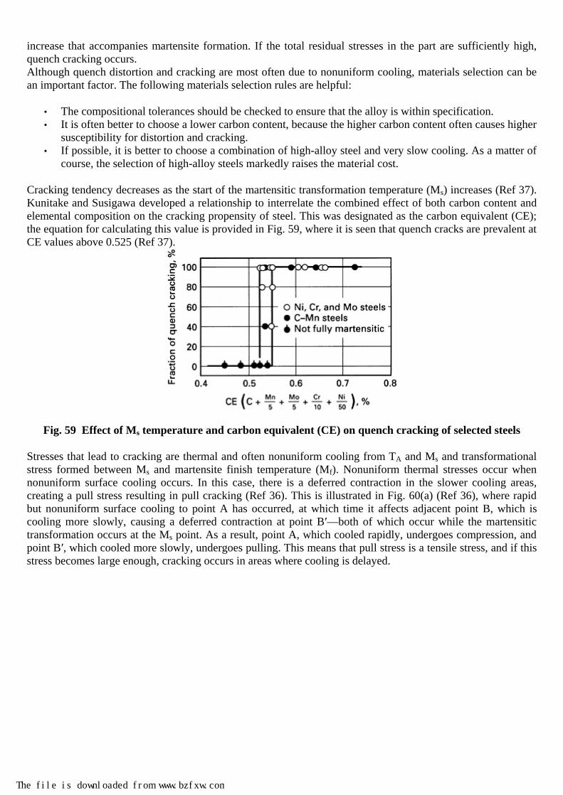
increase that accompanies martensite formation. If the total residual stresses in the part are sufficiently high, quench cracking occurs. Although quench distortion and cracking are most often due to nonuniform cooling, materials selection can be an important factor. The following materials selection rules are helpful:
• The compositional tolerances should be checked to ensure that the alloy is within specification. • It is often better to choose a lower carbon content, because the higher carbon content often causes higher
susceptibility for distortion and cracking. • If possible, it is better to choose a combination of high-alloy steel and very slow cooling. As a matter of
course, the selection of high-alloy steels markedly raises the material cost.
Cracking tendency decreases as the start of the martensitic transformation temperature (Ms) increases (Ref 37). Kunitake and Susigawa developed a relationship to interrelate the combined effect of both carbon content and elemental composition on the cracking propensity of steel. This was designated as the carbon equivalent (CE); the equation for calculating this value is provided in Fig. 59, where it is seen that quench cracks are prevalent at CE values above 0.525 (Ref 37).
Fig. 59 Effect of Ms temperature and carbon equivalent (CE) on quench cracking of selected steels
Stresses that lead to cracking are thermal and often nonuniform cooling from TA and Ms and transformational stress formed between Ms and martensite finish temperature (Mf). Nonuniform thermal stresses occur when nonuniform surface cooling occurs. In this case, there is a deferred contraction in the slower cooling areas, creating a pull stress resulting in pull cracking (Ref 36). This is illustrated in Fig. 60(a) (Ref 36), where rapid but nonuniform surface cooling to point A has occurred, at which time it affects adjacent point B, which is cooling more slowly, causing a deferred contraction at point B′—both of which occur while the martensitic transformation occurs at the Ms point. As a result, point A, which cooled rapidly, undergoes compression, and point B′, which cooled more slowly, undergoes pulling. This means that pull stress is a tensile stress, and if this stress becomes large enough, cracking occurs in areas where cooling is delayed.
The file is downloaded from www.bzfxw.com

Fig. 60 Schematics of the mechanisms that generate (a) pull stress and pull cracking and (b) push stress and push cracking
When there is nonuniform cooling within the part between the Ms and Mf, there is a stretching or elongation in areas where the cooling is slow, which acts as a push stress, leading to push cracking (Ref 38). This is illustrated by Fig. 60(b) (Ref 36), where point A, which cooled rapidly, stretches point B (which cooled more slowly) to point B′ below the Ms temperature, which is a state that undergoes the expansion due to martensitic transformation. As a result, the rapidly cooled point A (exterior) undergoes pulling, and the slowly cooled point B′ (interior) undergoes compression. This results in interior point B′ causing pushing and cracking at point A, which occurs in areas where quenching occurs rapidly. Therefore, pull cracking, which occurs with nonuniform surface cooling between TA and Ms, and push cracking, which occurs with nonuniform cooling within the part between Ms and Mf, are the opposite of each other, although the cracking event takes place for both between the Ms and Mf. Figure 61 provides illustrations of both push and pull cracking (Ref 36).

Fig. 61 Two forms of quench cracking. (a) Pull cracking (b) Push cracking
For cracking to occur, the presence of a stress raiser (points of stress concentration) is typically necessary. Two types of stress raisers may be found. One is a geometric notch, which includes cutting tool marks, sharp corner angles, and areas with rapid section thickness changes. The other type of stress raiser commonly found is a notch in the material, which may include intergranular effects, carbide segregation, and aggregates of impurities (Ref 36). Although it would be desirable to eliminate all stress raisers to facilitate quench processing without any potential for cracking, this is not possible, in most cases. Instead, methods of quenching to minimize potential cracking often must be developed. Polyakov provided immersion recommendations for parts with complex shapes, where cracking potential is minimum and maximum, and these are summarized in Fig. 62 (Ref 39). The Polyakov rules for quenching such parts include (Ref 39):
• Conditions for quench cracking are most favorable if parts are immersed into the quenchant, so the perimeter of the stress raiser (PSC) simultaneously touches the liquid along the entire length.
• In the case where the perimeter of the stress raiser slowly touches the quenchant at the moment of immersion in individual regions, quench cracking is reduced substantially.
The file is downloaded from www.bzfxw.com

Fig. 62 Polyakov rules for immersion of cylindrical parts into a quenchant. The dashed horizontal lines indicate the level of the liquid; the vertical arrows indicate the direction of immersion of the part. PSC indicates the perimeter of the stress concentrator.
Retained Austenite
The austenitic structure that remains in steel after quenching is called retained austenite. The amount of retained austenite is dependent on the Ms and Mf temperatures. To obtain complete transformation, steel must be quenched into the martensitic transformation region for sufficient time for austenite to transform to martensite. If the Mf temperature is below ambient temperature, the transformation to martensite is incomplete, and some austenite is retained in the as-quenched structure. In these cases, to obtain complete transformation, the steel must be quenched directly into a refrigerant to a temperature below the Mf. However, if steel is first quenched to ambient temperature and then cryogenically cooled, additional austenite is transformed to martensite, but there is still a small fraction of retained austenite (Ref 30). Increasing carbon content of steel increases the potential for retained austenite on quenching, as illustrated in Fig. 63 (Ref 30). This is because the Ms temperature decreases with increasing carbon content. The effect of carbon content on the Ms temperature can be calculated using the Steven and Haynes equation for steels containing up to 0.5% C (Ref 40):
Ms(°C) = 561 - 474C - 33Mn - 17Ni - 17Cr - 21Mo where carbon, manganese, nickel, chromium, and molybdenum are concentrations of these elements in percent. For carbon concentrations greater than 0.5%, corrections must be made using Fig. 64 (Ref 30).
Fig. 63 Influence of carbon content on the formation of retained austenite. Source: Ref 30
Fig. 64 Correction curves for use with the Steven and Haynes equation, with Parrish modifications indicated by dashed lines (see Ref 30). When the carbon content is less than 0.9%, an 830 °C (1530 °F) soak for greater than 2 h should produce a fully austenitic structure. Source: Ref 30
The Mf temperature is typically approximately 215 °C (385 °F) below the Ms (Ref 40). Typically, when the Mf temperature is less than the quenchant temperature, the transformation to martensite is incomplete. The volume of untransformed austenite (Vγ) is related to the Ms and the quenchant temperature (Tq) by the Koistinen and Marburger equation (Ref 41):
Vγ = exp [-1.10 × 10⁻²(Ms - Tq)] These equations are used to estimate the impact of steel chemistry and quenching conditions on the amount of retained austenite that may be expected.
The file is downloaded from www.bzfxw.com

Dimensional changes may occur slowly or fast and are due to the volume composition of the transformation products formed on quenching. One of the most important, with respect to residual stress variation, distortion, and cracking, is the formation and transformation of retained austenite. For example, the data in Table 12 indicate the slow conversion of retained austenite to martensite, which was still occurring days after the original quenching process for the two steels shown (Ref 18, 19). This is particularly a problem when dimensional control and stability is one of the primary goals of heat treatment. Therefore, microstructural determination is an essential component of any distortion-control process.
Table 12 Dimensional variation in hardened high-carbon steel with time at ambient temperature
Tempering temperature
Hardness, Change in length, % × 103 Steel type
°C °F HRC After 7 days
After 30 days
After 90 days
After 365 days
None 66 -9.0 -18.0 -27.0 -40.0 120 250 65 -0.2 -0.6 -1.1 -1.9 205 400 63 0.0 -0.2 -0.3 -0.7
1.1% C tool steel (790 °C, or 1450 °F, quench)
260 500 61.5 0.0 -0.2 -0.3 -0.3 None 64 -1.0 -4.2 -8.2 -11.0 120 250 65 0.3 0.5 0.7 0.6 205 400 62 0.0 -0.1 -0.1 -0.1
1% C/Cr (840 °C, or 1540 °F, quench)
260 500 60 0.0 -0.1 -0.1 -0.1 Figure 65 illustrates the microstructure of a nickel-chromium steel containing different amounts of retained austenite (Ref 30). The retained austenite resides in the interlath boundaries of martensite. The volume of retained austenite is dependent on the prior austenite grain size and the amount of austenite retained, which is dependent on the carbon content, alloying element concentration, and the quenching temperature.
Fig. 65 Retained austenite (white) and martensite in the surfaces of carburized and hardened nickel-chromium steel testpieces. (a) Approximately 40% retained austenite. (b) Approximately 15% retained austenite. Both 550×. Source: Ref 30
The effect of retained austenite on the properties of steel can be summarized generally as (Ref 30):
• Retained austenite reduces hardness, which is proportional to the amount of retained austenite present. • Tensile strength and yield strength decrease with increasing amounts of retained austenite.

• Because retained austenite relates to untransformed martensite, there is a reduction of maximum attainable surface compressive stresses that would have been attained if transformation to martensite was complete.
• Strength and compressive stresses are reduced by the presence of retained austenite, thus reducing fatigue resistance.
• Wear resistance decreases with increasing retained austenite.
The amount of retained austenite may be reduced by refrigeration to facilitate the transformation to martensite. Alternatively, surface-working methods, such as shot peening or surface rolling, may be used to effectively work harden the surface, resulting in higher compressive stresses.
Quenching Methods
Part design, materials selection, quenchant selection, and so on are important factors for suppressing quench distortion and cracking of steel parts. In addition, several methods for minimizing distortion and eliminating cracking may also be used, for example, interrupted quenching and press quenching. Interrupted Quenching Techniques. Interrupted quenching refers to the rapid cooling of the steel parts from the austenitizing temperature to a temperature where it is held for a specified period of time, followed by slow cooling. There are several different types of interrupted quenching: austempering, marquenching (martempering), time quenching, and so on. The temperature at which the quenching is interrupted, the length of time the steel is held at temperature, and the rate of cooling can vary, depending on the type of steel and workpiece thickness. Marquenching (martempering) is a term used to describe an interrupted quenching from the austenitizing temperature of steels. The purpose is to delay the cooling just above the martensitic transformation temperature until temperature equalization is achieved throughout the steel part. This minimizes the distortion, cracking, and residual stress. The term martempering is somewhat misleading, and the process is better described as marquenching. Figures 66(a) and (b) (Ref 42) show the significant difference between conventional quenching and marquenching. The marquenching of steel consists of:
• Quenching from the austenitizing temperature into a hot quenching medium (hot oil, molten salt, molten metal, or a fluidized particle bed) at a temperature usually above the martensite range (Ms point)
• Submerging in the quenching medium until the temperature throughout the steel workpiece is substantially uniform
• Cooling (usually in air) at a moderate rate to prevent large differences in temperature between the outside and the core of the workpiece
Fig. 66 Comparison of cooling curves as a workpiece cools into and through the martensite transformation range for a conventional quenching and tempering process and for interrupted quenching processes. (a) Conventional quenching and tempering. (b) Marquenching. (c) Modified marquenching. Ae1, austenite start transformation under equilibrium conditions
The formation of martensite occurs fairly uniformly throughout the workpiece during the cooling to room temperature, thereby avoiding excessive amounts of residual stress. Straightening or forming is also easily
The file is downloaded from www.bzfxw.com

accomplished on removal from the marquenching bath while the part is still hot. The marquenching can be accomplished in a variety of baths, including hot oil, molten salt, molten metal, or a fluidized particle bed. Cooling from the marquenching bath to room temperature is usually conducted in still air. Deeper hardening steels are susceptible to cracking while martensite forms, if the cooling rate is too rapid. Marquenched parts are tempered in the same manner as conventional quenched parts. The time lapse before tempering is not as critical, because the stress is greatly reduced. The advantage of marquenching lies in the reduced thermal gradient between surface and core as the part is quenched to the isothermal temperature and then is air cooled to room temperature. Residual stresses developed during marquenching are lower than those developed during conventional quenching, because the greatest thermal variations occur while the steel is in the relatively plastic austenitic condition, and because the final transformation and thermal changes occur throughout the part at approximately the same time. Marquenching also reduces susceptibility to cracking. Modified marquenching differs from standard marquenching only in that the temperature of the quenching bath is below the Ms point (Fig. 66c) (Ref 42). The lower temperature increases the severity of quenching. This is important for steels of lower hardenability that require faster cooling in order to harden to sufficient depth. Therefore, modified marquenching is applicable to a greater range of steel compositions than is the standard marquenching. Austempering consists of rapidly cooling the steel part from the austenitizing temperature to a temperature above that of martensite formation, holding at a constant temperature to allow isothermal transformation, followed by air cooling. The steel parts must be cooled fast enough so that no transformation of austenite occurs during cooling and then held at bath temperature long enough to ensure complete transformation of austenite to bainite. Molten salt baths are usually the most practical for austempering applications. Parts can usually be produced with less dimensional change by austempering than by conventional quenching and tempering. In addition, austempering can decrease the likelihood of cracking and can improve ductility, notch toughness, and wear resistance. However, austempering is applicable to a limited steel and parts size. Important considerations for the selection of steel parts for austempering are:
• The location for the nose of the time-temperature-transformation (TTT) curve and the speed of the quenching
• The time required for complete transformation of austenite to bainite at the austempering temperature • The location of the Ms point • Maximum thickness of section that can be austempered to a fully bainite structure
Carbon steels of lower carbon content are restricted to a lesser thickness. For 1080 steel, the maximum section
thickness is approximately 5 mm (0.2 in.). Low-alloy steels are usually restricted to approximately 10 mm ( 38
in.) or thinner sections, while more hardenable steels can be austempered in sections up to 25 mm (1 in.) thick. Nevertheless, sections of carbon steel thicker than 5 mm (0.2 in.) are regularly austempered in production, when some pearlite is permissible in the microstructure (Ref 43). Time quenching is one of the interrupted quenching methods and is used when the cooling rate of the part being quenched needs to be abruptly changed during the cooling cycle. The usual practice is to lower the temperature of the part by quenching in a medium with high heat-removal characteristics (for example, water) until the part has cooled below the nose of the TTT curve and then to transfer the part to a second medium (for example, oil, air, an inert gas), so that it cools more slowly through the martensite formation range. Time quenching is most often used to minimize distortion, cracking, and dimensional changes. Restraint Quenching Techniques. Restraint quenching refers to quenching under restraint of distortion of steel, for example, quenching by using restraint fixtures, press quenching, cold die quenching, plague quenching, and so on. There are many round, flat, or cylindrical parts that distort to an unacceptable degree by conventional immersion quenching. Under such conditions, it is necessary to resort to special techniques. However, the equipment for those special techniques is expensive, and production rates are slow. Consequently, the resulting cost of heat treatment is relatively high. Therefore, use of these techniques should be considered only when minimal distortion is mandatory. Press quenching is closely related to intense quenching, which is discussed elsewhere in this article.

Restraint fixturing is costly and is used primarily for highly specialized applications. Representative examples are the quenching of rocket and missile casings or other large components with thin wall sections. Press Quenching and Plug Quenching. Probably the most widely used special technique is press quenching. To minimize distortion caused by the quenching cycle, press and plug quenching dies must be made to provide the proper quenchant flow and hold critical dimensions of the part being quenched. In quenching, the die or plague contacts the heated part, and the pressure of the press restrains the part mechanically. This occurs before quenching begins, while the part is hot and plastic. The machine and dies then force the quenching medium into contact with the part in a controlled manner. Cold Die Quenching. Thin disks, long thin rods, and other delicate parts that distort excessively by conventional immersion quenching can often be quenched between cold dies with no distortion. Cold die quenching is limited to parts with a large surface area and small mass, such as washers, rods of small diameter, thin blades, and so on. Large, thin thrust washers have to be flat after quench hardening, but considerable distortions are developed as a result of blanking and machining stresses. To ensure the required flatness, the washers are squeezed between a pair of water-cooled dies immediately after leaving the furnace. Other quenching methods include selective quenching, spray quenching, and intensive quenching. Selective quenching is used when it is desirable for certain areas of a part to be relatively unaffected by the quenching medium. This can be accomplished by insulating an area to be more slowly cooled, so the quenchant contacts only those areas of the part that are to be rapidly cooled. A clay-coating method may be employed for selective quenching, as in, for example, the water quenching of Japanese swords. The distortion and microstructure of Japanese swords is controlled by the thickness distribution of the clay layer. A thick clay layer (>0.1 mm, or 0.004 in.) suppresses the cooling rate by its insulating effect, and a thin clay layer increases the cooling rate during water quenching by its cooling accelerating effect (Fig. 67). Selective quenching is often effective for suppressing excessive distortion or cracking.
Fig. 67 Effect of clay coating on cooling curves of steel test specimen quenched into still water at 30 °C (86 °F). Test specimen, JIS S45C steel cylinder (10 mm, or 0.40 in., diam × 30 mm, or 1.2 in., long)
Spray quenching involves directing high-pressure streams of liquid onto the surfaces of steel parts. Spray quenching is often useful for minimizing distortion and cracking, because it can realize a uniform quenching by selecting optimal spray condition and the sprayed surfaces where higher cooling rates are desired. The cooling rate can be faster, because the quenchant droplets formed by the high-intensity spray impact the part surface and remove heat very effectively.
The file is downloaded from www.bzfxw.com

Fog quenching uses a fine fog or mist of liquid droplets in a gas carrier as the cooling agent. Although similar to spray quenching, fog quenching produces lower cooling rates because of the relatively low liquid content of the stream. Intensive quenching (Ref 44) involves forced-convection heat exchange both during high-temperature cooling and also during the transformation of austenite into martensite. Intensive quenching promotes temperature uniformity during cooling through the cross section of the part. Cooling intensity should be sufficient to promote maximum surface compressive stresses. This occurs when the Biot number ≥18. The second criterion of intensive quenching is that the intensive cooling be stopped at the moment that maximum surface compressive stresses are formed.
References cited in this section
18. W.T. Cook, A Review of Selected Steel-Related Factors Controlling Distortion in Heat-Treatable Steels, Heat Treat. Met., Vol 26 (No. 2), p 27–36
19. Y. Toshioka, Heat Treatment Deformation of Steel Products, Mater. Sci. Technol., Vol 1, Oct 1985, p 1883–1892
22. R.F. Kern, Thinking Through to Successful Heat Treatment, Met. Eng. Q., Vol 11 (No. 1), 1971, p 1–4
23. R. Kern, Distortion and Cracking, Part II: Distortion from Quenching, Heat Treat., March 1985, p 41–45
27. R.R. Blackwood, L.M. Jarvis, D.G. Hoffman, and G.E. Totten, Conditions Leading to Quench Cracking other than Severity of Quench, Heat Treating, Including the Liu Dai Memorial Symposium, Proc. of the 18th Conf., R.A. Wallis and H.W. Walton, Ed., ASM International, 1998, p 575–585
28. F. Legat, “Why Does Steel Crack during Quenching,” Kovine Zlitine Technol., Vol 32 (No. 3–4), 1998, p 273–276
30. G. Parrish, Carburizing: Microstructure and Properties, ASM International, 1999
31. J.R. Davis, Ed., ASM Materials Engineering Dictionary, ASM International, 1992, p 407
32. P.F. Stratton, N. Saxena, and R. Jain, Requirements for Gas Quenching Systems, Heat Treat. Met., Vol 24 (No. 3), 1997, p 60–63
33. H.M. Tensi, G.E. Totten, and G.M. Webster, Proposal to Monitor Agitation of Production Quench Tanks, Heat Treating: Including the 1997 International Induction Heat Treating Symposium, Proc. of the 17th Conf., D.L. Milam, D.A. Poteet, G.D. Pfaffmann, V. Rudnev, A. Muehlbauer, and W.B. Albert, Ed., ASM International, 1997, p 423–441
34. S. Owaku, Quench Distortion of Steel Parts, Netsu Shori (J. Jpn. Soc. Heat Treat.), Vol 32 (No. 4), 1992, p 198–202
35. R.T. Von Bergen, The Effects of Quenchant Media Selection on the Distortion of Engineered Steel Parts, Quenching and Distortion Control, G.E. Totten, Ed., ASM International, 1992, p 275–282
36. H.M. Tensi, A. Stich, and G.E. Totten, Fundamentals of Quenching, Met. Heat Treat., Mar/Apr 1995, p 20–28
37. T. Kunitake and S. Susigawa, Sumitomo Search, May 1971, p 16–25
38. V.D. Kalner and S.A. Yurasov, Internal Oxidation during Carburizing, Met. Sci. Heat Treat. (USSR), Vol 12 (No. 6), June 1970, p 451–454
39. A.A. Polyakov, Quenching Properties of Parts Having Stress Concentrators, Met. Sci. Heat Treat., Vol 37 (No.7–8), 1995, p 324-325
40. A.G. Haynes, Interrelation of Isothermal and Continuous-Cooling Heat Treatments of Low-Alloy Steels and Their Practical Significance, Heat Treat. Met., Special Report 95, The Iron and Steel Institute, 1966, p 13–23
41. D.P. Koistinen and R.E. Marburger, A General Equation Prescribing the Extent of the Austenite-Martensite Transformation in Pure Iron-Carbon Alloys and Plain Carbon Steels, Acta. Metall., Vol 7, 1959, p 59–60
42. H. Webster and W.J. Laird, Jr., Martempering of Steel, Heat Treating, Vol 4, ASM Handbook, ASM International, 1991, p 137
43. J.R. Keough, W.J. Laird, Jr., and A.D. Godding, Austempering of Steel, Heat Treating, Vol 4, ASM Handbook, ASM International, 1991, p 152–163
44. N.I. Kobasko, M.A. Arpnov, G.E. Totten, and A.V. Sverdlin, Method and Equipment for Implementation of Intensive Quenching, Heat Treating, Including the Liu Dai Memorial Symposium, Proc. of the 18th Conf., R.A. Wallis and H.W. Walton, Ed., ASM International, 1998, p 616–621
Steel Transformation Products and Properties
Internal oxidation, also called subscale formation, is the formation of corrosion product particles below the surface of the metal. Internal oxidation has a deleterious effect on hardness, bending fatigue strength, residual stresses, and wear resistance. Internal oxidation occurs preferentially with certain alloy constituents, primarily manganese, chromium, and silicon, by inward diffusion of oxygen, sulfur, and other gases to the site of oxidation during carburizing using an endothermic atmosphere at 900 to 950 °C (1650 to 1740 °F). An endothermic atmosphere (endogas) is produced by the controlled combustion of a hydrocarbon gas, such as natural gas and propane, with air. The oxygen required for internal oxidation is derived primarily from carbon dioxide and water vapor, the by-products of the combustion process. Figure 68 shows the oxidation potential of various alloying elements in an endothermic gas (Ref 30).
Fig. 68 Oxidation potential of alloying elements and iron in steel heated in endothermic gas with an average composition of 40% H2, 20% CO, 1.5% CH4, 0.5% CO2, 0.28% H2O (dewpoint, 10 °C, or 50 °F), and 37.72% N2. Source: Ref 30
The file is downloaded from www.bzfxw.com

It is essentially impossible to eliminate internal oxidation when carburizing using an endothermic atmosphere. The presence of approximately 0.25% Si in carburizing grades of steel far exceeds the amount necessary to produce internal oxidation. In addition, the presence of silicon also reduces the threshold concentrations of manganese and chromium that produce internal oxidation. However, the sensitivity to internal oxidation may be decreased by the presence of alloying elements with atomic numbers greater than iron, such as nickel and molybdenum. The oxygen content and depth of oxygen penetration increase with increasing oxygen potential (concentration) at a particular temperature. However, the depth of penetration increases with both temperature and time, as shown in Fig. 69 (Ref 30). Because the oxygen potential decreases with increasing carbon potential, the amount of internal oxidation is less at higher-carbon-potential carburizing processes, depending on the carburizing time.
Fig. 69 Internal oxidation of a nickel-chromium steel carburized in a laboratory furnace, showing both grain-boundary oxides and oxide precipitates within grains. 402×. Source: Ref 30
Metallographically, there are two common forms of internal oxidation observed. The first type appears as globular particles of approximately 0.5 μm in diameter from nearest to the surface to a depth of approximately 8 μm. Although these oxides may occur along the surface, they usually are found in the grain and subgrain boundaries and possibly within the grain. If the oxidation occurs on the surface, the grains are typically 0.5 to 1 μm, although they may be as large as 2 to 4 μm (Ref 38). The second type of internal oxides occurs at greater depths, typically 5 to 25 μm and appear as a dark phase at prior austenite grain boundaries, as illustrated in Fig. 70 (Ref 30, 45). Thus, surface grain size also influences the amount of internal oxidation. As the grain size increases, the potential for internal oxidation within the grains increases (Ref 30).

Fig. 70 Depth of oxidized zones as a function of carburizing time at different carburizing temperatures for SAE 1015. Source: Ref 30
Internal oxidation is also affected by the surface condition of the material being carburized, because organic impurities, such as lubricants, can contaminate the furnace atmosphere, and the presence of oxides due to scale or corrosion affect the formation and depth of penetration of internal oxidation. Although surface oxides may be removed by electropolishing, electrochemical machining, honing, grinding, shot blasting, or peening, these methods must be selected with care, because they may induce such negative effects as increased tensile stresses, risk of inducing decarburization during subsequent reheating processes, or these processes may not allow precise control. Table 13 provides the maximum acceptable depth of internal oxidation relative to the case depth for carburized gears. (See also International Organization for Standardization (ISO) 6336-5.2; the equivalent grades are ML, MQ, and ME.) Note that grade 1 has no specification value. Also, recovery by shot peening is acceptable, with agreement of the customer.
Table 13 American National Standards Institute/American Gear Manufacturers Association (ANSI/AGMA) 2001-C95 standard values for acceptable depth of internal oxidation for carburized gears relative to case depth (tooth size)
Grade 2 Grade 3 Case depth mm in. mm in. mm in. 0.0178 0.0007 0.0127 0.0005 <0.75 <0.030 0.0254 0.0010 0.0203 0.0008 0.75–1.50 0.030–0.059 0.0381 0.0015 0.0203 0.0008 1.50–2.25 0.059–0.089 0.0508 0.0020 0.0254 0.0010 2.25–3.00 0.089–0.118 0.0610 0.0024 0.0305 0.0012 >3.00 >0.118 Alloy Depletion. Another source of nonhomogeneous steel composition is alloy depletion. As with nonmetallic inclusions, alloy depletion leads to greater stresses and cracking, as illustrated in Fig. 71 (Ref 27). Examples of alloys particularly susceptible to alloy depletion are AISI 4100, 4300, and 8600 series.
Fig. 71 Micrograph of AISI 4140 steel as quenched and tempered; microstructure is tempered martensite, where cracking is promoted by alloy depletion. 91×; 2% nital etch. Source: Ref 27
High-temperature transformation products (HTTP) are products that form on the surface of a carburized part within the same area where internal oxidation occurs. High-temperature transformation products are nonmartensitic microstructures that include pearlite, upper and lower bainite, or mixtures of two or more of these products. A lean-alloy steel or large cross section favors pearlite at the surface, whereas higher-alloy steel or thinner cross section favors the formation of bainitic microstructures when quenched. However, if the
The file is downloaded from www.bzfxw.com

cooling rate is sufficiently fast or if sufficient quantities of reducing elements, such as nickel and molybdenum, are within the oxide-forming region, it is possible that no HTTP is formed (Ref 30, 46). The formation of internal oxidation products effectively results in localized depletion of the elements that are preferentially oxidized, such as manganese and chromium. When HTTP are present, they often extend deeper than the internal oxidation, especially with leaner steel grades. The occurrence of HTTP results in lower hardness, reduction of surface compressive stresses, reduction of bending fatigue, and reduction of wear resistance. The effects of HTTP can be controlled by (Ref 30):
• Using a steel grade with sufficient alloy content in the depleted layer to give martensite on quenching • Reducing the amount of HTTP in the surface layer by a late increase of carbon potential or a late
addition of ammonia to the furnace chamber • Using a faster quench to suppress HTTP formation; however, beware of possible increased distortion • Removing HTTP by grinding, grit blasting, and/or shot peening
Decarburization is defined as “a loss of carbon atoms from the surface of a workpiece, thereby producing a surface with a lower carbon gradient than at some short distance below the surface” (Ref 30). This is important, because the strength of steel is dependent on carbon content (carbides) within the steel structure. If surface carbon is greater than 0.6%, the surface hardness should be acceptable. If surface carbon is approximately 0.6% or less, all the main properties are adversely affected; for example, bending fatigue could be reduced by 50%. The depth of decarburization is defined as “the thickness of the layer in which the structure differs significantly from that of the core.” Complete decarburization results in a completely ferritic microstructure within the surface layer. The depth of decarburization is the thickness of this layer. In the zone of partial decarburization, there is a gradual increase of carbon content within the ferritic layer to the core. Decarburization is observed metallographically. Figure 72(a) illustrates complete decarburization on the surface of 1018 steel. Figure 72(b) illustrates partial decarburization (Ref 30).

Fig. 72 Micrographs showing different degrees of decarburization. (a) Total decarburization caused by a furnace leak during gas carburizing of AISI 1018 steel. 500×; 1% nital etch. (b) Partially decarburized specimen. 190×. Source: Ref 30
Carbon may also be oxidized under the same conditions leading to metallic oxidation (scaling). Therefore, although decarburization may occur independently of scaling, they typically occur simultaneously. During carbon oxidation, gaseous by-products (CO and CO2) are formed. Usually, the most important factor controlling the rate of decarburization is the diffusion rate of carbon within the metal that must replace the carbon lost due to volatilization.
The file is downloaded from www.bzfxw.com

Although decarburization may occur at temperatures above 700 °C (1290 °F), decarburization is typically most severe when steel is heated to temperatures above 910°C (1670 °F) (Ref 47). The depth of decarburization actually depends on both temperature and time, as shown in Fig. 73 (Ref 30).
Fig. 73 Depth of decarburization of a cold-worked steel in a fluidized bed in air. Source: Ref 30
Exothermic atmosphere (exogas) is used as a protective atmosphere to prevent decarburization, scaling, and other undesirable surface reactions. To achieve the best results, the dewpoint must be minimized. This is accomplished by drying the gas. The relationship between dewpoint and carbon potential (concentration) is shown in Fig. 74 (Ref 30).
Fig. 74 Variation of carbon potential with dewpoint for an endothermic-based atmosphere containing 20% CO and 40% H2 in contact with plain carbon steel at various steel temperatures. Source: Ref 30
The effects of decarburization may be corrected, depending on the degree of decarburization. Shot peening may be used for shallow decarburization or partial decarburization. For deeper total decarburization or partial decarburization, a process called restoration carburizing may be used, but it is usually accompanied by some additional distortion. A specification for decarburization is ANSI/AGMA 2001-C95. There are no specification limits for grade 1. For grades 2 and 3, no partial decarburization is apparent in the outer 0.13 mm (0.005 in.), except in unground

roots. Another standard for decarburization is ISO 6336-5.2. For MQ and ME grades, the reduction of surface hardness due to decarburization in the outer 0.1 mm (0.004 in.) should not exceed 2 HRC on the test bar. Carbides. When the carbon content is greater than the eutectoid carbon content, free carbides may form when the steel is heated above the austenite formation temperature (Ac1) or when they are rejected by austenite during cooling and before the austenite-pearlite, austenite-bainite, or austenite-martensite transformations occur. Depending on the steel composition and processing conditions, free carbides may appear metallographically as networks, spheroids or large chunky particles, or as surface films (Ref 30). Different geometric models for carbide formation are shown schematically in Fig. 75 (Ref 48).
Fig. 75 Geometric models of carbides formed during case hardening. (a) Massive carbide grain, 4000×. (b) Film carbide, 2000×. (c) Intergranular carbide, 4000×. Source: Ref 30
So-called “massive carbides,” as illustrated in Fig. 76, may be formed under isothermal conditions at austenite grain junctions. Under these conditions, carbides are formed in three directions by step and ledge growth mechanisms, where ledge heights are much greater than step heights, as illustrated in Fig. 75(a).
Fig. 76 Micrograph of 4% Ni-C-Cr carburized steel showing massive carbides produced during carburizing with surface carbon above Accm carbon. Source: Ref 30
After diffusion to austenite grain boundaries below the Accm temperature, excess carbon is deposited to form a film of small, thin platelets, which are illustrated in Fig. 77 (Ref 30). Although the ledges and steps are of
The file is downloaded from www.bzfxw.com

heights similar to those producing massive carbides (Fig. 75(b)), they differ by the temperatures at which they are formed. These carbides may appear as isolated grain-boundary particles forming a row with a film length that is equivalent to the prior austenite grain boundary. This film carbide is a continuous carbide network and is illustrated in Fig. 78 (Ref 30). A fine grain size may reduce the amount of carbon deposited at the grain boundaries. Lean-alloy grades with high manganese contents may be more prone to developing network carbides.
Fig. 77 Direct quenching from carburizing temperature. (a) Phase diagram schematic. (b) Continuous cooling transformation curve for a high-carbon surface. (c) Micrograph of direct quenched 3% Ni-Cr carburized steel. 280×. Source: Ref 30

Fig. 78 Micrograph of 4% Ni steel showing carbides formed after slow cool from carburizing temperature. 178×. Source: Ref 30
Intergranular carbides, which precipitate on planes within the grains, exist in a cylindrical pattern and a smooth spiraling surface, as shown in Fig. 75(c). Network and dispersed carbides, while harder than martensite, typically exist in concentrations <10% to exhibit any significant effect on macrohardness. Surfaces containing network carbides exhibit tensile macroresidual stresses (Ref 49). However, spheroidal carbides exhibit compressive macroresidual stresses (Ref 49). Continuous network carbides reduce bending fatigue strength, whereas partial carbide networks do not exhibit any significant effect (Ref 50). Even under controlled carburizing conditions, carbide buildup can occur at external edges and corners. For example, corner carbides can reduce bending fatigue strength, depending on the concentration and type of carbide formed. Interestingly, the effect can be eliminated by rounding the corners and edges before carburizing (Ref 30). Increasing network carbide concentrations improved high-stress/low-cycle rolling-contact fatigue (Ref 50). Globular carbide dispersions, such as those illustrated in Fig. 79, are formed by slowly heating a steel surface through the Ac1 to the ferrite-to-austenite tranformation completion (Ac3) temperatures in the presence of a carburizing atmosphere (Ref 30). Film carbides or flake carbides, illustrated in Fig. 80 (Ref 30), exist as a continuous or discontinuous film on the surface of a carburized part. In gas carburizing, this carbide structure forms due to cooling from the carburizing temperature in an atmosphere with a high carbon potential.
The file is downloaded from www.bzfxw.com
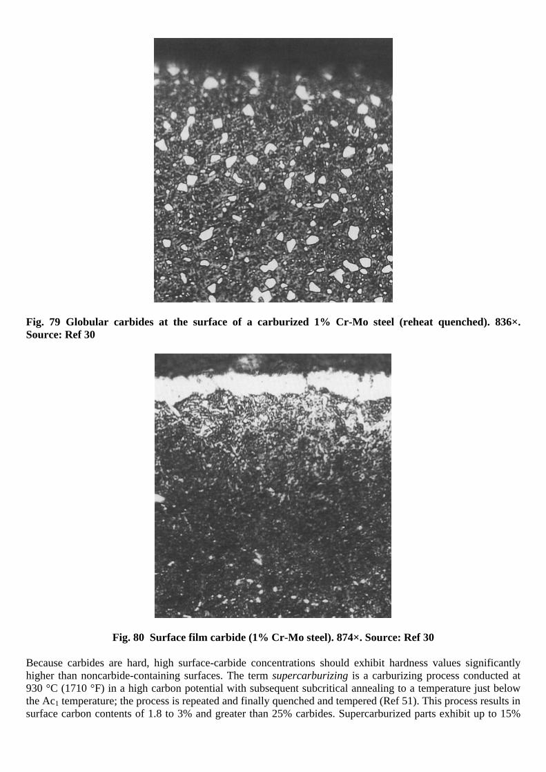
Fig. 79 Globular carbides at the surface of a carburized 1% Cr-Mo steel (reheat quenched). 836×. Source: Ref 30
Fig. 80 Surface film carbide (1% Cr-Mo steel). 874×. Source: Ref 30
Because carbides are hard, high surface-carbide concentrations should exhibit hardness values significantly higher than noncarbide-containing surfaces. The term supercarburizing is a carburizing process conducted at 930 °C (1710 °F) in a high carbon potential with subsequent subcritical annealing to a temperature just below the Ac1 temperature; the process is repeated and finally quenched and tempered (Ref 51). This process results in surface carbon contents of 1.8 to 3% and greater than 25% carbides. Supercarburized parts exhibit up to 15%

better bending fatigue properties. Coarse carbide structure may result in significantly reduced contact fatigue (Ref 30). Wear resistance generally increases with increasing carbide concentration. Carbide particles may be unavoidably formed during reheat-quenched carburized alloy steels. These dispersed, fine particles generally do not produce detrimental effects and may even be unavoidable in reheat-quenched carburized alloy steels. However, massive carbides, which may be formed at grain boundaries in the outer 0.05 mm (0.002 in.) at corners and edges, may be detrimental. Network carbides, which are formed during posthardening processes, can be detrimental to properties.
References cited in this section
27. R.R. Blackwood, L.M. Jarvis, D.G. Hoffman, and G.E. Totten, Conditions Leading to Quench Cracking other than Severity of Quench, Heat Treating, Including the Liu Dai Memorial Symposium, Proc. of the 18th Conf., R.A. Wallis and H.W. Walton, Ed., ASM International, 1998, p 575–585
30. G. Parrish, Carburizing: Microstructure and Properties, ASM International, 1999
38. V.D. Kalner and S.A. Yurasov, Internal Oxidation during Carburizing, Met. Sci. Heat Treat. (USSR), Vol 12 (No. 6), June 1970, p 451–454
45. I.Y. Arkhipov, V.A. Batyreva, and M.S. Polotskii, Internal Oxidation of the Case on Carburized Alloy Steels, Met. Sci. Heat Treat. (USSR), Vol 14 (No. 6), 1972, p 508–512
46. W.E. Dowling, W.T. Donlon, W.B. Copple, and C.V. Darragh, Fatigue Behavior of Two Carburized Low-Alloy Steels, Proc. of Second International Conference on Carburizing and Nitriding with Atmospheres, ASM International, 1995, p 55–60
47. B. Liscic, Heat Treatment of Steel, Steel Heat Treatment Handbook, G.E. Totten and M.A.H. Howes, Ed., Marcel Dekker, 1997, p 527–662
48. R. Ruxanda and E. Florian, Microscopic Observations of the Carbide/Matrix Interphasic Interface in a Low-Alloyed Hypercarburized Steel, Proc. of Second International Conference on Carburizing and Nitriding with Atmospheres, ASM International, 1995, p 117–121
49. J. Wang, Z. Qin, and J. Zhou, Formation and Properties of Carburized Case with Spheroidal Carbides, 5th International Congress on the Heat Treatment of Materials, (Budapest), International Federation for Heat Treating and Surface Engineering (Scientific Society for Mechanical Engineering), 1986, p 1212–1219
50. J.G. Wang, Z. Feng, and J.C. Zhou, Effect of the Morphology of Carbides in the Carburizing Case on the Wear Resistance and the Contact Fatigue of Gears, J. Mat. Eng. (China), Vol 6, Dec 1989, p 35–40
51. R. Kern, Supercarburizing, Heat Treat., Oct 1986, p 36–38
Influential Microstructural Features
Grain Size. The mechanical properties and toughness of steel, both in the case and core if the steel is carburized, are not only affected by carbon and alloying element concentration and microstructure but also by the grain size. Typically, finer grain sizes are preferred. The ASTM grain size characterization comparison is illustrated in Fig. 81 (Ref 30).
The file is downloaded from www.bzfxw.com

Fig. 81 Comparison of ASTM 6 to 9 grain size microstructures. 100×; nital etch. Source: Ref 30

Figure 82 illustrates the effect of increasing temperature on grain size (Ref 47). The following are reasons for grain growth when the temperature was increased from 850 to 1250 °C (1560 to 2280 °F) (Ref 52):
• Grain resorption occurs at 50 to 100 °C (90 to 180 °F) above Ac3 • New boundaries and grains are formed at 250 to 300°C (450 to 540 °F) above Ac3 • Although boundary migration occurs at all temperatures, it only affects grain growth above 1100 °C
(2010 °F).
Fig. 82 Schematic illustration of the effect of austenitizing temperature on grain size of a eutectoid steel after normalizing. Source: Ref 47
If the fractured surface of a steel tool or machine component is coarse grained, this often indicates the use of excessively high austenitizing temperatures during heat treatment, or that an incorrect heat treatment for a given steel grade was used. This is a problem, because many properties of steel are affected by grain size. Grain growth is affected by steel composition. Steels containing alloying elements such as aluminum nitride (AlN), which inhibits grain growth, are called fine-grained steels. Fine-grained steels do not exhibit grain growth, except at relatively high austenitizing temperatures when grain growth occurs rapidly, as illustrated in Fig. 83 (Ref 30). Coarse-grained steels contain silicon, and typically, the grain size increases slowly with increasing temperature, as illustrated in Fig. 83 (Ref 30).
The file is downloaded from www.bzfxw.com
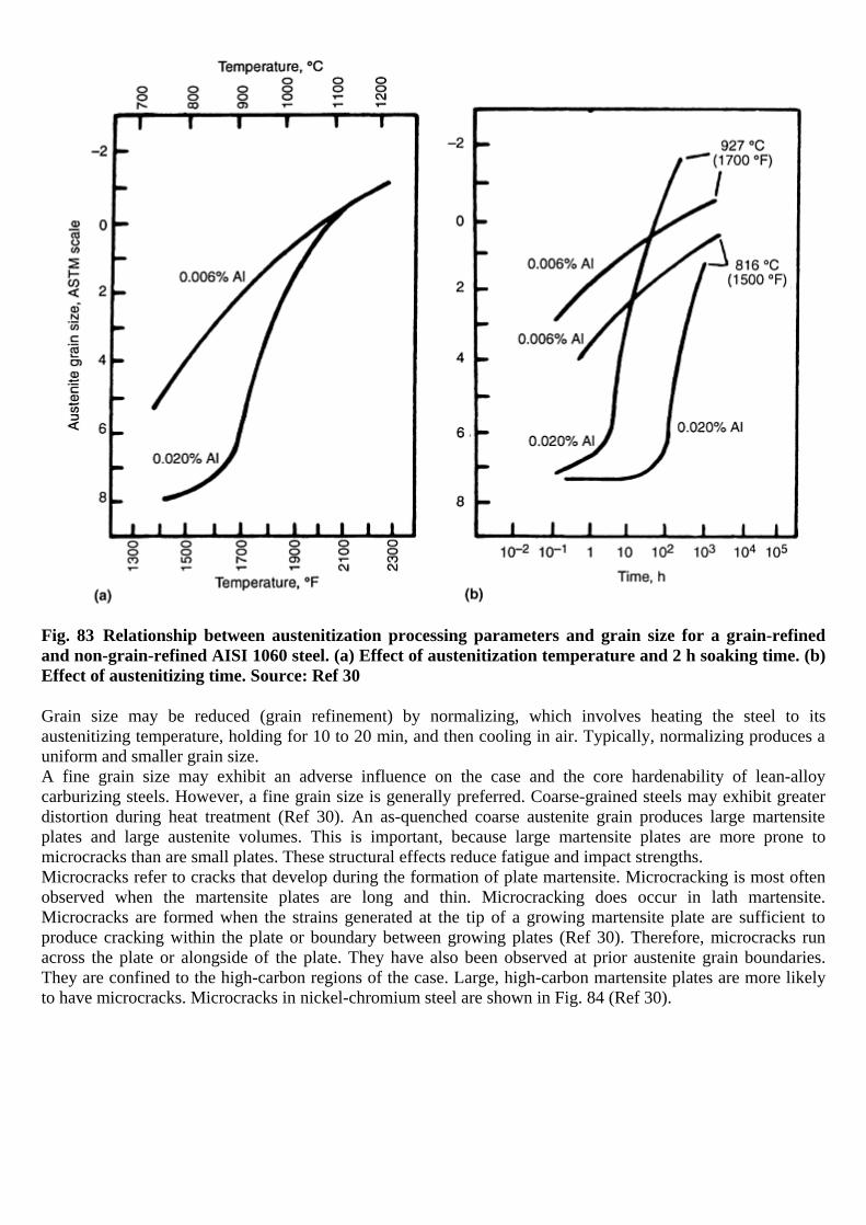
Fig. 83 Relationship between austenitization processing parameters and grain size for a grain-refined and non-grain-refined AISI 1060 steel. (a) Effect of austenitization temperature and 2 h soaking time. (b) Effect of austenitizing time. Source: Ref 30
Grain size may be reduced (grain refinement) by normalizing, which involves heating the steel to its austenitizing temperature, holding for 10 to 20 min, and then cooling in air. Typically, normalizing produces a uniform and smaller grain size. A fine grain size may exhibit an adverse influence on the case and the core hardenability of lean-alloy carburizing steels. However, a fine grain size is generally preferred. Coarse-grained steels may exhibit greater distortion during heat treatment (Ref 30). An as-quenched coarse austenite grain produces large martensite plates and large austenite volumes. This is important, because large martensite plates are more prone to microcracks than are small plates. These structural effects reduce fatigue and impact strengths. Microcracks refer to cracks that develop during the formation of plate martensite. Microcracking is most often observed when the martensite plates are long and thin. Microcracking does occur in lath martensite. Microcracks are formed when the strains generated at the tip of a growing martensite plate are sufficient to produce cracking within the plate or boundary between growing plates (Ref 30). Therefore, microcracks run across the plate or alongside of the plate. They have also been observed at prior austenite grain boundaries. They are confined to the high-carbon regions of the case. Large, high-carbon martensite plates are more likely to have microcracks. Microcracks in nickel-chromium steel are shown in Fig. 84 (Ref 30).

Fig. 84 Microcracking in a nickel-chromium steel that also exhibits microsegregation. 910×. Source: Ref 30
The propensity for microcracking increases as the carbon content of the steel increases above 0.6%. Microcracking potential increases with the amount of carbon in solution in the martensite, which increases as the temperature increases from Ac1 up to 920 °C (1690 °F). Direct quenching retains more carbon in solution in the martensite; therefore, quenching method and temperature are important. Plain-carbon and very lean-alloy grades of steel are more prone to microcracking during case hardening. However, 8620 and 52100 are known to be susceptible to microcracking (Ref 30). The frequency and size of microcracks increased with grain size (Ref 53). Microcracking has been reported to be aggravated by the presence of hydrogen (Ref 54), and tempering, even at temperatures as low as 180 °C (360 °F) for 20 min, has been reported to exhibit a healing effect (Ref 55). Although the presence of microcracks may potentially cause various problems, there are few studies reported in this area. It is possible that fatigue strength is reduced by as much as 20% (Ref 30). Similarly, there are few standards. There are no ANSI/AGMA specifications for grades 1 and 2. For the grade 3 quality, ten microcracks in a 0.06 mm2 (0.0001 in.2) field at 400× is specified. Microsegregation always occurs in processes such as casting. The amount of microsegregation in steel castings is affected by the alloy content of the steel, including tramp elements. The propensity for microsegregation is alloy-dependent. Silicon and manganese affect the microsegregation of molybdenum, and manganese affects the microsegregation of sulfur. In addition to microstructural analysis, elemental analysis may also provide an invaluable insight into potential for inclusion formation. For example, sulfide inclusions may be obtained if insufficient manganese is present. Generally, the manganese content should be approximately five times the sulfur content to convert sulfur to manganese sulfide. The order of microsegregation susceptibility (from most to least) is sulfur, niobium, phosphorus, tin, molybdenum, chromium, silicon, manganese, and nickel (Ref 30). Figure 85 illustrates dendritic microsegregation of a fractured gear tooth (Ref 30).
The file is downloaded from www.bzfxw.com

Fig. 85 Dendritic microsegregation in a fractured gear tooth. 2×. Source: Ref 30
Steel cracking may result from chemical segregation, which may be evident in the form of banding, as shown in Fig. 86 (Ref 27) Microstructural analysis showed that bands of tempered martensite were associated with bands of tempered martensite and bainite. The bainite appeared to originate from carbon and manganese segregation within the material, which would lead to increased internal stresses. Both surface and subsurface cracking was observed. Figure 87 shows subsurface cracking, which appeared to be intergranular (Ref 27).
Fig. 86 Micrograph of AISI 4140 steel as quenched and tempered, showing bands of tempered martensite and tempered martensite/bainite. 50×; 2% nital etch. Source: Ref 27

Fig. 87 Micrograph of AISI 4140 steel as quenched and tempered. Microstructure shows banded martensite and tempered martensite/bainite. Subsurface cracking is illustrated. 100×; 2% nital etch. Source: Ref 27
In a similar case, AISI 1144, a resulfurized steel, pins with subsequent cracking at the pin tips were accompanied with soft spotting. (The pins were through-hardened prior to induction hardening of the pin tip.) Microstructural analysis showed that the cracking and soft spotting condition was due to stringer inclusions, with bands of gross chemical segregation significantly greater than normally observed with this grade of steel. The stringers act as stress concentration sites for crack initiation in the presence of quenching stresses. Mechanical and thermal treatments may substantially affect the distribution and directionality of microsegregation, and, in some cases, it may be reduced significantly. However, because of the long soaking times required to completely homogenize the steel, it is generally recommended that nothing be done. Microsegregation may lead to machining problems, and severe cracking in the more alloyed carburizing grades of steel may occur during slow cooling from the carburizing temperature. In carburized and quenched steels, microsegregation may lead to unsatisfactory zones of martensite and austenite. Austenite-martensite or martensite-bainite banding probably reduces fatigue resistance, especially if bainite is present. Microsegregation may also influence the growth and distortion of a part during heat treatment. Microsegregation, along with nonmetallic inclusions, influences the transverse toughness and ductility of wrought steels. Effects of Grinding. A properly designed case-hardening process should produce surface microstructures containing essentially fine, tempered martensite with minimal part-to-part and batch-to-batch variation. However, grinding may be performed to achieve the desired dimensions and surface finish. It is also performed to remove undesired metallurgical products resulting from heat treatment, such as carbide films and internal oxidation. However, the grinding process can unacceptably heat a surface, leading to grinding burns and even cracking. A grinding burn occurs when the part becomes sufficiently hot, as a result of the grinding action, to cause discoloration or to exhibit a microstructural change due to tempering or hardening. The temperature distribution and associated microstructure products during grinding are illustrated in Fig. 88 (Ref 30).
The file is downloaded from www.bzfxw.com


Fig. 88 Temperature distribution within a ground surface, as indicated by microstructural modifications. The Ac temperature indicated is for slow heating; at high heating rates, such as encountered in grinding, the Ac temperatures are elevated. 500×. Source: Ref 30
There are different types of grinding burns. One type results in localized tempering and is called overtemper burning. This occurs when heat is not transferred from the grinding surface sufficiently to prevent induced tempering of the martensitic surface. This results in a loss of hardness on the burned surface and possibly a loss of compressive stresses. If the surface temperature during grinding exceeds the Ac3, a thin layer of austenite is formed that is cooled by the mass of the part to form a light-etching martensite. This is called a rehardening burn. Because of the thermal process, the rehardened material is surrounded by overtempered steel and reduced hardness, as illustrated in Fig. 88 (Ref 30). Grinding cracks, such as those illustrated in Fig. 89 and 90 are often accompanied by grinding burns (Ref 30). Grinding cracks typically form perpendicular to the grinding direction and penetrate at right angles to the surface. It is possible for the crack to penetrate substantially deeper than the depth of the burn.
Fig. 89 Micrograph of grinding cracks in case-hardened 8620 steel showing small cracks (see small arrows) that passed through the hardened case to the core, and the burned layer on the surface (dark band with arrow at the left) that resulted in grinding burns. (Note: Nital and acidic ferric chloride are suitable etchants for grinding burns.) Source: Ref 30
The file is downloaded from www.bzfxw.com
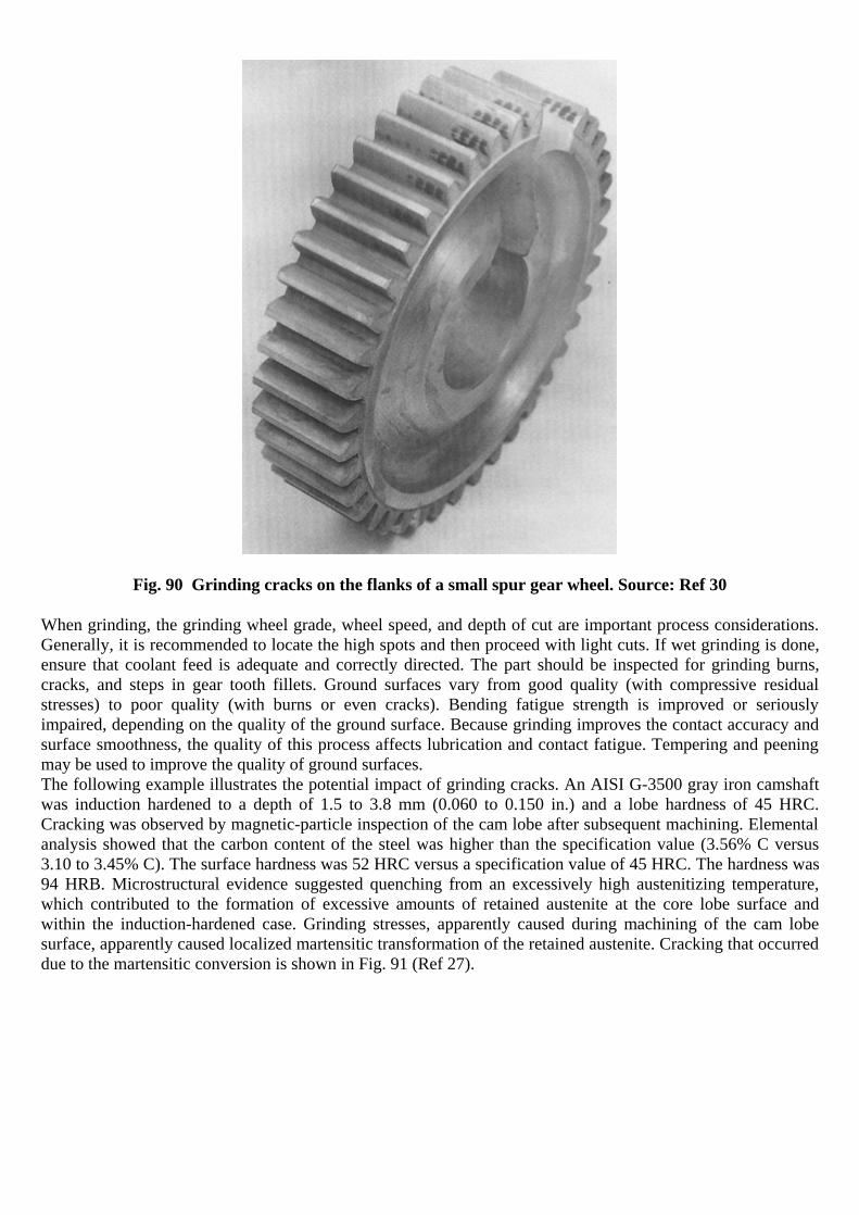
Fig. 90 Grinding cracks on the flanks of a small spur gear wheel. Source: Ref 30
When grinding, the grinding wheel grade, wheel speed, and depth of cut are important process considerations. Generally, it is recommended to locate the high spots and then proceed with light cuts. If wet grinding is done, ensure that coolant feed is adequate and correctly directed. The part should be inspected for grinding burns, cracks, and steps in gear tooth fillets. Ground surfaces vary from good quality (with compressive residual stresses) to poor quality (with burns or even cracks). Bending fatigue strength is improved or seriously impaired, depending on the quality of the ground surface. Because grinding improves the contact accuracy and surface smoothness, the quality of this process affects lubrication and contact fatigue. Tempering and peening may be used to improve the quality of ground surfaces. The following example illustrates the potential impact of grinding cracks. An AISI G-3500 gray iron camshaft was induction hardened to a depth of 1.5 to 3.8 mm (0.060 to 0.150 in.) and a lobe hardness of 45 HRC. Cracking was observed by magnetic-particle inspection of the cam lobe after subsequent machining. Elemental analysis showed that the carbon content of the steel was higher than the specification value (3.56% C versus 3.10 to 3.45% C). The surface hardness was 52 HRC versus a specification value of 45 HRC. The hardness was 94 HRB. Microstructural evidence suggested quenching from an excessively high austenitizing temperature, which contributed to the formation of excessive amounts of retained austenite at the core lobe surface and within the induction-hardened case. Grinding stresses, apparently caused during machining of the cam lobe surface, apparently caused localized martensitic transformation of the retained austenite. Cracking that occurred due to the martensitic conversion is shown in Fig. 91 (Ref 27).

Fig. 91 Micrograph of induction-hardened AISI G-3500 gray iron illustrating crack propagation into the hardened case. 88×; 3% nital etch. Source: Ref 27
Effects of Shot Peening. Shot peening improves surface hardness and induces compressive stresses. This is essentially a cold working process that plastically deforms the surface, producing increased surface compressive stresses. Figure 92 illustrates the formation of a case-hardened surface by shot peening (Ref 30).
Fig. 92 Effect of hardening by plastic deformation. (a) Case-hardened surface. (b) Non-case-hardened surface. Both 243×. Source: Ref 30
Shot peening may also be used to remove directional machining marks. By masking, it is possible to localize this process to affect only the most critically stressed areas. The benefits may be lost if the initial surface is rough, and ragged surfaces may lead to folded-in defects. Prior to conducting the peening process, the type of shot and the appropriate process parameters for the material and hardness must be determined. This may be done experimentally using an Almen strip. It is important that the shot are round, and the process must be precisely controlled to ensure complete coverage of the desired area.
The file is downloaded from www.bzfxw.com

Fatigue cracks generally initiate at the surface under bending conditions. Shot peening induces surface compressive residual stresses. Therefore, the possibility of fatigue crack initiation at the surface is reduced. A 20% improvement in fatigue limit or high-cycle fatigue life and contact-fatigue resistance has been quoted (Ref 30).
References cited in this section
27. R.R. Blackwood, L.M. Jarvis, D.G. Hoffman, and G.E. Totten, Conditions Leading to Quench Cracking other than Severity of Quench, Heat Treating, Including the Liu Dai Memorial Symposium, Proc. of the 18th Conf., R.A. Wallis and H.W. Walton, Ed., ASM International, 1998, p 575–585
30. G. Parrish, Carburizing: Microstructure and Properties, ASM International, 1999
47. B. Liscic, Heat Treatment of Steel, Steel Heat Treatment Handbook, G.E. Totten and M.A.H. Howes, Ed., Marcel Dekker, 1997, p 527–662
52. M.I. Vinograd, I.Y. Ul'Yanina, and G.A. Faivilevich, Mechanism of Austenite Grain Growth in Structural Steel, Met. Sci. Heat Treat. (USSR), Vol 17 (No. 1–2), 1975
53. R.P. Brobst and G. Krauss, The Effect of Austenite Grain Size on Microcracking in Martensite of an Fe-1.2C Alloy, Metall. Trans., Vol 5, Feb 1974, p 457–462
54. J. Hewitt, The Study of Hydrogen in Low Alloy Steels by Internal Friction Techniques, Hydrogen in Steel, Special Report 73, The Iron and Steel Institute, 1962, p 83–89
55. T.A. Balliet and G. Krauss, The Effect of the First and Second Stages of Tempering of Microcracking in Martensite of an Fe-1.2C Alloy, Metall. Trans. A, Vol 7, Jan 1976, p 81–86
References
1. S. Mocarski, Carburizing and Its Control, Part I: Basic Considerations, Ind. Heat., Vol 41 (No. 5), 1974, p 58–70
2. A. Bavaro, Heat Treatments and Deformation, Trait. Therm., Vol 240, 1990, p 37–41
3. F. Legat, Why Does Steel Crack during Quenching, Kovine Zlitine Technol., Vol 32 (No. 3–4), 1998, p 273–276
4. R.W. Bohl, Difficulties and Imperfections Associated with Heat Treated Steel, Lesson 13, Heat Treatment of Steel, Materials Engineering Institute Course 10, ASM International, 1978
5. K.E. Thelning, Steel and Its Heat Treatment, Butterworths, London, U.K., 1985
6. H. Berns, “Distortion and Crack Formation by Heat Treatment of Tools,” Radex Rundsch., Vol 1, 1989, p 40–57
7. G. Beck, Internal Stresses Associated with Heat Treatment of Alloys, Mém. Etud. Sci. Rev. Métall., June 1985, p 269–282
8. T. Ericsson and B. Hildenwall, Thermal and Transformational Stresses, Sagamore Army Mater. Res. Conf., 28th Proc., 1981, p 19–38
9. C. Jensen, Dimensional Changes during Heat Treatment of Hot Work Steel, Ind. Heat., March 1993, p 33–38

10. P. Mayr, “Dimensional Alteration of Parts due to Heat Treatment,” Residual Stresses in Science and Technology, Vol 1, Garmisch-Partenkirschen, FRG, 1986, DGM Informationsgesellschaft mbH, Adenauerallee 21, D-6370, Oberursel, FRG 1987, p 57–77
11. R.W. Edmonson, Dimensional Changes in Steel during Heat Treatment, Met. Treat., Vol 20 (No 6), 1969, p 3–19
12. M. Wisti and M. Hingwe, Tempering of Steel, Heat Treating, Vol 4, ASM Handbook, ASM International, 1991, p 121–136
13. Y. Toshioka, Heat Treatment Deformation of Steel Products, Mater. Sci. Technol., Vol 1, 1985, p 883–892
14. T. Inoue, K. Haraguchi, and S. Kimura, Analysis of Stresses due to Quenching and Tempering of Steel, Trans. Iron Steel Inst. Jpn., Vol 18, 1978, p 11–15
15. G.E. Totten and M.A.H. Howes, Distortion of Heat Treated Components, Steel Heat Treatment Handbook, G.E. Totten and M.A.H. Howes, Ed., Marcel Dekker Inc., 1997, p 292
16. D.A. Canonico, Stress-Relief in Heat Treating of Steel, Heat Treating, Vol 4, ASM Handbook, ASM International, 1991, p 33–34
17. C.E. Bates, G.E. Totten, and R.L. Brennan, Quenching of Steel, Heat Treating, Vol 4, ASM Handbook, ASM International, 1991, p 67–120
18. W.T. Cook, A Review of Selected Steel-Related Factors Controlling Distortion in Heat-Treatable Steels, Heat Treat. Met., Vol 26 (No. 2), p 27–36
19. Y. Toshioka, Heat Treatment Deformation of Steel Products, Mater. Sci. Technol., Vol 1, Oct 1985, p 1883–1892
20. A. Thuvander and A. Melander, Calculation of Distortion during Quenching of a Low Carbon Steel, First ASM Heat Treatment and Surface Engineering Conference in Europe (Proc.), Trans Tech Publications, Part 2, 1992, p 767–782
21. P.C. Clarke, Close-Tolerance Heat Treatment of Gears, Heat Treat. Met., Vol 25 (No. 3), 1998, p 61–64
22. R.F. Kern, Thinking Through to Successful Heat Treatment, Met. Eng. Q., Vol 11 (No. 1), 1971, p 1–4
23. R. Kern, Distortion and Cracking, Part II: Distortion from Quenching, Heat Treat., March 1985, p 41–45
24. R. Kern, Distortion and Cracking, Part III: How to Control Cracking, Heat Treat., April 1985, p 38–42
25. H.-J. Chen and Z.W. Jiang, Microstructure Improvement and Low-Temperature Quenching of Dies Made of Cr12-Type Steel, Jinshu Rechuli, No. 8, 1992, p 39–41
26. H.-H. Shao, Analysis of the Causes of Cracking of a 12% Cr Steel Cold Die during Heat Treatment, Jinshu Rechuli, No. 11, 1995, p 43
27. R.R. Blackwood, L.M. Jarvis, D.G. Hoffman, and G.E. Totten, Conditions Leading to Quench Cracking other than Severity of Quench, Heat Treating, Including the Liu Dai Memorial Symposium, Proc. of the 18th Conf., R.A. Wallis and H.W. Walton, Ed., ASM International, 1998, p 575–585
The file is downloaded from www.bzfxw.com

28. F. Legat, “Why Does Steel Crack during Quenching,” Kovine Zlitine Technol., Vol 32 (No. 3–4), 1998, p 273–276
29. X. Cheng and S. He, Analysis of Quenching Cracks in Machine-Tool Pistons under Supersonic Frequency Induction Hardening, Heat Treat. Met. (China), No. 4, 1991, p 51–52
30. G. Parrish, Carburizing: Microstructure and Properties, ASM International, 1999
31. J.R. Davis, Ed., ASM Materials Engineering Dictionary, ASM International, 1992, p 407
32. P.F. Stratton, N. Saxena, and R. Jain, Requirements for Gas Quenching Systems, Heat Treat. Met., Vol 24 (No. 3), 1997, p 60–63
33. H.M. Tensi, G.E. Totten, and G.M. Webster, Proposal to Monitor Agitation of Production Quench Tanks, Heat Treating: Including the 1997 International Induction Heat Treating Symposium, Proc. of the 17th Conf., D.L. Milam, D.A. Poteet, G.D. Pfaffmann, V. Rudnev, A. Muehlbauer, and W.B. Albert, Ed., ASM International, 1997, p 423–441
34. S. Owaku, Quench Distortion of Steel Parts, Netsu Shori (J. Jpn. Soc. Heat Treat.), Vol 32 (No. 4), 1992, p 198–202
35. R.T. Von Bergen, The Effects of Quenchant Media Selection on the Distortion of Engineered Steel Parts, Quenching and Distortion Control, G.E. Totten, Ed., ASM International, 1992, p 275–282
36. H.M. Tensi, A. Stich, and G.E. Totten, Fundamentals of Quenching, Met. Heat Treat., Mar/Apr 1995, p 20–28
37. T. Kunitake and S. Susigawa, Sumitomo Search, May 1971, p 16–25
38. V.D. Kalner and S.A. Yurasov, Internal Oxidation during Carburizing, Met. Sci. Heat Treat. (USSR), Vol 12 (No. 6), June 1970, p 451–454
39. A.A. Polyakov, Quenching Properties of Parts Having Stress Concentrators, Met. Sci. Heat Treat., Vol 37 (No.7–8), 1995, p 324-325
40. A.G. Haynes, Interrelation of Isothermal and Continuous-Cooling Heat Treatments of Low-Alloy Steels and Their Practical Significance, Heat Treat. Met., Special Report 95, The Iron and Steel Institute, 1966, p 13–23
41. D.P. Koistinen and R.E. Marburger, A General Equation Prescribing the Extent of the Austenite-Martensite Transformation in Pure Iron-Carbon Alloys and Plain Carbon Steels, Acta. Metall., Vol 7, 1959, p 59–60
42. H. Webster and W.J. Laird, Jr., Martempering of Steel, Heat Treating, Vol 4, ASM Handbook, ASM International, 1991, p 137
43. J.R. Keough, W.J. Laird, Jr., and A.D. Godding, Austempering of Steel, Heat Treating, Vol 4, ASM Handbook, ASM International, 1991, p 152–163
44. N.I. Kobasko, M.A. Arpnov, G.E. Totten, and A.V. Sverdlin, Method and Equipment for Implementation of Intensive Quenching, Heat Treating, Including the Liu Dai Memorial Symposium, Proc. of the 18th Conf., R.A. Wallis and H.W. Walton, Ed., ASM International, 1998, p 616–621
45. I.Y. Arkhipov, V.A. Batyreva, and M.S. Polotskii, Internal Oxidation of the Case on Carburized Alloy Steels, Met. Sci. Heat Treat. (USSR), Vol 14 (No. 6), 1972, p 508–512
46. W.E. Dowling, W.T. Donlon, W.B. Copple, and C.V. Darragh, Fatigue Behavior of Two Carburized Low-Alloy Steels, Proc. of Second International Conference on Carburizing and Nitriding with Atmospheres, ASM International, 1995, p 55–60
47. B. Liscic, Heat Treatment of Steel, Steel Heat Treatment Handbook, G.E. Totten and M.A.H. Howes, Ed., Marcel Dekker, 1997, p 527–662
48. R. Ruxanda and E. Florian, Microscopic Observations of the Carbide/Matrix Interphasic Interface in a Low-Alloyed Hypercarburized Steel, Proc. of Second International Conference on Carburizing and Nitriding with Atmospheres, ASM International, 1995, p 117–121
49. J. Wang, Z. Qin, and J. Zhou, Formation and Properties of Carburized Case with Spheroidal Carbides, 5th International Congress on the Heat Treatment of Materials, (Budapest), International Federation for Heat Treating and Surface Engineering (Scientific Society for Mechanical Engineering), 1986, p 1212–1219
50. J.G. Wang, Z. Feng, and J.C. Zhou, Effect of the Morphology of Carbides in the Carburizing Case on the Wear Resistance and the Contact Fatigue of Gears, J. Mat. Eng. (China), Vol 6, Dec 1989, p 35–40
51. R. Kern, Supercarburizing, Heat Treat., Oct 1986, p 36–38
52. M.I. Vinograd, I.Y. Ul'Yanina, and G.A. Faivilevich, Mechanism of Austenite Grain Growth in Structural Steel, Met. Sci. Heat Treat. (USSR), Vol 17 (No. 1–2), 1975
53. R.P. Brobst and G. Krauss, The Effect of Austenite Grain Size on Microcracking in Martensite of an Fe-1.2C Alloy, Metall. Trans., Vol 5, Feb 1974, p 457–462
54. J. Hewitt, The Study of Hydrogen in Low Alloy Steels by Internal Friction Techniques, Hydrogen in Steel, Special Report 73, The Iron and Steel Institute, 1962, p 83–89
55. T.A. Balliet and G. Krauss, The Effect of the First and Second Stages of Tempering of Microcracking in Martensite of an Fe-1.2C Alloy, Metall. Trans. A, Vol 7, Jan 1976, p 81–86
The file is downloaded from www.bzfxw.com


![Credit ratings failures and policy options [with Discussion]](https://static.fdokumen.com/doc/165x107/633fd3e6d10f841e2f086984/credit-ratings-failures-and-policy-options-with-discussion.jpg)