Evaluation of Anti-Wear Properties of Metalworking Fluids ...
15
applied sciences Article Evaluation of Anti-Wear Properties of Metalworking Fluids Enhanced with Halloysite Nanotubes Laura Peña-Parás 1, * ID , José Antonio Sánchez-Fernández 2 , Carlos Rafael Martínez 1 , José Abraham Ontiveros 1 , Karla Itzel Saldívar 1 , Luis Manuel Urbina 1 , Moisés Jair Arias 1 , Patricio García-Pineda 1 and Brenda Castaños 1 1 Departamento de Ingeniería, Universidad de Monterrey, 66238 San Pedro Garza García, Nuevo León, Mexico; [email protected] (C.R.M.); [email protected] (J.A.O.); [email protected] (K.I.S.); [email protected] (L.M.U.); [email protected] (M.J.A.);[email protected] (P.G.-P.); [email protected] (B.C.) 2 Escuela de Ingeniería y Ciencias, Tecnológico de Monterrey, Campus Monterrey, Eugenio Garza Sada 2501, Col. Tecnológico, 64849 Monterrey, Nuevo León, Mexico; [email protected] * Correspondence: [email protected]; Tel.: +52-8182151000 (ext. 1894) Received: 22 August 2017; Accepted: 25 September 2017; Published: 3 October 2017 Featured Application: nanoparticle additives for improving tribological properties of metalworking cutting fluids, enhancing tool life and surface finish in machining processes. Abstract: The study of nanoparticles as additives for metalworking fluids (MWFs) with applications in the metal removal processes, or machining, has received increasing attention due to the possible enhancements on tribological properties. In this study, low-cost and environmentally friendly nanoparticle additives of halloysite clay nanotubes (HNTs) were dispersed in metalworking fluids utilized for milling processes. Concentrations of 0.01, 0.05, 0.10 wt. % were incorporated into a mineral oil (MO) and a semi-synthetic fluid (SF) by ultrasonication. The anti-wear properties of metalworking nanofluids were characterized with a T-05 block-on-ring tribotester at a contact pressure of 0.5 GPa. Surface roughness of worn block materials was obtained with an optical 3D surface measurement system. Results showed that at a concentration of 0.10 wt. % HNTs block mass loss was lowered by 24% for the MO + HNTs nanofluids. For the SF + HNTs, a reduction of 63% and 32% in wear mass loss and coefficient of friction (COF), respectively, were found at the same concentration. The tribological enhancing mechanism for the applied contact pressure was proposed to be due to a reduction of the area of contact and nanoparticle sliding between surfaces with no HNT deposition, evidenced by energy dispersive spectrometry (EDS). Furthermore, surface roughness studies of worn blocks showed smoother surfaces with lower groove density with the addition of nanoparticle additives. The results of this study demonstrate that HNTs can improve the lubricity of metalworking cutting fluids used for machining processes, enhancing tool life and providing better surface finish of products. Keywords: nanofluids; metalworking fluids; halloysite nanotubes; wear; coefficient of friction; surface roughness 1. Introduction Metalworking fluids (MWFs) are used in metal removal processes such as cutting, milling, and grinding to reduce friction between the tool and the workpiece, increase tool life by reducing wear, and improve surface finish [1–4]. MWFs with nanoparticle additives have been widely investigated for the purpose of reducing the mechanical friction and wear between components obtaining very promising results [5–14]. For example, the wear scar diameters (WSDs) of a synthetic Appl. Sci. 2017, 7, 1019; doi:10.3390/app7101019 www.mdpi.com/journal/applsci
-
Upload
khangminh22 -
Category
Documents
-
view
2 -
download
0
Transcript of Evaluation of Anti-Wear Properties of Metalworking Fluids ...
applied sciences
Article
Evaluation of Anti-Wear Properties of MetalworkingFluids Enhanced with Halloysite Nanotubes
Laura Peña-Parás 1,* ID , José Antonio Sánchez-Fernández 2, Carlos Rafael Martínez 1,José Abraham Ontiveros 1, Karla Itzel Saldívar 1, Luis Manuel Urbina 1, Moisés Jair Arias 1,Patricio García-Pineda 1 and Brenda Castaños 1
1 Departamento de Ingeniería, Universidad de Monterrey,66238 San Pedro Garza García, Nuevo León, Mexico; [email protected] (C.R.M.);[email protected] (J.A.O.); [email protected] (K.I.S.); [email protected] (L.M.U.);[email protected] (M.J.A.); [email protected] (P.G.-P.); [email protected] (B.C.)
2 Escuela de Ingeniería y Ciencias, Tecnológico de Monterrey, Campus Monterrey, Eugenio Garza Sada 2501,Col. Tecnológico, 64849 Monterrey, Nuevo León, Mexico; [email protected]
* Correspondence: [email protected]; Tel.: +52-8182151000 (ext. 1894)
Received: 22 August 2017; Accepted: 25 September 2017; Published: 3 October 2017
Featured Application: nanoparticle additives for improving tribological properties of metalworkingcutting fluids, enhancing tool life and surface finish in machining processes.
Abstract: The study of nanoparticles as additives for metalworking fluids (MWFs) with applicationsin the metal removal processes, or machining, has received increasing attention due to the possibleenhancements on tribological properties. In this study, low-cost and environmentally friendlynanoparticle additives of halloysite clay nanotubes (HNTs) were dispersed in metalworking fluidsutilized for milling processes. Concentrations of 0.01, 0.05, 0.10 wt. % were incorporated intoa mineral oil (MO) and a semi-synthetic fluid (SF) by ultrasonication. The anti-wear propertiesof metalworking nanofluids were characterized with a T-05 block-on-ring tribotester at a contactpressure of 0.5 GPa. Surface roughness of worn block materials was obtained with an optical 3Dsurface measurement system. Results showed that at a concentration of 0.10 wt. % HNTs block massloss was lowered by 24% for the MO + HNTs nanofluids. For the SF + HNTs, a reduction of 63%and 32% in wear mass loss and coefficient of friction (COF), respectively, were found at the sameconcentration. The tribological enhancing mechanism for the applied contact pressure was proposedto be due to a reduction of the area of contact and nanoparticle sliding between surfaces with no HNTdeposition, evidenced by energy dispersive spectrometry (EDS). Furthermore, surface roughnessstudies of worn blocks showed smoother surfaces with lower groove density with the addition ofnanoparticle additives. The results of this study demonstrate that HNTs can improve the lubricity ofmetalworking cutting fluids used for machining processes, enhancing tool life and providing bettersurface finish of products.
Keywords: nanofluids; metalworking fluids; halloysite nanotubes; wear; coefficient of friction;surface roughness
1. Introduction
Metalworking fluids (MWFs) are used in metal removal processes such as cutting, milling,and grinding to reduce friction between the tool and the workpiece, increase tool life by reducingwear, and improve surface finish [1–4]. MWFs with nanoparticle additives have been widelyinvestigated for the purpose of reducing the mechanical friction and wear between componentsobtaining very promising results [5–14]. For example, the wear scar diameters (WSDs) of a synthetic
Appl. Sci. 2017, 7, 1019; doi:10.3390/app7101019 www.mdpi.com/journal/applsci

Appl. Sci. 2017, 7, 1019 2 of 15
fluid and base oil for machining applications were lowered by 10% and 86%, respectively, with0.01 wt. % CuO nanoparticles [10]. Similarly, Mosleh et al. [15] dispersed MoS2, WS2, and hexagonalboron nitride (hBN) nanoparticles in MWFs obtaining wear reductions of up to 66%. This wasattributed to nanoparticles filling surface valleys and the shearing of trapped nanoparticles at theinterface of contacting surfaces. Another study by Mosleh et al. [12] found that nanoparticlesalso deagglomerate metallic transfer films further reducing friction and wear. Zhang et al. [16]dispersed CaCO3 nanoparticles in a poly-alpha-olefin (PAO) base oil improving load-carrying capacity,and reducing friction and wear. Significant friction reductions in boundary and mixed lubricationregimes were obtained by Kalin et al. [17] through the formation of a protective film by dispersingMoS2 nanotubes into PAO. Moreover, Wu et al. [5] achieved reductions in friction and wear by CuO,TiO2, and nano-diamond nanoparticles due to a rolling effect provided by their spherical shape.
The addition of nanoparticles to MWFs has also demonstrated improvements in tool life andsurface finish of products. Exfoliated graphene nanoparticles added to a vegetable oil reduced edgechipping of cutting tool edges in ball milling experiments [18]. A cutting fluid with dispersed CuOnanoparticles developed by Vázquez et al. [11] was employed in a Computer Numerical Control (CNC)gear generator obtaining an improvement on the surface finish of workpieces of ~52%. Nanoparticlesof SiO2 blended into a mineral oil investigated for plain bearings by Sia et al. [19,20] reduced frictiontemperatures by acting as rolling and sliding particles between surfaces. Furthermore, a nanolubricantcontaining MoS2 nanoparticles for end-milling of AL6061-T6 developed by Rahmati et al. [21] improvedthe quality of the machined surfaces by the rolling, mending, and polishing tribological mechanismsprovided by MoS2 in the tool-workpiece interface.
Halloysite nanotubes (HNTs), with a molecular formula of Al2Si2O5(OH)4·nH2O, are hollow claymultiwalled tubular nanoparticles with lengths of 50–5000 nm, diameters of 20–200 nm, and innerlumen of 10–70 nm that naturally form in the Earth [22–24]; however, their dimensions may varydepending on the deposit [25]. These nanoparticles have negatively charged SiO2 groups on theoutside of the layers and positively charged Al(OH)3 on the inner lumen [26–28]. HNTs are non-toxiceven at high concentrations, and are much less expensive compared to other tubular-like nanoparticlessuch as carbon nanotubes (CNTs) [22]. Due to these characteristics they have been studied for diverseapplications, such as for preparing colloids with biopolymers providing tunable properties [29],for drug transport and delivery [28], as nanocontainers of additives for paper preservation [30],for obtaining inorganic reverse micelles for the entrapment of antibacterial agents [31], and forcapturing hydrocarbon and aromatic oils [32].
Recently, our group demonstrated that HNTs dispersed in metal-forming lubricants tested underextreme pressure conditions are able to increase the load-carrying capacity, scuffing load, and seizureload (load for lubricant film breakdown) under contacts pressures of 3.5–3.9 GPa [33]. At this highcontact pressure the tribological enhancing mechanism of HNTs was due to a possible exfoliation oftheir outer sheets and deposition on the surfaces.
In this work, two MWFs commonly used in the metal-mechanic industry, a semi-synthetic fluid(SF) and a mineral oil (MO), were reinforced with varying concentrations of HNTs and tested under acontact pressure of 0.5 GPa (lower than our previous work). The tribological properties of coefficient offriction (COF) and wear mass loss of nanofluids were determined with a block-on-ring test performedat room temperature. Surface roughness of tested materials was characterized after the test to study theinfluence of these nanoparticles on the surface finish of blocks. The proposed tribological enhancingmechanism of this study was determined by energy dispersive spectrometry (EDS).
2. Materials and Methods
2.1. Materials
Nanofluids were prepared by adding HNTs (purchased from Sigma-Aldrich, St. Louis, MO,USA) in concentrations of 0.01, 0.05, and 0.10 wt. % within a MO and a SF. These concentrations

Appl. Sci. 2017, 7, 1019 3 of 15
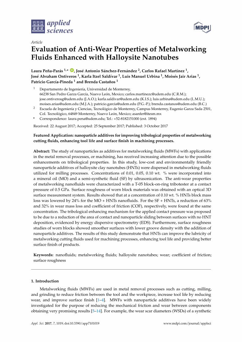
were selected based on a previous study by our group [33]. Figure 1a shows a micrograph with themorphology on HNTs obtained by scanning electron microscopy (SEM). Dimension measurements ofHNTs obtained by SEM are observed in Figure 1b. Elemental analysis of HNTs in Figure 1c shows Al,Si, and O in concentrations of 26%, 26%, and 43%, respectively. Also, Table 1 presents the propertiesof nanoparticles and MWFs. Nanoparticles were dispersed in both MWFs using an Ultra Turraz T10homogenizer for 5 min at room temperature (25 ◦C), followed by 5 min of ultrasonication with aCole-Parmer 750-watt ultrasonic homogenizer.
Appl. Sci. 2017, 7, 1019 3 of 15
morphology on HNTs obtained by scanning electron microscopy (SEM). Dimension measurements
of HNTs obtained by SEM are observed in Figure 1b. Elemental analysis of HNTs in Figure 1c shows
Al, Si, and O in concentrations of 26%, 26%, and 43%, respectively. Also, Table 1 presents the
properties of nanoparticles and MWFs. Nanoparticles were dispersed in both MWFs using an Ultra
Turraz T10 homogenizer for 5 min at room temperature (25 °C), followed by 5 min of ultrasonication
with a Cole-Parmer 750-watt ultrasonic homogenizer.
Figure 1. (a) Scanning electron micrograph of halloysite nanotubes (HNTs); (b) Micrograph of HNTs
at higher magnification indicating nanoparticle dimensions; (c) elemental analysis of HNTs showing
high concentrations of Al, Si, and O.
Table 1. Material properties.
Materials Properties
Metalworking fluids Density (15 °C) Viscosity (40 °C)
Semi-synthetic fluid (SF) 0.970 g/cm3 75.0 mm2/s
Mineral oil (MO) 0.871 g/cm3 33.2 mm2/s
Nanoparticle
Halloysite clay nanotubes (HNTs) Morphology: tubular; diameter: 28.5–135 nm × length: 1–3 μm
Test blocks
AISI 1018 Dimensions: 6.35 × 10 × 15.75 mm, 71 HRB, Ra = 0.45 μm
Chemical composition: 0.14–0.20% C, 0.60–0.90% Mn, <0.04% P, 0.05% S, Fe Balance
Test rings
AISI D2 Diameter: 35 mm, 58 HRC, Ra = 0.65 μm
Chemical composition: 1.5511.5% Cr, 0.90% Mo, 0.80% V, Fe Balance
Figure 1. (a) Scanning electron micrograph of halloysite nanotubes (HNTs); (b) Micrograph of HNTs athigher magnification indicating nanoparticle dimensions; (c) elemental analysis of HNTs showing highconcentrations of Al, Si, and O.
Table 1. Material properties.
Materials Properties
Metalworking fluids Density (15 ◦C) Viscosity (40 ◦C)
Semi-synthetic fluid (SF) 0.970 g/cm3 75.0 mm2/s
Mineral oil (MO) 0.871 g/cm3 33.2 mm2/s
Nanoparticle
Halloysite clay nanotubes (HNTs) Morphology: tubular; diameter: 28.5–135 nm × length: 1–3 µm
Test blocks
AISI 1018 Dimensions: 6.35 × 10 × 15.75 mm, 71 HRB, Ra = 0.45 µmChemical composition: 0.14–0.20% C, 0.60–0.90% Mn, <0.04% P, 0.05% S, Fe Balance
Test rings
AISI D2 Diameter: 35 mm, 58 HRC, Ra = 0.65 µmChemical composition: 1.5511.5% Cr, 0.90% Mo, 0.80% V, Fe Balance

Appl. Sci. 2017, 7, 1019 4 of 15
Figure 2 shows the hydrodynamic diameter size distribution of HNTs over time for MO and SFnanofluids, where measurements were taken after following the dispersion method. These tests wereperformed with a Malvern Zetasizer Nano ZS using dynamic light scattering after 3, 6, and 9 min.In Figure 2a the HNTs hydrodynamic diameter size distribution increases rapidly with time for MOnanofluids, suggesting lower stability in this fluid, likely due to its lower viscosity (33.2 mm2/s)compared to SF (75.0 mm2/s). For SF nanofluids the size distribution remains stable with very similarcurves (Figure 2b). Figure 2c shows a plot of the average HNTs hydrodynamic diameter size over time,indicating the lower stability in MO.
Appl. Sci. 2017, 7, 1019 4 of 15
Figure 2 shows the hydrodynamic diameter size distribution of HNTs over time for MO and SF
nanofluids, where measurements were taken after following the dispersion method. These tests
were performed with a Malvern Zetasizer Nano ZS using dynamic light scattering after 3, 6, and 9
min. In Figure 2a the HNTs hydrodynamic diameter size distribution increases rapidly with time for
MO nanofluids, suggesting lower stability in this fluid, likely due to its lower viscosity (33.2 mm2/s)
compared to SF (75.0 mm2/s). For SF nanofluids the size distribution remains stable with very similar
curves (Figure 2b). Figure 2c shows a plot of the average HNTs hydrodynamic diameter size over
time, indicating the lower stability in MO.
Figure 2. (a) Hydrodynamic size distribution of HNTs over time for MO + 0.01 wt. % HNT; (b)
Hydrodynamic size distribution of HNTs over time for SF + 0.01 wt. % HNTs; (c) Average HNTs
hydrodynamic diameter over time comparison for MO + 0.01 wt. % HNTs and SF + 0.01 wt. % HNTs.
Lower stability is found for MO nanofluids.
2.2. Tribological Tests
Tribological characterization of nanofluids was performed with a T-05 block-on-ring tribotester
shown in Figure 3a, according to ASTM G77. The schematic of the block-on-ring configuration used
for this study indicating the direction of the applied load is shown in Figure 3b. Figure 3c shows the
dimensions of test block and ring samples.
In this test a normal load is applied to the system (Figure 3b), where the test block is locked into
position and the ring rotates with a selected speed and load. Approximately 50 mL of nanofluids are
placed in the lubricant container so the materials are lubricated during testing. The block and ring
materials were an AISI 1018 steel and an AISI D2 steel, respectively (Table 1). Testing was done at
room temperature (25 °C) under the following parameters: a normal load of 750 N (contact pressure
of ~0.5 GPa), 200 rpm, and a duration of the run of 3600 s. Five tests were performed for each
nanofluid; after each test wear mass loss of blocks was recorded and COF was obtained.
Figure 2. (a) Hydrodynamic size distribution of HNTs over time for MO + 0.01 wt. % HNT;(b) Hydrodynamic size distribution of HNTs over time for SF + 0.01 wt. % HNTs; (c) Average HNTshydrodynamic diameter over time comparison for MO + 0.01 wt. % HNTs and SF + 0.01 wt. % HNTs.Lower stability is found for MO nanofluids.
2.2. Tribological Tests
Tribological characterization of nanofluids was performed with a T-05 block-on-ring tribotestershown in Figure 3a, according to ASTM G77. The schematic of the block-on-ring configuration usedfor this study indicating the direction of the applied load is shown in Figure 3b. Figure 3c shows thedimensions of test block and ring samples.
In this test a normal load is applied to the system (Figure 3b), where the test block is locked intoposition and the ring rotates with a selected speed and load. Approximately 50 mL of nanofluids areplaced in the lubricant container so the materials are lubricated during testing. The block and ringmaterials were an AISI 1018 steel and an AISI D2 steel, respectively (Table 1). Testing was done atroom temperature (25 ◦C) under the following parameters: a normal load of 750 N (contact pressure of~0.5 GPa), 200 rpm, and a duration of the run of 3600 s. Five tests were performed for each nanofluid;after each test wear mass loss of blocks was recorded and COF was obtained.

Appl. Sci. 2017, 7, 1019 5 of 15
Appl. Sci. 2017, 7, 1019 5 of 15
Figure 3. (a) T-05 Block-on-ring tribotester; (b) Schematic of the block-on-ring setup showing the
direction of the applied force; (c) Dimensions of the test block and ring.
2.3. Surface Characterization
Surface roughness characteristics of average roughness (Ra), root-mean-square roughness (Rq),
and mean roughness depth (Rz) were characterized with an Alicona IF-EdgeMaster optical 3D
surface measurement system (Alicona Imaging GmbH, Raaba/Graz, Austria). A Tescan Vega3 SB
Scanning Electron Microscope (SEM) equipped with EDS (Tescan, Brno—Kohoutovice, Czech
Republic) was used to identify the tribological mechanism provided by HNTs.
3. Results and Discussion
3.1. Tribological Results
Block mass loss presented in Figure 4 was quantified by weighting each block before and after
every test. In general, the SF + HNT nanofluids exhibited the best tribological behavior with much
lower wear mass loss compared to MO + HNT nanofluids. This was likely due to the higher viscosity
of SF compared to MO (75.0 mm2/s vs. 33.2 mm2/s) that was able to provide a better lubricant film
and nanoparticle stability, as shown in Figure 2. For MO + HNT nanofluids the lowest wear mass
loss was 8.05 mg for MO + 0.10 wt. % HNTs, giving an enhancement of 24% compared to the unfilled
MO. For SF + HNT nanofluids improvements of 6%, 36%, and 63% were found for 0.01, 0.05, and
0.1 wt. % HNTs, respectively. Only 2.5 mg of mass loss was obtained for SF + 0.1 wt. % HNTs
compared to 6.9 mg for the unfilled SF. It is also observed that the standard deviation of the wear
mass results diminishes with increasing nanoparticle concentration, thus increasing nanolubricant
reliability.
Figure 3. (a) T-05 Block-on-ring tribotester; (b) Schematic of the block-on-ring setup showing thedirection of the applied force; (c) Dimensions of the test block and ring.
2.3. Surface Characterization
Surface roughness characteristics of average roughness (Ra), root-mean-square roughness (Rq),and mean roughness depth (Rz) were characterized with an Alicona IF-EdgeMaster optical 3D surfacemeasurement system (Alicona Imaging GmbH, Raaba/Graz, Austria). A Tescan Vega3 SB ScanningElectron Microscope (SEM) equipped with EDS (Tescan, Brno—Kohoutovice, Czech Republic) wasused to identify the tribological mechanism provided by HNTs.
3. Results and Discussion
3.1. Tribological Results
Block mass loss presented in Figure 4 was quantified by weighting each block before and afterevery test. In general, the SF + HNT nanofluids exhibited the best tribological behavior with muchlower wear mass loss compared to MO + HNT nanofluids. This was likely due to the higher viscosityof SF compared to MO (75.0 mm2/s vs. 33.2 mm2/s) that was able to provide a better lubricantfilm and nanoparticle stability, as shown in Figure 2. For MO + HNT nanofluids the lowest wearmass loss was 8.05 mg for MO + 0.10 wt. % HNTs, giving an enhancement of 24% compared to theunfilled MO. For SF + HNT nanofluids improvements of 6%, 36%, and 63% were found for 0.01, 0.05,and 0.1 wt. % HNTs, respectively. Only 2.5 mg of mass loss was obtained for SF + 0.1 wt. % HNTscompared to 6.9 mg for the unfilled SF. It is also observed that the standard deviation of the wear massresults diminishes with increasing nanoparticle concentration, thus increasing nanolubricant reliability.

Appl. Sci. 2017, 7, 1019 6 of 15
Appl. Sci. 2017, 7, 1019 6 of 15
Figure 4. Block mass loss for SF and MO nanofluids with varying concentrations of HNTs.
Measurements of COF over the duration of the run are presented in Figure 5. These were
calculated by taking the friction force measured through a load cell and dividing it by the applied
load of 750 N. For SF nanofluids (Figure 5b) the improvements are significantly larger than the ones
obtained with MO. Figure 5a also shows that HNTs slightly decreased COF over time with
0.05 wt. % and 0.10 wt. % HNTs in MO due to a polishing effect provided by nanoparticles that
reduced the amount of asperities and metal-metal contact. The slight variations (peaks and valleys)
over time found for Figure 5b may be due to the presence of wear debris that affected the
measurement.
Figure 5. Coefficient of friction (COF) behavior as a function of time for: (a) MO + HNT nanofluids;
(b) SF + HNT nanofluids.
Figure 4. Block mass loss for SF and MO nanofluids with varying concentrations of HNTs.
Measurements of COF over the duration of the run are presented in Figure 5. These werecalculated by taking the friction force measured through a load cell and dividing it by the appliedload of 750 N. For SF nanofluids (Figure 5b) the improvements are significantly larger than the onesobtained with MO. Figure 5a also shows that HNTs slightly decreased COF over time with 0.05 wt. %and 0.10 wt. % HNTs in MO due to a polishing effect provided by nanoparticles that reduced theamount of asperities and metal-metal contact. The slight variations (peaks and valleys) over timefound for Figure 5b may be due to the presence of wear debris that affected the measurement.
Appl. Sci. 2017, 7, 1019 6 of 15
Figure 4. Block mass loss for SF and MO nanofluids with varying concentrations of HNTs.
Measurements of COF over the duration of the run are presented in Figure 5. These were
calculated by taking the friction force measured through a load cell and dividing it by the applied
load of 750 N. For SF nanofluids (Figure 5b) the improvements are significantly larger than the ones
obtained with MO. Figure 5a also shows that HNTs slightly decreased COF over time with
0.05 wt. % and 0.10 wt. % HNTs in MO due to a polishing effect provided by nanoparticles that
reduced the amount of asperities and metal-metal contact. The slight variations (peaks and valleys)
over time found for Figure 5b may be due to the presence of wear debris that affected the
measurement.
Figure 5. Coefficient of friction (COF) behavior as a function of time for: (a) MO + HNT nanofluids;
(b) SF + HNT nanofluids. Figure 5. Coefficient of friction (COF) behavior as a function of time for: (a) MO + HNT nanofluids;(b) SF + HNT nanofluids.

Appl. Sci. 2017, 7, 1019 7 of 15
For the average COF measurements in the steady state (Figure 6) SF + HNTs nanofluids exhibitedlower values compared to MO nanofluids, consistent with wear mass loss results. Here, it is evidentthat HNTs showed no major improvements in COF when added to MO. Nanofluids of SF + HNTsshowed a clear tendency to reduce COF with increasing HNTs concentration. A COF of 0.088 wasfound for unfilled SF, whereas SF + 0.1 wt. % HNTs exhibited a COF of 0.06, representing a reductionof 32%.
Appl. Sci. 2017, 7, 1019 7 of 15
For the average COF measurements in the steady state (Figure 6) SF + HNTs nanofluids
exhibited lower values compared to MO nanofluids, consistent with wear mass loss results. Here, it
is evident that HNTs showed no major improvements in COF when added to MO. Nanofluids of SF
+ HNTs showed a clear tendency to reduce COF with increasing HNTs concentration. A COF of
0.088 was found for unfilled SF, whereas SF + 0.1 wt. % HNTs exhibited a COF of 0.06, representing a
reduction of 32%.
Figure 6. Coefficient of friction values for MO and SF nanofluids with varying HNT nanoparticle concentration.
3.2. Surface Analysis
Micrographs of worn surfaces of tested blocks with MO + HNT and SF + HNT suspensions are
shown in Figure 7 and Figure 8, respectively. The worn block in Figure 7a with MO shows pitting
throughout the sample. Fewer regions with pitting are found for Figure 7b with MO + 0.01 wt. %
HNTs. Pitting wear is further reduced with higher nanoparticle content on the worn surfaces
observed in Figure 7c,d with 0.05 wt. % and 0.10 wt. % HNTs.
Figure 8 with SF nanofluids presents overall smoother surfaces compared to MO nanofluids
(Figure 7). Figure 8a (unfilled SF) shows very few regions with pitting and shallow furrows. Lower
groove density with increasing HNT concentration is evident in Figure 8b–d, with a very smooth
surface found with 0.10 wt. % HNTs.
Surface roughness profiles of worn blocks shown in Figure 7 and Figure 8 taken
perpendicularly to the sliding direction of the test are depicted in Figure 9 and Figure 10,
respectively. Table 2 presents surface roughness parameters of Ra, Rq, and Rz characterized by an
optical measurement system. For both MO and SF, the nanofluids roughness parameter values were
very similar, and decreased with increasing HNT concentration. Reductions in Ra by 36% and 34%
were obtained for MO and SF nanofluids, respectively, at 0.10 wt. % HNTs. Lower Ra values
achieved with HNTs were due to a higher amount of removed material during the wear testing that
provided a polishing effect, as observed in Figure 7 and Figure 8. Similar results have been found by
Sia et al. [20] with nanoparticles effectively reducing the Ra of surfaces through metal removal.
Figure 6. Coefficient of friction values for MO and SF nanofluids with varying HNTnanoparticle concentration.
3.2. Surface Analysis
Micrographs of worn surfaces of tested blocks with MO + HNT and SF + HNT suspensions areshown in Figures 7 and 8, respectively. The worn block in Figure 7a with MO shows pitting throughoutthe sample. Fewer regions with pitting are found for Figure 7b with MO + 0.01 wt. % HNTs. Pittingwear is further reduced with higher nanoparticle content on the worn surfaces observed in Figure 7c,dwith 0.05 wt. % and 0.10 wt. % HNTs.
Figure 8 with SF nanofluids presents overall smoother surfaces compared to MO nanofluids(Figure 7). Figure 8a (unfilled SF) shows very few regions with pitting and shallow furrows. Lowergroove density with increasing HNT concentration is evident in Figure 8b–d, with a very smoothsurface found with 0.10 wt. % HNTs.
Surface roughness profiles of worn blocks shown in Figures 7 and 8 taken perpendicularly to thesliding direction of the test are depicted in Figures 9 and 10, respectively. Table 2 presents surfaceroughness parameters of Ra, Rq, and Rz characterized by an optical measurement system. For both MOand SF, the nanofluids roughness parameter values were very similar, and decreased with increasingHNT concentration. Reductions in Ra by 36% and 34% were obtained for MO and SF nanofluids,respectively, at 0.10 wt. % HNTs. Lower Ra values achieved with HNTs were due to a higher amountof removed material during the wear testing that provided a polishing effect, as observed in Figures 7and 8. Similar results have been found by Sia et al. [20] with nanoparticles effectively reducing the Ra
of surfaces through metal removal.

Appl. Sci. 2017, 7, 1019 8 of 15
Appl. Sci. 2017, 7, 1019 8 of 15
Figure 7. Scanning electron micrographs of blocks after tribological testing of: (a) MO, (b) MO + 0.01
wt. % HNTs, (c) MO + 0.05 wt. % HNTs, (d) MO + 0.10 wt. % HNTs. Arrows indicate the direction of
sliding.
Figure 7. Scanning electron micrographs of blocks after tribological testing of: (a) MO, (b) MO +0.01 wt. % HNTs, (c) MO + 0.05 wt. % HNTs, (d) MO + 0.10 wt. % HNTs. Arrows indicate the directionof sliding.
Appl. Sci. 2017, 7, 1019 8 of 15
Figure 7. Scanning electron micrographs of blocks after tribological testing of: (a) MO, (b) MO + 0.01
wt. % HNTs, (c) MO + 0.05 wt. % HNTs, (d) MO + 0.10 wt. % HNTs. Arrows indicate the direction of
sliding.
Figure 8. Cont.

Appl. Sci. 2017, 7, 1019 9 of 15Appl. Sci. 2017, 7, 1019 9 of 15
Figure 8. Scanning electron micrographs after tribological testing of: (a) SF; (b) SF + 0.01 wt. % HNTs;
(c) SF + 0.05 wt. % HNTs; (d) SF + 0.10 wt. % HNTs. Arrows indicate the direction of sliding.
Elemental analysis performed by EDS on the worn blocks tested with MO + 0.10 wt. % HNTs
and SF + 0.10 wt. % HNTs can be observed in Figure 11a,b, respectively. No Al and/or Si elements
were detected on the surface, suggesting that at the contact pressure of this test of 0.5 GPa there was
no HNT deposition and formation of a protective film. Furthermore, nanoparticles were too large to
fill valleys or grooves of surfaces and provide a mending tribological mechanism.
This is in contrast to previously reported results by our group [33], where at 3.5–3.9 GPa (in a
four-ball extreme pressure test) Al and Si groups were found on the surface, likely due to HNT
exfoliation due to the compression forces. As explained by Lecouvet et al. [34], HNTs are hard
aluminosilicates with interlayer water molecules where weak Van der Waals forces and H-bonds are
present, and shearing occurs due to the slip motion between these layers, particularly for larger
nanoparticle diameters (>120 nm). A similar behavior has also been reported experimentally by
Lahouij et al. [35] for inorganic fullerene-like (IF)-MoS2 nanoparticles. At contact pressures of 1 GPa
exfoliation of outer fullerene sheets was found to be the predominant mechanism, and at lower
pressures (0.1 GPa) a rolling/sliding mechanism was observed. It is explained that under
compression forces the IF nanoparticles gradually deform and start to exfoliate, which is enhanced
by the large number of defects in the layers.
It is then proposed that the enhancement in tribological properties provided by HNTs can be
attributed to a third body mechanism, where nanoparticles separate surfaces reducing the real area
of contact and reducing wear, as proposed by Ghaednia et al. [36], and their possible sliding between
surfaces. The schematic of the anti-wear mechanism provided by HNTs is shown in Figure 12. As
observed in Figure 4 and Figure 5, increasing HNTs concentration resulted in lower wear mass loss
due to more nanoparticles on the wear zone that were able to reduce the area of contact and
decreased friction and wear. For MO nanofluids the lower stability of HNTs shown in Figure 2 likely
caused more precipitation, thus fewer nanoparticles were able to separate surfaces explaining their
poorer performance compared to SF nanofluids.
Figure 8. Scanning electron micrographs after tribological testing of: (a) SF; (b) SF + 0.01 wt. % HNTs;(c) SF + 0.05 wt. % HNTs; (d) SF + 0.10 wt. % HNTs. Arrows indicate the direction of sliding.
Elemental analysis performed by EDS on the worn blocks tested with MO + 0.10 wt. % HNTsand SF + 0.10 wt. % HNTs can be observed in Figure 11a,b, respectively. No Al and/or Si elementswere detected on the surface, suggesting that at the contact pressure of this test of 0.5 GPa there wasno HNT deposition and formation of a protective film. Furthermore, nanoparticles were too large tofill valleys or grooves of surfaces and provide a mending tribological mechanism.
This is in contrast to previously reported results by our group [33], where at 3.5–3.9 GPa (in afour-ball extreme pressure test) Al and Si groups were found on the surface, likely due to HNTexfoliation due to the compression forces. As explained by Lecouvet et al. [34], HNTs are hardaluminosilicates with interlayer water molecules where weak Van der Waals forces and H-bondsare present, and shearing occurs due to the slip motion between these layers, particularly for largernanoparticle diameters (>120 nm). A similar behavior has also been reported experimentally byLahouij et al. [35] for inorganic fullerene-like (IF)-MoS2 nanoparticles. At contact pressures of 1 GPaexfoliation of outer fullerene sheets was found to be the predominant mechanism, and at lowerpressures (0.1 GPa) a rolling/sliding mechanism was observed. It is explained that under compressionforces the IF nanoparticles gradually deform and start to exfoliate, which is enhanced by the largenumber of defects in the layers.
It is then proposed that the enhancement in tribological properties provided by HNTs can beattributed to a third body mechanism, where nanoparticles separate surfaces reducing the real area ofcontact and reducing wear, as proposed by Ghaednia et al. [36], and their possible sliding betweensurfaces. The schematic of the anti-wear mechanism provided by HNTs is shown in Figure 12.As observed in Figures 4 and 5, increasing HNTs concentration resulted in lower wear mass loss dueto more nanoparticles on the wear zone that were able to reduce the area of contact and decreasedfriction and wear. For MO nanofluids the lower stability of HNTs shown in Figure 2 likely causedmore precipitation, thus fewer nanoparticles were able to separate surfaces explaining their poorerperformance compared to SF nanofluids.

Appl. Sci. 2017, 7, 1019 10 of 15
Appl. Sci. 2017, 7, 1019 10 of 15
Figure 9. Roughness profiles and Ra values of worn blocks for MO + HNT nanofluidos: (a) MO, (b) MO +
0.01 wt. % HNTs, (c) MO + 0.05 wt. % HNTs, (d) MO + 0.10 wt. % HNTs. Figure 9. Roughness profiles and Ra values of worn blocks for MO + HNT nanofluidos: (a) MO,(b) MO + 0.01 wt. % HNTs, (c) MO + 0.05 wt. % HNTs, (d) MO + 0.10 wt. % HNTs.

Appl. Sci. 2017, 7, 1019 11 of 15
Appl. Sci. 2017, 7, 1019 11 of 15
Figure 10. Roughness profiles and Ra values of worn blocks for SF + HNT nanofluidos: (a) SF;(b) SF + 0.01 wt. % HNTs; (c) SF + 0.05 wt. % HNTs; (d) SF + 0.10 wt. % HNTs. Arrows indicate thedirection of sliding.

Appl. Sci. 2017, 7, 1019 12 of 15
Table 2. Comparison of surface roughness characteristics of block materials.
Average Roughness,Ra (µm)
Root Mean Square,Rq (µm)
Mean RoughnessDepth, Rz (µm)
MO 0.53 0.80 4.47MO + 0.01 wt. % 0.44 0.58 2.92MO + 0.05 wt. % 0.37 0.52 3.15MO + 0.10 wt. % 0.34 0.46 2.75
SF 0.53 0.68 3.29SF + 0.01 wt. % 0.47 0.63 2.83SF + 0.05 wt. % 0.42 0.61 2.94SF + 0.10 wt. % 0.35 0.46 2.48
Appl. Sci. 2017, 7, 1019 12 of 15
Figure 10. Roughness profiles and Ra values of worn blocks for SF + HNT nanofluidos: (a) SF; (b) SF
+ 0.01 wt. % HNTs; (c) SF + 0.05 wt. % HNTs; (d) SF + 0.10 wt. % HNTs. Arrows indicate the direction
of sliding.
Table 2. Comparison of surface roughness characteristics of block materials.
Average Roughness,
Ra (µm)
Root Mean Square,
Rq (µm)
Mean Roughness Depth,
Rz (µm)
MO 0.53 0.80 4.47
MO + 0.01 wt. % 0.44 0.58 2.92
MO + 0.05 wt. % 0.37 0.52 3.15
MO + 0.10 wt. % 0.34 0.46 2.75
SF 0.53 0.68 3.29
SF + 0.01 wt. % 0.47 0.63 2.83
SF + 0.05 wt. % 0.42 0.61 2.94
SF + 0.10 wt. % 0.35 0.46 2.48
Figure 11. Elemental analysis of worn blocks after tribological testing for: (a) MO + 0.10 wt. % HNTs,
and; (b) SF + 0.10 HNTs. Figure 11. Elemental analysis of worn blocks after tribological testing for: (a) MO + 0.10 wt. % HNTs,and; (b) SF + 0.10 HNTs.

Appl. Sci. 2017, 7, 1019 13 of 15
Appl. Sci. 2017, 7, 1019 13 of 15
Figure 12. Schematic of anti-wear mechanism for HNTs nanofluids. A reduction of the real area of
contact and sliding between surfaces with no deposition is proposed.
Overall, the significant difference in performance per concentration between the nanofluids of
MO and SF are due to the different anti-wear characteristics of each base fluid, and physical
properties such as fluid viscosity. The results shown in this study suggest that eco-friendly HNTs
have a positive effect improving tribological properties of MWFs. Surface roughness and wear mass
loss may be lowered due to a reduction of the contact area between surfaces by HNTs, thus
extending tool life, reducing material costs, and improving the surface finish of products.
4. Conclusions
In this work, two MWFs filled with low concentrations of HNT additives were prepared and
their anti-wear tribological properties were characterized with a T-05 block-on-ring tribotester.
Nanoparticle additives effectively reduced wear mass loss for both MO and SF nanofluids, with
improvements of up to 64%. Surface roughness of blocks and COF were also lowered. At the contact
pressure of the test of 0.5 GPa HNTs showed no exfoliation, thus the enhancement in anti-wear
properties is attributed to a reduction of contact area.
Acknowledgments: This works was partially supported by Vicerrectoría Académica Universidad de
Monterrey research grant No. 15013. The authors would like to acknowledge Manuel Morales for his
contribution to this work.
Author Contributions: L.P.-P. conceived and designed the experiments and wrote the paper; J.A.S.-F.
contributed materials, performed EDS experiments, and analyzed the data; C.R.M., J.A.O., K.I.S., L.M.U.,
M.J.A., and P.G.-P. performed tribological and surface roughness characterization experiments and analyzed
the data; B.C. performed SEM and surface roughness characterization and analyzed the data.
Conflicts of Interest: The authors declare no conflict of interest.
References
1. Brinksmeier, E.; Meyer, D.; Huesmann-Cordes, A.G.; Herrmann, C. Metalworking fluids—Mechanisms
and performance. CIRP Ann. 2015, doi:10.1016/j.cirp.2015.05.003.
2. Schwarz, M.; Dado, M.; Hnilica, R.; Veverkoná, D. Environmental and health aspects of metalworking
fluid use. Polish J. Environ. Stud. 2015, 24, 37–45.
3. Do, T.-V.; Hsu, Q.-C. Optimization of Minimum Quantity Lubricant Conditions and Cutting Parameters in
Hard Milling of AISI H13 Steel. Appl. Sci. 2016, 6, 83, doi:10.3390/app6030083.
4. Gariani, S.; Shyha, I.; Inam, F.; Huo, D. Evaluation of a Novel Controlled Cutting Fluid Impinging Supply
System When Machining Titanium Alloys. Appl. Sci. 2017, 7, 560, doi:10.3390/app7060560.
5. Wu, Y.Y.; Tsui, W.C.; Liu, T.C. Experimental analysis of tribological properties of lubricating oils with
nanoparticle additives. Wear 2007, 262, 819–825, doi:10.1016/j.wear.2006.08.021.
Figure 12. Schematic of anti-wear mechanism for HNTs nanofluids. A reduction of the real area ofcontact and sliding between surfaces with no deposition is proposed.
Overall, the significant difference in performance per concentration between the nanofluids ofMO and SF are due to the different anti-wear characteristics of each base fluid, and physical propertiessuch as fluid viscosity. The results shown in this study suggest that eco-friendly HNTs have a positiveeffect improving tribological properties of MWFs. Surface roughness and wear mass loss may belowered due to a reduction of the contact area between surfaces by HNTs, thus extending tool life,reducing material costs, and improving the surface finish of products.
4. Conclusions
In this work, two MWFs filled with low concentrations of HNT additives were prepared and theiranti-wear tribological properties were characterized with a T-05 block-on-ring tribotester. Nanoparticleadditives effectively reduced wear mass loss for both MO and SF nanofluids, with improvements ofup to 64%. Surface roughness of blocks and COF were also lowered. At the contact pressure of the testof 0.5 GPa HNTs showed no exfoliation, thus the enhancement in anti-wear properties is attributed toa reduction of contact area.
Acknowledgments: This works was partially supported by Vicerrectoría Académica Universidad de Monterreyresearch grant No. 15013. The authors would like to acknowledge Manuel Morales for his contribution tothis work.
Author Contributions: L.P.-P. conceived and designed the experiments and wrote the paper; J.A.S.-F. contributedmaterials, performed EDS experiments, and analyzed the data; C.R.M., J.A.O., K.I.S., L.M.U., M.J.A., and P.G.-P.performed tribological and surface roughness characterization experiments and analyzed the data; B.C. performedSEM and surface roughness characterization and analyzed the data.
Conflicts of Interest: The authors declare no conflict of interest.
References
1. Brinksmeier, E.; Meyer, D.; Huesmann-Cordes, A.G.; Herrmann, C. Metalworking fluids—Mechanisms andperformance. CIRP Ann. 2015. [CrossRef]
2. Schwarz, M.; Dado, M.; Hnilica, R.; Veverkoná, D. Environmental and health aspects of metalworking fluiduse. Polish J. Environ. Stud. 2015, 24, 37–45.
3. Do, T.-V.; Hsu, Q.-C. Optimization of Minimum Quantity Lubricant Conditions and Cutting Parameters inHard Milling of AISI H13 Steel. Appl. Sci. 2016, 6, 83. [CrossRef]
4. Gariani, S.; Shyha, I.; Inam, F.; Huo, D. Evaluation of a Novel Controlled Cutting Fluid Impinging SupplySystem When Machining Titanium Alloys. Appl. Sci. 2017, 7, 560. [CrossRef]

Appl. Sci. 2017, 7, 1019 14 of 15
5. Wu, Y.Y.; Tsui, W.C.; Liu, T.C. Experimental analysis of tribological properties of lubricating oils withnanoparticle additives. Wear 2007, 262, 819–825. [CrossRef]
6. Gara, L.; Zou, Q. Friction and Wear Characteristics of Water-Based ZnO and Al2O3 Nanofluids. Tribol. Trans.2012, 55, 345–350. [CrossRef]
7. Wong, K.V.; De Leon, O. Applications of nanofluids: Current and future. Adv. Mech. Eng. 2010, 2010.[CrossRef]
8. Yu, W.; Xie, H. A review on nanofluids: Preparation, stability mechanisms, and applications. J. Nanomater.2012, 2012. [CrossRef]
9. Thottackkad, M.V.; Rajendrakumar, P.K.; Prabhakaran Nair, K.P. Experimental studies on the tribologicalbehaviour of engine oil (SAE15W40) with the addition of CuO nanoparticles. Ind. Lubr. Tribol. 2014, 66,289–297. [CrossRef]
10. Peña-Parás, L.; Taha-Tijerina, J.; García, A.; Maldonado, D.; González, J.A.; Molina, D.; Palacios, E.; Cantú, P.Antiwear and Extreme Pressure Properties of Nanofluids for Industrial Applications. Tribol. Trans. 2014, 57,1072–1076. [CrossRef]
11. Vázquez, K.D.; Cantú, D.S.; Segura, A.F.; Araiz, F.; Peña-Parás, L.; Maldonado, D. Application of Nanofluidsto improve tool life in machining processes. In Proceedings of the LUBMAT 2014, Manchester, UK,25–27 June 2014; pp. 1–8.
12. Mosleh, M.; Ghaderi, M. Deagglomeration of Transfer Film in Metal Contacts Using Nanolubricants.Tribol. Trans. 2012, 55, 52–58. [CrossRef]
13. Ge, X.; Xia, Y.; Shu, Z.; Zhao, X. Conductive grease synthesized using nanometer ATO as an additive. Friction2015, 3, 56–64. [CrossRef]
14. Le, V.; Lin, J.-W. Tribological Properties of Aluminum Nanoparticles as Additives in an Aqueous GlycerolSolution. Appl. Sci. 2017, 7, 80. [CrossRef]
15. Mosleh, M.; Atnafu, N.D.; Belk, J.H.; Nobles, O.M. Modification of sheet metal forming fluids with dispersednanoparticles for improved lubrication. Wear 2009, 267, 1220–1225. [CrossRef]
16. Zhang, M.; Wang, X.; Fu, X.; Xia, Y. Performance and anti-wear mechanism of CaCO3 nanoparticles as agreen additive in poly-alpha-olefin. Tribol. Int. 2009, 42, 1029–1039. [CrossRef]
17. Kalin, M.; Kogovšek, J.; Remškar, M. Nanoparticles as novel lubricating additives in a green, physicallybased lubrication technology for DLC coatings. Wear 2013, 303, 480–485. [CrossRef]
18. Park, K.-H.; Ewald, B.; Kwon, P.Y. Effect of Nano-Enhanced Lubricant in Minimum Quantity LubricationBalling Milling. J. Tribol. 2011, 133, 31803. [CrossRef]
19. Sia, S.Y.; Sarhan, A.A.D. Morphology investigation of worn bearing surfaces using SiO2 nanolubricationsystem. Int. J. Adv. Manuf. Technol. 2014, 70, 1063–1071. [CrossRef]
20. Sia, S.Y.; Bassyony, E.Z.; Sarhan, A.A.D. Development of SiO2 nanolubrication system to be used in slidingbearings. Int. J. Adv. Manuf. Technol. 2014, 71, 1277–1284. [CrossRef]
21. Rahmati, B.; Sarhan, A.A.D.; Sayuti, M. Morphology of surface generated by end milling AL6061-T6 usingmolybdenum disulfide (MoS2) nanolubrication in end milling machining. J. Clean. Prod. 2014, 66, 685–691.[CrossRef]
22. Liu, M.; Jia, Z.; Jia, D.; Zhou, C. Recent advance in research on halloysite nanotubes-polymer nanocomposite.Prog. Polym. Sci. 2014, 39, 1498–1525. [CrossRef]
23. Rawtani, D.; Agrawal, Y.K. Multifarious applications of halloysite nano tubes: A review. Rev. Adv. Mater. Sci.2012, 30, 282–295.
24. Pasbakhsh, P.; Churchman, G.J.; Keeling, J.L. Characterisation of properties of various halloysites relevant totheir use as nanotubes and microfibre fillers. Appl. Clay Sci. 2013, 74, 47–57. [CrossRef]
25. Makaremi, M.; Pasbakhsh, P.; Cavallaro, G.; Lazzara, G.; Aw, Y.K.; Lee, S.M.; Milioto, S. Effect of Morphologyand Size of Halloysite Nanotubes on Functional Pectin Bionanocomposites for Food Packaging Applications.ACS Appl. Mater. Interfaces 2017, 9, 17476–17488. [CrossRef] [PubMed]
26. Sánchez-Fernández, A.; Peña-Parás, L.; Vidaltamayo, R.; Cué-Sampedro, R.; Mendoza-Martínez, A.;Zomosa-Signoret, V.; Rivas-Estilla, A.; Riojas, P. Synthesization, Characterization, and in Vitro Evaluationof Cytotoxicity of Biomaterials Based on Halloysite Nanotubes. Materials 2014, 7, 7770–7780. [CrossRef][PubMed]
27. Lvov, Y.; Abdullayev, E. Functional polymer—Clay nanotube composites with sustained release of chemicalagents. Prog. Polym. Sci. 2013, 38, 1690–1719. [CrossRef]

Appl. Sci. 2017, 7, 1019 15 of 15
28. Massaro, M.; Lazzara, G.; Milioto, S.; Noto, R.; Riela, S. Covalently modified halloysite clay nanotubes:Synthesis, properties, biological and medical applications. J. Mater. Chem. B 2017, 5, 4246. [CrossRef]
29. Bertolino, V.; Cavallaro, G.; Lazzara, G.; Milioto, S.; Parisi, F. Biopolymer-Targeted Adsorption onto HalloysiteNanotubes in Aqueous Media. Langmuir 2017, 33, 3317–3323. [CrossRef] [PubMed]
30. Cavallaro, G.; Danilushkina, A.; Evtugyn, V.; Lazzara, G.; Milioto, S.; Parisi, F.; Rozhina, E.; Fakhrullin, R.Halloysite Nanotubes: Controlled Access and Release by Smart Gates. Nanomaterials 2017, 7, 199. [CrossRef][PubMed]
31. Cavallaro, G.; Lazzara, G.; Milioto, S.; Parisi, F. Hydrophobically Modified Halloysite Nanotubes as ReverseMicelles for Water-in-Oil Emulsion. Langmuir 2015, 31, 7472–7478. [CrossRef] [PubMed]
32. Cavallaro, G.; Lazzara, G.; Milioto, S.; Parisi, F.; Sanzillo, V. Modified halloysite nanotubes: Nanoarchitecturesfor enhancing the capture of oils from vapor and liquid phases. ACS Appl. Mater. Interfaces 2014, 6, 606–612.[CrossRef] [PubMed]
33. Peña-Parás, L.; Maldonado-Cortés, D.; García, P.; Irigoyen, M.; Taha-Tijerina, J.; Guerra, J. Tribologicalperformance of halloysite clay nanotubes as green lubricant additives. Wear 2017, 376–377, 885–892.[CrossRef]
34. Lecouvet, B.; Horion, J.; D’haese, C.; Bailly, C.; Nysten, B.; D’Haese, C.; Bailly, C.; Nysten, B. Elastic modulusof halloysite nanotubes. Nanotechnology 2013, 24, 105704. [CrossRef] [PubMed]
35. Lahouij, I.; Dassenoy, F.; Vacher, B.; Martin, J.-M. Real Time TEM Imaging of Compression and Shear ofSingle Fullerene-Like MoS2 Nanoparticle. Tribol. Lett. 2012, 45, 131–141. [CrossRef]
36. Ghaednia, H.; Jackson, R.L. The Effect of Nanoparticles on the Real Area of Contact, Friction, and Wear.J. Tribol. 2013, 135, 41603. [CrossRef]
© 2017 by the authors. Licensee MDPI, Basel, Switzerland. This article is an open accessarticle distributed under the terms and conditions of the Creative Commons Attribution(CC BY) license (http://creativecommons.org/licenses/by/4.0/).