
"Failure Mode & Effects Analysis of Engineered Safety ...
95
- - , , , ~ WESTINGHOUSE NON-PROPRIETARY CLASS 3 , ~ o R5 i TG I %9 ' Me FAILURE MODE AND EFFECTS ANALYSIS 4 ' (FMEA) 0F THE ENGINEERED SAFETY FEATURES ' ACTUATION SYSTEM ;i .: | : February 1980 : J. C. Mesmeringer ; 1 I i i 1 . 1 i I , | Me: APPROVED: s . T. M. Anderson, Manager , ! Nuclear Safety Department | , i I , Westinghouse Electric Corporation i Nuclear Energy Systems | P.O. Box 355 Pittsburgh, PA 15230 g O O Y / 7 & o '3 -- - . - _ - .- - . - _ - _ - . _ - . -. - - . . . . _ - . - - - . . -- -
-
Upload
khangminh22 -
Category
Documents
-
view
3 -
download
0
Transcript of "Failure Mode & Effects Analysis of Engineered Safety ...

- -
,,
,
~
WESTINGHOUSE NON-PROPRIETARY CLASS 3,
~oR5
i TGI %9'
Me
FAILURE MODE AND EFFECTS ANALYSIS4
'
(FMEA)
0F THE
ENGINEERED SAFETY FEATURES'
ACTUATION SYSTEM
;i
.:|
:
February 1980
:
J. C. Mesmeringer;
1I
i
i1
.
1
iI
,
|
Me:APPROVED: s .
T. M. Anderson, Manager,
! Nuclear Safety Department|
,
i
I
, Westinghouse Electric Corporationi Nuclear Energy Systems| P.O. Box 355
Pittsburgh, PA 15230
g O O Y / 7 & o '3-- - . - _ - .- - . - _ - _ - . _ - . -. - - . . . . _ - . - - - . . -- -

m.
I
CODE FOR PROPRIETARY INFORMATION
.
Westinghouse Proprietary Class 2 information in topical reports is bracketed to identify theinformation that is proprietary and marked, using lower case alphabetical code letters outsidethe brackets to indicate the criteria or basis upon which the inforrration was determined tobe proprietary.
The letters used for coding the brackets are as follows:
a. The information reveals the distinguishing aspects of a process (or component,*
structure, tool, method, etc.) where prevention of its use by any of Westinghouse'scompetitors without license from Westinghouse constitutes a competitive economicadvantage over other companies.
b. It consists of supporting data, including test data, relative to a process (orcomponent, structure, tool, method, etc.), the application of which data securesa competitive economic advantage, e.g., by optimization or improved marketability.
c. Its use by a competitor would reduce his expenditure of resources or improve hiscompetitive position in the design, manufacture, shipment, installation, assuranceof quality, or licensing a similar product.
d. It reveals cost or price information, production capacities, budget levels, orcommercial strategies of Westinghouse, its customers or suppliers.
e. It reveals aspects of past, present, or future Westinghouse or customer fundeddevelopment plans and programs of potential commercial value to Westinghouse.
f. It contains patentable ideas, for which patent protection may be desirable,
g. It is rot the property of Westinghouse, but must be treated as proprietary byWestinghouse according to agreements with the owner. |
.
I
II
.
.
m
TABLE OF CONTENTS*,
Section Title Payg;
1.0 Introduction 1-1
2.0 Functional List and Description 2-1
2.1- Safety Injection 2-33
2.2 Main Steam Line Isolation 2-32.3 Containment Isolation Phase A 2-42.4 Containment Isolation Phase B 2-42.5 Containment Ventilation Isolation 2-42.6 Containment Spray 2-52.7 Block of Steam dump 2-52.8 Trip Turbine and Feedwater Pumps 2-62.9 Feedwater Isolation 2-62.10 Start of Auxiliary Feedwater Pumps 2-6'
2.11 Open Accumulator Isolation Valves on P-11 2-7
3.0 Conclusion 3-1
4.0 Cuide to reading the FMEA 4-1>
5.0 The FMEA 5-1 i,
5.1 Safety Injection 5-25.2 Main Steam Line Isolation 5-22 !
5. 3 Containment Isolation Phase A 5-255.4 Containment Isolation Phase B 5-305.5 Containment Ventilation Isolation 5-315.6 Contaimnent Spray 5-325.7 Block of Steam dump 5-335.8 Trip Turbine and Feedwater Pumps 5-345. 9 Feedwater Isolation 5-395.10 Start of Auxiliary Feedwater Pumps 5-425.11 Open Accumulator Isolation Valves on P III5-49
6.0 References 6-1
Appendix A Functional Diagrams A-1Appendix B Interface Statement for Electrical B-1
Circuit and Instrument ImpulseAppendix C Considerations on Bounds of FMEA C-1 *
Appendix D NRC Letter - John F. Stolz to D-1C. Eicheldinger of August 4,1977 including9 requests for additional information
III
* Lines indicate changes from previous issuance.
.
i

__. _ . - - _ _ _ . _ _ . . . . . _ _. .. . . . . . . . . . _ _ _ _ . . . _ . . _ . _ . _ _ . _ . _ . _ _ . _ _ . _ . _ . . _ . . - _ . -.-
p.,
,
;-. -
.
/;- ,
i! i
'! LIST OF TABLES!J
{#
'
j _ TABLE TITLE.
i
} l - Typical Failure Mechanisms! ''
1
2 Symbols and Terminology
3 SSPS Universal Logic Board Modules
j 4 Master Relay Driver Circuit Beardt
i Numbers5:
!!
!
!
!
!! .
.
:
1
i1.
:'
4
i
4
fii
2
|1-|
IV'*
9

-
.
.
J
LIST OF FIGURES
FICURE TITLE'
1 Hardware Configuration
la ESFAS FMEA Line Number ReferenceDiagram
2 Process Protection Set Summary
Diagram - Lo and Lo-Lo T,.
Signals to ESFAS,
3 Process Protection Set SummaryDiagram-Pressurizer Low PressureSignal to ESFAS
.
4. Process Protection Set Summary Diagram *
Hi-1, Hi-2, and Hi-3 ContainmentPressure Signal to ESFAS
|
5 Process Protection Set SummaryDiagram - High Steam Line FlowSignals to ESFAS
! 61
Process Protection Set Summary |l Diagram - Hi-Hi and Lo-Lo Steam
i
Generator Water Level Signals,
7 Process Protection Set Summary'
Diagram - Low Steam Line Pressure; and Differential Pressure -
!
.
V1
I
!L

_- _
,
!
.l
LIST OF FIGURES (CONTINUED)
I
FIGURE TITLE,
8 SSPS Summary Diagram Start
f Auxiliary Feedwater Pumps
9 SSPS Summary Diagram Feedwater
Control
|'
10 SSPS Summary Diagram Low
Pressurizer Safety Injection
j 11 SSPS Summary Diagram Steam Line'
Differential Pressure Safety
Injection
.
12 SSPS Summary. Diagram High Steam LineI Flow Coincident with Low S.L.
Pressure and Lo-Lo Tavg
13 SSPS Summary Diagram Hi-1 and Hi-2
Containment Pressure
!I
14 SSPS Summary Diagran Hi-3 Containment I
Spray Containment Isolation Phase B
15 SSPS Summary Diagram Safety Injection'
("S" Signal)|<
16 SSPS Summary Diagram Containment|'
Ventilation Isolation and Containment
Isolation Phase A,
1
|
|
-
.
! VI|
*
|
|
|__

-
.
/
LIST OF FIGURES (CONTINUED)!
fFIGURE TITLE'
_
17 Typical FMEA Worksheet
A-1 Functional Diagram
Index and Symbols -
A-2 Functional Diagram
Reactor Trip Signalsi
A-3 Functional Diagram
Reactor Trip Signals
A-4 Functional Diagram
Nuclear Instr. Permissives & Blocks.
A-5 Functional Diagram
Pressurizer Trip Signals
'
A-6 Functional Diagram
Pressurizer Trip Signals
A-7 Functional Diagram
Steam Generator Trip Signals.
'
A-8 Functional Diagram
Safeguards Actuation Signals
t
A-9 Functional Diagram
Rod Control & Rod Blocks
.
VII
-

-
.
's
LIST OF FIGURES (CONTINUED) '
!-
'FIGURE TITLE
A-10 Functional Diagram
Steam Dump Control .
A-ll Functional Diagram
Pressurizer Pressure & Level Control
A-12 Functional Diagram
Pressurizer Heater Control
A-13 Functional Diagram
Feedwater Control & Isolation
; '.A-14 Functional Diagraq ,
Feedwater Control & Isolation
A-15 Functional Diagram
Auxiliary Feedwater Pumps Startup
A-16 Functional Diagram'
Turbine Trip, Runbacks, and
Other Signals
A-17 Functional Diagram
Loop Stop Valve Interlocks
.
VIII
.
4
.- , .

__
__
i
I-
'!
ABSTRACT; }
||',
The Engineered Safeguard Features (ESF) are designed to' monitor plantparameters and to initiate necessary action to mitigate the consequencesof any number of postulated accidents. The Engineered Safeguard FeaturesActuation System (ESFAS), which tran;mits the signal to initiate a Safe-guard Feature, is designed to perform its function despite sustaining asingle failure by the judicious use of coincident logic, redundantcircuitry and diversity.
.
By the use of an analytic tool, the Failure Modes and Effects Analysis,it is shown that the ESFAS does indeed comply with the Single FailureCriterion. It also qualitatively demonstrates the reliability of theESFAS to perform its intended function.
.
I
i
!
i4
I
|
!
IIi
||
>
l

-
.
1.0 INTRODUCTION
The analysis contained within this document was performed to fulfillthe recommendations of Regulatory Guide 1.70 Section 7.3.2 with respectto the Engineered Safety Features Actuation System (ESFAS) of Westing-house standard plants. The base model used for this study is a West-inghouse 4 loop standard NSSS. The results of this analysis show thatno single failure will compromise the function < the ESFAS.
The type of analysis used is a Failure Mode and Effects Analysis (FMEA).The FMEA is a systematic procedure for identifying the modes of failureand for evaluating their consequences. The depth to which one performsthe analysis is a function of the complexity of the equipment beingstudied and to what system component level one chooses. Wes tinghous e,in this study, has chosen to go to the replaceable component level(i.e. transmitter, relay, module, etc.) The method used to do the
FMEA is consistent with that described in IEEE Standard 352-1975.
This report is written in a manner that if one wishes all they need dois read the first three chapters, the Introduction, Functional Descrip-tions and Conclusions, to gain an understanding of the study and itsresults. To gain detailed knowledge of the FMEA one only need go toChapter 4 " Guide to Reading the FMEA" and Chapter 5 which is the FMEA
itself. The appendix contains the functional diagrams which describeswhat tha syste.n is and how it operates.
;
t 1-1
||
[

___
2.0 FUNCTION LIST AND DESCRIPTION
The Engineered Safeguard Features (ESF) are designed to monitor plantparameters and to initiate necessary action to mitigate the consequencesof any number of Postulated Accidents.
In order to accomplish these design objectives the Engineered SafetyFeatures Actuation system shall have proper and timely initiating sig-
nals which are to be supplied by the sensors, transmitters and logic
components making up the various instrumentation channels of the Engi-neered Safety Features Actuation System.
.
The Engineered Safety Features Actuation System senses selected plantparameters, determines whether or not predetermined protection limitsare being exceeded and, if they are, combines the signals into logicmatrices. Once the required logic combination is completed, the systemtransmits actuation signals to those Engineered Safety Features Componentswhose aggregate function best serves the requirements of the accident.
The Engineered Safety Features Actuaticu System consists of two discrete
portions of circuitry: 1) An analog portion consisting of three or four,
redundant channels per system parameter to monitor various plant para-meters such as the Reactor Coolant System and steam system pressures,
temperatures and flows and containment pressures; and 2) a digital por- !
tion consisting of two redundant logic trains which receive inputs from !,
' the analog protection channels and perform the needed logic to actuatethe Engineered Safety Features. Each digital train is capable of actuat-ing the required Engineered Safety Features equipment. The objective,
of the design is such that any single failure within the Engineered Safetyi Features Actuation System shall not prevent system action when required.
:
t
5
[ 2-1
!
!
;
.;

, _ _ _ _ _- __
The entire ESFAS is designed to meet the Single Failure Criterion, that
is , the ESEAS can suffer any single f ailure within the protection systemwithout preventing proper protective action when required.
Two methods that are used to meet the Single Failure Criterion are re-
dundancy and diversity. Redundancy is providing a protection systemwith an independent duplication of equipment in such a manner that anyfailure or any cause of a f ailure in one channel will not affect the
other channel. The redundant concept is applied to both the analog and
logic portions of the system.
Although Westinghouse uses several types of diversity the most widelyused in the ESEAS is functional diversity. In functional diversity items
are diverse if they utilize unrelated methods to produce the desired
output. For example, in a saturated system, pressure and temperature
are diverse variables which may be measured to produce diverse pressureme asurements.
The Engineered Safety Actuation Features are designed to operate on the"de-energized to actuate" principle. That is the equipment will beactuated in the event of a loss of power. In the event a loss of power
the actuated safeguards equipment is transferred to the Emergency PowerSysters (Dienel Generators). One exception to the "de-energized toactuate" principle is the containment spray in which the final bistablesare energized to trip to decrease the likelihood of inadvertent spurious
. actuation.
The following are brief descriptions of the specific functions of the
ESAFS which are analyzed in Chapter 5.
I
i
|
|
| 2-2!
|
|,

___
\
2.} SAFETY INJECTION
Safety Injection (SI) provides emergency core cooling for primary systembreaks and rapid boration for secondary system breaks.
Safety Injection is automatically initiated by any of the followingparameters:
1. high containment pressure (Hi-1)
2. low pressurizer pressure
3. high steam line differential pressure
4. high steam line flow coincident with low steam line pressure ort
lo-lo Tavg
In addition, SI can be manually initiated from the control board.
2.2 MAIN STEAM LINE ISOLATION
Main Steam Line Isolation limits the uncontrolled steam flow from thesteam generators in the event of a break in the steam piping system.
.
Steam line isolation is automatically initiated by any one of the follow-
ing conditions:
i 1. high steam line flow coincident with low steam line pressure or
|. lo-lo Tavg!
'
|2. high containment pressure (Hi-2) ,
i
|
! 2-3|
|l
I

f. -
2.3 CONTAINMENT ISOLATION PHASE A
In the event of a postulated accident, Phase A containment isolation
initiates isolation of all lines penetrating the containment that are
not essential to_ reactor protection. The purpose is to prevent fission
product release outside containment.
Phase A containment isolation is initiated automatically by a safety
injection signal (SI) and can also be initiated manually from the control
board.
2.4 CONTAINMENT ISOLATION PHASE B
Initiating Phase B containment isolation isolates the containment fol-
lowing a loss of reactor coolant accident, or a steam or feedwater line
i break within containment to limit radiocctive releases. Phase B isola-
tion together with Phase A isolation results in isolation of all but
safety injection and spray lines penetrating the containment.
Phase B containment iso 3ation is initiated automatically by high con-
tainment pressure (Hi-3) and by manual initiation of containment spray.
2.5 CONTAINMENT VENTILATION ISOLATION;
In the unlikely event of a loss-of-coolant accident, the containment
atmosphere will be isolated from the environment by the use of isola-
tion valves for all pipelines which penetrate the containment, unless
such lines are required for service during the accident.
Containment air recirculation fans and filtration system are activated
which serve to cool the containment and limit the potential for release
2-4
!__-. _ _ _ _ _ .

-
of fission products from the containment by reducing the pressure fol-lowing an accident.
Containment ventilation isolation is initiated automatically by asafety injection signal. The manual actuation of containment spray orits Phase A containment isolation will also result in containment ven-tilation isolation.
2.6 CONTAINMENT SPRAY
The function of containment spray is to limit the peak pressure in thecontainment resulting from a LOCA or a steam break accident inside con-
tainment. It also removes iodine from the containment atmosphere.
Containment spray is actuated automatically by high containment pressure(Hi-3 setpoint), and manually by actuating the containment spray switcheson the control board.
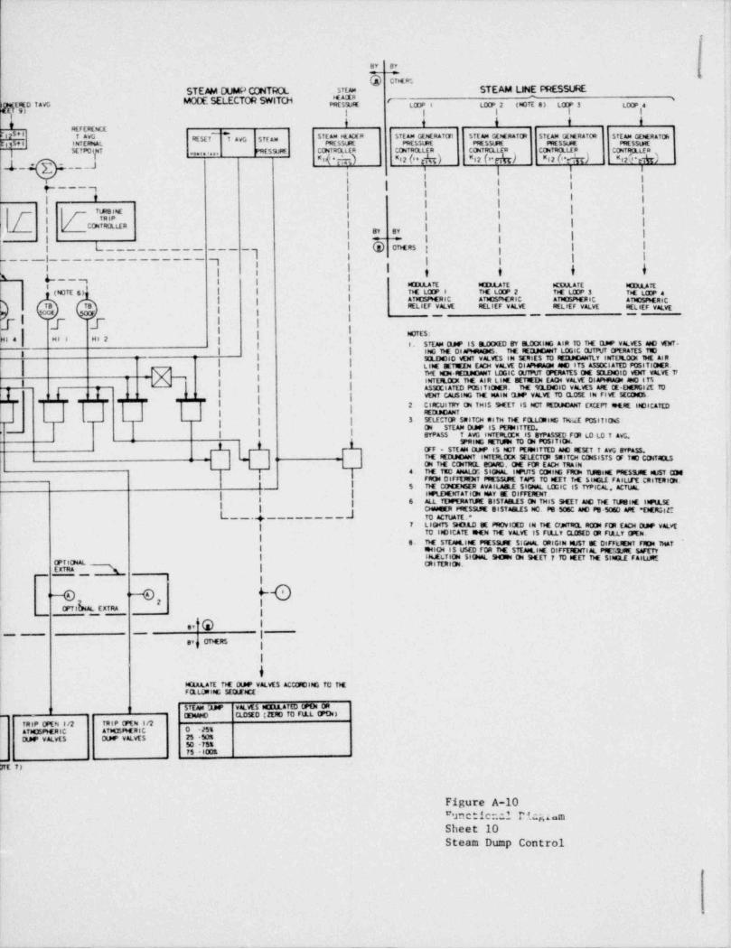
2.7 BLOCK OF STEAM DUMP
The steam dump control system is blocked in the event of a postulatedaccident which could result in cooldown of the primary system. Thesteam dump function is blocked by ESFAS. This prevents any additionalcooldown of primary system.
fhe dump system is not essential to the safe operation of the plant.
However, block of steam dump on lo-lo T,yg is a safety-related function.Steam dump is automatically blocked on lo-lo T,yg.
.
2-5
i

_
{
2.8 TRIP TURBINE AND FEEDWATER PUMPS
g A safety injection signal trips the turbine and feedwater pumps in order
I to prevent an excessive extraction of heat from the primary side.
When the feedwater pumps are tripped auxiliary feed provides for decayi heat removal and cooldown.
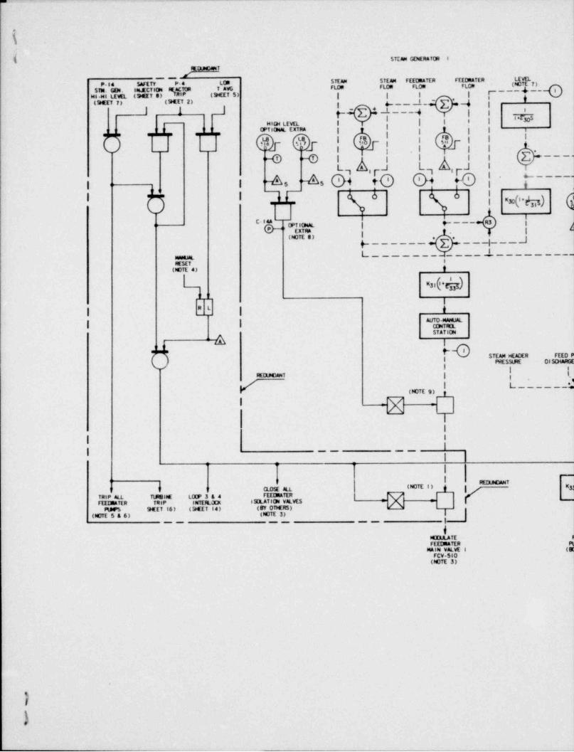
2.9 FEEDWATER ISOLATION
In the event of a secondary line break main feedwater is isolated to
prevent excessive cooldown of the system.
The feedwater isolation valves are closed automatically by any of the
following conditions:
1. safety injection signal
2 Hi-Hi water level in any steam generator
3' L"T if the reactor has been trippedavg-
2.10 START OF AUXILIARY FEEDWATER PUMPS
Auxiliary feedwater is provided as backup to the normal feedwater system
to ensure an adequate heat sink when the normal feedwater system is
unavailable. It can also provide an additional means for removing core
residual heat in the event of a loss-of-coolant accident for small breaks.
By removing the core heat through the steam generators, the pressure in
the reactor coolant system is correspondingly reduced.
Mbtor-driven auxiliary feedwater pumps are started automatically by the
ESF system on any of the 'following conditions:
2-6
.
E
- - _ _ _ _ . _ _ - - - -

-
1. safety injection signal
2. low-low water level in any steam generator
Turbine driven auxiliary feedwater pumps are started automatically byI the ESF system on any of the follotting conditions:|
1. low-low water level in the ap;ropriate number of steam generators2. undervoltage the ESF busses (time delayed 3 to 15 sec.)
2.11 OPEN ACCLHULATOR ISOLATION V/LVES ON P-ll
This function insures that the Accumulator Isolation Valves will be openduring pressurization of the Reactor Coolant System (RCS); however, theP-ll signal is not assumed for any accident. During power operation theAccumulator Isolation Valves are maintained in the open position. Nosafeguards equ'ipment is actuated by the P-11 signal since the SI functionwill also open (if closed) the Accunulator Isolation Valves.
.
1
2-7
.
. - - _ - , ,--

3.0 CONCLUSIONS
The Failure Mode and Effects Analysis qualitatively demonstrates thereliability of the Engineered Safety Features Actuation System (ESFAS)to perform its intended function. It shows that the ESFAS does indeedcomply with the Single Failure Criterion. No single failure was foundwhich could prevent the ESFAS from generating the proper actuation sig-nal on demand for an engineered safety feature. Failures are either inthe safe direction or a redundant channel or train insures the necessaryactuation capability.
Failures considered to be in the safe direction are not only those whichdo not interfere with generation of the proper actuation signal ondemand but also those which may cause an inadvertent actuation. Theef fect of all those f ailure modes where any single random failure in theESFAS causes an inadvertent actuation of an engineered safety feature (s)or plant control system are consequences that meet the acceptance cri-teria of RESAR-3S, Chapter 15.2, Condition II transients. This accep-tance criteria is that the consequences produce no fuel damage nor RCSoverpressurization. Therefore, it is concluded that such single randomfailures considered to be in the safe direction produce no adverseef fects on the Engineered Safety Features Actuation System (ESFAS) orthe safety of the plant.
: -,
*. ,
W @ -
i,
.O
e-
31~
_
.:..
|
h
. _ _ _ _ _ _ _ _ _ .
- - -_-

|
|
|
[! 4.0 CUIDE TO READING THE FMEA
This section describes the procedure used by Westinghouse to perform its 'FMEA on the ESFAS, as well as enabling the reader to understand the analysissections presented in Chapter 5. The RIEA may be performed with limiteddesign information because it is not primarily concerned with rate ofoccurrence or frequency of failure. The basic questions to be answeredby an EMEA are as follows:
1. How can each part credibily fail?2. What mechanisms might produce these modes of failure?3. What could the effects be if the failures did occur?4. Is the f ailure in the safe or unsafe direction?5. How is the f ailure detected?6. What inherent provisions are provided in the design to compensate
for the failure?
The form shown in Figure 17 is typical of that which can be used todocument an DfEA, however, other forms may be used. The form is notonly very helpful but also the very heart of the FMEA.
The columns on the FMEA work sheets are numbered (1) through (10) inclusive,.progressing lef t to right. The following paragraphs describe the contentof each column:
Column (1) "Line #"
This number is a convenient reference for guiding the reader in a logicalprogression through the FMEA. The digits preceeding the decimal pointidentify the basic function involved as follows :
1.XX = Safety Inj ection
2.XX = Steamline Isolation
4-1
!|?
_

,
,3.XX = Phase-A ($A) Isolation4.XX = Phase-B (4B) Isolation5.XX = Containment Ventilation Isolation
6.XX = Containment Spray
7.XX = Block of Steam Dump *
8.XX = Trip of Turbine and F/W Pumps *
9.XX = Feedwater (F/W) Isolation10.XX = Start of Auxiliary Feedwater Pumps11.XX = Auto opening of accumulator isolation valves above P-11
pressure setpoint*
(* = does not actuate safeguards equipment)
The digits af ter the decimal point are reference numbers for the basic
modules of hardware analyzed in the FMEA. All numbers are arranged so
that, for any line number. all inputs to that module have a lower reference
number. This is shown in Figure 1A. Figure 1A is a graphic depiction or" road map" showing how the 11 functions analyzed progress from sensorto the SSPS output cabinet. Figure 1 shows a disgram of the hardwarein the ESFAS also progressing from sensor to outputs. By insuring thatall inputs to a module have a lower line reference number, the readeris assured he has verified the effect of all input failures to that
module before he gets to the new module in question without duplicatingall shared modules. All summary diagrams (Figures 2 - 16) also contain
i the line reference number for the place in the work sheets where failureof that module is analyzed.
Column (2) " Summary Diagram (/"
This number refers to Figures 2 - 15 at the end of this section, wherethe module being analyzed is shown in summary schematic form. Diagrams
e
t
4-2r
t
i e
|
'
I

- - ___
2 - 7 are condensed versions of the Process Protection Set (analog)channels. Diagrams 8 - 16 are condensed versions of the Solid State
Protection System (digital) train s chematics. Figure 1 shows an overviewof the ESEAS system.
Column (3) " Component and Identification Tag #'s"
The first information in this column for a given line number identifies
the generic name of the module (s) being analyzed on that line #. The
grouping of numbers following the generic name are the module tag numbersused in the schematics. Refer to Table 2 for the abbreviations used.
Column (4) " Function"
This column gives a summary description of the function performed by themodule (s) listed in Column 3.
Column (5) " Failure Mode"
This column describos the possible failure modes of the modules listed
in Column 3.14
Column (6) " Failure Mechaaisms"
This column is coded to Table 1 at the end of this section. The codes |
are the most probable and most typical causes for the module to f ail jin the mode listed in Column 5. No attempt has been made to identifyevery possibic failure mechanism, since it is the failure mode that is
of prime importance in the analysis.
4-3
i 4
| I
!1ax.

Column (7) "Effect on System"
This column gives a short discussion on how the f ailure affects the
protection system. he reader will find it helpful to refer to the
Functional Diagrams listed in Appendix A, as well as to the summarydiagram listed in Column 2, to understand completely the affect of agiven f ailure on the system.
Column (8) " Method of Detection"
This column describes how the f ailure is detected. Periodic testing
refers to the 30-day periodic testing. Where failures are indicated
by other means, these are also listed.
,
Column (9) " Remarks"
This column lists other information considered by the analyst as pertinetitto the attalysis.
.
Column (10) "Go to "
This column assists the reader in identifying where the ouput of the modulebeing analyzed goes. For example line #1.30 lists in the "Go-to" column
! " lines 1.31 and 2.5". This means the output of the 2/2 logic circuit
analyzed in line 1.30 is used as an input to the logic circuit describedon line 1.31 and to the 1/2 logic circuit described on line 2.5. - Note
that in this example an S.I. signal (1.XX functien) is also being usedas an input to the Steamline Isolation (2.XX) function. Figure 1A again
provides a convenient " road map" for visualizing the various inter-connections between functions.
:,
}
!
|
| 4-4!
_ _ . . _____ _ __ _ - - _ _ _-_-_________ - _

_
|
' TABLE 1
TYPICAL FAILURE MECllANISMS |t
(C) Relay Contact Failures: f
C-1: Contacts fail mechanically in open positionC-2: Contacts fail mechanically in closed directionC-3: Contacts corrodedC-4: Contacts fused or shunted by parallel componentC-5: Series component open circuired
(D) Master Relay Driver Circuit Failures: *
D-1: Output diode to +48VDC shortedD-2: Output transistor openD-3: Driver transistor openD-4: Base resistor to driver transistor shortedD-5: Shorted base bias resistor on output transistorD-6: Input line open or shunted to +DCD-7: Reset line grounded (if reset option used)D-8: Output clamping diode shorted-
D-9: Output diode to +48vDC openD-10: Output or driver transistors openD-ll: Input gate diode ("0R" diode) openD-12: Driver transistor base input diode openD-13: Input line grounded
-
D-14: Reset switch open-circuited (if reset option used)
(L) Universal Logic Circuit Failures:
L-1: Test Inhibit Line (19, Ill, or I15) groundedL-2: Normal Inhibit Line (I8,110, or Il6) groundedL-3: Output series diode shortedL-4: Test Inhibit Line clamping diode shortedL-5: Normal Inhibit Line clamping diode shorted '
- L-6: Output gate failed highL-7: AND Extender line (A1, A4, or A6) groundedL-8: Output clamping diode shortedL-9: Output gate failed low
.
L-10: Loss of 15 or 48 volt power supplies.
L-ll: Inhibit Lines 18, I10, or 116 shunted to +DCL-12: Input to output gate high or open
CH) Latching Mechanism on Latching Relay Failures:M-1: Mechanism fails to holdM-2: Mechanism fails to release
|,
o
h-
;8584/1

.
/ TABLE 1 (Continued) ;
TYPICAL FAILURE MECllANISMSi
l
|"
(P) Process Protection Set Analog Modules: '
P-1: Output clamp shortsP-2: Output trancistor shortsP-3: Output transistor opensP-4: Output operational amplifier fails highP-5: Output operational amplifier fails lowP-6: Power supply fails ,
P-7: Output gate fails highP-8: Output gate fails lowP-9: Output bias tesistor shortsP-10: Base bias component on output transistor shortsP-11: Input to feedback amplifier shortedP-12: Diodes in operational amplifier output openP-13: Driver transistor shortsP-14: Emitter resistor in output transistor opensP-15: Bias failsP-16: Input amplifier failsP-17: Pulse-to-analog converter fails
,P-18: Setpoint fails
| P-19: Limiter failsI P-20: Characterizer fails.
,P-21: Up/down logic failsP-22: Counter failsP-23: Voltage-to-frequency converter failsP-24: Isolation failsP-25: Output series component opens
(R) Relay Actuation (or latching) Coil Failures:
R-1: Supply side of coil circuit shunted to power sourceR-2: Supply side of coil circuit shunted to ground or openR-3: Coil winding open, or coil shuntedR-4: Ground side of coil circuit shunted to supply or open
R-5: Ground side of coil circuit shunted to ground*
R-6: Loss of power source
(S) Associated Switch Failures:! S-1: Continuity Test Switch (S-604) open-circuited
S-2: Continuity Test Switch (S-604) shorted or shuntedS-3: Operate / Test Switch in " test" position or open-circuitedS-4: Relay Selector Switch wiper shorted to groundS-5: Manual Actuation Switch shorted or shunted to ground
| S-6: Latching relay " RESET" switch shorted to groundS-7: Spray Test Switch shorted or shunted to groundS-8: Channel (Comparator) Trip Switch open
!
S-9: Open Comparator Trip Switch Interlock| S-10: Relay Test Card Switch shorted or closedi S-11: Timer actuates prematurely| .
|
ap-8584/1

- - . . - - _ _ .
1
' TABLE 1 (Continued)TYPICAL FAILURE MEC11ANISMS j
?
|'
'(T) Transmitter Failures: r
T-1: Open Element' T-2: Open lead wire
T-3: Open cellT-4: Open output diode.T-5: Shorted output transistorT-6: Open output transisterT-7: Shorted output capacitorT-8: Shorted elementT-9: Low insulation resistance
(U) Relay Unlatching Coil Failures:
U-1: Supply side of unlatch coil shunted to power sourceU-2: Supply side of unlatch coil shunted to ground or openU-3: Unlatch coil winding open, or coil shuntedU-4: Grounding side of unlatch coil shunted to supply or openU-5: Grounding side of unlatch coil shunted to groundU-6: Reset line from Safeguards Test Cabinet groundedU-7: Loss of 118VAC supply
*
,
4
|
:8584/1

TABLE 2
SYMBOLS AND TERMINOLOGY
a, b, c- -
i
Contains Symbols and Terminology D scriptions
"J
O O Normally-closed stitch
Normally-open suitch
.
1

_ _ _ .
TABLE 3
SSPS UNIVERSAL LOGIC BOARD MODULES
a,b,c-
| Contains SSPS Universal Logic Board Modules Description
|
|
|

.
.
#TABLE 4
MASTER RELAY DRIVER CIRCUIT BOARD NUMBERS
i'
INPUT RESET LINE OUTPUT !
A SXXa 20 19 3 |i A 5XXb 18 13 4
i A SXXe 17 16 5*
A 5XXd 15 14 6
A 5XXe 31 30'
40A 5XXf 29 28 41
; A SXXg 25 23 42*
A SXXh 27 26 43
DIODE "0R" GATESA SXXj inputs = 7, 8, 9, 10, 11, 12 output = 1
32, 33, 34, 35 output = 36
A SXXk inputs = 37, 38 output = 39
.
.I
|i
I
[ .
| I
!|
e
I
|'
|
l
h8584/1
- - - - . _ . . -

-____ ___ ._ _ ______
_ _
Note: Figures 1 - 16 are considered Westinghouse Proprietary Class 2by notes a, b, c, f, and contain summary diagrams of the ESFsystems as listed below.
FIGURE TITLE''
1 Hardware Configuration
!
la ESFAS FMEA Line Number Reference
Diagram -
)
i
2 Process Protection Set Summary |
Diagram - Lo and Lo-Lo T ,yg1
Signals to ESFAS
3 . Process Protection Set Summary
Diagram-Pressurizer Low Pressure
Signal to ESFAS
.
4. Process Protection Set Summary Diagram *
Hi-1, Hi-2, and Hi-3 Containment
Pressure Signal to ESFAS
5.
Process Protection Set Summary,
Liagram - High Steam Line Flow|,
Signals to ESFAS
6 Process Protection Set Suecary
Diagram - Hi-Hi and Lo-Lo Steam -,
Generator Water Level Signals
7 Process Protection Set Summary.
,
Diagram - Low Steam Liue Pressure
and Differential Pressure_
,
d
|.'
t..
!
1 .,
1
|
| 1

, _ _ _ . .
.
e
\Note: Figures 1 - 16 are considered Westinghouse Proprietary Class 2
by notes a, b, c, f, and contain sumary diagrams of the ESFsystems as listed below.
i
FICURE TITLE,
8 SSPS Summary Diagram Start
- Auxiliary Feedwater Pumps J
9 SSPS Summary Diagram Feedwater
Control
10 SSPS Summary Diagram Low
Pressurizer Safety Injection
11 SSPS Summary Diagram Steam Line'
Differential Pressure Safety
Injectica.
*
.*
12 SSPS Sumary.Diagcan High Steam Line
Flow Coincident with Low S.L.
Pressure and Lo-Lo T,.
13 SSPS Sumary Diagram Hi-1 and Hi-2~ Containment Pressure
,
14 SSPS Summary Diagram Hi-3 Containment
Spray Containment Isolation Phase B.
15 SSPS Summary Diagram Safety Injection ,
("S" Signal) ,
"
- 16 SSPS Summary Diagram Containment
i Ventilation Isolation and Containmentl
Isolation Phase A.
d
..
- _ _____- - . - _ _ _______

i |
$ l
_
e. yo , .
.v ,-
N o. ; T sn
s ot Cs f .e o
*J __y .
r g
y- b ~.
s *d ke rr aa: t mpee eet e R
- rahPDS n
o yit ,
ce
- te
Df
. o *
dohte
M
y,
.
..
.
met -sy
S 'tn eo et hc se .f kf
SI
E r
t..
o . .SY -
* ts W .
M s .Aei* r n
S uu Eli MT
laht
L.' P
HF , l:
1 , a: ,
c4
M.
e ipd .
y_
o .
m M . Te '!.t ruA tF * .
7t
a 1,F
erugiF
_
_
_
-noitc
snuF
y,
t s_ f d 'lne_ R a_ 3 -
_ m t 4a n7.
r e. # g a .
a at- e i pn- cnD m eno ed- et ! I
eem,
rt
f m y8 .
eui rRF t
FT : mg.
.-
e.SS u uEIF Sh ~
g
p *er.i.'
..
. .

.!
}.
O
I
I
i
.
4 .
I
5.0 The FMEA
l,
.
I
,
I
i
|<
*,
I 5-1l
|
|
t
|,
t
L
- - - _ . .

. _ _ _ _ _ _ _ _ _ _ _ - -_ _ _ _ _ _ _ _
\ESF Reference #:
'
ESF Function:FAILl'RE MODE EFFECTSFunctional Diagram Ref:
Line Summary Jomponeat a ..d Function Failure Mode fallU# Diag. / Ident. Tag rd's !ccht'
(1) 2 733 77 3 fq3
|
1
This section contains the actual anal
considered Westinghouse Proprietary C
this format.
l
I
;
!i
|
|
| *
|
!
l
i
h
| | | | |i --
.I

- - - - _ _,I:
!
Prepared by: Westinghous-
ANALYSIS*
Date: .
Shce: 1 of fi
t
Effect on System Method of Detection Remarks Go To "a, b,I*
'IS7I t (73 (gi (9) (10) c, e,
's :2. - Sheets 1 of 48 to 48 of 48 are
ass-2. .All 48 sheets would appear in
//
.
|[
l
|
i
i
!
j!'
P
1 1 i.
e

_
#6.0 REFERENCES
-
,
1. IEEE-STD-352-1975: IEEE Cuide for General Princfr1.es of ReliabilityAnalysis of Nuclear Power Generating Station Protection Systems.
,
t
2. IEEE-STD-279-1971: IEEE Standard: Criteria For Protection Systems -
For Nuclear Power Generating Stations. f|
3. ANSI N41.2/IEEE-STD-379-1972: IEEE Trial - Use Guide for the Application '
of the Single - Failure Criterion to Nuclear Power Generating StationProtection Systems.
4. Westinghouse Electric' Corporation, !'A Guideline for the FMEA/FTA,"Westinghouse R&D Center, Churchill Borough, Pennsylvania, January, 1973.
5. Tashjian, .B. M., "The Failure Modes and Effects Analysis as a DesignTool for Nuclear Safety Systems," IEEE Transactions on Power Apparatusand Systens,' January / February 1975, Volume: PAS-94, Number 1, Page 97.
.
\4 -
,
|
t
[
|
| -
|
|
|
|
6-1-
;'
.
t
I 1
1

.
.
.,
9
||
li
]
|
I
Appendix A
Functional Diagrams
.
,
,
i
i
.
I
,
I
A-1*
|
|- _ _ _ _ _ _ _

lj i
t
LOGIC SWBOLS ADDITIONAL SYMOOLSSveen LOGIC FLpdCTIOe DE SCRIPTIOd
A MvsCE 54f CH PR0(RJCES Ms OUTNT#ENS'fueDv7 CHAPe(L 81STCSEN ANF Of IWT (OR sOE) EXISTS. -i
1 OUTPUT leOICATDR
$ NOTA MvlCE G41CH PRODUES AN OUTRif OLY elSTAHLE OUTPUT Im(N THE IWT DOES NOT ExtST. PARAMETER 15
OISTAILE QJ'PUTPARAMETER 45 LE. ,d , y .lSTA&E o,UT i' $
A DEvlCE etlCM Pul01LES AN QJTPUT OdLYg,gesfN EVERY INPUT ExlSTS SORpK
8w" Jala ir SA,(|ColNC100dCE A KvlCE #4804 PIO[1JCES AN QJ7PUT
V g2 QJ 3 94De M RIESCRIBED MaeER (OR #0PE) 0F imFUTSgog,T g EXIST (ERAprLE 2 |NPUTS peJSt LxlST FOR 27 *--- ION-INSTIU(NT SISTAILE53T '"'''''u'>-
le--- OUTPUT INDICATOR ($Ap( Cj
ADJUSTA8LE A MvtCE IBelO4 P900UGS AM (1)TRJT |4 Tis ( ELAT FELOlllNC A DEFiselft INTENTIDeAL TIME - N ApodLadCI ATOR ( ALAltti
DELAY AFTER RECElvlNG AN INPUT. g SLSSCRIPT SHARE A CDeON
A KvlCE #+104 RETAINS Trf COOITION OF ACTOR TRIP "FIRST CUY"0FF 5ETlFN OUTPUT CORMESPGoleO TO THE LAST ENER-8EIOpv GlIED ledi>T. EXCEPT UPON INTERRJPTION OF e TURBINE TRIP "FIRST GUY"
POIER IT ETLENS TO THE KF (DOITION.A KvlM milos RETAINS THE (DCITION OF OUTPUT y ~- polCATOR LAP'P(DIESPDOING TO TE LAST DsUrilZED INPUT (REGARLESS A- @ STATUS ,
E TENTi vE OF POER oNTURPflOe). IPGs INTENRPT104 (F PDRER.pg g3py (DolTIOe STATUS 15 MAINTAlt(C (BO ESET OCQJRS) AND T4 P-PESelS$1vE STATUS Lib
'SAME QJTPUT SIOeAL 65 RE-ESTAILIS(D leEN PouE.R 15ESTOEC. h CODFUTER INPUT
E T9sTIVE A ULylLE MAvap0 RETENTivt El(RY Asc LCGIC IP60meATIO4 TRANSMMDOPY ACTUATIOe SIG8eAL ELMK LCCIC FLNCTIONS ---- ANALJb 18dF0meATIOd TRAN5Ht RITM ACTUAThN AS 1601CATED BY T4 OIAGRAM BELOR.BLK81
NHRV ) 0 AfACTUATI'M SiOIAL (
* 'l- ANALOG l'OICATOR, RoR3-flEG)RDER 3 PIN, R8j
- ANALOG SLeeqER
" "GDeERAL NOTES- (FOR ALL SHETS)
1. IN ALL LOGIC CIRCulTS. THE 180lCATED"s
- TEXCEPT 540tE INDICATEC OTHEldll5E. C%I
.
MFINED 10 SE PESENT 4(N TT BISTA5
2. EXCEPT S*EM INCICATED OTHERRISE. THE|'mm m
HAS A TRPLICATE LOCATED IN A !EFARA'RLAfPS AE 80T EQJdOANT. MANLJAL (INT |RHERE LOGIC e 5 RE0uNOANT. ALL inj To 8CTH TRAINS (STERE LOG?C 15 REOUni
3. RMENEVER A PROCESS SIGNAL IS USEC!
| MUST BE PRCv10EG.A. TMi$ SET OF DR4 RINGS ILLilSTRATES
A,l,e,ALOG OUT,,J,_ . SYSTEM. INCL 101NG EhGil(ERED SAFEGUAR(m ,m aRr=AE n tEwNiari(N. ErER 20 =FlMTf CDeAL JI AW4Afd
1' EACTWI ruumIl38 SYSTDsLDG'C + 48eAdX; A MylCE EllCM PEFuelTS AN ANALCD Sih (9(ETS 1 TO 4 A.O g6 TO 17)
GATE TO PASS IN AM ISaA'ED CIRculf IF TT CDs. EACTOR (DNTROL SYSTEM'"NI ,- TROL LOGIC INPUT ExtSTS. ($4ETS 9 TC let 5. FOR A TIO LSelf PLANT:
AbiALOG TH15 SET OF DRARl88GS 1510DITICAL FT'OUTPUT M8EERS AQ) A '4" ERA 8PLE. IPB- A55E .
|I l
I. ,
I

___
I
!I
i
i
ii
DEVICE FUNCTK)N LETTERS AND NUMBERS |F8 FLOW ChmesEL ILS LEvtL Owe (L jNC tsJCLE AA Cheeses
I |PS PRESSURE Owe 4EL
i
AC RADI&FtCN Cheese I58 SPELO CHAPS 4EL
i a LOGIC *l* llHEN D( esE ASUREC 78 YEmRATURE Owe (L3 THAN THE SETPOINT VALUE. 28 POSITIOe CHWeeEL
20 ELECTRIC OPERATED WALVE& LOGIC *l* ie4N NE W ASUREONot TM SETP0 INT WALUE. 27 LDCERvCLTAG ELAy
A LOGlc *4* *(N THE 4 ASURED PAResETER 33 P05 it0N SWITCHNL'' MAL V1LC BY 880RE THAN ft( SETP0lNT meWNTS. SUFF I A LETTERi
As ARJVE EACEPT WITH AN AUTO 4ATecuy oc.co.ac.be . Limit SWITCHiTED SETP0fNT f c.to 70f0s SRITCHI'45 ASD E E ACEPT WITH flEQJIRED HV5 TEE 515 |
POSIfl0N SWITOt DEVEL& tests '
O FULL TRava |ec. oc
EllPLAll(0 A80VE) DO - 'Ohus
De THE SAfeE $HEET RITH THE SAME DC Eme4DeCIITCd CiastDI) o 805 M
b I CRII
(VALVE CLOSED) (valve &Ese)
NedLDdCl 4TR
52 AC CIRCUlf BREAMER
SUFFI A LETTER.5 T - TWIP STATUS LIG4TS.o AUAILIARY C04 TACT JPEN DEN NA'N CmTACTS AM CPDsIS, 8-SYPA55 STATUS LIGHT 5o AuulLi&RY CCNTACT - CLO5ED le(N pealN CDsTACTS AN OPENH IN CELL 5N1704 EOsED S(N WE ANG 15 IN TE MCTE
P051 TICss55'0"63 PRES 5URE SWITQ4
15540N 71 LEVEL SWITO+80 FLOP SWITTHat tDdDERFECLOdCY flELA'
dCOHOER. K2 - EC0f0ER 2 Poe,GIDRUE2 8 PolNT
c
lCTUATION CF A SYSTD4 OR DEVICE OCCURS INEfe A LLGIC 'l* SIGdAL 15 PRE 50eT.JIST AILES AE '0E ENERGilE TO ACTUATE" 5U04 THAT A LOGIC t SIGNAL 15E OUTPUT WLTAGE 15 0FF.0ULOWiNG 8 5 TEUE - ALL LDCIC CsROJITS AE RLDLDCANT THAT IS EvFRY trr.lc CIRCUlf Sp0RN INDEX
CA81; E T . ALL 81ST ARES. CIRCUlf BREaEERS. meADdCI ATORS. CDfUTER IWijT5 AND 19CICATORB15 Ch, NOT MA4 EDtJCANT ACTUATOR $. BUT 00 HAVE REDLDdCANT (IDdTACTS TI TLE 94 80 SLS5
DICITCl4 LAasPS. vsNUNCIATORS. AN0 COMPUTER INPUTS ARE CONNECTED T0 1*0EI AND SYDEICLS I I 5QA:t? ) 50 THAT A SI GN AL IN Elio(R TPAIN WILL ACTUATE. s( ACTue TRIP SIM5 2 5 7
FOR CONTack LNO 15 DERIVED FR0ss A PROTECTION Ce*ANNEL. 150L Atlomes>LLE Aft insTW. As0 anusuAL TWir 5tmALS 3 5 6
WE FuteC110N%L REDulREssENTS Or THE Rf ACTOR CONTF.0L AhD PROTECTION pe>f1 EAR INSTR l'E8|MI551wES As0 EL OCx5 A 6 7
h. THE J DIARINGS CD *0T llEPESENT ACTUAL MARONARE lefLEMENTATIOt. F0hIFCLLORING LIST PWineARv OI)Las? SYSTDs YRIP $19s4L5 5 6 7
j B.DCN OF RIRING OI A@ Ape PRE 55mifER TatP Sim4LS 6 5 6OftANsNG 8484EN3 405 dH85.1080032 MSSCa2, Il3Ev37 STEass GEilERATUI TRIP Sl(MALS 7 6 7
10FD5AO. 5655050. 5655058. II AE0lf. sAFEN ACTuATiGe stesAL5 e 6 7ORARifdG pa)EIERS: 10805A0. 271C320. 5655052.g 3 , , 7
STEAst CnDe COtT8K1 10 6 7JelT5 i AND 2 EACEPT FGI It( T AG NLDeERS. FOR (Delf i TAG PESSLP12Dr Pf(SSLPE 6 LEvfL CDdTRCL 11 6 7FOR LDelf 2 TAG NLDelERS ADO A "2*. E AAsftE : 2P8 455E.
PESSURIZER W ATER OTRa 12 6 7
FIEDRATER ODf710L 615CLAtl0M II O I
rEEONATER CUdTRM. 6 #5aATime la 6 7
AGAILlorY f tEDIATER PL8P5 SiedtTUP 15 A 5
ftseiNr fairs. sEDeACx5 6 ONER simALS i6 r a
LM)P STOP v&LVE #NYDILOCx5 ei 5 6
Figure A-1Functional DiagramSheet 11:'DF.E and Symbols
1

|
\ln
Ii
|SOURCE RANGE Rt AcioR TRIP NTERMEDATE RANGE ret 4 TOR TRP POwtR RA
" @, (_:r. TRIP
. '@ " @, =-.,, ' @, " (;T. I . .,,
(.:e.=, ' @, . =. (. = . (. ),+4,+-e e-e A-e es,em e-a 4-e e-a +-
y Z M M
.~.. .u.. . ~ . . . u ..
INTEft4DI ATE__
ELDCE CmML_ --
nsW" [-- tSamcE ness "*GE
70 B* ASS 70 sw&S5007f 5 I & 7)+-
4.R. RDD 5 ftPg a nog sipp(94ET 4) . i .3d .1--= + (SHEET 4) i.
HESET R.DCK R.DCK. .. _/g4
P6 P 10(9(ET 4) (9Ef T 4)
I f. ...
.;.b. . u. . __
P. 0 0.- (SCET 4) _.
b '$1m_RE r=x lC E Mu ,
wn .) i i,en .)
o . . i. . 0<-
g g (,em T) -(,em )
T.. - ,nSa# ICE AaNGE
M.v. (EDTH .A&8LOGIC TRAL $
$ $a m e se
D4 81G12E 10 SLDut .R. 800 .tSastCE MANGE M.V. TCP
(EIMR LOGIC NIN) (9fET 4)
1mig 4 8EUTIDs FLUll mig 4 DEUTf06 FLUX mig 4 NEUT50s FLUX
ftUlCT0lt TRIP IIEACTOR TRIP (LDI SE TPolNT), (9(17 2) (SEET 2) HEACTOR TRIPl (9(ET 2)
|
!t
,
1
|
|
!

7
CE REACTOR TRIP POWER RANGE HGH NEUTRON FLUX AATE REACTOR TAlp
|[ EmR a w
BLOCR (DNTROL 1 | | g
(NOTES a & 4, 3 gg
| |.- |""" l | | |
rs
eh uh ar$ g ,a |'
II i II e1
I3 l|
"
Im 42x im .3x i m 4. i.m einNaul i NaamL l iumus i NNaAL
M SE T IESET K5ET |P.10 sitsET g g imTE a> |(NOTE 6) t ecTE 6 > oeTE si p_twEy> L p__l p__ ,, _ _ _
' '",
I, I, H, H, E ,, E, E, E,. ..
' .J 1 J L I L I as LeiN 42K 43J gy gaj
%(IOTE T)
(NOT S)
A
$ $ $' '
' ' ' '
2 2 2 2
3 3 3 3
du. MANUAL TRIP SAAIN CONTROL BOARD)
g - - _ __..J_. .
_ . SET 1R P TR,P
.%
[C
B- thD-,A I I Ir
q.8 '
RESET E ACTGI TRIP mig 4 IEUTIOe
GH NEW ON FLUX | gg 9 7,,pg i 2) RA
"!WP' i;'' ( _ _ _J< -E T > >
' REIRACANT 8tAIAAL EOCx (DdTR$ cod $IST (F T110 CDdTES Od TW CONTIEL E)ARO FOR EACM RANGE,gee FOR CA04 TRAIN.
2. 1/N 33A 15 IN LOGIC TRalN A.t em 330 15 IN LOGIC TRAIN g.
,
3.1/N 344 IS IN LOGIC TRAIN A.| 8/N 348 l$ (N LOGtc TRAlt 8.
4. 9/M 4TA 15 IN LOGIC TRAIN A.1/N 479 l$ en 20GIC TRAlm 8.
S. TRO CONPUTER 186NTS ARE C08stECTED TO TMl1 CIRCulf , INDIVIOUAL FOR E ACM TRalN.6. NANUAL RE5ET CONTROLS CON $157 0F F0Ull NMNTART CDs TR0ts IN THE CONTROL A00m. ONE CONTROL
Fun EACM INSTRUtENT CHAgeqEL.7. TIC PE3 Del 5$lvt STATUS LtGMTS AE CDedECTE0 TO THIS CIRCulf, l@lv10UAL FOR EADe TRAIN.
i
i
Figure A-2Functional Diagram
| Sheet 2 ,
Reactor Trip Signals'
!
-

.. . .
.
.- -__
9
\'
Il
-
LOGIC TRAIN A REACTOR TRIP SIGNALS
[" S1JRCE RAfGE. HIG4 FLUX (INTEEDCMED BY P-6 & P 10)Mas 4JAL TRIP SIGs4L (SEET 3)
(NTDDEDI ATE RApCE. HIGH FLUX (INTULOOED BY P 10) gseGmune FLUX TRIP SIGeALS 1 HIG4 Flux. Lon SETPOINT (INTEEDOED BY P 10)-(SEET 3) POIER RAfCE NIGt FLUX, HIG4 SETPOINT
MIGH FLUX RATE
OvutTDFDtA1UE of EOvDFONFR af
[ LON FLON OR EACTOR (D(LAsti PW BEMERS (FEN IN ANY I 0F 4 LorP$ (INTEFLOOED BY P 8)" Las PRenAPr( LON FLON OR EACTOR (DCLANT PUF ONEAfERS (PEN IN ANY 2 0F 4 LorFS (INTEFLOQED sv P 7)TR S M t
CDOLMT FLOW
t)(ERvG.TAE (INTULOOED BY P-7) gGCERFEQJDeCY (INTEE00ED BY P 7) gHIGe PRES $URE E
PEsas12tR TRIP SienALS LDs PRESSUE (INTEEDOED BY P 7) g(SEET 6) wig, LEvtL (INTER.00E0 BY P 7) ESTEApe GDERATUI TRIP SIGeALS LDI FEIDpATER FL0n
(SEET 7) LOR-LOR STEM GDeERATOR RATER LEvtL
SAFETY :stJECTIGe $1GaAL (SEET s)( L0n AUTO STOP OIL PRESSJE m u STOP VALW3 N (INEEDOED p P 7)TUfelof TRIP SIGeAL (9(ET 16)
.
LOGIC TRAIN B REACTOR TRIP SIGNALS
(SDJRCE RANGE. HIG4 Flux (INTEE00ED BY P 6 & P 10)teANUAL TRY SIGaAL (SHEET 3) I
DEUTRGe FLUX TRIP $10eALS INTDtEDI ATE RANGE. HIG4 FLUX (INTEILOOE0 BY P 10)HIQ4 FLUX. L0s SETPOINT (INTULOOED BY P-10)i(9EET 3)
PON R RANGE HIG4 FLUX, HIGt SETPOINT
HlGi F111X RATE I5
#0VERfDFDIATUE AT IOW9| poser af
( LON FLON OR KACTOR C0(LMT PWF IIPEMERS (PDt IN ANY I 0F 4 LO(F5 (INTDLOOED BY P-8)P#
(.DR PRile,ARY.n SE T , LO. Fto. m - - P. .EA.ERS De l,. A.,, , 0, . uD,, (,NTm00ED .Y P.,, ,- 10tasGEp v(LTAGE (INTDLDOED BY P-7) g
tpGwfE(3JDsCY (INTULDOED BY P 7)~HIC 4 PfESSJE
R TRI Sim&$ LOP PESSJK (INTULOCKED BY P-7;
HIG4 LEWL (INTULOQED BY P 7) 5
,$TEme GDERATOR TRIP SIGedLS Lon FEE 0 MATER FLOW I(SHEET 7) LOR-LOW STEA04 ODERATOR WATER LEVEL
sArETY inuECTies St@A4. (9EET 8)TUReleE TRIP $19 eat (9(ET 16) L011 AUTD ST(P OIL PflESSufE OR ALL STOP VALVES CLOSED (INTER 00ED BY P-7,
.
I
, , , , , ;i i I I ' '' '
_
_ _
us i.ii
ROO OfMVE SUPPLY OBE LINE ORAGRAMm ano v AC as
M.S ET.
)um. ).MACTS TRsP,,
M-G ET EIN
flG) ORIWE 80sER RJPFLY ) S2M A )WWW&+
+
MD Iml1E P(M31 ma+( W TE 1)+ e
* E
8*
+ u+
LOG
7_nICTRArNA,'
m i ! E: s -N
.4(WTES I & 2) g -
Ok IC (SEET g)
: 6(WTE 4),
TO FETINATER, _ _g ISLAflDe LDGIC (9EIT 83)E a S2D (PEN
*a *
S2e CLDSED*t 5 k EACTOR TRIP $1(DEAL"*
2 $2H-IN (PERATE FOR TUIgif( TRIP (9(IT 16)2 d-a -
"i-1
I
--I_ i'
. 7-Mi
._
a e a $2H IN (PERATI .
h k k+g g s2= n osr0- zg T0 u ..
+,,, g
- ELODL LOGIC (SEET 8)e 2. m
{*
+ (WTE 4) /1 TO FEIDRATER,G IHLATime 6.0Glc (9(ET 13)
, - -. a (WES O 4 2) a
k . k.* P4
_ _E ACTOR TRIP SlipentV 5 - 52D (PDt _
_E* --
2 t-- - FOR TUROIIIE TRIP (SEIT is).
I.C. - -
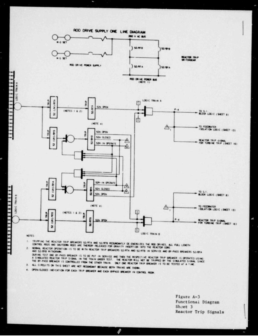
LOGIC TRAIN e* NOTES;.
l.
CDdTE fouS AfC 9tlTIDet FEDS ARE ME8Y fG. EASED FOR OtAvlTY INSERTIG( (NTO THE REACT 0ll C(NIE. TRIPPING THE EACTOR TRIP BREMERS 52/RTA As0 S2/RT8 REIUsosNTLY CE DERG12E5 TM FED UttvES. All FIA1 LDCTH.*
2.WfteAL MACTOR CPERAfl(N IS TO BE RtTH EACTOR TRIP SREMER5 52/RTA AND S2/RTS IN SElevlCE AND BT PAS $ OREAMIRS 52/87A
*AND 52/5YB R1fl(RAled.*
QJRING TEST ode BY PASS BREhER ($ TO BE PUT IN SERylCE AfC T14)# THE RESPECTIVE EACTOR TRIP liREMER IS (PERATED U$1NGA $lptLATED EACTOR TRIP Sl(DIAL IN THE TRAIN t.pGR TEST.THE BY. PASS OfqEAMER 15 CONTlu.LIO FlWN THE QMR TRAIN. M EACTGt alLL WT K TRIPPED BY THE StatLATED SIG6AL $198CE
30,Y ode REACTOR TRIP OREMER 15 TO BE TESTED AT A TitC.3.ALL CIR(litTS Of THIS $>EET AflE NOT E(pe0 ANT KCAUSE 80TH TRA1005 AE 9000t.
OPEN/(1.05ED IWICAfl0N FOR EAOI TRIP OEMER AND EA04 BVPA55 BREMER lat C(MTR(L ROGI.4.
.
Figure A-3
Functional DiagramSheet 3Reactor Trip Signals
L,

- _ _ _ . _ _ . _ _ _ _ _ _ _ _ _ _ _
.
\'
INTEFnEDIATE RANGEA, e
|r
|__ __ __ --
| |I
wf (.cn nngf IgI H@J I @ J _gI n,
g,.cf =asoA>a
Frp ta s.fX* LOGICo-@ O--{!] 'S p.,*r Fnm..e .l A, Ass36A
(wit u *(9(ET 3) (9(ET 3)
I i I
I. y; . .;a. . ; t-., .,
==(,on . )
__ -- --
Ve-6
(9(1T 3)|
'
(f',)I
4C8
Mlet efUTM)s FLUX e 59(BLOOt AUTtpenTIC a senseJAL G
W DemaanL) (9tEIT 9)_ __ __
!.cf =a.c a
3
|
|.
i
I'
s

T
PONER RANGE
l'
'@ " @f = "O = '@ "@ "@ '@I= f f f f f5/J 498 148 49A f Me egg
&e e s
I
I..s. = .u. ,g;j,"
'I
-- -- -- TmeiNE i.3 _I4P.1
eutsEOwom PasSuE
(STET 86)
|
M ", |
1
P hi <,
'' C i'
( g (SetET .6618) ( 3)FLC [lTHDRARAL) (SEET 9)
_ _
NOT KruCANT
I .c H NC M NC NcI I I f
&-Q &-@ &4 &-El
.
.L;j.
A'__
P-8(SHEET 5)
NOTES:
1. M 8vPASS SlOsALS AE NADE IP Irr ICANS OF TIC TletEE-PO$lfl0N $5170($ 06 A NISRAOL. SBitTDe l At 49A BYPASSES EIMR NC-41L OR NC 43L. SalTCH I Ae498 BYPASSESEIMR NC-42L (71 NC-44L.
2. THE TWO P 6 81STA8LES 90. NC 350 AfC NC 360 AE *DeERGlZED TO ACTUATE * SUDI THATA LOGIC 1 SIGeAL 15 DEFisED 10 IE PESENT se(N THE SISTAEE QJTPUT v0 TAGE 15 04-
Figure A 4nfunc.tional Diagram[Sheet 4
Nuclear Instr. Permissives 6 Blocks |t
rt

.
\l
)
LNDER,RE3;DeCY RCP.RJ$SESmutaz #Kr.8USSES
BJs i kJS , GUS 3 ajs 4 315 4 BUS 2 SJS 3 BUS 4
7 a T ,, ., ., .. .,
_ _1 1 L_1 _ _1 _ _1 _ _1 _ _1
(Rea_:R="atRtaCR .. ' OM., tRhu tg*" '' tRL% ti_ _
.< e s- m, &. &ep. & ,e ,,,
&4, &4, &4,&4, &4, &4, &4, & *
.bi. .L J.,,
($HEET 4)-- T
u{ },
'' "@_ _ _
_
By OMR$niTalP ' TRiliinip i
__ __ i
RCP 03- ,2RCPI (PCTE 3) - -,, -,a,
" " "sig, y 'IEE E'' 1EEr E'' | - - - -
,,un n.
|N NEI '03 Lon FL0n LO(P 1 L0n FLON LOOP , LOR FL0s LOOP 3
" '
m.1 @.1 @.1'@ "m.1 @.1 @.1'@ "y.1 @.1 @.1
"'@ " "
| & & e& && &&4,&4,&4, &4,&A&4, &4,&4,&4, G
.LJ. .LJ. .L J.% % %--
&4'--
&4'-- &-a
3 m E
_
''* ^> .1 .
__
"|En E''
\l
- - - -

I
wa.w c.u.;
( A [0) (LE404AG TED)
LOOP i LOOP 2 LGP 3 LOOP 4 LOOP 1 UI)P 2 LOOP 3 Loap a
!,, 'D,"@,'@,"D, 'D,"@,"@,"@,t ,, G, G, }, } },G, G, G ,,e-e-
3 3 3 3 4 4 4 4
.LI. .L J.*~
% KaH-a e-A
EACTOR TRIP EAC10R TRIP(SEET 2) NOT NGDOANT (SafET 2)
i
DVERTDSTR RJRE 1 OVERPOWER AT"
8Y ,, OTHERS (LEAD / LAG CDfTNSATED) (LEADAAG CDfENSATED), Trip LEP 1 LOIP 2 LOLP 3 00P 4 LOOP I OIP 2 LOOP 3 4
g g g.gxu
_
LCD FLOW LOCP 4 5 5 5 5 6 6 6 6
h;' -h, -_1p Lp,L y y
@ @U 0
.h , C3 C-4
2/ TO $ TART TURBipE RUNBAm AMJ BLDW AUTO-
/3 Matic AM) MANUAL f300 Rt THf31AAAL (9(ETS 9 416)
[L
]' LO LO TAVG Lou TAVG
' LGP I " LOOP 2 ' LOOP 4 " LOOP 2LOOP 3
O @1 @1 "@LUDP 3"@ LOOP 4@1 @1 "G1 "@s1 1 un. w w w
' '
11 11 || 11
tJ. .h J..- .
. a. . .-
X~ 'A--
.
*/ th( ET 4) (SHEET 5 T 410) E 13
NOTES.1. THE ETP0lNT OF THE LMERvnLTAGE RELAYS $>0ULO BE ACJUSTAILE KTMEN 60% APO 80s OF NOMINAL V(LTA2. SITH TE
-- A0JUSTA8LE Tief CELAY SET TO ITS MINIMLM VADE. T4 LpdCERVOLTAGE CETECTOR 9010 HAVE A Tid RESPWSE OF LESSTHAN 0.2 SECDC. THE A0JJ5 TABLE DELAY SOE.0 ALLOR AN AG)lTIChAL INTENTimAL DELAY KTEEN O TO 1.0 SECDC.
2 M SETFCINT Or THE LpOERFREQKNCY flELAYS 90LLO BE ACUU$TAILE KTEEN 54 Mr APO 59 Hz. WITH TK A03JSTAfLE| TipC CILAY El 70 ITS MINIIGI WALLE. TE LDOEliFREQUENCY DETECTOR SHOULO HAVE A TIME RESPSSE OF LE$$ THAN O.2| TM ACJUSTAEE DELAY 90ULD ALLO 4 AN A00lfimAL INTENTimAL KLAY BETWEEN O TO 0.5 SECDC.SECDNO.gacT0g m;>(9(ET 2) 3. TM MAAIO ALL0nA1E PCP GREAKER TRIP TitC DELAY 15 0.1 SECD40. 14 MAAIRM ALLOWAILE RCP OREAKER OPEN .
SimAL TIME ELA' is 0.1 SECDC.
Figure A-5
Functional DiagramSheet 5Pressurfzer Trip Signals
__

.. . . _ _ _ _ _ _ _ _ _ _ _ _ _ .
,
t. '
\..
PRES $URIZER LOW PRESSUREPRE 550Rf21tuerm CorossattD)
'@1 "@1 "@1 "@1 t@ ngp h h
*S, 64, ed, 64, &d, b' ' ' i ,
.L f.i
M-_ P-7 (9(I f .)'
. J.__
b,d"f"n'n'
FRESStHZER HIGH PESSURE
E'f E,f p,f p,3Os bds bds @d3
.k J._%_ qB
Od sani
U
SEET
PRESSURIZER HIGH MTER LEVEL
E'f @.f E,3bd. &d. &d. ,
.L .t .
MP.T yn .)--
. J.__
HEACTGt TRIP(SEET 2)
!. . _ . ..

Ss
,
1W ES MPRESSURIZER PRESSUAE 'mEssmiztR 5. i .
ILOCK CONT 80L |Q g (esNE 1) !v: .:.c I = gm a= _. ._ iM *N
& & g FIESET SLOCR-. .
,
2 2 hk_
L3EY M E (
. ...
kP. e l
b'. ; .i .
e(NOTE 2)
0(80TE 3)
. .l. .
__
1'
' IN.KCTIONEET 8)
!OTES :
8. THE REnsenNT IthMuAL OLDCM CGtTICL CDtSISTS OF TWO (XhTfl0LS 04 THECD-TRLL 00MO. DE FGI EAOt TilAIN.
2. TED COfUTER 88fUTS APE (DedECTED TD THis CIRQJIT, ifOlyl(LAL FQtEA04 TRAIN.
3. Tio POOsisSIVE STATUS LIG1TS ARE CD*ECTED TO THl3 CIRQJif, letviGJALFOR EACH TRAIN.
F'~ *e 8 6Functici 1 1%Sheet 6Pressurizer Trip signals
a

, , - - - - .
I\
STEAM GEERATOR,H14tl LEVEL,,,%,,,,,,
STIApe GEMaATOR I STEApe GosERATUI 2 STEast GENERATOR 3#
f f f f f f f f'' '
'(Om i LaaP Lorr s Lue 4
bu$ uc $u uN
*i i . 2 2 2 3uo I i
ssac ss 3s= s3ne 33ac ssac ssac ss=nWWW y y y- . - - __ _
&{ &+ &{ &4 N .,,_ y
rte 5 aUm'I STEAM GEERATOR ( *' ' 8'
LOW-LOW WATER LEVEL
'@f@f@I@EhLY@I@EbLE@d@EhLY "" 1LOF I 2 3 4T
:% Ais 0, .s,, %,, %,, %,, %%%&a%% @ is6 6FF6. ,0 &W ,, FF ,0
.ua. .u a. .ua .u e..
K K K K
.s . .L' L --
FM FM F ~-d FM
h3-
STEAMUNE ' " ' ' ' ''"djy"'' DIFFERENTIAL PRESSURE,
uIP [LD0P 2 LOOP 2-LOOP 4 UXP 2 s LOT -Lur s Lar LOT 4 LOOP s LOOP 4
@1@r @ r @1@r @ 1@r @1@r @1@rw%..+%..%.k>@a.7+%..%..%> ..%> ..%> ..>%.7+%..%+ 6 > ...
_
.L.. .L. .w. . . .l . !.
K 26 - K4,- K 'c'e- g:-'
. i. ,.w.. .u.. "....
EF;-A D-T,1 M ar-A
= .-i1
1a
_ _ _ _ _ _ - _ _ _ _ _ _ _ _ _ - _ - . _ _ _ _ _ _ _ _ _ _ _ _ _ _ _ _ _ _
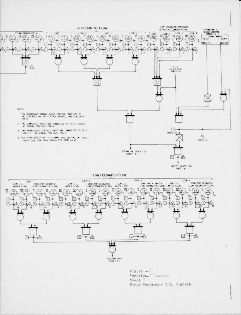
- _ _ _
!
S'EHI STEAMLINE FLOW (ty.o t[jt AN) sitm NE s. i .
T r L(AP i L(IJ' 2 LaF 3 LQfP 4 T r LOLF i etSTE AM GodRArap a
2@l@s"@)@)@)@)@d@)@)@2@l%e%"LMP 3@ "@& -
w w w w w w w w w w w w -- --
6 PAPA,&A&A&A&A&A&A&A&A&A&A&A&A&A !
5 g 6 6 7 7 e 8 9 19 9 9
.t t. Yx ( '
LO- 0 avg154ET S)
ai mm. .umu.
% %
as. .
NCTES
I T4 REDtJOANT MM8JAL BLOCR COvf R(L CCNSISTS OF '
" " "TRCIS ON T4 CCNTROL BCARD, OE FOR E ACM
2 in0 CDeUTER INS ARE CDe(CTED TO This CIRCulf-- ~~
I@lvtDUAL FOR FACH TRAIN
3. TNQ PEftel5SivE STATUS LIG4TS AN CDecECTED TO THIS b iC I ROJ l f , t@ivitLAL FOR E AOt TRAIN. (NOTE 2) 'P |
4. POSITIOe ETECit0415 ACCOfLISHED BT Yn0 SetTCHES(IN0lvlCb4L FOR E AOi TRAIN) PER STCP VALVE. (NOTE 3)
i,
STEARIT t$a.ATIOe(SHET 8) __
4,
8)
LOW FEEDWATER FLOW'
(gp g LO[P 2 LO(F 3 LMP 4f
SNF/ w mismATOs L0n s C. STWF/Far mitmATCH Los s G. stur/ Fir utSMATCHLE] 5.G STMF/rier utSMATO4 LOR 5. G. t
MATER LEVEL (LOR FEEimATER FLOR) MATER LEVEL (LGI FEEDilATER FLOR) MATER LEVEL (Lon FEEDitATER FLon) MATER LEVEL (L0n FEEDRATER FL0n)
~ Yh'hhe hi h' hhh@. h@, h i C p C i{ p ii, ,
i
A\&A&A&A&A&A&A&A&A&A&A&A&A&A&A&AT
la is s9 19 20 20 21 28 22 22 23 23 24 24 25 25
[
|
'
tt ,,t L .++ . .U. .
-A [D-T-A N F -A& -
M ACTGi TRIP'5dET 2)
Figure 4-7T,xnctiota ' 'tneruz
She et ?Steam Generator Trip Signals
q
,

-_
A
?
n
i
STEAM GEERATOR FHESSLJHZER CONTANMENT PRESSURE
[ E D N II'
a:Ge $ TEAM Liw rtOn NiO. STE AM Liw LD. P=5smiZER
STEAss List PRESSLAIE P455UNE g -f b6[I 9M 934 9?CD48eCl(Be7 ElTN LINI DiFFEIENTI AL g PnE55@E
(SetET 65 l C r
TEOR LO-LO TAW (5,g;T r)
SVP'D h, Q, @ i
+4,&4,&4S-a S-a e-a wI 2 2 2
a b d. ah mE.
Hl . )HI I
e-a|
b
h|teAaGJAL RESET P4 I '
AfC EOCR EACTOt TRIPth0TE g) (MET 2)
h<'
tg - 4- -
,
30-870 --
]i1.i, . .
O,,,-~ ( (. ,
;
i9 '
_
MartJAL Maps;AL
$TEastl#(flESET =
(DOTE g) a t $(LATIOs BY SY FEEONATER REACTOR AURELI AP /
I (TID (DiffELS) I SO.AY 10N TRIP FEE 0nar JI
|@(DOTE 14) OM (SM T 13) (MET 2) PMS
' @,|e I(SHEE T t$) 37"
|'
~ ~8V 0 71
m L0r I LEP 2 LatF 3 LGF 4 o
S E NE( $ NE $ E$ EIS(LATIOe ISELATIOe 15(LATIOe ISEL ATIOt
i
ramr n tete 3) (WTE 3) (POTE 3) J
L'
. . . ..
. o . . .o - . . .. i cu , o...o - i o . . .i >
L0tr I LGF 2 L3F 3 LfXr 4STEApLIE STEAstlE STEAfLIE $7EAfLIE
STUP $T[P $10P $1trVALVE WALVE VALVE VALVE
(acte 12 (tCTE 32 33tm (DCTE 12 35te (80TE 82
DOTES: '1. TID NOI(MTARY COeTROLS De M CDvTR(L ODARD. CPERATING EIMR COWTR[L WILL ACTUATE.
2. M seeftJAL SPRAY ACTUATIO4 COdSIST$ OF FQJit NO(NTARY CONTfl(LS. ACTUATIOe WILL OCClft OLY IF Tuo is, g$o m$ 3ASSOCI ATED CDeTRCLS Af( OPUtATED StatLTAf(OJSLY. 32 N$ M
3 04 CONTRCL PER LO(P De M COeTH(L 00ARD. afCICATE HEN4 COttales(NT PRESSIAIE Si$ TABLES FOR SPitAV ACTUATIDs ARE DElIGlZE TO ACTUATE LOMR sisTA8LES ARE BA. 74 ACTUATIO.
E D(RGIZE TO ACTJATEl- I$ LESS THAN T
$. De(L(BED CIRCulTRY 15 pc7 PART W M SAFEGuafos $YSTEM Asc t$ NOT llEDACANT, 98AY NOT EXCEE:
6 COEpDssT$ AfE ALL IIOlWl0UALLY SEALED IN (LATCHED), $0 THAT LOS$ & M ACTUATION $1GW WILL NOT 14. TWO COvifl0L$ 0CauSE MSE COf0(NTS TO RETLNBe TO M COCITIDs 84LD PRIOt TO TE ADVENT & TK ACTUATION SiOsAL. ,
T. SERvlCE #ATER $v57De ISCLAfl0N l$ U$ED OLY IF REGJIMED. 04JCLEAR ENERGY
8, M REGAOApeT seAf0AL IIESET COe51$t$ & in0 IO(NTARY COeTh$ O M CDeTII(L 004RD. Of FOR E ACH TRAIN. ggggg g9 SUPPLIED 8v OMR$.
{.
i,
N'- _---__ _. _ _ _ _ _ . _ _ _ _ - _ _ - _ _ _ _ _ _ _ - - _ _ _ _
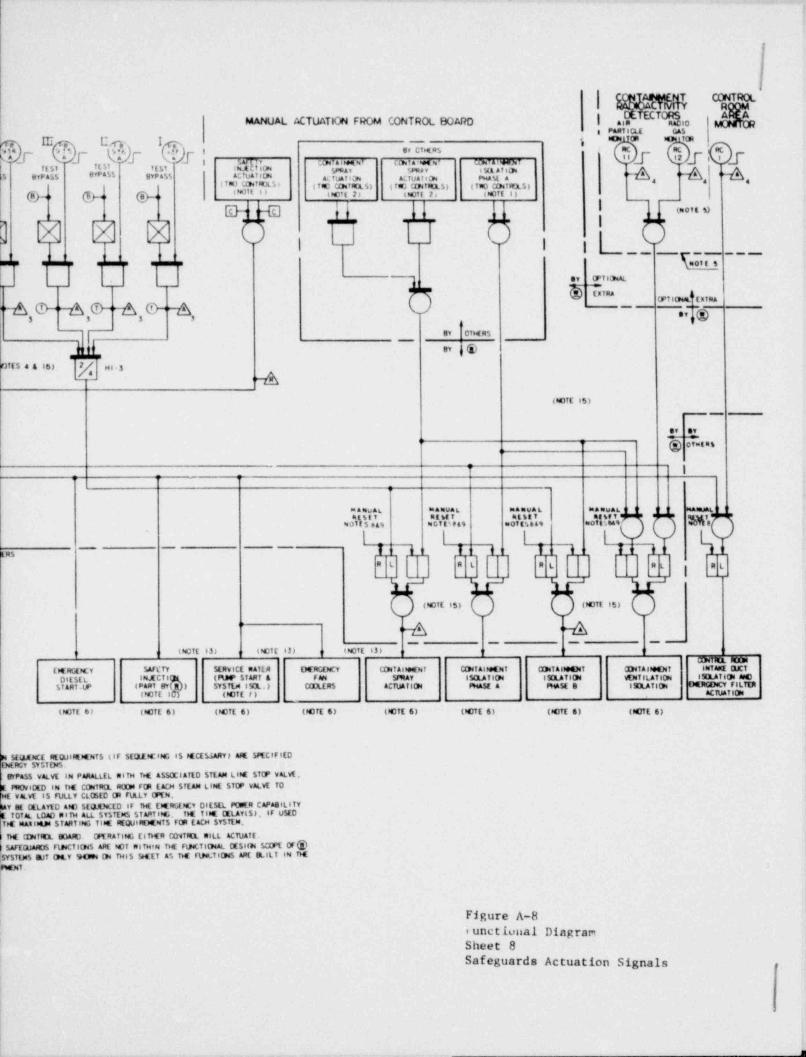
_ _ . _ _ _ _ _ _ _ _ _
f
i
|
| CONTROLR# #
MANUAL ACTUATION FROM CONTROL BOARD | migAime PARTICLE GAS
' * ' * '"E CoI , Xr
-i
WpgI t 8t CTHl#5 # 81C flC llcMa V, "J '' J NJJi s . ...1 . . . . , .A-
e "s afs$ OL My 3 -A,' 4*-A,IL ='Po= ='oli I,AI,L ( 1.A
A1 i i2u ,ro o n. Co.,oll
g g,g y , $) g gy,ro$)Wit it y, a ggg g y, , ,
I{D l| ,, , , ,(ao'E *)& ,
i
i_j
__ b. b-b b b b-. . .
i ,L,E $,. ._. ._. ._.
| .
g.. OP,,-
E.T. 4(FilDest' E R f ftA
4&4&d&%'., n.
$ 3 3 3 itw
SV OTHE RS_
. .eOTE$ 4 & 46) Hi-3
_1 .4(NOTE IS)
55@ Ofate$
l
asauvat manual mauvat manuati' i' ' i' enanmang '
NaNOT S eag enG T #At mofEst49 mot
i . I I_ l_tR$ L k_ 1j, 1 1; 11 1
R L R L ll L A L RL
(NOTE IS) (WTE I$)
' '
_ _ _ __ _
(NCTE 13) thCTE 13) l@TE 131GNTIE IEIBl
EtIncENtv SAFC TY $ERvlCE MATER ENRCDICY COeTaise(NT CDeTAlte(NT GBsTalteesi GDefalecost INTAslE (IJCT
DIE SE L INJECil (lue $fANT & F AN 5filAv 15(u iles 15ELAYl(De VDeflLATION 15DLATIGs age
$f AT.UP (Past pr( ) $YSTEs4 til[L.) CG)LER$ ACTUA tl@e f9th$t A PHASE 8 IXLAfl@e EMilGDICY FILTERACfuafl0Ntete I (WTE f )
_,
(NOTE 69 (NOTE 6) (@TE 6) (WTE 6) (CTE 6) (@TE 6) (80TE 6) (ICft 4) i
11
pe $E(ARNCE HE00tfEl(NT$ (IF $E31NCING l$ P(CE54 ART) AfE $PECIFIEDUsERG7 $Y$TDes.. Brea$$ YALVE IN PARALLEL RITH ft(. A$$MiafE0 $ TEAM Lips $7CP VALyt.
E PH0v10ED IN f>E CONTfla. NO[De FGI E ACM $fEAM LINE STOP WALtt TOHE Ylvt l$ FULLY CLO5ED DI FULLY CFEN,lav ft MLAYED tm $EGJDeCED IF M EDERGENCY OlESEL POWER CAPagtLITYE TOTAL LOAD Elfw At.L $v$7tu$ sf APfles. M Test MLAv($), 4F USEDM elantetse $ FARTING Tie ( flEQUtaDENT$ FWI E ACH $Y$ FEM.
I M GNTIEL SOAE. GTRATING EIMA C04TIEL a:LL ACTUATE.i $ATEQJam$ FU#CTIOs$ AflE NOT R4 Thin 7)( Ftps(.flO6AL (1$1Ge $M OF @
|$Y3TEJs1 RJT 04.Y 90se De TWi$ Se(ET AS M IUstflCDs$ ARE SLILT l's T)(Pt(NT.
Figure A-8
Iunctloual Diagram| Sheet 8
Safeguards Actuation Signals
I
i8

F'
\
(
C.s C-4 C-3 C- 2 C.
Wim PouER R y 4 P(MR RANGE EUTRoM TURB IN( 1888tLSE YAM y g4 gypagg g[af af (PouER INTLpee.D. Aft FLUE OwesEls CHApMR PEssisit LCOP 4 sesTCre (C(D4TR mg g,, ,gg
IML 6 ( E S) ( E s) (5HE 4) ( 4) hg pg p3 #4' (UTR
l i * * ' i i | | |AuCTIO4ER [ | |i b'
,h I i,
*.
( E~------ h___ _7_
h !E !b 8 | ,!'" ! !
i !| ) g
| L___'""_''_|__'"------I%T
(NOTE 2) |_ __ _ _ y d __<
, i i-
2i Innl i '
L___ g _____f_I. 74i __aI
.
__ __J_______l
| 4ib |g _ _ _ _ _ _._ 7_____
___________________j e.____
d.2 (NOTE 4) I.*a
1. _f Y~
To sit = To sTc=(ISP CDITE oLDP CoNTR
(3HEET to) (SHEET lo)m, ,
flac TR5o5 I"
I e4, o Posira _ __ _ _ ___
1"''' a' I eA,a c Posi te - - --- _ _ -
i BA#M B Pos.T IOd - __ __ _ _ _
, I sa,a a Posit a -- - __ _ _ _._ _
Irixco unti Roos ; a srtto
IN
Dem itset--
ANT FLLL LDeGN.R0o,FIEne G PoslT CDs
'-. -__ gh
e i t---O/a\s Roos =ALoc
a.N ouT = =co( st GNAL,
RA.L LENGN CD4TE BANKS
!
-- __ . - --

a
i
|
|
.TGI T (VG 1 Av3 Y avg AT AT 8vPA55 SELFCTOR AT AT Afdo) LCOP 2 LO[F 3 LCDP 4 LOW s SRI Tue (CDsT5El 80AIC) Lap 2 LOIP 3 L(DP 4'455]BvPas5 | | | *U'* kvPAS$ | BvP455 | SvPAb BT PA SS ] | Ie n]uxP . | 1 k0ar i | cop 2] tcop LOOP al | t s
,
t
| | | [ l I | fiI
I e i ib TO hi $ h ib hi |g. _ _ _ . __ _ _ _ __ _ _ __ _ _. - g ' __ _ _ __ _ _ _ __ _ _ e
-
t i l | I I I I I i i I i I 1 I'
:i 1 1
M. 18 i .} .'!.i I .!..! .5. . | .'E. .'
,, , ,
I I Ii i a iI | | [ & | A ] l | t |A &
! ] (ICTE S) (NOTE 5) 8 k(ICTE S) (NOTE S) \ITE 5) (NOTE S). _ __ _ __, _ l__ ( NOTE S) _ _,, ) L _ ___ _ _ _ AT AwfimR.__ r tvG ciimttR _ _ _ _ j_ _ _ __ _ _ __ _j. . _ . _ _ _ . , , ,
, ,
- - - - - L - - - - - - - ]I F - --- - - - L -~ ~ - - -'- - -'i - -- - - -~- - ~'J6 I I l
Ea |i
,__ __ _ i _ _ _ , _'' _ _t _ _- _ __ _T, _-- - l --7,r - -- - -r , __4
Ko IOTES:i
SIAS 8145 8845 81&5 1. ALL CIRCulT5 Od TH11 SHEET ARE NOT REDACANT.'-*]FRO CRE bTh5 As hNb5| || | ) ' L i R A. . . . H
g [. [ .j {. [ .j t. [ .jAT 30 TO S0g AND 60 70 005 TURB18E LOAD.t .[.jL ' 3. THE SusseER OUTPUTS MAWE FIIED se4NLA.LV AD U$TalLE WPER
r0 PNE55tRalE3 I I,, od DIRECT 10se alST ABLES NO. 58 412 A AND $8 4828 ARELESL C0eTRll | 1 | eENERGlZE TO ACTUATE *.I I l S. ALARBe t. ALAfte 2. ALAlte 3, AND ALAR 4 4 MJSY HAVE REFLASM(94ET II)
p ._ ___._ ____ p _ _ ,
|- ;_ - _ __4
,
I CAPAsitin.|
_ . - Re \ _ _ __ __ _. 4l I I ( ) | |
_ _._ _ _ _._ _J_ __ l_ ____l__ _t _|__1. ! t,. _. _ __ _ l __ __ __ I_. _ _ | _ _ I .4 I e i_________|___.4 I l~ i | | |l- ---i- - - -l-- J l I I I--
r--ii i i l I| |
g -l l 1 l g -l _| g - 1
r_-y r--4 r-_4 | F__,
d d's .$ .$ .) .) /.", *p .%
1 1 1& 'o45 5' A a
'o''Sh , a "o'' 5g, & A "*'t
, , .,LOR LO LO LOR L0 LO LOR LO -LO LDt LO.LD
BAret A BANK B BANK C BANK D
C.tl
I|
i
Figure A-9
Functional DiagramSheet 9Rod Control & Rod Blocka
L. . _ _ . _

_ _ _ ---
':
4''
i;.' 1 vp
e +\
- e.av av,
I ,,, ,,_, N $4"5
CONDENSER AMILABLE SIGNALS c.s T RErtENct rRms. _ _ _
I,P g Auc,CIRCULATIOe SATEq' TWNE IMPLLSE
(S$ttase (1r sanitHLOOL P 12 04asER PE514SE11CTOR 5RiTOe LO-LO CDCDsSER Pw rainin a inain g (WTE 4)
(No 4)l A PES $uR 581708 BEAIERS CLOSED i
(PcTE 3) '
'|I ! IGF Os DASS* 63 63 52e 2 ijIEsET iNTERLOCm g 1 1| u. 4. , , , em u r . __ _
i , ,
ir- 4 - - -. . .
(,crE 33 g 'W ~
|; -, m< , ,c
. 3. 4 ;-. .
'LE i__
l -- ,.@I m )-
ET DTH Rs
By,,@ j 'PflG4ALO
(~ ~ ~~~d " " _ '-
- - '
7. _ _ _I OI
(WTE 6), , PB PB TO Te Ti
suus 500 v.
| ["~ P (PT 3(>tALFIRST g, , g,, g, 3+
[b| [bjl ''u*I1
| | C-9 C-78 C-7A
'b { } ..i.l..,' b'1
',
.
g ~~ ~
-
. _ . ..
i __
l
i '
I us . ...
. 2.-- (,,,_
[ EXTRA , ,, ,
av "@i - -R.
_ __ __
I_ __
l
! I
'@ gy '@dI av
I' '
4, OTER$ BY 0TtER187 q
BLOC 8L STN.0LW OLOCK STN.DLW 70 SLOCN STN.DLW TRIP OPEN 4/2 TRIP (PD4 1/2TO 3 C00 Lupus ALL CDEN5ER TO AfteEMERIC CDEENGER COWEN5ER
1 COGN5ER (AW VALVE $ EXCEPT DLw wALvt5 DLW VALVES DJP VALVESi
|DLW VALVES Ytf 3 rrra m[ ESP VALVES
(1f LOTE t j (ICTE 1) (POTE t)-~
- , . - /,
l.
t
I
- - -_
ii
7
av ava>-+
@ CTeSTEAM DUMP CONTROL sit. STEAM LINE PRESSURE
gtgo iAVG g^p"eMODE SELECTOR SWITCH r '
(ecTE e), L iuxP,2 Lg 3 LOOP ,4
I i + 4 e i )REFERENCE
n sf.| ,,T m, eat ,,E sE ,-q A,, sTE A, sTEi.e . sTE- a*=Tm sTE. * * =T. sTE a =Tm sTE- a==Tv nER mssuRt PREsset mss.E mssin mssuE
PREsSURF CDeTRLER COeTR&LER CNT CDeTRa11R COeT p Rg $ETPolET "i@ M "i2 6+ h) "i2 (r ) "i2 6 mr) "itavkr). . . .
L E -- J,
; i i i,,
I i | 3'
! l | ! 3 it- - - ,ii * I
' i i ii Tm ief I i
| CONNLER l |I I
,, ,,
i i i lii _.
i i !t @ OraRsi L_________ ___
_] i ii____i______________ ,.i .i i i!
itL~]E 6)
i ,
I | NmluLATE teLLATE eGULATE BGLA.A ftg g(NOT | | TE LOCP | TE LOOP 2 TE LIDP 3 T4 LGIP A
| ATIOSPERIC ATt05f4CRIC AT1GPDERIC ATIO$MRICj gl T8 | RELIEF VALVE RELIEF WALVE RELfEF VALVE flELIEF VALVEw I i g _ _ -
| I I | |I
[ NOTES:Hj A Hf i Mt 2 | |
) s. STEAse aW 15 a.00 D BY m_00(ING AtR TO TE QW VALVES As0 vfMT-I | | ING M OtaPNitages. TE EmsesseT LOGIC OUTPUT (PERATES TIC
| SELDOIO WMT VALVES IN SERIES 10 IEnpOANTLY INTEILOOL 1ME AIR| | LinE ETEDs EACH VALVE DIAPlatsee age IT5 ASSOCIATED POSITIGER.|
_ | | M see-sEnsoANT LDGIC OUTPUT (PDt&TES DE SLEN010 VDfT VALVE Ti| INTE3 LEX TE AIR LipE BETEDs EAOe VAL %E DI APtcless AND tTS-
! | ASSDCIATED POSITIGER. 14 91D010 VALVES AfE m DEllG42E 10|_
} { | |VDiT CAU$lpeG TE STAIN QW VALVE 70 (LOSE IN FivE SECGCE.<
"'"'"| 2 CIRCulTRY De THl$ 9EET IS DCT REDLDOANT EXCEPT ieEIE ItCICATED' _ ' " -"'" "
| | 1 REDLBOANYIL
" T,_ _ _-
I | | 3 SEuCTCit SRITCH RIYM TtE F3.Laplac TNGit POSITICD.S-m sitAN ase is PEme TTED.
j i | BTPAs3 T AVG INTEnLau is syPasSED FCR LO LO Y AVG.SPRieIG fETufts TO Gs POSITICBe.
(FF - $ tease utse 15 80T PEltelTTED 480 #E$ET T AVG EvPASS..
{M unseANT iNTtRtoCm SEuCTm sa:TCn Cassists or Tic Conas
[ _L ON TIE COeTitCL 30AfD, OE FGI EADI TRAIN.4 TE TED AseALg; 51GBeAL lhPUTS (DelpG FID* TUlgieE PRESSJIE sUST (DG
i FIIGe OlFFERDiT PRESSUIE TAPS 70 seIT TrE $1NGLE FAILLFE CRITERIOt.i S M COODe5ER AVAILARI SIGeAL LKlC l$ TYPICAL ACTUAL,
4 lePLDENTATICDs te&T E CIFFEMNT.I 6 ALL TDPDIATUE St$TAE.E3 Ge THIS SEET AaC TE YtfelpE terLLSE j
L__.+| ____-J CHAFER PE55UE $l$ Tastes NO. Pe 506C As0 Pg 5000 APE * DER 3tz-'
TO ACTUATE.-i LIGHT 5 SDOLD E PROVIMD IN TE CrafTII(L RGBe FGI EACM Clse VALVEg
TO 180tCATE IDEN TE VALVE 15 FLA.LT (LINED Of FIALY (PEN.i S. TE STEAstleE PIE 53UE $1G#eAL ORIGIN 84J$7 GE DIFFUENT FIDS 1544T
| 88410e 15 USED FOR M $TEAstlef OlFFUENTI AL PIEMJIIE 5AFETYi
| tadLTIGe $tgetL See De SEET T TO EET TIE $1 NILE FAILURE(PTIO6AL OII TER IOs.EXTRA i
- -
i
"-O "-O____ _E XTRA 1
G'T l
@ l".,
|_ -
eq OMRs ,,1c'
1
iNanLATE M OL8F VALVES ACCUtlIG TO T1CFELOllitC $EChKBCE:
isrEAge ; ASP VALVE $ .eflfla AT(D OPDs OR
7 (BeAPO CLOSED (ZE110 TO FLLL (PDs).
' TOtP OPEN I/2 T11BP (PEls 1/2 .IC>TICSPERIC AT1GMRIC 0 251
|OLAP VALVES DLDP VALVES 2S +S04
i
50 755 '
TS -1005:
% f) ||
Figure A-10
"uncticr.cl Pica..mSheet 10Steam Dump Control
|
_ _ _ _ _ . - - - - . . - _ _ _ _ _ _ _ _ - - __

t
i
iPES $URIZER PRESSURE OtafedEl$
N m X I
+@ k L@ L@r___a-_____*_g__-_4' - - - - -__ . . . P.P.
, [ , _ _ i- _ _ _ 4 _ __ _ _4,sTAm.
i )_ _ _ _. _ %, i r- - + - - - - - i- _ - - , ai
{(______Tk666 | IQh|g g
: pes = 0.A,*t L _ _ _._ _- _ PEsSuKi | SELECTOR 5W134 KFERDCL
| (6 T)| | (NOTE 6) gp,p gg3g *I i i
5 . ( hs.r22s)| | | 2
i i F--- q@ +i ]
- - - _ t - - - - T-- vI iNTEa0CR | : i
(NOT 3) I(NOTE 3) g,OTE 3 (NOTE 3)!
B .N .N .N .Np |.y .;7 pg g ppu
di I'8 A a e
(WTE 8) (NOTE s) |1i,--
I,POER EllEF VALVE POER ELIEF WALVE PORER RELIEF WALVE |
upsTutt eGE CodTRCL ICOE CONTRG.tG E |iSELFCTOR SWITOE SEHCTGt SRITO4 SELECTOR SWITOs
3:g
(FEN AUTO CLOSE OPDs AUTO CLOSE OPEN AUTO CLOSE |I I
l ii i iI i
. . .f ..L;. . l . .t . ' seiE0 .ThAS AN OPTIONAL |
_ . . _ __ _ . _l* * * ^
i
b L 6 1,
'+ + + |'OPOe 1 CLOSE i 9PDd ' CLOSE |'
' Q.05E I OPEN i
P(MR ELIEF POER ELIEF POER EllEF i8
VALVE WALVE VALVE
PCV - 455A PCV-45EA PCV 4969 |
h(NDTE 46 (@TE 4) (POT (4)i
4)TES. TO %T N EXMA TURN.ON VARig1. ALL CIRCulT5 DI THl$ SEET ARE ICT REDJOANT. E Eal2. LOCAL CDsTIEL DWUIRIDEs ALL OMR $1GaALS.
LOCAL OWOWl10E ACTUATE 5 ALAfte IN CDITEL R(De.
3. PRESSIJIE Sl5TAdLES NO. PB-455E. PB.455G. PB-456E. PS.45ft. & P9 4508 (SHEET 12) (9E
Af0 LEVEL 81$TAILE5 NO. LB-459C. LB 459E. & LS-46G) AflE ENDIGtZE 10 ACTUATE.I 4. OPDe/SD4fT llelCATI@s IN (DfTML ftDI.
5. A LIGt7 9DA.D SE PIOVIDED IN THE CDITML fl004 FOR EA04 SPflAY VALVE T3 INDICATE RHEN THE VALVE IS NOT FLLLY CLOSED.6. ENTER #0517100 IOteALLY SELECTED.T. AlkAJSTAEE SETPOINT WITHIN CDf7MLLER8 ALAft8 i Ape ALAfte 2 84J5T HAWE KFLASH CAPASILITY.
\I.
v
c 1

,it
I,
,
i
, sSu,,u. uvu - Ls ,
,
I III IIauCumEEnEo T avo
'"E'' HD f@ f-OL z _ 7.,Le F. e =1 peg
( TE T) i ii i_ _ _ _ _ _ .L _ _ _ _ _.i _________
! ! p _ _ _ _ _ _ _ _ _ _ _ g+,_ _ _- _ _ _, i ,ifr_46 r -_ ; ,,
h 000 O00 0 OCOtT R LER g L
O'u _ - - --- C's|| (L REF. ) I
LEVEL OcAfedE.L SELE.CTOR $51T01i m ) ii
_ _ _ 7, _ _ _ .- - , e r __ _ _-- - - L -- - i r---4 o
, L____ ___________'r---I------------Ot-- c,r, r --- , i ! -
|/- j/- i i i l
o(. ,g ,4s),t i i i i
r--- % ,i(m.)' Ii,,,,, ; ,,,,, iI NN" | C0"' * E" I .i g $g, .i g oRirau.mT, ICEi, .ci
i, g 1 g <Avts aoSEoi -. -
,|
I I 2a '|
i i
I i i, (, ext .w, ,
uim, , u, ,mT.O. uim u. mnetI WALVE CCNTii[L v4LVE CO4TRe
| | [ SELECTOR $ WITCH SELECTOt SelTO4
I i __ __
l l I A Ctost mN ust mNi i i
.
,_ , . _..
.;
s s * ,.
L- g- :g- .g -I -- . ufo - aoro- umAu g ECD,,u a,,1 a,,1R
STOT ION $1 Afl0N STATIOe y,gygg(CONTfia RTM) {COtTR R[De) (COtTo RGDe) (NOTE 4)
-- --
1 I I
i l ii i auro N Nunt
| | CONTRSTATICN (NOTE 2)
g1. u. . L. .| |
=ca' >
I i i -- _-
To To.ottaTE maart mapai.
Tufte-Of M ATERSPRA7 v4LvE $RIAf VALVE FLDs
ALL INTERLOCK' O. 0 NO .2 C04T3E]L -
BAGGP (BLDCK ALLPCU-4558 PCv-455C M AIER5 ENCEPT LOCAL(NOTE S) (NOTE 5) (SHEET 12) (DeTRCL)
12) (SHEET 82)
'
'' CLOSE ' OPEN ' CLDSE 'CTNi
LETDDIB6 LIE LETCDIBe LIEISOLATIOG v4LVE (NOTE 4) II)LATIGe VALVE (fete 4)
L CV - 459 LCv mavalve sw watvE swOPEN CPOe
$iCaeAL 5iGNAL
:Fiture A-Il <
;ancti *.at i.tagram b
Sheet 11^
"
Pressarirer Pressure & Level Control i;
4r' i
'?
i
L
!>

_ _ _ _ _ _ _ _ _ _
|
tIceTE C3sT81[L $fATIOe REBOTE (Dein STATIOsFJi GIDF A 4ATER$ F;NI GIEP B 4 ATERS
(CDeTE MaJE)B (CDETR 304f0)(5ALECTOR sesToss tsaEC1UR 5etTCM)
i
3
er Auto me OrF AUTO os
A'JTDeATIC TATER TulW.LOm PESSUE MIGH LEVEL DEyl ATIONFROM P8AS$G FFD4 LSA89E(54E1 al) (SHEET 11) 1
| | |
. . J. .al.__ __
aumme aumum
_@ __ _
-av "
8v ,, OTMRS #4CTE 2) (NOTE 23LOCAL (DrTICL $1Af s0N LOC 4 CDeTIEL STATIOpeF31 GRP A EATERS pga giggp g eggTggs
(SELECTUt SWITD4) (SELECTOR $81700
lecTE LOCAL Of WF IUCTE LOCAL 04 WF
|(NUR SI
| (NOTE $)
I , 1. t it i i
u Emmu a e um a lumn a a a um u e
__ __ __ __
| |-- -. . . . ... .) M 2)
|GurA WERP & gunP g GfuP O
,IEATERS (RDTE 4) p(ATERS 1(A fER5 tecTE di MATERS
seTES:
t. ALL CIRCulTS De THl$ $417 AE ss(TT EGmosfef.2. GBP A AIO GERP S MATERS ItJST K 00 SEPAAATE WITAL POIER SJPPLIE$ EITH THE LOCAL (dst 4(L
SEPARATED E THAT Affy $4NG.E FAILL5E DK5 ICT (EFEAT WTH.
$. Tw sa85R OF BAGE.LP 1(ATER GGPS IS TYPICAL. Tit ACTuhl NLDSER OF GfGPS seAY DIFFER| MPD0181G Ge ELECTRICAL LDaOlBE HEGJtf00ff$.I A. SAGE-LP f(ATLR STATUS IlOICAfl0N IN CDeTIEIL RGM.! S. PRECAUTICDeS 9010 SE TastDe TO Av010 sessajAL 6(ATER (PERAtl0N, ilHIO4 UGAD CAUSE HEATER CAstAGE.
IF THE HATER LEVEL LAsGIVERS TM D(ATER$.
I
.

T
v&ha Aau te ATER REmoft CouTROL STAfl0h EWW CDsTR $YATIGsON 055 ST A T i(ps FCF G00.7 D et ATERS FOR GRQJP f s( AiERS(COST R g) ARC) (CouYR 80 ARC) (C0eTR BQh@)
(SELECTOR SelfCH) (SELECTOR 581TCM) ($ELEC1DR Self04)
Gi Os &F Auto Os (NOTE 3) GF AUTO Os
CDsTN5ATEDME1TER !NTEHLOCK PRE SSJE
L(p. LOR LEVEL FROB. OEvi&T104'Le 459C & L8 4600
($>(ET st) g
1|
I
j I L.".
1
i T T
3, ,
a u mu u n I ammme aRume
iO @ef'@ _ _ _ l _ . _ _ . _
ev
l~P 0TNGS P q OTEns3
|I
lIiiiiI (NOTE 3)I
il1
1
1
I
I
~'
t t iiat rues-Orr Tune.oe nsee-Orr m.m
vaRTRnsNear TuR= o.
CD QROLP O GR37 0 CKAP t (HMS EGROUP C (MAP CetiTG5 etafER$ St(BEAL 4 ATERS ME ATERS HEATER $ f(ATT t$
0 (@TC 4) (eCTE 4)
,
t
e
Fip.ure A-12
runctional Liagram I
Sheer 12 |Pressur;4ar Heater Controi
i
.
I'
_ _ _ _ _ _ _
- - - - - - -
ii . - - - .
_Td
L y ''P.14 SAFETY P- 4 La STEAas STEAM FEE 0 MATER FEEDRATER '
_"4FLD" FLO" FLO"
.s,i_n,. _ces. ( _cT io.N, R. Ton ( _i Avs,, --4-tu,T P , , , ,
4|(Mri T3 ( M ET , g _ _ _1_
I I d -
_ _ --4 | |pmfg 4 LEVEL | | | 8 |
j i i i- - - i .. .. . .....
i :p i i i
-- --
ggia ,1 I I I
4 '4 | i I | 1 E. ---'
L J L J i
| | ds ds @ O O O! f----
6 i u- s6 s6 | .<. . w ai
c-s - y _ _ - R,
,_ . ,r______ z. __ ___a.
L_______ ____L________c,,,,,,,oIRESET
(TOTE 4) {
l a i( 4ds
I ".1 I " IAuro A
| | (DdTR3.STATION
~
|D rtEodSTEAM HEAoER( | m ssuRE oisoupac
- i ! l't _ _ _ _ _ _;/ ,, ,,1
-gi
I
I
I il
|__ __
|
I
5I wt i> 1 i " *'"'aosE .Lt
TRIP ALL TLflBl8f L(XP 3 & 4 FEEDIATER
FIEWATER TRIP INTEfL.XM ISELATICDs VALVES : : -
Ptsr5 MET 16) (MIT I4) (BY OMR$)(NOTE $ & 6) (NOTE 3> T |:__ __ __
If(IRA. ATE F
N AL I (FCV SIO
(ICTE 3)
.
I
)
_ --

__ _,
t
p__-._._______.__________________________ ,$1EAN GOeERA1uR % g
IiSTEAN $TEAN FEEONATER FEE 0 MATER LEVEL |.
TURS MFLOR FLOH FLON FLOR (@TE T .
f | | | | I~-"k~~iMSEPESSURE g
i f; i p _ _ _ j p * _4 gii II 4 E*_|___q ..Ii
| NIGH LEVEL | | | | ' " 305,
!
| | CPfl@eAL EXTRA | | |
l !'[ f f | g
A, a|p i 4 t g _ _ _ __J-c) i A, a[i,.______,il | L e
!| 6 6 | )' '
9 | 14, | 3.F o a j 4.a ,' '
i i i yu d___ ___| C3 ___ g3,
_ . , iI 4_______- .g. __ _ | _ __ _Jl ______.1____________J_________l________ 3STEAN FLOR
(SHEET,14 ) g g
i'57.GD. s.3
| "3t ty|)ST. GEN.4,. .
_ r,__a ,1 og
h | AUTO-NAPAJAL
l CD4TfEL sOTES:
N7 | $TAflGI1. ANALOG GAR OSi$TS OF TW SEDelo VENT
i .t3 3s gI v4LvES IN SUllES TO K!UWANTLY INTER-
i h*- LO(X THE AIR LINE lETWEN EA04 VALVE| AOJU$1A8LE l j DI APHRAGI AfC ITS AS$11 ATED POSITIGW1.JNP AP AT NO
RESS. { LOAD SETP0lNT | | THE SILOdOID v4LVES AE DE ENDElIE 10.
vDef. CAU5ttG TE teAIN FEEDRATUI VALVE 4t
! ! TO CLOSE th FivE SEC380$. 5
)* I fI 2. Al CIRCUlTS De THl$ SDEIT ARE NOTE,-j 1 EDUIOANT. EXCEPT ID4ERE IWICATED jI g,cyg gyRE!UOANT* .
g3 (PDB/94UT IfOlCATIGi FOR EA04 FEE 0nATE4--_-o.
! VALVE IN ODdifEL fEDt.g
| | 4. THE KdDOANT tiefdukL RESET (DestSTS Org Tuo DOGITARY EDeffELS 01 THE CDITTELj gI 80AfD. GE FOR EAOt TRAIN.
| | REulDOANT S. TRIPPING OF FEDRATER PUF$ CAUSESl CLOSURE Gr ASSOCI ATED PUF OlSOtARGE
g | (- -- vAtvEs.i, 6. THE FEEORATER PWPS A80 PtDP DISOtARIE| VALVES AE SUPPLIED BY 01ERS.I I;o
8g | | | T. TK STEast GMRATOP LEVEL SletAL OPIGIN
C,,h/I (NOTE 1) 4 04JST BE OlFFERDiT FIDI THAT 19410415 USED
| ON 94EET T FON THE LOW FEE 0nATER FLon| |- REACTOR TRIP.
a-
| :
l 8 TE leGd REDAIDANT COdTRL1 GRADE 2/2
FMi | T LivCL valve Ovouliot is sJPPLic evh194as
| AN 0Prio AL EXTRA.v ii __ __
| f f 9 ANALOG GATE CDestSTS OF Old SILEN000 401T
EEORATEis (SEET 14)' NinLATE VALVE 70 INTE1 LOCK THE AIR LisE ETEEN
y SPEED FEE 0nATER EACH VALVE DI APNRAG4 ADO 11$ ASSOCI ATED
TH PWP5) DIAIN VEVE 2 POSITIOeER. TE TLDO10 v4Lvt 15 K-FCV-520 ENERGilE 70 VDsT. CAU5tNG TI( NAIN FEEO-
(NOTE 3) RATER VALVE 10 Q.0SE IN FivE $ECOOS.
Figure a-13Functional Diagram .
'
Sheet 13Feedwater Control & Isolation ;
I
6

iT STEAM GDeERATOR 3
STEAas STEAM FEEDnATER FEEDnATER LI G~
FLON FLOW FLOR FLOR (T d)y3gg
INTDLEK | | | | f ei g___g_ g 4 ;is,*ET isi
t-OE *_l-_--4 i i |
I I I i '' % S (4nim tem Yi | | | g jOPTIMAL EXTRA
@r @r Sri | 5 | | '.i ii i
i i , i z _______-4 i4J Li b, 3 r 3
d3r6..
, ,Li I
f O4 ib i f~ ~ldT OfdT ''
11- %6 %6 I %es) #tr
'fggy | h---as A<
. 1E . , i . .
, 7_______ r : _ _ _1p_.___________J
, ,
l i 4
| ,3, (, . D)To rEEo rER rrue srEEo c33s
CONTFCL(SKET II) g
6
AUTO-MANUAL(XNTFELSTATIM
alDE RANGE LEK|<
-STM. gds .1 STM. GEN.2
8 |
| k-e F-e1 | ,..=T,3 | ,,st,c' (- >
-g t _ +_ _a,
I_T
L_ _ _ _ .- _
I l
I |1
cuan is i=Z -
1__ _ -_
REIuomi_mFEEDRATER
< 2 >>
%
}

p____._______._______________._________,Ii STEAM GENERATOR 4I
IST' CAM STEaN FEEDmATER FEECRATER LEVEL ! i
g '(NOTg 4) |F.Dn FLon FLou F60s ,--- r, --ei i :
t . E . .ii i iw i i _ __ _i_ r 4 i
i i-i,--- -iSiG AL I i i,
1.r 5 [RaN SHE,ET 15 3| .Mi _G+ LEvE.L i,; i g 3o .
Tl TRA , ,, , ,
| I @s @s | t. | | <!. | | . |!
__ t - _ _; i ; t _____a4 i ,44. 0,1.c ,
.
d.c.
L J L J i
1 to Of to j |--- n47I 6 6 | 1
i 30( g) L.,,
lJ. .C. 0 _ - ,
&w !, t-- - "' | A,,em 5,
-'--- Jr __--_-- E..
___Jp_ _ __ ,t 6
TD FEEDe&TER I -PLDP FEED R31 l*f 3SICDiffDL(SEET 13) g
I NOTES:
5. ANALOG GATE CDeSISTS CF filo SOLEN 010 vDeT VALVES INSERIES TO KDL3eANTLY INTDLOCK TE AIR LIESTAf l0N BETKEN EAQ4 VALVE DI AMelAse Apo ITS ASSCCI ATED
| PO5ITIOER. THE SCLDOID v4LvES AE DE DIERGlZET3 VDET, CAUSING M ItalN FEEORATER VALVE TO ELOSE$- t., asApotts l IN FivE SECDdOS.
[ I 2. ALL CIROJITS 04 THIS SHLET ARE NOT REDACANT,STM.GOs.3 STM. gds..
| EXCEPT IDtERE l@lCATED "RE3JNDANT".g g 3. CFDt/94UT IPOICATIO4 FOR EA04 FEEONATER VALVEI | | IN COtT70. R(Dt.
, g y gTE STEAN GDdERA10R LEVEL SIGaAL ORIGIN 04J57 BC4
(NOTE 6) ! OlFFEENT FRG4 THAT 194104 85 USED 04 SEET T FOR Ti( )|| AUX. | AUX. 1 L0n FEEDRATER FLON REACTOR TRIP. i
F.P. STAtl@d4 | F.P. STATIO4 |L-- -j -
5 TE tod-MDAOANT C3dTR(L 2/2 NIG4 LEvu.vAtvt OvERRioE is amiED of AS AN CPTim.AL
I EXTRA.
| 6 ANALOG GATE C3eSISTS OF 04E SCLDeciD VDsT v4LVE 70pm7 INTEfLOOL TM AIR LINE BETWEEN EA04 VALVE DI AnelAGe
s ,
g AND ITS ASSOCf ATED POSIT 10NEP. THE SOLEsdOBO WALVE 15-- -~~
CE-DERGl2E TCt VENT. CAUSING T4 MAIN FEENIATER WALVEI | TO ctOSE iN rivt StCON05.I
I |(NOTE 1) i
Ts- _----
REasoANT[ IMCK11. ATEFEEDRATER
MAIN VALVE 4rCv.s40
(NOTE 3)
j
Figure A-14l|Functional Diagram
Sheet 14 1
iFeedwater Control & Isolationj
i*
|
|
| |
l ,
*l
_ -. ._ . . . .
.
;

-
__
i
$7EAM ENERATOR I STEAM GEMRATOR 2SarETY (MJECTION 2/3 Lon ton LEVEL. 2'3 Lon Lon LivEL
SiCMAL( 9(1T 3 ) ($HEIT f) (SHEET T)
-
Y u
._- __
qi NWTRIP OF MAIN FEED Ptses
FP. I FP-2
ELAG-QJT g gsiesAL
U __
'
C.- , _ ,
x__
_ .1.COeTMIL RGJM
(NOTE T)
MANUAL G)NTALM $ TART, GMTfEL fEDI (#OTE s)
LOCALsenNUAL START, LOCAL (DOTES 2,3 & 3 )
( ATES 2 & T )stN4JAL STCP, QMTpp. RODI (NDTES 4 & g)enemuda. STOP, LOCAL (NOTES 2,3 4 8)
hMOTOR ORlWEN
i in'-4 Aux, F(v.D pue""" ''" ' FEED SysTDe VALVES
(N0tE $)
___
STOP , START
(WTES to a II)
AM. FEED PL8FSt&2
(NOTES I & g)
||
|
'
(
._ . . __

--. .. .. .. . . .
.
. . .
'
|
1*
,
I
k.
*5TE AM EMRATup 3 STtAre r4NiRATOR A LOSS Or PonER sichAL2/3 LOR Lint LEvlt 2/3 lot Los LtvEL (2/A (M:tRviLTAcE a
(5HEET T) (MIT T) (5HEET Sn,
>
.t a.37015
-- SE COOS
" Iav @ pr @8v , OTHERS BY , OTHERS,
*
MANUAL START.CDsTIEL H00MBY OTHERS MnNuaL $f ART, LOCAL (NOTES 2 4 3)
6E i. MAleJAL STOP,OTIKL REM (eOTE A)
M488JAL STF, LOCAL (NOTE 2 4 3)- - - ==
% (DeTRll MANUAL CDeffl0L
CDeTROL filDe
(NOTE T J COdifl(L 500M
g NOTES:
I l. TRAIN A COeff0L$ MAFP t : SEAfER IOGERMANUAL (X)MTR(L MANUAL COeTil(L TRAIN g (DNTFE15 MAFP 2. WEAKER #UER
LOCAL LOCAL 2. LOCAL CDeffEL OWERal0ES ALL OTHER $1GMhLS.
(NOTES 2 & T) (DOTE 9) (NOTE 2) 3. LOCAL OvatR10E ACTUATE 5 ALAfee IN (DeT50L RDOM.A. MApeJAL STP AND PLA.L OvtRRICES TM AUTDeATIC $ FART.
I teAMJAL STP OVLflR10E ACTUATE $ ALAfee IN CDITIEL 140130.
M 5 TEN /94ff IBOICATION IN CDdTHDL R(De
f LOCAL 6 PWIP OPERATING LIQif$ IN (IINTROL HODSTURBINE ORivtN C R.AUX. FEED R.BF 1M '4' T. 180lVl0JAL FOR EACM VALVE.
( E5 9 NE SPE CGd IE3.15 TYPICAL. ACTUAL ||MPLDOITATIOe seAY NOT tesCLLEE STED CQeTfEL,
i
10. THE PGP START MAY 8C DELATED AfC 5EEDeCED IF i
TM EMERENCY DIESEL POER CAPA81LITY 15 LIS$ ,
-- -- THAN THE TOTAL LDAD RITH ALL SY5TDes $74RTING. I
TM TIIE DELAY. IF USED, teAY 107 EXEED Tl4 |beAIltUs $TARTjNC TIeE 8EQ)lRDelT5 FWt THIS '
sv5fmstat ' sTOP11, TM PLMP $ TART BtJST RE SEALED IN (LATOED). $0(IdOTE 11)
THAT,L,O,S$ OF TM,, ACTUATime slGsAL RILL eOT CAUSEitesi E mivEN rwc To 37Aux. FEE.D Pur ,
(DOTE 6) I
a0sE eu=x=.ISOLATIGI Af0 SME
LINE VALVESFGI ALL $ TEAM GO(RATORS
Figure A-15Functional DiagramSheet 15,
Auxiliary Feedwater Pumps Startup
i
_ _ ._ _ _ _ _ _ _

- - - . ~ . - , .,
8
I
IP4 STtase .NERATOR $T1888 GDdRATOR P.4
IEACTOR 1RsP Mt HI LEWEL OR $. I . NI M6 LEWEL OR S.I . MACTOR TRIP ~
(TRAIN 3)(5HET 63) (train A)($ stet 13) (TRalM A)(51tET 2) ;
''h (*Raim g)(SEET 2) h @BY1 SY
SY ,, 0Tw115 ,, OTERS (20/AST ) |BYI
#(dERATOR TRIPEt1MOANT |
E M 0 C. PrmR FA.cJat g J
|MAMb4L T171EINE TRIP 8 | |C0(EMSER WACCIAM
TYPICAL
RHlid P40ftCT10N T171814 KARIE OIL i>
TRIPS (( A3 AQJaED ev OTHR$) |
MMED |m ig m gKARIE F&lLUE
TWluST BE ARiW F AILUE
|63 alAraAAL Trip ( AT Tunel(,
[ ,0TER $lt#iALS l5
.|| i i
( n .) .' ,..auf0 51tFOtt PilESSJE gyp i
INTULODI |
|AUTO STP -
[ ''
BY OTHE RS |_
BY BYQ g8 e*(20ATOw o''' | 0xRs O
sTe , iEMRENCY = |
'TRIP FLul0 |
r- + - ,}. . . .
'__ '' E hw Im ;"
COBml(L EdAT sty itMilE63 63 O
EIE71LAfCY v4LWts STP v4LWE$(613) -- *
Trip Fluto
1 and_ _
l CousE ICt0sE - - --
E,& E.& &- E- E',,,,, Ra P. C.Tm. e,pp,p,p,p, pv4Las ==ws ,,
k k k k k & k-1, - -
33 SE(XBD5 .,
f .h h. . L .i."*"' "''yj| X l
i T T i. . . .PROTECT 13e
' ', '
SIGNAL 5(IY @dNI
9.T(Se(ET 4) ,h',,
.IorwR5 | - A I
C.0
|e i
FAST TO 70 IIEACTOR TRIP 70454ET 2) STEAse OLAPplL I ARY (iEMRATOR N
Ous TRIP g g 10)TRAse4R ,__
m, f(=Tt el
.
t
| \,
* _ _ _ _ _ _ _ _ _ _ _ _ _ . _ _ _ _ -

A
T U RBINE POWE R eTE5(rweiw HeutsE C>.aR PE55mE )f. TESE SIGeal 51801CATE TM CLO5INL Of TW SW VALVES. P05Bil0N-
' OETECTION 15 6 19(0 BY TIC CDeTACT5 PER STP VALVE, Ge.FORrE ACH TRAIN. M L(XilC 90EDd 15 FOR FCUR ST@ valves.. __
* 2 EIGPT IS(E ItOICATED OTERRISE. RES.pcaleCY 15 It04CATED IN 1(GAllDST. HT0 f *AJCLE AR DIERGY SYSTEMS 8|E@iff t(NT5 GLv.
5 OPEN'9tJT INDICATICDs IN CCBtTML RCD 4 FOR EACH Sir vatvtN0f REWahT 4 THE IIDdOTE DISPATCHtNG 15 TYPICAL . AC*ML ttfLD(hTAflG4 IIAY DCT
[ [ test.10E EIOTE DISPATCHING.5 GDERATGt toTORING PICTECTICDs 9010807 EFEAT T>( THIRTY SECDC 00 Av. |
| e 36 T4 KACTGt CD[LANT PUDP SJS TitAplSFER SOLD SE QBe'LETED RITHIN 545 '
I s CYCLES iN GraR 70 INSIE COFATiglLITY RITH THE tDCERFRE3JDety TRsP |
| i IOF THE MACTOR C01Assi Ptar CIROJIT BEAKERS. M Tilade 9ER TittL:Nii teAY BE EITENTO aNOTHER 4 CYCLES TO A TOTAL or e0T GIEATER THAM80 CTCLES,IF T)( SYSTD6 OYteaselCS ARE SULJ4 THAT A fl7 (RIP 00L5 NOTOCCUR. Tit 10 CYCLE LsNIT 15 FGt PLee ecTCP Pi40TECTime.
T. @STEaN TUR81st Devl510e EWIRES T4 THIRTY $ECOND file KLAY TO BEEDLD0aMT . CDs tiber 55 CDesECTED TO THE TRAIN A OUTPUT OF THEPROTECTIGd LOGIC SYSTDG aNO Tit OTHER titer 15 CDe(CTkD TO TW TRAIN 5OUTPUT. M TINER CU1 PUTS AE RIED SO THAT EITER RILL actuate A
h' GD(RATOR TillP.4 THE *aNO" LOGIC A80 Tbf ASSOCI ATED PESSUE 5R170($ (63/TB AND 63/AST)
P-11 C-5 peJST BE YESTED PERICOICALLY. IIMILE ON Lits AT PORER, RifiEUT PtahiTRIP. TEST VALVES a#O TEST leg 4TS AK E3JIED 10 Pf0v10E 1KNUJG4TESTING AND TO VERIFY PRESSURE SRITO4 OGeTACT ST ATUS.
I | |
I I Ig
P-8 5 C-5 TO MFEAT|
TO P-T SLUCK AUTGeATIC ENOTE .1
(SetET 4) RCD RIT60RARAL Di$ PATCHING d(54EY 9) (edOTE 4)(9Y CTHRS) '
-
I N RO &adY W M9 ar,AadT
TURBINE RUNBACKvi& LOAD RFFERDeG
',
r
--
C.S C-4OvtRTDetflATWC OVEsrolER
AT(2/4) AT( 2/4)(SEET 53 (SHEET 5)
C KwnT
| \ /
| 6 |I
TIT DELAYIIELAY LOGIC
(CVCLIC )
4+1 . s SECGesON /
ur y p,0 . g SEm
i I
I I
TO WFEAT REN0ft EDJCE loa 0 EFEllDeCEDISPAT041NG AT 2005 PER MINUTE
t eCTE 4 ) (87 OMR5)(BY OTHERS)
--
/,e, Ra,eAN,
Figure A-16Functional Diagram:;heet 16
Turtine trip, i:unbacks .,r tTr Signals
k- _ - _
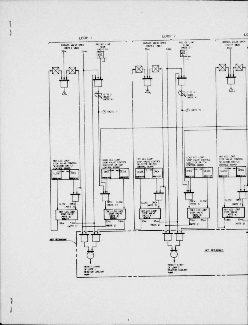
__ _ _ _
_
) LOLOOP 2ILOOP i * , r^ m a
r SVPASS Valve OPEN RELIEF LST BVPAS$ VALVE OPENavPAss v4 lye (PEN PEL:EF Lpd.
(WTES 2&e) FLOR (NOTES 26.)(ICTES m) Flour (#E I 33ac(NCIE II 330c 33ao
3'ac 13 ao
5 5 i
i
)),
1., ii i . L, , i
. ..i.i .b, ,
i .',
- . . . ..
. . .
I.--
I--
I 4 j8 0703
,O TO 3,
. oms1 ems (NOT 4)(NOTE A)
% gNOTE T)i
Q (POTE T)<
|
,
COLD LEG LOOP MOT MG LOOP
#CT LEG LOLP CCLD LEG LOOP ICT MG LOOP ST(F VALVE CONTROL STOP valve CONTR(L
STOP VALVE CENTROL STIP VALVE CONTR(L ST@ VALVE CONTR(L SELECl(R SRITCH SELECTGt SpiTCH
SE11CTm SRITC's SELECTW SalTCH SElfCTm Saf fCN CONTR(L 00AftC CONTROL BOARD
CNT8KL M ? CGF#CL 80480 CGFROL BOARD-** h**
h mf m gGTW TOSE ROSE ~****CLOSE (7Tps
-m m 'as aussies. ess eine samverw , , , , , , , , , , , , , , , ,,,, , , , ,
--
~~
J.- r- c.
. ............
aPEN CLOSE W- 6~~ ~~
g7~ l TN CLOSE CLOSF OPEN (WTE 3) (NOTE 31,gg ( O II (WTE 3)
(NUTE 3),,'
DCT LEG LOOP (ILD LfG LOCP PCT LEG LDCP C(LD LEG LOOP HDT LIG LOOP
ST(P V.ALVE STOP V.ALVE STEP V.ALvE STOP val.VE STOP VAL.VE(=g,) (gg, ) (gg, ) (n ) gTt >
%| 53cc 33eo 33ne 33aol 336c 33ao (33ac 33m(_,,,Iw
(NOTE 2) eTE 2) (NOTE 2) 4)TE 2) (NOTE 2)
-3- , , Ig .
-,-
u, --j,
.
--- --
.-|
-EEI
W paansas?
\
NOT EI1NDANT
I
PEfteif $ TARTITRNtf START & LCKP 2y L(XF g MACTm CGLANTEACTGI C0(LANT PtsrPtsy --
--
Y
b
IN

____ ____
i
!
.
NOT Al.C19&M1< @TE 11_ _ s ,_
OP 3 LOOP 4 COLD LEG TEMPERATURES HOT LEG TEMPERATURES#U -
, ,-
, ,-
,, e--
RELIEF Lig IvPA$$ VALVE &EN GLIEF LIE LOCP 1 L O(P 2 LOCP 3 LOCP 4 LO(P 8 LCOP 2 LOCP 3 LOOP A| 6 g | g | |FL@ (NOTE $ 2&S) FLOn
| 47 i 8 F-''' r-4 -- I it- r--4 , r17 I i i- Id t T7 A i e 1l1 |$) 33= sw (NcTt $) .' I 'A3 |
^
Ap1 i i i l i I i'
lJ l i i u,,xER i i i i AuCT,xt, i i
|'i i l I | I. I I
l '1 l ' '1 [rI@ @,
- r--r Jr- ' i
I , I I r- :, ig - - g - - 1 - - 1 -
;. ...|. . ...7 3. g 7 .g. g 7..g g. 7.
(DCTE 6 (4TE 6 (@TE EE E E 1 E 1 EgE g
TB T8 78 Tft T1- T3 TB 79| |
i
O 3 |]g t 2" 3 A^ +1 73" ! AO TO 3 1'
$HOLR$(NOTE 4) t@TE A)
hpip h- - ihh,hh 'i,i
Q(WTE T) i(WTE T) ii
- _ - - -_ _ _ t
| |
| | | ||
as a
r
n.. . . . .seu . .
(GE 6)
I ;_.
t
WTE S -
T4 ENCLOSED CIRCutT eEET$ T4 PHOTECT'4 REDLMAPCY IE3JINDENT1
SY CDelmipG $1GNALS FRCat TPE 6CT AfC tutD LEG2. PO$ lit @ MTECTl@ t$ p Tuo 16M60 Limi SetWS FT EACl4
COLD LEG LOCP 6CT LIG LO(P COLD LEG LOOP
3 4 @JtRED IN 80TM TR&lNS BEF@E YpE OPEN ACTUATICDs 159 C@ a SE CTOR Se T $ C @ $aC@TR1 BOARD CGdT181 BOARD CONTN1 BCARO 4 LOS$ 7 $ TO TPE Tine CEUT Ru M T>E fle TO RESET TO
T4 BEGl>SelpG 7 T6E CYCLI .
OPEN-+ -e --CLOSE CLOSE-++-TEN TEN-**-CLOSE $ FLOR DETECT 104 FGt EACH LO3' 15 BY TWO t@EMPOENT 5elTC6ES,OPE FOR EACM Tea N
=m - a ne - in- DW N '"' Ilrr"' suun'' 8"6. ALL St$TadLES Os THIS SEET AFE *DERG12E TO ACTUATE =.
-- T. TWO PERsis$lvt $fATUS LICHTS ARE (XpeEC1G TO TNi$ CIAQJif.
- teciviGJAL F0lt EACH TRAIN.-
"" 3 (PEN /94JT IM.;1CATIO4 'N (XhTIEL flCDe.
..J.. ............
~~ ~~
~~(PEN CLOSE CLOSE (PEN CPEh CLOSE
'I(PCTE 3)(NOTE 3),, ,,(NOTE 3)
,,
CULD LiG LOOP 60f LLG LOCP C1D LEG LOCr
$TCP vaLWE $TCP VALVE STCP vatytM 8)
(NDYE 8) (NOTE B) 800200002C accid
,--,I3" OP'I@AL ENTRA
TE 21 fMOTE 2)(NOTE 2) ALL C'RQJITS De TMi$ SHEET ARE SIPLIED BY@A$ AM (PTICDeAL EXTRA.
. -,---. ,-i-
- - - -1-- , r
I....L. .. . L.| NOT fEClasQaNT| /
||.
|
Missif $wT jPUusti $ TART w LOOP * ,
REACT @ CC1 ANT |AC ANT *w-
Figure A-17 i
Func aonal Diagram !i '
! Sheet 17Loop Stop Valve Interlocks
| c
I
- . _ _ _ _ _ _ _ _ _ -'

..
APPENDIX B
INTERFACE STATEMEfff FOR ELECTRICAL CIRCUIT AND4
INSTRUMENT IMPULSE LINES SEPARATION INVOLVING OTHER
PLAttr SYSTEMS INCLUDING BALANCE OF PLANT
The electrical conductors for power supply, instrumentation, and controlcircuits and the instrument impulse lines of a nuclear plant must havephysical and electrical separation to preserve the redundancy and toensure that no single credible event will prevent operation of therequired safety system function. Credible events shall include, but notbe limited to, the effects of fire, short circuits, pipe rupture , mis-siles, etc. Electrical separation required for protection against plantevents shall be included in the basic plant design in accordance with
IEEE Standard 384-1974*.
j B.1 ELECIRICAL SEPARATION
1. General
Separation of redundant circuits as described in this interf acea.
criteria document shall conform to the requirements of IEEES tandard 384-1974, Criteria for Separation of Class IE Equipment
and Circuits.
b. Separation required in Item 3 (Separation by Potential) is toprevent undetectable failures due to differences in potential,,
!
avoid common-mode events, and to minimize induced noise on low-level DC circuits from higher AC voltage circuits and switchingtransients (e.g. : Train A and Protection Set I do not requirephysical separation from each other except as described in
2.c.). Separation can be accomplished by use of barriers in the- same cable tray or separate cable trays (wire-wayd).
Basic plant design should also consider the requirements of Regula-*
tory Guide 1.75, " Physical Independence of Electric Systews". .'
.
B-1
-- __
-_ _ _ _ _ _

i
2. Separation of Redundant (Class IE) Circuits
Separate routing shall be maintained for the four reactor pro-c.
tection/ engineering safeguards channels. These channels aredesignated as I, II, III and IV and include impulse lines , sen-sors, process and nuclear instrumentation cabinets and the inputto the solid-state protection system. cabinets.
b. Separate routing shall be maintained for the two redundant pro-tection traira. These trains are designated as A and B and
include reactor trip sigaals, safeguards actuation signals andcontrol Soard actuation /resec/ block signals.
The safeguards actuation sistals shall have physical separationc.
from the four reactor protection / engineered safeguards channelsand the reactor trip signals to prevent undetectable failuresdue to differences in potential (see Item 3).
d. Post Accident Monitoring (PAMS) Signals
1. Post accident monitoring signals from sensors to instrumen-tation cabinets are identified as Channels I, II, III and IV
and shall be routed and separated in accordance with theregairements for reactor protection / engineering safeguardschannel signals as described in 2.a.
11. these sissals are isolated at the output of the instrumenta-tion cabinets and can be routed to the main control board by
I'
either of the following methods-
Method I - Combine PAM output channels from instrumentation |cabinets I and III into a channel called PAM 1.
.
|Combine the PAM output channels from instrumen-
tation cabinets II and IV into a channel calledPAM 2. Separately route PAM 1 and PAM 2 chan-
nels from the instrumentation cabinets to thecontrol board.
B-2
l, . . _ .

_ -_ - _ _ _ _ _ _ _ _ _ _ _ _ _ _ _ _ _ _ _ _ _
Method II - Combine PAM output channels into PAM 1 and PAM 2
as described in Method I. Route PAM 1 with any
redundant channel and PAM 2 with any other
redundant circuit not associated with PAM 1.
3. Separation by Potential
|a. Power and control conductors operating at potentials of 600
volts or less shall not be placed in cable trays with conductors
operating at potentials of more than 600 volts.
b. For class IE circuits, analog or other low level type signal
- conductors (potentials less than 100 volts) shall not be routedin cable trays containing power or control cables (potentialsgreater than 100 volts). The Solid. State Protection Sys tem usesthe designation V A (V B) for Train A (B) logic cabinet (low
level signals) and VI A (VI B) for Train A (B) output cabinet(power and control circuits) .
c. Analog or other low level type signal conductors for non-Class
IE circuits shall not be routed in cable trays with conductors
at AC or DC potentials exceeding 120V AC (RMS) and 140V DC.
4. Other Separation Requirenents
a. Reactor Shutdown Systems - Separate routing of control and powercircuits associated with the boric acid transfer pumps isrequired. Power sources are designated Train A and B.
b. Pressurizer Backup Heaters - The two groups of pressurizer back-up heaters used for maintaining the plant at hot shutdown obtain
~
power from separate emergency diesel generators.,
.
c. Nuclear Ins trumentation Sys tems (NIS) - All cables between theNIS cabinets and the sensors , including those associated with )pre-anplifiers shall be contained in four conduit groups: one
l
.
B-3
II- _ _ .
1
|

group for each redundant protection channel . Only NIS cables
shall be contained in these conduits. The minimum separation -
from the conduits and containment penetrations to electrical
noise sources such as power sources of 118V AC,10A and highervoltages or circuits with switched loads such as relays, or
SCR's shall be two feet. The minimum separation from 4160V and
above power cables shall be six feet.
d. Non-Class IE Circuits - Circuits not classified as reactor pro-
tection/ engineered safeguards channels, reactor trip signals,safeguards actuation signals or post-accident monitoring signalsare considered non-Class IE circuits and must be separated from
redundant circuits as required by IEEE Standard 384-1974.
B.2 INSTRUMENT IMPULSE LINES (SENSOR TO PROCESS CONNECTIONS)
1. The minimum separation between redundant instrument impulse linesshall be at least eighteen inches (46 centimeters) in air in both
horizontal and vertical directions in non-missile or jet stream
areas and shall be maintained from its s' tarting point at the rootvalves to the vicinity of the instrument. If this separation is not
possible, then a suitable barrier shall be used and it shall extend
at least one inch (25 milimeters) beyond the line of sight betweenthe redundant impulse lines .
Where potential missiles can be identified, additional separation,
missile shields and/or barriers shall be used.4
2. Where redundant, ins trument impulse lines penetrate a wall or floor,the penetrations shall be separated by a minimum distance ofeighteen inches in non-missile or jet stream areas. If separate
penetrations are not possible for the multiple lines, then they may,
be run through one common penetration provided that' the following
| conditiona are met:
B-4
_ . _ _ . - . ,

|
Redundant ins trument impulse ~ lines shall b2 protected from pos-! a.
tulated effects of f ailure of one another by a suitable barrier,such as guard pipe .
b. A missile shield shall be provided around the instrument impulselines until the minimum separation distance of 18 inches (46centimeters) is achieved between the different redundant impulse
t,
lines. |'
3. In those few places where it is impractical to provide redundantItaps (i.e. the inside tap on an elbow flow element for example), the
signal tap shall be protected from credible sources of common modedamage, and the " split" to redundant impulse lines shall be as closeas possible to the proces s.
4. Ins trument impulse line required in mitigating the ef fects of apostulated pipe rupture or bringing the reactor to a safe shutdowncondition shall be protected from the ef fects of that pos tulat edpipe rupture. Pipe rupture criteria for piping other than the mainreactor coolant loop piping will be provided as part of Balance of
Plant Scope.
Design against postulated " pipe whip" is a function of plant layout,the postulated piping break locations and mechanisms, and the par-ticular accident postulated at the time. Only when this informationit available can those safety related sensor connecting instrumenthapulse lines be evaluated within the scope of the Balance of Plantfor the degree of protection required against postulated pipe whips,
i
e
:
||
.e
B-5
|
|
_
1
;
|
| APPENDIX CI
CONSIDERATIONS ON BOUNDS OF FMEA
C.1 CONSIDERATION OF INTERFACES_
The electrical circuit separation statement governing interf ace betweenESFAS and other plant system is presented in Appendix B. As noted,
" circuits not classified as reactor protection / engineered safeguardchannels , reactor trip signals , safeguards actuation signals or post-accident monitoring signals are considered non-Class IE circuits andmust be separated from redundant circuits as required by IEEE 384-1974.The translation of this criteria into the design and hardware implemen-tation of other plant systems interfacing with the ESFAS assures thatthe conclusions of the FMEA will remain valid when the ESFAS is inte-grated into the plant design even t*c.:> ugh the FMEA itself is bounded bythe considerations discussed in Section 4.0. As noted in Section 4.0,
Figure 1A shows a main signal flow diagram of the hardware and compo-nents in the ESFAS as progressing from sensor to outputs. All singlerandom f ailure mechanisms are considered which produce failure modes
(e.g. open or short circuits) including f ailure mechanisms capable ofbeing propagated from isolation devices mid other ESFAS components notspecifically identified. Components not specifically identified include
. those that branch off from the main signal flow, such as , test connec-
tions , power supplies , manual switches , and auxiliary contacts that areassociated with or included in the ESFAS but are parts of other sys-
tems. However, single random failure mechanisms associated with theseunidentified components are inherently included as failure mechanismswhich could open or short the main signal path.
C.2 CONSIDERATIONS OF ISOLATION FROM COMPUTER AND CONIROL BOARD
.
Concerning isolation devices used to isolate the Solid State ProtectionSystem (ESFAS) trains from computer and control board multiplixer/demul-tiplixers and from each other, tests were made on these devices andreported to the NRC staff in connection with support of the Diablo
C-1
- _ _ __ .

Canyon Unit i review under the title, " Westinghouse Protection SystemNoise Tests (Supplement 1)," dated December 1974.
This report was subsequently accepted by the NRC in the U.S. NRC letterto Pacific Cas & Electric " Evaluation of the Westinghouse Protection
System Noise Test Report," April,1976.
C.3' CONSIDERATIONS OF ISOLATION FROM WESTINGHOUSE 7300 PROCESS CONTROL.
The ESFAS as described in this FMEA also implies, in addition to theSolid State Protection System, the use of die Westinghouse 7300 ProcessControl System, the tests of the isolation devices in this control sys-tem were reported in WCAP-8892-A, " Westinghouse 7300 Series Process
Control System Noise Tests". This report was also accepted by the NRCin the NRC letter to Westinghouse by Robert L. Tedesco dated April 20,1977.
C.4 CONSIDERATION OF INTERNAL LOGIC TRAIN POWER SUPPLIES
,
The electrical power supply requirements for each logic train's masterrelays (K501, K502, etc.), universal ligic modules (204, 205, etc.),master relay driver circuits (516, 517, and 518), output slave relays(K601, K602, K603, etc.), and SSPS input relays are serviced from the118V a-c Instrumentation and Control Power Supply System. In the case
of the output slave relays, the service to the coils of these relays isthe unconverted 118V a-c electrical power. The master relay contacts
apply power to 1 to 8 slave relays depending on the number of slaverelays required. In the case of the master relays, the service to thecoils of these master relays is 48V d-c that is derived from two 48Vpower supplies that convert the 118V a-c to 48V d-c. These 48V d-c
electrical power supplies also serve the universal logic modules and themaster relay driver circuits. In addition to 48-V d-c, the universal
logic modules and the master relay driver circuits are also served by15V d-c that is derived from two 15V power supplies that convert the118V a-c to 48V d-c. The 48V and 15V power supplies for the system
logic (i.e. master relays, universal logic modules, and master relay
i
C-2 *
|
|- . - - - - -

driver circuits) feed redundantly to the 48V and 15V buses. These sup-plies are regulated d-c supplies built to Westinghouse specificationswith voltage and current adjustments. The f ailure of any one of thefour output voltages will create a general warning alarm on the affected
! train's logic bay and on the control board. Thus any of the f ail openor fall short or f all overvoltage of the input or output of the 118V a-cpower supply which would cause an interruption of one cf the convertedoutput d-c voltages is detectable. The two 115V d-c and the two 48Vsupplies are used on an auctionerred basis. The interruption of any oneof the outputs of there d-c power supplies (e.g., if no. I 15V d-c isinterrupted) does not prevent power from the redundant d-c power supply(e.g. , no. 2 15V d-c) from being supplied to the services requiring iton an uninterruptible basis. In addition, it should be noted that theSSPS input relays are energized from the process protection set analogmodules.
The FMEA presented herein considers the random single f ailure mechanisms
of the power supplies to there SSPS input relays as well as the SSPSinternal 48v d-c,15V-de, and 118V a-c service to each of the componentsanalyzed in the FMEA, which can be observed by coinsidering the randomsingle f ailure mechanism code presented in Table 1 as follows:
1. Universal Logic Circuit Failure
Mechanisms involving loss of 15V or 48V d-c power supplies are iden-tified as L10. The following list identifies where these L10 mecha-
nisms are addressed in the FMEA
Universal Logic
Circuit. FPEA Line.No.(
- 204 8.7, 1.10, 2.5 -
205 1.28, 1.29
206 1.20, 1.30, 1.21
207 1.12, 1.11, 1.31
209 1.28, 4.5
| 210 1.57, 6,1
l
C-3
_ _ _ _ -
- ~ .. - . ._ . .. - _- . .
i
!
Universal Logic
Circuit FMEA Line No.,
213 1.36, 9.1
214 8.7, 8.8
216 1.36, 1.59,
4 217 8.7, 9.8, 9.9I
: 311 10.15
.i 313 1.60, 8.9 ,
-|315 1.43, 2.4
| 316 10.4, 10.5
j 317 10.4, 10.9
! 411 1.47
416 1.49, 1.48, 1.50
; 2. Master Relay Failure
i'
.!
Mechanisms involving loss of 48V d-c power supplies are identified
as R6. The following list identifies where these R6 enechanisms are
addressed in the FMEA.
Master Relay FMEA Line No.
! K501 1.63I K502 3.2
K503 5.3||
K504 2.7
K505 6.3
K506 4.7 |'
K507 9.3
K508 8.11 |
K510 11.2*-
K512 1.63
K513 7.2 j'
K514 10.17
K515 10.7
K516 10.11
.
c-4 '
i-
.. . . . . . . . _ - ..-- -_ . . . _ - ,_. . . . . . . _ .
~._ . - - - - - - -

- . . - _ .
|
|
Master Relay FMEA Line No.
K519 6.3
K520 9.111
K521 1.63
K522 3.2,
3. Master Relay Driver Circuit Failure:
1
Mechanisms are identified as D-X modes, which it.clude the mechanisms
associated with loss of power supplies. The following listidentifies where these D-X mechanisms are addressed in the FMEA
Master Relay
Driver Circuits FMEA Line No.
A-516 5. 2. 3.1, 7.1, 2. 6, 6. 2, 4'.6'
A-517 10.10, 10.6, 9.2, 8.10, 9.10, 11.1
A-518 10.16
'
4. SSPS Input Relay Failure
Mechanisms involving loss of Process Protection Set Analog modules
power supplies are identified as P6. The following list identifieswhere these P6 mechanisms are addressed in the FMEA.
SSPS Input Relay FMEA Line No.
K148 1.09
K229 1.C9:
! K306 1.09
K406 1.09'
K319 1.19
K320 1.19
K419 1.19
K420 1.19
K107 1.27
.
C-5
1
_ _ _ _ - . . - -. . _ . . _ . . . . . _ _ . .. ..-
" -,m

____ _ . . _.._ _- . ._.- _ _ . - . _ ._. . _ _ __
SSPS Input . Relay FMEA Line No.
K115 1.27
K243 1.27
K246 1.27
K116 1.27
K117 1.27
K244 1.27
K245 1.27
K113 1.34
K247 1.34| K203 1. 34
K119 1.34
| K318 1. 34
K204 1.34
; K134 1. 34
K417 1.34I K317 1.34
| K248 1.34
K118 1. 34
K418 1.34,
K131 1.42 ,
K201 1.42
K344 1.42
K444 1.42
. - -K132 1.46. . . . . .
K202 1.46
K315 1.46.
K217 1.56- K330 1.56 i
l K430 1.56*K249 2.3
K337 2.3
K439 2.3K137 4.4K216 4.4
*
|
C-6
'
. __ -_ -_

.,
! !
l||
!
SSPS 1.?wt Rel ay FMEA Line No.
K329 4.4
K429 4.4
K138 8.6
K218 8.6
K308 8.6
K310 8. 6
K431 8.6
K433 8.6
K139 8.6
K219 8.6"
K309 8.6
K311 8. 6
K432 8.6
K434 8. 6
K140 9.7
K232 9.7
K307 9.7
K411 9. 7
K114 10.3
K113 10.3
K230 10.3'
K231 10.3
K331 10.3 |
K332 10.3
K333 10.3
K334 10.3
K407 10.3
K408 10.3
K409 10.3
- K410 10.3 -
#K123 10.14
K340 10.14
K240 10.14
K412 10.14
1, a
.
C-7'
_ _ - - ._ _ _ _ , _

C.5 CONSIDERATIONS OF BLACKOUT SIGNAL START FOR TURBINE DRIVEN
AUXILIARY FEEDWATER PUMPS
On those plants where a delayed start of the turbine-driven auxiliaryfeedwater pumps is initiated on coincidence voting logic of redundant'
signals (typically 2/4 on a four loop plant) of RCP bus undervoltagefrom equipment available from the Westinghouse-supplied SSPS, initiationof the circuit is derived from BOP-supplied sensor (typically relaycontacts) that provide an output signal when the bus voltage goes belowapproximately 70% of rated voltage. Signals from these relays are timedelayed to prevent spurious trips caused by short term voltage tran-sients. The coincidence logic is presented on sheet 5 of Figure A-5,the logic for the pump start is capable of being tested from the SSPSlogic tes ter during power operation. The interf ace criteria that Wes t-inghouse supplies to the BOP is presented in Appendix B, and this crite-ria applies to these undervoltage sigaals. In addition, Wes tinglouserequires that the signals , input at the SSPS, derived from these sensorsmeet IEEE 279-1971.
C.6 CONSIDERATIONS.0F ENVIRONMENT
Techniques appropriate to a FFEA. are to consider all random single fall-ure mechanisms. Environmental considerations have shown that the ESFAS
' is adequate under the Wes tinghouse generic environmental qualificationprogram that is under review by the NRC staff in conjunction with WCAP8587, " Methodology for Qualifying Westinghouse PWR-SD Supplied NSSS
Safety Related Electrical Equipment", September 1977.
.
.
.8
.
C-8 .

,_. _ __ _ . _ . _ . _. . _ _ . . - _ _ _ _. _ _ . . _. . _. - __.- . . . _ .
t
I
!
!
*l
,
APPENDIX D
i US.NRC. LETTER
JOHN. F. . STOLZ. TO. C. EICHELDINGER. OF. AUGUST 4, .1979
SUBMITTING.9. REQUESTS FOR ADDITIONAL INFORMATION>
;
4
1
$,
1
t
#
4
e
!
!
,
f
!
Y.
ki
} *
I1-!
I
i
| D-1!
|.
i,n,- - -- .. _ _ _ _ _ . _ , , . ,- .n.- . - --. -,-.-. - ---- - -,,. -

.
.s ** ''" "'.itusen nr.rairs
..NUCt. EAR UCCULA e OHY Cui.U.USSIONt' ,
,C '.v .. :f|. ) wwnwuna.o.c.aon.
~
'
$,,' . ,
AUG t 41977....
$Nh,$.h,i'
F-
Mr. C. Eicheldinger, Manager ( g g 77 i&jNuclear Safety Department i
WWestinghouse Electric Corporation C.EICHELDINGERP. O Box 355 M WCM SAWPittsb'urgh, Pennsylvania 15230
Dear Mr. Eiche1dinger: ,
S'JBJECT: REVIEW 0F WCAP-8584 (P) AND WCAP-8760 (flP)
Additional information is required to complete our review of Westinghouse760 (llon-
proprietary)poration reports WCAP-8584 (Proprietary) and NCAP-8 entitled, " Failure l' ode and Effect Analysis of the EngineeredElectric Cor
Safeguard Features Actuation System." .The required additional inforraation ..
.
is enclosed. .
IfPlease provide the enclosed requested information by flovember 1,197;'.you cannot meet this schedule, please advise us within 10 days afterreceipt of this letter of a date you can meet so that we may revise ourschedule. _
P
If you have any questions about our request for Lditional information,-
please contact us.. '
Sincerely, -
? lli .
Job F. Stolz, Chief.
ight Water Reactors Branch No.1.
Division of Project Management$
Enclosure:Request for Additional
Information
.
.
- _.__ _ _.
_ _ _ _ _

32.1 Section 3.0 " Conclusions" refer to failures "in theI safe direction." We interpret this to mean that if
such failures occur there is no adverse effects on theEngineered Safety Features Actuation System (ESFAS) or
the safety of the plant.
li
Verify that this is a correct interpretation and pro-m
vide an explanation in support of such a conclusion.'
,
Reply See revised page 3-1.
.
-
.
6
'
D-2
._ _ . . __
--

32.2 In the FMEA worksheet, certain statements in "Coltznn 7"which addresses the effects on the system, refer todevices in the balance of plant design scope. There isno concluding remarks in " Column 9" which would indi-cate if the resultant ef fects are acceptable.
Therefore, we require that this area be specificallyaddressed in the topical report itself (not justmentioned in the diagram) via an interface section inorder to show that the FMEA results are dependent on
BOP design characteristics in those certain areas.
This area must then specify the interf ace requirementsfor the BOP design.
Reply See Appendix B for interf ace criteria.
See supplemental entries in Coltsun 9 of FMEA worksheets
!
.
O*
|
D-3!
!_ - . _ _ _ . _

- - - _ _ _ _ _ _ _ _ _ _ _ _ _
i-
32.3 Also in the FMEA worksheet, certain statements in
"Coltann 7" indicate that inadvertent actuation ofcertain equipment will occur. There is then no con-
'
cluding remarks in " Column 9" which would indicate ifthe resultant ef fects are acceptable. ,
An example where this assurance is not provided is on
Sheet 18 for line 1.58 which states that the PlantSafety In ection sequence is initiated as the result ofs
some f ailure. Provide a conclusion if this result isacceptable and also provide conclusions for all othersimilar type entries where concluding renarks are notprovided in " Column 9".
Reply See supplemented entries in all Coltann 9 of FMEA work-sheet fonnerly lacking entries.
See note or Coltunn 9 entries pertaining to evaluationof consequences in FMEA worksheets lines as follows:
1.29, 1.30, 1.31, 1.35, 1.36, 1.42, 1.43, 1.50, 1.57,1.58, 1.60, 1.61, 1.62, 1.63, 1.64, 1.65, 2.4, 2.5,2.6, 2.7, 2.8, 3.3, 4.6, 4.7, 4.8, 5.1, 5.2, 5.3, 5.4,6.4, 7.1, 7.2, 7.3, 8.7, 8.8, 8.9, 8.10, 8.11, 8.12,9.1, 9.2, 9.3, 9.4, 9.8, 9.9, 9.10, 9.11, 9.12, 10.4,10.5, 10.6, 10.7, 10.8, 10.9, 10.11, 10.12, 10.15,10.16, 10.17, 10.18, 10.19.
.
D-4
:

32.4 Provide justification for ornitting an entry in thecoltson for " Method of Detection" on sheet 23 of theFMEA worksheet for the " Normal Open Contacts Fall in
Open Position." It should be pointed out tha't anundetected f ailure of this nature combined with a
,
single f ailure would negate the total ESF systern.
|
Reply Sheet 23 has been anended.-
,
i
1
.
:),
|
i
l
D-5 1.
J
.

_ . . _ _
32.5 Provide, in the interf ace area, a requirement related
I~ to the BOP utidervoltage relays which are specified as"Not in Westinghouse Scope" on Sheet 45 of the FMEA
worksheet.
| Reply See Appendix C, Section C.5 and reference in Coliann 9!
of line 10.13.|
.
]
'e
[
.
\
\ .
D-6u.,|t
!. _. .. _ . . . _ __ , , _ _ _ ,_
%_. . . . ._
'
_ _ _ .___ _ _ _ _

t
32.6 The FMEA appears to consider the instrument loop powersupplies, for the 4 instrument channels, as part of the
system analysis of the ESFAS. However, the FMEA doesnot appeat to similarly address any internal logic
train power supplies. If there are such internal logic
power supplies include these in the analysis, andaddress all aspects of failures of these power suppliessuch as, loss of power source, maximum credible outputvoltage, etc.
If there are no internal power supplies address theseareas in response to ques tion 32.8 on interfacerequirements for failures in interconnected external
systems.
Reply See Appendix C, Section C.4.
.
l
.
D-7

_ ._ ._ _ __ _-
32.7 It is our understanding that there are more internalcomponents associated with ESFAS than are analyzed inthe FMEA. Specifically, we understand that isolationdevices and other components are provided at various
points in the ESFAS for interfacing with other plantsystems (both " safety" systems, such as, the ReactorTrip System or Safeguard Test System and "non-safety"systems, such as, the computer and annunciator). We
.
consider these components (up to the exact point ofisolation) to be part of the ESFAS and we require thatsuch components also be considered in the FMEA.
Therefore, include all components, such as thosementioned above, in the FMEA for the ESFAS.
.
See Appendix C, Section C.1, C.2, C.3.Reply
..
e
O
D-8'
,
I
- - _ _ _ _ _ _ __

32.8 We understand that the FMEA presented is intended toshow that the design objective (as stated in .he lastsentence on page 2-1) is achieved, (namely that "...anysingle f ailure within the Engineered Safety FeaturesActuation Sys tem shall not prevent system action whenrequired.") (emphasis added), however, we believe thatin order to ef fectively utilize such an analysis in theoverall evaluation of a given system, consideration off ailures in interconnected external sys tems and inter-
related areas must be included with the FMEA for theparticular sys tem analy:cd.
There is particular concern over the effects on thea.
ESFAS of failures in the interconnected areas suchas external power sources , external grounding sys-tems, and external tes t circuitry. Therefore,include consideration of all postulated externalf aults and f ailures of interconnected areas as part
of the FMEA for the ESFAS. This area will tisorequire special consideration of interf cce require-ments similar to those discussed ear'.ier. (See
Ques tion 32.2) . These interf ace requirementsshould be included as part of this FMEA document.
b. DEEE-3 52-1972, Section 4.1.3, " Preparatory Stepsfor Failure Mode and Effects Analysis," lists as an
essential step the " Description of the environ-mental conditions." This area is critical becausethe environment can be the source of common modefailure. Therefore, describe the environment alconditions which have been considered in the sys tem
.
design and the effects of failure under extremeenvironmental conditions .
The analysis does not indicate the effects ofc.
internal or external noise i .e. , EMI, RFI, A.C.
| *
D-9t
l
|
- _ _ _ _ -

_. . _ .. .__ . _ . _ . .- - . - . . ~ - - - - -. . - - . = _ .
>
!1
|
|
32.8 (Continued){i
line, on the system. This area is a potential
conanon mode faiure. Theretore, describe the con- -
! sideration given to the effects of noise on the
; system.
1
1eply a. See Appendix C, Section C.3..
+
[
"
b. See Appendix C, Section C.6.
c. See Appendix C, Section C.2 and Section C.6.
i
k'
!
4
)
h
4
1
!
s
4
i
!f
e
l
D-10!
__ . . . -- , . . _ _ -

- . ._. -.. . . - . . .. _ -- .-.
_ _ . . _ . _ . . _ _ . .. _ . . . . , . _ _ . . .
- . . . . . _ . . . _ _ .
,
-,
32.9 If there were any modifications made by the designersto ESFAS as a result of the perfonnance of the FMEA,~
provide a list of such changes identifying where in theESFAS they are implemented.
Reply No modifications have been made by the designers to the
i ESFAS as a result of this FMEA.!
,
)
,
j
|i
a
l
i
|
e
t
D-ll
,
_ ,_ . _ _ _ . _. _ , - .__ . _ _ _ _ _ _ _ _ _ _ _ _ _ _ _ _ . . - ---