Fabrication of computationally designed scaffolds by low temperature 3D printing
13
Fabrication of computationally designed scaffolds by low temperature 3D printing This article has been downloaded from IOPscience. Please scroll down to see the full text article. 2013 Biofabrication 5 035012 (http://iopscience.iop.org/1758-5090/5/3/035012) Download details: IP Address: 132.187.155.59 The article was downloaded on 30/07/2013 at 07:36 Please note that terms and conditions apply. View the table of contents for this issue, or go to the journal homepage for more Home Search Collections Journals About Contact us My IOPscience
-
Upload
uni-wuerzburg -
Category
Documents
-
view
4 -
download
0
Transcript of Fabrication of computationally designed scaffolds by low temperature 3D printing

Fabrication of computationally designed scaffolds by low temperature 3D printing
This article has been downloaded from IOPscience. Please scroll down to see the full text article.
2013 Biofabrication 5 035012
(http://iopscience.iop.org/1758-5090/5/3/035012)
Download details:
IP Address: 132.187.155.59
The article was downloaded on 30/07/2013 at 07:36
Please note that terms and conditions apply.
View the table of contents for this issue, or go to the journal homepage for more
Home Search Collections Journals About Contact us My IOPscience

IOP PUBLISHING BIOFABRICATION
Biofabrication 5 (2013) 035012 (12pp) doi:10.1088/1758-5082/5/3/035012
Fabrication of computationally designedscaffolds by low temperature 3D printingMiguel Castilho1,3, Marta Dias1, Uwe Gbureck2, Jurgen Groll2,Paulo Fernandes1, Ines Pires1, Barbara Gouveia1, Jorge Rodrigues1
and Elke Vorndran2
1 Institute of Mechanical Engineering/IST, Technical University of Lisbon, Portugal2 Department for Functional Materials in Medicine and Dentistry, University of Wurzburg,D-97070 Wurzburg, Germany
E-mail: [email protected]
Received 9 April 2013Accepted for publication 2 July 2013Published 26 July 2013Online at stacks.iop.org/BF/5/035012
AbstractThe development of artificial bone substitutes that mimic the properties of bone andsimultaneously promote the desired tissue regeneration is a current issue in bone tissueengineering research. An approach to create scaffolds with such characteristics is based on thecombination of novel design and additive manufacturing processes. The objective of this workis to characterize the microstructural and the mechanical properties of scaffolds developed bycoupling both topology optimization and a low temperature 3D printing process. The scaffolddesign was obtained using a topology optimization approach to maximize the permeabilitywith constraints on the mechanical properties. This procedure was studied to be suitable forthe fabrication of a cage prototype for tibial tuberosity advancement application, which is oneof the most recent and promising techniques to treat cruciate ligament rupture in dogs. Themicrostructural and mechanical properties of the scaffolds manufactured by reactingα/β-tricalcium phosphate with diluted phosphoric acid were then assessed experimentally andthe scaffolds strength reliability was determined. The results demonstrate that the lowtemperature 3D printing process is a reliable option to create synthetic scaffolds with tailoredproperties, and when coupled with topology optimization design it can be a powerful tool forthe fabrication of patient-specific bone implants.
(Some figures may appear in colour only in the online journal)
1. Introduction
During recent years there has been a significant rise in bonediseases such as osteoporosis, trauma and tumors, whichincrease the demand for bone grafts. Synthetic bone materialsbased on calcium phosphates (CaP) are being widely useddue to their excellent biocompatibility and to their relativeease of processability [1–3]. Most clinical cases use CaPbone grafts in the form of granules, cements, monoliths orsimple three-dimensional (3D) structures constructed withthe geometry of the desired implant [3–5]. Recent advancesin computational design and in the additive manufacturing
3 Author to whom any correspondence should be addressed.
processes (AM) enabled the fabrication of 3D scaffolds withcontrolled architecture that mimics the natural bone [6–13].According to Bose et al [9] the best techniques of bonescaffold fabrication with complex internal and external 3Dstructure are the AM-based processes. The combination of AMwith computational topology optimization is highly desired inorthopedic surgery to develop artificial bone scaffolds withtailored properties for the replacement of the injured anddiseased bones.
Bone synthetic scaffolds should present a balance betweenthe mechanical properties, to match those of the host tissue,and the permeability, to promote cell proliferation, diffusionof oxygen, nutrients and waste products [14, 15]. Theseproperties should be considered when designing the internal
1758-5082/13/035012+12$33.00 1 © 2013 IOP Publishing Ltd Printed in the UK & the USA

Biofabrication 5 (2013) 035012 M Castilho et al
geometry of scaffolds. Recently, topology optimization toolswere used to design scaffolds based on specific values ofstiffness and permeability, which will allow an efficient boneregeneration [7, 14, 16]. However, conventional strategies lackthe ability to consistently fabricate scaffolds with controlledpermeability and mechanical properties. To overcome theselimitations AM techniques have been investigated in severalstudies [8–13, 15, 17–19]. These techniques have been usedsince the 1990s for the direct or indirect production oftissue engineering scaffolds, which include fused depositionmodeling (FDM) [20, 21], stereolitography (SL) [22], selectivelaser sintering (SLS) [23, 24] and three-dimensional printing(3DP) [25, 26]. In principle the manufacturing is based on alayer by layer process replicating a computer-aided design(CAD), whereby a precise implementation of the internaland external geometry is possible. The versatility providedby these techniques allows the fabrication of scaffolds withdifferent porosities, pore sizes and mechanical properties thatcan mimic the complex architecture of bone-specific sites tooptimize bone tissue regeneration.
The 3DP process is a promising technique for calciumphosphate scaffold fabrication [27–33]. During the processa liquid binder is locally sprayed onto a powder materialusing the ink jet technology [34]. Two different approachescan be used to fabricate CaP scaffolds. In the first approachthe CaP powder particles are bound by a polymeric glueto form a green body during printing which is sinteredafterwards [35], while in the second approach the binderreacts with the CaP powder particles in a hydraulic settingreaction forming a stiff ceramic network [30, 31]. The latteris commonly referred as low temperature 3D printing and hasbeen proposed as an alternative for the powder printing withpolymeric binders, showing a good cytocompatibility [33],shorter building times (no thermal post processing is required),high specimen resolution (scaffolds with macropores around200 μm) and high compressive strengths, in the range of22–60 MPa [30, 36]. However, due to the printingcharacteristic the scaffolds do not have the same propertiesin all directions, i.e. the process leads to an anisotropicmechanical behavior [32, 37, 38]. Although there are recentstudies on low temperature 3D printing for bone scaffoldfabrication, no literature was found coupling a topologyoptimization tool for scaffolds design with this manufacturingtechnique.
The objective of this work was to produce scaffoldsfor bone tissue engineering by coupling both topologyoptimization and low temperature 3 DP. The present study is apreliminary work for a veterinary study, where a biodegradablecage prototype with optimized microstructural and mechanicalproperties for the treatment of cruciate ligament rupture indogs is fabricated. This orthopedic problem is one of the maincontributors to the development of knee osteoarthritis in dogs[39, 40]. A newer method of medical treatment is called tibialtuberosity advancement (TTA) and is known as a promisingorthopedic procedure to stabilize the knee [40–42]. It involvesthe advancement of the tibial tuberosity to eliminate cranialtibial thrust, which is then fixed with a titanium cage spacer anda tension band plate. Despite the favorable clinical outcomes of
this technique, the procedure has limitations related to the useof expensive and non-biodegradable titanium implants. Theseimplants fail in providing adequate implant–tissue integrationand may also lead to metal ion leaching [43]. Additionally,the low rate of bone ingrowths forces the veterinary surgeonto use an autogenous or allogenic bone graft to accelerate thebone union [42, 44].
The basic material used in this work to producebiodegradable and osteoinductive dicalcium phosphatedihydrate (brushite) scaffolds is α/ß-tricalcium phosphate(α/ß-TCP) powder, which reacts during printing with anacidic binder solution to form a stable matrix [45]. Thestudy was performed in several steps. Firstly, cylindricalspecimens were produced in order to evaluate the materialproperties depending on the process directionality. In thesecond step, scaffolds with an optimized design were producedand evaluated in terms of geometric accuracy, macroporosity,mechanical properties and strength reliability by the Weibullmoduli, following an analysis to quantify the decrease inthe mechanical strength and stiffness introduced by themacroporosity. Finally a comparative study between themechanical properties provided by the optimization softwareand the experimentally obtained values was carried out.
2. Materials and methods
2.1. Computational design
In the design phase the scaffold was assumed as a periodicporous (cellular) material obtained by the repetition of aunit cell (RVE: representative volume element). The topologyof the RVE was obtained solving a topology optimizationproblem [46, 47] defined in the context of continuummechanics in order to obtain the structure that satisfiesthe objective of maximum permeability and stiffness. Theelastic properties and permeability of the porous mediaare determined using homogenization methods [48]. Theoptimization problem is defined by maximization of thepermeability for a prescribed stiffness and volume fraction(VF):
minμ
1Fperm
(1)
such that
Felast � F∗elast
V F � V F∗
0 � μ � 1,
where Fperm is a function for permeability defined as
Fperm = KH11 + KH
22 + KH33
3(2)
with KH being the homogenized permeability properties. Felast
is the function for stiffness which can be defined as the elasticstrain energy density
Felast = 12 eEHe, (3)
where EH represents the homogenized elastic properties ande the strain field. F∗
elast is defined as a percentage of the strain
2

Biofabrication 5 (2013) 035012 M Castilho et al
energy for a full material solution and the design variable μ isa variable density field that defines the regions with materialand void within the design domain. The strain field is definedto replicate the predominant strain field on bone site where thescaffold will be applied.
In this work a hydrostatic load case e = (1,1,1,0,0,0) wasconsidered, for which it is expected to obtain a structure witha nearly isotropic mechanical behavior. In fact, although thecage used in TTA will be mainly submitted to compressionstresses [44], the definitive strain field is not fully knownand this approach leads to a compromise solution. Thus, theconstraint on elasticity was imposed, so that the strain energyfor the given strain field should be at least 30% of the maximumstrain energy (defining the maximum strain energy as the strainenergy obtained for a full material domain).
After the definition of the unit cell, cylindrical modelswere designed by the repetition of the resulting unit cells.These models were used to build the specimens (scaffolds)for mechanical testing. Later on, a full cage prototype can bedesigned and built also based on the repetition of the resultingunit cells.
2.2. Powder preparation and specimens manufacturing
Tricalcium phosphate powder (TCP) was synthesized bysintering a 2:1 molar mixture of dicalcium phosphateanhydrous (DCPA, CaHPO4, monetite) and calcium carbonate(both Merck, Darmstadt, Germany) at 1400 ◦C for 5 h. Afterquenching to room temperature the sintered cake was crushedwith a pestle and mortar and milled in a planetary ball mill(PM400 Retsch, Germany) at 200 rpm with 500 ml agate jars,4 agate balls (30 mm) and a load of 125 g TCP per jar, followedby sieving <160 μm.
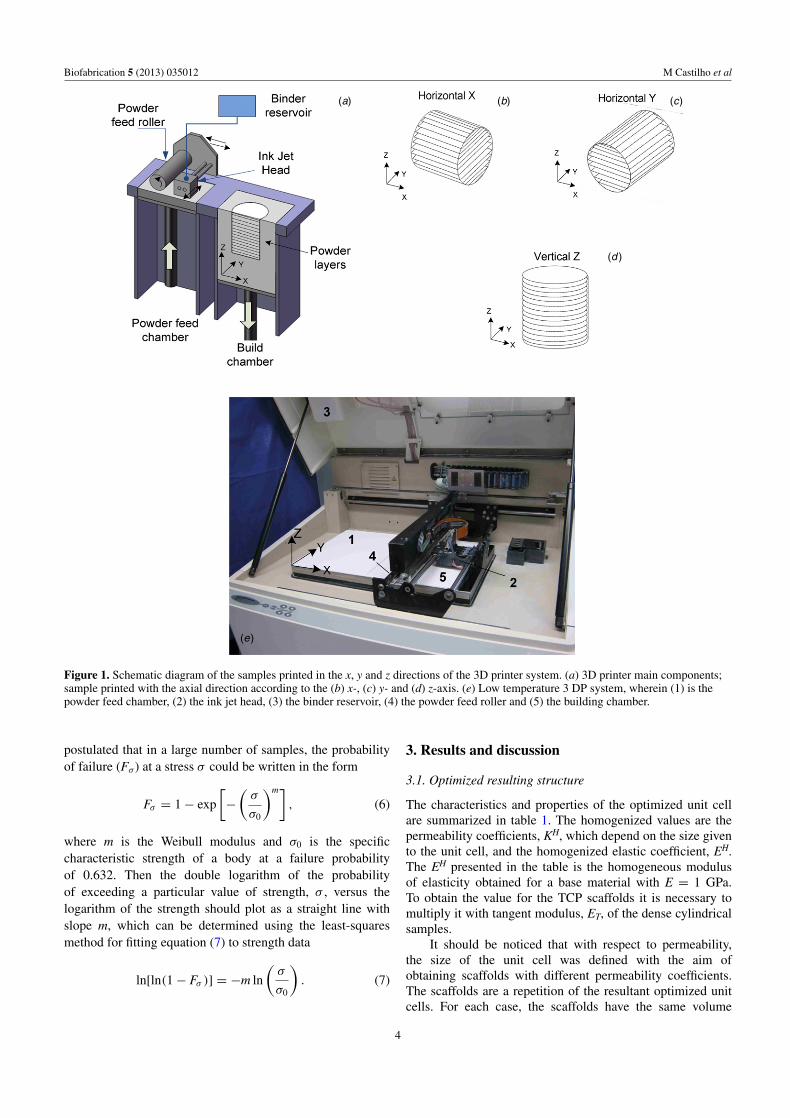
The samples were produced by the Z510 spectrum 3D-powder printing system (Z-Corporation, Burlington, USA)using the TCP powder and a binder solution, consisting of20% (v/v) phosphoric acid (Merck, Darmstadt, Germany).Specimens were printed using a layer thickness of 125 μmand a homogeneous binder to volume ratio of 0.26. Densecylindrical samples (height = 12 mm, diameter = 6 mm) aswell as macroporous scaffolds (height = 16 mm, diameter =8 mm with macropores of 500, 750, 1000 μm) were printedwith the axial direction aligned with the x, y and z directionof the printing chamber (figure 1), in order to evaluatethe process directionality on the geometric accuracy andmechanical properties of the samples. All cylinders wereclassified according to the printing direction on horizontal x,horizontal y and vertical z. Additionally, the scaffolds werealso classified according to the design macropore size, i.e.scaffold 500, 750 and 1000. After printing, the samples wereposthardened in the binder solution for 1 × 30 s.
2.3. Material and physical characterization
Scanning electron microscopy (SEM; Zeiss DSM940,Oberkochen, Germany), working at an accelerating voltage of10 kV, was used to analyze the powder particles morphologyand the ceramic samples before and after posthardening.
The powder particle size was measured with a particlesize distribution analyzer LA-300 (Horiba, Kyoto, Japan) bydispersing approximately 100 mg powder in isopropyl alcohol.X-ray diffraction (XRD) patterns of the samples before andafter post hardening were recorded using monochromaticCu-Kα radiation with a diffractometer D5005 (Siemens,Karlsruhe, Germany). Data were collected from 2θ = 20–40◦ with a step size of 0.02 and a normalized count time of3 s/step. The phase composition was checked by means ofJCPDS reference patterns for α-TCP (PDF Ref. 09–0348),β-TCP (PDF Ref. 09-0169) and brushite (PDF Ref. 09-0077).
The samples apparent density was calculated based ontheir weight and dimensions. The true density of post hardenedsamples was measured by helium pycnometry (AccuPycII 1340, Micrometrics, Dunstable, UK). The experimentalmicroporosity of the printed cylinders was then calculatedbased on the values of true and apparent density. Theexperimental macroporosity PE of the scaffolds was calculatedby
PE =(
ρμ − ρM
ρt
)100%, (4)
where ρM is the apparent density of the samples withmacropores and micropores, ρμ the respective apparent densitywithout macropores and ρt is the true density.
The dimensional variation of the samples exteriorcontouring and of the macropores, DV, was calculated bycomparing the designed and the experimental dimensions ofthe samples after posthardening as
DV = dSP − dSD
dSD, (5)
where d is the diameter/height of the samples/macroporesand the indexes SD and SP refer to the design andposthardened samples, respectively. An optical microscope(Wild Microscope M420, Leica, Glattbrugg, Switzerland)was used to evaluate the accuracy of the macropores in thecylindrical scaffolds, by measuring the macropore diameter.
2.4. Mechanical testing
For the mechanical characterization, a static mechanicaltesting device Zwick 1440 (Zwick, Ulm, Germany) with a 5 kNload cell was used. The cylindrical samples were subjected to acompressive load along the axial direction, at a constant crosshead speed of 1 mm min−1. The tests were performed with abatch size of at least ten specimens for each printed condition.
The evolution of the compressive engineering stress–strain curves, allowed us to obtain different mechanicalparameters. The ultimate compressive strength, σc, was definedas the maximum compressive stress necessary to causefracture; the corresponding strain, εc; the tangent modulus,ET, defined as the slope of the compressive stress–strain curvebefore fracture; and the modulus of toughness, UT, definedas the area below the stress–strain curve until the maximumpeak load. To evaluate the degree of strength dispersion ofthe specimens, the Weibull approach was used [49]. Weibull
3
Biofabrication 5 (2013) 035012 M Castilho et al
(a) (c)
(d )
(b)
(e)
Figure 1. Schematic diagram of the samples printed in the x, y and z directions of the 3D printer system. (a) 3D printer main components;sample printed with the axial direction according to the (b) x-, (c) y- and (d) z-axis. (e) Low temperature 3 DP system, wherein (1) is thepowder feed chamber, (2) the ink jet head, (3) the binder reservoir, (4) the powder feed roller and (5) the building chamber.
postulated that in a large number of samples, the probabilityof failure (Fσ) at a stress σ could be written in the form
Fσ = 1 − exp
[−
(σ
σ0
)m], (6)
where m is the Weibull modulus and σ0 is the specificcharacteristic strength of a body at a failure probabilityof 0.632. Then the double logarithm of the probabilityof exceeding a particular value of strength, σ , versus thelogarithm of the strength should plot as a straight line withslope m, which can be determined using the least-squaresmethod for fitting equation (7) to strength data
ln[ln(1 − Fσ )] = −m ln
(σ
σ0
). (7)
3. Results and discussion
3.1. Optimized resulting structure
The characteristics and properties of the optimized unit cellare summarized in table 1. The homogenized values are thepermeability coefficients, KH, which depend on the size givento the unit cell, and the homogenized elastic coefficient, EH.The EH presented in the table is the homogeneous modulusof elasticity obtained for a base material with E = 1 GPa.To obtain the value for the TCP scaffolds it is necessary tomultiply it with tangent modulus, ET, of the dense cylindricalsamples.
It should be noticed that with respect to permeability,the size of the unit cell was defined with the aim ofobtaining scaffolds with different permeability coefficients.The scaffolds are a repetition of the resultant optimized unitcells. For each case, the scaffolds have the same volume
4

Biofabrication 5 (2013) 035012 M Castilho et al
Table 1. Results of the optimization analysis.
sdloffacS llec tinU
Geometry Pore size
(µm) Unit cell size (µm)
PD KH (m2) EH Geometry
PD: design porosity, KH: homogenized permeability coefficient (m2), EH: homogenized elastic coefficient (0–1). In thecomputational design geometry, the black region represents material and the white region represents void space.
Table 2. Dimensional variation (DV), density and microporosity of the samples evaluated after the posthardening. The microporosity wascalculated with values of bulk density and a true density of 2.5 g cm−3. Samples theoretical dimensions were diameter = 6 mm and height =12 mm.
DV in % Density and microporosity
Printing direction Diameter Height Bulk density in g/cm3 Microporosity in %
Horizontal, x 4.78 ± 0.78 4.13 ± 0.31 1.47 ± 0.03 41.23 ± 1.21Horizontal, y 2.43 ± 1.31 4.97 ± 0.62 1.53 ± 0.05 38.87 ± 1.87Vertical, z 4.64 ± 0.97 4.11 ± 0.42 1.51 ± 0.04 39.58 ± 1.69
fraction, but different macropore sizes, which means that,theoretically, for each case the scaffolds will present the samestiffness but different permeability values.
3.2. Material and manufacturing process characterization
Samples were printed at room temperature through the reactionbetween the diluted phosphoric acid binder and the TCPpowder. The solidification occurred due to the formationof dicalcium phosphate dihydrate (brushite), as previouslydescribed by the authors [30, 50]. Figure 2(a) shows theirregularly shaped powder particles with different particlessizes, which were measured by laser diffraction analysis andindicated a bimodal distribution with a d50 value of about30 μm. The phase analysis performed after the posthardeningtreatment indicates brushite as the main constituent, althoughminor amounts of unreacted TCP were also detected.
Specimen’s dimensions were analyzed to evaluate thedeviations of the printed samples from the design geometry.This information is important for the production of tailoredimplants with low dimensional tolerances. The geometrical
variations as well as the microporosity for the three printingdirections, x, y and z, are listed in table 2. The procedure usedto evaluate these variables is described in section 2.3. Printedspecimens presented a nearly isotropic expansion of less than5% both in diameter and height. However, for the specimensprinted along to the y-axis the expansion was slightly lower indiameter. Although the measured densities were found to besimilar for all the tested directions, the highest bulk density,and consequently the lowest microporosity, was observedfor the specimens produced according to the y-axis. Sincea microporosity of around 40% can be favorable to induceosteogenesis [51], these specimens show a great promise forthe application as bone substitutes.
The results demonstrated that the printing orientation hasan insignificant influence on the dimensional accuracy anddensity of the specimens. However, these deviations mightbe considered in the design stage introducing a dimensionalcorrection factor to ensure that the implant or scaffold has agood fit inside the bone defect. This expansion can be attributedto the hardening process during printing, where the powder bedsuffers a small expansion during the setting reaction [30].
5

Biofabrication 5 (2013) 035012 M Castilho et al
(a)(b)
Figure 2. (a) SEM morphology of the TCP powder and (b) x-ray diffraction pattern of posthardened specimens.
(a) (b)
Figure 3. (a) A typical engineering stress–strain curve of the dense cylindrical specimens printed according to the x-, y- and z-axis of theprinting chamber; (b) a schematic representation of the evaluated mechanical parameters, σc: ultimate compressive stress and εc:corresponding strain, ET: tangent modulus and UT: modulus of toughness.
Table 3. Mechanical parameters and Weibull moduli (for the ultimate compressive stress) of dense cylindrical samples printed according tothe x-, y- and z-axis of the printing chamber (mean values ± standard deviation).
Mechanical parameters
Printing direction (axis) σ c in MPa εc in % UT in KJ/m3 ET in MPa (R2; RMSE) m value (R2)
Horizontal X 13.18 ± 1.45 2.43 ± 0.36 139 ± 21 908 ± 109(0.99; 0.03) 9.98 (0.98)Horizontal Y 19.07 ± 3.02 3.13 ± 0.62 233 ± 56 1083 ± 167(0.99;0.04) 7.26 (0.97)Vertical Z 14.38 ± 2.16 2.54 ± 0.41 145 ± 25 968 ± 255(0.99; 0.05) 7.72 (0.90)
Uniaxial compression tests were carried out to evaluatethe influence of the printing orientation on the mechanicalproperties of the material. Figure 3(a) shows typicalengineering stress–strain curves for specimens printedaccording to the x-, y- and z-axis of the printing chamber.The analysis of the stress–strain curves indicates that allspecimens present a brittle behavior, which is characteristicfor ceramic materials. Furthermore, the highest compressivestrength was obtained for the horizontally y printed specimens.The analysis of figure 3(b) allows the identification of twodistinct regions before sample failure. The first is a non-linear region representing the specimen’s accommodation tothe compression test. The second (linear region) was used
to evaluate the specimen’s stiffness using the slope of theleast-squared linear regression of the curve. An incrementalprocedure was used to determine the best least-squared linearregression of the experimental data (σ c, εc) back to the pointswith lower strains. Several linear regressions were done foreach curve, incrementing the number of points considered,based on two statistical measures to evaluate the goodnessof fit (R2 and RMSE). Table 3 summarizes the mechanicalparameters obtained and the Weibull moduli (m) for theultimate compressive strength.
The analysis of table 3 indicates that the compressivestrengths obtained are above the range of cancellous bone4–12 MPa [52]. A noticeable distinction can be observed in
6

Biofabrication 5 (2013) 035012 M Castilho et al
(a) (b)
Figure 4. Failure probability of printed samples according to the x-, y- and z-axis of the printing chamber. (a) Weibull compressive strengthplot, in which the straight lines are linear fits using Weibull probability function (equation (7)); (b) failure probability as function of therelative strength σ/σ0. σ0 is the strength value at a failure probability of 0.63, taking the value of 13.83, 20.33 and 15.29 MPa for the densesamples printed according to the x-, y- and z-axis, respectively.
strength, strain and modulus of toughness for the samplesprinted according the y-axis compared to the specimens printedaccording to the x- and z-axis. This difference is less evidentfor the tangent modulus values.
The Weibull statistical analysis was also considered forevaluating the wide variability observed in the strength ofthe printed samples. Figure 4(a) shows the Weibull plot,where the straight lines were obtained by least-square curvefitting of the experimental data with the Weibull probabilitydistribution function. Interestingly a higher Weibull moduluswas obtained for specimens printed according to the x-axis(m = 9.98), reflecting the lower variability of strength, whilea lower Weibull modulus and hence a higher variability ofstrengths was obtained for printing according to the y-axis(m = 7.26). A dispersion in the case of samples strength ischaracteristic for CaP bioceramics used for bone replacementand repair [53]. From figure 4(b) it can be seen that the failureprobability depends on the printing direction, and also thatthe samples printed according the y-axis have a higher risk offailure. Failure probability could be an interesting predictor ofclinical outcome and might be considered during the scaffoldsdesign.
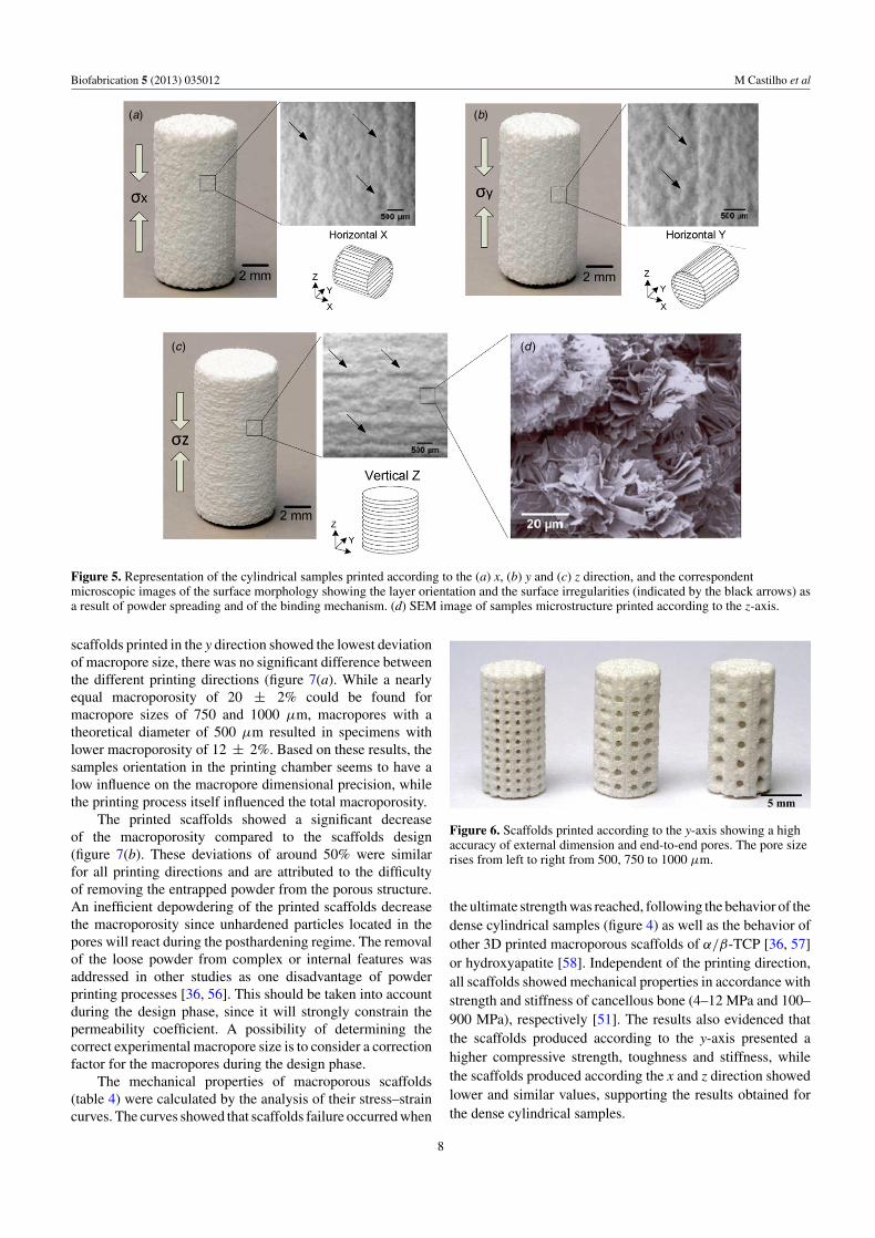
Figure 5 shows images of the specimens, printed indifferent directions, as well as a schematic illustration ofthe alignment of the samples layers. The orientation of thelayers, resulting from powder spreading direction as wellas surface irregularities (indicated by the black arrows), canbe seen in the magnification of the specimens. Figure 5(d)shows an SEM image of a printed and posthardened specimen,with randomly oriented tabular brushite crystals without anypreferential orientation according to the printing direction.This microstructure was observed in all analyzed samples,independently of the printing direction.
The results show that the mechanical behavior dependson the direction of the powder spreading (powder roller movesalong x-axis) as well as and on the direction of the binder jetting(the inkjet head moves along the y-axis). For the horizontallyy-direction printed samples the compressive load was applied
parallel to their constituent layers and to the direction of binderjetting, while for those samples printed in x direction thecompressive load was applied parallel to the constituent layerbut perpendicular to the direction of binder jetting. In the caseof printing according to the z-axis, the compressive load wasapplied perpendicular to both, constituent layer and binderjetting.
The horizontal y samples present higher mechanicalproperties in comparison to the horizontal x and vertical zsamples, which have similar mechanical properties. Theseresults suggested that the binder jetting direction has a greatinfluence on the mechanical properties of the 3D printed partsand if higher strengths are required, parts should be printed ina way that the binder jetting direction is parallel to the higheststress level.
3.3. Physical and mechanical characterization of thedesigned scaffolds
Recent studies showed the successful fabrication of tailoredbone implants by low temperature 3D printing. Torres et al[54] used disc-shaped blocks for vertical bone augmentationof the rabbit calvaria and Tamini et al [55] utilized a tubularbrushite block for rabbit ulna bone defect. However, despiteusing this technique for the production of bone implants, theoptimization of the topology in the design of the implantis not referred. To give consideration to the importance oftopology concerning the biological and mechanical behavior,structures were designed in this work based on an optimizationtopology tool. As referred previously these scaffolds wereprinted with the axial direction aligned with the x-, y- andz-axis of the printing chamber, in order to evaluate the influenceof the printing orientation on the dimensional accuracy andon the mechanical properties of the produced parts. Figure 6shows that the 3D printing process allows the fabricationof macroporous scaffolds with a high accuracy of externaldimensions.
The influence of the printing direction on the macroporesize and macroporosity is shown in figure 7. Although
7
Biofabrication 5 (2013) 035012 M Castilho et al
(a) (b)
(c) (d )
Figure 5. Representation of the cylindrical samples printed according to the (a) x, (b) y and (c) z direction, and the correspondentmicroscopic images of the surface morphology showing the layer orientation and the surface irregularities (indicated by the black arrows) asa result of powder spreading and of the binding mechanism. (d) SEM image of samples microstructure printed according to the z-axis.
scaffolds printed in the y direction showed the lowest deviationof macropore size, there was no significant difference betweenthe different printing directions (figure 7(a). While a nearlyequal macroporosity of 20 ± 2% could be found formacropore sizes of 750 and 1000 μm, macropores with atheoretical diameter of 500 μm resulted in specimens withlower macroporosity of 12 ± 2%. Based on these results, thesamples orientation in the printing chamber seems to have alow influence on the macropore dimensional precision, whilethe printing process itself influenced the total macroporosity.
The printed scaffolds showed a significant decreaseof the macroporosity compared to the scaffolds design(figure 7(b). These deviations of around 50% were similarfor all printing directions and are attributed to the difficultyof removing the entrapped powder from the porous structure.An inefficient depowdering of the printed scaffolds decreasethe macroporosity since unhardened particles located in thepores will react during the posthardening regime. The removalof the loose powder from complex or internal features wasaddressed in other studies as one disadvantage of powderprinting processes [36, 56]. This should be taken into accountduring the design phase, since it will strongly constrain thepermeability coefficient. A possibility of determining thecorrect experimental macropore size is to consider a correctionfactor for the macropores during the design phase.
The mechanical properties of macroporous scaffolds(table 4) were calculated by the analysis of their stress–straincurves. The curves showed that scaffolds failure occurred when
Figure 6. Scaffolds printed according to the y-axis showing a highaccuracy of external dimension and end-to-end pores. The pore sizerises from left to right from 500, 750 to 1000 μm.
the ultimate strength was reached, following the behavior of thedense cylindrical samples (figure 4) as well as the behavior ofother 3D printed macroporous scaffolds of α/β-TCP [36, 57]or hydroxyapatite [58]. Independent of the printing direction,all scaffolds showed mechanical properties in accordance withstrength and stiffness of cancellous bone (4–12 MPa and 100–900 MPa), respectively [51]. The results also evidenced thatthe scaffolds produced according to the y-axis presented ahigher compressive strength, toughness and stiffness, whilethe scaffolds produced according the x and z direction showedlower and similar values, supporting the results obtained forthe dense cylindrical samples.
8

Biofabrication 5 (2013) 035012 M Castilho et al
(b) (a)
Figure 7. Comparison of (a) experimental macropore diameter and (b) experimental macroporosity, PE, of scaffolds with macropore sizes of500, 750 and 1000 μm printed along the x-, y- and z-axis of the printing chamber. Design porosity, PD, was 35.7% and is represented bydashed line bars.
Table 4. Mechanical parameters and Weibull moduli (for the ultimate compressive stress) of the cylindrical scaffolds printed according tothe x-, y- and z-axis of the printing chamber.
Mechanical parameters
Scaffold Printing direction (axis) σ c in MPa εc in % UT in KJ m−3 ET in MPa (R2; RMSE) m value (R2)
x 5.69 ± 0.79 1.81 ± 0.21 48 ± 8 499 ± 83 (0.99; 0.03) 8.39 (0.97)Scaffold 500 y 12.49 ± 1.40 2.22 ± 0.19 111 ± 17 824 ± 89 (0.99; 0.05) 10.28 (0.93)
z 5.02 ± 1.83 1.99 ± 0.59 31 ± 9 517 ± 112 (0.99; 0.02) 3.21 (0.93)x 5.00 ± 0.56 1.45 ± 0.17 32 ± 6 502 ± 76 (0.99; 0.03) 10.42 (0.99)
Scaffold 750 y 9.22 ± 1.28 1.75 ± 0.35 66 ± 26 827 ± 52 (0.99; 0.01) 8.24 (0.94)z 4.87 ± 1.12 2.05 ± 0.48 48 ± 27 433 ± 144 (0.99; 0.01) 4.87 (0.92)x 3.43 ± 1.05 1.27 ± 0.62 19 ± 10 411 ± 181 (0.99; 0.01) 3.29 (0.95)
Scaffold 1000 y 8.23 ± 1.73 1.87 ± 0.24 53 ± 24 757 ± 121 (0.99; 0.02) 5.11 (0.86)z 5.03 ± 1.03 1.92 ± 0.30 44 ± 15 526 ± 129 (0.99; 0.02) 5.41 (0.99)
σc: ultimate compressive stress; εc: corresponding strain; ET: tangent modulus; UT: modulus of toughness; m: Weibull modulus (meanvalues ± standard deviation).
The reliability of the TCP scaffolds was also evaluatedby Weibull statistics. Higher values of Weibull modulus (m)were obtained for the scaffolds with a macropore diameterof 500 μm, printed along the y-axis, as well as for thosescaffolds with a macropore diameter of 750 μm printed inthe x direction. Although the analysis of dense specimenshowed lower variability of strength for the printing accordingto the x-axis (table 3, higher Weibull modulus), this was notproofed for the macroporous scaffolds. No particular trend wasfound for the different scaffold architectures, which reflect therandomly mechanism of failure in macroporous structures ofbrittle materials.
The applicability of the optimization tool can be accessedthrough the comparison of experimental tangent modulusof the printed scaffolds with the respective homogeneousmodulus of elasticity of the designed scaffolds. The laterwas determined by multiplying the homogenized elasticcoefficient, EH, with the tangent modulus, ET, of the densesamples printed in different directions, i.e. approximately399 MPa in x direction, 475 MPa in y direction and 425 MPain z direction. The results indicated a low deviation betweenexperimental and design moduli of approximately 17%for scaffolds printed in x and z direction, while manufacturingaccording to the y-axis caused a higher deviation of
approximately 70%. These differences could be explainedby both the lower experimental macroporosity and thedirectionality introduced by the printing process, which arenot taken into account in the computational formulation.
Figure 8 shows the evolution of the mechanical strengthand tangent modulus with the experimental macroporosity ofscaffolds printed according to the x-, y- and z-axis. The trendof decreasing mechanical properties with increasing porosity[59] is consistent with the presented results.
Furthermore the different linear regression slopes clearlyindicate different relations between the relative tangentmodulus or the relative strength and the experimentalmacroporosity for printing according to x- and z-axis or parallelto the y-axis. These relations emphasized the differencesintroduced by the directionality on the mechanical behaviorof printed samples, wherein the samples printed parallel to they-axis present higher tangent and compressive strength (lowerslope/dashed lines). This behavior should be consideredduring the cage printing so that the cage directions, whichwill be submitted to the highest compressive forces in vivo, areprinted according to the y-axis. As mentioned above, other keypoint of 3D printed scaffolds is the combination of adequatemechanical properties with micro- and macroporosities.Recent studies have shown that microporosity enhances
9

Biofabrication 5 (2013) 035012 M Castilho et al
(b) (a)
Figure 8. Relation between experimental macroporosity, PE, and (a) relative tangent modulus, Escaf/Eden, and (b) relative strengthσ scaf/σ den for scaffold with different macropore sizes printed according x-, y- and z-axis of the printing chamber. Straight lines represent thelinear fit for horizontal x (solid line), vertical z (dotted line) and horizontal y (dashed line). The tangent modulus of dense specimens andscaffolds were represented in the plot by Eden and Escaf, respectively.
osteoconductivity and potentially osteoinductivity [50, 60, 61],while macroporosity promotes a higher bone ingrowthcompared to scaffolds without engineered channels.
4. Conclusions
This study addressed the ability of the low temperature 3Dprinting process to fabricate bone scaffolds with the supportof an optimized computational topology design, taking intoaccount permeability and mechanical requirements for thein vivo situation. The influence of the printing direction onthe physical and mechanical properties of the specimens wasstudied in order to elect the most appropriate manufacturingparameters. The results suggested that the printing directionhas a significant influence on the scaffolds mechanicalbehavior, but only a slight influence on their structuralproperties, i.e. geometric accuracy as well as on the micro- andmacroporosity. Specimens printed according to the y-axis ofthe printing chamber showed considerable higher compressivestrength, toughness and stiffness compared to samples printedalong the x- and z-axis, which was attributed to the influenceof the binder jetting direction during sample fabrication. Thescaffolds compressive strength, as well as the stiffness ofthe scaffolds was found to be in the range of the cancellousbone. Therefore the coupling of topology optimization designwith low temperature 3D printing process revealed to be apowerful tool for the fabrication of bone scaffolds suitableto produce a biodegradable cage with tailored properties forTTA application. However, a correction factor may be addedto the computational formulation in order to balance thedirectionality and the dimensional deviation effect introducedby the printing process.
Acknowledgments
This work was sponsored by FCT through the PhD scholarshipwithin the company Altakitin SA, SFRH/BDE/51454/2011
(Miguel Castilho) and by the projects PTDC/EME-TME/103375/2008 (Ines Pires, Barbara Gouveia, JorgeRodrigues and Miguel Castilho) and PTDC/EME-PME/104498/2008 (Paulo Fernandes and Marta Dias). Theauthors would like to thank all staff of the Department forFunctional Materials in Medicine and Dentistry University ofWurzburg, Germany, for all the materials, assistance and facili-ties provided for this work, and also to the veterinary physicianDr Henrique Armes.
References
[1] Gross K and Berndt C 2002 Biomedical application of apatitesRev. Mineral. Geochem. 48 631–72
[2] Garrido C, Lobo S, Turıbio F and LeGeros R 2011 Biphasiccalcium phosphate bioceramics for orthopaedicreconstructions: clinical outcomes Int. J. Biomater. 2011 9
[3] Dorozhkin S V 2010 Bioceramics of calcium orthophosphatesBiomaterials 31 1465–85
[4] Bohner M 2010 Resorbable biomaterials as bone graftsubstitutes Mater. Today 13 24–30
[5] Bucklent B, Wettergreen W, Yuksel E and Liebschner M 2008Bone derived CAD library for assembly of scaffolds incomputer-aided tissue engineering Virtual Phys.Prototyping 3 13–23
[6] Hollister S, Liao E, Moffitt E, Jeong C and Kemppainen J2009 Defining design targets for tissue engineeringscaffolds Fundamentals of Tissue Engineering andRegenerative Medicine pp 521–37
[7] Kang H, Lin C and Hollister S 2010 Topology optimization ofthree dimensional tissue engineering scaffold architecturesfor prescribed bulk modulus and diffusivity Struct.Multidiscip. Optim. 42 633–44
[8] Lantada A and Morgado P 2012 Rapid prototyping forbiomedical engineering: current capabilities and challengesAnnu. Rev. Biomed. Eng. 14 73–96
[9] Bose S, Roy M and Bandyopadhyay A 2012 Recent advancesin bone tissue engineering scaffolds Trends Biotechnol.30 546–54
[10] Lee K W, Wang S, Lu L, Jabbari E, Currier B Land Yaszemski M J 2006 Fabrication and characterizationof poly(propylene fumarate) scaffolds with controlled porestructures using 3-dimensional printing and injectionmolding Tissue Eng. 12 2801–11
10

Biofabrication 5 (2013) 035012 M Castilho et al
[11] Lee K W, Wang S, Fox B C, Ritman E L, Yaszemski M Jand Lu L 2007 Poly(propylene fumarate) bone tissueengineering scaffold fabrication using stereolithography:effects of resin formulations and laser parametersBiomacromolecules 8 1077–84
[12] Lee K W, Wang S, Yaszemski M and Lu L 2010 Enhanced cellingrowth and proliferation through three-dimensionalnanocomposite scaffolds with controlled pore structuresBiomacromolecules 11 682–9
[13] Wei C, Cai L, Sonawane B, Wang S and Dong J 2012High-precision flexible fabrication of tissue engineeringscaffolds using polymers Biofabrication 4 025009
[14] Hutmacher D, Schantz J, Lam C, Tan K and Lim T 2007 Stateof the art and future directions of scaffold-based boneengineering from a biomaterials perspective J. Tissue Eng.Regenerative Med. 1 245–60
[15] Leong K, Chua C, Sudarmadgi N and Yeong W 2008Engineering functionally graded tissue engineeringscaffolds J. Mech. Behav. Med. Mater. 1 140–52
[16] Hollister S 2005 Porous scaffold design for tissue engineeringNature Mater. 4 518–24
[17] Hutmacher D, Sittinger M and Risbud M 2004 Scaffold basedtissue engineering: rationale for computer-aided design andsolid free-form fabrication systems Trends Biotechnol.22 354–62
[18] Peltola S, Melchels F, Grijpma D and Kellomaki M 2008 Areview of rapid prototyping techniques for tissueengineering purposes Ann. Med. 40 268–80
[19] Abdelaal O and Darwish S 2011 Fabrication of tissueengineering scaffolds using rapid prototyping techniquesWorld Acad. Sci. Eng. Technol. 59 577–85
[20] Bose S, Avila M and Bandyopadhyay A 1998 Processing ofbioceramic implants via fused deposition process Presentedat the ’98 SFF (Austin, TX) pp 10–12
[21] Zein I, Hutmacher D, Tan K and Teoh S 2002 Fuseddeposition modeling of novel scaffold architectures fortissue engineering applications Biomaterials 23 1169–85
[22] Chu T M G, Halloran J W, Hollister S J and Feinberg S E2001 Hydroxyapatite implants with designed internalarchitecture J. Mater. Sci. Mater. Med. 12 471–8
[23] Lee G, Barlow J W, Fox W C and Aufdermorte T B 1996Biocompatibility of SLS-formed calcium phosphateimplants Presented at the ’96 SFF, (Austin, TX) pp 12–4
[24] Tan K H, Chua C K, Leong K F, Cheah C M, Cheang P,Abu Bakar M S and Cha S W 2003 Scaffold developmentusing selective laser sintering of polyetheretherketone-hydroxyapatite biocomposite blends Biomaterials24 3115–23
[25] Cima M J, Sachs E, Cima L G, Yoo J, Khanuja S,Borland S W, Wu B and Giordano R A 1994Computer-driven microstructures by 3D printing: bio- andstructural materials Presented at the ’94 SFF (Austin, TX)pp 8–10
[26] Lam C X F, Mo X M, Teoh S H and Hutmacher D W 2002Scaffold development using 3D printing with a starch basedpolymer Mater. Sci. Eng. C 20 49–56
[27] Butscher A, Bohner M, Hoffmann S, Gauckler L and Muller R2011 Structural and material approaches to bone tissueengineering in powder-based three-dimensional printingActa Biomater. 7 907–20
[28] Butscher A, Bohner M, Roth C, Ernstberger A, Heuberger R,Doebelin N, Rohr P and Muller R 2012 Printability ofcalcium phosphate powders for three-dimensional printingof tissue engineering scaffolds Acta Biomater. 8 373–85
[29] Zhang Y, Tse C, Rouholamin D and Smith P 2012 Scaffoldsfor tissue engineering produced by inkjet printing Cent. Eur.J. Eng. 2 325–35
[30] Gbureck U, Holzel T, Klammert U, Wurzler K, Muller Fand Barralet J 2007 Resorbable dicalcium phosphate bone
substitute prepared by 3D powder printing Adv. Funct.Mater. 17 3940–5
[31] Vorndran E, Klarner M, Klammert U, Grover L, Patel S,Barralet J and Gbureck U 2008 3D Powder printing ofβ-tricalcium phosphate ceramics using different strategiesAdv. Eng. Mater. 10 B67–71
[32] Vorndran E, Wunder K, Moseke C, Biermann I, Muller F,Zorn K and Gbureck U 2011 Hydraulic settingMg3(PO4)2 powders for 3D printing technology Adv. Appl.Ceram. 110 476–81
[33] Klammert U, Reuther T, Jahn C, Kraski B, Kubler Aand Gbureck U 2009 Cytocompatibility of brushite andmonetite cell culture scaffolds made by three-dimensionalpowder printing Acta Biomater. 5 727–34
[34] Sachs E, Haggerty J, Cima M and Williams P 1993Three-dimensional printing techniques US PatentSpecification 5204055
[35] Seitz H, Rieder W, Irsen S, Leukers B and Tille C 2005 Threedimensional printing of porous ceramic scaffolds for bonetissue engineering J. Biomed. Mater. Res. B 74B 782–8
[36] Yoon J Y S, Deyhle H, Gbureck U, Vorndran E, Beckmann Fand Muller B 2012 Three-dimensional morphology andmechanics of bone scaffolds fabricated by rapid prototypingInt. J. Mater. Res. 02 200–6
[37] Fierz F, Beckmann F, Huser M, Irsen S, Leukers W,Degistirici O, Andronache A, Thie M and Muller B 2008The morphology of anisotropic 3D-printed hydroxyapatitescaffolds Biomaterials 29 3799–806
[38] Shanjani Y, Hu Y, Pilliar R and Toyserkani E 2011Mechanical characteristics of solid-freeform-fabricatedporous calcium polyphosphate structures with orientedstacked layers Acta Biomater. 7 1788–96
[39] Ness M, Abercromby R, May C, Turner M and Carmichael S1996 A survey of orthopedic conditions in small animalveterinary practice in Britain Vet. Comp. Orthop.Traumatol. 9 (2) 6–15
[40] Alvarez A 2011 Treatment of cranial cruciate ligament rupturein dogs—an overview Vet. Focus 21 (2) 39–46
[41] Boudrieau R 2009 Tibial plateau leveling osteotomy or tibialtuberosity advancement? Vet. Surg. 38 1–22
[42] Yeadon R, Fitzpatrick N and Kowaleski M 2011 Tibialtuberosity transposition advancement for treatment ofmedical patellar luxation and concomitant cranial cruciateligament disease in the dog Vet. Comp. Orthop. Traumatol.24 18–26
[43] Rezwan K, Chen Q, Blaker J and Boccaccini A 2006Biodegradable and bioactive porous polymer/inorganiccomposite scaffolds for bone tissue engineeringBiomaterials 27 3413–31
[44] Kim S, Pozzi A, Kowaleski M and Lewis D 2008 Tibialosteotomies for cranial cruciate ligament insufficiency indogs Vet. Sur. 37 111–25
[45] Habibovic P, Gbureck U, Doillon C, Bassett D, Blitterwijk Cand Barralet J 2008 Osteoconduction and osteoinduction oflow-temperature 3D printed bioceramic implantsBiomaterials 29 944–53
[46] Dias M, Fernandes P, Guedes J and Hollister S 2012Development of bone scaffolds with controlled permeabilityand stiffness J. Tissue Eng. Regenerative Med. 6 (Suppl. 1)390
[47] Bendsøe M P and Sigmund O 2003 Topology OptimizationTheory, Methods and Applications (Berlin: Springer)
[48] Guedes J and Kikuchi N 1990 Preprocessing and postprocessing for materials based on the homogenizationmethod with adaptive finite element method Comput.Methods Appl. Mech. Eng. 83 143–98
[49] Weibull W 1951 A statistical distribution function of wideapplicability Trans. ASME J. Appl. Mech. 18 293–7
11

Biofabrication 5 (2013) 035012 M Castilho et al
[50] Gbureck U, Holzel T, Doillon C, Muller F and Barralet J 2007Direct printing of bioceramic implants with spatiallylocalized angiogenic factors Adv. Mater. 19 795–800
[51] Karageorgiou V and Kaplan D 2005 Porosity of 3Dbiomaterial scaffolds and osteogenesis Biomaterials26 5474–91
[52] An Y and Draughn R 2000 Mechanical Testing of Bone andthe Bone-Implant Interface (Boca Raton, FL: CRC Press)
[53] Johnson A and Herschler B 2011 A review of the mechanicalbehavior of CaP and CaP/polymer composites forapplications in bone replacement and repair Acta Biomater.7 16–30
[54] Torres J, Tamimi F, Alkhraisat M, Prados-Frutos J,Rastikerdar E, Gbureck U, Barralet J and Lopez-Cabarcos E2011 Vertical bone augmentation with3D-syntheticmonetite blocks in the rabbit calvaria J. Clin.Periodontol. 38 1147–53
[55] Tamini F, Corneau P, Nihouannen D, Zhang Y, Bassett D,Khalili S, Gbureck U, Tran S, Komarova S and Barralet J2013 Perfluorodecalin and bone regeneration Eur. CellsMater. 25 22–36
[56] Castilho M, Pires I, Gouveia B and Rodrigues J 2011Structural evaluation of scaffolds prototypes produced bythree-dimensional printing Int. J. Adv. Manuf. Technol.56 5–8
[57] Muller B et al 2009 Bio-mimetic hollow scaffolds for longbone replacement Proc. SPIE 7401 74010D-1
[58] Will J, Melcher R, Treul C, Travitzky N, Kneser U,Polykandriotis E, Horch R and Greil P 2008 Porous ceramicbone scaffolds for vascularized bone tissue regenerationJ. Mater. Sci, Mater. Med. 19 2781–90
[59] Takahashi T, Yamamoto M, Ioku K and Goto S 1997Relationship between compressive strength and porestructure of hardened cement pastes Adv. Cem. Res. 9 25–30
[60] Habibovic P, Gbureck U, Doillon C, Bassett D, Blitterwijk Cand Barralet J 2008 Osteoconduction and osteoinduction oflow-temperature 3D printed bioceramic implantsBiomaterials 29 944–53
[61] Roy T, Simon J, Ricci J, Rekow E, Thompson V and Parsons J2003 Performance of degradable composite bone repairproducts made via three-dimensional fabrication techniquesJ. Biomed. Mater. Res. A 66 283–91
12