
f -TS YOU CAN tUILD, WITH COMPLETE . - World Radio History
260
f -TS YOU CAN tUILD, WITH COMPLETE . INSTRUCTIONS,, PICTURES AND DIAGRAMS 4
-
Upload
khangminh22 -
Category
Documents
-
view
0 -
download
0
Transcript of f -TS YOU CAN tUILD, WITH COMPLETE . - World Radio History

f -TS YOU CAN tUILD, WITH COMPLETE .
INSTRUCTIONS,, PICTURES AND DIAGRAMS4

OVER 100 HOME REPAIRSYOU CAN MAKE YOURSELF!
0 N LY 149FIX IT YOURSELF
TELLS YOU WHAT TO DOAND HOW TO DO IT!
A Few of the Hundreds ofItems in this Big Book: - -
Build a cedar closetRepair porch stepsFix wooden & slate roofsFix vacuum cl s
Fasten woodwork to brickInclose an open porchMake a p losetRepair doors that stickLay floor boardsFix washing machineLay linoleum floorsPatch plaster wallsApply wall paperApply border to wallF nish floor with varnishRemove old paintPaint wood and metalPaint stucco and concreteRepair leaking pipesClear clogged drainsKeep pipes from freezingRepair electric wiringOperate oil bRefinish furnitureRepair building tileAnd hundreds morel
Easy Money -SavingWays to Modernize
Your House!b.".7
Just one glance at this great new practical book, FIX IT YOUR-SELF, and you'll see how easy it is to save yourself hundreds ofdollars in home repairs and improvements! It's jam-packed with allthe tested methods of repairing your home appliances, plumbing,fixtures, furniture and heating plant! You'll say its 163 picturesand diagrams make everything as easy as ABC! You'll learn howsimple it is to enclose an open porch, make a preserve closet for thebasement, cut glass for a broken window pane, repair floors and laylinoleum, paper or plaster a room, build general purpose shelvesand ironing boards, and make old woodwork shine like new!
256 PAGES! 163 PICTURES! BARGAIN PRICE!Glance through these step-by-step instructions-see how fastyou can learn to fix a leaking water pipe, repair a faulty vacuumcleaner or washing machine-how you can clear a drain that'sclogged, and save a small fortune by applying your ownstorm doors and windows or weather stripping!
Anyone can learn to be a real "handyman" with this hugebook that shows all the important operations, the tricks of thetrade, tools and materials! It's called FIX IT YOURSELF ...Try it out -'t home! You don't risk a single cent!
SEND NO MONEY NOW!ORDER FOR 7 DAYS' FREE TRIAL!
Just think! This big clothbound volume jam-packed with pic-tures and diagrams-costs you only $1.49 if you order rightnow! Fill out and mail the order card on the back cover flapof this paper bound book. Pay postman only $1.49 plus a fewcents postage, as your payment in full. If after you've lookedit over for seven full days, you aren't completely satisfied, re-turn it and we'll gladly refund every cent you paid! You don'trisk a single penny, so:-
MAIL YOURORDER
RIGHT NOW!ItTA-50
(pi I I. \ IL St II:SI I: III WASHING CO.it 11 A,C11111'. Yt.:k 10. N. Y. t°: "
SAVE a Stamp by Using the Postage -FREE Order Card on Back Cover Flap

- ,
1 OM
POPULAR SCIENCE.
RADIO AND TELEVISION
ANNUAL
Everything You Want to Know
About Radio and Television
Repair and Construction
POPULAR SCIENCE PUBLISHING CO., INC.
353 Fourth Avenue New York 10, N. Y.

COPYRIGHT, 1950
POPULAR SCIENCE PUBLISHING COMPANY, INC.
ALL RIGHTS RESERVED
PRINTED IN THE UNITED STATES OF AMERICA

POPULAR SCIENCE
RADIO AND
TELEVISION
ANNUAL


Table of Contents
How to Buy Radio Parts 8 Old Tubes Salvaged as Rectifiers 73
Radio -Building Hints for the Beginner 14 Rectifier Gives Bias Voltage 73
The Last Word in Crystal Sets 18 Standard Symbols for Circuit Elements 73
Beginner's Radio Grows by Stages 22 Testing with Resistor Bridges 74
Intercoms Save You Steps 26 Repairing Noisy Potentiometers 74
Amplifier Fits on Headphone 31 Heavy -Duty Choke -Input Power Pack 75
Radio Parts from Your Scrap Box 32 Hidden Brackets Hold Radio on Wall .... 76
A Superhet the Beginner Can Build 36 Terminal Strips Help Test Circuits 76
Completing the Beginner's Set 40 What to Do About Intermittent Recep-tion 77
How to Stop Appliance Static 44Improving Low -Cost Record Players .. 78
Relaxation Oscillator for Code Practice 45Filter Improves Crystal Pick -Ups 81
Testing for Burned -Out Tube Filaments 45What Tube Can I use? 82
Meet Mr. Mike 46Glow Lamp Shows Tube Cutoff Action 85
Wiring Puzzlers 51Adapting Auto Radios to Home Use 86
Filters . . . Radio's Most ImportantNetworks 52 Tuning In Those Off -the -Dial Stations 88
Wireless Record Player Broadcasts 56 Arrow on Knob Gauges Volume 89
Personal Radio with a Bedside Manner 58 Clip on Portable Lid Holds Data 89
T.R.F. Receiver Has A.V.C. 60 Electronic Print Timer 90
Seeing Eye of Electronics 62 Eliminating Speaker Hum 91
Building a Cathode -Ray Oscilloscope .... 66 Homemade Wand Helps Alignment 91
Measuring Impedances 71 Loudspeaker Adjustments 92
Signal Booster Brings in Weak Stations 72 Circuit Tester Uses Standard Parts 93
5

Permissible Voltage Drop 93 Playing Records with One Tube 164
Multipurpose Test Instrument & Am-plifier 94
Listen in on This 10 -Meter Receiver
Short -Wave Converter Brings in theWorld 98
Midget 80 -Meter Code Transmitter 102
Two -Meter Handie Talkie 104
Low -Cost Parts Test Radios 107
Circuit Tester Uses Tuning Eye as Meter 111
Capacity Bridge for Testing Condensers 112
Pocket Radio Doubles as Hearing Aid 168
External Speaker Adds Uses to Auto96 Radio 172
One -Tube Radio Can Be Mailed 173
One -Tube Radio Is Matchbox Size 174
You Can't Sneak Past This RobotWatchman 176
Two -Band Superhet 178
More Power to You 182
Businessman's Radio Fits in Briefcase 186
Output Meter Uses 11/2 -Volt Tube 115 Bring Out High Notes with a Tweeter 190
Meters Clock Electricity's Flow 116
Building a Multimeter 120
Completing Your Multimeter 124
Midget Volt -Ohmmeter 127
Push -Button Selector Keeps Test ValuesHandy 129
Vacuum -Tube Meters Read VoltageRight 130
Pocket Set Has Permeability Tuning 135
High Fidelity with Two Tubes 136
De Luxe Vacation Portable Rivals Con-sole 140
Boy's Radio Lets Dad Enjoy His 145
Simple Guard Protects Needle 146
Tagging Wires Saves Time 146
4 -Way Portable Stretches Battery Life 147
Battery Phono-Radio Portable 152
Dry -Disk Rectifier Replaces Tubes 155
Tune In on High Fidelity 156
Hi-Fi Amplifier Gets ALL the Music 160
6
Portable Phono-Radio Combination 192
Three -Pound Radio Is on the Ball 196
RF Booster Stretches Radio's Range . 200
B Supply Cuts Battery Cost 202
Converting AC -DC Sets to Portables 204
Oscillator -Amplifier Is Master MusicSystem 208
Armchair Tuner Reaches to Your Radio 212
Tuning Eye Makes Old Radios Look Up 217
Wireless Mike Puts You on the Air 222
Getting Big -Set Quality from a Midget 224
Preamplifier Serves Mike or Pickup 227
How Good Is Your TV Picture? 229
Taking Care of a TV Set 231
I Assembled My TV Set from a Kit 234
Antennas for FM and Television 240
Improving Quality of TV Sound 245
How to Rotate TV Antennas 248
Glossary of Television Terms 252
Index 254


How to Buy
Radio PartsBy Frank Tobin
Knowing what to his and N. hy is
shopping. and the key to
SHOULD you ask a radio -parts salesmanfor a "double -o -one -mike condenser," he
could put out a counterful of parts-all dif-ferent, yet all .001-mfd. capacitors. "Whichdo you want?" he might ask. "Paper, mica, orceramic-and what voltage
If your first impulse is to say that it makesno difference so long as the capacity is right,you've probably never seen the wax meltout of a paper condenser used where a micashould have been. Sometimes, to be sure,identically rated parts may be used inter-changeably. But don't overlook the manycases where an improper part may cause ashort, burnout, or open circuit, or simplybecome defective in a hurry.
Some of the things that are worth know-ing about condensers, coils, resistors, outputtransformers, and tubes are dealt with inthis article. You may find them helpful nexttime you shop for radio parts.
Condensers-Fixed and Variable
Mica condensers ( Fig. 1) are easily recog-nized by their molded -plastic cases. They
are commonly used in by-pass and couplingcircuits and as grid condensers in grid -leakdetectors. Their working -voltage rating isgenerally about 500 volts DC but the casesare rarely marked. Mica condensers are usedmostly at high frequencies, and therefore ca-pacities are low, ranging from about 50 mmf.to 6,000 mmf. (.006 mfd.). You'll find micasin demand wherever low capacities with
8
the first step to successfulbuilding electronic gadgets that work.
low loss at high frequencies are required.Incidentally, in case condenser arithmetic
has you stumped, the basic unit of capacityis the farad. As radio components go, thisunit is enormous, so it's divided by a million.
(mfd.) and can beexpressed as .000001 farad, (one millionthfarad) but would normally be written 1 mfd.Even that's big in radio work-, so the micro -farad is further divided by a million to givethe micromicrofarad (mmf.) which can bewritten .000001 mfd. or, more simply, 1mmf. To translate mfd. to mmf., simplymove the decimal six places to the right (ineffect, multiply by a million). Thus .0001mfd. is the same as 100 mmf., and .005 mfd.becomes 5000 mmf.
One of the war -developed ceramic capaci-tors will often do when specifications call formica. Ceramics have high stability and com-pactness; they come in the form of smalldisks or tiny cylinders resembling fixed re-sistors (Fig. 1). They arc also primarily foruse in radio-frequency ( RF) circuits.
Paper condensers can be found in everystage of a modern receiver. They have suchvaried functions as by-passing stray signalvoltages, coupling two stages, bass boosting(in tone -control circuits), and filtering incertain rectifier applications.
Working voltages are usually indicated for
paper condensers, and it is important thatthe rating be adequate. When in doubt al-ways take a larger voltage. In AC -DC or

CONDENSERS (CAPACITORS/
MICA
D
PAPER CERAMICPAPER
ELECTROLYTIC
DUALCANTYPE
ELECTROLYTIC
battery -operated receivers a condenser ratedat 400 volts allows a safe margin. You mightget by with these even in an AC set oramplifier that delivers 250 to 350 volts ofB plus, but a few pennies more can buygreater safety in the form of 600 -volt con-densers. Sometimes heat generated by tubesmay melt the wax in which a condenser issealed. Where this seems likely, try to getcapacitors sealed in plastic.
There .is still another type of fixed con-denser that crops up in practically every
TRIMMERS
VARIABLE(TUNING
CONDENSER,
piece of radio or electronic equipment-theelectrolytic. This is used in all filter circuitsand in many special- applications. Electro-lytic condensers come in aluminum cans orcardboard containers. In order to save space(and cost), two or more units are often putin one container with separate leads broughtout. A single can containing two units iscalled a dual electrolytic; multiple electro-lytics with up to four sections are common.Polarity must be observed for electrolytics,so make sure the leads are color -coded or
9
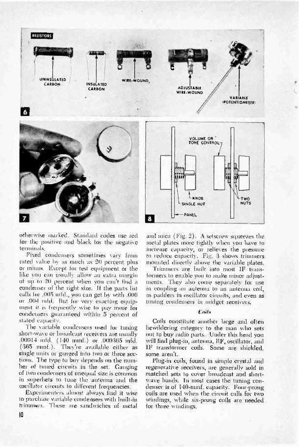
RESISTORS
UNINSULATEDCARBON INSU ATED
CARBON
WIRE -WOUND,
otherwise marked. Standard codes use redfor the positive and black for the negativeterminals.
Fixed condensers sometimes vary fromrated value by as much as 20 percent plusor minus. Except for test equipment or thelike you can usually allow an extra marginof up to 20 percent when you can't find acondenser of the right size. If the parts listcalls for .005 mfd., you can get by with .006or .004 mfd. But for very exacting equip-ment it is frequently wise to pay more forcondensers guaranteed within 5 percent ofstated capacity.
The variable condensers used for tuningshort-wave or broadcast receivers are usually.00014 mfd. (140 mmf.) or .000365 mfd.(365 mmf.). They're available either assingle units or ganged into two or three sec-tions. The type to buy depends on the num-ber of tuned circuits in the set. Gangingof two condensers of unequal size is commonin superhets to tune the antenna and theoscillator circuits to different frequencies.
Experimenters almost always find it wiseto purchase variable condensers with built-intrimmers. These are sandwiches of metal10
ADJUSTABLEWIRE -WOUND
VARIABLE(POTENT °METER,
I
itiE1-KNOS
SINGLE NUT
N
-PANEL
VOLUME ORTONE CONTROL
'TWONUTS
and mica ( Fig. 2). A setscrew squeezes themetal plates more tightly when you have toincrease capacity, or relieves the pressureto reduce capacity. Fig. 3 shows trimmersmounted directly above the variable plates.
Trimmers are built into most IF trans-formers to enable you to make minor adjust-ments. They also come separately for usein coupling an antenna to an antenna coil,as padders in oscillator circuits, and even astuning condensers in midget receivers.
Coils
Coils constitute another large and oftenbewildering category to the man who setsout to buy radio parts. Under this head youwill find plug-in, antenna, RF, oscillator, andIF transformer coils. Some are shielded,some aren't.
Plug-in coils, found in simple crystal andregenerative receivers, are generally sold inmatched sets to cover broadcast and short-wave bands. In most cases the tuning con-denser is of 140-mmf. capacity. Four -prongcoils are used when the circuit calls for twowindings, while six -prong coils are neededfor three windings.

Antenna and RF coils are employed insmall TRF receivers. They are availableeither shielded or unshielded. When usingunshielded coils, it is best to mount the an-tenna coil above the chassis and the RF coilunderneath so the chassis will serve as ashield. Wherever it is necessary to mountall coils on one side of the chassis, or wherethere's more than one tuned RF stage, onlyshielded units should be used. In buyingreceiver coils, ask for a matched set. Thiswill assure accurate ganging between coilsas well as with the condensers.
Most superheterodyne circuits call for anantenna coil, and they always require anoscillator coil, ;old at least two intermediate -frequency ( I F ) transformers. Shieldingproblems are the same as in the TRF set.In the lower foreground of Fig. 4 an un-shielded oscillator coil is mounted under-neath the chassis.
The transformers used to couple IF stagesare basically coils tuned to a fixed frequency-in broadcast receivers 456 kc. They are inaluminum cans (Fig. 5 shows one cut away)with lugs, clips, or feet by which they canhe mounted.
Some IF transformers are brought to peakfrequency by trimmers, and some by adjust-ing an iron core. The latter respond overa much broader tuning range and are there-fore easier to align without a signal generator.
One final point to bear in mind whenbuying coils: If you are building a receiverwith only a single stage of RF or IF, youneed maximum amplification in each stage.You will get this plus greater selectivity byusing coils with iron cores.
Fixed and Variable ResistorsYou'd have to look hard for an electronic
circuit that doesn't use a fixed or variable
resistor of some kind. Fixed carbon resistorsconstitute the bulk of all resistance units.They are inexpensive, reasonably accurate,and come in a large variety of sizes and rat-ings. Some are encased in plastic, whichmakes them impervious to moisture and lesslikely to short against other components.Uninsulated resistors (Fig. 6) dissipate heata little more readily but shouldn't be usedin cramped quarters.
All fixed resistors are rated in ohms (theunit of resistance) and watts (current rat-ing). As Nvith voltage ratings in condensers,a larger wattage is safer when there's doubt.
For AC -DC receivers and amplifiers,'S -watt units are generally adequate in thecontrol -grid circuits of amplifier tubes. Plateand screen circuits should get 1 -watt re-sistors, and cathode and filter circuits 2 wattsor more. Battery -operated equipment cangenerally get by with ratings half as large.
Wire -wound resistors are employed wherecurrent drain is high and where stability andaccuracy are paranount. On adjustablewire -wound resistors part of the winding isleft bare so that a movable metal band cantap off any resistance between zero and themaximum.
Variable resistors, now found chiefly inthe form of potentiometers, have a fixed car-bon or wire -wound element and a movingcontact turned by a shaft. If you want re-sistance to increase evenly in proportion toshaft movement, specify a linear -taper pot.Because of tube characteristics, nonlinearpots usually give more gradual control overvolume, tone, and bias. In logarithmic pots,usually. used for tone and volume controls,resistance increases at a definite but unevenrate. In end -tapered pots, used for varyingtube bias, resistance "thins out" at one end.
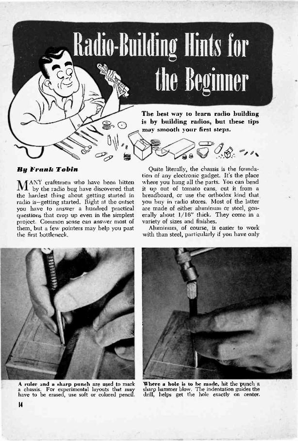
For the convenience of radio builders, the
10

makers of potentiometers provide switchesthat can be slipped onto the back of the unit(Fig. 7 ). The switch is actuated by the firstfew degrees of shaft turn.
A potentiometer is usually fastened to apanel by means of a gripping nut screwedon a threaded shaft. Since there is a gooddeal of variation in shaft nuts, you can oftendo yourself a favor by purchasing an extraone at the time you buy the potentiometer.With two nuts you can exactly regulate theprojection of the shaft in front of the panelas shown in Fig. 8.
Output TransformersIn purchasing an output transformer for
a small set, it is best to look for the universaltype. Taps on the secondary winding of thetransformer ( Fig. 9) allow matching of anytube impedance from 1,500 to 20,000 ohmsto any voice -coil impedance from .1 to 24ohms. These figures vary somewhat withdifferent makes.
Impedance matching is probably the lead-ing consideration in the selection of an out-put transformer, but there is one other thatmust never be overlooked. If the transformercan't handle all the plate current that willbe delivered to it, it cannot transfer thatpower to the speaker. Output transformersare rated in watts. For most battery andsmall AC -DC receivers, 4 to 5 watts is suit-able; for AC receivers and high-poweredaudio amplifiers you will usually want atransformer rated at 8 watts or more.
Tubes and Pilot LightsSome people feel that radio tubes offer
the largest variety of radio components.Several catalogs list upward of 400 types.This, however, need rarely worry the builderwho works from a parts list. The specifica-
tions always designate tubes by numbers.One puzzling element is the lettering that
follows the tube number. A metal 6K7, forexample, has the same electrical characteris-tics as the glass -dome 6K7 -G or the bantam6K7-GT (the latter is sometimes listed asGT/G). The only differences are in theirphysical dimensions (Fig. 10) and in themethod of shielding. The first of these tubesis encased in metal, the other two in glassenvelopes of different sizes (G being con-siderably larger than the GT). The 6K7 re-quires no separate shielding, while the othersmust be covered with a metal shield (Fig.11) to suppress undesirable coupling. Onlytubes used in the high -frequency circuits-RF, converter, IF, and sometimes detectorstages-need shielding; others such as poweroutput tubes and rectifiers don't require it.Fig. 10 shows the most common types of re-ceiving tubes, being, from left to right, sub-miniature, miniature, bantam (GT), metal,and glass dome (G).
Sometimes you want to duplicate a par-ticular circuit in a smaller size. This is be-coming increasingly possible with miniaturecomponents. For example, the 50L6 beam -power amplifier can be replaced with aSOBS miniature.
Dial pilot bulbs become critical in AC -DCsets, because they're in series with the tubesand must match them in current rating, sincecurrent is equal in all parts of a series circuit.The bulb ratings are marked by a coloredglass bead in the bulb. For example, a setusing tubes with heaters drawing .15 ampat 6.3 volts calls for a brown -bead pilot bulb.A white bead means .5 amp. at 2.5 volts, ablue .3 amp. at 6 to 8 volts, and a pink one.06 amp. at 2 volts. All types come withboth bayonet and screw bases to suit thetwo socket types (Fig. 12).
12

BULB TIESCUT FROM OLD
MEDICINE DROPPER
WIRE PIERCESauLe.
Rubber Tips Insulate ChokesWHEN crowding radio parts close together
to make a compact job, here's a method forprotecting the bare metal ends of an RFchoke against accidental contacts. For eachend, cut the rubber tip from an old medi-cine dropper and place it over the end asshown.-Alfred H. Fortier, Orono, Me.
Vent Holes Prolong Tube LifeA FEW 1i" holes
drilled around thesocket of the rectifiertube of a large re-ceiver, amplifier, ortransmitter will keepthe tube cooler andthus help to increaseits life. Other nearbycomponents are also benefited because theincreased air circulation carries away muchof the damaging heat.-D. J. Bachner, Jack-son Heights, N. Y.
WINDOW SCREEN,WALL,OR PARTITION
SOLDERING LUG
BRASS NUTS
CLEAR PLASTICFUNNELS
SAW OFF SPOUT
WA SN ER
346 0nAss RODTHREADED BOTH
ENDS
Insulators 31sule From FunnelsI MADE some swell cone -type feed -
through insulators from the small plasticfunnels sold in dime stores. Comparable com-mercial insulators would have cost me a lotmore. Two of the 'funnels, with the tips cutoff, are used for each insulator as shown inthe sketch above.-Arthur Trager, CouncilBluffs, Iowa.
Iron Plug Is Phone TerminalAN OLD electric -iron plug can be converted
into a handy terminal for a mike or phonoinput or used for an output connection tospeaker or phones. Its own cable can bebrought under the chassis to the appropriateconnections. Incoming leads are fitted withbanana plugs, which are in most cases agood fit in the holes. Either bolts and nutsor self -tapping screws can be used to holdthe clamp. Being built with heavy-dutyinsulation, the plugs can be attached di-rectly to the chassis as shown.
MUSIC
PINCNO
Pointer Filed on Plain KnobIT Is often convenient to have a reference
point on the knob of a volume, tone, or othercontrol so that a setting can be noted forfuture use. If you don't have a pointer knobon hand or want one that matches the othersas closely as possible, you can convert anordinary round knob to your purposes asshown. File two small flats on the rim, leav-ing a small portion between them. Then filethis portion sharp to form the pointer.
A spot of paint or nail polish on the pointwill make it easier to read.
13
Radio -Building Hints for
the lleginuer
By Frank TobinMANY craftsmen who have been bitten
by the radio bug have discovered thatthe hardest thing about getting started inradio is-getting started. Right at the outsetyou have to answer a hundred practicalquestions that crop up even in the simplestproject. Common sense can answer most ofthem, but a few pointers may help you pastthe first bottleneck.
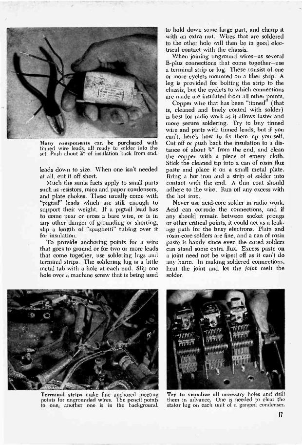
A ruler and a sharp punch are used to marka chassis. For experimental layouts that mayhave to be erased, use soft or colored pencil.
14
The best way to learn radio buildingis by building radios, but these tipsmay smooth your first steps.
c=c&67
ia
Quite literally, the chassis is the founda-tion of any electronic gadget. It's the placewhere you hang all the parts. You can bendit up out of tomato cans, cut it from abreadboard, or use the orthodox kind that,you buy in radio stores. Most of the latterare made of either aluminum or steel, gen-erally about 1/16" thick. They come in avariety of sizes and finishes.
Aluminum, of course, is easier to workwith than steel, particularly if you have only
Where a hole is to be made, hit the punch asharp hammer blow. The indentation guides thedrill, helps get the hole exactly on center.

a hand drill. With an electric drill the dif-ference isn't very great. You can use car-bon -steel bits with a hand drill, but high-speed drills will last longer if you have aheavy-duty electric drill.
Drilling the holes is an easier matter thandeciding where to drill them. Tube socketsand coils especially must never be placedhaphazardly. They have to be located andoriented so as to keep the leads as short aspossible. Not all wires can be short, ofcourse, but they aren't all equally important.The critical ones are those going to platesand grids. From the diagram or a tube man-ual you can easily figure which way to turna socket or IF transformer so that the leadswill remain short. Screen -grid and B -pluswires are next in importance. Keep themshort if you can, but don't worry if theyhave to stretch a bit. Heater, ground, andAVC leads practically don't count in theshortness sweepstakes.
Should you find that the grid leads in anaudio or output stage have to be long, useshielded wire and ground the braid to thechassis at some point. Good examples arethe connections to volume or tone controls.Do not use shielded wire in radio -frequencystages, as the added capacity of the shieldmay easily throw off the alignment of thecoils and tuning condenser. And if any gridwire has to cross one that goes to a plate,make sure they do so at right angles.
A chassis punch consists of a two -jaw cutter,left, a die, and a machine bolt. A separatepunch is needed for each different hole size.
Drawing up the bolt with a wrench brings thecutter and die in contact with the chassis andshears out a clean, precise socket opening.
Wherever possible, group componentswhich perform similar functions. The RFand IF parts can go on one section of achassis, the audio and output stages aregathered in another, and the rectifier andpower -supply pieces occupy still a differentcorner.
Once you've decided where each of theparts is to go, mark the chassis for drillingwith a soft pencil or a sharp -pointed tool.At the spot where a hole is to be drilled,make a punch mark that can serve as a pilotfor the drill. Since the three holes for atube socket ( two hold-down screws and thatfor the socket opening) must line up exact-ly, marking and drilling require care.
Small holes are easy. All you have to dois select a drill of the proper size. Largerones for tube sockets and the like are an-other matter. There are three common meth-ods for making such holes.
You can either enlarge a smaller openingwith a rat-tail file, use an adjustable holecutter in a drill press, or employ a chassispunch. Punches are made in all the com-mon socket sizes; the three that take careof most work are %", 1 1/16" and 1%".
It is difficult to visualize in advance allthe holes that may be needed, but drillingothers after some parts are mounted mayendanger those parts. Why not drill a fewextra holes, especially in strategic locations?
Remember, for example, that leads from
Any burred edges that are left after drilling-especially in aluminum-should be removedwith a file or a heavy knife blade.
15

Copper wire solders best when it is tinned.Best bet is to buy it that way, but you cantin the ends yourself by scraping them clean
a transformer or choke can't get to the un-derside of a chassis through solid metal. A5/32" or 3/16" hole is about right for pass-ing a wire through the chassis. You needan opening, also, when you use a tube thathas a grid connection brought to a metalcap on top. And for each gang of a tuningcondenser there has to be some way to getto the stator (fixed) plate terminals. If thecondenser has lugs on the bottom, drill over-
A soldering lug, held down by a screw that isused to fasten some other part to the chassis,provides an excellent ground connection.
16
and dipping them into rosin flux paste. Putan end on a metal plate and run a thin coatof solder over it. Melt off any excess.
size holes-say W' to %"-so that neither thelug nor the connecting wire can touch thechassis.
Once you have all the holes drilled andthe parts mounted, you can get down to theserious business of wiring the set. It is usu-ally advisable to make all filament or heaterconnection first. Take care of the cathodesnext, then go back to the RF stage and workalong, in order, to the rectifier.
In AC receivers where heater voltage isobtained from a filament winding on thepower transformer, twist the leads andground the centertap of the winding. Thishelps to reduce hum pickup. If the wind-ing has no centertap, ground one of its twoleads and one of the heater pins on eachtube socket directly to the chassis. Theother transformer lead then goes to the re-maining heater prongs. Always use strandedwire with good insulation; it withstandstwisting and bending a good deal betterthan solid wire.
While stranded wire is recommended forheater connections, a solid wire-preferablywith insulation of the "push -back" type-has advantages for B -plus and plate leads.Being less flexible, this wire can be bent upout of the way and will stay where it is put.
In actual practice you will find that youdon't need very much wire to hook up a set.Many components are sold with their ownleads, which are almost always ample forthe connections that have to be made. Ifthey aren't, the chances are that somethingis wrong with the placement of the parts.Most often it will be necessary to cut these
Many components can be purchased withtinned wire leads, all ready to solder into theset. Push about %" of insulation back from end.
leads down to size. When one isn't neededat all, cut it off short.
Much the same facts apply to small partssuch as resistors, mica and paper condensers,and plate chokes. These usually come with"pigtail" leads which are stiff enough tosupport their weight. If a pigtail lead hasto come near or cross a bare wire, or is inany other -danger of grounding or shorting,slip a length of "spaghetti" tubing over itfor insulation.
To provide anchoring points for a wirethat goes to ground or for two or more leadsthat come together, use soldering lugs andterminal strips. The soldering lug is a littlemetal tab with a hole at each end. Slip onehole over a machine screw that is being used
Terminal strips make fine anchored meetingpoints for ungrounded wires. The pencil pointsto one; another one is in the background.
to hold down some large part, and clamp itwith an extra nut. Wires that are solderedto the other hole will then be in good elec-trical contact with the chassis.
When joining unground wires-as severalB -plus connections that come together-usea terminal strip or lug. These consist of oneor more eyelets mounted on a fiber strip. Aleg is provided for bolting the strip to thechassis, but the eyelets to which connectionsare made are insulated from all other points.
Copper wire that has been "tinned" (thatis, cleaned and finely coated with solder)is best for radio work as it allows faster andmore secure soldering. Try to buy tinnedwire and parts with tinned leads, but if youcan't, here's how to fix them up yourself.Cut off or push back the insulation to a dis-tance of about %" from the end, and cleanthe copper with a piece of emery cloth.Stick the cleaned tip into a can of rosin fluxpaste and place it on a small metal plate.Bring a hot iron and a strip of solder intocontact with the end. A thin coat shouldadhere to the wire. Run off any excess withthe hot iron.
Never use acid -core solder in radio work.Acid can corrode the connections, and ifany should remain between socket prongsor other critical points, it could act as a leak-age path for the busy electrons. Plain androsin -core solders are fine, and a can of rosinpaste is handy since even the cored solderscan stand some extra flux. Excess paste ona joint need not be wiped off as it can't doany harm. In making soldered connections,heat the joint and let the joint melt thesolder.
Try to visualize all necessary holes and drillthem in advance. One is needed to clear thestator lug on each unit of a ganged condenser.
17

Still the beginner's choice, crystal
receivers refuse to die out. These
four de luxe versions will surprise
you with the things galena can do.
By FRANK TOBINCRYSTAL receivers occupy a unique and
honorable position in the history ofmodem science. Almost to a man, the pres-ent generation of engineers and techniciansgrew up on crystals, and it is this generationthat has made electronics a synonym forprogress and achievement.
With the rapid advance of the radio art,crystal detectors were forced to give wayto vacuum tubes. But as much as they'vebeen shoved into the background, theseperennial favorites have never passed out ofthe radio picture. Beginners and experi-menters who like to do a lot with a little stillfind their simple circuits inviting, especially.since new developments in crystals havegiven a boost to the old-fashioned sets.
Take, for example, the novel radio phono-graph shown on the next page. The outputof the pickup (which employs a piezoelectricrather than a detector crystal) is sufficientto drive one or two pairs of headphones atfull strength and with excellent quality. Byusing a spring -wound motor in place of theone shown, you can make the outfit inde-pendent of a power supply as well as of anamplifier.
Most of the space in .the standard 4" by10" by 12" cabinet is occupied by the phono-graph. One of the newer fixed crystals(type 1N34) is used in the radio. Anantenna coil of the type commonly used inA.C. - D.C. sets and a .00036-mfd. variablecondenser are employed for tuning. Con-nected between the primary and secondarywindings of the coil, a midget .00005-mfd.trimmer adjusts the coupling. The looserthe coupling (i.e., the more out of mesh therotor plates are) the greater will be theselectivity and the weaker the volume.Once it is set for any particular locality andantenna, the trimmer need not be altered.
A pickup with as little as .5 -volt outputwill serve, but one rated at 1.5 volts or moreis preferable because the output of thephono crystal is fed directly into the head-phones without amplification. To vary thevolume, use different needles. Soft needlesgive less headphone volume than hard ones.
Too much power can sometimes be as badas too little. Standard crystal receivers usedclose to several high-powered transmittersoften fail to separate the stations, and it isto overcome this weakness that two separatetuned circuits are employed in the super-selective receiver illustrated at the top ofpage 20. Coils LI and L2, together with a.00036-mfd. variable condenser (C1) formthe first tuned circuit; L3 and C2 form thesecond. Selectivity is obtained in this fash-ion without sacrificing signal strength.
All the coils are wound on a 23i" tube 6W'long. Use No. 24 enameled wire throughout,winding 50 turns for LI, 25 turns for L2,and 60 turns for L3. When a long outdoorantenna is available, better results can beobtained by connecting it to the midpointof Ll.
Closest in design to the conventional crys-tal set that has been popular since the begin-
II
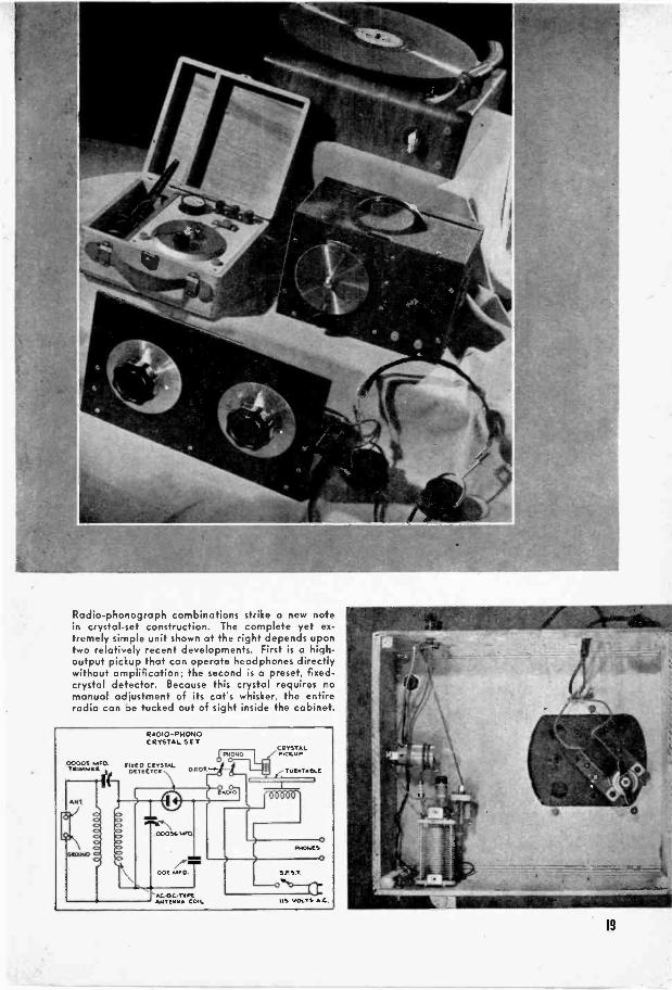
Radio -phonograph combinations strike a new no -ein crystal -set construction. The complete yet ex-tremely simple unit shown at the right depends upontwo relatively recent developments. First is a high -output pickup that can operate headphones directlywithout amplification; the second is a preset, fixed -crystal detector. Because this crystal requires nomanual adjustment of its cat's whisker, the entireradio can be tucked out of sight inside the cabinet.
RADIO-F.140N°CRYSTAL SIT
0000S PAFO. MCC. CRYSTALTe'.."4M OCT E C TOR
ANT
o
0 P DT
PEON
ao
000005CAVII
II
CRYSTALmccuP
TurATAOLL
006611'
ootO.
AL.O.C.TYPCIL/STEMMA COIL us VOLTS AL.
0MIMICS
0
SP ST.
19

Two separate tuned circuits enable this receiver todistinguish between two or more powerful signals.The alligator clip is used to centertap the antennacoil, LI, when a long aerial is available.
ning of radio is the compact portable shownbelow. To cover the entire broadcast bandwith its .00014-mfd. condenser, two sets ofcoils are needed. These can be made inter-changeable by winding them on a pair of4 -prong, II" plastic forms. For use between200 and 350 meters, L2 should consist of100 turns of 32 -gauge wire, and LI of 40turns of No. 36. Leave 1/16" to 3i" spacebetween the two windings. Stations oper-ating in the 350 to 550 -meter range can betuned in with a coil that consists of 170turns of No. 34 (L2), and 60 turns of No. 36(LI ). As before, enameled wire is used
This tiny set makes a fine traveling companion. Foruse on camping trips, carry a long coil of antennawire and a spike that can be driven into the ground.
CIMINO
20
PORTABLE CRYSTALRECEIVER
Lt
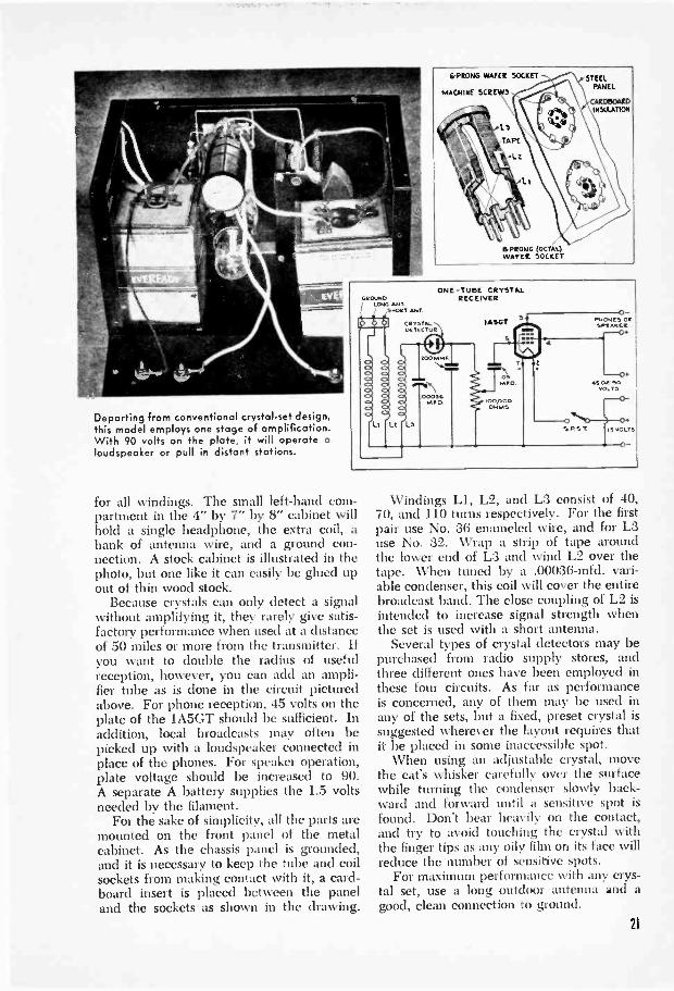
Departing from conventional crystal -set design,this model employs one stage of amplification.With 90 volts on the plate, it will operateloudspeaker or pull in distant stations.
GROUNDLONG MIT
SNORT ANT
'L
CRYSTALOR TT< TOR
I 2DODO
'L3
ONE -TUBE CRYSTALRECEIVER
IASGT0
PHONES ORSOK AKE!-0+
-0+4.101+ 10
VOLTS
'NOSY'
0
for all windings. The small left-hand com-partment in the 4" by 7" by 8" cabinet willhold a single headphone, the extra coil, ahank of antenna wire, and a ground con-nection. A stock cabinet is illustrated in thephoto, but one like it can easily be glued upout of thin wood stock.
Because crystals can only detect a signalwithout amplifying it, they rarely give satis-factory performance when used at a distanceof 50 miles or more from the transmitter. Ifyou want to double the radius of usefulreception, however, you can add an ampli-fier tube as is done in the circuit picturedabove. For phone reception, 45 volts on theplate of the 1A5GT should be sufficient. Inaddition, local broadcasts may often bepicked up with a loudspeaker connected inplace of the phones. For speaker operation,plate voltage should be increased to 90.A separate A battery supplies the 1.5 voltsneeded by the filament.
For the sake of simplicity, all the parts aremounted on the front panel of the metalcabinet. As the chassis panel is grounded,and it is necessary to keep the tube and coilsockets from making contact with it, a card-board insert is placed between the paneland the sockets as shown in the drawing.
Windings LI, L2, and L3 consist of 40,70, and 110 turns respectively. For the firstpair use No. 36 enameled wire, and for L3use No. 32. Wrap a strip of tape aroundthe lower end of L3 and wind L2 over thetape. When tuned by a .00036-mfd. vari-able condenser, this coil will cover the entirebroadcast band. The close coupling of L2 isintended to increase signal strength whenthe set is used with a short antenna.
Several types of crystal detectors may bepurchased from radio supply stores, andthree different ones have been employed inthese four circuits. As far as performanceis concerned, any of them may be used inany of the sets, but a fixed, preset crystal issuggested wherever the layout requires thatit be placed in some inaccessible spot.
When using an adjustable crystal, movethe cat's whisker carefully over the surfacewhile turning the condenser slowly back-ward and forward until a sensitive spot isfound. Don't bear heavily on the contact,and try to avoid touching the crystal withthe finger tips as any oily film on its face willreduce the number of sensitive spots.
For maximum performance with any crys-tal set, use a long outdoor antenna and agood, clean connection to ground.
21
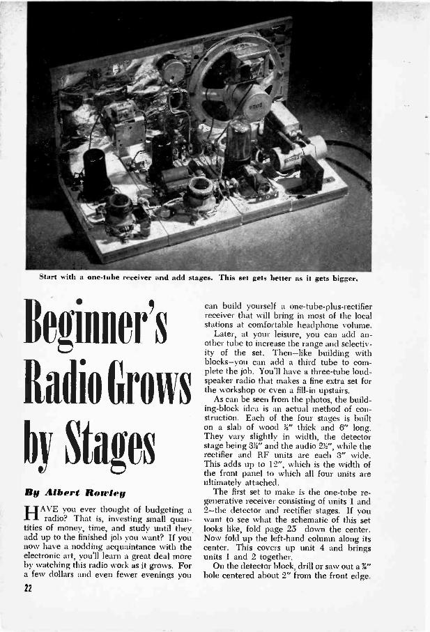
Start with a one -tube receiver and add stages. This set gets better as it gets bigger.
Beginer's
Radio Grows
by StagesBy Albert Rowley
HAVE you ever thought of budgeting aradio? That is, investing small quan-
tities of money, time, and study until they.add up to the finished job you want? If younow have a nodding acquaintance with theelectronic art, you'll learn a great deal moreby watching this radio work as it grows. Fora few dollars and even fewer evenings you
22
can build yourself a one -tube -plus -rectifierreceiver that will bring in most of the localstations at comfortable headphone volume.
Later, at your leisure, you can add an-other tube to increase the range and selectiv-ity of the set. Then-like building withblocks-you can add a third tube to com-plete the job. You'll have a three -tube loud-speaker radio that makes a fine extra set forthe workshop or even a fill-in upstairs.
As can be seen from the photos, the build-ing-block idea is an actual method of con-struction. Each of the four stages is builton a slab of wood thick and 6" long.They vary slightly in width, the detectorstage being 3V and the audio 2W', while therectifier and RF units are each 3" wide.This adds up to 12", which is the width ofthe front panel to which all four units areultimately attached.
The first set to make is the one -tube re-generative receiver consisting of units 1 and2-the detector and rectifier stages. If youwant to see what the schematic of this setlooks like, fold page 25 down the center.Now fold up the left-hand column along itscenter. This covers up unit 4 and bringsunits 1 and 2 together.
On the detector block, drill or saw out a %"hole centered about 2" from the front edge.

Mount an octal wafer socket with the prongsfitting into the hole and the base of the sock-et flush with the board. The lugs to whichconnections are soldered can be bent overto rest flat on the board. Wood screws holddown the.socket, coil LI, and the half dozenterminal strips that are used to anchor thefixed resistors and condensers. Predrillingthe screw holes makes the assembly easier.
An air -core RF coil is used in this stageas the antenna coil. The plate lead (A) isconnected to an external antenna and theB -Plus terminal (B) goes to the point markedC in the diagram. The other two leads arewired in the usual fashion to grid andground.
Before you do any wiring on the detectorstage, wind 15 to 20 turns of No. 34 D.C.C.wire around the ground end of the second-ary or grid winding. This will become thetickler coil (L2) and will serve to feed backsome of the signal to the grid in order tobuild up amplification. The amount of feed-back is controlled by the 5,000 -ohm poten-tiometer, R2, which makes it, in effect, thevolume control.
Ground connections are brought to a 1"angle bracket mounted flush with the frontedge of the block. A soldering lug under thewood screw that fastens the bracket collectsthe ground leads. No connection is made tothe phone jack terminal marked D in thediagram.
When the detector block is assembled,start on the rectifier. A feed -through switchis cut into the line cord to turn the power onand off. The two leads coming from theswitch are anchored to a 2 -lug terminalstrip. Solder the pigtails of a .01-mfd. con-denser (C9) across the same two lugs.
A filament transformer for the 6 -volt tubeheaters and a dry -disk selenium rectifier arethe principal components of the rectifierstage. Output of the dry disk, as filtered by
The coils in both the detector and RF stagesmust be altered. Nail polish is an effective coildope for sealing new turns in place.
Aluminum foil Nt,,i)I, tl t, the front panel actsas a common ground or chassis and also pro-vides shielding for the variable condenser.
R5, and the dual electrolytic, C7, C8, feedsabout 100 volts of direct current to the B -plus line going to the other stage or stages.
One leg of the angle bracket on eachblock is bolted to the front panel. This panelis backed by a sheet of aluminum foil or tin-foil stapled or tacked to the board. The foilserves as a shield for the tuning condenserand also as a common ground return.
If you plan to build all four stages of thereceiver in time, you can save yourself somework by completing the front panel right atthe start. It is a V by 6" by 12" board onwhich are mounted a two -gang tuning con-denser, closed-circuit phone jack, and 5,000 -ohm potentiometer. A trimmer might be in-cluded in this list although it is actually at-tached directly to the frame of Cl. The onlyparts that will have to be added later are the5" PM speaker and output transformer. Agrille for the speaker is made by drillingseven or eight rows of 34" holes spaced X"apart. If you don't have an electric drill ordrill press, you may find it easier to jigsawan opening and cover it with a cloth.
In this one -tube set, impulses that reachthe external antenna are brought down into
First of three sets you can make with yourbuilding-block receiver. It's a regenerative de-tector employing one tube plus rectifier.

(GND) (AVCORON 01
the primary winding of the RF coil. By in-duction the coil transfers them to the sec-ondary winding where the tuning condenser(in parallel with this part of the coil) se-lects one particular signal from the jumble.
This selected signal goes to the controlgrid of the 6SJ7 detector tube. It is thendemodulated-that is, the radio -frequencycomponent or carrier wave is rectified andfiltered out, leaving only the audio -frequencyvoltage to energize the headphones.
In order to increase the amount of am -
(TICKLE R ) (GRID)
(P..4ATE)
jost 2
CZ/
C5
J
CHASSIS
plification that can normally be obtainedfrom a single tube, part of the signal is fedback from the plate to the grid through thetickler winding.
If you'd like to add pep to the head-phone signals, bring in weak ones withgreater strength, and capture some new onesthat you can't get at all, try adding a stageof radio -frequency amplification. Unit 3,the RF stage, is assembled in much the sameway as the detector. Antenna coil L:3should be of the same manufacture as LI.
UNIT 1 (DETECTOR)
RI: 33.000 -ohm. 12 -watt carbon.R2: 5.000 -ohm potentiometer.R3: 50,000 -ohm. t. -watt carbon.R4: 100.000 -ohm. 1,/ -watt carbon.
UNIT
R5R6C7C8
LIST OF PARTS2 (RECTIFIER)
1.000 -ohm. 2 -watt carbon.15 -ohm. 1 -watt carbon.
50 -mid. 1150 -volt dual electrolytic.30-mfd. /
condenser (See CI).C11: .01 -mid.. 400 -volt paper.L3: Air -core Ant. coil. (See text ,Octal wafer socket and 6SK7
pentode.
Cl: Second section of 2 -gang tuning C9 .01 -mid.. 400 -volt paper. UNIT 4 (AUDIO)condenser. .00041 mid. each section. SI On -oil feed -through switch.
C2 4-80 mmf. variable trimmer. T1 6.3 -volt. 1.2 -amp. filament R8: I-meg.. 12 -watt carbon.C3 4 -mid.. 150 -volt electrolytic. transformer. R9: 200 -ohm. 12 -watt carbon.C4 .05 -mid.. 400 -volt paper. SR: 100 -ma. selenium rect. C12: 50 to 100 mini. ceramic or micaC5 .0001 -mid. mica. Line cord and plug. (see textC6 .01 -mid.. 400 -volt paper. C13: .0033 -mid.. 400 -volt paper.LI Air -core RF coll. UNIT 3 (RF) C14: 4 -mid.. 150 -volt electrolytic.L2 Tickler coil see text). T2: Output trans. (see text).J: Closed-circuit phone jack. R7: 27.000 -ohm. 1 -watt carbon. r PM speaker. octal wafer socketOctal wafer socket and 6SJ7 pentode. CIO: Front half of 2 -gang tuning and 6K6-GT pentode
24

UNIT 4 - AUDIO STAGE
+
S' SPAR
C14
I7
csI+
A+
Matching the coils is important, or the twosections of the tuning condenser won't aligncorrectly. Even buying a pair, however,won't insure matching in this case, becausethe addition of the tickler winding tends toupset the balance. To remedy this condi-tion, remove about ten turns of wire fromboth the primary and secondary windingsof the antenna coil.
When the RF block is finished, connectthe grid of the 6SK7 to the front section ofthe two -gang tuning condenser (C10). Re-move the external antenna from point A andconnect it to the antenna terminal of L3.Break the connection from B to C and con-nect A to E and B to F.
In this setup, incoming signals are firsttuned by C10, the variable condenser acrossthe secondary of the atenna coil. The se-lected signal is amplified in the 6SK7 andcoupled to the detector by means of the RFcoil, which has been restored to its properfuncticn. Having a stronger signal to startwith, the detector stage can now producegreater output.
Although this two -tuber will get more
UNIT t - RECTIFIER STAGE
SR
8+
,TOCHASSIS
ET Ge
VOn5L0TS,0 ACCI 0-0SI
than the one -tube job, it is still a headphonereceiver. If you want to strengthen the sig-nal enough to get loudspeaker volume, adda stage of audio amplification (Unit 4).Connect point D on the phone jack to G,the grid pin of the 6K6.
In order to obtain the correct match be-tween the plate of the 6K6 and the speaker,you need an output transformer with a pri-mary impedance of 10,000 to 12,000 ohmsand a secondary of the proper rating for thevoice coil of the speaker you will use.
Note the 50-mmf. ceramic condenser(C12) across the grid resistor. The capa-city of this condenser is far too low for it tohave any effect on the tone of the set. It isused to increase the amount of feedback get-ting to the grid of the detector tube whenthe audio stage is added. Although it iswired to the grid of the 6K6, it is effectivelylocated between the plate of the 6SJ7 andground. This capacity must be kept low inorder to prevent oscillation. However if50 mmf. doesn't provide enough feedback,try raising the value of C12 to a maximumof 100 or 150 mmf.
25

Illtercoms
Save You Steps
in Home,
Office, ShopTake your pick of a minimum tube-less circuit, an instant -heating batteryjob, or a heavy-duty AC -DC unit.
IF YOU live or work in inure than a coupleof rooms, the question you may well ask
yourself is not whether you need an intercombut what kind of intercom you need. Thesetireless servants run your errands faithfullyto save you countless steps. At home theymake it unnecessary to shout from cellar toattic; at work they lighten the load on tele-phone extensions and get your messagethrough fast.
But granting their usefulness, it must stillbe admitted that no one type of intercomis suited to every job. If you have to makeonly one or two calls a day, you wouldn'twant a set that draws current while it's idle.A battery set will give you the advantagesof instant heating. and uses no stand-bypower. On the other hand the cost of batteryreplacements may make it unwise to usethis type of circuit when the intercom mustbe left on for long periods.
To solve a variety of intercom problems,POPULAR SCIENCE has rounded up the three
26
In factories, offices,and stores, intercoms make
everyone's work easier.
pairs of squawk boxes pictured above andon the following pages. The first, built byTracy Diers, of Richmond Hill, N. Y., is athree -tube, battery -powered unit. It re-quires no warm-up period. so calls can bemade instantly from either end. Because nocurrent is used unless a call is being made,the batteries will have long life.
The second pair. devised by William Nor-ton, Manhattan. N. Y., consists of two iden-tical units. It would be hard to find a simplercircuit, for each box contains only a war -surplus carbon mike, a speaker, and a bat-tery. No tubes are used.
Henry C. Martin, also of Manhattan. builtthe third set. It operates from an AC or DChouse line and is ideal for service in whichit will be turned on in the morning and offat night. After it has warmed up, calls canbe made from either end just by pressing abutton. In the photo at the right, above, theremote unit is shown in service as a babytender. The master set in the shop enables
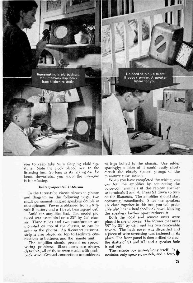
Homemaking is big businesstoo. Intercoms skip sairs
from kitcnen to study.
you to keep tabs on a sleeping child up-stairs. Note the clock placed next to thelistening box. So long as its ticking can beheard downstairs, you know the intercomis functioning.
Battery -operated Intercom
In the three -tube circuit shown in photosand diagram on the following page, twosmall permanent -magnet speakers double asmicrophones. Power is obtained from a 67% -volt B battery and a 1% -volt hearing -aid cell.
Build the amplifier first. The model pic-tured was assembled on a 3%" by 4r chas-sis. Three tubes and two transformers aremounted on top of the chassis, as can beseen in the photos. An 8 -contact terminalstrip is also placed on top to facilitate con-nections to batteries and the remote unit.
The amplifier should present no specialwiring problems. Short leads are alwaysdesirable; all of these were made with push -back wire. Ground connections are soldered
No need to run uo to seeif baby's awake. A speaker
listens Tor yo'..
to lugs bolted to the chassis. Use soldersparingly; a blob of it could easily short-circuit the closely spaced prongs of theminiature tube sockets.
When you have completed the wiring, youcan test the amplifier by connecting thevoice -coil terminals of the remote speakerto terminals 3 and 4. Press Si down to turnon the filaments. The amplifier should startoperating immediately. Since the speakersare close together in this test, you will prob-ably also hear a loud feedback howl. Movingthe speakers farther apart reduces it.
Both the local and remote units wereplaced in metal boxes. The former measures5V by 5W' by 6r, and has two removablecovers. The back cover was discarded anda piece of wire screening was fastened in itsplace. The front panel is then drilled to clearthe shafts of Si and R7, and a speaker holeis cut out.
The remote box is simplicity itself. It ,kcontains only speaker, switch, and a four -
21
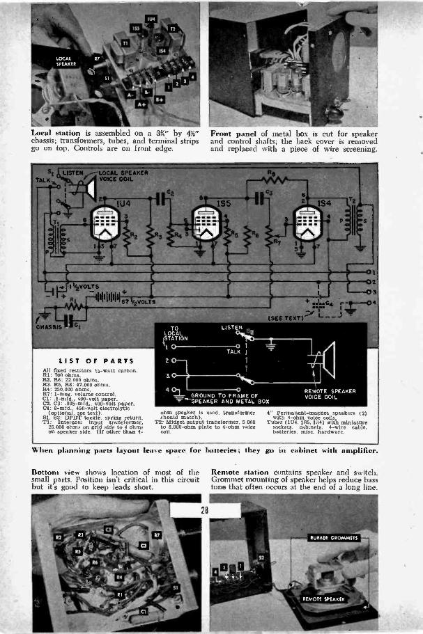
Local station is assembled on a 3%" by 4%"chassis; transformers, tubes, and terminal stripsgo on top. Controls are on front edge.
I 1/2VOLT S
RI
CHASSIS
VOICE COIL
67 /2VOLTS
LIST OF PARTSAll fixed resistors ).-watt carbon.RI: 700 ohms.R2. RES: 22.000 ohms.R.3. R.5. R8: 47.000 ohms.R4: 250,000 ohms.R7: 1-meg. volume control.Cl: .1-mid.. 400 -volt paper.C2. C3:.005 -mid.. 400 -volt paper.C4: 8 -mid.. 450 -volt electrolytic
(optional. see text).81. 82: DPDT toggle. spring return.T1: Intercom input transformer.
25.000 ohms on grid side to 4 ohmson speaker side. (If other than 4 -
Front panel of metal box is cut for speakerand control shafts; the back cover is removedand replaced with a piece of wire screening.
TO LISTENLOCAL
'STATION
IL ITALK I
REMOTE SPEAKERVOCE COIL
ohm speaker Is used. transformer 4" Permanent -magnet speakers (2)should match). with 4 -ohm voice coils.
T2: Midget output transformer. 5 000 Tubes (1U4. 155. 184) with miniatureto 8.000 -ohm plate to 4 -ohm voice sockets. cabinets. 4 -wire cable,coil, batteries. misc. hardware.
When planning parts layout leave space for batteries; they go in cabinet with amplifier.
Bottom view shows location of most of thesmall parts. Position isn't critical in this circuitbut its good to keep leads short.
Remote station contains speaker and switch.Grommet mounting of speaker helps reduce basstone that often occurs at the end of a long line.
contact terminal strip housed in a 4" by 5"by 6" metal box. Stack a couple of rubbergrommets or washers on the screws that holdthe speaker to space it back of the panel.
Connections between the two units arcbest made with four -conductor intercomcable, but you can use two lengths of lampcord. The latter, however, may cause someoscillation. Should this happen, add an8-mfd. electrolytic condenser (C4) fromterminal 2 to ground on the local unit. It'sessential, of course, to connect the local-
station terminals to the corresponding oneson the remote unit. With four -wire cable.the job is made easy by color -coded wires; ifyou use uncoded lamp cord, test each leadfor continuity.
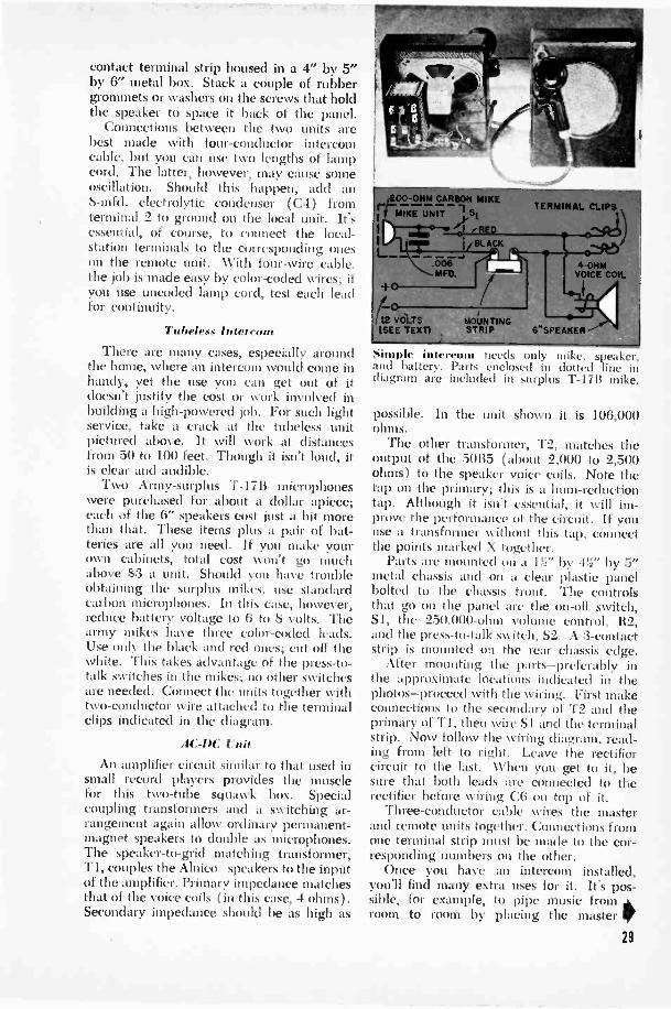
Tubeless Intercom
There arc many cases, especially aroundthe home, where an intercom would come inhandy, yet the use you can get out of itdoesn't justify the cost or work involved inbuilding a high-powered job. For such lightservice, take a crack at the tubeless unitpictured above. It will work at distancesfrom 50 to 100 feet. Though it isn't loud, itis clear and audible.
Two Army -surplus T -17B microphoneswere purchased for about a dollar apiece;each of the 6" speakers cost just a bit morethan that. These items plus a pair of bat-teries are all you need. If you make yourown cabinets, total cost won't go muchabove $3 a unit. Should you have troubleobtaining the surplus mikes, use standardcarbon microphones. In this case, however,reduce battery voltage to 6 to 8 volts. Thearmy mikes have three color -coded leads.Use only the black and red ones; cut off thewhite. This takes advantage of the press -to-talk switches in the mikes; no other switchesare needed. Connect the units together withtwo -conductor wire attached to the terminalclips indicated in the diagram.
AC -DC Unit
An amplifier circuit similar to that used insmall record players provides the musclefor this two -tube squawk box. Specialcoupling transformers and a switching ar-rangement again allow ordinary permanent -magnet speakers to double as microphones.The speaker -to -grid matching transformer,T1, couples the Alnico speakers to the inputof the amplifier. Primary impedance matchesthat of the voice coils (in this case, 4 ohms).Secondary impedance should be as high as
TERMINAL CLIPS
4 -OHMVOICE COIL
Simple intercom needs only mike, speaker,and battery. Parts enclosed in dotted line indiagram are included in surplus T-1711 mike.
possible. In the unit shown it is 106,000ohms.
The other transformer, T2, matches theoutput of the 50B5 ( about 2,000 to 2,500ohms) to the speaker voice coils. Note thetap on the primary; this is a hum -reductiontap. Although it isn't essential, it will im-prove the performance of the circuit. if youuse a transformer without this tap, connectthe points marked X together.
Parts are mounted on a 1!_" by -UV by 5"metal chassis and on a clear plastic panelbolted to the chassis front. The controlsthat go on the panel arc the on -off switch,SI, the 250,000 -ohm volume control, R2,and the press -to -talk switch, S2. A :3 -contactstrip is mounted on the rear chassis edge.
After mounting the parts-preferably inthe approximate locations indicated in thephotos-proceed with the wiring. First makeconnections to the secondary of T2 and theprimary of T1, then wire S I and the terminalstrip. Now follow the wiring diagram, read-ing from left to right. Leave the rectifiercircuit to the last. NN'hen you get to it, besure that both leads are connected to therectifier before wiring C6 on top of it.
Three -conductor cable wires the masterand remote units together. Connections fromone terminal strip must be made to the cor-responding numbers on the other.
Once you have an intercom installed,you'll find many extra uses for it. It's pos-sible, for example, to pipe music fromroom to room by placing the master If
29

12 BAG
cT 75 7 4
14lc
R2
2
T1
TALKY d
i AF6-1 i' 1
L41, LISTEN,
RI:82:R3:R4:R5:RG:R7:RE:Cl:C2:
33.000-okm i,.,-writt carbon.250.000 -ohm volume control.180.000 -ohm. to -watt carbon.680.000 -ohm. ,j -watt carbon.200 -ohm I -wet: carbon.39U -ohm line-c.rd resistor.68 -ohm. 1 -watt carbon.1.000 -ohm. 5 -watt wire -wound.1 -mid.. 150 -volt electrolytic.4 -mid.. 150-valt electrolytk.
--012
50856
115 VAC -DC
R7 .
Allini4.4411111111Lainiallabantgaiiik
LIST OF PARTSC3: .05 -mid.. 400 -volt paper.C4: .001-rifd.. 600 -volt paper.C5: 8 -mid.. 150 -volt electrolytic.C6: 40 -mid . 150 -volt electrolytic.C7: 50 -mid.. 150 -volt electrolytic.81: 8PST toggle.82. 83: SPDT spring -return switches.84. 85: SPOT roptional).T1: Intercom input trans.. 106.000 -
ohm grid to 4 -ohm speaker.
T2: Output trans. for SOBS; 2.000 -ohm plate to 4 -ohm voice coll.
SR: 100 -ma. selenium rectifier.5" Permanent -magnet speakers (2)
with 4 -ohm voice coils. (If otherthan 4 -ohm speakers are used.transformers should match.)
Tubes (12BA6. 50B5). miniaturesockets. cabinets. 3 -wire cablemisc. hardware.
AC -DC c uses speaker and two -tube ampli-fier in master or local station. Remote box,right, contains only speaker and switch.
Clear plastic front panel is attached directlyto amplifier. Isle pilot light is needed sinceplastic window shows when tubes an. lit.
30
unit in front of the radio. Since S2 is aspring -action switch and normally in the"listen" position you either have to replaceit with an ordinary SPDT switch, or, betterstill, add S4. Break the original connectionat the points marked Y -Y and wire in thenew switch. When S4 is in position a, inter-com operations remains unchanged; when it'sflipped to b, the master unit is locked in"talk" position.
The same considerations apply to the re-mote unit. Adding S5-and breaking theoriginal lead at Z-Z-readies the small box toact as a baby tender. Place it next to thebaby's crib and if the youngster cries, youcan hear it at the master unit.
The output transformer was placed underthe chassis in this set. If you use a shallowchassis, it c,in to the top.
C74411100011 **Z

Get more stations at better volume on yourcrystal and one -tube receivers by using ampli-fy ing phones. They'll work with any set.
t'ONE
16 570,000CI MFD.-s. OHMSPHON
r1) ___Eti-(C1 -22.5V. 4$'11-5.4 +223V.(PLATE GROUND) TO -1.5V. TO
(OR CRY STAL)45V. 45V.
NUT
MACH.SCREW
PHONE SHELL
BOTTLECAP CHASS
Tube connections ar soldered t Iv to thepins. Use a small iron and try to soidcr eachjoint quickly; too much heat may cause damage.
AN parts, including tube, are mounted insidethe bottle cap. Battery and phone wires aretaped together to keep them from snarling.
Amplifier FitsOn Headphone
YOU'LL listen more comfortably to yourcrystal and one -tube receivers with a
pair of amplifying headphones. And you'llalso find them helpful for signal tracing,checking phono cartridges, and the like.
This amplifier, built on a ordinary pairof 2,000 -ohm phones (each phone is 1,000ohms) will work with any type of set. Thewhole amplifier, less batteries, fits into ametal bottle cap measuring 1%" across byonly ii" deep. This bottle -cap chassis isbolted to the back of one phone. Since thecap is in effect grounded, you'll lessen thechance of shorts if you line it with cellulosetape. Also tape the bolts and spacers.
Initially the two sides of a pair of head-phones are wired in series, with the com-mon wire runing down to the yoke andback up the other side. To connect the am-plifier, remove the leads from the phonecarrying the bottle cap and connect themto the points marked X in the diagram. Thetwo phone terminals are then wired to pins4 and 5 of the tube, which is a subminiatureone, type 2E36.
44Insulate the bottle -cap chassis with tape. Theholes in back are for mounting; drill two morein the rim to clear battery and phone cables.
Amplifying headphones complete except forthe batteries. Use a 1.5 -volt flashlight cell anda 221- or 45 -volt hearing -aid B battery.
VOIGE-C(MAN
j SP£AkE
COUPLING DETECTOR ORCONDENSER FIRST -AUDIO
TUBE
VOLUME CONTROL
CHASSIS
FIRST -AUDIO TUBE(OR DETECTOR TUBE
IN RECEIVER)
COUPLINGCONDENSER
GRID RESISTOR
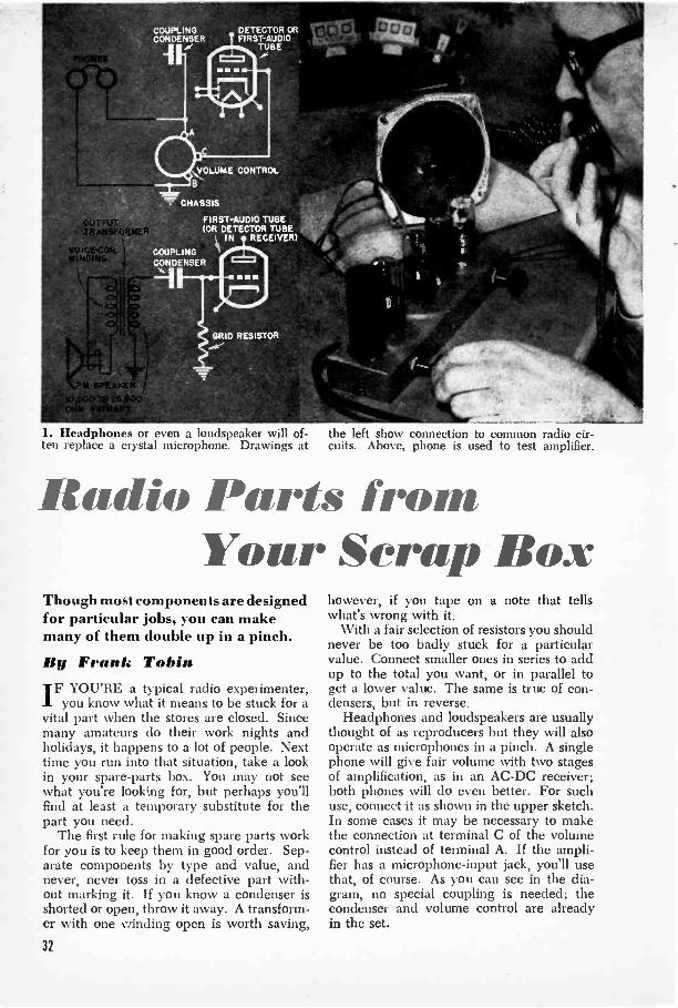
1. Headphones or even a loudspeaker will of- the left show connection to common radio cir-ten replace a crystal microphone. Drawings at cuits. Above, phone is used to test amplifier.
Radio Parts fromYour Scrap Box
Though most components are designedfor particular jobs, you can makemany of them double up in a pinch.
By Frank TobinIF YOU'RE a typical radio experimenter,
you know what it means to be stuck for avital part when the stores are closed. Sincemany amateurs do their work nights andholidays, it happens to a lot of people. Nexttime you run into that situation, take a lookin your spare -parts box. You may not seewhat you're looking for, but perhaps you'llfind at least a temporary substitute for thepart you need.
The first rule for making spare parts workfor you is to keep them in good order. Sep-arate components by type and value, andnever, never toss in a defective part with-out marking it. If you know a condenser isshorted or open, throw it away. A transform-er with one winding open is worth saving,
however, if you tape on a note that tellswhat's wrong with it.
With a fair selection of resistors you shouldnever be too badly stuck for a particularvalue. Connect smaller ones in series to addup to the total you want, or in parallel toget a lower value. The same is true of con-densers, but in reverse.
Headphones and loudspeakers are usuallythought of as reproducers but they will alsooperate as microphones in a pinch. A singlephone will give fair volume with two stagesof amplification, as in an AC -DC receiver;both phones will do even better. For suchuse, connect it as shown in the upper sketch.In some cases it may be necessary to makethe connection at terminal C of the volumecontrol instead of terminal A. If the ampli-fier has a microphone -input jack, you'll usethat, of course. As you can see in the dia-gram, no special coupling is needed; thecondenser and volume control are alreadyin the set.
32

To use a permanent -magnet speaker as amicrophone you need a transformer to matchthe voice -coil impedance to that of the am-plifier grid. The best bet is to use a regularintercom transformer which has a secondarywinding in the neighborhood of 70,000ohms. Lacking this, try an ordinary outputtransformer, selecting the highest primaryimpedance available. Wire them as shownin the lower sketch of Fig. I; black lines rep-resent the parts added to those already inthe set.
The humble wafer socket has the mak-ings of a test -point adapter (Fig. 2). Thewafer socket must be of the same base typeas the tube to be checked. Invert the socket,push in the tube, and plug both tube andtest socket into the socket on the chassis. Itmay be necessary to clip the prong sleeveson the wafer socket to allow the tube pinsto extend through. Bend back the solder-ing lugs.
You may find yourself short of test prodsat a bad time. That's nothing to worry aboutif you have two mechanical pencils aroundthe shop. These pencils make good substi-tutes for prods (Fig. 3). They should haveplastic barrels, or you may find yourselfholding a piece of high voltage. Make surethat a good contact exists between the metalferrule on top of the pencil and the metal tip.Wedge the wire from the meter under theeraser cap or solder it on.
Coil Forms from SpoolsAn ordinary wooden pencil, by the way,
will make a fine core for a high -frequencychoke. Such chokes are widely used in FMand TV receivers and in other high -fre-quency equipment. Leave the graphite inthe pencil; it takes the place of a powderedmetal core. Saw off a 1" piece and, wind thecoil around it.
Other substitute coil forms can be sal-vaged from flashlight batteries or a sewingbox (Fig. 4). In the former case, slip thecardboard sleeve off the cell; in the latter,use a wooden spool from which the threadhas been removed. Finished coils will stayneat longer if they arc coated with liquidcoil dope.
Have you ever thought of employing apower transformer as an output transform-er? Even a defective unit can be used attimes. In Fig. 5 a fairly common transform-er type is shown in this unconventional ap-plication. Using half the high -voltage wind-ing between the plate and B plus, and cm -
2. Test -point adapter, eacib made from w;,lertube socket, allows you to check ()nage, atthe tube instead of turning ch:issis us er.
DINALEAD
UNDEMETALFERR
3. Need a pair 1111rOd!.. Try using me-chanical 9elicik. ,orc ti eV lox\ c plastic bar-rels, for the metal parts nay"bet."
-I. Coil forms can he impro\ iscd troth manycum n lc n objects. W i lid i wis Iii us t, of course,be figured in relation to diatLetcr of the form.
!,.
33

..5, A porter transformer can be used in place stitute, but it will work nicely until you get aof an output transformer. It's an expensive sub- chance to put in the correct replacement unit.
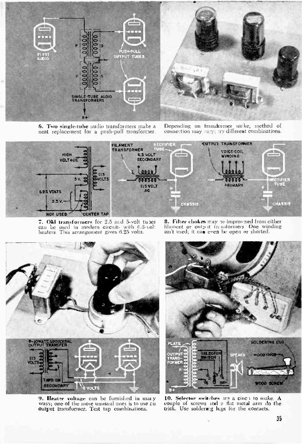
ploying the 5 -volt rectifier winding for thevoice coil gave a surprisingly good matchbetween a 35L6 power tube and the speaker.For other tubes and speakers you can try anumber of other combinations. The 6.3 -volt secondary, for example may be used inplace of the 5 -volt one. Also try the entirehigh -voltage side, or half the 6.3 -volt wind-ing.
A push-pull audio transformer can bemade from two single -tube transformers ifthey're wired in series as shown in Fig. 6.First try connecting one grid and oneground lead together at the center tap. Thismay not be the best arrangement, however,so experiment with others.
By juggling the filament windings on anold power transformer made for 5 -volt and2.5 -volt tubes, you can obtain 6.25 volts.This means you can use the transformer ina circuit employing modern 6.3 -volt tubes.Note, however, that you no longer have a5 -volt tap for the rectifier, so you'll have touse a 6X5 or similar 6.3 -volt rectifier, heat-ing all tubes off one winding.
Subs /or Filter ChokesIt often happens that a serviceman or ex-
perimenter is stuck for a filter choke. It mayoccur when you replace a field -coil speakerwith a permanent -magnet one, for the fieldcoil frequently doubles up as a choke. Ina pinch you'll find a filament transformer isa pretty good substitute. Lacking a filamenttransformer, try using the primary windingof an output transformer in place of themissing choke. Both applications are pic-tured in Fig. 8.
Figure 9 illustrates another possibletransformer dodge. The photo shows a uni-versal output transformer being used to feed
115VOLTS
(1,10T
USED)
6.3 -volt tube heaters. This won't work inall cases, but by trying the various taps onboth primary and secondary you may be ableto find a combination that steps down 115volts to a value very close to 6.3. Test thevoltage on an AC meter before risking thetubes. The transformer should be rated at 8to 10 watts or higher; smaller ones will over-heat. The voice -coil winding goes to thetube filaments while the primary is con-nected to the 115 -volt line.
Selector Switches
If it's a low -voltage switch you want, youdon't have to hunt very far. A few nickel -plated wood or machine screws will do thejob nicely, as pictured in Fig. 10. The setupshown is a test circuit in which a universaloutput transformer is used to feed a numberof different speakers. Instead of solderingand unsoldering a number of connections tofind the best match, make a selector switchby driving the required number of screwsinto a scrap of wood. Place them in an arcarrangement so that the moving arm-whichcan be a flat brass or plated bracket about13i" long-will make contact with each screwhead. A small wooden knob can be at-tached at the end opposite the pivot screw.
Parts substitution of the kind describedabove may not save you much money, butit will save a lot of time and energy. Obvi-ously it doesn't make sense to buy a $3 pow-er transformer in order to replace a filamenttransformer that costs half as much. But ifyou happen to have the more expensive unitgathering dust, you won't lose anything byputting it to work. If this makes it pos-sible to finish the building or repair jobyou're doing, it will often put you aheadof the game.
34
SINGLE -TUBE AUDIOTRANSFORMERS
6. Two single -tube audio transformers make aneat replacement for a push-pull transformer.
.111WMPIOMF
r-.
HIGH
VCLTAGE
5V
.625 VOLTS
NOT USED 'CENTER TAP
FILAMENTTR ANSFORMTR
6.3 VOLTSECCNDAR
Cift-2.1)
7. okl transformers for 2.5 ar.d 5 -volt to )esc,.11 be used in modern circuits with 6.3-toltheaters. This arrangement gives r3.25 volts.
61-1.0WATT uKROUTPUT TRANSFER
:L5VOLTS
9. Heater voltage can be furnished in mar _yways; one of the more unusual ones is to use E nOutput transformer. Test tap combinations.
Yr'
Depending on transformer mike, method ofconnection may %a:3'; Ay different combinations.
CUTpui TRANSFORMER
1
vOICS-COILWINDING
8. Filter chokes may le improvsed from eitherfilament or outp at tra niformers One windingisn't used; it can eren be open or shorted.
SOLDERING LUG
WOOD SORE
10. Selector swishes U2 a cinc 1 to make. Acouple of screws and a fiat metal arm do thetrick. Use soldering lugs for the contacts.
35

Superhet
the Beginner
Call BuildNever built a radio? Tune in onthis 1101)1), %%ill) these plansfor a five-ndier anyone can make.
By a nigh -SchoolShop Teacher
DO VOLTS scare you? Are y on sure youcan't get to first base with radio? Your
ails,ver to these questions should he a thump-If it isn't, someone's kidding you.
I'm not guessing about it. As a shop in-structor, I've met hundreds of beginnerswho were so scared of an Ohm they'd bideunder a table ,vhene, yr one crawled out ofa circuit. Yet a fray weeks the mosttimid of thrill was spiirting a receiver he'dbuilt from scratch.
When I say they made receivers, I meanthe same 5 tube AC -DC superhet you seehere. But isn't it wiser, you may ask, to startoff with a simple 01W-fIllier? 1 don't think Si).It's no harder to hook up live tubes than two-you just work a bit longer. And Nvhellyou've finished, you'll have a sweet little
Bottom .1 thy "mph Iii .ea. Follow this andthe pictorial diagrain in laying out the parts.
set with plenty of power and sensitivity.It's even got automatic volume control, some-thing you won't always find on small sets.
The superhet circuit is a highly efficientone used in scores of commercial designs.It has a few more parts than some others,but they're standard and easily obtained. Ifyou're remote from radio shops, the mail-order radio houses have all you'll need.Your parts cost may be as little as Sl 2, andyour time inycstmc nt will probably run fromfour to se, ell e5 rnings.
What this radio-and any other-has to dois to select the signal of a station you wantto listen to, separate the audio modulation(electric vibrations at sound frequencies)from the high frequencies that have carriedthem through space, and then fatten them
Soldering can be simplified by making allconvenient eminections before mounting parts.
36
up to loudspeaker volume. A superhet hasa baby transmitter of its own, consisting ofan oscillator coil and a mixer tube, whichgenerates a radio signal that's used to con-vert any broadcast signal to a standard fre-quency of 456 kc. This is lower than thebroadcast range but not yet in the audiblerange. It's intermediate, so the transform-ers and amplifiers that boost it are called in-termediate -frequency (IF) transformers andstages. What skims off the low audio fre-quencies is the detector (part of the 12SQ7tube in the diagrams), and they are thenbeefed up by a husky beam -power tube,the 50L6.
Sure, the schematic circuit at the top ofpage 39 looks complicated. But you've onlygot to follow one line at a time! Here eachpart is shown by a symbol-fixed condensersby two thick parallel lines, trimmer con-densers by one line and a thick curved ar-row, and variable tuning condensers by astraight arrow through a straight and curvedline. The letter C refers to condensers thatare numbered with the parts list; and R iden-tifies resistors, which are zigzags in the cir-cuit. The springlike symbols are coils or(when paired) transformers.
Those heavy ovals are tube symbols; in-side, from the bottom up, are the cathode,one or more grids (thick dotted lines), andthe plate. But all you really need to remem-ber is to make the connections to the properpins on the sockets. Looking at the bottomof the socket, these are always numberedclockwise from the little notch or key in thecenter hole. Connections to the heaters,which make the tubes glow, are separatefrom other wiring, so they're shown at thebottom of the diagram with just the pinnumbers for each of the tubes.
Schematics are drawn in a kind of elec-
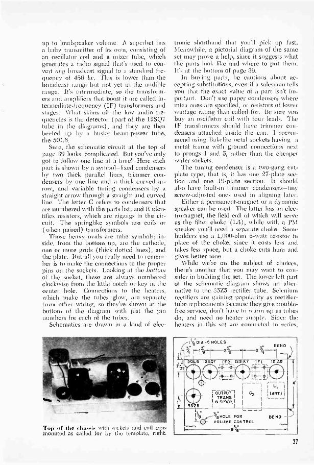
Top of the chassis with sockets and coil cansmounted as called for by the template, right.
tromuc shorthand that you'll pick up fast.Mcan hile, a pictorial diagram of the sameset may prove a help, since it suggests whatthe parts look like and where to put them.It's at the bottom of page 39.
In buying parts, be cautious about ac-cepting substitutions, even if a salesman tellsyou that the exact value of a part isn't im-portant. Don't use paper condensers wheremica ones are specified, or resistors of lowerwattage rating than called for. Be sure youbuy an oscillator coil with four leads. TheIF transformers should have trimmer con-densers attached inside the can. I recom-mend using Bakelite octal sockets having ametal frame with ground connections nextto prongs 1 and 5, rather than the cheaperwafer sockets.
The tuning condenser is a two -gang cut -plate type; that is, it has one 27 -plate sec-tion and one 19 -plate section. It shouldalso have built-in trimmer condensers-tinyscrew -adjusted ones used in aligning later.
Either a permanent -magnet or a dynamicspeaker can be used. The latter has an elec-tromagnet, the field coil of which will serveas the filter choke (L.3), while with a PMspeaker you'll need a separate choke. Somebuilders use a 1,000 -ohm 5 -watt resistor inplace of the choke, since it costs less andtakes less space, but a choke cuts hum andgives better tone.
While we're on the subject of choices,there's another that you may want to con-sider in building the set. The lower left partof the schematic diagram shows an alter-native to the 35Z5 rectifier tube. Seleniumrectifiers are gaining popularity as rectifier -tube replacements because they give trouble -free service, don't have to %yam up as tubesdo, and need no heater supply. Since theheaters in this set are connected in series,
11/8 DIA.-5 HOLES4 ei BEND
4 25/8 -ttLI 5OL6 12 07 r 1F24- I2S KT rIFt 12 A8
I:ri_ 35
I 1 Li I
iI 1 I
1 `ANT.r CTIFP CI I 1 C21' TRANS.' - .....)
I a SPWR. IZS I l 1
4
11,". Il I.Cr3/B
VVHOLE FOROLUME CONTROL
BEND
483e/
37

Arrow points to the plate ( blue) lead of theoscillator coil, soldered to pin 6 of the 12A8.
you'll have to insert the additional resistorsR11 and R12 if you omit the rectifier tube.
And now let's get down to building. Fora neat chassis arrangement, draw a full-sizechassis template, paste it on a flat piece ofaluminum, and punch and drill all holes. ANo. 28 drill is right to clear the 6-32 screwsused to mount all parts. Take pains in mak-ing the holes for the tube sockets, since thebig central hole and the two mounting onesmust be in line. While the 134" socket holescan be cut on the drill press with a holecutter, a chassis punch is much easier. Bendin the sides and letter on the tube numbersfor each socket. Many radio supply housessell prepunched chassis that'll do nicely.
Don't mount the tuning condenser andspeaker right away, since they're both fairlydelicate and might be damaged duringwork. Inasmuch as you're using a 12A8tube in which the signal -grid comes out to acap at the top, use an antenna coil that has ahole in the top of the shield can for this gridlead. When installing the IF transformers,orient them so that the plate and grid leadsare as short as possible. Follow the colorcoding; the blue one goes to plate, red toB plus, green to grid, and black to the AVCline.
Note the four holes to be drilled throughthe chassis under each IF can; they allowthe leads to be brought out singly for maxi-mum separation. Grid and plate leads of IFtransformers must be cut as short as possible,and kept away from each other and close tothe chassis. If they must cross, see to it thatthey cross at right angles.
Construction will go most smoothly if youcomplete all chassis drilling and punchingfirst, and have all parts at hand before you
FIBER GIVES PLATES RIGIDITY
STATORPLATES
(INSULATEDFROM FRAME
ROTOR PLATES(CONNECTED
TO FRAME)
MICA TRIMMERS
OSC. SECTION RF SECTION
Cut -plate, two -gang tuning condenser, showingbasic elements. Make sure yours has trimmers.
begin. Many parts can be wired beforethey're mounted on the chassis. For ex-ample, mica condenser C7 is shunted acrossthe outside terminals of the volume control(R5) before the latter is mounted. One endof C6 is similarly attached. Making con-nections out where you have plenty of roomrenders assembly easier. Make all leads asshort as possible, and don't be afraid tocrowd parts together.
It's also a good plan to wire each separatepart of the circuit with different coloredwire. Circuits are commonly coded like theIF leads-blue for plate, and so on, plusyellow for the filament and brown forcathode circuits. Pushback wire, the kindmost convenient to use, comes in thesecolors. The logical wiring sequence is: heat-ers, cathodes, screen grids, control grids anddiode plates (pins 4 and 5 of the 12SQ7),AVC leads, and the B -plus circuits.
Note the location of the dual electrolyticcondenser C11 and C12 in the pictorial dia-gram-as far as possible from the 35Z5 andthe 50L6 tubes. These are the ones thatgenerate most heat, and heat is bad for elec-trolytics. These condensers must be con-nected with the correct polarity; they'reruined by reversed polarity. Run the blacklead to ground and the red one to the plusside. If the leads aren't colored, the groundlead comes from the end with a heavy blackline. The value of this dual electrolytic isn'tcritical; anything from a 16-16 mfd. to a40-40 mfd. one will do. With paper con-densers, the lead attached to the outer foilis the one to be grounded if either one is. Inthe case of the tuning condenser, it's theterminals of the rotor section that go toground. TURN TO PAGE 40.
38

ANT. 12 A8
CAP 3
IF 1PLATE GRID
8 AVC
R2
12 SK 7
8
50L6 12AB 1251(7
1F2PLATE GRID
B+ AVC
C6.
TO 6+I PILOT
+ UGHT
C15 1115 V.IAC-DC
125077 8
12 S 0 7
6
50L6- GTC9
3
3525
CIO= a4
a
wSPKER
L3 +i C11 C12
BT--
Ti
8+
12 SO7RI 2 7 2 7 2 7
C13 50L6 1248 12SK7
An resist ors t_ -Watt carbon unlessotherwise specified.
RI: 50.000 -ohm. This is critical.52 R6: 15-megR3: 20.000 -ohm.54: 3-meg.125: 500.000 -ohm pot ( with switch).Ni 58: 500.000 -ohm.R9: 150 -ohm510: 30 to 50 -ohm. 10 -watt wire -
wound.R11: 22 -ohm. 10 -watt wire -wound.R12: 200 -ohm. 10 -watt wire -wound.513: 50.000 -ohm.All paper condensers 400 volt unless
otherwise specified.Cl. C7. C8: .00025-mfd. mica.
LIST OF PARTSC2: two -gang. cut -plate variable con-
denser for broadcast band and 456kc. IF.
C3: .0001-mfd. mica.C4: .1 mfd. paper.C5. C13: .05-mfd. paper.C6: .002-mfd. 600 -volt paper.C9. C10:.02-mfd. paper.Cll. C12: 20-20-mfd.. 150 volt dual
electrolytic.C14. C15: 40-40-mfd.. 150 volt dual
electrolytic.LI: Shielded ant. coil with trans.
windings. Grid lead should comeout at top of shield can.
L2: Four -lead. 455-6 kc. osc. coil.L3: 400 -ohm. 15 to 30 -henry. 75 -ma.
choke coil. or 450 -ohm field coil ondynamic spkr.
IF I. IF 2: Input and output shieldedintermediate -frequency translorm -ers for 455-6 kc.
T1: Output trans. to match 50L6SI: SPST switch on R5.SR: 100 -ma. selenium rectifier.Speaker: 6" PM or dynamic.Pilot light (6-8 volt. .15 -amp.. No
47) and bayonet socket: prepunchedchassis or 8.." by r sheet alumi-num: line cord: tubes: octal sock-ets: nuts: bolts; misc. hardware.
Note: With 35Z5 rect.. omit R11.R12. C14. C15. SR: with seleniumrect.. omit RIO. Cll. C12.
TOPILOT
Boa LIGHT
12607 (OUTPUT) 1F2-..-115 VOLTS AC -DC
TC12
,.iTO TOROSCILL SECTION-1 OF C2
GRID CAPTO RFSD
12S1(7 \1INPUT11 F1 12A8
CH I2A8TION
\ OF C2
39

A voltmeter check of a receher is the most efficient method of locating causes of trouble..
Completing the Beguiler's SetHere are further pointers on wiring,aligning, and checking a superhetthat anyone can build.
By a Nigh -School Shop Teacher
ONCE you get to know your way aroundradio you'll find that there are only two
things you really need to complete any build-ing project: a schematic diagram and a partslist. Photographs, description, and pictorialdiagrams are "extras" like a radio and heaterin a car. You can get where you're goingwithout them, but they sometimes make thetrip more comfortable.
Since all the essential information was
given in the first part of this article lastmonth, you may have completed your five -tube superhet. Assuming that you have, andthat it's working to your complete satisfac-tion, you need only file this installment forfuture reference. Radios do break down,and when they do it is comforting to knowthe most likely places to look for trouble.
If on the other hand you have waited tobecome thoroughly familiar with the projectbefore heating up your soldering iron, youmay be interested in more construction tips.
Most connections in a radio circuit end upat the tube sockets, so it seems reasonable-for the beginner at least-to start with thefive octal sockets and make them the heart
40

of the wiring schedule. It may be helpful toindicate the manner in which connectionsare made to a typical socket. Let's take the12A8, because it is probably the most diffi-cult of the lot.
Remember that pin numbers are countedclockwise from the keyway in the centerwhen you are looking at the underside ofthe socket. Prong 1 is a shield pin and itcan either be left alone or grounded to amounting screw and used as a lug for nearbyground leads.
Pins 2 and 7 are the filament connectionsThese are shown separately in the schematicdiagram. Solder a piece of yellow wire toone of these-say pin 2-but don't make anyconnection to the other one. If you followthe same system with the remaining tubesyou will simply connect the yellow lead frompin 2 of the 12SK7 to pin 7 of the 12A8after all sockets are in place.
The oscillator coil (L2) is a rather smallunit with four lugs. Solder the plate lug(usually indicated by a blue clot) directly toprong 6.
The critical 50,000 -ohm resistor, RI, isconnected across pins 5 and 8. Try to get avery small resistor that will fit neatly be-tween these pins and be entirely out of theway. Hook it in place, but don't flow in thesolder until you have made the remainingconnections to these pins. You can usuallyget a better joint when you avoid clutteringit up with too much solder. In the case ofprong 8 the additional connection is only aground lead; pin 5 isn't finished until youhave brought to it one end of 112 (a 15-meg.resistor) and of C3 (a .0001-mfd. mica con-denser). The other end of C3 can be sol-dered to the grid (green) lug of the oscilla-tor coil at the same time. One end of a 20,-000 -ohm resistor (11:3) goes to pin 4. holdoff the solder on this one, too, as anotherconnection will be made later.
All these connections can be made beforethe 12A8 socket is attached to the chassis.After the socket is in you will be able to bringthe plate (blue) lead of IFI (the input IFtransformer) to pin 3; the B -plus (red )wire from the same transformer to pin 4; andthe lead from filament pin 2 of the 12SK7 toprong 7. The connection to the grid cap atthe top of the tube consists of a short jumperfrom the RF section of the variable con-denser, C2.
For all of the tubes except the :35Z5 recti-fier, the filament connections may he re-versed without causing any harm. But on
Tubes are fragile, so instal' them only afterall the wiring is completed. The jut:T.2r leadfrom the RF section of C2 must be clipped tothe grid cap of the 12A8 mixer tube.
An alignment tool should L. 1.1.i d for acl.itstingtrimmers. Being nonmetallic. it can't sh.ort B-i?lus to ground. It also keeps iland cap:wit:niceiron- changing any of the circuit constants.
41
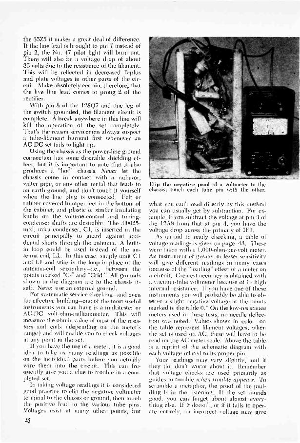
the 35Z5 it makes a great deal of difference.If the line lead is brought to pin 7 instead ofpin 2, the No. 47 pilot light will burn out.There will also be a voltage drop of about35 volts due to the resistance of the filament.This will be reflected in decreased B -plusand plate voltages in other parts of the cir-cuit. Make absolutely certain, therefore, thatthe live line lead comes to prong 2 of therectifier.
With pin 8 of the 12SQ7 and one leg ofthe switch grounded, the filament circuit iscomplete. A break anywhere in this line willkill the operation of the set completely.That's the reason servicemen always suspecta tube -filament burnout first whenever anAC -DC set fails to light up.
Using the chassis as the power -line groundconnection has some desirable shielding ef-fect, but it is important to note that it alsoproduces a "hot" chassis. Never let thechassis come in contact with a radiator,water pipe, or any other metal that leads toan earth ground, and don't touch it yourselfwhen the line plug is connected. Felt orrubber -covered bumper feet in the bottom ofthe cabinet, and plastic or similar insulatingknobs on the volume -control and tuning -condenser shafts are desirable. The .00025-mfd. mica condenser, Cl, is inserted in thecircuit principally to guard against acci-dental shorts through the antenna. A built-in loop could be used instead of the an-tenna coil, LI. In this case, simply omit Cland LI and wire in the loop in place of theantenna -coil secondary-i.e., between thepoints marked "C-" and "Grid." All groundsshown in the diagram are to the chassis it-self. Never use an external ground.
For systematic service checking-and evenfor effective building-one of the most usefulinstruments you can have is a multitester orAC -DC volt-ohm-milliammeter. This willmeasure the ohmic value of most of the resis-tors and coils (depending on the meter'srange) and will enable you to check voltagesat any point in the set.
If you have the use of a meter, it is a goodidea to take as many readings as possibleon the individual parts before yo actuallywire them into the circuit. This can fre-quently give you a clue to trouble in a com-pleted set.
In taking voltage readings it is consideredgood practice to clip the negative voltmeterterminal to the chassis or ground, then touchthe positive lead to the various tube pins.Voltages exist at many other points, but
Clip the negative prod of a voltmeter to thechassis; touch each tube pin with the other.
what you can't read directly by this methodyou can usually get by subtraction. For ex-ample, if you subtract the voltage at pin 3 ofthe 12A8 from that at pin 4, you have thevoltage drop across the primary of IF].
As an aid to ready checking, a table ofvoltage readings is given on page 43. Thesewere taken with a 1,000 -ohm -per -volt meter.An instrument of greater or lesser sensitivitywill give different readings in many casesbecause of the "loading" effect of a meter ona circuit. Greatest accuracy is obtained witha vacuum -tube voltmeter because of its highinternal resistance. If you have one of theseinstruments you will probably be able to ob-serve a slight negative voltage at the pointsmarked in the table 0.° On the low -resistancemeters used i these tests, no needle deflec-tion was noted. Values shown in color onthe table represent filament voltages; whenthe set is used on AC, these will have to beread on the AC meter scale. Above the tableis a reprint of the schematic diagram witheach voltage related to its proper pin.
Your readings may vary slightly, and ifthey do, don't worry about it. Rememberthat voltage checks are used primarily asguides to trouble when trouble appears. Toscramble a metaphor, the proof of the pud-ding is in the listening. if the set soundsgood, you can forget about almost every-thing else. If it doesn't, or if it fails to oper-ate entirely, an incorrect voltage may give
42

ANT. 12A8 .1F1PL E GINO
.1144aMaltS (.0 PILOT
/1115 VOLTS AG -D 50L6 12A8
O
90
IF2PLATE
TO B+PILOUGH
C25
125077 8
12 SK7
Taking a reading from each of these points toground will show whether voltages are present
you the clue you need to find the trouble.The big bugaboo in superhets-and the
thing that has made many experts feel thatthe circuit is too complicated for the begin-ner-is alignment. This consists of integrat-ing the various circuits so that they are inharmony with each other. Fortunately it israrely necessary to do the job entirely onyour own. Manufacturers generally aligntheir IF transformers pretty well at the fac-tory. You only have to make small adjust-ments. Whatever you do, don't tamper withthe trimmers on these transformers until theset is finished.
Automatic volume control-AVC-usespart of the rectified signal present at the de-tector to vary the grid bias on the 12SK7and 12A8. When a strong signal comesthrough, the amount of voltage available forbiasing goes up and this automatically de-creases the amplification of the tube. On aweak signal the reverse occurs. Now, foraligning you want to know when you aregetting a station at maximum strength, andthis automatic compensation for weaksignals would only throw you off. The firststep, then, is to ground the AVC by runninga jumper from the black lead of the input IFtransformer to ground.
Set the manual volume control ( R5) atmaximum, and tune in the strongest localstation. Working back from the output end,and using a fiber wand or other insulated
115AG -
12 SO7 50L6-GT
C
1.5 80 78 30
SP.KER
at the places where they should be and whetherthey are large enough to do their job properly.
TUBEPRONG
1 2 3 4 5 6 7 8
12A8 0 30 15 17 -1 10 21 012SK7 0 21 0 0' 0 90 10 88
12SQ7 0 Os 0 Os Os 10 10 0
50L6 NC 78 85. 90 Os NC 30 6
35Z5 NC 112 105 NC 110 NC 80 105
Fur a negative reading. polarity of the volt-meter terminals must )e reversed. A vacuum -tube voltmeter should read slightly negative atthe points marked with an asterisk ( ° ).
screwdriver, adjust the trimmers for maxi-mum output in the following order: the sec-ondary of IF2, then the primary; the second-ary of IF1, and again the primary. Now tunein a station somewhere around 1400 kc-thevariable -condenser plates are almost fullyopen at this point-and adjust the oscil-lator section of the tuning condenser, and,last, the RF section of C2. Bear in mind thatit is seldom necessary to make much of anadjustment in the IF trimmers. Don't touchthem at all until you have tuned in a station.
Should the signal become quite loud dur-ing the adjustment, it is advisable to get aweaker station. When you have the high endof the band lined up, tune in a station atthe other end and make whatever slight ad-justments may still be necessary.
43
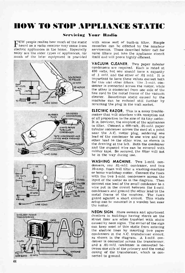
110W TO STOP .WPILIANCE STATICSem icing 1 0111` Radio
FEW people realize how much of the staticheard on a radio receiver may come from
electric appliances in the home. Especiallynoisy are the older types of appliances, formuch of the later equipment is provided
RUBBER
ITS !OLT'
MFD
TOFRAME
.E
I MFD
SOLDEREDTO FRAME
01 MFD
TO MOTOR
RUBBER SOLDERED
PLUG CONNECTIONS
.ol-meD. PAPERTUBULARCONDENSER
TAPE CONDENSER ANDLEADS WHEN FINISHED
LINE CORD
MOTOR
LINE CORD
SHIELDED POWERTRANSFO7MER
FUSES
SOLDERTO
RAMS
01 mro.
with some sort of built-in filter. Simpleremedies can be effected by the amateurserviceman. Those described below call fornoise filters put into the appliance circuititself and will prove highly efficient.
VACUUM CLEANER. Two paper tubularcondensers are required. Each is rated at400 volts, but one should have a capacityof .1 mfd. and the other of .01 mfd. It isimportant to have these values correct bothfor this and other filters. The .1-mfd. con-denser is connected across the motor, whilethe other is connected from one side of theline cord to the metal frame of the vacuumcleaner. Sometimes static caused by themachine can be reduced still further byreversing the plug in the wall socket.
ELECTRIC RAZOR. This is a noisy trouble-maker that will interfere with reception outof all proportion to the size of its tiny motor.It is, however, the simplest of the appliancesto filter. Connect a 400 -volt, .01-mfd. papertubular condenser across the cord at a pointnear the A.C. motor plug, soldering onelead of the condenser to one wire and theother lead to the other wire, as shown inthe drawing at the left. Both the condenserand the exposed wire can be covered withrubber tape. So secured, the filter will notbe in the way during use.
WASHING MACHINE. Two 1-mfd. con-densers, one .01 -mid. condenser, and two10 -amp. fuses will filter a washing -machineor home workshop motor. Connect the fuseswith the two 1-mfd. condensers across theinput of the motor as in the diagram. Thenconnect one lead of the small condenser to awire put in the circuit between the 1-mfd.condensers and ground the other lead to themetal frame of the machine. The fusesguard against a short circuit. This wholesetup can be mounted in a wooden box nearthe motor.
NEON SIGN. Store owners and apartmentdwellers in buildings having stores on thestreet floor are often troubled with staticcaused by neon signs. The owner of the signcan keep most of this static from enteringthe electric lines by inserting two papercondensers in the A.C. transformer circuit,as shown in the diagram. A 1-mfd. con-denser is connected across the transformer,and a .01-mfd. condenser is connected be-tween one side of the primary and the metalcasing of the transformer, which is con-nected to ground.
44
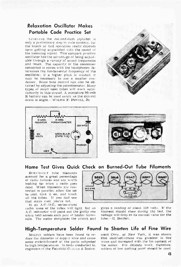
Relaxation Oscillator MakesPortable Code Practice SetLEARNING the dot -and -dash alphabet is
only a preliminary step in code mastery, forthe knack of fast operation really dependsupon getting acquainted with the sound ofthe incoming signal. This compact practiceoscillator has the advantage of being adjust-able through a variety of sound frequenciesand tones. The capacity of the condenserconnected in series with the headphones de-termines the fundamental frequency of theoscillator; if a higher pitch is wanted, itmay be necessary to use a smaller con-denser. Some tone control can also he ob-tained by adjusting the potentiometer. Manytypes of small neon tubes will work satis-factorily in this circuit. A miniature 90 -voltB battery can be used safely as the currentdrain is slight. ---WALTER F. PowELL, JR.
5-MEG. .5 M EGRESISTOR POTENTIOMETER
90VOLTS
KEYO
NEON BULB(TYPE T-2)
Home Test Gives Quick Check on Burned -Out Tube FilamentsBuaNED-i al' tube filaments
account for a great percentageof radio failures and are worthlooking for when a radio goesdead. When filaments are con-nected in parallel, allow the setto cool, turn it on, and touchall the tubes. If you find onethat stays cool, you're hot.
In an A.C.-D.C., series -wiredradio, none of the tubes will light, but anA.C. voltmeter will point out the guilty onewhen held across each pair of heater termi-nals. The meter completes the circuit and
gives a reading of about 110 volts. If thefilament should close during the test, thevoltage will drop to its normal value for thetube. --G. BOLTON.
High -Temperature Solder Found to Shorten Life of Fine WireMOLTEN solders have been found to re- ment Corp., of New York, it was shown
duce the diameter of copp'r wire and cause that destructiveness was greatest in finesome embrittlement of the parts subjected wires and increased with the tin content ofto high temperatures. In tests conducted by the solder. For delicate work, therefore,engineers of the Fairchild Cztio.,,ra & Instru- solders of low melting point should be used.
45

-the conversion of sound energy into elec-trical energy. David Edward Hughes stum-bled on his microphone while experimentingwith imperfect electrical contacts. You canduplicate his experiment by hooking upthree large iron nails as shown in Figs. 1and 2. Two are tacked down tight on aby 3" by 5" block of wood and hooked incircuit. The third merely lies across theother two. Small strips of sponge rubberinsulate the mike from the table.
When there is no sound to strike in waves,a smooth flow of current circulates; butsound waves shake the loose nail, and thisvaries the resistance of the contacts, inter-rupting the current flow and causing soundin the headphones.
Low -resistance headphones are best. Along line may be used. By listening to a
The history of the microphone is
closely linked to the story of broad-casting. A series of fascinating ex-periments will show you how radiodeveloped its high-fidelity ears.
By TRACY DIERS
ON JUNE 19, 1878, a routine perform-ance of Donizetti's opera "Don Pas-quale" was given in the Swiss town
of Bellinzona. Neither the date nor theevent would be remembered had it not beenfor a telegraphic engineer named Patocchi.
Patocchi installed a newly inventedHughes microphone on the stage and sev-eral Bell telephone receivers in another partof the building. Thus "Don Pasquale" be-came the first broadcast opera and Patocchithe first studio engineer. There was nosponsor.
Since then science has devoted much ef-fort toward developing a microphone thatwould reproduce all it heard. You can getan idea of the difficulties if you build andstudy some experimental "mikes."
Every microphone performs one basic job
46

metronome, you can adjustthe cross nail until it is ina sensitive spot and repro-duces speech understand-ably.
Many unstable -contactmicrophones were devel-oped. One with a loose car-bon rod i Fig. 3) was usedfor the "Don Pasquale"broadcast. It would be use-less in radio. One blastfrom a symphony orchestra.and you had to readjust itto a sensitive position.
A microphone employing a button con-taining carbon granules was invented byEdison in 1876. You can make one with a1,!" by 5" by 5" wood block having a holeover which you cement a diaphragm from aheadphone or a 3" iron diaphragm no thick-er than .006". Have the hole 1,4 " in diam-eter for a 21,s" headphone diaphragm or21" for the 3" diaphragm.
Solder No. 30 wire to the diaphragm andsolder wire to the top of a metal screw capfrom a solvent can or ketchup bottle. Halffill the cap, or "button," with microphone -carbon granules or crushed battery carbonand cement it to the diaphragm with a paperwasher under it for insulation, as in Fig. 4.The hookup is shown in Fig. 5.
Normally current flows smoothly throughthe carbon and headphone, but the pressureof sound waves on the diaphragm pressesand releases the granules, changing resist-ance and the current flow to the headphoneand thus producing sound.
There are disadvantages, as you will findif you listen to the continuous hiss of the
granules in a quiet room. Note, too, howthey react to different letters in the alpha-bet. Such a mike is erratic at various fre-quencies and is hardly of high fidelity. Heldin different positions, it varies in sensitivity,and frequently its granules pack. But in spiteof drawbacks, the carbon mike has leacheda good stage of development in telephones,walkie-talkies. and tank and plane radios.
The double -button carbon mike, havingbuttons on opposite sides of the diaphragm,saw us through the early days of broadcast-ing. It was connected through a center -tapped input transformer. Finally the de-mand for a higher -fidelity mike toughenough to stand a little manhandling re-sulted in the condenser microphone. Andfrom it radio got its first high-fidelity ears.
You can build a condenser mike fromscrap items. Cut a 212" diameter hole in a1:2" by 5" by 5" piece of wood and sand oneface smooth. Cover the hole on the sandedface with a 4" square of thin tin foil oraluminum foil, as in Fig. 6, insetting a 6"length of No. 30 wire under the foil for a
TO SUITDi API 'UGH
CLOCK OF A000
SOLDERED CONNECTION
METAL SCREW CAP
CARSON GRANULES
INSULATINGPAPERWASHER W
DIAPHRAGM PHONES
ISATTEPY(4112 VOLTS FOR7S-OMM PHONES,221/2 VOLTS FORRADIO PHONES
41

connection. Cut a 21 hole in a thin sheetof paper 5" square, lay it on the foil, andput on top of that an absolutely flat 14" by5" by 5" sheet of aluminum or brass inwhich two or three 14" holes have beendrilled near the center. Clamp the pieces,as in Fig. 7, and the mike is ready for action( Fig. 8 ). The wiring diagram is shown inFig. 9.
Since the output will be too low for head-phones, connect the condenser mike directlyto an amplifier by means of the ungroundedmike lead. The phonograph input of a radiomay be used if it has sufficient stages ofamplification, but a high -gain audio ampli-fier is more satisfactory.
The required 180 volts for charging themike is obtained with least hum from sepa-rate batteries. If voltage must be takenfrom the amplifier power supply itself, tapthe voltage divider at the 180 -volt point or,if there is no divider, tap at the filteredhigh -voltage point with a resistance in seriesto drop the voltage to 180. A separate smallB eliminator can also be used. The foildiaphragm and hackplate act as the platesof a condenser. Pressure from sound wavesmoves the diaphragm and changes the ca-pacity of the condenser, producing acrossthe 1-megohm resistor a voltage that is fedinto the grid of the first amplifying stage.
21;HOLE
BLOCK or WOOD
VA- FOIL DIAPHRAGM
RAO, PLATE
r PRESSURE
EWA, VENTS
PAPERSEPARATOR
RESISTOR
180 VOLTS
TO INPUTOF AMPLIFIER
- TO CHASSISOF AN1PL,F1ER
Condenser mikes were essential to radioand talkies for years. Their chief disad-vantage was the need of a small amplifiertagging along or in the same case. Then afact that had been known for 100 years wasutilized to make a microphone that waslight in weight, was high in fidelity, andcould be separated from the amplifier-thedynamic mike.
You can build a moving -coil dynamicmicrophone on a 12" by 5" by 5" block ofwood having a hole 212" in diameter. Ce-ment a very thin iron or mica diaphragmover the hole, and then to the center of thediaphragm cement a voice coil. Use a coilfrom an old dynamic speaker or make onewith No. 36 enameled wire wound in onelayer for 34" around the circumference of alight paper form 1" in diameter. Bring outthe ends of the wire to the terminals on theboard I Fig. 10).
Use two small permanent horseshoe mag-nets to surround the coil with a strong mag-netic field, attaching each with a screwpassed through 14" wood shims, as in Fig.11, so that the magnet does not touch thediaphragm. Opposite poles face each otherso the field flows through the coil.
An amplifier makes audible the soundspicked up. But since the impedance ( A.C.resistance) of the voice coil is very low,
48

.4
couple the mike to the amplifier through amatching transformer, such as a push-pulloutput transformer, as shown in Fig. 12.When sound waves strike the diaphragm.the coil moves in the magnetic field. A tinyvoltage is thus induced in the coil and flowsinto the transformer. A secondary voltageis induced in the other side of the trans-former, and this enters the amplifier.
Modern dynamic mikes reproduce soundsranging from 35 to 10,000 cycles per secondand are still widely used.
Another type, a ribbon or velocity mike,is operated by changes in the velocity of thesurrounding air instead of by pressure. Incontrast to the diaphragm, which tends toresist sound waves, the ribbon is so light itbobs up and down as the waves approachand offers so little resistance that they passon unaltered.
To make a ribbon microphone, cut a 7/16"by 4 % " slot in a 1,.i" by 3" by 9" piece ofplywood and screw a 1,i" by 41.." angle ironat each edge of the slot. The ribbon may bevery thin aluminum foil --the thinner thebetter. Cut a strip 1,.'t " wide and 51/2" inlength and corrugate it by pressing itagainst a piece of corrugated cardboard.Then.suspend it over the slot by a screw ateach end, as shown in Fig. 13. Place horse-shoe magnets at the ends with polarities ar-ranged for attraction. Connections to theribbon are made through the screws.
Hook a transformer between the mike andamplifier ( Fig. 19 ). Any transformer hav-ing 2 ohms or less impedance on one sideand 2,000 ohms or more on the other workswell. Turn the amplifier gain up high andtest the mike. The velocity of sounds in thevicinity starts a slight motion in the ribbon,and since the motion is in a strong field,voltage is generated and current flows tothe transformer.
Your ribbon mike will work whether youspeak in front of or behind it, but if youmove a sound producer such as a music boxor bell around it, as in Fig. 15, you will
vERY mtOmLOW IMPEDANCE IMPEDANCE(2 OHMS Or2 LESS) (2.000 OHMS on MORE
49

35
find spots of greater and less sensitivity.Figure 16 shows the field of sensitivity ofa typical ribbon mike.
If you could cut off one of the loops inFig. 16, you would have a directional mikethat would "select" sound from a givenarea. This is done with a cardioid mikeI named for the shape of the field, as shownin Fig. 17) which usually combines in onehousing a ribbon mike and a dynamic mike,the latter "phased" to cancel one loop.Opera is broadcast by such a cardioid mikewith the live side facing the performers.
A very new addition is the crystal mike.depending for its operation on what isknown as the piezoelectric effect. When acrystal held between metal plates vibratesunder slight pressure, a measurable voltageis produced in it. You can make the ac-tive element, a crystal sound cell.
Make a supersaturated solution by dis-solving 6 oz. Rochelle salt in 4 oz. waterat about 200 deg. F. As the solution coolsslowly, crystals about 1," long form. Whenone resembles that in Fig. 18. remove it andlet it dry. This is your seed crystal.
Bring 16 oz. water to the boiling point,dissolve in it as much Rochelle salt as canbe held in solution, and let it cool slowly,being sure to keep out dust. Then hang theseed crystal in the solution on a thread.Growth takes place in a few hours. Remove
RIBBON MICROPHONE
13/
I
z e
ADEAS Or SENSITIVITY
Ite,I DYNAMIC AND RIBBONI MICROPHONES IN ONE
HOUSING
AREA OFSENSIT ivIT Y
ROCHELLE-SALTSEED CRYSTAL
(ABOUT ./4: LONG)
the crystal when it measures about 1" inany direction, and put it in alcohol for 24hours. If your first attempt doesn't turnout well, try again.
Make a sound cell by wrapping a t"strip of tin foil around a perimeter of thecrystal and clamping any two oppositesurfaces between two metal plates, as inFig. 19; then hook the cell to the amplifieras shown in Fig. 20. Move the crystal to adifferent position in the holder if it doesn'tshow good sensitivity at first.
There are two types of crystal mikes.In one, two small plates of Rochelle saltare cemented together to make a "bimorph"unit of extreme fidelity that will respond tofrom 30 to 20,000 cycles a second. The pres-sure of sound waves causes the flat crystalplates to generate voltage. A more popu-lar, cheaper type has a diaphragm con-nected to a light driving rod that transmitsthe pressures to the bimorph unit.
"Don Pasquale" is still very much alive.but the methods of broadcasting it havechanged greatly. Instead of simple rodsdelicately adjusted, we now have slickchromium -plated cardioid mikes with direc-tional selectivity and high fidelity. Suchinnovations as frequency modulation haveput Mr. Mike on the spot, hut moving coils.vibrating ribbons. and sensitive crystalshave met the challenge.
ROCHELLE-SALT ColYSTAi
CLAMPINGPLATES
FOIL STRIP
A
SHIELDED CAGLE
TO AN PLir ER
50
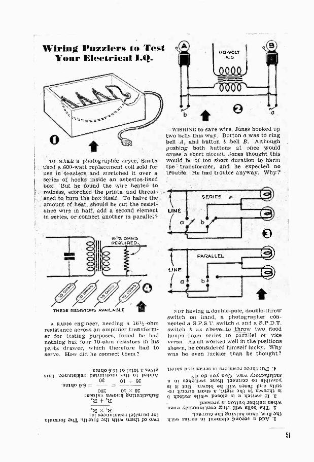
Wiring Puzzlers lo TestYour Electrical 11.41.
TO MARE a photographic dryer, Smithused a 600 -watt replacement coil sold foruse in. toasters and stretched it over aseries of hooks inside an asbestos -linedbox. But be found the wire heated toredness, scorched the prints, and threat-ened to burn the box itself. To halve the.amount of heat, should he cut the resist-ance wire in half, add' a second elementin series, or -connect another in parallel?
fE,1/2 OHMSREQUIRED
THESE RESISTORS AVAILABLE
A RADIO engineer, needing a 161 -ohmresistance across an amplifier transform-er for testing purposes, found he hadnothing but four 10 -ohm resistors in hisparts drawer, which therefore had toserve. How did he connect them ?
'swim 9.913o owl 8 saA!.6siq; 'aatorisiaai paitingsun am 01 pappy
OE OT OZ*swim 9.9 = -007, OT X OZ
:sanisn UM0t131 amittulsons+ itt
CU X '11:51 saoiniteisaa tattered Jo;
vinuiJoj atu, inino3 own magi Jo ont;
WISHING to save wire, Jones hooked uptwo bells this way. Button a was to ringbell A, and button b bell B. Althoughpushing both buttons at once wouldcause a short circuit,. Jones thought thiswould be of too short duration to harmthe transformer, and he expected notrouble. He had trouble' anyway. Why?'
NOT having a. double -pole, double -throwswitch on hand, a photographer con-nected a S.P.S.T. switch a and a S.P.D.T.switch b as above...to throw two floodlamps from series to paratlel or viceversa. As all worked well in the positionsshown, he considered himself lucky. Whywas he even luckier than he thought?
lungs one sapas uF 6SolsTsai aanoop not use *Atm kiolowstyes
tit saliatints asatil pauuoo o; alcussods4 31 ;rig timoici aq Him sastki two sunsas tinoito poqs B Iti2p aq; unnoiqi si
q 433 M5 alight pasota ji Cpassaad si uoling .zamian nag.%
liana 1:Isnonunuoo Mina ium snag au,luaiano ail 2uitt1ay snip ';sag
min& SaflOS OF insulate puooas a ppy
51
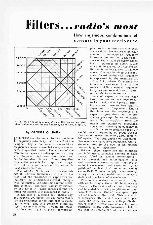
Filters ra d o's mostHow ingenious combinations ofcensors in your receiver to
0- 4 4..v4430 too cP o°
,"610,00041
7,000
5,000 SI
3,0008
2,00051
0,
O1,000 SI ,
1KC ', ,2 KC. \ KC 5 KC \ ,7 KC '10K0c?, 0_, -9, .00 .00
4 as0" le, 4, 4.,
40 0 ;' q" A,
A reactance -frequency graph, of which this is a section, givesdirect values in ohms for any frequency up to 1,000 kilocycles.
By GEORGE 0. SMITH
FILTERS are electronic circuits that havefrequency selectivity. At the will of the
designer, they can be made to pass or blockfrequencies below, above, between, or aroundcertain specified limits. The names of thefour major types are self-explanatory; theyare low-pass, high-pass, band-pass, andband -elimination filters. Taken togetherthey make possible two important things:the first is radio reception; the second isMood radio reception.
The ability of filters to discriminateagainst certain frequencies is due to thefact that the resistance of capacitors andinductors to alternating -current changeswith frequency. Alternating -current resist-ance is called reactance. and is symbolizedby the letter X. Like direct -current ( orpure) resistance, it is measured in ohms.
In the case of a choke coil labeled, say,300 henries, 200 ohms, the 200 ohms standsfor the resistance of the wire that is woundon the coil. This is a constant minimum,regardless of frequency: it would still meas-ure 200 ohms if a D. C. potential were ap-
plied, or if the wire were stretchedout straight. Reactance is anothermatter. It increases as frequencyincreases. In addition to the resist-ance of the wire, a 30 -henry chokehas a reactance of about 11,300ohms at 60 cycles. At 600 cycles,the reactance has grown to 113,000ohms. The way in which the react-ance of a coil varies with frequencyis expressed by the formula: XL=2 f L, where XL stands forinductive reactance, 2 7 is theconstant 6.28, f equals frequencyin cycles per second, and L repre-sents inductance in henries.
A good capacitor, on the otherhand, has infinite resistance to di-rect current, but will pass alternat-ing current more or less readily,depending on frequency. Unlikethe choke coil, the reactance ofcapacitor goes down as the fre-quency goes up. In mathematicalterms, XC = 1.1 Here, Xcstands for capacitive reactance,and C is a measure of capacity infarads. A .01-microfarad capacitor
would have a reactance of about 265,000ohms at 60 cycles, but only 26,500 ohms at600 cycles. The total opposition that induc-tive reactance, capacitive reactance, and re-sistance offer to the flow of an electriccurrent is called i»tpcdance.
Between them, capacitors and inductorscan hold any alternating current at theirmercy. Used in various combinationsseries, parallel, and series -parallel- coilsand condensers serve varied functions inradio transmission and reception. Theypolish off rectified A. C. so as to providea smooth D. C. power supply; in the form oftuning circuits they enable you to select astation at the twist of a condenser.
This article makes no attempt to dealwith all filtering actions. While filters areintegral in the basic radio circuit, they mayalso be added to existing amplifiers as tone -corrective devices. One of the simplest typesis that shown at the right. This is a formof high-pass filter, and it operates in pre-cisely the same way as a voltage divider,except that the resistance of one leg auto-matically varies with frequency. Let ussay that the components of the circuit are
52
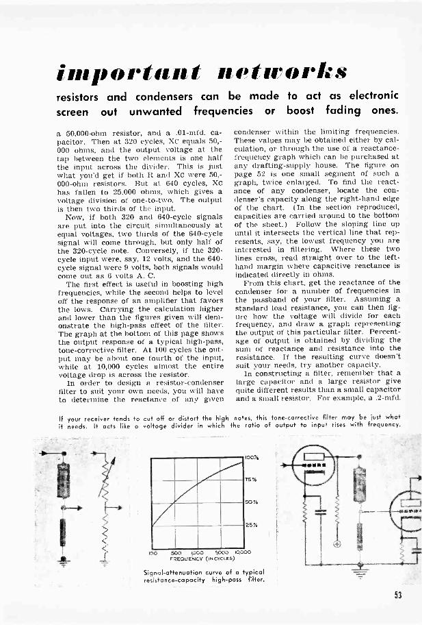
inept, eeiet 'Setif() N
resistors and condensers can be made to act as electronicscreen out unwanted frequencies or boost fading ones.
a 50,000 -ohm resistor, and a .01-mfd. ca-pacitor. Then at 320 cycles, XC equals 50,-000 ohms, and the output voltage at thetap between the two elements is one halfthe input across the divider. This is justwhat you'd get if both R and XC were 50,-000 -ohm resistors. But at 640 cycles, Xchas fallen to 25,000 ohms, which gives avoltage division of one -to -two. The outputis then two thirds of the input.
Now, if both 320 and 640 -cycle signalsare put into the circuit simultaneously atequal voltages, two thirds of the 640 -cyclesignal will come through, but only half ofthe 320 -cycle note. Conversely, if the 320 -cycle input were, say, 12 volts, and the 640 -cycle signal were 9 volts, both signals wouldcome out as 6 volts A. C.
The first effect is useful in boosting highfrequencies, while the second helps to leveloff the response of an amplifier that favorsthe lows. Carrying the calculation higherand lower than the figures given will dem-onstrate the high-pass effect of the filter.The graph at the bottom of this page showsthe output response of a typical high-pass,tone -corrective filter. At 100 cycles the out-put may be about one fourth of the input,while at 10,000 cycles almost the entirevoltage drop is across the resistor.
In order to design a resistor -condenserfilter to suit your own needs, you will haveto determine the reactance of any given
condenser within the limiting frequencies.These values may be obtained either by cal-culation, or through the use of a reactance -frequency graph which can be purchased atany drafting -supply house. The figure onpage 52 is one small segment of such agraph, twice enlarged. To find the react-ance of any condenser, locate the con-denser's capacity along the right-hand edgeof the chart. ( In the section reproduced,capacities are carried around to the bottomof the sheet.) Follow the sloping line upuntil it intersects the vertical line that rep-resents, say, the lowest frequency you areinterested in filtering. Where these twolines cross, read straight over to the left-hand margin where capacitive reactance isindicated directly in ohms.
From this chart, get the reactance of thecondenser for a number of frequencies inthe passband of your filter. Assuming astandard load resistance, you can then fig-ure how the voltage will divide for eachfrequency, and draw a graph representingthe output of this particular filter. Percent-age of output is obtained by dividing thesum of reactance and resistance into theresistance. If the resulting curve doesn'tsuit your needs, try another capacity.
In constructing a filter, remember that alarge capacitor and a large resistor givequite different results than a small capacitorand a small resistor. For example, a .2-mfd.
If your receiver tends to cut off or distort the high notes, this tone -corrective filter may be just whatit needs. It acts like a voltage divider in which the ratio of output to input rises with frequency.
1004
75%
50%
25%
500 1000 5000 10000FREQUENCY (IN CYCLES)
Signal -attenuation curve of a typicalresistance -capacity high-pass filter.
53

_ 1
Tapping the output voltage off the co- Used between amplifier stages, this type of filter requires anpacitor will tend to favor the low notes. extra condenser -resistor arrangement in the coupling circuit.
condenser and a 2-megohm resistor showless than 1 percent response difference be-tween 80 and 8,000 cycles, while .001 mfd.and 20,000 ohms will cause about 40 percentdifference in the same range.
This type of filter may be connected be-tween the audio stages of an average ampli-fier as shown in the hookup schematic onpage 53. While calculated values give youa good starting point, the final test of anyfilter is in its effect on the entire amplifier.Because of distributed effects, calculatedvalues are at best approximate, and it maybe necessary to juggle values a little untilyou get a result that is pleasing to the ear.A voltmeter placed across the amplifier out-put will help you to check the real effect ofa filter. Used in conjunction with an audio -frequency generator, or a frequency -testrecord, the voltmeter will show how outputvoltage varies as the input frequency ischanged.
While resistor -condenser combinationsare often favored for tone correction inaudio circuits, there are times when a morelevel response is desirable. Let us say, forexample, that you want to give equal em-phasis to all notes between 10 and 1,000cycles. The response curve shown on theprevious page would then not be satisfac-tory. At 1,000 cycles, this filter has almostthree times the output it has at 100 cycles,whereas the graph we now want should belevel between the two extremes of our pass -band.
To obtain this effect it is necessary to re-place the resistor with a choke coil, thusgiving your voltage divider two variable
arms instead of one. When the reactance ofone arm increases, that of the other de-creases correspondingly.
The use of inductance -capacity filters,however, involves a number of other criticalconsiderations which are outside the scopeof this article. Getting back to our firstcircuit, let's see what happens when wemake a few changes.
Reversing the positions of the filter com-ponents produces, reasonably enough, anopposite effect. The illustrations above showhow this is done to produce a low-pass filterthat will attenuate the higher frequencies.In this case the output voltage is tapped offthe variable leg of the divider. As frequencygoes up, the reactance of the capacitor de-creases, giving a lower voltage drop for thehigher frequencies.
Using a filter of this type between ampli-fier stages requires certain precautions thatare not needed with the high-pass unit. Bythemselves, the filter components would putpart of the high plate voltage on the grid,and the condenser would block the gridreturn to ground. The schematic diagramabove shows the additional circuit elementsthat must be used when this kind of low-pass filter is inserted between stages. Inthis hookup, the filtering is done betweenthe plate connection and ground, and thegrid is coupled to the filter terminal througha condenser -resistor arrangement. This,however, constitutes another high-pass fil-ter; if the components of both sets werealike, they would merely nullify each other.
To offset this possibility, the couplingcomponents are made large, thus reducing
54

their frequency selectivity, and allowing thedesired filter to do most of the frequencyselection. The coupling condenser for thiscircuit should be about .1 mfd., and the gridresistor about 2 megohms.
Among the "built-in" defects of manyexisting amplifiers is an auditory effectknown as "loss of bass." Most often this isnoted when the volume control is turned toa low position. A tone -corrective filter thatoften succeeds in eliminating this fault con-sists of a tapped volume control with a con-denser connected between the tap andground. When the volume control is turneddown near the tap or below, the condensercauses it to act as a type of low-pass filter.As volume decreases, the low notes are in-creasingly favored, thus compensating forthe loss of bass.
To prevent overemphasis of the bass, alimiting resistor should be used in serieswith the condenser from tap to ground, asshown at the left, below. At high frequen-cies the capacitive reactance may drop tojust a few ohms, yet the series resistor main-tains the total shunting effect above thelevel of its own resistance. At low frequen-cies, the higher capacitive reactance addsits ohmage to that of the resistor, raisingthe shunting effect.
In order to reverse this effect, the limit -resistor should be connected in parallel withthe condenser, as shown at the lower right.Below the so-called "cross -over frequency"-that frequency where the capacitive reac-tance equals the pure resistance-the in-coming signal sees mainly the pure resist-ance shunting the line. Above this frequen-cy, the line is shunted by the resistor andthe lowered reactance in parallel.
Connected in series, the impedance of thisfilter tends to level off to the limiting re-sistance above the cross -over frequency,while in the parallel hookup the total im-pedance is level for frequencies below thecross -over level, and the impedance dropsas the frequency rises above the criticalvalue.
As before, the final test of these filters isin the listening. Using a .01-mfd. condenserand a 30,000 -ohm resistor as a starter, thistone compensator can be adjusted to suityour taste. Set the volume -control arm tothe point that gives the lowest ohmmeterreading between tap and arm, and leave itat that value while making changes.
Some increase in high -frequency responsecan be obtained with this filter by connectinga small condenser-say 50 mmf. to 250 mmf.-between the top of the control and thetap. The over-all response will then be lowin the middle -frequency ranges, and havebroad peaks at both the low and the highends. This type of response curve is gen-erally considered to be the most pleasing.
The thing to remember about resistance -capacity filters is that the use of a frequency -selective element ( the capacitor), in con-junction with a nonselective element willproduce all manner of curves in the audioresponse of an amplifier. Whether high orlow frequencies will be passed or blockeddepends upon the position of the components,while the range of any filter is governedby the size of the parts. Doubling or addingfilter after filter will steepen the responsecurve. In one combination or another, fil-ters will permit you to do just about any-thing you want with just about any alter-nating -current signal.
yi
If turning the volume control low produces u-loss of bass- in your receiver, inserting a con-denser between volume -control tap and groundmay give the failing low notes o boost.
55

Wi lessBR DCASTS
By
Record PlayerTHROUGH YOUR RADIO
bert W. HellenthalHAVE you ished
your old nd-wound phonog h tothe attic beta radiohas spoiled you forits tinny sound? so,here's your than tomodernize the for tenantique, and for fewdollars give it a t asgood as that of urradio. Exactly the same
tone, in fact, for it will play records throuyour radio. From basement to attic,radio in the house can be tuned to picrecords played on the unit, so the enfamily can enjoy favorite selections evethough not gathered in one room.
The heart of the record player, a one -tubeoscillator small enough to fit into the palmof your hand, is actually a tiny broadcastinstation. It emits a radio -frequency carrierwave on which are impressed the audio fre-quencies comprising the recording.
Assuming that you have none ofthe necessary parts in your scrapbox, total cost for the oscillatorshould be about $5. Add to thisthe cost of a crystal pickup-sayanother $5 --and you're all set. Ifyou want to save yourself thebother of cranking up an old spring-wound clockwork drive, a phonomotor and turntable can be pickedup for only a few dollars more.
Compactness and simplicity of design areobtained chiefly through the use of a singlemultipurpose tube designed for use on 115 -volt house current. A 117N7 tube is shownin the diagram, but a 117L7, 117M7, or 117P7can be used equally well with a few minorchanges in the socket connections. Thediode section of the tube rectifies A.C. intoa D.C. power supply which is filtered throughR5, R6, C7, and C8. As with any A.C.-D.C.circuit, direct current goes through therectifier relatively unchanged.
Radio -frequency ( R.F.) currents are setup in the tank circuit, which consists of asmall trimmer condenser ( C2), and onewinding of an adjustable iron -core oscillatoror antenna coil ( L). Some experimenting
ay be necessary to find the correct connec-ons. Varying either the core or trimmer
or both will change the oscillator frequency.Transferred to the secondary of the coild applied to the control grid of the ampli-section, this R.F. constitutes the "carrier
wave" of your transmitter.Vibration in the needle of the
pickup causes a varying pressureto be exerted on the crystal.Through an effect known as piezo-electricity, these mechanical vi-brations are converted into alter-nating voltages that vary at audiofrequencies. When this audiosignal is applied to the screengrid, it alters the carrier wave,and it is the modulated wave that
56
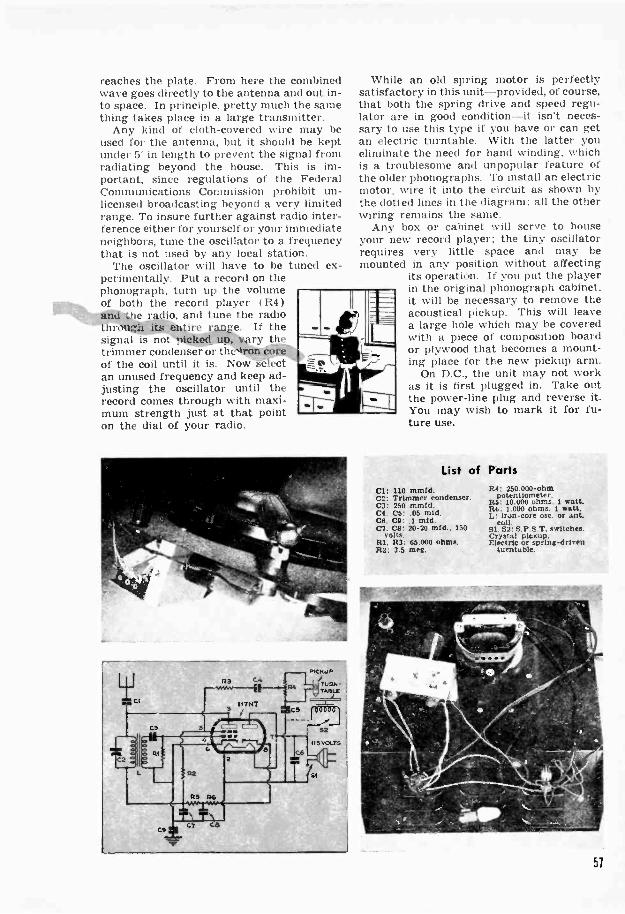
reaches the plate. From here the combinedwave goes directly to the antenna and out in-to space. In principle, pretty much the samething takes place in a large transmitter.
Any kind of cloth -covered wire may beused for the antenna, but it should be keptunder 5' in length to prevent the signal fromradiating beyond the house. This is im-portant, since regulations of the FederalCommunications Commission prohibit un-licensed broadcasting beyond a very limitedrange. To insure further against radio inter-ference either for yourself or your immediateneighbors, tune the oscillator to a frequencythat is not used by any local station.
The oscillator will have to be tuned ex-perimentally. Put a record on thephonograph, turn up the volumeof both the record player ( R4 )
e r io, and tune the radio, 'entire range. If the
signal is not picked up, v. ry thetrimmer condenser or theof the coil until it is. Now sean unused frequency and keep ad-justing the oscillator until therecord comes through with maxi-mum strength just at that pointon the dial of your radio.
While an old spring motor is perfectlysatisfactory in this unit-provided, of course,that both the spring drive and speed regu-lator are in good condition-it isn't neces-sary to use this type if you have or can getan electric turntable. With the latter youeliminate the need for hand winding, whichis a troublesome and unpopular feature ofthe older phonographs. To install an electricmotor, wire it into the circuit as shown bythe dotted lines in the diagram; all the otherwiring remains the same.
Any box or cabinet will serve to houseyour new record player; the tiny oscillatorrequires very little space and may bemounted in any position without affecting
its operation. If you put the playerin the original phonograph cabinet,it will be necessary to remove theacoustical pickup. This will leavea large hole which may be coveredwith a piece of composition boardor plywood that becomes a mount-ing place for the new pickup arm.
On D.C., the unit may not workas it is first plugged in. Take outthe power -line plug and reverse it.You may wish to mark it for fu-ture use.
List of Parts110 mmtd.
C2: Trimmer condenser.C3: 250 mmfd.C4. C5:.05 mid.C6. CS: .1 mfd.Cl. CS: 20-20 mfd.. 150
volts.RI. R3: 65.000 ohms.R2: 3.5 meg.
R4: 250.000 -ohmpotentiometer.
R.5: 10.000 ohms. 1 watt.R6: 1.000 ohms. 1 watt.L: iron -core osc. or ant.
coil.Si. 52: 8.P.S.T. switches.Crystal pickup.Electric or spring -driven
turntable.
51
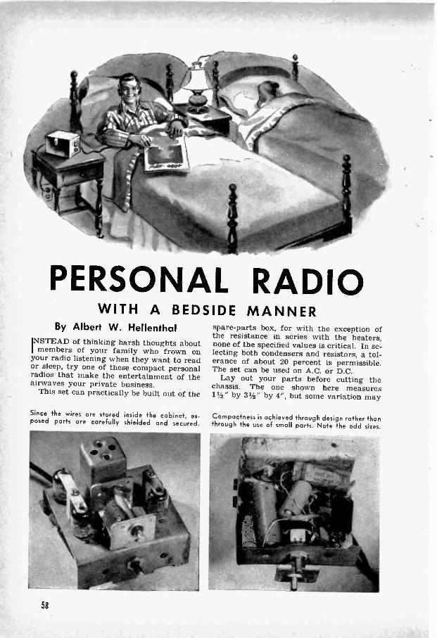
-411"'w41
PERSONAL RADIOWITH A BEDSIDE MANNER
By Albert W. HellenthalINSTEAD of thinking harsh thoughts aboutI members of your family who frown onyour radio listening when they want to reador sleep, try one of these compact personalradios that make the entertainment of theairwaves your private business.
This set can practically be built out of the
Since the wires are stored inside the cabinet, ex-posed parts are carefully shielded and secured.
spare -parts box, for with the exception ofthe resistance in series with the heaters,none of the specified values is critical. In se-lecting both condensers and resistors, a tol-erance of about 20 percent is permissible.The set can be used on A.C. or D.C.
Lay out your parts before cutting thechassis. The one shown here measures112" by 31/2" by 4", but some variation may
Compactness is achieved through design rather thanthrough the use of small ports. Note the odd sizes.
58

be necessary, depending on the parts youcan obtain. One 9002 tube is used as an A.F.amplifier; another, with its plate and gridtied together, serves as a diode half -waverectifier for the power supply. The thirdtube, a 9003, acts as detector and R.F. am-plifier. Regenerative oscillation, used to getadded selectivity and gain, is controlled byputting the volume control I R2) in thescreen -grid circuit.
With all tube heaters connected in series,a 600 -ohm voltage -dropping resistor mustbe inserted in the line. Any combination ofline cords adding up to 600 ohms will serve.
One of the last steps in the wiring consistsof winding the feedback, or tickler winding.This goes next to the grid section of a stand-ard iron -core adjustable antenna coil. Twoto 10 turns of 30 -gauge enameled or D.S.C.wire will be needed. Turn the set on andfind the exact number of turns by experi-menting. If no effect is noticed while mak-ing the adjustment, try reversing the leads.
Hard composition -board sides and analuminum front were used for the cabinetshown, which measures 41/2" by 43/4" by 614 ".To prevent the tubes from working loose intheir sockets, two " wood posts were fas-tened to the chassis. Small metal crossarmshave holes drilled to fit over the glass tips.
A 25' length of covered -wire antenna,dropped out the window or fastened to abedspring, will bring in the local stations.As the power line goes to chassis, use noground and keep the set away from radiators.
Although this set is designed for personallistening, it has enough power to drive asmall speaker. Should you want to add oneto yours, follow the inset shown in the dia-gram below. The extra parts that are need-ed are marked "optional."
Angle irons and small bolts holdtogether a composition -board box.
List of PartsLI. L2: Standard adjustable iron -core antenna
coil.I.3: Tickler coil.Cl: 365-mmfd. midget tuning condenser.C2: .00025 mfd.. mica.C3. CG: .5 mfd.(74: .0005 mid.. mica.C5: .03 mfd.C7. CS: 20-20 mid.. 150 volts, electrolytic.Cl: .05 mfd.. 400 volts.R1: 2 meg.. watt.R2: 15.000 -ohm potentiometer.It3: 50.0011 ohms. watt.R4: 45.000 ohms. watt.its: 1110.000 ohms. watt.
H00 ohms. 1 watt.R7: SOO ohms. 2 watts.RS. RI: ::00 -ohm line cords.st: s.P.s.T. switch.S2: S.P.D.T. switch (opt.).T: 10.000 -ohm midget output transformer (opt.).
2" Permanent -magnet speaker 1010%1.
The extra space inside the cabinet will hold eitherthe line cord and coiled antenna, or a 2- speaker.
RI
V
R9 R8
9002
57
CEIW*WC7+
R4
9002
CS
PHC NE S
HEATERS
9002
2. PIASPAR
PHONES
8+ 7°PHONE AND SPEAKER HOOKUP
59
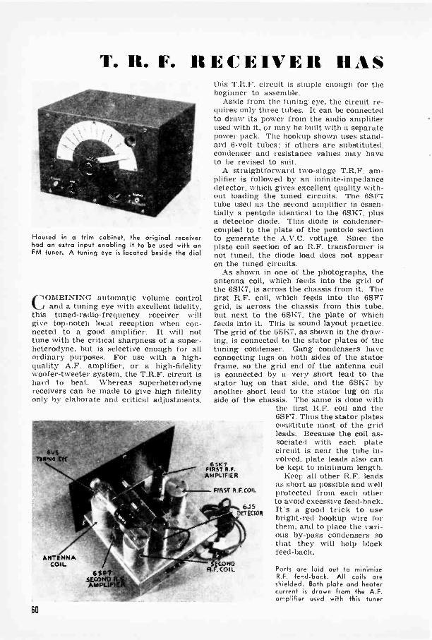
T. R. F. RECEIVER HAS
Housed in a trim cabinet, the original receiverhad an extra input enabling it to be used with onFM tuner. A tuning eye is located beside the dial
COMBINING automatic volume controland a tuning eye with excellent fidelity,
this tuned -radio -frequency receiver willgive top-notch local reception when con-nected to a good amplifier. It will nottune with the critical sharpness of a super-heterodyne, but is selective enough for allordinary purposes. For use with a high -quality A.F. amplifier, or a high-fidelitywoofer -tweeter system, the T.R.F. circuit ishard to beat. Whereas superheterodynereceivers can be made to give high fidelityonly by elaborate and critical adjustments,
TURIN.
ANTENNACOIL
6 S1*41
A(.0MPU
6 SK 7FIRST R.F.AMPLIFIER
FIRSr R.F.COIL
SICONDR.F. COIL
6J5DETECTOR
this T.R.F. circuit is simple enough for thebeginner to assemble.
Aside from the tuning eye, the circuit re-quires only three tubes. It can be connectedto draw its power from the audio amplifierused with it, or may be built with a separatepower pack. The hookup shown uses stand-ard 6 -volt tubes: if others are substituted,condenser and resistance values may haveto be revised to suit.
A straightforward two -stage T.R.F. am-plifier is followed by an infinite -impedancedetector, which gives excellent quality with-out loading the tuned circuits. The 6SF7tube used as the second amplifier is essen-tially a pentode identical to the 6SK7, plusa detector diode. This diode is condenser -coupled to the plate of the pentode sectionto generate the A.V.C. voltage. Since theplate coil section of an R.F. transformer isnot tuned, the diode load does not appearon the tuned circuits.
As shown in one of the photographs, theantenna coil, which feeds into the grid ofthe 6SK7, is across the chassis from it. Thefirst R.F. coil, which feeds into the 6SF7grid, is across the chassis from this tube,but next to the 6SK7, the plate of whichfeeds into it. This is sound layout practice.The grid of the 6SK7, as shown in the draw-ing, is connected to the stator plates of thetuning condenser. Gang condensers haveconnecting lugs on both sides of the statorframe, so the grid end of the antenna coilis connected by a very short lead to thestator lug on that side, and the 6SK7 byanother short lead to the stator lug on itsside of the chassis. The same is done with
the first R.F. coil and the6SF7. Thus the stator platesconstitute most of the gridleads. Because the coil as-sociated with each platecircuit is near the tube in-volved, plate leads also canbe kept to minimum length.
Keep all other R.F. leadsas short as possible and wellprotected from each otherto avoid excessive feed -back.It's a good trick to usebright -red hookup wire forthem, and to place the vari-ous by-pass condensers sothat they will help blockfeed -back.
Parts are laid out to minimizeR.F. feed -back. All coils oreshielded. Both plate and heatercurrent is drawn from the A.F.amplifier used with this tuner
60

AUTOMATIC VOLUME CONTROLSlight feed -back can be tolerated and is
even desirable. When plugged in, the setshould be somewhat "busy" with no stationtuned in, since a very small feed -back tendsto greatly increase sensitivity and improveselectivity. But do not expect critical tun-ing: the circuit is intended for high-fidelityreception, and must therefore pass the full10,000 -cycle band width of the transmitterwith nearly uniform response.
In selecting parts, be sure to use a
B+ 250 VOLTSB -
1sT R F.AMPLIFIER(651(7)\
1ST ecoiL.-3 -GANGTUNING
CONDENSER
2ND R FAMPLIFIER(6SF7)`.,
3 -GANGTUNING
CONDENSER
matched set of antenna and R.F. coils.Otherwise a slight difference between themmight mean, for example, that with theantenna circuit tuned to 1,100 kc., the firstR.F. stage might be tuned to 1,050 and thesecond to 1,200 kc., even though all trim-mers were adjusted so that the three circuitstune simultaneously to 1,500 kc.
A short indoor aerial will suffice for localreception. With an outdoor aerial, selectivitywill be somewhat poorer.
E(T6EJC 5T )0
I0,000 ul
3 -GANGTUNING
CONDENSER T 10 mrD
I mr0.
200.000 (1)
500,000 uuPOTENTIONI-..
ETER
TO - 'AMPLIFIER
_TUNING EVE(6U5 OR 6G5)
CHOOSING RADIO RESISTORSA commoN iticaas (If ectilicing voltage.
;it a desired point. or or limiting currentdraw to a safe value, is to insert a resist-ance in the circuit. This is usually con-nected in series with the power sourceand whatever device or apparatus is to beso controlled.
Two conditions must he wet in choos-ing the right resistor: it must have thecorrect resistance to cause the requiredvoltage drop. and it must have enoughcurrent -carrying capacity tii remain rea-sonably cool in operation.
The resistance is calculated by the for-mula R = E 1. where It is in ohms,E in volts, and I in amperes. If the cur-rent is in milliamperes, R will be in thou-sands of ohms.
EXAMPLE: A resistor is needed todrop a 300 -volt plate supply to 100 voltsfor the screen grid of a 6SA7 tube. Thus21111 volts must he dropped across the re-sistor. A tube manual Hsi:: the screen -
[ELECTRICAL]grid draw as 11 millianip. Dividing 200by 11 yields 18. which being in thousandsof 1,lints indicates a resistor of 18.000ohms. In practice 20.000 ohms would beclose enough.
The necessary current -carrying capacityor wattage rating is given by the formulaW (watts dissipated as heat = E2 ÷ R.Squaring the voltage drop 121111 X 200 =-10.0001 and dividing by the r-sistance(18.000) gives 2.2 watts: however. if weuse a 20.000 -ohm resistor. it need he ratedat only 2 watts.
EXAMPLE: The screen of an R.F am-plifier tube that draws 2 milliamp. is tobe supplied with 180 volts from a 200-y..11source. The voltage drop across the 1.
sistor niust therefore be 120 volts. Divid-ing 120 by 2 gives 60. which again is inthousands of ohms. Squaring the voltagedrop 111.000) and dividing by resistance160.000). we find the 1,5i:01W should berated n .24 watt,:.
POPULAR SCIENCE MONTHLY SHOP DATA
61
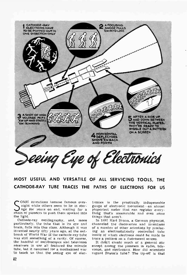
4 CATHODE -PAYI ELECTRONS HAVETO IIE POPPED OUT INONE DIRECTION ONLY
PA A SHOT OF HIGH*a VOLTAGE PEPS'EM UP AND STARTS'EM RUNNING
2A FOCUS! NGANODE PULLS'EM INTO LINE
4HORIZONTALDEFLECTORS
SHOVE 'EM BACKAND FORTH
5AFTER A RIDE UPAND DOWN BETWEEN
THE VERTICAL PLATES,THEY'RE READY TOWIGGLE OUT A PATTERNON A SCREEN
MOST USEFUL AND VERSATILE OF ALL SERVICING TOOLS, THE
CATHODE-RAY TUBE TRACES THE PATHS OF ELECTRONS FOR US
SOME inventions become famous over-night while others seem to lie in stor-age for years on end, waiting for a
chain of pioneers to push them upward intothe light.
Cathode-ray oscillography, and, moreparticularly, the tube that is its eye andbrain, falls into this class. Although it wasinvented nearly fifty years ago, at the out-break of World War II the cathode-ray tubewas still something of a rarity. Of course,the handful of oscilloscopes and televisionreceivers in use all featured the miracletube, but it remained for a mechanized warto teach us that the seeing eye of elec-
tronics is the practically indispensablegauge of electronic movement-an almostpluperfect meter that can register every-thing that's measurable and even somethings that aren't.
In 1897 Karl Braun, a German physicist,channeled the discoveries and inventionsof a number of other scientists by produc-ing an electrostatically controlled tubeinside of which electrons could be made totrace a pattern on a fluorescent screen.
It didn't create much of a general stirexcept among the pioneers in radio, tele-vision, and electronics. How did scientistsregard Braun's tube? The tip-off is that
62
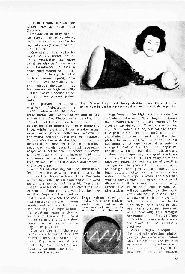
in 1909 Braun shared theNobel physics prize withMarconi.
Considered in only one ofits aspects- as a servicingtool -the jobs that a cathode-ray tube can perform are al-most endless.
Essentially the cathode-ray tube is a meter. Eitheras a voltmeter-the moreusual test -device form --or asa milliammeter, it uses apractically weightless pointercapable of being deflectedwith enormous rapidity. The"pointer" can faithfully fol-low voltage fluctuations atfrequencies as high as 200,-000,000 cycles a second or re-act to direct -current poten-tials.
The "pointer," of course,is a beam of electrons: it ismade visible when the elec-trons strike the fluorescent coating at theend of the tube. Electrostatic focusing anddeflection of the electron beam is commonin the test -instrument type of cathode-raytube, while television tubes employ mag-netic focusing and deflection because asomewhat sharper focus can be obtained.When deflection is obtained by the magneticfield of a coil, however, there is an induct-ance load which tends to limit frequencyresponse. Electrostatic deflectors representa more nearly pure resistance load andcan more readily be driven to very highfrequencies. This article deals chiefly withthe latter type.
An electron -emitting cathode, surroundedby a metal sleeve with a small opening, isthe heart of the cathode-ray tube. The holeserves to define the electron beam and actsas an intensity -controlling grid. Two ring -shaped anodes draw out the electrons, ac-celerating them to high velocity. Becauseof the shape of the electro-static fields between the con-trol electrode and the focusinganode, and between the focus-ing and high -voltage anodes,the electron beam is drawn,as if shot from a gun, to apin -point of light at the fluo-rescent screen. as shown inFig. 1 on page 64.
Leaving the gun, the elec-trons move toward the screenat great speed. En route, how-ever, they are pushed andpulled by the deflecting ap-paratus, causing the spot tomove on the screen.
Sweep voltage generatorsused in oscilloscopes producesowtooth waves that build upto a peak and then drop tozero almost instantaneously.
Size isn't everything in cathode-ray television tubes. The smaller oneon the right here is far -Fiore serviceable than the old-style large tube.
Just beyond the high -voltage anode thedeflectors take over. The diagram showsthe construction of a tube operated byelectrostatic deflection. Two pairs of plates,mounted inside the tube, control the beam.One pair is mounted in a horizontal planeand deflects the beam vertically; the otherplates lie in a vertical plane and deflecthorizontally. If one plate of a pair ischarged positive and the other negative,the beam will bend toward the positive plate-since the negatively charged electronswill be attracted to it and away from thenegative plate. By putting an alternatingvoltage on the plates they can be madeto change from positive to negative andback again as often as the voltage alter-nates. If the charge is weak, the electronswill be moved back and forth only a shortdistance: if it is strong, they will swingacross the screen from end to end. Analternating voltage applied to the hori-
zontal -deflecting plates, then,will sweep the beam right andleft at a rate equivalent to thefrequency. The trace of thisbeam on the screen, however,will appear only as a straighthorizontal line f Fig. 21 sinceeach side motion only coversthe trace of the precedingelectrons.
When a signal is applied tothe vertical -deflecting plates.exactly the same effect takesplat except that the trace isper;):11,1ictiiar to the horizontaltra' ,n Fig. 3. If,h(r.vi :;!. voltages
63

BASE
HEATER HIGH VOLTAGEANODE
CATHODE
L_
CONTROL FOCUSINGELECTRODE ANODE
VERTICAL DEFLECTINGPLATES
HORIZONTAL DEFLECTINGPLATES
1J N DEFLECTED HORIZONTALLYBEAM DEFLECTED BEAM
are simultaneously applied to both pairsof plates, so that as the spot moves acrossthe screen it also moves up and down, thenthe electron beam will trace out a visiblepattern (Fig. 4) representing the relation-ship of the two voltages applied.
The cathode-ray tube itself is ratherinsensitive. Some with screens 5" in diame-ter operate with 1,200 to 1,500 volts be-tween cathode and high -voltage anode.When electrons are accelerated by suchhigh voltages, they move with enormousspeed. Fairly heavy potentials are there-fore needed on the plates to cause adequatedeflection. For a standard 5" tube, about400 volts swing is needed to drive the spotcompletely across the screen. In checkingthe performance of a radio transmitter orthe power stage of an audio amplifier, suffi-ciently large voltages are normally avail-able and the tube can be directly con-nected. But for most work deflection volt-ages must be amplified, and amplifiers aretherefore built into test instruments such asthe oscilloscope.
An oscilloscope is a test instrument builtaround a cathode-ray tube. By means of ityou can amplify and feed a signal onto
VERTICALLYDEFLECTED BEAM
COMBINEDHORIZONTAL- VERTICAL
DEFLECTION
either the horizontal or vertical deflectors.Usually the test signal is applied only to
the vertical -deflecting plates of an oscillo-scope, while horizontal movement is ob-tained by means of a sweep -frequency gen-erator, which usually operates in directproportion to elapsed time. At the bottom ofpage 63 is a picture of a sweep voltageas recorded by the cathode-ray tube: it isobtained by means of an accumulation of acharge on the plates of a condenser con-nected across a control tube. This chargebuilds up at a uniform rate, reaches a peak,and discharges almost instantaneously. The"almost" is important because the veryslight time required for the spot to returnto its starting point introduces some distor-tion. For most practical uses, however, thefly -back time can be discounted.
Three basic factors account for the im-mense utility and adaptability of the cath-ode-ray tube as a test instrument: first, it isa double vacuum -tube voltmeter whichgives a direct, visual indication of instan-tanrons voltage. Second, being double, itcan indicate the instantaneous value of onevoltage while simultaneously indicating theinstantaneous value of a second, separate
64
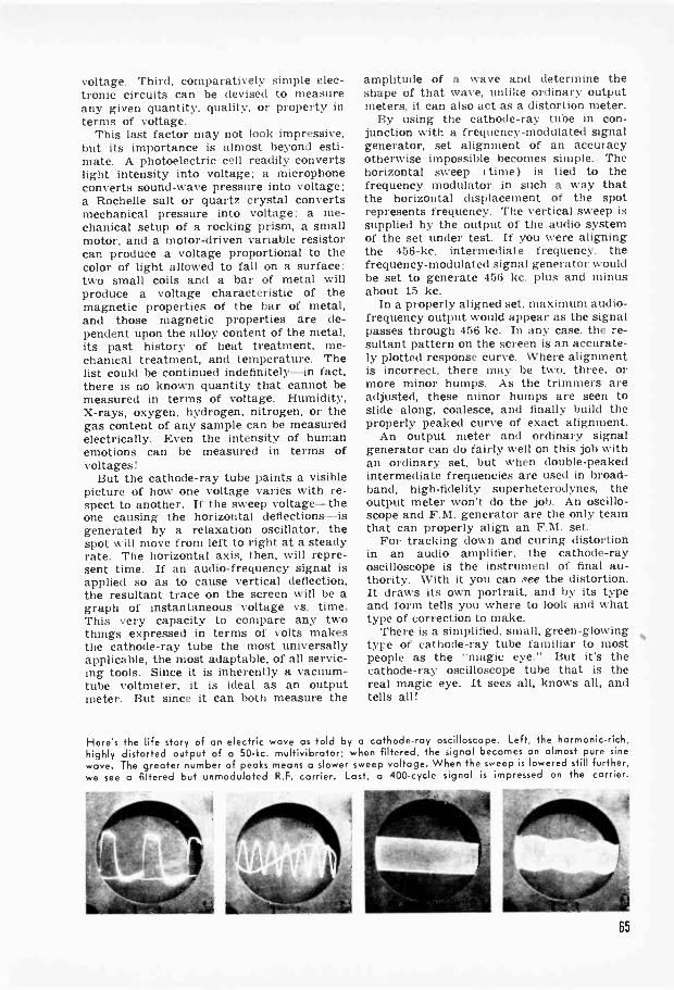
voltage. Third, comparatively simple elec-tronic circuits can be devised to measureany given quantity, quality, or property interms of voltage.
This last factor may not look impressive,but its importance is almost beyond esti-mate. A photoelectric cell readily convertslight intensity into voltage; a microphoneconverts sound -wave pressure into voltage;a Rochelle salt or quartz crystal convertsmechanical pressure into voltage; a me-chanical setup of a rocking prism, a smallmotor, and a motor -driven variable resistorcan produce a voltage proportional to thecolor of light allowed to fall on a surface;two small coils and a bar of metal willproduce a voltage characteristic of themagnetic properties of the bar of metal,and those magnetic properties are de-pendent upon the alloy content of the metal,its past history of heat treatment, me-chanical treatment, and temperature. Thelist could be continued indefinitely -in fact,there is no known quantity that cannot bemeasured in terms of voltage. Humidity,X-rays, oxygen, hydrogen, nitrogen, or thegas content of any sample can be measuredelectrically. Even the intensity of humanemotions can be measured in terms ofvoltages!
But the cathode-ray tube paints a visiblevaries with re-
spect to another. If the sweep voltage-theone causing the horizontal deflections-isgenerated by a relaxation oscillator, thespot will move from left to right at a steadyrate. The horizontal axis, then, will repre-sent time. If an audio -frequency signal isapplied so as to cause vertical deflection,the resultant trace on the screen will be agraph of instantaneous voltage vs. time.This very capacity to compare any twothings expressed in terms of volts makesthe cathode-ray tube the most universallyapplicable, the most adaptable, of all servic-ing tools. Since it is inherently a vacuum -tube voltmeter, it is ideal as an outputmeter. But since it can both measure the
amplitude of a wave and determine theshape of that wave, unlike ordinary outputmeters, it can also act as a distortion meter.
By using the cathode-ray tube in con-junction with a frequency -modulated signalgenerator, set alignment of an accuracyotherwise impossible becomes simple. Thehorizontal sweep I time) is tied to thefrequency modulator in such a way thatthe horizontal displacement of the spotrepresents frequency. The vertical sweep issupplied by the output of the audio systemof the set under test. If you were aligningthe 456-kc. intermediate frequency, thefrequency -modulated signal generator wouldbe set to generate 456 kc. plus and minusabout 15 kc.
In a properly aligned set, maximum audio -frequency output would appear as the signalpasses through 456 kc. In any case, the re-sultant pattern on the screen is an accurate-ly plotted response curve. Where alignmentis incorrect, there may be two, three, ormore minor humps. As the trimmers areadjusted, these minor humps are seen toslide along, coalesce, and finally build theproperly peaked curve of exact alignment.
An output meter and ordinary signalgenerator can do fairly well on this job withan ordinary set, but when double -peakedintermediate frequencies are used in broad-band, high-fidelity superheterodynes, theoutput meter won't do the job. An oscillo-scope and F.M. generator are the only teamthat can properly align an F.M. set.
For tracking down and curing distortionin an audio amplifier, the cathode-rayoscilloscope is the instrument of final au-thority. With it you can see the distortion.It draws its own portrait, and by its typeand form tells you where to look and whattype of correction to make.
There is a simplified, small, green -glowingtype of cathode-ray tube familiar to mostpeople as the "magic eye." But it's thecathode-ray oscilloscope tube that is thereal magic eye. It sees all, knows all, andtells all!
Here's the life story of an electric wave as told by a cathode-ray oscilloscope. Left, the harmonic -rich,highly distorted output of a 50-kc. multivibrator; when filtered. the signal becomes an almost pure sinewave. The greater number of peaks means a slower sweep voltage. When the sweep is lowered still further,we see a filtered but unmodulated R.F. carrier. Lost, a 400 -cycle signal is impressed on the carrier.
65
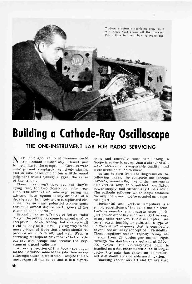
ticr.iern elc.stronic servicing requires ate:.! .-oeter that knows all the answers.This article tells you how to make one.
Building a Cathode -Ray OscilloscopeTHE ONE -INSTRUMENT LAB FOR RADIO SERVICING
NOT long ago, radio servicemen couldtroubleshoot almost any ailment just
by listening to the symptoms. Circuits were-by present standards relatively simple,and in nine cases out of ten a little soundjudgment would quickly suggest the causeof the trouble.
Those days aren't dead yet, but they'redying fast, for two closely connected rea-sons. The first is that radio engineering hasadvanced into regions hardly dreamed of adecade ago. Infinitely more complicated cir-cuits offer so many potential trouble spotsthat it is almost impossible to guess at thecause of poor operation.
Secondly, as an offshoot of better radiodesign, the public has come to expect qualityreception. The old feeling that a radio is allright as long as it plays is giving way to themore critical attitude that a radio should re-produce sound faithfully and well. From aservicing standpoint this means that a cath-ode-ray oscilloscope has become the key-stone of a good radio lab.
An earlier section of this book I see pages62-651 discussed some of the jobs than an os-cilloscope takes in its stride. Despite the al-most superstitious belief that it is a myste-
rious and fearfully complicated thing, a'scope is easier to set up than a standard all -wave receiver of comparable quality, andcosts about as much to make.
As can be seen from the diagrams on thefollowing pages, the complete oscilloscopeinvolves, essentially, five units: horizontaland vertical amplifiers, sawtooth oscillator,power supply, and cathode-ray tube circuit.The cathode follower which helps stabilizethe amplifiers need not be counted as a sepa-rate part.
Horizontal and vertical amplifiers aresimple repetitions of the same basic circuit.Each is essentially a phase -inverter, push-pull power amplifier such as might be usedin any radio receiver. But it is simpler, usesfewer parts, has higher gain, and a type of"high-fidelity" response that is completelybeyond the ordinary concept of high fidelity.These amplifiers respond equally to any fre-quency from 20 cycles per second rightthrough the short-wave spectrum at 2,500,-000 cycles. The 2.5 -megacycle band ishandled on a flat characteristic; at 10 mega-cycles the gain has fallen off somewhat,but still shows considerable amplification.
Blocking condensers Cl and C2 are used66
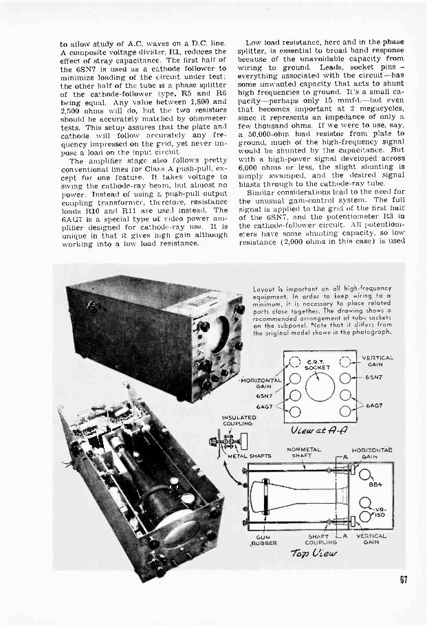
to allow study of A.C. waves on a D.C. line.A composite voltage divider, R1, reduces theeffect of stray capacitance. The first half ofthe 6SN7 is used as a cathode follower tominimize loading of the circuit under test;the other half of the tube is a phase splitterof the cathode -follower type, R5 and R6being equal. Any value between 1,800 and2,500 ohms will do, but the two resistorsshould be accurately matched by ohmmetertests. This setup assures that the plate andcathode will follow accurately any fre-quency impressed on the grid, yet never im-pose a load on the input circuit.
The amplifier stage also follows prettyconventional lines for Class A push-pull, ex-cept for one feature. It takes voltage toswing the cathode-ray beam, but almost nopower. Instead of using a push-pull outputcoupling transformer, therefore, resistanceloads R10 and R11 are used instead. The6AG7 is a special type of video power am-plifier designed for cathode-ray use. It isunique in that it gives high gain althoughworking into a low load resistance.
Low load resistance, here and in the phasesplitter, is essential to broad band responsebecause of the unavoidable capacity fromwiring to ground. Leads, socket pins-everything associated with the circuit-hassome unwanted capacity that acts to shunthigh frequencies to ground. It's a small ca-pacity-perhaps only 15 mmfd.-but eventhat becomes important at 2 megacycles,since it represents an impedance of only afew thousand ohms. If we were to use, say,a 50,000 -ohm load resistor from plate toground, much of the high -frequency signalwould be shunted by the capacitance. Butwith a high -power signal developed across6,000 ohms or less, the slight shunting issimply swamped, and the desired signalblasts through to the cathode-ray tube.
Similar considerations lead to the need forthe unusual gain -control system. The fullsignal is applied to the grid of the first halfof the 6SN7, and the potentiometer R3 inthe cathode -follower circuit. All potentiom-eters have some shunting capacity, so lowresistance (2,000 ohms in this case) is used
Layout is important on all high -frequencyequipment. In order to keep wiring to aminimum, it is necessary to place relatedparts close together. The drawing shows arecommended arrangement of tube socketson the subpanel. Note that it differs fromthe original model shown in the photograph.
HORIZONTALGAIN
6AG7
INSULATEDCOUPLING
C*1 i44
-
METAL SHAFTS
\NIIL
GUM,RUBIBER
Wear at 4-p
NONMETALSHAFT
VERTICALGAIN
HOPI ZCNTAL:A GAIN
SHAFT A VERTICALCOUPLING GAIN
C4..eUr
61
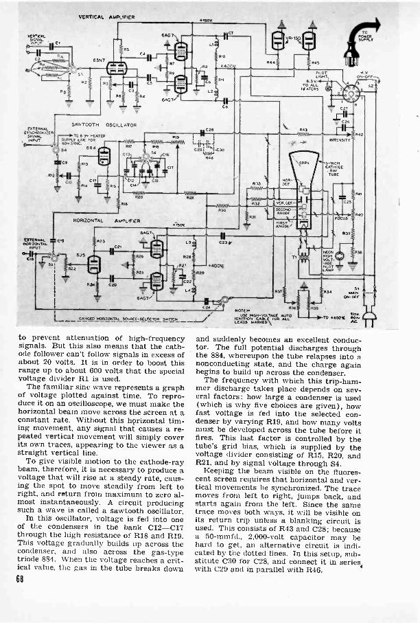
VERTICAL AMPLIFIER
VERTKALWAAL6IPvT
V
SAwTOOTH OSCILLATOREXTERNAL
SYNCHRONIZERTO 6 3N. HEATER
INPUT 1 --SUPPLY LAC FOR04--a4 60., SYNC.
SIGNAL
C9
RI2
EXTERNAL CIOHORIZONTAL T
INPUT
0-11---4,GNI
f(`,,,..
5I
L
884
R20
RI6
HORIZONTAL AMPLIFIER
6J5
824 C20
(AG,.
R9
7
RI
CI7
0V
IfC
C29. i-C30Rao
P29
P29
C231,
44001S
N t--e'I-j6)C24 r P30 R33NOTE..UTE HIGH -VOLTAGE AUTO
CAMEO HORIZONTAL SOURCE -SELECTOR SwITCH IGNITION CABLE FOR ALLLEADS HARMS ,1/4
NEONHIGHVOLT -
PILOTLAMP
R34
SAW
to prevent attenuation of high -frequencysignals. But this also means that the cath-ode follower can't follow signals in excess ofabout 20 volts. It is in order to boost thisrange up to about 600 volts that the specialvoltage divider R1 is used.
The familiar sine wave represents a graphof voltage plotted against time. To repro-duce it on an oscilloscope, we must make thehorizontal beam move across the screen at aconstant rate. Without this horizontal tim-ing movement, any signal that causes a re-peated vertical movement will simply coverits own traces, appearing to the viewer as astraight vertical line.
To give visible motion to the cathode-raybeam, therefore, it is necessary to produce avoltage that will rise at a steady rate, caus-ing the spot to move steadily from left toright, and return from maximum to zero al-most instantaneously. A circuit producingsuch a wave is called a sawtooth oscillator.
In this oscillator, voltage is fed into oneof the condensers in the bank C12-C17through the high resistance of R18 and R19.This voltage gradually builds up across thecondenser, and also across the gas -typetriode 884. When the voltage reaches a crit-ical value, the gas in the tube breaks down68
StMAIN
ON -OFF
TO 6100'AL
and suddenly becomes an excellent conduc-tor. The full potential discharges throughthe 884, whereupon the tube relapses into anonconducting state, and the charge againbegins to build up across the condenser.
The frequency with which this trip-ham-mer discharge takes place depends on sev-eral factors: how large a condenser is used(which is why five choices are given), howfast voltage is fed into the selected con-denser by varying R19, and how many voltsmust be developed across the tube before itfires. This last factor is controlled by thetube's grid bias, which is supplied by thevoltage divider consisting of R15, R20, andR21, and by signal voltage through S4.
Keeping the beam visible on the fluores-cent screen requires that horizontal and ver-tical movements be synchronized. The tracemoves from left to right, jumps back, andstarts again from the left. Since the sametrace moves both ways, it will be visible onits return trip unless a blanking circuit isused. This consists of R43 and C28; becausea 50-mmfd., 2,000 -volt capacitor may behard to get, an alternative circuit is indi-cated by the dotted lines. In this setup, sub-stitute C30 for C28, and connect it in series,with C29 and in parallel with R46.
V
32

NOTES WIRE No.6 141ST 85 AUTO/G,TOS. CASLE: WIRES Nos.211 5.01,-D SE $6 G.A. OR
PcmiErt-SUPPLY PACK
LIST OF PARTSAll condensers 600 vt Its unless
otherwise noted.('II, 1'10. ('23,
('21. 1 25. ('26: . I r. rd.C2: 2 told.. 2.000 volts or highest
voltage available.C4. C5. C10. C20. C2I: .25 mfd.CO. C"32: 20 mid.. 25 volts, elcc-
trolyt lc.C9: .5 and.C11: 25 mid., 25 volts. electro-
lytic.C12: .25 mid.. 400 tolls.
C13: .05 mid., 400 volts.C14: .005 mid.. 400 volts.C15: 1.500 tumid.. 400 volts.C16: 250 mmfd., 400 volts.Cu. C30: 50 mmfd.. 400 volts,C27. C31: 1 mid.. 1.500 volts. 311 -
filled paper.C28: 50 romfd., 2.000 volts.C29: 001 mid.. 2.000 volts.C32. C33. C34. C35: 16-mfd.. 450 -
volt. electrolytic filter con-densers.
All resistors 1 watt unlessotherwise noted.
Healthy voltages are needed to drive thespot across the screen, and call for a 200-milliamp. power supply capable of deliver-ing a full 400 volts under load. If you canget transmitter -type filament transformerswith 3,000 -volt insulation you can saveyourself the job of rewinding heater trans-formers for the 2X2 and cathode-ray tube.
SIGNALINPUT
RI: composite voltage divider. consisting of 3 -watt resistors: Ra. 10,090 ohms; lib. 2,500ohm, Rr. 1,200 ohne; ltd, 500 ohms.
R2, R4: 2 meg.R3: 2.000 -ohm pot.RS, R6, R13, R23. R24 2.000 ohms.R7, RA, 1(25. 1(26. R30. R3I. R38: 250,000 ohms.R8. R27: 50 ohms. 2 watts.RIO, RII. R28. R29: 0.000 ohms. 10 watts.RI2: 5.000 -ohm pot.R14: 40.000 ohms.RIO: 1.500 ohms.R16. R32. R33. R34. R37: 1 meg.1/17: 25 ohms.RIO: 400.000 ohms.RI9: 5-tneu. pot.R20: 80.000 ohms.R21: 60.000 ohms.R22: 2-meg. pot.R35. R36: 1-mcg. sot.R3t1: 700.000 ohms, 2 watts (two 350,000 ohms. 1
watt in series).R40: 500.000 ohms. 2 -watt pot.R41. R43. 549. R50. R51. R52: 100.000 ohms.R42: 250.000 -ohm not.R44. R45: 8.000 ohms. 10 watts.R46: 10 meg.R47: 20.000 ohms.R48: 5 meg.
lty: To he deter hied hy trial; Fe(' test 21T2 is a standard 3.000 -volt neon -tube trans..Rr e u i,l 101,0115 oho, s watts. and flyequals I meg., 2 wir ts
Ll. L2. L2. 1.4: one me front s:andard four -Pie.2.5 -Tait. R.F. choke.
L5: Dower filter choke 200 ma., 10 h.. or larger.T1: 113 -to -6.3 volt trans.: 5.000 -volt insulation,T2: 115 -to -1.000 volts or more.T3: 115 -to -2.5 volt trees.: 5.000 -volt innulaton.T4: rtandaid 200 -Ina. power trans.: 115 to 8.3.
5.0 and 425-0-425SI: D.P.S.T. tumbler.82: toggle.S3: 5-uont ion selecLor; preferably low -loss
ceramic.84: 3 -position selector.85: 3 -position D.F. selector.S6: 6 -position S.P. selector.Tubes, sockets, and accessories as noted.
This can be done, however, in a single eve-ning's work on two small, standard 6.3 -volttransformers. Taking out the core stack,you will find the 6.3 -volt winding outermost.Remove this winding, counting the turns.Wind two layers of 5.000 -volt insulatingcambric over the primary, and, for TI, re-place the 6.3 -volt secondary. Put another
/Slack Viaytam f Catkacia-Nay 6deillesicapeSYNCHRONIZATIONSIGNAL -SOURCE
SELECTOR TO 60 -CYCLESUPPLYCATHODE
FOLLOWER
VERTICALAMPLIFIER
HORIZONTALSIGNALINPut
I SAW TOOTHOSCILLATOR
RETURN -TRACEBLANKINGCIRCUIT
HoniZON-7ALAMPLIFIER
ExTERNALSYNCHRONIZER
INPUT
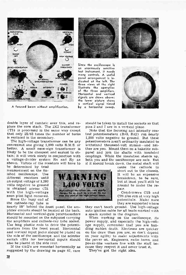
HOW ZONTALGAIN
HIGH
SWEEPOFF
4:4,ETNG,4 CION RATON
\
ExTEUNALSYNCHRONICATION
FOCUS INTEHam
011014 LOW
VERTICALGAIN
NIGH
POWER
HIGH VOLTAGE
0SWEEP
FREQUENCY
141,3H
POWER
2 0)HIGH VOLTAGE
? NO
A focused beam without amplification.
Since the oscilloscope isan enormously sensitivetest instrument, it needsmany controls. A usefulpanel arrangement is in-dicated ct the left. Thethree views at the rightillustrate the operationof the three amplifiers.Horizontal and verticalsignals are shown above;the lower picture showsa vertical signal timedby a horizontal sweep.
double layer of cambric over this, and re-place the core stack. The 2X2 transformer(T3) is processed in the same way exceptthat only 25/63 times the number of turnsis replaced in the secondary.
The high -voltage transformer can be anyconvenient one giving 1,000 volts R.M.S. orbetter. A small neon -sign transformer islikely to be the cheapest and easiest to ob-tain; it will work nicely in conjunction witha voltage -divider system Rx and Ry asshown. Values of the resistors will have tobe determined by trialmeasurement on the fin-ished oscilloscope. Usedifferent resistors untilan output voltage of 1,200volts negative to groundis obtained across C31with the high -voltageneon pilot light removed.
Since the busy end ofthe cathode-ray tube isnearly 18" behind the front panel, the am-plifier circuits should be located at the back.Horizontal and vertical -gain potentiometersshould be mounted on the subpanel carryingthe amplifiers and cathode-ray tube socket.Use long plastic rods to drive the potenti-ometers from the front panel. Horizontaland vertical input jacks should be placed onthe side of the oscilloscope, and the selectorswitch ( S5) for horizontal inputs shouldalso be placed at the side rear.
If the 6AG's are mounted horizontally assuggested by the drawing on page 67, care
wARNIN1,4 0 0 VOLT S
High -voltage capacitors Can sior deadlychores,. far as couch as a rah. Do nOmit any pare of rho high-volfae circa_
should be taken to install the sockets so thatpins 2 and 7 are in a vertical plane.
Note that the focusing and intensity con-trol potentiometers (R40, R42) run nearly1,200 volts negative to ground. But thesepotentiometers aren't ordinarily insulated towithstand thousand -volt strains-and nei-ther are you. Mount them on a bakelite sub -panel and join the shafts with insulatedcouplings. While the insulation stands up,both you and the oscilloscope are safe. Butif it should break down, the metal shaft will
cause the cathode toshort out to the chassis.It will be an expensivebreakdown, to be sure,but at least you'll still bearound to make the re-pair.
Condensers C25 andC26 also run at very highpotentials. Make surethey are supported where
they can't touch ground. Use high -voltageauto ignition cable for all leads marked witha spark symbol in the diagram.
When working on the oscilloscope, itspower supply, and especially the high -volt-age supply, remember that you are han-dling sudden death. Electrons are quickeron the draw than you are, so don't dependon your agility to make adjustments withthe power on. Engineers, radio hams, andpower -line workers live with the stuff be-cause they respect it and never trust it.
They've got the right idea.
10

WARPED PHONOGRAPH RECORDS that slip againstother records on an automatic changer can often bestraightened simply by placing them between glass andleaving them in a warm place for a few hours. Use twoscrap pieces of plate glass at least 12" square and lay asheet of paper between each surface of the record anda glass to avoid damaging the grooves. Put a weight,such an an electric iron, on top. A shelf over the kitchenrange, or some similar spot, should provide sufficientwarmth to take out the bend.
Occasionally a record so straightened will retain aslight curve that permits the convex surface to slip.This can be corrected by repeating the straighteningoperation with a 4" circle of heavy paper or thin card-board on the center of the convex side.
Slipping usually occurs when a record is so warpedthat the drag of the needle is greater than the drag ofthe record on the one below it on the automatic changer.Two adjacent records in a set may be warped and stilllit together in such a way that they do not slip. In sucha case straightening is unnecessary.- WILLARD A I I N.
TO TRANS FORM ER -ice
10(1 !M.PLUG D. P T-' ' 1 WAT 7
SWITCH 0 te0-1WW---- /TO 0 + CONNECTION
LINE
SAFETY CAN BE ASSURED in workingwith experimental high -vintage electronicequipment by incorporating a double -poledouble -throw switch in the circuit, as shownin the diagram above, instead of the cus-tomary line switch. This acts on the sameprinciple as the more expensive and hard -to -obtain interlock switches, permitting thecondensers to discharge automatically whenthe switch is thrown over. The resistor isadded to prevent excessive sparking at thecontacts. Since the discharge takes place ina matter of milliseconds, a 1 -watt resistoris adequate. --GEORGE 0. SMITH.
SHORTS IN A CONDENSER, such as areapparent when a radio goes dead over partof the dial, can be traced quickly by riggingup a homemade tester consisting of two drycells and a door buzzer. Disconnect thestator leads and connect the cells and buzzerin series with one section of the condenserat a time, as shown below. Then slowlyrotate the condenser back and forth, watch-ing the segments closely. A short will showup as sparks between the plates, which canthen be straightened. OTT() H. AD tAxit.
TO STATOR PLATES
VARIABLE '
CONDENSER
j GROUND TO CHASSIS -N
MEASURING IMPEDANCES [ELECTRICAL]ECTRIC A L
110-V.
FIG.1
110- V.A.0
FIG.21R2
I 111 011110.
If R, Is N.A.. ohm, Its 1. H ohms. V, Is 111 %oils. And I.
OUTPUT TRANSFORMER then lalloeolanee5t1 6.060 ,.tom,
ud I..rg. eototeo-ers )on, 0." ,IllonYolLonrY-frronlYtte chart. the 1111111.1111100 1111,00111,111111111: dote,mined eon he convert...I to henries mlerforar...1..
In FM. I. It Is a known reststor approximately equal 111 1110 11111.1 "ante of Ilk! 111/111rIane0 lout. to proqoot "seri...Wog. not les. IL
2.7iolo ohm-. while I. Is the rholie 111. Ire;.-tor.sl. Item! V, 1111.1
the '.,C. ylottlItettor: then use 11111 following formula:It x V..
Impedance of I. In ohms = V,If It Is 4.111 011110, V, In MN 5.olts. aziLl V2 1. 22 1110n
4.111111 22I. - 1.111 ohm-.
When Impeolanee eading . ate mote LLa IL Lo-L.L e...l.ottoe loaded with. resi-oor !of III, I Al, ..1 I I
otteon
!normally 1,011. The correct pair of -ecoliolory Ono, to Ut.41.'11 ..11 /11.11111.
'111,/ker to a required 011111111 eat, I.. .1.1.ronomst to ono ..,lorleow theloopeolanee of the transformer with an st-ooloon rosi-ter Loroos- ollfferent ,11. lary t.ons.
In rig. 2' It, Is Lt known re -1,1m- approximately ....ILA 111 1110 1110
1.0414110.10f Ill.. transformer hon. to Present "soot...a.m. pm le- th.on2.3111 ohms. mot It2 Is a resistor equal t., 1110 1M111 /111/11, Of 1110nortnallY used speaker sole!. eoil. FLor onto.h.poll tr.on-formers. toe thetwo plate taps and Ignore the renter lap. Thug. with eloolso-.reLoLl V, and V. and Use II,,- following formula:
It x V2
POPULAR SCIENCE MONTHLY SHOP DATA
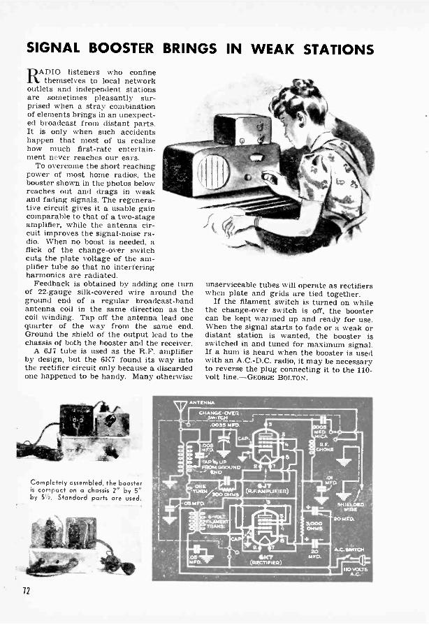
SIGNAL BOOSTER BRINGS IN WEAK STATIONSRADIO listeners who confine
themselves to local networkoutlets and independent stationsare sometimes pleasantly sur-prised when a stray combinationof elements brings in an unexpect-ed broadcast from distant parts.It is only when such accidentshappen that most of us realizehow much first-rate entertain-ment never reaches our ears.
To overcome the short reachingpower of most home radios, thebooster shown in the photos belowreaches out and drags in weakand fading signals. The regenera-tive circuit gives it a usable gaincomparable to that of a two -stageamplifier, while the antenna cir-cuit improves the signal -noise ra-dio. When no boost is needed, aflick of the change -over switchcuts the plate voltage of the am-plifier tube so that no interferingharmonics are radiated.
Feedback is obtained by adding one turnof 22 -gauge silk -covered wire around theground end of a regular broadcast -bandantenna coil in the same direction as thecoil winding. Tap off the antenna lead onequarter of the way from the same end.Ground the shield of the output lead to thechassis of both the booster and the receiver.
A 6J7 tube is used as the R.F. amplifierby design, but the 6K7 found its way intothe rectifier circuit only because a discardedone happened to be handy. Many otherwise
11101mow:, i.
Completely assembled, the boosteris compact on a chassis 2" by 5"by 5Vs. Standard parts are used.
unserviceable tubes will operate as rectifierswhen plate and grids are tied together.
If the filament switch is turned on whilethe change -over switch is off, the boostercan be kept warmed up and ready for use.When the signal starts to fade or a weak ordistant station is wanted, the booster isswitched in and tuned for maximum signal.If a hum is heard when the booster is usedwith an A.C.-D.C. radio, it may be necessaryto reverse the plug connecting it to the 110 -volt line.-GEORGE BOLTON.
12
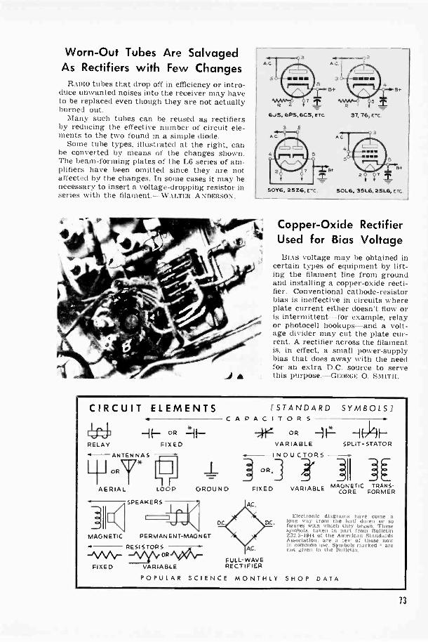
Worn -Out Tubes Are SalvagedAs Rectifiers with Few Changes
RADIO tubes that drop off in efficiency or intro-duce unwanted noises into the receiver may haveto be replaced even though they are not actuallyburned out.
Many such tubes can be reused as rectifiersby reducing the effective number of circuit ele-ments to the two found in a simple diode.
Some tube types, illustrated at the right, canbe converted by means of the changes shown.The beam -forming plates of the L6 series of am-plifiers have been omitted since they are notaffected by the changes. In some cases it may benecessary to insert a voltage -dropping resistor inseries with the filament.-WALTER ANDERSON.
Copper -Oxide RectifierUsed for Bias VoltageBIAS voltage may be obtained in
certain types of equipment by lift-ing the filament line from groundand installing a copper -oxide recti-fier. Conventional cathode -resistorbias is ineffective in circuits whereplate current either doesn't flow oris intermittent-for example, relayor photocell hookups-and a volt-age divider may cut the plate cur-rent. A rectifier across the filamentis, in effect, a small power -supplybias that does away with the needfor an extra D.C. source to servethis purpose.-GEoRoF: 0. Smrro.
CIRCUIT ELEMENTS
,L4 ORRELAY FIXED
"a-ANTENNAS
H OPT*AERIAL
II
MAGNETIC PERMANENT -MAGNET
RESISTORS
-V\r°RiVA41-
ILOOP GROUND
SPEAKERS
FIXED VARIABLE
D.C.
[STANDARD SYMBOLS /CAPACITOR S
°R rL -104--VARIABLE SPLIT -STATOR
INDUCTORS
j OR.] A-]IlMAGNETIC
CORE
AC.
FULL -WAVERECTIFIER
POPULAR SCIENCE MONTHLY
VARIABLE TRANS-FORMER
Electronic diagrams have come along way from the hall dw.en or sofigures with which they began Thesesymbols. taken in part from BulletinZ32.5-1944 of the American StandardsAssociation. are a lew of those nowin common use. Symbols marked < arenot given in the Bulletin.
SHOP DATA
13
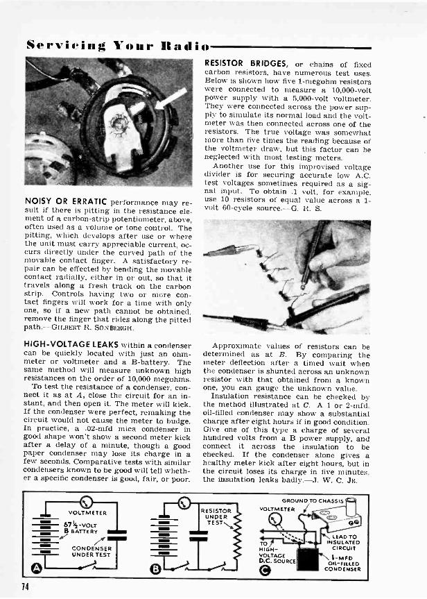
SerVieillg jour Radio
NOISY OR ERRATIC performance may re-sult if there is pitting in the resistance ele-ment of a carbon -strip potentiometer, above,often used as a volume or tone control. Thepitting, which develops after use or wherethe unit must carry appreciable current, oc-curs directly under the curved path of themovable contact finger. A satisfactory re-pair can be effected by bending the movablecontact radially, either in or out, so that ittravels along a fresh track on the carbonstrip. Controls having two or more con-tact fingers will work for a time with onlyone, so if a new path cannot be obtained,remove the finger that rides along the pittedpath.-GILBEIIT R. SONSERGII.
HIGH -VOLTAGE LEAKS within a condensercan be quickly located with just an ohm-meter or voltmeter and a B -battery. Thesame method will measure unknown highresistances on the order of 10,000 megohms.
To test the resistance of a condenser, con-nect it as at A, close the circuit for an in-stant, and then open it. The meter will kick.If the condenser were perfect, remaking thecircuit would not cause the meter to budge.In practice, a .02-mfd mica condenser ingood shape won't show a second meter kickafter a delay of a minute, though a goodpaper condenser may lose its charge in afew seconds. Comparative tests with similarcondensers known to be good will tell wheth-er a specific condenser is good, fair, or poor.
RESISTOR BRIDGES, or chains of fixedcarbon resistors, have numerous test uses.Below is shown how five 1-megohm resistorswere connected to measure a 10,000 -voltpower supply with a 5,000 -volt voltmeter.They were connected across the power sup-ply to simulate its normal load and the volt-meter was then connected across one of theresistors. The true voltage was somewhatmore than five times the reading because ofthe voltmeter draw, but this factor can beneglected with most testing meters.
Another use for this improvised voltagedivider is for securing accurate low A.C.test voltages sometimes required as a sig-nal input. To obtain .1 volt, for example,use 10 resistors of equal value across a 1 -volt 60 -cycle source.-G. R. S.
Approximate values of resistors can bedetermined as at B. By comparing themeter deflection after a timed wait whenthe condenser is shunted across an unknownresistor with that obtained from a knownone, you can gauge the unknown value.
Insulation resistance can be checked bythe method illustrated at C. A 1 or 2-mfd.oil -filled condenser may show a substantialcharge after eight hours if in good condition.Give one of this type a charge of severalhundred volts from a B power supply, andconnect it across the insulation to bechecked. If the condenser alone gives ahealthy meter kick after eight hours, but inthe circuit loses its charge in five minutes,the insulation leaks badly.-J. W. C. JR.
11=INI
VOLTMETER
67 -VOLTB BATTERY
7*CONDENSERUNDER TEST
RESISTORUNDERTESTN.,
GROUND TO CHASSISVOLTMETER
TOHIGH -VOLTAGED.C. SOURCE
O
LEAD TOINSULATED
CIRCUIT
1-MFDOIL -FILLED
CONDENSER
14
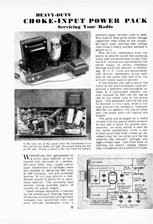
HEAVY-DUTYCHOKE -INPUT POWER PACK
Servicing Your Radio
In the rear view of the power pack, the transformer is atleft and the two chokes at right, the second being the oneon the side. Wiring is shown in the view from the bottom.
WHERE you find replacement ofa power pack difficult, or have
trouble with blowouts on a conden-ser -input filter, this rugged powerpack, constructed of salvaged partsand capable of delivering 300 voltsat 250 milliamp., will give excellentservice. It will also provide a well -filtered source of power for a short-wave receiver. The unusually highcurrent rating provides plenty ofcurrent for power stages.
Good voltage regulation is assuredby the choke -input filtering feature,which also will prevent the high peakvoltages that sometimes blow outeven 450 -volt condensers when a
75
4
mercury-vapor rectifier tube is used.This type of filter gives better voltageregulation than those of the conden-ser -input type, showing less voltagedrop when a heavy current demand isplaced on it.
Two .01-mfd. condensers from theplates to ground cancel the annoyinghums that are sometimes caused whenthe R.F. circuits are modulated by thepower supply at certain frequencysettings while the detector is oscillat-ing. If A. C. hums are encountered,add .25-mfd. condensers across eachside of the power line and from the6.3 -volt heater leads to ground.
If the speaker you use is one of themany of the electrodynamic type em-ploying a powerful electromagnet in-stead of a permanent magnet, youmay connect its field coil for use asone of the choke coils in the powerpack. This expedient permits the coilto function in two ways, since it willalso provide the necessary magneticfield for the speaker. For use on othersets, the power pack will require twochokes.
The parts are arranged on a metalchassis with the second choke screwedon one side to allow for greater corn-pactness. An octal socket is used forthe outlet connections, while a dis-carded octal -tube base makes an ex-cellent plug for the outlet cord for thereceiver -tube filament voltages andhigh -voltage taps. Less flash back onstarting, but poorer voltage regula-tion, is possible with a 5Z3 or 5U4 tube.
6.3 -VOLTHEATERLEADS
4
50 4)WATT,_ 11.
80,000W-Aail I WATT
2.500LOStWATT
83 TUBESECOND CHOKE
OR SPEAKER
51010 )HENRY
L ---J USE CENTER TAP CHOKEle PRESENT; OTHERWISEEITHER FILAMENT LEAD
25.000 uSIC -WATTWIRE -WOUNDRESISTOR
+
8 TOM -M F D. 450 -VOLT£C-*PLJLIMCS
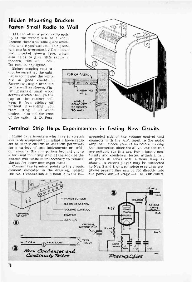
Hidden Mounting BracketsFasten Small Radio to Wall
ALL too often a small radio endsup at the wrong side of a roombecause there's no table space avail-able where you want it. This prob-lem can be overcome by the hiddenwall bracket shown here, whichalso helps to give little radios amodern, "built-in" look.Its cost is negligible.
Before hanging your ra-dio, be sure that the cabi-net is sound and the jointsare in good condition.Screw two angle bracketsto the wall as shown. Fin-ishing nails or small woodscrews driven through thetop of the cabinet willkeep it from sliding offwithout preventing youfrom lifting it off whendesired. Cut off the endsof the nails. H. D. POST.
FINISHINGNAIL
ANGLEBRACKETSCREWEDTO WALL
Terminal Strip Helps Experimenters in Testing New CircuitsRAmo experimenters who have to stretch
available equipment can adapt a home radioset to supply current at different potentialsfor a variety of test instruments or "add-on" circuits. Six connections brought out toa terminal mounting strip at the back of thechassis will make it unnecessary to removethe set for every new experiment.
Connect the terminal points to the circuitelement indicated in the drawing. Shieldthe No. 4 connection and hook it to the un-
IIl
CHASSISOF SET
ONo. I
b
-POWER SCREEN
R.F. OR I.F. SCREEN
VOLUME CONTROL
HEATER
GROUND
grounded side of the volume control thatconnects with the A.F. input to the audioamplifier. Check your radio before makingthis connection, since not all volume controlsare suitable for this use. For a handy con-tinuity and condenser tester, attach a pairof prods in series with a neon lamp asshown. A record player may be connectedto Nos. 1 and 4, or a complete crystal -micro-phone preamplifier can be fed directly intothe power output stage.-E. E. YOUNGKIN.
CRYSTALMICROPHONE
Ne.5 OR 6 NEON LAMP
-/*afrt n'/[L ee/atet a meteantimuity Tester
TESTPRO os
OO'00,000
01-11,45
6J7
.01 M PD.
,40.4
50,000OHMS
r)HAs tWO. MIT TFD
772-eaNgitziz.et
No.6
No 5
No .1
16
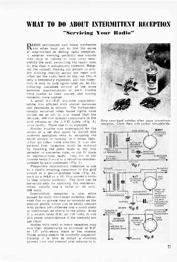
WHAT TO DO .1IIOUT INTERMITTENT RECEPTION-Servieing Your Radio"
ADIO servicemen and home mechanicsft are often hard put to find the causeof intermittent or fading radio reception.A receiver working perfectly one minutemay drop in volume or fade away com-pletely the next, perplexing the repair manno less than it exasperates listeners. Bang-ing the cabinet, flicking the switch, or sim-ply walking heavily across the room willoften jar the radio back to life, but this isonly a temporary expedient, and the recep-tion is sure to fade again later on. In thefollowing instances several of the morecommon manifestations of such troublewere traced to their source, and lastingremedies were applied.
A small A.C.-D.C. iivo-tube superheter-odyne was afflicted with abrupt increasesand decreases in volume. The fluctuationsusually occurred when house lights wereturned on or off. It was found that the.05-mfd., 400 -volt tubular condensers in thegrid returns of the A.V.C. tubes I Fig. 1)were faulty. These had to be replaced.
Similar trouble was experienced by theowner of a set that could be stirred intorenewed operation only by snapping theon -off switch or turning on a house light.After all tubes were checked. it was dis-covered that reception could be restoredby touching the plate leads of the firstdetector or converter tube, or the IF leadsor oscillator -tube leads. This led to thetrouble being traced to a defective detector -cathode by-pass condenser I Fig. 2t.
Frequently intermittent reception is dueto a faulty coupling condenser in the gridcircuit of a power -pentode tube I Fig. 3),such as a 50L6 or a 43. This causes a radioto lose volume suddenly. The fault can hecorrected only by replacing the condenser,which usually has a value of .05 mfd.,400 volts.
Intermittent reception is also oftencaused by dirty wave -band switches. Hard-ened flux or grease may accumulate on thecontact points, which can be easily cleanedwith carbon tetrachloride and a small clothor toothbrush, as shown in the photo. Evenif a switch teats O.K. on 110 volts, it willstill cause intermittence if the contacts arenot clean.
Radios with weak or noisy reception mayowe their eccentricity to corrosion of R.F.or I.F. grid -return leads at the chassis.These points should he carefully inspected.Usually it is best to install a commonground wire and connect grid returns to it.
Dirty wave -bond switches often cause intermittentreception. Clean them with carbon tetrachloride.
R.F.C.OIL ORI.F. TRANSFORMER
TO OTHER
4R.F TUBES
TO PLATE
Br
GR,C, LEAD -
TUNING ORTRIMMERCONDENSER
,,A0P1,
"P..-DEFECTiVECONDENSER
TO DETECTOR"7- STAGE
125)07,OR SIMILAR
p AMPLIFIERTUBE
L JLF.TRANSFORMER
CHASSIS
.DS etFo. Ws..To PLATE OFDETECTOR if
- - - -DEFECTIVE
CONDENSER
100.000 TO250,000 OHMS
or
501.6OR SIMILAR
OUTPUTTUBE
. .
AvC LINE
. -f
6.17OR SIMILARDETECTOR
Tu,AL
TO OUTPUTSTAGE
GRIDCAP
DEFECTIVE20.0000Ho.5
CTuNBUL
A R1APER
I, (SOMETIMESS
ELECTROLYTICC--- CONDENSER
IS USED)
CHASSIS O. S
TO SPEAKERTRANSFORMER
GRIDLEAD
17
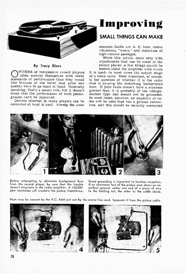
By Tracy Diers
OWNERS of inexpensive record playersoften content themselves with lower
standards of performance than they wouldlike because of the belief that price andquality have to go hand in hand. Generallyspeaking, that's a sound rule, but it doesn'tmean that the performance of such phono-graphs can't be improved.
Defects inherent in many players can becorrected at least in part. Among the most
Before attempting to eliminate background humfrom the record player, be sure that the troubledoesn't originate in the radio amplifier. A 100,000 -ohm resistance will simulate the pickup impedance.
Hum may be caused by the A.C. field put out by the
ImprovingSMALL THINGS CAN MAKE
common faults are A. C. hum, motorvibrations, "wows," and distortion ofhigh -volume passages.
While this article deals only withadjustments that can be made in therecord player, a few things should beknown about the amplifier with which
it is used-in most cases the output stageof a home radio. Most important, of course,is the question of whether it is the radiothat is causing the disturbing backgroundhum. If your radio doesn't have a separateground lead, it is probably of the voltage-doubler type and should not be grounded.In most cases, however, an amplifier or ra-dio will be used that has a ground connec-tion, and this should be securely connected
Good grounding is important to humless reception.If an ohmmeter test of the pickup case shows an im-perfect ground, solder one end of a piece of wireto the holding nut, the other to the cable shield.
motor line cord. Separate it from the pickup cable.
18
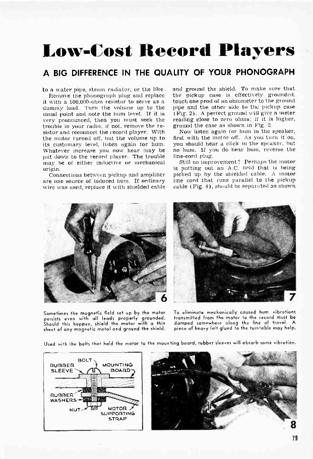
Low -Cost Record PlayersA BIG DIFFERENCE IN THE QUALITY OF YOUR PHONOGRAPH
to a water pipe, steam radiator, or the like.Remove the phonograph plug and replace
it with a 100,000 -ohm resistor to serve as adummy load. Turn the volume up to theusual point and note the hum level. If it isvery pronounced, then you must seek thetrouble in your radio; if not, remove the re-sistor and reconnect the record player. Withthe motor turned off, but the volume up toits customary level, listen again for hum.Whatever increase you now hear may beput down to the record player. The troublemay he of either inductive or mechanicalorigin.
Connections between pickup and amplifierare one source of induced hum. If ordinarywire was used, replace it with shielded cable
_40, 6Sometimes the magnetic field set up by the motorpersists even with all leads properly grounded.Should this happen, shield the motor with a thinsheet of any magnetic metal and ground the shield.
and ground the shield. To make sure thatthe pickup case is effectively grounded,touch one prod of an ohmmeter to the groundpipe and the other side to the pickup case(Fig. 2). A perfect ground will give a meterreading close to zero ohms; if it is higher,ground the case as shown in Fig. 3.
Now listen again for hum in the speaker,first with the motor off. As you turn it on,you should hear a click in the speaker, butno hum. If you do hear hum, reverse theline -cord plug.
Still no improvement? Perhaps the motoris putting out an A.C. field that is beingpicked up by the shielded cable. A motorline cord that runs parallel to the pickupcable ( Fig. 4 ), should be separated as shown
To eliminate mechanically caused hum, vibrationstransmitted from the motor to the record must bedamped somewhere along the line of travel. Apiece of heavy felt glued to the turntable may help.
Used with the bolts that hold the motor to the mounting board, rubber sleeves will absorb some vibration.
BOLTRUBBER t MOUNTINGSLEEVE Lk BOARD
RUBBERWASHERS
NUT
-111112 ,",
MOTORSUPPORTING
STRAP
19

The water test, above, shows if motor vibrationsare still being transmitted to the pickup. Onecommon cause of "wows" is fluctuation in the linevoltage. A voltmeter across the line (right) willshow a dip or rise at the time the music quavers.
in Fig. 5. Better still, replace the line cordwith a shielded two -conductor cable, andground the shield.
Despite all these precautions, inducedhum may still continue to ride through.One measure that still remains is to benda sheet of iron or similar magnetic materialaround the motor as shown in Fig. 6.
There seems to be a perverse force in lifethat always manages to put the thing we're
pile. Sodon't be too surprised if none of these im-provements quite turns the trick. There'sa pretty good chance that the trouble isnot inductive at all, but mechanical.
Mechanically caused hum usually orig-inates within the laminations of the motoritself, and works upward through the shaftto the spindle and turntable. Once in a whileit is possible to eliminate the trouble bytightening the laminations. More often, it
I ul
100,000 OHMS
TO AMPLIFIER,
200,000 '-100 MMFD.I OHMS
0CRYSTAL PICKUP
' GROUNDED LEAD
will require that the record be physicallyisolated from the vibrating motor and shaft.
Cement a piece of heavy felt over theturntable (Fig. 7), and place on it a recordhaving a quiet or unmodulated section.With the needle in the quiet grooves, turnthe gain up high. Any hum that can now beheard in addition to needle scratch may in-dicate that vibrations are being transmitted.Replacing the metal spindle with a rubberone should lessen this distortion. If itdoesn't, you will have to sound -insulate themotor from the mounting board.
Use live -rubber sleeves and washers forthe sound insulation. Discard old hardenedwashers, if any, and insert sleeves of at least12" o.d. I Fig. 8). Do not draw the nuts sotight as to cancel the springiness of therubber. To test for motor vibrations, use aglass of water as shown in Fig. 9; with themotor running, no ripples should appear onthe surface.
Another common trouble found in inex-pensive players is a malady known as"wows," caused when the turntable speedchanges and introduces unpleasant quaversinto sustained musical notes. Rooting outthis defect completely might require a majorrebuilding job, but the nuisance can be min-imized if it happens to be caused by over-loading of the line. Using the record playeron a circuit on which you already have arefrigerator, oil burner, or other fair-sizedload may mean that the player is subjected
80

to voltage fluctuations introduced into the Should this happen, try the record playerline when this equipment is turned on and on a less heavily loaded circuit.off by regular service demands. Distortion of high -frequency sound pas -
To check line fluctuations, connect a volt- sages results when a crystal pickup gener-meter across the record-player plug at the ates too high a voltage for the amplifier withpoint where it enters the wall receptacle which it is used. This defect, known as( Fig. 10). At the instant a "wow" occurs, "blasting," can be remedied by the simplethe voltage may show a marked variation. filter circuit shown with Fig. 11.
Filter Increases Tonal Range of High -Fidelity Crystal PickupsSem c of the newer phonographs feature
pickups with excellent crystals and extreme-ly light needle pressure. Used in conjunctionwith the vinylite-type records that prac-tically eliminate needle scratch, it is possibleto get the full tonal range actually recordedon the disks.
But because recordings are made withmagnetic cutters and played back with crys-tal, a filter should be inserted in the pickupcircuit to compensate for inherent differ- used to disconnect the filter when old-styleences in frequency characteristics between records-still the most common-are beingmagnetic and crystal devices. The shunt is played.-JOHN W. CAMPBELL, JR.
1.
SOO MA. 30 H.200 OHMS 30 WATTS
5,000 OHMS
froiTigr) 4111,1AAA
ox
Test Gives Field -Coil ResistanceWHEN the resistance of a burned -out
loudspeaker field coil is not marked on theoriginal-as often happens-finding a re-placement poses a problem for the service-man. Connect a resistance in series withcoil L, as shown above, across the field -coilterminals, and vary R until proper plate andscreen voltages are observed. Turn off thepower, and measure resistance x -.r. Installa coil with the same value.-JACK KING.
Knobs Protected by RecessingFLUSH knobs on a
portable radio orphonograph case canbe fitted by cuttingsuitably sized holesin a thick panel andmounting the con-trols on composition -board sheets screwedon behind. Knobs inthis position carmotinterfere with theclosing of tightfit-ting covers.-G. 0. S.
Surgical Instrument Serves as"Third Hand" for Serviceman
TEMPERED steel forceps that can he madeto lock in one of several positions are par-ticularly useful for holding wires or smallparts in place while both hands are used forsoldering. Slightly damaged or worn hem-ostatic forceps of the type illustrated aboveare available at many secondhand stores.Metal shims may be soldered to the bladesto allow the right pressure for frequentlyrepeated operations.-H. LEEPER.
81
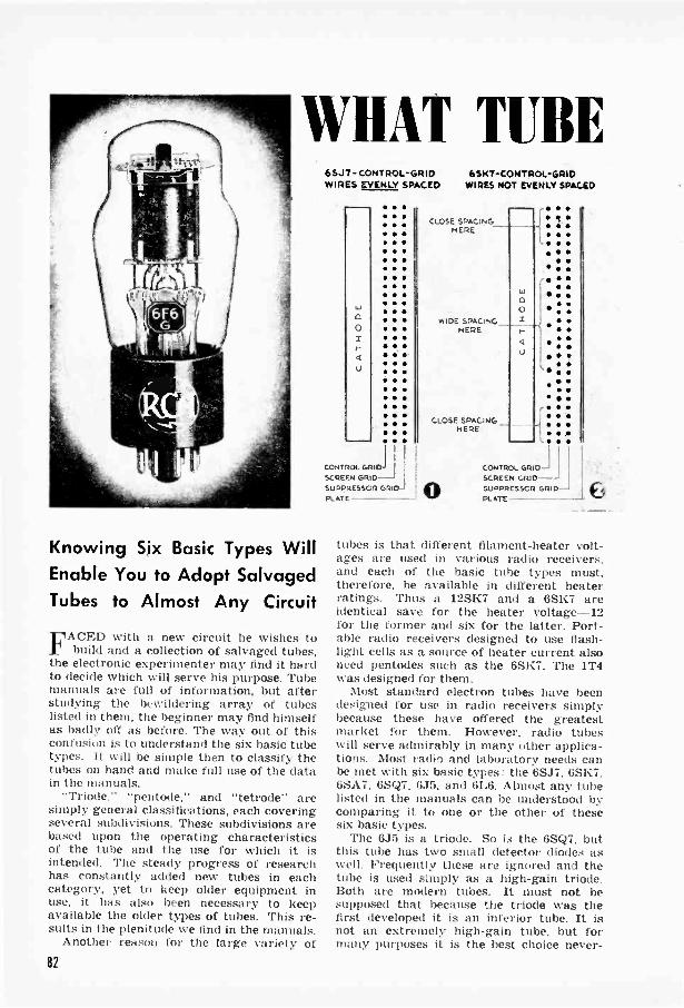
WHAT TUBE
Knowing Six Basic Types WillEnable You to Adopt SalvagedTubes to Almost Any Circuit
E1ACED with a new circuit he wishes tor build and a collection of salvaged tubes,the electronic experimenter may find it hardto decide which will serve his purpose. Tubemanuals are full of information, but afterstudying the bewildering array of tubeslisted in them, the beginner may find himselfas badly off as before. The way out of thisconfusion is to understand the six basic tubetypes. It will be simple then to classify thetubes on hand and make full use of the datain the manuals.
"Triode," "pentode," and "tetrode" aresimply general classifications, each coveringseveral subdivisions. These subdivisions arebased upon the operating characteristicsof the tube and the use for which it isintended. The steady progress of researchhas constantly added new tubes in eachcategory, yet to keep older equipment inuse, it has also been necessary to keepavailable the older types of tubes. This re-sults in the plenitude we find in the manuals.
Another reason for the large variety of
6SJ7- CONTROL -GRID 6SK7-CONTROL-GRIDWIRES EVENLY SPACED WIRES NOT EVENLY SPACED
I
I I
CONTROL GRID)
SCREENSUPPRESSOR GRID -PLATE
CLOSE SPACING
HERE ,
aO
: :
WIDE SPACING I :S.S. :
HERE I-
4 (7)::
CLOSE SPACING HERE L.
OJ ICONTROL Gam LI
SCREEN GRIDSUPPRESSOR GRIDPLATE 6
tubes is that different filament -heater volt-ages are used in various radio receivers,and each of the basic tube types must.therefore, be available in different heaterratings. Thus a 12SK7 and a 6SK7 areidentical save for the heater voltage --12for the former and six for the latter. Port-able radio receivers designed to use flash-light cells as a source of heater current alsoneed pentodes such as the 6SK7. The 1T4was designed for them.
Most standard electron tubes have beendesigned for use in radio receivers simplybecause these have offered the greatestmarket for them. However, radio tubeswill serve admirably in many other applica-tions. Most radii and laboratory needs canbe met with six basic types: the 6SJ7, 6SK7,6SA7, 6SQ7, 6J5, and 6L6. Almost any tubelisted in the manuals can be understood bycomparing it to one or the other of thesesix basic types.
The 6J5 is a triode. So is the 6SQ7, butthis tube has two small detector diodes aswell. Frequently these are ignored and thetube is used simply as a high -gain triode.Both are modern tubes. It must not besupposed that because the triode was thefirst developed it is an inferior tube. It isnot an extremely high -gain tube, but formany purposes it is the best choice never -
82

CAN I USE?P F AMP PIER
SUPERCONTROLPENTODE
(651(7, 6ABT
DIODE DETECTOROR FIRST A.F.AmPuFEI.
DUPLEX -0100ENIGH -MU TRIODE
(6S07)
MIXER
PENTAGRIDCONVERTER(6SA7, 6A8)
SECONDA.F. AMPLIFIER
TRIODE (6J5)OR PENTODE(6(6, 6SJ7)
BY JOHN W. CAMPBELL, JR.
Viaw "ty.pica/ litGei *re Zided Ek 4-/ameNculia!(
theless. The biggest transmitter power tubes--100,000-watt giants-are triodes.
Tube manuals list two kinds of triodes-voltage amplifiers and power amplifiers.Each of these is in turn subdivided into twoclasses- the voltage amplifiers as medium -mu and high -mu, and power tubes aslow -mu and high -mu, nu standing for theamplification factor. The designation ofvoltage or power amplifier indicates whatkind of gain the tube provides. Each hasadvantages in certain applications.
One type of gain does not exclude theother; a voltage amplifier steps up thepower ( current) to some extent, and a high -mu power amplifier amplifies the voltageswing somewhat, but the order of amplifica-tion is very different for the two types. Forexample, a 6A3 power -amplifier triode candeliver as much as 200 milliamperes, whilethe 6SQ7 voltage -amplifier triode is ratedat 0.9 milliampere. The 6A3, a low -gainpower tube, passes much more current thana high -mu power tube, while the 6SQ7 isa high -mu voltage amplifier that sacrificescurrent gain. Between these there is the6J5, a medium -mu triode rated at 9 milli-amperes and capable of an amplification ofabout 20 times.
In general, power -amplifier tubes requirea fairly strong grid signal, but they deliver
LF. AM%1,F.E2
cUPERCONTROLPENTODE
(i-S!<7, EA67)
POWERAMPLIFIEI:
POWER PENTODE(bKG, E.A4, 6F6,43),TRIODE (6A3), oRBEAM ROWER TUBE
(6v6, 6L6)
a powerful punch at the output. A low -mutriode power tube may require a grid varia-tion of 60 volts and have a plate- voltageswing of only 100 volts, so that its voltageamplification is small. But the current,which on the grid may be less than .01milliampere, may be stepped up severalthousand times at the output.
High -mu power tubes such as the 6AC5require smaller grid voltages, but they giveless power gain. High -gain voltage -ampli-fier tubes, on the other hand, may deliverup to 100 times as much voltage as is im-pressed on their grids, but with small cur-rent output.
The distinction between voltage and poweramplifiers holds for tetrodes and pentodesas well as for triodes. However, the tetrodepower amplifier becomes the beam powertube, which in effect acts as a pentode.Pentode and beam power amplifiers requiremuch smaller grid voltages than do triodes;their great gain makes them more efficientfor small apparatus such as radio receiversand public address systems. Two 6L6 beampower tubes can supply 15 to 30 watts ofaudio power, or, in a special hookup, asmuch as 80 watts-enough to be heard twomiles away. Amateur short-wave trans-mitters using two 6L6's can communicateacross the continent. The 6V6 is a slightly
83

smaller beam power tube thatcan be used in the same way.
Tetrode and pentode volt-age amplifiers are divided in-to remote -cutoff and sharp -cutoff types, the later alsobeing called a variable -muor supercontrol pentode. Thedifference between these liesin the structure of the con-trol grid.
So far as electrons are con-cerned, the grid wires can be"inflated" by impressing onthem a negative potentialuntil, in effect, they over-lap and block the tube. Close-ly spaced grid wires will beso inflated when a charge ofonly a few volts is applied.Widely spaced wires will beindividually inflated as muchwith the same charge, butbecause of their greater sep-aration, they will not blockthe tube.
Two pentodes among thesix basic tube types illustratethis. In the 6SJ7, the con-trol -grid wires are closely and uniformlyspaced ( Fig. 1). With a negative chargeof 3 volts on the grid, a change of 1 voltwill cause a change in plate current of 2.5milliamperes. In the 6SK7, the change inplate current would be about 2 milliamperesunder the same conditions, and both tubeswould have about the same amplification.
The 6SK7 has grid wires that are notuniformly spaced. As shown in Fig. 2, thoseat the top and bottom are spaced like thegrid wires of the 6SJ7, and at a potentialof -3 volts they act in much the same way.But the entire grid of the 6SJ7 "overlaps"at -9 volts; the tube is blocked and stopsconducting at that point, whereas the 6SK7is still strongly conductive at a grid chargeof - 19 or even - 29 volts, because its gridwires are widely spaced in the middle. Thiswide spacing permits the tube to pass cur-rent, but it also makes it less responsive tochanges in grid potential. For example,with a charge of 35 volts on the grid, a1 -volt signal will alter the plate current byonly .01 milliampere. Thus, at high gridpotentials, amplification is very low.
This feature characterizing the super -control pentode is very useful. With ordi-nary tubes, volume control is gained onlyby varying the strength of the signal im-pressed on the grid with a potentiometer ora similar device. With supercontrol pentodessuch as the 6SK7, the entire signal can befed into the grid, and amplification controlcan be gained simply by varying the grid
Shown full size, these tiny acorn triodes work at 500,000.000 cyclesand more. In the socket is a 6 -volt tube; the other is a I'/2 -volt type.
bias. This is purely an electronic control,involving no mechanical parts, and thereforeit can be readily incorporated into anelectronic circuit. It is this automaticvolume control that permits you to tunefrom a near -by 50,000 -watt station to a5,000 -watt one in another city withouttouching the manual volume control.
The 6SK7 differs from the 6K7 chiefly inbeing provided with internal shielding andhaving the control -grid lead come to aprong in the base instead of to a grid cap.
Sharp -cutoff pentodes like the 6SJ7 and6J7 are used in high -gain audio amplifiers,detectors, oscillators, and D.C. amplifiers.Frequently they are hooked up as triodes.
Heater rating is indicated by the figurepreceding the letter or letters in a tubedesignation. For each heater voltage thereis, in general, a high -gain pentode like the6J7, a supercontrol pentode correspondingto the 6K7, a pentagrid converter similar tothe 6SA7 or 6A8, a general-purpose triodelike the 6J5, a high -mu triode such as the6F5, and a duplex -diode high -mu triodeequivalent to the 6SQ7. There will also bepower -amplifier triodes corresponding to the6A3 or 6AC5.
If a circuit diagram calls for a 6SJ7, alittle adjustment of resistance and con-denser values will permit you to use a6J7, a 6AC7, a 6C6, a 12J7, or any ofseveral other pentodes. A few 6 -volt tubes,however, and some of the battery -typepentodes, have the suppressor grid con -
84

netted to the cathode within the tube.Usually 6S.17 circuits call for this connec-tion anyway: if the one in question does not,internally -connected pentodes can't he used.
Both pentodes and tctrodes can be usedas triodes. Simply connect the extra gridor grids to the plate. Some tube handbooksinclude data for using pentodes in triodeconnection in resistance -coupled amplifiers.
Among the things you cmtnot do is to usea voltage amplifier 16Sn) to replace a
power amplifier like the 610, or vice versa.The suffix "G" or "GT" indicates the tube
type designated in a glass envelope insteadof a metal one, the tube being otherwiseidentical.
With the advent of multielectrode tubes,the four -prong socket gave way to othersuntil today the octal eight -prong) socketis standard. It is wired differently forvarious tubes. Diagrams always show socketconnections as seen from beneath the chassis.
Glow Lamp Demonstrates Cutoff Action of Various Tubes
Extra sockets can be added. This chassis hos one for testing 6SQ7's
Wulf this simple test circuit, you cancompare visually the plate current that ispassed by different tubes at various gridpotentials, and you can also demonstrate thecutoff action of the tubes. An argon glowlamp will serve satisfactorily as the indicatorin the circuit. It is sensitive to a currentas small as .01 milliampere, and gives avisible indication of changes in current fromthis value all the way up to 50 milliamperes.
rR r"0-.5,000OHMS
GLOW LAMP
6SJ7SSW?
SOCKET
Between .01 and .1 milli-ampere, the character ofthe glow changes: from .1to 5 milliamperes the areaof glow increases: andabove 5 milliamperes thebrilliance of the glow in-creases.
The circuit can be as-sembled on an old radiochassis. Three sockets areused to facilitate the testingof different tubes. If avail-able, old sockets will dosatisfactorily, or three octalsockets can be utilized bywiring them as shown, theunused terminals being dis-regarded.
One 5,000 -ohm fixed re-sistor and two potentiom-eters are required. The5,000 -ohm potentiometermakes it possible to varythe control -grid voltage,while the other permitsvariation of the screen -gridvoltage. The screens of
beam power tubes frequently operate at fullplate -supply voltage, being connected direct-ly to the plus side while the plate is con-nected through the load. The switch shownpermits this hookup.
A voltmeter is optional. It will show ex-actly what grid bias is being applied. Amilliammeter, if available, may be used inplace of the argon bulb for better compar-ison of the plate current passed.-J. W. C.
6J5SOCKET
S.P.D.T. '
t A
TVAMPJALSANOT TO
6-, OLT SVPPLY--
c.V6
S'7K.KET
vCa.TME-ER,',OPT'ONAL)
\1 1
J

ADAPTING AUTO It A MOS TO 11011E USEServicing Y01111* nalli0
WITH a few basic changes an automo-bile receiver can be adapted for use in
the home on standard house current. Someof the parts do not work on 115 -volt A.C.,but substitution of parts that will result inconversion of the entire set.
First, get a new speaker- a permanent -magnet type. Most automobile speakers usea 6 -volt D.C. field, and you will need onethat uses no current for the field. Merelyconnect the voice coil to the leads that wereconnected to the voice coil of the originalspeaker. In some cases, a plug arrangementmay permit returning the set to the car.
The power supply must also be changed.There are two types com-monly used in auto re-ceivers. For that employ-ing a tube rectifier I Fig.1), obtain a 110 -volt pow-er transformer that willdeliver 150 milliamp. at250 to 350 volts and 6.3volts for tube heaters. Usethe same rectifier, hookingthe high -voltage leads tothe two plates as shown.These are the same con-nections used for the oldtransformer.
After this, remove theinput -line and ignition fil-
FUSE--cTO HOT SIDE OFCAR ISATTERY
SWITCH
TO 110 -VOLTLINE
86
SWITCH TO TUSEHEATERS
- RECTIFIER
5 -VOLT Wit.DINGa NOT USED
TO SPEAKER
6.3 -VOLT LINETO TUBE HEATERS
171:g..2
ter and add an on -off switch to break the115 -volt A.C. circuit. Run the filaments ofthe tubes from the 6.3 -volt A.C. winding ofthe transformer, hooking the transformerlead to any convenient filament prongs inthe set and grounding the other end of thetransformer winding. The circuit is shownin Fig. 2.
In an automobile receiver with a powersupply utilizing a synchronous -type vi-brator, the high -voltage input comes fromthe center tap of the car transformer. Use anew power transformer with a center tap toconnect to the filament of an 80. 5Y3, 5Y4.or similar -type rectifier tube, and use the
5 -volt winding to drive the recti-fier filaments. This, of course,requires the addition of a tubeand socket as well as the powertransformer.
A long antenna is not neces-sary since automobile receiversare made to operate on veryshort whip antennas. A shortpiece of wire about 20' --willserve very well. The speakermay be mounted on the panel ofa cabinet or in any way suitedto its use. Insert the shut-offswitch, which should be a 110 -volt type, in one lead to the trans-former primary.-G. 0. SMITH.
TO 6 -VOLTLINE
TO 11O -VOLTLINE
SWITCHFUSE
--1-1-0caaa sr -3TO TUISEHEATERS
TO SPEAKERFIELD
3.-
9
RECTIFIER(80, SY% ETC-)
6.3 -VOLT WINDINGTO TUBE HEATERS

RADIO SERVICING
WEAK RADIO TUBES often show new signs of life when sub-jected to the healing effects of heat. You may have noticedthat tubes that were relegated to the spare -parts shelf for a"rest" worked perfectly a year or so later. Heat merelyspeeds up this self -healing process. To reactivate tubes hav-ing no defects other than low electron emission, place them ina tray or shallow pan and bake them for four to five hours inan oven that is kept between 350 and 400 deg. F. Allow thetubes to cool in the oven, and test them after they are cool.Some tubes will show no improvement until they have beenin operation for a few hours. The process is usable only ontubes with oxide -coated cathodes, but this class embracespractically all modern receiving tubes. No tube can be suc-cessfully reactivated more than once, so those so treatedshould be plainly marked.-W. H. BLANEMEYER.
SPAGHETTI with nail -pol-ish "sauce" doesn't makea very appetizing dish, butyour radio won't be ableto tell the difference. Ifyou have trouble obtain-ing spaghetti tubing, useordinary soda -pop straws.After fitting the strawaround the wire, cover itwith nail polish or shellac.Be sure to apply the lattergenerously around theends to prevent slipping.
DIAL CORD won't snarl up in aserviceman's kit if it is carriedin a dispenser such as thatshown above. Drill a hole about1,;," diameter in the upper partof a typewriter -ribbon can andcut a corresponding notch in thelower piece. Cement a smallrubber patch over the hole, andwhen the cement has dried,punch a pinhole and draw thecord through. The patch actsto prevent the cord from slip-ping back inside.-R. P. TURNER.
FROZEN MUSIC used tobe a constant cold -weath-er problem because ourautomatic phonograph, lo-cated next to an outsidewall, refused to warm up.
We gave our sluggishturntable a boost bymounting a 5,000 -ohm re-sistor in a space betweenthe motor and record -changer mechanism. Aseparate cord and plugassembly, which can beremoved in the spring.connects with the 115 -voltline. The heat dissipatedby the resistor keeps thephonograph at operatingtemperature. Power con-sumption, even under con-tinuous operation, is lessthan two kilowatt-hours amonth.-W. A LixtilN.
rp
0BURNED FINGERS some-times result when tubesthat have become uncom-fortably hot are removedor switched around. Rec-tifiers, power -output tubes,and high -current televi-sion amplifiers such as the6AC7 shown often dissi-pate enough watts to be-come painful to the touch.A pair of rubber finger-tips of the sort used bymany bank tellers willprotect your fingersagainst heat, and will pro-vide a safe and sure gripon the tube as well.-G. S.
81

TUNING IN THOSEServicing Your Radio
OLD radio receivers that can't be tunedin clearly on stations at the high -fre-
quency end of the dial can be adjusted moreor less simply. How this is done is of partic-ular interest because of the addition of stationsat this end of the dial when all frequencieswere changed not so long ago.
In making the adjustment, however, a com-pensating loss is to be expected at the low -frequency end. Those who prefer stations atthe low end of the dial may be better pleased,therefore, to leave the adjustment as it is,though in many cases it is possible to get sat-isfactory reception at both ends.
Usually the radio will have to be lifted fromthe cabinet to make the adjustment. This isdone by first removing the tuning knobs andthen taking out the small bolts at the bottom.Often the chassis will bear a label telling
88

OFF -THE -DIAL STATIONSwhether the circuit is superheterodyne ortuned radio frequency ( T.R.F.). These twogeneral types require slightly different treat-ment, but if you can't find out which yoursis, handle it first as a superheterodyne.
The tuning condensers of many super -heterodynes are located on the chassis inthe position shown in Fig. 1, and are shuntedwith small trimmer condensers, indicatedby the two arrows marked 1. These trim-mers are not always located on the maintuning condenser, however. Some may beplaced underneath the chassis and can bereached from the rear as indicated by thetwo arrows in Fig. 2.
Mark on the trimmers the position of theslot in the holding screw, and open one ofthe screws a one -eighth turn ( Fig. 3). Havethe antenna attached and the radio turnedon so any change in reception can be noted.When the oscillator trimmer is opened up inthis way, all stations on the dial will bemoved up several points. Thescrew can then be turned backslightly, or opened up still fur-ther, until satisfactory recep-tion of the high -frequency sta-tions is obtained. Test stationsat both ends of the dial, and in-sulate the handle of the screw-driver so reception will be asnearly as possible the same asyou will get when the set is re-turned to the cabinet. If noth-ing happens when the screw isturned, the trimmer should beclosed up again by returningthe screw slot to its originalposition, and the same openingturn should then be given tothe other trimmer screw. Afterthe adjustment has been com-pleted, the trimmer should besealed with a drop of sealingwax so vibration will not openit further.
T.R.F. adjustment is a littlemore complicated. Mark thetrimmers as before, and openthem for a test one after theother until the detector stageis reached and the stationsshift on the dial as in the caseof the superheterodyne. If nosingle trimmer causes this,open the trimmers in groups oftwo so as to cause a greatercapacity change, choosing anytwo and opening them up equal-
ly. Should this still not produce the desiredchange, try bending the outside plates( shown at 2 in Fig. 1) of the main tuningcondensers with a pair of long -nosed pliers,as in Fig. 4. Make the test on one condenserin the gang at a time.
When all these capacity -changing methodsfail, the value of one or more of the in-ductances may be lowered in order toachieve the desired result. Insert a 1/16" byIV' by 4" piece of copper in the center ofany one of the inductances, as in Fig. 5,while the main tuning gang condenser isturned to its highest setting. At some defi-nite point of insertion, the high -frequencystations will begin to come in, and a littletuning will sharpen them. Insertions may betried in all the inductances to determinewhich produces the best results, after whichthe copper piece can be attached permanent-ly to the coil with a small screw or a drop ofsealing wax.-TRACY DIERs.
Arrow on Control Knob Will Gauge VolumeA SMALL arrow painted
on the volume -controlknob, as shown at right,will enable you to turnthe radio to nearly thevolume desired withoutwaiting for the tubes towarm up. On occasion itmay also indicate a weak-ening battery or otherloss of volume that mightnot otherwise be noticeduntil serious trouble oc-curs.-BLANCHE PORTER.
ARROW PAINTED ONVOLUME -CONTROL KNOB
Clip on Lid of Portable Holds Radio DataSPACE behind the lid or
door that protects control 44.3114."14knobs of some portableradios can be utilized byattaching a strip ofspringy metal, bamboo,or wood. Round the freeend of the clip so pro-gram lists, other papers,or booklets will slip un-der it easily, and mountwhere it won't interferewith the knobs.-W. E. B.
415
89

ELECTRONIC PRINT TIMER
Any lighttight box canbe used for this timer,but the fruit can is bigenough if the parts areproperly laid out. Thedrawing, right, shows apractical arrangement.
THOSE who go for canned fruit in a bigI way, or can get a 1 -gal. fruit can from a
boarding house, have a good photo accessoryat hand. Such a can is lighttight and justthe right size to hold this electronically con-trolled contact printer.
Bend the opening into a rectangular shapeand mount a standard 3,," by 5142" printingframe as shown. A hinge between the frameand pressure plate completes the photo-graphic part of the job. Chief componentsof the timer are a 117L7GT vacuum tube, alinear .5-meg. potentiometer with switch,a double -pole, double -throw pushbuttonswitch, and any fairly sensitive, normallyenergized relay rated at around 10 milliamp.and 2,000 to 3,000 ohms.
Mount and wire the parts as shown. Tocalibrate the timer, turn the potentiometerclockwise until you hear the snap of the
power switch. Both bulbs will light, butafter the tube starts to warm up it activatesthe relay and cuts out the exposure light.Allow a few more minutes for the tube toget into proper operation, set the potenti-ometer about half way, and press the push-button switch for one second.
The exposure lamp should go on and thenturn off automatically. Using a stop watch,time the length of exposure for various set-tings. Each time you get an even -secondexposure, scribe the position of the knob onthe can. The maximum time of this unitis about 15 seconds; for a longer maximum,increase the capacitance of Cl or the resist-ance of the potentiometer.
By plugging the line cord of your enlargerinto the exposure -lamp socket, you canmake the timer keep watch over your largerprints as well. --KARL. GREIF.
PUSHBUTTON
.25 MEG.
CI -6 N FD.400V.
4
.5 MEG.
6117L7-GT
RELAY
60WATTBULB
SWITCH(ON POTENTIOMETER)
0""""1.04.NO -VOLT ACr DC.
10 -WATTBULB(RED)
TM FD. 400 V../
90

ELIMINATING SPEAKER HUM
1 -our RadioRESIDUAL or "field" hum in a small
speaker is caused by ripple voltage onthe field winding. In an automobile receiverit comes from the transients on the field -supply line caused by the v:brator in thepower supply. This hum cannot he filtered,and although in some cases it may be pos-sible to readjust the "hum -bucking" coilthat is wired in series with the voice coil, itmay be more convenient to smooth the fieldripple in the following manner:
Wind a number of turns of heavy, tinnedwire about the field coil. The size of thewire is not important except that it shouldbe as large as is convenient to handle. Puton as many turns as possible. being carefulnot to break through the paper insulationthat covers the field coil, as this may causea field short. It is not necessary to insulate
the auxiliary coil from the frame of thespeaker ( Fig. 1). Solder the turns to-gether, as shown in Fig. 2, thus creating aneffective single shorted turn ( Fig. 3).
This shorted turn acts as a shading ring,which decreases the inductance of the fieldwhile increasing its reluctance. It behavessimilarly to a shorted turn in a power trans-former and tends to resist the collapse of amagnetic field as the ripple current passesthrough a cycle. This maintenance of aconstant field will reduce ripple hum, andthe lower the resistance of the shorted turn,the less the fluctuation of the field currentwill be observed.
The method is not a cure-all, nor a substi-tute for filtering. Although it works on anautomobile speaker as well as on a homeset, the effect is more noticeable on thebench than when the speaker is back in thecar.-GEORGE 0. SMITH.
Homemade Tuning Wand Helps in Aligning Receiver Oscillator
IN RECEIVERS where the oscillator andR.F. coils are not readily accessible for in-serting a tuning wand, a strip of photo-graphic film, old pyralin dial, celluloid, orsimilar material will serve handily. Itshould be thin enough to pass between rotorand stator plates without bending them.
When alignment is considered good, in-sert the strip between the plates of the an-tenna and R.F. section. If response increas-es, the antenna and R.F. tuning is high, andthe padding condenser should be decreased.Should response fall off immediately, insert
" of the strip in the oscillator section andturn the gang condenser to full resonance.If this gives more output, the oscillator tun-ing is high, and the padder should be in-creased slightly.-G. 0. S.
91

LOUDSPEAKER ADJUST3IENTSServicing
MANY radio owners will putsip with a certain amount of
distortion in their loudspeakersrather than tackle a repair be-cause they realizze how delicatesuch work is. Loudspeakers haveair gaps of only .005". If care is ex-ercised, however, a competent serv-iceman or home mechanic shouldbe able to do an effective job.
The most common fault isan off -center cone. This usuallycauses a fuzziness in the repro-duction, especially when the vol-mne is turned low. To recenterthe cone, obtain colored -papershims at a radio store, or cutshims from stiff paper such asthat used for calling cards.
Three strips are required forproper centering, and they areplaced at 120 -deg. angles fromeach other in the center of thecone, as shown in the photographat top. The cone is loosenedslightly to receive them by meansof its centering screw and then isretightened.
This centering screw is usuallybehind the speaker magnet or infront in the middle of the cone:but if the speaker has no suchscrew, the whole cone and voice -coil assembly can be loosened byapplying a cement solvent or lac-quer thinner to the cement hold-ing the rim of the cone to theframe of the speaker, as in one ofthe photos. Use the three shimsthe same way, and then cementthe cone back to the speakerframe and let it dry thoroughly.
Many loudspeakers have a "pa-pery" sound that mars the repro-duction. This is sometimes causedby an off -center cone. but moreoften it is due to an open seam ina cone that has nut been pressedor molded from a single piece.Cement in the seam dries outafter a time, and the loose edgestouch while the cone is vibrating,thus causing the objectionablesound. This trouble can be reme-died easily by putting new cementin the open places along the seam.Tears in a cone may be similarlycemented, as shown in the bottomphotograph.
92
Your Radio
Three paper shirrs are inserted to center a loudspeaker cone
Loosen the cement at the rim Paper centering shims ofof the frame to remove a cone different thicknesses can bethat has no centering screw obtained in a small kit
Tears in a cone ae easily mended by an application of cement

TESTLEADS
(
SWITCHCRYSTAL
400 VOLTS AA C. 2 5 MH
INPUT1 M FD.
R. F. bo POTENT.OMETER
CHOKE sopoo OHMS
400 VOLTS.1 MFD.
NIL .001TmFD
4 5 VOLTS
CONTINUITY
SWITCH 2 0 0PHONES
2
Radio Circuit Tester Uses Headphones and Standard Parts"TIHIS simple test circuit will prove useful1 to the student of electronics or the ex-
perimenter, and will often track downtrouble that can't be located by guesswork.
To check audio signals, use the A.C. inputleads with switch 1 at B and switch 2 at C.For example, if distortion is to be localized,put the leads first across the plate andcathode of an output tube, then across thegrid and cathode. If the signal is clear atthe grid but not at the plate. the distortionis in that output stage or tube.
For radio -frequency tests, set switch 1 atA and switch 2 at C. Place the prods on theplate of the tube and the positive side of theplate supply. The signal should be heard,rectified by the crystal detector. Shift thelead from the plate to the grid. If the signal
is not much weaker, the gain of the stageis low and some defect exists.
For continuity tests, disregard switch 1and set switch 2 at D. To test a fixed con-denser, touch the prods to its terminals. Aclick should be heard. Remove the prods,wait a few seconds, and again apply them.The click should be much weaker, showingthat the condenser has held the charge.
Coils, resistors, and tube filaments maybe tested on the same circuit. No clickmeans an open circuit. Tuning condenserscan be tested by first disconnecting the leadsto prevent shorting through other parts. Noclick should be heard when the rotor isturned. Never use the continuity leads ona receiver unless the line cord or batteriesare disconnected.-WILLARD MOODY.
PERMISSIBLE VOLTAGE DROP [ELECTRICAL]WHAT must be the rated capacity of a 10,000 -ohm resistor across which the
voltage drop is to be 125 volts? The table below shows instantly that the per-missible voltage drop across a 1 -watt, 10,000 -ohm resistor is 100 volts, which istoo small. The drop across a 2 -watt resistor may safely be 140 volts. A 2 -wattunit is therefore required. As another example, if a 500 -ohm resistor rated at 3watts is at hand, it may safely be used to create a potential drop of 38 volts or less.
Ohms1 -watt
size2 -watt
t ize3 -watt
size10 -watt
size Ohms1 -watt
size2 -watt
size3 -wattsize
10 -wattsize
100 10 14 17 30 10.000 100 140 170 310
200 14 20 2-1 45 20.000 140 200 2-15 4.15
300 17 24 30 55 30,003 170 245 300 550
500 22 31 3K 70 40,000 200 280 345 a
7(10 26 38 15 85 50,000 225 310 385
1,000 30 45 55 100 70.000 265 375 460
2,000 45 65 SU 140 100.000 310 450 550
5.000 70 Inn 125 225 200.000 450 500 c.
7.000 85 120 115 265 300.000 500
8.000 90 125 155 280 -100,000 o5011.111111
POPULAR SCIENCE MONTHLY SHOP DATA
93
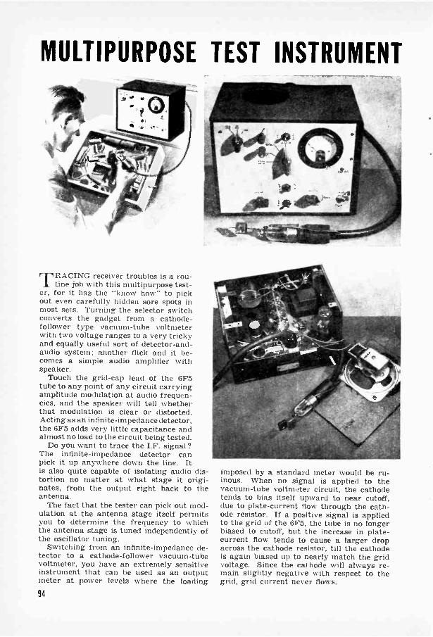
MULTIPURPOSE TEST INSTRUMENT
rr RACING receiver troubles is a rou-tine job with this multipurpose test-
er, for it has the "know how" to pickout even carefully hidden sore spots inmost sets. Turning the selector switchconverts the gadget from a cathode -follower type vacuum -tube voltmeterwith two voltage ranges to a very trickyand equally useful sort of detector -and -audio system: another flick and it be-comes a simple audio amplifier withspeaker.
Touch the grid -cap lead of the 6F5tube to any point of any circuit carryingamplitude modulation at audio frequen-cies, and the speaker will tell whetherthat modulation is clear or distorted.Acting as an infinite -impedance detector,the 6F5 adds very little capacitance andalmost no load to the circuit being tested.
Do you want to trace the I.F. signal?The infinite -impedance detector canpick it up anywhere down the line. Itis also quite capable of isolating audio dis-tortion no matter at what stage it origi-nates, from the output right back to theantenna.
The fact that the tester can pick out mod-ulation at the antenna stage itself permitsyou to determine the frequency to whichthe antenna stage is tuned independently ofthe oscillator tuning.
Switching from an infinite -impedance de-tector to a cathode -follower vacuum -tubevoltmeter, you have an extremely sensitiveinstrument that can be used as an outputmeter at power levels where the loading94
imposed by a standard meter would be ru-inous. When no signal is applied to thevacuum -tube voltmeter circuit, the cathodetends to bias itself upward to near cutoff,due to plate -current flow through the cath-ode resistor. If a positive signal is appliedto the grid of the 6F5, the tube is no longerbiased to cutoff, but the increase in plate -current flow tends to cause a larger dropacross the cathode resistor, till the cathodeis again biased up to nearly match the gridvoltage. Since the cathode will always re-main slightly negative with respect to thegrid, grid current never flows.

DOUBLES AS AUDIO AMPLIFIERThe filter arrangements 11,-C, and 11,-C,
hold the cathode at the highest voltageattained during any voltage wave cycle, sothe instrument becomes a peak -reading volt-meter. To obtain a root -mean -square volt-age, you will have to adjust the reading. Fora sine wave, r.m.s. voltage equals 0.707times peak voltage.
Shunting the grid condenser of the 6F5will cause the instrument to record D.C.volts, the grid lead becoming positive.
Potentiometer R,3 is used to adjust themilliameter to zero so that the initial platecurrent that must flow to bias the cathodecan be balanced out of the meter.
To minimize grid emission in the 6F5, theheaters are operated at less -than -rated volt-age via the 5 -volt filament winding, and a6X5 rectifier is employed in place of theusual rectifier circuit. If a 6X5 is not avail-able, but you happen to have a 5Y3 or sim-ilar tube, the 5 -volt transformer windingcan be diverted to its use. In this case,insert a 5 -ohm resistor in series with the6.3 -volt tap and the 6F5 filament.
SHIELDED CABLE-.,-.
6F 5 GT
CLIPGROUNDEDTO SETUNDERTEST
',OV AC
.1
KEY TO MULTITESTER PARTS
: 1.111R11010141. 11li.:1: mid. I. tr.dytie. ion I.1', : 2, I..tr..lytic,
11111. 11, II,. 200 V.: 1111111.11. 011,1
Will.: 2:1%.
C : .1
(' :
: 011,1. 150 v.4.'.; :.01 0011. 100 a11.: 10.004,
: 2014.01,41.41,msis : g.,!1111
1.11).): 2.2 11,44A.
117 : 11.5 mfg.1{.::350 tolimsR. : 1 104.g.11,.. : 311.0041 .,1101s. lit waitRn : 5.000 ..10,41,,. 2 %vat I.
25,000 011004Hut : 25.000-0100 1).4.Ru : 25.001) 1111111S. :i wattlin : 2014. 50 no g.T, : 350-441t. 50-01a. p44w41: tarts
: ),..5110-,111,1 "input trans.: 10-10.01 y iilt41: 411,,k4.
LrGANGED ISWITLH
-1 1
-71R2 z:
11
T,
I MA. C 3
- HIGHVOLTAGE
c-
'II
ES_17 6Vb
3
TO ALL TUBE HEATERS EXCEPT 6F5
95

Listen in Oilthe hams with this
10-11ETER BAND
RECEIVERBy Clinton Clark
TEN -METER phone reception and trans-mission have long been popular with
radio hams because this channel is good forboth long-distance and local communication.When the end of the war made it possiblefor communications authorities to turn on thegreen light, amateurs all over the world re-opened ten -meter transmitters, and lost littletime in contacting old friends, far and near.
If you tune in tonight, there's a goodchance that you can pick up Algeria, Eng-land, or the Philippines. Yes-you can tunein tonight, for this receiver, reduced to bareessentials, will take very little of your time tobuild. It is intended to open the door of afascinating spectrum to the beginner, andinvites experimentation on other short-wavebands through the use of easily made, inter-changeable coils.
First step in construction is the basewhich, in this case, is a %" by 7" by 7" pineboard, sanded and coated with clear varnish.Details of the condenser -tube -coil assemblyare not critical, but the layout illustrated inthe photographs is suggested because it al-lows for short connections. Low -loss insula-tion and direct wiring are very importantin all high -frequency circuits.
The tube upright is a 23i" by 4" strip ofcomposition board. Bore a 131" hole to take afive -prong ceramic tube socket. Anotherpiece of composition board, 3" by 53i", isused as an upright for the coil -and -condenserassembly. In the center of this panel mounta midget 15-mmfd. tuning condenser. Bolt a3!2" strip of bakelite or other low -loss materialto the edge of the upright, and drill threeholes for tip jacks. When fastened intoplace, these jacks form a socket for the coilends and tap.
Arrange the two uprights at a 90 -deg.
Fewer than o dozen electrical parts wentinto this short-wave receiver. It takes verylittle space, although no special attemptwas made to keep it compact.
Skip -distance effects are very markedon the 10 -meter band. Don't be sur-prised if your set pulls in stations5,000 miles away more readily thanthose only 500 miles from you.
angle to each other by screwing them to asquare wooden subbase. This is laterscrewed to the larger base. Nov make theshort connections from the coil terminals tothe condenser and tube socket. Attach theradio -frequency choke to the smaller square.The choke may be purchased, or handwound on a %" dowel. If you prefer the lat-ter, drill a %" hole in the subbase to receivethe dowel, and wind it with 100 turns of No.34 D.S.C. wire;
For the front panel, a 7" square of compo-sition board is screwed to the base. Drillholes for the dial, switch, antenna bindingpost, and phone jacks. Make sure that thehole for the dial is aligned with the con-denser shaft. Since approximately 3" is al-lowed between the front panel and the con-denser subpanel, a coupling will probably beneeded to connect the knob and the con-denser. The distance, plus a fiber or plasticcoupling shaft, helps to prevent the intro-duction of hand capacitance.
96

To make the coil, LI, wind 30 turns ofNo. 14 solid copper wire o a form.When the form is removed, you have a self-supporting, low -loss coil. Solder the coilends into phone tips to fit the jacks used assockets on the subpanel. The tap may be offlexible wire soldered approximately a quar-ter of the distance from the plate end of thecoil. Phone tips and jacks make a good coil -mounting combination; a dozen or so tipscost but a few cents, and will enable you tomake additional coils for trial on otherbands. Some experimentation may be neces-sary to locate the best spot for the tap, be-cause of the individual characteristics ofmany high -frequency elements.
A type 37 tube is used, requiring a 6 -voltA.C. or D.C. filament supply. If it is moreconvenient to operate the heater off a 2.1 -voltsupply, substitute a type 27 tube.
When Nviring is completed, apply thefilament voltage, then turn on the switch inthe plate circuit. Either a 90 or 1:35 -volt B
supply may be used, the higher voltage, ofcourse, providing greater output.
A loud, hissing noise, characteristic of allsuperregenerative receivers, should be heardin the earphones. As a station is timed in,this hiss Nyill be blocked out or recede intothe background.
A good high -frequency antenna is recom-mended for best results. It may be coupledinto the circuit by placing two turns of stiff,insulated wire near the grid end of the tun-ing coil, as shown. Alternatively, a hairpinloop of wire from the antenna binding postmay be inserted directly into the grid endof the coil.
For convenience, the battery connectionsare grouped in a single terminal strip, illus-trated in the photograph at the upper left,but omitted from the diagram.
Best reception on the ten -meter band canbe expected during daylight hours. It is,however, subject to strong interference (Incto seasonal and atmospheric changes.

Short -Wave
Comforter
Brings ill
the WorldOperated with your regular broadcastreceiver, this one -tuber will coverthe major foreign wavelengths.
By S. T. Van Essen. W2OXD
LONDON is calling. Lima, Sydney, andJohannesburg, are on the air too. There's
a wealth of news, information, and enter-tainment pouring out of foreign skies, justwaiting for you to listen in. If you've beenNvanting to do just that but have hesitatedbecause of the difficulty of building a short-wave receiver from scratch, here is youranswer. It's as simple as one tube and a fewcoils. The rest is already built into yourregular radio.
A superheterodyne will give best results,but most radios are of this type. These aswell as most other kinds of receivers haveeverything you need for short-wave recep-tion except that their antenna circuits aredesigned for a lower frequency. All you haveto do is change the short waves into longerones that can be detected by the broadcastreceiver.
A converter that will do this job consistsof a single tube of the pentagrid type oper-ated in conjunction with suitable coils andcapacitors. Two things should be notedabout this tube: first, it is actually two tubesin one, and second, it has five grids. For98
Standing on end, the chassis becomes the frontpanel. The larger knob governs the oscillatorcondenser; the small one the mixer. Finish isobtained by drawing steel wool along a rule.
simplicity, only three of them are shown inthe diagram; the suppressor and one of thescreen grids are omitted since their connec-tions are made internally.
One section of this tube is called the"mixer" because the incoming or short-wavesignal applied to its grid or input circuit ischanged to broadcast frequency in the plateor output circuit. The other section, the"oscillator," may be visualized as a miniaturetransmitter. It produces a signal voltage ofits own that is applied to the mixer circuitsimultaneously with the desired short-wavesignal.
Now let us say that the broadcast receiveris tuned to 1,500 kc. (1.5 me.). We willthen want the mixer to operate only at thisfrequency-that is, we want it to convertevery short-wave signal within its range to1,500 kc. To do this the oscillator must betuned 1,500 kc. higher or lower than theincoming programs. For example, to get aforeign station broadcasting on the 6 mc.channel, we tune the oscillator to 6 plus 1.5,or 7.5 mc. By combining or "beating" thetwo signals together, we obtain the 1.5 mc.

Coil sockets and the oscillator capacitor areraised from the chassis by insulated spacers.Solder all leads that go beneath these partsbefore you actually fasten them into position.
difference that can then be applied directlyto the input circuit of the broadcast receiver.
In this converter the critical tuning is doneby the oscillator capacitor, C2. As we rotatethe dial through its range of frequencies, anysignal that is lower than the oscillator settingby exactly 1.5 mc. will be heard in the loud-speaker of the broadcast receiver. Strictlyspeaking, "image" signals exactly 1.5 mc.higher should also be heard, but since themixer tuned circuits are adjusted for bestresponse to the lower frequency, the latterwill probably come in much stronger.
A 2" by 7" by 7" aluminum chassis dou-bles as the front panel. Aluminum is a goodchoice because it can be worked withoutspecial tools. If reasonable care is taken tokeep from scratching the face, it will be pos-sible to apply an attractive cross -grain finishby pulling a small wad of steel wool againsta straightedge.
Sockets for the three plug-in coils aremounted 1%" off the chassis. Common cera-mic stand-off insulators 1" long were used.(They are 1" in diameter and tapped atboth ends for 6-32 machine screws.) The
If a separa le poi% er Supply is used, the onlyconnections to the receiver %OH be those forantenna and ground. Alternatively. plate andfilament voltages can be tapped oft an AC set.
extra spacing was obtained by addinglengths of Li" aluminum tubing to the endof each insulator.
Because the type of vernier dial used hasa protruding hub, the main oscillator tuningcondenser also had to be spaced away fromthe chassis. Ceramic insulators were usedhere too with a metal strip bridged acrossthem to support and ground the rotor. De-tails of this construction are shown in thecloseup photo on page 100. The holesthrough which this bridge strip is fastenedto the insulators are slightly elongated sothat the tuning shaft can be aligned, and aflexible coupling is used to link it to thedial hub.
The tube socket, mounted to hold the6BE6 horizontally, has a metal ring thatallows it to be attached to one of the ceramicsupports by means of a 6-32 spade bolt. Amidget variable capacitor, mused to tune theoutput coil, is placed directly beneath thecoil socket. If there is not enough clearancebetween socket and capacitor, use longeraluminum spacers. Beau in mind that whilethe capacitor mounts directly on the chassis,
99
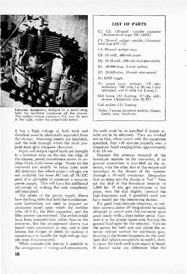
Cer. insulators, bridged by a metal strip,hold the oscillator condenser off the chassis.The midget tuning capacitor, C3, may be seenat the right, under the output -coil socket.
it has a high voltage at both ends andtherefore must be electrically separated fromthe chassis. Mounting inserts are insulated,and the hole through which the shaft pro-jects must give adequate clearance.
Input and output signal leads are broughtto a terminal strip on the rear top edge ofthe chassis; power connections center in an-other block at the lower edge. Power for theconverter can readily be taken from mostAC receivers, but where proper voltages arenot available (on some AC and all AC -DCsets) it is advisable to construct a separatepower supply. This will have the additionaladvantage of making the unit completelyself-contained.
The photo of the power supply showshow the long bolts that hold the transformer -core laminations are used to support analuminum panel upon which the rectifiertube (6 X 4), the filter capacitor, and thefilter resistor are mounted. The switch couldhave been mounted here rather than on theconverter, but the arrangement shown wasfound more convenient in use, and it alsolessens the danger of shock by making itunnecessary to handle the high -voltage sup-ply once it is connected.
While considerable leeway is possible inthe arrangement of Nviring and components,
100
LIST OF PARTS
Cl, C2: 140-mmf. variable capacitor(Hammarlund type MC -140M).
C3: 75-mmf. midget variable ( Hammar-lund type APC-75).
C4: 50-mmf. midget mica.
C5: .01-mfd., 400 -volt paper.
C6: 18-18 mfd., 450 -volt dual electrolytic.
RI: 20,000 -ohm, 31 -watt carbon.
R2: 30,000 -ohm, 10 -watt wire -wound.
Si: SPST toggle.
T1: power trans., primary: 115 volts:secondary: 700 volts (at 50 ma.) cen-tertapped, and 6 volts (at 2 amp.).
Coil forms (3) 5 -prong, poly-styrene (Amphenol type 24-5P).
Coil sockets (3) 5 -prong.
Tubes, 7 -prong miniature sockets, chassis,knobs, misc. hardware.
the coils must be as specified if proper re-sults arc to be obtained. They are workedout so that, when tuned with the capacitorsspecified, they will operate properly over afrequency band ranging from approximately6 to 16 mc.
Connect the antenna terminal of thebroadcast receiver to the converter; if noground connection is provided on the re-ceiver, wire the other end of the output -coilsecondary to the chassis of the receiverthrough a .01-mfd. condenser. Rememberthat on some sets the chassis is "hot." Nowset the dial of the broadcast receiver to1,500 kc. If you get interference at thispoint, turn the dial slightly (toward thehigh -frequency end, if possible) until youhave tuned out the interfering station.
For good long-distance reception, an out-door antenna about 40' long should be used,although in actual tests this converter gavegood results with a short indoor aerial. Con-nect it to the proper input post, leaving theground lead open for the moment. Turn onthe power for both sets and adjust the re-ceiver volume control for maximum gain.Starting at the lowest frequency on the oscil-lator dial (plates completely in mesh), slow-ly rotate the knob until some signal is heard.It doesn't make any difference what the
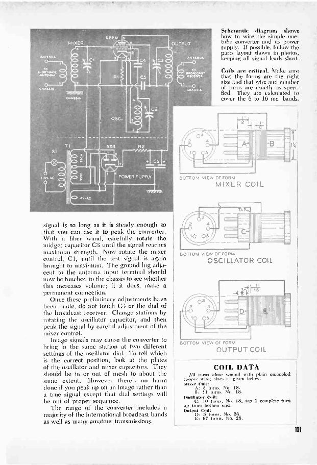
TOSHORTWAVE
ANTENNA
CHASSIS
6BE6MIXER OUTPUT
ca
roBROACCA STRECEIVER
CHASSIS
C2
0
21111111
signal is so long as it is steady enough sothat you can use it to peak the converter.With a fiber wand, carefully rotate themidget capacitor C3 until the signal reachesmaximum strength. Now rotate the mixercontrol, Cl, until the test signal is againbrought to maximum. The ground lug adja-cent to the antenna input terminal shouldnow be touched to the chassis to see whetherthis increases volume; if it does, make apermanent connection.
Once these preliminary adjustments havebeen made, do not touch CO or the dial ofthe broadcast receiver. Change stations byrotating the oscillator capacitor, and thenpeak the signal by careful adjustment of themixer control.
Image signals may cause the converter tobring in the same station at two differentsettings of the oscillator dial. To tell whichis the correct position, look at the platesof the oscillator and mixer capacitors. Theyshould be in or out of mesh to about thesame extent. However there's no harmdone if you peak up on an image rather thana true signal except that dial settings willbe out of proper sequence.
The range of the converter includes amajority of the international broadcast bandsas well as many amateur transmissions.
Schematic diagram showshow to wire the simple one -tube converter and its powersupply. If possible, follow theparts layout shown in photos,keeping all signal leads short.
Coils are critical. Make surethat the forms are the rightsize and that wire and numberof turns are exactly as speci-fied. They are calculated tocover the 6 to 16 mc. bands.
BOTTOM VIEW OF FORM
MIXER COIL
BOTTOM VIEW OF FORM
OSCILLATOR COIL
D-Uij
11!
11'1.1
'11;11
BOTTOM VIEW OF FORM
OUTPUT COIL
COIL DATAAll turns close wound with plain enameled
copper wire; sizes as given below.Mixer Coil:
A: 3 turns, No. 18.B: 11 t No. 18.
Oscillator Coll:C: 10 toms, No. 18; tap 1 complete tura
up from bottom end.Output Coil:
ll: 5 turns, No. 26.E: 87 turns, No. 28.
101

To check the frequency of your signal, separate your receiver and transmitter, and listen in on yourself.
GET STARTED IN HAM
Midget 80-11eterBy CLINTON E. CLARK
ARADIO "station" hardly bigger than ashoe box is an ideal rig in many respects.
If you've just obtained your license, you canuse it to get on the air at the cost of a fewdollars and even fewer hours. On the otherhand, if you're an old timer operating amore elaborate phone transmitter, here's aquick and inexpensive way to renew youracquaintance with the fast -fingered hamswho keep the code bands clicking.
Despite its size, this transmitter is capableof real performance. Just bear in mind thatthe 80 -meter band is crowded with high-powered outfits, so you'll have the bestchance of getting through during the rela-tively quiet hours.
For the baseboard, take a piece of %" by5" by 7" wood and center the tube socketand six -prong crystal holder on a line 2W'from the rear. Raise the socket on %" sleevesor small insulators, and drill a %" hole under
102
RADIO WITH THIS
Code Transmitterit to pass the filament and cathode wires.Fasten a six -lug terminal strip along the rearedge of the wood.
To make the plate coil, L3, wind 38 turnsof No. 20 D.C.C. wire on a 2" dia. form,spacing the turns to a length of 3". This coilis center tapped, as indicated in the diagram,and has a two -turn coupling coil wound overit. The antenna coil, L4, is made in thesame way except for the omission of the cen-ter tap. Mount the plate coil alongside thetube socket on a pair of standoff insulators.
The antenna tuning unit is the electricalcounterpart of the coil -condenser circuit inthe transmitter. Front and rear panels aremade of W' by 6" by 6" composition boardseparated by %" dowels 3" long.
When the wiring is completed, connectthe transmitter to a power supply capable ofdelivering 250 to 300 volts to the plate, and6.3 volts to the filament. Shunt a 0 -to -200milliammeter across the keying circuit asshown in the diagram, and, with the tube

lit, apply plate power by closing the key.The meter needle should rise sharply, but asthe plate circuit is tuned to the operatingfrequency of the crystal, the meter %yinregister a downward dip.
The next step is commonly called "loadingthe antenna.' Connect twistcd lamp cordbetween terminals y -y of the traiismitter andantenna unit. hook up the m itet ma andground, and rotate the antenna -tuning con-denser. With the key eb.st d. the meterneedle \rill rise when the antenna is in res-onance with the transmitter. After loadingthe antenna. it is sometines necessary torettmc the transnitter slightly. Anothernethod is shown at the right. The bulbshould be brightest when the transmitteris tuned to resonance, but the light de-creases as the antenna is closed.
An alternative antenna -tuning method consistsconnecting a loop of wire to a neon or Christmas -tree bulb, and holding the loop near either end ofthe plate coil. Energy in the coil lights the bulb.
of
66' OR 132,ANTENNA
6 B VOLTSAC ORD.0
t 1ST OF PARTS1:1, 1'2: 1 10-11.1.1. sari-ablc c,nul tort.C3. 1: 1: .ntiti lad.. 600jolt.it 1 : I MOO h 10
1.1. 1.2: 11.F.
1.3: No. 20D.C.C. \swan!, 2" dia.,3" tom:, (citt..r tapped.1..1: :it'. tutus N. 2013.C.(:. \smut(' 2" dia.,:3" ton'.Q11.111 / &rtto :34110_1,\
...krt.,
Legs for the transmitter are formed by two metal angles inback, and the bottom of the panel in front. The two stand-off insulators at the for left support the link -couplingcoil, which is made of two turns of insulated wire aroundthe center of the plate coil. Underneath the baseboard,mount the two R.F. chokes, the two by-pass condensers, andthe 5,000 -ohm cathode resistor, as shown at the right.
103

Two -Meter Handie TalkieADD THIS PORTABLE TRANSCEIVER TO YOUR LICENSED EQUIPMENT
By Harry R. Ryder
UNDER favorable conditions, a range ofup to 30 miles is possible with this
compact, self-contained transceiver, modeledon the handie talkie of the armed forces. Itis designed for use on the new 144 -148-me.amateur band, and, in common with all high-and ultrahigh -frequency apparatus, its effec-tive range depends on altitude. The fartherthe horizon, the greater the distance you cancover. But the power is all there-packedinto a 5" by 6" by 9" case. Licensed ama-teurs will find this portable rig a handyaddition to their present stations.
The circuit itself is simple; a 958A acts asa detector when receiving, and an oscillatorwhen transmitting, and a 3Q4 doubles as anamplifier and a modulator in the same order.A single dry cell constitutes the filament sup-ply of both tubes. For reliable operation onvery -high frequencies, the familiar ultrau-dion detector -oscillator circuit is used.
Lead lengths are particularly importanton these frequencies; in the oscillator, theterminals of one component are soldered di-rectly to the terminals of another. The an-tenna is capacitively coupled to the grid endof the oscillator tank coil.
It is important that the stator of the tun-ing condenser go directly to the plate of the958A, and the rotor to the grid, since theultraudion oscillator depends for its feed-back on the ratio of plate -to -filament andgrid -to -filament capacities. With the con-denser connected as shown, these capacitiesare just about right. All but one rotor andone stator plate were removed from a midget6 -plate 15-mmf. tuning condenser. The con-denser and the acorn -tube socket are spacedfrom the chassis on %" ceramic pillars, andthe shaft of the condenser is joined to thedial by a flexible coupling.
To make the two chokes (L2, L3) shownin the oscillator circuit, wind 25 turns ofNo. 22 enameled wire on 5-megohm, 1 -wattresistors, and solder the ends of the wire tothe resistor pigtails. Coat the coils with cel-lulose cement. For the oscillator coil (L1),wind 6 turns of No. 18 tinned wire to %"inside diameter, spacing them to a totallength of %". A transceiver transformer ofthe "microphone and plate -to -grid" type isused to couple the detector -oscillator to theamplifier -modulator.
Bias for the 3Q4 is supplied by a 350 -ohmresistor in the negative B return; this re-duces the total plate potential to 85 volts,
The complete transceiver, left, can becarried about conveniently. Carefulplacement of the parts is important bothfor compactness and to keep leads short.
104

but does away with the C bat-tery; the filaments of the tubes arewired for 1.4 -volt operation. Placea small shield over the tube toreduce R.F. pickup from the tankcoil.
In transmitting, only the pri-mary of the speaker output trans-former is used, while in receivinghalf the primary is used, and the2,000 -ohm phone is connected tothe voice -coil winding. This isn'tgood matching, but since the gainand output of the 3Q4 are ratherhigh, enough power is deliveredto the phones to give comfortablevolume.
Current for the microphone istaken from a 1.5 -volt dry -cell Abattery. The handset contains a200 -ohm carbon microphone inaddition to the 2,000 -ohm receiv-er. A three-way jack on the frontpanel takes the matching plug onthe handset.
Part sizes must be kept to aminimum if the entire assembly isto fit properly into the containerused for this model. Two 45 -volt B bat-teries and a small 13i -volt A cell make acompact package, as can be seen in theright-hand photo on page 104. A 4 -prongplug and socket assembly is used to connectthe batteries to the set terminals, and facili-tates removal of the batteries for checking
Try to get above nearby buildings when operating in a city.
and replacement. Screw four small rubberbumpers to the bottom of the can, and placeover them a 5" by 6" sheet of N," composi-tion board with holes drilled in the cornersto clear the bumpers. This board serves asa floor under the batteries.
Mount the chassis, inverted, at the top of
Brass spacers Vs" long are used to separate the chassisfrom the front panel. Both switches are mounted directlyon the panel. The tuning condenser is built on aceramic plate and spaced off on 1/2" pillars.
105
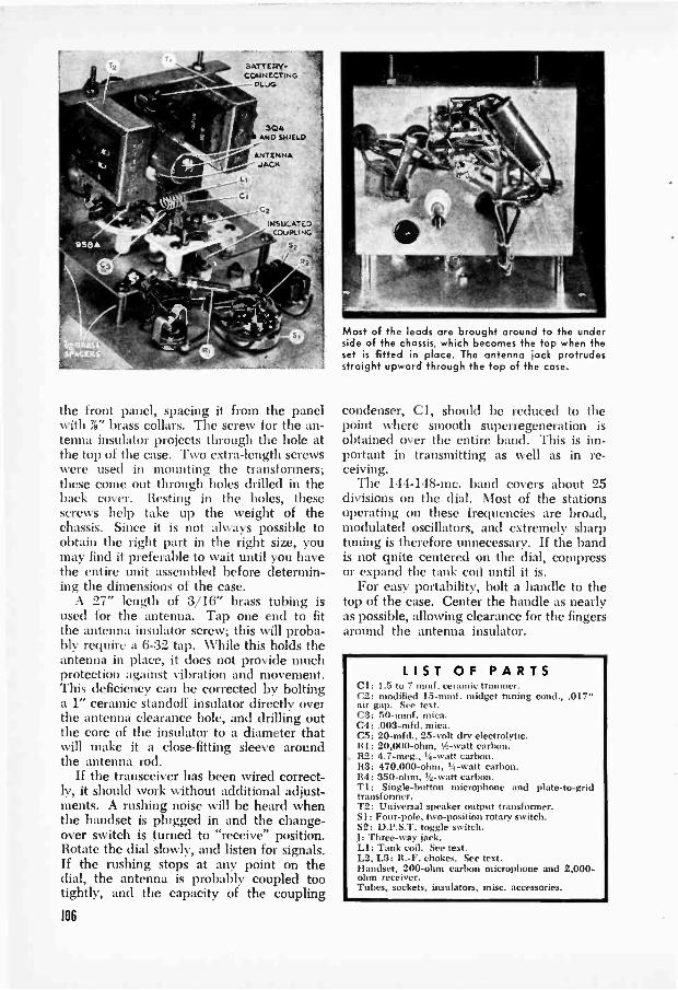
ELATTEIZY-CONNECTING-- PLUG
CI
304AND SHIELD
ANTENNAJACK
C2
INSULATEDCOUPLING
the front panel, spacing it from the panelwith IV brass collars. The screw for the an-tenna insulator projects through the hole atthe top of the case. Two extra -length screwswere used in mounting the transformers;these come out through holes drilled in theback cover. Resting in the holes, thesescrews help take up the weight of thechassis. Since it is not always possible toobtain the right part in the right size, youmay find it preferable to wait until you havethe entire unit assembled before determin-ing the dimensions of the case.
A 27" length of 3/16" brass tubing isused for the antenna. Tap one end to fitthe antenna insulator screw; this will proba-bly require a 6-32 tap. While this holds theantenna in place, it does not provide muchprotection against vibration and movement.This deficiency can be corrected by boltinga 1" ceramic standoff insulator directly overthe antenna clearance hole, and drilling outthe core of the insulator to a diameter thatwill make it a close -fitting sleeve aroundthe antenna rod.
If the transceiver has been wired correct-ly, it should work without additional adjust-ments. A rushing noise will be heard whenthe handset is plugged in and the change-over switch is turned to "receive" position.Rotate the dial slowly, and listen for signals.If the rushing stops at any point on thedial, the antenna is probably coupled tootightly, and the capacity of the coupling
106
Most of the leads are brought around to the underside of the chassis, which becomes the top when theset is fitted in place. The antenna jack protrudesstraight upward through the top of the case.
condenser, Cl, should be reduced to thepoint where smooth superregeneration isobtained over the entire band. This is im-portant in transmitting as well as in re-ceiving.
The 144-148-mc. band covers about 25divisions on the dial. Most of the stationsoperating on these frequencies are broad,modulated oscillators, and extremely sharptuning is therefore unnecessary. If the bandis not quite centered on the dial, compressor expand the tank coil until it is.
For easy portability, bolt a handle to thetop of the case. Center the handle as nearlyas possible, allowing clearance for the fingersaround the antenna insulator.
LIST OF PARTSCl: 1.5 to 7 mmf. ceramic trimmer.C2: modified 15-mmf. midget tuning cond., .017"air gap. See text.C3: 50-mmf. mica.C4: .003-mfd. mica.C5: 20-mfd., 25 -volt dry electrolytic.RI: 20,000 -ohm, %-watt carbon.R2: 4.7-meg., '4 -watt carbon.R3: 470,000 -ohm, %-watt carbon.R4: 350 -ohm, '4. -watt carbon.T1: Single -button microphone and plate -to -gridtransformer.T2: Universal speaker output transformer.Si: Four -pole, two -position rotary switch.S2: D.P.S.T. toggle switch.J: Three-way jack.LI: Tank coil. See text.L2, L3: R. -F. chokes. See text.Handset, 200 -ohm carbon microphone and 2,000 -ohm receiver.Tubes, sockets, insulators, misc. accessories.
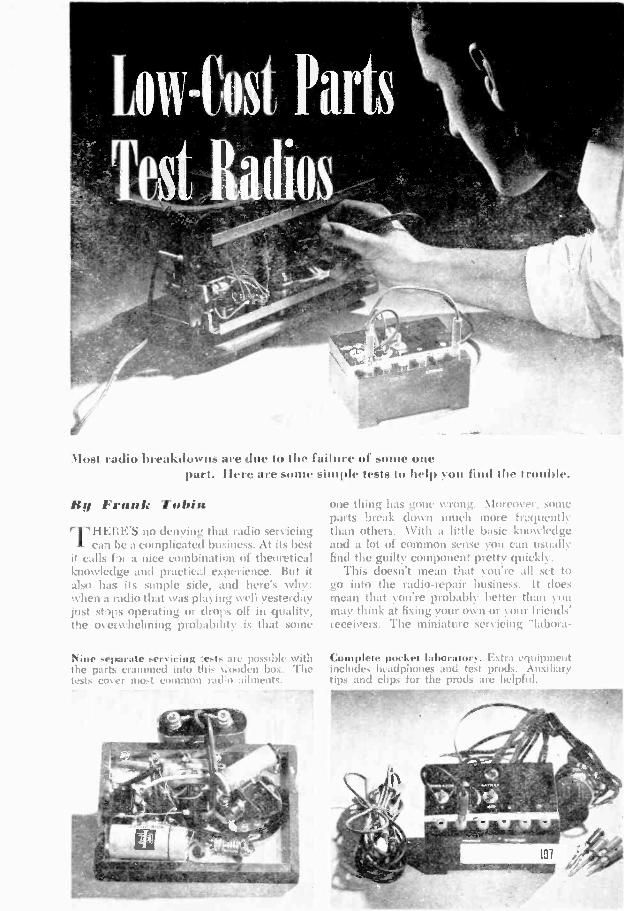
Most radio breakdowns are due to the failure of some onepart. Ilere are some simple tests to help you find ihe t rouble.
My Frank TobinrrlIEEE'S no denying that radio servicing
ca'( be a complicated business. At its bestit calls fir a nice combination of theoreticalknowledge and practic::1 experience. But italso has its simple side, and here's Nyhy:when a radio that was playing well yesterdayjust stays operating or drops off in quality,the overwhelming probability is that some
Nine separate servicing -.ests arc possible withthe parts crammed into this .-onden box. Thetests cover most common radio ailments.
one thing has gone wrong. Nloreover, sonicparts break down much more fr.quientlythan others. With a little basic knowledgeand a lot of common sense you can usuallyfind the guilty component pretty quickly.
This doesn't mean that you're all set togo into the radio -repair business. It doesmean that you're probably hatter than youmay think at fixing your own or your friends'receivers. The miniature servicing "laborit-
Complete pocket laboratory. Extra equipmentincludes headphones and test prods. Auxiliarytips and clips for the prods are helpful.

THESE SIMPLESERVICINGTESTS COVERTHE BULK OFRADIO ILLS.LETTERS REFERTO TABLE.
t SIGNAL GENERATOR.05
DUZZ E a.
E. RESISTOR ANG COIL TEST 3 SPEAKER TEST 4 HUM VEST
.t *AM400 v
TO RECEIVER
-P101.E
TO IMEIVER
INFO. +
fr- PLATE, -PROD 0"
FINALR.F. OR IF
AMPLIFYINGTUBE
R.F. OR LP/COIL
TO Bi-
PRODC.
swim .1 MFD.
CRYSTAL
PHONES
RECEIVER.CHASSIS
RF test No. 5 connects a crystal detector tothe RF or IF plate. The circuit is shown above.
tory" shown in these photos cost only a fewdollars to build. It is simply a collection ofinexpensive parts that combine in one unitthe various test setups shown in the dia-grams across the top of these pages. Eachtest is complete in itself and requires onlythe parts indicated by the individual draw-ing.
For example, to inject an audible signal
into a radio receiver, you need only a smallbuzzer, a battery, a .05-mfd. paper condens-er, and a test prod. Put the prod on thegrid pin of a tube-starting with the outputstage and working back. If the signal isheard in the loudspeaker, you know thatthe stage being tested (and all those follow-ing it) are working. When it stops beingheard, you have probably found the of-fending stage.
With the complete pocket laboratory youcan carry this test one step further. Thetable describes the first part. To this setupadd a pair of headphones by plugging themin at Jacks D and E, and another set of testprods at jacks C and F. With prod A on thegrid of an audio tube (or the plate of thedetector), prod C on the plate of the sametube (or the grid of the following one) andprod F grounded to chassis, you should beable to pick up the signal in the phones.Note, however, that it applies only to de-tector and audio tubes.
Common sense enters the picture in help-ing you select the order of the tests and de -
SI
4 "E -VOLTBATTERY
BUZZER PLUGI
SIGNAL GENER.ATOR.
'4.1-0
SET BEINGTESTED
PHONES
C4
7010F
USE0 FOR SHORTINGOUT PHONES
An octal tube socket is used for pin connections; jacks A to F are set in front of panel.
108
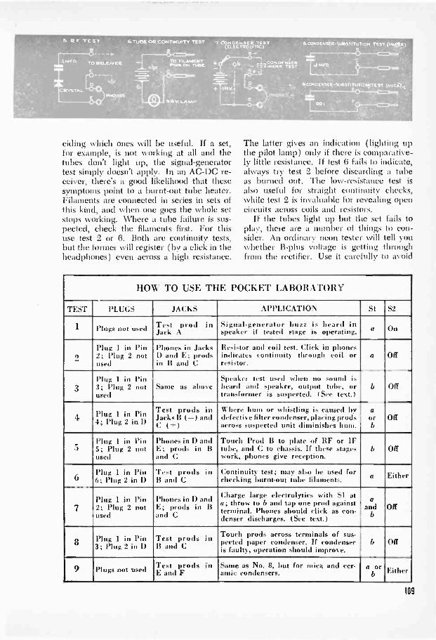
5. es TEST 6TU5E OR CONTINUITY TEST c'rilt74,16,1trS0
,.1...CONDENSERc..7A.UNOCR TEST
PHONES
S CONDENSER -SUBSTITUTION TEST (PNklet)S
SICONDENSER-SUSSTITUTION TEST (MICACti
T.01
ciding which ones will be useful. If a set,for example, is not working at all and thetubes don't light up, the signal -generatortest simply doesn't apply. In an AC -DC re-ceiver, there's a good likelihood that thesesymptoms point to a burnt -out tube heater.Filaments are connected in series in sets ofthis kind, and when one goes the whole setstops working. Where a tube failure is sus-pected, check the filaments first. For thisuse test 2 or 6. Both are continuity tests,but the former will register (by a click in theheadphones) even across a high resistance.
The latter gives an indication (lighting upthe pilot lamp) only if there is comparative-ly little resistance. If test 6 fails to indicate,always try test 2 before discarding a tubeas burned out. The low -resistance test isalso useful for straight continuity checks,while test 2 is invaluable for revealing opencircuits across coils and resistors.
If the tubes light up but the set fails toplay, there are a number of things to con-sider. An ordinary neon tester will tell youwhether B -plus voltage is getting throughfrom the rectifier. Use it carefully to avoid
HOW TO USE THE POCKET LABORATORY
TEST PLUGS JACKS APPLICATION Si S2
1 Plugs not used.
Test prod inJack A
Signal -generator buzz is heard inspeaker if tested stage is operating. a On
2Plug I in Pin2; Plug 2 notused
Phones in JacksI) and E; prodsin B and C
Resistor and coil test. Click in phonesindicates continuity through coil orresistor.
a Off
3Plug 1 in l'in3; Plug 2 notused
Same as aboveSpeaker test used when no sound isheard and speaker, output tube, ortransformer is suspected. (See text.)
b Off
4 Plug 1 in PinD
Test prods inJacks' B (-) andC (i- )
Where hum or whistling is caused bydefective filter condenser, placing prodsacross suspected unit diminishes hum.
aorb
Off
5Plug I in Pin5; Plug 2 notused
Phones in D andE; prods in Band C
Touch Prod B to plate of RF or IFtube, and C to chassis. If these stageswork, phones give reception.
b Off
6Plug 1 in Pin6; Plug 2 in D
Test prods inB and C
Continuity test; may also lie used forchecking burnt -out tube filaments. a Either
7Plug 1 in Pin2; Plug 2 notused
Phones in D andE; prods in Band C
Charge large electrolytics with SI ata; throw to b and tap one prod againstterminal. Phones should click as con -denser discharges. (See text.)
aand
bOff
8 Plug 1 in Pin3; Plug 2 in D
Test prods inB and C
Touch prods across terminals of sus -peeled paper condenser. If condenseris faulty, operation should improve.
b Off
9 Plugs not used Test prods inE and F
Same as No. 8, but for mica and cer-amie condensers.
a orb LsA. ,rtner
109

The pocket laboratory quickly tracked downthe fault in this receiver. Used for stage -by -stage checking, it's a valuable service tool.
shocks. Put one terminal on the chassis orground and the other on a screen -grid orplate pin of a tube. If the neon lamp glows,the voltage is probably adequate.
But let us assume that you are getting thenecessary voltage and none of the tubes isburned out. This could suggest that the re-ceiver itself is functioning but that the speak-er or output transformer isn't. Test 3 willtell you whether this is so. Touch one testprod to the plate of the output tube and theother to chassis and see if you can pick upa signal in the earphones. If you do, lookfor speaker trouble. It may be an openwinding in the transformer or voice coil, inwhich case the defective unit will have tobe replaced. The same test can be used atthe plate of the detector tube. Should youget no signal in the phones, the trouble prob-ably lies further back in the circuit. Use thesignal -generator test, working back from theoutput until the faulty stage shows up.
Or you can start from the "front end" ofthe receiver with RF test No. 5. This test,in effect, constitutes an untuned crystal set.By adding it to the tuned RF portion of aset you can get headphone reception, pro-vided the RF circuits are operating.
Hum in a receiver is frequently caused bya faulty electrolytic condenser in the filtercircuit or in the cathode -bias of a tube. Test4 puts an 8-mfd. electrolytic in parallel withthe suspected condenser. If hum is reduced,the condenser in the set should be replaced.Observe polarity in making the test. Prod Cgoes to the positive side of the electrolyticand prod B goes to the negative side orchassis.
When you suspect a paper condenser ofbeing shorted, make continuity test No. 6.If the pilot lamp glows, double-check byHO
unsoldering one lead of the condenser andrepeating the test on it alone. With one leadopen, use test 8 to put a good condenser inthe circuit.
Test 7 applies to the larger electrolyticsused in filter circuits. The index of a goodelectrolytic is its ability to store a charge.With the set turned off put prods B and Cacross the condenser, observing polarity.Throw S I to position a to put the battery inseries with the condenser. Change SI toposition b, then lift either one of the prodsfor a fraction of a second. This is almost arubbing or a tapping motion. As the storedcharge leaks off, you should hear rapidlydiminishing clicks in the headphones. Withsmaller electrolytics the 4% -volt battery won'tstore enough of a charge to click the phones.
There are some additional rule -of -thumbtests you can make when you want to findout the condition of a condenser. These arebased on the observation that when you puta good condenser in parallel with a bad one,part of the trouble caused by the defectiveunit should clear up. A leaky or open con-denser (as distinct from one that is shorted)may cause loss of volume, distortion, or othersymptoms. Tests 4, 8, and 9 are substitutiontests for electrolytic, paper, and mica con-densers respectively. They put a condenserthat is known to be good across one that issuspected. If the suspicion is correct, thetest should produce a marked improvementin set performance. Replace the faulty unit.
Make all tests with caution. Be sure thepower is off when it isn't actually neededfor the check you are making.
Building the pocket laboratory consistssimply of putting the components used inthe individual tests into a single box. Awooden box measuring 1%" by 311" by 4Vwas used here. The dimensions aren'tcritical. Neither are the parts, except thatthey must be dependable and of good qual-ity. A high -frequency buzzer, capable ofoperating on a 4V -volt C battery is anotherrequirement. The jeweled panel lamp waspurchased as a complete assembly with sock-et and mounting bracket; the 1N34 crystal isa germanium diode.
Since connections must be interchange-able, all contacts should be uniform in size.Phone tips are convenient, since headphonescome equipped with them and test prodsmay be so purchased or the original tipscan be replaced. They also allow the use ofon octal tube socket to permit selection ofpin positions.
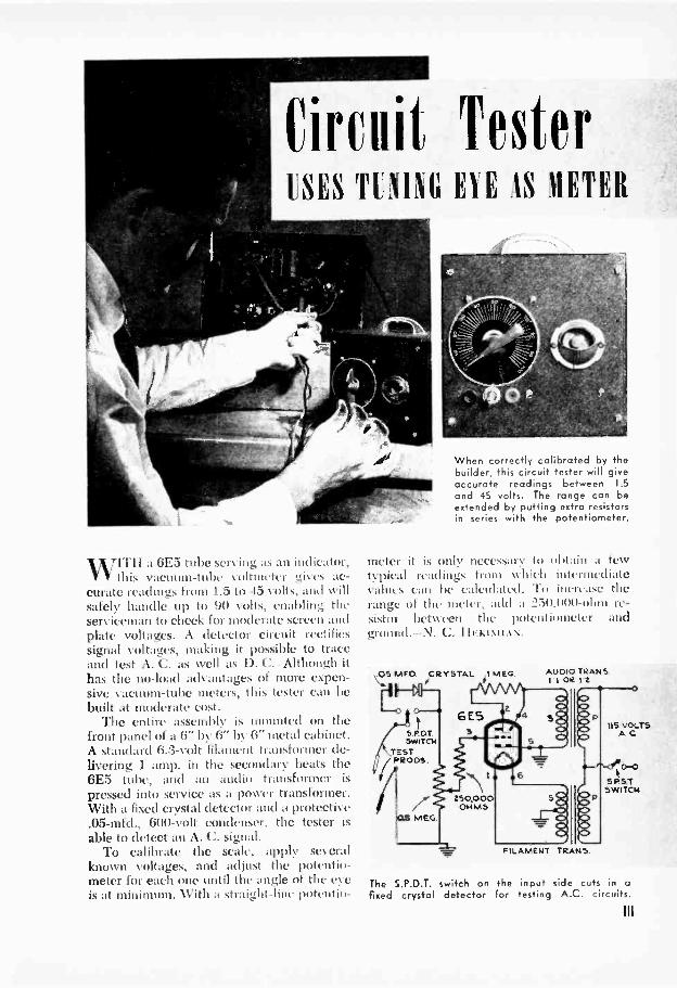
(limit TesterLSES TOM EYE IS METER
WITII a 6E5 tube sett ii (IiIator,this vacuum -tube collulctcr ..4i% es ac-
curate readings from 1.5 to 45 volts, and willsafely handle up to 90 volts, enabling theserviceman to check for moderate screen andplate voltages. A detector circuit rectifiessignal voltages, making it possible to traceand test A. C. as well as 13. C. - Although ithas the no-load advantages of more expen-sive vacuum -tube meters, this tester can bebuilt at moderate cost.
The entire assembly is mounted on thefront panel of a 6" by 6" by 6" metal cabinet.A standard 6.3 -volt filament transformer de-livering 1 amp. in the secondary heats the6E5 tube, and an audio transformer is
pressed into service as a power transformer.With a fixed crystal detector and a protective.05-mfd., 600 -volt condenser, the tester isable to detect an A. C. signal.
To calibrate the scale, apply severallmown voltages, and adjust the potenth,-meter for each one until the angle of the etis at minimum. With it straight-line potentiii-
When correctly calibrated by thebuilder, this circuit tester will giveaccurate readings between 1.5and 45 volts. The range can beextended by putting extra resistorsin series with the potentiometer.
meter it is only nectssary to obtain a fewtypical readings from w hich intermediatevalues can be calculated. To increase therange of the meter, add a 250,()00 -ohm re-sistor between the potentiometer andground.-N. C. I IEKIMIAN.
MEG.05MFD. CRYSTAL 1
ft)G ES
SPOT 3SwiTai
_TESTP4003.
The S.P.D.T.fixed crystal
230,000
AUDIO TRANSI I OR 12
FILAMENT TRANS.
IIS MOLTSAC
S.PST.
0-0
9WITEN
switch on the input sick cuts in adefector for testing A.G. circuits.
Ill
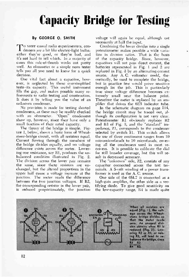
Capacity Bridge for TestingBy GEORGE 0. SMITH
TO MOST casual radio experimenters, con-densers are a bit like electric -light bulbs:
either they're good, or they're bad, andit's not hard to tell which. In a majority ofcases this rule -of -thumb works out prettywell. An ohmmeter or a simple neon testertells you all you need to know for a quickdecision.
One vital fact about a capacitor, how-ever, is neglected by these oversimplifiedtests-its capacity. This useful instrumentfills the gap, and makes possible many re-finements in radio testing and construction.It does it by telling you the value of anunknown condenser.
No provision is made for testing shortedcondensers, as these may be readily checkedwith an ohmmeter. "Open" condensersshow up, however, since they have only asmall fraction of their rated capacity.
The theory of the bridge is simple. Fig-ure 1, below, shows a basic form of Wheat-stone -bridge circuit, with all resistors equal.Current flowing through the members ofthe bridge divides equally, and no voltagedifference exists across the meter. Lower-ing one resistance, say RI, produces the un-balanced condition illustrated in Fig. 2.The division across the lower pair remainsthe same, since these resistors are un-changed, but the altered proportions in theupper half cause a voltage increase at thejunction. The meter reads the differencebetween the two junction voltages. If R2,the corresponding resistor in the lower pair,is reduced proportionately, the junction
voltage will again be equal, although notnecessarily at half the input.
Combining the lower divider into a singlepotentiometer makes possible a wide varia-tion in division ratios. That is the basisof the capacity bridge. Since, however,capacitors will not pass direct current, thebatteries represented in Fig. 1 and 2 arereplaced in Fig. 3 by an alternating -currentsource. Any A. C. voltmeter could, the-oretically, be used to complete the bridge,but in practice few would prove sensitiveenough for the job. This is particularlytrue since voltage difference becomes ex-tremely small near the balance point.Therefore the meter is replaced by an am-plifier that drives the 6E5 indicator tube.
In the schematic diagram on page 114,the bridge circuit may be traced out, al-though its configuration is not very clear.Potentiometer RI obviously replaces R2and R3 of Fig. 3, and the "standard" im-pedance, Z1, corresponds to the condenserselected by switch Si. This switch allowsthe use of three continuous ranges from 10micromicrofarads to 10 microfarads, cover-ing all the condensers used in most re-ceivers. It is possible to calibrate the dialfor still broader coverage, but this will re-sult in decreased accuracy.
The "unknown" side, Z2, consists of anycapacitor connected across the test ter-minals. A 5 -volt winding of a power trans-former is used as the A. C. source.
One side of the 6SL7 is connected as ahigh -gain amplifier, the other side as a rec-tifying diode. To give good sensitivity onthe low -capacity range, R4 is made quite
O
H2
6v.
0UNKNOWN
Z4
When all resistors oreequal ( Fig. I ), the volt-age across the Wheat-
51A1411rD stone bridge divides sothat the meter readszero. An unequal divi-sion obtains when RI is
reduced ( Fig. 2). Low-ering R2 or R4, or rais-ing R3, will tend to re-balance the bridge, sinceRI R2
R4-R3.
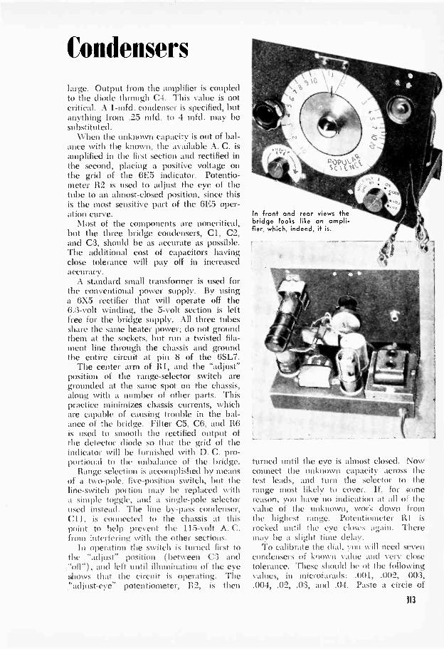
Condenserslarge. Output from the amplifier is coupledto the diode through C4. This value is notcritical. A 1-mfd. condenser is specified, butanything from .25 mfd. to 4 mfd. may besubstituted.
When the unknown capacity is out of bal-ance with the known, the available A. C. isamplified in the first section and rectified inthe second, placing a positive voltage onthe grid of the 6E5 indicator. Potentio-meter R2 is used to adjust the eye of thetube to an almost -closed position, since thisis the most sensitive part of the 6E5 oper-ation curve.
Most of the components are noncritical,but the three bridge condensers, Cl, C2,and C3, should be as accurate as possible.The additional cost of capacitors havingclose tolerance will pay off in increasedaccuracy.
A standard small transformer is used forthe conventional power supply. By usinga 6X5 rectifier that will operate off the6.3 -volt winding, the 5 -volt section is leftfree for the bridge supply. All three tubesshare the same heater power; do not groundthem at the sockets, but run a twisted fila-ment line through the chassis and groundthe entire circuit at pin 8 of the 6SL7.
The center arm of RI, and the "adjust"position of the range -selector switch aregrounded at the same spot on the chassis,along with a number of other parts. Thispractice minimizes chassis currents, whichare capable of causing trouble in the bal-ance of the bridge. Filter C5, C6, and 116is used to smooth the rectified output ofthe detector diode so that the grid of theindicator will be furnished with D. C. pro-portional to the unbalance of the bridge.
Range selection is accomplished by meansof a two -pole, five -position switch, but theline -switch portion may be replaced witha simple toggle, and a single -pole selectorused instead. The line by-pass condenser,C11, is connected to the chassis at thispoint to help prevent the 115 -volt A. C.from interfering with the other sections.
In operation the switch is turned first tothe "adjust" position (between C:3 and"off"), and left until illumination of the eyeshows that the circuit is operating. The"adjust -eye" potentiometer, R2, is then
In front and rear views thebridge looks like an ampli-fier. which, indeed, it is.
turned until the eye is almost closed. Nowconnect the unknown capacity across thetest leads, and turn the selector to therange most likely to cover. If, for somereason, you have no indication at all of thevalue of the unknown, work clown fromthe highest range. Potentiometer R I isrocked until the eye closes again. Theremay be a slight time delay.
To calibrate the dial, you will need sevencondensers of known value and very closetolerance. These should be of the followingvalues, in microfarads: .001, .002, 003,.004, .02, .03, and .04. Paste a circle of
113
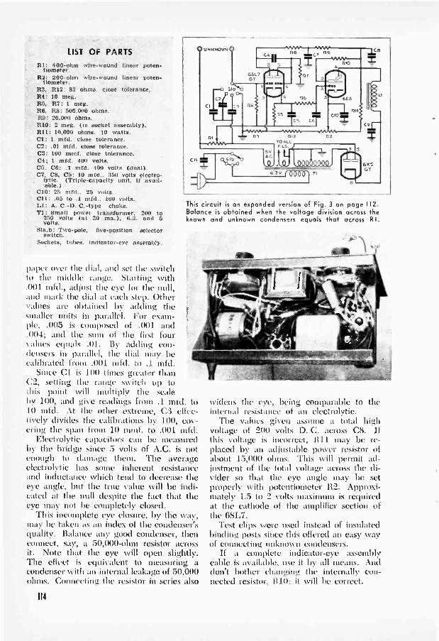
LIST OF PARTSRI: 400 -ohm wire -wound linear poten-
tiometer.R2: 200 -ohm wire -wound linear poten-
tiometer.R3, R12: 52 ohms. close tolerance.R4: 10 meg.R5, R7: 1 meg.R6. R8: 500.000 ohms.R9: 20.000 ohms.RIO: 2 meg. On socket assembly).R11: 10,000 ohms. 10 watts.CI: 1 mfd. close tolerance.C2: .01 mfd. close tolerance.C3: 100 mmf. close tolerance.C4; 1 mfd. 400 volts.C5, C6: .1 mfd. 400 volts (dual).C7, C8, C9: 10 mfd., 350 volts electro-
lytic. (Triple -capacity unit, If avail-able.)
CIO: 25 mfd.. 25 bolts.CII: .05 to .1 mid.. 400 volts.LI: A. C. -D. C. -type choke.T1: Small power transformer. 200 to
250 volts (at 30 ma.), 6.3. and 5volts.
Slab: Two -pole, five -position selectorswitch.
Sockets, tubes, Indicator -eye assembly.
paper over the dial, and set the switchto the middle range. Starting with.001 mfd., adjust the eye for the 111111,and mark the dial at each step. Othervalues are obtained by adding thesmaller units in parallel. For exam-ple, .005 is composed of .001 and.004; and the stun of the first fourvalues equals .01. By adding con-densers in parallel, the dial may becalibrated from .001 mfd. to .1 mfd.
Since Cl is 100 times greater thanC2, setting the range switch up tothis point will multiply, the scaleby 100, ilia' give readings from .1 mid. to10 mfd. At the other extreme, C3 effec-tively divides the calibrations by 100, cov-ering the span from 10 mmf. to .001 mfd.
Electrolytic capacitors can be measuredby the bridge since 5 volts of A.C. is notenough to damage them. The averageelectrolytic has some inherent resistanceand inductance which tend to decrease theeye angle, but the true value will be indi-cated at the null despite the fact that theeye may not be completely closed.
This incomplete eye closure, by the way,may be taken as an index of the condenser'squality. Balance any good condenser, thenconnect, say, a 50,000 -ohm resistor acrossit. Note that the eye will open slightly.The effect is equivalent to measuring acondenser with an internal leakage of 50,000ohms. Connecting the resistor in series also
0 UNKNOWN 0
RI
z SI b
This circuit is an expanded version of Fig. 3 on page 112.Balance is obtained when the voltage division across theknown and unknown condensers equals that across RI.
114
widens the eye, being comparable tointernal resistance of an electrolytic.
The values given assume a total highvoltage of 200 volts D. C. across C8. Ifthis voltage is incorrect, 1111 may be re-placed by an adjustable power resistor ofabout 15,000 ohms. This will permit ad-justment of the total voltage across the di-vider so that the eye angle may be setproperly with potentiometer R2. Approxi-mately 1.5 to 2 volts maximum is requiredat the cathode of the amplifier section ofthe 6SL7.
Test clips were used instead of insulatedbinding posts since this offered an easy wayof connecting unknown condensers.
If a complete indicator -eye assemblycable is available, use it by all means. Anddon't bother changing the internally con-nected resistor, 1110; it will be correct.
the
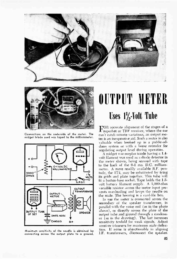
Connections on the underside of the meter. Themidget triode used was taped to the milliommeter.
OUTPUT TUBEOF SET
OUTPUTMETER
.5MFD. 400V.
CHASSIS B+
OUTPUTTRANSFORMER
SPEAKER
Maximum sensitivity of the needle is obtained byconnecting across the output plate to a ground.
OUTPUT METER
Uses 1'/Z toll Tube
FOR accurate alignment of the stages of asuperhet or TRF receiver, where the ear
can't catch minute variations, an output me-ter is an inexpensive aid. Such a meter is alsovaluable when hooked up in a public-ad-dress system or with a home recorder forregulating output level during operation.
A midget war -surplus triode having a 1.4 -volt filament was used as a diode detector inthe meter shown, being secured with tapeto the back of the 0-1 ma. D.C. milliam-meter. A more readily available R.F. pen-tode, the 1T4, may be substituted by tyingits grids and plate together. This tube willfit a button -base socket. Tape holds the 1.5 -volt battery filament supply. A 3,000 -ohmvariable resistor across the meter input pre-vents overloading and keeps the needle onthe scale. The housing is a card -file box.
In use the meter is connected across thesecondary of the speaker transformer, inparallel with the voice coil (as in the photoabove), or directly across the plate of theoutput tube and ground through a condens-er (as in the drawing). The last increasessensitivity tenfold for weak signals. Adjustreceiver trimmers for maximum scale deflec-tion. If noise is objectionable in aligningI.F. transformers, disconnect the speaker.
115

Meters Clerk
Flo;.Gilbert trisbertilt
FOR THE el, Lt runic experimenter, there'sone tool that's just about its essential as
a soldering iron-a wide -range AC -DC %lilt-ohm-milliammeter. 11 you work or playwith electricity and have graduated out 4)1the doorbell -and -dry -cell stage, you'll usesuch a meter to find accurate values of volt-age, current. and resistance. Beyond thesebasic applications. your meter will also tellyou a lot about the impedance, inductance.and capacitance of coils and condensers; itwill help test tubes and do general trouble-shooting; it will serve as an easy Nvii ofmeasuring output in voltage, decibels. orwatts; and it will permit accurate determina-tion of input to amplifiers and other ap-paratus.
Once you have a good understanding ofthe relation between volts, amperes, andohms, you can build yourself one of thesealmost indispensable tools around any fairly
116
A 11E.t r.om at '11.111t.111. !RTC in plum -tow. ludic:tics DC when the coil is rIllf:2,1/1,11.
sensitive D'Arson al movement. 'hi the be-ginner, it seem to 1w a lot ofOne meter to measure such different things,but actually it has to measure only one totell you all dirty. The ironclad magic ofOhm's Lass does the rest. This law specifiesthat a current of 1 ampere ill flow whena potential of I volt is applied across aresiskotee of 1 ohm. If the meter canwe.r.dirc any one of these, a second onebehe.2: known, the third always pops up asthe answer.
Heart of the standard DC meter, the cur-rent -measuring D'Arsonval movement con-sists of a lightweight pointer attached to apivoted coil of fine copper wire. Mountedbetween jewel bearings, the coil is free torotate in the field of a permanent magnet.

TWO delicate hairsprings carry current to thecoil and also serve to position it so that thepointer is normally at zero on the scale.When current flows in the coil, interactionof the lines of force produces a torque.This torque rotates the coil and its pointerto a position where it balances the oppos-ing torque of the springs.
For greatest versatility, multimeter move-ments are usually designed to react to verylow values of current, but it's a simple mat-ter to increase of such ameter. Let's say it has an internal resistance( Rm) of 100 ohms-that is, the moving coilitself offers this resistance to the flow ofcurrent-and that 1 milliampere (.001 amp.)will deflect the needle all the way acrossthe scale.
In order to double the range of such ameter, all you need to do is put a 100 -ohmresistor in parallel with the meter to by-passhalf the current, and multiply the readingby two. Shunts of lower resistance increasethe current -handling capacity still more.
Volt and Ohmmeters
Milliammeters plus Ohm's law also addup to volt and ohmmeters. By measuringcurrent, the former tells you how much volt-age is being applied to a circuit of knownresistance. Take the same 0 -to -1 ma. move-ment with an urn of 100 ohms. You wantto convert it into a 0 -to -10 volt meter. Thismeans merely that 1 ma. must flow throughthe coil when you put 10 volts across themeter. But its own resistance is far toolow and will pass too much current, so extraresistance is added. We know from Ohm'slaw that a potential of 10 volts will send acurrent of .001 amp. through a resistance
of 10,000 ohms. To the 100 ohms of themeter itself, 9,900 ohms must therefore beadded in series. For measuring AC voltages,a D'Arsonval meter must also be equippedwith some sort of rectifier that will serve toconvert to DC that portion of the currentneeded for the operation of the meter.
The conventional ohmmeter, as has beensaid, is also an ammeter in disguise. A.suitable voltage is applied to meter and re-sistor which permits, say, 1 ma. to flowwhen completed. Thus, if youshort the test prods the needle goes all theway across the dial to zero ohms. But whenyou put additional resistance in series withthis circuit, you decrease the current. Thehigher the resistance that you're measuring,the lower the current that gets through.Unlike other values, resistance is lowest atthe right, highest at the left end of the dial.
A variation of the usual resistance meteris the shunt ohmmeter used to measure lowohmic values. This is a millimeter of knowninternal resistance that is energized to readfull scale. When the unknown resistance isshunted across the circuit, current throughthe meter coil drops in proportion to theratio between the fixed and unknown re-sistances.
Measuring a Meter
In order to build a multitester, it is firstnecessary to know the characteristics of themovement you plan to use. The easiest wayto determine the current required for full-scale deflection is to connect the unknownmeter in series with a meter of known ac-curacy, a variable resistor, and a voltagesource. This is illustrated by the closedcircuit shown on page 118. Since the cur-
IIl

The internal resistance of a meter movementand the current required for full-scale deflec-tion can be determined with this setup.
rent is the same in all parts of a series cir-cuit, all you need do is adjust the variableresistor until the unknown meter readsfull scale. The amount of current requiredto produce this deflection may then be readdirectly on the known meter.
Using the same setup, you can determinethe internal resistance of the movement.\kith the variable resistor adjusted to makethe meter read full scale, shunt the meterwith fine resistance wire of, say, 10 ohmsper foot as indicated by the wavy line. Addwire until the meter reads half scale, and
118
reset the variable resistor as needed to keepthe total current (shown on the secondmeter) constant. When the wire shunt andthe unknown Rm are equal, half the currentgoes through the meter and the other halfthrough the wire. Measuring the length ofthe wire then tells you the Ron of the meter.Use accurately labeled resistance wire.
Sensitivity, another characteristic of themovement, may become important in someapplications of multitesters. A meter thatyields full-scale deflection with a current of1 ma. is said to have a sensitivity of 1,000ohms per volt, because 1 volt will give full-scale reading when the total series resist-ance equals 1,000 ohms. This ratio willapply for all other ranges, that is, 100 voltsfull scale will require resistance totaling100,000 ohms.
For electronic work, meters should haveat least 1,000 ohms per volt sensitivity toavoid "loading- circuits under test.
When building a multitester, it is usuallya good idea to complete the ohmmeter sec-tion first so that it can be used in theselection of other resistors. The accuracyof a series ohmmeter depends primarilyupon the accuracy with which the totalcircuit resistance is known. Since the volt-age of batteries. even when new, varieswidely, some means of zero adjustment isalways provided. With the test leads short-ed together, zero ohms, or full-scale deflec-tion, is adjusted by means of the variableresistor shunted across the meter.
Bear in mind that :uly series ohmmeter,
FORMULAS FOR MULTIMETERSGeneral Forms for Ohm's law
11 1=R
121 R= E
i 3 i E=IRi 4 I P=1E=VR=
To Calculate Milliammeter Shuntsi51R=Rm- -
n-1
To Calculate Voltmeter Multipliers161 R=Rm n-1
Series -Ohmmeter OperationR(7 R=s Its Rs
Im
Shunt -Ohmmeter Operation1m Rm181 .s=-Ifs-Im
Where I i, r urrent in .111111,,S.
R is resistance in ohms.
E is potential in volts
P is power in watts.
[ELECTRICITY ]
Rm is internal resistance of meter I plus resistance ofseries -connected fuse).is range -multiplication factor Ito convert from 1 ma.full scale to 10 ma.. n-1=10--1=9 .
Rs is total fixed resistance in meter circuit (includingRm,.
Ifs is meter's full-scale current.Im is reduced current during test.
(approximation.
POPULAR SCIENCE MONTHLY SHOP DATA
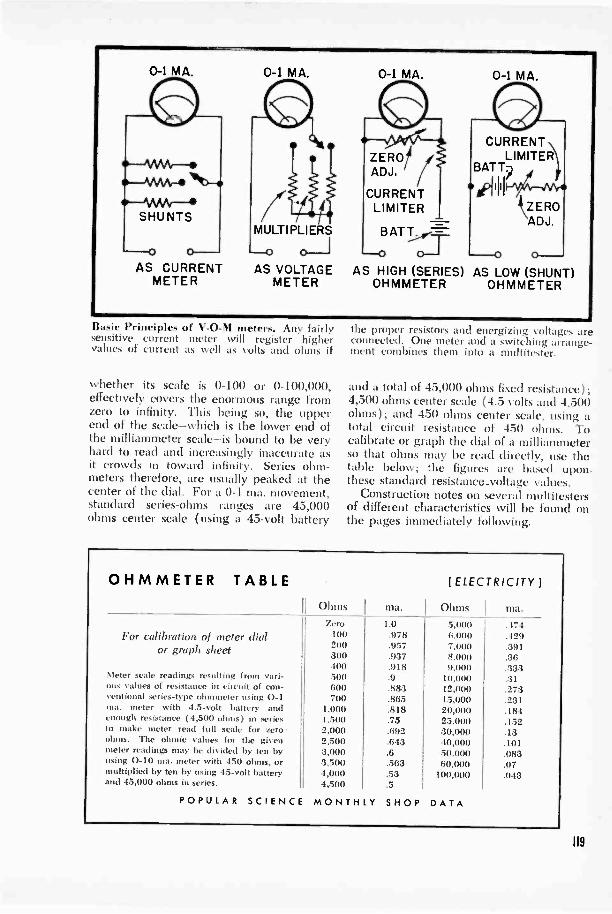
0-1 MA.
AS CURRENTMETER
0-1 MA.
MULTIPLIERS
AS VOLTAGEMETER
0-1 MA.
ZEROADJ,
CURRENTLIMITER
B AT T
0-AS HIGH (SERIES) AS LOW (SHUNT)
OHMMETER OHMMETER
0-1 MA.
BuNic Principles of V -0-N1 meter', Any fairlysensitive current meter xs i I I register highervalues of current as well as Volts and ohms if
whether its scale is 0-100 or 0-100,000,effectively covers the enormous range fromzero to infinity. This being so, the upperend of the scale-which is the lower end ofthe milliammeter scale-is bound to be veryhard to read and increasingly inaccurate asit crowds in toward infinity. Series ohm-meters therefore, are usually peaked at thecenter of the dial. For a 0-1 ma. movement,standard series -ohms ranges are 45,000ohms center scale (using a 45 -volt battery
the proper resistors and energizing voltages areconnected. One meter and a switching arrange-ment combines them into a nuiltitestcr.
and a total of 45,000 ohms fixed resistance);4,500 ohms center scale (4.5 volts and 4,500ohms); and 450 ohms center scale, using atotal circuit resistance of 450 ohms. Tocalibrate or graph the dial of a milliammeterso that ohms may be read directly, use thetable below; the figures are based upon.these standard resistance.voltage values.
Construction notes on several multitestersof different characteristics will be found onthe pages immediately following.
OHMMETER TABLE
For calibraor g
Meter scale readous values of resventional series -ma. meter witenough resistanto make meteroluns. The ohmmeter readingsusing 0-10 ma.multiplied by tenand 45,000 ohms
[ELECTRICITY ]
type
Ohms ma. OhmsZero 1.0 5,00()
ion of meter dial 100 . 978 8,00020 .957 7,000raph sheet 300 .937 8.000400 .918 9.000
ings resulting from vari- 500 .9 10,000stance in circuit of con- 600 .883 12,0(K)
of 'ter using 0-1 700 .865 15,000I 4.5 -volt battery and 1,000 .818 20,000! (4,500 ohms) in series 1.500 .75 25,000read full scale for zero 2,000 .692 30,000is values for the given 2.500 .643 40,000ay he divided by ten by 3,000 .8 50,000neter with 450 ohms, or 3.500 .563 60,000by using 45 -volt battery 4.000 .53 100,000in series. 4,500 .5
POPULAR SCIENCE MONTHLY SHOP DATA
a.
474429391363333127323118415213101083070-13
119

The multitester above, diagrammed on page
By Gilbert Stuthergh
BEFORE you start to build your ownmultitester, look over the fundamental
data on the relationship between volts,ohms, and amperes given in the previousinstallment. \Vith this information you candesign a meter for any special purpose,adapt spare parts to suit your circuit, orbuild a general -utility multimeter for radioand electrical checking. To make use ofspare parts, you must design your circuitaround them, for you can't substitute valuesthat are nearly but not quite correct. Re-sistors must be calculated with great pre-cision. Wherever possible, use wire -woundresistors that are guaranteed accurate to 1percent. Carbon resistors, costing muchless than the wire -wound type, may be usedin some cases, although they are less likelyto be stable over a long period of time. Theydo, however, have one advantage in that120
122, is a wide -range, general-purpose unit.
they can be adjusted upward in resistancevalue. To do this, file a small flat on oneside. Check the resistor on an accurateohmmeter as you file it, and when you haveexactly the right value, coat the scoredpart with wax or varnish to keep out mois-ture.
The photos here and the diagram onpage 122 show a V -O -\l meter designed toget the most measuring power in a relativelysimple one -meter unit at moderate cost.\Vith the aid of a few calibration graphs,this tester can cover more than 24 rangesof ohms, microfarads, henrys, AC and DCvolts and milliamperes.
Suggested diagrams for simpler and lesscostly meters are given on page 12:3. Bothof these models use standard 0-1 ma. me-ters and simplified switching systems. Inthe diagram at the left, toggle or pushbuttonstation -selector switches are employed; notethat the 10- and 100 -ma., as well as the

All parts except the batteries are mounted on a bakelile panel, shown here from beneath.
ohms -divided -by -ten ranges call for double -pole arrangements. If pushbutton switchesare used, depress two buttons simultane-ously. The companion drawing calls foronly one switch, and this is on R16 so thatthe 10,000 -ohm resistor can be cut out ofthe circuit for readings other than ohms.
No matter what meter you elect to build,two general precautions should be observed.First, avoid meter overloads, especially inswitching. Second, make certain that com-ponents are satisfactorily outside the circuitor isolated when the meter is positioned ona range not calling for them. For example,the meter in our principal circuit would beseriously m erloaded if you switched fromone milliampere range to another whilemaking a measurement except for the factthat the rotor of Si touches one contact be-fore leaving the previous one.
Despite all precautions, accidents do hap-pen, which is why all circuits display fuses.
The type of fuse to use is one that will "letgo" quickly on currents 10 to 25 timesgreater than the meter's normal full-scalecapacity. The resistance of the fuse, how-ever becomes part of the circuit and mustbe taken into account in all calculations.Make sure you can get replacements ofexactly the same resistance. A good proce-dure is to pick some identical fuses fromyour dealer's stock with the aid of a low -range ohmmeter.
Our major circuit contains a feature thatis well worth considering in the design ofyour own multitester: it has equal sensitivityof 1,000 -ohms -per -volt on both the AC andDC ranges, making it possible to use thesame set of multipliers and main selectorswitch for both currents. This arrangementcannot be achieved with an ordinary C-1ma. movement, but calls for a meter thatwill give full-scale deflection on .89 to .9 ma.for use with the full -wave rectifier connee-
121
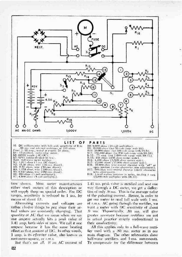
RECT.
45V
4 5V'R
0 0AC MA -DC OHMS
R18
5,000 V
415
1
1,000V.0
DC
LIST OFM: milliammieter sensiti, ity of (I to
.89 ma. and inter nal resistance of 105 loos.Fuse: 1/.32 atop.. tested at exactly 2(1 ohms.Si: 15 -posit' . meter -type rotary.S2: DPDT toggle ( AC -DC).S3: SPST (ohms -divided -by -ten).Rect.: full -wave meter rectifier.
1,1111 ohms (1 in 1)C sl ).112: 12.36 ohms, wire ( 10 -ma. shunt ).R3: 2.27 ohms, wire (50 -ma. shunt).R4: 1.124 ohms. wire ( 100 -ma. shunt I.115: 0.447 ohms, wire ( 250 -ma. shunt ).116: 89(1 ohms (1 -volt multiplier).117: 4,900 01 ( 5 -volt multiplier ).
PARTSH8: 9,900 ohm., t 10 -volt Iliplicr).119: 40.000 ohms (for 50-, out lanai. with R8).R10: .50,000 ohms (for In U-% range with R8-9).1111: 150,11(8) ohms ( for 2.10 ,olt range with R8-10).R-12: .7.5 meg. ( for 1,000,-,41 range with R8-111.R-13: 439 ohms (450 ohms center scale).R14: 4.4(8) ohms (4,500 ohms center scale).R 15. 45,000 ohms (45,1881 of (Inter scaleR16: 10.000 -ohm wire -wound rheostat with "off" or
open position (series ohmmeter zero adjustment).1117: 500 -ohm win -wound rheostat ( sl t ohmmeter
zero adjustment ).R18: 1 -watt carbon resistors in series, totaling 4 meg.
(5.000 -volt multiplier with 118-12).
tion shown. Most meter manufacturerseither stock meters of this description orwill supply them on special order. For DCranges, sensitivity is reduced to 1 ma. bymeans of shunt 111.
Alternating currents and voltages arerather elusive things to peg since their ac-tual values are constantly changing. Thatquantity of AC that we mean when we sayone ampere actually hits a peak value of1.41 amp. both sides of zero. We call it oneampere because it has the same heatingeffect as that amount of DC. In other words,1 amp. is its effectire calm', also known asroot -mean -square, or r.m.s.
But that's not all. If an AC current of
1.41 ma. peak value is rectified and sent oneway through a DC meter, we get a deflec-tion of only .9 ma. This is the average valueof the pulsating current. Hence, in order toget our meter to read full scale with 1 ma.of r.m.s. AC going through the rectifier, wewant a meter with DC sensitivity of about.9 ma. Theoretically, .89 ma. will givegreater accuracy because rectifiers are notin actual practice strictly undirectional intheir conductivity.
All this applies only to a full -wave recti-fier used with a .89 ma. meter as in ourmain diagram. The other schematics showhalf -wave rectifiers and 1 -ma, movements.To compensate for the difference between
122

1.26
13.9
O TEST
0 0 0
4O
+
a'aZO:0
1.
80 >
0 2 1:4 2 n : .
Pushbutton selector switches or individualtoggles are used here to simplify switching.
average and r.m.s. values, the AC multi-pliers (R20 in both circuits shown above)are made smaller than the comparable DCmultipliers. Using half -wave rectification,R20 will be approximately 445 ohms -per -volt (4,000 ohms for the 10 -volt, and 110,-000 ohms for the 250 -volt scale). With afour -element full -wave rectifier these valuesare doubled. As a check on operation, applyknown DC voltages across the AC terminals;the indication should be about 11 per centtoo high.
As was noted in the previous discussion,ohmmeters are usually peaked at centerscale, common ranges being 45,000 ohms,4,500 ohms and 450 ohms. Using a 0-1 ma.meter, the former calls for a 45 -volt batteryand total series resistance of 45,000 ohms.For the second, both values are divided byten. To divide again by ten in order toachieve the third range would seeminglycall for a .45 -volt battery. Since there is no
COPPER WIRE TABLE
43 OHMS PER FOOTI-.XZ
244.i6 68°F 77°F
;4;4.<70
22 .01615 .01646 130024 .02568 .02617 80026 .04082 .04162 5(8)28 .0649 .06617 30030 .1032 .1052 20032 .1641 .1673 12034 .2609 .266 8038 .4148 .423 5038 .6596 .6726 3040 1.05 1.069 20
13 9
26
2010
0-10
0-100
0-250
8
_
R-10
0 0 0 000 0 4
0 a; D;
> 0 0 82 2 a 0 It 0
For portability the high -ohms range has beenomitted, doing away with the 45 -volt battery.
reliable means for obtaining such a batteryvoltage, we must use a higher voltage and ahigher full-scale current in order to maintaintotal series resistance of 450 ohms. Twomethods of accomplishing this are shown inthe diagrams.
In the one on page 122 the meter isshunted to read 10 ma. full scale. Note thejumper from the 10 ma. shunt, R2, to posi-tion 13 on selector switch Si. When S3 isclosed, a current of 10 ma. flows from the4.5 -volt battery through R13 and theshunted meter. For measurements on theseries -ohm ranges, R17 is set at zero andcan therefore be disregarded.
The second method for obtaining thelowest series -ohms range requires the addi-tion of just one resistor to the 4,500 -ohmcenter -scale circuit. This is R19 in the twosmaller diagrams; the 500 -ohm unit shuntsthe 4,500 -ohm resistance that is made up byadding 4,400 ohms to the approximately100 -ohm meter. Two things are accom-plished by R19: the reduction of the totalcircuit resistance from 4,500 to 450 ohms,and the by-passing around the meter ofnine -tenths of the resulting increased cur-rent.
If still lower ohms ranges are desired, theshunt ohmmeter is recommended in place of,the series type. It is incorporated in themajor diagram on the facing page, and itsspecial advantages are considered on thepages immediately following.
123

Bench insti lit or po( het size Iget, .1 m ultin.stcr i eer electrical shoo.
Completing 1 our MultimeterIf 'on built the tester describedon page 120. want thesefurther pointers on its use.
By Gilbert Soubergh
SI \CE all the essential information neededfor building Ihree types of in altimeter
Nvas given on the previous eight pages, youprobably have your tester pretty well underconstruction. The two smaller units illus-trated on page 123 offer no special prob-lems. Most of this discussion, therefore,concerns the featured instrument.
It was stated that the range of a se-ries ohmmeter cannot readily be lowered
enough to measure very small resistances.To do that a shunt ()I) iiiiii eter was recom-mended. The principle of the shunt ohm-meter will he recognized as the same oneused to determine the internal resistance ofa meter with the aid of a known value ofshunting resistor (see page 118). If we usea 0 to 1 -ma. meter %yid) internal resistanceof 105 ohms, and shunt it \\Al an equal re-sistor while energizing the circuit, a half -scale reading of 103 ohms results. Colikeseries -ohms readings, infinite resistance is atfull scale and zero is at zero on the dial.
A reading of 103 ohnis center scale (high-er if a fuse is used in the circuit) is not,however, sufficiently lower than the -150-ohm range to he of great value. In our
124

circuit, therefore, the meter and fuse areshunted to read 10 ma. in order to providea center -scale reading of 11.4 ohms. Switchpositions are the same as for the lowestseries -ohms range, but a test lead is used toshort the DC and 011MS terminals. Theunknown resistor is then inserted betweenthis jumper and MA -DC. Since accuracy isdependent primarily upon current value,rheostat R16 is turned to "off- position, andcurrent is regulated to hill scale-precisely10 ma.-by 1117. This is being done by thescrewdriver adjustment illustrated at theupper right.
The resistor under test then shunts thewhole circuit, and its value may be calcu-lated from formula 8 (See page 118). Itmust be remembered that this formula isonly an approximation, and its accuracy de-creases as the circuit current is raised. Thegraph at the right was plotted by calculatinga number of points from a inure exact for-mula, and it should hold reasonably well forany meter constructed with the same valuesas the one shown.
If the graph should prove inaccurate foryour meter, you can plot another one withthe help of a few feet of resistance or fine-copper wire. Measure a dozen or so lengthsof wire and calculate the resistance ofeach from the ohms -per -foot rating of thewire. Then check the wire on the meterand plot scale deflection against knownohmic value. Shunt ohms are representedby the numbers in the left hand margin ofthe graph; a companion curve for a seriesohmmeter crosses it from upper left tolower right and is read against the figures inthe right-hand column. The chart is drawnon logarithmically scaled paper, availableat most stationers.
As has been pointed out, the reason thatohmmeters are peaked at center scale isthat all ranges cover the area from zero toinfinity, and therefore both ends of the scaleare bound to be inaccurate. The problemof measuring low resistances may be met bythe shunt ohmmeter. But what about veryhigh ohmic values? Of what use is a meterthat reads, say, 00,000 ohms when you wantto measure a resistance of several megohms?The answer seems to be that you can't makethese measurements, but in fact the prob-lem is easily solved. All you need is a volt-meter and a source of high voltage, such asthe power -supply circuit of an AC receiver.
Measure this voltage-preferably severalhundred volts-and then make a second
Adjusting the meter to read on the lowest ohmrange. Scale divisions are graphed as below.
1009080 -7060-50
40
30
1098765
-40
301-z 2x0
109
.7
.6 -
.5
.4
igrasunadoluanniV
11111111111111NNIMM. infll OMR WWI NZ f NMI111.111111MIN
:
10 20 30 40 50METER DEFLECTION -SCALE DIVISIONS
A graph of this type will help you interpretnonlinear shunt and series ohmmeter readings.It should hold for meters built like the oneabove, or it can be plotted from known values.
125

reading with the unknown resistor in serieswith the meter. The unknown value maythen be calculated from formula 9, below.
Your AC voltmeter may also be used tomeasure capacitance, inductance, and im-pedance with sufficient accuracy for mostpurposes. An AC power line will serve verywell, provided that you take adequate pre-cautions to prevent electrocution. Firstmeasure the line voltage; then take a secondreading with the unknown element in serieswith the voltmeter.
Capacitance of condensers is figured fromformula 10. Again it may be wise-if anyconsiderable number of readings is to bemade-to draw a logarithmic graph in whichthe voltage readings of your meter areplotted against capacitance. The graph willbe useful wherever the same meter is usedon the same line voltage. Use a dozen orso accurately known condensers to plot thisgraph. Capacitance measurements may bemultiplied by ten or a hundred if the volt-meter leads are shunted by suitable re-sistors to reduce the effective voltmeter re-sistance ( Rv in the formula) to a tenth or ahundredth of its normal value. Alternativelythe high ranges may be obtained by using astepdown transformer (and a lower volt-meter range) to reduce the values of Emand El.
Inductance is calculated approximatelyfrom formula 11. A graph of inductancevalues against meter readings would be ac-curate only for high "Q" inductances-those
126
in which DC resistance is small comparedto AC inductive reactance.
Impedance is expressed in ohms, and isthe tendency of capacitors or inductors toresist the flow of alternating current of anygiven frequency. When needed, the im-pedance of a coil or condenser may be ob-tained with the help of formula 12.
An AC rectifier -type voltmeter makes anexcellent output meter for receiver align-ment, power -output measurements, mea-surements of gains or losses of amplifiers,and the like; it may be calibrated in volts ordecibels. If any direct current is present inthe circuit under test, it should be kept fromthe meter by a good quality paper con-denser of from .5 to 2 mfd. The AC com-ponent or "ripple voltage" of power sup-plies is measured in this manner.
If your meter is built according to all thespecifications given in the previous install-ment, the face of the instrument, includingswitches and test jacks, will probably re-semble that of the larger unit shown on page124. To read DC milliamperes, then, inserttest leads into the DC and MA -DC pin jacks.Note that a narrow pin and adapter is shownin the photos for the latter jack. This is usedto lessen the possibility of applying a highvoltage to the milliammeter by accident.When making current measurements, al-ways start out with the selector switch in-dexed to the highest range and back downuntil an accurate reading can be made. In-sertion of a milliammeter into a circuit that
FORMULAS FOR MULTIMETERS
To Use Voltmeter as Ohmmeter
(9) R= ---1` -Rs
AC Voltmeter as Capacitance Meter
(10) C= Ens
Rv VE12-E...2
AC Voltmeter as Inductance Meter
( 11) L= ltv VE1'Em
AC Voltmeter as Impedance Meter
Rv VE12-E.,2(12) Z=Em
POPULAR SCIENCE MONTHLY SHOP DATA
[ELECTRICITY ]
Rs is total fixed n.i.tance in meter circuit.Eb is battery or imser-supply voltage.Em is reduced voltage reading during test.
C is unknown capacitance ( in microfarads).El is full voltage of AC line.f is AC frequency (2,1-377 on 60 cycles).Iv is total voltmeter resistance ( in megohms).
L is unknown inductance in henrys.Rv is total voltmeter resistance in ohms.
Z is unknown impedance in ohms (may becapacitive or inductive).
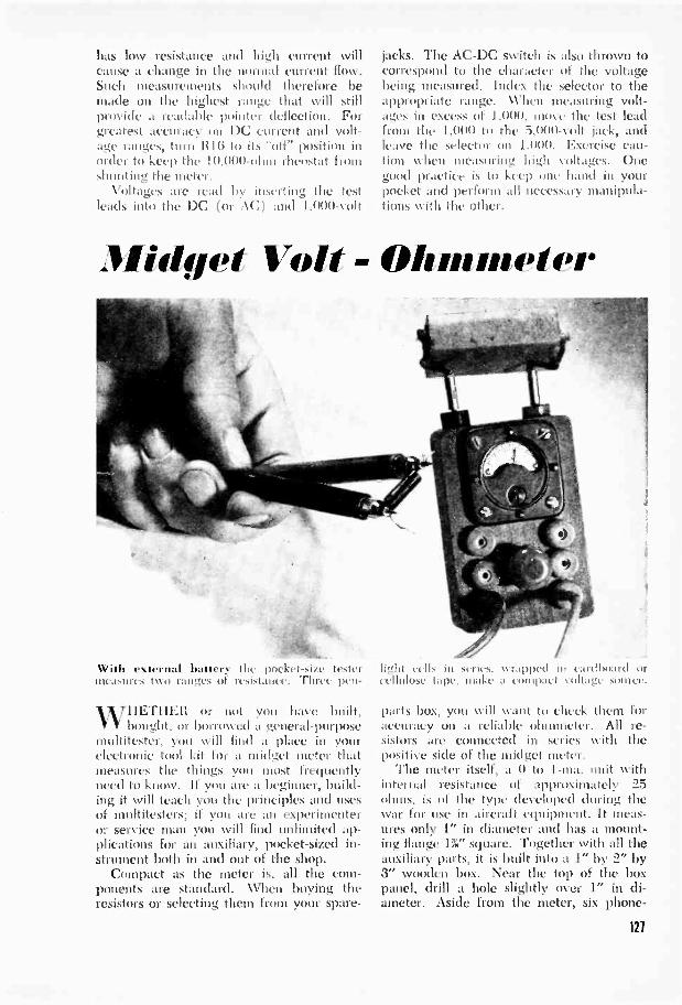
has low resistance and high current willcause a change in the normal current flow.Such measurements sly nild therefore bemade on the highest range that will stillprovide a readable pointer deflection. Forgreatest accuracy on DC current and volt-age ranges, turn 1116 to its "oil' position inorder to keep the 10,000 -ohm rheostat fromshunting the meter.
Voltages are read by inserting the testleads into the DC (or AC) and 1,000 -volt
jacks. The AC -DC switch is also thrown tocorrespond to the character of the voltagebeing measured. Index the selector to theappropriate range. When measuring volt-ages in excess of 1,000, move the test leadfrom the 1,000 to the 5,000 -volt jack, andleave the selector on 1,000. Exercise cau-tion when measuring high voltages. Onegood practice is to keel; one hand in yourpocket and perform all necessary manipula-tions with the other.
Midget Volt - Ohmmeter
With external battery the pocket-size testermeasures two ranges of resistance. Three pen -
WHETHER or not you have built,bought. or borrowed a general-purpose
multitester, you will find a place in yourelectronic tool kit for a midget meter thatmeasures the things you most frequentlyneed to know. If you are a beginner, build-ing it will teach you the principles and usesof multitesters; if you are an experimenteror service man you will find unlimited ap-plications for an auxiliary, pocket -sized in-strument both in and out of the shop.
Compact as the meter is, all the com-ponents are standard. When buying theresistors or selecting them from your spare -
light cells in series. wrapped in eard1),Thlcellulose tape, make a compact volt.t" ,voce.
parts box, you will want to check them foraccuracy on a reliable ohmmeter. All re-sistors are connected in series with thepositive side of the midget meter.
The meter itself, a 0 to 1 -ma. unit withiiiternal resistance of approximately 25ohms, is of the type developed during thewar for use in aircraft equipment. It meas-ures only 1" in diameter and has a mount-ing flange 1%" square. Together with all theauxiliary parts, it is built into a 1" by 2" by3" wooden box. Near the top of the boxpanel, drill a hole slightly over 1" in di-ameter. Aside from the meter, six phone -
121

Even inside the 1" by 2" by 3" case, there isplenty of room fir the handful of components.
tip jacks and a midget 25,000 -ohm rheostatare mounted on the face. In the edge ofthe box above the meter place two morejacks for the external battery. This will bein series with the rheostat and a :3,000 -ohmfixed resistor.
For both the low and medium -ohmsranges an external battery is required. Use a
supply; three pen -light cells in seriesare suggested because they will not add verymuch to the size and weight of the equip-ment.
The five scales chosen offer a wide va-riety of uses in radio servicing. The 0 to 10and 0 to 100 -volt ranges will enable you tocheck all sizes of A and B batteries, andthe 0 to 500 -volt scale will come in handywhen you want to know the potential acrossthe plate or screen of most receiver tubes.
Each of the ohms ranges has its ownparticular advantage. All antenna, RE andIF coil windings, as well as filter chokes andpower transformers, can be tested on the lowscale, and this range is also useful as a con-tinuity tester. By touching the two prods tothe heater pins on a tube, you can deter -
128
500,000OHMS)
500 VOLTS
LOW 064MS
METER(0-1 MA.,25 OHMS)
10,000 OHMS
3,000 OHMS
100,000OHMS
100 VOLTS
10 VC/STS
MEDIUM
25,000 OHMS
5 OHMSWIRE -WOUND +
EXTERNAL BATTERY
In st respects placement of the parts cat,follow the layout shown in the diagram above
mine whether the filament is open. If it is,there will be no deflection of the needle.About 80 percent of set failures can betraced to burned -out tubes, and in AC -DCreceivers, where tubes are connected inseries, it is impossible to tell which is caus-ing the trouble unless the filaments can bechecked.
With the medium -ohm meter you can tellwhether the high -resistance windings ofsuch parts as high -impedance chokes, outputand audio transformers are open or shorted.Higher resistors, such as may be found inplate, screen, or coupling circuits, can't bemeasured directly, but defects can easily bespotted by checking the voltage reachingthe tubes. Both ohms scales can be used todetect shorts in paper -tubular condensersand leakage in electrolytics.
You can read volts directly by multiplyingscale markings by 10, 100, or 500, dependingupon the range. The ohmmeter is servicechecking rather than for accurate measure-ment. To get approximate values, measurea dozen known resistors and graph pointerpositions.-ALBERT ROWLEY.

±MFD M FE) ILIrD 132 MFDIS NIFO
#00 500OHMS OHMS
1.000OHMS
1-7-1 Y1 -T-110,000 25,000 50000 100.000 250.000 500.000OHMS OHMS OHMS OHMS OHMS OHMS
Push -Button Selector Keeps Range of Test Values Handy on Bench
I1Aoto e\ perinienteis \\ lit like to try aVallety of condensers OF resistors in a work-ing circuit before soldering one in will findthis bench panel a useful workshop tool. Itis built around two discarded push-buttonselector switches, and employs a group ofclose-toleralice el iidensers and resistors.When condensers are used in parallel, their
Cement in Wrench Holds NutsTo It1.11'1.,.\( t .1 mitt 1111
part of a radio clhissis, put a drop of speakercement. or other thin. liquid adhesive. in theopening of a socket wrench. Just a slightamount of tackiness is needed to keep thenut in place while you place the wrenchover the bolt and engage the first couple ofturns. -1-1.
total capacity is equal to the stun of theindividual capacities. Adding resistors inparallel gives a total resistance smaller thanany of the components; it may be calcu-lated by adding reciprocals. The buildermay substitute yid' ICS in geometrical pro-gression in place of those shown in the (bit-gram.-AminEw VALLN.riNo.
Check Speaker -Plug ConnectionNiiisE, hum, or simil.ir tronhle in a radio
receiver is often due to loose connections atthe speaker plug. When checking thesewires, turn off the set, remove the pile, frontthe socket, and pull on the individualstrands as shown above. Resolder loosewires to the plug prongs. -11. L.
129

Does a VTVM draw current front the circuit under test? The milliatunteter gives the answer.
IF YOU'VE ever tried servicing a radio,you don't have to be told that a volt-
meter is like an extra right arm. It's thetool that often tells you what the troubleis, and when it can't do that, tells you whereto look for it.
Voltmeters can be roughly divided intothree classes. Low -resistance meters are thecommonest. They are usually rated forsensitivity in the neighborhood of 1,000 -ohms -per -volt and require 1 ma. of currentto deflect the pointer full scale. High -resist-ance meters of the 20,000 -ohms -per -voltclass are distinctly better and will give accu-rate results under most conditions. They needonly .05 ma. to drive the needle across thedial. The third type is the vacuum -tubevoltmeter, or VTVNI. It has almost infiniteresistance and takes practically no currentfor its operation. If you bear in mind thatany current required by the meter must be
1. Here's where the current goes. The meter"loads" the circuit by drawing extra current.
taken from the circuit being tested-whichtends to "load" the circuit-you can see whyit is often important to keep drain to aminimum.
None of this should be read as a criticismof the first two types of meter. Both havenumerous applications if you understandtheir limits. But take the situation diagramedin Fig. 1. The tube is receiving its platecurrent through R1 and R2. Now if you tryto measure the voltage at the plate with a1,000 -ohms -per -volt meter, you introduceanother current -drawing element into thecircuit, the meter itself. The extra drain maybe very little (say a half or quarter milli-ampere); but since it must also flow throughRI and R2, it introduces an extra voltagedrop. Thus the very presence of the meterchanges the circuit you are trying to meas-ure.
Another way of viewing the same problem
A i1 R 1C0,000
45V. i OHMS
90V. I
45V.100,000OHMS
90V
r.100,000OHMS
RI
60V 100,000OHMS
50,0007 OHMS
30VR2
100,000 OHMS
2. There should be 45 volts across R2, but anordinary meter will give a reading of only 30.
130
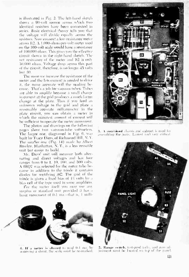
is illustrated in Fig. 2. The left-hand sketchshows a 90 -volt source across twoidentical resistors have heed connected inseries. Basic electrical theory tells you thatthe voltage will divide equally across theresistors. Now connect a low -resistance meteracross 112. A 1.000 -ohms -per -volt meter usedon the 100 -volt scale would have a resistance01100,000 ohms. This gives you the effectivecircuit shown in the right-hand sketch. Thenet resistance of the meter and 112 is only.50,000 ohms. Voltage drop across this partof the circuit, therefore, is no longer 45 voltsbut 30.
The more we increase the resistance of themeter and the less current is needed to driveit, the more accurate will the reading be-come. That's a job for vacuum tubes. Tubesare able to amplify because a small changein current at the grid produces a much larlichange at the plate. Thus if you feed aiunknown voltage to the grid and place areasonably accurate milliammeter in theplate circuit, you can obtain a meter inwhich the minutest amount of current willbe sufficient to operate the meter movement.
The photos and drawings on the followingpages show two vacuum -tube voltmeters.The larger one, diagramed in Fig. 6. WaS
built by Tracy Diers, of Richmond lfill, N.Y.The smaller one (Fig. 14) made by AlbertRowley, Manhattan, N. Y., is a less versatileunit but easier to build.
Mr. Diers' unit will measure both alter-nating and direct voltages and has fourranges from 0 to 1, 10, 100, and 500 volts.A 6SQ7 was selected for the meter tube be-cause in addition to the triode it containsdiodes for rectifying AC. The grid of thetriode is given a fixed bias of 1ff volts by abias cell of the type used in some amplifiers.
For the meter itself you may use anysurplus or standard unit provided it has abasic movement of 0-1 ma.-that is. I milli -
4. If a meter is uttered to read 0-1 ma. byremoving a shunt, the scale must be re -marked.
3. A e used 11,r
%cry critic al.
PANES -LIGHTASSENISLY
asseniblinu the I
PANEL LIGHT
5. Range test -prod iz.eks, and zeal ad-justment nal-t be located 01 tcp of the panel.
131

0-1 MA.METER
BIASCELL -
b. l'arts tv-rd in building the VTIIM st be of close tolerance, but the wiring is simple.
141: 10,000-01 ot. I -ff al> f02: 1,500 -ohm. 2 -watt carbon.li:3: 2,000 -ohm ire -wound
potentiometer.04: 40,000 -ohm. 20-, att adjust-
able wire-woond. Nt1 didi tor:16,000 1,1i111,. 51( test.
I4 is 2,500 -ohm. 5-n att wire-otanl.
06: I -meg.. I -watt carbon.
LIST OF PARTSIt 7. 10-aleg.. I ,tt Ann,
(2% toleratu, ).148: 9-meg., 1-, att t arbots
( tolerance).149: 900,000 -ohm. att earl
12'; tolerance).1110: 1110.000 -ohm, 1 -watt earl14 11: 1.5,000 -ohm, 50 -watt.
athostable wire -wound.Cl: S-111fd., 450 -volt electrolytic.
C'2:.3 -odd., 450 -volt paper.C3: .05-mfd., 6(10 -volt paper.C4:.1 -mid., 600 -volt paper.SI: 4 -contact rotary switch.52: DPST toggle.r 600 to 650 -volt power trans.Meter ( 0-1 Ina. DC). 1 ' ,volt bias
Cull and holder, panel -light as-sembly, Whys and sockets. misc.hardware.
500- OHMWIRE -WOUND
FLASHLIGHTCELL
ADJUST TO READI VOLT
LOW -RESISTANCEMETER
TO DC+
TERMINAL
TO NEG
TERMINAL
7. Calibrate the meter with this setup. Leavethe 1051-t.c:i.tanee meter connected throughout.
8. The vrvm Id give the same readingas the calibration meter. Zero the VTVNI first.
300,000 OHMS
9. In each of these circuits try first a low -resistance meter :11111 \'T\ -\I; compare results.
ampere causes full-scale deflection. It maybe necessary to rerun I shunts or multipliersthat are used to gi\ e the meter a differentscale. If you do. re -mark the dial as in Fig. 4.Figures :3, 5. and 6 show the location of theparts and the method of connection. Scrapeevery contact and tin those that need it be-fore soldering. This is important if you wantclean,
The unit is built into a chassis measuring:3" by 10" by 12". Tube sockets are mountedalong an inner chassis edge by means ofbolts and spacers. Some of the resistorscalled for may be hard to come by. If youhave trouble finding any, remember you canalways make up the right resistance by add-ing two or more smaller units in series. Ahigher wattage than specified will do noharm.
To obtain the proper operating voltage.a power transformer, T1, and a 5Y3 rectifierare used. The sliding arm on RI 1 has to beadjusted to 255 volts from slide to ground.
Scale selection is accomplished by meansof a single -pole four -position rotary switch.Vl'ith the slider on contact 1, the meter readsfrom 0 to 500 volts full scale (which meansthat you multiply the meter scale by 500).Contact 2 gives the 0 -to -100 range (multiplyby 100). Contacts :3 and 4 are for the 10 -and 1 -volt scales.
The meter is calibrated for DC. Note,however, that a separate terminal is providedfor measuring alternating voltages. Theseare rectified in the diode portion of the6SQ7. The meter registers peak voltage.Alternating current or voltage changes itsvalue every instant, ranging from zero to
132
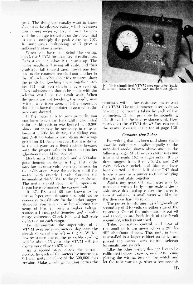
peak. The thing you usually want to knowabout it is the effective rahte, which is knownalso as root mean square, or r.m.s. To con-vert the voltage indicated on the meter dialto r.m.s.. multiply the peak value by .707.In most cases multiplying by .7 gives asufficiently dose answer.
When you have completed the xviring.check the VTVNI for accuracy of calibration.Turn it on and allow it to warm up. Themeter needle will swing off scale, and thengradually fall toward zero. Insert one testlead in the common terminal and another inthe DC jack. After about five minutes, shortthe prods by touching them together. Ad-just R:3 until you obtain a zero reading.These adjustments should be made with theselector switch on the 1 -volt scale. 'Whenthe prods are not touching the needle mayiss ing away from zero, but the importantthing is to have the pointer at zero when theprods are shorted.
If the meter fails to zero properly, youmay have to readjust R4 slightly. The initialvalue of this resistor was figured as :36,000ohms. but it may be necessary to raise orlower it a little by shifting the sliding con-tact. A 40.000 -ohm adjustable resistor is sug-gested for R4. Note however, that it is shownin the diagram as a fixed resistor becauseonce the proper value is found no furtheradjustment should be needed.
Hook tip a flashlight cell and a 500 -ohmpotentiometer as shown in Fig. 7. An ordi-nary but accurate voltmeter may be used forthe calibration. Vary the resistor until themeter reads exactly 1 volt. Connect theterminals of the VTVM to the points shown.The meter should read I milliampere-or.if you have re -marked the scale -1 volt.
If R7. 118. and R9 are known to bewithin 2 -percent tolerance, it should not benecessary to calibrate for the higher ranges.However you may do so by adapting thesetup of Fig. 7. using a higher voltagesource, a 1-meg. potentiometer, and a multi -range voltmeter. Check full- and half -scaledeflection on each range.
To demonstrate the superiority of a
VTVM over ordinary meters. duplicate thecircuit shown at the left in Fig. 9. With alow -resistance meter the probable readingwill be about 25 volts; the VTVNI will in-dicate very close to 671. volts.
As a second step. check the currentneeded by each of the meters 1w inserting a0-1 ma. meter in place of the 300,000 -ohmresistor. Make a voltage reading across the
10. This simplified VTVM uses one tube. Scaledivisions, from 0 to 25, are marked on glass.
terminals with a low -resistance meter andthe VTVNI. The milliammeter in series showshow much current is taken by each of thevoltmeters. It will probably be somethinglike .6 ma. for the low -resistance unit. Howmuch does the VTVM draw? You can readthe answer yourself at the top of page 130.
Compact One -Tuber
has been said about vacu-um -tube voltmeters applies equally to thesimplified model1shows) above and on thefollowing page. Mr. Rowley's meter uses onetube and reads DC voltages only. It hasthree ranges, from 0 to 2.3, 25, and 250volts. Selector switch and bias cell havebeen omitted, and one half of the 7N7 dualtriode is used as a power rectifier by tyingthe grid and plate together.
Again, any good 0-1 ma. meter may beused; one with a fairly large scale is desir-able since this hookup causes the meter tozero at midseale. A small meter would makethe divisions hard to read.
The power transformer has a high -voltagesecondary of 240 volts on either side of thecentertap. One of the outer leads is cut offand taped, as are both leads of the 5 -voltsecondary, which is not used.
Tube. calibration control. and most ofthe small parts are mounted on a 2T' by4i" aluminum chassis. This unit, in turn.is installed in a larger cabinet on which areplaced the meter. zero control. selectorterminals, and switch.
Like the other meter, this one has to becalibrated before it can be used. After com-pleting the wiring, turn on the switch andlet the tube warm up. After a few seconds
133

I I. A few of the parts are attached directlyto the front and top of a small metal cabinet.
'
13. it( g parts are wired underneaththe chassis, which is then placed in the cabinet.
the needle will start climbing to the centerof the scale. Use the zero control to bringthe needle to exact center. Repeat the setupshown in Fig. 7. Plug a positive test lead intothe 2.5 -volt jack and connect the leads to
12. The transformer is bolted to the chassis.Calibration control and the tube go on top.
take a reading. Adjust the calibration controlso that the needle swings exactly one divi-sion when the low -resistance meter shows 1volt. Reverse the polarity of the test prodsand check the swing in the opposite direc-tion.
Should the reading be inaccurate, readjustthe zero control until the swing is exactlyone division either Wily. Disconnect the testprods and make a sharp mark on the glassdial face at the point where the needle rests.Re-mark-on the glass-this new zero positionand use it whenever you are testing on the2.5 -volt scale. Use the normal zero-i.e.,dead center-on the 25 and 250 -volt ranges.The meter reads both ways from center, soyou don't have to worry about polarizingthe test prods. This is handy in checkingbias voltages where you'd usually have toreverse the prods.
All fixed resistors 1 -watt carbon.H I: 10 met;.112: 820.000 ohms.11 l 250.000-..hin potentiometer.Hi: 2.700 ohm-.
LIST OF PARTS11.5: 25.000 -ohm potentiometer.116: 68.000 ohms.H7: 1,000 ohms.118: 2.200 ohms.CI, C2: 8-8-mfd., 450 -volt dual
ciectrolync.Sl: SPST toggle.T1: 480 -volt power transformer.Meter (0-1 ma. DC), 7N7 tube
and lock -in socket. test prods.
T 115 VOLTS
AC
S, 0-0
ALL FIXED RESISTORSI WATT
I I. 11.11I ihe dilal triode serves as a !toner rectifier. the other half .1. the nmeter tithe.134

The dial plate on which the slug -tuning unitis mounted makes up the face of the receiver.
The bark of the toner is .gown at left. Nextto it is a rear view of the ..omplete receiver.
Pocket Set Has Permeability billingCONIPACTNESS in radio receiver design
has been achieved in many Ways, butMien really tiny sets are Made they willprobably employ permeability tuning. Inthis n.gencrative circnit the 'usual variablecondenser and the coil with primary, sec-ondary. :nal tickler windingsare replaced bya thin plastic form 5 16" in diameter aroundxyhich is wound a special low -resistance coil.An iron slug inovcs inside the form to varyits inductance and Pine to any frequencyin the broadcast band. The timing unitused comes mounted on a Ti" b 3" milalplate; dial ;Ind pointer are on the reviTSt Side.
lite single coil of the bowr serves for bothantenna and tickler windii igs: the latter actsas a feed -back path betwtvii plate and grid.Itcgt iteration is obtained by var itig theinter -electrode capacity of the I -..)1.1.A6 detec-
tor through the 100.01111 -ohm pitentionicter,113. When this capacity is high. the circuitbreaks into oscillation. As the plate voltageis deenased, the plate -to -grid capacity de-creases and the tube bccomus less SellsitiVeto U10)111111'2; Best l'eloptioll is ob-tained w ben the potentiometer is set justbelow the point where oscillation begins.
Four wire -mesh ventilators are let intothe sides of the I :3 16" by bywooden box. Shafts for the switch andregeneration control are brought out throughthe panel and holes are drilled for mountingthe earphone j.icks and the antenna bindingpost. Post amd jacks must be Of the insulatedtype and should not make contact with themetal panel.
No chassis is needed since byavy bus baris NI to support the tubesockets and other light comp moots. 'Whenwiring the set, leave the tubes in their sockets
to insure proper spacing of the parts. AdjustC2, the .001-mfd. trimmer that is broughtout through the side of the box, until sta-tions Cottle ill at their proper dial settings.Do not use an external ground. since thisconnection is already made din ingh the1 1 3 -volt .kC or DC line. A hank of wire willserve as an antenna, or you may connect theset to an outdoor aerial.-Enw eIto BLANTON.
LIST OF PARTSRI: 5112: 110.000 '
100,000-olo,.III: 50.000 ohm,. ' tt tt tArbon.113: 10.0011 olo»s. 5 111,1.o -wound or
HIS: 1$11 -ohms line-, rt,i.tor.CI. C5, C11: .005 told., 100 volLq midget tubular.
.001 mid. 1 ma'. I It units.(:3:.(1002 1111,1.. oeica.(:-I:.1 odd.. 100 volts. paper.C6: .002 odd.. oeit..1.C7: 16 -Told.. 1511 -volt electrol, CC.CS: 24) -odd.. 150-voIt electrolytic.Pr: peroleability-lo !! i !! 't for regenerative
circuit.S I : SPST rotary.TUN,. N1KLet,. inollated phone tip:, biorling post,
steel -mesh ventilators, misc. hardware.
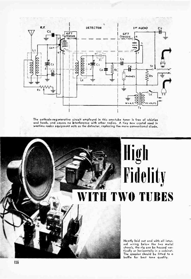
The cathode -regenerative circuit employed in this one -tube tuner is free of whistlesand howls, and causes no ilterference with other radios. A tiny new crystal used inwartime rodcr equipment acts as the detector, replacing the more conventional diode.
High
FidelityWITH TWO TUBES
Neotly laid out and with all inter-nal wiring below the two metalchassis, the rig can be housed ver-tically or horizontally in a cabinet.The speaker should be fitted to abaffle for best tone quality.
136

C.
dqR4 d
IT
2'1P AUDIO
, I it T NITGT/G1.-10 (PENTODE
SECTION)5
3
6
OC) C91+
RE.
R7
RECTIFIER
117N7GTG(DIODE SECTION)
Cu +1Cta
Cte
Cla T
PMSPEAKER
54C.)
115 VOLT'SAC
One stage of amplification is enough to drive a 12' speaker at comfortable volume,but a smaller unit can be used if preferred. When operating with a phonograph, theamplifier gives best results if coupled to a crystal pickup of the high -output type.
0
Dual -Purpose Tubes Provide Five Stages in Unusual Circuit
By WILLIAM NORTON
ACIIICUIT design that makes most ofthe components double up or perform
some extra function is largely responsiblefor the high quality of reception possiblewith this two -tube receive'. Each of thetubes actually contains two separate sec-tions within its glass envelope. and a Wal-born development replaces the detectortube, adding up to five stages in all
About the size of a small resistor. thenew part, XI in the diagram, is actually theold familiar crystal detector in a new dressEngineered for use in compact radar equip-ment. the midget crystal is now beingoffered to radio builders as a replacementfor all types of diode -detector circuits.Available with pkoail leads for wiring intothe set, it not only saves space but elimi-nates the need fora filament current, result-
ing in cook' operation %vitt' lie sacrifice-and possibly some gain-in performanceThe crystal is factory adjusted, and its cat swhisker' is imbedded in was for uniformshock -resistant service
Also contributing to the set's high fidelityis the use of an audio transformet. einployedhere in a somewhat tniciinventiiinal circuitThe transformer, T2, has a ratio nl :3.5 to Iand, as used with both B-plits and C -111'1 -firsleads soldered to the chassis. carries no platevoltage in its primary witalini4 This tends togive a flatter response curve-that is, moreuniform amplification of signal voltage andreproduction of the musical and voiceranges.
The elaborate filter circuit adds its shareto smooth performance. Output from thehalf -wave rectifier is first filtered throughthe heavy-duty choke. L:3, and electrolyticcondensers C11 and CI:3. It is then further
131

liS-Y. PLUG PHONES& SOCKET
3 -WAYPLUG & CABLE
The size of the metal chassis allowsample room for neat wiring. Note thetiny fixed crystal detector XI; it takesthe place of an extra tube, but is nolarger than a 1/2 -watt resistor.
Sa
PICKUP/
3 -WAY PLUGAND CABLE
,p,..T.W.S..1ffit". 2.-"it-Ptt
Note +he shielded wire used betweenthe grid of the I I7N7 and the volumecontrol, R5. The latter shunts thesecondary of the audio transformer.The feed -through switch, S4, can becombined with the potentiometer orreplaced by a separate panel switch.
Tuning and regeneration controls areboth placed on the front of the firstchassis. The regeneration control alsoacts as one of the two volume controls onthe radio. To align the set, adjust thetrimmers on top of CI. Ink the call lettersof local stations on the dial for easy ref-erence after you hove logged all of them.
PHONE c,LI JACKS R 3 -WAY PLUG
Large transformers and electrolyticcondensers contribute to the over-allefficiency and tone of the finishedreceiver. They olso give the set ahandsome, professional appearance.
138

filtered through R7 and C12. Tapped off thechoke, the voltage that reaches the plateof the 117N7 is higher than the one thatgets to the screen.
Fidelity of sound reproduction generallyrequires that the plate impedance of theoutput tube be matched to the impedanceof the speaker. This is done with an outputtransformer that has several taps in thesecondary winding. By selecting the rightones, any speaker can be matched to thetube through the simple trial -and -errorsystem of testing various taps until themost pleasing tone reproduction is obtained.There is enough power in this set to drivea 12" speaker, but if the full bass renditionof a large speaker is not required, an 8"or 10" unit may be used instead.
To make the tuner and audio amplifiersections independent of each other, twometal chassis blanks were used. The first2" by 7" by 11" unit contains the radio -frequency, detector, and first -audio stages;the other holds the second -audio amplifierand the rectifier. A black crackle finish onthe metal enhances the appearance of thework and lends a professional touch to theequipment. Used alone, the tuner will giveexcellent reception on headphones; alter-natively, the amplifier can be used witheither a microphone or a phonograph pick-up. Switches Si and S:3 allow individualoperation.
As only one stage of audio amplificationis provided for a phonograph, a high -outputpickup is needed to obtain high volume.For most satisfactory performance, one ofthe new crystal pickups with a signal out-put of about 4.5 volts should be used.
Air -core coils are used in the R.F. stage,but shielded iron -core coils may be substi-tuted if they are easier to obtain locally.The coils are tuned by a two -gang .000365-mfd. variable condenser against a dial thatcan be marked with the call letters of localstations. Dials of this type are furnished withseveral blanks so that new station letterscan be written in if the set is retuned ormoved to a new location.
Extremely stable regeneration, free ofwhistles, hoots, and howls, is provided bythe cathode -regenerative circuit, and con-trolled by R1. This type of regenerationboosts the power of the receiver but doesnot interfere with neighboring radios. Byusing external line switch S4, and a secondvolume control, R5, it is possible to leavethe regeneration control set at the point
where reception is best. No ground isneeded, but if one is used it should be con-nected to the chassis through a .1-mfd.,600 -volt condenser to prevent any possibilityof shorting the 115 -volt line. In some neigh-borhoods the receiver will give adequatevolume with a very small antenna, or evennone at all; in others anything from a 20'indoor line to an outdoor antenna of 100'or more may be needed.
Because this set is capable of qualitysound reproduction, it deserves a cabinetthat will help rather than hinder its tone.The speaker should be mounted on a baffle
LIST OF PARTS
R1: 50.000 -ohm potentiometer. with switch.R2. 13.3. R9: 100.000 ohms. watt.R5: 500.000 -ohm pot.R6: 600 ohms. 2 watts.R7: 500 ohms. 10 watts.Cl: .000365-mfd. two -gang tuning condenser.C2. C3. CS. C14: .1-mfd.. 600 volts.C4: .0002-mfd. mica.C5, C6: .05-mfd.. 600 volts.C7: 00025-mfd., mica.C9: 25-mfd.. 50 -volt electrolytic.C10: .003-mfd.. mica.CM C12: 8-mfd.. 450 -volt electrolytic.C13: 20-mfd.. 450 -volt electrolytic.Ll: Shielded air -core antenna coil.L2: Shielded air -core R.F. coil.L3: Shielded filter choke. 10 to 20 henries. 200
to 600 ohms.T1: Filament trans. 6.3 -volt. 1 -amp. second-
ary.T2: Shielded audio trans.. 3.5 to 1 ratio.T3: Output trans.. tapped secondary.X1 1N34 midget ci ystal detector.Sl. S3: S.P.D.T. toggle switches.S2: S.P.S.T. See Rl.S4: S.P.S.T.Tubes, sockets. P.M. speaker, dial, cable,
plugs, misc. hardware.
to prevent loss of low notes and an over-alltinny sound. The cabinet should be chosenwith an eye to the versatility of the twounits that make up the receiver. If you planto use a phonograph with the amplifier,some provision should be made to house it.The changeover switch, S3, may be movedif necessary to make it easily accessible out-side a closed cabinet. Similarly, the head-phone attachment on the tuner and switchSi may be shifted so that phones can beplugged in with the least difficulty. If theset is destined to remain in your workshop,the metal chassis can be mounted at anyangle on the walls or bench.
139

De lime Intim Portable
Rivals Console ill Tolleltd Ilenry C.DOBTABILITY in radios suggests the1 great outdoors, yet few manufactured re-ceivers allow for the different requirementsof out-of-door as against indoor listening.With the exception of more expensive mod-els, many commercial portables are eitherincapable of delivering comfortable outdoorvolume or else overload to the point of dis-tortion when they are turned up to an ade-quate level.
These Nvere the chief factors that xverekept in mind in the design of this portable.In tone it is equal to many large consoles,while the output level of undistorted volumeis high enough to flood a good-sized room.Even where surrounding noise would nor-mally drown out the sound of a radio, youwon't have to cock your ear to the loud-
speaker of this set. For all its power, it issmall enough in size and weight to be easilycarried on picnics, beach and boat trips,and the like.
Two 1S4 pentodes are wired in parallelin the output stage and matched to a lightpermanent -magnet speaker to produce theunusually good tone. The tubes feed intoa universal output transformer that has sev-eral taps on the voice -coil (or secondary)winding. A transformer with an input capa-ble of matching load impedances Up to4,000 ohms is desirable since that is thetheoretical resistance of two 1S4's in par-allel. In the original receiver the 2,000 -ohmtap was used because it produced the mostpleasing tone. The transformer matches thistube impedance to the voice -coil impedanceof the speaker which, in this case, is 4 to 6ohms. The speaker itself is one of the light -
140
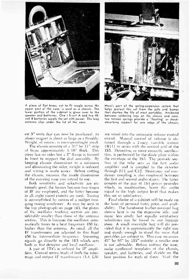
A piece of flat brass, cut to fit snugly across theupper part of the case, is used as a chassis. Thelower portion of the cabinet is given over to thespeoker and batteries. One 1.5 -volt A and two 45 -volt B batteries supply the set with power. The loopantenna slips under the lid of the case.
est 5" units that can now be purchased: itsalnico magnet is aboutWeight. of course. is correspondingly small.
The chassis consists of a :3!:J" by 11" stripof brass approximately 1.16" thick. Thispiece has no sides but a 2" flange is formedin front to support the dial assembly. Bykeeping chassis dimensions to a minmumnand eliminating the sides, weight is reducedand wiring is made easier. Before cuttingthe chassis, measure the inside dimensionsof the carrying case you intend to use.
Both sensitivity and selectivity are ex-tremely good. the former because two stagesof IF are employed, and the latter becausein all, eight tuned circuits are used. Timingis accomplished by means of a midget two -gang tuning condenser. As may be seen inthe top photograph on page 113. the platesof the oscillator tracking section are con-siderably smaller than those of the antennasection. This is because the oscillator auto-matically tunes to a beat frequency 456 kc.higher than the antenna. As usual. all theIF transformers are adjusted to this fixed456 ke. intermediate frequency. Incomingsiganls go directly to the 1115 which actsboth as first detector and local oscillator.
A pair of 1T4's is utilized for II' ampli-fiers. Ground return leads of both the inter -stage and output IF transformers (L4. L3)
Here's part of the spring -suspension system thathelps protect this set from the jolts and bumpsthat shorten the life of most portables. Anchoredbetween soldering lugs on the chassis and case.two tension springs provide a "floating" or shock -absorbing support for one edge of the chassis.
are wired into time automatic volume controlcircuit. Manual control of volumetained through a 1-meg. variable resistor(R11) in series with the control grid of the1S5. Detection, or more correctly rectifica-tion, is performed by the diode plate withinthe envelope of the 1S5. Time pentode sec-tion of the tube acts as the first audioamplifier and is coupled to the detectorthrough 1111 and C12. Resistance and con-denser coupling is also empltii.ti betweenthe first and second audio stagcs. The latterconsists of the pair of 1S4 power pentodeswhich, in combination, boost the audiosignal to the high output level that makesthis set so satisfactory.
Final choice of a cabinet will be made onthe basis of personal taste, price, and avail-ability. The handsome leather -covered bagshown here is on the expensive side. andmany less costly but equally satisfactorysubstitutes can be found in any luggagestore. A small overnight bag will do pro-vided that it is approximately the right sizeand sturdy enough to stand the wean thatportables are subject to. This ease measures4%" by 8%" by 11%" outside: a smaller oneis not advisable. Before cutting the case,make cardboard templates of the chassis,speaker, and batteries, and decide on thebest position for each of them. Marl: the
141

positions of the volume control and tuningshafts and the openings for the speaker anddial on the outside of the case. Score theleather with a sharp knife, drill the shaftholes, and cut or saw the circular speakerand dial apertures. The edges of the cutscan be concealed by suitable escutcheonplates.
Most overnight bags are fitted with mir-rors, and if yours has one it should be re-moved and the loop antenna slipped underthe cover lining. Instead of being mountedrigidly inside the case, the chassis is sprungto absorb jolts and shocks. Two solderinglugs are screwed to the top of the case andanother two lugs are bolted to the edge ofthe chassis. Behveen the anchor points thusformed, small tension springs are installedto support the rear edge. The front is heldonly by the shafts, which project throughthe face of the bag and are gripped by theknobs on the outside.
Since, in common with all portables, this
set is dependent entirely on its loop antennafor station pickup, it should not be expectedto perform any remarkable feats of long-distance reception. It will, however, easilypick up and separate all local stations, andits performance can be improved by usingthe antenna to best advantage. One way ofdoing this is to turn the set as you tune ituntil the position of the antenna favors thestation you are trying to get. Reception canalso be improved in many cases by leavingthe cover of the case slightly ajar. Mostloop antennas, in addition, have an extraconnection that permits the attachment ofan outside aerial when conditions permit.
In order to keep battery drain to a mini-mum, no pilot light was used in this circuit.This makes it all the more important thatyou remember to turn off the switch whenthe set is not in use. If you can't trust yourmemory, insert a 1.5 -volt .06 amp (60 ma.)pilot light behind the dial and wire it inparallel with the tube filaments.
LIST OF PARTSAll resistors watt carbon unless
otherwise noted.100,000 ohms.
112: 2 meg.113: 10,000 ohms.114: 2,000 ohms.115: 5,00(1 ohms.116, 119: 5 meg.117: 15,000 ohms.118: 1.000 ohms.
RIO: 3 meg.1111: 1 meg. with switch pot.1112: 10 meg.1113, 1114: 1 meg.1115: 180 ohms, I watt.CI: Two -gang tuning condenser.C2, C11: .1 -mfd., 450 -volt paper
tubular cond.C3, C13: .0001 mid. mica.C4, C5, C6, C7, C8. C9, C10,
C12, C15: .05-mfd., 450 -voltpaper tubular.
C14: .0002 mfd. mica.C16: .005-mfd.. 450 -volt paper
tubular.LI: Loop antenna.L2: iron -core oscillator coil.L3. L4. L5: input, interstage, and
output IF transformers.T1: Midget universal output
trans.SI: D.P.S.T. switch on 1111Speaker, tubes, case, tube sockets,
shields, batteries, hardware.
C to Re
142

Labeled photograph shows where major parts are placed on top of the chassis for most effective separation
Most of the wiring is done below the chassis. Use the new tiny resistors and condensers to save space.
155
4
R10
5
11111 MIMI MI
.11116
7 Ciz
R11
VOLUME
C13
812.
C14
1S4
=MNMN=
5
C15
R13
tiCHASSIS
.3
Aept.A. SPEAK ER
-9 ChfR14
I
R15I IS1 I
SWITCH
+90V.
-1.5V.
+1.5V.
143
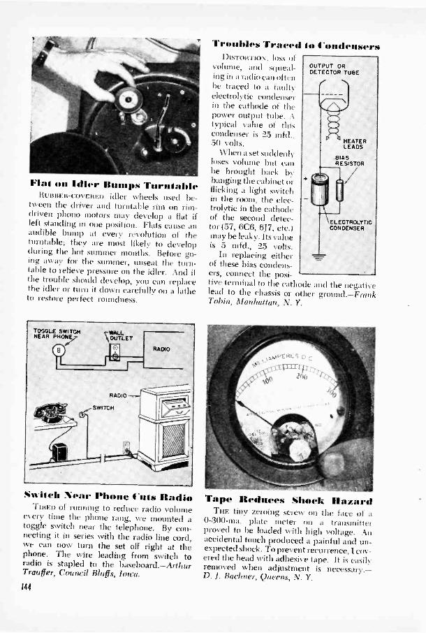
Flal on Idler Bumps TurnialoleIttiunEn-covERED idler wheels used be-
tween the driver and turntable rim on rim -driven phono motors may develop a flat ifleft standing in one position. Flats cause anaudible bump at every revolution of theturntable; they are most likely to developduring the hot summer months. Before go-ing away for the summer, unseat the turn-table to relieve pressure on the idler. And iithe trouble should develop, you can replacethe idler or turn it down carefully on a latheto restore perfect roundness.
Swilch Near Phone Cuts RadioTIRED of running to reduce radio volume
e. ery time the phone rang, we mounted atoggle switch near the telephone. By con-necting it in series with the radio line cord,we can now turn the set off right at thephone. The wire leading from switch toradio is stapled to the baseboard.-ArthurTrauffer, Council Bluffs, Iowa.
144
Troubles Traced i 41 4 'ondensersDIsiowrlo\. loss of
volume, and squeal-ing in a radio can oftenbe traced to a faultyelectrolytic condenserin the cathode of thepower output tube. Atypical value of thiscondenser is 25 mfd.,50 volts.
When a set suddenlyloses volume but canbe brought back bybanging the cabinet orflicking a light switchin the room, the elec-trolytic in the cathodeof the second detec-tor (57, 6C6, 6J7, etc.)may be leaky. Its valueis 5 mfd., 25 volts.
In replacing eitherof these bias condens-ers, connect the posi-tive terminal to the cath Kle and the negativelead to the chassis or other ground.-FrankTobin, Manhattan, N. Y.
OUTPUT ORDETECTOR TUBE
HEATERLEADS
BIASRESISTOR
\ ELECTROLYTICCONDENSER
Tape Reduces Shock HazardThe tiny zeroing screw on the face of a
0 -300 -ma. plate meter on a transmitterproved to be loaded with high voltage. Anaccidental touch produced a painful and un-expected shock. To prevent recurrence, I cov-ered the head with adhesive tape. It is easilyremoved when adjustment is necessary.-D. J. Bachner, Queens, N. Y.

llo's Radio
Leis !lad
No) His
Clinton E. Clark
EVERYONE in the .am..y will enjoy thislittle tv%o-tube headphone wt. Innioi
can listen to all the programs especiallymeant for him. and Pop and Momescape the nerve -shattering tominy gunsand thundering herds. Pretuning makesthings easy, for any young listener can turnon the switch and set the pointer knob tohis choice of three stations. A four -positionswitch and one extra trimmer would adaptthe set to cover all four major networks. Al-though the circuit is regenerative. prettm-ing eliminates the usual squeals.
Begin work on the chassis by drilling orpunching two 1%," holes for the tube sockets.Then drill holes for mounting the line -dropping resistor 1" in front of the I2j5CTtube. This resistor must be above thechassis because it creates considerable heat.
In the back of the chassis, drill three holes
rretime the .et with a neutralizing tool ora bakelite shaft ground to a screwdriver tip.
for the phone jacks and line cord, protectingthe latter with a rubber grommet. In thelimit, drill three evenly spaced holes for theswitch, pilot light, and regeneration control.Drill three corresponding holes in the panel,plus a fourth for the selector switch.
After the sockets, filter choke, andselenium rectifier line been mounted, thesubchassis wiring may be started, takingthe power -supply section first. If you havea meter, the DC voltage hen should testapproximately 100. Then install the fila-ment circuit, and determine the ,5 )-ohmsetting of the adjustable slide with all ohmmeter.
Mount two 1!.!" high standoff insulators:2" apart on the left rear of the chassis top.These support the coil mid tuning ca-pacitors, a soldering lug being used on thetop of each to .ittach a length of stiff wireto which the condensers art' soldered. Theother ends of the c(oidctiticl'S brought to
- ---mompummommimmigadlipintni.16.1011
Subehassis %iring is comp:mak cly simple.Test the various sections as con go along.
145
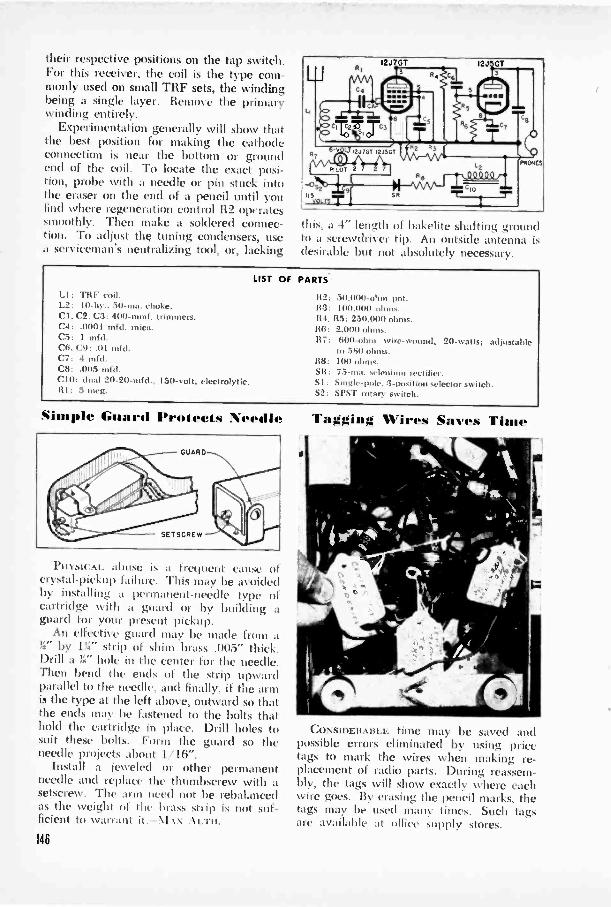
their respective positions on the tap switch.For this receiver, the coil is the type com-monly used on small TRF sets, the windingbeing a single layer. Remove the primarywinding entirely.
Experimentation generally will show thatthe best position for making the cathodeconnection is near the bottom or groundend of the coil. To locate the exact posi-tion, probe with a needle or pin stuck intothe eraser on the end of a pencil until youfind where regeneration control R2 operatessmoothly. Then make a soldered connec-tion. To adjust the tuning condensers, usea serviceman's neutralizing tool, or, lacking
12.17GT 124 GT
C4
6
Smos
LICA
c7773 if12.176T 12.1565 r
i, pHoN(s
fie_o.4:e
Us6
this, a 4" length of bakelite shafting groundto a screwdriver tip. An outside antenna isdesirable but not absolutely necessary.
LIST OF
LI: TRF coil.L2: 10 -he., 50 -ma. choke.Cl. C2. C3: 400-mmf. trimmers.C4: .0001 mfd. mica.C5: 1 mfd.C6, C9:.01 mfd.C7: 4 mktC8: .005 mfd.C10: dual 20-20-mfd.. 150 -volt. electrolytic.It
PARTS'
82: 50.000 -ohm pot.R3: 100.000 ohms.114, 85: 250,000 ohms.Rfi: 2,000 ohms.117: 600 -ohm wire -wound, 20 -watts; adjustable
to 580 ohms.118: 100 ohms.SR 75 ma. st ' rectifier.SI: Single -pole. 3 -position selector switch.S2: SPST rotary switch.
Simple Ii11:1111 PrO11.111% N4`4`IIII`
PHYSICAL abuse is a frequentcause ofcrystal -pickup failure. This may be avoidedby installing a permanent -needle type ofcartridge with a guard or by building aguard for your present pickup.
An effective guard may be made from aW' by strip of shim brass .005" thick.Drill a';," hole in the center for the needle.Then bend the ends of the strip upwardparallel to the needle, and finally, if the armis the type at the left above, outward so thatthe ends Illay be fastened to the bolts thathold the cartridge in place. Drill holes tosuit these bolts. Form the guard so theneedle projects about 1116".
Install a jeweled or other permanentneedle and replace the thumbscrew with asetscrew. The arm need not be rebalancedas the weight of the brass strip is not suf-ficient to warrant
146
Tagging iris SIMI'S Time
CONSIDERABLE IBM may be saved andpossible errors eliminated by using pricetags to mark the wires when making re-placement of radio parts. During reassem-bly, the tags will show exactly where eachwire goes. By erasing the pencil marks, thetags may be used many times. Such tagsare available at (Alive supply stores.
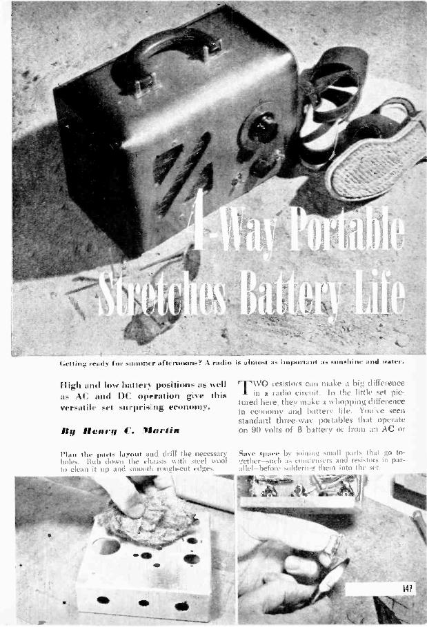
1.1;,41 har I ili11.1111041111s! 1 ra.liii Is .111111,4 .Is 1/,111.,11.111 ,is
Fligh and low batted positions as wellas AC and DC o..cration give thisversatile set -urpri - ng economy.
II II et; t ti 4 . 'Myriam
die parts layout and drill the necessaryHub down the eltaisis with steel wool
to clean it up and smooth rooglecut edges.
TWO resistors can make a big differencein a radio circuit. In the little set pic-
tured here, they make a whopping differencein economy and battery life. You've seenstandard three -rya: portables that iperateon 90 volts of B battery or from an AC or
dace .1 :we Itt ii ii small pail, 111a1 go to-.zeti h .1, 1 ,IWCIISCrS and 'I in
fore them int() thi .t
"114-- Lroitte5mit
IS

1U4
(LOOPANT)
1R52
ON si OFFO
115 VOLTS( AC- DC)
2
CHASSIS
1S55
TSR R5 . R9
1200 L 300
_1l2 C13(50)+ (30)+ c tom +
15
cia 3V4
0
5ThPEAK ER
-1KIV0
+90V
+7.5V
-7.5V0
All resistors 1:: -watt carbon unlessodic l'W iSV !TUC died.
111: 50.000 of .
112: 6.800 0111115113, 1112: 2.2 neg.lit. 117: 10 inett.113: 50 -ohm. 10-, att. wire-m.011ml.tut; mei:. potentiometer t 5o1 -
nine cuu.nd 1.118: 2.211(1 ohne119: 2.00-olim.10-watt wire -wound.li10: :3 meg.1111: I nog.111:3. 1511 obnr1114. 1.500-01iiii. 25-o all adjust-
able o ire -wound.
LIST OF PARTS1115: 2.500 ohms.Ic 16: 20 ohms.Cl A. B: Too -gang timing con-
denser with cut -plate sectionfor .133 Le. IF.
C2: i0 -noel. mica or ceramic.C.1. LI. C6. 01, (:10. (:1 I. (:1-1:
.0 1 -infil..21111-siilt initket paper.21111 -silt midget
paper.C7: 20-11,111.. I 50, alt electrol tie.C8: 1011- 1. unit a.C12. C1:3: 511-30-itild., 150 -volt
dual eiettroh .
C15: 100-m1(1., 50 -volt electro-lytic.
C16: .01-mfd.. 200 -volt midgetpaper.
SI: DPST snitch on 116.52: 1)I'l)T toggle.5:3: DPST toggle.Ti: Midget output trans. (see
test I.SR: 100 -ma. selenium rectifier.1,1: Loop1_2: Air -core ose. coil.
1F2: Iron -core tenuediate-frvquenc transformers.
Batteries ( 91) volts B: 71:: volts A I.5- I'M speaker, tubes, sockets,(minuet, hack panel, chassis.dial. tine cord and plug.
DC line. Another common design is the"personal" radio that generally uses a 67;: -volt battery to save spate. Compactness isachieved. but at the cost of lowered sensi-tivity and %ohmic.
Here, for the first time, both circuits areincorporated in one set. Indoors you'll runthis receiver off the house lines. When youget out of range of an extension cord, how-eer, you'll find that packaged power notoitl delivers the goods but does so at a con-siderable saving.
Thy whole trick is in the addition of twodropping resistors and an economy switch.Using 9(1 volts of B battery and 711 volts ofA, the receiver performs with maximumsensitivity and volume. That's fine for anoisy beach or hall park, or when you wantto listen to a far-off station. But most of thetime you call get away with less power with-out notienig the difference. Flicking a switchreduces the potential from 90 volts to about60. and from 7!; tilts to 6. Current drain
from the B battery is cut from IS milliam-peres to 7, while A current goes down from55 to 45 milliamperes.
All of this means long, long battery life,for even after the cells have run down by athird, the set will continue to give first-rateperformance if the economy switch is setup to maximum. To reduce battery drain,n15, a 2,500 -ohm resistor is inserted in theB -plus line, and 1116, a 20 -ohm unit, isplaced in thy filament lead. When full poweris needed. the DPST switch, S3, shorts outthe droppinit resistors.
A small 90 -volt battery was used in thisset in order to hold down size and weight.If you don't mind a slightly heavier pack-age, you can get even greater economy byusing two of the huskier 45 -volt batteriesin series.
Another feature of this set is a simplifiedrectifier circuit for 1C -13C operation. It con-sists of a 100 -ma. selenium rectifier, threeelectrolytic condensers, and three resistors.
148

Wire -wound resistor- Arc mounted outside thechassis for better heat dissipation. One machinescrew holds tile selenium rectifier.
One of the latter, R14, is a 1,500 -ohm, 25 -watt unit with an adjustable tap. Setting thetap varies the filament voltage. It shouldbe adjusted so that the tubes get about 7volts-or even slightly less-when the set isbeing operated on house current. For test-ing, fix the tap to give a division of about1,200 ohms to 300.
The balance of the circuit follows stand-ard practice pretty closely. There are fourminiature tubes in addition to the dry -diskrectifier, making this the equivalent of a five -tube superhet. The first tube, a 1R5, is apentagrid converter that acts as an RF am-plifier and local oscillator. The incomingsignal is tuned by one section of the two -gang tuning condenser, C1; the other gangtunes the oscillator. Try to buy a condenserthat has cut plates for the oscillator section,and built-in trimmers on both gangs.
The IF amplifier, a 1 U4, operates at thefixed frequency of 455-6 kc. Two IF trans-formers, tuned to the same frequency, arealso employed. Midget transformers withpowdered iron cores were selected as ironcores give higher gain. It makes relativelylittle difference whether fine adjustment ismade by means of air -spaced trimmers or bymoving the iron cores. The diagram indi-cates a movable -core transformer, but thetrimmer type may be more generally avail-able and will work as well.
The dual -electrolytic condenser projects partlybelow and partly abme the chassis. It is fas-tened on top by its noun -aim; collar.
A diode detector and pentode amplifierare combined in the 1S5. The former demod-ulates the RF signal, the latter acts as afirst audio amplifier. The 3V4 tube used inthe output stage is a relatively new develop-ment; it was selected because of its effective-ness in amplifying weak signals and bringingthem up to loudspeaker volume. Althoughthis tube has a plate impedance of 10,000ohms, it was found that an output trans-former with an 8,000 -ohm primary and 3.5to 4 -ohm secondary gave satisfactory match-ing. Transformers of the latter type aremore readily available in small sizes.
An aluminum chassis measuring 13i" by41i" by 5" provided ample space. Howeverit is always a good idea to assemble theparts for a set before finally determining thechassis size and arrangement. Aluminum isfirst choice for the chassis as it can be drilledand cut easily. Seven large holes had to bemade for the tube sockets, the dual -electro-lytic condenser, and the IF transformers.Socket holes are X" in diameter, those forpassing the IF leads through the chassis areV. The 50-30 dual electrolytic used hererequired a 13r hole in order to be mounted,as shown, partly above and partly below thechassis. If you don't have chassis punchesin the right sizes, drill smaller holes and fileor ream them to the required diameters.
Solid pushback wire is the easiest to use
149

also used to keep the batteries in place. Forit from sliding back in the cabinet. Cleats are carrying, a leather handle is screwed on top.A small wooden cleat behind the chassis keeps
for wiring the parts, and is suitable for allexcept the battery leads and those to R14.Cotton -covered stranded wire has the insidetrack for these connections where extra flexi-bility and current -handling capacity are im-portant. Note that R5, R9, and 1114 are allmounted above or outside the chassis. Thisis done because these resistors-all of thewife -wound type-generate more heat thancould be readily dissipated if they were con-fined under the chassis. They only comeinto operation when the set is used on a115 -volt line. Should they appear to gettoo hot, it might be well to open the backcover when the set is kept on for long.
.t d Nall is screwed to the side ofthe cabinet to pros ide an anchor for the AC-DCcord when the set is operated on batteries.
Although IF transformers are preset atthe factory, wiring them into a set maythrow them slightly out of adjustment. \\'henthe assembly is completed, tune in a stationat the high end of the broadcast band ( theplates of the tuning condenser are out ofmesh at the high end) and rock the trim-mers on the IF transformers Very slightlyto peak the signal. Use a small screwdriverfor this adjustment, or, preferably, an in-sulated tuning wand. Make any similar ad-justment that may be necessary on the trim-mer alongside the oscillator section of CI.Rock the tuning dial back and forth whileadjusting this trimmer, and then make afinal check on a station at the low end ofthe band.
An inexpensive solution to the cabinetproblem is to use one of the replacementcabinets for AC -DC receivers available atmany supply houses. It isn't likely that anyof them will come with carrying handles,but an attachable luggage handle takes careof that. Cut a plywood, plastic, or similarback to the proper size and hinge it to thecabinet along one edge. A loop antenna canbe fastened to the back with a couple ofscrews. The speaker is attached directly tothe front panel behind the grille, and thechassis is held by the two toggle switches,the volume control, and the tuning con-denser. if necessary, tack in wooden cleatsto keep the batteries from shifting insidethe box.
15C

Tape Shields %pea Ler 3 I a gamSiori.o you 1).1%,: to saw or file ci,ntrol
shafts or other metal parts of a radio whilemaking repairs or replaconents. see that nofilings are permitted to enter the speakerconc. where they may cause distortion :Indrattling. 1'4)11 can protect the speaker bykeeping a strip of adhesive tape mer theopening while you work.- I I. 1..v r
Markers flake "Tuning, EasierWEIR I I SPED bits
of cellulose tape makestation settings easy tolocate. Lettered withIndia ink and placed inappropriate spots on thedial, they help you tunein where the light ispoor without having toremember wavelengthsof favorite st;ttions.-C.E. II uines(.I
Iltra itl 1:roso tls .4)114111`11Ser
\ ()INN' Mill tIllIllIg is sometimesJosed by a poor connection between a t11) -
in J -condenser mint and ground. It is espe-cially common in portables where the con-denser has been !mantled on rubber toabsorb vibrations. A short piece of tinnedbraid soldered betw4 en the condenser frameand chassis cures %\K TOBIN.
Rine Shells Used as Wire CapsNE vi. ends for shield-
ed wire can be madefrom used .22 -cal. rifleshells. Drill or punch ahole in the end. slip theconductor through. andsolder the braid insidethe shell. Empty shellsare also Mehl] :as gridcaps. Spread or pinchthe side of the shell tofit.-II IcitAnn S ZED.
t. 52.2 -at .
TNT
ra Speaker 1'4,11% ell 114`444% el' 10 an 11114441111
TALK1 LISTEN
SPEAKER IN SET<=4
TO P1-10NOPLUG ON.SET
EXTRA OUTPUTTRANSFORMER
li.uno receivers hay ing sufficiently highandio gain will double as intercoms withthe addition of alt extra speaker and trans-former. A single wired connection to theremote speaker is sufficient. since the re-
(=.KZ>
PC)CZ*
k.
TALK
OUTPUTTRANSFORMERIN SET
LISTEN
TO REMOTESPEAKER
....
turn can be made to a common ground.When the switches are turned to "Talk." thespeakers act as microphones.. single DPDTswitch may he substituted for the two SPDTunits shown in the 1:.\\ -1,1.:S JONES.
151

Batter) Phonoltadio Portable
Built into a small carryingcase, this one -tube radio -phonograph can be playedanywhere. To suppress sur-face noises, close the lidwhile records ore playing.
P011 LABILITY' in a radio -phonographusually means little more than that the
unit is built into a carrying case and providedwith a handle. Such a set can be carriedaround easily um mgh, but can only beplayed where the right current is available.if v.al don't want to be tied down by the
er lines. and arc willing to sacrifice thecuiivenience of an electric motor for the ad-vantages of complete mobility, this one -tubecombination will reward you by playing any-where so long as it is supplied with batteriesand you remember to wind its spring -driventurntable motor.
The amplifier is a straightforward one -tube circuit in which the single tube-a11)8 GT-acts as a two -stage amplifier. Out-put from the pickup or from a fixed crystaldetector is fed into the grid of the triodesection which is resistance -capacity coupledto the power pentode. A variable 250,000 -ohm resistor between ground and the gridof the first audio stage acts as a volumecontrol for both the phonograph and radio.
Music where you like itwith this spring -driven,
battery -powered record
player and receiver.
By WILLIAM NORTON
Small as it is, the amplifier delivers enoughpower from the pickup to overload the 5"speaker.
Radio strength is not nearly as great, butlocal stations can be picked up with goodloudspeaker volume. An external antennaand ground will usually be required forclear reception.
The primary winding of a standardshielded antenna coil is connected to theantenna post and inductively coupled tothe secondary winding; capacitive couplingbetween the two coils is provided by Cl. aI 0-mml. air -spaced trimmer. The combina-tion of inductive and capacitive coupling in-creases selectivity without sacrificing volume.
For the tuning condenser, C2, a midget360-mmf. variable capacitor was used. gmalldimensions for this part arc important if thecondenser is to clear the speaker frame whenthe chassis is mounted in the cabinet.
The signal taken from the plate of thepower pentode is matched to the speakerthrough a midget universal output trans-
152

The chassis is a 6" by 6" metalsheet bent to conform with theslope of the wood panel. Thecabinet is covered with artifi-cial leather both inside and out.
former. Taps on the secondary winding ofthe transformer permit selection of the mostpleasing tone.
An automatic bias circuit consisting of R4and C6 makes it unnec-essary to carry a sepa-rate -C. battery to biasthe grid of the pentode.Bias voltage is takenfrom t I e drop acrossthe till() -ohm resistor.
TAN o midget 67z -volt-13- batteries are con-nected in series to givea total of 135 plate volts,but anything from thatdown to 90 volts wouldserve. Higher plate olt-age, of course, giveshigher volume output,but for most purposesthe lower voltage willbe sufficient. A B. -volt"A" battery supplies the
This one -tube circuit actuallyincludes a two -stage amplifierfed either by the pickup or bythe tuned circuit and detector.parts ore keyed to the list athe bottom of the next page.
TOGGLE -SWITCHNUT HOLDS PANEL
TO CHASSIS
Wiring must be kept reasonably compact, but if small parts are used, nospecial crowding is necessary. Note the small 360-mmf. tuning condenser,and the miniature fixed crystal detector on its right.
153

Af right, on insideview of the case withthe phonograph mo-tor board removed.Note the position ofthe batteries, whichare clomped clearof the motor.
The control panel isshown below in closeup. The knob on theleft governs RI andS2, the volume con-trol and switch. Tokeep from drainingbatteries, turn offthe switch when theset is not in use.
tube's (flail wilt. The entire chassiS is mountedon a (i" 0" steel sheet \\hieh is lwiit to fitbelow and in flout of the control panel. Tomount the chassis to the pa tiel bolt thetoggle sN itch through both pieces, as shownin the draw in, on ;)age 1.5:3. Follow thesaint' procydure itli the antenna andgroin id jacks.
l'hotiograpli case!, are nov available in at
vide selection of allracliye 11114,;1!2:eand you eau almost certainly find one to suityour taste a511(1 price. One factor that mustbe taken into account is the size of the rec-ords that von intend to play. ()lily 10"recortls can be played on the model shownhere, awl a larger case Will IR' nce(led it31011 \\ alit your conil)iiiation to handle 12"(lisks as well.
Single spring phonograph motors requireabout 50 turns for a lull \vim]. atoll Theythen play two 10" -record sides. 1)ou't over-wind the motor c.r th:p force in it.
Bearings should be oiled occasionally, andthe gear teeth lubricated vith petroleumjelly .iboot once a year.
If the motor has a speed rel ulator. set thepointer at 80, ur I I lidWily hetWeril "S'. and
Accurate aditisnueni of Willi:dill' SpeedWay he Made With St I I tilt 1,:c1 pk record. hotif you dont have one of these, insert a slipof paper between the turntable and a recordso that it projects at one point. Then countthe number of times the paper passes agiven spot in a minute. Increase or decreasethe speed until you get a count of 80 r.p.m.Actual playing speed, allowing for the weightof the pickup on the record, will then bevery close to 78 r.p.m., the speed for whichmany popular recordings are cut.
LIST OF PARTS
CI:C2:C:1:C4:
C:6.;
It'_:
It l.5I:52. 11 5.T. itt It tat *ohm.. kinttrtil.\ I \ I ftt II t 55551 II,I I I 2 I,' t5tt seta toil.I \ I t
5 t 55. 5tittet..t sound motor. batteries,
5511, t. dial. knob:, elf.
1111-ifittif. :tir-paced trimmer.:160,151111. tititket l,ui im5 ettittletiser.
.111-,ohl.. 6110 coil,.
.02-iiiiti.,elt etritl tie.
2511.(titti-elitit stiltittle control, with switch.s1
I att ,m.boil..1 earth'',
httti .51, .5 2 ,..11 LahintI',I). I .1.. with Ime.?: neck.
154

Dry -Disk
RECTIFIERREPLACES
BURNED -OUT TUBES
If the re:tifier stock doesn't fit conveniently beneaththe chassis, solder two extension leads to its te-minalsand install the disk over the empty tube socket.
PRACTICALLYall commonly used recti-
fier tubes are now replaceable by dry -disk selenium rectifiers. They not only takethe place of hard -to -get tubes, but are alsosmaller, cooler and quicker in operation (be-cause they have no filaments to warm up),and they won't burn out or break underconditions that generally damage tubes.
Details of the replacement vary from setto set; the diagrams on this page show twotypical installations. One involves a 35Z5tube and the other a 117Z6. In the formercase tube filaments are in series, requiringa 200 -ohm, 5- to 10 -watt resistor to be in-serted in the line to provide continuity forthe other heaters. Since the pilot light isgenerally operated off the center tap of the35Z5, some changes are called for in thatcircuit as %veil. One of the simpler solutionsto the pilot -light problem is shown at theupper left. The original pilot connectionsare shunted, and a 115 -volt bulb is connect-ed between the cold side of the powerswitch and the old tube's plate prong.
Where a tube of the 117 -volt type is be-ing replaced, a series resistor of between25 and 100 ohms is needed (as shown in thebottom drawing) to compensate for the low-er internal resistance of the dry disk. Thefilament connections, however, may be re-moved without affecting the other tubes.
155
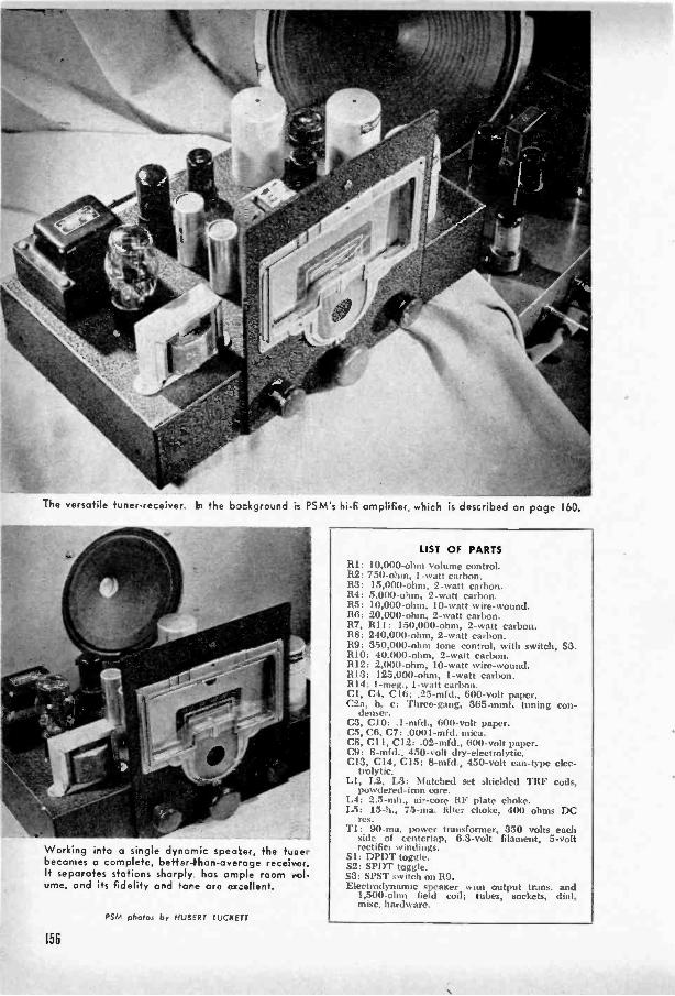
-he versatile tuner -receiver bi the 63:Aground is FSM's hi-fi amplifier, which is described on page 160.
Working into a single dynamic spea:er, the tune -becomes a complete, better-than-aveage receiver.It separates stations sharply, has ample room vol-ume, and its fidelity and tore are ex:ellent.
PSM photos by HUBERT LUCPETT
LIST OF PARTSRI: 10,000 -ohm volume control.R2: 750 -ohm, 1 -watt carbon.R3: 15,000 -ohm, 2 -watt carbon.R4: 5,000 -ohm, 2 -watt carbon.R5: 10,000 -ohm, 10 -watt wire -wound.R6: 20,000 -ohm, 2 -watt carbon.R7, RI I: 150,000 -ohm, 2 -watt carbon.R8: 240,000 -ohm, 2 -watt carbon.119: 350,000 -ohm tone control, with switch, S3.RIO: 40,000 -ohm, 2 -watt carbon.R12: 2,000 -ohm, 10 -watt wire -wound.1113: 125,000 -ohm, 1 -watt carbon.1114: 1-meg., 1 -watt carbon.CI, C4, C16: .25-mfd., 600 -volt paper,C2a, h, c: Three -gang, 365-mmf. tuning con-
denser.C3, CIO: .I-mfd., 600 -volt paper.C5, C6, C7: .0001-mfd. mica.C8, C11, C12: .02-mfd., 600 -volt paper.C9: 8-mfd., 450 -volt dry -electrolytic.C13, C14, C15: 8-mfd., 450 -volt can -type elec-
trolytic.LI, L2, L3: Matched set shielded TRF coils,
powdered -iron core.L4: 2.5-mh., air -core RF plate choke.L5: 15-h., 75 -ma. filter choke, 400 ohms DC
res.T1: 90 -ma. power transformer, 350 volts each
side of centertap, 6.3 -volt filament, 5 -voltrectifier windings.
Si: DPDT toggle.S2: SPDT toggle.S3: SPST switch on 119.Electrodynamic speaKer won output trans. and
1,500 -ohm field coil; tubes, sockets, dial,misc. hardware.
156
Tone In 011 High FidelityThis Till' unit can he used with an
amplifier or as a self-sufficient high-
qualit radio receiver.
By Edward Blanton
COLA D systems, like chains, are only as"..3 good as their weakest parts. Here is areally strong beginning for that high -quality,high-fidelity system you've been planningto build-a tuner or receiver that will giveyou perfect, undistorted reception of everynote sent out on the air by your localbroadcasting stations. The set pictured atthe left is a complete radio receiver. Usedalone, it will give excellent frequency cover-age and ample room volume. It may alsobe used with an amplifier as part of a morepowerful and elaborate setup. The follow-ing article gives a circuit for an amplifierthat will do full justice to the pure soundof this tuner.
But before you start, note the phrase"local broadcasting stations." A tuned radiofrequency (TRF) circuit such as is em-ployed here allows the full signal to comethrough to the detector stage. It does nothave the tendency of the superheterodyneto clip the side bands of broadcast signals,often eliminating the high -frequency re-sponse. The disadvantage of TRF is thatit lacks the ability to pull in and sharplyseparate distant stations. What this addsup to is simply that this tuner is recom-mended for those who live in or near metro-politan areas and who do most of theirlistening to nearby transmitters. For remote,rural listeners, a superhet tuner will provemore advantageous. However, if the sta-tions are close by, you needn't worry aboutthe selectivity of this set. Its three tunedcircuits give plenty of separation betweenstations even in radio -crowded areas.
Primary and secondary windings of theantenna and RF coils are inductivelycoupled, and, in addition. the windings ofthe two RF coils are coupled through small -capacity condensers built into the units.This construction allows a flat band of
frequencies to pass through to the detectorstage. All coils are shielded.
To do justice to the lull -frequency re-sponse, an infinite -impedance detector cir-cuit is employed. As can be seen in thediagram, the output from the 6SF5 detectoris taken from the cathode rather than theplate of the tube. This design, better knownas a cathode follower, requires no plate by-pass condensers, which usually dampen thehigh notes; linearity of such a detector isstraight from the lowest to the highest tones.
But again, the increase in fidelity is notachieved without cost. While a cathodefollower passes a signal faithfully, it addsnothing to its strength, and another stageof amplification is therefore needed. Thisstage is built around the 6V6-GT.
When the set is connected as 'an inde-pendent receiver, the 6V6 acts as a pentode.Flicking two switches changes the unit toa tuner and modifies the tube connectionsto those of a triode. This reduces the out-put, all of which is not now needed, andwhich might overload the amplifier. As areceiver, provision is made for the use ofa dynamic speaker with a 1,500 -ohm field.In order to change over to tuner position,it is necessary to make contact across thefield -coil terminals and also to achieve acompensating voltage drop. This is accom-plished by R12 and S2 when the latter isin position B. Still another change is need-ed: when the set is used as a receiver,two terminals of the four -prong speakersocket are connected to the output trans-former of the dynamic speaker. As a tunerthe set feeds directly into an amplifier, sothe transformer terminals must he shortedto complete the circuit. The shorting con-nection is made by a jumper plog (indi-cated by the broken lines in the socketdiagram) in which the corresponding prongshave been wired together.
In order to keep the unit self-sufficient,separate power supply and filter systemsare employed in this tuner and the forth-coming amplifier. This results in slightlyhigher parts cost but makes the units com-pletely independent for all future uses.
Layout isn't critical, but you will note
151
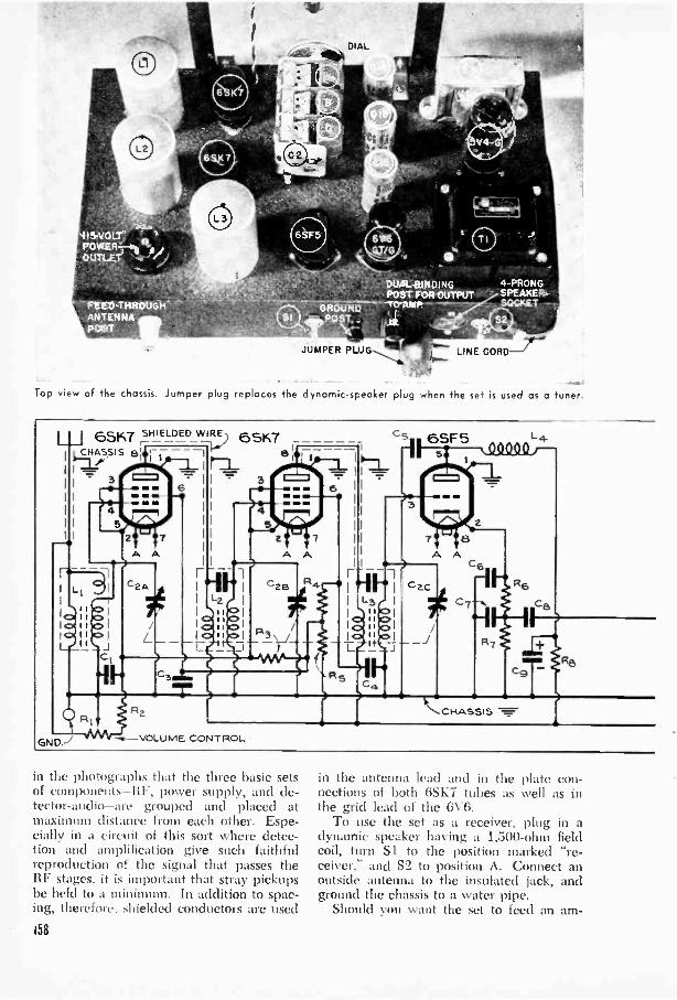
DIAL/4/E,
DUAL BINDINGPOST FOR OUTPUT
JUMPER PLUGS LINE CORD
Top view of the chassis. Jumper plug replaces the dynamic -speaker plug when the set is used as a tuner.
I I
65K7 swamp TFt) 6stc-T
wm.11111
GND. -..--VOLUME CONTROL
86SF 5 L4_
Q9000 f-
CHASSIS
in the photographs that the three basic setsof components-RF, power supply, and de-tector-audio-are grouped and placed atmaximum distance from each other. Espe-cially in a circuit of this sort where detec-tion and amplification give such faithfulreproduction of the signal that passes theRF stages, it is important that stray pickupsbe held to a minimum. In addition to spac-ing, therefore, shielded conductors are used
158
in the antenna lead and in the plate con-nections of both GSK7 tubes as well as inthe grid lead of the 6V6.
To use the set as a receiver, plug in adynamic speaker having a 1,500 -ohm fieldcoil, turn Si to the position marked "re-ceiver," and S2 to position A. Connect anoutside antenna to the insulated jack, andground the chassis to a water pipe.
Should you want the set to feed an am-
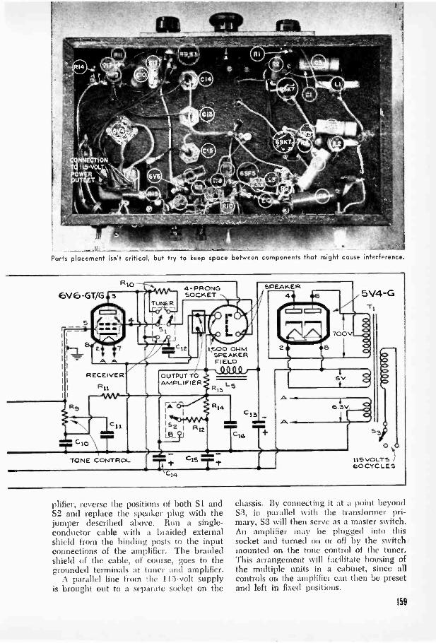
Parts placement isn't critical, but try to keep space between components that might cause interference
Rg
ci,
T cl° TTONE CONTROL
4 -PRONGSOCKET
OUTPUT TOAMPLIFIER
Cis
100 01-1MSPEAKERFIELD00 0 0 /-
13
R14
L 5
C13men sem
Tie Tt
SPEAKER4 5V4 -G
71
700V
6.3V
0 41
113 VOLTS )eo CYCLES
plifier, reverse the positions of both Si andS2 and replace the speaker plug with thejumper described above. Run a single -conductor cable with a braided externalshield from the binding posts to the inputconnections of the amplifier. The braidedshield of the cable, of course, goes to thegrounded terminals at tuner and amplifier.
A parallel line from the 115 -volt supplyis brought out to a separate socket on the
chassis. By connecting it at a point beyondS3, in parallel with the transformer pri-mary, S3 will then serve as a master switch.An amplifier may be plugged into thissocket and turned on or off by the switchmounted on the tone control of the tuner.This arrangement will facilitate housing ofthe multiple units in a cabinet, since allcontrols on the amplifier can then be presetand left in fixed positions.
159

Hi-Fi Amplifier GetsALL the MusicIt has power and quality, and will
faithfully reproduce the output of
pickup, mike, or radio tuner.
Hy Harry H. flutterMANY amplifiers claim the flattering
title of high fidelity, but relativelyfew satisfy the major requirements
of accurate record reproduction. It is true,of course, that there is a good deal of argu-ment as to just what is meant by the term,but all definitions agree on at least twothings.
Minimum Distortion
The first requirement is low distortion.This means that each stage must have a re-serve of gain so that it is worked well with-in its maximum ratings at all volume levels.Tubes and other components tend to distorta signal when driven at or near their theo-retical limits. While the reserve is importantfor all parts of an amplifier, it is particularlyneeded in the power -output stage. For goodvolume in an average room, only one wattof power is required, but occasional soundpeaks may call for several times as much,and the amplifier should be able to deliverthese peaks faithfully and without over-loading. A high-fidelity amplifier, then,needs at least five watts of undistorted out-put power.
Frequency Coverage
Wide frequency range is the second im-portant requirement. Practically all funda-mental musical notes are below .5,000 cyclesper second, but the overtones-the harmonicsor multiples of the fundamental-that givemusical instruments their characteristicsounds extend beyond the range of the hu-man ear to about 15,000 cycles. At the pres-ent state of the recording art, the highestaudio frequencies cannot be put on commer-cial disks, but the best new records exceed10,000 cycles, and your amplifier should becapable of reaching this level without anyfalling off in output. At the lower end, the
160
limit is set at about 50 cycles. Good bassreproduction, however, is easier to achievethan good treble.
Test Results
How does this amplifier meet high-fidelityrequirements? Actual tests were made onseveral units built from the same plans withsimilar but not identical parts. In each casethe output was measured at 9 watts or morebefore distortion became audible; at 5 wattsdistortion read less than 2 percent. Fre-quency response proved virtually flat from50 to 10,000 cycles-that is, all notes be-tween these limits were amplified aboutequally.
Because the amplifier has power as wellas quality, it can be used not only with aradio tuner and record player as a completeradio -phonograph combination, but also witha microphone to make a public-address sys-tem.
Construction Notes
The first, or phono-input terminal, 11, isfollowed by an equalizing network, R1 andC1, and then by a 6SJ7 input amplifier.When this tube is wired as a pentode, thegain of the stage is more than 100. Sincethis is much greater than will normally beneeded, an alternative circuit is given in thedrawing. Tying screen and suppressor gridsto the plate changes the tube to triode oper-ation, and makes it possible to omit severalcomponents. As a rule, triodes give loweroutput than pentodes, but also have lesstendency to produce distortion. Unless youintend to use the amplifier for public address,you will find the triode circuit completelysatisfactory. To find where the wires go,simply lay the shaded portion of the dia-gram over that part of the original which isdrawn inside the broken -line box, so that theconnections V, Y, and Z coincide.
For the second stage a 6N7 is used as aphase inverter in a self -balancing degenera-tive circuit. Part of the output of the firsttriode inside the tube envelope is fed backto the grid of the second triode in oppositephase to the original signal. This producesthe out -of -phase signals that are fed to the

These three uni-s and a carryinc case in which the spec ker is baffled make a complete portable PA system.
push-pull grids of the 6F6s- Strong signalsfrom a microphone or tuner may be fed di-rectly to the 6N7 through input terminal 12,thus by-passing the equaliz.ng network andfirst amplifier as well as tl e volume (R2)and tone (R7) controls. Since microphonesand tuners vury, try both inputs and usethe one that gives best results.
Tone control, in itself, is usually a com-promise with high fidelity. k condenser andvariable resistor silence ipper-frequencynoise merely by shunting flese frequenciesto ground. Fut while this gets rid of thenoise, it also loses the notes vith which it ismingled. Many high-fidelitN enthusiasts feelthat a small a Mount of 'lois( is preferable totone-controlle:l music. To s itisfy both sidesof the argument, R7 has been connected di-rectly to switch Si, making t possible to cutit out of the circuit entirely.
Two 6F6s in push-pull form the heart ofthe power -output stage. They are connectedas triodes in the interest of low distortionand high speaker damping. A 513-GT isused as the full -wave rectifier in the power -supply circuit.
The entire amplifier is mounted on astandard 2" by 7" by 13" metal chassis. Ascan be seen in the photographs, the space isnot used tightly and a smaller chassis may besubstituted if cabinet dimensions demand it.Power -supply components are placed at oneend and the input stage at the other, whilethe phase inverter, output tubes, and outputtransformer occupy the center of the chassis.The principal precaution to be observed inwiring is to keep the AC filament leadsspaced as far as possible from the grid leads,especially in the sensitive input stage. It isalso suggested that the 6SJ7 socket be
161
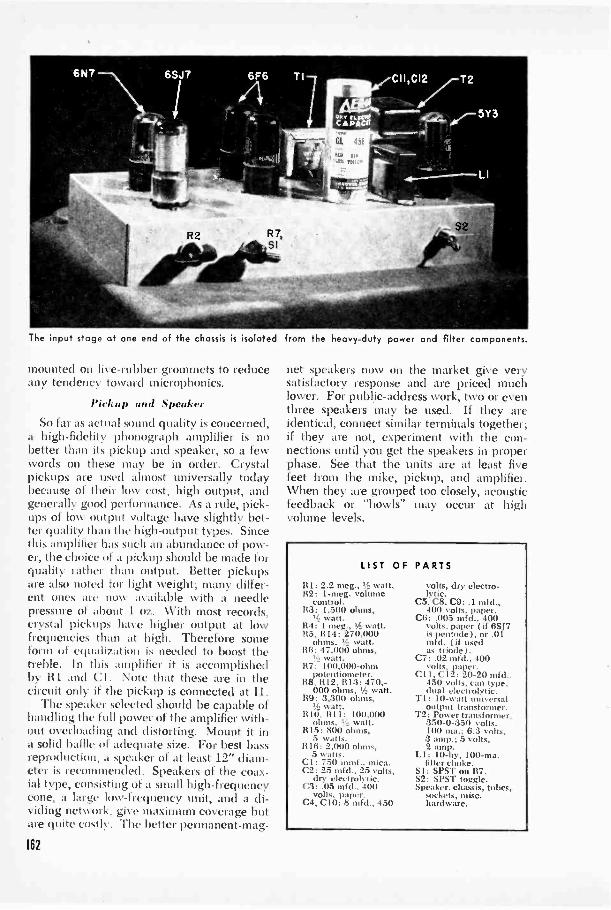
The input stage at one end of the chassis is isolated
mounted on live -rubber grommets to reduceany tendency toward microphonics.
Pickup and SpeakerSo far as actual sound quality is concerned,
a high-fidelity phonograph amplifier is nobetter than its pickup and speaker, so a fewwords on these may be in order. Crystalpickups are used almost universally todaybecause of their low cost, high output, andgenerally good performance. As a rule, pick-ups of low output voltage have slightly bet-ter quality than the high -output types. Sincethis amplifier has such an abundance of pow-er, the choice of a pickup should be made forquality rather than output. Better pickupsare also noted for light weight; many differ-ent ones are now available with a needlepressure of about 1 oz. With most records,crystal pickups have higher output at lowfrequencies than at high. Therefore someform of equali/ation is needed to boost thetreble. In this amplifier it is accomplishedby RI and (:I . Note that these are in thecircuit only if the pickup is connected at 11.
The speaker selected should be capable ofhandling the full power of the amplifier with-out overloading and distorting. Mount it ina solid baffle of adequate size. For best bassreproduction, a speaker of at least 12" diam-eter is recommended. Speakers of the coax-ial type, consisting of a small high -frequencycone, a large low -frequency unit, and a di-viding network, give maximum coverage butare quite costly. The better permanent-mag-
162
from the heavy-duty power and filter components.
net speakers now on the market give verysatisfactory response and are priced muchlower. For public-address work, two or eventhree speakers may be used. If they areidentical, connect similar terminals together;if they are not, experiment with the con-nections until you get the speakers in properphase. See that the units are at least fivefeet from the mike, pickup, and amplifier.When they are grouped too closely, acousticfeedback or "howls" may occur at highvolume levels.
LIST OF
R I: 2.2 meg., watt.82: 1-meg. volume
control.It :3 : 1,500 ohms,
watt.R4: 1 meg., tk. watt.1t3, R14: 270,000
ohms, watt.ISO: 47.000 ohms,
watt.li7: 100,000 -ohm
potentiometer.148: 1112. 1113: 470,-
000 ohms, Y2 watt.119: 3,300 ohms,
1,t: watt.It 10, 1111: 100.000
ohms, L! watt.R15: 800 ohms,
5 watts.1116: 2,000 ohms,
5 watts.Cl: 750 mud., mica.C2: 25 mfd., 25 volts,
dry electrolytic.03:.05 mfd., 400
volts, paper.C4, CIO: 8 mfd., 450
PARTS
volts, dry electro-lytic.
C5, C8, C9: .1 mfd.,401) volts, paper.
C6:.005 mfd.. 400volts. paper ( if 6517is pentode), or .01mfd. ( if usedas triode).
C7: .02 mfd., 400volts, paper.
Cl I, C12.: 20-20 mfd..450 volts, can type.dual electrolytic.
T1: 10 -watt universaloutput transformer.
T2: Power transformer,350-0-3.50 volts,10(1 ma.; 6.3 volts,3 amp.; 5 volts,2 amp.
LI: 10-hy. 100 -ma.filter choke.
SI: SPST on Ft7.S2: SPST toggle.Speaker. chassis, tubes,
sockets, misc.hardware.

Above, the 6517 amplif er is wired as a triode, and C3, C4, R4, and R5 have been omitted from the circuit.
12
PICKUP L ---:),%.7.6t47CRYSTAL
-7
Rt
Ft 3
1741 -C
C5
L -x
TRIODE ZCONNECTIONS
7 RG
5 6
CoiYt
6F6
E
+ CI
Two input circuits make it possible to leave both pickup and tuner permanently connected to the amplifier
163
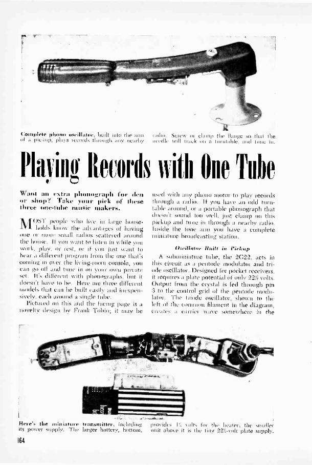
Complete phone oscillator, built into the armof a pickup. play, records through any nearby
radio. Scrcv or clamp the flatelx .so that theneedle will track no a turittal)1,. .1 (I tone in.
PIOT Records iiith One TitheWant an extra phonograph for denor shop? 'rake your pick of thesethree one-lulw music makers.
MOST people who live in largeholds know the advantages of
one or more small radios scattered
house -havingaround
the house. If you want to listen in while youwork, play. Or rest, or if )1)11 just want tohear a different program front the one that'scoming in Over the living -room console, youcan go off and tune in on your own privateset. It's different with phonographs, but itdoesn't have to be. Here are three differentmodels that can be built easily and inexpen-sively, each around a single tube.
Pictured on this and the facing page is anovelty design by Frank Tobin; it may be
r
Here's the miniature transmitter. includingits power supply. The larger battery, bottom,
used with any pbotio motor to play recordsthrough a radio. if you have an odd turn-table around, or a portable phonograph thatdoesn't sound too well, just clamp on thispickup and tune in through a nearby radio.Inside the tone arm you have a completeminiature broadcasting station.
lIseillaim Built in PickupA subminiature tube, the 2G22, acts in
this circuit as a pentode modulator and tri-ode oscillator. Designed for pocket receivers,it requires a plate potential of only 223i volts.Output from the crystal is fed through pin:3 to the control grid of the pentode modu-lator. The triode oscillator, shown to theleft of the common filament in the diagram,creates a carrier wave somewhere in the
provides 1!2 5ults for the heater; the smallerunit above it is the tiny 22Y2 -volt plate supply.
164

broadcast band. "Phis k, a \ c, illOdii.atud bythe output of the crystal. is radiated to anearby receiver and there tuned in as if itwere a regular broadcast signal.
Across the crystal cartridge is soldered alc -watt 20,000 -ohm carbon resistor. Thisrelatively low value was found to be neces-sary because the output of the crystal wasso great that it overmodulated the tube andcaused considerable distortion. Dependingupon the pickup used, you may find thatyou get better results with a higher or lowerresistor value.
No socket is required for the tube sinceit is small and light enough to be supportedby its own wiring. Place it directly behindthe crystal cartridge, and make sure that itdoes not touch either the cartridge or thesides of the arm, since needle vibrationmight cause the tube to become micro -phonic. Tuning of the transmitter is ac-complished by C2 and the secondary. orgrid -to -ground. winding of LI. The formeris a small padder condenser with a range ofapproximately :300 to 1,000 mmf., and thelatter is a standard midget iron -core antennacoil. mounted directly behind the tube.
Oscillation within the tube is developedby the feedback coupling between the two%%incline's of the coil. Just to preclude thepossibility of any wiring touching the metalof the arm, line the inside it I: two or threelayers of cellulose tape before you start.
The padder is mounted through a holein the arm so that the capacity -adjustmentscrew is accessible through the top. Thisallows you to vary the frequency until thesignal comes in at a blank spot on the radiodial. For the antenna lead, use a 20' hankof wire. Bring it close to the antenna lead-inof the radio, but do not connect them elec-trically.
Strip Amplifier
For beginners in electronics, Homer L.Davidson has worked out this one -eveningproject. You'll be surprised at the resultsyou Call ,et from a pint-sized amplifier thatuses only five condensers and four resistors.yet gives you independent control of bothvolume and tone.
Again the tube selected serves a dualpurpose. The 117L7-GT is both amplifierand power rectifier. Constructed on a thinstrip of composition board, the amplifier canbe mounted in any position inside the boxthat houses the phono motor and turntable.First drill a 1!;," hole to receive the octal
1 painted radio chassis holds the pho..ii motorand batteries; the rest is under the tone arm.
5
2G22
1.5 0RED MARKING
IC2
LGRE ENI r RED
sn IIall
-=" II:I ,+
BLACK BLJE-
CRYSTALCARTRIDGE PICKUP ARM
EP
22 5 VOLT0
05 \OLT
co --- 0+
LIST OF PARTS
RI: 20.000 -ohm, !-watt carbon.
II:2: 150.000 -ohm, !::!-watt carbon.
CI: 100-mml.
C2: 30() to 1,000-mml padder.
L1: Unshielded iron -core antenna coil.
Si: SPST toggle (or DPST to connectphono motor simultaneon.ly
Crystal pickup. 2C22 subminiabire tube.20' hank of antenna wire, 22!:,-Nolt Bbattery. IY2-volt A battery, mkt.. hard-ware.
165
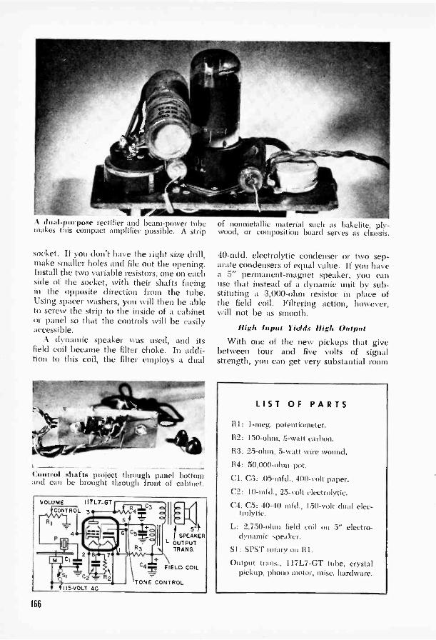
A dual-purpose rectifier and beam -power tubemakes this compact amplifier possible. A strip
socket. If you don't have the right size drill,make smaller holes and file out the opening.Install the two variable resistors, one on eachside of the socket, with their shafts facingin the opposite direction from the tube.Using spacer washers, you will then be ableto screw the strip to the inside of a cabinetor panel so that the controls will be easilyaccessible.
A dynamic speaker was used, and itsfield coil became the filter choke. In addi-tion to this coil, the filter employs a dual
Control shafts project through panel bottomand can be brought through front of cabinet.
VOLUME 117L7-GTCONTROL 3
I15 -VOLT
11KSPEAKER
L OUTPUTTRANS.
C4= FIELD COIL
TONE CONTROL
of nonmetallic material such as bakelite, ply-wood, or composition board serves as chassis.
40-mfd. electrolytic condenser or two sep-arate condensers of equal value. If you havea 5" permanent -magnet speaker, you canuse that instead of a dynamic unit by sub-stituting a 3,000 -ohm resistor in place ofthe field coil. Filtering action, however,will not be as smooth.
High Input Yields High OutputWith one of the new pickups that give
between four and five volts of signalstrength, you can get very substantial room
LIST OF PARTS
RI: 1-ineg. potentiometer.
R2: 150 -ohm, is -watt carbon.
R3: 25 -ohm, 5 -watt wire wound.
R4: 50,000 -ohm pot.
Cl, C3: .05-mfd., 400 -volt paper.
C2: 10-mfd., 25 -volt electrolytic.
C4, C5: 40-40 mfd., 150 -volt dual elec-trolytic.
L: 2,750 -ohm field coil on 5" electro-dynamic speaker.
SI: SPST rotary on RI.
Output trans., 117L7-GT tube, crystalpickup. phono motor, misc. hardware.
166

A simple cabinet, made of composition board, Posit' of components is optional. Drill onecompletes this one -evening phonograph project. or two holes under turntable for ventilation.
volume from this one -tube amplifier built byClinton E. Clark. As shown in the diagramat the right, the output of the crystal is feddirectly to the control grid of a 50L6-GTbeam -power pentode. Filament voltage forthe tube is taken from the 115 -volt linethrough dropping resistor 113, and in placeof a separate rectifier tube, a new seleniumstack is used in the power supply. The cabi-net is built up from composition board.
Assemble the parts on an aluminum orsteel chassis about 5" by 6". All groundconnections in the unit shown were broughtto a single point on a terminal strip, but thechassis can be used for ground if that shouldprove more convenient. Either way, groundis connected to one side of the 115 -volt line.The yellow or black terminal of the rectifiergoes to one side of the line switch. SI; thered side to the input of filter choke L.
When you have determined the positionof the chassis but have not vet mounted itin the cabinet. drill one or two ventilationholes to carry off the beat generated in thetube. If properly placed, these holes will beconcealed by the turntable. To avoid anypossible damage to the pickup, install itafter all other parts are in place.
The miniature oscillator is battery pow-ered, but the other two circuits will workequally well on AC or DC. Although AC in-put is specified in the diagrams, this is onlybecause the motors are connected to thesame line. If you have DC, you can substi-tute a suitable electric or spring -woundmotor.
50L6-GT3
VOLUMECONTROL
xYY
S2
LIST OF PARTSRI: 500,000 -ohm linear -taper potenti-
ometer.112: 200 -ohm. I -watt carbon.
500-ohni, 20 -watt wire wound.Cl: 25-mfd.. 25 -volt electrolytic.C2: 20-20 mfd., 150 -volt dual elec-
trolytic.C3: .01-mfd.. 400-i olt paper.SR: 100 -ma. selenium rectifier.L: 15-hy., 40 -ma. midget AC -DC choke.T: Midget universal output trans.Si: SPST rotary on RI.S2: SPST toggle.Phono motor. high -output (4-5 volts)
pickup, 50L6 -CT tube, PNI speaker,misc. hardware.
161

cry ,aal clegr.flgr, id' its rubbercushion is. reilioed Irian a iincropliolie I Wising.
Pocket Radio
Doubles
as Hearing AidBy Albert limrley
GUIDED by wartime needs and the in-genuity Of parts designers, electronic
components are getting to be so tiny thateven electrons may soon feel cramped.Elsewhere in this book you can see whatmanufacturers have in store in the xVity ofminiature radios, hearing aids, and the like.For the experimenter who must work withstandard parts, much of this is still out ofreach. But if you cant quite compete withmass -production techniques, you can climepretty close with some of the pint-size partsthat are now available.
The pocket radio and hearing aid de-scribed in these pages uses only four sub-miniature tubes in a dual circuit arrange-.ment. When the switches are in one posi-tion, all four are incorporated in a super-heterodyne receiver. With two of theswitches reversed, three tubes form a sensi-iiVe audio amplifier.
In the radio circuit the 2.(:22 acts as a
(1110 414
Cut a hole will make a pit ss fit for the few of the tiny c ponents. Note the smallrubber lip mid content the cartridge in place. condenser, %ohmic control, tube, and battery.
168

hibe-pin n tttt leers are
SPRAYEDSHIELD
Cb VOLUMECONTROL
LI
t ed fr the left when the red dot is at the right.
triode-heptode frequenc erter: it is re-placed by the microphone in the hearing -aidapplication. A shielded pentode BF ampli-fier, the 2E:32 is used alternately as IF ampli-fier and first -audio tube. Next comes the2E42, a diode -pentode which doubles assecond detector and second audio amplifier.The 2E:36 pentode is the output amplifierin both applications.
Proper assistance for the hard of hear-ing is something that may require the in-dividual attention of a physician as well asthe electronic designer. No attempt hasbeen made here to correct for varying con -
Interior of completed set. All parts exceptbatteries, mike, and C2 are on the front panel.
ditions of deafness. All thishearing add Nvill do is ampli-fy sounds at the microphoneso that they reach the earNvith far greater intensity.Many persons who are hardof hearing can use this in-strument with advantage asan auxiliary-not as a sub-stitute-for an expertly fitted device.
For those with normal hearing who fancya pocket-size radio without the extra fea-ture, it is a simple matter to omit the micro-phone and switches Si and S2. making the
Opened out, trout and hack look as above.Controls are on the front, mike on the back.
169

Placement of the part,. i. important for reasons of space economy rather than of function.
connections permanently in the radio posi-tion. The associated resistors and condens-ers can also be left out, thus making itpossible to reduce the size of the case be-low the 114" by 3%'" by 514" box needed tohouse the present components.
Two 1.5 -volt penlight cells in parallel sup-ply the filament voltage for the tubes. Asthese must be changed quite often, a clipbent from aluminum or other metal shouldbe used to permit easy insertion of replace-ments. The pair of 22.5 -volt batteries thatfurnish the 45 volts of B -plus last longerand can be soldered in. Other miniatureparts used in this set include paper tubularcondensers about the size of a 3i -watt re-sistor, IF -transformer cans %" square, and avolume control in which the carbonized ele-ment is contained inside the tiny knob.
A loop antenna consisting of 30 turns ofNo. 28 enameled wire is wound around thecase and held in place by a layer of clothtape. One side of the loop is connected topin 3 of the 2G22 converter and to the an-tenna section of the two -gang tuning con-denser, Cl. The other side of the loop goesto the chassis through a condenser. The in -
110
coming signal is mixed with a frequencygenerated by the oscillator circuit to createan intermediate frequency of 456 kc. Thisis amplified by the 2E32 IF tube. Couplingbetween the converter, IF, and second -de-tector stages is accomplished by the IFtransformers.
The larger of the two oscillator -coil wind-ings is connected in series with C5, a .0004-mfd. fixed mica condenser that acts as apadder. This condenser, plus the properadjustment of the iron core of the oscillatorcoil, permits this circuit to track at the prop-er frequency above that to which the an-tenna circuit is tuned.
Two midget IF transformers, mounted incans measuring only %" square by 2" long,are fastened directly to the chassis-which isthe reverse side of the front panel - bymeans of small machine screws. Like theoscillator coil, the IF transformers are tunedby adjustable iron cores. Since the tuningof these transformers is extremely broad, itis not necessary to use a signal generator inaligning the set. Once a station is tuned in,the cores can be adjusted by ear to maximumvolume.
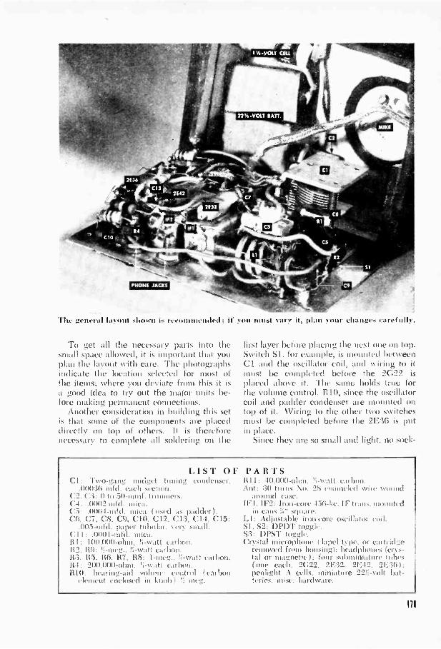
/NONE JACKS
The general layout n is r4,4...nnnund,t1: 11111,i vary ii, plan
To get all the necessary parts into thesmall space allowed, it is important that youplan the layout with care. The photographsindicate the location selected for most ofthe items; where you deviate from this it isa good idea to try out the major units be-fore making permanent connections.
Another consideration in building this setis that some of the components are placeddirectly on top of others. It is thereforenecessary to complete all soldering on the
change, carefully.
first layer before placing the next one on top.Switch SI. for example, is mounted betweenCl and the oscillator coil, and wiring to itmust be completed before the 2c22 isplaced above it. The same holds true forthe volume control. RIO, since the oscillatorcoil and padder condenser are mounted ontop of it. Wiring to the other two switchesmust he completed before the 2E36 is putin place.
Since they are so small and light, no sock -
LIST OFCl: Two -gang midget tuning condenser,
.000:30 mbl. each section.C2. (::3: 0 to 50-mmt. trimmers.
.0102 ofd. mica.C5: .0004-1111(1. used as padder 1.CO. C7, CS. C9, CIO, C12, C.1:3, C14, C15:
.003 -mild. paper tubular. very small.(:I .0001-nild. mica.
: 100 000 -ohm. ';-watt carbon.112. 119: !-meg., Yl-watt. carbon.11:3. 113. 116, 117, 118: I-meg.. ',watt carbon.Of : 200.000 -ohm. Carl )1m.H10: hearing -aid volunr emitrol (carbon
dement enclosed in kit meg.
PARTS1111: 40,000 -ohm. ?;-watt carbon.Ant: :30 turns No. 28 enanwlcd wire wound
around case.IF1, IF2: Iron -core 450-kc. IF trans. mounted
in cans .::" square.LI: Adjnstable iron core oscillator mil.SI, S2: Dviir toggle.S:3: DPST toggle.Crystal microphone 1 lapel t) pc. or cartridge
removed from housing): headphones (crys-tal or magnetic t: four subminiature tubes(one each. 2(122. 2E:32. 2E12. 2E:30 I:penlight A cells. miniature 22! -volt bat-teries. misc. hardware.
Ill

One of the newer pen -size soldering irons isalmost essential for vork on this midget set.
ets are required for the tubes. They areheld in position by strips of cellulose tapeplus the soldered connections to the pins.
A high -impedance lapel microphone wouldprobably be most satisfactory for use in thehearing -aid portion of this set, but a verysuitable-and much less expensive-substi-tute can be found inside an ordinary crys-
tal -mike housing. The photos show how thecartridge was removed from its bullet -likeshell and fastened inside a hole in one sideof the box that holds the set: The rubbercushion around the crystal unit must be lefton to protect the microphone from vibra-tion. It is fastened with rubber cement.
For other applications you may find itmore desirable to keep the mike entirelyseparate so that it can be placed in a deskstand or worn on the clothing. Either way,the cable should be shielded.
At the other end of the circuit, ordinaryhigh -impedance headphones of the crystalor magnetic type may be used. A singlephone gives adequate results.
While there is nothing intrinsically diffi-cult about the construction of this set, itcannot be built to size unless you are care -ltd to obtain the very smallest parts. Also, itwill take all your skill and experience witha soldering iron and the best workmanshipyou can put into it.To make the unit completely self-con-
tained, the external antenna and ground areomitted in favor of the case -wound loop.An antenna coil and aerial can be substi-tuted if the conditiOns of use permit. Pick-up will. of course, be improved. Using onlythe loop shown, however, stations as far offas 400 miles were brought in clearly.
Exler11aI Speaker _tdds Uses Ii, 1V01111* .11i0 RadioELATES OF ***** LEADS GOING TOOUTPUT TUNES e ITRANSFORATER AND CONNECT AS SNORE MALE PLue
OUT,PuuTTOT::07:01121EA
,ro
ESC
I4
I IIICESSE0 EEMALCI SOCKET
-
GIVE a loudspeaker enough cord and youcan hang it on a nearby limb or simply placeit on the ground beside you when you getout of an auto to loll in the shade. For thosemany times when you are just far enoughaway from a car for its radio to be of no use,this extension speaker is the perfect answer.
The toggle switch makes it possible tochange instantly from the internal to ex-ternal sound. Just plug in the connector,112
11 210, 2 OR! CONDUCTOR WIRE
SPOTTOGGLE UNTO.
UNIVERSAL EMT -PULLOUTPUT TRANSFORMER
EXTERNAL dPm SPEAKER
flick the switch, and carry the boxed speakeranywhere within the 15' to 25' range of theextension wire. The solid lines in the dia-gram show what must be done if the radiohas a single output tube; for push-pull out-put make the changes shown by the brokenlines as well. With single -tube output you'llneed only a SPDT switch. A two- or three-way polarized plug and socket and two- orthree -conductor wire make the connection.
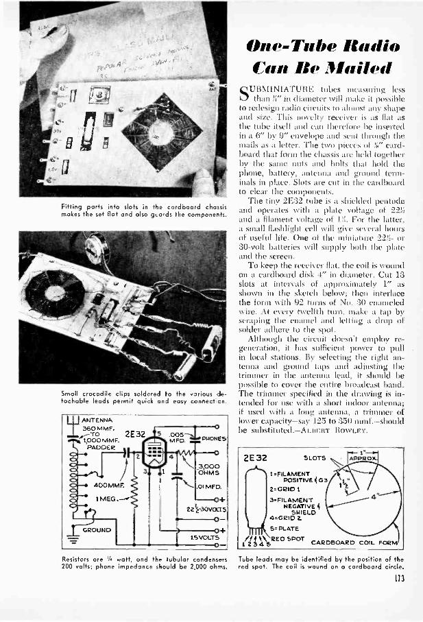
Fit-ing parts into slots in the ccrdooard chassismakes the set flat and also gLa-ds the components.
Small crocodile clips soldered to the various de-tachable leads permit quick and easy connect,on.
ANTENNA360 MMF.
1,000 MMF.PADDER
2E32 005PHONESM=D.m
O
400 MMF.
1 MEG
GROUND
1
3,000OHMS
01 MFD.
0+22 *-30VOLT 5
o+15 VOLTS
0-Resistors are 1', watt, and the ubular condensers
One -7'111w IhidioI'm: Be Mailed
SUBN1I\IATURE tubes measuring lessthan in diameter will make it possible
to redesign radio circuits to almost any shapeand size. This novelty receiver is as flat asthe tube itself and can therefore be insertedin a 6" by 9" envelope and sent through themails as a letter. The two pieces card-board that form the chassis are held togetherby the same nuts and bolts that hold thephone, battery, antenna and ground term-inals in place. Slots are cut in the cardboardto clear the components.
The tiny 2E:32 tube is a shielded pentodeand operates with a plate voltage of 221;and a filament voltage of Pi. For the latter,a small flashlight cell will give several hoursof useful life. One of the miniature 22Y2- or30 -volt batteries will supply both the plateand the screen.
To keep the receiver flat, the coil is woundon a cardboard disk 4" in diameter. Cut 13slots at intervals of approximately 1" asshown in the sketch below; then interlacethe form with 92 turns of No. 30 enameledwire. At every twelfth turn. make a tap byscraping the enamel and letting a drop ofsolder adhere to the spot.
Although the circuit doesn't employ re-generation, it has sufficient power to pullin local stations. By selecting the right an-tenna and ground taps and adjusting thetrimmer in the antenna lead, it should bepossible to cover the entire broadcast band.The trimmer specified in the drawing is in-tended for use with a short indoor antenna;if used with a long antenna, a trimmer oflower capacity-say 125 to 350 mmf.-shouldbe substituted.-ALBERT ROWLEY.
2E32 SLOTS
1 -FILAMENTPOSITIVE 4 G3
2= GRID
3 -FILAMENTNEGATIVE 4
SHIELD4=GRID 2.
5. PLATE
/11 1\ rem SPOT12 3 4 5 CARDBOARD COIL FORM
Tube leads may be identified by the position of the200 volts; phone impedance shoJld be 2,000 ohms. red spot. The coil is wound on a cardboard circle.
113
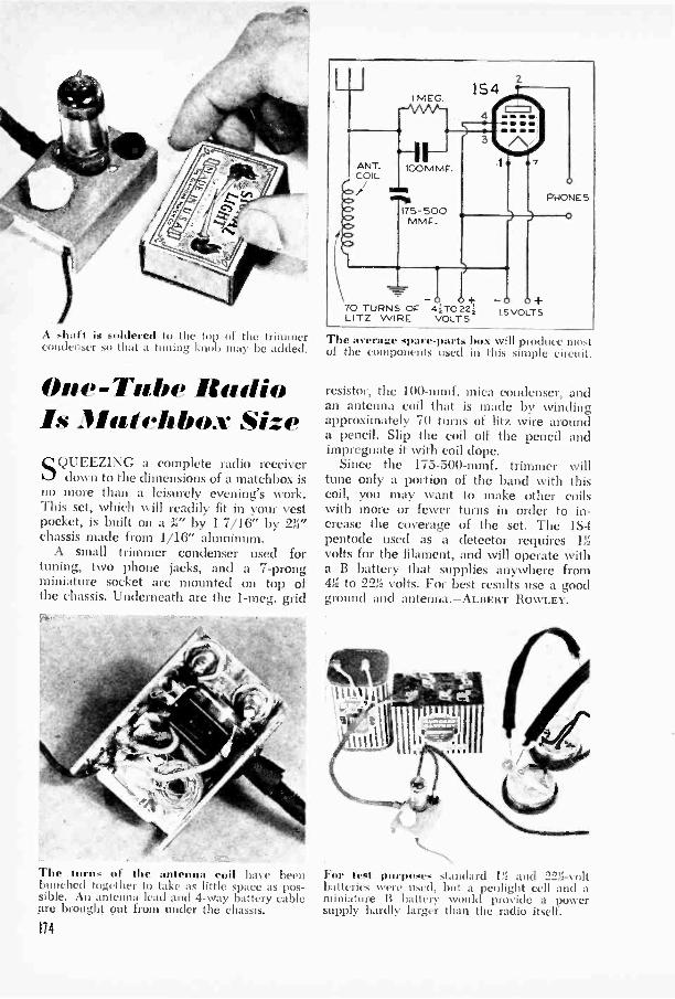
A shaft is soldered to the top of the trimmercondeuser so that a tuning knob may be added.
One -Tube RadioIs Matchbox Size
SQUEEZING a complete radio receiverdown to the dimensions of a matchbox is
no more than a leisurely evening's work.This set, which will readily fit in your vestpocket, is built on a by 1 7/16" by 231"chassis made from 1/16" aluminum.
A small trimmer condenser used fortuning, two phone jacks, and a 7 -prongminiature socket are mounted on top ofthe chassis. Underneath are the 1-meg. grid
The turns of the antenna coil have beenbunched together to take as little space as pos-sible. An antenna lead and 4 -way battery cablepre brought out from under the chassis.
114
70 TURNS OF 41T0221LITZ WIRE VOLTS
The average spare -parts box will produce mostof the components used in this simple circuit.
resistor, the 100-mmf. mica condenser, andan antenna coil that is made by windingapproximately 70 turns of Litz wire arounda pencil. Slip the coil off the pencil andimpregnate it with coil dope.
Since the 175-500-mmf. trimmer willtune only a portion of the band with thiscoil, may want to makewith more or fewer turns in order to in-crease the coverage of the set. The 1S4pentode used as a detector requires Rf..
volts for the filament, and will operate witha B battery that supplies anywhere from4Y: to 223i volts. For best results use a goodground and antenna.-ALBERT ROWLEY.
For test purposes standard and 2:IX-voltbatteries were used, but aeolight cell and aminiature B battery would pros ide a powersupply hardly larger than the radio itself.

You con listen to your best radiofrom any room with this system.
SOLDER
1k. RAHN ESTOCKCLIP
PORTABLE
BATTERY
(1 \'''RADIO TUBE PRONG
PIPED PROGRAMS. You can listen to youreIlnsc de radio room in the house Nviththe remote pickup and control system shoviibeim\ .1, portable speaker. plugged into thecircuit \vherexer con\ enient. has a volumecontrol and an on-oll switch that controls theradio.
The only eliale.tes necessar in the radioitself are the installation of a nev purser
itch vitli an (Alia pole. ;tml a relay forlemote net -all control. 'This relay. of about.1.0(11) ohuts Et.sistalice, should operate onhvo or three cells. 1-.0v-1)Itageconductors snch as bell or \\ ire willdo for tiu lions(' circuit. The portable spcak-er-more than one could be used-is a per-nianent-mawiet t pc: 'noun( it in a housing.with a (.m111)1,011 potter sitch and coloniccontrol ol 1.00() to 5.000 olims resistance.This achusts the remote speaker withoutallecting the radio.-NVii.l.no
AUXILIARYSPEAKER
OW -1 CELLS
41
)I i[_ _ OUTLETS
SWITCH ON ! ,
VOWME - -CONTROL/
_ .
RADIOSPEAttEr.
vOCE-COILC,r.CuiTCC RADIO
*--74,.e CARDBOARD
PLUG-IN ADAPTERS. Irrupt hunt burned -out radio tubes secured to .1 caldboard baseenable on to connect ping hpe portableradio batteries \\ Three pro!I S areneeded for a -11- battery his iii a 22.-\ oltterminal. Nlakc sure the 11..1(15 can't be ac-cidentally shorted. (:. NVAnn 1 1 I.
INSULATING GROMMETS SANDare made Irom slip- OFF
on pencil erasers. 1)rill the .(hole right throle,11 and roundoff corners on :in then \\ heel.
\\ lit 11(11(1 it on the 1/4,
wire.-AL. \I. 1.as.)\ mi. in.
VOLUMECONTROL
"i EL Ay
SNITCHON RADIO
I
LEST YOU FORGET \\ llieu part of a com-plicated 55 irile4 job has he'll finished. run acolored pencil gluier the bin, on the circuitdiagram as 5 ou \\ fir iu each one. Then thereis no need to trace \\ kin., to learn what isleft to du. It's also .1 help in preventing wir-ing mistakes.-jim
115
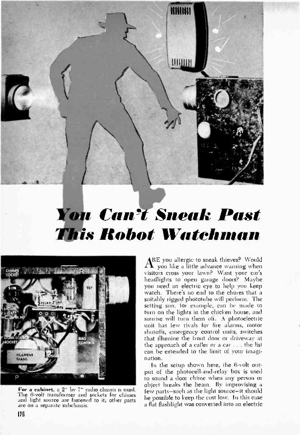
iCan" Sneak Pastis Robot Watchman
For a cabinet. a 2" by 7" radio chassis is used.The 8 -volt transformer and sockets for chimesand light source are fastened to it; other partsare on a separate subchassis.
ARE you allergic to sneak thieves? Wouldyou like a little advance warning when
visitors cross your lawn? Want your car'sheadlights to open garage doors? Maybeyou need an electric eye to help you keepwatch. There's no end to the chores that asuitably rigged phototube will perform. Thesetting sun, for example, can be made toturn on the lights in the chicken house, andsunrise will turn them off. A photoelectricunit has few rivals for fire alarms, motorshutoffs, emergency control units, switchesthat illumine the front door or driveway atthe approach of a caller or a car . . . the listcan be extended to the limit of your imagi-nation.
In the setup shown here, the 6 -volt out-put of the photocell -and -relay box is usedto sound a door chime when any person orobject breaks the beam. By improvising afew parts-such as the light source-it shouldbe possible to keep the cost low. In this casea flat flashlight was converted into an electric
116
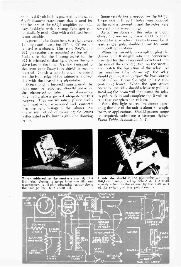
unit. A :3.8 -volt bulb is powered by the same6 -volt filament transformer that is used forthe heaters of the 6AQ5 amplifier pentode.Any flashlight with a strong light spot canbe similarly used. One with a diffused beamis not suitable.
A piece of aluminum bent to a right angle13;" high and measuring Pr by -Pr on topis used as a chassis. The relay, 6AQ5, and927 phototube are mounted on top of it.Make sure that the 3 -prong socket for the927 is oriented so that light strikes the sen-sitive face of the tube. A shield (snipped tosize from an ordinary tube shield) is recom-mended. Punch a hole through the shieldand the front edge of the cabinet in a directline with the face of the phototube.
Even though a focused beam is used, thelight must be refocused directly ahead ofthe photoelectric tube. Two dime -storemagnifying glasses proved adequate for thispurpose. They are set into a plastic flash-light head which is reversed and cementedover the light passage in the cabinet. Analternative method of mounting the lensesis illustrated in the lower right-hand drawingbelow.
Wires soldered to the contacts electrify thisflashlight. Power is taken from the filamenttransformer. A 15 -ohm adjustable resistor dropsthe voltage from 6 to about 4.5.
Some ventilatim is needed for the 6AQ5.To provide it, three 1" holes were punchedin the cabinet mound it and the holes werecovered with screen plugs.
Actual resistance of this relay is 3,800ohms; one measuring from 3,000 to 4,000should be satisfactory. Contacts must be atleast single pole, double throw for mostphotocell applications.
When the assembly is complete, plug thechimes and flashlight into the connectorsprovided for them (recessed sockets set intothe side of the cabinet), turn on the switch,and watch the operation of the relay. Asthe amplifier tibe warms up, the relayshould pull in; ii not, adjust the bias controluntil it does. Focus the light and the con-centrating lenses. When the spot strikescorrectly, the relay should release or pull up.Breaking the beam will then cause the relayto pull back in and complete the 6 -volt cir-cuit that energizes the chimes.
With this light source, maximum oper-ating distance of the unit is about 8'-amplefor most applications. Should greater rangebe required, substitute a stronger light.-Frank Tobin, Manhattan, N. Y.
Inside the shield is the phototube with the6AQ5 and relay :Med up behind it. The smallchassis is held in the cabinet by the shaft nutsof the switch and bias potentiometer.
927 6A0IRECTI ON
OFLIGHT 2
81 ASCONTROL
6 VOLT3 AMP. -
20 MEG.1 WATT
FILAMENT/TRANS.
CONTACTPOINTS
ON RELAY
FLASHLIGHT
1S -OHM 1CIMADJUSTABLE
WIRE WOUND
SPST/TOGGLE
115 VOLTSAC
2
FLASHLIGHTHEAD ---
(REVERSED)
CABINET
SPACER -
MAGNIFYINGLENSES
11
tNUTS
MACHINE SCREW
- DIA.)
HAN .
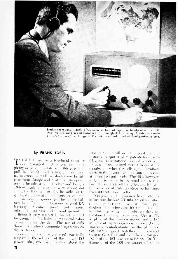
Elusive short-wave signals often come in best at night, so headphones are builtinto this two -band superheterodyne for midnight DX listening. Flicking a couple
f swi,ches however, brings in the full broadcast band at loudspeaker volume.
By FRANK TOBIN
TURFY. lobes for a two -band stiperhetdoesh't ,diggest much power, but there's
plenty of piallp and drive in this circuit topull ill the 20 and 4(1 -meter ham -bandtransmitters as well as short-wave broad-casts from Euroile and Australia. Receptionon the broadcast band is clear and loud; a10 -foot hank of antenna wire stroll°. (nitalong the lloor will usually 1)( sufficient toget local stations at hill loudspeaker vollinie.and an eternal ground can be omitted al-together. For remote locations or !rood I)Xlistening, of course. want a moresubstantial antenna and :t good ground.
Bring battery operated, this set is idealfor camp. limiting lodge, or week -end cabinas \yell as :or the den. The nose of onlythree tulles allows economical operation ondry batteries.
Considerations of size played practicallyno part in the selection of the midget 3S Ipower tube; what is important about the
tube is that it will maintain good and un-distorted output at plate potentials down to65 Volts. \lost battery -operated power pen-todes work well enough with a fresh battersupply, but when the cells age and V ulna(starts to drop. considerable distortion ocelir:,at normal output levels. The 3S4, howeer.is built to work in personal radios thatnormally use 67r2 -volt batteries, and is there-fore capable of distortion -free performancefeint 90 volts down to 65.
It is possible that you may have dill -lenityin locating the :3A8-GT tube called for. sincesome inanillactiirers h: se discontinned pro-duction III it. IlosseSer. its simple l'11011,11ato SilbStillite IWO Separate tulles lor the com-bination triode -pentode -diode. Use a ITTin place of the pentode section and a 1S5inn place of the triode -diode portion. \s the1S5 is a pcntode-diode, tie the plate am'.G2. (screen grid) together, and connectthem to C10. Cll. and 117. The control grid(C11 of the IS5 is wired to R5 and C9. Thefilaments of the 1S5 are connected to the
118

Tufo-Band
SHERRITHREE -TUBE CIRCUIT PERMITS
COMMUNICATIONS RECEIVERTO OPERATE UP TO 1,000 HOURS
ON BATTERY PACK
400 41110 di)
same points as the pins 1 and 7 of the:3A8 -CT.
Connections for the IT4 substitute aremade in a similar manner. Its plate is wiredto the same point as pin :3 of the :3A8 -CT.C2 of the 1T4 as if it were pin 4 of the:3A8 -CT. and G1 to the same connection asthe cap on the :3A8 -CT. The filament leadsare wired to pins 1 and 2.
If you happen to find a :3A8 -CT, it isprobably simpler not to make this changein the circuit diagram. Bear in mind, how-ever. that future replacement of the :3A8 -CTmay not be easy as stocks lessen.
For night-time listening or when signalsare weak, a headphone jack has been in-cluded. By taking the phone -jack connec-tions from the voice -coil winding of theniitput transformer. the phones can beswitched in at any time, regardless of vol-ume. without danger of blasting or over-biadin.r. Use the transformer tap that givesthe most comfortable volume. and be surethat the grounded side of the phones cor-
responds to the grounded side of the speaker.This connection shockproof since none ofthe high voltage flows through the phonecircuit.
A variable tone control, consisting of a.1-101d. tubular condenser (C12) in serieswith RIO. a 75,000 -ohm potentiometer, op-erates on both speaker and phones. Byreducing the audibility of higher sound fre-quencies, this control serves to relieve heavystatic conditions. High-pitched code sig-nals can also be changed to more pleasingnotes by means of the tone control, andmusical programs can be timed to suit the ear.
When a signal is picked up by the an-tenna, it is fed into the fourth grid of theI A 7 converter, where it is mixed with asignal generated by the local oscillator tocreate all intermediate frequency of 456 kc.After ihissing through the I.F. amplifier, thissignal is rectified the diode detector, thenfurther amplified by the first audio tube.All three functions -1.F. amplifier, diodedetector, and first audio-are performed bythe single :3:15 tube. Building a pentodeamplifier, diode rectifier. and high -mu triodeinto one glass envelope imt only saves space,parts and work for the builder, but also cutsdown filament current
The output of the :3A8 amplifier triode isresistance coupled to the control grid of the:3S4 power pentode through a 75,000 -ohmplate resistor, a .05-nild. coupling condenser.and a 1-meg. grid resistor. A mica condenserof 100-mml. capacity in the plate circuit ofthe first audio stage by-passes any unrecti-fied 11.F. current to ground, preventing it!non weakening or distorting the desiredsignal.
Through au output transformer, theaudio -frequency currents flowing in the platecircuit of the 3S4 are fed into a 6" P.M.speaker. Load resistance of the tithe is about5,000 ohms; a selection of taps on the sec-ondary of the transformer permits matchingof this resistance to the speaker's voice -coilimpedance.
Grid bias for the :3S-1 is obtained by meal'sof a 600 -ohm resistor. 119. in series with thenegative 90 -volt lead and ground. Thevoltage drop across this resistor is impressedon the grid of the tube through the 1-meg.grid leak, BS. As the B voltage chops, sodoes the negative bias on the tube, resultingin a compensating increase in amplification.Automatically regulated bias permits thepower tile to ft niction efficiently eventhough the output voltage of the B battery
119
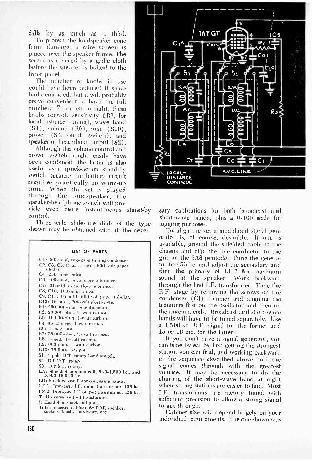
falls by as much as a third.To protect the loudspeaker cone
from damage, a wire screen isplaced over the speaker frame. Thescreen is covered by a grille clothbefore the speaker is bolted to theFront panel.
The number of knobs in usecould have been reduced if spacehad demanded, but it will probablyprove convenient to have the fullnumber. From left to right, theseknobs control: sensitivity (R1, forlocal -distance tuning), wave band(SI), volume (R6), tone (R10),power (S3. on -off switch), and;pecker or headphone output (S2).
Although the volume control andpower switch might easily havebeen combined, the latter is alsouseful as a quick -action stand-byswitch because the battery circuit
'requires practically no warm-uptime. When the set is playedthrough the loudspeaker, thespeaker -headphone switch will pro-vide even more instantaneous stand-bycontrol.
Three -scale slide -rule dials of the typeshown may be obtained with all the neces-
LIST OF PARTS
Cl: 360 -mint. two -gang tuning condenser.C2, C3, C5, C12: .1-mfd., 600 -volt paper
tubular.C4: 250-minf. mica.C6: 400 -mint. mica, close tolerance.C7:.01 -mid. mica, close Wier:ince.CS, CIO: 100-mmf. mica.C9, CII: .05-mfd., 800 -volt paper tubular.C13: 16 mfd., 200 -volt electrolytic.RI: 250,000 -ohm potentiometer.112: 50,000 -ohm. 1 -watt carbon.R3: 10.000 -ohm, I -watt carbon.
2-mcg., 1 -watt carbon.R6: I-meg. pot.117: 75,000 -ohm, ',watt carbon.118: 1 -watt carbon.119: 600 -ohm, I -watt carbon.RIO: 75,000 -ohm pot.Si: 4 -pole D.T. rotary band switch.S2: D.P.D.T. rotary.S3: D.P.S.T. rotary.LA: Shielded antenna coil, 540-1,500 kc., and
5,500-18,000 kc.LO: Shielded oscillator coil, same bands.I.F.I: Iron -core I.F. input transformer, 456 kc.I.F.2: Iron -core IX. output transformer, 456 kc.T: Universal output transformer.J: Headphone jack and plug.Tubes, chassis, cabinet. 6" P.M. speaker,
sockets, knobs, hardware, etc.
80
sary calibrations for both broadcast andshort-wave bands, plus a 0-100 scale forlogging purposes.
To align the set a modulated signal gen-erator is, of course, desirable. .1f one isavailable, ground the shielded cable to thechassis and clip the live conductor to thegrid of the 3A8 pentode. Tune the genera-tor to 456 kc. and adjust the secondary andthen the primary of I.F.2 for maximumsound at the speaker. Work backwardthrough the first I.F. transformer. Tune theR.F. stage by removing the screws on thecondenser (CI) trimmer and aligning thetrimmers first on the oscillator and then onthe antenna coils. Broadcast and short-wavebands will have to be tuned separately. Use
1,500-kc. R.F. signal for the former and15 or 16 Inc. for the latter.
If you don't have a signal generator, youcan tune by ear by first getting the strongeststation you can find, and working backwardin the sequence described above until thesignal comes through with the greatestvolume. It may be necessary to do thealigning of the short-wave band at nightwhen strong stations are easier to find. MostI.F. transformers are factory tuned withsufficient precision to allow a strong signalto get through.
Cabinet size will depend largely on yourindividual requirements. The one shown was

5P EAICEE
TONECONTROL
ReAUTOMATICBiAS(See TEXT)
ci
EMANIIMICaliMOMEILiiii.g"11411.1111111111
selected because it hasroom for a 1.000 -hourpower supply. Batterypacks that deliver 1.5volts for the filamentsand 90 volts for theplates arc now availablein a variety of sizes andshapes. Where porta-bility is a factor, a smallpack may be used, inwhich case the cabinetcan be much reduced insize. The lart;er of theso-called -faro- packsarc estimated to begood for a hill year ofservice with this low -drain circuit, based onaverage daily use ofabout three
For extra usefulnessthe set may be readilyconverted to 115 -voltA.C. or D.C. operation.An article on the nextpage describes a suit-able dry -disk rectifierunit that will enablethe builder to install acomplete three-way
ipower supply.
VOLUMECONTROL
C8 R7 R5 R.3 C4 C7C11 C10 R4 R2 C6
R9 Si51 53 C12 RIC R8 C13 R6 Cl RI
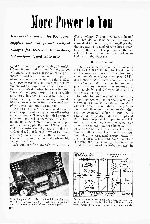
More Power to YouHere are three designs for D.C. power
supplies that will furnish rectified
voltages for receirers, transmitters,
test equipment, and other uses.
SMALT, power supplies capable of furnish-ing filtered and reasonably pure direct
current always have a place on the experi-menter's workbench. For some equipment,of course, power packs must be designed togive specific currents and voltages, but forthe majority of applications one or more ofthe three units described here can be used.They will conserve battery life in portableapparatus, balance a Wheatstone bridge,extend the range of an ohmmeter, or providebias or power voltage for experimental am-plifiers, receivers, and transmitters.
Dry -disk rectifiers, recently made avail-able to experimenters, replace rectifier tubesin many circuits. The selenium disks requireonly two soldered connections. They haveno filaments and therefore require no sepa-rate filament supply. Because of their ruggedmetallic construction they are also able towithstand a lot of knocks. Two of the threecircuits given below employ these new recti-fiers; all three are made of easily obtainableand standard parts.
Selenium rectifiers are color -coded to in -
An oblong metal tool box that will fit readily intothe battery compartmert of most receivers is boththe chassis and caoinet of this power supply.
182
RECTIFIER OOT
30 OHMS10 WATTS
40 MF O.150 VOL.T5
.0IMF D.
dicate polarity. The positive side, indicatedby a red dot or some similar marking, isequivalent to the cathode of a rectifier tube;the negative side, marked with black, func-tions as the plate. The position of the reddot in relation to the other circuit elementsis shown in the diagrams.
Battery Eliminator
The dry -disk battery eliminator shown onthese two pages was built by Frank Tobinas a companion piece for his three -tubesuperheterodyne receiver (See page 178).It is shaped to fit the battery compartment ofhis and other radios and can be used withpractically any receiver that requires ap-proximately 90 and 7.5 volts of B and Asupply respectively.
In order to use the eliminator with thethree -tube receiver, it is necessary to connectthe tubes in series so that the current drainwill not exceed 50 ma. Many battery tubeshave their filaments arranged so that theymay be connected either in series or inparallel. As originally built, the set placedall the tubes in parallel to operate on a 1.5-
volt battery. The diagram on the facing pageshows the changes that must be made if theset is to run on the higher filament voltage.Simply putting the tubes in series withoutmodifying the associated circuit shown bythe blue lines would also have the effectof raising the A.V.C. voltage to 7.5 volts-equal to the sum of the tube voltages. In
5 PLATE R ED r MIDGET AC-OCCHOKE
16 MF O.150 VOLTSTOGGLE
(SWITCH
115 VOLTS 500 OHMSAC -0C. 10 WATTS
+100VOLTS2 r:)0 OH MS50 WATT S
-100VOL
500 MFG'.25 VOLTS
+75VOLT5
7.5 VOLTS
The parts used in this simple rectifier unit may bepurchased for a couple of dollars. They will savemany times their cost in battery replacements.

When used with the rectifier, the superhet circuit must be altered as shown by the modified diagram, below.
New connections in the filament circuit are indicated by lines in color; remove lecds marked with on X.
183
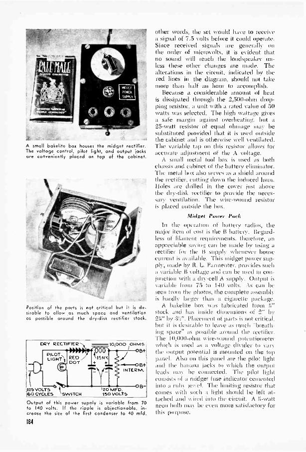
115 VOLTS60 CYCLES SWITCH
Position of the parts is not critical but it is de-sirable to allow as much space and ventilationas possible around the dry -disk rectifier stack.
A small bakelite box houses the midget rectifier.The voltage control, pilot light, and output jocksare conveniently placed on top of the cabinet.
other words, the set would have to receivea signal of 7.5 volts before it could operate.Since received signals are generally onthe order of microvolts, it is evident thatno sound will reach the loudspeaker un-less these other changes are made. Thealterations in the circuit, indicated by thered lines in the diagram, should not takemore than half an hour to accomplish.
Because a considerable amount of heatis dissipated through the 2,500 -ohm drop-ping resistor, a unit with a rated value of 50watts was selected. The high wattage givesa safe margin against overheating, but a25 -watt resistor of equal ohmage may besubstituted provided that it is used outsidethe cabinet and is otherwise well ventilated.The variable tap on this resistor allows foraccurate adjustment of the A voltage.
A small metal tool box is used as bothchassis and cabinet of the battery eliminator.The metal box also serves as a shield aroundthe rectifier, cutting down the induced hum.Holes are drilled in the cover just abovethe dry -disk rectifier to provide the neces-sary ventilation. The wire -wound resistoris placed outside the box.
Midget Power PackIn the operation of battery radios, the
major item of cost is the B battery. Regard-less of filament requirements, therefore, anappreciable saving can be made by using arectifier for the li supply whenever housecurrent is available. This midget power sup-ply, made by R. L. Parmenter, provides sucha variable B voltage and can be used in con-junction Nvith a dry -cell A supply. Output isvariable from 75 to 140 volts. As can beseen from the photos, the complete assembly
**: is hardly larger than a cigarette package.A bakelite box was fabricated from !;"
stock and has inside dimensions of 2" by2%" by 3b". Placement of parts is not critical,but it is desirable to leave as much "breath-ing space" as possible around the rectifier.The 10,000 -ohm wire -wound potentiometer
DRY RECT FIE1E1 10,000 OHMS which is used as a voltage divider to varyB+ the output potential is mounted on the top
panel. Also on this panel are the pilot light---0B+ and the banana jacks to which the output
INTER M. leads mat be connected. The pilot lightconsists of a midget fuse indicator cementedinto a ruby le' el. The limiting resistor thatcomes with such a light should be left at-tached and wired into the circuit. A Ii -watt
'20 MFD.1S0 VOLTS
Output of this power supply is variable from 70to 140 volts. If the ripple is objectionable, in-crease the size of the first condenser to 40 mfd.
184
neon bulb may be even more satisfactory forthis purpose.
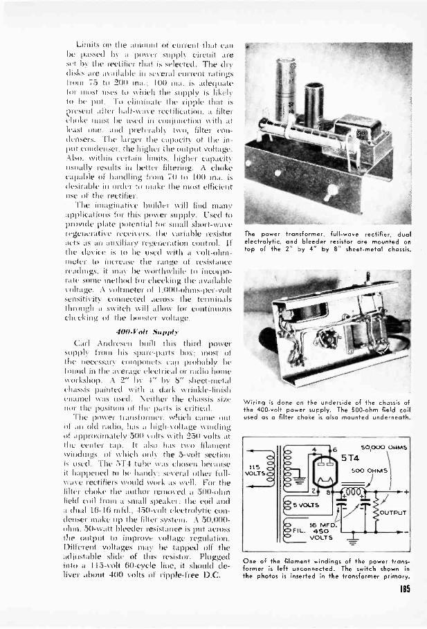
Limits on the anumnt of current that canhe passed by a power supply circuit areset 1) the rectifier that is selected. The drydisks are available in several current ratingsI runt 75 to 200 ma.; 100 ma. is adequatefor most uses to which the supply is likelyto be put. To eliminate the ripple that isj?resent after hall -w ae rectification, a filterchoke 1111.1S1 I>e used in CM I jUlleti011 with atleast one, and preferably two, filter con-densers. The larger the capacity of the in-put condenser. the higher the output voltage.Also, within certain limits, higher capacityusually results in better filtering. A chokecapable of handling from 70 to 100 ma. isdesirable in order to make the most efficientuse of the rectifier.
The imaginative builder will find manyapplications for this power supply. Used toprovide plate potential for small short-waveregenerative receivers. the variable resistoracts as an auxiliary regeneration control. Ifthe device is to be used with a volt -ohm-meter to increase the range of resistancereadings, it may be worthwhile to incorpo-rate some method for checking the availablevoltage. A voltmeter of 1.000 -ohms -per -voltsensitivity connected across the terminalsthrough a switch will allow for continuouschecking of the bimster voltage.
PM -troll SupplyCarl Andresen built this third power
supply from his spare -parts box; most ofthe necessary componcts can probably befound in the average electrical or radio homeworkshop. A 2" by -4" by 8" sheet -metalchassis painted with a dark wrinkle -finishenamel was used. Neither the chassis sizenor the position of the parts is critical.
The power transformer, which came outof an old radio, has a high -voltage winding,of approximately 500 volts with 250 volts atthe center tap. It also has two filamentwindings, of which only the 5 -volt sectionis used. The 514 tube was chosen becauseit happened to be handy: several other full -wave rectifiers would work as well. For thefilter choke the author removed a 500 -ohmfield coil from a small speaker: the coil anda dual 16-16 mid., 450 -volt electrolytic con-denser make up the filter system. A 50,000 -
ohm. 50 -watt bleeder resistance is put acrossthe output to improve voltage regulation.Different voltages may he tapped off theadjustable slide of this resistor. Pluggedinto a 115 -volt 60 -cycle line, it should de-liver about 400 volts of ripple -free D.C.
The powerelectrolytic,top of the
transformer, full -wave rectifier, dualand bleeder resistor are mounted on2- by 4" by 8 sheet -metal chassis.
Wiring is done on the underside of the chassis ofthe 400 -volt power supply. The 500 -ohm field coilused as a filter choke is also mounted underneath.
16F IL. 450
VOLTS
One of the filament windings of the power trans-former is left unconnected. The switch shown inthe photos is inserted in the transformer primary.
185

Busillessmall's RadioBy EDWARD BLANTON
FOR THE businessman who has to traveland likes to travel light, here is a handy
radio that manages to be a constant com-panion without becoming an extra piece ofluggage. Flat enough to fit into a briefcaseor overnight suitcase without crowding outthe other things you want to take along, thisfour -tube receiver operates on either -AC orDC at 115 volts.
The resistance of the four tube filamentsin series is such that no line -cord resistor isneeded to drop the voltage. Therefore anordinary two -conductor cord can be used,as long or as short as you like. A little extralength is all to the good, since in some ofthe older hotels electric outlets aren't placedas close as you might like to the desk ornight table.
All the tubes are midgets; leads from in-side are brought out to miniature metalprongs embedded in the glass envelopes.Connections are made to miniature 7 -prong
sockets that are fastened to the chassis.The chassis consists of a 53i" by 8" sheet
of thin aluminum bent to form a 90 -deg.angle about 2" from one of the longer edges.Most of the parts are fastened to the 2" legso formed.
The first tube, a 12BA6, is a radio -fre-quency amplifier pentode with remote cut-off characteristics. The control grid of thetube is connected to the secondary Nvindingof the antenna coil (L1) and the statorplates of one section of the two -gang tuningcondenser (C1). From the plate of the12BA6, the amplified radio -frequency signalis fed into the primary winding of the RFcoil, L2, which is coupled to a second tankcircuit composed of the secondary of theRF coil and the other half of Cl.
The unshielded antenna coil is placedbeneath the bend in the chassis; the RF coilis placed above the chassis and must beshielded to prevent oscillation and distortiondue to stray couplings between the coilwindings and the other circuit components.
To cover the coil, a por-tion of an old tube shieldwas cut off and boltedto the chassis as illus-trated on page 189.
Output from the RFtank circuit is fed to thegrid of the 12AT6, usedas an anode detectorand amplifier. Bias isprovided by a 2,700 -ohm resistor and a 10-mfd., 25 -volt electrolyt-ic condenser (RI, C4).A small mica condenser
An average -size briefcaseholds the radio and plentyof books, papers, and otherarticles as well. The caseis a leather -covered jewelbox or accessory case.
166
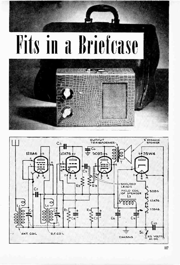
Fits ill a Briefcase
12 BA6
Lz
\ANT. COIL
C3
R.F. CO L
OUTPUTTRAA6FORMER
5" DYNAMIC"." SPEAKER
55W4
6 4-SHIELDED
E A.C.) S
F I E _D COIL/OF SPEAKER
L3
4.
SOBS
124T6
4leINAS
C
a II
ZILIFIASSI S
Si1115 VOLTS!)
AC -DC
187
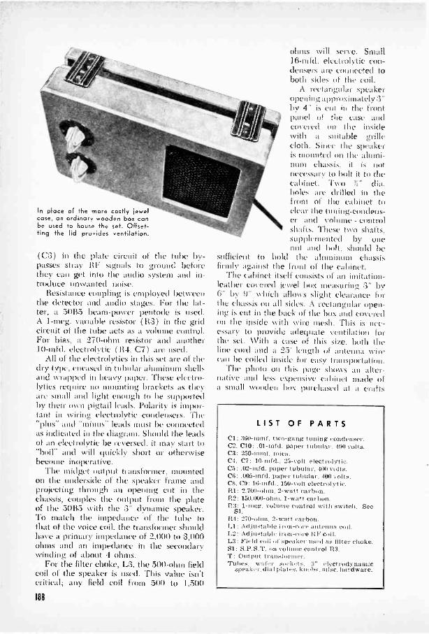
In place of the more costly jewelcase, an ordinary wooden box canbe used to house the set. Offset-ting the lid provides ventilation.
(C:3) in the plate circuit of the tube by-passes stray 111: signals to ground beforethey can get into the audio system and in-troduce unwanted noise.
Resistance coupling is employed betweenthe detector and audio stages. For the lat-ter, a 50B5 beam -power pentode is used.A 1-meg. variable resistor (R:3) in the gridcircuit of the tube acts as a volume control.For bias, a 270 -ohm resistor and another10 -mid. electrolytic (114, C7) are used.
All of the electrolvtics in this set are of thedry type, encased in tubular aluminum shellsand wrapped in heavy paper. These electro-lytics require no mounting brackets as theyare small and light enough to be supportedby their n pigtail leads. Polarity is impor-tant in wiring electrolytic condensers. The"plus- and "minus- leads must be connectedas indicated in the diagram. Should the leadsof an electndytic be reversed, it may start to"boil- and will (wick ly short or otherwisebecome inoperati
The midget output transformer. mountedon the underside of the speaker frame andprojecting through an opening, cut in thechassis, couples the output from the plateof the 50B5 with the :3" dynamic speaker.To match the impedance of the tube tothat of the voice coil, the transformer shouldhave a primary impedance of 2,000 to 3,000ohms and an impedance in the secondarywinding of about 4 ohms.
For the filter choke. L3, the 500-ohin fieldcoil of the speaker is used. This value isn'tcritical; any field coil from 500 to 1,500
ohms will serve. Small16 -mid. electrolytic con-densers are connected toboth sides of the coil.
A rectangular speakeropening approximately 3"by 4" is cut in the frontpanel of the case andcovered on the insidewith a suitable grillecloth. Since the speakeris mounted on the alumi-num chassis. it is notnecessary to bolt it to thecabinet. Two r" dia.boles are drilled in thefront of the cabinet tocleat the tuning -condens-er and volume - controlshafts. These two shafts,supplemented by onetout and bolt, should be
sufficient to hold the aluminum chassisfirmly against the front of the cabinet.
The cabinet itself consists of an imitation -
leather cmered jewel box measuring 3" by6" by 9" which allows slight clearance forthe chassis on all sides. A rectangular open-ing is cut in the hacko. box and coveredon the inside with wire mesh. This is nec-essary to provide adequate ventilation forthe set. With a case of this size. both theline cord and a 25' length 0 : I antenna wirecan be coiled inside for easy transportation.
The photo on this page shows an alter-native and less expensive cabinet made ofa small wonder box purchased at a crafts
LIST OF PARTSCl: 360-mmr. two -gang tuning condenser.C2. C10: .01-mrd. paper tubular. 400 volts.C3: 250-mmr. mica.
C7: 10-mfd.. 25 -volt electriilytic..02-nird. paper tubular. 400 volts.
(76: .005-mrd. paper tubular. 400 .olts.C8. ('9: 16 -turd.. 150 -volt electrolytic.111: 2.700 -ohm. 2 -watt carbon.R2: 150.000 -ohm. 1 -watt carbon.113: 1-meg. volume control with switch. Se.
Sl.R4 : 270 -ohm. 2 -watt carbon.Ll: Adjustable irn-core antenna coil.L2: Adjustable iron -core RFroil.L3: Field coil of spoultfq used as Otter choke.S1: S.P.S.T. on vol control R3.T: Output transformer.Tubes. wafer sockets. 3" electrodynamic
speaket. dia I plates. kto ohs. mist. hardware.
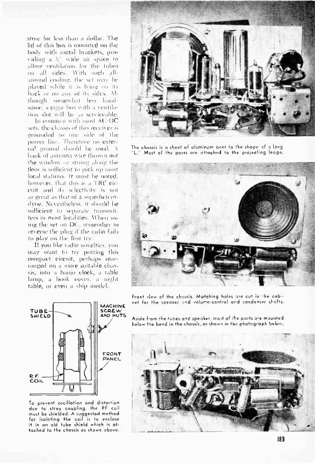
SIMI' 1 Or less hall .1 (1011:11.. I tic11(1 01 this bus is mounted on thebody with metal brackets, pro-"IIIIt4 a !?: \k id(' :Mr space toAlloss ventilation for the tithison all sides. \Vitli such all-around cooling:. the set Inas beplayed \slide it is lying oil itsback or on .inv III it. sides. .\I-11111nedi Nom( \\ 11;11 I1.'.. 11.illtl-S0111C. a (.1,4.11. 1111X with a V(11110;1-
11011 S114 \\ ill 1/t. ;IS stIA1(1%11)1('.111 C0111111011 with 1101.1 \(:-1)(..
sC1S.111C1:11,1ssis of tills el' isi.trimildial Side 01 1111'
lxwver 1111.'. 'I In 1111 l'Xter-stround should be used. .k
hank of :11111'1111;1 '.(ire tlirm11 0111111e \VilldIr\V or strong ;long thefloor is sufficient to pick (ip mostlocal stations. It must be noted.hosvever. that this I. a "HIV cir-cuit 114(1 it seleetis its' is nota. great ,is that of a superhetero-
dyne. Nevertheless. it should besufficient to slpalate transmit-ters ill most \\ I", ns-i11>; the sct 011 1V111(111111:1'
rcersc the pliig if the radio failsto play uu the first tiv.
If you like radio novelties. vonmay scant to 1111111111.2: thiscompact eircoit, perhaps rear-ranged on a more silit,Ible chas-sis, into a banjo clock, t tablelamp, a book cover, a nighttable, or even a ship model.
TUBESHIELD
P.F.COIL
MACHINESCREWAND NUTS
FRONTPANEL
To prevent oscillation and distortiondue to stray coupling, the RF coilmust be shielded. A suggested methodfor isolating the coil is to encloseit in an old tube shield which is at-tached to the chassis os shown above.
The chassis is a sheet of al Jrnir um oent to the shape of a long"L." Most of the por's are attached to the projectir g lec ge.
Front view of the chassis. Matching 'holes are cut in he cab -net for the speoKe- aid volur-e-con4rol ord condenser sl-cfts.
Aside from the tubes aid speaker, mo.t of the parts are mounfeibelow tie bend in the chassis, as shows in Hs? photograph bolos-.
v.
183
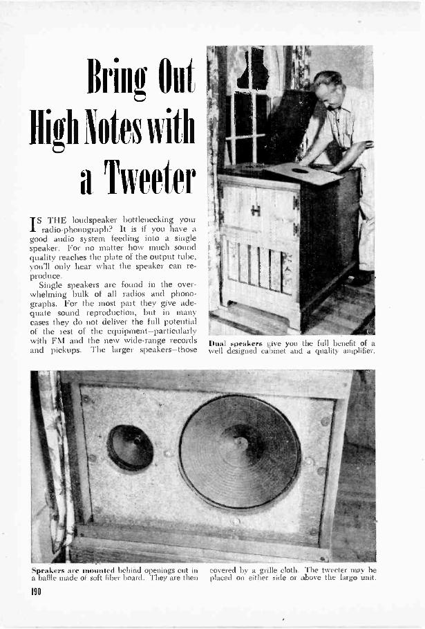
Brill Out
High Notes with
a TweeterIS THE loudspeaker bottlenecking your
radio -phonograph? It is if you have agood audio system feeding into a singlespeaker. For no matter how much soundquality reaches the plate of the output tube,you'll only hear what the speaker can re-produce.
Single speakers are found in the over-whelming bulk of all radios and phono-graphs. For the most part they give ade-quate sound reproduction, but in manycases they do not deliver the full potentialof the rest of the equipment-particularlywith FM and the new wide -range recordsand pickups. The larger speakers-those
Dual speakers give you the full benefit of awell designed cabinet and a quality amplifier.
Speakers are mounted behind openings cut in covered by a grille cloth. The tweeter may bea baffle made of soft fiber board. They are then placed on either side or above the large unit.
190
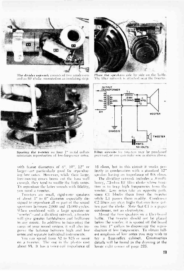
The divider network consists of two condensers;it'd ao I F choke, mounted on an insulating strip.
spacing the tweeter on four 1" metal collarsminimizes reproduction of low -frequency notes.
with frame diameters of 8", 10", 12" orlarger-are particularly good for reproduc-iog low notes. However, while their large,Itct'-11111)\ ing cones 1)00111 out the bass wellthough. they tend to muffle the high notes.To reproduce the latter sounds with fidelity,you need a tweeter.
Tweeters are small, rigid -cone speakersof about :3" to 6" diameter especially de-si..med to reproduce all or part of the soundspectrum between 2.000 and 15.000 cycles.When combined with a large speaker-or-woofer"-and a dividing network. a tweeterwill gise greater faithfulness and brillianceto any music. In addition to increasing therange of your sound system, it will also im-pros e the balance between high and lownotes and separate individual instruments.
You can spend from S2 to $2:5 or morenn a tweeter. The one in the photos costabout $8. It has a voice -coil impedance of
Place the ,peakers side by side on theThe filter network is attached near the tss,, hi.
OUTPUTANSFORMER
B+
50 VOLTS
Filter circuit. for tsste tcrs may be purchasedprewired, or )1/11 call make One as shown abos c.
16 ohms, but in this circuit it works per-fectly in combination with a standard 12"speaker having an impedance of 6-S ohms.
The dividing network includes a .6 -milli-henry, .75 -ohm B filter choke whose func-tion is to keep high frequencies Iron thewoofer. Low notes take au opposite path.since Cl blocks them from the tweeter -while LI passes them readily. Otudcosk rC2 filters any stray highs that may base got-ten past the choke. Note that Cl is a pdpercondenser, not an electrolytic.
Mount the two speakers on a fiber-boaolbaffle. The tweeter should not be placedbelow the woofer: it is spaced off the boardon four I" collars to discourage the repro-duction of low frequencies. To obtain full-est emphasis of low notes you may wish totry a bass -reflex cabinet. Constructiondetails will be found in the drawing at thelower right corner of page 225.
191

With the latest disks and even later music off theairwaves, you're equipped for any party-anywhere.
Portable Pho110-Itadio CombinationBy GEORGE 0. SMITH
FOR CANNED or current entertainment,here's an all-around music box that will
keep you in the swing. Built into a smallcase that usually holds only a phonograph,this set contains a five -tube superheterodynereceiver that can be used alone or as anamplifier for the record player. The radiooperates on A.C. or D.C., making the unituseful wherever 115 -volt current is avail-able. A universal motor would give therecord player an equal amount of flexibility,but since one may be hard to come by,either an A.C. or D.C. motor can be usedin its place. In this event, of course, youwill have to see that the phonograph partis not used on the wrong current.
To get the radio into a small cabinet, thetubes and intermediate -frequency trans-formers are mounted on one edge of thechassis. This "in -line" layout fits below thephonograph motor and tends to isolate sev-eral of the oscillation -producing compo-nents. A standard Dr by 5" by 9" blank isused for the chassis, but a satisfactory sub-stitute can be fornied from 20 -gauge steelor aluminum. Aluminum may be better ifheavier stock is used, and it should offer nosoldering difficulties since conections to the
192
chassis are made with lugs. The comple-ment of tubes and transformers will fill theedge of the chassis with no room to spare,so, as a step in space conservation, usespring -type tube bases; these fit into mount-ing holes of approximately 1 5/32" diameterand are secured by retaining clips.
The rest of the layout will depend uponthe space available in your cabinet. Inmounting the gang condenser, don't forgetto allow for the swing of the rotor plates.It may be possible to make a direct cou-pling in some cases; in others, a flexible cou-pling or flexible shaft must be used. Thelatter will allow the condenser to be mount-ed at some distance from the dial. If noneof these methods is feasible, you may haveto resort to the dial -cable system shown inthe photograph at the top of page 194.Cut the condenser shaft short of the frontpanel, and fasten over it a knob withstraight sides. Build up the hub of the dialassembly with tape or a metal bushing, andwrap the cable around it. To secure thecable ends, replace the knob setscrew witha longer screw of the same thread, slottedat one end. Tighten the knob with thisscrew, pull the cable firmly through theslot, and solder it fast.
When cutting the board for the phono-
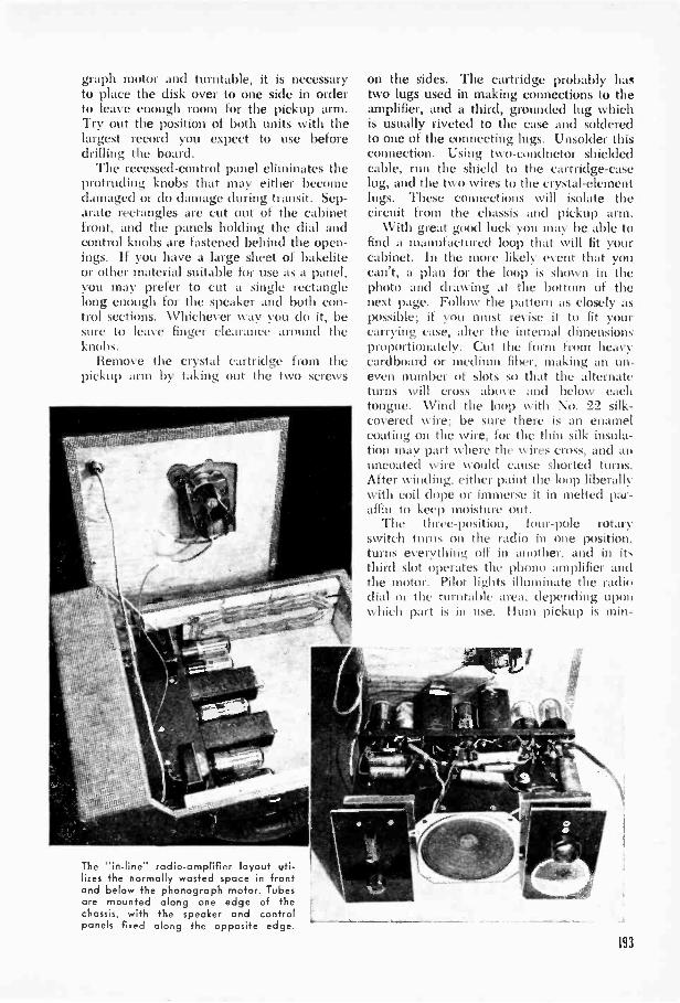
graph motor and turntable, it is necessaryto place the disk over to one side in orderto leave enough room for the pickup arm.Try out the position of both units with thelargest record you expect to use beforedrilling the board.
The recessed -control panel eliminates theprotruding knobs that may either becomedamaged or do damage during transit. Sep-arate rectangles are cut out of the cabinetfront, and the panels holding the dial andcontrol knobs are fastened behind the open-ings. If you have a large sheet of bakeliteor other material suitable for use as a panel,you may prefer to cut a single rectanglelong enough for the speaker and both con-trol sections. Whichever way you do it, besure to leave finger clearance around theknobs.
Remove the crystal cartridge from thepickup arm by taking out the two screws
The "in -line" radio -amplifier layout uti-lizes the normally wasted space in frontand below the phonograph motor. Tubesare mounted along one edge of the I
chassis, with the speaker and controlpanels fixed along the opposite edge.
on the sides. The cartridge probably hastwo lugs used in making connections to theamplifier, and a third, grounded lug whichis usually riveted to the case and solderedto one of the connecting lugs. Unsolder thisconnection. Using two -conductor shieldedcable, run the shield to the cartridge -caselug, and the two wires to the crystal -elementlugs. These connections will isolate thecircuit from the chassis and pickup arm.
With great good luck you may be able tofind a manufactured loop that will fit yourcabinet. In the more likely event that youcan't, a plan for the loop is shown in thephoto and drawing at the bottom of thenext page. Follow the pattern as closely aspossible; if you must revise it to fit yourcarrying case, alter the internal dimensionsproportionately. Cut the form from heavycardboard or medium fiber, making an un-even number of slots so that the alternateturns will cross above and below eachtongue. Wind the loop with No. 22 silk -covered wire; be sure there is an enamelcoating on the wire, for the thin silk insula-tion may part where the wires cross, and anuncoated wire Nvould cause shorted turns.After winding, either paint the loop liberallywith coil dope or immerse it in melted par-affin to keep moisture out.
The three -position, four -pole rotaryswitch turns on the radio in one position.turns everything off in another. and in itthird slot operates the phono amplifier andthe motor. Pilot lights illuminate the radiodial or the turntable area, depending uponwhich part is in use. Hum pickup is min -
193
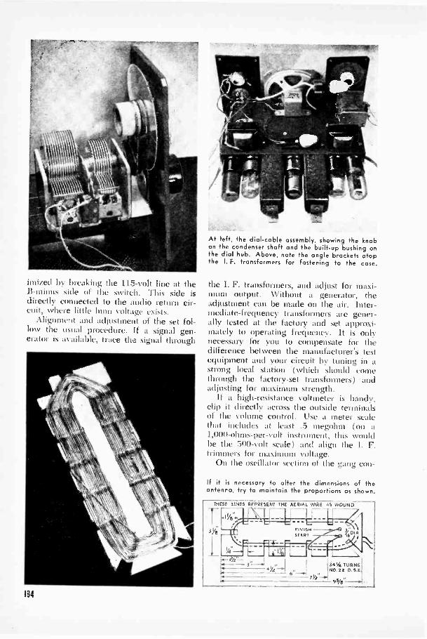
imized by breaking the 115 -volt line at theB -minus side of the switch. This side isdirectly connected to the audio return cir-cuit, where little hum voltage exists.
Alignment and adjustment of the set fol-low the usual procedure. If a signal gen-erator is a% ailable, trace the signal through
194
^7,1754-'311tr
At left, the dial -cable assembly, showing the knobon the condenser shaft and the built-up bushing onthe dial hub. Above, note the angle brackets atopthe I. F. transformers for fastening to the case.
the I. F. transformers, and adjust for maxi-mum output. Without a generator, theadjustment can be made on the air. Inter-mediate -frequency transformers are gener-ally tested at the factory and set approxi-mately to operating frequency. It is onlynecessary for you to compensate for thedifference between the manufacturer's testequipment and your circuit by tuning in astrong local station .( which should comethrough the factory -set transformers) andadjusting for maximum strength.
If a high -resistance voltmeter is handy,clip it directly across the outside terminalsof the volume control. Use a meter scalethat includes at least .5 megohm (on a1,000 -ohms -per -volt instrument, this %you'dbe the 500 -volt scale) and align the I. F.trimmers for maximum voltage.
On the oscillator section of the gang con -
If it is necessary to alter the dimensions of theantenna, try to maintain the proportions as shown
THESE LINES REPRESENT THE AERIAL WIRE AS WOUND
FINISHSTART
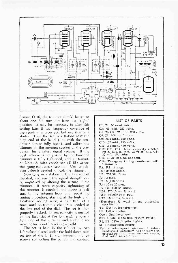
FLOATING" GROUND-'
denser, C 16, the trimmer should be set toabout one full turn out from the "tight"position. It may be necessary to alter thissetting later if the frequency coverage ofthe receiver is incorrect, but use this as astarter. Tune the set to a station near thehigh end of the band (i.e., with the con-denser almost fully open), and adjust thetrimmer on the antenna section of the con-denser for greatest signal volume. If thepeak volume is not passed by the time thetrimmer is fully tightened, add a 10-mmf.or 20-mmf. mica condenser (C 15) acrossthe gang -condenser section. Use which-ever value is needed to peak the trimmer.
Now tune in a station at the low end ofthe dial, and see if the signal strength canbe improved by altering the setting of thetrimmer. If more capacity-tightening ofthe trimmer-is needed, add about a halfturn to the antenna loop, and repeat thetuning procedure, starting at the high end.Continue adding wire, a half turn at atime, until no trimmer change is needed atthe low end of the dial. The set is thenproperly tracked. If less capacity is neededon the first trial at the low end, remove ahalf loop of the antenna and continue re-moving turns until tracking is right.
The set is held in the cabinet by twoL -brackets placed under the hold-down nutson top of the I. F. transformer:, and byscrews connecting the pane!: and cabinet.
LIST OF PARTSCl, C2: 50 mmf. mica.C3: .05 mfd., 250 volts.C4, C5, C8:.25 mfd., 250 volts.C6, C7: 100 mmf. mica.C9: .002 mfd., 250 volts.010:.02 mfd., 250 volts.C11:.01 mfd., 450 volts.C12, C13, C14: triple -capacity electro-
lytic. C12, 20 mfd. 25 volts; C13, C14.20 mfd. 150 volts.
C15: 10 or 20 mfd. See text.C16: Two -gang tuning condenser with
trimmers.11.1, R8: 1 meg.R2: 35,000 ohms.R3: 250,000 ohms.R4: 2 meg.R5: 50,000 ohms.R6: 10 to 20 meg.R7, R9: 500.000 ohms.R10: 170 ohms. 1/2 watt.R11: 500,000 -ohm pot.R12: 25 ohms, watt.(Resistors 14 watt unless otherwise
specified.)Ti: Output transformer.Ll: Filter choke.Osc.: Oscillator coil.Sw: 4 -pole, 3 -position rotary switch.P1, P2: 115 -volt pilot lights.M: Phonograph motor.Permanent -magnet speaker. 2 inter-
mediate -frequency transformers,crystal pickup. tubes. sockets, knobs,dial, misc. accessories.
195

Three -Pound
Radio h
OH the
housed in a etit-down file box, thislittle personal portable really drags inBy Albert Rowley
HOW much radio can you stuff into aportable, and how small can you make
it? POPULAR SCIENCE asked these two ques-tions, and here are my answers. The first is"plenty." The second is that with standard,easily available parts, you can boil it downto a three -pound package 3);" by 53r by 6".
Smaller sets can be made, but they'll prob-ably offer less radio. Here's a honey of acompromise between size and performance.It gives you a four -tube superhet circuit,good loudspeaker volume, and enough sen-sitivity to pull in practically everything onthe air. In tryouts the signal -grabbing quali-ties of this midget put several table -modelradios to shame.
It's a natural to take along to the ballpark-easier to carry than your best girl'shandbag. Your favorite sports announcer
196
stations.can feed you the statistics on the game whileyou watch, and if leather -lunged fans aroundyou get too noisy, all you have to do is plugin the earphone jack and listen in quiet andprivacy. And don't worry about having totote extra batteries to keep the set alive.This model went through two ball games onthe same single -cell A supply.
Your first job is to assemble the parts, andthat means careful shopping and selection.Chances are the spare -parts box won't beof much help in this case because you haveto make sure, before using any part, that nosmaller one is available. Be sure to specify;I -watt fixed resistors, and get the smallestpaper tubular condensers you can. Theydon't have to be rated higher than 200 voltsas they won't have anything over 70 voltsto cope with. Mica condensers don't haveto be any larger than 7/16" by 11/16". Youmay find a volume control even smaller than
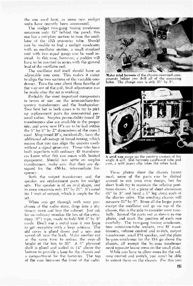
the one used here, as some new midgetunits have recently been announced.
The midget two -gang tuning condensermeasures only 1%" behind the panel; thisone has a cut -plate section to tune the oscil-lator of the 1115 converter tube. Shouldyou be unable to find a midget condenserwith an oscillator section, a small standardunit with two equal gangs can be used in-stead. In this case, however, a gadder willhave to be inserted in series with the groundlead of the oscillator coil.
The oscillator coil itself should have anadjustable iron core. This makes it easierto align the two sections of the variable con-denser. Turn the core about three fourths ofthe way out of the coil; final adjustment canbe made after the set is working.
Probably the most important componentsin terms of size are the intermediate-fre-queney transformers and the loudspeaker.Your best bet in both cases is to try to pickup replacement parts for commercial per-sonal radios. Surplus permeability -tuned IFtransformers also are available in the propersize, and some new IF's are to be had withinthe 31" by 'V by 2" dimensions of the ones Iused. Slug -tuned IF's, incidentally, have theadditional advantage of broad -tuning, whichmeans that you can align the circuits easilywithout a signal generator. Those who havebuilt superhets with ordinary IF transform-ers know what this can mean with limitedequipment. Should you settle on surplustransformers, make sure that they are de-signed for the 456-kc. intermediate fre-quency.
Both the output transformer and thespeaker are replacement parts for midgetsets. The speaker is of an oval shape, andits cone measures only 1%" by 2V. It's ratedfor 1 watt of output, which is ample for theset.
When you get through with your pur-chases at the radio store, drop into a sta-tionery store and buy the cabinet. Just askfor an ordinary wooden file box of the extra -deep ( 6") type, made to hold 500 3" by 5"cards. Don't use a metal case if you hopeto get reception with a loop antenna. Theold cover is glued down and a new onesawed off near the back. Make another cutat the same time to reduce the over-allheight of the box to 3%". A 31" plywoodshelf is glued and nailed in 1%" above thebottom to provide a base for the chassis anda compartment for the batteries. The topof the case becomes the front of the radio.
ask IttMake trial knout, ut the chassis -mounted com-ponents before you drill all of the mountingholes. The chassis area is only 2N" by 5".
grid cap snaps on the positive contact of thesingle A cell. Slid between cardboard tube andcase, a split paper clip takes the other lead.
These photos show the chassis layoutused; some of the parts can be shiftedaround to suit your own design, but forshort leads try to maintain the relative posi-tions shown. Cut a piece of sheet aluminum4%." by 5" and bend a 7;," leg along each ofthe shorter sides. The resulting chassis willmeasure 2%" by 5". Since all the larger partsexcept the oscillator coil go on top of thechassis, this is the side to consider most care-fully. Spread the parts out as shown in onephoto, and mark the position of each onecarefully. The two -gang tuning condenser,four miniature -tube sockets, two IF trans-formers, volume control and switch, outputtransformer, small PM speaker, and the plateby-pass condenser for the 1S4 go above thechassis; all except the by-pass condenserneed separate house room on the small plate.
While you have to allow room for the vol-ume control and switch, you won't be ableto mount them on the chassis. For this you
191
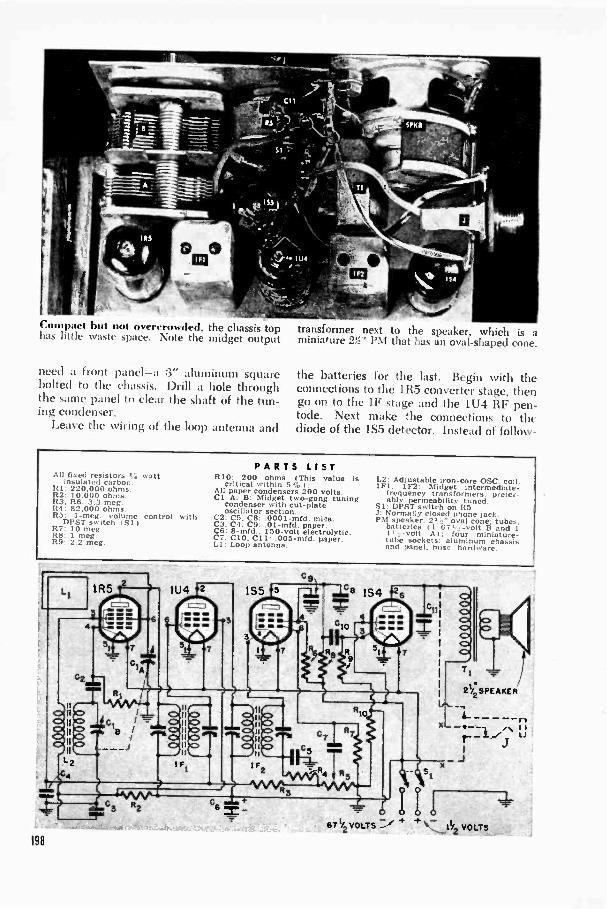
Compact lint not overcrowded. the chassis tophas littlt \\ .t.tc space. Note the midget output
need a front panel-a 3" aluminum squarebolted to the chassis. Drill a hole throughthe same panel to clear the shaft of the tun-ing condenser.
Leave the wiring of the loop antenna and
transformer next to the speaker, which is aminiature 2Y/' PM that has an oval -shaped cone.
the batteries for the last. Begin with theconnections to the 1R5 converter stage, thengo on to the IF stage and the 1U4 RF pen-tode. Next make the connections to thediode of the 1S5 detector. Instead of follow -
PARTS LISTAll fixed resistors .4 watt RIO: 200 ohms (This value isinsulated carbon. critical within 5 S7 i .RI: 220.000 ohms. All paper condensers 200 volts.R2: 10.000 ohms. Cl A. B: Midget two -gang tuningR3, R6: 3.3 meg. condenser with cut -plateR4: 82.000 ohms. oscillator section.R5: 1-meg volume control with C2, C5, C8:.0001 -mid. mice.DPST switch i Si I . C3. C4. C9: .01-mfd. paper.R7: 10 meg. C6: 8-mfd.. 150 -volt electrolytic.R8: 1 meg. C7. C10. C11: .005-mfd. paper.R!1 2 2 mee Lt . Loop antenna.
L2: Adjustable iron -core OSC. coil.1F1. 1F2: Midget intermediate -
frequency transformers, prefer-ably permeability tuned.
Si: DPST switch on R5.J: Normally closed phone jack.PM speaker, 21 oval cone: tubes,
batteries (1 671a -volt B and 11 I 2 -volt A I; four miniature -tube sockets: aluminum chassisand -lane!. mis. hardware
198

No rat's nest. the underside of the chassis is ever, a plawied wirintz ,ineoce will help tono tougher to wire than many larger sets. prevent yon from 2etti!!2 hadly in your own way
ing the usual segnence right through, it maybe better to stop at this point :old ci!!!!!!nlicewiring the speaker. Work back ard fromhere to the pentode portion of the 155. Thenetwork of resistors and condensers that goto the grid, screen and plate of this tube andto the grid of the 1S-1 ()input tube are thelast of the small parts to be connected. Thiswiring sequence isn't essential, but it willhelp you find soldering room.
Headphones aren't necessmy with this setbut there are times when you will find themhandy, so an optional phone jack is shownin the diagram. The jack to use is a normal-ly closed unit that completes the loudspeakercircuit when the phones are not being used.Plugging in the phones automatically breaksthe connection to the speaker.
For noisy spots, weak stations, or privatelistening, earphones arc nice extra equip-ment. But if you should decide to pass themby, all you have to do is omit the portionshown by broken lines and connect the twowires marked in the schematic drawing.
Drill a hole through the rear flange ofthe chassis and insert a rubber grommet.Through it you can bring fiair leads-pre-ferably color coded-to the batteries. Thecoding is only to help you until the connec-tions are made, since two of the leads aresoldered to a standard, polarized clip thatis used on 671't -volt batteries. The wire goingto the positive (center) terminal of the flash-light cell is soldered to a grid -cap clip. Forthe negative connection a paper fastener is
soldered to the lead and inserted betweenthe metal shell of the battery and its card-board sleeve. Cells of the sleeveless typewill require a different connection.
When the chassis is completely wired,connect the batteries and loop antenna andtune the circuits for maximum volume andsensiti% ity. Start with the secondary of 1F2,and work back to the primary of 1 F1. Bringin a station at the high end of the dial (withthe timing -condenser plates out of mesh)and adjust the trimmers on the side of thevariable condense!. Take care of the oscilla-tor trimmer first.
You'll find that you can strengthen weakstations a little by opening the back coverand allowing the antenna to swing abouttwo or three inches away from the metalchassis.
40'
(11Ir
Plugging in the phones automatically cuts offthe speaker. Phones are tmod ill noisy locations.

RF BoosterStretches
Radio's Rangein an Ixlra -'-egy of ampfilicali RI raft itop-cot thy performance of small portables.
.%. i011 out of the slide top of a ci:z ,-rctte cam cills for a 34- angle bracket, a flatmending plate, soldering lugs, and hardware.
Assembly of the switch can be seen here. Theview is through a by 2" rectangular cut-out made in the side of the cigarette cast.
.1//ocri ittruleu
ILIKE my portable radios small. It makessense to me to have a little set that I can
lug around without onethat threatens to pull my arm off at theshoulder.
At the same time I know my compactportable doesn't have as much pick-up powerbuilt into it as one of the larger, more ex-pensive sets. It works fine close to a smallstation and up to 50 miles from a high-powered transmitter; but when I take it ona long ride. performance definitely falls off.
To overcome this defect, I built an RFbooster for my set. It consists of an untunedRF stage packed in a plastic cigarette case.It can be plugged into the portable whenand if it's needed. The booster increasesthe signal pickup of the portable, convertingits four -tube circuit into a five -tuber on
A 5 -prong wafer socket mounted in the backof the cabinet supplies both electrical contactand mechanical support for the booster.
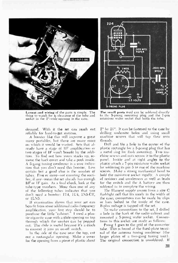
Layout and wiring of the parts is simple. Thething to watch for is clearance of the tube andsocket in the 2" -wide opening in the case.
demand. With it the set can reach outreliably for hard -to -get stations.
A booster like this will improve a greatmany portables, but there are many moreon which it would be wasted. Sets that al-ready have a stage of RF amplification ortwo stages of IF won't benefit by the addi-tion. To find out how yours stacks up, re-move the back cover and take a peek inside.A 3 -gang tuning condenser is a sure indica-tion that you don't need this booster. Lesscertain but a good clue is the number oftubes. Five or more-not counting the recti-fier, if any-mean the set already has enoughRF or IF gain. As a final check, look at thetube -type numbers. More than one of anyof the following tubes indicates that youdon't need a booster: 11'4, 1U4, 1N5-GT,or 1LN5.
If examinatio shows that your set canbenefit from some additional radio -frequencyamplification, your first step should be topurchase the little "cabinet." I used a plas-tic cigarette case with a slide opening on topthrough which the smokes can be 'poppedout. The slide is useful because it's a cinchto convert it into an on -off switch.
In the side of the case near the top, cutout a rectangular opening. Make a coverfor the opening from a piece of plastic about
The small parts used can be soldered directlyto the 5 -prong mounting plug and the 7 -pinminiature wafer socket that holds the tube.
2" by 211". It can be fastened to the case bydrilling undersize holes and using smallmachine screws that will tap their ownthreads.
Drill and file a hole in the center of theplastic rectangle for a 5 -prong plug that hasa metal ring for flush mounting. Two ma-chine screws and nuts secure it to the plasticpanel. Inside and at right angles to theplastic attach a 7 -pin miniature wafer socketby soldering its pin 5 to one of the machinescrews. Make a strong mechanical bond tohold the miniature socket rigidly. A coupleof resistors and condensers as well as leadsfor the switch and the A battery are thensoldered in to complete the wiring.
The filament supply comes from a size Cflashlight cell that fits nicely in the width ofthe case; connections can be made by clipsor bars bolted to the inside of the case.B -plus voltage is tapped off the set.
To make connections to the set, I drilleda hole in the back of the radio cabinet andmounted a 5 -prong wafer socket. Connec-tions to this socket are made as follows:
Prong 1 goes to the grid of the convertertube. This is found at the fixed -plate termi-nal of the antenna tuning condenser (thelarger plates of a two -gang tuning unit).The original connection is unsoldered. If
201

there are two connections at this point, don'ttouch the one that goes to the loop antenna.Prong 2 goes to the wire you have just un-soldered from the tuning condenser. Prong3 runs to the i:hassis of the set. Prong 4leads to the positive terminal of the B bat-tery. If you have a S -way portable, it maygo either here or to a B -plus point insidethe set. Prong 5 can go either to the chassis
of the set or to the AVC line (the black leadfrom either of the IF transformers). Tryboth of these connections and solder it per-manently to the one that gives best results.
For those times when the booster isn'tgoing to be used, buy an extra 5 -prong plugand solder a jumper lead between prongs1 and 2. Plugging in the jumper in place ofthe booster restores the original circuit.
B Supply Cuts Battery Cost
Listen all you want without draining those ex-pensive batterici. The little box supplies Bvoltage; weight of the portable turns it on.
Parts are mounted (1) a flat chassis that isfastened inside the steel box by machine screwsslipped through the rubber feet.
202
HAVING discovered how easy it is tomake my small portable behave like a
bigger set, I decided to get rid of anothersore spot in its operation-the high cost ofB batteries. It's no fun to shell out a coupleof bucks every few Nveeks to replace theweakened battery. For very little more thanthe price of a replacement battery I builtthis perpetual B supply that works off any115 -volt AC or DC line. I still use flashlightcells for the A supply, but their cost is in-significant.
Like the RF booster described above, thisdevice is independent of the set and doesn'timpair its usefulness as a portable. Whilemy set uses a 6Th -volt battery, the sameeliminator will serve other sets requiring upto 90 volts. It would be useless, naturally,on 3 -way portables.
Instant warm-up is retained by using a100 -ma. selenium rectifier. This and allother parts are assembled inside a steel first-aid box measuring 13(/' by 4V by 7W'.You'll find a cabinet of about this size con-venient, since it forms a platform on whichto rest the set.
The shaft of the voltage -regulating potenti-ometer is sawed off to fit inside the box. Slotthe shaft to permit screwdriver adjustment.

On top of the box and insulated from itby pieces of fiber are two 1" by Ifi" alumi-num contact plates. The remaining partsare mounted on a flat chassis inside that issecured by four mounting screws throughthe bottom. Use rubber insulating feet onthe bottom and never set the box on agrounded metal surface like a radiator orsink. Better still, use a plastic chassis panelto insulate all components frmn the box,wiring together the gromide(1 points in thediagram, and put in a two -pole switch in-stead of a single -pole one. This xvill openboth sides of the power Ifiie. You couldstill get a shock by pushing, the switch andtouching the terminal plates, or one plateand all outside ground. so keep the gadgetaway from kids.
One side of the line cord is connected tothe negative terminal 44 the selenium recti-fier through a :30-ohin wire -wound resistor.The other side roc. to the chassis througha push-tvpc switch i SI). An aluminumstrap holds this switch upright, permittingthe plunger to project through a hole in thetop of the cabinet. The switch is of thenormally -off type. It is turned on by theweight of the radio and goes off automati-cally when the set is lifted off. It's a goodidea to remove the set \Olen you are throughlistening. for current will continue to flowthrough R3 even with the set turned off.
Voltage output is regulated by a wire -wound potentiometer rated at 2 watts ormore and having a resistance of 10,000ohms. l'ou can adjust this to any value fromabout 60 to 100 volts. Set it 10 to 15 per-cent above the nominal rating of the batteryused in your portable. The higher voltagewill make the set more sensitive than itusually is on batteries alone, and it won'tdo any harm to the circuit components.
You'll have to make a few minor changesin the receiver. The first is to make somearrangement for disconnecting the batterywhen the eliminator is used. To (lo this.simply cut the lead to the plus terminal ofthe B battery and connect it to the centerarm of a SPOT toggle switch. \\'ire oneside of the switch to the battery and theremaining switch terminal to an aluminumcontact on the bottom of the cabinet. Thecircuit and suggested method of attachmentare shown at the lower right. Make surethat the contacts on the set line up withthose on the eliminator. The switch can beplaced in the back panel of the radio.-. 1-bert Rowley. Manhallan. N.1.
10000 OHM 1,000WIRE -WOUND OHMS ,
POT. 2 WATTS /
671/2
VOLTS
12 MFD. 4 C420 MFD.150 VOLTS 160 VOLTS
,SELENIUM" RECTIFIER
30 OHMS2 WATTS
Cl
/ Min.001MFD.
\ 400 VOLTS40MFD.150 VOLTS SI
--opo PUSH SWITCHrol OROPM1E1ANL)L Y
Wiring shown is fin- a metal chassis. To makethe unit still safer. use a plastic 'mod. aDPDT switch. and connect all grounds together.
Conner to the port:1 I 111:1(1e dir, tlyto the battery terminals. The b -plus tine iscut and rewired through a toggle switch.lr
[PORTABLE SOLDERING'CABINET LUG
ALUMINUM STRIP
ALUMINUM FIBER
SOLDERING LUG
ELIMINATOR CABINET
B+ LEAD(DISCONNECT!
,o FROMBATTERY)
J
CONTACT STR PS i
(:onlaet Aril). area tided to the bottom of theradio. These most 1 Ile III1 ,it.. the c'' :t irts 011the elimiu.aur, The out. r is
203

Cott ertillg
1C -DC Sets
to Portables
Need a portable? Switch your AC -DCmidget to battery power. It costslittle and doesn't harm the set.
By 444Maul NortonSUMMER months are outdoor months, and
radios that can't get out into the openwith you don't fit into the picture very well.But if you already own a number of house-bound receivers, you may have some objec-tion to buying or building still another set.You don't have to. One of those AC -DCmidgets has the makings of a good batteryportable. It isn't even necessary to make any
Hethethe
204
e all t iIo, before starting to work onset. Mark each socket with the number oforiginal tube and its battery replacement.
. u 1,1 emi mfe as
fIrrArTrel
New tubes and some minor changes turn this midgetradio into a self -powered portable-and back again.
permanent changes in the circuit. To re-store the portable to AC -DC operation, youneed only replace the original tubes andthrow a switch.
The main consideration is tube substitu-tion. The table on page 207 covers the com-moner tube lineups. It is impossible to showall variations, but the chances are that if theset uses standard -size tubes and was manu-factured in the last dozen years, it will fallinto one or another of the main groups listed.The more recent midgets employing minia-ture tubes are not included since these can'treadily be converted by the method de-scribed. In some cases you may also find aset that overlaps two groups.
Many of the tubes in the chart offer thepossibility of simple plug-in substitution.All you have to do with a 7A8 converter, forexample, is lift it out of its socket and slipin a 1LA6. Pin connections are the same.
Some problems arise, however, when itcomes to changing the detector tube. MostAC -DC sets use dual diode triodes in thisstage while battery detectors are generallysingle diode triodes or pentodes. For the firsttwo groups the 1S5 miniature diode pentodeis suggested. In the third group you have achoice of this tube or the IH5. Since thelatter tube is a triode, it may not give asmuch amplification. However, it can beplugged in in place of the 6Q7, while for the1S5 you'll have to make an adapter socket.
The adapter socket for a 1S5 consists of a

7 -pin miniature wafer socket mount. 'II ontop of au octal or luck -in base-wl le% Cr
matches the socket in the set. For the adapt-er base use a burnt -out tube. If you don'thave the right kind in your workshop, youcan pick one up for a few cents from a localrepairman. Place the tube in a paper bagand give it a sharp hammer blow to breakthe glass. Using pliers and cutters, removethe loosened elements and break off any re-maining glass.
Octal bases are easier to Nvork with sincethe prongs are hollow on the inside. Ilemovethe old connections by melting the milderand make new ones by inserting wires intothe hollow prongs and flowing in solder. Usesolid tinned wire of fairly heavy V.:uu,: \o.18 is about right-making sure that the ireis well insulated. Bare wire can be coveredwith plastic spaghetti.
If your set uses lock -in tol,es, file the partof the pin that protrudes inside tit, hose.Filing cleans the metal and allows the Ade('wires to be soldered on firmly.
\\here the 1S5 pentode is 'used I. icolacea triode, some provision must lir forthe screen grid. This is coil. weted In plusthrough a 680,000 -ohm. att resistor. Amidget .01-mfd., 200 -volt paper tubular con-denser provides a bypass path toBoth these p:uts are nr.nmrted direc:Ik.orsthe miniature socket. In die chart. idof the resistor is shown connected io pin 2.a dead prong used as an point.
If you plan to reconvert ttr louse at any fnture time, it is Avis .ble to is..phone tips and jacks for It -isle,: .and flit rconnections so that the original canbe easily restored. Find a 11-ohis point irthe receiver-usually at the screen _'d ofthe power output tube-install an insulatedphone jack on the chassis, and wire the twotogether. The lead from pii. 2 of the 185socket can terminate in a ph.nie tip and beplugged in whenever the tube is inserted.
A second lead (turn the adapter socketgoes to another phone j,uk on the chassis.This connects the second diode okay in theoriginal circuit to A -plus through a 1-meg.resistor. The reason for this connection isthat the single -diode 185 is being used inplace of a dual -diode detector in the orig-inal set. In sonic sets this wiring isn't nec-essary so if you like you can try the set firstbefore inserting it.
All AC -DC receivers have beatersconnected in series. By leas -nisi; them 111:itway it is possible to avoid rewiring. Make
To make an adapter M'il:t4 a 1.1ds v, iththe right base mid break till the 2Iass. Pilethe pills that protrude inside a hick -in base.
This adapter allows the halters tube to Inpivigged in in place of the original tithe. Newwiring i. made at the socket, not in the set.
.0% 411110,-.
fa&7 -pin lll i ll ;attire wafer socket, used upside
down, and the base of a burnt -out tube arewired together to make the adapter socket.
sure there are no resistors in series with theheaters. If there arc. they will have to beshorted out with a switch. One end of thefilament string is usually grounded at thedetector stage. Connect the negative A -bat-tery lead at this point. The B battery is notgrounded to the chassis directly; instead itgoes through a bias resistor. The installationof this resistor-which should be between:3;30 and 680 ohms-is shown in one of thedrawings. One side of the output tube's gridresistor must be disconnected from chassisor ground and wired to B -minus. When theset is restored to AC -DC operation, the small
205
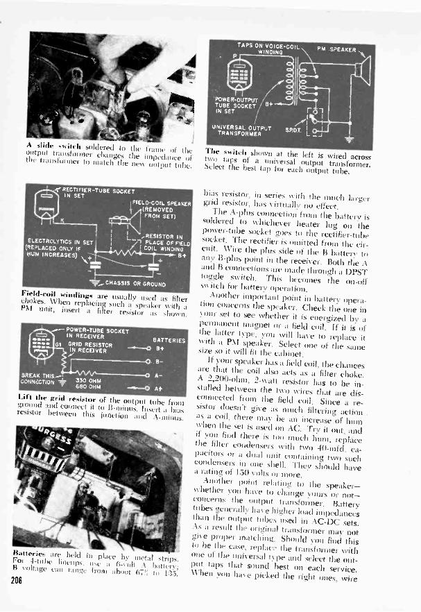
Aide switch ,oldered to the frame of theoutput transformer changes the impedance ofthe transformer to match the new output tube.
..,RECTIFIER -TUBE SOCKETIN SET
,FIELD -COIL SPEAKER(REMOVEDFROM SET)
I
_RESISTOR INELECTROLYT1CS IN SET . i
L, _PLACE OF FIELD(REDLACED ONLY IF / I COIL NINDINGEl+HUM INCREASES) +
mho +'1° 1---= CHASSIS OR GROUND7----
Field-coil windings are usually used as filterchokes. When replacing such a speaker with aPM unit, insert a filter resistor as shown.
POWER -TUBE SOCKETIN RECEIVER
BATTERIESG1 GRID RESISTCR
8+IN RECEIVER
0 S-
A-BREAK THISAA:CONVECTION 330 OHM
680 OHM -*--0 A+
Lift the grid resistor of the output tube fromground and connect it to B -minus. Insert a biasresistor between this junction and A -minus.
Itaneries are held in place by metal strips.For -1-tube lineups. use a .A 1 hat,flB voltage can range from about 135.
TAPS ON VOICE -COILWINDING
POWER -OUTPUT 'TUBE SOCKET / IN SET
UNIVERSAL OUTPUT SP.D.TTRANSFORMER
PM SPEAKER
The st.itell shown at the left is wired acrosstwo taps of a universal Output transformer.Select the best tap for each output tube.
bias resistor, in series with the much largergrid resistor, has virtually no effect.
The A -plus connection from the battery issoldered to whichever beater lug on thepower -tube socket goes to the rectifier -tubesocket. The rectifier is omitted from the cir-cuit. Wire the plus side of the B battery toany B -phis point in the receiver. Both tile Aand B connections are made through a DPSTtoggle switch. This becomes the on -offswitch for battery operation.
Another important point in hatters' opera-tion concerns the speaker. Check the one inour set to see whether it is energized by a
permanent magnet or a field coil, If it is ofthe latter type, you will have to replace itwith a PM speaker. Select one of the samesize so it will fit the cabinet.If your speaker has a field coil, the chances
are that the coil also acts as a filter choke.A 2,200 -ohm, 2-watt resistor has to be in-stalled between the two wires that are dis-connected from the field coil. Since a re-sistor doesn't give as much filtering action
.as a coil. there may be an increase of humwhen the set is used on AC. Try it out, andif you find there is too much hum, replacetile filter condensers with two -10-mfd. ca-pacitors or a dual unit containing two suchcondensers in one shell. They should havea rating of 150 volts or more.
Another point relating to the speaker-whether you have to change yours or not-concerns the output transformer. Batterytubes generally have higher load impedancesthan the output tubes used in AC -DC sets.As a result the original transformer may notgive proper matching. Should you find thisto be the case. replace the transformer withone of the universal type and select the out-put taps that sound best on each service.When you have picked the right ones, wire206

B
ACT
TER
DC
B
ER
AC
DC
CONVERTER TUBE I.F TUBE I DETECTOR TUBE
(SNIP THIS G2(PENT)PIN OFF)
o 5 4 0 ,7",636 3
078lo P
F- M F+
I LA61
ILN5GROUP NO I (LOCK -IN) INT
G3 GI SHIELD,... G3
G5" oG4 o,5 4.0 G2 GI
G6
7A8 i7B7
G3 NC
6SA7- GT12SA7- GT
1 A7-GTGROUP N0.3 (OCTAL)
G3GI G4
6A8 (GT)
6 SK7 (GT)12 SK7 (GT)
I N5-GT(GRID CAP)
GG3 2
6K7 (GT)
P
(PENT)
GI(PENT)
P 2) , INTo
%ICDEI) 5 4CON
AVC 6 3 (TRIODE)PIN 07 2
K 8 I P
H u M(TRIODE)
50A5 35A5
POWER OUTPUT TUBE
GI G2
I TS-GT
P(PENT.
(PENT)
P(DIODE1)
P65 4 3 07 2
l0 (TRIODE)(TRIODE) 4, SHIELD
6SQ7 (GT)12SQ7 (GT)
I MEGI
P(DIODE)
G2 (PENT)4P(DIODE)
5 3
6 27 I
P(DIODE 2)A+
K
GRID
1H5-GT
6Q7 (GT)
G2
076to o F+
NC NC
1T5-GT
35L6-GT50L6-GT
GI G2
5 43o
0 7,43 0F+
NC NC
1T5-GT
K NCG3
25L6 (GT)
Pick your tube lineup. Battery substitutes or adapter sockets are given. All are top views.
them across a SPDT switch as shown in oneof the drawings. The switch allows you toselect the correct match for either batteryor house -line operation. Like many of theother alterations, this one won't be neededin all cases. If cm already have a PM speak-er in your set, try the battery conversionwith the original transformer before invest -Mg in a new one.
Batteries can be held in place by metalstraps. Fasten the straps with screws.
or with nuts and bolts if you have a plasticcabinet. For series filaments, a 6 -volt A bat-tery is about right for a 4 -tube circuit, omit-ting the rectifier; B voltage can vary more.Depending on the space in the cabinet, youcan use one or two 67% -volt batteries in seriesto give a total of 135 volts, or two 45 -voltstotaling 90 volts. This gives you a choice of67%, 90, or 135 volts. The set should workwith any of these arrangements, but morevoltage usually gives higher output.
201

Oscillator -Amplifier
is Y0111.
Master Music System
Recorded music or your own voice goes over the airwaves at the mere flick of a switch.
1 4)ii can play it through its own..peaker, any nearby radio, or youcan combine both at the same time.fly Henry I'. Martin-FARCE households can get the most out1--.1 of this centralized control system thatpipes music anywhere in the house, butyou'll also find it handy if you have any -
Connections for speaker, phono motor, pickup,and mike are made by means of plugs and jacks.
thing larger than a one -room apartment.Here's a unit that combines two types ofrecord player-a direct amplifier and anoscillator that broadcasts through any near-by radio. The features may be used to-gether, or either one will work by itself.While your wife enjoys a stack of recordsin the living room, you can have the samemusic in your basement shop. Those littleradios in the kitchen or an upstairs bedroomcan also pick up the program. And if youhave a few radios strategically locatedaround the house, the microphone andoscillator become a handy one-way intercomto summon you to the telephone or to din-ner. All this and a hundred other uses ofyour own devising are controlled from thesingle switch panel on your master musicsystem.
An automatic record changer was used inthis model and is recommended, but aseparate motor and crystal pickup wouldoperate just as well on a one -record -at -a -timebasis. Also, if you are in an experimental
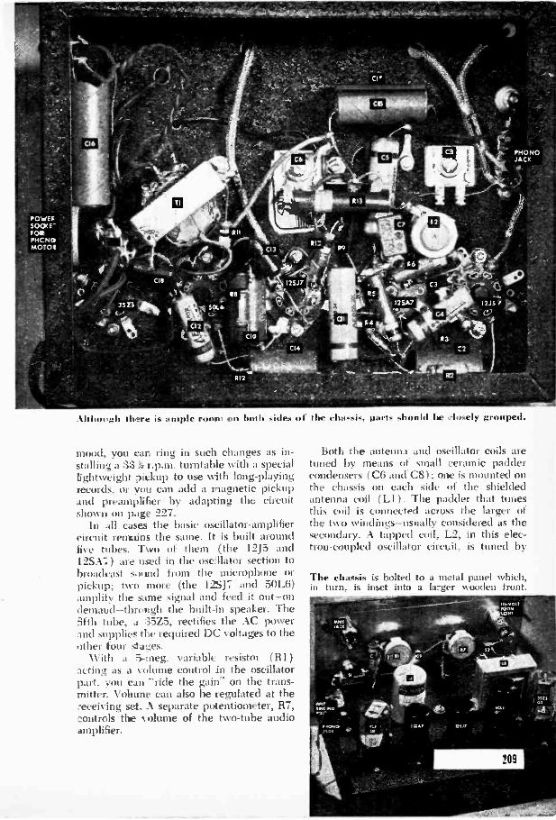
Although there is ample room on both sides of the chassis, parts should he closely grouped.
mood, you can ring in such changes as in-stalling a 3:3 r.p.m. turntable with a speciallightweight pickup to use with long-playingrecords, or you can add a magnetic pickupand preamplifier by adapting the circuitshown on page 227.
In all cases the basic oscillator -amplifiercircuit reirmins the same. It is built aroundfive tubes. Two of them (the 12J5 and1.2SA; ) are used in the osellator section tobroadcast sound from the microphone orpickup; two more (the 1.17 and 50L6)amplify the same signal and feed it out-ondemand-through the built-in speaker. Thefifth tube, a 35Z5, rectifies the AC powerand supplies the required DC voltages to theother tour stages.
With a 5-meg. variable resistor (R1)acting as a olume control in the oscillatorpart. you can "ride the gain" on the trans-mitter. Volume can also be regulated at thereceiving set. A separate potentiometer, R7,,controls the olume of the two -tube audioamplifier.
Both the antenna and oscillator coils aretuned by means of small ceramic paddercondensers (C6 and C8); one is mounted onthe chassis on each side of the shieldedantenna coil (LI ). The padder that tunesthis coil is connected across the larger ofthe two windings-usually considered as thesecondary. A tapped coil, L2, in this elec-tron -coupled oscillator circuit, is tuned by
The chassis is bolted to a metal panel which,in turn, is inset into a larger wooden front.

the second padder. Once the padders havebeen correctly set (by means of a smallscrewdriver adjustment) they S110111(1 IICIA1
110 further Att. noon unless you decide tochange the Irevliuney of the little transmit-ter. It is important to insulate both 'ladder;from the chassis: this can be clone by meansof fiber washers as shown in the drawingbelow. The bottom washer should have aslight shoulder to make the insulation posi-tive and pre \ent the shaft from slidin, side-ways into contact with the nxtal.
As ean be seen in the photos. tht staiidard2" by 7" by 9" ch:1ssis that was used ismore than ample for all the iieeessars parts.It can be made smaller. but since the chassistakes a relatit el\ small portion of the totalspace ill any phonograph. the saving will notbe great. Fit c octal sockets for the tubesare mounted in a line along, the rear of thechassis. The filter choke ;Ind antenna coilare placed in front of the tutu's. and paddercondensers peer up from underneath on 1)0(11sides of Li. Almost directly underneath the
NUTS ADJUSTMENT SCREW
METALCHASSIS
PADDER CONDENSER
FIBERWASHERS
The nutlike e leasers miNt be insulated fromthe chassis. use tt.e fiber washers as shown.
210
choke and at right angles to it is a smalluniversal output transformer. The photo ofthe underside of the chassis shows two leadscoming from the secondary of this trans-former and terminating at a recessed two-comwetion socket in the side of the chassis.This was done for convenience ill assemblingthe unit ill a cabinet. The two leads coiningfrom the voice coil of the speaker ping intothe socket and ean readily ht disconnectedwhen the chassis has to be wino\ cd hit- anyreason.
With the same idea of making the chassisas independent its possible of external con-neclions. all other contacts are made byjacks or sockets. This arrangement. of course.is optional with the builder. The feed -through, I 15 -volt line into which the phonomotor can be d is brought to a re-cessed socket. This connection is tapped offthe lint ahead of the power switch (S2).Most automatic record changers have theirown switches so they can be stopped (forchanging records or when the microphoneis to he used) tt ithout cutting off the cur-
et going to the oscillator -amplifier. If yourchanger hasn't such a switch, or if you areusing a plain motor, insert zi SPST switch inseries with one side of the motor's line cord.
A two-cininection jack on the chassis re-ceives the -hot- and grounded leads fromthe crystal pickup. This jack is not accessiblewhen the unit is in a cabinet, hut there's noneed to get at it since switch Si changesover the input circuit from phonograph tomicrophone. Because the mike need not be

50L6- GT5
P.M.SPEAKER
gul/
2
1l5VOLTNEON
LIGHT
115 -VOLT
PHONOOUTLET
115 VOLTS AG
a permanent part of the assembly, its jackis placed on the front panel.
In the diagram above, some of the inputleads are represented as being made withshielded wire. If you trace the same portions
the circuit in the photos, you will findthat some of these leads are unshielded. Thiswas done because it was found convenientto keep these leads short. near the chassis,and out of the way of other wires. When thelayout allows this you way (Unit the shield.but otherwise it is a good idea to providefor it.
Cabineting the oscillator -amplifier is aIn:utter for individual taste. For convenience,a purchased cabinet designed to hold .t
record changer, amplifier and speaker wasused in the model illustrated. Although itwas relatively inexpensive, it did add aboutSI to the cost of the item-an amount youmay be able to save by constructing yourown cabinet or building the unit into a book-case or other piece of furniture. Total cost.incidentally, ran to about 535. including thecabinet and record changer but not countinga microphone. This changer cost somethingover S20. Other models are available at halfor twice this price. Since the componentsare all star dard. your spare -parts box maymake a big dent in the cost figure.
Wien you have completed and doublechecked the wiring, connect the speaker,phono motor, and pickup. turn on S2 andthrow SI to "phono" position. Give theamplifier a few seconds to warm up. thencheck for sound by scraping a finger across
LIST 0 F PARTS111, 117: 5-nivg. poteliti,.111rtrr.112: 1,800 -ohm, 1 -wattR3: 68,000 -ohm. 1, -watt earl114: 100,000 -ohm. arlmn.115, 116, 1110: 51.000 -ohm. ',watt carbon.118: 22,000 -olio. 1-, :at carbon.119:IIII: 680,000 -ohm, att carbon.R12: 390 -ohm. 1 -watt earls m.1113: 1,000-ohni. 10 -watt is ire -wound.
, C9, C13, C18: .01 -odd.. 400 -volt paper.C2: 5-mfd., 25 -volt do electrolytic.C3: .0002-mfd. ceramic.C4, C12: .006-mfd.. 100 -volt paper.C5, Cl I: .05 -mid.. -Hill-volt paper.C8, C8: 175 to 500 -mud. ceramic padder.C7: .0001-mfd. micaCIO, C14: 10-infd., 25 -volt dry electrolytic.C15, C17: 16-mfd.. 1.50 -volt dry electrolytic.C16: 24-mfd., 150 -volt dry electrolytic.1-1L.iShielded iron -core ant. coil for broadcast
12: Tapped oscs coil, air -core, unshielded, 956ke.
T1: Universal output transformer.SI: SPDT toggle.S2: -SPST toggle.P.NI. speaker, 11.5 -volt neon pilot lamp, record
(hanger or phono motor :Ind pickup, tubes,sockets. two -connector tacks ( 2) and plugs;recessed feed -through socket, '. hardware.
the pickup needle. There are no tuningadjustments to be made on the amplifiersection.
In order to transmit. however, you mustfirst align the oscillator paddcrs. Tune anearby radio to a dead spot near the lowend of the broadcast band-around 600 kc.on the dial. Adjust the padder across theoscillator coil first. This one is critical andshould be tuned by turning the setscrewslowly until the test signal is heard on theradio. For a test signal you can eithercontinue the needle scraping or play somerecords with the amplifier volume turnedway down.
When you have the oscillator padder setto its best position, adjust C6 for maximumvolume. Once the signal starts comingthrough the radio receiver, lower the volumeadjustment (RI 1 to keep from overloadingthe transmitter and distorting the sound.Keep this resistor at about the half -waysetting for the phonograph but turn it upfor the mike. When either the oscillator oramplifier is wanted by itself, set the controlof the other all the way down.
This two -tube oscillator has a husky out-put and with a long antenna is capable ofradiating signals further than the maximumallowed by the Federal CommunicationsCommission. To avoid trouble, keep theantenna short. A 5' or 6' piece of insulatedcopper wire left dangling behind the cabinetshould be adequate.
211
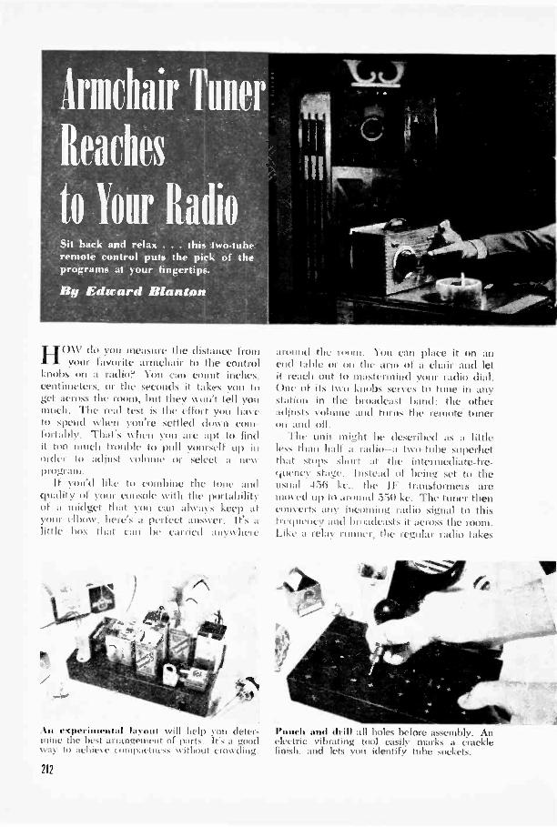
irmchair Tuner
Reaches
to lour Radio*Sit back and relax . . . this two -tuberemote control puts the pick of theprograms at your fingertips.
By Edward Wanton
HOW do you measure the distance fromyour favorite armchair to the control
knobs on a radio? You can count inches.centimeters, or the seconds it takes con toget across the room, but they on't tell youmuch. The real test is the effort Cott haleto spend 55 ('it you're settled drncu cootfortably. That's when you are apt to findit too much trouble to pull yotnrself tip illorder to adjust ohmic or select a mswprogram.
If you'd like to combine the tone andquality of your console with the portabilityof a midget that you can always keep atyour elbow, here's a perfect answer. It's alittle box that can he carried anywlwre
An experimental la. -out will help you deter-mine the best arrangement of parts. Its a goodway to achieve comp:tows% without crowding.
212
around the room. You can place it on anend table or On the arm of a chair and letit reach out to mastermind yIntr radio dial.One of its two knobs serves to tune in anystation in the broadcast band; the otheradjusts volume and turns the remote tuneron and off.
The unit might be described as a littleles. than half a radio-a two -tube soperbetthat stops short at the intermediate -fre-quency stage. Instead of being set to theusual 456 ke.. the IF transformers aremoved up to :wound 550 kc. The tuner thenconverts any incoming radio signal to thisfrequency and broadcasts it across the room.Like a relay runner, the regular radio takes
Punch and drill all holes before assembly. Anelectric vibrating tool easily marks a cracklefinish, and lets you identify tube sockets.

over at this point. When its dial is set tothe same frequency as the tuner's IF's (say550 kc.) it will pick up whatever programis being radiated by the little box.
Being half a radio, the tuner has half asmany components as a comparable smallset. Two 7 -pin miniature tubes plus a dry -disk selenium rectifier do the electronicwork. The tubes are a 6BE6 oscillator andfirst detector, and a 6BA6 IF amplifier.
For portability and general convenienceit is desirable to keep the tuner reasonablycompact. In assembling the tuner shown,the topside parts were arranged on a IV by4W' by 8" chassis, occupying a width of3V. After all holes were drilled andpunched, the extra 1r of chassis width washacksawed off.
Once the major parts are mounted youare ready to start wiring. The AC line cordis brought in under the chassis and helddown with a cable clamp. The two wiresfrom this cord are soldered to a two -lugterminal strip. One side of the power lineis grounded to the chassis through SPSTswitch Si. (Caution: This makes thechassis 'hot"; don't let it come in contactwith an external ground and don't touch itwhen the power is on.)
One side of each of the transformer wind-ings is also grounded. The ungrounded sideof the secondary-6.3-volt-winding goes topin 3 on both tube sockets. Both pins 4 arethen soldered to a chassis terminal to com-plete the heater connections.
The negative side of the selenium recti-fier is wired to the ungrounded side of the115 -volt primary winding of T1. Polarityis important here. The positive side of therectifier goes to the filter circuit through 116.
To save space, a strip wide \ as hacksawedfrom the standard 13:" by 4'2" In s" chassis. Thiswas done after layout, drilling, and punching.
Most manufacturers mark this side with ared dot or a plus sign.
If you'll recall what was said earlier aboutresetting the IF transformers, you will seewhy it is necessary to take special pains inthe selection and use of these transformers.Most commercial units are limited in rangeto from 400 to 500 kc., and these are nogood at all here. What's needed is a pairof wide -range IF's that are tunable to about600 kc. The bottom limit will probably beabout 380 kc., but this is less important.Be sure to mention these frequencies whenordering the transformers, and also add thespecification "iron core."
An old file cabinet measuring 4V by6%" by 8%" serves to house the tuner. Thehinged side becomes the front and an open-ing is cut in the back to allow free ventila-tion for the tubes. This hole is concealedby the loop antenna, which is mounted onthe back of the box with V brass spacersand 1" machine screws. A cover or protec-tive backing for the loop may be made fromany thin, nonmetallic sheet.
The opening in the back of the cabinetis also used to bring out the line cord anda 25' hank of wire that serves as the trans-mitting antenna (the loop is the receivingaerial). Fasten these leads with a cableclamp to keep them from pushing out onthe loop. The transmitter antenna is tossedout on the floor when the tuner is in use.
Adjusting the tuner is not difficult but ittakes a little patience. First turn on yourradio and set the dial to a quiet spotaround 550 kc. Put the tuner antenna (thetransmitter hank) close to that of the re-ceiver but without making direct contact.Now start raising the frequency of the IF
1
The stubby shaft on the t.\\ tuning con-denser used in this set (Iiih:t Lir the panel,so a shaft extension was attached as shown.
213
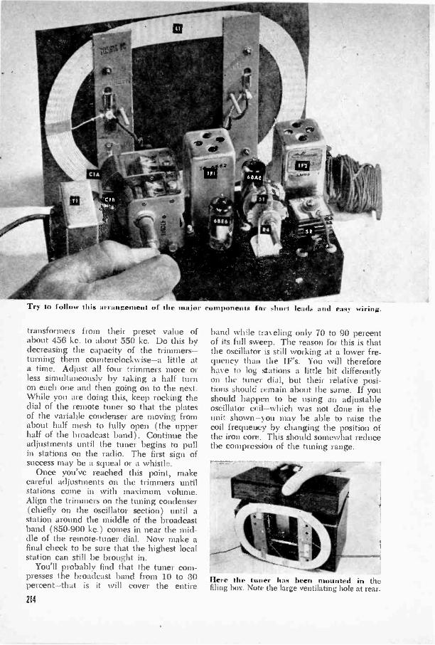
Try to follow this arrangement of the major components for short leads and easy wiring.
transformers from their preset value ofabout 456 kc. to about 550 kc. Do this bydecreasing the capacity of the trimmers-turning them counterclockwise-a little ata time. Adjust all four trimmers more orless simultaneously by taking a half turnon each one and then going on to the next.While you are doing this, keep rocking thedial of the remote tuner so that the platesof the variable condenser are moving fromabout half mesh to fully open (the upperhalf of the broadcast band). Continue theadjustments until the tuner begins to pullin stations on the radio. The first sign ofsuccess may be a squeal or a whistle.
Once you've reached this point, makecareful adjustments on the trimmers untilstations come in with maximum volume.Align the trimmers on the tuning condenser(chiefly on the oscillator section) until astation around the middle of the broadcastband (850-900 kc.) comes in near the mid-dle of the remote -tuner dial. Now make afinal check to be sure that the highest localstation can still be brought in.
You'll probably find that the tuner com-presses the broadcast band from 10 to 30percent-that is it will cover the entire214
band while traveling only 70 to 90 percentof its full sweep. The reason for this is thatthe oscillator is still working at a lower fre-quency than the IF's. You will thereforehave to log stations a little bit differentlyon the tuner dial, but their relative posi-tions should remain about the same. If youshould happen to be using an adjustableoscillator coil-which was not done in theunit shown-you may be able to raise thecoil frequency by changing the position ofthe iron core. This should somewhat reducethe compression of the tuning range.
Here the tuner has been mounted in thefiling box. Note the large ventilating hole at rear.

Bolt lieu of the completed chassis. It's "hot.," so see that it isn't externaII grounded.
LIST OF PARTSRIR2R3R4
10.000 -ohm. tZ-watt carbon22.000 -ohm. 'i-watt carbon330 -ohm. (2 -watt carbon.15.000 -ohm potentiometer oiih
C2C3C4CS
.0005-mfd. mica..05 -mid.. 400 -volt paper.50-mmf. ceramic.30-mfd.. 150 -volt dry electrolytic.
LI: Loop antenna.L2: Tapped oscillator coil.IFI. IF2: Input and output wide -
range (380-600 kc.) iron -core IFswitch (SI). 40-mfd.. 150 -volt dry transformers.
R5: 2.200 -ohm. 2 -watt carbon. electrolytic. SR: 100 -ma. selenium rectifier.R6: 51 -ohm. I -watt carbon. ,1 SPST rotary switch on R4. Miniature tubes and sockets. 25'Cl. A. B: 2 -gang. variable con- r1: Filament trans. with 6.3 -volt hank of antenna wire. tuning dial.
denser with cut -plate osc. section chassis. cabinet. misc. hardware.
68E6 6BA6
R5 R6
-=C5 =C6
2
5
SR
,-VOLUME CONTROLI F 2
aqthI 0all'sg550 KC
A63
VOLTS 11VOLTS ACC>
T`---cfsic)-(v)1 1
215

Pillow Phone Mutes Late MusicIF YOU like to let that last musical night-
cap rock you off to sleep like one of mother'slullabies, try this way of doing your mid-night listening. It's as comfortable for youas it is for the other members of the familywho have already succumbed to the sand-man. A suitable pillow can be made withtightly packed cotton. Wire any good -quality headphone to the output of yourradio as shown, and stitch the phone into adepression formed in the pillow. When usedwith large consoles, the headphone shouldcome off the second detector instead of thelast audio stage.-W. E. DAN \ EMAN.
HEADPHONE UN IT
1
PILLOW STUFFEDWITH COTTON
UUTPIJT 1u0E
DPDT SWITCH
0-1
TO VOICECOIL
.1 MFO. I
OUTPUTTRANSFORMER
Reinforcements Stop Record SlippingSTACKED phonograph
records sometimes skidover the records under-neath, resulting in musicaldistortion. One frequentlyeffective method of pre-venting this slippage con-sists of gumming three or'four loose-leaf reinforce-ments on each record toincrease the friction be-tween the disks.-G. 0. S.
Concealed AntennaSinn; I antennas need not
consist of wires dangled outthe window or bunched upbehind Hie hirniture. Screwsdriven into the bottom ofthe radio cabinet diagonallyfrom each corner make con-venient pegs for antennawire as shown at the left.-ROBERT H. DALTON.
O
,PHONE
Doorstop Pegs Radioyou st ;111(1 a radio on
end nir servicing, slip awedge-shaped doorstop un-der some solid part to keepthe weight of the set off tubesand coils and prevent thechassis trnin tipping. Flexiblestops of the type illustratedbelow can be purchased athardware. novelty or dimestores.-H. LEEPER.
216

Bring your radio up to date
by giving it
eye -sharp tuning plus freedom from
By William NortonHARSH background noises that come
through when a radio dial isn't prop-ci ly set won't spoil your listening if youtune by eye. Sounds may fool the ear, butthere's no deceiving an electron -ray indica-tor tube. When the eye squints down to itsnarrowest angle, you know you're on thebeam.
Perhaps you already enjoy the advantagesof eye tuning in your living -room console.It's easier than you think to add the samefeature to those extra sets in the kitchen,bedroom, and workshop. The two main ex-ceptions are midget TRF receivers and some
blasting. Here's how for most receiver!,
pre -1930 radios employing triode RF am-plifiers. In the former case there is usuallynot sufficient gain to operate the indicator,while the neutralizing circuits of the latterdo not lend themselves to diode detectionand AVC. If your radio is not much overten years old, the chances are that it willbe a relatively simple matter to add the eye.On some older sets it will first be necessaryto switch over to a diode detector before aneye can be made to operate. This procedurewill be described below.
Note the words diode detection and AVC.They are the key to the whole job. Auto-matic volume control-AVC-consists of acondenser -resistor network connecting the
211

An opening for the indicator tube is made withan expansive bit. For the 8AL7-CT it shouldbe 'A"; most other tubes need a 1 3/16" hole.
various grid -return leads of each RF or IFstage with the diode detector. The voltagedeveloped across this network controls thedeflection of the indicator eye.
How can you tell whether your set hasAVC? Sets that don't have it are usuallyguilty of "blasting"-a sudden increase involume as you tune from a weak station to-
a strong one. The reverse is also true, ofcourse, and you'll be able to tell these olderreceivers by the fact that they require con-stant adjustment of the volume. To makedoubly sure, tune in a local station and listenfor background noise when the station is si-lent for a moment. Now turn off the station.Sets that have AVC generally show an in-
7C6, 1207,607,75
AVC
VOLUMECONTROL
`CONDENSER
218
-.--11IFFAPER
TO AU0STAGE
\ PAPERCONDENSER
Paint the inside of the opening black to givegreatest definition to the tube pattern. Thedecorative bezel (foreground) goes on last.
crease in background noise when the pointeris set between stations.
Take a look, also, at the table on page221. If your detector tube is listed in Col. 1,the set probably has AVC. If you find it inCol. 2 instead, the answer is no.
Let's assume for the moment that we'redealing with one of the more modern sets.It may be an AC -DC midget or a straightAC job. If it is a midget, make sure it isalso a superhet. It isn't advisable to try theconversion on AC -DC TRF's.
Now find your detector tube in Col. 1 ofthe table mentioned above and read straightacross to the last column to find a suitableindicator tube. For some of these tubes the
5-10MEG
6250 VOLTS
6AL7-GT (OR I00 VOLTS7 -SEE TEXT)
i MEGA
(SEE TEXT)100-250 VOLTS

to indicator -eye assembly consists of a v ircdsocket and mounting hardware. The L -bracketwas used here instead to save cabinet space.
recommended plate potential is 250 volts,but they will still glow-less brightly, to besure-on the 110 volts available from theaverage AC -DC circuit.
The necessary parts for a tuning -eye as-sembly are generally sold in kit form. Thosemarketed by Amphenol come with addi-tional information and circuit data. Usethe 6 -prong NIEA6 for a 2E5, 6E5, or6AB5 "6N5; kit MEA8 will be needed forthe 8 -prong 6AL7-GT.
The new 6AL7-GT can be used whereverthe older 6AB5/6N5 is called for. In midgetcabinets the smaller size of the new tubemay prove a real convenience. Should youwish to use it, the first step will be to re-move the socket shield and solder togetherpins 4, 5, and 6. The reason for this is thatthe tube was engineered as an FM indicatorand the deflection plates must be tied to-gether when it's used on AM. Unlike mostother indicators, the 6AL7-GT shows a flatband of light on its translucent screen. Theband is at minimum width when a station istuned in.
Only six of the eight prongs on the as-sembly socket are Nvi red, and these may notbe the right ones for the 6AL7-GT. If youfind this to be the case, remove the extralead from pin 4 or 5 and solder it to pin 1.Note the color coding of the remaining leadsbefore replacing the socket cover.
\Vire the socket into the set as shown atthe bottom of page 218. When working on
Solder the six leads as sL,,\\u III till diagramson the facing page. This 1942 AC -DC superhetalready had AVC and diode detection.
an AC -DC receiver it will be necessary toopen the series -filament string at some con-venient point and wire the black leads fromthe tuning -eye socket in series with theothers. On an AC set the heaters are putin parallel.
The two schematics shown at the right-hand side of the diagram should apply tomost receivers, but it would be well to studyyour receiver for any possible variation inthe AVC circuit. For example, should theeye fail to operate when connected to thehot side of the volume control, it may benecessary to try other points in the detectorcircuit such as the black or AVC lead of theoutput IF transformer.
On AC -DC sets you'll need all the voltageyou can get, so run the lead from pin 3 tothe cathode (usually pin 8) of the rectifiertube. Where higher voltages are available-as on AC sets- this lead may be wired to theoutput of the power filter. Best place to lo-cate this is at the screen grid (usually pin 4)of the power output tube.
Unless the receiver uses a floating ground,the grid lead of the 6AL7-CT (pin 1) willbe connected to the chassis. However, whenthe chassis is not grounded, make this con-nection to the cathode of the detector tube.The cathode of the 6AL7-GT (pin 8) will beanchored to the same point if the set has aplate voltage of 125 volts or less-i.e., if it isan AC -DC receiver. For sets of higher volt-age, use a 3.300 -ohm cathode resistor and
219
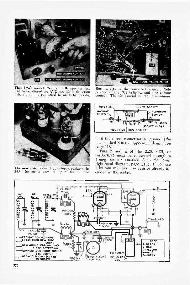
L
"[hi!. 1931 Iel. 2-st:it:(. '1'11F receiver firsthad to be altered for AVC and diode detectionbefore a tuning eye could he made to operate.
TWITCH
VOLUME CONTROL
ArTiriLiAViaii`W,VOLUME CONTROL
c.
The new 2A6 diode -triode detector reolaces the24A. Its socket goes on top of the old one.
B..114,111 'iew ri Ow c .1 ikurttil receiver. Noteposition of the 2E5 indicator and new volumecontrol. The old control is left at maximum.
RIVET (5)-"".
SCREW ----.,youhk ALUMINUM
SUPPORTI IMACHINE
-"'"''' -"::, '......... I ......... ...-.... .: el pi
NEW SOCKET
CHASSISSOCKET IN SET
MOUNTING'NEW SOCKET
omit the direct connection to ground (thelead marked X in the upper -right diagram onpage 218).
Pins 2 and 4 of the 2E5, 6E5, or6A135/6N5 must be connected through a1-meg. resistor (marked A in the lowerright-hand diagram, page 218). If you usea kit you may find this resistor already in-cluded in the socket.
ANT.COIL
VC.05-MFD.PAPER
-PRESENT CONNECTIONSLEADS FROM NEW TUBE
SOCKETNEW WIRING FOR AVC AND
DIODE DETECTION-CONNECTIONS FROM TUNING -
EYE SOCKETIII BREAK OLD CONNECTIONS
AS SHOWN
IT nnlunt irinnnnrltl11Srrrrr=100-MMF 24AMICA)
RF DETECTOR: 3-COIL STAGE
220
I/2MEG
10 MEG
4
MEG VOLUMESO D -MMFmICA CONTROL
+150 VOLTS
TUNING- EY ETUBE
8+
FINiELDED
CODEI -BLACK2 -RED3- YELLOW4 -BLUE5 -GREEN
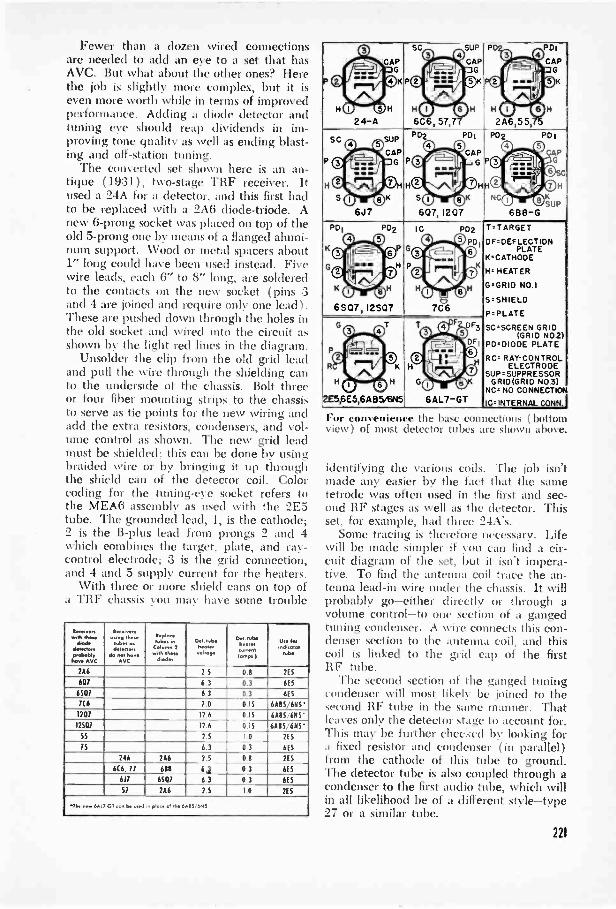
Fewer than a dozen wired connectionsare needed to add an eye to a set that hasAVC. But what about the other ones? Herethe job is slightly more complex, but it iseven more worth while in terms of improvedperformance. Adding a diode detector andtuning eye should reap dividends in improving tone quality as well as ending blast-ing and off -station tuning.
The converted set shown here is an an-tique (1931), two -stage TRF receiver. Itused a 24A for a detector, and this first hadto be replaced with a 2A6 diode -triode. Anew 6 -prong socket was placed on top of theold 5 -prong one by means of a flanged alumi-num support. Wood or metal spacers about1" long could have been used instead. Fivewire leads, each 6" to 8" long, are solderedto the contacts on the new socket (pins 3and 4 are joined and require only one lead 1.These are pushed down through the holes inthe old socket and wired into the circuit asshown by the light red lines in the diagram.
Unsolder the clip from the old grid leadand pull the wire through the shielding canto the underside of the chassis. Bolt threeor four fiber mounting strips to the chassisto serve as tie points for the new wiring andadd the extra resistors, condensers, and vol-ume control as shown. The new grid leadmust be shielded: this can be done by usingbraided wire or by bringing it up throughthe shield can of the detector coil. Colorcoding for the tuning -eye socket refers tothe MEA6 assembly as used with the 2E5tube. The grounded lead, 1, is the cathode;2 is the B -plus lead from prongs 2 and 4which combines the target, plate, and ray -
control electrode; 3 is the grid connection,and 4 and 5 supply current for the heaters.
\Vith three or more shield cans on top ofa TRF chassis you may have some trouble
wAft thew410110,....d.,.
fvbblvhere AVC
wt.., lb.,..0..,4.,...,.
d... i....AVC
.,,C0ub...n
Column 2-.....120.1vbeNM*r...inn*
Ct......rcum.(Amps.)
Use h.ond.te100."
266 2.5 0.1 2E5
607 6.3 0.3 6ES
6507 6.3 0.3 605
7(6 7.0 0.15 6615/615'1207 12.6 0.15 6615/615'12507 12.6 0.15 6615/615
SS 2.5 1.0 2E5
75 6.3 0.3 6E5
2411 266 2.5 0.0 2ES
6(6, 77 611 6.1 0.3 6E5
617 6507 6.3 0.3 6E5
57 266 2.S 1.1 2ES
914 new 6A1.7G11 ton be viod .n place of M. 6A115 ANS
PD,..
024-A
CAPG
K
H
SCO
P
H
6C6,
0
57,7
SUP
CAPG
0
H
P .PDIC1
' 0....Al
H CP 110
2A6,55,
C APG
QK
SC
S
0 0
0 OK6J7
SUPCAP
G
PD2
P
HO
SO607,
0 ©CAP""
SOH'0K
1207
PD1
G
PD2 P01
0.0 GAPPO it
. .4,0 0HNco olLp
688-GPD1
K &-swir0K
6507,
PD2
0 0
it 4600
0 012507
0H-
0
IC P02
0 0:....._.0 1
.10 LI 04.1;
7C6
PD
0K0
Tz TARGET
DFr DEFLECTIONPLATE
K.CATHODE
H. HEATER
G z GRID NO.1
S. SHIE LD
P.PL ATE
SC =SCREEN GRID(GRID NO2)
F,D.DIODE PLATE
RC= RAYCONTROLELECTRODE
SUP.SUPPRESSOR
NVINDOGCROIlLNEC)CVON
IC. INTERNAL CONN.
G
R
H
2E5,6E5,6A
0 0T
0 0B5/6N5
K
H
H
G0r
6A L7-GT
F DF3
OF!
0
o
For convenience the base con lections ( bottomview) of most detector tubes are shown above.
identifying the various coils. The job isn'tmade any easier by the fact that the sametetrode was often used in the first and sec-ond RF stages as well as the detector. Thisset, for example, had three 24A's.
Some tracing is therefore necessary. Lifewill be made simpler if von can find a cir-cuit diagram of the set, but it isn't impera-tive. To find the antenna coil trace the an-tenna lead-in wire under the chassis. It willprobably go -either directly or through avolume control -to one section of a gangedtuning condenser. A wire connects this con-denser section to the antenna coil, and thiscoil is linked to the grid cap of the firstIIF tube.
The second section of the ganged tuningcondenser will most likely be joined to thesecond RF tube in the same manner. Thatleaves only the detector stage to account for.This may be further checked by looking fora fixed resistor and condenser (in parallel)from the cathode of this tube to ground.The detector tube is also coupled through acondenser to the first audio tube, which willin all likelihood be of a different style -type27 or a similar tube.
221

This complete miniamre broadcasting stationwill fit comfortably in the palm of your hand.
The cartridge from a crystal mice, with therubber cushion left on. is set into the panel.
Wiring shouldn't he difficult. ;nst don't hiit spread out. Batieries lit uncirr the chassis.
222
Wireless Mike
Puts You
on the AirTALK into this tiny handful of radio
transmitter, and your voice will comeout of the nearest radio. It can be tunedto any quiet spot near the high end of theband. When held a few feet away from areceiver, this wireless microphone workswithout an antenna. For greater distancea hank of wire is needed to radiate thesignal. If you arrange it right, your partyguests don't even have to know that thevoice -and -music program that's coming overyour radio originates in the next room.
The complete miniature broadcasting sta-tion, including batteries, is housed in atapered plastic refrigerator box measuring2" deep and 4" square across the front. Onthe lid of the box, which becomes the frontpanel, are mounted the crystal unit takenfrom an inexpensive microphone, an on -offswitch, a closed-circuit phono jack, an an-tenna binding post, and a ceramic trimmer.The latter is used to tune to the best fre-quency between about 1,200 and 1,600 kc.A chassis cut from 1/16" aluminum to thesize and shape shown in the drawing holdsthe remainder of the parts. It is bolted tothe back of the same panel.
There is nothing difficult about the wir-ing, but this is a miniature circuit and callsfor a little extra care to keep the parts fromgetting in their own way. Use tiny resistors-the !S -watt type is husky enough-and thesmallest paper and mica condensers.
For the A battery. a flashlight cell inter-mediate in size between the regular and pen-light (type C) is used. It measures just un-der 2" long and so can be clipped into placebetween the rear leg of the chassis ( whichacts as the negative terminal) and a sep-arate tab of aluminum bolted to the frontpanel. Tlni B -voltage supply is obtained
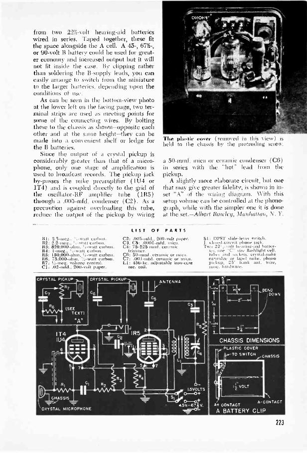
from two 2'a -volt hearing -aid batterieswired in series. Taped together, these fitthe space alongside the A cell. A 45-, 67%-,or 90 -volt B battery could be used for great-er economy and increased output but it willnot fit inside the case. By clipping ratherthan soldering the B -supply leads, you caneasily arrange to switch from the miniatureto the larger batteries, depending upon theconditions of use.
As can be seen in the bottom -view photoat the lower left on the facing page, two ter-minal strips are used as meeting points forsome of the connecting wires. By boltingthese to the chassis as shown-opposite eachother and at the same height-they can bemade into a convenient shelf or ledge forthe B batteries.
Since the output of a crystal pickup isconsiderably greater than that of a micro-phone, only one stage of amplification isused to broadcast records. The pickup jackby-passes the mike preamplifier (1U4 or1T4) and is coupled directly to the grid ofthe oscillator-RF amplifier tube (1R5)through a .005-mfd. condenser (C2). As aprecaution against overloading this tube,reduce the output of the pickup by wiring
R1: 3.3-meg.. ' -watt carbon.1i2: 2.2 -met;., ' , -watt carbon.113: 820,000 -ohm. '1 -watt carton.114: I-meg., ',-watt carbon.R5: 150,000 -ohm, I.', -watt carbon.R6: 75,000 -ohm, I..:, -watt carbon.R7: ',;-meg. volume control.Cl: .02-mfd., 200 -volt paper.
CRYSTAL PICKUP
(SEETEXT)
"A"
Tire plastie 1.111% rr
held to die chit-i,r, ul kl in this view) isby the protruding screw.
a 50-mmf. mica or ceramic condenser (C6)in series with the "hot" lead from thepickup.
A slightly more elaborate circuit, but onethat may give greater fidelity, is shown in in-set "A" A' the viring diagram. With thissetup volume can be controlled at the phono-graph, while with the simpler one it is cloneat the set.-Albert Rowley, Manhattan, N. 1'.
LIST OF PARTSC2: .005-mfd., 200 -volt paper.C3, C5: .0001-mfd. mica.C4: 75-225 mmf. ceramic
trimmer.C6: 50-mmf. ceramic or mica.C7: .001-mfd. ceramic orLI: 456-kc. adjustable iron-cc_re
osc. coil.
ANTENNA
Si: DPST slide -lever switch.closed-circnit phoe jack.
22..., -volt hearinng-aid batter-ies, Goy ''C'' size flashlight cell,tutu, and sockets. crvstal-mikecartridge or lapel mike, phonopickup. 25' hank ant. wire,misc. hardware.
?ENE!DOW'.
CHASSIS DIMENSIONSPLASTIC COVER
TO SWITCH CHASSIS
, CONTACT
A BATTERY CLIP
A -CONTACT
123
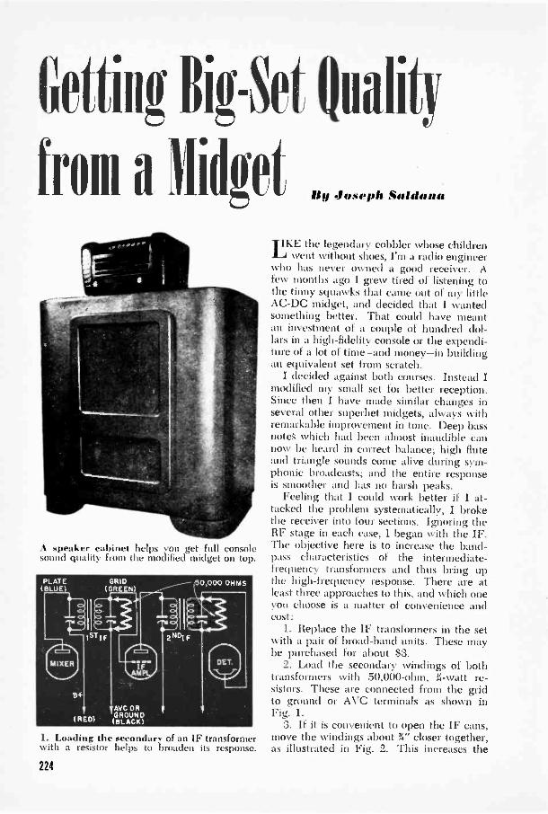
GM'lig Big -Set Quality
from a Midget d.
A speaker cabinet helps you get full consolesound quality from the modified midget on top.
1. Loading the secondary of an IF transformerwith a resistor helps to broaden its response.
IKE the legendary cobbler whose childrenwent without shoes, I'm a radio engineer
who has never owned a good receiver. Afew months ago I grew tired of listening tothe tinny squawks that came out of my littleAC -DC midget, and decided that I wantedsomething better. That could have meantan investment of a couple of hundred dol-lars in a high-fidelity console or the expendi-ture of a lot of time-and money-in buildingan equivalent set from scratch.
I decided against both courses. Instead Imodified my small set for better reception.Since then I have made similar changes inseveral other superhet midgets, always withremarkable improvement in tone. Deep bassnotes which had been almost inaudible cannow be heard in correct balance; high fluteand triangle sounds come alive during sym-phonic broadcasts; and the entire responseis smoother and has no harsh peaks.
Feeling that I could work better if I at-tacked the problem systematically, I brokethe receiver into four sections. Ignoring theRF stage in each case, 1 began with the IF.The objective here is to increase the band-pass characteristics of the intermediate -frequency transformers and thus bring upthe high -frequency response. There are atleast three approaches to this, and which oneyou choose is a matter of convenience andcost:
1. Replace the IF transformers in the setwith a pair of broad -band units. These maybe purchased for about $3.
2. Load the secondary windings of bothtransformers with 50,000 -ohm, 31 -watt re-sistors. These are connected from the gridto ground or AN'C terminals as shown inFig. 1.
3. If it is convenient to open the IF cans,move the windings about %" closer together,as illustrated in Fig. 2. This increases the
224

coupling ;uld broadens the resonance peak.Take great pains not to damage the delicatewires. Heating the coil to soften the waxcoating makes it easier and less hazardousto move the windings.
The next portion of the set to consider isthe audio amplifier. Because manufacturersare anxious to keep hum level low, theyusually use low values of coupling con-densers in midget sets. These, in turn, limitthe low -frequency response of the audiosection. I substituted .05-mfd. couplingcondensers in this section. A typical positionfor one of these capacitors is diagrammed inFig. 3. In sets using single pentode or beam -power output tubes, an R -C (resistance -ca-pacitance) filter can be used to advantageto smooth the high -frequency end. A re-sistor and condenser in series are connectedacross the primary of the output transformer(Fig. 4). This puts a more constant loud onthe output tube in the middle and upperfrequencies, and thus improves the response.The resistor should be 1.3 times the value ofthe output tube's rated load resistance. Youcan check this figure by looking up yourparticular tube in a tube manual. The con-denser may vary from .03 to 1 mfd.
The third section to be attended to is thespeaker system. Most midgets have 4" to 6"speakers that can't do much in the way ofbringing out low notes but which can beused as tweeters or high -frequency repro-ducers. By purchasing a 12" speaker andconnecting it in parallel with the one in theset, I had an effective woofer -tweeter com-bination. There are many more elaborate
2. The original IF ct ii ( left, can removed)can be modified by MON ing the windings closer.
3. Bass is increased by changing the couplingcondensers to .05 mfd. in the audio section.
4. An WC filter shunted across the primary ofthe output transformer smooths the response.
5. Use the original speaker as a tweeter andadd a lir woofer. A condenser divides the two.
6. A has., -reflex cabinet for a 12" speaker waybe made to these dimensions. Use li" plywood.
225

7. A commercial speaker cabinet seen from therear. Set and small speaker are used near it.
divider networks and speaker systems pos-sible (one is described on page 190) butfor my setup I found it sufficient to insert asingle .05-mfd. condenser as shown in Fig. 5to keep low frequencies from getting throughto the tweeter.
Cost is an important factor in the nextdecision. I purchased a bass -reflex cabinetto house my new 12" speaker. You can dolikewise, or build one to the measurementsshown in Fig. 6. There are decided advan-tages to such a cabinet, since it gives ex-tended bass reproduction without the an-noying booming often encountered in othertypes of baffle. But also bear in mind thatthere are some very good sets that do notuse speaker cabinets.
The tweeter may be mounted inside thespeaker cabinet at approximately the point
RESISTOR FIG.1)
eitt
OPTIONAL
8. Hum level is raised by some of the changes,so a new choke is inserted in the filter circuit.
shown in the drawing, or it may be left inthe original cabinet if the two units are go-ing to be kept fairly close together duringoperation (Fig. 7 ). Bass -reflex cabinets mustbe thoroughly enclosed on all sides. Toprevent the back from rattling due to soundpressure inside the box, attach a sturdy braceto frpnt and back as indicated by the dottedlines in Fig. 6. Line the cabinet with cottonbatting or other sound -absorbing material.
Having completed the modification of thesignal circuits, I found that I had workedmyself into an additional job. By bringingup low -frequency response, I had alsobrought up the AC hum, which is in thesame portion of the spectrum. In some setsI worked on, this was curable by the addi-tion of extra filtering capacitors, but in mostcases a small choke proved more useful.Remove the filter resistor (usually a 1,000 -ohm, 2 -watt unit) connected between thetwo positive terminals of the dual electro-lytic, and replace it with a filter choke ratedfrom 8 to 16 henries and 400 to 600 ohms.The higher the inductance the more thor-ough the hum filtering. If some hum re-mains, add a 20-mfd. electrolytic-rated at150 volts or up-as shown by the brokenlines in Fig. 8. END
CONDENSER I FIG.3)
A typical superhet midget looks like this. Some of the modifications are shown by arrows.
226
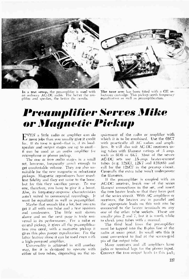
In a test setup, the preamplifier is used withan ordinary AC -DC radio. The better the am-plifier and speaker, the better the results.
The tone arm has been fitted with a CE re-luctance cartridge. This pickup needs frequencyequalization as well as preamplification.
Preamplifier Serves MikeorMagnetic PickupEVEN a little radio or amplifier can do
more jobs than you usually give it creditfor. If its tone is good-that is, if its loud-speaker and output stages arc up to snuff-it can be used as an audio amplifier formicrophone or phono pickup.
The one or two audio stages in a smallset, however, frequently aren't enough toget comfortable volume. They arc also un-suitable for the new magnetic or reluctancepickups. Magnetic reproducers have excel-lent fidelity and they cut noise to the bone,but for this they sacrifice power. To useone, therefore, you have to give it a boost.Also, its frequency -response characteristicsaren't suited to commercial recordings. Itmust be equalized as well as preamplified.
Maybe that sounds like a lot, but you canget it all with one tube :mil a few resistorsand condensers. The little unit shownabove and on the next page is truly uni-versal in its performance. For a mike orcrystal pickup, it gives all the preamplifica-tion you need; with a magnetic pickup itgives this plus proper equalization. For thelatter feature alone it can be used even witha high-powered amplifier.
Universality is achieved in still anotherway, for it is designed to operate witheither of two tubes, depending on the re-
quirement of the radio or amplifier withwhich it is to be combined. Use the 6SC7with practically all AC radios and ampli-fiers. It will also suit AC -DC receivers us-ing tubes with filament ratings of .3 amp.such as 6D6 or 6K7. Most of the newerAC -DC sets use .15 -amp. heater -currenttithes (e.g. I2SK7, 12K7 and 12BA6) andcall for the 12SC7 in the preamp circuit.Generally the extra tube won't underpowerthe filaments.
If the preamplifier is coupled Nvith anAC -DC receiver, break one of the seriesfilament connections in the set, and insertthe two heater leads so that they form partof the series circuit. With AC amplifiers orreceivers, the heaters arc in parallel andthe appropriate leads on this unit can beconnected to the heater terminals on anyone of the other tube sockets. These areusually pins 2 and 7, but it is Nvorth whileto check your tubes with a manual.
The third lead from the preamplifiermust be tapped into the B -plus line of theradio at some point. In small sets this ismost convenient to find at the screen -gridpin of the output tube.
Many receivers and all amplifiers havejacks or terminal lugs for the phono input.Connect the two output leads to this jack;
221
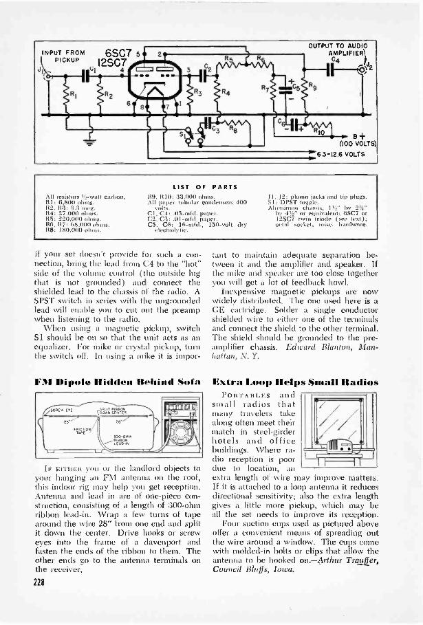
All iese.tor:. ,-watt carbon.81: 6,800 ohms.112, 113: 3.3 mee.114: 27,000 ohms.115: 220,000 ohms.116, 117: 68,006 ohms.R8: 180,000 ohms.
LIST OF PARTS119, RIO: 33,000 ohms.All paper tubular condensers 400
volts.Cl, C4: .05-mfd. paper.C2, C3: .0I-mfd. paper.C5, C6: 16-mfd., 150 -volt dry
electrolytic.
J1, J2: phono jacks and tip plug,.DPST toggle.
Aluminum chassis, 11:u" by 2'.,"by 4!/.;" or equivalent; 6SC7 or12SC7 twin triode ( see text I.octal socket, misc. hardware.
if your set doesn't provide for such a con-nection, bring the lead {ruin C4 to the "hot"side of the volume control (the outside lugthat is not grounded) and connect theshielded lead to the chassis of the radio. ASPST switch in series with the ungroundedlead will enable you to cut out the preampwhen listening to the radio.
When using a magnetic pickup, switchSi should be on so that the unit acts as anequalizer. For mike or crystal pickup, turnthe switch off. In using a mike it is impor-
FII Dipole Hidden Rehired Sofa
IF EITHER you or the landlord objects toyour hanging an F.N1 antenna on the roof,this indoor rig may help you get reception.Antenna and lead in are of one-piece con-struction, consisting of a length of 300 -ohmribbon lead-in. Wrap a few turns of tapearound the wire 28" from one end and splitit down the center. Drive hooks or screweyes into the frame of a davenport andfasten the ends of the ribbon to them. Theother ends go to the antenna terminals onthe receiver.
221
tant to maintain adequate separation be-tween it and the amplifier and speaker. Ifthe mike and speaker are too close togetheryou will get a lot of feedback howl.
Inexpensive magnetic pickups are nowwidely distributed. The one used here is aGE cartridge. Solder a single conductorshielded wire to either one of the terminalsand connect the shield to the other terminal.The shield should be grounded to the pre-amplifier chassis. Edward Blanton, Man-hattan, N. Y.
Exi ra Limp Helps Small RadiosPORTABLES and
small radios thatmany travelers takealong often meet theirmatch in steel -girderhotels and officebuildings. Where ra-dio reception is poordue to location, anextra length of wire may improve matters.If it is attached to a loop antenna it reducesdirectional sensitivity; also the extra lengthgives a little more pickup, which may beall the set needs to improve its reception.
Four suction cups used as pictured aboveoffer a convenient means of spreading outthe wire around a window. The cups comewith molded -in bolts or clips that allow theantenna to be hooked on.-Arthur Trauftr,Council Bluffs, Iowa.
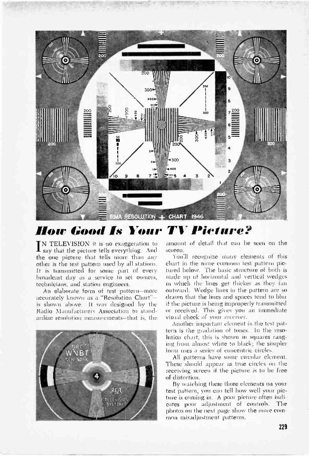
/how Good Is YourTN TELEVISION it is no exaggeration to1- say that the picture tells everything. Andthe one picture that tells more than anyother is the test pattern used by all stations.It is transmitted for some part of everybroadcast day as a service to set owners,technicians, and station engineers.
An elaborate form of test pattern-moreaccurately known as a "Resolution Chart"-is shown above. It was designed by theRadio Manufacturers Association to stand-ardize resolution measurements-that is, the
TS" Pieture?amount of detail that can be seen on thescreen.
You'll recognize many elements of thischart in the more common test pattern pic-tured below. The basic structure of both ismade up of horizontal and vertical wedgesin which the lines get thicker as they fanoutward. Wedge lines in the pattern are sodrawn that the lines and spaces tend to blurif the picture is being improperly transmittedor received. This gives you an immediatevisual check of )(air receiver.
Another important clement in the test pat-tern is the gradation of tones. In the reso-lution chart, this is shown in squares rang-ing from almost white to black; the simplerform uses a series of concentric circles.
All patterns have some circular clement.These should appear as true circles on thereceiving screen if the picture is to be freeof distortion.
By watching these three elements on yourtest pattern, you can tell how well your pic-ture is coming in. A poor picture often indi-cates poor adjustment of controls. Thephotos on the next page show the more com-mon misadjustment patterns.
221
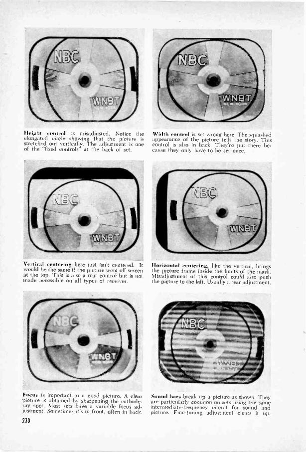
Height control is misadjusted. Notice the Width control is set wrong here. The squashedelongated circle showing that the picture is appearance of the picture tells the story. Thisstretched out vertically. The adjustment is one control is also in back. They're put there be-of the "fixed controls' at the back of set. cause they only have to he set once.
Vertical centering here just isn't centered. Itwould be the same if the picture went off screenat the top. This is also a rear control but is notmade accessible on all types of receiver.
Horizontal centering, like the vertical, bringsthe picture frame inside the limits of the mask.Misadjustment of this control could also pushthe picture to the left. Usually a rear adjustment.
- -Focus is important to a good picture. Sound bars break up a picture as shown. Theypicture is obtained by sharpening the cathode- are particularly common on sets using the sameray spot. Most sets have a variable focus ad- intermediate -frequency circuit for sound andjustment. Sometimes it's in front, often in back. picture. Fine-tuning adjustment clears it up.
230
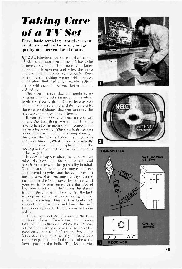
Taking Careof a TV SetThese basic servicing procedures youcan do yourself will improve imagequality and prevent breakdowns.
YOUR television set is a complicated ma-chine, but that doesn't mean it has to be
a mysterious one. The more von knowabout how it operates and why, the moreyou can save in needless service calls. Evenwhen there's nothing wrong with the set,you'll often find that a few careful adjust-ments will make it perform better than itdid before.
This doesn't mean that you ought to gobarging into the set's innards with a blow-torch and electric drill. But so long as youknow what you're doing and do it carefully,there's a good chance that you can raise thetelex ision standards in your house.
If you plan to do any work ou your setat all, the first thing you should know ishow to handle the picture tube-especially ifit's an all -glass tube. There's a high vacuuminside the shell, and if anything damagesthe glass, the tube is liable to shatter withexplosive force. (What happens is actuallyan "implosion'', not an explosion, but theflying glass fragments are just as dangerouseither xvay.)
It doesn't happen often, to be stile, buttubes do blow up. So play it safe andhandle the tube with that possibility in mind.That means, first, that you ought to wearshatterproof goggles and heavy gloves. Itmeans, also, that you must always handlethe tube by the bulb-never by the neck. Ifyour set is so constructed that the face ofthe tube is not supported when the chassisis out of the cabinet, make sure that the bulbis propped up when you're doing out -of -cabinet servicing. One or two books willsupport the tube face and keep the neckfrom straining inside the deflection and focusyokes.
The correct method of handling the tubeis shown above. There's one other impor-tant point to consider. When you removea tube from a set, yon have to disconnect thebase socket and the high -voltage lead. Thelatter is a small plug, usually enclosed in arubber cup. It is attached to the tube at thelower part of the bulb. This lead carries
-ad
REFLECTINGOBJECT
GHOSTIMAGE
2]I
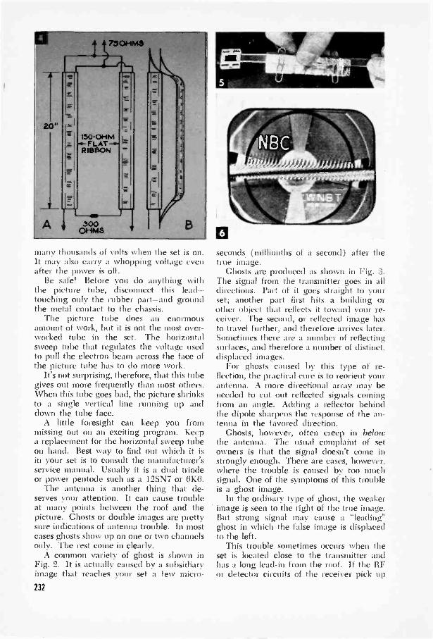
many thousands of volts when the set is on.It may also carry a whopping voltage evenafter the power is off.
Be safe! Before you do anything withthe picture tube, disconnect this lead-touching only the rubber part-and groundthe metal contact to the chassis.
The picture tube does an enormousamount of work, but it is not the most over-worked tube in the set. The horizontalsweep tube that regulates the voltage usedto pull the electron beam across the face ofthe picture tube has to do more work.
It's not surprising, therefore, that this tubegives out more frequently than most others.When this tube goes bad, the picture shrinksto a single vertical line running up anddown the tube face. -
A little foresight can keep you frommissing out on an exciting program. Keepa replacement for the horizontal sweep tubeon hand. Best way to find out which it isin your set is to consult the manufacturer'sservice manual. Usually it is a dual triodeor power pentode such as a I2SN7 or 6K6.
The antenna is another thing that de-serves your attention. It can cause troubleat many points between the roof and thepicture. Ghosts or double images are prettysure indications of antenna trouble. In mostcases ghosts show up on one or two channelsonly. The rest come in clearly.
A common variety of ghost is shown inFig. 2. It is actually caused by a subsidiaryimage that reaches your set a few micro -232
0seconds (millionths of a second) after thetrue image.
Ghosts are produced as shown in Fig. 3.The signal from the transmitter goes in alldirections. Part of it goes straight to yourset; another part first hits a building orother object that reflects it toward your re-ceiver. The second, or reflected image hasto travel further, and therefore arrives later.Sometimes there are a number of reflectingsurfaces, and therefore a number of distinct,displaced images.
For ghosts caused by this type of re-flection, the practical cure is to reorient yourantenna. A more directional array may beneeded to cut out reflected signals comingfrom an angle. Adding a reflector behindthe dipole sharpens the response of the an-tenna in the favored direction.
Ghosts, however, often creep in belowthe antenna. The usual complaint of setowners is that the signal doesn't come instrongly enough. There are cases, however,where the trouble is caused by too muchsignal. One of the symptoms of this troubleis a ghost image.
In the ordinary type of ghost, the weakerimage is seen to the right of the true image.But strong signal may cause a "leading"ghost in which the false image is displacedto the left.
This trouble sometimes occurs when theset is located close to the transmitter andhas a long lead-in from the roof. If the RFor detector circuits of the receiver pick up
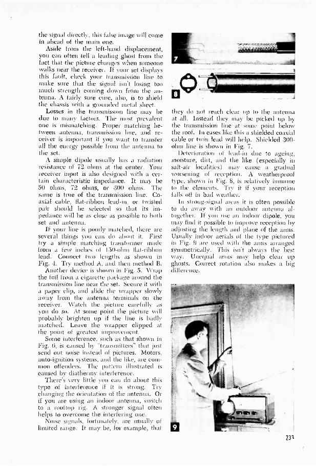
the signal directly, this false image will comein ahead of the main one.
Aside from the left-hand displacement,you can often tell a leading ghost from thefact that the picture changes when someonewalks near the receiver. If your set displaysthis fault, check your transmission line tomake sure that the signal isn't losing toomuch strength coming down from the an-tenna. A fairly sure cure, also, is to shieldthe chassis with a grounded metal sheet.
Losses in the transmission line may bedue to many factors. The most prevalentone is mismatching. Proper matching be-tween antenna, transmission line, and re-ceiver is important if you want to transferall the energy possible from the antenna tothe set.
A simple dipole usually has a radiationresistance of 72 ohms at the center. Yourreceiver input is also designed with a cer-tain characteristic impedance. It may be50 ohms, 72 ohms, or 300 ohms. Thesame is true of the transmission line. Co-axial cable, fiat -ribbon lead-in, or twistedpair should be selected so that its im-pedance will be as close as possible to bothset and antenna.
If your line is poorly matched, there areseveral things you can do about it. Firsttry a simple matching transformer madefrom a few inches of ISO -ohm flat -ribbonlead. Connect two lengths as shown inFig. 4. Try method A, and then method B.
Another device is shown i Fig. 5. Wrapthe foil from a cigarette package around thetransmission line near the set. Secure it witha paper clip, and slide the wrapper slowlyaway from the antenna terminals o thereceiver. Watch the picture carefully asyou do so. At some point the picture willprobably brighten up if the line is badlymatched. Leave the wrapper clipped atthe point of greatest improvement.
Some interference, such as that shown inFig. 6, is caused by "transmitters" that justsend out noise instead of pictures. Motors,auto -ignition systems, and the like, are com-mon offenders. The pattern illustrated iscaused by diathermy interference.
There's very little you can do about thistype of interference if it is strong. Trychanging the orientation of the antenna. Orif you are using an indoor antenna, switchto a rooftop rig. A stronger signal oftenhelps to overcome the interfering one.
Noise signals, fortunately, are usually oflimited range. It may be, for example, that
they do not reach clear up to the antennaat all. Instead they may be picked up bythe transmission line at some point belowthe roof. In cases like this a shielded coaxialcable or twin lead will help. Shielded 300 -ohm line is shown in Fig. 7.
Deterioration of lead-in due to ageing,moisture, dirt, and the like (especially insalt -air localities) may cause a gradualworsening of reception. A weatherprooftype, shown in Fig. 8, is relatively immuneto the elements. Try it if your receptionfalls off in bad weather.
In strong -signal areas it is often possibleto do away with an outdoor antenna al-together. If you uNe an indoor dipole, youmay find it possible to improve reception byadjusting the length and plane of the arms.Usually indoor aerials of the type picturedin Fig. 9 are used with the arms arrangedsymmetrically. This isn't always the bestway. Unequal arms may help clear upghosts. Correct rotation also makes a bigdifference.
231
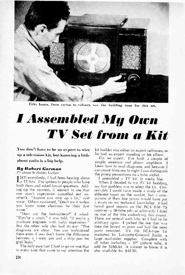
Fifty I fr (aton to eahinet, uas the building time for this set.
I Assembled Mg OwnTV Set from a Kit
You don't have to be an expert to wireup a television kit, but knowing a littleabout radio is a big help.
By Robert GormanI'S photos by Ilubert Luckett
LKE everybody, I had been hearing aboutTV kits. I've spoken to people who have
built them and asked lots of questions. Add-ing up the answers, it seemed to me thatone man's experience cancelled out an -other's. "Anyone can wire up a kit," saidsome. Others cautioned, "Don't try it unlessyou know some electrons by their firstname."
"How are the instructions?" I asked."They're a cinch," I was told, "if you're agraduate engineer with radar experience."But the other side also had its say: "Thediagrams are clear. You can understandthem even if you don't know the differencebetween a 1-meg. pot and a drip pan forgrid leaks."
The only sure fact I had to go on was thatin every case that came to my attention the
kit builder was either an expert radioman, orhe had an expert standing at his elbow.
I'm no expert. I've built a couple ofsimple receivers and phono amplifiers. Iknow how to read diagrams, and because Ican count from one to eight 1 can distinguishthe prong connections on a tube socket.
1 assembled a TV kit. It works fine.When I decided to try T\' kit building,
my first problem was to select the kit. Con-ceivably I could have made a study of thedifferent types on the market, but a com-parison of their fine points would have puta strain on my technical knowledge. I hadheard good reports on the RCA 6:30 TSreceiver-a 30 -tube job-so arbitrarily I fixedon one of the kits embodying this circuit.There are several such kits, so I had to bearbitrary again. I picked the one that wasthen the lowest in price and had the mostparts mounted. It's the RCA -type kitmarketed by Lafayette -Concord Radio, alarge mail-order supplier. Complete withall tubes including a 10" picture tube, itsold for $195.50. A cabinet to house it isalso available for $42.50.
234

1. Here's the kit unpacked from its cartons.There are a lot of loose parts despite the factthat all the major ones are mounted.
As I tumbled the parts and packages yousee in photo 1 out of the shipping cartonsI couldn't help feeling how nice it wouldbe to forget the whole thing. That feelingdidn't diminish when I unpacked the eightor ten envelopes and got a look at the hun-dreds of resistors, capacitors, and coils, plusmiscellaneous wires, knobs, hardware, andmany mysterious parts. There's no organiza-
"1101,1"*IA3. Organizing the items is a chore. I markedthe value of each one on the diagram and tapedthe parts down in order on separate sheets.
5. Chassis layouts in the service manual givemnch useful information, including the functionand location of each af the :30 tubes.
2. Emptying theenvelopes shown at the leftreveals this ben ildering array. There are 108resistors, 77 capacitors, and 11 coils.
tion of the components-they're all there, butseparating the pieces and relating them tothe circuit is the builder's job.
The instructions that are provided alsogive a minimum of orientation. You get anRCA service manual and a couple ofmimeographed sheets of parts lists, color -code information, and instructions for con-necting the prewired tuner section. Most
I. Removing 0 . isn't necessar I,utthought it was salcr. Li the tuner each mustbe marked for return to the identical socl'et.
6. As an aid in wiring. I marked the parts onthe underside of the chassis as well. It washelpful in locating terminals quickly.

7. Speakers are fragile. This one has fourleads which can be soldered in at the very end.I removed it for safety during the main job.
9. The deflection yoke is held iu a U -bracketby two wing bolts. They have to be taken outto complete internal wiring on the yoke.
important, there are six full-size pictorialdiagrams showing the mounted parts inblack and the wiring overprinted in red.Each of these sheets has a different set ofconnections, broken down for wiring con-venience. Because of their size and the redoverprinting, they are easy to read and fol-low. The RCA book has a good deal of
11. As a precaution against bnrning out thehigh-oltage transformer should one tube gobad, I wired in a No. 47 pilot as a fuse.
8. Do not remove is what it says, but I couldnot complete the wiring in this crowded cornerwithout first unbolting the tuner.
10. Two resistors, a condenser, and four wiresare soldered into the back of the yoke. Detailsare furnished in a corner of the diagram.
additional information. I found a coupleof minor changes from the RCA diagram;there are also one or two errors that hadbeen corrected in pencil on the sheets.
By way of getting started, my first stepwas to arrange the small components accord-ing to wiring sheets. The experienced manmay scoff at my system, but I found it help-ful. I went through each diagram and theparts lists, marking the value of each partnext to the code number printed in red. Atthe same time I picked out that part andtaped it to a sheet of plain paper, markingthe code number alongside it (photo 3).By first separating the resistors into pilesaccording to the first band of color, I wasable to pick out the proper one fairly quick-ly. For example, if I was looking for a6,800 -ohm resistor, I had only to glancethrough the pile containing those with bluebands, meanwhile looking for a gray secondband, and so on. With the parts taped tosheets, I didn't have to hunt for a singlepiece while doing the actual wiring.

12. The high -voltage recti-fier is placed on an insulatedplatform inside a shieldedcompartment. Remove theplatform to wire the socket.
13. Corona-a kind of electronhalo that occurs at high voltages-is minimized by removing the un-used rectifier -socket prongs. Onetwist and they drop out.
To minimize the risk of breakage inhandling the cumbersome chassis, I re-moved all the tubes. A band of transparenttape over the number on the glass insuredagainst it rubbing off in handling. The frontend or tuner section, which comes com-pletely wired and aligned, uses three 6J6miniatures. It's essential that each tube berestored to its original socket. Photos 4 and5 show how I marked each tube and socketwith precise identification.
With these preliminary details attendedto, I just had to buckle down to the seriousbusiness of wiring the chassis and solderingin a couple of hundred loose pieces. Onthis subject, too, I had heard all sorts of con-flicting reports. The best time estimate Igot was eight hours, but most of the peoplewho quoted this figure had it at secondhand. Reliably and at first hand I got ap-proximately this time from two people-both experts who had wired a number ofkits. One of them had a helper read off thediagrams while he worked.
However fast others may be, I have toreport that my wiring time exceeded fourtimes the estimated eight hours. I'll tip myhat twice to anyone who builds his first kit,alone, between sunup and sunup. Thereare about 400 pigtail leads to solder on theloose components alone, and another coupleof hundred on the wiring and ground con-nections. Going strictly by the book, I triedclinching every lead before soldering it.That makes a big difference in time-the fastradiomen I spoke to didn't clinch the wires;they merely pasted them to the lugs withsolder.
Incidentally, most of the lugs to whichconnections are made in the early sheetsget additional leads in the later ones. Ontube sockets it is therefore advisable to make
14. After mounting theparts and soldering in thecorona ring, I dabbed theterminals with cellulose ce-ment for extra insulation.
the initial connections to the lower of thetwo holes, saving the top one in case an-other wire has to be brought to it. It's alsoimportant to keep leads as short as possiblein any high -frequency radio work. I aimedat this but didn't succeed too well, as youcan see in the close-up photos of my chassis.While we're on the subject of soldering, re-member that rosin flux is conductive at highfrequencies. If you decide to build a TVkit, use as little rosin as you can get awaywith and wash off any excess with alcohol.Rosin -core solder is okay; it eases the work
15. Wiring took a long time and was a tediousjob. Professionals will scoff at these long leads.They should have been kept shorter.
231
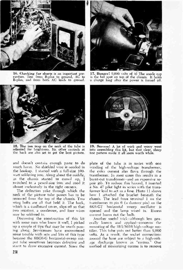
16. Checking for shorts is an important pre-caution. Test from B -plus to ground, AC toB -plus, and from both AC leads to ground.
18. The ion trap on the neck of the tube isadjusted for brightness. Six other controls atthe back are also set to get the best picture.
and doesn't contain enough paste to domuch harm. No shielded wire is needed inthe hookup. I started with a full-size 100 -watt soldering iron. Along about the middle,as the chassis started to crowd up, Iswitched to a pencil -size iron and used italmost exclusively in the tight corners.
The deflection yoke through which theneck of the picture tube passes has to beremoved from the top of the chassis. Twowing bolts are all that hold it. The back,which is a cardboard cover, slips off so thattwo resistors, a condenser, and four wiresmay be soldered in.
Discussing the construction of this kitwith some men who know it well, I pickedup a couple of tips that may be worth pass-ing along. Servicemen have encounteredsome trouble with sets and kits of this typebecause the 6BG6-G horizontal -sweep out-put tube sometimes becomes defective andstarts to draw excessive current. Since the
238
17. Danger! 9,000 volts of it! The anode capis the hot spot on top of the chassis. It holdsa charge long after the power is turned off.
19. Success! A lot of work and worry wentinto assembling this kit, but that clear, sharptest pattern made it all seem worth while.
plate of the tube is in series with onewinding of the high -voltage transformer,the extra current also flows through thetransformer. In most cases this results in aburnt -out transformer-and an expensive re-pair job. To reduce this hazard, I inserteda No. 47 pilot light in series with the trans-former lead to act as a fuse. Photo 11 showshow I attached the bracket beneath thechassis. The lead from terminal 1 on thetransformer to pin 6 (a dummy pin) on the6K6-GT horizontal sweep oscillator isopened and the lamp wired in. Excesscurrent burns out the bulb.
Another useful trick-although less gen-erally known and applied-concerns themounting of the 1B3/8016 high -voltage rec-tifier. This tube puts out better than 9,000volts. As a result, the socket connectionsaround the base are subject to a high -volt-age discharge known as "corona." Onemethod of minimizing corona is to remove

20. This isn'i mo set. I \\ ish it weir. not be- NIcIvin Pollack. Lafaette's chid MTV jet' engi-cause it works better than mine hut bccanse I'd neer. Note short. neatly dressed leads and min -he proud of the wiring. It as assembled by pact arrangement of small parts.
the extra lugs from the bottom of the tulsocket. Only three of them are needed, sothe others can be twisted slightly andpushed nut through the top of the socket(photo 13). The necessary parts and wiresare then soldered in, and the corona ring issweated into the two anchor points on themounting plate. Excess solder and rosin isscraped out and the anchor lugs arc coatedwith cellulose cement.
When I finally finished the wiring I hadto agree with the most. enthusiastic kitbuilders. It's not hard. It was, for me, a lungand tiring job, but it's certainly possible fora semiskilled experimenter to get it done.
After checking the wiring carefully, Imade a couple of safety tests before plug-ging in the set. To check for shorts you needan ohmmeter (photo 16) or a continuitytester. The main points to test are 13 -plusshorts (touching one meter prod to thechassis and the other to two or three elec-trolytic -capacitor terminals), shorts from ACto ground, and from AC to 13 -plus. If youget no reading at these points, it is reason-ably safe to plug in the set. It may not work,but the chances are that no serious troublewill result.
Handling the picture tube calls for spe-
cial precautions. Hold it only by the largebulb, never by the neck, and don't try tomove the set while the tube is in. Whenusing the tube out of a cabinet, prop amedium -size book under the face end tosupport the weight (in a cabinet it is heldby cushioned brackets). \\lien the set isturned right side up and all the shields arein place, the main danger spot is the secondanode cap (photo 17). Tliere's over 9,000volts there, so keep clear of it if you valueyour health. Make sure the power is off whenhandling the cap-but even that isn't enough.The high -voltage capacitors store a chargeand can give you a jolt long after theswitch is turned off. After removing the capfrom the tube, hold it a half inch from somepiece of grounded metal to draw a spark ifany energy remains. 13ring it closer until ittouches the metal. Make sure that the capis either in the tube or clear of any possibleground when tho power is on.
The ion trap, being adjusted in photo 18.and the six controls along the rear edge ofthe chassis must be set for the best image.Once they are tuned for your antenna andlocation, nothing has to be done to them. Allfurther tuning is done by the set en controlsin front.
239

Antennas for FM and TelevisionSignal strength may be good on the rooftops, but for good soundand video reception you have to pull it in and get it downstairs.
THE TWO most important parts of yourtelevision picture are your antenna and
receiver-in that order.Sure, there are differences in set design
and construction. Some are better thanothers. But any modern set is capable ofputting together a good image. All it needsis enough broadcast signal to work on. It'sthe job of the antenna to provide the signal.
Even if you have a professionally installedrig on your roof, it will pay you to know afew basic facts about FM and TV antennas.They will help you to add to or modify yourexisting arrangement to improve your set's
For best results the half -wave dipole shouldextend as high as possible above the building.A simple dipole and coaxial -cable transmissionline is shown in Fig. 1. You can use other typesof low -loss feeders in place of coax. Dipoles aredirectional; they favor signals coming from tliidirection of blocked arrows.
240
operation and bring in difficult stations.Electromagnetic waves are basically al-
ternating currents that travel through spaceat the uniform speed of 984,000,000 feet asecond. The thing that distinguishes them istheir frequency, or the rate at which theyalternate.
The distance that a wave travels in onecomplete alternation-or cycle-is called itswavelength. It follows that the more rapidlya current alternates-that is, the higher thefrequency-the shorter its wavelength will be.
Now, the reason wavelengths are so im-portant is simply this: as a radio signal isbroadcast into space, it showers its energyall about. Any rod, wire, or other conductorit meets absorbs some of that energy. Butmaximum energy is transferred when thelength of the conductor corresponds to thelength of the transmitted wave.
It is known that the most practical andefficient length for an antenna is half thelength of the wave. In practice antennas aremade 5 to 7 percent shorter than a half waveto compensate for certain undesirable effects.
From the above figure you can derive ahandy formula for calculating proper an-tenna length. The one commonly used is:
468Length ( feet) -frequency (megacycles)
WIRES SOLDEREDTO LUGS .
00,4jeffil zle
ALUMINUM WIIri it.
POLE
INSULATORSAND CLAMPS
CO* xiALCABLE
BEST RECEPTION
winE CLAMPED To ammo

BEST Ft ECERT1ON
L
FEEDERCABLE
fiEFLECTOR
( 2'
iTaa - ELemte.ctaecz "L Pfrt tenAt
H
PCST
DRIVEN ALUMINUMELEMENT TUGING
- C. -AMPS AND SUPPOrTING
The basic form of the TV and F\I an-tenna is the half -wave dipole shown at theleft. As you can see, the half wavelength ismade up of two equal arms extending Out-ward from the center. Each arm, then, isequal to the corrected half wave divided by2. The table at the right gives the lengthfor various channels; "L" represents thetotal length of both arms.
It is convenient to use the total lengthin the table because other elements of anantenna, such as reflectors and directors( which will be discussed below) can alsobe calculated as fractions of "L".
Proper length is one key factor in antennaconstruction. Another is the way in whichhigh -frequency waves travel. They move instraight lines and are reflected by flat sur-faces. When it comes to building an an-tenna, you also want to take into accountsuch things as elevation, neighboring build-ings. distance from transmitters, and strengthof the signal in your location. If you live
INSULATORS
PLUS 67.
, a
can be 'teen in the drawing above. the twoelement bean' antenna consists of a flail \\ a\dipole. now ealled the driven (lenient. and areflector. Ti. Later isn't connected.
A hte-t lector feeder cable is illustrated atthe left. One conductor is soldered to each halfof the dipole: the other ends go to set.
(Total lengthChannel Frequency of both rods
or ( nu.) of dipolebond -inches)
2 .1.1-0) 9S:3 611-6)3 884 66-72 805 76-82 706 82-88 657 174-18(1 :31
8 180-186 :30
9 186-192 2910 192198 2811 198-204 2712 204-210 2613 21(1-216 25low band
i 2-61 54-88 78high band17-1:3) 174-216 28
.ill band12-1:3) 54-216 60-65
FNI S8-11/8 56
241

Tur3ING FASTENED1TO STANDOF;.-I II c. 3172
INSULATOn 5-O k4A,TcH NGTDANSFOrImErl
r
LI
Adir
TO RECEIVER AirI
OPEN -WI rnrEEDER
RECEPTION IS 0EST FROor ARROW
6/a. it -WaveOpen- Were
-PAttektita
k3
SUPPORTING POLE.IS/4,4114
close to a broadcasting station you'll find theeasily constructed half -wave dipole efficient.
The dipoles are made of 1i" aluminumrod. After cutting (twin to length, threadone end of each g"-20. Use two nuts toclamp the end into an insulator as shown inthe inset of Fig. 1. Mount the insulators onopposite sides of a 2" -square wooden pole.Several types of feeders, or connecting wires,may be used between roof and receiver.
Most high -frequency antennas must becorrectly aimed for best performance. Toposition your antenna, rotate it slowly whilea helper times the receiver and signals toyou when all stations come in best.
Farther from the center of a service areathe antenna must be more sensitive to sig-nals coming from the chosen direction andcapable of cutting off noises from the rear.The two -element antenna of Fig. 2 is de-signed for that job. The addition of a re -242
The half -wave open -wire antenna is con-structed from two lengths of to %" aluminumtubing. Make a 90' bend at the midpoint ofeach tube to form the Q -matching transformer.
Spare the open -wire line with a suffici.,lit num-ber of 2" plastic spreaders. Use instil itors tokcal) the wire front tons h:11,z the building.
(lector behind the dipole gives a much higherratio in the favored direction. It can bemade of aluminum rod or tubing from Yz" toIf" in diameter. -
Transmission lines from antenna to setgenerally drop off in efficiency as a result ofage and weather. While coaxial cable isquite durable, it may prove to be a bit ex-pensive, especially if the receiver is locatedat any great distance from the roof.
You can make a low-cost, long-lastingfeeder line of ordinary No. 14 enameledcopper wire, but to link it to the antennayou will need a simple Q -matching trans-former. This is nothing more than two verti-cal legs. The combination is the half -waveantenna, open -wire line shown in Fig. 3.Bend two aluminum tubes and bolt them tostandoff insulators through 3,/16" holesdrilled in the tube walls. The vertical por-tions of the tubes must be perfectly paralleland spaced Hi" from center to center.
Another popular and efficient transmissionline is the flat ribbon -type lead. For difficultreception, the choice is almost always be-tween this and coaxial cable.
It isn't always easy to know what feeder

FOLDEDDIPOLE
The folded dipole has a broad directional pat-tern, which is desirable in localities that have
to select, but the first things to consider arethe input impedance of the receiver andthe radiation resistance of the antenna.
A properly made antenna is essentially atuned circuit. That is, it is resonant at theparticular frequency for which it is cut.For its own frequency, a dipole almost al-ways has an impedance of 72 ohms at thecenter.
Now, if a receiver has an input circuitmatched for 72 ohms and it is connected toa properly tuned antenna by 72 -ohm coaxialcable, you will obtain the most efficienttransfer of energy from the roof to the set.Impedance matching thus becomes a vitalconsideration when you're dealing with suchelusive things as television waves.
The most common receiver input circuitsare matched for 72 or 300 -ohm lines. Youshould know which yours is.
In virtually all cases you can get by witha certain amount of mismatch-say up to100 percent. Beyond that you begin to payfor it in weaker signals.
Coaxial or flat -ribbon transmission linesare available in a number of ratings fromabout 50 to 300 ohms, with stops at 72 and150 ohms. The higher values are usuallyribbon types.
Now consider a dipole that is cut to halfwavelength of television channel 2. Underideal conditions it will have an impedanceof 72 ohms-for the signal of channel 2.
DIRECTOR(L-57. )
several stations. The terminal impedance ishigher than that of a conventional dipole.
The same dipole has quite a different valuewhen it is receiving channel 6. Thus, eventhough you may match your transmissionline correctly, it will remain correct onlyunder specific conditions.
The terminal impedance of an antennais affected also by its design. For example,a folded dipole (Fig. 4) broadens the re-sponse of the antenna, and also raises itsimpedance to about :300 ohms. Adding areflector to a dipole, as in Fig. 2, sharpensits directional sensitivity and simultaneouslylowers the radiation resistance. Using a re-flector in back and a director in front (Fig.5) drops the terminal impedance to a stilllower figure (20 to 30 ohms for a plaindipole; about 100 for a folded type) whilegiving very high gain in the favored direc-tion.
Directional sensitivity is an important con-sideration in antenna design. Let's assumethere are three stations in your locality.Your present antenna may be bringing intwo of these very well but giving only poorresults on the third. It could then be wellworth your while to erect a separate antennafor the single hard -to -get station. In thiscase the more directional you can make itthe better it will be, since you can point itstraight at the desired transmitter. Youcan also cut it to correspond exactly withthe wavelength of the station.
Additional or special-purpose antennas243

such as this may be mounted on the samemast as the existing ones. Bring the feedline down separately and connect it to thereceiver- through a selector switch, as shownin Fig. 6.
Until you've tried it you won't know howmuch or what kind of antenna you need.The unpredictable factors such as naturaland man-made obstructions, radiated inter-ference, as well as the considerations dis-cussed above, make it practically impossibleto know in advance what your reception isgoing to be like.
TO SPECIAL_ANT.
ril?DPOT 5WITCH
TO RECEIVER
Where an extra antenna is used to bring in aw,ak station, use a separate transmission lineand connect it to the receiver as shown. Theantennas below and at right are indoor typesfor use in strong -signal localities.
ALUMINUMTUBE
3/7. DOWEL
a
BESTRECEPTION
(7)
vu WaveViteetccfriat
.eaap
3
You can, however, make certain guesses.Look into the experience of your close neigh-bors, ask the broadcasting stations aboutfield strength in your location, and find outabout the direction and distance of thetransmitters.
All this information will provide you witha starting point. Then, whether you buildor buy your equipment, start with the mini-mum reasonable amount. Try it out, and ifnecessary you can always add to it.
This applies even to commercial antennas,for most of them are so constructed thatyou can add additional elements as needed.
If you are located close to the broadcast-ing stations you may find that an indoor an-tenna gives adequate receptions. This canbe important if you are an apartment dwell-er, for landlords arc often reluctant to permitantennas to blossom out all over the roof.
One of the most satisfactory indoor an-tennas is the half -wave directional loop,(Fig. 7), since it can easily be turned tofavor any station. Drill a hole 3" in oneend of a dowel. Make the hole large enoughto permit a free fit on top of a music orlamp stand. Twisted lamp cord or flat rib-bon feeder is clamped to the ends of the
used, keep the length under 12".Where home decoration calls for a less
conspicuous type of indoor aerial, the fixed -position half -wave antenna (Fig. 8) maydo the trick. The flat wire can be concealedbehind a bookcase, under drapes, or in acloset. If any choice of position is possible,make tests to determine which is the best.
3;4
TUBINGSTRAP
STANDOFFINSULATOR
TWISTEDLAMP CORD
MUSIC ORLAMP STAND
TO,RE:EivER
SC2APE',INSULATION
ANO SOLDER
300OMPAFLATRIBBON
71,Lect7,a1lece3it_52Aciact
47/all-WaveAn take Ka
244

Amplifier is placed on top of TV set for tryout before being placed in its separate cabinet.
Improving Sound on TV SetsSpecial audio amplifier lets you getmaximum FM quality from the soundpart of a television signal.
MOST television sets are bought on thebasis of picture rather than sound,
and both buyers and sellers have paid sur-prisingly little attention to the quality of theaudio -output circuits. In the average setthe sound is heard through an output tubeand speaker such as you'd find in a smallAC -DC receiver.
The sound part of a video show is broad-cast and received by frequency modulation.That means it is capable of noise -free, full -frequency reproduction. All you need is agood speaker and a little extra power todrive it.
Works with All SetsThe audio unit shown here, consisting of
a phase inverter and two output tubes inpush-pull, can be attached to any TV setwithout touching the under -chassis wiring.
It has a tone control for reducing some ofthe objectionable high notes that you some-times get on the sound track of old-timemovies.
Parts for this 3 -tube push-pull amplifierare mounted on a 2" by 5" by 7" chassis.As the photos show, there is ample room ontop for the three miniature tubes, two trans-formers, and two selenium rectifiers. Thetinder side is a little more cluttered chieflybecause the half dozen electrolytic con-densers are a trifle bulky. You may be ableto save a little space and cost by using adual unit for C8 and C9.
Mount Parts CarefullyThe input transformer is the type used in
intercoms. It is a shielded unit and has aprimary of 4 ohms and a secondary of 25,000ohms. A good place to mount it is right be-hind the 12AU7 phase inverter. The filterchoke beneath the chassis is mounted direct-ly below the input transformer. In fact thesame two screws are used to hold both
245

Top view of chassis shows pla,, II lit ui part,.Note how selenium rectifiers are mounted on asingle screw that also holds terminal strip.
units. It is only possible to do this if themounting holes of the two units are spacedequal distances. It's not vital, though: ifthe units you purchase have different mount-ing centers, you'll merely have to drill twomore holes.
To attach the two selenium rectifiers, youneed a 2" long screw, preferably 6-32. Firstpass the screw through a 2 -lug terminal strip,and then through the center hole in bothdry disks. Put on a nut after this, andtighten up on the stack. You can even solderR13 and R14 in place before installing therectifier unit. To do this, drill a hole in thechassis and fit another nut underneath. It'simportant to observe polarity when wiringthe dry -disk units.
Electrolytics Go on LastLeave the electrolytic condensers for the
last so that you'll have plenty of room tocomplete the small amount of wiring thathas to be done under the chassis. Fit thefilter condensers in anywhere that you findspace. They can be supported by their ownleads, so no additional anchoring should benecessary.
The 25,000 -ohm tone control, R5, is op-tional. and can be omitted if you choose.Should you decide to leave it out, alsoomit C3.
One important component that is notshown in the diagram is the push-pull outputtransformer. Mount this on the frame of theloudspeaker you will use with this unit andconnect it to the amplifier by means of a
246
%I ling om transformer usedfor input. It's placed behind 12AU7 socket.Leads are pushed through a hole in chassis.
four -prong speaker plug. The 4 -prong socketthat receives it is flush mounted in one endof the chassis. Connections to the speakertransformer should be made as shown in thesocket diagram.
Only two connections have to be made tothe TV set itself. These go to the voice -coil-that is, the secondary-winding of the out-put transformer. They can be wired directlyinto the amplifier chassis or, as shown, toa pair of binding posts placed on the side.It is also necessary to disconnect the sametwo voice -coil wires from the speaker insidethe TV receiver.
The 1,800 -ohm resistor, R1, was placedacross the secondary winding of the inputtransformer because the high sensitivity ofthe amplifier caused too much hum. Thisresistor actually reduces the input and there-by eliminates hum. The exact value for thisresistor may vary from set to set. It can varyfrom 300 to 12,000 ohms. Start with thelarger value and reduce it in small unitsuntil hum disappears. The lower the value,the lower the volume will be, but you'll stillhave enough sound power to fill a small hall.
Use Good PM SpeakerTo get the maximum benefit from this
unit, use as large a speaker as possible. Itshouldn't be under 10". A good cabinet orbaffle for the speaker will also help thetone. In combination with a good perma-nent -magnet speaker, this amplifier will giveyou lots of sound-and what you get willsound good.

0-IN-
PUT
C1
vvvwc -R3
R2
12AU7
01(SEETEXT) C2
4 -PRONG SPEAKERSOCKET (CONNECTS TOT3)
C7 -
SOLDER GROUND WIRETO SPEAKER FRAME
1412
Slee115
SP2 VOLTSC94 Cl
IQ, al3Li5T2
6AQ5
All fixed resistors 1 -watt carbon.RI, 118: 1,800 ohms.R2. 114, 119: 100,000 ohms.113: 56,000 ohms.115: 2.0,000 -ohm variable tone
control with switch (see Si).116, 117: 270,000 ohms.1110: 5,600 ohms.1111: 12,000 ohms.1112: 150 ohms.1113, 1114: 47 ohms.Cl, C7: 8-mfd., 450 -volt
electrolytic.
LIST OF PARTSC2: 10-mfd., 25 -volt elect.C3, C4, C5, C6: .05-mfd., 400 -
volt paper.C8: 40-mfd., 450 -volt elect.C9: 20-mfd., 450 -volt elect.C10: 30-mfd., 450 -volt elect.SRI, SR2: 100 -ma. selenium
rectifier.LI: 8.5-hy., 50 -ma., 400 -ohm
filter choke.T1: Shielded intercom trans.,
4 -ohm primary, 25,000 -ohmsecondary.
T2: Filament trans., 8.3 volts,1.2 amp.
T3: Push-pull output transformer(not shown in diagram; thisis mounted on speaker frame.)
Si: SPST switch on 115.Speaker plug and socket ( 4 -prong ),
tubes, miniature sockets (two7 -prong, one 9 -prong), largeP.M. speaker (at least 10"),chassis, binding posts, misc.hardware.
l'artially wired chassis seen from below. Filterchoke is held in place by the same two screwsthat fasten the filament transformer on top.
Electrolytic condensers have been installed.This is done last dice the bulky paper tubeswould otherwise interfere with socket wiring.
241

Al
outsi& puller near th3 rcf peak allow
e the mast to be cut to a short stub.

ANTENNA MAST
PIPE SAWEDLENGTHWISE
PIPECLAMPS
Clever craftsmen improve receptionby devising ways to swing dipoles.
POSITION INDICATOR
FLOOR
PLATE:CREWED TO
SEAMS
PULLEYS ONINSIDE WALL
130555 NUTS DRILLEDDRILLED AND TAPPEDFOR Tv.o SETSCREWS
METAL SPACERBRACKET
THROUGH OUTSIDE WALL
THROUGH FIRST FLOOR
PULLEYS ONBASEMENT CEILING
By If obe rt Orilla II
IS YOUR television antenna doing the bestjob it can? An array that does wonders
in one location may be all wrong in another.Why? Because all TV dipoles are di-
rectional. They pick up signals best whenthey are oriented broadside to the trans-mitter. To catch a weak signal it is oftennecessary to increase the gain of an antenna,especially when you live on the fringes of asignal area. You can do this by adding re-flectors, directors, and other gimmicks, butincreasing an antenna's sensitivity automati-cally, narrows its directional pattern. It thenbecomes more necessary to line up yourantenna squarely at right angles to the direc-tion of the station you want to receive.
If there is only one station in your locality,this may not be difficult. But let's assumethat there are two or more on one band-for example, channels 2 and 4 at the low -frequency end-and that they come fromdifferent directions. You could orient yourantenna to a compromise position half -waybetween them, but this might sacrifice thequality of your reception of either or bothstations. Or you could use two or moreseparate antennas, each one favoring aparticular station.
There's a third choice. which is often theeasiest and best: to rotate your antenna. Bymaking it movable you can "tune" the anten-na every time you switch to a new channel.
In building a rotator, you have to considerthree main elements:
A mounting that will support the mastand permit it to turn. A control unit near the receiver thatwill permit you to move the antenna at
n SHAFT
Moving the position in-dicator shifts the roofantenna in any desireddirection. Equal pulleydiameters give a 1 -to -1ratio of pointer to mast.
will. An indexing arrangement on thecontrol to locate station positions is alsodesirable. A link between the inside control andthe antenna outside. This may be eithermechanical or electrical.You will, of course, also want to provide
enough slack in the transmission line orlead-in wire to let the array turn freely.A mechanical stop to keep the antennafrom turning more than :360` will keep youfrom twisting the wires off.
Mechanical Rotator
The rig pictured above and on the facingpage was built by Edward Zafian, of Bay-onne, N. J. His design was largely sug-gested by available materials and equip-ment-a drill press, lathe, and a weldingoutfit-but it can be adapted to your re-quirements.
The bracket that spaces the pulley outfrom the house wall, for example, is actuallybent up from g," metal, but it could just asreadily be made of wood. Similarly, thewheel -bearing assembly is a war -surplusbronze casting with the ends drilled for a 3rshaft. But this, too, could be wood, thoughmetal bushings would then be needed.
Pulley wheels are the double -groove type.The %vire in each groove enters a hole inthe groove and is secured by a clamp. Insimilar installations, baby -carriage wheelscould be made to serve nicely. The wheelcan be brazed to the shaft, or the hub canbe drilled and tapped for setscrews. Brassnuts or collars are used as hearings on thetwo arms of the supporting fork. All partsof the roof -top rig should be rustproof.
Stainless -steel cable is attached to thepulley wheel, looped around 180°, and II
1\
249

Adding a rotator required verychanges in the installation above.The control unit, made from a springphono motor. is pictured below.
CANES
CASTE..PULLEN STO WAL_
brought into the building. Tight rubberfittings help weatherproof the entrance holeson the outside.
Inside the building the cables are turneddownward over two pulleys. In this instal-lation the wires are brought into the base-ment, across the ceiling, and then up to thefloor of a closet near the receiver, where thecontrol handle and indexing pointer arelocated. The pulley wheel in the basementis the same size as that on the roof.
Phono-Motor Control
An odd assortment of junk -yard salvage isused in the second rig, shown at the left andbelow. Fred Henkel, of Hollis, N. Y., builtit. He used an old spring -wound phonomotor and part of a Model -A Ford generator.
The springs of the phono motor wereremoved and the wind-up shaft used todrive four cables. The cables operate inpairs, one pair reeling in as the other reelsout.
As you can see in the drawing, one wirefrom each pair goes outward, through pul-leys, to the leverage bar clamped to theantenna. The other two cables are broughtto a shaft and worm gear that drive a pointeron the turntable. Channels are marked offon the turntable for quick and easy selection.
The end plate and bearing of a Model -Agenerator are used as a pivot for the antennamast. The bearing plate supports the bottom
ANTENNA MAST
LEVERAGE DAR
250
P ULLEN'SON WALL
WORM GE
WIRES
TENSION
POINTER
RNTARLE
FASTEN TO FLOOR

Motor -driven antenna is governed by a switchhicatcd at the receiver. A three -wire cable1,1m,.:s power to the root; the rest of the mecha-nism is scaled inside a weathertight box.
end of the armature shaft, while the mast isslipped over the top end and rests on thecore.
A housing for the shaft is bent from steelstraps and bolted to one of the supportingarms of the antenna. Bolt clamps on themast itself are loosened a turn or two-justenough to allow rotation without permittingsway or side movement.
Motorized Antenna
The electrified system, above, is the workof George Basler, Hoboken, N. J. lie hasa surplus 24 -volt motor arranged so that hecan turn his antenna simply by throwing aswitch at the receiver. Aside from the switchand transformer, the entire mechanism is onthe mast.
The motor is mounted on a 5" by 12"piece of weatherproof composition "boardand attached by screws from the back. Inthis case the motor housing had tapped holesfor the screws; lacking them, a metal strapmight he used to secure the motor.
Two 5" by 5" squares of the same compo-sition board are drilled to line up with themi)tor shaft, and one is counterbored for astandard thrust bearing. The drive shaft canbe turned from steel or bronze. One end isa tight fit inside a piece of 1" aluminumpipe. while the slotted end fits over the(Iris(' pin on the motor shaft. The collarTesting on the thrust bearing is positioned totake the weight of the antenna off the motor.
Both high- and iow-band antennas arefastened to the aluminum pipe and the backhoard of the assembly is held on a support-ing mast by pipe clamps.
111
PIPECLAMP(3 PEG.)
MAST
THRUST fAAPINGD -20 D.
44PSLOT TO FIT- MOTOR PIN
1 -ALUMINUMPIPE
5
(*COLLAR
12"
HOLE FORCOTTER
PIN
POWSSHAFT
***\
TOGGLE SWITCH
L
MIN
SETSCREWS
MOTOR24VOLTSso R.D.M.
3-CONDUCTO:CABLE
GUY WIRES
115VOLTS
MAST
COMMONLEAD
!PILOTJ LIGHT
SPOT swrrcH
Electrical controls. consisting of answitch, an SPDT reversing switch, a pilotlight, and a 25 -volt transformer, are incor-porated in a box. Outdoor parts are boxedin with sheet copper for protection againstthe weather.
A standard 115 -volt motor could be sub-stituted for the one shown. It would haveto be a 1 or 2 r.p.m. type and would prob-ably require the addition of limit switches.These switches were built into the aircraftmotor that was used.
l'OndelISPIr Paris Salvaged. Inneed of a short length of L'i" steel rod. I re-membered an old radio stored away in theattic. The three -gang tuning condenser notonly supplied the desired rod. but Illallyother useful items as well.
Included in the parts I salvaged are twodozen 6-32 brass machine screws, six 8-;32setscrews. two dozen special washers, eightlock washers. and numerous brass plates.-.A. C. 1',orIcr. South Bend. Ind.
251

Television Glossa ryACTIVE LINES: Horizontal lines whichcontribute to the picture. as distinguishedfrom retrace lines which are blanked out,or inactive.
ARRAY: An arrangement of two or moreantenna elements in a single system.
'ASPECT RATIO: The ratio of picturewidth to height. The television standard is4::3, although receiving sets use pic-tures of dillerent shape.
AUTOMATIC GAIN CONTROL (AGO:Electronic regulation of amplification of areceiver to produce pictures of equal con-trast despite variations in signal strength.
BEAM: A stream of electrons moving in auniform path. Also applied to response pat-tern of directional antenna array.
BLANKING: Interruption of electron beamin a picture tube between scanning lines;i.e., during retrace of scanning voltage.
BOOSTER: An amplifier. usually broad-band, used to amplify weak radio or tl`k-%%mon signals before they reach the receiver.
CAMERA TUBE: A pickup tube used attelevision studios and elsewhere that -pho-tographs' a sf.eale and converts the pictureinto var mg voltages that can he use(I tomodulate a video .earrier wave..
CHANNEL: A portion of the frequencyspectrum assigned for the transmission ofa complete television signal.
CHARACTERISTIC IMPEDANCE: A ra-tio Of oltage to current in any circuit. Oftenused as descriptive of antenna or trans-mission line. In the latter it describes thevoltage -to -current ratio at every point alongthe length of the line.
COAXIAL C thLE (COAX): A cable usedFor high-Ineiniency transmission. It is usual -
252
by circular and consists of a central conduc-tor, an miter shield, and insulating material.
DEFLECTION YOKE: A unit placedannind the neck of magnetic picture tubesto bend the electron beam across the tubeface and up and down. This produces thescanning lines.
DIPOLE: An antenna that is resonant to ahalf wavelength. Usually divided at thecenter.
DIRECTOR: A rod placed between a di-pole and transmitter to increase sensitivityin one direction.
DISCRIMINATOR: A circuit that detectsor demodulates an FNI signal, i.e., thatseparates the message portion t modulation)from the higli-frequency carrier wave.
ELECTRON: A tiny portion of matter thathas a negative electrical charge.
ELECTROSTATIC FIELD: A field exist-ing. in space between two charged bodiesthat exerts a force on electrons.
FIELD: A complete tracing of an image ona television tube. Under U. S. standards.this contains only half the information trans-mitted and is accomplished in 1/60 sec. Asecond field, traced in the succeeding 1/60sec. contains the remaining picture informa-tion. Two fields constitute a frame.
FLUORESCENT SCREEN: A phosphorcoating applied to the inside face of a pic-ture tube. It lights up when struck by anelectron beam, thus producing a picture.
FOLDED DIPOLE: An arrangement of anantenna in which two half -wave dipoles aremade parallel and continuous. One of thedipoles remains open at the center for con-nection.
FRAME: One complete picture of a tele-
vision image, consisting of two fields. Aframe lasts 1/30 sec. before being replacedon the screen by the following one.
FRONT -TO -BACK RATIO: The ratio ofincreased sensitivity of an antenna for sig-nals received from the desired direction andrejection of those coining from the oppositeside.
GHOST: A subsidiary image seen along-side the desired image on a televisionscreen.
HALATION: A broadening of light on atelevision screen caused by excessive bril-liance or reflection of light from inside thetube or through the glass. The effect re-sembles that of a crown or halo.
ICONOSCOPE: A type of pickup tube usedin television cameras.
IMAGE ORTHICON: A television pickuptube with high sensitivity to light.
IMPLODE: Bursting of a television picturetube. It is distinguished from "explode" inthat the high vacuum inside the bulb causesthe glass fragments to fly inward ratherthan outward.
INTERCARRIER SOUND: A design of atelevision receiver in which a single inter-mediate frequency amplifier is used for bothpicture and sound signals.
INTERLACING: A system of tracing a tele-vision image in successive fields, each carry-ing half the information.
ION: A charged particle. Ions are emittedby the cathode of TV picture tubes; if per-mitted to reach the screen, they would causespots or discolorations of the phosphor. Inelectromagnetic tubes they are removedfrom the electron beam by ion traps.
LIMITER: An electronic circuit used to re-move noise and amplitude variations froman FM signal.
LINEARITY: Distribution of the elementsof a picture in either the horizontal or verti-cal planes.
MAGNETIC DEFLECTION: A system
used for bending the electron by means ofcoils placed outside the picture tube.
NOISE: Distortion or deterioration of atelevision picture due to atmospheric con-ditions, interference, and the like. Usuallyidentified by a "snow" pattern.
PERSISTENCE: The ability of the eye toretain the impression of an image after thelight producing the picture is extinguished.
RASTER: Scanning lines on a televisionscreen, usually without picture information.
REFLECTOR: A rod placed parallel to adipole and on the side away from the trans-mitter.
RETRACE: The travel of an electron beamfrom the end of one scanned line to the be-ginning of the succeeding one. Also calledFlyback.
SCANNING: The system of breaking downany picture into successive lines, each sub-divided into areas of light and shadow. Thecombination of scanned lines reproduces thepicture.
SNOW: An impression of rapidly movingwhite spots caused by certain types of tele-vision interference.
SYNCHRONIZING PULSES: Electricalimpulses sent out by the transmitter for thepurpose of controlling those portions of areceiver circuit which govern the timingaction of horizontal and vertical oscillators.
TEARING: The appearance of a torn pic-ture caused by failure of synchronizationthat groups scanning lines improperly.
TRANSMISSION LINE: Cable or wireused to carry electrical signals from an-tenna to receiver.
VESTIGIAL SIDEBAND TRANSMIS-SION: A method of picture modulation inwhich the carrier is modulated by all of theupper sideband and a portion (vestige) ofthe lower sideband.
YAGI: An antenna array in which one ele-ment is used as a dipole for one band andas a reflector or director for another dipolein the same array.
253

INDEX
A D
Amplifier and oscillator 208 D'A rsonval meter 116
Amplifier and tester 94
Amplifier, reluctance pickup 227 Electric -razor static 44Amplifier, headphone 31 Electrolytic fault 144Amplifier, high fidelity 160
Amplifier, phono 165, 167F
Antenna concealed 216 Field -coil resistance 81
Appliance static 44 Filament transformer 34
Auto receiver modifications 86 Filter -choke substitutes 34
Auto speaker 172 Filter for crystal pickup 81
A VC added 217 Filter, high-pass 53
BFilter, low-pass 54
FM antennas 240Battery adapters 175
Forceps as aid 81Battery eliminator 182
Battery eliminator, for portable 202 H
B supply for portable 202 Headphone as microphone 32
Hearing -aid amplifier 169
Capacity bridge 112 Hidden mounting bracket 76
Cathode-ray tubes 62 High-fidelity amplifier 160
Chassis drilling 15 High-fidelity TRF receiver 156
Choke -input power supply 75 High-fidelity two -tube receiver 136
Choke insulated 13 High -voltage safety 70: 238Circuit symbols 73 High -voltage safety switch 71Coil forms 33 Hum elimination 91Concealing FM antenna 228
Condenser, faulty electrolytic 144 I
Condenser, grounded 151 Impedances, measuring 71
Condenser, leaky 74 Improving record players 78
Condenser tester 112 Induced AC hum 78
Condenser types and ratings 8 Insulating grommets 175
Condenser, variable, shorted 71 Insulation, high voltage 70
Converter, short-wave 98 Insulators, from funnels 13
Crystal receivers 18 Intercom, AC -DC 29
254
Intercom, battery -operated 27 Phone terminal from plug 13
Intercom, from receiver 151 Phono amplifier 165, 167Intercom, tubeless 29 Phono needle guard 146
Intermittent reception 77 Phono oscillator, midget 164
K Phono-radio portable 152, 192Phono records, warped 71Knob arrow 89Phono thump prevented 144Knob made pointer 13Photoelectric relay 176Knobs recessed 81Piped programs 175
M Pocket laboratory 107Meter formulas 118, 126 Portable, booster for 200Meter, output 115 Portable, converted from AC -DC 204Meters 116 Portable, de luxe 140Meter shock hazard 144 Portable lid clip 89
Meter, tuning -eye 111 Portable, three -pound 196Microphone, carbon 47 Potentiometer servicing 74
Microphone, condenser 47 Power pack, 400 -volt 185Microphone, crystal 50 Power pack, midget 184
Microphone, dynamic 48 Power supply, heavy duty 75Microphone, ribbon 49 Preamplifier 227Microphone, unstable -contact 46 Progressive receiver 22Multimeter calibration 125 Push-button test values 129
construction 120 Push-pull transformer 34Multimeter fusing 121 Punches 15Multimeter, portable 123
RMultimeter, principles 119
Multimeter, push-button 123 Receiver, AC -DC, converted to portable 204Receiver as intercom 151
NReceiver, boy's 145
Neon sign static 44 Receiver, businessman's 186Noisy potentiometers 74 Receiver, communications 178
0 Receiver, crystal 18
Ohmmeter table 119 Receiver, de luxe portable 140
Oscillator and amplifier 208 Receiver, four-way portable 147
Oscillator, microphone 222 Receiver, high-fidelity 156
Oscillator, phono 56, 208 Receiver, high-fidelity two -tuber 136Oscillator, phono, midget 164 Receiver, improving quality 224Oscillator, relaxation 45 Receiver, one -tube mailable 173Oscilloscope, cathode-ray 66 Receiver, matchbox -size 174Output meter 115 Receiver, midget 196Output transformer 33 Receiver, permeability -tuned 135Output transformer rating 12 Receiver, personal 58
F Receiver, phono-radio portable 152, 192
Permeability -tuned receiver 135 Receiver, pocket 168
Pillow phone 216 Receiver, progressive 22
255
Receiver, remote tuner for 212 Terminal strip for testing 76
Receiver, short-wave 98 Tester 93
Receiver, ten -meter 96 Tester and amplifier 94
Receiver, TRF with AVC 60 Tester, low-cost 107
Receiver, two -band superhet 178 Testing condensers 74
Record player, wireless 56 Test prod, pencil 33
Record slippage 216 Timer, electronic print 90
Rectifier, copper -oxide 73 Transceiver 104
Rectifier, dry -disk 155 Transmitter, 80 -meter 102
Rectifiers, old tubes used as 73 Tube cutoff 85
Reluctance pickup amplifier 227 Tube filaments, testing 45
Remote tuner 212 Tubes, handling 87
Resistance bridges 24 Tubes, reactivating 87
Resistances in combination 51 Tube, replacing rectifier 155
Resistors, choosing 61 Tubes, salvaged as rectifiers 73
Resistor types and ratings 11 Tube substitutions 82
Resistor warms motor 87 Tube ventilation 13
RF amplifier 72 Tuning adjustments 88
RF booster 200 Tuning -eye installation 217
Tuning -eye meter 111S
Tuning markers 151Selector switch 34 TV antennas 240Short-wave converter 98 TV antenna rotators 248Shunt ohmmeter 124 TV assembly from kit 234Signal booster 72 TV corona prevention 239Socket as test -point adapter 33 TV glossary 252Solder, high -temperature 45 TV picture quality 229Soldering techniques 16, 17 TV servicing 231Speaker adjustment 92 TV sound improvement 245Speaker as microphone 32 TV transformer protection 238Speaker connection 129 Tweeter 190Speaker magnet shielded 151
Speakers, repeater 175 V
Storing dial cord 87 Volt -ohmmeter, midget 127
Straws as spaghetti 87 Vacuum -cleaner static 44
Superhet alignment 43 Vacuum -tube voltmeters 111, 130, 133
Superhet construction 36 Voltage drop, permissible 93
Superhet testing 42 WSwitch by phone 144
Wand for alignment 91Switch, safety 71
Washing -machine static 44Symbols 73
Wiring aid 175
T Wireless microphone 222
Tagging wires 146 Wows 80
Ten -meter receiver 96 Wrench kink 129
256
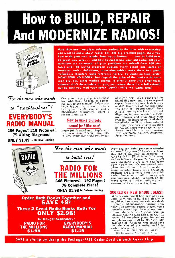
How to BUILD, REPAIRAnd MODERNIZE RADIOS!
Here they are-two giant volumes pocked to the brim with everythingyou want to know about radio! Yes, 448 big practical pages show youhow to do your own repairs from top to bottom ... how to build over80 great new sets ... and how to modernize your old radio! All yourquestions are answered, all your problems are solved! Over 860 pic-tures and 150 wiring diagrams explain every detail-and scores offormulas, codes, definitions, conversion tables make these two greatvolumes a complete radio reference library! So waste no time-orderNOW! SEND NO MONEY! Just deposit the price of the books with post-man plus few cents mailing charge. If after 7 days' Free Trial thesevolumes don't do wonders for you, lust return them for a full refund!But be sure you mail your order TODAY-while the supply lasts!
lot the man who wants
to11 ttouble-ihoot'1
EVERYBODY'SRADIO MANUAL256 Pages! 216 Pictures!
75 Wiring Diagrams!ONLY $1.49 in Deluxe Binding
Get your step-by-step instructionsfor radio repairing from this clear-cut easy -to -use manual! Before youknow it you'll learn how to wire abattery set for AC current, add aphonograph attachment, adapt aset for short wave.
How to make old sets
sound just like new!Every job is quick and simple withthis great volume! You'll read howto give those dusty old sets bright
new cabinets, loudspeakers thatsound like new, and the tone you'dexpect from a big new high fidelitymodel! Hundreds of pictures showyou how to "trouble -shoot" fromA to Z-how to check circuits, readdiagrams, improve selectivity, meas-ure voltages, and even make yourown testing instruments. And that'snot all-for you'll learn how to buildII brand new sets, everything froman AC -DC short wave receiver to a3 -way portable. It's just burstingwith shortcuts, pictures, diagrams.'So order now!
`Tot the man who want)
to Guild Jab I
RADIO FORTHE MILLIONS648 Pictures! 192 Pages!
78 Complete Plans!ONLY $1.98 in Deluxe Binding
Order Both Books Together andSAVE 49ir
These 2 Great Radio Books Both ForONLY $2.98!Or Bought Separately:
RADIO FOR EVERYBODY'STHE MILLIONS RADIO MANUAL
$1.98 $1.49
Now you can build your own favoriteradio-all by yourself! Here's the bookthat shows you how to construct 78GREAT NEW SETS! It explains everystep to follow-tells you the Parts you'llsteed-diagrams every wire and everycoil! You'll find it's jam-packed withplans for all your favorite models-giant consoles, handy little portables,brilliant FM's, a radio built for a bi-cycle. 2 -tube sets, radio phonographcombinations, AC -DC receivers, an all -wave radio, a kitchen radio -a vasttreasure of ideas in one big book!
SCORES OF NEW RADIO IDEAS!What's more, you'll find new ideas ga-lore-learn how to build a high fidelityamplifier, handsome new cabinets, dual -turntable phonograph, rectifier unit,television antenna, record player, homerecorder, even a light beam transmitter!
And think of it! A giant book inDeLuxe binding with 648 pictures, 192pages, 78 complete plans for radiosand phonographs-all for ONLY $1.98!Just one of the items here could saveyou the cost of the entire book! Soorder right now! ILYA -50
POPLIAR SCIENCE PUBLISH:NG CO.353 4th Awiitto, New York 10, N. Y.
SAVE a Stomp by Using the Postage -FREE Order Card on Back Cover Flap

EDITION ONLY $3.48DELUXE
COMPLETE INSTRUCTIONS
For Making
THOUSANDS of DOLLARS
WORTH of FINISHED ARTICLES!
DETAILED INSTRUCTIONS
SHOW HOW TC MAKE:-Matching chair, table and lampCollapsible clothes hamperColonial plant boxesOccasional mirrorFolding luggage standRepairs on your radioRepairs on electric motorsPeriod cabinet 34 inches tallRepairs on door locksModel windmill for your gardenHandy refreshment trayRepairs on your vacuum cleanerModern cabinet for sewing machineChest and secretary furnitureBackyard poultry houseKitchen knife rackDog houseRustic bench and table for outdoorsModel scenery for electric trainDozens of chemical experimentsRadio static suppressorRustic name post
,Home -built radio chargerAdd -a -unit bookcaseRepairs on your sewing machineDozens of car improvements
AND HUNDREDS MORE in theHome Workshop Encyclopedia!
580 PAGES!840 ITEMS!
1883 PICTURES!Printed in 5 COLORS!
You'll have the time of your life with this "NEW Home Work-shop Encyclopedia"! It's jam-packed with an endless variety ofthings to make and do . . . hundreds of interesting and usefulprojects for your workshop ... detailed instructions for workingwith hand and power tools ... for making all sorts of furniture,household accessories, toys, games, gifts and gadgets-from akitchen storage unit to a period cabinet!
TOYS, MODELS, FURNITURE, HOME REPAIRS!It's bursting with short-cut suggestions for every kind of im-provement around the house, garden, workshop, playroom andgarage. New shop ideas! Ideas for keeping the home shipshape!Radio ideas! Aids to modern living! Photo ideas! Home experi-ments! Ideas for motorists! Boat ideas!
It shows you how to do your own carpentry, machine work,wood carving, painting, repairing and electrical work. It givesyou expert advice on caring for your car, repairing vacuums andsewing machines, insulating your house, servicing your radio,and scores of other odd jobs around home.
What's more, it's brimming with exciting how-to -do -it infor-mation on chemistry, electronics, gardening, home movies, modelships and planes, miniature trains, whittling and other hobbies.
SEND NO MONEY NOW- ENJOY 5 -DAY FREE TRIALIts new from cover to cover!. . . With over 800 thrillingthings to do. A handsome DeLuxevolume luxuriously bound inBuckram cloth. Priced at only$3.48 instead of the 55.00 you'dexpect to pay, this huge bookprinted in 5 colors is the bar-
gain of a lifetime! A singleitem can save the entire costof the volume! Order now!Mail order form on back coverflap. On delivery pay postman$3.48 plus few cents postage aspayment in full. If not delightedreturn it in 7 days for refund.
Outdoor Life, Dept. RTA-50, 353 Fourth Avenue, New York 10, N. Y.
SAVE a Stamp by Using the Postage -PEE Order Card on Back Cover Flap11