Extraction of Geometrical Features in 3D Environments for Service Robotic Applications
10
E. Corchado, A. Abraham, and W. Pedrycz (Eds.): HAIS 2008, LNAI 5271, pp. 441–450, 2008. © Springer-Verlag Berlin Heidelberg 2008 Extraction of Geometrical Features in 3D Environments for Service Robotic Applications * Paloma de la Puente, Diego Rodríguez-Losada, Raul López, and Fernando Matía Intelligent Control Group - Universidad Politécnica de Madrid, José Gutiérrez Abascal 2 28006 Madrid, Spain [email protected], [email protected] Abstract. Modeling environments with 3D feature based representations is a challenging issue in current mobile robotics. Fast and robust algorithms are re- quired for applicability to navigation. We present an original and effective seg- mentation method that uses computer vision techniques and the residuals from plane fitting as measurements to generate a range image from 3D data acquired by a laser scanner. The extracted points of each region are converted into plane patches, spheres and cylinders by means of least-squares fitting. Keywords: Laser-range finder, 3D point cloud, range-image based segmenta- tion, least-squares fitting. 1 Introduction In the mobile robotics community significant research efforts are lately focusing on acquiring and processing information about the 3D nature of the environments found in real world scenarios. Overcoming the limitations imposed by the 2D models is of great importance regarding safe navigation but also to provide further knowledge to be used in other robotic tasks. This is the main field of application towards which this work is orientated. Yet it could be of interest in some other areas such as building modeling or industrial reconstruction and identification, being there several publica- tions that address the issues of 3D data acquisition, segmentation and fitting in these contexts [1], [2]. The most remarkable particular aspect of the 3D feature-based navi- gation problem is the need for real-time algorithms, especially when performing Si- multaneous Localization and Mapping (SLAM). To comply with this requirement, a practical approach may go for obtaining and storing the data in an organized way. If methods that consider the extra information hence available are applied subsequently compact models that replace the initial large and scarcely meaningful point cloud can be built in reasonable time. Although there are other means to obtain 3D data from the environment, up to now the laser range scanner is the most popular stereoceptive sensor used in mobile robot- ics. The newly developed Swiss Ranger Camera from the CSEM (Swiss Center for * This work is funded by the Spanish Ministry of Science and Technology, DPI2007-66846- c02-01.
Transcript of Extraction of Geometrical Features in 3D Environments for Service Robotic Applications

E. Corchado, A. Abraham, and W. Pedrycz (Eds.): HAIS 2008, LNAI 5271, pp. 441–450, 2008. © Springer-Verlag Berlin Heidelberg 2008
Extraction of Geometrical Features in 3D Environments for Service Robotic Applications*
Paloma de la Puente, Diego Rodríguez-Losada, Raul López, and Fernando Matía
Intelligent Control Group - Universidad Politécnica de Madrid, José Gutiérrez Abascal 2 28006 Madrid, Spain
[email protected], [email protected]
Abstract. Modeling environments with 3D feature based representations is a challenging issue in current mobile robotics. Fast and robust algorithms are re-quired for applicability to navigation. We present an original and effective seg-mentation method that uses computer vision techniques and the residuals from plane fitting as measurements to generate a range image from 3D data acquired by a laser scanner. The extracted points of each region are converted into plane patches, spheres and cylinders by means of least-squares fitting.
Keywords: Laser-range finder, 3D point cloud, range-image based segmenta-tion, least-squares fitting.
1 Introduction
In the mobile robotics community significant research efforts are lately focusing on acquiring and processing information about the 3D nature of the environments found in real world scenarios. Overcoming the limitations imposed by the 2D models is of great importance regarding safe navigation but also to provide further knowledge to be used in other robotic tasks. This is the main field of application towards which this work is orientated. Yet it could be of interest in some other areas such as building modeling or industrial reconstruction and identification, being there several publica-tions that address the issues of 3D data acquisition, segmentation and fitting in these contexts [1], [2]. The most remarkable particular aspect of the 3D feature-based navi-gation problem is the need for real-time algorithms, especially when performing Si-multaneous Localization and Mapping (SLAM). To comply with this requirement, a practical approach may go for obtaining and storing the data in an organized way. If methods that consider the extra information hence available are applied subsequently compact models that replace the initial large and scarcely meaningful point cloud can be built in reasonable time.
Although there are other means to obtain 3D data from the environment, up to now the laser range scanner is the most popular stereoceptive sensor used in mobile robot-ics. The newly developed Swiss Ranger Camera from the CSEM (Swiss Center for
* This work is funded by the Spanish Ministry of Science and Technology, DPI2007-66846-
c02-01.

442 P. de la Puente et al.
Electronics and Microtechnology), commercialized by Acroname Robotics, may become a good alternative, but it is yet not very suitable for mapping activities due to its reduced field-of-view (of about 45º) and the noisiness of its measurements [3]. Stereo vision systems are also less accurate than the laser range finder and they pose more difficulties to the data manipulation and interpretation processes.
Here we put forward our ideas to obtain 3D primitives frequently found by mobile robots in indoor environments out of distance measurements provided by such laser devices. Our main contribution is a novel method to solve the segmentation of the laser data by integrating vision based techniques. Taking advantage of the ordered nature of the data, real-time capabilities are achieved.
The paper is organized as follows. Section 2 constitutes a brief explanation of the hardware and system configuration we have employed in the 3D data acquisition. Section 3 introduces the segmentation problem, revises some related work and pre-sents the range image based technique we propose to solve it keeping in mind the specific conditions of the feature based navigation goal. In Section 4 we expose how the final fitting to geometrical primitives is carried out. Section 5 shows some ex-perimental results. Finally, Section 6 summarizes our conclusions and future work.
2 3D Data Acquisition
One of the simplest solutions to gather 3D data with a 2D laser range finder consists of displacing it along the perpendicular direction to its scanning plane, normally hori-zontal. Equivalently, instead of actually moving one single laser scanner up and down, adding a second laser vertically mounted is a practical option when the robot operates in strictly flat terrain [4][5]. Another possibility is to make the laser collect data in a vertical plane while it turns around its upright axis by means of an extra servo drive [6]. One laser rotating around its optical axis, with a yaw movement, gen-erates 3D data too [7], but requires higher mechanical effort and leads to each indi-vidual 2D scan not having much intuitive sense.
The most natural approach seems to be that of employing a nodding system as is done in [3] [5] [8] [9]. We have mounted a SICK LMS200 laser device on top of a servo pan-tilt unit (PowerCube Wrist 070, by Amtec Robotics) positioned at the front of our Pioneer 3AT robot, Nemo (Fig. 1).
A data server running on an onboard laptop computer sends synchronous updated information about odometry, PW70 and laser readings at clients’ cyclical requests within a capture procedure in a stop-and-go manner. The communication protocols between the laptop and each of both devices and the robot work via serial connection. The port’s baud rate for the laser scanner is set at 500 kb (using an external USB to 422 interface) so as to gain velocity and permit a good precision in synchronization with the PW70. This is of utmost importance to avoid distortions when applying the relative transformations to calculate each point’s [x, y, z] coordinates.
The laser beams of a 2D scan are emitted between 0° and 180° at regular intervals dθ we have fixed in 1°. We obtain a 3D scan by varying the tilt angle.
Extraction of Geometrical Features in 3D Environments 443
Fig. 1. Our robot Nemo equipped with a laser mounted on a wrist for 3D data acquisition
3 Segmentation
Segmentation undertakes the partition of a 3D point cloud into smaller subsets repre-senting objects of interest (different surfaces, here). Points identified as part of the same region are allotted the same tag so that they can be treated as raw data of a sought-after feature. This is a key subject in feature based navigation for mobile ro-bots, being especially challenging the fact that it is not known a priori what stuff the scanned scene may contain apart from those elements we intend to recognize [3].
3.1 Related Work
In computer vision, the segmentation problem has received considerable attention for the last decades. Notwithstanding, the adaptation of developed techniques and algo-rithms to robotic applications with data coming not from cameras but from laser sen-sors has not been much exploited. Indeed, a great deal of recent research has focused on extracting enhanced levels of detail in complex scenes and better preserving the objects’ exact shape, [10] [11]. Robots do not yet need that much knowledge about small items in the environment and this approach implies too complicated, time con-suming solutions that are therefore not adequate for navigation.
Three main categories of existing methods are commonly used, namely edge-based segmentation, region-based segmentation and scanline-based segmentation [12].
• Edge-based segmentation consists of detecting those points where disconti-nuities in certain local properties are noteworthy and then grouping together points that fall inside the closed boundaries found.
• Region algorithms follow a merging schema. They usually start from some seed points to which near points are added in accordance to a certain similar-ity criterion.
• Scanline-based segmentation in first place analyses each scanline or row of a range image independently and then checks whether extracted features of consecutive 2D scans are combinable into the same 3D feature.
In [13] and [14] a series of range image segmentation methods within these three classes are thoroughly described and evaluated. We think that edge-based algorithms are more suitable here because they are faster and more direct and elegant than the other two approaches. Some hybrid techniques complementing it with any of the other two are interesting as well [15].
444 P. de la Puente et al.
We have observed that a vast majority of segmentation algorithms are limited to planar surfaces, mainly among those few explicitly designed for mobile robotics ap-plications. An assessment of four different line extraction algorithms to separate points from different planar surfaces in service robotics has recently been published, [16]. In [3] two region-based algorithms for planar segmentation of range images were presented; they are both capable of processing probabilistic data in order to do 3D SLAM based upon planar features. Reference [17] is the closest work to the ap-proach presented in this paper. It addresses the segmentation of laser data in mobile robotics by applying common range image processing operations, but also sticks to planar patches. The edge-based algorithm there presented introduces a new measure, the so called bearing angle, to characterize the surfaces and then apply a standard Sobel border detector.
The algorithm reported in [12] inspired the key idea of the method we propose. It is a region growing strategy for unstructured point clouds from industrial environments.
3.2 Vision-Based Range Image Segmentation
The first step towards classifying points in a 3D scan through range image segmenta-tion may be to fill an image like structure with the available raw measurements com-ing from the sensor and then apply computer vision edge detection algorithms. This allows finding the jump edges of the data, i.e. those associated to depth discontinuities between two physically separated (or not intersecting) surfaces. However, different objects and surfaces are usually touching one another (things standing on the floor are in permanent contact with it, walls join at corners...). In that case, boundaries are defined by crease or roof edges (changes in orientation) that are totally compatible with smooth variations in distance measurements. Similar conclusions were pointed out in [15], [17].
The solution we suggest comes from the fact that the residuals of fitting one point’s neighborhood to a plane will have higher values at both jump and crease edges. As-suming the laser is correctly calibrated and errors in the measurements can be mod-eled as Gaussian noise with a not too high standard deviation (5mm for the LMS 200), most points inside a planar patch have tiny residuals. Points from other kind of primitives have residuals proportional to the local curvature. The basic features we are going to use for representation (planar patches, cylinders and spheres) have theoreti-cal constant curvatures for all of their points. Nevertheless, segmentation would not be affected if that were not the case, for residuals would still change smoothly and have greater values at break points.
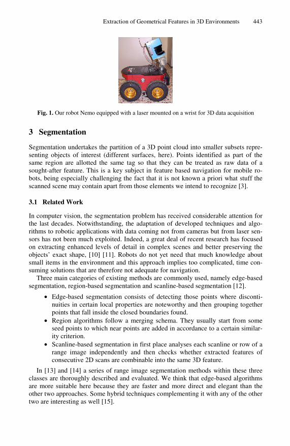
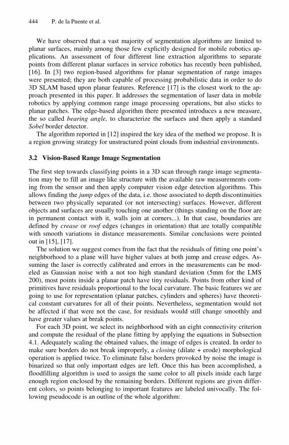
For each 3D point, we select its neighborhood with an eight connectivity criterion and compute the residual of the plane fitting by applying the equations in Subsection 4.1. Adequately scaling the obtained values, the image of edges is created. In order to make sure borders do not break improperly, a closing (dilate + erode) morphological operation is applied twice. To eliminate false borders provoked by noise the image is binarized so that only important edges are left. Once this has been accomplished, a floodfilling algorithm is used to assign the same color to all pixels inside each large enough region enclosed by the remaining borders. Different regions are given differ-ent colors, so points belonging to important features are labeled univocally. The fol-lowing pseudocode is an outline of the whole algorithm:
Extraction of Geometrical Features in 3D Environments 445
Input: matrix A containing the 3D data ( , )
{ } { ( ), , ( , ), , ( )} ( , ) * ( )(See 4.1)
( ) 2
residual
for every i j element in Aneigh A i -1, j -1 A i j A i+1, j+1
image i j k PlaneLSQ neighendimage Closing imageimage Th
←=
= ×=
K K
( )
if ( ) %pixel not labeled yet _ ( , _ ) ( _ ) %create new labeled region else
resholding imagefor each pixel in mask of image
black pixelnew colorFloodFilling image new colorr NewRegion new colorR r
=←
{ }
if ( ( ) ( )) 3 ( , ) ; end end
%the extracted features
if ( re
for all existing regionscolor pixel color region
r D point associated to pixel i jbreak
end
endFfor r R
PlaneLSQ
==←
= ∅∈
( ) ) Plane p= ( ) p else if ( ( ) )(See 4.2) Cylinder c= ( ) c else if (
sidual
residual
resi
r thresholdPlaneLSQ r
FCylinderLSQ r threshold
CylinderLSQ rF
SphereLSQ
<
←<
←( ) )(See 4.3.)
Sphere s= ( ) s
dual r thresholdSphereLSQ r
Fend
<
←
Fig. 2. Pseudocode for segmentation and fitting
4 Model Fitting
4.1 Plane Fitting
In the Hessian Normal Form of a plane the model parameters are the normal vector components (nx, ny, nz) and the perpendicular distance to the origin, d. The parameters
446 P. de la Puente et al.
of the plane that best fits a set of N points pi = (xi, yi, zi) in a least squares sense can be obtained by solving a 3x3 eigenvalue problem. We aim at minimizing the sum of squares of the orthogonal distances from the points to the estimated surface (the residual):
2
1
)(),,,( dznynxndnnnR iziyi
N
ixzyx −++=∑
=
. (1)
Differentiation with respect to the four parameters yields a 4x4 linear system on the parameters, but the problem can be simplified. If the partial derivative with re-spect to d is obtained, it is easy to see that the best possible estimation of the plane passes through the center of gravity (ox,oy,oz).of the points. The normal vector can then be obtained as the eigenvector associated to the smallest eigenvalue of:
⎥⎥⎥⎥
⎦
⎤
⎢⎢⎢⎢
⎣
⎡
=
∑∑∑∑∑∑∑∑∑
===
===
===
N
i i
N
i ii
N
i ii
N
i ii
N
i i
N
i ii
N
i ii
N
i ii
N
i i
zzyzx
zyyyx
zxyxx
A
0
2'
0
''
0
''0
''
0
2'
0
''0
''
0
''
0
2'
, (2)
being 'ip = ( '
ix , 'iy , '
iz ) =( xi ox − , yi oy − , zi oz − ).
The residual value will be 2
1
( )N
i
R=
= ⋅∑ 'ip n .
4.2 Sphere Fitting
A way to determine an estimation of the center coordinates (xc, yc, zc) and the radius r is to minimize the following function for all the points pi:
2222 )()()( rzzyyxx cicici −−+−+− . (3)
To make the equation linear the variable 2222 )( rzyxt ccc −++= is intro-
duced so that the problem comes to solving
0
1222
1222
1222
222
22
22
22
21
21
21
222
11
=
⎥⎥⎥⎥⎥
⎦
⎤
⎢⎢⎢⎢⎢
⎣
⎡
−−−
−−−−−−
−
⎥⎥⎥⎥
⎦
⎤
⎢⎢⎢⎢
⎣
⎡
⎥⎥⎥⎥
⎦
⎤
⎢⎢⎢⎢
⎣
⎡
−−−
−−−−−−
NNN
c
c
c
NNN
i
zyx
zyx
zyx
t
z
y
x
zyy
zyx
zyx
MMMMM . (4)
Or in matrix notation, BMx = . So, BMMx T 1)( −= is the solution we sought.
4.3 Cylinder Fitting
A cylinder may be represented by a normalized vector along its axis (a, b, c), a point on the axis (x0, y0, z0) and the radius R. Equation 5 holds:

Extraction of Geometrical Features in 3D Environments 447
.)]()([
)]()([)]()([22
00
200
200
Ryyaxxb
xxczzazzbyyc
ii
iiii
=−−−+
+−−−+−−− (5)
Developing the former expression and grouping the coefficients, it can be put
as: 0222 =+++++++++ JIzHyGxzFyzExyDxCzByAx iiiiiiiiiiii .
Dividing it by A, we get a linear system with nine unknowns that can be solved in a least squares fashion. The following approximations have proven accurate enough in our experiments.
If E/A, F/A and G/A are close to zero, B/A close to 1 implies (a, b, c) = (0, 0, 1) and C/A close to 1 implies (a, b, c) = (0, 1, 0) .Otherwise, A= 2/(1+B/A+C/A). If A and B are close to 1 (a, b, c) = (-EA/2C, -F/2c, (1-C)1/2). If A is close to 1 but B is not close to 1 (a, b, c) = (-D/2b, (1-B)1/2, -F/2b). If A is not close to 1 (a, b, c) = ((1-A)1/2, -D/2a,-E/2A). If the resultant vectors are not normalized they must be divided by their magnitude.
Once (a, b, c) has been obtained, the point on the axis is computed by solving:
⎥⎥⎥⎥
⎦
⎤
⎢⎢⎢⎢
⎣
⎡
=⎥⎥⎥
⎦
⎤
⎢⎢⎢
⎣
⎡
⎥⎥⎥⎥⎥
⎦
⎤
⎢⎢⎢⎢⎢
⎣
⎡
+−+−
+−
0
)(222
2)(22
22)(2
0
0
0
22
22
22
I
H
G
z
y
x
cba
babcac
bccaab
acabcb
. (6)
The estimation of the radius value is done by:
Jzbcy
zbcyzbcyzbaycaxcbR
−−−−−+++++=
00
000020
2220
2220
222
2
22)()()(
5 Experiments
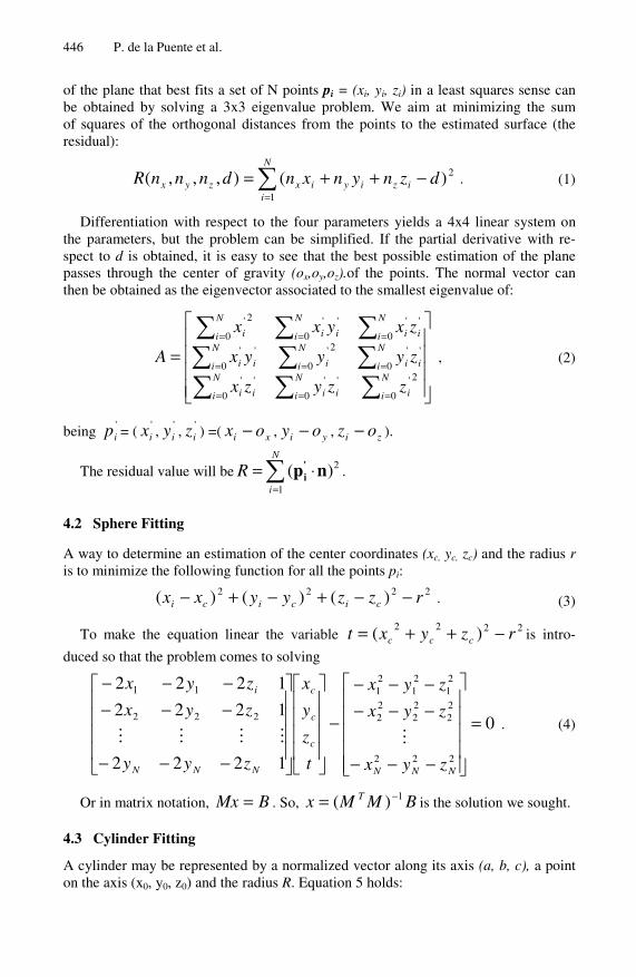
To capture the 3D data, the laser is tilted from -0.4 radians (upwards looking) to 0.3 radians (downwards looking) at a constant speed of 0.05 rad/s, which results in a 70x181 matrix of measurements. We process the central 70x131submatrix to avoid problems caused by the points being to near from each other at the extreme lateral angles of the view area. Fig. 3 shows some results of the image processing steps of our algorithm. They correspond to two 3D scans taken at our laboratory with different room configurations.
The segmentation process takes about 1 second. It is considerably below the time consumed by region growing algorithms, applied when not much speed is required, such as [12], which we implemented for evaluation. Our development has been in C++ using the OpenCv libraries.
Table 1. shows some information about a series of experiments conducted by mov-ing the robot across the corridors and rooms of our laboratory. Under segmentation
448 P. de la Puente et al.
Fig. 3. Images on the left contain raw distance measurements. Next images show the plane fitting residuals followed by the region extraction output. Images on the right are the environ-ments where the data for these experiments were taken, with some modifications.
Table 1. Summary of results from several different experiments
Experiment Extracted features
Under segmentation
Over segmentation
False fittings
Processing time (s)
1 7 1 (14.3%) 0(0%) 0 1.06 2 13 0 (0%) 1(7.7%) 0 1.00 3 17 1(5.9%) 1(5.9%) 0 1.05 4 10 0(0%) 2(20%) 0 1.03 5 12 2(16.7%) 1(8.3%) 1 1.00 6 17 0(0%) 4(23.5%) 0 1.04 7 18 1(5.6%) 2(11.1%) 0 1.04 8 13 1(7.7%) 1(7.7%) 1 1.06 9 20 2(10%) 1(5%) 0 1.07
10 23 0(0%) 6(26.1%) 0 0.98
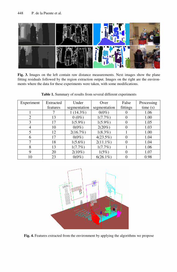
Fig. 4. Features extracted from the environment by applying the algorithms we propose

Extraction of Geometrical Features in 3D Environments 449
consists of having different surfaces belonging to the same extracted region. It may lead to obtaining a wrong plane model (false fitting). Over segmentation happens when several contiguous patches are acquired from a surface.
Some changes in the threshold values were made so as to adapt the segmentation process to the particular conditions of the experiments. Although at first it may leave out a greater number of points than other methods, ours allows for the extraction of the most important elements of the structure in cluttered environments, consuming less time. As already mentioned, surfaces other than planes can be obtained this way.
The final feature extraction for experiment number 10 is shown in Fig. 4. No false fittings were done and only few unimportant objects were missing. The outcome for other 3D scans was similar.
6 Conclusions and Future Working Lines
We have presented a novel range-image based algorithm employing computer vision techniques. The residuals of a least squares fitting process for each pixel’s neighbor-hood are used to detect surface discontinuities in the data and achieve effective fast performance, as is needed in mobile robotics applications. The segmented 3D points are fitted to planar, cylindrical or spherical models to generate a compact representa-tion of the environment.
One of the earliest improvements we plan to introduce is the combination of this segmentation results with the detection of edges at both sides of the image, to widen the field of view. We need to make the algorithm completely robust by applying local checking methods that will eliminate the under-segmentation cases. Furthermore, once the different regions have been found some close points left out after the image processing steps may be added in order to enlarge the patches. Finally, patches’ boundaries should be determined and patches belonging to the same object ought to be merged (we think about convex hulls determination and applying boolean opera-tions among polygons). This will directly deal with the over-segmentation cases.
A higher level goal we have is the integration of features to generate room and cor-ridor models, aiming at building rich maps containing topological information.
References
1. Dorninger, P., Nothegger, C.: 3D Segmentation of Unstructured Point Clouds for Building Modelling. In: Stilla, U., et al. (eds.) PIA 2007. International Archives of Photogrammetry, Remote Sensing and Spatial Information Sciences, vol. 36 (3/W49A) (2007)
2. Delft Univeristy of Technology. Department of Earth Observation & Space Systems, http://www.lr.tudelft.nl/live/ pagina.jsp?id=14f981bc-23a0-4dd8-8653-3db5a5f6f627&lang=en
3. Weingarten, J.: Feature-based 3D SLAM. PhD thesis, EPFL (2006) 4. Mahon, I., Williams, S.: Three Dimensional Robotic Mapping. In: Proc. of the Austral-
asian Conference on Robotics & Automation (ACRA) (2003) 5. Hähnel, D., Burgard, W., Thrun, S.: Learning Compact 3d Models of Indoor and Outdoor
Environments with a Mobile Robot. Robotics and Autonomous Systems 44(1), 15–27 (2003)

450 P. de la Puente et al.
6. Brenneke, C., Wulf, O., Wagner, B.: Using 3D Laser Range Data for SLAM in Outdoor Environments. In: Proc. of the 2003 IEEWRSI Intl. Conference on Intelligent Robots and Systems, Las Vegas, Nevada (2003)
7. Kohlhepp, P., Pozzo, P., Walther, M., Dillmann, R.: Sequential 3DSLAM for Mobile Ac-tion Planning. In: Proc. of 2004 IEEE/RSJ International Conference, vol. 1, pp. 722–729 (2004)
8. Cole, D., Newman, P.: Using Laser Range Data for 3D SLAM in Outdoor Environments. In: Proc. of the IEEE International Conference on Robotics and Automation, Florida (2006)
9. Nüchter, A., Lingemann, K., Hertzberg, J., Surmann, H.: 6D SLAM—3D Mapping, Out-door Environments. Journal of Field Robotics 24(8/9), 699–722 (2007)
10. Han, F., Tu, Z., Zhu, S.C.: Range Image Segmentation by an Effective Jump-diffusion Method. IEEE Transactions on Pattern Analysis and Machine Intelligence 26(9), 1138–1153 (2004)
11. Bellon, O., Silva, L.: New Improvements to Range Image Segmentation by Edge Detec-tion. IEEE Signal Processing Letters 9(2) (2002)
12. Rabbani, T., van den Heuvel, F.A., Vosselman, G.: Segmentation of Point Clouds Using Smoothness Constraint. In: ISPRS Commission V Symposium Image Engineering and Vi-sion Metrology, Dresden, vol. XXXVI, Part 5 (2006)
13. Hoover, A., Jean-Baptiste, G., Jiang, X., Flynn, P.J., Bunke, H., Goldgof, D.B., Bowyer, K., Eggert, D.W., Fitzgibbon, A., Fisher, R.B.: An Experimental Comparison of Range Image Segmentation Algorithms. IEEE Transactions on Pattern Analysis and Machine In-telligence 18(7), 673–689 (1996)
14. Jiang, X., Bowyer, K., Morioka, Y., Hiura, S., Sato, K., Inokuchi, S., Bock, M., Guerra, C., Loke, R., du Buf, J.: Some Further Results of Experimental Comparison of Range Image Segmentation Algorithms. In: Proc. of the 15th International Conference on Pattern Rec-ognition (2000)
15. Sappa, A.D., Devy, M.: Fast Range Image Segmentation by an Edge Detection Strategy. In: Third IEEE International Conference on 3D Digital Imaging and Modeling, p. 292 (2001)
16. Gächter, S., Nguyen, V., Siegwart, R.: Results on Range Image Segmentation for Service Robots. In: Proc. of the 4th IEEE International Conference on Computer Vision Systems (2006)
17. Harati, A., Gächter, S., Siegwart, R.: Fast Range Image Segmentation for Indoor 3D-SLAM. In: 6th IFAC Symposium on Intelligent Autonomous Vehicles (2007)