In situ determination of PCB biodeposition by Mytilus edulis in a Baltic coastal ecosystem
Upload
khangminh22Category
view
3download
0
Model EXTO607A11
Platinum Swiveler® Industrial ICP® Accelerometer
Installation and Operating Manual
For assistance with the operation of this product,
contact the PCB Piezotronics, Inc.
Toll-free: 800-959-446424-hour SensorLine: 716-684-0001
Fax: 716-684-3823E-mail: [email protected]
Web: www.imi-sensors.com

Manual 21354 Rev E ECN 50523
Repair and Maintenance
PCB guarantees Total Customer Satisfaction through its “Lifetime Warranty Plus” on all Platinum Stock Products sold by PCB and through its limited warranties on all other PCB Stock, Standard and Special products. Due to the sophisticated nature of our sensors and associated instrumentation, field servicing and repair is not recommended and, if attempted, will void the factory warranty. Beyond routine calibration and battery replacements where applicable, our products require no user maintenance. Clean electrical connectors, housings, and mounting surfaces with solutions and techniques that will not harm the material of construction. Observe caution when using liquids near devices that are not hermetically sealed. Such devices should only be wiped with a dampened cloth—never saturated or submerged.
In the event that equipment becomes damaged or ceases to operate, our Application Engineers are here to support your troubleshooting efforts 24 hours a day, 7 days a week. Call or email with model and serial number as well as a brief description of the problem.
Calibration
Routine calibration of sensors and associated instrumentation is necessary to maintain measurement accuracy. We recommend calibrating on an annual basis, after exposure to any extreme environmental influence, or prior to any critical test.
PCB Piezotronics is an ISO-9001 certified company whose calibration services are accredited by A2LA to ISO/IEC 17025, with full traceability to SI through N.I.S.T. In addition to our standard calibration services, we also offer specialized tests, including: sensitivity at elevated or cryogenic temperatures, phase response, extended high or low frequency response, extended range, leak testing, hydrostatic pressure testing, and others. For more information, contact your local PCB Piezotronics distributor, sales representative, or factory customer service representative.
Returning Equipment If factory repair is required, our representatives will provide you with a Return Material Authorization (RMA) number, which we use to reference any information you have already provided and expedite the repair process. This number should be clearly marked on the outside of all returned package(s) and on any packing list(s) accompanying the shipment.
Contact Information
PCB Piezotronics, Inc.
3425 Walden Ave.
Depew, NY14043 USA
Toll-free: (800) 828-8840 24-hour SensorLine: (716) 684-0001 General inquiries: [email protected] Repair inquiries: [email protected]
For a complete list of distributors, global offices and sales representatives, visit our website, www.pcb.com.
Safety Considerations
This product is intended for use by qualified personnel who recognize shock hazards and are familiar with the precautions required to avoid injury. While our equipment is designed with user safety in mind, the protection provided by the equipment may be impaired if equipment is used in a manner not specified by this manual.
Discontinue use and contact our 24-Hour Sensorline if:
Assistance is needed to safely operate equipment
Damage is visible or suspected
Equipment fails or malfunctions
For complete equipment ratings, refer to the enclosed specification sheet for your product.
Definition of Terms and Symbols
The following symbols may be used in this manual:
DANGER Indicates an immediate hazardous situation, which, if not avoided, may result in death or serious injury.

Manual 21354 Rev E ECN 50523
CAUTION Refers to hazards that could damage the instrument.
NOTE Indicates tips, recommendations and important information. The notes simplify processes and contain additional information on particular operating steps.
The following symbols may be found on the equipment described in this manual:
This symbol on the unit indicates that high voltage may be present. Use standard safety precautions to avoid personal contact with this voltage.
This symbol on the unit indicates that the user should refer to the operating instructions located in the manual.
This symbol indicates safety, earth ground.
Manual 21354 Rev E ECN 50523
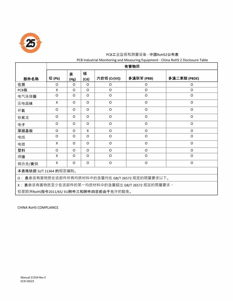
PCB工业监视和测量设备 - 中国RoHS2公布表
PCB Industrial Monitoring and Measuring Equipment - China RoHS 2 Disclosure Table
部件名称
有害物质
铅 (Pb) 汞
(Hg)
镉
(Cd) 六价铬 (Cr(VI)) 多溴联苯 (PBB) 多溴二苯醚 (PBDE)
住房 O O O O O O
PCB板 X O O O O O
电气连接器 O O O O O O
压电晶体 X O O O O O
环氧 O O O O O O
铁氟龙 O O O O O O
电子 O O O O O O
厚膜基板 O O X O O O
电线 O O O O O O
电缆 X O O O O O
塑料 O O O O O O
焊接 X O O O O O
铜合金/黄铜 X O O O O O
本表格依据 SJ/T 11364 的规定编制。
O: 表示该有害物质在该部件所有均质材料中的含量均在 GB/T 26572 规定的限量要求以下。
X: 表示该有害物质至少在该部件的某一均质材料中的含量超出 GB/T 26572 规定的限量要求。
铅是欧洲RoHS指令2011/65/ EU附件三和附件四目前由于允许的豁免。
CHINA RoHS COMPLIANCE
Manual 21354 Rev E ECN 50523
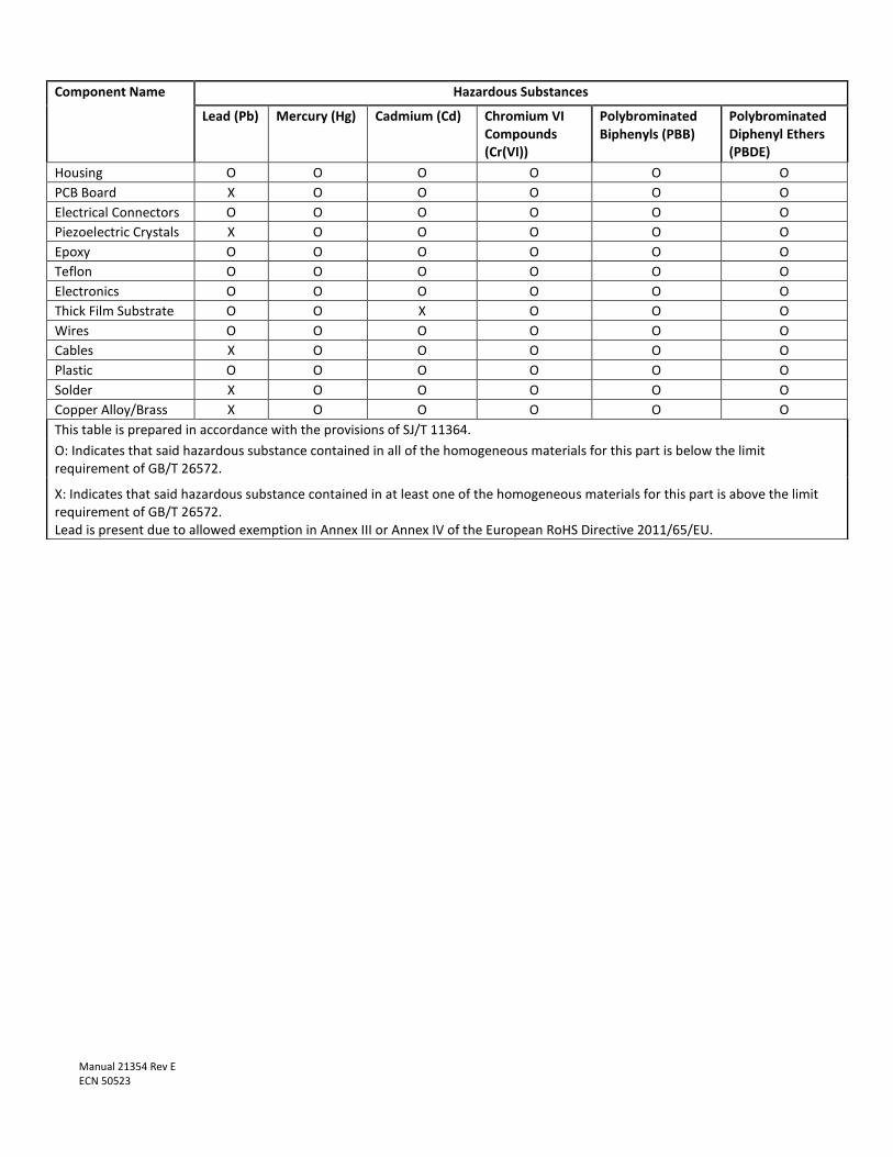
Component Name Hazardous Substances
Lead (Pb) Mercury (Hg) Cadmium (Cd) Chromium VI Compounds (Cr(VI))
Polybrominated Biphenyls (PBB)
Polybrominated Diphenyl Ethers (PBDE)
Housing O O O O O O
PCB Board X O O O O O
Electrical Connectors O O O O O O
Piezoelectric Crystals X O O O O O
Epoxy O O O O O O
Teflon O O O O O O
Electronics O O O O O O
Thick Film Substrate O O X O O O
Wires O O O O O O
Cables X O O O O O
Plastic O O O O O O
Solder X O O O O O
Copper Alloy/Brass X O O O O O
This table is prepared in accordance with the provisions of SJ/T 11364.
O: Indicates that said hazardous substance contained in all of the homogeneous materials for this part is below the limit requirement of GB/T 26572.
X: Indicates that said hazardous substance contained in at least one of the homogeneous materials for this part is above the limit requirement of GB/T 26572. Lead is present due to allowed exemption in Annex III or Annex IV of the European RoHS Directive 2011/65/EU.
MANUAL NUMBER: 18405 MANUAL REVISION: A
ECN NUMBER: 49766
Operating Guide with Enclosed Warranty Information
3424 Walden Avenue, Depew, New York 14043-2495
Phone (716) 684-0003
Fax (716) 684-3823
Toll Free Line 1-800-959-4IMI
Piezoelectric ICP® Accelerometers Operating Guide
General
OPERATING GUIDE for use with
PIEZOELECTRIC ICP® ACCELEROMETERS SPECIFICATION SHEET, INSTALLATION DRAWING AND CALIBRATION INFORMATION ENCLOSED
IMI ASSUMES NO RESPONSIBILITY FOR DAMAGE CAUSED TO THIS PRODUCT AS A RESULT OF PROCEDURES THAT ARE INCONSISTENT WITH THIS OPERATING GUIDE
1.0 INTRODUCTION
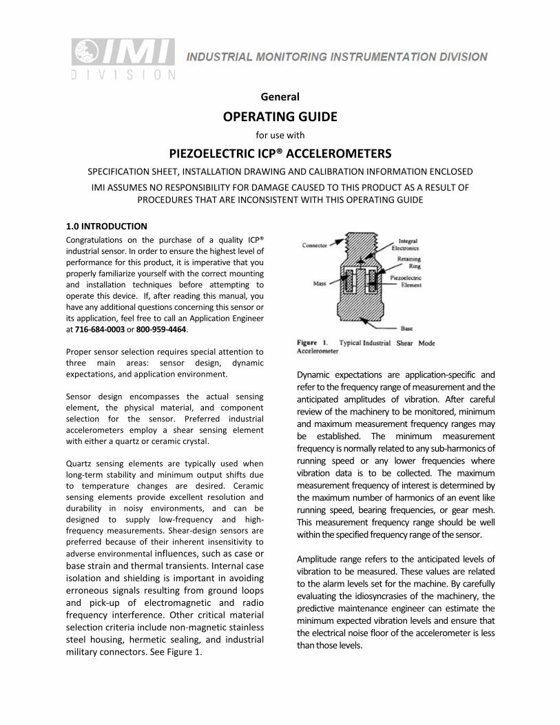
Congratulations on the purchase of a quality ICP® industrial sensor. In order to ensure the highest level of performance for this product, it is imperative that you properly familiarize yourself with the correct mounting and installation techniques before attempting to operate this device. If, after reading this manual, you have any additional questions concerning this sensor or its application, feel free to call an Application Engineer at 716-684-0003 or 800-959-4464. Proper sensor selection requires special attention to three main areas: sensor design, dynamic expectations, and application environment. Sensor design encompasses the actual sensing element, the physical material, and component selection for the sensor. Preferred industrial accelerometers employ a shear sensing element with either a quartz or ceramic crystal. Quartz sensing elements are typically used when long-term stability and minimum output shifts due to temperature changes are desired. Ceramic sensing elements provide excellent resolution and durability in noisy environments, and can be designed to supply low-frequency and high-frequency measurements. Shear-design sensors are preferred because of their inherent insensitivity to
adverse environmental influences, such as case or base strain and thermal transients. Internal case isolation and shielding is important in avoiding erroneous signals resulting from ground loops and pick-up of electromagnetic and radio frequency interference. Other critical material selection criteria include non-magnetic stainless steel housing, hermetic sealing, and industrial military connectors. See Figure 1.
Dynamic expectations are application-specific and refer to the frequency range of measurement and the anticipated amplitudes of vibration. After careful review of the machinery to be monitored, minimum and maximum measurement frequency ranges may be established. The minimum measurement frequency is normally related to any sub-harmonics of running speed or any lower frequencies where vibration data is to be collected. The maximum measurement frequency of interest is determined by the maximum number of harmonics of an event like running speed, bearing frequencies, or gear mesh. This measurement frequency range should be well within the specified frequency range of the sensor. Amplitude range refers to the anticipated levels of vibration to be measured. These values are related to the alarm levels set for the machine. By carefully evaluating the idiosyncrasies of the machinery, the predictive maintenance engineer can estimate the minimum expected vibration levels and ensure that the electrical noise floor of the accelerometer is less than those levels.
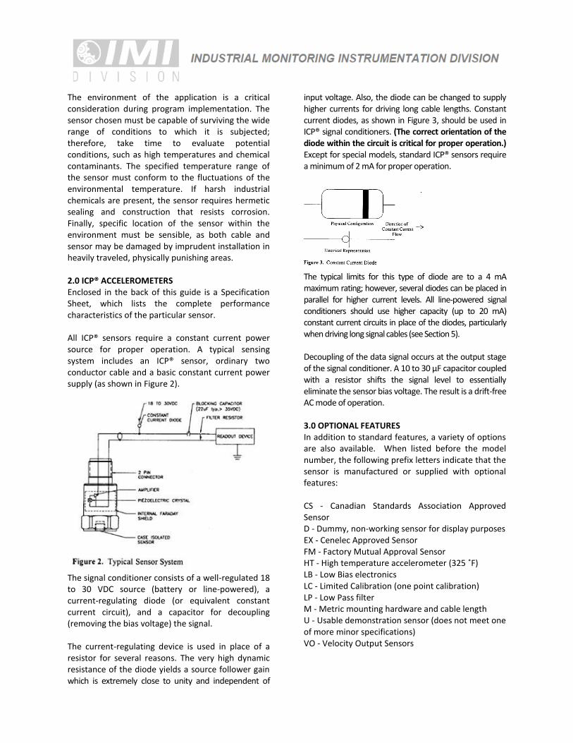
The environment of the application is a critical consideration during program implementation. The sensor chosen must be capable of surviving the wide range of conditions to which it is subjected; therefore, take time to evaluate potential conditions, such as high temperatures and chemical contaminants. The specified temperature range of the sensor must conform to the fluctuations of the environmental temperature. If harsh industrial chemicals are present, the sensor requires hermetic sealing and construction that resists corrosion. Finally, specific location of the sensor within the environment must be sensible, as both cable and sensor may be damaged by imprudent installation in heavily traveled, physically punishing areas. 2.0 ICP® ACCELEROMETERS Enclosed in the back of this guide is a Specification Sheet, which lists the complete performance characteristics of the particular sensor. All ICP® sensors require a constant current power source for proper operation. A typical sensing system includes an ICP® sensor, ordinary two conductor cable and a basic constant current power supply (as shown in Figure 2).
The signal conditioner consists of a well-regulated 18 to 30 VDC source (battery or line-powered), a current-regulating diode (or equivalent constant current circuit), and a capacitor for decoupling (removing the bias voltage) the signal. The current-regulating device is used in place of a resistor for several reasons. The very high dynamic resistance of the diode yields a source follower gain which is extremely close to unity and independent of
input voltage. Also, the diode can be changed to supply higher currents for driving long cable lengths. Constant current diodes, as shown in Figure 3, should be used in ICP® signal conditioners. (The correct orientation of the diode within the circuit is critical for proper operation.) Except for special models, standard ICP® sensors require a minimum of 2 mA for proper operation.
The typical limits for this type of diode are to a 4 mA maximum rating; however, several diodes can be placed in parallel for higher current levels. All line-powered signal conditioners should use higher capacity (up to 20 mA) constant current circuits in place of the diodes, particularly when driving long signal cables (see Section 5). Decoupling of the data signal occurs at the output stage of the signal conditioner. A 10 to 30 µF capacitor coupled with a resistor shifts the signal level to essentially eliminate the sensor bias voltage. The result is a drift-free AC mode of operation. 3.0 OPTIONAL FEATURES In addition to standard features, a variety of options are also available. When listed before the model number, the following prefix letters indicate that the sensor is manufactured or supplied with optional features: CS - Canadian Standards Association Approved Sensor D - Dummy, non-working sensor for display purposes EX - Cenelec Approved Sensor FM - Factory Mutual Approval Sensor HT - High temperature accelerometer (325 ˚F) LB - Low Bias electronics LC - Limited Calibration (one point calibration) LP - Low Pass filter M - Metric mounting hardware and cable length U - Usable demonstration sensor (does not meet one of more minor specifications) VO - Velocity Output Sensors
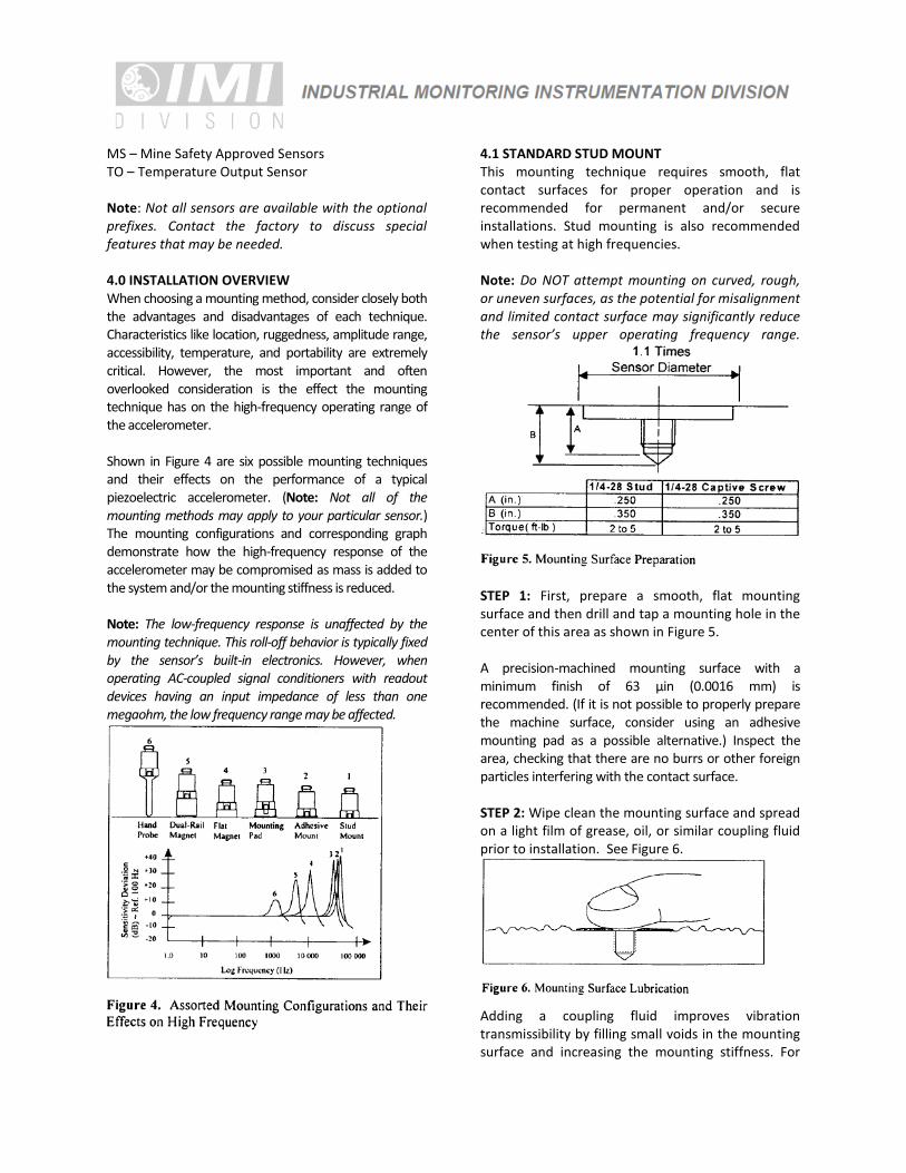
MS – Mine Safety Approved Sensors TO – Temperature Output Sensor Note: Not all sensors are available with the optional prefixes. Contact the factory to discuss special features that may be needed. 4.0 INSTALLATION OVERVIEW When choosing a mounting method, consider closely both the advantages and disadvantages of each technique. Characteristics like location, ruggedness, amplitude range, accessibility, temperature, and portability are extremely critical. However, the most important and often overlooked consideration is the effect the mounting technique has on the high-frequency operating range of the accelerometer. Shown in Figure 4 are six possible mounting techniques and their effects on the performance of a typical piezoelectric accelerometer. (Note: Not all of the mounting methods may apply to your particular sensor.) The mounting configurations and corresponding graph demonstrate how the high-frequency response of the accelerometer may be compromised as mass is added to the system and/or the mounting stiffness is reduced. Note: The low-frequency response is unaffected by the mounting technique. This roll-off behavior is typically fixed by the sensor’s built-in electronics. However, when operating AC-coupled signal conditioners with readout devices having an input impedance of less than one megaohm, the low frequency range may be affected.
4.1 STANDARD STUD MOUNT This mounting technique requires smooth, flat contact surfaces for proper operation and is recommended for permanent and/or secure installations. Stud mounting is also recommended when testing at high frequencies. Note: Do NOT attempt mounting on curved, rough, or uneven surfaces, as the potential for misalignment and limited contact surface may significantly reduce the sensor’s upper operating frequency range.
STEP 1: First, prepare a smooth, flat mounting surface and then drill and tap a mounting hole in the center of this area as shown in Figure 5. A precision-machined mounting surface with a minimum finish of 63 µin (0.0016 mm) is recommended. (If it is not possible to properly prepare the machine surface, consider using an adhesive mounting pad as a possible alternative.) Inspect the area, checking that there are no burrs or other foreign particles interfering with the contact surface. STEP 2: Wipe clean the mounting surface and spread on a light film of grease, oil, or similar coupling fluid prior to installation. See Figure 6.
Adding a coupling fluid improves vibration transmissibility by filling small voids in the mounting surface and increasing the mounting stiffness. For
semi-permanent mounting, substitute epoxy or another type of adhesive. STEP 3: Hand-tighten the sensor/mounting stud to the machine, then secure the sensor with a torque wrench to the mounting surface by applying the recommended mounting torque. (See enclosed specification data sheet for proper mounting torque.) It is important to use a torque wrench during this step. Under-torqueing the sensor may not adequately couple the device; over-torqueing may result in stud failure and possibly permanent damage. 4.2 ADHESIVE MOUNT Adhesive mounting is often used for temporary installation or when the machine surface cannot be adequately prepared for stud mounting. Adhesives like hot glue or wax work well for temporary mounts; two-part epoxies and quick-bonding gels provide a more permanent mount. Note: Adhesively-mounted sensors often exhibit a reduction in high-frequency range. Generally, smooth surfaces and stiff adhesives provide the best frequency response. Contact the factory for recommended epoxies. METHOD 1 – Adhesive mounting base This method involves attaching a base to the machine surface, then securing the sensor to the base. This allows for easy removal of the accelerometer. STEP 1: Prepare a smooth, flat mounting surface. A minimum surface finish of 63 µin (0.0016 mm) generally works best. STEP 2: Stud-mount the sensor to the appropriate adhesive mounting base according to the guidelines set forth in STEPS 2 and 3 of the Stud Mount Procedure. STEP 3: Place a small portion of adhesive on the underside of the mounting base. Firmly press down on the assembly to displace any extra adhesive remaining under the base. See Figure 7.
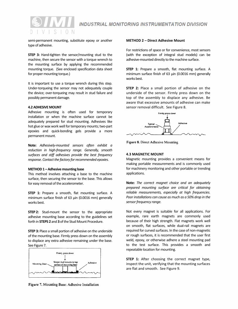
METHOD 2 – Direct Adhesive Mount For restrictions of space or for convenience, most sensors (with the exception of integral stud models) can be adhesive-mounted directly to the machine surface. STEP 1: Prepare a smooth, flat mounting surface. A minimum surface finish of 63 µin (0.0016 mm) generally works best. STEP 2: Place a small portion of adhesive on the underside of the sensor. Firmly press down on the top of the assembly to displace any adhesive. Be aware that excessive amounts of adhesive can make sensor removal difficult. See Figure 8.
4.3 MAGNETIC MOUNT Magnetic mounting provides a convenient means for making portable measurements and is commonly used for machinery monitoring and other portable or trending applications. Note: The correct magnet choice and an adequately prepared mounting surface are critical for obtaining reliable measurements, especially at high frequencies. Poor installations can cause as much as a 50% drop in the sensor frequency range. Not every magnet is suitable for all applications. For example, rare earth magnets are commonly used because of their high strength. Flat magnets work well on smooth, flat surfaces, while dual-rail magnets are required for curved surfaces. In the case of non-magnetic or rough surfaces, it is recommended that the user first weld, epoxy, or otherwise adhere a steel mounting pad to the test surface. This provides a smooth and repeatable location for mounting. STEP 1: After choosing the correct magnet type, inspect the unit, verifying that the mounting surfaces are flat and smooth. See Figure 9.
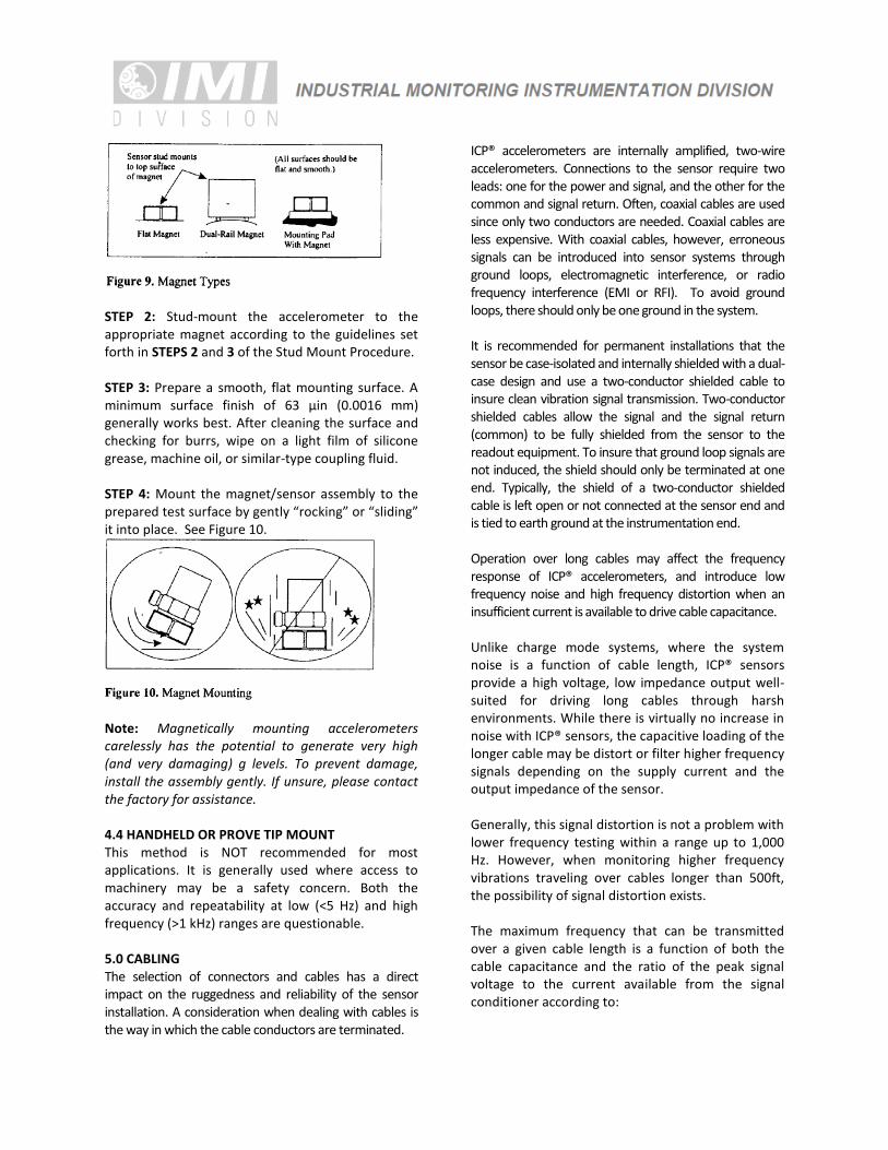
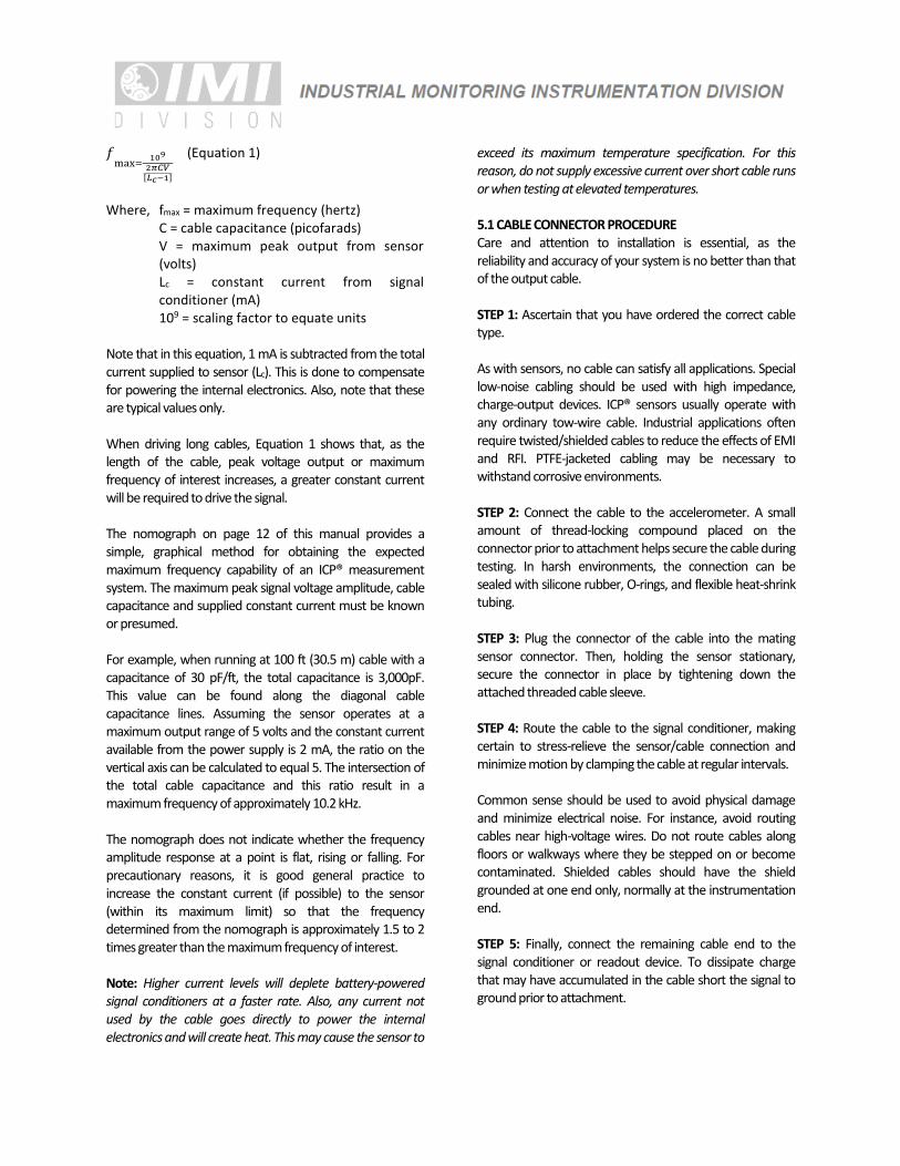
STEP 2: Stud-mount the accelerometer to the appropriate magnet according to the guidelines set forth in STEPS 2 and 3 of the Stud Mount Procedure. STEP 3: Prepare a smooth, flat mounting surface. A minimum surface finish of 63 µin (0.0016 mm) generally works best. After cleaning the surface and checking for burrs, wipe on a light film of silicone grease, machine oil, or similar-type coupling fluid. STEP 4: Mount the magnet/sensor assembly to the prepared test surface by gently “rocking” or “sliding” it into place. See Figure 10.
Note: Magnetically mounting accelerometers carelessly has the potential to generate very high (and very damaging) g levels. To prevent damage, install the assembly gently. If unsure, please contact the factory for assistance. 4.4 HANDHELD OR PROVE TIP MOUNT This method is NOT recommended for most applications. It is generally used where access to machinery may be a safety concern. Both the accuracy and repeatability at low (<5 Hz) and high frequency (>1 kHz) ranges are questionable. 5.0 CABLING The selection of connectors and cables has a direct impact on the ruggedness and reliability of the sensor installation. A consideration when dealing with cables is the way in which the cable conductors are terminated.
ICP® accelerometers are internally amplified, two-wire accelerometers. Connections to the sensor require two leads: one for the power and signal, and the other for the common and signal return. Often, coaxial cables are used since only two conductors are needed. Coaxial cables are less expensive. With coaxial cables, however, erroneous signals can be introduced into sensor systems through ground loops, electromagnetic interference, or radio frequency interference (EMI or RFI). To avoid ground loops, there should only be one ground in the system. It is recommended for permanent installations that the sensor be case-isolated and internally shielded with a dual-case design and use a two-conductor shielded cable to insure clean vibration signal transmission. Two-conductor shielded cables allow the signal and the signal return (common) to be fully shielded from the sensor to the readout equipment. To insure that ground loop signals are not induced, the shield should only be terminated at one end. Typically, the shield of a two-conductor shielded cable is left open or not connected at the sensor end and is tied to earth ground at the instrumentation end. Operation over long cables may affect the frequency response of ICP® accelerometers, and introduce low frequency noise and high frequency distortion when an insufficient current is available to drive cable capacitance. Unlike charge mode systems, where the system noise is a function of cable length, ICP® sensors provide a high voltage, low impedance output well-suited for driving long cables through harsh environments. While there is virtually no increase in noise with ICP® sensors, the capacitive loading of the longer cable may be distort or filter higher frequency signals depending on the supply current and the output impedance of the sensor. Generally, this signal distortion is not a problem with lower frequency testing within a range up to 1,000 Hz. However, when monitoring higher frequency vibrations traveling over cables longer than 500ft, the possibility of signal distortion exists. The maximum frequency that can be transmitted over a given cable length is a function of both the cable capacitance and the ratio of the peak signal voltage to the current available from the signal conditioner according to:
𝑓max=
109
2𝜋𝐶𝑉[𝐿𝑐−1]
(Equation 1)
Where, fmax = maximum frequency (hertz)
C = cable capacitance (picofarads) V = maximum peak output from sensor (volts) Lc = constant current from signal conditioner (mA) 109 = scaling factor to equate units
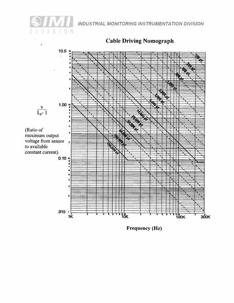
Note that in this equation, 1 mA is subtracted from the total current supplied to sensor (Lc). This is done to compensate for powering the internal electronics. Also, note that these are typical values only. When driving long cables, Equation 1 shows that, as the length of the cable, peak voltage output or maximum frequency of interest increases, a greater constant current will be required to drive the signal. The nomograph on page 12 of this manual provides a simple, graphical method for obtaining the expected maximum frequency capability of an ICP® measurement system. The maximum peak signal voltage amplitude, cable capacitance and supplied constant current must be known or presumed. For example, when running at 100 ft (30.5 m) cable with a capacitance of 30 pF/ft, the total capacitance is 3,000pF. This value can be found along the diagonal cable capacitance lines. Assuming the sensor operates at a maximum output range of 5 volts and the constant current available from the power supply is 2 mA, the ratio on the vertical axis can be calculated to equal 5. The intersection of the total cable capacitance and this ratio result in a maximum frequency of approximately 10.2 kHz. The nomograph does not indicate whether the frequency amplitude response at a point is flat, rising or falling. For precautionary reasons, it is good general practice to increase the constant current (if possible) to the sensor (within its maximum limit) so that the frequency determined from the nomograph is approximately 1.5 to 2 times greater than the maximum frequency of interest. Note: Higher current levels will deplete battery-powered signal conditioners at a faster rate. Also, any current not used by the cable goes directly to power the internal electronics and will create heat. This may cause the sensor to
exceed its maximum temperature specification. For this reason, do not supply excessive current over short cable runs or when testing at elevated temperatures. 5.1 CABLE CONNECTOR PROCEDURE Care and attention to installation is essential, as the reliability and accuracy of your system is no better than that of the output cable. STEP 1: Ascertain that you have ordered the correct cable type. As with sensors, no cable can satisfy all applications. Special low-noise cabling should be used with high impedance, charge-output devices. ICP® sensors usually operate with any ordinary tow-wire cable. Industrial applications often require twisted/shielded cables to reduce the effects of EMI and RFI. PTFE-jacketed cabling may be necessary to withstand corrosive environments. STEP 2: Connect the cable to the accelerometer. A small amount of thread-locking compound placed on the connector prior to attachment helps secure the cable during testing. In harsh environments, the connection can be sealed with silicone rubber, O-rings, and flexible heat-shrink tubing. STEP 3: Plug the connector of the cable into the mating sensor connector. Then, holding the sensor stationary, secure the connector in place by tightening down the attached threaded cable sleeve. STEP 4: Route the cable to the signal conditioner, making certain to stress-relieve the sensor/cable connection and minimize motion by clamping the cable at regular intervals. Common sense should be used to avoid physical damage and minimize electrical noise. For instance, avoid routing cables near high-voltage wires. Do not route cables along floors or walkways where they be stepped on or become contaminated. Shielded cables should have the shield grounded at one end only, normally at the instrumentation end. STEP 5: Finally, connect the remaining cable end to the signal conditioner or readout device. To dissipate charge that may have accumulated in the cable short the signal to ground prior to attachment.
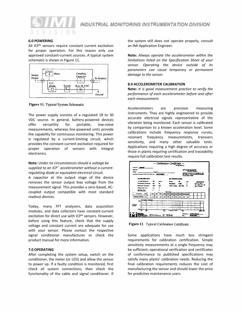
6.0 POWERING All ICP® sensors require constant current excitation for proper operation. For this reason only use approved constant-current sources. A typical system schematic is shown in Figure 11.
The power supply consists of a regulated 18 to 30 VDC source. In general, battery-powered devices offer versatility for portable, low-noise measurements, whereas line-powered units provide the capability for continuous monitoring. This power is regulated by a current-limiting circuit, which provides the constant-current excitation required for proper operation of sensors with integral electronics. Note: Under no circumstances should a voltage be supplied to an ICP® accelerometer without a current-regulating diode or equivalent electrical circuit. A capacitor at the output stage of the device removes the sensor output bias voltage from the measurement signal. This provides a zero-based, AC-coupled output compatible with most standard readout devices. Today, many FFT analyzers, data acquisition modules, and data collectors have constant-current excitation for direct use with ICP® sensors. However, before using this feature, check that the supply voltage and constant current are adequate for use with your sensor. Please contact the respective signal conditioner manufacturer or check the product manual for more information. 7.0 OPERATING After completing the system setup, switch on the conditioner, the meter (or LED) and allow the sensor to power up. If a faulty condition is monitored, first check all system connections, then check the functionality of the cable and signal conditioner. If
the system still does not operate properly, consult an IMI Application Engineer. Note: Always operate the accelerometer within the limitations listed on the Specification Sheet of your sensor. Operating the device outside of its parameters can cause temporary or permanent damage to the sensor. 8.0 ACCELEROMETER CALIBRATION Note: It is good measurement practice to verify the performance of each accelerometer before and after each measurement. Accelerometers are precision measuring instruments. They are highly engineered to provide accurate electrical signals representative of the vibration being monitored. Each sensor is calibrated by comparison to a known acceleration level. Some calibrations include frequency response curves, resonant frequency measurements, transvers sensitivity, and many other valuable tests. Applications requiring a high degree of accuracy or those in plants requiring certification and traceability require full calibration test results.
Some applications have much less stringent requirements for calibration certification. Simple sensitivity measurements at a single frequency may be sufficient; operational verification and certificates of conformance to published specifications may satisfy many plants’ calibration needs. Reducing the final calibration requirements reduces the cost of manufacturing the sensor and should lower the price for predictive maintenance users.
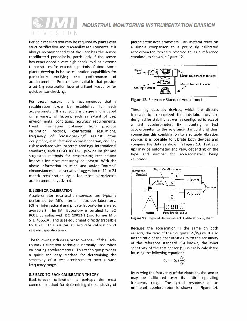
Periodic recalibration may be required by plants with strict certification and traceability requirements. It is always recommended that the user has the sensor recalibrated periodically, particularly if the sensor has experienced a very high shock level or extreme temperatures for extended periods of time. Some plants develop in-house calibration capabilities for periodically verifying the performance of accelerometers. Products are available that provide a set 1 g-acceleration level at a fixed frequency for quick sensor checking. For these reasons, it is recommended that a recalibration cycle be established for each accelerometer. This schedule is unique and is based on a variety of factors, such as extent of use, environmental conditions, accuracy requirements, trend information obtained from previous calibration records, contractual regulations, frequency of “cross-checking” against other equipment, manufacturer recommendation, and any risk associated with incorrect readings. International standards, such as ISO 10012-1, provide insight and suggested methods for determining recalibration intervals for most measuring equipment. With the above information in mind and under “normal” circumstances, a conservative suggestion of 12 to 24 month recalibration cycle for most piezoelectric accelerometers is advised. 8.1 SENSOR CALIBRATION Accelerometer recalibration services are typically performed by IMI’s internal metrology laboratory. (Other international and private laboratories are also available.) The IMI laboratory is certified to ISO 9001, complies with ISO 10012-1 (and former MIL-STD-45662A), and uses equipment directly traceable to NIST. This assures an accurate calibration of relevant specifications. The following includes a broad overview of the Back-to-Back Calibration technique normally used when calibrating accelerometers. This technique provides a quick and easy method for determining the sensitivity of a test accelerometer over a wide frequency range. 8.2 BACK-TO-BACK CALIBRATION THEORY Back-to-back calibration is perhaps the most common method for determining the sensitivity of
piezoelectric accelerometers. This method relies on a simple comparison to a previously calibrated accelerometer, typically referred to as a reference standard, as shown in Figure 12.
Figure 12. Reference Standard Accelerometer These high-accuracy devices, which are directly traceable to a recognized standards laboratory, are designed for stability, as well as configured to accept a test accelerometer. By mounting a test accelerometer to the reference standard and then connecting this combination to a suitable vibration source, it is possible to vibrate both devices and compare the data as shown in Figure 13. (Test set-ups may be automated and vary, depending on the type and number for accelerometers being calibrated.)
Figure 13. Typical Back-to-Back Calibration System Because the acceleration is the same on both sensors, the ratio of their outputs (VT/VR) must also be the ratio of their sensitivities. With the sensitivity of the reference standard (SR) known, the exact sensitivity of the test sensor (ST) is easily calculated by using the following equation:
𝑆𝑇 = 𝑆𝑅(𝑉𝑇
𝑉𝑅
)
By varying the frequency of the vibration, the sensor may be calibrated over its entire operating frequency range. The typical response of an unfiltered accelerometer is shown in Figure 14.
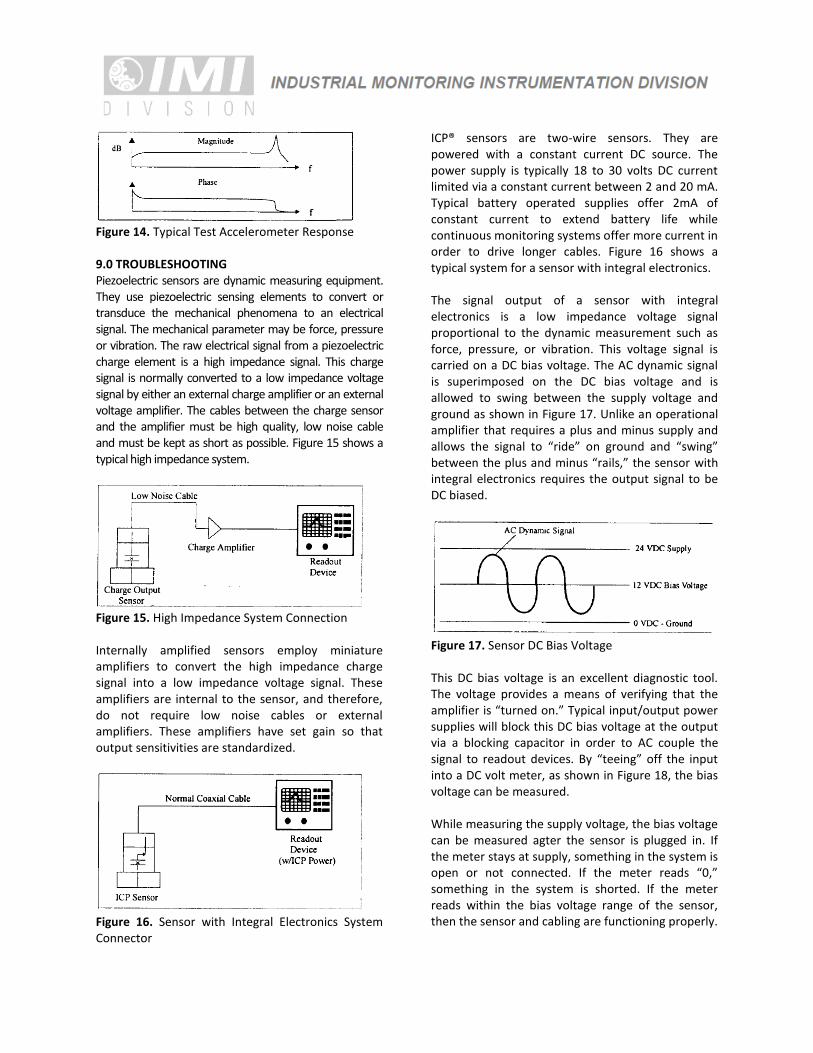
Figure 14. Typical Test Accelerometer Response 9.0 TROUBLESHOOTING Piezoelectric sensors are dynamic measuring equipment. They use piezoelectric sensing elements to convert or transduce the mechanical phenomena to an electrical signal. The mechanical parameter may be force, pressure or vibration. The raw electrical signal from a piezoelectric charge element is a high impedance signal. This charge signal is normally converted to a low impedance voltage signal by either an external charge amplifier or an external voltage amplifier. The cables between the charge sensor and the amplifier must be high quality, low noise cable and must be kept as short as possible. Figure 15 shows a typical high impedance system.
Figure 15. High Impedance System Connection Internally amplified sensors employ miniature amplifiers to convert the high impedance charge signal into a low impedance voltage signal. These amplifiers are internal to the sensor, and therefore, do not require low noise cables or external amplifiers. These amplifiers have set gain so that output sensitivities are standardized.
Figure 16. Sensor with Integral Electronics System Connector
ICP® sensors are two-wire sensors. They are powered with a constant current DC source. The power supply is typically 18 to 30 volts DC current limited via a constant current between 2 and 20 mA. Typical battery operated supplies offer 2mA of constant current to extend battery life while continuous monitoring systems offer more current in order to drive longer cables. Figure 16 shows a typical system for a sensor with integral electronics. The signal output of a sensor with integral electronics is a low impedance voltage signal proportional to the dynamic measurement such as force, pressure, or vibration. This voltage signal is carried on a DC bias voltage. The AC dynamic signal is superimposed on the DC bias voltage and is allowed to swing between the supply voltage and ground as shown in Figure 17. Unlike an operational amplifier that requires a plus and minus supply and allows the signal to “ride” on ground and “swing” between the plus and minus “rails,” the sensor with integral electronics requires the output signal to be DC biased.
Figure 17. Sensor DC Bias Voltage This DC bias voltage is an excellent diagnostic tool. The voltage provides a means of verifying that the amplifier is “turned on.” Typical input/output power supplies will block this DC bias voltage at the output via a blocking capacitor in order to AC couple the signal to readout devices. By “teeing” off the input into a DC volt meter, as shown in Figure 18, the bias voltage can be measured. While measuring the supply voltage, the bias voltage can be measured agter the sensor is plugged in. If the meter stays at supply, something in the system is open or not connected. If the meter reads “0,” something in the system is shorted. If the meter reads within the bias voltage range of the sensor, then the sensor and cabling are functioning properly.
Figure 18. DC Bias Voltage Measurement
10.0 REPAIR/RETURN PROCEDURE Because of the nature of most IMI instrumentation, field repair is typically NOT recommended and may void any warranty. If factory service is required, contact IMI for a RETURN MATERIAL AUTHORIZATION (RMA) number prior to sending equipment to the factory. Please have information available, such as model and serial number. Also, to insure efficient service, be sure to include a written description of the symptoms and problems with the equipment to a local sales representative or distributor, or contact IMI if none are located in your area. Customers outside the U.S. should consult their local IMI distributor for information on returning equipment. For exceptions, please contact the International Sales department at IMI to request shipping instructions and an
RMA. For assistance, please call (716) 684-0003, or fax us at (716) 684-3823. You may also receive assistance via e-mail at [email protected] or visit our website at www.pcb.com. 11.0 CUSTOMER SERVICE/WARRANTY IMI, a division of PCB Piezotronics, guarantees Total Customer Satisfaction. If, at any time, for any reason, you are not completely satisfied with any IMI product, IMI will repair, replace or exchange it at no charge. You may also choose to have your purchase price refunded. IMI instrumentation is warranted against defective material workmanship for 1 year unless otherwise expressly specified. Damage to instruments caused by incorrect power or misapplication, is not covered by warranty. If there are any questions regarding power, intended application, or general usage, please consult with your local sales contact or distributor. Batteries or expendable hardware items are not covered by warranty. IMI offers to all customers, at no charge, 24-hour phone support. This service makes product or application support available to our customers, day or night, seven days a week. When unforeseen problems or emergency situations arise, call the IMI Hot Line at (716) 684-0003, and an application specialist will assist you.

Model Number 607A11 PLATINUM SWIVELER® INDUSTRIAL ICP® ACCELEROMETER
Revision: J
ECN #: 41189
Performance ENGLISH SI Sensitivity(± 15 %) 100 mV/g 10.2 mV/(m/s²) [2] Measurement Range ± 50 g ± 490 m/s² Frequency Range(± 3 dB) 30 to 600,000 cpm 0.5 to 10,000 Hz Resonant Frequency 1500 kcpm 25 kHz [1] Broadband Resolution(1 to 10,000 Hz) 350 µg 3434 µm/sec2 [1] Non-Linearity ± 1 % ± 1 % [3] Transverse Sensitivity ≤ 7 % ≤ 7 % Environmental Overload Limit(Shock) 5000 g pk 49,050 m/s² pk Temperature Range -65 to +250 °F -54 to +121 °C Enclosure Rating IP68 IP68 Electrical Settling Time(within 1% of bias) ≤ 2 sec ≤ 2 sec Discharge Time Constant ≥ 0.3 sec ≥ 0.3 sec Excitation Voltage 18 to 28 VDC 18 to 28 VDC Constant Current Excitation 2 to 20 mA 2 to 20 mA Output Impedance <150 Ohm <150 Ohm Output Bias Voltage 8 to 12 VDC 8 to 12 VDC Spectral Noise(10 Hz) 8 µg/√Hz 78.5 (µm/sec2)/√Hz [1] Spectral Noise(100 Hz) 5 µg/√Hz 49.1 (µm/sec2)/√Hz [1] Spectral Noise(1 kHz) 4 µg/√Hz 39.2 (µm/sec2)/√Hz [1] Electrical Isolation(Case) >108 Ohm >108 Ohm Physical Size (Hex x Height) 9/16 in x 0.97 in 14 mm x 24.6 mm Weight(without cable) 1.1 oz 31 gm [4] Mounting Stud Stud Mounting Thread 1/4-28 Male 1/4-28 Male [5] Mounting Torque(stud) 3 to 4 ft-lb 4.1 to 5.4 Nm [6][7] Mounting Torque(hex nut) 2 to 3 ft-lb 2.7 to 4.1 Nm Sensing Element Ceramic Ceramic Sensing Geometry Shear Shear Housing Material Stainless Steel Stainless Steel Sealing Welded Hermetic Welded Hermetic Electrical Connector Molded Integral Cable Molded Integral Cable Electrical Connection Position Side Side Cable Length 10 ft 3.0 m Cable Type Polyurethane Polyurethane [8]
[9]
All specifications are at room temperature unless otherwise specified. In the interest of constant product improvement, we reserve the right to change specifications without notice.
ICP® is a registered trademark of PCB Group, Inc.
OPTIONAL VERSIONS Optional versions have identical specifications and accessories as listed for the standard model
except where noted below. More than one option may be used.
EX - Hazardous Area Approval- contact factory for specific approvals Hazardous Area Approval Exia IIC T4, AExia IIC, T4 Exia IIC T4, AExia IIC, T4 Hazardous Area Approval EEx nL IIC T4, -40°
C≤Ta≤121°C, II 1 G EEx nL IIC T4, -40°C≤Ta≤121°C, II 1 G
Hazardous Area Approval Cl I, Div I, Groups A, B, C, D; Cl II, Div I, Groups E, F, G; Cl
III, Div I
Cl I, Div I, Groups A, B, C, D; Cl II, Div I, Groups E, F, G; Cl
III, Div I Hazardous Area Approval Cl I, Div 2, Groups A, B, C, D;
ExnL IIC T4, AExnA IIC T4 Cl I, Div 2, Groups A, B, C, D;
ExnL IIC T4, AExnA IIC T4 Hazardous Area Approval EEx nL IIC T4, -40°
C≤Ta≤121°C, II 3 G EEx nL IIC T4, -40°C≤Ta≤121°C, II 3 G
M - Metric Mount Supplied Accessory : Model M080A159A Mounting stud, 1/2-20 to M6 x 1 (1) TO - Temperature Output Temperature Output Range +36 to +250 °F +2 to +121 °C Temperature Scale Factor 5.56 mV/°F + 32 +10 mV/°C Electrical Connector Molded Integral Cable Molded Integral Cable Electrical Connections(Red) Acceleration Output Acceleration Output Electrical Connections(Black) Ground Ground Electrical Connections(White) Temperature Output Temperature Output
NOTES:[1] Typical.[2] Conversion Factor 1g = 9.81 m/s².[3] Zero-based, least-squares, straight line method.[4] Measured with mounting stud.[5] 1/4-28 has no equivalent in S.I. units.[6] 1/8" hex Allen key required for English version, 3mm hex Allen key required for metric
version.[7] Stud torque must exceed sensor hex nut torque to ensure proper dismantling.[8] Twisted shielded pair.[9] See PCB Declaration of Conformance PS023 or PS060 for details.
SUPPLIED ACCESSORIES: Model 080A156 Mounting Base (1) Model ICS-2 NIST-traceable single-axis single-point amplitude response calibration at 6000 cpm (100 Hz) (1)
Entered: AP Engineer: jg Sales: EGY Approved: BAM Spec Number: Date: 4/11/2013 Date: 4/11/2013 Date: 4/11/2013 Date: 4/11/2013 12650
3425 Walden Avenue, Depew, NY 14043
Phone: 800-959-4464 Fax: 716-684-3823 E-Mail: [email protected]
1
1
2
2
A A
B B
CODEIDENT. NO.
52681
DWG. NO.
SCALE: SHEET
DRAWN CHECKED ENGINEER
TITLE
UNLESS OTHERWISE SPECIFIED TOLERANCES ARE:DIMENSIONS IN MILLIMETERS
[ IN BRACKETS ]
ANGLES 2 DEGREES 3425 WALDEN AVE. DEPEW, NY 14043(716) 684-0001 E-MAIL: [email protected]
DIMENSIONS IN INCHES
ANGLES 2 DEGREES
FILLETS AND RADII .003 - .005
FILLETS AND RADII 0.07 - 0.13
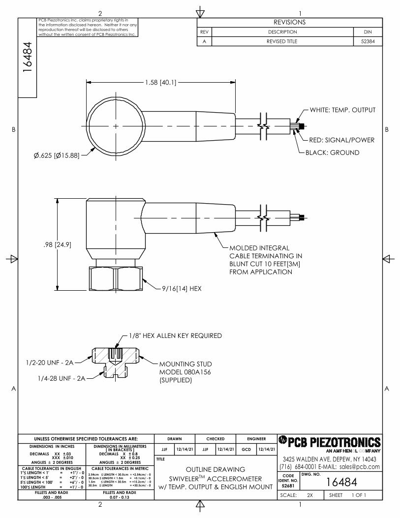
OUTLINE DRAWING
164841 OF 12X
w/ TEMP. OUTPUT & ENGLISH MOUNT
DECIMALS XX ±.03XXX ±.010
DECIMALS X ± 0.8XX ± 0.25
JJF 12/14/21 JJF 12/14/21 GCD 12/14/21
CABLE TOLERANCES IN ENGLISH CABLE TOLERANCES IN METRIC1"≤ LENGTH < 1' = +1"/ - 01'≤ LENGTH < 5' = +2"/ - 05'≤ LENGTH < 100' = +6"/ - 0100'≤ LENGTH = +1'/ - 0
2.54cm ≤ LENGTH < 30.5cm = +2.54cm/ - 030.5cm ≤ LENGTH < 1.5m = +5.1cm/ - 01.5m ≤ LENGTH < 30.5m = +15.2cm/ - 030.5m ≤ LENGTH = +30.5cm/ - 0
SWIVELERTM ACCELEROMETER
1648
4PCB Piezotronics Inc. claims proprietary rights inthe information disclosed hereon. Neither it nor anyreproduction thereof will be disclosed to otherswithout the written consent of PCB Piezotronics Inc.
REVISIONSREV DESCRIPTION DIN
A REVISED TITLE 52384
1.58 [40.1]
.625 [15.88]
.98 [24.9]
1/2-20 UNF - 2A
1/4-28 UNF - 2A
1/8" HEX ALLEN KEY REQUIRED
MOUNTING STUDMODEL 080A156(SUPPLIED)
9/16[14] HEX
MOLDED INTEGRALCABLE TERMINATING INBLUNT CUT 10 FEET[3M]FROM APPLICATION
WHITE: TEMP. OUTPUT
BLACK: GROUND
RED: SIGNAL/POWER
1
1
2
2
3
3
4
4
A A
B B
CODEIDENT. NO.
52681
DWG. NO.
SCALE: SHEET
DRAWN CHECKED ENGINEER
TITLE
UNLESS OTHERWISE SPECIFIED TOLERANCES ARE:DIMENSIONS IN MILLIMETERS
[ IN BRACKETS ]
XX ± 0.13
ANGLES 2 DEGREES
3425 WALDEN AVE. DEPEW, NY 14043(716) 684-0001 E-MAIL: [email protected]
DIMENSIONS IN INCHES
DECIMALS XX ±.01
ANGLES 2 DEGREES
FILLETS AND RADII .003 - .005
DECIMALS X ± 0.3
FILLETS AND RADII 0.07 - 0.13
INSTALLATION DRAWING
185511 OF 1FULL
MODEL 607 SERIES
XXX ±.005
JDM 10/9/14 ECB 10/9/14 DRK 10/9/14
1855
1PCB Piezotronics Inc. claims proprietary rights inthe information disclosed hereon. Neither it nor anyreproduction thereof will be disclosed to otherswithout the written consent of PCB Piezotronics Inc.
REVISIONSREV DESCRIPTION DIN
B ADDED METRIC MOUNTING INFORMATION 43341
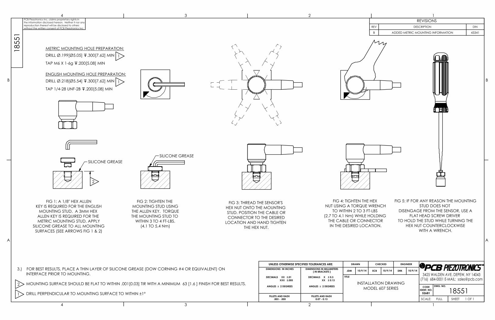
FIG 1: A 1/8" HEX ALLENKEY IS REQUIRED FOR THE ENGLISH
MOUNTING STUD. A 3MM HEX ALLEN KEY IS REQUIRED FOR THE METRIC MOUNTING STUD. APPLY
SILICONE GREASE TO ALL MOUNTINGSURFACES (SEE ARROWS FIG 1 & 2)
FIG 2: TIGHTEN THE MOUNTING STUD USINGTHE ALLEN KEY. TORQUETHE MOUNTING STUD TO
WITHIN 3 TO 4 FT-LBS.(4.1 TO 5.4 Nm)
FIG 3: THREAD THE SENSOR'S HEX NUT ONTO THE MOUNTING STUD. POSITION THE CABLE ORCONNECTOR TO THE DESIRED
LOCATION AND HAND TIGHTEN THE HEX NUT.
FIG 4: TIGHTEN THE HEX NUT USING A TORQUE WRENCH
TO WITHIN 2 TO 3 FT-LBS (2.7 TO 4.1 Nm) WHILE HOLDING
THE CABLE OR CONNECTORIN THE DESIRED LOCATION.
FIG 5: IF FOR ANY REASON THE MOUNTINGSTUD DOES NOT
DISENGAGE FROM THE SENSOR, USE AFLAT HEAD SCREW DRIVER
TO HOLD THE STUD WHILE TURNING THEHEX NUT COUNTERCLOCKWISE
WITH A WRENCH.
SILICONE GREASESILICONE GREASE
2
METRIC MOUNTING HOLE PREPARATION:DRILL Ø.199[Ø5.05] .300[7.62] MIN
TAP M6 X 1-6g .200[5.08] MIN ENGLISH MOUNTING HOLE PREPARATION:DRILL Ø.218[Ø5.54] .300[7.62] MIN
TAP 1/4-28 UNF-2B .200[5.08] MIN
1
3.) FOR BEST RESULTS, PLACE A THIN LAYER OF SILICONE GREASE (DOW CORNING #4 OR EQUIVALENT) ON INTERFACE PRIOR TO MOUNTING. MOUNTING SURFACE SHOULD BE FLAT TO WITHIN .001[0.03] TIR WITH A MINIMUM 63 [1.6 ] FINISH FOR BEST RESULTS. DRILL PERPENDICULAR TO MOUNTING SURFACE TO WITHIN ±1°1
2
1
PCB PIEZOTRONICS INC. 3425 WALDEN AVE.
DEPEW, NEW YORK 14043
3425 Walden Ave
Depew, New York 14043
No 41721 No 1 of 3
Rev. B
ECO #: 49938
10/7/2019
INSTRUCTIONS FOR USE - EX(TO)(M)602yzzz/aaa, EX(TO)(M)603yzzz/aaa, EX(TO)(M)606yzzz/aaa, EX(TO)(M)607yzzz/aaa, and EX(TO)(M)608yzzz/aaa Series
Model(s) EX(TO)(M)602yzzz/aaa, EX(TO)(M)603yzzz/aaa, EX(TO)(M)606yzzz/aaa, EX(TO)(M)607yzzz/aaa, and
EX(TO)(M)608yzzz/aaa Series where:
Model Options Include:
TO – Temperature Output Sensor
M – Metric mounting hardware and cable
y = One Letter from A to Z denoting revision level (with “M” reserved for customer Special Orders)
zzz = Two or Three Numbers 00 to 999 which cable/connector type and sensitivity, filtering, or bias (two numbers)
or special order sequential number (up to three digits)
aaa = Designates cable length and/or connector type Markings PCB
Depew, NY
IECEx LCIE 13.0045X
LCIE 06, ATEX 6033X
LCIE 06, ATEX 6032X
Ex ia IIC T4 Ga Ta=121ºC
Ex nA IIC T4 Gc Ta=121ºC
Install per 64371 Putting Into
Service Powering: All ICP® sensors require constant current excitation for proper operation. For this reason, use only PCB
constant-current signal conditioners or other approved constant-current sources. The power supply consists of a
current-regulated, 18 to 30 VDC source. This power is regulated by a current-limiting circuit, which provides the
constant-current excitation required for proper operation of ICP sensors.
In general, battery-powered devices offer versatility for portable, low-noise measurements, whereas line-powered
units provide the capability for continuous monitoring. Consult the Vibration Division’s product catalog for more
information about signal conditioners.
NOTE: Under no circumstances should a voltage be supplied to an ICP accelerometer without a current-regulating
diode or equivalent electrical circuit. This may include ohmmeters, multi-meters and continuity testers. Safe Use After completing the system setup, switch on the signal conditioner and allow 1 to 2 minutes for the system to
stabilize. The meter (or LED) on the signal conditioner should be reading “green.” This indicates proper operation
and you may begin taking measurements. If a faulty condition is indicated (red or yellow reading), first check all
system connections, then check the functionality of the cable and signal conditioner. If the system still does not
operate properly, consult a PCB factory representative.
NOTE: Always operate the accelerometer within the limitations listed on the enclosed Specification Sheet.
Operating the device outside these parameters can cause temporary or permanent damage to the sensor.
WARNING: Do not separate when Energized. Assembling The EX(TO)(M)602yzzz/aaa, EX(TO)(M)603yzzz/aaa, EX(TO)(M)606yzzz/aaa, EX(TO)(M)607yzzz/aaa, and
EX(TO)(M)608yzzz/aaa Series have hermetically sealed titanium housings, with a sealed integral cable, and do not
require any assembly. Only mounting to the machine being monitored using standard mounting accessories. Dismantling Other than removal from the mounting, there is no disassembly of the sensor required to take it out of service.
PCB PIEZOTRONICS INC. 3425 WALDEN AVE.
DEPEW, NEW YORK 14043
3425 Walden Ave
Depew, New York 14043
No 41721 No 2 of 3
Rev. B
ECO #: 49938
10/7/2019
Maintenance Routine maintenance, such as the cleaning of electrical connectors, housings, and mounting surfaces with solutions
and techniques that will not harm the physical material of construction, is acceptable.
Servicing Due to the sophisticated nature of the sensors and associated instrumentation provided by PCB Piezotronics, user
servicing or repair is not recommended and, if attempted, may void the factory warranty. However, routine
calibration of sensors and associated instrumentation is recommended as this helps build confidence in
measurement accuracy and acquired data. Repair In the event that equipment becomes damaged or ceases to operate, arrangements should be made to return the
equipment to
PCB Piezotronics for repair. User servicing or repair is not recommended and, if attempted, may void the factory
warranty. Installation Overview: Sensor must be mounted in order to be put into service. When choosing a mounting method, consider
closely both the advantages and disadvantages of each technique. Characteristics like location, ruggedness, amplitude
range, accessibility, temperature, and portability are extremely critical. However, the most important and often
overlooked consideration is the effect the mounting technique has on the high-frequency performance of the
accelerometer. Mounting methods include: Stud mount, adhesive mount, magnetic mount, handheld, or probe tip
mount.
Cabling: Care and attention to cable installation and cable condition is essential as the reliability and accuracy of any
measurement system is no better than that of its weakest link. Due to the nature of vibration measurements, all sensor
cables will ultimately fatigue and fail. Good installation practice will extend the life of a cable, however, it is highly
recommended to keep spare cables on hand to enable continuation of the test in the event of a cable failure. Adjustment The sensor is a sealed device and no user adjustments are possible. However, routine calibration of sensors by the
manufacturer is recommended as this helps build confidence in measurement accuracy and acquired data. Danger Areas (for
pressure-relief
devices)
N/A – not a pressure relief device.
Training
Instructions Industrial sensors must be installed in Hazardous Locations by trained professionals according to EN/IEC 60079-14
requirements. Details on Safety
of Protection
Category
Ex ia is “intrinsic safety”, which limits the energy of sparks and surface temperatures to safe levels.
Ex nA is “Non-Sparking”, which ensures that there is no risk of arcing and sparking or hot surfaces during normal
operation. Entity Parameters
and Limits
(Values)
Temperature Range: -54⁰C to +121⁰C
Connector Version:
Ui = 28V, Ii = 120 mA, Pi = 0.84W, Ci = 46.5nF, Li= 0
Integral Cable Version (with a max cable length of 152.5 m (500 ft.))
Ui = 28V, Ii = 120 mA, Pi = 0.84W, Ci = 77nF, Li= 152.5 µH
Special Conditions
of Use Version Ex ia :
The apparatus must only be connected to a certified associated intrinsically safe equipment. This combination must
be compatible regarding intrinsic safety rules (see electrical parameters). The apparatus shall be connected
according to drawing 64371 (page 1/2).
Version Ex nA:
The apparatus must be only connect to an equipment whose electrical parameters are compatible with the electrical
parameters. The apparatus shall be connected according to drawing 64371 (page 2/2).
WARNING: Do not separate when Energized. Essential
Characteristics of
tools fitted to the
system (if any).
N/A – No tools are fitted to the system.
PCB PIEZOTRONICS INC. 3425 WALDEN AVE.
DEPEW, NEW YORK 14043
3425 Walden Ave
Depew, New York 14043
No 41721 No 3 of 3
Rev. B
ECO #: 49938
10/7/2019
Drawings and
Diagrams 33701, 33700, 56178, 56179, 64371, 23402, 23575, 64374, and 41721.
Other EN 60079-0:2012+A11:2013
EN 60079-11:2012
EN 60079-15:2010
IEC 60079-0 Ed. 6
IEC 60079-11 Ed. 6
IEC 60079-15 Ed. 4
Note: Literature (such as the manual or marketing materials) describing the equipment or protective system must not contradict the instructions with regard to safety aspects.
Note: IMI sensors is a Division of PCB Piezotronics. This Division is wholly contained in the PCB Piezotronics
manufacturing facility at 3425 Walden Avenue, Depew, New York. Same address, same manufacturing facility. Some
of the documentation contained in the Technical File associated with this application is labeled IMI Sensors, A PCB
Piezotronics Div. and some is labeled simply PCB Piezotronics. PCB Piezotronics labeled drawing are higher level
drawings which are used across multiple divisions, while IMI labeled drawing are specific to IMI models. There will
be a mixture of IMI and PCB drawing to support this application, and in reality they are the same entity however with
an associated trade name (IMI) that is recognized by our customer base.

1
1
2
2
3
3
4
4
A A
B B
CODEIDENT. NO.
52681
DWG. NO.
SCALE: SHEET
DRAWN CHECKED ENGINEER
TITLE
UNLESS OTHERWISE SPECIFIEDDIMENSIONS ARE IN INCHES
DECIMALS X .05XX .01
XXX .005
ANGLES ± 2 DEGREESFILLETS AND RADII .003 - .005
HEX DIMENSIONS ARE:≤ .5 + .000 / - .003> .5 + .000 / - .005
REMOVE ALL BURRSSHARP = R.000 - R.003
INTERNAL THREAD DEPTH MIN.
3425 WALDEN AVE. DEPEW, NY 14043(716) 684-0002 E-MAIL: [email protected]
64371
APPROVALEX(TO)(M)60X SERIESINTERCONNECTION
1 OF 2NONE
XXXX .0005
KSR 2/17/20 GGS 2/17/20
CABLE SINGLE CHANNEL
RMIN
TRANSDUCERVIN ≤ +24 VOLTS
SIGNAL/POWER
GND
SHIELD
NON-HAZARDOUS / SAFE AREA HAZARDOUS AREAZONE 0
TEMPERATURE OUTPUT
GND
SIGNAL/POWER
SHIELDPOWER SUPPLY
READOUT DEVICE
RMINTEMPERATURE OUTPUT
GND
SHIELD
6437
1PCB Piezotronics Inc. claims proprietary rights inthe information disclosed hereon. Neither it nor anyreproduction thereof will be disclosed to otherswithout the written consent of PCB Piezotronics Inc.
REVISIONSREV DESCRIPTION DIN
A UPDATED NOTES, REMOVED LCIE 49938
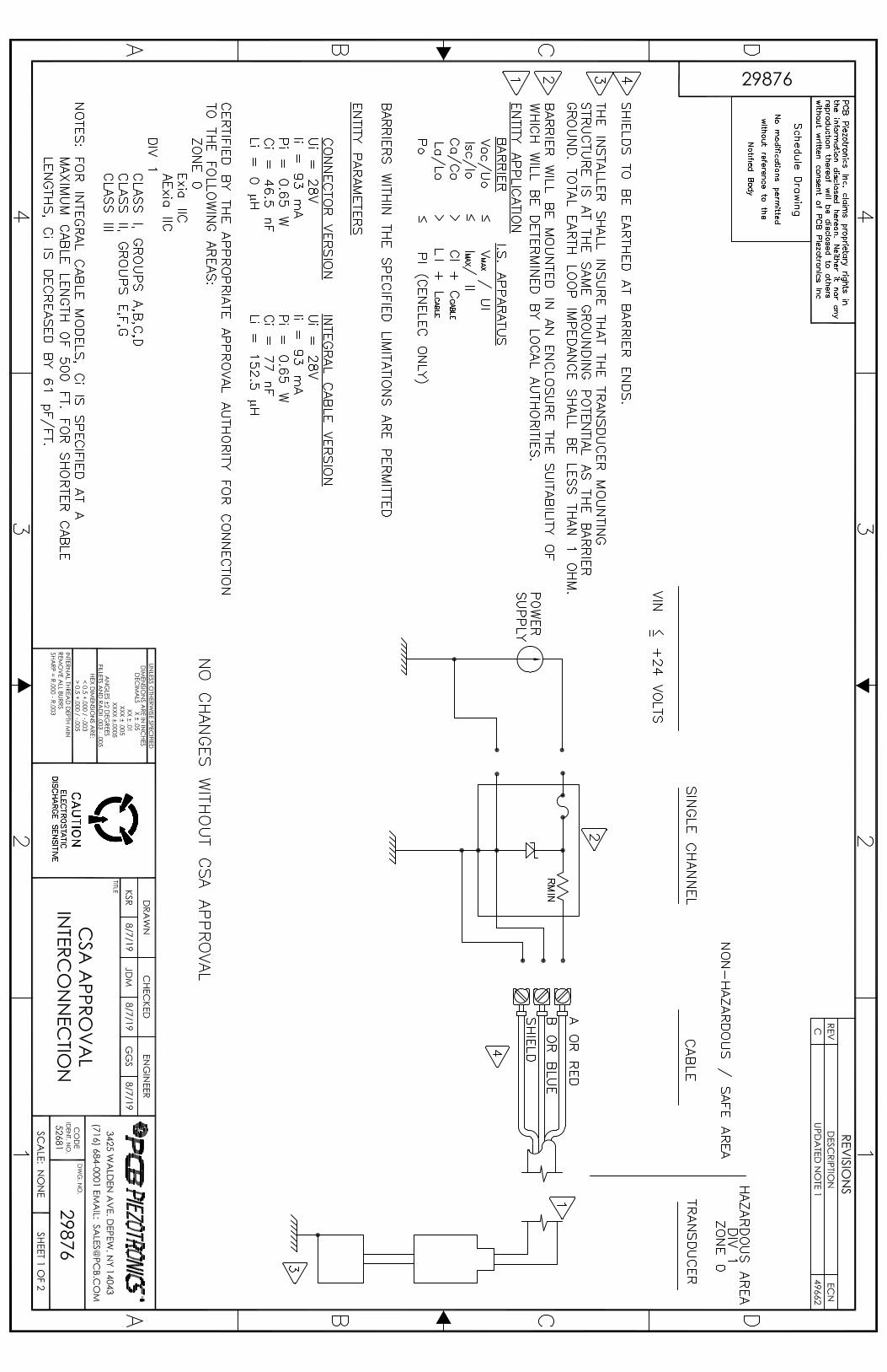
ONLY APPLICABLE FOR "TO" OPTION SHIELDS TO BE EARTHED AT BARRIER ENDS THE INSTALLER SHALL INSURE THAT THE TRANSDUCER MOUNTINGSTRUCTURE IS AT THE SAME GROUNDING POTENTIAL AS THE BARRIERGROUND. TOTAL EARTH LOOP IMPEDANCE SHALL BE LESS THAN 1 OHM BARRIER WILL BE MOUNTED IN AN ENCLOSURE THE SUITABILITY OFWHICH WILL BE DETERMINED BY LOCAL AUTHORITIES. ENTITY APPLICATION BARRIER I.S. APPARATUS Voc/Uo ≤ VMAX / UI Isc/Io ≤ IMAX/ II Ca/Co > CI + CCABLE La/Lo > LI + LCABLE Po ≤ PI (CENELEC ONLY) BARRIERS WITHIN THE SPECIFIED LIMITATIONS ARE PERMITTED ENTITY PARAMETERS CONNECTOR VERSION INTEGRAL CABLE VERSION Ui = 28V Ui = 28V li = 120 mA Ii = 120 mA Pi = 0.84 W Pi = 0.84 W Ci = 46.5 nF Ci = 77 nF Li = 0 uH Li = 152.5 uH CERTIFIED BY THE APPROPRIATE APPROVAL AUTHORITY FOR CONNECTIONTO THE FOLLOWING AREAS: ZONE 0 Ex ia IIC T4 Ga NOTES: FOR MODELS INTEGRAL CABLE SERIES, Ci IS SPECIFIED AT A MAXIMUM CABLE LENGTH OF 500 FT. FOR SHORTER CABLE LENGTHS, Ci IS DECREASED BY 61 pF/FT
1
2
3
4
SCHEDULE DRAWING
NO MODIFICATIONS PERMITTEDWITHOUT REFERENCE TO THE
NOTIFIED BODY
4
1
2
3
55

1
1
2
2
3
3
4
4
A A
B B
CODEIDENT. NO.
52681
DWG. NO.
SCALE: SHEET
DRAWN CHECKED ENGINEER
TITLE
UNLESS OTHERWISE SPECIFIEDDIMENSIONS ARE IN INCHES
DECIMALS X .05XX .01
XXX .005
ANGLES ± 2 DEGREESFILLETS AND RADII .003 - .005
HEX DIMENSIONS ARE:≤ .5 + .000 / - .003> .5 + .000 / - .005
REMOVE ALL BURRSSHARP = R.000 - R.003
INTERNAL THREAD DEPTH MIN.
3425 WALDEN AVE. DEPEW, NY 14043(716) 684-0002 E-MAIL: [email protected]
64371
APPROVALEX(TO)(M)60X SERIESINTERCONNECTION
2 OF 2NONE
XXXX .0005
KSR 2/17/20 GGS 2/17/20
TRANSDUCER
SIGNAL/POWER
GND
SHIELD
APPROVEDPOWER SUPPLY/
SIGNAL CONDITIONER
CABLE
POWERSUPPLY
NON-HAZARDOUS / SAFE AREAZONE 2
GND
SHIELDTEMPERATURE OUTPUT
SIGNAL/POWER, TEMPERATURE OUTPUT
READOUTDEVICE
TEMPERATURE OUTPUT
6437
1PCB Piezotronics Inc. claims proprietary rights inthe information disclosed hereon. Neither it nor anyreproduction thereof will be disclosed to otherswithout the written consent of PCB Piezotronics Inc.
REVISIONSREV DESCRIPTION DIN
-SEE SHEET 1- SCHEDULE DRAWING
NO MODIFICATIONS PERMITTED
WITHOUT REFERENCE TO THENOTIFIED BODY
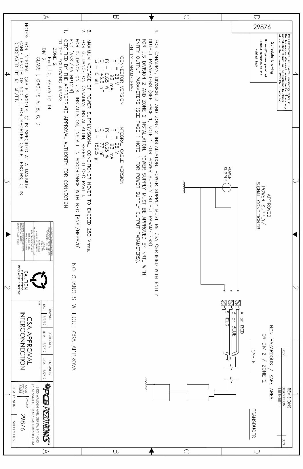
2.) MAXIMUM VOLTAGE OF POWER SUPPLY/SIGNAL CONDITIONER NEVER TO EXCEED 250 Vrms. 1.) CERTIFIED BY THE APPROPRIATE APPROVAL AUTHORITY FOR CONNECTION TO THE FOLLOWING AREAS: ZONE 2 Ex nA IIC T4 Gc NOTES: FOR MODELS INTEGRAL CABLE SERIES, Ci IS SPECIFIED AT A MAXIMUM CABLE LENGTH OF 500 FT. FOR SHORTER CABLE LENGTHS, Ci IS DECREASED BY 61 pF/FT.
ATTESTATION D'EXAMEN DE TYPE
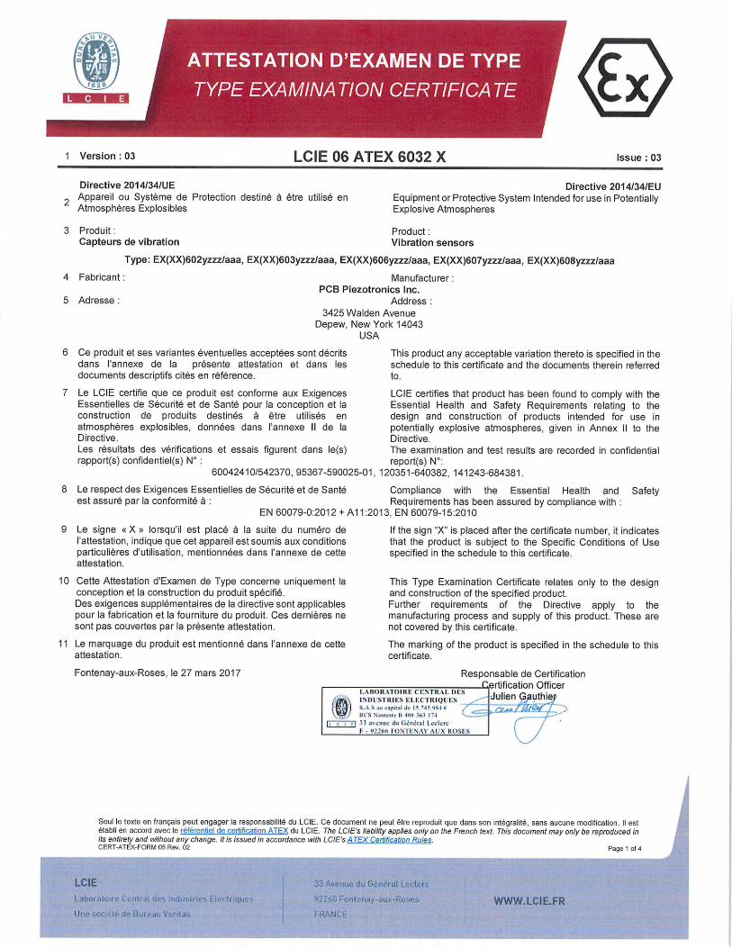
1 Version :03 LCIE 06 ATEX 6032 X Issue : 03
Directive 2014134/UE 2 Appareil ou Système de Protection destine a être utilisé en
Atmospheres Explosibles
3 Produit: Capteurs de vibration
Directive 2014/34/EU Equipment or Protective System Intended for use in Potentially Explosive Atmospheres
Product: Vibration sensors
Type: EX(XX)602yzzzlaaa, EX(XX)603yzzz/aaa, EX(XX)606yzzzlaaa, EX(XX)607yzzz/aaa, EX(XX)608yzzzlaaa
4 Fabricant: Manufacturer: PCB Piezotronics Inc.
5 Adresse : Address 3425 Walden Avenue
Depew, New York 14043 USA
6 Ce produit et ses variantes éventuelles acceptées sont décrits This product any acceptable variation thereto is specified in the dans l'annexe de la présente attestation et dans les schedule to this certificate and the documents therein referred documents descriptifs cites en référence. to.
7 Le LCIE certifie que ce produit est conforme aux Exigences Essentielles de Sécurité et de Sante pour Ia conception et Ia construction de produits destinés a être utilisès en atmospheres explosibles, données dans l'annexe II de la Directive. Les rèsultats des verifications et essais figurent dans le(s) rapport(s) confidentiel(s) N
60042410/542370, 95367-590025-01,
LCIE certifies that product has been found to comply with the Essential Health and Safety Requirements relating to the design and construction of products intended for use in potentially explosive atmospheres, given in Annex II to the Directive. The examination and test results are recorded in confidential report(s) N:
120351-640382, 141243-684381.
8 Le respect des Exigences Essentielles de Sécurité et de Sante Compliance with the Essential Health and Safety est assure par la conformité a : Requirements has been assured by compliance with
EN 60079-0:2012 +A11:2013, EN 60079-15:2010
9 Le signe eXs lorsqu'il est place a la suite du numéro de l'attestation, indique que cet appareil est soumis aux conditions particulières d'utilisation, mentionnèes dans l'annexe de cette attestation.
10 Cette Attestation dExamen de Type concerne uniquement la conception et la construction du produit spécifié. Des exigences supplementaires de la directive sont applicables pour la fabrication et la fourniture du produit. Ces dernières ne sont pas couvertes par la prèsente attestation.
If the sign "X" is placed after the certificate number, it indicates that the product is subject to the Specific Conditions of Use specified in the schedule to this certificate.
This Type Examination Certificate relates only to the design and construction of the specified product. Further requirements of the Directive apply to the manufacturing process and supply of this product. These are not covered by this certificate.
11 Le marquage du produit est mentionné dans lannexe de cette The marking of the product is specified in the schedule to this attestation. certificate.
Fontenay-aux-Roses, le 27 mars 2017 Responsable de Certification rtjfication Officer
1.AflOR.TOtRJ. CENTRAL 11-:s j . ,-
INL)LSIRIES I:E.F:c'IRIQuF:s uthIl1 au iep
---- --- ---------
- rl 33 (fl13I t.ctvr I . . )22(6 FONI 1, NAY AL X ROSES
I
Seul le texte en francais peut engager la responsabuith du LCIE. Ce document ne peut btre reproduit que dans son integralite, sans aucune modification. II est établi en accord avec le référentiel de certification AlEX du LCIE. The LCIE's liability applies only on the French text. This document may only be reproduced in its entirety and without any change. It is issued in accordance with LCIE's A TEX Certification Rules. - -. CERT-ATEX-FORM 05 Rev, 02 Page 1 of 4
LCIE 33 Avenuu du C.r-;r.ii
.ahurntcr1 ucntri cie:c rid uslrws Ftctt quc:. - 92,260 Fontoruy- au.- uurs WWWLCIEFR LInE socwih do Bur ,-au V2r31ai FRANIE
1 Version :03 LCIE 06 ATEX 6032 X Issue 03
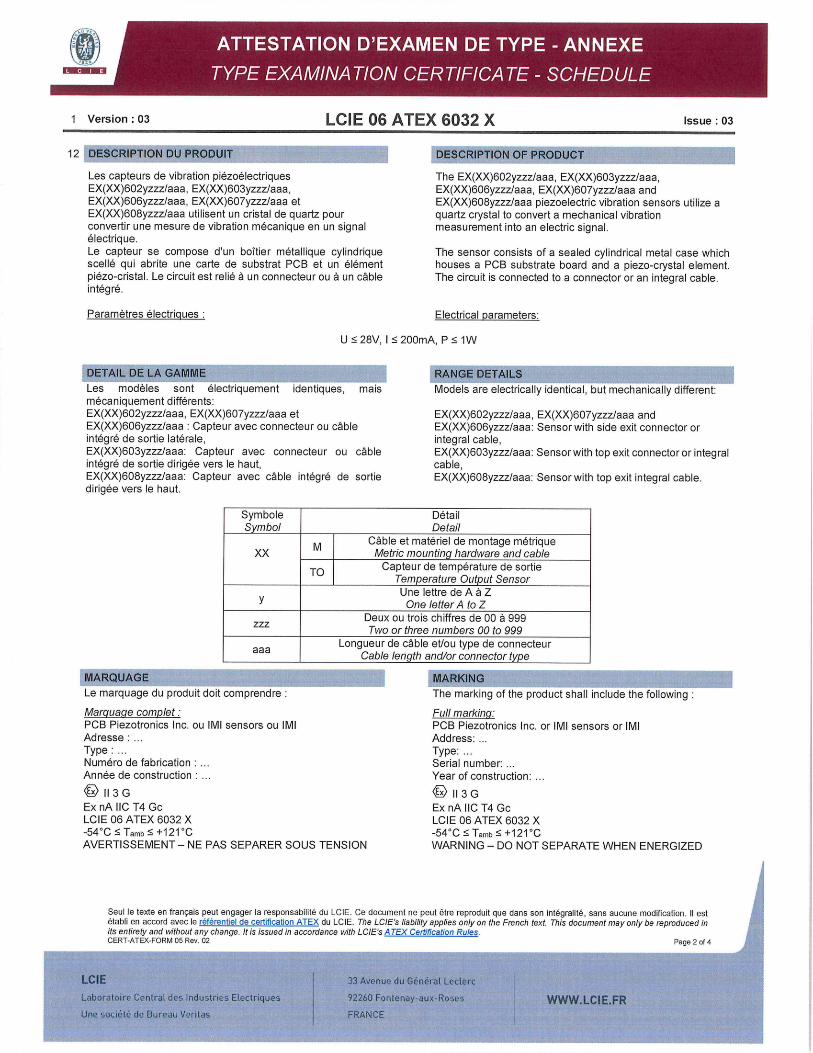
12 DESCRIPTION DU PRODUIT DESCRIPTION OF PRODUCT
Les capteurs de vibration piézoelectriques EX(X)602yzzzIaaa, EX(X)603yzzzIaaa, EX(XX)606yzzzlaaa, EX(X)607yzzzIaaa et EX(XX)608yzzz1aaa utilisent un cristal de quartz pour convertir une mesure de vibration mécanique en un signal électrique. Le capteur se compose dun boltier metallique cylindrique scellé qui abrite une carte de substrat FOB et un élément piézo-cristal. Le circuit est relié a un connecteur ou a un cable integré.
Paramètres électrigues
The EX(XX)602yzzz1aaa, EX(XX)603yzzz1aaa, EX(XX)606yzzz/aaa, EX(XX)607yzzz1aaa and EX(XX)608yzzz1aaa piezoelectric vibration sensors utilize a quartz crystal to convert a mechanical vibration measurement into an electric signal.
The sensor consists of a sealed cylindrical metal case which houses a PCB substrate board and a piezo-crystal element. The circuit is connected to a connector or an integral cable.
Electrical parameters:
U :~ 28V, I 200mA, P :5 1W
DETAIL DE LA GAMME
Les modèles sont electriquement identiques, mais mecaniquement différents: EX(XX)602yzzz/aaa, EX(XX)607yzzz/aaa et EX(XX)606yzzz1aaa : Capteur avec connecteur ou cable integre de sortie latérale, EX(XX)603yzzz!aaa: Capteur avec connecteur ou cable intégre de sortie dirigee vers le haut, EX(XX)608yzzz/aaa: Capteur avec cable intégre de sortie dirigee vers le haut.
RANGE DETAILS Models are electrically identical, but mechanically different:
EX(XX)602yzzz1aaa, EX(XX)607yzzzIaaa and EX(XX)606yzzzlaaa: Sensor with side exit connector or integral cable, EX(XX)603yzzz1aaa: Sensor with top exit connector or integral cable, EX(XX)608yzzz1aaa: Sensor with top exit integral cable.
Symbole Detail Symbol Detail
M Cable et materiel de montage metrique XX Metric mounting hardware and cable
TO Capteur de temperature de sortie Temperature Output Sensor Une lettre de A a z
y One letter A to Z Deux ou trois chiffres de 00 a 999 zzz Two or three numbers 00 to 999
Longueur de cable et/ou type de connecteur aaa Cable length and/or connector type
MARQUAGE Le marquage du produit doit comprendre:
Marguage complet: PCB Piezotronics Inc. ou IMI sensors ou IMI Adresse: Type: Numéro de fabrication An née de construction
113 G Ex nA IIC T4 Gc LCIE 06 ATEX 6032 X -540 C :5 Tam +121 -C AVERTISSEMENT - NE PAS SEPARER SOUS TENSION
MARKING The marking of the product shall include the following
Full marking: FOB Piezotronics Inc. or IMI sensors or IMI Address: Type: Serial number: Year of construction:
113 G Ex nA IIC T4 Gc LCIE 06 ATEX 6032 X -54O :5 Tam :5 +121O WARNING - DO NOT SEPARATE WHEN ENERGIZED
Seul le texte en francais peut engager la responsabilite du LCIE. Ce document ne peut être reproduit que dans son integralite, sans aucune modification. II eat établi en accord avec le référentiel de certification ATEX du LCIE. The LCIE's liability applies only on the French text. This document may only be reproduced in its entirety and without any change. It is issued in accordance with LCIE's A TEX Certification Rules. CERT-ATEX-FORM 05 Rev. 02 Page 2 of 4
..
LCIE 33 Avenue du G6n6rat Leclerc
Laboratoire Central des Industries Etectriques 92260 Fontenay-aux-Roses WWW.LCIEFR Une socété cia Bureau Verrtav FRANCE
1 Version : 03 LCIE 06 ATEX 6032 X Issue 03
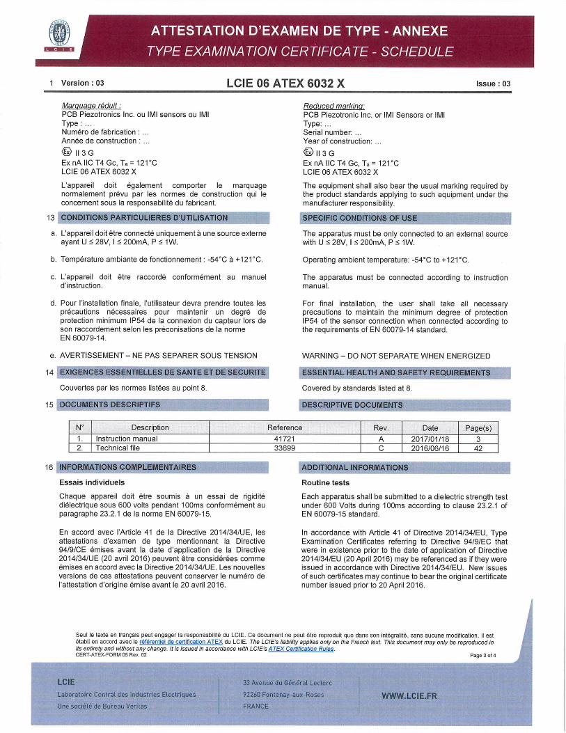
Marguage réduit: PCB Piezotronics Inc. ou IMI sensors ou IMI Type: Numéro de fabrication Année de construction
113 G ExnA IlC 14 Gc, Ta= 121 CC LCIE 06 ATEX 6032 X
L'appareil dolt également comporter le marquage normalement prévu par les normes de construction qui le concernent sous la responsabilité du fabricant.
13 CONDITIONS PARTICULIERES DUTILISATION
a. L'appareil dolt être connecté uniquement a une source externe ayant U 28V, 1 :5 200mA, P :5 1W.
b. Temperature ambiante de fonctionnement: -54CC a +121CC
c. L'appareil doit étre raccordé conformément au manuel d'instruction.
d. Pour 'installation finale, l'utilisateur devra prendre toutes les precautions nécessaires pour maintenir un degre de protection minimum IP54 de la connexion du capteur lors de son raccordement selon les preconisations de la norme EN 60079-14.
e. AVERTISSEMENT— NE PAS SEPARER SOUS TENSION
14 EXIGENCES ESSENTIELLES DE SANTE ET DE SECURITE
Couvertes par les normes listées au point 8.
15 DOCUMENTS DESCRIPTIFS
Reduced marking: PCB Piezotronic Inc. or IMI Sensors or IMI Type: Serial number: Year of construction:
113 G Ex nA 110 T4 Gc, Ta = 121CC LCIE 06 ATEX 6032 X
The equipment shall also bear the usual marking required by the product standards applying to such equipment under the manufacturer responsibility.
SPECIFIC CONDITIONS OF USE
The apparatus must be only connected to an external source with U 5 28V, I 200mA, P :5 1W.
Operating ambient temperature: -540C to +121CC.
The apparatus must be connected according to instruction manual.
For final installation, the user shall take all necessary precautions to maintain the minimum degree of protection IP54 of the sensor connection when connected according to the requirements of EN 60079-14 standard.
WARNING - DO NOT SEPARATE WHEN ENERGIZED
ESSENTIAL HEALTH AND SAFETY REQUIREMENTS
Covered by standards listed at 8.
DESCRIPTIVE DOCUMENTS
No Description Reference Rev. Date Page(s)
1. Instruction manual 41721 A 2017/01/18 3 2. Technical file 33699 C 2016/06/16 42
16 INFORMATIONS COMPLEMENTAIRES ADDITIONAL INFORMATIONS
Essais individuels Routine tests
Chaque appareil dolt être soumis a un essai de rigidité Each apparatus shall be submitted to a dielectric strength test dielectrique sous 600 volts pendant lOOms conformément au under 600 Volts during lOOms according to clause 23.2.1 of paragraphe 23.2.1 de la norme EN 60079-15. EN 60079-15 standard.
En accord avec I'Article 41 de la Directive 2014/34/UE, les attestations d'examen de type mentionnant la Directive 94/9/CE émises avant la date d'application de la Directive 2014/34/UE (20 avril 2016) peuvent être considérées comme émises en accord avec la Directive 2014/34/UE. Les nouvelles versions de ces attestations peuvent conserver le numéro de 'attestation d'origine émise avant le 20 avril 2016.
In accordance with Article 41 of Directive 2014/34/EU, Type Examination Certificates referring to Directive 94/9/EC that were in existence prior to the date of application of Directive 2014/34/EU (20 April 2016) may be referenced as if they were issued in accordance with Directive 2014/34/EU. New issues of such certificates may continue to bear the original certificate number issued prior to 20 April 2016.
Seul le texte en français peut engager la responsabilite du LCIE. Ce document ne peut étre reproduit que dans son integraute, sans aucune modification. II est établi en accord avec le référentiel de certification ATEX du LCIE. The LCIE's liability applies only on the French text. This document may only be reproduced in its entirety and without any change. It is issued in accordance with LCIE's A TEX Certification Rules. CERT-ATEX-FORM 05 Rev. 02 Page 3 of 4
LCIE 33 Avenue du G6nCrol Leclerc
Leborotoire Central des Industries Electririues 92260 Fontenoy aux-Roses WWWLCIEFR Une sodélC de Bureau VerUas FRANCE
1 Version :03 LCIE 06 ATEX 6032 X Issue :03
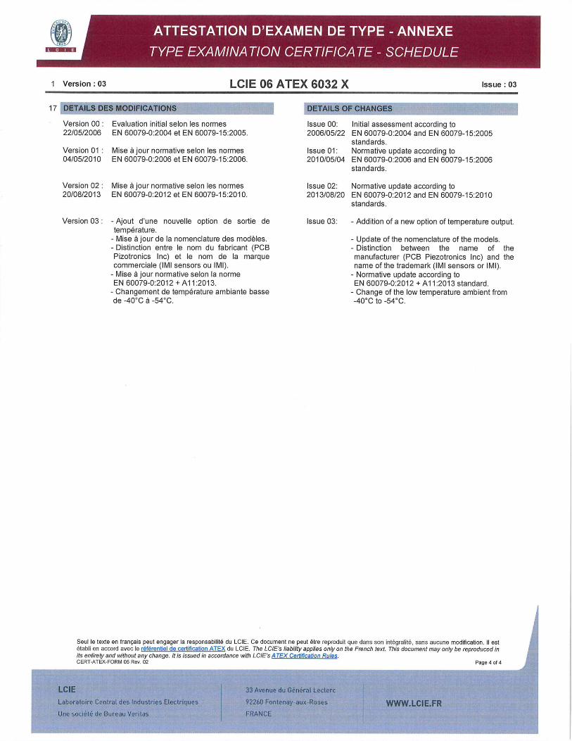
17 DETAILS DES MODIFICATIONS
Version 00 : Evaluation initial selon les normes 22/05/2006 EN 60079-0:2004 et EN 60079-15:2005.
Version 01 : Mise a jour normative selon les normes 04/05/2010 EN 60079-0:2006 et EN 60079-15:2006.
Version 02 : Mise a jour normative selon les normes 20/08/2013 EN 60079-0:2012 et EN 60079-15:2010
Version 03 : - Ajout dune nouvelle option de sortie de temperature.
- Mise a jour do la nomenclature des modèles. - Distinction entre le nom du fabricant (PCB Pizotronics Inc) et le nom de la marque commerciale (IMI sensors ou IMI).
- Mise a jour normative selon la norme EN 60079-0:2012 +A11:2013.
- Changement de temperature ambiante basse de -400C a -54CC.
DETAILS OF CHANGES
Issue 00: Initial assessment according to 2006/05/22 EN 60079-0:2004 and EN 60079-15:2005
standards. Issue 01: Normative update according to 2010/05/04 EN 60079-0:2006 and EN 60079-15:2006
standards.
Issue 02: Normative update according to 2013/08/20 EN 60079-0:2012 and EN 60079-15:2010
standards.
Issue 03: - Addition of a new option of temperature output.
- Update of the nomenclature of the models. - Distinction between the name of the manufacturer (PCB Piezotronics Inc) and the name of the trademark (IMI sensors or IMI).
- Normative update according to EN 60079-0:2012 + A11:2013 standard.
- Change of the low temperature ambient from -400C to -540C.
I
Seul le texte en francais peut engager la responsabilité du LCIE. Ce document ne peut être reproduit que dans son integralité, sans aucune modification. II est établi en accord avec le rOférentiel de certification ATEX du LCIE. The LCIE's liability applies only on the French text. This document may only be reproduced in its entirety and without any change. It is issued in accordance with LCIE's A TEX Certification Rules, CERT-ATEX-FORM 05 Rev. 02 Page 4014
LCIE 33 Avenue du GiidraI Loctcrc
Laboratoirc Central den industnes Elecinquns 92260 Fontenay-aux-Roses WWWLCIEFR Une socidlé do Bureau Veitas FRANCE

41
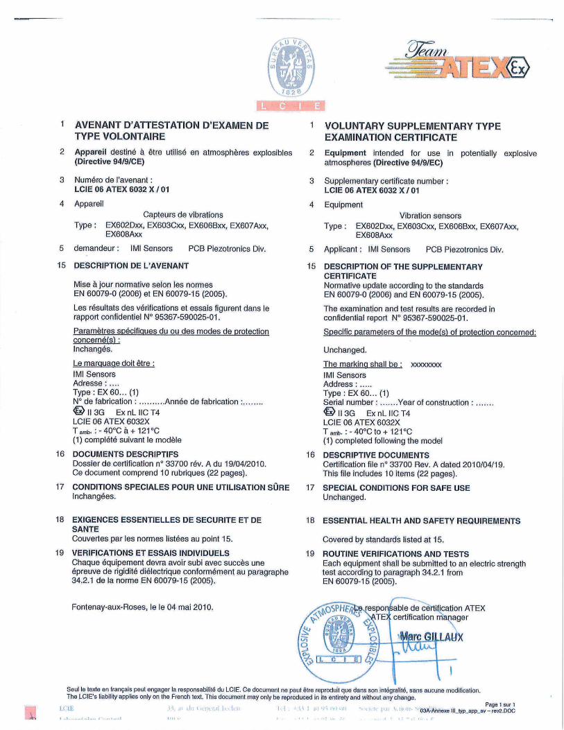
1 AVENANT D'ATTESTATION D'EXAMEN DE I SUPPLEMENTARY VOLUNTARY TYPE TYPE VOLONTAIRE EXAMINATION CERTIFICATE
2 Appareil ou système de protection destine a être utflisé en 2 Equipment or protective system intended for use in atmospheres explosibles (Directive 94/9/CE) potentially explosive atmospheres (Directive 94I9/EC)
3 Numéro de lavenant:
LCIE 06 ATEX 6032 X 102
4 Appareil ou système de protection: Capteur de vibration
Type: EX602Dxx, EX603Cxx, EX606Bxx, EX607Axx, EX608Axx
5 Demandeur: IMI Sensors A PCB Piezoelectric Div.
15 DESCRIPTION DE L'AVENANT
Mise a jour normative suivant les normes EN 60079-0:2012 et EN 60079-15:2010. Mise a jour des documents.
Les résultats des verifications et essais figurent dans le rapport confidentiel N°120351-640382.
Paramètres spécificiues du ou des modes de protection concerné(s) Inchanges.
Le marguaqe dolt étre : Modifié comme suit: Ml Sensors Adresse:
Type: EX602Dxx, EX603Cxx, EX606Bxx, EX607Axx, EX608Axx (1) Numéro de fabrication: ... Année de fabrication:.
113 G Ex nA IIC T4 Gc LCIE 06 ATEX 6032 X -40°C 5 Ta :5 +121°C (1) complété avec le modèle
16 DOCUMENTS DESCRIPTIFS
Dossier technique n°33701 rev.B du 18/04/2013. Ce dossier comprend 10 rubriques (25 pages).
17 CONDITIONS SPECIALES POUR UNE UTILISATION SURE
lnchangees.
18 EXIGENCES ESSENTIELLES DE SECURITE ET DE SANTE
Couvertes par les normes EN 60079-0:2009 et EN 60079-15:2010.
19 VERIFICATIONS ET ESSAIS INDIVIDUELS
Inchanges.
3 Supplementary certificate number:
LCIE 06 ATEX 6032 X /02
4 Equipment or protective system:
Vibration sensor
Type: EX602Dxx, EX603Cxx, EX606Bxx, EX607Axx, EX608Axx
5 Applicant: IMI Sensors A PCB Piezoelectric Div.
15 DESCRIPTION OF THE SUPPLEMENTARY CERTIFICATE
Normative update according standards EN 60079-0:2012 and EN 60079-15:2010. Update of documents.
The examination and test results are recorded in confidential report N°120351-640382.
Specific parameters of the concerned protection mode:
Unchanged.
The marking shall be: Modified as follow: IMI Sensors Address: Type: EX602Dxx, EX603Cxx, EX606Bxx, EX607Axx, EX608Axx (1) Serial number: ... Year of construction:
113 G Ex nA IIC T4 Gc LCIE 06 ATEX 6032 X -40°C :5 Ta :5 +121°C (1) completed with the model
16 DESCRIPTIVE DOCUMENTS
Technical file n033701 rev.B dated 2013/04/18. This file includes 10 items (25 pages).
17 SPECIAL CONDITIONS FOR SAFE USE
Unchanged.
18 ESSENTIAL HEALTH AND SAFETY REQUIREMENTS
Covered by standards EN 60079-0:2009 and EN 60079-15:2010.
19 ROUTINE VERIFICATIONS AND TESTS
Unchanged.
Fontenay-aux-Roses, le 2 0 AOUT 2013
Seul le texte en français peut engager la responsabilité du LCIE. Ce document ne peut étre The LClE's liability applies only on the French text. This document may only be reproduced
I I
Le responsable de certification ATEX ATEX Certification Officer
CLPHFR6 1,141. I /
uit e n int lité. s fléothflcation. ntir out ar)ianë.
-
Page 1 sur 1 OIA Annexe flLCE_typ_app_av rev3 DOC
U .
ING
1 AVENANT D'ATTESTATION D'EXAMEN DE 1 VOLUNTARY SUPPLEMENTARY TYPE TYPE VOLONTAIRE EXAMINATION CERTIFICATE
2 Appareil destine a ètre utiflsé en atmospheres explosibles 2 Equipment intended for use in potentially explosive (Directive 94/9/CE) atmospheres (Directive 9419/EC)
3 Numéro de 'avenant: 3 Supplementary certificate number: LCIE 06 ATEX 6032 X /01 LCIE 06 ATEX 6032 X /01
4 Appareil 4 Equipment Capteurs de vibrations Vibration sensors
Type: EX602Dxx, EX603Cxx, EX606Bxx, EX607Axx, Type: EX602Dxx, EX603Cxx, EX606Bxx, EX607Axx, EX608Axx EX608Axx
5 demandeur: IMI Sensors PCB Piezotronics Div. 5 Applicant: IMI Sensors PCB Piezotronics Div.
15 DESCRIPTION DE L'AVENANT 15 DESCRIPTION OF THE SUPPLEMENTARY CERTIFICATE
Mise a jour normative selon les normes Normative update according to the standards EN 60079-0 (2006) et EN 60079-15 (2005). EN 60079-0 (2006) and EN 60079-15 (2005).
Les résultats des verifications et essais figurent dans le The examination and test results are recorded in rapport confidentiel NO 95367-590025-01. confidential report N0 95367-590025-01.
Paramètres spécifigues du ou des modes de protection Specific parameters of the mode(s) of protection concerned: concerné(s): lnchangés. Unchanged.
Le marquage dolt être: The marking shall be: xxxxxxxx IMI Sensors lMl Sensors Adresse Address: ..... Type: EX6O...(1) Type: EX6O...(1) NO de fabrication . .......... Année de fabrication .......Year Serial number: of construction ........ 'Il3G ExnLllCT4 G113G ExnLllCT4 LCIE 06 ATEX 6032X LCIE 06 ATEX 6032X Tarrgj.40°Cà+121°C Tant.H40°CtO+121°C (1) complété suivant le modèle (1) completed following the model
16 DOCUMENTS DESCRIPTIFS 16 DESCRIPTIVE DOCUMENTS Dossier de certification n° 33700 rev. A du 19/04/2010. Certification file n° 33700 Rev. A dated 2010/04/19. Ce document comprend 10 rubriques (22 pages). This file includes 10 items (22 pages).
17 CONDITIONS SPECIALES POUR LINE UTILISATION SURE 17 SPECIAL CONDITIONS FOR SAFE USE lnchangees. Unchanged.
18 EXIGENCES ESSENTIELLES DE SECURITE ET DE SANTE Couvertes par les normes listées au point 15.
19 VERIFICATIONS ET ESSAIS INDIVIDUELS Chaque equipement devra avoir subi avec succès une epreuve de rigidité diélectrique conformément au paragraphe 34.2.1 de la norme EN 60079-15 (2005).
18 ESSENTIAL HEALTH AND SAFETY REQUIREMENTS
Covered by standards listed at 15.
19 ROUTINE VERIFICATIONS AND TESTS Each equipment shall be submitted to an electric strength test according to paragraph 34.2.1 from EN 60079-15 (2005).
Font enay-aux-Roses, le le 04 mai 2010. f.. f&;l ib.e resp
/ 'AT
/. CU ( ..LJ
able decertification ATEX certification manager
rclfLAUX
HHr Seul le texte en français peut engager la responsabilité du LCIE. Ce document ne peut ôtre reproduit que dans son intégralité, sans aucune modification. The LctE's liability applies only on the French text. This document may only be reproduced in its entirety and without any change.
Page 1 sur 1 03AAnnexe111_pappav-rev2.DOC
,,....,_.., ,., .
I ATTESTATION D'EXAMEN DE TYPE
ç v
\
18 2 .
I TYPE EXAMINATION CERTIFICATE
2 Appareil ou système de protection destine a être utilisé en 2 Equipment or protective system intended for use in atmospheres explosibles (Directive 94/9/CE) potentially explosive atmospheres (Directive 9419/EC)
3 Numéro de l'attestation dexamen de type 3 Type Examination Certificate number LCIE 06 ATEX 6032 X LCIE 06 ATEX 6032 X
4 Appareil ou système de protection: 4 Equipment or protective system: Capteurs de vibrations Vibration sensors
Type: EX602Dxx, EX603Cxx, EX606Bxx, EX607Axx, Type: EX602Dxx, EX603Cxx, EX606Bxx, EX607Axx, EX608Axx EX608Axx
5 Demandeur: IMI Sensors A PCB Piezotronics Div. 5 applicant: IMI Sensors A PCB Piezotronics Div. Adresse: 3425 Walden Avenue Address: 3425 Walden Avenue
Depew, New York 14043 USA Depew, New York 14043 USA
7 Cet appareil ou système de protection et ses variantes éventuelles acceptées sont décrits dans lannexe de la présente attestation et dans les documents descriptifs cites en référence.
8 Le LCIE certifie que cet appareil ou système de protection est conforme aux exigences essentielles de sécurité et de sante pour la conception et la construction d'appareils et de systemes de protection destinés a être utilisés en atmospheres explosibles, données dans lannexe Il de la directive 94/9/CE du Parlement europeen et du Conseil du 23 mars 1994.
Les résultats des verifications et essais figurent dans le rapport confidentiel No 60042410/542370.
9 Le respect des exigences essentielles de sécurité et de sante est assure par la conformité a:
- EN 60075-15 (2005)
10 Le signe X Iorsqu'il est place 6 la suite du numéro de lattestation, indique que cet appareil ou système de protection est soumis aux conditions spéciales pour une utilisation sUre, mentionnées dans l'annexe de la présente attestation.
11 Cette attestation d'examen de type concerne uniquement la conception et la construction de lappareil ou du système de protection spéciflé, conformément a I'annexe III de la directive 94/9/CE. Des exigences supplémentaires de la directive sont applicables pour la fabrication et la fourniture de lappareil ou du système de protection. Ces dernières ne sont pas couvertes par la présente attestation.
12 Le marquage de lappareil ou du système de protection doit comporter les informations détaillées au point 15.
Fontenay-aux-Roses, le 22 mai 2006
7 This equipment or protective system and any acceptable variation thereto is specified in the schedule to this certificate and the documents therein referred to.
8 LCIE certifies that this equipment or protective system has been found to comply with the essential Health and Safety Requirements relating to the design and construction of equipment and protective system intended for use in potentially explosive atmospheres, given in Annex II of the Directive 94/9/EC of the European Parliament and Council of 23 March 1994.
The examination and test results are recorded in confidential report N° 60042410/542370.
9 Compliance with the Essential Health and Safety Requirements has been assured by compliance with:
- EN 60079-15 (2005)
10 If the sign X is placed after the certificate number, it indicates that the equipment or protective system is subject to special conditions for safe use specified in the schedule to this certificate.
11 This type examination certificate relates only to the design and construction of this specified equipment or protective system in accordance with annex Ill to the directive 94/9/EC.
Further requirements of the Directive apply to the manufacture and supply of this equipment or protective system. These are not covered by this certificate.
12 The marking of the equipment or protective system shall include informations as detailed at 15.
Le responsable de certification ATEX ATEX certification manager
C I. -
.11~ Z
0 1628 - 01,
2
\\ 1end CBRVELU
Seul le texte en francais peut engager Ia responsabilite du LCIE. Ce document ne peut êlre reproduit que dans son integralite, sans aucune modification The LCIE's liability applies only on the French text. This document may be reproduced in its entirety and without any change
Page lsur2 03-Annexe III_typ_app - revO.DOC
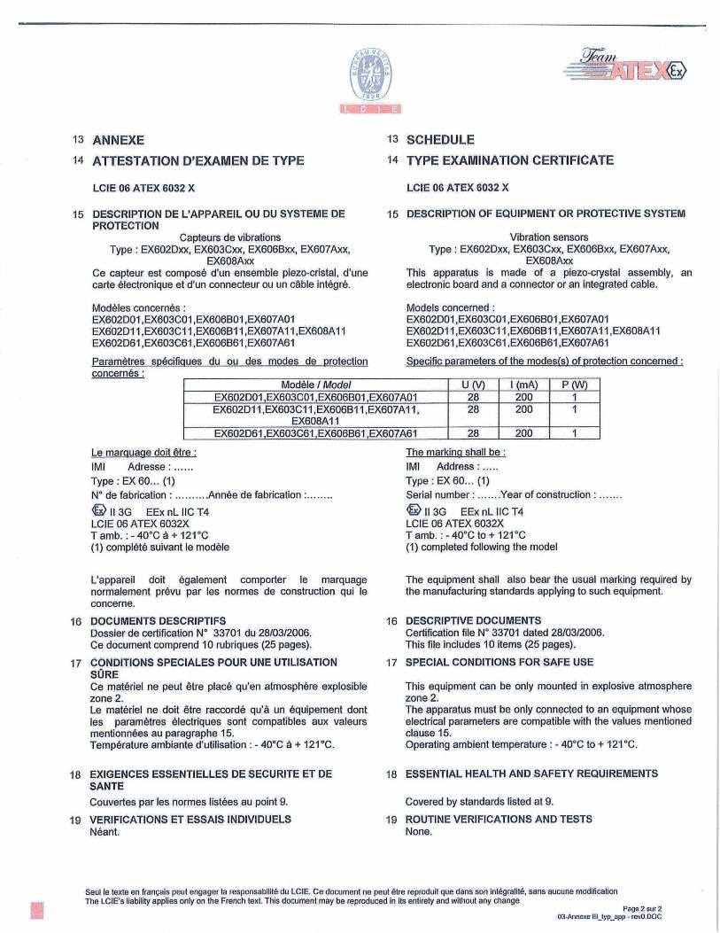
U Vi.
-=-- Jit-
IIiL4
14 ATTESTATION D'EXAMEN DE TYPE
LCIE 06 ATEX 6032 X
15 DESCRIPTION DE L'APPAREIL OU DU SYSTEME DE PROTECTION
Capteurs de vibrations Type: EX602Dxx, EX603Cxx, EX606Bxx, EX607Axx,
EX6O8Axx Ce capteur est compose d'un ensemble piezo-cristat, d'une carte electronique et dun connecteur ou un cable integré.
13 SCHEDULE
14 TYPE EXAMINATION CERTIFICATE
LCIE 06 ATEX 6032 X
15 DESCRIPTION OF EQUIPMENT OR PROTECTIVE SYSTEM
Vibration sensors Type: EX602Dxx, EX603Cxx, EX606Bxx, EX607Axx,
EX608Axx This apparatus is made of a piezo-crystal assembly, an electronic board and a connector or an integrated cable.
Modèles concernés: EX602001 ,EX6O3CO1 ,EX6O6BOI ,EX607A01 EX602DI 1 ,EX603C1 I ,EX6O6B1 I ,EX6O7AI I ,EX6O8AI 1 EX602D61 ,EX603C61 ,EX606B61 ,EX607A61
Paramètres spOcifigues du ou des modes de protection concernés:
Models concerned: EX602DOI ,EX6O3CO1 ,EX606B01,EX607A01 EX602DI I ,EXSO3CI I ,EX6O6B1 I ,EX6O7AI I ,EX6O8AI I EX602D61 ,EX603C61 ,EX606B61 ,EX607A61
Specific parameters of the modes(s) of protection concerned:
Modéle I Model U (V) I (mA) P (W) EX602DOI ,EX6O3CO1 ,EX6O6BO1 ,EX6O7AOI 28 200 1 EX602D11,EX603C1I ,EX60613II,EX607AI1,
EX608A11 28 200 1
EX602D61 ,EX603C61 ,EX606B61 ,EX607A61 28 200 1
Le maruage doit être:
IMI Adresse: ...... Type: EX 60... (1) N° de fabrication . .......... Année de fabrication :..
11 3G EExnLlICT4 LCIE 06 ATEX 6032X Tamb. :-40°Cà+121°C (1) complété suivant le modèle
L'appareil doit egalement comporter le marquage normalement prOvu par les normes de construction qui le concerne.
16 DOCUMENTS DESCRIPTIFS Dossier de certification No 33701 du 28/03/2006. Ce document comprend 10 rubriques (25 pages).
17 CONDITIONS SPECIALES POUR UNE UTILISATION SURE Ce materiel ne peut être place qu'en atmosphere explosible zone 2. Le materiel ne doit être raccordé qu'â un équipement dont les paramètres électriques sont compatibles aux valeurs mentionnées au paragraphe 15. Temperature ambiante d'utilisation : - 40°C a + 121°C.
18 EXIGENCES ESSENTIELLES DE SECURITE ET DE SANTE
Couvertes par les normes listées au point 9.
19 VERIFICATIONS El ESSAIS INDIVIDUELS Want.
The marking shall be:
IMI Address: ..... Type: EX6O... (1) Serial number: .......Year of construction:.
'll3G EExnLllCT4 LCIE 06 ATEX 6032X Tamb, :-40°Cto+ 121°C (1) completed following the model
The equipment shall also bear the usual marking required by the manufacturing standards applying to such equipment.
16 DESCRIPTIVE DOCUMENTS Certification file N° 33701 dated 28/03/2006. This file includes 10 items (25 pages).
17 SPECIAL CONDITIONS FOR SAFE USE
This equipment can be only mounted in explosive atmosphere zone 2. The apparatus must be only connected to an equipment whose electrical parameters are compatible with the values mentioned clause 15. Operating ambient temperature : - 40°C to + 121°C.
18 ESSENTIAL HEALTH AND SAFETY REQUIREMENTS
Covered by standards listed at 9.
19 ROUTINE VERIFICATIONS AND TESTS None.
I
Seul le texte en francais peut engager la responsabilité du LCIE. Ce document ne peut être reproduit que dans son intégralité, sans aucune modification The LCIE's liability applies only on the French text. This document may be reproduced in its entirety and without any change
Page 2 sur 2 03-Annexe IlI_(yp_app - rev0.DOC

DQD 507 Rev. 2019-04-30 © 2018 CSA Group. All rights reserved. Page 1
Certificate of Compliance
Certificate: 1469131 Master Contract: 184981
Project: 80008175 Date Issued: 2019-07-23
Issued To: PCB Piezotronics
3425 Walden Ave
Depew, New York, 14043
United States
Attention: Carrie Termin
The products listed below are eligible to bear the CSA Mark shown with
adjacent indicators 'C' and 'US' for Canada and US or with adjacent
indicator 'US' for US only or without either indicator for Canada only.
Issued by:
Hossein Saleh
Hossein Saleh
PRODUCTS
CLASS 2258 04 - PROCESS CONTROL EQUIPMENT - Intrinsically Safe, Entity - For Hazardous
Locations
CLASS 2258 84 - PROCESS CONTROL EQUIPMENT - Intrinsically Safe, Entity - For Hazardous
Locations - Certified to US Standards
Class I, Div. 1, Groups A, B, C and D; Class II, Div. 1, Groups E, F and G; Class III, Div. 1
Ex ia IIC T4
AEx ia IIC T4
Generic Model Nomenclature:
a = TO or blank where TO is Temperature Output Option
b = M or blank where M is Metric stud option

Certificate: 1469131
Project: 80008175
Master Contract: 184981
Date Issued: 2019-07-23
DQD 507 Rev. 2019-04-30 © 2018 CSA Group. All rights reserved. Page 2
c = any alpha digit as follows dealing with changes not affecting the certification:
A-Z for EX602 series
A-Z for EX603 series
A-Z for EX606 series
A-Z for EX607 and EX608 series
d = any numeric digit denoting connector style or integral cable
e = any numeric digit denoting variations in sensor sensitivity
Two Wire Models that pertain to schematic 71758:
- Model EXab602cde, EXab603cde, EXab606cde, EXab607cde and EXab608cde Vibration Sensors, input rated
28 Vdc max, 20 mA; intrinsically safe with entity parameters of: Ui (Vmax) = 28 V, Ii (Imax) = 93 mA, Pi = 0.65
W, Ci = 46.5 nF, Li = 0; when installed per installation drawing 29876; Temperature Code T4 at maximum
ambient 121 °C.
- Model EXab602cde, EXab603cde, EXab606cde, EXab607cde and EXab608cde Vibration Sensors, input rated
28 Vdc max, 20 mA; intrinsically safe with entity parameters (for models with integral cables up to 500 feet) of:
Ui (Vmax) = 28 V, Ii (Imax) = 93 mA, Pi = 0.65 W, Ci = 77 nF, Li = 152.5 µH; when installed per installation
drawing 29876; Temperature Code T4 at maximum ambient 121 °C.
- Model 200350 Vibration Sensors, input rated 28 Vdc max, 20 mA max; intrinsically safe with entity parameters
of: Ui (Vmax) = 30V, Ii (Imax) = 200mA, Pi = 1 W, Ci = 16.2 nF, Li = 0; when installed per installation drawing
22775; Temperature Code T4 at maximum ambient 121 °C.
Three Wire Models that pertain to schematic 45280:
- Model EXab602cde, EXab603cde, EXab606cde, EXab607cde, EXab608cde Vibration Sensors, intrinsically
safe with entity parameters of: Ui (Vmax) = 8 V, Ii (Imax) = 160 mA, Pi = 1 W, Ci = 44.6 nF, Li = 100 µH; when
installed per installation drawing 45279; Temperature Code T4 at maximum ambient 121 °C.
CLASS 2258 03 - PROCESS CONTROL EQUIPMENT - Intrinsically Safe and Non-Incendive Systems -
For Hazardous Locations
CLASS 2258 83 - PROCESS CONTROL EQUIPMENT - Intrinsically Safe and Non-Incendive Systems -
For Hazardous Locations – Certified to U.S. Standards
Class I, Div. 2, Groups A, B, C and D
Ex nL IIC T4
AEx nA IIC T4
Generic Model Nomenclature:
a = TO or blank where TO is Temperature Output Option
b = M or blank where M is Metric stud option
c = any alpha digit as follows dealing with changes not affecting the certification:
A-Z for EX602 series
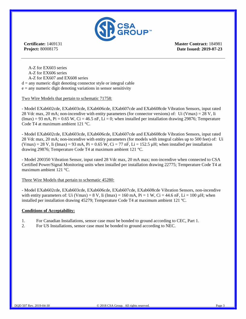
Certificate: 1469131
Project: 80008175
Master Contract: 184981
Date Issued: 2019-07-23
DQD 507 Rev. 2019-04-30 © 2018 CSA Group. All rights reserved. Page 3
A-Z for EX603 series
A-Z for EX606 series
A-Z for EX607 and EX608 series
d = any numeric digit denoting connector style or integral cable
e = any numeric digit denoting variations in sensor sensitivity
Two Wire Models that pertain to schematic 71758:
- Model EXab602cde, EXab603cde, EXab606cde, EXab607cde and EXab608cde Vibration Sensors, input rated
28 Vdc max, 20 mA; non-incendive with entity parameters (for connector versions) of: Ui (Vmax) = 28 V, Ii
(Imax) = 93 mA, Pi = 0.65 W, Ci = 46.5 nF, Li = 0; when installed per installation drawing 29876; Temperature
Code T4 at maximum ambient 121 °C.
- Model EXab602cde, EXab603cde, EXab606cde, EXab607cde and EXab608cde Vibration Sensors, input rated
28 Vdc max, 20 mA; non-incendive with entity parameters (for models with integral cables up to 500 feet) of: Ui
(Vmax) = 28 V, Ii (Imax) = 93 mA, Pi = 0.65 W, Ci = 77 nF, Li = 152.5 µH; when installed per installation
drawing 29876; Temperature Code T4 at maximum ambient 121 °C.
- Model 200350 Vibration Sensor, input rated 28 Vdc max, 20 mA max; non-incendive when connected to CSA
Certified Power/Signal Monitoring units when installed per installation drawing 22775; Temperature Code T4 at
maximum ambient 121 °C.
Three Wire Models that pertain to schematic 45280:
- Model EXab602cde, EXab603cde, EXab606cde, EXab607cde, EXab608cde Vibration Sensors, non-incendive
with entity parameters of: Ui (Vmax) = 8 V, Ii (Imax) = 160 mA, Pi = 1 W, Ci = 44.6 nF, Li = 100 µH; when
installed per installation drawing 45279; Temperature Code T4 at maximum ambient 121 ºC.
Conditions of Acceptability:
1. For Canadian Installations, sensor case must be bonded to ground according to CEC, Part 1.
2. For US Installations, sensor case must be bonded to ground according to NEC.
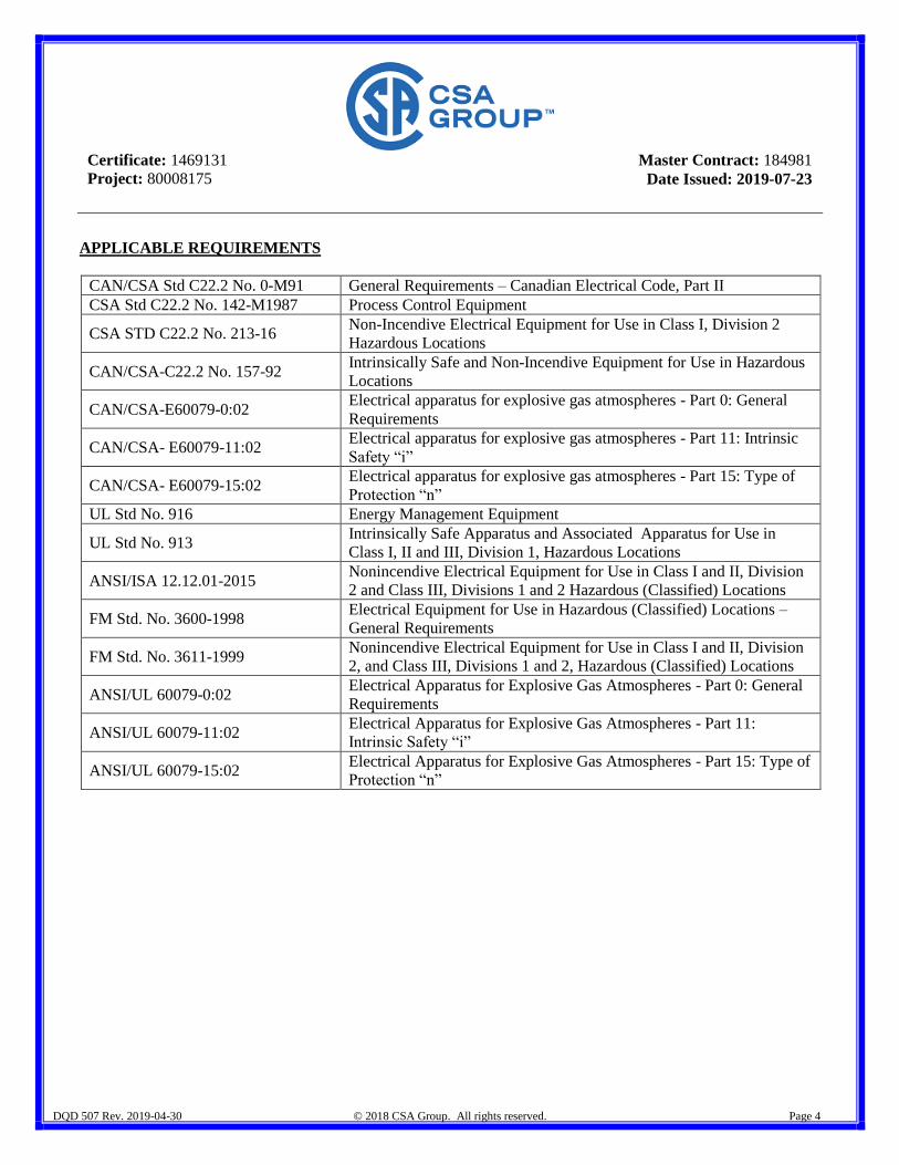
Certificate: 1469131
Project: 80008175
Master Contract: 184981
Date Issued: 2019-07-23
DQD 507 Rev. 2019-04-30 © 2018 CSA Group. All rights reserved. Page 4
APPLICABLE REQUIREMENTS
CAN/CSA Std C22.2 No. 0-M91 General Requirements – Canadian Electrical Code, Part II
CSA Std C22.2 No. 142-M1987 Process Control Equipment
CSA STD C22.2 No. 213-16 Non-Incendive Electrical Equipment for Use in Class I, Division 2
Hazardous Locations
CAN/CSA-C22.2 No. 157-92 Intrinsically Safe and Non-Incendive Equipment for Use in Hazardous
Locations
CAN/CSA-E60079-0:02 Electrical apparatus for explosive gas atmospheres - Part 0: General
Requirements
CAN/CSA- E60079-11:02 Electrical apparatus for explosive gas atmospheres - Part 11: Intrinsic
Safety “i”
CAN/CSA- E60079-15:02 Electrical apparatus for explosive gas atmospheres - Part 15: Type of
Protection “n”
UL Std No. 916 Energy Management Equipment
UL Std No. 913 Intrinsically Safe Apparatus and Associated Apparatus for Use in
Class I, II and III, Division 1, Hazardous Locations
ANSI/ISA 12.12.01-2015 Nonincendive Electrical Equipment for Use in Class I and II, Division
2 and Class III, Divisions 1 and 2 Hazardous (Classified) Locations
FM Std. No. 3600-1998 Electrical Equipment for Use in Hazardous (Classified) Locations –
General Requirements
FM Std. No. 3611-1999 Nonincendive Electrical Equipment for Use in Class I and II, Division
2, and Class III, Divisions 1 and 2, Hazardous (Classified) Locations
ANSI/UL 60079-0:02 Electrical Apparatus for Explosive Gas Atmospheres - Part 0: General
Requirements
ANSI/UL 60079-11:02 Electrical Apparatus for Explosive Gas Atmospheres - Part 11:
Intrinsic Safety “i”
ANSI/UL 60079-15:02 Electrical Apparatus for Explosive Gas Atmospheres - Part 15: Type of
Protection “n”

Certificate: 1469131
Project: 80008175
Master Contract: 184981
Date Issued: 2019-07-23
DQD 507 Rev. 2019-04-30 © 2018 CSA Group. All rights reserved. Page 5
MARKINGS
I.S. models
- CSA Monogram with C US Indicator
- Submitter Identification
- Model Number
- Serial Number, Date Code or Month and Year of Manufacture
- Electrical Rating
- Hazardous Location Designation (i.e., the symbol Ex ia IIC T4; AEx ia IIC T4; Class I, Div. 1, Groups A,
B, C and D; Class II, Div. 1, Groups E, F and G; Class III, Div. 1)
- Certificate # reference (i.e., 2006 1469131)
- Reference to Installation Instructions
Div. 2 Non-Incendive models
- CSA Monogram with C US indicator.
- Submitter Identification
- Model Number
- Serial Number, Date Code or Month and Year of Manufacture
- Electrical Rating
- Hazardous Location Designation (i.e., Ex nL IIC T4, AEx nA IIC T4, Class I, Div. 2, Groups A, B, C and
D)
- Certificate # reference (i.e., 2006 1469131)
DQD 507 Rev. 2019-04-30 © 2018 CSA Group. All rights reserved. Page 1
Supplement to Certificate of Compliance
Certificate: 1469131 Master Contract: 184981
The products listed, including the latest revision described below,
are eligible to be marked in accordance with the referenced Certificate.
Product Certification History
Project Date Description
80008175 2019-07-23 Update Report 1469131 to cover changes applicable to Two Wire Model
Vibration Sensors that pertain to schematic 71758 and are used in Class
I/II/III Division 1, Zone 0; and, Class I Division 2, Zone 2. Updates include:
Addition of three capacitors; A change in values of Entity Parameters.
000070125525 2017-09-05 Update CSA Report 1469131 to assess the modified entity parameters for
the 3 wire type Vibration Sensors.
000070079443 2016-07-15 Update Report 1469131 to assess the replacing of a new temperature output
chip LM45 instead of old sensor temperature output chip LM35 for Class I,
Div 1, Groups A, B, C, D, Class II, Div 1, Groups E, F and G ,Class III, Div
1 A/Ex ia IIC for all EXTO models indicated on the original report
1469131. Model No: EXab607cde and EXab608cde and ab608cde with
New Temperature output chip LM45 for the #EXTO# models
0002625009 2013-07-19 Update to report 1469131 to include revised drawings and remove “Date”
column from the Descriptive Document List.
0002285154 2010-04-14 Update of Report 1469131 to include models EXab602cde, EXab603cde,
EXab606cde, EXab607cde, and EXab608cde.
0001750643 2006-04-18 Update to Include models EX602Dxx, EX606Bxx, EX607Axx and
EX608A1x; addition of models EX603C1x and EX603C6x.
0001469131 2003-08-22 Original Certification - Models 603C01 and 200350.

:Yt
$ J.A)( RU C-US.AA87.B.00217/I9
Eepu51 IUJ .N ) tB(;
R1 114. WWI
OPFAH HO CEPT144?HKA1HH Opran no cepTu4umawlll B3pb1Bo3au11Luerntoro It pyiwnrnoro o(5opyoaarnisi (OC LCB3) O6iuecTBa C Orpanu'iennoü OTBeTCTBeHHOcThIO d1eHTp no cepTH4nuawI1I B3pb1Bo3aw1llenfloro It
M u'1uOro o6opyjwBannn (000 HAFIHO UC83>>). Ajpec eca naxoeimu Iopivinecioro .rinia: Poccaw, 140004, icoacian 06jiacm, J1i06epeciiii patton, ropoR Jlio6epubI, noce.moK BYFH, AO <<3anoi (0KOMAIII>), .rmTepa B, 06ecr 6, :)Tam 3, o4rnc 26. Mpec MecTa ocywecTarzenlnl W1eJThHocTIa B o6.iiacm aicicpeiurrawin: Poccan, 140004, MocKoncKasl o6jiacm, .JIio6epewnfi paou, ropwi illo6epubt, noceio EYf14, AO <3aaoj K0MAIll>, JlnTepa B, Mimi- 6,3Ta 3, o4nci,i 26/3,26/4,26/5,27/6,30/1,32. ATrecTaT X RA.RU.11AA87 OT 20.07.2015 r. Teae4on +7(495) 558-&3-53, +7 (495) 5588244 Aiipec 3JleKrpOnnoll noqmi ccve(ccve ru
3A51B14TEAb OöIICCTBO C orpallwlenlloui OTBTCTBCi1HOCTb1O <<AJ1b4rnTex>> Aipec MecTa Haxoeiiuii !opumn'lecKoro .rinua: Poccun, 125009, Mocicna, MaJibiul 1Ne3EIHHKoBcKHä uepeyJioK, LoM N2 12, noeweijne I, KoMuaTa 4. A.rpec meCTa ocyuecTB3enun JeuTe.J1bIIocTn: Poccnn, 127495, MocKna, oJIronpy)HencIcoe mocce, joi N2 3, TexuonapK <<(1n3TexHapK>>. OFPH: 1167746393792. Teie4ou: +7 (495) 642-49-14. At*pec 3iieNTPOH110ft no'imi: [email protected]
H3FOTOBHTEAb PCB Piezotronics, Inc Ajpec Mecra naxoacreunsi Joputw'IecKoro AHija H aipec MecTa ocywecTBJlellnsl )eaTeJIbHocTn no fl3FOToI3CHhIO npoiyicwin: 3425 Walden Av., Depew, NY 14043, CIlIA
HPO4YKI45I flbe3oIeIcTp1I 'lecKne ii pe06pa308aTe.rin, Bn6poHepeKJuoqaTeJuj, n peJycHJInTe.rIH c Ex-MapidnpoBKoIr cormacuo HHJ1OKCHftI0 (CM. 6JIarndn .NW& 0621345, 0621346, 0621347).
OKyMCHTbI, B COOTBeTcTBHU C KOTOpbJMH 1130TOBJCHbI H3J*e3HNI - CM. UpflJIOKdHHe, 6JIaJ1K Ni 0621344. Cepafinblui flblllyCK.
KOA TH B3A EA3C 903180 3800,902620 20009 8517 69 9000
COOTBETCTBYET TPEBOBAHHSIM TP TC 012/2011 <0 6e30nad110cT11 O6Opy/oBa11Hu1 Aim pa6oTbI BO B3pb4noonacn16lx cpeiax>.
CEPT11414KAT COOTBETCTBFI5I BbI4AH HA OCHOBAHI{H ilporoKoJia Ildilbiranuhi J'& 235.2019-Tor 11.09.2019 lfcnblTaTeju.uoui JIa6opaTopnh1 TexunqecKux yCTpouicTn ABTOHOMBOhi HeKOMMeptiecKon oprannaiiin <<HanoHaJi16H161fl llCflblTaTejlbnblhi U HaIHO-HCcJieoBaTeJ1 bcKllli HHCTUTT 060pyLOBaHH51 TJ111 113L1BOOfl2CHb1X cpej>> Iii! Ex TY (arrecTaT Ni P0CC RU.0001.21M11119 OT 16.10.2015); AKTa anaJm3a COCTOSIHUH 11pOU3BocTna .N1i 35-A119 or 14.03.2019 Opraiia no cepuniaiau -T B3PbIB03 1UftWC1II10fO if pyjnt,uoro o6opyjwnaiina (OC 1ICB3) 06utecTBa C orpanutielijioli ornercrnennocrblo <Iewrp 110 cepTll4nlKauu11 B3pb1Bo3aH1nueuHoro 11 pyiun'uioro o6opyloBaHuH>> (000 <<HAHIIO 1C133>>) (arrecrar )& RA.RU.11AA87 ubliiaii 20.07.2015); ,LoKyMenTos, npe/cTaBJIe}rnb,x 3auBnTeJIeM B Kaqecme )oKa3aTeJ1hc7FBa COOTBTCTBHS1 I1pOJyK1HH Tpe6oBaH1mM TP TC 012/2011 (CM- npuaoaenne, 6JIaIIK Ng 0621344). CxcMa cepmrnauniz - ic.
- AOHOAHHTEJThHASI HH(OPMA1145I
I1epeqCHb cTaHJapToB, UHMHHMLIX Ha )06pOBoJIbnohi OCHOBe /1q co6Jt1oL(ellaln Tpe6oBaulihi TP TC 012/2011 t npJuioxenue, 6JIaI1K 0621344). YcJIOBHn H COR xpanennn Eh! a 'lKdnJIyaTaunonHohi /o1cyMeuT a14uu. llaqelnlblhi COOK CJty*c6b1 - 10 JICT. .. -
CPOK 4EhCTBH 20 M C 13.09.19 rio 12.09.2024,
'T7. :•\
BKUOqHTEAbHO 1
3tjioi un A ,ecanp Cepreennq PyKonoAnTeith (yno4inoM0eHHoe
oprana no ceprn4nixairm (nognm b I a4aaiom14 hope A.rIeIcaHELpoBnq
31c1wpT(9xdnpJ-av4nrop) • - ()LcIIeprhI (3KcIu:plf.1- ayAJIropbl)) . - ....
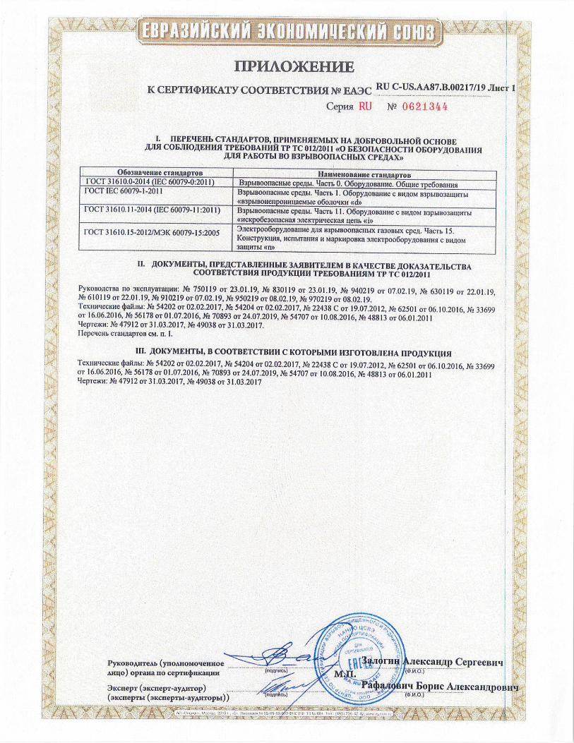
PyKoioAnTeu (ynoAnoMoennoe 2tJno) oprana no ceprn4)m<aIm1
3acnepT (aKcnepl-ayAnlop) (axcnepmi (3xcneprbI-ayiTopbI))
4JleIcan,Ip CeplecBll'I • fii
H 1opiic AJ1eKeaJ1J11)0131011
MXL
-
060ia'ieiue cTaIIIaproB HanMeHosanHeCTaIJL*apToB -
I_FOCI 3 1610M-2014 (IEC 60079-0:2011) B3pbIBoonaduMecpewacmo. 06opyoBanue. 061aneTpe6oaim 1-OCT IEC 60079-1 -2011 l33pblBoorlaculie cpelbl, '-lacm 1. 06opyjioname c BH)0M B3pbJ303auwr&I
<li3pbrnoHenponMuaeMwe o6ojiotnui <d>> [OCT 31610.11-2014 (IEC 60079-11:2011) B3pbrBoonacllble CpeJibl. 4aem 11. 06opyjWt3alllle C l3IU0M 133ph1B03a[UHTM
((HcKpo6e3onacHasl DllelcrpnLlecKasl ieim <<1>>
[OCT 31610. 15-2012/M3K 60079-15:2005 3jiei t'poo5op•yoaaniie ansi npwsoonacmtx 1a30rn1x cpei. 4acm 15. KoIic-rpyKuwl, flcrihllaulnl H mapyaipoBica 3jieKTpoo6opyAOBanmjq C BW0M 3aUM-r1.1 <(fl>
11 ,1OKYMEIITh1, 11PEJCTAB.ThFHHME 3A5IBIITEJIEM 13 KAECTBE AOKA3ATEJIbCTBA COOTBETCTBHM I1PO)YKIHh1 TPEOBAHH5LM TP TC 012/2011
PKo1JocTHa 110 31dfl1yaTaLHH N 750119 oi 230119 N 83011901 230119 N' 940219 oT0702 19 K 630119 oi 220119 N 610119or2201 19 N29102190T0702 19 N 950219oi0802 19 N 970219oi0802 19 Temili'lecraic ~aUbr X2 54202oT02022017 N 54204or02022017 Ki, 22438Coi 19072012 X2 62501 or06 102016 XL, 33699 oi 16062016 N 56178oT01072016 XL, 70893oT24072019 1L54707oi 10082016 XL, 48813oT06012011 L1epj.c)J(}, X2 47912oT31032017 X2 49038oT31032017 flepe'lLHb cral-LoapTol3 CM Ii I
111 )IOKYMEHTb1, B COOTBETCTBHH C KOTOPb1MH 1131'OTOBJIEHA llPOJYK1115I IexHuqecKH.()aHJ1b1 Xg 54202 OT 02.02.2017, N 54204 0T02 022017 N 22438CoT 19072012 XL, 62501 oi06 102016 K 33699 0116062016N056l780101072016N0708930124072019 XL) 5470701 1008.2016, N948813 oi06 012011 1-h.p-reKM XL, 47912oT3103 2017 X2 49038oT31 032017
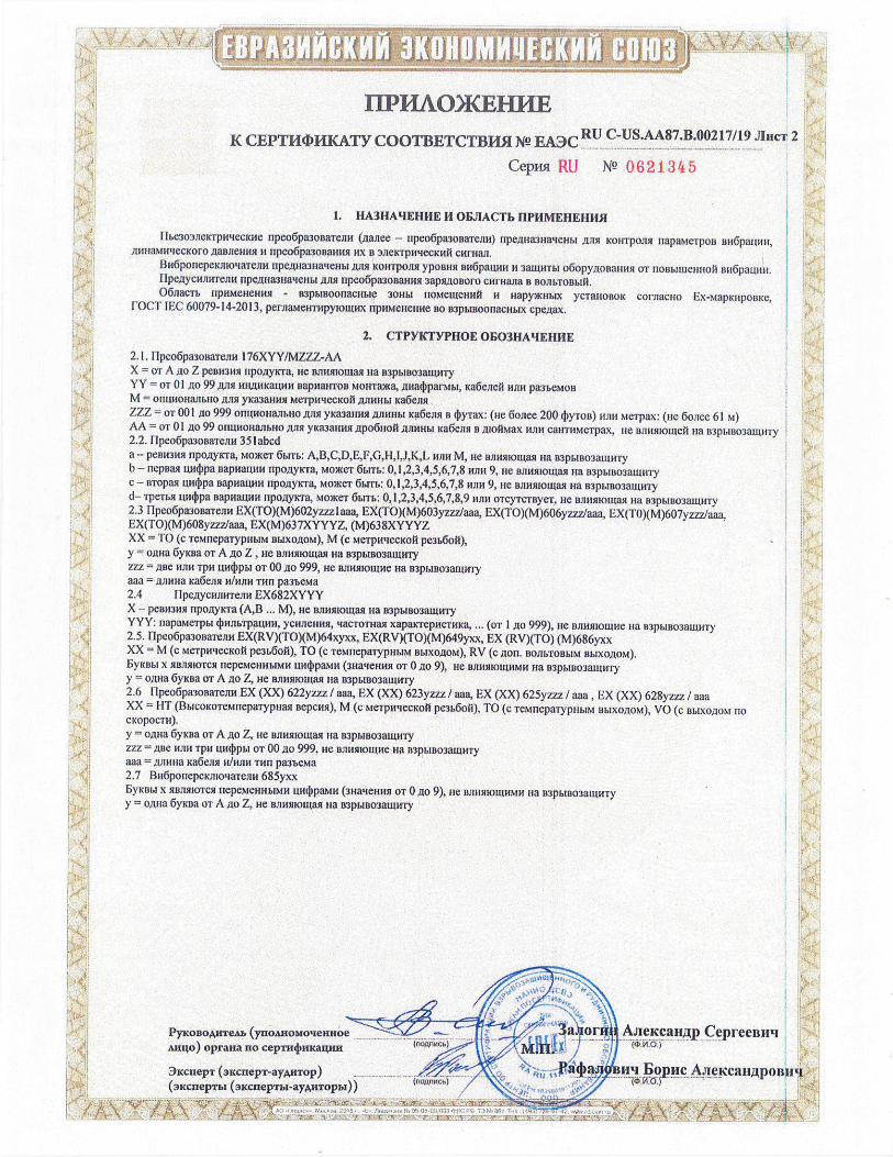
JJWAJJJ$JJJJ
IPFLAO){<EHILE RU K CEPTWDHKATY COOTBETCTBH5I N EA3C PT ,0
Jl h1CT2
Cepiisi LW NQ 0621345
k 1. HA3HAqEHHE II OBJIACTb EIPHMEHEHII$I
flbe3o3J1e1crpHecKI1e npeo6pa3ooaTeJ1M (.aaiiee - npeo6pa3oi3aTellll) npeJuia3na'eJmt ,TI)1Sl KOHT0351 11apaMe'poB BH5paiWH, /j1IHaMHqeCKOfO .oaB1eHMsl ii npeo6pa30Ballusl HX B 3J1eIcrpHqecKMi CHFHWL
BH6p0rIepeKrn04aTeJ1H I1pe.iva31IattenbI ,LULSL K0HT0J1$l yporw BH6paW4H H 3amHTbl o6opyJoRarnin OT rlol3buhle}ilroil wi6paullH. I1pe.uycrfnwreJlH llpe1ula3Ha'lenbl ,BJISI flpC0pa30BaHH1 3apsUtolloro CHI'Hana B B0JJbT0B1,111, 06iacm flMMCHHH$l - 03p&lBoonacnble 30}thl fl0MeWeHHi H HO)KH14X yclal-roBoic corsiaciio Ex-vrapKripoDxe,
['OCT IEC 60079-14-2013, pernar1eH'rHpyrouu1x HPHMCHCHHC BO B3pbr000nacI-ralx cpezrax.
2. CTPYKTYPHOE OF03HAEHJ1E k.
2.1. llpeo6pa3onalenH 176XYY/MZZZ-AA X = or A 110 Z PC111131131 rtpo,ayicra, He Bslmllotlrag na n3pbrrr03alullly YY = or 01)10 99 ,rrrn HH,iuu<anrn BapnlaHloa Mowra)Ka, an1aparMM, Ka6encri 111111 pa3'beMoB M = OI1UHOHJIhHO )UTB yfca3aHn MC'rpHtlecKO[i .E1J1HHM ka6ellsl ZZZ =oT001 iio 999 0HIH0HaJ1bll0 jllrsr yKaarmsr 2IJIUHb1 Ka6eJor B 4yTaX: (He 6w=200 yToD) wur Me'rpax: (rio 6oiee 61 M) AA = or 01 jo 99 OHUHOHaJmHO .11101 yK113HiB1 )lpO6110fi AJBlHhl xa6en,i i 1uo1Max 05tH callloMelpax, He BJtH5110ll)eI na 113p61liO3auw'ly
H 2.2. flpeo6pa3oBaTeirn 351abcd a - pernl3itn npo.ayrcra, roce'r 6brrb: A,B,C,D,E,F,G,H,I,J,K,L ruin M, He wlnls0011rall ua B3pMr30'3amllly b— nepuai 1uujpa BaPMaIIHH npo,lryrcra, MO)KOT 6Mm: 0, 1,2,3,4.5,6,7,8 wilt 9, ire BJIH11I0Ua Ha B3pMu03a[unly C - BT011M uwpa 011P011UiIM flpO)1y'a, M0Of 6bITb 0, 1,2,3,4,5,6,7,8 115tH 9, He Bjumomaq na B'3pbIBOau1HTy d— TPCTMt un4pa DapHaIUH rlpo.iryx'ra, M0CT 6tnn.: 0, 1,2,3,4,5,6,7,8,9 rum o'rcyTcBye, He nuuurnourail Ha B3PblB03WHTY 2.3 I1peo6pa300aTeaH EX(TO)(M)602yzzzlaaa, EX(TO)(M)603yzzz1aaa, EX(TO)(M)606yzz7Jaaa, EX(TO)(M)607yzzz/aaa, EX(TO)(M608yzzz/aaa, EX(M)637XYYYZ, (M)638XYYYZ 1 ;H XX = TO (c emepaiypimri m.rxo.LroM), M (c MeTpI-NCCK01 pe3b6ol),
= y o.tma 6yiura 01 A ,iO Z He usuuirooiasr Ha B1pbIB03auU1Ty ZZZ =ABC 11.1111 TPH U)M 01' 00.110 999, HO 131I115l10U1H oa B3p6ln03auioly aaa = ,rijuuna Ka6eslsr 11/Hfl}1 TILt pameia 2.4 IIpesrycmiirreiinr EX682XYYY X - peirnrwi npoxrycra (A,B ... M), He Biioiiioiiasr Ha R3pI.1B03aIIrHTy YYY: rrapairepr 4mlrblpaumi, ycirnerinrir, qacTomall xaparcrepilc'InfKa, ... (01 1 ,rio 999), oe niiiusrioanre ira 133pbrno3awll'ry 2.5. 11peo6pa30ualeilo EX(RV)(TO)(M)64xyxx, EX(RV)(TO)(M)649yxx, EX (RV)(TO) (M)686yxx XX = M (c MeTpwlecxoi pe3&6oi), TO (c leMllepalypllhiM Bb1X01l0M), RV (c 51011. BOJIbTOBbIM BbIX0J1OM). b'.rcobr x 51BJIMIOTCSI flLMOHh4b1M14 [IH4)paMH (311a reuwi 01 0)10 9) He BJIHIHO[WIMH ma 113p1I1303auulry y = osu-ja 6yKrra UT A 510 Z oe BJ1HlHoII1as1 Ha 133b1B0311U1H1
2.6 [1peo6pa3oaaTeJm EX (XX) 622yzzz / aaa, EX (XX) 623yzzz / aaa, EX (XX) 625yzzz / aaa, EX (XX) 628yzzz / aaa XX = FIT (BblcoKoTeronepalypoair Bepcwi), M (c Merpru'IecKoi pe3b601j), TO (c ieMnepa'rypno.ibi m.lxo51oM), VO (c BI.IXO51oM Ho c1(OpOCT11).
y = oiuia Gyrura or A 510 Z, ne ojiilsriouiasi ua BIPMBO3BIUHTY iiz = 1113e Will ipo 1114!p1o1 OT 00 40 999 He oimiaouloe nia 113pbro03alunny aaa srjrriva ha6esur ilIwIn1 11111 pamea 2.7 Bll6porTepcInroaTennr 685yxx
X 51Balflo'rCsl nepeM000brMlr IuurIrpaMH (30aierunlB OT 0A 9), nie BJ1HM1OLUHMH nia 113pb1B03aiuHTy y = o nra 6yKw1 or A oo Z nie Brnrtllolllarl nia
H Ponone ( Cepreeniiti 1 H Mu4o) oprana no cep4nrKam
" 3iciiepi (3EcnepT ay,nTop) Pâ4a$Iu Bopuc A.r!u.caLI,iLpoBItq (3xcnepml (arcrrepmr-ayuTopbI))
1 T .IjSHL:. t:.'/
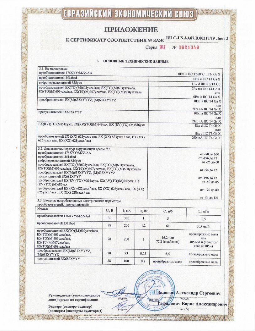
I I. Ex-iapiuipoaia: npeo6pa3ooaieiel 176XYY1MZZ-AA 0Ex ia IIC 1660°C. .16 Ga X ripeo6pmmeacA 35 labcd 0Ex ia HC T4 Ga X an6ponepeimoa'reiie3 685yxx lEx d 1113+1-12 14 Gb npeo6pa3onaTenei EX(TO)(M)602yzz21aaa, EX(TO)(M)603yzzz/aaa. 2Ex nA TIC 14 Ge X EX(TO)(M)606y7zz/aaa, EX(TO)(M)607yzzzlaaa, EX(TO)(M)608yzzz1aaa HIM
0Ex ia IIC 14 (laX npe06pa30aa1e2re11 EX(M)637XYYYZ, (M)638XYYYZ 0Ex ia IIC T4 Ga X
14JTh 2Ex nA IIC T4GcX
npe,aycimmenck EX682XYYY 0Ex in lie 14 Ga X Will
2Ex nA IIC 14 Ge X EX(RV)(TO)(M)64xyxx, EX(RV)(TO)(M)649yxx, EX (RV)(TO) (M)686yxx I Ex d TIC 14 Gb X
1 Lx d IIC 13 Gb X ripeo6paaonaiemiei EX (XX) 622yzzz/ aaa, EX (XX) 623yzzz/ aaa, LX (XX) 2Ex nA IIC T4 Ge X 625yzzz/ aaa, EX (XX) 628yzzz/ aaa
3,2. Amalmoll TeMnepaTyp 0KpyKalolueii Cpeai, °C, npeo6pa3onnaTeneti I76XYYfMZZ-AA OT -70 jio 650 npeo6pa3oaa'remnet 351 abed OT -196 ,mto 121 1m6ponepeKJno4aTcJle1 685yxx or -25 ito 60 upeo6pa3oaa'renetl EX(TO)(M)602y7-zz1aaa, EX(TO)(M)603yzzz/aaa, EX(TO)(M)606yzzzlaaa, EX(TO)(M)607yzzz1aaa, EX(TO)(M)608yzzzJaaa OT -54 Ao 121 rlpeo6pa3onaTeneii EX(M)637XYYYZ, (M)638XYYYZ npe,tiycHllHTeilell EX682XYYY or -196 .io 121 ripeo6paaonaieine EX(RV)(TO)(M)64xyxx, EX(RV)(TO)(M)649yxx, LX OT -40 io 85 (RV)(TO) (M)686yxx npeo6pa308aTemle1l EX (XX) 622yz7z/ aaa, EX (XX) 623yzzz / aim, EX (XX) OT —20 jo 80 625yzzz / aaa • EX (XX) 628yzzz/ aaa
OT-54210 121 -, ""1-' lit l(i.'¼LlJbi
nncnfinAInnATnqeri ilfltflurn4rlUTprlptl'
MOAeJlb Ut, B Ii, MA Pt, 131
--•1--
Cj, WI) -
Li. Nin, upco6pa30aaTemleui I76XYY/MZZ-AA
30 300 I 5 0,5 rlpco6pa3ooaTenetl 35labed
28 200 1,2 61 305 M1d'H npeo6pa3osalemidil EX(TO)(M)602yzzz I aaa, EX(TO)(M)603yzzzlaaa, EX(TO)(M)606yzzz/aaa, 28 200 mm
npeeicoio Ma,na16,2 l-IJI}1
EX('l'0)(M)607yzzz/aaa, 77,2 (c Ka6eJ1eM) 305 NIKi11 (c y;ne-roi EX(TO)(M)608y7,zz Ka6ei15l 305M)1aaa llpeo6pa3ollale.qefl EX(M)637XYYYZ,
28 93 0,65 6,5 - (M)638XYYYZ npee6peaciito mam
npeitycnun.rrexie0 EX682XYYY28 EIOO
0,7lnpcne6pe?KoMQ aim flpCllC6pCixHMo
--------------------
3 Ponoie
a oi .iiird Aiiei canp CepreeBllq
AuIo) opraita no ceprn4ma4mt
3xcnep1 (xcnepT-aytTop) Iitj,aJtbiuiq Eopnc AJeIcaHjpoB1Iq
(.ncnIepT1n (iKdneprbn-.l)'xnnopzin)) .';Ii•'.' l
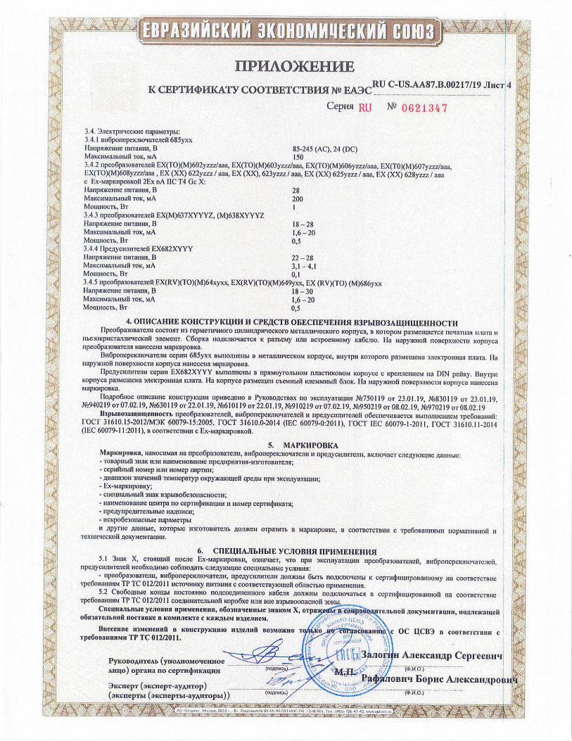
H
3.4. 3ieicrpirtecore napaMerpb1 3.4.1 Bu6ponepekJllo4alcneil 685yxx Hanpoceiie rmTaun3I, B 85-245 (AC), 24 (DC) VtaKcMaJibnb0 10K, MA 150 3.4.2 npeo6pa3o1saTeJIei EX(T0)(M)602yzzzlaaa, EX(TO)(M)603yzzz/aaa, EX(T0)(M)606yzzz1aaa, EX(TO)(M)607yzzz/aaa. EX(TO)(M)608yz77Jaaa , EX (XX) 622yzzz/ aaa, EX (XX), 623yzzz/ aaa, EX (XX) 625yzzz / aaa, EX (XX) 628yzzz/ aaa c Ex-MapknponKofi 2Ex nA DC T4 Gc X: Haiipaaeiiue niiraiiiui, B 28 MaKcaMaibtn!i1 10K, MA 200 Mownocm, BI 3.4.3 ripeo6paonareieii EX(M)637XYYYZ, (M)638XYYYZ llarlpsnKem(e riwraiui, 13 18-28 MaKcw1arIbIab1fi TOK, MA 1,6-20 Motiuiocm, Br 0,5 3.4.4 F1pcjycwin'reiieil EX682XYYY I1anpenne riniatnin, II 22-28 MaKdHMaJi1Im1i 10K, MA 3,1 —4,1 Moiwiocm, 13i 0,1 3.4.5 npeo6pa01aiejeii EX(RV)(TO)(M)64xyxx, EX(RV)(TO)(M)649yxx, EX (RV)(TO) (M)686yxx 11aripnKenne rnn'annii, 13 18-30 MaKdllMaflbiibi0 10K, NiA 1,6-20 Moiiwocm, BI 0,5
4. OIIHCAHIIE KOHCTPYKUIIII H CPE,ECTB 0EECHE4EIIH5L B3Pb1B03AEIHLEEH}LOCT11 11peo6pa3osaTe1u COCTOI1T 113 repMe'rivuioro LUrn11W1pi{eCKoro MelaluiwiecKoi-o Koprryca, 14 KOTOPOM pa3MeiLLaeTcsJ nCiaI1iasi rIJIaTa H
nhe3oKpuc'ranJlliqecKnui 3J1eMeuT. C6opKa noj.usuoae'rvsi K pamey njni nclpoenHoMy Ka6eJuo. Ha Hapy)KHOO IIOBCXH0CTiI Kopuyca npeo6pa3oBaTcJin iiaiiecena MapluiponKa.
Bu6ponepeKjnotiaTeJni ceprni 685yxx Bbinoimem.I a MeTaJLr11tMecKoM Kopoyce, BUTH Koroporo pa3Mewe1-Ia 3JIeK'rpollm131 rriaa. Ha uapyiio1i noaepxuocm Kopnyca naiiecena M4pKapoeKa.
flpe)lycarmlemu cepin EX682XYYY BbiIIOJIHCHLI B 11PS1M0F0JThH0M IUTaCTHKoBoM K0I1CC C RiUiCHCM na DIN peOKy. 13iiyipu opnyca paemena 3JICKTPOHMA miaTa. Ha Kcipayce paeiueu e'eiiiadl KJ1eMMHbIti 6110K. Ha HapyMcuoi OOBCpXHOCTII icopnyca iiaeceiia
Mapiu!poaKa.
UTojpo6iioe ornicai-me KoHc'rpylauln ripiine;teuo B PyKoBo.cTBax no 3KCflJTYBTLUffi X2750119 Or 23.01.19, M830119 01 23.01.19, M940219 OT 07.02.19, XL,630119 oT 22.01.19, XL,610119 OT 22.01,19, M-010219 OT 07.02.19, XL050219 OT 08-02.19, X970219 wr 08.02,19
BJphIBo3atUnhfela!ioem npeo6pa3onaTeiieii, aH6ponepeKnlo'.{aldneil ti npejycrnrriie,rie1i o6ecnctRrnaelcli BbinORMIRCM i'pe6onauiiit roc- 31610.15-2012/M3K 60079-15:2005, FOCI 31610.0-2014 (IEC 60079-0:2011), FOCI IEC 60079-1-2011, FOCI 31610.11-2014 (IEC 60079-11:2011), B COOTBCTCIBHII c Ex-MapiuJponicoii.
5. MAPICIIPOBKA MapluiponKa, HBHOCHMBH ua npeo6pa3oBaTernx, nll6poliepeKnioqalejllf H npemyciuni'reini, BKJIIO'iaCT CJIeiyIouue ;aillihIe: - Tonapriblil 3IiK 111111 nanenonane flpejljipil5llH5l-113roloni!lejisi; - cepuihiMli iioitep 111111 HOMC riapTilhi; - /jna11a3011 311a'4e111111 TemnepaTyp oKpyx(aIoaeIi cpeILh1 npii )KCri11yaraui111; - Ex-1apKupoaKy;
- crIe1LHa1IbLIbiI 3HaK 133phuIo6e30r1aeuocTri; - iiaiienonaune ueirrpa no cepllillnn(awm ii Romep cepm4mKaTa; - upejlynpe4uleJmuble 1114.LIHHCM - ncKpo6e300aduMe napaMe'rpM ii ipynie /xallnbie, K0T0b1C ll3rolonwrenb 10JDKCH o'rpa3llm B MaplalpoaKe, B COOTBCTCTBHH c 'rpe6onami51ii uopMa'rualioii U
'rex}lHtiecKoii .aoxyMenrarunl.
6. CflELEIAJ1bF1b1E YCJIOBH5I LIPHMEHEHH5I 5.1 3i1aK X, CTORUIIIO nocile Ex-laapJcMpoBKn, 0311aBeT, 'iTO BPI' 3KCi1flflTtjH14 flpeo6pa3ol3alelieii, B116ponepeKJnoMaTcJieii,
npej.tycwuiieieii lieo6xouiMo co6mo;jam cmejyioinne cueLHaJmubie VCJIBIIII: - 0pe06pa300a'resui, nri6ponepexinoqaierni, flP1C111iHTCJIH Aonwubi 6b1m no11Knjoqenbi K cepTncjnn.uponamtoiy Ha COOTBCTCTEIHC
1pe6oaallnslM TP 'rc 0 12/2011 IICTOMimKy linmilhia c coolncicluylolaeui o6nacmio np}IMeHemn. 5.2 Cno6oflhlbic K01!Lhl II0CTOMHHO noJeoe.rumewioro xa6e1131 .L4011)K.Hbi no/jicriioqamcn B CCPTII(1)illhiipoaaijh{ojl HB c0olnelcr13iIe
i-pe6onaiitii TP IC 012/2011 COCJUIRHTCJIbHOIi Kopo6Ke 113Th nue 133phiBO0rIaCH0ii 3011141.
Cueuuallbnkle ycionnn npnMe,ie,nhii, 06031109e1111a1c 3BBKOM X, o'rpaeiI1.i pojLjileln.hloh oIyMcIIrawm, I1oJmeKaIIeii o6a3aTeJu.uoil IJOCTBBICC B KONIHJIeKI'e C KBK3bi4i II31ICJIUCM. 7 .
.,.
Bueceane u3Meflenlltl a KoncvpyKuliw 113JeJi1iü B03MO)RIIO I Oe acnnanlno\c OC UCB3 B coolnercunuit C 'rpe6onauunMll TP TC 012/2011. ;.
. . 3aJioru As1eicca1I)p CeprceBuq
PYK0BOAnTeA1 (yno2s.noMoeRHoe .. .. Amlo) oprana no cep1n4nwawu1 OATli : )
Pa4jJIoBnq BoplIc Aiei'cazijtpoi 3KcnepT (adnepT-ayAnTop) .
(10flCb) (2 4 ID)................... (3xcixepml (cnepTb1-ayAnT0pbi))
AN /
,f -------------
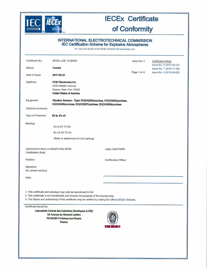
MMOW IECEx Certificate of Conformity
Lain T, % I
INTERNATIONAL ELECTROTECHNICAL COMMISSION lEG Certification Scheme for Explosive Atmospheres
for rules and details of the tECEx Scheme visit www.iecex.com
Certificate No.: lECEx LCIE 13.0045X Issue No: 2 Certificate history:
Issue No. 2 (2017-03-27) Status: Current Issue No. 1(2015-11-09)
Page 1 of 4 Issue No. 0 (2013-08-20) Date of Issue: 2017-03-27
Applicant: PCB Piezofronics Inc. 3425 Walden Avenue
Depew, New York 14043
United States of America
Equipment: Vibration Sensors - Type: EX(00602yzz7/aaa, EX(XX)603yzzz/aaa,
EX(XX)606yzzz/aaa, EX(XX)607yzz7/aaa, EX(X9608yzzz/aaa
Optional accessoiy:
Type of Protection: Ex ia, Ex nA
Marking: Ex ia IIC T4 Ga
Ex nA IIC T4 Gc
(Refer to attachment for full marking)
Approved for issue on behalf of the lECEx
Certification Body:
Position:
Signature:
(for printed version)
Date:
Julien GAUTHIER
Certification Officer
1. This certificate and schedule may only be reproduced in full.
2. This certificate is not transferable and remains the property of the issuing body.
3. The Status and authenticity of this certificate may be verified by visiting the Official lECEx Website.
Certificate issued by:
Laboratoire Central des Industries Electriques (LCIE) 33 Avenue du General Leclerc
FR-92260 Fontenay-aux-Roses I f France
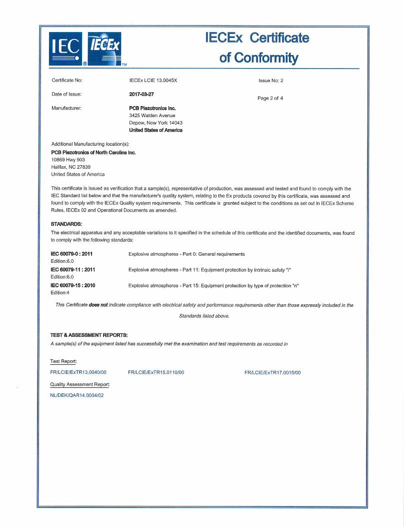
IECEx Certificate of Conformity
Certificate No: lECEx LCIE 13.0045X Issue No: 2
Date of Issue: 2017-03-27 Page 2 of 4
Manufacturer: PCB Piezofronics Inc.
3425 Walden Avenue
Depew, New York 14043
United States of America
Additional Manufacturing location(s):
PCB Piezotronics of North Carolina Inc.
10869 Hwy 903
Halifax, NC 27839
United States of America
This certificate is issued as verification that a sample(s), representative of production, was assessed and tested and found to comply with the
IEC Standard list below and that the manufacturer's quality system, relating to the Ex products covered by this certificate, was assessed and
found to comply with the lECEx Quality system requirements. This certificate is granted subject to the conditions as set out in lECEx Scheme
Rules, lECEx 02 and Operational Documents as amended.
STANDARDS:
The electrical apparatus and any acceptable variations to it specified in the schedule of this certificate and the identified documents, was found
to comply with the following standards:
IEC 60079-0: 2011 Explosive atmospheres - Part 0: General requirements
Edition:6.0
IEC 60079-11 : 2011 Explosive atmospheres - Part 11: Equipment protection by intrinsic safety "i'
Edition:6.0
IEC 60079-15: 2010 Explosive atmospheres - Part 15: Equipment protection by type of protection 'n"
Edition:4
This Certificate does not indicate compliance with electrical safety and performance requirements other than those expressly included in the
Standards listed above.
TEST & ASSESSMENT REPORTS:
A sample(s) of the equipment listed has successfully met the examination and test requirements as recorded in
Test Report:
FR/LCIE/ExTR13.0040/00 FR/LCIE/ExTR15.01 10/00 FR/LCIE/ExTR17.0015/00
Quality Assessment Report:
NL/DEK/QARI4.0004/02

IECEx Certificate of Conformity
tIVIETM
Certificate No: lECEx LCIE 13.0045X Issue No: 2
Date of Issue: 2017-03-27 Page 3 of 4
Schedule
EQUIPMENT:
Equipment and systems covered by this certificate are as follows:
The EX(XX)602yzzz/aaa, EX(XX)603yzzz/aaa, EX(XX)606yzzz1aaa, EX(XX)607yzzz/aaa and EX(XX)608yzzz1aaa piezoelectric vibration sensors utilize a quartz crystal to convert a mechanical vibration measurement into an electric signal.
The sensor consists of a sealed cylindrical metal case which houses a pcb substrate board and a piezo-crystal element. The circuit is connected to a connector or an integral cable.
SPECIFIC CONDITIONS OF USE: YES as shown below:
Version Bc Ia:
- The apparatus must be only connected to a certified associated intrinsically safe equipment. This combination must be compatible regarding intrinsic safety rules (see electrical parameters).
- Operating ambient temperature: -54CC to + 121CC.
- The apparatus shall be connected according to instruction manual.
- The mounting of the apparatus into an installation must be carried out in such a way that metallic body of the sensor is reliably connected to the system earth.
Version Bc nA - The apparatus must be only connected to an external source with U :5 28V, 1 :5 200mA, P !5 1W.
- For final installation, the user shall take all necessary precautions to maintain the minimum degree of protection IP54 of the sensor connection when connected according to the requirements of EN 60079-14 standard.
- Operating ambient temperature: -54CC to +121 C.
- The apparatus must be connected according to instruction manual.
- WARNING - DO NOT SEPARATE WHEN ENERGIZED.
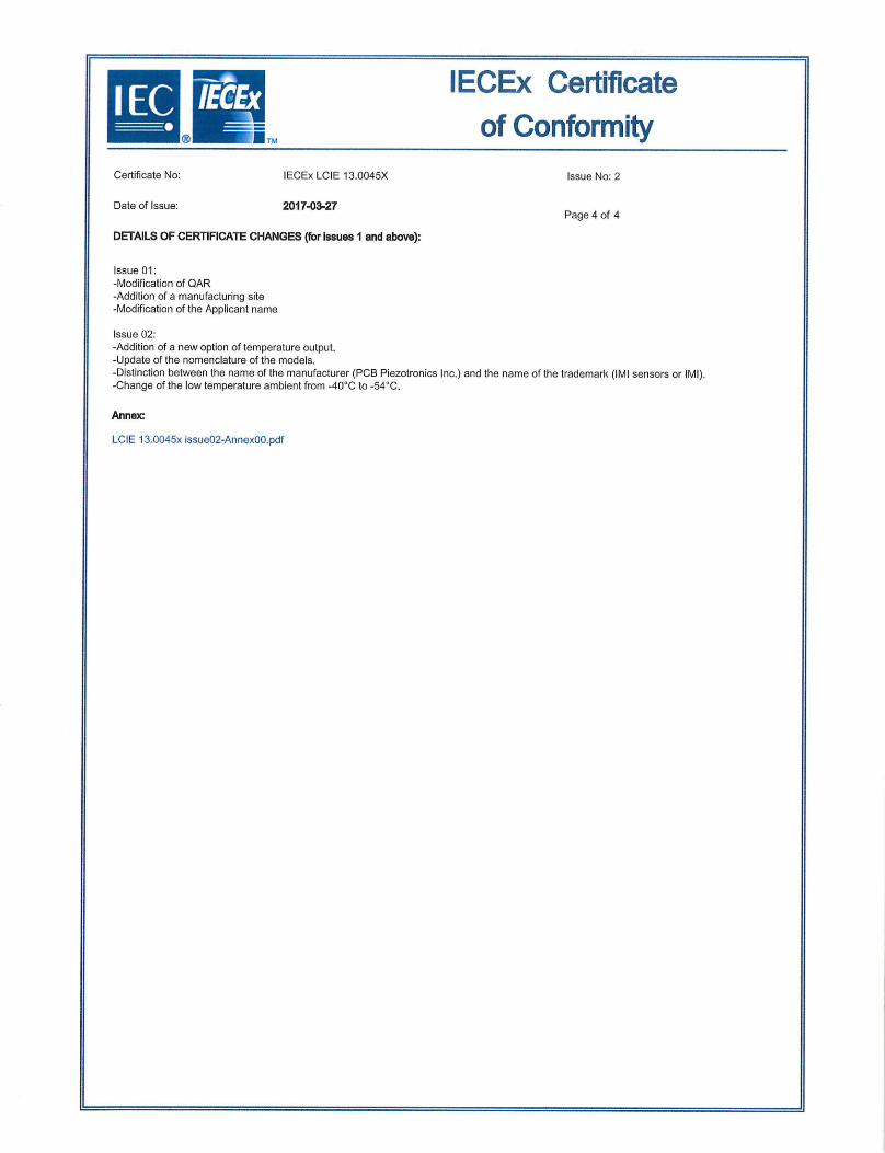
IECEx Certificate of Conformity
Certificate No: lECEx LCIE 13.0045X Issue No: 2
Date of Issue: 2017-03-27 Page 4 of 4
DETAILS OF CERTIFICATE CHANGES (for issues I and above):
Issue 01: -Modification of QAR -Addition of a manufacturing site -Modification of the Applicant name
Issue 02: -Addition of a new option of temperature output. -Update of the nomenclature of the models. -Distinction between the name of the manufacturer (PCB Piezotronics Inc.) and the name of the trademark (IMI sensors or Ml). -Change of the low temperature ambient from -40CC to -540C.
Annex
LCIE 13.0045x issue02-AnnexOo.pdf

F1 Annex 00 to Certificate Ln
U v
= lECEx LCIE 13.0045X issue 02 ____ I
_
FULL EQUIPMENT DESCRIPTION
The EX(XX)602yzzz/aaa, EX603(XX)yzzz/aaa, EX(XX)606yzzz/aaa, EX607(XX)yzzzlaaa et EX(XX)608yzzzlaaa piezoelectric vibration sensors utilize a quartz crystal to convert a mechanical vibration measurement into an electric signal. The sensor consists of a sealed cylindrical metal case which houses a PCB substrate board and a piezo-crystal element. The circuit is connected to a connector or an integral cable.
Title: Drawing No.: Rev. Level: Date:
Technical file "Ex ia' and "Ex nA' (lECEx) 56178 A 2016/07/01
Installation manual 41721 A 2017/01/18
MARKING Full marking: PCB PIEZOTRONICS INC. or IMI sensors or IMI Address: Type: Serial number: Year of construction: Ex ía 110 T4 Ga Ex nA 110 14 Gc 54°C :5 Iamb :5 +121°C
lECEx LCIE 13.0045X U: ... V, i: ... mA, F: . .W, C: . . .nF, L: . . pH (completed with electrical parameters) WARNING - DO NOT SEPARATE WHEN ENERGIZED.
Reduced marking: FOB Piezotronic Inc. or IMI Sensors or IMI Type: Serial number: Year of construction: Ex ia 110 T4 Ga Ex nA 110 14 Gc Ta= 121°C lECEx LCIE 13.0045X
RANGE DETAILS Models are electrically identical, but mechanically different EX(XX)602yzzz/aaa, EX(XX)607yzzz/aaa and EX(XX)606yzzz/aaa: Sensor with side exit connector or integral cable, EX(XX)603yzzz/aaa Sensor with top exit connector or integral cable, EX(XX)608yzzz/aaa Sensor with top exit integral cable.
Symbol Detail
XX M Metric mounting hardware and cable
TO Temperature Output Sensor One letter A to Z
zzz Two or three numbers 00 to 999 aaa Cable length and/or connector type
Page 1 of 2 This Annex is valid only in combination with certificate mentioned above and may only be reproduced in its entirety and without any change.
cERT-ATEX-FORM 14 Rev. 01
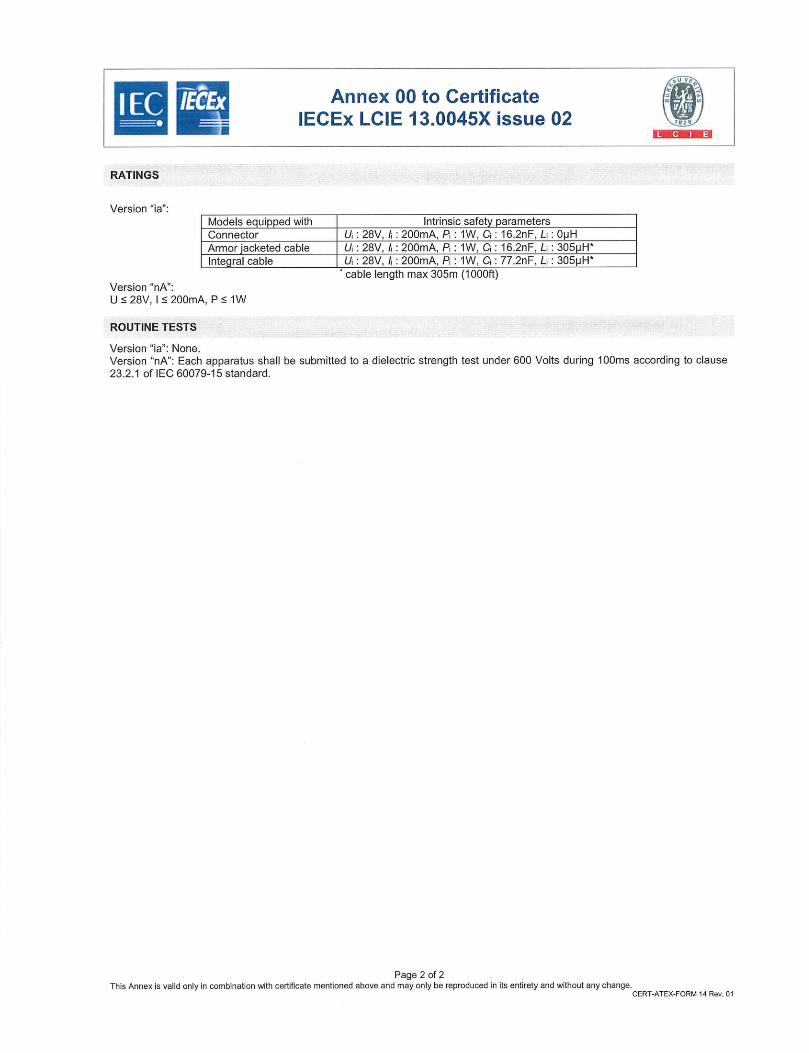
wi
u
Annex 00 to Certificate lECEx LCIE 13.0045X issue 02
RATINGS
Version 'ia": Models equipped with Intrinsic safety parameters Connector U : 28V, I : 200mA, P1: 1W, C: 16.2nF, Li : 0pH Armor jacketed cable U : 28V, I : 200mA, P: 1W, C: 16.2nF, L 305pH*
Integral cable U: 28V, I : 200mA, P1: 1W, C1: 77.2nF, Li : 305pH" cable length max 305m (1000ft)
Version "nA': U :5 28V, 15 200mA, P :5 1W
ROUTINE TESTS Version "ia': None. Version "nA': Each apparatus shall be submitted to a dielectric strength test under 600 Volts during lOOms according to clause 23.2.1 of IEC 60079-15 standard.
Page 2 of 2 This Annex is valid only in combination with certificate mentioned above and may only be reproduced in its entirety and without any change.
cERT.ATEX.FORM 14 Rev. 01
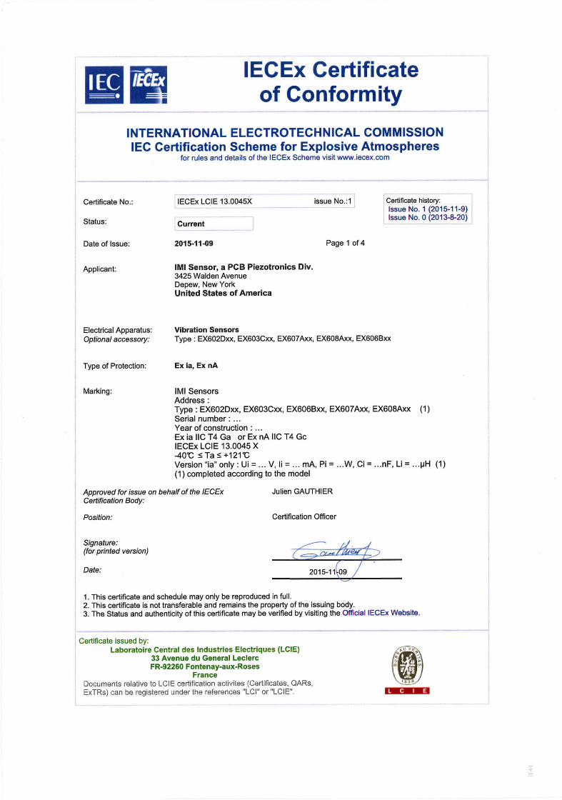
IECEx Certificate of Conformity
INTERNATIONAL ELECTROTECHNICAL COMMISSION IEC Certification Scheme for Explosive Atmospheres
for rules and details of the lECEx Scheme visit www.iecex.com
Certificate No.: lECEx LCIE 13.0045X issue No,:1 Certificate history: Issue No. 1(2015-11-9)
Status: Current Issue No. 0 (2013-8-20)
Date of Issue: 2015-11-09 Page 1 of 4
Applicant: IMI Sensor, a PCB Piezotronics Div. 3425 Walden Avenue Depew, New York United States of America
Electrical Apparatus: Vibration Sensors Optional accessory: Type: EX602Dxx, EX603Cxx, EX607Axx, EX608Axx, EX60613xx
Type of Protection: Ex ia, Ex nA
Marking: IN Sensors Address: Type: EX602Dxx, EX603Cxx, EX606Bxx, EX607Axx, EX608Axx (1) Serial number: Year of construction: ExiaIlCT4Ga orExnAllCT4Gc lECEx LCIE 13.0045 X 40cC :5Ta:5+121t Version "ia" only: Ui=...VIi= ... mA,Pi...W,Ci ... nF,Li ... pH (1) (1) completed according to the model
Approved for issue on behalf of the IECEx Julien GAUTHIER Certification Body:
Position: Certification Officer
Signature: ------S
(for printed version)
Date: 2015-1109
1. This certificate and schedule may only be reproduced in full. 2. This certificate is not transferable and remains the property of the issuing body. 3. The Status and authenticity of this certificate may be verified by visiting the Official lECEx Website.
Certificate issued by: Laboratoire Central des Industries Electriques (LCIE)
33 Avenue du General Leclerc FR-92260 Fontenay-aux-Roses
France Documents relative to LCIE certification activites (Certificates, OARs,
ExTRs) can be registered under the references 'LCI or 'LCIE.
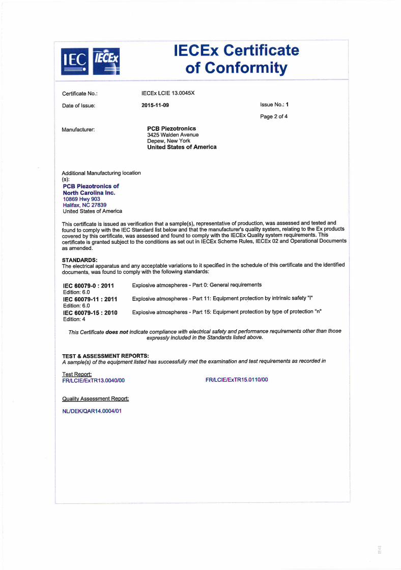
IECEx Certificate of Conformity
Certificate No.: lECEx LCIE 13.0045X
Date of Issue: 2015-11-09 Issue No.: I
Page 2 of 4
Manufacturer: PCB Piezotronics 3425 Walden Avenue Depew, New York United States of America
Additional Manufacturing location (s): PCB Piezotronics of North Carolina Inc. 10869 Hwy 903 Halifax, NC 27839 United States of America
This certificate is issued as verification that a sample(s), representative of production, was assessed and tested and found to comply with the IEC Standard list below and that the manufacturer's quality system, relating to the Ex products covered by this certificate, was assessed and found to comply with the lECEx Quality system requirements. This certificate is granted subject to the conditions as set out in lECEx Scheme Rules, lECEx 02 and Operational Documents as amended.
STANDARDS: The electrical apparatus and any acceptable variations to it specified in the schedule of this certificate and the identified documents, was found to comply with the following standards:
IEC 60079-0 :2011 Explosive atmospheres - Part 0: General requirements Edition: 6.0 IEC 60079-11: 2011 Explosive atmospheres - Part 11: Equipment protection by intrinsic safety 'i" Edition: 6.0 IEC 60079-15: 2010 Explosive atmospheres - Part 15: Equipment protection by type of protection "n" Edition: 4
This Certificate does not indicate compliance with electrical safety and performance requirements other than those expressly included in the Standards listed above.
TEST & ASSESSMENT REPORTS: A sample(s) of the equipment listed has successfully met the examination and test requirements as recorded in
Test Report: FRILClE/ExTR13.0040/00 FR/LClEJExTR15.01 10/00
Quality Assessment Report:
NL/DEK/QAR14.0004/01
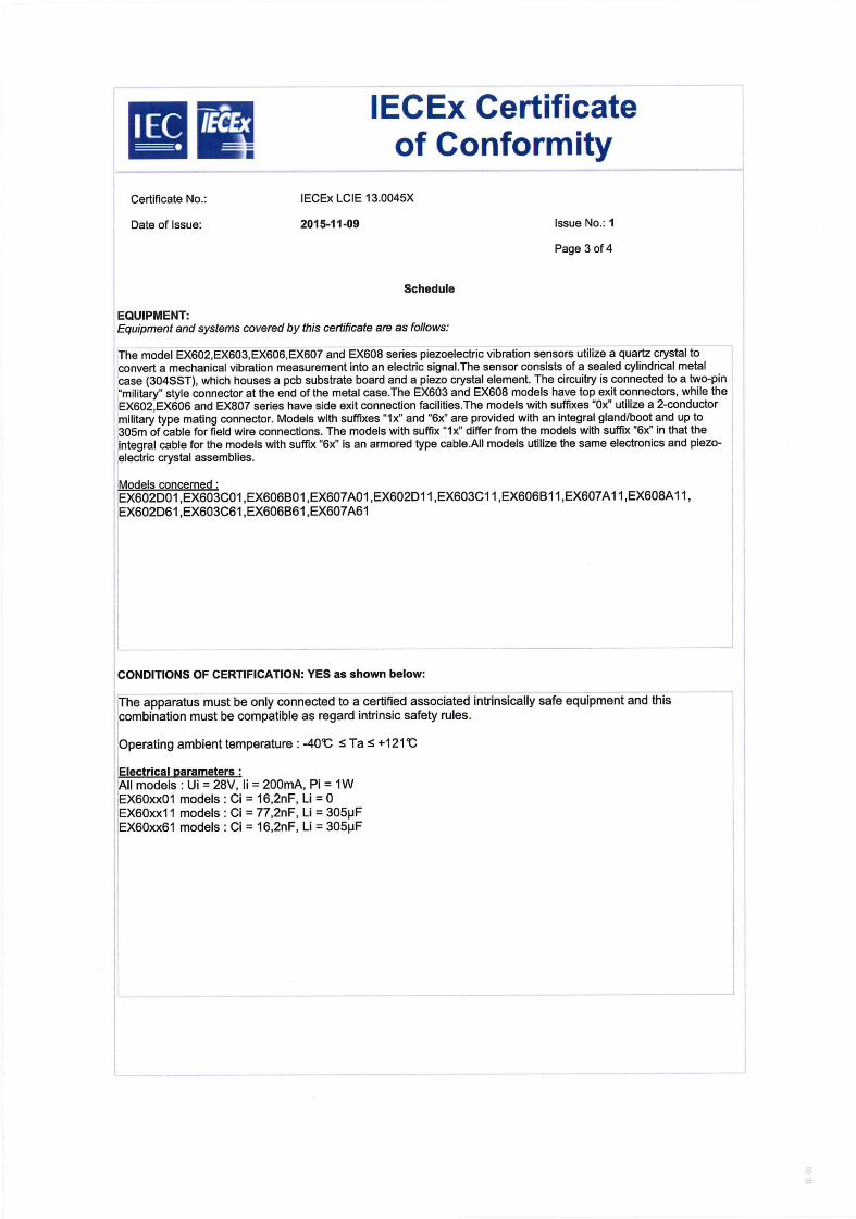
IECEx Certificate win of Conformity
Certificate No.: lECEx LCIE 13.0045X
Date of Issue: 2015-11-09 Issue No.: I
Page 3 of 4
Schedule
EQUIPMENT: Equipment and systems covered by this certificate are as follows:
The model EX602,EX603,EX606,EX607 and EX608 series piezoelectric vibration sensors utilize a quartz crystal to convert a mechanical vibration measurement into an electric signal.The sensor consists of a sealed cylindrical metal case (304SST), which houses a pcb substrate board and a piezo crystal element. The circuitry is connected to a two-pin "military" style connector at the end of the metal case.The EX603 and EX608 models have top exit connectors, while the EX602,EX606 and EX807 series have side exit connection facilities.The models with suffixes "Ox" utilize a 2-conductor military type mating connector. Models with suffixes "lx" and "6x" are provided with an integral gland/boot and up to 305m of cable for field wire connections. The models with suffix "lx" differ from the models with suffix "6x" in that the integral cable for the models with suffix "6x" is an armored type cable.All models utilize the same electronics and piezo-electric crystal assemblies.
Models concerned: EX602DOI ,EX603C01,EX6O6BO1 ,EX6O7AOI ,EX6O2DI I ,EX6O3C1 1 ,EX6O6B1 1 ,EX6O7AI 1,EX608AI 1, EX602D61 ,EX6O3C61,EX606B61 ,EX607A61
CONDITIONS OF CERTIFICATION: YES as shown below:
The apparatus must be only connected to a certified associated intrinsically safe equipment and this combination must be compatible as regard intrinsic safety rules.
Operating ambient temperature: -409C _-~ Ta :5 +121'C
Electrical parameters: All models: Ui = 28V, Ii = 200mA, Pi = 1W EX60xx01 models: Ci = 16,2nF, Li = 0 EX60xx1 I models: Ci = 77,2nF, Li = 305pF EX60xx6I models: Ci = 16,2nF, Li = 305pF

IECEx Certificate of Conformity
Certificate No.: lECEx LCIE 13.0045X
Date of Issue: 2015-11-09 Issue No.: I
Page 4 of 4
DETAILS OF CERTIFICATE CHANGES (for issues I and above):
Issue 01 Modification of QAR Addition of a manufacturing site Modification of the Applicant name
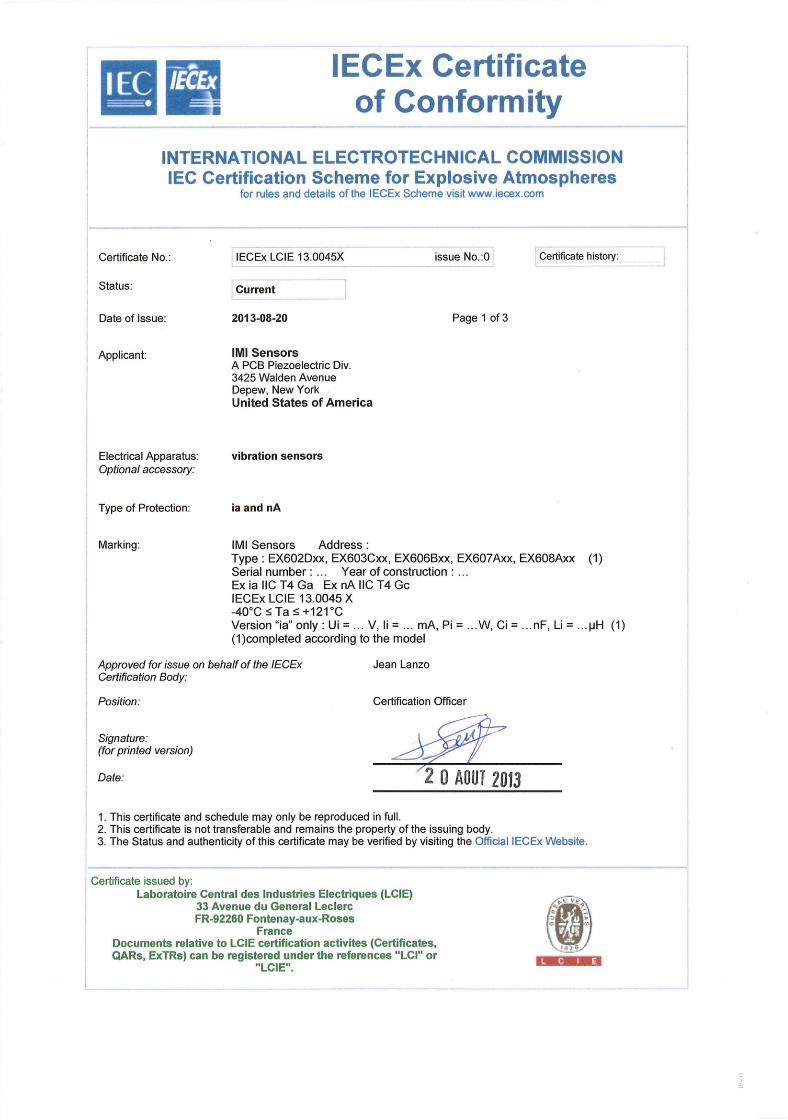
IECEx Certificate Wi of Conformity
INTERNATIONAL ELECTROTECHNICAL COMMISSION IEC Certification Scheme for Explosive Atmospheres
for rules and details of the lECEx Scheme visit www.iecex.com
Certificate history: Certificate No.: lECEx LCIE 13.0045X issue No.:0
Status. Current
Date of Issue: 2013-08-20 Page 1 of 3
Applicant: IMI Sensors A PCB Piezoelectric Div. 3425 Walden Avenue Depew, New York United States of America
Electrical Apparatus: vibration sensors Optional accessory:
Type of Protection ía and nA
Marking: IMI Sensors Address: Type: EX602Dxx, EX603Cxx, EX606Bxx, EX607Axx, EX608Axx (1) Serial number: ... Year of construction: ExiallCT4Ga ExnAllCT4Gc lECEx LCIE 13.0045 X -40°C :5 Ta :5 +121°C Version "ia" only: Ui=..V,li= ... mA,Pi=...W,Ci= ... nF,Li=...pH (1) (1)completed according to the model
Approved for issue on behalf of the lECEx Jean Lanzo Certification Body:
Position: Certification Officer
Signature: (for printed version)
Date: "2 0 AOUT 2013
1. This certificate and schedule may only be reproduced in full. 2. This certificate is not transferable and remains the property of the issuing body. 3. The Status and authenticity of this certificate may be verified by visiting the Official IECEx Website.
Certificate issued by: Laboratoire Central des Industries Electriques (LCIE)
33 Avenue du General Leclerc FR-92260 Fontenay-aux-Roses
France Documents relative to LCIE certification activites (Certificates, QARs, ExTRs) can be registered under the references "LCI" or
"LCIE".

7 it X IECEx Certificate
of Conformity Certificate No. lECEx LCIE 13.0045X
Date of Issue: 2013-08-20 Issue No.: 0
Page 2 of 3
Manufacturer: IMI Sensors A PCB Piezoelectric Div. 3425 Walden Avenue Depew, New York United States of America
Additional Manufacturing location (s):
This certificate is issued as verification that a sample(s), representative of production, was assessed and tested and found to comply with the IEC Standard list below and that the manufacturer's quality system, relating to the Ex products covered by this certificate, was assessed and found to comply with the lECEx Quality system requirements. This certificate is granted subject to the conditions as set out in lECEx Scheme Rules, lECEx 02 and Operational Documents as amended.
STANDARDS: The electrical apparatus and any acceptable variations to it specified in the schedule of this certificate and the identified documents, was found to comply with the following standards:
IEC 60079-0 : 2011 Explosive atmospheres - Part 0: General requirements Edition: 6.0 IEC 60079-11: 2011 Explosive atmospheres - Part 11: Equipment protection by intrinsic safety "i' Edition: 6.0 IEC 60079-15 : 2010 Explosive atmospheres - Part 15: Equipment protection by type of protection "n" Edition: 4
This Certificate does not indicate compliance with electrical safety and performance requirements other than those expressly included in the Standards listed above.
TEST & ASSESSMENT REPORTS: A sample(s) of the equipment listed has successfully met the examination and test requirements as recorded in
Test Report: FR/LClE/ExTR1 3.0040/00
Quality Assessment Report:
CA/CSA/OAR09. 00 18/02
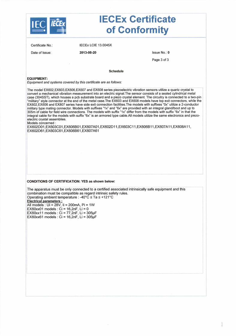
Max 4.
Certificate No
IECEx Certificate of Conformity
lECEx LCIE 13.0045X
Date of Issue 2013-08-20 Issue No.: 0
Page 3of3
Schedule
EQUIPMENT: Equipment and systems covered by this certificate are as follows:
The model EX602,EX603,EX606,EX607 and EX608 series piezoelectric vibration sensors utilize a quartz crystal to convert a mechanical vibration measurement into an electric signal.The sensor consists of a sealed cylindrical metal case (304SST), which houses a pcb substrate board and a piezo crystal element. The circuitry is connected to a two-pin "military" style connector at the end of the metal case.The EX603 and EX608 models have top exit connectors, while the EX602,EX606 and EX807 series have side exit connection facilities.The models with suffixes "Ox" utilize a 2-conductor military type mating connector. Models with suffixes "lx" and "6x" are provided with an integral gland/boot and up to 305m of cable for field wire connections. The models with suffix "lx" differ from the models with suffix "6x" in that the integral cable for the models with suffix "6x" is an armored type cable.All models utilize the same electronics and piezo-electric crystal assemblies. Models concerned EX602DO1 ,EX6O3COI ,EX6O6BO1 ,EX6O7AO1 ,EX6O2DI 1 ,EX6O3C1 1 ,EX6O6B1 1 ,EX6O7AI 1 ,EX6O8A1 1, EX602D61 ,EX603C61 ,EX606B61 ,EX607A61
CONDITIONS OF CERTIFICATION: YES as shown below:
The apparatus must be only connected to a certified associated intrinsically safe equipment and this combination must be compatible as regard intrinsic safety rules. Operating ambient temperature : -40°C :5 Ta 5 +121°C Electrical parameters: All models: Ui = 28V, Ii = 200mA, Pi = 1W EX60xx01 models: Ci = 16,2nF, Li = 0 EX60xx1 1 models: Ci = 77,2nF, Li = 305pF EX60xx61 models: Ci = 16,2nF, Li = 305pF

ATTESTATION D'EXAMEN LIE DE TYPE
L C I E EU TYPE EXAM/NA TION CER TIFICA TE
-
1 Version :03 LCIE 06 ATEX 6033 X Issue :03
Directive 2014/34/UE Directive 2014/34/EU 2 Appareil ou Système de Protection destine a être utilisé en Equipment or Protective System Intended for use in Potentially
Atmospheres Explosibles Explosive Atmospheres
3 Produit: Product: Capteurs de vibration Vibration sensors
Type: EX(XX)602yzzz/aaa, EX(XX)603yzzz1aaa, EX(XX)606yzzz/aaa, EX(XX)607yzzz/aaa, EX(XX)608yzzz/aaa
4 Fabricant: Manufacturer: PCB Piezotronics Inc.
A Adresse: Address: 3425 Walden Avenue
Depew, New York 14043 USA
6 Ce produit et ses variantes èventuelles acceptèes sont décrits This product any acceptable variation thereto is specified in the dans l'annexe de Ia présente attestation et dans les schedule to this certificate and the documents therein referred documents descriptifs cites en référence. to.
7 Le LCIE, Organisme Notiflé sous la référence 0081 LCIE, Notified Body number 0081 in accordance with article 17 conformément a 'article 17 de la directive 2014/34/UE du of the Directive 2014/34/EU of the European Parliament and Parlement europeen et du Conseil du 26 février 2014, certifie the Council of 26 February 2014 certifies that product has been que ce produit est conforme aux Exigences Essentielles de found to comply with the Essential Health and Safety Sécurité et de Sante pour la conception et la construction de Requirements relating to the design and construction of produits destinés a étre utilisés en atmospheres explosibles, products intended for use in potentially explosive atmospheres, données dans l'annexe II de la Directive, given in Annex 11to the Directive. Les résultats des verifications et essais figurent dans le(s) The examination and test results are recorded in confidential rapport(s) confidentiel(s) N : report(s) N:
60042416/542372, 95367-590025-02, 120351-640382, 141243-684381
8 Le respect des Exigences Essentielles de Sécurité et de Sante Compliance with the Essential Health and Safety est assure par la conformité a : Requirements has been assured by compliance with
EN 60079-0:2012 +A11:2013, EN 60079-11:2012
9 Le signe eXa lorsqu'il est place a la suite du numéro de If the sign "X" is placed after the certificate number, it indicates l'attestation, indique que cet appareil est soumis aux conditions that the product is subject to the Specific Conditions of Use particulières d'utilisation, mentionnées dans l'annexe de cette specified in the schedule to this certificate. attestation.
10 Cette Attestation d'Examen UE de Type concerne uniquement This EU Type Examination Certificate relates only to the design la conception et la construction du produit spécifié. and construction of the specified product. Des exigences supplémentaires de la directive sont applicables Further requirements of the Directive apply to the pour la fabrication et la fourniture du produit. Ces dernières ne manufacturing process and supply of this product. These are sont pas couvertes par la présente attestation, not covered by this certificate.
11 Le marquage du produit est mentionné dans l'annexe de cette The marking of the product is specified in the schedule to this attestation. certificate.
Fontenay-aux-Roses, le 27 mars 2017 Responsable de Certification
i..floItVIOIIfF c'i.:vrif..\I. flIS C rinsiIuLs t.I.Lcrgloti:s ,
rtification Officer Julien Guthiei
\'Sau CIplialdv4 5(5 Nat'-r,, I3.I1)v,, '4
/
I.922(oiO\tI'..\Y At. XRUSI,S
Seul le texte en françaia peut engager Ia responsabilite du LCIE. Ce document ne peut fltre reproduit que dans son intégralite, sans aucune modification. II eat établi en accord avec le référentiel de certification ATEX du LCIE. The LCIE's liability applies only on the French text. This document may only be reproduced in its entirety and without any change. It is issued in accordance with LCIE's A TEX Certification Rules. CERT-ATEX-FORM 04 Rev. 02 Page 1 of 4
LCIE .,3 Avenue du Géricirol Leck it:
unIrnt duo rduvlriu:, FloTt( men 92260 For ry- au -Rosrrs WWWLCIE.FR Ii:.' nocréle do Brronu VOrIIOO FRANCE
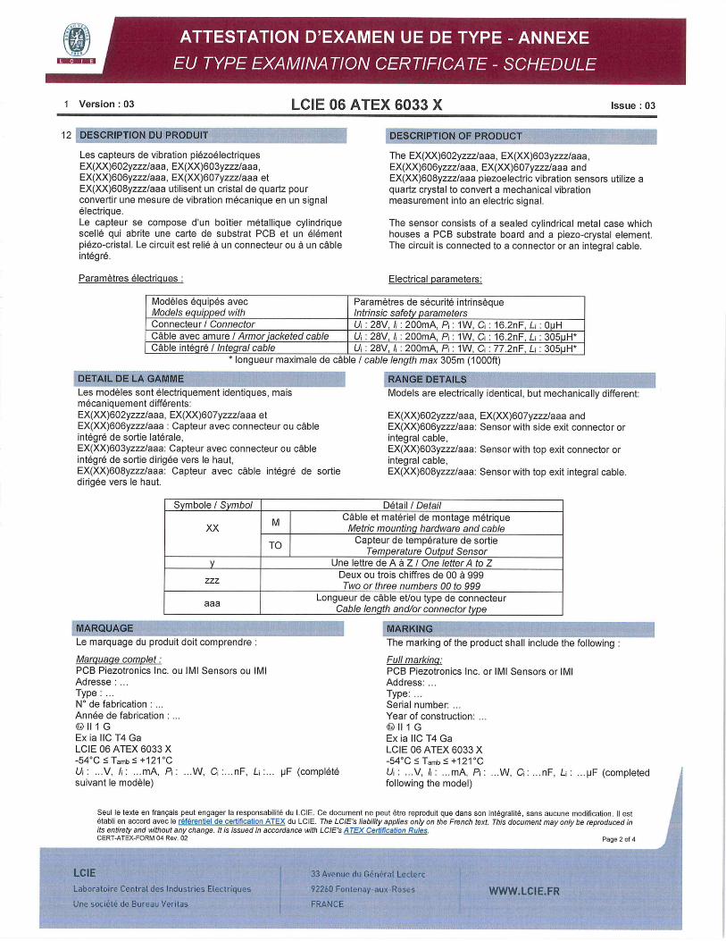
1 Version : 03 LCIE 06 ATEX 6033 X Issue : 03
12 DESCRIPTION DU PRODUIT DESCRIPTION OF PRODUCT
Les capteurs de vibration piezoelectriques EX(XX)602yzzz1aaa, EX(XX)603yzzz/aaa, EX(XX)606yzzz1aaa, EX(XX)607yzzz/aaa et EX(XX)608yzzz1aaa utilisent un cristal de quartz pour convertir une mesure de vibration mecanique en un signal electrique. Le capteur se compose dun boItier metailique cylindrique scellé qui abrite une carte de substrat PCB et un élément piézo-cristal. Le circuit est relié a un connecteur ou a un cable integre.
Paramètres électrigues
The EX(XX)602yzzz1aaa, EX(XX)603yzzz1aaa, EX(XX)606yzzz1aaa, EX(XX)607yzzz/aaa and EX(XX)608yzzz/aaa piezoelectric vibration sensors utilize a quartz crystal to convert a mechanical vibration measurement into an electric signal.
The sensor consists of a sealed cylindrical metal case which houses a PCB substrate board and a piezo-crystal element. The circuit is connected to a connector or an integral cable.
Electrical parameters:
Modéles équipés avec Models equipped with
Faramètres de sécurité intrinseque Intrinsic safety parameters
Connecteur/ Connector U : 28V, l : 200mA, P:1W, C: 16.2nF, Lr: OpH Cable avec amure I Armor jacketed cable U : 28V, I : 200mA, P: 1W, 0: 16.2nF, L: 3051jH* Cable intégré I Integral cable I U : 28V, I : 200mA, Pi : 1W, Q : 77.2nF, L: 305pH*
iongueur maximale Ce cable / cable length max 30bm (1 UUUtt)
DETAIL DE LA GAMME RANGE DETAILS Les modéles sont electriquement identiques, mais Models are electrically identical, but mechanically different: mecaniquement différents: EX(XX)602yzzz/aaa, EX(XX)607yzzz/aaa et EX(XX)602yzzzlaaa, EX(XX)607yzzz/aaa and EX(XX)606yzzz1aaa: Capteur avec connecteur ou cable EX(XX)606yzzzlaaa: Sensor with side exit connector or integre de sortie latérale, integral cable, EX(XX)603yzzzlaaa: Capteur avec connecteur ou cable EX(XX)603yzzz1aaa: Sensor with top exit connector or integre de sortie dirigee vers le haut, integral cable, EX(XX)608yzzzlaaa: Capteur avec cable integre de sortie EX(XX)608yzzzlaaa: Sensor with top exit integral cable. dirigee vers le haut.
Sym bole I Symbol Detail / Detail
M Cable et materiel de montage metrique XX Metric mounting hardware and cable
TO Capteur de temperature de sortie
Temperature Output Sensor Une lettre de A a Z I One letter to Z
Deux ou trois chiffres de 00 a 999 zzz Two or three numbers 00 to 999
Longueur de cable et/ou type de connecteur aaa Cable length and/or connector type
MARQUAGE
Le marquage du produit doit comprendre
Marguaqe complet: PCB Piezotronics Inc. ou IMI Sensors ou IMI Adresse: Type: No de fabrication Année de fabrication
Ill G Ex ia tic 14 Ga LCIE 06 ATEX 6033 X -540C :5 Tamb :5 +121 -C U . ... V, Ii: mA, P . ...W, C:...nF, Li:... pF (complete suivant le modéle)
MARKING The marking of the product shall include the following
Full marking: PCB Piezotronics Inc. or IMI Sensors or IMI Address: Type: Serial number: Year of construction:
II 1 G Ex ia IiC T4 Ga LCIE 06 ATEX 6033 X -540 C:5 Iamb :5 +121CC U: ...V, I: mA, Pi W, C: ... nF, L: ... pF (completed following the model)
Seul le texte en français peut engager la responsabilite du LCIE. Ce document ne peut être reproduit que dans son integralite, sans aucune modification. II est établi en accord avec le référentiel de certification ATEX du LCIE. The LCIE's liability applies only on the French text. This document may only be reproduced in its entirety and without any change. Ills issued in accordance with LCIE's ATEX Certification Rules. CERT-ATEX-FORM 04 Rev. 02 Page 2 of 4
I
LCIE I 33 Avenue du 06n6ra1 Leclerc
Laboratoire Central des Industries Electriques 92260 Fontenoyaux Roses WWWLCIEFR Une société do Bureau Verit.ss FRANCE
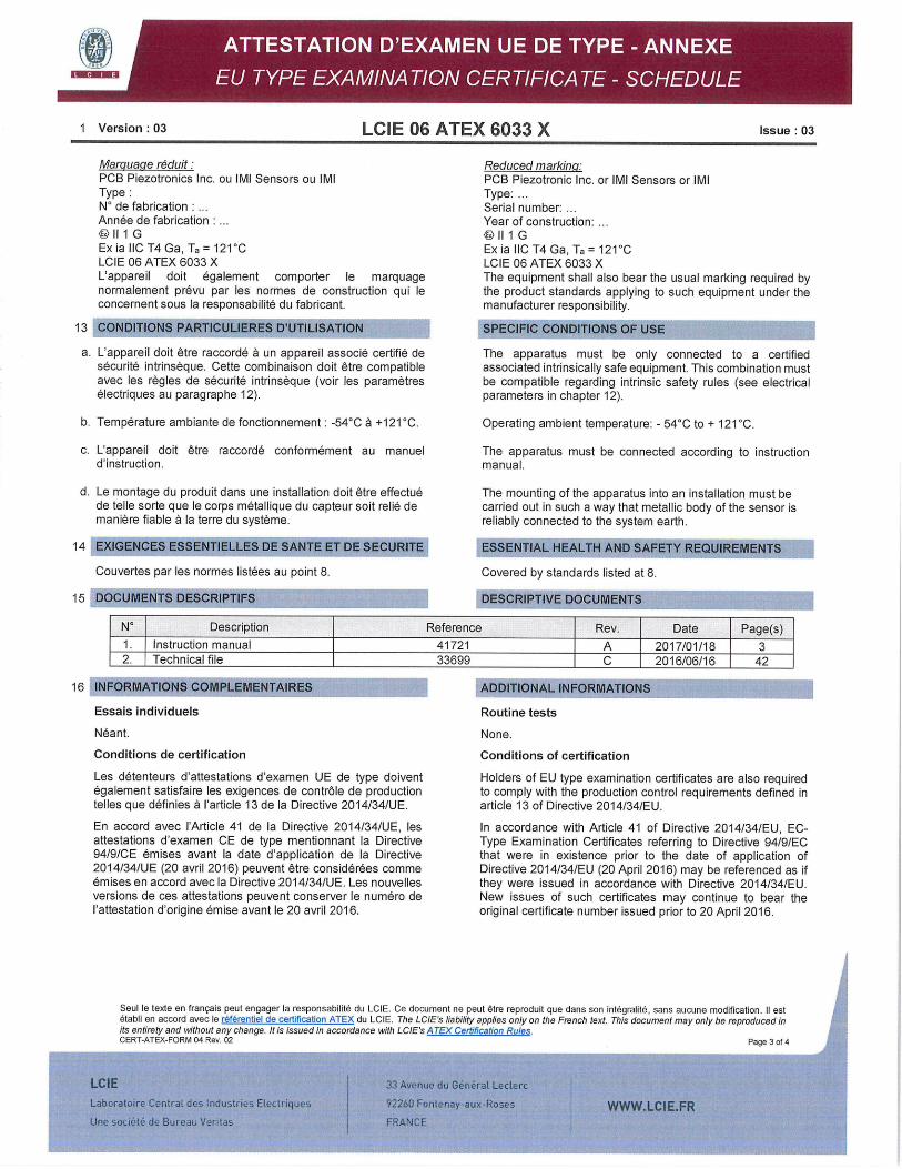
1 Version : 03 LCIE 06 ATEX 6033 X -
Issue : 03
Marguaqe réduit: PCB Piezotronics Inc. ou IMI Sensors ou IMI Type: N de fabrication An née de fabrication
Ill G Ex ia IIC T4 Ga, Ta = 121CC LCIE 06 ATEX 6033 X L'appareil doit également comporter le marquage normalement prévu par les normes de construction qui le concernent sous la responsabilité du fabricant.
13 CONDITIONS PARTICULIERES DUTILISATION
a. L'appareil doit être raccordé a un appareil associé certifié de sécurité intrinseque. Cette combinaison doit étre compatible avec les regles de sécurité intrinséque (voir les paramétres électriques au paragraphe 12).
b. Temperature ambiante de fonctionnement: -540 C a +121'C.
c. L'appareil dolt étre raccordé conformément au manuel d'instruction.
d. Le montage du produit dans une installation doit étre effectué de telle sorte que le corps métallique du capteur soit relié de manière fiable a la terre du système.
14 EXIGENCES ESSENTIELLES DE SANTE El DE SECURITE
Couvertes par les normes listées au point 8.
15 DOCUMENTS DESCRIPTIFS
Reduced marking: PCB Piezotronic Inc. or IMI Sensors or IMI Type: Serial number: Year of construction:
II 1 G Ex Ia 110 T4 Ga, Ta = 121CC LCIE 06 ATEX 6033 X The equipment shall also bear the usual marking required by the product standards applying to such equipment under the manufacturer responsibility.
SPECIFIC CONDITIONS OF USE
The apparatus must be only connected to a certified associated intrinsically safe equipment. This combination must be compatible regarding intrinsic safety rules (see electrical parameters in chapter 12).
Operating ambient temperature: - 540 C to + 121 CC.
The apparatus must be connected according to instruction manual.
The mounting of the apparatus into an installation must be carried out in such a way that metallic body of the sensor is reliably connected to the system earth.
ESSENTIAL HEALTH AND SAFETY REQUIREMENTS
Covered by standards listed at 8.
DESCRIPTIVE DOCUMENTS
No Description Reference Rev. Date Page(s) 1. Instruction manual 41721 A 2017/01/18 3 2. Technical file 33699 C 2016/06/16 42
16 INFORMATIONS COMPLEMENTAIRES
Essais individuels
Néant.
Conditions de certification
Les détenteurs d'attestations d'examen UE de type doivent également satisfaire les exigences de contrOle de production telles que définies a l'article 13 de la Directive 2014/34/UE.
En accord avec 'Article 41 de la Directive 2014/34/UE, les attestations d'examen CE de type mentionnant Ia Directive 94/9/CE émises avant Ia date d'application de la Directive 2014/34/UE (20 avril 2016) peuvent ètre considérées comme émises en accord avec la Directive 2014/34/UE. Les nouvelles versions de ces attestations peuvent conserver le numéro de 'attestation d'origine émise avant le 20 avril 2016.
ADDITIONAL INFORMATIONS
Routine tests
None.
Conditions of certification
Holders of EU type examination certificates are also required to comply with the production control requirements defined in article 13 of Directive 2014/34/EU.
In accordance with Article 41 of Directive 2014/34/EU, EC-Type Examination Certificates referring to Directive 94/9/EC that were in existence prior to the date of application of Directive 2014/34/EU (20 April 2016) may be referenced as if they were issued in accordance with Directive 2014/34/EU. New issues of such certificates may continue to bear the original certificate number issued prior to 20 April 2016.
Seul le texte en français peut engager la responsabilité do LCIE. Ce document ne peut être reproduit que dans son integralite, sans aucune modification. II est étabti en accord avec le référentiel de certification ATEX du LCIE. The LCIE's liability applies only on the French text. This document may only be reproduced in its entirety and without any change. It is issued in accordance with LClE's ATEX Certification Rules. CERT-ATEX-FORM 04 Rev. 02 Page 3 of 4
LCIE 33 Avenue du GOnérat Lecterc
Laboratofre Central des Industries Electriques i 92260 Fonienay-aux-Rose's WWWLCIEFR Une soclété de Bureau Veritas FRANCE
1 Version : 03 LCIE 06 ATEX 6033 X Issue : 03
17 DETAILS DES MODIFICATIONS DETAILS OF CHANGES
Version 00: Evaluation initiale selon les normes Issue 00: Initial assessment according to EN 50014:1997 22/05/2006 EN 50014:1997 + amendement 1 a 2 et 2006/05/22 + amendments 1 to 2 and EN 50020:2002
EN 50020:2002. standards.
Version 01 : Mise a jour normative selon les normes Issue 01: Normative update according to 04/05/2010 EN 60079-0:2006 et EN 60079-11:2007. 2010/05/04 EN 60079-0:2006 and EN 60079-11:2007
standards.
Version 02 : - Mise a jour normative selon les normes Issue 02: - Normative update according to 20/08/2015 EN 60079-0:2012 et EN 60079-11:2012. 2015/08/20 EN 60079-0:2012 and EN 60079-11:2012
standards. - Mise a jour des documents techniques. - Update of technical documents.
Version 03 : - Ajout d'une nouvelle option de sortie de Issue 03: - Addition of a new option of temperature output. temperature.
- Mise a jour de la nomenclature des modèles. - Update of the nomenclature of the models. - Distinction entre le nom du fabricant (PCB - Distinction between the name of the
PiezotronicsInc) et le nom de la marque manufacturer (PCB Piezotronics Inc) and the commerciale (IMI sensors ou IMI). name of the trademark (IMI sensors or IMI).
- Mise a jour normative selon Pa norme - Normative update according to EN 60079-0:2012 + Al 1:2013. EN 60079-0:2012 + Al 1:2013 standard.
- Changement de temperature ambiante basse - Change of the low temperature ambient from de -400C a -540 C. -40CC to -54"C.
Seui le texte en français peut engager la responsabiiitO du LCIE. Ce document ne peut être reproduit que dans son intégrahté, sans aucune modification. H est btabh en accord avec le référentiei de certification ATEX du LCIE. The LCIE's liability applies only on the French text. This document may only be reproduced in its entirety and without any change. It is issued in accordance with LCIE's A TEX Certification Rules. CERT-ATEX-FORM 04 Rev. 02 Page 4 of 4
LCIE 33 Avcnuo du Gent-rat Leclerc
Laborotoire Contra', des Industries Electriques 92260 Fonienoy-aux-Roses WWW.LCIEFR Une société do Bureau Veritas FRANCE
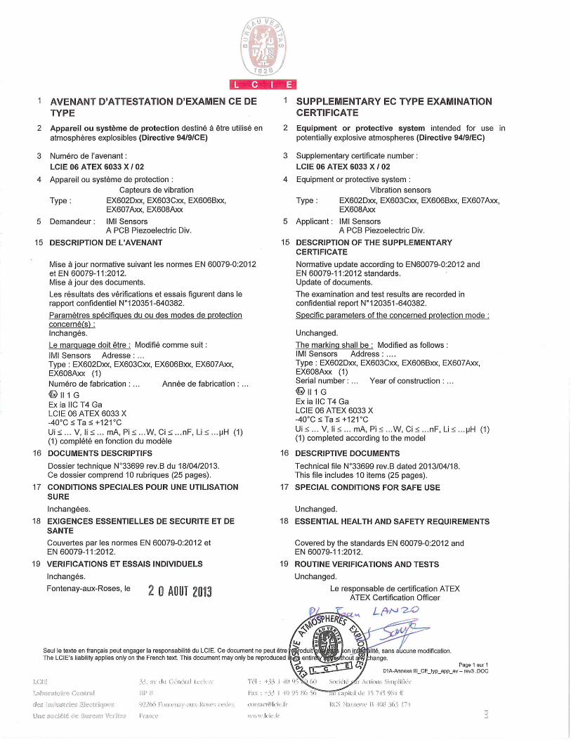
/,41
--
1 AVENANT D'ATTESTATION D'EXAMEN CE DE TYPE
2 Appareil ou système de protection destine a ëtre utilisé en atmospheres explosibles (Directive 9419/CE)
3 Numéro de 'avenant:
LCIE 06 ATEX 6033 X I 02
4 Appareil ou système de protection
Capteurs de vibration
Type: EX602Dxx, EX603Cxx, EX606Bxx, EX607Axx, EX608Axx
5 Demandeur: IMI Sensors A PCB Piezoelectric Div.
15 DESCRIPTION DE L'AVENANT
Mise a jour normative suivant les normes EN 60079-0:2012 et EN 60079-11:2012. Mise a jour des documents.
Les résultats des verifications et essais figurent dans le rapport confidentiel N°120351-640382.
Paramètres spécifigues du ou des modes de protection concerné(s): Inchanges.
Le marguage doit être: Modiflé comme suit:
Ml Sensors Adresse: Type: EX602Dxx, EX603Cxx, EX606Bxx, EX607Axx, EX608Axx (1) Numéro de fabrication: ... Année de fabrication:
111 G Ex ia 11C T4 Ga LCIE 06 ATEX 6033 X -40°C :5 Ta :5 +121°C Ui :!~ ... V, Ii ... mA, Pi !~ ...W, Ci :!~ . . .nF, Li :!~ ... pH (1) (1) complété en fonction du modèle
16 DOCUMENTS DESCRIPTIFS
Dossier technique N°33699 rev.B du 18/04/2013. Ce dossier comprend 10 rubriques (25 pages).
17 CONDITIONS SPECIALES POUR LINE UTILISATION SURE
lnchangees.
18 EXIGENCES ESSENTIELLES DE SECURITE ET DE SANTE
Couvertes par les normes EN 60079-0:2012 et EN 60079-11:2012.
19 VERIFICATIONS ET ESSAIS INDIVIDUELS
lnchangés.
Fontenay-aux-Roses, le 20 AOUT 2013
I SUPPLEMENTARY EC TYPE EXAMINATION CERTIFICATE
2 Equipment or protective system intended for use in potentially explosive atmospheres (Directive 94/9/EC)
3 Supplementary certificate number:
LCIE 06 ATEX 6033 X /02
4 Equipment or protective system:
Vibration sensors
Type: EX602Dxx, EX603Cxx, EX606Bxx, EX607Axx, EX608Axx
5 Applicant: IMI Sensors A PCB Piezoelectric Div.
15 DESCRIPTION OF THE SUPPLEMENTARY CERTIFICATE
Normative update according to EN60079-0:2012 and EN 60079-11:2012 standards. Update of documents.
The examination and test results are recorded in confidential report N°120351-640382.
Specific parameters of the concerned protection mode
Unchanged.
The marking shall be: Modified as follows IMI Sensors Address ..... Type: EX602Dxx, EX603Cxx, EX606Bxx, EX607Axx, EX608Axx (1) Serial number: ... Year of construction
Il 1 G ExiallCT4Ga LCIE 06 ATEX 6033 X -40°C < Ta :5 +121°C Ui:!~ ... V,li:!~ ... mA,Pi:!~ ... W,Ci:!~ ... nF,Li:~ ... pH (1) (1) completed according to the model
16 DESCRIPTIVE DOCUMENTS
Technical file N°33699 rev.B dated 2013/04/18. This file includes 10 items (25 pages).
17 SPECIAL CONDITIONS FOR SAFE USE
Unchanged.
18 ESSENTIAL HEALTH AND SAFETY REQUIREMENTS
Covered by the standards EN 60079-0:2012 and EN 60079-11:2012.
19 ROUTINE VERIFICATIONS AND TESTS
Unchanged.
Le responsable de certification ATEX ATEX Certification Officer
u yE4
Seul le texte en francais peut engager Ia responsabilite du LCIE. Ce document ne peut étre oduit on lité, sans acune modification. The LCIE's liability applies only on the French text. This document may only be reproduced i centir hout hange.
Page 1 sur I
ii II I
oi-Annexe 111 —rev3 DO
ictjita]dc l
des seusirses 1ecreke::.: )?s Iin;-;isRoe; sI o5I:I(15Icjr.I1 Ii sIriftri. Ii i( (3 Li
Une déI e ' li.ince
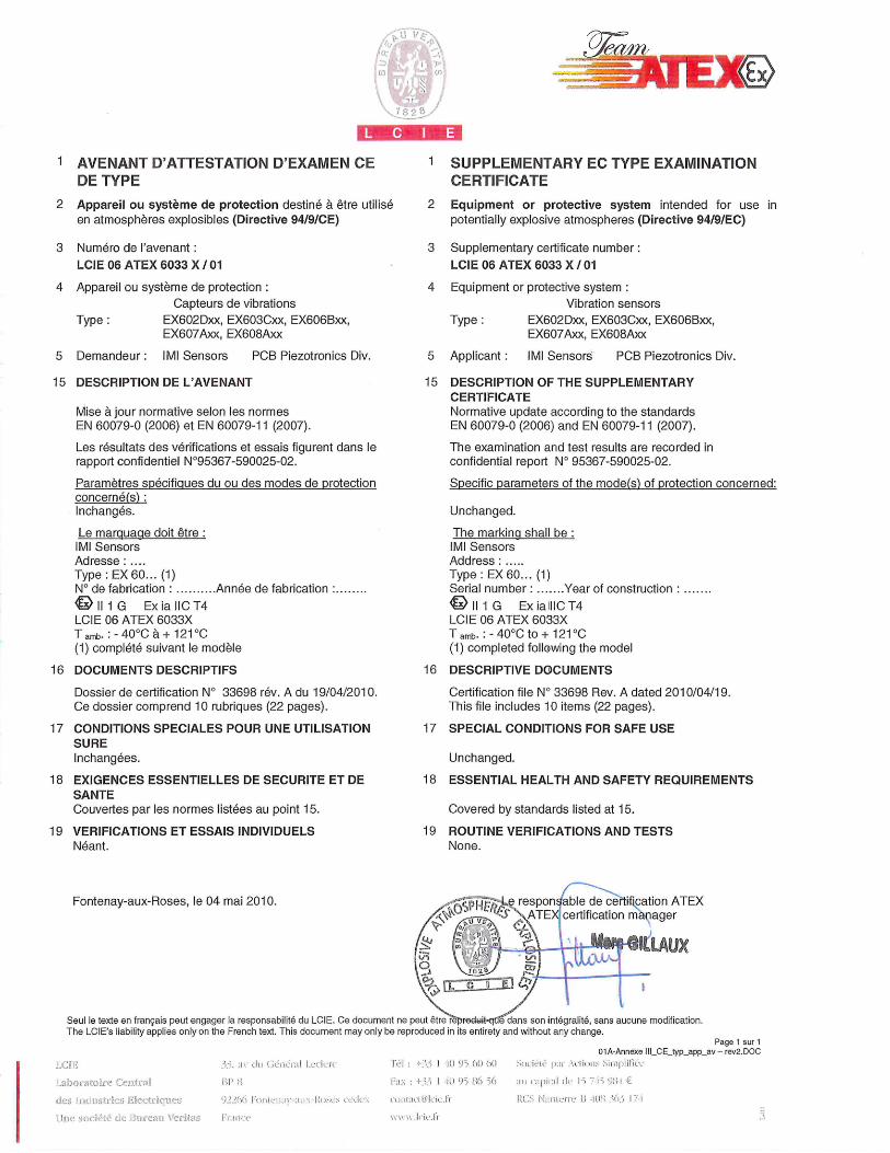
1 AVE NANT D'ATTESTATION D'EXAMEN CE DE TYPE
2 Appareil ou système de protection destine a être utiUsé en atmospheres explosibles (Directive 94/9/CE)
3 Numéro de l'avenant:
LCIE 06 ATEX 6033 X / 01
4 Appareil ou système de protection: Capteurs de vibrations
Type: EX602Dxx, EX603Cxx, EX606Bxx, EX607Axx, EX608Axx
5 Demandeur: IMI Sensors PCB Piezotronics Div.
15 DESCRIPTION DE L'AVENANT
Mise a jour normative selon les normes EN 60079-0 (2006) et EN 60079-11(2007).
Les résultats des verifications et essais figurent Clans le rapport confidentiel N°95367-590025-02.
Paramètres spécificues du ou des modes de protection concerné(s) Inchangés.
Le marouace doit être: Ml Sensors Adresse ..... Type: EX 60... (1) N° de fabrication . .......... Année de fabrication
111G ExiallCT4 LCIE 06 ATEX 6033X Iamb. :-40°Cà+121°C (1) complété suivant le modèle
16 DOCUMENTS DESCRIPTJFS
Dossier de certification N° 33698 rev. A du 19/04/2010. Ce dossier comprend 10 rubriques (22 pages).
17 CONDITIONS SPECIALES POUR UNE UTILISATION SURE lnchangees.
18 EXIGENCES ESSENTIELLES DE SECURITE ET DE SANTE Couvertes par les normes listées au point 15.
19 VERIFICATIONS ET ESSAIS INDIVIDUELS Want.
Fontenay-aux-Roses, le 04 mai 2010.
1 SUPPLEMENTARY EC TYPE EXAMINATION CERTIFICATE
2 Equipment or protective system intended for use in potentially explosive atmospheres (Directive 94/9/EC)
3 Supplementary certificate number:
LCIE 06 ATEX 6033 X / 01
4 Equipment or protective system Vibration sensors
Type: EX602Dxx, EX603Cxx, EX606Bxx, EX607Axx, EX608Axx
5 Applicant: IMI Sensors PCB Piezotronics Div.
15 DESCRIPTION OF THE SUPPLEMENTARY CERTIFICATE Normative update according to the standards EN 60079-0 (2006) and EN 60079-11(2007).
The examination and test results are recorded in confidential report N° 95367-590025-02.
Specific parameters of the mode(s) of protection concerned:
Unchanged.
The marking shall be: IMI Sensors Address ...... Type: EX 60... (1) Serial number: .......Year of construction
111G ExialllCT4 LCIE 06 ATEX 6033X Tamb. : -40°Cto+ 121°C (1) completed following the model
16 DESCRIPTIVE DOCUMENTS
Certification file N° 33698 Rev. A dated 2010/04/19. This file includes 10 items (22 pages).
17 SPECIAL CONDITIONS FOR SAFE USE
Unchanged.
18 ESSENTIAL HEALTH AND SAFETY REQUIREMENTS
Covered by standards listed at 15.
19 ROUTINE VERIFICATIONS AND TESTS None.
}I ;.L responable de certification ATEX —ATEX certification manager
I -- LLAUX
i
3EL I
Seul Is texte en français peut engager la responsabilité du LclE, ce document ne peut être 'rpreduit-eri dans son iint6gralit6, sans aucune modification. The LclE's liability applies only on the French text. This document may only be reproduced in its entirety and without any change.
Page 1 sur 1 01A-Annexe III_CE_typ_app..av - rev2.DOC
'H h (() (H iJC 'I i I Hi
H2if)O!((C Ii F:. I -1(1 HF HG 56 u lipid ft Im F €
•r(H(;r -,(5t11H(3 ItLicutFicines 9-) )()0 liritu: -: -lftu,u :1_ft: coI;tI€hl ..i HC( ill': H -(F Ft
J(:H :IHc1HLH u ..tiL'HiH \u: li:i riuc vi vN, lcii.hr
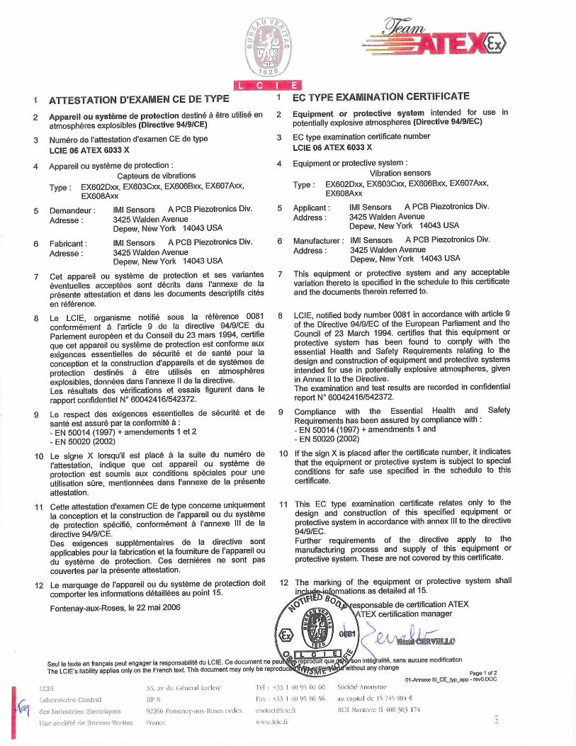
EX
I-i I ATTESTATION DEXAMEN CE DE TYPE I EC TYPE EXAMINATION CERTIFICATE
2 Appareil ou système de protection destine a être utilisé en atmospheres explosibles (Directive 94/9/CE)
3 Numéro de l'attestation d'examen CE de type LCIE 06 ATEX 6033 X
4 Appareil ou système de protection: Capteurs de vibrations
Type: EX602Dxx, EX603Cxx, EX606Bxx, EX607Axx, EX608Axx
5 Demandeur: IMI Sensors A PCB Piezotronics Div Adresse: 3425 Walden Avenue
Depew, New York 14043 USA
6 Fabricant IMI Sensors A PCB Piezotronics Div Adresse: 3425 Walden Avenue
Depew, New York 14043 USA
Cet appareil ou système de protection et ses variantes éventuelles acceptèes sont décrits dans l'annexe de la présente attestation et dans les documents descriptifs cites en référence.
Le LCIE, organisme notifié sous la référence 0081 conformément a l'article 9 de la directive 94/9/CE du Parlement européen et du Conseil du 23 mars 1994, certifie que cet appareil ou système de protection est conforme aux exigences essentielles de sécurité et de sante pour la conception et la construction d'appareils et de systèmes de protection destinés a ètre utilisés en atmospheres explosibles, données dans l'annexe II de Ia directive. Les résultats des verifications et essais flgurent dans le rapport confidentiel N° 60042416/542372.
Le respect des exigences essentielles de sécurité et de sante est assure par la conformité a: - EN 50014 (1997) + amendements I et 2 - EN 50020 (2002)
Le signe X lorsqu'il est place a la suite du numéro de attestation, indique que cet appareil ou système de
protection est soumis aux conditions spéciales pour une utilisation sUre, mentionnées dans l'annexe de la présente attestation.
11 Cette attestation d'examen CE de type concerne uniquement a conception et Ia construction de l'appareil ou du système de protection spécifié, conformément a l'annexe III de la directive 94/9/CE. Des exigences supplémentaires de la directive sont applicables pour la fabrication et la fourniture de I'appareil ou du système de protection. Ces dernières ne sont pas couvertes par la présente attestation.
12 Le marquage de l'appareil ou du système de protection doit comporter les informations détaillées au point 15.
Fontenay-aux-Roses, le 22 mal 2006
Seul le texte en francais peut engager la responsabilité du LCIE. ce document ne The LCIE's liability applies only on the French text. This document may only be re
2 Equipment or protective system intended for use in potentially explosive atmospheres (Directive 94/9/EC)
3 EC type examination certificate number LCIE 06 ATEX 6033 X
4 Equipment or protective system: Vibration sensors
Type: EX602Dxx, EX603Cxx, EX606Bxx, EX607Axx, EX608Axx
5 Applicant: IMI Sensors A PCB Piezotronics Div. Address: 3425 Walden Avenue
Depew, New York 14043 USA
6 Manufacturer: IMI Sensors A PCB Piezotronics Div. Address: 3425 Walden Avenue
Depew, New York 14043 USA
7 This equipment or protective system and any acceptable variation thereto is specified in the schedule to this certificate and the documents therein referred to.
8 LCIE, notified body number 0081 in accordance with article 9 of the Directive 94/9/EC of the European Parliament and the Council of 23 March 1994. certifies that this equipment or protective system has been found to comply with the essential Health and Safety Requirements relating to the design and construction of equipment and protective systems intended for use in potentially explosive atmospheres, given in Annex II to the Directive. The examination and test results are recorded in confidential report N° 60042416/542372.
9 Compliance with the Essential Health and Safety Requirements has been assured by compliance with: - EN 50014 (1997) + amendments I and - EN 50020 (2002)
10 If the sign Xis placed after the certificate number, it indicates that the equipment or protective system is subject to special conditions for safe use specified in the schedule to this certificate.
11 This EC type examination certificate relates only to the design and construction of this specified equipment or protective system in accordance with annex Ill to the directive 94/9/EC. Further requirements of the directive apply to the manufacturing process and supply of this equipment or protective system. These are not covered by this certificate.
12 The marking of the equipment or protective system shall indi&formations as detailed at 15.
O ') BO esponsable de certification ATEX \ATEX certification manager
06 02
o F-t -QIIJ que son inté sans aucune modification u repro ui 't
duc without any change page 1 of 2
01-Annexe Hl_CE_typ_app - revO.DOC
7
8
pe
10
I,(, i.aholatofie Ccntrafl
5es 1uitries i51ec.:i
Uiie oc151é 3111eai \r11i
3$. du i40110111 LuHuic '16! : $$ 1 -ill 65 60 61
0 f-1t:' : +3 1 0) 95 156 56
62260 17 ui v-LuN-Il,uscs cuckN cunu'u6ticft.fi'
\\ \VU'. Ici.!i
Ouciulu Aiiunvnie
LU cLpi)al de 15 7 iS 915-1 €
RCS Naului'i'c 11 408 363 IT!
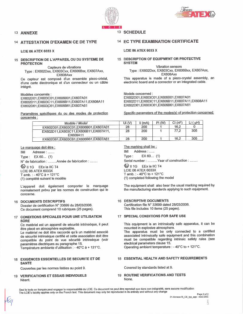
0
13 ANNEXE 13 SCHEDULE
14 ATTESTATION D'EXAMEN CE DE TYPE 14 EC TYPE EXAMINATION CERTIFICATE
LCIE 06 ATEX 6033 X LCIE 06 ATEX 6033 X
15 DESCRIPTION DE L'APPAREIL OU DU SYSTEME DE 15 DESCRIPTION OF EQUIPMENT OR PROTECTIVE PROTECTION SYSTEM
Capteurs de vibrations Vibration sensors Type: EX602Dxx, EX603Cxx, EX606Bxx, EX607Axx, Type: EX602Dxx, EX603Cxx, EX606Bxx, EX607Axx,
EX608Axx EX608Axx Ce capteur est compose d'un ensemble piezo-cristal, This apparatus is made of a piezo-crystal assembly, an
d'une carte électronique et dun connecteur ou un cable electronic board and a connector or an integrated cable.
intégré.
Modèles concernés: EX602DOI ,EX603C01 ,EX606B01 ,EX607A01 EX602DI 1 ,EX60301 1 ,EX6O6BI I ,EX6O7A1 I ,EX608A1 I EX602D61 ,EX6o3.ç61 ,EX606B61 ,EX607A61
Paramètres spécifigues du ou des modes de protection concernés:
Models concerned: EX602DO1 ,EX6O3COI ,EX606B01 ,EX6O7AOI EX602D1 1 ,EX6O3CI I ,EX6O6BI 1,EX607AI I ,EX6O8AI I EX602D61 ,EX603C61 ,EX606B61 ,EX607A61
Specific parameters of the modes(s) of protection concerned:
Modèle I Model UI (V) Ii (mA) Pi (W) Ci (nF) Li (pH)
EX602D01,EX603C01,EX606B01,EX607A01 28 200 1 16,2 0
I EX602DI1,EX603C11,EX606B11,EX607A11, EX608A11
28 200 1 77,2 305
EX602D61 ,EX603C61,EX606B61,EX607A61 28 200 1 16,2 305
Le marauacie dolt être:
Ml Adresse .....
Type: EX 60... (1)
N° de fabrication . ........ Année de fabrication ........
111G EExiallCT4 LCIE 06 ATEX 6033X Tamb. : - 40°C a + 121°C (1) complété suivant le modèle
L'appareil dolt égalernent comporter le marquage normalement prevu par les normes de construction qui le concerne.
16 DOCUMENTS DESCRIPTIFS Dossier de certification N° 33699 du 28/03/2006. Ce document comprend 10 rubriques (25 pages).
17 CONDITIONS SPECIALES POUR UNE UTILISATION SURE Ce materiel est un appareil de sécurité intrinsèque, ii peut être place en atmosphere explosible. Le materiel ne dolt être raccordé qu'à un materiel associO de sOcurité intrinsèque certiflé et cette association doit ëtre compatible du point de vue sécurité intrinsèque (voir paramètres électriques au paragraphe 15. Temperature ambiante d'utilisation : - 40°C a + 121°C.
18 EXIGENCES ESSENTIELLES DE SECURITE ET DE SANTE
Couvertes par les normes listées au point 9.
19 VERIFICATIONS ET ESSAIS INDIVIDUELS Want.
The marking shall be
Ml Address ......
Type: EX6O... (1)
Serial number: ......... Year of construction
111G EExiallCT4 LCIE 06 ATEX 6033X T amb. : - 40°C to + 121°C (I) completed following the model
The equipment shall also bear the usual marking required by the manufacturing standards applying to such equipment.
16 DESCRIPTIVE DOCUMENTS Certification file N° 33699 dated 28/03/2006. This file includes 10 items (25 pages).
17 SPECIAL CONDITIONS FOR SAFE USE
This equipment is an intrinsically safe apparatus, it can be mounted in explosive atmosphere. The apparatus must be only connected to a certified associated intrinsically safe equipment and this combination must be compatible regarding intrinsic safety rules (see electrical parameters clause 15. Operating ambient temperature : - 40°C to + 121°C.
18 ESSENTIAL HEALTH AND SAFETY REQUIREMENTS
Covered by standards listed at 9.
19 ROUTINE VERIFICATIONS AND TESTS None.
Seul Is texte en francais peut engager la responsabilité du LCIE. Ce document ne peut étre reproduit que dans son intégralité, sans aucune modification The LCIE's liability applies only on the French text. This document may only be reproduced in its entirety and without any change
Page 2 of 2 01 -Annexe lil_CE_typ_app . revO.00fJ

PS060 REV. K 07/02/2021
EU Declaration of Conformity PS060 In Accordance with ISO/IEC 17050
Manufacturer: PCB Piezotronics, Inc. 3425 Walden Avenue Depew, New York 14043 USA
Authorized PCB Piezotronics Europe GmbH European Porschestrasse 20-30 Representative: 41836 Hückelhoven,Germany
Certifies that type of equipment: ICP® Industrial Sensor(s)
Whose Product Models Include: EX602Dxx, EX603Cxx, EX606Bxx, EX607Axx, EX608Axx Series
Note: “xx” is a place holder for two numbers. For example: EX602D01Industrial Vibration Sensor
These letters and numbers are included in the model numbers of the series. For details see the related data sheets.
This declaration is applicable to all Sensor(s) of the above series which have the CE & (EX) ATEX mark on their data sheets and where those data sheets refer to this declaration of conformity. The data sheets for all model numbers referenced above, which include the CE & (EX) ATEX mark on such data sheets and refer to this Declaration of Conformity are hereby incorporated by reference into this Declaration.
Conform to the following EU Directive(s) when installed per product documentation:
2014/30/EU 2014/34/EU 2011/65/EU w/2015/863/EU
EMC Directive ATEX Directive RoHS Directive
Standards to which Conformity is Declared:
Harmonized Standards EN 61326-1:2013 EN 61326-2-3: 2013 EN 61010-1:2010 EN 60079-0 :2012+ A11:2013 EN 60079-11 2012 EN 63000:2018
Electrical Equipment for Measurement, Control and Laboratory Use- EMC Electrical Equipment for Measurement, Control and Laboratory Use- EMC Safety Requirements for Electrical Equipment for Measurement, Control, and Laboratory Use - Part 1: General Requirements General Explosive Atmosphere Intrinsic safe, i Technical documentation for the assessment of electrical and electronic
products with respect to the restriction of hazardous substances
Emissions Test Standards
EN 55011:2009+ A1:2010
Industrial, scientific and medical (ISM) radio frequency equipment-Electromagnetic disturbance characteristics- Limits and methods of Measurement Class B
Other Standards Applied (non-OJEU)
Immunity Test Standards
EN 61000-4-2:2001 EN 61000-4-3:2006 EN 61000-4-4:2004 EN 61000-4-5:2005 EN 61000-4-6:2006 EN 61000-4-8:2001
Electrostatic discharge (ESD) Radiated, radio-frequency, electromagnetic field immunity Electrical fast transient (EFT) / Burst immunity Surge immunity Immunity to RF conducted line disturbances Power frequency magnetic field immunity
Test Reports EMC Reports Safety Reports
GM29028c, GM29030c, GM29032c, GM29045c GM29029s, GM29031s, GM29033s, GM29046s
EC Type Examination ATEX Certification
LCIE 06 ATEX 6033 X Ex ia IIC T4 Ga, II 1 G
Voluntary Certification Voluntary Type Examination Certificate
LCIE 06 ATEX 6032 X Ex nA IC T4 Gc, II 3 G
Other International
Certifications
IECEx Certification IECEx LCIE 13.0045 X Ex ia IIC T4 Ga Ex nA IICT4 Gc
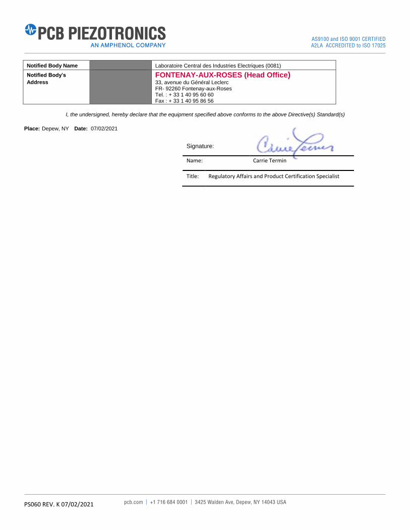
PS060 REV. K 07/02/2021
Notified Body Name Laboratoire Central des Industries Electriques (0081)
Notified Body’s
Address
FONTENAY-AUX-ROSES (Head Office)
33, avenue du Général Leclerc FR- 92260 Fontenay-aux-Roses Tel. : + 33 1 40 95 60 60 Fax : + 33 1 40 95 86 56
I, the undersigned, hereby declare that the equipment specified above conforms to the above Directive(s) Standard(s)
Place: Depew, NY Date: 07/02/2021
Signature:
Name: Carrie Termin
Title: Regulatory Affairs and Product Certification Specialist
Copyright © 2022 FDOKUMEN