Extending component-based design with hardware components
20
? ?
Transcript of Extending component-based design with hardware components

Extending component-based design with
hardware components ?
Péter Arató, Zoltán Ádám Mann, András Orbán
Budapest University of Technology and Economics
Department of Control Engineering and Information Technology
H-1117 Budapest, Magyar tudósok körútja 2, Hungary
Phone: +36 14632487, Fax: +36 14632204
Abstract
In order to cope with the increasing complexity of system design, component-basedsoftware engineering advocates the reuse and adaptation of existing software com-ponents. However, many applications � particularly embedded systems � consist ofnot only software, but also hardware components. Thus, component-based designshould be extended to systems with both hardware and software components.
Such an extension is not without challenges though. The extended methodologyhas to consider hard constraints on performance as well as di�erent cost factors.Also, the dissimilarities between hardware and software (such as level of abstraction,communication primitives etc.) have to be resolved.
In this paper, the authors propose such an extended component-based designmethodology to include hardware components as well. This methodology allowsthe designer to work at a very high level of abstraction, where the focus is onfunctionality only. Non-functional constraints are speci�ed in a declarative manner,and the mapping of components to hardware or software is determined automaticallybased on those constraints in the so-called hardware/software partitioning step.
Moreover, a tool is presented supporting the new design methodology. Besideautomating the partitioning process, this tool also checks the consistency betweenhardware and software implementations of a component.
The authors also present a case study to demonstrate the applicability of theoutlined concepts.
Key words: component-based design, hardware/software co-design,hardware/software partitioning
? This work has been supported by the European Union as part of the EASYCOMPproject (IST-1999-14151) and by OTKA T 043329Email address: [email protected], {Zoltan.Mann,Andras.Orban}@cs.bme.hu
Preprint submitted to Science of Computer Programming

1 Introduction
The requirements towards today's computer systems are tougher than ever.Parallel to the growth in complexity of the systems to be designed, the time-to-market pressure is also increasing. In most applications, it is not enoughfor the product to be functionally correct, but it has to be cheap, fast, andreliable as well.
Component-based software engineering holds the promise of overcoming thedesign productivity gap by the systematic reuse of software components [1,2].
In this paper, we address the problem of using a component-based methodol-ogy in the design of embedded systems. According to a recent study, embeddedsoftware is an over $1.4 billion business and is growing steadily [3]. Embeddedsystems have become a part of our lives in the form of consumer electronics,cell phones, smart cards, car electronics etc. These computer systems con-sist of both hardware and software. The design of the hardware and softwareparts cannot be done separately because they depend heavily on each other.Therefore, the design of such systems involves hardware/software co-design(HSCD [4]). It should also be noted that the di�erences between hardware andsoftware and their interaction also contribute signi�cantly to the complexityof the systems. Therefore, the design of such systems would also bene�t froma component-based methodology.
Of course, the reuse of previously designed components is not unfamiliar inthe hardware world either. Actually, because of the high costs of hardwareproduction, the idea of reusing existing units and creating the new applicationsout of the existing building blocks is even more adopted in the hardware world.This process has led from transistors to logic gates, then to simple circuits like�ip-�ops and registers, and then to more and more complex building blockslike microprocessors. Today's building blocks perform complex tasks and arehighly adaptable. These building blocks are called IP (intellectual property)blocks [5�7].
Despite the striking similarity between IP blocks and software components,there are also some important di�erences:
• Since modi�ability is not a key issue in hardware design, there is no strictdecoupling between the interface and the implementation of an IP block.• Similarly, there are no standardized high-level component models (such ase.g. CORBA or EJB in the software world), nor supporting middlewareplatforms.• The 'interface description' of an IP block (which is typically just a textual
(Péter Arató, Zoltán Ádám Mann, András Orbán).
2
description and a data sheet) is very low-level, focusing on voltages andclock signals.
This paper introduces a component-based design methodology that handleshardware and software components in a uniform way by using a generic com-ponent notion focusing on functionality, and by using software-like interfaceadapters for hardware. The methodology is described in Section 2. The authorshave also developed a tool supporting the new concepts, which is demonstratedin Section 3. Moreover, a case study was conducted to evaluate the practicalapplicability of the presented concepts (Section 4). Section 5 presents relatedwork, and �nally, Section 6 concludes the paper.
2 Extended component-based methodology
Based on the growing needs towards system design, as well as both the soft-ware and hardware industry's commitment to emphasize reuse as the remedyfor growing design complexity, we propose a novel HSCD methodology we callcomponent-based hardware-software co-design (CBHSCD). CBHSCD is animportant contribution in the Easycomp (Easy Composition in Future Gener-ation Component Systems 1 ) project of the European Union. The main goal ofCBHSCD is to assemble the system from existing pre-veri�ed building blocksallowing the designer rapid prototyping [8,9] at a very high level of abstrac-tion. At this abstraction level components do not know any implementationdetails of each other, not even whether the other is implemented as hardwareor as software. The behavior of this prototype system can be simulated andvalidated at an early stage of the design process. CBHSCD also supports hi-erarchical design: the generalized notion of components makes it possible toreuse complex hardware-software systems as components in later designs.
2.1 Basic concepts
Our overall aim is to handle hardware components similar to software onesand use the existing software composition methodologies to assemble complexheterogeneous systems. To achieve this, hardware components should be pro-vided with a software�like interface hiding all hardware�speci�c details. Theneed for a high�level abstract interface has led us to the following componentnotion.
We de�ne a component as a functional unit. The composition of components
1 www.easycomp.org
3

Table 1Mapping between the hardware and software notations
Software notation Hardware notation
property ←→ status/state signal
method call ←→ start/enable signal, command
event ←→ interrupt
is based on their functionality. This functionality is captured by the interfaceof the component. It is described in a very generic way, via methods, propertiesand events. Although these terms originate from the software�world, they aregeneral enough to capture the functional behavior of hardware elements aswell. The status and state signals of the hardware component can be mappedto properties, the various start/enable signals and commands to method calls,and the interrupts to events. This mapping (see Table 1) is realized by awrapper surrounding the hardware component. To be exact, the wrapper isdesigned around the device driver communicating directly with the hardware(see Fig. 1). The device driver and the wrapper together hide all hardware-speci�c details including port reads/writes, direct memory access (DMA) etc.:these are all done inside the wrapper and the device driver, transparently forother components. As a consequence hardware components behave exactly thesame way as software ones for the rest of the system, they can be composed assoftware components, they can also participate in remote method calls bothas initiator or as acceptor.
driverDevice
Hardware
Hardware wrapper
Fig. 1. Wrapper around a hardware component to achieve software�like interface
The functionality captured by the interface is completely decoupled from itsimplementation. It is also possible to have more than one implementationfor the same interface. What is more, it is possible that there is a hardwareimplementation and a software implementation for the same interface. Oneof our main motivation was to achieve hardware/software transparency, whichmeans that a change between the two implementations is transparent to therest of the system, hence the decision which implementation to use can bemade as late as possible. The designer works with abstract behavioral unitsin the majority of the design process.
We can identify three di�erent kinds of components. There can be componentsfor which there is only a software implementation. For instance, GUI elements
4

or a database component are typically implemented in software. Similarly,there can be components for which there is only a hardware implementation.For example, it does not make sense to implement a video card in software.And �nally, there can be components for which there is both a hardwareand a software implementation. For instance, a cryptographic algorithm canbe realized either by a program or by a special-purpose hardware unit. Suchcomponents will be called partitionable components (see Fig. 2).
partitionable componentInterface of
Hardware wrapper
driverDevice
Hardware
EJB wrapper
EJB component
Fig. 2. Example partitionable component with two implementations
After transforming the components to a generic abstract component model,the composition and communication between components can be realized withexisting software methodologies [10]. The communication between the compo-nents is facilitated through a middleware layer, which consists of the wrappersfor the respective component types, as well as support for the naming of com-ponents, the conversion of data types and the delivery of events and methodcalls. (See Section 4 for an example.) This way we can achieve hardware-software transparency much in the same way as middleware systems for dis-tributed software systems achieve location and implementation transparency.The resulting architecture is shown in Fig. 3. Note that the adapters facilitat-ing the event�to�method mapping can be generated automatically [10].
COM wrapper
COM component
Hardware wrapper
driverDevice
Hardware
Middleware
Fig. 3. Communication between a COTS software component (COM component inthis example) and a hardware unit. The dotted line indicates the virtual communi-cation, the full line the real communication.
The drawback of this approach is the large communication overhead intro-duced by the wrappers and the middleware layer in general. Furthermore, this
5
is only problematic if the communication between hardware and software in-volves many calls, which is not typical. Most often, a hardware unit is givenan amount of data on which it performs computation-intensive calculationsand then it returns the results. In such cases, if the amount of computation issu�ciently large, the communication overhead is less important. However, the�exible but complicated wrapper structure is only used in the design phase,and it is replaced by a simpler, faster, but less �exible communication infras-tructure in the synthesis phase. There are standard methodologies for thattask, see e.g. [11,6].
2.2 CBHSCD process
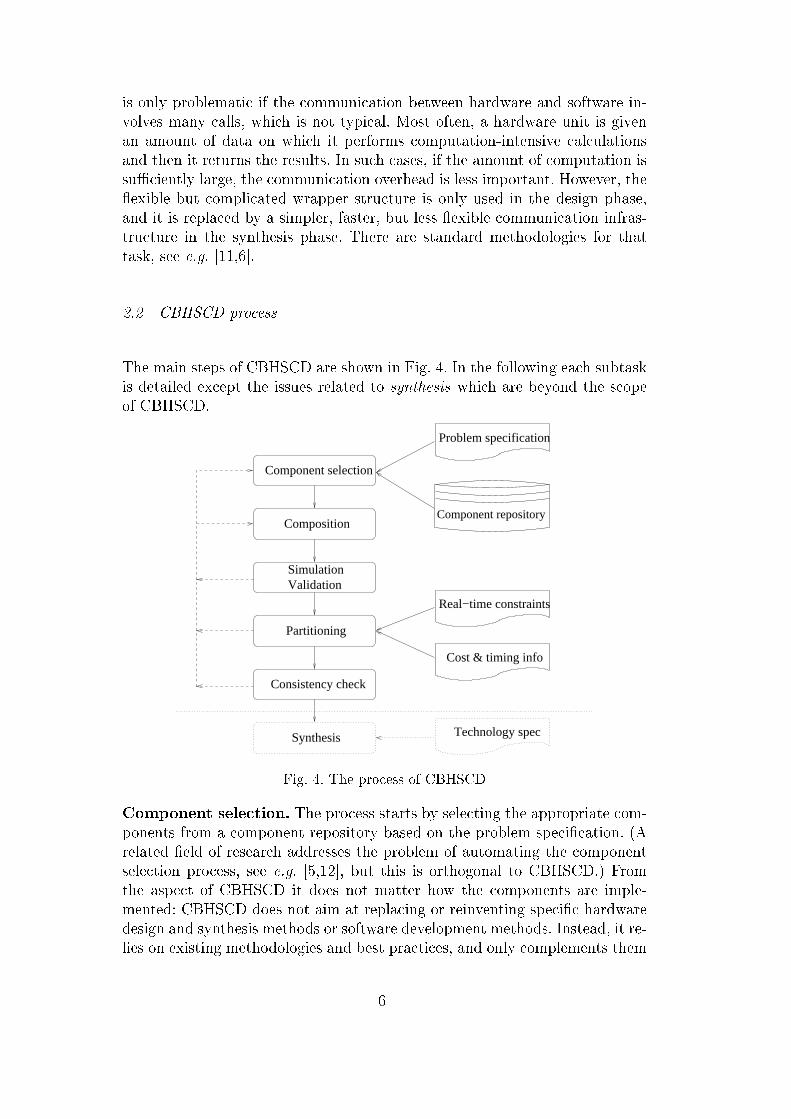
The main steps of CBHSCD are shown in Fig. 4. In the following each subtaskis detailed except the issues related to synthesis which are beyond the scopeof CBHSCD.
Component selection
Composition
Real−time constraints
Cost & timing info
Partitioning
Component repository
Problem specification
Synthesis Technology spec
Consistency check
SimulationValidation
Fig. 4. The process of CBHSCD
Component selection. The process starts by selecting the appropriate com-ponents from a component repository based on the problem speci�cation. (Arelated �eld of research addresses the problem of automating the componentselection process, see e.g. [5,12], but this is orthogonal to CBHSCD.) Fromthe aspect of CBHSCD it does not matter how the components are imple-mented: CBHSCD does not aim at replacing or reinventing speci�c hardwaredesign and synthesis methods or software development methods. Instead, it re-lies on existing methodologies and best practices, and only complements them
6
with co-design aspects. The used components might include pure software andpure hardware components, but mixed components are also allowed, as wellas components which exist in both hardware and software. In the latter casethe designer does not have to decide in advance which version to use (onlythe functionality is considered), but this will be subject to optimization in thepartitioning phase.
Composition. After the components are selected, they are composed to forma prototype system. This composition mechanism deals with abstract func-tional units with interfaces; the implementation issues, the hardware/softwareboundary are irrelevant at this stage.
Each component provides an interface for the outside world. The speci�cationof this interface is either delivered with the component or if the componentmodel provides a su�cient level of re�ection, it can be generated automati-cally. One of the important contributions of CBHSCD is that the compositionof all components is based on remote method calls between components sup-ported by the underlying middleware. Since hardware components are alsotransformed to the generic component model, they can be composed using thetechnique in [10].
Composition is supported by a visual tool that provides an intuitive graphicaluser interface as well as an easy-to-use interconnection wizard. This ease-of-usehelps to overcome problems related to the learning-curve, since traditionallysystem designers have had to possess professional knowledge on hardware,software and architectural issues; thus, the lack of quali�ed system designershas been a critical problem.
Simulation and validation. Since the application has been composed oftested and veri�ed components, only the correctness of the composition hasto be validated by simulation. The individual units are handled as black-boxcomponents in this phase and only functional simulation is carried out. Forinstance, if a calculation is required from a hardware component, one wouldonly monitor the �nal result passed back to the initiator component and notthe individual steps taken inside the hardware. If problems are detected, thecomponent selection and/or composition steps can be reviewed.
It is important to note that components are fully operable at composition time(e.g. a button can be pressed and it generates events), hence the applicationcan be tried out by simply triggering an event or sending a start signal to acomponent. This helps validate the system enormously.
Since the design is only in a premature prototyping phase, it is possible thatthe (expensive) hardware components are not available at this stage 2 . If the
2 Before partitioning it is not even known of each component whether to be realized
7
hardware component is already available and the component is decided to be inthe hardware context, it can be used already in the simulation phase. However,it is possible that we want to synthesize or buy the hardware component onlyif it is surely needed. In this case, we can use software simulation instead.
Note that simulation concentrates only on the functionality and not on thetiming characteristics of the system. The latter is unfortunately distorted bythe several indirections caused by the wrappers around the components. Ofcourse these wrappers are eliminated during synthesis.
Partitioning. After the designer is convinced that the system is functionallycorrect, the system has to be partitioned, i.e. the partitionable componentshave to be mapped to either their software or hardware implementation. (The'mapping' of components which only exist in hardware or only in softwareis trivial.) This is an important optimization problem, in which the optimaltrade-o� between cost and performance has to be found, since hardware istypically faster but more costly than software. (See Section 4 for an exam-ple.) Traditionally, this has been the task of the system designer, but manualpartitioning is very time-consuming and often yields sub-optimal solutions.
CBHSCD on the other hand makes it possible to design the system at a veryhigh level, only concentrating on functionality. This frees the designer fromdealing with low-level implementation issues. It is important to note that up tothis point, the design process is completely implementation-independent. Par-titioning is automated based on a declarative requirements speci�cation. Wede�ned a graph-theoretic model for the partitioning problem and developedappropriate algorithms for it [13,14]. The partitioning algorithm takes intoaccount the software running times, hardware costs (price, area, heat dissi-pation, energy consumption etc.), communication costs between componentsas well as possible constraints de�ned by the user (including soft and hardreal-time constraints, area constraints etc.). This is very helpful for the designof embedded systems, especially real-time systems. When limiting the runningtime, partitioning aims at minimizing costs. Similarly, when costs are limited,the running time is minimized. It is also possible to constrain both runningtime and costs, in which case it has to be decided whether there is a systemthat ful�lls all these constraints, and in the case of a positive answer, such apartition has to be found.
To generate all the input data for the partitioning algorithm is rather challeng-ing. In case of hardware costs, it is assumed that the characteristic values ofthe components are provided with the component itself by the vendor. Com-munication costs are estimated based on the amount of exchanged data andthe communication protocol. Concerning the running times, a worst case (ifhard real-time constraints are speci�ed) or average case running time is either
in software or hardware.
8

provided with the component or extracted by pro�ling techniques. An indepen-dent research �eld deals with the measurement or estimation of these values,see e.g. [15,16]. The time and cost constraints must be speci�ed explicitly bythe designer via use cases (see Section 3 for more details).
Consistency check. The requirement of hardware/software transparency im-plies two consistency problems speci�c to CBHSCD. Note that we are not deal-ing here with the�otherwise very important�consistency of the compositionwhich occurs in pure software composition as well [17], only with additionalconsistency problems due to hybrid hardware/software systems.
The �rst is the interface consistency problem. The question to answer here iswhether or not two implementations can form a partitionable component.
To ensure interface consistency, the compulsory features of a given compo-nent, that is: those features that both implementations have to implement,are speci�ed in an interface description �le. Then, it is automatically checkedif the two implementations do implement the required features.
The second is the state consistency problem. The prototype system is likelyto be partitioned and repartitioned several times during the design process.Each time to realize a transparent swap between implementations, the newimplementation should be set to exactly the same state as the current one,because otherwise it might behave di�erently in the future than expected bythe rest of the system. The designer might not want to reset the whole systemto its initial state (and restart the simulation process) every time the system isrepartitioned, so the state consistency must be handled in a more sophisticatedway. It is not straightforward to achieve this, because the components areregarded as black-box, and it is generally not possible to access all the state-variables from the outside. (A number of component models explicitly forbidstateful components to avoid these problems.)
To address the state consistency problem we should de�ne the notion of con-sistent states :
Two implementations are in consistent states if the same sequence ofmethod calls can be executed on them and they produce the same output.
The consequence of this de�nition is, that starting the two implementationsfrom consistent states and executing the same sequence of method calls onthem, they will be again in consistent states.
Assuming that the initial states of the two implementations are consistent, wecan bring the newly selected implementation to a state consistent with the oldone by automatically repeating the same sequence of method calls and prop-erty changes that had been performed on the old one by the outside world
9
since the last consistent states. (Remember that the old and new implemen-tations o�er the same interface, hence providing exactly the same methods,properties etc.) This way, we can guarantee that consistent states are reached.
A special attribute is associated with every method in the description of thecomponent which speci�es the e�ect of this method on the state of the com-ponent. The appropriate methods to repeat have to be selected intelligentlyaccording to these attributes. (See Section 3 for more details.)
3 CWB-X: a tool for CBHSCD
Our tool to support CBHSCD is an extension of a component-based soft-ware engineering tool called Component Workbench (CWB), which has beendeveloped at the Vienna Technical University in the Easycomp project [10].
CWB is a graphical design tool for the easy composition of applications fromCOTS software components. The main contribution of CWB is the supportfor multiple component models, like COM, CORBA, EJB etc. To achieve this,CWB uses a generic component model called Vienna Composition Framework(VCF). This generic model o�ers a �exible way to represent components, henceall existing software component models can be transformed to this one bymeans of wrappers.
In the philosophy of CWB, each component is associated with a set of features.A feature is anything a component can provide. A component can declare thefeatures it supports and new features can also be added to the CWB. Themost typical features are the following.
Property The properties (attributes) provided by the component.Method The methods of the component.Eventset The sets of events the component can emit.Lifecycle If a component has this feature, then it can be created and de-stroyed, activated or deactivated.
GUI The graphical interface of the component.
Each component model is implemented as a plug-in in the CWB (see Fig 5).The plug-in class only provides information about the features the componentcan o�er, the real functionality is hidden in the classes implementing thefeatures. New component models can be implemented by creating a new plug-in class and a class for each required feature.
For the communication between the components, CWB o�ers event-to-methodcommunication, i.e. a component triggers an event which induces a method
10

Generic Component Model
COMPlugin
CORBAPlugin
EJBPlugin
CORBA EJBCOM
GUI
CWB
Fig. 5. The architecture of the CWB.
call in all registered components. The registration mechanism and the remotemethod call is supported by Java. A wizard helps the user to set up a properconnection. Adapters are automatically created to facilitate the communica-tion between the components.
The used components are already operable at composition-time. This is veryadvantageous because this way the simulation and evaluation of the system ispossible already in the early phases of the design process. Also, the user caninvoke methods of the components, thus use cases or call sequences can betested without any programming e�orts.
3.1 Extension of CWB to support CBHSCD
CWB o�ers a good starting point for a hardware-software co-design tool be-cause of its �exibility and extensibility. We extended CWB to support CBH-SCD principles. In CWB-X (CWB eXtended), the designer of a hardware-software application may select software, hardware, or partitionable compo-nents from a repository. These components can originate from di�erent ven-dors and di�erent component models. The selected component is put on theworking canvas. In case of pure software components, the operable componentitself�with possible GUI�can appear, but in case of hardware componentsthe component itself might not be available and simulation is used.
To enable the integration of hardware components in CWB-X, new componentmodels are added to the CWB as plug-ins. Similarly to the software side, thereis a need for several hardware component models according to the di�erentways the actual hardware might be connected to the computer. This goal iscomplicated by the lack of widely accepted industry standards for IP interfaceand communication speci�cation.
Since the implementation details of a component should be transparent for the
11

other components, the hardware components should provide similar featuresas the software ones. Therefore we de�ne the Method, Property and Eventsetfeatures for hardware components as well, and map methods to operations ofthe underlying hardware, properties to status information and initial parame-ters, and events to hardware interrupts. Our mapping is actually between thedevice driver and the generic component model of the CWB, hence the plug-indoes not have to address hardware�speci�c low�level issues.
To identify the features a hardware component can provide, re�ection is neces-sary, i.e. information about the interface of the component. Today's IP vendorsdo not o�er a standardized way to do that, often a simple text description isattached to the IP. In our model we require a hardware component to providea description about its features (Properties, Methods, Events).
The composition of components is supported by wizards. Due to the wrappers,hardware components act the same way as software ones, thus the wizards ofthe CWB can be used.
When the architecture of the designed application is ready, partitioning isperformed. We have integrated a partitioning algorithm [13] based on integerlinear programming (ILP). This is not an approximation algorithm: it �ndsthe exact optimum. This approach can handle systems with several hundredsof components in acceptable time. For the automatic partitioning process, thevarious cost parameters and the time constraints must be speci�ed.
Time constraints are de�ned on the basis of use cases. A use case involves somecomponents of the system in a given order. A component can also participatemultiple times in a use case. The designer de�nes a use case by specifying thesequence of components a�ected in it and gives a time constraint for the sumof the execution times of the concerned components including communication.The constraints for all use cases are simultaneously taken into account duringpartitioning.
The partitioning algorithm also needs the estimated running times and com-munication cost parameters. As mentioned previously, the measurement orestimation of these cost values is a large independent research �eld (see e.g.[15,16]). We are aware of the importance of these measurements, but this iscurrently at an initial stage in our tool: we expect that this data is explicitlygiven.
CWB-X is able to check both interface and state consistency. To each par-titionable component a Java-like interface is attached which describes therequired features of the implementations. The tool checks whether the asso-ciated implementations are appropriate. Furthermore, to each method in thisinterface description �le an attribute is ordered, which describes the behaviorof this method in the state consistency check. The value and the meaning of
12

the attribute are the following:
NO_EFFECT: the corresponding method has no e�ect on the state of the com-ponent, thus it should not be repeated after repartition.
REPEAT_AT_REPARTITION: the corresponding method a�ects the state but hasno side e�ect, thus it should be repeated after repartition.
REPEAT_AT_REPARTITION_ONCE: the same as the previous one, but in a se-quence of calls to this method only the last one should be repeated. Anexample is setting a property to a value.
SIDE_EFFECT: the method does a�ect the state and also has some side e�ect(e.g. sends 100 pages to the printer) or takes too long to repeat.
CWB-X logs every method call and property change since the last implemen-tation swap. If all these belong to the �rst three categories, the correct statewill be set automatically after the change of the implementations by repeatingthe appropriate function calls. If there is at least one call with SIDE_EFFECT,the system shows a warning and asks the designer to decide which methodsto repeat. The designer is supported by a detailed log in this decision.
4 Case study
In this section, the CBHSCD methodology is demonstrated step by step on anexample application. In this example a frequency modulated signal should bedecoded. A signal generator (which is not part of the system to be designed)generates a signal with frequency modulation. The frequency of the incomingsignal should be measured and the signal is decoded to 0 or 1 according to themeasured frequency value. This task appears in several real-world applications.The architecture of the system can be seen in Fig. 6. The frequency measurer(FM) measures the frequency of the incoming signal and sends the measuredvalue periodically to the demodulator unit (DU). The DU decodes the signaland sends the result to the displayer. The displayer consists of two components:a textual display shows the current value of the decoded signal, and a chartshows the graph of the alteration of the value. Furthermore, there are twobuttons that control the measurer through start and stop signals. Both theFM and the DU are partitionable components.
There are two implementations available for the FM: the �rst one is a pro-gram on a PIC 16F876 microcontroller (software implementation) and a �eld-programmable gate array (FPGA) on a XILINX VIRTEX II XC2V1000 card(hardware implementation). The two implementations behave exactly the sameway, but their performance (and cost) is di�erent. The microcontroller is ableto precisely measure the frequency up to 25kHz (i.e. taking a sample lasts40µs). The FPGA on the other hand can take a sample in 50ns, thus it can
13

Display
(SW impl. only)
0110100measuredfreq.
decodedsignal
Software impl.
Hardware impl.
(FPGA)
(microcontroller)
Frequency measurer
System boundary
signalmodulated
Signal generator
start stop
Software impl.
Hardware impl.
(ASIC)
Demodulation unit
(microcontroller)
Fig. 6. The architecture of the example application
measure up to 20MHz without any problem. However, the FPGA is morecostly. The software implementation of the DU runs on the same microcon-troller, while the hardware implementation is an ASIC (application speci�cintegrated circuit). Again the two implementations di�er in price and perfor-mance.
The designer might want to impose several constraints on the system to bedesigned. These constraints are bound to use�cases of the system. In thisexample the following constraints are de�ned.
Frequency constraint (C1). The constraint de�nes an upper bound ontaking one sample of the signal by the FM. This constraint implicitly de-clares the maximum frequency that should be handled correctly. In our ex-ample let us de�ne the maximum frequency to be 50kHz, hence one sampleshould be taken in 20µs.
Response time constraint (C2). Prescribes the time needed for a sent bitto appear in the displayer, that is the response time of the system for aninput. We de�ne this limit as 1200µs.
The task of the partitioning algorithm is to decide which implementationsto use for the partitionable components to satisfy the constraints. For thepartitioning algorithm the system is converted to a graph representation withhardware and software costs on the vertices and communication costs on theedges. Fig. 7 depicts the graph corresponding to the demo application. (Forsimplicity, only the components a�ected by the constraints are shown.) Foreach partitionable node there are two values speci�ed: the hardware cost (e.g.in $) and the worst case software running time (in µs). For the edges thecommunication overhead is given (also in µs) 3 . Note that this cost arises onlyif the edge crosses the hardware/software boundary.
Table 2 shows the optimal hardware/software partitions found by our algo-
3 The values are for demonstrative purposes only.
14

DU200 150
FM Disp.
−/10008/10010/40
Fig. 7. The graph representation of the system for the partitioning algorithm
rithm. (See [13,14] for more details on the partitioning model.) If only con-straint C1 is imposed, then FM should be implemented in hardware since insoftware it would require 40µs to take one sample, thus violating C1. To min-imize cost, all the other components should be in software, and there are noother constraints forbidding this. If only C2 is required, then all componentscan be put into software, since the total running time is 40+100+1000 < 1200.If both C1 and C2 are imposed, both FM and DU should be put into hard-ware. FM because of C1, and DU because of C2. (If we put only FM intohardware, the (FM,DU) edge would cross the hardware/software boundary,hence the total running time would be 200+100+1000, violating C2.) The ex-ample clearly demonstrates how the tool automatically achieves an optimaltrade�o� between price and performance.
Table 2Optimal hardware/software partitions found by our tool according to the requiredconstraints.
Constraints Software Hardware Hardware cost
C1 DU, Disp FM 10
C2 FM, DU, Disp � 0
C1+C2 Disp FM, DU 18
The described demo can be realized in CWB-X as follows. There are six com-ponents: two JavaBeans buttons (start and stop), a text�eld and a chart com-ponent for display, the FM and the DU declared as a partitionable compo-nent with the two implementations detailed above 4 . The device driver of thehardware components is wrapped by a CWB wrapper providing a software-like interface. Special adapter classes are then generated automatically by theCWB for facilitating communication. Note that di�erent hardware compo-nents with the same device driver interface (which is the case e.g. for the twoimplementations of the FM) require only one wrapper.
The structure of the system can be demonstrated on an example communi-cation process. Fig. 8 shows the reaction of the system on pressing the startbutton. Each component on the �gure is separated by a dashed line, the lowerpart contains the type of the component, while the upper part shows the nameof the speci�c component. The arrows indicate the communication between
4 The signal generator is regarded as an outside source, hence not part of the system
15

components, the labels on the arrows mean either a method call or other kindsof communication. One can see how the device driver hides all the hardware�and communication�speci�c details.
0 0 0 1framebegin
frameend
specificevent handling
Component model
enable()
comm. channel:serial port
fire pressEvent
FM
Hardwarecomponent
driverdevice
FMdev. driver
FMwrapper
CWBwrapper
CWBwrapper
JavaBeanswrapper
AdapterComm.
catch event
pressEventto
startMethodprocess
componentJavaBeans
Start button
event() start()
Middleware layer
Fig. 8. Communication induced by pressing the start button.
For the purposes of the consistency check, an interface description of the re-quired features is also provided with the component (Fig. 9). The tool checkswhether the interfaces of the wrappers match the requirements. The interfacedescription also contains the attributes necessary for the state consistencymechanism.
package frequency;
public interface FrequencyMeasurerInterface {
SIDE_EFFECT public void start();
SIDE_EFFECT public void stop();
NO_EFFECT public void takeOneSample();
NO_EFFECT public String getMeasuredFrequencyString();
NO_EFFECT public Integer getMeasuredFrequency();
REPEAT_AT_REPARTITION_ONCE public void setCountEveryEdge(boolean b);
NO_EFFECT public boolean getCountEveryEdge();
NO_EFFECT public void addFreqMeasuredEventListener(Listener l);
NO_EFFECT public void removeFreqMeasuredEventListener(Listener l);
}
Fig. 9. Part of the required interface (with state consistency attributes) of the par-titionable frequency measurer (FM) component
16

In the composition phase the start and stop buttons are mapped with the aidof the mentioned wizard to the start and stop methods of the FM, respec-tively. The FM sends an interrupt whenever a new measured value is ready.This interrupt appears as an event in CWB-X, which triggers the DU to askfor the measured value. When the DU is ready with the decoding, it againsends an interrupt. This triggers the setText function of the TextField andthe addValue function of the chart. The system can be immediately simulatedwithout any further e�ort: after pressing the start button the current imple-mentation of the FM starts measuring the signal of the generator and thedisplayer displays the measured values. The system can be partitioned and re-partitioned an arbitrary number of times based on the de�ned constraints; thestate consistency mechanism makes sure that the change in implementationremains transparent to the rest of the system.
5 Related work
In recent years, there has been a substantial amount of work in the sys-tem design community targeting the design of SoC-s (System on Chip), andmaking use of existing components (IP blocks, also called Virtual Compo-nents) [18,6,19,20,7]. Unfortunately, most of these approaches handle low-level interconnection issues in system design, and provide very little tool sup-port. There are hardly any standards for the interoperability of IP blocks.Although the VSI Alliance has published some standards and speci�cationsin this �eld [21], they only handle the lowest levels of interconnection, i.e. thephysical details.
A higher level of abstraction characterizes the approaches for hardware/softwareco-simulation [6,22,20,23]. They aim at enabling the simulation of the sys-tem in the early stages of the design, either functionally, or concerning bothfunctionality and performance (real-time simulation). Our work also uses co-simulation; however, we support the designer with several automatisms (par-titioning, consistency checks) as well.
Another interesting thread of related work is concerned with the automaticsynthesis of hardware/software interfaces [11,24,6]. This approach is ratherorthogonal to our work, because it aims at constructing run-time interfaces,whereas we focus only on the design phase, and hence use composition-timewrappers.
Component selection and trading [18,5,12] is also a related research �eld thatis orthogonal to our approach. Here, the aim is to de�ne description formatsfor components which enable the automatic retrieval of suitable componentsfor a given task.
17

In the component-based software engineering community, the most stronglyrelated e�orts are those concerned with the adaptation of components [25�27,10]. Our way of using wrappers for this task is similar to these approaches;however, we also consider hardware components, which also leads to suchissues as partitioning, which are not present in pure software systems.
6 Conclusion
This paper presented an extension to component-based software engineering toalso include hardware components. The new methodology, called component-based hardware/software co-design (CBHSCD) provides a uniformly high levelof abstraction for software, hardware, and partitionable components.
The concepts of CBHSCD, as well as partitioning, enable advanced tool sup-port for the system-level design process. Our tool CWB-X is based on theComponent Workbench (CWB), a visual tool for the composition of softwarecomponents of di�erent component models. CWB-X extends the CWB withnew component models for hardware components as well as partitioning andconsistency checking functionality. We presented a case study to demonstratethe applicability of our concepts and the usefulness of our tool.
We believe that the notion of CBHSCD uni�es the advantages of hardwareand software design to a synergetic system-level design methodology, whichcan help in designing complex, reliable and cheap computer systems rapidly.
References
[1] G. T. Heineman, W. T. Councill, Component Based Software Engineering:Putting the Pieces Together, Addison-Wesley, 2001.
[2] U. Assmann, Invasive Software Composition, Springer, 2003.
[3] Venture Development Corporation, The embedded software strategic marketintelligence program 2002/2003, volume II, http://www.vdc-corp.com/
embedded/reports/03/br03-10.html (2003).
[4] R. Niemann, Hardware/Software Co-Design for Data Flow DominatedEmbedded Systems, Kluwer Academic Publishers, 1998.
[5] G. Martin, R. Seepold, T. Zhang, L. Benini, G. D. Micheli, Component selectionand matching for IP-based design, in: Proceedings of Design, automation andtest in Europe, IEEE Press, 2001.
18
[6] P. Chou, R. Ortega, K. Hines, K. Partridge, G. Borriello, IPCHINOOK: anintegrated IP-based design framework for distributed embedded systems, in:Design Automation Conference, 1999, pp. 44�49.
[7] F. Pogodalla, R. Hersemeule, P. Coulomb, Fast protoyping: a system design �owfor fast design, prototyping and e�cient IP reuse, in: CODES, 1999.
[8] G. Spivey, S. S. Bhattacharyya, K. Nakajima, Logic Foundry: A rapidprototyping tool for FPGA-based DSP systems, Tech. rep., Department ofComputer Science, University of Maryland (2002).
[9] K. Buchenrieder, Embedded system prototyping, in: Tenth IEEE InternationalWorkshop on Rapid System Prototyping, 1999.
[10] J. Oberleitner, T. Gschwind, Composing distributed components with thecomponent workbench, in: Proceedings of the Software Engineering andMiddleware Workshop (SEM2002), Springer Verlag, 2002.
[11] A. Basu, R. Mitra, P. Marwedel, Interface synthesis for embedded applicationsin a co-design environment, in: 11th IEEE International conference on VLSIdesign, 1998, pp. 85�90.
[12] P. Roop, A. Sowmya, Automatic component matching using forced simulation,in: 13th International Conference on VLSI Design, IEEE Press, 2000.
[13] Z. A. Mann, A. Orbán, Optimization problems in system-level synthesis,in: Proceedings of the 3rd Hungarian-Japanese Symposium on DiscreteMathematics and Its Applications, 2003.
[14] P. Arató, S. Juhász, Z. A. Mann, A. Orbán, D. Papp, Hardware/softwarepartitioning in embedded system design, in: Proceedings of the IEEEInternational Symposium on Intelligent Signal Processing, 2003.
[15] X. Hu, T. Zhou, E. Sha, Estimating probabilistic timing performance for real-time embedded systems, IEEE Transactions on VLSI Systems 9 (6).
[16] S. L. Graham, P. B. Kessler, M. K. McKusick, An execution pro�ler for modularprograms, Software Practice & Experience 13 (1983) 671�685.
[17] A. Speck, E. Pulvermüller, M. Jerger, B. Franczyk, Component compositionvalidation, International Journal of Applied Mathematics and Computer Science(2002) 581�589.
[18] E. Casseau, Soc design using behavioral level virtual components, in: IEEEInternational Conference on Electronics, Circuits, and Systems, 2002.
[19] P. Coussy, A. Baganne, E. Martin, A design methodology for integrating IP intoSOC systems, in: Conférence Internationale IEEE CICC, 2002.
[20] S. J. Krolikoski, F. Schirrmeister, B. Salefski, J. Rowson, G. Martin,Methodology and technology for virtual component-driven hardware/softwareco-design on the system level, in: ISCAS, 1999.
19

[21] VSI Alliance, VSIA architecture document, http://www.vsi.org/resources/techdocs/vsi-or.pdf (1997).
[22] J. Davis, C. Hylands, J. Janneck, E. A. Lee, J. Liu, X. Liu, S. Neuendor�er,S. Sachs, M. Stewart, K. Vissers, P. Whitaker, Y. Xiong, Overview ofthe Ptolemy project, Tech. rep., Department of Electrical Engineering andComputer Science, University of California, Berkeley (2001).
[23] P. L. Marrec, C. A. Valderrama, F. Hessel, A. A. Jerraya, M. Attia, O. Cayrol,Hardware, software and mechanical cosimulation for automotive applications,in: IEEE International Workshop on Rapid Systems Prototyping, 1998.
[24] W. Cesario, A. Baghdadi, L. Gauthier, D. Lyonnard, G. Nicolescu, Y. Paviot,S. Yoo, A. A. Jerraya, M. Diaz-nava, Component-based design approach formulticore SoCs, in: DAC'02, 2002.
[25] S. R. Thatté, Automated synthesis of interface adapters for reusable classes, in:Proceedings of the 21st ACM SIGPLAN-SIGACT symposium on Principles ofprogramming languages, 1994.
[26] D. M. Yellin, R. E. Strom, Protocol speci�cations and component adaptors,ACM Transactions on Programming Languages and Systems 19 (2) (1997) 292�333.
[27] R. H. Reussner, Automatic component protocol adaptation with the CoConut/Jtool suite, Future Generation Computer Systems 19 (5) (2003) 627�639.
20