Exploring Properties of a Hyperthermophilic Membrane-Bound Hydrogenase at Carbon Nanotube Modified...
11
Exploring Properties of a Hyperthermophilic Membrane-Bound Hydrogenase at Carbon Nanotube Modified Electrodes for a Powerful H 2 /O 2 Biofuel Cell Anne De Poulpiquet, a Alexandre Ciaccafava, a Katarzyna Szot, b Baptiste Pillain, a Pascale Infossi, a Marianne Guiral, a Marcin Opallo, b Marie-ThȖrŕse Giudici-Orticoni, a Elisabeth Lojou* a a UnitȖ de BioȖnergȖtique et IngȖnierie des ProtȖines, UMR7281-FR3479, CNRS, AMU, Marseille, France tel: + 33 491164524, fax: + 33 491164097 b Institute of Physical Chemistry, Polish Academy of Sciences, ul. Kasprzaka 44/52, 01-224 Warszawa, Poland *e-mail: [email protected] Received: July 27, 2012 Accepted: November 6, 2012 Published online: January 15, 2013 Abstract Hydrogenases are the key enzymes for hydrogen metabolism in many microorganisms. Due to the high efficiency and specificity they developed for H 2 oxidation, they have been recently used as biocatalysts for an efficient H 2 /O 2 biofuel cell. In this work we explore new properties of an O 2 -, CO- and T8-resistant hydrogenase. Enzyme immobili- zation on carbon nanotube modified electrodes is studied and optimized for long-term stabilization of the direct hy- drogen catalytic oxidation process. The role of co-immobilized redox mediator is finally discussed in view of H 2 /O 2 fuel cell performance enhancement. Keywords: Hydrogenase, Carbon nanotube, Biofuel cell, Immobilization, Electrochemistry DOI: 10.1002/elan.201200405 Supporting Information for this article is available on the WWW under http://dx.doi.org/10.1002/elan.201200405. 1 Introduction Microorganisms couple enzymatic reactions via a mem- brane quinone pool with generation of a proton gradient for the synthesis of ATP, their energy source [1,2]. This energetic pathway can be considered as an “in vivo fuel cell”, and led to the concept of biofuel cells as a new val- uable source for our energy needs. Biofuel cells function like chemical low temperature fuel cells (proton exchange membrane (PEM) fuel cell), coupling the oxidation of a fuel at the anode with the reduction of an oxidant at the cathode, but using enzymes instead of expensive and scarce platinum catalysts [3]. There are numerous advan- tages of enzymatic biofuel cells. Biocatalysts are wide- spread and biodegradable. They exhibit high efficiency and specificity for their substrates that might allow de- signing fuel cells without separator. A large variety of fuels and oxidants can be used as many enzymes which differ by their natural abundant substrates are nowadays characterized. Finally, biofuel cells can deliver power under mild working conditions typical for enzymes, namely at mild pH and temperatures. However, some ex- tremophilic enzymes operate at extreme acidic or basic pH, as well as at high temperatures (up to 90 8C) or high pressures, offering the possibility of developing biofuel cell devices for special applications requiring extreme working conditions [4]. So far sugar/O 2 is the most common fuel/oxidant couple to power biofuel cells, essentially because of its abundance in nature and essential role in living metabo- lism [5–7]. Glucose oxidase and copper proteins, such as laccase and bilirubin oxidase (BOD), were largely studied as biocatalysts for glucose oxidation and O 2 reduction, re- spectively. All over the last ten years, thanks to great re- search in engineering of enzymes, electrochemical interfa- ces and cell design, power densities as high as 1 mW cm À2 were recently reached [8–10]. The step for biofuel cell credibility was jumped and some emerging applications are nowadays reported [11–13]. A few years ago, a new type of biofuel cells, based on an enzyme specific for dihydrogen oxidation, the hydro- genase, was developed [14]. This H 2 /O 2 biofuel cell is di- rectly inspired from PEM fuel cell, and is expected to yield the highest massic energy output. Various types of hydrogenases are available, differing by the metal content of their active site, their activity towards H 2 uptake or evolution, and their localization in bacterial cells. All [NiFe] hydrogenases from the group 1 [15] share a similar structure, composed of two subunits with a molecular weight around 100 kDa. The large subunit harbors the active [NiFe] centre where dihydrogen is cleaved. In the TOPICAL CLUSTER Electroanalysis 2013, 25, No. 3, 685 – 695 # 2013 Wiley-VCH Verlag GmbH &Co. KGaA, Weinheim 685 Full Paper
-
Upload
independent -
Category
Documents
-
view
1 -
download
0
Transcript of Exploring Properties of a Hyperthermophilic Membrane-Bound Hydrogenase at Carbon Nanotube Modified...
Exploring Properties of a Hyperthermophilic Membrane-BoundHydrogenase at Carbon Nanotube Modified Electrodes fora Powerful H2/O2 Biofuel Cell
Anne De Poulpiquet,a Alexandre Ciaccafava,a Katarzyna Szot,b Baptiste Pillain,a Pascale Infossi,a Marianne Guiral,a
Marcin Opallo,b Marie-Th�r�se Giudici-Orticoni,a Elisabeth Lojou*a
a Unit� de Bio�nerg�tique et Ing�nierie des Prot�ines, UMR7281-FR3479, CNRS, AMU, Marseille, Francetel: +33491164524, fax: +33491164097
b Institute of Physical Chemistry, Polish Academy of Sciences, ul. Kasprzaka 44/52, 01-224 Warszawa, Poland*e-mail: [email protected]
Received: July 27, 2012Accepted: November 6, 2012Published online: January 15, 2013
AbstractHydrogenases are the key enzymes for hydrogen metabolism in many microorganisms. Due to the high efficiencyand specificity they developed for H2 oxidation, they have been recently used as biocatalysts for an efficient H2/O2
biofuel cell. In this work we explore new properties of an O2-, CO- and T8-resistant hydrogenase. Enzyme immobili-zation on carbon nanotube modified electrodes is studied and optimized for long-term stabilization of the direct hy-drogen catalytic oxidation process. The role of co-immobilized redox mediator is finally discussed in view of H2/O2
fuel cell performance enhancement.
Keywords: Hydrogenase, Carbon nanotube, Biofuel cell, Immobilization, Electrochemistry
DOI: 10.1002/elan.201200405
Supporting Information for this article is available on the WWW under http://dx.doi.org/10.1002/elan.201200405.
1 Introduction
Microorganisms couple enzymatic reactions via a mem-brane quinone pool with generation of a proton gradientfor the synthesis of ATP, their energy source [1,2]. Thisenergetic pathway can be considered as an “in vivo fuelcell”, and led to the concept of biofuel cells as a new val-uable source for our energy needs. Biofuel cells functionlike chemical low temperature fuel cells (proton exchangemembrane (PEM) fuel cell), coupling the oxidation ofa fuel at the anode with the reduction of an oxidant atthe cathode, but using enzymes instead of expensive andscarce platinum catalysts [3]. There are numerous advan-tages of enzymatic biofuel cells. Biocatalysts are wide-spread and biodegradable. They exhibit high efficiencyand specificity for their substrates that might allow de-signing fuel cells without separator. A large variety offuels and oxidants can be used as many enzymes whichdiffer by their natural abundant substrates are nowadayscharacterized. Finally, biofuel cells can deliver powerunder mild working conditions typical for enzymes,namely at mild pH and temperatures. However, some ex-tremophilic enzymes operate at extreme acidic or basicpH, as well as at high temperatures (up to 90 8C) or highpressures, offering the possibility of developing biofuel
cell devices for special applications requiring extremeworking conditions [4].
So far sugar/O2 is the most common fuel/oxidantcouple to power biofuel cells, essentially because of itsabundance in nature and essential role in living metabo-lism [5–7]. Glucose oxidase and copper proteins, such aslaccase and bilirubin oxidase (BOD), were largely studiedas biocatalysts for glucose oxidation and O2 reduction, re-spectively. All over the last ten years, thanks to great re-search in engineering of enzymes, electrochemical interfa-ces and cell design, power densities as high as 1 mW cm�2
were recently reached [8–10]. The step for biofuel cellcredibility was jumped and some emerging applicationsare nowadays reported [11–13].
A few years ago, a new type of biofuel cells, based onan enzyme specific for dihydrogen oxidation, the hydro-genase, was developed [14]. This H2/O2 biofuel cell is di-rectly inspired from PEM fuel cell, and is expected toyield the highest massic energy output. Various types ofhydrogenases are available, differing by the metal contentof their active site, their activity towards H2 uptake orevolution, and their localization in bacterial cells. All[NiFe] hydrogenases from the group 1 [15] share a similarstructure, composed of two subunits with a molecularweight around 100 kDa. The large subunit harbors theactive [NiFe] centre where dihydrogen is cleaved. In the
TO
PIC
AL
CLU
STE
R
Electroanalysis 2013, 25, No. 3, 685 – 695 � 2013 Wiley-VCH Verlag GmbH & Co. KGaA, Weinheim 685
Full Paper
small subunit three FeS clusters drive the electrons fromthe active site to the surface of the enzyme, where theredox partners (including the electrode) bind for accept-ing electrons [16]. It was reported that [NiFe] hydroge-nases can be as efficient as platinum catalysts when im-mobilized on an electrode [17–19]. Unfortunately, the ex-treme oxygen sensitivity of most hydrogenases sloweddown their potential use as biocatalysts in biofuel cells[17]. However, in very recent years, in addition to funda-mental studies that aim at improving and overcoming O2
sensitivity of classical hydrogenases [20], four [NiFe]membrane-bound hydrogenases have been characterizedfrom aerobic or extremophilic organisms [21–24]. Theyhave been demonstrated to oxidize H2 in the presence ofoxygen and CO. This tolerance may be related to an un-common geometry of the FeS cluster proximal to theactive site. Given an efficient immobilization of these hy-drogenases on electrodes, these new biocatalysts appearas attractive candidates for fuel oxidation in a powerfulH2/O2 biofuel cell.
Recently, we reported on the electrochemistry of oneof these O2- and CO resistant hydrogenases. It is a mem-brane-bound [NiFe] hydrogenase purified from Aquifexaeolicus (Aa), a hydrogen-oxidizing, microaerophilic bac-terium growing at 85 8C [16,25]. This hydrogenase fromAa (MbH1) is involved in a complex with a diheme cyto-chrome b anchored in the membrane, coupling H2 oxida-tion to O2 reduction. Efficient MbH1 immobilization fordirect H2 oxidation was achieved by different strategieslike (i) adsorption on pyrolytic graphite electrode (PG)[26], in buffer electrolytes and room temperature ionicliquids [27], (ii) adsorption on self-assembled-monolayer(SAM) modified gold electrode [28], or (iii) connectionto a redox polymer film [29]. As MbH1 is membrane-bound, encapsulation in liposomes was shown to enhancethe enzyme stability at the electrode [30]. A complete un-derstanding of the role of the detergent in the immobili-zation process was also undertaken [31], which clearlyput forwards that detergent stabilizes the enzyme and hasless affinity for the electrode than the enzyme. It wasproved to allow high direct electron transfer process forH2 oxidation on charged or hydrophilic surfaces, even atconcentrations above the micellar concentration.
However, H2/O2 biofuel cells domain is still in its infan-cy. Only two of these biofuel cells have been fully de-scribed so far [32,33]. Their performances rely on themodification of electrodes by carbon nanotube (CNT)networks. Both the interfacial electron transfer rate, andthe amount of enzymes directly connected to the elec-trode are supposed to be increased due to high conductiv-ities, large surface areas and tuned functionalization ofcarbon nanotubes. This was first underlined in our groupfor D. fructosovorans hydrogenase, then MbH1 [26,34],and successfully applied to E. coli hydrogenase. Using co-valent attachment of both O2 resistant E. coli hydroge-nase and BOD on pyrene derivative functionalized multi-walled carbon nanotubes, a membrane-less biofuel cellwas designed, that was fed with a nonexplosive 80/20 di-
hydrogen/air mixture [32]. This biofuel cell displayedquite good stability with time and an average power den-sity of 119 mWcm�2. Based on MbH1 at the anode andBOD at the cathode, we built a 300 mWcm�2 H2/O2 medi-atorless biofuel cell. It was architectured with one stepcovalent attachment on a single-walled carbon nanotube(SWCNT) coating of MbH1 at the anode and BOD atthe cathode [33].
In view of improvement of the H2/O2 biofuel cell basedon MbH1 at the anode, enhancement of both long termstability and current density is needed. Therefore, westudy in this work various procedures for architecturingthe CNT coating and for stabilizing MbH1 at the CNTlayer. Although many studies have been done about thecatalytic mechanisms for H2 oxidation by hydrogenase[17], physicochemical data on MbH1 electrochemistry arestill lacking. The influence of physicochemical parame-ters, such as pH and ionic strength, on the direct H2 oxi-dation by MbH1 immobilized on CNT networks is thusreported in this work. It was previously demonstratedthat the H2/O2 biofuel cell performance was limited byhydrogenase inhibition at high potentials [33]. The addi-tion of an appropriate redox mediator that could compen-sate for this limitation is finally discussed in the presentwork.
2 Experimental
2.1 Reagents
All used reagents were analytical grade and the solutionswere prepared using Milli-Q water. 4-(2-Hydroxyethyl)pi-perazine-1-ethanesulfonic acid (HEPES) was used forMbH1 dilution and as the supporting electrolyte atpH 6.8 and 50 mM concentration. For pH studies, bothelectrochemistry and spectrophotometric assays were re-alized in Britton�Robinson buffer, adjusted at the desiredpH using NaOH. N-(3-Dimethylaminopropyl)-N’-ethyl-carbodiimide hydrochloride (EDC), N-hydroxysuccini-mide (NHS), n-dodecyl b-d-maltoside (DDM) were pur-chased at Sigma. Nafion 5 % alcoholic solution fromSigma was diluted in water for coatings. Procedure forpreparing gels of Nafion and tetrabutylammonium bro-mide salts was realized as described in [35]. SWCNTs andcarboxylic functionalized MWCNTs were purchased atSigma. Multiwalled carbon nanotubes with 0.5% NH2
functions (MWCNT-NH2) were purchased at DropSensand used with no purification.
2.2 Purification of MbH1
MbH1 was purified as described by Luo et al. [26].Excess of DDM detergent used for the solubilization ofMbH1 from the bacterial cell membrane extracts is re-moved using concentrator Vivaspin (cut off 100 K,2500 xg ) and Bio-beads SM2 (Bio-rad) for 2 h at 4 8C.Final DDM concentration was determined as described in[31] to ensure correct micellar concentration before
TO
PIC
AL
CLU
STE
R
686 www.electroanalysis.wiley-vch.de � 2013 Wiley-VCH Verlag GmbH & Co. KGaA, Weinheim Electroanalysis 2013, 25, No. 3, 685 – 695
Full Paper A. De Poulpiquet et al.
enzyme dilution. MbH1 activity assays were performed at80 8C by the hydrogen consumption assay using methyl-vi-ologen as the electron acceptor and hydrogen as the elec-tron donor [26]. The hydrogen-dependant reduction rateof methyl viologen was followed spectrophotometricallyat 604 nm using a Cary winUV50 with Peltier accessoryfor temperature control. MbH1 activity was also revealedusing blue native gels with H2 as electron donor andmethyl viologen as electron acceptor at 80 8C. Reductionof 2,3,5-triphenyltetrazolium chloride by reduced methylviologen produces on gels the pink colour which is char-acteristic of hydrogenase activity [24].
2.3 Electrochemistry Experiments
Cyclic voltammetry (CV) was done using a PARSTAT2273 potentiostat from Princeton Applied Research(PAR). A conventional three-electrode system was usedwith a Ag/AgCl/NaCl (sat.) reference electrode, anda platinum wire as auxiliary electrode. All potentials werequoted against the Ag/AgCl reference. Prior to each ex-periment, the solutions were deoxygenated by bubblingwith high-purity nitrogen or hydrogen. The temperatureof the electrochemical cell was regulated using a waterbath. The reference electrode was separated from thewarmed electrolyte using a side junction maintained atroom temperature. The direct catalytic current for H2 oxi-dation was measured at the potential where the currentleveled off. Current densities are referred to the electrodegeometric area. For comparative data, normalized cur-rents are preferred and referred to the maximum currentobtained. The addition of CV signals was realized by ad-dition of the current value at each potential value aftersubtraction of the capacitive current.
2.4 Design of the Working Electrode
The graphite working electrode was constructed from3 mm rods of pyrolytic graphite (PG) inserted in Peekpolymer casings from Bio-Logic SAS. The PG electrodewas carefully polished on wet fine emery papers (PRESI,P800 then P1200). After polishing, the PG electrode waswashed thoroughly with water, then ethanol, followed bysonication and rinsed again with water. The membraneelectrode technology was used for some electrochemicalmeasurements. Briefly, an aliquot of 5 mL of the buffercontaining or not the enzyme was deposited on the elec-trode. The electrode was then gently pressed againsta square piece of dialysis membrane (Visking membrane– MWCO 6000–8000). A rubber ring was fitted aroundthe electrode body so that the volume between the mem-brane and the electrode surface corresponded to a uni-form thin layer of less than 50 mm [36–38].
SWCNT were functionalized with carboxylic groups(SWCNT-COOH) as described by Lojou et al. [34] anddiluted in Milli-Q water. They were dispersed in ultrason-ic bath before coating. SWCNT-COOH solution wasdropped on the PG electrode under N2 atmosphere until
complete drying. For carbodiimide coupling between thecarbon nanotube and MbH1, the SWCNT-COOH modi-fied PG electrode was dipped in a 40 mM/10 mM EDC/NHS solution, for half an hour. Then, 5 mL of 2 mMMbH1 were deposited on the surface and left to dry forcovalent attachment under N2 stream on the bench. Theoptimization of EDC/NHS covalent coupling was realizedafter incubation of 10 mg MbH1 in a solution of EDC/NHS at different concentrations in 50 mM Hepes bufferpH 6.8 for one hour. Enzymes were then denatured bya combination of reducing agent (2-b-mercaptoethanol)and heating procedure. Samples were finally separated ona classical denaturating 8–16 % Sodium Dodecyl SulfatePolyAcrylamide Gel Electrophoresis (SDS-PAGE).
3 Results and Discussion
3.1 Carbon Nanotube Coatings for an Enhanced H2
Oxidation Process by Immobilized MbH1
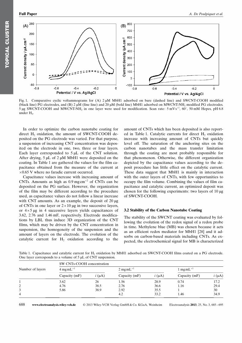
We earlier demonstrated that the orientation of immobi-lized MbH1 cannot be controlled simply by electrostaticinteraction because of the absence of a high dipolemoment and a charged patch surrounding the distal FeScluster situated at the surface of the enzyme [28]. In addi-tion, we have shown that a hydrophilic domain near thedistal FeS cluster is formed by the trans-membrane helixsurrounded by neutral detergent. As a consequence, a dis-tribution of orientations always exists for the hydrogenaseimmobilized at charged electrochemical interfaces. Wethus observed that direct but also mediated H2 oxidationproceeded at SAM modified gold electrodes presentingeither positive or negative end-functions [28]. Figure 1shows comparative CV curves for H2 oxidation by MbH1immobilized on a SWCNT-COOH or a MWCNT-NH2
coating, at 60 8C under H2. For comparison, H2 oxidationcurve by MbH1 on a bare PG is overlaid.
In agreement with our findings on SAM modified goldelectrodes [28], efficient direct oxidation of H2 is record-ed with MbH1 immobilized either on SWCNT-COOH orMWCNT-NH2 films. Deposition of modified CNTs onPG is clearly advantageous: it results in more than 15fold enhancement of catalytic current. The change of theelectrode material from PG to the SWCNT-COOH filmdoes not affect the shape of the catalytic curve. H2 oxida-tion proceeds at an overpotential of less than 150 mV andlevels off at potentials higher than �200 mV. This reversi-ble inhibition may be due to the formation of an inactivestate of MbH1, most probably with a hydroxide bridgingFe and Ni at the active site. Using MWCNT-NH2 asa CNT platform, a higher MbH1 concentration is neededto observe a direct H2 oxidation current. We already no-ticed this feature by modifying the electrode with non-purified MWCNT-COOH. In that case, only concentra-tions of MbH1 higher than 20 mM yielded detectabledirect catalytic current. Furthermore the shape of the vol-tammogram obtained for MWCNT-NH2 electrode is quiteunusual and needs further investigation.
TO
PIC
AL
CLU
STE
R
Electroanalysis 2013, 25, No. 3, 685 – 695 � 2013 Wiley-VCH Verlag GmbH & Co. KGaA, Weinheim www.electroanalysis.wiley-vch.de 687
Exploring Properties of an Hyperthermophilic Membrane-Bound
In order to optimize the carbon nanotube coating fordirect H2 oxidation, the amount of SWCNT-COOH de-posited on the PG electrode was varied. For that purpose,a suspension of increasing CNT concentration was depos-ited on the electrode in one, two, three or four layers.Each layer corresponded to 5 mL of the CNT solution.After drying, 5 mL of 2 mM MbH1 were deposited on thecoating. In Table 1 are gathered the values for the film ca-pacitance obtained from the measure of the current at�0.65 V where no faradic current occurred.
Capacitance values increase with increasing amount ofCNTs. Amounts as high as 0.9 mg cm�2 of CNTs can bedeposited on the PG surface. However, the organizationof the film may be different according to the procedureused, as capacitance values do not follow a linear increasewith CNT amounts. As an example, the deposit of 20 mgof CNTs in one layer or 2 �10 mg in two successive layers,or 4� 5 mg in 4 successive layers yields capacitances of3.62, 2.76 and 1.46 mF, respectively. Electrode modifica-tions by LBL thus induce 3D organization of the CNTfilms, which may be driven by the CNT concentration insuspension, the homogeneity of the suspension and theamount of layers on the electrode. The evolution of thecatalytic current for H2 oxidation according to the
amount of CNTs which has been deposited is also report-ed in Table 1. Catalytic currents for direct H2 oxidationincrease with increasing amount of CNTs but quicklylevel off. The saturation of the anchoring sites on thecarbon nanotubes and the mass transfer limitationthrough the coating are most probably responsible forthat phenomenon. Otherwise, the different organizationdepicted by the capacitance values according to the de-posit procedure has little effect on the catalytic current.These data suggest that MbH1 is mainly in interactionwith the outer layers of CNTs, with few opportunities tooccupy the film volume. Combining the values of film ca-pacitance and catalytic current, an optimized deposit waschosen for the following experiments: two layers of 10 mgof SWCNT-COOH.
3.2 Stability of the Carbon Nanotube Coating
The stability of the SWCNT coating was evaluated by fol-lowing the evolution of the redox signal of a redox probein time. Methylene blue (MB) was chosen because it actsas an efficient redox mediator for MbH1 [28] and it ad-sorbs on carbon-based materials including CNTs. As ex-pected, the electrochemical signal for MB is characterized
TO
PIC
AL
CLU
STE
R
Fig. 1. Comparative cyclic voltammograms for (A) 2 mM MbH1 adsorbed on bare (dashed line) and SWCNT-COOH modified(black line) PG electrodes, and (B) 2 mM (fine line) and 20 mM (bold line) MbH1 adsorbed on MWCNT-NH2 modified PG electrodes.5 mg SWCNT-COOH and MWCNT-NH2 in one layer were used for modification. Scan rate: 5 mVs�1, 608, 50 mM Hepes, pH 6.8under H2.
Table 1. Capacitance and catalytic current for H2 oxidation by MbH1 adsorbed on SWCNT-COOH films coated on a PG electrode.One layer corresponds to a volume of 5 mL of CNT suspension.
SW CNTs-COOH concentration
Number of layers 4 mgmL�1 2 mgmL�1 1 mgmL�1
Capacity (mF) i (mA) Capacity (mF) i (mA) Capacity (mF) i (mA)
1 3.62 26 1.56 28.9 0.74 17.22 4.76 38.5 2.76 36.6 1.16 29.43 5.86 38.9 2.92 35.5 1 304 4.2 33.2 1.46 34.9
688 www.electroanalysis.wiley-vch.de � 2013 Wiley-VCH Verlag GmbH & Co. KGaA, Weinheim Electroanalysis 2013, 25, No. 3, 685 – 695
Full Paper A. De Poulpiquet et al.
at the bare PG electrode by a single reversible redoxwave at �240 mV at pH 6.8, according to the redox reac-tion 1 (Scheme 1).
A steady state is obtained from the first voltammetriccycle. The variation of the peak current with scan rateafter electrode transfer in pure buffer demonstrates ad-sorption of MB on the PG surface. At a CNT-modifiedelectrode, the redox wave is slightly moved cathodic.Consecutive CV curves demonstrating MB adsorptionprogress on the SWCNT-COOH coating were then re-corded. Both capacitance of the film and anodic currentfor MB before and after electrode transfer in pure bufferare reported in Table 2.
After consecutive cycles in MB solution the peak cur-rents reach maximal values 20 times larger. This suggestsprogressive adsorption of MB on the surface and withinthe pores of the CNT film. The maximal value of the cur-rent is also 20 fold higher than at the bare PG electrodebecause of the increase in surface area. Some drop in cur-rent is recorded after transfer because of some leakage ofMB molecules that were not strongly adsorbed in theSWCNT film. However the remaining signal is linearwith the scan rate denoting an adsorption-limited process.It is very stable in time, with no decrease of the currentor the capacitance over 15 cycles (i.e. 30 min) whateverthe pH. The mean redox potential of MB followsa 25 mV/U pH dependence, which only slightly differsfrom what is expected at a bare electrode. The redox re-action becomes less reversible at nonneutral pH, DEp
reaching for example 160 mV at pH 5. Only a slight varia-tion of current and capacitance in time can be measuredafter electrode transfer in the presence of 200 mM NaClin solution. The adsorption of CNTs on the PG electrodeis most probably stabilized by p–p interactions.
3.3 Stability of the Biohybrid Electrode
In our previous work using MbH1 for direct H2 oxidationat SWCNT modified electrodes, although high currentdensities were reached with large MbH1 concentration(40 mM), we noted a very quick decrease of the catalyticcurrent [26]. Up to 70% of the catalytic current was lostafter one hour at 60 8C. Thus a mandatory conditionbefore use of MbH1 for H2 oxidation in biofuel cells isthe long term stabilization of the catalytic current. Withthis objective in mind we have explored in this workthree different procedures of immobilization of MbH1 onan electrode.
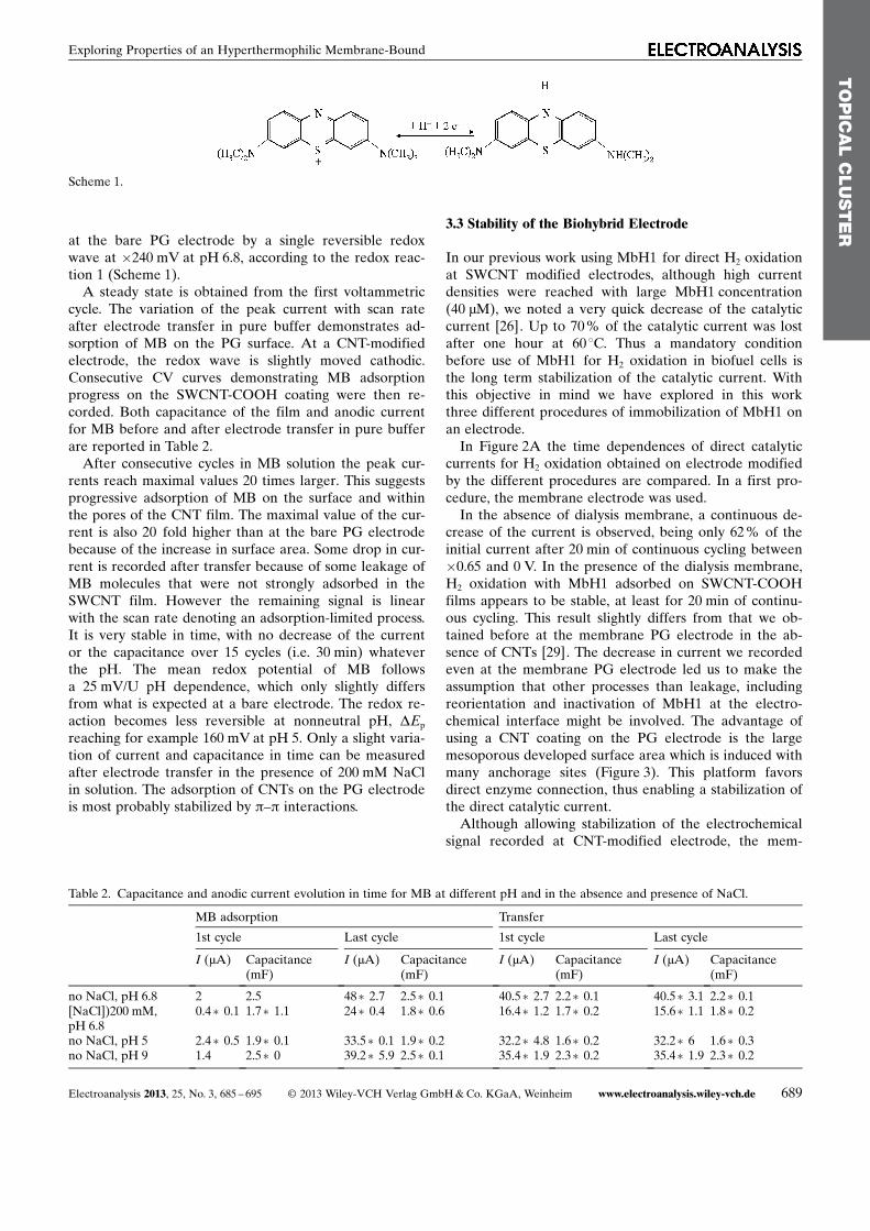
In Figure 2A the time dependences of direct catalyticcurrents for H2 oxidation obtained on electrode modifiedby the different procedures are compared. In a first pro-cedure, the membrane electrode was used.
In the absence of dialysis membrane, a continuous de-crease of the current is observed, being only 62% of theinitial current after 20 min of continuous cycling between�0.65 and 0 V. In the presence of the dialysis membrane,H2 oxidation with MbH1 adsorbed on SWCNT-COOHfilms appears to be stable, at least for 20 min of continu-ous cycling. This result slightly differs from that we ob-tained before at the membrane PG electrode in the ab-sence of CNTs [29]. The decrease in current we recordedeven at the membrane PG electrode led us to make theassumption that other processes than leakage, includingreorientation and inactivation of MbH1 at the electro-chemical interface might be involved. The advantage ofusing a CNT coating on the PG electrode is the largemesoporous developed surface area which is induced withmany anchorage sites (Figure 3). This platform favorsdirect enzyme connection, thus enabling a stabilization ofthe direct catalytic current.
Although allowing stabilization of the electrochemicalsignal recorded at CNT-modified electrode, the mem-
TO
PIC
AL
CLU
STE
R
Scheme 1.
Table 2. Capacitance and anodic current evolution in time for MB at different pH and in the absence and presence of NaCl.
MB adsorption Transfer
1st cycle Last cycle 1st cycle Last cycle
I (mA) Capacitance(mF)
I (mA) Capacitance(mF)
I (mA) Capacitance(mF)
I (mA) Capacitance(mF)
no NaCl, pH 6.8 2 2.5 48�2.7 2.5�0.1 40.5�2.7 2.2�0.1 40.5�3.1 2.2�0.1[NaCl])200 mM,pH 6.8
0.4�0.1 1.7�1.1 24�0.4 1.8�0.6 16.4�1.2 1.7�0.2 15.6�1.1 1.8�0.2
no NaCl, pH 5 2.4�0.5 1.9�0.1 33.5�0.1 1.9�0.2 32.2�4.8 1.6�0.2 32.2�6 1.6�0.3no NaCl, pH 9 1.4 2.5�0 39.2�5.9 2.5�0.1 35.4�1.9 2.3�0.2 35.4�1.9 2.3�0.2
Electroanalysis 2013, 25, No. 3, 685 – 695 � 2013 Wiley-VCH Verlag GmbH & Co. KGaA, Weinheim www.electroanalysis.wiley-vch.de 689
Exploring Properties of an Hyperthermophilic Membrane-Bound
brane configuration is not convenient for future bioelec-trochemical devices such as biofuel cells. Search for mem-brane replacement led us to explore the possibility ofusing polymers such as perfluorinated Nafion or EastmanAQ [39,40]. These polymer matrices behave as cation ex-changers, and have been used earlier in our laboratory toentrap proteins such as cytochromes [40]. Recently,Reuillard et al. protected a tyrosinase based bioelectrodefrom leakage using a film of 0.5 % Nafion [41]. Morraet al. covered an electrode modified by [FeFe] hydroge-nase from Clostridium acetobutylicum with a layer ofNafion neutralized by tetraethylammonium bromide [42].This layer was supposed to decrease enzyme leakage andprotect the hydrogenase from O2 inactivation. When com-pared to unprotected electrode, a decrease of the current
was observed due to mass transport limitations, concomi-tantly with a less pronounced current decay.
In this work, the PG electrode was modified bya SWCNT-COOH layer, then MbH1 was added. Afterdrying, a layer of Nafion diluted to 0.05, 0.1 or 0.5% wasdropped on the enzyme layer. The films obtained fromthe most diluted Nafion solutions did not help in stabiliz-ing the electrocatalytical current. For 0.5% Nafion con-centrations no catalytic current was observed. Otherwise,when either the Nafion layer was formed before MbH1adsorption or when a mixture of Nafion and MbH1 wasdeposited at the CNT modified PG electrode, again nocatalytic current could be observed. Oxygen reduction at�0.4 V was only slightly diminished in the presence of0.5 % Nafion, showing that gas diffusion through the
TO
PIC
AL
CLU
STE
R
Fig. 2. Comparison between immobilization procedures of MbH1 on SWCNT-COOH modified PG electrodes. (A) Evolution withtime of the catalytic currents for H2 oxidation by 2 mM MbH1 immobilized (*) by simple adsorption, (&) in the membrane configura-tion, (�) via EDC/NHS coupling. (B) Native blue gels showing the effect of Nafion on 2 mM MbH1 activity: from left to right: 1)MbH1 after 24 h at 4 8C, 2) MbH1 after 1h incubation in Nafion 0.5 %, 3) MbH1 after 1h incubation in Nafion 0.1 %, 4) MbH1 after24h incubation in Nafion 0.5%, 5) MbH1 after 24 h incubation in Nafion 0.1 %. (C) EDC/NHS covalent coupling: SDS gels stainedwith Coomassie Blue from left to right: 1) Molecular weight markers, 2) MbH1, 3) MbH1 with 400/100 mM EDC/NHS, 4) MbH1 with40/10 mM EDC/NHS, 5) MbH1 with 4/1 mM EDC/NHS. (D) Arginine (in red) and Lysine (in blue) residues present in a sphere of12 � radius centered on the FeS distal cluster of MbH1. MbH1 modelization is based on R. eutropha membrane-bound hydrogenaseas a template (PDB ID: 3RGW [24]).
690 www.electroanalysis.wiley-vch.de � 2013 Wiley-VCH Verlag GmbH & Co. KGaA, Weinheim Electroanalysis 2013, 25, No. 3, 685 – 695
Full Paper A. De Poulpiquet et al.
polymer film is not responsible for the vanishing of thecatalytic current. The effect of both Nafion concentration(0.5 and 0.1 %) and incubation time with MbH1 (1 and24 h) was evaluated using blue native gels (Figure 2B). Inthe time scale of the electrochemistry experiment, Nafionhas no strong effect on MbH1 activity, even when incuba-tion is realized using 0.5 % Nafion. However, upon longerincubation times, gels clearly show that no activity can bedetected in the presence of 0.5 % Nafion, while MbH1alone is still active. This activity is retained, although farless pronounced, using 0.1% Nafion. Electrical insulationof MbH1 due to wrapping by the charged polymer canexplain the absence of electrocatalytic signal at electrodescovered by 0.5 % Nafion films. A preliminary experimentperformed by incubating 0.5 % Nafion polymer with tet-rabutylammonium bromide salts tends to confirm this hy-pothesis. It was previously reported that such polymer ex-hibited larger pore size [35]. In this work, the salt addi-tion allowed to recover H2 catalytic oxidation, althoughthe current was still lower than in the absence of Nafion.Interestingly, a stabilization of the catalytic current wasobserved (Supporting Information S1).
The third procedure for MbH1 immobilization is basedon enzyme cross-linking. This procedure is commonlyused in the case of stabilization of bioelectrodes. As ex-amples nitrite, l-arginine or glucose biosensors were con-structed based on cross-linking by means of glutaralde-hyde of nitrite reductase, arginase and urease, and cello-biose dehydrogenase, respectively [43–45]. Cross-linkingby glutaraldehyde was supposed to suppress leakage ofthe enzymes. Here, electrochemically active MbH1 ad-sorbed on a PG electrode was exposed for a few minutesto glutaraldehyde vapor. After soaking in Hepes buffer,the bioelectrode exhibited smaller activity towards H2 ox-idation, however (Supporting Information S2). This resultcan be understood taking into account that glutaralde-hyde is known to accentuate protein aggregation [46].
Carbodiimide coupling was thus used for covalent cou-pling between the carboxylic-functionalized SWCNT-COOH and lysine and arginine residues on the surface ofMbH1. Various procedures exist to perform this couplingin the literature, including different EDC/NHS concentra-tions and incubation durations. In a very recent report,Krishnan et al. observed an enhanced and stabilized
TO
PIC
AL
CLU
STE
R
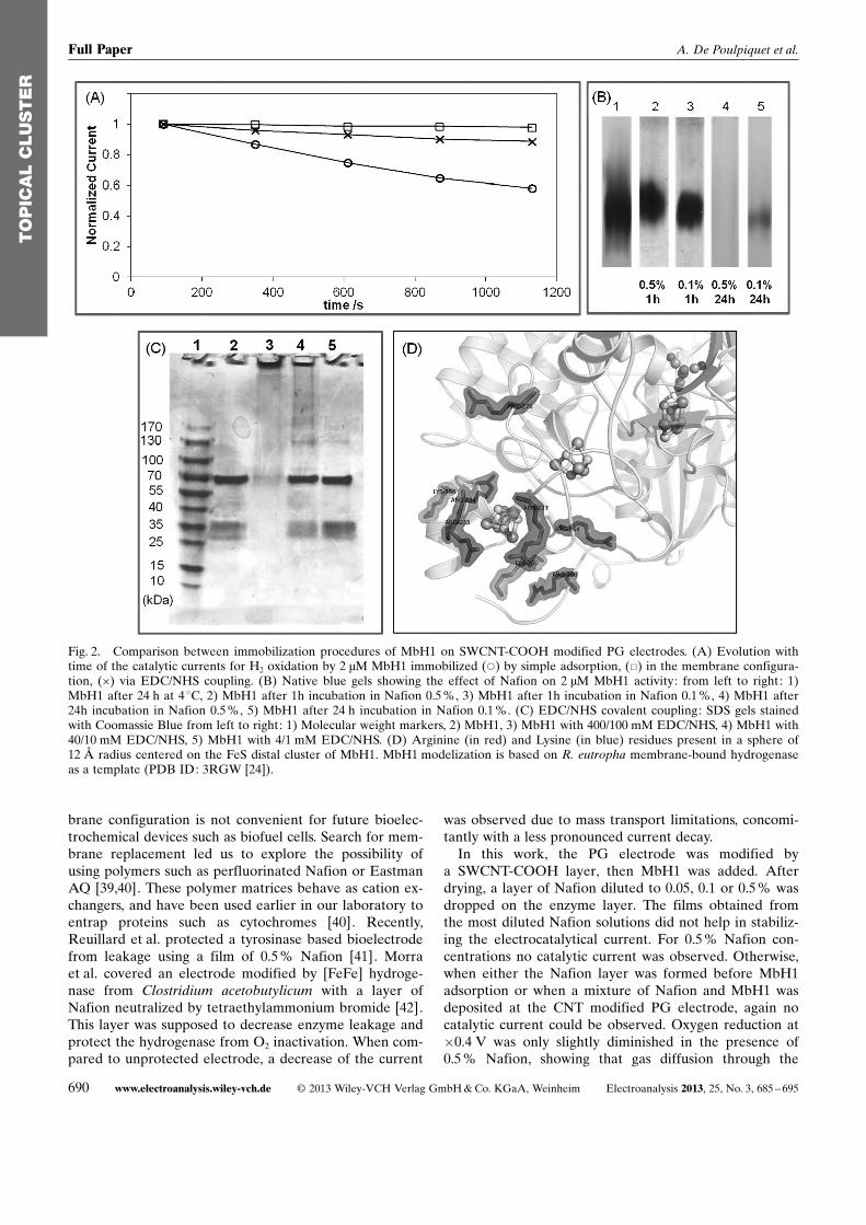
Fig. 3. Evolution with pH of H2 oxidation by MbH1 adsorbed on SWCNT-COOH modified PG electrode; (A) direct catalytic cur-rent evolution with pH; (B) CV curves for pH 5 (dashed line), pH 7.5 (bold line) and pH 9 (fine line); (C) evolution with time of thecatalytic current for H2 oxidation by MbH1 simply adsorbed at pH 5 (^),pH 9 (*), pH 7.5 (�) or covalently coupled at pH 7.5 (+).Britton�Robinson Buffer, 60 8C, 5 mVs�1.
Electroanalysis 2013, 25, No. 3, 685 – 695 � 2013 Wiley-VCH Verlag GmbH & Co. KGaA, Weinheim www.electroanalysis.wiley-vch.de 691
Exploring Properties of an Hyperthermophilic Membrane-Bound
signal for H2 oxidation by covalent coupling of E. coli hy-drogenase on pyrene-functionalized multiwalled carbonnanotubes [32]. The authors used unusually high concen-tration of EDC/NHS to realize the coupling. Althoughthe need for such a high concentration can be linked inthis case to the Tris Buffer, i.e. an amine-based buffer,the determination of the optimal EDC/NHS concentra-tion that allows the coupling while avoiding aggregationis necessary. We used denaturing SDS gels for that pur-pose (Figure 2C). The large and the small sub-units ofMbH1 expected at 72 and 34 kDa are present on the gelswhen MbH1 is incubated with EDC/NHS of 4/1 and 40/10 mM. Based on blue native gels, these EDC/NHS con-centrations were shown to allow similar hydrogenase ac-tivity as with no coupling agent. Conversely, no enzyme isrevealed using 400/100 mM EDC/NHS, suggesting inac-tive aggregation of the enzyme due to an excessiveamount of coupling agent (Figure 2C, line 3).
After covalent coupling of MbH1 using the optimized40/10 mM EDC/NHS concentration, direct catalytic cur-rent for H2 oxidation was observed. This was expectedsince among more than seventy lysine and arginine resi-dues exposed to solvent, seven are present in the vicinityof the distal FeS cluster within a distance compatible withdirect electron transfer (Figure 2D). Moreover, the stabil-ity of the catalytic current was significantly increased ascompared to adsorbed MbH1 (Figure 2A). Whereas thecatalytic current was 60% of the initial value after 20 minwith MbH1 adsorbed on CNT modified electrode, 90 %of the initial current remained, using covalent couplingwith 40/10 mM EDC/NHS.
3.4 pH Effect on Direct H2 Oxidation by MbH1
In view of the development of a membraneless H2/O2 bio-fuel cell, knowledge of pH influence that is relevant forthe efficiency of the bioelectrodes is required. Among theenzymes mostly used for oxygen reduction, laccase isknown to be the most efficient at pH 5, whereas BOD isstill very active at pH 7 [47]. On the other hand, thereare large discrepancies in the optimum pH for H2 oxida-tion by [NiFe] hydrogenases. Typically, the optimal pHfor H2 oxidation was determined using spectrophotomet-ric assays via various electron acceptors. Using methyl vi-ologen, optimal pH for the O2-sensitive hydrogenasesfrom D. fructosovorans and Thiocapsa roseopersicinawere estimated at 8.5 and 9.5, respectively [48,49]. How-ever, direct electrochemistry on O2-sensitive [NiFe] hy-drogenases, like D. fructosovorans [50] and Allochromati-um vinosum [51] revealed a H2 oxidation process inde-pendent on pH. This difference was interpreted in termsof the oxidation of the enzyme by soluble dyes limitingthe rate of turnover in spectrophotometric assays. Asa further illustration, optimum pH for H2 oxidation bythe hydrogenase from H. marinus was found to be 9.4and 7.5 using methyl viologen and benzyl viologen, re-spectively [52,53]. Only in the case of the O2-tolerant hy-drogenase from R. eutropha [54], both spectrometric
assays using methylene blue and direct electrochemistryagreed. A pH-dependent H2 oxidation process was ob-served, with an optimum at pH 5.5.
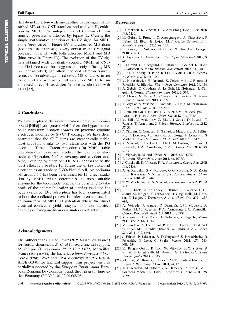
The pH-dependence of H2 direct oxidation is confirmedin this work using MbH1 immobilized on CNT-modifiedPG electrodes. Figure 3 displays the evolution of thedirect catalytic process for H2 oxidation by MbH1 simplyadsorbed on SWCNT-COOH in the pH range 5–9(Figure 3). A belt-shaped evolution of the catalytic cur-rent is obtained with an optimum pH around 7.5. Con-comitantly, mid-potential values of the CV signal shift to-wards more negative potentials in line with the evolutionof the thermodynamic potential of H2/H
+ couple. Thesame pH dependence for direct H2 oxidation was record-ed in the absence of CNT coating, demonstrating that thisbehavior is an intrinsic property of MbH1. Strong effectof pH on the evolution of catalytic activity in time is alsoobserved (Figure 3C). The direct catalytic signal for H2
oxidation is quite stable at pH 5, because in these condi-tions electrostatic interactions between carboxylatedcarbon interface and MbH1 (pI=6.9) are favored. Thestability of the catalytic signal decreases with increasingpH, however, which might be due either to release of theenzyme because of weaker electrostatic interactions, or toprogressive deactivation of the enzyme. At pH 9, onlya very weak activity can be detected upon simple adsorp-tion of MbH1 (Figure 3C). No enhanced activity is ob-served at the membrane electrode, or after MbH1 cova-lent coupling. Transfer of MbH1 modified electrode frompH 9 back to pH 7.5 did not restore the activity towardsH2 oxidation. Intriguingly, spectrophotometric assays inBritton-Robinson buffer at pH 9 allowed an activity closeto that measured at pH 5. Basic pH is thus supposed to ir-reversibly inactivate MbH1 when it is immobilized onCNT layers. For pH close to the pI of MbH1, covalentcoupling of the enzyme to the CNT coating helps in stabi-lizing the signal. Thus the decrease of the stability at neu-tral pH is not linked to deactivation of the enzyme but toelectrostatic interactions that drive the immobilizationprocess on CNT films. For future H2/O2 biofuel cells, theoptimum pH activity for MbH1 induces the choice of anoxidase showing efficient activity for O2 reduction aroundpH 7.5.
3.5 Can a Redox Mediator Help in Overcoming MbH1Inhibition at High Potentials?
We already reported in this work on the reversible inhibi-tion of MbH1 at potentials higher than - 200 mV. Thisfeature is common to all [NiFe] hydrogenases, and is at-tributed to the formation of an inactive state of the activesite, most probably with a hydroxide bridging Ni and Fe.Previous studies using MbH1 immobilized on SAM modi-fied gold electrodes [28], had shown that the addition insolution of MB allowed to mediate the oxidation of H2 atthe potential of MB (�240 mV). This process occurs viaMbH1 not directly connected to the electrode, thus notinhibited by anaerobic oxidation. MB thus appears to en-
TO
PIC
AL
CLU
STE
R
692 www.electroanalysis.wiley-vch.de � 2013 Wiley-VCH Verlag GmbH & Co. KGaA, Weinheim Electroanalysis 2013, 25, No. 3, 685 – 695
Full Paper A. De Poulpiquet et al.
hance the potential window at which H2 can be catalyti-cally oxidized. We also demonstrated that electropolyme-rization of a similar dye, toluidine blue O (TBO), at a PGelectrode, allowed a mixed direct and mediated H2 oxida-tion process with immobilized MbH1, provided that themembrane configuration was applied [29]. It was noticedthat only the TBO monomer-like units retained in thepolymer played an efficient mediator role.
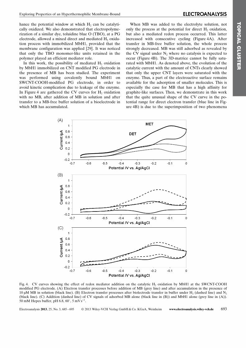
In this work, the possibility of mediated H2 oxidationby MbH1 immobilized on CNT modified PG electrode inthe presence of MB has been studied. The experimentwas performed using covalently bound MbH1 onSWCNT-COOH-modified PG electrode, in order toavoid kinetic complication due to leakage of the enzyme.In Figure 4 are gathered the CV curves for H2 oxidationwith no MB, after addition of MB in solution and aftertransfer to a MB-free buffer solution of a bioelectrode inwhich MB has accumulated.
When MB was added to the electrolyte solution, notonly the process at the potential for direct H2 oxidation,but also a mediated redox process occurred. This latterincreased with consecutive cycling (Figure 4A). Aftertransfer in MB-free buffer solution, the whole processstrongly decreased. MB was still adsorbed as revealed bythe CV signal under N2 where no catalysis is expected tooccur (Figure 4B). The 3D-matrice cannot be fully satu-rated with MbH1. As denoted above, the evolution of thecatalytic current with the amount of CNTs clearly showedthat only the upper CNT layers were saturated with theenzyme. Thus, a part of the electroactive surface remainsavailable for the adsorption of smaller molecules. This isespecially the case for MB that has a high affinity forgraphite-like surfaces. Then, we demonstrate in this workthat the quite unusual shape of the CV curve in the po-tential range for direct electron transfer (blue line in Fig-ure 4B) is due to the superimposition of two phenomena
TO
PIC
AL
CLU
STE
R
Fig. 4. CV curves showing the effect of redox mediator addition on the catalytic H2 oxidation by MbH1 at the SWCNT-COOHmodified PG electrode. (A) Electron transfer processes before addition of MB (grey line) and after accumulation in the presence of10 mM MB in solution (black line). (B) Electron transfer processes after biolectrode transfer in buffer under H2 (dashed line) and N2
(black line). (C) Addition (dashed line) of CV signals of adsorbed MB alone (black line in (B)) and MbH1 alone (grey line in (A)).50 mM Hepes buffer, pH 6.8, 608, 5 mVs�1.
Electroanalysis 2013, 25, No. 3, 685 – 695 � 2013 Wiley-VCH Verlag GmbH & Co. KGaA, Weinheim www.electroanalysis.wiley-vch.de 693
Exploring Properties of an Hyperthermophilic Membrane-Bound
that do not interfere with one another: redox signal of ad-sorbed MB at the CNT interface, and catalytic H2 oxida-tion by MbH1. The independence of the two electrontransfer processes is attested by Figure 4C. Clearly, thesimple mathematical addition of the CV signal for MbH1alone (grey curve in Figure 4A) and adsorbed MB alone(red curve in Figure 4B) is very similar to the CV signalobtained under H2 with both adsorbed MbH1 and MB(blue curve in Figure 4B). The evolution of the CV sig-nals obtained with covalently coupled MbH1 at CNT-modified electrode thus suggests that only diffusing MB(i.e. nonadsorbed) can allow mediated electron transferto occur. The advantage of adsorbed MB would be to actas an electrical wire in case of uncoupled MbH1 for anenhanced direct H2 oxidation (as already observed withTBO [29]).
4 Conclusions
We have explored the immobilization of the membrane-bound [NiFe] hydrogenase MbH1 from the hyperthermo-philic bacterium Aquifex aeolicus on pyrolytic graphiteelectrodes modified by SWCNT coatings. We have dem-onstrated that the CNT films are mechanically stable,most probably thanks to p–p interactions with the PGelectrode. Three different procedures for MbH1 stableimmobilization have been studied: the membrane elec-trode configuration, Nafion coverage and covalent cou-pling. Coupling by mean of EDC/NHS appears to be themost efficient procedure for future use of the biohybridelectrode as an anode in H2/O2 biofuel cell. An optimumpH around 7.5 has been determined for H2 direct oxida-tion by MbH1, which determines the most suitableenzyme for the biocathode. Finally, the possibility to takeprofit of the co-immobilization of a redox mediator hasbeen evaluated. Dye adsorption has been demonstratedto limit the mediated process. In order to ensure mediat-ed connection of MbH1 at potentials where the directelectrical connection yields enzyme inhibition, matricesenabling diffusing mediators are under investigation.
Acknowledgements
The authors thank Dr M. Ilbert (BIP, Marseilles, France)for fruitful discussions, E. Civel for experimental support,M. Bauzan (Fermentation Plant Unit IMM, Marseilles,France) for growing the bacteria, R�gion Provence-Alpes-C�te d�Azur, CNRS and ANR Bio�nergie N8 ANR-2010-BIOE-003-01 for financial support. This project was alsopartially supported by the European Union within Euro-pean Regional Development Fund, through grant Innova-tive Economy (POIG.01.01.02-00-008/08).
References
[1] J. Cracknell, K. Vincent, F. A. Armstrong, Chem. Rev. 2008,108, 2439.
[2] M. Guiral, L. Prunetti, C. Aussignargues, A. Ciaccafava, P.Infossi, M. Ilbert, E. Lojou, M. T. Giudici-Orticoni, Adv.Microbiol. Physiol. 2012, 61, 125.
[3] I. Ivanov, T. Vidakovic-Koch, K. Sundmacher, Energies2010, 3, 803.
[4] K. Egorova, G. Antranikian, Cur. Opin. Microbiol. 2005, 8,649.
[5] F. Durand, C. Kjaergaard, E. Suraniti, S. Gounel, R. Hadt,E. Solomon, N. Mano, Biosens. Bioelectron. 2012, 35, 140.
[6] J. Liu, X. Zhang, H. Pang, B. Liu, Q. Zou, J. Chen, Biosens.Bioelectron. 2012, 31, 170.
[7] M. Karaskiewicz, E. Nazaruk, K. Zelechowska, J. Biernat, J.Rogalski, R. Bilewicz, Electrochem. Commun. 2012, 20, 124.
[8] A. Zebda, C. Gondran, A. Le Goff, M. Holzinger, P. Cin-quin, S. Cosnier, Nature Commun. 2011, 2, 370.
[9] V. Flexer, N. Brun, O. Courjean, R. Backov, N. Mano,Energ. Environ. Sci. 2011, 4, 2097.
[10] T. Miyake, S. Yoshino, T. Yamada, K. Hata, M. Nishizawa,J. Am. Chem. Soc. 2011, 133, 5129.
[11] L. Halamkova, J. Halamek, V. Bocharova, A. Szczupak, L.Alfonta, E. Katz, J. Am. Chem. Soc. 2012, 134, 5040.
[12] M. Falk, V. Andoralov, Z. Blum, J. Sotres, D. Suyatin, T.Ruzgas, T. Arnebrant, S. Shleev, Biosens. Bioelectron. 2012,37, 38.
[13] P. Cinquin, C. Gondran, F. Giroud, S. Mazabrard, A. Pelliss-ier, F. Boucher, J. P. Alcaraz, K. Gorgy, F. Lenouvel, S.Math�, P. Porcu, S. Cosnier, PLoS ONE 2010, 5 e10476.
[14] K. Vincent, J. Cracknell, J. Clark, M. Ludwig, O. Lenz, B.Friedrich, F. A. Armstrong, J. Am. Chem. Soc. 2006, 48,5033.
[15] P. Vignais, B. Billoud, Chem. Rev. 2007, 107, 4206.[16] E. Lojou, Electrochim. Acta 2011, 56, 10385.[17] J. Cracknell, K. Vincent, F. A. Armstrong, Chem. Rev. 2008,
108, 2439.[18] A. A. Karyakin, S. V. Morozov, O. G. Voronin, N. A. Zorin,
E. E. Karyakina, V. N. Fateyev, S. Cosnier, Angew. Chem.Int. Ed. 2007, 46, 7244.
[19] T. W. Woolerton, K. A. Vincent, Electrochim. Acta 2009, 54,5011.
[20] P. P. Liebgott, A. de Lacey, B. Burlat, L. Cournac, P. Ri-chaud, M. Brugna, V. Fernandez, B. Guigliarelli, M. Rous-set, C. Le�ger, S. Dementin, J. Am. Chem. Soc. 2011, 133,986.
[21] A. Volbeda, P. Amara, C. Darnault, J. M. Mouesca, A.Parkin, M. M. Roessler, F. A. Armstrong, J. C. Fontecilla-Camps, Proc. Natl. Acad. Sci. 2012, 10, 5305.
[22] Y. Shomura, K. S. Yoon, H. Nishihara, Y. Higuchi, Nature2011, 479, 253-NIL 143.
[23] M. Pandelia, V. Fourmond, P. Tron, E. Lojou, P. Bertrand,C. L�ger, M. T. Giudici-Orticoni, W. Lubitz, J. Am. Chem.Soc. 2010, 132, 6991.
[24] J. Fritsch, P. Scheerer, S. Frielingsdorf, S. Kroschinsky, B.Friedrich, O. Lenz, C. Spahn, Nature 2011, 479, 249-NIL 134.
[25] M. Brugna-Guiral, P. Tron, W. Nitschke, K-O. Stetter, B.Burlat, B. Guigliarelli, M. Bruschi, M. T. Giudici-Orticoni,Extremophiles 2003, 7, 145.
[26] XJ. Luo, M. Brugna, P. Infossi, M. T. Giudici-Orticoni, E.Lojou, J. Biol. Inorg. Chem. 2009, 14, 1275.
[27] A. Ciaccafava, M. Alberola, S. Hameury, P. Infossi, M. T.Giudici-Orticoni, E. Lojou, Electrochim. Acta 2011, 56,3359.
TO
PIC
AL
CLU
STE
R
694 www.electroanalysis.wiley-vch.de � 2013 Wiley-VCH Verlag GmbH & Co. KGaA, Weinheim Electroanalysis 2013, 25, No. 3, 685 – 695
Full Paper A. De Poulpiquet et al.
[28] A. Ciaccafava, P. Infossi, M. Ilbert, M. Guiral, S. Lecomte,M. T. Giudici-Orticoni, E. Lojou, Angew. Chem. Int. Ed.2012, 51, 953.
[29] A. Ciaccavafa, P. Infossi, M. T. Giudici-Orticoni, E. Lojou,Langmuir 2010, 26, 18534.
[30] P. Infossi, E. Lojou, J. P. Chauvin, G. Herbette, M. Brugna,M. T. Giudici-Orticoni, Int. J. Hyd. Energ. 2010, 35, 10778.
[31] A. Ciaccafava, A. De Poulpiquet, P. Infossi, S. Robert, R.Gadiou, M. T. Giudici-Orticoni, S. Lecomte, E. Lojou, Elec-trochim. Acta 2012, 82, 115.
[32] S. Krishnan, F. A. Armstrong, Chem. Sci. 2012, 3, 1015.[33] A. Ciaccafava, A. de Poulpiquet, V. Techer, M. T. Giudici-
Orticoni, S. Tingry, C. Innocent, E. Lojou, Electrochem.Commun. 2012, 23, 25.
[34] E. Lojou, X. Luo, M. Brugna, N. Candoni, S. Dementin,M. T. Giudici-Orticoni, J. Biol. Inorg. Chem. 2008, 13, 1157.
[35] C. M. Moore, N. L. Akers, A. D. Hill, Z. C. Johnson, S. D.Minteer, Biomacromolecules 2004, 5, 1241.
[36] M. Correira dos Santos, P. Paes de Sousa, M. Simoes Gon-calves, L. Krippahl, J. Moura, E. Lojou, P. Bianco, J. Elec-troanal. Chem. 2003, 541, 153.
[37] E. Lojou, P. Bianco, J. Electroanal. Chem. 2000, 485, 71.[38] E. Lojou, P. Bianco, Electroanalysis 2004, 16, 1113.[39] E. Lojou, P. Luciano, S. Nitsche, P. Bianco, Electrochim.
Acta 1999, 44, 3341.[40] E. Lojou, P. Bianco, J. Electroanal. Chem. 2003, 557, 37.[41] B. Reuillard, A. Le Goff, C. Agn�s, A. Zebda, M. Holzing-
er, S. Cosnier, Electrochem. Commun. 2012, 20, 19.[42] S. Morra, F. Valetti, S. J. Sadeghi, P. W. King, T. Meyer, G.
Gilardi, Chem. Commun. 2011, 47, 10566.
[43] H. Chen, C. Mousty, S. Cosnier, C. Silveira, J. J. Moura,M. G. Almeida, Electrochem. Commun. 2007, 9, 2240.
[44] M. Zafar, G. Safina, R. Ludwig, L. Gorton, Anal. Biochem.2012, 425, 36.
[45] O. Saiapina, S. Dzyadevych, N. Jaffrezic-Renault, P. Soldat-kin, Talanta 2012, 92, 58.
[46] G. Karthikeyan, G. Lakshmikant, W. Wagle, G. Krishna-moorthy, B. J. Rao, J. Mol. Microbiol. Biotechnol. 1999, 1,149.
[47] K. Otsuka, T. Sugihara, Y. Tsujino, T. Osakai, E. Tamiya,Anal. Biochem. 2007, 370, 98.
[48] S. Dementin, B. Burlat, A. De Lacey, A. Pardo, G. Adryanc-zyk-Perrier, B. Guigliarelli, V. Fernandez, M. Rousset, J.Biol. Chem. 2004, 11, 10508.
[49] N. Zorin, B. Dimon, J. Gagnon, J. Gaillard, P. Carrier, P. Vi-gnais, Eur. J. Biochem. 1996, 241, 675.
[50] C. L�ger, S. Dementin, P. Bertrand, M. Rousset, B. Guigliar-elli, J. Am. Chem. Soc. 2006, 128, 5209.
[51] C. L�ger, A. Jones, W. Roseboom, S. Albracht, F. Arm-strong, Biochemistry 2002, 41, 15736.
[52] H. Nishihara, Y. Miyashita, K. Aoyama, T. Kodama, Y. Igar-ashi, Y. Takamura, Biochem. Biophys. Res. Commun. 1997,232, 766.
[53] K-S. Yoon, K. Fukuda, K. Fujisawa, H. Nishihara, Int. J.Hyd. Energ. 2011, 36, 7081.
[54] M. Ludwig, J. Cracknell, K. Vincent, F. Armstrong, O. Lenz,J. Bioanal. Chem. 2009, 284, 465.
TO
PIC
AL
CLU
STE
R
Electroanalysis 2013, 25, No. 3, 685 – 695 � 2013 Wiley-VCH Verlag GmbH & Co. KGaA, Weinheim www.electroanalysis.wiley-vch.de 695
Exploring Properties of an Hyperthermophilic Membrane-Bound


![Analysis of [FeFe]hydrogenase genes for the elucidation of a ...](https://static.fdokumen.com/doc/165x107/6324e1b9051fac18490cfd07/analysis-of-fefehydrogenase-genes-for-the-elucidation-of-a-.jpg)