Biofuel-driven Biorefineries | Nachhaltig Wirtschaften
38
This report, that was prepared on behalf of IEA Bioenergy – Task42 Biorefinery, addresses a selection of the most promising biorefinery concepts to produce large volumes of road transportation biofuels by 2025. Biorefining, i.e. the sustainable processing of biomass into a spectrum of marketable bio-based products (food/feed ingredients, chemicals, materials) and bioenergy (fuels, power, heat), is the optimal approach to use biomass resources as efficient as possible, thereby optimising the specific financial added-value obtained from the biomass at acceptable social and ecological impact. In energy or biofuel-driven biorefineries the main focus is to produce transportation fuels from biomass, where chain composing agro-, forestry and process residues are used to co-produce added-value bio-based products to make the overall product portfolio more market competitive. The road transportation biofuels produced in both commercial scale, demonstration scale and conceptual biofuel-driven biorefineries dealt with in this report are: 1) biodiesel from oilseed crops and residues, 2) bioethanol from sugar and starch crops, 3) bioethanol from straw – biochemical pathway, 4) bioethanol from wood – combined bio-/thermochemical pathway, 5) bio-methane from grass and manure, 6) bio-methane from wood, 7) FT- biofuels from straw, 8) FT-biofuels from wood, 9) bioethanol from wood and liquor, 10) bioethanol from starch crops and straw, 11) biofuels from microalgae. Concepts 3, 4, and 5 are environmentally assessed in more detail in section 5. The purpose of the report is to provide an unbiased, authoritative statement aimed at stakeholders from the agro- sector, forestry-sector, industry, SMEs, policy makers, and NGOs. Biofuel-driven Biorefineries IEA Bioenergy – Task42 Biorefinery A Selection of the Most Promising Biorefinery Concepts to Produce Large Volumes of Road Transportation Bofuels by 2025
-
Upload
khangminh22 -
Category
Documents
-
view
2 -
download
0
Transcript of Biofuel-driven Biorefineries | Nachhaltig Wirtschaften

IEA Bioenergy is an international collaboration set-up
in 1978 by the International Energy Agency (IEA) to
improve international co-operation and information
exchange between national bioenergy RD&D programmes.
IEA Bioenergy’s vision is to achieve a substantial
bioenergy contribution to future global energy demands
by accelerating the production and use of environmentally
sound, socially accepted, and cost-competitive bioenergy on
a sustainable basis, thus providing the increased security
of supply whilst reducing greenhouse gas emissions from
energy use. Currently, IEA Bioenergy has 24 Members and
is operating on the basis of 12 Tasks covering all aspects of
the bioenergy chain, from resource to the supply of energy
services to the consumer.
Further Information
IEA Bioenergy Task42 Websitewww.iea-bioenergy.task42-biorefi neries.com
IEA Bioenergy Websitewww.ieabioenergy.com
Contact – IEA Bioenergy Task42 SecretariatWageningen UR – Food and Bio-based Research
Hilde Holleman – Secretary
P.O. Box 17
6700 AA Wageningen
The Netherlands
Phone: +31 317 481165
Email: [email protected]
Leader of Task42René van Ree
Wageningen UR – Food and Bio-based Research
Phone: +31 317 611894
Email: [email protected]
Co-leader of Task42Ed de Jong
Avantium Chemicals BV
Amsterdam
The Netherlands
Phone: +31 20 586 80 80
Email: [email protected]
Operating Agent Task42Kees Kwant
NL Agency
Ministry of Economic Affairs, Agriculture and Innovation
Utrecht
The Netherlands
Phone: +31 88 602 2458
Email: [email protected]
Report PreparationThis Task42 report is prepared by the Austrian Task
representative Joanneum Research Forschungsgesellschaft
mbH with input from the other Task representatives.
Main author and contact: Gerfried Jungmeier
Phone: +43 316 876 1313
Email: [email protected]
The Austrian participation in Tasks 42 of IEA Bioenergy is
fi nanced by the Federal Ministry for Transport, Innovation
and Technology / Department for Energy and Environmental
Technologies.
This report, that was prepared on behalf of IEA Bioenergy – Task42 Biorefi nery, addresses a selection of the most promising biorefi nery concepts to produce large volumes of road transportation biofuels by 2025. Biorefi ning, i.e. the sustainable processing of biomass into a spectrum of marketable bio-based products (food/feed ingredients, chemicals, materials) and bioenergy (fuels, power, heat), is the optimal approach to use biomass resources as effi cient as possible, thereby optimising the specifi c fi nancial added-value obtained from the biomass at acceptable social and ecological impact. In energy or biofuel-driven biorefi neries the main focus is to produce transportation fuels from biomass, where chain composing agro-, forestry and process residues are used to co-produce added-value bio-based products to make the overall product portfolio more market competitive.The road transportation biofuels produced in both commercial scale, demonstration scale and conceptual biofuel-driven biorefi neries dealt with in this report are: 1) biodiesel from oilseed crops and residues, 2) bioethanol from sugar and starch crops, 3) bioethanol from straw – biochemical pathway, 4) bioethanol from wood – combined bio-/thermochemical pathway, 5) bio-methane from grass and manure, 6) bio-methane from wood, 7) FT-biofuels from straw, 8) FT-biofuels from wood, 9) bioethanol from wood and liquor, 10) bioethanol from starch crops and straw, 11) biofuels from microalgae. Concepts 3, 4, and 5 are environmentally assessed in more detail in section 5.The purpose of the report is to provide an unbiased, authoritative statement aimed at stakeholders from the agro-sector, forestry-sector, industry, SMEs, policy makers, and NGOs.
IEA Bioenergy Task42 Biorefi nery deals with knowledge
building and exchange within the area of biorefi ning, i.e.
the sustainable processing of biomass into a spectrum
of marketable Bio-based Products and Bioenergy. The
Task was started in 2007, and is now very successfully in
operation involving Australia, Austria, Canada, Denmark,
France, Germany, Ireland, Italy, Netherlands, Turkey,
United Kingdom, United States of America. Within the
fi rst triennium (2007-2009) the main focus of activities
was on setting a common international framework on
biorefi ning (i.e. defi nition, classifi cation system, state-of-
the-art in participating countries). In the second (this)
triennium (2010-2012) the focus of the activities is on the
integral technical, economic and ecological assessments
of full biofuel-driven biorefi neries; the analysis of the
types of Bio-based Chemicals that potentially could be
co-produced with secondary energy carriers to maximise
full biomass valorisation chain economics, and to minimise
the overall environmental impact (this report), to study
overall sustainability aspects of integrated biorefi neries,
and to organise a Biorefi ning Summer School to get
both industrial stakeholders, policy makers and students
acquainted with the principles, current state-of-the-
art, and future possibilities of applying the biorefi ning
approach as base for a Bio-based Economy. Task42 will
continue in the next triennium (2013-2015) with main
focus on tackling market deployment aspects for integrated
biorefi neries, supporting stakeholders in the energy sector
fi nding their position within a future Bio(-based) Economy,
optimal sustainable use of biomass for Food and Non-food
applications, and dissemination & training activities.
Biofuel-driven Biorefi neries
IEA Bioenergy – Task42 Biorefi nery
| Task 42 Biorefi nery
This publication was produced by the Implementing Agreement on Bioenergy Task 42 Biorefi nery, which forms part of a programme of international energy technology collaboration undertaken under the auspices of the International Energy Agency.
A Selection of the Most Promising Biorefi nery Concepts to
Produce Large Volumes of Road Transportation Bofuels by 2025
Omslag IEA Report Biofuel-driven Biorefineries_v4.indd 1 11/03/2013 09:20:38
Biofuel-driven Biorefineries A selection of the most promising biorefinery concepts to produce large volumes
of road transportation biofuels by 2025
Publication dateFebruary 2013
Report prepared byGerfried Jungmeier and Maria Hingsamer, Joanneum Research (Austria)
René van Ree, WUR Food and Biobased Research (Netherlands)
With input fromHenning Jørgensen, University of Copenhagen (Denmark)
Maria Wellisch, Agriculture and Agri-Food Canada (Canada)
Heinz Stichnote, Johann Heinrich von Thunen-Institut (Germany)
Reinhard Rauch, Vienna University of Technology (Austria)
Ed de Jong, Avantium Chemicals (Netherlands)
Isabella De Bari, ENEA (Italy)
on behalf of
The authors want to thank all other Task members for their contribution in various discussions.
Disclaimer: Whilst the information in this publication is derived from reliable sources an reasonable care has been
taken in the compilation, IEA Bioenergy, its Task42 Biorefinery, and the authors of the publication cannot make any
representation of warranty, expressed or implied, regarding the verity, accuracy, adequacy or completeness of the
information contained herein. IEA Bioenergy, its Task42 Biorefinery, and the authors do not accept any liability towards
the readers and users of the publication for any inaccuracy, error, or omission, regardless of the cause, or any damages
resulting therefrom. In no event shall IEA Bioenergy, its Task42 Biorefinery or the authors have any liability for loss of
profits and/or indirect, special, punitive or consequential damages.
| Task 42 Biorefinery
Omslag IEA Report Biofuel-driven Biorefineries_v4.indd 2 11/03/2013 09:20:38

1
TABLE OF CONTENTS
INTRODUCTION 2 1.
1.1 Description of an energy or biofuel-driven biorefinery 2 1.2 Classification (naming) of biorefineries 2
APPROACH 3 2.
SELECTION OF ROAD TRANSPORTATION BIOFUELS, BIO-BASED PRODUCTS AND 3.FEEDSTOCKS 3 3.1 Selection procedure 3 3.2 Road transportation biofuels 4
IDENTIFICATION OF BIOFUEL-DRIVEN BIOREFINERIES 5 4.
4.1 Selected biofuel-driven biorefineries 5 4.2 Commercial scale biofuel-driven biorefineries 5
Biodiesel from oilseed crops and residues 5 4.2.1
Bioethanol from sugar and starch crops 8 4.2.2
4.3 Demonstration scale biofuel-driven biorefineries 10 Bioethanol from straw 10 4.3.1
Bioethanol from wood 11 4.3.2
Bio-methane from grass and manure 13 4.3.3
Bio-methane from wood 14 4.3.4
FT-biofuels from straw 16 4.3.5
FT-biofuels from wood 17 4.3.6
4.4 Conceptual biofuel-driven biorefineries 19 Bioethanol from wood and liquor 19 4.4.1
Bioethanol from starch crops and straw 20 4.4.2
Biofuels from microalgae 22 4.4.3
4.5 Possible combination of biofuel-driven biorefineries 25
ASSESSMENT OF BIOREFINERIES 25 5.
5.1 Introduction 25 5.2 Methodology 26 5.3 Examples for determination of conventional systems 26
Bioethanol from wood 27 5.3.1
Bio-methane from grass 27 5.3.2
Bioethanol from straw 27 5.3.3
5.4 Case study for environmental assessment of a biorefinery 29
DISCUSSION & CONCLUSIONS 34 6.
OUTLOOK 34 7.
REFERENCES 34 8.

2
INTRODUCTION 1.
1.1 Description of an energy or biofuel-
driven biorefinery
IEA Bioenergy Task42 “Biorefineries“ has defined biorefinery as follows: “Biorefining is the sustainable processing of biomass into a spectrum of marketable bio-based products (food/feed ingredients, chemicals, materials) and bioenergy (biofuels, power and/or heat)” (see Figure 1). There are two different motivations recognised for the development of biorefineries (see Figure 2), viz.: 1) energy or biofuel production and 2) the production of a portfolio of bio-based products. In energy or biofuel-driven biorefineries biomass is primarily used for the production of road transportation biofuels, power and heat. Process residues are sold or even further upgraded to value-added bio-based products to provide further economic and environmental benefits. In product driven biorefineries biomass is typically fractionated into a portfolio of bio-based products with the focus being to derive the highest economic value from the biomass. A cascade approach is often used where the agro- and process residues are used for power and/or heat production. In Figure 3 the product trade-off of market volume and price of gaseous biofuels, liquid transportation biofuels, biomaterials and biochemicals is shown. Due to the current low price of fossil fuels, the market price of transportation biofuels is lower compared to the chemicals and materials; however, the market volume is significantly higher. Currently, it is difficult to identify the most promising biorefinery product portfolio with the most interesting economic potential, as many framework conditions must be considered, e.g.: raw material prices, energy prices, regulatory conditions like 10% renewable transportation fuels in Europe 2020 according to the Renewable Energy Directive (RED). Beside answering to the demand for food and feed, the main interest of the International Energy Agency is to produce bioenergy in various forms. A transportation biofuel-driven biorefinery aims to produce huge volumes of liquid and/or gaseous transportation fuels from biomass co-producing (high) added-value food/feed ingredients and/or bio-based chemicals/materials. The expectation is that the co-produced bio-based products will give additional economic and environmental benefits both reducing production costs and the environmental impacts of the transportation biofuels. It is evident however that overall optimisation strategies are necessary as a trade-off between maximising the amount of transportation biofuels production and the additional benefits from co-producing bio-based products.
Figure 1. Definition of biorefinery (IEA Bioenergy Task42 “Biorefineries”).
Figure 2. The energy-driven and product-driven biorefinery.
Figure 3. Product trade-off – Market volume and price.
1.2 Classification (naming) of
biorefineries
IEA Bioenergy Task42 has developed a classification (naming) scheme to describe different biorefineries obviously. The classification of a biorefinery consists of the following four features (see Figure 4): 1. Platforms 2. Products 3. Feedstocks 4. Processes With the combination of these four features, different biorefinery configurations can be described in a consistent manner. The first three elements in the classification system are always necessary, whereas the inclusion of processes is optional.
Biorefinery
“Energy-driven” biorefinery
e.g. bioethanol,FT-biofuels
“Product-driven” biorefinery
e.g. wheat flour, pulp&paper, lactic acid

3
Figure 4. The 4 features to characterise a biorefinery system.
The classification scheme will be used for the description of the selected energy or biofuel-driven biorefinery systems in this report. For simplification in most of the cases electricity and heat are combined into one platform “electricity&heat”. In Figure 5 a generic classification scheme of a biorefinery is shown on the left hand side, and an example of the production of biodiesel, glycerin and animal feed from oilseed crops in a classified biorefinery on the right hand side.
Figure 5. Classification scheme of a biorefinery: generic scheme (left), example (right) “1-platform (oil) biorefinery using oilseed crops for biodiesel, glycerin and feed via pressing,
esterification and distillation”.
The most important feature is the platform. Platforms might be (see Figure 6): intermediate products from biomass feedstocks towards products or linkages between different biorefinery concepts or final products.
Figure 6. Examples for possible platforms in a biorefinery system.
The platforms might represent mixtures of compounds (C6&lignin, C5&C6 sugars) or more isolated compounds. For the platform “electricity and heat” it is important to define, if electricity and heat are produced from process residues, directly from biomass feedstock, fossil fuels, or other forms of renewable energy (e.g. wind, solar). Electricity and heat can be produced within the biorefinery plant e.g. from process residues or can be covered by external supply.
APPROACH 2.
The approach adopted in this report is to describe a selection the most promising energy or biofuel-driven biorefineries already existing today or having the potential for implementation by 2025. The identification of the biorefinery concepts is done based on a selection procedure of the most promising road transportation biofuels, bio-based products and feedstocks with their possible combinations in biorefinery systems. Transportation biofuels for aviation and ships are not covered here. Based on the ongoing activities in the 11 partnering countries in Task42 (AT, AUS, CAN, DEN, FRA, GER, IT, IR, NL, TUR, US), Task42 has identified and assessed the current status and development potential of energy or biofuel-driven biorefineries. These assessments are based on a “full value chain approach”, covering raw material supply, conversion processes and final product applications in an integrated approach.
SELECTION OF ROAD 3.
TRANSPORTATION BIOFUELS,
BIO-BASED PRODUCTS AND
FEEDSTOCKS
3.1 Selection procedure
The selection was done in three steps, viz. 1) selection of the road transportation biofuel concerned, 2) listing of to be co-produced bio-based products, and 3) selection of possible feedstocks. The main motivation of the selection procedure was to produce large volumes of road transportation biofuels at low costs in order to contribute substantially to the goal of increasing the share of renewable road transportation fuels e.g. in Europe 10% in 2020 according to the Renewable Energy Directive (RED). As a first step, a selection of the most interesting road transportation biofuels, bio-based products and feedstocks was carried out. The selection started with road transportation biofuels that are well suited to the current infrastructure for gasoline, diesel and natural gas for the existing vehicle fleet, e.g. utilizing the current infrastructure of pumps, pipelines and other existing equipment.

4
Therefore, the most interesting road transportation biofuels are considered to be “drop in” biofuels that can be easily mixed and used in internal combustion engines in different blends with the fossil road transportation fuels. This selection concluded with the following four road transportation biofuels: 1) biodiesel (FAME - fatty acid methyl ester), 2) bioethanol, 3) Fischer-Tropsch (FT)-biofuels, and 4) bio-methane from upgraded biogas and synthetic natural gas (SNG). Without modifications of the engine the blending of biodiesel to diesel, and that of bioethanol to gasoline, is limited to 10vol-%. In modified engines also higher blends are possible (e.g. a flexi-fuel vehicle (FFV) for bioethanol up to 85vol-% (E85)). In the second step the processes to produce these four road transportation biofuels were analysed with respect to the bio-based co-products that resulted from different conversion processes. This resulted in the identification of the following bio-based products: animal feed, glycerin, sugar, phenol, pulp and paper, amino acids, lactic acid, methanol, fertilizer, waxes, hydrogen1 and carbon dioxide. In the third step the raw materials to produce these four road transportation biofuels were identified which led to the identification of the following feedstocks: oilseed crops, oil based residues, sugar crops, starch crops, wood chips, straw, grass, saw mill residues, microalgae and manure.
The feedstock straw is a co-product from oilseed and starch crops. The following biorefinery platforms are involved: oil, C6 sugars, C5 sugars, bagasse, lignin, lignin and C6 sugars, green pressate, fibres, biogas, bio-methane, syngas, pyrolysis oil and slurry, hydrogen, (black/sulphite) liquor, pulp, electricity and heat. The following processes are involved: thermochemical processes (combustion, steam and oxygen gasification, pyrolysis), biochemical processes (fermentation, anaerobic fermentation, hydrolysis), mechanical processes (pressing, distillation, filtration, fractionation, drying, (biogas) upgrading, hydro-processing, separation, extraction, and chemical processes (esterification, methanation, steam reforming, FT-synthesis, methanol-synthesis).
3.2 Road transportation biofuels
The main characteristics of the four road transportation biofuels are presented in Table 1, including the feedstock, the production processes, the co-products, the state of technology, the biofuel heating value, the density, and the application in an internal combustion engine.
Table 1. Main characteristics of the four selected road transportation biofuels.
Characteristics Biodiesel (FAME - Fatty Acid Methyl
Esters)
Bioethanol Biomethane Synthetic biofuels
Main feedstocks - Oils from
agricultural crops (rapeseed,
sunflower, soybean, palm oil)
- Waste cooking oil - Animal fats
- Microalgae
- Sugars and starch from
agricultural crops, (sugar cane, cereals, sugar beets)
- Lignocellulosic biomass (forestry residues, agricultural
residues, energy crops) - Macroalgae
- Biogas via fermentation:
energy crops, manure, organic residues
- SNG via gasification: energy crops and trees,
agricultural food & feed crops, agricultural crop
residues, wood residues
- Energy crops and
trees - Agricultural food and
feed crops - Agricultural crop
residues - Wood residues
Production
processes
Esterification of oils
and fats
Fermentation of sugars
Pre-treatment/hydrolysis (LC biomass)
- Upgraded biogas from
anaerobic fermentation - Methanation of syngas
from gasification
Catalytic reaction of
syngas
Typical co-products
Animal feed, glycerin Straw2)
Animal feed (sugars, starch), CO2, Straw2)
Lignin (from lignocellulose)
Fertilizer (digestate from fermenter)
Bottom/fly-ash gasifier
Heat Ash/Slag gasifier
State of
technology
Commercial Commercial
Demo plant for lignocellulose
Commercial from biogas
Pilot plant from syngas
Pilot plant
Heating value1) 36.9 MJ/kg 26.7 MJ/kg 49.0 MJ/kg 41.7 – 42.9 MJ/kg
32.6 MJ/l 21.2 MJ/l 35.8 MJ/Nm³ 30.9 – 35.7 MJ/l
Density 0.883 kg/l 0.794 kg/l 0.730 kg/Nm³ 0.742 – 0.832 kg/l
Application in
internal combustion
engines
Blending to diesel
Max 7vol-%: all vehicles
7vol-%: modified engine
Blending to gasoline:
5vol-% (E5): all vehicles 10vol-% (E10): nearly all vehicles
Up to 85vol-% (E85): flexi fuel vehicle (FFV)
E95: modified heavy duty engines feedstock for petrol additive ETBE
For all natural gas engines Substitute for gasoline
and diesel, blending to 100% possible; high
quality, low-S
1) Diesel: 42.4 MJ/kg; 35.3 MJ/l; 0.832 kg/l Gasoline: 41.7 MJ/kg; 30.9 MJ/l; 0.742 kg/l Natural gas: 35.8 MJ/Nm³; 49.0 MJ/kg; 0.730 kg/Nm³ 2) Straw is a co-product from oilseed and starch crops
1 Hydrogen is considered here as a chemical for various processes and not as a transportation fuel, as hydrogen as energy carrier needs a totally new infrastructure, e.g. vehicles, filling station, distribution and production systems, which is assumed to be not in place by 2025 on a large scale.
5
IDENTIFICATION OF 4.
BIOFUEL-DRIVEN
BIOREFINERIES
4.1 Selected biofuel-driven biorefineries
The selected biofuel-driven biorefineries are designed to produce large volumes of liquid and/or gaseous road transportation biofuels co-producing marketable bio-based products. The expectation is that the bio-based products provide both additional revenue streams and environmental benefits that reduce the production costs and environmental impact of road transportation biofuels. Modelling and optimisation is necessary to evaluate the trade-off between the amount of road transportation biofuel produced vs. deriving economic benefits from the co-products. The optimal product portfolio might change over time as the product markets can change, policies evolve, and new technologies are developed. The most promising biorefinery concepts are presented in the following list using the classification nomenclature of IEA Bioenergy Task42. The state of technology and their commercialisation is quite different for these concepts. Here three different states of technologies are distinguished: 1. Commercial scale biofuel-driven biorefineries: these
biorefineries are state-of-the-art and are worldwide in commercial operation under current economic conditions.
2. Demonstration scale biofuel-driven biorefineries: these biorefineries or their main processes are demonstrated on a technical scale at one or more locations worldwide, but they need further technical optimisation and cannot be operated under current commercial conditions. It is expected that these biorefineries will be commercially operated in 2025.
3. Conceptual biofuel-driven biorefineries: these biorefineries are not demonstrated on technical scale so far, but it is expected that they will be further technically developed and demonstrated after further necessary R&D developments within the next years. It is expected that also these biorefineries will be commercially operated in 2025.
Below an overview is given of the different commercial scale, demonstration scale and conceptual biofuel-driven biorefineries that will be described in more detail in this chapter. Commercial scale biofuel-driven biorefineries • “1-platform (oil) biorefinery using oilseed crops for
biodiesel, glycerin and feed“ • “1-platform (oil) biorefinery using oil based residues &
oilseed crops for biodiesel, glycerin and feed“ • “1-platform (C6 sugars) biorefinery using sugar & starch
crops for bioethanol and feed“ • “3-platform (C6 sugars, bagasse, electricity&heat)
biorefinery using sugar cane for bioethanol, electricity, heat, sugar and fertilizer”
Demonstration scale biofuel-driven biorefineries • “4-platform (C6 sugars, C5 sugars, lignin, electricity&heat)
biorefinery using straw for bioethanol, electricity, heat and feed“
• “3-platform (C5&C6 sugars, electricity&heat, lignin) biorefinery using wood chips for bioethanol, electricity, heat and phenols“
• “5-platform (biogas, bio-methane, green pressate, fibres, electricity&heat) biorefinery using grass and manure for bio-methane, amino acids, lactic acid, biomaterials and fertilizer“
• “4-platform (electricity&heat, hydrogen, bio-methane, syngas) biorefinery using wood chips for bio-methane (SNG), hydrogen and carbon dioxide“
• “5-platform (C6 sugars, C5&C6 sugars, lignin, syngas, electricity&heat) biorefinery using starch crops and straw for bioethanol, FT-biofuels, feed, electricity and heat“
Conceptual biofuel-driven biorefineries • “2-platform (electricity&heat, syngas) biorefinery using
wood chips for FT-biofuels, electricity, heat and waxes with steam gasification“
• “3-platform (pyrolysis oil, syngas, electricity&heat) biorefinery using straw for FT-biofuels and methanol with oxygen gasification“
• “4-platform (pulp, syngas, electricity&heat) biorefinery using wood chips for FT-biofuels, electricity, heat and pulp“
• “5-platform (C5&C6 sugars, lignin & C6 sugars, electricity&heat) biorefinery using saw mill residues, wood chips and sulphite liquor for bioethanol, pulp&paper, electricity and heat“
• “4-platform (biogas, biomethane, oil, electricity&heat) biorefinery using algae for biodiesel, biomethane, electricity, heat, glycerin, omega-3 fatty acids, and fertilizer“
Some of these concepts can be easily integrated in current existing infrastructures. Examples are: • Pulp and paper production: integrated in the current pulp
and paper production by using the spent liquor from chemical pulp production as feedstock either for bioethanol or FT-biofuels.
• Bioethanol production: the production of bioethanol from straw can be integrated in a “conventional” bioethanol production from starch and sugars.
• Bio-methane production: the production of lactic acid can be integrated into an existing biogas plant using grass and manure for bio-methane.
4.2 Commercial scale biofuel-driven
biorefineries
Biodiesel from oilseed crops and residues 4.2.1 Concept description The commercial scale biofuel-driven biorefinery “1-platform (oil) biorefinery using oilseed crops for biodiesel, glycerin and feed” is shown in Figure 7 and the “1-platform (oil) biorefinery using oil based residues & oilseed crops for biodiesel, glycerin and feed“ in Figure 8.

6
Figure 7. 1-platform (oil) biorefinery using oilseed crops for biodiesel, glycerin and feed.
Figure 8. 1-platform (oil) biorefinery using oil based residues & oilseed crops for biodiesel, glycerin and feed.

7
Biorefinery scheme The oilseed crops in the “1-platform (oil) biorefinery using oilseed crops for biodiesel, glycerin and feed” are transported to the biorefinery, where the vegetable oil and the animal feed are produced in the pressing step. The oil is considered as a platform, and it is esterified, producing FAME biodiesel and raw glycerin. To derive pure glycerin for pharmaceutical purposes the glycerin is subsequently distilled. The heat and electricity are typically supplied by fossil fuel energy carriers. The plant scheme of the “1-platform (oil) biorefinery using oil based residues & oilseed crops for biodiesel, glycerin and feed“ is similar to the biorefinery using only oilseed crops, with the inclusion of an additional step for the filtration of the used cooking oil or animal fat. Future perspectives This biorefinery is state-of-the-art and commercial production facilities have an annual biodiesel production capacity between 50,000 up to 150,000 t per year. Many of the successfully operated biorefineries today are multi feedstock plants that are able to use different oilseed crops, fat and oil-based residues. The oil platform and the glycerin platform offer the possibilities for a wide range of bio-chemicals and bio-materials that are currently under development and partly at the beginning of commercialisation. For example, the oil from certain oilseeds can be further processed via hydrolysis to long-chain fatty acids for lubricants; and the glycerin can be converted to softening agents, such as propanediol by fermentation or to triacetin by chemical conversion.
Also, as new configurations are developed; i.e. the external energy sources can be partially or fully replaced by bioenergy produced from within the process to reduce the GHG footprint. Commercial example In Germany ecoMotion produces biodiesel based on vegetable oils at its sites in Sternberg and Lünen. Rapeseed oil is the raw material and comes primarily from their rapeseed mill in Sternberg or other local mills. Biodiesel is used as a substitute fuel and also by the oil industry to meet its biofuel quota of the European Directive on renewable fuels. The saving on greenhouse gas emissions achieved by the biodiesel is about 40% compared to fossil diesel calculated according to the European Renewable Energy Directive. The core process in biodiesel production is transesterification. In a chemical exchange reaction, the glycerin contained in rapeseed oil is replaced by methanol. This leads to the formation of fatty acid methyl ester (biodiesel) and glycerin. In Sternberg the biodiesel plant (see Figure 9) covers the entire product line, from seeds to biodiesel right through to pharmaceutical glycerin. Facts about the Sternberg site: Production: • biodiesel (RME): 100,000 t/a • rapeseed cake: 100,000 t/a (for the animal feed
industry) • glycerin: 10,000 t/a Feedstock: • rapeseed: 170,000 t/a • plant oils: 40,000 t/a
Figure 9. The biodiesel plant Sternberg/Germany.
http://www.ecomotion.de/en/eco/products/biodiesel-from-vegitable-oils/ http://www.ecomotion.de/en/eco/the-company/locations/sternberg/

8
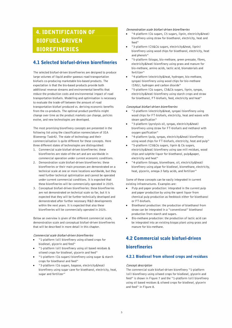
Bioethanol from sugar and starch crops 4.2.2 Concept description The commercial scale biofuel-driven biorefinery “1-platform (C6 sugars) biorefinery using sugar & starch crops for bioethanol and feed“ is shown in Figure 10, and the “3-platform (C6 sugars, bagasse, electricity&heat) biorefinery using sugar cane for bioethanol, electricity, heat and sugar” in Figure 11. Biorefinery scheme The sugar and/or starch crops in the “1-platform (C6 sugars) biorefinery using sugar & starch crops for bioethanol and feed” are transported to the biorefinery where the starch is converted to C6 sugars in the enzymatic hydrolysis step. The sugar crop e.g. from sugar beet is used to produce C6 sugars via mechanical pressing. The co-product, sugar beet pulp, is dried and used as animal feed. The C6 sugars are fermented to bioethanol which is purified using distillation. The fermentation solids, mainly proteins, are dried and pelleted for animal feed e.g. DDGS (Dried Distillers Grains with Solubles). In the fermentation CO2 is produced, which can be separated and used for the food industry (e.g. beverage industry) or as an industrial gas (e.g. pH control of waste water). The heat and electricity are often supplied by fossil fuel energy carriers. The sugar cane in the “3-platform (C6 sugars, bagasse, electricity&heat) biorefinery using sugar cane for bioethanol, electricity, heat and sugar” is transported to the biorefinery, where C6 sugars and bagasse are produced within a mechanical processing unit. A part of the C6 sugars is used to produce sugar by crystallization. The other part of the C6 sugars is fermented to bioethanol which is afterwards purified using distillation.
The bagasse is combusted to produce electricity and heat. The fermentation solids e.g. vinasse from distillation, are used as fertilizer. Future perspectives This biorefinery is state-of-the-art and commercial production facilities have an annual bioethanol production capacity between 100,000 up to 300,000 t per year. Many of the successfully operated biorefineries in Europe are multi feedstock plants using different starch and sugar crops. In America most biorefineries use sugar cane or starch e.g. maize. The C6 sugar platform offers the possibilities to produce a wide range of bio-chemicals based on sugars. These processes are currently under development or just starting to become commercialised. There will be a diversification of products from sugar and starch-derived C6 sugars (hexoses) towards other alcohols, chemicals and organic acids. A specific route currently under development, and likely to be commercialised in a medium-term perspective is the fermentation of sugars to lipids. These lipids could be used by the oleochemical industry or to produce jet fuels, providing further integration potential between existing value chains (www.star-colibri.eu). Also the sugar and starch based biorefinery offers interesting perspectives to integrate cereal straw (crop residues) into the supply chain, to produce C6 and C5 sugars. The use of dedicated lignocellulosic crops from agriculture is expected to increase when lignocellulosic conversion becomes more affordable. Also, as new configurations are developed, the external energy sources can be partially or fully replaced by bioenergy produced from within the process to reduce the GHG footprint.
Figure 10. 1-platform (C6 sugars) biorefinery using sugar&starch crops for bioethanol and feed.
9
Figure 11. 3-platform (C6 sugars, bagasse, electricity&heat) biorefinery using sugar cane for bioethanol, electricity, heat, sugar and fertilizer.
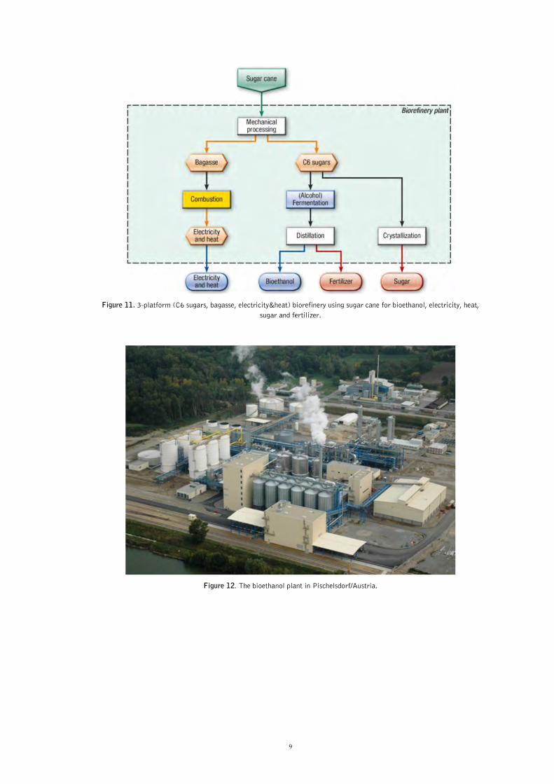
Figure 12. The bioethanol plant in Pischelsdorf/Austria.

10
Commercial example Based on the favourable economic conditions in Austria AGRANA decided in 2005 to build a bioethanol plant with a maximum capacity of 240,000 m³/a or 190,000 t/a (99.4% ethanol content) in Pischelsdorf in Lower Austria (see Figure 12). The raw materials are wheat, corn, triticale, barley and syrup made from sugar beet. Beside bioethanol, the high quality protein rich feed “DDGS” (Dried Distillers Grains with Solubles) with a maximum capacity of 180,000 t/a is co-produced, which is put on the market with the brand “ActiProt”, and substitutes imported soya feed. This plant advanced KATZEN's innovative integration of heat usage and recovery to a new level. In addition by utilizing an on-site natural gas boiler, the plant integrates the steam generated by a nearby power plant using mainly municipal solid waste. Although thermally integrated, the ultra-high quality steam and condensate must be kept separated from the plant system; so that 100% steam condensate may be returned at its highest purity back to the power plant. Additional heat and water recovery has been implemented, further increasing the sustainability of the plant. In 2012 a CO2-plant went into operation that produces liquid carbon dioxide by using the renewable CO2 produced from the fermentation of the feedstock with a maximum capacity of 100,000 t/a. The CO2 is sold to the food and beverage industry as well as for industrial purposes by substituting fossil derived CO2 in products and services. The saving on greenhouse gas emissions achieved by the bioethanol is about 70% with CO2 use and about 50% without CO2 use compared to fossil gasoline calculated according to the European Renewable Energy Directive.
4.3 Demonstration scale biofuel-driven
biorefineries
Bioethanol from straw 4.3.1 Concept description The demonstration scale biofuel-driven biorefinery “4-platform (C6 sugars, C5 sugars, lignin, electricity&heat) biorefinery using straw for bioethanol, electricity, heat and feed“ is shown in Figure 13. Biorefinery scheme The straw is transported in bales to the biorefinery, pre-treated either thermochemically or chemically prior to hydrolysis, separation and fermentation. The C6 sugars are fermented to bioethanol and the C5 sugars are used to produce molasses that are fed to cattle that are able to digest C5 sugars. The C5 sugars might also be fermented to bioethanol to increase the amount of bioethanol. The lignin co-product is used as a solid fuel to produce electricity and heat to run the biorefinery and to sell electricity and heat to consumers. Future perspectives This biorefinery system is demonstrated in Denmark (see next section). Other concepts for converting straw and lignocellulosic material into bioethanol and co-products are under demonstration in Spain, Italy and the US. They use different pre-treatment concepts and novel processes. The main challenges of all these demonstration scale plants are the relatively high production cost. Conversion of the lignin into high value bio-based products and further process optimisation is required to make the concept financially feasible.
Figure 13. 4-platform (C6 sugars, C5 sugars, lignin, electricity&heat) biorefinery using straw for bioethanol, electricity, heat and feed.
http://www.agrana.at/

11
Demonstrated example The Kalundborg plant in Denmark (see Figure 14) is integrated with the adjacent Asnæs Power Station, which is owned by DONG Energy. The principal purpose of the demonstration plant is to show that second-generation technology can be applied on a large-scale, i.e. that large-scale production of ethanol from straw is possible. The Kalundborg plant will also demonstrate energy integration with a coal-fired power station. The power station delivers waste steam to the biomass refinery, where it breaks down the straw fibres so they can be converted into sugars, ethanol, and lignin. The lignin Inbicon’s process produces is so clean that it requires no further treatment or purification when used to replace some of the coal burned by a power plant, generating renewable electricity. Since the biomass refinery will be integrated with a coal fired power plant, the overall efficiency of each operation will increase.
The raw materials for the production of bioethanol are 4 metric tons per hour straw equivalent to about 30,000 metric tons of straw a year. The enzymes are supplied by Danisco Genencor, Novozymes and Royal DSM. The annual production is about 5.4 million litre (1.4 million gallons) of cellulosic ethanol, 11,400 metric tons of lignin pellets and 13,900 metric tons of C5 molasses. The biomass refinery at Kalundborg is the heartbeat of the Inbicon Biomass Technology Campus, and another example why Industrial Symbiosis is the most promising model for clean energy parks and sustainable renewable businesses. The biorefinery in Kalundborg realises the concept shown in Figure 13. Only the combustion of the lignin to produce electricity and heat takes place in the collocated CHP plant.
Figure 14. The bioethanol plant in Kalundborg/Denmark.
Bioethanol from wood 4.3.2 Concept description The demonstration scale biofuel-driven biorefinery “3-platform (C5&C6 sugars, electricity&heat, lignin) biorefinery using wood chips for bioethanol, electricity, heat and phenols“ is shown in Figure 15.
Biorefinery scheme The wood chips (without bark) are transported to the biorefinery, where the wood chips are pre-treated for the hydrolysis to separate the sugars and the lignin. The C5&C6 sugars are fermented to bioethanol and the lignin is used to produce bio-oil via a pyrolysis step. The phenols from the bio-oil are separated and the residues are combusted to produce electricity and heat.
http://www.inbicon.com/Biomass%20Refinery/Pages/Inbicon_Biomass_Refinery_at_Kalundborg.aspx http://www.inbicon.com/Projects/Kalundborg%20Demonstration%20plant/Pages/Kalundborg%20Demonstration%20plant.aspx

12
Future perspectives This biorefinery system is partly demonstrated, the production of bioethanol is demonstrated in Sweden, and the pyrolysis of the lignin is tested on laboratory scale. So far the production of bioethanol from hard wood is easier to be developed than from soft wood. Recent R&D results show that the integration of bioethanol production from wood in pulp and paper production offers promising synergies like handling and logistic of wood, water and waste water treatment, electricity and steam infrastructure and personnel. Realising these synergies would enable commercial bioethanol production from wood by 2025. Demonstrated example In Sweden the “Ethanol Pilot” (see Figure 16), the demo plant of SEKAB E-technology is responsible for, was inaugurated in 2004, and is adjacent to SEKAB’s plant in Domsjö facility in Örnsköldsvik. Advanced research and development work has been carried out here to verify all the process steps required to commercialise the technology. The development work has comprised everything from raw materials, chemical and biological processes, command and control technology to the integration of these processes with other production.
Around a hundred different research and development projects on cellulosic ethanol are in place globally and SEKAB E-technology is considered to be among the top four in the world. The “Ethanol Pilot” has been funded by money from the Swedish Energy Agency, the EU and SEKAB, and it is owned by a holding company at the universities of Umeå and Luleå together with SEKAB. SEKAB has experience from over 28,000 hours of operation in the demo plant and this has created unique know-how and knowledge which does not exist anywhere else in the industry. The demo plant stopped operation by the end of 2011. The demonstration plant in Örnsköldsvik realises the biorefinery concept shown in Figure 15 by producing bioethanol from wood, but the generation of electricity and heat as well as the pyrolysis of the lignin with the phenol production is not realised.
Figure 15. 3-platform (C5&C6 sugars, electricity&heat, lignin) biorefinery using wood chips for bioethanol, electricity, heat and phenols.
http://www.sekab.com/cellulose-ethanol/demo-plant

13
Figure 16. The bioethanol plant in Domsjö/Sweden.
Bio-methane from grass and manure 4.3.3 Concept description The demonstration scale biofuel-driven biorefinery “5-platform (biogas, bio-methane, green pressate, fibres, electricity&heat) biorefinery using grass and manure for bio-methane, amino acids, lactic acid, biomaterials and fertilizer“ is shown in Figure 17. Biorefinery scheme After harvesting of the grass, the fresh grass is pressed to receive a “green pressate” and the fibres. The fibres are used to produce bio-materials like insulation material. Via different separation and filter technologies lactic acid and amino acids are received from the green pressate. All the residues from these processes are digested in a biogas reactor to produce biogas, which is upgraded to bio-methane. A part of the biogas is used to produce electricity and heat in a CHP plant. As the biogas process needs additional water for optimised conditions, manure (or water) is added in the anaerobic digestion process. The digested material is used as fertilizer. Due to the high water content for commercialisation this fertilizer has to be further upgraded.
Future perspectives The main challenges in future development are the separation, upgrading and purification of the chemicals. Most promising is the integration of the grass processing to chemicals and fibres in existing biogas plants. Demonstrated example In Austria a green biorefinery pilot plant is situated in Utzenaich (Upper Austria) (see Figure 18). The green biorefinery started operation in 2008 and was built next to an existing digester, in order to easily use the press cake for biogas production. Out of the silage feedstock a liquid fraction is generated which is rich in lactic acid and amino acids. These two key products are being separated out of the juice and purified to marketable qualities. The lactic acid is an interesting building block for chemicals; amino acids mixtures out of grass hold all essential amino acids. The solid press cake and all liquid residues are used for running an anaerobic digester producing biogas. The biogas is combusted for electricity and heat production, the digested material is used as fertilizer. The green biorefinery demonstrates the core process of the biorefinery concept shown in Figure 17, but the biogas is not upgraded to bio-methane.
http://demoplants.bioenergy2020.eu/projects/info/342

14
Figure 17. 5-platform (biogas, bio-methane, green pressate, fibres, electricity&heat) biorefinery using grass and manure for bio-methane, lactic acid, biomaterials and fertilizer.
Figure 18. Green biorefinery – demonstration plant in Utzenaich.
Bio-methane from wood 4.3.4 Concept description The demonstration scale biofuel-driven biorefinery “4-platform (electricity&heat, hydrogen, bio-methane, syngas) biorefinery using wood chips for bio-methane (SNG), hydrogen and carbon dioxide“ is shown in Figure 19. Biorefinery scheme The wood chips are gasified with steam to produce a product gas which is upgraded to synthesis gas; the steam gasification also includes a necessary gas treatment. Via methanation synthetic natural gas (SNG as bio-methane) is produced. Via steam reforming the syngas is used to produce hydrogen, which can be used as a process media or chemical. Also carbon dioxide is co-
produced, which can be separated and used for various industrial applications, e.g. in the food industry. Residues and gaseous side streams are used to produce electricity and heat in a CHP application. Future perspectives Depending on the further successful development beside the steam gasification of wood, which is suitable for smaller to medium sized gasifiers, also the gasification with oxygen for large applications (e.g. entrained flow gasification) might become interesting. The necessary oxygen must be produced via air separation or as a co-product from water electrolyses (e.g. with renewable electricity from excess wind power), which will offer further opportunities for integration in existing infrastructures to create additional synergies.
http://www.energieinstitut-linz.at/index.php?menuid=24

15
Figure 19. 4-platform (electricity&heat, hydrogen, bio-methane, syngas) biorefinery using wood chips for bio-methane (SNG), hydrogen and carbon dioxide.
Figure 20. Biomass CHP Güssing (left), BioSNG demonstration plant (middle), Technikum (right) and BioSNG filling station (right front).
Demonstrated example The invented word “bioSNG” is derived from the biogenic, renewable origin of the gas, hence bio, and the way it is produced, in process engineering terms – Synthetic Natural Gas. Thus bioSNG stands for natural gas produced from renewable sources by synthetic means. The production of renewable natural gas from wood was demonstrated by a consortium, consisting of the core partners Repotec and CTU (industry), Vienna University of Technology and Paul Scherrer Institute (R&D) at the Güssing facility, as part of the EU project “bioSNG”, during the years 2006 to 2009 – for the first time in the world and along its entire production chain, from wood chips to the use of the gas in the natural gas powered car.
Three kilograms of wood produces a standard cubic metre (Nm3) of bioSNG, and it makes no difference for the car, either during consumption or in terms of the emissions, whether the methane molecule originated in Russia or in domestic forests. Around 100 Nm³ of bioSNG is produced per hour in the Güssing demonstration plant. The methanation process takes place in a fluidised bed reactor at a temperature of 300 to 350°C, a pressure of 1 to 5 bar and under the catalysis of nickel. The underlying chemical reaction is expressed in the formula 3H2 + CO > CH4 + H2O

16
Largely purified of sulphur and tar through particle filters, scrubbers and active carbon filters, with a hydrogen-to-carbon monoxide ratio of 1.8 to 2.0, and a methane content of already 10vol%, the synthesis gas from the Güssing biomass steam gasification plant offers virtually optimal preconditions for methanation. At present, the project results are being commercially marketed by the industry partner Repotec. The technology is being brought onto the market and in parallel the BioSNG demonstration plant in Güssing is used by Bioenergy 2020+ for further R&D and demonstration. Here the local natural gas grid will be supplied with BioSNG in the future.
FT-biofuels from straw 4.3.5 Concept description The demonstration scale biofuel-driven biorefinery “3-platform (pyrolysis oil, syngas, electricity&heat) biorefinery using straw for FT-biofuels and methanol with oxygen gasification“ is shown in Figure 21. Biorefinery scheme In fast pyrolysis the straw is used to produce pyrolysis oil and char in several decentralised locations close to the origin of the straw supply. The oil and the char are mixed together and are transported as a slurry to one central gasification plant. In the gasification plant a syngas is produced by using oxygen as gasification medium. This syngas is then converted to FT-biofuels in the FT-synthesis, and to methanol in the methanol-synthesis. The main difference of the FT- and the methanol-synthesis process is on pressure, temperature, catalyst and the ratio between CO and H2 in the synthesis gas (e.g. FT-biofuel: 200 – 250°C, 20 – 30 bar with Fe and/or Co as a catalyst). The methanol is mainly used as a chemical. Process residues are used to produce electricity and heat.
Future perspectives After the successful development and demonstration of fast pyrolysis of straw in further future applications and uses for the pyrolysis oil might become interesting, e.g. the direct integration of pyrolysis oil in an existing oil refinery via upgrading to a renewable diesel fuel. In addition the char from pyrolysis can be used to produce other products for the chemical industry to substitute fossil based products, e.g. activated char. Demonstrated example In Germany the bioliq® pilot plant under construction (see Figure 22) will cover the process chain required for producing customized fuels from residual biomass. Being mainly synthesized from dry straw or wood, the BTL fuels offer environmental and climatic benefits through clean combustion. The integrative process chain, moreover, enables production of synthesis gas and chemicals. Bioliq® intends to mainly convert large local quantities of residual biomass by densifying energy. To save carbon dioxide and reduce routes of transport to refineries, the Karlsruhe BTL concept combines decentralized production of energy-rich bioliqSynCrude® by means of rapid pyrolysis and central processing with final industrial-scale refinement. Since the energy density of bioliqSynCrude® is by more than one order of magnitude higher relative to the volume of dry straw, it is evident that the method’s efficiency is enhanced by decentralized energy densification and that such densification ensures that biomass can be fully exploited and put to use in substance and in energy. The bioliq® pilot plant mainly demonstrates the gasification of pyrolysis oil and char slurry to synthesis gas, shown in the biofuel-driven biorefinery concept in Figure 21.
Figure 21. 3-platform (pyrolysis oil, syngas, electricity&heat) biorefinery using straw for FT-biofuels and methanol with oxygen gasification.
17
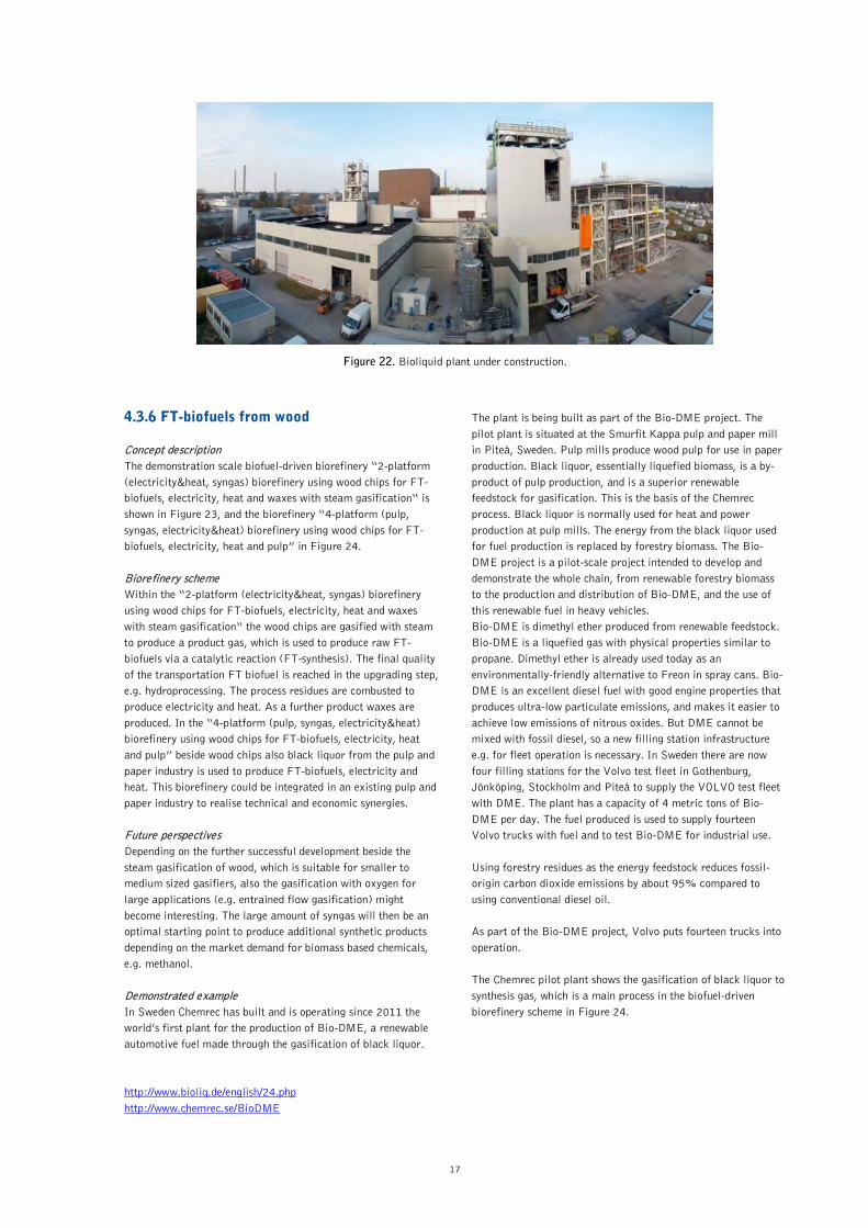
Figure 22. Bioliquid plant under construction.
FT-biofuels from wood 4.3.6 Concept description The demonstration scale biofuel-driven biorefinery “2-platform (electricity&heat, syngas) biorefinery using wood chips for FT-biofuels, electricity, heat and waxes with steam gasification“ is shown in Figure 23, and the biorefinery “4-platform (pulp, syngas, electricity&heat) biorefinery using wood chips for FT-biofuels, electricity, heat and pulp” in Figure 24. Biorefinery scheme Within the “2-platform (electricity&heat, syngas) biorefinery using wood chips for FT-biofuels, electricity, heat and waxes with steam gasification“ the wood chips are gasified with steam to produce a product gas, which is used to produce raw FT-biofuels via a catalytic reaction (FT-synthesis). The final quality of the transportation FT biofuel is reached in the upgrading step, e.g. hydroprocessing. The process residues are combusted to produce electricity and heat. As a further product waxes are produced. In the “4-platform (pulp, syngas, electricity&heat) biorefinery using wood chips for FT-biofuels, electricity, heat and pulp” beside wood chips also black liquor from the pulp and paper industry is used to produce FT-biofuels, electricity and heat. This biorefinery could be integrated in an existing pulp and paper industry to realise technical and economic synergies. Future perspectives Depending on the further successful development beside the steam gasification of wood, which is suitable for smaller to medium sized gasifiers, also the gasification with oxygen for large applications (e.g. entrained flow gasification) might become interesting. The large amount of syngas will then be an optimal starting point to produce additional synthetic products depending on the market demand for biomass based chemicals, e.g. methanol. Demonstrated example In Sweden Chemrec has built and is operating since 2011 the world’s first plant for the production of Bio-DME, a renewable automotive fuel made through the gasification of black liquor.
The plant is being built as part of the Bio-DME project. The pilot plant is situated at the Smurfit Kappa pulp and paper mill in Piteå, Sweden. Pulp mills produce wood pulp for use in paper production. Black liquor, essentially liquefied biomass, is a by-product of pulp production, and is a superior renewable feedstock for gasification. This is the basis of the Chemrec process. Black liquor is normally used for heat and power production at pulp mills. The energy from the black liquor used for fuel production is replaced by forestry biomass. The Bio-DME project is a pilot-scale project intended to develop and demonstrate the whole chain, from renewable forestry biomass to the production and distribution of Bio-DME, and the use of this renewable fuel in heavy vehicles. Bio-DME is dimethyl ether produced from renewable feedstock. Bio-DME is a liquefied gas with physical properties similar to propane. Dimethyl ether is already used today as an environmentally-friendly alternative to Freon in spray cans. Bio-DME is an excellent diesel fuel with good engine properties that produces ultra-low particulate emissions, and makes it easier to achieve low emissions of nitrous oxides. But DME cannot be mixed with fossil diesel, so a new filling station infrastructure e.g. for fleet operation is necessary. In Sweden there are now four filling stations for the Volvo test fleet in Gothenburg, Jönköping, Stockholm and Piteå to supply the VOLVO test fleet with DME. The plant has a capacity of 4 metric tons of Bio-DME per day. The fuel produced is used to supply fourteen Volvo trucks with fuel and to test Bio-DME for industrial use. Using forestry residues as the energy feedstock reduces fossil-origin carbon dioxide emissions by about 95% compared to using conventional diesel oil. As part of the Bio-DME project, Volvo puts fourteen trucks into operation. The Chemrec pilot plant shows the gasification of black liquor to synthesis gas, which is a main process in the biofuel-driven biorefinery scheme in Figure 24.
http://www.bioliq.de/english/24.php http://www.chemrec.se/BioDME

18
Figure 23. 2-platform (electricity&heat, syngas) biorefinery using wood chips for FT-biofuels, electricity, heat and waxes with steam gasification.
Figure 24. 4-platform (pulp, syngas, electricity&heat) biorefinery using wood chips for FT-biofuels, electricity, heat and pulp.

19
Figure 25. The DME-Plant, a DME filling station and a DME Truck in Sweden.
4.4 Conceptual biofuel-driven
biorefineries
Bioethanol from wood and liquor 4.4.1 Concept description The conceptual biofuel-driven biorefinery “5-platform (lignin, C5&C6 sugars, lignin&C6 sugars, pulp, electricity&heat) biorefinery using saw mill residues, wood chips and sulphite liquor for bioethanol, pulp&paper, electricity and heat“ is shown in Figure 26. Biorefinery scheme The wood chips (without bark) and saw mill residues are transported to the biorefinery, where the wood chips and saw mill residues are pre-treated for the hydrolysis to separate the sugars and the lignin. The C5&C6 sugars are fermented to bioethanol. In the fermentation CO2 is produced, which can be separated and used for the food industry (e.g. beverage industry) or as an industrial gas (e.g. pH control of waste water). The lignin is combusted to produce electricity and heat. For bioethanol production also C6 sugars in the sulphite liquor from pulp production can be used. Future perspectives The pulp and paper industry has an attractive infrastructure for the integration of bioethanol production, e.g. raw material logistics. Producing also bioethanol as a road transportation biofuel might offer new and additional business opportunities beside the pulp and paper production.
Demonstrated example In Norway Borregaard has a unique concept for the utilisation of wood as a raw material for a wide range of advanced bio-based products. By using natural, sustainable raw materials, Borregaard produces advanced and sustainable bio-chemicals, bio-materials and bioethanol that can replace oil-based products. Borregaard also holds strong positions in additives and fine chemicals. During cellulose production, sugar compounds are released from the wood as liquor. Borregaard converts these sugar compounds into ethanol through fermentation. Ethanol from Borregaard is used for biofuel, chemical-technical applications, such as car care products, household chemicals and solvents, and also for products that require a high degree of purity, such as pharmaceutical products. From the production site in Sarpsborg, Norway (Borregaard's largest plant, Figure 27 shows the IEA Bioenergy classification), they produce two different high quality technical grades of ethanol: A-Grade (96%) and Absolute Technical (99.9%). The Borrgaard biorefinery shows the commercial realisation of the bioethanol production form black liquor which is a main process step in the biofuel-driven biorefinery shown in Figure 26.
http://www.borregaard.com/Business-Areas/Borregaard-ChemCell/Ethanol-products

20
Figure 26. 5-platform (C5&C6 sugars, lignin&C6 sugars, electricity&heat) biorefinery using saw mill residues, wood chips and sulphite liquor for bioethanol, pulp&paper, electricity and heat.
Figure 27. Borregaard.
Bioethanol from starch crops and straw 4.4.2 Concept description The conceptual biofuel-driven biorefinery “5-platform (C6 sugars, C5&C6 sugars, lignin, syngas, electricity&heat) biorefinery using starch crops and straw for bioethanol, FT-biofuels, feed, electricity and heat“ is shown in Figure 28.
Biorefinery scheme The starch crops are transported to the biorefinery, where the starch is converted to C6 sugars in the enzymatic hydrolysis step. The straw is transported to the biorefinery, where the straw is pre-treated for the hydrolysis to separate the sugars and the lignin. The C6 sugars from the starch crops and the C5&C6 sugars from the straw are fermented to bioethanol which is purified using distillation.

21
The fermentation solids, mainly proteins, are dried and pelleted for animal feed e.g. DDGS (Dried Distillers Grains with Solubles). In the fermentation CO2 is produced, which can be separated and used for the food industry (e.g. beverage industry) or as an industrial gas (e.g. pH control of waste water). The lignin is gasified, and the syngas out of the gasification is used to produce FT-biofuels. The residues are combusted to produce electricity and heat. Future perspectives After the necessary successful development of this biorefinery processes they might be well integrated into existing bioethanol production plants. The main advantage then is the possible common production of a substitute for gasoline and diesel in one biorefinery. With the syngas platform it is also possible to produce a further broad range of different chemicals. So with this type of biorefinery using starch crops and straw it will be possible to substitute the broad range of different petrochemical products from an oil refinery.
Demonstrated example In Spain, managed by Abengoa Bioenergía Nuevas Tecnologías, the construction of the lignocellulosic biomass plant (see Figure 29) was completed in December 2008 and has been in full operation since September 2009, being the first plant in the world to operate with enzymatic hydrolysis technology at this production level. It is located within the Biocarburantes de Castilla y León plant in Babilafuente (Salamanca, Spain) a bioethanol biorefinery using starch crops meaning that both facilities share common services and process chains. The ethanol produced is distilled up to 42% and then is concentrated and dehydrated. The annual bioethanol production capacity is 1.3 Mgal from grain straw. The lignocellulosic biomass plant serves to improve the design of the commercial scale plants to be built in years to come, to evaluate operating costs, identify bottlenecks and streamline operations. The Abengoa biorefinery demonstrates the bioethanol production from straw and its integration in a commercial bioethanol production plant from wheat. The gasification of lignin to produce FT-biofuels, which is shown in the biofuel-driven biorefinery concept in Figure 28, is not realised yet.
Figure 28. 5-platform (C6 sugars, C5&C6 sugars, lignin, syngas, electricity&heat) biorefinery using starch crops and straw for bioethanol, FT-biofuels, feed, electricity&heat.
http://www.abengoabioenergy.com/web/en/acerca_de/oficinas_e_instalaciones/bioetanol/europa/biomasa/

22
Figure 29. The bioethanol plant in Babilafuente (Salamanca)/Spain.
Biofuels from microalgae 4.4.3
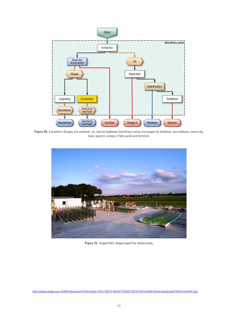
Concept description The conceptual biofuel-driven biorefinery “4-platform (biogas, bio-methane, oil, electricity&heat) biorefinery using microalgae for biodiesel, bio-methane, electricity, heat and glycerin, omega 3 fatty acids, and fertilizer“ is shown in Figure 30. Biorefinery scheme The algae are (grown and) harvested and the oil of the algae is extracted. The oil is a platform, omega 3 fatty acids are separated and the rest of the oil is esterified, producing FAME biodiesel and raw glycerin. To derive pure glycerin for pharmaceutical purposes the glycerin is subsequently distilled. The residues of the oil extraction are fermented in a biogas reactor to produce biogas. The biogas is upgraded to bio-methane and partly combusted in a CHP plant to produce electricity and heat. The digestate is used as a fertilizer. Future perspectives In light of the global efforts in developing microalgal biomass as a promising raw material for the industry and the energy sector by relevant scientific work, further successes in the development of efficient, low-cost, ecological cultivation and refinery processes for the conversion of microalgae to bio-based products and bioenergy is necessary. A strong effort will be put on the development of further speciality products made from microalgae.
Tested applications In the Netherlands the objective of AlgaePARC (Algae Production And Research Centre, see Figure 31) is to develop knowledge, technology and process strategies for sustainable production of microalgae as feedstock for fuel, chemicals, food and feed at industrial scale. AlgaePARC is the first research centre in the world that allows comparison of different outdoor photo-bioreactor designs. The pilot facility comprises four large (24 m2) and three small (2.4 m2) photo-bioreactors: a raceway pond, a horizontal tubular photo-bioreactor, a vertically stacked horizontal tubular photo-bioreactor and flat panels. They were chosen based on state-of-the-art technology and will allow to study and overcome critical aspects for the successful operation and scale-up of the photo-bioreactors, i.e. mass transfer, light supply and photosynthetic efficiency. The systems will be run in parallel and compared on technical, economic and sustainability performance and results will be used to build up knowledge required for commercial production of microalgae for bulk products, including biofuels. The pilot set-up will be flexible and fully automated in order to allow a fast change in photo-bioreactor type, layout, and process control strategies. The initial systems chosen reflect the present development of several reactor concepts at laboratory scale, by different research groups and companies, and will enable a rigorous comparison between systems, selection and, ultimately, the development of a more efficient system and optimised operational concepts.
http://www.abengoabioenergy.com/web/en/acerca_de/oficinas_e_instalaciones/bioetanol/europa/biomasa/ http://www.algae.wur.nl/UK/projects/AlgaePARC/
23
Figure 30. 4-platform (biogas, bio-methane, oil, electricity&heat) biorefinery using microalgae for biodiesel, bio-methane, electricity, heat, glycerin, omega 3 fatty acids and fertilizer.
Figure 31. AlgaePARC Wageningen/The Netherlands.
http://www.algae.wur.nl/NR/rdonlyres/FD401A06-1943-4DFD-B340-FD6907BC5C99/140843/OverviewAlgaePARCfromNW.jpg

24
Fig
ure
32. P
ossi
ble
com
bina
tion
of
biof
uel-
driv
en b
iore
fine
ries
.

25
Beside the sustainable cultivation of microalgae also the refinery processes to co-produce food/feed ingredients, chemicals, materials, fuels, power and heat still need significant development. Recently (2013), two large multi-stakeholder European Integrated Projects have been started by Wageningen UR that fully focus on the development of these biorefinery technologies. Macroalgae (seaweeds) offer another significant potential raw material for the co-production of bio-based products and biofuels. However, here both the off-shore cultivation, harvesting and pre-processing part and the on-shore refinery part still need significant R&D before large-scale implementation is expected.
4.5 Possible combination of biofuel-
driven biorefineries
In the previous section the basic concepts of biofuel-driven biorefineries are described. These basic concepts can be combined at different levels to construct bigger “Biorefinery Complexes”. Also, they can be co-located and integrated with the oil industry infrastructure. The combination of the concepts can be done on the level of the same feedstock, platforms, products or processes. In Figure 32 many possible combinations of the described biofuel-driven biorefineries are presented.
ASSESSMENT OF 5.
BIOREFINERIES
5.1 Introduction
To produce biofuels for transportation in an economic profitable and environmentally and socially acceptable way co-production with bio-based products using high-efficiency biorefinery processes seems to be the favourable approach. Economic and environmental benefits can be gained through system design, co-product valorisation and the development of new conversion technologies. The main question that still has to be answered is what the advantages of a multi-product biorefinery system are, compared to conventional single-product biofuel production facilities. The advantages might be in terms of environmental, economic, technological and social benefits. In IEA Bioenergy Task42 a consistent methodology is under development to establish a framework for such a comparison, which is already applied to several biorefinery examples. It is generally agreed that as a basis for a comparative assessment the whole value chain has to be taken into account, including all effects from the feedstock production to the supply of products to the consumer until finally the “end of life” of the products. The effects could be economic, socio-economic, environmental and social aspects. Therefore, the following steps in the value chain must be considered in an assessment of a biorefinery (see Figure 33): feedstock production/residues collection, transport of feedstock/residues, processing of feedstock/residues into bio-based products and bioenergy in the biorefinery plant, distribution of products/energy carriers, use of products/energy carriers and “end-of-life” of products.
Figure 33. The value chain approach for biorefineries.
26
5.2 Methodology
The relevant issues of the comparison are discussed and described, whereas the following system descriptions are used: 1. “Biorefinery system” or “multi-product system”: a
biorefinery system is the sustainable processing of biomass into a spectrum of marketable products, fuels and materials, where other energy carriers (e.g. electricity) might be co-produced.
2. “Single-product process”: a single-product process is the processing of biomass into one marketable product, which might be an energy carrier or a bio-based material; e.g. wood pellets for heating.
3. “Conventional system”: a conventional system is the processing of biomass or fossil resources into one or more marketable products either energy carriers or (bio-)products. These conventional systems are commercially available and used; e.g. the conventional processes for biomass are mainly used for heat and power supply via different processes.
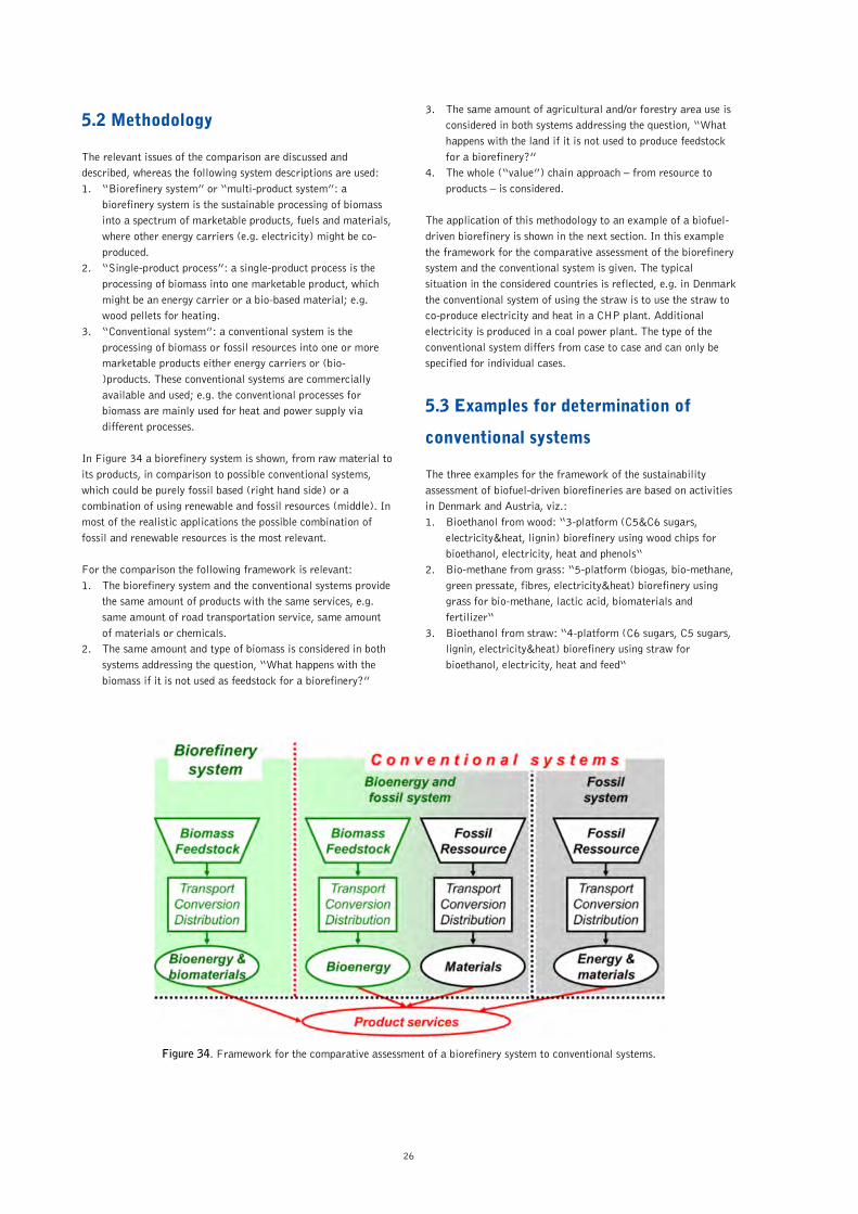
In Figure 34 a biorefinery system is shown, from raw material to its products, in comparison to possible conventional systems, which could be purely fossil based (right hand side) or a combination of using renewable and fossil resources (middle). In most of the realistic applications the possible combination of fossil and renewable resources is the most relevant. For the comparison the following framework is relevant: 1. The biorefinery system and the conventional systems provide
the same amount of products with the same services, e.g. same amount of road transportation service, same amount of materials or chemicals.
2. The same amount and type of biomass is considered in both systems addressing the question, “What happens with the biomass if it is not used as feedstock for a biorefinery?”
3. The same amount of agricultural and/or forestry area use is considered in both systems addressing the question, “What happens with the land if it is not used to produce feedstock for a biorefinery?”
4. The whole (“value”) chain approach – from resource to products – is considered.
The application of this methodology to an example of a biofuel-driven biorefinery is shown in the next section. In this example the framework for the comparative assessment of the biorefinery system and the conventional system is given. The typical situation in the considered countries is reflected, e.g. in Denmark the conventional system of using the straw is to use the straw to co-produce electricity and heat in a CHP plant. Additional electricity is produced in a coal power plant. The type of the conventional system differs from case to case and can only be specified for individual cases.
5.3 Examples for determination of
conventional systems
The three examples for the framework of the sustainability assessment of biofuel-driven biorefineries are based on activities in Denmark and Austria, viz.: 1. Bioethanol from wood: “3-platform (C5&C6 sugars,
electricity&heat, lignin) biorefinery using wood chips for bioethanol, electricity, heat and phenols“
2. Bio-methane from grass: “5-platform (biogas, bio-methane, green pressate, fibres, electricity&heat) biorefinery using grass for bio-methane, lactic acid, biomaterials and fertilizer“
3. Bioethanol from straw: “4-platform (C6 sugars, C5 sugars, lignin, electricity&heat) biorefinery using straw for bioethanol, electricity, heat and feed“
Figure 34. Framework for the comparative assessment of a biorefinery system to conventional systems.

27
The framework for the sustainability assessment in the next chapter is mainly focusing on the selection of the conventional system to which the biorefinery should be compared to. So only the relevant parts of the whole value chain for this purpose are addressed.
Bioethanol from wood 5.3.1The framework for the assessment of the biofuel-driven biorefinery “3-platform (C5&C6 sugars, electricity&heat, lignin) biorefinery using wood chips for bioethanol, electricity, heat and phenols“, already described in Figure 15, in comparison to a conventional system is shown in Figure 35. The biorefinery system on the right hand uses 1 t of wood to produce 5 GJ of bioethanol as road transportation fuel, 1.2 GJ of electricity, 0.7 GJ of heat and about 0.01 t of phenols. The conventional system (left hand side) uses natural gas to produce the 1.2 GJ of electricity in a power plant and oil in the oil refinery to produce gasoline as road transport fuel, heat and phenols. In the case of the conventional system the 1 t of wood was not used and remained in the forest, where natural oxidation took place.
Bio-methane from grass 5.3.2The framework for the assessment of the biofuel-driven biorefinery “5-platform (biogas, bio-methane, green pressate, fibres, electricity&heat) biorefinery using grass for bio-methane, lactic acid, biomaterials and fertilizer“ is shown in Figure 36. On the right hand side, the biorefinery system, and on the left hand side the conventional system is shown. To provide the same services the biorefinery system consists of the biorefinery and natural gas, whereas the conventional systems consist of a biogas system and raw oil.
In the biorefinery system 1 t of grass silage (right hand side) is used to produce 0.09 MWh of bio-methane and 0.25 t of products (mainly lactic acid and amino acids). In the conventional system (right hand side) the 1 t of grass silage is used only to produce about 0.1 MWh bio-methane, which is more than in the biorefinery system. So for the comparison it is necessary to add additional fossil energy on the right hand side, to have the same amount of road transportation fuel on both sides. In the conventional system the 0.25 t of products is provided by raw oil.
Bioethanol from straw 5.3.3In Figure 37 the framework for the assessment of the biofuel-driven biorefinery “4-platform (C6 sugars, C5 sugars, lignin, electricity&heat) biorefinery using straw for bioethanol, electricity, heat and feed“, already described in Figure 13, in comparison to a conventional system is shown. The biorefinery system on the right hand uses 1 t of straw to produce 4.6 GJ of bioethanol as road transportation fuel, 1.6 GJ of electricity, 1.1 GJ of heat and about 3.1 GJ animal feed (C5 molasses). The conventional system (left hand side) uses raw oil to produce 4.6 GJ of gasoline and 1 t of straw is used to produce 3.6 GJ electricity and 8.7 GJ heat, referring to the situation in Denmark. As the amount of electricity and heat in the conventional system is more than in the biorefinery system the additional electricity and heat is produced in a coal-fired CHP plant, which would be typically in the case of Denmark. In the conventional system the animal feed is provided by grain, whereas the amount of land used to grow the grain for the animal feed is set aside land in the biorefinery system. This assumption is necessary to guarantee that the same amount of agricultural land is considered in the compared systems.
Figure 35. Framework for the comparison of a “3-platform (C5&C6 sugars, electricity&heat, lignin) biorefinery using wood chips for bioethanol, electricity, heat and phenols” to a conventional system.

28
Figure 36. Framework for the comparison of a “5-platform (biogas, bio-methane, green pressate, fibres, electricity&heat) biorefinery using grass for bio-methane, lactic acid, biomaterials and fertilizer” to a conventional system.
Figure 37. Framework for the comparison of a “4-platform (C6 sugars, C5 sugars, lignin, electricity&heat) biorefinery using straw for bioethanol, electricity, heat and feed” to a conventional system.
29
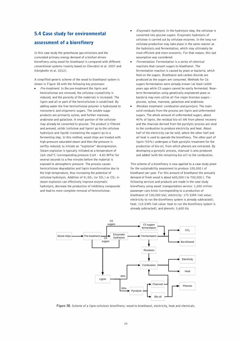
5.4 Case study for environmental
assessment of a biorefinery
In this case study the greenhouse gas emissions and the cumulated primary energy demand of a biofuel-driven biorefinery using wood for bioethanol is compared with different conventional systems (mainly based on Cherubini et al. 2007 and Könighofer et al. 2012). A simplified generic scheme of the wood to bioethanol system is shown in Figure 38 with the following key processes: • Pre-treatment. In the pre-treatment the lignin and
hemicellulose are removed, the cellulose crystallinity is reduced, and the porosity of the materials is increased. The lignin and all or part of the hemicellulose is solubilised. By adding water the free hemicellulose polymer is hydrolysed to monomeric and oligomeric sugars. The soluble sugar products are primarily xylose, and further mannose, arabinose and galactose. A small portion of the cellulose may already be converted to glucose. The product is filtered and pressed, solids (cellulose and lignin) go to the cellulose hydrolysis and liquids (containing the sugars) go to a fermenting step. In this method, wood chips are treated with high-pressure saturated steam and then the pressure is swiftly reduced, to initiate an “explosive” decompression. Steam explosion is typically initiated at a temperature of 160–260°C (corresponding pressure 0.69 – 4.83 MPa) for several seconds to a few minutes before the material is exposed to atmospheric pressure. The process causes hemicellulose degradation and lignin transformation due to the high temperature, thus increasing the potential of cellulose hydrolysis. Addition of H2SO4 (or SO2) or CO2 in steam explosion can effectively improve enzymatic hydrolysis, decrease the production of inhibitory compounds and lead to more complete removal of hemicellulose.
• Enzymatic hydrolysis. In the hydrolysis step, the cellulose is converted into glucose sugars. Enzymatic hydrolysis of cellulose is carried out by cellulase enzymes. In the long run cellulase production may take place in the same reactor as the hydrolysis and fermentation, which may ultimately be most efficient and more economic. For that reason, this last assumption was considered.
• Fermentation. Fermentation is a series of chemical reactions that convert sugars to bioethanol. The fermentation reaction is caused by yeast or bacteria, which feed on the sugars. Bioethanol and carbon dioxide are produced as the sugars are consumed. Methods for C6 sugars fermentation were already known (at least) 6000 years ago while C5 sugars cannot be easily fermented. Near-term fermentation using genetically engineered yeast or bacteria may even utilise all five major biomass sugars – glucose, xylose, mannose, galactose and arabinose.
• Residues treatment: combustion and pyrolysis. The main solid residuals from the process are lignin and unfermented sugars. The whole amount of unfermented sugars, about 45% of lignin, the residual bio-oil left from phenol recovery and the charcoal derived from the pyrolytic process are send to the combustion to produce electricity and heat. About half of the electricity can be sold, where the other half and all heat is used to operate the biorefinery. The other part of lignin (55%) undergoes a flash pyrolytic treatment for the production of bio-oil, from which phenols are extracted. By developing a pyrolytic process, charcoal is also produced and added (with the remaining bio-oil) to the combustion.
This scheme of a biorefinery is now applied to a case study plant for the sustainability assessment to produce 100,000 t of bioethanol per year. For this amount of bioethanol the annually demand of fresh wood is about 600,000 t to 700,000 t. The following services and products are made in the case study biorefinery using wood: transportation service: 1,000 million passenger cars-km/a (corresponding to a production of bioethanol of 100,000 t/a); electricity: 175 GWh (net value: electricity to run the biorefinery system is already subtracted); heat: 110 GWh (net value: heat to run the biorefinery system is already subtracted), and phenols: 5,600 t/a.
Wood chips FermentationEnzymatic hydrolysisPre-treatment
Bio-Ethanol
CO2
Residues
Lignin
Combustion
Pyrolysis
Electricity
Heat
Bio-oil
Charcoal Phenols
45%
55%
C5 sugars fermentation
C6 sugars
C5 sugars
Figure 38. Scheme of a ligno-cellulosic biorefinery: wood to bioethanol, electricity, heat and chemicals.

30
Figure 39. System boundaries for the sustainability assessment to compare the biorefinery system and the fossil energy system.
Table 2. The four different conventional systems compared to the biorefinery system.
Compared systems Heat Electricity Transportation service Phenols
Wood bioethanol biorefinery wood chips
Wood polygeneration and conventional phenols wood chips oil
Wood CHP, conventional phenols and gasoline wood chips gasoline oil
Wood heating, conventional phenols, natural gas and gasoline wood chips natural gas gasoline oil
Fossil reference system heating oil natural gas gasoline oil
The basis of the sustainability assessment is the whole value chain of the biorefinery and for comparison its conventional systems. The system boundaries for the sustainability assessment to compare the biorefinery system and the fossil energy system are shown in Figure 39. This “product basket” – serves as the “functional unit” in LCA for the comparison with conventional systems. The biorefinery system and the following four different conventional systems are considered in the analysis (see Table 2): • Wood bioethanol biorefinery: bioethanol, electricity, heat
and phenols are produced by wood chips. • Wood polygeneration and conventional phenols: bioethanol,
electricity and heat are produced by wood chips; phenols are obtained in a conventional way from oil refinery.
• Wood CHP, conventional phenols and gasoline: electricity and heat are produced by a CHP plant with wood chips; bioethanol is replaced by gasoline; phenols are obtained in a conventional way.
• Wood heating, conventional phenols, natural gas and gasoline: heat from wood chips; electricity from a natural gas combined-cycle power plant; bioethanol is replaced by gasoline; phenols are obtained in a conventional way.
• Fossil reference system: heat from oil; electricity from a natural gas combined-cycle power plant; bioethanol is replaced by gasoline; phenols are obtained in a conventional way.
In Figure 40 the greenhouse gas emissions of the different systems are shown. The biorefinery system releases 48 kt CO2-eq./a (which is broken down as 79% CO2, 17% N2O and 4% CH4) – the lowest GHG emissions, and the fossil reference system releases 408 kt CO2-eq./a – the highest emissions. The emissions of the other conventional systems lie in between. In Figure 41 it is shown that the contribution to the greenhouse gas emission of gasoline for transportation and natural gas for electricity are the dominating part in conventional systems. In Figure 42 the cumulated primary energy demand of the different systems is shown. The biorefinery system has on the one hand the lowest fossil energy demand but on the other hand the highest total primary energy demand at 8.6 PJ/a. The fossil reference system has the highest fossil energy demand but the lowest total primary energy demand at 5.9 PJ/a. The energy demands of the other conventional systems lie between these two values. In Table 3 the potential reductions of greenhouse gas emissions and cumulated fossil energy demand of the different systems are presented. The biorefinery system has the highest reductions, between 88 – 90%, relative to the fossil energy system.

31
Figure 40. Comparison of the annual greenhouse gas emissions.
Figure 41. Contributions to the annual greenhouse gas emissions.
Figure 42. Comparison of the annual cumulated primary energy demand.

32
Table 3. Reduction of greenhouse gas emissions and cumulated fossil energy demand of the different systems referring to the fossil energy system.
Compared systems Greenhouse gases Fossil energy demand
Emissions Reduction Demand Reduction
kt CO2-eq./a % CO2-eq./a PJ/a % PJ/a
Wood bioethanol biorefinery 48 -88% -360 0.56 -90% -5.27
Wood polygeneration and conventional
phenols
57 -86% -350 0.93 -84% -4.90
Wood CHP, conventional phenols and
gasoline
288 -29% -120 3.92 -33% -1.91
Wood heating, conventional phenols,
natural gas and gasoline
367 -10% -40 5.28 -9% -0.54
Fossil reference system 408 -- -- 5.83 -- --
Besides the comparison of the absolute annual greenhouse gas emissions and cumulated primary energy demand based on a life-cycle-assessment of the whole value chain, other indicators are necessary to compare the biorefinery system to conventional systems. In Figure 43 indicators of the greenhouse gas reduction and fossil energy consumption per metric ton of wood used in the different systems are presented. The indicators show that this specific biorefinery system has the lowest reduction of greenhouse gas emissions and fossil energy demand per metric ton of wood, where the conventional system using wood for heating only has the highest specific reductions. From the point of view for the most efficient use of the wood for greenhouse gas and fossil energy reductions, the use of biomass for heating only is the best option.
Further evaluation a trade-off between the annual and the specific greenhouse gas reductions of the compared systems is shown in Figure 44. It can be seen that using wood for heat only leads to the lowest annual greenhouse gas reduction with the highest specific greenhouse gas reduction per metric ton of wood. Whereas, the biorefinery system has the highest annual greenhouse gas reduction with the lowest specific greenhouse gas reduction per metric ton of wood. These results could seem in contradiction to each other and a further discussion is then required. The evaluation of system performances provided by the specific reductions takes into account the efficiency with which the benefits (i.e. GHG emission reduction and fossil fuel saving) can be obtained. This assessment becomes very useful when finite resources are considered, for example, where the GHG reduction per unit of feedstock should be maximized when a non-renewable resource is exploited. This is particularly valid for fossil fuel consumption.

33
Figure 43. Comparison of specific reductions of greenhouse gas and fossil energy reductions per metric ton of wood.
Figure 44. Trade-off between the annual and the specific greenhouse gas reductions of the compared systems.

34
DISCUSSION & 6.
CONCLUSIONS
IEA Bioenergy Task42 “Biorefineries“ has defined biorefining as the sustainable processing of biomass into a spectrum of marketable bio-based products (food/feed ingredients, chemicals, materials) and bioenergy (biofuels, power and/or heat). The ongoing international activities on the development of new biorefinery concepts have shown that the distinction between “Bioproduct-driven” and “Bioenergy/Biofuel-driven” biorefinery is helpful in developing biorefinery concepts by 2025. The unique classification system for biorefineries developed in Task42 via the four features platforms, products, feedstocks and processes has shown its importance and is now used more and more in the area of biorefinery activities, e.g. German Roadmap for Biorefineries. The first step of identifying the most interesting biofuel-driven biorefinery concepts by 2025 and their value chains, including the integration and deployment options in existing industrial infrastructures, helps stakeholders to focus future efforts in developing and deploying biorefineries. These identified concepts produce the following four road transportation biofuels: biodiesel, bioethanol, FT-biofuels, and bio-methane from upgraded biogas and synthetic natural gas (SNG) from the following feedstocks: oilseed crops, oil based residues, sugar and starch crops, wood chips, straw, grass, manure, saw mill residues, pulping liquor and microalgae. The state of technological development varies significantly between these concepts. Finally, four commercial scale, five demonstration scale, and five conceptual biofuel-driven biorefineries potentially feasible by 2025 are identified. In addition the framework for the comparison of these multi-product biorefinery systems to conventional single-product systems is described as a basis to assess the sustainability of these concepts by analysing economic, environmental and social aspects in comparison to conventional processes and products. This assessment framework is applied to a case study to assess the greenhouse gas emissions and the cumulated primary energy consumption. The sustainability assessment must be based on the “Whole Value Chain” and is compared to conventional systems. The conventional system can be fossil and/or biomass based.
OUTLOOK 7.
Based on this first selection of most promising biorefinery concepts to produce large volumes of road transportation biofuels by 2025, Task42 will further assess the sustainability of these biorefinery concepts by analysing economic, environmental and social aspects in comparison to conventional processes and products.
In a next step a Biorefinery Factsheet for each of these selected biofuel-driven biorefineries will be developed, which will contain the following key characteristics for a specific production capacity of road transportation biofuel e.g. 100,000 t/a: mass balance, energy balance, investment costs, total operational costs, primary energy input, greenhouse gas emissions and specific parameters (a.o. costs per t avoided CO2 emission eq.) calculated based on the above mentioned characteristics. In addition a so called Biorefinery Complexity Index is under development for these biorefineries similar to the “Nelson`s complexity index” for oil refineries. The “Nelson`s complexity index” was developed by Wilbur L. Nelson and was first mentioned in several articles of the Oil and Gas Journal in 1960-61. The basic idea was to assign the factor 1 to the primary crude distillation. All other units are rated in terms of their costs relative to primary distillation. Generally speaking, the higher the complexity and the more flexible a refinery’s feedstock slate, the better positioned it will be to take advantage of lower-cost crude material and benefit from the gross margin opportunities they offer. The development of the “Biorefinery Complexity Index” will be done in the following way: define the complexity index for each of the 4 features of biorefinery systems, expert judgement on the complexity index of each feature, adequate combination of complexity values e.g. amount of annual material flows involved, define a reference case of biorefinery (e.g. biodiesel made of vegetable oil with a certain complexity index), and application to examples and case studies.
REFERENCES 8.
• Francesco Cherubini, Gerfried Jungmeier, Maria Wellisch, Thomas Willke, Ioannis Skiadas, René Van Ree, Ed de Jong: Towards a common classification approach for Biorefinery Systems, Biofpr – Biofuels, Bioproducts and Biorefining, BBB 172, 2009
• Cherubini et al 2007: Francesco Cherubini, Gerfried Jungmeier, Angelika Lingitz: Environmental Evaluation of Biorefinery Concepts – A Case Study for Analysis of Greenhouse Gas Emissions and Cumulated Primary Energy Demand, European Biomass Conference, Proceedings, Berlin, Germany 2010
• Könighofer et al. 2012: K. Könighofer, G. Jungmeier, L. Canella, I. Kaltenegger, A. Friedl, P. Kravanja: Bioethanol aus Holz und Stroh – Energieträger- und Technologiebewertung für Bioethanol aus Holz und Stroh (Bioethanol from Wood and Straw – Technology Assessment for Bioethanol from Wood and Straw in Austria), Report, JOANNEUM RESEARCH, Graz, Austria, 2012
• Luguel, C., E. Annevelink, C. Burel & G. Gosse (editors), 2011:, European Biorefinery 2030 Vision Document. Star-Colibri, 71 pp.
• Luguel, C., E. Annevelink, J. Laurmaa, N. von Weymarn & G. Gosse (editors), 2011: European Biorefinery Joint Strategic Research Road Map for 2020. Star-Colibri, 67 pp.
• www.IEA-Bioenergy.Task42-Biorefineries.com

IEA Bioenergy is an international collaboration set-up
in 1978 by the International Energy Agency (IEA) to
improve international co-operation and information
exchange between national bioenergy RD&D programmes.
IEA Bioenergy’s vision is to achieve a substantial
bioenergy contribution to future global energy demands
by accelerating the production and use of environmentally
sound, socially accepted, and cost-competitive bioenergy on
a sustainable basis, thus providing the increased security
of supply whilst reducing greenhouse gas emissions from
energy use. Currently, IEA Bioenergy has 24 Members and
is operating on the basis of 12 Tasks covering all aspects of
the bioenergy chain, from resource to the supply of energy
services to the consumer.
Further Information
IEA Bioenergy Task42 Websitewww.iea-bioenergy.task42-biorefi neries.com
IEA Bioenergy Websitewww.ieabioenergy.com
Contact – IEA Bioenergy Task42 SecretariatWageningen UR – Food and Bio-based Research
Hilde Holleman – Secretary
P.O. Box 17
6700 AA Wageningen
The Netherlands
Phone: +31 317 481165
Email: [email protected]
Leader of Task42René van Ree
Wageningen UR – Food and Bio-based Research
Phone: +31 317 611894
Email: [email protected]
Co-leader of Task42Ed de Jong
Avantium Chemicals BV
Amsterdam
The Netherlands
Phone: +31 20 586 80 80
Email: [email protected]
Operating Agent Task42Kees Kwant
NL Agency
Ministry of Economic Affairs, Agriculture and Innovation
Utrecht
The Netherlands
Phone: +31 88 602 2458
Email: [email protected]
Report PreparationThis Task42 report is prepared by the Austrian Task
representative Joanneum Research Forschungsgesellschaft
mbH with input from the other Task representatives.
Main author and contact: Gerfried Jungmeier
Phone: +43 316 876 1313
Email: [email protected]
The Austrian participation in Tasks 42 of IEA Bioenergy is
fi nanced by the Federal Ministry for Transport, Innovation
and Technology / Department for Energy and Environmental
Technologies.
This report, that was prepared on behalf of IEA Bioenergy – Task42 Biorefi nery, addresses a selection of the most promising biorefi nery concepts to produce large volumes of road transportation biofuels by 2025. Biorefi ning, i.e. the sustainable processing of biomass into a spectrum of marketable bio-based products (food/feed ingredients, chemicals, materials) and bioenergy (fuels, power, heat), is the optimal approach to use biomass resources as effi cient as possible, thereby optimising the specifi c fi nancial added-value obtained from the biomass at acceptable social and ecological impact. In energy or biofuel-driven biorefi neries the main focus is to produce transportation fuels from biomass, where chain composing agro-, forestry and process residues are used to co-produce added-value bio-based products to make the overall product portfolio more market competitive.The road transportation biofuels produced in both commercial scale, demonstration scale and conceptual biofuel-driven biorefi neries dealt with in this report are: 1) biodiesel from oilseed crops and residues, 2) bioethanol from sugar and starch crops, 3) bioethanol from straw – biochemical pathway, 4) bioethanol from wood – combined bio-/thermochemical pathway, 5) bio-methane from grass and manure, 6) bio-methane from wood, 7) FT-biofuels from straw, 8) FT-biofuels from wood, 9) bioethanol from wood and liquor, 10) bioethanol from starch crops and straw, 11) biofuels from microalgae. Concepts 3, 4, and 5 are environmentally assessed in more detail in section 5.The purpose of the report is to provide an unbiased, authoritative statement aimed at stakeholders from the agro-sector, forestry-sector, industry, SMEs, policy makers, and NGOs.
IEA Bioenergy Task42 Biorefi nery deals with knowledge
building and exchange within the area of biorefi ning, i.e.
the sustainable processing of biomass into a spectrum
of marketable Bio-based Products and Bioenergy. The
Task was started in 2007, and is now very successfully in
operation involving Australia, Austria, Canada, Denmark,
France, Germany, Ireland, Italy, Netherlands, Turkey,
United Kingdom, United States of America. Within the
fi rst triennium (2007-2009) the main focus of activities
was on setting a common international framework on
biorefi ning (i.e. defi nition, classifi cation system, state-of-
the-art in participating countries). In the second (this)
triennium (2010-2012) the focus of the activities is on the
integral technical, economic and ecological assessments
of full biofuel-driven biorefi neries; the analysis of the
types of Bio-based Chemicals that potentially could be
co-produced with secondary energy carriers to maximise
full biomass valorisation chain economics, and to minimise
the overall environmental impact (this report), to study
overall sustainability aspects of integrated biorefi neries,
and to organise a Biorefi ning Summer School to get
both industrial stakeholders, policy makers and students
acquainted with the principles, current state-of-the-
art, and future possibilities of applying the biorefi ning
approach as base for a Bio-based Economy. Task42 will
continue in the next triennium (2013-2015) with main
focus on tackling market deployment aspects for integrated
biorefi neries, supporting stakeholders in the energy sector
fi nding their position within a future Bio(-based) Economy,
optimal sustainable use of biomass for Food and Non-food
applications, and dissemination & training activities.
Biofuel-driven Biorefi neries
IEA Bioenergy – Task42 Biorefi nery
| Task 42 Biorefi nery
This publication was produced by the Implementing Agreement on Bioenergy Task 42 Biorefi nery, which forms part of a programme of international energy technology collaboration undertaken under the auspices of the International Energy Agency.
A Selection of the Most Promising Biorefi nery Concepts to
Produce Large Volumes of Road Transportation Bofuels by 2025
Omslag IEA Report Biofuel-driven Biorefineries_v4.indd 1 11/03/2013 09:20:38