
Market-driven process of strategy development purposed to ...

{ HAUPTBEITRAG / MODELLIERUNG
Model-Driven DevelopmentPiecing Together the MDA Jigsaw Puzzle
Oscar Pastor · Sergio EspañaJosé Ignacio Panach · Nathalie Aquino
The MDA paradigm [21]is extensively used
by the softwareengineering (SE)
community. Thereare a large number
of methods, suchas USIXML [33] or
OOWS [14], that arebased on the MDA
paradigm and thatapply model trans-
formations during thedevelopment process.
The MDA paradigmproposes several modelsto represent the system.Each model describesthe system from a dif-ferent abstraction level.According to MDA, thefirst model to be builtduring the softwaredevelopment processis the computation-independent model(CIM). The CIM isa viewpoint focused
on the environment and system requirements; itdisregards the computerisation of the system beingmodelled. The next level of abstraction is called theplatform-independent model (PIM). This modeltakes into account which parts of the system willbe computerised, but it still does not determinethe technological platform that will support theimplementation. After these models have been built,a platform-specific viewpoint is needed. This layeris called the platform specific model (PSM) andit describes the system attending to the specificcharacteristics of the platform that will support it.Finally, the code model is derived from the PSM.Transformations among all these MDA modelsare (semi)automatic, depending on the MDA en-vironment that supports them. Moreover, someMDA environments implement MDA models witha combination of several models. The route fromthe CIM to the final code can be quite tortuous, be-cause the analyst has to construct a large number ofmodels.
Furthermore, depending on a number of con-tingencies, the sequence in which the analyst fillsout the models may change. For example, a CIM canbe composed of several requirements models. Theorder in which they are built may be determined bythe type of user that is formulating the requirements.Certain requirement models may be more appro-priate for initiating capturing requirements with anexpert computer user than others.
One contribution of this paper is to show thatthere are various ways of automatically generatingthe final code in an MDA environment called theOO-Method [27]. The OO-Method is a softwaredevelopment method that models the system atdifferent abstraction levels, distinguishing betweenproblem space (the highest abstract level) andsolution space (the lowest abstract level). Thesoftware generation process of the OO-Methodis shown in Fig. 1. This figure also shows the cor-respondence between each OO-Method modeland the MDA models. It is important to note herethat some models belonging to the same stage inthe OO-Method software development processcorrespond to different MDA models. This issuewill be discussed in Sect. “The MDA Jigsaw Puzzleand the OO-Method”. Each OO-Method modelcan be seen as a piece of a jigsaw puzzle that has tofit together with the rest, depending on a number
DOI 10.1007/s00287-008-0275-8© Springer-Verlag 2008
Oscar Pastor · Sergio España · José Ignacio PanachNathalie AquinoCentro de Investigación en Métodos de Producciónde Software (ProS), Universidad Politécnica de Valencia,Camino de Vera s/n, 46022, Valencia, SpainE-Mail:{opastor, sergio.espana, jpanach, naquino}@pros.upv.es
394 Informatik_Spektrum_31_5_2008

AbstractThe model-driven architecture (MDA)paradigm is well-known and widely used inthe field of model-based software development.However, there are still some issues that areproblematic and that need to be dealt withcarefully. In this paper we present a metaphorthat explains how MDA grows in complexityas problems faced become more difficult or“wicked”, and how a method designed to bepowerful, flexible and MDA-compliant caneventually become, in effect, a “jigsaw puzzle”.This jigsaw puzzle is not merely the result of hav-ing a collection of methodological “pieces” withroutes across them, but also arises as a resultof the criteria underlying the MDA abstractionlayers. We compare MDA to other researchfields such as human-computer interaction,model management and method engineering,and we use as an example the OO-Method,a software development method based on MDA-compliant model transformations. We focus ona methodological piece that is conceived to allowthe specification of interaction requirements bymeans of interface sketches. These sketches aresupported by a task model that serves as a soundbasis for formalisation and allows the applica-tion of model transformation in order to obtainsubsequent models. A case study illustrates therequirements capture method together with thesoftware development process defined by theOO-Method. The whole process presented in thecase study represents one of the possible routesthat can be followed when developing a softwaresystem with the OO-Method.
of factors. All pieces together represent the systembeing built.
From all the pieces that compose the OO-Method jigsaw, this work focuses on the pieces(models) that capture interaction requirements,which are very important non-functional require-ments when producing high-quality software.A system with an inadequate interaction is likelyto be rejected by the user, even though the system isfunctionally correct. Many MDA-based approachesdisregard interaction requirements; in doing that,we argue, they disregard a key factor for success.
Our proposal to capture interaction require-ments is based on a formal notation proposed byPaternò called ConcurTaskTree (CTT) [28]. A taskdefines how the user can reach a goal in a specificapplication domain. The main reason for usingthis notation is the fact that it is a formal languagethat provides a formal semantic, makes the modelverifiable, and avoids ambiguity in the specification.
However, creating task trees during require-ments modelling is an arduous endeavour. Thisnotation is not friendly with regard to medium-sized systems. For this reason, this paper proposesto superimpose a more manageable model overthe task trees (although it adds a new piece to thejigsaw puzzle). The proposed model is based onsketches, i.e. drawings that represent the final systeminterface. Each part of a sketch corresponds to a partof a CTT tree. In order to guarantee the correspon-dence between sketches and CTTs, syntactic ruleshave been defined. These rules limit the degree offreedom when producing the sketches, but theyallow derivation of the CTTs from the sketches.CTTs are synchronously created while the analyst iscreating the sketches.
To accomplish these goals this paper is struc-tured as follows. Section “Related Works” showsa set of related works based on method engineeringand interaction requirements capture. Section “TheMDA Jigsaw Puzzle and the OO-Method” reflectson the complexity of using MDA methods withtheir multiple models and multiple routes formodelling, and the MDA jigsaw metaphor is intro-duced. Section “A Method for Capturing InteractionRequirements: Sketches” focuses on interactionrequirements capture. Section “Case Study” showsa case study using the pieces of the OO-Methodjigsaw puzzle that support user-system interac-tion modelling. Finally, Sect. “Conclusions andFuture Work” provides our conclusions and outlinespossible future work.
Related WorksThis work is related to the application of situationalmethod engineering to requirements elicitation,alternative routes for following the OO-Method,and capturing interaction requirements by meansof sketches. In this section a brief review of theserelated works is presented.
Method engineering represents a structuredframework in which methods for software devel-
Informatik_Spektrum_31_5_2008 395

{ MODELLIERUNG
Fig. 1 Comparison between MDA and the OO-Method
opment activities can be designed, constructed,and adapted. Methods are assembled from multi-ple individually identifiable parts, often referredto as “method fragments” or “method chunks”.Situational method engineering is therefore theconfiguration of these resultant methods specificallyfor individual projects [5]. This topic is especiallyrelevant and useful in areas such as requirementsengineering where various situation-specific factors,e.g. project objective, application domain, features ofthe product to be developed, stakeholders involved,and technological conditions and constraints, exerta significant influence [2].
Ågerfalk and Ralyté [2] have identified an ini-tial and traditional assembly-based approach inmethod engineering. In their work the procedurewas used to describe methods and processes inmeta-models to be used as a basis for computersupported instantiation of situational methods,typically through the assembly of a number ofmethod fragments from different methods stored ina method base [6, 20]. Recently, however, methodengineering research and practice have extendedbeyond the traditional assembly-based approachto address a variety of issues including methodrequirements specification [15], method configu-ration [17] and roadmap-driven approaches [22].Recent works [1, 18] also pay more attention tomethod rationale (i.e. the reasons behind and ar-guments for the method) and the tension between
method-in-concept (as described in method hand-books) and method-in-action (as enacted in actualengineering practice).
Taking into consideration the ideas behindsituational method engineering and requirementsengineering, this paper is a first step to analyzedifferent routes or directions taken when followingthe OO-Method. This is where a useful connec-tion can be made between MDA and situationalmethod engineering. Different starting points inthe requirements phase, as well as different routesfor continuing the software development process,could represent an improvement, depending onthe characteristics of the specific project to bedeveloped. In this work, the analysis is limited topossible alternatives, but always within the samesoftware development method: the OO-Method.
Regarding interaction requirements, it can besaid that no widely accepted method for capturingthem currently exists, and that the drawing of userinterface sketches is becoming more important inthis field. A significant variety of tools now exist fordrawing interface sketches which are then used toautomatically (or semi-automatically) generate thefinal interface.
DEMAIS [3] and DENIM [25] are tools for de-signing a particular kind of application. DEMAISwas specially designed for multimedia applicationsdesign. This tool allows the designer to shape inter-action and temporality ideas and to see the result
396 Informatik_Spektrum_31_5_2008
obtained. DENIM helps website designers in thepreparation of sketches at different levels: site map,storyboard and individual pages. The levels areunified through views.
On the other hand, more general tools existfor designing any type of application. One of thesetools is SILK [19], which provides four primitives:rectangle, free line, straight line, and ellipse. Inter-face prototypes are formed combining primitives.The designer can choose the interface componentsstyle once the tool has recognized each component(i.e. button type). Storyboards are used to illustratenavigation between interfaces. JavaSketchIt [7]uses a combination of simple figures for represent-ing each possible widget (interface component).FreeForm [30] is another tool for creating sketches.Storyboards are used to navigate between sketches.The tool has an execution mode in which the usercan test navigations, and offers a facility to align anddetermine a standard size for the created controls.
On one hand, all the previously presented toolsgenerate code for a specific programming languagewhich varies according to the tools. On the otherhand, SketchiXML [9] generates user interface spe-cifications in UsiXML [33], a platform-independentlanguage for user interface description. This toolis able to advise the user about potential usabilityproblems in the sketches that are produced. Besides,the figure representations can be configured by theuser.
All the previously described tools share a com-mon limitation: they only generate the softwaresystem interface, and in some cases, support navi-gation between interfaces. The approach proposedin this work was designed to be incorporated intoa completely functional automatic code generationprocess, which uses a model compiler to generatenot only the software user interface, but all theinformation system functionality too. Other relevantcharacteristics of the approach are the independenceof the code language, which is generated to supportdifferent platforms.
The MDA Jigsaw Puzzle and the OO-MethodSoftware development methods usually offer severalmodelling techniques. The aim is that models com-plement each other and offer various perspectives onreality. In some cases, the complementary nature ofthe perspectives is horizontal. For example, aspect-oriented methods seek to segregate cross-cutting
concerns that are observable at a certain abstractionlevel. In other cases, the complementary nature ofthe perspectives is vertical. The aim is to segregatethe different abstraction levels of the descriptions.For example, data flow diagrams allow the levelof detail of system descriptions to be increasedby means of stepwise refinement. The four viewsof the OO-Method conceptual model (object, dy-namic, functional and presentation models) alsospecify complementary perspectives on reality. Forexample, the functional model offers a horizontalcomplementary perspective with respect to theother three models. The functional model deals withaspects related to information system (IS) reactionwhile the other models specify IS memory and ISinterface. However, the object model already hasa dynamic part that structures IS reaction in termsof class methods. The functional model refines classmethods by decomposition so, in this sense, it alsooffers a vertical complement to the object model.Further argumentation on the use of complementaryperspectives can be found in [26].
The MDA paradigm proposes criteria to struc-ture system descriptions in different layers. Havingreached this point, a question arises: whether thecomplementary nature of the MDA layers is ho-rizontal or vertical. MDA model definitions do notclarify this issue. Another question is whether theMDA criteria are pragmatic in real projects. AsFig. 2 depicts and we later argue, the MDA frontierbetween CIM and PIM layers cuts across the OO-Method requirements model diagonally. Figure 2zooms in on the first two MDA layers shown in Fig. 1.
The MDA paradigm would be extremely easyand powerful if it were possible to follow a cascadesoftware-development lifecycle. For this to work,one person would start building the models of thehighest abstraction level. The subsequent modelswould then be manually or automatically derived,each time adding the details related to the newabstraction level. However, since reality is often verycomplex, the iterative and incremental developmentparadigm is more practical and popular. MDAadapts well to this way of working. One can startby modelling one part of the system and feelingone’s way down the abstraction ladder. When thispart of the system is more or less consolidated andperhaps even implemented and deployed, a newiteration starts. Another part of the system is mod-elled top-down. In an MDA-based iterative software
Informatik_Spektrum_31_5_2008 397

{ MODELLIERUNG
Fig. 2 The MDA layers andthe OO-Method:pragmatics going beyondfrontiers
development, either it is possible to partition thesystem with surgical precision, seeking a high co-hesion and minimal coupling between the parts, orautomatic transformations arise as a strong need.
Furthermore, in the area of ISs we often haveto deal with so-called wicked problems. Wickedproblems are often not fully understood until a so-lution has been found, since every wicked problemis essentially unique. Solutions to these problems arenot right or wrong, simply “better”, “worse”, “goodenough”, or “not good enough” [31]. Indeed, it is thesocial complexity of these problems, not their tech-nical complexity, which overwhelms most currentproblem-solving approaches. To appropriately dealwith wicked problems, it is common to carry outopportunity-driven problem solving. At any giventime the developers are seeking the best opportunityto progress toward a solution, regardless of whetherthey are going up or down in the abstraction ladder.Rittel [31] identified a type of problematic situationthat can only be solved if representatives of all thestakeholders participate in a joint effort. Models arespecifications of the shared knowledge about theproblem and they serve as an agreement. There-fore, it is important that some specific models areunderstandable for the users.
The consequence of this tangle of cognitive,social and abstraction-level issues is that no singleingenuous solution is adequate. Methodologists
need to offer software-development strategies thatfacilitate opportunity-driven problem solving. Anevident corollary is that it is important to deal withcontingency in software development. Methodsmust be flexible in the sense that the techniquesto be applied in each moment are determined byvarious factors: the characteristics of the system tobe computerised (i.e. automatic teller machines arenot dealt with the same way as ISs), the nature ofa specific problem presented at a given moment (e.g.to design a user interface, to specify business objects,to design strategic-level reports), the expertise of thedevelopment team (which techniques they knowbest), the maturity of the organisational system, theusers’ organisational and technological knowledge,the predisposition of the stakeholders to be involvedin development, and so on.
With regards to the MDA paradigm, the numberand variety of these issues give it a complexityakin to a jigsaw puzzle. Methodological confusionamong practitioners appears, worsened by thefuzziness with which most methods and techniquesare defined. Because of the lack of sound criteria,gurus proliferate, and practitioners try to make upfor a lack of adequate methodological guides bygeneralising from examples and case studies. Thesolution to all of this, i.e. piecing together a well-founded method requires a number of issues toconsider:
398 Informatik_Spektrum_31_5_2008

1. A theoretical soundness should be assured.This requires the basing of argumentations onunambiguous and well-defined concepts.
2. The usage of techniques should be specified.Modelling techniques are often offered by theirauthors as a panacea for all problems. Also, manymodelling primitives can be used to describethings at different abstraction levels; techniquesshould be located in the methodological jigsawpuzzle, reducing the degrees of freedom withwhich they are marketed.
3. Method design that aims to facilitate opportunity-driven problem solving.
4. Provision is made for contingencies. This maybe achieved by offering several alternative routesaimed at completing the methodological jigsawpuzzle. The routes should be appropriate forovercoming problems during complex projects.
5. To empirically assess all the alternative method-ological routes. It is convenient to carry outa series of empirical tests to evaluate theirviability, pros and cons.
We will now clarify the issues commented abovewith an example using some of the methodologicalpieces of the OO-Method (see Fig. 3). Firstly (is-sue 1), one way of gaining deeper knowledge abouta method is to conceptually align it with an ontology,a set of well-defined related concepts. This ontology
Fig. 3 The MDA jigsawpuzzle in the OO-Method:aiming to supportcontingency
must be appropriate for the type of problem that willbe solved using the method. For example, in [26] theOO-Method conceptual model is aligned with regardto a conceptual framework concerning informationsystems.
Each method must locate and place the piecesof its puzzle depending on the semantics associatedwith the modelling techniques being proposed (is-sue 2). For example, there is no consensus withregard to the criteria underlying use cases. Asthings stand, the rational unified process (RUP)proposes to distinguish between business use casesand (computerised system) use cases. In the caseof the OO-Method functional requirements model,use cases are located at the CIM level (as the RUPbusiness use cases), as Fig. 2 shows. This implies thatno computerisation aspects should be consideredat this level. Use case templates are also designed tobe computation-independent. However, sequencediagrams decompose the IS in terms of objectsthat react to external and internal messages andmany of them presuppose a computerisation of thesystem; for this reason, sequence diagrams in theOO-Method are not located at the CIM level, butrather at the PIM level. Particularly interesting is thecase of the interaction requirements model. Whiletask trees can be argued to focus on the interactionbetween the user and the system, it is still arguablewhether the system refers to an information sys-
Informatik_Spektrum_31_5_2008 399

{ MODELLIERUNG
tem or a computerised information system. In ourproposal, the CTT notation is used as a computation-independent description of the interaction. Bydetermining the semantics of each modelling prim-itive in a computationally independent way, wecan fix the task model at the CIM. However, thesketch of the interface is evidently oriented towardsa computerisation. Our sketching primitives are stillindependent of the particular programming andruntime environment, so the user interface sketchesare claimed as part of the PIM. Figure 2 showshow the functional and the interaction require-ments model are crossed diagonally by an MDAfrontier.
In the OO-Method we confront the challengein order to facilitate opportunity-driven problemsolving (issue 3). We offer the chance to go up anddown in the abstraction layers depending on thespecific problems that the developers come acrossduring a software project. Automatic transform-ations and the compilation of the conceptual modelallow for an incremental development. Also, thesetransformations permit the testing and valida-tion of partial solutions at a low cost. For a realopportunity-driven approach to be possible, theproblem of inter-model incoherence must be dealtwith. Sometimes a model B has been derived froma model A that is of a higher abstraction layer. Later,B is modified and details are added to it. Thenit may occur that models A and B are no longerconsistent. This problem is solved by round-tripengineering, that is, by offering support for thebottom-up propagation of changes in the models. Inthe case of the OO-Method conceptual model andthe code model, the stress is put in the extreme non-programming paradigm [24], that is, no changesshould be made to the code. However, currenttools are not so refined, and when this is reallyneeded, a Tweaking application solves the round-trip problem. Between the conceptual model andthe requirements models, the round-trip problemis an issue still requiring a great deal of research,although some promising strategies are beingtested.
When solving complex problems, contingenciesmust be dealt with appropriately. The developmentteam may need to take different routes through themethod (issue 4). All these methodological routesmust be theoretically and practically achievable.Within the MDA paradigm, the routes usually
involve manual derivations and (semi)automatictransformations among the models. In the OO-Method, we offer several routes (see Fig. 2). In thecase of the OO-Method functional requirementsmodel, the analyst can chose between describinguse cases via specification templates or via se-quence diagrams. The interaction requirementsmodel is optional; it will not be necessary when-ever the system being developed does not havedemanding user interface requirements. How-ever, it is recommended to specify the interactionrequirements of those use cases that are not CRUD-like.1 Furthermore, on some occasions, it is evenconvenient to start with the interaction require-ments model for those parts of the system wherethe users already predispose some user interfacesketches. This model then serves to establish a de-gree of shared knowledge between the users and thedevelopers.
See Fig. 3 for a graph where the vertices repre-sent the proposed models (methodological pieces)and the arcs represent transformations and map-pings among the models. The core of the OO-Methodis the conceptual model. Above it, at the functionalrequirements level, there are several proposals. Inthis paper we only present those proposals relatedto use cases. A different approach is describedin [10], where the authors present an adaptationof BPMN to fit the OO-Method. The analyst willchoose the most appropriate technique dependingon the problem being solved (i.e. the system beingdeveloped). The OO-Method is also being extendedat the lower abstraction levels. In order to givemore expressiveness to the interface modelling,a concrete interface model [29] is being researchedto deal with issues like widgets, alignment, look andfeel, etc.
We can argue that our approach is theoreticallyvalid. The different methodological routes are well-founded and the corresponding derivations andtransformations are offered. However, not all of theroutes necessarily give good results in all cases. Weacknowledge that it is even possible that some routesare not convenient at all. This is closely relatedto empirical validation of methodological routes(issue 5). Evaluating situational methods (what wehave called routes across the jigsaw puzzle) is one ofthe topics of interest of method engineering [13, 32].
1 Create, read, update and delete are typical actions in information systems
400 Informatik_Spektrum_31_5_2008

For the sake of brevity, the following sectionfocuses only on one of the OO-Method methodolog-ical pieces. Interaction modelling is chosen becauseit is still a pending issue in software engineering.To understand its context for use, in Sect. “CaseStudy” we offer an overview of a methodologicalroute within the technique makes sense. The routestarts with the functional requirements model (seeFig. 3). The use case templates branch is taken. Thenthe interaction requirements model is created; theinterface sketches are manually mapped to the usecase template. The derivation of the object modelfrom use case templates is described in [11]. Thestrategy for deriving the presentation model fromthe interaction requirements model is describedin [12]. Then a manual mapping could be carriedout relating the presentation model and the objectmodel. However, we are considering applying modelmanagement techniques and tools [4] to automat-ically obtain this mapping. Once the rest of theviews of the conceptual model are created, the finalapplication is automatically generated by a modelcompiler [8].
A Method for Capturing InteractionRequirements: Sketches
From all the pieces which compose the OO-Methodjigsaw puzzle, this paper focuses on those piecesthat specify the system interaction abstractly. Thissection proposes a method for capturing interac-tion requirements in an MDA environment. Wehave selected, as a starting point, the pieces of theOO-Method jigsaw puzzle devoted to interactionmodelling due to the importance of modellinginteraction to build usable systems. Following ISO9126-1 [16], usability is a software characteristic thatstrongly influences software quality. Usability isrelated to modelling and implementing interactionaccording to user requests. Therefore, a require-ments model to formally capture user interactionrequests is appropriate.
The technique that the OO-Method proposesfor capturing interaction requirements is based onPaternò’s ConcurTaskTrees (CTT) [28]. The originalgrammar is extended to suit the OO-Method. Thishas the following layers:
– Lexical. This is provided by CTT notation (in-teraction tasks, system tasks, and abstracttasks).
– Syntactic. This is made up of structural task pat-terns that are structures of tasks related to eachother by means of temporal operators.
– Semantic. This is provided by the correspondencebetween task patterns and model presentationpatterns of the OO-Method.
Structural task patterns have been definedgenerically. Therefore, they offer arguments thatare instantiated when patterns are used to modela specific interface. In the following figures, thesearguments are shown in cursive format, indicatingthat their names and values should be instantiated.Arguments with variable cardinality are representedwith ellipses (i.e. 1. . . N).
However, manual construction of these struc-tural task patterns is very difficult, even though thereis a tool to support the drawing thereof. Moreover,for small applications, the structural task patternsbecome illegible due to the huge number of CTTsthat are created. This paper proposes a differentabstraction level to represent the interface by meansof sketches. The analyst, with the help of the user,draws sketches that represent the final interfaces. Asthe sketches are drawn, the structural task patternsare built automatically.
Sketches are an early model to represent theuser interface. In order to define a new model, thefirst step is to establish a set of basic builders. Inother words, the primitives for building up a sketchto represent the interface should be defined. TheCTTs are built at the same time that the sketches aredrawn. The second step is then to define a biunivocalrelationship between sketch primitives and struc-tural task patterns. For each structural task pattern,a sketch primitive is defined.
Therefore there are two models to representsystem interaction, in other words, two pieces ofthe jigsaw puzzle to represent the interaction. Onthe one hand, CTTs have the advantage of beinga formal language. A formal language providesa formal semantic, makes the model verifiable, andavoids ambiguity in specification. On the otherhand, sketches are very simple. Therefore they areeasy to create and can be understood by the finaluser.
For the sake of brevity, this work is based on thestructural task patterns related to a list of instances(Population IU and the Elemental Patterns [23]related to it):
Informatik_Spektrum_31_5_2008 401

{ MODELLIERUNG
Filter. Filter primitives for sketches specify a filtercriterion for the listed instances in the population.The analyst must place a symbol above the columnsthat the user wants to use in the filter (the letter Fin Fig. 4). These marked columns instantiate thearguments of the corresponding structural taskpattern.
Fig. 4 Graphical primitive and structural task pattern for filter
Order criteria. The order criteria is defined ina manner similar to the filter primitive. Some sym-bols are placed above the columns (the letter O inFig. 5) to order the listed instances. These symbolsprovide values for the arguments of the pattern.
Fig. 5 Graphical primitive and structural task pattern for theorder criteria
Actions. The actions, shown in Fig. 6, representoperations that can be made with the selected in-stance in the population list. Some actions are verycommon (i.e. create a new instance, modify it, ordelete it); others are specific to the system that isbeing sketched. Actions instantiate the arguments ofthe structural task pattern.
Fig. 6 Graphical primitive and structural task pattern for actions
Navigations. The analyst draws the navigation tosystem interfaces that implement queries or editionsof objects related to the object source (Fig. 7). Forexample, starting from an invoice line list, the usercan navigate to the client data. The set of possibledestinations builds the arguments of this pattern.Once the arguments are built, the system task is incharge of carrying out the navigation.
Fig. 7 Graphical primitive and structural task pattern fornavigation
Display set. The display set primitive (Fig. 8) spec-ifies the columns of the population instances thatwill be shown graphically. This primitive is a set ofcolumns that the analyst can assign a name to. Thenames of the columns inserted in the sketch providethe values of the structural task pattern arguments.
Fig. 8 Graphical primitive and structural task pattern fordisplay set
Population. Once the correspondences between thestructural task patterns and the third level of thepresentation model patterns [23] are defined, thenext step is to do the same with the second level ofthe presentation model patterns.
Fig. 9 Graphical primitive for population
402 Informatik_Spektrum_31_5_2008
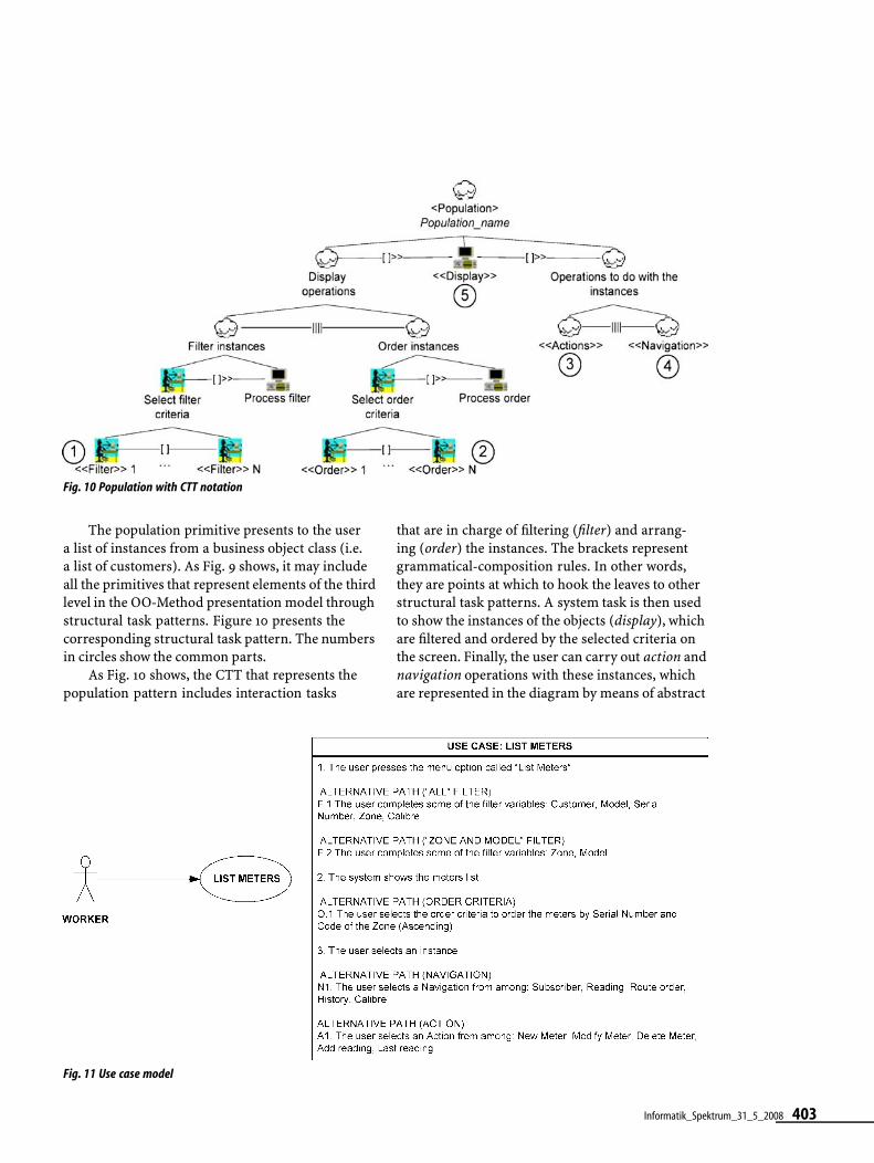
Fig. 10 Population with CTT notation
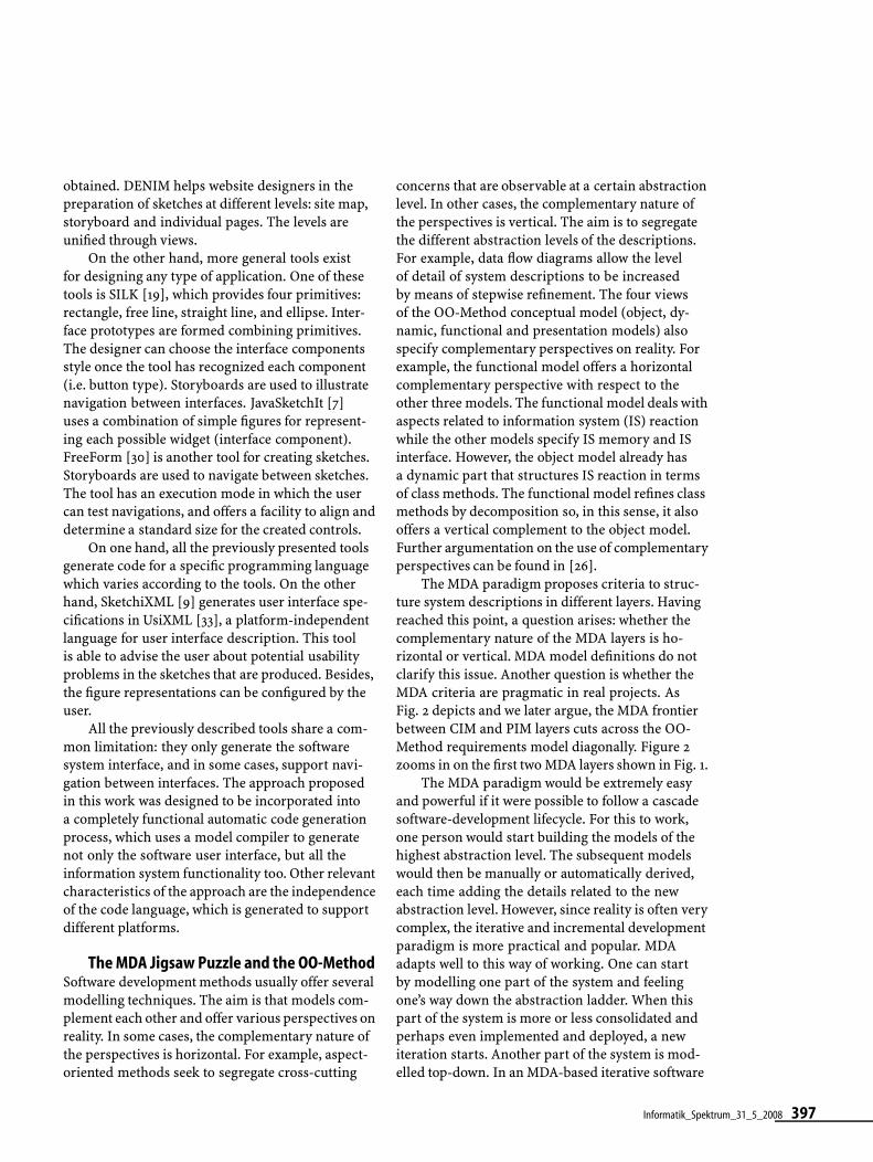
The population primitive presents to the usera list of instances from a business object class (i.e.a list of customers). As Fig. 9 shows, it may includeall the primitives that represent elements of the thirdlevel in the OO-Method presentation model throughstructural task patterns. Figure 10 presents thecorresponding structural task pattern. The numbersin circles show the common parts.
As Fig. 10 shows, the CTT that represents thepopulation pattern includes interaction tasks
Fig. 11 Use case model
that are in charge of filtering (filter) and arrang-ing (order) the instances. The brackets representgrammatical-composition rules. In other words,they are points at which to hook the leaves to otherstructural task patterns. A system task is then usedto show the instances of the objects (display), whichare filtered and ordered by the selected criteria onthe screen. Finally, the user can carry out action andnavigation operations with these instances, whichare represented in the diagram by means of abstract
Informatik_Spektrum_31_5_2008 403

{ MODELLIERUNG
tasks. All of these structural task patterns can becomposed to model the interaction with a list ofinstances.
Case StudyThis section shows the development process of a realsystem with the OO-Method methodology. Thissystem is called AguasDeBullent, a water supplymanagement system. In this case study, one of thepossible routes across the MDA jigsaw puzzle isfollowed, using many of the models proposed by theOO-Method. The case study starts with the stage ofrequirements capture. First, the analyst creates theuse case model. To keep the example simple, thispaper focuses on one use case, list meters. This usecase represents the functionality of showing a listwith all the information about the water metersstored in the system.
Figure 11 shows the use case model with a tem-plate that specifies the steps required to accomplishthe goal of this use case. Again, for the sake ofsimplicity, the template does not fully comply withthe notation described in [11] but it does specify theuse case in detail.
Once the functional requirements have beencaptured, the last step in requirements capture is tomodel interaction requirements using sketches (seeFig. 12).
Fig. 13 CTT model
Fig. 12 Sketch
The CTT that represents the sketch isautomatically built (see Fig. 13).
Some of the views that compose the con-ceptual model (object, functional and dynamicmodels) can be derived from functional require-ments applying the transformation rules detailedin [11]. The presentation model can be derivedfrom the CTTs by applying transformation rulesexplained in [12]. This case study focuses on theobject model (Fig. 14a) and presentation model(Fig. 14b).
Finally, the model compiler automaticallygenerates the source code of the fully functional
404 Informatik_Spektrum_31_5_2008
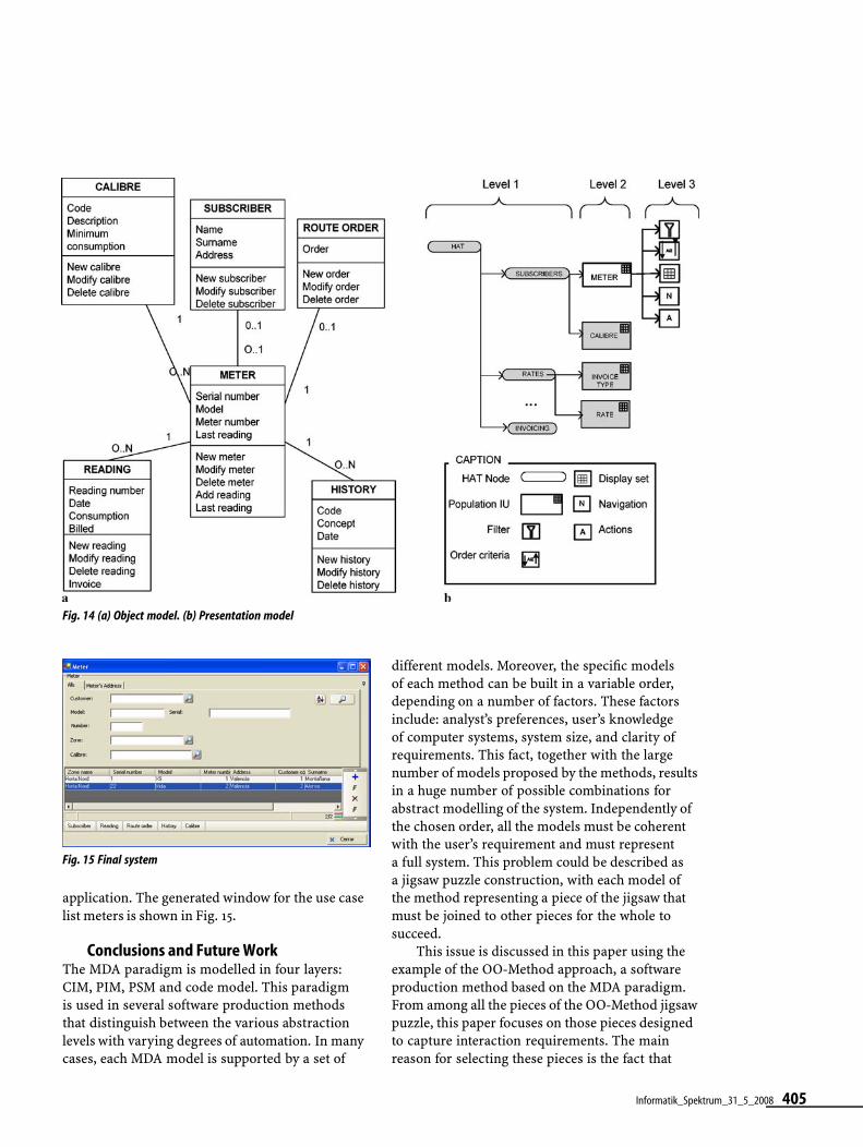
Fig. 14 (a) Object model. (b) Presentation model
Fig. 15 Final system
application. The generated window for the use caselist meters is shown in Fig. 15.
Conclusions and Future WorkThe MDA paradigm is modelled in four layers:CIM, PIM, PSM and code model. This paradigmis used in several software production methodsthat distinguish between the various abstractionlevels with varying degrees of automation. In manycases, each MDA model is supported by a set of
different models. Moreover, the specific modelsof each method can be built in a variable order,depending on a number of factors. These factorsinclude: analyst’s preferences, user’s knowledgeof computer systems, system size, and clarity ofrequirements. This fact, together with the largenumber of models proposed by the methods, resultsin a huge number of possible combinations forabstract modelling of the system. Independently ofthe chosen order, all the models must be coherentwith the user’s requirement and must representa full system. This problem could be described asa jigsaw puzzle construction, with each model ofthe method representing a piece of the jigsaw thatmust be joined to other pieces for the whole tosucceed.
This issue is discussed in this paper using theexample of the OO-Method approach, a softwareproduction method based on the MDA paradigm.From among all the pieces of the OO-Method jigsawpuzzle, this paper focuses on those pieces designedto capture interaction requirements. The mainreason for selecting these pieces is the fact that
Informatik_Spektrum_31_5_2008 405

{ MODELLIERUNG
interaction modelling is often disregarded by thesoftware engineering community. However, thehuman-computer interaction community has of-fered many successful techniques for capturinginteraction requirements, a prime example aresketches. Sketches have been chosen to capture theinteraction requirements in the OO-Method due totheir simplicity. However, sketches cannot be usedin an automatic transformation process unless weformalise their underlying language. We have cho-sen the ConcurTaskTree (CTT) notation to formallyrepresent the sketches. CTTs allow the sketches torepresent interaction unambiguously; they can bevalidated and then transformed into the OO-Methodpresentation model. The implementation of the toolto draw sketches and to synchronously generateCTTs is planned as future work. This functionality,together with the transformation of the task modelinto the presentation model, will offer efficienttechnological support for automatically generatingapplication interfaces and will allow early feedbackfrom the user. This provides an interesting andspecific example of how to put together the variouspieces needed to create a complete, MDA-compliantsoftware production process, the so-called MDAjigsaw puzzle.
We also plan to assess the efficiency of theproposed interaction requirements technique, aswell as the various alternatives for building therest of the models. This will be done by means ofempirical evaluation. Moreover, a case-base with thevarious methodological routes should be definedtogether with the factors that lead the analyst tochoose one specific route.
References1. Ågerfalk PJ, Fitzgerald B (2006) Exploring the concept of method rationale: A con-
ceptual tool for method tailoring. In: Siau K (ed) Advanced Topics in Database Re-search, vol 5. Idea Group, Hershey, PA
2. Ågerfalk PJ, Ralyté J (2006) Situational requirements engineering processes: re-flecting on method engineering and requirements practice. Software process: im-provement and practice. Wiley, New York
3. Bailey BP, Konstan JA (2003) Are Informal Tools Better? Comparing DEMAIS, Pen-cil and Paper, and Authorware for Early Multimedia Design. Human Factors inComputing Systems CHI’2003. ACM, New York
4. Bernstein PA (2003) Applying Model Management to Classical Meta Data Prob-lems. In: Proceedings of Conference on Innovative Data Systems Research (CIDR)2003
5. Brinkkemper S (1996) Method engineering: engineering of information systemsdevelopment methods and tools. Inf Softw Technol 38:275–280
6. Brinkkemper S, Saeki M, Harmsen F (1999) Metamodelling based assembly tech-niques for situational method engineering. Inf Syst 24(3):209–228, doi: 10.1016/S0306-4379(99)00016-2
7. Caetano A, Goulart N, Fonseca M, Jorge J (2002) JavaSketchIt: Issues in Sketchingthe Look of User Interfaces. AAAI Spring Symposium. Sketch understanding. AAAIPress, Menlo Park, CA, pp 9–14
8. Care Technologies (2007) http://www.care-t.com. Accessed July 20079. Coyette A, Vanderdonckt J (2005) A Sketching Tool for Designing Anyuser, Any-
platform, Anywhere User Interfaces. INTERACT 2005, LNCS 3585. Springer, BerlinHeidelberg New York, pp 550–564
10. DeLaVara JL, Sánchez J (2007) Business process-driven requirements engineering:a goal-based approach. In: 8th Workshop on Business Process Modeling, Develop-ment, and Support (BPMDS’07), CAiSE’07, Trondheim, Norway (in press)
11. Díaz I, Losavio F, Matteo A, Pastor O (2003) A Specification Pattern for Use Cases.Inf Manage J (Elsevier Science B.V.) 41:961–975
12. España S, Pederiva I, Panach JI (2007) Integrating Model-Based and Task-BasedApproaches to User Interface Generation. In: Calvary, Pribeanu C, Santucci G, Van-derdonckt J (eds) Computer-Aided Design of User Interfaces VI. Kluwer, Dordrecht,pp 255–263
13. Fitzgerald G (1991) Validating new information systems techniques: a retrospec-tive analysis. In: Nissen HE, Klein HK, Hirschheim R (eds) Information Systems Re-search: Contemporary Approaches and Emergent Traditions. Elsevier Science, Ox-ford, pp 657–672
14. Fons J, Valderas P, Albert M, Pastor O (2003) Development of Web Applicationsfrom Web Enhanced Conceptual Schemas. ER 2003, LNCS. Springer, Berlin Heidel-berg New York, pp 232–245
15. Gupta D, Prakash N (2001) Engineering methods from method requirements spe-cifications. Requirements Engineering 6(3):135–160, doi: 10.1007/s007660170001
16. ISO/IEC 9126-1 (2001) Software engineering. Product quality 1: Quality model17. Karlsson F, Ågerfalk PJ (2004) Method configuration: Adapting to situational char-
acteristics while creating reusable assets. Inf Softw Technol 46(9):619–633, doi:10.1016/j.infsof.2003.12.004
18. Karlsson F, Wistrand K (2006) Combining method engineering with activity the-ory: Theoretical grounding of the method component concept. Eur J Inf Syst15(1):82–90, doi: 10.1057/palgrave.ejis.3000596
19. Landay J, Myers BA (2001) Sketching Interfaces: Toward More Human InterfaceDesign. IEEE Comput 34:56–64
20. Lyytinen K, Welke R (1999) Guest editorial: Special issue on meta-modelling andmethodology engineering. Inf Syst 24(2):67–69, doi: 10.1016/S0306-4379(99)00005-8
21. MDA (2007) http://www.omg.org/mda. Accessed July/June 2007/200822. Mirbel I, Ralyté J (2006) Situational method engineering: Combining assembly-
based and roadmap-driven approaches. Requirements Eng 11(1):58–78, doi:10.1007/s00766-005-0019-0
23. Molina P (2003) User interface specification: from requirements to automatic gen-eration. PhD Thesis, DSIC, Universidad Politécnica de Valencia (in Spanish)
24. Morgan T (2002) Business Rules and Information Systems: Aligning IT with Busi-ness Goals. Addison-Wesley, Boston
25. Newman MW, Lin J, Hong JI, Landay JA (2003) DENIM: An Informal Web Site De-sign Tool Inspired by Observations of Practice. Human Comput Inter 18:259–324
26. Pastor O, González A, España S (2007) Conceptual alignment of software produc-tion methods. In: Krogstie J, Opdahl A, Brinkkemper S (eds) Conceptual modellingin information systems engineering. Springer, Berlin Heidelberg New York,pp 209–228
27. Pastor Ó, Insfrán E et al. (1997) OO-Method: An OO Software Production Environ-ment Combining Conventional and Formal Methods. Lecture Notes in ComputerScience. 9th Conference on Advanced Information Systems Engineering(CAiSE’97), Barcelona, Spain. Springer, Berlin Heidelberg New York
28. Paternò F, Mancini C et al. (1997) ConcurTaskTrees: A Diagrammatic Notation forSpecifying Task Models. In: Proceedings of the IFIP TC13 International Conferenceon Human-Computer Interaction. Chapman and Hall, London, pp 362–369
29. Pederiva I, Vanderdonckt J, España S, Panach JI, Pastor O (2007) The Beautifica-tion of Automatically Generated User Interfaces. In: Proceedings of XI IFIP TC13International Conference on Human-Computer Interaction (INTERACT 2007), LNCS4662. Springer, Berlin Heidelberg New York, pp 209–422
30. Plimmer BE, Apperley M (2003) Software for Students to Sketch Interface Designs.In: Proceedings of Conference on Human-Computer Interaction (INTERACT 2003).IOS, Amsterdam, pp 73–80
31. Rittel H, Webber M (1973) Dilemmas in a general theory of planning. Policy Sci4:155–169
32. Schipper M, Joosten S (1996) A validation procedure for information systemsmodelling techniques. In: Workshop on Evaluation of Modeling Methods in Sys-tems Analysis and Design, 8th Conference on Advanced Information Systems En-gineering (CAISE’96). Springer, Berlin Heidelberg New York
33. Vanderdonckt J, Limbourg Q et al. (2004) USIXML: a User Interface Description Lan-guage for Specifying Multimodal User Interfaces. In: Proceedings of W3CWorkshop on Multimodal Interaction (WMI’2004), Sophia Antipolis,Greece
406 Informatik_Spektrum_31_5_2008

Oscar Pastor is Pro-fessor and Directorof the Centro deInvestigación en Méto-dos de Producciónde Software -ProS-of the UniversidadPolitécnica de Valencia(Spain). He got hisPhD in 1992. Formerlyhe was a researcherin HP Labs, Bristol,UK. He is (co-) authorof more than 100 re-
search papers in conference proceedings, journalsand books, and he has received numerous researchgrants from public institutions and private indus-try. He was keynote speaker at many conferencesand workshops. Research activities focus on webengineering, object-oriented conceptual modelling,requirements engineering, information systems andmodel-based software production.
Sergio España re-ceived his MSc inComputer Scienceand is a member ofthe Centro de Inves-tigación en Métodosde Producción deSoftware -ProS- ofthe UniversidadPolitécnica de Va-lencia (Spain). Hecurrently holds a grantby the Spanish Min-istry of Science and
Innovation. His research interests revolve aroundinformation systems, requirements engineering,conceptual modelling and interface design.
José Ignacio Panach isa member of the Cen-tro de Investigaciónen Métodos de Pro-ducción de Software-ProS- of the Univer-sidad Politécnica deValencia (Spain). Cur-rently he is working onhow to model usabilityat the first stages of thesoftware developmentprocess. This work isbeing developed in his
PhD thesis. Moreover, he has participated in worksfor capturing interaction requirements and how toevaluate automatically the system usability fromconceptual models.
Nathalie Aquino isa member of the Cen-tro de Invetigaciónen Métodos de Pro-ducción de Software-PROS- of the Univer-sidad Politécnica deValencia (Spain). Sheis also a PhD studentof the UPV. Researchactivities focus onmodel-based userinterface developmentand user interfaceengineering.
Informatik_Spektrum_31_5_2008 407
Copyright © 2022 FDOKUMEN