Experimental and analytical studies of melt jet-coolant interactions: a synthesis
29
Nuclear Engineering and Design 189 (1999) 299 – 327 Experimental and analytical studies of melt jet-coolant interactions: a synthesis T.N. Dinh *, V.A. Bui, R.R. Nourgaliev, J.A. Green, B.R. Sehgal Di6ision of Nuclear Power Safety, Royal Institute of Technology (RIT) Drottning Kristinas 6a ¨g. 33A, 10044 Stockholm, Sweden Received 29 June 1998; accepted 29 June 1998 Abstract Instability and fragmentation of a core melt jet in water have been actively studied during the past 10 years. Several models, and a few computer codes, have been developed. However, there are, still, large uncertainties, both, in interpreting experimental results and in predicting reactor-scale processes. Steam explosion and debris coolability, as reactor safety issues, are related to the jet fragmentation process. A better understanding of the physics of jet instability and fragmentation is crucial for assessments of fuel-coolant interactions (FCIs). This paper presents research, conducted at the Division of Nuclear Power Safety, Royal Institute of Technology (RIT/NPS), Stockholm, concerning molten jet-coolant interactions, as a precursor for premixing. First, observations were obtained from scoping experiments with simulant fluids. Second, the linear perturbation method was extended and applied to analyze the interfacial-instability characteristics. Third, two innovative approaches to computational fluid dynamics (CFD) modeling of jet fragmentation were developed and employed for analysis. The focus of the studies was placed on (a) identifying potential factors, which may affect the jet instability, (b) determining the scaling laws, and (c) predicting the jet behavior for severe accident conditions. In particular, the effects of melt physical properties, and the thermal hydraulics of the mixing zone, on jet fragmentation were investigated. Finally, with the insights gained from a synthesis of the experimental results and analysis results, a new phenomenological concept, named ‘macrointerac- tions concept of jet fragmentation’ is proposed. © 1999 Elsevier Science S.A. All rights reserved. Keywords: Jet coolant interactions; Synthesis; Reactor-scale processes 1. Motivation and background 1.1. Practical importance and rele6ance During the last 10–15 years, much research has been performed, including both experimental and numerical investigations, to study the interaction of molten fuel with water. Fuel-coolant interac- tions (FCIs) may occur during the course of a severe accident in a light water reactor (The- ofanous, 1995). The nature of FCIs can range from benign film boiling to explosive interactions. Four distinct phases are thought to occur during an explosive FCI: pre-mixing, triggering, propaga- tion (or fine fragmentation), and expansion phases (Corradini et al., 1988). Although remark- * Corresponding author. Tel.: +46-8-790-9254; fax: +46- 8-790-9197. E-mail address: [email protected] (T.N. Dinh) 0029-5493/99/$ - see front matter © 1999 Elsevier Science S.A. All rights reserved. PII:S0029-5493(98)00275-1
Transcript of Experimental and analytical studies of melt jet-coolant interactions: a synthesis
Nuclear Engineering and Design 189 (1999) 299–327
Experimental and analytical studies of melt jet-coolantinteractions: a synthesis
T.N. Dinh *, V.A. Bui, R.R. Nourgaliev, J.A. Green, B.R. SehgalDi6ision of Nuclear Power Safety, Royal Institute of Technology (RIT) Drottning Kristinas 6ag. 33A, 10044 Stockholm, Sweden
Received 29 June 1998; accepted 29 June 1998
Abstract
Instability and fragmentation of a core melt jet in water have been actively studied during the past 10 years. Severalmodels, and a few computer codes, have been developed. However, there are, still, large uncertainties, both, ininterpreting experimental results and in predicting reactor-scale processes. Steam explosion and debris coolability, asreactor safety issues, are related to the jet fragmentation process. A better understanding of the physics of jetinstability and fragmentation is crucial for assessments of fuel-coolant interactions (FCIs). This paper presentsresearch, conducted at the Division of Nuclear Power Safety, Royal Institute of Technology (RIT/NPS), Stockholm,concerning molten jet-coolant interactions, as a precursor for premixing. First, observations were obtained fromscoping experiments with simulant fluids. Second, the linear perturbation method was extended and applied toanalyze the interfacial-instability characteristics. Third, two innovative approaches to computational fluid dynamics(CFD) modeling of jet fragmentation were developed and employed for analysis. The focus of the studies was placedon (a) identifying potential factors, which may affect the jet instability, (b) determining the scaling laws, and (c)predicting the jet behavior for severe accident conditions. In particular, the effects of melt physical properties, and thethermal hydraulics of the mixing zone, on jet fragmentation were investigated. Finally, with the insights gained froma synthesis of the experimental results and analysis results, a new phenomenological concept, named ‘macrointerac-tions concept of jet fragmentation’ is proposed. © 1999 Elsevier Science S.A. All rights reserved.
Keywords: Jet coolant interactions; Synthesis; Reactor-scale processes
1. Motivation and background
1.1. Practical importance and rele6ance
During the last 10–15 years, much research hasbeen performed, including both experimental and
numerical investigations, to study the interactionof molten fuel with water. Fuel-coolant interac-tions (FCIs) may occur during the course of asevere accident in a light water reactor (The-ofanous, 1995). The nature of FCIs can rangefrom benign film boiling to explosive interactions.Four distinct phases are thought to occur duringan explosive FCI: pre-mixing, triggering, propaga-tion (or fine fragmentation), and expansionphases (Corradini et al., 1988). Although remark-
* Corresponding author. Tel.: +46-8-790-9254; fax: +46-8-790-9197.
E-mail address: [email protected] (T.N. Dinh)
0029-5493/99/$ - see front matter © 1999 Elsevier Science S.A. All rights reserved.
PII: S0029 -5493 (98 )00275 -1
T.N. Dinh et al. / Nuclear Engineering and Design 189 (1999) 299–327300
able progress in the description of the pre-mixingand expansion phases of the steam explosion hasbeen achieved in recent years, the initial phase ofthe FCI process has not been well understood yet.This includes jet breakup, droplet formation andsubsequent fragmentation. Several large-scale ex-perimental programs and analyses efforts are un-derway to determine physical mechanismsassociated with FCIs and to provide models andmethods, which could be used to predict theconsequences of FCIs in reactor accident situa-tions (Magallon et al., 1995; Turland and Dob-son, 1996; Berthoud, 1996a,b).
This paper focuses on the ex-vessel fuel-coolantinteractions. Such a hypothetical situation mayoccur in the newer ABB boiling water reactor(BWR) plants which are located in Sweden andFinland. These plants employ a severe accidentmanagement procedure, in which a deep, highly-subcooled, water pool is established under thevessel, as soon as it becomes clear that the waterlevel in the core may fall below the top of the fuel.The motivation for this strategy is the engineeringjudgement that the core melt jet will fragmentduring its passage through the water and that theparticles, which are formed, will be cooled perma-nently within the water pool. The success of thisprocedure is predicated upon the judgement that alarge steam explosion, which could threaten thecontainment integrity during the melt-water inter-action, will not occur.
It is important to note that the study, per-formed at RIT/NPS on the reactor vessel holeablation, indicates that most of the melt volumewill be discharged from the reactor pressure vessel(RPV) as a coherent jet. The melt volume avail-able in the lower plenum for release before the gasblowthrough onset is generally more than 90%(for overpressurization of 0.7 MPa). The vesselhole enlargement dynamics for the prototypic ves-sel, with about 70 t of molten core materials in thevessel lower plenum, is predicted to be in therange 6–10 mm s−1, i.e. the time period (to havethe initial hole of 3–10 cm diameter to grow to25–30 cm) would take 20–25 s (Dinh et al.,1997b).
Therefore, the interaction between a quasi-steady large-diameter (10–15 cm) core-melt jet
and a highly-subcooled deep water pool at thecontainment pressure must be considered.
This paper is concerned with the FCI phasebefore the traditional FCI phases, i.e. the jetfragmentation, which serves as the source forpremixing. Such a process is also important fordebris formation and subsequent debriscoolability.
1.2. Past work: classification
Previously, such a severe accident scenario inthe Swedish BWRs was analyzed by Chu et al.(1995), using the EPRI/ANL THIRMAL-1 com-puter code. In that work one can also find acomprehensive review on jet instability mecha-nisms and related processes. In addition, a reviewof jet break-up mechanisms under isothermal andfilm-boiling conditions was performed by Burgeret al. (1995), where the jet break-up experimentaldata base was also presented. Several other im-portant experimental and analytical studies, re-lated to molten jet-coolant interactions performedbefore the year 1993, were presented at the previ-ous OECD/CSNI Meeting on ‘Fuel-Coolant In-teractions’ at Santa Barbara, 1993 (and publishedin vol. 155 of Nuclear Engineering and Design,1995). Therefore, a full review is not attempted inthis paper.
It is instructive, however, to note that in thelast 2–3 years, studies of jet instability were fur-ther pursued, analytically, at IKE (Stuttgart, Ger-many) by Burger and coworkers, and at CENG(Grenoble, France) by Berthoud and co-workers(Berthoud, 1996a,b). During this period, severalexperimental programs were performed. Specifi-cally, the MIXA, BILLEAU, and QUEOS-testswere conducted, using jet-like configurations ofhot spheres, in order to obtain data for validationof the pre-mixing models and codes (Jacobs et al.,1996; Berthoud, 1996a,b). The interactions ofmelt with coolant were experimentally investi-gated in FARO (Ispra, Italy) and PREMIX (FzK,Karlshure, Germany) tests at high temperatures,using both prototypic and thermite melts (Magal-lon et al., 1995; Berthoud, 1996a,b), and in JEFRItests (IKE, Stuttgart, Germany) at low tempera-tures, using Wood’s metal as jet simulant fluid
T.N. Dinh et al. / Nuclear Engineering and Design 189 (1999) 299–327 301
and freon R113 as coolant. In high-temperaturetests the melt mass was limited, so that a quasi-steady process was not achieved.
Three approaches to jet fragmentation analysisand modeling can be mentioned:1. Correlation approach. These are based on ex-
perimental data and appropriate scaling,which may fail when extrapolating the data toprototypic reactor conditions;
2. One-dimensional models. These models relyon linear stability analysis, with a hope todevelop constitutive physics to describe thetransition of melt from a continuous jet phaseinto a droplet phase. Further, these modelscan be categorized by the jet-linearstabilitymodels they employ: Kelvin-Helmholtz inTHIRMAL-1 code (Chu et al., 1995); Jeffrey-Miles in IKEJET code (Burger et al., 1995)and CENG model (Berthoud, 1996a,b); Ray-leigh-Taylor in TEXAS code (Chu and Corra-dini, 1989), and the methods used to accountfor thermal hydraulics of the ambient fluid(boiling-coolant pool dynamics, film boiling).The one-dimensional formulation employed inthese models poses significant difficulties whenimplementing a jet fragmentation model intothe Eulerian multi-dimensional (2-D and 3-D)multifield (e.g. steam, water, melt, debris) pre-mixing codes.
3. Computational fluid dynamics (CFD) models.There have been no attempts to model thefragmentation of a continuous-phase jet intoparticles, using CFD methods (Turland andDobson, 1996).
1.3. Objecti6es and methods of the present study
The present study aims to investigate moltenjet-coolant interactions, limited to the physicalmechanisms which may govern instability andfragmentation of a jet penetrating a coolant pool.Since the experimental data base is rather meagerand uncertain, and the validity and applicabilityof different models is not so clear, perhaps, arational synthesis of the experimental informationand calculation results may help to delineate vari-ous aspects of the underlying physics.
Clearly, there are three primary inter-relatedthermal-hydraulic phenomena:1. jet instability and fragmentation;2. film boiling around the high-temperature jet;
and3. boiling dynamics in the coolant pool1.
First, it is noteworthy that this study is accom-panied by a study of film boiling of highly-sub-cooled water on a high-temperature long verticalsurface under FCI conditions (Dinh et al.,1997a,c). Second, jet fragmentation experimentsand linear perturbation analyses were performed,in order to have a better understanding of the roleof melt physical properties and of thermal hy-draulics of the coolant pool (Bui and Dinh,1996a,b). Third, several CFD methods for model-ing of interfacial phenomena and multiphase mix-ing processes were developed at RIT (Bui andDinh, 1996a,b; Bui et al., 1997a,b,c; Dinh et al.,1997c; Nourgaliev et al., 1997a,b). These methodswere employed in this study to perform sensitivityand comparative analyses.
The major idea being pursued in this work,however, is that three phenomena should not beconsidered in isolation. On one hand, jet fragmen-tation is a pre-condition for the premixing. On theother hand, the steam produced, due to mixing ofmelt and coolant, affects jet fragmentation forquasi-steady (long-duration) melt jets. Therefore,a separate-effect description is not suitable forsuch an integrated and synergistic transientprocess.
The main thrust of this paper is, therefore, notto repeat work reported elsewhere (Bui and Dinh,1996a,b; Bui et al., 1997a,b,c; Dinh et al., Nour-galiev et al., 1997a; 1997c,b), but to synthesize thefindings from relevant experiments and numericalsimulations for the penetration of a large-diame-ter melt jet into a subcooled deep water pool.
1 Component phenomena of the mixing zone thermal hy-draulics include particle-fluid heat transfer, particle solidifica-tion, steam production from a debris collected on the poolbottom, etc.

T.N. Dinh et al. / Nuclear Engineering and Design 189 (1999) 299–327302
2. Experimental study: observations and findings
2.1. Experimental arrangement
Both isothermal and non-isothermal jetbreakup experiments were performed at RIT/NPSlaboratory employing different pairs of simulantmaterials for jet fluid and coolant, such as Cer-robend–water, molten salt–paraffin oil, water–paraffin oil, Cerrobend–paraffin oil,Cerrobend–molten salt2,3 (see Table 2).
Melt is released from a crucible through a tubesection to a coolant tank. The melt crucible is acylinder of 16 cm in diameter and 0.5 m in height,which is electrically heated from the external sur-face in order to provide the required melt temper-ature (up to 700 K). The melt temperature waslimited to B575 K to preclude any potential forsteam explosions.
The jet (tube) diameter varied from 2.5 to 25mm. The tube was thermally insulated and heatedby electrical wire-heaters from outside to maintaina constant melt temperature. The jet velocity wasup to 4 m s−1. In most cases, the tube exit-nozzlewas submerged in the coolant pool in order toprevent gas entrainment, which would reduce vi-sualization capability. Several tests, however, wereconducted with a jet dropping and accelerating inair before penetrating the coolant pool surface.
The melt volume was varied to a maximum of 8l, so that a steady-jet situation was ensured. Thecoolant tank, containing either water or paraffinoil, was 0.25×0.25×1.5 m, with the volume of#80 l. Electrical heaters were installed to providethe required coolant temperature. In non-isother-mal tests, both melt and coolant were well mixedto ensure the uniform temperature of the melt andcoolant.
Visualization was performed by means of avideo system with 25 fps. In order to provide
exposure times of 1/4000 s and 1/10 000 s, goodlighting conditions were maintained. Sharp still-pictures, without noticeable smearing out of theinterfaces were obtained. In the water–paraffin oilexperiments, the water was colored, in order todistinguish the jet interface and fragments.
2.2. Properties and range of parameter 6ariations
Since in liquid–liquid contact mode, the ratioof jet fluid and ambient fluid densities (Q=rj/ra)is important, this parameter varied from 1.14 to10.8 (Table 1). The maximum Weber numbers inthe tests performed are also shown in the table(Wea=ra · U j
2 · Dj/s).
2.2.1. ViscositiesIn water–paraffin oil tests the temperature of
the water was varied from 2 to 99°C, so that thejet-fluid viscosity, mj, changes as much as sixtimes, as does the jet Reynolds number Rej. Theeffect of the ambient-fluid viscosity was investi-gated in Cerrobend–water and Cerrobend–paraffin oil experiments, in which theambient-fluid viscosity changed by #3 orders ofmagnitude (mwater=3·10−4�10−3 and moil=0.29). In these cases, the jet Reynolds number Rej
remained invariant, while the ambient-fluidReynolds number changed by three orders ofmagnitude.
2.2.2. Non-iosthermal liquid– liquid contact modeCerrobend–water jet-fragmentation experi-
ments were also conducted, using water at differ-ent temperatures as the coolant (Ta=100, 40, 20and 4°C).
Table 1Density ratio and Weber number, based on the ambient-fluiddensity
N° Wea (max.)Q rj/raFluid pairs
Jet Coolant
Water1 Paraffin oil 1.14 500Paraffin oilMolten salt 2252 2.4
254.7Molten saltCerrobend3Cerrobend Water4 9.5 1000Cerrobend Paraffin oil5 10.8 885
2 Cerrobend-70 is a low-melting point allow (Tmp#72°C),with high density (r#9670 kg m−3), low viscosity (m#0.002Pa.s), and surface tension s#0.35–0.4 N m−1.
3 Molten salt mixture NaNO3�KNO3�NaNO2 (Hitec) hasTmp#150°C, r#2000 kg m−3, m#0.002 Pa.s and s#0.1 Nm−1.

T.N. Dinh et al. / Nuclear Engineering and Design 189 (1999) 299–327 303
Table 2Reynolds numbers for jet and ambient fluids
Rej=UjDj/nj (max.) Rea=UjDj/na (max.)N° Fluid pairs
Jet Coolant
42000 38.51 Water Oil38.52 Salt Oil 12600
3 3000Cerrobend 18000Salt6·105 3.3·1054 Cerrobend Water
5 Cerrobend Oil 3056·105
2.2.3. Non-isothermal boiling modeThis fragmentation mode was investigated in
experiments, which employed Cerrobend at tem-peratures up to 550 K as the jet and nearly-satu-rated water as the coolant.
Most of isothermal jet-fragmentation experi-ments, performed in the past, employed Wood’smetal (similar to Cerrobend-70) and water assimulant materials for jet and ambient fluids(Burger et al., 1995). The experiments, performedin the present study, provide a significantlybroader variation of parameters influencing jetfragment.
In prototypical core melt jet-coolant interac-tions (Section 1.1), the Weber number Wea, basedon the water density, may be up to 25 000, whilethe jet Reynolds number and ambient-fluidReynolds number are up to 2.4·106 and 1.5·106,respectively. The Weber numbers Wea are signifi-cantly reduced if the homogenized density of theboiling coolant pool is used. Nevertheless, thereactor-scale Weber numbers are far larger thanthe transition criterion Wea,cr=102, where theatomization regime is predicted (Burger et al.,1995). In this context, the high-Weber numberexperiments, listed in Tables 1 and 2 can providerelevant observations.
2.3. Obser6ations and findings
2.3.1. Beha6ior of the jet leading edgeThe mushroom-like jet head was observed in
low-velocity small-diameter water–paraffin oil ex-periments during the water jet penetration intothe oil pool. It disappears after the steady jetconfiguration was achieved. The mushroom-like
jet head is hardly noticeable at high Weber num-bers even in water–paraffin oil experiments (seeFig. 1). No leading edge breakup was observed inexperiments which have density ratio Q\2.4. Thesteady jet-fragmentation configuration was estab-lished almost immediately as the jet penetrates acertain pool depth, namely the jet breakup length.It should be noted that the focus of our observa-tions is on jet instability and dynamic behavior,rather than on the measurement of the jetbreakup length4.
2.3.2. Effect of the jet-fluid 6iscosityThe water–paraffin oil experiments, with differ-
ent water temperatures, and, hence, different vis-cosities, revealed no evidence of the effect of thejet-fluid viscosity on the jet instability behavior.That is to say, the low density ratio and highambient-fluid viscosity in these experiments sig-nificantly enhance the jet integration (to be dis-cussed later), so that the effect of the jet-fluidviscosity, if any, may well be suppressed.
2.3.3. Effect of the ambient-fluid 6iscosityIn a number of studies of jet fragmentation, jet
instability is related to the ambient-fluid shearstress. The role of the ambient-fluid viscosity wasinvestigated by comparing the jet fragmentationbehavior in two similar experiments; by usingCerrobend as jet fluid and water or paraffin–oilas coolant. The density ratios in these two casesare roughly the same. No differences in jet frag-mentation behavior were noticed in cases of low
4 For high Weber numbers and for boiling mode, the defin-ition of the jet breakup length has been largely subjective.

T.N. Dinh et al. / Nuclear Engineering and Design 189 (1999) 299–327304
Fig. 1. The breakup of water jet in paraffin oil. RIT experiment. Dj=6.3 mm, Uj=2.5 m s−1 (Wea#575).
Weber numbers (Wea=50–70). Even in case ofhigh Weber numbers (Wea=800–1000), the phys-ical picture was essentially similar in the paraffinoil and water pools. The jets atomize, after pass-ing a short distance (2–4 jet-diameters) from thenozzle, into a cloud of fine particles (see Fig. 2).To some extent, it seems that the expansion of theCerrobend particle cloud is wider in water than inparaffin oil. The higher viscosity of paraffin oilmay have resisted the lateral dispersion (Dr) ofthe small-size (Dp#1–2 mm) particles Dr�4/3 rj/ra Dp/CD(na).
2.3.4. Effect of heat transfer and phase changeThe effect of phase change on the jet dynamics
was investigated by non-isothermal liquid-liquidcontact-mode experiments. The results of theisothermal jet breakup tests (Tj=Ta=100°C) arecompared to those of the tests, conducted withwater temperatures lower (Ta=20, 40°C) andmuch lower (Ta=4°C) than the freezing point ofCerrobend-70. The initial melt temperature waskept at Tj#100°C. For jet diameters (Dj=15mm), the physical picture of the jet fragmentationis similar for cases with different water tempera-tures (see Fig. 3). Nevertheless, clear differencesof droplet size were evident from these experi-ments. The droplet size ranged from 0.3–0.5 mmin case Ta#100°C to 3–5 mm in case of Ta=4°C. Such differences in particle size may beassociated with the cooling of the jet surface layer
and with the crust formation on the droplet’ssurface, which prevents the droplet from furthersequential fragmentation. Thus, the droplet sizeobtained from the post-test examination, or fromthe video-picture (of an outer layer of the particlecloud), may not necessarily reflect the length scaleof ligaments stripped from the jet body.
2.3.5. Effect of the density ratioClassically, the density ratio Q was found to
significantly affect the jet instability, and hence,the jet breakup length Lbr or Lbr/Dj; see, forexample, Taylor’s correlation Lbr/Dj#5·Q1/2. It isworth noting however that similar correlations,derived from Kelvin–Helmholtz instability analy-sis, are associated with breakup regimes at lowWeber numbers (WeaB100). In addition, the pre-vious isothermal high-Weber-number jet fragmen-tation experiments were conducted withQ#9–9.5. Therefore, experiments with differentdensity ratios could provide useful observations ofthe jet dynamics under high Weber number condi-tions (Wea\100). While in Cerrobend–water,Cerrobend–paraffin oil experiments the jet atom-ization with lateral dispersion of the particle cloudwas observed, the water–paraffin oil, moltensalt–paraffin oil tests featured more coherent jets,even at Wea numbers in the range 100–500. Al-though, the breakup length is not long in small-density-ratio cases, resistance of the ambient fluidto the lateral transport of the fragments is high,

T.N. Dinh et al. / Nuclear Engineering and Design 189 (1999) 299–327 305
so that they move primarily downwards. Thus,the jet breakup regimes can not be determined,based on the Weber number alone for low valuesof Q.
2.3.6. Free falling jetsA limited number of tests were conducted with
the jet nozzle at a distance from the coolantsurface. Significant gas entrainment and bubblingin the coolant tank made it difficult to visualize.However, the observations at high Weber num-bers, so far, indicate no significant differences ofthe jet behavior in cases of submerged and unsub-merged jet-nozzles. Future tests with unsub-merged jet-nozzle are planned to determine the
Fig. 3. The breakup of Cerrobend jets in water of differenttemperatures. RIT experiment. Dj=15 mm, Uj=1.5 m s−1
(Wea#100).
Fig. 2. The breakup of Cerrobend jets in water and paraffinoil. RIT experiment. Dj=25 mm, Uj=4 m s−1 (Wea#1000–1200).
effect of in-tube turbulence and vortices on the jetatomization.
2.3.7. Boiling-mode jet breakupHigh-temperature tests were conducted with
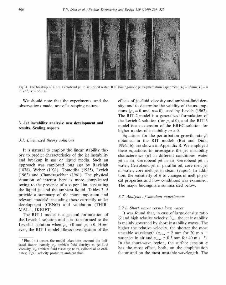
6.3, 15 and 25 mm-diameter jets. The melt tem-peratures were varied in the tests, with maximumtemperature about 550 K. This temperature wasevaluated to be higher than the minimum film-boiling temperature in a saturated water pool5.Unfortunately, the video-visualization capabilitywas limited by the boiling dynamics. It was ob-served that during the initial period of jet penetra-tion, the two-phase region around the jet wasthin. Later on, when the jet probably reached itsfragmentation state, intense steam generation wasobserved, with large vapor bulges moving up-wards (see Fig. 4). Large quantities of melt andwater were blown off the test section due to thevapor flows. Also, the section (250×250 mm) wasperhaps too small for the violent boilingoccurring.
5 Factors such as surface movement, surface roughness, etc.are not taken into account.
T.N. Dinh et al. / Nuclear Engineering and Design 189 (1999) 299–327306
Fig. 4. The breakup of a hot Cerrobend jet in saturated water. RIT boiling-mode jetfragmentation experiment. Dj=25mm, Uj=4m s−1, Tj=550 K.
We should note that the experiments, and theobservations made, are of a scoping nature.
3. Jet instability analysis: new development andresults. Scaling aspects
3.1. Linearized theory solutions
It is natural to employ the linear stability the-ory to predict characteristics of the jet instabilityand breakup in gas or liquid media. Such anapproach was employed long ago by Rayleigh(1878), Weber (1931), Tomotika (1935), Levich(1962) and Chandrasekhar (1961). The physicalsituation of interest here is more complicatedowing to the presence of a vapor film, separatingthe liquid jet and the ambient liquid. Tables 3–5provide a summary of the more important andrelevant models6, including those currently underdevelopment (CENG) and validation (THIR-MAL-1, IKEJET).
The RIT-1 model is a general formulation ofthe Levich-1 solution and it is transformed to theLevich-1 solution when ra�0 and ma�0. How-ever, the RIT-1 model allows investigation of the
effects of jet-fluid viscosity and ambient-fluid den-sity, and to determine the validity of the assump-tions (ra=0 and m=0), used by Levich (1962).The RIT-2 model is a generalized formulation ofthe Levich-2 solution (for ra"0), and the RIT-3model is an extension of the EREC solution forhigher modes of instability m\0.
Equations for the perturbation growth rate b,obtained in the RIT models (Bui and Dinh,1996a,b), are shown in Appendix B. We employedthese equations to investigate the jet instabilitycharacteristics (b) in different conditions: waterjet in air, Cerrobend jet in air, Cerrobend jet inwater, Cerrobend jet in paraffin oil, core melt jetin water, core melt jet in steam (vapor). In addi-tion, the sensitivity of b to changes in melt physi-cal properties and flow conditions was examined.The major findings are summarized below.
3.2. Analysis of simulant experiments
3.2.1. Short wa6es 6ersus long wa6esIt was found that, in case of large density ratio
Q and high relative velocity Urel, the jet instabilityis mainly governed by short instability waves. Thehigher the relative velocity, the shorter the mostunstable wavelength (amax.#2 mm for 20 m s−1
water jet in air and amax.#0.3 mm for 40 m s−1).In the short-wave region, the surface tension s
has the most effect, both, on the amplificationfactor and on the most unstable wavelength. The
6 Plus (+ ) means the model takes into account the indi-cated factor, namely ra, ambient-fluid density; mj, jet-fluidviscosity; ma, ambient-fluid viscosity; (r, z), cylindrical co-ordi-nates; Va(r), velocity profile in ambient fluid.

T.N. Dinh et al. / Nuclear Engineering and Design 189 (1999) 299–327 307
Table 3Jet instability models-two-layer symmetrical (zero-mode m=0) analysis
mj maAuthors/Refs. Va(r)ra (r, z)
Levich-1 (Levich, 1962) + ++THIRMAL (Chu et al., 1995)+IKE (Burger et al., 1995) + +
+ +CENG-1 (Berthoud, 1996a,b) ++ + ++RIT-1 (Bui and Dinh, 1996a,b)
higher the surface tension, the larger the mostunstable wavelength amax. and the lower the per-turbation growth rate b. The jet-fluid viscositywas found to reduce the perturbation growth rateand displace the most unstable waves to greaterlength. For example, results of calculations for awater jet (Dj=15 mm, Uj=40 m s−1) in air showthat the increase of the jet-fluid viscosity by 10and 100 times may reduce the perturbationgrowth rate by 1.3 and 4 times, respectively.
3.2.2. Cerrobend melt jet in 6aporIt was found that the heavy-material jets (rj\
8000 kg m−3) are generally stable in air/vapormedia until the relative velocity Urel=Uj−Uv
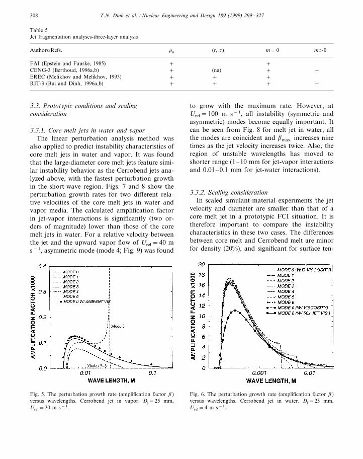
becomes more than 20 m s−1. For small diameterjets, the instability is governed by the symmetricmode, while for bigger jets (Dj\20 mm) one ofasymmetric modes may determine the maximumgrowth rate and the most unstable wavelength(e.g. mode 4 for water jet in air and mode 2 forCerrobend jet in vapor) (see Fig. 5). However,with increased velocity Urel, the differences be-tween the symmetric and asymmetric modesdecrease.
3.2.3. Cerrobend melt jets in water and inparaffin–oil
First, it was found that the perturbation growthrates b are maximum in the short-wave region.
Secondly, when comparing the calculated b forthe two cases (in water and in paraffin–oil), noeffect of the ambient-fluid viscosity was predicted.This agrees well with the RIT experimental obser-vation (Section 2.3).
Thirdly, the increase of the jet diameter tends tobring the asymmetric modes to behave more likethe symmetric mode. In fact, already for Dj\25mm, the symmetric mode and several asymmetricmodes (modes 1 to 6) behave similarly (Fig. 6).
Fourth, it was found that the maximum pertur-bation growth rate bmax. is sensitive to the jetvelocity Uj. For example, Cerrobend jets (Dj=25mm) of Uj=3 m s−1 and Uj=4 m s−1 providebmax.#6750 s−1 and bmax.#16 500 s−1, respec-tively. The shorter waves were found to be moredangerous in case of high-velocity jets (amax.#0.6mm and amax.#0.25 mm for Uj=3 m s−1 andUj=4 m s−1, respectively).
Finally, the potential effect of the jet solidifica-tion was investigated by increasing the jet-fluid(Cerrobend) viscosity 50 times. The analysis resultshows that this increase in jet viscosity reducedthe perturbation growth rate in the short-waverange by about 30% (see Fig. 6).
It appears that the dominant instability of shortwaves (both the symmetric and asymmetricmodes) and their fast growth rate causes the jetsto atomize into a particle cloud as observed in theRIT experiments at high Weber numbers.
Table 4Jet instability models-two-layer asymmetrical (higher-modem\0) analysis
Authors/Refs. mjra ma (r, z)
++Levich-2 (Levich, 1962)Yang (1992) ++
+ +CENG-2 (Berthoud, 1996a,b)+++RIT-2 (Bui and Dinh, 1996a,b)
T.N. Dinh et al. / Nuclear Engineering and Design 189 (1999) 299–327308
Table 5Jet fragmentation analyses-three-layer analysis
(r, z) m=0Authors/Refs. m\0ra
FAI (Epstein and Fauske, 1985) + +(na) ++ +CENG-3 (Berthoud, 1996a,b)
+EREC (Melikhov and Melikhov, 1993) + ++RIT-3 (Bui and Dinh, 1996a,b) + + +
3.3. Prototypic conditions and scalingconsideration
3.3.1. Core melt jets in water and 6aporThe linear perturbation analysis method was
also applied to predict instability characteristics ofcore melt jets in water and vapor. It was foundthat the large-diameter core melt jets feature simi-lar instability behavior as the Cerrobend jets ana-lyzed above, with the fastest perturbation growthin the short-wave region. Figs. 7 and 8 show theperturbation growth rates for two different rela-tive velocities of the core melt jets in water andvapor media. The calculated amplification factorin jet-vapor interactions is significantly (two or-ders of magnitude) lower than those of the coremelt jets in water. For a relative velocity betweenthe jet and the upward vapor flow of Urel=40 ms−1, asymmetric mode (mode 4; Fig. 9) was found
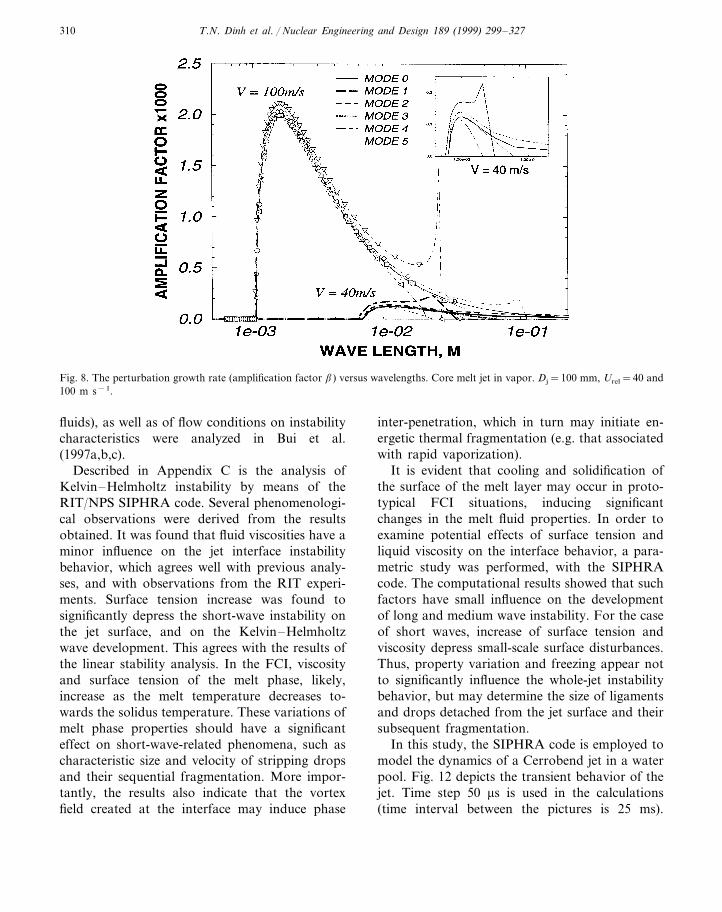
to grow with the maximum rate. However, atUrel=100 m s−1, all instability (symmetric andasymmetric) modes become equally important. Itcan be seen from Fig. 8 for melt jet in water, allthe modes are coincident and bmax. increases ninetimes as the jet velocity increases twice. Also, theregion of unstable wavelengths has moved toshorter range (1–10 mm for jet-vapor interactionsand 0.01–0.1 mm for jet-water interactions).
3.3.2. Scaling considerationIn scaled simulant-material experiments the jet
velocity and diameter are smaller than that of acore melt jet in a prototypic FCI situation. It istherefore important to compare the instabilitycharacteristics in these two cases. The differencesbetween core melt and Cerrobend melt are minorfor density (20%), and significant for surface ten-
Fig. 6. The perturbation growth rate (amplification factor b)versus wavelengths. Cerrobend jet in water. Dj=25 mm,Urel=4 m s−1.
Fig. 5. The perturbation growth rate (amplification factor b)versus wavelengths. Cerrobend jet in vapor. Dj=25 mm,Urel=30 m s−1.

T.N. Dinh et al. / Nuclear Engineering and Design 189 (1999) 299–327 309
Fig. 7. The perturbation growth rate (amplification factor b)versus wavelengths. Core melt jet in water. Dj=100 mm,Urel=10 and 20 m s−1.
(with lower jet velocity and diameter), the domi-nance of mode 4 is predicted for case with voidfraction of 0.9. Thus, in a coolant pool with ahigh void fraction, the scaled jet and prototypicjet may behave differently. That is to say, whenthe prototypic jet is likely to atomize, the scaledjet may be governed by an asymmetric mode(mode 4; see Fig. 9).
To conclude this section we note that themethod of linear perturbation analysis is found tobe a useful approach for comparative assessmentsand to identify the potential effects of physicalproperties and flow conditions on the jet instabil-ity. It also delineates the scaling difficulties. How-ever, more mechanistic approach must be used todescribe the jet fragmentation, which, in a proto-typic FCI, is greatly affected by the thermal hy-draulics of the ‘ambient’ fluid.
4. Jet fragmentation modeling: phenomenologicalconcept
4.1. Jet fragmentation modeling. An Eulerianmethod
In another study by the authors (Bui et al.,1997a,b,c), the numerical method, combining theadvanced 3-D Level-Set Algorithm (LSA) for in-terface tracking (Osher and Sethian, 1988; Suss-man et al., 1994) and the high-orderCubic-Interpolated Pseudoparticle (CIP) method(Yabe et al., 1990) for solution of the Navier–Stokes equations, was developed to model thephenomena, occurring at the fuel-coolant inter-face. Both CIP and LSA were formulated andprogrammed in 3-D Cartesian system of co-ordi-nates. The resulting computer code is named asSIPHRA-3D, which stands for Simulation of In-terfacial Phenomena in Hypothetical Reactor Ac-cidents. Based on this numerical method,simulations were performed for a melt jet enteringinto a lighter liquid pool, for Kelvin–Helmholtzinstability, and for melt droplet deformation andfragmentation. It was found that the method iscapable of describing the major interfacial charac-teristics. Effects of physical properties (surfacetension and viscosities of melt and ambient
sion (score/sCerr.#3) and viscosity (ncore/nCerr.#3).As noted above, the effect of jet-fluid viscosity isrelatively small, but the effect of surface tension isquite large. The smaller surface tension of Cer-robend tends to displace the most unstable wavesamax. to the region of shorter waves and to in-crease the amplification factor b. The calculatedresults also indicate that the instability character-istics (bmax., amax.) are very sensitive to the relativevelocities Urel, as is the Weber number Wea�U rel
2 .Despite the differences in qualities, the generalbehavior of instability characteristics is foundsimilar in the selected cases of Cerrobend jet andcore-melt jet penetrating the water and vapormedia (compare Figs. 5 and 6 and Figs. 7 and 8).
3.3.3. Melt jet beha6ior in two-phase mediaJet instability in the two-phase media is ana-
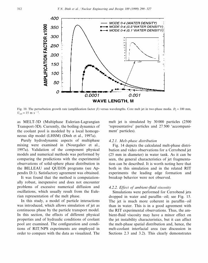
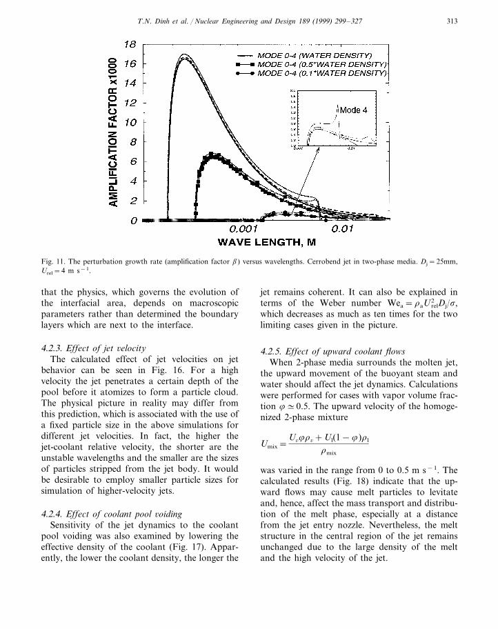
lyzed employing the effective (homogenized) den-sity rmix. Figs. 10 and 11 respectively depict theinstability characteristics for core melt and Cer-robend melt jets in the two-phase media with voidfraction 8=0.5 and 0.9. As it can be seen, thevoid fraction affects differently the prototypiccore melt jet and scaled experimental jet. Thesymmetric mode dominance and coincidence ofdifferent modes are predicted in all cases calcu-lated for core melt jets, whereas for Cerrobend jet
T.N. Dinh et al. / Nuclear Engineering and Design 189 (1999) 299–327310
Fig. 8. The perturbation growth rate (amplification factor b) versus wavelengths. Core melt jet in vapor. Dj=100 mm, Urel=40 and100 m s−1.
fluids), as well as of flow conditions on instabilitycharacteristics were analyzed in Bui et al.(1997a,b,c).
Described in Appendix C is the analysis ofKelvin–Helmholtz instability by means of theRIT/NPS SIPHRA code. Several phenomenologi-cal observations were derived from the resultsobtained. It was found that fluid viscosities have aminor influence on the jet interface instabilitybehavior, which agrees well with previous analy-ses, and with observations from the RIT experi-ments. Surface tension increase was found tosignificantly depress the short-wave instability onthe jet surface, and on the Kelvin–Helmholtzwave development. This agrees with the results ofthe linear stability analysis. In the FCI, viscosityand surface tension of the melt phase, likely,increase as the melt temperature decreases to-wards the solidus temperature. These variations ofmelt phase properties should have a significanteffect on short-wave-related phenomena, such ascharacteristic size and velocity of stripping dropsand their sequential fragmentation. More impor-tantly, the results also indicate that the vortexfield created at the interface may induce phase
inter-penetration, which in turn may initiate en-ergetic thermal fragmentation (e.g. that associatedwith rapid vaporization).
It is evident that cooling and solidification ofthe surface of the melt layer may occur in proto-typical FCI situations, inducing significantchanges in the melt fluid properties. In order toexamine potential effects of surface tension andliquid viscosity on the interface behavior, a para-metric study was performed, with the SIPHRAcode. The computational results showed that suchfactors have small influence on the developmentof long and medium wave instability. For the caseof short waves, increase of surface tension andviscosity depress small-scale surface disturbances.Thus, property variation and freezing appear notto significantly influence the whole-jet instabilitybehavior, but may determine the size of ligamentsand drops detached from the jet surface and theirsubsequent fragmentation.
In this study, the SIPHRA code is employed tomodel the dynamics of a Cerrobend jet in a waterpool. Fig. 12 depicts the transient behavior of thejet. Time step 50 ms is used in the calculations(time interval between the pictures is 25 ms).

T.N. Dinh et al. / Nuclear Engineering and Design 189 (1999) 299–327 311
Calculated results show that the jet instability is,likely, governed initially by the symmetric mode,which changes to the dominance of asymmetricmodes when the jet is decelerating. A detail analy-sis of the calculation results revealed that thejet-coolant interfacial structure is strongly coupledwith the ambient-flow field. Furthermore, theRayleigh–Taylor instability (leading edge behav-ior) is found effective only during the initial jet-penetration period. After detachment of the jethead the quasi-steady jet fragmentation pattern isestablished.
It can also be seen that the jet fragments at adistance of about 300–350 mm from the jet noz-zle. On one hand, Taylor’s correlation (Lbr/Dj#5·Q1/2) predicts the jet breakup length for thiscase of about Lbr#300–400 mm. On the otherhand, it must be noted that neither the classicalbreakup theory nor the SIPHRA code (withpresent computational grid) deal with the atom-ization regime (when Wea�1), when the surfacetension forces are significantly smaller than thedynamic forces. Apparently, with decreasedlength scales (e.g. in case of small-diameter jets ormelt particles) the effect of surface tension be-comes more pronounced. Simulation and descrip-tion of small-scale interfacial structures forhigh-Weber-number conditions are extremelycomputationally intensive.
Conceptually, this numerical simulation ap-proach provides a promising method for investi-gating the micro-physics of intense multiphaseinteractions during FCIs. Integrated analyses ofFCI processes is not the focus of the SIPHRAmethod and code. Instead, the focus is on per-forming numerical ‘experiments’ to foster under-standing, examine separate effects, and determinethe influence of physical parameters. Furtherwork on the melt jet and droplet instability andfragmentation processes has been performed andwill be reported (Bui et al., 1997a,b,c).
4.2. Jet fragmentation modeling: a Lagrangianmethod
In a companion study by (Nourgaliev et al.,1997a), a method for multidimensional simulationof multiphase mixing in FCIs was developed.Melt or debris movements are simulated by aparticle transport model in a 3-D Lagrangianformulation, while thermohydraulic conditions ofthe surrounding medium are obtained from solu-tion of the Navier–Stokes and energy-conserva-tion equations written in a 3-D Eulerianformulation. The Lagrangian and the Euleriansolutions are coupled and advanced in time, withsource terms included to model the interactionsbetween the particle and the continuum phases. Ageneral scheme of the modeling method is shownin Fig. 13. The resulting computer code is named
Fig. 9. Geometrical interpretation of a jet with the dominanceof mode 4.
T.N. Dinh et al. / Nuclear Engineering and Design 189 (1999) 299–327312
Fig. 10. The perturbation growth rate (amplification factor b) versus wavelengths. Core melt jet in two-phase media. Dj=100 mm,Urel=15 m s−1.
as MELT-3D (Multiphase Eulerian-LagrangianTransport-3D). Currently, the boiling dynamics ofthe coolant pool is modeled by a local homoge-neous slip model (LHSM) (Dinh et al., 1997a).
Purely hydrodynamic aspects of multiphasemixing were examined in (Nourgaliev et al.,1997a). Validation of the component physicalmodels and numerical methods was performed bycomparing the predictions with the experimentalobservations of solid-sphere phase distribution inthe BILLEAU and QUEOS programs (see Ap-pendix D.1). Satisfactory agreement was obtained.
It was found that the method is computation-ally robust, inexpensive and does not encounterproblems of excessive numerical diffusion andoscillations, which usually result from the Eule-rian representation of the melt phase.
In this study, a model of particle interactionswas introduced, which allows simulation of jet ascontinuous phase by the particle transport model.In this section, the effects of different physicalproperties and of hydraulic conditions of coolantpool are examined. The configuration and condi-tions of RIT/NPS experiments are employed inorder to compare with the data as visualized. The
melt jet is simulated by 30 000 particles (2500‘representative’ particles and 27 500 ‘accompani-ment’ particles).
4.2.1. Melt-phase distributionFig. 14 depicts the calculated melt-phase distri-
bution and video observations for a Cerrobend jet(25 mm in diameter) in water tank. As it can beseen, the general characteristics of jet fragmenta-tion can be described. It is worth noting here thatboth in this simulation and in the related RITexperiments the leading edge formation andbreakup behavior were not observed.
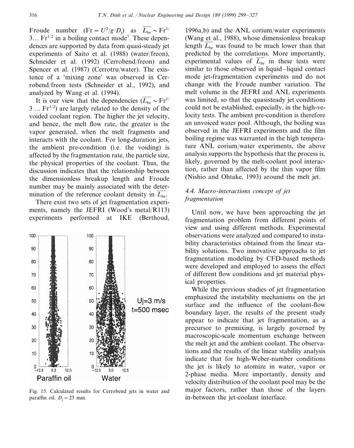
4.2.2. Effect of ambient-fluid 6iscositySimulations were performed for Cerrobend jets
dropped in water and paraffin–oil; see Fig. 15.The jet is much more coherent in paraffin–oilthan in water. This is in a good agreement withthe RIT experimental observations. Thus, the am-bient-fluid viscosity may have a minor effect onthe jet instability characteristics, but it can affectthe melt-phase spatial distribution and, hence, themelt-coolant interfacial area (see discussion inSections 2.3 and 3.2). This clearly demonstrates
T.N. Dinh et al. / Nuclear Engineering and Design 189 (1999) 299–327 313
Fig. 11. The perturbation growth rate (amplification factor b) versus wavelengths. Cerrobend jet in two-phase media. Dj=25mm,Urel=4 m s−1.
that the physics, which governs the evolution ofthe interfacial area, depends on macroscopicparameters rather than determined the boundarylayers which are next to the interface.
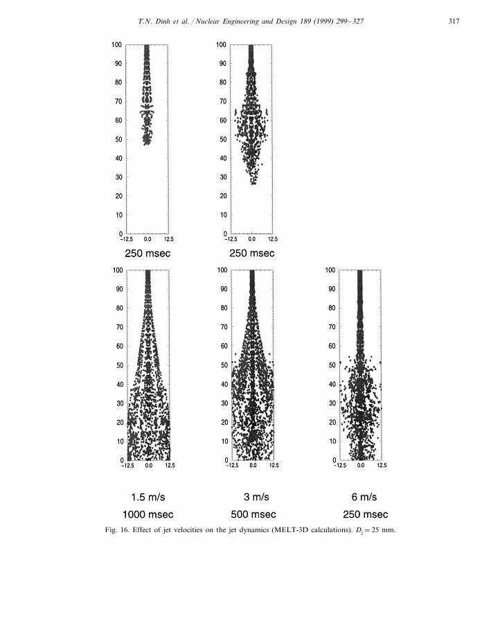
4.2.3. Effect of jet 6elocityThe calculated effect of jet velocities on jet
behavior can be seen in Fig. 16. For a highvelocity the jet penetrates a certain depth of thepool before it atomizes to form a particle cloud.The physical picture in reality may differ fromthis prediction, which is associated with the use ofa fixed particle size in the above simulations fordifferent jet velocities. In fact, the higher thejet-coolant relative velocity, the shorter are theunstable wavelengths and the smaller are the sizesof particles stripped from the jet body. It wouldbe desirable to employ smaller particle sizes forsimulation of higher-velocity jets.
4.2.4. Effect of coolant pool 6oidingSensitivity of the jet dynamics to the coolant
pool voiding was also examined by lowering theeffective density of the coolant (Fig. 17). Appar-ently, the lower the coolant density, the longer the
jet remains coherent. It can also be explained interms of the Weber number Wea=raU rel
2 Dj/s,which decreases as much as ten times for the twolimiting cases given in the picture.
4.2.5. Effect of upward coolant flowsWhen 2-phase media surrounds the molten jet,
the upward movement of the buoyant steam andwater should affect the jet dynamics. Calculationswere performed for cases with vapor volume frac-tion 8#0.5. The upward velocity of the homoge-nized 2-phase mixture
Umix=U68r6+Ul(1−8)rl
rmix
was varied in the range from 0 to 0.5 m s−1. Thecalculated results (Fig. 18) indicate that the up-ward flows may cause melt particles to levitateand, hence, affect the mass transport and distribu-tion of the melt phase, especially at a distancefrom the jet entry nozzle. Nevertheless, the meltstructure in the central region of the jet remainsunchanged due to the large density of the meltand the high velocity of the jet.

T.N. Dinh et al. / Nuclear Engineering and Design 189 (1999) 299–327314
Fig. 12. Jet fragmentation Dj=25 mm, Uj=3 m s−1.

T.N. Dinh et al. / Nuclear Engineering and Design 189 (1999) 299–327 315
The description of the thermal hydraulics of aboiling coolant pool, which may greatly affect thejet dynamics and the jet fragmentation behavior isquite uncertain. An example of simulation of jet-coolant interaction with boiling is shown in Ap-pendix D (D.2). In order to gain insight into themixing zone thermal hydraulics and to provide adata base for code and model validation, measure-ments of 2-phase flow characteristics during thejet-coolant interactions are recommended.
The modeling methods and the computer codes(SIPHRA-3D and MELT-3D), developed at RIT/NPS, are new. They therefore need extensive vali-dation and examination. More importantly, theseCFD-based modeling methods describe the tran-sient processes of macroscopic nature rather thandealing with instabilities which may have very largeamplification factor (b of the order 103–104 s−1).We believe these innovative modeling approachesare very useful and can be employed to analyze themultiphase interactions during the initial phase ofFCIs when molten jets penetrate a coolant pool.
4.3. Analysis of the jet-breakup-length data base
In most cases, observations from experiments,performed in the past, resulted in the jet breakuplength. At high Weber numbers, the consensus isthat jet atomization is likely to occur. Thus, thedetermination of the jet breakup length is at leastproblematic, as is the validation of different mod-els against such data. However, in a comparativesense one can employ the past observations and
Fig. 14. MELT-3D calculations versus experimental visualiza-tion (Dj=25 mm, Uj=3 m s−1).
Fig. 13. Outline of the particle-transport modeling concept.
data to identify the underlying physicalmechanisms.
First of all, it is worth noting that while in anon-boiling contact mode the dimensionless jet-breakup length Lbr=Lbr/Djra/rj is independentof jet velocity, Lbr was found to correlate with
7 In some studies, it was however defined as ‘jet breakupunder film boiling condition’. Since neither the minimumfilm-boiling temperature nor the effect of jet atomization on itwere explicitly determined, the film boiling regime is therefore
T.N. Dinh et al. / Nuclear Engineering and Design 189 (1999) 299–327316
Froude number (Fr=U2/g ·Dj) as Lbr�Fr1/
3… Fr1/2 in a boiling contact mode7. These depen-dences are supported by data from quasi-steady jetexperiments of Saito et al. (1988) (water/freon),Schneider et al. (1992) (Cerrobend/freon) andSpencer et al. (1987) (Cerrotru/water). The exis-tence of a ‘mixing zone’ was observed in Cer-robend/freon tests (Schneider et al., 1992), andanalyzed by Wang et al. (1994).
It is our view that the dependencies (Lbr�Fr1/
3 … Fr1/2) are largely related to the density of thevoided coolant region. The higher the jet velocity,and hence, the melt flow rate, the greater is thevapor generated, when the melt fragments andinteracts with the coolant. For long-duration jets,the ambient pre-condition (i.e. the voiding) isaffected by the fragmentation rate, the particle size,the physical properties of the coolant. Thus, thediscussion indicates that the relationship betweenthe dimensionless breakup length and Froudenumber may be mainly associated with the deter-mination of the reference coolant density in Lbr.
There exist two sets of jet fragmentation experi-ments, namely the JEFRI (Wood’s metal/R113)experiments performed at IKE (Berthoud,
1996a,b) and the ANL corium/water experiments(Wang et al., 1988), whose dimensionless breakuplength Lbr was found to be much lower than thatpredicted by the correlations. More importantly,experimental values of Lbr in these tests weresimilar to those observed in liquid–liquid contactmode jet-fragmentation experiments and do notchange with the Froude number variation. Themelt volume in the JEFRI and ANL experimentswas limited, so that the quasisteady jet conditionscould not be established, especially, in the high-ve-locity tests. The ambient pre-condition is thereforean unvoiced water pool. Although, the boiling wasobserved in the JEFRI experiments and the filmboiling regime was warranted in the high tempera-ture ANL corium/water experiments, the aboveanalysis supports the hypothesis that the process is,likely, governed by the melt-coolant pool interac-tion, rather than affected by the thin vapor film(Nishio and Ohtake, 1993) around the melt jet.
4.4. Macro-interactions concept of jetfragmentation
Until now, we have been approaching the jetfragmentation problem from different points ofview and using different methods. Experimentalobservations were analyzed and compared to insta-bility characteristics obtained from the linear sta-bility solutions. Two innovative approachs to jetfragmentation modeling by CFD-based methodswere developed and employed to assess the effectof different flow conditions and jet material phys-ical properties.
While the previous studies of jet fragmentationemphasized the instability mechanisms on the jetsurface and the influence of the coolant-flowboundary layer, the results of the present studyappear to indicate that jet fragmentation, as aprecursor to premixing, is largely governed bymacroscopic-scale momentum exchange betweenthe melt jet and the ambient coolant. The observa-tions and the results of the linear stability analysisindicate that for high-Weber-number conditionsthe jet is likely to atomize in water, vapor or2-phase media. More importantly, density andvelocity distribution of the coolant pool may be themajor factors, rather than those of the layersin-between the jet-coolant interface.
Fig. 15. Calculated results for Cerrobend jets in water andparaffin oil. Dj=25 mm.
T.N. Dinh et al. / Nuclear Engineering and Design 189 (1999) 299–327 317
Fig. 16. Effect of jet velocities on the jet dynamics (MELT-3D calculations). Dj=25 mm.

T.N. Dinh et al. / Nuclear Engineering and Design 189 (1999) 299–327318
Fig. 17. Effect of coolant pool voiding on the jet dynamics. Dj=25 mm.
With this understanding of phenomenology inmind, we propose a ‘macroscopic interactionsconcept of jet fragmentation’. It should be empha-sized that this concept is only valid for the jet-fragmentation phase of the FCI process. We be-lieve that the ‘microinteractions concept’ of (Yuenet al., 1992) applies to the steam explosion phasein which the jet has already fragmented intoparticles.
5. Concluding remarks
In this study the quasi-steady state of ex-vesseljet-coolant interactions is considered. The focuswas placed on instability and fragmentation ofhigh-density, high-velocity, high-temperature andlarge-diameter jets in a deep highly-subcooled wa-ter pool. For such a situation, we propose that jetfragmentation is a function of the macroscopicinteractions (momentum exchange) between thejet body and the ambient coolant pool and not
that of interfacial interactions. This ‘macrointer-action concept’ of jet fragmentation is based onthe synthesis of the experimental observations, theresults of the linear stability analysis and theresults from CFD modeling of jet fragmentationas summarized below.
First, it was found from the investigation offilm-boiling thermal hydraulics that the pure va-por film is very thin, even under prototypic high-temperature FCI conditions (Dinh et al., 1997a).If it exists, such a vapor film (Nishio and Ohtake,1993), separating a melt jet and a 2-phase (boil-ing) coolant pool, acts like an incompressiblelayer, which does not significantly affect themacrocsopic-scale momentum exchange betweenthe jet and the surrounding medium.
Secondly, the analysis of the relevant jet-frag-mentation data base, and observations, appears toshow that the voiding of the coolant pool, as apre-condition of jet-coolant interactions, is themajor factor which determines characteristics ofjet breakup. It was found that greater phe-

T.N. Dinh et al. / Nuclear Engineering and Design 189 (1999) 299–327 319
nomenological uncertainties are associated withthe pool conditions, rather than with the vapor-film characteristics, or with microscopic character-istics of surface instability mechanisms.
Third, the results of jet fragmentation modelingby CFD-based methods show that the macro-scopic hydraulic parameters, such as the initialrelative (jet-pool) velocity and the transient flowpattern, the density of melt and the effectivedensity of coolant, greatly affect the jet dynamicsand the melt distribution.
Fourth, the leading edge breakup (Rayleigh–Taylor) was noticed only in experiments with lowdensity ratio (jet fluid/coolant fluid) and for casesof low jet velocity and small jet diameter. Inaddition, it was found from the CFD simulationresults that the jet leading edge behavior is largelygoverned by the coolant flows, induced by the jetpenetration into a small-dimension tank.
Fifth, it was found from visual observations forthe jet-coolant (liquid–liquid) contact mode, andfrom the results of the linear perturbation analy-sis, that at high Weber numbers, both, symmetricmode and asymmetric modes may become equallyimportant for the jet instability. Furthermore, thefast perturbation growth rate and the dominanceof short instability waves, likely, will induce jetatomization.
Finally, using an idealized formulation of liq-uid–liquid contact, it was found from the linearstability analysis that the jet-fluid viscosity andthe ambient-fluid viscosity have only minor effectson the jet stability characteristics. However, theexperimental observations and the results of CFDmodeling demonstrate that the viscosities of meltand coolant may greatly affect (i) the sequentialfragmentation of the ligaments stripped off the jetbody and, hence, the length scale of the particle;and (ii) the characteristics of the particle cloud (itslateral dispersion), which may even feedback tothe jet stability.
The present study indicates the need for furtherexperimental and analytical investigation ofmolten-jet dynamics in 2-phase media as well asof mixing-zone thermal hydraulics during jet frag-mentation. The methods developed in this studywill be further refined and employed for scalingand design of jet fragmentation experiments atRIT/NPS.
Acknowledgements
This work was supported by Swedish NuclearPower Inspectorate (SKI), US Nuclear Regula-tory Commission (US NRC), Swedish andFinnish Power Companies, Nordic Nuclear SafetyProject, Swiss Nuclear Inspectorate (HSK), andthe European Union. Many thanks are due to I.Bromberg and C. Olander, who constructed thefacility, and to A.T. Dinh, K. Ekstrom and A.Gubaiduline for their help in some experiments.The authors thank T.J. Okkonen (ABB-Atom)and O.I. Melikhov (EREC) for valuable discus-sions on various aspects of jet instabilitymodeling.
Fig. 18. Effect of coolant velocity on the jet dynamics (MELT-3D calculations). Dj=25 mm.

T.N. Dinh et al. / Nuclear Engineering and Design 189 (1999) 299–327320
Appendix A. Nomenclature
Arabic lettersdrag coefficientCD
d, D diameter (m)gravitational acceleration (mgs−2)Froude number, Fr=U j
2/gDjFri imaginary unit
Bessel functions (modified)I, I %(K, K %)length (m)Linstability modemPrandtl number, Pr=n/aPr
Q density ratio, Q=rj/ra
radius (m)RRe Reynolds number, rU ·d/m
time (s)tT temperature (K)
velocity (U, V, W) (m s−1)UWeber number, We=rU j
2WeD j/s
Greek letterswavelength (m)a
perturbation growth rate (s−1)b
d Thicknessdynamic viscosity (Pa·s−1)m
kinematic viscosity (m2 s−1)n
r density (kg m−3)surface tension (N m−1)s
ratio of number of representa-g
tive particles and number oftotal particles
8 vapor volume fractionparticle volume fraction8p
Subscriptsa ambient
breakupbrf vapor film
jet, melt phasejliquidlmixturemixinitialoparticlepvaporv
Appendix B. The linear perturbation solutions ofjet instability
B.1. The RIT-1 model (zero-mode analysis)
If we assume the perturbation on the jet surfaceas
d=d0 eiaz+bt, (1)
and d0 is the initial perturbation, the followingequation for the growth rate b of symmetricalinstability wave can be obtained.
2nja2
I0(aR0)�
I %1(aR0)−2alj
a2+ l j2
I1(aR0)I1(ljR0)
I %1(ljR0)n
b
+b2=a
rj
I1(aR0)(aR0)
l j2−a2
l j2+a2
� s
R02 (1−a2R0
2)
−ra
a(b+ iaU)
la2+a2
la2−a2
K0(aR0)K1(aR0)
n(2)
where lj=a2+b/nj; la=a2+b+ iaU/na. Usingasymptotic expressions for short-wave approxima-tion, Eq. (2) becomes
b2�1+ra
rj
�+2b
��1+
lj−a
lj+a
�nja
2+ iaUra
rj
+a2na
ra
rj
n+
sa3
rj
−a2U2 ra
rj
+2ia3Una
ra
rj
=0 (3)
B.2. The RIT-2 model (asymmetrical analysis)
In case of long-wave instabilities the asymmet-ric modes (m\o) become more important. Levich(1962) showed that accounting for jet viscositydisplaces the most unstable deformations into theregion of longer waves. If we assume the pertur-bation on the jet surface as
d=d0 eiaz+ imu+bt (4)
the equation for b can be obtained, taking intoaccount the jet-fluid viscosity nj.

T.N. Dinh et al. / Nuclear Engineering and Design 189 (1999) 299–327 321
b2+2nja2b=
sa2
2rjR0
(1−m2−a2R02)
+aR0
2ra
rj
(b+ iaU)2
×la
2+a2
la2−a2
Km(aR0)K %m(aR0)
(5)
The inviscid formulation was obtained by Yang(1992).
(rjIm* (aRj,0)+raKm* (aR6,0))b2
+2iab(rjuz,jIm* (aRj,0)+rauz,aKm* (aR6,0))
−a2(rju z,j2 Im* (aRj,0)+rau z,a
2 Km* (aR6,0))
+as�
a2+m2−1
R j,02
�=0 (6)
This equation can also be obtained by simplifyingthe RIT-3 solution (Eq. (9)) to the 2-layerformulation.
The RIT-3 model: three-layer in6iscid formula-tion. Assuming the waves on the jet-vapor andvapor-water interfaces presented by
Rj=Rj,0+dj(z, t)=Rj,0+dj,0 ei(mu+az)+bt (7)
R6=R6,0+d6(z, t)=R6,0+d6,0 ei(mu+az)+bt (8)
we obtain the following equation relating theperturbation growth rate b with other parameters.
SI{PK,6 [Qm* (aRj,0)+Pm* (aR6,0)]
+SK [Qm* (aR6,0)−Qm* (aRj,0)]}
+PK,j{PK,6 [Pm* (aR6,0)−Pm* (aRj,0)]
+SK [Qm* (aR6,0)+Pm* (aRj,0)]}=0 (9)
where
SI=�PI,j+asj
�a2+
m2−1R j,0
2
�nSK=
�PK,6+as6
�a2+
m2−1R 6,02
�nPK,6=r6(b+ iauz,6)2 Km* (aR6,0)
PK,j=r6(b+ iauz,6)2 Km* (aRj,0)
PI,j=rj(b+ iauz,j)2 Im* (aRj,0)
Im* =Im
I %m; Km* = −
Km
K %m; Pm* =
Im
Km
;
Qm* = −I %mK %m
Appendix C. Kelvin–Helmholtz instability
C.1. Problem formulation
The development of surface instability wavescaused by shear on the surface between two fluids(heavy metal-water) in relative motion is numeri-cally investigated. The properties of the fluidschosen are that of Wood’s metal (Cerrobend) andwater. These simulant materials have been em-ployed in the experimental program of jet frag-mentation being performed at RIT. The relativevelocity of fluid layers is 3 m s−1 (uj=1.5 m s−1
and ua= −1.5 m s−1). The flow field in eachfluid layer is initially set as constant and unidirec-tional. The initial perturbations are initialized assinusoidal waves of different wave lengths andamplitudes. During calculation, the fluid viscosi-ties and surface tensions can be set to zero inorder to investigate their effects on the instabilitybehavior separately.
Calculations have been performed with arectangular, uniform grid of 128×256. The sizeof the computational domain is 4×10 cm. Peri-odic boundary conditions are set for the left andright boundaries and Neuman boundary condi-tions for the top and bottom of the domain. Thetime step used is to 2.5·10−5 s in all calculations.
C.2. Results and 6alidation
First, the grid dependence of the SIPHRA coderesults in two-dimensional geometry was exam-ined. It was found that with a coarse grid, interfa-cial structure is smoothed, with short-waves beingdamped. On a fine grid, the calculatedmacrostructure of the interface remains essentiallythe same, but secondary waves appear on themacro-waves.
The evolution of the interfacial waves of differ-ent wavelengths was investigated. Depending onthe wavelengths, the initial wave amplitudes wereassumed to be different. For the long and mediumwaves (wavelengths L=5 and 2.5 cm, respec-tively), the initial wave amplitude is 5 mm. Forshorter waves, the initial wave amplitude of 2.5mm was chosen. Fig. 19 depicts the SIPHRAresults for a long-wave case.

T.N. Dinh et al. / Nuclear Engineering and Design 189 (1999) 299–327322
Fig. 19. Long-wave instability, L=5 cm.
The propagation speed of the waves, Cr, canbe estimated from the pictures and is found tobe (1.23}1.25) m s−1. These numerical resultsare then compared with an analytical solution ofKelvin–Helmholtz instability in irrotational per-turbed flows; Eq. (10) (Chandrasekhar, 1961).
Cr=rj · coth(k · hj)uj+ra · coth(k · ha)ua
rj · coth(k · hj)+ra · coth(k · ha)(10)
where h is the height of the layer and k is thewave number determined from the wavelength.For the given conditions, Eq. (10) provides Cr#1.2 m s−1. Such good agreement between theSIPHRA results and Eq. (10) indicates that thespeed of the instability-wave is not sensitive tothe rotational flow induced by the relative flowfield and movement of the interface.
C.3. Implications for FCI modeling
The classical Kelvin–Helmholtz instability the-ory plays an important role in understandinginterfacial phenomena. In most previous studies,particular attention was placed on the behaviorof the interface itself, rather than upon the flowfields around the interface. The assumptionabout unidirectionality of the flow fields on bothsides of the interface was employed. Usually, astep (discontinuous) change of velocity at theinterface was assumed and, only in a few studies,the effect of continuous change of the velocityacross the interface has been taken into account.Such an assumption about unidirectional velocityfields is valid only in the framework of the lineartheory, in which the amplitude of interfacial dis-turbances is assumed to be small. For the condi-tions of large-amplitude surface disturbances,this assumption does not hold, and evaluation ofthe surface structure may be significantly affectedby the shear-induced vortex field around theinterface.
Even though a liquid–liquid isothermal contactmode was analyzed in this section, the calculatedcomplex wave structure (Fig. 19) tends to indicatethat phase inter-penetration may initiate mecha-nisms of violent interactions in non-isothermalcases. For example, penetration of water into the
As can be seen from the pictures, in mostcases vortices quickly appear to form the waveleading edge. The results indicate that furtherevolution of the leading edge is affected not onlyby the shear, but also by the once-formed vortexfield. Calculations also show that long waves aremore unstable than short waves under the chosenconditions. The computational results indicatethat the development of only the very short waveinstability is more-or-less irrotational.
T.N. Dinh et al. / Nuclear Engineering and Design 189 (1999) 299–327 323
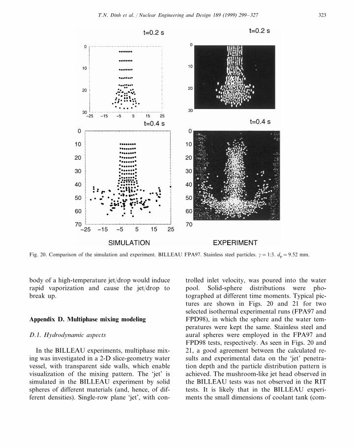
Fig. 20. Comparison of the simulation and experiment. BILLEAU FPA97. Stainless steel particles. g=1:3. dp=9.52 mm.
body of a high-temperature jet/drop would inducerapid vaporization and cause the jet/drop tobreak up.
Appendix D. Multiphase mixing modeling
D.1. Hydrodynamic aspects
In the BILLEAU experiments, multiphase mix-ing was investigated in a 2-D slice-geometry watervessel, with transparent side walls, which enablevisualization of the mixing pattern. The ‘jet’ issimulated in the BILLEAU experiment by solidspheres of different materials (and, hence, of dif-ferent densities). Single-row plane ‘jet’, with con-
trolled inlet velocity, was poured into the waterpool. Solid-sphere distributions were pho-tographed at different time moments. Typical pic-tures are shown in Figs. 20 and 21 for twoselected isothermal experimental runs (FPA97 andFPD98), in which the sphere and the water tem-peratures were kept the same. Stainless steel andaural spheres were employed in the FPA97 andFPD98 tests, respectively. As seen in Figs. 20 and21, a good agreement between the calculated re-sults and experimental data on the ‘jet’ penetra-tion depth and the particle distribution pattern isachieved. The mushroom-like jet head observed inthe BILLEAU tests was not observed in the RITtests. It is likely that in the BILLEAU experi-ments the small dimensions of coolant tank (com-

T.N. Dinh et al. / Nuclear Engineering and Design 189 (1999) 299–327324
Fig. 21. Comparison of the simulation and experiment. BILLEAU FPD98 experiment. Dural particles. g=1:7. dp=9.52 mm.
pared to the jet dimension and the volume of meltintroduced) produce the upward flows which in-duce the mushroom-like configuration of the jet.
D.2. Drag coefficient
Effect of drag force FDp on the particle behavior
was examined for different formulations of C,which accounts for the influence of the presenceof neighboring particles on the actual drag be-tween the ambient fluid and a moving particle.
FDp =
18
pdp2raC · CD
o �Ua−Up� · (Ua−Up) (11)
Three formulations of C (Nigmatulin, 1991) wereexamined against the BILLEAU experimental ob-servations. These are Eq. (12), obtained for peri-odic (or regular) particle arrangement
C=1
1−b(8p), b=
32
8p1/3−8p
1−8p
(12)
and Eqs. (13) and (14) obtained for randomarrangement
C= (1−8p)−5 (13)
C= (1−8p)−2.7 (14)

T.N. Dinh et al. / Nuclear Engineering and Design 189 (1999) 299–327 325
Fig. 22. MELT-3D simulation results (Dj=25 mm, Uj=4 m s−1, Tj=558 K; Ta=373 K).

T.N. Dinh et al. / Nuclear Engineering and Design 189 (1999) 299–327326
These equations are valid for 8p50.1. For highervolume fractions, C are constant and determinedas C=C(8p=0.1). It was found, that the bestcomparison between the simulation results andexperimental observations was achieved with Eq.(13). In fact, this equation was derived for therandom packing of particles in Stokes flow.
D.3. Three-phase mixing zone thermal hydraulics
The scoping calculation using the MELT-3Dcode (Nourgaliev et al., 1997a,b) was also per-formed to analyze a high-temperature jet frag-menting in a nearly saturated water pool. Violentboiling in the whole test section, and water deple-tion, were observed in the RIT/NPS experiment;Fig. 4. Qualitatively, a similar physical picturewas predicted by the MELT-3D as shown in Fig.22. It can be seen that the melt jet is surroundedby a two-phase region, with vapor volume frac-tions up to 0.5–0.7.
References
Berthoud, G., 1996a. Progress Made in the Area of Molten FuelCoolant Interaction. Proceeding of the FISA 95 Symposiumon EU Research on Severe Accidents, 20-22 November1995, Luxembourg, pp. 119–139.
Berthoud, G., 1996b. Molten Fuel-Coolant Interactions,EUR17126 EN, Luxembourg.
Bui, V.A., Dinh, T.N., 1996a. Instabilities and Fragmentationof Jets: Experiments and Analyses. Research Report RIT/NPS, p. 25
Bui, V.A., and Dinh, T.N., 1996b. A Study of Instabilities ofLiquid (Melt) Jet in a Lighter Coolant Pool. Book ofsummaries, EUROMECH Colloquium 355 on InterfacialInstabilities: Numerical Technique, Ecole Polytechnique,Paris, France, September 11–13.
Bui, V.A., Dinh, T.N., Sehgal, B.R., 1997b. Numerical Simula-tion of Surface Instability Phenomena Associated withFuel-Coolant Interaction. Proceedings of the Eighth Inter-national Topical Meeting on Nuclear Reactor ThermalHydraulics (NuReTH-8), Kyoto, Japan, September.
Bui, V.A., Dinh, T.N., Sehgal, B.R., 1997c. Deformation andFragmentation of a Melt Drop in the Flow Field: Resultsof a Numerical Study. International Symposium on IntenseMultiphase Interactions and Explosive Eruptions AMI-GOIMI’, Sendai, Japan.
Bui, V.A., Dinh, T.N., Sehgal, B.R., 1997a. Analysis of LiquidJet Instability: Effects of Physical Properties and PhaseChange. International Symposium on Liquid–Liquid 2-Phase Flow and Transport Phenomena, Antalya, Turkey.
Burger, M., Cho, S.H., Berg, E.V., Schatz, A., 1995. Breakupof Melt Jets as Pre-condition for Premixing: Modeling andExperimental Verification. Nucl. Eng. Des. 155, 215–251.
Chandrasekhar, S., 1961. Hydrodynamic and HydromagneticStability. Oxford at the Clarendon Press.
Chu, C.C., Corradini, M.L., 1989. One-dimensional TransientFluid Model for Fuel/Coolant Interaction Analysis. Nucl.Sci. Eng. 101, 48–71.
Chu, C.C., Sienicki, J.J., Spencer, B.W., Frid, W., Lowenhielm,G., 1995. Ex-vessel Melt-Coolant Interactions in DeepWater Pool: Studies and Accident Management for SwedishBWRs. Nucl. Eng. Des. 155, 159–213.
Corradini, M.L., Kim, B.J., Oh, M.D., 1988. Vapor Explosionsin Light Water Reactors: a review of theory and modelling.Prog. Nucl. Energy 22 (1), 1–117.
Dinh, T.N., Dinh, A.T., Nourgaliev, R.R., Sehgal, B.R., 1997a.Investigation of Film Boiling Thermal Hydraulics underFCI Conditions: Results of a Numerical Study. Proceedingsof the OECD/CSNI Specialist Meeting on Fuel-CoolantInteractions. JEARI-Conf97-011(PArt II), NEA/CSNI/R(97)26, JEARI Tokai, Japan, May 19–21, pp. 674–695.
Dinh, T.N., Green, J.A., Sehgal, B.R., 1997b. On Mechanismsthat Govern the Vessel Melt Source for Ex-Vessel FCIs.CD-ROM Proceedings of the 5th International Conferenceon Nuclear Engineering, Nice, France, May 26–30.
Dinh, T.N., Dinh, A.T., Nourgaliev, R.R., Sehgal, B.R., 1997c.Numerical Simulation of Film Boiling Heat Transfer: Mod-eling Concept and Model Capability. Proceedings of theNational Heat Transfer Conference, Baltimore, USA.
Epstein, M., Fauske, H.K., 1985. Steam Film Instability andthe Mixing of Core-Melt Jets and Water. ANS Proceedingsof the 1985 National Heat Transfer Conference, Denver,Colorado, USA, pp.277–284.
Jacobs, H., Berg, E.V., Berthoud, G., et al., 1996. Studies ofPrincipal Processes during Melt-Water Premixing. In: VanGoethem, G., Balz, W., Loggia, E.D. (Eds.), FISA-95-EUResearch on Severe Accidents-EUR 16896 EN. Luxem-bourg, pp. 165–183.
Levich, V.G., 1962. Physicochemical Hydrodynamics. Prentice-Hall, Englewood Cliffs, NJ.
Magallon, D., Will, H., Turland, B.D., et al., 1995. HighTemperature Melt/Water Mixing: Results and Calculationsof FARO, PREMIX and MIXA Experiments. Proceedingof the FISA 95 Symposium on EU Research on SevereAccidents, Luxembourg, pp. 40–164.
Melikhov and Melikhov, 1993. Melikhov, O.I., Melikhov, V.I.,1993. Investigation of Processes of Melt–Water Interactionsduring Nuclear Reactor Severe Accidents. Preprint EREC,Electrogorsk, Moscow (in Russian).
Nigmatulin, R.I., 1991. Dynamics of Multiphase Media. Hemi-sphere 1, 56, 73.
Nishio, S., Ohtake, H., 1993. Vapor-film-unit Model and HeatTransfer Correlation for Natural-Convection Film Boilingwith Wave Motion under Subcooled Conditions. Intern. J.Heat Mass Transfer 36 (10), 2541–2552.
Nourgaliev, R.R., Dinh, T.N., Sehgal, B.R., 1997a. Simulationof Multiphase Mixing by a Particle Transport Model.CD-ROM Proceedings of the 5th International Conferenceon Nuclear Engineering, Nice, France.

T.N. Dinh et al. / Nuclear Engineering and Design 189 (1999) 299–327 327
Nourgaliev, R.R., Dinh, T.N., Sehgal, B.R., 1997b. Paramet-ric Investigation of a Model of Film Boiling on Horizon-tal Cylinders. CD-ROM Proceedings of the 5thInternational Conference on Nuclear Engineering, Nice,France.
Osher, S., Sethian, J.A., 1988. Fronts Propagating with Cur-vature-Dependent Speed: Algorithms Based on Hamil-ton–Jacobi Formulations. J. Comp. Physics 79, 12–49.
Rayleigh, 1878. On the Instability of Jets. London Math.Soc. Proc. 10, pp. 4–18.
Saito, M., Sato, K., Imahori, S., 1988. Experimental Studyon Penetration of Water Jet into Freon-11 and LiquidNitrogen. ANS Proceedings of the 25th National HeatTransfer Conference, HTC3, Houston TX, pp.173–183.
Schneider, J.P., Marciniak, M., Jones, B.G., 1992. Breakupof Metal Jets Penetrating a Volatile Liquid. Proc. 5thInternational Topical Meeting on Reactor Thermal Hy-draulics (NURETH-5), vol. 2. Salt Lake City, USA, pp.437–449.
Spencer, B.W., Gabor, J.D., Cassulo, J.C., 1987. Effect ofBoiling Regime on Melt Stream Breakup in Water. In:T.N. Veziroglu (Ed.), Particulate Phenomena and Multi-phase Transport, vol. 3. Hemisphere.
Sussman, M., Smereka, P., Osher, S., 1994. A Level SetApproach for Computing Solutions to IncompressibleTwo-Phase Flow. J. Comp. Physics 114, 146–159.
Theofanous, T.G., 1995. The Study of Steam Explosions inNuclear Systems. Nucl. Eng. Des. 155, 1–26.
Tomotika, 1935. On the Instability of a Cylindrical Thread ofa Viscous Liquid Surrounded by Another Viscous Fluid.Proc. Royal Society. A150, pp. 322–337.
Turland, B.D., Dobson, G.P., 1996. Molten Fuel CoolantInteractions: A State of the Art Report. EUR 16874 EN,Luxembourg.
Wang, S.K., Blomquist, C.A., Spencer, B.W., McUmber,L.M., Schneider, Y.P., 1988. Experimental Study of theFragmentation and Quench Behavior of Corium Melts inWater, ANS Proceedings of the 25th National HeatTransfer Conference, HTC3, Houston, TX, pp. 120–153.
Wang, S.K., Hung, T.C., Schneider, J.P., 1994. A Simplified2-D Modeling of Fragmentation Behavior of Corium/Coolant Interactions. Proceedings of the 4th Internna-tional Tipical Meeting on Nuclear Thermal Hydraulics,Operations and Safety, Paper 10.C, Taipei, Taiwan.
Weber, C., 1931. On the Instability of a Liquid Jet. Z. Ag-new. Math. Phys. 11, pp. 136–154.
Yabe, T., Ishikawa, T., Kadota, Y., Ikeda, F., 1990. A Mul-tidimensional Cubic-Interpolated Pseudoparticle (CIP)Method without Time Splitting Technique for HyperbolicEquations. J. Phys. Soc. Jpn. 59, 2301–2304.
Yang, H.Q., 1992. Asymmetric Instability of a Liquid Jet. J.Phys. Fluids A 4 (4), 681–688.
Yuen, W.W., Chen, X., Theofanous, T.G., 1992. On theFundamental Microinteractions that Support the propa-gation of a Steam Explosion. Proceedings 5th Interna-tional Topical Meeting on Nuclear Reactor ThermalHydraulics-NURETH-5, Salt Lake City.
.