EXPERIMENT NO. 20
6
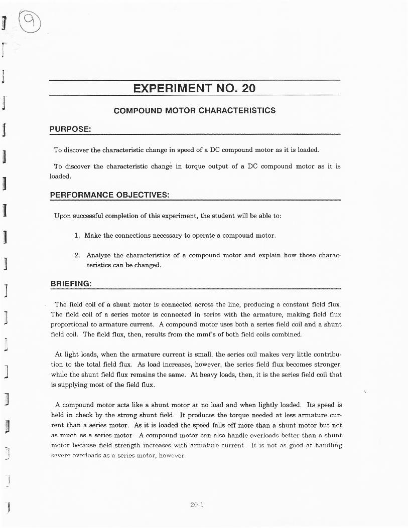
g I EXPERIMENT NO. 20 .l I COMPOUND MOTOR CHARACTERISTICS PURPOSE: To discover the characteristic change in speed of a DC compound motor as it is loaded. To discover the characteristic chang6 in toryue output of a DC compound motor as it is loaded. PERFORMANCE OBJECTIVES: Upon successful completion of this experiment, the student will be able to: 1. Make the connections necessaryto operate a compound motor. 2. Analyze the characteristics of a compound motor and explain how those charac- teristics can be changed. BRIEFING: The field coil of a shunt motor is ennnected across the line, producing a constant field flux. The field coil of a series motor is connected in series with the armature, making field flux proportional to armature current. A compound motor uses both a series field coil and a shunt field coil. The field flux, then, results from the mmfs of both field coils combined. At light loads, when the armature current is small, the series coil makes very little contribu- tion to the total field flux. As load increases, however, the series field flux becomesstronger, while the shunt field flux remains the same. At heavy loads, then, it is the series field coil that is supplying most of the field flux. A compound motor acts like a shunt motor at no load and when lightly loaded. Its speed is held in check by the strong shunt field. It produces the toryue needed at less armature cur- rent than a series motor. As it is loaded the speed falls off more than a shunt motor but not as mucb as a series motor. A compound motor can also handle overloads better than a shunt motor because field strength increases with armature current. It is not as good at handling severeoverloads as a seriesmotor. however. 20 1
-
Upload
khangminh22 -
Category
Documents
-
view
0 -
download
0
Transcript of EXPERIMENT NO. 20
gI
EXPERIMENT NO. 20
.l
I
COMPOUND MOTOR CHARACTERISTICS
PURPOSE:
To discover the characteristic change in speed of a DC compound motor as it is loaded.
To discover the characteristic chang6 in toryue output of a DC compound motor as it is
loaded.
PERFORMANCE OBJECTIVES:
Upon successful completion of this experiment, the student will be able to:
1. Make the connections necessary to operate a compound motor.
2. Analyze the characteristics of a compound motor and explain how those charac-
teristics can be changed.
BRIEFING:
The field coil of a shunt motor is ennnected across the line, producing a constant field flux.
The field coil of a series motor is connected in series with the armature, making field fluxproportional to armature current. A compound motor uses both a series field coil and a shunt
field coil. The field flux, then, results from the mmfs of both field coils combined.
At light loads, when the armature current is small, the series coil makes very little contribu-
tion to the total field flux. As load increases, however, the series field flux becomes stronger,
while the shunt field flux remains the same. At heavy loads, then, it is the series field coil that
is supplying most of the field flux.
A compound motor acts like a shunt motor at no load and when lightly loaded. Its speed is
held in check by the strong shunt field. It produces the toryue needed at less armature cur-
rent than a series motor. As it is loaded the speed falls off more than a shunt motor but not
as mucb as a series motor. A compound motor can also handle overloads better than a shunt
motor because field strength increases with armature current. It is not as good at handling
severe overloads as a series motor. however.
20 1
If a compound motor is run sometimes without a load, care must be taken to shut motor
down if the shunt field looses its excitation current. If the shunt field were to become de-ener-
g,zed,, the motor would become a series motor. Series motots, as you remember reach
dangerous speeds at no load.
MACHINES REQUIRED:
DM-1OOA DC Machine operating as a motor
DYN-100-DM Dynamometer operating as a generator
POWER REQUIRED:
O-125 volt variable DC, 5 amps
0-150 volt variable DC, 1 amp
METERS REQUIRED:
O-150 volt DC voltrneter0-150 volt DC voltrneter
0-5 amp DC ammeter
ADDITIONAL MATERIAL REQUIRED:
MGB-100-DG Bedplate
RL-1OOA Resistance Load Bank
HT-1OOJ Tachometer
SFR-I0O Series Field fDiverrer) Rheostat
PROGRAM PI.AN:
Step 1. Place the two machinea on the bedplate with the motor on the left and the
dynamometer on the right.
Step 2. Couple the two machines tightly, using the rubber coupling, Be sure the coupling
fits snugly inside both flanges. Be sure the rotor locking device has been removed
from the dvnamometer.
Step 3. Clamp the machines tightly to the bedplate. Place the coupling guard over thr:
coupling and the shaft guard ovr:r the notor and dynamometer shafts.
2$2
ilTItI
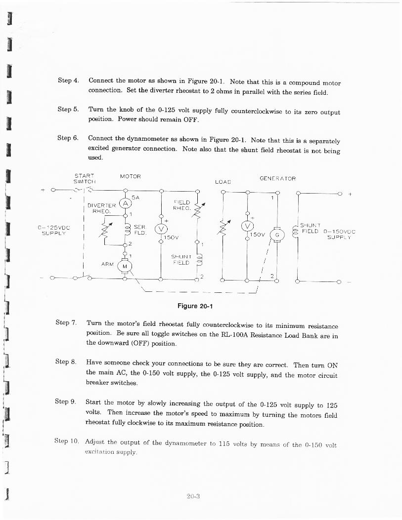
Step 4. Connect the motor as shown in Figure 20-1. Note that this is a compound motorconnection. Set the diverter rheostat to 2 ohms in parallel with the series field.
Step 5. T\rr:r the knob of the 0-125 volt supply fully counterclockwise to its zero ourputposition. Power should remain OFF.
Step 6. Connect the dynamometer as shown in Figure 20-1. Note that this is a separatelyexcited generator connection. Note also that the shunt field rheostat is not beingI
I useo.
STARTSW TCH
MOTOR GEN ERATORLOADI
I
lII
i
II
;lI
I;1TIII
r !r.t
t!
i
nt -II'gnJ
)
- t r
' l
II
o-12svDC ISUPPLY
I
III
DI VERTERRHEO.
o- 1 50VDCSUPPLY
\ - - - - lFigure 2G.l
Step 7' T\rrn the motor's field rheostat fully counterclockwise to its minimum resistanceposition. Be sur.e all toggle switches on the RL-100A Resistance load Bank are inthe downward (OFF) position.
Step 8' Have someone check your connections to be sure they are correct. Then turn ONthe main AC, the 0-150 volt supply, the 0-125 volt supply, and the motor circuitbreaker switches.
Step 9' Start the motor by slowly increasing the output of the 0-12b volt supply to I2Evolts' Then increase the motor's speed to maximum by turning the motors fieldrheostat fully clockwise to its maximum reeistance position.
Step 10. Adjust the output of the dlmamometer toexci*rtion supply.
FIf LDRHEO.
+
1 50V
SHUNTFIELD
1 50v
I
2(),:i
115 volts by means of the 0-150 volt
Step 11. Readjust the output of the O-I25 volt supply ta I25 volts, if necessary. Then, ifnece&sary, readjust the dynamometer's output to 115 volts again.
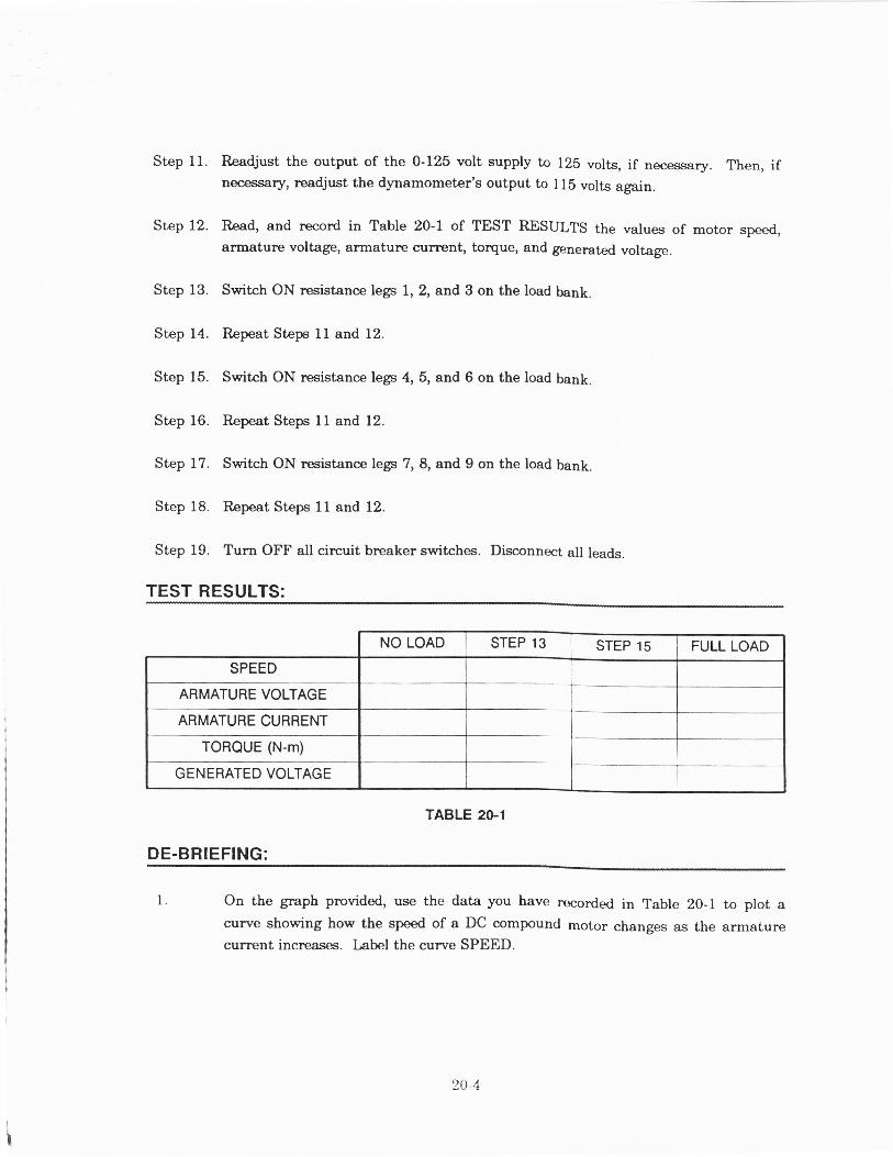
Step 12. Il,ead, and record in Table 20-1 of TEST RESULTS the values of motor speed,armatur€ voltage, armature current, toryue, and generated voltage.
Step 13. Switch ON resistance lep 1, 2, and 3 on the load bank.
Step 14. Repeat Steps 1l and 12.
Step 15. Switch ON resistance lep 4, 5, and 6 on the load bank.
Step 16. Repeat Steps 11 and 12.
Step 17. Switch ON resistance lep 7, 8, and 9 on the load bank.
Step 18. Repeat SteF 11 and 12.
Step 19. Turn OFF all circuit breaker switches. Disconnect all leads.
TEST RE_.SULTS: .. __._* .. . .... ............- .. . , .... ... .... ...... .
TABLE 2G1
DE.BRIEFING:
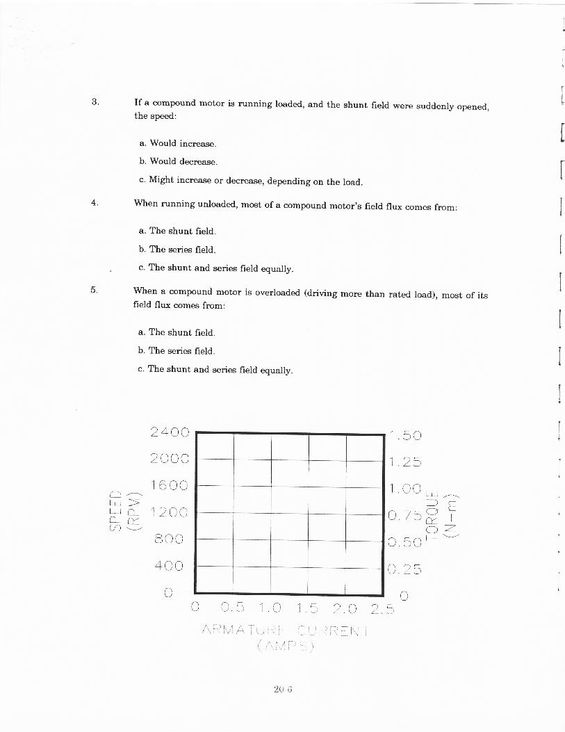
1. On the graPh provided, use the data you have nrcorded in Table 20-1 to plot acurve showing how the speed of a DC compound motor changes as the arnaturecurrent increases. Label the curve SPEED.
NO LOAD STEP 13 STEP 15 FULL LOAD
SPEED
ARMATURE VOLTAGE
ARMATURE CURRENT
ToRaUE (N-m)
GENERATED VOLTAGE
2A-4
I
3.
On the same graph use the data from Table 20-1 to plot a curye showing how theoutput toryue of a DC compound motor changes ss the armature current increaseswith increasing load. Label the curve TORQIIE.
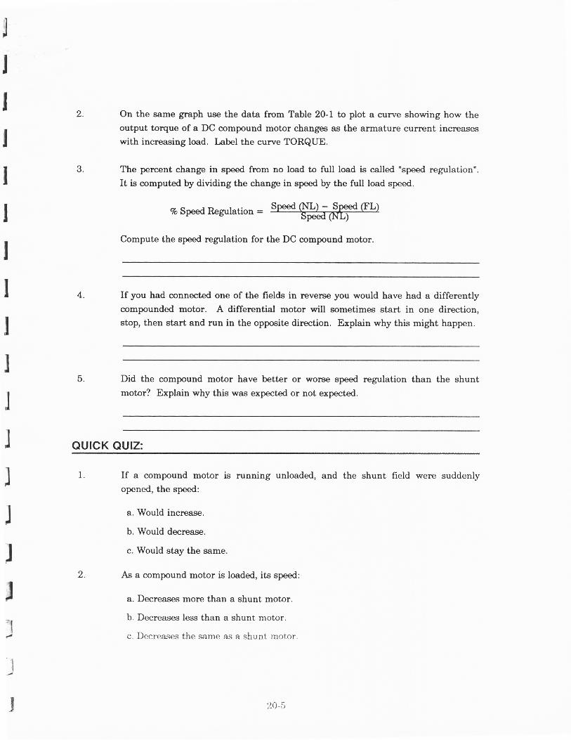
The percent change in speed from no load to full load is called "speed regulation".
It is computed by dividing the change in speed by the full load speed.
7o Speed Regulation =
Compute the speed regulation for the DC compound motor.
If you had connected one of the fields in r€verse you would have had a differentlycompounded motor. A differential motor will sometimes start in one direction,stop, then start and run in the opposite direction, Explain why this might happen.
Did the compound motor have better or worse speed regulation than the shunt
motor? Explain why this was expected or not expected.
4.
5.
QUICK QUIZ:
2.
If a compound motor is running unloaded, and the shunt freld were suddenlyopened, the speed:
a. Would increase.
b. Would decrease.
c. Would stay the same.
As a compound motor is loaded, its speed:
a. Decreases more than a shunt motor.
b. Decreases less than a shunt motor.
c. Decrease-s the same as a shunt rnotor.
J-t4
I
I
20-5
It
7
ttrI
3.
4.
If a compound motor is running loaded, and the shunt field were suddenly opened,the speed:
a. Would increase.
b. Would decreese.
c. Might increase or decrease, depending on the load.
when running unloaded, most of a compound motor's field flux comes fi.om:
a. The shunt field.
b. The series field.
c. The shunt and series field equally.
Wheu a compound motor is overloaded (driving more than rated load), most of itsfield flux comes fipm:
a. The shunt field.
b. The series field.
c. The shunt and series field equally.
5.
LLI >L! O_a^/A \-/
2400
20cc
16CO
1 20C
80c
4CC
C
1 .50
1 .25
1.CO
c 75
o 50
c.25
o5
1' l - - :--)
-(-1 !-I
CYIr-; -.2'I v
-\ - / \J. , ) I
/ \ [ - - i i , ,4 / , I ]r ' , 1.1/ i f1 i \
I
o 15 2C 2.I i:: i i- i,-i i-? i? f i.l T
n ! I i I , - ', . r i ,_/ j i - ' - t )
20-6