Experiences with Thermal Spray Zinc Duplex Coatings ... - MDPI
15
coatings Article Experiences with Thermal Spray Zinc Duplex Coatings on Road Bridges Ole Øystein Knudsen 1, * , Håkon Matre 2 , Cato Dørum 2 and Martin Gagné 3 1 SINTEF, P.O. Box 4760 Torgarden, NO-7465 Trondheim, Norway 2 Norwegian Public Roads Administration, 5008 Bergen, Norway; [email protected] (H.M.); [email protected] (C.D.) 3 Zelixir Inc., Toronto, ON M5A4R4, Canada; [email protected] * Correspondence: [email protected]; Tel.: +47-9823-0420 Received: 12 May 2019; Accepted: 4 June 2019; Published: 8 June 2019 Abstract: Road bridges are typically designed with a 100-year lifetime, so protective coatings with very long durability are desired. Thermal spray zinc (TSZ) duplex coatings have proven to be very durable. The Norwegian Public Roads Administration (NPRA) has specified TSZ duplex coatings for protection of steel bridges since 1965. In this study, the performance of TSZ duplex coatings on 61 steel bridges has been analyzed. Based on corrosivity measurements on five bridges, a corrosivity category was estimated for each bridge in the study. Coating performance was evaluated from pictures taken by the NPRA during routine inspections of the bridges. The results show that very long lifetimes can be achieved with TSZ duplex coatings. There are examples of 50-year old bridges with duplex coatings in good condition. Even in very corrosive environments, more than 40-year old coatings are still in good condition. While there are a few bridges in this study where the coating failed after only about 20 years, the typical coating failures are due to application errors, low paint film thickness and saponification of the paint. Modern bridge designs and improved coating systems are assumed to increase the duplex coating lifetime on bridges even further. Keywords: thermal spray zinc; duplex coatings; coating lifetime; coating maintenance 1. Introduction Road bridges are typically designed with a lifetime of 100 years. However, lifetime extensions are normal and there are many bridges that are older than 100 years. Bridges are most likely to be replaced or decommissioned due to increased traffic capacity or the closing of the road than for exceeding the design lifetime. With such long lifetimes, the maintenance of the protective coating is a major contributor to the operational expenses. Hence, coating systems with very long durability are of great interest. Multi-layer paint coating systems are specified in many countries, but such coating systems have limited lifetime, especially in corrosive environments. According to the ISO 12944-1 coating selection standard, a very long lifetime is defined as more than 25 years [1]. In a 100 years construction life perspective (or more than 100 years), 25 years is relatively short and implies that the coating must be maintained several times. In order to increase the coating lifetime and reduce the coating maintenance costs, The Norwegian Public Roads Administration (NPRA) introduced thermally sprayed zinc (TSZ) duplex coatings for coastal steel bridges in 1965 and for all bridges in 1977, replacing red lead coatings. Klinge published a study of the TSZ duplex coating on the Rombak Bridge in Norway, documenting almost 40-year coating lifetimes [2,3]. The bridge was coated in the field with a duplex coating consisting of a pure zinc TSZ coating of 100 μm and two layers of alkyd paint at 100 μm each. The bridge was opened to traffic in 1965 and for various reasons left partly uncoated until 1970, when the duplex coating was Coatings 2019, 9, 371; doi:10.3390/coatings9060371 www.mdpi.com/journal/coatings
-
Upload
khangminh22 -
Category
Documents
-
view
6 -
download
0
Transcript of Experiences with Thermal Spray Zinc Duplex Coatings ... - MDPI

coatings
Article
Experiences with Thermal Spray Zinc DuplexCoatings on Road Bridges
Ole Øystein Knudsen 1,* , Håkon Matre 2, Cato Dørum 2 and Martin Gagné 3
1 SINTEF, P.O. Box 4760 Torgarden, NO-7465 Trondheim, Norway2 Norwegian Public Roads Administration, 5008 Bergen, Norway; [email protected] (H.M.);
[email protected] (C.D.)3 Zelixir Inc., Toronto, ON M5A4R4, Canada; [email protected]* Correspondence: [email protected]; Tel.: +47-9823-0420
Received: 12 May 2019; Accepted: 4 June 2019; Published: 8 June 2019�����������������
Abstract: Road bridges are typically designed with a 100-year lifetime, so protective coatings withvery long durability are desired. Thermal spray zinc (TSZ) duplex coatings have proven to be verydurable. The Norwegian Public Roads Administration (NPRA) has specified TSZ duplex coatings forprotection of steel bridges since 1965. In this study, the performance of TSZ duplex coatings on 61 steelbridges has been analyzed. Based on corrosivity measurements on five bridges, a corrosivity categorywas estimated for each bridge in the study. Coating performance was evaluated from pictures takenby the NPRA during routine inspections of the bridges. The results show that very long lifetimescan be achieved with TSZ duplex coatings. There are examples of 50-year old bridges with duplexcoatings in good condition. Even in very corrosive environments, more than 40-year old coatings arestill in good condition. While there are a few bridges in this study where the coating failed after onlyabout 20 years, the typical coating failures are due to application errors, low paint film thickness andsaponification of the paint. Modern bridge designs and improved coating systems are assumed toincrease the duplex coating lifetime on bridges even further.
Keywords: thermal spray zinc; duplex coatings; coating lifetime; coating maintenance
1. Introduction
Road bridges are typically designed with a lifetime of 100 years. However, lifetime extensions arenormal and there are many bridges that are older than 100 years. Bridges are most likely to be replacedor decommissioned due to increased traffic capacity or the closing of the road than for exceedingthe design lifetime. With such long lifetimes, the maintenance of the protective coating is a majorcontributor to the operational expenses. Hence, coating systems with very long durability are of greatinterest. Multi-layer paint coating systems are specified in many countries, but such coating systemshave limited lifetime, especially in corrosive environments. According to the ISO 12944-1 coatingselection standard, a very long lifetime is defined as more than 25 years [1]. In a 100 years constructionlife perspective (or more than 100 years), 25 years is relatively short and implies that the coating mustbe maintained several times.
In order to increase the coating lifetime and reduce the coating maintenance costs, The NorwegianPublic Roads Administration (NPRA) introduced thermally sprayed zinc (TSZ) duplex coatings forcoastal steel bridges in 1965 and for all bridges in 1977, replacing red lead coatings. Klinge publisheda study of the TSZ duplex coating on the Rombak Bridge in Norway, documenting almost 40-yearcoating lifetimes [2,3]. The bridge was coated in the field with a duplex coating consisting of a purezinc TSZ coating of 100 µm and two layers of alkyd paint at 100 µm each. The bridge was opened totraffic in 1965 and for various reasons left partly uncoated until 1970, when the duplex coating was
Coatings 2019, 9, 371; doi:10.3390/coatings9060371 www.mdpi.com/journal/coatings

Coatings 2019, 9, 371 2 of 15
applied. The bridge is a 750 m long suspension bridge with a bolted truss work under the bridgeway.The large numbers of overlapping joints in the truss work are typical corrosion traps, but the duplexcoating even protected these from corrosion. In 2012, preventive coating maintenance was performedby washing and the application of a new topcoat due to the partial flaking of the old topcoat.
There is a long history of corrosion protection of steel bridges with TSZ coatings. The RidgeAvenue Bridge in Philadelphia was metalized with zinc already in 1938 [4]. In the UK, the Forth RoadBridge was installed with zinc metalized and painted steel in 1964, which was the largest metalizedsteel bridge at the time [5]. The coating performed very well in contrast to the parallel Forth RailwayBridge that was painted, probably with red lead. The experiences with the Forth Road Bridge wereimportant when the NPRA started to specify TSZ duplex coatings in 1965. TSZ duplex coatings havelater been extensively used in the Scandinavian countries, UK, France and, to some extent, in the USAand Canada. However, no extensive review of their performance has been published to our knowledge.
Duplex coatings consist of a metal coating, typically hot-dip galvanizing, electroplated zinc orTSZ, painted with a protective organic coating. TSZ with a sealer is usually not regarded as a duplexcoating. Duplex coatings are now very common across many industry sectors. For example, in theautomotive industry, duplex coatings are the norm for the manufacturing of about 50 million carbodies per year. TSZ duplex coatings for steel structures were already documented to perform well inthe 19-year field test by the American Welding Society that was terminated in 1974 [6]. In his bookfrom 1994, van Eijnsbergen published a comprehensive study of duplex coatings consisting of hot-dipgalvanized steel and paint [7]. Based on his findings, he claimed that the durability of a duplex coatingis longer than the sum of the durability of the metallic and the paint coatings:
Dduplex = K · (Dzinc + Dpaint) (1)
where D is the durability or lifetime of the coats and K is a synergy factor, ranging from 1.5 in aggressiveclimates to 2.3 in less aggressive climates.
The objective of the present work has been to investigate the performance of zinc duplex coatingson 61 steel bridges in Norway as a function of corrosivity on site and the type of paint coating applied.Corrosivity was measured on four coastal bridges and one inland bridge in order to help estimatecorrosivity on all the bridges. Typical coating failures and their causes are also discussed.
2. Materials and Methods
2.1. Corrosivity
Corrosivity was measured as material loss on steel panels according to ISO 9226 [8] on five roadbridges, described in Table 1. The bridges were selected based on climatic conditions, height andavailability for the deployment of samples. Gjemnessund and Sotra (43 and 14) are part of the coatingcondition study, while Nessundet, Tjeldsund and Hardanger are not because they have other coatingsthan investigated in this study. Annual temperature and precipitation averages and sailing clearanceare given for each bridge in the table. Wind strength and direction will also affect corrosivity, but suchdata are not available and have not been measured in this study.

Coatings 2019, 9, 371 3 of 15Coatings 2019, 9, x FOR PEER REVIEW 4 of 15
Figure 1. A map of Norway showing the location of the 61 bridges studied. Corrosivity was measured
on bridges A, B, C, 14 and 43.
2.3. Coating Performance Data
Coating condition has been assessed based on pictures from routine bridge inspections performed
by NPRA personnel. A thorough coating inspection is performed every 5 years and the results are
documented in the NPRA bridge management database. The database also contains information about
coating maintenance. In addition, information about the extent and scope of maintenance has been
collected from the NPRA personnel responsible for the specific maintenance operations. The coating
condition on the various bridges have been assessed according to four categories defined for this study:
Good: The paint coating is in good condition and little or no degradation can be seen;
Figure 1. A map of Norway showing the location of the 61 bridges studied. Corrosivity was measuredon bridges A, B, C, 14 and 43.
Panels of cold rolled mild steel, 150 mm × 100 mm × 2 mm in dimensions, were exposed for oneyear. Corrosivity was measured at the level of the bridgeway on all the bridges. For Gjemnessund, Sotraand Hardanger, corrosivity was also measured on one tower at various heights between 5 and 70 mabove sea level. After retrieval, the samples were cleaned in a solution of 500 mL 37% HCl and 3.5 ghexamethylene-tetraamine diluted to 1000 mL. The samples were kept in the solution for 10 min at roomtemperature. The corrosivity at the various sites was evaluated according to weight loss and labeledwith a corrosion category according to ISO 12944-2 [9]. A corrosion depth of 1.3–25 µm/y is category C2,25–50 µm/y is C3, 50–80 µm/y is C4 and 80–200 µm/y is C5. Corrosion in the range 200–700 µm/y iscategory CX, but such a high corrosivity was not measured in this study. Each corrosivity measurementwas assessed from three replicate samples.

Coatings 2019, 9, 371 4 of 15
The results from the corrosivity measurements were used to estimate corrosivity on all the 61bridges in the study.
Table 1. The description of the bridges where corrosivity was measured. The location of the bridges isshown in Figure 1, labeled A, B, 43, 14 and C as given in the table.
Bridge Climatic ConditionsSailing Clearance
(m)Geography TemperatureAvg. (◦C)
PrecipitationAvg. (mm/year)
Nessundet (A) Inland lake 3 700 10Tjeldsund (B) Shielded coast 3 1000 41
Gjemnessund (43) Shielded coast 7 1300 43Sotra (14) Exposed coast 8 1900 50
Hardanger (C) Shielded fjord 6 1100 55
2.2. Bridges and Coatings
Steel bridges longer than 100 m built between 1967 and 1995 were included in the study, 61 bridgesin total. For C4 and C5 environments, shorter steel bridges were included to increase the number ofbridges in these categories of corrosivity. The duplex coatings were specified from 1965, but assumingthat it took some time to implement, only bridges from 1967 are included in this study. Bridges builtafter 1995 were not included due to the insufficient exposure time so far. The location of the 61 bridgesis shown in Figure 1. For each bridge, corrosivity was estimated based on the corrosivity measurementson the five bridges described in Table 1. The estimates were based on the geographical location andsailing clearance. Average daily traffic was not assumed to affect the corrosivity significantly since thecoated steel construction is located under the bridgeway on all the bridges in the study.
Two coating specifications were used in this period, as shown in Table 2. The only differencebetween the two specifications is that the zinc chromate in the two first alkyd coats was replaced withzinc phosphate in 1977.
Table 2. The coating specifications between 1965 and 1995.
Coat No. 1965 1977
1 TSZ, pure Zn 100 µm TSZ, pure Zn 100 µm2 Phosphoric acid wash primer − Phosphoric acid wash primer −
3 Alkyd with zinc chromate 50 µm Alkyd with zinc phosphate 50 µm4 Alkyd with zinc chromate 50 µm Alkyd with zinc phosphate 50 µm5 Alkyd 50 µm Alkyd 50 µm6 Alkyd 50 µm Alkyd 50 µm
2.3. Coating Performance Data
Coating condition has been assessed based on pictures from routine bridge inspections performedby NPRA personnel. A thorough coating inspection is performed every 5 years and the results aredocumented in the NPRA bridge management database. The database also contains information aboutcoating maintenance. In addition, information about the extent and scope of maintenance has beencollected from the NPRA personnel responsible for the specific maintenance operations. The coatingcondition on the various bridges have been assessed according to four categories defined for this study:
• Good: The paint coating is in good condition and little or no degradation can be seen;• Fair: There is some paint degradation, and zinc corrosion products (white) can be found locally;• Poor: The steel has started to corrode and red rust is found;• Repaired: Coating maintenance has been performed; in most cases, patch repair with a full topcoat.
Coatings 2019, 9, 371 5 of 15
The coating condition can vary across steel structures and typically overlapping joints, edges,welds and bolts are attacked by corrosion before the flat surfaces. Older truss construction bridgeshave more of these corrosion traps, while on modern box beam bridges these are, to a large extent,avoided. This has not been considered in the assessment. However, various coating application errorswere found, which will be discussed.
2.4. Coating Performance Indicator
To enable a quantitative comparison of coating performance on the various bridges, a coatingperformance indicator (CPI) has been defined for this study:
CPI = L + L·SC
(2)
where L is the coating lifetime for a repaired coating or present coating age for not repaired coatings,C is the corrosivity category number (category 2–5) and S is the assessment of condition describedabove, but numerical. The coating condition has been assessed as either good, fair, poor or repaired,which have been given the values 3, 2, 1 and 0 respectively. For repaired coatings, CPI will then bethe coating lifetime. For not repaired coatings, the CPI will be the current age of the coating, withan additional expected life proportional to current age and condition, and inversely proportional tocorrosivity. Though CPI may be regarded as an expected lifetime of not repaired coatings, such aclaim cannot be made without further investigation into coating performance and maintenance, whichis beyond the scope of this work. Here, the CPI is only used for estimating an indicator for coatingperformance to enable comparison.
3. Results
3.1. Corrosivity
Corrosivity at the level of the bridgeway on the five bridges is shown in Table 3. Hardanger bridgeand Gjemnessund bridge are modern box beam bridges, while the others are older truss constructions.Nessundet bridge is an arch bridge, while the rest are suspension bridges. The samples were placed atdifferent locations on the bridges, as shown in the table.
Table 3. The description of the bridges where corrosivity was measured and the corrosivity found atthe level of the bridgeway.
Bridge.Measurement Site
Climatic Conditions SailingClearance
(m)
Corrosivity
Geography Temp.Avg. (◦C)
PrecipitationAvg. (mm/y) µm/year Category
Nessundet (A)Truss, west sideTruss, middle
Truss, east side
Inland lake 3 700 10266
13
C3C2C2
Tjeldsund (B)Truss, south side
Truss, middleTruss, north side
Shieldedcoast 3 1000 41
121318
C2C2C2
Gjemnessund (43)Pylon, west sideBridgeway fenceUnder bridgeway
Shieldedcoast 7 1300 43
112848
C2C3C3
Sotra (14)Pylon, west side
Exposedcoast 8 1900 50 27 C3
Hardanger (C)Pylon, west side
Shieldedfjord 6 1100 55 9 C2

Coatings 2019, 9, 371 6 of 15
The relative standard deviation for the measurements was 4% on average and ranging between2% and 6% for the individual sets of three parallels. All measurements were performed during the12 months in 2016–2017. Hence, variations from year to year are not accounted for.
The dominant wind direction is from the west on all the bridges. The Gjemnessund and Tjeldsundbridges are located behind larger islands and, therefore, somewhat shielded. Hardanger bridge islocated deep inside a fjord and even more shielded. Freshwater from rivers reduce the salinity in thefjord to 3.1% at the bridge location, compared to 3.5% in the open sea, but this difference is assumedto be insignificant. Sotra bridge is quite exposed. Nessundet bridge is also somewhat exposed butcrossing a strait in an inland lake where the only salt exposure is from winter deicing salt.
Annual precipitation varies significantly between the locations of the five bridges. The precipitationmay have two opposite effects on corrosivity. Primarily, increasing precipitation will increase the timeof wetness on the steel and thereby increase corrosion. However, in marine environments, precipitationmay also decrease corrosion by washing off salt deposits. This effect is typically found under thebridgeway, where salt accumulates but never or rarely is washed away by rain [10]. Hence, in aninland environment, corrosivity will normally increase with annual precipitation, while in a coastalenvironment, the effect of precipitation may vary from place to place on the construction.
As Table 3 shows, the corrosivities measured at the level of the bridgeway are all within categoriesC2 and C3. On Nessundet bridge, the west side is more corrosive, probably because western winds aredominating. Under the bridgeway, the samples were shielded from rain, which resulted in a muchlower corrosion rate than on the sides. Tjeldsund bridge is going east-west, so the difference betweenthe directions are smaller, but the north side is slightly more exposed. On Gjemnessund, the corrosivitywas highest under the bridgeway, where the samples were mounted on a vortex shedding blade. Thisis probably explained by the deposition of sea salt and shielding from rain that would wash the salt off
the surface. The sailing clearance is 43 m, but salt deposits are nevertheless found under the bridgeway.In general, coastal bridges are more susceptible to coating degradation and corrosion on the undersideof the bridgeway due to this effect. On Sotra bridge, C3 corrosivity was found on the pylon at thelevel of the bridgeway. No measurements were performed on the bridgeway, which may have shownhigher corrosivity, as found on Gjemnessund. Hardanger bridge, which is the most shielded of the fivebridges showed low corrosivity. As for Gjemnessund, the corrosivity may have been somewhat higheron the bridgeway, but due to the high sailing clearance and wind shielding, the corrosivity is assumedto be low even here. Figure 2 shows corrosivity as a function of the height along one pylon on three ofthe bridges, measured from 5 m above the sea level. On Gjemnessund and Hardanger, the corrosivitywas generally low all the way. For both bridges, this was somewhat surprising since the pylons arelocated near the sea. Airflow patterns around the massive concrete pylons may partly explain thedifference, but the lower annual precipitation at these two sites may also have contributed, decreasingthe time of wetness on the samples. For the Sotra bridge, it is interesting to see how the corrosivitydecreases as a function of height. Up to about 12 m, the corrosivity was category C5. Further up thecorrosivity gradually decreased and reached almost category C2 from 45 m.
From the corrosivity measurements, it is evident that the height above sea level has a large influenceon corrosivity. Annual precipitation also seems to be an important parameter. Wind conditions areexpected to contribute, but wind measurements on the investigated bridges have not been performedand cannot be discussed in this study.

Coatings 2019, 9, 371 7 of 15
Coatings 2019, 9, x FOR PEER REVIEW 7 of 15
Figure 2. Corrosivity on three bridges as a function of height over sea level.
3.2. Coating Lifetimes
Tables 4 and 5 show the lifetime of duplex coatings on 23 steel bridges built between 1967 and
1977 and 38 bridges built between 1978 and 1995, respectively, 61 bridges in total. As shown in Table
2, the coating specification was changed during 1977 and the zinc chromate in the two first paint coats
was replaced with zinc phosphate. Corrosivity is estimated for each bridge based on the geographical
location and sailing clearance, relative to the five bridges where corrosivity was measured. Sailing
clearance is given for all the coastal bridges. All the inland bridges are assumed to be in C2
environments. Winter salting of roads is assumed not to affect the corrosivity since the load bearing
steel construction is located under the bridgeway for all the bridges in this study. There are few
bridges in C2 environments in Table 4 since duplex coatings were not specified for inland bridges
before 1977.
A graphical summary of the coating performance on the bridges in Table 4 is given in Figure 3a.
Of the 23 bridges, 16 have received coating maintenance, i.e., about 70%. Of these, eight are in C4
environments, five in C3 environments a one in a C2 environment. The repair of the C2 bridge was
preventive maintenance due to topcoat flaking and not corrosion. Both the two bridges in the C5
environment have received maintenance. Of the remaining bridges, two are in a fair condition and
five are in good condition.
The coating performance of bridges in Table 5 is shown graphically in Figure 3b for the 38
bridges built between 1978 and 1995. Of the 38 bridges, only five have received coating maintenance
so far, i.e., about 13%. These five bridges are all exposed in C4 or C5 environments. Not surprising,
the duplex coatings are performing very well in C2 environments. Contrary to Figure 3a, Figure 3b
does show a correlation between corrosivity and coating performance.
The performance of the coatings in the C5 environment is similar for bridges coated with the
1965 specification and with the 1977 specification. The Madsøybrua and Erikstadstrøm bridges listed
in Table 4 were repaired after 25 and 42 years, respectively. The Bergsøysundbrua and
Nordhordlandsbrua bridges listed in Table 5 were repaired after only 19 and 23 years. A close
inspection of the coatings reveals that application errors led to the failures on Bergsøysundbrua and
Nordhordlandsbrua. Both bridges are floating bridges and may be regarded as mainly exposed in
the marine splash zone. In the offshore industry, the corrosion rate in the marine splash zone is
assumed to be 400 µm/y, i.e., corrosivity category CX [9]. Hence, to classify these bridges as category
C5 may be too low. The coatings were mainly degraded on the underside of the bridgeway, where
marine salt deposits will never be washed off by rain. Hence, a concentrated and very aggressive
brine is formed on the coating surface. For Bergsøysundbrua, the maintenance started too early. Even
though the organic coating had partly failed, the zinc coating was still protecting the steel. For
Nordhordlandsbrua, the degradation was more severe and the steel had started to corrode in some
areas.
0
20
40
60
80
100
120
140
160
0 10 20 30 40 50 60 70 80
Co
rro
sio
n (m
m/y
ear)
Height over sea level (m)
Sotra bridge
Gjemnessund bridge
Hardanger bridge
C5
C4
C3
C2
Figure 2. Corrosivity on three bridges as a function of height over sea level.
3.2. Coating Lifetimes
Tables 4 and 5 show the lifetime of duplex coatings on 23 steel bridges built between 1967 and1977 and 38 bridges built between 1978 and 1995, respectively, 61 bridges in total. As shown inTable 2, the coating specification was changed during 1977 and the zinc chromate in the two firstpaint coats was replaced with zinc phosphate. Corrosivity is estimated for each bridge based on thegeographical location and sailing clearance, relative to the five bridges where corrosivity was measured.Sailing clearance is given for all the coastal bridges. All the inland bridges are assumed to be in C2environments. Winter salting of roads is assumed not to affect the corrosivity since the load bearingsteel construction is located under the bridgeway for all the bridges in this study. There are few bridgesin C2 environments in Table 4 since duplex coatings were not specified for inland bridges before 1977.
Table 4. The coating lifetime on coastal bridges built between 1967 and 1977. CPI is the coatingperformance indicator.
Name Corrosiv.(C) Built Clearance
(m)Condition
(S) Maintenance Lifetime(years) CPI
1 MadsøybruaC5
1975 6 Repaired 2000 25 252 Erikstadstrøm 1975 3 Repaired 2017 42 42
3 Grov
C4
1968 7 Repaired 1996 28 284 Kjerringstraum 1969 15 Repaired 1998 29 295 Sørstraumen 1969 3 Repaired 1998 29 296 Strømsund 1970 4 Repaired 2017 47 477 Stamnes 1970 6 Repaired 2006 36 368 Verdal 1972 2 Repaired 1995 23 239 Kvalpsundet 1974 10 Repaired 1995 21 21
10 Slottvikstraumen 1974 6 Fair − >45 6811 Kvalsundbrua 1977 26 Repaired 2001 24 24
12 Naustdal Bru
C3
1970 2 Good − >49 9013 Revøysund 1971 20 Good − >48 9614 Sotrabrua 1971 50 Repaired 2011 40 4015 Sundbrua 1971 3 Good − >48 9616 Kjærfjorden 1972 5 Repaired 2010 38 3817 Skjomen 1972 35 Repaired 2000 28 2818 Tofterøy 1975 20 Repaired 2011 36 3619 Kjellingstraumen 1975 29 Good − >44 8820 Randøy 1976 24 Fair − >43 7221 Lokkarbrua 1977 30 Repaired 2005 28 28
22 RombaksbruaC2
1970 40 Repaired 2011 41 8223 Rolvsøysund 1970 5 Good − 49 123

Coatings 2019, 9, 371 8 of 15
Table 5. The coating lifetime on bridges built between 1978 and 1995. CPI is coating performanceindicator.
Name Corrosiv.(C) Built Clearance
(m)Condition
(S) Maintenance Lifetime(years) CPI
24 BergsøysundbruaC5
1992 5 Repaired 2011 19 1925 Nordhordlandsbrua 1994 5 Repaired 2017 23 23
26 Store Holmsund
C4
1978 4 Repaired 2007 29 2927 Åndervåg 1980 3 Repaired 2001 21 2128 Nærøysund 1981 41 Repaired 2011 30 3029 Ytterbystrømmen 1982 4 Good − >37 6530 Torvsundet 1984 5 Fair − >35 5331 Kulisvabrua 1988 16 Fair − >31 4732 Klubbasund 1989 20 Fair − >30 4533 Djupasund 1990 20 Poor − >29 3634 Bøfjordbrua 1992 2 Poor − >27 34
35 Høyknesbrua
C3
1978 5 Fair − >41 6836 Stavanger Bybru 1978 26 Poor − >41 5537 Haglesundbrua 1982 50 Fair − >37 6238 Eikanger I 1987 5 Good − >32 6439 Helgøysund 1988 14 Fair − >31 5240 Bukkholmstraum 1988 16 Fair 2012 24 5241 Botn Bru 1991 2 Good − >28 5642 Brandasund 1991 24 Fair − >28 4743 Gjemnessundbrua 1991 43 Fair − >28 4744 Mjåsund 1993 30 Fair − >26 4345 Sandfærhus 1995 5 Fair − >24 4046 Dromnessundbrua 1995 16 Good − >24 4847 Grimsøy Bru 1995 10 Good − >24 48
48 Hvåra
C2
1978 − Good − >41 10349 Ulefossbrua 1978 − Fair − >41 8250 Korgen Bru 1978 − Good − >41 10351 Glåmbrua Elverum 1979 − Good − >40 10052 Pothus 1979 − Good − >40 10053 Moslett 1980 − Good − >39 9854 Jordet bru 1981 − Good − >38 9555 Åmot bru 1981 − Good − >38 9556 Sundbru Ny 1981 − Good − >38 9557 Akkerhaugen 1981 − Good − >38 9558 Nødalsbrua 1982 − Good − >37 9359 Lillehammer 1984 − Good − >35 8860 Grinienga 1986 − Good − >33 8361 Nautesund 1986 − Good − >33 83
A graphical summary of the coating performance on the bridges in Table 4 is given in Figure 3a.Of the 23 bridges, 16 have received coating maintenance, i.e., about 70%. Of these, eight are in C4environments, five in C3 environments a one in a C2 environment. The repair of the C2 bridge waspreventive maintenance due to topcoat flaking and not corrosion. Both the two bridges in the C5environment have received maintenance. Of the remaining bridges, two are in a fair condition and fiveare in good condition.
The coating performance of bridges in Table 5 is shown graphically in Figure 3b for the 38 bridgesbuilt between 1978 and 1995. Of the 38 bridges, only five have received coating maintenance so far,i.e., about 13%. These five bridges are all exposed in C4 or C5 environments. Not surprising, theduplex coatings are performing very well in C2 environments. Contrary to Figure 3a, Figure 3b doesshow a correlation between corrosivity and coating performance.
The performance of the coatings in the C5 environment is similar for bridges coated with the 1965specification and with the 1977 specification. The Madsøybrua and Erikstadstrøm bridges listed inTable 4 were repaired after 25 and 42 years, respectively. The Bergsøysundbrua and Nordhordlandsbruabridges listed in Table 5 were repaired after only 19 and 23 years. A close inspection of the coatingsreveals that application errors led to the failures on Bergsøysundbrua and Nordhordlandsbrua.Both bridges are floating bridges and may be regarded as mainly exposed in the marine splash zone.In the offshore industry, the corrosion rate in the marine splash zone is assumed to be 400 µm/y,i.e., corrosivity category CX [9]. Hence, to classify these bridges as category C5 may be too low.

Coatings 2019, 9, 371 9 of 15
The coatings were mainly degraded on the underside of the bridgeway, where marine salt depositswill never be washed off by rain. Hence, a concentrated and very aggressive brine is formed on thecoating surface. For Bergsøysundbrua, the maintenance started too early. Even though the organiccoating had partly failed, the zinc coating was still protecting the steel. For Nordhordlandsbrua, thedegradation was more severe and the steel had started to corrode in some areas.
Coatings 2019, 9, x FOR PEER REVIEW 9 of 15
55 Åmot bru 1981 − Good − >38 95
56 Sundbru Ny 1981 − Good − >38 95
57 Akkerhaugen 1981 − Good − >38 95
58 Nødalsbrua 1982 − Good − >37 93
59 Lillehammer 1984 − Good − >35 88
60 Grinienga 1986 − Good − >33 83
61 Nautesund 1986 − Good − >33 83
(a)
(b)
Figure 3. The summary of coating condition for the two specifications as a function of corrosivity: (a)
1965 specification; (b) 1977 specification.
3.3. Coating Performance Versus Corrosivity
Figure 4a shows the average age and age span of the bridges in the study, illustrating the
difference in exposure time for the two coating specifications. Since only 21 of the 61 bridges has
received coating maintenance so far, the average coating lifetimes as defined by time to first major
coating maintenance (ISO 12944-1 [11]) cannot be calculated. Only the result for the C5 exposures
represents actual lifetime since all bridges have had coating maintenance. In order to enable a
quantitative comparison of coating performance, the coating performance indicator (CPI) was
defined, as described above. The average CPI as a function of corrosivity is shown in Figure 4b, while
the CPI for each bridge is given in Tables 4 and 5. The error bars show the standard deviation. Figure
4b shows that the coating performance increases with decreasing corrosivity for both coating
specifications, as expected. There are only two bridges in both the C2 and C5 environments for the
1965 specification though, which gives a rather weak statistical base for making conclusions.
Additionally, the standard deviation is rather high for several of the categories, but the trend in the
results is evident.
0
2
4
6
8
10
12
C2 C3 C4 C5
No
. of b
rid
ges
1965 specification
Good Fair Poor Repaired
0
2
4
6
8
10
12
14
16
18
C2 C3 C4 C5N
o. o
f b
rid
ges
1977 specification
Good Fair Poor Repaired
Figure 3. The summary of coating condition for the two specifications as a function of corrosivity:(a) 1965 specification; (b) 1977 specification.
3.3. Coating Performance versus Corrosivity
Figure 4a shows the average age and age span of the bridges in the study, illustrating the differencein exposure time for the two coating specifications. Since only 21 of the 61 bridges has received coatingmaintenance so far, the average coating lifetimes as defined by time to first major coating maintenance(ISO 12944-1 [11]) cannot be calculated. Only the result for the C5 exposures represents actual lifetimesince all bridges have had coating maintenance. In order to enable a quantitative comparison of coatingperformance, the coating performance indicator (CPI) was defined, as described above. The averageCPI as a function of corrosivity is shown in Figure 4b, while the CPI for each bridge is given in Tables 4and 5. The error bars show the standard deviation. Figure 4b shows that the coating performanceincreases with decreasing corrosivity for both coating specifications, as expected. There are only twobridges in both the C2 and C5 environments for the 1965 specification though, which gives a ratherweak statistical base for making conclusions. Additionally, the standard deviation is rather high forseveral of the categories, but the trend in the results is evident.

Coatings 2019, 9, 371 10 of 15Coatings 2019, 9, x FOR PEER REVIEW 10 of 15
(a)
(b)
Figure 4. The coating age and performance: (a) Average age of the bridges. The bars show the highest
and lowest age within each category of corrosivity; (b) Coating performance indicator as a function
of corrosivity. The bars indicate standard deviation.
3.4. Coating Failure Mechanisms
Four different coating failure mechanisms have been identified in this study, of which two are
specific to TSZ duplex coatings, and two are generally found in paint coatings. The most common
failure mechanism was an insufficient barrier due to low paint film thickness. In many cases, this was
found at steel edges, e.g., flanges on H-beams. This is typical for all paint coatings that are applied as
a wet film. Due to surface tension, the paint will retract from sharp edges in order to reduce surface
area, resulting in an inferior film thickness. Poor edge retention being a typical failure mode for paint
has been subject to investigation, e.g., by Yun et al. [12].
Another reason for low film thickness that is specific to TSZ duplex coatings is the lack of an
instrument that can measure paint film thickness over TSZ. The commonly used magnetic film
thickness gauges will measure the total duplex film thickness, i.e., both TSZ and paint. The eddy
current thickness gauges that will measure thickness over the first electrically conducting layer, i.e.,
the zinc coating, does not work well with TSZ due to its rough microstructure and porosity (see
Figure 5). This makes large variations in conductivity and unstable measurements. The magnetic
thickness gauge is, therefore, presently the only option. Ideally, each coating thickness should be
measured as applied to ensure the coatings meet specifications.
The second failure mechanism is the formation of pinholes in the paint film [13]. When applying
paint on TSZ, bubbles of trapped air and evaporating solvent are easily formed inside the film,
probably due to the rough surface structure of the TSZ. As the bubbles grow, they attract paint from
around and the wet film thickness grows locally. When the paint dries, the bubbles crack open, but
if the opening is too narrow, it will not be filled by the subsequent coats. Thus, a pinhole is formed in
the paint where the zinc will start to corrode at an early stage.
The third failure mechanism found was “spitting” during thermal spraying. If the arc spray gun
is not properly adjusted, there will be incomplete melting of the zinc wire. These pieces of solid zinc
will be sprayed along with the melted zinc but may protrude from the surface as tall peaks. When
the paint is applied, the film thickness will be too low over these peaks and the paint will fail during
exposure. A typical example is shown in Figure 6.
The fourth failure mechanism is the hydrolysis of the alkyd paint in contact with concrete. The
ester bonds in the alkyd binder are broken when exposed to an alkaline environment. This is also
called saponification and is a well-known degradation mechanism for alkyds [14]. This was typically
found on the upper flange of H-beams carrying a concrete bridgeway, see Figure 7.
0
10
20
30
40
50
60
C2 C3 C4 C5
Ave
rage
age
of
bri
dge
s (y
ears
)
1965 spec. 1977 spec.
0
20
40
60
80
100
120
140
C2 C3 C4 C5
Co
atin
g p
erf
orm
an
ce in
dic
ato
r
1965 spec. 1977 spec.
Figure 4. The coating age and performance: (a) Average age of the bridges. The bars show the highestand lowest age within each category of corrosivity; (b) Coating performance indicator as a function ofcorrosivity. The bars indicate standard deviation.
3.4. Coating Failure Mechanisms
Four different coating failure mechanisms have been identified in this study, of which two arespecific to TSZ duplex coatings, and two are generally found in paint coatings. The most commonfailure mechanism was an insufficient barrier due to low paint film thickness. In many cases, this wasfound at steel edges, e.g., flanges on H-beams. This is typical for all paint coatings that are applied as awet film. Due to surface tension, the paint will retract from sharp edges in order to reduce surface area,resulting in an inferior film thickness. Poor edge retention being a typical failure mode for paint hasbeen subject to investigation, e.g., by Yun et al. [12].
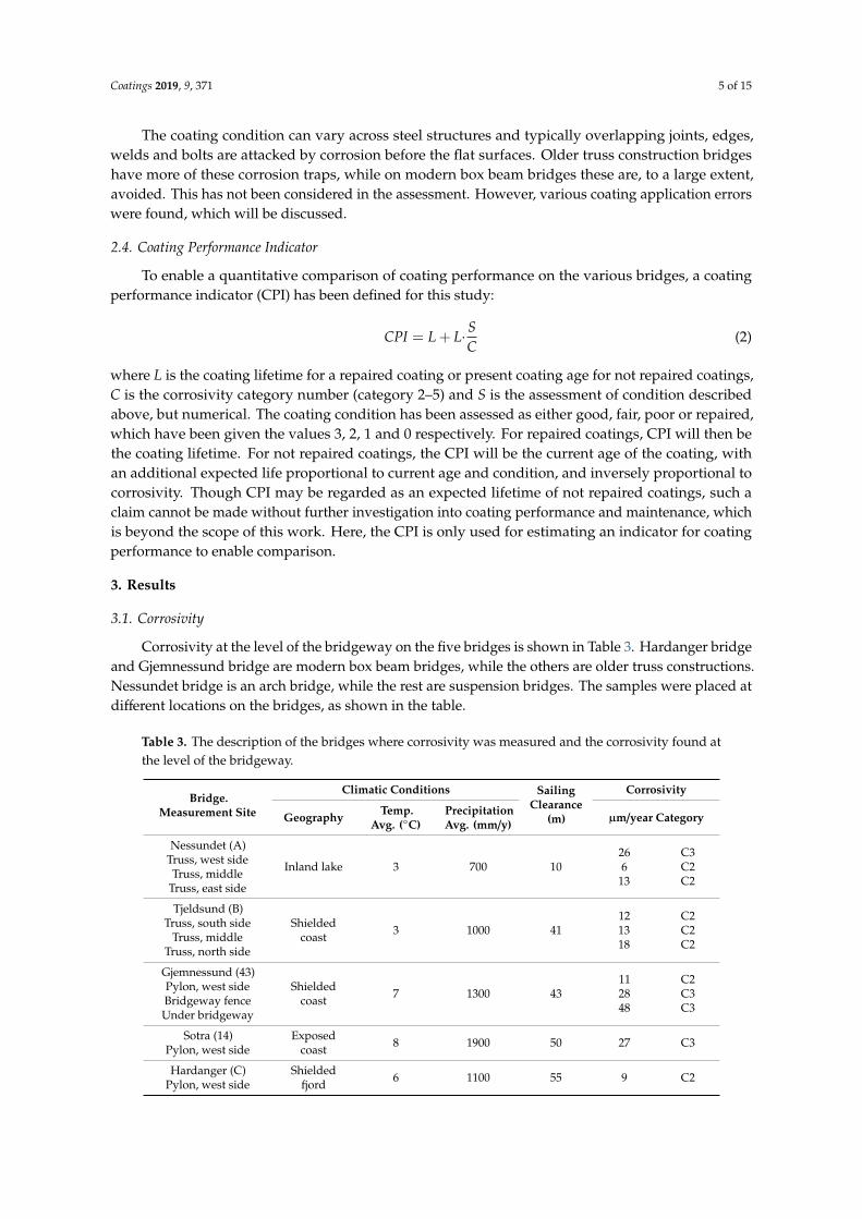
Another reason for low film thickness that is specific to TSZ duplex coatings is the lack ofan instrument that can measure paint film thickness over TSZ. The commonly used magnetic filmthickness gauges will measure the total duplex film thickness, i.e., both TSZ and paint. The eddycurrent thickness gauges that will measure thickness over the first electrically conducting layer, i.e., thezinc coating, does not work well with TSZ due to its rough microstructure and porosity (see Figure 5).This makes large variations in conductivity and unstable measurements. The magnetic thickness gaugeis, therefore, presently the only option. Ideally, each coating thickness should be measured as appliedto ensure the coatings meet specifications.
The second failure mechanism is the formation of pinholes in the paint film [13]. When applyingpaint on TSZ, bubbles of trapped air and evaporating solvent are easily formed inside the film, probablydue to the rough surface structure of the TSZ. As the bubbles grow, they attract paint from around andthe wet film thickness grows locally. When the paint dries, the bubbles crack open, but if the openingis too narrow, it will not be filled by the subsequent coats. Thus, a pinhole is formed in the paint wherethe zinc will start to corrode at an early stage.
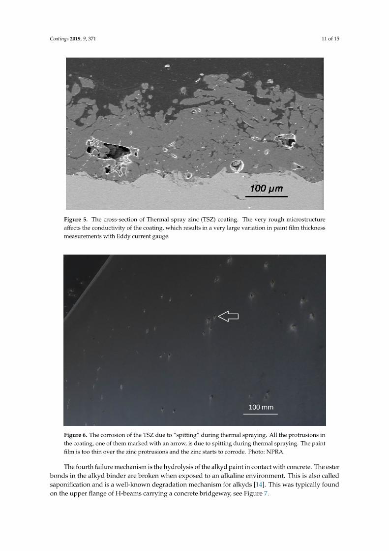
The third failure mechanism found was “spitting” during thermal spraying. If the arc spray gunis not properly adjusted, there will be incomplete melting of the zinc wire. These pieces of solid zincwill be sprayed along with the melted zinc but may protrude from the surface as tall peaks. Whenthe paint is applied, the film thickness will be too low over these peaks and the paint will fail duringexposure. A typical example is shown in Figure 6.
Coatings 2019, 9, 371 11 of 15Coatings 2019, 9, x FOR PEER REVIEW 11 of 15
Figure 5. The cross-section of Thermal spray zinc (TSZ) coating. The very rough microstructure affects
the conductivity of the coating, which results in a very large variation in paint film thickness
measurements with Eddy current gauge.
Figure 6. The corrosion of the TSZ due to “spitting” during thermal spraying. All the protrusions in
the coating, one of them marked with an arrow, is due to spitting during thermal spraying. The paint
film is too thin over the zinc protrusions and the zinc starts to corrode. Photo: NPRA.
Figure 5. The cross-section of Thermal spray zinc (TSZ) coating. The very rough microstructureaffects the conductivity of the coating, which results in a very large variation in paint film thicknessmeasurements with Eddy current gauge.
Coatings 2019, 9, x FOR PEER REVIEW 11 of 15
Figure 5. The cross-section of Thermal spray zinc (TSZ) coating. The very rough microstructure affects
the conductivity of the coating, which results in a very large variation in paint film thickness
measurements with Eddy current gauge.
Figure 6. The corrosion of the TSZ due to “spitting” during thermal spraying. All the protrusions in
the coating, one of them marked with an arrow, is due to spitting during thermal spraying. The paint
film is too thin over the zinc protrusions and the zinc starts to corrode. Photo: NPRA.
Figure 6. The corrosion of the TSZ due to “spitting” during thermal spraying. All the protrusions inthe coating, one of them marked with an arrow, is due to spitting during thermal spraying. The paintfilm is too thin over the zinc protrusions and the zinc starts to corrode. Photo: NPRA.
The fourth failure mechanism is the hydrolysis of the alkyd paint in contact with concrete. The esterbonds in the alkyd binder are broken when exposed to an alkaline environment. This is also calledsaponification and is a well-known degradation mechanism for alkyds [14]. This was typically foundon the upper flange of H-beams carrying a concrete bridgeway, see Figure 7.

Coatings 2019, 9, 371 12 of 15Coatings 2019, 9, x FOR PEER REVIEW 12 of 15
Figure 7. The saponification of alkyd paint where the painted H-beam is in contact with the concrete
(marked with an arrow) and subsequent corrosion of zinc and steel.
4. Discussion
4.1. TSZ Duplex Coating Failure Mechanisms
The coating failure mechanisms that were identified have different origins. Pinholes and spitting
are typical application errors with TSZ duplex coatings. When coating a large bridge, such errors are
likely to appear occasionally. By adjusting the application parameters immediately to prevent further
formation of such errors, and light grinding with sandpaper before application of the next coat, the
quality of the coating will improve significantly. Mainly pinholes and spitting were responsible for
the degradation at Bergsøysundbrua and large amounts of pinholes were also found at
Nordhordlandsbrua. In the very corrosive C5 environment, the TSZ started to corrode locally shortly
after the bridge was built. The TSZ was protecting the steel, but the TSZ has a certain capacity for
protection and when it is consumed, the steel starts to corrode.
Low film thickness results in coating failure due to the penetration of ions. Studies have shown
that a protective coating should have a resistivity of more than 109 Ohm·cm2 [15]. The film thickness
required to reach this resistivity depends on the generic type of coating. The thickness specification
given by the coating supplier will normally provide the required barrier. Low film thickness over
edges due to low edge retention is a general problem with paint. TSZ duplex coatings will give longer
lifetimes than pure paint coating systems since the TSZ coat is not susceptible to this. The TSZ film
thickness will be the same over sharp edges as on flat surfaces. However, if the paint film degrades
early, the TSZ will start to corrode, and depending on the corrosivity, it will eventually be consumed.
Grinding and stripe-coating of edges are routinely performed to reduce this problem, but it will not
be eliminated. On modern box beam bridges, the amount of edges is significantly reduced, compared
to a truss bridge.
Low paint film thickness on flat surfaces was one of the main degradation mechanisms on
Nordhordlandsbrua. The zinc started to corrode under the paint after a few years due to a
combination of low film thickness and formation of a very aggressive brine under the bridgeway,
where rain never could wash deposited sea salt away. Inspections and control during painting seem
to have been insufficient. This problem may be negligible with modern epoxy coatings. The old alkyd
paints were applied in thin coats specified at 50 µm each. High build epoxy mastic coatings typically
must be applied in thicker coats in order to form a continuous film. Hence, the painter will see when
enough paint has been applied, i.e., an inherent “smartness” in the paint.
Figure 7. The saponification of alkyd paint where the painted H-beam is in contact with the concrete(marked with an arrow) and subsequent corrosion of zinc and steel.
4. Discussion
4.1. TSZ Duplex Coating Failure Mechanisms
The coating failure mechanisms that were identified have different origins. Pinholes and spittingare typical application errors with TSZ duplex coatings. When coating a large bridge, such errors arelikely to appear occasionally. By adjusting the application parameters immediately to prevent furtherformation of such errors, and light grinding with sandpaper before application of the next coat, thequality of the coating will improve significantly. Mainly pinholes and spitting were responsible for thedegradation at Bergsøysundbrua and large amounts of pinholes were also found at Nordhordlandsbrua.In the very corrosive C5 environment, the TSZ started to corrode locally shortly after the bridge wasbuilt. The TSZ was protecting the steel, but the TSZ has a certain capacity for protection and when it isconsumed, the steel starts to corrode.
Low film thickness results in coating failure due to the penetration of ions. Studies have shownthat a protective coating should have a resistivity of more than 109 Ohm·cm2 [15]. The film thicknessrequired to reach this resistivity depends on the generic type of coating. The thickness specificationgiven by the coating supplier will normally provide the required barrier. Low film thickness overedges due to low edge retention is a general problem with paint. TSZ duplex coatings will give longerlifetimes than pure paint coating systems since the TSZ coat is not susceptible to this. The TSZ filmthickness will be the same over sharp edges as on flat surfaces. However, if the paint film degradesearly, the TSZ will start to corrode, and depending on the corrosivity, it will eventually be consumed.Grinding and stripe-coating of edges are routinely performed to reduce this problem, but it will not beeliminated. On modern box beam bridges, the amount of edges is significantly reduced, compared to atruss bridge.
Low paint film thickness on flat surfaces was one of the main degradation mechanisms onNordhordlandsbrua. The zinc started to corrode under the paint after a few years due to a combinationof low film thickness and formation of a very aggressive brine under the bridgeway, where rain nevercould wash deposited sea salt away. Inspections and control during painting seem to have beeninsufficient. This problem may be negligible with modern epoxy coatings. The old alkyd paints wereapplied in thin coats specified at 50 µm each. High build epoxy mastic coatings typically must beapplied in thicker coats in order to form a continuous film. Hence, the painter will see when enoughpaint has been applied, i.e., an inherent “smartness” in the paint.

Coatings 2019, 9, 371 13 of 15
The saponification problem was found on most bridges where a concrete bridgeway was restingon a coated H-beam. This problem was eliminated when the NPRA paint specification was changedfrom alkyds to epoxies. Epoxies are very tolerant to the alkaline conditions in concrete.
4.2. The Durability of TSZ Duplex Coatings
Coating maintenance constitutes the main operational cost for most steel bridges. Given the longlifetime of bridges, coating durability is a key factor for reducing life cycle costs. The TSZ duplexcoatings investigated in this study provide very long lifetimes and, for most bridges, significantlylonger than 25 years, which is defined as a “very high” lifetime in ISO 12944-1. Since only about 70%of the bridges with the 1965 coating specification and about 13% of the bridges with the 1977 coatingspecification have been repaired, and many of the bridges still have coatings in good or fair condition,even longer lifetimes will be achieved. For the less corrosive environments at least, it is likely thatduplex coatings may last for the lifetime of the bridge.
There are several sources of variation that complicate the comparison of coating performances.Most important is the sample size. As stated earlier, the study includes few bridges in C5 environments,which constitute a weak statistical base for comparison. Geographical location plays a role. Bridgeswith the same sailing clearance may have different orientations or see different weather patterns leadingto variable coating performance. Criteria for coating maintenance will affect the calculated performanceindicator. Decisions about coating maintenance are made by different people and no firm criteria havebeen set by the NPRA. For example, the coating maintenance on Rombak bridge in 2011 was initiatedas a preventive action. There was no corrosion on the bridge, but the topcoat had flaked off from partsof the bridge and the topcoat was renewed to prevent a more expensive maintenance operation inthe future. The maintenance of the Nordhordland bridge, however, was initiated due to extensivecoating degradation under the bridgeway and corrosion of the steel. In addition, non-technical factorsaffect the decision, like the available maintenance budget. Corrosion is a slow process and coatingmaintenance can often be postponed for many years without compromising the load carrying capacityof the bridge.
Both the 1965 and the 1977 coating specifications show a correlation between coating performanceand corrosivity. The coatings have performed very well in mild conditions and failed earlier incorrosive conditions. Though the coating failures in C5 environments, at least partly, was due to coatingapplication errors; this suggests that a stronger paint coating is required in corrosive environments.When the paint fails, the zinc coating will first act as a barrier, and later as a sacrificial anode whenbare steel is exposed. Zinc is an active metal and even the 15% aluminum alloy that is used mainlytoday will have a certain corrosion rate. Hence, when the zinc is exposed, the remaining lifetime ofthe coating will be limited by its corrosion rate, which again is determined by the local corrosivity.The durability of a TSZ duplex coating in a corrosive environment is, therefore, very dependent on theperformance of the paint coating.
5. Conclusions
Thermal spray zinc duplex coatings have provided long term corrosion protection to steel bridgesin Norway. Considering the present coating age and condition, it is reasonable to assume that the duplexcoating may last the entire 100-year bridge design life for many of the bridges in this investigation.For very corrosive environments, the two paint coating specifications appear to have been too weak.
Application quality has the strongest impact on coating life. Application errors like pinholes,spitting and low paint film thickness caused most coating failures found in this study. These errorsdecrease the protective properties of the paint film. The zinc coating provides active corrosionprotection, but will have a definite lifetime, depending on the corrosivity. Hence, such applicationerrors will reduce the coating lifetime more in corrosive environments than in mild environments.
Coatings 2019, 9, 371 14 of 15
Some of the coating degradation mechanisms found in this study will be significantly reduced oreliminated with modern bridge designs and modern paint systems, which probably will increase TSZduplex coating durability in the future. The most important improvements being
• Box beam bridge designs with fewer edges, reducing the edge retention problem• Using epoxy coatings with high tolerance to alkaline environments• Coatings with an inherent “smartness”, that tell the painter when enough paint is applied• Awareness of the spitting and pinhole problems so that adequate measures can be made during
the application
Author Contributions: Conceptualization, O.Ø.K., C.D. and H.M.; Investigation, O.Ø.K.; Data curation, O.Ø.K.,C.D. and H.M.; Writing—original draft preparation, O.Ø.K.; Writing—review and editing, M.G.; Fundingacquisition, C.D., H.M. and M.G.
Funding: This research was funded by the Norwegian Public Roads Administration, contract number 2014059758,and the International Zinc Association.
Acknowledgments: Funding from the Norwegian Public Roads Administration and the International ZincAssociation is gratefully acknowledged.
Conflicts of Interest: The International Zinc Association promotes the use of zinc worldwide, including forcorrosion protection. However, they do not sell any products or services, and were not involved in the datacollection or interpretation in this study. The NPRA is a governmental body and responsible for all public roadbridges in Norway but has no commercial interests in coatings. They made their entire bridge administrationdatabase available to the project and put no limitations on the data selection. The decision to publish this studywas made by O.Ø. Knudsen, SINTEF.
References
1. ISO 12944-5 Paints and Varnishes-Corrosion Protection of Steel Structures by Protective Paint Systems. Part 5:Protective Paint Systems; The International Organization for Standardization: Geneva, Switzerland, 2018.
2. Klinge, R. Protection of norwegian steel bridges against corrosion (Korrosionsschutz von NorwegischenStahlbrücken). Stahlbau 1999, 68, 382–391. [CrossRef]
3. Klinge, R. Altered specifications for the protection of norwegian steel bridges and offshore structures againstcorrosion. Steel Constr. Des. Res. 2009, 2, 109–118. [CrossRef]
4. Porter, F.C. Zinc Handbook: Properties, Processing, and Use in Design; CRC Press: Boca Raton, FL, USA, 1991.5. Perkins, R.A. Metallized Coatings for Corrosion Control of Naval Ship Structures and Components; National
Materials Advisory Board: Washington, DC, USA, 1983; No. NMAB-409.6. AWS. Corrosion Test of Flames-Sprayed Coated Steel. 19-Year Report; American Welding Society: Miami, FL,
USA, 1974; No. C2.14-74.7. Eijnsbergen, J.F.H.v. Duplex Systems. Hot-Dip Galvanizing Plus Painting; Elsevier Science: Amsterdam, The
Netherlands, 1994; p. 222.8. ISO 9226 Corrosion of Metals and Alloys—Corrosivity of Atmospheres—Determination of Corrosion Rate of Standard
Specimens for the Evaluation of Corrosivity; The International Organization for Standardization: Geneva,Switzerland, 2012.
9. ISO 12944-2 Paints and Varnishes-Corrosion Protection of Steel Structures by Protective Paint Systems. Part 2:Classification of Environments; The International Organization for Standardization: Geneva, Switzerland, 2017.
10. Kreislova, K.; Geiplova, H. Evaluation of corrosion protection of steel bridges. Procedia Eng. 2012, 40, 229–234.[CrossRef]
11. ISO 12944-1 Paints and Varnishes-Corrosion Protection of Steel Structures by Protective Paint Systems. Part 1:General Introduction; The International Organization for Standardization: Geneva, Switzerland, 2017.
12. Yun, J.T.; Kwon, T.K.; Kang, T.S.; Kim, K.L.; Kim, T.K.; Han, J.M. A critical study on edge retention ofprotective coatings for a ship hull. In Proceedings of the CORROSION 2005, Houston, TX, USA, 3–7 April2005; National Association of Corrosion Engineers (NACE): Houston, TX, USA, 2005.
13. Hasselø, J.-A.; Djuve, G. Coating systems with long lifetime–paint on thermally sprayed zinc. In Proceedingsof the CORROSION 2016, Vancouver, BC, Canada, 6–10 March 2016; National Association of CorrosionEngineers (NACE): Houston, TX, USA, 2016.

Coatings 2019, 9, 371 15 of 15
14. Knudsen, O.Ø.; Forsgren, A. Corrosion Control through Organic Coatings; Taylor & Francis: London, UK, 2017.15. Bierwagen, G.P.; He, L.; Li, J.; Ellingson, L.; Tallman, D. Studies of a new accelerated evaluation method for
coating corrosion resistance—Thermal cycling testing. Prog. Org. Coat. 2000, 39, 67–78. [CrossRef]
© 2019 by the authors. Licensee MDPI, Basel, Switzerland. This article is an open accessarticle distributed under the terms and conditions of the Creative Commons Attribution(CC BY) license (http://creativecommons.org/licenses/by/4.0/).