Exp-2-Ohms-Law.pdf - University of Portland
10
University of Portland - p. 1 of 10 - Exp 2 - Ohms Law.docx University of Portland EE 271 Electrical Circuits Laboratory Experiment: Ohm’s Law I. Objective The objectives of this experiment are to learn how to read a resistor’s color code, measure current, and measure the relationship between voltage and current for a resistor. II. List of Components The following components will be used in this experiment: • One 1 kΩ resistor • One 10 kΩ resistor III. Background: Resistor Color Codes Standard resistors are labeled with a color code which indicates their resistance values (see Figure 1). Tolerance 1st Digit 2nd Digit Multiplier Figure 1. Resistor with 4 color bands. The value indicated by each color band is listed in Tables 1, 2, and 3, and the resistor's value can be computed by the following equation: ( ) ( ) ( ) 1st Digit 10 2nd Digit Multiplier R = × + ×
-
Upload
khangminh22 -
Category
Documents
-
view
0 -
download
0
Transcript of Exp-2-Ohms-Law.pdf - University of Portland
University of Portland - p. 1 of 10 - Exp 2 - Ohms Law.docx
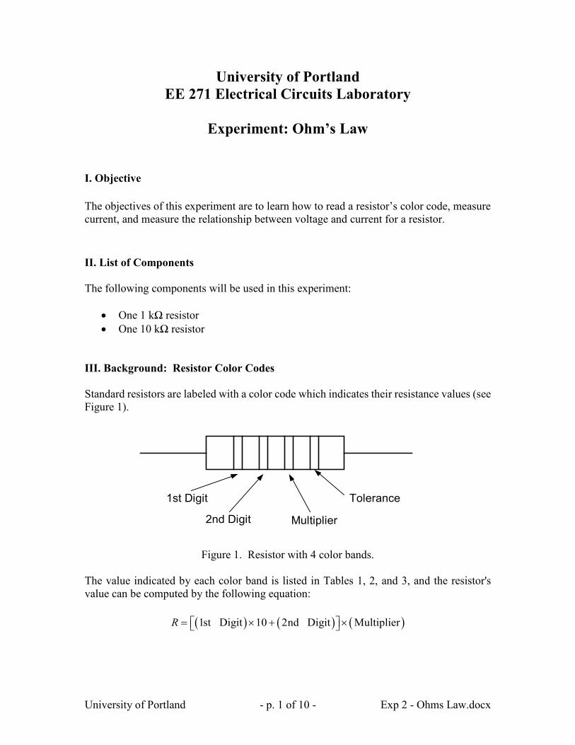
University of Portland EE 271 Electrical Circuits Laboratory
Experiment: Ohm’s Law
I. Objective The objectives of this experiment are to learn how to read a resistor’s color code, measure current, and measure the relationship between voltage and current for a resistor. II. List of Components The following components will be used in this experiment:
• One 1 kΩ resistor • One 10 kΩ resistor
III. Background: Resistor Color Codes Standard resistors are labeled with a color code which indicates their resistance values (see Figure 1).
Tolerance1st Digit
2nd Digit Multiplier
Figure 1. Resistor with 4 color bands.
The value indicated by each color band is listed in Tables 1, 2, and 3, and the resistor's value can be computed by the following equation:
( ) ( ) ( )1st Digit 10 2nd Digit MultiplierR = × + ×
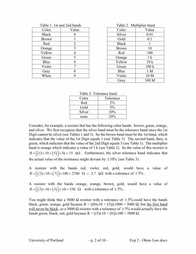
University of Portland - p. 2 of 10 - Exp 2 - Ohms Law.docx
Table 1. 1st and 2nd bands Color Value Black 0 Brown 1
Red 2 Orange 3 Yellow 4 Green 5 Blue 6
Violet 7 Gray 8 White 9
Table 2. Multiplier band Color Value Silver 0.01 Gold 0.1 Black 1 Brown 10
Red 100 Orange 1 k Yellow 10 k Green 100 k Blue 1 M
Violet 10 M Gray 100 M
Table 3. Tolerance band Color Tolerance Red 2% Gold 5% Silver 10% none 20%
Consider, for example, a resistor that has the following color bands: brown, green, orange, and silver. We first recognize that the silver band must be the tolerance band since the 1st Digit cannot be silver (see Tables 1 and 3). So the brown band must be the 1st band, which indicates that the value of the 1st Digit equals 1 (see Table 1). The second band, then, is green, which indicates that the value of the 2nd Digit equals 5 (see Table 1). The multiplier band is orange which indicates a value of 1 k (see Table 2). So the value of this resistor is
( ) ( )1 10 5 1k 15 kR = × + × = Ω . Furthermore, the silver tolerance band indicates that the actual value of the resistance might deviate by %10± (see Table 3). A resistor with the bands red, violet, red, gold, would have a value of
( ) ( )2 10 7 100 2700 2.7 kR = × + × = Ω = Ω with a tolerance of %5± . A resistor with the bands orange, orange, brown, gold, would have a value of
( ) ( )3 10 3 10 330R = × + × = Ω with a tolerance of %5± . You might think that a 5000 Ω resistor with a tolerance of %5± could have the bands black, green, orange, gold because R = [(0)x10 + (5)]x1000 = 5000 Ω, but the first band will never be black, so a 5000 Ω resistor with a tolerance of %5± would actually have the bands green, black, red, gold because R = [(5)x10 + (0)]x100 = 5000 Ω.

University of Portland - p. 3 of 10 - Exp 2 - Ohms Law.docx
IV. Prelab Assignment
1. Determine the color bands for a 1 kΩ and 10 kΩ, resistor with 5% tolerance.
Table 4. Color codes for the 1 kΩ and 10 kΩ resistors. R (kΩ) First Second Third Fourth
1 10
2. Read the Analog Discovery Tutorial – Part 1. Download and install the software.
V. Procedure Part 1: Set up the Analog Discovery Power Supply Connect the Analog Discovery’s V+ Power Supply and Ground to the breadboard as shown in Figure 2 (see Analog Discovery tutorial). Launch the WaveForms software and set the power supply to 1V. Measure the power supply voltage with your DMM. Measured power supply voltage: ____________
Figure 2: Using Analog Discovery’s Power Supply

University of Portland - p. 4 of 10 - Exp 2 - Ohms Law.docx
Part 2: Measure the Current through a 1 kΩ Resistor Before we use a resistor, it is good practice to measure its value. It is very easy to misread the color code, and measuring the value of each resistor is an easy way to check to make sure that you have the correct value. Also, resistance cannot be measured properly once the resistor is connected in a circuit, so checking the resistor values after building the circuit is inconvenient. Use the DMM to measure the resistance of the 1 kΩ resistor: _______________ Compute the % 𝑒𝑒𝑒𝑒𝑒𝑒𝑒𝑒𝑒𝑒 = 𝑇𝑇ℎ𝑒𝑒𝑒𝑒𝑒𝑒𝑒𝑒𝑒𝑒𝑒𝑒𝑒𝑒𝑒𝑒𝑒𝑒−𝑀𝑀𝑒𝑒𝑒𝑒𝑀𝑀𝑀𝑀𝑒𝑒𝑒𝑒𝑀𝑀
𝑇𝑇ℎ𝑒𝑒𝑒𝑒𝑒𝑒𝑒𝑒𝑒𝑒𝑒𝑒𝑒𝑒𝑒𝑒𝑒𝑒𝑥𝑥100 = ______________
Is the absolute value of the % error less than the 5% tolerance? _________ Next we will construct the circuit in Figure 3 to measure the current through a resistor where R = 1 kΩ and V = 1V. It is good practice to turn off the power supply while you construct or modify circuits. In order to measure current, the DMM must be placed in series with the resistor (see DMM tutorial). When the DMM is used to measure current, it behaves like a short circuit, so be careful NOT to short out the power supply by connecting the DMM directly across the power supply. Doing so may burn out a fuse in your DMM. If your DMM always displays close to 0A when you measure current, the fuse may be burned out or it may be connected improperly.
V
I
R
Ammeter
Figure 3: Circuit to Measure I and V
University of Portland - p. 5 of 10 - Exp 2 - Ohms Law.docx
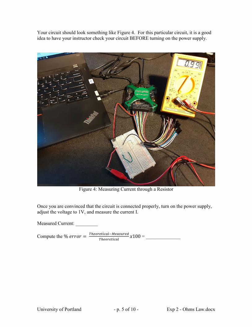
Your circuit should look something like Figure 4. For this particular circuit, it is a good idea to have your instructor check your circuit BEFORE turning on the power supply.
Figure 4: Measuring Current through a Resistor
Once you are convinced that the circuit is connected properly, turn on the power supply, adjust the voltage to 1V, and measure the current I. Measured Current: _________ Compute the % 𝑒𝑒𝑒𝑒𝑒𝑒𝑒𝑒𝑒𝑒 = 𝑇𝑇ℎ𝑒𝑒𝑒𝑒𝑒𝑒𝑒𝑒𝑒𝑒𝑒𝑒𝑒𝑒𝑒𝑒𝑒𝑒−𝑀𝑀𝑒𝑒𝑒𝑒𝑀𝑀𝑀𝑀𝑒𝑒𝑒𝑒𝑀𝑀
𝑇𝑇ℎ𝑒𝑒𝑒𝑒𝑒𝑒𝑒𝑒𝑒𝑒𝑒𝑒𝑒𝑒𝑒𝑒𝑒𝑒𝑥𝑥100 = ______________

University of Portland - p. 6 of 10 - Exp 2 - Ohms Law.docx
Part 3: Measure the Relationship Between Voltage and Current in a Resistor Using the circuit from Figure 3, change the power supply voltage to several values between 0 and 5V and record the resulting current I for each voltage (you will need at least 6 or so values for a decent graph).
V (Volts) I (Amps)
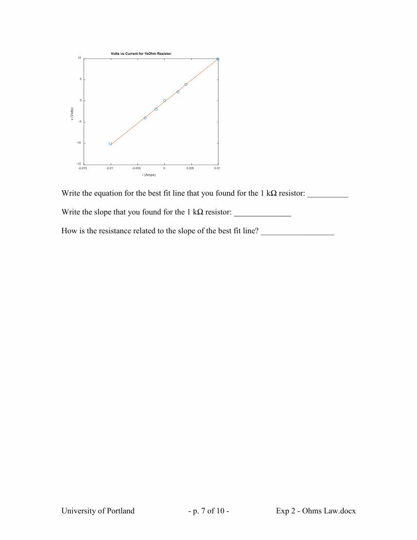
Use MATLAB (or your favorite software) to graph your measured voltages (on the vertical axis) versus current (on the horizontal axis) and the best fit line. An example using MATLAB is shown below (replace the values of voltage and current with your measured values). % Measured voltage(V) (replace with your values) v = [-10.1 -4.0 -1.9 0.1 2.2 3.9 9.9]; % Measured current(A) (replace with your values) i = [-0.0101 -0.0036 -0.0016 0.00 0.0025 0.0040 0.0099]; % Compute 1st degree polynomial fit c = polyfit(i,v,1) % Compute best fit line % c(1) is the slope for example data % c(2) is the intercept for example data vfit = c(1)*i + c(2); % Plot measured values with circles % and plot best fit line plot(i,v,'o',i,vfit)
University of Portland - p. 7 of 10 - Exp 2 - Ohms Law.docx
Write the equation for the best fit line that you found for the 1 kΩ resistor: __________ Write the slope that you found for the 1 kΩ resistor: ______________ How is the resistance related to the slope of the best fit line? __________________
i (Amps)
-0.015 -0.01 -0.005 0 0.005 0.01
v (V
olts
)
-15
-10
-5
0
5
10Volts vs Current for 1kOhm Resistor

University of Portland - p. 8 of 10 - Exp 2 - Ohms Law.docx
Part 4: Series Resistances Resistors are manufactured in a variety of standard values, but sometimes we need a resistance that is not a standard value. In this case, we can often combine two or more resistors in series (or parallel) to achieve the desired value. Use the DMM to measure the resistance of the 10 kΩ resistor: _______________ Compute the % 𝑒𝑒𝑒𝑒𝑒𝑒𝑒𝑒𝑒𝑒 = 𝑇𝑇ℎ𝑒𝑒𝑒𝑒𝑒𝑒𝑒𝑒𝑒𝑒𝑒𝑒𝑒𝑒𝑒𝑒𝑒𝑒−𝑀𝑀𝑒𝑒𝑒𝑒𝑀𝑀𝑀𝑀𝑒𝑒𝑒𝑒𝑀𝑀
𝑇𝑇ℎ𝑒𝑒𝑒𝑒𝑒𝑒𝑒𝑒𝑒𝑒𝑒𝑒𝑒𝑒𝑒𝑒𝑒𝑒𝑥𝑥100 = ______________
Is the absolute value of the % error less than the 5% tolerance? _________ Connect the 1 kΩ resistor in series with the 10 kΩ resistor and measure the resistance of the series combination (see Figure 5). Compare the resistance of the series combination to the measured values of each resistor. How does connecting resistors in series affect the resistance? _____________________ Does connecting two (or more) resistors in series increase or decrease the resistance? ___
Figure 5: Measuring Series Resistors

University of Portland - p. 9 of 10 - Exp 2 - Ohms Law.docx
Part 5: Parallel Resistances Connect the 1 kΩ resistor in parallel with the 10 kΩ resistor and measure the resistance of the parallel combination (see Figure 6). Compare the resistance of the parallel combination to the measured values of each resistor. How does connecting resistors in parallel affect the resistance? _____________________ Does connecting two (or more) resistors in parallel increase or decrease the resistance? _______________
Figure 6: Measuring Parallel Resistors
University of Portland - p. 10 of 10 - Exp 2 - Ohms Law.docx
VI. Conclusion Write a paragraph that summarizes what you have learned in this lab. Describe the relationship between voltage and current in a resistor (which is called Ohm’s Law) and how the resistance is related to the graph of voltage versus current. Describe how the resistance of series and parallel resistors can be computed.