
excor - Berlin Heart
212
EXCOR ® Adult EXCOR ® Pediatric EXCOR ® VAD Ventricular Assist Device EXCOR ® Active Driving System Instructions for Clinical Use Edition 1.0
-
Upload
khangminh22 -
Category
Documents
-
view
0 -
download
0
Transcript of excor - Berlin Heart

EXCOR®
EXCOR® VAD
Ventricular Assist Device
EXCOR® Active Driving SystemInstructions for Clinical Use Edition 1.0
Adult E
XCOR® Pediatric
2
e
1015002x00
n

These instructions for use apply to the EXCOR Active system.
Approval and declaration of conformity
Instructions for use edition
1015002x00 Edition 1.0 2019-10
These instructions for use may not be reproduced, forwarded, transmitted by electronic media, stored in a data processing system or translated into another language, either wholly or in part, without the written consent of Berlin Heart GmbH.
These instructions for use are intended for information purposes only. The contents of the instructions for use may be supplemented, modified or updated at any time without prior notice. Previous editions of these clinical instructions for use are superseded by the publication of this edition. All translations of these instructions for use have been prepared and checked to the best of our knowl-edge. Only the German edition of these instructions for use is considered to be legally binding, however.
Component Software 2
Driving unit 1 (for model-dependent scope of functionality, see Tab. 3-2 , page 20)
Driving unit 1502200Driving unit 1502210
from version 01.09.00 onwardfrom version 01.09.00 onward
Panel PC including docking station and panel PC power supply unit
from version 01.09.00 onward
Flow sensor including cable wrap from version 1.0 onward
Manual pump
Battery charging unit
Power supply unit for driving unit and battery charging unit
Caddy with accessory bag
Baby buggy (stroller with stroller board, optional accessory)
Adapter for external alarm
USB cable
USB stick
1 Depending on approval region; not all models available. Ask your manufacturer or distributor about model availability.
2 All software versions are compatible with one another
UMDNS number: 10-847
1015002x00 3
en

4
e
Licenses and trademarks
EXCOR® and the Berlin Heart logo are trade names of Berlin Heart GmbH. They are protected in Germa-ny and other countries.
All other trade names mentioned in these instructions for use are subject to the rights of their respective owners. These rights are expressly recognized and respected when referring to these names in the pres-ent publication. Use of the trademark will be dispensed with in the further text. Berlin Heart GmbH will be hereinafter referred to as Berlin Heart.
© Berlin Heart GmbH All rights reserved.
1015002x00
n

Table of Contents
Table of Contents
1 Contact 13
2 Introduction 152.1 Target Audience ............................................................................................................... 152.2 Explanation of the Safety Information and Signal Words ................................................. 152.3 Terms ............................................................................................................................... 162.4 Meaning of Text Markups ................................................................................................. 172.5 Pictograms on Components ............................................................................................. 172.5.1 Safety Symbols ........................................................................................................... 172.5.2 Symbols....................................................................................................................... 18
3 General Information EXCOR Active 193.1 System Overview - Driving Unit with EXCOR VAD .......................................................... 193.2 Components and Locations of Use .................................................................................. 203.3 Scope of Driving Unit Functionality................................................................................... 203.4 Intended Use .................................................................................................................... 213.4.1 Use .............................................................................................................................. 213.4.2 Indications, Contraindications, and Potential Therapeutic Objectives......................... 223.5 EMC - Electromagnetic Compatibility ............................................................................... 223.6 Combination with Other Products and Procedures .......................................................... 223.7 Replacement Components ............................................................................................... 233.8 Information Regarding the Instructions for Use ................................................................ 233.9 Disposal of Components .................................................................................................. 233.10 Product Life ...................................................................................................................... 24
4 Safety Information 254.1 General............................................................................................................................. 254.2 Configuration .................................................................................................................... 254.3 Caregivers ........................................................................................................................ 264.4 Ambient Conditions .......................................................................................................... 264.5 Diagnostic Procedures, EMC ........................................................................................... 274.6 Connections and Operation Elements.............................................................................. 274.7 Power Supply ................................................................................................................... 284.8 Operation.......................................................................................................................... 28
5 Driving Unit 295.1 Structure and Function ..................................................................................................... 295.1.1 Primary Function ......................................................................................................... 295.1.2 Setup ........................................................................................................................... 305.2 Connections and Operation Elements.............................................................................. 315.2.1 Control Panel............................................................................................................... 315.2.1.1 Indicator Lights ....................................................................................................... 315.2.1.2 Button ..................................................................................................................... 315.2.1.3 Display.................................................................................................................... 325.2.2 Connections ................................................................................................................ 385.2.2.1 Overview of Connections ....................................................................................... 395.2.2.2 Connecting and Disconnecting Driving Tubes ....................................................... 395.2.2.3 Connecting the Power Supply Unit to the Driving Unit ........................................... 405.2.2.4 Disconnecting the Power Supply Unit from the Driving Unit .................................. 405.2.2.5 Connecting to the Panel PC................................................................................... 405.2.2.6 Connecting the External Alarm (Nurse Call) Adapter............................................. 415.2.3 Flow Sensor ................................................................................................................ 415.2.3.1 Setup ...................................................................................................................... 425.2.3.2 Measurement Accuracy and Alarms ...................................................................... 44
1015002x00 5
en

6
Table of Contents
e
5.2.3.3 Attaching the Flow Sensors to the Cannulae and the Blood Pumps...................... 455.2.3.4 Removing the Flow Sensor from the Cannula........................................................ 465.2.3.5 Replacing the Sensor Quick Connect .................................................................... 465.2.3.6 Connecting/Disconnecting the Flow Sensor to/from the Driving Unit ..................... 465.2.3.7 Guiding the Driving Tube and the Flow Sensor Cable in the Cable Wrap ............. 475.2.3.8 Removing the Cable Wrap ..................................................................................... 485.2.4 Carrying System and Locking Mechanism .................................................................. 485.2.4.1 Driving Unit Setup .................................................................................................. 495.2.4.2 Setup of Mobile Components ................................................................................. 495.3 Switching On the Driving Unit........................................................................................... 495.4 Start Test for the Driving Unit ........................................................................................... 505.5 Driving Unit Self-Test........................................................................................................ 505.6 Switching Off the Driving Unit........................................................................................... 505.7 Power Supply ................................................................................................................... 515.7.1 Batteries ...................................................................................................................... 515.7.1.1 Inserting the Batteries ............................................................................................ 525.7.1.2 Removing the Batteries .......................................................................................... 535.7.1.3 Charging Batteries in the Driving Unit .................................................................... 535.7.1.4 Charging Batteries in the Battery Charging Unit .................................................... 535.7.1.5 Charging Replacement Batteries ........................................................................... 535.7.1.6 Charging Time........................................................................................................ 535.7.1.7 Checking the Battery Charge Level........................................................................ 545.7.1.8 Determining the Charge Level................................................................................ 555.7.1.9 Driving Unit Operating Time in Battery Operation .................................................. 565.7.1.10 Notes on Replacing the Batteries........................................................................... 575.7.2 Power Supply Unit ....................................................................................................... 575.7.3 Emergency Battery ...................................................................................................... 585.7.3.1 General................................................................................................................... 585.7.3.2 Charging the Emergency Battery ........................................................................... 585.8 Battery Charging Unit ....................................................................................................... 595.8.1 Setup ........................................................................................................................... 595.8.2 Function....................................................................................................................... 605.9 Connecting Electrical Components .................................................................................. 615.10 Replacing a Driving Unit ................................................................................................... 615.10.1 Replacing a Driving Unit - BVAD................................................................................. 615.10.2 Replacing a Driving Unit in LVAD and RVAD Patients................................................ 635.10.2.1 Checking the Functionality of an Unconfigured Driving Unit and Panel PC ........... 635.10.2.2 Configuring the Driving Unit from File .................................................................... 635.10.2.3 Checking Configuration and Starting the Driving Unit ............................................ 635.10.2.4 Replacing the Driving Unit...................................................................................... 645.11 BVAD Emergency Operation............................................................................................ 65
6 Panel PC and Docking Station 676.1 Safety Information ............................................................................................................ 676.2 Setup - Overview .............................................................................................................. 676.3 Supplying Power via Power Supply Unit .......................................................................... 696.4 Supplying Power Using Batteries ..................................................................................... 696.4.1 Inserting and Removing the Battery ............................................................................ 696.5 Docking Station ................................................................................................................ 706.5.1 Setup ........................................................................................................................... 706.5.2 Panel PC and Docking Station .................................................................................... 716.5.3 Switching the Panel PC On and Off ............................................................................ 716.6 Connecting the Panel PC to the Driving Unit.................................................................... 726.6.1 Connection via USB .................................................................................................... 72
7 User Interface 737.1 General............................................................................................................................. 73
1015002x00
n

Table of Contents
7.1.1 File and Menu Bar ....................................................................................................... 747.1.2 Status Bar.................................................................................................................... 757.1.3 Buttons ....................................................................................................................... 767.2 Functions of the Menu Bar ............................................................................................... 777.2.1 User Login ................................................................................................................... 777.2.2 Passwords ................................................................................................................... 797.2.3 User Log Off ................................................................................................................ 797.3 Monitoring......................................................................................................................... 797.4 Settings for the Blood Pumps ........................................................................................... 807.4.1 Parameter.................................................................................................................... 807.4.2 Display of Pressure Curves ......................................................................................... 847.5 Settings for the Driving Unit.............................................................................................. 857.5.1 Patient information and driving unit settings................................................................ 857.5.2 Blood pumps and cannulae......................................................................................... 867.5.3 Settings - Overview ..................................................................................................... 877.6 Data .................................................................................................................................. 887.6.1 Files ............................................................................................................................. 887.6.2 Options ........................................................................................................................ 887.6.3 System Information...................................................................................................... 897.6.4 Resetting the Driving Unit............................................................................................ 897.6.5 Switching Off the Panel PC ......................................................................................... 907.7 Alarm History .................................................................................................................... 917.7.1 Progression ................................................................................................................. 917.7.2 Trend Info .................................................................................................................... 917.8 Active Alarms.................................................................................................................... 937.9 Audio Paused ................................................................................................................... 937.10 Messages and Help.......................................................................................................... 937.10.1 Messages .................................................................................................................... 937.10.2 Help ............................................................................................................................. 93
8 Configuring and Operating the Driving Unit 958.1 General............................................................................................................................. 958.2 Switching On the System ................................................................................................. 958.3 Checking Functions .......................................................................................................... 958.3.1 Checking Functionality of an Unconfigured Driving Unit ............................................. 958.3.2 Checking Functionality of a Configured Replacement Driving Unit ............................. 968.4 Parameters and Configuration.......................................................................................... 968.4.1 Default Parameter Settings ......................................................................................... 968.4.2 Blood Pumps - Cannulae - Maximum Rate ................................................................. 978.4.3 Selecting Blood Pumps and Cannulae........................................................................ 978.5 Configuring the System .................................................................................................... 988.5.1 Configuration Options - Overview................................................................................ 988.5.2 Configuring a Driving Unit - MANUAL ......................................................................... 998.5.2.1 Starting Configuration............................................................................................. 998.5.2.2 Entering Patient Information................................................................................... 998.5.2.3 Selecting Settings for the Driving Unit.................................................................. 1008.5.2.4 Selecting Blood Pumps and Cannulae................................................................. 1008.5.2.5 Checking Settings and Transferring to the Driving Unit ....................................... 1018.5.3 Configuring the Driving Unit from File........................................................................ 1018.6 De-Airing, Starting, and Setting the Blood Pumps.......................................................... 1028.6.1 De-Airing the Blood Pump......................................................................................... 1028.6.2 LVAD and RVAD ....................................................................................................... 1028.6.3 BVAD:........................................................................................................................ 1038.6.4 Setting Rate and Synchronization ............................................................................. 1048.6.5 Optimizing the Filling and Emptying of the Blood Pumps.......................................... 1058.6.5.1 Blood Pump Phases............................................................................................. 1058.6.5.2 Basic Procedure ................................................................................................... 105
1015002x00 7
en

8
Table of Contents
e
8.6.5.3 Piston Stroke and Mean Driving Pressure ........................................................... 1068.6.5.4 Optimizing Filling and Emptying ........................................................................... 1068.6.6 Setting the Parameter Duration Systole .................................................................... 1078.6.7 Displaying the Pressure Curves ................................................................................ 1078.6.8 Resetting the Driving Unit.......................................................................................... 1088.7 Measuring the Blood Flow .............................................................................................. 1088.7.1 Connecting the Flow Sensor ..................................................................................... 1088.7.2 Setting a Flow Alarm Threshold ................................................................................ 1098.8 Postoperative.................................................................................................................. 1108.8.1 Monitoring the Patient ............................................................................................... 1108.8.2 Changing Parameters................................................................................................ 1108.8.3 Mobilizing Patients..................................................................................................... 1118.8.4 Changing the Blood Pump Size................................................................................. 1128.8.5 Changing the Operating Mode .................................................................................. 1138.9 Replacing and Upgrading the Blood Pump .................................................................... 1148.9.1 Replacing Blood Pumps - BVAD Left, LVAD, RVAD................................................. 1148.9.2 Replacing the Blood Pump - BVAD Right.................................................................. 1158.10 Replacing the Driving Tube ............................................................................................ 1168.10.1 Replacing Driving Tubes - BVAD Left, LVAD, RVAD................................................ 1168.10.2 Replacing Driving Tubes - BVAD Right ..................................................................... 1178.11 Configuring and Updating the Replacement Driving Unit ............................................... 1178.11.1 Configuring the Replacement Driving Unit ................................................................ 1178.11.2 Replacement Driving Unit - Updating Configuration.................................................. 1188.12 Types of Data ................................................................................................................. 1198.12.1 Configurations ........................................................................................................... 1198.12.2 Logs........................................................................................................................... 1198.13 Managing Data ............................................................................................................... 119
9 Replacing the Driving System 1239.1 General........................................................................................................................... 1239.2 From Ikus to EXCOR Active ........................................................................................... 1239.2.1 Prerequisites for a Replacement ............................................................................... 1239.2.2 Preparing EXCOR Active .......................................................................................... 1239.2.3 Switching to EXCOR Active....................................................................................... 1249.3 From EXCOR Active to Ikus ........................................................................................... 1259.3.1 Preparing the Ikus ..................................................................................................... 1259.3.2 Replacing the Driving Unit ......................................................................................... 125
10 Weaning and Explantation 12710.1 General........................................................................................................................... 12710.2 Weaning the Patient ....................................................................................................... 12710.3 Performing an Explantation ............................................................................................ 127
11 Performing Trainings 12911.1 Target Group for Trainings ............................................................................................. 12911.1.1 Qualified Medical Personnel...................................................................................... 12911.1.2 Lay Users ................................................................................................................. 12911.2 Safety Information .......................................................................................................... 12911.3 Training Content Checklists............................................................................................ 13011.3.1 Using Components .................................................................................................... 13011.3.2 Behavior and Safety .................................................................................................. 13111.4 Training Log.................................................................................................................... 132
12 Mobile Use of EXCOR Active 13312.1 Help with Mobilization..................................................................................................... 133
13 Caddy 135
1015002x00
n

Table of Contents
13.1 Setup .............................................................................................................................. 13513.2 Assembly - Disassembly ................................................................................................ 13513.2.1 Adjusting the Stand ................................................................................................... 13513.2.2 Mounting - Dismounting the Wheels.......................................................................... 13613.2.3 Inflating the Tires ....................................................................................................... 13613.2.4 Attaching the Accessory Bag..................................................................................... 13713.2.5 Fastening the Hand Strap ......................................................................................... 13713.2.6 Adjusting the Handle Height ...................................................................................... 13713.3 Using the Caddy ............................................................................................................. 13813.3.1 Safety Information ..................................................................................................... 13813.3.2 Positioning the Driving Unit ....................................................................................... 13813.3.3 Securing and Releasing the Driving Tubes ............................................................... 13913.3.4 Using the Brake......................................................................................................... 13913.3.5 Carrying the Caddy with the Driving Unit................................................................... 13913.3.6 Folding the Caddy into Transport Position ................................................................ 139
14 Accessory Bag 14114.1 Design and Function....................................................................................................... 14114.2 Packing the Accessory Bag............................................................................................ 141
15 Baby Buggy - Stroller Board 14315.1 Safety Information .......................................................................................................... 14315.2 General........................................................................................................................... 14315.3 Setup .............................................................................................................................. 14315.4 Mounting the Stroller Board............................................................................................ 14315.4.1 Checking the Scope of Delivery ................................................................................ 14315.4.2 Overview - Assembly................................................................................................. 14515.4.3 Mounting the Stroller Board....................................................................................... 14615.4.4 Adjusting the Suspension .......................................................................................... 14615.4.5 Combination with the Stroller..................................................................................... 14615.4.5.1 Set 1 - Frame ....................................................................................................... 14715.4.5.2 Set 2 - Child Seat Fixture with Accessories ......................................................... 14715.4.5.3 Set 3 - Baby Seat Fixture ..................................................................................... 14715.4.5.4 Using the Child Seat and the Baby Seat .............................................................. 14715.4.6 Attaching the Stroller Board to the Stroller ................................................................ 14815.4.7 Releasing the Stroller Board from the Stroller ........................................................... 14815.5 Using the Stroller Board ................................................................................................. 14815.6 Positioning the Driving Tubes......................................................................................... 149
16 Manual Pump 15116.1 General........................................................................................................................... 15116.2 Safety Information .......................................................................................................... 15116.3 Setup .............................................................................................................................. 15216.4 Supporting the Patient with the Manual Pump ............................................................... 153
17 Identifying Errors and Troubleshooting 15517.1 Safety Information .......................................................................................................... 15517.2 Contact Person in Case of Error..................................................................................... 15517.2.1 Contact Person Regarding Errors ............................................................................. 15517.2.2 Reporting Serious Incidents ...................................................................................... 15517.3 Driving Unit and Panel PC Alarms.................................................................................. 15617.3.1 Alarms ....................................................................................................................... 15617.3.2 Priority ....................................................................................................................... 15617.3.3 Perceiving Alarms Reliably........................................................................................ 15717.3.4 Alarm Times .............................................................................................................. 15717.3.5 Alarm Coding............................................................................................................. 15717.3.6 Visual Alarms on the Driving Unit .............................................................................. 157
1015002x00 9
en

10
Table of Contents
e
17.3.7 Audible Alarms on the Driving Unit............................................................................ 15817.3.8 Audio Off ................................................................................................................... 15917.3.9 Saving Configurations and Logs................................................................................ 15917.3.10 Canceling an Alarm .................................................................................................. 15917.4 Reacting to Driving Unit Alarms...................................................................................... 15917.5 Driving Unit Alarms......................................................................................................... 16017.5.1 Alarms on the Driving Unit......................................................................................... 16017.5.2 Panel PC Alarms ....................................................................................................... 16217.6 Panel PC Messages ....................................................................................................... 16417.7 Alarms H1 and H2 .......................................................................................................... 16517.8 Battery ............................................................................................................................ 16517.9 P6 Emergency Battery in Use ........................................................................................ 16617.10 Battery Charging Unit ..................................................................................................... 16617.11 Flow Sensor - Temperature Alarms................................................................................ 16617.12 Errors without Messages ................................................................................................ 16717.13 Unexpected Changes in Functionality ............................................................................ 16817.14 Driving Tube Repair........................................................................................................ 168
18 Maintenance, Cleaning and Disinfection 17118.1 Safety Information .......................................................................................................... 17118.2 Maintenance ................................................................................................................... 17118.2.1 Maintenance Personnel............................................................................................. 17118.2.2 Maintenance by the Manufacturer / Distributor.......................................................... 17118.2.2.1 Intervals................................................................................................................ 17118.2.3 Inspections by the Operator ...................................................................................... 17218.2.3.1 Intervals................................................................................................................ 17218.2.3.2 Panel PC .............................................................................................................. 17218.2.3.3 Power Supply Units .............................................................................................. 17218.2.3.4 Docking Station .................................................................................................... 17318.2.3.5 Battery Charging Unit ........................................................................................... 17318.3 Cleaning and Disinfection............................................................................................... 17318.3.1 General Rules ........................................................................................................... 17318.3.2 Cleaning Agents and Disinfectants, Resources ........................................................ 17418.3.3 Cleaning Intervals...................................................................................................... 17418.3.4 Notes on Cleaning and Disinfecting Components ..................................................... 17618.4 Performing Functional Tests........................................................................................... 17718.5 Overview of Regular Actions .......................................................................................... 178
19 Scope of Delivery and Transport Cases 18119.1 Contents of the Components Case ................................................................................ 18119.2 Contents of the Driving Unit Case .................................................................................. 18219.3 Flow Sensor Set Contents.............................................................................................. 18319.4 Optional Components..................................................................................................... 185
20 Technical Specifications 18720.1 Driving Unit ..................................................................................................................... 18720.2 Battery ............................................................................................................................ 18720.3 Flow sensor .................................................................................................................... 18820.4 Power Supply Unit for Driving Unit and Battery Charging Unit ....................................... 18820.5 Panel PC and Docking Station ....................................................................................... 18920.6 Battery Charging Unit ..................................................................................................... 19020.7 Caddy, Stroller Board ..................................................................................................... 19020.8 Packaging....................................................................................................................... 19120.9 Ambient Conditions ........................................................................................................ 19220.9.1 Operating Conditions................................................................................................. 19220.9.2 Storage Conditions .................................................................................................... 19320.9.3 Transport Conditions and Long-Term Storage Conditions ........................................ 193
1015002x00
n

Table of Contents
21 Overview - Parameters 19521.1 Parameters - Blood Pumps and Cannulae ..................................................................... 19521.2 Permitted BVAD Combinations ...................................................................................... 19521.3 Permitted Combinations of Blood Pumps and Cannulae ............................................... 19621.4 Patient and Driving Unit.................................................................................................. 196
22 Using the External Alarm (Nurse Call) 19922.1 Assembling the External Alarm (Nurse Call) Adapter..................................................... 199
23 EMC 20123.1 Safety Information .......................................................................................................... 20123.2 Major Performance Characteristics ................................................................................ 20123.3 Electromagnetic Emissions ............................................................................................ 20223.4 Electromagnetic Immunity, Part 1................................................................................... 20323.5 Electromagnetic Immunity, Part 2................................................................................... 204
24 Patient ID Labels 207
Abbrevations 209
1015002x00 11
en

12
Table of Contents
e
1015002x00
n

Contact
1 Contact
Hotline +49 (0)30 81 87 27 72
Medical and technical assistance for medical personnel
24 hours a day, every day
Manufacturer
Berlin Heart GmbH
Wiesenweg 10
12247 Berlin
Germany
www.berlinheart.de
Tel.: +49 (0)30 8187 2600
Mon - Fri 8:00 am - 6:00 pm
Fax: +49 (0)30 8187 2601
Sales
• Orders, deliveries• Prices, quotes• Claims
Clinical Affairs
• Support with technical and medical issues
• Training courses
Distributor
1015002x00 13
en

14
Contact
e
1015002x00
n

Introduction
WARNING
CAUTION
NOTICE
ADVICE
2 Introduction
2.1 Target AudienceThese instructions for use are intended for professional medical personnel.
These instructions for use describe the correct handling of the components of the EX-COR Active system. EXCOR Active is used in combination with the EXCOR VAD ven-tricular assist device. Correct usage of the sterile components of the EXCOR VAD system is described in the EXCOR Sterile Components instructions for use.
2.2 Explanation of the Safety Information and Signal Words
Indicates a hazardous situation which, if not avoided, may result in se-rious injury or death.
Indicates a hazardous situation which - if not avoided -, may result in minor or moderate injury. The device may suffer damage.
Indicates practices that will not result in personal injury. The device may suffer damage.
Indicates corrective actions and work techniques that are recommend-ed by Berlin Heart.
Heed the instructions for use on EXCOR sterile components!
Reference to explanations in the EXCOR Sterile Components instructions for use.
Contact the emergency hotline! +49 (0)30 81 87 27 72
HOTLINE
EXCOR Active - Driving system EXCOR VAD sterile components
Describes the driving unit, the acces-sories, and parameter settings
Describes applied parts, implantation, and patient medical supervision
Tab. 2-1 Overview of Instructions for Use manuals
1015002x00 15
en

16
Introduction
e
2.3 Terms
EXCOR EXCOR VAD and its corresponding driving sys-tems
EXCOR VAD Paracorporeal VAD system consisting of blood pumps, cannulae, cannulae extension set, con-necting set, and accessories
EXCOR Pediatric EXCOR VAD system components approved for pediatric use
EXCOR Adult The EXCOR VAD system components approved for use on adult patients
EXCOR Active Mobile driving system for EXCOR VAD
EXCOR Ikus Stationary driving system for the EXCOR VAD (hereinafter referred to as Ikus)
Driving unit Driving system for EXCOR VAD - EXCOR Active or Ikus, depending on context (usually EXCOR Active in these instructions for use)
Replacement driving unit EXCOR Active driving unit configured with the current settings for the patient.
Inflow cannula Cannula attached to the inflow side of the blood pump. The inflow cannula transports blood to the blood pump.
Outflow cannula Cannula attached to the outflow side of the blood pump. The outflow cannula transports blood to the patient.
Baby buggy Transport system for EXCOR Active, comprised of stroller and stroller board.
Product life Period of time for which the product has been developed and tested. The product may be used during this period of time. With unsterile products, product life begins on the date of initial shipment.
Use-by date Period for which an unused, sterile product in its original packaging remains sterile.
Expiry date The date after which the product may no longer be used.
Maintenance interval Cycle during which the product must undergo maintenance.
1015002x00
n

Introduction
2.4 Meaning of Text Markups
Instructions:
Explanations of emphases
2.5 Pictograms on Components
2.5.1 Safety Symbols
Fig. 2-1 Safety symbols
1. Read the instructions completely.
2. Carry out steps as instructed.
3. ...
Formatting Meaning
Parameter Denotes a parameter
(except in headers or directories)
MENU Indicates a menu or a button on the user interface.
<Button> Button labels
<<Placeholder>> Denotes variable text in error messages
[unit of measure-ment]
Unit of measurement, e.g. [mmHg]
Describes a part or a function in a diagram
Denotes an action shown in a diagram
Tab. 2-2 Explanation of highlights/emphases in text and images
Instructions for use must be observed
Note instructions for use
Do not use the device in con-junction with magnetic reso-nance imaging, avoid remaining in environments with MR applications
Do not climb
Do not lean against the caddy or push the caddy in such a way that it can fall over.
1015002x00 17
en

18
Introduction
e
2.5.2 Symbols
Order numberElectrical or electronic device; do not dispose with household waste.
Lot numberOnly use and store in a dry environment.
Serial numberApplied part, cardiac floating type
ManufacturerDefibrillation-proof applied part, cardiac floating (CF) type
Date of manufacture Use by
Temperature limitation with display of the lower tempera-ture threshold
Air humidity, limitation
Temperature limitation with display of the upper tempera-ture threshold
Air pressure, limitation
Temperature limitation with display of the upper and lower temperature thresholds
Protection class II device
Medical device For indoor use only
Protection type, IP - Ingress Protection, see also chapter 20: Technical Specifi-cations, page 187
The transport systems are labeled with the weights of the connected components: baby buggy with patient and driving unit, accessory bag including contents.
The transport systems are labeled with the weights of the connected components: caddy with driving unit and accessory bag including con-tents.
Tab. 2-3 Meaning of symbols
1015002x00
n
General Information EXCOR Active
3 General Information EXCOR Active
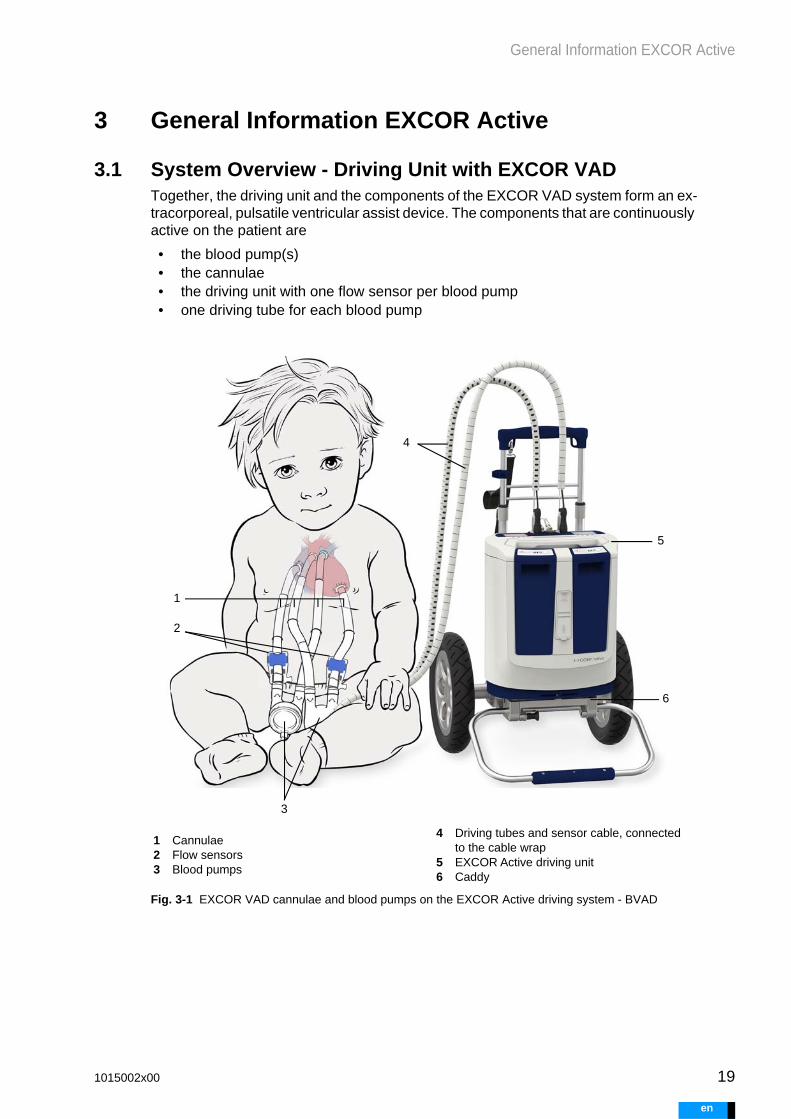
3.1 System Overview - Driving Unit with EXCOR VADTogether, the driving unit and the components of the EXCOR VAD system form an ex-tracorporeal, pulsatile ventricular assist device. The components that are continuously active on the patient are
• the blood pump(s)• the cannulae• the driving unit with one flow sensor per blood pump• one driving tube for each blood pump
Fig. 3-1 EXCOR VAD cannulae and blood pumps on the EXCOR Active driving system - BVAD
1 Cannulae2 Flow sensors3 Blood pumps
4 Driving tubes and sensor cable, connected to the cable wrap
5 EXCOR Active driving unit6 Caddy
1
2
3
4
5
6
1015002x00 19
en

20
General Information EXCOR Active
e
3.2 Components and Locations of Use
3.3 Scope of Driving Unit FunctionalityThe scope of the driving unit’s functionality depends on the model.
Mobile components for use in the hospital and healthcare environ-ments, suitable for use in indoor and outdoor areas
Stationary components for use in the hospital, suitable for indoor use
Driving unit
Flow sensor with cable wrap
Battery
Caddy
Baby buggy
Accessory Bag
Manual pump
Battery charging unit
Power Supply Unit for Driving Unit and Battery Charging Unit
Panel PC
Docking Station
Panel PC power supply unit
Adapter for external alarm (nurse call)
USB cable
USB stick
Tab. 3-1 Components of the EXCOR Active system
+
Driving unit
1502200 1502210
Operating mode BVAD: BVAD:
LVAD LVAD
RVAD —
Blood pump 10 mL 10 mL
15 mL 15 mL
25 mL 25 mL
30 mL 30 mL
50 mL 50 mL
60 mL 60 mL
80 mL —
Tab. 3-2 Overview of driving unit functionalities by model
1015002x00
n

General Information EXCOR Active
3.4 Intended Use
3.4.1 Use
The EXCOR Active system is an electro-pneumatic driving system for the EXCOR ventricular assist device. The EXCOR Active system may only be used for uni- or biventricular circulatory support.
• LVAD- indicated for patients with sole left ventricular failure• RVAD- indicated for patients with sole right ventricular failure• BVAD- indicated for patients with identifiable failure of both the left and right ven-
tricles
All decisions regarding the selection of components as well as the care of the patient are the sole responsibility of the treating physician. The recommendations made in these instructions for use are based on the experiences of Berlin Heart. Before thera-py with the EXCOR system, the treating physician must conduct a medical evaluation of the mental and physical compliance of the patient.
EXCOR VAD in combination with EXCOR Active may only be used in combination with EXCOR VAD system components, and only in accordance with the indications, contraindications, and instructions for use.
Patient population
The EXCOR VAD ventricular assist device is designed for use on the hearts of pa-tients ranging in age from newborn to adult.
Target cardiac output is based on patient size, weight, and body surface area. This information is used in order to select a combination of blood pumps and cannulae that will meet the patient’s medical needs.
The intended patient population may be restricted depending on country-specific ap-provals.
Professional users
EXCOR VAD and EXCOR Active may only be implanted and configured by medical personnel. Medical personnel are persons considered professional users who have the necessary medical expertise, e.g., surgeons, VAD coordinators, cardiovascular perfusionists, etc. EXCOR VAD and EXCOR Active training is a prerequisite.
Lay users
EXCOR Active can be used by patients or caregivers without medical knowledge. Pa-tients and caregivers must receive training from the hospital. They must be able to identify critical situations and react to them appropriately. Operation of the system by the patient is contingent upon the patient’s mental and physical capability of doing so.
Intended conditions of use and usage environments
EXCOR VAD in combination with EXCOR Active is suitable for indoor and outdoor use in professional healthcare facilities.
The device can be operated on mains power as well as using the included batteries. The system can switch between power sources without operational downtime. EXCOR VAD is used for continuous patient care. How long EXCOR VAD and EXCOR Active are used depends on the patient’s particular indication.
1015002x00 21
en

22
General Information EXCOR Active
e
3.4.2 Indications, Contraindications, and Potential Therapeutic Objec-tives
The indications, contraindications, and potential therapeutic objectives for EXCOR VAD apply to EXCOR Active in connection with EXCOR VAD. These are de-scribed in the EXCOR Sterile Components instructions for use.
Heed the instructions for use on EXCOR sterile components!
3.5 EMC - Electromagnetic CompatibilityEXCOR Active is shielded against electromagnetic radiation, including both electro-magnetic emissions and electromagnetic disturbances. Nevertheless, electromagnet-ic radiation can cause disruptions. Disruptions may occur if the minimum distance to a source of interference is not observed.
Potential sources of interference include
• Mobile communication• WLAN• Bluetooth• Radio installations• Insufficiently shielded electrical devices• Security-check devices, such as security scanners• Magnetic resonance imaging scanners• Magnetic levitation trains
See chapter 23: EMC, page 201 for more detailed information on electromagnetic compatibility.
Possible consequences could include
• Modified filling and emptying of the blood pump• View on the display of the driving unit and the panel PC is modified• Faulty alarms
Major performance characteristics are described in section 23.2: Major Performance Characteristics, page 201.
3.6 Combination with Other Products and Procedures
Permitted combinations
The EXCOR Active system is to be operated exclusively with components of the EXCOR VAD system. Take all indications, contraindications, and instructions for use into account. An overview of the blood pumps and cannulae to be used, as well as in-formation on their possible combinations, can be found in the EXCOR Sterile Compo-nents instructions for use.
Heed the instructions for use on EXCOR sterile components!
1015002x00
n

General Information EXCOR Active
Impermissible combinations
Combination with the following diagnostic procedure is not allowed:
• magnetic resonance imaging
Permitted
Combination with the following diagnosis/therapy procedures is permitted:
• high-frequency surgery, diathermy (flow measurement may be disrupted for the duration of the high-frequency surgical procedure).
• radiotherapy• nuclear diagnostics / nuclear therapy• CT scans• electrostimulation therapy• therapeutic ultrasound (e.g. lithotripsy)
Other combinations
No other devices may be connected to the EXCOR Active system; otherwise, the elec-trical safety of the patient cannot be guaranteed.
Combinations with other products or procedures not expressly approved here is at the discretion of the treating physician.
3.7 Replacement ComponentsSuitable types, quantities and sizes of the following components must be available at the hospital for replacement purposes:
• for LVAD and RVAD patients: driving unit (EXCOR Active or Ikus)• for BVAD patients: EXCOR Active, configured with patient’s current settings• flow sensor including cable wrap• red-marked and/or blue-marked driving tube• blood pump• T00L-002• connector set, cannula extension set, if required for therapy
3.8 Information Regarding the Instructions for UseThe instructions for use are a part of the EXCOR system. Please keep the instructions for use in a safe place. In the event of loss or damage, another copy of the instructions for use can be requested from the manufacturer. You can download the instructions for use from the manufacturer’s website. See chapter 1: Contact, page 13.
3.9 Disposal of Components
General
Electronic components may be returned to the Manufacturer for professional disposal. Professional disposal of all other components is the responsibility of the operator.
Batteries
Defective batteries may not be returned to the manufacturer. Old or defective batteries must be disposed of in accordance with local regulations.
1015002x00 23
en

24
General Information EXCOR Active
e
Medical waste
Dispose of explanted cannulae, used blood pumps, and contaminated disposable items in accordance with the valid local, state, and national laws and guidelines re-garding medical waste.
3.10 Product Life
Reaching the intended product life for the components depends on proper use and ad-herence to the specified inspection and maintenance intervals. See chapter 18: Main-tenance, Cleaning and Disinfection, page 171 for more information.
Component Product life in years
Driving unit 6
Battery 1
Power Supply Unit for Driving Unit and Battery Charging Unit
3
Panel PC including docking station and power supply unit
6
Flow sensor 6
Manual pump 6
Battery charging unit 6
Caddy 6
Accessory Bag 2
Baby buggy 6
Adapter for external alarm 6
USB cable 6
USB stick 6
Tab. 3-3 Product Life - Components
1015002x00
n

Safety Information
WARNING
WARNING
4 Safety Information
4.1 General
Use EXCOR only in accordance with its intended use! Otherwise, safe and proper operation of EXCOR is not guaranteed.
Only professional medical personnel with product-specific training may elect to use EXCOR and configure EXCOR. Training is offered by the manufacturer. Contact the manufacturer or the distributor for product trainings. For contact infor-mation, see: chapter 1: Contact, page 13.
Only use components that are in perfect working order! Components that are visibly damaged must not be used and must be replaced im-mediately.
Do not make any changes to system components. Do not open or dis-assemble any components!
Only use EXCOR Active with components of the EXCOR VAD system. Components made by other manufacturers may only be used together with EXCOR Active if their use is specified in the instructions for use, and if the components are supplied by Berlin Heart.
Only use, handle, and service the components of the EXCOR Active system appropriately, as described in the instructions for use.
Install and configure the components of the EXCOR Active system in accordance with the instructions for use.
Do not continue to use components after they have reached the end of their product life. If these warnings are not heeded, safe and proper op-eration is not guaranteed. Information on product life is given in section 3.10, page 24.
To prevent endangerment of patient safety, users must learn and un-derstand the contents of these Instructions for Use. Read the instruc-tions for use before using EXCOR. Follow the instructions as described.
Otherwise, the safe and smooth operation of EXCOR is not guaranteed. This could result in, for example, insufficient support, blood loss, electric shock or strangulation.
4.2 Configuration
Keep a replacement configured driving unit on hand for BVAD patients at all times! This driving unit must be kept at the ready under conditions like those described in Tab. 20-9 , page 192. If this is not the case, there is no guarantee that the driving unit can be replaced in reason-able time. This could result in, for example, insufficient patient support.
1015002x00 25
en
26
Safety Information
e
WARNING
WARNING
Have an EXCOR Active or an Ikus on hand in the hospital at all times as a backup. Medical personnel must be trained in the use of the back-up system. Medical personnel must be available in the hospital at all times.
4.3 Caregivers
Patients who are not physically or mentally capable of operating EXCOR Active correctly, or patients who do not understand how to use the system safely, must be supervised at all times. This also applies to patients who have not yet received EXCOR Active training.
4.4 Ambient Conditions
Do not operate EXCOR Active in ambient conditions under which heavy condensation could form! In particular, avoid transitions from very cold to humid and warm.Avoid extreme fluctuations in temperature.
Before commissioning of EXCOR Active, the system must have adapt-ed to the ambient temperature. This applies, for example, after trans-portation or storage in different temperatures. Otherwise, condensation could form. Water condensation can damage electrical and pneumatic components. As a result, the safe and smooth operation of EXCOR would not be guaranteed. Follow the instructions in section 20.9.3: Transport Conditions and Long-Term Storage Conditions, page 193
Observe the minimum and maximum ambient temperatures for the components of the EXCOR Active system. If these warnings are not heeded, safe and proper operation is not guaranteed. Possible conse-quences could be the failure of components due to overheating, or loss of functionality due to low temperatures. For information on ambient temperatures, see section 20.9: Ambient Conditions, page 192.
Do not expose the electrical components to direct radiant heat, e.g., in-tense, direct sunlight or positioning directly beside a heater. Do not cov-er the air vents on the driving unit or the battery charging unit. If there is poor ventilation, heat will accumulate.If component temperatures exceed permitted thresholds, it could result in functions failing.
Electrical components that are not protected from penetration of spray water must be protected from moisture. The IP protection type indi-cates the device’s degree of protection against the ingress of liquids. For information on IP protection types, see chapter 20: Technical Spec-ifications, page 187.
Do not operate EXCOR Active in an oxygen-enriched environment (ox-ygen percentage above 25%)! Otherwise there will be a greatly in-creased risk of fire.
1015002x00
n

Safety Information
WARNING
WARNING
Do not use EXCOR Active in the vicinity of flammable gases! Otherwise there is a risk of explosion from ignition of the gas mixture.
Observe correct storage conditions for all EXCOR System compo-nents, see section 20.9.2: Storage Conditions, page 193. Failure to maintain correct storage conditions could damage components, short-en product life, and delay usability in emergency situations.
Only place the driving unit (alone or in combination with a transport sys-tem) on stable, level, horizontal surfaces. Otherwise, the driving unit could tip over or fall down. This could cause damage to the driving unit. It could result in disruption of driving unit support.
Do not use liquids to cool the driving unit. Liquids that seep in could damage the driving unit. To cool the driving unit, seek out a cooler en-vironment.
4.5 Diagnostic Procedures, EMC
Prevent any exposure to strong electromagnetic radiation. Adhere to the cautionary measures. Suitable cautionary measures are described in these instructions for use, see chapter 3.5: EMC - Electromagnetic Compatibility, page 22.
Do not conduct magnetic resonance therapy in patients with EXCOR Active!
Do not operate the driving unit in the immediate vicinity of other electri-cal devices. If such circumstances cannot be avoided, e.g. in a hospital environment, monitor the driving unit closely.
When using the driving unit, observe the EMC specifications, particu-larly when using the driving unit in conjunction with other therapies and procedures.
When using X-ray diagnostic methods: Protect the driving unit, includ-ing the flow sensors, from exposure to X-rays. Protect the driving unit with radiation-blocking material, or place the driving unit outside the area of X-ray exposure. Disconnect the flow sensors from the cannulae and position them outside the irradiated area.
Strong electromagnetic radiation could damage the electrical components of EXCOR Active and impair its operation.
4.6 Connections and Operation Elements
To connect the electrical devices, only use the mains power cables supplied. Use of other mains cables could result in reduced immunity. The electromagnetic emission could be elevated and affect the opera-tion of other devices.
1015002x00 27
en

28
Safety Information
e
WARNING
WARNING
Only connect electrical components to fixed mains power outlets. Do not use extension cables. Take into account the protection class of the power outlet and components!
Do not touch the electrical contacts on a component and the patient at the same time. Doing so could cause contact voltage to reach an intra-cardial area. which could harm the patient.
4.7 Power Supply
When switching from mains to battery operation, check the charge level of the batteries. If a longer period of non-mains operation is anticipated, check the charge levels of the replacement batteries as well. Do this by pressing the <charge level button> on the battery. If a power supply is not available, the driving unit will stop.
When using the system in mobile operation, always ensure that an al-ternative source of power can be reached within the battery operating time. Keep in mind that batteries can also fail. Alternative sources of power could include: Replacement batteries, extra power supply unit with means of connecting to mains power.
4.8 Operation
Ensure that driving unit audible alarms can be reliably heard by medical personnel / caregivers at all times. Other methods of monitoring the driving unit, such as the external alarm (nurse call), must only be used as supplementary tools.
The values and data displayed assist in the monitoring and configura-tion of the EXCOR Active system. Other therapeutic measures must al-ways be reinforced through appropriate diagnostic procedures. Therapeutic measures must not be derived solely on the basis of the values and data shown on EXCOR Active.
1015002x00
n

Driving Unit
5 Driving Unit
5.1 Structure and Function
5.1.1 Primary Function
The driving unit contains two pneumatic units. Each pneumatic unit consists of one cylinder, inside of which a piston moves. The piston motion alternately produces driv-ing and suction pressures. These alternating pressures are transferred to the blood pump via the driving tube. As a result, the blood pump fills and empties.
The blood flow produced by the blood pump is measured by a flow sensor. Blood flow is continuously monitored and displayed.
Each pneumatic unit can drive one blood pump. If one pneumatic unit fails under uni-ventricular operation, the other pneumatic unit automatically assumes control of the blood pump. Pump output and parameters remain the same. The switching unit auto-matically switches to the other pneumatic unit, so the driving tube connections do not need to be changed.
If one pneumatic unit fails under biventricular operation, the other pneumatic unit will drive both blood pumps. The switching unit distributes pressure to the two blood pumps alternately. The system will switch between the two blood pumps with alternat-ing strokes. Patient support will be limited, see section 5.11: BVAD Emergency Oper-ation, page 65.
Fig. 5-1 Driving unit - functionality
1 Driving tubes - connection to the blood pumps
2 Switching unit3 Left pneumatic unit4 Right pneumatic unit5 Piston in the cylinder6 Motor
1
23 45
6
1015002x00 29
en

30
Driving Unit
e
The driving unit can be operated using mains power or two batteries. An integrated emergency battery is available as reserve.
5.1.2 Setup
Fig. 5-2 Driving unit front and control panel
1 Control panel2 Handle3 Batteries4 USB port cover (connection to Panel
PC)5 External alarm (nurse call) cover6 Air vents
Fig. 5-3 Driving unit rear side and underside
1 Mounting bracket2 Air vent3 Speaker4 Identification plate5 Maintenance label6 Additional information, including dis-
tributor information if applicable7 Tray for patient-specific label:
Patient ID
1
2
3
4
6
6
5
1
4
6
7
5
2
3
22
1015002x00
n

Driving Unit
5.2 Connections and Operation Elements
5.2.1 Control Panel
The control panel is divided into two sides. The red side is used to control left circula-tory support, and the blue side controls right circulatory support. The connection for the power supply unit is located in the middle.
The red and blue drive sides have identical setups. Each side consists of a display, indicator lights, button, driving tube connection, and flow sensor connection.
Fig. 5-4 Control panel
5.2.1.1 Indicator Lights
5.2.1.2 Button
1 Display2 Maintenance LED3 Battery LED4 Driving unit LED
5 Button6 Connection - driving tube / seal plug7 Connection - flow sensor8 Connection - power supply unit / cap
2 3 4 5 6 7 81
There are maintenance, battery, and driving unit LEDs underneath each display. The LEDs indicate notification messages or errors. Each set of LEDs refers to its corresponding drive side. The LEDs light up or flash depending on message priority, see section 17.3.6: Visual Alarms on the Driving Unit, page 157.
Each drive side has a <button>. The button serves multiple func-tions.
Function Press Result
Audio paused 1x. Switches off the audible alarm for a set period of time if a message appears. The display switches to the ERROR view.
Navigation through the views
1x. The display switches to the next view.
Navigation through the list of errors
1x. The next error is displayed.
1015002x00 31
en

32
Driving Unit
e
5.2.1.3 Display
The display shows information for the corresponding driving unit side. Information that is applicable to the driving unit as a whole is shown on both displays. The <button> on the control panel can be used to switch to the next display view. The status bar is displayed in every view.
Display setup
Fig. 5-5 Display – configuration overview
Status bar symbols
The status bar provides information on current driving unit status. Information is shown using symbols.
Switching off the driv-ing unit
Both buttons simultaneously for around five sec-onds
The SHUTDOWN view is displayed.
The driving unit can be switched off by disconnecting the mains or removing both batteries. For shut-down information, see also section 5.6: Switching Off the Driv-ing Unit, page 50.
Charging the emer-gency battery
Press and hold one button while connecting the device to mains power
The driving unit can be connected to the mains without starting. This function allows for charging of the replacement driving unit’s emer-gency battery. For information on emergency battery charging, see also section 5.7.3: Emergency Bat-tery, page 58.
Switching on display illumination
1x. When a <button> is pressed, the illumination on the corresponding display is switched on.
1 Status bar2 Bars3 Display area4 Symbol
1
3
2
4
1015002x00
n

Driving Unit
Symbol Significance
ALARM
An alarm condition is in place. The driving unit emits audible alarm signals. Once the alarm condition has been rectified, the symbol dis-appears. If the <button> is pressed, the display switches to AUDIO PAUSED.
AUDIO PAUSED
An alarm condition is in place. The driving unit does not emit audible alarm signals for a period of time. Once the alarm condition has been rectified, the symbol disappears. If the alarm condition is still valid, the ALARM symbol will reappear after the pause.
AUDIO OFF
The audible alarm is switched off. AUDIO OFF cannot be specifically selected by the user; it is only available under the user profiles EXPERT or MEDICAL. The driving unit remains in status Audio off even when not configured.
NUMBER OF ACTIVE ALARMS
The display shows “Alarm x of n active alarms”. The total number of active alarms is only displayed in the ERROR view.
In the example: Alarm 1 / 2 total alarms
In all other views, the number of active alarms is displayed.
CHILD PROTECTION ON
Displays that child protection is active.
When child protection is active, audible alarms will be emitted for around 15 seconds after PAUSE AUDIO is pressed. This gives caregiv-ers and medical personnel a chance to hear the audible alarm even after the child confirms the alarm.
MAINS OPERATION
The driving unit is connected to the mains. If there is no mains, the symbol will not appear.
RELATIVE STATE OF CHARGE AND CHARGING DISPLAY FOR BATTERIES / EMERGENCY BATTERY
BATTERY: Displays the relative charge level of the battery as well as the charging display.If the battery is charging, the symbol will be animated. If the battery is not charging, the charge level will be displayed. If no battery is dis-played, no battery has been inserted.
EMERGENCY BATTERY: In CHARGING EMERGENCY BATTERY mode, the symbols are used to indicate the relative state of charge for the emergency battery.
ACTIVITY
A moving dot signals that the display is active.
1015002x00 33
en

34
Driving Unit
e
Views
The display has six views. The views are arranged in a fixed order. Use the contents of the display area, the view marker, and the view symbol in the bottom right to deter-mine which view is currently being shown. The ALARM and ALARM HISTORY views may have sub-views showing current alarms and/or previous alarms that have been re-solved.
Operation view
After start-up and when in error-free operation, the display appears as shown in Fig. 5-7 . If an error condition occurs, the error code, message, and number of errors are displayed.
Fig. 5-7 Display of view – Error-free operation
Depicted in the example: Child protection is active. The driving unit is connected to mains power. The battery is fully charged. The Activity view is shown. No alarm con-ditions are in place.
Fig. 5-6 Display - example Info view
1 View marker2 Content of display area3 View symbol
1. Operation
2. Error
3. Flow
4. Info
5. Maintenance
6. Error history
12
3
1015002x00
n

Driving Unit
Error view
Error messages are displayed on the Start screen. When the button is pressed, audi-ble alarms are paused, and the ERROR view is shown. The following appears:
If the driving unit is set to the non-verbal version, only the alarm code will be displayed. Messages and instructions can be looked up in the short instructions.
If multiple errors occur simultaneously, use the button to page through all current er-rors.
Flow Display view
Displays the current flow for the left and/or right blood pump.
Info view
Display showing the current driving parameters. The values apply to the correspond-ing driving unit side.
• S: Driving pressure in systole [mmHg]• D: Driving pressure in diastole [mmHg]• R: Rate [bpm]• %: Duration systole [%]
Fig. 5-8 Display of view – Error
1 Alarm paused2 Display of current errors; error 1
of 2 is currently being displayed3 Display of error codes and mes-
sage
Alarm code H2
Message Flow too low
Instructions >> Check driving tube, blood pump, and cannulae
Fig. 5-9 Display of view – Flow; LVAD
1 Display of the current flow left in [l/min]
2 Display of the current flow right in [l/min]
1 2
3
1
2
1015002x00 35
en

36
Driving Unit
e
Maintenance view
Displays information regarding MAINTENANCE and the driving unit software version.
The following is displayed:
Maintenance is to be conducted after one year or 34 million pump cycles, whichever comes first. An active driving unit emits an alarm before reaching the maintenance date. The expected date of next maintenance is calculated based on rate settings and displayed, see also section 7.6.3: System Information, page 89.
Error History view
The ERROR HISTORY view shows the last five rectified errors.
Fig. 5-10 Display of view – Info
Fig. 5-11 Display of view – Maintenance
1 Driving unit software version2 Expected date of next mainte-
nance3 Pump cycles
pump cycles conducted / number of cycles after which maintenance is required
expected date of next maintenance
driving unit software version
1 2 3
1015002x00
n

Driving Unit
For each error, the
• error code and message text (no message text with non-verbal setting)• date and time of occurrence• duration of the alarm
are displayed.
Shutdown
If both buttons are pressed for five seconds, the symbol SHUTDOWN appears. The driv-ing unit can now be disconnected from the power supply. The driving unit switches off after the disconnection. The countdown shows the time remaining for disconnection. See also section 5.6: Switching Off the Driving Unit, page 50.
Charging the emergency battery
The emergency battery is charged when one of the buttons is pressed when connect-ing to the mains. The battery symbol appears in the display. The charge level is dis-played. See also section 5.7.3.2: Charging the Emergency Battery, page 58.
When one driving unit is active, the emergency battery charges automatically when the unit is running on mains power. Automatic emergency battery charging is not dis-played.
Fig. 5-12 Display of view – Maintenance
1 Error code2 Date3 Duration of the alarm
Fig. 5-13 Display of view – Shutdown
1 Countdown: Time to disconnect the power supply in seconds
2 Shutdown symbol
1
23
1
2
1015002x00 37
en

38
Driving Unit
e
WARNING
Start test
Fig. 5-15 Display view – Start test
A driving unit that has not yet been configured will automatically perform
a start test upon starting up, see section 5.4: Start Test for the Driving Unit, page 50.
5.2.2 Connections
Close any unused connections sockets. Dirt and liquids could pene-trate the driving unit through open connection sockets. Dirt and liquids could damage the driving unit itself as well as any connected compo-nents.
Only properly inserted connector plugs can guarantee the system's op-eration. Loose plug connections can interrupt patient care or disrupt the flow of information. Pay attention to the markings. Never use excessive force when plug-ging in. Always push the connector plugs all the way in. After plugging in, check the connection.
Fig. 5-14 Display view – Charge emergency battery
1 Emergency battery charge level
1
1015002x00
n

Driving Unit
5.2.2.1 Overview of Connections
Fig. 5-16 Connections on the control panel
Fig. 5-17 Connections on the front panel with cover closed and open
5.2.2.2 Connecting and Disconnecting Driving Tubes
The driving tube transfers the driving and suction pressures from the driving unit to the blood pump.
1 Driving tube left blood pump2 Flow sensor left blood pump3 Power supply unit connection (under the
cover)4 Driving tube right blood pump5 Flow sensor right blood pump
1 USB, connection to the panel PC2 Connection adapter for external alarm
(nurse call)
1 2 3 4 5
1
2
1. Pull out the seal plugs and put them in the holder.
2. Grasp the connector plug by its ribbed body.
3. Insert the connector plug into the appropriate connector.driving tube marked in red - red connectiondriving tube marked in blue - blue connection
Fig. 5-18 Plugging and checking
4. In the end position, the connector plug will snap into place. The plug is locked and cannot disengage itself.
5. Check the connector plug for correct positioning. To do so, hold the fixed por-tion of the plug body and pull lightly. The plug may not loosen itself from the connection socket. It is important to ensure proper plug connections so that the connector plugs do not accidentally come loose and interrupt care.
6. To pull the connector plug out, grasp the ribbed area and pull upwards.
1015002x00 39
en

40
Driving Unit
e
5.2.2.3 Connecting the Power Supply Unit to the Driving Unit
5.2.2.4 Disconnecting the Power Supply Unit from the Driving Unit
5.2.2.5 Connecting to the Panel PC
A USB cable connects the panel PC to the driving unit in order to allow data transfer between the two.
1. Open the cap.2. Grasp the connector plug by its
ribbed body (1).3. Align the markings on the con-
nector plug and the connector.4. Insert the connector plug into
the connector.5. The connector plug will snap
audibly into place. When the device is connected to mains power, a brief signal tone will be emitted. 1 Connector plug
2 Marking
21
1. To pull the connector plug out, grasp the ribbed area and pull upwards.
2. Close cap
1. Open the top cover.
2. Plug the USB cable into the driv-ing unit.
1 Cover2 USB connector
1 2
1015002x00
n

Driving Unit
WARNING
5.2.2.6 Connecting the External Alarm (Nurse Call) Adapter
The adapter for the external alarm (nurse call) connects the driving unit with a hospital alarm system. The driving unit emits a signal as soon as a medium- or high-priority alarm occurs. This signal can be forwarded to the hospital alarm system.
To be able to use the external alarm (nurse call) function, the hospital must prepare a suitable connector - see chapter 22: Using the External Alarm (Nurse Call), page 199 for more information.
5.2.3 Flow Sensor
Flow measurement is only active when the flow sensors are connected to the driving unit and the cannulae. Flow alarms are only emitted if a flow alarm threshold has been set.If no flow sensors are connected or no flow alarm threshold has been set, make sure to monitor the blood pumps to ensure that they are filling and emptying completely.
The flow sensors are not sterile. Do not connect the flow sensors to the cannulae until the patient’s thorax has been closed. If the patient’s tho-rax must temporarily remain open, protect the thorax with a temporary wound closure before connecting the flow sensors.
3. Insert the USB cable into the panel PC or docking station.
3 USB cable on panel PC
3
1. Open the bottom cover.
2. Plug in the external alarm (nurse call) adapter.
3. Connect the external alarm (nurse call) adapter to the hospital connection.
1015002x00 41
en

42
Driving Unit
e
The flow measurement displayed may deviate from the actual flow, see Tab. 5-2 , page 44. Use only flow progression over time for diagnostic purposes, see section 7.7.2: Trend Info, page 91. Progression over time is only mean-ingful provided that other conditions (parameters, blood pumps, driving unit, flow conditions within cannulae) have remained the same.
Only use flow sensors in combination with protective caps. Using flow sensors without protective caps can damage the skin.
Always attach the flow sensor correctly to the cannula and the blood pump, see section 5.2.3.3: Attaching the Flow Sensors to the Cannulae and the Blood Pumps, page 45. Make sure that the correct sensor lock-ing clip is always used. The sensor locking clip and flow sensor colors need to match, see Fig. 5-19 , page 42.
5.2.3.1 Setup
The flow sensor measures the blood flow within a cannula. The measured values are displayed on the driving unit and the panel PC. An alarm is emitted in the event of in-sufficient support. The Flow alarm threshold (the value below which an alarm is emit-ted) can be set manually. Always set the flow alarm threshold to a level that will ensure that an H2 FLOW TOO LOW alarm will be emitted in the event of insufficient support.
The flow sensor can be connected to either the inflow or the outflow cannula. It can also be switched from the inflow to the outflow side if cannulation permits, see Tab. 5-1 , page 44.
The flow sensor has a stop to help users position it correctly on the blood pump. Use the mirror to check the underside of the cannula without having to remove the flow sensor. On staged cannulae, the connection between the cannula and the connector is not within the visibility range of the mirror. In such cases, the flow sensor will need to be removed when inspecting the cannula.
Fig. 5-19 Flow sensor and color marking
1 Sensor locking clip2 Protective cap3 Sensor quick connect4 Stop5 Sensor cable
1
2
3
4
5
Color marking
1015002x00
n

Driving Unit
Sensor models
There are matching flow sensors for the different cannula sizes and blood pumps. The flow sensor label indicates the cannula-blood pump combination for which the flow sensor is designed.
Fig. 5-20 FS06-06-P flow sensor on a 6 mm cannula
1 Cannula2 Flow sensor3 Sensor locking clip4 Protective cap5 Mirror6 Sensor quick connect7 Stop8 Sensor cable
Fig. 5-21 FS06-06-P FS09-09-P FS12-12-P
Fig. 5-22 Model label
1 Cannula diameter2 Connector diameter3 Blood pump type, pursuant to
information on flow sensor and blood pump: P10P-001 or P50C-001
1 2 3 4 5 6 87
FS06 - 06 - P
121 3
1015002x00 43
en

44
Driving Unit
e
Example
• FS - Flow sensor• 06 - 6 mm cannula diameter• 06 - 6 mm blood pump connector• P - For blood pumps with tri-leaflet polyurethane valves
Only use the intended flow sensors. Flow sensors that are too small could pinch the cannulae. Incorrectly sized flow sensors will not fit optimally and may yield inaccurate, incorrect, or no measured values.
5.2.3.2 Measurement Accuracy and Alarms
As with all measurement processes, flow measurements have a certain degree of ac-curacy. When assessing the flow rate displayed, this degree of accuracy must be tak-en into account. The flow is shown rounded to one decimal place.
Cannula diameter Blood pump connector diameter
For blood pumps with
FS06-06-P. 6 mm and 5/6 mm 6 mm Tri-leaflet polyure-thane valve
FS09-09-P. 9 mm 9 mm Tri-leaflet polyure-thane valve
FS09-12-P. 9 mm / 12 mm using stage
12 mm Tri-leaflet polyure-thane valve
FS12-12-P. 12 mm 12 mm Tri-leaflet polyure-thane valve
FS09-12-C. 9 mm / 12 mm using stage
12 mm Bileaflet valve
FS12-12-C. 12 mm 12 mm Bileaflet valve
Tab. 5-1 Flow sensor model overview
Measurement accuracy within the measurement range
FS06-06-P ± 15% within the range of 0.6 l/min to 2 l/min
FS09-09-P
± 15% within the range of 0.9 l/min to 5 l/minFS09-12-P
FS09-12-C
Tab. 5-2 Flow measurement accuracy
1015002x00
n
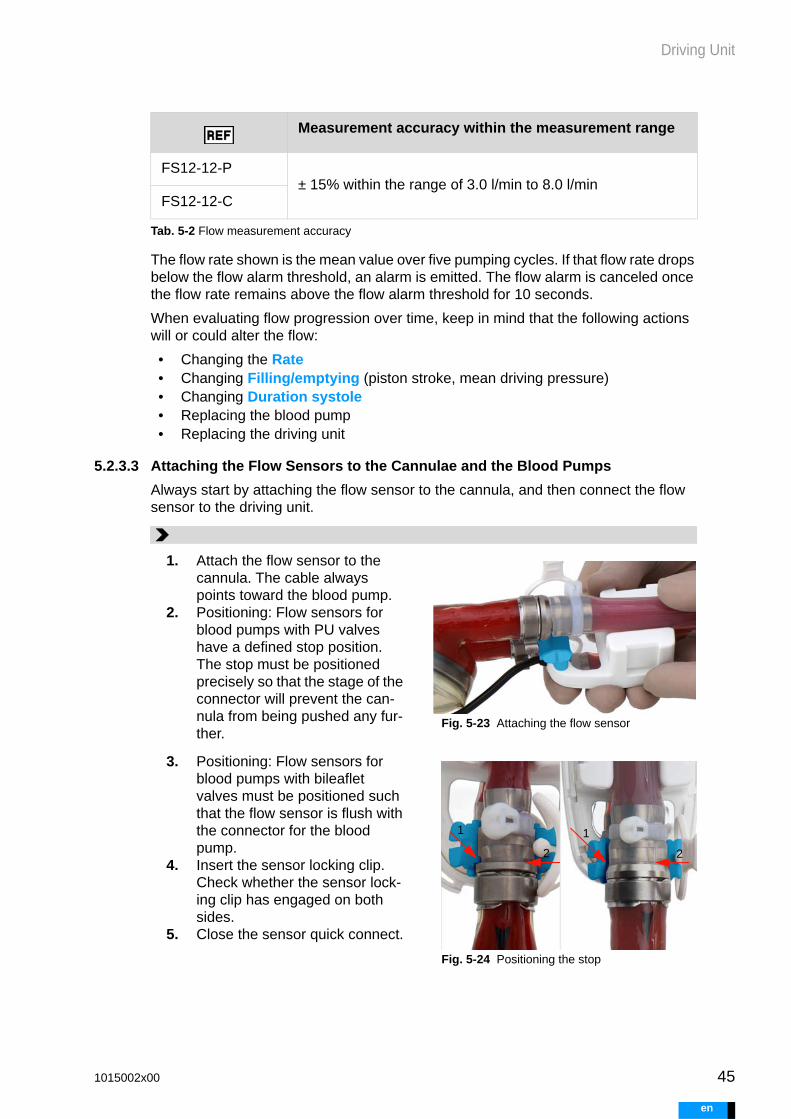
Driving Unit
The flow rate shown is the mean value over five pumping cycles. If that flow rate drops below the flow alarm threshold, an alarm is emitted. The flow alarm is canceled once the flow rate remains above the flow alarm threshold for 10 seconds.
When evaluating flow progression over time, keep in mind that the following actions will or could alter the flow:
• Changing the Rate• Changing Filling/emptying (piston stroke, mean driving pressure)• Changing Duration systole• Replacing the blood pump• Replacing the driving unit
5.2.3.3 Attaching the Flow Sensors to the Cannulae and the Blood Pumps
Always start by attaching the flow sensor to the cannula, and then connect the flow sensor to the driving unit.
FS12-12-P± 15% within the range of 3.0 l/min to 8.0 l/min
FS12-12-C
Measurement accuracy within the measurement range
Tab. 5-2 Flow measurement accuracy
1. Attach the flow sensor to the cannula. The cable always points toward the blood pump.
2. Positioning: Flow sensors for blood pumps with PU valves have a defined stop position. The stop must be positioned precisely so that the stage of the connector will prevent the can-nula from being pushed any fur-ther.
Fig. 5-23 Attaching the flow sensor
3. Positioning: Flow sensors for blood pumps with bileaflet valves must be positioned such that the flow sensor is flush with the connector for the blood pump.
4. Insert the sensor locking clip. Check whether the sensor lock-ing clip has engaged on both sides.
5. Close the sensor quick connect.
Fig. 5-24 Positioning the stop
1 1
2 2
1015002x00 45
en

46
Driving Unit
e
5.2.3.4 Removing the Flow Sensor from the Cannula
5.2.3.5 Replacing the Sensor Quick Connect
5.2.3.6 Connecting/Disconnecting the Flow Sensor to/from the Driving Unit
1. Open the sensor quick connect (1).
2. Pinch the sensor locking clip (2) together at the top.
3. Remove the sensor locking clip.4. Remove the flow sensor from
the cannula.
Fig. 5-25 Removing the flow sensor
1
2 2
1. Attach the sensor quick connect (1) to the flow sensor.
2. Attach the sensor quick connect (2).
3. Close (3).4. To change the closure side,
rotate the sensor quick connect (4) or attach it to the other side. Fig. 5-26 Closing the sensor quick connect
Replace worn or lost sensor quick connects. Corresponding sensor quick connects are available for all sizes of flow sensors.
Fig. 5-27 Sensor quick connect for flow sen-sors FS06, FS09, FS12
1 23
4
06 09 12
1. Grasp the connector plug under-neath by the ring.
2. Align the white markings.3. Using light force, press the ring
downwards and turn it in the direction of the green arrow until it reaches the stop position.
4. To release the connection, turn the ring in the direction of the white arrow. The plug will release itself.
Fig. 5-28 Insert the flow sensor
1015002x00
n

Driving Unit
5.2.3.7 Guiding the Driving Tube and the Flow Sensor Cable in the Cable Wrap
1. Draw the cable wrap up from the blood pump toward the driving unit.
2. Align the driving tube and sen-sor cable.
3. Insert the driving tube and the sensor cable into the wrapping tool.
4. Attach the cable wrap to the wrapping tool
5. Slowly guide the wrapping tool along the cable wrap with one hand while grasping the cable wrap with the other. Avoid creat-ing tensile force on the blood pump or the cannulae.
6. At the end, guide the driving tube and sensor cable out of the wrapping tool. The sensor cable will need to form a small loop by the driving unit. The loop makes plug insertions easier.
7. Insert the flow sensor into the corresponding connector. Make sure to keep left and right in mind.
1015002x00 47
en

48
Driving Unit
e
WARNING
5.2.3.8 Removing the Cable Wrap
5.2.4 Carrying System and Locking Mechanism
Make sure to lift and carry the driving unit by the handles designed for this purpose, meaning the handle on the driving unit and the handle on the caddy. Otherwise, safe and proper operation of EXCOR is not guar-anteed. It may result in damage to the driving unit or to connected com-ponents.
Do not carry the baby buggy (stroller, stroller board and driving unit). Together, they are very heavy. Attempting to carry the full weight could cause injury. The connections are not designed to bear that load. Sys-tem components could be damaged.
When positioning the driving unit on the intended system components, make sure that no parts become clamped. Pay attention to the driving tube and flow sensor cable. Any parts interfering with the locking sys-tem may disable the locking mechanism.
After positioning the driving unit on the intended system components, e.g. the caddy, check the locking mechanism. Check whether the han-dle is completely pushed in. The driving unit could come loose if not properly locked. This could cause damage to the driving unit. It could result in disruption of driving unit support. Damage could occur to the driving tube or the flow sensor cable.
1. Remove the cable wrap starting from the driving unit in the direc-tion of the blood pump.
2. Always hold the driving tube and sensor cable together. Pull the driving tube and sensor cable out of the cable wrap. Always draw them out of the cable wrap gradually, one small section at a time.
3. The cable wrap will open more easily if the driving tube is on top when pulling out. Make sure not to exert any tensile force on the blood pump or cannulae when pulling.
1015002x00
n

Driving Unit
5.2.4.1 Driving Unit Setup
• Handle: The handle is used to carry the driving unit as well as to lock the driving unit onto the transport system. Pulling out the handle releases the lock. Pushing it in sets the lock.
• Mounting bracket: Use the mounting bracket to attach the driving unit to the transport system using the mounting hook.
• Locking mechanism: The depressions on the underside of the driving unit posi-tion the driving unit on the mobile components. The locking mechanisms are found inside the depressions.
5.2.4.2 Setup of Mobile Components
5.3 Switching On the Driving UnitThe driving unit will switch on as soon as it is connected to a power supply. Its power supply sources include:
• connection to the mains via a power supply unit• one or two charged batteries
A previously configured driving unit will immediately begin operation, generating the suctioning and driving pressures for the blood pumps. An unconfigured driving unit must be configured before operation.
1 Handle2 Mounting bracket3 Mount
1
2
3
1 Mounting hook2 Mount
1
2
1015002x00 49
en
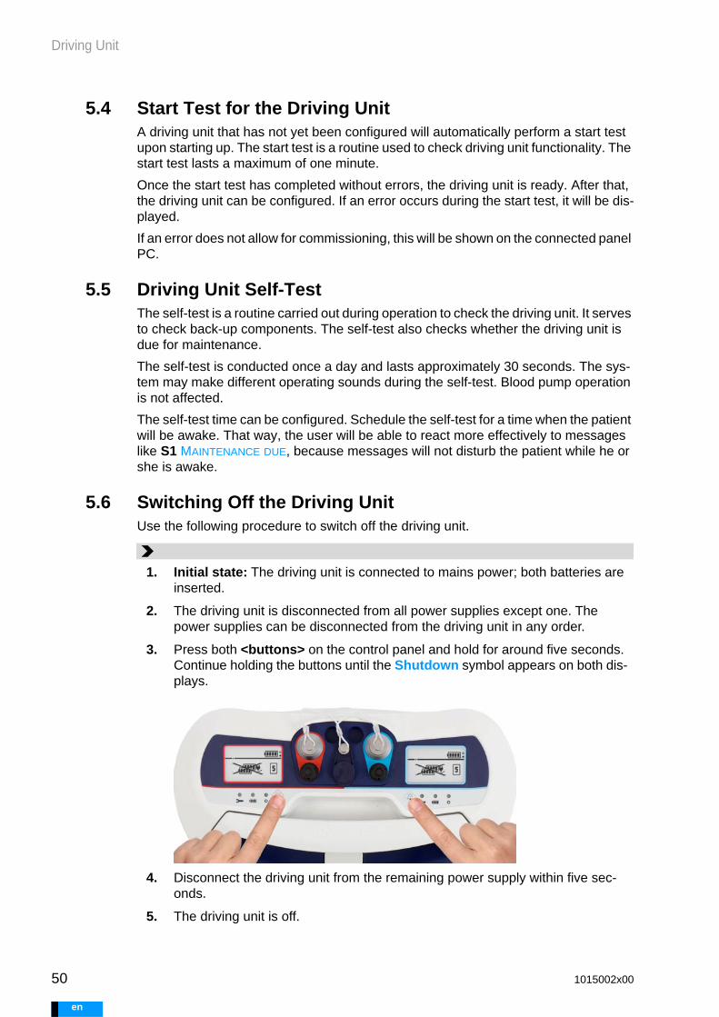
50
Driving Unit
e
5.4 Start Test for the Driving UnitA driving unit that has not yet been configured will automatically perform a start test upon starting up. The start test is a routine used to check driving unit functionality. The start test lasts a maximum of one minute.
Once the start test has completed without errors, the driving unit is ready. After that, the driving unit can be configured. If an error occurs during the start test, it will be dis-played.
If an error does not allow for commissioning, this will be shown on the connected panel PC.
5.5 Driving Unit Self-TestThe self-test is a routine carried out during operation to check the driving unit. It serves to check back-up components. The self-test also checks whether the driving unit is due for maintenance.
The self-test is conducted once a day and lasts approximately 30 seconds. The sys-tem may make different operating sounds during the self-test. Blood pump operation is not affected.
The self-test time can be configured. Schedule the self-test for a time when the patient will be awake. That way, the user will be able to react more effectively to messages like S1 MAINTENANCE DUE, because messages will not disturb the patient while he or she is awake.
5.6 Switching Off the Driving UnitUse the following procedure to switch off the driving unit.
1. Initial state: The driving unit is connected to mains power; both batteries are inserted.
2. The driving unit is disconnected from all power supplies except one. The power supplies can be disconnected from the driving unit in any order.
3. Press both <buttons> on the control panel and hold for around five seconds. Continue holding the buttons until the Shutdown symbol appears on both dis-plays.
4. Disconnect the driving unit from the remaining power supply within five sec-onds.
5. The driving unit is off.
1015002x00
n

Driving Unit
WARNING
WARNING
If the Shutdown symbol appears but power supply is not interrupted, the driving unit will continue running.
The driving unit cannot only be switched off by disconnecting the mains and removing both batteries. If the driving unit’s power supply is interrupted, the emergency battery will power the driving unit.
Avoid operating the device in emergency battery mode or discharging the emergency battery. If the driving unit is running on an emergency battery, reconnect the driving unit to a power supply and repeat the shutdown procedure.
5.7 Power SupplyThe driving unit can be operated using mains or battery power. Battery operation al-lows for mobile use of the driving unit.
Power supply components:
If mains and battery operation are both unavailable, the emergency battery will supply power.
A secure power supply is fundamental to uninterrupted operation. Select locations and plan mobile use such that power supply is guaranteed at all times. Keep in mind that mains power, batteries, or the power supply unit could potentially fail.
Arrange all EXCOR Active components with mains connections such that they are easy to disconnect from mains power. To disconnect components from the mains, pull the mains plug on the power supply unit.
If mains power fails, an alternative source of power must be made avail-able within the battery operating time. This power supply source must be capable of ensuring continued driving unit operation.
In the event that a power supply unit fails, the second power supply unit must be made available within the operating time of the current battery.
Charge the replacement driving unit's emergency battery once a month!
If a power supply is not available, the driving unit will stop.
5.7.1 Batteries
Never disconnect both batteries from the driving unit at the same time when the driving unit is being used with a patient. Disconnecting both batteries at the same time could endanger the patient.
Battery 4x - two in the driving unit plus two replacements
Power supply unit 2 units
Battery charging unit
1 unit, for simultaneous charging of two batteries
Emergency bat-tery
built into the driving unit, not replaceable
1015002x00 51
en

52
Driving Unit
e
The battery charge level display allows users to estimate how much longer the system can be used in mobile operation. This is a guideline value. Factors that determine the duration of mobile use: chapter 5.7.1.9: Driving Unit Operating Time in Battery Operation, page 56.
Batteries continue discharging even when not in use. Every two weeks, replace the batteries in the driving unit with the replacement batteries. Charge batteries that are not in use every three months. Failure to do so can shorten battery lifetime. It may also prevent the batteries from maintaining their guaranteed properties.
Store and transport batteries so as to protect them against short cir-cuits. Potential hazards could include metallic objects, such as keys, or liquids. A short circuit will cause the battery to discharge.
5.7.1.1 Inserting the Batteries
The driving unit has two identical battery mounts. Each of them holds one battery.
Grasp the battery by the recessed grip. Insert the battery into the lower guide first, then into the upper one, and push it downwards. In the bottom position, the battery will au-dibly snap into place. Press the battery downward if necessary.
Fig. 5-29 Inserting the battery into the battery mount
1 Locking plate2 Upper guide
3 Lower guide4 Contacts
12
3
4
1015002x00
n

Driving Unit
5.7.1.2 Removing the Batteries
5.7.1.3 Charging Batteries in the Driving Unit
To charge the batteries, insert them into the battery mounts. Two batteries can be charged at the same time. The charging process begins as soon as the power supply unit is connected. The charging process is shown on the display of the driving unit and on the batteries. Charging the batteries does not affect blood pump operation.
5.7.1.4 Charging Batteries in the Battery Charging Unit
See section 5.8: Battery Charging Unit, page 59.
5.7.1.5 Charging Replacement Batteries
Batteries discharge even when not in use. Every two weeks, replace the batteries be-ing used in the driving unit with the replacement batteries.
5.7.1.6 Charging Time
Batteries charge most quickly at room temperature. Cold batteries will not charge. Bat-teries may be cold as a result of having been transported at temperatures below 0°C or brought along during mobile operation. Allow the batteries to acclimatize. Charging is possible at a battery temperature of at least 5°C.
Charging time is not affected by whether one battery or two is being charged in the driving unit or the battery charging unit.
Fig. 5-30 Removing the battery
To remove a battery, reach into the recessed grip. Press the button on the grip upwards. Pull the battery upwards to remove it. When the driving unit is being used with a patient, never remove more than one battery at a time.
Component Charging time
Charging in the battery charging unit maximum 3 h
Charging in the driving unit maximum 7 h
Charging the emergency battery maximum 7 h
Tab. 5-3 Maximum charging time
1015002x00 53
en

54
Driving Unit
e
5.7.1.7 Checking the Battery Charge Level
The charge level of a battery can be read:
• on the battery, by pressing the <charge level button>• on the corresponding driving unit display• on the panel PC
The charge level display is located on the top of the battery. Next to it is the <charge level button>. Press the button in order to display the charge level.
If the battery is in the driving unit, the charge level is displayed on the corresponding display. If the battery is being charged, the charging process is displayed.
Charge level and capacity
Charge level refers to the available battery capacity in percent. This capacity is re-duced with increasing duration of use and number of charge cycles. The charge level does not specifically indicate how much operating time the driving unit has remaining.
Fig. 5-31 Pressing the charge level button
1015002x00
n

Driving Unit
5.7.1.8 Determining the Charge Level
Charge level provides a basis for estimating the driving unit’s approximate operating time. Charge level is displayed on components as follows:
Relative state of charge
Driving unit and panel PC
Battery dischar-ging
Battery char-ging
Emer-gency battery
Battery charging unit
≥ 75 %
Battery fully charged
≥ 50 % to < 75 %
The chaser light shows the charging process.
≥ 25 % to< 50 %
≥ 15 % to< 25 %
≥ 10 % to< 15 %
≥ 0 % to 10 %
Battery dis-charged
denotes a flashing LED
1015002x00 55
en

56
Driving Unit
e
5.7.1.9 Driving Unit Operating Time in Battery Operation
The operating time of the driving unit depends primarily on the operating mode, the size of the blood pump, the set rate, and the ambient temperature. The cannulae in use, the systolic duration, and the patient’s pre- and afterloads all affect operating time as well.
The following values are guidelines for biventricular operation of 10 mL blood pumps or an 80 mL/60 mL combination.
BVAD 10 mL blood pumps Ambient temperature
Battery oper-ating time
Operating timeEmergency battery
Cannulae 6 mm / 5 mm
Rates 90 bpm / 80 bpm
Systole 30 % / 40 %
Preload 10 mmHg
Afterload 100 mmHg
0 °C min. 8 h at least 30 min
25 °C min. 9 h
40 °C min. 8:30 h
Operating times are based on new, 100% charged batteries. The operating time of the emergency battery is measured from the “P7 Emergency battery dis-charged” notification.
Tab. 5-4 Driving unit operating time in battery operation or emergency battery operation, 10 mL
BVAD 80 mL / 60 mL Blood pumps
Ambient temperature
Battery oper-ating time
Operating timeEmergency battery
Cannulae 12 mm / 12 mm
Rates 90 bpm / 80 bpm
Systole 50 %
Preload 10 mmHg
Afterload 100 mmHg
0 °C min. 5 h at least 30 min
25 °C min. 5:15 h
40 °C min. 5:15 h
Operating times are based on new, 100% charged batteries. The operating time of the emergency battery is measured from the “P7 Emergency battery dis-charged” notification.
Tab. 5-5 Driving unit operating time in battery operation or emergency battery operation, 80 mL / 60 mL
1015002x00
n

Driving Unit
5.7.1.10 Notes on Replacing the Batteries
Always insert two fully charged batteries into the driving unit each time if possible. If the system emits a P1 alarm, BATTERY LEFT/RIGHT DISCHARGED, always replace the other battery at the same time.
Background: If the driving unit contains two batteries with different charge levels, the system will draw power from the battery with the higher charge level. This will continue until the two batteries have the same charge level.
5.7.2 Power Supply Unit
Power supply units supply power to the driving unit or battery charging unit. The same power supply unit is used for the driving unit and the battery charging unit. As soon as the power supply unit is supplied with electricity, the power supply unit indicator light will illuminate green.
Influencing factors Operating time of the driving unit in battery operation
BVAD, LVAD or RVAD operating mode
In BVAD operating mode, both pneumatic units are operated, whereas only one is operated in LVAD or RVAD mode. As such, system operating time is comparatively longer in LVAD and RVAD modes.
Size of the blood pump The higher the blood flow, the larger the output that the driving unit must provide. Operating time decreases with larger blood pumps and higher rates.
Higher pressures and larger piston strokes reduce operating times.
The lower the blood flow, the smaller the output that the driving unit must provide. Operating time increases with smaller blood pumps, lower pres-sures and lower rates.
Set rate, average driving pressure, and piston stroke
Ambient temperature Lower temperatures reduce battery power, which shortens operating times.
Tab. 5-6 Factors influencing the operating time in battery operation
Only the battery with the higher charge level will be used until the two batteries have the same charge level.
Once the batteries’ charge levels are equal, both batteries will be used.
1015002x00 57
en

58
Driving Unit
e
5.7.3 Emergency Battery
5.7.3.1 General
The driving unit has an integrated emergency battery. The emergency battery sup-plies the system with power if the mains or battery are unable to do so. The emergency battery guarantees an operation of at least 30 minutes. Operating time could be lon-ger depending on the operating mode, temperature, size of the blood pump, and set rate.
If the driving unit is connected to the mains, the emergency battery is automatically charged. As long as the emergency battery is charging, the batteries will charge more slowly.
If a replacement driving unit is available, its emergency battery must be charged every four weeks.
5.7.3.2 Charging the Emergency Battery
Charge the emergency battery on an inactive driving unit every four weeks. This ap-plies to any driving units that are not currently being used with patients (replacement driving units, driving units in storage).
Fig. 5-32 Power supply unit
1 Power cable connection2 Power supply unit3 Mains operation indicator4 Power cable (country-specific - the power
cable supplied may differ from the one shown)
5 Device connection plug (for connection to the driving unit and the battery charging unit)1 2 4 5
3
1. Initial state: driving unit without mains or batteries
2. Prepare the power supply unit.
3. Press and hold one of the two <but-tons> on the driving unit control panel.
4. At the same time, connect the driving unit to the mains. Continue to press the <button> until both displays switch on and the logo appears.
1015002x00
n
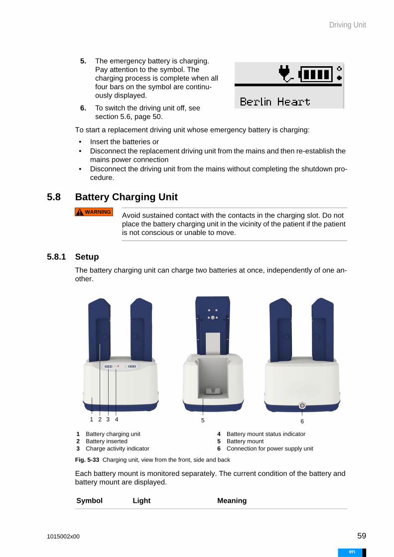
Driving Unit
WARNING
To start a replacement driving unit whose emergency battery is charging:
• Insert the batteries or• Disconnect the replacement driving unit from the mains and then re-establish the
mains power connection• Disconnect the driving unit from the mains without completing the shutdown pro-
cedure.
5.8 Battery Charging Unit
Avoid sustained contact with the contacts in the charging slot. Do not place the battery charging unit in the vicinity of the patient if the patient is not conscious or unable to move.
5.8.1 Setup
The battery charging unit can charge two batteries at once, independently of one an-other.
Fig. 5-33 Charging unit, view from the front, side and back
Each battery mount is monitored separately. The current condition of the battery and battery mount are displayed.
5. The emergency battery is charging. Pay attention to the symbol. The charging process is complete when all four bars on the symbol are continu-ously displayed.
6. To switch the driving unit off, see section 5.6, page 50.
1 Battery charging unit2 Battery inserted3 Charge activity indicator
4 Battery mount status indicator 5 Battery mount6 Connection for power supply unit
Symbol Light Meaning
1 2 3 4 5 6
1015002x00 59
en

60
Driving Unit
e
5.8.2 Function
Batteries charge most quickly at room temperature, between 19 °C and 23 °C. Always charge batteries fully whenever possible.
Connecting the battery charging unit
Charging the battery and checking the charge level
illuminated green The battery charging unit is connected to the mains, the battery mount is ready for operation.
chaser light The battery is charging.
green, steadily illumi-nated
The battery is fully charged.
orange, flashing The battery is defective and may not be used further.
orange, flashing The battery mount is defective. The battery charging unit must not be used again.
orange, steadily illu-minated
The battery mount is too warm. Place the battery charging unit in a cooler location.
1. Connect the power supply unit to the battery charging unit.
2. Check the readiness for operation. The sta-tus indicator must be illuminated green on both sides.
1. Insert the battery into a free battery mount from above.
2. Check the charge activity indicator. A green chaser light shows the charging process.
3. If all charge activity indicators are illumi-nated green, the battery is fully charged.
4. Removal: Pull the battery upwards.
1015002x00
n

Driving Unit
WARNING
5.9 Connecting Electrical Components
Fig. 5-34 Connection of electrical components
5.10 Replacing a Driving UnitThe driving unit must be replaced:
• to conduct driving unit maintenance• in the event of an error that cannot be immediately rectified
A replacement driving unit is required in order to conduct such a replacement. A re-placement driving unit is a driving unit that has been configured with the current set-tings for the patient.
It is not possible to switch directly to an unconfigured driving unit. The driving unit must always be configured beforehand.
5.10.1 Replacing a Driving Unit - BVAD
BVAD: After replacing the driving unit, check the settings. Adjust the settings if necessary. Make sure that pulmonary circulation is not being overloaded.
5. Check the charge level on the battery. Press the <charge level button> on the battery and check whether the battery is fully charged.
1 Power supply unit2 Adapter for external alarm3 Batteries4 Driving unit5 USB cable6 USB stick7 Panel PC
8 Docking Station9 Panel PC power supply unit10 Battery charging unit11 Flow sensor right12 Flow sensor left13 Power cable (country-specific)14 Applied parts: blood pumps (defibrillation-
protected)
1
3
4 107
11 12
85 12
3
965
13
13 13
14
1015002x00 61
en

62
Driving Unit
e
Switching to a configured replacement driving unit
1. Have the patient sit or lie down.
2. Remove the driving unit from the transport system.
3. Compare the patient ID information on the driving unit and the replacement driving unit. The patient ID can be found on the back of the driving unit. Check whether the selected replacement driving unit is intended for the patient.
4. Place the driving unit and the replacement driving unit close together. Match the driving units' connection sockets to one another by color.
5. On the replacement driving unit: Remove the seal plugs from the driving tube connections.
6. Connect the power supply to the replacement driving unit. Insert the charged batteries. If possible, connect the replacement driving unit to mains power as well. The replacement driving unit will now begin blood pump operation.
7. Disconnect the flow sensors from the driving unit the patient is connected to.
8. Note: H1, H2 and S6 alarms will be emitted during the replace-ment process. These alarms can be ignored initially. Finish replac-ing the driving unit first. After that, if the alarms are not automati-cally canceled, see section 17.7: Alarms H1 and H2, page 165 and section 17.5: Driving Unit Alarms, page 160.
9. Reconnect both driving tubes. Be mindful of the color markings. driving tube marked in red - red connectiondriving tube marked in blue - blue connection
10. Connect the flow sensors to the driving unit.
11. Double-check the color markings, and make sure that all connectors are secure.
12. Place the driving unit onto the transport system.
13. Monitor filling and emptying of the blood pumps. Make sure that each blood pump is filling and emptying completely. The membrane must be crease-free in its end position. Monitor the patient. If necessary, connect the panel PC and optimize the parameters.
14. Switch off the driving unit that is no longer in use. For shutdown information, see section 5.6: Switching Off the Driving Unit, page 50. Close all open con-nectors.
15. Configure a new driving unit as a replacement driving unit.
1015002x00
n

Driving Unit
5.10.2 Replacing a Driving Unit in LVAD and RVAD Patients
5.10.2.1 Checking the Functionality of an Unconfigured Driving Unit and Panel PC
5.10.2.2 Configuring the Driving Unit from File
5.10.2.3 Checking Configuration and Starting the Driving Unit
1. Have the panel PC and driving unit ready.
2. Connect the panel PC to the mains and switch it on.
3. Connect the driving unit to a power supply. Insert charged batteries. Establish a mains power connection
4. The driving unit will conduct a start test. During the start test, the driving tube connectors must be closed.
5. Connect the driving unit and panel PC with the USB cable.
6. The panel PC will log into the driving unit automatically as user EXPERT.
7. Check the following items on the driving unit:
• Did the start test run without errors?
• Are the displays active?
• Can an audible alarm be heard when the buttons are pressed?
8. Check the following items on the panel PC:
• Is a driving unit – panel PC connection in place?
• Does the user interface respond when the buttons are pressed?
• Is the user interface bright and easy to read?
9. If errors occur, see chapter 17: Identifying Errors and Troubleshooting, page 155.
1. Initial state: The configuration file can be found on the panel PC or on a USB stick.
2. If the configuration file is on the USB stick, then insert the USB stick into the USB port on the panel PC.
3. In the CONFIGURE DRIVING UNIT view, press the FROM FILE tab.
4. The available configuration files will be displayed.
5. Select the configuration file for the patient, and confirm the selection.
1. Switch to the Settings view.
2. Carefully check the settings.
1015002x00 63
en

64
Driving Unit
e
5.10.2.4 Replacing the Driving Unit
3. If settings need to be changed, switch to the corresponding view. Make the necessary changes.
4. If all settings are correct, press APPLY. The settings are copied to the driving unit.
5. Open the left pneumatic connection for LVAD operation, or the right pneu-matic connection for RVAD operation. Do this by removing the corresponding seal plug.
6. In the BLOOD PUMP SETTINGS view, select the START/STOP BLOOD PUMP tab.
7. Press the SINGLE STEP tab. After that, start the blood pump.
8. Note: H1, H2 and S6 alarms will be emitted during the replacement process. These alarms can be ignored initially. Finish replacing the driving unit first. After that, if the alarms are not automatically canceled, see section 17.7: Alarms H1 and H2, page 165 and section 17.5: Driving Unit Alarms, page 160.
1. Have the patient sit or lie down.
2. Remove the driving unit to which the patient is connected from the transport system.
3. Place the two driving units close together. Align the driving units' connectors by color.
4. Disconnect the flow sensor from the driving unit the patient is connected to.
5. Switch the driving tube.
6. Connect the flow sensor to the driving unit.
7. Double-check the color coding, and make sure that the connectors are secure.
8. Monitor filling and emptying of the blood pump. Make sure that the blood pump is filling and emptying completely. The membrane must be crease-free in its end position. Monitor the patient.
1015002x00
n

Driving Unit
WARNING
5.11 BVAD Emergency OperationIf one of the driving unit’s pneumatic systems fails in BVAD operating mode, the driv-ing unit will automatically switch into emergency operation. In emergency operation, the intact pneumatic unit will supply both blood pumps. Each blood pump is driven for two pump cycles. After two pump cycles, the switching unit switches the suctioning and driving pressures to the other blood pump.
At least 45% of the original flow is available during emergency operation. If the driving unit is in emergency operation, switch to the replacement driving unit as soon as pos-sible.
In BVAD emergency operation, the blood pumps must be monitored continuously to ensure complete filling and emptying. Monitor patient status. If necessary, support the patient using the manual pump. In emergency operation, the driving unit will not be able to detect insuffi-cient patient support. Pneumatic leaks cannot be detected with certain-ty.
9. In the BLOOD PUMP SETTINGS view, select the FLOW ALARM THRESHOLD tab. Set the Flow alarm threshold.
10. Switch off the driving unit that is no longer in use. For shutdown information, see section 5.6: Switching Off the Driving Unit, page 50. Close all open con-nectors.
11. Place the active driving unit onto the transport system.
1015002x00 65
en

66
Driving Unit
e
1015002x00
n

Panel PC and Docking Station
WARNING
6 Panel PC and Docking Station
6.1 Safety Information
The panel PC is intended for mains operation. Use battery operation only for transportation within the hospital.
The panel PC must not be connected to a driving unit that is supporting a patient while the batteries are being replaced. Before replacing the batteries, check the connection and disconnect if needed.
6.2 Setup - OverviewThis section only describes the connections and operation elements utilized. Any con-nections, functions or operation elements that are not described have been deactivat-ed.
Front view and rear view
Fig. 6-1 Panel PC
1 Cover for connections2 USB 3.03 USB 2.04 Cover closed5 Locking mechanism6 Charge level display
7 HDD display8 Touchscreen9 Power On / Off10 Connections for docking station11 Connection for power supply unit12 Centering for docking station
1 4 6 9
10 11
2
3
5
87
12 12
1015002x00 67
en
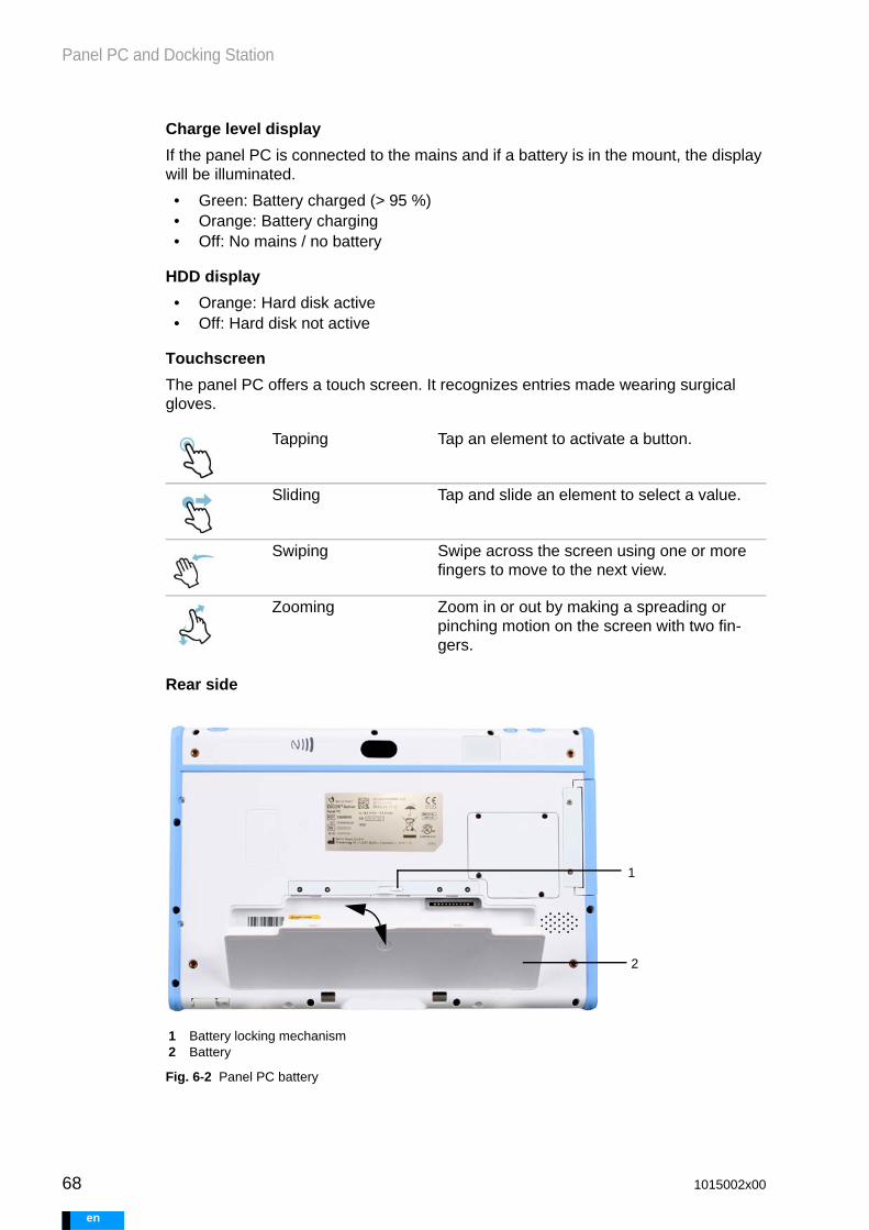
68
Panel PC and Docking Station
e
Charge level display
If the panel PC is connected to the mains and if a battery is in the mount, the display will be illuminated.
• Green: Battery charged (> 95 %)• Orange: Battery charging• Off: No mains / no battery
HDD display
• Orange: Hard disk active• Off: Hard disk not active
Touchscreen
The panel PC offers a touch screen. It recognizes entries made wearing surgical gloves.
Rear side
Fig. 6-2 Panel PC battery
Tapping Tap an element to activate a button.
Sliding Tap and slide an element to select a value.
Swiping Swipe across the screen using one or more fingers to move to the next view.
Zooming Zoom in or out by making a spreading or pinching motion on the screen with two fin-gers.
1 Battery locking mechanism2 Battery
1
2
1015002x00
n

Panel PC and Docking Station
6.3 Supplying Power via Power Supply UnitThe panel PC is designed for mains operation. The panel PC power supply unit can be directly connected to the panel PC or to the docking station.
Connecting the power supply unit to the panel PC
Connecting the power supply unit to the docking station
6.4 Supplying Power Using BatteriesBefore the first use, charge the panel PC battery completely.
6.4.1 Inserting and Removing the Battery
When replacing the battery, make sure that the panel PC is not connected to a driving unit that is currently supporting a patient.
Fig. 6-3 Panel PC power supply unit
1 Panel PC power supply unit2 Plug for panel PC3 Panel PC power supply unit On / Off display4 Mains power connector
2
1 3
4
1. Open the panel PC cap.2. Connect the plug to the panel
PC.3. Connect the mains power con-
nector to the power supply unit.4. Connect the plug to the mains.
1 Cap2 Plug for panel PC power supply unit
1
2
1. The mains power connector is located on the rear side of the device, on the left.
2. Connect the plug to the docking station.
3. Connect the mains power con-nector to the power supply unit.
4. Connect the plug to the mains.1 Mains power connector2 Plug
1 2
1015002x00 69
en

70
Panel PC and Docking Station
e
Inserting the battery
Removing the battery
6.5 Docking Station
6.5.1 Setup
The docking station may be used as both a stand and a charging unit for the panel PC.
Fig. 6-4 Front and rear sides of the docking station
1. Open the locking mechanism. To do so, slide the lock toward the right.
1 Bolt, right = open2 Inserting the battery
2. Place the battery in the mount.
3. Close the locking mechanism. To do so, slide the lock toward the left.
1
2
1. Open the locking mechanism. To do so, slide the lock toward the right.
1 Removing the battery
2. Remove the battery.
1
1 Mount for panel PC2 Mount for battery3 Lock release4 USB
5 Connection for power supply unit6 USB
1 unlocked2 locked
1 2
3
4
2
5 6
1 2
1015002x00
n
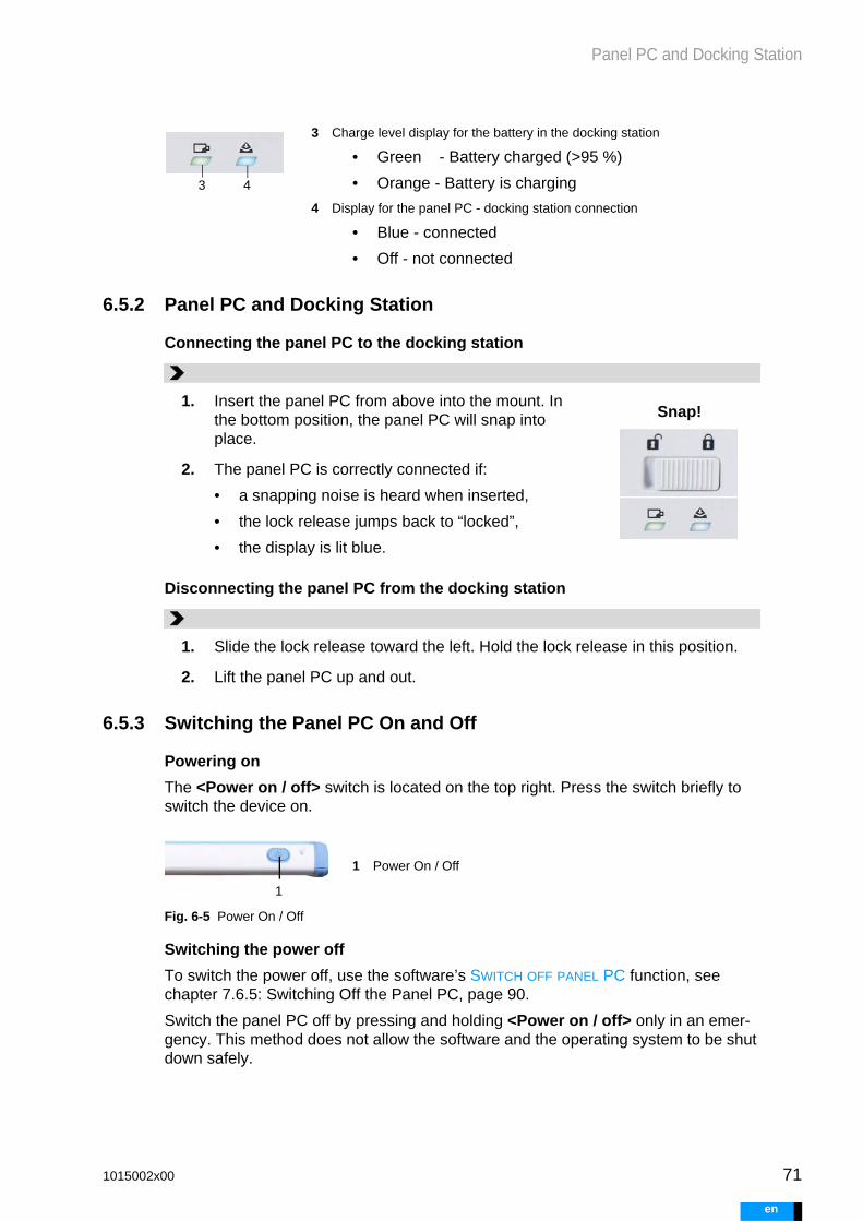
Panel PC and Docking Station
6.5.2 Panel PC and Docking Station
Connecting the panel PC to the docking station
Disconnecting the panel PC from the docking station
6.5.3 Switching the Panel PC On and Off
Powering on
The <Power on / off> switch is located on the top right. Press the switch briefly to switch the device on.
Fig. 6-5 Power On / Off
Switching the power off
To switch the power off, use the software’s SWITCH OFF PANEL PC function, see chapter 7.6.5: Switching Off the Panel PC, page 90.
Switch the panel PC off by pressing and holding <Power on / off> only in an emer-gency. This method does not allow the software and the operating system to be shut down safely.
3 Charge level display for the battery in the docking station
• Green - Battery charged (>95 %)
• Orange - Battery is charging
4 Display for the panel PC - docking station connection
• Blue - connected
• Off - not connected
3 4
1. Insert the panel PC from above into the mount. In the bottom position, the panel PC will snap into place.
2. The panel PC is correctly connected if:
• a snapping noise is heard when inserted,
• the lock release jumps back to “locked”,
• the display is lit blue.
Snap!
1. Slide the lock release toward the left. Hold the lock release in this position.
2. Lift the panel PC up and out.
1 Power On / Off
1
1015002x00 71
en

72
Panel PC and Docking Station
e
WARNING
6.6 Connecting the Panel PC to the Driving Unit
6.6.1 Connection via USB
Only use the USB ports on the panel PC and the docking station for connecting the driving unit and the USB stick. Otherwise, operation of the panel PC could be disrupted.
Use the USB stick only for reading and saving configuration and log files. Use for any other purpose may result in an unintended transfer of software to the USB stick.
USB in panel PC
USB on the docking station
The docking station has two USB ports: one on the front panel and one on the back. Both can be used.
1. Open the USB port covers.
1 USB 3.0 connection (blue slot)2 USB cable
2. Insert a USB cable into one of the USB ports. It is preferable to use the USB 3.0 port when con-necting the driving unit to the panel PC. This port is identified with a blue slot.
3. Flip open the cover on the driving unit.
4. Plug the USB cable into the driv-ing unit. 2
1
1015002x00
n

User Interface
7 User Interface
7.1 GeneralThe user interface starts when the panel PC is switched on. The user interface allows users to adjust driving unit and panel PC settings. Inactive functions and information are grayed out or hidden. Information on the status of the driving unit and the panel PC is shown in the status bar.
Fig. 7-1 User interface
1 File Menu for administration of files, for configuration of the panel PC, for display of system information, for switching off the panel PC and for resetting the driving unit
2 Work area Display and change of parameters as well as display of error messages
3 Menu bar Selection of different work areas for the configuration and monitoring of driving unit and blood pumps
4 Alarm Display of a current alarm
5 Status bar Display of information on the status of the driving unit and panel PC
6 Help Help for the panel PC user interface
7 Messages Displays messages that relate to the panel PC itself or to the communication between panel PC and driving unit.
1 2
4 6 7
3
5
1015002x00 73
en

74
User Interface
e
7.1.1 File and Menu Bar
The FILE pull-down menu is located on the top left. The File menu contains general functions for operating and configuring the panel PC and driving unit.
The menu bar offers access to the most important functions and views of the user in-terface.
Button Meaning
FILE
Menu for administration of files, for configuration of the panel PC, for display of system information, for switching off the panel PC and for resetting the driving unit.
LOG IN, LOG OFF
Opens an option for logging in a user, or a window for logging off the current user.
Only one of the two buttons is visible at a time.
MONITORING
Patient monitoring, display of parameters and graphic illustration of the current flow, rate, and flow alarm threshold.
BLOOD PUMP SETTINGS
PARAMETER view: Display and setting of the parameters with which the blood pumps are operated. Starting and stopping of blood pumps.
PRESSURE CURVES view: Display and selection of the pressure curves displayed.
DRIVING UNIT SETTINGS
PATIENT INFORMATION AND DRIVING UNIT SETTINGS view: Display and configuration of the patient information and general configu-ration of the driving unit.
BLOOD PUMPS AND CANNULAE view: Selection and display of the operating mode, as well as of the blood pumps and cannulae used.
SETTINGS view: Overview of the chosen settings.
ALARM HISTORY
Progression: Alarms over time
Trend info: Trend information on driving unit pressures and flows
1015002x00
n

User Interface
7.1.2 Status Bar
The status bar is located in the lower portion of the user interface. It displays informa-tion on the status of the driving unit and panel PC.
ACTIVE ALARM
High-priority alarms: flashing red bell symbol, error shown along with troubleshooting instructions. Only visible when a high-priority alarm is being signaled.
Active medium-priority alarm: flashing yellow bell symbol, error shown along with troubleshooting instructions. Only visible when a medium-priority alarm is signaled and a high-priority alarm is not present at the same time.
Active low-priority alarm: yellow bell symbol, error shown along with troubleshooting instructions. Only visible when a low-priority alarm is being signaled and no high- or medium-priority alarms are active at the same time.
AUDIO PAUSED
Temporarily mutes audible acoustic alarms. The duration of the muting depends on the priority level of the alarm.
Symbol Significance
AUDIO PAUSED
No audible acoustic alarms will be emitted for a period of time. Once the alarm condition has been rectified, the symbol disap-pears. If the alarm condition is still valid, the symbol Alarm will appear again after the pause.
AUDIO OFF
Display showing that the audible alarm is switched off.
CHILD PROTECTION ON
Displays that child protection is active. If the child protection set-ting is not active, no symbol will be displayed.
USER
Shows the user logged in [MEDICAL, EXPERT, LOCAL]. If no user is logged in, nothing will be shown.
PANEL PC DATA TRANSMISSION DISPLAY
Animated depiction of data transmission from the driving unit to the panel PC. Only shown if data transmission takes longer than three seconds.
1015002x00 75
en

76
User Interface
e
7.1.3 Buttons
DISPLAY DATA TRANSFER, USB
Animated depiction of data transmission from the panel PC to the USB stick. Only shown if data transmission takes longer than three seconds.
DRIVING UNIT - PANEL PC CONNECTION
not connected
connected
RELATIVE STATE OF CHARGE AND CHARGING DISPLAY FOR BATTERIES
Display of the relative state of charge as well as charge display for the left and right batteries on the driving unit.If the batteries are charged, the symbols shown will be animated. If the batteries are not charged, the charge level will be displayed. If no battery is displayed, this means that there is no battery in the driving unit.
RELATIVE STATE OF CHARGE AND CHARGING DISPLAY FOR PANEL PC
Display of the relative state of charge as well as charge display for the batteries on the panel PC.If the battery is charging, the shown symbol will be animated. If the battery is not charging, the charge level will be displayed.
MAINS OPERATION
The driving unit is connected to the mains. If there is no mains, the symbol will not appear.
PATIENT ID
Displays the patient ID. Only shown if a configured driving unit is connected.
TIME AND DATE
Time and date on the panel PC
Element Button Result
Buttons, gen-eral
Buttons have dark edges. A symbol or text is found on each button.
Some buttons show the value of a parameter. If the button is pressed, a window opens. The value of the parameter can be set in the win-dow.
Views Menus with multiple views are displayed using dots. The active view is marked and labeled.
1015002x00
n

User Interface
7.2 Functions of the Menu Bar
7.2.1 User Login
Login passwords can be found in the additional information passwords. When enter-ing the password, it is important to pay attention to upper and lower case spelling.
Slider control Slider controls allow parameters to be set by sliding the bar. Values can also be entered using the keypad. The ends of the slider con-trol delimit the possible input values.
Keypad Parameter values and symbols can be entered using the keypad.
Rotating field Selection windows with preset options pos-sess a rotating field. The active value is in the middle and is displayed in bold letters. Selec-tions can also be made by tapping or swiping.
Activity view If data or commands are being transmitted to the driving unit, the activity view will be shown for the duration of the transmission (if the pro-cess takes longer than one second).
Different users can log into the panel PC. To log in, the user must be selected and the corresponding password must be entered. The patient may not log in as a user.
User Use case
LOCAL Display and analysis of historical data, driving unit not con-nected to the panel PC
EXPERT Performance of medical procedures such as implantation, trans-plantation, weaning, or blood pump replacement.
Precondition: Driving unit and panel PC are connected via USB cable.
Tab. 7-1 User - use cases
1015002x00 77
en

78
User Interface
e
Each user is assigned rights. The rights define access to the functions of the user in-terface. The functions that can be selected depend on the use situation. Thus, all func-tions for configuring the driving unit are hidden if no driving unit is connected.
MEDICAL • Change of settings• Display of data• Analysis of historical data• Configuration of a replacement driving unit
Precondition: Driving unit and panel PC are connected via USB cable.
No user logged in
Monitoring of flow and system functions
Precondition: Driving unit and panel PC are connected via USB cable.
User Access rights
LOCAL LOCAL has access to panel PC functions
• Display of historical data• Analysis of historical data
EXPERT EXPERT has access to all driving unit and panel PC functions. Characteristics:
• EXPERT is automatically logged off if, after configuration is finished or the user logs in, no settings are changed for 4 hours. The 4-hour countdown until automatic log-off always begins with the last setting changed on the panel PC.
• Audible alarms are only active when the blood pumps are operating in automatic mode.
MEDICAL MEDICAL has access to all functions of the driving unit and the panel PC. Characteristic:
• MEDICAL is automatically logged off if no action is taken on the user interface for 10 minutes.
• Audible alarms are only active when the blood pumps are operating in automatic mode.
No user logged in
• Logging in• Accessing the HELP, MONITORING and SETTINGS menus• Changing the language on the panel PC, setting the date
and time on the panel PC
Tab. 7-2 User - access rights
User Use case
Tab. 7-1 User - use cases
1015002x00
n

User Interface
7.2.2 Passwords
Passwords are provided separately for each system. Store passwords in a safe place. Keep passwords secret from unauthorized persons.
7.2.3 User Log Off
7.3 MonitoringMonitoring is the view used to monitor the patient. The parameters Flow, Rate and Flow alarm threshold are displayed. The current values for the blood pump on the left side of the heart are displayed on the left. Those for the blood pump on the right side of the heart are displayed on the right. If only one blood pump is connected, one of the images is omitted.
User Password
EX
CO
R A
ctiv
e
LOCAL xxxxxx
MEDICAL xxxxxx
EXPERT xxxxxx
To log off the panel PC, press the LOG OFF button.
Disconnecting the USB connection between the panel PC and the driving unit will also result in the user being logged off. Reconnecting the USB cable will not auto-matically result in the user logging in again. The user will need to log in again using the correct password.
Disconnecting the USB connection:
• Pull out the USB cable
• Remove the panel PC from the docking station (if the driving unit is con-nected to the docking station)
1015002x00 79
en

80
User Interface
e
Fig. 7-2 Monitoring
The Monitoring view is available when the panel PC is connected to the driving unit via a USB cable. Logging in as a user is not required.
7.4 Settings for the Blood Pumps
7.4.1 Parameter
BLOOD PUMP SETTINGS contains the PARAMETER settings window. The parameters set there are used to operate the blood pumps. Another window shows the PRESSURE CURVES.
1 Bar flow Graphical illustration of the current blood flow
2 Bell Alarm threshold set for the flow alarm in [l/min]
3 Flow Display of the current blood flow in [l/min]
4 Rate Display of the rate in [bpm]
5 Alarm Displays a current active alarm
21
3
4
5
1015002x00
n

User Interface
Fig. 7-3 Settings for the blood pump parameters
Parameters for setting the blood pumps
Parameter Description
Filling / Emptying Optimization of the filling and emptying of the blood pump by changing the piston stroke as well as the suctioning and driving pressures generated.
Average driving pressure
The mean driving pressure is calculated using the pressures that the driving unit applies for the ejec-tion and suction of the blood pump membrane.
The mean driving pressure cannot be set directly. It can only be set in combination with the piston stroke, using the PLUS and MINUS buttons.
Piston stroke The piston stroke indicates what percentage of the possible distance the piston covers within the pneu-matic unit. The piston stroke determines the air vol-ume that is driven into or suctioned out of the blood pump.
The piston stroke cannot be set directly. It can only be set in combination with the mean driving pres-sure, using the PLUS and MINUS buttons.
Duration systole Percentage and time-related share of the systole in relation to one pump cycle. The duration of the dias-tole results accordingly.
Tab. 7-3 Parameter – Driving unit blood pumps
1015002x00 81
en

82
User Interface
e
Selection of synchronization
Rate Number of pump cycles [1/min] One pump cycle comprises the suctioning and ejec-tion of blood by the blood pump.
In synchronous and asynchronous modes, setting the rate in one blood pump simultaneously sets the rate of the other blood pump.In separate mode, the rate for each blood pump can be set separately. Here, the rate for the right side of the heart can be selected as equal to or smaller than the rate for the left side of the heart.
Flow alarm threshold The flow alarm threshold is a freely adjustable threshold value. If the measurement falls below the flow alarm threshold, an alarm will be emitted.
Flow The flow sensor measures the current flow in the cannula. The measured value is displayed in the MONITORING window.
The flow cannot be set directly. The flow is automat-ically calculated based on the rate and on the selected combination of blood pump and cannulae.
Parameter Description
Synchronization Synchronization of the blood pumps can only be selected in BVAD operating mode. These settings determine whether the right and left blood pumps are operated in synchronous, asynchronous, or sep-arate mode (independently of one another).
Synchronous mode
The two blood pumps work synchronously. This is the default setting if the blood pump connected on the left is larger than the one on the right.
Tab. 7-4 Parameter – Synchronization
Parameter Description
Tab. 7-3 Parameter – Driving unit blood pumps
1015002x00
n

User Interface
Default Parameter Settings
When the START / STOP button is pressed, a window opens showing buttons to control the driving unit. The symbols on the buttons show the action to be performed.
Fig. 7-4 Settings – Start-Stop
Asynchronous mode
The two blood pumps work asynchronously. When one blood pump is in systole, the other blood pump is in diastole. Asynchronous mode can be used with very small patients to minimize intra-thoracic volume displacement.
Separate mode Both blood pumps work independently from one another. Separate mode allows for selection of lower rates for the right side of the heart. Separate mode is recommended for patients who are supplied with same-sized blood pumps on the right and left sides.
Parameter Default settings
left right
Synchronization Synchronous mode
Rate 20 [1/min] 20 [1/min]
Duration systole 50 [%] 50 [%]
Flow alarm threshold - [l/min] - [l/min]
Tab. 7-5 Parameter - default settings
1 Step left With each press of this button, the left blood pump is filled or emptied. Pressing 2x equals one pump cycle.
Parameter Description
Tab. 7-4 Parameter – Synchronization
1 2 4 5
6
3
1015002x00 83
en

84
User Interface
e
7.4.2 Display of Pressure Curves
PRESSURE CURVES shows the pressures generated in the driving unit for the right and left blood pumps. Pressure curves can be shown or hidden individually. An overview of the currently set parameters is shown on the right-hand side.
2 Auto / Pause Starts or stops the continuous operation of the left blood pump.
3 Step right With each press of this button, the right blood pump is filled or emptied. Pressing 2x equals one pump cycle.
4 Auto / Pause Starts or stops the continuous operation of the right blood pump.
5 Auto / Pause both
Starts or stops the continuous operation of both blood pumps.
6 Close The window is closed.
1015002x00
n

User Interface
7.5 Settings for the Driving Unit
7.5.1 Patient information and driving unit settings
Parameter Description
Patient ID Patient ID
Driving unit settings (configuration file) and log files are saved under the patient ID.
The patient ID is assigned during driving unit configura-tion. The patient ID can be freely chosen using a com-bination of characters and numbers. The patient ID is limited to 32 characters.
Patient weight Weight of the patient (optional)
The recommendations for the blood pump and cannula sizes are based on the weight entered. The recommen-dations are visually highlighted *. Without entering a weight, a recommendation cannot be shown and an indication can also not be made for recommended Ber-lin Heart pump-cannula combinations. The weight parameter can be changed at a later time.
Implantation date Date of implantation. The current date is preset.
Language for driving unit
Language on the driving unit display
In addition to the different languages, a non-verbal vari-ant is also available. Only symbols are shown in the non-verbal setting.
Tab. 7-6 Overview of patient information and driving unit settings
1015002x00 85
en

86
User Interface
e
7.5.2 Blood pumps and cannulae
Child protection Switching child protection on and off
Muting of audible alarms can be delayed by 15 s. To do this, child protection must be activated. Child protection prevents children or unauthorized persons from paus-ing audible alarms before medical personnel or care-givers have an opportunity to hear them.
Time of self-test Setting for the time at which the driving unit conducts a daily self-test.
The self-test is a routine to check the function of the components of the driving unit.
Schedule the self-test for a time outside of sleeping hours so that the patient can confirm messages if required.
Parameter Default settings
Operating mode BVAD
Language for driving unit
English
Child protection Off
Time of self-test 10:00
Tab. 7-7 Parameter - default settings
Parameter Description
Tab. 7-6 Overview of patient information and driving unit settings
1015002x00
n

User Interface
first, select the operating mode in the BLOOD PUMPS AND CANNULAE window. next, se-lect the size of the implanted blood pumps and cannulae. the values entered here are critical for the correct regulation of the suctioning and driving pressures.
7.5.3 Settings - Overview
SETTINGS shows an overview of the parameters selected during configuration. Each time the driving unit is commissioned, the user must re-check the selections made. APPLY transmits the data to the driving unit. When configuring a driving unit as a re-placement driving unit, the current blood pump settings are also displayed.
Parameter Description
Operating mode BVAD circulatory support, biventricular
LVAD circulatory support, left-sided
RVAD circulatory support, right-sided
Blood pumps Size of the blood pumps left I right in [mL]
Cannulae inflow I outflow
Cannulae inflow I outflow left or right, respectively, in [mm]
Tab. 7-8 Overview of blood pump and cannula parameters
1015002x00 87
en

88
User Interface
e
7.6 Data
7.6.1 Files
FILES opens a menu in which
• log files can be imported from the driving unit to the panel PC• log files can be exported from the panel PC to a USB stick• log and configuration files can be deleted from the panel PC• configuration files can be exported from the panel PC to a USB stick• the automatic loading of driving unit logs can be activated or deactivated.
7.6.2 Options
LANGUAGE FOR PANEL PC , DATE AND TIME can also be changed by users who are not logged in.
Fig. 7-5 Options menu
OPTIONS opens a menu in which
• language• date and time
of the panel PC can be set.
1015002x00
n

User Interface
Setting the language
LANGUAGE FOR PANEL PC opens a window listing the available languages. The lan-guage can be selected by pressing the corresponding button.
Setting date and time
DATE AND TIME opens a window for setting the date and the system time of the panel PC.
7.6.3 System Information
The calculated maintenance date is not a fixed value. It is estimated based on the cur-rent rate. Maintenance is actually due once the maximum number of pump cycles be-tween maintenance dates has been reached. Around five days before the maintenance date, an active alarm is emitted. For more information on maintenance dates, see also section 18.2.2: Maintenance by the Manufacturer / Distributor, page 171.
7.6.4 Resetting the Driving Unit
RESET DRIVING UNIT reverts driving parameters to their default values. All logs and con-figuration files are preserved.
The time is set using two rotary knobs (hours and min-utes).
The DATE button opens up a calendar. In the calendar, the desired date must be pressed and accepted.
1 Manufacturer's specifications2 Counter for number of pump cycles completed3 Maintenance due date: calculated date of next maintenance4 Information on the software versions of the individual driving unit components
1 2 3 4
1015002x00 89
en
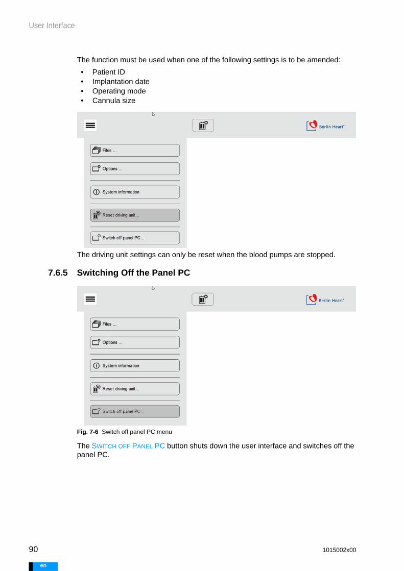
90
User Interface
e
The function must be used when one of the following settings is to be amended:
• Patient ID• Implantation date• Operating mode• Cannula size
The driving unit settings can only be reset when the blood pumps are stopped.
7.6.5 Switching Off the Panel PC
Fig. 7-6 Switch off panel PC menu
The SWITCH OFF PANEL PC button shuts down the user interface and switches off the panel PC.
1015002x00
n

User Interface
7.7 Alarm History
7.7.1 Progression
All past messages can be found under Progression. Tapping the column header will make an arrow appear. Tapping the arrow allows alarms to be sorted according to the corresponding categories.
If the panel PC is connected to a driving unit, the alarms for the connected driving unit are displayed. The messages for the current day are shown. Scroll within the table by swiping.
7.7.2 Trend Info
Patient ID Users logged in as LOCAL can view all patient infor-mation found on the panel PC. Tapping on the PATIENT ID button will call up a selection of available data records.
Date Selection of a different date.
1015002x00 91
en

92
User Interface
e
Navigating within the Trend Info window and zooming
To zoom in on part of an image, select the image area and make a spreading motion with two fingers. To zoom out, draw two fingers together in a pinching motion.
Navigating within the Trend Info window - moving
To move the displayed area, tap the screen once. Arrows will appear at the edges of the image. Use one finger to move the displayed area. Tapping the screen again will hide the arrows. After that, you can change the complete view.
Curve selection Selection window to show or hide parameters for the right and left drive sides. The following can be selected:
• systolic pressure (driving unit)
• diastolic pressure (driving unit)
• flow
Patient ID Users logged in as LOCAL can view all data records on the panel PC which are assigned to a patient ID. Tapping on the PATIENT ID button will call up a selec-tion of available data records.
Date Selection of a different date.
1015002x00
n

User Interface
7.8 Active AlarmsThe button becomes visible when an alarm is signaled. The BELL button will be flash-ing red, flashing yellow, or continuous yellow depending on the priority of the alarm. When the button is pressed, the alarm, the alarm code and the troubleshooting in-structions will appear (chapter 17.5: Driving Unit Alarms, page 160).
7.9 Audio PausedMutes the alarm for a designated period of time (chapter 17.3.7: Audible Alarms on the Driving Unit, page 158).
7.10 Messages and Help
7.10.1 Messages
The information appearing in the MESSAGES window concerns the panel PC or com-munication between the panel PC and the driving unit. Messages that concern the safety of the patient are not shown in the MESSAGES window.
When a message arrives, it is briefly shown on the bottom right. An exclamation point indicates that current messages are available.
7.10.2 Help
HELP opens a window providing assistance for operating the user interface.
• Tap HELP once to open the help window halfway.• Tap HELP twice to open the window fully.• Tapping outside of the HELP window will close the window.
Messages are briefly dis-played.
Reminder that not all mes-sages have been read or acknowledged.
Tap the button to display messages.
Tap the message to acknowledge it.
1015002x00 93
en

94
User Interface
e
Fig. 7-7 Help window
1 Help display2 Help button
1
2
1015002x00
n

Configuring and Operating the Driving Unit
WARNING
8 Configuring and Operating the Driving Unit
8.1 GeneralThis section describes all procedure steps that must be conducted on the EXCOR Active system. Handling of the sterile components, such as the blood pumps, is described in the EXCOR Sterile Components instructions for use.
Heed the instructions for use on EXCOR sterile components!
8.2 Switching On the System
8.3 Checking Functions
Before using EXCOR Active with patients, check the functionality of the driving unit, the replacement driving unit, the panel PC, and the re-placement panel PC. The check must be conducted within 24 hours be-fore the planned use. Otherwise, safe and proper operation of EXCOR is not guaranteed.
Before using the driving unit for medical purposes, charge all batteries fully, including the emergency battery. Do this by operating the driving unit on mains power for a sufficient length of time. For charging times, see section 5.7.1.6: Charging Time, page 53. Without charged batter-ies, transportation is not possible.
8.3.1 Checking Functionality of an Unconfigured Driving Unit
1. Connect the driving unit to the power supply. Insert charged batteries. If nec-essary, connect to mains power.
2. Connect the panel PC to the panel PC power supply unit. Connect the panel PC power supply unit to mains power.
3. Switch on the panel PC.
4. Connect the driving unit and panel PC to the USB cable.
1. Have the panel PC and driving unit ready.
2. Connect the panel PC to the mains and switch it on.
3. Connect the driving unit to the mains and insert batteries.
4. The driving unit will conduct a start test. During the start test, the driving tube connectors must be closed.
5. Connect the driving unit and panel PC with the USB cable.
6. The panel PC will log into the driving unit automatically as user EXPERT.
1015002x00 95
en
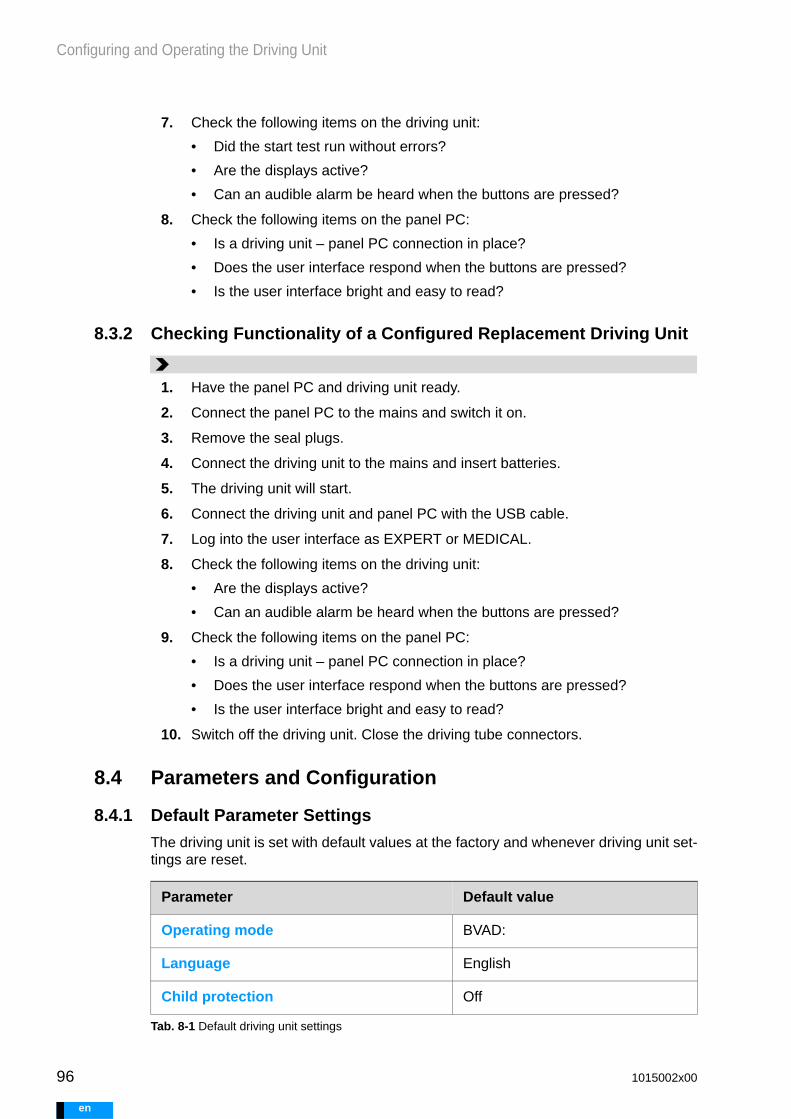
96
Configuring and Operating the Driving Unit
e
8.3.2 Checking Functionality of a Configured Replacement Driving Unit
8.4 Parameters and Configuration
8.4.1 Default Parameter Settings
The driving unit is set with default values at the factory and whenever driving unit set-tings are reset.
7. Check the following items on the driving unit:
• Did the start test run without errors?
• Are the displays active?
• Can an audible alarm be heard when the buttons are pressed?
8. Check the following items on the panel PC:
• Is a driving unit – panel PC connection in place?
• Does the user interface respond when the buttons are pressed?
• Is the user interface bright and easy to read?
1. Have the panel PC and driving unit ready.
2. Connect the panel PC to the mains and switch it on.
3. Remove the seal plugs.
4. Connect the driving unit to the mains and insert batteries.
5. The driving unit will start.
6. Connect the driving unit and panel PC with the USB cable.
7. Log into the user interface as EXPERT or MEDICAL.
8. Check the following items on the driving unit:
• Are the displays active?
• Can an audible alarm be heard when the buttons are pressed?
9. Check the following items on the panel PC:
• Is a driving unit – panel PC connection in place?
• Does the user interface respond when the buttons are pressed?
• Is the user interface bright and easy to read?
10. Switch off the driving unit. Close the driving tube connectors.
Parameter Default value
Operating mode BVAD:
Language English
Child protection Off
Tab. 8-1 Default driving unit settings
1015002x00
n

Configuring and Operating the Driving Unit
8.4.2 Blood Pumps - Cannulae - Maximum Rate
8.4.3 Selecting Blood Pumps and Cannulae
The method for selecting appropriate blood pumps and cannulae for implantation is described in the instructions for use of sterile components.
Heed the instructions for use on EXCOR sterile components!
Type of synchronization Synchronous mode
left right
Rate 20 bpm 20 bpm
Duration systole 50 % 50 %
Flow alarm threshold - -
No preset value
Parameter Default value
Tab. 8-1 Default driving unit settings
Cannulation1 Blood pump
Diameter of apex/atrial cannula
Diameter of arterial cannula
10mL
15 mL
25 mL
30 mL
50 mL
60 mL
80 mL
5 mm 5 mm 110
6 mm 5 mm 130 100
6 mm 6 mm 130 120 80
9 mm 6 mm 130 90 90
9 mm 9 mm 130 120 120 100
12 mm 9 mm 100 80
12 mm 12 mm 110 100 95
1 With cannulae having multiple diameters, the smaller diameter determines the classification. This also applies to the use of connecting sets.
110 possible combination and maximum possible rate in [bpm]
95 80 mL blood pump not on driving unit REF: 1502210 selectable
Tab. 8-2 Blood pump/cannula combinations
1015002x00 97
en

98
Configuring and Operating the Driving Unit
e
WARNING
8.5 Configuring the System
Only configure blood pumps and cannulae that are being used. Deviat-ing settings could lead to the patient receiving insufficient support.
If there is no way of adjusting insufficient driving unit settings, take al-ternative corrective actions immediately. Possible corrective actions could be supplying the patient with the manual pump or switching to an-other driving system.
Audible alarm signals are only emitted during the start test and when the blood pumps are in automatic operation. An audible alarm is not emitted in single-step mode or when one or both blood pumps are stopped. The driving unit must thus be monitored in such cases.Otherwise, alarms could be noticed too late or not at all.
Check the blood pumps and cannulae for full de-airing before AUTO op-eration. Perform individual steps to de-air and check the system.
8.5.1 Configuration Options - Overview
After switching on the system, the driving unit can be configured. Three options are available.
Configuration Prerequisite
MANUAL —
FROM FILE A suitable configuration file is saved on the panel PC or the USB stick.
Commissioning from a file makes sense if very few parameters need to be changed. In particu-lar, the BVAD, LVAD or RVAD operating mode must be the same.
REPLACEMENT The configuration file for the primary driving unit is saved on the panel PC or the USB stick.
Tab. 8-3 Configuration - options
1015002x00
n

Configuring and Operating the Driving Unit
8.5.2 Configuring a Driving Unit - MANUAL
8.5.2.1 Starting Configuration
8.5.2.2 Entering Patient Information
1. Initial state: The driving unit is connected to the panel PC. Both devices are on. The driving unit is not yet configured or the driving unit was reset. The panel PC will log in automatically as user EXPERT.
2. In the CONFIGURE DRIVING UNIT view, select the MANUAL option. Configuration only takes a few minutes.
3. The PATIENT INFORMATION AND DRIVING UNIT SETTINGS view will appear.
Continue with chapter 8.5.2.2: Entering Patient Information, page 99
1. Press PATIENT ID.
2. Enter a patient ID. The patient ID can be selected freely and can contain all characters.
3. Accept entry.
4. Press PATIENT WEIGHT.
5. Select the patient weight. Blood pump and cannula size recommendations will be shown later in the configuration process based on the patient weight. Recommendations are marked with *. If no weight is entered, a recommendation cannot be dis-played. There may not be any information provided to the effect that the selected pump-cannula combination does not conform to the recommenda-tions of Berlin Heart.
6. Accept entry.
7. Press IMPLANTATION DATE button.
1015002x00 99
en

100
Configuring and Operating the Driving Unit
e
8.5.2.3 Selecting Settings for the Driving Unit
8.5.2.4 Selecting Blood Pumps and Cannulae
Suitable components must be selected by the physician who performed the implanta-tion, based on the individual needs of the patient. The recommended blood pump and cannula sizes are visually highlighted. This advice is based on the patient weight that was entered.
Heed the instructions for use on EXCOR sterile components!
8. Select the date of implantation in the calendar. Accept entry.
9. Continue with chapter 8.5.2.3: Selecting Settings for the Driving Unit, page 100.
1. Press LANGUAGEFOR DRIVING UNIT.
2. Select the desired language in the window. If that language is unavailable, choose NON-VERBAL. If this version is selected, only symbols will be used on the driving unit.
3. Accept entry.
4. Select CHILD PROTECTION.
5. Select ON or OFF. ON delays pausing of audible alarms by around 15 sec-onds.
6. Select the TIME OF SELF-TEST button.
7. Select the correct time in the window.
8. Accept entry.
9. Continue with chapter 8.5.2.4: Selecting Blood Pumps and Cannulae, page 100.
1. Press the OPERATING MODE button.
2. Select BVAD, LVAD or RVAD mode and accept entry.
3. Press BLOOD PUMP.
4. Select the size of the connected blood pump or a combination of connected blood pumps in the case of a BVAD. Only select those components that are actually being used.
5. Press CANNULA INFLOW I OUTFLOW. Select the size of the implanted compo-nents. When using cannulae with multiple diameters, or when using a con-necting set, always use the smaller lumen.
6. Accept entry.
7. If the pump-cannula combination selected does not conform to Berlin Heart recommendations, a message will appear. Nonetheless, any permissible combination can be selected.
1015002x00
n

Configuring and Operating the Driving Unit
8.5.2.5 Checking Settings and Transferring to the Driving Unit
8.5.3 Configuring the Driving Unit from File
8. Continue with chapter 8.5.2.5: Checking Settings and Transferring to the Driv-ing Unit, page 101
1. Switch to the SETTINGS view.
2. Carefully check the settings.
3. If settings need to be changed, switch to the appropriate view and make the necessary changes.
4. If all settings are correct, press APPLY. The settings are copied to the driving unit.
5. Continue with chapter 8.6: De-Airing, Starting, and Setting the Blood Pumps, page 102
1. Initial state: Driving unit and panel PC connected, both devices are on. A suitable configuration file can be found on the panel PC or on a USB stick.
2. If the configuration file is found on the USB stick, then insert the USB stick into the USB port on the panel PC.
3. In the CONFIGURE DRIVING UNIT view, press the FROM FILE tab.
4. The available configuration files will be displayed.
5. Select configuration files and confirm.
6. Continue with chapter 8.5.2.5: Checking Settings and Transferring to the Driv-ing Unit, page 101
1015002x00 101
en

102
Configuring and Operating the Driving Unit
e
WARNING
8.6 De-Airing, Starting, and Setting the Blood Pumps
Do not set blood pumps solely on the basis of achievable and displayed flow. Always check that the new blood pump is filling and emptying completely. Select a suitable systolic duration. The goal is to generate sufficient flow for the patient’s needs, while also ensuring that the blood pump fills and empties completely.
If air penetrates into the circulatory system after the blood pump is start-ed, stop pumping immediately. One fast, safe way of doing this is to pull the driving tube out of the driving unit. Before starting the blood pump again, troubleshoot the source of the air and de-air the system again.
8.6.1 De-Airing the Blood Pump
The Instructions for Use of EXCOR Sterile Components explain how to prime blood pumps, connect blood pumps to cannulae, and use the T00L-002 de-airing set.
Heed the instructions for use on EXCOR sterile components!
8.6.2 LVAD and RVAD
1. Status before de-airing
• Blood pump filled with sterile saline solution
• Blood pump connected to cannulae
• De-airing cannula placed
• Driving tube connected to the blood pump
2. Connect the driving tube to the connection on the driving unit. Pay attention to the color markings.
3. Put the patient into the Trendelenburg position.
4. Lift the blood pump. During de-airing, the de-airing stubs of the blood pump must remain the highest point on the blood-carrying side of the blood pump.
5. De-air the blood pump completely before performing single steps. Make sure that the first step is a diastole. The process for performing single steps and starting the blood pump is described below in section 8.6.2: LVAD and RVAD, page 102 and in section 8.6.3: BVAD:, page 103.
1. Press the START / STOP button. The START / STOP blood pump view appears.
1015002x00
n

Configuring and Operating the Driving Unit
8.6.3 BVAD:
2. Every start of a blood pump begins with a step. The first step is always a diastole. If the membrane of the blood pump is in the diastolic end position, membrane movement cannot be observed.
Each time the STEP button is pressed, another step will be per-formed. The blood pump empties / fills the blood chamber. Pressing the button twice will yield a complete pump cycle con-sisting of a diastole and a systole.
3. Ensure complete de-airing in single step mode. Check connec-tion tightness. Verify anastomosis as well as the connections between the components (cannulae to blood pumps; connec-tor sets and extension sets if applicable).
4. After conducting one step, the blood pump can be started with AUTO. The pump cycles are conducted in accordance with the set parameters. To stop the blood pumps, the START / STOP button must be pressed once again. Next, press the STOP button. The blood pump can be restarted with STEP or AUTO.
5. The start of the pump is thus concluded. The parameters must be adjusted subsequently. Make sure that the blood pump is filling and emptying completely.
6. Continue with chapter 8.6.4: Setting Rate and Synchroniza-tion, page 104.
1
1. Press the START / STOP button.
2. Every start of a blood pump begins with a step. The first step is always a diastole. If the membrane of the blood pump is in the diastolic end position, membrane movement cannot be observed. The left blood pump must be started before the right blood pump. Each time the STEP button is pressed, another step will be per-formed. The blood pump empties / fills the blood chamber. Pressing the button twice will yield a complete pump cycle con-sisting of a diastole and a systole.
3. Ensure complete de-airing in single step mode. Check that connections are air-tight. Verify anastomosis as well as the connections between the components (cannulae to blood pumps; connector sets and extension sets if applicable).
4. After each blood pump has performed at least one step, the left blood pump or both blood pumps can be started using AUTO. The pump cycles are conducted in accordance with the set parameters.
1
1015002x00 103
en

104
Configuring and Operating the Driving Unit
e
WARNING
8.6.4 Setting Rate and Synchronization
Only use rates below 60 bpm during implantation, explantation and weaning. Do not set rates below 60 bpm on a long-term basis. When using rates below 60 bpm, monitor blood pump filling and emptying, and conduct visual checks for deposits and thrombi. At rates below 50 bpm, the driving unit cannot reliably detect losses of pressure, and may delay emitting alarms.
5. To stop the blood pumps, the START / STOP button must be pressed once again. Press the corresponding button to stop the blood pumps. Only both blood pumps or the right blood pump can be paused. The blood pumps can be restarted with STEP or AUTO.
6. The start of the pumps is thus concluded. The parameters must be adjusted subsequently. Check that the blood pumps are filling and emptying completely.
7. Continue with chapter 8.6.4: Setting Rate and Synchroniza-tion, page 104.
1. The default setting for the Rate is 20 bpm. The blood pump starts with this rate. For regular operation, a value greater than 60 bpm must be selected. To change the rate, press the RATE button.
2. Adjust the rate value. Accept the value.
3. BVAD: In Synchronous mode and Asynchronous mode, the left and right blood pumps always operate with the same rate. If the rate for a blood pump is adjusted, the rate for the other blood pump will be automatically changed.Differing rates are only possible in Separate mode. It is never possible to select a higher rate for the right blood pump than for the left blood pump. If the rate for the right blood pump is increased, the value for the left blood pump will be automati-cally adjusted. For further information regarding synchroniza-tion, see Tab. 7-4 , page 82.
4. To change the synchronization, press the SYNCHRONIZATION button.
5. Select the type of synchronization and accept the value.
6. After every rate change, the filling and emptying of the blood pump must be checked and adjusted if required. Continue with chapter 8.6.5: Optimizing the Filling and Emptying of the Blood Pumps, page 105.
7. After each change in rate, check the Flow alarm threshold and change the settings if necessary.
1015002x00
n

Configuring and Operating the Driving Unit
8.6.5 Optimizing the Filling and Emptying of the Blood Pumps
8.6.5.1 Blood Pump Phases
8.6.5.2 Basic Procedure
Individual settings: The parameter values must be determined and set individually for each patient.
Preconditions: Before setting the parameters, the status of the patient must be as-certained (blood volume, MAP,PAP, CVP). Ensure that the patient has sufficient blood volume. Patient blood pressure will need to be between 60 and 80 mmHg, but certain-ly no higher than 80 mmHg. At higher pressures, the blood may not be completely driv-en out of the blood pump. If necessary, reduce the patient’s blood pressure using medication.
Goal: Generate a blood flow that corresponds to the patient’s needs.
Choose settings in this order:
1. Rate - 2. Filling/Emptying (++ + - --) - 3. Duration systole.
Monitoring: Monitor and evaluate the filling and emptying of the blood pump over sev-eral cycles after each parameter change.
1. Adjust the Rate to generate sufficient blood flow.2. Adjust Filling and Emptying. The goal is to completely fill and empty the blood
pump. A crease-free membrane in the end position indicates complete filling and emptying. Complete filling and emptying ensures that the volume of the blood pump is used and, therefore, that the required blood flow is achieved in the pa-tient. The complete filling and emptying of the blood pump reduces the risk of de-posits. Ensure that the membrane moves continuously. At very high pressures, the
Movement of the membrane to the diastolic end position in order to fill the blood pump.
1. Suction of blood 2. Diastolic end position
Emptying of the blood pump through ejection of the membrane.
3. Ejection of the membrane 4. Systolic end position
1015002x00 105
en

106
Configuring and Operating the Driving Unit
e
WARNING
membrane can reach the end position very quickly and pause in the respective end position. This can increase the risk of the formation of deposits.
3. By default, the parameter Duration systole is set to 50 %. If changes to Filling and Emptying result in the system no longer being able to completely fill or empty the blood pumps, change the systolic duration. Lowering the systolic duration can improve filling; raising the systolic duration will improve emptying.
8.6.5.3 Piston Stroke and Mean Driving Pressure
Piston stroke - what percentage of the possible stroke is utilized in [%]
Average driving pressure - Mean of the driving and suction pressures in [mmHg]
Values for the piston stroke and the mean driving pressure cannot be set directly. They are set indirectly using the FILING (++ +) and EMPTYING (- --) buttons. The closed loop control first adjusts the piston stroke and then regulates the mean driving pressure.
8.6.5.4 Optimizing Filling and Emptying
To prevent incorrect settings: Before adjusting settings, make sure that support via the driving tube - blood pump - cannula is not interrupted. While adjusting settings, make sure that the degree of patient activity remains constant. After settings have been selected, wait until the system has adjusted, then check whether the settings allow the blood pumps to fill and empty completely.
In its default setting and after a reset, the driving unit is configured so that the blood pump fills and empties almost completely at rates between 20 and 60 bpm and an af-terload of 70 mmHg. Minor corrections might be necessary.
At higher rates or at a higher afterload, the filling behavior must be manually adjusted. The afterload increases with physically active patients. Configure the blood pumps in such a manner that they also fill and empty completely for the activity level that is ex-pected.
Configure initial settings while the patient is lying down. In the course of mobilization, conduct gradual adjustments.
1. Baseline situation: The blood pump is connected, de-aired, and has been started. The driving unit is connected to the panel PC and the user is logged in.Goal: The blood pump fills and empties completely. The membrane is crease-free in its end position.
2. Check whether the cannulae and driving tube are kink-free and not exposed to mechanical strain. Mechanical strain could result in faulty settings.
3. Observe the membrane movement on the air side of the blood pump. If the membrane is not crease-free in its end position, this must be corrected.
4. Open the SETTINGS menu.
5. Tap the FILLING/EMPTYING button for the right or left blood pump.
1015002x00
n

Configuring and Operating the Driving Unit
8.6.6 Setting the Parameter Duration Systole
The parameter Duration systole specifies the percentage of time the systole com-prises within each pump cycle. The default setting is 50 %.
8.6.7 Displaying the Pressure Curves
In the PRESSURE CURVES work area, a pressure curve is displayed for each blood pump. In BVAD operating mode, the DISPLAY CURVES button can be used to select whether the pressure curves for the left, right, or both sides are displayed.
6. Increase or decrease the filling and/or emptying by tapping on the PLUS and MINUS buttons. After every tap, the system requires a short period of adjust-ment. No additional settings can be changed during that period. Buttons can-not be selected until the system has finished self-regulation. A counter (1) shows how much longer the system will need to finish adjusting. The counter will remain visible even if the window is closed (2).
7. Repeat the setting process until the membrane is crease-free in both end positions. In doing so, take into account that the settings for one end position can also have an effect on the opposite end position.
Only conclude the setting process when, over the course of one full learning process REGULATION OPTIMIZED IN ... [MIN:SEC],, the blood pumps fill and empty completely. Also ensure that the cannulae and driving tube are kink-free and not exposed to mechanical strain.
1 2
1015002x00 107
en

108
Configuring and Operating the Driving Unit
e
Swipe to switch quickly between the PARAMETER and PRESSURE CURVES views.
8.6.8 Resetting the Driving Unit
8.7 Measuring the Blood Flow
8.7.1 Connecting the Flow Sensor
The flow sensor measures the blood flow within a cannula. As a result, insufficient support to the patient can be detected and notified. For insufficient support to be de-tected, a flow alarm threshold needs to be set.
Operation without flow sensors is only possible with continuous monitoring of the pa-tient and the blood pumps. As soon as the driving unit is supporting the patient and the patient’s thorax is closed, connect the flow sensors. The flow sensor can be at-tached to both the inflow cannula as well as the outflow cannula. Among BVAD pa-tients, positioning on the outer cannulae is preferred. Any orientation is possible.
For information on connecting flow sensors, see chapter 5.2.3.6: Connecting/Discon-necting the Flow Sensor to/from the Driving Unit, page 46 and section 5.2.3.3: Attach-ing the Flow Sensors to the Cannulae and the Blood Pumps, page 45.
Check the flow alarm threshold regularly, i.e., at least once per day. Select a flow alarm threshold such that insufficient support will reliably trigger alarms.
Setting parameters Viewing and assessing changes
RESET DRIVING UNIT reverts driving parameters to their default values. RESET DRIV-ING UNIT can only be selected when the blood pumps are stopped. After the reset, the user arrives at the CONFIGURATION view.
1. Stop the blood pumps if they are running. Press the START / STOP button. In the window that opens, press the STOP button. Confirm the prompt accord-ingly.
2. Select File.
3. Press the RESET DRIVING UNIT button. Confirm the prompt accordingly.
4. The CONFIGURATION view appears.
1015002x00
n

Configuring and Operating the Driving Unit
WARNING
8.7.2 Setting a Flow Alarm Threshold
Set the flow alarm threshold for each patient individually; check it and adjust it as needed. If the flow alarm threshold is set too low, it can re-sult in insufficient patient support not triggering alarms. Do not set the flow alarm threshold to a value that will make the alarm unusable.
1. The flow alarm needs to signal insufficient support reliably, while avoiding unnecessary alarms for minor flow fluctuations. The flow alarm must be set immediately after connection of the flow sensor. Each time after the rate is adjusted, check the flow alarm threshold and adjust it if necessary.
2. Call up the BLOOD PUMPS/PARAMETERS view. Set a separate Flow alarm threshold value for each flow sensor.
1015002x00 109
en

110
Configuring and Operating the Driving Unit
e
WARNING
8.8 Postoperative
8.8.1 Monitoring the Patient
Qualified medical personnel logged in as EXPERT or MEDICAL must al-ways log off of the panel PC before moving away from the patient. Log-ging off prevents accidental or unauthorized modification of parameters.
Use intensive-care monitoring to monitor the patient following implantation of a EX-COR VAD system. Make sure that the user can reliably perceive any potential alarms.
8.8.2 Changing Parameters
The EXPERT and MEDICAL users can change the driving unit parameters. Several pa-rameters can only be changed after the blood pumps have been paused or the driving unit has been reset.
Parameters can only be set within a defined range of values. These value ranges de-pend on the specific components implanted.
1 Lower threshold for the flow alarm2 Currently selected value3 Upper threshold for the flow alarm
3. Set the flow alarm threshold value and use APPLY to confirm.
Note: If no flow alarm threshold is selected, an alarm will be emitted after 5 minutes if the rate is 60 bpm or higher.
1 2 3
Parameter Auto operation Blood pump(s) stopped
Patient information and driving unit settings
Parameter settings for the blood pumps
Blood pump size
Tab. 8-4 Changing parameters
1015002x00
n

Configuring and Operating the Driving Unit
8.8.3 Mobilizing Patients
Because of the changing hemodynamic conditions when lying down, sitting, standing, and with normal movement, perform mobilization gradually.
Checking support while sitting
Checking support while standing
Operating mode Operating modes can only be changed after the driving unit is reset.
Cannula sizes Cannula sizes can be only changed after the driving unit is reset.
Parameter Auto operation Blood pump(s) stopped
Tab. 8-4 Changing parameters
1. Initial state: Driving unit and panel PC connected, both devices are on.
2. Log in - EXPERT OR Medical.
3. Select BLOOD PUMP settings or DRIVING UNIT settings.
• Duration systole
• Rate
• Flow alarm threshold
• Filling / Emptying
• Synchronization
• Patient weight
• Language for driving unit
• Child protection
• Time of self-test
4. Choose and set parameters that are to be changed.
5. When changing blood pump parameters, pay attention to the correct filling and emptying of the blood pump. Observe patients.
1. Ask the patient to sit on the edge of the bed for 5 to 10 min and check the fill-ing behavior of the blood pumps.
2. If filling / emptying worsens, adjust the parameters.
1. Ask the patient to get up out of bed for 5 min.
2. If filling / emptying worsens, adjust the parameters.
1015002x00 111
en

112
Configuring and Operating the Driving Unit
e
Checking support while moving
Monitoring
8.8.4 Changing the Blood Pump Size
The size of the blood pump can only be changed when the blood pump has been stopped beforehand. Only blood pumps that fit the cannula combination settings may be selected.
1. Ask patient to walk for at least 10 min.
2. If filling / emptying worsens, adjust the parameters.
1. Monitor filling / emptying behavior again after one hour.
2. Adjust the parameters if necessary.
1. Initial state: Driving unit and panel PC connected, both devices are on.
2. Log in as user EXPERT or MEDICAL.
3. Select the BLOOD PUMP SETTINGS view.
4. Open the START / STOP BLOOD PUMPS window and stop the blood pump(s).
5. Select the DRIVING UNIT SETTINGS view and then open the BLOOD PUMPS AND CANNULAE window.
6. Tap the BLOOD PUMP button and then use the rotary field to select the desired size of the blood pump / the blood pump combination. Press APPLY to confirm the selection.
1015002x00
n

Configuring and Operating the Driving Unit
8.8.5 Changing the Operating Mode
The operating mode can only be changed when the blood pumps are stopped and the driving unit has been reset. One typical use case would be switching from LVAD to BVAD mode.
7. Switch to the BLOOD PUMP SETTINGS view and de-air the blood pump(s) in sin-gle-step operation. After completely de-airing the blood pump(s), start the blood pump(s).
1. Initial state: Driving unit and panel PC connected, both devices are on.
2. Log in as user EXPERT or MEDICAL.
3. Select the BLOOD PUMP SETTINGS view.
4. Open the START / STOP BLOOD PUMPS window and stop the blood pump(s).
5. Select FILE / RESET DRIVING UNIT ....
6. Select CONFIGURE DRIVING UNIT / FROM FILE.
7. Select the configuration file for the current patient.
8. Select the DRIVING UNIT SETTINGS view and then open the BLOOD PUMPS AND CANNULAE window.
9. Adjust the settings for Operating mode, Blood pump and Inflow I Outflow cannula. Apply the settings.
10. Switch to the BLOOD PUMP SETTINGS view and de-air the blood pump(s) in single-step operation. After completely de-airing the blood pump(s), start the blood pump(s).
11. Setting parameters: Rate, Filling and emptying, Flow alarm threshold, Systolic duration.
1015002x00 113
en

114
Configuring and Operating the Driving Unit
e
WARNING
8.9 Replacing and Upgrading the Blood Pump
Heed the instructions for use on EXCOR sterile components!
Before switching to a different blood pump size, check whether a differ-ent flow sensor will be required. Information on which sensors can be used with which pumps and cannulae is available here: Tab. 5-1 , page 44. Contact the hotline regarding any questions.
Each time after replacing a blood pump, check that the new blood pump is filling and emptying completely. Adjust parameters if necessary.
Replacement of the blood pump is only described here in terms of the work steps to be performed on the driving unit and panel PC.
8.9.1 Replacing Blood Pumps - BVAD Left, LVAD, RVAD
1. Initial state: The system is in AUTO operation. The panel PC is connected to the driving unit. A sterile environment has been prepared. The blood pump has been prepared. The necessary materials are ready for use.
2. Log in with the EXPERT user profile.
3. Remove the cable wrap.
4. Remove the flow sensor from the cannula. If alarms are emitted with regard to flow or a flow sensor not being connected, press AUDIO PAUSED. After one blood pump has been paused, audible alarms will no longer be emitted for as long as the blood pump is paused.
5. Call up the START / STOP blood pump view.
6. In BVAD operating mode, stop both blood pumps; in LVAD or RVAD mode, stop the corresponding blood pump.
7. Replace the blood pump. See EXCOR Sterile Components instructions for use.
8. Perform de-airing in single step mode. Check that the system is completely de-aired. Do not start the blood pump until the system has been completely de-aired. Check that connections are air-tight.
1015002x00
n

Configuring and Operating the Driving Unit
8.9.2 Replacing the Blood Pump - BVAD Right
In BVAD operating mode, while the blood pump used in right-side circulatory support is being replaced, the left-side blood pump can continue running at a low rate. The treating physician will determine whether the rate on the left pump needs to be re-duced.
9. In the event of a blood pump upgrade: See chapter 8.8.4: Changing the Blood Pump Size, page 112, steps 5 and 6.
10. Start the blood pump.
11. Check the filling and emptying of the blood pump and optimize if necessary.
12. Attach the flow sensor.
13. Check the flow alarm threshold and adjust if necessary.
14. Log off.
1. Initial state: The system is in AUTO operation. The panel PC is connected to the driving unit. A sterile environment has been prepared. The blood pump has been prepared. The necessary materials are ready for use.
2. Log in with the EXPERT user profile.
3. Remove the cable wrap.
4. Remove the flow sensor from the cannula. If alarms are emitted with regard to flow or a flow sensor not being connected, press AUDIO PAUSED.
5. Reduce the rate on the left blood pump if necessary.
6. Call up the START / STOP BLOOD PUMPS view.
7. Stop the right blood pump.
8. Replace the blood pump.
9. Perform de-airing in single step mode and check. Do not start the blood pump before a complete de-airing. Check the seals on the connections
10. In the event of a blood pump upgrade: See chapter 8.8.4: Changing the Blood Pump Size, page 112, steps 5 and 6.
11. Start the blood pumps. Adjust the rates.
12. Check blood pump filling and emptying; optimize if necessary.
1015002x00 115
en

116
Configuring and Operating the Driving Unit
e
8.10 Replacing the Driving Tube
Heed the instructions for use on EXCOR sterile components!
Replacement of the driving tube is only described here in terms of the work steps to be performed on the driving unit and panel PC.
When replacing a driving tube, pause the blood pump(s). Allowing the driving unit to continue running with the connections open could result in particles being drawn into the driving unit. These could damage the driving unit, or result in later damage to the blood pumps. Audible alarms are off while the blood pumps are paused.
8.10.1 Replacing Driving Tubes - BVAD Left, LVAD, RVAD
13. Mount the flow sensors and cable protectors.
14. Log off.
1. Initial state: System in AUTO operation. The panel PC is connected to the driving unit. The driving tube with corresponding color coding is ready.
2. Log in with the EXPERT user profile.
3. Remove the cable wrap.
4. Remove the flow sensor from the blood pump.
5. Call up the START / STOP BLOOD PUMPS view.
6. In BVAD operating mode, stop both blood pumps; in LVAD or RVAD mode, stop the corresponding blood pump.
7. Replace the driving tube.
8. Start the blood pumps.
9. Check blood pump filling and emptying; optimize if necessary.
10. Mount the flow sensor and cable wrap.
11. Log off.
1015002x00
n

Configuring and Operating the Driving Unit
WARNING
8.10.2 Replacing Driving Tubes - BVAD Right
8.11 Configuring and Updating the Replacement Driving Unit
A configured replacement driving unit must be labeled in such a way that it is possible to easily allocate it to the correct patient. Otherwise, switching to the replacement driving unit could result in use of a driving unit with unsuitable settings. This could lead to insufficient support, no support, or overloading.
Immediately transfer the changes in the driving parameters to the re-placement driving unit. Otherwise, the patient will not receive appropri-ate support if switching to the replacement driving unit becomes necessary.
8.11.1 Configuring the Replacement Driving Unit
1. Initial state: System in AUTO operation. The panel PC is connected to the driving unit. Driving tube with blue color coding is ready.
2. Log in with the EXPERT user profile.
3. Remove the cable wrap.
4. Remove the flow sensor from the cannula. If alarms are emitted with regard to flow or a flow sensor not being connected, press AUDIO PAUSED.
5. Reduce the rate on the left blood pump if necessary.
6. Call up the START / STOP BLOOD PUMPS view.
7. Stop the right blood pump.
8. Replace the right driving tube.
9. Raise the left blood pump rate back to its original value. Start the right blood pump.
10. Check the filling and emptying of the blood pumps and optimize, if necessary.
11. Mount the flow sensor and cable wrap.
12. Log off.
1. Initial state: The driving unit that is to be configured as a replacement driving unit is connected to the panel PC. Both devices are on. The configuration file to be transferred is on the panel PC or on the USB stick.
2. If the configuration file is found on the USB stick, then insert the USB stick into the USB port on the panel PC.
1015002x00 117
en

118
Configuring and Operating the Driving Unit
e
8.11.2 Replacement Driving Unit - Updating Configuration
3. In the CONFIGURATION view, press the REPLACEMENT but-ton.
Replacement driving units can only be configured using the REPLACEMENT function. This is the only function that will yield a driving unit that immediately commences pump operation in the event of an emergency, as soon as it is supplied with power.
4. The available configuration files will be displayed.
5. Select the configuration file and confirm.
6. The settings for the parameter are displayed. Check the parameters in both windows thoroughly. Check one more time that the patient ID is for the correct patient, and that the parameters are suitable. Press APPLY to confirm the set-tings. The replacement driving unit is now configured.
7. Switch off the replacement driving unit.
8. Label the replacement driving unit. There is a tray for the label on the back of the driving unit. Mark the label in a suitably unique manner, such as with the patient ID. Select a label that will make it clear which patient the replacement driving unit is configured for.
1. Initial state: The current configuration file can be found on the panel PC or on a USB stick.
2. On the replacement driving unit, remove the seal plugs from the driving tube connections.
3. Supply power to the replacement driving unit. The replacement driving unit will start. Ignore the H1 and H2 alarms. These alarms are emitted because no blood pumps are connected, meaning that no pressure can be built up.
1015002x00
n

Configuring and Operating the Driving Unit
8.12 Types of Data
8.12.1 Configurations
The configuration contains the set values for the driving parameters as well as data on the patient. The configuration has one clear designation, the patient ID.
The configuration file is saved to the driving unit during configuration. A copy is auto-matically saved on the panel PC. Every time a parameter is changed, the configura-tions on the driving unit and panel PC are updated.
8.12.2 Logs
The driving unit records all driving unit alarms as well as information on flow and pres-sure. For every message, e.g. an error, there is a sequence of measured values. The sequence generally comprises a period of time beginning 90 s before the error to 90 s after the error.
A single file with pressure and flow values is generated each day.
8.13 Managing DataData for different patients can be saved and viewed on the panel PC. In order to make data available on the panel PC, such data must be loaded from the driving unit.
Importing logs
This function copies selected logs from the driving unit to the panel PC.
4. Connect the panel PC to the driving unit. If necessary, plug the USB stick into the panel PC. Wait until the panel PC has connected to the replacement driv-ing unit.
5. Log in with the EXPERT user profile.
6. A query will appear: A NEW CONFIGURATION IS AVAILABLE ON THE PANEL PC. DO YOU WANT TO TRANSFER THE CONFIGURATION FILE TO THE DRIVING UNIT?
7. Apply the configuration file.
8. Once configuration is complete, switch off the replacement driving unit. Use the seal plugs to close the connections for the driving tubes.
9. Disconnect the panel PC from the driving unit.
1. Connect the driving unit to the panel PC.
2. Log in.
3. Open the DATA menu and select IMPORTING LOGS.
4. Choice of one, multiple, or all days with logs. Accept selection. Data transmis-sion will begin.
5. Once data transmission is complete, the driving unit can be disconnected from the panel PC.
6. To conduct analyses, log in with the user LOCAL.
1015002x00 119
en

120
Configuring and Operating the Driving Unit
e
Automatically importing logs
This function copies log data onto the panel PC as soon as the panel PC is connected to the driving unit. Log files that are already on the panel PC are not re-imported.
Exporting logs
This function copies selected logs from the panel PC to a connected USB stick.
Deleting logs
This function deletes all logs as well as the configuration of the selected patients from the panel PC.
1. Connect the driving unit to the panel PC.
2. Log in.
3. Open the DATA menu and select FILES.../AUTOMATIC LOG.
4. Select AUTOMATIC ON and accept.
5. Now, every time that a driving unit is connected, the logs will be automatically copied to the panel PC.
1. Log in.
2. Connect the USB stick to the panel PC. Only one USB stick may be inserted into the panel PC.
3. Select the DATA menu.
4. Select FILES.../EXPORT LOGS.
5. The logs will now be copied to the USB stick.
1. Log in.
2. Select the DATA menu.
3. Select FILES.../DELETING LOGS.
4. The selected logs and the configuration will be deleted.
1015002x00
n

Configuring and Operating the Driving Unit
Exporting the configuration
This function copies the selected configuration to the connected USB stick. The se-lected configuration is always one that is saved on the panel PC.
1. Log in.
2. Connect the USB stick to the panel PC. Only one USB stick may be inserted into the panel PC. Otherwise, the user will be prompted to remove one USB stick.
3. Select the DATA menu.
4. Select FILES.../EXPORT CONFIGURATION.
5. The selected configuration file is copied onto the USB stick.
1015002x00 121
en

122
Configuring and Operating the Driving Unit
e
1015002x00
n

Replacing the Driving System
WARNING
9 Replacing the Driving System
9.1 GeneralThis section describes all steps that must be performed on the driving unit of the EXCOR Active system. Make sure to consult the Ikus instructions for use regarding actions to take on the Ikus and configuration of that driving system.
Heed the instructions for use on the EXCOR driving system!
For information and specifications on blood pumps and cannulae, be sure to consult the EXCOR Sterile Components instructions for use.
Heed the instructions for use on EXCOR sterile components!
9.2 From Ikus to EXCOR Active
When switching from the RVAD Ikus to the EXCOR Active system, the red-marked driving tube must be replaced with a blue-marked driving tube. Otherwise, operating errors are possible when using EXCOR Active.
9.2.1 Prerequisites for a Replacement
1. EXCOR Active can achieve the required flow rate using the combination of pumps and cannulae, see section 8.4.2: Blood Pumps - Cannulae - Maximum Rate, page 97.
2. If the patient has received staged cannulae, the length of the stages must permit attachment of a flow sensor. If necessary, the stage will need to be shortened to a suitable length beforehand. Information on the required lengths is provided in the EXCOR Sterile Components instructions for use.
3. The distal portion of the cannula without velour must be long enough to allow the required flow sensor to be attached.
The decision regarding replacement of the driving system is the responsibility of the treating physician.
9.2.2 Preparing EXCOR Active
1. Charge all batteries as well as the emergency battery.
2. Have the components ready. Insert both batteries and connect the power supply unit.
1015002x00 123
en

124
Replacing the Driving System
e
9.2.3 Switching to EXCOR Active
3. Configure the driving unit, see section 8.5: Configuring the System, page 98. Transfer the following parameters from Ikus to EXCOR Active (for each sup-ported side in BVAD mode):
• Operating mode
• Cannula sizes
• Size of the blood pump
• Rate
• Synchronization type (in BVAD operating mode)
• Initially, leave the parameter Duration systole set to the standard value of 50%.
4. Start operation of the blood pump(s) on the driving unit.
5. Position the driving unit on the Ikus so as to allow fast and secure reconnec-tion of the driving tube.
1. Lay the patient on his or her back. Perform the following steps (for each sup-ported side in BVAD mode):
2. Connect the flow sensor to the cannula.
3. Connect the flow sensor to EXCOR Active.
4. Remove the seal plugs from the EXCOR Active driving unit.
5. Switch the driving tube connection from Ikus to EXCOR Active.
6. Check filling and emptying of the blood pump and adjust as needed.
7. Set the Flow alarm threshold.
8. Attach the cable wrap.
9. Allow Ikus to remain active for a while, in parallel with the EXCOR Active driv-ing unit. Switching back is easy to do if necessary. Connect the tank unit so that Ikus does not run with the pneumatic connections open.
10. Adjust the parameters for mobilization purposes, see section 8.8.3: Mobilizing Patients, page 111.
1015002x00
n

Replacing the Driving System
9.3 From EXCOR Active to Ikus
9.3.1 Preparing the Ikus
9.3.2 Replacing the Driving Unit
1. Switch on and configure the Ikus, see the Ikus instructions for use.
2. Transfer the EXCOR Active driving parameters to the Ikus. The following parameters are transferred (for each supported side in BVAD mode):
• Operating mode
• Cannula sizes
• Size of the blood pump
• Rate
• Driving pressure in systole
• Driving pressure in diastole
• Synchronization type (in BVAD operating mode)
3. Initially, leave the parameter Systolic duration on the Ikus to the default value of 40%.
4. Position the driving unit on the Ikus so as to allow fast and secure reconnec-tion of the driving tube(s).
1. Lay the patient on his or her back. Perform the following steps (for each sup-ported side in BVAD mode):
2. Remove the cable wrap from the driving tube.
3. Disconnect the flow sensor from the cannula and the driving unit. Press AUDIO PAUSED.
4. Disconnect the tank unit from Ikus.
5. Switch the driving tube from EXCOR Active to Ikus.
6. Check filling and emptying of the blood pump and adjust as needed.
7. EXCOR Active driving unit: Stop blood pump operation. Use the seal plugs to close the pneumatic connections on EXCOR Active.
8. Allow EXCOR Active to run for a time, in parallel with Ikus. Switching back is easy to do if necessary. After that, switch off the driving unit, see section 5.6: Switching Off the Driving Unit, page 50.
1015002x00 125
en

126
Replacing the Driving System
e
1015002x00
n

Weaning and Explantation
10 Weaning and Explantation
10.1 GeneralThis section describes all procedure steps that must be conducted on the driving unit. Handling of the sterile components, such as the blood pumps, is described in the EXCOR Sterile Components instructions for use.
10.2 Weaning the PatientLonger periods of blood pump stoppage or blood pump operation at a very low rate are both unfavorable in terms of hemostasis and risk of thrombogenesis. Please see the Instructions for Use of Sterile Components for guidelines on how to test the inde-pendent performance of the heart without having to pause the blood pump for a lengthy period.
Heed the instructions for use on EXCOR sterile components!
10.3 Performing an Explantation
1. Initial state: The driving unit is connected to the panel PC. Both components are in mains operation.
2. Log into the EXPERT user profile.
3. Vary the rate as described in the Instructions for Use of Sterile Components.
1. Initial state: The driving unit is connected to the panel PC. Both components are in mains operation.
2. Log into the EXPERT user profile.
3. Shift patient support from the VAD to the HLM.
4. When the heart-lung machine is providing full patient support, stop the blood pumps.
5. Switch off the driving unit.
6. Disconnect the driving tubes from the driving unit and seal the connectors with seal plugs.
7. Disconnect the flow sensors from the driving unit and detach them from the cannulae.
1015002x00 127
en

128
Weaning and Explantation
e
1015002x00
n

Performing Trainings
WARNING
11 Performing Trainings
11.1 Target Group for Trainings
11.1.1 Qualified Medical Personnel
The manufacturer offers training sessions for qualified medical personnel. Contact the manufacturer or the distributor to schedule training dates, see chapter 1: Contact, page 13.
11.1.2 Lay Users
EXCOR Active is suitable for use by users without specific medical knowledge. The treating physician is responsible for determining the degree to which the patient and the caregiver operate the EXCOR system independently, along with the extent to which the patient can be removed from a hospital environment. All functions protected by password may not be used by lay users.
Either way, the patient and caregiver(s) must receive training. Checklists offer assis-tance with this training by specifying the minimum content to be included in the train-ing. After training has been given, double-check that it has succeeded.
11.2 Safety Information
Train patient and caregivers on handling of EXCOR. The contents and operations taught must be well understood and mastered. Conduct training programs in their entirety. Refresh training program contents regularly.Without training, the safe and smooth operation of EXCOR is not guar-anteed.
Use the training checklists. The checklists ensure that all relevant top-ics have been covered.
At minimum, patient and caregiver training must include the following items listed in the checklists:chapter 11.3.1: Using Components, page 130,chapter 11.3.2: Behavior and Safety, page 131 as well as the contents of the Patient’s Instructions for Use.
Make a caregiver available to the patient who is trained and competent in the use of EXCOR.
Only trained adult patients who are capable of operating EXCOR Active are permitted to move around outside the ward unac-companied. All other patients (children, for example) may only move around outside the ward when accompanied by medical personnel or a caregiver.
Caregivers for infants and small children must be trained to position the driving tubes laterally, running directly towards the patient’s feet.
1015002x00 129
en

130
Performing Trainings
e
Caregivers supervising patients who do not understand how to operate the system safely must undergo training, because those patients re-quire continuous monitoring.
11.3 Training Content Checklists
11.3.1 Using Components
Training of patient and caregivers Check
Function
Functionality of the driving unit
Connecting components
Calling up display views and knowing what they mean
Connecting the driving unit to mobile components
Positioning cannulae, blood pumps, and driving tubes
Attaching driving tubes and sensor cables to the mobile compo-nents
Power supply
Charging batteries in the driving unit
Charging batteries in the battery charging unit
Recognizing charge level
Connecting and disconnecting to mains power
Charging and using the emergency battery
Response to errors
Perception of alarms
Troubleshooting errors
Replacement of the driving unit
Manual pump use
Driving tube repair
Contact person, hospital contact information
1015002x00
n

Performing Trainings
11.3.2 Behavior and Safety
Flow sensors
Attaching and detaching flow sensors
Attaching and detaching the cable wrap
Sensor locking clip - flow sensor color marking
Corrective actions in the event of a defective flow sensor(Contact the hospital and have the defective flow sensor replaced)
Information on components by other manufacturers
Using the stroller / baby seat components
Safety information regarding strollers / baby seats
Training of patient and caregivers Check
Safety Check
Children
Children and people who are physically and/or mentally incapable of operating the system - as patients
Children and people who are physically and/or mentally incapable of operating the system - outside the hospital setting
Care
Identifying insufficient support
Monitoring fluid intake
Notifying a contact person of any sign of changes in the patient’s clinical condition (neurological impairment, insufficient care)
Animals
Risks posed by animals
Ambient conditions
Electromagnetic influences, electrical devices, cell phones
Heat, cold, humidity
Interactions with other medical therapies
Keeping replacement driving units available (for BVAD patients)
1015002x00 131
en

132
Performing Trainings
e
11.4 Training Log
Contact person
Hospital
Psychological support
Caregiver
Special environmental conditions - identifying dangers
Stairs
Bathroom
Kitchen
Mobility
Maneuvering in public areas and recognizing dangers
Safety Check
Training Check
section 11.3.1: Using Components, page 130
section 11.3.2: Behavior and Safety, page 131
Contents and instructions as described in the Instructions for patient and caregiver use
Physician name Signature Date
Patient / caregiver name Signature Date
1015002x00
n

Mobile Use of EXCOR Active
12 Mobile Use of EXCOR Active
12.1 Help with MobilizationThe following components are available for use when mobilizing the patient:
• Caddy, chapter 13: Caddy, page 135 • Baby Buggy, chapter 15: Baby Buggy - Stroller Board, page 143
Fig. 12-1 Mobilization in the baby buggy, stroller with stroller board
1015002x00 133
en

134
Mobile Use of EXCOR Active
e
1015002x00
n
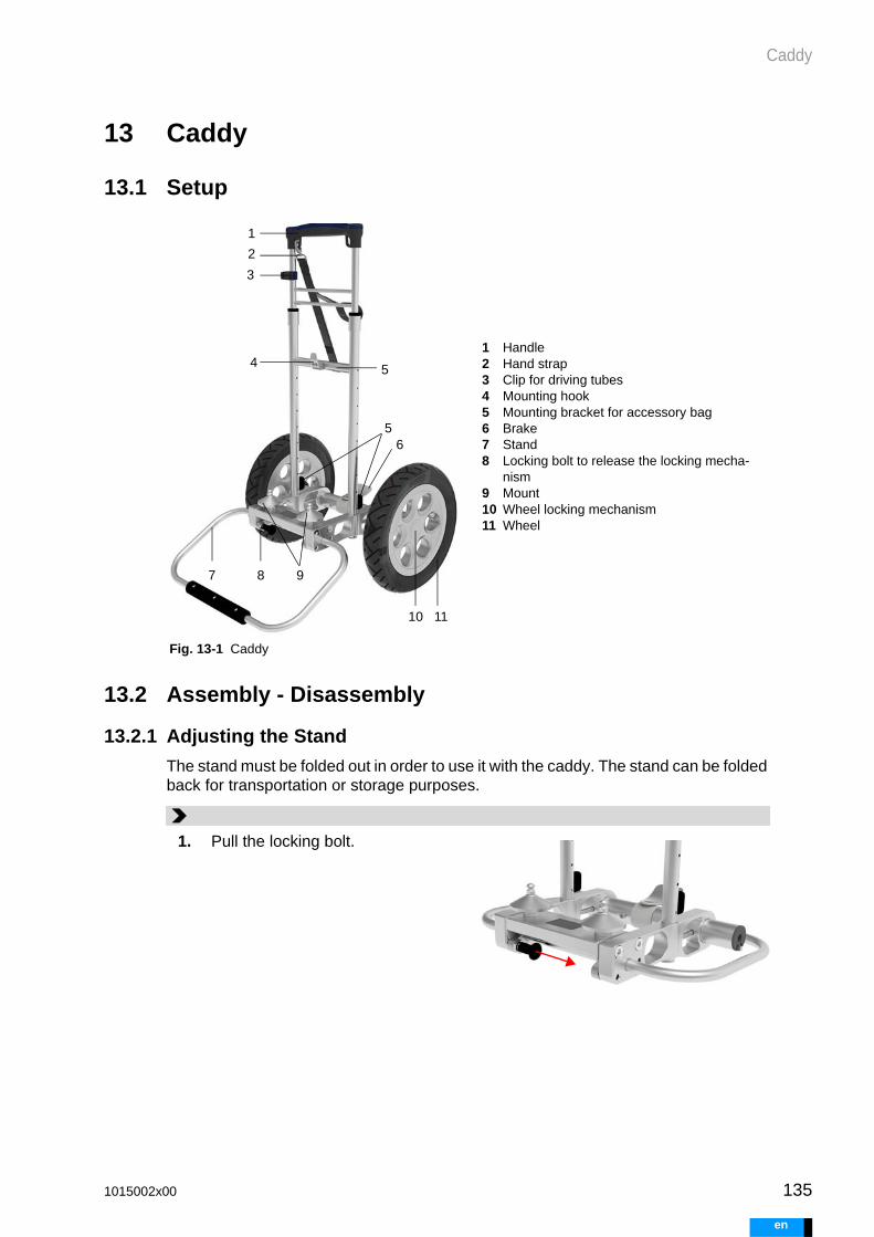
Caddy
13 Caddy
13.1 Setup
13.2 Assembly - Disassembly
13.2.1 Adjusting the Stand
The stand must be folded out in order to use it with the caddy. The stand can be folded back for transportation or storage purposes.
Fig. 13-1 Caddy
1 Handle2 Hand strap3 Clip for driving tubes4 Mounting hook5 Mounting bracket for accessory bag6 Brake7 Stand8 Locking bolt to release the locking mecha-
nism9 Mount10 Wheel locking mechanism11 Wheel
1
2
3
4
56
1110
87 9
5
1. Pull the locking bolt.
1015002x00 135
en

136
Caddy
e
13.2.2 Mounting - Dismounting the Wheels
13.2.3 Inflating the Tires
The caddy has pneumatic tires. The air pressure on the tires must be checked regu-larly. Inflate them as needed. The valves are accessible from the inner side of the cad-dy.
2. Unfold the stand to the stop posi-tion and allow the locking handle to snap into place.
1. In order to mount the wheels, the stand must be folded open.
2. Mounting: Press the wheel lock-ing mechanism inwards and attach the wheel in the process. Release the locking mechanism. Check that the wheels are firmly seated.
3. Dismounting: Press the wheel's locking mechanism inwards while removing the wheel.
2
Type Schrader valve (car valve)
Air pressure max. 2.0 bar or 28 PSI
1015002x00
n
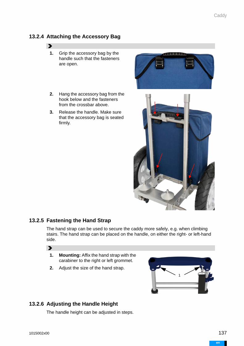
Caddy
13.2.4 Attaching the Accessory Bag
13.2.5 Fastening the Hand Strap
The hand strap can be used to secure the caddy more safely, e.g. when climbing stairs. The hand strap can be placed on the handle, on either the right- or left-hand side.
13.2.6 Adjusting the Handle Height
The handle height can be adjusted in steps.
1. Grip the accessory bag by the handle such that the fasteners are open.
2. Hang the accessory bag from the hook below and the fasteners from the crossbar above.
3. Release the handle. Make sure that the accessory bag is seated firmly.
1. Mounting: Affix the hand strap with the carabiner to the right or left grommet.
2. Adjust the size of the hand strap.
1
1015002x00 137
en

138
Caddy
e
WARNING
13.3 Using the Caddy
13.3.1 Safety Information
Activate the brake whenever the transport system is not in motion. The brake prevents the caddy from rolling away accidentally.
13.3.2 Positioning the Driving Unit
1. Release the clips before repositioning the driving tubes, see section 13.3.3: Securing and Releasing the Driving Tubes, page 139.
2. Press the lock release on both sides.
3. Press and hold the lock release, and slide the handle to the desired height. Let go of the lock release.
4. Push the handle gently until you feel it snap into place. Secure the driving tubes again.
1 1
2
1. Attach the driving unit to the hook. At the same time, position the driving unit in such a way that it slides onto the mount.
2. The mount serves to position the bottom of the driving unit.
3. Release the driving unit handle. If needed, press the handle down-ward. In the lower position, the handle locks the driving unit.
4. Check the connection between the driving unit and the caddy.
1
2
1015002x00
n

Caddy
13.3.3 Securing and Releasing the Driving Tubes
13.3.4 Using the Brake
The brake prevents the caddy from accidentally rolling away.
13.3.5 Carrying the Caddy with the Driving Unit
When the driving unit is mounted onto the caddy, two people will need to carry the sys-tem.
13.3.6 Folding the Caddy into Transport Position
The caddy can be collapsed for transportation purposes.
1. Lay the driving tubes such that they will not tangle on the wheels or drag on the ground when in motion.
2. Press the driving tubes into the clips.
3. To release the driving tubes, pull them out of the clips.
1. Locking: Press the level down with your foot. If you feel signifi-cant resistance when pressing down, move the caddy slightly until the brake snaps into place.
2. Releasing: Move the level up with your foot.
2
1015002x00 139
en
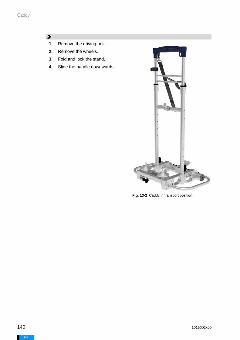
140
Caddy
e
1. Remove the driving unit.
Fig. 13-2 Caddy in transport position
2. Remove the wheels.
3. Fold and lock the stand.
4. Slide the handle downwards.
1015002x00
n

Accessory Bag
WARNING
14 Accessory Bag
14.1 Design and Function
14.2 Packing the Accessory Bag
The accessory bag contains components that increase safety during mobile use. Keep the bag in the immediate vicinity of the patient. Attach the accessory bag to the transport system during mobile use.
Keep the following components available in the accessory bag:
1 Valves with magnetic closure2 Battery compartment3 Pump compartment
4 Closure5 Handle and opening contact for the locking
mechanism6 Grommets for mounting bracket
1
2 3
4 5 4
6
Battery compartment Pump compartment
Two charged batteries Manual pump
Tire pump for the caddy
Short instructions
1015002x00 141
en

142
Accessory Bag
e
1 Two charged batteries2 Manual pump3 Short instructions4 Tire pump for caddy
1
2
3
4
1015002x00
n

Baby Buggy - Stroller Board
WARNING
15 Baby Buggy - Stroller Board
15.1 Safety Information
The stroller board may only be connected to a stroller that has been ob-tained from Berlin Heart. Otherwise, secure connections and safe us-age cannot be guaranteed.
Activate the brake whenever the transport system is not in motion. The brake prevents the caddy from rolling away accidentally.
15.2 GeneralThe driving unit can be connected to a stroller using the stroller board. The driving unit and accessory bag are transported on the stroller board.
15.3 Setup
Fig. 15-1 Stroller Board
15.4 Mounting the Stroller Board
15.4.1 Checking the Scope of Delivery
After unpacking, check the scope of delivery and lay out the parts.
1 Snap-in connector2 Mounting hook3 Crossbar to hang the bag4 Hook for bag5 Mount
1
2
3
4
5
Name Unit
1015002x00 143
en

144
Baby Buggy - Stroller Board
e
Body 1
Carrier 1
Wheel 2
Cap 2
Countersunk screw 2
Hook for bag 2
Hexagon screw 2
Sleeve 2
Spacer set 2
Stroller clip 3
Allen wrench 3 mm 1
1015002x00
n

Baby Buggy - Stroller Board
15.4.2 Overview - Assembly
Fig. 15-2 Stroller board assembly
1 Hexagon screw2 Hook for bag3 Sleeve4 Carrier
5 Countersunk screw6 Cap7 Body8 Wheel
1 23
4
5
6
7
8
1015002x00 145
en

146
Baby Buggy - Stroller Board
e
WARNING
15.4.3 Mounting the Stroller Board
15.4.4 Adjusting the Suspension
15.4.5 Combination with the Stroller
The manufacturer’s instructions for use are included with each compo-nent. Take note of all instructions and safety information given in the in-structions for use.
Strollers and child seats that are compatible with the stroller board can be ordered from Berlin Heart.
1. Insert the carrier into the body. The safety hook must point in the direction of the mount.
2. Connect the hexagon screw with the hook. Insert both into the body and use to affix the carrier. Insert the sleeve on the opposite side. Tighten the sleeve using the Allen wrench. Repeat the proce-dure with the second hook.
3. Insert the wheel into the bearing.
4. Slide on the cap to affix the wheel. Tighten cap with the coun-tersunk screw.
5. Check that the components are firmly seated. Make sure it is not possible to pull out the wheels.
1
2
3
45
1. The cushioning can be adjusted by pressing down on and shifting the spring element. Adjust the suspension as shown in the image.
1015002x00
n

Baby Buggy - Stroller Board
15.4.5.1 Set 1 - Frame
15.4.5.2 Set 2 - Child Seat Fixture with Accessories
15.4.5.3 Set 3 - Baby Seat Fixture
15.4.5.4 Using the Child Seat and the Baby Seat
Always mount the child seat and the baby seat in the direction of motion. Make sure the child’s feet are facing forward. Do not place the child seat or the baby seat in a fully horizontal position. Make sure the baby seat or the child seat is not on top of the con-nections or the driving unit while in motion.
1 Base frame2 Set of wheels
3 Sunshade
1 2 3
1 Child seat2 Frame
3 Cover4 Rain protection5 Brackets
1 2 3 4
5
1 Rain protection2 Baby seat
3 Baby seat adapter
1 2 3
1015002x00 147
en

148
Baby Buggy - Stroller Board
e
15.4.6 Attaching the Stroller Board to the Stroller
15.4.7 Releasing the Stroller Board from the Stroller
15.5 Using the Stroller Board
Prerequisite
• The stroller board is fully assembled.• The stroller board and stroller are attached to one another.• The stroller clips are mounted on the stroller.
Use
Before treating the patient and before handling any components, the brake on the stroller must be set.
1. Mount the spacers onto the rear axle. To do so, place two spacers around each axle and press them tight. Position as shown in the diagram.
2. Press the snap-in connectors of the stroller board over the rear axle.
3. Check that the components are firmly seated.
4. Mount the stroller clips onto the stroller.
1 Spacer2 Snap-in connector3 Stroller clip
1
1
2 2
3
1. The snap-in connectors are opened by pulling the latches.
2. Open both snap-in connectors at the same time and lift the stroller board from the axis.
1 Snap-in connector
1
1
1015002x00
n

Baby Buggy - Stroller Board
WARNING
15.6 Positioning the Driving Tubes
Position the driving tubes on the baby buggy such that the driving tubes will not be subjected to tensile force.
The correct positioning and guiding of the driving tubes is very important.
Avoid forming loops!
• Guide the driving tubes laterally to the body, running downward toward the feet. No loops may form as these could wrap around the patient's neck.
• There may also not be any large loops extending outward that could become en-tangled.
Avoid tension and kinks!
• The driving tubes must not run too tightly between the stroller and stroller board. Make sure there is no tension on the driving tubes.
• Position the driving tubes in large radii. The driving tubes must not kink.
1. Activate the brake on the stroller.
2. Hang the bag on the stroller board.
3. Attach the driving unit. Check the locking mechanism.
4. Sit or lay the patient into the stroller.
5. Position the driving tubes and secure them with the stroller clips. Adjust the position of the stroller clips if needed.
1015002x00 149
en

150
Baby Buggy - Stroller Board
e
Fig. 15-3 Guiding of the driving tubes
1015002x00
n

Manual Pump
WARNING
16 Manual Pump
16.1 GeneralIn a case of emergency, the manual pump can temporarily replace a driving unit. The manual pump shall be operated by medical personnel trained in the use of the manual pump.
Pumping for long periods of time is strenuous. Ideally, two persons will need to alter-nate operating the manual pump. While one person pumps, the other one shall mon-itor the filling and emptying of the blood pump(s).
In biventricular operation, the manual pump drives the blood pumps asynchronously.
When not in use, the plugs are to be left in the connection sockets.
16.2 Safety Information
The manual pump must be kept available at all times. If the manual pump is not available, adequate patient support may not be ensured in case of emergency.
First, ensure the patient is receiving support. At the right time, call on one or more persons for assistance. Otherwise, the supply to the pa-tient is not guaranteed.
Note the color coding on the driving tubes and on the connectors on the manual pump. Connect the red-marked driving tube to the red connection.Connect the blue-marked driving tube to the blue connection. Otherwise, pulmonary edema could result.
Protect the manual pump against contamination. Store the manual pump in the accessory bag. When the manual pump is not in use, make sure to close the connectors using the seal plugs.
At the beginning of support, use the manual pump as shown in Fig. 16-1 . Feet on the base plate, one or two hands on the handle. This the most energy-efficient method. Other pumping methods may be too strenuous to perform for a sufficient length of time.
Fig. 16-1 Recommended pump use
1015002x00 151
en

152
Manual Pump
e
16.3 Setup
Fig. 16-2 Composition of the manual pump
1 Handle2 Connection for blue driving tube3 Valves; one negative pressure valve and
one overpressure valve per side4 Base plate5 Connection for red driving tube6 Plug
Fig. 16-3 Driving tube in socket
1 Color marking red to red2 Area above the release sleeve, fixed3 Release sleeve, movable4 Valve
1
2
3
4 6
5
3
33
1
234
1015002x00
n

Manual Pump
16.4 Supporting the Patient with the Manual Pump
Fig. 16-4 Support from the manual pump
Two-handed operation
One-handed operat
1. Lay the patient on his or her back.
2. Remove the seal plugs from the driving tube connections. Always remove both plugs. This makes pumping easier.
3. Detach the flow sensor(s) from the driving unit.
4. Remove the driving tube(s) from the driving unit.
5. Connect the driving tube(s) to the manual pump. Note:
• Connect the red-marked driving tube to the red connection.
• Connect the blue-marked driving tube to the blue connection.
6. Pump smoothly and rhythmically, at a rate of around 60 to 80 strokes per minute. Move the piston as far as is necessary to fill all blood pumps completely, and ensure that the membrane is crease-free in the end position.
7. Make sure not to block the lateral valves on the manual pump.
8. Conduct a visual inspection of each blood pump.
• The blood pump fills and empties completely.
• The membrane moves and is crease-free in its end position.
1015002x00 153
en

154
Manual Pump
e
1015002x00
n

Identifying Errors and Troubleshooting
WARNING
17 Identifying Errors and Troubleshooting
17.1 Safety Information
Immediately replace any components if they malfunction in a manner that cannot be rectified by the user! Replace components even if the malfunction does not put patient sup-port at immediate risk. If the system emits an alarm indicating that a component is defective, replace the component. The use of defective components puts the safety of the patient at risk. Consult your contact person regarding the malfunction.
Immediately replace any driving unit with a malfunction that cannot be rectified by the user that may result in insufficient patient support!
After hearing an alarm, press the <button> or press AUDIO PAUSED! Otherwise, additional alarms may not be heard or may be heard too late.
Replace the driving unit if its audible signals are inaudible or incorrect! Otherwise, the user or caregiver might not react to an error, or might react incorrectly. This could impair the safety of the patient.
Alarms signaled on the driving unit take priority over alarms signaled by other components (panel PC, alarm via external alarm (nurse call)).
If several alarms are being signaled at once, take note of all alarm mes-sages. Monitor both driving unit displays / monitor all alarms on the panel PC. Follow the instructions for action given.
17.2 Contact Person in Case of Error
17.2.1 Contact Person Regarding Errors
If you cannot remedy an error yourself or you need more information regarding the system, speak to your contact person.
17.2.2 Reporting Serious Incidents
Report serious incidents that occur in relation to the product to the manufacturer, as well as to the government office responsible in that country.
Patients and caregivers
→ Contact person in the treating hospital
Hospital → Manufacturer’s hotline
1015002x00 155
en

156
Identifying Errors and Troubleshooting
e
17.3 Driving Unit and Panel PC Alarms
17.3.1 Alarms
If an alarm condition develops, an alarm will be emitted:
17.3.2 Priority
Different alarms have differing priority levels: high, medium and low. Higher priority alarms are signaled visually and audibly before lower priority ones. When alarms of the same priority level occur at the same time, the most recent alarm will be shown on the display first.
The user interface displays the higher-priority alarm on the left hand side. If multiple alarms have the same priority level, the most recent one will be displayed on the left.
Responding to alarms by priority
Identifying alarm priority
Driving unit Panel PC External alarm
Message Message and instructions on the display
Detailed mes-sage and instructions on the user inter-face
Forwarding of high- and medium-priority alarms. Alarms are emitted in accordance with the system used at the hospital.
Visual alarm Battery, system, and mainte-nance LEDs
Bell on the user interface
Audible alarm Audible alarm (for exceptions, see section 17.3.8, page 159)
—
Tab. 17-1 Alarms
high Requires users to react immediately.
medium Requires users to react in a timely fashion.
low Requires acknowledgment by the user.
Priority Driving unit Panel PC
high red flashing system LED or battery LED
rapid tone sequence every 2.5 seconds
red flashing bell, alarm code on red background
Tab. 17-2 Identifying priority
1015002x00
n

Identifying Errors and Troubleshooting
17.3.3 Perceiving Alarms Reliably
You can only reliably react to system alarms if your ability to perceive them is ensured. Therefore, always remain well within hearing range of the audible alarms. Position the driving unit and panel PC in such a way that visual alarms are easily visible.
17.3.4 Alarm Times
Alarms are emitted visually and audibly without delay. The only exception is the main-tenance alarm, S1, which is emitted at the time of the self-test.
17.3.5 Alarm Coding
17.3.6 Visual Alarms on the Driving Unit
Alarms are divided into 3 groups:
• System• Battery• maintenance
There is an LED for each group. If an alarm condition occurs, the corresponding LED illuminates.
medium yellow flashing system LED or battery LED
slow tone sequence every 7.5 seconds
yellow flashing bell, alarm code on yellow back-ground
low continuously illuminated yellow system LED, bat-tery LED or maintenance LED
slow tone sequence every 20 seconds
continuously illuminated yellow bell, alarm code on white background
Priority Driving unit Panel PC
Tab. 17-2 Identifying priority
H Hemodynamics - Alarms related to hemodynamic status. The alarms indicate that the patient may not be receiving adequate support. Pres-sure and/or realized flow are too low.
P Power - Alarms related to energy management. The power supply to the driving unit must be ensured.
S System - Alarms related to general driving system functionality.
T Temperature - Alarms related to excessively high or low tempera-tures.
1015002x00 157
en

158
Identifying Errors and Troubleshooting
e
17.3.7 Audible Alarms on the Driving Unit
When an alarm condition occurs, an audible alarm is emitted. An audible alarm con-sists of one or more tones. Priority is differentiated using:
• alarm tone sequence• tone length• length of time until the alarm is repeated• duration of muting (AUDIO PAUSED)
Alarms gradually get louder over time. Volume is increased twice, each time following two alarm signal sequences. When AUDIO PAUSED is pressed, the volume is reset.
Display and meaning
FLASHING RED
High priority alarm
twice every second
FLASHING YELLOW
Medium priority alarm
every two seconds
ILLUMINATED YELLOW
Low priority alarm
continuous
Tab. 17-3 Visual displays on the driving unit
Priority Alarm tone sequence Alarm
high every 2.5 s
60 s
medium every 7.5 s
3 min
low every 20 s
24 h
Informa-tion signal
1 x —
Tab. 17-4 Audible signals
1015002x00
n

Identifying Errors and Troubleshooting
17.3.8 Audio Off
Audible alarms are switched off (AUDIO OFF) when the user is logged in as EXPERT or MEDICAL and one or both blood pump(s) is/are paused or has/have not been started.
Fig. 17-1 Audio off
17.3.9 Saving Configurations and Logs
Driving unit
The driving unit is equipped with internal memory. Configurations and logs are stored to this internal memory. Alarm settings and logs are preserved even if the driving unit is off or the power supply is interrupted for a longer period of time. An S1 MAINTENANCE DUE alarm is signaled if the memory is full. The driving unit must be replaced. When the memory is full, the driving unit will not save any subsequent logs. The current con-figuration can always be modified.
Panel PC
The panel PC saves configurations and logs to the internal hard disk. Configurations and logs are preserved even when the panel PC is off or the power supply is interrupt-ed for a longer period of time. When less than 20% of disk space is available, config-urations and logs will be deleted from the panel PC.
17.3.10 Canceling an Alarm
Once the alarm condition is no longer in place, the driving unit will cancel the alarm. Canceling an alarm may take a few seconds.
Example: Alarm: H2 FLOW TOO LOW. Cause: Once the cause of the error has been rec-tified, the driving unit will need several seconds to fill and empty the blood pumps com-pletely. Once the flow is at or above the flow alarm threshold again, the alarm will stop after a few seconds, see also section 5.2.3.2: Measurement Accuracy and Alarms, page 44.
17.4 Reacting to Driving Unit Alarms
Alarm:
• The driving unit emits an audible alarm. section 17.3.7: Audible Alarms on the Driving Unit, page 158
• The display backlight automatically switches on. This helps indicate which drive side the error condition has occurred on.
• A message is shown on the display. section 17.5.1: Alarms on the Driving Unit, page 160
• One or more error LEDs illuminate on the corresponding drive side.section 17.3.6: Visual Alarms on the Driving Unit, page 157
1015002x00 159
en

160
Identifying Errors and Troubleshooting
e
17.5 Driving Unit Alarms
17.5.1 Alarms on the Driving Unit
When the driving unit detects an error condition, a message is shown on the display. The message will appear on the side where the alarm condition has occurred. The cor-responding LED illuminates. If the message affects the entire driving unit, it will be shown on both displays.
1. Notice the alarm.
1 Press the button2 Read the alarm message3 Check the number of alarms
2. Pause audio. Do this by pressing the <but-ton> on the driving unit.
3. Read the message and instructions on the display.
4. Check if any other alarms are being sig-naled. Check both displays.
5. Work through the instructions for action, starting with the highest-priority alarm. If alarms have the same priority level, it may be a judgment call in some cases as to which message needs to be addressed first.
6. Once the alarm condition is no longer in place, the driving unit will cancel the alarm. This may take several seconds.
3
2
1
If the driving unit is connected to a panel PC, users can also complete the trouble-shooting process via the panel PC.
1. Notice the alarm.
2. Show the message. If there are multiple messages, select the highest-priority mes-sage.
3. Read the message and the instructions.
4. Pause audio. Do this by pressing AUDIO PAUSED on the user interface.
5. Call up any other messages, if applicable.
6. Work through the alarms in descending order of priority. If alarms have the same pri-ority level, use judgment to determine which alarm to address first.
1 Press Audio paused2 Show alarm message
1
2
1015002x00
n

Identifying Errors and Troubleshooting
Code and priority
Message Instructions Information in the instructions for use
H1 Pressure loss Check driving tube and plug
section 5.2.2.2, page 39
section 17.7, page 165
H2 Flow too low Check the driving tube, blood pump and cannulae
section 17.7, page 165
P1 Battery dis-charged
Replace battery or con-nect power supply unit
section 5.7.1.1, page 52
section 5.2.2.3, page 40
P2 Battery defec-tive
Replace battery and notify contact person
section 5.7.1.1, page 52
Emergency hotline
P3 Battery not connected
Connect battery section 5.7.1.1, page 52
P5 Battery old Replace battery and notify contact person
section 5.7.1.1, page 52
Emergency hotline
P6 Emergency battery in use
Replace batteries or con-nect power supply unit
section 5.7.1.1, page 52
section 5.2.2.3, page 40
P7 Emergency battery dis-charged
Connect power supply unit
section 5.2.2.3, page 40
P8 Emergency battery dis-charged
Leave power supply unit connected
section 5.2.2.3, page 40
S1 Maintenance due
Notify contact person Emergency hotline
S4 Driving unit defective
Replace driving unit and notify contact person
section 5.10, page 61
Emergency hotline
1015002x00 161
en

162
Identifying Errors and Troubleshooting
e
17.5.2 Panel PC Alarms
If the panel PC is connected to the driving unit, all errors detected by the driving unit are also displayed on the panel PC. The alarm codes are identical. The messages and instructions on the panel PC are more detailed. Each message shows which side of the driving unit is affected. The panel PC does not emit audible alarms.
See section 17.5.1: Alarms on the Driving Unit, page 160 for more information on rec-tifying alarms, with references to the corresponding sections of the instructions for use.
S5 Pressure build-up not possible
Check and seal pneu-matic connection
-
S6 Flow sensor not connected
Connect flow sensor section 5.2.3.6, page 46
S7 Flow sensor defective
Immediately disconnect the flow sensor, notify contact person
section 5.2.3.6, page 46
Emergency hotline
S8 Driving unit in emergency operation
Replace driving unit immediately and notify contact person
section 5.10, page 61
Emergency hotline
S9 Flow monitor-ing not ready
Set threshold value for the flow alarm
section 8.7.2, page 109
T2 Driving unit too hot
Search for a cooler envi-ronment
-
T3 Driving unit too cold
Search for a warmer envi-ronment
-
T4 Battery too hot
Replace battery and search for a cooler envi-ronment
section 5.7.1.1, page 52
T5 Flow sensor too warm
Avoid direct skin contact, search for a cooler envi-ronment
-
T6 Flow sensor too hot
Temporarily disconnect the flow sensor,, notify contact person
section 5.2.3.6, page 46
Emergency hotline
Code and priority
Message Instructions Information in the instructions for use
1015002x00
n

Identifying Errors and Troubleshooting
Code and priority
Message Instructions
H1 Pressure loss <left/right>!
Check the connection of the <left/right> driving tube to the blood pump and to the driving unit.
H2 Flow <left/right> too low!
Check the driving tube, the blood pump and the cannulae.
P1 Battery <left/right> dis-charged!
Replace battery or connect power sup-ply unit.
P2 Battery <left/right> defective!
Replace the battery. Notify your contact person.
P3 Battery <left/right> not connected!
Connect a charged battery.
P5. Battery <left/right> old! Replace the battery. Notify your contact person.
P6 Emergency battery in use!
Replace the batteries or connect a power supply unit.
P7 Emergency battery discharged!
Connect a power supply unit.
P8 Emergency battery discharged!
Leave the power supply unit connected.
S1 Maintenance due! Notify your contact person.
S4 Driving unit defective! Replace the driving unit and notify your contact person.
S5 Pressure build-up <left/right> not possi-ble!
Test run for the <left/right> drive failed! Check the <left/right> pneumatic con-nection and, if necessary, seal it with the seal plug; test run will be repeated.
S6 Flow sensor <left/right> not connected!
Connect flow sensor.
S7 Flow sensor <left/right> defective!
Immediately disconnect the flow sensor from the driving unit, notify your contact person.
S8 The driving unit is run-ning in emergency operation!
Replace the driving unit immediately and notify your contact person.
1015002x00 163
en

164
Identifying Errors and Troubleshooting
e
17.6 Panel PC Messages
S9 Flow monitoring not ready
Set threshold value for the flow alarm.
T2 Driving unit too hot! Search for a cooler environment imme-diately.
T3 Driving unit too cold! Search for a warmer environment imme-diately.
T4 Battery <left/right> too hot!
Replace the battery. Search for a cooler environment immediately.
T5 Flow sensor too warm <left/right>!
Avoid direct skin contact with the flow sensor; search for a cooler environment immediately.
T6 Flow sensor too hot <left/right>!
Temporarily disconnect the flow sensor from the drive; notify your contact per-son.
Code and priority
Message Instructions
Error message Solution
It was not possible to accept the entry. Please repeat the process. If this occurs again, contact the manufacturer.
Proceed in the following order when rectifying the error
• Repeat the process. If the problem per-sists:
• disconnect and reconnect the USB cable. If the problem persists:
• switch the panel PC off and on. If the problem persists:
• replace the panel PC.
Log off failed. Please repeat the process.
A communications error has occurred. Please repeat the process.
The help could not be loaded. Please repeat the process.
Error when copying the data. Process aborted. Please repeat the process.
Error when deleting the data. Process interrupted. Please repeat the process.
Tab. 17-5 Panel PC messages
1015002x00
n

Identifying Errors and Troubleshooting
17.7 Alarms H1 and H2H1 and H2 alarms indicate possible insufficient patient support. When these alarms occur, check the following:
1. Are the blood pumps filling and emptying completely?2. Are the driving tubes plugged into the driving unit securely?3. Are the driving tubes undamaged and free of mechanical strain (kinks, torsion,
tension, pressure)?4. Is the connection between the driving tube and the blood pump intact?5. Is the blood pump undamaged and free of mechanical strain (pressure, torsion)?6. Are the connections between the blood pumps and the cannulae intact?7. Are the cannulae undamaged and free of mechanical strain (kinks, torsion, ten-
sion, pressure)?
For more information on alarms, see also section 5.2.3.2: Measurement Accuracy and Alarms, page 44.
17.8 BatteryBattery errors are
• displayed on the driving unit when the battery is in the driving unit• displayed by the battery charging unit when the battery is in the battery charging
unit.
To check whether a battery is free of technical issues, operate the battery in the driving unit.
Fig. 17-2 Alarms H1 and H2
1 +5
2
3
4
6
7
1015002x00 165
en

166
Identifying Errors and Troubleshooting
e
WARNING
17.9 P6 Emergency Battery in UseWhen the emergency battery is active, immediately insert charged batteries and/or es-tablish a mains power connection. When the P7 EMERGENCY BATTERY DISCHARGED alarm is emitted, the emergency battery has a remaining operating time of 30 minutes.
If only partially charged batteries are inserted, the alarm may not be canceled.
17.10 Battery Charging Unit
17.11 Flow Sensor - Temperature Alarms
In the event of a T5 alarm, FLOW SENSOR TOO WARM, limit direct contact between the flow sensor and the skin to no more than 10 minutes. Use bandages or clothing to protect the skin from excessive heat.
Display Description Solution
Status dis-play is not illu-minated.
The charging unit is not connected or not properly connected.
Connect power supply unit. Check the mains power connectors for cor-rect positioning.
Power supply unit defective.
Check the status display on the power supply unit. Replace the defective power supply unit.
Battery charging unit defective.
Replace the battery charging unit.
Error display is perma-nently illumi-nated.
The temperature in the charging unit is too high.
Place the charging unit in a cooler location.
The battery mount is defective. The charging unit must be replaced.
Error display flashing.
The charging unit is defective.
Disconnect the battery charging unit from the mains power supply and then reconnect. If the dis-play continues to flash, replace the battery charging unit.
Battery dis-play flashes orange
The battery charging unit indicates that the battery is defective.
Do not use the battery. Replace the battery.
Tab. 17-6 Troubleshooting the battery charging unit
1015002x00
n

Identifying Errors and Troubleshooting
When a T5 alarm (FLOW SENSOR TOO WARM) or a T6 alarm (FLOW SEN-SOR TOO HOT) occurs, the temperature of the flow sensor is too high. Seek out a cooler environment immediately. Remove coverings that could prevent heat dissipation (such as clothing or bed linens) from the flow sensor.
In the event of a T6 alarm (Flow sensor too hot), idisconnect the flow sensor from both the driving unit and the cannula. Otherwise, there is a risk of excessive heat being transferred to the blood. Once the sensor has cooled off, it can be re-connected.
In the event of an S7 alarm, FLOW SENSOR DEFECTIVE, disconnect the flow sensor from the driving unit. Defective flow sensors cannot reliably detect excessively high temperatures,
When the system is in operation, the surface of the flow sensor warms slightly. Under certain external conditions, the surface of the flow sensor may reach temperatures of between 41 °C and 43 °C. Examples of such external conditions could be high ambi-ent temperatures (above 38 °C) or a feverish patient. Covering the flow sensor, e.g., with clothing or a blanket, is an additional factor. Pediatric patients’ skin is particularly sensitive. Avoid exposing patients’ skin to contact temperatures above 41 °C for more than 10 min. If a flow sensor temperature alarm is emitted, protect the patient’s skin. Follow the recommendations given in the warnings. This will prevent injury to the pa-tient’s skin.
17.12 Errors without MessagesNot every error results in a system alarm. Defects related to the enclosure or a non-functioning locking mechanism cannot be detected by the system.
Notify your contact person immediately if:
• functions fail• there is any uncertainty regarding proper system functionality• damage is visible• Errors are not detected but are suspected, e.g. after the driving unit has fallen
from a height
Error Removal
Panel PC does not respond to input. Proceed in the following order when rectifying the error
• disconnect and reconnect the USB cable. If the problem per-sists:
• switch the panel PC off and on. If the problem persists:
• replace the panel PC.
The panel PC user interface is frozen.
Mechanical error Replace component.
Clamping or tight components Notify contact person.
Tab. 17-7 Errors without messages
1015002x00 167
en

168
Identifying Errors and Troubleshooting
e
17.13 Unexpected Changes in FunctionalitySudden, unexpected changes in the functionality or performance of components could be caused by strong electromagnetic radiation.
Electromagnetic radiation as the cause
• Are other electronic devices in the patient environment active, for example as part of therapy?
• Is the patient in a different environment?• Do the changes in functionality occur during mobile use?
Corrective actions
• Remove the sources of interference from the patient's environment. Observe the minimum distances to other electronic devices, see chapter 23: EMC, page 201.
• If the source of interference cannot be removed in the short term, ensure that the patient is being supplied adequately. Monitor the correct filling and emptying of the blood pump. Monitor patient vital parameters.
17.14 Driving Tube RepairA defective driving tube must be replaced immediately. If a new driving tube is not im-mediately available, the defective driving tube can be temporarily repaired. The goal is
• to seal leakages in order to maintain the flow• to prevent the penetration of foreign bodies into the blood pump and driving unit
Missing or illegible inscriptions or safety symbols
Notify contact person.
Display failure Replace the driving unit.
Display frozen, activity symbol showing
Failure of backlight
<Button> on driving unit does not respond or is permanently on
Changes to audible alarms indicate fail-ure of an alarm module. Failure can be identified through changes in alarm vol-ume or excessively long pauses between alarms. Audible alarms must be emitted as described in section 17.3.7: Audible Alarms on the Driving Unit, page 158.
<Charge level button> on battery does not respond or is permanently on
Replace the battery
Error Removal
Tab. 17-7 Errors without messages
1015002x00
n

Identifying Errors and Troubleshooting
1. Find the defect. This may require removal of the cable wrap.
2. Wipe away any contamination. Do not introduce any contamination or fluids into the damaged area.
3. Wrap the damaged area with air-tight adhesive tape.
4. Check the flow. Improve on the repair, if required.
1015002x00 169
en

170
Identifying Errors and Troubleshooting
e
1015002x00
n

Maintenance, Cleaning and Disinfection
WARNING
18 Maintenance, Cleaning and Disinfection
18.1 Safety Information
Observe the prescribed maintenance intervals. If these warnings are not heeded, safe and smooth operation is not guaranteed.
Do not conduct service or maintenance work on components that are actively being used on patients. Otherwise, safe patient care cannot be guaranteed.
Maintenance on EXCOR Active is performed by the manufacturer or distributor. Do not perform maintenance or repair work yourself.
18.2 Maintenance
18.2.1 Maintenance Personnel
Inspections by the operator must be performed by suitable, qualified personnel.
18.2.2 Maintenance by the Manufacturer / Distributor
18.2.2.1 Intervals
The maintenance label shows the latest possible date of next maintenance. Active driving units may require maintenance before that date, depending on the number of pump cycles performed.
18.2.2.2 Shipment
Place the components inside their intended packaging and send them to the manufac-turer or distributor. If the original packaging is no longer available, additional packag-ing can be ordered from the manufacturer.
Component Interval
Driving unit and replace-ment driving unit
Maintenance is to be conducted after one year or 34 million pump cycles, whichever comes first. Five days before the maintenance interval ends, an active alarm is emitted.
Manual pump Annually
Flow sensor Every two years
Caddy First after two years, then annually
Tab. 18-1 Intervals - maintenance by the manufacturer
1015002x00 171
en

172
Maintenance, Cleaning and Disinfection
e
WARNING
18.2.3 Inspections by the Operator
18.2.3.1 Intervals
18.2.3.2 Panel PC
Check the panel PC display once a year for good recognizability of the representations and displays.
18.2.3.3 Power Supply Units
Electrical test
• Device discharge current• Insulation resistance
Visual inspections
• Check of external integrity
Component Packaging
Driving unit and batteries Driving unit case
Replacement driving unit
Manual pump
Flow sensor Packaging for flow sensor
Caddy Components case
Tab. 18-2 Intended packaging
Component Interval
Panel PC Annually
Power supply units Every two years
Docking Station Every two years
Battery charging unit Every two years
Tab. 18-3 Intervals - maintenance by the operator
1. Switch on the panel PC.
2. Log in as user LOCAL.
3. Check the readability and brightness distribution of the display.
1015002x00
n

Maintenance, Cleaning and Disinfection
WARNING
18.2.3.4 Docking Station
Functional test
• Check of external integrity• Check of display and connections
18.2.3.5 Battery Charging Unit
Functional test
• Check of external integrity• Check of display and connections
18.3 Cleaning and Disinfection
Between uses, clean and disinfect components that are intended for use on multiple patients. Otherwise, there is a risk of infection.
Only clean and disinfect EXCOR Active using cleaning agents and dis-infectants described in Tab. 18-4 , page 174. Do not use cleaning agents or disinfectants that will damage or stain the materials. Do not disinfect the flow sensors with agents that will stain them. Otherwise, the protection offered by enclosures and coatings could be reduced or entirely lost.
Cleaning and disinfection may only be performed by trained users.
18.3.1 General Rules
1. First clean, then disinfect. 2. Before cleaning components, check for damage that could allow liquids to pene-
trate into them.3. Do not spray directly onto the components or apply liquids to them directly. Apply
cleaning agents and disinfectants to a cloth. Only moisten the cloth, do not wet it. Liquids must not seep into the components.
4. Do not immerse components (for exceptions, see Tab. 18-6 , page 176).5. Close all openings with their corresponding covers before cleaning.6. Clean components individually so that all exterior surfaces are accessible (re-
move batteries from the driving unit, detach sensor locking clip and sensor quick connect from flow sensor).
7. Wear personal protective gear.8. Observe all instructions provided by cleaning agent and disinfectant manufactur-
ers: • Instructions for use• Concentration, preparation, application time• Personal protection• Safety Information
9. Always use new batches of cleaning agents and disinfectants. 10. Never use contaminated cleaning agents or disinfectants.
1015002x00 173
en
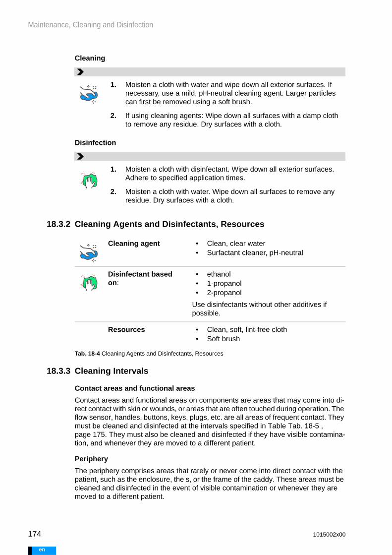
174
Maintenance, Cleaning and Disinfection
e
Cleaning
Disinfection
18.3.2 Cleaning Agents and Disinfectants, Resources
18.3.3 Cleaning Intervals
Contact areas and functional areas
Contact areas and functional areas on components are areas that may come into di-rect contact with skin or wounds, or areas that are often touched during operation. The flow sensor, handles, buttons, keys, plugs, etc. are all areas of frequent contact. They must be cleaned and disinfected at the intervals specified in Table Tab. 18-5 , page 175. They must also be cleaned and disinfected if they have visible contamina-tion, and whenever they are moved to a different patient.
Periphery
The periphery comprises areas that rarely or never come into direct contact with the patient, such as the enclosure, the s, or the frame of the caddy. These areas must be cleaned and disinfected in the event of visible contamination or whenever they are moved to a different patient.
1. Moisten a cloth with water and wipe down all exterior surfaces. If necessary, use a mild, pH-neutral cleaning agent. Larger particles can first be removed using a soft brush.
2. If using cleaning agents: Wipe down all surfaces with a damp cloth to remove any residue. Dry surfaces with a cloth.
1. Moisten a cloth with disinfectant. Wipe down all exterior surfaces. Adhere to specified application times.
2. Moisten a cloth with water. Wipe down all surfaces to remove any residue. Dry surfaces with a cloth.
Cleaning agent • Clean, clear water• Surfactant cleaner, pH-neutral
Disinfectant based on:
• ethanol• 1-propanol• 2-propanol
Use disinfectants without other additives if possible.
Resources • Clean, soft, lint-free cloth• Soft brush
Tab. 18-4 Cleaning Agents and Disinfectants, Resources
1015002x00
n

Maintenance, Cleaning and Disinfection
Key
Fixed intervals for contact areas and functional areas - every... days
Cleaning
before the component is used by another patient
Disinfection
If necessary, if contamina-tion is visible
Component When? Cleaning / disinfection
Flow sensor including protective cap, sensor quick connect and sensor locking clip
At each dressing change
Driving unit
Battery
Power supply unit
Sensor cable
Cable wrap
Battery charging unit
Caddy with accessory bag
Child caddy
Stroller Board
Panel PC including power supply unit and docking station
Manual pump
Short instructions
Tab. 18-5 Intervals
1015002x00 175
en

176
Maintenance, Cleaning and Disinfection
e
18.3.4 Notes on Cleaning and Disinfecting Components
Component Notes on cleaning and disinfection
Flow sensor including protective cap, sensor locking clip, and sen-sor quick connect (without sensor cable - for sensor cable, see below)
Check the flow display and note values.
Remove the flow sensor from the cannula.
Remove the sensor quick connect and the protective cap from the flow sensor. Clean and disinfect all com-ponents separately.
The flow sensor can also be rinsed or immersed in water. The flow sensor can be sprayed with disinfectant directly or cleaned in an ultrasound. Perform ultra-sound cleaning each time before using the product with a new patient. Water temperature 40°C, duration approx. 20 min, cleaning additives in accordance with manufacturer specifications (recommendation: 3 % Mediclean)
If the sensor locking clip, sensor quick connect, and protective cap cannot be cleaned thoroughly, replace those components.
Replace the sensor locking clip, sensor quick con-nect and protective cap for each new patient.
Dry the flow sensor and the cannula.
After cleaning and disinfection, re-attach the flow sen-sor to the cannula. Check the correct position of the flow sensor. Check the flow display and compare the values to the ones recorded prior to cleaning. If dis-crepancies of more than 10% are observed, check and correct sensor position.
Flow sensor cable Remove the cable wrap.
Cover electrical contacts.
Driving unit The driving unit can be cleaned and disinfected during operation.
Only remove one battery at a time.
Close any openings that can be closed if they are not in use.
Pull out the handle for cleaning and disinfection.
Take care not to allow any liquids to seep inside the driving unit. Do not immerse the driving unit.
Tab. 18-6 handling
1015002x00
n

Maintenance, Cleaning and Disinfection
18.4 Performing Functional TestsUsers will need to perform the functional tests listed in the table.
Battery Remove the battery from the driving unit or battery charging unit. Only remove one battery from the driving unit at a time.
Do not immerse the battery.
Cover electrical contacts.
Battery charging unit Disconnect the battery charging unit from mains power.
Remove the batteries.
Cover electrical contacts.
Do not immerse the battery charging unit.
Power supply unit Disconnect from mains power and connected device. Remove the cable.
Cover electrical contacts.
Do not immerse the power supply unit.
Cable wrap Remove the cable wrap.
If cleaning and disinfection are not possible, replace the cable wrap.
USB cable, adapter for external alarm (nurse call), power supply cable
Disconnect the cable from the connected device and from mains power.
Cover electrical contacts.
Panel PC Disconnect from mains power and the docking station.
Switch off the panel PC.
Close the USB port cover.
Caddy Remove the driving unit and accessory bag.
Pull out the handle for cleaning and disinfection. Remove the wheels if necessary.
Accessory Bag Remove the accessory bag from the caddy.
Empty the bag.
Use a soft brush to remove any contamination.
Stroller Board Remove the driving unit.
Remove the accessory bag.
Disconnect the stroller board from the stroller.
Component Notes on cleaning and disinfection
Tab. 18-6 handling
1015002x00 177
en

178
Maintenance, Cleaning and Disinfection
e
18.5 Overview of Regular Actions
Component When? Execution
Alarm module: Check of audible alarms
On the driving unit control panel:
1. Press and release the left <button>2. Press and release the right <button>
Result
The functional test is passed if, when both the left and right <buttons> are pressed, an audible tone is emitted. The absence of an audible tone indicates an error. The driving unit is incapable of emitting audible alarms correctly. The driving unit must be replaced.
Tab. 18-7 Functional tests
Fig. 18-1 Overview of regular actions
1015002x00
n

Maintenance, Cleaning and Disinfection
When? What / Where? Action
Every four hours Cannulae Check for deposits and defects
Blood pump Check for deposits and defects
Check for complete filling and emptying
Driving unit Check list of emitted alarms
Daily Alarm module Alarm module functional test
When changing dressings: Intervals vary, see EXCOR Sterile Compo-nents instructions for use
Transcutaneous exit site
Cleaning and disinfection
Dressing change
Cannulae under-neath dressing
Cleaning and disinfection
Check for deposits and defects
Flow sensor Cleaning and disinfection
Weekly Contact and func-tional areas on all EXCOR Active components
Cleaning and disinfection
Check for defects
Every four weeks Emergency battery on non-active driv-ing unit
Fully charge
Every three months Batteries that are not in use (batteries in storage)
Fully charge
1015002x00 179
en

180
Maintenance, Cleaning and Disinfection
e
1015002x00
n

Scope of Delivery and Transport Cases
WARNING
19 Scope of Delivery and Transport Cases
System components must only be transported or shipped in their in-tended transport cases / packaging. Otherwise, safe and proper trans-portation of the components is not guaranteed.
19.1 Contents of the Components Case
Pos. Component Quantity
1 Caddy 1 1501400
2 Accessory Bag 1 1501560
3 Battery charging unit 1 1540060
4 Docking Station 1 1501510
5 Caddy castors 2 see caddy
6 Power supply unit 2 1501200
7 Panel PC power supply unit 1 1501520
8 Panel PC 1 1501500
9 Power cable 3 country-specific
10 Tire pump for caddy 1 1501410
11 USB stick 1 1501530
12 USB cable 1 1501540
13 Adapter for external alarm 1 1501550
14 Instructions for clinical use - for hospitals and patients
1 each country-specific
15 Short instructions 1 country-specific
16 Components case (case without contents)
1 1501100
Tab. 19-1 Contents of the Components Case
1015002x00 181
en

182
Scope of Delivery and Transport Cases
e
Fig. 19-1 Contents of the components case
Pack the case as shown in the diagram.
19.2 Contents of the Driving Unit CaseThe driving unit case contains the driving unit, the batteries, and the manual pump. The specific driving unit model varies by approval region. Driving unit cases that are labeled as “Driving unit back-up set” only contain a driving unit.
1 2 3 4
55
6 6 7
8
9
9
9
10 11 12
13
1415
Pos. Component Quantity
1 Manual pump 1 1502400
2 Driving unit or 1 1502200
Driving unit 1502210
3 Battery 4 1503200
4 Driving unit case (case without con-tents)
1 1502100
Tab. 19-2 Contents of driving unit case
1015002x00
n

Scope of Delivery and Transport Cases
19.3 Flow Sensor Set ContentsThe flow sensors are selected based on the combination of blood pumps and cannu-lae in use. Each blood pump requires one flow sensor set.
Pack the driving unit, batteries, and manual pump into the driving unit case as shown in the figure.
1 Manual pump2 Driving unit3 Battery
Fig. 19-2 Driving unit case
1 Pull-out handle2 Grommet for sealing the box3 Lock
1
2
3
3
3
3
12
3
3
2
Flow sensor set Quantity
Flow sensor set 1 - FS06-06-P 1505000
Flow sensor 1 FS06-06-P
Replacement parts set FS06, consist-ing of:
1 1505110
- Sensor quick connect FS06 3
- Sensor locking clip FS06 2
- Protective cap 1
Tab. 19-3 Flow sensor set contents
1015002x00 183
en

184
Scope of Delivery and Transport Cases
e
Cable wrap including wrapping tool 2 1505100
Accompanying documentation 1
Flow sensor set 2 - FS09-09-P 1505010
Flow sensor 1 FS09-09-P
Replacement parts set FS09, consist-ing of:
1 1505120
- Sensor quick connect FS09 3
- Sensor locking clip FS09 2
- Protective cap 1
Cable wrap including wrapping tool 2 1505100
Accompanying documentation 1
Flow sensor set 3 - FS09-12-P 1505020
Flow sensor 1 FS09-12-P
Replacement parts set FS09-12, con-sisting of:
1 1505140
- Sensor quick connect FS12 3
- Sensor locking clip FS09 2
- Protective cap 1
Cable wrap including wrapping tool 2 1505100
Accompanying documentation 1
Flow sensor set 4 - FS12-12-P 1505030
Flow sensor 1 FS12-12-P
Replacement parts set FS12, consist-ing of:
1 1505130
- Sensor quick connect FS12 3
- Sensor locking clip FS12 2
- Protective cap 1
Flow sensor set Quantity
Tab. 19-3 Flow sensor set contents
1015002x00
n

Scope of Delivery and Transport Cases
19.4 Optional Components
Cable wrap including wrapping tool 2 1505100
Accompanying documentation 1
Flow sensor set 5 - FS09-12-C 1505040
Flow sensor 1 FS09-12-C
Replacement parts set FS12, consist-ing of:
1 1505130
- Sensor quick connect FS12 3
- Sensor locking clip FS09 2
- Protective cap 1
Cable wrap including wrapping tool 2 1505100
Accompanying documentation 1
Flow sensor set 6 - FS12-12-C 1505050
Flow sensor 1 FS12-12-C
Replacement parts set FS12, consist-ing of:
1 1505130
- Sensor quick connect FS12 3
- Sensor locking clip FS12 2
- Protective cap 1
Cable wrap including wrapping tool 2 1505130
Accompanying documentation 1 1505260
Flow sensor set Quantity
Tab. 19-3 Flow sensor set contents
Pos. Component Quantity
1 Stroller board 1 1504430
2 Stroller frame 1 1550201
Tab. 19-4 Optional components
1015002x00 185
en

186
Scope of Delivery and Transport Cases
e
3 Child seat fixture with accesso-ries
1 1550202
4 Baby seat fixture 1 1550203
Pos. Component Quantity
Tab. 19-4 Optional components
1015002x00
n

Technical Specifications
20 Technical Specifications
20.1 Driving Unit
20.2 Battery
Parameter Value
Weight approx. 12 kg
Weight with batteries approx. 14.4 kg
Dimensions (L x W x H) 326 mm x 218 mm x 398 mm
Protection class
(Protection against electric shock)
II
Input voltage 19 V DC
Power consumption 110 VA
Protection type, ingress protection IP 53 (dust-protected, protected against spray-ing water)
Sound pressure 45 ±3 dB (A)
Alarm acoustic pressure level max. 76 ±3 dB (A)
Operating time on battery power 4 to 10h, see also section 5.7.1.9, page 56 et seq.
Emergency battery charging time max.. 7h
Maintenance interval 12 months or 34 million pump cycles (whichever comes first)
Tab. 20-1 Driving unit
Parameter Value
Type Li-Ion 4INR 19/66-3
Weight approx. 1.2 kg
Dimensions (L x W x H) 58 mm x 100 mm x 253 mm
Tab. 20-2 Battery
1015002x00 187
en

188
Technical Specifications
e
20.3 Flow sensor
20.4 Power Supply Unit for Driving Unit and Battery Charging Unit
Nominal voltage 14.4 V DC
Nominal capacity 6.0 Ah
Capacity 86.4 Wh
Charging time max. 7h in driving unit
max. 3h in battery charging unit
Protection type, ingress protection IP 53 (dust-protected, protected against spray-ing water)
Tab. 20-2 Battery
Parameter Value
Weight approx. 80 g
Dimensions without cable (L x W x H) 57 mm x 36 mm x 35 mm
Sensor cable approx. 2000 mm
Protection type, ingress protection IP 67 (dust-resistant, pro-tected against the effects of temporary immersion in water)
Tab. 20-3 Battery
Parameter Value
Weight approx. 0.85 kg
Dimensions (L x W x H) 200 mm x 80 mm x 41 mm
Input voltage 100 V to 240 V AC
50 Hz to 60 Hz
Input current max. 2.2 A
Output voltage 19.0 V DC
Tab. 20-4 Power Supply Unit for Driving Unit and Battery Charging Unit
1015002x00
n

Technical Specifications
20.5 Panel PC and Docking Station
Output current max. 9.47 A
Protection class II
Tab. 20-4 Power Supply Unit for Driving Unit and Battery Charging Unit
Parameter Value
Pan
el P
C
Weight 1.2 kg
Dimensions (L x W x H) 295 mm x 199 mm x 23 mm
Input voltage 18 V DC
Input current max. 3.5 A
Protection class I
I/O ports USB 3.0, USB 2.0
Battery Li-Ion
11.1 V, 2860 mAh
Operating time on battery power min. 1 h
Display size 10.1” multi-touch
Display resolution 1280 x 800
Doc
king
sta
tion
Input voltage 100 V to 240 V AC
50 Hz to 60 Hz
Input current max. 1.62 A
Output voltage 18 V DC
Output current max. 3.5 A
Protection class I
Tab. 20-5 Panel PC, docking station, power supply unit for panel PC
1015002x00 189
en

190
Technical Specifications
e
20.6 Battery Charging Unit
20.7 Caddy, Stroller Board
Doc
king
sta
tion
Weight approx. 1.1 kg
Dimensions (L x W x H) 261 mm x 185 mm x 104 mm
Input voltage 18 V DC
Input current 3.5 A
Protection class I
Tab. 20-5 Panel PC, docking station, power supply unit for panel PC
Parameter Value
Weight 1.0 kg
Dimensions (L x W x H) 207 mm x 166 mm x 126 mm
Input voltage 19 V DC
Input current max. 9.47 A
Output voltage for each battery mount 16.4 V DC
Charging current for each battery mount 4,0 A max.
Protection class II
Protection type, ingress protection IP 31 (protected against ingress of solid foreign bodies 2.5 mm in diame-ter or larger; protected against water ingress - vertical drips)
Tab. 20-6 Battery charging unit
Parameter Value
Cad
dy
Weight 8.5 kg
Dimensions (L x W x H) 574 mm x 462 mm x (832 mm to 1152 mm)
Tab. 20-7 Caddy, Stroller Board
1015002x00
n

Technical Specifications
20.8 Packaging
Acc
esso
ry b
ag Weight approx. 1.0 kg
Dimensions (L x W x H) 157 mm x 328 mm x 346 mm
Str
olle
r bo
ard Weight 3.6 kg
Dimensions 559 mm x 542 mm x 652 mm(mounted)
Tab. 20-7 Caddy, Stroller Board
Parameter Value
Com
pone
nts
case Weight 18.3 kg (empty)
36.3 kg (with contents)
Dimensions (L x W x H) 933 mm x 573 mm x 588 mm
Driv
ing
unit
case Weight 7.9 kg (empty)
25.4 kg (with contents)
Dimensions (L x W x H) 618 mm x 459 mm x 365 mm
Tab. 20-8 Components case and driving unit case
1015002x00 191
en

192
Technical Specifications
e
20.9 Ambient ConditionsAll specified air humidity values refer to non-condensing environmental conditions.
20.9.1 Operating Conditions
The following operating conditions apply to EXCOR Active.
Components Temperature Air humidity Pressure
Mobile:
Driving unit includ-ing battery1
Manual pump
Caddy
Baby buggyAll components can be used at elevations ranging from 0m to 2000m above sea level.Flow sensor
Stationary:
Power supply unit
Docking Station
Charging unit
USB memory stick
Adapter for exter-nal alarm (nurse call)
Panel PC
1 The driving unit and replacement driving unit may only be switched on in tem-peratures ranging from +5 to + 40 °C. Replacement driving units for BVAD patients must be kept at the ready in this temperature range.
Tab. 20-9 Ambient conditions for EXCOR Active
- 10 °C
40 °C
15 %
98 % 1060 hPa
800 hPa
15 °C
40 °C
5 °C
40 °C
15 %
90 %
1015002x00
n

Technical Specifications
ADVICE
20.9.2 Storage Conditions
The following storage conditions apply to EXCOR Active. They refer to the conditions at which components are to be stored for potential immediate use.
Store batteries in a dry place, at a temperature between 10 °C and 30 °C.
20.9.3 Transport Conditions and Long-Term Storage Conditions
The following transport and long-term storage conditions apply to EXCOR Active. Transport refers to shipment of components between the hospital and the manufac-turer or distributor.
After storage or transport, allow EXCOR Active to acclimatize at 20 °C for one hour. Remove the components from the transport boxes if necessary.
Temperature Air humidity Pressure
Tab. 20-10 Conditions for storage of EXCOR Active
10 °C
40 °C
20 %
90 % 1060 hPa
600 hPa
Temperature Air humidity Pressure
Tab. 20-11 Conditions for transport of EXCOR Active
- 10 °C
50 °C
20 %
90 % 1060 hPa
600 hPa
1015002x00 193
en

194
Technical Specifications
e
1015002x00
n

Overview - Parameters
21 Overview - Parameters
Not all parameter values can always be selected - availability depends on the driving unit model (see section 3.3: Scope of Driving Unit Functionality, page 20) and the spe-cific parameter. Example: if a 10 mL blood pump has been selected, 12 mm cannulae will not be available for selection.
21.1 Parameters - Blood Pumps and Cannulae
21.2 Permitted BVAD Combinations
Parameter Possible values
Operating mode BVAD, LVAD, RVAD
Blood pump 10 mL, 15 mL, 25 mL, 30 mL, 50 mL, 60 mL, 80 mL
Cannula 5 mm, 6 mm, 9 mm, 12 mm
Duration systole 30 % to 60 %
Rate 5 bpm to 130 bpm
Synchronization synchronous mode, asynchronous mode, separate mode
Flow alarm threshold 0 l/min to 10 l/min
Tab. 21-1 Parameters for blood pumps and cannulae
Left blood pump [mL] Right blood pump [mL]
10 10
15 10, 15
25 10, 15, 25
30 15, 25, 30
50 25, 30, 50
60 30, 50, 60
80 50, 60, 80
Tab. 21-2 Permitted BVAD combinations
1015002x00 195
en

196
Overview - Parameters
e
21.3 Permitted Combinations of Blood Pumps and Cannulae
21.4 Patient and Driving Unit
Size of the blood pump [mL]
Inflow cannula [mm] Outflow cannula [mm]
10 5
6
6
5
5
6
15 6 with connecting set
6 with connecting set
9
9
5 with connecting set
6 with connecting set
6 with connecting set
9
25 6 with connecting set
9
9
6 with connecting set
6 with connecting set
9
30 9
9
6 with connecting set
9
50 9
12
12
9
9
12
60 12
12
9
12
80 12 12
Tab. 21-3 Permitted combinations of blood pumps and cannulae
Parameter Value
Patient ID 1 to 32 characters, freely selectable
Patient weight 2 kg to 255 kg
Implantation date Freely selectable, up to the current date
Language for driving unit Based on language package installed, along with non-verbal version
Tab. 21-4 Patient and driving unit parameters
1015002x00
n

Overview - Parameters
Child protection on, off
Time of self-test Freely selectable down to the minute
Parameter Value
Tab. 21-4 Patient and driving unit parameters
1015002x00 197
en

198
Overview - Parameters
e
1015002x00
n

Using the External Alarm (Nurse Call)
22 Using the External Alarm (Nurse Call)
22.1 Assembling the External Alarm (Nurse Call) AdapterBefore using the external alarm (nurse call), the hospital must put a connector in place. The required connector plug is included in delivery and can be assembled by the hospital's qualified personnel.
Both opening and closing external alarm (nurse call) systems are supported. The con-nector and connector plug are marked to indicate whether they can be assigned as opening or closing contacts.
Before using the external alarm (nurse call) with a patient, check its functionality and ensure that it is properly connected.
Type
2-pole conductor to be used
Opening contact
Closing contact
Connector: Connector on the driving unit side
Connector plug: The connector assembled by the hospital must include a strain relief enclosure.
Driving unit connection to the hospital's alarm system →
Connector Wago WINSTA® mini 3-pole 890-113
Plug Wago WINSTA® mini 3-pole 890-103
Cable cross-section, single-wire and fine-wire
0.25 … 1.5 mm² / 22 … 16 AWG
Cable cross-section, multi-wire 0.25 … 1 mm² / 22 … 18 AWG
Stripping length 9 mm / 0.35”
Sheath stripping 37 mm / 1.45”
Conductor diameter 4.5 … 10 mm / 0.18... 0.39”
1015002x00 199
en

200
Using the External Alarm (Nurse Call)
e
Electrical data The contacts are de-energized.
Rated voltage maximum 60 V
Rated current maximum 3 A
1015002x00
n

EMC
WARNING
23 EMC
23.1 Safety Information
Use of EXCOR Active with accessories or components (e.g., power supply cables) that have not been specified and supplied by the EXCOR Active system manufacturers could create increased electro-magnetic disturbances or reduce the electromagnetic immunity of EXCOR Active. This may lead to malfunctions.
Ensure that a distance of at least 30 cm is maintained between EXCOR Active and any active mobile phones or portable HF commu-nication equipment (including accessories such as antenna cables or external antennas). Otherwise, electromagnetic disturbances may oc-cur, and the functionality of EXCOR Active cannot be guaranteed.
Additional devices connected to medical electrical equipment must comply with IEC or ISO standards (e.g. IEC 60950 or IEC 62368 for data processing equipment). In addition, all configurations must meet the requirements for medical electrical systems (see section 16 of the latest valid version of IEC 60601-1). Anyone who connects additional devices to medical electrical equipment configures a medical system and is therefore responsible for ensuring that the system meets the re-quirements for medical electrical systems. In case of doubt, please contact Berlin Heart.
23.2 Major Performance CharacteristicsThe following essential performance characteristics have been tested, and are valid even under the influence of electromagnetic disturbances:
• Automatic start of a configured driving unit when connected to a power supply• Blood pump operation using the set parameters• Continuous monitoring of driving unit pressures and blood flow in order to detect
changes in patient care and emit any necessary alarms.• Audible and visible emission of high-priority alarms
The following parameters can be set on EXCOR Active to the specified degrees of ac-curacy (for right and left in BVAD mode, if applicable):
• The Rate can be set within a range of 5 bpm to 130 bpm. The parameter does not deviate from the set value by more than ± 5%.
• Duration systole can be set within a range of 30% to 60%. The parameter does not deviate from the set value by more than ± 5%.
• The Average driving pressure does not deviate from the set value by more than ± 10 mmHg.
• The Piston stroke does not deviate from the set value by more than ± 2 mm.• The Flow does not deviate from the set value by more than ± 10%.• Synchronization does not deviate by more than ± 8%.
Even under the influence of interference, the following apply:
• In normal operation, no false positive alarms of low, medium, or high priority oc-cur. Electromagnetic radiation has no effect on the driving unit’s capability of emit-
1015002x00 201
en

202
EMC
e
ting high-priority alarms with the following characteristics: The tone sequence for the high-priority alarm is recognizable, and the corresponding LED flashes red.
• No disruptions in communication between the panel PC and the driving unit oc-cur, or no more than one temporary (max. 5 s) disruption occurs (e.g., due to high-frequency surgery). When communication is interrupted, switching the panel PC off and on restores communication. The USB cable must be disconnected and reconnected.
• Information is always visible on the user interface of the panel PC. If the user in-terface freezes, switching the panel PC off and on rectifies the problem. The USB cable must be disconnected and reconnected. When the user interface is disrupt-ed by electromagnetic radiation (e.g., noise, flickering, bars), the information dis-played (symbols, text, graphics) remains easy to read.
• No undesired switch to emergency operation occurs.
23.3 Electromagnetic Emissions
Applicable test standard: IEC 60601-1-2:2014
Failure to maintain the recommended minimum safety distances to the electromagnet-ic disturbances can lead to impairment or loss of essential performance, see section 23.2: Major Performance Characteristics, page 201.
Guidance and manufacturer's declaration – electromagnetic interference emission measure-ment
EXCOR Active is intended for use in an electromagnetic environment as described below. The customer or user of EXCOR Active must ensure that EXCOR Active is used in such an environment.
Interference emissionmeasurements
Compliance Electromagnetic environment - Guidance
HF emissions as per CISPR 11 Group 1 EXCOR Active uses HF energy only for its internal function. Its HF emission is therefore very low and is not likely to cause any interference in nearby elec-tronic equipment.
HF emissions as per CISPR 11 Class B EXCOR Active is suitable for use in all establishments, including domestic establishments and those directly con-nected to the public low-voltage power supply network that supplies buildings used for domestic purposes..
Harmonic emissions as per IEC 61000-3-2
Class A
Voltage fluctuations/flicker emissions according to IEC 61000-3-3
Complies
Tab. 23-1 Electromagnetic emissions
1015002x00
n

EMC
23.4 Electromagnetic Immunity, Part 1
Guidance and manufacturer's declaration – electromagnetic immunity
EXCOR Active is intended for use in an electromagnetic environment as specified below. The customer or user of EXCOR Active must ensure that EXCOR Active is used in such an envi-ronment.
Immunity tests IEC 60601 Test level
Compliance level Electromagnetic environ-ment - Guidance
Electrostatic dis-charge (ESD) as per IEC 61000-4-2
±8 kV contact discharge
±15 kV air discharge
±8 kV contact discharge
±15 kV air discharge
Floors should be wood or con-crete, or ceramic tiles. If the floor is covered with synthetic material, the relative air humidity must be at least 30 %.
Fast transient electrical interfer-ence/bursts as per IEC 61000-4-4
±2 kV power supply lines
±1 kV for input and output lines
±2 kV power supply lines
±1 kV for input and output lines
Mains power quality should be that of a professional health-care establishment, as well as that of a home healthcare environment.
Surges as per IEC 61000-4-5
±1 kV differential mode voltage
±2 kV common mode volt-age
±1 kV differential mode voltage
±2 kV common mode voltage
Mains power quality should be that of a professional health-care establishment, as well as that of a home healthcare environment.
Voltage dips, short interrup-tions and volt-age variations on power supply input lines as per IEC 61000-4-11
0 % UT (100 % dip in UT) for ½ cycle at 0,45, 90, 135, 180, 225, 270 and 315 degrees
0 % UT (100% dip in UT) for 1 cycle
70 % UT (30 % dip in UT) for 0.5 sec-onds
0 % UT (100 % dip in UT) for 5 seconds = 50 Hz and 6 sec-onds = 60 Hz
0 % UT (100 % dip in UT) for ½ period at 0, 45, 90, 135, 180, 225, 270 and 315 degrees
0 % UT (100 % dip in UT) for 1 period
70 % UT (30 % dip in UT) for 0.5 sec-onds
0 % UT (100 % dip in UT) for 5 seconds = 50 Hz and 6 seconds = 60 Hz
Mains power quality should be that of a professional health-care establishment, as well as that of a home healthcare environment. If the EXCOR Active user requires continued operation during power mains interruptions, it is recom-mended that EXCOR Active be powered from an uninter-ruptible power supply or a bat-tery.
Power fre-quency (50/60 Hz) magnetic field as per IEC 61000-4-8
30 A/m 30 A/m Magnetic fields at the mains frequency should be that of typical levels found in profes-sional healthcare establish-ments and in home healthcare environments.
Presumed distance from mag-netic field sources: 15 cm.
NOTE: UT is the AC supply voltage prior to application of the test level.
Tab. 23-2 Electromagnetic immunity, part 1
1015002x00 203
en

204
EMC
e
23.5 Electromagnetic Immunity, Part 2
Guidance and manufacturer's declaration – electromagnetic immunity
EXCOR Active is intended for use in an electromagnetic environment as described below. The customer or user of EXCOR Active must ensure that EXCOR Active is used in such an environment.
Immunity tests IEC 60601 test level
Level of compli-ance
Electromagnetic environ-ment - Guidance
Portable and mobile RF communication equipment should be used no closer to the EXCOR Active sys-tem or its cables than the recommended separation distance, calculated from the equation applicable to frequencies of the transmit-ter.
Recommended separa-tion distance
Conducted interfer-ence induced by high-frequency distur-bances, pursuant to IEC 61000-4-6
3 V
150 kHz to 80 MHz outside of ISM or amateur radio band-widthsa
3 V d=2√P
6 V
150 kHz to 80 MHz within ISM or ama-teur radio band-widthsa
6 V d=1√P
Radiated HF interfer-ence according to IEC 61000-4-3
10 V/ m
80 MHz to 6 GHz
9V/m or 28V/m from 385MHz to 6GHz at selected frequen-cies
10 V/ m
80 MHz to 6 GHz
9V/m or 28V/m from 385MHz to 6GHz at selected frequencies
d=0.6√P
Where "P" is the maximum nominal output power rating of the trans-mitter in watts (W) according to the specifications of the transmitter manufacturer and "d" as the recommended separation distance in meters (m) "b". Field strengths from fixed RF transmitters, as deter-mined by an electromagnetic site survey "c" should be less than the compliance level in each frequency range "d". Interference may occur in the vicinity of equipment marked with the following symbol.
NOTE: this guidance may not apply in all situations. Electromagnetic propagation is affected by absorption and reflection from structures, objects, and people.
Tab. 23-3 Electromagnetic immunity, part 2 (Table 1 of 2)
1015002x00
n
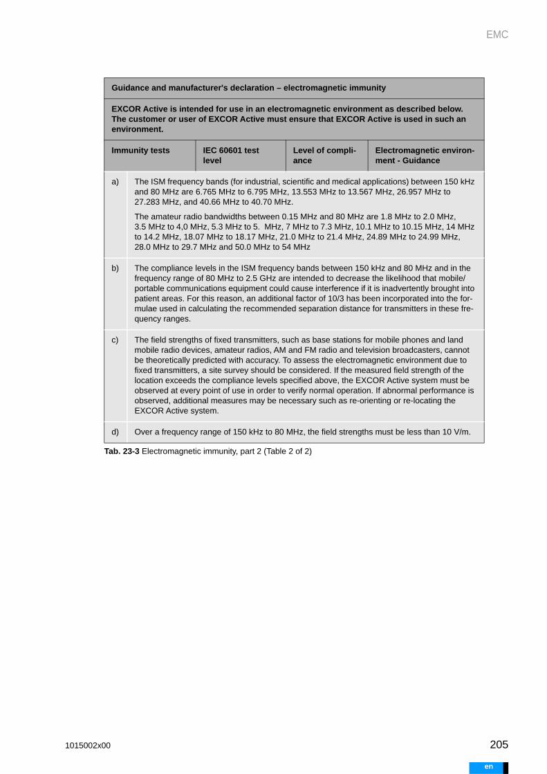
EMC
a) The ISM frequency bands (for industrial, scientific and medical applications) between 150 kHz and 80 MHz are 6.765 MHz to 6.795 MHz, 13.553 MHz to 13.567 MHz, 26.957 MHz to 27.283 MHz, and 40.66 MHz to 40.70 MHz.
The amateur radio bandwidths between 0.15 MHz and 80 MHz are 1.8 MHz to 2.0 MHz, 3.5 MHz to 4,0 MHz, 5.3 MHz to 5. MHz, 7 MHz to 7.3 MHz, 10.1 MHz to 10.15 MHz, 14 MHz to 14.2 MHz, 18.07 MHz to 18.17 MHz, 21.0 MHz to 21.4 MHz, 24.89 MHz to 24.99 MHz, 28.0 MHz to 29.7 MHz and 50.0 MHz to 54 MHz
b) The compliance levels in the ISM frequency bands between 150 kHz and 80 MHz and in the frequency range of 80 MHz to 2.5 GHz are intended to decrease the likelihood that mobile/portable communications equipment could cause interference if it is inadvertently brought into patient areas. For this reason, an additional factor of 10/3 has been incorporated into the for-mulae used in calculating the recommended separation distance for transmitters in these fre-quency ranges.
c) The field strengths of fixed transmitters, such as base stations for mobile phones and land mobile radio devices, amateur radios, AM and FM radio and television broadcasters, cannot be theoretically predicted with accuracy. To assess the electromagnetic environment due to fixed transmitters, a site survey should be considered. If the measured field strength of the location exceeds the compliance levels specified above, the EXCOR Active system must be observed at every point of use in order to verify normal operation. If abnormal performance is observed, additional measures may be necessary such as re-orienting or re-locating the EXCOR Active system.
d) Over a frequency range of 150 kHz to 80 MHz, the field strengths must be less than 10 V/m.
Guidance and manufacturer's declaration – electromagnetic immunity
EXCOR Active is intended for use in an electromagnetic environment as described below. The customer or user of EXCOR Active must ensure that EXCOR Active is used in such an environment.
Immunity tests IEC 60601 test level
Level of compli-ance
Electromagnetic environ-ment - Guidance
Tab. 23-3 Electromagnetic immunity, part 2 (Table 2 of 2)
1015002x00 205
en

206
EMC
e
1015002x00
n

Patient ID Labels
24 Patient ID Labels
Configured replacement driving units must be clearly labeled so that they can be de-finitively associated with a patient. There is a tray for the patient ID on the rear side of the driving unit. If the original label is already filled in, feel free to copy and use this label template.
Replacement driving unit configured for
Patient ID:
—————————————————————
Replacement driving unit configured for
Patient ID:
—————————————————————
Replacement driving unit configured for
Patient ID:
—————————————————————
Replacement driving unit configured for
Patient ID:
—————————————————————
Replacement driving unit configured for
Patient ID:
—————————————————————
Replacement driving unit configured for
Patient ID:
—————————————————————
Replacement driving unit configured for
Patient ID:
—————————————————————
1015002x00 207
en

208
Patient ID Labels
e
1015002x00
n

Abbrevations
Abbrevations
BBVAD: Biventricular Assist Device
CCISPR: Special International Committee on Radio Interference (comité international spécial des perturbations ra-dioélectriques) CPB: Cardiopulmonary bypass
EEMC: Electromagnetic compatibility ESD: Electrostatic discharge
HHDD: Hard Disk Drive HF: High frequency
IIEC: International Eletrotechnical Commission
LLVAD: Left Ventricular Assist Device
RRVAD: Right Ventricular Assist Device
1015002x00 209
en

Abbrevations
210
e
1015002x00
n

Print Control
A B C D E F G H I J K L M N O P Q R S T U V W X Y Z
a b c d e f g h i j k l m n o p q r s t u v w x y z
+ - * / > < ≥ ≤ = ± ¼ ½ ¾ ?
, ; . : - _ ( ) [ ] { } \ ´ ‘ “ „
! % & § ° $ ^ □
µ @ € # ~
© ®
←→ ↑ ↓
1 2 3 4 5 6 7 8 9 0
1 2 3 √
1015002x00 211
en

212
e
1015002x00
n