Evaluation of a Foreign Silicon Nitride as a Potential Gun ...
24
Evaluation of a Foreign Silicon Nitride as a Potential Gun Barrel Liner by Jeffrey J. Swab, Dominic Danna, Charles Leveritt, and Stephanie Piraino ARL-TR-5146 April 2010 Approved for public release; distribution is unlimited.
-
Upload
khangminh22 -
Category
Documents
-
view
5 -
download
0
Transcript of Evaluation of a Foreign Silicon Nitride as a Potential Gun ...
Evaluation of a Foreign Silicon Nitride as a Potential
Gun Barrel Liner
by Jeffrey J. Swab, Dominic Danna, Charles Leveritt,
and Stephanie Piraino
ARL-TR-5146 April 2010
Approved for public release; distribution is unlimited.
NOTICES
Disclaimers The findings in this report are not to be construed as an official Department of the Army position unless so designated by other authorized documents. Citation of manufacturer’s or trade names does not constitute an official endorsement or approval of the use thereof. Destroy this report when it is no longer needed. Do not return it to the originator.
Army Research Laboratory Aberdeen Proving Ground, MD 21005-5069
ARL-TR-5146 April 2010
Evaluation of a Foreign Silicon Nitride as a Potential Gun Barrel Liner
Jeffrey J. Swab and Stephanie Piraino
Weapons and Materials Research Laboratory, ARL
Dominic Danna Oak Ridge Institute for Science and Engineering
Oak Ridge, TN 37831
Charles Leveritt Advocate Wood
Harford County, MD 21084
Approved for public release; distribution is unlimited.
ii
REPORT DOCUMENTATION PAGE Form Approved OMB No. 0704-0188
Public reporting burden for this collection of information is estimated to average 1 hour per response, including the time for reviewing instructions, searching existing data sources, gathering and maintaining the data needed, and completing and reviewing the collection information. Send comments regarding this burden estimate or any other aspect of this collection of information, including suggestions for reducing the burden, to Department of Defense, Washington Headquarters Services, Directorate for Information Operations and Reports (0704-0188), 1215 Jefferson Davis Highway, Suite 1204, Arlington, VA 22202-4302. Respondents should be aware that notwithstanding any other provision of law, no person shall be subject to any penalty for failing to comply with a collection of information if it does not display a currently valid OMB control number. PLEASE DO NOT RETURN YOUR FORM TO THE ABOVE ADDRESS.
1. REPORT DATE (DD-MM-YYYY)
April 2010 2. REPORT TYPE
Final 3. DATES COVERED (From - To)
June 2008–August 2009 4. TITLE AND SUBTITLE
Evaluation of a Foreign Silicon Nitride as a Potential Gun Barrel Liner 5a. CONTRACT NUMBER
622618AH80 5b. GRANT NUMBER
5c. PROGRAM ELEMENT NUMBER
6. AUTHOR(S)
Jeffrey J. Swab, Dominic Danna, Charles Leveritt, and Stephanie Piraino 5d. PROJECT NUMBER
5e. TASK NUMBER
5f. WORK UNIT NUMBER
7. PERFORMING ORGANIZATION NAME(S) AND ADDRESS(ES)
U.S. Army Research Laboratory ATTN: RDRL-WMM-E Aberdeen Proving Ground, MD 21005-5069
8. PERFORMING ORGANIZATION REPORT NUMBER
ARL-TR-5146
9. SPONSORING/MONITORING AGENCY NAME(S) AND ADDRESS(ES)
10. SPONSOR/MONITOR’S ACRONYM(S)
11. SPONSOR/MONITOR'S REPORT NUMBER(S)
12. DISTRIBUTION/AVAILABILITY STATEMENT
Approved for public release; distribution is unlimited.
13. SUPPLEMENTARY NOTES
14. ABSTRACT
A silicon nitride (Si3N4) ceramic manufactured by FCT Technologie GmbH, Rauenstein, Germany was subjected to a series of tests (mechanical, physical, thermal, and erosion) to determine if this material might have potential applications as gun barrel liners. The tests conducted were similar to earlier tests performed by the U.S. Army Research Laboratory (ARL) on a variety of ceramic materials, including silicon nitride, for the same application. The erosion behavior was comparable to the previously tested ceramics but the mechanical and thermal properties were inferior making it unlikely that it would survive the interior ballistic conditions of a gun barrel.
15. SUBJECT TERMS
Silicon nitride, gun barrel liner, strength, fracture toughness
16. SECURITY CLASSIFICATION OF: 17. LIMITATION
OF ABSTRACT
UU
18. NUMBER OF PAGES
24
19a. NAME OF RESPONSIBLE PERSON
Jeffrey J. Swab a. REPORT
UNCLASSIFIED
b. ABSTRACT
UNCLASSIFIED
c. THIS PAGE
UNCLASSIFIED 19b. TELEPHONE NUMBER (Include area code)
(410) 306-0753 Standard Form 298 (Rev. 8/98)
Prescribed by ANSI Std. Z39.18

iii
Contents
List of Figures iv
List of Tables iv
1. Summary 1
1.1 Purpose/Scope .................................................................................................................1
1.2 Key Findings ...................................................................................................................1
2. Introduction 1
3. Material 3
4. Test Methodology 3
4.1 Mechanical Properties .....................................................................................................3
4.2 Thermal Properties ..........................................................................................................4
4.3 Erosion Testing................................................................................................................5
5. Results 6
6. Conclusions 9
7. References 10
Appendix. Mechanical Property Data 13
Distribution List 17
iv
List of Figures
Figure 1. Material data sheet provided by the manufacturer with the material. The Si3N4 evaluated in this effort is the gas pressure sintered (GPS) labeled FSNI highlighted by red box..............................................................................................................................................2
Figure 2. Gun used for blow-out tests. ............................................................................................5
Figure 3. Nozzle assembly for the blow-out gun test. Dimensions are in inches. .........................6
Figure 4. Example of a pore as the strength-limiting flaw. White arrow shows that the pore is located just beneath the tensile surface of this c-ring specimen. Specimen strength was 565 MPa. ....................................................................................................................................7
Figure 5. Images of FCT nozzle #1 before and after erosion testing. .............................................8
Figure 6. Images of FCT nozzle #2 after erosion testing. ...............................................................9
List of Tables
Table 1. Mechanical and thermal properties summary. ..................................................................7
Table 2. Summary of the mass loss/shot for FCT Si3N4. ................................................................8
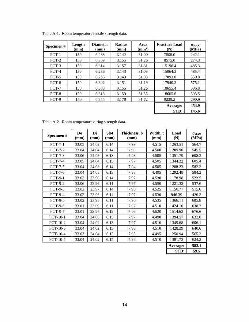
Table A-1. Room temperature tensile strength data. ....................................................................14
Table A-2. Room temperature c-ring strength data. .....................................................................14
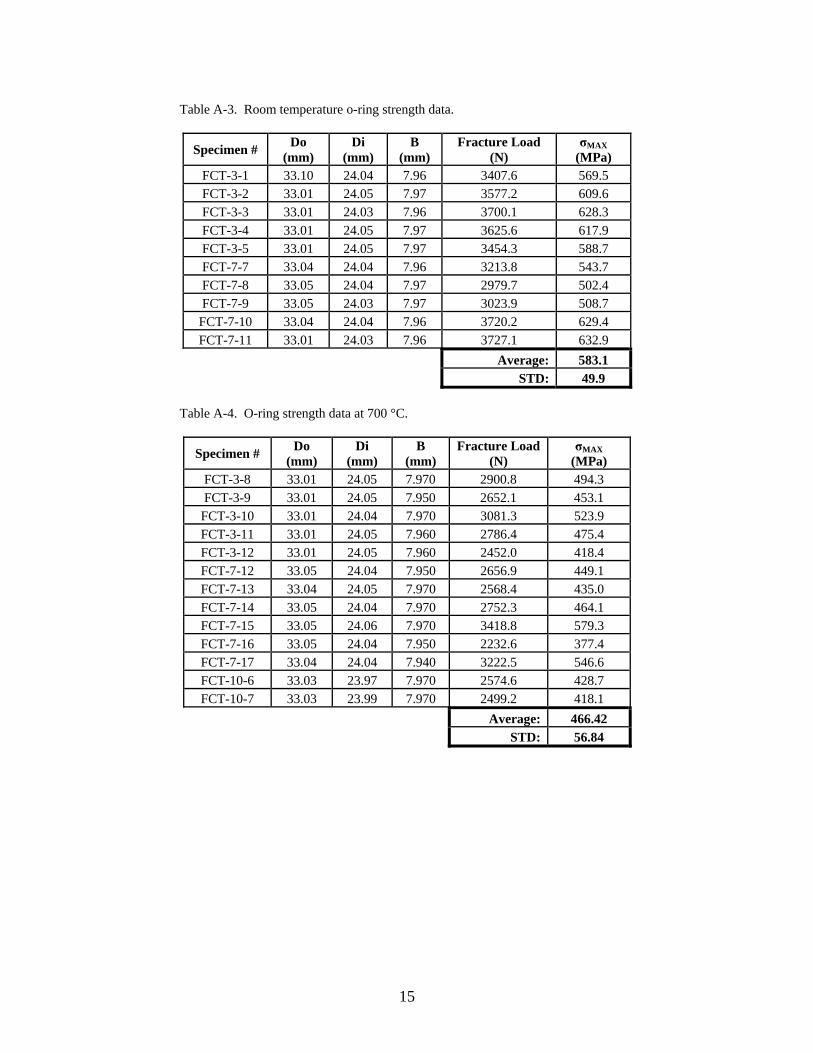
Table A-3. Room temperature o-ring strength data. .....................................................................15
Table A-4. O-ring strength data at 700 °C. ...................................................................................15
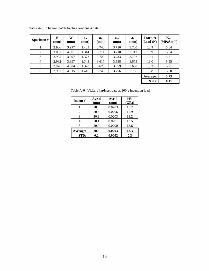
Table A-5. Chevron notch fracture toughness data. .....................................................................16
Table A-6. Vickers hardness data at 300 g indention load. ..........................................................16
1
1. Summary
1.1 Purpose/Scope
In this study a silicon nitride ceramic manufactured by a German company was subjected to a series of tests (mechanical, physical, thermal, and erosion) to determine if this material might have potential applications as gun barrel liners. The tests conducted were similar to earlier tests performed by the U.S. Army Research Laboratory (ARL) on a variety of ceramic materials, including silicon nitride, for the same application.
1.2 Key Findings
This silicon nitride performed quite well in the erosion testing. It exhibited a very low mass loss per test, which is in excellent agreement with other silicon nitrides previously subjected to the same erosion test procedure and parameters. However, when the mechanical and thermal properties of this Si3N4 are compared to the previously evaluated silicon nitrides and SiAlONs, it is inferior. The lower strength and toughness makes it unlikely that this Si3N4 would be able to handle the pressure and temperature profiles present during the interior ballistic event.
2. Introduction
The Army has a desire to develop lighter weight gun barrels with longer lifecycles that can handle the new high energy propellants currently available or under development. The steel barrels used in many systems have a short lifecycle and are susceptible to rapid and severe degradation when exposed to these new high-energy propellants. Ceramic materials have long been considered as a potential solution to these issues (1–5). It is anticipated that ceramic gun barrel liners will provide a 50% increase in barrel life with sustained accuracy for direct and indirect fire, enable a 20% increase in muzzle kinetic energy for direct fire, and provide a 5–25% weight reduction (per unit length of barrel) because of the combination of superior wear resistance, high temperature capability, and relatively low density that are inherent to ceramic materials. The development of a ceramic gun barrel will reduce maintenance costs while serving as an enabling technology for the use of higher energy propellants.
ARL completed a number of studies which have examined a variety of commercially-available ceramics for gun barrel applications (6–14). The ceramics examined included alumina (Al2O3), zirconia (ZrO2), silicon carbide (SiC), silicon nitride (Si3N4) and silicon-aluminum oxynitride (SiAlON). These studies clearly identified the silicon nitride/SiAlON family of materials as the most promising for applications as gun barrel liners across a wide range of calibers.

2
In this study a Si3N4 ceramic manufactured by a company in Germany was subjected to tests similar to the ones used to evaluate the earlier silicon nitride ceramics (6) in order to determine if it also might be applicable for gun barrel applications. According to the manufacturer’s property data sheet, figure 1, this Si3N4 has property values similar to the previously evaluated Si3N4 ceramics (6). The property values determined for this Si3N4 will be compared to the data already available on Si3N4.
Figure 1. Material data sheet provided by the manufacturer with the material. The Si3N4 evaluated in this effort is the gas pressure sintered (GPS) labeled FSNI highlighted by red box.

3
3. Material
The silicon nitride material to be evaluated was purchased from FCT Technologie GmbH, Rauenstein, Germany (FCT). It is fabricated using a GPS technique. Material was obtained from the manufacturer in three different geometries to facilitate the machining of the different test specimens required. Tubes 200-mm long with a nominal inner (Di) and outer (Do) diameters of 24 mm and 33 m, respectively, as well as two different cylinders: one 80-mm long with a 30-mm diameter and the other 150-mm long with a 20-mm diameter, were purchased.
4. Test Methodology
4.1 Mechanical Properties
Three different specimens were prepared and used to determine the strength of each ceramic. Uniaxial tension tests were used in an attempt to promote the volume-distributed flaws in the material while c-ring and o-ring tests highlighted the surface-distributed flaws on the outer and inner diameter respectively.
Cylindrical button-head tensile specimens were machined from the 150-mm long cylinders to the gage section dimensions listed in figure 9 of ASTM C1273 (15) with an overall specimen length of 135 mm. The room temperature uniaxial strength was determined using 10 specimens following the guidelines and equations in ASTM C1273 (15). The uniaxial tensile strength was calculated using equation 1:
Amax
P
uS , (1)
where Su is the tensile strength, Pmax is the breaking load, and A is the cross sectional area of the specimen.
C-ring specimens having a width of 8 mm with longitudinal 45° chamfers to a distance of 0.15 mm on the Do, and a slot height of 5.7 mm were machined from the tubular components and tested at room temperature in accordance with ASTM C1323 (16). A displacement rate of 0.5 mm/min was used to compressively and diametrally load the specimens to failure. A thin (0.005-in) graphite sheet was placed between the upper and lower contact locations to minimize the likelihood of contact-induced fracture. The geometry and failure loads were used to calculate the hoop or Do tangential failure stress (max) for each specimen according to the strength of materials solution in ASTM C1323:
4
max PR
btro
ro ra
ra R
, (2)
where P is the failure load, R = (ro-ri)/ln(ro/ri), ro is the outer c-ring radius, ri is the inner c-ring radius, ra is the average of ro and ri, b is width, and t is thickness or ro-ri.
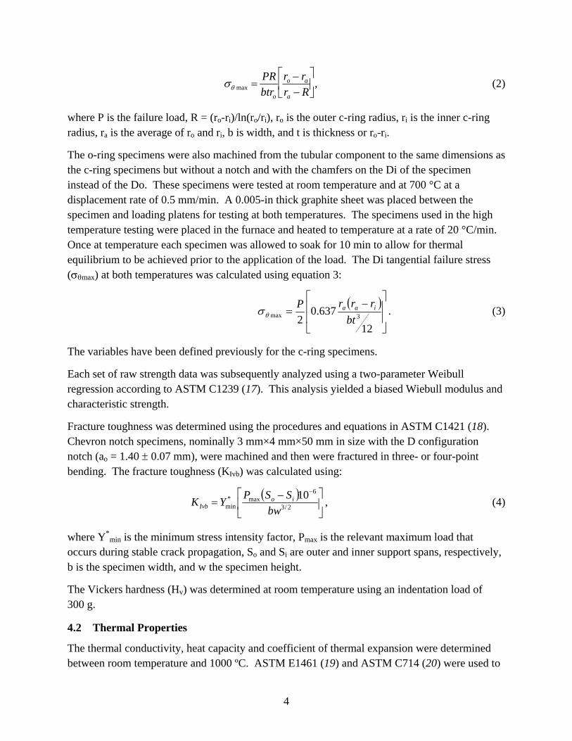
The o-ring specimens were also machined from the tubular component to the same dimensions as the c-ring specimens but without a notch and with the chamfers on the Di of the specimen instead of the Do. These specimens were tested at room temperature and at 700 °C at a displacement rate of 0.5 mm/min. A 0.005-in thick graphite sheet was placed between the specimen and loading platens for testing at both temperatures. The specimens used in the high temperature testing were placed in the furnace and heated to temperature at a rate of 20 °C/min. Once at temperature each specimen was allowed to soak for 10 min to allow for thermal equilibrium to be achieved prior to the application of the load. The Di tangential failure stress (max) at both temperatures was calculated using equation 3:
12
637.02 3max bt
rrrP iaa . (3)
The variables have been defined previously for the c-ring specimens.
Each set of raw strength data was subsequently analyzed using a two-parameter Weibull regression according to ASTM C1239 (17). This analysis yielded a biased Wiebull modulus and characteristic strength.
Fracture toughness was determined using the procedures and equations in ASTM C1421 (18). Chevron notch specimens, nominally 3 mm×4 mm×50 mm in size with the D configuration notch (ao = 1.40 0.07 mm), were machined and then were fractured in three- or four-point bending. The fracture toughness (KIvb) was calculated using:
2/3
6max*
min
10
bw
SSPYK io
Ivb , (4)
where Y*min is the minimum stress intensity factor, Pmax is the relevant maximum load that
occurs during stable crack propagation, So and Si are outer and inner support spans, respectively, b is the specimen width, and w the specimen height.
The Vickers hardness (Hv) was determined at room temperature using an indentation load of 300 g.
4.2 Thermal Properties
The thermal conductivity, heat capacity and coefficient of thermal expansion were determined between room temperature and 1000 ºC. ASTM E1461 (19) and ASTM C714 (20) were used to

5
obtain thermal diffusivity and heat capacity values using the laser flash method. A thermal conductivity was calculated from these values. The linear coefficient of thermal expansion was obtained using a prismatic specimen nominally 3 mm×4 mm×25 mm in size. Tests were conducted in a dual-rod dilatometer using a heating rate of 1 ºC/min following the procedure outlined in ASTM E228 (21). The data collection rate for this test was two datapoints/ºC.
4.3 Erosion Testing
The test used to simulate the interior ballistic conditions was a blow-out gun, figure 2. In this test the ceramic was exposed to interior ballistic conditions (temperature, pressure, etc.) created using JA-2 propellant (flame temperature–3420 K, impetus–1144 J/g). A ceramic nozzle was machined and placed in a steel surround, figure 3, creating a test piece that could be inserted into the gun. The nozzle was exposed to one shot then cleaned and weighed. The mass loss was determined and compared to the mass loss experienced by typical gun steel and the previously tested Si3N4 exposed to the same conditions. Each nozzle tested was exposed to a total of six shots.
Figure 2. Gun used for blow-out tests.

6
Figure 3. Nozzle assembly for the blow-out gun test. Dimensions are in inches.
5. Results
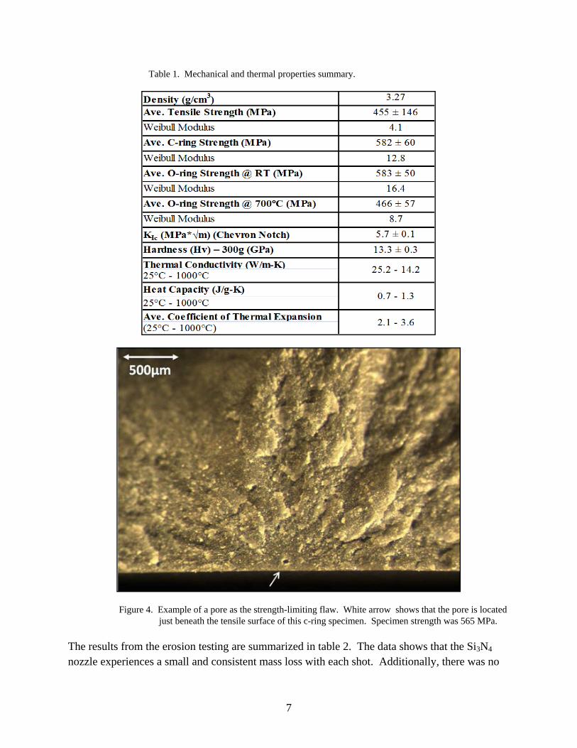
The results of the mechanical and thermal property testing are summarized in table 1 with the individual data points listed in the appendix. While the FCT material possesses a hardness value and thermal properties very similar to the Si3N4/SiAlON materials evaluated previously, it is inferior to these same materials when strength and fracture toughness are considered. Irrespective of the strength methodology employed there are two dominant flaw populations present in the material. One was a volume-distributed pore and the other was cracks or damage related to the surface finish. The pores, see figure 4, were essentially circular in shape with a diameter between 50 and 80 μm and were always located in the bulk of the specimen. The other flaw populations was always located at the specimen surface and due to either the machining process used to create the specimens for testing (for example, the chamfers machined on the c- or o-ring specimens) or the surface finish provided by the manufacturer. In the later instance the manufacturer was only provided the dimensional tolerances for the inner and outer diameter of tubes and not the procedure to achieve these dimensions or a requisite final surface finish. As a result, there were a number of specimens machined from these tubes that failed due to damage (cracks) imparted during the manufacturer’s finishing process.
7
Table 1. Mechanical and thermal properties summary.
Figure 4. Example of a pore as the strength-limiting flaw. White arrow shows that the pore is located just beneath the tensile surface of this c-ring specimen. Specimen strength was 565 MPa.
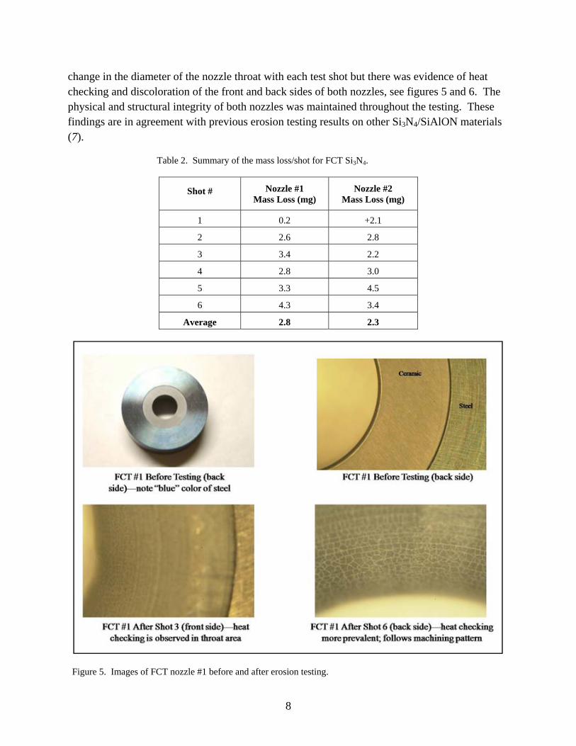
The results from the erosion testing are summarized in table 2. The data shows that the Si3N4 nozzle experiences a small and consistent mass loss with each shot. Additionally, there was no
8
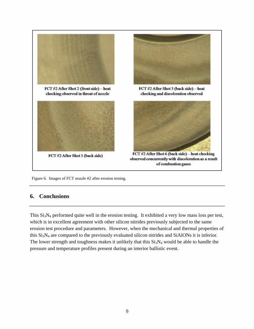
change in the diameter of the nozzle throat with each test shot but there was evidence of heat checking and discoloration of the front and back sides of both nozzles, see figures 5 and 6. The physical and structural integrity of both nozzles was maintained throughout the testing. These findings are in agreement with previous erosion testing results on other Si3N4/SiAlON materials (7).
Table 2. Summary of the mass loss/shot for FCT Si3N4.
Shot # Nozzle #1 Mass Loss (mg)
Nozzle #2 Mass Loss (mg)
1 0.2 +2.1
2 2.6 2.8
3 3.4 2.2
4 2.8 3.0
5 3.3 4.5
6 4.3 3.4
Average 2.8 2.3
Figure 5. Images of FCT nozzle #1 before and after erosion testing.
9
Figure 6. Images of FCT nozzle #2 after erosion testing.
6. Conclusions
This Si3N4 performed quite well in the erosion testing. It exhibited a very low mass loss per test, which is in excellent agreement with other silicon nitrides previously subjected to the same erosion test procedure and parameters. However, when the mechanical and thermal properties of this Si3N4 are compared to the previously evaluated silicon nitrides and SiAlONs it is inferior. The lower strength and toughness makes it unlikely that this Si3N4 would be able to handle the pressure and temperature profiles present during an interior ballistic event.
10
7. References
1. Giles, R.; Bunning, E.; Claxton, D. Feasibility of Ceramic Lined Gun Tube; ARLCD-CR-80058; U. S. Army Armament Research and Development Command, prepared by Maremont Corporation: Saco, ME, 1981.
2. Katz, R. N. Ceramic Gun Barrel Liners: Retrospect and Prospect. Proceedings of the Sagamore Workshop on Gun Barrel Wear and Erosion, sponsored by the U.S. Army Research Laboratory: Wilmington, DE, 1996; pp. 69–84.
3. SACO Defense, Advanced Materials Gun System Program–Phase I Final Technical Report, Government Contract No. DAAA21-88-C-0037, U.S. Army Armament Research, Development and Engineering Center: Picatinny Arsenal, NJ, May 1988–August 1989.
4. SACO Defense, Advanced Materials Gun System Program–Phase II Final Report, Government Contract No. DAAA21-88-C-0037, U.S. Army Armament Research, Development and Engineering Center: Picatinny Arsenal, NJ, August 1992.
5. SACO Defense, Advanced Materials Gun System Program–Phase III Final Report, Government Contract No. DAAA21-88-C-0037, U.S. Army Armament Research, Development and Engineering Center: Picatinny Arsenal, NJ, February 1995.
6. Swab, J. J.; Wereszczak, A. A.; Tice, J.; Caspe, R.; Kraft, R. Mechanical and Thermal Properties of Advanced Ceramics for Gun Barrel Applications; ARL-TR-3417; U.S. Army Research Laboratory: Aberdeen Proving Ground, MD, February 2005.
7. Swab, J. J.; Szewcyk, S.; Leveritt, C.; Van Akin, D. A.; Mossey, C.; Hellmann, J.; Homan, B.; Conroy, P.; Vigilante, G. Ceramic/Propellant Interactions in a Gun Barrel Environment; ARL-TR-4349; U.S. Army Research Laboratory: Aberdeen Proving Ground, MD, January 2008.
8. Woodruff, A. K.; Hellmann, J. Characterization of Long SiAlON Ceramic Tubes for Gun Barrel Applications; ARL-CR-573; U.S. Army Research Laboratory: Aberdeen Proving Ground, MD, June 2006.
9. Burton, L.; Swab, J. J.; Emerson, R.; Carter, R. Ceramic Gun Barrel Technology; Flis, W.; Scott, B., Eds.; 22nd International Symposium on Ballistics, Vol. 1; DEStech Publications Inc.: Lancaster, PA, 2005; pp. 251–258.
10. Carter, R. H.; Underwood, J. H.; Swab, J. J.; Emerson, R.; Wereszczak, A. A.; Leveritt, C. Material Selection for Ceramic Gun Tube Liner. Materials and Manufacturing Processes–Special Issue on the 2005 Gun Barrel Materials & Manufacturing Symposium, 21 (6); June 2006; pp. 584–590.

11
11. Carter, R. H.; Swab, J. J. Internal Pressure Testing of Structural Ceramic Tubes. Ceram. Eng. Sci. Proc. 2004, 25 (4), 295–300.
12. Durrett, M.; Shin, Y. C.; Tian, Y. Laser-Assisted Machining Applied to Rifling of Ceramic Barrels; ARL-CR-571; U.S. Army Research Laboratory: Aberdeen Proving Ground, MD, March 2006.
13. Christou, K.; Hida, G. SiAlON for Monolithic Ceramic Gun-Barrel Liners; ARL-CR-572; U.S. Army Research Laboratory: Aberdeen Proving Ground, MD, June 2006.
14. Withers, J. C. Silicon-Nitride-Based Ceramic Tubes for Gun Barrel Applications; ARL-CR-618; U.S. Army Research Laboratory: Aberdeen Proving Ground, MD, December 2008.
15. ASTM C1273. Standard Test Method for Tensile Strength of Monolithic Advanced Ceramics at Ambient Temperatures. Annu. Book ASTM Stand. 2003, Vol. 15.01.
16. ASTM C1323. Standard Test Method for Ultimate Strength of Advanced Ceramics with Diametrally Compressed C-Ring Specimens at Ambient Temperatures. Annu. Book ASTM Stand. 2002, Vol. 15.01.
17. ASTM C1239. Standard Practice for Reporting Uniaxial Strength Data and Estimating Weibull Distribution Parameters for Advanced Ceramics. Annu. Book ASTM Stand. 2003, Vol. 15.01.
18. ASTM C1421. Standard Test Methods for Determination of Fracture Toughness of Advanced Ceramics at Ambient Temperatures. Annu. Book ASTM Stand. 2003, Vol. 15.01.
19. ASTM E1461. Standard Test Method for Thermal Diffusivity of Solids by the Flash Method. Annu. Book ASTM Stand. 2003, 15.01.
20. ASTM C714. Standard Test Method for Thermal Diffusivity of Carbon and Graphite by a Thermal Pulse Method. Annu. Book ASTM Stand. 2003, Vol. 05.05.
21. ASTM E228. Standard Test Method for Linear Thermal Expansion of Solid Materials with a Vitreous Silica Dilatometer. Annu. Book ASTM Stand. 2003, Vol. 14.02.

12
INTENTIONALLY LEFT BLANK.

13
Appendix. Mechanical Property Data
14
Table A-1. Room temperature tensile strength data.
Specimen # Length (mm)
Diameter (mm)
Radius (mm)
Area (mm2)
Fracture Load (N)
σMAX (MPa)
FCT-1 150 6.283 3.142 31.00 7505.0 242.1 FCT-2 150 6.309 3.155 31.26 8575.0 274.3 FCT-3 150 6.314 3.157 31.31 15196.4 485.3 FCT-4 150 6.286 3.143 31.03 15064.3 485.4 FCT-5 150 6.286 3.143 31.03 17093.0 550.8 FCT-6 150 6.302 3.151 31.19 17940.2 575.1 FCT-7 150 6.309 3.155 31.26 18655.4 596.8 FCT-8 150 6.318 3.159 31.35 18605.6 593.5 FCT-9 150 6.355 3.178 31.72 9228.2 290.9
Average: 454.9 STD: 145.6
Table A-2. Room temperature c-ring strength data.
Specimen # Do
(mm) Di
(mm) Slot
(mm) Thickness, b
(mm) Width, t
(mm) Load (N)
σMAX
(MPa)
FCT-7-1 33.05 24.02 6.14 7.99 4.515 1263.51 564.7 FCT-7-2 33.04 24.04 6.14 7.98 4.500 1209.90 545.5 FCT-7-3 33.06 24.05 6.13 7.98 4.505 1351.79 608.3 FCT-7-4 33.05 24.04 6.15 7.97 4.505 1344.22 605.4 FCT-7-5 33.04 24.03 6.14 7.94 4.505 1288.23 582.2 FCT-7-6 33.04 24.05 6.13 7.98 4.495 1292.48 584.2 FCT-9-1 33.02 23.96 6.14 7.97 4.530 1178.98 523.5 FCT-9-2 33.06 23.96 6.11 7.97 4.550 1221.33 537.6 FCT-9-3 33.02 23.97 6.14 7.96 4.525 1156.77 515.6 FCT-9-4 33.02 23.96 6.14 7.97 4.530 946.39 420.2 FCT-9-5 33.02 23.95 6.11 7.96 4.535 1366.11 605.8 FCT-9-6 33.01 23.99 6.11 7.97 4.510 1424.10 638.7 FCT-9-7 33.01 23.97 6.12 7.96 4.520 1514.63 676.6
FCT-10-1 33.04 24.06 6.15 7.97 4.490 1394.57 632.8 FCT-10-2 33.04 24.02 6.13 7.97 4.510 1349.68 606.1 FCT-10-3 33.04 24.02 6.15 7.98 4.510 1428.29 640.6 FCT-10-4 33.03 24.04 6.13 7.98 4.495 1250.94 565.2 FCT-10-5 33.04 24.02 6.15 7.98 4.510 1391.73 624.2
Average: 582.1 STD: 59.5
15
Table A-3. Room temperature o-ring strength data.
Specimen # Do
(mm) Di
(mm) B
(mm) Fracture Load
(N) σMAX
(MPa) FCT-3-1 33.10 24.04 7.96 3407.6 569.5 FCT-3-2 33.01 24.05 7.97 3577.2 609.6 FCT-3-3 33.01 24.03 7.96 3700.1 628.3 FCT-3-4 33.01 24.05 7.97 3625.6 617.9 FCT-3-5 33.01 24.05 7.97 3454.3 588.7 FCT-7-7 33.04 24.04 7.96 3213.8 543.7 FCT-7-8 33.05 24.04 7.97 2979.7 502.4 FCT-7-9 33.05 24.03 7.97 3023.9 508.7
FCT-7-10 33.04 24.04 7.96 3720.2 629.4 FCT-7-11 33.01 24.03 7.96 3727.1 632.9
Average: 583.1 STD: 49.9
Table A-4. O-ring strength data at 700 °C.
Specimen # Do
(mm) Di
(mm) B
(mm) Fracture Load
(N) σMAX
(MPa) FCT-3-8 33.01 24.05 7.970 2900.8 494.3 FCT-3-9 33.01 24.05 7.950 2652.1 453.1
FCT-3-10 33.01 24.04 7.970 3081.3 523.9 FCT-3-11 33.01 24.05 7.960 2786.4 475.4 FCT-3-12 33.01 24.05 7.960 2452.0 418.4 FCT-7-12 33.05 24.04 7.950 2656.9 449.1 FCT-7-13 33.04 24.05 7.970 2568.4 435.0 FCT-7-14 33.05 24.04 7.970 2752.3 464.1 FCT-7-15 33.05 24.06 7.970 3418.8 579.3 FCT-7-16 33.05 24.04 7.950 2232.6 377.4 FCT-7-17 33.04 24.04 7.940 3222.5 546.6 FCT-10-6 33.03 23.97 7.970 2574.6 428.7 FCT-10-7 33.03 23.99 7.970 2499.2 418.1
Average: 466.42 STD: 56.84
16
Table A-5. Chevron notch fracture toughness data.
Specimen # B
(mm) W
(mm) a0
(mm) a1
(mm) a11
(mm) a12
(mm) Fracture Load (N)
KIC (MPa*m1/2)
1 2.986 3.997 1.433 3.748 3.716 3.780 18.3 5.84 2 3.001 4.001 1.344 3.711 3.710 3.712 18.9 5.64 3 2.995 3.997 1.372 3.720 3.733 3.707 19.1 5.81 4 2.982 3.997 1.343 3.617 3.558 3.675 19.0 5.55 5 2.976 4.004 1.370 3.675 3.659 3.690 19.3 5.71
6 2.991 4.015 1.410 3.746 3.756 3.736 18.8 5.80
Average: 5.73
STD: 0.11
Table A-6. Vickers hardness data at 300 g indention load.
Indent # Ave d (um)
Ave d (mm)
HV (GPa)
1 20.3 0.0203 13.2 2 20.6 0.0206 12.9 3 20.3 0.0203 13.2 4 20.1 0.0201 13.5 5 20.0 0.0200 13.6
Average: 20.3 0.0203 13.3 STD: 0.2 0.0002 0.3
NO. OF COPIES ORGANIZATION
17
1 DEFENSE TECHNICAL (PDF INFORMATION CTR only) DTIC OCA 8725 JOHN J KINGMAN RD STE 0944 FORT BELVOIR VA 22060-6218 1 DIRECTOR US ARMY RESEARCH LAB IMNE ALC HRR 2800 POWDER MILL RD ADELPHI MD 20783-1197 1 DIRECTOR US ARMY RESEARCH LAB RDRL CIM L 2800 POWDER MILL RD ADELPHI MD 20783-1197 2 DIRECTOR US ARMY RESEARCH LAB RDRL CIM P RDRL SES P D DANNA 2800 POWDER MILL RD ADELPHI MD 20783-1197
ABERDEEN PROVING GROUND 20 DIR USARL RDRL CIM G (BLDG 4600) RDRL WM J MCCAULEY RDRL WMM J ZABINSKI RDRL WMB B S PIRAINO RDRL WMB D P CONROY C LEVERITT RDRL WMB E T JESSEN J LASALVIA J SWAB (5) J SYNOWCZYNSKI RDRL WMB F R CARTER W DEROSSET RDRL WML E G OBERLIN RDRL WMM A J TZENG RDRL WMM B R KASTE RDRL WMM G J ANDZELM
18
INTENTIONALLY LEFT BLANK.