Essentials of Preclinical Conservative Dentistry ... - Notes Ocean
333
-
Upload
khangminh22 -
Category
Documents
-
view
1 -
download
0
Transcript of Essentials of Preclinical Conservative Dentistry ... - Notes Ocean

Essentials of
Preclinical Conservative Dentistry
EDITION2nd
Preclinical Dentistry.indb 1 29-05-2020 12:56:11
https://t.me/DentalBooksWorld

Preclinical Dentistry.indb 2 29-05-2020 12:56:11
https://t.me/DentalBooksWorld

EDITION2nd
EDITION2nd
EDITION2nd
Harpreet Singh, mds
Professor and HeadDepartment of Conservative Dentistry & EndodonticsMNDAV Dental College & HospitalSolan, India
Essentials of
Preclinical Conservative Dentistry
Preclinical Dentistry.indb 3 29-05-2020 12:56:11
https://t.me/DentalBooksWorld

Commissioning Editor: Gagandeep Kaur Sr. Manager - Publishing: Sangeetha P. Manager-Production Editorial: Pooja Chauhan Asstt. Manager Manufacturing: Sumit Johry
Copyright © 2020 by Wolters Kluwer Health (India)
10th Floor, Tower C, Building No. 10, Phase – II, DLF Cyber City Gurgaon, Haryana - 122002
All rights reserved. This product, consisting of the printed book, is protected by copyright. No part of this book may be reproduced in any form or by any means, including photocopying, or utilized by any informa-tion storage and retrieval system without written permission from the copyright owner.
The publisher is not responsible (as a matter of product liability, negligence, or otherwise) for any injury resulting from any material contained herein. This publication contains information relating to preclin-ical conservative dentistry that should not be construed as specific instructions for individual patients. Manufacturers’ product information and package inserts should be reviewed for current information, including contraindications, dosages, and precautions. All products/brands/names/processes cited in this book are the properties of their respective owners. Reference herein to any specific commercial products, processes, or services by trade name, trademark, manufacturer, or otherwise is purely for academic purposes and does not constitute or imply endorsement, recommendation, or favoring by the publisher. The views and opinions of authors expressed herein do not necessarily state or reflect those of the publisher, and shall not be used for advertising or product endorsement purposes.
Care has been taken to confirm the accuracy of the information presented and to describe generally accepted practices. However, the authors, editors, and publishers are not responsible for errors or omissions or for any consequences from application of the information in this book and make no warranty, expressed or implied, with respect to the currency, completeness, or accuracy of the contents of the publication. Application of this information in a particular situation remains the professional responsibility of the practitioner. Readers are urged to confirm that the information, especially with regard to drug dose/usage, complies with current legislation and standards of practice.
Please consult full prescribing information before issuing prescription for any product mentioned in the publication.
The publishers have made every effort to trace copyright holders for borrowed material. If they have inadver-tently overlooked any, they will be pleased to make the necessary arrangements at the first opportunity.
Second Edition ISBN: 978-93-89859-41-6
Published by Wolters Kluwer (India) Pvt. Ltd., New Delhi Compositor: Design Modus, New Delhi (www.designmodus.in)
For product enquiry, please contact– Marketing Department ([email protected]) or log on to our website www.wolterskluwerindia.co.in.
Preclinical Dentistry.indb 4 29-05-2020 12:56:11
https://t.me/DentalBooksWorld

Dedicated
To Pooja, my beloved wife, and Yash, my son.
Preclinical Dentistry.indb 5 29-05-2020 12:56:11
https://t.me/DentalBooksWorld

Gratitude
Sir Greene Vardiman Black(1836-1915)
‘Until the future dares forget the past, his name shall be a lantern and a light unto eternity”
Sidney lanier
Preclinical Dentistry.indb 6 29-05-2020 12:56:12
https://t.me/DentalBooksWorld

I am delighted to write the foreword for the second edition of ‘Essentials of Preclinical Conservative Dentistry’. This book has been written in order to emphasize the pertinent information which can serve the students as a fundamental source of knowledge. The first edition of this book, which was released seven years back in 2013 keeping in mind the need to train the undergraduate students efficiently for the subject of Preclinical Conservative Dentistry, has been well received by the students and the faculty alike.
The second edition involves contributions from several faculty members from across the country and beyond which for sure has further widened the horizons of this venture. The layout of each chapter includes description of the content in a simple, easy to understand language, use of numerous tables, figures and line diagrams in immaculate manner, finally concluding with a set of points to remember for a quick revision and self-assessment questions to test the reader’s understanding of the subject.
The contents are arranged in a logical sequential and in a unique presentation with exhaustive coverage of the relevant topics which would be useful and advantageous to readers from all the angles. The attention to minute details, evident in this book reflects the meticulousness and efficiency of the author.
It is my hope and expectation that this book will provide an effective learning experience for the preclinical students which eventually shall lead to improved patient care in the subsequent years to follow.
I am certain that this book shall be a valuable tool to reinforce and expand the possibilities of learning and teaching.
I wish Dr Harpreet Singh all that is best for the success of his venture.
Dr. Anil Chandra, mds, fadiDean
Faculty of Dental ScienceKing George’s Medical University
Lucknow, UP, IndiaFellow, Academy of Dentistry International
Fellow, American Academy of Cosmetic DentistryMember, American Association of Endodontics
Member, International Association of Dental ResearchMember, British Society of Restorative Dentistry
Member, Canadian Academy of Esthetic DentistryMember, Academy of Dental Materials
Member, Academy of Operative DentistryMember, Canadian Academy of Endodontics
Past President, Federation of Operative Dentistry of IndiaMember, Cariology Group IADR
President, IAOMT (India Chapter)Vice President, Academy of Cosmetic Dentistry, India
Vice President, Microscopic Dental Club, Italy
Foreword
Preclinical Dentistry.indb 7 29-05-2020 12:56:12
https://t.me/DentalBooksWorld

Preclinical Dentistry.indb 8 29-05-2020 12:56:12
https://t.me/DentalBooksWorld
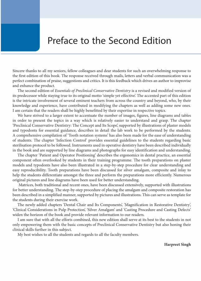
Sincere thanks to all my seniors, fellow colleagues and dear students for such an overwhelming response to the first edition of this book. The response received through mails, letters and verbal communication was a perfect combination of praise, suggestions and critics. It is this feedback which drives an author to improvise and enhance the product.
The second edition of Essentials of Preclinical Conservative Dentistry is a revised and modified version of its predecessor while staying true to its original motto ‘simple yet effective’. The accented part of this edition is the intricate involvement of several eminent teachers from across the country and beyond, who, by their knowledge and experience, have contributed in modifying the chapters as well as adding some new ones. I am certain that the readers shall be highly benefitted by their expertise in respective topics.
We have strived to a larger extent to accentuate the number of images, figures, line diagrams and tables in order to present the topics in a way which is relatively easier to understand and grasp. The chapter ‘Preclinical Conservative Dentistry: The Concept and Its Scope’, supported by illustrations of plaster models and typodonts for essential guidance, describes in detail the lab work to be performed by the students. A comprehensive compilation of ‘Tooth notation systems’ has also been made for the ease of understanding of students. The chapter ‘Infection Control’ provides essential guidelines to the students regarding basic sterilisation protocol to be followed. Instruments used in operative dentistry have been described individually in the book and are supported by line diagrams and photographs for easy identification and understanding.
The chapter ‘Patient and Operator Positioning’ describes the ergonomics in dental practice, an essential component often overlooked by students in their training programme. The tooth preparations on plaster models and typodonts have also been illustrated in a step-by-step procedure for clear understanding and easy reproducibility. Tooth preparations have been discussed for silver amalgam, composite and inlay to help the students differentiate amongst the three and perform the preparations more efficiently. Numerous original pictures and line diagrams have been used for better understanding.
Matrices, both traditional and recent ones, have been discussed extensively, supported with illustrations for better understanding. The step-by-step procedure of placing the amalgam and composite restoration has been described in a simplified manner, supported by pictures and illustrations. This can serve as template for the students during their exercise work.
The newly added chapters ‘Dental Chair and Its Components’, ‘Magnification in Restorative Dentistry’, ‘Clinical Considerations in Pulp Protection’, ‘Silver Amalgam’ and ‘Casting Procedure and Casting Defects’ widen the horizon of the book and provide relevant information to our readers.
I am sure that with all the efforts combined, this new edition shall serve at its best to the students in not only empowering them with the basic concepts of Preclinical Conservative Dentistry but also honing their clinical skills further in this subject.
My best wishes to all the students and regards to all the faculty members.
Harpreet Singh
Preface to the Second Edition
Preclinical Dentistry.indb 9 29-05-2020 12:56:12
https://t.me/DentalBooksWorld
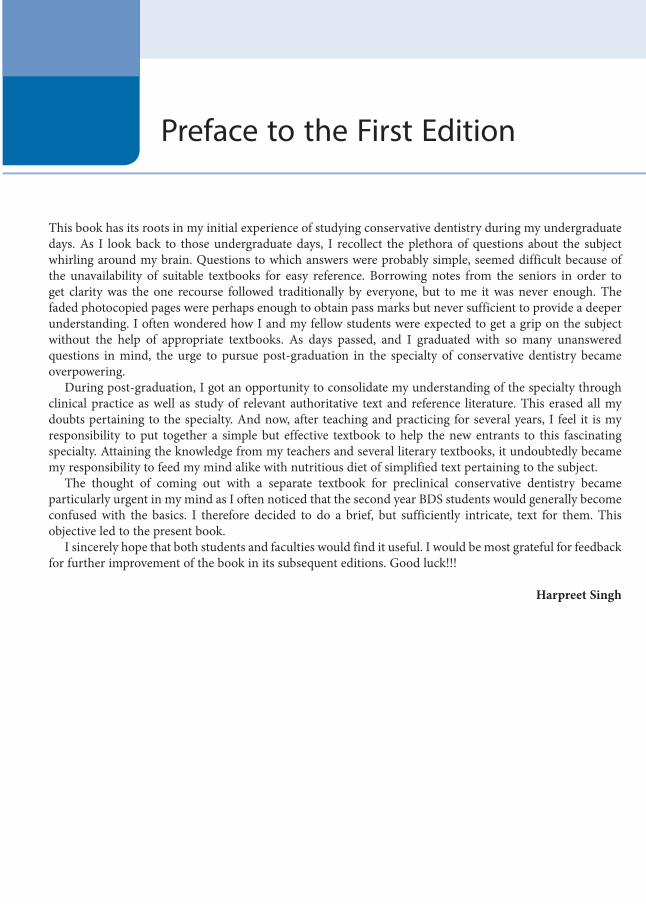
This book has its roots in my initial experience of studying conservative dentistry during my undergraduate days. As I look back to those undergraduate days, I recollect the plethora of questions about the subject whirling around my brain. Questions to which answers were probably simple, seemed difficult because of the unavailability of suitable textbooks for easy reference. Borrowing notes from the seniors in order to get clarity was the one recourse followed traditionally by everyone, but to me it was never enough. The faded photocopied pages were perhaps enough to obtain pass marks but never sufficient to provide a deeper understanding. I often wondered how I and my fellow students were expected to get a grip on the subject without the help of appropriate textbooks. As days passed, and I graduated with so many unanswered questions in mind, the urge to pursue post-graduation in the specialty of conservative dentistry became overpowering.
During post-graduation, I got an opportunity to consolidate my understanding of the specialty through clinical practice as well as study of relevant authoritative text and reference literature. This erased all my doubts pertaining to the specialty. And now, after teaching and practicing for several years, I feel it is my responsibility to put together a simple but effective textbook to help the new entrants to this fascinating specialty. Attaining the knowledge from my teachers and several literary textbooks, it undoubtedly became my responsibility to feed my mind alike with nutritious diet of simplified text pertaining to the subject.
The thought of coming out with a separate textbook for preclinical conservative dentistry became particularly urgent in my mind as I often noticed that the second year BDS students would generally become confused with the basics. I therefore decided to do a brief, but sufficiently intricate, text for them. This objective led to the present book.
I sincerely hope that both students and faculties would find it useful. I would be most grateful for feedback for further improvement of the book in its subsequent editions. Good luck!!!
Harpreet Singh
Preface to the First Edition
Preclinical Dentistry.indb 10 29-05-2020 12:56:12
https://t.me/DentalBooksWorld

An idea is like an abstract seed which requires the sunshine and the manure of the intellect. It also requires patience and tender nurturing for it to germinate into a sapling and then into a tree – its ultimate destiny.
Any piece of creation, whether it represents a dream or its ultimate realisation, owes a humble encomium to forces and reasons beyond the more visible.
My beloved wife, Dr Pooja Kapoor, very much deserves a special thanks. Her enthusiasm and diligence were the invaluable ingredients in making of this book. Her unconditional support always motivated me to work more and more towards my target. I thank her for being the force and the strength behind me and for having stood by me always. Had it not been for her, this book would not have seen the light of the day.
I owe my sincere gratitude to Dr Vinod Kapoor and Dr (Mrs.) Daljit Kapoor. Not only on professional but also on personal grounds I respect them for their simplicity and endearing nature. Their vast knowledge and experience has always been a source of inspiration and support for me. Amongst the most approachable teachers of my entire academic career, their conscientious approach and humility have taught me more than just the subject of Dentistry itself. I will always remain indebted to them for the same.
I thank Dr Upasna Kapoor for sharing her profound knowledge and showing keen personal interest. Her contribution is indeed invaluable.
Gratitude from the deepest part of my heart to (late) Dr G.K. Meshram Sir, for what I learned in the field, I owe it to him. Dr M.M. Warhadpande, Dr V. Gade and Dr V. Kokane deserve special thanks for their teachings to me regarding the subject and otherwise.
I thank my publisher Wolters Kluwer Health (India) for their efforts in meticulously developing the manuscript and bringing it out as a high-quality product. In particular, I would like to thank Ms Sangeetha Parthasarathy, Dr Harini Swaminathan and Ms Pooja Chauhan for their intense efforts in editing this textbook.
I thank my students for reposing their faith in me. Like the proverbial ‘foundation stone’ there will always be people whose contribution despite being so
magnanimous, unconditional and immeasurable remains invisible and unspoken of. I humbly thank them all.I would like to express my everlasting gratitude to my parents for their constant encouragement and
support. Their affable demeanour has always put me at ease – thus creating the most conducive ambience for performing this task.
And above all – The Almighty. A humble obeisance of my creation to him – from his creation.
Harpreet Singh
Acknowledgements
Preclinical Dentistry.indb 11 29-05-2020 12:56:12
https://t.me/DentalBooksWorld

KS BangaProfessor and HeadDepartment of Conservative Dentistry &
EndodonticsNair Hospital Dental CollegeMumbai, Maharashtra
Manju NairReaderDepartment of Conservative Dentistry &
EndodonticsPushpagiri College of Dental SciencesTiruvalla, Kerala
Minimol K JohnySenior LecturerDepartment of Conservative Dentistry &
EndodonticsPushpagiri College of Dental SciencesTiruvalla, Kerala
Reviewers
Preclinical Dentistry.indb 12 29-05-2020 12:56:12
https://t.me/DentalBooksWorld
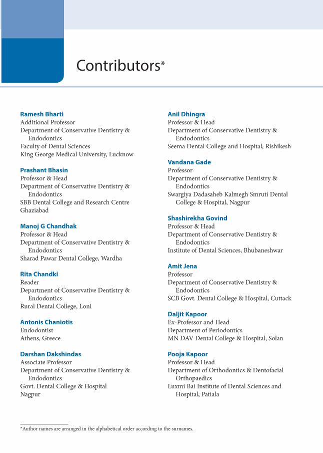
Ramesh BhartiAdditional Professor Department of Conservative Dentistry &
EndodonticsFaculty of Dental SciencesKing George Medical University, Lucknow
Prashant BhasinProfessor & HeadDepartment of Conservative Dentistry &
EndodonticsSBB Dental College and Research CentreGhaziabad
Manoj G ChandhakProfessor & HeadDepartment of Conservative Dentistry &
EndodonticsSharad Pawar Dental College, Wardha
Rita ChandkiReaderDepartment of Conservative Dentistry &
EndodonticsRural Dental College, Loni
Antonis ChaniotisEndodontist Athens, Greece
Darshan DakshindasAssociate ProfessorDepartment of Conservative Dentistry &
EndodonticsGovt. Dental College & HospitalNagpur
Anil DhingraProfessor & HeadDepartment of Conservative Dentistry &
EndodonticsSeema Dental College and Hospital, Rishikesh
Vandana GadeProfessor Department of Conservative Dentistry &
EndodonticsSwargiya Dadasaheb Kalmegh Smruti Dental
College & Hospital, Nagpur
Shashirekha GovindProfessor & HeadDepartment of Conservative Dentistry &
EndodonticsInstitute of Dental Sciences, Bhubaneshwar
Amit JenaProfessorDepartment of Conservative Dentistry &
EndodonticsSCB Govt. Dental College & Hospital, Cuttack
Daljit KapoorEx-Professor and HeadDepartment of Periodontics MN DAV Dental College & Hospital, Solan
Pooja KapoorProfessor & HeadDepartment of Orthodontics & Dentofacial
OrthopaedicsLuxmi Bai Institute of Dental Sciences and
Hospital, Patiala
Contributors
*Author names are arranged in the alphabetical order according to the surnames.
*
Preclinical Dentistry.indb 13 29-05-2020 12:56:12
https://t.me/DentalBooksWorld

xiv Contributors
JS MannAssociate ProfessorDepartment of Conservative Dentistry &
EndodonticsGovt. Dental College & HospitalPatiala
Ratnakar PProfessor & HeadDepartment of Conservative Dentistry &
EndodonticsS Nijalingappa Institute of Dental Sciences and
ResearchKalaburagi
B RajkumarPrincipal, Professor & HeadDepartment of Conservative Dentistry &
EndodonticsBabu Banarasi Das College of Dental SciencesLucknow
VV Bhadra Rao Principal, Professor & HeadDepartment of Conservative Dentistry &
EndodonticsNanded Rural Dental College & Research CentreNanded
Sandhya PSProfessorDepartment of Conservative Dentistry &
EndodonticsMeghna College of Dental Sciences, Nizamabad
Pratima ShenoiProfessor & HeadDepartment of Conservative Dentistry &
EndodonticsVSPM Dental College & Research Centre, Nagpur
Shishir SinghPrincipal, Professor & HeadDepartment of Conservative Dentistry &
EndodonticsTerna Dental College & Hospital, Navi Mumbai
Renu Bala SroaPrincipal, Professor & HeadDepartment of Conservative Dentistry &
EndodonticsGovt. Dental College & Hospital, Patiala
MM WarhadpandeProfessor & HeadDepartment of Conservative Dentistry &
EndodonticsGovt. Dental College & Hospital, Nagpur
Preclinical Dentistry.indb 14 29-05-2020 12:56:12
https://t.me/DentalBooksWorld

Foreword viiPreface to the Second Edition ixPreface to the First Edition xAcknowledgements xiReviewers xiiContributors xiii
1. Introduction to Preclinical Conservative Dentistry 1
2. Preclinical Conservative Dentistry: The Concept and Its Scope 5
3. Dental Chair and Its Components 13
4. Tooth Notations 21
5. Dental Caries 28
6. Classification of Dental Caries 44
7. Instruments in Restorative Dentistry 49
8. Magnification in Restorative Dentistry 71
9. Infection Control 77
10. Patient and Operator Positioning 95
11. Principles of Tooth Preparation 103
12. Tooth Preparation for Silver Amalgam Restoration 125
13. Matrices 153
14. Clinical Considerations in Pulp Protection 168
15. Silver Amalgam 173
16. Step-by-Step Technique for Placing Amalgam Restoration 182
17. Cavity Preparation for Composite Resin 195
Table of Contents
Preclinical Dentistry.indb 15 29-05-2020 12:56:12
https://t.me/DentalBooksWorld

xvi Table of Contents
18. Composite Resin Restoration Procedure 211
19. Tooth Preparation for Class II Inlay 225
20. Casting Procedure and Casting Defects 238
21. Non-Carious Lesions of the Tooth Surface 247
22. Traumatic Injuries of the Teeth 255
23. Vital Pulp Therapy 269
24. Endodontics: An Overview 279
Further Readings 299
Index 305
Preclinical Dentistry.indb 16 29-05-2020 12:56:12
https://t.me/DentalBooksWorld

‘Operative dentistry is the art and science of the diagnosis, treatment and prognosis of the defects of the teeth that do not require full-coverage resto-rations for correction. Such treatment should result in the restoration of proper tooth form, function and aesthetics while maintaining the physiological integrity of the teeth in harmonious relationship with the adjacent hard and soft tissues, all of which should enhance the general health and welfare of the patient’.
Historical Perspective: Brief Overview
Till 1900 AD, the term ‘operative dentistry’ included all dental services provided to the patients, because all the dental treatments were considered to be an operation performed in the dental operating room. Later, with the development of techniques and the enhancement of knowledge, new dental specialties were recognised and divided accordingly.
Pierre Fauchard (1678–1761), father of dentistry, enlightened the field of dentistry with his first textbook Le Chirurgien Dentiste in 1728. The book was published in two volumes and comprised over 800 pages; it was a major breakthrough in the field of dental education in that era. He proposed theo-ries for causes of tooth decay and also suggested the use of various restorative materials for the manage-ment of the same. To commemorate his invaluable contributions, Pierre Fauchard Academy, an inter-national dental organisation, was founded in 1936 which is working till date for the betterment of dental practice.
Dr G.V. Black (1836–1915) is known as the ‘father of operative dentistry’. His contribution has made the field of operative dentistry more organ-ised and scientific. He established the principles of
cavity preparation, tooth nomenclature, instrument formulae and other numerous facts and factuals pertaining to operative dentistry.
His first textbook The Formation of Poisons by Microorganisms was published in 1883. In 1890, his second book A Descriptive Anatomy of Human Teeth was released. Five of his scientific papers got published in 1891 in the journal Dental Cosmos on ‘management of enamel margins’. He introduced the term ‘extension for prevention’ in these publi-cations, which became the golden statement in the field of restorative dentistry later. His two-volume book named Operative Dentistry in 1908 comprised detailed description on ideal techniques to be used for tooth preparations and use of new instruments for this purpose. The book attained fame worldwide in short time and raised the level of dental education by leaps and bounds. He laid down the ‘principles of cavity preparation’ comprising a seven-stage opera-tive sequence, a protocol still being followed by the restorative dentists across the globe, in one form or the other. He introduced a novel way of designating each instrument with an ‘instrument formula’ for its easy identification. He also devised a system of clas-sification of cavities popularly known as G.V. Black’s Classification, which is widely accepted till date.
Dr Arthur, son of Dr G.V. Black, continued his father’s efforts to strengthen the scientific founda-tion of operative dentistry.
Sir Robert Arthur (1855) introduced cohesive annealed gold foil into dental practice, while rubber dam was introduced by S.C. Barnum in 1864.
Silicate cement was introduced in 1871 as the first aesthetic restorative material. Fleck introduced zinc phosphate cement in 1902, and Taggart introduced the casting method for inlay in 1907.
Introduction to Preclinical Conservative Dentistry1
Chapter
This chapter is authored by Dr Harpreet Singh.
Preclinical Dentistry.indb 1 29-05-2020 12:56:12
https://t.me/DentalBooksWorld
2 Essentials of Preclinical Conservative Dentistry
Gaylor provided the first scientific description of the chemistry of amalgam reaction in 1935. She coined the terms gamma-1 and gamma-2 phases for the reaction products of silver amalgam.
Polycarboxylate cement was introduced by Smith in 1968, whereas the credit of introducing glass ionomer cement (GIC) in dentistry goes to Wilson and Kent (1972). Both these materials possess the unique property of chemical bonding to the natural tooth.
The field of operative dentistry was revolu-tionised by the introduction of the concept of acid etching and use of dentin bonding agents by Buonocore in 1955, followed by the placement of composite resin by Rafael Bowen in 1962. These concepts shifted the retention mechanisms from ‘mechanical’ to ‘micromechanical,’ and therefore, the term ‘conservative dentistry’ then replaced the term ‘operative dentistry’. Both the terminologies will be used in this textbook and should be considered as synonyms wherever read.
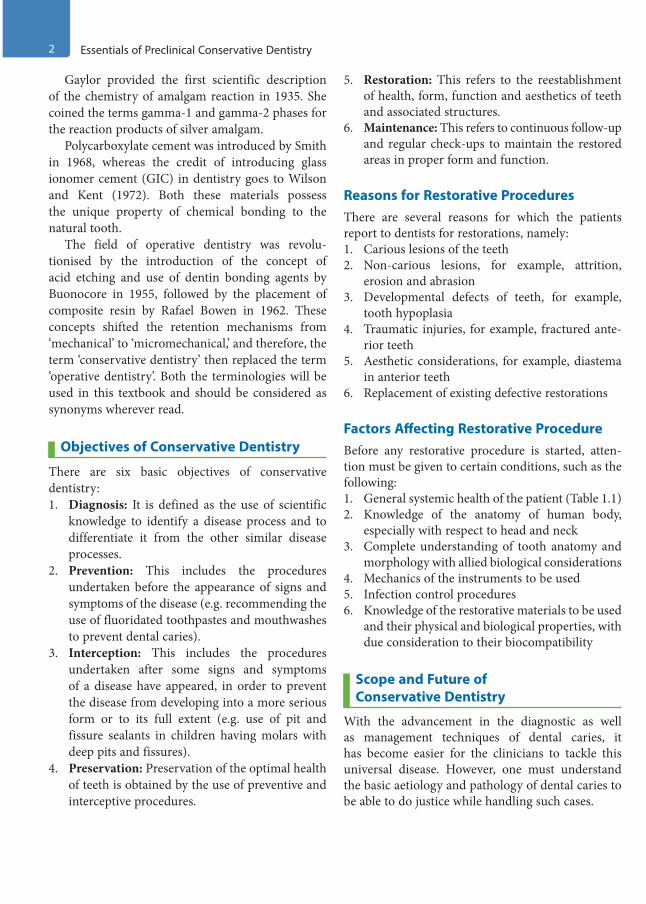
Objectives of Conservative Dentistry
There are six basic objectives of conservative dentistry:1. Diagnosis: It is defined as the use of scientific
knowledge to identify a disease process and to differentiate it from the other similar disease processes.
2. Prevention: This includes the procedures undertaken before the appearance of signs and symptoms of the disease (e.g. recommending the use of fluoridated toothpastes and mouthwashes to prevent dental caries).
3. Interception: This includes the procedures undertaken after some signs and symptoms of a disease have appeared, in order to prevent the disease from developing into a more serious form or to its full extent (e.g. use of pit and fissure sealants in children having molars with deep pits and fissures).
4. Preservation: Preservation of the optimal health of teeth is obtained by the use of preventive and interceptive procedures.
5. Restoration: This refers to the reestablishment of health, form, function and aesthetics of teeth and associated structures.
6. Maintenance: This refers to continuous follow-up and regular check-ups to maintain the restored areas in proper form and function.
Reasons for Restorative ProceduresThere are several reasons for which the patients report to dentists for restorations, namely:1. Carious lesions of the teeth2. Non-carious lesions, for example, attrition,
erosion and abrasion3. Developmental defects of teeth, for example,
tooth hypoplasia4. Traumatic injuries, for example, fractured ante-
rior teeth5. Aesthetic considerations, for example, diastema
in anterior teeth6. Replacement of existing defective restorations
Factors Affecting Restorative ProcedureBefore any restorative procedure is started, atten-tion must be given to certain conditions, such as the following:1. General systemic health of the patient (Table 1.1)2. Knowledge of the anatomy of human body,
especially with respect to head and neck3. Complete understanding of tooth anatomy and
morphology with allied biological considerations4. Mechanics of the instruments to be used5. Infection control procedures6. Knowledge of the restorative materials to be used
and their physical and biological properties, with due consideration to their biocompatibility
Scope and Future of Conservative Dentistry
With the advancement in the diagnostic as well as management techniques of dental caries, it has become easier for the clinicians to tackle this universal disease. However, one must understand the basic aetiology and pathology of dental caries to be able to do justice while handling such cases.
Preclinical Dentistry.indb 2 29-05-2020 12:56:12
https://t.me/DentalBooksWorld

Chapter 1 Introduction to Preclinical Conservative Dentistry 3
Table 1.1 Systemic Conditions Affecting Restorative Procedures
Systemic Condition Clinical Implications on Dental Chair
Hypertension (uncontrolled)
Stress and anxiety associated with dental treatment can further aggravate the uncontrolled hypertension, which can jeopardise the cardiovascular health
Diabetes (uncontrolled) Patient can go into the stage of hypoglycaemia/hyperglycaemia, leading at times to shock
Rheumatic fever Patient with a history of rheumatic fever is prone to an attack of subacute bacterial endocar-ditis after any bacteraemia happening during the dental procedure
Artificial heart valves Chances of cardiac complications persist
Coronary artery disease Cardiac complications can occur, especially if local anaesthesia is to be used
Hepatitis Risk of cross-infection
Haemophilia/other bleeding disorders
Risk of uncontrolled bleeding in case of accidental injury to the soft tissues
HIV infection Risk of cross-infection through blood, saliva, etc.
Tuberculosis Risk of cross-infection through aerosols
Psychological disorders Patient may get non-cooperative during the procedure
Epilepsy Seizure during the procedure on chair may be fatal
Allergy Patients allergic to medications can be a problem if the dentist is unaware of it. Medications and materials (such as latex gloves) to which the patient is allergic should be avoided
Pregnancy Long appointments for restorative procedure should not be given to pregnant women, as this can increase abdominal pressure and cause foetal distress
Liver diseases Several local anaesthetics, antibiotics and analgesics used in dentistry are metabolised primarily by the liver
Compromised liver function could reduce the ability to clear these drugs from the system
Although the new-generation composites require minimal tooth preparation and the strict guidelines given by G.V. Black, about 100 years ago, need not be adhered to in toto, still it is mandatory for the students to understand and practice these principles so as to train themselves for the most difficult situ-ation they can come across in restorative dentistry.
It is believed that if one can prepare a tooth struc-ture ideal for receiving silver amalgam restoration, one can practically handle any other restorative material with great efficiency.
The scope of conservative dentistry lies in minimal interceptive procedures, taking along the conventional procedures. Also, the preventive aspect
must be given due consideration by promoting the use of fluorides, both systemic and local. The use of antimicrobial rinses must be advocated to all the patients as a part of the preventive therapy. This, however, does not infer that by the use of all preven-tive measures, the dental caries can be eradicated from the mankind. One must clearly understand that caries, being a multifactorial disease, has several aspects and cannot be eradicated.
The future lies in the combined venture of using preventive, interceptive and treatment aspects in order to provide maximum service to all who need dental care.
Preclinical Dentistry.indb 3 29-05-2020 12:56:12
https://t.me/DentalBooksWorld
4 Essentials of Preclinical Conservative Dentistry
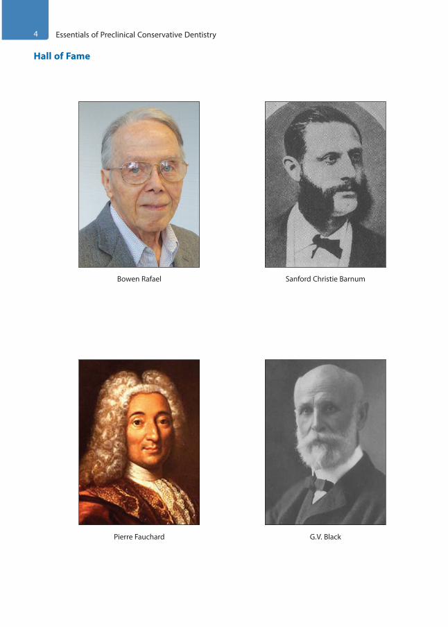
Hall of Fame
Bowen Rafael
G.V. Black
Sanford Christie Barnum
Pierre Fauchard
Preclinical Dentistry.indb 4 29-05-2020 12:56:13
https://t.me/DentalBooksWorld
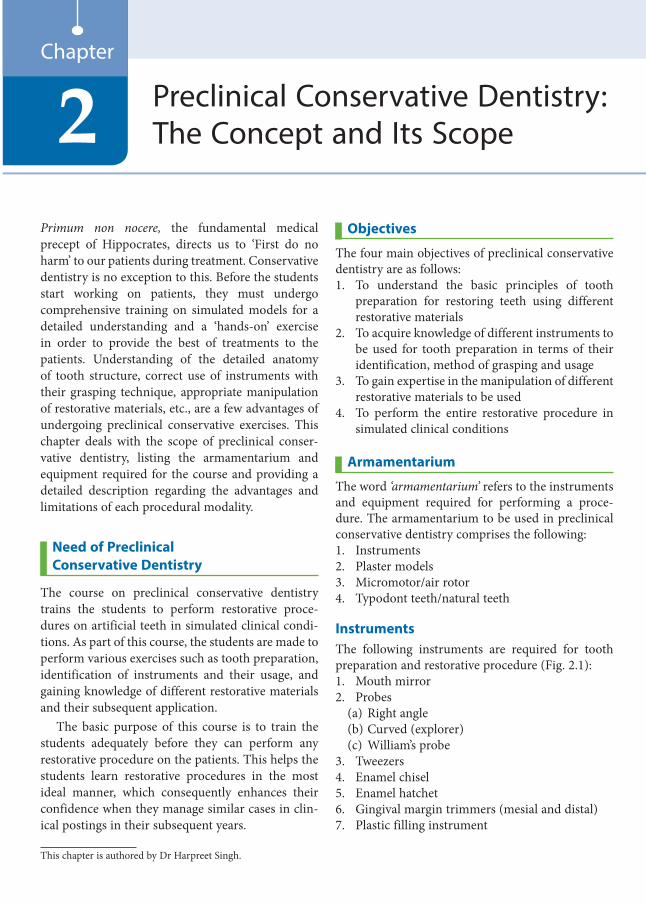
Primum non nocere, the fundamental medical precept of Hippocrates, directs us to ‘First do no harm’ to our patients during treatment. Conservative dentistry is no exception to this. Before the students start working on patients, they must undergo comprehensive training on simulated models for a detailed understanding and a ‘hands-on’ exercise in order to provide the best of treatments to the patients. Understanding of the detailed anatomy of tooth structure, correct use of instruments with their grasping technique, appropriate manipulation of restorative materials, etc., are a few advantages of undergoing preclinical conservative exercises. This chapter deals with the scope of preclinical conser-vative dentistry, listing the armamentarium and equipment required for the course and providing a detailed description regarding the advantages and limitations of each procedural modality.
Need of Preclinical Conservative Dentistry
The course on preclinical conservative dentistry trains the students to perform restorative proce-dures on artificial teeth in simulated clinical condi-tions. As part of this course, the students are made to perform various exercises such as tooth preparation, identification of instruments and their usage, and gaining knowledge of different restorative materials and their subsequent application.
The basic purpose of this course is to train the students adequately before they can perform any restorative procedure on the patients. This helps the students learn restorative procedures in the most ideal manner, which consequently enhances their confidence when they manage similar cases in clin-ical postings in their subsequent years.
Objectives
The four main objectives of preclinical conservative dentistry are as follows:1. To understand the basic principles of tooth
preparation for restoring teeth using different restorative materials
2. To acquire knowledge of different instruments to be used for tooth preparation in terms of their identification, method of grasping and usage
3. To gain expertise in the manipulation of different restorative materials to be used
4. To perform the entire restorative procedure in simulated clinical conditions
Armamentarium
The word ‘armamentarium’ refers to the instruments and equipment required for performing a proce-dure. The armamentarium to be used in preclinical conservative dentistry comprises the following:1. Instruments2. Plaster models3. Micromotor/air rotor4. Typodont teeth/natural teeth
InstrumentsThe following instruments are required for tooth preparation and restorative procedure (Fig. 2.1):1. Mouth mirror2. Probes
(a) Right angle(b) Curved (explorer)(c) William’s probe
3. Tweezers4. Enamel chisel5. Enamel hatchet6. Gingival margin trimmers (mesial and distal)7. Plastic filling instrument
Preclinical Conservative Dentistry: The Concept and Its Scope2
Chapter
This chapter is authored by Dr Harpreet Singh.
Preclinical Dentistry.indb 5 29-05-2020 12:56:13
https://t.me/DentalBooksWorld

6 Essentials of Preclinical Conservative Dentistry
Figure 2.1 Instruments required for tooth preparation.
A
B
Figure 2.2 Teflon-coated instruments for handling composite resin.
8. Dappen dish 9. Spoon excavator10. Round condenser11. Parallelogram condenser12. Ward’s carver13. Diamond-shaped carver (Frahm’s carver)14. Hollenback’s carver15. Amalgam carrier16. Ball burnisher17. Diamond points (straight, tapered, round,
inverted, cone, etc.)18. Steel burs (round—No. 4 and No. 6)19. Glass slab20. Ivory matrix retainers (No. 1 and No. 8) and
Tofflemire retainer21. Matrix bands for retainers (No. 1 and No. 8) and
for Tofflemire retainer22. Wedges (plastic and wooden)23. Mortar and pestle/amalgamator24. Teflon-coated instruments for handling
composite resin (Fig. 2.2)
A detailed explanation of all these instruments is given in Chapter 7, Instruments in Restorative Dentistry.
Plaster ModelsPlaster models can be used to train the students for preclinical work before directly starting on extracted natural teeth or typodont teeth. Ready-made moulds (Fig. 2.3) are available, which can be poured with plaster, and the models of different shapes of teeth can be made and worked upon (Figs 2.4–2.6). Different tooth preparations (Class I to Class V) can be made on these plaster models by the use of chisels and carvers (Figs 2.7 and 2.8).
Figure 2.3 Moulds for making plaster models.
Figure 2.4 Plaster model of a maxillary first premolar.
Preclinical Dentistry.indb 6 29-05-2020 12:56:14
https://t.me/DentalBooksWorld

Chapter 2 Preclinical Conservative Dentistry: The Concept and Its Scope 7
Advantages
The advantages of this exercise are as follows:1. The size of plaster models is very large as
compared to extracted natural teeth or typodont teeth, so a better vision and easy understanding of the steps of cavity preparation is possible.
2. The line angles and point angles can be easily identified and understood in these models
during cavity preparation and thus can be easily reproduced in extracted natural teeth or typodont teeth.
3. The concepts of occlusally converging walls and convex axial walls can be easily mastered while working on plaster models.
4. After the cavity preparation, these can be filled with wax and carving can be done to repro-duce the normal anatomy of tooth structure (Fig. 2.9A,B). This helps to understand the basic procedure of carving and the position of various grooves and fissures.
Micromotor/Air RotorMicromotor is a low-speed motor (approx. 25,000 rpm), which uses a corresponding contra-angle handpiece for tooth preparation (Figs 2.10 and 2.11). This system works without a water spray and thus produces frictional heat. The preparation is slow but at the same time a good control over the apparatus is maintained. This is the preferred equip-ment for beginners in conservative dentistry.
Air rotor (>200,000 rpm) is a high-speed instru-ment which works with the water spray as a coolant (Fig. 2.12). This system is efficient and makes the procedure of tooth preparation faster, but requires continuous practice before it can be mastered, to have an adequate control over it.
Typodont Teeth/Natural TeethThe students are made to use either extracted natural teeth or typodont teeth for practicing various restor-ative procedures. These teeth are mounted in plaster
Figure 2.5 Plaster model of a maxillary first molar.
Figure 2.6 Plaster model of a mandibular first molar.
Figure 2.7 Plaster model of a maxillary first molar, showing tooth preparation.
Figure 2.8 Plaster model of a mandibular first molar, showing tooth preparation.
Preclinical Dentistry.indb 7 29-05-2020 12:56:14
https://t.me/DentalBooksWorld

8 Essentials of Preclinical Conservative Dentistry
blocks, stone models or prefabricated plastic jaws. It is recommended that these teeth should be mounted properly, simulating the oral conditions, in proper contact with the adjacent teeth so as to practice in an environment as close as possible to the clinical condition.
Typodont Teeth
These are the teeth made up of a special kind of plastic and are readily available in all shapes (all maxillary and mandibular teeth). Typodont teeth usually have
a small root form extension, with a screw attached to it. These can be used in several ways:1. These are available in prefixed maxillary and
mandibular arch shapes, mounted in plastic jaws and placed in plastic articulators (Fig. 2.13).
2. These jaw forms can be placed in simulated rubber human faces called phantom heads (Fig. 2.14).
3. Phantom heads can be attached to the upper trunk of the human body made of rubber/ plastic. These can be compared to plastic or rubber mannequins (Fig. 2.15).
4. Typodont teeth can also be individually mounted in plaster blocks, plaster moulds (Fig. 2.16) or brass phantom jaws.
Advantages
1. Easily available2. Available in good anatomical shapes with well-
formed cusps and fissures3. No disinfection required4. No risk of cross-infection
Drawbacks
1. The feeling of cutting a typodont tooth is different from that of a natural tooth. They get
Figure 2.11 Micromotor with control box.
Figure 2.10 Micromotor contra-angle handpiece.
Figure 2.12 Air rotor handpiece.
Figure 2.9 (A) Wax filling done in a plaster model of mandibular first molar. (B) Wax filling done in a plaster model of maxillary premolar.
A
B
Preclinical Dentistry.indb 8 29-05-2020 12:56:14
https://t.me/DentalBooksWorld
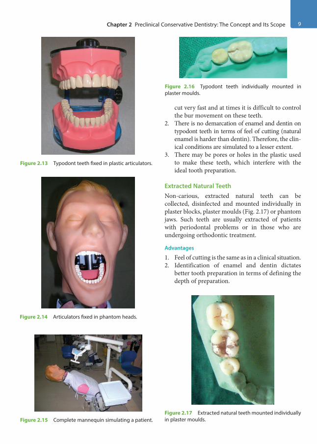
Chapter 2 Preclinical Conservative Dentistry: The Concept and Its Scope 9
cut very fast and at times it is difficult to control the bur movement on these teeth.
2. There is no demarcation of enamel and dentin on typodont teeth in terms of feel of cutting (natural enamel is harder than dentin). Therefore, the clin-ical conditions are simulated to a lesser extent.
3. There may be pores or holes in the plastic used to make these teeth, which interfere with the ideal tooth preparation.
Extracted Natural TeethNon-carious, extracted natural teeth can be collected, disinfected and mounted individually in plaster blocks, plaster moulds (Fig. 2.17) or phantom jaws. Such teeth are usually extracted of patients with periodontal problems or in those who are undergoing orthodontic treatment.
Advantages
1. Feel of cutting is the same as in a clinical situation.2. Identification of enamel and dentin dictates
better tooth preparation in terms of defining the depth of preparation.
Figure 2.13 Typodont teeth fixed in plastic articulators.
Figure 2.14 Articulators fixed in phantom heads.
Figure 2.15 Complete mannequin simulating a patient.
Figure 2.16 Typodont teeth individually mounted in plaster moulds.
Figure 2.17 Extracted natural teeth mounted individually in plaster moulds.
Preclinical Dentistry.indb 9 29-05-2020 12:56:14
https://t.me/DentalBooksWorld
10 Essentials of Preclinical Conservative Dentistry
Drawbacks
1. Not easily available2. Require thorough disinfection3. A risk of cross-infection always
Method of Disinfection/Sterilisation of Extracted Natural Teeth
Various methods have been recommended for sterilisation of extracted natural teeth before using them for preclinical work. It is advocated that the extracted teeth be sterilised by either autoclaving or immersing them in 10% formalin for a week before these are used.
Use of Personal Protective Equipment
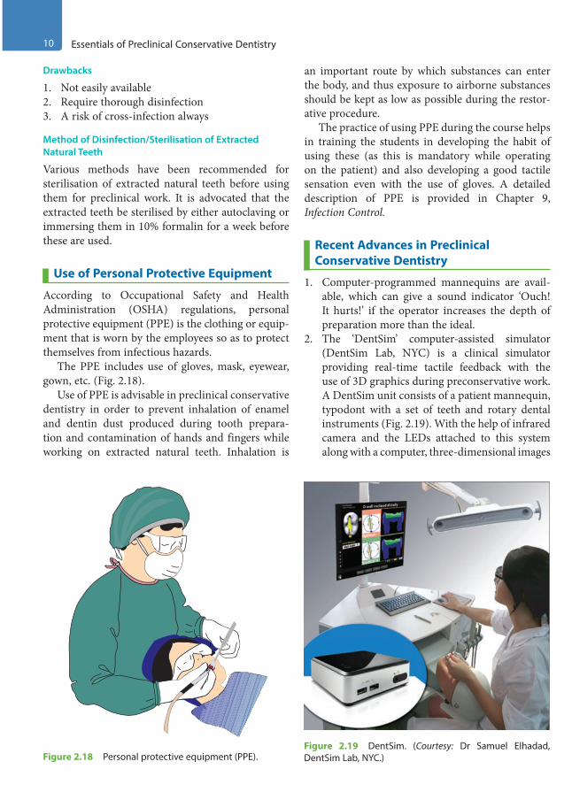
According to Occupational Safety and Health Administration (OSHA) regulations, personal protective equipment (PPE) is the clothing or equip-ment that is worn by the employees so as to protect themselves from infectious hazards.
The PPE includes use of gloves, mask, eyewear, gown, etc. (Fig. 2.18).
Use of PPE is advisable in preclinical conservative dentistry in order to prevent inhalation of enamel and dentin dust produced during tooth prepara-tion and contamination of hands and fingers while working on extracted natural teeth. Inhalation is
an important route by which substances can enter the body, and thus exposure to airborne substances should be kept as low as possible during the restor-ative procedure.
The practice of using PPE during the course helps in training the students in developing the habit of using these (as this is mandatory while operating on the patient) and also developing a good tactile sensation even with the use of gloves. A detailed description of PPE is provided in Chapter 9, Infection Control.
Recent Advances in Preclinical Conservative Dentistry
1. Computer-programmed mannequins are avail-able, which can give a sound indicator ‘Ouch! It hurts!’ if the operator increases the depth of preparation more than the ideal.
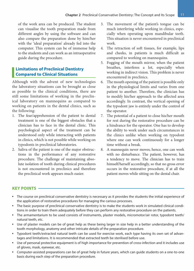
2. The ‘DentSim’ computer-assisted simulator (DentSim Lab, NYC) is a clinical simulator providing real-time tactile feedback with the use of 3D graphics during preconservative work. A DentSim unit consists of a patient mannequin, typodont with a set of teeth and rotary dental instruments (Fig. 2.19). With the help of infrared camera and the LEDs attached to this system along with a computer, three-dimensional images
Figure 2.18 Personal protective equipment (PPE).Figure 2.19 DentSim. (Courtesy: Dr Samuel Elhadad, DentSim Lab, NYC.)
Preclinical Dentistry.indb 10 29-05-2020 12:56:15
https://t.me/DentalBooksWorld
Chapter 2 Preclinical Conservative Dentistry: The Concept and Its Scope 11
of the work area can be produced. The student can visualise the tooth preparation made from different angles by using the software and can also compare the preparation done by him/her with the ‘ideal preparation’ already fed into the computer. This system can be of immense help to the students and can work as an intraoperative guide during the procedure.
Limitations of Preclinical Dentistry Compared to Clinical Situations
Although with the advent of new technologies the laboratory situations can be brought as close as possible to the clinical conditions, there are still some limitations of working in the preclin-ical laboratory on mannequins as compared to working on patients in the dental clinics, such as the following:1. The fear/apprehension of the patient to dental
treatment is one of the biggest obstacles that a clinician has to face in the dental clinic. This psychological aspect of the treatment can be understood only while interacting with patients in clinics, which is not possible while working on typodonts in preclinical laboratories.
2. Saliva of the patient is one of the major obstruc-tions in the performance of any restorative procedure. The challenge of maintaining abso-lute isolation of tooth during clinical procedures is not encountered in preclinics and therefore the preclinical work appears much easier.
3. The movement of the patient’s tongue can be much interfering while working in clinics, espe-cially when operating upon mandibular teeth. This situation is never encountered in preclinical work.
4. The retraction of soft tissues, for example, lips and cheeks, in patients is much difficult as compared to working on mannequins.
5. Fogging of the mouth mirror, when the patient breathes, interferes a lot, especially when working in indirect vision. This problem is never encountered in preclinics.
6. The mouth opening of the patient is possible only in the physiological limits and varies from one patient to another. Therefore, the clinician has to modify his/her approach to the affected area accordingly. In contrast, the vertical opening of the typodont jaw is entirely under the control of the operator.
7. The potential of a patient to close his/her mouth for rest during the restorative procedure can be a hindrance for the operator. One has to develop the ability to work under such circumstances in the clinics unlike when working on typodont where one can work continuously for a longer time without a break.
8. A mannequin never moves; hence, one can work with no disturbance. The patient, however, has a tendency to move. The clinician has to train himself/herself accordingly, so that no gross error occurs in the restorative procedure, if at all the patient moves while sitting on the dental chair.
KEY POINTS
• The course on preclinical conservative dentistry is necessary as it provides the students the initial experience of the application of restorative procedures for managing the carious processes.
• The basic purpose of preclinical conservative dentistry is to make the students work in simulated clinical condi-tions in order to train them adequately before they can perform any restorative procedure on the patients.
• The armamentarium to be used consists of instruments, plaster models, micromotor/air rotor, typodont teeth/natural teeth, etc.
• Use of plaster models can be of great help as these being larger in size help in a better understanding of the tooth morphology, anatomy and other intricate details of the preparation procedure.
• Typodont teeth/extracted natural teeth can be used for exercise work, each type having its own set of advan-tages and limitations. It is recommended that extracted teeth be sterilised before use.
• Use of personal protective equipment is of high importance for prevention of cross-infection and it includes use of gloves, mask, eyewear, etc.
• Computer-assisted preparations can be of great help in future years, which can guide students on a one-to-one basis during each step of the preparation procedure.
Preclinical Dentistry.indb 11 29-05-2020 12:56:15
https://t.me/DentalBooksWorld

12 Essentials of Preclinical Conservative Dentistry
• Although the aim of preclinical work exercise is to simulate the clinical conditions as close as possible, certain situations such as managing the anxious patients, isolation of tooth from saliva, interference by tongue move-ment and limited mouth opening of the patient are encountered only in clinical situations and hence will always be the limitation of the laboratory work.
SELF-ASSESSMENT QUESTIONS
1. Define preclinical conservative dentistry.
2. What are the objectives of preclinical conservative dentistry?
3. What are the advantages of using plaster models for preclinical conservative exercise work?
4. List the advantages and drawbacks of using typodont teeth for preclinical conservative exercise work.
5. List the advantages and drawbacks of using natural extracted teeth for preclinical conservative exercise work.
6. Discuss the importance of using personal protective equipment (PPE).
7. Discuss the limitations of preclinical work as compared to clinical situations in restorative dentistry.
Preclinical Dentistry.indb 12 29-05-2020 12:56:15
https://t.me/DentalBooksWorld
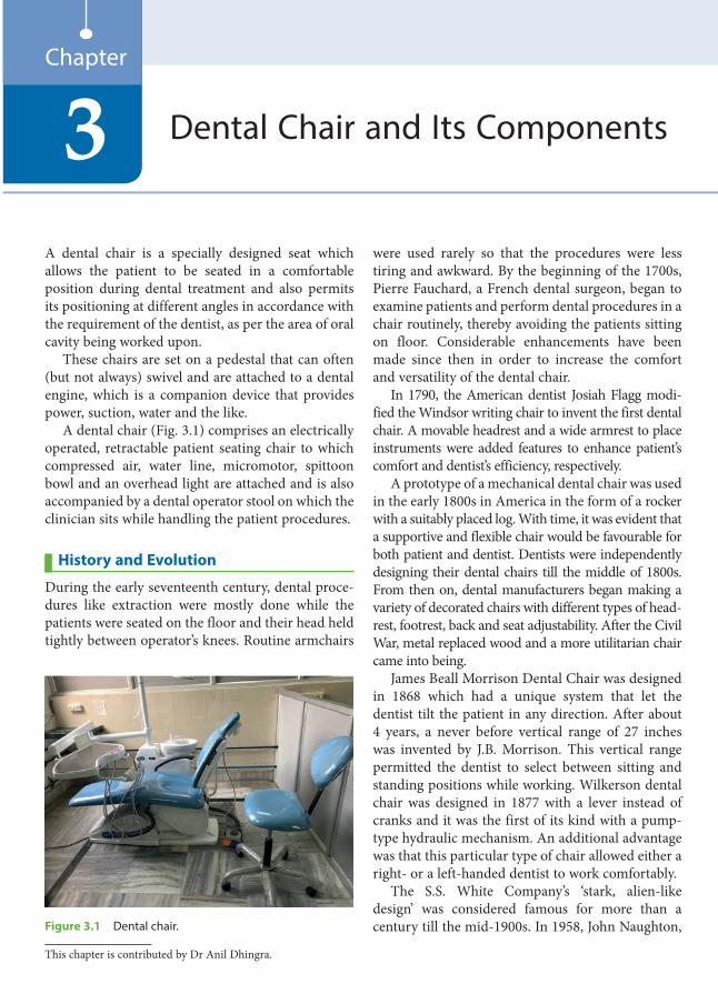
A dental chair is a specially designed seat which allows the patient to be seated in a comfortable position during dental treatment and also permits its positioning at different angles in accordance with the requirement of the dentist, as per the area of oral cavity being worked upon.
These chairs are set on a pedestal that can often (but not always) swivel and are attached to a dental engine, which is a companion device that provides power, suction, water and the like.
A dental chair (Fig. 3.1) comprises an electrically operated, retractable patient seating chair to which compressed air, water line, micromotor, spittoon bowl and an overhead light are attached and is also accompanied by a dental operator stool on which the clinician sits while handling the patient procedures.
History and Evolution
During the early seventeenth century, dental proce-dures like extraction were mostly done while the patients were seated on the floor and their head held tightly between operator’s knees. Routine armchairs
were used rarely so that the procedures were less tiring and awkward. By the beginning of the 1700s, Pierre Fauchard, a French dental surgeon, began to examine patients and perform dental procedures in a chair routinely, thereby avoiding the patients sitting on floor. Considerable enhancements have been made since then in order to increase the comfort and versatility of the dental chair.
In 1790, the American dentist Josiah Flagg modi-fied the Windsor writing chair to invent the first dental chair. A movable headrest and a wide armrest to place instruments were added features to enhance patient’s comfort and dentist’s efficiency, respectively.
A prototype of a mechanical dental chair was used in the early 1800s in America in the form of a rocker with a suitably placed log. With time, it was evident that a supportive and flexible chair would be favourable for both patient and dentist. Dentists were independently designing their dental chairs till the middle of 1800s. From then on, dental manufacturers began making a variety of decorated chairs with different types of head-rest, footrest, back and seat adjustability. After the Civil War, metal replaced wood and a more utilitarian chair came into being.
James Beall Morrison Dental Chair was designed in 1868 which had a unique system that let the dentist tilt the patient in any direction. After about 4 years, a never before vertical range of 27 inches was invented by J.B. Morrison. This vertical range permitted the dentist to select between sitting and standing positions while working. Wilkerson dental chair was designed in 1877 with a lever instead of cranks and it was the first of its kind with a pump-type hydraulic mechanism. An additional advantage was that this particular type of chair allowed either a right- or a left-handed dentist to work comfortably.
The S.S. White Company’s ‘stark, alien-like design’ was considered famous for more than a century till the mid-1900s. In 1958, John Naughton,
Dental Chair and Its Components3Chapter
Figure 3.1 Dental chair.
This chapter is contributed by Dr Anil Dhingra.
Preclinical Dentistry.indb 13 29-05-2020 12:56:15
https://t.me/DentalBooksWorld
14 Essentials of Preclinical Conservative Dentistry
Iowa, made the true progenitor of the present-day reclining chair and delivered his chair in a hearse to a grateful local dentist. This was the first type of chair having a gap in the seat back that allowed the dentist to sit and the patient to lie in a prone posi-tion. Naughton’s recliner was considered as a very flexible seat design and accepted as the standard by the dental professionals.
Thereafter, in 1984 came the dental chair, which allowed ‘sit-down’ dentistry. Today’s dental chair maximises patient comfort while providing adjustability to the dentist that allows ‘optimal access to the oral cavity’.
Modern Dental Chair
The modern dental chair is a piece of art, so well designed ergonomically that it ensures a highly comfortable positioning of the patient as well as the ease with which the dentist can position himself or herself and the patient in order to ensure adequate accessibility to the area being worked upon.
Types
The dental chairs can be classified according to design and portability. I. According to the design of the dental chair:
Depending on the design of the dental chair and location of the dental engine and the other
attachments connected to it, there are three basic types of modern dental chairs:
1. Floor-mounted design: This is the most common and popular design of the dental chair in which the dental engine and all neces-sary attachments are built into the chair itself.
2. Ceiling-mounted design: In this design, all the attachments of the dental chair are built into the ceiling, while the chair is positioned on the floor.
3. Mobile independent design: These specially designed dental chairs are wheel-mounted with locking mechanisms, or are folding-style chairs that are especially used in mobile dental clinics while organising dental camps in rural areas.
II. According to the portability of the dental chair: Depending on whether dental chairs are fixed at one position or can be easily moved from one place to another, these can be classified as portable and non-portable dental chairs.
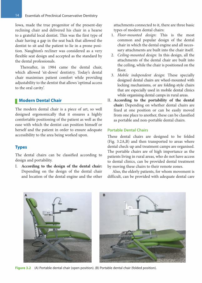
Portable Dental Chairs These dental chairs are designed to be folded (Fig. 3.2A,B) and then transported to areas where dental check-up and treatment camps are organised. The portable chairs are of high importance as the patients living in rural areas, who do not have access to dental clinics, can be provided dental treatment by moving these chairs to their remote zones.
Also, the elderly patients, for whom movement is difficult, can be provided with adequate dental care
Figure 3.2 (A) Portable dental chair (open position). (B) Portable dental chair (folded position).
A B
Preclinical Dentistry.indb 14 29-05-2020 12:56:15
https://t.me/DentalBooksWorld

Chapter 3 Dental Chair and Its Components 15
by carrying the portable dental units to their place of living.
The basic system of these portable dental units includes an operator light source, an examination kit, a portable head rest and a first aid kit for dental purposes. These portable dental units have a rotary instrument and an operator light fixture that is packed in two cases.
More complex portable units may include a vacuum canister, ultrasonic scaler and radiographic equipment along with compressors for air–water syringes and high- and low-speed handpieces. These equipment are stored and transported in durable boxes and cases. The rationale for these chairs is to allow provision for simple fillings and basic preven-tative treatments such as fluoride therapy and atrau-matic restorative treatment (ART).
Non-Portable Dental ChairThe non-portable dental chair is non-movable as the wide base is attached to the floor. It is very heavy and is used in dental clinics. It can be of two types—general dental chair and paediatric dental chair.1. General dental chair: It is used for any purpose
in a dental clinic and is the most common type used by dentists (Fig. 3.3), especially for adult patients. The various parts of this chair and their functions have been described later in this chapter.
2. Paediatric dental chair: It is a special type of chair used for paediatric patients (kids). This chair is different for the fact that it is much smaller in size as compared with the ordinary dental chair so that small children can easily fit into it (Fig. 3.4). Also, most of these dental chairs are highly colourful with lots of cartoon characters attached or printed on them so as to attract the small children and keep them in their comfort zone during dental treatment. Some of these chairs may also have a monitor attached to them, in which the nursery rhymes are played during treatment so that children may remain distracted during the treatment procedure.
Figure 3.3 General dental chair.
Figure 3.4 Paediatric dental chair.
Preclinical Dentistry.indb 15 29-05-2020 12:56:16
https://t.me/DentalBooksWorld

16 Essentials of Preclinical Conservative Dentistry
Parts and Functions of a Dental ChairThe dental chair has several components and it is essential for the beginners to have a thorough understanding about these so as to be in a comfort zone while working. The different parts along with their functions are described next one by one in detail.
Dental Light/Operator Light/Bulb
The dental light attached to the dental chair illumi-nates the oral cavity of the patient to be examined or treated (Fig. 3.5). The bulb in the light is safely shielded by a plastic cover.1. The light bulb is attached at a distance of
30–50 inches from the mouth of the patient. This avoids the light shining in the patient’s eyes, thereby reducing discomfort.
2. There are dimmer provisions in the light so as to change the intensity of light according to the situation.
3. Protective barriers such as plastic wrap and aluminium foil are put on handles and switches of the bulb before procedure. These must be removed and replaced with fresh wraps for every subsequent appointment.
4. Frequent cleaning of the light cover is recom-mended using a surface disinfectant so as to achieve disinfection and also to ensure that proper intensity of light reaches the area of work.
5. All movable parts of the light should be lubri-cated with routine all-purpose lubricant agents at least once a week.
Dental Chair Controls
The control buttons present on the bracket table (Fig. 3.5) are used for:1. Movement of the dental chair upwards and
downwards 2. Reclining and uprighting of the chair3. Turning the dental chair light on/off4. Turning on/off of the water tumbler5. Turning on/off of water in spittoon
Different dental chair manufacturers have different designs of these control buttons and these buttons usually have symbols pasted on them for easy identification of their functions. The control buttons at times are present at the foot control of the chair as well.
Cup (or Disposable Glass) Holder
Disposable glasses/cups (preferably) kept on the holders (Fig. 3.5) are used for the patients to take in water during the dental procedures (as they might feel uncomfortable with the saliva or debris in the mouth), and then gargle and spit out in the spit-toon bowl.
Spittoon Bowl
A spittoon is a bowl or basin-like receptable for the patient to spit saliva from the mouth during dental procedure (Fig. 3.5).
It is provided with water pipe supply to clean the bowl and then push the water towards the drain.
Bracket Table
It is the platform on which the hand instruments and other materials such as cotton, cotton holders and dental cements are placed. This bracket table can be shifted near to the dental chair or pushed away, depending on the requirement of the dentist. Its vertical position can also be changed according to the requirement (Fig. 3.5).
Air–Water Syringe
It is a dental device that supplies a focused stream of compressed air, water or combination of both Figure 3.5 Components of dental chair.
Disposable glass and holder
Dental lightSpittoon
Bracket table
Control buttonsat foot control
Preclinical Dentistry.indb 16 29-05-2020 12:56:16
https://t.me/DentalBooksWorld

Chapter 3 Dental Chair and Its Components 17
(Fig. 3.6). It is frequently used to clean a tooth surface during dental treatment.
Air–rotor Handpiece
It is attached to the air–water pipes (Fig. 3.6) which are further attached to a compressor. The compressor which builds up the pressure and trans-fers it to the dental chair can be either individual for a single chair or a centralised one providing pressure to multiple chairs. The details of the handpiece have been described in detail later in the chapter.
Radiograph Film Viewer
It helps in the examination and interpretation of the radiographs of the patient’s tooth. There is a small button, usually at its side, to turn the light inside the viewer on/off (Fig. 3.6).
Foot Control
Foot control (Fig. 3.7) is used by the dentist to operate the air–rotor and micromotor units. Also, some dental chairs have dental chair control buttons on this foot control so that the chair can be managed by feet when both the hands of the dentist are engaged.
Dental Handpiece
The currently used dental handpiece is an advanced amalgamation of precision parts working in perfect synchronisation at a very high speed, thereby providing a smooth, powerful cut. It permits the dentist to reduce the tooth structure in a structured manner with very less discomfort to the patient.
Evolution and Development of Handpiece
Till the 1950s, in dentistry, electric belt–driven instruments with maximum speed of 50,000 rpm were used for all operative procedures in dentistry. The heavy and restrictive belts of the handpiece had comparatively slow speed. This caused extreme discomfort to the patient due to more pressure and vibration because of more time spent on tooth preparation. The handpiece belts also entangled with any nearby hair.
In the 1950s, Dr John Borden from the United States developed an air-driven handpiece from
Figure 3.7 Foot control.
Figure 3.6 Air–water syringe, air–rotor handpiece and radiograph film viewer.
Radiographicfilm viewer
Air–watersyringeAir–rotor
handpiece
Preclinical Dentistry.indb 17 29-05-2020 12:56:16
https://t.me/DentalBooksWorld

18 Essentials of Preclinical Conservative Dentistry
belt-driven handpieces. Later, Sir John Walsh from New Zealand conducted pioneering work for the air-driven high-speed handpiece. This technology introduced the path for higher cutting speeds, which drastically decreased the time taken for tooth prepa-ration and restoration subsequently.
With the evolution of air turbine handpiece, increased concentricity and other similar problems were avoided. Thus, the patient experienced lesser vibrations during tooth preparation and the operator achieved a smoother cut with better margins in the preparation. A higher-speed handpiece generated more heat while cutting the tooth surface. To avoid this, water spray was used to cool the tooth being prepared.
By the 1970s, the traditional methods were replaced by modern treatment options, thereby making the patient and the dentist more comfort-able. The dental practice was revolutionised with the initiation of ‘sit-down dentistry’ and ‘four-handed dentistry’, in addition to reclining patient chairs. The present-day restorative dentistry is the effect of the advancing technology of the air-driven handpiece.
Advancements in Handpiece DevelopmentFurther advancements in the handpiece industry started in the 1980s: 1. Optic fibres were introduced to deliver light
directly to the cutting area at the tip of the bur.2. Automatic chucking was introduced which led
to an increase in the speed of changing the bur.3. Swivel connector was attached to decrease the
amount of ‘tubing torque’. Tubing torque is the
resistance or drag the operator experiences due to the transfer of weight of the tubing through the handpiece, and creates a tendency for the handpiece to resist rotating in the operator’s hand or to spring back after being rotated during a procedure.
Types of HandpiecesI. According to the mode of operation
1. Air-driven handpieces2. Electric handpieces3. Hybrid air–electric handpieces
II. According to the size of the handpiece head1. Standard head type2. Mini head type
III. According to the light source attached1. Standard handpiece2. Fibreoptic handpiece
IV. According to the mode of bur change1. Chuck-type handpiece2. Push button–type handpiece
Air-Driven Handpieces These are the most commonly used handpieces in dental practice. The two main parts of an air-driven high-speed handpiece are the body/shell and a turbine (Fig. 3.8). Repeated heat sterilisation affects every component in different ways; therefore, stan-dardised protocols of sterilisation must be strictly adhered to, in order to increase the life of a hand-piece. The body consists of the head and outer sheath. The turbine rests in the head of the body.
Figure 3.8 Air-driven handpiece. (A) Close view of the head. (B) Complete handpiece.
A B
Preclinical Dentistry.indb 18 29-05-2020 12:56:17
https://t.me/DentalBooksWorld
Chapter 3 Dental Chair and Its Components 19
Handpiece body is mostly made of brass which is comparatively a cheap material and easy to use; yet it is soft and susceptible to denting. Stainless steel is another common choice of material for making handpiece bodies. Steel is expensive, but lighter and stronger than brass. Nowadays, titanium is also considered for making handpiece as it is stronger and 40% lighter than stainless steel. More so, it is resistant to the corrosive effects of autoclaving.
The body of the handpiece delivers air and water to the handpiece head. This includes drive air (used to rotate the turbine), coolant water and chip air (mostly used to atomise the water spray). Once the drive air is passed through the turbine, it is released through the hollow body of the handpiece and down the handpiece tubing.
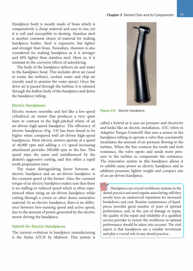
Electric Handpieces Electric motors resemble and feel like a low-speed cylindrical air motor that produces a very quiet hum in contrast to the high-pitched whine of an air-driven high-speed handpiece. The efficiency of electric handpieces (Fig. 3.9) has been found to be higher when compared with air-driven high-speed handpieces. Most electric motors operate at a speed of 40,000 rpm and adding a 1:5 speed-increasing attachment provides 200,000 rpm to the bur. This speed stays the same and uninfluenced by the dentist’s aggressive cutting, and this offers a rapid tooth preparation time.
The major distinguishing factor between an electric handpiece and an air-driven handpiece is the constant speed of the former. Also, the constant torque of an electric handpiece makes sure that there is no stalling or reduced speed which is often expe-rienced when using an air-driven handpiece while cutting through a crown or other dense restorative material. In an electric handpiece, there is no differ-ence between free-running speed and active speed, due to the amount of power generated by the electric motor driving the handpiece.
Hybrid Air–Electric Handpieces The current evolution in handpiece manufacturing is the Stylus ATC® by Midwest. This system is
called a hybrid as it uses air pressure and electricity and looks like an electric installation. ATC refers to Adaptive Torque Control® that uses a sensor in the handpiece tubing to operate a valve that consistently modulates the amount of air pressure flowing to the turbine. When the bur contacts the tooth and feels resistance, the valve opens and sends more pres-sure to the turbine to compensate the resistance. The innovative system in this handpiece allows it to exhibit same power as electric handpiece and in addition possesses lighter weight and compact size of an air-driven handpiece.
Handpieces are crucial workhorse systems in the dental practice and need regular autoclaving; still they mostly have an undeserved reputation for increased breakdown and cost. Routine maintenance of hand-pieces provides good number of years of optimal performance, and, in the case of damage or repair, the quality of the repair and reliability of a qualified service provider to restore the workhorse to optimal performance should be taken into account. The vital aspect is that handpieces are a notable investment and play a crucial role in any dental practice.
Figure 3.9 Electric handpiece.
Preclinical Dentistry.indb 19 29-05-2020 12:56:17
https://t.me/DentalBooksWorld

20 Essentials of Preclinical Conservative Dentistry
KEY POINTS
• Dental chair is unquestionably one of the most crucial things in a dental office. The design has evolved since the time of its inception way back in the early 1700s.
• The modern dental chair can be floor-mounted, ceiling-mounted designer and a mobile-independent design.• The dental chair can also be a ‘paediatric chair’ specially designed for the children or it could be a ‘standard chair’
for general use.• The dental chair has several parts, each having a specific function to perform. The body of the chair is designed
so as to provide maximum comfort to the back of the patient during lying-down posture. The ‘head rest’ also can be changed in position as per the requirement of the patient.
• The head light holds the source of light, which can be a halogen bulb or a set of LEDs. A good source of light is highly essential for optimal visibility while treating the patient.
• The bracket table is attached to the arm of the dental chair and is used to keep the instruments which shall be used during the dental procedure. Mostly a radiograph film viewer with a light source is attached to it to help viewing an intraoral periapical radiograph film.
• A spittoon is present on the left side of the chair, in order to facilitate rinsing of mouth by the patient. A waterflow line is attached to it to ensure that it is kept clean. A disposable cup is usually kept on the cup holder area to provide water/mouthwash to the patient for rinsing.
• A three-way air–water syringe is attached to the chair which can be used as per the requirement. Air–rotor handpiece, used for tooth preparation procedure, is attached to air–water pipes which are further attached to a compressor.
• A foot control is used to operate the micromotor/air rotor handpiece as per the need.• Dental handpiece is an essential part of a dentist’s armamentarium. It can be air driven, electric handpiece or a
hybrid air–electric handpiece. • Utmost care should be taken in handling the handpiece in order to increase its longevity.
SELF-ASSESSMENT QUESTIONS
1. Describe in brief the historical evolution of a dental chair.
2. What are the different types of dental chairs available in the market?
3. What is so special about the paediatric dental chair?
4. Enumerate the different parts of a dental chair.
5. Enumerate the different types of handpieces available to a dental practitioner.
Preclinical Dentistry.indb 20 29-05-2020 12:56:17
https://t.me/DentalBooksWorld
Tooth numbering system is used by dentists for uniquely identifying and referring to a specific tooth. This not only helps in the ease of prescription but also facilitates communication between the dental professionals among each other and with the labora-tory technicians. Over the years, almost 20 different teeth numbering systems have been developed. The most commonly used have been discussed in this chapter.
Definition and Significance
Dental notation refers to designating a special number to each tooth in the dental arch for the ease of dental charting. Recording the conditions in the patient’s oral cavity on a dental chart using symbols and numbers in a shorthand technique is called dental charting.
Providing a specific number to a tooth helps in making notes easily about the condition of that specific tooth. It also helps in communication between one dentist and another, and also between the dentist and the laboratory technician.
Notation system is of great help during billing and while providing detailed description of a specific tooth in medicolegal and forensic cases.
The history of notations of teeth dates back to several hundred years. In Europe, the notations were based on Latin and German and were very lengthy. For example, Mol.II Scup.Sin was the abbreviated form for Molaris Secundus Superior Sinister which in English would mean ‘maxillary left second molar’.
However, the dentists across the world now use different dental notation systems which are much simpler. Therefore, it is necessary to acquire the knowledge of the most common ones used. These are the Fédération Dentaire Internationale (FDI) notation, the Palmer notation method and the Universal Numbering System (dental). In addition
to these systems, there are other notation systems as well, which are not so commonly used and are discussed at the end of this chapter.
FDI Notation
The FDI notation system was developed by the Fédération Dentaire Internationale in 1970. It is also known as the ISO 3950 notation.
This system uses a two-digit numbering system, in which the first number represents a tooth’s quad-rant and the second number represents the number of the tooth from the midline of the face.
The International Organization for Standardization (ISO) is a worldwide federation of national standards bodies based in Geneva, Switzerland. It consists of technical committees that represent an array of disciplines seeking improved international standard-isation. Technical Committee (TC) 106 specifically represents the field of dentistry. In 1977, ISO TC 106 published ISO 3950 entitled ‘Dentistry—Designation System for Teeth and Areas of the Oral Cavity’, based on the FDI’s two-digit tooth numbering system with additional numeric notations for the areas of the mouth. A second edition of the ISO 3950 document was issued in 1984, and it was reissued in an updated form in 1995.
Notation for Permanent TeethFor permanent teeth, maxillary right teeth begin with the number ‘1’ (first quadrant), maxillary left teeth begin with the number ‘2’ (second quad-rant), mandibular left teeth begin with the number ‘3’ (third quadrant) and mandibular right teeth begin with the number ‘4’ (fourth quadrant). Teeth in each quadrant are numbered from 1 to 8 (Table 4.1). Therefore, the right maxillary first molar is designated as 16 (read as one six and not sixteen),
Tooth Notations4Chapter
This chapter is contributed by Dr Pooja Kapoor.
Preclinical Dentistry.indb 21 29-05-2020 12:56:17
https://t.me/DentalBooksWorld
22 Essentials of Preclinical Conservative Dentistry
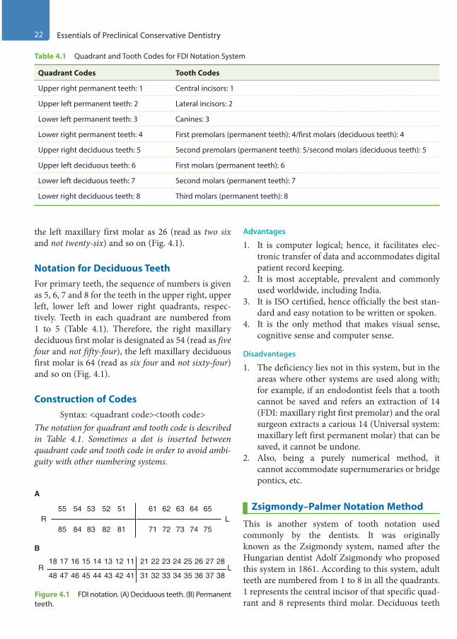
the left maxillary first molar as 26 (read as two six and not twenty-six) and so on (Fig. 4.1).
Notation for Deciduous TeethFor primary teeth, the sequence of numbers is given as 5, 6, 7 and 8 for the teeth in the upper right, upper left, lower left and lower right quadrants, respec-tively. Teeth in each quadrant are numbered from 1 to 5 (Table 4.1). Therefore, the right maxillary deciduous first molar is designated as 54 (read as five four and not fifty-four), the left maxillary deciduous first molar is 64 (read as six four and not sixty-four) and so on (Fig. 4.1).
Construction of CodesSyntax: <quadrant code><tooth code>
The notation for quadrant and tooth code is described in Table 4.1. Sometimes a dot is inserted between quadrant code and tooth code in order to avoid ambi-guity with other numbering systems.
Advantages
1. It is computer logical; hence, it facilitates elec-tronic transfer of data and accommodates digital patient record keeping.
2. It is most acceptable, prevalent and commonly used worldwide, including India.
3. It is ISO certified, hence officially the best stan-dard and easy notation to be written or spoken.
4. It is the only method that makes visual sense, cognitive sense and computer sense.
Disadvantages
1. The deficiency lies not in this system, but in the areas where other systems are used along with; for example, if an endodontist feels that a tooth cannot be saved and refers an extraction of 14 (FDI: maxillary right first premolar) and the oral surgeon extracts a carious 14 (Universal system: maxillary left first permanent molar) that can be saved, it cannot be undone.
2. Also, being a purely numerical method, it cannot accommodate supernumeraries or bridge pontics, etc.
Zsigmondy–Palmer Notation Method
This is another system of tooth notation used commonly by the dentists. It was originally known as the Zsigmondy system, named after the Hungarian dentist Adolf Zsigmondy who proposed this system in 1861. According to this system, adult teeth are numbered from 1 to 8 in all the quadrants. 1 represents the central incisor of that specific quad-rant and 8 represents third molar. Deciduous teeth
Table 4.1 Quadrant and Tooth Codes for FDI Notation System
Quadrant Codes Tooth Codes
Upper right permanent teeth: 1 Central incisors: 1
Upper left permanent teeth: 2 Lateral incisors: 2
Lower left permanent teeth: 3 Canines: 3
Lower right permanent teeth: 4 First premolars (permanent teeth): 4/first molars (deciduous teeth): 4
Upper right deciduous teeth: 5 Second premolars (permanent teeth): 5/second molars (deciduous teeth): 5
Upper left deciduous teeth: 6 First molars (permanent teeth): 6
Lower left deciduous teeth: 7 Second molars (permanent teeth): 7
Lower right deciduous teeth: 8 Third molars (permanent teeth): 8
R L31 32 33 34 35 36 37 384142434445464748
1112131415161718 21 22 23 24 25 26 27 28
R L54 53 52 5155
A
B
84 83 82 8185 72 73 74 7571
62 63 64 6561
Figure 4.1 FDI notation. (A) Deciduous teeth. (B) Permanent teeth.
Preclinical Dentistry.indb 22 29-05-2020 12:56:17
https://t.me/DentalBooksWorld
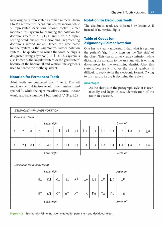
Chapter 4 Tooth Notations 23
were originally represented as roman numerals from I to V. I represented deciduous central incisor, while V represented deciduous second molar. Palmer modified this system by changing the notation for deciduous teeth to A, B, C, D and E, with A repre-senting deciduous central incisor and E representing deciduous second molar. Hence, the new name for the system is the Zsigmondy–Palmer notation system. The quadrant to which the tooth belongs is designated using a symbol ( ). This system is also known as the ‘angular system’ or the ‘grid system’ because of the horizontal and vertical line segments used to denote the tooth’s quadrant.
Notation for Permanent TeethAdult teeth are numbered from 1 to 8. The left maxillary central incisor would have number 1 and symbol ‘’, while the right maxillary central incisor would also have number 1 but symbol ‘’ (Fig. 4.2).
Notation for Deciduous TeethThe deciduous teeth are indicated by letters A–E instead of numerical digits.
Table of Codes for Zsigmondy–Palmer NotationOne has to clearly understand that what is seen on the patient’s ‘right’ is written on the ‘left side’ of the chart. This can at times create confusion while dictating the notation to the assistant who is writing down notes for the examining dentist. Also, this system, because it involves the use of symbols, is difficult to replicate in the electronic format. Owing to this reason, its use is declining these days.
Advantages
1. As the chart is in the pictograph style, it is user-friendly and helps in easy identification of the tooth in question.
Figure 4.2 Zsigmondy–Palmer notation method for permanent and deciduous teeth.
ZSIGMONDY–PALMER NOTATION
Permanent teeth
Upper right Upper left
Lower left
Upper left
Lower leftLower right
Lower right
Deciduous teeth (baby teeth)
Upper right
8
E D C B A
7 6 5 4 3 2 1
8
E D C B A
7 6 5 4 3 2 1 1
A B C D E
2 3 4 5 6 7 8
1
A B C D E
2 3 4 5 6 7 8
Preclinical Dentistry.indb 23 29-05-2020 12:56:17
https://t.me/DentalBooksWorld

24 Essentials of Preclinical Conservative Dentistry
2. If required, additional alphabetic characters or other symbols to denote supernumerary teeth can be easily used in this system, unlike the FDI method.
Disadvantage
It is less easy to type this notation using simple computer systems. The FDI and ‘universal’ methods (discussed below) use numbers only; thus, repre-senting them using a computer is not complex.
Universal Numbering System
Also known as the ‘American System’, this system was proposed by Parreidt (1882) and Cunningham (1883). This system is more commonly used in the USA and Canada and was adopted by the American Dental Association in 1975 and was also used by the Delta Dental Insurance Company, which made it quite popular. Unlike its name, it does not imply that it is universally acceptable.
Notation for Permanent TeethTeeth are numbered from 1 to 32, with 1 repre-senting maxillary right third molar, 8 representing maxillary right central incisor, 9 representing maxil-lary left central incisor and 16 representing maxillary left third molar. Thereafter, 17 represents mandib-ular left third molar, 24 represents mandibular left central incisor, 25 represents mandibular right central incisor and 32 represents mandibular right third molar (Fig. 4.3). As in this system each tooth has a unique numerical number and no symbols, it is easy to represent this in the electronic format.
Notation for Deciduous TeethFor the deciduous teeth, tooth letter ‘A’ is the farthest back on maxillary right, continuing towards the front and across the left up to ‘J’, which is the maxil-lary left last molar tooth. In the lower jaw, ‘K’ is the left last molar of the patient continuing forwards and across to the right, the last being ‘T’. Some dentists use the alternative version, which designates teeth as numbers 1–20 in the same procedure as used above, but they place a lower case ‘d’ (deciduous) right after the number.
Advantages
1. It is one of the first few classifications for tooth notations making communication easy.
2. Each tooth has a specific number, so no number is repeated as in other systems, such as the Zsigmondy–Palmer system.
3. There is no need of symbols to denote the quadrants.
4. This can be easily mentioned in the electronic format.
Disadvantages
1. Difficult to memorise2. Confusing, as 32, which is the lower right third
molar in this system, may be mistaken as the left lower lateral incisor of the more common FDI double-digit classification
Other Notation Systems
Less frequently used systems of tooth notation systems include those suggested by Dane and Haderup, angle system followed in Holland, South African system, Army system, Navy system and Bosworth system.
Dental Notation by Dane and HaderupIt is also known as the ‘+, −’ system invented by Dane (1887) and Haderup (1891). The teeth are
Figure 4.3 Universal system of tooth notation.
Maxillaryteeth
Mandibularteeth
1
2
3
4
5
67
8 910
11
12
13
14
15
16
17
18
19
20
21
2223242526
2728
29
30
31
32
Preclinical Dentistry.indb 24 29-05-2020 12:56:17
https://t.me/DentalBooksWorld
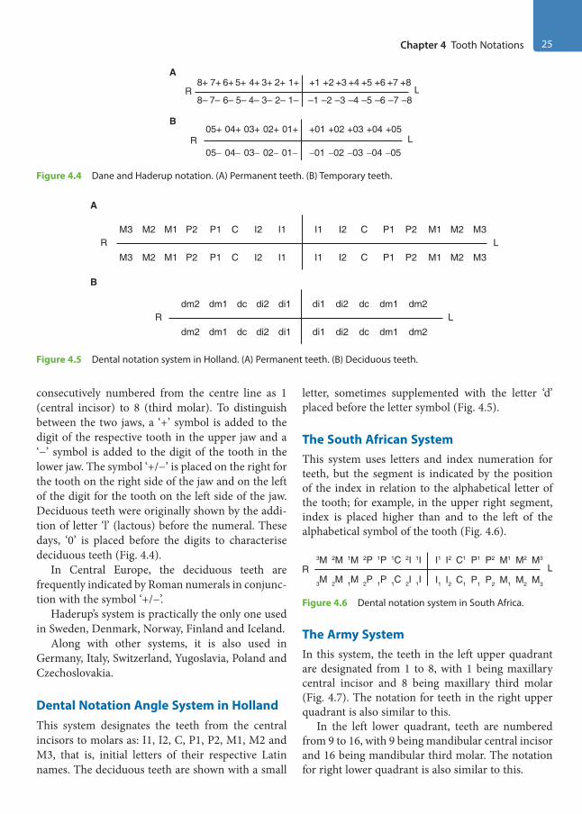
Chapter 4 Tooth Notations 25
consecutively numbered from the centre line as 1 (central incisor) to 8 (third molar). To distinguish between the two jaws, a ‘+’ symbol is added to the digit of the respective tooth in the upper jaw and a ‘−’ symbol is added to the digit of the tooth in the lower jaw. The symbol ‘+/−’ is placed on the right for the tooth on the right side of the jaw and on the left of the digit for the tooth on the left side of the jaw. Deciduous teeth were originally shown by the addi-tion of letter ‘l’ (lactous) before the numeral. These days, ‘0’ is placed before the digits to characterise deciduous teeth (Fig. 4.4).
In Central Europe, the deciduous teeth are frequently indicated by Roman numerals in conjunc-tion with the symbol ‘+/−’.
Haderup’s system is practically the only one used in Sweden, Denmark, Norway, Finland and Iceland.
Along with other systems, it is also used in Germany, Italy, Switzerland, Yugoslavia, Poland and Czechoslovakia.
Dental Notation Angle System in HollandThis system designates the teeth from the central incisors to molars as: I1, I2, C, P1, P2, M1, M2 and M3, that is, initial letters of their respective Latin names. The deciduous teeth are shown with a small
letter, sometimes supplemented with the letter ‘d’ placed before the letter symbol (Fig. 4.5).
The South African SystemThis system uses letters and index numeration for teeth, but the segment is indicated by the position of the index in relation to the alphabetical letter of the tooth; for example, in the upper right segment, index is placed higher than and to the left of the alphabetical symbol of the tooth (Fig. 4.6).
R3M 2M 1M 2P 1P 1C 2I 1I
3M 2M 1M 2P 1P 1C 2I 1IL
I1 I2 C1 P1 P2 M1 M2 M3
I1 I2 C1 P1 P2 M1 M2 M3
Figure 4.6 Dental notation system in South Africa.
The Army SystemIn this system, the teeth in the left upper quadrant are designated from 1 to 8, with 1 being maxillary central incisor and 8 being maxillary third molar (Fig. 4.7). The notation for teeth in the right upper quadrant is also similar to this.
In the left lower quadrant, teeth are numbered from 9 to 16, with 9 being mandibular central incisor and 16 being mandibular third molar. The notation for right lower quadrant is also similar to this.
A
R8+ 7+ 6+ 5+ 4+ 3+ 2+ 1+
8– 7– 6– 5– 4– 3– 2– 1–L
+1 +2 +3 +4 +5 +6 +7 +8
–2 –3 –4 –5 –6 –7 –8–1
B
R05+ 04+ 03+ 02+ 01+
05− 04− 03− 02− 01−
+01 +02 +03 +04 +05
−01 −02 −03 −04 −05L
Figure 4.4 Dane and Haderup notation. (A) Permanent teeth. (B) Temporary teeth.
Figure 4.5 Dental notation system in Holland. (A) Permanent teeth. (B) Deciduous teeth.
B
A
RM3 M2 M1 P2 P1 C I2 I1
M3 M2 M1 P2 P1 C I2 I1L
I1 I2 C P1 P2 M1 M2 M3
I1 I2 C P1 P2 M1 M2 M3
Rdm2 dm1 dc di2 di1
dm2 dm1 dc di2 di1
dc dm2
dm2
dm1
dm1dc
di2
di2
di1
di1L
Preclinical Dentistry.indb 25 29-05-2020 12:56:18
https://t.me/DentalBooksWorld

26 Essentials of Preclinical Conservative Dentistry
The Navy SystemIn this system, maxillary teeth are notated from 1 to 16, with 1 being right maxillary third molar and 16 being left maxillary third molar (Fig. 4.8).
R17 18 19 20 21 22 23 24
L1 2 3 4 5 6 7 8
26 27 28 29 30 31 3225
10 11 12 13 14 15 169
Figure 4.8 Navy dental notation system.
Mandibular teeth are notated from 17 to 32, with 17 being right mandibular third molar and 32 being left mandibular third molar.
The Bosworth SystemThis is a unique notation system in which perma-nent maxillary teeth are notated from 1 to 8, while permanent mandibular teeth are notated from A to H (Fig. 4.9A).
The deciduous maxillary teeth in this system are designated from D1 to D5, while deciduous mandib-ular teeth are designated from DA to DE (Fig. 4.9B).
R8 7 6 5 4 3 2 1
H G F E D C B AL
1 2 3 4 5 6 7 8
B C D E F G HA
RD5 D4 D3 D2 D1
DE DD DC DB DAL
D1 D2 D3 D4 D5
DB DC DD DEDA
A
B
Figure 4.9 The Bosworth dental notation system. (A) Permanent teeth. (B) Primary teeth.
Notation for Supernumerary Teeth
According to the Oklahoma Department of Human Services, supernumerary teeth can be notated as follows:1. Permanent dentition: Supernumerary teeth are
mentioned from numbers 51 to 82, beginning
from the upper right third molar, following around the upper arch and continuing on the lower arch to the left lower third molar and then moving towards the right lower third molar. In other words, the supernumerary teeth are desig-nated by simply adding 50 to the existing number of the tooth; for example, supernumerary tooth close to tooth number 1 is designated as 51 and that close to tooth number 12 is designated as 62.
2. Primary dentition: For deciduous dentition, supernumerary tooth is designated by simply writing the letter S after the letter representing the closest deciduous tooth; for example, a supernumerary tooth close to tooth A is desig-nated as AS.
Natal and Neonatal TeethTeeth that are present at birth are known as natal teeth. These teeth are also referred to as congenital teeth, foetal teeth or dentition praecox. Teeth which erupt during first 30 days of life are called neonatal teeth. As these are primary teeth only which have erupted early, notation is same as that used for deciduous dentition.
Notation Used by Palaeoanthropologists
Palaeoanthropologists use a system suitable to other primates as well. The maxillary teeth are denoted I1, I2, C–, Pm3, Pm4, M1, M2 and M3. Left or right has to be specified in each case. The mandibular teeth are designated as I1, I2, C–, Pm3, Pm4, M1, M2 and M3. The reason the premolars are labelled 3 and 4 here is that, in earlier primates, there were two premolars more between Pm3 and canine. This system is also known as alphanumeric notation. The four quadrants are designated as: UR (upper right), UL (upper left), LR (lower right) and LL (lower left). For example, the permanent left maxillary first molar is designated as UL6.
R8 7 6 5 4 3 2 1
16 15 14 13 12 11 10 9L
1 2 3 4 5 6 7 8
10 11 12 13 14 15 169
Figure 4.7 Army dental notation system.
Preclinical Dentistry.indb 26 29-05-2020 12:56:18
https://t.me/DentalBooksWorld
Chapter 4 Tooth Notations 27
KEY POINTS
• Dental notation means providing a unique number to each tooth in the dental arch.• Tooth notation system not only helps in easy communication among the dentists and between the dentists and
the lab technician but also leaves no chance of confusion regarding the tooth being treated.• The three most common systems are the Fédération Dentaire Internationale (FDI) notation, the Zsigmondy–
Palmer notation method and the Universal Numbering System.• FDI system designates a tooth by providing a two-digit code. The first number of the code represents the jaw
quadrant, while the second number represents the tooth in that quadrant.
• The Zsigmondy–Palmer notation consists of a symbol ( ) designating the quadrant in which the tooth is found and a number indicating the position from the midline. Adult teeth are numbered 1–8, with deciduous teeth indicated by letters A–E.
• In the Universal Numbering System, teeth are numbered from 1 to 32, 1 being the right maxillary third molar and 16 being the left maxillary third molar; 17 is the left mandibular third molar and then the number goes up to 32 for the right mandibular third molar.
• Other numbering systems used in different parts of the world are dental notation by Dane and Haderup, dental notation system in Holland, dental notation system in South Africa, the army dental notation system, the navy dental notation system, the Bosworth system, etc.
• The supernumerary teeth associated with permanent teeth can be designated by simply adding 50 to the existing number of the tooth; for example, supernumerary tooth close to tooth number 1 is designated as 51. Supernumerary teeth associated with deciduous teeth can be designated by writing ‘S’ after the closest decid-uous tooth; for example, one close to tooth B is written as BS.
SELF-ASSESSMENT QUESTIONS
1. What is the need of tooth nomenclature/notations?
2. What do you mean by the FDI nomenclature system?
3. How do you notate the teeth in the Zsigmondy–Palmer notation system?
4. Explain the details of the Universal Numbering System.
5. How will you notate a supernumerary tooth present in the dentition?
Preclinical Dentistry.indb 27 29-05-2020 12:56:18
https://t.me/DentalBooksWorld
It is quite apparent that dental caries forms the most common problem with which a patient reports to the dentist. The complaint of the patient could be simply food lodgment or unsightly appearance of tooth due to discolouration caused by dental caries or pain in the affected teeth. It is therefore necessary to understand the phenom-enon of ‘dental caries’ in order to best treat the affected tooth and provide the most appropriate treatment to the patient.
Definitions
The word ‘caries’ is derived from the Latin word ‘carius’ meaning ‘rot’ or ‘decay’.
According to Sturdevant‘Dental caries is an infectious microbiologic disease of the teeth that results in localised dissolution and destruction of the calcified tissues’.
According to Shafer‘Dental caries is a microbial disease of the calcified tissues of the teeth, characterised by demineralisa-tion of the inorganic portion and destruction of the organic substances of the tooth’.
According to WHO‘Caries is defined as a localised posteruptive patho-logical process of external origin involving soft-ening of the hard tooth tissue and proceeding to the formation of a cavity’.
According to Marsh and MartinDental caries is an endogenous, biofilm-medi-ated disease that occurs when acidogenic/aciduric members of resident oral flora obtain a selective
ecological advantage over other species, disrupting the homeostatic balance of the plaque biofilm and initiating the disease process.
The aetiology of dental caries is generally agreed to be a complex phenomenon, complicated by many indirect factors that obscure the direct or indirect causes. There is no universally accepted opinion about the aetiology of dental caries. Numerous refer-ences on dental caries, including ‘early theories’, have been attempted to explain its aetiology and many theories have evolved through years of investigation and observation.
Theories of Dental Caries
Historically, various theories (early theories) were proposed as an explanation for the aetiology of dental caries, such as ‘the legend of worms’, ‘humoral theory’, ‘vital theory’, ‘chemical theory’ and ‘parasitic theory’. However, these theories were discarded for their inability to rationalise the onset of dental caries.
Different theories still exist, proposing their own different school of thoughts regarding the aetiology of dental caries.
Chemicoparasitic Theory (1889)This theory is the most widely accepted worldwide and was proposed by W.D. Miller in 1889. He prop-agated the concept of acid formation in the oral cavity and attributed the synthesis of acid to the action of microbes. He stated that dental decay is a chemoparasitic process consisting of two stages:1. Decalcification or softening of the tissues2. Dissolution of the softened residue
The acid that affects this primary decalcification is derived from the fermentation of food particles lodged in the grooves and fissures of the teeth. Miller
Dental Caries5Chapter
This chapter is a joint contribution by the author and Dr JS Mann.
Preclinical Dentistry.indb 28 29-05-2020 12:56:18
https://t.me/DentalBooksWorld
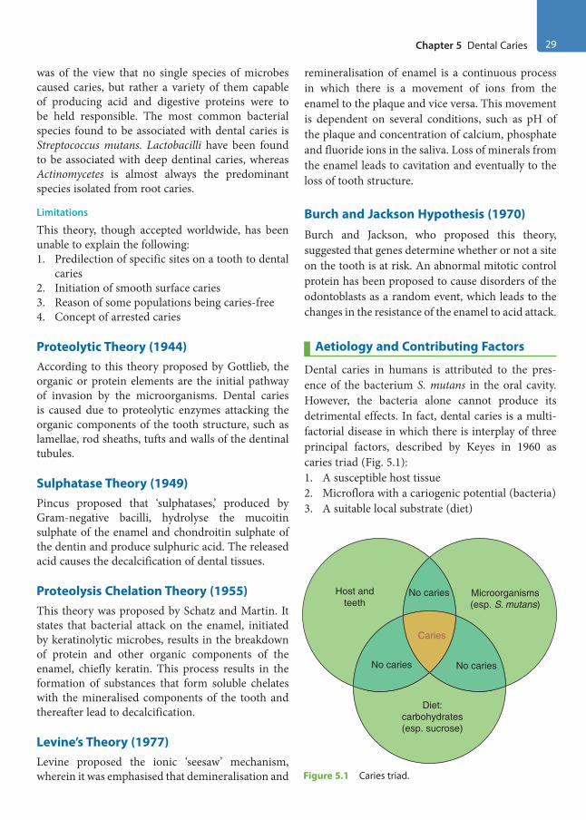
Chapter 5 Dental Caries 29
was of the view that no single species of microbes caused caries, but rather a variety of them capable of producing acid and digestive proteins were to be held responsible. The most common bacterial species found to be associated with dental caries is Streptococcus mutans. Lactobacilli have been found to be associated with deep dentinal caries, whereas Actinomycetes is almost always the predominant species isolated from root caries.
Limitations
This theory, though accepted worldwide, has been unable to explain the following:1. Predilection of specific sites on a tooth to dental
caries2. Initiation of smooth surface caries3. Reason of some populations being caries-free4. Concept of arrested caries
Proteolytic Theory (1944)According to this theory proposed by Gottlieb, the organic or protein elements are the initial pathway of invasion by the microorganisms. Dental caries is caused due to proteolytic enzymes attacking the organic components of the tooth structure, such as lamellae, rod sheaths, tufts and walls of the dentinal tubules.
Sulphatase Theory (1949)Pincus proposed that ‘sulphatases,’ produced by Gram-negative bacilli, hydrolyse the mucoitin sulphate of the enamel and chondroitin sulphate of the dentin and produce sulphuric acid. The released acid causes the decalcification of dental tissues.
Proteolysis Chelation Theory (1955)This theory was proposed by Schatz and Martin. It states that bacterial attack on the enamel, initiated by keratinolytic microbes, results in the breakdown of protein and other organic components of the enamel, chiefly keratin. This process results in the formation of substances that form soluble chelates with the mineralised components of the tooth and thereafter lead to decalcification.
Levine’s Theory (1977)Levine proposed the ionic ‘seesaw’ mechanism, wherein it was emphasised that demineralisation and
remineralisation of enamel is a continuous process in which there is a movement of ions from the enamel to the plaque and vice versa. This movement is dependent on several conditions, such as pH of the plaque and concentration of calcium, phosphate and fluoride ions in the saliva. Loss of minerals from the enamel leads to cavitation and eventually to the loss of tooth structure.
Burch and Jackson Hypothesis (1970)Burch and Jackson, who proposed this theory, suggested that genes determine whether or not a site on the tooth is at risk. An abnormal mitotic control protein has been proposed to cause disorders of the odontoblasts as a random event, which leads to the changes in the resistance of the enamel to acid attack.
Aetiology and Contributing Factors
Dental caries in humans is attributed to the pres-ence of the bacterium S. mutans in the oral cavity. However, the bacteria alone cannot produce its detrimental effects. In fact, dental caries is a multi-factorial disease in which there is interplay of three principal factors, described by Keyes in 1960 as caries triad (Fig. 5.1):1. A susceptible host tissue2. Microflora with a cariogenic potential (bacteria)3. A suitable local substrate (diet)
No caries
Caries
No caries No caries
Host andteeth
Microorganisms(esp. S. mutans)
Diet:carbohydrates(esp. sucrose)
Figure 5.1 Caries triad.
Preclinical Dentistry.indb 29 29-05-2020 12:56:18
https://t.me/DentalBooksWorld
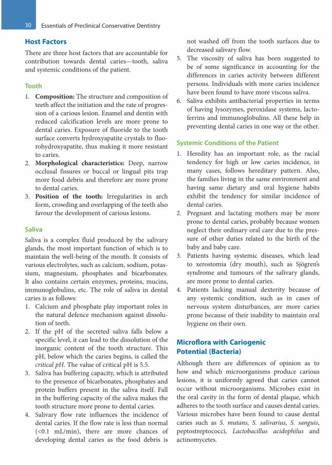
30 Essentials of Preclinical Conservative Dentistry
Host FactorsThere are three host factors that are accountable for contribution towards dental caries—tooth, saliva and systemic conditions of the patient.
Tooth1. Composition: The structure and composition of
teeth affect the initiation and the rate of progres-sion of a carious lesion. Enamel and dentin with reduced calcification levels are more prone to dental caries. Exposure of fluoride to the tooth surface converts hydroxyapatite crystals to fluo-rohydroxyapatite, thus making it more resistant to caries.
2. Morphological characteristics: Deep, narrow occlusal fissures or buccal or lingual pits trap more food debris and therefore are more prone to dental caries.
3. Position of the tooth: Irregularities in arch form, crowding and overlapping of the teeth also favour the development of carious lesions.
SalivaSaliva is a complex fluid produced by the salivary glands, the most important function of which is to maintain the well-being of the mouth. It consists of various electrolytes, such as calcium, sodium, potas-sium, magnesium, phosphates and bicarbonates. It also contains certain enzymes, proteins, mucins, immunoglobulins, etc. The role of saliva in dental caries is as follows:1. Calcium and phosphate play important roles in
the natural defence mechanism against dissolu-tion of teeth.
2. If the pH of the secreted saliva falls below a specific level, it can lead to the dissolution of the inorganic content of the tooth structure. This pH, below which the caries begins, is called the critical pH. The value of critical pH is 5.5.
3. Saliva has buffering capacity, which is attributed to the presence of bicarbonates, phosphates and protein buffers present in the saliva itself. Fall in the buffering capacity of the saliva makes the tooth structure more prone to dental caries.
4. Salivary flow rate influences the incidence of dental caries. If the flow rate is less than normal (<0.1 mL/min), there are more chances of developing dental caries as the food debris is
not washed off from the tooth surfaces due to decreased salivary flow.
5. The viscosity of saliva has been suggested to be of some significance in accounting for the differences in caries activity between different persons. Individuals with more caries incidence have been found to have more viscous saliva.
6. Saliva exhibits antibacterial properties in terms of having lysozymes, peroxidase systems, lacto-ferrins and immunoglobulins. All these help in preventing dental caries in one way or the other.
Systemic Conditions of the Patient
1. Heredity has an important role, as the racial tendency for high or low caries incidence, in many cases, follows hereditary pattern. Also, the families living in the same environment and having same dietary and oral hygiene habits exhibit the tendency for similar incidence of dental caries.
2. Pregnant and lactating mothers may be more prone to dental caries, probably because women neglect their ordinary oral care due to the pres-sure of other duties related to the birth of the baby and baby care.
3. Patients having systemic diseases, which lead to xerostomia (dry mouth), such as Sjögren’s syndrome and tumours of the salivary glands, are more prone to dental caries.
4. Patients lacking manual dexterity because of any systemic condition, such as in cases of nervous system disturbances, are more caries prone because of their inability to maintain oral hygiene on their own.
Microflora with Cariogenic Potential (Bacteria)Although there are differences of opinion as to how and which microorganisms produce carious lesions, it is uniformly agreed that caries cannot occur without microorganisms. Microbes exist in the oral cavity in the form of dental plaque, which adheres to the tooth surface and causes dental caries. Various microbes have been found to cause dental caries such as S. mutans, S. salivarius, S. sanguis, peptostreptococci, Lactobacillus acidophilus and actinomycetes.
Preclinical Dentistry.indb 30 29-05-2020 12:56:18
https://t.me/DentalBooksWorld

Chapter 5 Dental Caries 31
S. mutans is an important pathogen in initiation of caries. It takes approximately 5–6 years to pene-trate 2.7 mm deep into the enamel.
Lactobacilli are the next common bacteria held responsible for dental caries in humans. In root caries, actinomycetes have been found to be predominant. Organisms such as streptococci and many lactobacilli ferment sugars, producing more than 90% of lactic acid as the end product of their metabolic cycle. These acids thus formed cause the demineralisation of the tooth structure.
Suitable Local Substrate (Diet)The aetiology of dental caries involves interplay between tooth surface, oral bacteria and local carbo-hydrates. Role of diet towards dental caries can be understood from the following observations:1. The cariogenic carbohydrates are dietary in
origin. Certain features affect the cariogenic potential of a carbohydrate, such as the physical form of the food, frequency of intake and chem-ical composition of the ingredient.
2. Food items that are sticky tend to remain adhered to the tooth surface for longer period of time and hence can cause more dental caries.
3. Carbohydrates that are rapidly cleared from the oral cavity by saliva and swallowing are less conducive to caries than those that are slowly cleared.
4. In carbohydrates, it is the polysaccharides that get easily fermented as compared with the monosaccharides and disaccharides.
5. Pure carbohydrates are more caries producing than crude carbohydrates complexed with other food elements capable of reducing enamel solu-bility or possessing antibacterial properties.
6. Meals high in fat and protein reduce the oral retentiveness of carbohydrates.
7. Deficiency of vitamins A, B complex and D can make a person more prone to dental caries.
Caries Tetralogy (Caries Tetrad)Caries tetralogy included a fourth factor ‘time’ in the aetiology of caries (Fig. 5.2). In other words, caries requires a susceptible host, a cariogenic oral flora and a suitable substrate which must be present for a sufficient length of time as proposed by Newbrun in 1982.
Histopathology
Before proceeding further, it is essential to under-stand the histopathology of dental caries as it can guide us to formulate the treatment procedure while managing carious lesions, for example, decision regarding removal of infected dentin and leaving behind affected dentin.
Caries of EnamelCaries of enamel is preceded by the formation of dental plaque. Caries on enamel can be categorised as smooth surface caries and pit and fissure caries.
Smooth Surface Caries
It occurs due to plaque formation on the enamel. The earliest manifestation of incipient caries (early caries) of enamel is usually seen beneath the dental plaque as areas of decalcification (white spots/incip-ient caries). The following changes can be observed histologically:1. Loss of inter-rod substance of enamel with
increased prominence of the rods2. Appearance of transverse striations of the enamel
rods3. Accentuation of incremental lines of Retzius
As it goes deeper, the caries forms a triangular pattern or cone-shaped lesion with the apex towards the dentinoenamel junction (DEJ) and base towards the tooth surface. This shape is because the direction
Microflora
Host
Diet
Time
Nocaries
Nocaries
Nocaries
Nocaries
Caries
Figure 5.2 Caries tetrad.
Preclinical Dentistry.indb 31 29-05-2020 12:56:18
https://t.me/DentalBooksWorld

32 Essentials of Preclinical Conservative Dentistry
of enamel rods in this area is such and the path of ingress of the lesion is roughly parallel to the long axes of the enamel rods in this region. There is even-tually a loss in the continuity of the enamel. This enamel surface, when evaluated with an explorer, feels rough.
The zones seen before the complete disintegra-tion of enamel, based on their histological appear-ance, as seen when longitudinal ground sections are examined under the light microscope, starting from the inner advancing front of the lesion, are as given next (Fig. 5.3).
Zone 1: Translucent ZoneThis zone lies at the advancing front of the lesion and is not always present. It is slightly more porous than the healthy enamel. The fluoride content has been found to be increased in this zone as compared with the adjacent healthy enamel.
Zone 2: Dark ZoneThis zone lies superficial to the translucent zone. This zone is usually present and thus referred to as the positive zone. There is also a loss of crystal-line structure in the dark zone, suggestive of the
process of demineralisation and remineralisation. The size of the dark zone is probably an indication of the amount of remineralisation that has recently occurred.
Zone 3: Body of the LesionThis zone is found between the surface zone and the dark zone. It is the area that has maximum demin-eralisation. Bacteria may be present in this zone if the pore size is large enough to permit their entry. Scanning electron microscopy studies have shown the presence of bacteria invading between the enamel rods in the body zone.
Zone 4: Surface ZoneThe surface layer is 20–100 µm thick and appears to be relatively unaffected. Greater resistance of this layer is probably due to the greater degree of mineralisation and greater fluoride concentration. In microradiographs, it is radio-opaque and sharply demarcated from the underlying radiolucent areas.
Pit and Fissure CariesOcclusal fissures are deep invaginations of the enamel; they can be extremely diverse in shape and have been described as broad or narrow funnels, constricted hour glasses, multiple invaginations with inverted Y-shaped divisions, etc.
Classification of Fissures
According to the shape of the fissure, these can be classified (in the order of percentage of incidence) as follows:1. V type (34%): Wide at the top and gradually
narrowing towards the bottom2. IK type (26%): Extremely narrow slit associated
with a larger space at the bottom3. I type (19%): An extremely narrow slit4. U type (14%): Almost the same width from top
to bottom5. Other types (7%)
As in smooth surface caries, the lesion in the pit and fissure caries also begins beneath the plaque with decalcification of the enamel. Pits and fissures are more prone to food lodgment and thus chances of bacterial growth are more in these regions. Enamel in the bottom of the pit or the fissure is very thin. This leads to early dentin involvement in these areas. Here, the caries follows the direction of the enamel rods.
Dentinoenameljunction
Translucent zone
Dark zone
Body of lesion
Surface zone
EnamelDentin
Figure 5.3 Zones seen before complete disintegration of enamel
Preclinical Dentistry.indb 32 29-05-2020 12:56:18
https://t.me/DentalBooksWorld
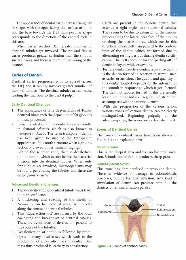
Chapter 5 Dental Caries 33
The appearance of dental caries here is triangular in shape, with the apex facing the surface of tooth and the base towards the DEJ. This peculiar shape corresponds to the direction of the enamel rods in this area.
When caries reaches DEJ, greater number of dentinal tubules get involved. The pit and fissure caries produces greater cavitation than the smooth surface caries and there is more undermining of the enamel.
Caries of DentinDentinal caries progresses with its spread across the DEJ and it rapidly involves greater number of dentinal tubules. The dentinal tubules act as tracts, leading the microbes to the dental pulp.
Early Dentinal Changes1. The appearance of fatty degeneration of Tome’s
dentinal fibres with the deposition of fat globules in these processes.
2. Initial penetration of the dentin by caries results in dentinal sclerosis, which is also known as transparent dentin. The term transparent dentin has been given because of the transparent appearance of the tooth structure when a ground section is viewed under transmitting light.
3. Behind the sclerotic zone, there is decalcifica-tion of dentin, which occurs before the bacterial invasion into the dentinal tubules. When only few tubules are involved, microorganisms may be found penetrating the tubules and these are called pioneer bacteria.
Advanced Dentinal Changes1. The decalcification of dentinal tubule walls leads
to their confluence.2. A thickening and swelling of the sheath of
Neumann can be noted at irregular intervals along the course of dentinal tubules.
3. Tiny ‘liquefaction foci’ are formed by the focal coalescing and breakdown of dentinal tubules. These are ovoid areas of destruction parallel to the course of the tubules.
4. Decalcification of dentin is followed by prote-olysis in many focal areas, which leads to the production of a necrotic mass of dentin. This mass thus produced is leathery in consistency.
5. Clefts are present in the carious dentin that extends at right angles to the dentinal tubules. They seem to be due to extension of the carious process along the lateral branches of the tubules or along the matrix fibres, which run in this direction. These clefts run parallel to the contour lines of the dentin, which are formed due to alternating resting periods during dentin calcifi-cation. The clefts account for the ‘peeling off ’ of dentin in layers while excavating.
6. Tertiary dentin/reactive dentin/reparative dentin is the dentin formed in reaction to stimuli such as caries or attrition. The quality and quantity of this dentin formed depends on the intensity of the stimuli in response to which it gets formed. The dentinal tubules formed in this are usually lesser in number and are irregular in distribution as compared with the normal dentin.
7. With the progression of the carious lesion, various zones of carious dentin can be clearly distinguished. Beginning pulpally at the advancing edge, the zones are as described next.
Zones of Dentinal CariesThe zones of dentinal caries have been shown in Figure 5.4 and explained next.
Normal DentinThis is the deepest area and has no bacterial inva-sion. Stimulation of dentin produces sharp pain.
Subtransparent DentinThis zone has demineralised intertubular dentin. There is evidence of damage to odontoblastic processes, but no bacterial invasion. Any kind of stimulation of dentin can produce pain but the chances of remineralisation persist.
TransparentSubtransparent
Infected Turbid
Normal dentin
Figure 5.4 Zones of dentinal caries.
Preclinical Dentistry.indb 33 29-05-2020 12:56:19
https://t.me/DentalBooksWorld

34 Essentials of Preclinical Conservative Dentistry
Transparent DentinTransparent dentin is softer than the normal dentin and exhibits further mineral loss from the intertu-bular dentin. No bacteria are present and stimulation produces pain. Collagen network is intact, serves for remineralisation and is capable of self-repair if pulp is vital.
Turbid DentinIn this zone, bacterial invasion is present. There is intense widening of the dentinal tubules, which are filled with bacteria. Collagen network is irreversibly denatured and dentin cannot remineralise. Mineral content is very less. This zone must be removed during tooth preparation.
Infected DentinIt is the outermost zone composed of decomposed dentin, and great number of bacteria are present in this zone. Collagen network and minerals are absent. Removal of this zone is essential before the restor-ative procedure.
Types of Dental Caries
There are various types of dental caries that can be categorised based on different parameters. For instance, depending on the site of the tooth at which it occurs, it can be pit and fissure caries or smooth surface caries; depending on the rate of progress, it can be acute or chronic caries; as per the possi-bility of reversal of the disease, it can be reversible or irreversible dental caries. Similarly, according to the direction of progress of the disease, it can be forward or backward dental caries. Let us have a close look at all the different types of carious lesions in detail.
Pit and Fissure CariesPit and fissure caries develops on the occlusal surface of molars and premolars (Fig. 5.5A), on the buccal and lingual surfaces of molars and on the palatal surface of maxillary incisors.1. This is the most common type of caries seen in
teeth.2. Pits and fissures, owing to their narrow bases
and steep side walls, are more prone to dental caries due to their mechanical characteristics, which results in poor self-cleansing features.
3. There is softening at the base of the pit or fissure.
4. Softened enamel usually can be flaked away by the explorer. Actual penetration of the enamel by an explorer tip at the base of pit or fissure suggests extensive demineralisation and weak-ening of the enamel.
5. Enamel becomes porous and appears chalky or opaque, when dried with compressed air.
6. Undermining of the enamel occurs either through the lateral spreading of caries at the DEJ or because of penetration of the bacteria into the dentin, along the dentinal tubules. As a result, a large carious lesion is produced below a tiny opening on the occlusal surface. This under-mined enamel, at times, breaks suddenly due to masticatory forces, leading to a large carious lesion being exposed to the oral cavity (Fig. 5.5B).
7. This can also be experienced by the treating dentist, when he/she suddenly encounters a large lesion by just removing some amount of enamel in what looks like a small pit caries clinically.
8. Figure 5.5C shows clinical image of pit and fissure caries in mandibular second molar and Figure 5.5D depicts radiographic appearance of this carious lesion on the same tooth.
Smooth Surface CariesSmooth surface caries is the caries that develops on the proximal surfaces of the teeth or on the gingival third of the facial/buccal and lingual/palatal surfaces (Fig. 5.6A,B).1. Usually, smooth surface caries on the proximal
surface begins below the contact point.2. Clinically, when observed, it appears as faint
white opacity of the enamel, but the enamel surface is intact.
3. In certain cases, it can appear as yellowish or light brown-pigmented area as well.
Figure 5.6C shows smooth surface caries (mesial surface involvement) on mandibular second molar. Figure 5.6D shows the radiographic image of the same tooth showing radioluceny in the carious site.
Cervical CariesThis type of caries occurs on the labial or lingual surfaces in the gingival third areas (Fig. 5.7) and it extends laterally towards the proximal surfaces. The occurrence of this form of caries is usually related to the lack of oral hygiene.
Preclinical Dentistry.indb 34 29-05-2020 12:56:19
https://t.me/DentalBooksWorld

Chapter 5 Dental Caries 35
Root CariesRoot caries is defined by Hazen and his colleagues as ‘a soft, progressive lesion that is found anywhere on the root surface that has lost connective tissue attachment and is exposed to the oral environment’.1. It is also known as senile caries (Fig. 5.8).2. This type of caries is predominantly found in
dentitions of the older age groups, with signifi-cant gingival recession and exposed root surfaces.
3. At one time, it was also referred to as ‘caries of cementum’.
4. Microorganisms invade the cementum of the root either along the Sharpey’s fibres or between the bundles of fibres, and the microorganisms spread laterally in between various layers.
5. Actinomycetes have been found to be mostly associated with root caries.
Acute Dental Caries
As the name indicates, it refers to that type of carious lesion which spreads very fast and, consequently, early pulp involvement occurs.1. This kind of carious lesion is most commonly
found in children and young adults, owing to the fact that the diameter of dentinal tubules is large in such individuals and hence the lesion progresses very rapidly.
2. As the caries process is very fast, there are less chances of reparative dentin formation.
Figure 5.5 Pit and fissure caries on tooth. (A) Photograph. (B) Diagrammatic representation. (C) Pit and fissure caries in mandibular second molar. (D) Radiographic appearance of pit and fissure carious lesion on mandibular second molar.
A
B
C
D
Preclinical Dentistry.indb 35 29-05-2020 12:56:20
https://t.me/DentalBooksWorld

36 Essentials of Preclinical Conservative Dentistry
3. Undermining of enamel is commonly found in such lesions.
4. In acute caries, the dentin is usually stained light yellow as compared with the dark brown staining of chronic caries.
Rampant CariesIt is most often observed in the primary dentition of young children and the permanent dentition of teenagers.1. It is a condition characterised by sudden and
rapid destruction of teeth, affecting those surfaces which are relatively caries free.Figure 5.7 Cervical caries.
Figure 5.6 (A) Smooth surface caries on the mesial surfaces of maxillary central and lateral incisors and on the labial surfaces of mandibular canines. (B) Diagrammatic representation of smooth surface caries on the proximal surface of a mandibular molar. (C) Smooth surface caries (mesial surface involvement) on mandibular second molar. (D) Radiographic image of the same tooth showing radioluceny in the carious site.
C
D
B
A
Preclinical Dentistry.indb 36 29-05-2020 12:56:21
https://t.me/DentalBooksWorld

Chapter 5 Dental Caries 37
AEnamel
Dentin
Pulp
Cementum
Rootcaries
B
Figure 5.8 Root caries on tooth. (A) Photograph. (B) Diagrammatic representation.
2. Most commonly involved are the proximal and cervical surfaces of the mandibular incisors.
3. A caries increment of 10 or more new carious lesions over a period of about a year is character-istic of rampant caries.
Nursing Bottle Caries
This is a type of rampant caries seen in infants who are bottle-fed, and hence the name nursing bottle caries. It is also known as baby bottle syndrome.1. The aetiology of this lesion lies in the fact that
when infants are bottle-fed, milk/sweetened water/fruit juice gets collected on the surface of the anterior teeth (especially maxillary inci-sors) and stays there for a considerable amount of time, leading to an acid attack of bacteria and thus formation of dental caries.
2. Honey-sweetened pacifiers, if given for a longer period of time to the infants, can result in similar carious lesions.
3. As it usually affects maxillary anterior teeth, it can be clinically distinguished very easily from ordinary rampant caries, which affects mandib-ular incisors more commonly.
4. At times, the carious lesion spreads so fast that in very less number of days the entire crown portion of the deciduous tooth gets carious and only root stumps are seen (Fig. 5.9).
Chronic Dental CariesIt is that form of caries which progresses very slowly and therefore the pulp involvement is very late.1. It is most commonly seen in adults.2. These lesions appear larger clinically as compared
to acute carious lesions. Since the progression is slow, there is sufficient time for the deposition of reparative dentin.
3. The colour of the lesion is usually dark brown.4. The cavity is usually very shallow and there is
very less softening of the dentin.
Recurrent (Secondary) CariesIt is that type which occurs at the junction of the tooth and the restoration (Fig. 5.10).
It is usually due to poor adaptation of the restor-ative material to the cavity, which causes microle-akage, thereby causing dental caries.
Figure 5.9 Nursing bottle caries.
Preclinical Dentistry.indb 37 29-05-2020 12:56:22
https://t.me/DentalBooksWorld
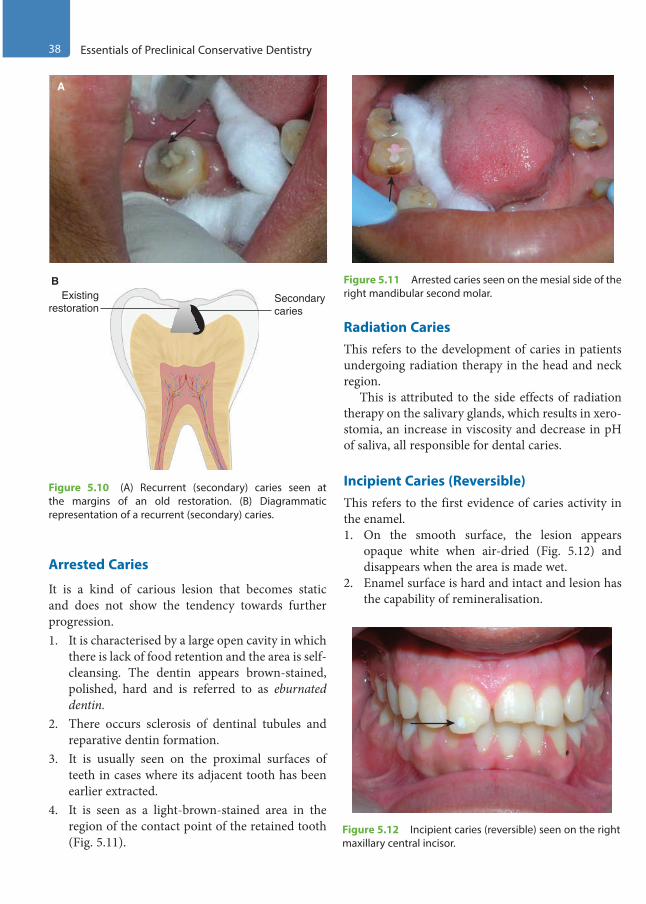
38 Essentials of Preclinical Conservative Dentistry
Arrested Caries
It is a kind of carious lesion that becomes static and does not show the tendency towards further progression.1. It is characterised by a large open cavity in which
there is lack of food retention and the area is self-cleansing. The dentin appears brown-stained, polished, hard and is referred to as eburnated dentin.
2. There occurs sclerosis of dentinal tubules and reparative dentin formation.
3. It is usually seen on the proximal surfaces of teeth in cases where its adjacent tooth has been earlier extracted.
4. It is seen as a light-brown-stained area in the region of the contact point of the retained tooth (Fig. 5.11).
Radiation CariesThis refers to the development of caries in patients undergoing radiation therapy in the head and neck region.
This is attributed to the side effects of radiation therapy on the salivary glands, which results in xero-stomia, an increase in viscosity and decrease in pH of saliva, all responsible for dental caries.
Incipient Caries (Reversible)This refers to the first evidence of caries activity in the enamel.1. On the smooth surface, the lesion appears
opaque white when air-dried (Fig. 5.12) and disappears when the area is made wet.
2. Enamel surface is hard and intact and lesion has the capability of remineralisation.
A
Existingrestoration
Secondarycaries
B
Figure 5.10 (A) Recurrent (secondary) caries seen at the margins of an old restoration. (B) Diagrammatic representation of a recurrent (secondary) caries.
Figure 5.11 Arrested caries seen on the mesial side of the right mandibular second molar.
Figure 5.12 Incipient caries (reversible) seen on the right maxillary central incisor.
Preclinical Dentistry.indb 38 29-05-2020 12:56:23
https://t.me/DentalBooksWorld
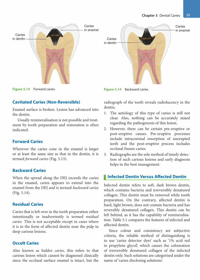
Chapter 5 Dental Caries 39
Cavitated Caries (Non-Reversible)
Enamel surface is broken. Lesion has advanced into the dentin.
Usually remineralisation is not possible and treat-ment by tooth preparation and restoration is often indicated.
Forward Caries
Wherever the caries cone in the enamel is larger or at least the same size as that in the dentin, it is termed forward caries (Fig. 5.13).
Backward Caries
When the spread along the DEJ exceeds the caries in the enamel, caries appears to extend into the enamel from the DEJ and is termed backward caries (Fig. 5.14).
Residual Caries
Caries that is left over in the tooth preparation either intentionally or inadvertently is termed residual caries. This is not acceptable except in cases where it is in the form of affected dentin near the pulp in deep carious lesions.
Occult Caries
Also known as hidden caries, this refers to that carious lesion which cannot be diagnosed clinically since the occlusal surface enamel is intact, but the
radiograph of the tooth reveals radiolucency in the dentin.1. The aetiology of this type of caries is still not
clear. Also, nothing can be accurately stated regarding the pathogenesis of this lesion.
2. However, there can be certain pre-eruptive or post-eruptive causes. Pre-eruptive processes include intracoronal resorption of unerupted teeth and the post-eruptive process includes occlusal fissure caries.
3. Radiographs are the sole method of timely detec-tion of such carious lesions and early diagnosis helps in the best management.
Infected Dentin Versus Affected Dentin
Infected dentin refers to soft, dark brown dentin, which contains bacteria and irreversibly denatured collagen. This dentin must be removed while tooth preparation. On the contrary, affected dentin is hard, light brown, does not contain bacteria and has reversibly denatured collagen. This dentin can be left behind, as it has the capability of remineralisa-tion. Table 5.1 compares the features of infected and affected dentin.
Since colour and consistency are subjective criteria, the reliable method of distinguishing is to use ‘caries detector dyes’ such as ‘1% acid red in propylene glycol’, which causes the colouration of irreversibly denatured collagen of the infected dentin only. Such solutions are categorised under the name of ‘caries disclosing solutions’.
Cariesin enamel
Cariesin dentin
Figure 5.13 Forward caries.
Cariesin enamel
Cariesin dentin
Figure 5.14 Backward caries.
Preclinical Dentistry.indb 39 29-05-2020 12:56:23
https://t.me/DentalBooksWorld
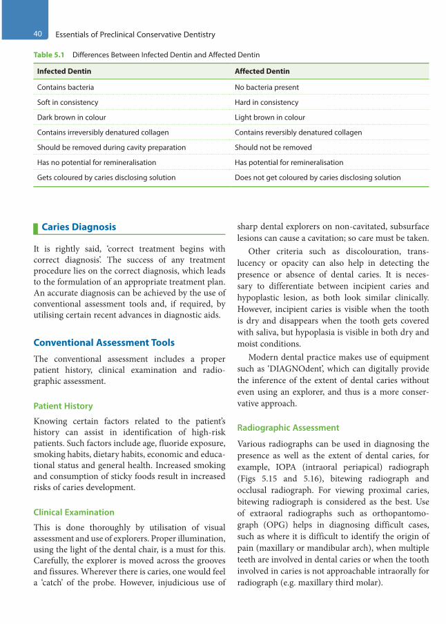
40 Essentials of Preclinical Conservative Dentistry
Caries Diagnosis
It is rightly said, ‘correct treatment begins with correct diagnosis’. The success of any treatment procedure lies on the correct diagnosis, which leads to the formulation of an appropriate treatment plan. An accurate diagnosis can be achieved by the use of conventional assessment tools and, if required, by utilising certain recent advances in diagnostic aids.
Conventional Assessment Tools
The conventional assessment includes a proper patient history, clinical examination and radio-graphic assessment.
Patient History
Knowing certain factors related to the patient’s history can assist in identification of high-risk patients. Such factors include age, fluoride exposure, smoking habits, dietary habits, economic and educa-tional status and general health. Increased smoking and consumption of sticky foods result in increased risks of caries development.
Clinical Examination
This is done thoroughly by utilisation of visual assessment and use of explorers. Proper illumination, using the light of the dental chair, is a must for this. Carefully, the explorer is moved across the grooves and fissures. Wherever there is caries, one would feel a ‘catch’ of the probe. However, injudicious use of
sharp dental explorers on non-cavitated, subsurface lesions can cause a cavitation; so care must be taken.
Other criteria such as discolouration, trans-lucency or opacity can also help in detecting the presence or absence of dental caries. It is neces-sary to differentiate between incipient caries and hypoplastic lesion, as both look similar clinically. However, incipient caries is visible when the tooth is dry and disappears when the tooth gets covered with saliva, but hypoplasia is visible in both dry and moist conditions.
Modern dental practice makes use of equipment such as ‘DIAGNOdent’, which can digitally provide the inference of the extent of dental caries without even using an explorer, and thus is a more conser-vative approach.
Radiographic Assessment
Various radiographs can be used in diagnosing the presence as well as the extent of dental caries, for example, IOPA (intraoral periapical) radiograph (Figs 5.15 and 5.16), bitewing radiograph and occlusal radiograph. For viewing proximal caries, bitewing radiograph is considered as the best. Use of extraoral radiographs such as orthopantomo-graph (OPG) helps in diagnosing difficult cases, such as where it is difficult to identify the origin of pain (maxillary or mandibular arch), when multiple teeth are involved in dental caries or when the tooth involved in caries is not approachable intraorally for radiograph (e.g. maxillary third molar).
Table 5.1 Differences Between Infected Dentin and Affected Dentin
Infected Dentin Affected Dentin
Contains bacteria No bacteria present
Soft in consistency Hard in consistency
Dark brown in colour Light brown in colour
Contains irreversibly denatured collagen Contains reversibly denatured collagen
Should be removed during cavity preparation Should not be removed
Has no potential for remineralisation Has potential for remineralisation
Gets coloured by caries disclosing solution Does not get coloured by caries disclosing solution
Preclinical Dentistry.indb 40 29-05-2020 12:56:24
https://t.me/DentalBooksWorld
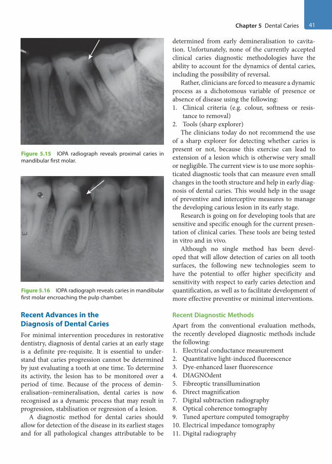
Chapter 5 Dental Caries 41
Recent Advances in the Diagnosis of Dental CariesFor minimal intervention procedures in restorative dentistry, diagnosis of dental caries at an early stage is a definite pre-requisite. It is essential to under-stand that caries progression cannot be determined by just evaluating a tooth at one time. To determine its activity, the lesion has to be monitored over a period of time. Because of the process of demin-eralisation–remineralisation, dental caries is now recognised as a dynamic process that may result in progression, stabilisation or regression of a lesion.
A diagnostic method for dental caries should allow for detection of the disease in its earliest stages and for all pathological changes attributable to be
determined from early demineralisation to cavita-tion. Unfortunately, none of the currently accepted clinical caries diagnostic methodologies have the ability to account for the dynamics of dental caries, including the possibility of reversal.
Rather, clinicians are forced to measure a dynamic process as a dichotomous variable of presence or absence of disease using the following:1. Clinical criteria (e.g. colour, softness or resis-
tance to removal)2. Tools (sharp explorer)
The clinicians today do not recommend the use of a sharp explorer for detecting whether caries is present or not, because this exercise can lead to extension of a lesion which is otherwise very small or negligible. The current view is to use more sophis-ticated diagnostic tools that can measure even small changes in the tooth structure and help in early diag-nosis of dental caries. This would help in the usage of preventive and interceptive measures to manage the developing carious lesion in its early stage.
Research is going on for developing tools that are sensitive and specific enough for the current presen-tation of clinical caries. These tools are being tested in vitro and in vivo.
Although no single method has been devel-oped that will allow detection of caries on all tooth surfaces, the following new technologies seem to have the potential to offer higher specificity and sensitivity with respect to early caries detection and quantification, as well as to facilitate development of more effective preventive or minimal interventions.
Recent Diagnostic MethodsApart from the conventional evaluation methods, the recently developed diagnostic methods include the following:1. Electrical conductance measurement2. Quantitative light-induced fluorescence3. Dye-enhanced laser fluorescence4. DIAGNOdent5. Fibreoptic transillumination6. Direct magnification7. Digital subtraction radiography8. Optical coherence tomography9. Tuned aperture computed tomography10. Electrical impedance tomography11. Digital radiography
Figure 5.16 IOPA radiograph reveals caries in mandibular first molar encroaching the pulp chamber.
Figure 5.15 IOPA radiograph reveals proximal caries in mandibular first molar.
Preclinical Dentistry.indb 41 29-05-2020 12:56:24
https://t.me/DentalBooksWorld

42 Essentials of Preclinical Conservative Dentistry
Demineralisation–Remineralisation Cycle and Prevention of Caries
Over the past 30 years, there has been a considerable increase in the knowledge and understanding of the process of dental caries. It has now been proved that remineralisation of the tooth structure can happen if proper preventive measures are taken in early stages, before any cavitation takes place.
Enamel and dentin demineralisation is not a continuous irreversible process. Through a series of demineralisation and remineralisation cycles, the tooth alternatively loses and gains Ca++ and PO2– ions, depending on the microenvironment.
When the pH of the oral cavity is <5.5, subsurface enamel or dentin demineralise, owing to the release of Ca++ and PO4
2– ions, leaving behind the deminer-alised collagen framework.
In early carious lesion, there is subsurface demin-eralisation of enamel. Because the saliva is already a supersaturated solution of Ca++ and PO4
2– ions, there is a potential of the return of these ions to the tooth surface. Thus, when the ambient pH rises >5.5, an early carious lesion will begin to reminer-alise and heal.
However, if the acidity remains for a prolonged period or reaches these levels with great frequency, surface integrity may be lost to the extent of cavi-tation. Thereafter, it becomes difficult or impossible for the patient to keep the area free from further plaque accumulation. Therefore, surgical treatment,
that is, caries removal, followed by a restoration, is indicated for cavitated lesions.
In case where cavitation has not yet occurred, the oral environment can be changed and the tooth can be moved towards remineralisation and away from demineralisation.
This approach includes the following:1. Dietary control: Decreasing the frequency of
intake of refined carbohydrates.2. Plaque control: Ensuring optimum plaque
control by using mechanical and chemical methods.
3. Ensuring optimum salivary flow by use of home-care measures, such as sugar-free candies or medicinal agents such as sialogogues.
4. Conducting patient education.5. Utilising agents such as chlorhexidine and fluo-
ride in the form of mouthwashes and toothpastes. Alternatively, the dentists can apply topical fluo-rides or use pit and fissure sealants as measures for preventing the progression of dental caries in caries-prone areas.
6. Use of biofilm-modifying oral products such as fluoride–arginine combinations is now being evaluated as a new standard of care for caries prevention.
7. Dentifrices containing enzymes and proteins have also shown to shift the ecology of the oral microbiome to a large extent and thus may be a promising home care measure in the near future.
KEY POINTS
• Dental caries is an infectious microbiological disease of the teeth that results in localised dissolution and destruction of the calcified tissues.
• Many theories have been proposed which explain the aetiology of dental caries. However, the most widely accepted is the ‘chemicoparasitic theory’ proposed by Miller in 1889.
• Other theories proposed are proteolytic theory, sulphatase theory, proteolysis chelation theory, Levine’s theory and Burch and Jackson hypothesis.
• Keyes, in 1960, proposed dental caries to be a multifactorial disease in which there is interplay of three principal factors: a susceptible host tissue (tooth), microflora with a cariogenic potential (bacteria) and a suitable local substrate (diet). This is called caries triad.
• Newbrun, in 1982, proposed to add a fourth factor ‘time’ in the existing triad and hence the term ‘caries tetrad’ came into existence.
• Carious lesion in the enamel, as seen histopathologically, shows the translucent zone, dark zone, body zone and surface zone.
• Carious lesion in the dentin, as seen histopathologically, shows the normal dentin, subtransparent dentin, transparent dentin, turbid dentin and infected dentin.
Preclinical Dentistry.indb 42 29-05-2020 12:56:24
https://t.me/DentalBooksWorld
Chapter 5 Dental Caries 43
• Various terminologies, such as pit and fissure caries, smooth surface caries, cervical caries, root caries, acute dental caries, rampant caries, nursing bottle caries and chronic dental caries, need to be understood for clinical reference and their management thereafter.
• Diagnosis of presence of dental caries can be made by careful clinical and radiographic examination. Undue use of sharp explorer is not recommended.
• Use of recent diagnostic tools such as the ‘DIAGNOdent’ can be of immense help, especially in the diagnosis of early dental caries.
• Preventive therapy must always be given due consideration, understanding the fact that caries is a dynamic process comprising the demineralisation–remineralisation cycle, wherein altering the oral environment can tip the balance in favour of remineralisation and away from demineralisation.
• Diet control, plaque control, usage of fluoride and chlorhexidine mouthwashes, etc., can help in remineralisation of non-cavitated lesions.
SELF-ASSESSMENT QUESTIONS
1. Define dental caries.
2. Enumerate different theories proposed as aetiological proposals for dental caries.
3. Explain the chemicoparasitic theory of dental caries.
4. Explain the histopathological pattern of dental caries in human enamel and dentin.
5. What do you understand by pit and fissure caries and smooth surface caries?
6. Explain the terms acute dental caries, rampant caries and nursing bottle caries.
7. What do you understand by recurrent caries and arrested caries?
8. Define radiation caries.
9. What do you understand by incipient caries?
10. How do you differentiate between forward caries and backward caries?
11. What do you understand by residual caries?
12. What is the importance of radiographs in the detection of dental caries?
13. Enumerate various recent technologies being used for the detection of dental caries.
14. Elaborate the term demineralisation–remineralisation cycle in the context of dental caries.
15. Discuss the methods of prevention of dental caries.
Preclinical Dentistry.indb 43 29-05-2020 12:56:24
https://t.me/DentalBooksWorld
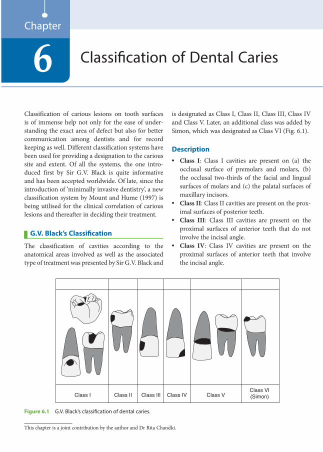
Classification of carious lesions on tooth surfaces is of immense help not only for the ease of under-standing the exact area of defect but also for better communication among dentists and for record keeping as well. Different classification systems have been used for providing a designation to the carious site and extent. Of all the systems, the one intro-duced first by Sir G.V. Black is quite informative and has been accepted worldwide. Of late, since the introduction of ‘minimally invasive dentistry’, a new classification system by Mount and Hume (1997) is being utilised for the clinical correlation of carious lesions and thereafter in deciding their treatment.
G.V. Black’s Classification
The classification of cavities according to the anatomical areas involved as well as the associated type of treatment was presented by Sir G.V. Black and
is designated as Class I, Class II, Class III, Class IV and Class V. Later, an additional class was added by Simon, which was designated as Class VI (Fig. 6.1).
Description• Class I: Class I cavities are present on (a) the
occlusal surface of premolars and molars, (b) the occlusal two-thirds of the facial and lingual surfaces of molars and (c) the palatal surfaces of maxillary incisors.
• Class II: Class II cavities are present on the prox-imal surfaces of posterior teeth.
• Class III: Class III cavities are present on the proximal surfaces of anterior teeth that do not involve the incisal angle.
• Class IV: Class IV cavities are present on the proximal surfaces of anterior teeth that involve the incisal angle.
Classification of Dental Caries6Chapter
Class I Class II Class III Class IV Class VClass VI(Simon)
Figure 6.1 G.V. Black’s classification of dental caries.
This chapter is a joint contribution by the author and Dr Rita Chandki.
Preclinical Dentistry.indb 44 29-05-2020 12:56:24
https://t.me/DentalBooksWorld

Chapter 6 Classification of Dental Caries 45
• Class V: Class V cavities are present on the gingival third of the facial or the lingual surface of all teeth.
• Class VI: Class VI cavities are present on the incisal edge of anterior teeth or the occlusal cusp heights of posterior teeth.
Cavities on the occlusal surface of mandib-ular molars extending to two-thirds of their facial surface are commonly known as Class I with a buccal extension. Similarly, cavities on the occlusal surface of maxillary molars extending to two-thirds of their palatal surface are commonly known as Class I with a palatal extension. Such cavities are also known as Class I compound cavities.
Drawbacks
Certain surfaces of teeth, if affected, fail to find their designation in the Black’s system of classifica-tion, such as the labial and the lingual surfaces of the anterior teeth other than the cervical one-third and cavities on the line angles of teeth. Also, no proper designation can be given to lesions such as caries on the proximal and the buccal surfaces of the same tooth. In such cases, elaborate description of the surfaces involved has to be given, for example, the above-mentioned case can be denoted as Class II lesion and buccal pit.
New Classification Systems
For almost 100 years, Black’s classification of carious lesions according to the site involved has guided dentists in the restorative management of teeth.
This classification was based on the cavity prepa-ration equipment and restorative materials available at that time. Over the past 20 years, there has been a considerable modification in the understanding of the initiation and progress of caries and the
significance of fluoride and other ions in the demin-eralisation–remineralisation process.
It was therefore suggested that the profession adopt new classification systems based on the site and size of a lesion, wherein the two descriptors are used together. More relevant details can be recorded for each restoration, and this is of immense value, for both personal records and epidemiological studies.
The instruments available for cavity prepara-tion have changed, and there are now restorative materials capable of long-term adhesion to tooth structure, both to the enamel and to dentin, in spite of the relatively hostile oral environment.
One should always keep in mind that despite the introduction of new classification systems, the contemporary one cannot be ignored. All the classi-fication systems can be used depending on the indi-vidual requirement.
Based on Site and Size of the LesionThis classification of carious lesions was proposed by G.J. Mount and W.R. Hume in 1997 (Table 6.1). The rationale behind this cavity classification system based on lesion site and size is that it is necessary only to gain access to the lesions and remove areas that are infected and broken down to the point where remineralisation is no longer possible.
The classification is linked to the stage of progres-sion of the lesion and not to cavity design.
SiteThe site description is simple, accurate and compre-hensive (Fig. 6.2).• Site 1: It describes all lesions originating in pits
and fissures and other defects on the otherwise smooth surfaces of the enamel. It includes buccal pits on mandibular molars, palatal grooves on maxillary molars and similar defects as well as erosion lesions on the incisal edges of anterior teeth and the occlusal surfaces of posterior teeth.
Table 6.1 Mount’s Classification of Dental Caries Based on the Site and Size of the Lesion
Location 0 = No Cavity 1 = Minimal 2 = Moderate 3 = Advanced 4 = Extensive
Site 1: Pits and fissures 1.0 1.1 1.2 1.3 1.4
Site 2: Proximal surfaces 2.0 2.1 2.2 2.3 2.4
Site 3: Cervical surfaces 3.0 3.1 3.2 3.3 3.4
Preclinical Dentistry.indb 45 29-05-2020 12:56:24
https://t.me/DentalBooksWorld
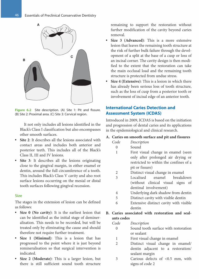
46 Essentials of Preclinical Conservative Dentistry
It not only includes all lesions identified in the Black’s Class I classification but also encompasses other smooth surfaces.
• Site 2: It describes all the lesions associated with contact areas and includes both anterior and posterior teeth. This includes all of the Black’s Class II, III and IV lesions.
• Site 3: It describes all the lesions originating close to the gingival margin, in either enamel or dentin, around the full circumference of a tooth. This includes Black’s Class V cavity and also root surface lesions occurring on the mesial or distal tooth surfaces following gingival recession.
Size
The stages in the extension of lesion can be defined as follows:• Size 0 (No cavity): It is the earliest lesion that
can be identified as the initial stage of deminer-alisation. This needs to be recorded, but will be treated only by eliminating the cause and should therefore not require further treatment.
• Size 1 (Minimal): This is a lesion that has progressed to the point where it is just beyond remineralisation so that surgical intervention is indicated.
• Size 2 (Moderate): This is a larger lesion, but there is still sufficient sound tooth structure
remaining to support the restoration without further modification of the cavity beyond caries removal.
• Size 3 (Advanced): This is a more extensive lesion that leaves the remaining tooth structure at the risk of further bulk failure through the devel-opment of a split at the base of a cusp or loss of an incisal corner. The cavity design is then modi-fied to the extent that the restoration can take the main occlusal load and the remaining tooth structure is protected from undue stress.
• Size 4 (Extensive): This is a lesion in which there has already been serious loss of tooth structure, such as the loss of cusp from a posterior tooth or involvement of incisal edge of an anterior tooth.
International Caries Detection and Assessment System (ICDAS)Introduced in 2009, ICDAS is based on the initiation and progression of dental caries and its applications in the epidemiological and clinical research.
A. Caries on smooth surface and pit and fissuresCode Description
0 Sound1 First visual change in enamel (seen
only after prolonged air drying or restricted to within the confines of a pit or fissure)
2 Distinct visual change in enamel3 Localised enamel breakdown
(without clinical visual signs of dentinal involvement)
4 Underlying dark shadow from dentin5 Distinct cavity with visible dentin6 Extensive distinct cavity with visible
dentinB. Caries associated with restoration and seal-
ants codesCode Description
0 Sound tooth surface with restoration or sealant
1 First visual change in enamel2 Distinct visual change in enamel/
dentin adjacent to a restoration/sealant margin
3 Carious defects of <0.5 mm, with signs of code 2
Figure 6.2 Site description. (A) Site 1: Pit and fissure. (B) Site 2: Proximal area. (C) Site 3: Cervical region.
A
CB
Preclinical Dentistry.indb 46 29-05-2020 12:56:24
https://t.me/DentalBooksWorld

Chapter 6 Classification of Dental Caries 47
4 Marginal caries in enamel/dentin/cementum adjacent to restoration/sealant, with underlying dark shadow from dentin
5 Distinct cavity adjacent to restoration /sealant
6 Extensive distinct cavity with visible dentin
C. Caries on root surfaceCode Description
E If the root surface cannot be visual-ised directly, then it is excluded.
0 The root surface does not exhibit any unusual discolouration that distin-guishes it from the surrounding root areas nor does it exhibit a surface defect at the cementoenamel junc-tion or root surface. The root surface has a natural anatomical contour.
1 There is a demarcated area on the root surface or at the cementoenamel junction that is discoloured but there is no cavitation (loss of anatomical contour less than 0.5 mm) present.
2 There is a demarcated area on the root surface or at the cementoenamel junction that is discoloured and there is cavitation (loss of anatomical contour more than 0.5 mm) present.
Based on Radiographical Evaluation of Proximal CariesEarly proximal lesions are those that have been identified as radiolucencies in the inner half of
the enamel, at the dentinoenamel junction or even slightly into the dentin, but with little or no evidence of cavitation.
The radiographical changes in the proximal lesions can be assessed on the following classifica-tion given by Ben and Dankel et al.:
E1 : Radiolucency in the outer half of the enamel
E2 : Radiolucency in the inner half of the enamel D1 : Radiolucency in the outer one-third of
the dentin D2 : Radiolucency in the middle one-third of
dentin D3 : Radiolucency in the inner one-third of the
dentin
It has been noted that 60–80% of initial proximal lesions with radiolucencies in the outer one-third of the dentin do not show cavitation. Therefore, resto-rations are indicated only when a radiolucent lesion has extended to the D2 region, where the probability of cavitation is around 20–40%.
This delay in attempting the restoration at a later point of time is justifiable, as cavitation is a late event in the proximal carious lesion, taking up to 4–5 years in low- or moderate-risk patients. In such cases, a change in the oral environment can tip the balance from demineralisation to remineralisation of the subsurface lesions, thereby avoiding cavita-tions. Every attempt at the biological approach of disease control and facilitation of remineralisation should be considered prior to surgical intervention after assessing the caries risk of the patient.
KEY POINTS
• Classification of cavities holds paramount importance in restorative dentistry, as it depicts the exact site of carious involvement in a tooth. This helps in easy record keeping as well.
• G.V. Black proposed the first classification system according to the tooth surface involved and coined the terms Class I, II, III, IV and V.
• Simon added another class to the existing classification and designated it as Class VI.• Cavity classification system based on the lesion site and size was proposed by G.J. Mount and W.R. Hume in 1997.
This classification is linked to the stage of progression of lesion and is not related to cavity design.• In 2009, ICDAS was introduced based on the initiation and progression of dental caries. It categorises the carious
lesions as (a) caries on smooth surface and pit and fissures, (b) caries associated with restoration and sealants and (c) caries on root surface.
• The classification system based on the radiographical changes in the proximal lesions was given by Ben and Dankel et al. This classification divides the carious lesions depending on the fact that they involve only the enamel or extend into the dentin as well, when observed radiographically.
Preclinical Dentistry.indb 47 29-05-2020 12:56:24
https://t.me/DentalBooksWorld

48 Essentials of Preclinical Conservative Dentistry
SELF-ASSESSMENT QUESTIONS
1. Describe G.V. Black’s classification of dental caries.
2. What are the limitations of G.V. Black’s classification of dental caries?
3. Describe G.J. Mount and W.R. Hume’s classification of dental caries.
4. Describe ICDAS in brief.
5. Describe the classification based on the radiographical evaluation of proximal caries.
Preclinical Dentistry.indb 48 29-05-2020 12:56:24
https://t.me/DentalBooksWorld
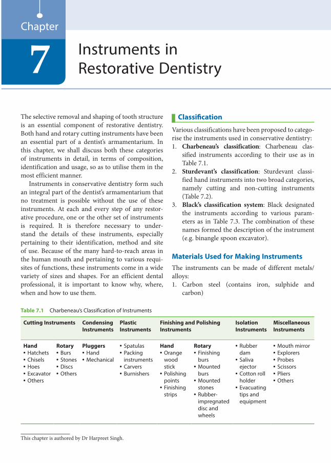
The selective removal and shaping of tooth structure is an essential component of restorative dentistry. Both hand and rotary cutting instruments have been an essential part of a dentist’s armamentarium. In this chapter, we shall discuss both these categories of instruments in detail, in terms of composition, identification and usage, so as to utilise them in the most efficient manner.
Instruments in conservative dentistry form such an integral part of the dentist’s armamentarium that no treatment is possible without the use of these instruments. At each and every step of any restor-ative procedure, one or the other set of instruments is required. It is therefore necessary to under-stand the details of these instruments, especially pertaining to their identification, method and site of use. Because of the many hard-to-reach areas in the human mouth and pertaining to various requi-sites of functions, these instruments come in a wide variety of sizes and shapes. For an efficient dental professional, it is important to know why, where, when and how to use them.
Classification
Various classifications have been proposed to catego-rise the instruments used in conservative dentistry:1. Charbeneau’s classification: Charbeneau clas-
sified instruments according to their use as in Table 7.1.
2. Sturdevant’s classification: Sturdevant classi-fied hand instruments into two broad categories, namely cutting and non-cutting instruments (Table 7.2).
3. Black’s classification system: Black designated the instruments according to various param-eters as in Table 7.3. The combination of these names formed the description of the instrument (e.g. binangle spoon excavator).
Materials Used for Making InstrumentsThe instruments can be made of different metals/ alloys:1. Carbon steel (contains iron, sulphide and
carbon)
Instruments in Restorative Dentistry7
Chapter
Table 7.1 Charbeneau’s Classification of Instruments
Cutting Instruments Condensing Instruments
Plastic Instruments
Finishing and Polishing Instruments
Isolation Instruments
Miscellaneous Instruments
Hand• Hatchets• Chisels• Hoes• Excavator• Others
Rotary• Burs• Stones• Discs• Others
Pluggers• Hand• Mechanical
• Spatulas• Packing
instruments• Carvers• Burnishers
Hand• Orange
wood stick
• Polishing points
• Finishing strips
Rotary• Finishing
burs• Mounted
burs• Mounted
stones• Rubber-
impregnated disc and wheels
• Rubber dam
• Saliva ejector
• Cotton roll holder
• Evacuating tips and equipment
• Mouth mirror• Explorers• Probes• Scissors• Pliers• Others
This chapter is authored by Dr Harpreet Singh.
Preclinical Dentistry.indb 49 29-05-2020 12:56:24
https://t.me/DentalBooksWorld
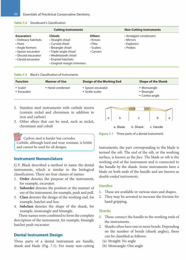
50 Essentials of Preclinical Conservative Dentistry
2. Stainless steel instruments with carbide inserts (contain nickel and chromium in addition to iron and carbon)
3. Other alloys that can be used, such as nickel, chromium and cobalt
Carbon steel is harder but corrodes.Carbide, although hard and wear resistant, is brittle and cannot be used for all designs.
Instrument NomenclatureG.V. Black described a method to name the dental instruments, which is similar to the biological classification. There are four classes of names:1. Order denotes the purpose of the instrument,
for example, excavator.2. Suborder denotes the position or the manner of
use of the instrument, for example, push and pull.3. Class denotes the design of the working end, for
example, hatchet and hoe.4. Subclass denotes the shape of the shank, for
example, monoangle and binangle.These names were combined to form the complete
description of the instrument, for example, binangle hatchet push excavator.
Dental Instrument DesignThree parts of a dental instrument are handle, shank and blade (Fig. 7.1). For many non-cutting
instruments, the part corresponding to the blade is termed the nib. The end of the nib, or the working surface, is known as the face. The blade or nib is the working end of the instrument and is connected to the handle by the shank. Some instruments have a blade on both ends of the handle and are known as double-ended instruments.
Handles
1. These are available in various sizes and shapes.2. They may be serrated to increase the friction for
hand gripping.
Shanks
1. These connect the handle to the working ends of the instruments.
2. Shanks often have one or more bends. Depending on the number of bends (shank angles), these can be classified as follows:
(a) Straight: No angle(b) Monoangle: One angle
Table 7.2 Sturdevant’s Classification
Cutting Instruments Non-Cutting Instruments
Excavators• Ordinary hatchets• Hoes• Angle formers• Spoon excavator• Discoid excavator• Cleoid excavator
Chisels• Straight chisel• Curved chisel• Binangle chisel• Triple-angle chisel• Wedelstaedt chisel• Enamel hatchets• Gingival margin trimmers
Others• Knives• Files• Scalers• Carvers
• Amalgam condensers• Mirrors• Explorers• Probes
Table 7.3 Black’s Classification of Instruments
Function Manner of Use Design of the Working End Shape of the Shank
• Scaler• Excavator
• Hand condenser • Spoon excavator• Sickle scaler
• Monoangle• Binangle• Contra-angle
a ab bc
a. Blade b. Shank c. Handle
Figure 7.1 Three parts of a dental instrument.
Preclinical Dentistry.indb 50 29-05-2020 12:56:24
https://t.me/DentalBooksWorld
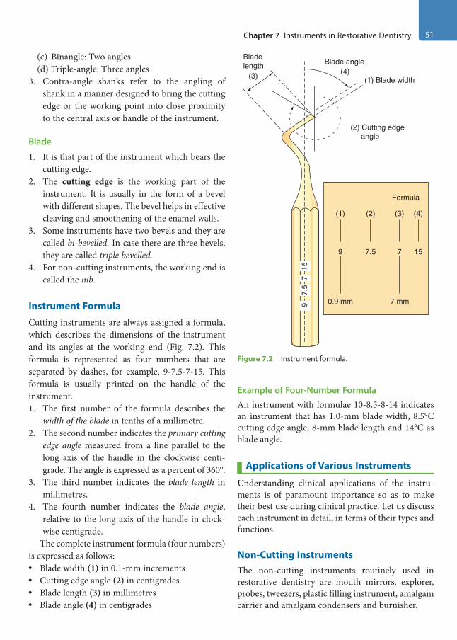
Chapter 7 Instruments in Restorative Dentistry 51
(c) Binangle: Two angles(d) Triple-angle: Three angles
3. Contra-angle shanks refer to the angling of shank in a manner designed to bring the cutting edge or the working point into close proximity to the central axis or handle of the instrument.
Blade
1. It is that part of the instrument which bears the cutting edge.
2. The cutting edge is the working part of the instrument. It is usually in the form of a bevel with different shapes. The bevel helps in effective cleaving and smoothening of the enamel walls.
3. Some instruments have two bevels and they are called bi-bevelled. In case there are three bevels, they are called triple bevelled.
4. For non-cutting instruments, the working end is called the nib.
Instrument Formula
Cutting instruments are always assigned a formula, which describes the dimensions of the instrument and its angles at the working end (Fig. 7.2). This formula is represented as four numbers that are separated by dashes, for example, 9-7.5-7-15. This formula is usually printed on the handle of the instrument.1. The first number of the formula describes the
width of the blade in tenths of a millimetre.2. The second number indicates the primary cutting
edge angle measured from a line parallel to the long axis of the handle in the clockwise centi-grade. The angle is expressed as a percent of 360°.
3. The third number indicates the blade length in millimetres.
4. The fourth number indicates the blade angle, relative to the long axis of the handle in clock-wise centigrade.
The complete instrument formula (four numbers) is expressed as follows:• Blade width (1) in 0.1-mm increments• Cutting edge angle (2) in centigrades• Blade length (3) in millimetres• Blade angle (4) in centigrades
Example of Four-Number FormulaAn instrument with formulae 10-8.5-8-14 indicates an instrument that has 1.0-mm blade width, 8.5°C cutting edge angle, 8-mm blade length and 14°C as blade angle.
Applications of Various Instruments
Understanding clinical applications of the instru-ments is of paramount importance so as to make their best use during clinical practice. Let us discuss each instrument in detail, in terms of their types and functions.
Non-Cutting InstrumentsThe non-cutting instruments routinely used in restorative dentistry are mouth mirrors, explorer, probes, tweezers, plastic filling instrument, amalgam carrier and amalgam condensers and burnisher.
Bladelength
(3) (4)Blade angle
(1) Blade width
(2) Cutting edge angle
Formula
(1) (2) (3) (4)
9 7.5 7 15
0.9 mm 7 mm15
77.
59
Figure 7.2 Instrument formula.
Preclinical Dentistry.indb 51 29-05-2020 12:56:25
https://t.me/DentalBooksWorld
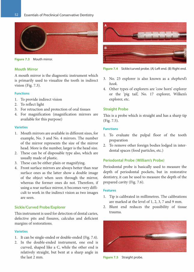
52 Essentials of Preclinical Conservative Dentistry
Mouth Mirror
A mouth mirror is the diagnostic instrument which is primarily used to visualize the tooth in indirect vision (Fig. 7.3).
Functions
1. To provide indirect vision2. To reflect light3. For retraction and protection of oral tissues4. For magnification (magnification mirrors are
available for this purpose)
Varieties
1. Mouth mirrors are available in different sizes, for example, No. 3 and No. 4 mirrors. The number of the mirror represents the size of the mirror head. More is the number, larger is the head size.
2. These can be of disposable type also, which are usually made of plastic.
3. These can be either plain or magnifying.4. Front surface mirrors are always better than rear
surface ones as the latter show a double image of the object when seen through the mirror, whereas the former ones do not. Therefore, if using a rear surface mirror, it becomes very diffi-cult to work in the indirect vision as two images are seen.
Sickle/Curved Probe/Explorer
This instrument is used for detection of dental caries, defective pits and fissures, calculus and deficient margins of restorations.
Varieties
1. It can be single-ended or double-ended (Fig. 7.4).2. In the double-ended instrument, one end is
curved, shaped like a C, while the other end is relatively straight, but bent at a sharp angle in the last 2 mm.
3. No. 23 explorer is also known as a shepherd’s hook.
4. Other types of explorers are ‘cow horn’ explorer or the ‘pig tail’, No. 17 explorer, Wilken’s explorer, etc.
Straight Probe
This is a probe which is straight and has a sharp tip (Fig. 7.5).
Functions
1. To evaluate the pulpal floor of the tooth preparation
2. To remove other foreign bodies lodged in inter-dental spaces (food particles, etc.)
Periodontal Probe (William’s Probe)
Periodontal probe is basically used to measure the depth of periodontal pockets, but in restorative dentistry, it can be used to measure the depth of the prepared cavity (Fig. 7.6).
Features
1. Tip is calibrated in millimetres. The calibrations are marked at the level of 1, 2, 3, 7 and 9 mm.
2. Blunt end reduces the possibility of tissue trauma.
Figure 7.3 Mouth mirror.
A
B
Figure 7.4 Sickle/curved probe. (A) Left end. (B) Right end.
Figure 7.5 Straight probe.
Preclinical Dentistry.indb 52 29-05-2020 12:56:26
https://t.me/DentalBooksWorld
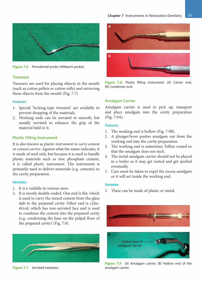
Chapter 7 Instruments in Restorative Dentistry 53
TweezersTweezers are used for placing objects in the mouth (such as cotton pellets or cotton rolls) and retrieving these objects from the mouth (Fig. 7.7).
Features
1. Special ‘locking-type tweezers’ are available to prevent dropping of the materials.
2. Working ends can be serrated or smooth, but usually serrated to enhance the grip of the material held in it.
Plastic Filling InstrumentIt is also known as plastic instrument to carry cement or cement carrier. Against what the name indicates, it is made of steel only, but because it is used to handle plastic materials such as zinc phosphate cement, it is called plastic instrument. The instrument is primarily used to deliver materials (e.g. cements) to the cavity preparation.
Varieties
1. It is a vailable in various sizes.2. It is mostly double-ended. One end is flat, which
is used to carry the mixed cement from the glass slab to the prepared cavity. Other end is cylin-drical, which has non-serrated face and is used to condense the cement into the prepared cavity (e.g. condensing the base on the pulpal floor of the prepared cavity) (Fig. 7.8).
Amalgam CarrierAmalgam carrier is used to pick up, transport and place amalgam into the cavity preparation (Fig. 7.9A).
Features
1. The working end is hollow (Fig. 7.9B).2. A plunger/lever pushes amalgam out from the
working end into the cavity preparation.3. The working end is sometimes Teflon coated so
that the amalgam does not stick.4. The metal amalgam carrier should not be placed
in a boiler as it may get rusted and get spoiled eventually.
5. Care must be taken to expel the excess amalgam or it will set inside the working end.
Varieties
1. These can be made of plastic or metal.
Figure 7.6 Periodontal probe (William’s probe).
Figure 7.7 Serrated tweezers.
A
B
Figure 7.8 Plastic filling instrument. (A) Carrier end. (B) Condenser end.
A
B
Hollow end ofamalgam carrier
Figure 7.9 (A) Amalgam carrier. (B) Hollow end of the amalgam carrier.
Preclinical Dentistry.indb 53 29-05-2020 12:56:27
https://t.me/DentalBooksWorld
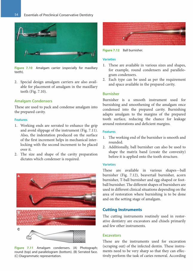
54 Essentials of Preclinical Conservative Dentistry
2. Special design amalgam carriers are also avail-able for placement of amalgam in the maxillary teeth (Fig. 7.10).
Amalgam CondensersThese are used to pack and condense amalgam into the prepared cavity.
Features
1. Working ends are serrated to enhance the grip and avoid slippage of the instrument (Fig. 7.11). Also, the indentation produced on the surface of the first increment helps in mechanical inter-locking with the second increment to be placed over it.
2. The size and shape of the cavity preparation dictates which condenser is required.
Varieties
1. These are available in various sizes and shapes, for example, round condensers and parallelo-gram condensers.
2. Each type can be used as per the requirement and space available in the prepared cavity.
BurnisherBurnisher is a smooth instrument used for burnishing and smoothening of the amalgam once condensed into the prepared cavity. Burnishing adapts amalgam to the margins of the prepared tooth surface, reducing the chance for leakage around restorations and deficient margins.
Features
1. The working end of the burnisher is smooth and rounded.
2. Additionally, ball burnisher can also be used to shape the matrix band (create the convexity) before it is applied onto the tooth structure.
Varieties
These are available in various shapes—ball burnisher (Fig. 7.12), beavertail burnisher, acorn burnisher, T-ball burnisher and egg-shaped or foot-ball burnisher. The different shapes of burnishers are used in different clinical situations depending on the area of restoration where burnishing is to be done and on the setting stage of amalgam.
Cutting InstrumentsThe cutting instruments routinely used in restor-ative dentistry are excavators and chisels primarily and few other instruments.
ExcavatorsThese are the instruments used for excavation (scraping out) of the infected dentin. These instru-ments need to be very sharp so that they can effec-tively perform the task of caries removal. According
Figure 7.10 Amalgam carrier (especially for maxillary teeth).
A
B
C
Figure 7.11 Amalgam condensers. (A) Photograph; round (top) and parallelogram (bottom). (B) Serrated face. (C) Diagrammatic representation.
Figure 7.12 Ball burnisher.
Preclinical Dentistry.indb 54 29-05-2020 12:56:28
https://t.me/DentalBooksWorld
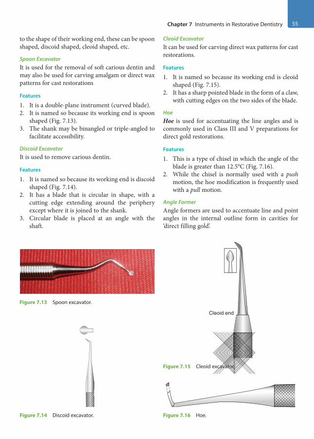
Chapter 7 Instruments in Restorative Dentistry 55
to the shape of their working end, these can be spoon shaped, discoid shaped, cleoid shaped, etc.
Spoon ExcavatorIt is used for the removal of soft carious dentin and may also be used for carving amalgam or direct wax patterns for cast restorations
Features
1. It is a double-plane instrument (curved blade).2. It is named so because its working end is spoon
shaped (Fig. 7.13).3. The shank may be binangled or triple-angled to
facilitate accessibility.
Discoid ExcavatorIt is used to remove carious dentin.
Features
1. It is named so because its working end is discoid shaped (Fig. 7.14).
2. It has a blade that is circular in shape, with a cutting edge extending around the periphery except where it is joined to the shank.
3. Circular blade is placed at an angle with the shaft.
Cleoid ExcavatorIt can be used for carving direct wax patterns for cast restorations.
Features
1. It is named so because its working end is cleoid shaped (Fig. 7.15).
2. It has a sharp pointed blade in the form of a claw, with cutting edges on the two sides of the blade.
HoeHoe is used for accentuating the line angles and is commonly used in Class III and V preparations for direct gold restorations.
Features
1. This is a type of chisel in which the angle of the blade is greater than 12.5°C (Fig. 7.16).
2. While the chisel is normally used with a push motion, the hoe modification is frequently used with a pull motion.
Angle FormerAngle formers are used to accentuate line and point angles in the internal outline form in cavities for ‘direct filling gold’.
Figure 7.13 Spoon excavator.
Figure 7.14 Discoid excavator.
Cleoid end
Figure 7.15 Cleoid excavator.
Figure 7.16 Hoe.
Preclinical Dentistry.indb 55 29-05-2020 12:56:29
https://t.me/DentalBooksWorld
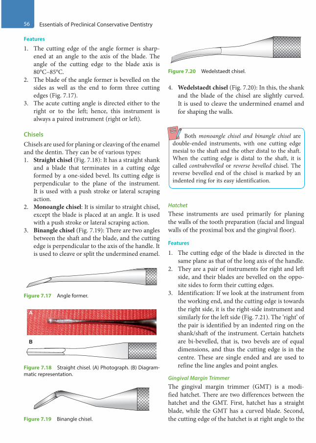
56 Essentials of Preclinical Conservative Dentistry
Features
1. The cutting edge of the angle former is sharp-ened at an angle to the axis of the blade. The angle of the cutting edge to the blade axis is 80°C–85°C.
2. The blade of the angle former is bevelled on the sides as well as the end to form three cutting edges (Fig. 7.17).
3. The acute cutting angle is directed either to the right or to the left; hence, this instrument is always a paired instrument (right or left).
ChiselsChisels are used for planing or cleaving of the enamel and the dentin. They can be of various types:1. Straight chisel (Fig. 7.18): It has a straight shank
and a blade that terminates in a cutting edge formed by a one-sided bevel. Its cutting edge is perpendicular to the plane of the instrument. It is used with a push stroke or lateral scraping action.
2. Monoangle chisel: It is similar to straight chisel, except the blade is placed at an angle. It is used with a push stroke or lateral scraping action.
3. Binangle chisel (Fig. 7.19): There are two angles between the shaft and the blade, and the cutting edge is perpendicular to the axis of the handle. It is used to cleave or split the undermined enamel.
4. Wedelstaedt chisel (Fig. 7.20): In this, the shank and the blade of the chisel are slightly curved. It is used to cleave the undermined enamel and for shaping the walls.
Both monoangle chisel and binangle chisel are double-ended instruments, with one cutting edge mesial to the shaft and the other distal to the shaft. When the cutting edge is distal to the shaft, it is called contrabevelled or reverse bevelled chisel. The reverse bevelled end of the chisel is marked by an indented ring for its easy identification.
HatchetThese instruments are used primarily for planing the walls of the tooth preparation (facial and lingual walls of the proximal box and the gingival floor).
Features
1. The cutting edge of the blade is directed in the same plane as that of the long axis of the handle.
2. They are a pair of instruments for right and left side, and their blades are bevelled on the oppo-site sides to form their cutting edges.
3. Identification: If we look at the instrument from the working end, and the cutting edge is towards the right side, it is the right-side instrument and similarly for the left side (Fig. 7.21). The ‘right’ of the pair is identified by an indented ring on the shank/shaft of the instrument. Certain hatchets are bi-bevelled, that is, two bevels are of equal dimensions, and thus the cutting edge is in the centre. These are single ended and are used to refine the line angles and point angles.
Gingival Margin TrimmerThe gingival margin trimmer (GMT) is a modi-fied hatchet. There are two differences between the hatchet and the GMT. First, hatchet has a straight blade, while the GMT has a curved blade. Second, the cutting edge of the hatchet is at right angle to the
Figure 7.17 Angle former.
A
B
Figure 7.18 Straight chisel. (A) Photograph. (B) Diagram-matic representation.
Figure 7.19 Binangle chisel.
Figure 7.20 Wedelstaedt chisel.
Preclinical Dentistry.indb 56 29-05-2020 12:56:29
https://t.me/DentalBooksWorld
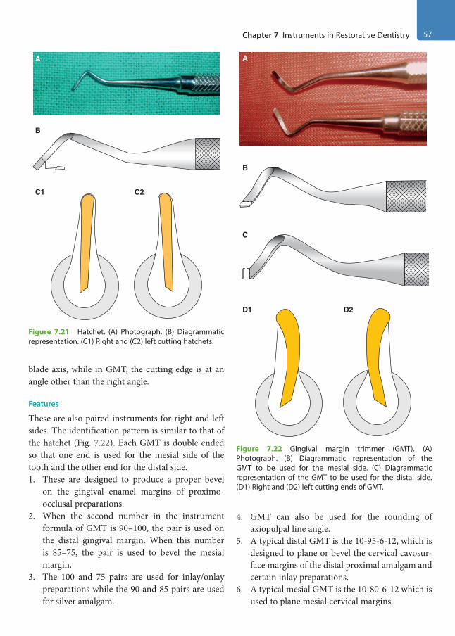
Chapter 7 Instruments in Restorative Dentistry 57
blade axis, while in GMT, the cutting edge is at an angle other than the right angle.
Features
These are also paired instruments for right and left sides. The identification pattern is similar to that of the hatchet (Fig. 7.22). Each GMT is double ended so that one end is used for the mesial side of the tooth and the other end for the distal side.1. These are designed to produce a proper bevel
on the gingival enamel margins of proximo- occlusal preparations.
2. When the second number in the instrument formula of GMT is 90–100, the pair is used on the distal gingival margin. When this number is 85–75, the pair is used to bevel the mesial margin.
3. The 100 and 75 pairs are used for inlay/onlay preparations while the 90 and 85 pairs are used for silver amalgam.
4. GMT can also be used for the rounding of axiopulpal line angle.
5. A typical distal GMT is the 10-95-6-12, which is designed to plane or bevel the cervical cavosur-face margins of the distal proximal amalgam and certain inlay preparations.
6. A typical mesial GMT is the 10-80-6-12 which is used to plane mesial cervical margins.
A
B
C1 C2
Figure 7.21 Hatchet. (A) Photograph. (B) Diagrammatic representation. (C1) Right and (C2) left cutting hatchets.
A
B
C
D1 D2
Figure 7.22 Gingival margin trimmer (GMT). (A) Photograph. (B) Diagrammatic representation of the GMT to be used for the mesial side. (C) Diagrammatic representation of the GMT to be used for the distal side. (D1) Right and (D2) left cutting ends of GMT.
Preclinical Dentistry.indb 57 29-05-2020 12:56:31
https://t.me/DentalBooksWorld
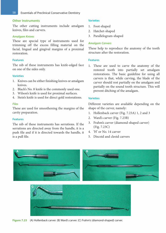
58 Essentials of Preclinical Conservative Dentistry
Other InstrumentsThe other cutting instruments include amalgam knives, files and carvers.
Amalgam KnivesThese are special type of instruments used for trimming off the excess filling material on the facial, lingual and gingival margins of a proximal restoration.
Features
The nib of these instruments has knife-edged face on one of the sides only.
Varieties
1. Knives can be either finishing knives or amalgam knives.
2. Black’s No. 8 knife is the commonly used one.3. Wilson’s knife is used for proximal surfaces.4. Stein’s knife is used for direct gold restorations.
FilesThese are used for smoothening the margins of the cavity preparation.
Features
The nib of these instruments has serrations. If the serrations are directed away from the handle, it is a push file and if it is directed towards the handle, it is a pull file.
Varieties
1. Foot-shaped2. Hatchet-shaped3. Parallelogram-shaped
Amalgam Carvers
These help to reproduce the anatomy of the tooth structure after the restoration.
Features
1. These are used to carve the anatomy of the restored tooth into partially set amalgam restorations. The basic guideline for using all carvers is that, while carving, the blade of the carver should rest partially on the amalgam and partially on the sound tooth structure. This will prevent ditching of the amalgam.
Varieties
Different varieties are available depending on the shape of the carver, namely:1. Hollenback carver (Fig. 7.23A) 1, 2 and 32. Ward’s carver (Fig. 7.23B)3. Frahm’s carver (diamond-shaped carver)
(Fig. 7.23C)4. ‘H’ or No. 14 carver5. Discoid and cleoid carvers
A B
C
Figure 7.23 (A) Hollenback carver. (B) Ward’s carver. (C) Frahm’s (diamond -shaped) carver.
Preclinical Dentistry.indb 58 29-05-2020 12:56:31
https://t.me/DentalBooksWorld

Chapter 7 Instruments in Restorative Dentistry 59
Instrument Sequence Display During Patient WorkFigure 7.24 demonstrates the ideal sequence of display of instruments in the order they would be used while performing the procedure of silver amalgam restoration.1. Mouth mirror should be kept in the first position
followed by explorer, straight probe and tweezers as these are diagnostic instruments.
2. Thereafter, a spoon excavator should be kept as this instrument is the first hand cutting instru-ment to be used.
3. Plastic filling instrument and cement spatula should be kept next in sequence to facilitate base mixing and application.
4. Subsequently, the amalgam carrier, the round and parallelogram condenser, followed by the round condenser are used to carry and condense amalgam into the cavity.
5. In the end, one should keep the amalgam carvers (Hollenbeck and Frahm’s) to perform carving of the amalgam restoration.
Hand Instrument Techniques
Correct instrument grasp is important to achieve success in the restorative procedure. There are different methods of holding an instrument, which depends on factors such as the following:1. Type of instrument2. Area of oral cavity to be instrumented, for
example, maxillary/mandibular teeth3. Surface of the tooth to be instrumented
Instrument GraspsThere are four grasps used with hand instruments, namely:1. Modified pen grasp2. Inverted pen grasp3. Palm-and-thumb grasp4. Modified palm-and-thumb grasp
Modified Pen GraspThis is the most commonly applied method of instrument grasp. This is a modification of the method in which a pen is held in hand and hence the name. Pads of the thumb and index and middle fingers contact the instrument, while the tip of the ring finger is placed on a nearby tooth surface of the same arch as a rest (Fig. 7.25). In this grip, the palm of the hand usually faces away from the operator and the pad of the middle finger is placed near the shank of the instrument, which helps in controlling the movement.
Inverted Pen GraspThe finger positions in this grasp are similar to those in the modified pen grasp technique with a differ-ence that the hand is rotated in a way such that the palm faces towards the operator. This grasp is used for preparations on the palatal surface of maxillary anterior teeth (Fig. 7.26).
Figure 7.24 Ideal display of the instruments used for silver amalgam restoration in the sequence of their usage.
B
A
Figure 7.25 Modified pen grasp. (A) Photograph. (B) Diagrammatic representation.
Preclinical Dentistry.indb 59 29-05-2020 12:56:32
https://t.me/DentalBooksWorld
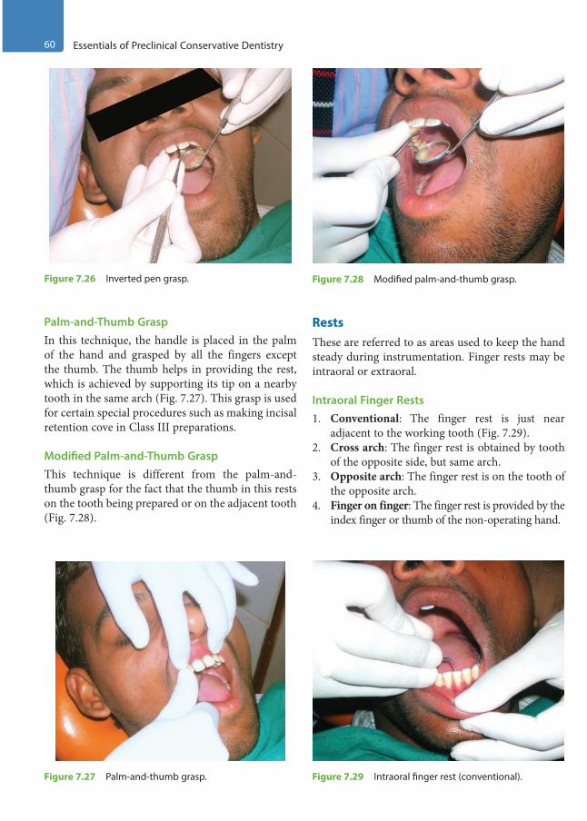
60 Essentials of Preclinical Conservative Dentistry
Palm-and-Thumb GraspIn this technique, the handle is placed in the palm of the hand and grasped by all the fingers except the thumb. The thumb helps in providing the rest, which is achieved by supporting its tip on a nearby tooth in the same arch (Fig. 7.27). This grasp is used for certain special procedures such as making incisal retention cove in Class III preparations.
Modified Palm-and-Thumb GraspThis technique is different from the palm-and-thumb grasp for the fact that the thumb in this rests on the tooth being prepared or on the adjacent tooth (Fig. 7.28).
RestsThese are referred to as areas used to keep the hand steady during instrumentation. Finger rests may be intraoral or extraoral.
Intraoral Finger Rests1. Conventional: The finger rest is just near
adjacent to the working tooth (Fig. 7.29).2. Cross arch: The finger rest is obtained by tooth
of the opposite side, but same arch.3. Opposite arch: The finger rest is on the tooth of
the opposite arch.4. Finger on finger: The finger rest is provided by the
index finger or thumb of the non-operating hand.
Figure 7.26 Inverted pen grasp.
Figure 7.27 Palm-and-thumb grasp.
Figure 7.28 Modified palm-and-thumb grasp.
Figure 7.29 Intraoral finger rest (conventional).
Preclinical Dentistry.indb 60 29-05-2020 12:56:32
https://t.me/DentalBooksWorld

Chapter 7 Instruments in Restorative Dentistry 61
Extraoral Finger Rests
1. Palm up: The rest is established by resting the back of the middle and fourth fingers on the lateral aspect of the mandible on the right side of the face (Fig. 7.30).
2. Palm down: The rest is established by resting the front surface of the middle and fourth fingers on the lateral aspect of the mandible on the left side of the face.
Clinical Tips
1. When the modified pen and inverted pen grasps are used, rests are established by placing the ring finger or both the ring and little fingers on a tooth (or teeth) of the same arch and as close to the operating site as possible.
2. When the palm-and-thumb grasps are used, rests are created by placing the tip of the thumb on the tooth being operated on, an adjacent tooth or a convenient area of the same arch.
3. In some instances, soft tissues may be used as a rest, although they are not as reliable.
4. In rare instances, the operating hand may rest on the opposite hand, which further rests on a stable oral structure. This is called indirect rest.
GuardsGuards are hand instruments or other items, such as wedges, which are used to protect soft tissue from contact with sharp cutting or abrasive instruments during tooth preparation procedure. These have been discussed in detail in Chapter 13, Matrices.
Sharpening of Hand InstrumentsDuring tooth preparation procedure, only sharp instruments should be used for the cutting purpose. They offer the advantage of fast cutting, less discom-fort to the patient and enhanced control over the instrument with greater precision. However, the hand instruments get dull after some time and must be sharpened from time to time in order to maintain their efficacy for clinical usage.
Sharpness TestingThere are two ways to test the sharpness of an instrument:1. Light test: The sharpened edge is looked at
directly in this test. If the instrument is dull, the edge will be shiny as it reflects light. If the instrument is sharp, the edge appears as black line, since the sharp edge cannot reflect back the light.
2. Thumbnail test: The instrument to be tested is held at 45° angle to one’s nail. With light pres-sure, the instrument is pulled or pushed. If the instrument is sharp, it will shave off the nail, but if it is dull, it will glide along the nail.
Of the two tests mentioned above, the thumb-nail test is considered to be more reliable.
Methods for Sharpening the InstrumentsSeveral methods are available for sharpening of instruments such as those given next.
Use of Stationary Sharpening StonesSharpening stones are available in a variety of grits, shapes and materials. These are made of aluminium oxide, silicon carbide, etc. The use of fine grit stones is recommended for sharpening of dental instru-ments (Fig. 7.31) and their use varies according to their shape:1. Flat stones: For instruments with straight
cutting edge2. Cylindrical stones: For instruments with curved
cutting edge
Use of Mechanical SharpenersMechanical sharpeners consist of hones of abrasives such as aluminium oxide, which are electrically
Figure 7.30 Extraoral finger rest (palm-up).
Preclinical Dentistry.indb 61 29-05-2020 12:56:32
https://t.me/DentalBooksWorld
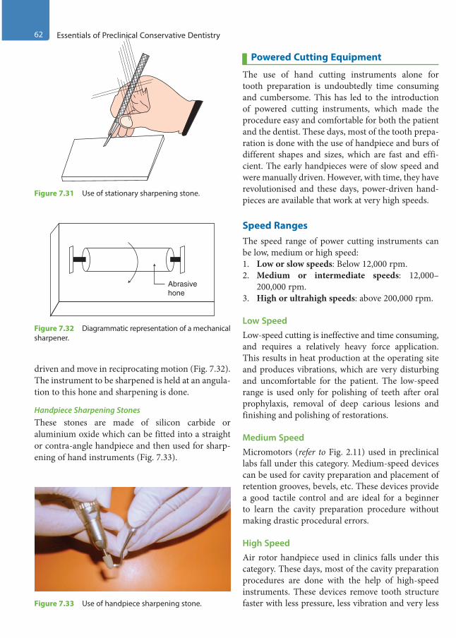
62 Essentials of Preclinical Conservative Dentistry
driven and move in reciprocating motion (Fig. 7.32). The instrument to be sharpened is held at an angula-tion to this hone and sharpening is done.
Handpiece Sharpening StonesThese stones are made of silicon carbide or aluminium oxide which can be fitted into a straight or contra-angle handpiece and then used for sharp-ening of hand instruments (Fig. 7.33).
Powered Cutting Equipment
The use of hand cutting instruments alone for tooth preparation is undoubtedly time consuming and cumbersome. This has led to the introduction of powered cutting instruments, which made the procedure easy and comfortable for both the patient and the dentist. These days, most of the tooth prepa-ration is done with the use of handpiece and burs of different shapes and sizes, which are fast and effi-cient. The early handpieces were of slow speed and were manually driven. However, with time, they have revolutionised and these days, power-driven hand-pieces are available that work at very high speeds.
Speed RangesThe speed range of power cutting instruments can be low, medium or high speed:1. Low or slow speeds: Below 12,000 rpm.2. Medium or intermediate speeds: 12,000–
200,000 rpm.3. High or ultrahigh speeds: above 200,000 rpm.
Low SpeedLow-speed cutting is ineffective and time consuming, and requires a relatively heavy force application. This results in heat production at the operating site and produces vibrations, which are very disturbing and uncomfortable for the patient. The low-speed range is used only for polishing of teeth after oral prophylaxis, removal of deep carious lesions and finishing and polishing of restorations.
Medium SpeedMicromotors (refer to Fig. 2.11) used in preclinical labs fall under this category. Medium-speed devices can be used for cavity preparation and placement of retention grooves, bevels, etc. These devices provide a good tactile control and are ideal for a beginner to learn the cavity preparation procedure without making drastic procedural errors.
High SpeedAir rotor handpiece used in clinics falls under this category. These days, most of the cavity preparation procedures are done with the help of high-speed instruments. These devices remove tooth structure faster with less pressure, less vibration and very less
Figure 7.31 Use of stationary sharpening stone.
Abrasivehone
Figure 7.32 Diagrammatic representation of a mechanical sharpener.
Figure 7.33 Use of handpiece sharpening stone.
Preclinical Dentistry.indb 62 29-05-2020 12:56:33
https://t.me/DentalBooksWorld
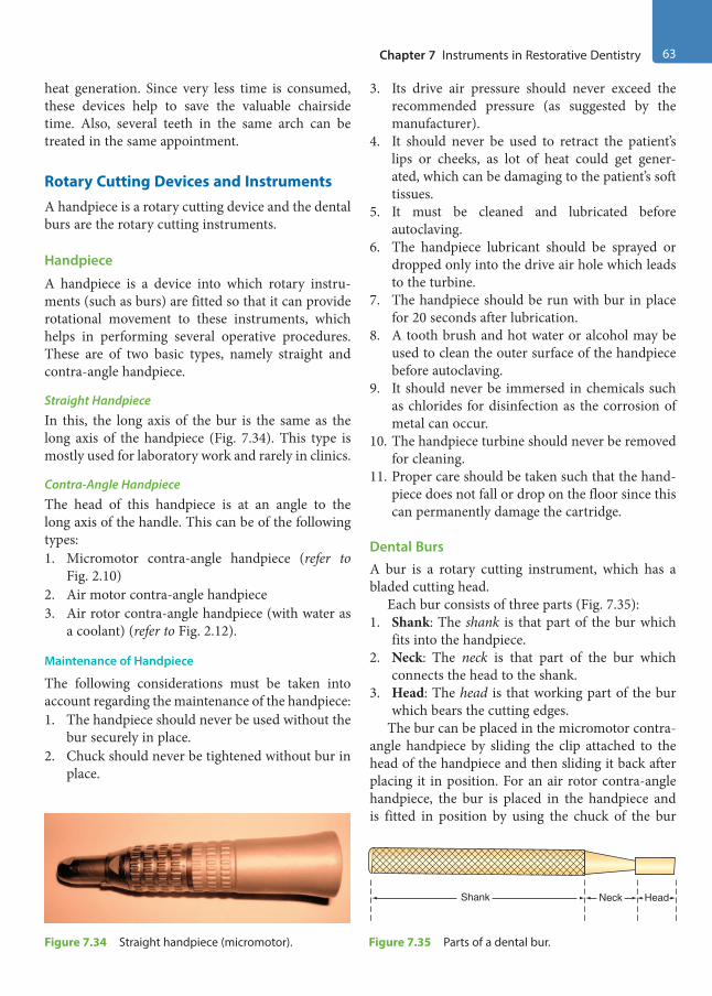
Chapter 7 Instruments in Restorative Dentistry 63
heat generation. Since very less time is consumed, these devices help to save the valuable chairside time. Also, several teeth in the same arch can be treated in the same appointment.
Rotary Cutting Devices and InstrumentsA handpiece is a rotary cutting device and the dental burs are the rotary cutting instruments.
Handpiece
A handpiece is a device into which rotary instru-ments (such as burs) are fitted so that it can provide rotational movement to these instruments, which helps in performing several operative procedures. These are of two basic types, namely straight and contra-angle handpiece.
Straight Handpiece
In this, the long axis of the bur is the same as the long axis of the handpiece (Fig. 7.34). This type is mostly used for laboratory work and rarely in clinics.
Contra-Angle Handpiece
The head of this handpiece is at an angle to the long axis of the handle. This can be of the following types:1. Micromotor contra-angle handpiece (refer to
Fig. 2.10)2. Air motor contra-angle handpiece3. Air rotor contra-angle handpiece (with water as
a coolant) (refer to Fig. 2.12).
Maintenance of Handpiece
The following considerations must be taken into account regarding the maintenance of the handpiece:1. The handpiece should never be used without the
bur securely in place.2. Chuck should never be tightened without bur in
place.
3. Its drive air pressure should never exceed the recommended pressure (as suggested by the manufacturer).
4. It should never be used to retract the patient’s lips or cheeks, as lot of heat could get gener-ated, which can be damaging to the patient’s soft tissues.
5. It must be cleaned and lubricated before autoclaving.
6. The handpiece lubricant should be sprayed or dropped only into the drive air hole which leads to the turbine.
7. The handpiece should be run with bur in place for 20 seconds after lubrication.
8. A tooth brush and hot water or alcohol may be used to clean the outer surface of the handpiece before autoclaving.
9. It should never be immersed in chemicals such as chlorides for disinfection as the corrosion of metal can occur.
10. The handpiece turbine should never be removed for cleaning.
11. Proper care should be taken such that the hand-piece does not fall or drop on the floor since this can permanently damage the cartridge.
Dental BursA bur is a rotary cutting instrument, which has a bladed cutting head.
Each bur consists of three parts (Fig. 7.35):1. Shank: The shank is that part of the bur which
fits into the handpiece.2. Neck: The neck is that part of the bur which
connects the head to the shank.3. Head: The head is that working part of the bur
which bears the cutting edges.The bur can be placed in the micromotor contra-
angle handpiece by sliding the clip attached to the head of the handpiece and then sliding it back after placing it in position. For an air rotor contra-angle handpiece, the bur is placed in the handpiece and is fitted in position by using the chuck of the bur
Figure 7.34 Straight handpiece (micromotor).
Shank Neck Head
Figure 7.35 Parts of a dental bur.
Preclinical Dentistry.indb 63 29-05-2020 12:56:33
https://t.me/DentalBooksWorld
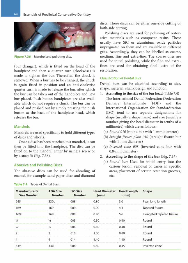
64 Essentials of Preclinical Conservative Dentistry
(bur changer), which is fitted on the head of the handpiece and then a quarter turn (clockwise) is made to tighten the bur. Thereafter, the chuck is removed. When a bur has to be changed, the chuck is again fitted in position and an anti-clockwise quarter turn is made to release the bur, after which the bur can be taken out of the handpiece and new bur placed. Push button handpieces are also avail-able which do not require a chuck. The bur can be placed and pushed out by simply pressing the push button at the back of the handpiece head, which releases the bur.
MandrelsMandrels are used specifically to hold different types of discs and wheels.
Once a disc has been attached to a mandrel, it can then be fitted into the handpiece. The disc can be fitted on to the mandrel either by using a screw or by a snap fit (Fig. 7.36).
Abrasive and Polishing DiscsThe abrasive discs can be used for abrading of enamel, for example, sand paper discs and diamond
discs. These discs can be either one-side cutting or both-side cutting.
Polishing discs are used for polishing of restor-ative materials such as composite resins. These usually have SiC or aluminium oxide particles impregnated on them and are available in different grits. Accordingly, they can be labelled as coarse, medium, fine and extra-fine. The coarse ones are used for initial polishing, while the fine and extra-fines are used for obtaining final lustre of the restoration.
Classification of Dental Burs
Dental burs can be classified according to size, shape, material, shank design and function.1. According to the size of the bur head (Table 7.4) The International Dental Federation (Federation
Dentaire Internationale [FDI]) and the International Organization for Standardization (ISO) tend to use separate designations for shape (usually a shape name) and size (usually a number giving the head diameter in tenths of a millimetre) which are as follows:
(a) Round 010 (round bur with 1-mm diameter)(b) Straight fissure plain 010 (straight fissure bur
with 1-mm diameter)(c) Inverted cone 008 (inverted cone bur with
0.8-mm diameter)2. According to the shape of the bur (Fig. 7.37)
(a) Round bur: Used for initial entry into the carious lesion, removal of caries in specific areas, placement of certain retention grooves, etc.
Mandrel
Polishingdisc
Figure 7.36 Mandrel and polishing disc.
Table 7.4 Types of Dental Burs
Manufacturer’s Size Number
ADA Size Number
ISO Size Number
Head Diameter (mm)
Head Length (mm)
Shape
245 330L 008 0.80 3.0 Pear, long length
169 169 009 0.90 4.3 Tapered fissure
169L 169L 009 0.90 5.6 Elongated tapered fissure
¼ ¼ 005 0.50 0.40 Round
½ ½ 006 0.60 0.48 Round
2 2 010 1.00 0.80 Round
4 4 014 1.40 1.10 Round
33½ 33½ 006 0.60 0.45 Inverted cone
Preclinical Dentistry.indb 64 29-05-2020 12:56:33
https://t.me/DentalBooksWorld
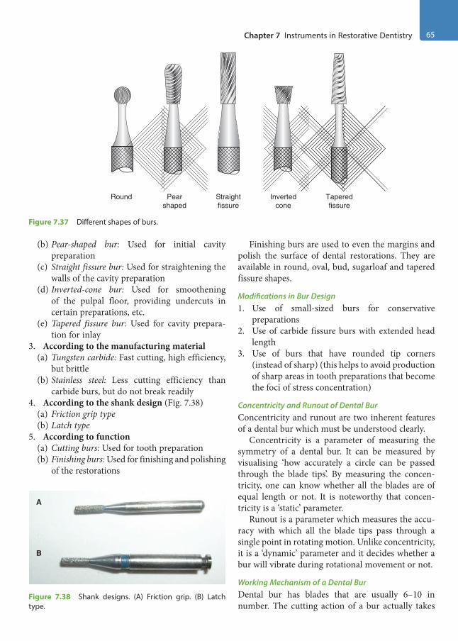
Chapter 7 Instruments in Restorative Dentistry 65
(b) Pear-shaped bur: Used for initial cavity preparation
(c) Straight fissure bur: Used for straightening the walls of the cavity preparation
(d) Inverted-cone bur: Used for smoothening of the pulpal floor, providing undercuts in certain preparations, etc.
(e) Tapered fissure bur: Used for cavity prepara-tion for inlay
3. According to the manufacturing material(a) Tungsten carbide: Fast cutting, high efficiency,
but brittle(b) Stainless steel: Less cutting efficiency than
carbide burs, but do not break readily4. According to the shank design (Fig. 7.38)
(a) Friction grip type(b) Latch type
5. According to function(a) Cutting burs: Used for tooth preparation(b) Finishing burs: Used for finishing and polishing
of the restorations
Finishing burs are used to even the margins and polish the surface of dental restorations. They are available in round, oval, bud, sugarloaf and tapered fissure shapes.
Modifications in Bur Design1. Use of small-sized burs for conservative
preparations2. Use of carbide fissure burs with extended head
length3. Use of burs that have rounded tip corners
(instead of sharp) (this helps to avoid production of sharp areas in tooth preparations that become the foci of stress concentration)
Concentricity and Runout of Dental BurConcentricity and runout are two inherent features of a dental bur which must be understood clearly.
Concentricity is a parameter of measuring the symmetry of a dental bur. It can be measured by visualising ‘how accurately a circle can be passed through the blade tips’. By measuring the concen-tricity, one can know whether all the blades are of equal length or not. It is noteworthy that concen-tricity is a ‘static’ parameter.
Runout is a parameter which measures the accu-racy with which all the blade tips pass through a single point in rotating motion. Unlike concentricity, it is a ‘dynamic’ parameter and it decides whether a bur will vibrate during rotational movement or not.
Working Mechanism of a Dental BurDental bur has blades that are usually 6–10 in number. The cutting action of a bur actually takes
Round Invertedcone
Pearshaped
Straightfissure
Taperedfissure
Figure 7.37 Different shapes of burs.
A
B
Figure 7.38 Shank designs. (A) Friction grip. (B) Latch type.
Preclinical Dentistry.indb 65 29-05-2020 12:56:34
https://t.me/DentalBooksWorld
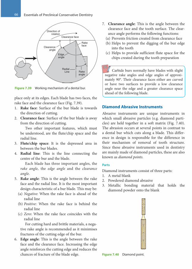
66 Essentials of Preclinical Conservative Dentistry
place only at its edges. Each blade has two faces, the rake face and the clearance face (Fig. 7.39).1. Rake face: Surface of the bur blade is towards
the direction of cutting.2. Clearance face: Surface of the bur blade is away
from the direction of cutting. Two other important features, which must
be understood, are the flute/chip space and the radial line.
3. Flute/chip space: It is the depressed area in between the bur blades.
4. Radial line: This is the line connecting the centre of the bur and the blade.
Each blade has three important angles, the rake angle, the edge angle and the clearance angle.
5. Rake angle: This is the angle between the rake face and the radial line. It is the most important design characteristic of a bur blade. This may be:
(a) Negative: When the rake face is ahead of the radial line
(b) Positive: When the rake face is behind the radial line
(c) Zero: When the rake face coincides with the radial line
For cutting hard and brittle materials, a nega-tive rake angle is recommended as it minimises fractures of the cutting edge of the bur.
6. Edge angle: This is the angle between the rake face and the clearance face. Increasing the edge angle reinforces the cutting edge and reduces the chances of fracture of the blade edge.
7. Clearance angle: This is the angle between the clearance face and the tooth surface. The clear-ance angle performs the following functions:
(a) Prevents friction created from clearance face(b) Helps to prevent the digging of the bur edge
into the tooth(c) Helps to provide sufficient flute space for the
chips created during the tooth preparation
Carbide burs normally have blades with slight negative rake angles and edge angles of approxi-mately 90°. Their clearance faces either are curved or have two surfaces to provide a low clearance angle near the edge and a greater clearance space ahead of the following blade.
Diamond Abrasive InstrumentsAbrasive instruments are unique instruments in which small abrasive particles (e.g. diamond parti-cles) are held together in a soft matrix (Fig. 7.40). The abrasion occurs at several points in contrast to a dental bur which cuts along a blade. This differ-ence in design is responsible for the difference in their mechanism of removal of tooth structure. Since these abrasive instruments used in dentistry are mainly made of diamond particles, these are also known as diamond points.
Parts
Diamond instruments consist of three parts:1. A metal blank2. Powdered diamond abrasive3. Metallic bonding material that holds the
diamond powder onto the blank
Clearanceangle
Edgeangle
RadialLine
Clearance face
Direction ofrotation
Rakeangle
Rakeface
Figure 7.39 Working mechanism of a dental bur.
Figure 7.40 Diamond point.
Preclinical Dentistry.indb 66 29-05-2020 12:56:34
https://t.me/DentalBooksWorld
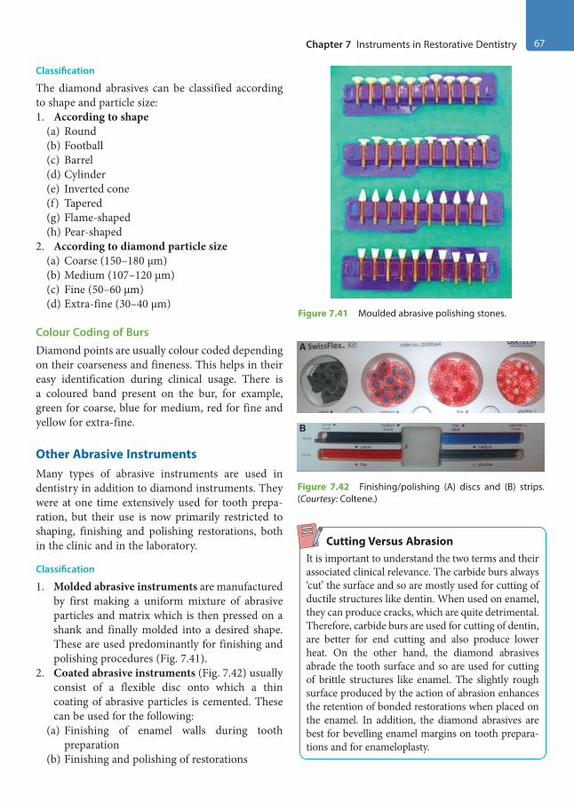
Chapter 7 Instruments in Restorative Dentistry 67
Classification
The diamond abrasives can be classified according to shape and particle size:1. According to shape
(a) Round(b) Football(c) Barrel(d) Cylinder(e) Inverted cone(f) Tapered(g) Flame-shaped(h) Pear-shaped
2. According to diamond particle size(a) Coarse (150–180 µm)(b) Medium (107–120 µm)(c) Fine (50–60 µm)(d) Extra-fine (30–40 µm)
Colour Coding of BursDiamond points are usually colour coded depending on their coarseness and fineness. This helps in their easy identification during clinical usage. There is a coloured band present on the bur, for example, green for coarse, blue for medium, red for fine and yellow for extra-fine.
Other Abrasive InstrumentsMany types of abrasive instruments are used in dentistry in addition to diamond instruments. They were at one time extensively used for tooth prepa-ration, but their use is now primarily restricted to shaping, finishing and polishing restorations, both in the clinic and in the laboratory.
Classification
1. Molded abrasive instruments are manufactured by first making a uniform mixture of abrasive particles and matrix which is then pressed on a shank and finally molded into a desired shape. These are used predominantly for finishing and polishing procedures (Fig. 7.41).
2. Coated abrasive instruments (Fig. 7.42) usually consist of a flexible disc onto which a thin coating of abrasive particles is cemented. These can be used for the following:
(a) Finishing of enamel walls during tooth preparation
(b) Finishing and polishing of restorations
Cutting Versus AbrasionIt is important to understand the two terms and their associated clinical relevance. The carbide burs always ‘cut’ the surface and so are mostly used for cutting of ductile structures like dentin. When used on enamel, they can produce cracks, which are quite detrimental. Therefore, carbide burs are used for cutting of dentin, are better for end cutting and also produce lower heat. On the other hand, the diamond abrasives abrade the tooth surface and so are used for cutting of brittle structures like enamel. The slightly rough surface produced by the action of abrasion enhances the retention of bonded restorations when placed on the enamel. In addition, the diamond abrasives are best for bevelling enamel margins on tooth prepara-tions and for enameloplasty.
Figure 7.41 Moulded abrasive polishing stones.
A
B
Figure 7.42 Finishing/polishing (A) discs and (B) strips. (Courtesy: Coltene.)
Preclinical Dentistry.indb 67 29-05-2020 12:56:35
https://t.me/DentalBooksWorld
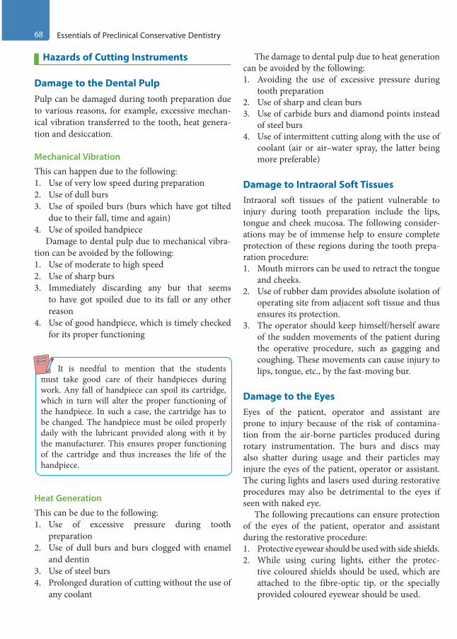
68 Essentials of Preclinical Conservative Dentistry
Hazards of Cutting Instruments
Damage to the Dental PulpPulp can be damaged during tooth preparation due to various reasons, for example, excessive mechan-ical vibration transferred to the tooth, heat genera-tion and desiccation.
Mechanical Vibration
This can happen due to the following:1. Use of very low speed during preparation2. Use of dull burs3. Use of spoiled burs (burs which have got tilted
due to their fall, time and again)4. Use of spoiled handpiece
Damage to dental pulp due to mechanical vibra-tion can be avoided by the following:1. Use of moderate to high speed2. Use of sharp burs3. Immediately discarding any bur that seems
to have got spoiled due to its fall or any other reason
4. Use of good handpiece, which is timely checked for its proper functioning
It is needful to mention that the students must take good care of their handpieces during work. Any fall of handpiece can spoil its cartridge, which in turn will alter the proper functioning of the handpiece. In such a case, the cartridge has to be changed. The handpiece must be oiled properly daily with the lubricant provided along with it by the manufacturer. This ensures proper functioning of the cartridge and thus increases the life of the handpiece.
Heat Generation
This can be due to the following:1. Use of excessive pressure during tooth
preparation2. Use of dull burs and burs clogged with enamel
and dentin3. Use of steel burs4. Prolonged duration of cutting without the use of
any coolant
The damage to dental pulp due to heat generation can be avoided by the following:1. Avoiding the use of excessive pressure during
tooth preparation2. Use of sharp and clean burs3. Use of carbide burs and diamond points instead
of steel burs4. Use of intermittent cutting along with the use of
coolant (air or air–water spray, the latter being more preferable)
Damage to Intraoral Soft TissuesIntraoral soft tissues of the patient vulnerable to injury during tooth preparation include the lips, tongue and cheek mucosa. The following consider-ations may be of immense help to ensure complete protection of these regions during the tooth prepa-ration procedure:1. Mouth mirrors can be used to retract the tongue
and cheeks.2. Use of rubber dam provides absolute isolation of
operating site from adjacent soft tissue and thus ensures its protection.
3. The operator should keep himself/herself aware of the sudden movements of the patient during the operative procedure, such as gagging and coughing. These movements can cause injury to lips, tongue, etc., by the fast-moving bur.
Damage to the EyesEyes of the patient, operator and assistant are prone to injury because of the risk of contamina-tion from the air-borne particles produced during rotary instrumentation. The burs and discs may also shatter during usage and their particles may injure the eyes of the patient, operator or assistant. The curing lights and lasers used during restorative procedures may also be detrimental to the eyes if seen with naked eye.
The following precautions can ensure protection of the eyes of the patient, operator and assistant during the restorative procedure:1. Protective eyewear should be used with side shields.2. While using curing lights, either the protec-
tive coloured shields should be used, which are attached to the fibre-optic tip, or the specially provided coloured eyewear should be used.
Preclinical Dentistry.indb 68 29-05-2020 12:56:35
https://t.me/DentalBooksWorld

Chapter 7 Instruments in Restorative Dentistry 69
Damage to the EarsEars of the operator and assistant are prone to injury because of the sounds produced by the use of malfunctioning handpiece, use of eccentric burs, continued exposure to noise produced by suction, etc.
The following precautions can ensure protection of the ears of the operator and the assistant during the restorative procedure:1. Use of proper handpiece and burs (handpiece
with spoiled cartridge produces more noise; dull burs also produce more noise)
2. Use of intermittent suction instead of its continuous use
Inhalation of AerosolsDuring tooth preparation procedures, aerosols are produced which are nothing but fine dispersions of
water, tooth debris, microbes, etc., in air. Removal of old silver amalgam restorations also produces submi-cron particles that may be inadvertently inhaled and thus cause alveolar irritation. The mercury vapours are also produced which are hazardous. Removal of old composite restorations produces monomers, which are again potential irritants.
The following precautions can ensure that no such aerosols are inhaled by the personnel involved in the restorative procedure:1. Use of suction next to the restoration being
removed2. Use of rubber dam, which ensures no inhalation
of aerosols by the patient3. Use of disposable masks, which also helps
prevent the inhalation of aerosols by the oper-ator and the assistant
KEY POINTS
• Instruments in conservative dentistry are an essential component, and therefore one must clearly understand the identification and usage of each instrument.
• It is essential that the instruments be laid in the working area in a sequential manner according to their usage during the operative procedure so as to have an uninterrupted work flow.
• The hand instruments can be made of carbon steel, stainless steel or other alloys.• Three parts of a dental instrument are handle, shank and blade.• Cutting instruments have formulas describing the dimensions and angles of the working end. The complete
instrument formula (four numbers) is expressed as the blade width (1) in 0.1-mm increments, cutting edge angle (2) in centigrades, blade length (3) in millimetres and blade angle (4) in centigrades.
• It is essential that the instrument be grasped in a correct manner to achieve the adequate working efficiency. The various grasps used with hand instruments are modified pen grasp, inverted pen grasp, palm-and-thumb grasp and modified palm-and-thumb grasp.
• Rests, used during instrumentation, are referred to as areas used to keep the hand steady during instrumenta-tion. Finger rests may be intraoral or extraoral.
• Only sharp instruments should be used for cutting purpose during tooth preparation procedure. For sharpening of cutting instruments, sharpening stones are used.
• Rotary cutting instruments are used with slow speed or high speed, with latter being preferred.• A bur is a rotary cutting instrument, which has a bladed cutting head. Each bur consists of three parts: shank,
neck and head.• Diamond abrasive instruments are based on small, angular particles of a hard substance held in the matrix of a
softer material.• Diamond instruments consist of three parts: a metal blank, powdered diamond abrasive and a metallic bonding
material that holds the diamond powder onto the blank.• Hazards during tooth preparation must be taken into serious account and necessary measures must be taken to
avoid these as far as possible.• Pulp can be damaged during tooth preparation due to various reasons, for example, excessive mechanical vibra-
tion transferred to the tooth, heat generation and dessication.
Preclinical Dentistry.indb 69 29-05-2020 12:56:35
https://t.me/DentalBooksWorld
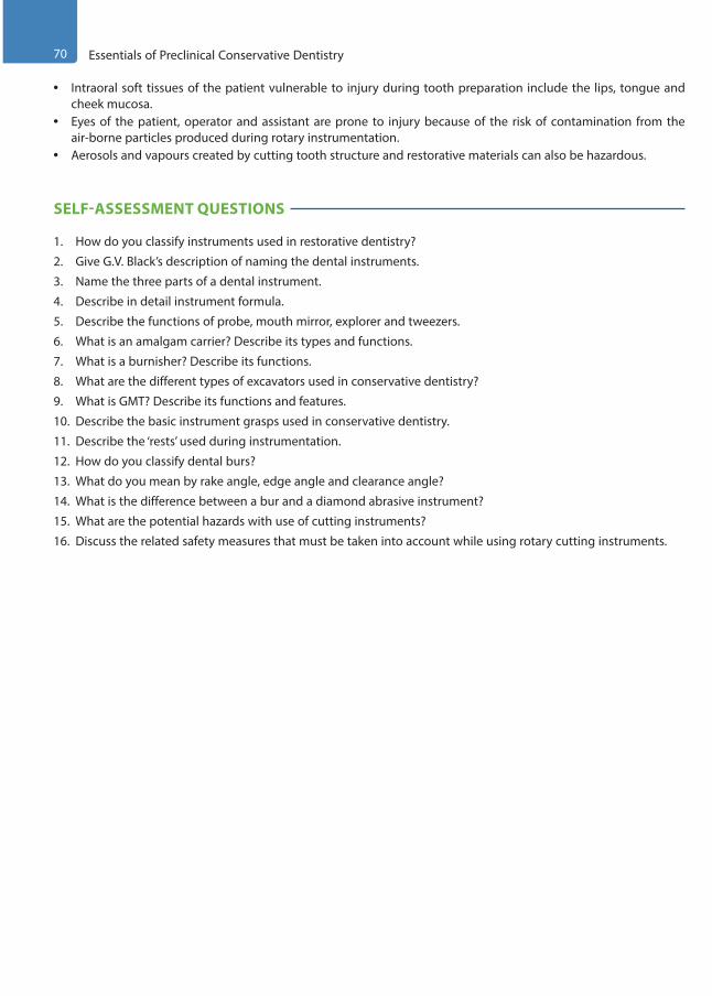
70 Essentials of Preclinical Conservative Dentistry
• Intraoral soft tissues of the patient vulnerable to injury during tooth preparation include the lips, tongue and cheek mucosa.
• Eyes of the patient, operator and assistant are prone to injury because of the risk of contamination from the air-borne particles produced during rotary instrumentation.
• Aerosols and vapours created by cutting tooth structure and restorative materials can also be hazardous.
SELF-ASSESSMENT QUESTIONS
1. How do you classify instruments used in restorative dentistry?
2. Give G.V. Black’s description of naming the dental instruments.
3. Name the three parts of a dental instrument.
4. Describe in detail instrument formula.
5. Describe the functions of probe, mouth mirror, explorer and tweezers.
6. What is an amalgam carrier? Describe its types and functions.
7. What is a burnisher? Describe its functions.
8. What are the different types of excavators used in conservative dentistry?
9. What is GMT? Describe its functions and features.
10. Describe the basic instrument grasps used in conservative dentistry.
11. Describe the ‘rests’ used during instrumentation.
12. How do you classify dental burs?
13. What do you mean by rake angle, edge angle and clearance angle?
14. What is the difference between a bur and a diamond abrasive instrument?
15. What are the potential hazards with use of cutting instruments?
16. Discuss the related safety measures that must be taken into account while using rotary cutting instruments.
Preclinical Dentistry.indb 70 29-05-2020 12:56:35
https://t.me/DentalBooksWorld
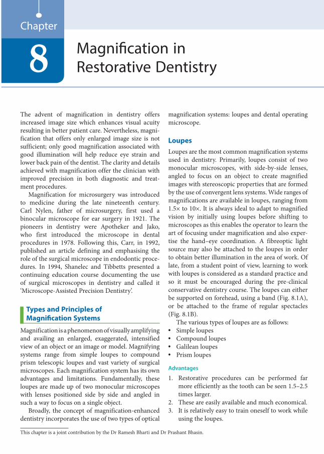
The advent of magnification in dentistry offers increased image size which enhances visual acuity resulting in better patient care. Nevertheless, magni-fication that offers only enlarged image size is not sufficient; only good magnification associated with good illumination will help reduce eye strain and lower back pain of the dentist. The clarity and details achieved with magnification offer the clinician with improved precision in both diagnostic and treat-ment procedures.
Magnification for microsurgery was introduced to medicine during the late nineteenth century. Carl Nylen, father of microsurgery, first used a binocular microscope for ear surgery in 1921. The pioneers in dentistry were Apotheker and Jako, who first introduced the microscope in dental procedures in 1978. Following this, Carr, in 1992, published an article defining and emphasising the role of the surgical microscope in endodontic proce-dures. In 1994, Shanelec and Tibbetts presented a continuing education course documenting the use of surgical microscopes in dentistry and called it ‘Microscope-Assisted Precision Dentistry’.
Types and Principles of Magnification Systems
Magnification is a phenomenon of visually amplifying and availing an enlarged, exaggerated, intensified view of an object or an image or model. Magnifying systems range from simple loupes to compound prism telescopic loupes and vast variety of surgical microscopes. Each magnification system has its own advantages and limitations. Fundamentally, these loupes are made up of two monocular microscopes with lenses positioned side by side and angled in such a way to focus on a single object.
Broadly, the concept of magnification-enhanced dentistry incorporates the use of two types of optical
magnification systems: loupes and dental operating microscope.
LoupesLoupes are the most common magnification systems used in dentistry. Primarily, loupes consist of two monocular microscopes, with side-by-side lenses, angled to focus on an object to create magnified images with stereoscopic properties that are formed by the use of convergent lens systems. Wide ranges of magnifications are available in loupes, ranging from 1.5× to 10×. It is always ideal to adapt to magnified vision by initially using loupes before shifting to microscopes as this enables the operator to learn the art of focusing under magnification and also exper-tise the hand–eye coordination. A fibreoptic light source may also be attached to the loupes in order to obtain better illumination in the area of work. Of late, from a student point of view, learning to work with loupes is considered as a standard practice and so it must be encouraged during the pre-clinical conservative dentistry course. The loupes can either be supported on forehead, using a band (Fig. 8.1A), or be attached to the frame of regular spectacles (Fig. 8.1B).
The various types of loupes are as follows:• Simple loupes• Compound loupes• Galilean loupes• Prism loupes
Advantages
1. Restorative procedures can be performed far more efficiently as the tooth can be seen 1.5–2.5 times larger.
2. These are easily available and much economical.3. It is relatively easy to train oneself to work while
using the loupes.
Magnification in Restorative Dentistry8
Chapter
This chapter is a joint contribution by the Dr Ramesh Bharti and Dr Prashant Bhasin.
Preclinical Dentistry.indb 71 29-05-2020 12:56:35
https://t.me/DentalBooksWorld
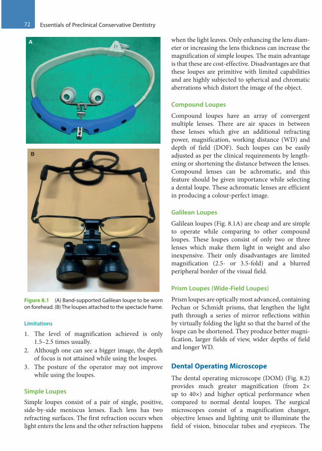
72 Essentials of Preclinical Conservative Dentistry
Limitations
1. The level of magnification achieved is only 1.5–2.5 times usually.
2. Although one can see a bigger image, the depth of focus is not attained while using the loupes.
3. The posture of the operator may not improve while using the loupes.
Simple Loupes
Simple loupes consist of a pair of single, positive, side-by-side meniscus lenses. Each lens has two refracting surfaces. The first refraction occurs when light enters the lens and the other refraction happens
when the light leaves. Only enhancing the lens diam-eter or increasing the lens thickness can increase the magnification of simple loupes. The main advantage is that these are cost-effective. Disadvantages are that these loupes are primitive with limited capabilities and are highly subjected to spherical and chromatic aberrations which distort the image of the object.
Compound Loupes
Compound loupes have an array of convergent multiple lenses. There are air spaces in between these lenses which give an additional refracting power, magnification, working distance (WD) and depth of field (DOF). Such loupes can be easily adjusted as per the clinical requirements by length-ening or shortening the distance between the lenses. Compound lenses can be achromatic, and this feature should be given importance while selecting a dental loupe. These achromatic lenses are efficient in producing a colour-perfect image.
Galilean Loupes
Galilean loupes (Fig. 8.1A) are cheap and are simple to operate while comparing to other compound loupes. These loupes consist of only two or three lenses which make them light in weight and also inexpensive. Their only disadvantages are limited magnification (2.5- or 3.5-fold) and a blurred peripheral border of the visual field.
Prism Loupes (Wide-Field Loupes)
Prism loupes are optically most advanced, containing Pechan or Schmidt prisms, that lengthen the light path through a series of mirror reflections within by virtually folding the light so that the barrel of the loupe can be shortened. They produce better magni-fication, larger fields of view, wider depths of field and longer WD.
Dental Operating Microscope
The dental operating microscope (DOM) (Fig. 8.2) provides much greater magnification (from 2× up to 40×) and higher optical performance when compared to normal dental loupes. The surgical microscopes consist of a magnification changer, objective lenses and lighting unit to illuminate the field of vision, binocular tubes and eyepieces. The
A
B
Figure 8.1 (A) Band-supported Galilean loupe to be worn on forehead. (B) The loupes attached to the spectacle frame.
Preclinical Dentistry.indb 72 29-05-2020 12:56:35
https://t.me/DentalBooksWorld
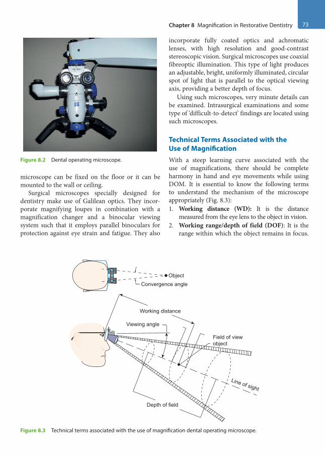
Chapter 8 Magnification in Restorative Dentistry 73
microscope can be fixed on the floor or it can be mounted to the wall or ceiling.
Surgical microscopes specially designed for dentistry make use of Galilean optics. They incor-porate magnifying loupes in combination with a magnification changer and a binocular viewing system such that it employs parallel binoculars for protection against eye strain and fatigue. They also
incorporate fully coated optics and achromatic lenses, with high resolution and good-contrast stereoscopic vision. Surgical microscopes use coaxial fibreoptic illumination. This type of light produces an adjustable, bright, uniformly illuminated, circular spot of light that is parallel to the optical viewing axis, providing a better depth of focus.
Using such microscopes, very minute details can be examined. Intrasurgical examinations and some type of ‘difficult-to-detect’ findings are located using such microscopes.
Technical Terms Associated with the Use of MagnificationWith a steep learning curve associated with the use of magnifications, there should be complete harmony in hand and eye movements while using DOM. It is essential to know the following terms to understand the mechanism of the microscope appropriately (Fig. 8.3):1. Working distance (WD): It is the distance
measured from the eye lens to the object in vision. 2. Working range/depth of field (DOF): It is the
range within which the object remains in focus.
Figure 8.2 Dental operating microscope.
Viewing angle
Field of viewobject
Line of sight
Depth of field
Working distance
ObjectConvergence angle
Figure 8.3 Technical terms associated with the use of magnification dental operating microscope.
Preclinical Dentistry.indb 73 29-05-2020 12:56:35
https://t.me/DentalBooksWorld
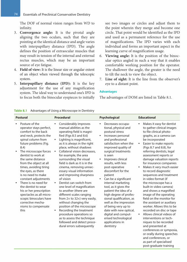
74 Essentials of Preclinical Conservative Dentistry
The DOF of normal vision ranges from WD to infinity.
3. Convergence angle: It is the pivotal angle aligning the two oculars, such that they are pointing at the identical distance and angle varies with interpupillary distance (IPD). The angle defines the position of extraocular muscles that may result in tension of the internal and external rectus muscles, which may be an important source of eye fatigue.
4. Field of view: It is the linear size or angular extent of an object when viewed through the telescopic system.
5. Interpupillary distance (IPD): It is the key adjustment for the use of any magnification system. The ideal way to understand one’s IPD is to focus both the binocular eyepieces to initially
see two images or circles and adjust them to the point wherein they merge and become one circle. That point would be identified as the IPD and used as a permanent reference for the use of magnifications. The IPD varies with each individual and forms an important aspect in the learning curve of magnification usage.
6. Viewing angle: It is the position of the binoc-ular optics angled in such a way that it enables comfortable working position for the operator. The shallower the angle, the greater is the need to tilt the neck to view the object.
7. Line of sight: It is the line from the observer’s eye to a distant point.
Advantages
The advantages of DOM are listed in Table 8.1.
Table 8.1 Advantages of Using a Microscope in Dentistry
Postural Procedural Psychological Educational
• Posture of the operator stays perfect, comfort to the back and neck, protects the spinal column from future problems (Fig. 8.4)
• The microscope forces dentist to work at the same distance from the object at all times, avoiding tiring the eyes, as there is no need to make constant adjustments
• There is no need for the dentist to wear his or her prescription spectacles as all micro-scopic binoculars have corrective mecha-nisms to compensate this
• Considerably improves manual abilities as the operating field is magni-fied (Figs 8.5 and 8.6)
• Lighting is magnificent, as it is always in the right place, without shadows
• Collateral vision decreases, for example, the area surrounding the visual field is dark as it is in the cinema, removing unnec-essary visual information and improving sharpness of vision
• Dentist can switch from one level of magnification to another (there are different scales ranging from 2× to 32×) very easily, without changing the position of the microscope
• Recording the treatment procedure operations so as to assess the technique followed and detect proce-dural errors subsequently
• Decreases occupa-tional, physical and postural stress
• Increases personal and professional satisfaction when the improved quality of surgical treatments is seen
• Improves clinical results, with less post-operative discomfort for the patient
• Can be a significant internal marketing tool, as it gives the patient the idea of a high degree of profes-sional qualification, as well as the impression of being very up to date with new optical, digital and comput-erised technological applications in dentistry
• Makes it easy for dentist to gather clinical images to file clinical photo-graphs, as a camera can be incorporated
• Easier to make reports (Figs 8.7 and 8.8), for referring dentists, legal assessment reports or damage valuation reports for insurance companies
• Makes it very much easier to record diagnostic sequences and treatment in video format (if the microscope has a built-in video camera) and shows a magnified image of the operating field on the monitor for the assistant or auxiliary worker. Allows this to be recorded on disc or tape
• Allows clinical videos of interventions or tech-niques to be recorded and presented at conferences or symposia, or orally during speeches and conferences, or as part of specialised post-graduate training
Preclinical Dentistry.indb 74 29-05-2020 12:56:35
https://t.me/DentalBooksWorld

Chapter 8 Magnification in Restorative Dentistry 75
Limitations of Dental Operating Microscope
• High cost of the equipment• Specialised education and training required
before one can master working under DOM• Limited surgical access
Application of Magnification in Preclinical Conservative Dentistry
While the use of magnification has an immense role to play in various fields of dentistry such as endodon-tics, implantalogy and oral surgery, in this chapter, we shall be highlighting its applications in the field of restorative dentistry only, especially pre-clinical conservative dentistry. The students, during the pre-clinical exercises, may use magnification loupes in order to better assess their preparations as they can see the tooth in a dimension 2–2.5 times larger
Figure 8.4 Correct posture of back and neck during the use of microscope.
Figure 8.5 Proximal caries in a molar. (Courtesy: Dr Prashant Bhasin, India.)
Figure 8.6 Caries excavated under magnification using microscope. (Courtesy: Dr Prashant Bhasin, India.)
Figure 8.7 Exploration of the subgingival area on the labial surface of maxillary canine with naked eye. (Courtesy: Dr Prashant Bhasin, India.)
Figure 8.8 Crack seen clearly on the root surface of the same tooth under microscope using a dye. (Courtesy: Dr Prashant Bhasin, India.)
Preclinical Dentistry.indb 75 29-05-2020 12:56:36
https://t.me/DentalBooksWorld
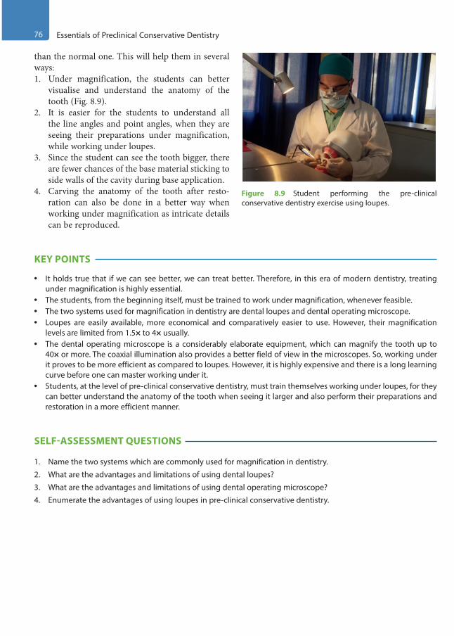
76 Essentials of Preclinical Conservative Dentistry
than the normal one. This will help them in several ways:1. Under magnification, the students can better
visualise and understand the anatomy of the tooth (Fig. 8.9).
2. It is easier for the students to understand all the line angles and point angles, when they are seeing their preparations under magnification, while working under loupes.
3. Since the student can see the tooth bigger, there are fewer chances of the base material sticking to side walls of the cavity during base application.
4. Carving the anatomy of the tooth after resto-ration can also be done in a better way when working under magnification as intricate details can be reproduced.
KEY POINTS
• It holds true that if we can see better, we can treat better. Therefore, in this era of modern dentistry, treating under magnification is highly essential.
• The students, from the beginning itself, must be trained to work under magnification, whenever feasible.• The two systems used for magnification in dentistry are dental loupes and dental operating microscope.• Loupes are easily available, more economical and comparatively easier to use. However, their magnification
levels are limited from 1.5× to 4× usually.• The dental operating microscope is a considerably elaborate equipment, which can magnify the tooth up to
40× or more. The coaxial illumination also provides a better field of view in the microscopes. So, working under it proves to be more efficient as compared to loupes. However, it is highly expensive and there is a long learning curve before one can master working under it.
• Students, at the level of pre-clinical conservative dentistry, must train themselves working under loupes, for they can better understand the anatomy of the tooth when seeing it larger and also perform their preparations and restoration in a more efficient manner.
SELF-ASSESSMENT QUESTIONS
1. Name the two systems which are commonly used for magnification in dentistry.
2. What are the advantages and limitations of using dental loupes?
3. What are the advantages and limitations of using dental operating microscope?
4. Enumerate the advantages of using loupes in pre-clinical conservative dentistry.
Figure 8.9 Student performing the pre-clinical conservative dentistry exercise using loupes.
Preclinical Dentistry.indb 76 29-05-2020 12:56:36
https://t.me/DentalBooksWorld

Effective and efficient infection control in the dental office is essential for the safety of both the patients and the professionals and also to ensure that produc-tivity does not suffer. Infection control programme includes cleaning and sterilisation of all instruments to be used during dental treatment. This chapter deals with the various methods that can be used for cleaning, disinfection and sterilisation of dental instruments. Also, focus is laid on obtaining assur-ance of sterility of instruments through the use of several tests. Guidelines have also been discussed regarding disposal of waste generated in the dental office. Sterilisation and asepsis, when included in the treatment protocol, not only increase the inci-dence of success of treatment but also help prevent cross-contamination, especially of agents such as HBV and human immunodeficiency virus (HIV), which are potential health hazards in the field of dentistry.
The concept of asepsis and its role in the preven-tion of infection was put forward nearly two centu-ries ago. The general principles of asepsis were laid down by a Hungarian obstetrician Ignaz in Europe in the early 1850s and by Oliver Holmes in the USA. These principles were accepted after Joseph Lister’s studies on prevention of wound infection were carried out between 1865 and 1891.
Definitions
Cleaning: It is the process of effectively removing the debris without putting oneself at the risk of exposure to puncture from the contaminated instru-ment or from spatter of the debris (blood or saliva) on the instruments; for example, scrubbing with a brush and ultrasonic cleaning.Sterilisation: It is defined as a process by which an article, a surface or a medium is freed of all microbes, in either vegetative or spore state.
Disinfection: It is a process which reduces the number of viable microbes to an acceptable level, but may not inactivate some viruses and bacterial spores.Disinfectant: These are substances that are applied onto the non-living objects to destroy microorgan-isms that are living on the objects.
Disinfection does not necessarily kill all micro-organisms, especially resistant bacterial spores; it is less effective than sterilisation, which is an extreme physical and/or chemical process that kills all types of life.
Bacterial endospores are most resistant to disin-fectants, but some viruses and bacteria also possess some tolerance. Disinfectants are frequently used in hospitals, dental surgeries, kitchens and bathrooms to kill infectious organisms.Sanitisers: These are substances that clean and disinfect simultaneously.Asepsis: It is the avoidance of pathogenic organ-isms. It is the term used to describe methods that prevent contamination of wounds and other sites by ensuring that only sterile objects and fluids come into contact with them and that the risk of air-borne contamination is minimised.
Basic Principles of Sterilisation
The basic principles of sterilisation are listed as follows:1. All instruments used should be thoroughly
cleaned; all deposits of blood and debris should be removed before sterilisation.
2. It is essential for the sterilising agent to be in contact with every surface of each item to be sterilised for the specified period of time at the specified temperature.
3. The equipment used for sterilisation must be regularly checked and serviced.
Infection Control9Chapter
This chapter is a joint contribution by the author and Dr Renu Bala Sroa.
Preclinical Dentistry.indb 77 29-05-2020 12:56:36
https://t.me/DentalBooksWorld
78 Essentials of Preclinical Conservative Dentistry
4. The manufacturer’s instructions should be strictly adhered to for equipment’s operation and maintenance.
Classification of Methods Used for Sterilisation and Disinfection
The method of sterilisation employed depends on the purpose for which sterilisation is carried out and the nature of microbes that are to be destroyed. The standard classification of sterilisation methods is as given in Box 9.1.
Agents of Sterilisation
The following methods of sterilisation have been discussed in detail in this chapter as they have specific indications in dentistry:1. Cleaning agents2. Chemicals3. Dry heat: Hot air oven, flaming4. Moist heat: Boiling, autoclave5. Gas sterilisation: Ethylene oxide6. Chemiclaving7. Radiations8. Special equipment for endodontics, for example,
glass bead steriliser
Personal protection barriers and barrier tech-nique are other important aspects of sterilisation and asepsis, which will be discussed separately.
Cleaning of Instruments and EquipmentIt is necessary that all instruments be thoroughly cleaned before subjecting them to sterilisation.1. Manual cleaning: This can be done by using
scrubs or different kinds of brushes. Care must be taken by the person doing this job not to injure himself/herself while carrying out this procedure. Soap solutions can be used along with the scrubs.
2. Ultrasonic cleaning: These days, ultrasonic cleaners are recommended for cleaning of instru-ments. Certain chemicals are also provided that can be mixed in water in the ultrasonic cleaner. By the virtue of ultrasonics, the instruments get thor-oughly cleaned and there is no risk of injury from the sharp instruments to the operator as well.
3. Chemical cleaning agents: These include soaps and detergents.
(a) Soaps: These are salts of fatty acids and are effective at pH 9 or higher; also, they are effective in a weakly acidic environment.
(b) Detergents: These are synthetic compounds compatible with Ca++ and Mg++, effective in a neutral or slightly acidic environment.
Both the groups act by reducing the surface tension along the instrument surface, leading to emulsification of contaminants, which are removed in the rinsing phase. Other fat-solvent solutions, such as acetone, ether and xylene, are sometimes used in cleaning. Some disinfectant solutions, such as aldehydes and phenols, are also used. All instru-ments must be cleaned of all the debris, including blood, saliva and necrotic material. This debris prevents the contact of the sterilising medium with the instrument, such as heat, chemical or gas.
Chemicals for Disinfection and SterilisationVarious chemicals can be used for the purpose of disinfection and sterilisation, such as those given next.
AlcoholsThe alcohols routinely used for sterilisation in dentistry are ethyl alcohol and isopropyl alcohol (Fig. 9.1).
Box 9.1 Standard Classification of Sterilisation Methods
1. Physical methods(a) Heat
• Dry – Flaming – Incineration
• Moist – Boiling – Steam under normal pressure – Steam under pressure
(b) Filtration, for example, membranes(c) Radiation(d) Ultrasonic and sonic vibrations
2. Chemical methods(a) Alcohols: Ethyl, isopropyl(b) Aldehydes: Formaldehyde, glutaraldehyde(c) Halogens(d) Phenols(e) Surface-active agents(f ) Metallic salts(g) Gases: Ethylene oxide, formaldehyde
Preclinical Dentistry.indb 78 29-05-2020 12:56:36
https://t.me/DentalBooksWorld
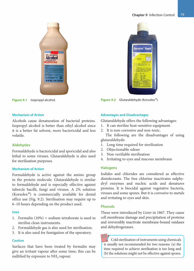
Chapter 9 Infection Control 79
Mechanism of Action
Alcohols cause denaturation of bacterial proteins.Isopropyl alcohol is better than ethyl alcohol since it is a better fat solvent, more bactericidal and less volatile.
AldehydesFormaldehyde is bactericidal and sporicidal and also lethal to some viruses. Glutaraldehyde is also used for sterilisation purposes.
Mechanism of Action
Formaldehyde is active against the amino group in the protein molecule. Glutaraldehyde is similar to formaldehyde and is especially effective against tubercle bacilli, fungi and viruses. A 2% solution (Korsolex®) is commercially available for dental office use (Fig. 9.2). Sterilisation may require up to 6–10 hours depending on the product used.
Uses
1. Formalin (10%) + sodium tetraborate is used to sterilise clean instruments.
2. Formaldehyde gas is also used for sterilisation.3. It is also used for fumigation of the operatory.
Caution
Surfaces that have been treated by formalin may give an irritant vapour after some time; this can be nullified by exposure to NH3 vapour.
Advantages and Disadvantages
Glutaraldehyde offers the following advantages:1. It can sterilise heat-sensitive equipment.2. It is non-corrosive and non-toxic.
The following are the disadvantages of using glutaraldehyde:1. Long time required for sterilisation2. Objectionable odour3. Non-verifiable sterilisation4. Irritating to eyes and mucous membrane
HalogensIodides and chlorides are considered as effective disinfectants. The free chlorine inactivates sulphy-dryl enzymes and nucleic acids and denatures proteins. It is biocidal against vegetative bacteria, viruses and some spores. But it is corrosive to metals and irritating to eyes and skin.
PhenolsThese were introduced by Lister in 1867. They cause cell membrane damage and precipitation of proteins and irreversibly inactivate membrane-bound oxidases and dehydrogenases.
Cold sterilisation of instruments using chemicals is usually not recommended for two reasons: (a) the time required to achieve sterilisation is too long and (b) the solutions might not be effective against spores.
Figure 9.1 Isopropyl alcohol. Figure 9.2 Glutaraldehyde (Korsolex®).
Preclinical Dentistry.indb 79 29-05-2020 12:56:37
https://t.me/DentalBooksWorld

80 Essentials of Preclinical Conservative Dentistry
Specifications for Use of Chemicals Used in Dental Office1. Endodontic instruments can be cleansed of
debris by squeezing the instrument blade with gauze moistened with isopropyl alcohol, while withdrawing the instrument, rotating in an anticlockwise motion (Fig. 9.3).
2. Quaternary ammonium compounds are effec-tive against vegetative bacteria while isopropyl alcohol is effective against tubercle bacilli.
3. Glutaraldehyde (Korsolex®) can be used for both disinfection and sterilisation. However, its use as a sterilising agent is not much recommended.
4. It is recommended that dappen dishes be ster-ilised before use by swabbing thoroughly with Merthiolate, followed by alcohol. Such swab-bing is always done by applying some pressure (Fig. 9.4).
5. Tweezers can be sterilised by dipping their working point in isopropyl alcohol and flaming twice. This method is an auxiliary method and used when already sterilised instruments have become infected intraoperatively (Fig. 9.5).
6. To sterilise the gutta-percha cone, it should be immersed in 5.2% sodium hypochlorite (NaOCl) for 1 minute, and then rinsed with hydrogen peroxide (H2O2) and dried between two layers of sterile gauze pieces. Also, one can use 0.5% NaOCl for 5 minutes (Fig. 9.6).
Figure 9.3 Squeezing the instrument blade by a gauze moistened with alcohol.
Figure 9.4 Swabbing of the dappen dish.
Figure 9.5 Flaming the tips of cotton pliers.
Figure 9.6 Sodium hypochlorite (NaOCl).
Preclinical Dentistry.indb 80 29-05-2020 12:56:37
https://t.me/DentalBooksWorld
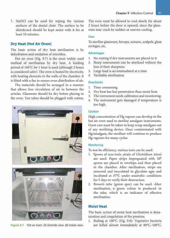
Chapter 9 Infection Control 81
7. NaOCl can be used for wiping the various surfaces of the dental chair. The surface to be disinfected should be kept moist with it for at least 10 minutes.
Dry Heat (Hot Air Oven)The basic action of dry heat sterilisation is by dehydration and oxidation of microbes.
Hot air oven (Fig. 9.7) is the most widely used method of sterilisation by dry heat. A holding period of 160°C for 1 hour is used (although 2 hours is considered safer). The oven is heated by electricity, with heating elements in the walls of the chamber. It is fitted with a fan to ensure even distribution of air.
The materials should be arranged in a manner that allows free circulation of air in between the articles. Glassware should be dry before placing in the oven. Test tubes should be plugged with cotton.
The oven must be allowed to cool slowly for about 2 hours before the door is opened, since the glass-ware may crack by sudden or uneven cooling.
Uses
To sterilise glassware, forceps, scissors, scalpels, glass syringes, etc.
Advantages
1. No rusting if dry instruments are placed in it2. Sharp instruments can be sterilised without the
loss of their sharpness3. Large load is accommodated at a time4. Verifiable sterilisation
Drawbacks
1. Time consuming.2. Dry heat has less penetration than moist heat.3. The instrument needs calibration and monitoring.4. The instrument gets damaged if temperature is
too high.
Caution
High concentration of Hg vapour can develop in the hot air oven used to sterilise amalgam instruments. Great care must be taken to keep scrap amalgam out of any sterilising device. Once contaminated with Hg/amalgam, the steriliser will continue to produce Hg vapours for many cycles.
Monitoring
To test its efficiency, various tests can be used:1. Spores of non-toxic strain of Clostridium tetani
are used. Paper strips impregnated with 106 spores are placed in envelops and then placed in the chamber. After sterilisation, strips are removed and inoculated in glycolate agar and incubated at 37°C under anaerobic conditions for 5 days to verify their destruction.
2. Brown’s tube (green spot) can be used. After sterilisation, a green colour is produced in the tube, which is an indicator of effective sterilisation.
Moist HeatThe basic action of moist heat sterilisation is dena-turation and coagulation of the proteins.1. Boiling at 100°C (Fig. 9.8): Vegetative bacteria
are killed almost immediately at 90°C–100°C,
B
A
Figure 9.7 Hot air oven. (A) Outside view. (B) Inside view.
Preclinical Dentistry.indb 81 29-05-2020 12:56:37
https://t.me/DentalBooksWorld

82 Essentials of Preclinical Conservative Dentistry
but sporing bacteria require a considerable period of boiling. Hard water should not be used. Sterilisation can be promoted by adding 2% NaHCO3 to the water. The material should be immersed in the water and boiled for a period of 10–30 minutes. The lid of the steriliser should not be opened during this period.
2. Steam under pressure (autoclaving) can be used.
Principle
The principle of autoclave is that water boils when its vapour pressure equals that of the surrounding atmo-sphere. Hence, when pressure inside a closed vessel increases, the temperature at which water boils also increases. Saturated steam has greater penetrating power. When steam comes into contact with a cooler surface, it condenses to H2O and gives up its latent heat to that surface. The large reduction in volume sucks in more steam to the area and the process continues till the temperature of that surface is raised to that of steam. The condensed vapour ensures moist conditions for killing the microbes present. The cycle is set at 121°C at 15 psi for 15 minutes.
Working
In today’s modern world, front-loading autoclaves (Fig. 9.9) are used. These are fully automatic auto-claves and the manufacturer’s instructions for their working must be adhered to. Recommended amount of water is placed in the autoclave and the instru-ments are placed on the trays inside. The procedure of placing the instruments in the autoclave is called loading. One should be careful not to overload the autoclave, as in this case the steam will not reach all the instruments and the sterilisation may be ineffec-tive. The front door is then shut and the autoclave is turned on. The sterilisation cycle starts and it stops automatically after the completion of the cycle. The door can now be opened and the instruments retrieved. It is necessary that the pressure gauge on the autoclave should show ‘zero’ reading before an attempt is made to open the door.
Advantages
1. The moist heat acts by denaturation and coagu-lation of enzymes and proteins, whereas dry heat acts by destructive oxidation of cell contents.
2. Moist heat kills more rapidly and at much lower temperature than dry heat. There is condensa-tion of a large amount of steam on the instru-ment surface, which produces latent heat, and also there is a contraction in its volume, which produces a negative pressure and brings in more steam to the site. Thus, steam acts more rapidly in raising the temperature than hot air. Steam penetrates better than hot air. This is partly due to its density and partly due to the nega-tive pressure.
3. Sterilisation is verifiable.
Figure 9.8 Boiler.
A B
Figure 9.9 Autoclave. (A) Outside view. (B) Inside view.
Preclinical Dentistry.indb 82 29-05-2020 12:56:38
https://t.me/DentalBooksWorld
Chapter 9 Infection Control 83
Drawbacks
1. Corrosion of carbon steel instruments may occur.2. Cutting edges of sharp instruments may get
dulled.To avoid or minimise corrosion, use of ammonia
or 20% sodium nitrate has been recommended.
Monitoring
To test its efficiency, various tests can be used, such as follows:1. An interesting test for sterilisation monitoring is
autoclave tape test or Bowie–Dick tape test. This is a tape printed with sensitive ink that undergoes colour change at a specific temperature. Two pieces of strips are stuck onto a piece of square paper and placed on the middle of the test pack. With the application of a temperature of 121°C for 15 minutes, there is uniform development of bars throughout the length of the strips.
2. Paper strips are impregnated with 106 spores of Bacillus stearothermophilus and placed along with the package. The optimal growth tempera-ture is 55°C–60°C and the spore requires an exposure of 15 minutes at 121°C to be killed. After autoclaving, the paper strips are placed in suitable culture media and checked for growth.
3. Brown’s test: In this test, a chemical is used which changes its colour from red to amber and finally to green once the autoclaving is complete.
Sterilisation MonitoringThis can be done daily, weekly, quarterly or annually, depending on the usage of the equipment.
Gas SterilisationEthylene oxide is a highly penetrative noncorrosive agent with a cidal action against bacteria, spores and viruses. It destroys microbes by alkylation and causes denaturation of nucleic acids.
It is a strong irritant, highly inflammable and a toxic agent and therefore should not be used if other means of sterilisation are feasible. Gas sterilisation is used for pre-sterilising single-use medical devices. The gas is used at room temperature and at 30% humidity for periods as long as 24 hours. The gas is highly permeable and items exposed to it must be aerated after sterilisation.
Advantages
1. Good penetration ability2. Can be used for sterilising heat- and mois-
ture-sensitive equipment
Disadvantages
1. Cost of equipment is high.2. Gas is toxic.3. Long period of aeration is required.4. Concentration exceeding 3% could be explosive.
Therefore, it is necessary that the room is prop-erly vented.
Chemiclaving (Chemical Vapour Sterilisation)The principle is that although some H2O is necessary to catalyse the destruction of microbes, H2O satu-ration is not necessary. The method uses a vapour created by heating a deodorised alcohol–formalde-hyde solution in a pre-heated tank chamber called a chemiclave or Harvey chemiclave. H2O content is below 15%, the level where rusting occurs.
The vapour is collected at a temperature of 132°C and brought up to a pressure of 20–40 psi. The superheated vapour condenses upon the instru-ments in chamber and the cycle is maintained for 20–25 minutes. The destruction of the microbes is due to double action by the heat and by the formal-dehyde. Formaldehyde acts by alkylation of nucleic acids, which are responsible for synthesis of proteins.
It takes longer time than an autoclave and shorter time than a hot air oven. It is also called low-tem-perature-steam-formaldehyde (LTSF) sterilisation. Formaldehyde chemiclave solution must not be recirculated; a fresh mixture should be used for each cycle.
Advantages
1. Short 25-minute cycle of sterilisation2. No rusting of instruments3. Availability of dry, immediately usable instru-
ments with no delay for aeration
Disadvantages
1. Cost is high.2. It requires provision of adequate ventilation
to expel chemical vapours released from the chamber at the end of the cycle.
3. Vapour odour may be offensive.
Preclinical Dentistry.indb 83 29-05-2020 12:56:38
https://t.me/DentalBooksWorld

84 Essentials of Preclinical Conservative Dentistry
4. Vapours may not penetrate the intricate internal workings of the handpiece.
RadiationsRadiations used for sterilisation are of two types: ionising and non-ionising radiations
Ionising RadiationsIonising radiations such as gamma rays have great penetrating properties and are commonly used at the industrial level for sterilisation of disposable items such as syringes and gloves.
There is no appreciable rise in tempera-ture. High-energy gamma rays from Co-60 and caesium-137 are commonly used.
Non-Ionising RadiationsThese include UV rays and infrared rays.1. UV rays: These are absorbed by proteins and
nucleic acids and kill microbes by the chemical reactions that are set up in the bacterial cell. These have low-penetrating capacity and their main application is for purification of air in the operating rooms or for surface sterilisation, as for handpieces. All forms of bacteria and viruses are vulnerable to UV rays below 3000 atmo-spheric pressure. Care must be taken to protect skin and eyes while using UV for sterilisation.
2. Infrared radiations (IR): These too are used for air purification in operatories and for sterilising a large number of syringes contained in a metal container.
Glass Bead Steriliser/Hot Salt SteriliserThis compact apparatus is considered indispensable for the procedure of root canal treatment. It consists of a metal cup in which glass beads or table salt is kept at a temperature between 425°F and 475°F (Fig. 9.10). At this temperature, broaches, files and reamers may be sterilised in 5 seconds and absor-bent points in 10 seconds. The availability of a ther-mometer to monitor the temperature of the steriliser is necessary, since the desired temperature may not be reached if the thermostat is not working properly.
The hot salt steriliser is considered better than the glass bead steriliser because of the following reasons:1. Ordinary salt is readily available for replacement.
2. There are less chances of clogging the root canals, as compared with glass beads, which often cling to wet instruments and block the canals.
The salt used in the steriliser is not just the table salt but contains 1% of sodium silicoaluminate, Mg2CO3 or Na2CO3. These additional agents do not allow the salt to get fused under heat. The salt should be changed on a regular basis.
Clinical Tips
1. The hottest part of the salt bath is along its outer rim, so the instruments are always placed in the peripheral area.
2. Also, the temperature is more at the bottom of the cup, so the instruments should always be placed at least 0.25 in below the salt surface.
3. Absorbent points are immersed butt-end first to avoid their bending and left on the surface of hot salt until used.
A
B
Figure 9.10 Glass bead steriliser. (A) Outside view. (B) Inside view showing glass beads.
Preclinical Dentistry.indb 84 29-05-2020 12:56:39
https://t.me/DentalBooksWorld
Chapter 9 Infection Control 85
The Concept of Asepsis
The asepsis protocol involves the utilisation of infection control procedure and use of personal protection equipment (PPE).
Infection Control ProcedureOne of the prime objectives of restorative dentistry is to provide the highest standard of care to the patients. The universal use of gloves, masks, head caps, protective overgarments and sterile instru-ments is a must to achieve this goal. The Federal Occupational Safety Health Administration (OSHA) has issued some guidelines for the infection control procedures.
Summary of OSHA regulation is as follows:1. Hepatitis B immunisation must be provided to
the employees without charge within 10 days of employment.
2. Precaution must be taken to prevent contact with blood or other such infectious materials.
3. Specific equipment must be used to prevent spatter or aerosols. These include use of rubber dam, suction and hard-walled containers for collection of sharps.
4. Precaution must be taken to minimise the splat-ters or contact of bare hands with the contam-inated surface, for example, while using brush to clean blood-stained instruments, one should always brush away from oneself. It is recom-mended not to touch telephones, door handles, etc., with soiled gloves.
5. There must be provision of facilities for instruc-tions for washing hands after removing gloves and for washing skin or eyes immediately on contact with blood or other infectious material.
6. Needles and other sharps must be safely handled.7. Single-use needles, wires and carpules must
be properly disposed of as close to the place of use as possible in hard-walled, leak-proofed containers labelled as ‘sharps’.
8. Contaminated, reusable sharps should not be stored in a manner that the attendants concerned have to use hands to retrieve them.
9. Eating, drinking and handling contact lenses should be prohibited in operatories and cleanup areas.
10. Blood and contaminated specimens (e.g. unclean impression, biopsy specimens) should be trans-ported in leak-proof containers.
11. Provide the attending staff with necessary PPE and the direction of use, for example, gloves, masks and gowns.
12. Ensure that the staff use PPE correctly and also discard them properly after use.
13. Ensure proper cleaning of floor, countertops, sinks, etc., which are subject to contamination. A written schedule for cleaning and then using a decontaminating procedure for equipment, work surfaces and contaminated floors should be provided.
14. Contaminated equipment that require service must first be decontaminated or a ‘Biohazard’ label must be used to indicate contaminated parts.
15. Regulated waste includes contaminated sharps, blood and other infectious materials, contami-nated items that release blood when compressed, etc. These must be properly disposed of.
16. Reusable contaminated sharp instruments must be placed into a basket in a hard-walled container for transportation to the cleanup area.
17. The facility of laundering of the protective garments used for universal precautions must be provided at no cost to the attending staff.
Personal Protection EquipmentPPE include gloves, protective eyewears, mask and head caps and overgarments.
GlovesIt is mandatory to wear gloves during treatment procedures and these must be changed after treating every patient (Fig. 9.11). Also, if during the proce-dure, these get torn or contaminated, one must change the gloves.
Hand WashingIt is necessary that hands be washed thoroughly before wearing the gloves. This procedure can be divided into three main segments:1. Preparation before washing: All jewellery, such
as hand rings, should be removed. Also, one has to be careful that nails should be neat and nicely cut.
Preclinical Dentistry.indb 85 29-05-2020 12:56:39
https://t.me/DentalBooksWorld

86 Essentials of Preclinical Conservative Dentistry
2. Washing and rinsing: For washing of hands, a soap solution should be used, which should be kept in a dispenser. The solution should be nicely scrubbed in between both the hands and in between the fingers (webs) also. The hands should then be rinsed in running tap water thor-oughly so that no soap remnants are left over on the hands. Alcohol solution (such as Sterillium) can be used for decontamination of the hands.
3. Drying of the hands: The hands should be completely dried before wearing gloves. Disposable paper towels can be used for this purpose. Alternatively, hot air driers can also be used, which are wall mounted.
It is recommended that a hand cream be used regularly as the skin gets dried by regular washing and drying of hands.
Types of Gloves
1. According to the material used(a) Latex gloves: These gloves are most commonly
used in dental practice.(b) Brown milled rubber gloves: These are thinner
than latex gloves and provide a better tactile sensation, but are more fragile and require frequent changing.
2. According to the usage(a) Non-sterile gloves: These should be used for
the examination of the patient only.(b) Sterile gloves: These should be used for the
treatment procedure.(c) Utility gloves: These should be used for
cleaning of the instruments before they are subjected to sterilisation. These are made of thick rubber, as they are puncture proof, in order to prevent any injury from sharp instru-ments while cleaning.
(d) Polyurethane/polythene gloves: They are used while performing certain assistance proce-dures, for example, mixing of rubber base impression material.
Protective Eyewear, Masks, Head CapsWearing a protective eyewear, face mask and head cap is compulsory during the treatment procedure (Fig. 9.12).1. Protective eyewear must be worn to protect the
eyes from splatter.2. Clear glasses should be worn with protective side
shields.3. Alternatively, face shields can be used which
cover the entire face. Both the eyewear and the face shield should be disinfected.
4. The face mask has to be changed after every patient or at times during the procedure if it becomes wet.
Figure 9.11 Gloves.
Clinical Tips
1. Remove jewellery, watch, rings, etc., especially those which can penetrate gloves prior to hand washing.
2. Wash hands with a suitable cleanser, lather hands for at least 10 seconds, rubbing all surfaces, and rinse. Use a clean brush to scrub under and around the nails.
3. Wash hands well when changing gloves; even good-quality gloves develop minor pin holes or leak during vigorous use.
4. Prior to surgery, use surgical scrub for washing and rinsing from hands towards elbows—this is done for 10 minutes.
5. Hand cleansers containing a mild antiseptic such as 3% para-chloro-meta-xylenol (PCMX) or chlorhexi-dine (4%) are preferred to control transient patho-gens and suppress overgrowth of skin bacteria. Povidone–iodine (7.5%) can also be used.
6. Soap containing hexachlorophene or 70% Hibisol (2.5% chlorhexidine in 70% alcohol) can be used.
Preclinical Dentistry.indb 86 29-05-2020 12:56:39
https://t.me/DentalBooksWorld

Chapter 9 Infection Control 87
5. Touching the face mask during the procedure should be avoided.
6. The mask must not be kept hanging around the neck.
7. Head caps should be used to cover the hair. If uncovered, contamination of hair occurs, which can be hazardous.
Protective OvergarmentsAn ideal overgarment should be light in weight, cover the chest up to the neck and arms to the full length and should have knit cuffs that can be tucked under the gloves (refer to Fig. 2.18). Spatter, if left on uncovered arms, can be a source of infection. The overgarment should be long enough so that it covers the lap when the operator is sitting.
Concept of Zones: Zones in the Vicinity or Area of Operation
Segregating the operatory into different zones ensures that the infected material from outside, such as patient footwear from the streets, does not enter the sterile aseptic area. Similarly, infected mate-rial from the patients’ wound should be properly disposed of so that patients in the waiting area are not exposed to any risk of cross-contamination.
The operatory can be categorised into four zones:1. Outer/general access zone, for example, patient
reception area2. Clean/limited access zone, for example, area
between reception and general office, corridors and staff room
3. Restricted access zone, for example, for properly clothed personnel engaged in operating theatre activities and anaesthetic room.
4. Aseptic or operating zone, for example, opera-tion theatre
Classification of Items Used in Dental Operatory1. Critical items: Instruments that contact cut
tissues or penetrate the tissues are considered to be critical items. These require thorough cleaning and sterilisation for reuse, as described earlier.
2. Semi-critical items: These include items attached to the dental unit that are used intra-orally or are handled and touched interchange-ably with mucosa by gloved hands coated with blood and saliva, for example, suction tips and handpieces.
Semi-critical items should not be disinfected. They should be covered or cleaned and sterilised or discarded.
3. Non-critical items: These include chairs, tables, etc. These, if contaminated, will need cleaning and disinfection.
Ultrasonic Cleaners and Solutions
Ultrasonic cleaning is a very safe and efficient way to clean sharp instruments after these have been rinsed or soaked.
Burs and other sharp hand instruments should be ultrasonically cleaned.
An ultrasonic cleaning device (Fig. 9.13) consists of a basket/tank, a lid and a timer to control the duration of the cycle.
Following precautions must be observed:1. The tank should be operated filled with cleaning
solution one-half to three-fourth of its capacity at all times.
2. The solution recommended by the manufacturer should be used. An antimicrobial solution should be preferred (Fig. 9.14). The solution should be changed as per the manufacturer’s instructions.
3. The ultrasonic cleaner should be operated for the time specified by the manufacturer.
4. The ultrasonic performance should be verified on a regular basis by ‘ultrasonic cleaner foil test’. The basket should be removed from the device
Figure 9.12 Protective mask and head cap.
Preclinical Dentistry.indb 87 29-05-2020 12:56:39
https://t.me/DentalBooksWorld
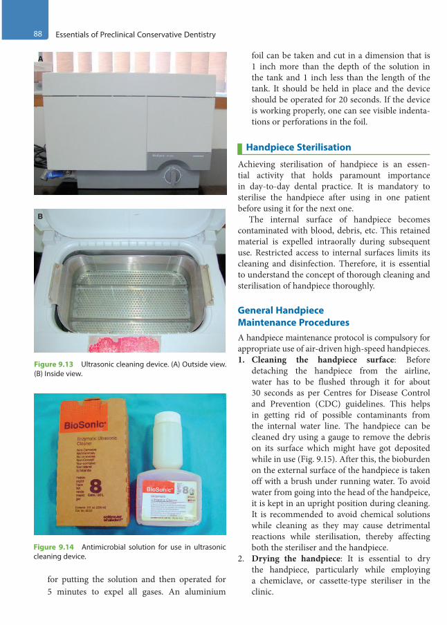
88 Essentials of Preclinical Conservative Dentistry
for putting the solution and then operated for 5 minutes to expel all gases. An aluminium
foil can be taken and cut in a dimension that is 1 inch more than the depth of the solution in the tank and 1 inch less than the length of the tank. It should be held in place and the device should be operated for 20 seconds. If the device is working properly, one can see visible indenta-tions or perforations in the foil.
Handpiece Sterilisation
Achieving sterilisation of handpiece is an essen-tial activity that holds paramount importance in day-to-day dental practice. It is mandatory to sterilise the handpiece after using in one patient before using it for the next one.
The internal surface of handpiece becomes contaminated with blood, debris, etc. This retained material is expelled intraorally during subsequent use. Restricted access to internal surfaces limits its cleaning and disinfection. Therefore, it is essential to understand the concept of thorough cleaning and sterilisation of handpiece thoroughly.
General Handpiece Maintenance ProceduresA handpiece maintenance protocol is compulsory for appropriate use of air-driven high-speed handpieces.1. Cleaning the handpiece surface: Before
detaching the handpiece from the airline, water has to be flushed through it for about 30 seconds as per Centres for Disease Control and Prevention (CDC) guidelines. This helps in getting rid of possible contaminants from the internal water line. The handpiece can be cleaned dry using a gauge to remove the debris on its surface which might have got deposited while in use (Fig. 9.15). After this, the bioburden on the external surface of the handpiece is taken off with a brush under running water. To avoid water from going into the head of the handpeice, it is kept in an upright position during cleaning. It is recommended to avoid chemical solutions while cleaning as they may cause detrimental reactions while sterilisation, thereby affecting both the steriliser and the handpiece.
2. Drying the handpiece: It is essential to dry the handpiece, particularly while employing a chemiclave, or cassette-type steriliser in the clinic.
A
B
Figure 9.13 Ultrasonic cleaning device. (A) Outside view. (B) Inside view.
Figure 9.14 Antimicrobial solution for use in ultrasonic cleaning device.
Preclinical Dentistry.indb 88 29-05-2020 12:56:40
https://t.me/DentalBooksWorld
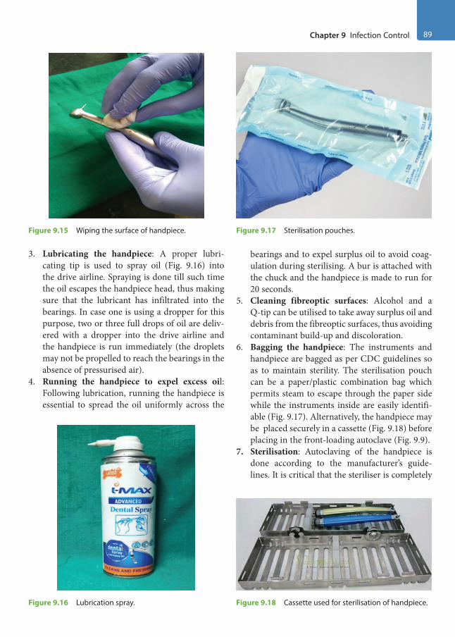
Chapter 9 Infection Control 89
3. Lubricating the handpiece: A proper lubri-cating tip is used to spray oil (Fig. 9.16) into the drive airline. Spraying is done till such time the oil escapes the handpiece head, thus making sure that the lubricant has infiltrated into the bearings. In case one is using a dropper for this purpose, two or three full drops of oil are deliv-ered with a dropper into the drive airline and the handpiece is run immediately (the droplets may not be propelled to reach the bearings in the absence of pressurised air).
4. Running the handpiece to expel excess oil: Following lubrication, running the handpiece is essential to spread the oil uniformly across the
bearings and to expel surplus oil to avoid coag-ulation during sterilising. A bur is attached with the chuck and the handpiece is made to run for 20 seconds.
5. Cleaning fibreoptic surfaces: Alcohol and a Q-tip can be utilised to take away surplus oil and debris from the fibreoptic surfaces, thus avoiding contaminant build-up and discoloration.
6. Bagging the handpiece: The instruments and handpiece are bagged as per CDC guidelines so as to maintain sterility. The sterilisation pouch can be a paper/plastic combination bag which permits steam to escape through the paper side while the instruments inside are easily identifi-able (Fig. 9.17). Alternatively, the handpiece may be placed securely in a cassette (Fig. 9.18) before placing in the front-loading autoclave (Fig. 9.9).
7. Sterilisation: Autoclaving of the handpiece is done according to the manufacturer’s guide-lines. It is critical that the steriliser is completely
Figure 9.15 Wiping the surface of handpiece.
Figure 9.18 Cassette used for sterilisation of handpiece.Figure 9.16 Lubrication spray.
Figure 9.17 Sterilisation pouches.
Preclinical Dentistry.indb 89 29-05-2020 12:56:41
https://t.me/DentalBooksWorld
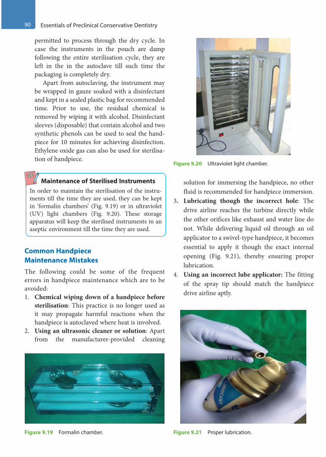
90 Essentials of Preclinical Conservative Dentistry
permitted to process through the dry cycle. In case the instruments in the pouch are damp following the entire sterilisation cycle, they are left in the in the autoclave till such time the packaging is completely dry.
Apart from autoclaving, the instrument may be wrapped in gauze soaked with a disinfectant and kept in a sealed plastic bag for recommended time. Prior to use, the residual chemical is removed by wiping it with alcohol. Disinfectant sleeves (disposable) that contain alcohol and two synthetic phenols can be used to seal the hand-piece for 10 minutes for achieving disinfection. Ethylene oxide gas can also be used for sterilisa-tion of handpiece.
Maintenance of Sterilised InstrumentsIn order to maintain the sterilisation of the instru-ments till the time they are used, they can be kept in ‘formalin chambers’ (Fig. 9.19) or in ultraviolet (UV) light chambers (Fig. 9.20). These storage apparatus will keep the sterilised instruments in an aseptic environment till the time they are used.
Common Handpiece Maintenance MistakesThe following could be some of the frequent errors in handpiece maintenance which are to be avoided:1. Chemical wiping down of a handpiece before
sterilisation: This practice is no longer used as it may propagate harmful reactions when the handpiece is autoclaved where heat is involved.
2. Using an ultrasonic cleaner or solution: Apart from the manufacturer-provided cleaning
solution for immersing the handpiece, no other fluid is recommended for handpiece immersion.
3. Lubricating though the incorrect hole: The drive airline reaches the turbine directly while the other orifices like exhaust and water line do not. While delivering liquid oil through an oil applicator to a swivel-type handpiece, it becomes essential to apply it though the exact internal opening (Fig. 9.21), thereby ensuring proper lubrication.
4. Using an incorrect lube applicator: The fitting of the spray tip should match the handpiece drive airline aptly.
Figure 9.19 Formalin chamber.
Figure 9.20 Ultraviolet light chamber.
Figure 9.21 Proper lubrication.
Preclinical Dentistry.indb 90 29-05-2020 12:56:41
https://t.me/DentalBooksWorld
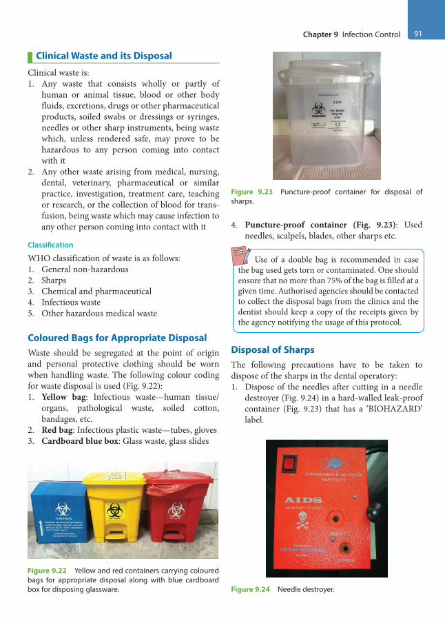
Chapter 9 Infection Control 91
Clinical Waste and its Disposal
Clinical waste is:1. Any waste that consists wholly or partly of
human or animal tissue, blood or other body fluids, excretions, drugs or other pharmaceutical products, soiled swabs or dressings or syringes, needles or other sharp instruments, being waste which, unless rendered safe, may prove to be hazardous to any person coming into contact with it
2. Any other waste arising from medical, nursing, dental, veterinary, pharmaceutical or similar practice, investigation, treatment care, teaching or research, or the collection of blood for trans-fusion, being waste which may cause infection to any other person coming into contact with it
Classification
WHO classification of waste is as follows:1. General non-hazardous2. Sharps3. Chemical and pharmaceutical4. Infectious waste5. Other hazardous medical waste
Coloured Bags for Appropriate DisposalWaste should be segregated at the point of origin and personal protective clothing should be worn when handling waste. The following colour coding for waste disposal is used (Fig. 9.22):1. Yellow bag: Infectious waste—human tissue/
organs, pathological waste, soiled cotton, bandages, etc.
2. Red bag: Infectious plastic waste—tubes, gloves3. Cardboard blue box: Glass waste, glass slides
4. Puncture-proof container (Fig. 9.23): Used needles, scalpels, blades, other sharps etc.
Use of a double bag is recommended in case the bag used gets torn or contaminated. One should ensure that no more than 75% of the bag is filled at a given time. Authorised agencies should be contacted to collect the disposal bags from the clinics and the dentist should keep a copy of the receipts given by the agency notifying the usage of this protocol.
Disposal of SharpsThe following precautions have to be taken to dispose of the sharps in the dental operatory:1. Dispose of the needles after cutting in a needle
destroyer (Fig. 9.24) in a hard-walled leak-proof container (Fig. 9.23) that has a ‘BIOHAZARD’ label.
Figure 9.22 Yellow and red containers carrying coloured bags for appropriate disposal along with blue cardboard box for disposing glassware.
Figure 9.23 Puncture-proof container for disposal of sharps.
Figure 9.24 Needle destroyer.
Preclinical Dentistry.indb 91 29-05-2020 12:56:41
https://t.me/DentalBooksWorld
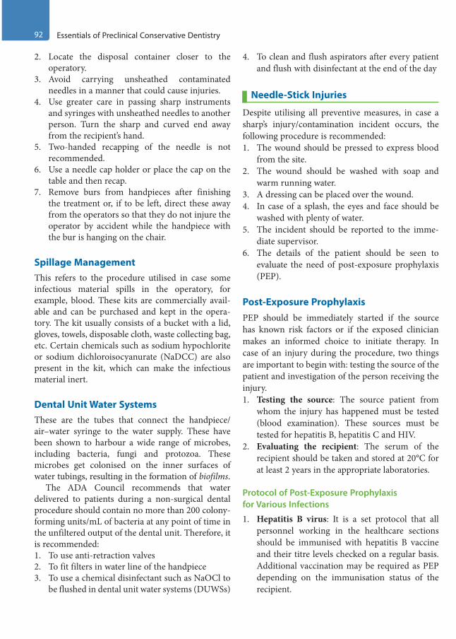
92 Essentials of Preclinical Conservative Dentistry
2. Locate the disposal container closer to the operatory.
3. Avoid carrying unsheathed contaminated needles in a manner that could cause injuries.
4. Use greater care in passing sharp instruments and syringes with unsheathed needles to another person. Turn the sharp and curved end away from the recipient’s hand.
5. Two-handed recapping of the needle is not recommended.
6. Use a needle cap holder or place the cap on the table and then recap.
7. Remove burs from handpieces after finishing the treatment or, if to be left, direct these away from the operators so that they do not injure the operator by accident while the handpiece with the bur is hanging on the chair.
Spillage ManagementThis refers to the procedure utilised in case some infectious material spills in the operatory, for example, blood. These kits are commercially avail-able and can be purchased and kept in the opera-tory. The kit usually consists of a bucket with a lid, gloves, towels, disposable cloth, waste collecting bag, etc. Certain chemicals such as sodium hypochlorite or sodium dichloroisocyanurate (NaDCC) are also present in the kit, which can make the infectious material inert.
Dental Unit Water SystemsThese are the tubes that connect the handpiece/ air–water syringe to the water supply. These have been shown to harbour a wide range of microbes, including bacteria, fungi and protozoa. These microbes get colonised on the inner surfaces of water tubings, resulting in the formation of biofilms.
The ADA Council recommends that water delivered to patients during a non-surgical dental procedure should contain no more than 200 colony- forming units/mL of bacteria at any point of time in the unfiltered output of the dental unit. Therefore, it is recommended:1. To use anti-retraction valves2. To fit filters in water line of the handpiece3. To use a chemical disinfectant such as NaOCl to
be flushed in dental unit water systems (DUWSs)
4. To clean and flush aspirators after every patient and flush with disinfectant at the end of the day
Needle-Stick Injuries
Despite utilising all preventive measures, in case a sharp’s injury/contamination incident occurs, the following procedure is recommended:1. The wound should be pressed to express blood
from the site.2. The wound should be washed with soap and
warm running water.3. A dressing can be placed over the wound.4. In case of a splash, the eyes and face should be
washed with plenty of water.5. The incident should be reported to the imme-
diate supervisor.6. The details of the patient should be seen to
evaluate the need of post-exposure prophylaxis (PEP).
Post-Exposure ProphylaxisPEP should be immediately started if the source has known risk factors or if the exposed clinician makes an informed choice to initiate therapy. In case of an injury during the procedure, two things are important to begin with: testing the source of the patient and investigation of the person receiving the injury.1. Testing the source: The source patient from
whom the injury has happened must be tested (blood examination). These sources must be tested for hepatitis B, hepatitis C and HIV.
2. Evaluating the recipient: The serum of the recipient should be taken and stored at 20°C for at least 2 years in the appropriate laboratories.
Protocol of Post-Exposure Prophylaxis for Various Infections
1. Hepatitis B virus: It is a set protocol that all personnel working in the healthcare sections should be immunised with hepatitis B vaccine and their titre levels checked on a regular basis. Additional vaccination may be required as PEP depending on the immunisation status of the recipient.
Preclinical Dentistry.indb 92 29-05-2020 12:56:41
https://t.me/DentalBooksWorld
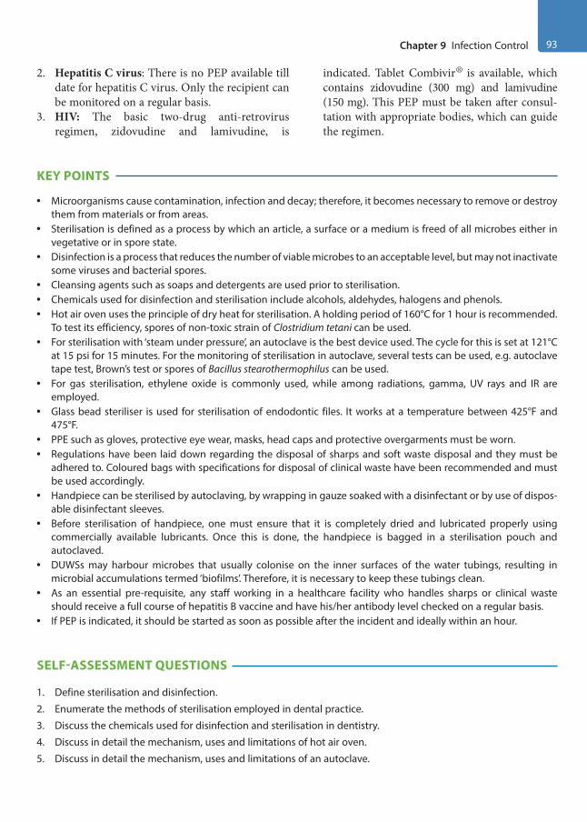
Chapter 9 Infection Control 93
2. Hepatitis C virus: There is no PEP available till date for hepatitis C virus. Only the recipient can be monitored on a regular basis.
3. HIV: The basic two-drug anti-retrovirus regimen, zidovudine and lamivudine, is
indicated. Tablet Combivir® is available, which contains zidovudine (300 mg) and lamivudine (150 mg). This PEP must be taken after consul-tation with appropriate bodies, which can guide the regimen.
KEY POINTS
• Microorganisms cause contamination, infection and decay; therefore, it becomes necessary to remove or destroy them from materials or from areas.
• Sterilisation is defined as a process by which an article, a surface or a medium is freed of all microbes either in vegetative or in spore state.
• Disinfection is a process that reduces the number of viable microbes to an acceptable level, but may not inactivate some viruses and bacterial spores.
• Cleansing agents such as soaps and detergents are used prior to sterilisation.• Chemicals used for disinfection and sterilisation include alcohols, aldehydes, halogens and phenols.• Hot air oven uses the principle of dry heat for sterilisation. A holding period of 160°C for 1 hour is recommended.
To test its efficiency, spores of non-toxic strain of Clostridium tetani can be used.• For sterilisation with ‘steam under pressure’, an autoclave is the best device used. The cycle for this is set at 121°C
at 15 psi for 15 minutes. For the monitoring of sterilisation in autoclave, several tests can be used, e.g. autoclave tape test, Brown’s test or spores of Bacillus stearothermophilus can be used.
• For gas sterilisation, ethylene oxide is commonly used, while among radiations, gamma, UV rays and IR are employed.
• Glass bead steriliser is used for sterilisation of endodontic files. It works at a temperature between 425°F and 475°F.
• PPE such as gloves, protective eye wear, masks, head caps and protective overgarments must be worn.• Regulations have been laid down regarding the disposal of sharps and soft waste disposal and they must be
adhered to. Coloured bags with specifications for disposal of clinical waste have been recommended and must be used accordingly.
• Handpiece can be sterilised by autoclaving, by wrapping in gauze soaked with a disinfectant or by use of dispos-able disinfectant sleeves.
• Before sterilisation of handpiece, one must ensure that it is completely dried and lubricated properly using commercially available lubricants. Once this is done, the handpiece is bagged in a sterilisation pouch and autoclaved.
• DUWSs may harbour microbes that usually colonise on the inner surfaces of the water tubings, resulting in microbial accumulations termed ‘biofilms’. Therefore, it is necessary to keep these tubings clean.
• As an essential pre-requisite, any staff working in a healthcare facility who handles sharps or clinical waste should receive a full course of hepatitis B vaccine and have his/her antibody level checked on a regular basis.
• If PEP is indicated, it should be started as soon as possible after the incident and ideally within an hour.
SELF-ASSESSMENT QUESTIONS
1. Define sterilisation and disinfection.
2. Enumerate the methods of sterilisation employed in dental practice.
3. Discuss the chemicals used for disinfection and sterilisation in dentistry.
4. Discuss in detail the mechanism, uses and limitations of hot air oven.
5. Discuss in detail the mechanism, uses and limitations of an autoclave.
Preclinical Dentistry.indb 93 29-05-2020 12:56:42
https://t.me/DentalBooksWorld

94 Essentials of Preclinical Conservative Dentistry
6. How can you verify the process of sterilisation?
7. What do you mean by gas sterilisation?
8. Which radiations are used for the process of sterilisation?
9. What do you mean by chemiclaving?
10. Discuss in detail glass bead steriliser.
11. Enumerate the OSHA regulations.
12. Discuss ‘waste disposal’ in healthcare setting.
13. What do you understand by the terms ‘critical items’, ‘semi-critical items’ and ‘non-critical items’?
14. Discuss the functioning of an ultrasonic cleaner.
15. How can you sterilise your handpiece?
16. Enumerate various methods of keeping the dental unit water systems clean.
17. Discuss the colour coding of disposal bags.
18. How will you dispose of ‘sharps’ in your operatory after using them?
19. Discuss the term ‘spillage management’.
20. What do you understand by PEP?
Preclinical Dentistry.indb 94 29-05-2020 12:56:42
https://t.me/DentalBooksWorld
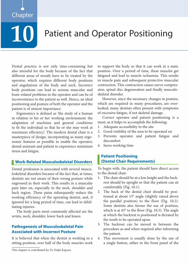
Dental practice is not only time-consuming but also stressful for the body because of the fact that different areas of mouth have to be treated by the operator, which requires different body positions and angulations of the body and neck. Incorrect body positions can lead to serious muscular and bone-related problems in the operator and can be of inconvenience to the patient as well. Hence, an ideal positioning and posture of both the operator and the patient is of utmost importance.
Ergonomics is defined as ‘the study of a human in relation to his or her working environment: the adaptation of machines and general conditions to fit the individual so that he or she may work at maximum efficiency’. The modern dental chair is a masterpiece of design, incorporating as many ergo-nomic features as possible to enable the operator, dental assistant and patient to experience minimum stress and fatigue.
Work-Related Musculoskeletal Disorders
Dental profession is associated with several muscu-loskeletal disorders because of the fact that, at times, dentists are not aware of their wrong posture while engrossed in their work. This results in a muscular pain later on, especially in the neck, shoulder and back region. These pains subsequently reduce the working efficiency of the operating dentist, and, if ignored for a long period of time, can lead to debil-itating injuries.
The body parts most commonly affected are the wrists, neck, shoulder, lower back and knees.
Pathogenesis of Musculoskeletal Pain Associated with Incorrect PostureIt is believed that when the dentist is working in a sitting position, over half of the body muscles work
to support the body so that it can work in a static position. Over a period of time, these muscles get fatigued and lead to muscle ischaemia. This results in muscle pain and subsequent protective muscular contraction. This contraction causes nerve compres-sion, spinal disc degeneration and finally musculo-skeletal disorder.
However, since the necessary changes in posture, which are required in many procedures, are over-looked, many dentists often present with symptoms of excessive fatigue, if not skeletal damage.
Correct operator and patient positioning is a must, as it helps to accomplish the following:1. Adequate accessibility to the site2. Good visibility of the area to be operated on3. Prevents operator and patient fatigue and
discomfort4. Saves working time
Patient Positioning (Dental Chair Requirements)
To begin with, the patient should have direct access to the dental chair.1. The chair should be at a low height and the back-
rest should be upright so that the patient can sit comfortably (Fig. 10.1).
2. The back of the dental chair should be posi-tioned at about 15° angle (slightly raised above the parallel position) to the floor (Fig. 10.2). Some dentists also favour the use of position, which is at 45° to the floor (Fig. 10.3). The angle at which the backrest is positioned is dictated by the tooth to be operated upon.
3. The backrest can be moved in between the procedure as and when required after informing the patient.
4. This movement is usually done by the use of a single button, either in the front panel of the
Patient and Operator Positioning10Chapter
This chapter is contributed by Dr Daljit Kapoor.
Preclinical Dentistry.indb 95 29-05-2020 12:56:42
https://t.me/DentalBooksWorld

96 Essentials of Preclinical Conservative Dentistry
bracket table (Fig. 10.4) or in the foot control of the dental chair.
5. The top of the patient’s head must be at the level of the end of headrest of the chair (Fig. 10.5) so that the dentist can have good access to the patient’s mouth.
6. Also, the vertical height of the chair should be adjusted in a manner so that the patient’s oral cavity and the dentist’s heart (while the dentist is in sitting position) are at the same level. If the patient is seated above this level, then the oper-ating dentist can have shoulder fatigue during the treatment procedure. On the other hand, if the patient is seated below this level, then the operating dentist has to bend too much to work,
Figure 10.1 Normal position of the dental chair.
Figure 10.2 The back of the dental chair positioned at 15° angle.
Figure 10.3 The back of the dental chair positioned at 45° angle.
Figure 10.4 The front panel of the bracket table showing buttons for controlling the movement of the dental chair.
Figure 10.5 The top of the patient’s head even with the end of the headrest.
Preclinical Dentistry.indb 96 29-05-2020 12:56:42
https://t.me/DentalBooksWorld
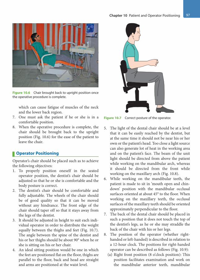
Chapter 10 Patient and Operator Positioning 97
which can cause fatigue of muscles of the neck and the lower back region.
7. One must ask the patient if he or she is in a comfortable position.
8. When the operative procedure is complete, the chair should be brought back to the upright position (Fig. 10.6) for the ease of the patient to leave the chair.
Operator Positioning
Operator’s chair should be placed such as to achieve the following objectives:1. To properly position oneself in the seated
operator position, the dentist’s chair should be adjusted so that he or she is comfortable and the body posture is correct.
2. The dentist’s chair should be comfortable and fully adjustable. The wheels of the chair should be of good quality so that it can be moved without any hindrance. The front edge of the chair should taper off so that it stays away from the legs of the dentist.
3. It should be adjusted in height to suit each indi-vidual operator in order to distribute the weight equally between the thighs and feet (Fig. 10.7). The angle between the spine of the dentist and his or her thighs should be about 90° when he or she is sitting on his or her chair.
4. An ideal sitting position would be one in which the feet are positioned flat on the floor, thighs are parallel to the floor, back and head are straight and arms are positioned at the waist level.
5. The light of the dental chair should be at a level that it can be easily reached by the dentist, but at the same time it should not be near his or her own or the patient’s head. Too close a light source can also generate lot of heat in the working area and on the patient’s face. The beam of the unit light should be directed from above the patient while working on the mandibular arch, whereas it should be directed from the front while working on the maxillary arch (Fig. 10.8).
6. While working on the mandibular teeth, the patient is made to sit in ‘mouth open and chin- down’ position with the mandibular occlusal surfaces oriented at about 45° to the floor. When working on the maxillary teeth, the occlusal surfaces of the maxillary teeth should be oriented approximately perpendicular to the floor.
7. The back of the dental chair should be placed in such a position that it does not touch the top of the dentist’s legs, as he or she may straddle the back of the chair with his or her legs.
8. The position of the operator (whether right-handed or left-handed) is described in relation to a 12-hour clock. The positions for right-handed operator can be described as follows (Fig. 10.9):
(a) Right front position (8 o’clock position): This position facilitates examination and work on the mandibular anterior teeth, mandibular
Figure 10.6 Chair brought back to upright position once the operative procedure is complete.
Figure 10.7 Correct posture of the operator.
Preclinical Dentistry.indb 97 29-05-2020 12:56:42
https://t.me/DentalBooksWorld
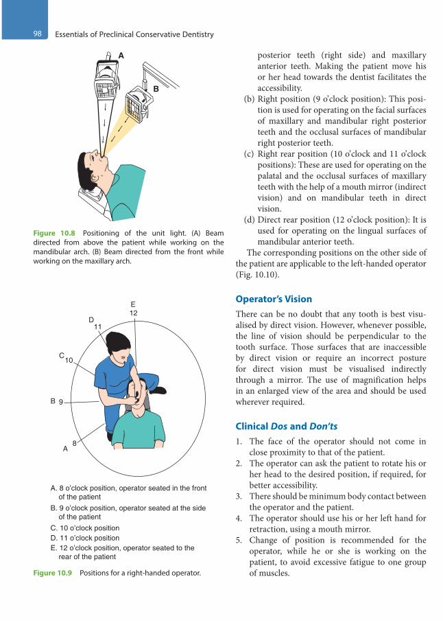
98 Essentials of Preclinical Conservative Dentistry
posterior teeth (right side) and maxillary anterior teeth. Making the patient move his or her head towards the dentist facilitates the accessibility.
(b) Right position (9 o’clock position): This posi-tion is used for operating on the facial surfaces of maxillary and mandibular right posterior teeth and the occlusal surfaces of mandibular right posterior teeth.
(c) Right rear position (10 o’clock and 11 o’clock positions): These are used for operating on the palatal and the occlusal surfaces of maxillary teeth with the help of a mouth mirror (indirect vision) and on mandibular teeth in direct vision.
(d) Direct rear position (12 o’clock position): It is used for operating on the lingual surfaces of mandibular anterior teeth.
The corresponding positions on the other side of the patient are applicable to the left-handed operator (Fig. 10.10).
Operator’s VisionThere can be no doubt that any tooth is best visu-alised by direct vision. However, whenever possible, the line of vision should be perpendicular to the tooth surface. Those surfaces that are inaccessible by direct vision or require an incorrect posture for direct vision must be visualised indirectly through a mirror. The use of magnification helps in an enlarged view of the area and should be used wherever required.
Clinical Dos and Don’ts1. The face of the operator should not come in
close proximity to that of the patient.2. The operator can ask the patient to rotate his or
her head to the desired position, if required, for better accessibility.
3. There should be minimum body contact between the operator and the patient.
4. The operator should use his or her left hand for retraction, using a mouth mirror.
5. Change of position is recommended for the operator, while he or she is working on the patient, to avoid excessive fatigue to one group of muscles.
A
B
Figure 10.8 Positioning of the unit light. (A) Beam directed from above the patient while working on the mandibular arch. (B) Beam directed from the front while working on the maxillary arch.
A. 8 o’clock position, operator seated in the front of the patientB. 9 o’clock position, operator seated at the side of the patient
E. 12 o’clock position, operator seated to the rear of the patient
D. 11 o’clock positionC. 10 o’clock position
A
B
C
D
E12
11
10
9
8
Figure 10.9 Positions for a right-handed operator.
Preclinical Dentistry.indb 98 29-05-2020 12:56:42
https://t.me/DentalBooksWorld
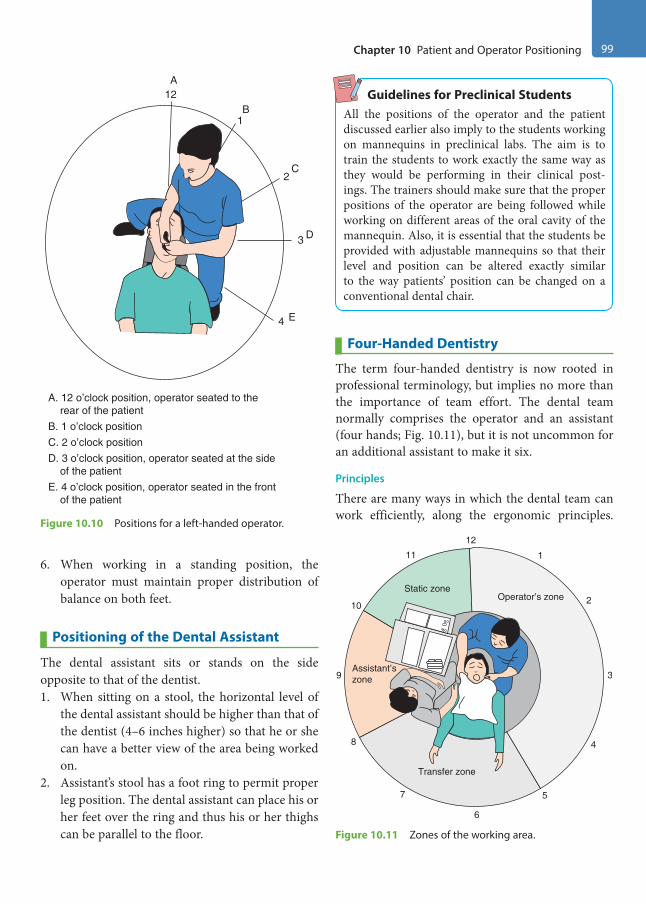
Chapter 10 Patient and Operator Positioning 99
6. When working in a standing position, the operator must maintain proper distribution of balance on both feet.
Positioning of the Dental Assistant
The dental assistant sits or stands on the side opposite to that of the dentist.1. When sitting on a stool, the horizontal level of
the dental assistant should be higher than that of the dentist (4–6 inches higher) so that he or she can have a better view of the area being worked on.
2. Assistant’s stool has a foot ring to permit proper leg position. The dental assistant can place his or her feet over the ring and thus his or her thighs can be parallel to the floor.
Guidelines for Preclinical StudentsAll the positions of the operator and the patient discussed earlier also imply to the students working on mannequins in preclinical labs. The aim is to train the students to work exactly the same way as they would be performing in their clinical post-ings. The trainers should make sure that the proper positions of the operator are being followed while working on different areas of the oral cavity of the mannequin. Also, it is essential that the students be provided with adjustable mannequins so that their level and position can be altered exactly similar to the way patients’ position can be changed on a conventional dental chair.
Four-Handed Dentistry
The term four-handed dentistry is now rooted in professional terminology, but implies no more than the importance of team effort. The dental team normally comprises the operator and an assistant (four hands; Fig. 10.11), but it is not uncommon for an additional assistant to make it six.
Principles
There are many ways in which the dental team can work efficiently, along the ergonomic principles.
E. 4 o’clock position, operator seated in the front of the patient
D. 3 o’clock position, operator seated at the side of the patient
A. 12 o’clock position, operator seated to the rear of the patientB. 1 o’clock positionC. 2 o’clock position
A
B
C
D
E
12
1
2
3
4
Figure 10.10 Positions for a left-handed operator.
Static zone
Assistant’szone
Transfer zone
Operator’s zone
12
1
2
3
4
5
6
7
8
9
10
11
Figure 10.11 Zones of the working area.
Preclinical Dentistry.indb 99 29-05-2020 12:56:43
https://t.me/DentalBooksWorld
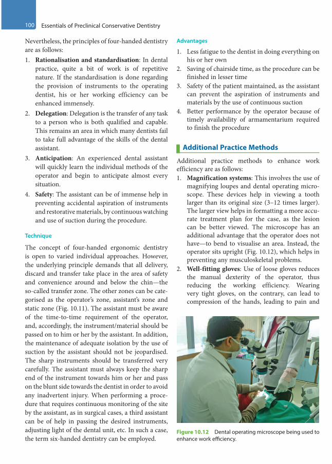
100 Essentials of Preclinical Conservative Dentistry
Nevertheless, the principles of four-handed dentistry are as follows:1. Rationalisation and standardisation: In dental
practice, quite a bit of work is of repetitive nature. If the standardisation is done regarding the provision of instruments to the operating dentist, his or her working efficiency can be enhanced immensely.
2. Delegation: Delegation is the transfer of any task to a person who is both qualified and capable. This remains an area in which many dentists fail to take full advantage of the skills of the dental assistant.
3. Anticipation: An experienced dental assistant will quickly learn the individual methods of the operator and begin to anticipate almost every situation.
4. Safety: The assistant can be of immense help in preventing accidental aspiration of instruments and restorative materials, by continuous watching and use of suction during the procedure.
Technique
The concept of four-handed ergonomic dentistry is open to varied individual approaches. However, the underlying principle demands that all delivery, discard and transfer take place in the area of safety and convenience around and below the chin—the so-called transfer zone. The other zones can be cate-gorised as the operator’s zone, assistant’s zone and static zone (Fig. 10.11). The assistant must be aware of the time-to-time requirement of the operator, and, accordingly, the instrument/material should be passed on to him or her by the assistant. In addition, the maintenance of adequate isolation by the use of suction by the assistant should not be jeopardised. The sharp instruments should be transferred very carefully. The assistant must always keep the sharp end of the instrument towards him or her and pass on the blunt side towards the dentist in order to avoid any inadvertent injury. When performing a proce-dure that requires continuous monitoring of the site by the assistant, as in surgical cases, a third assistant can be of help in passing the desired instruments, adjusting light of the dental unit, etc. In such a case, the term six-handed dentistry can be employed.
Advantages
1. Less fatigue to the dentist in doing everything on his or her own
2. Saving of chairside time, as the procedure can be finished in lesser time
3. Safety of the patient maintained, as the assistant can prevent the aspiration of instruments and materials by the use of continuous suction
4. Better performance by the operator because of timely availability of armamentarium required to finish the procedure
Additional Practice Methods
Additional practice methods to enhance work efficiency are as follows:1. Magnification systems: This involves the use of
magnifying loupes and dental operating micro-scope. These devices help in viewing a tooth larger than its original size (3–12 times larger). The larger view helps in formatting a more accu-rate treatment plan for the case, as the lesion can be better viewed. The microscope has an additional advantage that the operator does not have—to bend to visualise an area. Instead, the operator sits upright (Fig. 10.12), which helps in preventing any musculoskeletal problems.
2. Well-fitting gloves: Use of loose gloves reduces the manual dexterity of the operator, thus reducing the working efficiency. Wearing very tight gloves, on the contrary, can lead to compression of the hands, leading to pain and
Figure 10.12 Dental operating microscope being used to enhance work efficiency.
Preclinical Dentistry.indb 100 29-05-2020 12:56:43
https://t.me/DentalBooksWorld

Chapter 10 Patient and Operator Positioning 101
numbness. It is therefore advised that the oper-ator should wear exact fitting gloves.
3. Use of indirect vision: It is recommended that wherever indicated, indirect vision should be used, using a fine mouth mirror. This will not only increase the work efficiency but also prevent any undue neck and back pain caused while trying to visualise the maxillary teeth in direct vision by bending. The students undergoing preclin-ical training are always guided to work in indi-rect vision while working on maxillary teeth so that they can train themselves adequately before entering the clinic. This way of working requires a learning curve that can be easily mastered while working on artificial teeth. The errors made while working on artificial teeth can be rectified, and by repeatedly doing this exercise, one gets trained to work in indirect vision and faces least problems while working on patients.
Equipment Layout
Layout of the equipment required during restor-ative procedure forms an important feature of the working environment. Things that are required most commonly should be kept at a distance such that minimum effort is required by the operator to access these. The height at which these things must be kept should be neither above the shoulder level height
nor below the waist level. The design and position of the side trolleys on which the instruments are kept should be such that these are easily accessible to the operator by minimal movement of the arms. The areas to access can be categorised into normal and maximum working areas (Fig. 10.13). Normal working area is within the limits of a comfortable sweeping movement of one’s arm while maximum working area is the area within comfortable reach of one’s extended arm. Things that are frequently required are kept in the normal working area, while those that are less frequently required are kept in the maximum working area. Organising the work area in this way helps in saving the chairside time and increases the working efficiency of the operator.
KEY POINTS
• Correct operator and patient positioning is a must, as it helps to have adequate visibility and accessibility to the surgical site and also prevents operator and patient fatigue and discomfort.
• The patient should have direct access to the dental chair when asked to sit for dental treatment. The backrest can be tilted from 15° to 45° depending on the patient’s comfort and the operator’s requirement.
• As far as the operator is concerned, the dental stool should be so adjusted that one is comfortable and the body posture is correct.
• Unit light should be kept at an arm’s length above or in front of the patient.
• The position of the bracket table should be low enough to permit a clear view of the instruments.
• For instrumentation in the mandibular area, the patient should have his or her mouth open in a chin-down position, with the mandibular occlusal surfaces oriented at about 45° to the floor.
• When working on the teeth in the maxillary arch, the occlusal surfaces of the teeth should be perpendicular to the floor.
• Operating positions for the right-handed and the left-handed operators are usually identified in relation to a 12-hour clock, namely right front position (8 o’clock position), right position (9 o’clock position), right rear posi-tion (10 and 11 o’clock positions) and direct rear position (12 o’clock position).
Maximumwork area
Normalwork area
24’’
15’’
Figure 10.13 Equipment layout area depicting normal and maximum working areas.
Preclinical Dentistry.indb 101 29-05-2020 12:56:43
https://t.me/DentalBooksWorld
102 Essentials of Preclinical Conservative Dentistry
• While assisting, the assistant should sit on a stool in such a way that his or her horizontal level is higher than that of the dentist. This helps in better visibility of the working area and thus better assistance.
• Use of magnification loupes and dental operating microscope can help in increasing the efficiency of the operator.
• Use of indirect vision is recommended for the operator whenever appropriate to avoid any musculoskeletal disorder.
• Instruments should be laid out in the working area in such a manner that they are easily accessible to the operator without much of movement.
SELF-ASSESSMENT QUESTIONS
1. What do you mean by the term ‘ergonomics’?
2. Discuss the important features regarding patient positioning on dental chair.
3. Discuss the various operator’s positions during instrumentation in different parts of the oral cavity.
4. Discuss the importance of proper positioning of the dental assistant.
5. Discuss the principles and importance of four-handed dentistry.
6. What do you understand by the term working in indirect vision? Discuss its importance.
7. Discuss the technique of instrument layout and its significance.
Preclinical Dentistry.indb 102 29-05-2020 12:56:43
https://t.me/DentalBooksWorld
Tooth preparation techniques have been known for many centuries. Cavities have been prepared for dental inlays since as early as the ninth century. During the early nineteenth century, preparation was done mainly by hand-operated instruments. Later, drills operated by bowstring, Archimedean drives, were used. During the late nineteenth century, pedal-driven engine using flexible cables, handpiece and burs came into being. In 1955, Page-Chayas handpiece, the first belt-driven angle hand-piece to operate successfully at speeds over 100,000 rpm, was introduced. In 1957, the first clinically acceptable air turbine handpiece, Borden air-rotor handpiece, came into play. Then air motor, electric micromotor, straight handpiece and contra-angled handpiece were introduced.
Hamelton Jameson, for the first time in the nine-teenth century, emphasised the need for organised cavity preparation. In the 1930s, G.V. Black gave a systematic approach to cavity preparation.
Dr Charles E. Woodbury and Henry A. True suggested inconspicuous type of preparations, which were a modification of Black’s preparations.
Introduction of new aesthetic restorative mate-rials, particularly during the past two decades, has changed the conventional ideas of tooth prepara-tion, in which conservative preparation is done by removing the carious lesion alone.
Tooth Preparation: The Concept
Tooth preparation not only involves the removal of entire carious lesion from the tooth structure but also provides a specific design so as to ensure the ability of prepared tooth structure to retain the restor-ative material being used. This of course depends on the kind of restorative material being used for that specific case. The principles of modern cavity prepa-ration were first defined in 1896 by Dr G.V. Black,
considered to be the ‘Father of Operative Dentistry’. Although techniques have been refined and outlines have been modified, Black’s principles are still used as the basic steps in the process of designing and preparing a cavity. Adherence to these principles facilitates the procedure of cavity preparation and decay removal. Thus, this systematic approach is still recommended to operative dentists as reliable guidelines for today.
Understanding the fundamentals of tooth prepa-ration in the context of the usage of different restor-ative materials is a definite pre-requisite to a dental practitioner. Different restorative materials exhibit a variety of physical and biological characteristics, which must be taken into consideration while tooth preparation to ensure a successful restoration.
It is necessary for the readers to understand that the long-term used nomenclature ‘cavity prepara-tion’ is now changed to ‘tooth preparation’, owing to the introduction of newer restorative materials such as composite resins, which do not require the so-called ‘preparation of a cavity’ for the restorative procedure.
Need for RestorationsTeeth need restorative intervention for a variety of reasons:1. To repair a tooth after destruction from a carious
lesion2. Replacement or repair of restoration with serious
defects, such as improper proximal contact, gingival excess, caries risk margin and poor aesthetics
3. To restore fractured tooth to proper form and function
4. To restore a congenitally malformed tooth to proper form and function
5. To enhance aesthetics
Principles of Tooth Preparation11Chapter
This chapter is authored by Dr Harpreet Singh.
Preclinical Dentistry.indb 103 29-05-2020 12:56:43
https://t.me/DentalBooksWorld
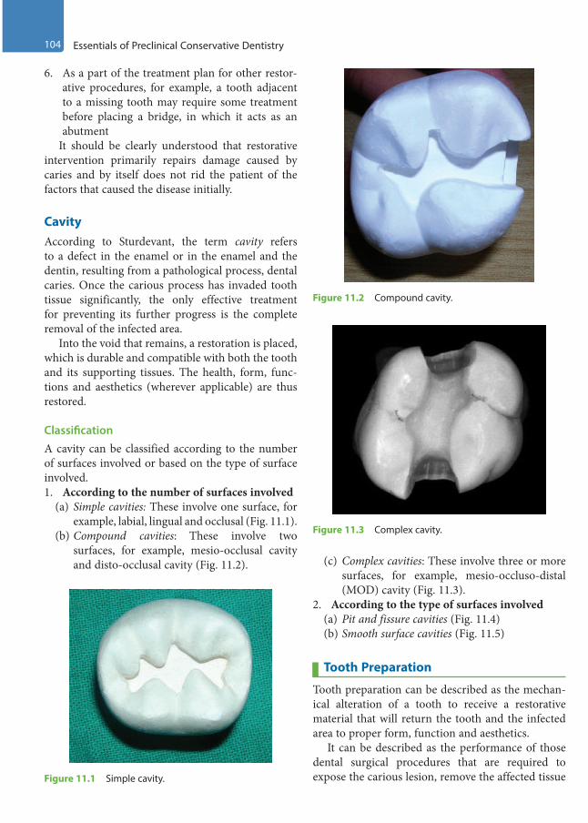
104 Essentials of Preclinical Conservative Dentistry
6. As a part of the treatment plan for other restor-ative procedures, for example, a tooth adjacent to a missing tooth may require some treatment before placing a bridge, in which it acts as an abutment
It should be clearly understood that restorative intervention primarily repairs damage caused by caries and by itself does not rid the patient of the factors that caused the disease initially.
CavityAccording to Sturdevant, the term cavity refers to a defect in the enamel or in the enamel and the dentin, resulting from a pathological process, dental caries. Once the carious process has invaded tooth tissue significantly, the only effective treatment for preventing its further progress is the complete removal of the infected area.
Into the void that remains, a restoration is placed, which is durable and compatible with both the tooth and its supporting tissues. The health, form, func-tions and aesthetics (wherever applicable) are thus restored.
ClassificationA cavity can be classified according to the number of surfaces involved or based on the type of surface involved.1. According to the number of surfaces involved
(a) Simple cavities: These involve one surface, for example, labial, lingual and occlusal (Fig. 11.1).
(b) Compound cavities: These involve two surfaces, for example, mesio-occlusal cavity and disto-occlusal cavity (Fig. 11.2). (c) Complex cavities: These involve three or more
surfaces, for example, mesio-occluso-distal (MOD) cavity (Fig. 11.3).
2. According to the type of surfaces involved(a) Pit and fissure cavities (Fig. 11.4)(b) Smooth surface cavities (Fig. 11.5)
Tooth Preparation
Tooth preparation can be described as the mechan-ical alteration of a tooth to receive a restorative material that will return the tooth and the infected area to proper form, function and aesthetics.
It can be described as the performance of those dental surgical procedures that are required to expose the carious lesion, remove the affected tissue Figure 11.1 Simple cavity.
Figure 11.2 Compound cavity.
Figure 11.3 Complex cavity.
Preclinical Dentistry.indb 104 29-05-2020 12:56:43
https://t.me/DentalBooksWorld
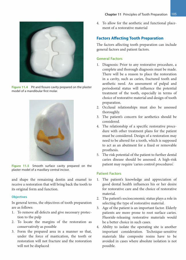
Chapter 11 Principles of Tooth Preparation 105
and shape the remaining dentin and enamel to receive a restoration that will bring back the tooth to its original form and function.
Objectives
In general terms, the objectives of tooth preparation are as follows:1. To remove all defects and give necessary protec-
tion to the pulp2. To locate the margins of the restoration as
conservatively as possible3. Form the prepared area in a manner so that,
under the force of mastication, the tooth or restoration will not fracture and the restoration will not be displaced
4. To allow for the aesthetic and functional place-ment of a restorative material
Factors Affecting Tooth PreparationThe factors affecting tooth preparation can include general factors and patient factors.
General Factors
1. Diagnosis: Prior to any restorative procedure, a complete and thorough diagnosis must be made. There will be a reason to place the restoration in a cavity, such as caries, fractured tooth and aesthetic need. An assessment of pulpal and periodontal status will influence the potential treatment of the tooth, especially in terms of choice of restorative material and design of tooth preparation.
2. Occlusal relationships must also be assessed thoroughly.
3. The patient’s concern for aesthetics should be considered.
4. The relationship of a specific restorative proce-dure with other treatment plans for the patient must be considered. Design of a restoration may need to be altered for a tooth, which is supposed to act as an abutment for a fixed or removable prosthesis.
5. The risk potential of the patient to further dental caries disease should be assessed. A high-risk patient may require ‘caries control procedures’.
Patient Factors
1. The patient’s knowledge and appreciation of good dental health influences his or her desire for restorative care and the choice of restorative material.
2. The patient’s socioeconomic status plays a role in selecting the type of restorative material.
3. Age of the patient is an important factor. Elderly patients are more prone to root surface caries. Fluoride-releasing restorative materials would be a better choice in such cases.
4. Ability to isolate the operating site is another important consideration. Technique-sensitive materials like composite resins have to be avoided in cases where absolute isolation is not possible.
Figure 11.4 Pit and fissure cavity prepared on the plaster model of a mandibular first molar.
Figure 11.5 Smooth surface cavity prepared on the plaster model of a maxillary central incisor.
Preclinical Dentistry.indb 105 29-05-2020 12:56:43
https://t.me/DentalBooksWorld
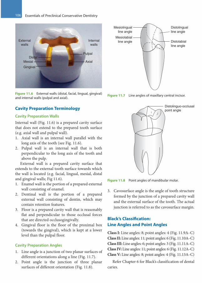
106 Essentials of Preclinical Conservative Dentistry
Cavity Preparation Terminology
Cavity Preparation Walls
Internal wall (Fig. 11.6) is a prepared cavity surface that does not extend to the prepared tooth surface (e.g. axial wall and pulpal wall).1. Axial wall is an internal wall parallel with the
long axis of the tooth (see Fig. 11.6).2. Pulpal wall is an internal wall that is both
perpendicular to the long axis of the tooth and above the pulp.
External wall is a prepared cavity surface that extends to the external tooth surface towards which the wall is located (e.g. facial, lingual, mesial, distal and gingival walls; Fig 11.6).1. Enamel wall is the portion of a prepared external
wall consisting of enamel.2. Dentinal wall is the portion of a prepared
external wall consisting of dentin, which may contain retention features.
3. Floor is a prepared cavity wall that is reasonably flat and perpendicular to those occlusal forces that are directed occlusogingivally.
4. Gingival floor is the floor of the proximal box (towards the gingival), which is kept at a lower level than the pulpal floor.
Cavity Preparation Angles
1. Line angle is a junction of two planar surfaces of different orientations along a line (Fig. 11.7).
2. Point angle is the junction of three planar surfaces of different orientation (Fig. 11.8).
3. Cavosurface angle is the angle of tooth structure formed by the junction of a prepared cavity wall and the external surface of the tooth. The actual junction is referred to as the cavosurface margin.
Black’s Classification: Line Angles and Point Angles
Class I: Line angles: 8; point angles: 4 (Fig. 11.9A–C)Class II: Line angles: 11; point angles: 6 (Fig. 11.10A–C)Class III: Line angles: 6; point angles: 3 (Fig. 11.11A–C)Class IV: Line angles: 11; point angles: 6 (Fig. 11.12A–C)Class V: Line angles: 8; point angles: 4 (Fig. 11.13A–C)
Refer Chapter 6 for Black’s classification of dental caries.
Externalwalls
Internalwalls
Pulpal
AxialDistal
Mesial
Gingival
Figure 11.6 External walls (distal, facial, lingual, gingival) and internal walls (pulpal and axial).
Mesiolingualline angle
Distolabialline angle
Distolingualline angle
Mesiolabialline angle
Figure 11.7 Line angles of maxillary central incisor.
Distolinguo-occlusalpoint angle
Figure 11.8 Point angles of mandibular molar.
Preclinical Dentistry.indb 106 29-05-2020 12:56:44
https://t.me/DentalBooksWorld
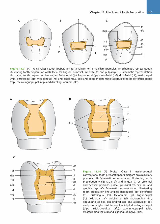
Chapter 11 Principles of Tooth Preparation 107
A
d
lp
m
fB
mfp
fp
dfp
mlp
lp
dlp
mf
mpml
dpdl
df
C
Figure 11.9 (A) Typical Class I tooth preparation for amalgam on a maxillary premolar. (B) Schematic representation illustrating tooth preparation walls: facial (f ), lingual (I), mesial (m), distal (d) and pulpal (p). (C) Schematic representation illustrating tooth preparation line angles: faciopulpal (fp), linguopulpal (lp), mesiofacial (mf), distofacial (df ), mesiopulpal (mp), distopulpal (dp), mesiolingual (ml) and distolingual (dl); and point angles: mesiofaciopulpal (mfp), distofaciopulpal (dfp), mesiolinguopulpal (mlp) and distolinguopulpal (dlp).
Figure 11.10 (A) Typical Class II mesio-occlusal conventional tooth preparation for amalgam on a maxillary premolar. (B) Schematic representation illustrating tooth preparation walls: facial (f ) and lingual (l) of proximal and occlusal portions, pulpal (p), distal (d), axial (a) and gingival (g). (C) Schematic representation illustrating tooth preparation line angles: distopulpal (dp), distofacial (df ), distolingual (dl), faciopulpal (fp), linguopulpal (lp), axiofacial (af ), axiolingual (al), faciogingival (fg), linguogingival (lg), axiogingival (ag) and axiopulpal (ap); and point angles: distofaciopulpal (dfp), distolinguopulpal (dlp), axiofaciopulpal (afp), axiolinguopulpal (alp), axiofaciogingival (afg) and axiolinguogingival (alg).
A
d
p
l
ag
B
afg
fg
af
afp
fp
dfp
df dl
dp
dlplpapalpal
alglg
ag
C
f
Preclinical Dentistry.indb 107 29-05-2020 12:56:44
https://t.me/DentalBooksWorld

108 Essentials of Preclinical Conservative Dentistry
A
l
g
B
fa
C
aiaf
fg
i
al
lg
afgagalg
Figure 11.11 (A) Class III conventional tooth preparation on a maxillary central incisor. (B) Schematic representation illustrating tooth preparation walls: facial (f ), lingual (l), axial (a) and gingival (g). (C) Schematic representation illustrating tooth preparation line angles: incisal (i), axiofacial (af ), axiolingual (al), faciogingival (fg), linguogingival (lg) and axiogingival (ag); and point angles: axioincisal (ai), axiofaciogingival (afg) and axiolinguogingival (alg).
A
g
p l
m
B
a
f
C
agfg
afgaf
afp
fp
mfpmf
mpmlmlp
lpapalp
alalglg
Figure 11.12 (A) Class IV conventional tooth preparation on a maxillary canine. (B) Schematic representation illustrating tooth preparation walls: facial (f ) and lingual (l) of proximal and incisal portions, mesial (m), pulpal (p), axial (a) and gingival (g). (C) Schematic representation illustrating tooth preparation line angles: mesiopulpal (mp), mesiofacial (mf), mesiolingual (ml), faciopulpal (fp), linguopulpal (lp), axiofacial (af ), axiolingual (al), faciogingival (fg), linguogingival (lg), axiopulpal (ap) and axiogingival (ag); and point angles: mesiofaciopulpal (mfp), mesiolinguopulpal (mlp), axiofaciopulpal (afp), axiolinguopulpal (alp), axiofaciogingival (afg) and axiolinguogingival (alg).
Preclinical Dentistry.indb 108 29-05-2020 12:56:44
https://t.me/DentalBooksWorld
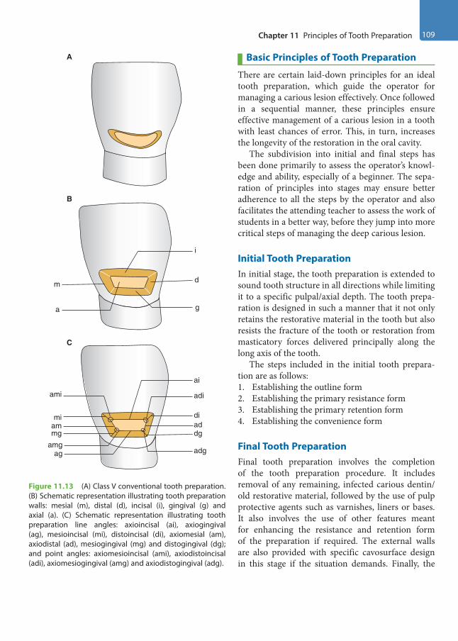
Chapter 11 Principles of Tooth Preparation 109
Basic Principles of Tooth Preparation
There are certain laid-down principles for an ideal tooth preparation, which guide the operator for managing a carious lesion effectively. Once followed in a sequential manner, these principles ensure effective management of a carious lesion in a tooth with least chances of error. This, in turn, increases the longevity of the restoration in the oral cavity.
The subdivision into initial and final steps has been done primarily to assess the operator’s knowl-edge and ability, especially of a beginner. The sepa-ration of principles into stages may ensure better adherence to all the steps by the operator and also facilitates the attending teacher to assess the work of students in a better way, before they jump into more critical steps of managing the deep carious lesion.
Initial Tooth PreparationIn initial stage, the tooth preparation is extended to sound tooth structure in all directions while limiting it to a specific pulpal/axial depth. The tooth prepa-ration is designed in such a manner that it not only retains the restorative material in the tooth but also resists the fracture of the tooth or restoration from masticatory forces delivered principally along the long axis of the tooth.
The steps included in the initial tooth prepara-tion are as follows:1. Establishing the outline form2. Establishing the primary resistance form3. Establishing the primary retention form4. Establishing the convenience form
Final Tooth PreparationFinal tooth preparation involves the completion of the tooth preparation procedure. It includes removal of any remaining, infected carious dentin/ old restorative material, followed by the use of pulp protective agents such as varnishes, liners or bases. It also involves the use of other features meant for enhancing the resistance and retention form of the preparation if required. The external walls are also provided with specific cavosurface design in this stage if the situation demands. Finally, the
A
C
amgag adg
diaddg
miammg
ami
ai
adi
i
m
B
d
a g
Figure 11.13 (A) Class V conventional tooth preparation. (B) Schematic representation illustrating tooth preparation walls: mesial (m), distal (d), incisal (i), gingival (g) and axial (a). (C) Schematic representation illustrating tooth preparation line angles: axioincisal (ai), axiogingival (ag), mesioincisal (mi), distoincisal (di), axiomesial (am), axiodistal (ad), mesiogingival (mg) and distogingival (dg); and point angles: axiomesioincisal (ami), axiodistoincisal (adi), axiomesiogingival (amg) and axiodistogingival (adg).
Preclinical Dentistry.indb 109 29-05-2020 12:56:45
https://t.me/DentalBooksWorld
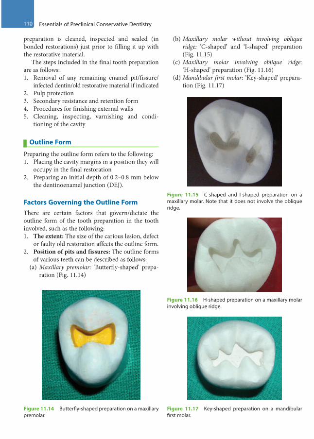
110 Essentials of Preclinical Conservative Dentistry
preparation is cleaned, inspected and sealed (in bonded restorations) just prior to filling it up with the restorative material.
The steps included in the final tooth preparation are as follows:1. Removal of any remaining enamel pit/fissure/
infected dentin/old restorative material if indicated2. Pulp protection3. Secondary resistance and retention form4. Procedures for finishing external walls5. Cleaning, inspecting, varnishing and condi-
tioning of the cavity
Outline Form
Preparing the outline form refers to the following:1. Placing the cavity margins in a position they will
occupy in the final restoration2. Preparing an initial depth of 0.2–0.8 mm below
the dentinoenamel junction (DEJ).
Factors Governing the Outline FormThere are certain factors that govern/dictate the outline form of the tooth preparation in the tooth involved, such as the following:1. The extent: The size of the carious lesion, defect
or faulty old restoration affects the outline form.2. Position of pits and fissures: The outline forms
of various teeth can be described as follows:(a) Maxillary premolar: ‘Butterfly-shaped’ prepa-
ration (Fig. 11.14)
(b) Maxillary molar without involving oblique ridge: ‘C-shaped’ and ‘I-shaped’ preparation (Fig. 11.15)
(c) Maxillary molar involving oblique ridge: ‘H-shaped’ preparation (Fig. 11.16)
(d) Mandibular first molar: ‘Key-shaped’ prepara-tion (Fig. 11.17)
Figure 11.14 Butterfly-shaped preparation on a maxillary premolar.
Figure 11.15 C-shaped and I-shaped preparation on a maxillary molar. Note that it does not involve the oblique ridge.
Figure 11.16 H-shaped preparation on a maxillary molar involving oblique ridge.
Figure 11.17 Key-shaped preparation on a mandibular first molar.
Preclinical Dentistry.indb 110 29-05-2020 12:56:45
https://t.me/DentalBooksWorld

Chapter 11 Principles of Tooth Preparation 111
(e) Mandibular second molar: ‘Plus-shaped’ preparation (Fig. 11.18)
3. Aesthetic considerations: The position of the tooth in the arch dictates not only the selection of the restorative material but also the design of the tooth preparation so as to maximise the aesthetic results of the restoration.
4. Preservation of healthy and vital tooth struc-ture: Healthy tooth structure should not be removed unless justified, as tooth structure once removed cannot be put back.
5. Restorative material being used: This guides the outline form, for example, the preparation required for amalgam is deeper, as compared with that for composite resin.
6. Occlusal considerations: Tooth preparation, at times, has to be modified according to the variant occlusal relationships, if present.
7. Adjacent tooth contour: At times, the tooth preparation (proximo-occlusal) has to be modi-fied according to the adjacent tooth contour so as to achieve the most efficient contact areas.
8. Cavosurface configuration: The preparation, whether bevelled or butt joint, is dictated by the restorative material to be used. Silver amalgam requires a butt joint configuration, whereas inlay will need a bevelled preparation.
Principles
1. All weak enamel should be removed.2. All faulty areas of the tooth prone to caries
should be included.3. All margins must be placed in a position to
afford good marginal finishing.
Features
1. Preserve the cuspal strength and marginal ridge strength.
2. Minimise the faciolingual extension.3. Perform enameloplasty.4. Connect the two preparations which are
<0.5 mm apart.5. Restrict the depth of preparation up to
0.2 mm into dentin for pit and fissure caries, and 0.2–0.8 mm for axial wall in case of smooth surface caries.
Special Consideration for Pit and Fissure CavitiesOutline form and initial depth in pit and fissure preparations are controlled by various factors such as the extent to which the enamel has been involved by the carious process and the extensions that must be made along the fissures to achieve sound and smooth margins. To be as conservative as possible, initial preparation is done to a depth of 1.5 mm, as measured at the central fissure (Fig. 11.14). Once this depth is established, if remaining pit/ fissure is present on <50% of the pulpal floor, it is removed during the final stage of cavity preparation. However, if the amount of pit/fissure is >50% of the pulpal floor, the entire pulpal floor is deepened to a maximum initial depth of 0.2 mm into the dentin.
Special Consideration for Smooth Surface CavitiesThe depth of the axial wall of proximal preparation is to be limited to 0.2–0.8 mm into the dentin. The gingival margin of proximal preparation is extended to provide a minimal clearance of 0.5 mm from the adjacent tooth. The facial and lingual margins of prox-imal preparation must be extended into the respective embrasures in order to provide sufficient clearance between the prepared margins and the adjacent tooth such that these margins can be well-visualised, instru-mented and better cleaned (Fig. 11.5).
EnameloplastyIt refers to eliminating the developmental fault by opening it using the side of a flame-shaped diamond stone, leaving a smooth surface (a saucer-shaped area) (Fig. 11.19).
Figure 11.18 Plus-shaped preparation on a mandibular second molar.
Preclinical Dentistry.indb 111 29-05-2020 12:56:45
https://t.me/DentalBooksWorld

112 Essentials of Preclinical Conservative Dentistry
Features
1. If one-third or less of the enamel depth is involved in a fissure, then enameloplasty is indicated.
2. Enameloplasty does not extend the outline form.3. This procedure is also applicable to supplemental
grooves extending up to the cuspal inclines.4. It is also indicated on a shallow fissure that
approaches or crosses a lingual or a facial ridge. This fissure, if extended otherwise, would involve two surfaces of the tooth.
5. The surface left by enameloplasty should meet the cavity preparation wall with a cavosurface angle not >100°.
6. The restorative material is not placed into the recontoured area.
7. During carving, amalgam should be removed from areas of enameloplasty.
Cusp CappingThis refers to involving the cusps of teeth into the cavity preparation design, and thereafter restoring them with the restorative material. Since a part of the restorative material also covers (caps) the cusps, hence the name cusp capping.
This decision has to be made very carefully and judiciously, as cusp involvement may reduce the strength of the tooth otherwise.
Principles
There is a set of rules that governs whether the cusps are to be involved or not:1. If the extension of cavity preparation from the
primary groove towards the cusp tip is less than half the distance (measured from the primary groove up to the cusp tip in unprepared tooth), then no cusp capping is required.
2. If this extension is from one-half to two-thirds of the distance, then cusp capping is considered.
3. If the extension is more than two-thirds of the distance, then cusp capping is considered mandatory.
Primary Resistance Form
It is defined as the shape and placement of tooth preparation walls that best enable both the resto-ration and the tooth to withstand, without fracture, masticatory forces delivered principally along the long axis of the tooth.
Principles
1. Obtain a box shape with a relatively flat floor (Fig. 11.20).
Masticatory forces are directed primarily along the long axis of the teeth. Since the teeth and the restorative materials best resist compres-sive forces, the cavity preparation should be designed to minimise the tensile and shear stresses. This is done by preparing the internal walls of the cavity perpendicular or parallel to the direction of the force, which is along the long axis. Thus, pulpal and gingival walls should be perpendicular to the long axis. The other walls, including the axial, are vertical or parallel to the long axis of the tooth. ‘Cup-shaped’ cavity preparations are to be avoided, as they poorly resist dislodging of restorations. Flat floor will help prevent restoration movement, whereas
A B
Figure 11.19 Enameloplasty. (A) Shallow fissure. (B) Enameloplasty done.
Figure 11.20 Box-shaped cavity with a flat floor.
Preclinical Dentistry.indb 112 29-05-2020 12:56:45
https://t.me/DentalBooksWorld
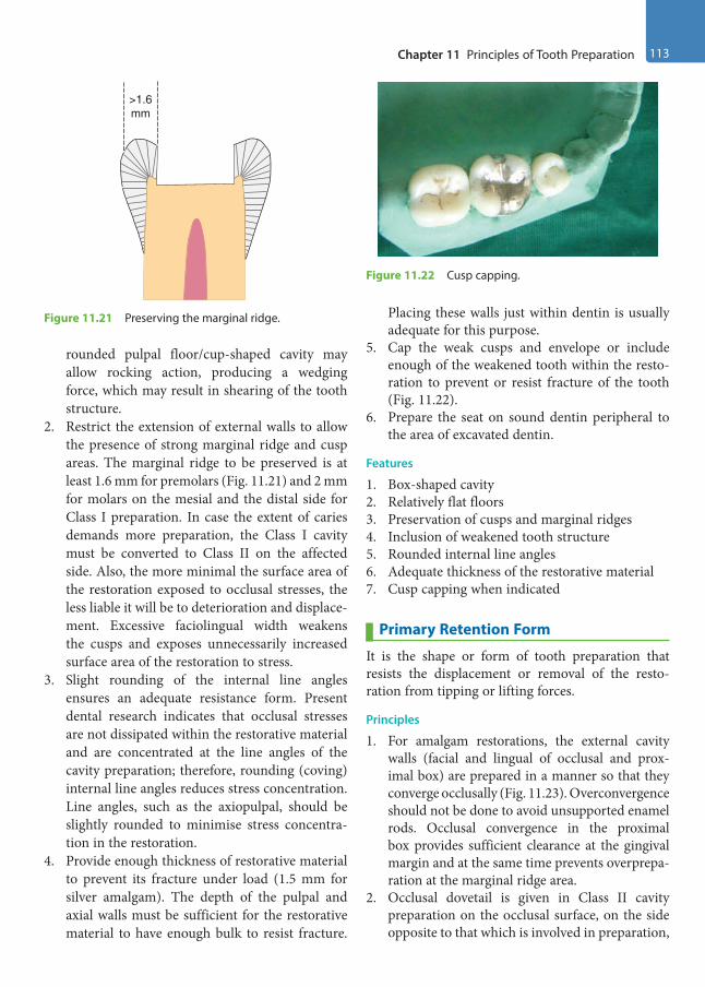
Chapter 11 Principles of Tooth Preparation 113
rounded pulpal floor/cup-shaped cavity may allow rocking action, producing a wedging force, which may result in shearing of the tooth structure.
2. Restrict the extension of external walls to allow the presence of strong marginal ridge and cusp areas. The marginal ridge to be preserved is at least 1.6 mm for premolars (Fig. 11.21) and 2 mm for molars on the mesial and the distal side for Class I preparation. In case the extent of caries demands more preparation, the Class I cavity must be converted to Class II on the affected side. Also, the more minimal the surface area of the restoration exposed to occlusal stresses, the less liable it will be to deterioration and displace-ment. Excessive faciolingual width weakens the cusps and exposes unnecessarily increased surface area of the restoration to stress.
3. Slight rounding of the internal line angles ensures an adequate resistance form. Present dental research indicates that occlusal stresses are not dissipated within the restorative material and are concentrated at the line angles of the cavity preparation; therefore, rounding (coving) internal line angles reduces stress concentration. Line angles, such as the axiopulpal, should be slightly rounded to minimise stress concentra-tion in the restoration.
4. Provide enough thickness of restorative material to prevent its fracture under load (1.5 mm for silver amalgam). The depth of the pulpal and axial walls must be sufficient for the restorative material to have enough bulk to resist fracture.
Placing these walls just within dentin is usually adequate for this purpose.
5. Cap the weak cusps and envelope or include enough of the weakened tooth within the resto-ration to prevent or resist fracture of the tooth (Fig. 11.22).
6. Prepare the seat on sound dentin peripheral to the area of excavated dentin.
Features
1. Box-shaped cavity2. Relatively flat floors3. Preservation of cusps and marginal ridges4. Inclusion of weakened tooth structure5. Rounded internal line angles6. Adequate thickness of the restorative material7. Cusp capping when indicated
Primary Retention Form
It is the shape or form of tooth preparation that resists the displacement or removal of the resto-ration from tipping or lifting forces.
Principles
1. For amalgam restorations, the external cavity walls (facial and lingual of occlusal and prox-imal box) are prepared in a manner so that they converge occlusally (Fig. 11.23). Overconvergence should not be done to avoid unsupported enamel rods. Occlusal convergence in the proximal box provides sufficient clearance at the gingival margin and at the same time prevents overprepa-ration at the marginal ridge area.
2. Occlusal dovetail is given in Class II cavity preparation on the occlusal surface, on the side opposite to that which is involved in preparation,
>1.6mm
Figure 11.21 Preserving the marginal ridge.
Figure 11.22 Cusp capping.
Preclinical Dentistry.indb 113 29-05-2020 12:56:45
https://t.me/DentalBooksWorld
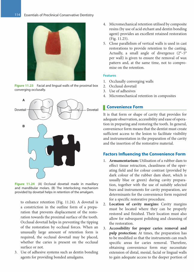
114 Essentials of Preclinical Conservative Dentistry
to enhance retention (Fig. 11.24). A dovetail is a constriction in the outline form of a prepa-ration that prevents displacement of the resto-ration towards the proximal surface of the tooth. Occlusal dovetail helps in preventing the tipping of the restoration by occlusal forces. When an unusually large amount of retention form is required, the occlusal dovetail may be placed, whether the caries is present on the occlusal surface or not.
3. Use of adhesive systems such as dentin bonding agents for providing bonded amalgams.
4. Micromechanical retention utilised by composite resins (by use of acid etchant and dentin bonding agent) provides an excellent retained restoration (Fig. 11.25).
5. Close parallelism of vertical walls is used in cast restorations to provide retention to the casting. Actually, a small angle of divergence (2°–5° per wall) is given to ensure the removal of wax pattern and, at the same time, not to compro-mise on the retention.
Features
1. Occlusally converging walls2. Occlusal dovetail3. Use of adhesives4. Micromechanical retention in composites
Convenience Form
It is that form or shape of cavity that provides for adequate observation, accessibility and ease of opera-tion in preparing and restoring the tooth. In general, convenience form means that the dentist must create sufficient access to the lesion to facilitate visibility and instrumentation in the preparation of the cavity and the insertion of the restorative material.
Factors Influencing the Convenience Form1. Armamentarium: Utilisation of a rubber dam to
effect tissue retraction, cleanliness of the oper-ating field and for colour contrast (provided by dark colour of the rubber dam sheet, which is usually blue or green) during cavity prepara-tion, together with the use of suitably selected burs and instruments for cavity preparation, are determinants for the convenience form required for a specific restorative procedure.
2. Location of cavity margins: Cavity margins must be located where they can be properly restored and finished. Their location must also allow for subsequent polishing and cleansing of the restoration.
3. Accessibility for proper caries removal and pulp protection: At times, the preparation has to be modified so that the instruments can reach specific areas for caries removal. Therefore, obtaining convenience form may necessitate extension of distal, mesial, facial or lingual walls to gain adequate access to the deeper portion of
Figure 11.23 Facial and lingual walls of the proximal box converging occlusally.
A
Dovetail Dovetail
B
Figure 11.24 (A) Occlusal dovetail made in maxillary and mandibular molars. (B) The interlocking mechanism provided by dovetail helps in retention of the amalgam.
Preclinical Dentistry.indb 114 29-05-2020 12:56:46
https://t.me/DentalBooksWorld
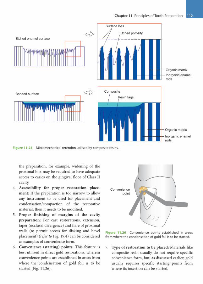
Chapter 11 Principles of Tooth Preparation 115
the preparation, for example, widening of the proximal box may be required to have adequate access to caries on the gingival floor of Class II cavity.
4. Accessibility for proper restoration place-ment: If the preparation is too narrow to allow any instrument to be used for placement and condensation/compaction of the restorative material, then it needs to be modified.
5. Proper finishing of margins of the cavity preparation: For cast restorations, extension, taper (occlusal divergence) and flare of proximal walls (to permit access for disking and bevel placement) (refer to Fig. 19.4) can be considered as examples of convenience form.
6. Convenience (starting) points: This feature is best utilised in direct gold restorations, wherein convenience points are established in areas from where the condensation of gold foil is to be started (Fig. 11.26).
7. Type of restoration to be placed: Materials like composite resin usually do not require specific convenience form, but, as discussed earlier, gold usually requires specific starting points from where its insertion can be started.
Composite
Resin tags
Organic matrix
Inorganic enamelrods
Organic matrixInorganic enamelrods
Surface loss
Etched porosity
Etched enamel surface
Bonded surface
Figure 11.25 Micromechanical retention utilised by composite resins.
Figure 11.26 Convenience points established in areas from where the condensation of gold foil is to be started.
Conveniencepoint
Preclinical Dentistry.indb 115 29-05-2020 12:56:46
https://t.me/DentalBooksWorld
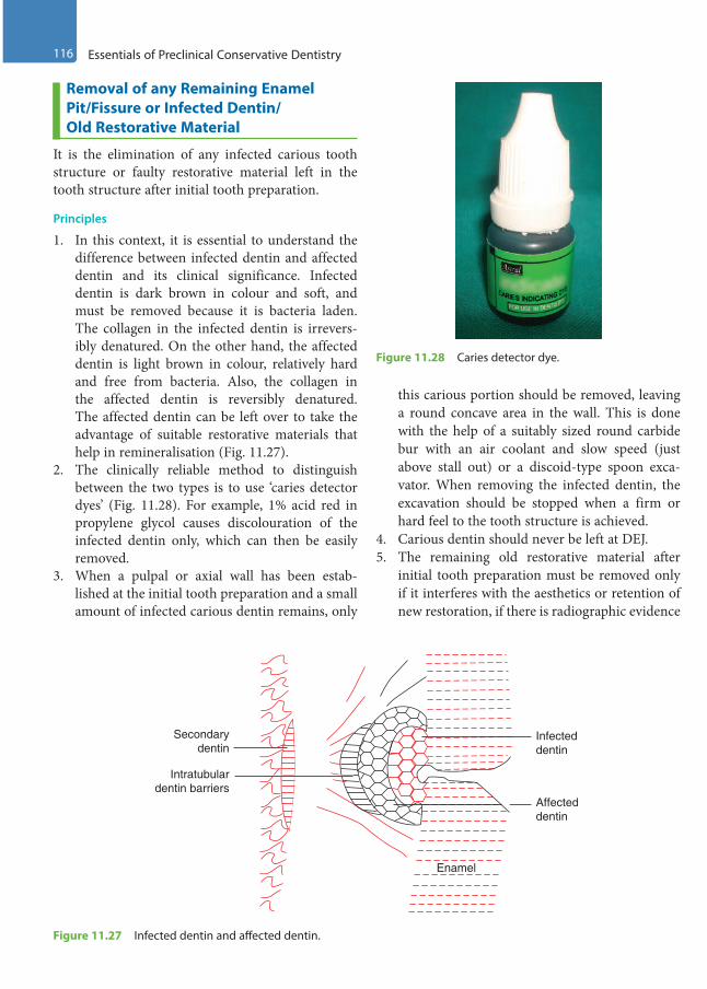
116 Essentials of Preclinical Conservative Dentistry
Removal of any Remaining Enamel Pit/Fissure or Infected Dentin/Old Restorative Material
It is the elimination of any infected carious tooth structure or faulty restorative material left in the tooth structure after initial tooth preparation.
Principles
1. In this context, it is essential to understand the difference between infected dentin and affected dentin and its clinical significance. Infected dentin is dark brown in colour and soft, and must be removed because it is bacteria laden. The collagen in the infected dentin is irrevers-ibly denatured. On the other hand, the affected dentin is light brown in colour, relatively hard and free from bacteria. Also, the collagen in the affected dentin is reversibly denatured. The affected dentin can be left over to take the advantage of suitable restorative materials that help in remineralisation (Fig. 11.27).
2. The clinically reliable method to distinguish between the two types is to use ‘caries detector dyes’ (Fig. 11.28). For example, 1% acid red in propylene glycol causes discolouration of the infected dentin only, which can then be easily removed.
3. When a pulpal or axial wall has been estab-lished at the initial tooth preparation and a small amount of infected carious dentin remains, only
this carious portion should be removed, leaving a round concave area in the wall. This is done with the help of a suitably sized round carbide bur with an air coolant and slow speed (just above stall out) or a discoid-type spoon exca-vator. When removing the infected dentin, the excavation should be stopped when a firm or hard feel to the tooth structure is achieved.
4. Carious dentin should never be left at DEJ.5. The remaining old restorative material after
initial tooth preparation must be removed only if it interferes with the aesthetics or retention of new restoration, if there is radiographic evidence
Infecteddentin
Affecteddentin
Enamel
Intratubulardentin barriers
Secondarydentin
Figure 11.27 Infected dentin and affected dentin.
Figure 11.28 Caries detector dye.
Preclinical Dentistry.indb 116 29-05-2020 12:56:46
https://t.me/DentalBooksWorld
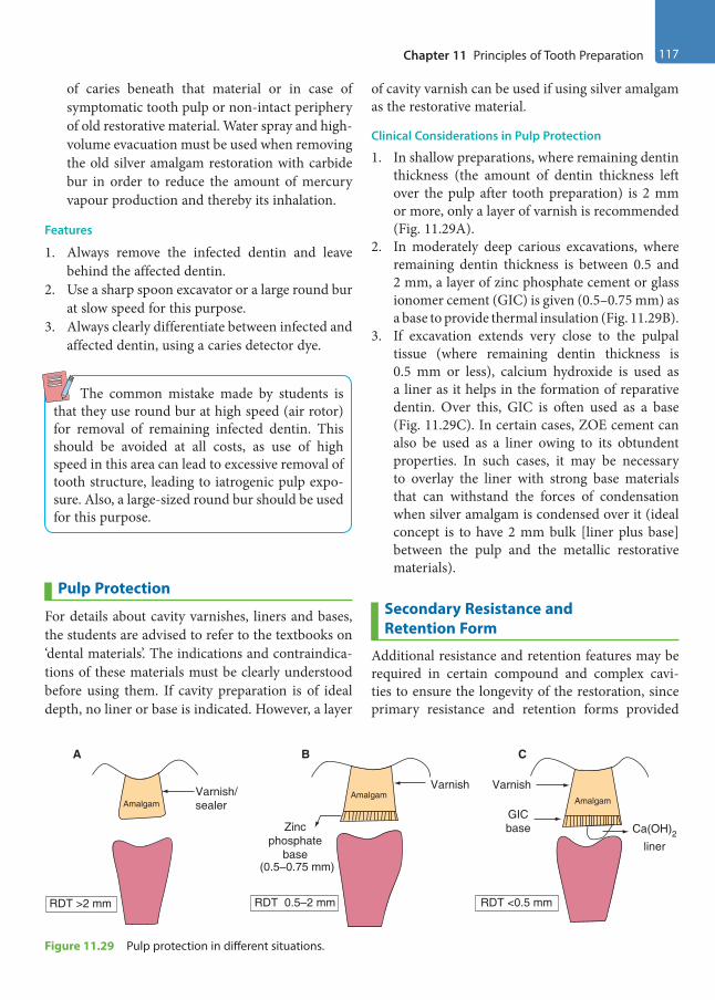
Chapter 11 Principles of Tooth Preparation 117
of caries beneath that material or in case of symptomatic tooth pulp or non-intact periphery of old restorative material. Water spray and high-volume evacuation must be used when removing the old silver amalgam restoration with carbide bur in order to reduce the amount of mercury vapour production and thereby its inhalation.
Features
1. Always remove the infected dentin and leave behind the affected dentin.
2. Use a sharp spoon excavator or a large round bur at slow speed for this purpose.
3. Always clearly differentiate between infected and affected dentin, using a caries detector dye.
The common mistake made by students is that they use round bur at high speed (air rotor) for removal of remaining infected dentin. This should be avoided at all costs, as use of high speed in this area can lead to excessive removal of tooth structure, leading to iatrogenic pulp expo-sure. Also, a large-sized round bur should be used for this purpose.
Pulp Protection
For details about cavity varnishes, liners and bases, the students are advised to refer to the textbooks on ‘dental materials’. The indications and contraindica-tions of these materials must be clearly understood before using them. If cavity preparation is of ideal depth, no liner or base is indicated. However, a layer
of cavity varnish can be used if using silver amalgam as the restorative material.
Clinical Considerations in Pulp Protection
1. In shallow preparations, where remaining dentin thickness (the amount of dentin thickness left over the pulp after tooth preparation) is 2 mm or more, only a layer of varnish is recommended (Fig. 11.29A).
2. In moderately deep carious excavations, where remaining dentin thickness is between 0.5 and 2 mm, a layer of zinc phosphate cement or glass ionomer cement (GIC) is given (0.5–0.75 mm) as a base to provide thermal insulation (Fig. 11.29B).
3. If excavation extends very close to the pulpal tissue (where remaining dentin thickness is 0.5 mm or less), calcium hydroxide is used as a liner as it helps in the formation of reparative dentin. Over this, GIC is often used as a base (Fig. 11.29C). In certain cases, ZOE cement can also be used as a liner owing to its obtundent properties. In such cases, it may be necessary to overlay the liner with strong base materials that can withstand the forces of condensation when silver amalgam is condensed over it (ideal concept is to have 2 mm bulk [liner plus base] between the pulp and the metallic restorative materials).
Secondary Resistance and Retention Form
Additional resistance and retention features may be required in certain compound and complex cavi-ties to ensure the longevity of the restoration, since primary resistance and retention forms provided
RDT >2 mm RDT 0.5–2 mm RDT <0.5 mm
Varnish/sealer
Varnish VarnishAmalgam
Amalgam Amalgam
GICbase Ca(OH)2
liner
Zincphosphate
base(0.5–0.75 mm)
A B C
Figure 11.29 Pulp protection in different situations.
Preclinical Dentistry.indb 117 29-05-2020 12:56:46
https://t.me/DentalBooksWorld

118 Essentials of Preclinical Conservative Dentistry
may not be enough to hold the restorative material in position. These additional features are categorised under this topic.
Features
Secondary resistance and retention features may be subdivided into two types:1. Mechanical features2. Cavity wall conditioning features
Mechanical FeaturesThe mechanical features include those given next.
Retention Locks, Grooves and Coves1. Longitudinally (vertically) oriented retention
locks are given in axiofacial/axiolingual line angles in the proximal box of Class II prepara-tion for silver amalgam (Fig. 11.30).
2. Longitudinally oriented retention grooves are given in the axiofacial/axiolingual line angles in proximal box of Class II preparation for inlay (Fig. 11.31). (Vertically oriented locks are for amalgams and the vertically oriented grooves are for cast metal restoration.)
3. Transverse-oriented retention grooves are given in axio-occlusal/axiogingival line angles in Class V preparation for silver amalgam (Fig. 11.32).
4. Retention coves are given in point angles for Class III amalgam and gold foil restorations (Fig. 11.33).
Figure 11.30 Retention locks in the proximal box of Class II preparation for silver amalgam.
Figure 11.31 Retention grooves in proximal box of Class II preparation for inlay.
Figure 11.32 Transverse-oriented retention grooves in Class V preparation for silver amalgam.
Figure 11.33 Retention cove in point angle for Class III gold foil restorations.
Preclinical Dentistry.indb 118 29-05-2020 12:56:47
https://t.me/DentalBooksWorld

Chapter 11 Principles of Tooth Preparation 119
Groove ExtensionsThese refer to the extensions of the cavity prepara-tion of molars onto the facial or the lingual surface to include facial or lingual groove. These are mostly used for cast restorations (Fig. 11.34).
SkirtsThese refer to the extensions of the cavity prepara-tion around some of the transitional longitudinal angles of the tooth. These are mostly used for cast restorations (Fig. 11.35).
Bevelled Enamel MarginsThese provide a better junctional relationship between the restorative material and the tooth. These are mostly used for cast restorations and composite resin restorations (Fig. 11.36).
Pins, Slots and Amalgam PinsThese provide extra retention in case of large resto-rations and are mostly used for silver amalgam restorations.1. Pins are cemented or threaded into the dentin
and then the restorative material is placed around these. This helps in increasing retention (Fig. 11.37).
2. Slots are channels cut in dentin to provide retention.
Figure 11.34 Groove extension to include the buccal surface groove.
Facial skirtextension
Figure 11.35 When the lingual wall of the proximal box is inadequate or missing, retention form is improved by a facial skirt extension.
Figure 11.36 Bevelled enamel margins.
Figure 11.37 Use of pins to increase the retention form.
Pins
Preclinical Dentistry.indb 119 29-05-2020 12:56:47
https://t.me/DentalBooksWorld

120 Essentials of Preclinical Conservative Dentistry
3. Amalgam pins refer to placement of amalgam in areas deepened, especially at specific sites, to help ensure the retention of silver amalgam. This procedure is usually applied in large resto-rations, wherein cylindrical pits are made in the dentin of the tooth and amalgam is filled in these deep areas along with that in the prepared cavity. These pillars of amalgam, thus formed, help in retention of the bulky restoration and are termed amalgam pins.
Cavity Wall Conditioning FeaturesThese include the enamel and dentin wall conditioning.• Enamel wall conditioning: Refers to acid etching
of enamel by acids, to increase the surface area and thus better retention
• Dentin conditioning: Refers to the use of dentin bonding agents, which on one side bond to tooth dentin and on the other side to the restorative material and thus improve the retention form
Finishing the External Walls
It is the further development, when indicated, of a specific cavosurface design and degree of smooth-ness that produces maximum effectiveness of the restorative material being used.
Principles
1. To establish the best marginal seal between the prepared tooth structure and the restorative material used
2. To provide a smooth marginal junction3. To provide maximum strength at the marginal
junction of the tooth and the restorative material
Features
These may be subdivided into two main categories:1. Cavosurface angle design2. Degree of smoothness of the wall
Design of Cavosurface AngleA cavosurface angle is defined as the angle between the prepared tooth wall and the external wall of the
tooth surface. For silver amalgam, this angle should be 90°, also called butt joint (Fig. 11.38). This results in 80°–90° amalgam at the margins.1. Butt joint of silver amalgam and enamel is
considered to be the strongest. Amalgam is a brittle material with low-edge strength and tends to chip under occlusal stresses if its angle at margins is <80°.
2. For cast metal restorations, a bevel is given at the cavosurface angle to provide a burnishable metal margin and better marginal seal (Fig. 11.39). Bevels are also indicated for composite resin restorations in order to increase the surface area, and thus a better bonding is achieved.
DEJ
Figure 11.38 The 90° cavosurface angle for silver amalgam.
Bevel
Figure 11.39 Bevel at the cavosurface angle for cast metal restorations.
Preclinical Dentistry.indb 120 29-05-2020 12:56:47
https://t.me/DentalBooksWorld

Chapter 11 Principles of Tooth Preparation 121
3. For restorative materials like porcelain, a butt joint is advisable.
4. A strong enamel margin must be provided to the preparation as far as possible. The strongest enamel margin is one that is composed of full-length enamel rods supported on the prepara-tion side by shorter enamel rods, all of which extend to the sound dentin (Fig. 11.40).
Degree of Smoothness of WallUse of high-speed cutting instruments provides a smooth surface, for example, plain-cut fissure burs.1. In areas of improper access, hand instruments
such as enamel hatchets and gingival margin trimmers can be used for planing the walls.
2. For cast restorations, a very smooth preparation wall is desirable to ensure smooth removal of wax pattern, whereas it is not the same for silver amalgam or gold foil restoration, as these have only mechanical bond to the tooth structure.
3. For composite resin restorations, a rough surface provides larger surface area and thus better bonding.
Cleaning, Inspecting and Varnishing
This includes cleaning of cavity, inspecting the tooth preparation and applying varnish when indicated.
Principles
Tooth preparation should be free of debris and visible moisture, but not dehydrated.1. Before inserting the amalgam, two layers of
varnish should be applied with the help of a small cotton pellet or a brush small enough to fit
into the preparation. This reduces microleakage between prepared walls and restoration.
2. Bonding the amalgam with the enamel and the dentin by use of dentin adhesive systems containing 4-META can increase retention and decrease the chances of microleakage.
3. The application of bonding agent is done after acid etching and washing the preparation walls, and then freshly mixed silver amalgam is inserted, resulting in the autopolymerising of the bonding agent, mechanically interlocking with silver amalgam as well as etched prepara-tion surfaces.
Plaster Model Preparations
Figure 11.41A,B represents Class I cavity prepa-rations done on the plaster models of a maxillary premolar and mandibular first molar.
Figure 11.41C represents Class I cavity prepa-ration on a maxillary molar, without involving the oblique ridge.
Figure 11.41D represents Class I cavity prepa-ration on a maxillary molar, involving the oblique ridge.
Figure 11.42A represents Class I with buccal extension made on the plaster model of a mandib-ular molar, while Figure 11.42B represents Class I with palatal extension on the plaster model of a maxillary molar.
Figure 11.43A represents Class II preparation done on the plaster model of a mandibular first molar. Figure 11.43B represents Class II prepara-tion done on the plaster model of a maxillary molar, without involving the oblique ridge.
Figure 11.43C represents Class II preparation done on the plaster model of a maxillary molar, involving the oblique ridge.
Figure 11.44 represents MOD preparation done on the plaster model of a mandibular first molar.
Red marks in the plaster models indicate point angles.
Figure 11.40 Strong enamel margin (arrow).
Preclinical Dentistry.indb 121 29-05-2020 12:56:48
https://t.me/DentalBooksWorld
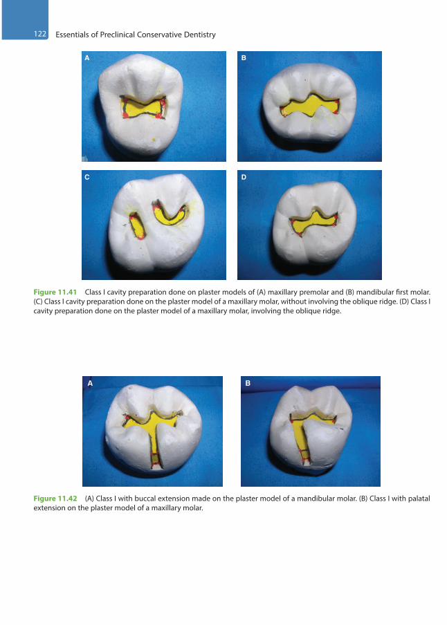
122 Essentials of Preclinical Conservative Dentistry
A B
C D
Figure 11.41 Class I cavity preparation done on plaster models of (A) maxillary premolar and (B) mandibular first molar. (C) Class I cavity preparation done on the plaster model of a maxillary molar, without involving the oblique ridge. (D) Class I cavity preparation done on the plaster model of a maxillary molar, involving the oblique ridge.
A B
Figure 11.42 (A) Class I with buccal extension made on the plaster model of a mandibular molar. (B) Class I with palatal extension on the plaster model of a maxillary molar.
Preclinical Dentistry.indb 122 29-05-2020 12:56:50
https://t.me/DentalBooksWorld

Chapter 11 Principles of Tooth Preparation 123
KEY POINTS
• Tooth preparation is the mechanical alteration of a tooth to receive a restorative material that will return the tooth and the infected area to proper form, function and aesthetics.
• Line angle can be defined as the junction of two planar surfaces while point angle is a junction of three planar surfaces.
• Principles of tooth preparation are as follows: establishing the outline form; establishing the resistance form; establishing the retention form; convenience form; removal of any remaining enamel pit/fissure and/or old restorative material if indicated; pulp protection; secondary resistance and retention form; procedures for finishing external walls; and cleaning, inspecting, varnishing and conditioning of the cavity.
• Establishing the outline form means placing the cavity margins in a position that they will occupy in the final restoration and preparing an initial depth of 0.2–0.8 mm below the DEJ.
A B C
Figure 11.43 (A) Class II preparation done on the plaster model of a mandibular first molar. (B) Class II preparation done on the plaster model of a maxillary molar, without involving the oblique ridge. (C) Class II preparation done on the plaster model of a maxillary molar, involving the oblique ridge.
Figure 11.44 Mesio-occlusodistal preparation done on the plaster model of a mandibular first molar.
Preclinical Dentistry.indb 123 29-05-2020 12:56:52
https://t.me/DentalBooksWorld

124 Essentials of Preclinical Conservative Dentistry
• Primary resistance form is defined as the shape and placement of tooth preparation walls that best enable both the restoration and the tooth to withstand, without fracture, masticatory forces delivered principally along the long axis of the tooth.
• Primary retention form is defined as that shape or form of tooth preparation that resists displacement or removal of the restoration from tipping or lifting forces.
• Convenience form is that form or shape of cavity that provides for adequate observation, accessibility and ease of operation in preparing and restoring the tooth.
• Removal of remaining enamel pit/fissure or the infected dentin/restorative material refers to the elimination of any infected carious tooth structure or faulty restorative material left in the tooth structure after initial tooth preparation.
• Pulp protection refers to the placement of cavity varnish/liner/base, depending on the depth of the prepared cavity.
• Secondary resistance and retention features are incorporated in preparations where it seems that primary resis-tance and retention features would not be sufficient in placing a successful restoration. Retention locks, grooves and coves can be utilised. Enamel and dentin conditioning can also be done.
• Finishing the external walls is the next step, wherein a specific cavosurface design and degree of smoothness is indicated that produces maximum effectiveness of the restorative material being used.
• The final procedure of inspecting and varnishing includes cleaning of cavity, inspecting the tooth preparation and applying varnish when indicated.
• These general guidelines help the operator to ensure adequate preparation of the tooth structure so that it can best retain the restorative material being used. Not all the principles would be applicable in every case, as their requirement is based on the extent of dental caries, the surface of tooth involved, the type of restorative material being used, etc. Nevertheless, these principles when taken into consideration during the procedure guide the operator to achieve optimal results.
SELF-ASSESSMENT QUESTIONS
1. Define tooth preparation.
2. What do you understand by line angle and point angle?
3. Enumerate the principles of tooth preparation.
4. Define outline form and discuss its features.
5. Define primary resistance form and discuss its features.
6. Define primary retention form and discuss its features.
7. What do you understand by convenience form?
8. What are the factors to be taken into consideration while removing the remaining enamel pit/fissure/infected dentin/old restorative material?
9. Discuss the pulp protection measures utilised in deep carious lesions.
10. How do you provide secondary resistance and retention form whenever required?
11. What do you understand by locks, grooves, slots and coves?
12. What do you understand by finishing the external walls?
13. Discuss in detail the final procedure of inspecting and varnishing.
Preclinical Dentistry.indb 124 29-05-2020 12:56:52
https://t.me/DentalBooksWorld
Silver amalgam restorations can be done in Class I, II, III, V and VI cases. Class I restorations are the restorations on the occlusal surface of premolars and molars, on the occlusal two-thirds of the facial and lingual surfaces of molars, and on the lingual surfaces of maxillary incisors. Class II restorations are the restorations on the proximal surfaces of the posterior teeth. Class III restorations are the restorations on the proximal surfaces of anterior teeth that do not involve the incisal angle. Class V restorations are present on the gingival one-third of the facial and lingual surfaces of all teeth. Class VI restorations are the restorations on the incisal edge of the anterior teeth or the cusp-tip regions of the posterior teeth.
Tooth Preparation for Class I Silver Amalgam Restorations
The shape/outline form of the preparation is guided by the position of the fissures on the tooth surface.1. In maxillary premolars, the outline form is
‘butterfly’ shaped.2. In maxillary molars, there are two preparations:
‘C’ shaped and ‘I’ shaped, if the two fissures are not joined; but if joined, it becomes ‘H’ shaped.
3. In mandibular premolars, it is usually ‘U’ shaped or ‘Y’ shaped, but again conforms to the fissure position, owing to the wide variety of fissure positions in these teeth.
4. In mandibular first molars, it is ‘key’ shaped, owing to five cusps and the corresponding fissure position.
5. In mandibular second molars, it is ‘plus’ shaped, as four cusps are present in these teeth.
Class I preparations, though considered to be the simplest of all the other types, need to be mastered
thoroughly as these form the basis of all other more difficult preparations that one has to perform.
Preparation on the Plaster ModelClass I preparation on a maxillary premolar is shown in Figure 12.1A–E. The plaster model is made cautiously, ensuring that no voids are present on the model (Fig. 12.1A). It is advisable that the student should draw the outline form with a pencil and get it approved by the teacher to avoid any errors (Fig. 12.1B). The dimensions of the preparation on the plaster model are kept up to three times than those on the natural tooth, for example, the depth of the preparation here would be 4.5 mm instead of 1.5 mm. This is in accordance with the fact that the plaster model dimensions are roughly three times larger than those of the natural tooth. The discoid end of the Le Cron carver is used to make the initial ditch (Fig. 12.1C,D). Straight chisel is then used to complete the preparation (Fig. 12.1E). The depth can be evaluated by using the William’s (calibrated) probe (Fig. 12.1F).
Preparation for Maxillary Premolars1. Patient and operator position
(a) Since it is a maxillary tooth, the entire proce-dure should preferably be done in indirect vision.
(b) The patient/mannequin should be placed in a semireclined position (30°–40°) and the operator should be in the 10-o’clock or the 11-o’clock position.
(c) The mouth mirror should be in the operator’s left hand for indirect vision and the fingers of the same hand should be used to retract the cheek of the patient. The left hand of the oper-ator should go from behind/above the patient’s head.
Tooth Preparation for Silver Amalgam Restoration12
Chapter
This chapter is a joint contribution by the author and Dr Darshan Dakshindas.
Preclinical Dentistry.indb 125 29-05-2020 12:56:52
https://t.me/DentalBooksWorld
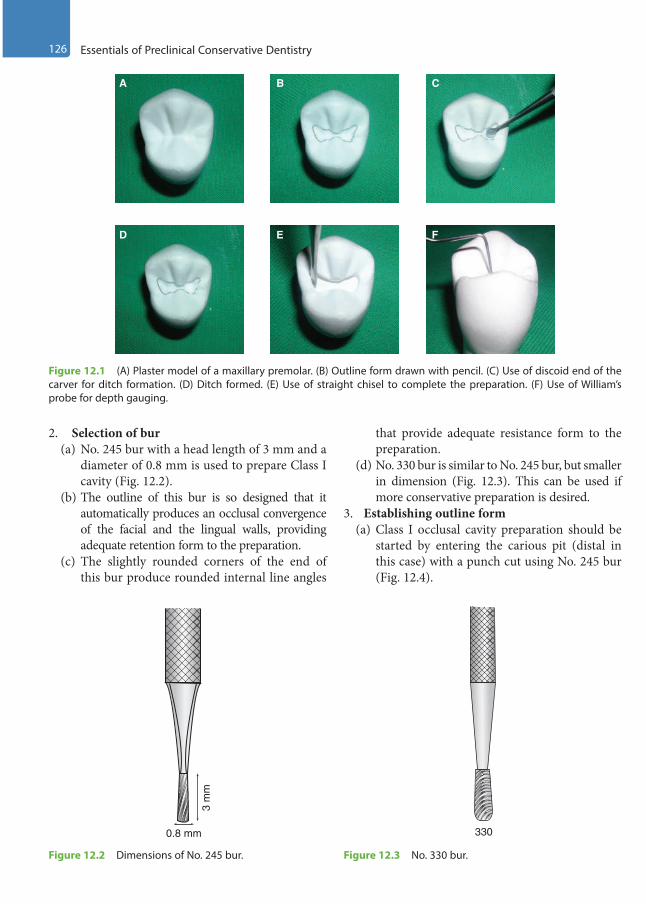
126 Essentials of Preclinical Conservative Dentistry
2. Selection of bur(a) No. 245 bur with a head length of 3 mm and a
diameter of 0.8 mm is used to prepare Class I cavity (Fig. 12.2).
(b) The outline of this bur is so designed that it automatically produces an occlusal convergence of the facial and the lingual walls, providing adequate retention form to the preparation.
(c) The slightly rounded corners of the end of this bur produce rounded internal line angles
that provide adequate resistance form to the preparation.
(d) No. 330 bur is similar to No. 245 bur, but smaller in dimension (Fig. 12.3). This can be used if more conservative preparation is desired.
3. Establishing outline form(a) Class I occlusal cavity preparation should be
started by entering the carious pit (distal in this case) with a punch cut using No. 245 bur (Fig. 12.4).
A B C
D E F
Figure 12.1 (A) Plaster model of a maxillary premolar. (B) Outline form drawn with pencil. (C) Use of discoid end of the carver for ditch formation. (D) Ditch formed. (E) Use of straight chisel to complete the preparation. (F) Use of William’s probe for depth gauging.
0.8 mm
3 m
m
Figure 12.2 Dimensions of No. 245 bur.
330
Figure 12.3 No. 330 bur.
Preclinical Dentistry.indb 126 29-05-2020 12:56:55
https://t.me/DentalBooksWorld
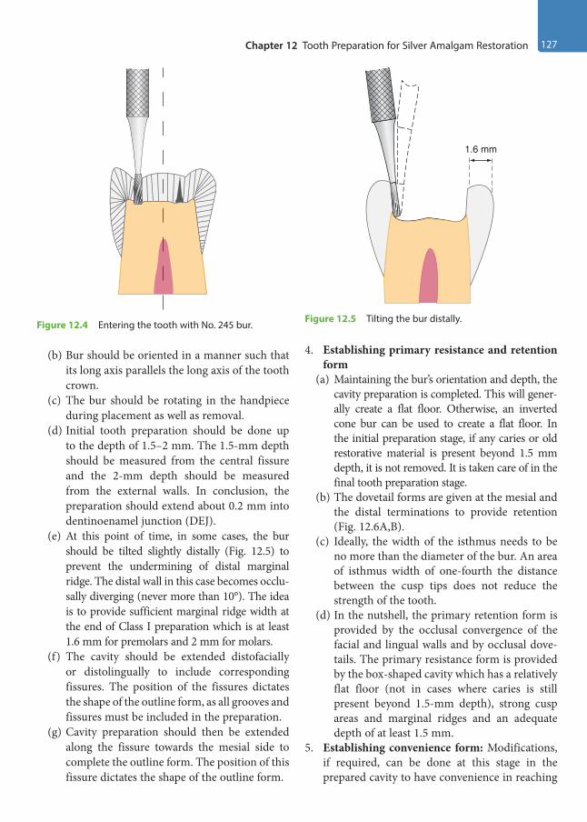
Chapter 12 Tooth Preparation for Silver Amalgam Restoration 127
(b) Bur should be oriented in a manner such that its long axis parallels the long axis of the tooth crown.
(c) The bur should be rotating in the handpiece during placement as well as removal.
(d) Initial tooth preparation should be done up to the depth of 1.5–2 mm. The 1.5-mm depth should be measured from the central fissure and the 2-mm depth should be measured from the external walls. In conclusion, the preparation should extend about 0.2 mm into dentinoenamel junction (DEJ).
(e) At this point of time, in some cases, the bur should be tilted slightly distally (Fig. 12.5) to prevent the undermining of distal marginal ridge. The distal wall in this case becomes occlu-sally diverging (never more than 10°). The idea is to provide sufficient marginal ridge width at the end of Class I preparation which is at least 1.6 mm for premolars and 2 mm for molars.
(f) The cavity should be extended distofacially or distolingually to include corresponding fissures. The position of the fissures dictates the shape of the outline form, as all grooves and fissures must be included in the preparation.
(g) Cavity preparation should then be extended along the fissure towards the mesial side to complete the outline form. The position of this fissure dictates the shape of the outline form.
4. Establishing primary resistance and retention form
(a) Maintaining the bur’s orientation and depth, the cavity preparation is completed. This will gener-ally create a flat floor. Otherwise, an inverted cone bur can be used to create a flat floor. In the initial preparation stage, if any caries or old restorative material is present beyond 1.5 mm depth, it is not removed. It is taken care of in the final tooth preparation stage.
(b) The dovetail forms are given at the mesial and the distal terminations to provide retention (Fig. 12.6A,B).
(c) Ideally, the width of the isthmus needs to be no more than the diameter of the bur. An area of isthmus width of one-fourth the distance between the cusp tips does not reduce the strength of the tooth.
(d) In the nutshell, the primary retention form is provided by the occlusal convergence of the facial and lingual walls and by occlusal dove-tails. The primary resistance form is provided by the box-shaped cavity which has a relatively flat floor (not in cases where caries is still present beyond 1.5-mm depth), strong cusp areas and marginal ridges and an adequate depth of at least 1.5 mm.
5. Establishing convenience form: Modifications, if required, can be done at this stage in the prepared cavity to have convenience in reaching
1.6 mm
Figure 12.5 Tilting the bur distally.Figure 12.4 Entering the tooth with No. 245 bur.
Preclinical Dentistry.indb 127 29-05-2020 12:56:55
https://t.me/DentalBooksWorld

128 Essentials of Preclinical Conservative Dentistry
areas on the pulpal floor, especially in the line angle areas, for removal of any remaining caries. This is usually done either by widening of the cavity or by slight diverging one of the walls of the cavity, which will facilitate access to the carious area (Fig. 12.6A,B).
6. Removal of the remaining enamel pit/fissure or the infected dentin: After achieving adequate access to the carious area, it is now easy to remove the remaining caries, if present. This is usually done by using a sharp spoon excavator or large round bur at slow speed. Adequate use of caries detector dyes is recommended at this stage.
7. Pulp protection: This procedure is completed thereafter as per guidelines described in Chapter 11, Principles of Tooth Preparation. The pulpal floor after base application should become flat so that it can provide adequate resistance form.
8. Secondary resistance and retention forms: Additional resistance and retention features may be required in certain compound and complex cavities to ensure the longevity of the restoration, since the primary resistance and retention forms provided may not be enough to hold the restor-ative material in position. Locks can be given at certain line angles, if required (in case cavity does not have sufficient primary resistance and retention form).
9. Finishing the external walls: For silver amalgam, cavosurface angle is kept 90°, also called butt
joint (refer to Fig. 11.38). This results in 90° amalgam at the margins. Butt joint is considered as the strongest joint for silver amalgam, since it is a brittle material otherwise (Chapter 11, Principles of Tooth Preparation).
10. Final procedure—inspecting and varnishing: After the entire preparation, the cavity is eval-uated visibly so as to make sure that no debris is present. Use of varnish or bonding systems can be considered if so desired (Chapter 11, Principles of Tooth Preparation).
At the end of initial tooth preparation, there should be no sharp areas in the preparation. All line angles and point angles should be rounded and the outline form should be in the form of sweeping curves.
Figure 12.7A–D represents step-by-step procedure of performing a Class I tooth preparation on a maxil-lary first premolar. Figure 12.7A depicts the maxillary first premolar typodont tooth, the bur entry into which has been made parallel to the long axis of the tooth (Fig. 12.7B). The bur may be tilted in order to make the buccal and palatal walls converging towards the occlusal surface in order to achieve primary retention form (Fig. 12.7C). The completed tooth preparation is shown in Figure 12.7D.
The key points of Class I preparation are summarised in Table 12.1.
Figure 12.6 (A) Finished preparation of a maxillary premolar on the plaster model showing occlusal dovetail. (B) Finished preparation of a maxillary premolar (diagrammatic representation).
A B
Preclinical Dentistry.indb 128 29-05-2020 12:56:56
https://t.me/DentalBooksWorld
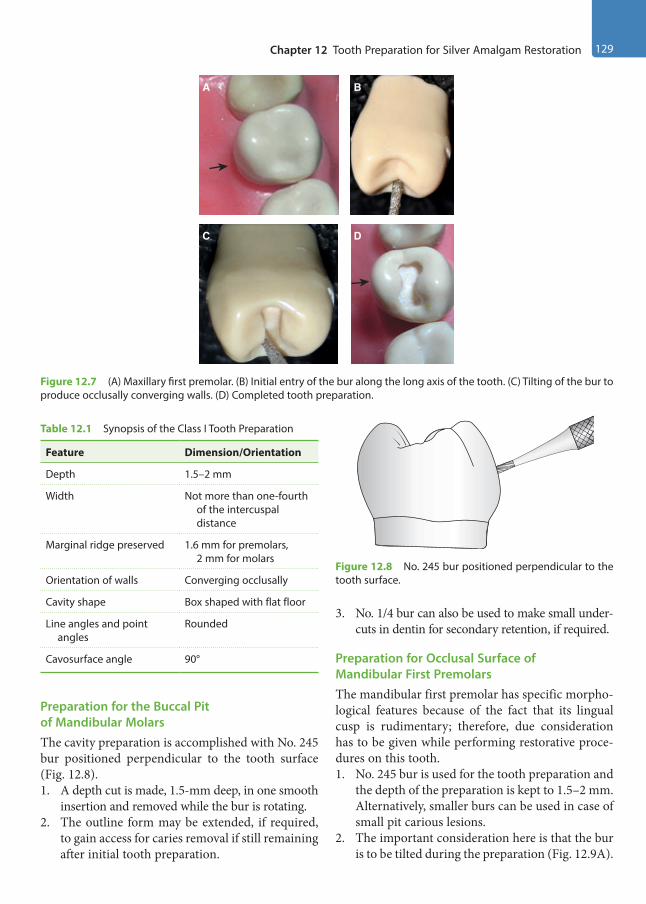
Chapter 12 Tooth Preparation for Silver Amalgam Restoration 129
Preparation for the Buccal Pit of Mandibular MolarsThe cavity preparation is accomplished with No. 245 bur positioned perpendicular to the tooth surface (Fig. 12.8).1. A depth cut is made, 1.5-mm deep, in one smooth
insertion and removed while the bur is rotating.2. The outline form may be extended, if required,
to gain access for caries removal if still remaining after initial tooth preparation.
3. No. 1/4 bur can also be used to make small under-cuts in dentin for secondary retention, if required.
Preparation for Occlusal Surface of Mandibular First PremolarsThe mandibular first premolar has specific morpho-logical features because of the fact that its lingual cusp is rudimentary; therefore, due consideration has to be given while performing restorative proce-dures on this tooth.1. No. 245 bur is used for the tooth preparation and
the depth of the preparation is kept to 1.5–2 mm. Alternatively, smaller burs can be used in case of small pit carious lesions.
2. The important consideration here is that the bur is to be tilted during the preparation (Fig. 12.9A).
Figure 12.7 (A) Maxillary first premolar. (B) Initial entry of the bur along the long axis of the tooth. (C) Tilting of the bur to produce occlusally converging walls. (D) Completed tooth preparation.
A B
C D
Table 12.1 Synopsis of the Class I Tooth Preparation
Feature Dimension/Orientation
Depth 1.5–2 mm
Width Not more than one-fourth of the intercuspal distance
Marginal ridge preserved 1.6 mm for premolars, 2 mm for molars
Orientation of walls Converging occlusally
Cavity shape Box shaped with flat floor
Line angles and point angles
Rounded
Cavosurface angle 90°
Figure 12.8 No. 245 bur positioned perpendicular to the tooth surface.
Preclinical Dentistry.indb 129 29-05-2020 12:56:57
https://t.me/DentalBooksWorld
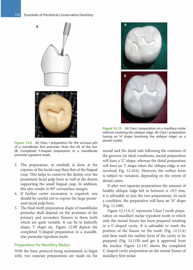
130 Essentials of Preclinical Conservative Dentistry
3. The preparation, in nutshell, is done at the expense of the facial cusp than that of the lingual cusp. This helps to conserve the dentin over the prominent facial pulp horn as well as the dentin supporting the small lingual cusp. In addition, this also results in 90° cavosurface margin.
4. If further caries excavation is required, one should be careful not to expose the large promi-nent facial pulp horn.
5. The final tooth preparation shape of mandibular premolar shall depend on the positions of the primary and secondary fissures in these teeth which are quite variable. It can be in butterfly shape, Y shape etc. Figure 12.9B depicts the completed Y-shaped preparation in a mandib-ular premolar typodont tooth.
Preparation for Maxillary MolarsWith the basic protocol being maintained, to begin with, two separate preparations are made on the
mesial and the distal side following the contours of the grooves (in ideal conditions, mesial preparation will have a ‘C’ shape, whereas the distal preparation will have an ‘I’ shape when the oblique ridge is not involved; Fig. 12.10A). However, the outline form is subject to variation, depending on the extent of dental caries.
If after two separate preparations the amount of healthy oblique ridge left in between is <0.5 mm, it is advisable to join the two preparations. In such a condition, the preparation will have an ‘H’ shape (Fig. 12.10B).
Figure 12.11A–C represents Class I tooth prepa-ration on maxillary molar typodont tooth in which only the mesial fissure has been prepared resulting in a C-shaped cavity. It is advisable to mark the position of the fissure on the tooth (Fig. 12.11A) and then mark the outline form of the cavity to be prepared (Fig. 12.11B) and get it approved from the teacher. Figure 12.11C shows the completed C-shaped cavity preparation on the mesial fissure of maxillary first molar.
A
B
Figure 12.9 (A) Class I preparation for the occlusal pits of a mandibular first premolar. Note the tilt of the bur. (B) Completed Y-shaped preparation in a mandibular premolar typodont tooth.
Figure 12.10 (A) Class I preparation on a maxillary molar without involving the oblique ridge. (B) Class I preparation having an ‘H’ shape (involving the oblique ridge) on a plaster model.
B
A
Preclinical Dentistry.indb 130 29-05-2020 12:56:57
https://t.me/DentalBooksWorld
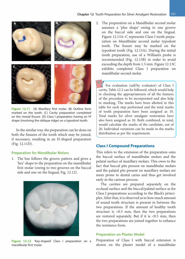
Chapter 12 Tooth Preparation for Silver Amalgam Restoration 131
In the similar way, the preparation can be done on both the fissures of the tooth which may be joined, if necessary, resulting in an H-shaped preparation (Fig. 12.11D).
Preparation for Mandibular Molars1. The bur follows the groove pattern and gives a
‘key’ shape to the preparation on the mandibular first molar (owing to two grooves on the buccal side and one on the lingual; Fig. 12.12).
2. The preparation on a Mandibular second molar assumes a ‘plus shape’ owing to one groove on the buccal side and one on the lingual. Figure 12.13A–C represents Class I tooth prepa-ration on Mandibular second molar typodont tooth. The fissure may be marked on the typodont tooth (Fig. 12.13A). During the initial tooth preparation, use of a William’s probe is recommended (Fig. 12.13B) in order to avoid exceeding the depth from 1.5 mm. Figure 12.13C exhibits completed Class I preparation on mandibular second molar.
For evaluation (self/by evaluator) of Class I cavity, Table 12.2 can be followed, which would help in checking the appropriateness of all the features of the procedure to be incorporated and also help in marking. The marks have been allotted in this table for each step performed and the total marks of tooth preparation have been assigned as 10. Total marks for silver amalgam restoration have also been assigned as 10. Both combined, in total, would calculate the marks of the candidate, out of 20. Individual variations can be made in the marks distribution as per the requirement.
Class I Compound PreparationsThis refers to the extension of the preparation onto the buccal surface of mandibular molars and the palatal surface of maxillary molars. This owes to the fact that buccal pits present on mandibular molars and the palatal pits present on maxillary molars are more prone to dental caries and thus get involved early in the carious process.
The cavities are prepared separately on the occlusal surface and the buccal/palatal surface as for Class I preparations according to the Black’s princi-ples. After that, it is observed as to how much amount of sound tooth structure is present in between the two preparations. If the amount of healthy tooth structure is >0.5 mm, then the two preparations are restored separately. But if it is <0.5 mm, then the two preparations are joined together to enhance the resistance form.
Preparation on Plaster ModelPreparation of Class I with buccal extension is shown on the plaster model of a mandibular
Figure 12.11 (A) Maxillary first molar. (B) Outline form marked on the tooth. (C) Cavity preparation completed on the mesial fissure. (D) Class I preparation having an ‘H’ shape (involving the oblique ridge) on a typodont tooth.
A B
C D
Figure 12.12 ‘Key-shaped’ Class I preparation on a mandibular first molar.
Preclinical Dentistry.indb 131 29-05-2020 12:56:58
https://t.me/DentalBooksWorld

132 Essentials of Preclinical Conservative Dentistry
molar in Figure 12.14A–G. Plaster model is made cautiously, ensuring that no voids are present on the model (Fig. 12.14A). It is advisable that the student should draw the outline form with a pencil and get it approved by the teacher (Fig. 12.14B). Occlusal
preparation is finished first (Fig. 12.14C) using the discoid end of the carver for initial ditch and then straight chisel for the remaining preparation. The chisel is then kept perpendicular to the tooth and the buccal extension preparation is started
Figure 12.13 (A) Mandibular second molar. (B) Use of William’s probe to measure the initial depth of the cavity. (C) Completed Class I tooth preparation (plus-shaped).
A B C
Table 12.2 Evaluation of the Class I Cavity
Feature Proper Status Remarks Marks
Cavity preparation outline form Smooth sweeping curves Includes all pits and fissures
/1
Buccolingual extension One-fourth of the intercuspal distance and centralisedMinimal mesiodistal width and centralised
/2
Mesiodistal extension Extended sufficiently to the corresponding fossa /1
Depth of pulpal floorSurface of the floor
1.5–2 mmSmooth, flat
/2
Direction of buccal and lingual walls Parallel to the corresponding external surfaces, i.e. slightly converge pulpo-occlusally
/1
Direction of mesial and distal walls Parallel to the corresponding external surfaces, i.e. slightly diverge pulpo-occlusally
/1
Cavity refinement Well-defined walls, line angles and point angles /2
Cavity preparation Signature /10
Amalgam surface quality Smooth Dense, no porosity
/2
Margins Undetectable to sharp explorer No excess alloy No deficient alloy (ditch)
/3
Occlusal anatomy Ridges, fossae and grooves in harmony with the tooth structure
No overcarving No undercarving
/5
Amalgam Signature /10
Total procedure Signature /20
Preclinical Dentistry.indb 132 29-05-2020 12:56:59
https://t.me/DentalBooksWorld

Chapter 12 Tooth Preparation for Silver Amalgam Restoration 133
(Fig. 12.14D). The finished preparation is shown in Figure 12.14E. The pulpal floor (Fig. 12.14F) and the axial wall (Fig. 12.14G) can be easily identified now.
Preparation of Maxillary Molar with Palatal ExtensionThe basic features of tooth preparation remain the same; however, the additional features to be taken into consideration are as follows:1. The ideal width of cavity preparation is 1.5 mm.2. The preparation is not extended unnecessarily
onto the marginal ridge side; it may be done at the expense of the oblique ridge, if so required.
3. No. 245 bur is used to enter the distal pit.
4. Cutting is done more towards the mesial part of the pit than its distal part (in proportion of 70/30) to a depth of 1.5–2 mm.
5. Once this is done, the bur is moved along the fissure towards the palatal surface, maintaining the same depth (Fig. 12.15).
6. While doing this, the long axis of the bur is kept parallel to the palatal surface and the tip of the bur is located at the gingival extent of the palatal fissure.
7. The axial wall of this preparation on the palatal surface should follow the contour of the palatal surface of the tooth and the depth of this prepa-ration should be 1.5 mm ideally (Fig. 12.16).
A DB C
E GF
Figure 12.14 (A) Plaster model of a mandibular molar. (B) Outline form drawn with pencil. (C) Preparation done on the occlusal surface. (D) Chisel held perpendicular to the tooth surface for buccal preparation. (E) Preparation completed. (F) Probe indicating the pulpal floor. (G) Probe indicating the axial wall.
Figure 12.15 Palatal extension preparation of a maxillary molar. Initially, the bur is held parallel to the long axis of the tooth (A) and later, the bur is held perpendicular to the palatal surface (B).
A B
Preclinical Dentistry.indb 133 29-05-2020 12:57:02
https://t.me/DentalBooksWorld

134 Essentials of Preclinical Conservative Dentistry
8. Now, the bur is oriented with its long axis perpendicular to the axial wall to accentuate the mesioaxial and the distoaxial line angles. Axiopulpal line angle is rounded off to avoid stress concentration in this area after the restoration.
9. The preparation is now ready to receive the restoration (Figs 12.17–12.19).
10. If additional retention is required (as in the case of large carious destruction), No. 1/4 bur is used to prepare locks into the mesioaxial and the distoaxial line angles.
Preparation of Mandibular Molar with Buccal Extension1. The preparation is extended through the buccal
ridge onto the buccal surface, following the contour of the tooth, as explained for maxillary molar’s palatal extension (Fig. 12.20).
2. The bur is then held perpendicular to the buccal surface for finishing the preparation.
3. If required, retention locks can be given with No. 1/4 round bur.
Two extensions can be made if both the buccal grooves are carious in a mandibular first molar (Fig. 12.21A); otherwise, in most instances, one extension is made (Fig. 12.21B). Figure 12.22A represents unprepared mandibular molar typodont tooth, while completed Class I preparation with buccal extension is seen in Figure 12.22B.
For evaluation of Class I cavity with buccal/ palatal extension, refer Table 12.3.
Technique for Class II Tooth Preparation
Class II restorations are the restorations on the prox-imal surfaces of the posterior teeth.
MO Preparation of a Maxillary PremolarThe mesio-occlusal (MO) preparation is usually the first class II exercise given to the students for
Figure 12.16 Schematic representation of the preparation technique.
Figure 12.17 Finished preparation.
Figure 12.18 Finished preparation of an extracted natural human tooth.
Figure 12.19 Finished preparation of the plaster model.
Preclinical Dentistry.indb 134 29-05-2020 12:57:03
https://t.me/DentalBooksWorld
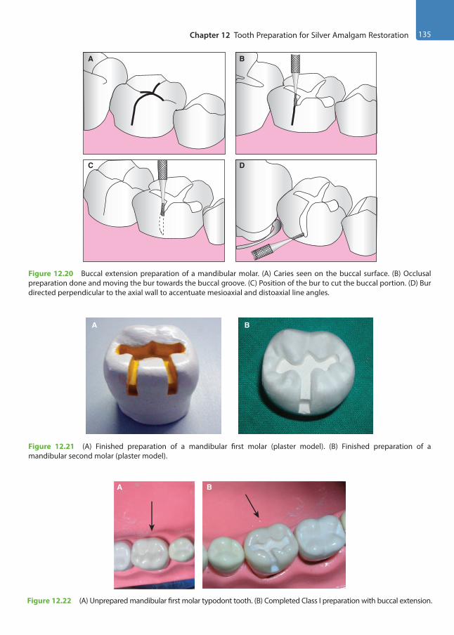
Chapter 12 Tooth Preparation for Silver Amalgam Restoration 135
Figure 12.20 Buccal extension preparation of a mandibular molar. (A) Caries seen on the buccal surface. (B) Occlusal preparation done and moving the bur towards the buccal groove. (C) Position of the bur to cut the buccal portion. (D) Bur directed perpendicular to the axial wall to accentuate mesioaxial and distoaxial line angles.
BA
DC
Figure 12.21 (A) Finished preparation of a mandibular first molar (plaster model). (B) Finished preparation of a mandibular second molar (plaster model).
A B
Figure 12.22 (A) Unprepared mandibular first molar typodont tooth. (B) Completed Class I preparation with buccal extension.
A B
Preclinical Dentistry.indb 135 29-05-2020 12:57:04
https://t.me/DentalBooksWorld

136 Essentials of Preclinical Conservative Dentistry
learning purpose. Let us understand the step-by-step technique of performing this procedure in an ideal manner.
Establishing Outline FormOutline form for occlusal portion is the same as for Class I.1. No. 245 bur is used to enter the tooth near the
carious proximal surface (mesial in this case). As a general rule, the long axis of the bur is held parallel to the long axis of the tooth (Fig. 12.23).
2. The preparation is now extended along the central fissure towards the distal pit and exten-sions are made to include distofacial and disto-lingual developmental fissures, which provide a dovetail retention form (Fig. 12.24).
At this stage, the preparation is 1.5-mm deep, irrespective of any carious dentin still present. The pulpal floor is made relatively flat.
3. Now, from the mesial side of the preparation, an extension is made towards the marginal ridge. Before extending into the involved proximal marginal ridge, the final location of the facial and the lingual walls of the proximal relative to the contact area is visualised.
4. The preparation is extended mesially, stopping 0.8 mm short of the mesial marginal ridge.
5. With same orientation of the bur, it is posi-tioned on the pulpal floor next to the remaining mesial marginal ridge. The end of the bur is used to cut a ditch gingivally along the exposed DEJ (two-third at the expense of the dentin
Table 12.3 Evaluation of Class I Cavity with Buccal Extension/Class I Cavity with Palatal Extension
Features Proper Status Remarks Marks
Cavity preparation outline form Smooth sweeping curves Includes all pits and fissures
/1
Buccolingual extension One-fourth of the intercuspal distance and centralisedMinimal mesiodistal width and centralised
/2
Mesiodistal extension Extended sufficiently to the corresponding fossa /1
Buccal/palatal cavity extension Mesial and distal walls are parallel Extend to the height of contour and/or till termination of
buccal/palatal groove
/2
Depth of pulpal floor Surface of the floor Gingival floor
1.5–2 mm Smooth, flat Smooth, flat
/2
Direction of buccal and lingual walls Parallel to the corresponding external surfaces, i.e. slightly converge pulpo-occlusally
/1
Direction of mesial and distal walls Parallel to the corresponding external surfaces Slightly diverge pulpo-occlusally
/1
Cavity refinement Well-defined walls, line angles and point angles /2
Cavity preparation Signature /10
Amalgam surface quality Smooth Dense, no porosity
/2
Margins Undetectable to sharp explorer No excess alloy No deficient alloy (ditch)
/3
Occlusal anatomy Ridges, fossae and grooves in harmony with the tooth structure
No overcarving No undercarving
/5
Amalgam Signature /10
Total procedure Signature /20
Preclinical Dentistry.indb 136 29-05-2020 12:57:04
https://t.me/DentalBooksWorld
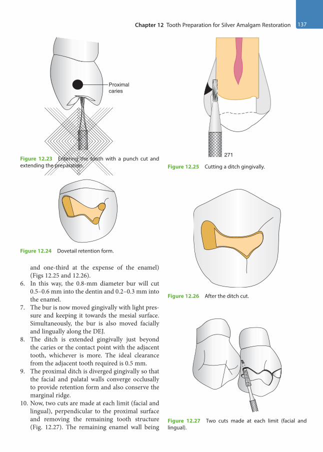
Chapter 12 Tooth Preparation for Silver Amalgam Restoration 137
and one-third at the expense of the enamel) (Figs 12.25 and 12.26).
6. In this way, the 0.8-mm diameter bur will cut 0.5–0.6 mm into the dentin and 0.2–0.3 mm into the enamel.
7. The bur is now moved gingivally with light pres-sure and keeping it towards the mesial surface. Simultaneously, the bur is also moved facially and lingually along the DEJ.
8. The ditch is extended gingivally just beyond the caries or the contact point with the adjacent tooth, whichever is more. The ideal clearance from the adjacent tooth required is 0.5 mm.
9. The proximal ditch is diverged gingivally so that the facial and palatal walls converge occlusally to provide retention form and also conserve the marginal ridge.
10. Now, two cuts are made at each limit (facial and lingual), perpendicular to the proximal surface and removing the remaining tooth structure (Fig. 12.27). The remaining enamel wall being
Figure 12.23 Entering the tooth with a punch cut and extending the preparation.
Proximalcaries
Figure 12.24 Dovetail retention form.
Figure 12.25 Cutting a ditch gingivally.
271
Figure 12.26 After the ditch cut.
Figure 12.27 Two cuts made at each limit (facial and lingual).
Preclinical Dentistry.indb 137 29-05-2020 12:57:04
https://t.me/DentalBooksWorld

138 Essentials of Preclinical Conservative Dentistry
very thin breaks, and if it does not, a spoon exca-vator is used to do so (Fig. 12.28A).
11. The walls of the proximal box can be further planed by using hand-cutting instruments or burs.
12. A matrix band may be placed around the adjacent tooth to protect it from injury during proximal box preparation.
13. Wooden wedge placement to protect the gingiva when extending gingival wall more gingivally is another consideration. Round wedge is recom-mended for shallow and moderate gingival extensions and triangular one for deep gingival extensions.
14. The axial wall shape should follow the contour of the external tooth surface wall at the end of the preparation (Fig. 12.28B), i.e. the shape of the axial wall when viewed from the occlusal surface should be convex. In order to create this shape, a tapered fissure bur can be placed at the axiofacial and axiopalatal line angles and moved occlusally. This will convert the concave axial wall to a convex shape and thus provide the desired retention to the proximal box.
Establishing Primary Resistance and Retention FormBox-shaped cavity, flat floor and preserving the marginal ridge on the unaffected side should be kept in mind as for Class I cavity explained before.1. The dovetail form is given at the termination oppo-
site to that of the proximal box to provide retention.2. The occlusally converging facial and lingual
walls of the occlusal box provide necessary
retention form to the occlusal preparation, while the facial and lingual walls of the proximal box provide necessary retention form to the prox-imal preparation.
3. The occlusal and proximal boxes should have independent retention form whenever possible.
Establishing Convenience FormModifications in the prepared cavity, if required, can be done at this stage to have convenience in reaching areas on the pulpal floor or the gingival floor, especially in the line angle areas, for removal of any remaining caries. This is usually done by either widening of the cavity or slight diverging of the walls of the cavity that will facilitate access to the carious area.
Removal of Remaining Enamel Pit/Fissure or Infected DentinAfter achieving adequate access to the carious area, it is now easy to remove the remaining caries, if any present. This is usually done by using a sharp spoon excavator or large round bur at slow speed.
Pulp ProtectionThis procedure is completed thereafter as per guide-lines already described in Chapter 11, Principles of Tooth Preparation.
In Class II preparations, the base should be applied on the pulpal floor and axial wall only.
Figure 12.28 (A) Spoon excavator being used to break the remaining thin enamel wall (left). After breaking the wall, the proximal box prepared can be seen (right). (B) Axial wall shape following the contour of the external tooth surface wall (dotted red line).
AB
Preclinical Dentistry.indb 138 29-05-2020 12:57:04
https://t.me/DentalBooksWorld
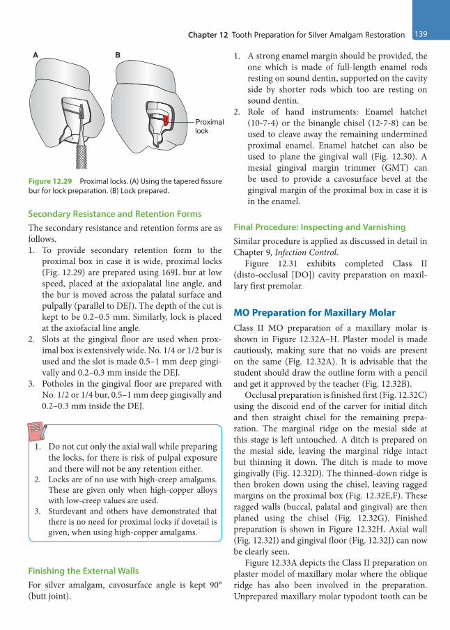
Chapter 12 Tooth Preparation for Silver Amalgam Restoration 139
Secondary Resistance and Retention FormsThe secondary resistance and retention forms are as follows.1. To provide secondary retention form to the
proximal box in case it is wide, proximal locks (Fig. 12.29) are prepared using 169L bur at low speed, placed at the axiopalatal line angle, and the bur is moved across the palatal surface and pulpally (parallel to DEJ). The depth of the cut is kept to be 0.2–0.5 mm. Similarly, lock is placed at the axiofacial line angle.
2. Slots at the gingival floor are used when prox-imal box is extensively wide. No. 1/4 or 1/2 bur is used and the slot is made 0.5–1 mm deep gingi-vally and 0.2–0.3 mm inside the DEJ.
3. Potholes in the gingival floor are prepared with No. 1/2 or 1/4 bur, 0.5–1 mm deep gingivally and 0.2–0.3 mm inside the DEJ.
1. Do not cut only the axial wall while preparing the locks, for there is risk of pulpal exposure and there will not be any retention either.
2. Locks are of no use with high-creep amalgams. These are given only when high-copper alloys with low-creep values are used.
3. Sturdevant and others have demonstrated that there is no need for proximal locks if dovetail is given, when using high-copper amalgams.
Finishing the External WallsFor silver amalgam, cavosurface angle is kept 90° (butt joint).
1. A strong enamel margin should be provided, the one which is made of full-length enamel rods resting on sound dentin, supported on the cavity side by shorter rods which too are resting on sound dentin.
2. Role of hand instruments: Enamel hatchet (10-7-4) or the binangle chisel (12-7-8) can be used to cleave away the remaining undermined proximal enamel. Enamel hatchet can also be used to plane the gingival wall (Fig. 12.30). A mesial gingival margin trimmer (GMT) can be used to provide a cavosurface bevel at the gingival margin of the proximal box in case it is in the enamel.
Final Procedure: Inspecting and VarnishingSimilar procedure is applied as discussed in detail in Chapter 9, Infection Control.
Figure 12.31 exhibits completed Class II (disto-occlusal [DO]) cavity preparation on maxil-lary first premolar.
MO Preparation for Maxillary MolarClass II MO preparation of a maxillary molar is shown in Figure 12.32A–H. Plaster model is made cautiously, making sure that no voids are present on the same (Fig. 12.32A). It is advisable that the student should draw the outline form with a pencil and get it approved by the teacher (Fig. 12.32B).
Occlusal preparation is finished first (Fig. 12.32C) using the discoid end of the carver for initial ditch and then straight chisel for the remaining prepa-ration. The marginal ridge on the mesial side at this stage is left untouched. A ditch is prepared on the mesial side, leaving the marginal ridge intact but thinning it down. The ditch is made to move gingivally (Fig. 12.32D). The thinned-down ridge is then broken down using the chisel, leaving ragged margins on the proximal box (Fig. 12.32E,F). These ragged walls (buccal, palatal and gingival) are then planed using the chisel (Fig. 12.32G). Finished preparation is shown in Figure 12.32H. Axial wall (Fig. 12.32I) and gingival floor (Fig. 12.32J) can now be clearly seen.
Figure 12.33A depicts the Class II preparation on plaster model of maxillary molar where the oblique ridge has also been involved in the preparation. Unprepared maxillary molar typodont tooth can be
Figure 12.29 Proximal locks. (A) Using the tapered fissure bur for lock preparation. (B) Lock prepared.
A B
Proximallock
Preclinical Dentistry.indb 139 29-05-2020 12:57:05
https://t.me/DentalBooksWorld
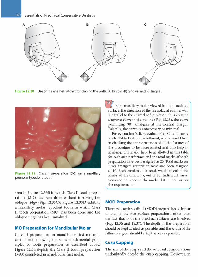
140 Essentials of Preclinical Conservative Dentistry
seen in Figure 12.33B in which Class II tooth prepa-ration (MO) has been done without involving the oblique ridge (Fig. 12.33C). Figure 12.33D exhibits a maxillary molar typodont tooth in which Class II tooth preparation (MO) has been done and the oblique ridge has been involved.
MO Preparation for Mandibular MolarClass II preparation on mandibular first molar is carried out following the same fundamental prin-ciples of tooth preparation as described above. Figure 12.34 depicts the Class II tooth preparation (MO) completed in mandibular first molar.
For a maxillary molar, viewed from the occlusal surface, the direction of the mesiofacial enamel wall is parallel to the enamel rod direction, thus creating a reverse curve in the outline (Fig. 12.35), the curve permitting 90° amalgam at mesiofacial margin. Palatally, the curve is unnecessary or minimal. For evaluation (self/by evaluator) of Class II cavity made, Table 12.4 can be followed, which would help in checking the appropriateness of all the features of the procedure to be incorporated and also help in marking. The marks have been allotted in this table for each step performed and the total marks of tooth preparation have been assigned as 20. Total marks for silver amalgam restoration have also been assigned as 10. Both combined, in total, would calculate the marks of the candidate, out of 30. Individual varia-tions can be made in the marks distribution as per the requirement.
MOD PreparationThe mesio-occluso-distal (MOD) preparation is similar to that of the two surface preparations, other than the fact that both the proximal surfaces are involved (Figs 12.36 and 12.37). The depth of the preparation should be kept as ideal as possible, and the width of the isthmus region should be kept as less as possible.
Cusp CappingThe size of the cusps and the occlusal considerations undoubtedly decide the cusp capping. However, in
Figure 12.30 Use of the enamel hatchet for planing the walls. (A) Buccal, (B) gingival and (C) lingual.
A B C
Figure 12.31 Class II preparation (DO) on a maxillary premolar typodont tooth.
Preclinical Dentistry.indb 140 29-05-2020 12:57:05
https://t.me/DentalBooksWorld

Chapter 12 Tooth Preparation for Silver Amalgam Restoration 141
Figure 12.32 (A) Plaster model of a maxillary molar. (B) Outline form drawn with pencil. (C) Preparation done on the occlusal surface, leaving the marginal ridge intact. (D) Ditch prepared in the marginal ridge area, moving gingivally. (E) Undermined ridge removed using chisel, leaving ragged margins. (F) Ragged walls, as seen from the proximal side. (G) Planing the ragged walls using chisel. (H) Finished preparation. (I) Axial wall of the proximal box. (J) Gingival floor of the proximal box.
A B C D
E F G
I J
H
Figure 12.33 (A) Class II preparation of a maxillary molar on the plaster model. (B) Unprepared maxillary molar typodont tooth. (C) Completed Class II preparation (MO) on a maxillary molar. (D) Completed Class II preparation (DO) on a maxillary molar, involving the oblique ridge.
A C DB
Preclinical Dentistry.indb 141 29-05-2020 12:57:10
https://t.me/DentalBooksWorld

142 Essentials of Preclinical Conservative Dentistry
general, the rule that is followed for cusp capping is as follows:1. If the outline form has extended half the distance
from the primary groove to a cusp tip, cusp capping has to be considered, but if the exten-sion is two-third or more, the cusp capping is mandatory.
2. Reduction is done in the initial stages of tooth preparation because it becomes a part of the convenience form.
3. Depth gauge cuts are made at a depth of 2 mm for functional cusps, and 1.5 mm for non-func-tional cusps, using the side of a carbide fissure bur (Fig. 12.38).
4. The flattening is then done, moving the bur side-ways (Fig. 12.39).
5. Any sharp corners, if present, should be rounded to improve the resistance form.
6. Since cusp reduction decreases the retention form, additional features such as slots and potholes can be given.
7. Pins can also be used to increase the retention form when cusp capping is performed.
8. The tooth is then restored after placing matrix band and retainer (Fig. 12.40).
Figure 12.34 Class II preparation on a mandibular molar on the typodont tooth.
Figure 12.35 Reverse curve in a maxillary molar.
90°
Figure 12.36 MOD preparation of a mandibular second premolar. (A) Occlusal view. (B) Proximal view.
A B
Figure 12.37 (A) MOD preparation of a maxillary first molar on a typodont tooth. (B) Schematic representation.
A
B
Preclinical Dentistry.indb 142 29-05-2020 12:57:10
https://t.me/DentalBooksWorld

Chapter 12 Tooth Preparation for Silver Amalgam Restoration 143
Preparation for Class III Amalgam
Class III preparations for silver amalgam are very technique sensitive, owing to the difficult access to the involved proximal surface. Therefore, these preparations must be done very carefully.
Preparation on Plaster ModelClass III preparation on a maxillary central incisor is shown in Figure 12.41A–E. Plaster model is made cautiously, ensuring that no voids are present on the model (Fig. 12.41A). It is advisable that the student
Table 12.4 Evaluation of Class II Cavity
Features Status Remarks Marks
Cavity preparation outline form Smooth sweeping curves Include all pits and fissures
/2
Buccolingual extension One-fourth of the intercuspal distance and centralisedMinimal mesiodistal width and centralised
/2
Proximal box Free of contact and 90° with imaginary tangent /2
Gingival floor Smooth and flat Extended 0.5 mm below the contact point with the
adjacent tooth
/2
Depth of pulpal floorSurface
1.5–2 mmSmooth and flat
/2
Axial wall Follows the contour of the external wall Depth 1.25–1.75 mm
/2
Direction of walls in:• Occlusal portion• Isthmus portion• Proximal portion
Buccal and lingual walls are:• Parallel to the corresponding external surfaces• Parallel to the corresponding external surfaces• Parallel to the corresponding external surfaces
/2/2/2
Cavity refinement and adjacent teeth preservation
Well-defined walls, line angles and point angles Rounded axiopulpal line angleAdjacent teeth preserved intactAdjacent soft tissues remain intact
/2
Cavity Preparation Signature /20
Amalgam surface quality Smooth Dense, no porosity
/2
Margins Undetectable to sharp explorer No excess alloy No deficient alloy (ditch)
/2
Occlusal anatomy Ridges, fossae and grooves in harmony with tooth structure No overcarving No undercarving
/2
Proximal contact Visually closed and smooth to floss /2
Embrasures Symmetrical to adjacent tooth Neither too open nor too closed
/2
Amalgam Signature /10
Evaluator Signature /30
Preclinical Dentistry.indb 143 29-05-2020 12:57:11
https://t.me/DentalBooksWorld
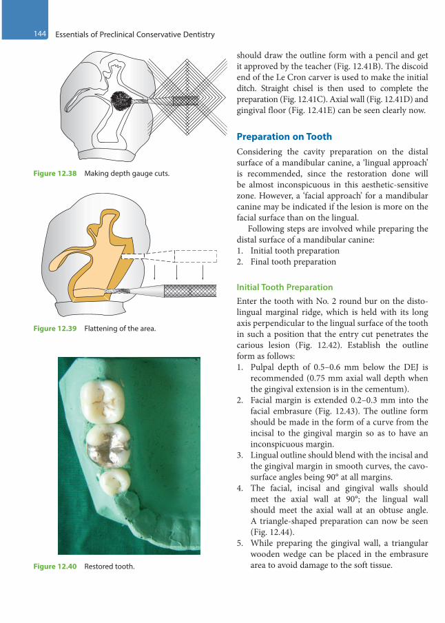
144 Essentials of Preclinical Conservative Dentistry
should draw the outline form with a pencil and get it approved by the teacher (Fig. 12.41B). The discoid end of the Le Cron carver is used to make the initial ditch. Straight chisel is then used to complete the preparation (Fig. 12.41C). Axial wall (Fig. 12.41D) and gingival floor (Fig. 12.41E) can be seen clearly now.
Preparation on ToothConsidering the cavity preparation on the distal surface of a mandibular canine, a ‘lingual approach’ is recommended, since the restoration done will be almost inconspicuous in this aesthetic-sensitive zone. However, a ‘facial approach’ for a mandibular canine may be indicated if the lesion is more on the facial surface than on the lingual.
Following steps are involved while preparing the distal surface of a mandibular canine:1. Initial tooth preparation2. Final tooth preparation
Initial Tooth PreparationEnter the tooth with No. 2 round bur on the disto-lingual marginal ridge, which is held with its long axis perpendicular to the lingual surface of the tooth in such a position that the entry cut penetrates the carious lesion (Fig. 12.42). Establish the outline form as follows: 1. Pulpal depth of 0.5–0.6 mm below the DEJ is
recommended (0.75 mm axial wall depth when the gingival extension is in the cementum).
2. Facial margin is extended 0.2–0.3 mm into the facial embrasure (Fig. 12.43). The outline form should be made in the form of a curve from the incisal to the gingival margin so as to have an inconspicuous margin.
3. Lingual outline should blend with the incisal and the gingival margin in smooth curves, the cavo-surface angles being 90° at all margins.
4. The facial, incisal and gingival walls should meet the axial wall at 90°; the lingual wall should meet the axial wall at an obtuse angle. A triangle-shaped preparation can now be seen (Fig. 12.44).
5. While preparing the gingival wall, a triangular wooden wedge can be placed in the embrasure area to avoid damage to the soft tissue.
Figure 12.38 Making depth gauge cuts.
Figure 12.39 Flattening of the area.
Figure 12.40 Restored tooth.
Preclinical Dentistry.indb 144 29-05-2020 12:57:11
https://t.me/DentalBooksWorld

Chapter 12 Tooth Preparation for Silver Amalgam Restoration 145
6. No. 1/2 bur can be used thereafter to accentuate the axial line angles, especially the axiogingival line angle.
7. The axial wall should follow the contour of the external tooth surface.
8. All line angles and point angles should be rounded.
The primary resistance form should be achieved by making a box-shaped cavity, rounded line angles and point angles and sufficient depth of the prepara-tion. The primary retention form should be achieved by providing specific orientation to the facial, incisal and gingival walls. However, secondary retention
Figure 12.41 (A) Plaster model of a maxillary central incisor. (B) Outline form drawn with pencil. (C) Completed Class III preparation. (D) Axial wall. (E) Gingival floor.
A B C
D E
Figure 12.42 Entering the tooth perpendicular to the enamel surface.
Proximalcaries
Figure 12.43 Extending the margins.
Preclinical Dentistry.indb 145 29-05-2020 12:57:14
https://t.me/DentalBooksWorld

146 Essentials of Preclinical Conservative Dentistry
features are usually required in Class III prepara-tions for silver amalgam.
Final Tooth PreparationRemoval of the remaining infected dentin is done at this stage by using a sharp spoon excavator or a large round bur at slow speed. Pulp protection is performed thereafter with appropriate use of varnish/liner/base (refer Chapter 11, Principles of Tooth Preparation).
Secondary retention form can be achieved by the use of the following:1. Gingival retention groove: No. 1/4 bur is kept
at the axiofaciogingival point angle and moved lingually along the axiogingival line angle, cutting mostly gingivally and slightly pulpally. Depth of the groove is kept 0.25 mm (Fig. 12.45).
2. Incisal retention cove: It is given with No. 1/4 bur at the axioincisal point angle in the dentin and it is kept 0.25 mm deep (Fig. 12.46).
3. Modification in the conventional Class III preparation—lingual dovetail: This is reserved for large preparations only and prepared when the proximal box is complete. It is usually not extended beyond the mesiodistal midpoint of the lingual surface, and pulpal depth is about 1 mm. A No. 245 bur is placed perpendicular to the lingual surface and preparation is done by moving the bur up to the final extension limit (Figs 12.47 and 12.48). The bur is then moved incisally and gingivally, and all walls are smoothened and curved (Fig. 12.49). GMT can be used to bevel
Figure 12.44 Final position of the walls. Figure 12.45 Placing the gingival retention groove.
Figure 12.46 Placing the incisal retention cove.
Figure 12.47 Bur placed in position for preparing lingual dovetail.
Preclinical Dentistry.indb 146 29-05-2020 12:57:14
https://t.me/DentalBooksWorld

Chapter 12 Tooth Preparation for Silver Amalgam Restoration 147
the axiopulpal line angle. Retention coves in the incisal and gingival corners can be placed for extra retention (Fig. 12.50). Figures 12.51 and 12.52A depict a finished Class III preparation with lingual dovetail on plaster models. Figure 12.52B represents a finished conventional Class III prepa-ration on a plaster model. Unprepared typodont maxillary central incisor (proximal surface) is shown in Figure 12.52C, while completed Class III preparation in the same tooth can be seen in Figure 12.52D.
To finish the external walls for silver amalgam, the cavosurface angle is kept at 90°, also called butt joint. This will result in 80°–90° amalgam at the margins. Finally, tooth preparation should be free of debris and visible moisture. Before inserting the amalgam, two layers of varnish can be applied with the help of a small cotton pellet or a brush. Alternatively, dentin adhesive systems containing 4-META (4-methacry-loxyethyl trimellitate anhydride) can be used, which can increase the retention and decrease the chances of microleakage.
Figure 12.48 Bur moved mesially.
Figure 12.49 Bur moved gingivally and incisally.
Figure 12.50 Gingival retention cove in the lingual dovetail.
Figure 12.51 Finished Class III preparation with the lingual dovetail on the plaster model (incisal view).
Preclinical Dentistry.indb 147 29-05-2020 12:57:15
https://t.me/DentalBooksWorld
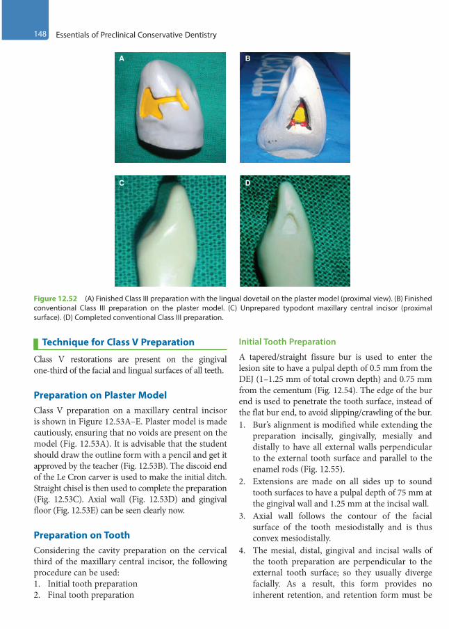
148 Essentials of Preclinical Conservative Dentistry
Technique for Class V Preparation
Class V restorations are present on the gingival one-third of the facial and lingual surfaces of all teeth.
Preparation on Plaster ModelClass V preparation on a maxillary central incisor is shown in Figure 12.53A–E. Plaster model is made cautiously, ensuring that no voids are present on the model (Fig. 12.53A). It is advisable that the student should draw the outline form with a pencil and get it approved by the teacher (Fig. 12.53B). The discoid end of the Le Cron carver is used to make the initial ditch. Straight chisel is then used to complete the preparation (Fig. 12.53C). Axial wall (Fig. 12.53D) and gingival floor (Fig. 12.53E) can be seen clearly now.
Preparation on ToothConsidering the cavity preparation on the cervical third of the maxillary central incisor, the following procedure can be used:1. Initial tooth preparation2. Final tooth preparation
Initial Tooth Preparation
A tapered/straight fissure bur is used to enter the lesion site to have a pulpal depth of 0.5 mm from the DEJ (1–1.25 mm of total crown depth) and 0.75 mm from the cementum (Fig. 12.54). The edge of the bur end is used to penetrate the tooth surface, instead of the flat bur end, to avoid slipping/crawling of the bur.1. Bur’s alignment is modified while extending the
preparation incisally, gingivally, mesially and distally to have all external walls perpendicular to the external tooth surface and parallel to the enamel rods (Fig. 12.55).
2. Extensions are made on all sides up to sound tooth surfaces to have a pulpal depth of 75 mm at the gingival wall and 1.25 mm at the incisal wall.
3. Axial wall follows the contour of the facial surface of the tooth mesiodistally and is thus convex mesiodistally.
4. The mesial, distal, gingival and incisal walls of the tooth preparation are perpendicular to the external tooth surface; so they usually diverge facially. As a result, this form provides no inherent retention, and retention form must be
Figure 12.52 (A) Finished Class III preparation with the lingual dovetail on the plaster model (proximal view). (B) Finished conventional Class III preparation on the plaster model. (C) Unprepared typodont maxillary central incisor (proximal surface). (D) Completed conventional Class III preparation.
A B
C D
Preclinical Dentistry.indb 148 29-05-2020 12:57:16
https://t.me/DentalBooksWorld

Chapter 12 Tooth Preparation for Silver Amalgam Restoration 149
provided because the primary retention form for an amalgam restoration is mechanical.
Final Tooth PreparationRemoval of the remaining infected dentin is done using a sharp spoon excavator or large round bur at slow speed. Pulp protection is performed by the appropriate use of varnish/liner/base.
Secondary resistance and retention form can be achieved by the use of the following:1. Using No. 1/4 bur and placing two retention
grooves, one directed depthwise most occlus-ally at the incisoaxial line angle (Fig. 12.56A) and the other most gingivally at the gingivoaxial line angle (Fig. 12.56B), increases the retention. Depth of the grooves should be about 0.25 mm.
2. Placing four retention coves at four point angles is another conservative alternative (Fig. 12.57).
3. Angle former or No. 33½ bur can also be used to form the retention grooves.
Figure 12.53 (A) Plaster model of a maxillary central incisor. (B) Outline form drawn with pencil. (C) Completed Class V preparation. (D) Axial wall. (E) Gingival floor.
A B C
D E
Figure 12.54 Entry into Class V lesion.
Preclinical Dentistry.indb 149 29-05-2020 12:57:18
https://t.me/DentalBooksWorld

150 Essentials of Preclinical Conservative Dentistry
4. For larger cavities, retention grooves can be placed circumferentially. Figure 12.58 represents finished conventional Class V preparation on the plaster model. Unprepared typodont right maxil-lary central incisor is shown in Figure 12.59A, while completed Class V preparation in the same tooth can be seen in Figure 12.59B.
5. Dentin and enamel adhesive systems can further increase resistance and retention forms.
To finish the external walls for silver amalgam, the cavosurface angle is kept at 90°, also called butt joint. This will result in 80°–90° amalgam at the margins. At the end, tooth preparation should
Figure 12.55 Bur’s alignment is modified while extending the preparation (A) incisally, (B) distally, (C) gingivally and (D) mesially.
A B
C D
Figure 12.56 (A) Retention groove directed depthwise most incisally at the incisoaxial line angle. (B) Retention groove directed depthwise most gingivally at the gingivoaxial line angle.
A B
Preclinical Dentistry.indb 150 29-05-2020 12:57:20
https://t.me/DentalBooksWorld

Chapter 12 Tooth Preparation for Silver Amalgam Restoration 151
be free of debris. Use of varnish/dentin adhesive systems containing 4-META is recommended.
Technique for Class VI Tooth Preparation
The Class VI tooth preparation is used to restore the incisal edge of the anterior teeth or the cusp-tip regions of the posterior teeth.1. For Class VI amalgam preparations on posterior
teeth, the area is entered with a small tapered fissure bur, such as No. 169L bur, and the prepa-ration is extended to a sufficient size to place the cavosurface margin on the enamel that has a sound dentin support. The preparation is done in a manner so as to achieve a 90° cavosurface margin (Fig. 12.60).
2. A depth of 1.5 mm is made so as to have adequate resistance form for silver amalgam to be used as a restorative material.
3. Undercuts can be placed along the internal line angles to achieve retention form.
4. Conservative tooth preparation is particularly important with Class VI preparations, because it is easy to undermine the enamel on cusp tips.
Figure 12.57 Four retention coves at four-point angles.
Figure 12.58 Finished conventional Class V preparation on the plaster model.
Figure 12.59 (A) Unprepared typodont right maxillary central incisor. (B) Completed Class V preparation in the same tooth.
A
B
Figure 12.60 Tooth preparation for Class VI cavity.
Preclinical Dentistry.indb 151 29-05-2020 12:57:21
https://t.me/DentalBooksWorld
152 Essentials of Preclinical Conservative Dentistry
KEY POINTS
• Class I restorations are the restorations on the occlusal surface of premolars and molars, on the occlusal two-thirds of the facial and the lingual surfaces of molars and on the lingual surfaces of maxillary incisors.
• Class I preparation is done using No. 245 bur. The bur is held parallel to the long axis of the tooth throughout the procedure. The preparation is made 1.5–2 mm deep. Dovetails are given for achieving the retention form. The cavity is made like a box which has a flat pulpal floor and all line angles and point angles are rounded off.
• For Class I cavity preparation on the maxillary molar with palatal extension, after the occlusal preparation, the bur is moved towards the palatal fissure; while doing this, the long axis of the bur is kept parallel to the palatal surface and the tip of the bur is located at the gingival extent of the palatal fissure. After this, the bur is oriented with its long axis perpendicular to the axial wall to accentuate the mesioaxial and the distoaxial line angles.
• For a Class II preparation on a maxillary premolar, outline form for occlusal portion is the same as for Class I. After that, the preparation is extended proximally to make a proximal box. The gingival floor of this box should be below the contact point with the adjacent tooth. The facial and lingual walls of the box should be converging occlusally to provide retention form. The axiopulpal line angle is also rounded off.
• Class III restorations are the restorations on the proximal surfaces of the anterior teeth that do not involve the incisal angle.
• While preparing cavity on the distal surface of a mandibular canine, the carious lesion is entered with No. 2 round bur from lingual side, and a pulpal depth of 0.5–0.6 mm of the DEJ is recommended.
• The facial, gingival and incisal walls are kept perpendicular to the axial wall. However, the lingual wall is kept at an obtuse angle to the axial wall.
• Gingival retention groove is made using No. 1/4 bur.• Incisal retention cove can be given at the axioincisal point angle using No. 1/4 bur.• Lingual dovetail is made for large preparations only.• Class V restorations are present on the gingival one-third of the facial and lingual surfaces of all teeth.• While preparing cavity on the cervical third of a mandibular canine, a tapered/straight fissure bur is used to enter
the lesion site to have a pulpal depth of 0.5 mm from the DEJ.• The alignment of the bur is changed according to the wall being prepared to ensure that all the external walls are
finally placed perpendicular to the external tooth surface.• At the end of the preparation, axial wall should follow the contour of the facial surface.• Retention grooves can be placed at incisoaxial and axiogingival line angles or retention coves can be placed at
all the four-point angles to enhance the retention form.• Class VI preparations are made very conservatively in order to prevent any undermining of the enamel. A small
bur such as No. 169L is used to perform this procedure. Depth of the preparation is kept at 1.5 mm and at times undercuts are given to enhance the retention form.
SELF-ASSESSMENT QUESTIONS
1. Discuss in detail the procedure for Class I preparation on a premolar.2. What do you understand by the term ‘strongest enamel margin’?3. Discuss in detail the procedure for Class II preparation on a premolar.4. What do you mean by reverse curve?5. What features would you incorporate for providing secondary resistance and retention form in Class II preparation?6. What do you mean by proximal locks and proximal grooves?7. Discuss in detail the cavity preparation on the cervical third of a maxillary central incisor (Class V).8. How will you achieve secondary resistance and retention form in large Class V lesions?9. How will you achieve secondary resistance and retention form in large Class III lesions?10. What do you mean by lingual dovetail?11. How will you achieve secondary resistance and retention form in large Class V lesions?12. Discuss in detail the procedure for Class VI preparation on a mandibular molar.
Preclinical Dentistry.indb 152 29-05-2020 12:57:21
https://t.me/DentalBooksWorld
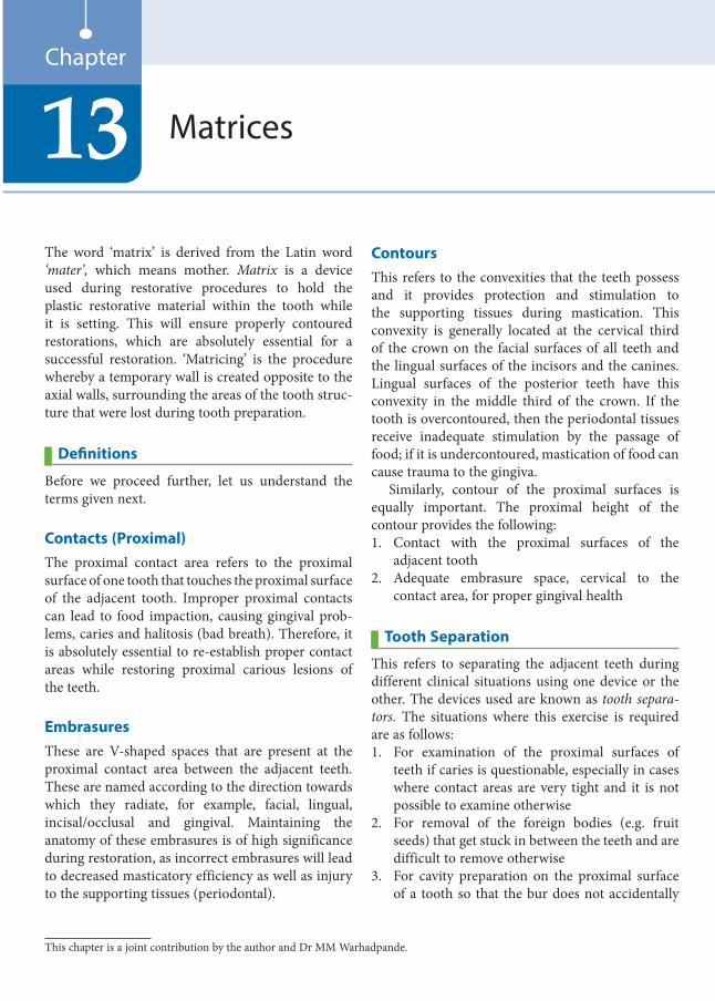
The word ‘matrix’ is derived from the Latin word ‘mater’, which means mother. Matrix is a device used during restorative procedures to hold the plastic restorative material within the tooth while it is setting. This will ensure properly contoured restorations, which are absolutely essential for a successful restoration. ‘Matricing’ is the procedure whereby a temporary wall is created opposite to the axial walls, surrounding the areas of the tooth struc-ture that were lost during tooth preparation.
Definitions
Before we proceed further, let us understand the terms given next.
Contacts (Proximal)The proximal contact area refers to the proximal surface of one tooth that touches the proximal surface of the adjacent tooth. Improper proximal contacts can lead to food impaction, causing gingival prob-lems, caries and halitosis (bad breath). Therefore, it is absolutely essential to re-establish proper contact areas while restoring proximal carious lesions of the teeth.
EmbrasuresThese are V-shaped spaces that are present at the proximal contact area between the adjacent teeth. These are named according to the direction towards which they radiate, for example, facial, lingual, incisal/occlusal and gingival. Maintaining the anatomy of these embrasures is of high significance during restoration, as incorrect embrasures will lead to decreased masticatory efficiency as well as injury to the supporting tissues (periodontal).
ContoursThis refers to the convexities that the teeth possess and it provides protection and stimulation to the supporting tissues during mastication. This convexity is generally located at the cervical third of the crown on the facial surfaces of all teeth and the lingual surfaces of the incisors and the canines. Lingual surfaces of the posterior teeth have this convexity in the middle third of the crown. If the tooth is overcontoured, then the periodontal tissues receive inadequate stimulation by the passage of food; if it is undercontoured, mastication of food can cause trauma to the gingiva.
Similarly, contour of the proximal surfaces is equally important. The proximal height of the contour provides the following:1. Contact with the proximal surfaces of the
adjacent tooth2. Adequate embrasure space, cervical to the
contact area, for proper gingival health
Tooth Separation
This refers to separating the adjacent teeth during different clinical situations using one device or the other. The devices used are known as tooth separa-tors. The situations where this exercise is required are as follows:1. For examination of the proximal surfaces of
teeth if caries is questionable, especially in cases where contact areas are very tight and it is not possible to examine otherwise
2. For removal of the foreign bodies (e.g. fruit seeds) that get stuck in between the teeth and are difficult to remove otherwise
3. For cavity preparation on the proximal surface of a tooth so that the bur does not accidentally
Matrices13Chapter
This chapter is a joint contribution by the author and Dr MM Warhadpande.
Preclinical Dentistry.indb 153 29-05-2020 12:57:21
https://t.me/DentalBooksWorld
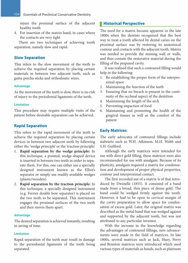
154 Essentials of Preclinical Conservative Dentistry
injure the proximal surface of the adjacent healthy tooth
4. For insertion of the matrix band, in cases where the contacts are very tight
There are two techniques of achieving tooth separation, namely slow and rapid.
Slow SeparationThis refers to the slow movement of the teeth to achieve the required separation by placing certain materials in between two adjacent teeth, such as gutta-percha sticks and orthodontic wires.
Advantage
As the movement of the teeth is slow, there is no risk of injury to the periodontal ligaments of the teeth.
Limitation
This procedure may require multiple visits of the patient before desirable separation can be achieved.
Rapid SeparationThis refers to the rapid movement of the teeth to achieve the required separation by placing certain devices in between two adjacent teeth by following either the ‘wedge principle’ or the ‘traction principle’.1. Rapid separation by the wedge principle: In
this technique, a pointed, wedge-shaped device is inserted in between two teeth in order to sepa-rate them. For this, one can either use a specially designed instrument known as the Elliot’s separator or simply use readily available wedges (plastic/wooden).
2. Rapid separation by the traction principle: In this technique, a specially designed instrument (e.g. Ferrier double bow separator) is placed on the two teeth to be separated. This instrument engages the proximal surfaces of the two teeth and then moves them apart.
Advantage
The desired separation is achieved instantly, resulting in saving of time.
Limitation
Rapid separation of the teeth may result in damage to the periodontal ligaments of the teeth being separated.
Historical Perspective
The need for a matrix became apparent in the late 1800s when the dentists recognised that the best way to treat a tooth affected by dental caries on the proximal surface was by restoring its anatomical contour and contacts with the adjacent tooth. Matrix was needed to provide the missing wall or walls, and thus contain the restorative material during the filling of the prepared cavity.
It was realised that such a contoured filling would help in the following:1. Re-establishing the proper form of the interpro-
ximal space2. Maintaining the function of the teeth3. Ensuring that no breach is present in the conti-
nuity of the occlusal aspect of the dentition4. Maintaining the length of the arch5. Preventing impaction of food6. Maintaining and promoting the health of the
gingival tissues as well as the comfort of the patient
Early MatricesThe early advocates of contoured fillings include stalwarts such as W.H. Atkinson, M.H. Webb and S.H. Guilford.
Although the early matrices were intended for use with direct gold filling, these matrices were also recommended for use with amalgam. Because of its plasticity, amalgam required a matrix for condensa-tion and development of proper physical properties, contour and interproximal contact.
The first recorded use of a matrix is of that intro-duced by Dwinelle (1855). It consisted of a band made from a broad, thin piece of dense gold. The band could be wedged firmly against the tooth. However, it had to be open to cervical margin of the cavity preparation to allow space for conden-sation of excess gold. Later, the original matrix was described as the metal band that was wedged against and supported by the adjacent tooth, but was not attributed to any particular inventor.
With the increase in the knowledge regarding the advantages of contoured fillings, new advance-ments were made in the field of matrices. In late 1800s, several matrices such as Jack, Huey, Perry and Brunton matrices were introduced which used various types of materials as bands, such as platinum
Preclinical Dentistry.indb 154 29-05-2020 12:57:21
https://t.me/DentalBooksWorld
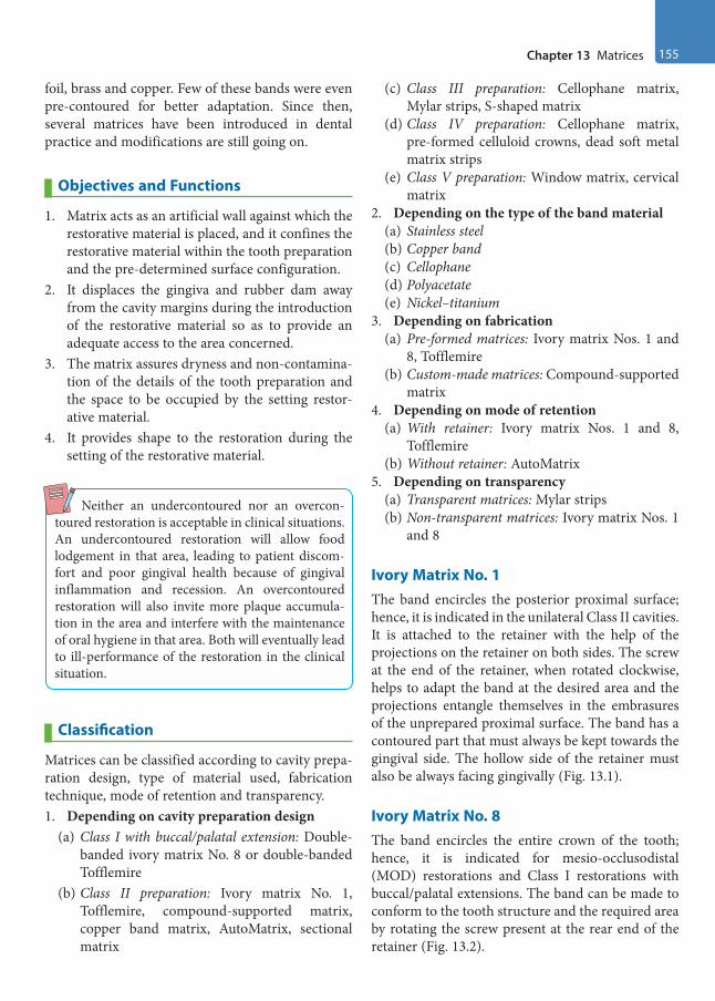
Chapter 13 Matrices 155
foil, brass and copper. Few of these bands were even pre-contoured for better adaptation. Since then, several matrices have been introduced in dental practice and modifications are still going on.
Objectives and Functions
1. Matrix acts as an artificial wall against which the restorative material is placed, and it confines the restorative material within the tooth preparation and the pre-determined surface configuration.
2. It displaces the gingiva and rubber dam away from the cavity margins during the introduction of the restorative material so as to provide an adequate access to the area concerned.
3. The matrix assures dryness and non-contamina-tion of the details of the tooth preparation and the space to be occupied by the setting restor-ative material.
4. It provides shape to the restoration during the setting of the restorative material.
Neither an undercontoured nor an overcon-toured restoration is acceptable in clinical situations. An undercontoured restoration will allow food lodgement in that area, leading to patient discom-fort and poor gingival health because of gingival inflammation and recession. An overcontoured restoration will also invite more plaque accumula-tion in the area and interfere with the maintenance of oral hygiene in that area. Both will eventually lead to ill-performance of the restoration in the clinical situation.
Classification
Matrices can be classified according to cavity prepa-ration design, type of material used, fabrication technique, mode of retention and transparency. 1. Depending on cavity preparation design
(a) Class I with buccal/palatal extension: Double-banded ivory matrix No. 8 or double-banded Tofflemire
(b) Class II preparation: Ivory matrix No. 1, Tofflemire, compound-supported matrix, copper band matrix, AutoMatrix, sectional matrix
(c) Class III preparation: Cellophane matrix, Mylar strips, S-shaped matrix
(d) Class IV preparation: Cellophane matrix, pre-formed celluloid crowns, dead soft metal matrix strips
(e) Class V preparation: Window matrix, cervical matrix
2. Depending on the type of the band material(a) Stainless steel(b) Copper band(c) Cellophane(d) Polyacetate(e) Nickel–titanium
3. Depending on fabrication(a) Pre-formed matrices: Ivory matrix Nos. 1 and
8, Tofflemire(b) Custom-made matrices: Compound-supported
matrix4. Depending on mode of retention
(a) With retainer: Ivory matrix Nos. 1 and 8, Tofflemire
(b) Without retainer: AutoMatrix5. Depending on transparency
(a) Transparent matrices: Mylar strips(b) Non-transparent matrices: Ivory matrix Nos. 1
and 8
Ivory Matrix No. 1The band encircles the posterior proximal surface; hence, it is indicated in the unilateral Class II cavities. It is attached to the retainer with the help of the projections on the retainer on both sides. The screw at the end of the retainer, when rotated clockwise, helps to adapt the band at the desired area and the projections entangle themselves in the embrasures of the unprepared proximal surface. The band has a contoured part that must always be kept towards the gingival side. The hollow side of the retainer must also be always facing gingivally (Fig. 13.1).
Ivory Matrix No. 8The band encircles the entire crown of the tooth; hence, it is indicated for mesio-occlusodistal (MOD) restorations and Class I restorations with buccal/palatal extensions. The band can be made to conform to the tooth structure and the required area by rotating the screw present at the rear end of the retainer (Fig. 13.2).
Preclinical Dentistry.indb 155 29-05-2020 12:57:21
https://t.me/DentalBooksWorld
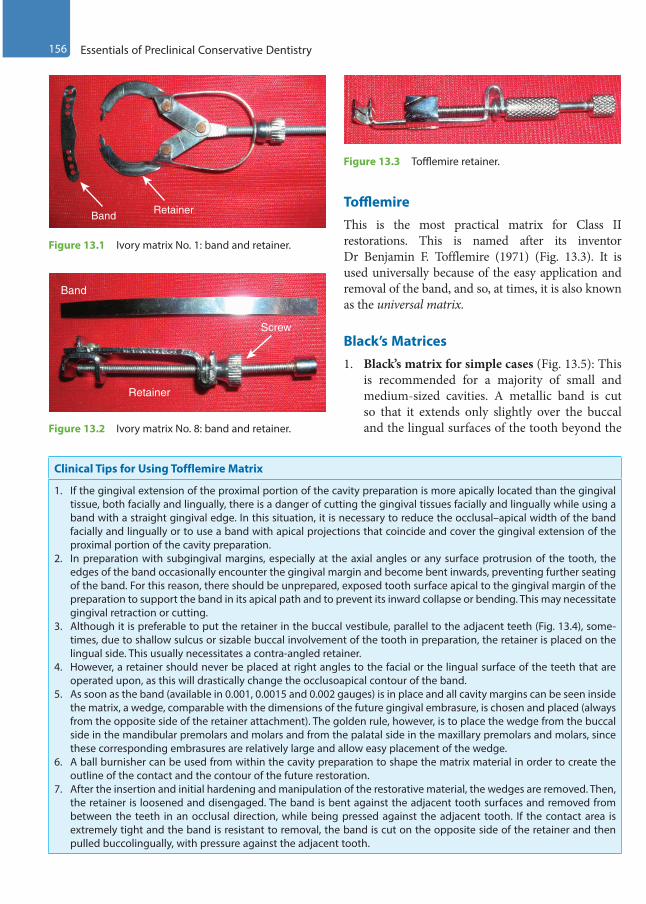
156 Essentials of Preclinical Conservative Dentistry
TofflemireThis is the most practical matrix for Class II restorations. This is named after its inventor Dr Benjamin F. Tofflemire (1971) (Fig. 13.3). It is used universally because of the easy application and removal of the band, and so, at times, it is also known as the universal matrix.
Black’s Matrices1. Black’s matrix for simple cases (Fig. 13.5): This
is recommended for a majority of small and medium-sized cavities. A metallic band is cut so that it extends only slightly over the buccal and the lingual surfaces of the tooth beyond the
Clinical Tips for Using Tofflemire Matrix
1. If the gingival extension of the proximal portion of the cavity preparation is more apically located than the gingival tissue, both facially and lingually, there is a danger of cutting the gingival tissues facially and lingually while using a band with a straight gingival edge. In this situation, it is necessary to reduce the occlusal–apical width of the band facially and lingually or to use a band with apical projections that coincide and cover the gingival extension of the proximal portion of the cavity preparation.
2. In preparation with subgingival margins, especially at the axial angles or any surface protrusion of the tooth, the edges of the band occasionally encounter the gingival margin and become bent inwards, preventing further seating of the band. For this reason, there should be unprepared, exposed tooth surface apical to the gingival margin of the preparation to support the band in its apical path and to prevent its inward collapse or bending. This may necessitate gingival retraction or cutting.
3. Although it is preferable to put the retainer in the buccal vestibule, parallel to the adjacent teeth (Fig. 13.4), some-times, due to shallow sulcus or sizable buccal involvement of the tooth in preparation, the retainer is placed on the lingual side. This usually necessitates a contra-angled retainer.
4. However, a retainer should never be placed at right angles to the facial or the lingual surface of the teeth that are operated upon, as this will drastically change the occlusoapical contour of the band.
5. As soon as the band (available in 0.001, 0.0015 and 0.002 gauges) is in place and all cavity margins can be seen inside the matrix, a wedge, comparable with the dimensions of the future gingival embrasure, is chosen and placed (always from the opposite side of the retainer attachment). The golden rule, however, is to place the wedge from the buccal side in the mandibular premolars and molars and from the palatal side in the maxillary premolars and molars, since these corresponding embrasures are relatively large and allow easy placement of the wedge.
6. A ball burnisher can be used from within the cavity preparation to shape the matrix material in order to create the outline of the contact and the contour of the future restoration.
7. After the insertion and initial hardening and manipulation of the restorative material, the wedges are removed. Then, the retainer is loosened and disengaged. The band is bent against the adjacent tooth surfaces and removed from between the teeth in an occlusal direction, while being pressed against the adjacent tooth. If the contact area is extremely tight and the band is resistant to removal, the band is cut on the opposite side of the retainer and then pulled buccolingually, with pressure against the adjacent tooth.
Screw
Retainer
Band
Figure 13.2 Ivory matrix No. 8: band and retainer.
Figure 13.3 Tofflemire retainer.
Band Retainer
Figure 13.1 Ivory matrix No. 1: band and retainer.
Preclinical Dentistry.indb 156 29-05-2020 12:57:23
https://t.me/DentalBooksWorld
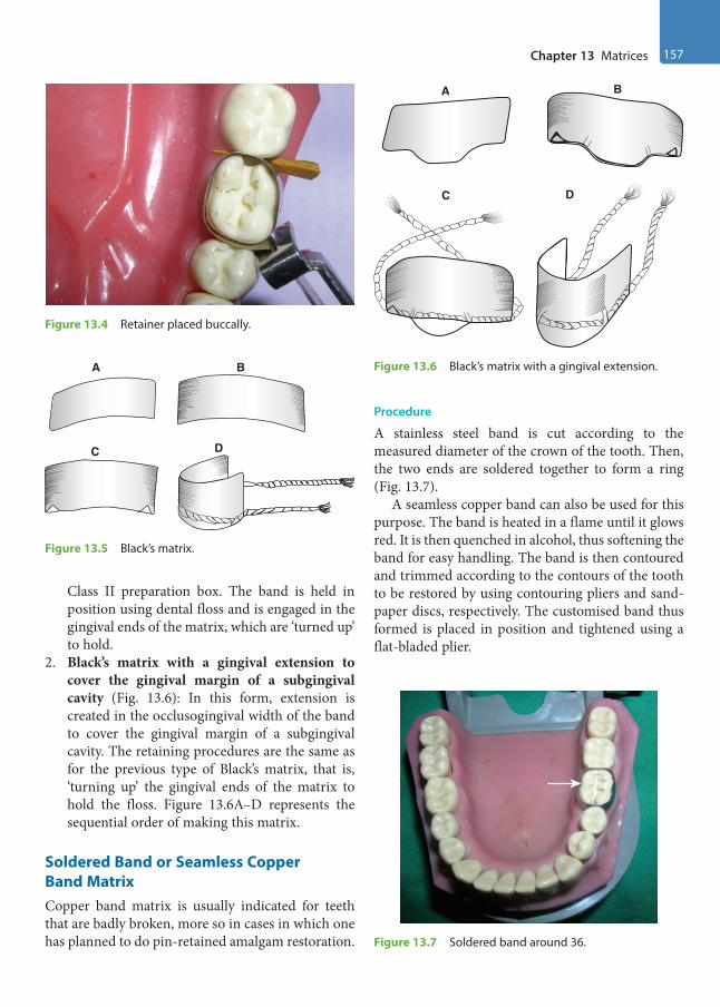
Chapter 13 Matrices 157
Class II preparation box. The band is held in position using dental floss and is engaged in the gingival ends of the matrix, which are ‘turned up’ to hold.
2. Black’s matrix with a gingival extension to cover the gingival margin of a subgingival cavity (Fig. 13.6): In this form, extension is created in the occlusogingival width of the band to cover the gingival margin of a subgingival cavity. The retaining procedures are the same as for the previous type of Black’s matrix, that is, ‘turning up’ the gingival ends of the matrix to hold the floss. Figure 13.6A–D represents the sequential order of making this matrix.
Soldered Band or Seamless Copper Band MatrixCopper band matrix is usually indicated for teeth that are badly broken, more so in cases in which one has planned to do pin-retained amalgam restoration.
Procedure
A stainless steel band is cut according to the measured diameter of the crown of the tooth. Then, the two ends are soldered together to form a ring (Fig. 13.7).
A seamless copper band can also be used for this purpose. The band is heated in a flame until it glows red. It is then quenched in alcohol, thus softening the band for easy handling. The band is then contoured and trimmed according to the contours of the tooth to be restored by using contouring pliers and sand-paper discs, respectively. The customised band thus formed is placed in position and tightened using a flat-bladed plier.
Figure 13.4 Retainer placed buccally.
A B
C D
Figure 13.5 Black’s matrix.
A B
C D
Figure 13.6 Black’s matrix with a gingival extension.
Figure 13.7 Soldered band around 36.
Preclinical Dentistry.indb 157 29-05-2020 12:57:24
https://t.me/DentalBooksWorld

158 Essentials of Preclinical Conservative Dentistry
To stabilise the band and prevent cervical flashes of amalgam, wedges and impression compounds are placed.
Anatomical Matrix (Compound-Supported Matrix) Anatomical matrix is considered as one of the best matrices, since it is entirely custom-made and can be contoured specifically for individual tooth. It is very beneficial for those teeth that have wide contact area loss due to caries.
Procedure
A piece of stainless steel matrix band is drawn between the handles of a pair of festooning scissors. This procedure facilitates the adaptation of the free ends of the matrix to the proximal surface of the tooth.
The matrix band is cut to proper length and is contoured with contouring pliers. It is then trimmed appropriately.
A wedge is selected and shaped to conform to the gingival embrasures, and it is then placed in warm water to soften it slightly. It is then placed in position. Two small cones of compound are warmed in hot water. These compound cones are forced one at a time, using thumb and finger pressure, into the buccal and lingual embrasures. A wire staple, constructed from a paper clip, is heated in a flame and forced into the compound in the buccal and lingual embrasures. This adds to the stability of the matrix.
Figure 13.8 (from top to bottom) reveals how the band is taken, contoured and adapted according to the need and then stabilised using an impression compound which is softened and adapted around the band in position.
After initial hardening of the inserted restorative material, the compound is cracked at its occlusal junctions using a sharp chisel or knife. The wedges are removed using a haemostat and the band is curled backwards against the adjacent tooth and withdrawn buccolingually, with pressure against the adjacent proximal surface.
AutoMatrix (Roll-in-Band Matrix) This is a retainerless matrix system, especially used for complex amalgam restorations and in patients who cannot tolerate the retainer hanging out for long.
In addition, it is beneficial for teeth that have short occlusogingival height.
To increase the size of matrix, so that it can fit into the tooth, the coil should be unrolled. The system consists of bands of varying sizes, a tightening device and nippers (cutting device). The types, parts of AutoMatrix, their functions and the step-by-step procedure of using it are described in Figure 13.9.
S-Shaped Matrix
This is an ideal matrix for Class III cavity prepara-tion on the distal side of the canine, with either a labial or a lingual access.
Procedure
1. One-half to 1 inch of regular strip matrix is used.2. A mirror handle is used to produce the S-shape
in the strip. The band is contoured over the labial surface of the canine and the lingual surface of the adjacent premolar (Fig. 13.10).
3. With contouring pliers, the strip is contoured in its middle part to create the desired form for the resto-ration. It is then placed interproximally, wedged firmly apical to the gingival margin and covered with compound at its facial and lingual ends.
Figure 13.8 Anatomical matrix (compound-supported matrix).
Preclinical Dentistry.indb 158 29-05-2020 12:57:24
https://t.me/DentalBooksWorld
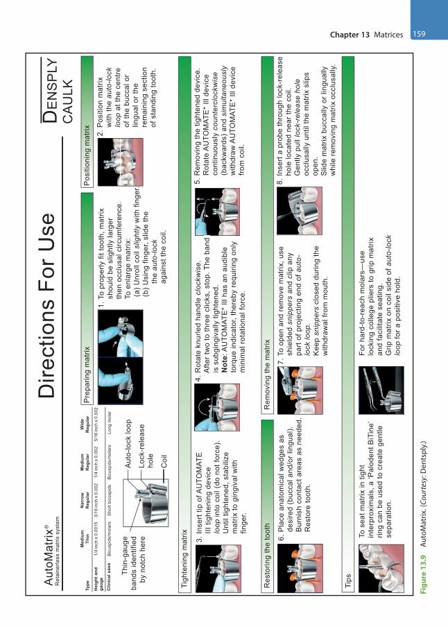
Chapter 13 Matrices 159
Figu
re 1
3.9
Auto
Mat
rix. (
Cour
tesy
: Den
tspl
y.)
1. T
o pr
oper
ly fi
t too
th, m
atrix
sho
uld
be s
light
ly la
rger
then
occ
lusa
l circ
umfe
renc
e.
To
enla
rge
mat
rix:
(
a) U
nrol
l coi
l slig
htly
with
fing
er.
(
b) U
sing
fing
er, s
lide
the
t
he a
uto-
lock
a
gain
st th
e co
il.
2. P
ositi
on m
atrix
w
ith th
e au
to-lo
ck
loop
at t
he c
entre
o
f the
buc
cal o
r
ling
ual o
r the
rem
aini
ng s
ectio
n
of s
tand
ing
toot
h.
6. P
lace
ana
tom
ical
wed
ges
as
d
esire
d (b
ucca
l and
/or l
ingu
al).
B
urni
sh c
onta
ct a
reas
as
need
ed.
R
esto
re to
oth.
To s
eat m
atrix
in ti
ght
inte
rpro
xim
als,
a ‘P
alod
ent B
iTin
e’rin
g ca
n be
use
d to
cre
ate
gent
lese
para
tion.
For h
ard-
to-r
each
mol
ars—
use
lock
ing
colle
ge p
liers
to g
rip m
atrix
and
faci
litat
e se
atin
g.G
rip m
atrix
on
coil
side
of a
uto-
lock
loop
for a
pos
itive
hol
d.
7. T
o op
en a
nd re
mov
e m
atrix
, use
shi
elde
d sn
ippe
rs a
nd c
lip a
ny
par
t of p
roje
ctin
g en
d of
aut
o-
lock
loop
.
Kee
p sn
ippe
rs c
lose
d du
ring
the
w
ithdr
awal
from
mou
th.
Coi
l
Pre
parin
g m
atrix
Dire
ctio
ns F
or U
seD
EN
SP
LYC
AU
LKA
utoM
atrix
Ret
aine
rless
mat
rix s
yste
m
Thin
-gau
geba
nds
iden
tifie
dby
not
ch h
ere
Aut
o-lo
ck lo
op
Lock
-rel
ease
ho
le
3. In
sert
tip o
f AU
TOM
ATE
II
I tig
hten
ing
devi
ce
loop
into
coi
l (do
not
forc
e).
U
ntil
tight
ened
, sta
biliz
e
mat
rix to
gin
giva
l with
fi
nger
.
4. R
otat
e kn
urle
d ha
ndle
clo
ckw
ise.
Afte
r tw
o to
thre
e cl
icks
, sto
p. T
he b
and
is
is s
ubgi
ngiv
ally
tigh
tene
d.
N
ote:
AU
TOM
ATE
* Ill
has
an
audi
ble
to
rque
indi
cato
r, th
ereb
y re
quiri
ng o
nly
m
inim
al ro
tatio
nal f
orce
.
5. R
emov
ing
the
tight
ened
dev
ice.
Rot
ate
AU
TOM
ATE
* Ill
dev
ice
c
ontin
uous
ly c
ount
ercl
ockw
ise
(b
ackw
ards
) and
sim
ulta
neou
sly
w
ithdr
aw A
UTO
MAT
E*
Ill d
evic
e
from
coi
l.
8. In
sert
a pr
obe
thro
ugh
lock
-rel
ease
h
ole
loca
ted
near
the
coil.
G
ently
pul
l loc
k-re
leas
e ho
le
occ
lusa
lly u
ntil
the
mat
rix s
lips
o
pen.
Slid
e m
atrix
buc
cally
or l
ingu
ally
whi
le re
mov
ing
mat
rix o
cclu
sally
.
iiisisiisissiisisisssssssssssississsiisssssssissssssissssssiiisssssssiiiissssssssssiisssssssssisisisiiiissssiiiiisiissiii
Tigh
teni
ng m
atrix
Res
torin
g th
e to
oth
Rem
ovin
g th
e m
atrix
LOC
K
Pos
ition
ing
mat
rixM
ediu
mTh
in
1/4
inch
� 0
.001
53/
16 in
ch �
0.0
021/
4 in
ch �
0.0
025/
16 in
ch �
0.0
02
Nar
row
Reg
ular
Med
ium
Reg
ular
Wid
eR
egul
arTy
pe
Hei
ght a
ndga
uge
Clin
ical
use
sB
icus
pids
/mol
ars
Bic
uspi
ds/m
olar
sS
hort
bicu
spid
sLo
ng m
olar
Tips
®
Preclinical Dentistry.indb 159 29-05-2020 12:57:25
https://t.me/DentalBooksWorld
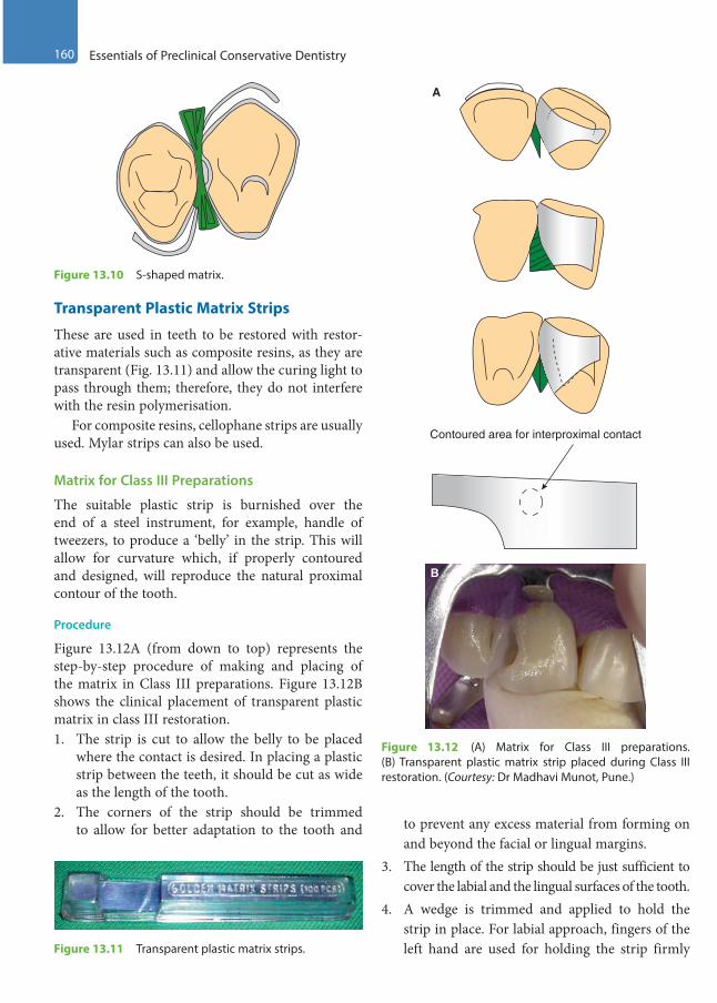
160 Essentials of Preclinical Conservative Dentistry
Contoured area for interproximal contact
A
B
Figure 13.12 (A) Matrix for Class III preparations. (B) Transparent plastic matrix strip placed during Class III restoration. (Courtesy: Dr Madhavi Munot, Pune.)
Transparent Plastic Matrix Strips
These are used in teeth to be restored with restor-ative materials such as composite resins, as they are transparent (Fig. 13.11) and allow the curing light to pass through them; therefore, they do not interfere with the resin polymerisation.
For composite resins, cellophane strips are usually used. Mylar strips can also be used.
Matrix for Class III Preparations
The suitable plastic strip is burnished over the end of a steel instrument, for example, handle of tweezers, to produce a ‘belly’ in the strip. This will allow for curvature which, if properly contoured and designed, will reproduce the natural proximal contour of the tooth.
Procedure
Figure 13.12A (from down to top) represents the step-by-step procedure of making and placing of the matrix in Class III preparations. Figure 13.12B shows the clinical placement of transparent plastic matrix in class III restoration. 1. The strip is cut to allow the belly to be placed
where the contact is desired. In placing a plastic strip between the teeth, it should be cut as wide as the length of the tooth.
2. The corners of the strip should be trimmed to allow for better adaptation to the tooth and to prevent any excess material from forming on
and beyond the facial or lingual margins.3. The length of the strip should be just sufficient to
cover the labial and the lingual surfaces of the tooth.4. A wedge is trimmed and applied to hold the
strip in place. For labial approach, fingers of the left hand are used for holding the strip firmly
Figure 13.10 S-shaped matrix.
Figure 13.11 Transparent plastic matrix strips.
Preclinical Dentistry.indb 160 29-05-2020 12:57:26
https://t.me/DentalBooksWorld

Chapter 13 Matrices 161
against the lingual surface of the tooth while the material is being placed in the cavity.
Matrices for Class IV Preparations Class IV restorations are considered as one of the difficult ones to perform especially because of aesthetic considerations involved and the fact that anatomic details need to be reproduced as close as possible to the missing natural tooth structure. Therefore, it is highly essential to train oneself for the correct placement of matrices in these situations in order to obtain desired results.
Procedure
Figure 13.13A–D shows the step-by-step proce-dure of placing the matrix in class IV preparations. Figure 13.13E shows L-shaped matrix placed during composite resin restoration procedure in maxillary left lateral incisor.1. A suitable plastic strip is folded at an angle into
an L-shape (Fig. 13.13A,B).2. One side of the strip is cut so that it is as wide as
the length of the tooth.3. The other side is cut so that it is as wide as the
width of the tooth.4. The strip with a wedge in place is adapted to the
tooth (Fig. 13.13C,D).
Aluminium Foil Incisal Corner MatricesThese are ‘stock’ metallic matrices shaped according to the proximoincisal corner and the surfaces of anterior teeth. They can be adapted to each specific case.
Procedure
1. A corner matrix closest in size and shape to the lost area of the tooth is selected.
2. It is trimmed gingivally so that it coincides with the gingival architecture and covers the gingival margin of the preparation.
3. As it is readily deformable, it is shaped with the thumb and first finger until it fits the mesiodistal and labiolingual dimensions of the tooth. The wedge is loosely placed, allowing space for placing the matrix band.
4. The preparation is partially filled and the partially filled matrix is applied over the partially filled tooth preparation at its predetermined location between the loosened wedge and the tooth.
Transparent Crown Form MatricesThese are ‘stock’ plastic crowns that can be adapted to the tooth anatomy. They are available in various sizes and shapes (Fig. 13.14).
Procedure
In bilateral Class IV preparations, the entire crown form is used. In unilateral Class IV preparations, the plastic crown is cut incisogingivally into two halves and only the side corresponding to the location of the preparation is used.1. The crown form is chosen with the size and
shape close to the tooth to be restored.
A B
C D
E
Figure 13.13 (A–D) Matrices for Class IV preparations. (E) L-shaped matrix placed in position. (Courtesy: Dr Madhavi Munot, Pune.)
Preclinical Dentistry.indb 161 29-05-2020 12:57:26
https://t.me/DentalBooksWorld

162 Essentials of Preclinical Conservative Dentistry
2. The crown form is trimmed gingivally so that it coincides with the gingival architecture and completely covers the gingival margin of the preparation.
3. The matrix is checked to ensure that it will recreate proper contact and contour. The matrix is then removed and thinned at its contact area with a sandpaper disc. It should be perforated at the incisal angle.
4. The matrix is completely filled with the restor-ative material while the preparation is partially filled with the restorative material.
5. The filled crown form is placed on the tooth in the desired location. The wedge is then tightened.
Window MatrixThis matrix is prepared using either a Tofflemire or a copper band matrix and is used in restoring Class V cavities, which are restored mainly using silver amalgam.
Procedure
Figure 13.15 (from top to bottom) shows a prepared Class V cavity followed by the placement of the matrix, showing a window in the area where restoration is needed.1. The band is adapted to the tooth structure, with
the retainer placed towards the lingual side.2. A window is cut on the labial surface of the band,
just smaller than the outline form of the prepared cavity (Fig. 13.15).
3. Silver amalgam is placed through this window.4. The matrix is removed once the material has
hardened.
Tin Foil MatrixThis matrix is used in restoring Class V cavities mainly with glass ionomer cement.
Procedure
The foils may be pre-shaped and cut according to the size and contour of the area to be restored.1. The foil should extend 1–2 mm beyond all the
cavity margins when placed.2. After placing the restorative material, this matrix
is placed in position and held for some time.3. The foil is removed once the restorative material
has set.
Pre-Formed Transparent Cervical Matrices These are preformed matrices that are available commercially and used with composite resins or glass ionomer cements (Fig. 13.16). These are provided with knob-like extensions on the external
Figure 13.14 Transparent crown form matrices. Figure 13.15 Window matrix.
Figure 13.16 Pre-formed transparent cervical matrix.
Preclinical Dentistry.indb 162 29-05-2020 12:57:27
https://t.me/DentalBooksWorld

Chapter 13 Matrices 163
surface (Fig. 13.17) so as to hold them in position easily with the help of tweezers. The procedure of use is otherwise same as that for tin foil matrix.
Sectional MatricesOf late, new matrices have been developed, known as sectional matrices, which do not have very long retainers hanging out. A variety of them are available in the market, for example:1. V3 matrix system2. Micromachined matrix3. Barton matrix4. Palodent matrix5. BiTine matrix6. Composi-Tight matrix7. Garrison’s matrix
Advantages
In general, these sectional matrices offer the following advantages:1. They provide natural contours and profiles.2. The thickness of the band is just 25–30 mm; so,
the contact areas can be established perfectly.3. They are malleable and can be properly adapted
to the remaining tooth structures, thus providing better margins.
4. Embrasure can be easily created without spending extra time during finishing and polishing.
5. They can be removed buccally/lingually with minimal disruption of the freshly placed restoration.
6. They are faster and easier to use.7. It is easier to disengage the matrix from the
tooth due to the absence of matrix thickness on the opposite side.
8. They can be used with any restorative material.
Since a detailed description of all these is beyond the scope of this book, a brief overview of ‘V3 matrix system (GC, Japan)’ is given here for a better under-standing of the students.
Components of V3 Matrix System (GC, Japan)
1. Universal V3 ring (Fig. 13.18A): This special-ised ring is made of NiTi and has glass fibre-reinforced plastic tines. Its V-shaped tines can accommodate the wedge nicely.
2. V3 tab matrix (Fig. 13.18B): This matrix band is very soft and thin, which provides better adaptation.
3. Wave wedge (Fig. 13.18C): This soft plastic wedge has special wings that get compressed on entry and flared on exit. This property helps in good tooth separation.
4. Pin tweezers (Fig. 13.18D,E): This is used to hold the V3 tab matrix. The pin in the tip of this tweezer grips the hole in V3 tab matrix.
5. Forceps (Fig. 13.18F): This is used to hold the V3 ring during placement and removal.
Technique
Figure 13.18A–K shows the components and placement of sectional matrix Universal V3. 1. Initially, a wedge is placed for tooth separation in
case of tight contact points (Fig. 13.18G).2. V3 tab matrix is gripped with the pin tweezers,
ensuring that the gold side of the tweezer tip is facing away from the tooth (Fig. 13.18H). The tip of the tweezer has a gripping extension that can be placed inside the hole on the tab so that the tab is firmly gripped.
3. The tab is taken to site, the wedge is slided out, the matrix is placed in and the wedge is rein-serted (Fig. 13.18I).
4. The V3 ring is now held using forceps (Fig. 13.18J) and placed onto the tab, as low as possible, with its tines straddling the wedge. Forceps can now be released, and while doing this, a finger is used to press down the matrix tab to prevent its movement. The ring and the tab matrix can now be seen in the final position (Fig. 13.18K).
5. After completing the restorative procedure, the wedge is removed, the V3 ring is taken out using the forceps and the matrix tab is removed gently using pin tweezers.
Figure 13.17 Knob-like extension on the external surface of transparent cervical matrix (two different sizes).
Preclinical Dentistry.indb 163 29-05-2020 12:57:27
https://t.me/DentalBooksWorld

164 Essentials of Preclinical Conservative Dentistry
A B C
D E F
G H
J K
I
Figure 13.18 (A) Universal V3 ring. (B) V3 tab matrix. (C) Wave wedge. (D) Pin tweezers. (E) Tip of pin tweezers showing the gripping end. (F) Forceps. (G) Wedge placed for tooth separation in case of tight contact points. (H) V3 tab matrix gripped with the pin tweezers. (I) Placement of the matrix tab in position. (J) V3 ring held in the forceps. (K) The ring and tab matrix in the final position.
Preclinical Dentistry.indb 164 29-05-2020 12:57:32
https://t.me/DentalBooksWorld
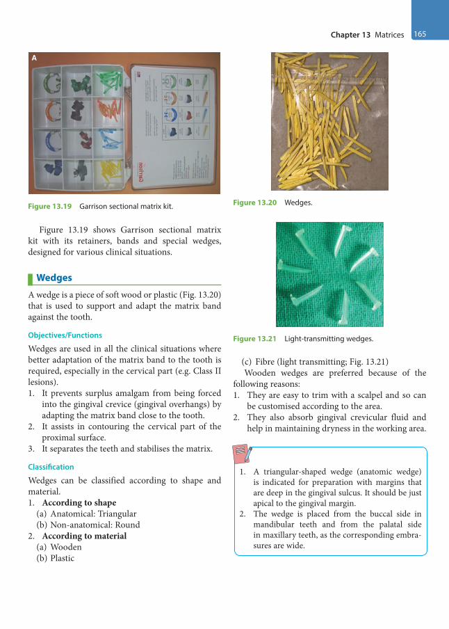
Chapter 13 Matrices 165
Figure 13.19 shows Garrison sectional matrix kit with its retainers, bands and special wedges, designed for various clinical situations.
Wedges
A wedge is a piece of soft wood or plastic (Fig. 13.20) that is used to support and adapt the matrix band against the tooth.
Objectives/Functions
Wedges are used in all the clinical situations where better adaptation of the matrix band to the tooth is required, especially in the cervical part (e.g. Class II lesions).1. It prevents surplus amalgam from being forced
into the gingival crevice (gingival overhangs) by adapting the matrix band close to the tooth.
2. It assists in contouring the cervical part of the proximal surface.
3. It separates the teeth and stabilises the matrix.
Classification
Wedges can be classified according to shape and material.1. According to shape
(a) Anatomical: Triangular(b) Non-anatomical: Round
2. According to material(a) Wooden(b) Plastic
(c) Fibre (light transmitting; Fig. 13.21)Wooden wedges are preferred because of the
following reasons:1. They are easy to trim with a scalpel and so can
be customised according to the area.2. They also absorb gingival crevicular fluid and
help in maintaining dryness in the working area.
1. A triangular-shaped wedge (anatomic wedge) is indicated for preparation with margins that are deep in the gingival sulcus. It should be just apical to the gingival margin.
2. The wedge is placed from the buccal side in mandibular teeth and from the palatal side in maxillary teeth, as the corresponding embra-sures are wide.
A
Figure 13.19 Garrison sectional matrix kit. Figure 13.20 Wedges.
Figure 13.21 Light-transmitting wedges.
Preclinical Dentistry.indb 165 29-05-2020 12:57:32
https://t.me/DentalBooksWorld
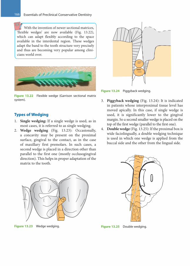
166 Essentials of Preclinical Conservative Dentistry
With the invention of newer sectional matrices, ‘flexible wedges’ are now available (Fig. 13.22), which can adapt flexibly according to the space available in the interdental region. These wedges adapt the band to the tooth structure very precisely and thus are becoming very popular among clini-cians world over.
Types of Wedging1. Single wedging: If a single wedge is used, as in
most cases, it is referred to as single wedging.2. Wedge wedging (Fig. 13.23): Occasionally,
a concavity may be present on the proximal surface, gingival to the contact, as in the case of maxillary first premolars. In such cases, a second wedge is placed in a direction other than parallel to the first one (mostly occlusogingival direction). This helps in proper adaptation of the matrix to the tooth.
3. Piggyback wedging (Fig. 13.24): It is indicated in patients whose interproximal tissue level has moved apically. In this case, if single wedge is used, it is significantly lower to the gingival margin. So a second smaller wedge is placed on the top of the first wedge (parallel to the first one).
4. Double wedge (Fig. 13.25): If the proximal box is wide faciolingually, a double wedging technique is used in which one wedge is applied from the buccal side and the other from the lingual side.
Figure 13.22 Flexible wedge (Garrison sectional matrix system).
Figure 13.23 Wedge wedging.
Figure 13.24 Piggyback wedging.
Figure 13.25 Double wedging.
Preclinical Dentistry.indb 166 29-05-2020 12:57:33
https://t.me/DentalBooksWorld
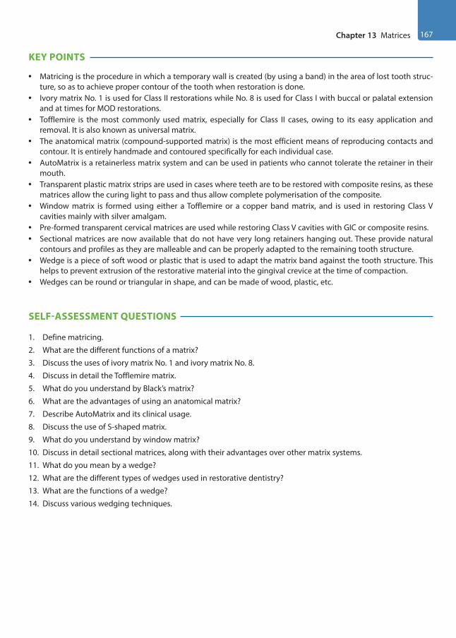
Chapter 13 Matrices 167
KEY POINTS
• Matricing is the procedure in which a temporary wall is created (by using a band) in the area of lost tooth struc-ture, so as to achieve proper contour of the tooth when restoration is done.
• Ivory matrix No. 1 is used for Class II restorations while No. 8 is used for Class I with buccal or palatal extension and at times for MOD restorations.
• Tofflemire is the most commonly used matrix, especially for Class II cases, owing to its easy application and removal. It is also known as universal matrix.
• The anatomical matrix (compound-supported matrix) is the most efficient means of reproducing contacts and contour. It is entirely handmade and contoured specifically for each individual case.
• AutoMatrix is a retainerless matrix system and can be used in patients who cannot tolerate the retainer in their mouth.
• Transparent plastic matrix strips are used in cases where teeth are to be restored with composite resins, as these matrices allow the curing light to pass and thus allow complete polymerisation of the composite.
• Window matrix is formed using either a Tofflemire or a copper band matrix, and is used in restoring Class V cavities mainly with silver amalgam.
• Pre-formed transparent cervical matrices are used while restoring Class V cavities with GIC or composite resins.• Sectional matrices are now available that do not have very long retainers hanging out. These provide natural
contours and profiles as they are malleable and can be properly adapted to the remaining tooth structure.• Wedge is a piece of soft wood or plastic that is used to adapt the matrix band against the tooth structure. This
helps to prevent extrusion of the restorative material into the gingival crevice at the time of compaction.• Wedges can be round or triangular in shape, and can be made of wood, plastic, etc.
SELF-ASSESSMENT QUESTIONS
1. Define matricing.
2. What are the different functions of a matrix?
3. Discuss the uses of ivory matrix No. 1 and ivory matrix No. 8.
4. Discuss in detail the Tofflemire matrix.
5. What do you understand by Black’s matrix?
6. What are the advantages of using an anatomical matrix?
7. Describe AutoMatrix and its clinical usage.
8. Discuss the use of S-shaped matrix.
9. What do you understand by window matrix?
10. Discuss in detail sectional matrices, along with their advantages over other matrix systems.
11. What do you mean by a wedge?
12. What are the different types of wedges used in restorative dentistry?
13. What are the functions of a wedge?
14. Discuss various wedging techniques.
Preclinical Dentistry.indb 167 29-05-2020 12:57:33
https://t.me/DentalBooksWorld

Pulp protection is an essential component of tooth restoration procedure and must be thoroughly understood by the restorative dentist. There are several methods that can be used for pulp protec-tion, and the procedure adopted depends entirely on the amount of tooth structure lost due to dental caries, especially towards the pulpal direction. In other words, the remaining dentin thickness (RDT) over the dental pulp after the tooth preparation is the decisive factor for the selection of specific agent to be placed over the pulpal floor/axial wall to ensure complete chemical/thermal/mechanical insulation to the dental pulp.
Materials used for pulp protection can be broadly categorised as cavity varnishes, cavity liners and bases. All these are discussed individually in this chapter in order to clarify their respective indica-tions and usage in different clinical situations. This will help the operator in deciding an ideal pulp protection plan which is one of the crucial steps in tooth restoration.
Cavity Varnish
Cavity varnish is described as a natural gum, copal or resin dissolved in an organic solvent such as chlo-roform acetone or ether.
Functions
The cavity varnish acts as a barrier and prevents penetration of oral fluids into the underlying dentin from the tooth–restoration interface. Cavity varnish is indicated for the following purposes:• Inhibit microleakage under the restoration• Prevent penetration of corrosion by-products (e.g.
amalgam blues) into the underlying tooth structure• Inhibit acid penetration into dentinal tubules• Seal the dentinal tubules temporarily• Prevent post-operative sensitivity
Method of Application
Cavity varnish is available in dark-coloured bottles (Fig. 14.1) and can be applied directly to the cavity with a sable hairbrush, camel hairbrush, an appli-cator tip (Fig. 14.2), or tiny cotton pledget or a wire loop.1. Cavity varnish is applied in a thin consistency
and requires two or three applications.2. After drying the cavity, the first layer is applied
and allowed to dry for 1–2 minutes (Fig. 14.3A).3. After this, a second application is done
(Fig. 14.3B) to attain uniform and continuous wetting of the surface and fill the voids, if any left, after the first coat.
4. A consecutive third layer may be applied to ensure complete protection.
5. The varnish application ideally should be limited to the dentinal surface only.
6. The preferred thickness for the varnish is 5–10 µm.
Clinical Considerations in Pulp Protection14
Chapter
Figure 14.1 Cavity varnish.
This chapter is contributed by Dr Shishir Singh.
Preclinical Dentistry.indb 168 29-05-2020 12:57:33
https://t.me/DentalBooksWorld

Chapter 14 Clinical Considerations in Pulp Protection 169
Clinical Considerations
• Varnishes are contraindicated under composite restorations as they may interfere with the polymerisation reaction.
• When using glass ionomers and polycarboxylates as a base, the varnish should be avoided. The varnish interferes with the chemical adhesion of these materials to the tooth structure and in addition the fluoride uptake from these cements is impaired. In case, if needed, varnish may be applied only after placement of either of the two materials.
• When using zinc phosphate as a base, the varnish must be applied before placement of the phos-phate base. This is done to prevent acid penetra-tion that may happen due to the high acidity of the phosphate cement.
• Avoid the varnish if the clinical situation demands using zinc oxide eugenol or calcium hydroxide for their therapeutic effect, as the varnish layer prevents them from coming in direct contact with the dentinal surface.
Cavity Liner
Cavity liners are relatively thin layers of materials used primarily to provide a barrier to protect the dentin from residual reactants diffusing out of the restoration and/or oral fluids that may penetrate leaky tooth restoration surfaces.
Functions
Cavity liner is an aqueous or volatile suspension or dispersion of zinc oxide or calcium hydroxide or glass ionomer. The primary purpose of the cavity liner is to serve as an intermediate bonding material between the tooth and the restoration.
Functions of various cavity liners are summarised in Table 14.1.
Method of Application
Application of cavity liner is limited to the pulpal floor and the axial wall, especially the area where the dentin thickness is less over the underlying pulp (refer to Chapter 11, Principles of Tooth Preparation). It is applied in a thin layer in order to elicit a partic-ular pulpal response. The recommended thickness of a liner is ≤0.5 mm.
Figure 14.2 Application of varnish using an applicator tip.
Figure 14.3 After application of the (A) first layer and (B) second layer of varnish.
A
B
Preclinical Dentistry.indb 169 29-05-2020 12:57:33
https://t.me/DentalBooksWorld

170 Essentials of Preclinical Conservative Dentistry
Liner may be restricted only to the area where the RDT is less than 0.5 mm. It is not necessary to cover the entire pulpal floor with a cavity liner. Figure 14.4 shows the application of calcium hydroxide liner in the specified area on the pulpal floor in a mandibular second molar, where the cavity was deep.
Special care should be taken to not leave any of the calcium hydroxide liner on the margins of cavity preparation as it will dissolve in the oral fluid resulting in marginal leakage of the restoration. The use of GIC liners is done mainly under composite resin restorations as the use of eugenol-based liners interferes with their polymerisation reaction.
Bases
Bases are applied to provide physical, mechan-ical, chemical, thermal and electrical protection to
the dental pulp. The base supplements mechanical support for the restoration by distributing local stresses from the restoration to the underlying dentin surface. The ideal thickness of the cavity base should be more than 0.75 mm.
Functions
Bases are indicated for the following purposes:• Thermal protection to the pulp• Protects pulp from mechanical trauma• Protects pulp from chemical irritation/acid
penetration• Protects the pulp from electrical stimulation
caused by dissimilar metals/restorations• May have a therapeutic effect on the pulp
Base Materials
Various restorative materials which can be used as a base are as follows:• Zinc phosphate cement• Reinforced zinc oxide eugenol cement• Glass ionomer cement• Zinc polycarboxylate cement• MTA• Biodentin
Method of Application
Base is always applied in a relatively thicker layer in order to ensure that it can provide all sorts of pulp protection.
Base is ideally mixed in a putty consistency and then placed over the underlying liner (if present) and on the entire pulpal floor. Figure 14.5 shows a clinical situation of a maxillary premolar in which a liner has been placed only in the deeper part of the cavity. Over this liner, a zinc phosphate base has been applied which covers the entire pulpal floor.
Table 14.1 Functions of Various Cavity Liners
Calcium Hydroxide Liner Zinc Oxide Liner Glass Ionomer Liner
• Accelerates formation of repara-tive dentin
• The alkaline pH of 11 and above helps neutralise the acids from the overlying base
• Has antibacterial effect• Reduces post-operative sensitivity
• Excellent sealing ability• Chemical protection to the pulp• Has a palliative/obtundent effect
on the pulp
• Forms a chemical bond with the tooth structure
• Anticariogenic and fluoride releasing ability
• Excellent sealing ability• Good compatibility
Figure 14.4 Calcium hydroxide placed as liner on the distal aspect of the pulpal floor in a mandibular second molar.
Preclinical Dentistry.indb 170 29-05-2020 12:57:33
https://t.me/DentalBooksWorld
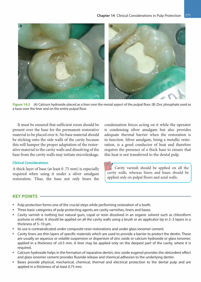
Chapter 14 Clinical Considerations in Pulp Protection 171
It must be ensured that sufficient room should be present over the base for the permanent restorative material to be placed over it. No base material should be sticking onto the side walls of the cavity because this will hamper the proper adaptation of the restor-ative material to the cavity walls and dissolving of the base from the cavity walls may initiate microleakage.
Clinical Considerations
A thick layer of base (at least 0 .75 mm) is especially required when using it under a silver amalgam restoration. Thus, the base not only bears the
condensation forces acting on it while the operator is condensing silver amalgam but also provides adequate thermal barrier when the restoration is in function. Silver amalgam, being a metallic resto-ration, is a good conductor of heat and therefore requires the presence of a thick base to ensure that this heat is not transferred to the dental pulp.
Cavity varnish should be applied on all the cavity walls, whereas liners and bases should be applied only on pulpal floors and axial walls.
KEY POINTS
• Pulp protection forms one of the crucial steps while performing restoration of a tooth.• Three basic categories of pulp protecting agents are cavity varnishes, liners and bases.• Cavity varnish is nothing but natural gum, copal or resin dissolved in an organic solvent such as chloroform
acetone or ether. It should be applied on all the cavity walls using a brush or an applicator tip in 2–3 layers in a thickness of 5–10 µm.
• Its use is contraindicated under composite resin restorations and under glass ionomer cement.• Cavity liners are thin layers of specific materials which are used to provide a barrier to protect the dentin. These
are usually an aqueous or volatile suspension or dispersion of zinc oxide or calcium hydroxide or glass ionomer, applied in a thickness of ≤0.5 mm. A liner may be applied only on the deepest part of the cavity, where it is required.
• Calcium hydroxide helps in the formation of reparative dentin; zinc oxide eugenol provides the obtundent effect and glass ionomer cement provides fluoride release and chemical adhesion to the underlying dentin.
• Bases provide physical, mechanical, chemical, thermal and electrical protection to the dental pulp and are applied in a thickness of at least 0.75 mm.
Figure 14.5 (A) Calcium hydroxide placed as a liner over the mesial aspect of the pulpal floor. (B) Zinc phosphate used as a base over the liner and on the entire pulpal floor.
A B
Preclinical Dentistry.indb 171 29-05-2020 12:57:33
https://t.me/DentalBooksWorld

172 Essentials of Preclinical Conservative Dentistry
• Zinc phosphate cement, reinforced zinc oxide eugenol cement, glass ionomer cement, zinc polycarboxylate cement, MTA and Biodentin are the commonly used bases.
• A base is applied on the entire pulpal floor or the axial wall.
SELF-ASSESSMENT QUESTIONS
1. What is a cavity varnish? Discuss its indications and contraindications.
2. Define cavity liner. Describe the exact function of calcium hydroxide and zinc oxide eugenol, when used as a liner.
3. What is the thickness of an ideal base? Name the walls of Class II cavity where you would apply the base.
4. Describe the various functions of a base.
5. Name two recent materials which can be used as a base.
Preclinical Dentistry.indb 172 29-05-2020 12:57:33
https://t.me/DentalBooksWorld
Silver amalgam is one of the most common of all materials used in dentistry for more than a century. It is commonly used as a restorative material for poste-rior teeth. An amalgam is an alloy of mercury with another metal, which may be a liquid, a soft paste or a solid, depending on the proportion of mercury. Silver amalgam alloy consists of silver, tin, copper and sometimes small amounts of zinc, indium or palladium. These alloys are mixed with mercury to form a plastic mass which can be directly packed into the prepared cavity of the tooth. The wetting of alloy with mercury initiates a physicochemical reaction that causes hardening of the material over time and provides a strong filling material.
With the increasing popularity of tooth-co-loured restorative materials such as composites and glass ionomer cements, use of silver amalgam has reduced considerably. However, amalgam is still used as a posterior restorative material for the ease of manipulation, durability, longevity and ability to maintain proper anatomic form in the mouth.
According to Anusavice, ‘amalgam’ is an alloy that contains mercury while ‘silver amalgam’ is an alloy of mercury, silver, copper and tin which may also contain palladium, zinc and other elements to improve handling characteristics and clinical performance.
History
Before amalgam, stone chips, cork, resin, turpen-tine, gum, lead, gold leaf and other metals were used by dentists for restoring teeth. The history of silver amalgam from the beginning up to its current clinical use is as follows:659 ad: First indication of use of silver amalgam in Tang dynasty (China).1528: Silver amalgam introduced in Germany by Johannes Stockerus.
1578: Li Shihchen used 100 parts of Hg, 900 parts of Sn and 45 parts of Ag for tooth restoration.
1603: Tobias Dorn Kreilius described a process for creating amalgam filling by dissolving copper sulphide with strong acids and mercury.
1800: D’Arcet made the first silver amalgam alloy of bismuth (8 parts), lead (1 part), tin (3 parts) and mercury (1 part) which plasticised at 100°C and was called mineral cement.
1818: Louis Regnart was credited as ‘Father of Amalgam’. He increased the amount of mercury (Hg) and lowered the plasticising temperature of mineral cement to 68°C.
1819: Charles Bell introduced the room temperature mixed amalgam known as ‘Bell’s putty’.
1833: Englishmen, Edward Crawcour and his nephew Moses Crawcour, introduced silver mercury paste in the USA and named it ‘Royal Mineral Succedaneum’ meaning ‘substitute for gold’.
1843: First amalgam war—the American Society of Dental Surgeons disapproved all filling materials and condemned their use due to toxicity except the use of gold. Members pledged not to use amalgam in dental practice.
1861: John Tomes conducted first research programme on amalgam.
1895: G.V. Black standardised cavity preparations and manufacturing process.
1926: German dentist A. Stock claimed to have evidence that mercury from amalgam can lead to serious health hazards. This started the second amalgam war.
1930: End of war after investigation by a committee from Charité Hospital in Berlin.
Silver Amalgam15Chapter
This chapter is contributed by Dr Amit Jena and Dr Shashirekha Govind.
Preclinical Dentistry.indb 173 29-05-2020 12:57:33
https://t.me/DentalBooksWorld
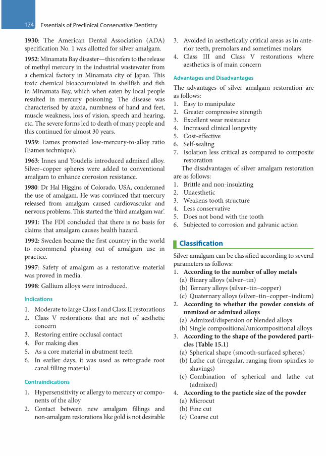
174 Essentials of Preclinical Conservative Dentistry
1930: The American Dental Association (ADA) specification No. 1 was allotted for silver amalgam.1952: Minamata Bay disaster—this refers to the release of methyl mercury in the industrial wastewater from a chemical factory in Minamata city of Japan. This toxic chemical bioaccumulated in shellfish and fish in Minamata Bay, which when eaten by local people resulted in mercury poisoning. The disease was characterised by ataxia, numbness of hand and feet, muscle weakness, loss of vision, speech and hearing, etc. The severe forms led to death of many people and this continued for almost 30 years.1959: Eames promoted low-mercury-to-alloy ratio (Eames technique).1963: Innes and Youdelis introduced admixed alloy. Silver–copper spheres were added to conventional amalgam to enhance corrosion resistance.1980: Dr Hal Higgins of Colorado, USA, condemned the use of amalgam. He was convinced that mercury released from amalgam caused cardiovascular and nervous problems. This started the ‘third amalgam war’.1991: The FDI concluded that there is no basis for claims that amalgam causes health hazard.1992: Sweden became the first country in the world to recommend phasing out of amalgam use in practice.1997: Safety of amalgam as a restorative material was proved in media.1998: Gallium alloys were introduced.
Indications
1. Moderate to large Class I and Class II restorations2. Class V restorations that are not of aesthetic
concern3. Restoring entire occlusal contact4. For making dies5. As a core material in abutment teeth6. In earlier days, it was used as retrograde root
canal filling material
Contraindications
1. Hypersensitivity or allergy to mercury or compo-nents of the alloy
2. Contact between new amalgam fillings and non-amalgam restorations like gold is not desirable
3. Avoided in aesthetically critical areas as in ante-rior teeth, premolars and sometimes molars
4. Class III and Class V restorations where aesthetics is of main concern
Advantages and Disadvantages
The advantages of silver amalgam restoration are as follows:1. Easy to manipulate2. Greater compressive strength3. Excellent wear resistance4. Increased clinical longevity5. Cost-effective6. Self-sealing7. Isolation less critical as compared to composite
restorationThe disadvantages of silver amalgam restoration
are as follows:1. Brittle and non-insulating2. Unaesthetic3. Weakens tooth structure4. Less conservative5. Does not bond with the tooth6. Subjected to corrosion and galvanic action
Classification
Silver amalgam can be classified according to several parameters as follows:1. According to the number of alloy metals
(a) Binary alloys (silver–tin)(b) Ternary alloys (silver–tin–copper)(c) Quaternary alloys (silver–tin–copper–indium)
2. According to whether the powder consists of unmixed or admixed alloys
(a) Admixed/dispersion or blended alloys(b) Single compositional/unicompositional alloys
3. According to the shape of the powdered parti-cles (Table 15.1)
(a) Spherical shape (smooth-surfaced spheres)(b) Lathe cut (irregular, ranging from spindles to
shavings)(c) Combination of spherical and lathe cut
(admixed)4. According to the particle size of the powder
(a) Microcut(b) Fine cut(c) Coarse cut
Preclinical Dentistry.indb 174 29-05-2020 12:57:34
https://t.me/DentalBooksWorld
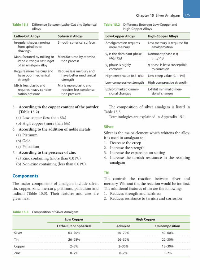
Chapter 15 Silver Amalgam 175
5. According to the copper content of the powder (Table 15.2)
(a) Low copper (less than 6%)(b) High copper (more than 6%)
6. According to the addition of noble metals(a) Platinum (b) Gold(c) Palladium
7. According to the presence of zinc(a) Zinc containing (more than 0.01%)(b) Non-zinc containing (less than 0.01%)
Components
The major components of amalgam include silver, tin, copper, zinc, mercury, platinum, palladium and indium (Table 15.3). Their features and uses are given next.
The composition of silver amalgam is listed in Table 15.3.
Terminologies are explained in Appendix 15.1.
SilverSilver is the major element which whitens the alloy. It is used in amalgam to: 1. Decrease the creep2. Increase the strength3. Increase the expansion on setting4. Increase the tarnish resistance in the resulting
amalgam
Tin Tin controls the reaction between silver and mercury. Without tin, the reaction would be too fast. The additional features of tin are the following:1. Reduces strength and hardness2. Reduces resistance to tarnish and corrosion
Table 15.2 Difference Between Low-Copper and High-Copper Alloys
Low-Copper Alloys High-Copper Alloys
Amalgamation requires more mercury
Less mercury is required for amalgamation
γ1 is the dominant phase (Ag2Hg3)
Dominant phase is η (Cu6Sn5)
γ2 phase is highly corrosive
η phase is least susceptible to corrosion
High creep value (0.8–8%) Low creep value (0.1–1%)
Low compressive strength High compressive strength
Exhibit marked dimen-sional changes
Exhibit minimal dimen-sional changes
Table 15.1 Difference Between Lathe-Cut and Spherical Alloys
Lathe-Cut Alloys Spherical Alloys
Irregular shapes ranging from spindles to shavings
Smooth spherical surface
Manufactured by milling or lathe cutting a cast ingot of an amalgam alloy
Manufactured by atomisa-tion process
Require more mercury and have poor mechanical strength
Require less mercury and have better mechanical strength
Mix is less plastic and requires heavy conden-sation pressure
Mix is more plastic and requires less condensa-tion pressure
Table 15.3 Composition of Silver Amalgam
Low Copper High Copper
Lathe Cut or Spherical Admixed Unicomposition
Silver 63–70% 40–70% 40–60%
Tin 26–28% 26–30% 22–30%
Copper 2–5% 2–30% 13–30%
Zinc 0–2% 0–2% 0–2%
Preclinical Dentistry.indb 175 29-05-2020 12:57:34
https://t.me/DentalBooksWorld
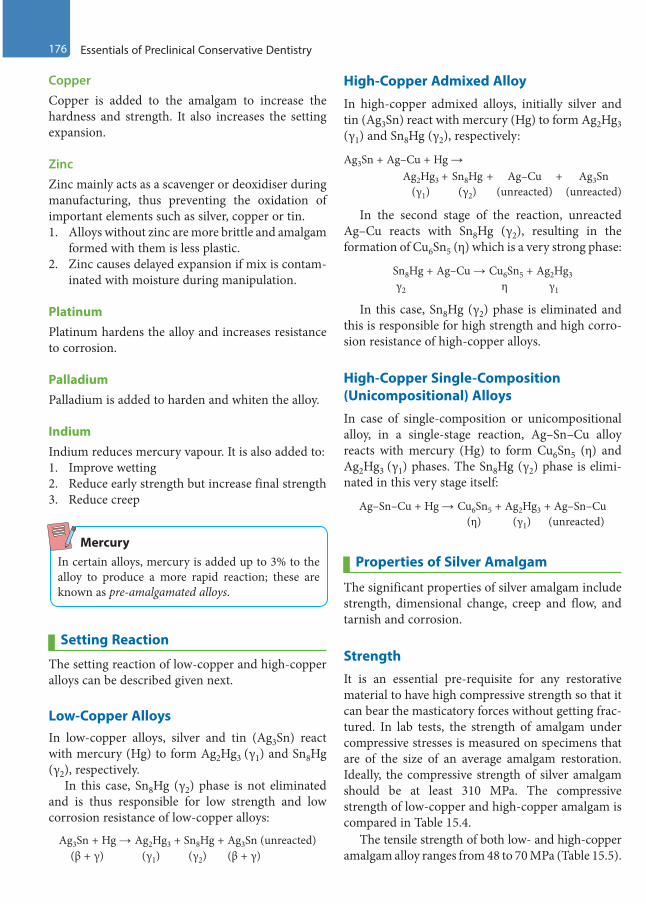
176 Essentials of Preclinical Conservative Dentistry
CopperCopper is added to the amalgam to increase the hardness and strength. It also increases the setting expansion.
ZincZinc mainly acts as a scavenger or deoxidiser during manufacturing, thus preventing the oxidation of important elements such as silver, copper or tin.1. Alloys without zinc are more brittle and amalgam
formed with them is less plastic.2. Zinc causes delayed expansion if mix is contam-
inated with moisture during manipulation.
PlatinumPlatinum hardens the alloy and increases resistance to corrosion.
PalladiumPalladium is added to harden and whiten the alloy.
IndiumIndium reduces mercury vapour. It is also added to: 1. Improve wetting2. Reduce early strength but increase final strength3. Reduce creep
MercuryIn certain alloys, mercury is added up to 3% to the alloy to produce a more rapid reaction; these are known as pre-amalgamated alloys.
Setting Reaction
The setting reaction of low-copper and high-copper alloys can be described given next.
Low-Copper AlloysIn low-copper alloys, silver and tin (Ag3Sn) react with mercury (Hg) to form Ag2Hg3 (γ1) and Sn8Hg (γ2), respectively.
In this case, Sn8Hg (γ2) phase is not eliminated and is thus responsible for low strength and low corrosion resistance of low-copper alloys:
Ag3Sn + Hg → Ag2Hg3 + Sn8Hg + Ag3Sn (unreacted) (β + γ) (γ1) (γ2) (β + γ)
High-Copper Admixed AlloyIn high-copper admixed alloys, initially silver and tin (Ag3Sn) react with mercury (Hg) to form Ag2Hg3 (γ1) and Sn8Hg (γ2), respectively:
Ag3Sn + Ag–Cu + Hg → Ag2Hg3 + Sn8Hg + Ag–Cu + Ag3Sn (γ1) (γ2) (unreacted) (unreacted)
In the second stage of the reaction, unreacted Ag–Cu reacts with Sn8Hg (γ2), resulting in the formation of Cu6Sn5 (η) which is a very strong phase:
Sn8Hg + Ag–Cu → Cu6Sn5 + Ag2Hg3 γ2 η γ1
In this case, Sn8Hg (γ2) phase is eliminated and this is responsible for high strength and high corro-sion resistance of high-copper alloys.
High-Copper Single-Composition (Unicompositional) AlloysIn case of single-composition or unicompositional alloy, in a single-stage reaction, Ag–Sn–Cu alloy reacts with mercury (Hg) to form Cu6Sn5 (η) and Ag2Hg3 (γ1) phases. The Sn8Hg (γ2) phase is elimi-nated in this very stage itself:
Ag–Sn–Cu + Hg → Cu6Sn5 + Ag2Hg3 + Ag–Sn–Cu (η) (γ1) (unreacted)
Properties of Silver Amalgam
The significant properties of silver amalgam include strength, dimensional change, creep and flow, and tarnish and corrosion.
StrengthIt is an essential pre-requisite for any restorative material to have high compressive strength so that it can bear the masticatory forces without getting frac-tured. In lab tests, the strength of amalgam under compressive stresses is measured on specimens that are of the size of an average amalgam restoration. Ideally, the compressive strength of silver amalgam should be at least 310 MPa. The compressive strength of low-copper and high-copper amalgam is compared in Table 15.4.
The tensile strength of both low- and high-copper amalgam alloy ranges from 48 to 70 MPa (Table 15.5).
Preclinical Dentistry.indb 176 29-05-2020 12:57:34
https://t.me/DentalBooksWorld

Chapter 15 Silver Amalgam 177
Factors Affecting the Strength of Amalgam
The factors affecting the strength of amalgam are as follows:1. Trituration: Both undertrituration and
overtrituration decrease the strength in conventional as well as high-copper amalgams. However, if trituration is continued even after the formation of the matrix, it will lead to crack formation and subsequent drop in the strength of the set amalgam.
2. Mercury content: If the mercury content of amalgam mix is more than 53–55%, it causes a drop in the compressive strength by 50%.
3. Effect of condensation: Lathe-cut alloys require greater condensation pressure. This is because irregular-shaped particles require more pressure to be packed completely to minimise porosity, and at the same time express excess mercury on the surface. This results in higher compres-sive strength, particularly the early strength. Spherical particles tend to slip under heavy pres-sure, so lighter pressure is required.
4. Effect of porosity: Voids and porosity present in the hardened amalgam are weak areas of restoration and tend to decrease the strength. Porosities can be due to undertrituration, inser-tion of too large increments into the cavity or delayed insertion after trituration.
5. Particle size: The smaller the size of the original particle, the greater will be the strength.
6. Temperature: About 15% of the strength is lost when the amalgam’s temperature is elevated from room temperature to mouth and 50% of strength is lost when temperature is elevated to 60°.
Dimensional ChangeTwo distinct dimensional changes are seen when mercury combines with amalgam—contraction and expansion.
Stage 1 (Contraction): It occurs 20 minutes after the beginning of trituration or initial trituration. Contraction results as the alloy particles dissolve in mercury and the γ1 phase grows. Contraction continues as long as there is growth of the γ1 phase.
Stage 2 (Expansion): As the γ1 phase grows, they start impinging against each other. When there are adequate crystals, this impingement and the outward pressure will counteract the initial contraction and result in expansion. Expansion occurs when there is adequate liquid mercury to provide a plastic matrix. Once the γ1 phase becomes rigid, no expansion occurs. Expansion is more for low-copper alloys than for high-copper ones.
Factors Affecting Dimensional Changes
According to ADA Specification No. 1, amalgam should neither contract nor expand more than 20 μm/cm when measured at 37°C between 5 min-utes and 24 hours after the beginning of trituration.
The factors affecting dimensional change are as follows:1. Mercury content: More is the mercury in the
mix, more is the expansion.2. Moisture contamination: Moisture contamina-
tion during trituration or condensation may lead to expansion of the restoration at a later stage, and is called delayed expansion.
Creep and Flow
The time-dependent plastic deformation that occurs when stress is applied to amalgam is known as creep. It is a slow progressive change in dimension under either static or dynamic loading. According to ADA specification no. 1, creep of amalgam should be below 3% (Table 15.6).
Table 15.4 Compressive Strength of Low-Copper and High-Copper Amalgam
Type of Amalgam Compressive Strength (MPa)
1 h 7 d
Low copper 145 343
Admixed 137 431
Single composition 262 510
Table 15.5 Tensile Strength of Amalgam Type of Amalgam Tensile Strength in 24 h (MPa)
Low copper 60
Admixed 48
Single composition 64
Preclinical Dentistry.indb 177 29-05-2020 12:57:34
https://t.me/DentalBooksWorld

178 Essentials of Preclinical Conservative Dentistry
Factors Influencing Creep
Creep is affected by phases of amalgam and manip-ulation. The various factors influencing creep are as follows:1. Copper content: Low-copper alloys have higher
creep as compared to high-copper ones as the former have γ2 phase which is a weak phase and is responsible for higher creep.
2. Mercury-to-alloy ratio: A low mercury-to-alloy ratio ensures reduced creep.
3. Condensation pressure: A greater condensation pressure when applied to lathe-cut alloys reduces the chances of creep.
Tarnish and CorrosionSometimes black silver sulphide can form on the surface of amalgam restorations indicating that the restoration has become tarnished.
However, corrosion of the amalgam restoration may also occur, especially at the junction of the tooth and the newly placed restoration. This is because of the fact that the microspace between the tooth and the restoration allows the microleakage of electrolytes and thus the process of ‘crevice corro-sion’ starts. The oxides and chlorides of tin are the corrosion products of amalgam.
The corrosion products, in the long run, seal the microspace between the tooth and the restoration, thus making the amalgam restoration as ‘self-sealing restoration’.
Factors Causing Tarnish and Corrosion
Factors affecting tarnish and corrosion are as follows: • Mercury-to-alloy ratio: Increased residual
mercury in the amalgam increases the chances of tarnish and corrosion.
• Copper content: Low-copper alloys are less resis-tant to tarnish and corrosion as compared to the high-copper ones as the former have γ2 phase which is a weak phase.
• Surface texture: Irregular surface with voids and scratches on a restoration makes it more prone to tarnish and corrosion.
• Dissimilar metal contact: When dissimilar metals such as amalgam and gold come in contact with each other in the oral cavity (e.g. antagonist teeth having these two different restorative mate-rials), galvanism may occur. This may result in the release of mercury from the amalgam, thus weakening it and simultaneously spoiling the gold restoration as well.
Bonded Amalgam Restoration
To improve the adhesion of amalgam to enamel and dentin and to reinforce the tooth structure, bonded amalgam restorations have been developed.
The adhesive agents contain monomers such as 4-META (4-methacryloxyethyl trimellitate anhydride), 10 MDP (10 methacryloyloxydecyl dihydrogen phosphate) and bis-GMA (bisphenol A-glycidyl methacrylate).
Delayed ExpansionIf zinc-containing alloys get contaminated with water during trituration or condensation, a large expansion (up to 4%) can take place which usually starts after 3–5 days and may continue for months. This expansion is called delayed expansion/secondary expansion.
Mechanism Zinc present in the alloy powder reacts with water from the moisture to form zinc hydroxide and releases hydrogen gas. This hydrogen gas does not combine with amalgam and instead collects within the resto-ration, increasing the internal pressure resultantly and finally causing expansion of the restoration.
Complication The complications of delayed expansion include the following:1. Protrusion of entire restoration out of the cavity2. Increased microleakage around the restoration3. Restoration perforations4. Increased flow and creep5. Pain due to pressure exerted by the expanding
amalgam
Table 15.6 Comparison of Creep of Low Copper, High Copper and Single Composition
Amalgam Creep
Low copper 2.0
Admixed 0.4
Single composition 0.13
Preclinical Dentistry.indb 178 29-05-2020 12:57:34
https://t.me/DentalBooksWorld

Chapter 15 Silver Amalgam 179
Retention is by micromechanical means where the amalgam gets entangled into the microscopic projections of the resin. Amalgam bonding agents can be dual cured or chemically cured.
Indications
Amalgam bonding agents are commercially available as Metabond, Panavia 21, All-Bond 2, Scotchbond Multipurpose and Amalgambond Plus. The indica-tions are as follows:1. In situations where auxiliary retention, rein-
forcement of the remaining tooth structure and improvement of marginal seal is necessary
2. Posterior teeth with extensive caries3. Teeth with low gingivo-occlusal height, that is,
short clinical crown4. Core for cast crown restoration
Advantages and Disadvantages
The advantages include the following:1. More conservative tooth preparations2. Reinforcement of tooth structure3. Minimisation of microleakage with resultant
secondary caries and postoperative sensitivity4. Decrease in the incidence of marginal fracture5. Cost-effective and completed in a single
appointmentThe disadvantages include the following:
1. It is highly technique sensitive.2. Mechanical properties of amalgam are lowered
due to incorporation of the resins.3. Long-term results are not documented.4. Isolation is critical.
Failures of Amalgam Restorations
The following possibilities could be called the failure of amalgam restoration: • Bulk fracture of the restoration• Pain or sensitivity• Marginal fracture• Tarnish and corrosion • Fracture of the tooth structure forming restor-
ative tooth preparation wall• Dimensional change• Proximal overhangings• Marginal ridge incompatibility and poor contouring
The causes of failure may be as follows:1. Improper case selection
2. Improper cavity design3. Inadequate proximal extension4. Inadequate depth of preparation5. Overtriturated mixture6. Incorrect alloy-to-mercury ratio7. Presence of γ2 phase8. Moisture contamination during manipulation9. Improper adaptation of matrix10. Fracture of amalgam due to stress concentration
at sharp axiopulpal line angle11. Excessive heat build-up during finishing and
polishing12. Premature contact with opposing tooth
Repaired Amalgam Restorations
Total restoration replacement is the most common treatment for defective amalgam restoration. Repair is an alternative option for the treatment of amalgam restoration with localised defects. It involves the removal of part of the restoration and any defective tissue adjacent and subjacent to the defective area and the restoration of the prepared site. This proce-dure allows for the preservation of sound tooth structure. However, the flexural strength of repaired amalgam restoration is less than 50% of that of unre-paired amalgam. Factors such as corrosion and saliva contamination at the interphase present formidable barriers that interfere with the bonding of the old and new amalgam.
For repair of amalgam restorations:1. Condensation pressure should be applied verti-
cally to the repair surface whenever possible, or the size of the condenser should only be slightly smaller than the repair site in order to exert maximum pressure on the repair surface.
2. A material of a different composition should be used to achieve greater repair strength.
Repair should be done if: 1. The area involved is not subjected to high stresses.2. The two restoration parts are adequately supported
and retained.3. Areas exhibit minor marginal breakdown (gaps
that are 250 mm in width). In this case, the enamel is etched adjacent to the restoration and after rinsing and drying the marginal gap area, the gap is sealed with a dentin-bonding adhesive.
Preclinical Dentistry.indb 179 29-05-2020 12:57:34
https://t.me/DentalBooksWorld

180 Essentials of Preclinical Conservative Dentistry
KEY POINTS
• Silver amalgam is one of the oldest restorative materials used in dental practice.• It basically comprises silver alloy powder particles which are mixed with mercury to make the silver amalgam.• Silver alloy powder comprises silver, tin, copper, zinc, platinum, palladium and indium.• Silver increases the strength and decreases the creep while tin controls the reaction between silver and mercury.
Without tin, the reaction would be too fast.• Copper increases the strength, hardness and setting expansion of the alloy. Zinc acts as a deoxidiser and prevents
the oxidation of silver, copper and tin.• Platinum hardens the alloy and increases resistance to corrosion while palladium also hardens the alloy and in
addition whitens it. On the other hand, indium reduces mercury vapour content in total. • While there are several types of silver amalgam alloys, the two major types are the ‘low-copper alloys’, having
copper content less than 6%, and ‘high-copper alloys’, having copper content more than 6%.• In low-copper alloys, the powder when mixed with mercury results in the formation of γ2 phase, which is weak
and responsible for their low strength and low resistance to tarnish and corrosion. However, this weak γ2 phase is eliminated in both admixed and single-composition-type high-copper alloys by the formation of a much stronger η phase.
• A high compressive and tensile strength is desirable for the success of silver amalgam in the oral cavity. Ideally, it should possess at least 310 MPa of compressive strength.
• High-copper alloys have higher compressive strength as they have copper which eliminates the weak γ2 phase.• According to ADA Specification No. 1, amalgam should neither contract nor expand more than 20 um/cm when
measured at 37°C between 5 minutes and 24 hours after the beginning of trituration.• The time-dependent plastic deformation that occurs when stress is applied to amalgam is known as creep.
According to ADA specification no. 1, creep of amalgam should be below 3%.• Silver sulphide is the tarnish product of amalgam, whereas oxides and chlorides of tin are its corrosion products. • The concept of bonded amalgam restorations was developed to improve the adhesion of amalgam to the
tooth. The adhesive agents containing monomers such as 4-META and bis-GMA are applied to the tooth prepa-ration followed by placement of the restoration.
• While amalgam usually serves in the oral cavity for a considerable period of time, failures do occur. Some of the major reasons of its failure are bulk fracture of the restoration, marginal fracture and proximal overhangs.
• Amalgam restorations can also be repaired in certain cases, especially when the restoration is not in the area of heavy masticatory forces. One can just create an independent resistance and retention form for the fractured area and can place fresh amalgam adjacent to the existing one. The use of adhesives can improve the retention in such situations.
SELF-ASSESSMENT QUESTIONS
1. Define silver amalgam.
2. Discuss in detail the composition of silver alloy powder and the functions of each component.
3. How do you classify the silver allow powder particles?
4. What is the difference between low-copper and high-copper alloys?
5. Discuss the importance of copper in silver amalgam setting reaction.
6. Discuss the various phases in silver amalgam setting reaction and their significance.
7. Discuss the importance of dimensional change in silver amalgam restoration.
8. Define ‘creep’ and discuss its clinical significance in relation to silver amalgam restoration.
9. What are bonded amalgam restorations? Enumerate three adhesives used for the bonding of amalgam to the tooth structure.
10. Enumerate the various types of silver amalgam restoration failures.
Preclinical Dentistry.indb 180 29-05-2020 12:57:34
https://t.me/DentalBooksWorld
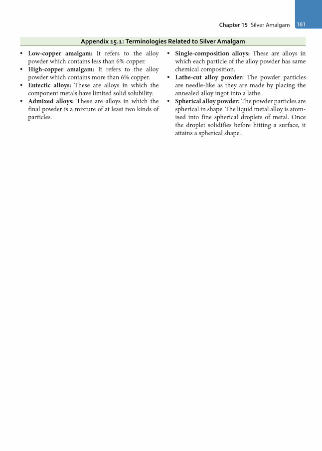
Chapter 15 Silver Amalgam 181
Appendix 15.1: Terminologies Related to Silver Amalgam
• Low-copper amalgam: It refers to the alloy powder which contains less than 6% copper.
• High-copper amalgam: It refers to the alloy powder which contains more than 6% copper.
• Eutectic alloys: These are alloys in which the component metals have limited solid solubility.
• Admixed alloys: These are alloys in which the final powder is a mixture of at least two kinds of particles.
• Single-composition alloys: These are alloys in which each particle of the alloy powder has same chemical composition.
• Lathe-cut alloy powder: The powder particles are needle-like as they are made by placing the annealed alloy ingot into a lathe.
• Spherical alloy powder: The powder particles are spherical in shape. The liquid metal alloy is atom-ised into fine spherical droplets of metal. Once the droplet solidifies before hitting a surface, it attains a spherical shape.
Preclinical Dentistry.indb 181 29-05-2020 12:57:34
https://t.me/DentalBooksWorld

Placing a silver amalgam restoration is actually a perfect combination of both art and science. To obtain the best results from a silver amalgam resto-ration, a good knowledge of the technical consider-ations involved is a must. Starting from the selection of the alloy to the finishing and polishing of the restoration, each step is discrete and is of utmost importance. Inappropriate attention at any step can lead to the failure of the restoration in one way or the other.
The step-by-step technique for placing an amalgam restoration can be described as given next.
Selection of the Alloy
The selection of the alloy powder mainly depends on the operator. The high-copper alloys (Fig. 16.1) are preferred for clinical use because of the fact that they do not have the γ2 phase after the setting reaction with mercury, which is considered as the weakest phase, responsible for low strength of the low-copper alloys. Also, high-copper alloys possess good corrosion resistance and low creep.
Finer particle sizes are used for the ease of handling and dispensing; in addition, they produce a smoother surface during carving and finishing.
Spherical particle alloys are preferred over lathe-cut alloys, because they have more regular surfaces, require less condensation pressure and require less mercury for trituration. Non-zinc-containing alloys are used only in those cases where moisture control is very difficult.
Proportioning (Mercury Alloy Ratio)
Despite the various techniques prescribed, the one that is most acceptable is the minimal mercury technique (Eames’ technique). In 1960, Eames was the first to promote low mercury:alloy ratio (Fig. 16.2). According to this technique, the recom-mended mercury to alloy ratio is 1:1 by volume. This amounts to the fact that the mercury content is 50%. However, for spherical alloys, the recom-mendations for mercury are closer to 42%, because spherical particles have lower surface:volume ratio
Step-by-Step Technique for Placing Amalgam Restoration16
Chapter
Figure 16.1 High-copper alloy powder. Figure 16.2 Mercury:alloy proportioning (alloy powder and mercury dispensed in mortar).
This chapter is a joint contribution by the author and Dr VV Bhadra Rao and Dr Sandhya PS.
Preclinical Dentistry.indb 182 29-05-2020 12:57:34
https://t.me/DentalBooksWorld

Chapter 16 Step-by-Step Technique for Placing Amalgam Restoration 183
and so they require less mercury to completely wet the particles.
Dispensing
A wide variety of dispensers are available through which mercury and alloy are dispensed for dental use. Some of them are as follows:1. Bottles containing bulk of mercury (30 g) and
alloy powder (225 g) are available (Fig. 16.3). The proportioning is done by the dentist according to the amount of the mix required for the restoration to be done. Although this kind of dispensing is economical, inappropriate propor-tioning can lead to too grainy or too plastic mix, thus hampering the properties of the material.
2. Pre-weighed pellets: The pellets of alloy are available in different sizes, which can be mixed with appropriate amount of mercury to obtain a suitable mix.
3. Disposable capsules containing pre-proportioned aliquots of mercury and alloy are also available. These pre-proportioned capsules contain alloy particles and mercury in compartments sepa-rated by a disc or membrane. In older type, before use, the membrane was ruptured by compression of capsule and then the capsule was placed in an amalgamator. Newer types, called self-activating types, are now available which are more convenient but expensive. In these capsules, the membrane ruptures on its own once the capsule is activated in the amalgamator.
4. Reusable capsules are also available into which the amalgam alloy is dispensed as a pellet of
pressed powder of standard weight and mercury is dispersed from an automatic dropper bottle. The capsule and its contents are automatically mixed using an amalgamator. The amalgamator is designed to oscillate in a pattern of figure ‘8’.
Disposable capsules are advantageous, as they are convenient, save proportioning time, cause minimal contamination and also maintain the mercury hygiene. For reusable capsules, threaded ones are better than friction fit, as the latter may create a mercury aerosol in the office atmosphere.
Trituration
Trituration is described as the process of mixing the amalgam alloy particles with mercury. The alloy and mercury can be mixed or triturated by hand with mortar and pestle (Fig. 16.4) or with a mechanical amalgamator (Fig. 16.5), which saves time and stan-dardises the procedure.
Objectives
1. To remove oxides from the powdered particle surface, facilitating direct contact between the alloy particles and the mercury
2. To achieve a workable mass of amalgam within a minimum time, leaving sufficient time for inser-tion into the cavity
Hand TriturationThis is done using mortar and pestle (Fig. 16.4). These can be made of either glass or ceramic. The
Figure 16.3 Bottles containing bulk of alloy powder (left) and bulk of mercury (right).
Figure 16.4 Hand trituration.
Preclinical Dentistry.indb 183 29-05-2020 12:57:35
https://t.me/DentalBooksWorld
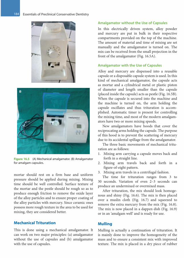
184 Essentials of Preclinical Conservative Dentistry
mortar should rest on a firm base and uniform pressure should be applied during mixing. Mixing time should be well controlled. Surface texture of the mortar and the pestle should be rough so as to produce enough friction to remove the oxide layer of the alloy particles and to ensure proper coating of the alloy particles with mercury. Since ceramic ones possess more rough texture in the area to be used for mixing, they are considered better.
Mechanical Trituration
This is done using a mechanical amalgamator. It can work on two major principles: (a) amalgamator without the use of capsules and (b) amalgamator with the use of capsules.
Amalgamator without the Use of Capsules
In this electrically driven system, alloy powder and mercury are put in bulk in their respective compartments provided on the top of the machine. The amount of material and time of mixing are set manually and the amalgamator is turned on. The mix can be received from the small projection in the front of the amalgamator (Fig. 16.5A).
Amalgamator with the Use of Capsules
Alloy and mercury are dispensed into a reusable capsule or a disposable capsule system is used. In this kind of mechanical amalgamator, the capsule acts as mortar and a cylindrical metal or plastic piston of diameter and length smaller than the capsule (placed inside the capsule) acts as pestle (Fig. 16.5B). When the capsule is secured into the machine and the machine is turned on, the arm holding the capsule oscillates and thus trituration is accom-plished. Automatic timer is present for controlling the mixing time, and most of the modern amalgam-ators have two or more mixing speeds.
New amalgamators have hoods that cover the reciprocating arms holding the capsule. The purpose of this hood is to prevent the scattering of mercury due to its accidental spillage from the amalgamator.
The three basic movements of mechanical tritu-ration are as follows:1. Mixing arm carrying a capsule moves back and
forth in a straight line.2. Mixing arm travels back and forth in a
figure-of-eight pattern.3. Mixing arm travels in a centrifugal fashion.
The time for trituration ranges from 3 to 30 seconds. Variation of even 2–3 seconds can produce an undermixed or overmixed mass.
After trituration, the mix should look homoge-nous and shiny (Fig. 16.6). The mix is then placed over a muslin cloth (Fig. 16.7) and squeezed to remove the extra mercury from the mix (Fig. 16.8). The mix is now placed in a dappen dish (Fig. 16.9) or in an ‘amalgam well’ and is ready for use.
MullingMulling is actually a continuation of trituration. It is mainly done to improve the homogeneity of the mass and to ensure a consistent mix with improved texture. The mix is placed in a dry piece of rubber
A
B
Figure 16.5 (A) Mechanical amalgamator. (B) Amalgamator for amalgam capsules.
Preclinical Dentistry.indb 184 29-05-2020 12:57:36
https://t.me/DentalBooksWorld
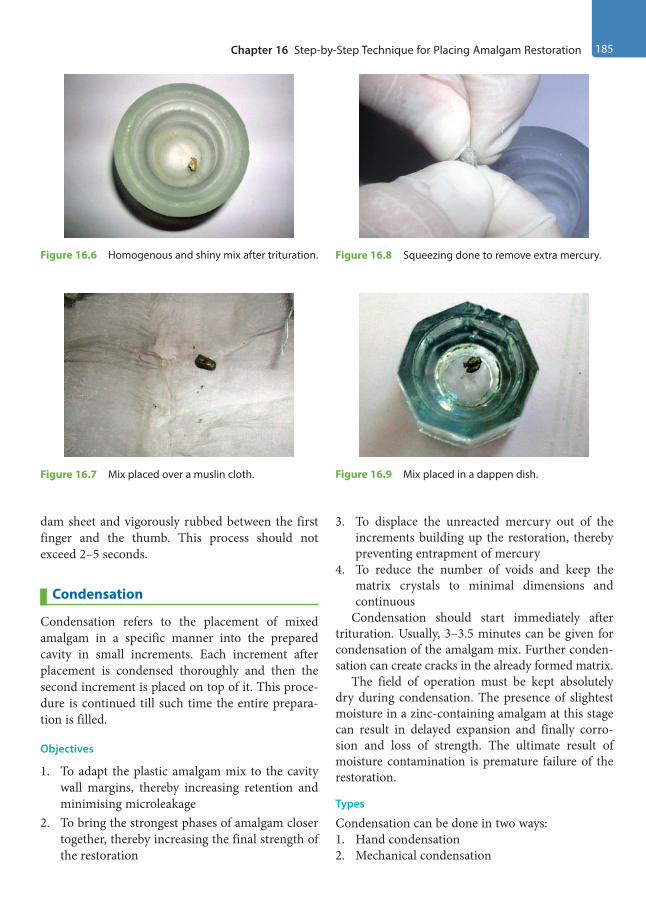
Chapter 16 Step-by-Step Technique for Placing Amalgam Restoration 185
dam sheet and vigorously rubbed between the first finger and the thumb. This process should not exceed 2–5 seconds.
Condensation
Condensation refers to the placement of mixed amalgam in a specific manner into the prepared cavity in small increments. Each increment after placement is condensed thoroughly and then the second increment is placed on top of it. This proce-dure is continued till such time the entire prepara-tion is filled.
Objectives
1. To adapt the plastic amalgam mix to the cavity wall margins, thereby increasing retention and minimising microleakage
2. To bring the strongest phases of amalgam closer together, thereby increasing the final strength of the restoration
3. To displace the unreacted mercury out of the increments building up the restoration, thereby preventing entrapment of mercury
4. To reduce the number of voids and keep the matrix crystals to minimal dimensions and continuous
Condensation should start immediately after trituration. Usually, 3–3.5 minutes can be given for condensation of the amalgam mix. Further conden-sation can create cracks in the already formed matrix.
The field of operation must be kept absolutely dry during condensation. The presence of slightest moisture in a zinc-containing amalgam at this stage can result in delayed expansion and finally corro-sion and loss of strength. The ultimate result of moisture contamination is premature failure of the restoration.
Types
Condensation can be done in two ways:1. Hand condensation2. Mechanical condensation
Figure 16.6 Homogenous and shiny mix after trituration.
Figure 16.7 Mix placed over a muslin cloth.
Figure 16.8 Squeezing done to remove extra mercury.
Figure 16.9 Mix placed in a dappen dish.
Preclinical Dentistry.indb 185 29-05-2020 12:57:36
https://t.me/DentalBooksWorld
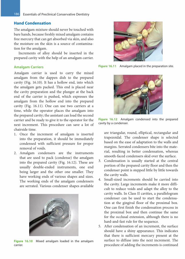
186 Essentials of Preclinical Conservative Dentistry
Hand CondensationThe amalgam mixture should never be touched with bare hands, because freshly mixed amalgam contains free mercury that can get absorbed via skin, and also the moisture on the skin is a source of contamina-tion for the amalgam.
Increments of alloy should be inserted in the prepared cavity with the help of an amalgam carrier.
Amalgam Carriers
Amalgam carrier is used to carry the mixed amalgam from the dappen dish to the prepared cavity (Fig. 16.10). It has a hollow end, into which the amalgam gets packed. This end is placed near the cavity preparation and the plunger at the back end of the carrier is pushed, which expresses the amalgam from the hollow end into the prepared cavity (Fig. 16.11). One can use two carriers at a time, while the operator places the amalgam into the prepared cavity; the assistant can load the second carrier and be ready to give it to the operator for the next increment. This procedure can save a lot of chairside time.1. Once the increment of amalgam is inserted
into the preparation, it should be immediately condensed with sufficient pressure for proper removal of voids.
2. Amalgam condensers are the instruments that are used to pack (condense) the amalgam into the prepared cavity (Fig. 16.12). These are usually double-ended instruments, one end being larger and the other one smaller. They have working ends of various shapes and sizes. The working ends of the amalgam condensers are serrated. Various condenser shapes available
are triangular, round, elliptical, rectangular and trapezoidal. The condenser shape is selected based on the ease of adaptation to the walls and margins. Serrated condensers bite into the mate-rial, resulting in better condensation, whereas smooth-faced condensers skid over the surface.
3. Condensation is usually started at the central portion of the prepared cavity floor and then the condenser point is stepped little by little towards the cavity walls.
4. Small-sized increments should be carried into the cavity. Large increments make it more diffi-cult to reduce voids and adapt the alloy to the cavity walls. In Class II cavities, a parallelogram condenser can be used to start the condensa-tion at the gingival floor of the proximal box. One can first finish the condensation process in the proximal box and then continue the same for the occlusal extension, although there is no hard-and-fast rule for the sequence.
5. After condensation of an increment, the surface should have a shiny appearance. This indicates that there is sufficient mercury present at the surface to diffuse into the next increment. The procedure of adding the increments is continued
Figure 16.10 Mixed amalgam loaded in the amalgam carrier.
Figure 16.11 Amalgam placed in the preparation site.
Figure 16.12 Amalgam condensed into the prepared cavity by a condenser.
Preclinical Dentistry.indb 186 29-05-2020 12:57:37
https://t.me/DentalBooksWorld
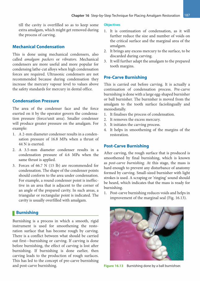
Chapter 16 Step-by-Step Technique for Placing Amalgam Restoration 187
till the cavity is overfilled so as to keep some extra amalgam, which might get removed during the process of carving.
Mechanical Condensation
This is done using mechanical condensers, also called amalgam packers or vibrators. Mechanical condensers are more useful and more popular for condensing lathe-cut alloys when high condensation forces are required. Ultrasonic condensers are not recommended because during condensation they increase the mercury vapour level to values above the safety standards for mercury in dental office.
Condensation Pressure
The area of the condenser face and the force exerted on it by the operator govern the condensa-tion pressure (force/unit area). Smaller condenser will produce greater pressure on the amalgam. For example:1. A 2-mm diameter condenser results in a conden-
sation pressure of 16.8 MPa when a thrust of 44 N is exerted.
2. A 3.5-mm diameter condenser results in a condensation pressure of 4.6 MPa when the same thrust is applied.
3. Forces of 66.7 N (15 lb) are recommended for condensation. The shape of the condenser points should conform to the area under condensation. For example, a round condenser point is ineffec-tive in an area that is adjacent to the corner of an angle of the prepared cavity. In such areas, a triangular or rectangular point is indicated. The cavity is usually overfilled with amalgam.
Burnishing
Burnishing is a process in which a smooth, rigid instrument is used for smoothening the resto-ration surface that has become rough by carving. There is a conflict between what should be carried out first—burnishing or carving. If carving is done before burnishing, the effect of carving is lost after burnishing. If burnishing is done earlier, then carving leads to the production of rough surfaces. This has led to the concept of pre-carve burnishing and post-carve burnishing.
Objectives
1. It is continuation of condensation, as it will further reduce the size and number of voids on the critical surface and the marginal area of the amalgam.
2. It brings any excess mercury to the surface, to be discarded during carving.
3. It will further adapt the amalgam to the prepared tooth margins.
Pre-Carve BurnishingThis is carried out before carving. It is actually a continuation of condensation process. Pre-carve burnishing is done with a large egg-shaped burnisher or ball burnisher. The burnisher is moved from the amalgam to the tooth surface faciolingually and mesiodistally.1. It finalises the process of condensation.2. It removes the excess mercury.3. It initiates the carving process.4. It helps in smoothening of the margins of the
restoration.
Post-Carve BurnishingAfter carving, the rough surface that is produced is smoothened by final burnishing, which is known as post-carve burnishing. At this stage, the mass is hard enough to prevent any disturbance of anatomy formed by carving. Small-sized burnisher with light strokes is used. A scraping or ‘ringing’ sound should be heard, which indicates that the mass is ready for burnishing.1. Post-carve burnishing reduces voids and helps in
improvement of the marginal seal (Fig. 16.13).
Figure 16.13 Burnishing done by a ball burnishser.
Preclinical Dentistry.indb 187 29-05-2020 12:57:37
https://t.me/DentalBooksWorld

188 Essentials of Preclinical Conservative Dentistry
2. Obtaining the satin or velvet finish is the main aim of this step.
Carving
Carving is defined as the anatomical sculpturing of amalgam to re-obtain the original anatomy of the restored tooth. This is performed by using instru-ments called amalgam carvers. The cutting edges of these carvers are sharp, which are used to reproduce the anatomy of the restored tooth.
Objectives
The objectives of carving are as follows:1. To produce a restoration with proper physiolog-
ical contours and no overhangs2. To produce a restoration with adequate marginal
ridges, proper size and location of contact areas and embrasures
3. To produce a restoration with functional non-in-terfering occlusal anatomy
Carving is begun soon after condensation, but the amalgam should be hard enough to offer resistance to the carving instrument. If carving is started too soon, the amalgam is pulled away from the margins. Carving is always done from the tooth surface to the restoration surface. This is done to avoid removal of the amalgam at the margins.
Procedure
Hollenback carver (Fig. 16.14), Ward’s carver, Frahm’s carver (diamond-shaped carver), cleoid and discoid carvers, etc., are some of the different types of carvers used.1. First, the embrasures are carved with Hollenback
carvers and then the triangular fossa is carved
with the discoid/cleoid carver, which will enhance the marginal ridge (Fig. 16.15).
2. Then, the inclined planes as well as occlusal fossae and grooves are carved.
3. The occlusal contours are checked during centric occlusion and during lateral mandibular movements.
4. Carving is done by moving the instrument laterally and cutting the amalgam, while being guided by the intact tooth.
5. Post-carve burnishing is done to remove scratches and irregularities on the amalgam surface, facilitating easier and efficient finishing and polishing.
Matrix Band Removal
After carving the occlusal portion, the matrix retainer, matrix band and wedges are removed. Proper care needs to be taken while removing the band, since many a times, restoration can fracture (especially Class II) during this step. To prevent this failure, one should first ensure that the amalgam is set hard enough, which can be done with the help of a burnisher. Thereafter, the wedge and the retainer should be removed carefully, keeping the band in position. The ends of the band (facial and lingual) should be held with the fingers of the two hands and everted in the opposite direction (e.g. while restoring the distal surface of a mandibular second molar, Figure 16.14 Carving done by a Hollenback carver.
Figure 16.15 Restorations completed and carving done in mandibular premolar and molar.
Preclinical Dentistry.indb 188 29-05-2020 12:57:37
https://t.me/DentalBooksWorld
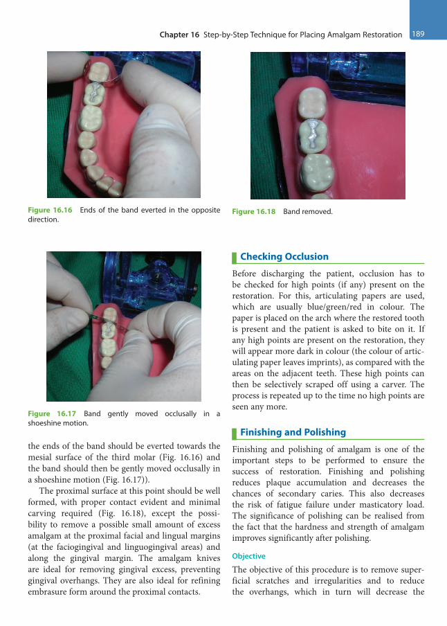
Chapter 16 Step-by-Step Technique for Placing Amalgam Restoration 189
the ends of the band should be everted towards the mesial surface of the third molar (Fig. 16.16) and the band should then be gently moved occlusally in a shoeshine motion (Fig. 16.17)).
The proximal surface at this point should be well formed, with proper contact evident and minimal carving required (Fig. 16.18), except the possi-bility to remove a possible small amount of excess amalgam at the proximal facial and lingual margins (at the faciogingival and linguogingival areas) and along the gingival margin. The amalgam knives are ideal for removing gingival excess, preventing gingival overhangs. They are also ideal for refining embrasure form around the proximal contacts.
Checking Occlusion
Before discharging the patient, occlusion has to be checked for high points (if any) present on the restoration. For this, articulating papers are used, which are usually blue/green/red in colour. The paper is placed on the arch where the restored tooth is present and the patient is asked to bite on it. If any high points are present on the restoration, they will appear more dark in colour (the colour of artic-ulating paper leaves imprints), as compared with the areas on the adjacent teeth. These high points can then be selectively scraped off using a carver. The process is repeated up to the time no high points are seen any more.
Finishing and Polishing
Finishing and polishing of amalgam is one of the important steps to be performed to ensure the success of restoration. Finishing and polishing reduces plaque accumulation and decreases the chances of secondary caries. This also decreases the risk of fatigue failure under masticatory load. The significance of polishing can be realised from the fact that the hardness and strength of amalgam improves significantly after polishing.
Objective
The objective of this procedure is to remove super-ficial scratches and irregularities and to reduce the overhangs, which in turn will decrease the
Figure 16.16 Ends of the band everted in the opposite direction.
Figure 16.17 Band gently moved occlusally in a shoeshine motion.
Figure 16.18 Band removed.
Preclinical Dentistry.indb 189 29-05-2020 12:57:37
https://t.me/DentalBooksWorld
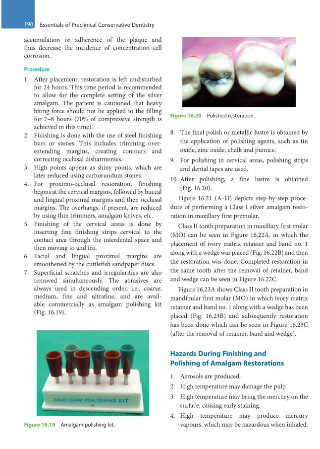
190 Essentials of Preclinical Conservative Dentistry
accumulation or adherence of the plaque and thus decrease the incidence of concentration cell corrosion.
Procedure
1. After placement, restoration is left undisturbed for 24 hours. This time period is recommended to allow for the complete setting of the silver amalgam. The patient is cautioned that heavy biting force should not be applied to the filling for 7–8 hours (70% of compressive strength is achieved in this time).
2. Finishing is done with the use of steel finishing burs or stones. This includes trimming over-extending margins, creating contours and correcting occlusal disharmonies.
3. High points appear as shiny points, which are later reduced using carborundum stones.
4. For proximo-occlusal restoration, finishing begins at the cervical margins, followed by buccal and lingual proximal margins and then occlusal margins. The overhangs, if present, are reduced by using thin trimmers, amalgam knives, etc.
5. Finishing of the cervical areas is done by inserting fine finishing strips cervical to the contact area through the interdental space and then moving to and fro.
6. Facial and lingual proximal margins are smoothened by the cuttlefish sandpaper discs.
7. Superficial scratches and irregularities are also removed simultaneously. The abrasives are always used in descending order, i.e., coarse, medium, fine and ultrafine, and are avail-able commercially as amalgam polishing kit (Fig. 16.19).
8. The final polish or metallic lustre is obtained by the application of polishing agents, such as tin oxide, zinc oxide, chalk and pumice.
9. For polishing in cervical areas, polishing strips and dental tapes are used.
10. After polishing, a fine lustre is obtained (Fig. 16.20).
Figure 16.21 (A –D) depicts step-by-step proce-dure of performing a Class I silver amalgam resto-ration in maxillary first premolar.
Class II tooth preparation in maxillary first molar (MO) can be seen in Figure 16.22A, in which the placement of ivory matrix retainer and band no. 1 along with a wedge was placed (Fig. 16.22B) and then the restoration was done. Completed restoration in the same tooth after the removal of retainer, band and wedge can be seen in Figure 16.22C.
Figure 16.23A shows Class II tooth preparation in mandibular first molar (MO) in which ivory matrix retainer and band no. 1 along with a wedge has been placed (Fig. 16.23B) and subsequently restoration has been done which can be seen in Figure 16.23C (after the removal of retainer, band and wedge).
Hazards During Finishing and Polishing of Amalgam Restorations
1. Aerosols are produced.2. High temperature may damage the pulp.3. High temperature may bring the mercury on the
surface, causing early staining.4. High temperature may produce mercury
vapours, which may be hazardous when inhaled.Figure 16.19 Amalgam polishing kit.
Figure 16.20 Polished restoration.
Preclinical Dentistry.indb 190 29-05-2020 12:57:37
https://t.me/DentalBooksWorld

Chapter 16 Step-by-Step Technique for Placing Amalgam Restoration 191
Figure 16.21 (A) Class I tooth preparation in maxillary first premolar. (B) Silver amalgam condensed layer by layer. (C) Silver amalgam till the surface. (D) Finished silver amalgam restoration.
A B
C D
Figure 16.22 (A) Class II tooth preparation in maxillary first molar. (B) Matrix retainer, band and wedge in position. (C) Finished silver amalgam restoration.
A B
C
Preclinical Dentistry.indb 191 29-05-2020 12:57:38
https://t.me/DentalBooksWorld
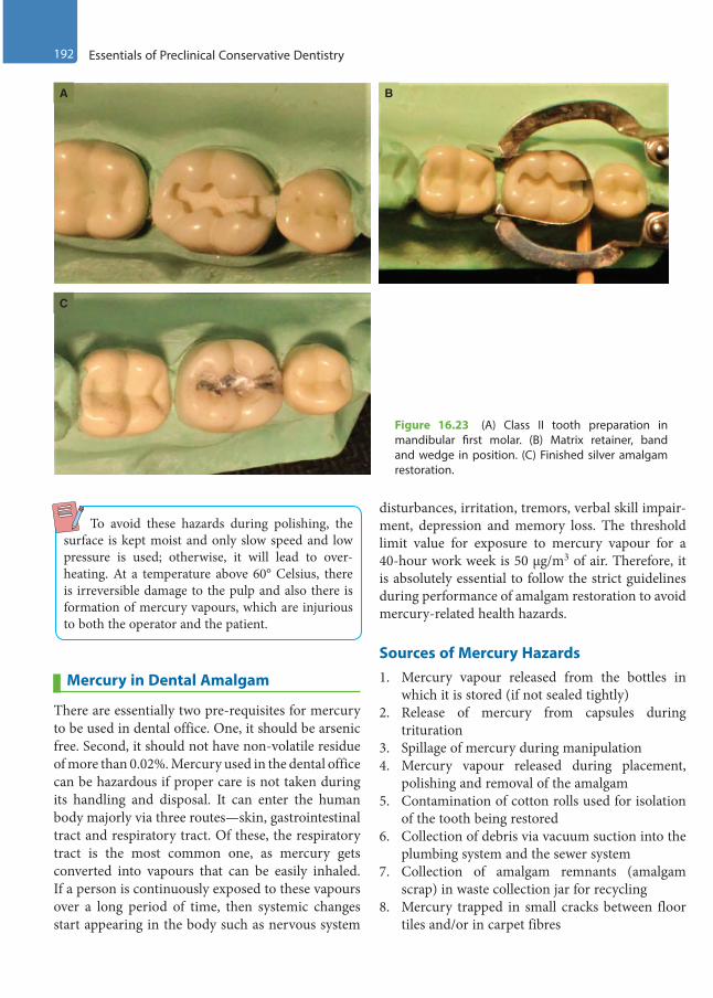
192 Essentials of Preclinical Conservative Dentistry
To avoid these hazards during polishing, the surface is kept moist and only slow speed and low pressure is used; otherwise, it will lead to over-heating. At a temperature above 60° Celsius, there is irreversible damage to the pulp and also there is formation of mercury vapours, which are injurious to both the operator and the patient.
Mercury in Dental Amalgam
There are essentially two pre-requisites for mercury to be used in dental office. One, it should be arsenic free. Second, it should not have non-volatile residue of more than 0.02%. Mercury used in the dental office can be hazardous if proper care is not taken during its handling and disposal. It can enter the human body majorly via three routes—skin, gastrointestinal tract and respiratory tract. Of these, the respiratory tract is the most common one, as mercury gets converted into vapours that can be easily inhaled. If a person is continuously exposed to these vapours over a long period of time, then systemic changes start appearing in the body such as nervous system
disturbances, irritation, tremors, verbal skill impair-ment, depression and memory loss. The threshold limit value for exposure to mercury vapour for a 40-hour work week is 50 µg/m3 of air. Therefore, it is absolutely essential to follow the strict guidelines during performance of amalgam restoration to avoid mercury-related health hazards.
Sources of Mercury Hazards1. Mercury vapour released from the bottles in
which it is stored (if not sealed tightly)2. Release of mercury from capsules during
trituration3. Spillage of mercury during manipulation4. Mercury vapour released during placement,
polishing and removal of the amalgam5. Contamination of cotton rolls used for isolation
of the tooth being restored6. Collection of debris via vacuum suction into the
plumbing system and the sewer system7. Collection of amalgam remnants (amalgam
scrap) in waste collection jar for recycling8. Mercury trapped in small cracks between floor
tiles and/or in carpet fibres
Figure 16.23 (A) Class II tooth preparation in mandibular first molar. (B) Matrix retainer, band and wedge in position. (C) Finished silver amalgam restoration.
A B
C
Preclinical Dentistry.indb 192 29-05-2020 12:57:38
https://t.me/DentalBooksWorld
Chapter 16 Step-by-Step Technique for Placing Amalgam Restoration 193
Guidelines for Handling Mercury and its Disposal1. All the personnel working in a dental office
who come in contact with the restorative mate-rials should be well educated about the mercu-ry-related health hazards and should be trained regarding its proper disposal.
2. The operatory should be well ventilated so as to avoid accumulation of mercury vapours in the working area.
3. Preferably, amalgam capsules should be used instead of bulk bottles to avoid any leakage of the mercury from the bottles.
4. Use of an amalgamator is preferred instead of mortar and pestle, as the latter exposes more mercury to the environment than the former.
5. If using the manual technique of trituration, the squeezed mercury should be collected carefully in a container and not spilled.
6. Amalgam should always be handled with gloved hands only to avoid skin contamination.
7. High-volume evacuation should be used while performing the restoration as well as removal of old amalgam restoration, as both these
procedures cause release of mercury vapour to one extent or the other.
8. Instruments used for inserting, finishing, polishing or removing amalgam restorations contain some amalgam material on their surfaces. During instrument sterilisation tech-niques, this material may be heated and can release mercury vapours. Therefore, it is advis-able to properly isolate or specially vent the air from the sterilisation areas.
9. Mercury-contaminated cotton rolls should not be thrown out with regular trash. They should be stored in a tightly capped plastic container or closed plastic bag for separate disposal.
10. All excess mercury (squeezed out) and leftover amalgam (amalgam scrap) should be placed in used radiographic fixer solution, which can be kept in a dark bottle. Fixer solution contains sulphur, which can combine with mercury to form stable sulphides. Also, used fixer solution is a source of silver, which can react with the unused mercury to form stable compounds.
11. Spilled mercury should be cleaned up properly using trap bottles, tape or commercial cleanup kits. Household vacuum cleaner should never be used.
KEY POINTS
• It is important to understand the technical considerations of silver amalgam thoroughly in order to perform the restorative procedure in most efficient manner.
• A high-copper alloy is mostly selected because of no γ2 phase and high early strength, low creep, good corrosion resistance and good resistance to marginal fracture.
• The alloy powder:mercury ratio during proportioning is kept as 1:1 by volume and is referred to as Eames’ technique.
• The alloy powder and mercury are available as bottles containing bulk of mercury and bulk of alloy powder, pre-weighed pellets and disposable capsules.
• The alloy powder and mercury are mixed thoroughly and this process is termed trituration. It can be manual or mechanical, the latter being a more standardised procedure.
• Condensation refers to inserting the mixed amalgam into the prepared tooth structure by use of serrated condensers. Sufficient force is required to perform this step.
• Burnishing refers to smoothening of the condensed amalgam by using a burnisher. It can be pre-carve burnishing or post-carve burnishing.
• Carving refers to sculpturing of amalgam to re-obtain original anatomy of the restored tooth by use of various amalgam carvers.
• The final step is finishing and polishing of the amalgam restoration, which provides a smooth and lustrous surface, thus increasing the longevity of the restoration.
Preclinical Dentistry.indb 193 29-05-2020 12:57:38
https://t.me/DentalBooksWorld

194 Essentials of Preclinical Conservative Dentistry
SELF-ASSESSMENT QUESTIONS
1. What are the criteria for selection of a good alloy powder?
2. What do you mean by Eames’ technique?
3. What do you mean by trituration?
4. Describe mulling.
5. What is the objective of condensation? Name the different types of condensers used for the same.
6. What do you understand by burnishing? Describe the types of burnishing.
7. Discuss the importance of carving a silver amalgam restoration.
8. Describe the step-by-step procedure of polishing a silver amalgam restoration.
Preclinical Dentistry.indb 194 29-05-2020 12:57:38
https://t.me/DentalBooksWorld

The course of inventions and developments in the field of aesthetic dentistry reached a landmark when R.L. Bowen introduced composites in 1962.
Anusavice defined composite as a compound of two or more distinctly different materials with properties that are superior to or intermediate between those of individual components. The use of composite restorations is increasing because of the benefits accrued, adhesive bonding to the tooth structure and thus requiring minimal cutting of the natural tooth structure, aesthetic qualities and almost universal clinical usage. With meticulous procedural performance, these restorations provide excellent service for many years.
Originally discovered in chemical cure form, the composites used these days are light-cured ones having several advantages over their older versions.
Composition of Composite Resins
Light-cure composites are available in single paste form, which consists of the following:1. Resin matrix such as BisGMA, UDMA,
TEGDMA HEMA, EGDMA and semicrystalline polyceram (PEX)
2. Fillers (quartz, silica, tricalcium phosphate, zirconium dioxide, yttrium trifluoride, etc.)
3. Coupling agent (organosilanes [γ-methacryloxypropyltrimethoxysilane])
4. Polymerisation inhibitors (hydroquinone)5. Polymerisation initiators such as benzoyl
peroxide (chemical cure), benzoin methyl ether (UV light activated), camphoroquinone (visible light activated), phenylpropanedione (PPD) or Lucirin/trimethylbenzoyldiphenylphosphine oxide (TPO) [blue light activated]
6. Polymerisation activator (tertiary amine)7. Colouring agents (aluminium oxide, titanium
dioxide)
Tooth Preparation for Composite Resin Restoration
The objectives of tooth preparation for composite resin restoration are as follows:1. To remove all the defects, faults, old material or
friable tooth structure2. To extend the preparation as conservatively as
possible3. To provide proper form to the tooth preparation,
so that both the tooth and the restoration do not fracture under the forces of mastication
4. Creating the convenience form for the restoration5. To allow aesthetic and functional placement of
the composite resin6. To create prepared enamel margins of 90° or
greaterComposite restoration and amalgam restorations
have been compared and contrasted in Table 17.1.
Types
The different types of tooth preparations for restoration using composite resins are as follows:1. Conventional tooth preparation2. Bevelled conventional tooth preparation3. Modified tooth preparation4. Combined tooth preparation
Conventional Tooth Preparation
Conventional tooth preparations for composite resins are same as those typical for amalgam resto-rations. The outline form for these is the extension of external walls at uniform and limited depth, which results in the formation of a butt joint junc-tion between the walls of the preparation and the restorative material (Fig. 17.1).
Cavity Preparation for Composite Resin17
Chapter
This chapter is a joint contribution by the author and Dr B. Rajkumar.
Preclinical Dentistry.indb 195 29-05-2020 12:57:38
https://t.me/DentalBooksWorld
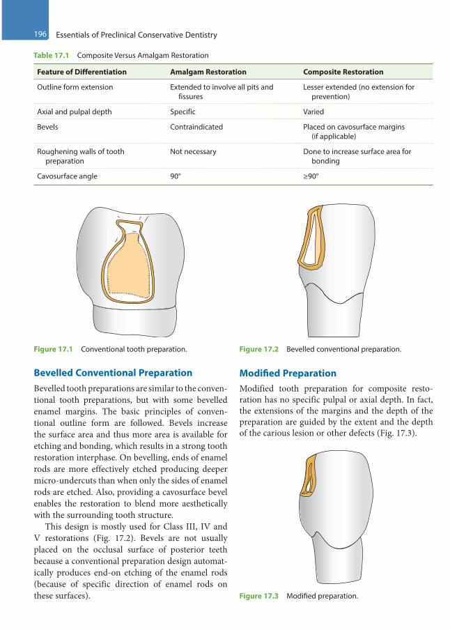
196 Essentials of Preclinical Conservative Dentistry
Bevelled Conventional PreparationBevelled tooth preparations are similar to the conven-tional tooth preparations, but with some bevelled enamel margins. The basic principles of conven-tional outline form are followed. Bevels increase the surface area and thus more area is available for etching and bonding, which results in a strong tooth restoration interphase. On bevelling, ends of enamel rods are more effectively etched producing deeper micro-undercuts than when only the sides of enamel rods are etched. Also, providing a cavosurface bevel enables the restoration to blend more aesthetically with the surrounding tooth structure.
This design is mostly used for Class III, IV and V restorations (Fig. 17.2). Bevels are not usually placed on the occlusal surface of posterior teeth because a conventional preparation design automat-ically produces end-on etching of the enamel rods (because of specific direction of enamel rods on these surfaces).
Modified PreparationModified tooth preparation for composite resto-ration has no specific pulpal or axial depth. In fact, the extensions of the margins and the depth of the preparation are guided by the extent and the depth of the carious lesion or other defects (Fig. 17.3).
Figure 17.1 Conventional tooth preparation.
Table 17.1 Composite Versus Amalgam Restoration
Feature of Differentiation Amalgam Restoration Composite Restoration
Outline form extension Extended to involve all pits and fissures
Lesser extended (no extension for prevention)
Axial and pulpal depth Specific Varied
Bevels Contraindicated Placed on cavosurface margins (if applicable)
Roughening walls of tooth preparation
Not necessary Done to increase surface area for bonding
Cavosurface angle 90° ≥90°
Figure 17.2 Bevelled conventional preparation.
Figure 17.3 Modified preparation.
Preclinical Dentistry.indb 196 29-05-2020 12:57:38
https://t.me/DentalBooksWorld
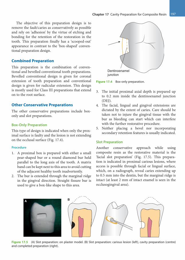
Chapter 17 Cavity Preparation for Composite Resin 197
The objective of this preparation design is to remove the fault/caries as conservatively as possible and rely on ‘adhesion’ by the virtue of etching and bonding for the retention of the restoration in the tooth. This preparation finally has a ‘scooped-out’ appearance in contrast to the ‘box-shaped’ conven-tional preparation design.
Combined PreparationThis preparation is the combination of conven-tional and bevelled conventional tooth preparations. Bevelled conventional design is given for coronal extension of tooth preparation and conventional design is given for radicular extension. This design is mostly used for Class III preparations that extend on to the root surface.
Other Conservative PreparationsThe other conservative preparations include box- only and slot preparations.
Box-Only PreparationThis type of design is indicated when only the prox-imal surface is faulty and the lesion is not extending on the occlusal surface (Fig. 17.4).
Procedure
1. A proximal box is prepared with either a small pear-shaped bur or a round diamond bur held parallel to the long axis of the tooth. A matrix band can be kept next to this area to avoid cutting of the adjacent healthy tooth inadvertently.
2. The bur is extended through the marginal ridge in the gingival direction. Straight fissure bur is used to give a box-like shape to this area.
3. The initial proximal axial depth is prepared up to 0.2 mm inside the dentinoenamel junction (DEJ).
4. The facial, lingual and gingival extensions are dictated by the extent of caries. Care should be taken not to injure the gingival tissue with the bur as bleeding can start which can interfere with the further restorative procedure.
5. Neither placing a bevel nor incorporating secondary retention features is usually indicated.
Slot PreparationAnother conservative approach while using composite resin as the restorative material is the ‘facial slot preparation’ (Fig. 17.5). This prepara-tion is indicated in proximal carious lesions, where access is possible through facial or lingual surface, which, on a radiograph, reveal caries extending up to 0.5 mm into the dentin, but the marginal ridge is intact (at least 2 mm of intact enamel is seen in the occlusogingival area).
Dentinoenameljunction
Figure 17.4 Box-only preparation.
A B
Figure 17.5 (A) Slot preparation: on plaster model. (B) Slot preparation: carious lesion (left), cavity preparation (centre) and completed preparation (right).
Preclinical Dentistry.indb 197 29-05-2020 12:57:39
https://t.me/DentalBooksWorld
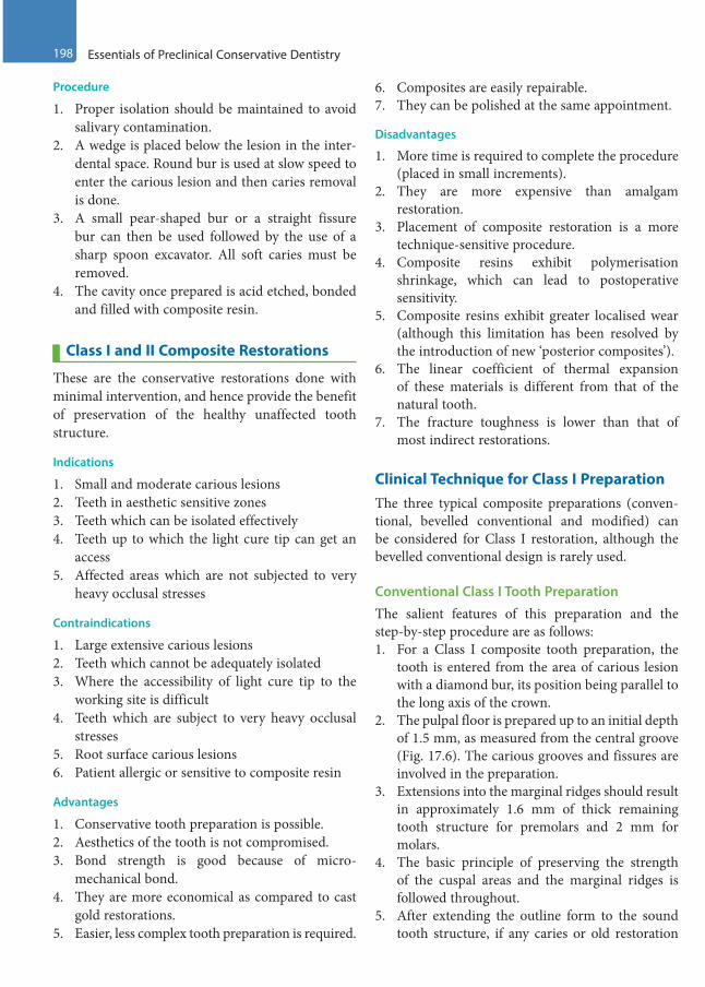
198 Essentials of Preclinical Conservative Dentistry
Procedure
1. Proper isolation should be maintained to avoid salivary contamination.
2. A wedge is placed below the lesion in the inter-dental space. Round bur is used at slow speed to enter the carious lesion and then caries removal is done.
3. A small pear-shaped bur or a straight fissure bur can then be used followed by the use of a sharp spoon excavator. All soft caries must be removed.
4. The cavity once prepared is acid etched, bonded and filled with composite resin.
Class I and II Composite Restorations
These are the conservative restorations done with minimal intervention, and hence provide the benefit of preservation of the healthy unaffected tooth structure.
Indications
1. Small and moderate carious lesions2. Teeth in aesthetic sensitive zones3. Teeth which can be isolated effectively4. Teeth up to which the light cure tip can get an
access5. Affected areas which are not subjected to very
heavy occlusal stresses
Contraindications
1. Large extensive carious lesions2. Teeth which cannot be adequately isolated3. Where the accessibility of light cure tip to the
working site is difficult4. Teeth which are subject to very heavy occlusal
stresses5. Root surface carious lesions6. Patient allergic or sensitive to composite resin
Advantages
1. Conservative tooth preparation is possible.2. Aesthetics of the tooth is not compromised.3. Bond strength is good because of micro-
mechanical bond.4. They are more economical as compared to cast
gold restorations.5. Easier, less complex tooth preparation is required.
6. Composites are easily repairable.7. They can be polished at the same appointment.
Disadvantages
1. More time is required to complete the procedure (placed in small increments).
2. They are more expensive than amalgam restoration.
3. Placement of composite restoration is a more technique-sensitive procedure.
4. Composite resins exhibit polymerisation shrinkage, which can lead to postoperative sensitivity.
5. Composite resins exhibit greater localised wear (although this limitation has been resolved by the introduction of new ‘posterior composites’).
6. The linear coefficient of thermal expansion of these materials is different from that of the natural tooth.
7. The fracture toughness is lower than that of most indirect restorations.
Clinical Technique for Class I PreparationThe three typical composite preparations (conven-tional, bevelled conventional and modified) can be considered for Class I restoration, although the bevelled conventional design is rarely used.
Conventional Class I Tooth PreparationThe salient features of this preparation and the step-by-step procedure are as follows:1. For a Class I composite tooth preparation, the
tooth is entered from the area of carious lesion with a diamond bur, its position being parallel to the long axis of the crown.
2. The pulpal floor is prepared up to an initial depth of 1.5 mm, as measured from the central groove (Fig. 17.6). The carious grooves and fissures are involved in the preparation.
3. Extensions into the marginal ridges should result in approximately 1.6 mm of thick remaining tooth structure for premolars and 2 mm for molars.
4. The basic principle of preserving the strength of the cuspal areas and the marginal ridges is followed throughout.
5. After extending the outline form to the sound tooth structure, if any caries or old restoration
Preclinical Dentistry.indb 198 29-05-2020 12:57:39
https://t.me/DentalBooksWorld

Chapter 17 Cavity Preparation for Composite Resin 199
remains on the pulpal floor, it should be removed with a round bur in slow speed or a sharp spoon excavator.
6. Pulp protection is done using GIC in moderately deep preparations and calcium hydroxide liner followed by GIC base in deep preparations.
Bevelled Conventional Class I Tooth PreparationThis kind of preparation is avoided on the occlusal surfaces of premolars and molars for the fact that the thin layer of the composite that is applied over the bevel (if given) would chip off under the mastica-tory forces, leading to the failure of the restoration. In addition, because of the specific occlusal surface enamel rod direction, the ends of the enamel rods automatically get exposed by the preparation, which further reduces the need for occlusal bevel.
In case of Class I preparation with buccal or palatal extension, a bevel is placed on the extension side; hence, the resulting preparation design is a combination of conventional and bevelled conven-tional preparation. The bevel is 0.25- to 0.5-mm wide and is at a 45° angle to the prepared wall (Fig. 17.7).
Modified Class I Tooth PreparationMinimally involved Class I lesions or faults are restored with composite using the modified tooth preparation. These preparations do not have any specific outline form, no specified pulpal or axial depth, and usually have a scooped-out appearance, as the outline form is dictated by the extent of the lesion. A round, inverted cone or a straight fissure
diamond point is used for the preparation. If a round diamond is used, the resulting cavosurface margin angle may be more flared than the one achieved with an inverted cone diamond. Figure 17.8 depicts the schematic representation of tooth preparation for composite on premolar. Figure 17.9A,B shows the Class I caries and the subsequent tooth preparation done on mandibular second molar, respectively.
Clinical Technique for Class II PreparationThe tooth preparation for Class II composite resto-rations can be of either conventional or modified preparation design.
Conventional Class II Tooth PreparationThe occlusal portion is prepared similar to that for Class I preparation.1. The preparation is started from the pit area
opposite to that of the involved proximal surface.2. Tooth preparation is done as conservatively as
possible with minimal faciolingual width.3. The preparation is done up to the area just short
of the marginal ridge of the involved proximal surface.
Figure 17.6 Initial pulpal depth of 1.5 mm.
Bevel
Figure 17.7 Bevel made on the buccal side preparation of a mandibular molar.
Figure 17.8 Modified Class I tooth preparation of a premolar.
Preclinical Dentistry.indb 199 29-05-2020 12:57:39
https://t.me/DentalBooksWorld

200 Essentials of Preclinical Conservative Dentistry
4. The facial and lingual extensions of the prox-imal box to be made are visualised and then the bur is moved gingivally to involve the proximal surface. This gingivally directed cut is 0.2 mm inside the DEJ (Fig. 17.10).
5. A 0.8-mm diameter 245 bur should cut in a way that it is one-fourth inside the dentin and three-fourth inside the enamel.
6. While the bur is moved gingivally, it is also moved facially and lingually simultaneously to create the proximal box.
7. Gingivally, the preparation is extended below the carious lesion (but not necessarily below the contact point with the adjacent tooth as in silver amalgam preparations).
8. The facial and the lingual walls of the proximal box may be left in contact with the adjacent tooth (Fig. 17.11).
9. No bevels are placed on the occlusal margins (Fig. 17.12) as it results in a thin layer of the composite on the occlusal surface in areas of potentially heavy contact. This can result in the fracture or wear of the composite restoration in these areas.
10. No bevels are indicated for the facial and lingual walls of the proximal box unless the proximal box is too wide and bevels may help in increasing the surface area in this case for retention via micromechanical bond.
11. Basic protocol of the pulp protection is followed as explained in Class I preparations.
Figure 17.9 (A) Class I caries on mandibular second molar. (Picture courtesy: Dr Madhupa Chaudhari, Mumbai.) (B) Class I tooth preparation on mandibular second molar. (Picture courtesy: Dr Madhupa Chaudhari, Mumbai.)
A B
Figure 17.10 Gingivally directed cut, 0.2 mm inside the DEJ using No. 245 bur.
Figure 17.11 The facial and the lingual walls of the proximal box left in contact with the adjacent tooth.
Preclinical Dentistry.indb 200 29-05-2020 12:57:40
https://t.me/DentalBooksWorld
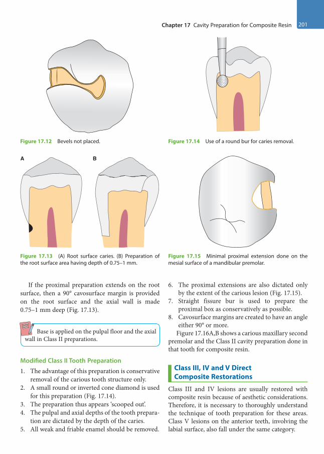
Chapter 17 Cavity Preparation for Composite Resin 201
If the proximal preparation extends on the root surface, then a 90° cavosurface margin is provided on the root surface and the axial wall is made 0.75–1 mm deep (Fig. 17.13).
Base is applied on the pulpal floor and the axial wall in Class II preparations.
Modified Class II Tooth Preparation
1. The advantage of this preparation is conservative removal of the carious tooth structure only.
2. A small round or inverted cone diamond is used for this preparation (Fig. 17.14).
3. The preparation thus appears ‘scooped out’.4. The pulpal and axial depths of the tooth prepara-
tion are dictated by the depth of the caries.5. All weak and friable enamel should be removed.
6. The proximal extensions are also dictated only by the extent of the carious lesion (Fig. 17.15).
7. Straight fissure bur is used to prepare the proximal box as conservatively as possible.
8. Cavosurface margins are created to have an angle either 90° or more.
Figure 17.16A,B shows a carious maxillary second premolar and the Class II cavity preparation done in that tooth for composite resin.
Class III, IV and V Direct Composite Restorations
Class III and IV lesions are usually restored with composite resin because of aesthetic considerations. Therefore, it is necessary to thoroughly understand the technique of tooth preparation for these areas. Class V lesions on the anterior teeth, involving the labial surface, also fall under the same category.
Figure 17.12 Bevels not placed.
Figure 17.13 (A) Root surface caries. (B) Preparation of the root surface area having depth of 0.75–1 mm.
A B
Figure 17.14 Use of a round bur for caries removal.
Figure 17.15 Minimal proximal extension done on the mesial surface of a mandibular premolar.
Preclinical Dentistry.indb 201 29-05-2020 12:57:40
https://t.me/DentalBooksWorld

202 Essentials of Preclinical Conservative Dentistry
Indications
1. Almost all Class III and IV restorations are appropriately restored with composites.
2. Most Class V restorations that are in aesthetically prominent areas are also appropriately restored with composites.
Contraindications
1. An operating area that cannot be adequately isolated
2. Some Class V restorations that are not aestheti-cally critical
3. Large extensive carious lesions4. Root surface carious lesions are preferably not
restored using composite resins5. Patient allergic or sensitive to resin composite
Clinical Technique for Class III PreparationWhen the proximal surface of the tooth is to be restored and there is choice between the facial and the lingual entry into the tooth, the lingual approach is preferable.
The advantages of restoring the proximal lesion from the lingual approach include the following:1. Tooth aesthetics is maintained since the
facial enamel is conserved (unsupported, but
non-friable enamel may be left on the facial wall).
2. Discolouration at the junction of the restoration and tooth structure, if appears, would be less visible.
However, facial approach is used if:1. The carious lesion is positioned facially such that
facial access would significantly conserve the tooth structure.
2. A faulty restoration that was originally placed from the facial approach needs to be replaced.
3. The teeth are irregularly aligned, making lingual approach impractical.
Conventional Class III Tooth PreparationThe primary indication for this type of preparation is for the restoration of root surfaces. If the carious lesion extends to both the root and the enamel surfaces, only a part of the preparation, that is, the portion of the root surface that has no enamel margin, would be prepared this way. Design of the complete preparation then would be a combination of the modified or the bevelled conventional prepa-ration for the enamel surface with a conventionally prepared root surface area (Fig. 17.17).
The preparation is the same as that for an amalgam preparation, that is, cavosurface margins should exhibit a 90° cavosurface angle.
Steps for the Preparation on Root Surface Carious Lesion1. No. 1/2 or No. 1 round bur is used to prepare the
outline form on the root surface area.2. The external walls are extended to the sound
tooth structure by removing the entire carious lesion.
Figure 17.16 (A) Carious maxillary second premolar. (Picture courtesy: Dr Madhupa Chaudhari, Mumbai.) (B) Cavity preparation done in maxillary second premolar for composite resin (Picture courtesy: Dr Madhupa Chaudhari, Mumbai.)
A
B
0.75 mm axialwall depth
Figure 17.17 Class III preparation involving root surface.
Preclinical Dentistry.indb 202 29-05-2020 12:57:41
https://t.me/DentalBooksWorld

Chapter 17 Cavity Preparation for Composite Resin 203
3. An initial depth of 0.75 mm is considered as ideal.4. External walls are prepared perpendicular to the
root surface and they are entirely in the dentin and cementum regions (Fig. 17.18).
5. The remaining infected dentin is removed using a round bur at slow speed or a sharp spoon excavator.
6. For achieving secondary retention form, a continuous retention groove can be prepared in the internal portion of the external walls using No. 1/4 round bur. The groove is located 0.25 mm from the root surface and is prepared to a depth of 0.25 mm. The groove should be parallel to the root surface (Fig. 17.19).
7. In the crown areas of the preparation (when enamel margins are present), bevel is given.
8. Finally, the preparation is cleaned and inspected for presence of any debris
Steps for the Preparation on Proximal Enamel Carious Lesion1. The round bur is held perpendicular to the
enamel surface and an opening is made from the lingual side (Fig. 17.20).
2. The angle of entry is made in such a way that it is parallel to the enamel rods.
3. A slightly larger-sized bur can then be used for the entire caries removal (Fig. 17.21).
4. The initial depth is kept up to 0.2 mm into the dentin (Fig. 17.22).
5. The axial wall at the end of preparation should follow the contour of the tooth.
Figure 17.18 External wall prepared perpendicular to the root surface.
Figure 17.19 Continuous retention groove.
Figure 17.20 Opening made from the lingual side of a maxillary lateral incisor for entering a proximal lesion.
Figure 17.21 Larger-sized bur is used for the entire caries removal.
Preclinical Dentistry.indb 203 29-05-2020 12:57:41
https://t.me/DentalBooksWorld

204 Essentials of Preclinical Conservative Dentistry
6. Secondary retention features, if necessary, can be incorporated in the form of retention grooves to be placed at the gingivoaxial and the incisoaxial line angles by using No. 1/4 bur.
7. Alternatively, an incisal retention cove may be given by using No. 1/4 bur at the axioincisal point angle.
Bevelled Conventional Class III Tooth PreparationThe bevelled conventional preparation is character-ised by external walls that are perpendicular to the enamel surface. With the bevelled enamel margins, the pulpal depth of the axial line angles may or may not be uniform. Usually, retention is obtained only by acid etching of the enamel walls and no retention grooves are necessary.
Lingual Access for Tooth PreparationAn indirect vision is usually required for the lingual access to a tooth preparation; for this, a clean, unscratched front surface mirror is recommended that would provide a clear, undistorted view.1. A round carbide bur or a diamond point
(No. 1/2, 1 or 2) is used to prepare the outline form. The point of entry should be within the incisogingival dimension of the carious lesion.
2. The cutting instrument is directed perpendic-ular to the enamel surface, and light pressure and intermittent cutting is used to gain access into the lesion. The external walls are extended to the sound tooth structure, but only to the initial limited prescribed depth. Subgingival extension should be avoided, unless the lesion extends so.
3. The axial wall depth at this initial stage of tooth preparation is limited to 0.2 mm inside the DEJ, which means it will be approximately 0.75–1.25 mm deep in total. The axial line angles are positioned at an initial depth of 0.2 mm into the dentin. But if retention grooves are required, the axial wall should be 0.5 mm into the dentin at the retention location to prevent the undermining of the enamel.
4. Thereafter, all the remaining infected dentin is removed using a round bur or a small spoon excavator, or both. If retention features are indi-cated, they are prepared along the gingivoaxial line angle and, sometimes, along the incisoaxial line angle with No. 1/4 bur.
5. The cavosurface bevel is prepared with a flame-shaped diamond point, resulting in a 45° angle to the external tooth surface. A bevel width of 0.25–0.5 mm is provided (Fig. 17.23) and it is not required on the lingual/palatal margins that are in areas of centric contact because compos-ites have less wear resistance than enamel. So the thin composite in the bevel area may get chipped off. If the preparation extends gingivally onto the root surface, no bevel is placed on the cementum and the area is prepared as a conven-tional preparation.
Facial Access for Tooth PreparationIn facial access, the procedure is simplified due to direct access to the lesion (Fig. 17.24A,B). After the caries removal, the bevel is placed on the facial wall (Fig. 17.24C).
0.2 mminto DEJ
Figure 17.22 The initial depth kept up to 0.2 mm into the dentin.
Figure 17.23 Placing a bevel.
Preclinical Dentistry.indb 204 29-05-2020 12:57:41
https://t.me/DentalBooksWorld

Chapter 17 Cavity Preparation for Composite Resin 205
Modified Class III Tooth Preparation
Modified Class III tooth preparation is indicated for small and moderate lesions and is considered as a very conservative approach.
1. The extent of fault or defect decides the prepa-ration design and the tooth is prepared from the lingual side whenever possible using an appro-priate-sized round bur or diamond point.
2. All weakened and friable enamel is removed.3. Additional retention by making grooves is
not required here because the retention of the material in the tooth will result from the micro-mechanical adhesion of the composite resin to the tooth structure. The completed preparation appears as ‘scooped’ or concave.
4. The preparation is started usually from the lingual side by making an opening using a round carbide bur or a diamond point.
5. The cutting instrument is directed perpendic-ular to the enamel surface and, as a rule, light pressure is applied and intermittent cutting is done.
6. The walls thus prepared need not be perpen-dicular to the enamel surface. In fact, for small preparations, the walls may diverge externally from the axial depth in a ‘scoop shape’, resulting in a bevelled marginal design as well as conser-vation of tooth structure (Fig. 17.25).
7. As a golden rule, the preparation should be as minimal as possible. If possible, the entire proximal contact area should not be included, the preparation should not extend onto the facial surface and the preparation should not be extended subgingivally.
Clinical Technique for Class IV PreparationClass IV preparations may be considered as one of the most challenging ones, although these look rela-tively simpler to perform. The reason for this can be attributed to the fact that the aesthetic appearance of the restoration in these cases is highly dependent on the tooth preparation design. The placement of bevels in these cases, in particular, is very critical so as to ensure that the junction between the tooth and the restoration should not be visible under any circumstances, which in turn shall ensure the desir-able aesthetics.
Conventional Class IV Tooth PreparationThis type of tooth preparation is done on the carious lesion that extends onto the root surface. A 90° cavosurface margin is provided on the root surface
Figure 17.24 (A) Class III lesions seen in maxillary right central incisor and lateral incisor (Picture courtesy: Dr Madhavi Mhapuskar, Pune.) (B) Class III cavity preparation done on maxillary right central and lateral incisor. (Picture courtesy: Dr Madhavi Mhapuskar, Pune.) (C) Bevel placed on the facial wall of the proximal preparation in the left maxillary central incisor.
A
B
C
Preclinical Dentistry.indb 205 29-05-2020 12:57:42
https://t.me/DentalBooksWorld

206 Essentials of Preclinical Conservative Dentistry
lesion as a general rule. It may also happen that the conventional Class IV tooth preparation is done on the root surface, whereas bevelled conventional or modified preparation design is used to prepare the anatomical crown of the tooth.
Bevelled Conventional Class IV Tooth PreparationClass IV bevelled conventional tooth preparations are characterised by a bevelled preparation that increases the surface area for etching and bonding, and, thus, increases retention of the composite resin.1. The outline form is prepared by using an appro-
priate tapered diamond point at high speed with an air coolant.
2. All the weakened enamel is removed and the initial wall depth is established at 0.5 mm into the dentin.
3. The outline form is dictated by the extent of the caries or defect.
4. The remaining infected dentin, if still left, is excavated.
5. The cavosurface margins are bevelled of all accessible enamel margins of the preparation. Bevel is prepared at 45° angle to the external tooth surface with a flame-shaped bur. Width of the bevel can range from 0.25 to 2.0 mm, depending on the amount of the tooth structure missing and the retention desired (Fig. 17.26).
6. Additional retention, if required, can be obtained by placing retention undercuts, such as grooves, coves and dovetails, although in this type of preparation technique, the retention is mainly provided by the micromechanical bonding of the composites to the enamel and the dentin.
7. Gingival and incisal retentive undercuts may be indicated in a large Class IV preparation and are similar to those used in Class III preparation, in which rounded undercuts are placed in the dentin along the line angles and into the point angles wherever possible, without undermining the enamel.
8. A dovetail extension onto the lingual surface has also been advocated to enhance the retention of the restoration, especially if the lesion is large, but it is not used often, as it leads to the destruc-tion of the healthy tooth structure (Fig. 17.27).
Modified Class IV Tooth PreparationThis kind of preparation for composites is indicated for small/moderate-sized Class IV lesions. This prepa-ration is considered the most conservative approach.1. Any existing lesion or defective restoration is
removed with a suitable-sized round carbide bur or a diamond point.
2. The outline form is prepared in a manner to include all weakened and friable enamel.
Figure 17.25 (A) Scooped-out preparation, as seen from the proximal surface (left) and the lingual surface (right). (B) Preparation done on plaster model.
A B
Figure 17.26 Bevelled Class IV tooth preparation on the right maxillary central incisor.
Preclinical Dentistry.indb 206 29-05-2020 12:57:43
https://t.me/DentalBooksWorld

Chapter 17 Cavity Preparation for Composite Resin 207
3. If the lesion is in the form of just a fractured incisal corner, just roughening of the margins is done.
4. The axial depth is kept initially up to 0.2 mm inside the DEJ, unless the extent of the lesion dictates more depth.
5. Bevels are given on the prepared cavosurface margins, and most of the times no grooves or coves are required for additional retention (Fig. 17.28).
Figure 17.29A,B represents the fractured maxil-lary right central incisor and the minimal tooth preparation done on the same to receive a composite restoration, respectively.
Clinical Technique for Class V PreparationClass V restorations are those present in the gingival one-third of the facial and the lingual surfaces of all teeth. Due to aesthetic considerations, composites
are used for the restoration of Class V lesions in the anterior teeth. During shade selection, it must be remembered that tooth is darker and more opaque in its cervical third.
Conventional Class V Tooth Preparation
This is similar to that of Class V tooth preparation for silver amalgam restoration.1. A tapered fissure carbide bur is used to start the
preparation.2. The preparation is started from one side
(e.g. mesial). The bur is positioned at 45° angle to the tooth surface by tilting it distally, but as the preparation progresses distally, the hand-piece is held in such a manner so as to maintain the bur’s long axis perpendicular to the external surface. This eventually results in 90° cavosur-face margins.
Figure 17.27 A dovetail extension onto the lingual surface.
A B
BevelBevel
Figure 17.28 Bevels given on the prepared cavosurface margins. (A) Facial view. (B) Proximal view.
Figure 17.29 (A) Fractured maxillary right central incisor. (B) Minimal tooth preparation done to receive a composite restoration.
A
B
Preclinical Dentistry.indb 207 29-05-2020 12:57:44
https://t.me/DentalBooksWorld

208 Essentials of Preclinical Conservative Dentistry
3. At this initial tooth preparation stage, extensions in every direction are made and the axial depth is kept to 0.75 mm (Fig. 17.30).
4. The outline form extension of the mesial, distal, occlusal and gingival walls is dictated by the extent of the lesion.
5. The axial wall follows the original contour of the facial surface and so is made convex mesiodistally.
6. Remaining infected dentin is removed, if present.7. Retention grooves, if required, are prepared with
No. 1/4 bur along the gingivoaxial and inciso-axial line angles (Fig. 17.31). These grooves are prepared 0.25-mm deep.
8. In certain areas like those of maxillary molars, at times, the accessibility of the handpiece is diffi-cult on the distal aspect of the facial surface. In such a case, hand instruments such as ‘gingival
margin trimmer’ can be used to finish the prepa-ration and simultaneously to provide retention grooves. Instruments like angle formers can also be used to provide retention grooves in such areas.
Bevelled Conventional Class V Tooth PreparationThe bevelled conventional Class V tooth preparation is characterized by bevelled enamel margins.
The basic procedure for this kind of preparation is the same as that for the conventional preparation with the following differences:1. The outline form is made up to an initial depth
of 0.2 mm into the dentin when retention groove is not required and up to 0.5 mm when retention groove is required.
2. The bevels are placed (mostly on the incisal/ occlusal wall) to increase the surface area for bonding (Fig. 17.32).
Modified Class V Tooth PreparationThe modified Class V tooth preparation is used for small Class V lesions.1. The objective here is to restore the carious tooth
as conservatively as possible without destroying the healthy tooth structure.
2. The lesion appears ‘scooped out’, resulting in a preparation form that may have diverging walls. Axial wall is not made of any uniform depth (Fig. 17.33).
3. Diamond points are used to eliminate the lesion by just removing the area involved. The 90° cavosurface design is not required.
0.75 mmdepth of the
axial wall
Figure 17.30 Axial depth kept up to 0.75 mm.
Figure 17.31 Retention grooves prepared with No. 1/4 bur.
Bevel
Figure 17.32 Bevel placed on the incisal wall of Class V cavity in a maxillary incisor.
Preclinical Dentistry.indb 208 29-05-2020 12:57:44
https://t.me/DentalBooksWorld
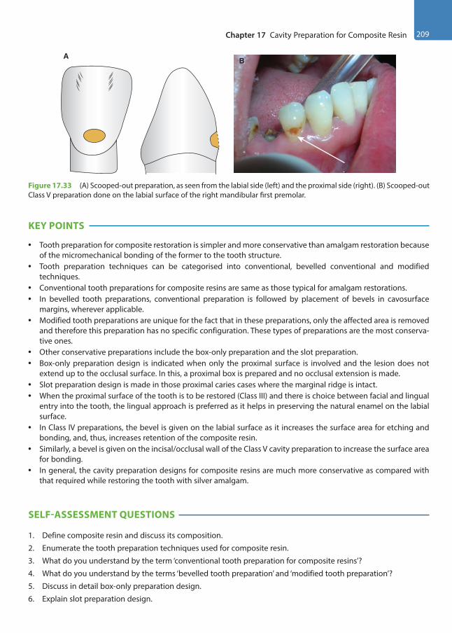
Chapter 17 Cavity Preparation for Composite Resin 209
KEY POINTS
• Tooth preparation for composite restoration is simpler and more conservative than amalgam restoration because of the micromechanical bonding of the former to the tooth structure.
• Tooth preparation techniques can be categorised into conventional, bevelled conventional and modified techniques.
• Conventional tooth preparations for composite resins are same as those typical for amalgam restorations.• In bevelled tooth preparations, conventional preparation is followed by placement of bevels in cavosurface
margins, wherever applicable.• Modified tooth preparations are unique for the fact that in these preparations, only the affected area is removed
and therefore this preparation has no specific configuration. These types of preparations are the most conserva-tive ones.
• Other conservative preparations include the box-only preparation and the slot preparation.• Box-only preparation design is indicated when only the proximal surface is involved and the lesion does not
extend up to the occlusal surface. In this, a proximal box is prepared and no occlusal extension is made.• Slot preparation design is made in those proximal caries cases where the marginal ridge is intact.• When the proximal surface of the tooth is to be restored (Class III) and there is choice between facial and lingual
entry into the tooth, the lingual approach is preferred as it helps in preserving the natural enamel on the labial surface.
• In Class IV preparations, the bevel is given on the labial surface as it increases the surface area for etching and bonding, and, thus, increases retention of the composite resin.
• Similarly, a bevel is given on the incisal/occlusal wall of the Class V cavity preparation to increase the surface area for bonding.
• In general, the cavity preparation designs for composite resins are much more conservative as compared with that required while restoring the tooth with silver amalgam.
SELF-ASSESSMENT QUESTIONS
1. Define composite resin and discuss its composition.
2. Enumerate the tooth preparation techniques used for composite resin.
3. What do you understand by the term ‘conventional tooth preparation for composite resins’?
4. What do you understand by the terms ‘bevelled tooth preparation’ and ‘modified tooth preparation’?
5. Discuss in detail box-only preparation design.
6. Explain slot preparation design.
BA
Figure 17.33 (A) Scooped-out preparation, as seen from the labial side (left) and the proximal side (right). (B) Scooped-out Class V preparation done on the labial surface of the right mandibular first premolar.
Preclinical Dentistry.indb 209 29-05-2020 12:57:45
https://t.me/DentalBooksWorld

210 Essentials of Preclinical Conservative Dentistry
7. Discuss the difference in tooth preparation technique for Class II preparation for silver amalgam and that for composite resin.
8. Discuss the various techniques for tooth preparation of a Class III carious lesion.
9. Describe in detail the bevelled conventional tooth preparation and modified tooth preparation technique for Class IV lesion.
10. Discuss the various techniques for tooth preparation of a Class V carious lesion.
Preclinical Dentistry.indb 210 29-05-2020 12:57:45
https://t.me/DentalBooksWorld
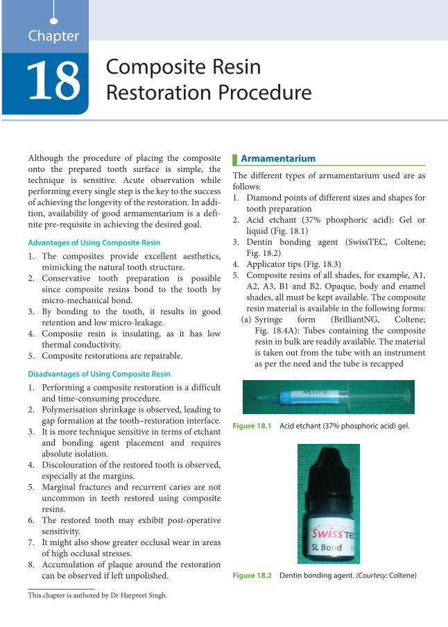
Although the procedure of placing the composite onto the prepared tooth surface is simple, the technique is sensitive. Acute observation while performing every single step is the key to the success of achieving the longevity of the restoration. In addi-tion, availability of good armamentarium is a defi-nite pre-requisite in achieving the desired goal.
Advantages of Using Composite Resin
1. The composites provide excellent aesthetics, mimicking the natural tooth structure.
2. Conservative tooth preparation is possible since composite resins bond to the tooth by micro-mechanical bond.
3. By bonding to the tooth, it results in good retention and low micro-leakage.
4. Composite resin is insulating, as it has low thermal conductivity.
5. Composite restorations are repairable.
Disadvantages of Using Composite Resin
1. Performing a composite restoration is a difficult and time-consuming procedure.
2. Polymerisation shrinkage is observed, leading to gap formation at the tooth–restoration interface.
3. It is more technique sensitive in terms of etchant and bonding agent placement and requires absolute isolation.
4. Discolouration of the restored tooth is observed, especially at the margins.
5. Marginal fractures and recurrent caries are not uncommon in teeth restored using composite resins.
6. The restored tooth may exhibit post-operative sensitivity.
7. It might also show greater occlusal wear in areas of high occlusal stresses.
8. Accumulation of plaque around the restoration can be observed if left unpolished.
Armamentarium
The different types of armamentarium used are as follows:1. Diamond points of different sizes and shapes for
tooth preparation2. Acid etchant (37% phosphoric acid): Gel or
liquid (Fig. 18.1)3. Dentin bonding agent (SwissTEC, Coltene;
Fig. 18.2)4. Applicator tips (Fig. 18.3)5. Composite resins of all shades, for example, A1,
A2, A3, B1 and B2. Opaque, body and enamel shades, all must be kept available. The composite resin material is available in the following forms:
(a) Syringe form (BrilliantNG, Coltene; Fig. 18.4A): Tubes containing the composite resin in bulk are readily available. The material is taken out from the tube with an instrument as per the need and the tube is recapped
Composite Resin Restoration Procedure18
Chapter
Figure 18.1 Acid etchant (37% phosphoric acid) gel.
Figure 18.2 Dentin bonding agent. (Courtesy: Coltene)
This chapter is authored by Dr Harpreet Singh.
Preclinical Dentistry.indb 211 29-05-2020 12:57:45
https://t.me/DentalBooksWorld
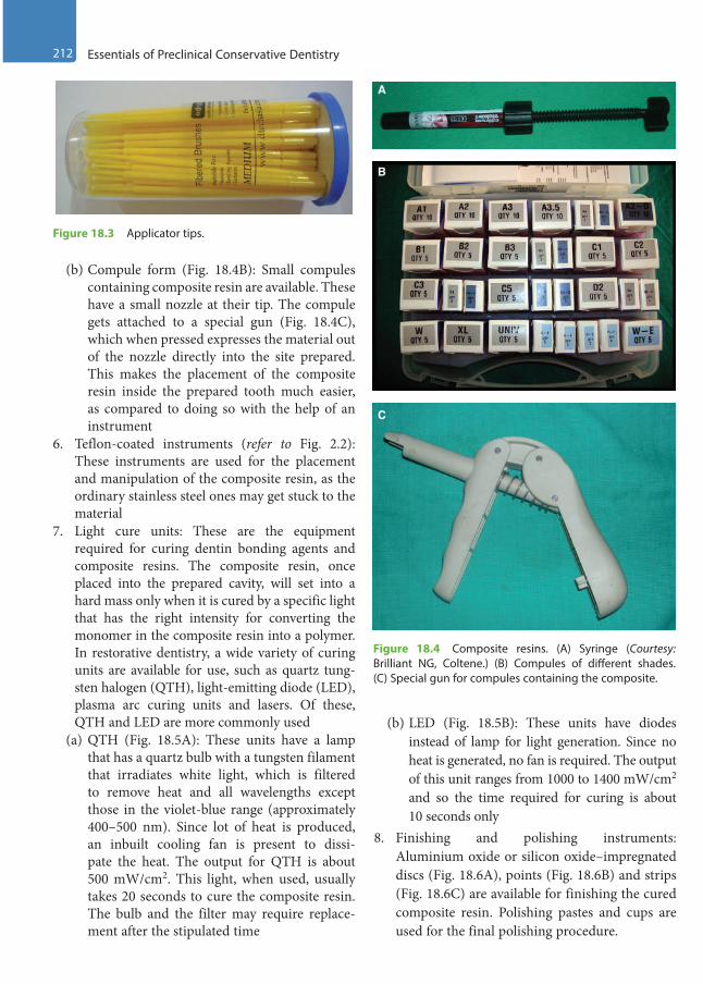
212 Essentials of Preclinical Conservative Dentistry
(b) Compule form (Fig. 18.4B): Small compules containing composite resin are available. These have a small nozzle at their tip. The compule gets attached to a special gun (Fig. 18.4C), which when pressed expresses the material out of the nozzle directly into the site prepared. This makes the placement of the composite resin inside the prepared tooth much easier, as compared to doing so with the help of an instrument
6. Teflon-coated instruments (refer to Fig. 2.2): These instruments are used for the placement and manipulation of the composite resin, as the ordinary stainless steel ones may get stuck to the material
7. Light cure units: These are the equipment required for curing dentin bonding agents and composite resins. The composite resin, once placed into the prepared cavity, will set into a hard mass only when it is cured by a specific light that has the right intensity for converting the monomer in the composite resin into a polymer. In restorative dentistry, a wide variety of curing units are available for use, such as quartz tung-sten halogen (QTH), light-emitting diode (LED), plasma arc curing units and lasers. Of these, QTH and LED are more commonly used
(a) QTH (Fig. 18.5A): These units have a lamp that has a quartz bulb with a tungsten filament that irradiates white light, which is filtered to remove heat and all wavelengths except those in the violet-blue range (approximately 400–500 nm). Since lot of heat is produced, an inbuilt cooling fan is present to dissi-pate the heat. The output for QTH is about 500 mW/cm2. This light, when used, usually takes 20 seconds to cure the composite resin. The bulb and the filter may require replace-ment after the stipulated time
(b) LED (Fig. 18.5B): These units have diodes instead of lamp for light generation. Since no heat is generated, no fan is required. The output of this unit ranges from 1000 to 1400 mW/cm2 and so the time required for curing is about 10 seconds only
8. Finishing and polishing instruments: Aluminium oxide or silicon oxide–impregnated discs (Fig. 18.6A), points (Fig. 18.6B) and strips (Fig. 18.6C) are available for finishing the cured composite resin. Polishing pastes and cups are used for the final polishing procedure.
Figure 18.3 Applicator tips.
A
B
C
Figure 18.4 Composite resins. (A) Syringe (Courtesy: Brilliant NG, Coltene.) (B) Compules of different shades. (C) Special gun for compules containing the composite.
Preclinical Dentistry.indb 212 29-05-2020 12:57:46
https://t.me/DentalBooksWorld
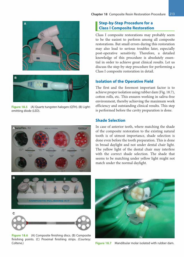
Chapter 18 Composite Resin Restoration Procedure 213
Step-by-Step Procedure for a Class I Composite Restoration
Class I composite restorations may probably seem to be the easiest to perform among all composite restorations. But small errors during this restoration may also lead to serious troubles later, especially post-operative sensitivity. Therefore, a detailed knowledge of this procedure is absolutely essen-tial in order to achieve great clinical results. Let us discuss the step-by-step procedure for performing a Class I composite restoration in detail.
Isolation of the Operative FieldThe first and the foremost important factor is to achieve proper isolation using rubber dam (Fig. 18.7), cotton rolls, etc. This ensures working in saliva-free environment, thereby achieving the maximum work efficiency and outstanding clinical results. This step is performed before the cavity preparation is done.
Shade SelectionIn case of anterior teeth, where matching the shade of the composite restoration to the existing natural tooth is of utmost importance, shade selection is done even before the tooth preparation. This is done in broad daylight and not under dental chair light. The yellow light of the dental chair may interfere with the correct shade selection. The shade that seems to be matching under yellow light might not match under the normal daylight.
B
A
Figure 18.5 (A) Quartz tungsten halogen (QTH). (B) Light-emitting diode (LED).
A
B
C
Figure 18.6 (A) Composite finishing discs. (B) Composite finishing points. (C) Proximal finishing strips. (Courtesy: Coltene.) Figure 18.7 Mandibular molar isolated with rubber dam.
Preclinical Dentistry.indb 213 29-05-2020 12:57:49
https://t.me/DentalBooksWorld
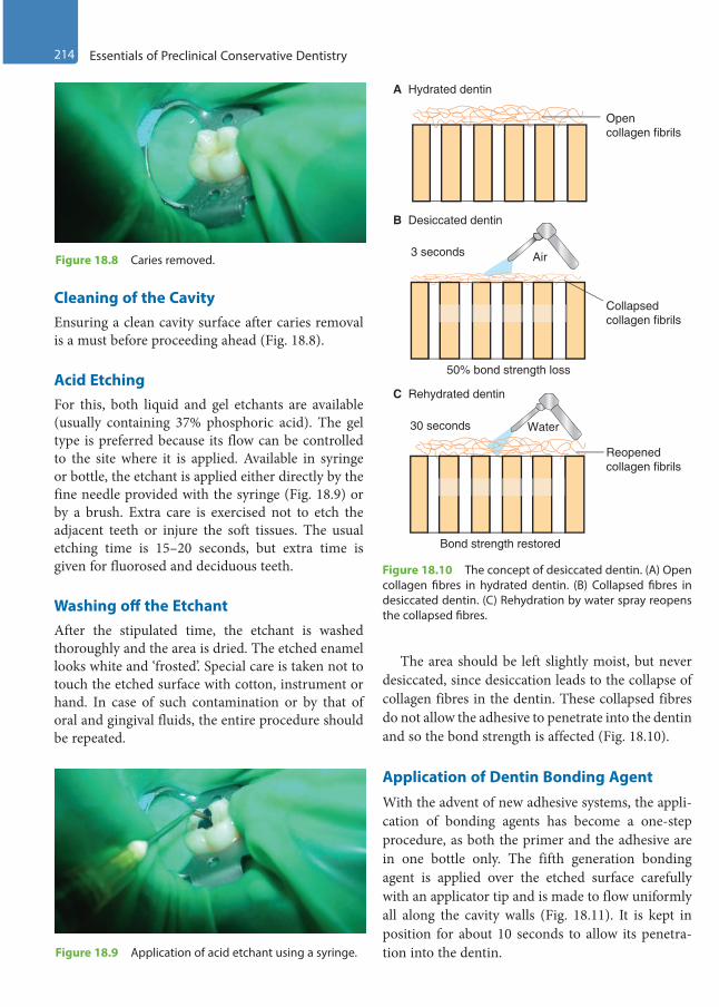
214 Essentials of Preclinical Conservative Dentistry
Cleaning of the CavityEnsuring a clean cavity surface after caries removal is a must before proceeding ahead (Fig. 18.8).
Acid EtchingFor this, both liquid and gel etchants are available (usually containing 37% phosphoric acid). The gel type is preferred because its flow can be controlled to the site where it is applied. Available in syringe or bottle, the etchant is applied either directly by the fine needle provided with the syringe (Fig. 18.9) or by a brush. Extra care is exercised not to etch the adjacent teeth or injure the soft tissues. The usual etching time is 15–20 seconds, but extra time is given for fluorosed and deciduous teeth.
Washing off the EtchantAfter the stipulated time, the etchant is washed thoroughly and the area is dried. The etched enamel looks white and ‘frosted’. Special care is taken not to touch the etched surface with cotton, instrument or hand. In case of such contamination or by that of oral and gingival fluids, the entire procedure should be repeated.
The area should be left slightly moist, but never desiccated, since desiccation leads to the collapse of collagen fibres in the dentin. These collapsed fibres do not allow the adhesive to penetrate into the dentin and so the bond strength is affected (Fig. 18.10).
Application of Dentin Bonding AgentWith the advent of new adhesive systems, the appli-cation of bonding agents has become a one-step procedure, as both the primer and the adhesive are in one bottle only. The fifth generation bonding agent is applied over the etched surface carefully with an applicator tip and is made to flow uniformly all along the cavity walls (Fig. 18.11). It is kept in position for about 10 seconds to allow its penetra-tion into the dentin.
Figure 18.8 Caries removed.
Figure 18.9 Application of acid etchant using a syringe.
A Hydrated dentin
B Desiccated dentin
C Rehydrated dentin
3 seconds
30 seconds
Air
Water
Open collagen fibrils
Collapsed collagen fibrils
Reopened collagen fibrils
Bond strength restored
50% bond strength loss
Figure 18.10 The concept of desiccated dentin. (A) Open collagen fibres in hydrated dentin. (B) Collapsed fibres in desiccated dentin. (C) Rehydration by water spray reopens the collapsed fibres.
Preclinical Dentistry.indb 214 29-05-2020 12:57:49
https://t.me/DentalBooksWorld
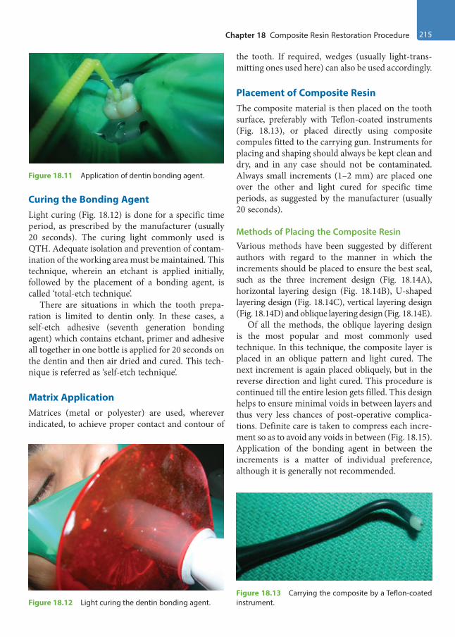
Chapter 18 Composite Resin Restoration Procedure 215
Curing the Bonding AgentLight curing (Fig. 18.12) is done for a specific time period, as prescribed by the manufacturer (usually 20 seconds). The curing light commonly used is QTH. Adequate isolation and prevention of contam-ination of the working area must be maintained. This technique, wherein an etchant is applied initially, followed by the placement of a bonding agent, is called ‘total-etch technique’.
There are situations in which the tooth prepa-ration is limited to dentin only. In these cases, a self-etch adhesive (seventh generation bonding agent) which contains etchant, primer and adhesive all together in one bottle is applied for 20 seconds on the dentin and then air dried and cured. This tech-nique is referred as ‘self-etch technique’.
Matrix ApplicationMatrices (metal or polyester) are used, wherever indicated, to achieve proper contact and contour of
the tooth. If required, wedges (usually light-trans-mitting ones used here) can also be used accordingly.
Placement of Composite ResinThe composite material is then placed on the tooth surface, preferably with Teflon-coated instruments (Fig. 18.13), or placed directly using composite compules fitted to the carrying gun. Instruments for placing and shaping should always be kept clean and dry, and in any case should not be contaminated. Always small increments (1–2 mm) are placed one over the other and light cured for specific time periods, as suggested by the manufacturer (usually 20 seconds).
Methods of Placing the Composite ResinVarious methods have been suggested by different authors with regard to the manner in which the increments should be placed to ensure the best seal, such as the three increment design (Fig. 18.14A), horizontal layering design (Fig. 18.14B), U-shaped layering design (Fig. 18.14C), vertical layering design (Fig. 18.14D) and oblique layering design (Fig. 18.14E).
Of all the methods, the oblique layering design is the most popular and most commonly used technique. In this technique, the composite layer is placed in an oblique pattern and light cured. The next increment is again placed obliquely, but in the reverse direction and light cured. This procedure is continued till the entire lesion gets filled. This design helps to ensure minimal voids in between layers and thus very less chances of post-operative complica-tions. Definite care is taken to compress each incre-ment so as to avoid any voids in between (Fig. 18.15). Application of the bonding agent in between the increments is a matter of individual preference, although it is generally not recommended.
Figure 18.11 Application of dentin bonding agent.
Figure 18.12 Light curing the dentin bonding agent.Figure 18.13 Carrying the composite by a Teflon-coated instrument.
Preclinical Dentistry.indb 215 29-05-2020 12:57:49
https://t.me/DentalBooksWorld
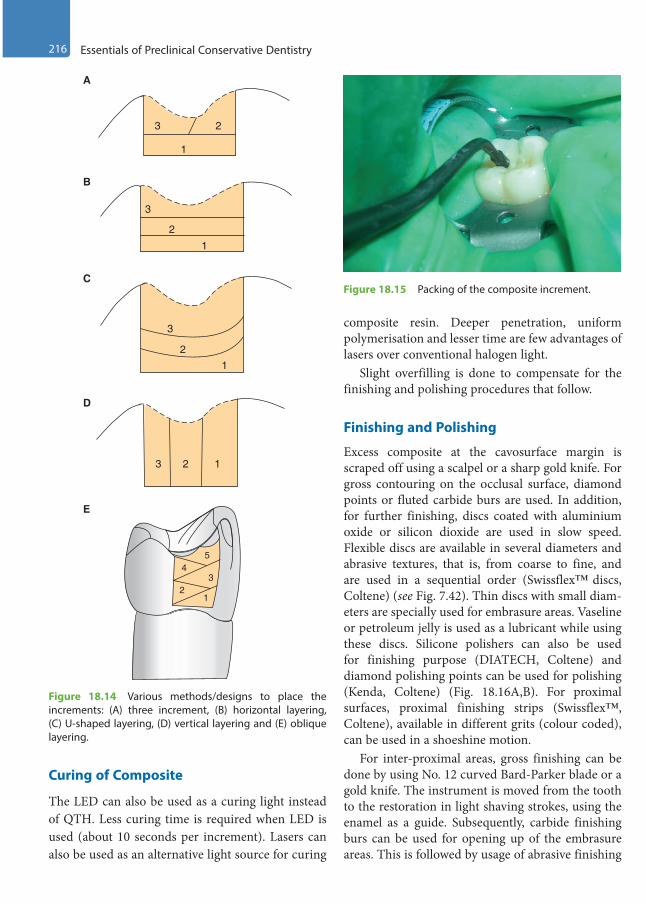
216 Essentials of Preclinical Conservative Dentistry
Curing of Composite
The LED can also be used as a curing light instead of QTH. Less curing time is required when LED is used (about 10 seconds per increment). Lasers can also be used as an alternative light source for curing
composite resin. Deeper penetration, uniform polymerisation and lesser time are few advantages of lasers over conventional halogen light.
Slight overfilling is done to compensate for the finishing and polishing procedures that follow.
Finishing and Polishing
Excess composite at the cavosurface margin is scraped off using a scalpel or a sharp gold knife. For gross contouring on the occlusal surface, diamond points or fluted carbide burs are used. In addition, for further finishing, discs coated with aluminium oxide or silicon dioxide are used in slow speed. Flexible discs are available in several diameters and abrasive textures, that is, from coarse to fine, and are used in a sequential order (Swissflex™ discs, Coltene) (see Fig. 7.42). Thin discs with small diam-eters are specially used for embrasure areas. Vaseline or petroleum jelly is used as a lubricant while using these discs. Silicone polishers can also be used for finishing purpose (DIATECH, Coltene) and diamond polishing points can be used for polishing (Kenda, Coltene) (Fig. 18.16A,B). For proximal surfaces, proximal finishing strips (Swissflex™, Coltene), available in different grits (colour coded), can be used in a shoeshine motion.
For inter-proximal areas, gross finishing can be done by using No. 12 curved Bard-Parker blade or a gold knife. The instrument is moved from the tooth to the restoration in light shaving strokes, using the enamel as a guide. Subsequently, carbide finishing burs can be used for opening up of the embrasure areas. This is followed by usage of abrasive finishing
3 2
1
3
2
1
3
21
3 2 1
45
32
1
A
B
C
D
E
Figure 18.14 Various methods/designs to place the increments: (A) three increment, (B) horizontal layering, (C) U-shaped layering, (D) vertical layering and (E) oblique layering.
Figure 18.15 Packing of the composite increment.
Preclinical Dentistry.indb 216 29-05-2020 12:57:49
https://t.me/DentalBooksWorld

Chapter 18 Composite Resin Restoration Procedure 217
strips available in medium grit (zirconium silicate) and fine grit (aluminium oxide) types. Diamond-coated thin metal strips are also available in various grits and widths and can be used in a shoeshine motion.
Obtaining Final LustreFinal lustre is obtained with polishing pastes containing pumice or silica or diamond particles and used along with a polishing cup (KENDA, Coltene; Fig. 18.16B) run at a slow speed.
GlazeA glaze (Fortify, Bisco) can be applied on the tooth surface and light cured. The glaze increases the wear resistance by flowing across the surface and pene-trating the microstructural defects in the restorative material.
A fine restoration is now ready as a ‘piece of art’ to work in the oral cavity (Fig. 18.17).
Figure 18.18 represents a case of defective Class I restoration in mandibular first molar and
Class I caries in mandibular second molar in which minimal Class I tooth preparations were done and composite resin restorations were done.
A
B
Figure 18.16 (A) Finishing points. (Courtesy: Coltene.) (B) Diamond polishing points and cups. (Courtesy: Coltene.)
Figure 18.17 Final restoration in 46.
Figure 18.18 (A) Case of defective Class I restoration in mandibular first molar and caries in mandibular second molar. (B) Minimal tooth preparation done in both teeth. (C). Composite resin restorations given in both the teeth. (Case courtesy: Dr Madhupa Chaudhari, Mumbai.)
A
B
C
Preclinical Dentistry.indb 217 29-05-2020 12:57:50
https://t.me/DentalBooksWorld

218 Essentials of Preclinical Conservative Dentistry
Restoration Procedure for Class II Cavities
Restoration of a modified Class II tooth preparation (Fig. 18.19) with composite resin should be carried out carefully to ensure good adaptation of the mate-rial to the tooth surface, especially at the gingival floor, which is often overlooked.
The step-by-step procedure can be explained as follows:1. Matrix band is well adapted around the prepa-
ration to ensure good contact and to avoid over-hangs. Use of dead soft matrix (metallic matrix which is so soft that it can be molded even with fingers; Fig. 18.20) or clear Mylar matrix (trans-parent matrix, which allows light to pass through it; refer to Fig. 13.11) depends on the operator’s choice.
2. Etching and bonding is done as previously described. 3. For beginning the restorative procedure, flowable
composite is placed on the gingival floor of the proximal box and is light cured. On top of this, a posterior composite is placed in increments in the box as well as in the occlusal preparation and these are cured successively. The oblique layering design (Fig. 18.14E) is commonly preferred in order to avoid any gaps in between the succes-sive increments.
4. The matrix band is removed after completing the procedure, followed by finishing and polishing of the restoration.
Figure 18.21 shows a case of mesial caries in maxillary second premolar restored with composite resin.
Restoration Procedure for Class III Cavities
The Mylar matrix and wedge are placed after the tooth preparation. The Mylar strip helps in restoring the proximal contact appropriately. Etching and bonding are done in the usual manner.1. The composite is placed in the preparation and
is wedged between the preparation and a piece of Mylar.
2. The material is then packed into the prepara-tion with a carrier (Fig. 18.22A1) and a suit-able instrument can be used to adapt it well (Fig. 18.22A2).
Figure 18.19 Modified Class II tooth preparation (mesio-occlusal) in a maxillary second premolar.
Figure 18.20 Dead soft matrix adapted on the distal side of a maxillary first premolar.
Figure 18.21 (A) Pre-operative picture of mesial caries in maxillary second premolar. (B) Restored with composite resin. (Case courtesy: Dr Madhupa Chaudhari, Mumbai.)
A
B
Preclinical Dentistry.indb 218 29-05-2020 12:57:50
https://t.me/DentalBooksWorld

Chapter 18 Composite Resin Restoration Procedure 219
B1 B2
B4 B5
B7
B6
A4 A5
Lightcure unit
A1 A2 A3 Lightcure unit
B3
Figure 18.22 Restoration procedure for Class III cavities. (A1) The material is packed into the preparation with a carrier, with Mylar strip already in position. (A2) Material is adapted into the preparation. (A3) Composite is light cured. (A4) Next increment is placed in position. (A5) Composite is light cured. (B) Step-by-step procedure of Class III restoration in a maxillary canine and box-only restoration in the adjacent maxillary premolar. (B1) Distal caries in 13, temporary filling in 14. (B2) Tooth preparation done in 13, temporary filling removed from 14, preparation modified. (B3) Matrix placed. (B4) Restoration done in 13. (B5) Intact labial enamel of 13. (B6) Use of proximal finishing strip in 13. (B7) Restoration done in 14.
Preclinical Dentistry.indb 219 29-05-2020 12:57:54
https://t.me/DentalBooksWorld
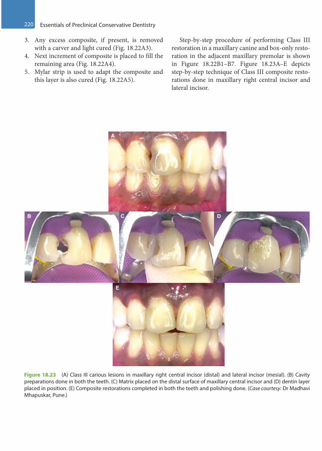
220 Essentials of Preclinical Conservative Dentistry
Figure 18.23 (A) Class III carious lesions in maxillary right central incisor (distal) and lateral incisor (mesial). (B) Cavity preparations done in both the teeth. (C) Matrix placed on the distal surface of maxillary central incisor and (D) dentin layer placed in position. (E) Composite restorations completed in both the teeth and polishing done. (Case courtesy: Dr Madhavi Mhapuskar, Pune.)
A
B C
E
D
3. Any excess composite, if present, is removed with a carver and light cured (Fig. 18.22A3).
4. Next increment of composite is placed to fill the remaining area (Fig. 18.22A4).
5. Mylar strip is used to adapt the composite and this layer is also cured (Fig. 18.22A5).
Step-by-step procedure of performing Class III restoration in a maxillary canine and box-only resto-ration in the adjacent maxillary premolar is shown in Figure 18.22B1–B7. Figure 18.23A–E depicts step-by-step technique of Class III composite resto-rations done in maxillary right central incisor and lateral incisor.
Preclinical Dentistry.indb 220 29-05-2020 12:57:54
https://t.me/DentalBooksWorld
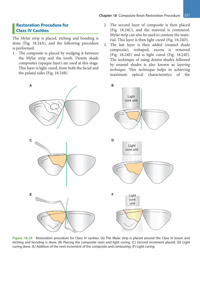
Chapter 18 Composite Resin Restoration Procedure 221
A B
Lightcure unit
C
F
DLight
cure unit
Lightcureunit
E
Figure 18.24 Restoration procedure for Class IV cavities. (A) The Mylar strip is placed around the Class IV lesion and etching and bonding is done. (B) Placing the composite resin and light curing. (C) Second increment placed. (D) Light curing done. (E) Addition of the next increment of the composite and contouring. (F) Light curing.
Restoration Procedure for Class IV Cavities
The Mylar strip is placed, etching and bonding is done (Fig. 18.24A), and the following procedure is performed:1. The composite is placed by wedging it between
the Mylar strip and the tooth. Dentin shade composites (opaque layer) are used at this stage. This layer is light cured, from both the facial and the palatal sides (Fig. 18.24B).
2. The second layer of composite is then placed (Fig. 18.24C), and the material is contoured. Mylar strip can also be used to contour the mate-rial. This layer is then light cured (Fig. 18.24D).
3. The last layer is then added (enamel shade composite), reshaped, excess is removed (Fig. 18.24E) and is light cured (Fig. 18.24F). The technique of using dentin shades followed by enamel shades is also known as layering technique. This technique helps in achieving maximum optical characteristics of the
Preclinical Dentistry.indb 221 29-05-2020 12:57:55
https://t.me/DentalBooksWorld
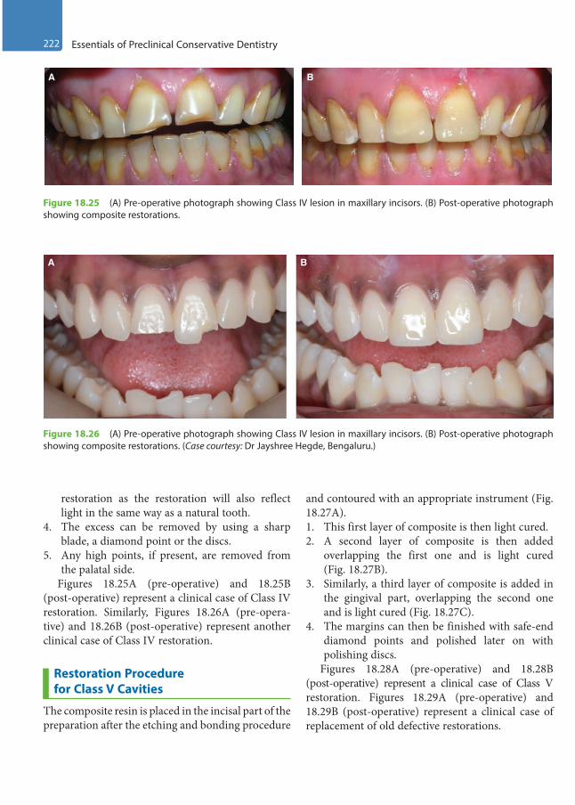
222 Essentials of Preclinical Conservative Dentistry
A B
Figure 18.25 (A) Pre-operative photograph showing Class IV lesion in maxillary incisors. (B) Post-operative photograph showing composite restorations.
Figure 18.26 (A) Pre-operative photograph showing Class IV lesion in maxillary incisors. (B) Post-operative photograph showing composite restorations. (Case courtesy: Dr Jayshree Hegde, Bengaluru.)
A B
restoration as the restoration will also reflect light in the same way as a natural tooth.
4. The excess can be removed by using a sharp blade, a diamond point or the discs.
5. Any high points, if present, are removed from the palatal side.
Figures 18.25A (pre-operative) and 18.25B (post-operative) represent a clinical case of Class IV restoration. Similarly, Figures 18.26A (pre-opera-tive) and 18.26B (post-operative) represent another clinical case of Class IV restoration.
Restoration Procedure for Class V Cavities
The composite resin is placed in the incisal part of the preparation after the etching and bonding procedure
and contoured with an appropriate instrument (Fig. 18.27A). 1. This first layer of composite is then light cured.2. A second layer of composite is then added
overlapping the first one and is light cured (Fig. 18.27B).
3. Similarly, a third layer of composite is added in the gingival part, overlapping the second one and is light cured (Fig. 18.27C).
4. The margins can then be finished with safe-end diamond points and polished later on with polishing discs.
Figures 18.28A (pre-operative) and 18.28B (post-operative) represent a clinical case of Class V restoration. Figures 18.29A (pre-operative) and 18.29B (post-operative) represent a clinical case of replacement of old defective restorations.
Preclinical Dentistry.indb 222 29-05-2020 12:57:55
https://t.me/DentalBooksWorld
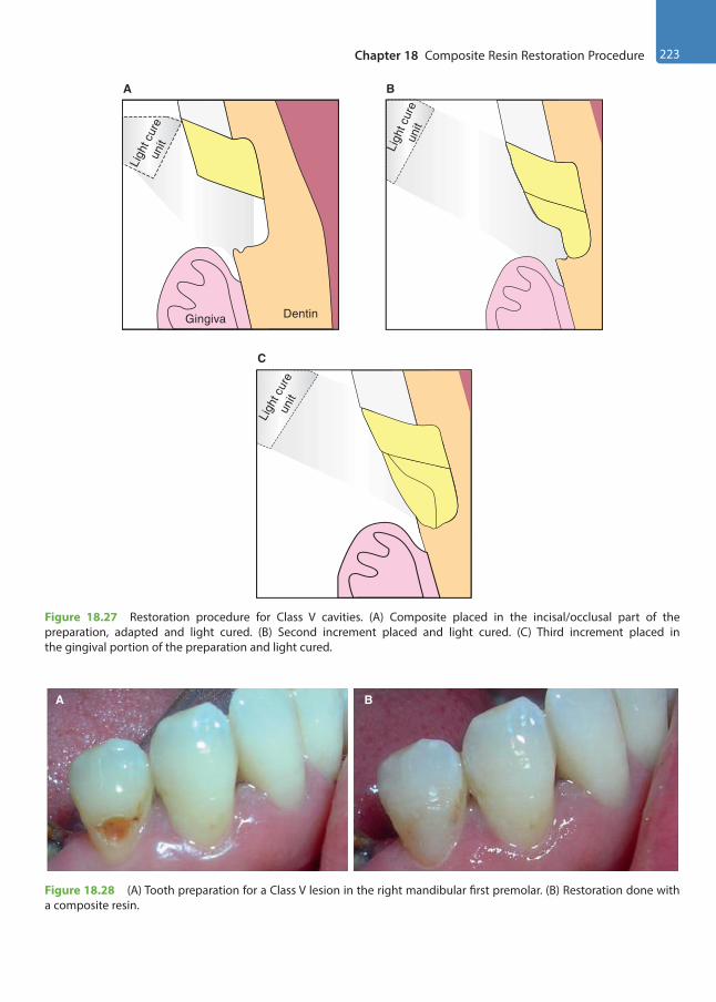
Chapter 18 Composite Resin Restoration Procedure 223
BA
Figure 18.28 (A) Tooth preparation for a Class V lesion in the right mandibular first premolar. (B) Restoration done with a composite resin.
Gingiva Dentin
A
Ligh
t cur
eun
it Ligh
t cur
eun
it
B
22
C
Ligh
t cur
eun
it
Figure 18.27 Restoration procedure for Class V cavities. (A) Composite placed in the incisal/occlusal part of the preparation, adapted and light cured. (B) Second increment placed and light cured. (C) Third increment placed in the gingival portion of the preparation and light cured.
Preclinical Dentistry.indb 223 29-05-2020 12:57:56
https://t.me/DentalBooksWorld
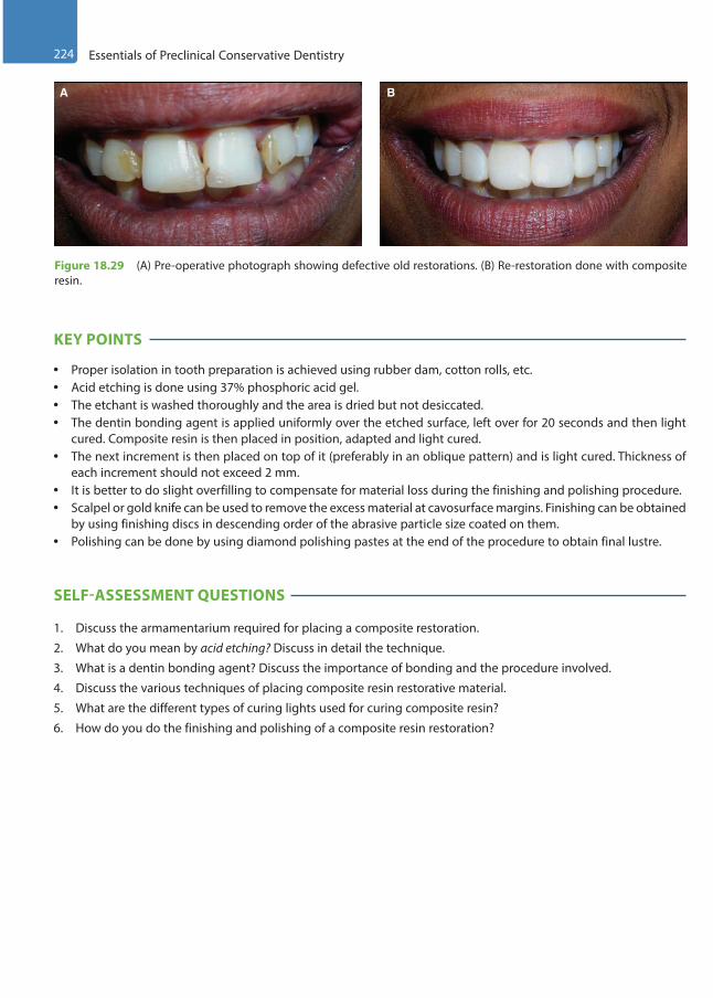
224 Essentials of Preclinical Conservative Dentistry
KEY POINTS
• Proper isolation in tooth preparation is achieved using rubber dam, cotton rolls, etc.• Acid etching is done using 37% phosphoric acid gel.• The etchant is washed thoroughly and the area is dried but not desiccated.• The dentin bonding agent is applied uniformly over the etched surface, left over for 20 seconds and then light
cured. Composite resin is then placed in position, adapted and light cured.• The next increment is then placed on top of it (preferably in an oblique pattern) and is light cured. Thickness of
each increment should not exceed 2 mm.• It is better to do slight overfilling to compensate for material loss during the finishing and polishing procedure.• Scalpel or gold knife can be used to remove the excess material at cavosurface margins. Finishing can be obtained
by using finishing discs in descending order of the abrasive particle size coated on them.• Polishing can be done by using diamond polishing pastes at the end of the procedure to obtain final lustre.
SELF-ASSESSMENT QUESTIONS
1. Discuss the armamentarium required for placing a composite restoration.
2. What do you mean by acid etching? Discuss in detail the technique.
3. What is a dentin bonding agent? Discuss the importance of bonding and the procedure involved.
4. Discuss the various techniques of placing composite resin restorative material.
5. What are the different types of curing lights used for curing composite resin?
6. How do you do the finishing and polishing of a composite resin restoration?
A B
Figure 18.29 (A) Pre-operative photograph showing defective old restorations. (B) Re-restoration done with composite resin.
Preclinical Dentistry.indb 224 29-05-2020 12:57:56
https://t.me/DentalBooksWorld
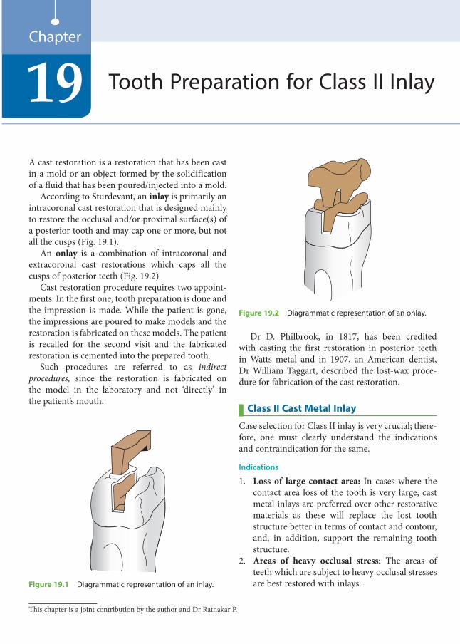
A cast restoration is a restoration that has been cast in a mold or an object formed by the solidification of a fluid that has been poured/injected into a mold.
According to Sturdevant, an inlay is primarily an intracoronal cast restoration that is designed mainly to restore the occlusal and/or proximal surface(s) of a posterior tooth and may cap one or more, but not all the cusps (Fig. 19.1).
An onlay is a combination of intracoronal and extracoronal cast restorations which caps all the cusps of posterior teeth (Fig. 19.2)
Cast restoration procedure requires two appoint-ments. In the first one, tooth preparation is done and the impression is made. While the patient is gone, the impressions are poured to make models and the restoration is fabricated on these models. The patient is recalled for the second visit and the fabricated restoration is cemented into the prepared tooth.
Such procedures are referred to as indirect procedures, since the restoration is fabricated on the model in the laboratory and not ‘directly’ in the patient’s mouth.
Dr D. Philbrook, in 1817, has been credited with casting the first restoration in posterior teeth in Watts metal and in 1907, an American dentist, Dr William Taggart, described the lost-wax proce-dure for fabrication of the cast restoration.
Class II Cast Metal Inlay
Case selection for Class II inlay is very crucial; there-fore, one must clearly understand the indications and contraindication for the same.
Indications
1. Loss of large contact area: In cases where the contact area loss of the tooth is very large, cast metal inlays are preferred over other restorative materials as these will replace the lost tooth structure better in terms of contact and contour, and, in addition, support the remaining tooth structure.
2. Areas of heavy occlusal stress: The areas of teeth which are subject to heavy occlusal stresses are best restored with inlays.
Tooth Preparation for Class II Inlay19Chapter
Figure 19.1 Diagrammatic representation of an inlay.
Figure 19.2 Diagrammatic representation of an onlay.
This chapter is a joint contribution by the author and Dr Ratnakar P.
Preclinical Dentistry.indb 225 29-05-2020 12:57:56
https://t.me/DentalBooksWorld

226 Essentials of Preclinical Conservative Dentistry
3. Diastema closure (adjunct to periodontal therapy): Inlays are indicated in physiologically restoring and maintaining the dimensions of the contact, contour, marginal ridge and embra-sure areas, which are vital for the health of the periodontium.
4. As abutment for removable prosthodontic appliance: When the restored tooth is to act as an abutment for a cast partial denture as well, it is better to restore it with inlay/onlay because the cast metal alloy inlay/onlay can better withstand the forces transmitted to it by the cast partial denture. Also, the rest seats or the guiding planes (as a feature of cast partial denture) to be made in the abutment tooth can be made easily in the inlay/onlay while making it in the laboratory than on any other restorative material, directly in the mouth.
Contraindications
1. In young patients, because of large pulp chambers2. In patients with high incidence of dental caries3. In areas where aesthetics is of prime concern4. In small carious lesions where amalgam or
composite can easily serve the purpose
Advantages
1. The lost contacts and contours can best be restored with cast restorations.
2. The compressive, tensile, yield and shear strengths of dental casting alloys are far greater than those of other materials used intraorally.
3. Biocompatibility is an additional advantage because of use of noble metals (cast gold).
4. They show high wear resistance.
Disadvantages
1. The number of appointments to perform cast restoration procedure is more and the chairside time is longer.
2. Temporary restoration has to be given in between the appointments.
3. The procedure is technique sensitive.4. This procedure is more expensive than direct
restorations.5. Microleakage can be a problem if there is disso-
lution of cement with which these restorations are cemented.
6. Inlays, at times, can produce wedging effect which can cause fracture of the tooth.
Cavity Design: Basic Concept
The cast restoration is fabricated in a noble metal by the replacement of a wax pattern formed directly in the prepared tooth or indirectly on a die. Removal of the wax pattern without distortion and subsequent insertion of the casting can be accomplished only when the prepared cavity exhibits a fundamentally different form as compared to the one made for direct filling materials. The preparation has walls diverging towards the occlusal surface and no undercuts.
Principles of Tooth Preparation for Class II Cast Metal InlayIt is noteworthy to mention that the basic principles of tooth preparation for Class II cast metal inlay are same as those for silver amalgam, with some signifi-cant differences owing to the fact that the former is an indirect restoration, whereas the latter is a direct one.
Apart from the general principles of tooth prepa-ration, cast restoration preparations should have the following three salient features:1. Preparation path/draw path2. Apico-occlusal taper3. Features of the circumferential tie
Preparation Path/Draw PathThe preparation should have a single draw path, usually parallel to the long axis of the tooth crown (Fig. 19.3) and opposite to the direction of occlusal loading. All reductions in tooth structure are performed in a way that preparation has a ‘draft’, that is, path of insertion and withdrawal, without any hindrance. This path should be opposite to the direction of occlusal forces so that the occlusal function seats the restoration instead of displacing it.
Inlay
Tooth
Figure 19.3 Path of draw.
Preclinical Dentistry.indb 226 29-05-2020 12:57:56
https://t.me/DentalBooksWorld

Chapter 19 Tooth Preparation for Class II Inlay 227
Apico-Occlusal TaperThe axial surfaces of tooth preparation and opposing walls should ideally be parallel to each other in a cast restoration. But exact parallelism is not possible as it will interfere with the removal of wax pattern and insertion of cast restoration. Therefore, a slight divergence of 2°–5° is advisable (Fig. 19.4). However, in cases where the depth of the preparation is less, the degree of divergence is also reduced. In cases of extensive preparations, the degree of divergence is increased to reduce the friction between preparation walls and the restoration.
Preparation Features of the Circumferential TieThe weakest link in any cast restoration is the tooth–cement–restoration interface. So, special attention should be given to design the margins of the prepa-ration. This peripheral marginal anatomy of the preparation is called circumferential tie.
If the margin ends on the enamel, the enamel walls should fulfil all the requirements advocated by Noy for an ideal cavity wall:1. The enamel rods must always be supported by a
sound dentin.2. The enamel rods forming the cavosurface margin
should be continuous with the sound dentin and covered with the restorative material.
3. The angular cavosurface margins should be trimmed.
Cast restorations are the only restorations that can fulfil these requirements.
For the occlusal and gingival walls in inlay prepa-rations, the tooth circumferential tie will be in the form of a bevel.
Initial Tooth PreparationFor ease of understanding, let us consider the prepa-ration for inlay on a maxillary premolar in which a carious lesion is present on the distal surface.1. Plain cut, tapered fissure carbide burs are used
for inlay preparation, since plain cut burs lead to smooth walls. The carbide burs used are No. 271 and 169L. The diamond point used for preparing bevels is No. 8862 (Fig. 19.5).
2. The 271 bur is held in the pit closer to the affected proximal portion (the distal side in this case) and a punch cut is given up to a depth of 1.5 mm (Fig. 19.6). The preparation is extended towards the mesial pit along the central fissure (Fig. 19.7).
3. The burs are oriented in such a manner during the preparation that the vertical walls are oriented to a single draw path, usually the long axis of the crown. This helps to achieve a path of draw, which is a definite pre-requisite for any cast restoration. This implies that there should be no undercuts in the preparation and when the wax pattern is to be removed, it comes out without breaking or distorting. Also, a diver-gence of 2°–5° is given in the gingival to occlusal direction as explained earlier.
Figure 19.4 Apico-occlusal taper, as seen from the proximal surface.
0.5 mm
169L
0.8 mm
271 8862
Figure 19.5 Burs used for preparation of an inlay.
Preclinical Dentistry.indb 227 29-05-2020 12:57:57
https://t.me/DentalBooksWorld
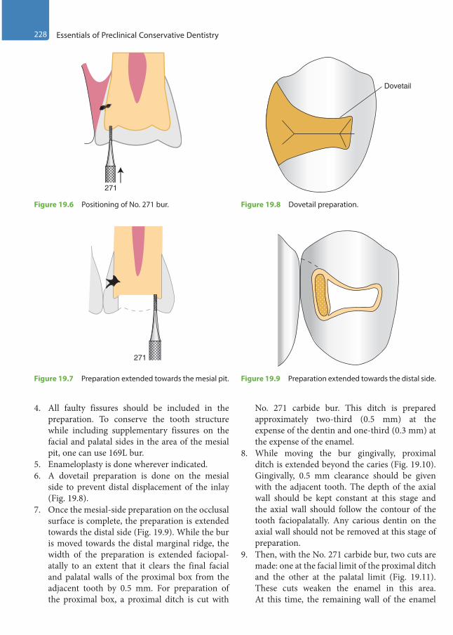
228 Essentials of Preclinical Conservative Dentistry
4. All faulty fissures should be included in the preparation. To conserve the tooth structure while including supplementary fissures on the facial and palatal sides in the area of the mesial pit, one can use 169L bur.
5. Enameloplasty is done wherever indicated.6. A dovetail preparation is done on the mesial
side to prevent distal displacement of the inlay (Fig. 19.8).
7. Once the mesial-side preparation on the occlusal surface is complete, the preparation is extended towards the distal side (Fig. 19.9). While the bur is moved towards the distal marginal ridge, the width of the preparation is extended faciopal-atally to an extent that it clears the final facial and palatal walls of the proximal box from the adjacent tooth by 0.5 mm. For preparation of the proximal box, a proximal ditch is cut with
No. 271 carbide bur. This ditch is prepared approximately two-third (0.5 mm) at the expense of the dentin and one-third (0.3 mm) at the expense of the enamel.
8. While moving the bur gingivally, proximal ditch is extended beyond the caries (Fig. 19.10). Gingivally, 0.5 mm clearance should be given with the adjacent tooth. The depth of the axial wall should be kept constant at this stage and the axial wall should follow the contour of the tooth faciopalatally. Any carious dentin on the axial wall should not be removed at this stage of preparation.
9. Then, with the No. 271 carbide bur, two cuts are made: one at the facial limit of the proximal ditch and the other at the palatal limit (Fig. 19.11). These cuts weaken the enamel in this area. At this time, the remaining wall of the enamel
271
Figure 19.6 Positioning of No. 271 bur.
Dovetail
Figure 19.8 Dovetail preparation.
271
Figure 19.7 Preparation extended towards the mesial pit. Figure 19.9 Preparation extended towards the distal side.
Preclinical Dentistry.indb 228 29-05-2020 12:57:57
https://t.me/DentalBooksWorld
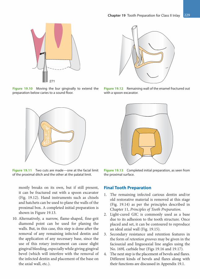
Chapter 19 Tooth Preparation for Class II Inlay 229
mostly breaks on its own, but if still present, it can be fractured out with a spoon excavator (Fig. 19.12). Hand instruments such as chisels and hatchets can be used to plane the walls of the proximal box. A completed initial preparation is shown in Figure 19.13.
10. Alternatively, a narrow, flame-shaped, fine-grit diamond point can be used for planing the walls. But, in this case, this step is done after the removal of any remaining infected dentin and the application of any necessary base, since the use of this rotary instrument can cause slight gingival bleeding, especially while giving gingival bevel (which will interfere with the removal of the infected dentin and placement of the base on the axial wall, etc.).
Final Tooth Preparation1. The remaining infected carious dentin and/or
old restorative material is removed at this stage (Fig. 19.14) as per the principles described in Chapter 11, Principles of Tooth Preparation.
2. Light-cured GIC is commonly used as a base due to its adhesion to the tooth structure. Once placed and set, it can be contoured to reproduce an ideal axial wall (Fig. 19.15).
3. Secondary resistance and retention features in the form of retention grooves may be given in the facioaxial and linguoaxial line angles using the No. 169L carbide bur (Figs 19.16 and 19.17).
4. The next step is the placement of bevels and flares. Different kinds of bevels and flares along with their functions are discussed in Appendix 19.1.
271
Figure 19.10 Moving the bur gingivally to extend the preparation below caries to a sound floor.
Figure 19.12 Remaining wall of the enamel fractured out with a spoon excavator.
Figure 19.11 Two cuts are made—one at the facial limit of the proximal ditch and the other at the palatal limit.
Figure 19.13 Completed initial preparation, as seen from the proximal surface.
Preclinical Dentistry.indb 229 29-05-2020 12:57:57
https://t.me/DentalBooksWorld
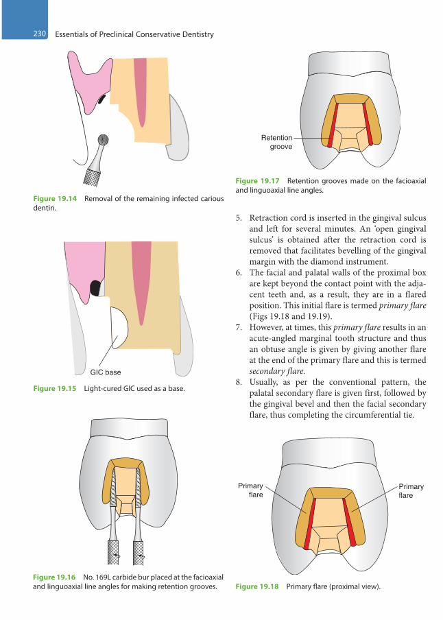
230 Essentials of Preclinical Conservative Dentistry
5. Retraction cord is inserted in the gingival sulcus and left for several minutes. An ‘open gingival sulcus’ is obtained after the retraction cord is removed that facilitates bevelling of the gingival margin with the diamond instrument.
6. The facial and palatal walls of the proximal box are kept beyond the contact point with the adja-cent teeth and, as a result, they are in a flared position. This initial flare is termed primary flare (Figs 19.18 and 19.19).
7. However, at times, this primary flare results in an acute-angled marginal tooth structure and thus an obtuse angle is given by giving another flare at the end of the primary flare and this is termed secondary flare.
8. Usually, as per the conventional pattern, the palatal secondary flare is given first, followed by the gingival bevel and then the facial secondary flare, thus completing the circumferential tie.
Figure 19.14 Removal of the remaining infected carious dentin.
GIC base
Figure 19.15 Light-cured GIC used as a base.
Figure 19.16 No. 169L carbide bur placed at the facioaxial and linguoaxial line angles for making retention grooves.
Retentiongroove
Figure 19.17 Retention grooves made on the facioaxial and linguoaxial line angles.
Primaryflare
Primaryflare
Figure 19.18 Primary flare (proximal view).
Preclinical Dentistry.indb 230 29-05-2020 12:57:58
https://t.me/DentalBooksWorld
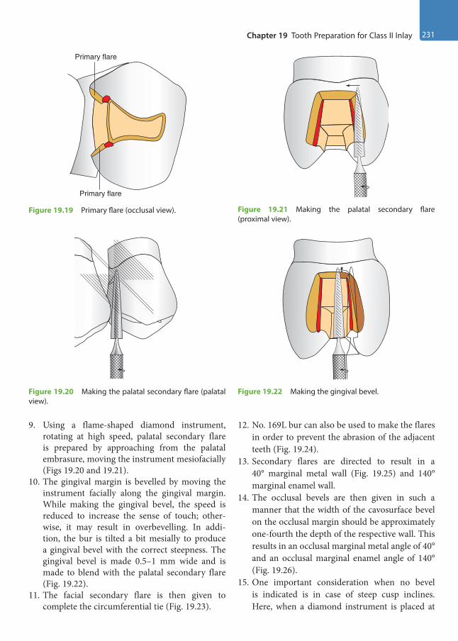
Chapter 19 Tooth Preparation for Class II Inlay 231
9. Using a flame-shaped diamond instrument, rotating at high speed, palatal secondary flare is prepared by approaching from the palatal embrasure, moving the instrument mesiofacially (Figs 19.20 and 19.21).
10. The gingival margin is bevelled by moving the instrument facially along the gingival margin. While making the gingival bevel, the speed is reduced to increase the sense of touch; other-wise, it may result in overbevelling. In addi-tion, the bur is tilted a bit mesially to produce a gingival bevel with the correct steepness. The gingival bevel is made 0.5–1 mm wide and is made to blend with the palatal secondary flare (Fig. 19.22).
11. The facial secondary flare is then given to complete the circumferential tie (Fig. 19.23).
12. No. 169L bur can also be used to make the flares in order to prevent the abrasion of the adjacent teeth (Fig. 19.24).
13. Secondary flares are directed to result in a 40° marginal metal wall (Fig. 19.25) and 140° marginal enamel wall.
14. The occlusal bevels are then given in such a manner that the width of the cavosurface bevel on the occlusal margin should be approximately one-fourth the depth of the respective wall. This results in an occlusal marginal metal angle of 40° and an occlusal marginal enamel angle of 140° (Fig. 19.26).
15. One important consideration when no bevel is indicated is in case of steep cusp inclines. Here, when a diamond instrument is placed at
Primary flare
Primary flare
Figure 19.19 Primary flare (occlusal view).
Figure 19.20 Making the palatal secondary flare (palatal view).
Figure 19.21 Making the palatal secondary flare (proximal view).
Figure 19.22 Making the gingival bevel.
Preclinical Dentistry.indb 231 29-05-2020 12:57:58
https://t.me/DentalBooksWorld
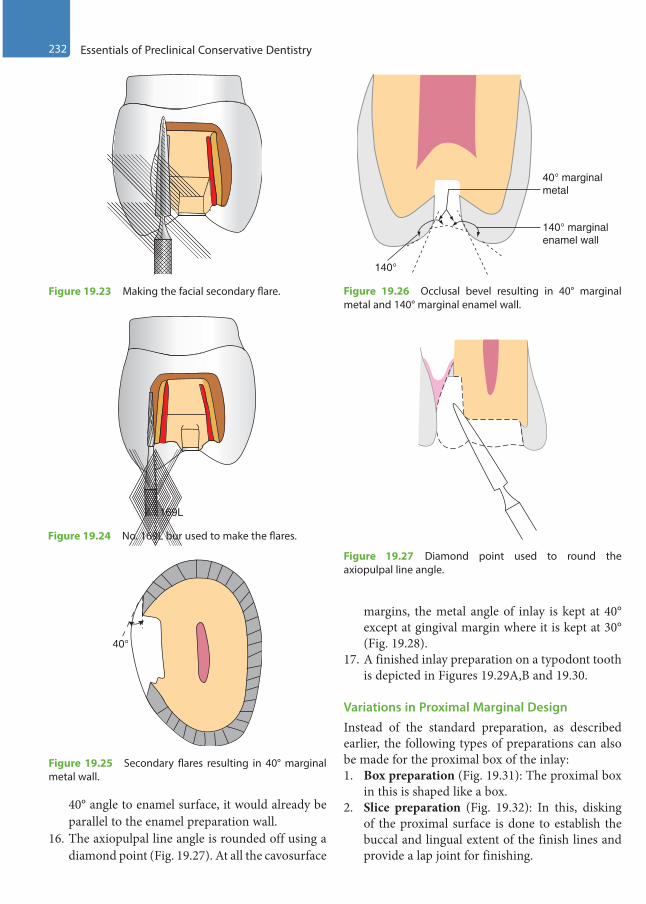
232 Essentials of Preclinical Conservative Dentistry
40° angle to enamel surface, it would already be parallel to the enamel preparation wall.
16. The axiopulpal line angle is rounded off using a diamond point (Fig. 19.27). At all the cavosurface
margins, the metal angle of inlay is kept at 40° except at gingival margin where it is kept at 30° (Fig. 19.28).
17. A finished inlay preparation on a typodont tooth is depicted in Figures 19.29A,B and 19.30.
Variations in Proximal Marginal DesignInstead of the standard preparation, as described earlier, the following types of preparations can also be made for the proximal box of the inlay:1. Box preparation (Fig. 19.31): The proximal box
in this is shaped like a box.2. Slice preparation (Fig. 19.32): In this, disking
of the proximal surface is done to establish the buccal and lingual extent of the finish lines and provide a lap joint for finishing.
169L
Figure 19.24 No. 169L bur used to make the flares.
40°
Figure 19.25 Secondary flares resulting in 40° marginal metal wall.
140° marginalenamel wall
40° marginalmetal
140°
Figure 19.26 Occlusal bevel resulting in 40° marginal metal and 140° marginal enamel wall.
Figure 19.27 Diamond point used to round the axiopulpal line angle.
Figure 19.23 Making the facial secondary flare.
Preclinical Dentistry.indb 232 29-05-2020 12:57:59
https://t.me/DentalBooksWorld
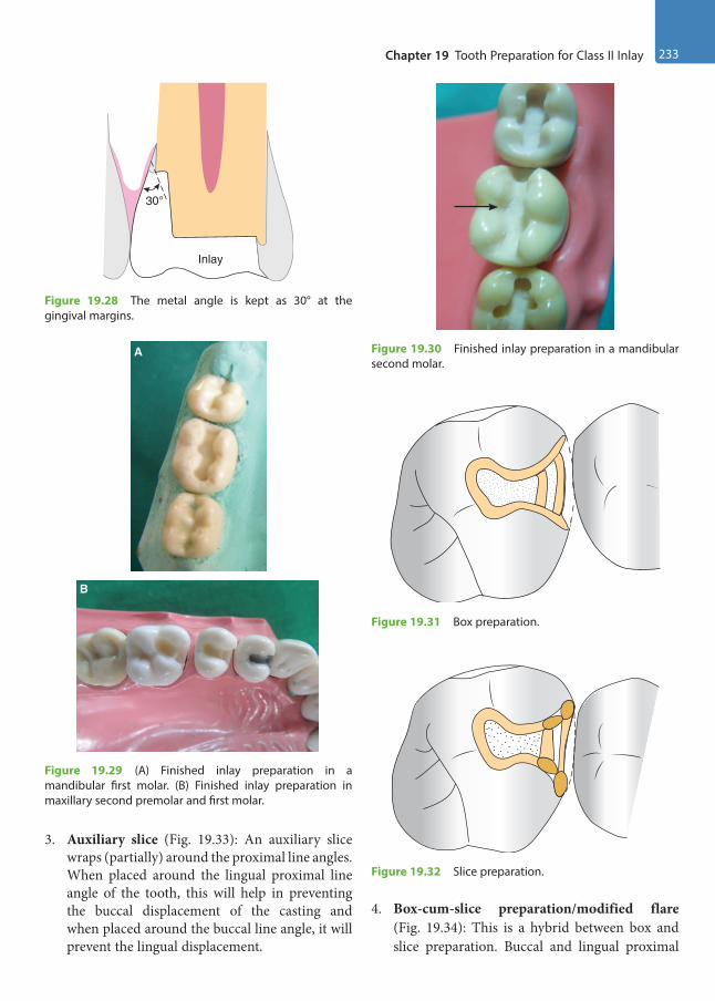
Chapter 19 Tooth Preparation for Class II Inlay 233
3. Auxiliary slice (Fig. 19.33): An auxiliary slice wraps (partially) around the proximal line angles. When placed around the lingual proximal line angle of the tooth, this will help in preventing the buccal displacement of the casting and when placed around the buccal line angle, it will prevent the lingual displacement.
4. Box-cum-slice preparation/modified flare (Fig. 19.34): This is a hybrid between box and slice preparation. Buccal and lingual proximal
Inlay
30°
Figure 19.28 The metal angle is kept as 30° at the gingival margins.
A
B
Figure 19.29 (A) Finished inlay preparation in a mandibular first molar. (B) Finished inlay preparation in maxillary second premolar and first molar.
Figure 19.30 Finished inlay preparation in a mandibular second molar.
Figure 19.31 Box preparation.
Figure 19.32 Slice preparation.
Preclinical Dentistry.indb 233 29-05-2020 12:57:59
https://t.me/DentalBooksWorld

234 Essentials of Preclinical Conservative Dentistry
walls are first formed with minimal extension and then are disked in a plane that only slightly reduces the proximal wall dimension.
For easy reference, the differences of tooth prepa-ration between silver amalgam and inlay have been summarised in Table 19.1.
Table 19.1 Differences Between Tooth Preparation Procedure for Silver Amalgam and Cast Restorations
Class II Silver Amalgam Class II Inlay
Restoration is supported by the tooth. Inlay itself may support the tooth structure, especially when the cusps are covered.
This provides poor resistance to the forces of occlusion. This provides good resistance to the forces of occlusion.
The width of the preparation is one-fourth of the inter-cuspal width.
The width of the preparation is one-third of the inter-cuspal width.
Depth of the preparation is kept more. Depth of the preparation is kept less.
Preparation is designed to create retention from the converging walls and undercuts.
Preparation is designed to create retention from nearly parallel walls.
A butt joint is given at the cavosurface margin (90°). Bevels are given at the cavosurface margin.
Reverse curve is incorporated in tooth preparation, especially in maxillary molars to provide a strong enamel margin.
No reverse curve is incorporated in the tooth preparation.
Proximal outline form provides 0.5 mm clearance from the adjacent tooth at the level of contact.
Proximal outline form is slightly kept more extensive, since primary flares are to be incorporated in the preparation.
Line angles and point angles are rounded. Line angles and point angles are well defined.
Axiopulpal line angle is bevelled. Axiopulpal line angle is slightly rounded.
Reverse bevel is not given. Reverse bevel may be given.
Gingival wall of the proximal box is made at a right angle or slightly acute angle with the axial wall. It provides a defi-nite seat when silver amalgam is condensed in this area.
Gingival wall of the proximal box is straight buccolingually and in two planes, providing a definite axiogingival line angle for the ease of the casting procedure.
Longitudinally oriented retention locks are given in Class II amalgam and transverse-oriented retention grooves are given in Class V amalgam.
No retention locks are given in Class II inlay, but longitudi-nally oriented retention grooves are given.
A ‘path of draw’ is not required in the tooth preparation. A ‘path of draw’ is a definite pre-requisite for a cast resto-ration, since the wax pattern has to be removed and the casting seated, preferably in one direction.
Figure 19.33 Auxiliary slice preparation. Figure 19.34 Box-cum-slice preparation/modified flare preparation.
Preclinical Dentistry.indb 234 29-05-2020 12:57:59
https://t.me/DentalBooksWorld
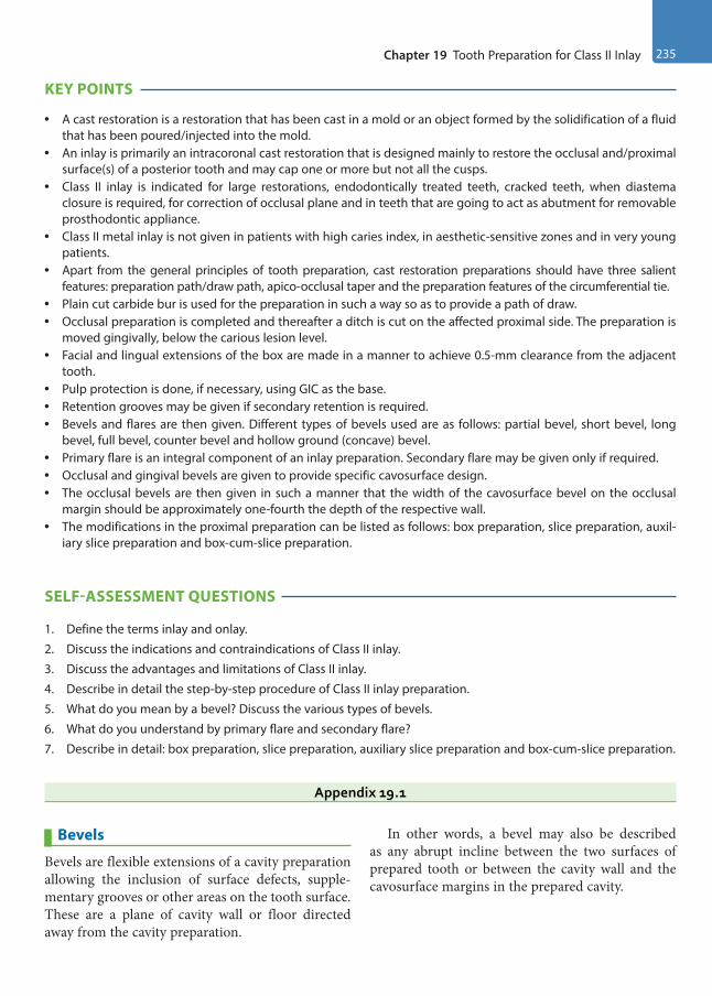
Chapter 19 Tooth Preparation for Class II Inlay 235
KEY POINTS
• A cast restoration is a restoration that has been cast in a mold or an object formed by the solidification of a fluid that has been poured/injected into the mold.
• An inlay is primarily an intracoronal cast restoration that is designed mainly to restore the occlusal and/proximal surface(s) of a posterior tooth and may cap one or more but not all the cusps.
• Class II inlay is indicated for large restorations, endodontically treated teeth, cracked teeth, when diastema closure is required, for correction of occlusal plane and in teeth that are going to act as abutment for removable prosthodontic appliance.
• Class II metal inlay is not given in patients with high caries index, in aesthetic-sensitive zones and in very young patients.
• Apart from the general principles of tooth preparation, cast restoration preparations should have three salient features: preparation path/draw path, apico-occlusal taper and the preparation features of the circumferential tie.
• Plain cut carbide bur is used for the preparation in such a way so as to provide a path of draw.• Occlusal preparation is completed and thereafter a ditch is cut on the affected proximal side. The preparation is
moved gingivally, below the carious lesion level.• Facial and lingual extensions of the box are made in a manner to achieve 0.5-mm clearance from the adjacent
tooth.• Pulp protection is done, if necessary, using GIC as the base.• Retention grooves may be given if secondary retention is required.• Bevels and flares are then given. Different types of bevels used are as follows: partial bevel, short bevel, long
bevel, full bevel, counter bevel and hollow ground (concave) bevel.• Primary flare is an integral component of an inlay preparation. Secondary flare may be given only if required.• Occlusal and gingival bevels are given to provide specific cavosurface design.• The occlusal bevels are then given in such a manner that the width of the cavosurface bevel on the occlusal
margin should be approximately one-fourth the depth of the respective wall.• The modifications in the proximal preparation can be listed as follows: box preparation, slice preparation, auxil-
iary slice preparation and box-cum-slice preparation.
SELF-ASSESSMENT QUESTIONS
1. Define the terms inlay and onlay.
2. Discuss the indications and contraindications of Class II inlay.
3. Discuss the advantages and limitations of Class II inlay.
4. Describe in detail the step-by-step procedure of Class II inlay preparation.
5. What do you mean by a bevel? Discuss the various types of bevels.
6. What do you understand by primary flare and secondary flare?
7. Describe in detail: box preparation, slice preparation, auxiliary slice preparation and box-cum-slice preparation.
Appendix 19.1
Bevels
Bevels are flexible extensions of a cavity preparation allowing the inclusion of surface defects, supple-mentary grooves or other areas on the tooth surface. These are a plane of cavity wall or floor directed away from the cavity preparation.
In other words, a bevel may also be described as any abrupt incline between the two surfaces of prepared tooth or between the cavity wall and the cavosurface margins in the prepared cavity.
Preclinical Dentistry.indb 235 29-05-2020 12:58:00
https://t.me/DentalBooksWorld
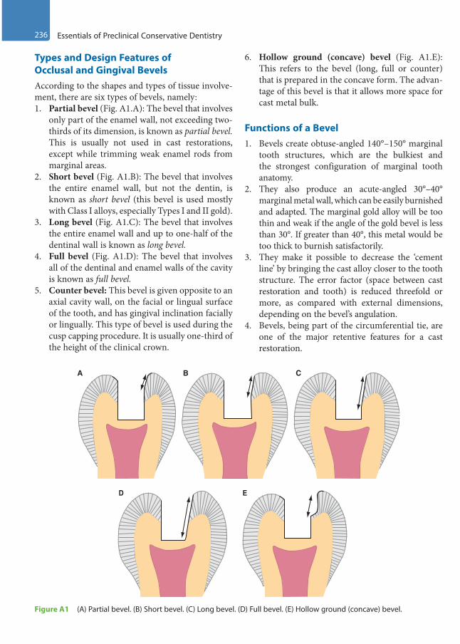
236 Essentials of Preclinical Conservative Dentistry
Types and Design Features of Occlusal and Gingival BevelsAccording to the shapes and types of tissue involve-ment, there are six types of bevels, namely:1. Partial bevel (Fig. A1.A): The bevel that involves
only part of the enamel wall, not exceeding two- thirds of its dimension, is known as partial bevel. This is usually not used in cast restorations, except while trimming weak enamel rods from marginal areas.
2. Short bevel (Fig. A1.B): The bevel that involves the entire enamel wall, but not the dentin, is known as short bevel (this bevel is used mostly with Class I alloys, especially Types I and II gold).
3. Long bevel (Fig. A1.C): The bevel that involves the entire enamel wall and up to one-half of the dentinal wall is known as long bevel.
4. Full bevel (Fig. A1.D): The bevel that involves all of the dentinal and enamel walls of the cavity is known as full bevel.
5. Counter bevel: This bevel is given opposite to an axial cavity wall, on the facial or lingual surface of the tooth, and has gingival inclination facially or lingually. This type of bevel is used during the cusp capping procedure. It is usually one-third of the height of the clinical crown.
6. Hollow ground (concave) bevel (Fig. A1.E): This refers to the bevel (long, full or counter) that is prepared in the concave form. The advan-tage of this bevel is that it allows more space for cast metal bulk.
Functions of a Bevel1. Bevels create obtuse-angled 140°–150° marginal
tooth structures, which are the bulkiest and the strongest configuration of marginal tooth anatomy.
2. They also produce an acute-angled 30°–40° marginal metal wall, which can be easily burnished and adapted. The marginal gold alloy will be too thin and weak if the angle of the gold bevel is less than 30°. If greater than 40°, this metal would be too thick to burnish satisfactorily.
3. They make it possible to decrease the ‘cement line’ by bringing the cast alloy closer to the tooth structure. The error factor (space between cast restoration and tooth) is reduced threefold or more, as compared with external dimensions, depending on the bevel’s angulation.
4. Bevels, being part of the circumferential tie, are one of the major retentive features for a cast restoration.
A
D E
B C
Figure A1 (A) Partial bevel. (B) Short bevel. (C) Long bevel. (D) Full bevel. (E) Hollow ground (concave) bevel.
Preclinical Dentistry.indb 236 29-05-2020 12:58:00
https://t.me/DentalBooksWorld
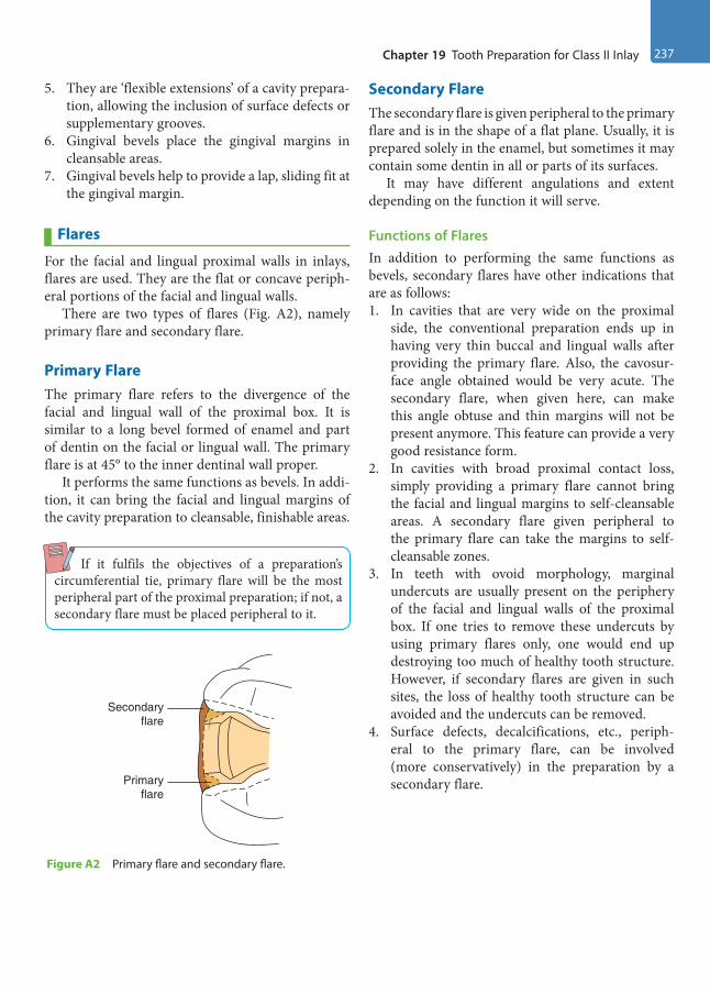
Chapter 19 Tooth Preparation for Class II Inlay 237
5. They are ‘flexible extensions’ of a cavity prepara-tion, allowing the inclusion of surface defects or supplementary grooves.
6. Gingival bevels place the gingival margins in cleansable areas.
7. Gingival bevels help to provide a lap, sliding fit at the gingival margin.
Flares
For the facial and lingual proximal walls in inlays, flares are used. They are the flat or concave periph-eral portions of the facial and lingual walls.
There are two types of flares (Fig. A2), namely primary flare and secondary flare.
Primary FlareThe primary flare refers to the divergence of the facial and lingual wall of the proximal box. It is similar to a long bevel formed of enamel and part of dentin on the facial or lingual wall. The primary flare is at 45° to the inner dentinal wall proper.
It performs the same functions as bevels. In addi-tion, it can bring the facial and lingual margins of the cavity preparation to cleansable, finishable areas.
If it fulfils the objectives of a preparation’s circumferential tie, primary flare will be the most peripheral part of the proximal preparation; if not, a secondary flare must be placed peripheral to it.
Secondary FlareThe secondary flare is given peripheral to the primary flare and is in the shape of a flat plane. Usually, it is prepared solely in the enamel, but sometimes it may contain some dentin in all or parts of its surfaces.
It may have different angulations and extent depending on the function it will serve.
Functions of Flares In addition to performing the same functions as bevels, secondary flares have other indications that are as follows:1. In cavities that are very wide on the proximal
side, the conventional preparation ends up in having very thin buccal and lingual walls after providing the primary flare. Also, the cavosur-face angle obtained would be very acute. The secondary flare, when given here, can make this angle obtuse and thin margins will not be present anymore. This feature can provide a very good resistance form.
2. In cavities with broad proximal contact loss, simply providing a primary flare cannot bring the facial and lingual margins to self-cleansable areas. A secondary flare given peripheral to the primary flare can take the margins to self- cleansable zones.
3. In teeth with ovoid morphology, marginal undercuts are usually present on the periphery of the facial and lingual walls of the proximal box. If one tries to remove these undercuts by using primary flares only, one would end up destroying too much of healthy tooth structure. However, if secondary flares are given in such sites, the loss of healthy tooth structure can be avoided and the undercuts can be removed.
4. Surface defects, decalcifications, etc., periph-eral to the primary flare, can be involved (more conservatively) in the preparation by a secondary flare.
Secondaryflare
Primaryflare
Figure A2 Primary flare and secondary flare.
Preclinical Dentistry.indb 237 29-05-2020 12:58:00
https://t.me/DentalBooksWorld
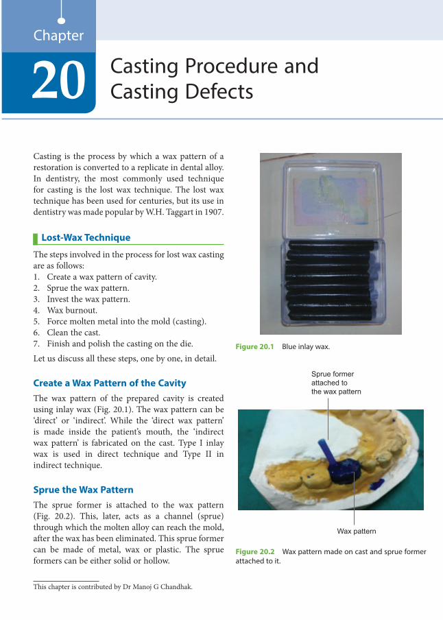
Casting is the process by which a wax pattern of a restoration is converted to a replicate in dental alloy. In dentistry, the most commonly used technique for casting is the lost wax technique. The lost wax technique has been used for centuries, but its use in dentistry was made popular by W.H. Taggart in 1907.
Lost-Wax Technique
The steps involved in the process for lost wax casting are as follows:1. Create a wax pattern of cavity.2. Sprue the wax pattern.3. Invest the wax pattern.4. Wax burnout.5. Force molten metal into the mold (casting).6. Clean the cast.7. Finish and polish the casting on the die.Let us discuss all these steps, one by one, in detail.
Create a Wax Pattern of the CavityThe wax pattern of the prepared cavity is created using inlay wax (Fig. 20.1). The wax pattern can be ‘direct’ or ‘indirect’. While the ‘direct wax pattern’ is made inside the patient’s mouth, the ‘indirect wax pattern’ is fabricated on the cast. Type I inlay wax is used in direct technique and Type II in indirect technique.
Sprue the Wax PatternThe sprue former is attached to the wax pattern (Fig. 20.2). This, later, acts as a channel (sprue) through which the molten alloy can reach the mold, after the wax has been eliminated. This sprue former can be made of metal, wax or plastic. The sprue formers can be either solid or hollow.
Casting Procedure and Casting Defects20
Chapter
Figure 20.1 Blue inlay wax.
Sprue former attached tothe wax pattern
Wax pattern
Figure 20.2 Wax pattern made on cast and sprue former attached to it.
This chapter is contributed by Dr Manoj G Chandhak.
Preclinical Dentistry.indb 238 29-05-2020 12:58:00
https://t.me/DentalBooksWorld
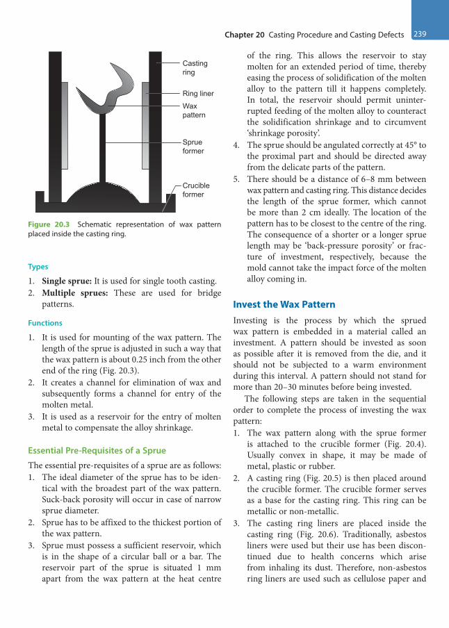
Chapter 20 Casting Procedure and Casting Defects 239
Types
1. Single sprue: It is used for single tooth casting.2. Multiple sprues: These are used for bridge
patterns.
Functions
1. It is used for mounting of the wax pattern. The length of the sprue is adjusted in such a way that the wax pattern is about 0.25 inch from the other end of the ring (Fig. 20.3).
2. It creates a channel for elimination of wax and subsequently forms a channel for entry of the molten metal.
3. It is used as a reservoir for the entry of molten metal to compensate the alloy shrinkage.
Essential Pre-Requisites of a Sprue
The essential pre-requisites of a sprue are as follows:1. The ideal diameter of the sprue has to be iden-
tical with the broadest part of the wax pattern. Suck-back porosity will occur in case of narrow sprue diameter.
2. Sprue has to be affixed to the thickest portion of the wax pattern.
3. Sprue must possess a sufficient reservoir, which is in the shape of a circular ball or a bar. The reservoir part of the sprue is situated 1 mm apart from the wax pattern at the heat centre
of the ring. This allows the reservoir to stay molten for an extended period of time, thereby easing the process of solidification of the molten alloy to the pattern till it happens completely. In total, the reservoir should permit uninter-rupted feeding of the molten alloy to counteract the solidification shrinkage and to circumvent ‘shrinkage porosity’.
4. The sprue should be angulated correctly at 45° to the proximal part and should be directed away from the delicate parts of the pattern.
5. There should be a distance of 6–8 mm between wax pattern and casting ring. This distance decides the length of the sprue former, which cannot be more than 2 cm ideally. The location of the pattern has to be closest to the centre of the ring. The consequence of a shorter or a longer sprue length may be ‘back-pressure porosity’ or frac-ture of investment, respectively, because the mold cannot take the impact force of the molten alloy coming in.
Invest the Wax PatternInvesting is the process by which the sprued wax pattern is embedded in a material called an investment. A pattern should be invested as soon as possible after it is removed from the die, and it should not be subjected to a warm environment during this interval. A pattern should not stand for more than 20–30 minutes before being invested.
The following steps are taken in the sequential order to complete the process of investing the wax pattern:1. The wax pattern along with the sprue former
is attached to the crucible former (Fig. 20.4). Usually convex in shape, it may be made of metal, plastic or rubber.
2. A casting ring (Fig. 20.5) is then placed around the crucible former. The crucible former serves as a base for the casting ring. This ring can be metallic or non-metallic.
3. The casting ring liners are placed inside the casting ring (Fig. 20.6). Traditionally, asbestos liners were used but their use has been discon-tinued due to health concerns which arise from inhaling its dust. Therefore, non-asbestos ring liners are used such as cellulose paper and
Casting ring
Ring liner
Wax pattern
Sprue former
Crucible former
Figure 20.3 Schematic representation of wax pattern placed inside the casting ring.
Preclinical Dentistry.indb 239 29-05-2020 12:58:00
https://t.me/DentalBooksWorld

240 Essentials of Preclinical Conservative Dentistry
fibrous aluminosilicate ceramic. Usually, the liner is kept within the ring allowing a gap of approximately 2–3 mm from both ends so as to facilitate contact between investment and casting ring. The liner gives a cushioning effect, thereby permitting expansion of the mold. It makes venting possible during the casting procedure and allows for easy removal of the investment block once casting is completed. It avoids distor-tion by facilitating the expansion of the mold in an outward direction.
4. An investment material (gypsum, phosphate or silicate-based) is mixed in a flowable consistency and made to flow inside the casting ring. This material covers the entire wax pattern and the sprue former. Since the wax surface is generally not easily wetted, a surface-active wetting agent is applied on it to ensure that entire wax pattern gets covered with the investment material regu-larly. Instead of doing this investing procedure manually, one can use ‘vacuum investing tech-nique’ also to ensure better wetting of the wax pattern with the investment material.
5. This material is then allowed to set at room temperature. The casting ring keeps the invest-ment in position while setting and limits the expansion of the mold.
Wax Elimination (Burnout)
1. Wax elimination or burnout is a process in which the investment is heated in a thermostati-cally controlled furnace (Fig. 20.7) till the entire amount of wax gets vaporised. This is done so that we get an empty mold that can receive the molten alloy during the procedure.
2. The temperature is slowly increased in order to eliminate the wax and water without cracking the investment.
3. The ring has to be persistently kept at the highest temperature (‘heat soak’) for a prolonged period
Figure 20.4 Sprue former attached to the crucible former.
Figure 20.5 Casting ring placed in position with crucible former acting as its base.
Figure 20.6 Ring liner inside the casting ring.
Preclinical Dentistry.indb 240 29-05-2020 12:58:00
https://t.me/DentalBooksWorld

Chapter 20 Casting Procedure and Casting Defects 241
of time so that a sudden decrease in temperature is minimised while removing it from the oven.
Force Molten Metal into the Mold (Casting)1. The metal to be used for making the inlay is
placed in a crucible which can be made of clay, carbon, quartz, etc.
2. The metal, once placed in the crucible, is heated using a casting torch (Fig. 20.8) which uses fuels such as acetylene, natural gas and propane.
3. This molten metal is then pushed into the mold which has been created by the melted wax. Different techniques can be used for this
procedure, for example, centrifugal casting and air pressure casting.
Centrifugal Casting
In this technique, the metal is melted in a crucible and forced into a mold by centrifugal force. A centrifugal casting machine (Fig. 20.9A,B) is used for this.
Air Pressure Casting
Alloy is melted in situ in the hollow left by crucible former and then air pressure is applied through piston using a pressure of 10–15 psi. Carbon dioxide, carbon monoxide or nitrogen gas can be used for this purpose. 1. Vacuum casting: Vacuum is forced into the base
below the casting ring and suction is used to draw the molten alloy into the mold.
2. Induction casting: An induction field is formed inside the crucible which is encompassed by metal tubing that is cooled by water. This induction field melts the metal, frequently melting the base metal alloy (Fig. 20.10).
Cleaning of the CastOnce the molten metal solidifies inside the mold (Fig. 20.11), the mold is broken to take out the raw
Figure 20.7 Wax burnout furnace.
Figure 20.8 Casting torch.
Figure 20.9 (A) Centrifugal casting machine. (B) Crucible in centrifugal casting machine after the casting is complete.
Crucible in position
A B
Preclinical Dentistry.indb 241 29-05-2020 12:58:01
https://t.me/DentalBooksWorld
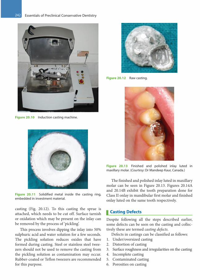
242 Essentials of Preclinical Conservative Dentistry
casting (Fig. 20.12). To this casting the sprue is attached, which needs to be cut off. Surface tarnish or oxidation which may be present on the inlay can be removed by the process of ‘pickling’.
This process involves dipping the inlay into 50% sulphuric acid and water solution for a few seconds. The pickling solution reduces oxides that have formed during casting. Steel or stainless steel twee-zers should not be used to remove the casting from the pickling solution as contamination may occur. Rubber-coated or Teflon tweezers are recommended for this purpose.
The finished and polished inlay luted in maxillary molar can be seen in Figure 20.13. Figures 20.14A and 20.14B exhibit the tooth preparation done for Class II onlay in mandibular first molar and finished onlay luted on the same tooth respectively.
Casting Defects
Despite following all the steps described earlier, some defects can be seen on the casting and collec-tively these are termed casting defects.
Defects in castings can be classified as follows:1. Under/oversized casting2. Distortion of casting3. Surface roughness and irregularities on the casting4. Incomplete casting5. Contaminated casting6. Porosities on casting
Figure 20.10 Induction casting machine.
Figure 20.11 Solidified metal inside the casting ring, embedded in investment material.
Figure 20.12 Raw casting.
Figure 20.13 Finished and polished inlay luted in maxillary molar. (Courtesy: Dr Mandeep Kaur, Canada.)
Preclinical Dentistry.indb 242 29-05-2020 12:58:01
https://t.me/DentalBooksWorld
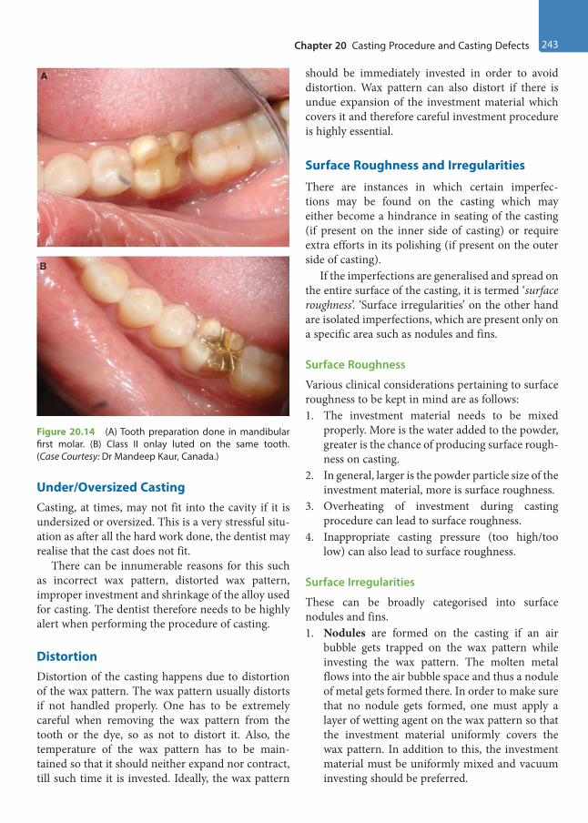
Chapter 20 Casting Procedure and Casting Defects 243
Under/Oversized CastingCasting, at times, may not fit into the cavity if it is undersized or oversized. This is a very stressful situ-ation as after all the hard work done, the dentist may realise that the cast does not fit.
There can be innumerable reasons for this such as incorrect wax pattern, distorted wax pattern, improper investment and shrinkage of the alloy used for casting. The dentist therefore needs to be highly alert when performing the procedure of casting.
Distortion Distortion of the casting happens due to distortion of the wax pattern. The wax pattern usually distorts if not handled properly. One has to be extremely careful when removing the wax pattern from the tooth or the dye, so as not to distort it. Also, the temperature of the wax pattern has to be main-tained so that it should neither expand nor contract, till such time it is invested. Ideally, the wax pattern
should be immediately invested in order to avoid distortion. Wax pattern can also distort if there is undue expansion of the investment material which covers it and therefore careful investment procedure is highly essential.
Surface Roughness and Irregularities
There are instances in which certain imperfec-tions may be found on the casting which may either become a hindrance in seating of the casting (if present on the inner side of casting) or require extra efforts in its polishing (if present on the outer side of casting).
If the imperfections are generalised and spread on the entire surface of the casting, it is termed ‘surface roughness’. ‘Surface irregularities’ on the other hand are isolated imperfections, which are present only on a specific area such as nodules and fins.
Surface Roughness
Various clinical considerations pertaining to surface roughness to be kept in mind are as follows:1. The investment material needs to be mixed
properly. More is the water added to the powder, greater is the chance of producing surface rough-ness on casting.
2. In general, larger is the powder particle size of the investment material, more is surface roughness.
3. Overheating of investment during casting procedure can lead to surface roughness.
4. Inappropriate casting pressure (too high/too low) can also lead to surface roughness.
Surface Irregularities
These can be broadly categorised into surface nodules and fins.1. Nodules are formed on the casting if an air
bubble gets trapped on the wax pattern while investing the wax pattern. The molten metal flows into the air bubble space and thus a nodule of metal gets formed there. In order to make sure that no nodule gets formed, one must apply a layer of wetting agent on the wax pattern so that the investment material uniformly covers the wax pattern. In addition to this, the investment material must be uniformly mixed and vacuum investing should be preferred.
A
B
Figure 20.14 (A) Tooth preparation done in mandibular first molar. (B) Class II onlay luted on the same tooth. (Case Courtesy: Dr Mandeep Kaur, Canada.)
Preclinical Dentistry.indb 243 29-05-2020 12:58:01
https://t.me/DentalBooksWorld
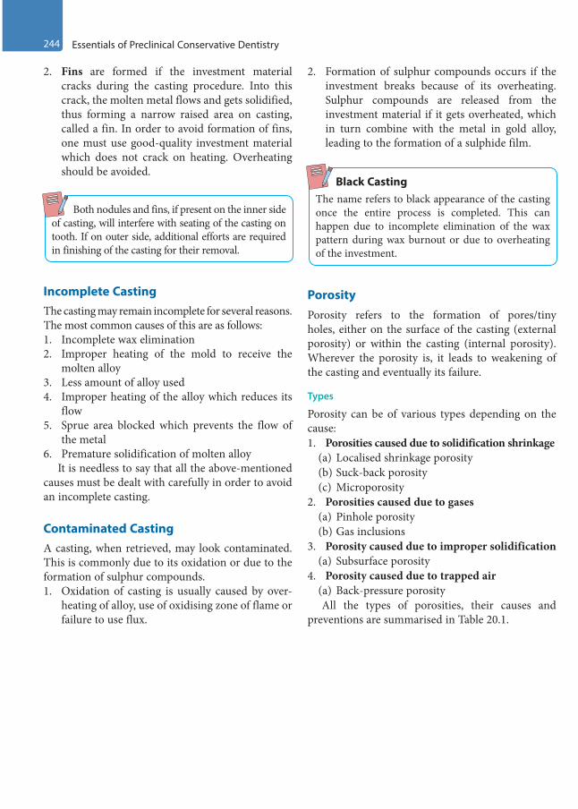
244 Essentials of Preclinical Conservative Dentistry
2. Fins are formed if the investment material cracks during the casting procedure. Into this crack, the molten metal flows and gets solidified, thus forming a narrow raised area on casting, called a fin. In order to avoid formation of fins, one must use good-quality investment material which does not crack on heating. Overheating should be avoided.
Both nodules and fins, if present on the inner side of casting, will interfere with seating of the casting on tooth. If on outer side, additional efforts are required in finishing of the casting for their removal.
Incomplete CastingThe casting may remain incomplete for several reasons. The most common causes of this are as follows:1. Incomplete wax elimination 2. Improper heating of the mold to receive the
molten alloy3. Less amount of alloy used4. Improper heating of the alloy which reduces its
flow5. Sprue area blocked which prevents the flow of
the metal6. Premature solidification of molten alloy
It is needless to say that all the above-mentioned causes must be dealt with carefully in order to avoid an incomplete casting.
Contaminated CastingA casting, when retrieved, may look contaminated. This is commonly due to its oxidation or due to the formation of sulphur compounds.1. Oxidation of casting is usually caused by over-
heating of alloy, use of oxidising zone of flame or failure to use flux.
2. Formation of sulphur compounds occurs if the investment breaks because of its overheating. Sulphur compounds are released from the investment material if it gets overheated, which in turn combine with the metal in gold alloy, leading to the formation of a sulphide film.
Black CastingThe name refers to black appearance of the casting once the entire process is completed. This can happen due to incomplete elimination of the wax pattern during wax burnout or due to overheating of the investment.
PorosityPorosity refers to the formation of pores/tiny holes, either on the surface of the casting (external porosity) or within the casting (internal porosity). Wherever the porosity is, it leads to weakening of the casting and eventually its failure.
Types
Porosity can be of various types depending on the cause:1. Porosities caused due to solidification shrinkage
(a) Localised shrinkage porosity (b) Suck-back porosity(c) Microporosity
2. Porosities caused due to gases(a) Pinhole porosity (b) Gas inclusions
3. Porosity caused due to improper solidification(a) Subsurface porosity
4. Porosity caused due to trapped air(a) Back-pressure porosityAll the types of porosities, their causes and
preventions are summarised in Table 20.1.
Preclinical Dentistry.indb 244 29-05-2020 12:58:02
https://t.me/DentalBooksWorld

Chapter 20 Casting Procedure and Casting Defects 245
Table 20.1 Types of Porosities, Their Causes and Preventions
Type of Porosity Cause Prevention
Localised shrinkage porosity or ‘shrink spot’ porosity
Porosity (large irregular voids) created at the junction of the casting and the sprue. It occurs when metal in the sprue freezes before the metal in the actual casting area. Ideally, the metal in the casting area should freeze before the metal in sprue area so that when the metal in that area solidifies and shrinks, it can have more metal from the sprue area to compensate for the shrinkage. When this does not happen, a void, called ‘shrink spot’, is created
1. Adequate-sized sprue should be used2. Sprue should be attached to the
thickest part of the wax pattern3. A reservoir must be created near to the
wax pattern
‘Suck-back’ porosity
This occurs if the sprue is attached at right angle to the wax pattern. This type of attachment creates a ‘hot spot’. This spot retains the heat of molten metal longer than the rest of the area and thus the metal solidifies last in this area. Once the metal solidifies here in the end and shrinks, no more molten metal is available to compensate for its shrinkage and thus ‘suck-back’ porosity is created. It is usually seen at the sharp occlusoaxial line angle
1. Proper sprue attachment should be made to the wax pattern
2. Mold should be adequately and uniformly heated
3. There should be minimal difference between the temperature of the mold and that of the molten alloy
Microporosity Microporosities are fine irregular voids present within the casting, making it weak. This happens when the casting cools too rapidly. These are visible only under a magnifier and hence the name
Mold and the alloy should be adequately and uniformly heated so that they do not cool down very rapidly
Pinhole porosity This is formed due to the inclusion of gases in metal when it is melting and it dissolves some gases. When this metal solidifies, it expels these gases, thus creating porosity (e.g. gold dissolves oxygen in melted state and liberates it during solidification)
Since it is caused by an inherent property of the metal involved, nothing much can be done to prevent it, although all efforts should be made in the direction of keeping such porosities minimal
‘Gas inclusion’ porosity
This is caused by the inability of the gas in the mold to escape through the pores of the investment
The gas comes from the following:• Blowpipe torch flame (if reducing zone not used)• Gases released by the investment material• Absorption of oxygen by the molten alloy
The reducing zone of the flame should be used to melt the alloy/metal
‘Subsurface’ porosity
These are the porosities present within the structure of the restoration. These are caused by casting the metal in cold mold or due to simultaneous nucle-ation of the solid grains and the gas bubbles at the first moment the alloy freezes at the mold walls
The rate at which the molten metal enters the mold should be controlled
‘Back-pressure’ porosity
This is caused by the inability of the air in the mold to escape through the pores of the investment when the molten metal is entering the mold. This causes rise in the pressure inside the mold and the molten metal solidifies before the entire mold gets completely filled with the metal. This results in formation of a porous casting which has rounded margins
1. More porous investment material should be used
2. The wax pattern should be placed towards the end of the casting ring (6–8 mm) so that too much investment material should not be present over it, which can prevent escape of air
3. Adequate casting pressure should be used
Preclinical Dentistry.indb 245 29-05-2020 12:58:02
https://t.me/DentalBooksWorld

246 Essentials of Preclinical Conservative Dentistry
KEY POINTS
• Indirect cast restorations need a wax pattern to be made either directly in the mouth or indirectly on the dye. Thereafter, the procedure of casting is done to convert the wax pattern into cast restoration, most commonly using the ‘lost wax technique’.
• A sprue former is attached to the wax pattern and thereafter the entire assembly is placed on a crucible former.• A casting ring is placed around this assembly, which is lined by a casting ring liner. Into this hollow ring, a
uniformly mixed investment material is poured which covers the entire wax pattern.• Once the investment material sets completely, it is placed in a furnace for wax burnout. The entire wax burns out
through the sprue channel and a mold is thus created.• Into this mold, a molten metal is pushed, so that it can take up the entire space, which was occupied originally
by the wax pattern. This procedure can be performed using various casting machines such as centrifugal casting machine and induction casting machine.
• Once the molten metal solidifies and cools down, the investment is broken and the cast restoration is taken out and inspected.
• Pickling, which refers to cleaning of the restoration by dipping it in a specific solution for cleaning it, is then performed.• Despite taking all good care during the entire procedure of casting, some casting defects may appear on the
final casting.• These ‘casting defects’ can be categorised as under/oversized casting, distortion of casting, surface roughness
and irregularities on the casting, incomplete casting, contaminated casting and porosities on casting. • Incorrect wax pattern, distorted wax pattern, improper investment or shrinkage of the alloy used for casting are
the usual causes of under/oversized casting.• Distortion of the casting also happens due to distortion of the wax pattern in one way or the other.• If the imperfections seen on the casting are generalised and spread on the entire surface of the casting, it is
termed ‘surface roughness’ and if present on a specific area it is called ‘surface irregularities’. These either become a hindrance in seating of the casting or require extra efforts in its polishing.
• The casting at times may remain incomplete for several reasons such as incomplete wax elimination, improper heating of the mold to receive the molten alloy, less amount of alloy used and improper heating of the alloy which reduces its flow.
• A casting, when retrieved, may look contaminated, either due to its oxidation or due to formation of sulphur compounds.
• At times, certain kinds of porosities may appear on the casting such as localised shrinkage porosity, micropo-rosity, suck-back porosity, pinhole porosity, gas inclusions, subsurface porosity and back-pressure porosity.
• In order to avoid all such casting defects, one must be careful to perform each and every step of casting proce-dure with utmost care so as to provide a well-fitting restoration to the patient.
SELF-ASSESSMENT QUESTIONS
1. Which technique is most commonly used for the casting procedure in dental practice?
2. What do you mean by ‘direct wax pattern’ and ‘indirect wax pattern’?
3. What is a sprue and why is it used?
4. What are the essential pre-requisites of a sprue?
5. What is a casting ring liner? Describe its various types.
6. Enumerate the various casting machines used for the casting procedure.
7. What is pickling? Discuss its significance.
8. Enumerate various types of ‘casting defects’.
9. What is ‘suck-back porosity’? How can it be avoided?
10. Discuss in detail ‘pinhole porosity’.
11. What is ‘back-pressure porosity’? Discuss its significance.
Preclinical Dentistry.indb 246 29-05-2020 12:58:02
https://t.me/DentalBooksWorld
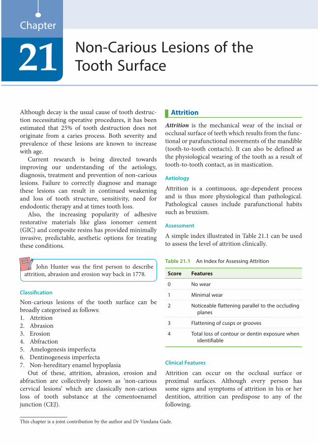
Although decay is the usual cause of tooth destruc-tion necessitating operative procedures, it has been estimated that 25% of tooth destruction does not originate from a caries process. Both severity and prevalence of these lesions are known to increase with age.
Current research is being directed towards improving our understanding of the aetiology, diagnosis, treatment and prevention of non-carious lesions. Failure to correctly diagnose and manage these lesions can result in continued weakening and loss of tooth structure, sensitivity, need for endodontic therapy and at times tooth loss.
Also, the increasing popularity of adhesive restorative materials like glass ionomer cement (GIC) and composite resins has provided minimally invasive, predictable, aesthetic options for treating these conditions.
John Hunter was the first person to describe attrition, abrasion and erosion way back in 1778.
Classification
Non-carious lesions of the tooth surface can be broadly categorised as follows:1. Attrition2. Abrasion3. Erosion4. Abfraction5. Amelogenesis imperfecta6. Dentinogenesis imperfecta7. Non-hereditary enamel hypoplasia
Out of these, attrition, abrasion, erosion and abfraction are collectively known as ‘non-carious cervical lesions’ which are classically non-carious loss of tooth substance at the cementoenamel junction (CEJ).
Attrition
Attrition is the mechanical wear of the incisal or occlusal surface of teeth which results from the func-tional or parafunctional movements of the mandible (tooth-to-tooth contacts). It can also be defined as the physiological wearing of the tooth as a result of tooth-to-tooth contact, as in mastication.
Aetiology
Attrition is a continuous, age-dependent process and is thus more physiological than pathological. Pathological causes include parafunctional habits such as bruxism.
Assessment
A simple index illustrated in Table 21.1 can be used to assess the level of attrition clinically.
Table 21.1 An Index for Assessing Attrition
Score Features
0 No wear
1 Minimal wear
2 Noticeable flattening parallel to the occluding planes
3 Flattening of cusps or grooves
4 Total loss of contour or dentin exposure when identifiable
Clinical Features
Attrition can occur on the occlusal surface or proximal surfaces. Although every person has some signs and symptoms of attrition in his or her dentition, attrition can predispose to any of the following.
Non-Carious Lesions of the Tooth Surface21
Chapter
This chapter is a joint contribution by the author and Dr Vandana Gade.
Preclinical Dentistry.indb 247 29-05-2020 12:58:02
https://t.me/DentalBooksWorld
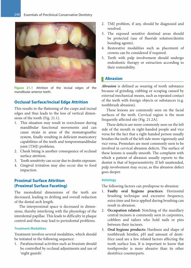
248 Essentials of Preclinical Conservative Dentistry
Occlusal Surface/Incisal Edge Attrition This results in the flattening of the cusps and incisal edges and thus leads to the loss of vertical dimen-sions of the tooth (Fig. 21.1).1. This situation may result in overclosure during
mandibular functional movements and can cause strain in areas of the stomatognathic system, finally resulting in deficient masticatory capabilities of the teeth and temporomandibular joint (TMJ) problems.
2. Cheek biting is another consequence of occlusal surface attrition.
3. Tooth sensitivity can occur due to dentin exposure.4. Gingival irritation may also occur due to food
impaction.
Proximal Surface Attrition (Proximal Surface Faceting)The mesiodistal dimensions of the teeth are decreased, leading to drifting and overall reduction of the dental arch length.
The interproximal space is decreased in dimen-sions, thereby interfering with the physiology of the interdental papillae. This leads to difficulty in plaque control and thus may lead to periodontal problems.
Treatment Modalities
Treatment involves several modalities, which should be initiated in the following sequence:1. Parafunctional activities such as bruxism should
be controlled by occlusal adjustments and use of ‘night guards’.
2. TMJ problem, if any, should be diagnosed and resolved.
3. The exposed sensitive dentinal areas should be protected (use of fluoride solution/dentin bonding agents).
4. Restorative modalities such as placement of crowns can be considered if required.
5. Teeth with pulp involvement should undergo endodontic therapy or extraction according to their restorability.
Abrasion
Abrasion is defined as wearing of tooth substance because of grinding, rubbing or scraping caused by external mechanical means, such as repeated contact of the teeth with foreign objects or substances (e.g. toothbrush abrasion).
These lesions are commonly seen on the facial surfaces of the teeth. Cervical region is the most frequently affected site (Fig. 21.2A).
These defects are more commonly seen on the left side of the mouth in right-handed people and vice versa for the fact that a right-handed person usually brushes the teeth of the left side more vigorously and vice versa. Premolars are most commonly seen to be involved in cervical abrasion defects. The surface of these lesions is usually smooth. The complaint with which a patient of abrasion usually reports to the dentist is that of hypersensitivity. If left unattended, pulp involvement may occur, as this abrasion defect goes deeper.
Aetiology
The following factors can predispose to abrasion: 1. Faulty oral hygiene practices: Horizontal
brushing technique and excessive frequency, extra time and force applied during brushing can result in abrasion.
2. Occupation related: Notching of the maxillary central incisors is commonly seen in carpenters, cobblers and tailors who hold nails or pins between their incisors.
3. Oral hygiene products: Hardness and shape of toothbrush bristles, pH and amount of denti-frice used are a few related factors affecting the tooth surface loss. It is important to know that toothpowder is more abrasive than its other dentifrice counterparts.
Figure 21.1 Attrition of the incisal edges of the mandibular anterior teeth.
Preclinical Dentistry.indb 248 29-05-2020 12:58:02
https://t.me/DentalBooksWorld
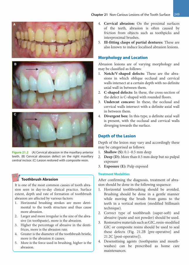
Chapter 21 Non-Carious Lesions of the Tooth Surface 249
4. Cervical abrasion: On the proximal surfaces of the teeth, abrasion is often caused by friction from objects such as toothpicks and interproximal brushes.
5. Ill-fitting clasps of partial dentures: These are also known to induce localised abrasion lesions.
Morphology and LocationAbrasion lesions are of varying morphology and may be classified as follows:1. Notch/V-shaped defects: These are the abra-
sions in which oblique occlusal and cervical walls intersect at a certain depth with no definite axial wall in between them.
2. C-shaped defects: In these, the cross-section of the defect is C-shaped with rounded floors.
3. Undercut concave: In these, the occlusal and cervical walls intersect with a definite axial wall in between them.
4. Divergent box: In this type, a definite axial wall is present, with the occlusal and cervical walls diverging towards the surface.
Depth of the LesionDepth of the lesion may vary and accordingly these may be categorised as follows: 1. Shallow (S): 0.1–0.5 mm deep2. Deep (D): More than 0.5 mm deep but no pulpal
exposure 3. Exposure (E): Pulp exposed
Treatment Modalities
After confirming the diagnosis, treatment of abra-sion should be done in the following sequence:1. Horizontal toothbrushing should be avoided.
Brushing should be done in a gentle manner while moving the brush from gums to the teeth in a vertical motion (modified Stillman’s technique).
2. Correct type of toothbrush (super-soft) and abrasive (paste and not powder) should be used.
3. Restorative materials such as GIC, resin-modified GIC or composite resins should be used to seal these defects (Fig. 21.2B [pre-operative] and 21.2C [post-operative]).
4. Desensitising agents (toothpastes and mouth-washes) can be prescribed as home care maintenances.
A
B
C
Figure 21.2 (A) Cervical abrasion in the maxillary anterior teeth. (B) Cervical abrasion defect on the right maxillary central incisor. (C) Lesion restored with composite resin.
Toothbrush AbrasionIt is one of the most common causes of tooth abra-sion seen in day-to-day clinical practice. Surface extent, depth and rate of formation of toothbrush abrasion are affected by various factors:1. Horizontal brushing strokes are more detri-
mental to the tooth structure and thus cause more abrasion.
2. Larger and more irregular is the size of the abra-sive (in toothpaste), more is the abrasion.
3. Higher the percentage of abrasive in the denti-frices, more is the abrasion rate.
4. Greater is the diameter of the toothbrush bristle, more is the abrasion it causes.
5. More is the force used in brushing, higher is the abrasion.
Preclinical Dentistry.indb 249 29-05-2020 12:58:02
https://t.me/DentalBooksWorld
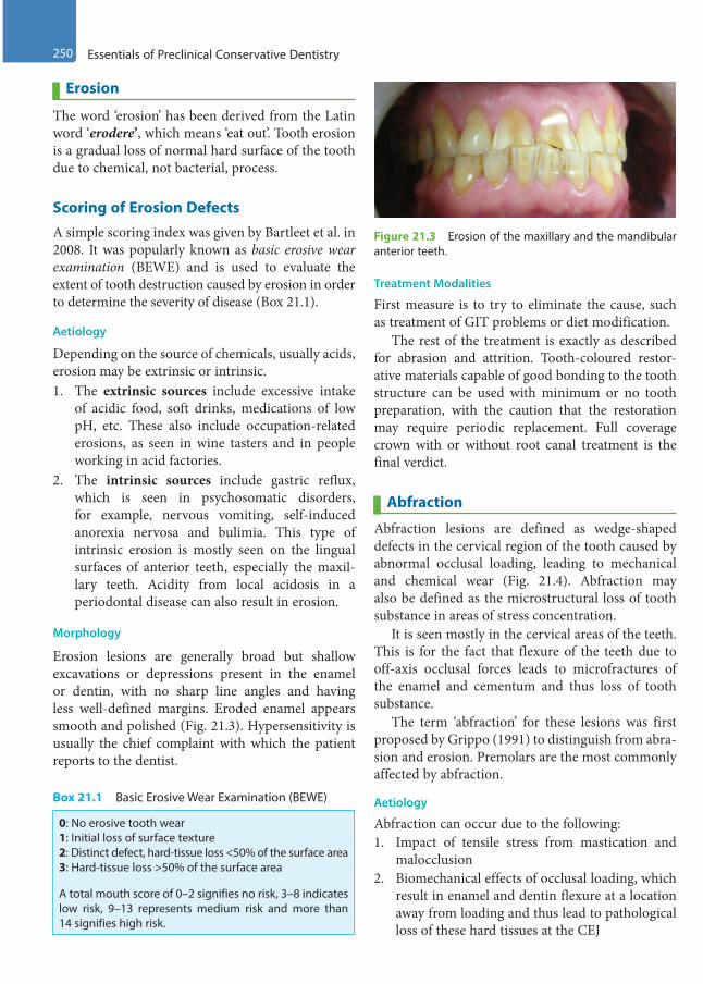
250 Essentials of Preclinical Conservative Dentistry
Erosion
The word ‘erosion’ has been derived from the Latin word ‘erodere’, which means ‘eat out’. Tooth erosion is a gradual loss of normal hard surface of the tooth due to chemical, not bacterial, process.
Scoring of Erosion DefectsA simple scoring index was given by Bartleet et al. in 2008. It was popularly known as basic erosive wear examination (BEWE) and is used to evaluate the extent of tooth destruction caused by erosion in order to determine the severity of disease (Box 21.1).
Aetiology
Depending on the source of chemicals, usually acids, erosion may be extrinsic or intrinsic.1. The extrinsic sources include excessive intake
of acidic food, soft drinks, medications of low pH, etc. These also include occupation-related erosions, as seen in wine tasters and in people working in acid factories.
2. The intrinsic sources include gastric reflux, which is seen in psychosomatic disorders, for example, nervous vomiting, self-induced anorexia nervosa and bulimia. This type of intrinsic erosion is mostly seen on the lingual surfaces of anterior teeth, especially the maxil-lary teeth. Acidity from local acidosis in a periodontal disease can also result in erosion.
Morphology
Erosion lesions are generally broad but shallow excavations or depressions present in the enamel or dentin, with no sharp line angles and having less well-defined margins. Eroded enamel appears smooth and polished (Fig. 21.3). Hypersensitivity is usually the chief complaint with which the patient reports to the dentist.
Treatment Modalities
First measure is to try to eliminate the cause, such as treatment of GIT problems or diet modification.
The rest of the treatment is exactly as described for abrasion and attrition. Tooth-coloured restor-ative materials capable of good bonding to the tooth structure can be used with minimum or no tooth preparation, with the caution that the restoration may require periodic replacement. Full coverage crown with or without root canal treatment is the final verdict.
Abfraction
Abfraction lesions are defined as wedge-shaped defects in the cervical region of the tooth caused by abnormal occlusal loading, leading to mechanical and chemical wear (Fig. 21.4). Abfraction may also be defined as the microstructural loss of tooth substance in areas of stress concentration.
It is seen mostly in the cervical areas of the teeth. This is for the fact that flexure of the teeth due to off-axis occlusal forces leads to microfractures of the enamel and cementum and thus loss of tooth substance.
The term ‘abfraction’ for these lesions was first proposed by Grippo (1991) to distinguish from abra-sion and erosion. Premolars are the most commonly affected by abfraction.
Aetiology
Abfraction can occur due to the following:1. Impact of tensile stress from mastication and
malocclusion2. Biomechanical effects of occlusal loading, which
result in enamel and dentin flexure at a location away from loading and thus lead to pathological loss of these hard tissues at the CEJ
Figure 21.3 Erosion of the maxillary and the mandibular anterior teeth.
Box 21.1 Basic Erosive Wear Examination (BEWE)
0: No erosive tooth wear1: Initial loss of surface texture2: Distinct defect, hard-tissue loss <50% of the surface area3: Hard-tissue loss >50% of the surface area
A total mouth score of 0–2 signifies no risk, 3–8 indicates low risk, 9–13 represents medium risk and more than 14 signifies high risk.
Preclinical Dentistry.indb 250 29-05-2020 12:58:03
https://t.me/DentalBooksWorld
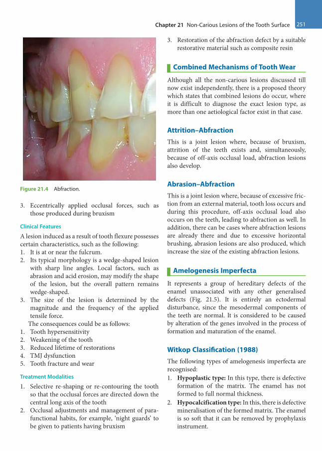
Chapter 21 Non-Carious Lesions of the Tooth Surface 251
3. Eccentrically applied occlusal forces, such as those produced during bruxism
Clinical Features
A lesion induced as a result of tooth flexure possesses certain characteristics, such as the following:1. It is at or near the fulcrum.2. Its typical morphology is a wedge-shaped lesion
with sharp line angles. Local factors, such as abrasion and acid erosion, may modify the shape of the lesion, but the overall pattern remains wedge-shaped.
3. The size of the lesion is determined by the magnitude and the frequency of the applied tensile force.
The consequences could be as follows:1. Tooth hypersensitivity2. Weakening of the tooth3. Reduced lifetime of restorations4. TMJ dysfunction5. Tooth fracture and wear
Treatment Modalities
1. Selective re-shaping or re-contouring the tooth so that the occlusal forces are directed down the central long axis of the tooth
2. Occlusal adjustments and management of para-functional habits, for example, ‘night guards’ to be given to patients having bruxism
3. Restoration of the abfraction defect by a suitable restorative material such as composite resin
Combined Mechanisms of Tooth Wear
Although all the non-carious lesions discussed till now exist independently, there is a proposed theory which states that combined lesions do occur, where it is difficult to diagnose the exact lesion type, as more than one aetiological factor exist in that case.
Attrition–AbfractionThis is a joint lesion where, because of bruxism, attrition of the teeth exists and, simultaneously, because of off-axis occlusal load, abfraction lesions also develop.
Abrasion–AbfractionThis is a joint lesion where, because of excessive fric-tion from an external material, tooth loss occurs and during this procedure, off-axis occlusal load also occurs on the teeth, leading to abfraction as well. In addition, there can be cases where abfraction lesions are already there and due to excessive horizontal brushing, abrasion lesions are also produced, which increase the size of the existing abfraction lesions.
Amelogenesis Imperfecta
It represents a group of hereditary defects of the enamel unassociated with any other generalised defects (Fig. 21.5). It is entirely an ectodermal disturbance, since the mesodermal components of the teeth are normal. It is considered to be caused by alteration of the genes involved in the process of formation and maturation of the enamel.
Witkop Classification (1988) The following types of amelogenesis imperfecta are recognised: 1. Hypoplastic type: In this type, there is defective
formation of the matrix. The enamel has not formed to full normal thickness.
2. Hypocalcification type: In this, there is defective mineralisation of the formed matrix. The enamel is so soft that it can be removed by prophylaxis instrument.
Figure 21.4 Abfraction.
Preclinical Dentistry.indb 251 29-05-2020 12:58:03
https://t.me/DentalBooksWorld
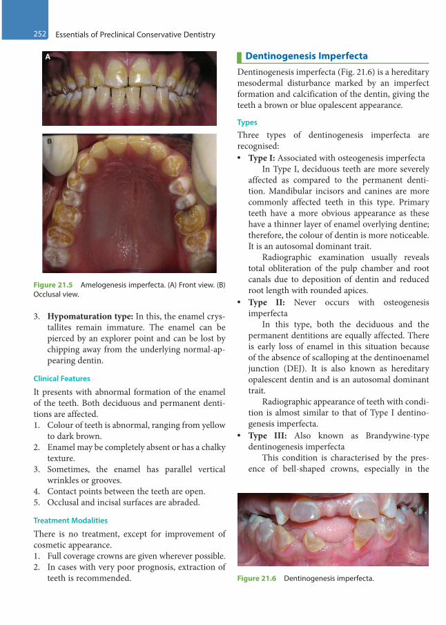
252 Essentials of Preclinical Conservative Dentistry
3. Hypomaturation type: In this, the enamel crys-tallites remain immature. The enamel can be pierced by an explorer point and can be lost by chipping away from the underlying normal-ap-pearing dentin.
Clinical Features
It presents with abnormal formation of the enamel of the teeth. Both deciduous and permanent denti-tions are affected.1. Colour of teeth is abnormal, ranging from yellow
to dark brown.2. Enamel may be completely absent or has a chalky
texture.3. Sometimes, the enamel has parallel vertical
wrinkles or grooves.4. Contact points between the teeth are open.5. Occlusal and incisal surfaces are abraded.
Treatment Modalities
There is no treatment, except for improvement of cosmetic appearance.1. Full coverage crowns are given wherever possible.2. In cases with very poor prognosis, extraction of
teeth is recommended.
Dentinogenesis ImperfectaDentinogenesis imperfecta (Fig. 21.6) is a hereditary mesodermal disturbance marked by an imperfect formation and calcification of the dentin, giving the teeth a brown or blue opalescent appearance.
Types
Three types of dentinogenesis imperfecta are recognised: • Type I: Associated with osteogenesis imperfecta In Type I, deciduous teeth are more severely
affected as compared to the permanent denti-tion. Mandibular incisors and canines are more commonly affected teeth in this type. Primary teeth have a more obvious appearance as these have a thinner layer of enamel overlying dentine; therefore, the colour of dentin is more noticeable. It is an autosomal dominant trait.
Radiographic examination usually reveals total obliteration of the pulp chamber and root canals due to deposition of dentin and reduced root length with rounded apices.
• Type II: Never occurs with osteogenesis imperfecta
In this type, both the deciduous and the permanent dentitions are equally affected. There is early loss of enamel in this situation because of the absence of scalloping at the dentinoenamel junction (DEJ). It is also known as hereditary opalescent dentin and is an autosomal dominant trait.
Radiographic appearance of teeth with condi-tion is almost similar to that of Type I dentino-genesis imperfecta.
• Type III: Also known as Brandywine-type dentinogenesis imperfecta
This condition is characterised by the pres-ence of bell-shaped crowns, especially in the
A
B
Figure 21.5 Amelogenesis imperfecta. (A) Front view. (B) Occlusal view.
Figure 21.6 Dentinogenesis imperfecta.
Preclinical Dentistry.indb 252 29-05-2020 12:58:03
https://t.me/DentalBooksWorld
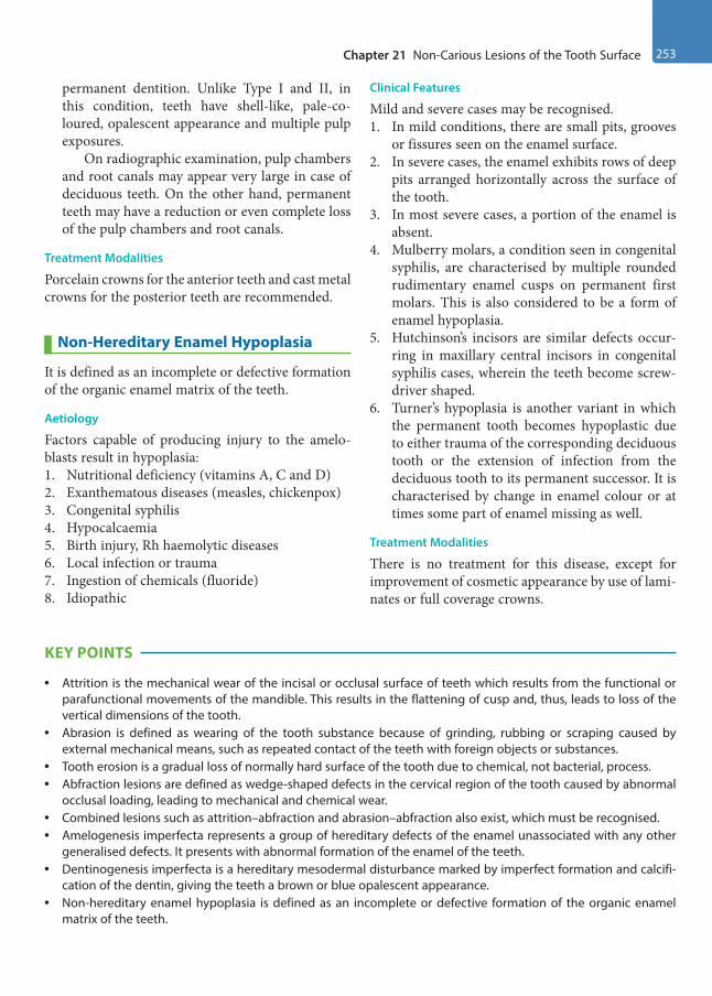
Chapter 21 Non-Carious Lesions of the Tooth Surface 253
permanent dentition. Unlike Type I and II, in this condition, teeth have shell-like, pale-co-loured, opalescent appearance and multiple pulp exposures.
On radiographic examination, pulp chambers and root canals may appear very large in case of deciduous teeth. On the other hand, permanent teeth may have a reduction or even complete loss of the pulp chambers and root canals.
Treatment Modalities
Porcelain crowns for the anterior teeth and cast metal crowns for the posterior teeth are recommended.
Non-Hereditary Enamel Hypoplasia
It is defined as an incomplete or defective formation of the organic enamel matrix of the teeth.
Aetiology
Factors capable of producing injury to the amelo-blasts result in hypoplasia:1. Nutritional deficiency (vitamins A, C and D)2. Exanthematous diseases (measles, chickenpox)3. Congenital syphilis4. Hypocalcaemia5. Birth injury, Rh haemolytic diseases6. Local infection or trauma7. Ingestion of chemicals (fluoride)8. Idiopathic
Clinical Features
Mild and severe cases may be recognised. 1. In mild conditions, there are small pits, grooves
or fissures seen on the enamel surface.2. In severe cases, the enamel exhibits rows of deep
pits arranged horizontally across the surface of the tooth.
3. In most severe cases, a portion of the enamel is absent.
4. Mulberry molars, a condition seen in congenital syphilis, are characterised by multiple rounded rudimentary enamel cusps on permanent first molars. This is also considered to be a form of enamel hypoplasia.
5. Hutchinson’s incisors are similar defects occur-ring in maxillary central incisors in congenital syphilis cases, wherein the teeth become screw-driver shaped.
6. Turner’s hypoplasia is another variant in which the permanent tooth becomes hypoplastic due to either trauma of the corresponding deciduous tooth or the extension of infection from the deciduous tooth to its permanent successor. It is characterised by change in enamel colour or at times some part of enamel missing as well.
Treatment Modalities
There is no treatment for this disease, except for improvement of cosmetic appearance by use of lami-nates or full coverage crowns.
KEY POINTS
• Attrition is the mechanical wear of the incisal or occlusal surface of teeth which results from the functional or parafunctional movements of the mandible. This results in the flattening of cusp and, thus, leads to loss of the vertical dimensions of the tooth.
• Abrasion is defined as wearing of the tooth substance because of grinding, rubbing or scraping caused by external mechanical means, such as repeated contact of the teeth with foreign objects or substances.
• Tooth erosion is a gradual loss of normally hard surface of the tooth due to chemical, not bacterial, process.• Abfraction lesions are defined as wedge-shaped defects in the cervical region of the tooth caused by abnormal
occlusal loading, leading to mechanical and chemical wear.• Combined lesions such as attrition–abfraction and abrasion–abfraction also exist, which must be recognised.• Amelogenesis imperfecta represents a group of hereditary defects of the enamel unassociated with any other
generalised defects. It presents with abnormal formation of the enamel of the teeth.• Dentinogenesis imperfecta is a hereditary mesodermal disturbance marked by imperfect formation and calcifi-
cation of the dentin, giving the teeth a brown or blue opalescent appearance.• Non-hereditary enamel hypoplasia is defined as an incomplete or defective formation of the organic enamel
matrix of the teeth.
Preclinical Dentistry.indb 253 29-05-2020 12:58:03
https://t.me/DentalBooksWorld

254 Essentials of Preclinical Conservative Dentistry
SELF-ASSESSMENT QUESTIONS
1. Define attrition.
2. Discuss the salient features and treatment for attrition of teeth.
3. What do you understand by abrasion?
4. Discuss the aetiology and treatment for abrasion.
5. Define erosion and discuss its aetiology.
6. Discuss the biomechanics of abfraction.
7. Define amelogenesis imperfecta and discuss its classification and management.
8. Define dentinogenesis imperfecta and discuss its classification and management.
9. What do you understand by non-hereditary enamel hypoplasia?
Preclinical Dentistry.indb 254 29-05-2020 12:58:03
https://t.me/DentalBooksWorld
Traumas that affect the hard tissues and cause pulpal and periodontal lesions are of high significance to the dental professionals because of the increasing frequency with which such patients are reporting. These cases have both functional and aesthetic components to be dealt with and hence must be thor-oughly understood in terms of treatment planning.
Aetiology
The Merriam Webster Dictionary defines trauma as an injury (as a wound) to living tissue caused by an extrinsic agent. Tooth fracture is understood to be the cracking or breaking of a tooth that has been subjected to a force or impact, greater than its resis-tance. It can be caused by the following: 1. Iatrogenic injuries in the newborn2. Fall in infancy3. Automobile accident4. Injuries that are drug related/due to mental
retardation5. Sports injuries
Classification of Tooth Fracture
Tooth fracture can be assessed based on Ellis clas-sification and World Health Organization (WHO) classification or WHO classification modified by Andreasen.
Ellis ClassificationEllis classification is based on the criteria of ‘extent of the involvement of tooth’ during fracture. It has nine classes as follows: • Class I: Simple crown fracture with little or no
dentin affected• Class II: Extensive crown fracture with consid-
erable loss of dentin, but the pulp is not affected
• Class III: Extensive crown fracture with consid-erable loss of dentin and pulp exposure
• Class IV: A tooth devitalised by trauma with or without loss of tooth structure
• Class V: Tooth lost as a result of trauma• Class VI: Root fracture with or without crown or
root structure• Class VII: Displacement of the tooth with neither
root nor crown fracture• Class VIII: Complete crown fracture• Class IX: Traumatic injuries of the primary teeth
WHO ClassificationThe WHO proposed a numerical system to classify the traumatic injuries to the teeth. A unique code number represents a specific type of injury to the tooth, which actually makes data interpretation quite simple:• 873.60 ◊ Enamel fracture• 873.61 ◊ Crown fracture involving enamel/dentin
without pulp exposure• 873.62 ◊ Crown fracture with pulp exposure• 873.63 ◊ Root fracture• 873.64 ◊ Crown root fracture• 873.66 ◊ Luxation• 873.67 ◊ Intrusion or extrusion• 873.68 ◊ Avulsion• 873.69 ◊ Other injuries, such as to the soft tissues
Classification Modified by AndreasenThe currently accepted system is based on the WHO’s Application of International Classification of Diseases to Dentistry and Stomatology, modified by Andreasen. The classification is applicable to inju-ries to the teeth and supporting structures, and can be applied to both primary and permanent denti-tions (Tables 22.1 and 22.2).
Traumatic Injuries of the Teeth22Chapter
This chapter is a joint contribution by the author and Dr Pratima Shenoi.
Preclinical Dentistry.indb 255 29-05-2020 12:58:03
https://t.me/DentalBooksWorld
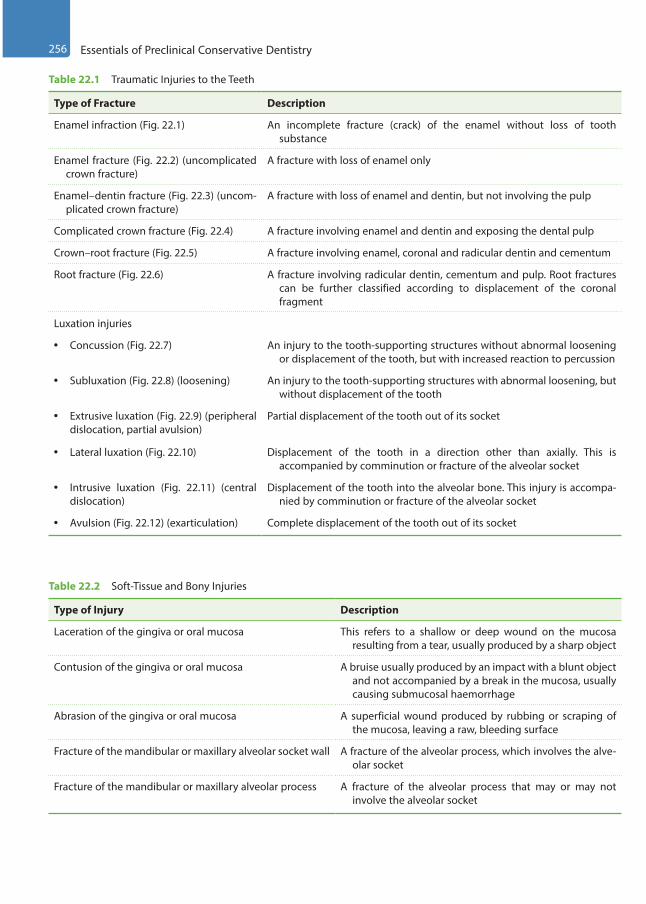
256 Essentials of Preclinical Conservative Dentistry
Table 22.1 Traumatic Injuries to the Teeth
Type of Fracture Description
Enamel infraction (Fig. 22.1) An incomplete fracture (crack) of the enamel without loss of tooth substance
Enamel fracture (Fig. 22.2) (uncomplicated crown fracture)
A fracture with loss of enamel only
Enamel–dentin fracture (Fig. 22.3) (uncom-plicated crown fracture)
A fracture with loss of enamel and dentin, but not involving the pulp
Complicated crown fracture (Fig. 22.4) A fracture involving enamel and dentin and exposing the dental pulp
Crown–root fracture (Fig. 22.5) A fracture involving enamel, coronal and radicular dentin and cementum
Root fracture (Fig. 22.6) A fracture involving radicular dentin, cementum and pulp. Root fractures can be further classified according to displacement of the coronal fragment
Luxation injuries
• Concussion (Fig. 22.7) An injury to the tooth-supporting structures without abnormal loosening or displacement of the tooth, but with increased reaction to percussion
• Subluxation (Fig. 22.8) (loosening) An injury to the tooth-supporting structures with abnormal loosening, but without displacement of the tooth
• Extrusive luxation (Fig. 22.9) (peripheral dislocation, partial avulsion)
Partial displacement of the tooth out of its socket
• Lateral luxation (Fig. 22.10) Displacement of the tooth in a direction other than axially. This is accompanied by comminution or fracture of the alveolar socket
• Intrusive luxation (Fig. 22.11) (central dislocation)
Displacement of the tooth into the alveolar bone. This injury is accompa-nied by comminution or fracture of the alveolar socket
• Avulsion (Fig. 22.12) (exarticulation) Complete displacement of the tooth out of its socket
Table 22.2 Soft-Tissue and Bony Injuries
Type of Injury Description
Laceration of the gingiva or oral mucosa This refers to a shallow or deep wound on the mucosa resulting from a tear, usually produced by a sharp object
Contusion of the gingiva or oral mucosa A bruise usually produced by an impact with a blunt object and not accompanied by a break in the mucosa, usually causing submucosal haemorrhage
Abrasion of the gingiva or oral mucosa A superficial wound produced by rubbing or scraping of the mucosa, leaving a raw, bleeding surface
Fracture of the mandibular or maxillary alveolar socket wall A fracture of the alveolar process, which involves the alve-olar socket
Fracture of the mandibular or maxillary alveolar process A fracture of the alveolar process that may or may not involve the alveolar socket
Preclinical Dentistry.indb 256 29-05-2020 12:58:03
https://t.me/DentalBooksWorld
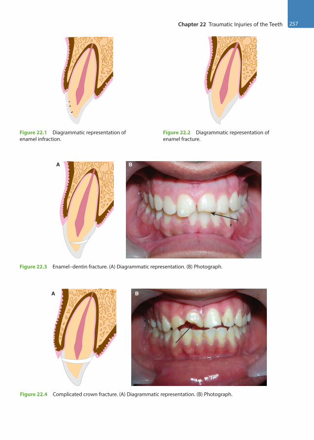
Chapter 22 Traumatic Injuries of the Teeth 257
Figure 22.1 Diagrammatic representation of enamel infraction.
Figure 22.2 Diagrammatic representation of enamel fracture.
A B
Figure 22.3 Enamel–dentin fracture. (A) Diagrammatic representation. (B) Photograph.
BA
Figure 22.4 Complicated crown fracture. (A) Diagrammatic representation. (B) Photograph.
Preclinical Dentistry.indb 257 29-05-2020 12:58:04
https://t.me/DentalBooksWorld
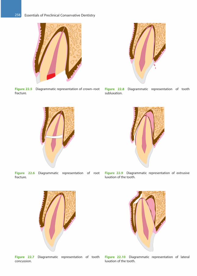
258 Essentials of Preclinical Conservative Dentistry
Figure 22.5 Diagrammatic representation of crown–root fracture.
Figure 22.6 Diagrammatic representation of root fracture.
Figure 22.7 Diagrammatic representation of tooth concussion.
Figure 22.8 Diagrammatic representation of tooth subluxation.
Figure 22.9 Diagrammatic representation of extrusive luxation of the tooth.
Figure 22.10 Diagrammatic representation of lateral luxation of the tooth.
Preclinical Dentistry.indb 258 29-05-2020 12:58:05
https://t.me/DentalBooksWorld
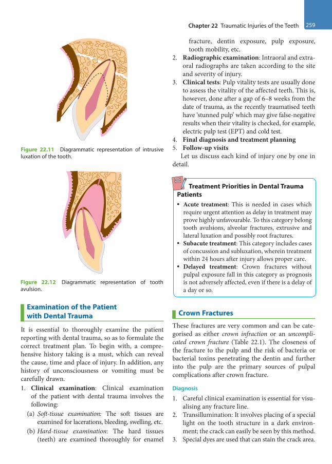
Chapter 22 Traumatic Injuries of the Teeth 259
Examination of the Patient with Dental Trauma
It is essential to thoroughly examine the patient reporting with dental trauma, so as to formulate the correct treatment plan. To begin with, a compre-hensive history taking is a must, which can reveal the cause, time and place of injury. In addition, any history of unconsciousness or vomiting must be carefully drawn.1. Clinical examination: Clinical examination
of the patient with dental trauma involves the following:
(a) Soft-tissue examination: The soft tissues are examined for lacerations, bleeding, swelling, etc.
(b) Hard-tissue examination: The hard tissues (teeth) are examined thoroughly for enamel
fracture, dentin exposure, pulp exposure, tooth mobility, etc.
2. Radiographic examination: Intraoral and extra-oral radiographs are taken according to the site and severity of injury.
3. Clinical tests: Pulp vitality tests are usually done to assess the vitality of the affected teeth. This is, however, done after a gap of 6–8 weeks from the date of trauma, as the recently traumatised teeth have ‘stunned pulp’ which may give false-negative results when their vitality is checked, for example, electric pulp test (EPT) and cold test.
4. Final diagnosis and treatment planning5. Follow-up visits
Let us discuss each kind of injury one by one in detail.
Treatment Priorities in Dental Trauma Patients• Acute treatment: This is needed in cases which
require urgent attention as delay in treatment may prove highly unfavourable. To this category belong tooth avulsions, alveolar fractures, extrusive and lateral luxation and possibly root fractures.
• Subacute treatment: This category includes cases of concussion and subluxation, wherein treatment within 24 hours after injury allows proper care.
• Delayed treatment: Crown fractures without pulpal exposure fall in this category as prognosis is not adversely affected, even if there is a delay of a day or so.
Crown Fractures
These fractures are very common and can be cate-gorised as either crown infraction or an uncompli-cated crown fracture (Table 22.1). The closeness of the fracture to the pulp and the risk of bacteria or bacterial toxins penetrating the dentin and further into the pulp are the primary sources of pulpal complications after crown fracture.
Diagnosis
1. Careful clinical examination is essential for visu-alising any fracture line.
2. Transillumination: It involves placing of a special light on the tooth structure in a dark environ-ment; the crack can easily be seen by this method.
3. Special dyes are used that can stain the crack area.
Figure 22.11 Diagrammatic representation of intrusive luxation of the tooth.
Figure 22.12 Diagrammatic representation of tooth avulsion.
Preclinical Dentistry.indb 259 29-05-2020 12:58:05
https://t.me/DentalBooksWorld
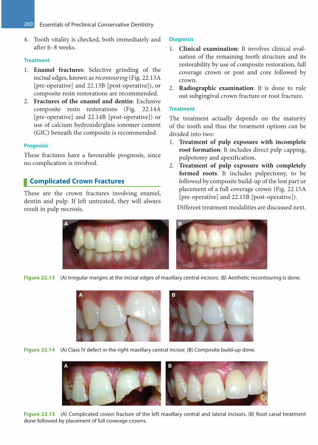
260 Essentials of Preclinical Conservative Dentistry
4. Tooth vitality is checked, both immediately and after 6–8 weeks.
Treatment
1. Enamel fractures: Selective grinding of the incisal edges, known as recontouring (Fig. 22.13A [pre-operative] and 22.13B [post-operative]), or composite resin restorations are recommended.
2. Fractures of the enamel and dentin: Exclusive composite resin restorations (Fig. 22.14A [pre-operative] and 22.14B [post-operative]) or use of calcium hydroxide/glass ionomer cement (GIC) beneath the composite is recommended.
Prognosis
These fractures have a favourable prognosis, since no complication is involved.
Complicated Crown Fractures
These are the crown fractures involving enamel, dentin and pulp. If left untreated, they will always result in pulp necrosis.
Diagnosis
1. Clinical examination: It involves clinical eval-uation of the remaining tooth structure and its restorability by use of composite restoration, full coverage crown or post and core followed by crown.
2. Radiographic examination: It is done to rule out subgingival crown fracture or root fracture.
Treatment
The treatment actually depends on the maturity of the tooth and thus the treatment options can be divided into two:1. Treatment of pulp exposure with incomplete
root formation: It includes direct pulp capping, pulpotomy and apexification.
2. Treatment of pulp exposure with completely formed roots: It includes pulpectomy, to be followed by composite build-up of the lost part or placement of a full coverage crown (Fig. 22.15A [pre-operative] and 22.15B [post-operative]).
Different treatment modalities are discussed next.
Figure 22.13 (A) Irregular margins at the incisal edges of maxillary central incisors. (B) Aesthetic recontouring is done.
A B
Figure 22.14 (A) Class IV defect in the right maxillary central incisor. (B) Composite build-up done.
A B
Figure 22.15 (A) Complicated crown fracture of the left maxillary central and lateral incisors. (B) Root canal treatment done followed by placement of full coverage crowns.
A B
Preclinical Dentistry.indb 260 29-05-2020 12:58:05
https://t.me/DentalBooksWorld

Chapter 22 Traumatic Injuries of the Teeth 261
Direct Pulp CappingDirect pulp capping implies placing the calcium hydroxide material directly onto the pulp exposure. Details of this procedure are described in Chapter 23, Vital Pulp Therapy.
Partial/Cvek PulpotomyIn this procedure, the coronal pulp is removed up to the level where healthy pulp begins (usually 2 mm from the coronal end). This is done by using a sterile
diamond point at high speed, using copious amount of water as coolant. Thereafter, haemorrhage is controlled and calcium hydroxide is placed followed by zinc oxide eugenol or GIC. This procedure is done under the effect of local anaesthesia.
Figure 22.16A–E describes a case of trauma to a deciduous maxillary central incisor in which the pulp was exposed (Fig. 22.16A,B). Partial pulpo-tomy was done in this tooth (Fig. 22.16C) and the haemorrhage was obtained. Thereafter, Biodentin (Septodont) was placed as a pulp capping agent to
Figure 22.16 (A) Fractured deciduous maxillary central incisor. (B) Pulp exposure seen in the same tooth as viewed from the incisal edge. (C) Partial pulpotomy done. (D) Biodentin placed as pulp capping agent. (E) Composite build-up done. (F) Aesthetics restored with composite build-up. (Case courtesy: Dr. Daniela Bololoi, Canada)
A D
E
F
B
C
Preclinical Dentistry.indb 261 29-05-2020 12:58:06
https://t.me/DentalBooksWorld

262 Essentials of Preclinical Conservative Dentistry
induce the formation of calcific barrier (Fig. 22.16D). To restore the aesthetics of the tooth, composite build-up was done (Fig. 22.16E,F).
Figure 22.17A–G presents a case of trauma to a permanent maxillary central incisor with pulp exposure. Figure 22.17A,B depicts the pulp exposure seen after trauma in right maxillary central incisor clinically and radiographically, respectively. Partial pulpotomy was done and Biodentine (Septodont) was placed as pulp capping material (Fig. 22.17C). The tooth fragment attachment was done using the conventional etching (Fig. 22.17D) and bonding procedure followed by the use of composite resin for the reattachment (Fig. 22.17E). A 3-year recall shows excellent condition of the tooth as seen clinically (Fig. 22.17F) and radiographically (Fig. 22.17G).
Full PulpotomyThis refers to the removal of the entire coronal pulp to the level of the root orifices and is indicated when the pulp is inflamed to deeper levels of the coronal pulp. The remaining procedure is the same as that for partial pulpotomy.
PulpectomyPulpectomy implies the removal of the entire dental pulp up to the level of the apical foramen.
Apexogenesis and ApexificationThese are discussed in detail in Chapter 23, Vital Pulp Therapy.
Figure 22.17 (A) Pulp exposure seen after trauma in right maxillary central incisor. (B) Radiograph of right maxillary central incisor after trauma. (C) Biodentine placed as a pulp capping agent after partial pulpotomy. (D) Acid etching in progress during the procedure of tooth fragment reattachment. (E) Tooth fragment reattachment completed using composite resin. (F) A 3-year recall shows excellent condition of the affected tooth clinically. (G) Radiograph of the affected tooth on 3-year recall shows normal appearance of the tooth. (Case courtesy: Dr. Daniela Bololoi, Canada)
A
D
E
F
GB
C
Preclinical Dentistry.indb 262 29-05-2020 12:58:07
https://t.me/DentalBooksWorld
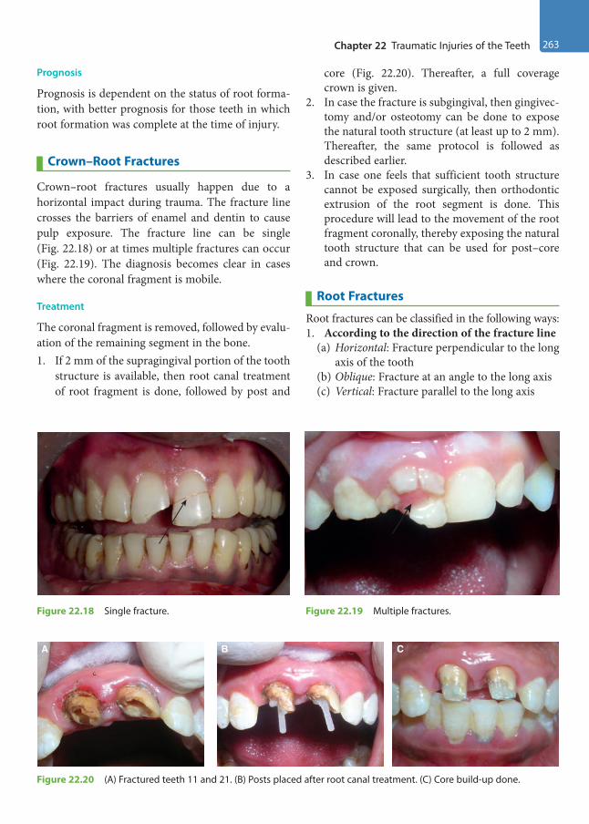
Chapter 22 Traumatic Injuries of the Teeth 263
Prognosis
Prognosis is dependent on the status of root forma-tion, with better prognosis for those teeth in which root formation was complete at the time of injury.
Crown–Root Fractures
Crown–root fractures usually happen due to a horizontal impact during trauma. The fracture line crosses the barriers of enamel and dentin to cause pulp exposure. The fracture line can be single (Fig. 22.18) or at times multiple fractures can occur (Fig. 22.19). The diagnosis becomes clear in cases where the coronal fragment is mobile.
Treatment
The coronal fragment is removed, followed by evalu-ation of the remaining segment in the bone. 1. If 2 mm of the supragingival portion of the tooth
structure is available, then root canal treatment of root fragment is done, followed by post and
core (Fig. 22.20). Thereafter, a full coverage crown is given.
2. In case the fracture is subgingival, then gingivec-tomy and/or osteotomy can be done to expose the natural tooth structure (at least up to 2 mm). Thereafter, the same protocol is followed as described earlier.
3. In case one feels that sufficient tooth structure cannot be exposed surgically, then orthodontic extrusion of the root segment is done. This procedure will lead to the movement of the root fragment coronally, thereby exposing the natural tooth structure that can be used for post–core and crown.
Root Fractures
Root fractures can be classified in the following ways: 1. According to the direction of the fracture line
(a) Horizontal: Fracture perpendicular to the long axis of the tooth
(b) Oblique: Fracture at an angle to the long axis(c) Vertical: Fracture parallel to the long axis
Figure 22.18 Single fracture. Figure 22.19 Multiple fractures.
A B C
Figure 22.20 (A) Fractured teeth 11 and 21. (B) Posts placed after root canal treatment. (C) Core build-up done.
Preclinical Dentistry.indb 263 29-05-2020 12:58:10
https://t.me/DentalBooksWorld
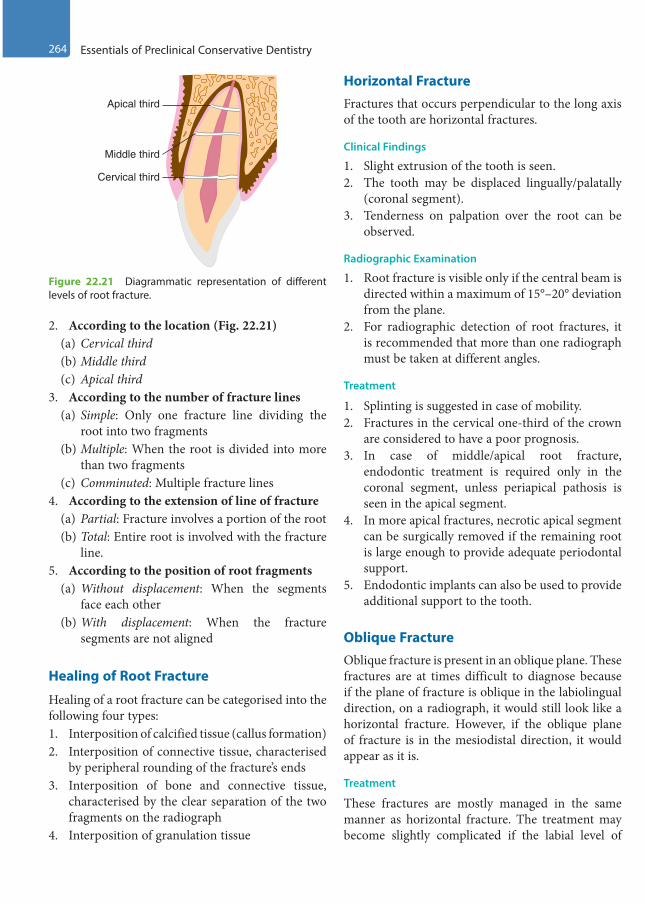
264 Essentials of Preclinical Conservative Dentistry
2. According to the location (Fig. 22.21)(a) Cervical third(b) Middle third(c) Apical third
3. According to the number of fracture lines(a) Simple: Only one fracture line dividing the
root into two fragments(b) Multiple: When the root is divided into more
than two fragments(c) Comminuted: Multiple fracture lines
4. According to the extension of line of fracture(a) Partial: Fracture involves a portion of the root(b) Total: Entire root is involved with the fracture
line.5. According to the position of root fragments
(a) Without displacement: When the segments face each other
(b) With displacement: When the fracture segments are not aligned
Healing of Root Fracture
Healing of a root fracture can be categorised into the following four types:1. Interposition of calcified tissue (callus formation) 2. Interposition of connective tissue, characterised
by peripheral rounding of the fracture’s ends3. Interposition of bone and connective tissue,
characterised by the clear separation of the two fragments on the radiograph
4. Interposition of granulation tissue
Horizontal FractureFractures that occurs perpendicular to the long axis of the tooth are horizontal fractures.
Clinical Findings
1. Slight extrusion of the tooth is seen.2. The tooth may be displaced lingually/palatally
(coronal segment).3. Tenderness on palpation over the root can be
observed.
Radiographic Examination
1. Root fracture is visible only if the central beam is directed within a maximum of 15°–20° deviation from the plane.
2. For radiographic detection of root fractures, it is recommended that more than one radiograph must be taken at different angles.
Treatment
1. Splinting is suggested in case of mobility.2. Fractures in the cervical one-third of the crown
are considered to have a poor prognosis.3. In case of middle/apical root fracture,
endodontic treatment is required only in the coronal segment, unless periapical pathosis is seen in the apical segment.
4. In more apical fractures, necrotic apical segment can be surgically removed if the remaining root is large enough to provide adequate periodontal support.
5. Endodontic implants can also be used to provide additional support to the tooth.
Oblique FractureOblique fracture is present in an oblique plane. These fractures are at times difficult to diagnose because if the plane of fracture is oblique in the labiolingual direction, on a radiograph, it would still look like a horizontal fracture. However, if the oblique plane of fracture is in the mesiodistal direction, it would appear as it is.
Treatment
These fractures are mostly managed in the same manner as horizontal fracture. The treatment may become slightly complicated if the labial level of
Cervical third
Apical third
Middle third
Figure 22.21 Diagrammatic representation of different levels of root fracture.
Preclinical Dentistry.indb 264 29-05-2020 12:58:10
https://t.me/DentalBooksWorld
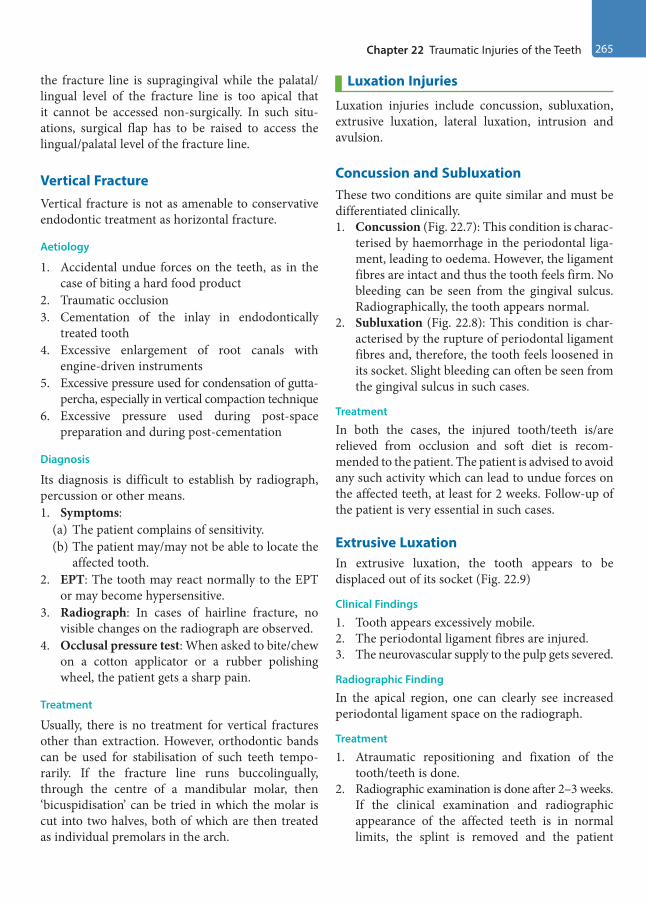
Chapter 22 Traumatic Injuries of the Teeth 265
the fracture line is supragingival while the palatal/ lingual level of the fracture line is too apical that it cannot be accessed non-surgically. In such situ-ations, surgical flap has to be raised to access the lingual/palatal level of the fracture line.
Vertical FractureVertical fracture is not as amenable to conservative endodontic treatment as horizontal fracture.
Aetiology
1. Accidental undue forces on the teeth, as in the case of biting a hard food product
2. Traumatic occlusion3. Cementation of the inlay in endodontically
treated tooth4. Excessive enlargement of root canals with
engine-driven instruments5. Excessive pressure used for condensation of gutta-
percha, especially in vertical compaction technique6. Excessive pressure used during post-space
preparation and during post-cementation
Diagnosis
Its diagnosis is difficult to establish by radiograph, percussion or other means.1. Symptoms:
(a) The patient complains of sensitivity.(b) The patient may/may not be able to locate the
affected tooth.2. EPT: The tooth may react normally to the EPT
or may become hypersensitive.3. Radiograph: In cases of hairline fracture, no
visible changes on the radiograph are observed.4. Occlusal pressure test: When asked to bite/chew
on a cotton applicator or a rubber polishing wheel, the patient gets a sharp pain.
Treatment
Usually, there is no treatment for vertical fractures other than extraction. However, orthodontic bands can be used for stabilisation of such teeth tempo-rarily. If the fracture line runs buccolingually, through the centre of a mandibular molar, then ‘bicuspidisation’ can be tried in which the molar is cut into two halves, both of which are then treated as individual premolars in the arch.
Luxation Injuries
Luxation injuries include concussion, subluxation, extrusive luxation, lateral luxation, intrusion and avulsion.
Concussion and SubluxationThese two conditions are quite similar and must be differentiated clinically.1. Concussion (Fig. 22.7): This condition is charac-
terised by haemorrhage in the periodontal liga-ment, leading to oedema. However, the ligament fibres are intact and thus the tooth feels firm. No bleeding can be seen from the gingival sulcus. Radiographically, the tooth appears normal.
2. Subluxation (Fig. 22.8): This condition is char-acterised by the rupture of periodontal ligament fibres and, therefore, the tooth feels loosened in its socket. Slight bleeding can often be seen from the gingival sulcus in such cases.
Treatment
In both the cases, the injured tooth/teeth is/are relieved from occlusion and soft diet is recom-mended to the patient. The patient is advised to avoid any such activity which can lead to undue forces on the affected teeth, at least for 2 weeks. Follow-up of the patient is very essential in such cases.
Extrusive LuxationIn extrusive luxation, the tooth appears to be displaced out of its socket (Fig. 22.9)
Clinical Findings
1. Tooth appears excessively mobile. 2. The periodontal ligament fibres are injured.3. The neurovascular supply to the pulp gets severed.
Radiographic Finding
In the apical region, one can clearly see increased periodontal ligament space on the radiograph.
Treatment
1. Atraumatic repositioning and fixation of the tooth/teeth is done.
2. Radiographic examination is done after 2–3 weeks. If the clinical examination and radiographic appearance of the affected teeth is in normal limits, the splint is removed and the patient
Preclinical Dentistry.indb 265 29-05-2020 12:58:10
https://t.me/DentalBooksWorld
266 Essentials of Preclinical Conservative Dentistry
is recommended to report for follow-up on a regular basis.
3. If at any point of time, the radiograph reveals resorption of the root and/or bone, endodontic therapy is recommended.
Lateral Luxation In this condition, the tooth is displaced laterally (Fig. 22.10).
Radiographic Finding
The occlusal-view radiographs, when taken in such cases, reveal increased periodontal ligament space.
Treatment
Same protocol is followed as in the cases of extrusive luxation.
Intrusion In intrusion, the tooth is displaced axially into the alveolar bone (Fig. 22.11).
Clinical Findings
1. The periodontal ligament fibres get injured and the neurovascular supply to the pulp gets severed.
2. The tooth becomes immobile and on percussion gives a metallic sound.
Radiographic Finding
When seen radiographically, the periodontal liga-ment space may be missing from some parts of the root or from the entire root.
Treatment
1. Cases of complete root formation: In such cases, the affected tooth is kept under observa-tion for at least 3 weeks. If repositioning of the tooth takes place naturally, no further treat-ment is required. However, in cases when it does not happen, orthodontic repositioning is recommended.
2. Cases of incomplete root formation: In such cases, as soon as possible, repositioning of the tooth is recommended either orthodontically or surgically. If the pulp gets devitalised, endodontic therapy is advised to the patient.
Avulsion InjuriesThe complete expulsion of the tooth (see Fig. 22.12) is one of the most difficult cases to be managed by a dental professional. The key to success in re-im-plantation of the avulsed tooth lies in the amount of time the tooth has been out of socket (Fig. 22.22). Lesser is the time elapsed, greater are the chances of success.
Consequences of Tooth Avulsion
1. Damage to the periodontal ligaments2. Pulp necrosis
Clinical Management
The management can be done under two levels, namely emergency treatment at accident site and treatment at dental clinic thereafter.
Emergency Treatment at the Accident SiteIf possible, the tooth should be re-implanted in the socket carefully. In cases it is not feasible, the tooth should be immersed in appropriate storage medium (saliva, milk, Hank’s balanced salt solution [HBSS], ViaSpan, etc.) and the patient should report to the dentist.
Treatment in the Dental OfficeThe tooth, if replanted already at the site of trauma, is checked for its proper repositioning and, if found ok, is splinted.1. When brought in a storage medium, socket is
prepared if required, followed by root preparation
Figure 22.22 Tooth avulsed in the area of 21; the socket is seen.
Preclinical Dentistry.indb 266 29-05-2020 12:58:10
https://t.me/DentalBooksWorld

Chapter 22 Traumatic Injuries of the Teeth 267
and re-implantation. A functional splint is then provided and local and systemic antibiotics are prescribed.
2. The socket is carefully examined for the pres-ence of any foreign body and, if present, is gently removed. Slight aspiration can be done if a blood clot is present.
3. If, due to trauma, the socket wall has collapsed, a blunt instrument can be used to reposition the collapsed wall to its original position.
4. The root surface should be minimally disturbed; however, at times, the root has to be prepared before re-implanting it in the socket. This depends on the time the tooth has been out of the socket (extraoral dry time).
(a) Extraoral dry time <60 minutes: If the tooth has a closed apex, there are no chances of revascularisation, but there are chances of peri-odontal healing. So, the root is gently rinsed off the debris with saline and re-implanted. If the tooth has an open apex, chances of revas-cularisation exist. So, the root is soaked in
doxycycline/minocycline for 5 minutes before re-implantation. Splinting of tooth is done; physiological splinting is preferred over the rigid splinting. The patient is called again after 2–3 weeks and the splint is removed. Vitality of the tooth is checked, and if the tooth turns out to be non-vital, endodontic therapy is done.
(b) Extraoral dry time >60 minutes: If the tooth has a closed apex, then the root has to be treated. Root canal treatment of the tooth is done outside the oral cavity by holding the tooth with a saline-soaked gauge. Also, the root surface is treated so that it can resist resorption after it is reimplanted. For this, the root is soaked in 2% stannous fluoride for 5 minutes and then re-implanted. Physiological splinting is done and the patient is recalled after 2–3 weeks for splint removal. If the tooth has an open apex, similar procedure is followed.
5. Anti-inflammatory analgesics and systemic antibiotics are advised to the patient.
KEY POINTS
• Tooth fracture refers to the breakage of the tooth structure because of an impact which is greater than the tooth’s resistance.
• The aetiological factors that cause fracture are as follows: iatrogenic injuries in the newborn, fall in infancy, auto-mobile accidents, drug-related/mental retardation injuries, sports injuries, etc.
• Ellis classification divides the types of tooth fractures into nine categories, from Types I to IX.• A patient reporting after dental trauma should be thoroughly examined, clinically and radiographically.• Uncomplicated crown fractures can be well treated by use of composite resins, while complicated crown frac-
tures have to undergo direct pulp capping, partial pulpotomy/Cvek pulpotomy or pulpectomy depending on the extent of pulpal involvement.
• Direct pulp capping refers to the procedure in which a suitable medicament (such as calcium hydroxide) is placed directly over a small pulp exposure in a caries-free zone.
• Partial pulpotomy/Cvek pulpotomy refers to removal of coronal pulp tissue up to the level of healthy pulp (usually up to 2 mm).
• Pulpectomy refers to the removal of entire pulp from the coronal as well as radicular portion of the tooth.• A crown–root fracture refers to a fracture involving enamel, coronal and radicular dentin and cementum, and its
treatment depends on the level of fracture.• Root fracture is a fracture involving radicular dentin, cementum and pulp.• Vertical fractures, whenever present, are difficult to diagnose, unless the two segments are completely apart, and
usually have a poor prognosis.• Concussion and subluxation injuries represent minor injuries to the periodontal ligament and pulp caused by an
acute impact.
Preclinical Dentistry.indb 267 29-05-2020 12:58:10
https://t.me/DentalBooksWorld
268 Essentials of Preclinical Conservative Dentistry
• Avulsion (exarticulation) refers to complete displacement of the tooth out of its socket. The tooth is replanted if possible or is placed in an appropriate storage medium within 15–20 minutes, until the patient can get to the dental office for reimplantation by the dentist.
SELF-ASSESSMENT QUESTIONS
1. What are the causes of tooth fracture?
2. Discuss Ellis classification of traumatic injuries to the teeth.
3. Discuss the steps of examination of a patient reporting with dental trauma.
4. Discuss the diagnosis and treatment of complicated crown fractures.
5. Explain pulp capping.
6. What do you mean by partial pulpotomy/Cvek pulpotomy?
7. Discuss the treatment options for a crown–root fracture.
8. Classify root fractures and discuss their prognosis.
9. How will you diagnose a vertical fracture and what treatment will be advised to the patient in such a case?
10. Discuss various luxation injuries in detail.
11. What do you mean by the tooth avulsion?
12. What storage mediums can be used for transporting the avulsed tooth from the site of trauma?
13. Discuss the prognosis of re-implanting an avulsed tooth, especially in relation to the extraoral dry time.
Preclinical Dentistry.indb 268 29-05-2020 12:58:10
https://t.me/DentalBooksWorld

Treatment of the exposed pulp by pulp capping has a long clinical history. The purpose of the treatment is to keep the exposed pulp vital and functioning in the tooth. A number of experimental studies have shown that pulp capping may have a success rate close to 90% if specific clinical criteria are met and the treatment is performed correctly.
For pulp capping to be successful, the following factors are of decisive importance:1. The condition of the pulp (pre-operative diagnosis)2. The pulp capping material3. Obtaining a permanent bacteria-tight seal of the
pulp cavityPre-operative diagnosis can be made by obtaining
correct history regarding the kind of associated pain, visual examination of the carious dentin and radiographic examination.
Vital pulp therapy for primary and young perma-nent teeth can be broadly classified into two catego-ries: ‘indirect pulp capping’, applied in cases where the pulp is not exposed, and ‘direct pulp capping’, implemented in case of pulp exposure. These methods of vital pulp therapy assist in retaining the vitality of the tooth.
Materials Used for Vital Pulp Therapy
Various materials have been used till date for vital pulp therapy, for example, zinc oxide eugenol (ZOE) (Fig. 23.1), calcium hydroxide (available in paste form, Fig. 23.2; or single-syringe, light-cured form), mineral trioxide aggregate (MTA) and Biodentine.
MTAMTA is the most commonly used material for vital pulp therapy (Fig. 23.3). This cement was devel-oped at the Loma Linda University by Dr Mahmoud Torabinejad for the purpose of root-end filling and
furcation perforation repair in the year 1993. The material has undergone extensive research for its sealing ability and biocompatibility. The unique ability of this cement to stimulate osteogenesis and cementogenesis makes this material a good choice for usage in conservative dentistry and endodontics in a wide variety of cases.
Vital Pulp Therapy23Chapter
Figure 23.1 Zinc oxide eugenol.
Figure 23.2 Calcium hydroxide (Dycal).
This chapter is authored by Dr Harpreet Singh.
Preclinical Dentistry.indb 269 29-05-2020 12:58:11
https://t.me/DentalBooksWorld

270 Essentials of Preclinical Conservative Dentistry
Composition
The material consists of the following ingredients:1. Tricalcium silicate2. Tricalcium aluminate3. Tricalcium oxide4. Silicate oxide5. Bismuth oxide (opacifier)
MTA is a hydrophilic material that has a 3-hour setting time in the presence of moisture. Mixing is done with sterile water in a powder:water ratio of 3:1. The initial pH is 10.2, which changes gradually to 12.5.
Advantages
1. Excellent sealing ability2. Excellent biocompatibility3. Good compressive strength (70 MPa)4. Stimulation of osteogenesis and cementogenesis5. Not soluble in water6. Radiopacity
Biodentine Biodentine is the first all-in-one bioactive and biocompatible dentine substitute introduced by Septodont. It is based on a unique ‘Active Biosilicate Technology’ and is being used for restorative as well as endodontic purpose.
Composition
It consists of a powder (in a capsule) and a liquid (Fig. 23.4) which has to be mixed uniformly in order to obtain putty-like material which is ready for use.Powder: • Tricalcium silicate (3CaO.SiO2)
• Dicalcium silicate (2CaO·SiO2)• Calcium carbonate (CaCO3)• Zirconium dioxide (ZrO2)• Iron oxideLiquid: • Calcium chloride • Water reducing agent• Water
Advantages
1. The setting time of Biodentine is very less as compared to that of MTA; thus, pulp capping can be completed in one visit using Biodentine.
2. It has better handling properties than MTA, thus making it more convenient to use.
3. Biodentine has improved mechanical properties as compared to MTA.
Indirect Pulp Capping
Indirect pulp capping refers to a technique in which a suitable medicament is placed in a deep carious lesion after excavation of the caries, in cases where there is no pulp exposure. These medicaments, such as ZOE, provide an obtundent (soothing) effect to the underlying pulp, while calcium hydroxide helps in formation of reparative dentin.
When a deep carious lesion is treated, two distinctive layers are encountered: infected dentin and affected dentin. The infected dentin is the outer layer, which is soft, dark brown in colour and contains microbes. The collagen of the dentin in this layer is irreversibly denatured. This layer should definitely be removed. The inner layer is
Figure 23.3 Mineral trioxide aggregate (MTA). Figure 23.4 Biodentine.
Preclinical Dentistry.indb 270 29-05-2020 12:58:11
https://t.me/DentalBooksWorld
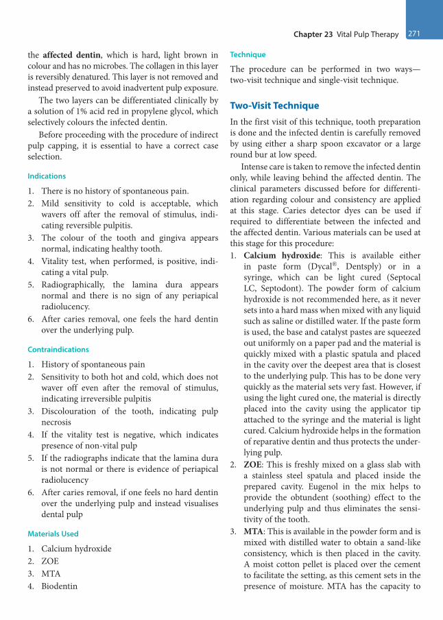
Chapter 23 Vital Pulp Therapy 271
the affected dentin, which is hard, light brown in colour and has no microbes. The collagen in this layer is reversibly denatured. This layer is not removed and instead preserved to avoid inadvertent pulp exposure.
The two layers can be differentiated clinically by a solution of 1% acid red in propylene glycol, which selectively colours the infected dentin.
Before proceeding with the procedure of indirect pulp capping, it is essential to have a correct case selection.
Indications
1. There is no history of spontaneous pain.2. Mild sensitivity to cold is acceptable, which
wavers off after the removal of stimulus, indi-cating reversible pulpitis.
3. The colour of the tooth and gingiva appears normal, indicating healthy tooth.
4. Vitality test, when performed, is positive, indi-cating a vital pulp.
5. Radiographically, the lamina dura appears normal and there is no sign of any periapical radiolucency.
6. After caries removal, one feels the hard dentin over the underlying pulp.
Contraindications
1. History of spontaneous pain2. Sensitivity to both hot and cold, which does not
waver off even after the removal of stimulus, indicating irreversible pulpitis
3. Discolouration of the tooth, indicating pulp necrosis
4. If the vitality test is negative, which indicates presence of non-vital pulp
5. If the radiographs indicate that the lamina dura is not normal or there is evidence of periapical radiolucency
6. After caries removal, if one feels no hard dentin over the underlying pulp and instead visualises dental pulp
Materials Used
1. Calcium hydroxide2. ZOE3. MTA4. Biodentin
Technique
The procedure can be performed in two ways—two-visit technique and single-visit technique.
Two-Visit Technique
In the first visit of this technique, tooth preparation is done and the infected dentin is carefully removed by using either a sharp spoon excavator or a large round bur at low speed.
Intense care is taken to remove the infected dentin only, while leaving behind the affected dentin. The clinical parameters discussed before for differenti-ation regarding colour and consistency are applied at this stage. Caries detector dyes can be used if required to differentiate between the infected and the affected dentin. Various materials can be used at this stage for this procedure:1. Calcium hydroxide: This is available either
in paste form (Dycal®, Dentsply) or in a syringe, which can be light cured (Septocal LC, Septodont). The powder form of calcium hydroxide is not recommended here, as it never sets into a hard mass when mixed with any liquid such as saline or distilled water. If the paste form is used, the base and catalyst pastes are squeezed out uniformly on a paper pad and the material is quickly mixed with a plastic spatula and placed in the cavity over the deepest area that is closest to the underlying pulp. This has to be done very quickly as the material sets very fast. However, if using the light cured one, the material is directly placed into the cavity using the applicator tip attached to the syringe and the material is light cured. Calcium hydroxide helps in the formation of reparative dentin and thus protects the under-lying pulp.
2. ZOE: This is freshly mixed on a glass slab with a stainless steel spatula and placed inside the prepared cavity. Eugenol in the mix helps to provide the obtundent (soothing) effect to the underlying pulp and thus eliminates the sensi-tivity of the tooth.
3. MTA: This is available in the powder form and is mixed with distilled water to obtain a sand-like consistency, which is then placed in the cavity. A moist cotton pellet is placed over the cement to facilitate the setting, as this cement sets in the presence of moisture. MTA has the capacity to
Preclinical Dentistry.indb 271 29-05-2020 12:58:11
https://t.me/DentalBooksWorld
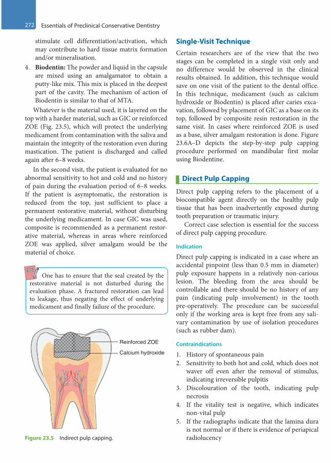
272 Essentials of Preclinical Conservative Dentistry
stimulate cell differentiation/activation, which may contribute to hard tissue matrix formation and/or mineralisation.
4. Biodentin: The powder and liquid in the capsule are mixed using an amalgamator to obtain a putty-like mix. This mix is placed in the deepest part of the cavity. The mechanism of action of Biodentin is similar to that of MTA.
Whatever is the material used, it is layered on the top with a harder material, such as GIC or reinforced ZOE (Fig. 23.5), which will protect the underlying medicament from contamination with the saliva and maintain the integrity of the restoration even during mastication. The patient is discharged and called again after 6–8 weeks.
In the second visit, the patient is evaluated for no abnormal sensitivity to hot and cold and no history of pain during the evaluation period of 6–8 weeks. If the patient is asymptomatic, the restoration is reduced from the top, just sufficient to place a permanent restorative material, without disturbing the underlying medicament. In case GIC was used, composite is recommended as a permanent restor-ative material, whereas in areas where reinforced ZOE was applied, silver amalgam would be the material of choice.
One has to ensure that the seal created by the restorative material is not disturbed during the evaluation phase. A fractured restoration can lead to leakage, thus negating the effect of underlying medicament and finally failure of the procedure.
Single-Visit TechniqueCertain researchers are of the view that the two stages can be completed in a single visit only and no difference would be observed in the clinical results obtained. In addition, this technique would save on one visit of the patient to the dental office. In this technique, medicament (such as calcium hydroxide or Biodentin) is placed after caries exca-vation, followed by placement of GIC as a base on its top, followed by composite resin restoration in the same visit. In cases where reinforced ZOE is used as a base, silver amalgam restoration is done. Figure 23.6A–D depicts the step-by-step pulp capping procedure performed on mandibular first molar using Biodentine.
Direct Pulp Capping
Direct pulp capping refers to the placement of a biocompatible agent directly on the healthy pulp tissue that has been inadvertently exposed during tooth preparation or traumatic injury.
Correct case selection is essential for the success of direct pulp capping procedure.
Indication
Direct pulp capping is indicated in a case where an accidental pinpoint (less than 0.5 mm in diameter) pulp exposure happens in a relatively non-carious lesion. The bleeding from the area should be controllable and there should be no history of any pain (indicating pulp involvement) in the tooth pre-operatively. The procedure can be successful only if the working area is kept free from any sali-vary contamination by use of isolation procedures (such as rubber dam).
Contraindications
1. History of spontaneous pain2. Sensitivity to both hot and cold, which does not
waver off even after the removal of stimulus, indicating irreversible pulpitis
3. Discolouration of the tooth, indicating pulp necrosis
4. If the vitality test is negative, which indicates non-vital pulp
5. If the radiographs indicate that the lamina dura is not normal or if there is evidence of periapical radiolucency
Calcium hydroxide
Reinforced ZOE
Figure 23.5 Indirect pulp capping.
Preclinical Dentistry.indb 272 29-05-2020 12:58:13
https://t.me/DentalBooksWorld

Chapter 23 Vital Pulp Therapy 273
6. Pulp exposed or serous exudate seen in the carious area
7. Profuse bleeding from the area exposed
Materials Used
1. Calcium hydroxide2. MTA3. Biodentin4. Others: Antibiotics, steroids, formocresol, trical-
cium phosphate, etc.
Technique
When a pinpoint exposure is observed during tooth preparation (with adequate isolation protocol) in a caries-free zone, haemorrhage is controlled using cotton pellets by keeping them under pressure.
Cotton pellets moistened with sodium hypochlo-rite can also be kept to stop the bleeding. At times, 2 mm of coronal pulp tissue is removed with the intention of removing the inflamed pulp tissue. This procedure was described by Cvek et al. and is termed partial pulpotomy. Bacterial contamination has to be prevented at all costs and so adequate isolation is a must throughout. Various medicaments can be used at this stage, such as the following:1. Calcium hydroxide: This is applied over the
exposed pulp in a manner similar to that described in the section ‘Indirect Pulp Capping’. This is followed by the placement of reinforced ZOE to obtain a tight seal. Alternatively, GIC can also be used as the coronal seal, followed by composite resin (Fig. 23.7). This should be followed by
A
B
C
D
Figure 23.6 (A) Carious mandibular first molar. (B) Caries excavation done. (C) Biodentine placed as pulp capping agent over the pulpal floor. (D) High-strength posterior restorative glass ionomer cement used as restorative material over Biodentine.
Preclinical Dentistry.indb 273 29-05-2020 12:58:13
https://t.me/DentalBooksWorld

274 Essentials of Preclinical Conservative Dentistry
placement of composite resin as the final restor-ative material on the top, so as to provide a tight seal as an insulator to bacterial contamination. When using reinforced ZOE as a base, silver amalgam is used as the restorative material.
2. MTA: This is mixed with distilled water and then placed in the cavity. A moist cotton pellet is placed over the cement to facilitate the setting, as this cement sets in the presence of moisture. The patient is recalled next day, the temporary resto-ration is removed, the cotton plug is removed and a permanent restorative material can now be placed over the set MTA. Recently, the use of flowable composite, to be placed directly over the freshly placed MTA, which is followed by the placement of packable composite, has been reported in order to avoid the second appoint-ment. However, the long-term clinical results of this one-step technique with MTA are yet to be evaluated.
Figure 23.8A shows a case of inadvertent pulp exposure during cavity preparation under rubber dam. MTA was placed as direct pulp capping agent (Fig. 23.8B), followed by composite resin restoration in the subsequent appointment (Fig. 23.8C).
Calcium hydroxide
GIC
Composite resin
Figure 23.7 Direct pulp capping.
A B
C
Figure 23.8 (A) Pulp exposure during cavity preparation in 46. (B) MTA placed as direct pulp capping agent at the site of exposure. (C) Composite resin restoration done in 46.
Preclinical Dentistry.indb 274 29-05-2020 12:58:15
https://t.me/DentalBooksWorld

Chapter 23 Vital Pulp Therapy 275
3. Biodentin: It is used in the manner similar to as described before for ‘Indirect Pulp Capping’. The additional advantage is that since this material sets faster, it can be covered with glass ionomer cement in the same visit.
Pulpotomy
Pulpotomy is defined as a procedure in which the coronal inflamed pulp is removed, leaving behind the vital radicular pulp, which can remain func-tional. After the removal of the coronal pulp, haem-orrhage is controlled and a suitable medicament is placed over the radicular pulp.
Indications
1. Pulp exposure in permanent teeth with incom-plete root formation (due to caries or trauma)
2. Pulp exposure in asymptomatic primary teeth
Contraindications
1. Persistent pain and pus discharge2. Marked tenderness to percussion3. Radiographic evidence of root resorption or
periapical radiolucency4. Teeth with furcation involvement
Techniques
There are three approaches that can be considered while performing pulpotomy procedure:1. Devitalisation approach (formocresol pulpo-
tomy): This approach involves the use of formocresol for fixation/mummification of the pulp tissue. The term ‘mummified’ refers to chemically treated pulp tissue that is inert, sterilised, metabolically suppressed and inca-pable of autolysis.
2. Preservation approach: This approach involves the use of medicaments and techniques that will help in preserving the vitality of the radicular pulp. The agents used for this approach can be either pharmacotherapeutic (corticosteroids, glutaraldehyde and ferric sulphate) or non-phar-macotherapeutic (electrosurgery and lasers).
3. Regeneration approach (calcium hydroxide pulpotomy): This approach involves the use of agents that can induce hard-tissue formation (reparative dentin), most commonly calcium hydroxide. Transforming growth factor-b in the
form of bone morphogenetic proteins, freeze-dried bone and MTA also fall in this category.
Formocresol PulpotomyFormocresol was introduced by Buckley in 1904. It consists of 35% cresol, 19% formalin in a vehicle of glycerine and water at a pH of approximately 5.1.
Technique
1. In the one-visit technique, after excavating the carious lesion, the roof of the pulp chamber is removed using a high-speed round bur or tapered fissure bur (Fig. 23.9). Sharp spoon excavator can be used to remove the pulp tissue remnants in the coronal portion. Dry cotton pellets are placed under pressure for controlling bleeding. Diluted formocresol is then applied over the radicular pulp by using a small cotton pellet for 3–5 minutes (Fig. 23.10). Cotton pellet is removed and clinical observation is made for satisfactory action of formocresol. ZOE cement is then applied to fill the entire pulp chamber. A stainless steel crown is thereafter luted with zinc phosphate cement to restore the tooth (Fig. 23.11).
2. In the two-visit technique, the formocre-sol-dampened cotton pellet is placed on the radicular pulp and reinforced ZOE cement is placed on it for obtaining a tight seal. The patient is sent back and called again after 1 week. The temporary filling is removed, cotton is removed and ZOE cement is then applied to fill the entire pulp chamber. A stainless steel crown is there-after used to restore the tooth.
Figure 23.9 Coronal pulp tissue removed using a high-speed round bur.
Preclinical Dentistry.indb 275 29-05-2020 12:58:17
https://t.me/DentalBooksWorld
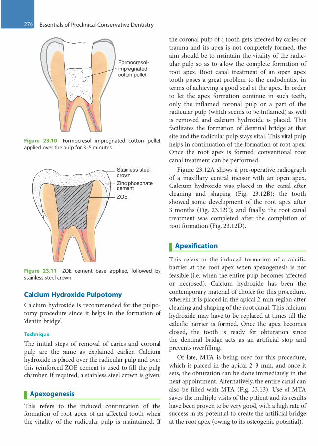
276 Essentials of Preclinical Conservative Dentistry
Calcium Hydroxide PulpotomyCalcium hydroxide is recommended for the pulpo-tomy procedure since it helps in the formation of ‘dentin bridge’.
Technique
The initial steps of removal of caries and coronal pulp are the same as explained earlier. Calcium hydroxide is placed over the radicular pulp and over this reinforced ZOE cement is used to fill the pulp chamber. If required, a stainless steel crown is given.
Apexogenesis
This refers to the induced continuation of the formation of root apex of an affected tooth when the vitality of the radicular pulp is maintained. If
the coronal pulp of a tooth gets affected by caries or trauma and its apex is not completely formed, the aim should be to maintain the vitality of the radic-ular pulp so as to allow the complete formation of root apex. Root canal treatment of an open apex tooth poses a great problem to the endodontist in terms of achieving a good seal at the apex. In order to let the apex formation continue in such teeth, only the inflamed coronal pulp or a part of the radicular pulp (which seems to be inflamed) as well is removed and calcium hydroxide is placed. This facilitates the formation of dentinal bridge at that site and the radicular pulp stays vital. This vital pulp helps in continuation of the formation of root apex. Once the root apex is formed, conventional root canal treatment can be performed.
Figure 23.12A shows a pre-operative radiograph of a maxillary central incisor with an open apex. Calcium hydroxide was placed in the canal after cleaning and shaping (Fig. 23.12B); the tooth showed some development of the root apex after 3 months (Fig. 23.12C); and finally, the root canal treatment was completed after the completion of root formation (Fig. 23.12D).
Apexification
This refers to the induced formation of a calcific barrier at the root apex when apexogenesis is not feasible (i.e. when the entire pulp becomes affected or necrosed). Calcium hydroxide has been the contemporary material of choice for this procedure, wherein it is placed in the apical 2-mm region after cleaning and shaping of the root canal. This calcium hydroxide may have to be replaced at times till the calcific barrier is formed. Once the apex becomes closed, the tooth is ready for obturation since the dentinal bridge acts as an artificial stop and prevents overfilling.
Of late, MTA is being used for this procedure, which is placed in the apical 2–3 mm, and once it sets, the obturation can be done immediately in the next appointment. Alternatively, the entire canal can also be filled with MTA (Fig. 23.13). Use of MTA saves the multiple visits of the patient and its results have been proven to be very good, with a high rate of success in its potential to create the artificial bridge at the root apex (owing to its osteogenic potential).
ZOE
Zinc phosphatecement
Stainless steelcrown
Figure 23.11 ZOE cement base applied, followed by stainless steel crown.
Formocresol-impregnatedcotton pellet
Figure 23.10 Formocresol impregnated cotton pellet applied over the pulp for 3–5 minutes.
Preclinical Dentistry.indb 276 29-05-2020 12:58:21
https://t.me/DentalBooksWorld
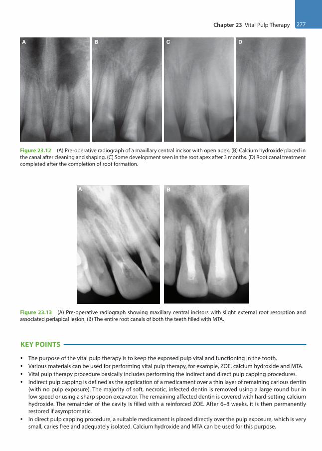
Chapter 23 Vital Pulp Therapy 277
A B C D
Figure 23.12 (A) Pre-operative radiograph of a maxillary central incisor with open apex. (B) Calcium hydroxide placed in the canal after cleaning and shaping. (C) Some development seen in the root apex after 3 months. (D) Root canal treatment completed after the completion of root formation.
A B
Figure 23.13 (A) Pre-operative radiograph showing maxillary central incisors with slight external root resorption and associated periapical lesion. (B) The entire root canals of both the teeth filled with MTA.
KEY POINTS
• The purpose of the vital pulp therapy is to keep the exposed pulp vital and functioning in the tooth.• Various materials can be used for performing vital pulp therapy, for example, ZOE, calcium hydroxide and MTA.• Vital pulp therapy procedure basically includes performing the indirect and direct pulp capping procedures.• Indirect pulp capping is defined as the application of a medicament over a thin layer of remaining carious dentin
(with no pulp exposure). The majority of soft, necrotic, infected dentin is removed using a large round bur in low speed or using a sharp spoon excavator. The remaining affected dentin is covered with hard-setting calcium hydroxide. The remainder of the cavity is filled with a reinforced ZOE. After 6–8 weeks, it is then permanently restored if asymptomatic.
• In direct pulp capping procedure, a suitable medicament is placed directly over the pulp exposure, which is very small, caries free and adequately isolated. Calcium hydroxide and MTA can be used for this purpose.
Preclinical Dentistry.indb 277 29-05-2020 12:58:22
https://t.me/DentalBooksWorld

278 Essentials of Preclinical Conservative Dentistry
• Pulpotomy is defined as the surgical removal of the entire coronal pulp presumed to be partially or totally inflamed and quite possibly infected, leaving intact the vital radicular pulp within the canals. A medicament (formocresol or calcium hydroxide, etc.) is then placed over the remaining vital radicular pulp stumps.
• Apexogenesis is the term used when there is induced continuation of root apex formation in case the entire radicular pulp is not inflamed. Use of calcium hydroxide is widely advocated for apexogenesis.
• Apexification is the term used when there is induced formation of a calcific barrier at the root apex by using medicaments such as calcium hydroxide or MTA.
SELF-ASSESSMENT QUESTIONS
1. What do you mean by vital pulp therapy?
2. What is indirect pulp capping? How is this procedure performed?
3. Explain the term direct pulp capping. Discuss its indications and the procedure involved.
4. What do you mean by pulpotomy?
5. Explain the three different treatment approaches that can be used for pulpotomy procedure.
6. What is MTA? Discuss its composition and uses.
7. Discuss the role of calcium hydroxide in vital pulp therapy.
8. Explain apexogenesis and apexification.
Preclinical Dentistry.indb 278 29-05-2020 12:58:22
https://t.me/DentalBooksWorld

In the previous chapters, we have discussed different treatment modalities for restoring a tooth affected with carious/non-carious lesions. In all the discussed procedures, it was evident that the dental pulp was not involved in the lesion. However, not in all cases, the pulp may remain unaffected. In cases where pulp exposure occurs, the bacteria invade this vascular and nervous tissue and cause infection. This results in pain and thus forms the most common cause of patients reporting to the dentist. Considering the strategic importance of the involved tooth, endodontic therapy (root canal treatment [RCT]) forms the only solution to alleviate pain and save the tooth from extraction.
Procedural Overview of Endodontic Treatment
It is beyond the scope of BDS II year students to understand the detailed aspects of endodontic treatment. However, for the basic knowledge of this treatment procedure, the following description will give an overview.
It is highly essential to achieve a correct diag-nosis before advising endodontic treatment for an involved tooth to any patient. Three basic steps which need to be performed for correct diagnosis are discussed next.
HistoryHistory of sensitivity to hot and cold, persistence of pain even after removal of stimulus, history of continuous pain, pain on lying down, etc., are all suggestive of pulp involvement. History of pus discharge is suggestive of chronic infection with abscess formation or periapical cyst/granuloma. This discharge can be intraoral or extraoral.
Clinical ExaminationMany a times, pulp exposure can be observed with the naked eye, especially in cases of traumatic inju-ries or in case of large carious exposure. The infec-tion, if has traversed from the pulp to the periodontal tissue, causes the tooth to be tender when percussed. In case where pulp exposure is not observed by the naked eye, simulations of oral conditions (e.g. sprinkling of cold water on the affected tooth) can help in the diagnosis. Various pulp vitality tests can be done to determine the status of vitality of the dental pulp:1. Heat test: Hot gutta-percha (GP) stick (Fig. 24.1)
or a hot ball burnisher is placed over the tooth surface to be tested and the response of the patient is exposed.
2. Cold test: Ethyl chloride spray (Fig. 24.2, Endo-Frost) or ice sticks are used to test the tooth for response to cold.
3. Electric pulp test: A specially designed electric pulp tester (Fig. 24.3) is used, which transmits the electric current to the tooth. To begin with, lesser intensity of current is applied on tooth and gradually it is increased till the patient feels the
Endodontics: An Overview24Chapter
Figure 24.1 Hot gutta-percha sticks.
This chapter is a joint contribution by the author and Dr Antonis Chaniotis.
Preclinical Dentistry.indb 279 29-05-2020 12:58:22
https://t.me/DentalBooksWorld
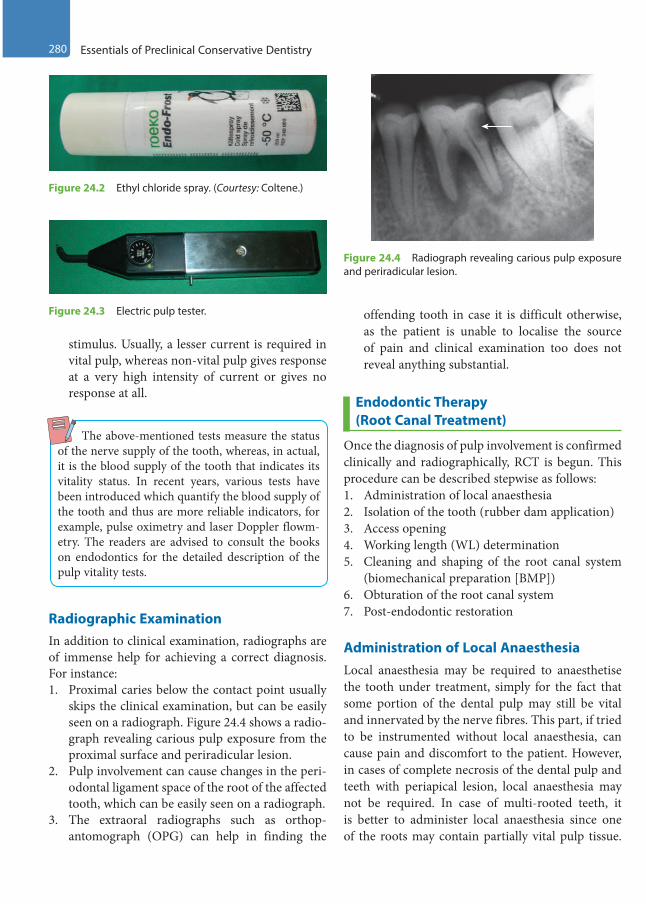
280 Essentials of Preclinical Conservative Dentistry
stimulus. Usually, a lesser current is required in vital pulp, whereas non-vital pulp gives response at a very high intensity of current or gives no response at all.
The above-mentioned tests measure the status of the nerve supply of the tooth, whereas, in actual, it is the blood supply of the tooth that indicates its vitality status. In recent years, various tests have been introduced which quantify the blood supply of the tooth and thus are more reliable indicators, for example, pulse oximetry and laser Doppler flowm-etry. The readers are advised to consult the books on endodontics for the detailed description of the pulp vitality tests.
Radiographic ExaminationIn addition to clinical examination, radiographs are of immense help for achieving a correct diagnosis. For instance:1. Proximal caries below the contact point usually
skips the clinical examination, but can be easily seen on a radiograph. Figure 24.4 shows a radio-graph revealing carious pulp exposure from the proximal surface and periradicular lesion.
2. Pulp involvement can cause changes in the peri-odontal ligament space of the root of the affected tooth, which can be easily seen on a radiograph.
3. The extraoral radiographs such as orthop-antomograph (OPG) can help in finding the
offending tooth in case it is difficult otherwise, as the patient is unable to localise the source of pain and clinical examination too does not reveal anything substantial.
Endodontic Therapy (Root Canal Treatment)
Once the diagnosis of pulp involvement is confirmed clinically and radiographically, RCT is begun. This procedure can be described stepwise as follows:1. Administration of local anaesthesia2. Isolation of the tooth (rubber dam application)3. Access opening4. Working length (WL) determination5. Cleaning and shaping of the root canal system
(biomechanical preparation [BMP])6. Obturation of the root canal system7. Post-endodontic restoration
Administration of Local AnaesthesiaLocal anaesthesia may be required to anaesthetise the tooth under treatment, simply for the fact that some portion of the dental pulp may still be vital and innervated by the nerve fibres. This part, if tried to be instrumented without local anaesthesia, can cause pain and discomfort to the patient. However, in cases of complete necrosis of the dental pulp and teeth with periapical lesion, local anaesthesia may not be required. In case of multi-rooted teeth, it is better to administer local anaesthesia since one of the roots may contain partially vital pulp tissue.
Figure 24.2 Ethyl chloride spray. (Courtesy: Coltene.)
Figure 24.3 Electric pulp tester.
Figure 24.4 Radiograph revealing carious pulp exposure and periradicular lesion.
Preclinical Dentistry.indb 280 29-05-2020 12:58:22
https://t.me/DentalBooksWorld
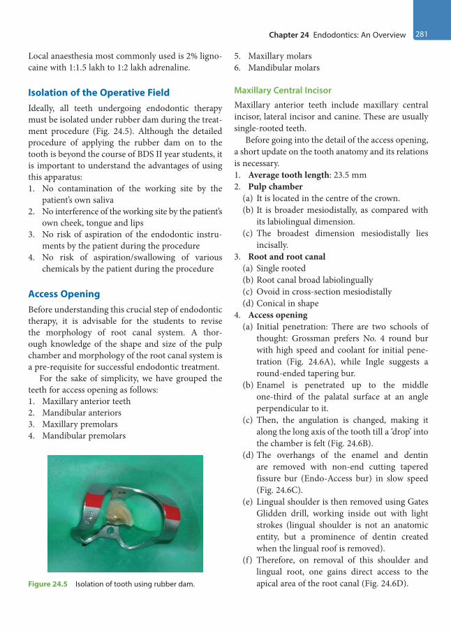
Chapter 24 Endodontics: An Overview 281
Local anaesthesia most commonly used is 2% ligno-caine with 1:1.5 lakh to 1:2 lakh adrenaline.
Isolation of the Operative FieldIdeally, all teeth undergoing endodontic therapy must be isolated under rubber dam during the treat-ment procedure (Fig. 24.5). Although the detailed procedure of applying the rubber dam on to the tooth is beyond the course of BDS II year students, it is important to understand the advantages of using this apparatus:1. No contamination of the working site by the
patient’s own saliva2. No interference of the working site by the patient’s
own cheek, tongue and lips3. No risk of aspiration of the endodontic instru-
ments by the patient during the procedure4. No risk of aspiration/swallowing of various
chemicals by the patient during the procedure
Access OpeningBefore understanding this crucial step of endodontic therapy, it is advisable for the students to revise the morphology of root canal system. A thor-ough knowledge of the shape and size of the pulp chamber and morphology of the root canal system is a pre-requisite for successful endodontic treatment.
For the sake of simplicity, we have grouped the teeth for access opening as follows:1. Maxillary anterior teeth2. Mandibular anteriors3. Maxillary premolars4. Mandibular premolars
5. Maxillary molars6. Mandibular molars
Maxillary Central Incisor
Maxillary anterior teeth include maxillary central incisor, lateral incisor and canine. These are usually single-rooted teeth.
Before going into the detail of the access opening, a short update on the tooth anatomy and its relations is necessary.1. Average tooth length: 23.5 mm2. Pulp chamber
(a) It is located in the centre of the crown.(b) It is broader mesiodistally, as compared with
its labiolingual dimension.(c) The broadest dimension mesiodistally lies
incisally.3. Root and root canal
(a) Single rooted(b) Root canal broad labiolingually(c) Ovoid in cross-section mesiodistally(d) Conical in shape
4. Access opening(a) Initial penetration: There are two schools of
thought: Grossman prefers No. 4 round bur with high speed and coolant for initial pene-tration (Fig. 24.6A), while Ingle suggests a round-ended tapering bur.
(b) Enamel is penetrated up to the middle one-third of the palatal surface at an angle perpendicular to it.
(c) Then, the angulation is changed, making it along the long axis of the tooth till a ‘drop’ into the chamber is felt (Fig. 24.6B).
(d) The overhangs of the enamel and dentin are removed with non-end cutting tapered fissure bur (Endo-Access bur) in slow speed (Fig. 24.6C).
(e) Lingual shoulder is then removed using Gates Glidden drill, working inside out with light strokes (lingual shoulder is not an anatomic entity, but a prominence of dentin created when the lingual roof is removed).
(f) Therefore, on removal of this shoulder and lingual root, one gains direct access to the apical area of the root canal (Fig. 24.6D).Figure 24.5 Isolation of tooth using rubber dam.
Preclinical Dentistry.indb 281 29-05-2020 12:58:23
https://t.me/DentalBooksWorld

282 Essentials of Preclinical Conservative Dentistry
(g) Thus, the access cavity prepared in the maxil-lary central has a triangular shape, with its apex towards the cervical zone (Fig. 24.6E,F).
Maxillary Lateral IncisorThe access cavity preparation for maxillary lateral incisor is shown in Figure 24.7.1. Average tooth length: 22 mm2. Pulp chamber: Similar to central incisor, but
smaller in dimension3. Root and root canal
(a) Conical in shape(b) Has a finer diameter(c) Lateral canals frequent (26%)
4. Access opening(a) It is similar to that of central incisor, but is
smaller and more ovoid in shape.(b) Technique for entry is the same, except that a
smaller, that is, No. 2, round bur may be used instead of No. 4 as for the central incisor.
(c) Access cavity preparation in maxillary lateral incisor needs to be modified in certain cases such as in anomalies (dens invaginatus, peg-shaped laterals and lateral incisors with talon cusps, etc.).
D E F
CBA
Figure 24.6 (A) Initial access through the palatal surface (bur held perpendicular) for a maxillary central incisor. (B) Angulation is changed, making it along the long axis of the tooth. (C) The overhangs of the enamel and dentin removed with non-end cutting bur. (D) Straight line access achieved. (E) Triangular shape of the access cavity. (F) Access cavity made in maxillary central incisor.
Figure 24.7 Access cavity preparation for maxillary lateral incisor.
Preclinical Dentistry.indb 282 29-05-2020 12:58:23
https://t.me/DentalBooksWorld
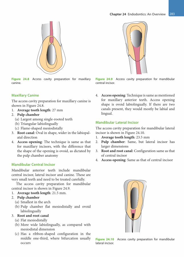
Chapter 24 Endodontics: An Overview 283
Maxillary CanineThe access cavity preparation for maxillary canine is shown in Figure 24.8.1. Average tooth length: 27 mm2. Pulp chamber
(a) Largest among single-rooted teeth(b) Triangular labiolingually(c) Flame-shaped mesiodistally
3. Root canal: Oval in shape, wider in the labiopal-atal direction
4. Access opening: The technique is same as that for maxillary incisors, with the difference that the shape of the opening is ovoid, as dictated by the pulp chamber anatomy
Mandibular Central IncisorMandibular anterior teeth include mandibular central incisor, lateral incisor and canine. These are very small teeth and need to be treated carefully.
The access cavity preparation for mandibular central incisor is shown in Figure 24.9.1. Average tooth length: 21.5 mm.2. Pulp chamber
(a) Smallest in the arch(b) Pulp chamber flat mesiodistally and ovoid
labiolingually3. Root and root canal
(a) Flat mesiodistally(b) More wide labiolingually, as compared with
mesiodistal dimension(c) Has a ribbon-shaped configuration in the
middle one-third, where bifurcation usually occurs
4. Access opening: Technique is same as mentioned for maxillary anterior teeth. Access opening shape is ovoid labiolingually. If there are two canals present, they would mostly be labial and lingual.
Mandibular Lateral IncisorThe access cavity preparation for mandibular lateral incisor is shown in Figure 24.10.1. Average tooth length: 23.5 mm2. Pulp chamber: Same, but lateral incisor has
larger dimensions3. Root and root canal: Configuration same as that
of central incisor4. Access opening: Same as that of central incisor
Figure 24.8 Access cavity preparation for maxillary canine.
Figure 24.9 Access cavity preparation for mandibular central incisor.
Figure 24.10 Access cavity preparation for mandibular lateral incisor.
Preclinical Dentistry.indb 283 29-05-2020 12:58:24
https://t.me/DentalBooksWorld
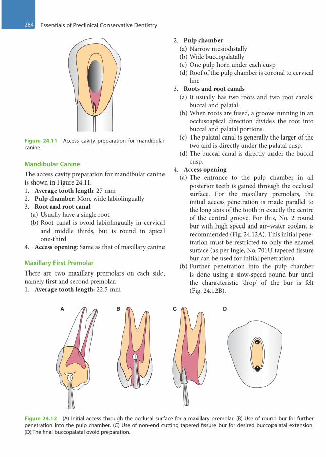
284 Essentials of Preclinical Conservative Dentistry
Mandibular CanineThe access cavity preparation for mandibular canine is shown in Figure 24.11.1. Average tooth length: 27 mm2. Pulp chamber: More wide labiolingually3. Root and root canal
(a) Usually have a single root(b) Root canal is ovoid labiolingually in cervical
and middle thirds, but is round in apical one-third
4. Access opening: Same as that of maxillary canine
Maxillary First PremolarThere are two maxillary premolars on each side, namely first and second premolar.1. Average tooth length: 22.5 mm
2. Pulp chamber(a) Narrow mesiodistally(b) Wide buccopalatally(c) One pulp horn under each cusp(d) Roof of the pulp chamber is coronal to cervical
line3. Roots and root canals
(a) It usually has two roots and two root canals: buccal and palatal.
(b) When roots are fused, a groove running in an occlusoapical direction divides the root into buccal and palatal portions.
(c) The palatal canal is generally the larger of the two and is directly under the palatal cusp.
(d) The buccal canal is directly under the buccal cusp.
4. Access opening(a) The entrance to the pulp chamber in all
posterior teeth is gained through the occlusal surface. For the maxillary premolars, the initial access penetration is made parallel to the long axis of the tooth in exactly the centre of the central groove. For this, No. 2 round bur with high speed and air–water coolant is recommended (Fig. 24.12A). This initial pene-tration must be restricted to only the enamel surface (as per Ingle, No. 701U tapered fissure bur can be used for initial penetration).
(b) Further penetration into the pulp chamber is done using a slow-speed round bur until the characteristic ‘drop’ of the bur is felt (Fig. 24.12B).
Figure 24.11 Access cavity preparation for mandibular canine.
A B C D
Figure 24.12 (A) Initial access through the occlusal surface for a maxillary premolar. (B) Use of round bur for further penetration into the pulp chamber. (C) Use of non-end cutting tapered fissure bur for desired buccopalatal extension. (D) The final buccopalatal ovoid preparation.
Preclinical Dentistry.indb 284 29-05-2020 12:58:24
https://t.me/DentalBooksWorld
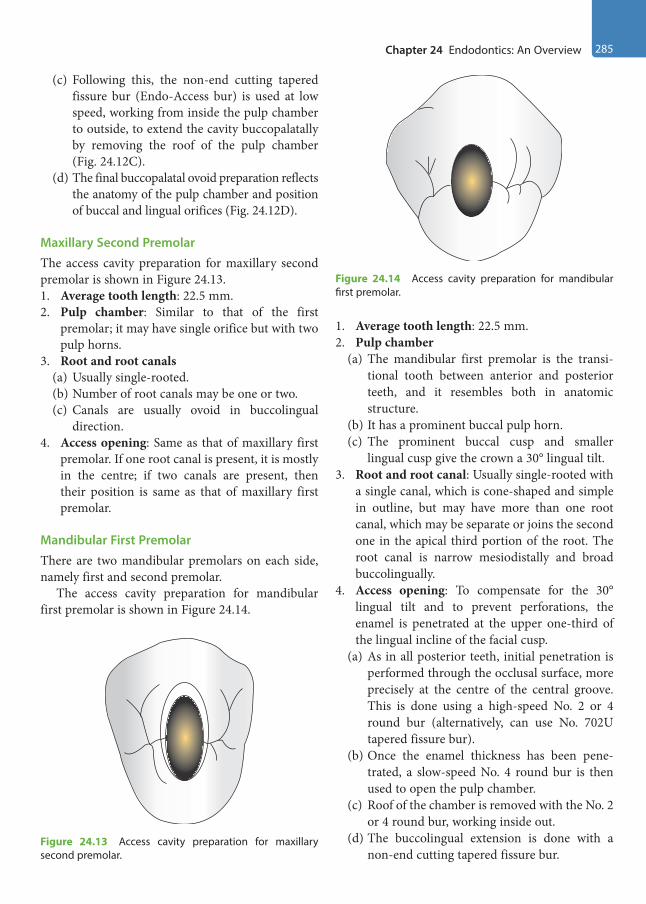
Chapter 24 Endodontics: An Overview 285
(c) Following this, the non-end cutting tapered fissure bur (Endo-Access bur) is used at low speed, working from inside the pulp chamber to outside, to extend the cavity buccopalatally by removing the roof of the pulp chamber (Fig. 24.12C).
(d) The final buccopalatal ovoid preparation reflects the anatomy of the pulp chamber and position of buccal and lingual orifices (Fig. 24.12D).
Maxillary Second PremolarThe access cavity preparation for maxillary second premolar is shown in Figure 24.13.1. Average tooth length: 22.5 mm.2. Pulp chamber: Similar to that of the first
premolar; it may have single orifice but with two pulp horns.
3. Root and root canals(a) Usually single-rooted.(b) Number of root canals may be one or two.(c) Canals are usually ovoid in buccolingual
direction.4. Access opening: Same as that of maxillary first
premolar. If one root canal is present, it is mostly in the centre; if two canals are present, then their position is same as that of maxillary first premolar.
Mandibular First PremolarThere are two mandibular premolars on each side, namely first and second premolar.
The access cavity preparation for mandibular first premolar is shown in Figure 24.14.
1. Average tooth length: 22.5 mm.2. Pulp chamber
(a) The mandibular first premolar is the transi-tional tooth between anterior and posterior teeth, and it resembles both in anatomic structure.
(b) It has a prominent buccal pulp horn.(c) The prominent buccal cusp and smaller
lingual cusp give the crown a 30° lingual tilt.3. Root and root canal: Usually single-rooted with
a single canal, which is cone-shaped and simple in outline, but may have more than one root canal, which may be separate or joins the second one in the apical third portion of the root. The root canal is narrow mesiodistally and broad buccolingually.
4. Access opening: To compensate for the 30° lingual tilt and to prevent perforations, the enamel is penetrated at the upper one-third of the lingual incline of the facial cusp.
(a) As in all posterior teeth, initial penetration is performed through the occlusal surface, more precisely at the centre of the central groove. This is done using a high-speed No. 2 or 4 round bur (alternatively, can use No. 702U tapered fissure bur).
(b) Once the enamel thickness has been pene-trated, a slow-speed No. 4 round bur is then used to open the pulp chamber.
(c) Roof of the chamber is removed with the No. 2 or 4 round bur, working inside out.
(d) The buccolingual extension is done with a non-end cutting tapered fissure bur.
Figure 24.13 Access cavity preparation for maxillary second premolar.
Figure 24.14 Access cavity preparation for mandibular first premolar.
Preclinical Dentistry.indb 285 29-05-2020 12:58:24
https://t.me/DentalBooksWorld
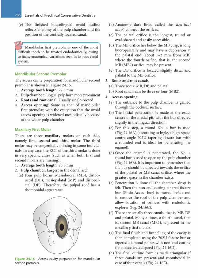
286 Essentials of Preclinical Conservative Dentistry
(e) The finished buccolingual ovoid outline reflects anatomy of the pulp chamber and the position of the centrally located canal.
Mandibular first premolar is one of the most difficult tooth to be treated endodontically, owing to many anatomical variations seen in its root canal system.
Mandibular Second PremolarThe access cavity preparation for mandibular second premolar is shown in Figure 24.15.1. Average tooth length: 22.5 mm2. Pulp chamber: Lingual pulp horn more prominent3. Roots and root canal: Usually single-rooted4. Access opening: Same as that of mandibular
first premolar, with the exception that the ovoid access opening is widened mesiodistally because of the wider pulp chamber
Maxillary First MolarThere are three maxillary molars on each side, namely first, second and third molar. The third molar may be congenitally missing in some individ-uals. In any case, the RCT of the third molar is done in very specific cases (such as when both first and second molars are missing).1. Average tooth length: 20.5 mm2. Pulp chamber: Largest in the dental arch
(a) Four pulp horns: Mesiobuccal (MB), distob-uccal (DB), mesiopalatal (MP) and distopal-atal (DP). Therefore, the pulpal roof has a rhomboidal appearance.
(b) Anatomic dark lines, called the ‘dentinal map’, connect the orifices.
(c) The palatal orifice is the longest, round or oval-shaped and easily accessible.
(d) The MB orifice lies below the MB cusp, is long buccopalatally and may have a depression at the palatal end (about 1–2 mm from MB) where the fourth orifice, that is, the second MB (MB2) orifice, may be present.
(e) The DB orifice is located slightly distal and palatal to the MB orifice.
3. Roots and root canals(a) Three roots: MB, DB and palatal.(b) Root canals can be three or four (MB2).
4. Access opening(a) The entrance to the pulp chamber is gained
through the occlusal surface.(b) The initial penetration is made at the exact
centre of the mesial pit, with the bur directed slightly in the lingual direction.
(c) For this step, a round No. 4 bur is used (Fig. 24.16A) (according to Ingle, a high-speed contra-angle 702U tapering fissure bur with a rounded end is ideal for penetrating the enamel).
(d) Once the enamel is penetrated, the No. 4 round bur is used to open up the pulp chamber (Fig. 24.16B). It is important to remember that the bur should be directed towards the orifice of the palatal or MB canal orifice, where the greatest space in the chamber exists.
(e) Penetration is done till the chamber ‘drop’ is felt. Then the non-end cutting tapered fissure bur (Endo-Access bur) is moved inside out to remove the roof of the pulp chamber and allow location of orifices with endodontic explorer (Fig. 24.16C).
(f) There are usually three canals, that is, MB, DB and palatal. Many a times, a fourth canal, that is, second MB canal (MB2), is present in the maxillary first molars.
(g) The final finish and funnelling of the cavity is then completed using the 702U fissure bur or tapered diamond points with non-end cutting tip at accelerated speed (Fig. 24.16D).
(h) The final outline form is made triangular if three canals are present and rhomboidal in case of four canals (Fig. 24.16E).
Figure 24.15 Access cavity preparation for mandibular second premolar.
Preclinical Dentistry.indb 286 29-05-2020 12:58:24
https://t.me/DentalBooksWorld
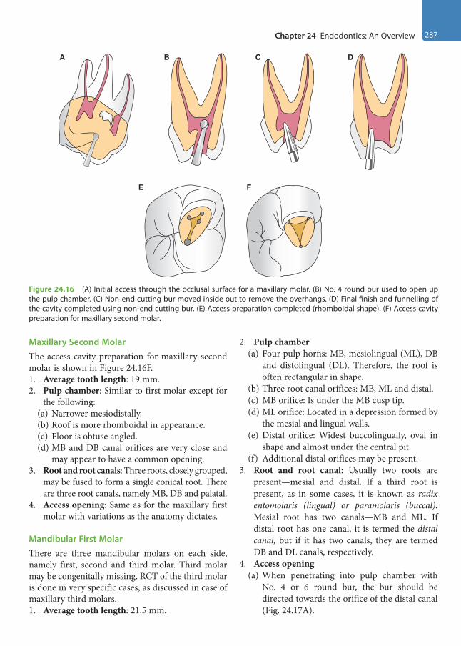
Chapter 24 Endodontics: An Overview 287
Maxillary Second MolarThe access cavity preparation for maxillary second molar is shown in Figure 24.16F.1. Average tooth length: 19 mm.2. Pulp chamber: Similar to first molar except for
the following:(a) Narrower mesiodistally.(b) Roof is more rhomboidal in appearance.(c) Floor is obtuse angled.(d) MB and DB canal orifices are very close and
may appear to have a common opening.3. Root and root canals: Three roots, closely grouped,
may be fused to form a single conical root. There are three root canals, namely MB, DB and palatal.
4. Access opening: Same as for the maxillary first molar with variations as the anatomy dictates.
Mandibular First MolarThere are three mandibular molars on each side, namely first, second and third molar. Third molar may be congenitally missing. RCT of the third molar is done in very specific cases, as discussed in case of maxillary third molars.1. Average tooth length: 21.5 mm.
2. Pulp chamber(a) Four pulp horns: MB, mesiolingual (ML), DB
and distolingual (DL). Therefore, the roof is often rectangular in shape.
(b) Three root canal orifices: MB, ML and distal.(c) MB orifice: Is under the MB cusp tip.(d) ML orifice: Located in a depression formed by
the mesial and lingual walls.(e) Distal orifice: Widest buccolingually, oval in
shape and almost under the central pit.(f) Additional distal orifices may be present.
3. Root and root canal: Usually two roots are present—mesial and distal. If a third root is present, as in some cases, it is known as radix entomolaris (lingual) or paramolaris (buccal). Mesial root has two canals—MB and ML. If distal root has one canal, it is termed the distal canal, but if it has two canals, they are termed DB and DL canals, respectively.
4. Access opening(a) When penetrating into pulp chamber with
No. 4 or 6 round bur, the bur should be directed towards the orifice of the distal canal (Fig. 24.17A).
A B
E F
C D
Figure 24.16 (A) Initial access through the occlusal surface for a maxillary molar. (B) No. 4 round bur used to open up the pulp chamber. (C) Non-end cutting bur moved inside out to remove the overhangs. (D) Final finish and funnelling of the cavity completed using non-end cutting bur. (E) Access preparation completed (rhomboidal shape). (F) Access cavity preparation for maxillary second molar.
Preclinical Dentistry.indb 287 29-05-2020 12:58:24
https://t.me/DentalBooksWorld

288 Essentials of Preclinical Conservative Dentistry
(b) The remaining preparation follows the same pattern as maxillary molars, with the consider-ation of the position of the root canal orifices. The access opening is extended towards the MB cusp to expose the MB canal, lingually (about 2 mm from MB canal) slightly beyond the central groove to expose the ML canal and distally (towards the central pit) slightly beyond the buccal groove to expose the distal canal using a non-end cutting tapered fissure bur (Endo-Access bur) (Fig. 24.17B).
(c) Final access opening is trapezoidal in shape if three canals are present or rectangular in shape if four canals (two distal canals) are present (Fig. 24.17C).
Mandibular Second MolarThe access cavity preparation for mandibular second molar is shown in Figure 24.18.1. Average tooth length: 20 mm.
2. Pulp chamber: Same as the first molar, but smaller in size and the root canal orifices are smaller and closer.
3. Root and root canal: In most cases, there are two roots—mesial and distal. There are mostly two canals in the mesial root—MB and ML. Distal root mostly has one canal and is known as the distal canal. There are a few variations, such as only one canal in the mesial root; in such cases, it is known as the mesial canal. There can be a single ‘C-shaped’ canal in the tooth as well.
4. Access opening: Same as the mandibular first molar, but smaller. However, greater amount of tooth structure in region of the MB cusp may have to be removed to expose the MB canal because of the buccoaxial inclination of the tooth.
Working Length DeterminationIt is the distance from the coronal reference point to the point at which the canal preparation and obtura-tion should end.
This refers to measuring the length of the root canals so that the entire infected pulp may be removed, leaving behind no source of infection. Accurate WL determination is important since a ‘short WL’ will lead to pulp remnants and thus rein-fection, whereas working beyond the root will lead to injury to the periodontal ligament and bone, and thus overfilling and subsequent pain to the patient.
Procedures
A pre-operative radiograph is considered mandatory before starting endodontic therapy (Fig. 24.19A). A file is placed inside the root canal through the access
A B C
Figure 24.17 (A) Initial access through the occlusal surface for a mandibular molar. (B) Finishing of the preparation walls. (C) Access preparation completed (rectangular shape).
Figure 24.18 Access cavity preparation for mandibular second molar.
Preclinical Dentistry.indb 288 29-05-2020 12:58:25
https://t.me/DentalBooksWorld
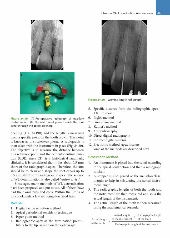
Chapter 24 Endodontics: An Overview 289
opening (Fig. 24.19B) and the length is measured from a specific point on the tooth crown. This point is known as the reference point. A radiograph is then taken with the instrument in place (Fig. 24.20). The objective is to measure the distance between this reference point and the cementodentinal junc-tion (CDJ). Since CDJ is a histological landmark, clinically, it is considered that it lies about 0.5 mm short of the radiographic apex. Therefore, the aim should be to clean and shape the root canals up to 0.5 mm short of the radiographic apex. The science of WL determination is also called ‘endometrics’.
Since ages, many methods of WL determination have been proposed and put to use. All of them have had their own pros and cons. Within the limits of this book, only a few are being described here.
Methods
1. Digital tactile sensation method2. Apical periodontal sensitivity technique3. Paper point method4. Radiographic apex as the termination point—
filling to the tip, as seen on the radiograph
5. Specific distance from the radiographic apex—1.0 mm short
6. Ingle’s method7. Grossman’s method8. Kuttler’s method9. Xeroradiography10. Direct digital radiography11. Indirect digital systems12. Electronic method: apex locaters
Some of the methods are described next.
Grossman’s Method
1. An instrument is placed into the canal extending to the apical constriction and then a radiograph is taken.
2. A stopper is also placed at the incisal/occlusal margin to help in calculating the actual instru-ment length
3. The radiographic lengths of both the tooth and the instrument are then measured and so is the actual length of the instrument.
4. The actual length of the tooth is then measured using the mathematical formula:
=
Actual length Radiographic lengthActual lengthof the tooth Radiographic length of the instrument
of the instrument of the tooth×
Figure 24.20 Working length radiograph.
Figure 24.19 (A) Pre-operative radiograph of maxillary central incisor. (B) The instrument placed inside the root canal through the access opening.
A
B
Preclinical Dentistry.indb 289 29-05-2020 12:58:25
https://t.me/DentalBooksWorld
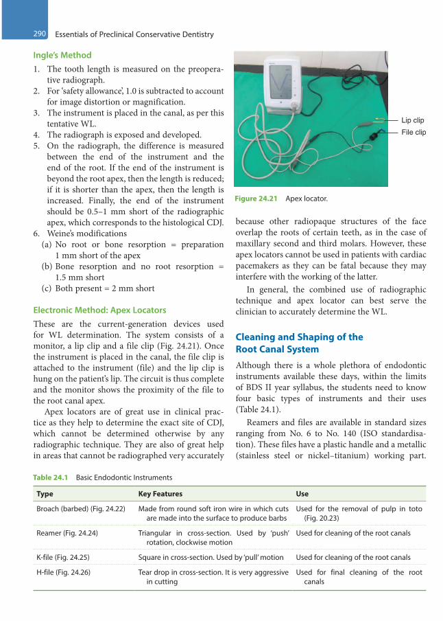
290 Essentials of Preclinical Conservative Dentistry
Ingle’s Method1. The tooth length is measured on the preopera-
tive radiograph.2. For ‘safety allowance’, 1.0 is subtracted to account
for image distortion or magnification.3. The instrument is placed in the canal, as per this
tentative WL.4. The radiograph is exposed and developed.5. On the radiograph, the difference is measured
between the end of the instrument and the end of the root. If the end of the instrument is beyond the root apex, then the length is reduced; if it is shorter than the apex, then the length is increased. Finally, the end of the instrument should be 0.5–1 mm short of the radiographic apex, which corresponds to the histological CDJ.
6. Weine’s modifications(a) No root or bone resorption = preparation
1 mm short of the apex(b) Bone resorption and no root resorption =
1.5 mm short(c) Both present = 2 mm short
Electronic Method: Apex LocatorsThese are the current-generation devices used for WL determination. The system consists of a monitor, a lip clip and a file clip (Fig. 24.21). Once the instrument is placed in the canal, the file clip is attached to the instrument (file) and the lip clip is hung on the patient’s lip. The circuit is thus complete and the monitor shows the proximity of the file to the root canal apex.
Apex locators are of great use in clinical prac-tice as they help to determine the exact site of CDJ, which cannot be determined otherwise by any radiographic technique. They are also of great help in areas that cannot be radiographed very accurately
because other radiopaque structures of the face overlap the roots of certain teeth, as in the case of maxillary second and third molars. However, these apex locators cannot be used in patients with cardiac pacemakers as they can be fatal because they may interfere with the working of the latter.
In general, the combined use of radiographic technique and apex locator can best serve the clinician to accurately determine the WL.
Cleaning and Shaping of the Root Canal System
Although there is a whole plethora of endodontic instruments available these days, within the limits of BDS II year syllabus, the students need to know four basic types of instruments and their uses (Table 24.1).
Reamers and files are available in standard sizes ranging from No. 6 to No. 140 (ISO standardisa-tion). These files have a plastic handle and a metallic (stainless steel or nickel–titanium) working part.
Lip clip
File clip
Figure 24.21 Apex locator.
Table 24.1 Basic Endodontic Instruments
Type Key Features Use
Broach (barbed) (Fig. 24.22) Made from round soft iron wire in which cuts are made into the surface to produce barbs
Used for the removal of pulp in toto (Fig. 20.23)
Reamer (Fig. 24.24) Triangular in cross-section. Used by ‘push’ rotation, clockwise motion
Used for cleaning of the root canals
K-file (Fig. 24.25) Square in cross-section. Used by ‘pull’ motion Used for cleaning of the root canals
H-file (Fig. 24.26) Tear drop in cross-section. It is very aggressive in cutting
Used for final cleaning of the root canals
Preclinical Dentistry.indb 290 29-05-2020 12:58:25
https://t.me/DentalBooksWorld
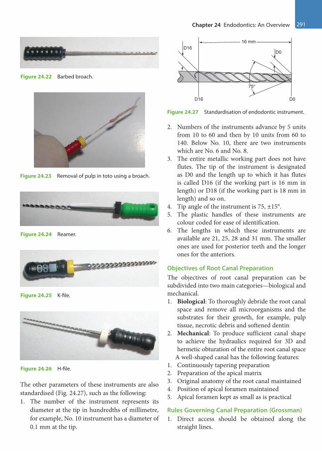
Chapter 24 Endodontics: An Overview 291
The other parameters of these instruments are also standardised (Fig. 24.27), such as the following:1. The number of the instrument represents its
diameter at the tip in hundredths of millimetre, for example, No. 10 instrument has a diameter of 0.1 mm at the tip.
2. Numbers of the instruments advance by 5 units from 10 to 60 and then by 10 units from 60 to 140. Below No. 10, there are two instruments which are No. 6 and No. 8.
3. The entire metallic working part does not have flutes. The tip of the instrument is designated as D0 and the length up to which it has flutes is called D16 (if the working part is 16 mm in length) or D18 (if the working part is 18 mm in length) and so on.
4. Tip angle of the instrument is 75, ±15°.5. The plastic handles of these instruments are
colour coded for ease of identification.6. The lengths in which these instruments are
available are 21, 25, 28 and 31 mm. The smaller ones are used for posterior teeth and the longer ones for the anteriors.
Objectives of Root Canal PreparationThe objectives of root canal preparation can be subdivided into two main categories—biological and mechanical.1. Biological: To thoroughly debride the root canal
space and remove all microorganisms and the substrates for their growth, for example, pulp tissue, necrotic debris and softened dentin
2. Mechanical: To produce sufficient canal shape to achieve the hydraulics required for 3D and hermetic obturation of the entire root canal space
A well-shaped canal has the following features:1. Continuously tapering preparation2. Preparation of the apical matrix3. Original anatomy of the root canal maintained4. Position of apical foramen maintained5. Apical foramen kept as small as is practical
Rules Governing Canal Preparation (Grossman)1. Direct access should be obtained along the
straight lines.
Figure 24.22 Barbed broach.
Figure 24.23 Removal of pulp in toto using a broach.
Figure 24.24 Reamer.
Figure 24.25 K-file.
Figure 24.26 H-file.
D16
D16 D0
D0
16 mm
75°
Figure 24.27 Standardisation of endodontic instrument.
Preclinical Dentistry.indb 291 29-05-2020 12:58:25
https://t.me/DentalBooksWorld
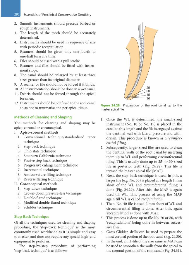
292 Essentials of Preclinical Conservative Dentistry
2. Smooth instruments should precede barbed or rough instruments.
3. The length of the tooth should be accurately determined.
4. Instruments should be used in sequence of size with periodic recapitulation.
5. Reamers should be given only one-fourth to one-half turn at a time.
6. Files should be used with a pull stroke.7. Reamers and files should be fitted with instru-
ment stops.8. The canal should be enlarged by at least three
sizes greater than its original diameter.9. A reamer or file should not be forced if it binds.10. All instrumentation should be done in a wet canal.11. Debris should not be forced through the apical
foramen.12. Instruments should be confined to the root canal
so as not to traumatise the periapical tissue.
Methods of Cleaning and ShapingThe methods for cleaning and shaping may be apico-coronal or coronoapical.I. Apico-coronal methods
1. Conventional technique/standardised taper technique
2. Step-back technique3. Ohio state technique4. Southern California technique5. Passive step-back technique6. Progressive enlargement technique7. Incremental technique8. Anticurvature filing technique9. Reverse flaring technique
II. Coronoapical methods1. Step-down technique2. Crown-down pressure-less technique3. Double-flared technique4. Modified double-flared technique5. Schilder technique
Step-Back TechniqueOf all the techniques used for cleaning and shaping procedure, the ‘step-back technique’ is the most commonly used worldwide as it is simple and easy to master, and does not require any special high-end equipment to perform.
The step-by-step procedure of performing ‘step-back technique’ is as follows:
1. Once the WL is determined, the small-sized instrument (No. 10 or No. 15) is placed in the canal to this length and the file is engaged against the dentinal wall with lateral pressure and with-drawn. This procedure is known as circumfer-ential filing.
2. Subsequently, larger-sized files are used to clean the dentinal walls of the root canal by inserting them up to WL and performing circumferential filing. This is usually done up to 25- or 30-sized file in posterior teeth (Fig. 24.28). This file is termed the master apical file (MAF).
3. Next, the step-back technique is used. In this, a larger file (e.g. No. 30) is placed at a length 1 mm short of the WL and circumferential filing is done (Fig. 24.29). After this, the MAF is again used till WL. This process of using the MAF again till WL is called recapitulation.
4. Then, No. 40 file is used 2 mm short of WL and circumferential filing is done. After this, again ‘recapitulation’ is done with MAF.
5. This process is done up to file No. 70 or 80, with ‘recapitulations’ being done in between succes-sive files.
6. Gates Glidden drills can be used to prepare the most coronal portion of the root canal (Fig. 24.30).
7. In the end, an H-file of the size same as MAF can be used to smoothen the walls from the apical to the coronal portion of the root canal (Fig. 24.31).
25
1510
20
Figure 24.28 Preparation of the root canal up to the master apical file.
Preclinical Dentistry.indb 292 29-05-2020 12:58:26
https://t.me/DentalBooksWorld

Chapter 24 Endodontics: An Overview 293
8. One must never forget to irrigate the root canal with a suitable antibacterial irrigant (sodium hypochlorite or chlorhexidine) after each step of filing. This step helps in the removal of the debris created in the canal during filing, in addi-tion to the antibacterial effect shown by these irrigants (Fig. 24.32).
9. In this way, the entire root canal walls are cleaned off debris and bacteria.
10. A suitable intracanal medicament such as calcium hydroxide/chlorhexidine can be used for placement in the root canal for its antibacte-rial action and left for a stipulated period before the next appointment.
Obturation of the Root Canal System
It is defined as the three-dimensional filling of the entire root canal system as close to the CDJ as possible.
Objectives
1. Substitution of an inert filling in the space previ-ously occupied by the pulp tissue
40
35
30
25
Figure 24.29 Step-back procedure.
Gates Glidden drill
Figure 24.30 Gates Glidden drills used to prepare the most coronal portion of the root canal.
25
Figure 24.31 Use of H-file of the size same as MAF to smoothen the walls.
Figure 24.32 Use of antibacterial irrigant.
Preclinical Dentistry.indb 293 29-05-2020 12:58:26
https://t.me/DentalBooksWorld
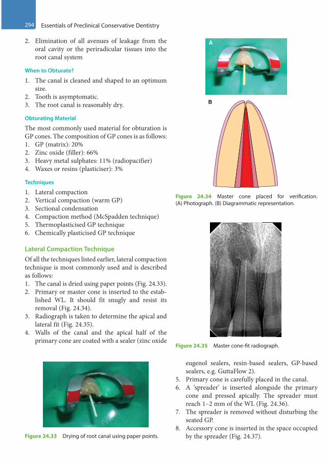
294 Essentials of Preclinical Conservative Dentistry
2. Elimination of all avenues of leakage from the oral cavity or the periradicular tissues into the root canal system
When to Obturate?
1. The canal is cleaned and shaped to an optimum size.
2. Tooth is asymptomatic.3. The root canal is reasonably dry.
Obturating Material
The most commonly used material for obturation is GP cones. The composition of GP cones is as follows:1. GP (matrix): 20%2. Zinc oxide (filler): 66%3. Heavy metal sulphates: 11% (radiopacifier)4. Waxes or resins (plasticiser): 3%
Techniques
1. Lateral compaction2. Vertical compaction (warm GP)3. Sectional condensation4. Compaction method (McSpadden technique)5. Thermoplasticised GP technique6. Chemically plasticised GP technique
Lateral Compaction TechniqueOf all the techniques listed earlier, lateral compaction technique is most commonly used and is described as follows:1. The canal is dried using paper points (Fig. 24.33).2. Primary or master cone is inserted to the estab-
lished WL. It should fit snugly and resist its removal (Fig. 24.34).
3. Radiograph is taken to determine the apical and lateral fit (Fig. 24.35).
4. Walls of the canal and the apical half of the primary cone are coated with a sealer (zinc oxide
eugenol sealers, resin-based sealers, GP-based sealers, e.g. GuttaFlow 2).
5. Primary cone is carefully placed in the canal.6. A ‘spreader’ is inserted alongside the primary
cone and pressed apically. The spreader must reach 1–2 mm of the WL (Fig. 24.36).
7. The spreader is removed without disturbing the seated GP.
8. Accessory cone is inserted in the space occupied by the spreader (Fig. 24.37).
Figure 24.35 Master cone-fit radiograph.
Figure 24.33 Drying of root canal using paper points.
B
A
Figure 24.34 Master cone placed for verification. (A) Photograph. (B) Diagrammatic representation.
Preclinical Dentistry.indb 294 29-05-2020 12:58:27
https://t.me/DentalBooksWorld
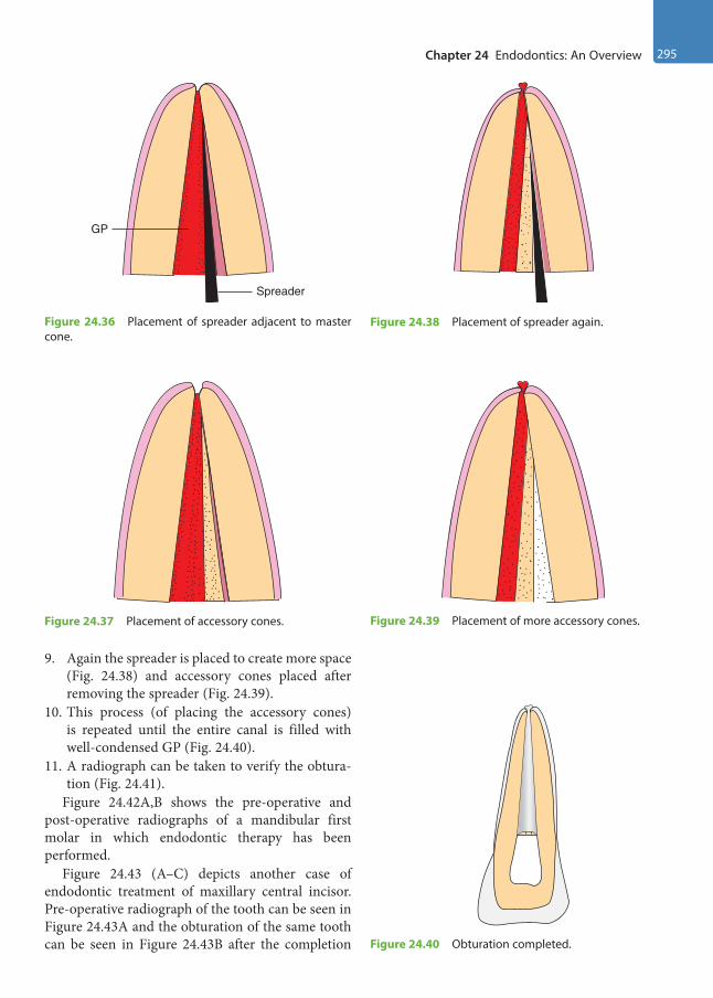
Chapter 24 Endodontics: An Overview 295
9. Again the spreader is placed to create more space (Fig. 24.38) and accessory cones placed after removing the spreader (Fig. 24.39).
10. This process (of placing the accessory cones) is repeated until the entire canal is filled with well-condensed GP (Fig. 24.40).
11. A radiograph can be taken to verify the obtura-tion (Fig. 24.41).
Figure 24.42A,B shows the pre-operative and post-operative radiographs of a mandibular first molar in which endodontic therapy has been performed.
Figure 24.43 (A–C) depicts another case of endodontic treatment of maxillary central incisor. Pre-operative radiograph of the tooth can be seen in Figure 24.43A and the obturation of the same tooth can be seen in Figure 24.43B after the completion
Spreader
GP
Figure 24.36 Placement of spreader adjacent to master cone.
Figure 24.37 Placement of accessory cones.
Figure 24.38 Placement of spreader again.
Figure 24.39 Placement of more accessory cones.
Figure 24.40 Obturation completed.
Preclinical Dentistry.indb 295 29-05-2020 12:58:27
https://t.me/DentalBooksWorld
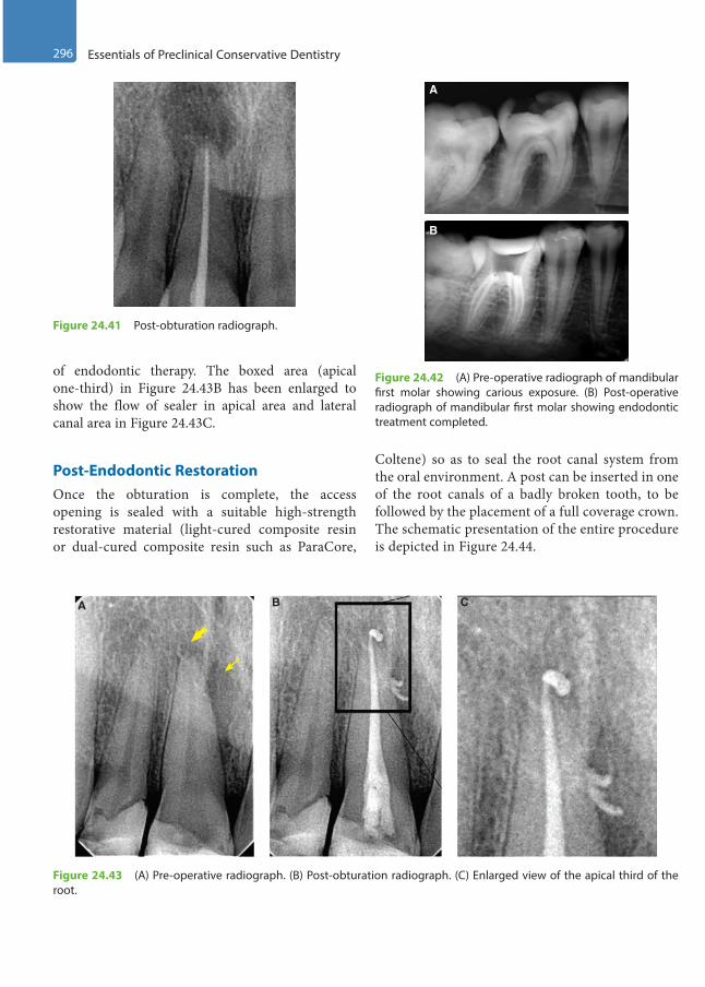
296 Essentials of Preclinical Conservative Dentistry
of endodontic therapy. The boxed area (apical one-third) in Figure 24.43B has been enlarged to show the flow of sealer in apical area and lateral canal area in Figure 24.43C.
Post-Endodontic RestorationOnce the obturation is complete, the access opening is sealed with a suitable high-strength restorative material (light-cured composite resin or dual-cured composite resin such as ParaCore,
Coltene) so as to seal the root canal system from the oral environment. A post can be inserted in one of the root canals of a badly broken tooth, to be followed by the placement of a full coverage crown. The schematic presentation of the entire procedure is depicted in Figure 24.44.
Figure 24.41 Post-obturation radiograph.
Figure 24.42 (A) Pre-operative radiograph of mandibular first molar showing carious exposure. (B) Post-operative radiograph of mandibular first molar showing endodontic treatment completed.
A
B
A B C
Figure 24.43 (A) Pre-operative radiograph. (B) Post-obturation radiograph. (C) Enlarged view of the apical third of the root.
Preclinical Dentistry.indb 296 29-05-2020 12:58:28
https://t.me/DentalBooksWorld

Chapter 24 Endodontics: An Overview 297
Figure 24.44 Schematic presentation of the entire procedure of root canal treatment.
Gums
File Plugger
Guttapercha
Crown
Post
Filling
Infectedtooth
Access opening Root canal preparation
Post-endodonticrestoration
Post and coreFull coverage
crown
Infected pulp
AbscessNerve
Cementum
Obturation
Dentalcaries
KEY POINTS
• In cases where the pulp gets infected for one reason or the other, RCT (endodontic treatment) is advocated to save the tooth.
• A thorough clinical and radiographic examination is essential before starting RCT.• Pulp vitality tests, wherever required, must be done to assess the status of the pulp.• Isolation of tooth with rubber dam is mandatory for performing endodontic therapy.• One should be thorough with the morphology of the root canal system before attempting to begin with an
endodontic procedure.• Access openings of maxillary anterior teeth are made from the palatal surface, while those of maxillary premolars
and molars are made from the occlusal surface.• Access openings of mandibular anterior teeth are made from the lingual surface, while those of mandibular
premolars and molars are made from the occlusal surface.• WL is then determined, which refers to measuring the length of the root canals so that entire infected pulp may
be removed, leaving behind no source of infection. Radiograph or an apex locator can be used for this purpose.• Cleaning and shaping is then done using files. Step-back technique is commonly used for this purpose.• Obturation of the root canals is then done using GP, lateral compaction technique being widely used for this.• Once the obturation is complete, the access opening is sealed with a suitable high-strength restorative material
so as to seal the root canal system from the oral environment.
Preclinical Dentistry.indb 297 29-05-2020 12:58:30
https://t.me/DentalBooksWorld
298 Essentials of Preclinical Conservative Dentistry
SELF-ASSESSMENT QUESTIONS
1. Enumerate various pulp vitality tests used to assess the status of the dental pulp.
2. What is the importance of administering local anaesthesia before endodontic treatment?
3. What is the best way of isolating a tooth undergoing endodontic treatment?
4. Enumerate the site for access opening in case of endodontic procedure to be performed on maxillary and mandibular teeth.
5. Discuss the step-by-step procedure of making an access cavity for a maxillary central incisor.
6. What do you mean by working length determination and how is it done?
7. What do you mean by step-back technique for preparation of root canals?
8. What are the objectives of obturation of the root canal system?
9. Discuss in detail the lateral compaction technique of obturation of the root canal system.
10. What do you understand by the term post-endodontic restoration?
Preclinical Dentistry.indb 298 29-05-2020 12:58:30
https://t.me/DentalBooksWorld

1. Abel LC, Miller RL, Micik RE, Ryge G. Studies on dental aerobiology. IV. Bacterial contamination of water delivered by dental units. J Dent Res. 1971;50(6):1567–9.
2. Allen AL, Organ RJ. Occult blood accumulation under the fingernails: a mechanism for the spread of blood-borne infection. J Am Dent Assoc. 1982;105(3):455–9.
3. Almquist TC, Cowan RD, Lambert RL. Conservative amalgam restorations. J Prosthet Dent. 1973;29(5):524–8.
4. American Academy of Operative Dentistry. Non-carious cervical lesions. Recommendations for clinical practice. Oper Dent. 2003;28(2):109–13.
5. Andreasen JO, Andreasen FM. Textbook and color atlas of traumatic injuries to the teeth. 3rd ed. St Louis: Mosby; 1994.
6. Andreasen JO. Effect of extra-alveolar period and storage media upon periodontal and pulpal healing after replantation of mature permanent incisors in monkeys. Int J Oral Surg. 1981;10(1):43–53.
7. Anusavice KJ. Phillips’ science of dental materials. 10th ed. St Louis: Mosby; 1996.
8. Apotheker H. A microscope for use in dentistry. J Micosurg. 1981;3:7.
9. Apotheker H. The applications of the dental microscope: Preliminary report. J Microsurg. 1981;3:103–6.
10. Arends J, Ruben J, Jongebloed WL. Dentine caries in vivo. Combined scanning electron microscopic and microradiographic investigation. Caries Res. 1989;23(1):36–41.
11. Arhun N, Celik C, Yamanel K. Clinical evaluation of resin-based composites in posterior restorations: two-year results. Oper Dent. 2010;35(4):397–404.
12. Bader JD, Levitch LC, Shugars DA, Heymann HO, McClure F. How dentists classified and treated non-car-ious cervical lesions. J Am Dent Assoc. 1993;124(5):46–54.
13. Bailey JH. Retention design for amalgam restorations: pins versus slots. J Prosthet Dent. 1991;65(1):71–4.
14. Bartlett DW, Shah P. A critical review of non-carious cervical (wear) lesions and the role of abfraction, erosion, and abrasion. J Dent Res. 2006;85(4):306–12.
15. Bartlett DW. A rationale for use of bases with amalgam restorations. Dent Update. 1992;19(10):413–4, 416–7.
16. Baskaran BE, Geetha Prabhu KR, Prabhu R, Krishna GP, Eswaran MA, Gajapathi B. Casting made simple using modified sprue design: An in vitro study. Indian J Dent Res. 2014;25:340–45.
17. Bauer JG. A study of procedures for burnishing amalgam restorations. J Prosthet Dent. 1987;57(6):669–73.
18. Baume LJ, Holz J. Long term clinical assessment of direct pulp capping. Int Dent J. 1981;31(4):251–60.
19. Berry J. The demographics of dentistry. J Am Dent Assoc. 1996;127(9):1327–30.
20. Bhaskar SN, Rappaport HM. Dental vitality tests and pulp status. J Am Dent Assoc. 1973;86(2):409–11.
21. Black GV. The management of enamel margins. Dent Cosm. 1891;33:1–14.
22. Black GV. The management of enamel margins – Weak lines of the enamel. Dent Cosm. 1891;33:85–100.
23. Black GV. The management of enamel margins – The incisors. Dent Cosm. 1891;33:347–58.
Further Readings
Preclinical Dentistry.indb 299 29-05-2020 12:58:30
https://t.me/DentalBooksWorld
300 Further Readings
24. Black GV. The management of enamel margins – The form and finish line of the marginal edge of the enamel. Dent Cosm. 1891;33:440–7.
25. Black GV. Operative dentistry. 8th ed. Woodstock: Medico–Dental Publishing; 1947.
26. Blinkhorn A, Choi CL, Paget HE. An investigation into the use of the FDI tooth notation system by dental schools in the UK. Eur J Dent Educ. 1998;2(1):3941.
27. Braem M, Lambrechts P, Vanherle G. Stress-induced cervical lesions. J Prosthet Dent. 1992;67(5):718–22.
28. Brown LJ, Lazar V. Dentists and their practices. J Am Dent Assoc. 1998;129(12):1692–99.
29. Brown LJ, Lazar V. Dentist work force and educational pipeline. J Am Dent Assoc. 1998;129(12):1700–7.
30. Caldwell RC. Physical properties of foods and their caries-producing potentials. J Dent Res. 1970;49(6):1293–8.
31. Carr GB. Microscopes in endodontics. J Calif Dent Assoc. 1992;20(11):55–61.
32. Charbeneau Gerald T. Principles and practice of operative dentistry. 3rd ed. Bombay: Varghese Publishing House; 1989.
33. Charles AD. The story of dental amalgam. Bull Hist Dent. 1982;30:2–7.
34. Cleveland JL, Cardo DM. Occupational exposures to human immunodeficiency virus, hepatitis B virus, and hepatitis C virus: risk, prevention, and management. Dent Clin North Am. 2003;47(4):681–96.
35. Cohen S, Burns RC. Pathways of the pulp. 7th ed. London: Mosby; 1988.
36. Compagni R, Faucher RR, Yuodelis RA. Effects of sprue design, casting machine, and heat source on casting porosity. J Prosthet Dent. 1984;52:41–5.
37. Craig RG. Chemistry, composition, and properties of composite resins. Dent Clin North Am. 1981;25(2):219–39.
38. Craig RG. Restorative dental materials. 11th ed. St Louis: Mosby; 2001.
39. Crawford PR. The story of silver amalgam (and how a Canadian changed it all)! J Can Dent Assoc. 1989;55:887–90.
40. Crockett WD, Shepard FE, Moon PC, Creal AF. The influence of proximal retention grooves on the retention and resistance of class II preparations for amalgam. J Am Dent Assoc. 1975;91(5):1053–6.
41. Cunningham PJ. Matrices for amalgam restorations. Aust Dent J. 1968;13(2):139–42.
42. Cvek M. A clinical report on partial pulpotomy and capping with calcium hydroxide in permanent incisors with complicated crown fracture. J Endod. 1978;4(8):232–7.
43. Das UK, Das S. Dental operating microscope in endodontics – A review. J Dent Med Sci. 2013;5:1–8.
44. Della Bona A, Summitt JB. The effect of amalgam bonding on resistance form of class II amalgam resto-rations. Quintessence Int. 1998;29(2):95–101.
45. Drummond JL, Jung H, Savers EE, Novickas D, Toepke TR. Surface roughness of polished amalgams. Oper Dent. 1992;17(4):129–34.
46. Dugmore CR, Rock WP. A multifactorial analysis of factors associated with dental erosion. Br Dent J. 2004;196(5):283–6.
47. Duncalf WV, Wilson NH. Adaptation and condensation of amalgam restorations in Class II preparations of conventional and conservative design. Quintessence Int. 1992;23(7):499–504.
48. Dyson JE, Darvell BW. The development of the high-speed air turbine handpiece. Part 2 Aust Dent J. 1993;38:131–43.
49. Eid H. Retention of composite resin restorations in class IV preparations. J Clin Pediatr Dent. 2002;26(3):251–6.
50. Elderton RJ, Mjor IA. Changing scenes in cariology and operative dentistry. Int Dent J. 1992;42(3):165–9.
Preclinical Dentistry.indb 300 29-05-2020 12:58:30
https://t.me/DentalBooksWorld
Further Readings 301
51. Fanian F, Hadavi F, Asgar K. Marginal leakage of dental amalgams: effect of cavity varnish and burnishing. J Can Dent Assoc. 1984;50(6):484–7.
52. Ferguson JW. The Palmer notation system and its use with personal computer applications. Br Dent J. 2005;198(9):551–3.
53. Fitzgerald RJ, Adams BO, Davis ME. A microbiological study of recurrent dentinal caries. Caries Res. 1994;28(6):409–15.
54. Folayan MO, Sowole CA, Owotade FJ, Sote E. Impact of infant feeding practices on caries experience of preschool children. J Clin Pediatr Dent. 2010;34(4):297–301.
55. Ford TR, Torabinejad M, Abedi HR, Bakland LK, Kariyawasam SP. Using mineral trioxide aggregate as a pulp-capping material. J Am Dent Assoc. 1996;127(10):1491–4.
56. Fusayama T. Factors and technique of precision casting Part I. J Prosthet Dent. 1959;9:468–85.
57. Fusayama T. Two layers of carious dentin: diagnosis and treatment. Oper Dent. 1979;4(2):63–70.
58. Geiger F, Reller U, Lutz F. Burnishing, finishing, and polishing amalgam restorations: a quantitative scanning electron microscopic study. Quintessence Int. 1989;20(7):461–8.
59. Ghose LJ, Baghdady VS, Hikmat YM. Apexification of immature apices of pulp less permanent anterior teeth with calcium hydroxide. J Endod. 1987;13(6):285–90.
60. Gibbons RJ. Bacteriology of dental caries. J Dent Res. 1964;43(suppl):1021–8.
61. Gilmore HW. Restorative materials and tooth preparation design. Dent Clin North Am. 1971;15(1):99–114.
62. Gilmore HW et al. Operative dentistry. 4th ed. St Louis: Mosby; 1982.
63. Glenn A, Van AS. Digital documentation and the dental operating microscope: What you see is what you get. Int J Microdent. 2009;1:30–41.
64. Glenner RA. The Dental Chair—A Brief Pictorial History. J Am Dent Assoc. 1973;86:38–49.
65. Glenner RA. The modern reclining dental chair. J Hist Dent. 1996;44:122–4.
66. Greener EH. Amalgam – Yesterday, today, and tomorrow. Oper Dent. 1979;4:24–35.
67. Grippo JO, Simring M, Schreiner S. Attrition, abrasion, corrosion and abfraction revisited: a new perspective on tooth surface lesions. J Am Dent Assoc. 2004;135(8):1109–18.
68. Grossman Louis I. Endodontic practice. 11th ed. Bombay: Varghese Publishing House; 1988.
69. Gwinnett AJ. Moist versus dry dentin: its effect on shear bond strength. Am J Dent. 1992;5(3):127–9.
70. H M Pickard, Edwina AM Kidd, Bernard GM Smith, Toimothy F Watson. Pickard’s manual of operative dentistry. 8th ed. Oxford: Oxford University Press; 2003.
71. Hackney RW Jr, Crawford JJ, Tulis JJ. Using a biological indicator to detect potential sources of cross-contamination in the dental operatory. J Am Dent Assoc. 1998;129(11):1567–77.
72. Haikel Y, Frank RM, Voegel JC. Scanning electron microscopy of the human enamel surface layer of incip-ient carious lesions. Caries Res. 1983;17(1):1–13.
73. Harris RK. Dental amalgam: success or failure? Oper Dent. 1992;17(6):243–52.
74. Harry F. Albers. Tooth-colored restoratives principles and techniques. 9th ed. London: BC Decker Inc; 2002.
75. Henry EE, Peyton FA. The relationship between design and cutting efficiency of dental burs. J Dent Res 1954;33(2):281–92.
76. Herschfeld JJ. G.V. Black and the search for a better amalgam. Bull Hist Dent. 1980;28:76–82.
77. Hinman TP. Methods of filling teeth with gold inlays. Items Interest. 1907;29:58–61.
78. Hume WR. Restorative Dentistry: Current status and future directions. J Dent Educ. 1998;62(10):781–90.
Preclinical Dentistry.indb 301 29-05-2020 12:58:30
https://t.me/DentalBooksWorld
302 Further Readings
79. ADA Council on Scientific Affairs and ADA Council on Dental Practice. Infection control recommenda-tions for the dental office and the dental laboratory. J Am Dent Assoc. 1992;(5):672–80.
80. Ingle JI. Endodontics. 6th ed. Ontario: BC Decker Inc; 2008.81. Jenkin GN. A critique of the proteolysis—chelation theory of caries. Br Dent J. 1961;111:311–30.82. Kaplan I, Schuman NJ. Selecting a matrix for a Class II amalgam restoration. J Prosthet Dent. 1986;56(1):25–31.83. Kaur M, Singh H, Dhillon JS, Batra M, Saini M. MTA versus Biodentine: Review of Literature with a
Comparative Analysis. J Clin Diagn Res. 2017;11(8):ZG01–ZG05.84. Kerekes K, Tronstad L. Long-term results of endodontic treatment performed with a standardized technique.
J Endod. 1979;5(3):83–90.85. Khera SC, Chan KC. Microleakage and enamel finish. J Prosthet Dent. 1978;39(4):414–9.86. Kim S, Kratchman S. Modern endodontic surgery concepts and practice: A review. J Endod. 2006;32(7):601–23.87. Kremenak N. John L. Naughton, inventor of the Den-Tal-Ez chair. An Iowa original. Iowa Dent J.
1984;70:23–5.88. Kuttler Y. Microscopic investigation of root apices. J Am Dent Assoc. 1955;50(5):544–52.89. Lange P, Savage NW, Walsh LJ. Utilization of personal protective equipment in general dental practice. Aust
Dent J. 1996;41(3):164–8.90. Leinfelder KF. The amalgam restoration. Dent Clin North Am. 1983;27(4):685–96.91. Levine RS. The microradiographic features of dentin caries. Observations on 200 lesions. Br Dent J.
1974;137(8):301–6.92. Lovadino JR, Ruhnke LA, Consani S. Influence of burnishing on amalgam adaptation to cavity walls. J
Prosthet Dent. 1987;58(3):284–6.93. Macdonald FW. The evolution of the “inlay” in dentistry. Am Dent J. 1907;6:507–10.94. Mahler DB, Engle JH. Clinical evaluation of amalgam bonding in class I and II restorations. J Am Dent
Assoc. 2000;131(1):43.95. Marzouk MA, et al. Operative dentistry. 1st ed. St. Louis: Ishiyaku Euro America; 1985. 96. Mayhew RB, Schmeltzer LD, Pierson WP. Effect of polishing on the marginal integrity of high-copper amal-
gams. Oper Dent. 1986;11(1):8–13.97. Mcghee. A textbook of operative dentistry. 4th ed. New York, Blakiston Division: McGraw-Hill; 1956.98. Medlock JW, Re GJ. Contoured mylar matrices. J Prosthet Dent. 1984;51(3):364–5.99. Michael JA, Townsend GC, Greenwood LF, Kaidonis JA. Abfraction: separating fact from fiction. Aust Dent
J. 2009;54(1):2–8.100. Miles JP, Gluskin AH, Chambers D, Peters OA. Pulp capping with mineral trioxide aggregate (MTA): A
retrospective analysis of carious pulp exposures treated by undergraduate dental students. Oper Dent. 2010;35(1):20–8.
101. Mitushirotsukiboshi M. Treatment planning for traumatized teeth. Tokyo: Quintessence Publishing Co.; 2000.
102. Mjör IA, Toffenetti F. Secondary caries: a literature review with case reports. Quintessence Int. 2000;31(3):165–79.
103. Mondelli J, Francischone CE, Steagall L, Batista Franco E, Ishikiriama A. Influence of proximal retention on the fracture strength of class II amalgam restorations. J Prosthet Dent. 1981;46(4):420–4.
104. Moore DL. Retentive grooves for the Class II amalgam restoration. Necessity or hazard? Oper Dent. 1992;17(1):29–33.
Preclinical Dentistry.indb 302 29-05-2020 12:58:30
https://t.me/DentalBooksWorld

Further Readings 303
105. Morrant GA, Stephens RR. The development and application of modern methods in cavity preparation. VI-The evolution of turbine handpieces. Br Dent J. 1960;109:215–19.
106. Morrant GA. Burs and rotary instruments: introduction of a new standard numbering system. Br Dent J. 1979;147(4):97–8.
107. Mount GJ, Hume WR. A revised classification of carious lesions by site and size. Quintessence Int. 1997;28(5):301–3.
108. Mount GJ, Hume WR. Preservation and restoration of tooth structure. Philadelphia: Mosby; 1998. 109. Mount GJ, Ngo H. Minimal intervention: early lesions. Quintessence Int. 2000;31(8):535–46.110. Moynihan PJ. Dietary advice in dental practice. Br Dent J. 2002;193(10):563–8.111. Niemczyk SP. Essential of endodontic microsurgery. Dent Clin North Am. 2010;54:375–99.112. Osborne JW, Summitt JB. Extension for prevention: is it relevant today? Am J Dent. 1998;11(4):189–96.113. Pederson ED, Stone ME, Ragain JC Jr, Simecek JW. Waterline biofilm and the dental treatment facility: a
review. Gen Dent. 2002;50(2):190–5.114. Peters E, McGaw WT. Dental unit water contamination. J Can Dent Assoc. 1996;62(6):492–5.115. Peyton FA. Effectiveness of water coolants with rotary cutting instruments. J Am Dent Assoc.
1958;56(5):664–675.116. Phillips RW. Should I be using amalgam or composite restorative materials? Int Dent J. 1975;25(4):236–41.117. Pugach MK et al. Dentin caries zones: mineral, structure, and properties. J Dent Res. 2009;88(1):71–6.118. Revised American National Standards Institute/American Dental Association specification no. 23 for dental
excavating burs. J Am Dent Assoc. 1982;104(6):887–8.119. Ricucci D. Apical limit of root canal instrumentation and obturation, part 1. Literature review. Int Endod J.
1998;31(6):384–93.120. Ricucci D, Langeland K. Apical limit of root canal instrumentation and obturation, part 2. A histological
study. Int Endod J. 1998;31(6):394–409.121. Robbins JW. The placement of bases beneath amalgam restorations: review of literature and recommenda-
tions for use. J Am Dent Assoc. 1986;113(6):910–2.122. Robbins SL, Cotran R. Pathologic basis of disease. 2nd ed. Philadelphia: WB Saunders Co; 1979.123. Roberts GJ. Matrices for the acid etch and composite technique. J Dent. 1976;4(4):190–4.124. Roulet JF. Benefits and disadvantages of tooth-coloured alternatives to amalgam. J Dent. 1997;25(6):459–73.125. Rubinstein R. Magnification and illumination in apical surgery. Endod Top. 2005;11:56–77.126. Russell RR. Changing concepts in caries microbiology. Am J Dent. 2009;22(5):304–10. 127. Sathyanarayanan R, Carounnanidy U. Classification and management of dental caries. New concepts. Indian
J Dent Res. 2002;13(1):21–5.128. Schilder H. Cleaning and shaping the root canal. Dent Clin North Am. 1974;18(2):269–96.129. Schulein TM. The era of high speed development in dentistry. J Hist Dent. 2002;50:131–7.130. Schwartz IS. A review of methods and techniques to improve the fit of cast restorations. J Prosthet Dent.
1986;56:279–83.131. Setcos JC, Staninec M, Wilson NH. Bonding of amalgam restorations: existing knowledge and future pros-
pects. Oper Dent. 2000;25(2):121–9.132. Settineri S, Tati F, Fanara G. Gender differences in dental anxiety: is the chair position important? J Contemp
Dent Pract. 2005;6(1):115–22.133. Shafer WG, Hines MK, Levy BM. Oral pathology. 4th ed. Philadelphia: WB Saunders; 1983.
Preclinical Dentistry.indb 303 29-05-2020 12:58:30
https://t.me/DentalBooksWorld
304 Further Readings
134. Sheiham A. Changing trends in dental caries. Int J Epidemiol. 1984;13(2):142–7.135. Siegel SC, Von Fraunhofer JA. Dental cutting: The historical development of diamond burs. J Am Dent
Assoc. 1998;129:131–7.136. Singh H, Kaur M, Markan S, Kapoor P Biodentin: A promising dentin substitute. J Interdiscipl Med Dent
Sci. 2014;2:5.137. Singh H, Kaur M, Dhillon JS, Mann JS, Kumar A. Evolution of restorative dentistry from past to present. Ind
J Dent Sci. 2017;9:38–43.138. Singh H. Magnification in Endodontics: The third eye. Res Rev: J Dent Sci. 2016;4(2):56–57.139. Sockwell CL. Dental handpieces and rotary cutting instruments. Dent Clin North Am. 1971;15(1):219–44.140. Söderholm KJ, Tyas MJ, Jokstad A. Determinants of quality in operative dentistry. Crit Rev Oral Biol Med.
1998;9(4):464–79.141. Spranger H. Investigation into the genesis of angular lesions at the cervical region of teeth. Quintessence Int.
1995;26(2):149–54.142. Sreebny LM. Sugar availability, sugar consumption and dental caries. Community Dent Oral Epidemiol.
1982;10(1):1–7.143. Stolker WF, Campbell JG. The amalgam war and its modern echoes. Contact Point. 1943;20:259–63.144. Sturdevant JR, Taylor DF, Leonard RH, Straka WF, Roberson TM, Wilder AD. Conservative preparation
designs for Class II amalgam restorations. Dent Mater. 1987;3(3):144–8.145. Summitt JB, Osborne JW, Burgess JO, Howell ML. Effect of grooves on resistance form of Class 2 amalgams
with wide occlusal preparations. Oper Dent. 1993;18(2):42–7.146. Summitt JB. Conservative cavity preparations. Dent Clin North Am. 2002;46(2):171–84.147. Sweet AP. The amalgam war. Dent Radiogr Photogr. 1956;29:4–9.148. Swift EJ Jr, Perdigão J, Heymann HO. Bonding to enamel and dentin: a brief history and state of the art, 1995.
Quintessence Int. 1995;26(2):95–110.149. Tagami J, Hosoda H, Fusayama T. Optimal technique of etching enamel. Oper Dent. 1988;13(4):181–4.150. Taggart WH. A new and accurate method of making gold inlays. Dent Cosm. 1907;49:117–21.151. Teitler D Tzadik D, Eidelman E, Odont, Chosack A. A clinical evaluation of vitality tests in anterior teeth
following fracture of enamel and dentin. Oral Surg Oral Med Oral Pathol. 1972;34(4):649–52.152. Torabinejad M, Chivian N. Clinical applications of mineral trioxide aggregate. J Endod. 1999;25(3):197–205.153. Trairatvorakul C, Piwat S. Comparative clinical evaluation of slot versus dovetail Class III composite resto-
rations in primary anterior teeth. J Clin Pediatr Dent. 2004;28(2):125–9.154. Trope M. Clinical management of the avulsed tooth. Dent Clin North Am. 1995;39(1):93–112.155. Tyas MJ. The Class V lesion—aetiology and restoration. Aust Dent J. 1995;40(3):167–70. 156. Valachi B, Valachi K. Preventing musculoskeletal disorders in clinical dentistry: strategies to address the
mechanisms leading to musculoskeletal disorders. J Am Dent Assoc. 2003;134(12):1604–12.157. Verrett RG, Duke ES. The effect of sprue attachment design on castability and porosity. J Prosthet Dent.
1989;61:418–24.158. Weine Franklin S. Endodontic therapy. 6th ed. St. Louis: Mosby; 2004.159. Weissman N. Tiny bearings make possible high speed drills for patient comfort. J Am Dent Assoc.
1962;64:142.160. Welk DA, Laswell HR. Rationale for designing cavity preparations in light of current knowledge and tech-
nology. Dent Clin North Am. 1976;20(2):231–9.
Preclinical Dentistry.indb 304 29-05-2020 12:58:30
https://t.me/DentalBooksWorld
Note: Page numbers with b indicate boxes; those with f indicate figures; and those with t indicate tables.
Aabfraction, 250–251, 251fabrasion, 248–249, 249f
aetiology of, 248–249definition of, 248depth of lesion, 249morphology and location, 249treatment modalities, 249, 249f
abrasion−abfraction, 251abrasive disc, 64acid etching, 214, 214facute dental caries, 35–36Adaptive Torque Control®, 19admixed alloys, 181affected dentin
indirect pulp capping, 271infected dentin vs., 39, 40t
air-driven handpiece, 18–19, 18fair rotor, 7, 8fair−rotor handpiece, 8f, 17, 17fair−water syringe, 16–17, 17falcohols, 78–79, 79faldehydes, 79, 79faluminium foil incisal corner
matrices, 161amalgam carriers, 53–54, 53f–54f,
186–187, 186famalgam carvers, 58, 58famalgam condensers, 54, 54famalgam knives, 58amalgam pins, 120amelogenesis imperfecta, 251–252,
252fanatomical matrix, 158, 158fangle dental notation system in
Holland, 25, 25fangle formers, 55–56, 56fanticipation, 100apexification, 262, 276, 277f
apex locators, 290, 290fapexogenesis, 262, 276, 277fapico-occlusal taper, 227, 227farmamentarium
composite resins, 211–212, 211f–213f
instruments, 5–6, 6fmicromotor/air rotor, 7, 8fplaster models, 6–7, 6f–8ftypodont teeth/natural teeth,
7–10, 9fArmy dental notation system, 25,
26farrested caries, 38, 38fArthur, Robert Sir, 1asepsis
definition of, 77infection control procedure, 85personal protection equipment,
85–87, 86f, 87faseptic or operating zone, 87attrition
aetiology of, 247assessing, 247, 247tclinical features, 247–248, 248fdefinition of, 247incisal edge, 248occlusal surface, 248proximal surface, 248treatment modalities, 248
attrition−abfraction, 251AutoMatrix, 158, 159fauxiliary slice, 233, 234favulsion, 256t, 259f, 266, 266faxial wall, 106
Bbaby bottle syndrome, 37back-pressure porosity, 245t
backward caries, 39, 39fbarbed broach, 290t, 291fBarnum, Sanford Christie, 1, 4basic erosive wear examination
(BEWE), 251bbevelled conventional tooth
preparation, 196, 196fbevelled enamel margins, 119, 119fbevels
definition of, 235functions of, 236–237types and design features of,
236, 236fBEWE. See basic erosive wear
examinationbinangle chisel, 56, 56fbiodentine, 270, 270f, 272black casting, 244Black, G.V. Sir, 1, 3, 4, 44, 50, 103Black’s classification of
instruments, 49, 50tBlack’s matrices, 156–157, 157fblade, 50f, 51body of lesion, 32bonded amalgam restoration,
178–179bony injury, 256tBorden , John, 17Bosworth dental notation system,
26, 26fBowen, Rafael, 2, 4box-cum-slice preparation/
modified flare, 233–234, 234f
box-only preparation, 197, 197f, 232, 233f
bracket table, 16, 16fBrandywine-type dentinogenesis
imperfecta, 252–253
Index
Preclinical Dentistry.indb 305 29-05-2020 12:58:30
https://t.me/DentalBooksWorld

306 Index
brown milled rubber gloves, 86Burch and Jackson hypothesis, 29burnishers, 54, 54fburnishing, 187–188, 187f
post-carve, 187–188, 187fpre-carve, 187
Ccalcium hydroxide, 170f–171f,
170t, 269, 269f, 271calcium hydroxide pulpotomy, 276carbide burs, 66cardboard blue box, 91, 91fcaries detector dye, 116, 116fcaries of dentin
advanced dentinal changes, 33early dentinal changes, 33infected dentin, 34normal dentin, 33subtransparent dentin, 33transparent dentin, 34turbid dentin, 34zones of, 33–34, 33f
caries of enamelpit and fissure caries, 32–33smooth surface caries, 31–32,
32fcaries tetrad, 31, 31fcaries tetralogy, 31, 31fcaries triad, 29, 29fcarving, 188, 188fcasting defects
categories, 242contaminated casting, 244distortion of casting, 243incomplete casting, 244porosities on casting, 244, 245tsurface roughness and
irregularities, 243–244under/oversized casting, 243
casting, definition of, 238cast restorations
definition of, 225silver amalgam restoration vs.,
234tcavitated caries (non-reversible),
39cavities, 104, 104f–105fcavity bases, 170–171, 171fcavity liners, 169–170, 170f, 170tcavity preparation angles, 106, 106fcavity preparation walls, 106, 106f
cavity varnish, 168–169, 168f–169fcavity wall conditioning, 120cavosurface angle, 106, 120–121,
120fceiling-mounted design dental
chair, 14cervical caries, 34, 36fCharbeneau’s classification of
instruments, 49, 49tchemical cleaning agents, 78chemical vapour sterilisation,
83–84chemiclaving, 83–84chemicoparasitic theory of dental
caries, 28–29chisels, 56–57, 57fchronic dental caries, 37circumferential tie preparation, 227Class I cavity preparation, 122fClass I composite resins
restorationsadvantages and disadvantages,
198bevelled conventional tooth
preparation, 199, 199fcontraindications, 198conventional tooth preparation,
198–199, 199findications, 198modified tooth preparation,
199, 199f–200fClass I composite restorations
acid etching, 214, 214fcleaning of cavity, 214, 214fcuring bonding agent, 215, 215fcuring of composite, 216dentin bonding agent, 214, 215ffinishing and polishing,
216–217, 216f–217fisolation of operative field, 213,
213fmatrix application, 215placement, 215, 216fshade selection, 213washing off etchant, 214, 214f
Class I compound silver amalgam restorations, 131–134
cavity evaluation, 132tcavity with buccal extension/
palatal extension evaluation, 136t
mandibular molar with buccal extension, 134, 135f
maxillary molar with palatal extension, 133–134, 133f–134f
plaster model preparation, 131–133, 133f
Class I silver amalgam restorationsbuccal pit of mandibular
molars, 129mandibular molars preparation,
131, 131fmaxillary molars preparations,
130–131, 130f–131fmaxillary premolars
preparations, 125–128, 126f–129f
occlusal surface of mandibular first premolars, 129–130, 130f
shape/outline form, 125synopsis of, 129t
Class I tooth preparation, 107fClass II cast metal inlay
advantages and disadvantages, 226
apico-occlusal taper, 227, 227fcircumferential tie preparation,
227contraindications, 226final tooth preparation,
229–234, 230f–234findications, 225–226initial tooth preparation,
227–229, 227f–229fpath/draw path preparation,
226, 226fClass II cavities composite resins
restoration procedures, 218, 218f
Class II cavity preparation, 123fClass II composite resins
restorationsconventional tooth preparation,
199–201, 200f–201fmodified tooth preparation,
201, 201fClass II silver amalgam
restorations, 134–142cavity evaluation, 143tcusp capping, 140, 142
Preclinical Dentistry.indb 306 29-05-2020 12:58:30
https://t.me/DentalBooksWorld

Index 307
mesio-occlusal (MO) preparation of mandibular molar, 140, 142f
mesio-occlusal (MO) preparation of maxillary molar, 139–140, 141f–142f
mesio-occlusal (MO) preparation of maxillary premolar, 134–139, 137f–140f
mesio-occluso-distal (MOD) preparation, 140
Class II tooth preparation, 107fClass III composite resins
restoration procedures, 218–220, 218f–220f
Class III composite resins restorations
bevelled conventional tooth preparation, 204, 205f
contraindications, 202conventional tooth preparation,
202–204, 203f–204findications, 202modified tooth preparation,
205, 206fClass III silver amalgam
restorations, 143–147final tooth preparation,
146–147, 146–147finitial tooth preparation,
144–146, 145f–146fplaster model preparation,
143–144, 145fClass III tooth preparation, 108fClass IV cavities composite resins
restoration procedures, 221–222, 221f–222f
Class IV composite resins restorations
bevelled conventional tooth preparation, 206, 206f
conventional tooth preparation, 205–206
modified tooth preparation, 206–207, 207f
Class IV silver amalgam restorations, 151, 151f
Class IV tooth preparation, 108f
Class V cavities composite resins restoration procedures, 222, 223f–224f
Class V composite resins restorations
bevelled conventional tooth preparation, 208, 208f
conventional tooth preparation, 207–208, 208f
modifed tooth preparation, 208, 209f
Class V silver amalgam restorations, 148–151
final tooth preparation, 149–151, 150f–151f
initial tooth preparation, 148–149, 149f–150f
plaster model preparation, 148, 149f
Class V tooth preparation, 109fcleaning
of cast, 241–242, 242fdefinition of, 77for instruments and equipment,
78for tooth preparation, 121
clean/limited access zone, 87cleoid excavator, 55, 55fclinical waste and disposal, 91–92,
91fcoloured bags for appropriate
disposal, 91, 91fdental unit water systems, 92disposal of sharps, 91–92, 91fspillage management, 92WHO classification, 91
coated abrasive instruments, 67, 67f
cold test, 279, 280fcoloured bags for appropriate
disposal, 91, 91fcombined tooth preparation, 197complex cavities, 104, 104fcomplicated crown fracture, 256t,
257fapexogenesis and apexification,
262diagnosis, 260direct pulp capping, 261full pulpotomy, 262partial/Cvek pulpotomy,
261–262, 261f–262f
prognosis, 263pulpectomy, 262treatment, 260–262, 260f
composite resinsadvantages of using, 211armamentarium, 211–212,
211f–213fcomposition of, 195disadvantages of using, 211
composite resins restorationamalgam restoration vs., 196tbevelled conventional tooth
preparation, 196, 196fbox-only preparation, 197, 197fClass I, 198–199, 199f–200fClass II, 199–201, 200f–201fClass III, 202–205, 203f–206fClass IV, 205–207, 206f, 207fClass V, 207–208, 208f, 209fcombined tooth preparation,
197conventional tooth preparation,
195, 196fmodified tooth preparation,
196–197, 196fslot preparations, 197–198, 197ftypes of, 195
composite resins restoration procedures
for Class II cavities, 218, 218ffor Class III cavities, 218–220,
218f–220ffor Class IV cavities, 221–222,
221f–222ffor Class V cavities, 222,
223f–224fcompound cavities, 104, 104fcompound loupes, 72compound-supported matrix, 158,
158fconcentricity, 65concussion, 256t, 258f, 265condensation, 185–187, 186f
amalgam carriers, 186–187, 186f
condensation pressure, 187hand condensation, 186–187,
186fmechanical condensation, 187
condensation pressure, 187
Preclinical Dentistry.indb 307 29-05-2020 12:58:30
https://t.me/DentalBooksWorld
308 Index
conservative dentistryobjectives of, 2scope and future of, 2–3
contacts (proximal), 153contaminated casting, 244contours, 153contra-angle handpiece, 63convenience form, 114–115, 115fconventional tooth preparation,
195, 196fconvergence angle, 73f, 74copper, 176counter bevel, 236critical items, 87crown fractures
complicated, 256t, 257f, 260–262, 261f–262f
diagnosis, 259–260prognosis of, 260treatment of, 260
crown−root fractures, 256t, 258f, 263, 263f
cup (disposable glass) holder, 16, 16f
curing bonding agent, 215, 215fcuring of composite, 216cusp capping, 112cutting instruments
amalgam carvers, 58, 58famalgam knives, 58chisels, 56–57, 57fdescription of, 54excavators, 54–56, 55f–56ffiles, 58
cutting instruments hazardsdamage to dental pulp, 68damage to ears, 69damage to eyes, 68damage to intraoral soft tissues,
68inhalation of aerosols, 69
cutting vs. abrasion, 67
DDane and Haderup dental notation
system, 25, 25fdark zone, 32delayed expansion, 178delegation, 100demineralisation, 42dental amalgam, mercury, 192–193dental assistant, 99
dental bursclassification of, 64–65components of, 63, 63fconcentricity and runout, 65shapes of, 64–65, 65ftypes of, 64tworking mechanism of, 65–66,
66fdental caries
acute, 35–36aetiology and contributing
factors of, 29–31arrested caries, 38, 38fbackward caries, 39, 39fcaries of enamel, 31–33, 32fcaries tetralogy, 31, 31fcavitated caries
(non-reversible), 39cervical caries, 34, 36fchronic, 37definitions of, 28demineralisation−
remineralisation cycle and prevention of, 42
forward caries, 39, 39fhistopathology of, 31–34host factors of, 30incipient caries (reversible),
38, 38fmicroflora with cariogenic
potential of, 30–31nursing bottle caries, 37, 37foccult caries, 39pit and fissure caries, 34, 35fradiation caries, 38rampant, 36–37recurrent (secondary) caries,
37, 38fresidual caries, 39root caries, 35, 37fsmooth surface caries, 34, 36fsuitable local substrate (diet),
31theories of, 28–29types of, 34–39
dental caries classificationG.V. Black’s classification of,
44–45, 44fInternational Caries Detection
and Assessment System, 46–47
Mount’s classification of, 45–46, 45t
radiographical evaluation of proximal caries, 47
site of lesion, 45–46, 46fsize of lesion, 46
dental caries diagnosisclinical examination, 40patient history, 40radiographic assessment, 40,
41frecent diagnostic methods, 41
dental chair, 13fdefinition of, 13history and evolution, 13–14modern. See modern dental
chairpatient positioning, 95–97, 96f,
97fdental chair components, 16–17,
16fair−rotor handpiece, 17, 17fair−water syringe, 16–17, 17fbracket table, 16, 16fcontrol buttons, 16, 16fcup (or disposable glass)
holder, 16, 16fdental light/operator light/bulb,
16, 16ffoot control, 17, 17fradiograph film viewer, 17, 17fspittoon bowl, 16, 16f
dental charting, 21dental handpiece. See handpiecedental instrument design, 50, 50f
blade, 50f, 51handles, 50, 50fshanks, 50–51, 50f
dental light, 16, 16fdental notation, 21. See also tooth
notationsdental office
specifications for use of chemicals, 80–81, 80f
treatment, 266–267dental operating microscope
(DOM), 72–73, 73f, 74t, 75, 75f, 100f
dental pulp, 68dental trauma
patient examination, 259treatment priorities in, 259
Preclinical Dentistry.indb 308 29-05-2020 12:58:30
https://t.me/DentalBooksWorld
Index 309
dental unit water systems, 92dentinal wall, 106dentin bonding agent, 214, 215fdentin conditioning, 120dentinogenesis imperfecta,
252–253, 252fDentSim, 10, 10fdepth of field, 73, 73fdetergents, 78devitalisation approach, 275diamond abrasive instruments,
66–67, 66fdiamond points, 66, 66fdirect pulp capping, 261, 272–275,
274fcontraindications, 272–273indications, 272materials used, 273–275
discoid excavator, 55, 55fdisinfectant, 77disinfection
chemicals for, 78–81classification of methods, 78definition of, 77
dispensing, 183, 183fdisposal of sharps, 91–92, 91fdistortion of casting, 243DOM. See dental operating
microscopedouble-ended instruments, 50double wedging, 166, 166fdry heat sterilisation, 81, 81f
Eears, cutting instruments hazards,
69electric handpieces, 19, 19felectric pulp test, 279–280, 280fembrasures, 153enamel−dentin fracture, 256t, 257fenamel fracture, 256t, 257fenamel infraction, 256t, 257fenameloplasty, 111–112, 112fenamel wall, 106enamel wall conditioning, 120endodontics
basic instruments, 290tclinical examination, 279–280,
279f–280fhistory of, 279procedural treatment of,
279–280
radiograph examination, 280, 280f
therapy. See root canal treatment
endometrics, 289equipment layout, 101, 101fergonomics, 95erosion, 250, 250fethyl chloride spray, 279, 280feutectic alloys, 181excavators, 54–56, 55f–56fexternal wall finishing, 120–121
cavosurface angle design, 120–121, 120f
degree of smoothness of wall, 121
features, 120principles, 120
extracted natural teeth, 9–10, 9fextraoral finger rests, 61, 61fextrusive luxation, 256t, 258feyes, cutting instruments hazards,
68
FFauchard, Pierre, 1, 4, 13Fédération Dentaire Internationale
(FDI) notationfor deciduous teeth, 22, 22fdescription of, 21for permanent teeth, 21–22,
22f, 22tquadrant and tooth codes for,
22, 22tfield of view, 73f, 74files, 58final tooth preparation, 109–110finishing and polishing, 189–191,
190f–192ffins, 244Flagg, Josiah, 13flares
functions of, 237primary, 237, 237fsecondary, 237, 237f
flexible wedge, 166, 166ffloor-mounted design dental chair,
14foot control, 17, 17fforce molten metal into the mold,
241, 241fforceps, 163, 164f
formalin chamber, 90fformocresol pulpotomy, 275, 276fforward caries, 39, 39ffour-handed dentistry, 18, 99–100,
100ffour-number formula, 51fractured teeth, 263fFrahm’s carver, 58ffull bevel, 236, 236ffull pulpotomy, 262
GGalilean loupes, 72, 72fGarrison sectional matrix kit, 165,
165fgas inclusion porosity, 245tgas sterilisation, 83general dental chair, 15, 15fgingival bevel, 236–237gingival floor, 106gingival margin trimmer (GMT),
56–57, 57fglass bead steriliser, 84, 84fgloves, 85–86, 86f
hand washing, 85–86types of, 86
GMT. See gingival margin trimmergroove extensions, 119, 119fGrossman’s method of working
length, 289guards, hand instrument
techniques, 61
Hhall of fame, 4halogens, 79hand condensation, 186–187, 186fhand instrument techniques
extraoral finger rests, 61, 61ffactors, 59guards, 61intraoral finger rests, 60, 60finverted pen grasp, 59, 60fmodified palm-and-thumb
grasp, 60, 60fmodified pen grasp, 59, 59fpalm-and-thumb grasp, 60, 60fsharpening of, 61–62, 62f
handles, 50, 50fhandpiece
advancements in, 18air-driven, 18–19, 18f
Preclinical Dentistry.indb 309 29-05-2020 12:58:30
https://t.me/DentalBooksWorld
310 Index
description of, 17electric, 19, 19fevolution and development of,
17–18hybrid air−electric, 19rotary instruments, 63types of, 18–19
handpiece sharpening stones, 62, 62f
handpiece sterilisation, 88–90, 89f, 90f
common maintenance mistakes, 90, 90f
general maintenance procedures, 88–90, 89f, 90f
maintenance of instruments, 90hand trituration, 183–184, 183fhatchet, 56, 57fheat generation, 68heat test, 279, 279fH-file, 290t, 291fhidden caries, 39high-copper admixed alloys, 176high-copper alloys, 175thigh-copper amalgam, 181high-copper single composition
alloys, 176Hippocrates, 5hoe, 55, 55fHollenback carver, 58fhollow ground bevel, 236, 236fhorizontal fractures, 264hot air oven, 81, 81fhot gutta-percha (GP) stick, 279,
279fhot salt steriliser, 84, 84fHume, W.R., 45hybrid air−electric handpieces, 19hypocalcification type
amelogenesis imperfecta, 251
hypomaturation type amelogenesis imperfecta, 252
hypoplastic type amelogenesis imperfecta, 251
I
incipient caries (reversible), 38, 38fincisal edge attrition, 248incomplete casting, 244
indirect pulp capping, 270–272, 272f, 273f
contraindications, 271definition of, 270indications, 271materials used, 271single-visit technique, 272two-visit technique, 271–272
indirect vision, 101indium, 176infected dentin
affected dentin vs., 39, 40tdefinition of, 34indirect pulp capping, 270
infection controlasepsis, 77, 85–87, 86f, 87fclinical waste and disposal,
91–92, 91fhandpiece sterilisation, 88–90,
89f, 90fneedle-stick injuries, 92–93sterilisation. See Sterilisationultrasonic cleaning, 87–88, 88fzones in vicinity, 87
infrared radiations, 84Ingle’s method of working length,
290inhalation of aerosols, 69initial tooth preparation, 109inlay, 225, 225finspecting tooth preparation, 121instruments
armamentarium, 5–6, 6fBlack’s classification of, 49, 50tCharbeneau’s classification of,
49, 49tcutting. See cutting instrumentsdental design, 50–51, 50fdouble-ended, 50formula, 51, 51fhand techniques. See hand
instrument techniquesmaterials used for making,
49–50non-cutting. See non-cutting
instrumentssequence display during patient
work, 59, 59fSturdevant’s classification of,
49, 50tinterpupillary distance (IPD), 73f,
74
intraoral finger rests, 60, 60fintraoral soft tissues, 68intrusive luxation, 256t, 259f, 266inverted pen grasp, 59, 60fionising radiations, 84IPD. See interpupillary distanceISO 3950 notation, 21ivory matrix No. 1, 155, 156fivory matrix No. 8, 155, 156f
KK-file, 290t, 291f
Llateral compaction technique,
294–296, 294f–295flateral luxation, 256t, 258f, 266latex gloves, 86lathe-cut alloy powder, 181lathe-cut alloys, 175tLevine’s theory of dental caries, 29light bulb, 16, 16flight-cure composites, 195light test, 61light-transmitting wedge, 165fline angle, 106line of sight, 73f, 74localised shrinkage porosity, 245tlong bevel, 236, 236flost-wax technique
cleaning of cast, 241–242, 242fcreating wax pattern of cavity,
238, 238ffinishing and polishing, 242,
242fforce molten metal into the
mold, 241, 241finvesting wax pattern, 239–240,
240fsprue wax pattern, 238–239,
238f–239fwax burnout, 240–241, 241f
loupesadvantages of, 71compound, 72definition of, 71Galilean, 72, 72flimitations of, 72prism, 72simple, 72types of, 71–72
low-copper alloys, 175t, 176
Preclinical Dentistry.indb 310 29-05-2020 12:58:30
https://t.me/DentalBooksWorld

Index 311
low-copper amalgam, 181lubrication spray, 89, 89fluxation injuries, 256t, 265–267
avulsion, 256t, 259f, 266, 266fconcussion, 256t, 258f, 265dental office treatment,
266–267emergency treatment at
accident site, 266extrusive luxation, 256t, 258f,
265–266intrusive luxation, 256t, 259f,
266lateral luxation, 256t, 258f, 266subluxation, 256t, 258f, 265
Mmagnification, 71–76, 100
applications of, 75–76dental operating microscope,
72–73, 73f, 74t, 75floupes, 71–72, 72fprinciple of, 71technical terms, 73–74, 73f
mandibular canine, 284, 284fmandibular central incisor, 283,
283fmandibular first molar, 287–288,
288fmandibular first molar plaster
model, 7fmandibular first premolar,
285–286, 285fmandibular lateral incisor, 283,
283fmandibular second molar, 288,
288fmandibular second premolar, 286,
286fmandrels, 64, 64fmanual cleaning, 78matrices
aluminium foil incisal corner matrices, 161
anatomical, 158, 158fAutoMatrix, 158, 159fBlack’s matrices, 156–157, 157fclassifications of, 155contacts (proximal), 153contours, 153definitions of, 153early, 154–155
embrasures, 153historical perspective of,
154–155ivory matrix No. 1, 155, 156fivory matrix No. 8, 155, 156fobjectives and functions of, 155pre-formed transparent cervical
matrices, 162–163, 162f–163f
seamless copper band, 157–158, 157f
sectional matrices, 163–165, 164f–165f
soldered band, 157–158, 157fS-shaped matrix, 158, 160ftin foil, 162, 162fTofflemire retainer, 156, 156ftooth separation, 153–154transparent crown form
matrices, 161–162, 162f
transparent plastic matrix strips, 160–161, 160f–161f
window, 162, 162fmatrix band removal, 188–189,
189fmaxillary canine, 283, 283fmaxillary central incisor, 281–282,
282fmaxillary first molar, 286, 287fmaxillary first molar plaster model,
7fmaxillary first premolar, 284–285,
284fmaxillary first premolar plaster
model, 6fmaxillary lateral incisor, 282, 282fmaxillary second molar, 287, 287fmaxillary second premolar, 285,
285fmechanical condensation, 187mechanical sharpeners, 61–62, 62fmechanical trituration, 184, 184fmechanical vibration, 68mercury, 176
in dental amalgam, 192–193disposal, 193guidelines for handling, 193sources of hazards, 192
mercury alloy ratio, 182–183, 182f
mesio-occlusodistal preparation, 123f
micromotor, 7, 8fmicromotor contra-angle
handpiece, 8fmicroporosity, 245tmineral trioxide aggregate (MTA),
269–270, 270f, 271–272minimally invasive dentistry, 44mobile independent design dental
chair, 14modern dental chair
description of, 14non-portable, 15, 15fportable, 14–15, 14ftypes of, 14–15
modified palm-and-thumb grasp, 60, 60f
modified pen grasp, 59, 59fmodified tooth preparation,
196–197, 196fmoist heat sterilisation
advantages of, 82drawbacks of, 83monitoring of, 83principle, 82working of, 82, 82f
molded abrasive instruments, 67, 67f
monoangle chisel, 56Morrison, James Beall, 13moulds for plaster models, 6fMount, G.J, 45mouth mirrors, 52, 52fMTA. See mineral trioxide
aggregatemulling, 184–185multiple fracture, 263f
Nnatal teeth, 26Navy dental notation system, 26,
26fneedle-stick injuries, 92–93neonatal teeth, 26nodules, 243non-carious lesions
abfraction, 250–251, 251fabrasion, 248–249, 249famelogenesis imperfecta,
251–252, 252fattrition, 247–248, 247t, 248f
Preclinical Dentistry.indb 311 29-05-2020 12:58:31
https://t.me/DentalBooksWorld

312 Index
categories of, 247dentinogenesis imperfecta,
252–253, 252ferosion, 250, 250fnon-hereditary enamel
hypoplasia, 253non-critical items, 87non-cutting instruments
amalgam carriers, 53–54, 53f–54f
amalgam condensers, 54, 54fburnishers, 54, 54fdescription of, 51mouth mirrors, 52, 52fperiodontal probe (William’s
probe), 52, 53fplastic filling instrument, 53,
53fprobes, 52, 53fsickle/curved probe/explorer,
52, 52fstraight probe, 52, 52ftweezers, 53, 53f
non-hereditary enamel hypoplasia, 253
non-ionising radiations, 84non-portable dental chair, 15, 15f
general dental chair, 15, 15fpaediatric dental chair, 15, 15f
non-sterile gloves, 86normal dentin, 33nursing bottle caries, 37, 37f
O
oblique fractures, 264–265obturation of root canal treatment,
293–296, 294f–295flateral compaction technique,
294–296, 294f–295fmaterials used, 294objectives of, 293–294
occlusal bevel, 236–237occlusal surface attrition, 248occlusion, 189occult caries, 39Occupational Safety and Health
Administration (OSHA)infection control procedure, 85regulations, 10
onlay, 225, 225f
operative dentistrydefinition of, 1historical perspective of, 1–2
operator light, 16, 16foperator positioning, 97–99, 98f,
99fclinical Dos and Don’ts, 98–99correct posture, 97, 97fleft-handed operator, 99foperator’s vision, 98right-handed operator, 98f
OSHA. See Occupational Safety and Health Administration
outer/general access zone, 87outline form
cusp capping, 112enameloplasty, 111–112, 112ffactors affecting, 110–111,
110f–111fpit and fissure cavities, 110f,
111principles of, 111smooth surface cavities, 110f,
111oversized casting, 243
Ppaediatric dental chair, 15, 15fPalaeoanthropologists, 26palladium, 176palm-and-thumb grasp, 60, 60fpartial bevel, 236, 236fpartial/Cvek pulpotomy, 261–262,
261f–262fpartial pulpotomy, 273path/draw path preparation, 226,
226fpatient positioning, 95–97, 96f, 97fPEP. See post-exposure prophylaxisperiodontal probe (William’s
probe), 52, 53fpersonal protective equipment
(PPE), 10fgloves, 85–86, 86fOSHA regulations, 10protective eyewear, face mask
and head cap, 86–87, 87f
protective overgarments, 87, 87fphantom heads, 8, 9fphenols, 79
Philbrook, D., 225piggyback wedging, 166, 166fpinhole porosity, 245tpins, 119, 119fpin tweezers, 163, 164fpit and fissure caries, 32–33, 34,
35fpit and fissure cavities, 104, 105f,
110f, 111plaster models, 6–7, 6f–8f
mandibular first molar, 7fmaxillary first molar, 7fmaxillary first premolar, 6fmoulds for, 6ftooth preparations, 121,
122f–123fwax filling done, 8f
plastic filling instrument, 53, 53fplatinum, 176point angle, 106polishing disc, 64, 64fpolyurethane/polythene gloves, 86porosities on casting, 244, 245tportable dental chair, 14–15
folded position, 14fopen position, 14f
positioningof dental assistant, 99equipment layout, 101, 101ffour-handed dentistry, 99–100,
100foperator, 97–99, 98f, 99fpatient, 95–97, 96f, 97f
post-carve burnishing, 187–188, 187f
post-endodontic restoration, 296, 296f
post-exposure prophylaxis (PEP), 91–92
power cutting instrumentsdescription of, 62diamond abrasive instruments,
66–67, 66fother abrasive instruments, 67,
67frotary cutting device, 63–66speed range of, 62–63
PPE. See personal protective equipment
pre-carve burnishing, 187preclinical conservative dentistry
advances in, 10–11, 10f
Preclinical Dentistry.indb 312 29-05-2020 12:58:31
https://t.me/DentalBooksWorld

Index 313
armamentarium, 5–10limitations of, 11needs of, 5objectives of, 5personal protective equipment,
10, 10fpre-formed transparent cervical
matrices, 162–163, 162f–163f
preservation approach, 275primary flare, 230f–231f, 237, 237fprimary resistance form, 113–114,
114fprimum non nocere, 5prism loupes, 72proportioning (mercury alloy
ratio), 182–183, 182fprotective eyewear, face mask and
head cap, 86–87, 87fprotective overgarments, 87, 87fproteolysis chelation theory of
dental caries, 29proteolytic theory of dental caries,
29proximal caries, 75fproximal surface attrition, 248pulpal wall, 106pulpectomy, 262pulpotomy, 275–276, 275f–276f
calcium hydroxide, 276contraindications, 275definition of, 275devitalisation approach, 275formocresol, 275, 276findications, 275partial, 273preservation approach, 275regeneration approach, 275
pulp protectioncavity bases, 170–171, 171fcavity liners, 169–170, 170f,
170tcavity varnish, 168–169,
168f–169fdescription of, 168tooth preparation, 117, 117f
puncture-proof container, 91, 91f
Rradiation caries, 38radiograph film viewer, 17, 17frampant caries, 36–37
rapid separationtraction principle, 154wedge principle, 154
rationalisation, 100reamer, 290t, 291frecurrent (secondary) caries, 37,
38fred bags, 91, 91freference point, 289regeneration approach, 275remineralisation, 42repaired amalgam restorations, 179residual caries, 39restorative procedures. See also
silver amalgam restoration techniques
factors affecting, 2, 3treasons for, 2systemic conditions affecting, 3t
restricted access zone, 87retention coves, 118, 118fretention grooves, 118, 118f, 230fretention locks, 118, 118froll-in-band matrix, 158root canal treatment
cleaning and shaping of, 290–293, 290t, 291f–293f
isolation of tooth, 281, 281flocal anaesthesia, 280–281mandibular canine, 284, 284fmandibular central incisor, 283,
283fmandibular first molar,
287–288, 288fmandibular first premolar,
285–286, 285fmandibular lateral incisor, 283,
283fmandibular second molar, 288,
288fmandibular second premolar,
286, 286fmaxillary canine, 283, 283fmaxillary central incisor,
281–282, 282fmaxillary first molar, 286, 287fmaxillary first premolar,
284–285, 284fmaxillary lateral incisor, 282,
282f
maxillary second molar, 287, 287f
maxillary second premolar, 285, 285f
obturation of, 293–296, 294f–295f
post-endodontic restoration, 296, 296f
working length, 288–290, 289f–290f
root caries, 35, 37froot fractures, 256t, 258f
classification of, 263–264fracture line, 263healing of, 264horizontal fractures, 264levels of, 264foblique fractures, 264–265vertical fractures, 265
runout, 65
Ssafety, four-handed dentistry, 100sanitisers, 77schematic presentation of, 297fseamless copper band matrix,
157–158, 157fsecondary flare, 237, 237fsecondary resistance and retention
formcavity wall conditioning
features, 120mechanical features, 118–120,
118f–119fsectional matrices, 163–165,
164f–165fsemi-critical items, 87senile caries, 35, 37fshanks, 50–51, 50fsharpening hand instruments,
61–62, 62fhandpiece sharpening stones,
62, 62fmechanical sharpeners, 61–62,
62fstationary sharpening stones,
61, 62ftesting, 61
short bevel, 236, 236fsickle/curved probe/explorer, 52,
52fsilver, 175
Preclinical Dentistry.indb 313 29-05-2020 12:58:31
https://t.me/DentalBooksWorld

314 Index
silver amalgamadvantages and disadvantages
of, 174bonded amalgam restoration,
178–179classification of, 174–175components of, 175–176composition of, 175tcontraindications of, 174history of, 173–174indications of, 174properties of, 176–178repaired amalgam restorations,
179setting reaction, 176terminologies, 181
silver amalgam propertiescorrosion, 178creep, 177–178, 178tdimensional changes, 177strength, 176–177, 177ttarnish, 178
silver amalgam restorationbonded amalgam restoration,
178–179cast restorations, 234tClass I compound preparations,
131–134Class I tooth preparation,
125–131Class II tooth preparation,
134–142Class III tooth preparation,
143–147Class IV tooth preparation,
151, 151fClass V tooth preparation,
148–151repaired amalgam restorations,
179silver amalgam restoration
techniquesburnishing, 187–188, 187fcarving, 188, 188fchecking occlusion, 189condensation, 185–187, 186fdispensing, 183, 183ffinishing and polishing,
189–191, 190f–192fmatrix band removal, 188–189,
189f
proportioning (mercury alloy ratio), 182–183, 182f
selection of alloy, 182, 182ftrituration, 183–185, 183f–185f
simple cavities, 104, 104fsimple loupes, 72single-composition alloys, 181single fracture, 263fsingle wedging, 166sit-down dentistry, 14, 18skirt extensions, 119, 119fslice preparation, 232, 233fslot preparations, 197–198, 197fslots, 119, 119fslow separation, 154smooth surface caries, 31–32, 32f,
34, 36fsmooth surface cavities, 104, 105f,
110f, 111soaps, 78soft-tissue injury, 256tsoldered band matrix, 157–158,
157fSouth African dental notation
system, 25, 25fspeed range, 62–63spherical alloy powder, 181spherical alloys, 175tspillage management, 92spittoon bowl, 16, 16fspoon excavator, 55, 55fS-shaped matrix, 158, 160fstandardisation, 100stationary sharpening stones, 61,
62fsterile gloves, 86sterilisation
chemicals for, 78–81chemical vapour, 83–84chemiclaving, 83–84classification of methods, 78,
78bdefinition of, 77dry heat, 81, 81fgas, 83glass bead steriliser, 84, 84fmoist heat, 81–83, 82fprinciples of, 77–78radiations for, 84
sterilisers, glass bead/hot salt, 84, 84f
straight chisel, 56, 56f
straight handpiece, 63, 63fstraight probe, 52, 52fstrong enamel margin, 121, 121fSturdevant’s classification of
instruments, 49, 50tsubluxation, 256t, 258f, 265subsurface porosity, 245tsubtransparent dentin, 33suck-back porosity, 245tsulphatase theory of dental caries,
29supernumerary teeth, tooth
notations, 26surface irregularities, 243–244surface roughness, 243surface zone, 32
TTaggart, W.H., 238teflon-coated instruments, 6fthumbnail test, 61tin, 175tin foil matrix, 162, 162fTofflemire retainer, 156, 156ftoothbrush abrasion, 249tooth fracture
Andreasen classification of, 255definition of, 255Ellis classification of, 255WHO classification of, 255
tooth notationsangle system in Holland, 25, 25fArmy system, 25, 26fBosworth system, 26, 26fDane and Haderup dental
notation, 25, 25fFDI notation, 21–22, 22f, 22tNavy system, 26, 26fSouth African system, 25, 25ffor supernumerary teeth, 26universal numbering system,
24, 24fZsigmondy−Palmer notation,
22–23, 23ftooth numbering system, 21tooth preparation
cavities, 104, 104f–105fcavity preparation angles, 106,
106fcavity preparation walls, 106,
106fClass I, 107f
Preclinical Dentistry.indb 314 29-05-2020 12:58:31
https://t.me/DentalBooksWorld

Index 315
Class II, 107fClass III, 108fClass IV, 108fClass V, 109fcleaning, inspecting and
varnishing, 121convenience form, 114–115,
115fexternal wall finishing, 120–121final tooth preparation,
109–110general and patient factors
affecting, 105initial tooth preparation, 109need for restorations, 103–104objectives of, 105outline form, 110–112,
110f–112fpit/fissure or infected dentin/
old restorative material, 116–117, 116f
plaster model preparations, 121, 122f–123f
primary resistance form, 113–114, 114f
pulp protection, 117, 117fsecondary resistance and
retention form, 117–120
tooth separation, 153–154tooth wear
abrasion−abfraction, 251attrition−abfraction, 251
traction principle, 154translucent zone, 32transparent crown form matrices,
161–162, 162ftransparent dentin, 34transparent plastic matrix strips,
160–161, 160f–161ftransverse-oriented retention
grooves, 118, 118ftraumatic injuries, 255–267, 256t
crown fractures, 256t, 257f, 259–262, 261f–262f
crown−root fractures, 256t, 258f, 263, 263f
dental trauma patients, 259luxation injuries, 256t, 265–267root fractures, 256t, 258f,
263–265
tooth fracture classification of, 255
triangular-shaped wedge, 165trituration, 183–185, 183f–185f
hand trituration, 183–184, 183fmechanical trituration, 184,
184fmulling, 184–185
tubing torque, 18turbid dentin, 34tweezers, 53, 53fType I dentinogenesis imperfecta,
252Type II dentinogenesis imperfecta,
252Type III dentinogenesis imperfecta,
252–253typodont teeth, 7–9, 9f
Uultrasonic cleaning, 78, 87–88, 88fultraviolet light chamber, 90funder casting, 243unicompositional alloys, 176universal system of tooth notation
notation for deciduous teeth, 24notation for permanent teeth,
24, 24funiversal V3 ring matrix, 163, 164futility gloves, 86UV rays, 84
VV3 tab matrix, 163, 164fvarnishing tooth preparation, 121vertical fractures, 265viewing angle, 73f, 74vital pulp therapy
apexification, 276, 277fapexogenesis, 276, 277fdirect pulp capping, 272–275,
274findirect pulp capping, 270–272,
272f, 273fmaterials used for, 269–270,
270fpulpotomy, 275–276, 275f–276f
WWalsh, John Sir, 18Ward’s carver, 58f
wave wedge, 163, 164fwax burnout, 240–241, 241fwax pattern
creating, 238, 238finvesting, 239–240, 240fsprue, 238–239, 238f–239f
wedelstaedt chisel, 56, 56fwedge principle, 154wedge wedging, 166, 166fwedging
classification, 165double, 166, 166fflexible, 166, 166fobjectives/functions, 165piggyback, 166, 166fsingle, 166types of, 166wedge, 166, 166f
well-fitting gloves, 100–101wide-field loupes, 72window matrix, 162, 162fWitkop classification of
amelogenesis imperfecta, 251–252
working distance, 73, 73fworking length determination,
288–290, 289f–290fapex locators, 290, 290fGrossman’s method, 289Ingle’s method, 290methods, 289procedures, 288–289
working range, 73, 73fwork-related musculoskeletal
disorders, 95
Yyellow bags, 91, 91f
Zzinc, 176zinc oxide eugenol (ZOE), 269,
269f, 271zinc phosphate, 171fZOE. See zinc oxide eugenolzones in vicinity, 87Zsigmondy−Palmer notation
methodfor deciduous teeth, 23, 23fdescription of, 22–23for permanent teeth, 23, 23ftable of codes, 23–24
Preclinical Dentistry.indb 315 29-05-2020 12:58:31
https://t.me/DentalBooksWorld

Preclinical Dentistry.indb 316 29-05-2020 12:58:31
https://t.me/DentalBooksWorld