ESP Maintenance and its Efficient Operation-A Key to ... - IPPTA
6
INTRODUCTION There has been lot of actions in paper industry in the recent past in area of environmental management. After implementation of CREP, paper mills have spent lot of money to improve its operations in order to reduce the volumes and quality of various discharges. As regards to air quality, all power boilers, recovery boilers and limekiln are now equipped with Electrostatic Precipitators (ESP), which have either been upgraded or newly installed to reduce the emission to meet norms of regulatory authorities. It has been observed that operation of even newly installed ESP does not meet the expectations of discharge norms particularly with passage of time as it does not get proper attention from maintenance crew. This paper presents various aspects of ESP maintenance, which have helped to achieve desired performance from the same equipment. ELECTROSTATIC PRECIPITATOR (ESP) Fig 1. shows the schematic diagram of ESP. Main parts of ESP are discharge electrodes, collecting electrodes, Rapping hammers, Rectifier- Transformer, Controllers, Insulators, gas distribution system and dust conveying system. The mechanism of dust collection in ESP is through ionization of gas, corona generation and charging and discharging of dust particles. The details of ESP and dust collection mechanism are shown in Fig.2 and 3 respectively. The important design parameters of ESP are flue gas flow through ESP (m3/sec), flue gas temperature (ºC), Inlet dust load (g/Nm2-dry or wet), outlet emission desired (mg/Nm3-dry or Wet), moisture in flue gas by v/v (%), characteristics of dust to be handled such as particle size, electrical resistivity of ash etc. While designing the gas flow, some margin is kept to take care of ingress and overloading of boilers. Efficiency of ESP is defined as the ratio of weight of dust particles removed to weight of dust particles entering ESP per unit volume of flue gas. Efficiency of ESP can be computed by formula Efficiency=1-exp (-AV /V) m 2 Where A=Collection Plate area, m V =Migration velocity of dust m particle, m/sec V=Gas velocity through particle, m/sec The factors which affect the efficiency of ESP are particle size, migration velocity, collection area, number of electrical fields, gas velocity inside ESP, treatment time, particle resistivity, corona characteristics, applied voltage, back corona, flue gas distribution and ash hopper level. Effect of moisture and gas temperature on resistivity is shown in Fig. 4 and effect of gas velocity on ESP performance has been demonstrated in Fig. 5. ESP Maintenance and its Efficient Operation-A Key to Improved Air Quality S B Sapre, N S Saini, Ashok Kumar 83 IPPTA J. Vol.19, No. 3, July-Sep., 2007 Environmental management has assumed vital importance in view of awareness at various levels and stricter norms by regulatory authorities. Most paper mills in country have acted in a responsible manner by directing substantial investment to comply with the CREP norms. To improve air quality, all power boilers, recovery boilers and time kiln are now equipped with new and efficient ESP. This has significantly improved emission from chimneys of paper mills. It has, however, been observed that due to lack of proper attention on maintenance of ESP, performance deteriorates with time resulting in increased emission. This paper discusses simple maintenance steps for ESP of coal fired and recovery boilers to achieve desired performance and proper asset utilization. Ballarpur Industries Ltd., Unit Shree Gopal, Yamuna Nagar-135 001 ABSTRACT
-
Upload
khangminh22 -
Category
Documents
-
view
2 -
download
0
Transcript of ESP Maintenance and its Efficient Operation-A Key to ... - IPPTA

INTRODUCTIONThere has been lot of actions in paper industry in the recent past in area of environmental management. After implementation of CREP, paper mills have spent lot of money to improve its operations in order to reduce the volumes and quality of various discharges. As regards to air quality, all power boilers, recovery boilers and limekiln are now equipped with Electrostatic Precipitators (ESP), which have either been upgraded or newly installed to reduce the emission to meet norms of regulatory authorities. It has been observed that operation of even newly installed ESP does not meet the expectations of discharge norms particularly with passage of time as it does not get proper attention from maintenance crew. This paper presents various aspects of ESP maintenance, which have helped to achieve desired performance from the same equipment.
ELECTROSTATIC PRECIPITATOR (ESP)
Fig 1. shows the schematic diagram of ESP. Main parts of ESP are discharge electrodes, collecting electrodes, Rapp ing hammers , Rec t i f i e r-Transformer, Controllers, Insulators, gas distribution system and dust conveying system. The mechanism of dust collection in ESP is through ionization of gas, corona generation and charging and discharging of dust particles. The details of ESP and dust collection mechanism are shown in Fig.2 and 3 respectively.
The important design parameters of ESP are flue gas flow through ESP (m3/sec), flue gas temperature (ºC), Inlet dust load (g/Nm2-dry or wet), outlet emission desired (mg/Nm3-dry or Wet), moisture in flue gas by v/v (%), characteristics of dust to be handled such as particle size, electrical resistivity of ash etc. While designing the gas flow, some margin is kept to take care of ingress and overloading of boilers.
Efficiency of ESP is defined as the ratio of weight of dust particles removed to weight of dust particles entering ESP per unit volume of flue gas.
Efficiency of ESP can be computed by formula Efficiency=1-exp (-AV /V)m
2 Where A=Collection Plate area, m V =Migration velocity of dustm
particle, m/sec V=Gas velocity through particle, m/sec
The factors which affect the efficiency of ESP are particle size, migration velocity, collection area, number of electrical fields, gas velocity inside ESP, treatment time, particle resistivity, corona characteristics, applied voltage, back corona, flue gas distribution and ash hopper level.
Effect of moisture and gas temperature on resistivity is shown in Fig. 4 and effect of gas velocity on ESP performance has been demonstrated in Fig. 5.
ESP Maintenance and its Efficient Operation-A Key to Improved Air Quality
S B Sapre, N S Saini, Ashok Kumar
83IPPTA J. Vol.19, No. 3, July-Sep., 2007
Environmental management has assumed vital importance in view of awareness at various levels and stricter norms by regulatory authorities. Most paper mills in country have acted in a responsible manner by directing substantial investment to comply with the CREP norms. To improve air quality, all power boilers, recovery boilers and time kiln are now equipped with new and efficient ESP. This has significantly improved emission from chimneys of paper mills.
It has, however, been observed that due to lack of proper attention on maintenance of ESP, performance deteriorates with time resulting in increased emission. This paper discusses simple maintenance steps for ESP of coal fired and recovery boilers to achieve desired performance and proper asset utilization.
Ballarpur Industries Ltd., Unit Shree Gopal, Yamuna Nagar-135 001
ABSTRACT

84IPPTA J. Vol.19, No. 3, July-Sep., 2007
Ashes conveyed to silo
Electrostatic Precipitator
( E S P)
FIG. 1 SCHEMATIC DIAGRAM OF ESP
Clean gas out to Stack
Ash Hopper
Dust Laden Gas in
FIG. 2 DETAILS OF ESP Transformer Out put
40 to 80 KVInsulators
Emitting electrodes
Collecting plates
Casing
Ash hopper
FIG. 4 EFFECT OF MOISTURE AND GAS TEMPERATURE ON RESISTIVITY
Escape to atmospherePath of
Particle
Gas Flow
Electrostatic force
Resultant
FIG. 5 GAS VELOCITY AFFECTING ESP PERFORMANCE
FIG. 3 DUST COLLECTION MECCHANISM IN ESP
Discharge
Electrode
High voltageDC
Plasma zone
+ -
-
+ -
-
+ -
-
+ -
-
+ -
-
+ -
-
+ -
-
+ -
-
+ -
-
+ -
-
Gas flow
Charged dust Particle
Collecting Plate
Collected dust Particle
+ -
-
+ -
-
+ -
-
+ -
-
+ -
-
+ -
-
+ -
-
+ - -
Temperature OC
0 50 150 250 350
10.0 %
5.0 %
Moisture Content 1.5 %
1012
1011
1010
109
108

Open circuit current in 1st and 2nd field was 300 & 500 mA respectively.
5. ESP field megger test value was only 15 M ohm with 500V but after repairing of insulator heaters and proper setting of thermostat value, insulation value improved to 750 M ohm. the purge air blower inlet duct was also shifted to another location where fresh air was available.
The field was boxed up and boiler started but the same problem was observed. The current was not going beyond 20 mA. We then called the manufacturer to rectify the problem. The boiler was shut and all fields were checked again. Special attention was given this time to the gap between emitting and collecting electrode. The gap between the electrodes was not uniform. The main problem was misalignment of emitt ing and collecting plates. At the bottom, the gap between emitting and collecting plates was 150 mm but it was as low as 50 mm at the places on top. The emitting electrode assembly was lifted with the help of tackles and uniform gap of 152 mm was maintained between the electrodes. The field was charged again. The voltage and current in first field went up to 37 KV and 240 mA and in second field 36 KV and 380 mA respectively. Total time taken for carrying out the above job was 4 days.
From the above, it is evident that non-unifrom gap in electrodes was resulting in passing of current through gas at lower voltage. The low current density was responsible for low corona generation and thus poor charging of dust particles resulting in poor performance of ESP. A well-designed ESP was giving emission of more than 250 mg/Nm3 due to above problem. After rectification of problem emission came down to less than 150 mg/Nm3 and stack was absolutely clear. Thus, Maintaining proper gap is crucial for optimum performance of ESP.
CASE-STUDY-2 (ESP of Recovery Boiler)
The emission control from Recovery Boiler ESP has always been a problem as it different from Coal boiler ESP due to its ash and flue gas characteristics. Following factors cause deterioration in performance of Recovery ESP with the passage of time:
achieved. The following parameters were observed during running of ESP:
! Rappers were not operating properly.
! Current and voltages in the first field was 20 mA and 24 KV respectively.
! Current and voltages in the second field was 10 mA and 20 KV respectively.
From the above parameters, it was clear that the power input to ESP i.e. current density was less which should go up to 300 mA as per design. It was concluded that since rapping was not proper, the dust was not getting dislodged properly resulting in above problem. The rapper controller was set right in terms of intensity and sequencing but the problem of low current and voltage still persisted. We then checked the ESP thoroughly from electrical and mechanical point of view. Boiler was shut down and following checks were carried out :
1. All the collecting plates and emitting electrodes were checked for any looseness or sag. No bend in the plates was observed. Emitting electrodes were found in excellent condition.
BILT-SHREE GOPAL UNIT (SGU)
We produce 82,000 TPA writing and printing grades of paper at this location. The mill is having integrated operations. Total steam requirement is about 136 TPH and power requirement is 14.5 MW. The gird power requirement is only 0.750 MW. Recovery boiler meets 27% of the total energy requirement of mill. The details of power boilers, Recovery boilers, TG sets and ESP are given below.
As can be seen from the on last page table, there are 4 ESPs installed at coal boilers, 2 at Recovery Boilers and 1 at Lime Kiln. Practical experience with the running of ESPs, maintenance practices etc. are described below.
CASE STUDY -1 (ESP of coal fired boilers)
We had installed one common ESP for 2 Nos. of spreader stoker coal fired boilers having working pressure of 46.0 kg/cm2 and temperature of 404 deg C. Steam generating capacity of each boiler is 35TPH. We are using 'B' grade coal from ECL colliery having calorific value of 5000-5200 kcal/kg and ash content of 20-24%.
85IPPTA J. Vol.19, No. 3, July-Sep., 2007
2. All the collecting plates and gas distribution screen were cleaned.
3. The support and shaft insulators were checked. One broken shaft insulator was replaced. Some nuts of insulators were found loose. All the nuts holding insulators were tak welded.
4. High voltage transformers were checked for open circuit test by disconnecting from the field. The voltage was going up to 89 KV.
ESP is having 54 (4 in inlet GD screen, 30 for emitting electrodes and 20 for collecting plates) EMIGI (Electro-magnetic Impulse gravity Impact) type rappers. They operate from TOP and Rapper controller controls their sequence and impact intensity of rapping. The ESP was installed in year 2000 but was not operating properly since commissioning. The design parameters were well within the limit but desired performance was not
Thermax make ESP installed on boiler is having following specifications: Flue gas flow : 2,20,000 m
3/hour (61.1 m3/sec)
Flue gas temperature : 155 deg C Inlet dust concentration : 12g / Nm
3
Outlet emission : 150 mg/Nm3
Total collection area : 3979 m2 Specific collection area : 65.12 m
2/m
3/sec
Gas velocity inside ESP : 0.92m/sec Gap between emitting and collecting : 304 mm Electrode Migration velocity of dust particles : 6.72 cm/sec No. of fields : 2 Field characteristic : 1
st Field 300 mA and 40 KV
: 2nd Field 500 mA and 40 KV ESP Efficiency : 98.75 %

all Recovery Boiler ESP casings are made of concrete. Corrosion of ducting results in ingress of atmospheric air, disturbing the gas distribution and thus resulting in poor performance.
3. Recovery ESP dust is having high resistivity and hygroscopic in nature. Due to this reason, a thin layer of dust is deposited with the passage of time resulting in poor performance.
4. Worn-out collecting plates sometimes get detached from the bottom or top and result in sagging under the influence of flue gas flow. This may not be visible when we enter ESP during the shut condition. This disturbs the gap between emitting electrodes and collecting plates. Thus, power input to ESP gets reduced resulting in poor performance.
5. With the passage of time the alignment gets disturbed. This results in lesser input of power thus reduced performance.
ABL Recovery boiler ESP at Unit Shree Gopal is a 2 path ESP having 2 fields in e a c h p a t h . T h i s b o i l e r w a s commissioned in year 1988 and has as listed on left here specifications.
After commissioning of the Boiler, ESP gave good performance. The Voltage and current were as per design parameters. However with passage of t i m e , i t s e f f i c i e n c y r e d u c e d significantly. The current flow through ESP reduced to 100 mA in second field. The worn out collecting. plates and emitting electrodes were changed from time to time to keep the emission within limit.
The management took the ambitious target of reducing emission from this boiler to 80 mg/Nm3 with solids firing of 200 T/day. After having discussion with various suppliers, following decisions were taken regarding New ESP.
1. ESP will have 3 electrical fields in series to have better control. Third field will arrest very fine particles. Normally, Recovery boilers ESPs in India are having 2 fields in series.
2. ESP is to be made in single path to have better gas distribution against normal practice of 2 paths.
3. Specific Collection Area quoted by different manufacturers varied
2 3from 65 to 95 m /m /sec. After
particles, which form corrosive Sulphuric acid when it comes in contact with moisture. This causes corrosion of flue gas ducting and ESP internals. Due to this reason
1. Recovery boiler flue gas dust is highly resistive in nature and thus it is difficult to charge the dust particles.
2. The dust contains sulphate
86IPPTA J. Vol.19, No. 3, July-Sep., 2007
Specifications for ESP Commissioned in 1998
Specifications for BHEL make ESP of JMW Bolier
! Support & shaft insulators not cleaned during shut due to non-availability of time.
! Decrease in KV & mA of both fields resulting in reduction in collection efficiency.
! Leakage in flue gas ducting resulting in increased velocity through ESP thus reducing treatment time.
From above, it was clear that both fields of ESP were not building up required voltage and current resulting in less corona generation and thus reduced collection efficiency. It was decided to inspect ESP thoroughly during its shut and take proper action on its maintenance of internals and ducting. A cross functional team was formed with the following responsibilities:
! Electrical team to check condition of support and shaft insulators.
! Mechanical team to check gap between collecting and emitting e l e c t r o d e s a n d m i s s i n g hammers.
! Process to clean internals thoroughly with the help of long brushes.
! Tuning of controllers to be done to get optimum efficiency.
The boiler was shut and following actions were taken:
All rapping motors were kept on for about 4 hours after shutting firing in Boiler.
12 number missing and worn out hammers replaced. (Fig. 6)
were discussed with process and maintenance personnel. The following possible reasons were identified:
! Improper cleaning of internals.
! Rapping hammers worn out resulting in deposits on plates.
! Plummer blocks supporting rapping shaft worn out resulting in misa l ignment & improper rapping.
! Bent collecting plates resulting in non-uniform gap between plates. Ideal gap is 300 mm.
careful study, we decided minimum collection area of
2 390m /m /sec so as to ensure Consistence performance.
ESP was commissioned in June 2005. Its emission was monitored on weekly basis. Emission varied from 64 to 82 mg/Nm3. Performance guarantee test was conducted on 22 Dec 2005.
CASE STUDY-3 (ESP of JMW Recovery Boiler)
BHEL make ESP was commissioned in March 1999 on JMW boiler having as on Last page specifications:
M/s BHEL conducted performance test on 20th march 1999. The results are given here under.
It can be seen that outlet emission was as per the guarantee. However, with the passage of time, the efficiency of ESP decreased and emission became visible from the chimney.
The data were collected from June 2003 3in terms of emission in mg/Nm .
Although we were doing our maintenance and cleaning during boiler shuts in a routine manner but the results were not encouraging as they were found above the guaranteed values. KV and mA data are given below:
The reasons for efficiency deterioration
87IPPTA J. Vol.19, No. 3, July-Sep., 2007
Fig. 6 Worn out hammer
3
--
-
88IPPTA J. Vol.19, No. 3, July-Sep., 2007
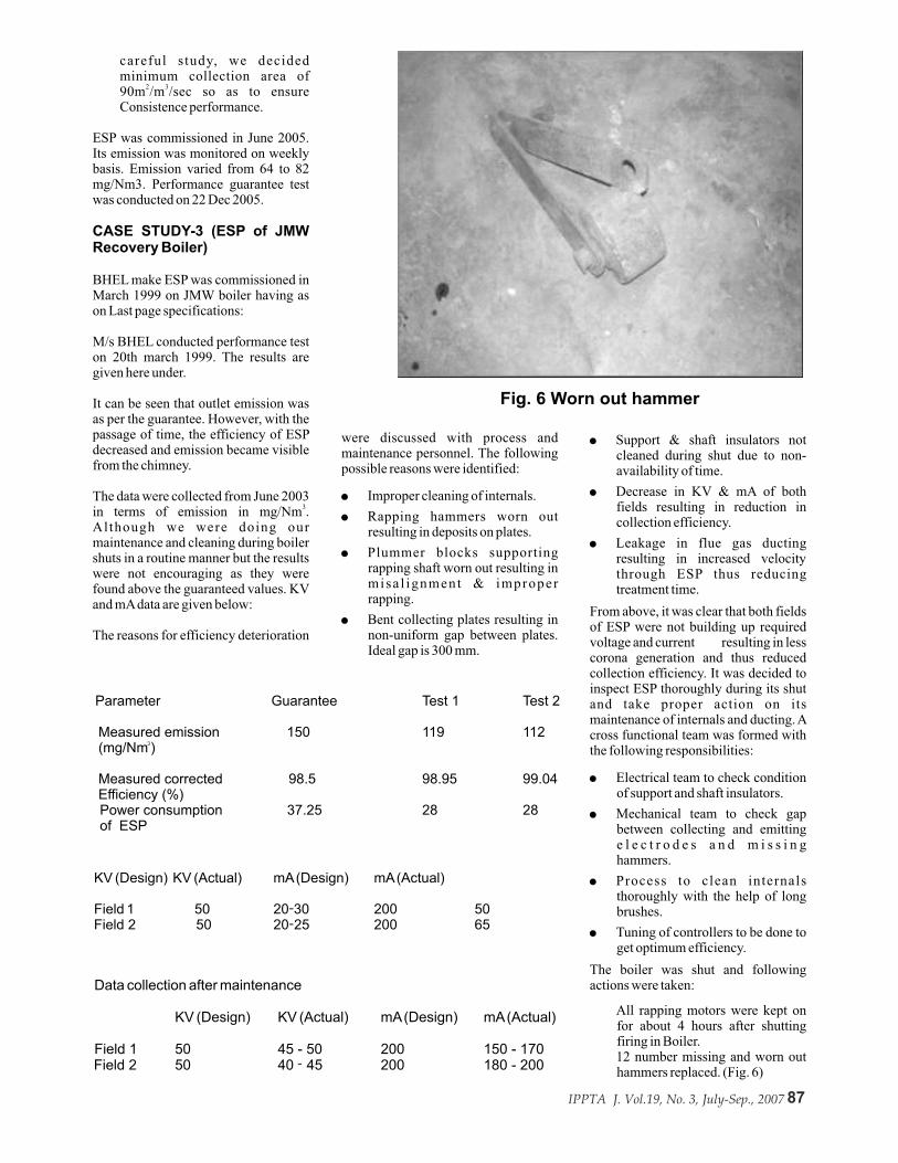
Fig. 8 New Plummer block
Fig.7 Worn out Plummer block
Fig. 10 New Hammer Clamp
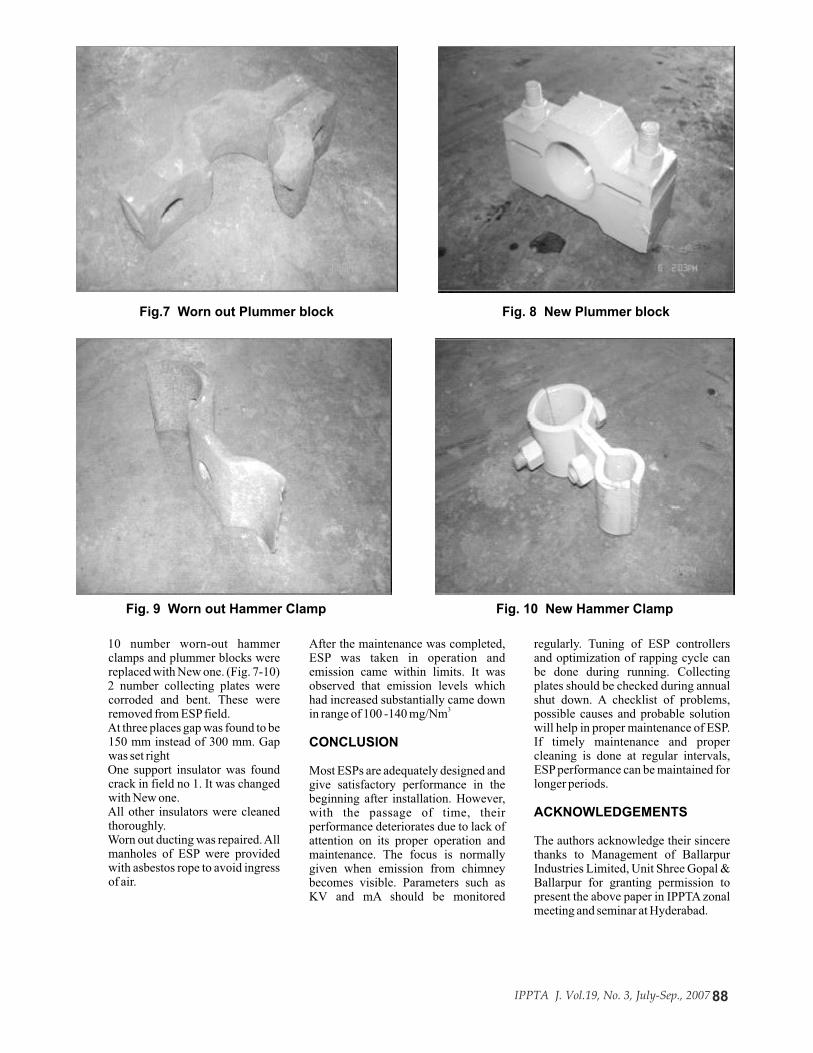
Fig. 9 Worn out Hammer Clamp
regularly. Tuning of ESP controllers and optimization of rapping cycle can be done during running. Collecting plates should be checked during annual shut down. A checklist of problems, possible causes and probable solution will help in proper maintenance of ESP. If timely maintenance and proper cleaning is done at regular intervals, ESP performance can be maintained for longer periods.
ACKNOWLEDGEMENTS
The authors acknowledge their sincere thanks to Management of Ballarpur Industries Limited, Unit Shree Gopal & Ballarpur for granting permission to present the above paper in IPPTA zonal meeting and seminar at Hyderabad.
After the maintenance was completed, ESP was taken in operation and emission came within limits. It was observed that emission levels which had increased substantially came down
3 in range of 100 -140 mg/Nm
CONCLUSION
Most ESPs are adequately designed and give satisfactory performance in the beginning after installation. However, with the passage of time, their performance deteriorates due to lack of attention on its proper operation and maintenance. The focus is normally given when emission from chimney becomes visible. Parameters such as KV and mA should be monitored
10 number worn-out hammer clamps and plummer blocks were replaced with New one. (Fig. 7-10)
2 number collecting plates were corroded and bent. These were removed from ESP field.
At three places gap was found to be 150 mm instead of 300 mm. Gap was set right
One support insulator was found crack in field no 1. It was changed with New one.
All other insulators were cleaned thoroughly.
Worn out ducting was repaired. All manholes of ESP were provided with asbestos rope to avoid ingress of air.