ESIE18-14 Service Manual Daikin VRV IV+ Heat Pump_EN.pdf
200
Service manual VRV IV+ Heat Pump English Service manual VRV IV+ Heat Pump RYYQ8U7Y1B* RYYQ10U7Y1B* RYYQ12U7Y1B* RYYQ14U7Y1B* RYYQ16U7Y1B* RYYQ18U7Y1B* RYYQ20U7Y1B* RYMQ8U7Y1B* RYMQ10U7Y1B* RYMQ12U7Y1B* RYMQ14U7Y1B* RYMQ16U7Y1B* RYMQ18U7Y1B* RYMQ20U7Y1B* RXYQ8U7Y1B* RXYQ10U7Y1B* RXYQ12U7Y1B* RXYQ14U7Y1B* RXYQ16U7Y1B* RXYQ18U7Y1B* RXYQ20U7Y1B* https://daikin-p.ru/catalog/vrv-daikn/naruzhnye-vrv-bloki-daikin
-
Upload
khangminh22 -
Category
Documents
-
view
1 -
download
0
Transcript of ESIE18-14 Service Manual Daikin VRV IV+ Heat Pump_EN.pdf

Service manualVRV IV+ Heat Pump English
Service manual
VRV IV+ Heat Pump
RYYQ8U7Y1B*RYYQ10U7Y1B*RYYQ12U7Y1B*RYYQ14U7Y1B*RYYQ16U7Y1B*RYYQ18U7Y1B*RYYQ20U7Y1B*
RYMQ8U7Y1B*RYMQ10U7Y1B*RYMQ12U7Y1B*RYMQ14U7Y1B*RYMQ16U7Y1B*RYMQ18U7Y1B*RYMQ20U7Y1B*
RXYQ8U7Y1B*RXYQ10U7Y1B*RXYQ12U7Y1B*RXYQ14U7Y1B*RXYQ16U7Y1B*RXYQ18U7Y1B*RXYQ20U7Y1B*
https://daikin-p.ru/catalog/vrv-daikn/naruzhnye-vrv-bloki-daikin

Disclaimer
Service manual
2RYYQ+RYMQ+RXYQ8~20U7Y1B
VRV IV+ Heat PumpESIE18-14 – 2019.07
Disclaimer
The present publication is drawn up by way of information only and does not constitute an offer binding upon Daikin Europe N.V.. DaikinEurope N.V. has compiled the content of this publication to the best of its knowledge. No express or implied warranty is given for thecompleteness, accuracy, reliability or fitness for particular purpose of its content and the products and services presented therein.Specifications are subject to change without prior notice. Daikin Europe N.V. explicitly rejects any liability for any direct or indirect damage, inthe broadest sense, arising from or related to the use and/or interpretation of this publication. All content is copyrighted by Daikin Europe N.V..
https://daikin-p.ru/catalog/vrv-daikn/naruzhnye-vrv-bloki-daikin

Version log
Service manual
3RYYQ+RYMQ+RXYQ8~20U7Y1BVRV IV+ Heat PumpESIE18-14 – 2019.07
Version logVersion code Description DateESIE18-14 Document release July 2019
https://daikin-p.ru/catalog/vrv-daikn/naruzhnye-vrv-bloki-daikin

Table of contents
Service manual
4RYYQ+RYMQ+RXYQ8~20U7Y1B
VRV IV+ Heat PumpESIE18-14 – 2019.07
Table of contents
1 General operation 72 Troubleshooting 9
2.1 To access push buttons and 7-segment display ....................... 92.2 To check the error history.......................................................... 9
2.2.1 Via service checker type 3 .......................................... 92.2.2 Via the indoor unit remote controller BRC1H.............. 92.2.3 Via the outdoor unit..................................................... 102.2.4 Via the wired remote control BRC1E .......................... 102.2.5 Via the wireless controller BRC4/7 ............................. 112.2.6 Via the wired remote control BRC1D .......................... 11
2.3 Error based troubleshooting ...................................................... 122.3.1 E1-01 – Outdoor unit main PCB A1P error ................. 122.3.2 E1-02 – Outdoor unit main PCB A1P error ................. 122.3.3 E2-01-02-03 – Current leak detection......................... 122.3.4 E2-06-07-08 – Open circuit on earth leakage
detection core ............................................................. 132.3.5 E3-01-03-05 – Actuation of high pressure switch ....... 132.3.6 E3-02-04-06 – High pressure error ............................. 142.3.7 E3-07 – High pressure switch reset error ................... 142.3.8 E3-13-14-15 – Liquid stop valve check error .............. 142.3.9 E3-18 – Actuation of high pressure switch during test
run............................................................................... 152.3.10 E3-20-21-22 – Jumper open on main PCB................. 152.3.11 E4-01-02-03 – Low pressure error.............................. 152.3.12 E5-01-02-03 – Compressor overload error ................. 162.3.13 E5-07-08-09 – Compressor overload error ................. 172.3.14 E6-17-19-21 – Inverter overcurrent error .................... 172.3.15 E6-18-20-22 – Inverter overcurrent error .................... 182.3.16 E7-01-13-25 – Outdoor unit fan motor M1F error ....... 182.3.17 E7-02-14-26 – Outdoor unit fan motor M2F error ....... 192.3.18 E7-05-17-29 – Outdoor unit fan motor M1F
overcurrent error ......................................................... 192.3.19 E7-06-18-30 – Outdoor unit fan motor M2F
overcurrent error ......................................................... 192.3.20 E7-09-21-33 – Fan inverter PCB A4P (integrated
power module) overheated ......................................... 192.3.21 E7-10-22-34 – Fan inverter PCB A7P (integrated
power module) overheated ......................................... 202.3.22 E9-01-05-08 – Expansion valve Y1E abnormality ...... 202.3.23 E9-03-06-09 – Expansion valve Y2E abnormality ...... 212.3.24 E9-04-07-10 – Expansion valve Y3E abnormality ...... 212.3.25 E9-20-21-22 – Failure detection on Y1E..................... 222.3.26 E9-23-24-25 – Failure detection on Y2E..................... 222.3.27 E9-26-27-28 – Expansion valve Y4E abnormality ...... 232.3.28 E9-48-49-50 – Expansion valve overcurrent error ...... 232.3.29 E9-51-52-53 – Expansion valve thermal cutting error. 242.3.30 E9-54-55-56 – Expansion valve defective circuit ........ 242.3.31 F3-01-03-05 – Compressor discharge temperature
too high ....................................................................... 252.3.32 F3-20-21-22 – Compressor body temperature too
high ............................................................................. 252.3.33 F4-01 – Wet operation caution.................................... 262.3.34 F6-02 – Refrigerant overcharge detection during
test-run........................................................................ 262.3.35 H3-02-04-06 – Transmission error on inverter PCB
A3P ............................................................................. 272.3.36 H3-03-05-07 – Transmission error on inverter PCB
A6P ............................................................................. 272.3.37 H9-01-02-03 – Ambient temperature thermistor R1T
abnormality ................................................................. 272.3.38 HA-00 – Defrost fail alarm........................................... 282.3.39 J3-16-22-28 – Discharge thermistor R21T open
circuit........................................................................... 282.3.40 J3-17-23-29 – Discharge thermistor R21T short
circuit........................................................................... 28
2.3.41 J3-18-24-30 – Discharge thermistor R22T opencircuit............................................................................ 28
2.3.42 J3-19-25-31 – Discharge thermistor R22T shortcircuit............................................................................ 29
2.3.43 J3-38-42-44 – Compressor body thermistor R9Topen circuit................................................................... 29
2.3.44 J3-39-43-45 – Compressor body thermistor R9Tshort circuit................................................................... 29
2.3.45 J3-47-49-51 – Compressor body thermistor R8Topen circuit................................................................... 30
2.3.46 J3-48-50-52 – Compressor body thermistor R8Tshort circuit................................................................... 30
2.3.47 J3-56-57-58 – High discharge temperature ................. 302.3.48 J3-59-60-61 – Discharge thermistor crosswired .......... 312.3.49 J5-01-03-05 – Suction thermistor R3T abnormality ..... 312.3.50 J6-01-02-03 – De–icer thermistor R7T abnormality..... 312.3.51 J7-06-07-08 – Liquid thermistor R5T abnormality........ 322.3.52 J8-01-02-03 – Outdoor heat exchanger thermistor
R4T abnormality........................................................... 322.3.53 J9-01-02-03 – Gas thermistor R6T abnormality........... 322.3.54 JA-06-08-10 – High pressure sensor S1NPH
abnormality .................................................................. 322.3.55 JA-07-09-11 – High pressure sensor S1NPH
malfunction................................................................... 332.3.56 JC-06-08-10 – Low pressure sensor S1NPL
abnormality .................................................................. 332.3.57 JC-07-09-11 – Low pressure sensor S1NPL
abnormality .................................................................. 332.3.58 L1-01-07-11 – Inverter PCB A3P abnormality ............. 342.3.59 L1-02-08-12 – Inverter PCB A3P current detection
primary circuit............................................................... 342.3.60 L1-03-09-13 – Inverter PCB A3P current detection
secondary circuit .......................................................... 342.3.61 L1-04-10-14 – Power transistor error on inverter
PCB A3P...................................................................... 352.3.62 L1-05-15-16 – Inverter PCB A3P hardware fault ......... 352.3.63 L1-17-22-42 – Inverter PCB A6P abnormality ............. 362.3.64 L1-18-23-43 – Inverter PCB A6P current detection
primary circuit............................................................... 362.3.65 L1-19-24-44 – Inverter PCB A6P current detection
secondary circuit .......................................................... 362.3.66 L1-20-25-45 – Power transistor error on inverter
PCB A6P...................................................................... 372.3.67 L1-21-26-46 – Inverter PCB A6P hardware fault ......... 372.3.68 L1-28-32-34 – Fan inverter PCB A4P Eeprom error.... 372.3.69 L1-29-33-35 – Fan inverter PCB A7P Eeprom error.... 382.3.70 L1-36-38-40 – Inverter PCB A3P Eeprom error........... 382.3.71 L1-37-39-41 – Inverter PCB A6P Eeprom error........... 382.3.72 L1-47-49-51 – Inverter PCB A3P 16 V DC abnormal .. 392.3.73 L1-48-50-52 – Inverter PCB A6P 16 V DC abnormal .. 392.3.74 L2-01-02-03 – Power supply abnormality during test
run................................................................................ 392.3.75 L2-04-05-06 – Power supply abnormality during
normal operation .......................................................... 402.3.76 L4-01-02-03 – Inverter PCB A3P high fin
temperature.................................................................. 402.3.77 L4-06-18-20 – Fan inverter PCB A4P high fin
temperature.................................................................. 402.3.78 L4-07-19-21 – Fan inverter PCB A7P high fin
temperature.................................................................. 412.3.79 L4-09-10-11 – Inverter PCB A6P high fin
temperature.................................................................. 412.3.80 L5-03-05-07 – Output overcurrent detection on
inverter PCB A3P......................................................... 422.3.81 L5-14-15-16 – Output overcurrent detection on
inverter PCB A6P......................................................... 422.3.82 L8-03-06-07 – Overcurrent on inverter PCB A3P
except start-up ............................................................. 422.3.83 L8-11-12-13 – Overcurrent on inverter PCB A6P
except start-up ............................................................. 432.3.84 L9-01-05-06 – Stall prevention by inverter PCB A3P... 432.3.85 L9-10-11-12 – Stall prevention by inverter PCB A6P... 44
https://daikin-p.ru/catalog/vrv-daikn/naruzhnye-vrv-bloki-daikin
Table of contents
Service manual
5RYYQ+RYMQ+RXYQ8~20U7Y1BVRV IV+ Heat PumpESIE18-14 – 2019.07
2.3.86 L9-13-14-15 – Inverter PCB A3P output phaseabnormality ................................................................. 44
2.3.87 L9-16-17-18 – Inverter PCB A6P output phaseabnormality ................................................................. 44
2.3.88 LC-01 – Transmission abnormality ............................. 452.3.89 LC-14-15-16 – Transmission abnormality main PCB/
inverter PCB A3P........................................................ 452.3.90 LC-19-20-21 – Transmission abnormality main PCB/
fan inverter PCB A4P.................................................. 452.3.91 LC-24-25-26 – Transmission abnormality main PCB/
fan inverter PCB A7P.................................................. 462.3.92 LC-30-31-32 – Transmission abnormality main PCB/
inverter PCB A6P........................................................ 462.3.93 P1-01-02-03 – Open phase or unbalanced power
supply detection by inverter PCB A3P ........................ 472.3.94 P1-07-08-09 – Open phase or unbalanced power
supply detection by inverter PCB A6P ........................ 472.3.95 P2-00 – Refrigerant auto-charge interrupted .............. 472.3.96 P4-01-04-05 – Fin thermistor abnormality on inverter
PCB A3P..................................................................... 482.3.97 P4-02-15-17 – Fin thermistor abnormality on fan
inverter PCB A4P........................................................ 482.3.98 P4-03-16-18 – Fin thermistor abnormality on fan
inverter PCB A7P........................................................ 482.3.99 P4-06-07-08 – Fin thermistor abnormality on inverter
PCB A6P..................................................................... 492.3.100 P8-00 – Freeze-up during refrigerant auto-charge ..... 492.3.101 P9-00 – Refrigerant auto-charge finished normally .... 492.3.102 PA-00 – No refrigerant in refrigerant cylinder during
auto-charge................................................................. 502.3.103 PE-00 – Refrigerant auto-charge in last stage............ 502.3.104 PF-00 – Long test run failed........................................ 502.3.105 PJ-04-05-06 – Capacity setting mismatch for inverter
PCB A3P..................................................................... 502.3.106 PJ-09-15-16 – Capacity setting mismatch for fan
inverter PCB A4P........................................................ 502.3.107 PJ-10-17-18 – Capacity setting mismatch for fan
inverter PCB A7P........................................................ 512.3.108 PJ-12-13-14 – Capacity setting mismatch for inverter
PCB A6P..................................................................... 512.3.109 U0-05 – Refrigerant shortage detection...................... 512.3.110 U0-06 – Refrigerant shortage detection...................... 522.3.111 U0-08-09-10 – Refrigerant shortage detection by
high pressure sensor .................................................. 522.3.112 U1-01-05-07 – Reverse phase detection .................... 532.3.113 U1-04-06-08 – Reverse phase detection .................... 532.3.114 U2-01-08-11 – Inverter circuit power supply
abnormality - inverter PCB A3P abnormal voltage ..... 532.3.115 U2-02-09-12 – Inverter circuit power supply
abnormality - inverter PCB A3P phase loss................ 542.3.116 U2-03-10-13 – Inverter circuit power supply
abnormality - inverter PCB A3P DC circuit notcharging ...................................................................... 54
2.3.117 U2-22-25-28 – Inverter circuit power supplyabnormality - inverter PCB A6P abnormal voltage ..... 55
2.3.118 U2-23-26-29 – Inverter circuit power supplyabnormality - inverter PCB A6P phase loss................ 55
2.3.119 U2-24-27-30 – Inverter circuit power supplyabnormality - inverter PCB A6P DC circuit notcharging ...................................................................... 56
2.3.120 U3-02 – Test run interrupted manually ....................... 562.3.121 U3-03 – Test run not performed yet............................ 572.3.122 U3-04 – Test run ended abnormally ........................... 572.3.123 U3-05 – Test run aborted on initial transmission ........ 572.3.124 U3-06 – Test run aborted on normal transmission...... 572.3.125 U3-07 – Transmission abnormality on test run ........... 582.3.126 U3-08 – Transmission abnormality on test run ........... 582.3.127 U4-01 – Communication error on Q1-Q2
transmission line ......................................................... 582.3.128 U4-03 – Communication error on F1-F2 transmission
line .............................................................................. 582.3.129 U4-15 – Unable to start test run.................................. 59
2.3.130 U7-01 – Transmission abnormality between systems- DTA104A61,62 error.................................................. 59
2.3.131 U7-02 – Transmission abnormality between systems- DTA104A61,62 error.................................................. 59
2.3.132 U7-03 – Transmission abnormality between mainoutdoor unit and sub 1 outdoor unit ............................. 60
2.3.133 U7-04 – Transmission abnormality between mainoutdoor unit and sub 2 outdoor unit ............................. 60
2.3.134 U7-05 – Multi system abnormality................................ 602.3.135 U7-06 – Multi system address abnormality.................. 612.3.136 U7-07 – More than 3 outdoor units on Q1-Q2
transmission................................................................. 612.3.137 U7-11 – Excess indoor units detected on test run ....... 612.3.138 U7-24 – Duplication of address setting on multiple
DTA104A61,62 installation .......................................... 612.3.139 U9-01 – Other indoor unit has error ............................. 612.3.140 UA-00 – Combination abnormality ............................... 622.3.141 UA-03 – Combination abnormality - Mix of R22,
R407C and R410A type units detected........................ 622.3.142 UA-16 – Combination abnormality - More than 64
indoor units detected on same system ........................ 622.3.143 UA-17 – Combination abnormality - Local setting
abnormality .................................................................. 622.3.144 UA-18 – Combination abnormality - Outdoor unit not
compatible with indoor units (refrigerant type) ............. 632.3.145 UA-19 – Combination abnormality - Local set alarm ... 632.3.146 UA-20 – Combination abnormality - Non-compatible
outdoor unit in multi-combination ................................. 632.3.147 UA-21 – Combination abnormality - BPMK units
detected ....................................................................... 632.3.148 UA-31 – Combination abnormality - Multi
combination abnormality .............................................. 632.3.149 UA-38 – Combination abnormality - Altherma hydro
unit detected ................................................................ 642.3.150 UA-39 – Combination abnormality - Incorrect
combination.................................................................. 642.3.151 UA-49 – Combination abnormality - Wrong unit
combination.................................................................. 642.3.152 UF-01 – Wiring and piping mismatch - Auto address
inconsistency on F1-F2 transmission........................... 642.3.153 UF-05 – Wiring and piping mismatch - Stop valves
closed or incorrect........................................................ 642.3.154 UF-11 – Wiring and piping mismatch - Excess
connection ratio............................................................ 652.3.155 UH-01-02 – Auto-address failure ................................. 652.3.156 E-1 – Refrigerant leak check is not possible................ 652.3.157 E-2 – Refrigerant leak check cannot be performed -
indoor air temperature is out of range.......................... 662.3.158 E-3 – Refrigerant leak check cannot be performed -
outdoor air temperature is out of range........................ 662.3.159 E-4 – Refrigerant leak check is interrupted - too low
pressure is detected..................................................... 662.3.160 E-5 – Refrigerant leak check cannot be performed -
a unit which is not compatible with leak detectionfunction is installed....................................................... 66
2.3.161 NG – Refrigerant leak check function detectsrefrigerant leak ............................................................. 66
2.3.162 OK – Refrigerant leak check function detects norefrigerant leak ............................................................. 67
2.3.163 Indoor unit related error codes..................................... 682.3.164 Overview of error codes............................................... 69
2.4 Symptom based troubleshooting................................................ 732.4.1 Normal operating conditions ........................................ 732.4.2 Symptom: The system does not operate ..................... 732.4.3 Symptom: Cool/Heat cannot be changed over ............ 732.4.4 Symptom: Fan operation is possible, but cooling and
heating do not work...................................................... 732.4.5 Symptom: The fan speed does not correspond to the
setting .......................................................................... 732.4.6 Symptom: The fan direction does not correspond to
the setting .................................................................... 732.4.7 Symptom: White mist comes out of a unit (Indoor
unit) .............................................................................. 73
https://daikin-p.ru/catalog/vrv-daikn/naruzhnye-vrv-bloki-daikin

Table of contents
Service manual
6RYYQ+RYMQ+RXYQ8~20U7Y1B
VRV IV+ Heat PumpESIE18-14 – 2019.07
2.4.8 Symptom: White mist comes out of a unit (Indoorunit, heat exchanger unit) ........................................... 73
2.4.9 Symptom: The user interface display reads "U4" or"U5" and stops, but then restarts after a few minutes. 73
2.4.10 Symptom: Noise of air conditioners (Indoor unit)........ 732.4.11 Symptom: Noise of air conditioners (Indoor unit,
outdoor unit)................................................................ 742.4.12 Symptom: Noise of air conditioners (Outdoor unit) ..... 742.4.13 Symptom: Dust comes out of the unit ......................... 742.4.14 Symptom: The units can give off odours..................... 742.4.15 Symptom: The outdoor unit fan does not spin ............ 742.4.16 Symptom: The display shows "88".............................. 742.4.17 Symptom: The compressor in the outdoor unit does
not stop after a short heating operation ...................... 742.4.18 Symptom: The inside of an outdoor unit is warm
even when the unit has stopped ................................. 742.4.19 Symptom: Hot air can be felt when the indoor unit is
stopped ....................................................................... 742.4.20 Symptom: Unit operation problems............................. 752.4.21 Other symptoms.......................................................... 76
3 Components 773.1 4-way valve ............................................................................... 77
3.1.1 Main 4-way valve ........................................................ 773.1.2 Sub 4-way valve.......................................................... 80
3.2 Compressor............................................................................... 823.2.1 Checking procedures .................................................. 823.2.2 Repair procedures ...................................................... 84
3.3 Crankcase heater ...................................................................... 873.3.1 Checking procedures .................................................. 873.3.2 Repair procedures ...................................................... 87
3.4 Current sensor........................................................................... 883.4.1 Checking procedures .................................................. 883.4.2 Repair procedures ...................................................... 88
3.5 Expansion valve ........................................................................ 893.5.1 Checking procedures .................................................. 893.5.2 Repair procedures ...................................................... 90
3.6 Fan inverter PCB....................................................................... 923.6.1 Single fan outdoor unit ................................................ 923.6.2 Double fan outdoor unit............................................... 95
3.7 High pressure switch ................................................................. 973.7.1 Checking procedures .................................................. 973.7.2 Repair procedures ...................................................... 98
3.8 Inverter PCB.............................................................................. 993.8.1 Checking procedures .................................................. 993.8.2 Repair procedures ...................................................... 103
3.9 Main PCB .................................................................................. 1063.9.1 Checking procedures .................................................. 1063.9.2 Repair procedures ...................................................... 108
3.10 Noise filter PCB ......................................................................... 1103.10.1 Checking procedures .................................................. 1103.10.2 Repair procedures ...................................................... 112
3.11 Oil return valve .......................................................................... 1123.11.1 Checking procedures .................................................. 1123.11.2 Repair procedures ...................................................... 114
3.12 Outdoor unit fan motor .............................................................. 1153.12.1 Single fan outdoor unit ................................................ 1153.12.2 Double fan outdoor unit............................................... 116
3.13 Plate work.................................................................................. 1183.13.1 To access the switch box on single fan units.............. 1183.13.2 To access the switch box on double fan units ............ 1193.13.3 To remove the plate work on single fan units ............. 1193.13.4 To remove the plate work on double fan units ............ 121
3.14 Reactor...................................................................................... 1233.14.1 Checking procedures .................................................. 1233.14.2 Repair procedures ...................................................... 124
3.15 Refrigerant high pressure sensor .............................................. 1243.15.1 Checking procedures .................................................. 1243.15.2 Repair procedures ...................................................... 125
3.16 Refrigerant low pressure sensor ............................................... 126
3.16.1 Checking procedures ...................................................1263.16.2 Repair procedures .......................................................127
3.17 Thermistors ................................................................................1283.17.1 Refrigerant side thermistors.........................................1283.17.2 Other thermistors .........................................................130
4 Third party components 1304.1 Electrical circuit ..........................................................................130
4.1.1 Checking procedures ...................................................1304.1.2 Repair procedures .......................................................133
4.2 Refrigerant circuit .......................................................................1334.2.1 Checking procedures ...................................................1334.2.2 Repair procedures .......................................................136
4.3 External factors ..........................................................................1384.3.1 Checking procedures ...................................................1384.3.2 Repair procedures .......................................................139
5 Maintenance 1405.1 Maintenance shedule .................................................................1405.2 Maintenance procedures for outdoor units.................................140
5.2.1 To check the general status of the unit ........................1405.2.2 To clean the cover plates.............................................1405.2.3 To clean the outdoor unit heat exchanger ...................141
5.3 Maintenance procedures for indoor units ...................................1425.3.1 To check the general status of the unit ........................1425.3.2 To clean the cover plates.............................................1425.3.3 To clean the indoor unit heat exchanger......................142Direct expansion: Maintenance – VRV.......................................143
6 Technical data 1456.1 Detailed information setting mode..............................................145
6.1.1 Detailed information setting mode: Outdoor unit..........1456.1.2 Detailed information setting mode: Remote controller .145
6.2 Wiring diagram ...........................................................................1466.2.1 Wiring diagram: Outdoor unit .......................................146
6.3 Piping diagram ...........................................................................1486.3.1 Piping diagram: Outdoor unit .......................................1486.3.2 Refrigerant flow diagram: Outdoor unit ........................151
6.4 Component overview..................................................................1646.4.1 Component overview: RXYQ8~12U units....................1646.4.2 Component overview: RXYQ14~16U units..................1666.4.3 Component overview: RXYQ18~20U units..................1686.4.4 Component overview: RYMQ8~12U units ...................1706.4.5 Component overview: RYMQ14~16U units .................1726.4.6 Component overview: RYMQ18~20U units .................1746.4.7 Component overview: RYYQ8~12U units....................1766.4.8 Component overview: RYYQ14~16U units..................1786.4.9 Component overview: RYYQ18~20U units..................180
6.5 Switchbox overview....................................................................1826.5.1 Single fan units ............................................................1826.5.2 Double fan units ...........................................................182
6.6 Safety devices ............................................................................1836.7 Field information report ..............................................................1846.8 Service tools...............................................................................1876.9 Field settings ..............................................................................188
6.9.1 To access mode 1 or 2 ................................................1886.9.2 To use mode 1 .............................................................1886.9.3 To use mode 2 .............................................................1886.9.4 Mode 1: Field settings..................................................1896.9.5 Mode 2: Field settings..................................................1916.9.6 Overview of field settings for indoor units ....................1946.9.7 Field settings as per type of indoor unit .......................197
https://daikin-p.ru/catalog/vrv-daikn/naruzhnye-vrv-bloki-daikin
1 General operation
Service manual
7RYYQ+RYMQ+RXYQ8~20U7Y1BVRV IV+ Heat PumpESIE18-14 – 2019.07
1 General operationThe VRV IV+ hp outdoor unit is a heat pump used for cooling orheating in commercial applications.
Outdoor unitsThe outdoor unit consists of:▪ 1 or 2 inverter compressor(s)▪ A switchbox containing necessary PCBs▪ A liquid cooling circuit to cool down inverter switchbox▪ An air cooled heat-exchanger▪ 3 expansion valves (main, sub-cool and liquid cooling)▪ 1 or 2 fan motor(s)▪ Two refrigerant piping connections: gas and liquid.
There are 3 types of outdoor units:▪ RXYQ-U: VRV IV+ hp, non-continuous Heating▪ RYYQ-U: VRV IV+ hp, continuous Heating▪ RYMQ-U: VRV IV+ hp, continuous Heating
RYYQ-U units can ONLY be used as stand-alone units and not inmulti combinations.
RYMQ-U units can ONLY be used in multi combinations and not asstand-alone units.
Non-continuous heating and continuous heating type units CANNOTbe used together in multi combination.
VRV IV+ hp U-series and T-series cannot be used together in multicombination.
Up to 3 modules of VRV IV+ hp outdoor units can be connectedusing refnet BHFQ22P.
Field piping must be thermally insulated copper piping.
To split the refrigerant circuit between outdoor units and indoor units(expansion valve kit in case air handling unit and BP branch selectorbox in case Split or Sky air units), KHRQ22M refnet branches areused.
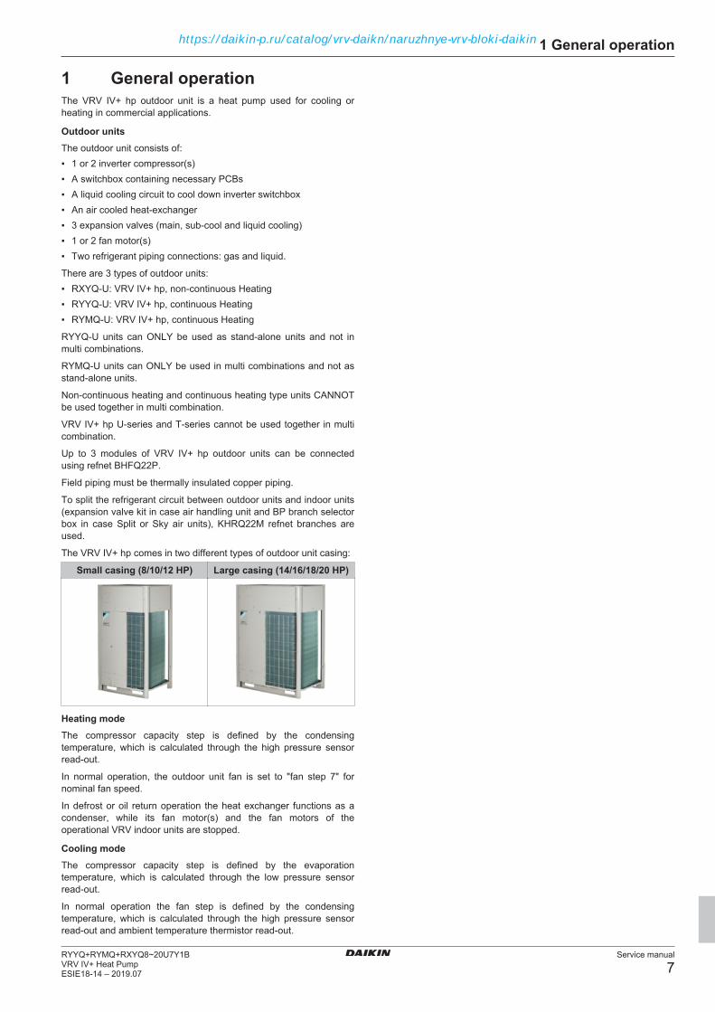
The VRV IV+ hp comes in two different types of outdoor unit casing:
Small casing (8/10/12 HP) Large casing (14/16/18/20 HP)
Heating modeThe compressor capacity step is defined by the condensingtemperature, which is calculated through the high pressure sensorread-out.
In normal operation, the outdoor unit fan is set to "fan step 7" fornominal fan speed.
In defrost or oil return operation the heat exchanger functions as acondenser, while its fan motor(s) and the fan motors of theoperational VRV indoor units are stopped.
Cooling modeThe compressor capacity step is defined by the evaporationtemperature, which is calculated through the low pressure sensorread-out.
In normal operation the fan step is defined by the condensingtemperature, which is calculated through the high pressure sensorread-out and ambient temperature thermistor read-out.
https://daikin-p.ru/catalog/vrv-daikn/naruzhnye-vrv-bloki-daikin

1 General operation
Service manual
8RYYQ+RYMQ+RXYQ8~20U7Y1B
VRV IV+ Heat PumpESIE18-14 – 2019.07
Indoor UnitsThe below illustration does not reflect allowed combinations or compatibility. The intention is to give an overview on piping installation fordifferent types of units.
a
b
a
c c c c c
d e f h j k
g
i
a VRV IV+ hp outdoor unitb Refnet BHFQ22P for Outdoor multi connectionc Refnet KHRQ22Md VRV indoor unite Low temperature Hydroboxf Expansion valve kitg Air handling unith Branch selector box (BP unit is mandatory if Split/Sky air unit is to be connected)i Split/Sky air unitj Heat reclaim ventilator with DX coil
k Air curtainVRV systems have combination limits for different types of indoor units and also limits for piping length and connection ratio for each indoor unitcombination pattern. Refer to the Engineering Databook.The list below is only for reference of compatible units. Always refer to Engineering Databook for compatibility.
Round flowcassette FXFQ
Floor standingFXLQ
Fully flatcassette FXZQ
AHU kit EKEXV+ EKEQM -EKEQF
2 Way cassetteFXCQ
LowtemperatureHydrobox - HXY
Corner cassetteFXKQ
Heat recoveryventilator VKM
Concealedceiling FXDQ
Air curtainCYVS, CYVM,CYVL
Concealedceiling withmedium ESP -FXSQ
Concealedceiling with highESP - FXMQ
Wall mountedFXAQ
CeilingsuspendedFXHQ
4 Way ceilingsuspended –FXUQ
Concealed floorstanding -FXNQ
Branch selectorbox BPMKS
https://daikin-p.ru/catalog/vrv-daikn/naruzhnye-vrv-bloki-daikin

2 Troubleshooting
Service manual
9RYYQ+RYMQ+RXYQ8~20U7Y1BVRV IV+ Heat PumpESIE18-14 – 2019.07
2 Troubleshooting
2.1 To access push buttons and 7-segment display
1 Remove the service plate, see "3.13 Plate work" on page 118.
Result: The push buttons and 7-segment display are located onA1P behind the service plate.
b
a
a Push buttonsb 7-segment display
2.2 To check the error history
2.2.1 Via service checker type 3With the service checker, it is possible to monitor not only errorcodes but also some common retries and stepping down controls:
▪ Unit error
▪ Error code
▪ High pressure retry
▪ Low pressure retry
▪ Discharge pipe retry
▪ Inverter retry
▪ High pressure stepping down control
▪ Low pressure stepping down control
▪ Over current stepping down control
▪ Fin temperature stepping down control
▪ Compressor discharging stepping down control
2.2.2 Via the indoor unit remote controllerBRC1H
To indicate a system error, the controller displays on themessages zone (a) of the home screen.
1 Press the middle button (b) to enter the main menu from thehome screen.
Result: An error screen (c) is displayed.
b
a
c
2 Press the middle button (b) to return to the home screen.
Active error codes are also accessible through the Madoka Assistantfor BRC1H.
The active error (d) is shown on the home screen (e).
e gd f
3 Tap the error message (d).
Result: The detail(s) of the error(s) (f) are shown on thenotifications screen (g).
To check the error history with the Madoka Assistant for BRC1H:
4 Tap the settings icon (h).
Result: The “Unit settings” screen appears.h i
5 Choose “Errors and warnings” (i).
6 The “Errors and warnings” screen appears.
https://daikin-p.ru/catalog/vrv-daikn/naruzhnye-vrv-bloki-daikin

2 Troubleshooting
Service manual
10RYYQ+RYMQ+RXYQ8~20U7Y1B
VRV IV+ Heat PumpESIE18-14 – 2019.07
kj
7 Choose “Error history” (j).
Result: The “Error history” screen (k) appears.
For more details on the Madoka Assistant please refer to the BRC1Htraining course material which is available on the Daikin BusinessPortal.
2.2.3 Via the outdoor unitError codes and/or retry descriptions are accessible on “Mode 1:Monitor Mode”.
The table below shows which setting shows the error codes that ledto an outdoor unit forced stop and/or retry.
▪ When an error is generated, the unit performs a forced off until theerror is retrieved.
▪ On retry, the system attempts to stay in operation. Depending onthe type of root cause, after a certain amount of retry attempts, theunit generates an error.Retry cause is also visible as an item on the service checker.
Mode Setting DescriptionMode 1: Monitor
mode17 Error code last forced off18 Error code 2nd last forced off19 Error code 3rd last forced off23 Error code last retry24 Error code 2nd last retry25 Error code 3rd last retry
Please follow the procedure described below to access theregarding error code for outdoor unit forced stop and/or retrydescription:
Action Result DisplayMake sure the 7-segment displayindication is as duringnormal operation.To enter “Mode 1”,push the (BS1) buttonone time
Mode 1 is accessed.
Push the (BS2)button as many timesas the setting youwant to go to.
The setting isaccessed (e.g. 17,Error code last forcedoff)
Press the RETURN(BS3) Button.
Malfunction/Retryitem will appear ondisplay.
Action Result DisplayPress the SET (BS2)Button.
Detailed Malfunction/Retry sub-code willappear on display.
Press SET (BS2)once again to returnto main Malfunction/Retry display.
Main Malfunction/Retry item will appearon display.
Press the RETURN(BS3) Button to returnto Home Screen for“Monitoring Mode”.
Home Screen for“Monitoring Mode”will appear ondisplay.
Press the MODE(BS1) Button to returnto “Normal Mode”.
Back in normal mode.
2.2.4 Via the wired remote control BRC1EIn case of an error or warning, the operation lamp on the ON/OFFButton (a) will blink and an error message (b) or warning (c) will bedisplayed at the bottom of the screen.
a
de
b
c
1 Press the Menu/Enter button (d) to see the content of the error/warning.
Result: The error code (f) appears on the screen.
f
To check the error history with the wired remote control BRC1E:
g
e
2 Press and hold the cancel button (e) for 4 seconds or longerwhile the backlight of the screen (g) is lit.
Result: The “Service Settings” screen (h) appears.
h
d
3 Scroll down to “Error History” and press the Menu/Enter button(d).
Result: The “Error History” screen (i) appears.
https://daikin-p.ru/catalog/vrv-daikn/naruzhnye-vrv-bloki-daikin

2 Troubleshooting
Service manual
11RYYQ+RYMQ+RXYQ8~20U7Y1BVRV IV+ Heat PumpESIE18-14 – 2019.07
i
d
4 Choose “RC Error History” or “Indoor Unit Error History” andconfirm with the Menu/Enter button (d).
j k
Result: RC Error History shows (j) history for all units in case ofgroup control.Result: Indoor Unit Error history (k) shows history for theselected unit.
2.2.5 Via the wireless controller BRC4/7
e
cd
b
a
gf
1 Press and hold inspection/TESTbutton (a) for 5 seconds.
Result: The “unit indication” isdisplayed on screen and UNIT No.(b) is displayed as “0”, blinking.
2 Set the UNIT No. via UP/DOWNbuttons (c and d) until a buzzersound* is generated from the indoorunit.
Result: Possible buzzer sounds*:
▪ 3 short beeps; conduct all items ofthe following procedure.
▪ 1 short beep; conduct steps 3 & 4.Continue the operation in step 4 untilthe buzzer sounds continuously.
▪ Continuous buzzer; indicates theerror code is confirmed.
3 Press the Mode button (e).
Result: The left digit (f) of the error code on display will blink.
4 Press UP/DOWN button (c or d) to change the left digit (f) of theerror code.
Result: The left digit (f) changes as indicated below.
“UP” button“DOWN” button
5 Continue to change until the matching buzzer sound** isgenerated.
Result: Possible buzzer sounds**:
▪ Continuous buzzer; both digits (f and g) match with the errorcode.
▪ 2 short beeps; left digit (f) matches with the error code.
▪ 1 short beep; right digit (g) matches with the error code.
6 Press the MODE button (e).
Result: The right digit (g) of the error code on display will blink.
7 Press UP/DOWN button (c or d) to change the right digit (g) ofthe error code.
Result: The right digit (g) changes as indicated below.
“UP” button“DOWN” button
8 Continue to change until the matching buzzer sound*** isgenerated.
Result: Possible buzzer sounds***:
▪ Continuous buzzer; both digits (f and g) match with the errorcode.
▪ 2 short beeps; left digit (f) matches with the error code.
▪ 1 short beep; right digit (g) matches with the error code.
INFORMATIONIt is not possible to acces the error history with the wirelesscontroller BRC4/7.
2.2.6 Via the wired remote control BRC1DIf operation stops due to a malfunction, the remote controller’soperation LED (a) will blink and an error code (b) will be displayed.
The error code will stay available at inspection mode even afterforced off operation or after the error is reset.
The inspection display (c) and error code (b) blink while an error isactive.
a
d
e
cb
f
To access the error code while in normal operation; follow theprocedure below.
1 Press TEST button (d) once.
Result: Error Code (b) for corresponding Unit No (e) will bedisplayed.
2 Press TEST button (d).
Result: Indoor unit model code will be displayed.
3 Press TEST button (d).
Result: Outdoor unit model code will be displayed.
4 Press TEST button (d).
Result: Test operation will be displayed.
5 Press TEST button (d) for the last time to return to homescreen.
Result: The home screen appears.
To check the malfunction history, you will need to access Mode 40on the BRC1D. Mode 40 stands for malfunction history display.
6 While in home screen, press TEST button (d) for 5 seconds.
Result: Field settings mode is accessed.
https://daikin-p.ru/catalog/vrv-daikn/naruzhnye-vrv-bloki-daikin

2 Troubleshooting
Service manual
12RYYQ+RYMQ+RXYQ8~20U7Y1B
VRV IV+ Heat PumpESIE18-14 – 2019.07
7 While in field settings mode, press TEST button (d) for 5seconds.
Result: Mode 40 is accessed.
8 Push the temperature set button (f) to change the History No.(g).No 1 stands for the latest error.
Result: The History No. (g) and error code (h) are displayed.
g h
9 Press TEST button (d) to return to the home screen.
2.3 Error based troubleshooting
2.3.1 E1-01 – Outdoor unit main PCB A1P error
Trigger Effect ResetMain PCB failsreading/writingmemory (EEPROMerror).
Unit will stopoperating.
Manual reset via userinterface.
To solve the error code
INFORMATIONIt is recommended to perform the checks in the listedorder.
1 Perform a check of the main PCB. See "3.9 Main PCB" onpage 106.
Possible cause: Faulty main PCB.
2 Check if the power supply is conform with the regulations. See"4.1 Electrical circuit" on page 130.
Possible cause:▪ Faulty or disturbance of the power supply (imbalance
>10%),▪ Power drop,▪ Short circuit.
3 Check the F1‑F2 transmission line between the indoor units andoutdoor unit. See "4.1 Electrical circuit" on page 130.
Possible cause: Faulty or interruption in transmission linebetween indoor units and outdoor unit.
4 Perform a power reset. If the error disappears and is raisedagain after a while, check for the presence of an externalsource causing electrical noise. See "4.3 External factors" onpage 138.
Possible cause: External source may cause interference.
INFORMATIONIf all procedures listed above have been performed and theproblem is still present, contact the helpdesk.
2.3.2 E1-02 – Outdoor unit main PCB A1P error
Trigger Effect ResetDefected main PCB. Unit will stop
operating.Manual reset via userinterface.
To solve the error code1 Perform a check of the main PCB. See "3.9 Main PCB" on
page 106.
Possible cause: Faulty main PCB.
INFORMATIONIf all procedures listed above have been performed and theproblem is still present, contact the helpdesk.
2.3.3 E2-01-02-03 – Current leak detection
Main error code Sub error code UnitE2 01 Main
02 Sub 103 Sub 2
INFORMATIONMain, Sub 1 and Sub 2 indications are relevant in multipleoutdoor unit configurations. Main outdoor unit is the unit towhich F1‑F2 IN transmission line is connected. Main, Sub1 and Sub 2 outdoor units can be identified by field setting1‑00.
Trigger Effect ResetMain PCB detectsearth leakage throughcurrent sensor>safety value, see"6.6 Safetydevices" onpage 183.
Unit will stopoperating.
Manual reset via userinterface.
To solve the error code
INFORMATIONIt is recommended to perform the checks in the listedorder.
1 Perform a check of the current sensor. See "3.4 Currentsensor" on page 88.
Possible cause: Faulty current sensor.
2 Check if the power supply is conform with the regulations. See"4.1 Electrical circuit" on page 130.
Possible cause:▪ Faulty or disturbance of the power supply (imbalance
>10%),▪ Power drop,▪ Short circuit.
3 Perform a check of the main PCB. See "3.9 Main PCB" onpage 106.
Possible cause: Faulty main PCB.
4 Using a megger device, check the solenoid valve coils, 4‑wayvalve coil, fan motors and compressors if any earth leakage isfound. Replace the component(s) that generate earth leakage.
5 Check if the refrigerant circuit is correctly charged. See"4.2 Refrigerant circuit" on page 133.
Possible cause: Refrigerant overcharge.
6 Check for the presence of humidity in the refrigerant circuit. See"4.2 Refrigerant circuit" on page 133.
https://daikin-p.ru/catalog/vrv-daikn/naruzhnye-vrv-bloki-daikin

2 Troubleshooting
Service manual
13RYYQ+RYMQ+RXYQ8~20U7Y1BVRV IV+ Heat PumpESIE18-14 – 2019.07
Possible cause: Humidity in the refrigerant circuit.
INFORMATIONIf all procedures listed above have been performed and theproblem is still present, contact the helpdesk.
2.3.4 E2-06-07-08 – Open circuit on earthleakage detection core
Main error code Sub error code UnitE2 06 Main
07 Sub 108 Sub 2
INFORMATIONMain, Sub 1 and Sub 2 indications are relevant in multipleoutdoor unit configurations. Main outdoor unit is the unit towhich F1‑F2 IN transmission line is connected. Main, Sub1 and Sub 2 outdoor units can be identified by field setting1‑00.
Trigger Effect ResetMain PCB detectsopen circuit onconnector X101A.
Unit will stopoperating.
Manual reset via userinterface.
To solve the error code
INFORMATIONIt is recommended to perform the checks in the listedorder.
1 Check that connector X101A is correctly connected to the mainPCB. See "3.9 Main PCB" on page 106.
Possible cause: Open circuit on connector X101A.
2 Perform a check of the current sensor. See "3.4 Currentsensor" on page 88.
Possible cause: Faulty current sensor.
3 Perform a check of the main PCB. See "3.9 Main PCB" onpage 106.
Possible cause: Faulty main PCB.
INFORMATIONIf all procedures listed above have been performed and theproblem is still present, contact the helpdesk.
2.3.5 E3-01-03-05 – Actuation of high pressureswitch
Main error code Sub error code UnitE3 01 Main
03 Sub 105 Sub 2
INFORMATIONMain, Sub 1 and Sub 2 indications are relevant in multipleoutdoor unit configurations. Main outdoor unit is the unit towhich F1‑F2 IN transmission line is connected. Main, Sub1 and Sub 2 outdoor units can be identified by field setting1‑00.
Trigger Effect ResetHigh pressure switchopens due to highpressure >safetyvalue, "6.6 Safetydevices" onpage 183.
Unit will stopoperating.
If field setting 2-15=1(default): Whenpressure drops belowthe reset value andthen via the indoorunit remote controller,cycle OFF & ON.If field setting 2-15=0:When pressure dropsbelow the reset valueand then pressingBS3 on main PCB onoutdoor unit, and thenvia indoor unit remotecontroller, cycle OFF& ON.
To solve the error code
INFORMATIONIt is recommended to perform the checks in the listedorder.
1 Check that all stop valves of the refrigerant circuit are open.See "4.2 Refrigerant circuit" on page 133.
Possible cause: Closed stop valve in the refrigerant circuit.
2 Check the required space around the outdoor unit heatexchanger. See "4.3 External factors" on page 138.
Possible cause: Insufficient air flow or air by‑pass due torequired space specifications not met.
3 Clean the outdoor heat exchanger. See "5 Maintenance" onpage 140.
Possible cause: Dirty outdoor heat exchanger.
4 Perform a check of the high pressure switch. See "3.7 Highpressure switch" on page 97.
Possible cause: Faulty high pressure switch.
5 Check if the refrigerant circuit is correctly charged. See"4.2 Refrigerant circuit" on page 133.
Possible cause: Refrigerant overcharge.
6 Check for the presence of non‑condensables and/or humidity inthe refrigerant circuit. See "4.2 Refrigerant circuit" on page 133.
Possible cause: Non‑condensables and/or humidity in therefrigerant circuit.
7 Check if the refrigerant circuit is clogged. See "4.2 Refrigerantcircuit" on page 133.
Possible cause: Clogged refrigerant circuit.
8 Perform a check of the condenser side expansion valve. See"3.5 Expansion valve" on page 89.
Possible cause: Faulty condenser side expansion valve.
9 Perform a check of the main PCB. See "3.9 Main PCB" onpage 106.
Possible cause: Faulty main PCB.
INFORMATIONIf all procedures listed above have been performed and theproblem is still present, contact the helpdesk.
https://daikin-p.ru/catalog/vrv-daikn/naruzhnye-vrv-bloki-daikin

2 Troubleshooting
Service manual
14RYYQ+RYMQ+RXYQ8~20U7Y1B
VRV IV+ Heat PumpESIE18-14 – 2019.07
2.3.6 E3-02-04-06 – High pressure error
Main error code Sub error code UnitE3 02 Main
04 Sub 106 Sub 2
INFORMATIONMain, Sub 1 and Sub 2 indications are relevant in multipleoutdoor unit configurations. Main outdoor unit is the unit towhich F1‑F2 IN transmission line is connected. Main, Sub1 and Sub 2 outdoor units can be identified by field setting1‑00.
Trigger Effect ResetHigh pressure control(by sensor) activedue to pressure>safety value certaintimes within certainminutes, see"6.6 Safetydevices" onpage 183.
Unit will stopoperating.
If field setting 2-15=1(default): Via theindoor unit remotecontroller, cycle OFF& ON.If field setting 2-15=0:Press BS3 on mainPCB on outdoor unit,and then via indoorunit remote controller,cycle OFF & ON.
To solve the error code
INFORMATIONIt is recommended to perform the checks in the listedorder.
1 Check that all stop valves of the refrigerant circuit are open.See "4.2 Refrigerant circuit" on page 133.
Possible cause: Closed stop valve in the refrigerant circuit.
2 Check the required space around the outdoor unit heatexchanger. See "4.3 External factors" on page 138.
Possible cause: Insufficient air flow or air by‑pass due torequired space specifications not met.
3 Clean the outdoor heat exchanger. See "5 Maintenance" onpage 140.
Possible cause: Dirty outdoor heat exchanger.
4 Perform a check of the refrigerant high pressure sensor. See"3.15 Refrigerant high pressure sensor" on page 124.
Possible cause: Faulty refrigerant high pressure sensor.
5 Check if the refrigerant circuit is correctly charged. See"4.2 Refrigerant circuit" on page 133.
Possible cause: Refrigerant overcharge.
6 Check for the presence of non‑condensables and/or humidity inthe refrigerant circuit. See "4.2 Refrigerant circuit" on page 133.
Possible cause: Non‑condensables and/or humidity in therefrigerant circuit.
7 Check if the refrigerant circuit is clogged. See "4.2 Refrigerantcircuit" on page 133.
Possible cause: Clogged refrigerant circuit.
8 Perform a check of the condenser side expansion valve. See"3.5 Expansion valve" on page 89.
Possible cause: Faulty condenser side expansion valve.
9 Perform a check of the main PCB. See "3.9 Main PCB" onpage 106.
Possible cause: Faulty main PCB.
INFORMATIONIf all procedures listed above have been performed and theproblem is still present, contact the helpdesk.
2.3.7 E3-07 – High pressure switch reset error
Trigger Effect ResetHigh pressure switchdid not reset and itstays activated.
Unit will stopoperating.
If field setting 2-15=1(default): Via theindoor unit remotecontroller, cycle OFF& ON.If field setting 2-15=0:Press BS3 on mainPCB on outdoor unit,and then via indoorunit remote controller,cycle OFF & ON.
To solve the error code
INFORMATIONIt is recommended to perform the checks in the listedorder.
1 Check that all stop valves of the refrigerant circuit are open.See "4.2 Refrigerant circuit" on page 133.
Possible cause: Closed stop valve in the refrigerant circuit.
2 Perform a check of the high pressure switch. See "3.7 Highpressure switch" on page 97.
Possible cause: Faulty high pressure switch.
3 Perform a check of the main PCB. See "3.9 Main PCB" onpage 106.
Possible cause: Faulty main PCB.
INFORMATIONIf all procedures listed above have been performed and theproblem is still present, contact the helpdesk.
2.3.8 E3-13-14-15 – Liquid stop valve checkerror
Main error code Sub error code UnitE3 13 Main
14 Sub 115 Sub 2
INFORMATIONMain, Sub 1 and Sub 2 indications are relevant in multipleoutdoor unit configurations. Main outdoor unit is the unit towhich F1‑F2 IN transmission line is connected. Main, Sub1 and Sub 2 outdoor units can be identified by field setting1‑00.
Trigger Effect ResetPressure builds upquickly on test runoperation.
Unit will stop test run. Eliminate the cause,repeat test operationprocedure.
To solve the error code
INFORMATIONIt is recommended to perform the checks in the listedorder.
1 Check that all stop valves of the refrigerant circuit are open.See "4.2 Refrigerant circuit" on page 133.
https://daikin-p.ru/catalog/vrv-daikn/naruzhnye-vrv-bloki-daikin

2 Troubleshooting
Service manual
15RYYQ+RYMQ+RXYQ8~20U7Y1BVRV IV+ Heat PumpESIE18-14 – 2019.07
Possible cause: Closed stop valve in the refrigerant circuit.
2 Perform a check of the refrigerant high pressure sensor. See"3.15 Refrigerant high pressure sensor" on page 124.
Possible cause: Faulty refrigerant high pressure sensor.
3 Check if the refrigerant circuit is correctly charged. See"4.2 Refrigerant circuit" on page 133.
Possible cause: Refrigerant overcharge.
4 Check for the presence of non‑condensables and/or humidity inthe refrigerant circuit. See "4.2 Refrigerant circuit" on page 133.
Possible cause: Non‑condensables and/or humidity in therefrigerant circuit.
5 Check if the refrigerant circuit is clogged. See "4.2 Refrigerantcircuit" on page 133.
Possible cause: Clogged refrigerant circuit.
6 Perform a check of the condenser side expansion valve. See"3.5 Expansion valve" on page 89.
Possible cause: Faulty condenser side expansion valve.
7 Perform a check of the main PCB. See "3.9 Main PCB" onpage 106.
Possible cause: Faulty main PCB.
INFORMATIONIf all procedures listed above have been performed and theproblem is still present, contact the helpdesk.
2.3.9 E3-18 – Actuation of high pressure switchduring test run
Trigger Effect ResetHigh pressure switchis activated duringtest run.
Unit will stop test run. If field setting 2-15=1(default): Via theindoor unit remotecontroller, cycle OFF& ON.If field setting 2-15=0:Press BS3 on mainPCB on outdoor unit,and then via indoorunit remote controller,cycle OFF & ON.
To solve the error code
INFORMATIONIt is recommended to perform the checks in the listedorder.
1 Check that all stop valves of the refrigerant circuit are open.See "4.2 Refrigerant circuit" on page 133.
Possible cause: Closed stop valve in the refrigerant circuit.
2 Perform a check of the high pressure switch. See "3.7 Highpressure switch" on page 97.
Possible cause: Faulty high pressure switch.
3 Check if the refrigerant circuit is correctly charged. See"4.2 Refrigerant circuit" on page 133.
Possible cause: Refrigerant overcharge.
4 Check for the presence of non‑condensables and/or humidity inthe refrigerant circuit. See "4.2 Refrigerant circuit" on page 133.
Possible cause: Non‑condensables and/or humidity in therefrigerant circuit.
5 Check if the refrigerant circuit is clogged. See "4.2 Refrigerantcircuit" on page 133.
Possible cause: Clogged refrigerant circuit.
6 Perform a check of the condenser side expansion valve. See"3.5 Expansion valve" on page 89.
Possible cause: Faulty condenser side expansion valve.
7 Perform a check of the main PCB. See "3.9 Main PCB" onpage 106.
Possible cause: Faulty main PCB.
INFORMATIONIf all procedures listed above have been performed and theproblem is still present, contact the helpdesk.
2.3.10 E3-20-21-22 – Jumper open on main PCB
Main error code Sub error code UnitE3 20 Main
21 Sub 122 Sub 2
INFORMATIONMain, Sub 1 and Sub 2 indications are relevant in multipleoutdoor unit configurations. Main outdoor unit is the unit towhich F1‑F2 IN transmission line is connected. Main, Sub1 and Sub 2 outdoor units can be identified by field setting1‑00.
Trigger Effect ResetX4A jumper on mainPCB open.
Unit will stopoperating.
Ensure X4A jumper isinserted.
To solve the error code
INFORMATIONIt is recommended to perform the checks in the listedorder.
1 Check that the bridge connector X4A of the main PCB iscorrectly connected. See "3.9 Main PCB" on page 106.
Possible cause: Open jumper X4A on main PCB.
2 Perform a check of the high pressure switch. See "3.7 Highpressure switch" on page 97.
Possible cause: Faulty high pressure switch.
3 Perform a check of the main PCB. See "3.9 Main PCB" onpage 106.
Possible cause: Faulty main PCB.
INFORMATIONIf all procedures listed above have been performed and theproblem is still present, contact the helpdesk.
2.3.11 E4-01-02-03 – Low pressure error
Main error code Sub error code UnitE4 01 Main
02 Sub 103 Sub 2
https://daikin-p.ru/catalog/vrv-daikn/naruzhnye-vrv-bloki-daikin

2 Troubleshooting
Service manual
16RYYQ+RYMQ+RXYQ8~20U7Y1B
VRV IV+ Heat PumpESIE18-14 – 2019.07
INFORMATIONMain, Sub 1 and Sub 2 indications are relevant in multipleoutdoor unit configurations. Main outdoor unit is the unit towhich F1‑F2 IN transmission line is connected. Main, Sub1 and Sub 2 outdoor units can be identified by field setting1‑00.
Trigger Effect ResetLow pressure control(by sensor) activedue to <safety valuecertain times withincertain minutes, see"6.6 Safetydevices" onpage 183.
Unit will stopoperating.
Manual reset via userinterface.Automatic Resetwhen Low Pressure>reset value, see"6.6 Safetydevices" onpage 183.
To solve the error code
INFORMATIONIt is recommended to perform the checks in the listedorder.
1 Check that all stop valves of the refrigerant circuit are open.See "4.2 Refrigerant circuit" on page 133.
Possible cause: Closed stop valve in the refrigerant circuit.
2 Perform a cross‑wiring check of the F1‑F2 transmission wiringbetween the indoor units and outdoor unit. Set field setting 2‑5of the outdoor unit to 1 to start the indoor units connected tothat outdoor unit on forced fan operation, see "6.9 Fieldsettings" on page 188. If any other indoor unit (that should beconnected to a different outdoor unit) is operating, this indoorunit is connected to the wrong outdoor unit (cross‑wired).Correct the wiring between the indoor unit(s) and outdoor unit.
Possible cause: F1‑F2 transmission wiring is cross‑wiredwith another outdoor unit system.
3 Check if the refrigerant circuit is correctly charged. See"4.2 Refrigerant circuit" on page 133.
Possible cause: Refrigerant shortage.
4 Check for the presence of humidity in the refrigerant circuit. See"4.2 Refrigerant circuit" on page 133.
Possible cause: Humidity in the refrigerant circuit.
5 Check if the refrigerant circuit is clogged. See "4.2 Refrigerantcircuit" on page 133.
Possible cause: Clogged refrigerant circuit.
6 Perform a check of the evaporator side expansion valve. See"3.5 Expansion valve" on page 89.
Possible cause: Faulty evaporator side expansion valve.
7 Check the required space around the outdoor unit heatexchanger. See "4.3 External factors" on page 138.
Possible cause: Insufficient air flow or air by‑pass due torequired space specifications not met.
8 Clean the outdoor heat exchanger. See "5 Maintenance" onpage 140.
Possible cause: Dirty outdoor heat exchanger.
9 Perform a check of the refrigerant low pressure sensor. See"3.16 Refrigerant low pressure sensor" on page 126
Possible cause: Faulty refrigerant low pressure sensor.
10 Perform a check of the main PCB. See "3.9 Main PCB" onpage 106.
Possible cause: Faulty main PCB.
11 Check the F1‑F2 transmission line between the indoor units andoutdoor unit. See "4.1 Electrical circuit" on page 130.
Possible cause: Faulty or interruption in transmission linebetween indoor units and outdoor unit.
INFORMATIONIf all procedures listed above have been performed and theproblem is still present, contact the helpdesk.
2.3.12 E5-01-02-03 – Compressor overload error
Main error code Sub error code UnitE5 01 Main
02 Sub 103 Sub 2
INFORMATIONMain, Sub 1 and Sub 2 indications are relevant in multipleoutdoor unit configurations. Main outdoor unit is the unit towhich F1‑F2 IN transmission line is connected. Main, Sub1 and Sub 2 outdoor units can be identified by field setting1‑00.
Trigger Effect ResetCompressor overloadis detected for M1C.
Unit will stopoperating.
Manual reset via userinterface.
To solve the error code
INFORMATIONIt is recommended to perform the checks in the listedorder.
1 Check that all stop valves of the refrigerant circuit are open.See "4.2 Refrigerant circuit" on page 133.
Possible cause: Closed stop valve in the refrigerant circuit.
2 Check if the refrigerant circuit is clogged. See "4.2 Refrigerantcircuit" on page 133.
Possible cause: Clogged refrigerant circuit.
3 Perform a check of the oil return valve Y2S. See "3.11 Oil returnvalve" on page 112.
Possible cause: Faulty oil return valve Y2S.
4 Perform a check of the oil return valve Y3S. See "3.11 Oil returnvalve" on page 112.
Possible cause: Faulty oil return valve Y3S.
5 Perform a check of the oil return valve Y4S. See "3.11 Oil returnvalve" on page 112.
Possible cause: Faulty oil return valve Y4S.
6 Check if there are oil traps in the field piping. See installationmanual for piping rules.
Possible cause: Compressor running without oil will drawhigher current and get locked.
7 Perform a check of the compressor. See "3.2 Compressor" onpage 82.
Possible cause: Faulty compressor.
8 Check liquid back issue. Check expansion valve operation. See"3.5 Expansion valve" on page 89.
Possible cause: Expansion valve CANNOT keep minimumsuperheat of 3 K while running as evaporator.
9 Check if the refrigerant circuit is correctly charged. See"4.2 Refrigerant circuit" on page 133.
Possible cause: Refrigerant shortage.
https://daikin-p.ru/catalog/vrv-daikn/naruzhnye-vrv-bloki-daikin
2 Troubleshooting
Service manual
17RYYQ+RYMQ+RXYQ8~20U7Y1BVRV IV+ Heat PumpESIE18-14 – 2019.07
10 Perform a check of the 4‑way valve. See "3.1 4-way valve" onpage 77.
Possible cause: Faulty 4‑way valve.
11 Perform a check of the discharge pipe thermistor. See"3.17 Thermistors" on page 128.
Possible cause: Faulty discharge pipe thermistor orconnector fault.
12 Perform a check of the inverter PCB A3P. See "3.8 InverterPCB" on page 99.
Possible cause: Faulty inverter PCB A3P.
13 Perform a check of the main PCB. See "3.9 Main PCB" onpage 106.
Possible cause: Faulty main PCB.
INFORMATIONIf all procedures listed above have been performed and theproblem is still present, contact the helpdesk.
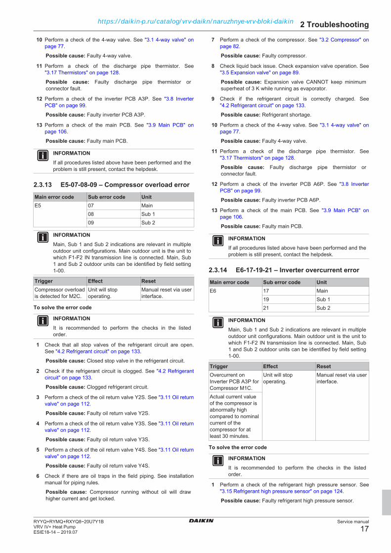
2.3.13 E5-07-08-09 – Compressor overload error
Main error code Sub error code UnitE5 07 Main
08 Sub 109 Sub 2
INFORMATIONMain, Sub 1 and Sub 2 indications are relevant in multipleoutdoor unit configurations. Main outdoor unit is the unit towhich F1‑F2 IN transmission line is connected. Main, Sub1 and Sub 2 outdoor units can be identified by field setting1‑00.
Trigger Effect ResetCompressor overloadis detected for M2C.
Unit will stopoperating.
Manual reset via userinterface.
To solve the error code
INFORMATIONIt is recommended to perform the checks in the listedorder.
1 Check that all stop valves of the refrigerant circuit are open.See "4.2 Refrigerant circuit" on page 133.
Possible cause: Closed stop valve in the refrigerant circuit.
2 Check if the refrigerant circuit is clogged. See "4.2 Refrigerantcircuit" on page 133.
Possible cause: Clogged refrigerant circuit.
3 Perform a check of the oil return valve Y2S. See "3.11 Oil returnvalve" on page 112.
Possible cause: Faulty oil return valve Y2S.
4 Perform a check of the oil return valve Y3S. See "3.11 Oil returnvalve" on page 112.
Possible cause: Faulty oil return valve Y3S.
5 Perform a check of the oil return valve Y4S. See "3.11 Oil returnvalve" on page 112.
Possible cause: Faulty oil return valve Y4S.
6 Check if there are oil traps in the field piping. See installationmanual for piping rules.
Possible cause: Compressor running without oil will drawhigher current and get locked.
7 Perform a check of the compressor. See "3.2 Compressor" onpage 82.
Possible cause: Faulty compressor.
8 Check liquid back issue. Check expansion valve operation. See"3.5 Expansion valve" on page 89.
Possible cause: Expansion valve CANNOT keep minimumsuperheat of 3 K while running as evaporator.
9 Check if the refrigerant circuit is correctly charged. See"4.2 Refrigerant circuit" on page 133.
Possible cause: Refrigerant shortage.
10 Perform a check of the 4‑way valve. See "3.1 4-way valve" onpage 77.
Possible cause: Faulty 4‑way valve.
11 Perform a check of the discharge pipe thermistor. See"3.17 Thermistors" on page 128.
Possible cause: Faulty discharge pipe thermistor orconnector fault.
12 Perform a check of the inverter PCB A6P. See "3.8 InverterPCB" on page 99.
Possible cause: Faulty inverter PCB A6P.
13 Perform a check of the main PCB. See "3.9 Main PCB" onpage 106.
Possible cause: Faulty main PCB.
INFORMATIONIf all procedures listed above have been performed and theproblem is still present, contact the helpdesk.
2.3.14 E6-17-19-21 – Inverter overcurrent error
Main error code Sub error code UnitE6 17 Main
19 Sub 121 Sub 2
INFORMATIONMain, Sub 1 and Sub 2 indications are relevant in multipleoutdoor unit configurations. Main outdoor unit is the unit towhich F1‑F2 IN transmission line is connected. Main, Sub1 and Sub 2 outdoor units can be identified by field setting1‑00.
Trigger Effect ResetOvercurrent onInverter PCB A3P forCompressor M1C.
Unit will stopoperating.
Manual reset via userinterface.
Actual current valueof the compressor isabnormally highcompared to nominalcurrent of thecompressor for atleast 30 minutes.
To solve the error code
INFORMATIONIt is recommended to perform the checks in the listedorder.
1 Perform a check of the refrigerant high pressure sensor. See"3.15 Refrigerant high pressure sensor" on page 124.
Possible cause: Faulty refrigerant high pressure sensor.
https://daikin-p.ru/catalog/vrv-daikn/naruzhnye-vrv-bloki-daikin
2 Troubleshooting
Service manual
18RYYQ+RYMQ+RXYQ8~20U7Y1B
VRV IV+ Heat PumpESIE18-14 – 2019.07
2 Perform a check of the refrigerant low pressure sensor. See"3.16 Refrigerant low pressure sensor" on page 126
Possible cause: Faulty refrigerant low pressure sensor.
3 Connect a pressure gauge to both high and low pressureservice ports and read the high and low refrigerant pressure.Connect the service monitoring tool to the unit and compare thepressure values to the pressure read on the pressure gauges.In case the service monitoring tool read‑out does NOTcorrespond with the pressures read through the pressuregauges, the main PCB needs to be replaced, see "3.9 MainPCB" on page 106.
4 Perform a check of the main PCB. See "3.9 Main PCB" onpage 106.
Possible cause: Faulty main PCB.
5 Perform a check of the inverter PCB A3P. See "3.8 InverterPCB" on page 99.
Possible cause: Faulty inverter PCB A3P.
6 Perform a check of the compressor. See "3.2 Compressor" onpage 82.
Possible cause: Faulty compressor.
INFORMATIONIf all procedures listed above have been performed and theproblem is still present, contact the helpdesk.
2.3.15 E6-18-20-22 – Inverter overcurrent error
Main error code Sub error code UnitE6 18 Main
20 Sub 122 Sub 2
INFORMATIONMain, Sub 1 and Sub 2 indications are relevant in multipleoutdoor unit configurations. Main outdoor unit is the unit towhich F1‑F2 IN transmission line is connected. Main, Sub1 and Sub 2 outdoor units can be identified by field setting1‑00.
Trigger Effect ResetOvercurrent oninverter PCB A6P forcompressor M2C.
Unit will stopoperating.
Manual reset via userinterface.
Actual current valueof the compressor isabnormally highcompared to nominalcurrent of thecompressor for atleast 30 minutes.
To solve the error code
INFORMATIONIt is recommended to perform the checks in the listedorder.
1 Perform a check of the refrigerant high pressure sensor. See"3.15 Refrigerant high pressure sensor" on page 124.
Possible cause: Faulty refrigerant high pressure sensor.
2 Perform a check of the refrigerant low pressure sensor. See"3.16 Refrigerant low pressure sensor" on page 126
Possible cause: Faulty refrigerant low pressure sensor.
3 Connect a pressure gauge to both high and low pressureservice ports and read the high and low refrigerant pressure.Connect the service monitoring tool to the unit and compare thepressure values to the pressure read on the pressure gauges.In case the service monitoring tool read‑out does NOTcorrespond with the pressures read through the pressuregauges, the main PCB needs to be replaced, see "3.9 MainPCB" on page 106.
4 Perform a check of the main PCB. See "3.9 Main PCB" onpage 106.
Possible cause: Faulty main PCB.
5 Perform a check of the inverter PCB A6P. See "3.8 InverterPCB" on page 99.
Possible cause: Faulty inverter PCB A6P.
6 Perform a check of the compressor. See "3.2 Compressor" onpage 82.
Possible cause: Faulty compressor.
INFORMATIONIf all procedures listed above have been performed and theproblem is still present, contact the helpdesk.
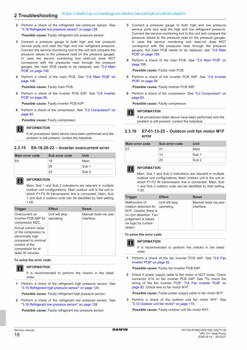
2.3.16 E7-01-13-25 – Outdoor unit fan motor M1Ferror
Main error code Sub error code UnitE7 01 Main
13 Sub 125 Sub 2
INFORMATIONMain, Sub 1 and Sub 2 indications are relevant in multipleoutdoor unit configurations. Main outdoor unit is the unit towhich F1‑F2 IN transmission line is connected. Main, Sub1 and Sub 2 outdoor units can be identified by field setting1‑00.
Trigger Effect ResetMalfunction ofrotation detection forM1F. Careful, there isno rpm detection. Fanjudgement is basedon logic by currentdrawn.
Unit will stopoperating.
Manual reset via userinterface.
To solve the error code
INFORMATIONIt is recommended to perform the checks in the listedorder.
1 Perform a check of the fan inverter PCB A4P. See "3.6 Faninverter PCB" on page 92.
Possible cause: Faulty fan inverter PCB A4P.
2 Check if power supply cable to fan motor is NOT loose. Checkconnector X1A on fan inverter PCB A4P. See "To check thewiring of the fan inverter PCB" "3.6 Fan inverter PCB" onpage 92. Check wire to fan motor M1F.
Possible cause: Faulty power supply cable to fan motor M1F.
3 Perform a check of the outdoor unit fan motor M1F. See"3.12 Outdoor unit fan motor" on page 115.
Possible cause: Faulty outdoor unit fan motor M1F.
https://daikin-p.ru/catalog/vrv-daikn/naruzhnye-vrv-bloki-daikin
2 Troubleshooting
Service manual
19RYYQ+RYMQ+RXYQ8~20U7Y1BVRV IV+ Heat PumpESIE18-14 – 2019.07
INFORMATIONIf all procedures listed above have been performed and theproblem is still present, contact the helpdesk.
2.3.17 E7-02-14-26 – Outdoor unit fan motor M2Ferror
Main error code Sub error code UnitE7 02 Main
14 Sub 126 Sub 2
INFORMATIONMain, Sub 1 and Sub 2 indications are relevant in multipleoutdoor unit configurations. Main outdoor unit is the unit towhich F1‑F2 IN transmission line is connected. Main, Sub1 and Sub 2 outdoor units can be identified by field setting1‑00.
Trigger Effect ResetMalfunction ofrotation detection forM2F. Careful, there isno rpm detection. Fanjudgement is basedon logic by currentdrawn.
Unit will stopoperating.
Manual reset via userinterface.
To solve the error code
INFORMATIONIt is recommended to perform the checks in the listedorder.
1 Perform a check of the fan inverter PCB A7P. See "3.6 Faninverter PCB" on page 92.
Possible cause: Faulty fan inverter PCB A7P.
2 Check if power supply cable to fan motor is NOT loose. Checkconnector X1A on fan inverter PCB A7P. See "To check thewiring of the fan inverter PCB" "3.6 Fan inverter PCB" onpage 92. Check wire to fan motor M2F.
Possible cause: Faulty power supply cable to fan motor M2F.
3 Perform a check of the outdoor unit fan motor M2F. See"3.12 Outdoor unit fan motor" on page 115.
Possible cause: Faulty outdoor unit fan motor M2F.
INFORMATIONIf all procedures listed above have been performed and theproblem is still present, contact the helpdesk.
2.3.18 E7-05-17-29 – Outdoor unit fan motor M1Fovercurrent error
Main error code Sub error code UnitE7 05 Main
17 Sub 129 Sub 2
INFORMATIONMain, Sub 1 and Sub 2 indications are relevant in multipleoutdoor unit configurations. Main outdoor unit is the unit towhich F1‑F2 IN transmission line is connected. Main, Sub1 and Sub 2 outdoor units can be identified by field setting1‑00.
Trigger Effect ResetOvercurrent detectedon outdoor unit fanmotor M1F.
Unit will stopoperating.
Manual reset via userinterface.
To solve the error code
INFORMATIONIt is recommended to perform the checks in the listedorder.
1 Perform a check of the fan inverter PCB A4P. See "3.6 Faninverter PCB" on page 92.
Possible cause: Faulty fan inverter PCB A4P.
2 Perform a check of the outdoor unit fan motor M1F. See"3.12 Outdoor unit fan motor" on page 115.
Possible cause: Faulty outdoor unit fan motor M1F.
INFORMATIONIf all procedures listed above have been performed and theproblem is still present, contact the helpdesk.
2.3.19 E7-06-18-30 – Outdoor unit fan motor M2Fovercurrent error
Main error code Sub error code UnitE7 06 Main
18 Sub 130 Sub 2
INFORMATIONMain, Sub 1 and Sub 2 indications are relevant in multipleoutdoor unit configurations. Main outdoor unit is the unit towhich F1‑F2 IN transmission line is connected. Main, Sub1 and Sub 2 outdoor units can be identified by field setting1‑00.
Trigger Effect ResetOvercurrent detectedon outdoor unit fanmotor M2F.
Unit will stopoperating.
Manual reset via userinterface.
To solve the error code
INFORMATIONIt is recommended to perform the checks in the listedorder.
1 Perform a check of the fan inverter PCB A7P. See "3.6 Faninverter PCB" on page 92.
Possible cause: Faulty fan inverter PCB A7P.
2 Perform a check of the outdoor unit fan motor M2F. See"3.12 Outdoor unit fan motor" on page 115.
Possible cause: Faulty outdoor unit fan motor M2F.
INFORMATIONIf all procedures listed above have been performed and theproblem is still present, contact the helpdesk.
2.3.20 E7-09-21-33 – Fan inverter PCB A4P(integrated power module) overheated
Main error code Sub error code UnitE7 09 Main
21 Sub 133 Sub 2
https://daikin-p.ru/catalog/vrv-daikn/naruzhnye-vrv-bloki-daikin
2 Troubleshooting
Service manual
20RYYQ+RYMQ+RXYQ8~20U7Y1B
VRV IV+ Heat PumpESIE18-14 – 2019.07
INFORMATIONMain, Sub 1 and Sub 2 indications are relevant in multipleoutdoor unit configurations. Main outdoor unit is the unit towhich F1‑F2 IN transmission line is connected. Main, Sub1 and Sub 2 outdoor units can be identified by field setting1‑00.
Trigger Effect ResetFan inverter PCBA4P is overheated.
Unit will stopoperating.
Manual reset via userinterface.
To solve the error code
INFORMATIONIt is recommended to perform the checks in the listedorder.
1 Perform a check of the fan inverter PCB A4P. See "3.6 Faninverter PCB" on page 92.
Possible cause: Faulty fan inverter PCB A4P.
2 Check the required space around the outdoor unit heatexchanger. See "4.3 External factors" on page 138.
Possible cause: Insufficient air flow or air by‑pass due torequired space specifications not met.
3 Clean the outdoor heat exchanger. See "5 Maintenance" onpage 140.
Possible cause: Dirty outdoor heat exchanger.
4 Perform a check of the liquid cooling expansion valve. See"3.5 Expansion valve" on page 89.
Possible cause: Faulty liquid cooling expansion valve.
INFORMATIONIf all procedures listed above have been performed and theproblem is still present, contact the helpdesk.
2.3.21 E7-10-22-34 – Fan inverter PCB A7P(integrated power module) overheated
Main error code Sub error code UnitE7 10 Main
22 Sub 134 Sub 2
INFORMATIONMain, Sub 1 and Sub 2 indications are relevant in multipleoutdoor unit configurations. Main outdoor unit is the unit towhich F1‑F2 IN transmission line is connected. Main, Sub1 and Sub 2 outdoor units can be identified by field setting1‑00.
Trigger Effect ResetFan inverter PCBA7P is overheated.
Unit will stopoperating.
Manual reset via userinterface.
To solve the error code
INFORMATIONIt is recommended to perform the checks in the listedorder.
1 Perform a check of the fan inverter PCB A7P. See "3.6 Faninverter PCB" on page 92.
Possible cause: Faulty fan inverter PCB A7P.
2 Check the required space around the outdoor unit heatexchanger. See "4.3 External factors" on page 138.
Possible cause: Insufficient air flow or air by‑pass due torequired space specifications not met.
3 Clean the outdoor heat exchanger. See "5 Maintenance" onpage 140.
Possible cause: Dirty outdoor heat exchanger.
4 Perform a check of the liquid cooling expansion valve. See"3.5 Expansion valve" on page 89.
Possible cause: Faulty liquid cooling expansion valve.
INFORMATIONIf all procedures listed above have been performed and theproblem is still present, contact the helpdesk.
2.3.22 E9-01-05-08 – Expansion valve Y1Eabnormality
Main error code Sub error code UnitE9 01 Main
05 Sub 108 Sub 2
INFORMATIONMain, Sub 1 and Sub 2 indications are relevant in multipleoutdoor unit configurations. Main outdoor unit is the unit towhich F1‑F2 IN transmission line is connected. Main, Sub1 and Sub 2 outdoor units can be identified by field setting1‑00.
Trigger Effect ResetMain expansion valveY1E malfunction.
Unit will stopoperating.
Power reset atoutdoor unit.
To solve the error code
INFORMATIONIt is recommended to perform the checks in the listedorder.
INFORMATIONWhen the power is switched ON, the outdoor unit mainPCB checks all expansion valve coil windings by currentcheck.
1 Perform a check of the main PCB. See "3.9 Main PCB" onpage 106.
Possible cause: Faulty main PCB.
2 Perform a check of the main expansion valve. See"3.5 Expansion valve" on page 89.
Possible cause: Faulty main expansion valve.
3 Perform a check of all refrigerant side thermistors. See"3.17 Thermistors" on page 128.
Possible cause: Faulty refrigerant side thermistor(s).
4 Perform a check of the refrigerant low pressure sensor. See"3.16 Refrigerant low pressure sensor" on page 126
Possible cause: Faulty refrigerant low pressure sensor.
5 Check if the refrigerant circuit is correctly charged. See"4.2 Refrigerant circuit" on page 133.
Possible cause: Refrigerant overcharge.
6 Check if the power supply is conform with the regulations. See"4.1 Electrical circuit" on page 130.
https://daikin-p.ru/catalog/vrv-daikn/naruzhnye-vrv-bloki-daikin

2 Troubleshooting
Service manual
21RYYQ+RYMQ+RXYQ8~20U7Y1BVRV IV+ Heat PumpESIE18-14 – 2019.07
Possible cause:▪ Faulty or disturbance of the power supply (imbalance
>10%),▪ Power drop,▪ Short circuit.
7 Perform a power reset. If the error disappears and is raisedagain after a while, check for the presence of an externalsource causing electrical noise. See "4.3 External factors" onpage 138.
Possible cause: External source may cause interference.
INFORMATIONIf all procedures listed above have been performed and theproblem is still present, contact the helpdesk.
2.3.23 E9-03-06-09 – Expansion valve Y2Eabnormality
Main error code Sub error code UnitE9 03 Main
06 Sub 109 Sub 2
INFORMATIONMain, Sub 1 and Sub 2 indications are relevant in multipleoutdoor unit configurations. Main outdoor unit is the unit towhich F1‑F2 IN transmission line is connected. Main, Sub1 and Sub 2 outdoor units can be identified by field setting1‑00.
Trigger Effect ResetSubcool expansionvalve Y2Emalfunction.
Unit will stopoperating.
Power reset atoutdoor unit.
To solve the error code
INFORMATIONIt is recommended to perform the checks in the listedorder.
INFORMATIONWhen the power is switched ON, the outdoor unit mainPCB checks all expansion valve coil windings by currentcheck.
1 Perform a check of the main PCB. See "3.9 Main PCB" onpage 106.
Possible cause: Faulty main PCB.
2 Perform a check of the subcool expansion valve. See"3.5 Expansion valve" on page 89.
Possible cause: Faulty subcool expansion valve.
3 Perform a check of all refrigerant side thermistors. See"3.17 Thermistors" on page 128.
Possible cause: Faulty refrigerant side thermistor(s).
4 Perform a check of the refrigerant low pressure sensor. See"3.16 Refrigerant low pressure sensor" on page 126
Possible cause: Faulty refrigerant low pressure sensor.
5 Check if the refrigerant circuit is correctly charged. See"4.2 Refrigerant circuit" on page 133.
Possible cause: Refrigerant overcharge.
6 Check if the power supply is conform with the regulations. See"4.1 Electrical circuit" on page 130.
Possible cause:▪ Faulty or disturbance of the power supply (imbalance
>10%),▪ Power drop,▪ Short circuit.
7 Perform a power reset. If the error disappears and is raisedagain after a while, check for the presence of an externalsource causing electrical noise. See "4.3 External factors" onpage 138.
Possible cause: External source may cause interference.
INFORMATIONIf all procedures listed above have been performed and theproblem is still present, contact the helpdesk.
2.3.24 E9-04-07-10 – Expansion valve Y3Eabnormality
Main error code Sub error code UnitE9 04 Main
07 Sub 110 Sub 2
INFORMATIONMain, Sub 1 and Sub 2 indications are relevant in multipleoutdoor unit configurations. Main outdoor unit is the unit towhich F1‑F2 IN transmission line is connected. Main, Sub1 and Sub 2 outdoor units can be identified by field setting1‑00.
Trigger Effect ResetLiquid coolingexpansion valve Y3Emalfunction.
Unit will stopoperating.
Power reset atoutdoor unit.
To solve the error code
INFORMATIONIt is recommended to perform the checks in the listedorder.
INFORMATIONWhen the power is switched ON, the outdoor unit mainPCB checks all expansion valve coil windings by currentcheck.
1 Perform a check of the main PCB. See "3.9 Main PCB" onpage 106.
Possible cause: Faulty main PCB.
2 Perform a check of the liquid cooling expansion valve. See"3.5 Expansion valve" on page 89.
Possible cause: Faulty liquid cooling expansion valve.
3 Perform a check of all refrigerant side thermistors. See"3.17 Thermistors" on page 128.
Possible cause: Faulty refrigerant side thermistor(s).
4 Perform a check of the refrigerant low pressure sensor. See"3.16 Refrigerant low pressure sensor" on page 126
Possible cause: Faulty refrigerant low pressure sensor.
5 Check if the refrigerant circuit is correctly charged. See"4.2 Refrigerant circuit" on page 133.
Possible cause: Refrigerant overcharge.
6 Check if the power supply is conform with the regulations. See"4.1 Electrical circuit" on page 130.
https://daikin-p.ru/catalog/vrv-daikn/naruzhnye-vrv-bloki-daikin

2 Troubleshooting
Service manual
22RYYQ+RYMQ+RXYQ8~20U7Y1B
VRV IV+ Heat PumpESIE18-14 – 2019.07
Possible cause:▪ Faulty or disturbance of the power supply (imbalance
>10%),▪ Power drop,▪ Short circuit.
7 Perform a power reset. If the error disappears and is raisedagain after a while, check for the presence of an externalsource causing electrical noise. See "4.3 External factors" onpage 138.
Possible cause: External source may cause interference.
INFORMATIONIf all procedures listed above have been performed and theproblem is still present, contact the helpdesk.
2.3.25 E9-20-21-22 – Failure detection on Y1E
Main error code Sub error code UnitE9 20 Main
21 Sub 122 Sub 2
INFORMATIONMain, Sub 1 and Sub 2 indications are relevant in multipleoutdoor unit configurations. Main outdoor unit is the unit towhich F1‑F2 IN transmission line is connected. Main, Sub1 and Sub 2 outdoor units can be identified by field setting1‑00.
Trigger Effect ResetMain expansion valveY1E malfunction.
Unit will stopoperating.
Power reset atoutdoor unit.
To solve the error code
INFORMATIONIt is recommended to perform the checks in the listedorder.
INFORMATIONWhen the power is switched ON, the outdoor unit mainPCB checks all expansion valve coil windings by currentcheck.
1 Perform a check of the main PCB. See "3.9 Main PCB" onpage 106.
Possible cause: Faulty main PCB.
2 Perform a check of the main expansion valve. See"3.5 Expansion valve" on page 89.
Possible cause: Faulty main expansion valve.
3 Perform a check of all refrigerant side thermistors. See"3.17 Thermistors" on page 128.
Possible cause: Faulty refrigerant side thermistor(s).
4 Perform a check of the refrigerant low pressure sensor. See"3.16 Refrigerant low pressure sensor" on page 126
Possible cause: Faulty refrigerant low pressure sensor.
5 Check if the refrigerant circuit is correctly charged. See"4.2 Refrigerant circuit" on page 133.
Possible cause: Refrigerant overcharge.
6 Check if the power supply is conform with the regulations. See"4.1 Electrical circuit" on page 130.
Possible cause:▪ Faulty or disturbance of the power supply (imbalance
>10%),▪ Power drop,▪ Short circuit.
7 Perform a power reset. If the error disappears and is raisedagain after a while, check for the presence of an externalsource causing electrical noise. See "4.3 External factors" onpage 138.
Possible cause: External source may cause interference.
INFORMATIONIf all procedures listed above have been performed and theproblem is still present, contact the helpdesk.
2.3.26 E9-23-24-25 – Failure detection on Y2E
Main error code Sub error code UnitE9 23 Main
24 Sub 125 Sub 2
INFORMATIONMain, Sub 1 and Sub 2 indications are relevant in multipleoutdoor unit configurations. Main outdoor unit is the unit towhich F1‑F2 IN transmission line is connected. Main, Sub1 and Sub 2 outdoor units can be identified by field setting1‑00.
Trigger Effect ResetSubcool expansionvalve Y2Emalfunction.
Unit will stopoperating.
Power reset atoutdoor unit.
To solve the error code
INFORMATIONIt is recommended to perform the checks in the listedorder.
INFORMATIONWhen the power is switched ON, the outdoor unit mainPCB checks all expansion valve coil windings by currentcheck.
1 Perform a check of the main PCB. See "3.9 Main PCB" onpage 106.
Possible cause: Faulty main PCB.
2 Perform a check of the subcool expansion valve. See"3.5 Expansion valve" on page 89.
Possible cause: Faulty subcool expansion valve.
3 Perform a check of all refrigerant side thermistors. See"3.17 Thermistors" on page 128.
Possible cause: Faulty refrigerant side thermistor(s).
4 Perform a check of the refrigerant low pressure sensor. See"3.16 Refrigerant low pressure sensor" on page 126
Possible cause: Faulty refrigerant low pressure sensor.
5 Check if the refrigerant circuit is correctly charged. See"4.2 Refrigerant circuit" on page 133.
Possible cause: Refrigerant overcharge.
6 Check if the power supply is conform with the regulations. See"4.1 Electrical circuit" on page 130.
https://daikin-p.ru/catalog/vrv-daikn/naruzhnye-vrv-bloki-daikin
2 Troubleshooting
Service manual
23RYYQ+RYMQ+RXYQ8~20U7Y1BVRV IV+ Heat PumpESIE18-14 – 2019.07
Possible cause:▪ Faulty or disturbance of the power supply (imbalance
>10%),▪ Power drop,▪ Short circuit.
7 Perform a power reset. If the error disappears and is raisedagain after a while, check for the presence of an externalsource causing electrical noise. See "4.3 External factors" onpage 138.
Possible cause: External source may cause interference.
INFORMATIONIf all procedures listed above have been performed and theproblem is still present, contact the helpdesk.
2.3.27 E9-26-27-28 – Expansion valve Y4Eabnormality
INFORMATIONThis error is ONLY applicable for RYYQ-U units.
Main error code Sub error code UnitE9 26 Main
27 Sub 128 Sub 2
INFORMATIONMain, Sub 1 and Sub 2 indications are relevant in multipleoutdoor unit configurations. Main outdoor unit is the unit towhich F1‑F2 IN transmission line is connected. Main, Sub1 and Sub 2 outdoor units can be identified by field setting1‑00.
Trigger Effect ResetStorage vesselexpansion valve Y4Emalfunction.
Unit will stopoperating.
Power reset atoutdoor unit.
To solve the error code
INFORMATIONIt is recommended to perform the checks in the listedorder.
INFORMATIONWhen the power is switched ON, the outdoor unit mainPCB checks all expansion valve coil windings by currentcheck.
1 Perform a check of the main PCB. See "3.9 Main PCB" onpage 106.
Possible cause: Faulty main PCB.
2 Perform a check of the storage vessel expansion valve. See"3.5 Expansion valve" on page 89.
Possible cause: Faulty storage vessel expansion valve.
3 Perform a check of all refrigerant side thermistors. See"3.17 Thermistors" on page 128.
Possible cause: Faulty refrigerant side thermistor(s).
4 Perform a check of the refrigerant low pressure sensor. See"3.16 Refrigerant low pressure sensor" on page 126
Possible cause: Faulty refrigerant low pressure sensor.
5 Check if the refrigerant circuit is correctly charged. See"4.2 Refrigerant circuit" on page 133.
Possible cause: Refrigerant overcharge.
6 Check if the power supply is conform with the regulations. See"4.1 Electrical circuit" on page 130.
Possible cause:▪ Faulty or disturbance of the power supply (imbalance
>10%),▪ Power drop,▪ Short circuit.
7 Perform a power reset. If the error disappears and is raisedagain after a while, check for the presence of an externalsource causing electrical noise. See "4.3 External factors" onpage 138.
Possible cause: External source may cause interference.
INFORMATIONIf all procedures listed above have been performed and theproblem is still present, contact the helpdesk.
2.3.28 E9-48-49-50 – Expansion valveovercurrent error
Main error code Sub error code UnitE9 48 Main
49 Sub 150 Sub 2
INFORMATIONMain, Sub 1 and Sub 2 indications are relevant in multipleoutdoor unit configurations. Main outdoor unit is the unit towhich F1‑F2 IN transmission line is connected. Main, Sub1 and Sub 2 outdoor units can be identified by field setting1‑00.
Trigger Effect ResetExpansion valveovercurrent.
Unit will stopoperating.
Power reset atoutdoor unit.
To solve the error code
INFORMATIONIt is recommended to perform the checks in the listedorder.
INFORMATIONWhen the power is switched ON, the outdoor unit mainPCB checks all expansion valve coil windings by currentcheck.
1 Perform a check of the main PCB. See "3.9 Main PCB" onpage 106.
Possible cause: Faulty main PCB.
2 Perform a check of all expansion valves. See "3.5 Expansionvalve" on page 89.
Possible cause: Faulty expansion valve.
3 Perform a check of all refrigerant side thermistors. See"3.17 Thermistors" on page 128.
Possible cause: Faulty refrigerant side thermistor(s).
4 Perform a check of the refrigerant low pressure sensor. See"3.16 Refrigerant low pressure sensor" on page 126
Possible cause: Faulty refrigerant low pressure sensor.
5 Check if the refrigerant circuit is correctly charged. See"4.2 Refrigerant circuit" on page 133.
Possible cause: Refrigerant overcharge.
6 Check if the power supply is conform with the regulations. See"4.1 Electrical circuit" on page 130.
https://daikin-p.ru/catalog/vrv-daikn/naruzhnye-vrv-bloki-daikin

2 Troubleshooting
Service manual
24RYYQ+RYMQ+RXYQ8~20U7Y1B
VRV IV+ Heat PumpESIE18-14 – 2019.07
Possible cause:▪ Faulty or disturbance of the power supply (imbalance
>10%),▪ Power drop,▪ Short circuit.
7 Perform a power reset. If the error disappears and is raisedagain after a while, check for the presence of an externalsource causing electrical noise. See "4.3 External factors" onpage 138.
Possible cause: External source may cause interference.
INFORMATIONIf all procedures listed above have been performed and theproblem is still present, contact the helpdesk.
2.3.29 E9-51-52-53 – Expansion valve thermalcutting error
Main error code Sub error code UnitE9 51 Main
52 Sub 153 Sub 2
INFORMATIONMain, Sub 1 and Sub 2 indications are relevant in multipleoutdoor unit configurations. Main outdoor unit is the unit towhich F1‑F2 IN transmission line is connected. Main, Sub1 and Sub 2 outdoor units can be identified by field setting1‑00.
Trigger Effect ResetExpansion valvethermal cutting error.
Unit will stopoperating.
Power reset atoutdoor unit.
To solve the error code
INFORMATIONIt is recommended to perform the checks in the listedorder.
INFORMATIONWhen the power is switched ON, the outdoor unit mainPCB checks all expansion valve coil windings by currentcheck.
1 Perform a check of the main PCB. See "3.9 Main PCB" onpage 106.
Possible cause: Faulty main PCB.
2 Perform a check of all expansion valves. See "3.5 Expansionvalve" on page 89.
Possible cause: Faulty expansion valve.
3 Perform a check of all refrigerant side thermistors. See"3.17 Thermistors" on page 128.
Possible cause: Faulty refrigerant side thermistor(s).
4 Perform a check of the refrigerant low pressure sensor. See"3.16 Refrigerant low pressure sensor" on page 126
Possible cause: Faulty refrigerant low pressure sensor.
5 Check if the refrigerant circuit is correctly charged. See"4.2 Refrigerant circuit" on page 133.
Possible cause: Refrigerant overcharge.
6 Check if the power supply is conform with the regulations. See"4.1 Electrical circuit" on page 130.
Possible cause:▪ Faulty or disturbance of the power supply (imbalance
>10%),▪ Power drop,▪ Short circuit.
7 Perform a power reset. If the error disappears and is raisedagain after a while, check for the presence of an externalsource causing electrical noise. See "4.3 External factors" onpage 138.
Possible cause: External source may cause interference.
INFORMATIONIf all procedures listed above have been performed and theproblem is still present, contact the helpdesk.
2.3.30 E9-54-55-56 – Expansion valve defectivecircuit
Main error code Sub error code UnitE9 54 Main
55 Sub 156 Sub 2
INFORMATIONMain, Sub 1 and Sub 2 indications are relevant in multipleoutdoor unit configurations. Main outdoor unit is the unit towhich F1‑F2 IN transmission line is connected. Main, Sub1 and Sub 2 outdoor units can be identified by field setting1‑00.
Trigger Effect ResetExpansion valvedefective circuit.
Unit will stopoperating.
Power reset atoutdoor unit.
To solve the error code
INFORMATIONIt is recommended to perform the checks in the listedorder.
INFORMATIONWhen the power is switched ON, the outdoor unit mainPCB checks all expansion valve coil windings by currentcheck.
1 Perform a check of the main PCB. See "3.9 Main PCB" onpage 106.
Possible cause: Faulty main PCB.
2 Perform a check of all expansion valves. See "3.5 Expansionvalve" on page 89.
Possible cause: Faulty expansion valve.
3 Perform a check of all refrigerant side thermistors. See"3.17 Thermistors" on page 128.
Possible cause: Faulty refrigerant side thermistor(s).
4 Perform a check of the refrigerant low pressure sensor. See"3.16 Refrigerant low pressure sensor" on page 126
Possible cause: Faulty refrigerant low pressure sensor.
5 Check if the refrigerant circuit is correctly charged. See"4.2 Refrigerant circuit" on page 133.
Possible cause: Refrigerant overcharge.
6 Check if the power supply is conform with the regulations. See"4.1 Electrical circuit" on page 130.
https://daikin-p.ru/catalog/vrv-daikn/naruzhnye-vrv-bloki-daikin
2 Troubleshooting
Service manual
25RYYQ+RYMQ+RXYQ8~20U7Y1BVRV IV+ Heat PumpESIE18-14 – 2019.07
Possible cause:▪ Faulty or disturbance of the power supply (imbalance
>10%),▪ Power drop,▪ Short circuit.
7 Perform a power reset. If the error disappears and is raisedagain after a while, check for the presence of an externalsource causing electrical noise. See "4.3 External factors" onpage 138.
Possible cause: External source may cause interference.
INFORMATIONIf all procedures listed above have been performed and theproblem is still present, contact the helpdesk.
2.3.31 F3-01-03-05 – Compressor dischargetemperature too high
Main error code Sub error code UnitF3 01 Main
03 Sub 105 Sub 2
INFORMATIONMain, Sub 1 and Sub 2 indications are relevant in multipleoutdoor unit configurations. Main outdoor unit is the unit towhich F1‑F2 IN transmission line is connected. Main, Sub1 and Sub 2 outdoor units can be identified by field setting1‑00.
Trigger Effect ResetDischargetemperature >safetyvalue certain timeswithin certainminutes, see"6.6 Safetydevices" onpage 183.
Unit will stopoperating.
Manual reset via userinterface.Automatic reset whendischargetemperature <resetvalue, see "6.6 Safetydevices" onpage 183.
To solve the error code
INFORMATIONIt is recommended to perform the checks in the listedorder.
1 Check that all stop valves of the refrigerant circuit are open.See "4.2 Refrigerant circuit" on page 133.
Possible cause: Closed stop valve in the refrigerant circuit.
2 Perform a check of the discharge pipe thermistor. See"3.17 Thermistors" on page 128.
Possible cause: Faulty discharge pipe thermistor orconnector fault.
3 Perform a check of the main PCB. See "3.9 Main PCB" onpage 106.
Possible cause: Faulty main PCB.
4 Check if the refrigerant circuit is correctly charged. See"4.2 Refrigerant circuit" on page 133.
Possible cause: Refrigerant shortage.
5 Perform a check of the compressor. See "3.2 Compressor" onpage 82.
Possible cause: Faulty compressor.
6 Perform a check of the main expansion valve. See"3.5 Expansion valve" on page 89.
Possible cause: Faulty main expansion valve.
7 Perform a check of the expansion valve(s) of the indoor unit(s).See service manual of the respective indoor unit(s) for moreinformation.
Possible cause: Faulty indoor unit expansion valve.
INFORMATIONIf all procedures listed above have been performed and theproblem is still present, contact the helpdesk.
2.3.32 F3-20-21-22 – Compressor bodytemperature too high
Main error code Sub error code UnitF3 20 Main
21 Sub 122 Sub 2
INFORMATIONMain, Sub 1 and Sub 2 indications are relevant in multipleoutdoor unit configurations. Main outdoor unit is the unit towhich F1‑F2 IN transmission line is connected. Main, Sub1 and Sub 2 outdoor units can be identified by field setting1‑00.
Trigger Effect ResetBody temperature>safety value certaintimes within certainminutes, see"6.6 Safetydevices" onpage 183.
Unit will stopoperating.
Manual reset via userinterface.Automatic reset whenbody temperature<reset value, see"6.6 Safetydevices" onpage 183.
To solve the error code
INFORMATIONIt is recommended to perform the checks in the listedorder.
1 Perform a check of the compressor body thermistors. See"3.17 Thermistors" on page 128.
Possible cause: Faulty compressor body thermistor orconnector fault.
2 Perform a check of the main PCB. See "3.9 Main PCB" onpage 106.
Possible cause: Faulty main PCB.
3 Check if the refrigerant circuit is correctly charged. See"4.2 Refrigerant circuit" on page 133.
Possible cause: Refrigerant shortage.
4 Perform a check of the compressor. See "3.2 Compressor" onpage 82.
Possible cause: Faulty compressor.
5 Perform a check of the main expansion valve. See"3.5 Expansion valve" on page 89.
Possible cause: Faulty main expansion valve.
6 Perform a check of the expansion valve(s) of the indoor unit(s).See service manual of the respective indoor unit(s) for moreinformation.
Possible cause: Faulty indoor unit expansion valve.
https://daikin-p.ru/catalog/vrv-daikn/naruzhnye-vrv-bloki-daikin

2 Troubleshooting
Service manual
26RYYQ+RYMQ+RXYQ8~20U7Y1B
VRV IV+ Heat PumpESIE18-14 – 2019.07
INFORMATIONIf all procedures listed above have been performed and theproblem is still present, contact the helpdesk.
2.3.33 F4-01 – Wet operation caution
Trigger Effect ResetDischarge superheat<10˚C(SHDischarge=TDischarge −Tcondensation).
Unit keeps running. Automatic reset whendischarge superheat>10˚C.
To solve the error code
INFORMATIONIt is recommended to perform the checks in the listedorder.
1 Check if the refrigerant circuit is correctly charged. See"4.2 Refrigerant circuit" on page 133.
Possible cause: Refrigerant overcharge.
2 Check for the presence of non‑condensables and/or humidity inthe refrigerant circuit. See "4.2 Refrigerant circuit" on page 133.
Possible cause: Non‑condensables and/or humidity in therefrigerant circuit.
3 Perform a check of the evaporator side expansion valve. See"3.5 Expansion valve" on page 89.
Possible cause: Faulty evaporator side expansion valve.
4 Check for objects near the indoor unit that may block theairflow. See "4.3 External factors" on page 138.
Possible cause: Airflow of the indoor unit is blocked.
5 Clean the air filters of the indoor unit(s). See service manual ofthe respective indoor unit(s).
Possible cause: Faulty or clogged air filter.
6 Adjust external static pressure setting for ducted type indoorunits, if necessary.
7 Perform a check of the indoor unit fan motor. See servicemanual of the respective indoor unit(s).
Possible cause: Faulty indoor unit fan motor.
8 Perform a check of the discharge pipe thermistor. See"3.17 Thermistors" on page 128.
Possible cause: Faulty discharge pipe thermistor orconnector fault.
9 Perform a check of the refrigerant high pressure sensor. See"3.15 Refrigerant high pressure sensor" on page 124.
Possible cause: Faulty refrigerant high pressure sensor.
10 Perform a check of the indoor air thermistor. See"3.17 Thermistors" on page 128.
Possible cause: Faulty indoor air thermistor.
11 Check all indoor units operation when in heating mode. Indoorroom temperature MUST be below 20°C.
Possible cause: Indoor room temperature too high when inheating mode.
INFORMATIONIf all procedures listed above have been performed and theproblem is still present, contact the helpdesk.
2.3.34 F6-02 – Refrigerant overcharge detectionduring test-run
Trigger Effect ResetDischarge superheat<10˚C(SHDischarge=TDischarge −Tcondensation) during testrun.
Unit will stop test run. Push BS3 (return)button once.
To solve the error code
INFORMATIONIt is recommended to perform the checks in the listedorder.
1 Check if the refrigerant circuit is correctly charged. See"4.2 Refrigerant circuit" on page 133.
Possible cause: Refrigerant overcharge.
2 Check for the presence of non‑condensables and/or humidity inthe refrigerant circuit. See "4.2 Refrigerant circuit" on page 133.
Possible cause: Non‑condensables and/or humidity in therefrigerant circuit.
3 Perform a check of the evaporator side expansion valve. See"3.5 Expansion valve" on page 89.
Possible cause: Faulty evaporator side expansion valve.
4 Check for objects near the indoor unit that may block theairflow. See "4.3 External factors" on page 138.
Possible cause: Airflow of the indoor unit is blocked.
5 Clean the air filters of the indoor unit(s). See service manual ofthe respective indoor unit(s).
Possible cause: Faulty or clogged air filter.
6 Adjust external static pressure setting for ducted type indoorunits, if necessary.
7 Perform a check of the indoor unit fan motor. See servicemanual of the respective indoor unit(s).
Possible cause: Faulty indoor unit fan motor.
8 Perform a check of the discharge pipe thermistor. See"3.17 Thermistors" on page 128.
Possible cause: Faulty discharge pipe thermistor orconnector fault.
9 Perform a check of the refrigerant high pressure sensor. See"3.15 Refrigerant high pressure sensor" on page 124.
Possible cause: Faulty refrigerant high pressure sensor.
10 Perform a check of the indoor unit air thermistors. See servicemanual of the respective indoor unit(s) for more information.
Possible cause: Faulty indoor unit air thermistor(s).
11 Check all indoor units operation when in heating mode. Indoorroom temperature MUST be below 20°C.
Possible cause: Indoor room temperature too high when inheating mode.
INFORMATIONIf all procedures listed above have been performed and theproblem is still present, contact the helpdesk.
https://daikin-p.ru/catalog/vrv-daikn/naruzhnye-vrv-bloki-daikin

2 Troubleshooting
Service manual
27RYYQ+RYMQ+RXYQ8~20U7Y1BVRV IV+ Heat PumpESIE18-14 – 2019.07
2.3.35 H3-02-04-06 – Transmission error oninverter PCB A3P
Main error code Sub error code UnitH3 02 Main
04 Sub 106 Sub 2
INFORMATIONMain, Sub 1 and Sub 2 indications are relevant in multipleoutdoor unit configurations. Main outdoor unit is the unit towhich F1‑F2 IN transmission line is connected. Main, Sub1 and Sub 2 outdoor units can be identified by field setting1‑00.
Trigger Effect ResetTransmissionabnormality betweenoutdoor unit mainPCB and inverterPCB A3P.
Unit will stopoperating.
Power reset atoutdoor unit.
To solve the error code
INFORMATIONIt is recommended to perform the checks in the listedorder.
1 Check transmission wire between connector X28A on mainPCB and connector X6A on inverter PCB A3P. See "6.2 Wiringdiagram" on page 146.
Possible cause: Faulty transmission wiring between mainPCB and inverter PCB A3P.
2 Perform a check of the main PCB. See "3.9 Main PCB" onpage 106.
Possible cause: Faulty main PCB.
3 Perform a check of the inverter PCB A3P. See "3.8 InverterPCB" on page 99.
Possible cause: Faulty inverter PCB A3P.
INFORMATIONIf all procedures listed above have been performed and theproblem is still present, contact the helpdesk.
2.3.36 H3-03-05-07 – Transmission error oninverter PCB A6P
Main error code Sub error code UnitH3 03 Main
05 Sub 107 Sub 2
INFORMATIONMain, Sub 1 and Sub 2 indications are relevant in multipleoutdoor unit configurations. Main outdoor unit is the unit towhich F1‑F2 IN transmission line is connected. Main, Sub1 and Sub 2 outdoor units can be identified by field setting1‑00.
Trigger Effect ResetTransmissionabnormality betweenoutdoor unit mainPCB and inverterPCB A6P.
Unit will stopoperating.
Power reset atoutdoor unit.
To solve the error code
INFORMATIONIt is recommended to perform the checks in the listedorder.
1 Check transmission wire between connector X61A on mainPCB and connector X6A on inverter PCB A6P. See "6.2 Wiringdiagram" on page 146.
Possible cause: Faulty transmission wiring between mainPCB and inverter PCB A6P.
2 Perform a check of the main PCB. See "3.9 Main PCB" onpage 106.
Possible cause: Faulty main PCB.
3 Perform a check of the inverter PCB A6P. See "3.8 InverterPCB" on page 99.
Possible cause: Faulty inverter PCB A6P.
INFORMATIONIf all procedures listed above have been performed and theproblem is still present, contact the helpdesk.
2.3.37 H9-01-02-03 – Ambient temperaturethermistor R1T abnormality
Main error code Sub error code UnitH9 01 Main
02 Sub 103 Sub 2
INFORMATIONMain, Sub 1 and Sub 2 indications are relevant in multipleoutdoor unit configurations. Main outdoor unit is the unit towhich F1‑F2 IN transmission line is connected. Main, Sub1 and Sub 2 outdoor units can be identified by field setting1‑00.
Trigger Effect ResetAmbient temperaturethermistor R1T read-out is out of range.
Unit will stopoperating.
Manual reset via userinterface.Automatic reset whenthermistor read-out iswithin range.
To solve the error code
INFORMATIONIt is recommended to perform the checks in the listedorder.
1 Perform a check of the outdoor air thermistor. See"3.17 Thermistors" on page 128.
Possible cause: Faulty ambient air thermistor.
2 Perform a check of the main PCB. See "3.9 Main PCB" onpage 106.
Possible cause: Faulty main PCB.
INFORMATIONIf all procedures listed above have been performed and theproblem is still present, contact the helpdesk.
https://daikin-p.ru/catalog/vrv-daikn/naruzhnye-vrv-bloki-daikin

2 Troubleshooting
Service manual
28RYYQ+RYMQ+RXYQ8~20U7Y1B
VRV IV+ Heat PumpESIE18-14 – 2019.07
2.3.38 HA-00 – Defrost fail alarm
Trigger Effect ResetWhen outdoor unitjudges defrost is notcompleted.
Unit keeps running. Auto reset.
To solve the error code
INFORMATIONIt is recommended to perform the checks in the listedorder.
1 Check the required space around the outdoor unit heatexchanger. See "4.3 External factors" on page 138.
Possible cause: Insufficient air flow or air by‑pass due torequired space specifications not met.
2 Clean the outdoor heat exchanger. See "5 Maintenance" onpage 140.
Possible cause: Dirty outdoor heat exchanger.
3 Check if the refrigerant circuit is correctly charged. See"4.2 Refrigerant circuit" on page 133.
Possible cause: Refrigerant shortage.
4 Perform a check of the de–icer thermistor. See"3.17 Thermistors" on page 128.
Possible cause: Faulty de–icer thermistor or connector fault.
5 Perform a check of the refrigerant high pressure sensor. See"3.15 Refrigerant high pressure sensor" on page 124.
Possible cause: Faulty refrigerant high pressure sensor.
INFORMATIONIf all procedures listed above have been performed and theproblem is still present, contact the helpdesk.
2.3.39 J3-16-22-28 – Discharge thermistor R21Topen circuit
Main error code Sub error code UnitJ3 16 Main
22 Sub 128 Sub 2
INFORMATIONMain, Sub 1 and Sub 2 indications are relevant in multipleoutdoor unit configurations. Main outdoor unit is the unit towhich F1‑F2 IN transmission line is connected. Main, Sub1 and Sub 2 outdoor units can be identified by field setting1‑00.
Trigger Effect ResetCompressor (M1C)discharge thermistorR21T open circuit orout of range.
Unit will stopoperating.
Manual reset via userinterface.Automatic reset whenthermistor read-out iswithin range.
To solve the error code
INFORMATIONIt is recommended to perform the checks in the listedorder.
1 Perform a check of the discharge pipe thermistor. See"3.17 Thermistors" on page 128.
Possible cause: Faulty discharge pipe thermistor orconnector fault.
2 Perform a check of the main PCB. See "3.9 Main PCB" onpage 106.
Possible cause: Faulty main PCB.
INFORMATIONIf all procedures listed above have been performed and theproblem is still present, contact the helpdesk.
2.3.40 J3-17-23-29 – Discharge thermistor R21Tshort circuit
Main error code Sub error code UnitJ3 17 Main
23 Sub 129 Sub 2
INFORMATIONMain, Sub 1 and Sub 2 indications are relevant in multipleoutdoor unit configurations. Main outdoor unit is the unit towhich F1‑F2 IN transmission line is connected. Main, Sub1 and Sub 2 outdoor units can be identified by field setting1‑00.
Trigger Effect ResetCompressor (M1C)discharge thermistorR21T short circuit orout of range.
Unit will stopoperating.
Manual reset via userinterface.Automatic reset whenthermistor read-out iswithin range.
To solve the error code
INFORMATIONIt is recommended to perform the checks in the listedorder.
1 Perform a check of the discharge pipe thermistor. See"3.17 Thermistors" on page 128.
Possible cause: Faulty discharge pipe thermistor orconnector fault.
2 Perform a check of the main PCB. See "3.9 Main PCB" onpage 106.
Possible cause: Faulty main PCB.
INFORMATIONIf all procedures listed above have been performed and theproblem is still present, contact the helpdesk.
2.3.41 J3-18-24-30 – Discharge thermistor R22Topen circuit
Main error code Sub error code UnitJ3 18 Main
24 Sub 130 Sub 2
INFORMATIONMain, Sub 1 and Sub 2 indications are relevant in multipleoutdoor unit configurations. Main outdoor unit is the unit towhich F1‑F2 IN transmission line is connected. Main, Sub1 and Sub 2 outdoor units can be identified by field setting1‑00.
https://daikin-p.ru/catalog/vrv-daikn/naruzhnye-vrv-bloki-daikin

2 Troubleshooting
Service manual
29RYYQ+RYMQ+RXYQ8~20U7Y1BVRV IV+ Heat PumpESIE18-14 – 2019.07
Trigger Effect ResetCompressor (M2C)discharge thermistorR22T open circuit orout of range.
Unit will stopoperating.
Manual reset via userinterface.Automatic reset whenthermistor read-out iswithin range.
To solve the error code
INFORMATIONIt is recommended to perform the checks in the listedorder.
1 Perform a check of the discharge pipe thermistor. See"3.17 Thermistors" on page 128.
Possible cause: Faulty discharge pipe thermistor orconnector fault.
2 Perform a check of the main PCB. See "3.9 Main PCB" onpage 106.
Possible cause: Faulty main PCB.
INFORMATIONIf all procedures listed above have been performed and theproblem is still present, contact the helpdesk.
2.3.42 J3-19-25-31 – Discharge thermistor R22Tshort circuit
Main error code Sub error code UnitJ3 19 Main
25 Sub 131 Sub 2
INFORMATIONMain, Sub 1 and Sub 2 indications are relevant in multipleoutdoor unit configurations. Main outdoor unit is the unit towhich F1‑F2 IN transmission line is connected. Main, Sub1 and Sub 2 outdoor units can be identified by field setting1‑00.
Trigger Effect ResetCompressor (M2C)discharge thermistorR22T short circuit orout of range.
Unit will stopoperating.
Manual reset via userinterface.Automatic reset whenthermistor read-out iswithin range.
To solve the error code
INFORMATIONIt is recommended to perform the checks in the listedorder.
1 Perform a check of the discharge pipe thermistor. See"3.17 Thermistors" on page 128.
Possible cause: Faulty discharge pipe thermistor orconnector fault.
2 Perform a check of the main PCB. See "3.9 Main PCB" onpage 106.
Possible cause: Faulty main PCB.
INFORMATIONIf all procedures listed above have been performed and theproblem is still present, contact the helpdesk.
2.3.43 J3-38-42-44 – Compressor bodythermistor R9T open circuit
Main error code Sub error code UnitJ3 38 Main
42 Sub 144 Sub 2
INFORMATIONMain, Sub 1 and Sub 2 indications are relevant in multipleoutdoor unit configurations. Main outdoor unit is the unit towhich F1‑F2 IN transmission line is connected. Main, Sub1 and Sub 2 outdoor units can be identified by field setting1‑00.
Trigger Effect ResetCompressor (M2C)body temperaturethermistor R9T opencircuit or out of range.
Unit will stopoperating.
Manual reset via userinterface.Automatic reset whenthermistor read-out iswithin range.
To solve the error code
INFORMATIONIt is recommended to perform the checks in the listedorder.
1 Perform a check of the compressor body thermistors. See"3.17 Thermistors" on page 128.
Possible cause: Faulty compressor body thermistor orconnector fault.
2 Perform a check of the main PCB. See "3.9 Main PCB" onpage 106.
Possible cause: Faulty main PCB.
INFORMATIONIf all procedures listed above have been performed and theproblem is still present, contact the helpdesk.
2.3.44 J3-39-43-45 – Compressor bodythermistor R9T short circuit
Main error code Sub error code UnitJ3 39 Main
43 Sub 145 Sub 2
INFORMATIONMain, Sub 1 and Sub 2 indications are relevant in multipleoutdoor unit configurations. Main outdoor unit is the unit towhich F1‑F2 IN transmission line is connected. Main, Sub1 and Sub 2 outdoor units can be identified by field setting1‑00.
Trigger Effect ResetCompressor (M2C)body temperaturethermistor R9T shortcircuit or out of range.
Unit will stopoperating.
Manual reset via userinterface.Automatic reset whenthermistor read-out iswithin range.
To solve the error code
INFORMATIONIt is recommended to perform the checks in the listedorder.
https://daikin-p.ru/catalog/vrv-daikn/naruzhnye-vrv-bloki-daikin

2 Troubleshooting
Service manual
30RYYQ+RYMQ+RXYQ8~20U7Y1B
VRV IV+ Heat PumpESIE18-14 – 2019.07
1 Perform a check of the compressor body thermistors. See"3.17 Thermistors" on page 128.
Possible cause: Faulty compressor body thermistor orconnector fault.
2 Perform a check of the main PCB. See "3.9 Main PCB" onpage 106.
Possible cause: Faulty main PCB.
INFORMATIONIf all procedures listed above have been performed and theproblem is still present, contact the helpdesk.
2.3.45 J3-47-49-51 – Compressor bodythermistor R8T open circuit
Main error code Sub error code UnitJ3 47 Main
49 Sub 151 Sub 2
INFORMATIONMain, Sub 1 and Sub 2 indications are relevant in multipleoutdoor unit configurations. Main outdoor unit is the unit towhich F1‑F2 IN transmission line is connected. Main, Sub1 and Sub 2 outdoor units can be identified by field setting1‑00.
Trigger Effect ResetCompressor (M1C)body temperaturethermistor R8T opencircuit or out of range.
Unit will stopoperating.
Manual reset via userinterface.Automatic reset whenthermistor read-out iswithin range.
To solve the error code
INFORMATIONIt is recommended to perform the checks in the listedorder.
1 Perform a check of the compressor body thermistors. See"3.17 Thermistors" on page 128.
Possible cause: Faulty compressor body thermistor orconnector fault.
2 Perform a check of the main PCB. See "3.9 Main PCB" onpage 106.
Possible cause: Faulty main PCB.
INFORMATIONIf all procedures listed above have been performed and theproblem is still present, contact the helpdesk.
2.3.46 J3-48-50-52 – Compressor bodythermistor R8T short circuit
Main error code Sub error code UnitJ3 48 Main
50 Sub 152 Sub 2
INFORMATIONMain, Sub 1 and Sub 2 indications are relevant in multipleoutdoor unit configurations. Main outdoor unit is the unit towhich F1‑F2 IN transmission line is connected. Main, Sub1 and Sub 2 outdoor units can be identified by field setting1‑00.
Trigger Effect ResetCompressor (M1C)body temperaturethermistor R8T shortcircuit or out of range.
Unit will stopoperating.
Manual reset via userinterface.Automatic reset whenthermistor read-out iswithin range.
To solve the error code
INFORMATIONIt is recommended to perform the checks in the listedorder.
1 Perform a check of the compressor body thermistors. See"3.17 Thermistors" on page 128.
Possible cause: Faulty compressor body thermistor orconnector fault.
2 Perform a check of the main PCB. See "3.9 Main PCB" onpage 106.
Possible cause: Faulty main PCB.
INFORMATIONIf all procedures listed above have been performed and theproblem is still present, contact the helpdesk.
2.3.47 J3-56-57-58 – High discharge temperature
Main error code Sub error code UnitJ3 56 Main
57 Sub 158 Sub 2
INFORMATIONMain, Sub 1 and Sub 2 indications are relevant in multipleoutdoor unit configurations. Main outdoor unit is the unit towhich F1‑F2 IN transmission line is connected. Main, Sub1 and Sub 2 outdoor units can be identified by field setting1‑00.
Trigger Effect ResetCompressordischargetemperature (R21Tand/or R22T) toohigh.
Unit keeps running. Auto reset.
To solve the error code
INFORMATIONIt is recommended to perform the checks in the listedorder.
1 Perform a check of the discharge pipe thermistor. See"3.17 Thermistors" on page 128.
Possible cause: Faulty discharge pipe thermistor orconnector fault.
2 Perform a check of the main expansion valve. See"3.5 Expansion valve" on page 89.
Possible cause: Faulty main expansion valve.
3 Perform a check of the subcool expansion valve. See"3.5 Expansion valve" on page 89.
Possible cause: Faulty subcool expansion valve.
4 Perform a check of the expansion valve(s) of the indoor unit(s).See service manual of the respective indoor unit(s) for moreinformation.
Possible cause: Faulty indoor unit expansion valve.
https://daikin-p.ru/catalog/vrv-daikn/naruzhnye-vrv-bloki-daikin

2 Troubleshooting
Service manual
31RYYQ+RYMQ+RXYQ8~20U7Y1BVRV IV+ Heat PumpESIE18-14 – 2019.07
5 Perform a check of the main PCB. See "3.9 Main PCB" onpage 106.
Possible cause: Faulty main PCB.
6 Check if the refrigerant circuit is correctly charged. See"4.2 Refrigerant circuit" on page 133.
Possible cause: Refrigerant shortage.
INFORMATIONIf all procedures listed above have been performed and theproblem is still present, contact the helpdesk.
2.3.48 J3-59-60-61 – Discharge thermistorcrosswired
Main error code Sub error code UnitJ3 59 Main
60 Sub 161 Sub 2
INFORMATIONMain, Sub 1 and Sub 2 indications are relevant in multipleoutdoor unit configurations. Main outdoor unit is the unit towhich F1‑F2 IN transmission line is connected. Main, Sub1 and Sub 2 outdoor units can be identified by field setting1‑00.
Trigger Effect ResetCompressor (M1C)discharge thermistorand compressor(M2C) dischargethermistor are cross-wired.
Unit keeps running. Auto reset.
To solve the error code
INFORMATIONIt is recommended to perform the checks in the listedorder.
1 Check the wiring of the discharge pipe thermistors on the mainPCB. See "3.9 Main PCB" on page 106.
Possible cause: Discharge pipe thermistors are cross–wired.
INFORMATIONIf all procedures listed above have been performed and theproblem is still present, contact the helpdesk.
2.3.49 J5-01-03-05 – Suction thermistor R3Tabnormality
Main error code Sub error code UnitJ5 01 Main
03 Sub 105 Sub 2
INFORMATIONMain, Sub 1 and Sub 2 indications are relevant in multipleoutdoor unit configurations. Main outdoor unit is the unit towhich F1‑F2 IN transmission line is connected. Main, Sub1 and Sub 2 outdoor units can be identified by field setting1‑00.
Trigger Effect ResetSuction (accumulator)temperaturethermistor R3T short/open circuit or out ofrange.
Unit will stopoperating.
Manual reset via userinterface.Automatic reset whenthermistor read-out iswithin range.
To solve the error code
INFORMATIONIt is recommended to perform the checks in the listedorder.
1 Perform a check of the suction pipe thermistor. See"3.17 Thermistors" on page 128.
Possible cause: Faulty suction pipe thermistor or connectorfault.
2 Perform a check of the main PCB. See "3.9 Main PCB" onpage 106.
Possible cause: Faulty main PCB.
INFORMATIONIf all procedures listed above have been performed and theproblem is still present, contact the helpdesk.
2.3.50 J6-01-02-03 – De–icer thermistor R7Tabnormality
Main error code Sub error code UnitJ6 01 Main
02 Sub 103 Sub 2
INFORMATIONMain, Sub 1 and Sub 2 indications are relevant in multipleoutdoor unit configurations. Main outdoor unit is the unit towhich F1‑F2 IN transmission line is connected. Main, Sub1 and Sub 2 outdoor units can be identified by field setting1‑00.
Trigger Effect ResetDe-icer temperaturethermistor R7T short/open circuit or out ofrange.
Unit will stopoperating.
Manual reset via userinterface.Automatic reset whenthermistor read-out iswithin range.
To solve the error code
INFORMATIONIt is recommended to perform the checks in the listedorder.
1 Perform a check of the de–icer thermistor. See"3.17 Thermistors" on page 128.
Possible cause: Faulty de–icer thermistor or connector fault.
2 Perform a check of the main PCB. See "3.9 Main PCB" onpage 106.
Possible cause: Faulty main PCB.
INFORMATIONIf all procedures listed above have been performed and theproblem is still present, contact the helpdesk.
https://daikin-p.ru/catalog/vrv-daikn/naruzhnye-vrv-bloki-daikin

2 Troubleshooting
Service manual
32RYYQ+RYMQ+RXYQ8~20U7Y1B
VRV IV+ Heat PumpESIE18-14 – 2019.07
2.3.51 J7-06-07-08 – Liquid thermistor R5Tabnormality
Main error code Sub error code UnitJ7 06 Main
07 Sub 108 Sub 2
INFORMATIONMain, Sub 1 and Sub 2 indications are relevant in multipleoutdoor unit configurations. Main outdoor unit is the unit towhich F1‑F2 IN transmission line is connected. Main, Sub1 and Sub 2 outdoor units can be identified by field setting1‑00.
Trigger Effect ResetRefrigerant liquidthermistor R5T aftersubcool heatexchanger short/opencircuit or out of range.
Unit will stopoperating.
Manual reset via userinterface.Automatic reset whenthermistor read-out iswithin range.
To solve the error code
INFORMATIONIt is recommended to perform the checks in the listedorder.
1 Perform a check of the refrigerant liquid thermistor of thesubcool heat exchanger. See "3.17 Thermistors" on page 128.
Possible cause: Faulty refrigerant liquid thermistor of thesubcool heat exchanger or connector fault.
1 Perform a check of the main PCB. See "3.9 Main PCB" onpage 106.
Possible cause: Faulty main PCB.
INFORMATIONIf all procedures listed above have been performed and theproblem is still present, contact the helpdesk.
2.3.52 J8-01-02-03 – Outdoor heat exchangerthermistor R4T abnormality
Main error code Sub error code UnitJ8 01 Main
02 Sub 103 Sub 2
INFORMATIONMain, Sub 1 and Sub 2 indications are relevant in multipleoutdoor unit configurations. Main outdoor unit is the unit towhich F1‑F2 IN transmission line is connected. Main, Sub1 and Sub 2 outdoor units can be identified by field setting1‑00.
Trigger Effect ResetOutdoor heatexchanger refrigerantliquid thermistor R4Tshort/open circuit orout of range.
Unit will stopoperating.
Manual reset via userinterface.Automatic reset whenthermistor read-out iswithin range.
To solve the error code
INFORMATIONIt is recommended to perform the checks in the listedorder.
1 Perform a check of the refrigerant liquid thermistor of theoutdoor heat exchanger. See "3.17 Thermistors" on page 128.
Possible cause: Faulty refrigerant liquid thermistor of theoutdoor heat exchanger or connector fault.
1 Perform a check of the main PCB. See "3.9 Main PCB" onpage 106.
Possible cause: Faulty main PCB.
INFORMATIONIf all procedures listed above have been performed and theproblem is still present, contact the helpdesk.
2.3.53 J9-01-02-03 – Gas thermistor R6Tabnormality
Main error code Sub error code UnitJ9 01 Main
02 Sub 103 Sub 2
INFORMATIONMain, Sub 1 and Sub 2 indications are relevant in multipleoutdoor unit configurations. Main outdoor unit is the unit towhich F1‑F2 IN transmission line is connected. Main, Sub1 and Sub 2 outdoor units can be identified by field setting1‑00.
Trigger Effect ResetGas thermistor R6Tafter subcool heatexchanger short/opencircuit or out of range.
Unit will stopoperating.
Manual reset via userinterface.Automatic reset whenthermistor read-out iswithin range.
To solve the error code
INFORMATIONIt is recommended to perform the checks in the listedorder.
1 Perform a check of the gas pipe thermistor of the subcool heatexchanger. See "3.17 Thermistors" on page 128.
Possible cause: Faulty gas pipe thermistor of the subcoolheat exchanger.
1 Perform a check of the main PCB. See "3.9 Main PCB" onpage 106.
Possible cause: Faulty main PCB.
INFORMATIONIf all procedures listed above have been performed and theproblem is still present, contact the helpdesk.
2.3.54 JA-06-08-10 – High pressure sensorS1NPH abnormality
Main error code Sub error code UnitJA 06 Main
08 Sub 110 Sub 2
https://daikin-p.ru/catalog/vrv-daikn/naruzhnye-vrv-bloki-daikin

2 Troubleshooting
Service manual
33RYYQ+RYMQ+RXYQ8~20U7Y1BVRV IV+ Heat PumpESIE18-14 – 2019.07
INFORMATIONMain, Sub 1 and Sub 2 indications are relevant in multipleoutdoor unit configurations. Main outdoor unit is the unit towhich F1‑F2 IN transmission line is connected. Main, Sub1 and Sub 2 outdoor units can be identified by field setting1‑00.
Trigger Effect ResetHigh pressure sensorS1NPH read-outopen circuit or out ofrange.
Unit will stopoperating.
Manual reset via userinterface.Automatic reset whensensor read-out iswithin range.
To solve the error code
INFORMATIONIt is recommended to perform the checks in the listedorder.
1 Perform a check of the refrigerant high pressure sensor. See"3.15 Refrigerant high pressure sensor" on page 124.
Possible cause: Faulty refrigerant high pressure sensor.
2 Perform a check of the main PCB. See "3.9 Main PCB" onpage 106.
Possible cause: Faulty main PCB.
INFORMATIONIf all procedures listed above have been performed and theproblem is still present, contact the helpdesk.
2.3.55 JA-07-09-11 – High pressure sensorS1NPH malfunction
Main error code Sub error code UnitJA 07 Main
09 Sub 111 Sub 2
INFORMATIONMain, Sub 1 and Sub 2 indications are relevant in multipleoutdoor unit configurations. Main outdoor unit is the unit towhich F1‑F2 IN transmission line is connected. Main, Sub1 and Sub 2 outdoor units can be identified by field setting1‑00.
Trigger Effect ResetHigh pressure sensorS1NPH read-outshort circuit or out ofrange.
Unit will stopoperating.
Manual reset via userinterface.Automatic reset whensensor read-out iswithin range.
To solve the error code
INFORMATIONIt is recommended to perform the checks in the listedorder.
1 Perform a check of the refrigerant high pressure sensor. See"3.15 Refrigerant high pressure sensor" on page 124.
Possible cause: Faulty refrigerant high pressure sensor.
2 Perform a check of the main PCB. See "3.9 Main PCB" onpage 106.
Possible cause: Faulty main PCB.
INFORMATIONIf all procedures listed above have been performed and theproblem is still present, contact the helpdesk.
2.3.56 JC-06-08-10 – Low pressure sensorS1NPL abnormality
Main error code Sub error code UnitJC 06 Main
08 Sub 110 Sub 2
INFORMATIONMain, Sub 1 and Sub 2 indications are relevant in multipleoutdoor unit configurations. Main outdoor unit is the unit towhich F1‑F2 IN transmission line is connected. Main, Sub1 and Sub 2 outdoor units can be identified by field setting1‑00.
Trigger Effect ResetLow pressure sensorS1NPL read-out opencircuit or out of range.
Unit will stopoperating.
Manual reset via userinterface.Automatic reset whensensor read-out iswithin range.
To solve the error code
INFORMATIONIt is recommended to perform the checks in the listedorder.
1 Perform a check of the refrigerant low pressure sensor. See"3.16 Refrigerant low pressure sensor" on page 126
Possible cause: Faulty refrigerant low pressure sensor.
2 Perform a check of the main PCB. See "3.9 Main PCB" onpage 106.
Possible cause: Faulty main PCB.
INFORMATIONIf all procedures listed above have been performed and theproblem is still present, contact the helpdesk.
2.3.57 JC-07-09-11 – Low pressure sensorS1NPL abnormality
Main error code Sub error code UnitJC 07 Main
09 Sub 111 Sub 2
INFORMATIONMain, Sub 1 and Sub 2 indications are relevant in multipleoutdoor unit configurations. Main outdoor unit is the unit towhich F1‑F2 IN transmission line is connected. Main, Sub1 and Sub 2 outdoor units can be identified by field setting1‑00.
Trigger Effect ResetLow pressure sensorS1NPL read-out opencircuit or out of range.
Unit will stopoperating.
Manual reset via userinterface.Automatic reset whensensor read-out iswithin range.
https://daikin-p.ru/catalog/vrv-daikn/naruzhnye-vrv-bloki-daikin

2 Troubleshooting
Service manual
34RYYQ+RYMQ+RXYQ8~20U7Y1B
VRV IV+ Heat PumpESIE18-14 – 2019.07
To solve the error code
INFORMATIONIt is recommended to perform the checks in the listedorder.
1 Perform a check of the refrigerant low pressure sensor. See"3.16 Refrigerant low pressure sensor" on page 126
Possible cause: Faulty refrigerant low pressure sensor.
2 Perform a check of the main PCB. See "3.9 Main PCB" onpage 106.
Possible cause: Faulty main PCB.
INFORMATIONIf all procedures listed above have been performed and theproblem is still present, contact the helpdesk.
2.3.58 L1-01-07-11 – Inverter PCB A3Pabnormality
Main error code Sub error code UnitL1 01 Main
07 Sub 111 Sub 2
INFORMATIONMain, Sub 1 and Sub 2 indications are relevant in multipleoutdoor unit configurations. Main outdoor unit is the unit towhich F1‑F2 IN transmission line is connected. Main, Sub1 and Sub 2 outdoor units can be identified by field setting1‑00.
Trigger Effect ResetMain PCB detectsvoltage/current errorson output waveformor current read-out.
Unit will stopoperating.
Manual reset via userinterface.Power reset atoutdoor unit.
To solve the error code
INFORMATIONIt is recommended to perform the checks in the listedorder.
1 Perform a check of the main PCB. See "3.9 Main PCB" onpage 106.
Possible cause: Faulty main PCB or wrong capacity setting.
2 Perform a check of the inverter PCB A3P. See "3.8 InverterPCB" on page 99.
Possible cause: Faulty inverter PCB A3P or non‑compatibleinverter PCB.
3 Perform a check of the compressor. See "3.2 Compressor" onpage 82.
Possible cause: Faulty compressor.
4 Check if the power supply is conform with the regulations. See"4.1 Electrical circuit" on page 130.
Possible cause:▪ Faulty or disturbance of the power supply (imbalance
>10%),▪ Power drop,▪ Short circuit.
INFORMATIONIf all procedures listed above have been performed and theproblem is still present, contact the helpdesk.
2.3.59 L1-02-08-12 – Inverter PCB A3P currentdetection primary circuit
Main error code Sub error code UnitL1 02 Main
08 Sub 112 Sub 2
INFORMATIONMain, Sub 1 and Sub 2 indications are relevant in multipleoutdoor unit configurations. Main outdoor unit is the unit towhich F1‑F2 IN transmission line is connected. Main, Sub1 and Sub 2 outdoor units can be identified by field setting1‑00.
Trigger Effect ResetMain PCB detectsvoltage/current errorson output waveformor current read-out.
Unit will stopoperating.
Manual reset via userinterface.Power reset atoutdoor unit.
To solve the error code
INFORMATIONIt is recommended to perform the checks in the listedorder.
1 Perform a check of the main PCB. See "3.9 Main PCB" onpage 106.
Possible cause: Faulty main PCB or wrong capacity setting.
2 Perform a check of the inverter PCB A3P. See "3.8 InverterPCB" on page 99.
Possible cause: Faulty inverter PCB A3P or non‑compatibleinverter PCB.
3 Perform a check of the compressor. See "3.2 Compressor" onpage 82.
Possible cause: Faulty compressor.
4 Check if the power supply is conform with the regulations. See"4.1 Electrical circuit" on page 130.
Possible cause:▪ Faulty or disturbance of the power supply (imbalance
>10%),▪ Power drop,▪ Short circuit.
INFORMATIONIf all procedures listed above have been performed and theproblem is still present, contact the helpdesk.
2.3.60 L1-03-09-13 – Inverter PCB A3P currentdetection secondary circuit
Main error code Sub error code UnitL1 03 Main
09 Sub 113 Sub 2
INFORMATIONMain, Sub 1 and Sub 2 indications are relevant in multipleoutdoor unit configurations. Main outdoor unit is the unit towhich F1‑F2 IN transmission line is connected. Main, Sub1 and Sub 2 outdoor units can be identified by field setting1‑00.
https://daikin-p.ru/catalog/vrv-daikn/naruzhnye-vrv-bloki-daikin

2 Troubleshooting
Service manual
35RYYQ+RYMQ+RXYQ8~20U7Y1BVRV IV+ Heat PumpESIE18-14 – 2019.07
Trigger Effect ResetMain PCB detectsvoltage/current errorson output waveformor current read-out.
Unit will stopoperating.
Manual reset via userinterface.Power reset atoutdoor unit.
To solve the error code
INFORMATIONIt is recommended to perform the checks in the listedorder.
1 Perform a check of the main PCB. See "3.9 Main PCB" onpage 106.
Possible cause: Faulty main PCB or wrong capacity setting.
2 Perform a check of the inverter PCB A3P. See "3.8 InverterPCB" on page 99.
Possible cause: Faulty inverter PCB A3P or non‑compatibleinverter PCB.
3 Perform a check of the compressor. See "3.2 Compressor" onpage 82.
Possible cause: Faulty compressor.
4 Check if the power supply is conform with the regulations. See"4.1 Electrical circuit" on page 130.
Possible cause:▪ Faulty or disturbance of the power supply (imbalance
>10%),▪ Power drop,▪ Short circuit.
INFORMATIONIf all procedures listed above have been performed and theproblem is still present, contact the helpdesk.
2.3.61 L1-04-10-14 – Power transistor error oninverter PCB A3P
Main error code Sub error code UnitL1 04 Main
10 Sub 114 Sub 2
INFORMATIONMain, Sub 1 and Sub 2 indications are relevant in multipleoutdoor unit configurations. Main outdoor unit is the unit towhich F1‑F2 IN transmission line is connected. Main, Sub1 and Sub 2 outdoor units can be identified by field setting1‑00.
Trigger Effect ResetMain PCB detectsvoltage/current errorson output waveformor current read-out.
Unit will stopoperating.
Manual reset via userinterface.Power reset atoutdoor unit.
To solve the error code
INFORMATIONIt is recommended to perform the checks in the listedorder.
1 Perform a check of the main PCB. See "3.9 Main PCB" onpage 106.
Possible cause: Faulty main PCB or wrong capacity setting.
2 Perform a check of the inverter PCB A3P. See "3.8 InverterPCB" on page 99.
Possible cause: Faulty inverter PCB A3P or non‑compatibleinverter PCB.
3 Perform a check of the compressor. See "3.2 Compressor" onpage 82.
Possible cause: Faulty compressor.
4 Check if the power supply is conform with the regulations. See"4.1 Electrical circuit" on page 130.
Possible cause:▪ Faulty or disturbance of the power supply (imbalance
>10%),▪ Power drop,▪ Short circuit.
INFORMATIONIf all procedures listed above have been performed and theproblem is still present, contact the helpdesk.
2.3.62 L1-05-15-16 – Inverter PCB A3P hardwarefault
Main error code Sub error code UnitL1 05 Main
15 Sub 116 Sub 2
INFORMATIONMain, Sub 1 and Sub 2 indications are relevant in multipleoutdoor unit configurations. Main outdoor unit is the unit towhich F1‑F2 IN transmission line is connected. Main, Sub1 and Sub 2 outdoor units can be identified by field setting1‑00.
Trigger Effect ResetMain PCB detectsvoltage/current errorson output waveformor current read-out.
Unit will stopoperating.
Manual reset via userinterface.Power reset atoutdoor unit.
To solve the error code
INFORMATIONIt is recommended to perform the checks in the listedorder.
1 Perform a check of the main PCB. See "3.9 Main PCB" onpage 106.
Possible cause: Faulty main PCB or wrong capacity setting.
2 Perform a check of the inverter PCB A3P. See "3.8 InverterPCB" on page 99.
Possible cause: Faulty inverter PCB A3P or non‑compatibleinverter PCB.
3 Perform a check of the compressor. See "3.2 Compressor" onpage 82.
Possible cause: Faulty compressor.
4 Check if the power supply is conform with the regulations. See"4.1 Electrical circuit" on page 130.
Possible cause:▪ Faulty or disturbance of the power supply (imbalance
>10%),▪ Power drop,▪ Short circuit.
INFORMATIONIf all procedures listed above have been performed and theproblem is still present, contact the helpdesk.
https://daikin-p.ru/catalog/vrv-daikn/naruzhnye-vrv-bloki-daikin
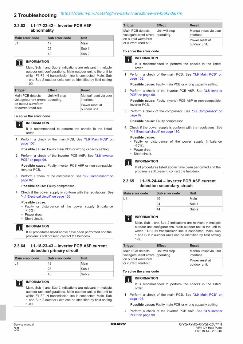
2 Troubleshooting
Service manual
36RYYQ+RYMQ+RXYQ8~20U7Y1B
VRV IV+ Heat PumpESIE18-14 – 2019.07
2.3.63 L1-17-22-42 – Inverter PCB A6Pabnormality
Main error code Sub error code UnitL1 17 Main
22 Sub 142 Sub 2
INFORMATIONMain, Sub 1 and Sub 2 indications are relevant in multipleoutdoor unit configurations. Main outdoor unit is the unit towhich F1‑F2 IN transmission line is connected. Main, Sub1 and Sub 2 outdoor units can be identified by field setting1‑00.
Trigger Effect ResetMain PCB detectsvoltage/current errorson output waveformor current read-out.
Unit will stopoperating.
Manual reset via userinterface.Power reset atoutdoor unit.
To solve the error code
INFORMATIONIt is recommended to perform the checks in the listedorder.
1 Perform a check of the main PCB. See "3.9 Main PCB" onpage 106.
Possible cause: Faulty main PCB or wrong capacity setting.
2 Perform a check of the inverter PCB A6P. See "3.8 InverterPCB" on page 99.
Possible cause: Faulty inverter PCB A6P or non‑compatibleinverter PCB.
3 Perform a check of the compressor. See "3.2 Compressor" onpage 82.
Possible cause: Faulty compressor.
4 Check if the power supply is conform with the regulations. See"4.1 Electrical circuit" on page 130.
Possible cause:▪ Faulty or disturbance of the power supply (imbalance
>10%),▪ Power drop,▪ Short circuit.
INFORMATIONIf all procedures listed above have been performed and theproblem is still present, contact the helpdesk.
2.3.64 L1-18-23-43 – Inverter PCB A6P currentdetection primary circuit
Main error code Sub error code UnitL1 18 Main
23 Sub 143 Sub 2
INFORMATIONMain, Sub 1 and Sub 2 indications are relevant in multipleoutdoor unit configurations. Main outdoor unit is the unit towhich F1‑F2 IN transmission line is connected. Main, Sub1 and Sub 2 outdoor units can be identified by field setting1‑00.
Trigger Effect ResetMain PCB detectsvoltage/current errorson output waveformor current read-out.
Unit will stopoperating.
Manual reset via userinterface.Power reset atoutdoor unit.
To solve the error code
INFORMATIONIt is recommended to perform the checks in the listedorder.
1 Perform a check of the main PCB. See "3.9 Main PCB" onpage 106.
Possible cause: Faulty main PCB or wrong capacity setting.
2 Perform a check of the inverter PCB A6P. See "3.8 InverterPCB" on page 99.
Possible cause: Faulty inverter PCB A6P or non‑compatibleinverter PCB.
3 Perform a check of the compressor. See "3.2 Compressor" onpage 82.
Possible cause: Faulty compressor.
4 Check if the power supply is conform with the regulations. See"4.1 Electrical circuit" on page 130.
Possible cause:▪ Faulty or disturbance of the power supply (imbalance
>10%),▪ Power drop,▪ Short circuit.
INFORMATIONIf all procedures listed above have been performed and theproblem is still present, contact the helpdesk.
2.3.65 L1-19-24-44 – Inverter PCB A6P currentdetection secondary circuit
Main error code Sub error code UnitL1 19 Main
24 Sub 144 Sub 2
INFORMATIONMain, Sub 1 and Sub 2 indications are relevant in multipleoutdoor unit configurations. Main outdoor unit is the unit towhich F1‑F2 IN transmission line is connected. Main, Sub1 and Sub 2 outdoor units can be identified by field setting1‑00.
Trigger Effect ResetMain PCB detectsvoltage/current errorson output waveformor current read-out.
Unit will stopoperating.
Manual reset via userinterface.Power reset atoutdoor unit.
To solve the error code
INFORMATIONIt is recommended to perform the checks in the listedorder.
1 Perform a check of the main PCB. See "3.9 Main PCB" onpage 106.
Possible cause: Faulty main PCB or wrong capacity setting.
2 Perform a check of the inverter PCB A6P. See "3.8 InverterPCB" on page 99.
https://daikin-p.ru/catalog/vrv-daikn/naruzhnye-vrv-bloki-daikin

2 Troubleshooting
Service manual
37RYYQ+RYMQ+RXYQ8~20U7Y1BVRV IV+ Heat PumpESIE18-14 – 2019.07
Possible cause: Faulty inverter PCB A6P or non‑compatibleinverter PCB.
3 Perform a check of the compressor. See "3.2 Compressor" onpage 82.
Possible cause: Faulty compressor.
4 Check if the power supply is conform with the regulations. See"4.1 Electrical circuit" on page 130.
Possible cause:▪ Faulty or disturbance of the power supply (imbalance
>10%),▪ Power drop,▪ Short circuit.
INFORMATIONIf all procedures listed above have been performed and theproblem is still present, contact the helpdesk.
2.3.66 L1-20-25-45 – Power transistor error oninverter PCB A6P
Main error code Sub error code UnitL1 20 Main
25 Sub 145 Sub 2
INFORMATIONMain, Sub 1 and Sub 2 indications are relevant in multipleoutdoor unit configurations. Main outdoor unit is the unit towhich F1‑F2 IN transmission line is connected. Main, Sub1 and Sub 2 outdoor units can be identified by field setting1‑00.
Trigger Effect ResetMain PCB detectsvoltage/current errorson output waveformor current read-out.
Unit will stopoperating.
Manual reset via userinterface.Power reset atoutdoor unit.
To solve the error code
INFORMATIONIt is recommended to perform the checks in the listedorder.
1 Perform a check of the main PCB. See "3.9 Main PCB" onpage 106.
Possible cause: Faulty main PCB or wrong capacity setting.
2 Perform a check of the inverter PCB A6P. See "3.8 InverterPCB" on page 99.
Possible cause: Faulty inverter PCB A6P or non‑compatibleinverter PCB.
3 Perform a check of the compressor. See "3.2 Compressor" onpage 82.
Possible cause: Faulty compressor.
4 Check if the power supply is conform with the regulations. See"4.1 Electrical circuit" on page 130.
Possible cause:▪ Faulty or disturbance of the power supply (imbalance
>10%),▪ Power drop,▪ Short circuit.
INFORMATIONIf all procedures listed above have been performed and theproblem is still present, contact the helpdesk.
2.3.67 L1-21-26-46 – Inverter PCB A6P hardwarefault
Main error code Sub error code UnitL1 21 Main
26 Sub 146 Sub 2
INFORMATIONMain, Sub 1 and Sub 2 indications are relevant in multipleoutdoor unit configurations. Main outdoor unit is the unit towhich F1‑F2 IN transmission line is connected. Main, Sub1 and Sub 2 outdoor units can be identified by field setting1‑00.
Trigger Effect ResetMain PCB detectsvoltage/current errorson output waveformor current read-out.
Unit will stopoperating.
Manual reset via userinterface.Power reset atoutdoor unit.
To solve the error code
INFORMATIONIt is recommended to perform the checks in the listedorder.
1 Perform a check of the main PCB. See "3.9 Main PCB" onpage 106.
Possible cause: Faulty main PCB or wrong capacity setting.
2 Perform a check of the inverter PCB A6P. See "3.8 InverterPCB" on page 99.
Possible cause: Faulty inverter PCB A6P or non‑compatibleinverter PCB.
3 Perform a check of the compressor. See "3.2 Compressor" onpage 82.
Possible cause: Faulty compressor.
4 Check if the power supply is conform with the regulations. See"4.1 Electrical circuit" on page 130.
Possible cause:▪ Faulty or disturbance of the power supply (imbalance
>10%),▪ Power drop,▪ Short circuit.
INFORMATIONIf all procedures listed above have been performed and theproblem is still present, contact the helpdesk.
2.3.68 L1-28-32-34 – Fan inverter PCB A4PEeprom error
Main error code Sub error code UnitL1 28 Main
32 Sub 134 Sub 2
INFORMATIONMain, Sub 1 and Sub 2 indications are relevant in multipleoutdoor unit configurations. Main outdoor unit is the unit towhich F1‑F2 IN transmission line is connected. Main, Sub1 and Sub 2 outdoor units can be identified by field setting1‑00.
https://daikin-p.ru/catalog/vrv-daikn/naruzhnye-vrv-bloki-daikin

2 Troubleshooting
Service manual
38RYYQ+RYMQ+RXYQ8~20U7Y1B
VRV IV+ Heat PumpESIE18-14 – 2019.07
Trigger Effect ResetFan inverter PCBA4P fails reading/writing memory(EEPROM error).
Unit will stopoperating.
Manual reset via userinterface.Power reset atoutdoor unit.
To solve the error code
INFORMATIONIt is recommended to perform the checks in the listedorder.
1 Perform a check of the fan inverter PCB A4P. See "3.6 Faninverter PCB" on page 92.
Possible cause: Faulty fan inverter PCB A4P.
INFORMATIONIf all procedures listed above have been performed and theproblem is still present, contact the helpdesk.
2.3.69 L1-29-33-35 – Fan inverter PCB A7PEeprom error
Main error code Sub error code UnitL1 29 Main
33 Sub 135 Sub 2
INFORMATIONMain, Sub 1 and Sub 2 indications are relevant in multipleoutdoor unit configurations. Main outdoor unit is the unit towhich F1‑F2 IN transmission line is connected. Main, Sub1 and Sub 2 outdoor units can be identified by field setting1‑00.
Trigger Effect ResetFan inverter PCBA7P fails reading/writing memory(EEPROM error).
Unit will stopoperating.
Manual reset via userinterface.Power reset atoutdoor unit.
To solve the error code
INFORMATIONIt is recommended to perform the checks in the listedorder.
1 Perform a check of the fan inverter PCB A7P. See "3.6 Faninverter PCB" on page 92.
Possible cause: Faulty fan inverter PCB A7P.
INFORMATIONIf all procedures listed above have been performed and theproblem is still present, contact the helpdesk.
2.3.70 L1-36-38-40 – Inverter PCB A3P Eepromerror
Main error code Sub error code UnitL1 36 Main
38 Sub 140 Sub 2
INFORMATIONMain, Sub 1 and Sub 2 indications are relevant in multipleoutdoor unit configurations. Main outdoor unit is the unit towhich F1‑F2 IN transmission line is connected. Main, Sub1 and Sub 2 outdoor units can be identified by field setting1‑00.
Trigger Effect ResetInverter PCB A3Pfails reading/writingmemory (EEPROMerror).
Unit will stopoperating.
Manual reset via userinterface.Power reset atoutdoor unit.
To solve the error code
INFORMATIONIt is recommended to perform the checks in the listedorder.
1 Perform a check of the inverter PCB A3P. See "3.8 InverterPCB" on page 99.
Possible cause: Faulty inverter PCB A3P or non‑compatibleinverter PCB.
INFORMATIONIf all procedures listed above have been performed and theproblem is still present, contact the helpdesk.
2.3.71 L1-37-39-41 – Inverter PCB A6P Eepromerror
Main error code Sub error code UnitL1 37 Main
39 Sub 141 Sub 2
INFORMATIONMain, Sub 1 and Sub 2 indications are relevant in multipleoutdoor unit configurations. Main outdoor unit is the unit towhich F1‑F2 IN transmission line is connected. Main, Sub1 and Sub 2 outdoor units can be identified by field setting1‑00.
Trigger Effect ResetInverter PCB A6Pfails reading/writingmemory (EEPROMerror).
Unit will stopoperating.
Manual reset via userinterface.Power reset atoutdoor unit.
To solve the error code
INFORMATIONIt is recommended to perform the checks in the listedorder.
1 Perform a check of the inverter PCB A6P. See "3.8 InverterPCB" on page 99.
Possible cause: Faulty inverter PCB A6P or non‑compatibleinverter PCB.
INFORMATIONIf all procedures listed above have been performed and theproblem is still present, contact the helpdesk.
https://daikin-p.ru/catalog/vrv-daikn/naruzhnye-vrv-bloki-daikin

2 Troubleshooting
Service manual
39RYYQ+RYMQ+RXYQ8~20U7Y1BVRV IV+ Heat PumpESIE18-14 – 2019.07
2.3.72 L1-47-49-51 – Inverter PCB A3P 16 V DCabnormal
Main error code Sub error code UnitL1 47 Main
49 Sub 151 Sub 2
INFORMATIONMain, Sub 1 and Sub 2 indications are relevant in multipleoutdoor unit configurations. Main outdoor unit is the unit towhich F1‑F2 IN transmission line is connected. Main, Sub1 and Sub 2 outdoor units can be identified by field setting1‑00.
Trigger Effect ResetMain PCB detectsvoltage/current errorson output waveformor current read-out.
Unit will stopoperating.
Manual reset via userinterface.Power reset atoutdoor unit.
To solve the error code
INFORMATIONIt is recommended to perform the checks in the listedorder.
1 Perform a check of the main PCB. See "3.9 Main PCB" onpage 106.
Possible cause: Faulty main PCB or wrong capacity setting.
2 Perform a check of the inverter PCB A3P. See "3.8 InverterPCB" on page 99.
Possible cause: Faulty inverter PCB A3P or non‑compatibleinverter PCB.
3 Perform a check of the compressor. See "3.2 Compressor" onpage 82.
Possible cause: Faulty compressor.
4 Check if the power supply is conform with the regulations. See"4.1 Electrical circuit" on page 130.
Possible cause:▪ Faulty or disturbance of the power supply (imbalance
>10%),▪ Power drop,▪ Short circuit.
INFORMATIONIf all procedures listed above have been performed and theproblem is still present, contact the helpdesk.
2.3.73 L1-48-50-52 – Inverter PCB A6P 16 V DCabnormal
Main error code Sub error code UnitL1 48 Main
50 Sub 152 Sub 2
INFORMATIONMain, Sub 1 and Sub 2 indications are relevant in multipleoutdoor unit configurations. Main outdoor unit is the unit towhich F1‑F2 IN transmission line is connected. Main, Sub1 and Sub 2 outdoor units can be identified by field setting1‑00.
Trigger Effect ResetMain PCB detectsvoltage/current errorson output waveformor current read-out.
Unit will stopoperating.
Manual reset via userinterface.Power reset atoutdoor unit.
To solve the error code
INFORMATIONIt is recommended to perform the checks in the listedorder.
1 Perform a check of the main PCB. See "3.9 Main PCB" onpage 106.
Possible cause: Faulty main PCB or wrong capacity setting.
2 Perform a check of the inverter PCB A6P. See "3.8 InverterPCB" on page 99.
Possible cause: Faulty inverter PCB A6P or non‑compatibleinverter PCB.
3 Perform a check of the compressor. See "3.2 Compressor" onpage 82.
Possible cause: Faulty compressor.
4 Check if the power supply is conform with the regulations. See"4.1 Electrical circuit" on page 130.
Possible cause:▪ Faulty or disturbance of the power supply (imbalance
>10%),▪ Power drop,▪ Short circuit.
INFORMATIONIf all procedures listed above have been performed and theproblem is still present, contact the helpdesk.
2.3.74 L2-01-02-03 – Power supply abnormalityduring test run
Main error code Sub error code UnitL2 01 Main
02 Sub 103 Sub 2
INFORMATIONMain, Sub 1 and Sub 2 indications are relevant in multipleoutdoor unit configurations. Main outdoor unit is the unit towhich F1‑F2 IN transmission line is connected. Main, Sub1 and Sub 2 outdoor units can be identified by field setting1‑00.
Trigger Effect ResetMain PCB detects 50Hz zero-crossingerror.
Unit stops and retriesafter guard timer (3minutes) - infinitecycle.
Automatic reset whenwithin zero-crossinginterval range.Power reset atoutdoor unit.
To solve the error code
INFORMATIONIt is recommended to perform the checks in the listedorder.
https://daikin-p.ru/catalog/vrv-daikn/naruzhnye-vrv-bloki-daikin

2 Troubleshooting
Service manual
40RYYQ+RYMQ+RXYQ8~20U7Y1B
VRV IV+ Heat PumpESIE18-14 – 2019.07
INFORMATIONMain PCB checks L1‑N on connector X1A for sinuswaveform each time crossing the zero‑line. Intervalbetween each zero‑crossing is 10 miliseconds when thepower supply is 50 Hz.
1 Check if the power supply is conform with the regulations. See"4.1 Electrical circuit" on page 130.
Possible cause:▪ Faulty or disturbance of the power supply (imbalance
>10%),▪ Power drop,▪ Short circuit.
2 Perform a check of the main PCB. See "3.9 Main PCB" onpage 106.
Possible cause: Faulty main PCB.
3 Perform a check of the inverter PCB(s). See "3.8 InverterPCB" on page 99.
Possible cause: Faulty inverter PCB(s).
INFORMATIONIf all procedures listed above have been performed and theproblem is still present, contact the helpdesk.
2.3.75 L2-04-05-06 – Power supply abnormalityduring normal operation
Main error code Sub error code UnitL2 04 Main
05 Sub 106 Sub 2
INFORMATIONMain, Sub 1 and Sub 2 indications are relevant in multipleoutdoor unit configurations. Main outdoor unit is the unit towhich F1‑F2 IN transmission line is connected. Main, Sub1 and Sub 2 outdoor units can be identified by field setting1‑00.
Trigger Effect ResetMain PCB detects 50Hz zero-crossingerror.
Unit stops and retriesafter guard timer (3minutes) - infinitecycle.
Automatic reset whenwithin zero-crossinginterval range.Power reset atoutdoor unit.
To solve the error code
INFORMATIONIt is recommended to perform the checks in the listedorder.
INFORMATIONMain PCB checks L1‑N on connector X1A for sinuswaveform each time crossing the zero‑line. Intervalbetween each zero‑crossing is 10 miliseconds when thepower supply is 50 Hz.
1 Check if the power supply is conform with the regulations. See"4.1 Electrical circuit" on page 130.
Possible cause:▪ Faulty or disturbance of the power supply (imbalance
>10%),▪ Power drop,▪ Short circuit.
2 Perform a check of the main PCB. See "3.9 Main PCB" onpage 106.
Possible cause: Faulty main PCB.
3 Perform a check of the inverter PCB(s). See "3.8 InverterPCB" on page 99.
Possible cause: Faulty inverter PCB(s).
INFORMATIONIf all procedures listed above have been performed and theproblem is still present, contact the helpdesk.
2.3.76 L4-01-02-03 – Inverter PCB A3P high fintemperature
Main error code Sub error code UnitL4 01 Main
02 Sub 103 Sub 2
INFORMATIONMain, Sub 1 and Sub 2 indications are relevant in multipleoutdoor unit configurations. Main outdoor unit is the unit towhich F1‑F2 IN transmission line is connected. Main, Sub1 and Sub 2 outdoor units can be identified by field setting1‑00.
Trigger Effect ResetInverter PCB A3Pdetects high fintemperature.
Unit will stopoperating.
Manual reset via userinterface.
To solve the error code
INFORMATIONIt is recommended to perform the checks in the listedorder.
1 Check (by touching) if refrigerant is flowing through the radiantcooling refrigerant circuit. The radiant cooling refrigerant circuitshould be warm if refrigerant is flowing. If no refrigerant flow,perform a check of the liquid cooling expansion valve, see"3.5 Expansion valve" on page 89.
Possible cause: No refrigerant flow through the radiantcooling refrigerant circuit.
2 Perform a check of the liquid cooling expansion valve. See"3.5 Expansion valve" on page 89.
Possible cause: Faulty liquid cooling expansion valve.
INFORMATIONIf all procedures listed above have been performed and theproblem is still present, contact the helpdesk.
2.3.77 L4-06-18-20 – Fan inverter PCB A4P highfin temperature
Main error code Sub error code UnitL4 06 Main
18 Sub 120 Sub 2
INFORMATIONMain, Sub 1 and Sub 2 indications are relevant in multipleoutdoor unit configurations. Main outdoor unit is the unit towhich F1‑F2 IN transmission line is connected. Main, Sub1 and Sub 2 outdoor units can be identified by field setting1‑00.
https://daikin-p.ru/catalog/vrv-daikn/naruzhnye-vrv-bloki-daikin

2 Troubleshooting
Service manual
41RYYQ+RYMQ+RXYQ8~20U7Y1BVRV IV+ Heat PumpESIE18-14 – 2019.07
Trigger Effect ResetFan inverter PCBA4P detects high fintemperature.
Unit will stopoperating.
Manual reset via userinterface.
To solve the error code
INFORMATIONIt is recommended to perform the checks in the listedorder.
1 Check (by touching) if refrigerant is flowing through the radiantcooling refrigerant circuit. The radiant cooling refrigerant circuitshould be warm if refrigerant is flowing. If no refrigerant flow,perform a check of the liquid cooling expansion valve, see"3.5 Expansion valve" on page 89.
Possible cause: No refrigerant flow through the radiantcooling refrigerant circuit.
2 Perform a check of the liquid cooling expansion valve. See"3.5 Expansion valve" on page 89.
Possible cause: Faulty liquid cooling expansion valve.
INFORMATIONIf all procedures listed above have been performed and theproblem is still present, contact the helpdesk.
2.3.78 L4-07-19-21 – Fan inverter PCB A7P highfin temperature
Main error code Sub error code UnitL4 07 Main
19 Sub 121 Sub 2
INFORMATIONMain, Sub 1 and Sub 2 indications are relevant in multipleoutdoor unit configurations. Main outdoor unit is the unit towhich F1‑F2 IN transmission line is connected. Main, Sub1 and Sub 2 outdoor units can be identified by field setting1‑00.
Trigger Effect ResetFan inverter PCBA7P detects high fintemperature.
Unit will stopoperating.
Manual reset via userinterface.
To solve the error code
INFORMATIONIt is recommended to perform the checks in the listedorder.
1 Perform a check of the outdoor unit fan motor. See"3.12 Outdoor unit fan motor" on page 115.
Possible cause: Faulty outdoor unit fan motor.
2 Check if the power supply is conform with the regulations. See"4.1 Electrical circuit" on page 130.
Possible cause:▪ Faulty or disturbance of the power supply (imbalance
>10%),▪ Power drop,▪ Short circuit.
3 Perform a check of the inverter PCB. See "3.8 Inverter PCB" onpage 99.
Possible cause: Faulty inverter PCB.
4 Perform a check of the main PCB. See "3.9 Main PCB" onpage 106.
Possible cause: Faulty main PCB.
5 Check that the silicon grease is applied properly on theradiation fin of the outdoor unit PCB. Adjust if needed.
Possible cause: Silicon grease NOT applied properly on theradiation fin.
INFORMATIONIf all procedures listed above have been performed and theproblem is still present, contact the helpdesk.
2.3.79 L4-09-10-11 – Inverter PCB A6P high fintemperature
Main error code Sub error code UnitL4 09 Main
10 Sub 111 Sub 2
INFORMATIONMain, Sub 1 and Sub 2 indications are relevant in multipleoutdoor unit configurations. Main outdoor unit is the unit towhich F1‑F2 IN transmission line is connected. Main, Sub1 and Sub 2 outdoor units can be identified by field setting1‑00.
Trigger Effect ResetInverter PCB A6Pdetects high fintemperature.
Unit will stopoperating.
Manual reset via userinterface.
To solve the error code
INFORMATIONIt is recommended to perform the checks in the listedorder.
1 Perform a check of the outdoor unit fan motor. See"3.12 Outdoor unit fan motor" on page 115.
Possible cause: Faulty outdoor unit fan motor.
2 Check if the power supply is conform with the regulations. See"4.1 Electrical circuit" on page 130.
Possible cause:▪ Faulty or disturbance of the power supply (imbalance
>10%),▪ Power drop,▪ Short circuit.
3 Perform a check of the inverter PCB. See "3.8 Inverter PCB" onpage 99.
Possible cause: Faulty inverter PCB.
4 Perform a check of the main PCB. See "3.9 Main PCB" onpage 106.
Possible cause: Faulty main PCB.
5 Check that the silicon grease is applied properly on theradiation fin of the outdoor unit PCB. Adjust if needed.
Possible cause: Silicon grease NOT applied properly on theradiation fin.
INFORMATIONIf all procedures listed above have been performed and theproblem is still present, contact the helpdesk.
https://daikin-p.ru/catalog/vrv-daikn/naruzhnye-vrv-bloki-daikin

2 Troubleshooting
Service manual
42RYYQ+RYMQ+RXYQ8~20U7Y1B
VRV IV+ Heat PumpESIE18-14 – 2019.07
2.3.80 L5-03-05-07 – Output overcurrentdetection on inverter PCB A3P
Main error code Sub error code UnitL5 03 Main
05 Sub 107 Sub 2
INFORMATIONMain, Sub 1 and Sub 2 indications are relevant in multipleoutdoor unit configurations. Main outdoor unit is the unit towhich F1‑F2 IN transmission line is connected. Main, Sub1 and Sub 2 outdoor units can be identified by field setting1‑00.
Trigger Effect ResetInverter PCB A3Pdetects overcurrent topower transistor.
Unit will stopoperating.
Manual reset via userinterface.
To solve the error code
INFORMATIONIt is recommended to perform the checks in the listedorder.
1 Check if the power supply is conform with the regulations. See"4.1 Electrical circuit" on page 130.
Possible cause:▪ Faulty or disturbance of the power supply (imbalance
>10%),▪ Power drop,▪ Short circuit.
2 Check if the refrigerant circuit is clogged. See "4.2 Refrigerantcircuit" on page 133.
Possible cause: Clogged refrigerant circuit.
3 Check that all stop valves of the refrigerant circuit are open.See "4.2 Refrigerant circuit" on page 133.
Possible cause: Closed stop valve in the refrigerant circuit.
4 Check for the presence of non‑condensables and/or humidity inthe refrigerant circuit. See "4.2 Refrigerant circuit" on page 133.
Possible cause: Non‑condensables and/or humidity in therefrigerant circuit.
5 Perform a check of the inverter PCB A3P. See "3.8 InverterPCB" on page 99.
Possible cause: Faulty inverter PCB A3P.
6 Perform a check of the compressor M1C. See"3.2 Compressor" on page 82.
Possible cause: Faulty compressor M1C.
INFORMATIONIf all procedures listed above have been performed and theproblem is still present, contact the helpdesk.
2.3.81 L5-14-15-16 – Output overcurrentdetection on inverter PCB A6P
Main error code Sub error code UnitL5 14 Main
15 Sub 116 Sub 2
INFORMATIONMain, Sub 1 and Sub 2 indications are relevant in multipleoutdoor unit configurations. Main outdoor unit is the unit towhich F1‑F2 IN transmission line is connected. Main, Sub1 and Sub 2 outdoor units can be identified by field setting1‑00.
Trigger Effect ResetInverter PCB A6Pdetects overcurrent topower transistor.
Unit will stopoperating.
Manual reset via userinterface.
To solve the error code
INFORMATIONIt is recommended to perform the checks in the listedorder.
1 Check if the power supply is conform with the regulations. See"4.1 Electrical circuit" on page 130.
Possible cause:▪ Faulty or disturbance of the power supply (imbalance
>10%),▪ Power drop,▪ Short circuit.
2 Check if the refrigerant circuit is clogged. See "4.2 Refrigerantcircuit" on page 133.
Possible cause: Clogged refrigerant circuit.
3 Check that all stop valves of the refrigerant circuit are open.See "4.2 Refrigerant circuit" on page 133.
Possible cause: Closed stop valve in the refrigerant circuit.
4 Check for the presence of non‑condensables and/or humidity inthe refrigerant circuit. See "4.2 Refrigerant circuit" on page 133.
Possible cause: Non‑condensables and/or humidity in therefrigerant circuit.
5 Perform a check of the inverter PCB A6P. See "3.8 InverterPCB" on page 99.
Possible cause: Faulty inverter PCB A6P.
6 Perform a check of the compressor M2C. See"3.2 Compressor" on page 82.
Possible cause: Faulty compressor M2C.
INFORMATIONIf all procedures listed above have been performed and theproblem is still present, contact the helpdesk.
2.3.82 L8-03-06-07 – Overcurrent on inverterPCB A3P except start-up
Main error code Sub error code UnitL8 03 Main
06 Sub 107 Sub 2
INFORMATIONMain, Sub 1 and Sub 2 indications are relevant in multipleoutdoor unit configurations. Main outdoor unit is the unit towhich F1‑F2 IN transmission line is connected. Main, Sub1 and Sub 2 outdoor units can be identified by field setting1‑00.
https://daikin-p.ru/catalog/vrv-daikn/naruzhnye-vrv-bloki-daikin

2 Troubleshooting
Service manual
43RYYQ+RYMQ+RXYQ8~20U7Y1BVRV IV+ Heat PumpESIE18-14 – 2019.07
Trigger Effect ResetInverter PCB A3Pdetects overcurrent tocompressor excepton start‑up.
Unit will stopoperating.
Manual reset via userinterface.
To solve the error code
INFORMATIONIt is recommended to perform the checks in the listedorder.
1 Check if the power supply is conform with the regulations. See"4.1 Electrical circuit" on page 130.
Possible cause:▪ Faulty or disturbance of the power supply (imbalance
>10%),▪ Power drop,▪ Short circuit.
2 Check if the refrigerant circuit is clogged. See "4.2 Refrigerantcircuit" on page 133.
Possible cause: Clogged refrigerant circuit.
3 Check that all stop valves of the refrigerant circuit are open.See "4.2 Refrigerant circuit" on page 133.
Possible cause: Closed stop valve in the refrigerant circuit.
4 Check for the presence of non‑condensables and/or humidity inthe refrigerant circuit. See "4.2 Refrigerant circuit" on page 133.
Possible cause: Non‑condensables and/or humidity in therefrigerant circuit.
5 Perform a check of the inverter PCB A3P. See "3.8 InverterPCB" on page 99.
Possible cause: Faulty inverter PCB A3P.
6 Perform a check of the compressor M1C. See"3.2 Compressor" on page 82.
Possible cause: Faulty compressor M1C.
INFORMATIONIf all procedures listed above have been performed and theproblem is still present, contact the helpdesk.
2.3.83 L8-11-12-13 – Overcurrent on inverterPCB A6P except start-up
Main error code Sub error code UnitL8 11 Main
12 Sub 113 Sub 2
INFORMATIONMain, Sub 1 and Sub 2 indications are relevant in multipleoutdoor unit configurations. Main outdoor unit is the unit towhich F1‑F2 IN transmission line is connected. Main, Sub1 and Sub 2 outdoor units can be identified by field setting1‑00.
Trigger Effect ResetInverter PCB A6Pdetects overcurrent tocompressor excepton start‑up.
Unit will stopoperating.
Manual reset via userinterface.
To solve the error code
INFORMATIONIt is recommended to perform the checks in the listedorder.
1 Check if the power supply is conform with the regulations. See"4.1 Electrical circuit" on page 130.
Possible cause:▪ Faulty or disturbance of the power supply (imbalance
>10%),▪ Power drop,▪ Short circuit.
2 Check if the refrigerant circuit is clogged. See "4.2 Refrigerantcircuit" on page 133.
Possible cause: Clogged refrigerant circuit.
3 Check that all stop valves of the refrigerant circuit are open.See "4.2 Refrigerant circuit" on page 133.
Possible cause: Closed stop valve in the refrigerant circuit.
4 Check for the presence of non‑condensables and/or humidity inthe refrigerant circuit. See "4.2 Refrigerant circuit" on page 133.
Possible cause: Non‑condensables and/or humidity in therefrigerant circuit.
5 Perform a check of the inverter PCB A6P. See "3.8 InverterPCB" on page 99.
Possible cause: Faulty inverter PCB A6P.
6 Perform a check of the compressor M2C. See"3.2 Compressor" on page 82.
Possible cause: Faulty compressor M2C.
INFORMATIONIf all procedures listed above have been performed and theproblem is still present, contact the helpdesk.
2.3.84 L9-01-05-06 – Stall prevention by inverterPCB A3P
Main error code Sub error code UnitL9 01 Main
05 Sub 106 Sub 2
INFORMATIONMain, Sub 1 and Sub 2 indications are relevant in multipleoutdoor unit configurations. Main outdoor unit is the unit towhich F1‑F2 IN transmission line is connected. Main, Sub1 and Sub 2 outdoor units can be identified by field setting1‑00.
Trigger Effect ResetInverter PCB A3Pdetects overcurrent orno rotation at start-up.
Unit will stopoperating.
Manual reset via userinterface.
To solve the error code
INFORMATIONIt is recommended to perform the checks in the listedorder.
1 Check if the power supply is conform with the regulations. See"4.1 Electrical circuit" on page 130.
https://daikin-p.ru/catalog/vrv-daikn/naruzhnye-vrv-bloki-daikin
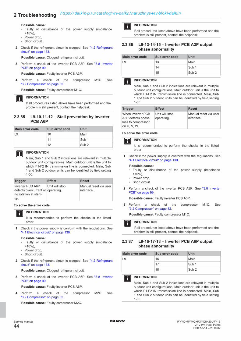
2 Troubleshooting
Service manual
44RYYQ+RYMQ+RXYQ8~20U7Y1B
VRV IV+ Heat PumpESIE18-14 – 2019.07
Possible cause:▪ Faulty or disturbance of the power supply (imbalance
>10%),▪ Power drop,▪ Short circuit.
2 Check if the refrigerant circuit is clogged. See "4.2 Refrigerantcircuit" on page 133.
Possible cause: Clogged refrigerant circuit.
3 Perform a check of the inverter PCB A3P. See "3.8 InverterPCB" on page 99.
Possible cause: Faulty inverter PCB A3P.
4 Perform a check of the compressor M1C. See"3.2 Compressor" on page 82.
Possible cause: Faulty compressor M1C.
INFORMATIONIf all procedures listed above have been performed and theproblem is still present, contact the helpdesk.
2.3.85 L9-10-11-12 – Stall prevention by inverterPCB A6P
Main error code Sub error code UnitL9 10 Main
11 Sub 112 Sub 2
INFORMATIONMain, Sub 1 and Sub 2 indications are relevant in multipleoutdoor unit configurations. Main outdoor unit is the unit towhich F1‑F2 IN transmission line is connected. Main, Sub1 and Sub 2 outdoor units can be identified by field setting1‑00.
Trigger Effect ResetInverter PCB A6Pdetects overcurrent orno rotation at start-up.
Unit will stopoperating.
Manual reset via userinterface.
To solve the error code
INFORMATIONIt is recommended to perform the checks in the listedorder.
1 Check if the power supply is conform with the regulations. See"4.1 Electrical circuit" on page 130.
Possible cause:▪ Faulty or disturbance of the power supply (imbalance
>10%),▪ Power drop,▪ Short circuit.
2 Check if the refrigerant circuit is clogged. See "4.2 Refrigerantcircuit" on page 133.
Possible cause: Clogged refrigerant circuit.
3 Perform a check of the inverter PCB A6P. See "3.8 InverterPCB" on page 99.
Possible cause: Faulty inverter PCB A6P.
4 Perform a check of the compressor M2C. See"3.2 Compressor" on page 82.
Possible cause: Faulty compressor M2C.
INFORMATIONIf all procedures listed above have been performed and theproblem is still present, contact the helpdesk.
2.3.86 L9-13-14-15 – Inverter PCB A3P outputphase abnormality
Main error code Sub error code UnitL9 13 Main
14 Sub 115 Sub 2
INFORMATIONMain, Sub 1 and Sub 2 indications are relevant in multipleoutdoor unit configurations. Main outdoor unit is the unit towhich F1‑F2 IN transmission line is connected. Main, Sub1 and Sub 2 outdoor units can be identified by field setting1‑00.
Trigger Effect ResetWhen inverter PCBA3P detects phaseloss to compressoron U, V, W.
Unit will stopoperating.
Manual reset via userinterface.
To solve the error code
INFORMATIONIt is recommended to perform the checks in the listedorder.
1 Check if the power supply is conform with the regulations. See"4.1 Electrical circuit" on page 130.
Possible cause:▪ Faulty or disturbance of the power supply (imbalance
>10%),▪ Power drop,▪ Short circuit.
2 Perform a check of the inverter PCB A3P. See "3.8 InverterPCB" on page 99.
Possible cause: Faulty inverter PCB A3P.
3 Perform a check of the compressor M1C. See"3.2 Compressor" on page 82.
Possible cause: Faulty compressor M1C.
INFORMATIONIf all procedures listed above have been performed and theproblem is still present, contact the helpdesk.
2.3.87 L9-16-17-18 – Inverter PCB A6P outputphase abnormality
Main error code Sub error code UnitL9 16 Main
17 Sub 118 Sub 2
INFORMATIONMain, Sub 1 and Sub 2 indications are relevant in multipleoutdoor unit configurations. Main outdoor unit is the unit towhich F1‑F2 IN transmission line is connected. Main, Sub1 and Sub 2 outdoor units can be identified by field setting1‑00.
https://daikin-p.ru/catalog/vrv-daikn/naruzhnye-vrv-bloki-daikin

2 Troubleshooting
Service manual
45RYYQ+RYMQ+RXYQ8~20U7Y1BVRV IV+ Heat PumpESIE18-14 – 2019.07
Trigger Effect ResetWhen inverter PCBA6P detects phaseloss to compressoron U, V, W.
Unit will stopoperating.
Manual reset via userinterface.
To solve the error code
INFORMATIONIt is recommended to perform the checks in the listedorder.
1 Check if the power supply is conform with the regulations. See"4.1 Electrical circuit" on page 130.
Possible cause:▪ Faulty or disturbance of the power supply (imbalance
>10%),▪ Power drop,▪ Short circuit.
2 Perform a check of the inverter PCB A6P. See "3.8 InverterPCB" on page 99.
Possible cause: Faulty inverter PCB A6P.
3 Perform a check of the compressor M2C. See"3.2 Compressor" on page 82.
Possible cause: Faulty compressor M2C.
INFORMATIONIf all procedures listed above have been performed and theproblem is still present, contact the helpdesk.
2.3.88 LC-01 – Transmission abnormality
Trigger Effect ResetNo transmissionbetween PCB boards.
Unit will stopoperating.
Automatic reset.
To solve the error code
INFORMATIONIt is recommended to perform the checks in the listedorder.
1 Perform a check of the main PCB. See "3.9 Main PCB" onpage 106.
Possible cause: Faulty main PCB or wrong capacity setting.
2 Perform a check of the noise filter PCB. See "3.10 Noise filterPCB" on page 110.
Possible cause: Faulty noise filter PCB.
3 Perform a check of the inverter PCB. See "3.8 Inverter PCB" onpage 99.
Possible cause: Faulty inverter PCB.
4 Perform a check of the fan inverter PCB. See "3.6 Fan inverterPCB" on page 92.
Possible cause: Faulty fan inverter PCB.
5 Check that the bridge connector X4A of the fan inverter PCB iscorrectly connected. See "3.6 Fan inverter PCB" on page 92.
Possible cause: Open jumper X4A on fan inverter PCB.
6 Check the wiring between the PCB's. See "6.2 Wiringdiagram" on page 146.
Possible cause: Faulty wiring between PCB's.
7 Check if the correct spare part is installed for all PCB's. Seechecking procedures of the specific PCB's.
Possible cause: Wrong spare part PCB installed.
INFORMATIONIf all procedures listed above have been performed and theproblem is still present, contact the helpdesk.
2.3.89 LC-14-15-16 – Transmission abnormalitymain PCB/inverter PCB A3P
Main error code Sub error code UnitLC 14 Main
15 Sub 116 Sub 2
INFORMATIONMain, Sub 1 and Sub 2 indications are relevant in multipleoutdoor unit configurations. Main outdoor unit is the unit towhich F1‑F2 IN transmission line is connected. Main, Sub1 and Sub 2 outdoor units can be identified by field setting1‑00.
Trigger Effect ResetNo transmissionbetween main PCBand inverter PCBA3P.
Unit will stopoperating.
Automatic reset.
To solve the error code
INFORMATIONIt is recommended to perform the checks in the listedorder.
1 Perform a check of the main PCB. See "3.9 Main PCB" onpage 106.
Possible cause: Faulty main PCB or wrong capacity setting.
2 Perform a check of the noise filter PCB A2P. See "3.10 Noisefilter PCB" on page 110.
Possible cause: Faulty noise filter PCB A2P.
3 Perform a check of the inverter PCB A3P. See "3.8 InverterPCB" on page 99.
Possible cause: Faulty inverter PCB A3P.
4 Check the wiring between the PCB's. See "6.2 Wiringdiagram" on page 146.
Possible cause: Faulty wiring between PCB's.
5 Check if the correct spare part is installed for all PCB's. Seechecking procedures of the specific PCB's.
Possible cause: Wrong spare part PCB installed.
INFORMATIONIf all procedures listed above have been performed and theproblem is still present, contact the helpdesk.
2.3.90 LC-19-20-21 – Transmission abnormalitymain PCB/fan inverter PCB A4P
Main error code Sub error code UnitLC 19 Main
20 Sub 121 Sub 2
https://daikin-p.ru/catalog/vrv-daikn/naruzhnye-vrv-bloki-daikin

2 Troubleshooting
Service manual
46RYYQ+RYMQ+RXYQ8~20U7Y1B
VRV IV+ Heat PumpESIE18-14 – 2019.07
INFORMATIONMain, Sub 1 and Sub 2 indications are relevant in multipleoutdoor unit configurations. Main outdoor unit is the unit towhich F1‑F2 IN transmission line is connected. Main, Sub1 and Sub 2 outdoor units can be identified by field setting1‑00.
Trigger Effect ResetNo transmissionbetween main PCBand fan inverter PCBA4P.
Unit will stopoperating.
Automatic reset.
To solve the error code
INFORMATIONIt is recommended to perform the checks in the listedorder.
1 Perform a check of the main PCB. See "3.9 Main PCB" onpage 106.
Possible cause: Faulty main PCB or wrong capacity setting.
2 Perform a check of the noise filter PCB A2P. See "3.10 Noisefilter PCB" on page 110.
Possible cause: Faulty noise filter PCB A2P.
3 Perform a check of the inverter PCB A3P. See "3.8 InverterPCB" on page 99.
Possible cause: Faulty inverter PCB A3P.
4 Perform a check of the fan inverter PCB A4P. See "3.6 Faninverter PCB" on page 92.
Possible cause: Faulty fan inverter PCB A4P.
5 Check that the bridge connector X4A of the fan inverter PCB iscorrectly connected. See "3.6 Fan inverter PCB" on page 92.
Possible cause: Open jumper X4A on fan inverter PCB.
6 Check the wiring between the PCB's. See "6.2 Wiringdiagram" on page 146.
Possible cause: Faulty wiring between PCB's.
7 Check if the correct spare part is installed for all PCB's. Seechecking procedures of the specific PCB's.
Possible cause: Wrong spare part PCB installed.
INFORMATIONIf all procedures listed above have been performed and theproblem is still present, contact the helpdesk.
2.3.91 LC-24-25-26 – Transmission abnormalitymain PCB/fan inverter PCB A7P
Main error code Sub error code UnitLC 24 Main
25 Sub 126 Sub 2
INFORMATIONMain, Sub 1 and Sub 2 indications are relevant in multipleoutdoor unit configurations. Main outdoor unit is the unit towhich F1‑F2 IN transmission line is connected. Main, Sub1 and Sub 2 outdoor units can be identified by field setting1‑00.
Trigger Effect ResetNo transmissionbetween main PCBand fan inverter PCBA7P.
Unit will stopoperating.
Automatic reset.
To solve the error code
INFORMATIONIt is recommended to perform the checks in the listedorder.
1 Perform a check of the main PCB. See "3.9 Main PCB" onpage 106.
Possible cause: Faulty main PCB or wrong capacity setting.
2 Perform a check of the noise filter PCB A2P. See "3.10 Noisefilter PCB" on page 110.
Possible cause: Faulty noise filter PCB A2P.
3 Perform a check of the inverter PCB A3P. See "3.8 InverterPCB" on page 99.
Possible cause: Faulty inverter PCB A3P.
4 Perform a check of the noise filter PCB A5P. See "3.10 Noisefilter PCB" on page 110.
Possible cause: Faulty noise filter PCB A5P.
5 Perform a check of the inverter PCB A6P. See "3.8 InverterPCB" on page 99.
Possible cause: Faulty inverter PCB A6P.
6 Perform a check of the fan inverter PCB A7P. See "3.6 Faninverter PCB" on page 92.
Possible cause: Faulty fan inverter PCB A7P.
7 Check that the bridge connector X4A of the fan inverter PCB iscorrectly connected. See "3.6 Fan inverter PCB" on page 92.
Possible cause: Open jumper X4A on fan inverter PCB.
8 Check the wiring between the PCB's. See "6.2 Wiringdiagram" on page 146.
Possible cause: Faulty wiring between PCB's.
9 Check if the correct spare part is installed for all PCB's. Seechecking procedures of the specific PCB's.
Possible cause: Wrong spare part PCB installed.
INFORMATIONIf all procedures listed above have been performed and theproblem is still present, contact the helpdesk.
2.3.92 LC-30-31-32 – Transmission abnormalitymain PCB/inverter PCB A6P
Main error code Sub error code UnitLC 30 Main
31 Sub 132 Sub 2
INFORMATIONMain, Sub 1 and Sub 2 indications are relevant in multipleoutdoor unit configurations. Main outdoor unit is the unit towhich F1‑F2 IN transmission line is connected. Main, Sub1 and Sub 2 outdoor units can be identified by field setting1‑00.
https://daikin-p.ru/catalog/vrv-daikn/naruzhnye-vrv-bloki-daikin

2 Troubleshooting
Service manual
47RYYQ+RYMQ+RXYQ8~20U7Y1BVRV IV+ Heat PumpESIE18-14 – 2019.07
Trigger Effect ResetNo transmissionbetween main PCBand inverter PCBA6P .
Unit will stopoperating.
Automatic reset.
To solve the error code
INFORMATIONIt is recommended to perform the checks in the listedorder.
1 Perform a check of the main PCB. See "3.9 Main PCB" onpage 106.
Possible cause: Faulty main PCB or wrong capacity setting.
2 Perform a check of the noise filter PCB A2P. See "3.10 Noisefilter PCB" on page 110.
Possible cause: Faulty noise filter PCB A2P.
3 Perform a check of the inverter PCB A3P. See "3.8 InverterPCB" on page 99.
Possible cause: Faulty inverter PCB A3P.
4 Perform a check of the noise filter PCB A5P. See "3.10 Noisefilter PCB" on page 110.
Possible cause: Faulty noise filter PCB A5P.
5 Perform a check of the inverter PCB A6P. See "3.8 InverterPCB" on page 99.
Possible cause: Faulty inverter PCB A6P.
6 Check the wiring between the PCB's. See "6.2 Wiringdiagram" on page 146.
Possible cause: Faulty wiring between PCB's.
7 Check if the correct spare part is installed for all PCB's. Seechecking procedures of the specific PCB's.
Possible cause: Wrong spare part PCB installed.
INFORMATIONIf all procedures listed above have been performed and theproblem is still present, contact the helpdesk.
2.3.93 P1-01-02-03 – Open phase or unbalancedpower supply detection by inverter PCBA3P
Main error code Sub error code UnitP1 01 Main
02 Sub 103 Sub 2
INFORMATIONMain, Sub 1 and Sub 2 indications are relevant in multipleoutdoor unit configurations. Main outdoor unit is the unit towhich F1‑F2 IN transmission line is connected. Main, Sub1 and Sub 2 outdoor units can be identified by field setting1‑00.
Trigger Effect ResetInverter PCB A3Pdetects powerunbalance >4%.
Unit will stopoperating.
Manual reset via userinterface.Automatic reset.
To solve the error code
INFORMATIONIt is recommended to perform the checks in the listedorder.
1 Check if the power supply is conform with the regulations. See"4.1 Electrical circuit" on page 130.
Possible cause:▪ Faulty or disturbance of the power supply (imbalance
>10%),▪ Power drop,▪ Short circuit.
2 Perform a check of the inverter PCB A3P. See "3.8 InverterPCB" on page 99.
Possible cause: Faulty inverter PCB A3P.
INFORMATIONIf all procedures listed above have been performed and theproblem is still present, contact the helpdesk.
2.3.94 P1-07-08-09 – Open phase or unbalancedpower supply detection by inverter PCBA6P
Main error code Sub error code UnitP1 07 Main
08 Sub 109 Sub 2
INFORMATIONMain, Sub 1 and Sub 2 indications are relevant in multipleoutdoor unit configurations. Main outdoor unit is the unit towhich F1‑F2 IN transmission line is connected. Main, Sub1 and Sub 2 outdoor units can be identified by field setting1‑00.
Trigger Effect ResetInverter PCB A6Pdetects powerunbalance >4%.
Unit will stopoperating.
Manual reset via userinterface.Automatic reset.
To solve the error code
INFORMATIONIt is recommended to perform the checks in the listedorder.
1 Check if the power supply is conform with the regulations. See"4.1 Electrical circuit" on page 130.
Possible cause:▪ Faulty or disturbance of the power supply (imbalance
>10%),▪ Power drop,▪ Short circuit.
2 Perform a check of the inverter PCB A6P. See "3.8 InverterPCB" on page 99.
Possible cause: Faulty inverter PCB A6P.
INFORMATIONIf all procedures listed above have been performed and theproblem is still present, contact the helpdesk.
2.3.95 P2-00 – Refrigerant auto-chargeinterrupted
Trigger Effect ResetAuto-charge functionis terminated beforefinished.
Auto-chargeoperation willterminate.
Push BS3 (return)button once.
https://daikin-p.ru/catalog/vrv-daikn/naruzhnye-vrv-bloki-daikin

2 Troubleshooting
Service manual
48RYYQ+RYMQ+RXYQ8~20U7Y1B
VRV IV+ Heat PumpESIE18-14 – 2019.07
To solve the error code
INFORMATIONIt is recommended to perform the checks in the listedorder.
1 Check for objects near the indoor unit that may block theairflow. See "4.3 External factors" on page 138.
Possible cause: Airflow of the indoor unit is blocked.
2 Clean the air filters of the indoor unit(s). See service manual ofthe respective indoor unit(s).
Possible cause: Faulty or clogged air filter.
3 Adjust external static pressure setting for ducted type indoorunits, if necessary.
4 Restart refrigerant auto‑charge function. See installer referenceguide for more information.
INFORMATIONIf all procedures listed above have been performed and theproblem is still present, contact the helpdesk.
2.3.96 P4-01-04-05 – Fin thermistor abnormalityon inverter PCB A3P
Main error code Sub error code UnitP4 01 Main
04 Sub 105 Sub 2
INFORMATIONMain, Sub 1 and Sub 2 indications are relevant in multipleoutdoor unit configurations. Main outdoor unit is the unit towhich F1‑F2 IN transmission line is connected. Main, Sub1 and Sub 2 outdoor units can be identified by field setting1‑00.
Trigger Effect ResetInverter PCB A3Pdetects hightemperature onpower module.
Unit will stopoperating.
Manual reset via userinterface.Automatic reset whenfin temperaturedrops.
To solve the error code
INFORMATIONIt is recommended to perform the checks in the listedorder.
1 Perform a check of the fin thermistor of the PCB. See"3.17 Thermistors" on page 128.
Possible cause: Faulty fin thermistor of the PCB.
1 Check the required space around the outdoor unit heatexchanger. See "4.3 External factors" on page 138.
Possible cause: Insufficient air flow or air by‑pass due torequired space specifications not met.
2 Perform a check of the liquid cooling expansion valve. See"3.5 Expansion valve" on page 89.
Possible cause: Faulty liquid cooling expansion valve.
3 Perform a check of the inverter PCB A3P. See "3.8 InverterPCB" on page 99.
Possible cause: Faulty inverter PCB A3P.
INFORMATIONIf all procedures listed above have been performed and theproblem is still present, contact the helpdesk.
2.3.97 P4-02-15-17 – Fin thermistor abnormalityon fan inverter PCB A4P
Main error code Sub error code UnitP4 02 Main
15 Sub 117 Sub 2
INFORMATIONMain, Sub 1 and Sub 2 indications are relevant in multipleoutdoor unit configurations. Main outdoor unit is the unit towhich F1‑F2 IN transmission line is connected. Main, Sub1 and Sub 2 outdoor units can be identified by field setting1‑00.
Trigger Effect ResetFan inverter PCBA4P detects hightemperature onpower module.
Unit will stopoperating.
Manual reset via userinterface.Automatic reset whenfin temperaturedrops.
To solve the error code
INFORMATIONIt is recommended to perform the checks in the listedorder.
1 Perform a check of the fin thermistor of the PCB. See"3.17 Thermistors" on page 128.
Possible cause: Faulty fin thermistor of the PCB.
1 Check the required space around the outdoor unit heatexchanger. See "4.3 External factors" on page 138.
Possible cause: Insufficient air flow or air by‑pass due torequired space specifications not met.
2 Perform a check of the liquid cooling expansion valve. See"3.5 Expansion valve" on page 89.
Possible cause: Faulty liquid cooling expansion valve.
3 Perform a check of the fan inverter PCB A4P. See "3.6 Faninverter PCB" on page 92.
Possible cause: Faulty fan inverter PCB A4P.
INFORMATIONIf all procedures listed above have been performed and theproblem is still present, contact the helpdesk.
2.3.98 P4-03-16-18 – Fin thermistor abnormalityon fan inverter PCB A7P
Main error code Sub error code UnitP4 03 Main
16 Sub 118 Sub 2
INFORMATIONMain, Sub 1 and Sub 2 indications are relevant in multipleoutdoor unit configurations. Main outdoor unit is the unit towhich F1‑F2 IN transmission line is connected. Main, Sub1 and Sub 2 outdoor units can be identified by field setting1‑00.
https://daikin-p.ru/catalog/vrv-daikn/naruzhnye-vrv-bloki-daikin

2 Troubleshooting
Service manual
49RYYQ+RYMQ+RXYQ8~20U7Y1BVRV IV+ Heat PumpESIE18-14 – 2019.07
Trigger Effect ResetFan inverter PCBA7P detects hightemperature onpower module.
Unit will stopoperating.
Manual reset via userinterface.Automatic reset whenfin temperaturedrops.
To solve the error code
INFORMATIONIt is recommended to perform the checks in the listedorder.
1 Perform a check of the fin thermistor of the PCB. See"3.17 Thermistors" on page 128.
Possible cause: Faulty fin thermistor of the PCB.
1 Check the required space around the outdoor unit heatexchanger. See "4.3 External factors" on page 138.
Possible cause: Insufficient air flow or air by‑pass due torequired space specifications not met.
2 Perform a check of the liquid cooling expansion valve. See"3.5 Expansion valve" on page 89.
Possible cause: Faulty liquid cooling expansion valve.
3 Perform a check of the fan inverter PCB A7P. See "3.6 Faninverter PCB" on page 92.
Possible cause: Faulty fan inverter PCB A7P.
INFORMATIONIf all procedures listed above have been performed and theproblem is still present, contact the helpdesk.
2.3.99 P4-06-07-08 – Fin thermistor abnormalityon inverter PCB A6P
Main error code Sub error code UnitP4 06 Main
07 Sub 108 Sub 2
INFORMATIONMain, Sub 1 and Sub 2 indications are relevant in multipleoutdoor unit configurations. Main outdoor unit is the unit towhich F1‑F2 IN transmission line is connected. Main, Sub1 and Sub 2 outdoor units can be identified by field setting1‑00.
Trigger Effect ResetInverter PCB A6Pdetects hightemperature onpower module.
Unit will stopoperating.
Manual reset via userinterface.Automatic reset whenfin temperaturedrops.
To solve the error code
INFORMATIONIt is recommended to perform the checks in the listedorder.
1 Perform a check of the fin thermistor of the PCB. See"3.17 Thermistors" on page 128.
Possible cause: Faulty fin thermistor of the PCB.
1 Check the required space around the outdoor unit heatexchanger. See "4.3 External factors" on page 138.
Possible cause: Insufficient air flow or air by‑pass due torequired space specifications not met.
2 Perform a check of the liquid cooling expansion valve. See"3.5 Expansion valve" on page 89.
Possible cause: Faulty liquid cooling expansion valve.
3 Perform a check of the inverter PCB A6P. See "3.8 InverterPCB" on page 99.
Possible cause: Faulty inverter PCB A6P.
INFORMATIONIf all procedures listed above have been performed and theproblem is still present, contact the helpdesk.
2.3.100 P8-00 – Freeze-up during refrigerant auto-charge
Trigger Effect ResetVery lowtemperaturesdetected on indoorunit coil duringrefrigerantauto‑charge.
Auto-chargeoperation willterminate.
Push BS3 (return)button once.
To solve the error code
INFORMATIONIt is recommended to perform the checks in the listedorder.
1 Check for objects near the indoor unit that may block theairflow. See "4.3 External factors" on page 138.
Possible cause: Airflow of the indoor unit is blocked.
2 Clean the air filters of the indoor unit(s). See service manual ofthe respective indoor unit(s).
Possible cause: Faulty or clogged air filter.
3 Adjust external static pressure setting for ducted type indoorunits, if necessary.
4 Restart refrigerant auto‑charge function. See installer referenceguide for more information.
INFORMATIONIf all procedures listed above have been performed and theproblem is still present, contact the helpdesk.
2.3.101 P9-00 – Refrigerant auto-charge finishednormally
Trigger Effect ResetThis is not an error. Itindicates thatrefrigerantauto‑charge functionended normally anduser may proceedwith test run.
- Push BS1 (mode)button once.
To solve the error code1 Proceed with test run.
INFORMATIONIf all procedures listed above have been performed and theproblem is still present, contact the helpdesk.
https://daikin-p.ru/catalog/vrv-daikn/naruzhnye-vrv-bloki-daikin
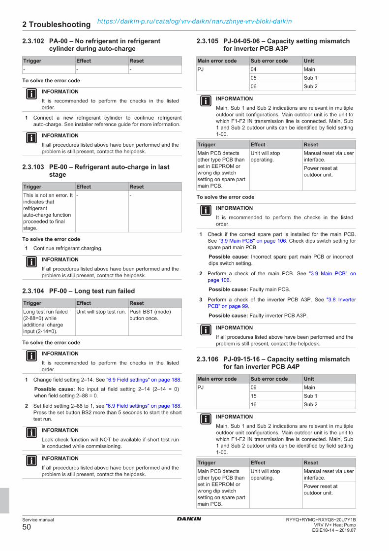
2 Troubleshooting
Service manual
50RYYQ+RYMQ+RXYQ8~20U7Y1B
VRV IV+ Heat PumpESIE18-14 – 2019.07
2.3.102 PA-00 – No refrigerant in refrigerantcylinder during auto-charge
Trigger Effect Reset- - -
To solve the error code
INFORMATIONIt is recommended to perform the checks in the listedorder.
1 Connect a new refrigerant cylinder to continue refrigerantauto‑charge. See installer reference guide for more information.
INFORMATIONIf all procedures listed above have been performed and theproblem is still present, contact the helpdesk.
2.3.103 PE-00 – Refrigerant auto-charge in laststage
Trigger Effect ResetThis is not an error. Itindicates thatrefrigerantauto‑charge functionproceeded to finalstage.
- -
To solve the error code1 Continue refrigerant charging.
INFORMATIONIf all procedures listed above have been performed and theproblem is still present, contact the helpdesk.
2.3.104 PF-00 – Long test run failed
Trigger Effect ResetLong test run failed(2-88=0) whileadditional chargeinput (2-14=0).
Unit will stop test run. Push BS1 (mode)button once.
To solve the error code
INFORMATIONIt is recommended to perform the checks in the listedorder.
1 Change field setting 2–14. See "6.9 Field settings" on page 188.
Possible cause: No input at field setting 2–14 (2–14 = 0)when field setting 2–88 = 0.
2 Set field setting 2–88 to 1, see "6.9 Field settings" on page 188.Press the set button BS2 more than 5 seconds to start the shorttest run.
INFORMATIONLeak check function will NOT be available if short test runis conducted while commissioning.
INFORMATIONIf all procedures listed above have been performed and theproblem is still present, contact the helpdesk.
2.3.105 PJ-04-05-06 – Capacity setting mismatchfor inverter PCB A3P
Main error code Sub error code UnitPJ 04 Main
05 Sub 106 Sub 2
INFORMATIONMain, Sub 1 and Sub 2 indications are relevant in multipleoutdoor unit configurations. Main outdoor unit is the unit towhich F1‑F2 IN transmission line is connected. Main, Sub1 and Sub 2 outdoor units can be identified by field setting1‑00.
Trigger Effect ResetMain PCB detectsother type PCB thanset in EEPROM orwrong dip switchsetting on spare partmain PCB.
Unit will stopoperating.
Manual reset via userinterface.Power reset atoutdoor unit.
To solve the error code
INFORMATIONIt is recommended to perform the checks in the listedorder.
1 Check if the correct spare part is installed for the main PCB.See "3.9 Main PCB" on page 106. Check dips switch setting forspare part main PCB.
Possible cause: Incorrect spare part main PCB or incorrectdips switch setting.
2 Perform a check of the main PCB. See "3.9 Main PCB" onpage 106.
Possible cause: Faulty main PCB.
3 Perform a check of the inverter PCB A3P. See "3.8 InverterPCB" on page 99.
Possible cause: Faulty inverter PCB A3P.
INFORMATIONIf all procedures listed above have been performed and theproblem is still present, contact the helpdesk.
2.3.106 PJ-09-15-16 – Capacity setting mismatchfor fan inverter PCB A4P
Main error code Sub error code UnitPJ 09 Main
15 Sub 116 Sub 2
INFORMATIONMain, Sub 1 and Sub 2 indications are relevant in multipleoutdoor unit configurations. Main outdoor unit is the unit towhich F1‑F2 IN transmission line is connected. Main, Sub1 and Sub 2 outdoor units can be identified by field setting1‑00.
Trigger Effect ResetMain PCB detectsother type PCB thanset in EEPROM orwrong dip switchsetting on spare partmain PCB.
Unit will stopoperating.
Manual reset via userinterface.Power reset atoutdoor unit.
https://daikin-p.ru/catalog/vrv-daikn/naruzhnye-vrv-bloki-daikin
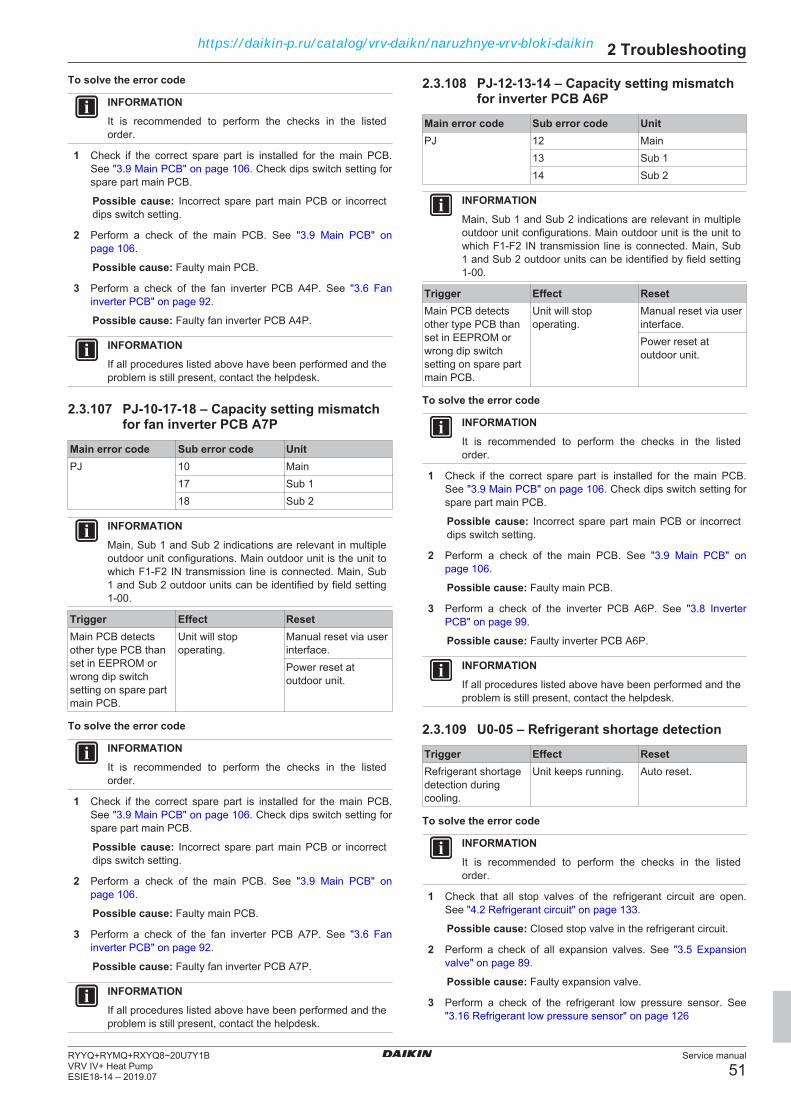
2 Troubleshooting
Service manual
51RYYQ+RYMQ+RXYQ8~20U7Y1BVRV IV+ Heat PumpESIE18-14 – 2019.07
To solve the error code
INFORMATIONIt is recommended to perform the checks in the listedorder.
1 Check if the correct spare part is installed for the main PCB.See "3.9 Main PCB" on page 106. Check dips switch setting forspare part main PCB.
Possible cause: Incorrect spare part main PCB or incorrectdips switch setting.
2 Perform a check of the main PCB. See "3.9 Main PCB" onpage 106.
Possible cause: Faulty main PCB.
3 Perform a check of the fan inverter PCB A4P. See "3.6 Faninverter PCB" on page 92.
Possible cause: Faulty fan inverter PCB A4P.
INFORMATIONIf all procedures listed above have been performed and theproblem is still present, contact the helpdesk.
2.3.107 PJ-10-17-18 – Capacity setting mismatchfor fan inverter PCB A7P
Main error code Sub error code UnitPJ 10 Main
17 Sub 118 Sub 2
INFORMATIONMain, Sub 1 and Sub 2 indications are relevant in multipleoutdoor unit configurations. Main outdoor unit is the unit towhich F1‑F2 IN transmission line is connected. Main, Sub1 and Sub 2 outdoor units can be identified by field setting1‑00.
Trigger Effect ResetMain PCB detectsother type PCB thanset in EEPROM orwrong dip switchsetting on spare partmain PCB.
Unit will stopoperating.
Manual reset via userinterface.Power reset atoutdoor unit.
To solve the error code
INFORMATIONIt is recommended to perform the checks in the listedorder.
1 Check if the correct spare part is installed for the main PCB.See "3.9 Main PCB" on page 106. Check dips switch setting forspare part main PCB.
Possible cause: Incorrect spare part main PCB or incorrectdips switch setting.
2 Perform a check of the main PCB. See "3.9 Main PCB" onpage 106.
Possible cause: Faulty main PCB.
3 Perform a check of the fan inverter PCB A7P. See "3.6 Faninverter PCB" on page 92.
Possible cause: Faulty fan inverter PCB A7P.
INFORMATIONIf all procedures listed above have been performed and theproblem is still present, contact the helpdesk.
2.3.108 PJ-12-13-14 – Capacity setting mismatchfor inverter PCB A6P
Main error code Sub error code UnitPJ 12 Main
13 Sub 114 Sub 2
INFORMATIONMain, Sub 1 and Sub 2 indications are relevant in multipleoutdoor unit configurations. Main outdoor unit is the unit towhich F1‑F2 IN transmission line is connected. Main, Sub1 and Sub 2 outdoor units can be identified by field setting1‑00.
Trigger Effect ResetMain PCB detectsother type PCB thanset in EEPROM orwrong dip switchsetting on spare partmain PCB.
Unit will stopoperating.
Manual reset via userinterface.Power reset atoutdoor unit.
To solve the error code
INFORMATIONIt is recommended to perform the checks in the listedorder.
1 Check if the correct spare part is installed for the main PCB.See "3.9 Main PCB" on page 106. Check dips switch setting forspare part main PCB.
Possible cause: Incorrect spare part main PCB or incorrectdips switch setting.
2 Perform a check of the main PCB. See "3.9 Main PCB" onpage 106.
Possible cause: Faulty main PCB.
3 Perform a check of the inverter PCB A6P. See "3.8 InverterPCB" on page 99.
Possible cause: Faulty inverter PCB A6P.
INFORMATIONIf all procedures listed above have been performed and theproblem is still present, contact the helpdesk.
2.3.109 U0-05 – Refrigerant shortage detection
Trigger Effect ResetRefrigerant shortagedetection duringcooling.
Unit keeps running. Auto reset.
To solve the error code
INFORMATIONIt is recommended to perform the checks in the listedorder.
1 Check that all stop valves of the refrigerant circuit are open.See "4.2 Refrigerant circuit" on page 133.
Possible cause: Closed stop valve in the refrigerant circuit.
2 Perform a check of all expansion valves. See "3.5 Expansionvalve" on page 89.
Possible cause: Faulty expansion valve.
3 Perform a check of the refrigerant low pressure sensor. See"3.16 Refrigerant low pressure sensor" on page 126
https://daikin-p.ru/catalog/vrv-daikn/naruzhnye-vrv-bloki-daikin

2 Troubleshooting
Service manual
52RYYQ+RYMQ+RXYQ8~20U7Y1B
VRV IV+ Heat PumpESIE18-14 – 2019.07
Possible cause: Faulty refrigerant low pressure sensor.
4 Perform a check of the suction pipe thermistor. See"3.17 Thermistors" on page 128.
Possible cause: Faulty suction pipe thermistor or connectorfault.
5 Perform a check of the discharge pipe thermistor. See"3.17 Thermistors" on page 128.
Possible cause: Faulty discharge pipe thermistor orconnector fault.
6 Check for the presence of non‑condensables and/or humidity inthe refrigerant circuit. See "4.2 Refrigerant circuit" on page 133.
Possible cause: Non‑condensables and/or humidity in therefrigerant circuit.
7 Check if the refrigerant circuit is correctly charged. See"4.2 Refrigerant circuit" on page 133.
Possible cause: Refrigerant shortage.
8 Perform a check of the refrigerant high pressure sensor. See"3.15 Refrigerant high pressure sensor" on page 124.
Possible cause: Faulty refrigerant high pressure sensor.
9 Perform a check of the compressor. See "3.2 Compressor" onpage 82.
Possible cause: Faulty compressor.
INFORMATIONIf all procedures listed above have been performed and theproblem is still present, contact the helpdesk.
2.3.110 U0-06 – Refrigerant shortage detection
Trigger Effect ResetRefrigerant shortagedetection duringheating.
Unit keeps running. Auto reset.
To solve the error code
INFORMATIONIt is recommended to perform the checks in the listedorder.
1 Check that all stop valves of the refrigerant circuit are open.See "4.2 Refrigerant circuit" on page 133.
Possible cause: Closed stop valve in the refrigerant circuit.
2 Perform a check of all expansion valves. See "3.5 Expansionvalve" on page 89.
Possible cause: Faulty expansion valve.
3 Perform a check of the refrigerant low pressure sensor. See"3.16 Refrigerant low pressure sensor" on page 126
Possible cause: Faulty refrigerant low pressure sensor.
4 Perform a check of the suction pipe thermistor. See"3.17 Thermistors" on page 128.
Possible cause: Faulty suction pipe thermistor or connectorfault.
5 Perform a check of the discharge pipe thermistor. See"3.17 Thermistors" on page 128.
Possible cause: Faulty discharge pipe thermistor orconnector fault.
6 Check for the presence of non‑condensables and/or humidity inthe refrigerant circuit. See "4.2 Refrigerant circuit" on page 133.
Possible cause: Non‑condensables and/or humidity in therefrigerant circuit.
7 Check if the refrigerant circuit is correctly charged. See"4.2 Refrigerant circuit" on page 133.
Possible cause: Refrigerant shortage.
8 Perform a check of the refrigerant high pressure sensor. See"3.15 Refrigerant high pressure sensor" on page 124.
Possible cause: Faulty refrigerant high pressure sensor.
9 Perform a check of the compressor. See "3.2 Compressor" onpage 82.
Possible cause: Faulty compressor.
INFORMATIONIf all procedures listed above have been performed and theproblem is still present, contact the helpdesk.
2.3.111 U0-08-09-10 – Refrigerant shortagedetection by high pressure sensor
Main error code Sub error code UnitU0 08 Main
09 Sub 110 Sub 2
INFORMATIONMain, Sub 1 and Sub 2 indications are relevant in multipleoutdoor unit configurations. Main outdoor unit is the unit towhich F1‑F2 IN transmission line is connected. Main, Sub1 and Sub 2 outdoor units can be identified by field setting1‑00.
Trigger Effect ResetRefrigerant shortagedetection.
Unit keeps running. Auto reset.
To solve the error code
INFORMATIONIt is recommended to perform the checks in the listedorder.
1 Check that all stop valves of the refrigerant circuit are open.See "4.2 Refrigerant circuit" on page 133.
Possible cause: Closed stop valve in the refrigerant circuit.
2 Perform a check of all expansion valves. See "3.5 Expansionvalve" on page 89.
Possible cause: Faulty expansion valve.
3 Perform a check of the refrigerant low pressure sensor. See"3.16 Refrigerant low pressure sensor" on page 126
Possible cause: Faulty refrigerant low pressure sensor.
4 Perform a check of the suction pipe thermistor. See"3.17 Thermistors" on page 128.
Possible cause: Faulty suction pipe thermistor or connectorfault.
5 Perform a check of the discharge pipe thermistor. See"3.17 Thermistors" on page 128.
Possible cause: Faulty discharge pipe thermistor orconnector fault.
6 Check for the presence of non‑condensables and/or humidity inthe refrigerant circuit. See "4.2 Refrigerant circuit" on page 133.
Possible cause: Non‑condensables and/or humidity in therefrigerant circuit.
https://daikin-p.ru/catalog/vrv-daikn/naruzhnye-vrv-bloki-daikin

2 Troubleshooting
Service manual
53RYYQ+RYMQ+RXYQ8~20U7Y1BVRV IV+ Heat PumpESIE18-14 – 2019.07
7 Check if the refrigerant circuit is correctly charged. See"4.2 Refrigerant circuit" on page 133.
Possible cause: Refrigerant shortage.
8 Perform a check of the refrigerant high pressure sensor. See"3.15 Refrigerant high pressure sensor" on page 124.
Possible cause: Faulty refrigerant high pressure sensor.
9 Perform a check of the compressor. See "3.2 Compressor" onpage 82.
Possible cause: Faulty compressor.
INFORMATIONIf all procedures listed above have been performed and theproblem is still present, contact the helpdesk.
2.3.112 U1-01-05-07 – Reverse phase detection
Main error code Sub error code UnitU1 01 Main
05 Sub 107 Sub 2
INFORMATIONMain, Sub 1 and Sub 2 indications are relevant in multipleoutdoor unit configurations. Main outdoor unit is the unit towhich F1‑F2 IN transmission line is connected. Main, Sub1 and Sub 2 outdoor units can be identified by field setting1‑00.
Trigger Effect ResetMain PCB detectsreverse phasebetween L1 - L3phases.
Forced stop. Power reset atoutdoor unit.
To solve the error code
INFORMATIONIt is recommended to perform the checks in the listedorder.
1 Check the phase sequence on the mains power supplyterminal, see "To check the power supply of the unit" in"4.1 Electrical circuit" on page 130. Correct if needed.
Possible cause: Incorrect phase sequence on mains powersupply terminal.
2 Check if any of the phases is missing on the mains powersupply terminal, see "To check the power supply of the unit" in"4.1 Electrical circuit" on page 130. Correct if needed.
Possible cause: Missing phase(s) on mains power supplyterminal.
3 Check if the phase L3 is present on the power supply connectorX1A on the main PCB, see "To perform a power check" in"3.9 Main PCB" on page 106. Correct if needed.
Possible cause: Missing phase L3 on main PCB powersupply connector.
4 Perform a check of the fuses of the main PCB, see "3.9 MainPCB" on page 106.
Possible cause: Blown fuse(s) on main PCB.
INFORMATIONIf all procedures listed above have been performed and theproblem is still present, contact the helpdesk.
2.3.113 U1-04-06-08 – Reverse phase detection
Main error code Sub error code UnitU1 04 Main
06 Sub 108 Sub 2
INFORMATIONMain, Sub 1 and Sub 2 indications are relevant in multipleoutdoor unit configurations. Main outdoor unit is the unit towhich F1‑F2 IN transmission line is connected. Main, Sub1 and Sub 2 outdoor units can be identified by field setting1‑00.
Trigger Effect ResetMain PCB detectsreverse phasebetween L1 - L3phases.
Forced stop. Power reset atoutdoor unit.
To solve the error code
INFORMATIONIt is recommended to perform the checks in the listedorder.
1 Check the phase sequence on the mains power supplyterminal, see "To check the power supply of the unit" in"4.1 Electrical circuit" on page 130. Correct if needed.
Possible cause: Incorrect phase sequence on mains powersupply terminal.
2 Check if any of the phases is missing on the mains powersupply terminal, see "To check the power supply of the unit" in"4.1 Electrical circuit" on page 130. Correct if needed.
Possible cause: Missing phase(s) on mains power supplyterminal.
3 Check if the phase L3 is present on the power supply connectorX1A on the main PCB, see "To perform a power check" in"3.9 Main PCB" on page 106. Correct if needed.
Possible cause: Missing phase L3 on main PCB powersupply connector.
4 Perform a check of the fuses of the main PCB, see "3.9 MainPCB" on page 106.
Possible cause: Blown fuse(s) on main PCB.
INFORMATIONIf all procedures listed above have been performed and theproblem is still present, contact the helpdesk.
2.3.114 U2-01-08-11 – Inverter circuit powersupply abnormality - inverter PCB A3Pabnormal voltage
Main error code Sub error code UnitU2 01 Main
08 Sub 111 Sub 2
INFORMATIONMain, Sub 1 and Sub 2 indications are relevant in multipleoutdoor unit configurations. Main outdoor unit is the unit towhich F1‑F2 IN transmission line is connected. Main, Sub1 and Sub 2 outdoor units can be identified by field setting1‑00.
https://daikin-p.ru/catalog/vrv-daikn/naruzhnye-vrv-bloki-daikin

2 Troubleshooting
Service manual
54RYYQ+RYMQ+RXYQ8~20U7Y1B
VRV IV+ Heat PumpESIE18-14 – 2019.07
Trigger Effect ResetInverter PCB A3Pdetects DC voltagecannot reach ormaintain minimum500 V DC.
Unit will stopoperating.
Power reset atoutdoor unit.
No zero cross isdetected by mainPCB through at least10 seconds.Abnormal voltagedrop is detected byDC voltage detectioncircuit.Abnormal voltage riseis detected by overvoltage detectioncircuit.
To solve the error code
INFORMATIONIt is recommended to perform the checks in the listedorder.
1 Check if the power supply wiring is correct. See "4.1 Electricalcircuit" on page 130.
Possible cause: Incorrect power supply wiring.
2 Perform a check of the noise filter PCB A2P. See "3.10 Noisefilter PCB" on page 110.
Possible cause: Faulty noise filter PCB A2P.
3 Perform a check of the inverter PCB A3P. See "3.8 InverterPCB" on page 99.
Possible cause: Faulty inverter PCB A3P.
4 Check the wiring between the PCB's. See "6.2 Wiringdiagram" on page 146.
Possible cause: Faulty wiring between PCB's.
INFORMATIONIf all procedures listed above have been performed and theproblem is still present, contact the helpdesk.
2.3.115 U2-02-09-12 – Inverter circuit powersupply abnormality - inverter PCB A3Pphase loss
Main error code Sub error code UnitU2 02 Main
09 Sub 112 Sub 2
INFORMATIONMain, Sub 1 and Sub 2 indications are relevant in multipleoutdoor unit configurations. Main outdoor unit is the unit towhich F1‑F2 IN transmission line is connected. Main, Sub1 and Sub 2 outdoor units can be identified by field setting1‑00.
Trigger Effect ResetInverter PCB A3Pdetects DC voltagecannot reach ormaintain minimum500 V DC.
Unit will stopoperating.
Power reset atoutdoor unit.
No zero cross isdetected by mainPCB through at least10 seconds.Abnormal voltagedrop is detected byDC voltage detectioncircuit.Abnormal voltage riseis detected by overvoltage detectioncircuit.
To solve the error code
INFORMATIONIt is recommended to perform the checks in the listedorder.
1 Check if the power supply wiring is correct. See "4.1 Electricalcircuit" on page 130.
Possible cause: Incorrect power supply wiring.
2 Perform a check of the noise filter PCB A2P. See "3.10 Noisefilter PCB" on page 110.
Possible cause: Faulty noise filter PCB A2P.
3 Perform a check of the inverter PCB A3P. See "3.8 InverterPCB" on page 99.
Possible cause: Faulty inverter PCB A3P.
4 Check the wiring between the PCB's. See "6.2 Wiringdiagram" on page 146.
Possible cause: Faulty wiring between PCB's.
INFORMATIONIf all procedures listed above have been performed and theproblem is still present, contact the helpdesk.
2.3.116 U2-03-10-13 – Inverter circuit powersupply abnormality - inverter PCB A3P DCcircuit not charging
Main error code Sub error code UnitU2 03 Main
10 Sub 113 Sub 2
INFORMATIONMain, Sub 1 and Sub 2 indications are relevant in multipleoutdoor unit configurations. Main outdoor unit is the unit towhich F1‑F2 IN transmission line is connected. Main, Sub1 and Sub 2 outdoor units can be identified by field setting1‑00.
https://daikin-p.ru/catalog/vrv-daikn/naruzhnye-vrv-bloki-daikin
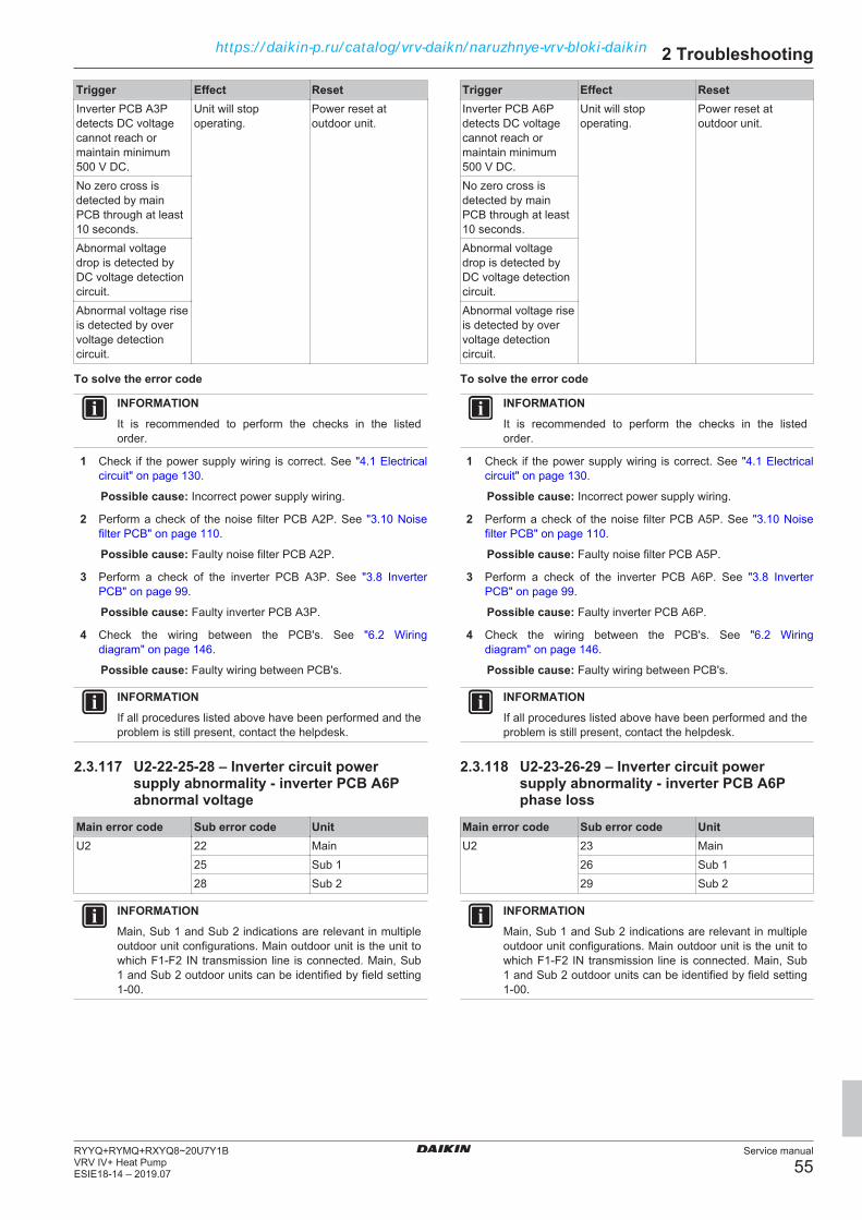
2 Troubleshooting
Service manual
55RYYQ+RYMQ+RXYQ8~20U7Y1BVRV IV+ Heat PumpESIE18-14 – 2019.07
Trigger Effect ResetInverter PCB A3Pdetects DC voltagecannot reach ormaintain minimum500 V DC.
Unit will stopoperating.
Power reset atoutdoor unit.
No zero cross isdetected by mainPCB through at least10 seconds.Abnormal voltagedrop is detected byDC voltage detectioncircuit.Abnormal voltage riseis detected by overvoltage detectioncircuit.
To solve the error code
INFORMATIONIt is recommended to perform the checks in the listedorder.
1 Check if the power supply wiring is correct. See "4.1 Electricalcircuit" on page 130.
Possible cause: Incorrect power supply wiring.
2 Perform a check of the noise filter PCB A2P. See "3.10 Noisefilter PCB" on page 110.
Possible cause: Faulty noise filter PCB A2P.
3 Perform a check of the inverter PCB A3P. See "3.8 InverterPCB" on page 99.
Possible cause: Faulty inverter PCB A3P.
4 Check the wiring between the PCB's. See "6.2 Wiringdiagram" on page 146.
Possible cause: Faulty wiring between PCB's.
INFORMATIONIf all procedures listed above have been performed and theproblem is still present, contact the helpdesk.
2.3.117 U2-22-25-28 – Inverter circuit powersupply abnormality - inverter PCB A6Pabnormal voltage
Main error code Sub error code UnitU2 22 Main
25 Sub 128 Sub 2
INFORMATIONMain, Sub 1 and Sub 2 indications are relevant in multipleoutdoor unit configurations. Main outdoor unit is the unit towhich F1‑F2 IN transmission line is connected. Main, Sub1 and Sub 2 outdoor units can be identified by field setting1‑00.
Trigger Effect ResetInverter PCB A6Pdetects DC voltagecannot reach ormaintain minimum500 V DC.
Unit will stopoperating.
Power reset atoutdoor unit.
No zero cross isdetected by mainPCB through at least10 seconds.Abnormal voltagedrop is detected byDC voltage detectioncircuit.Abnormal voltage riseis detected by overvoltage detectioncircuit.
To solve the error code
INFORMATIONIt is recommended to perform the checks in the listedorder.
1 Check if the power supply wiring is correct. See "4.1 Electricalcircuit" on page 130.
Possible cause: Incorrect power supply wiring.
2 Perform a check of the noise filter PCB A5P. See "3.10 Noisefilter PCB" on page 110.
Possible cause: Faulty noise filter PCB A5P.
3 Perform a check of the inverter PCB A6P. See "3.8 InverterPCB" on page 99.
Possible cause: Faulty inverter PCB A6P.
4 Check the wiring between the PCB's. See "6.2 Wiringdiagram" on page 146.
Possible cause: Faulty wiring between PCB's.
INFORMATIONIf all procedures listed above have been performed and theproblem is still present, contact the helpdesk.
2.3.118 U2-23-26-29 – Inverter circuit powersupply abnormality - inverter PCB A6Pphase loss
Main error code Sub error code UnitU2 23 Main
26 Sub 129 Sub 2
INFORMATIONMain, Sub 1 and Sub 2 indications are relevant in multipleoutdoor unit configurations. Main outdoor unit is the unit towhich F1‑F2 IN transmission line is connected. Main, Sub1 and Sub 2 outdoor units can be identified by field setting1‑00.
https://daikin-p.ru/catalog/vrv-daikn/naruzhnye-vrv-bloki-daikin
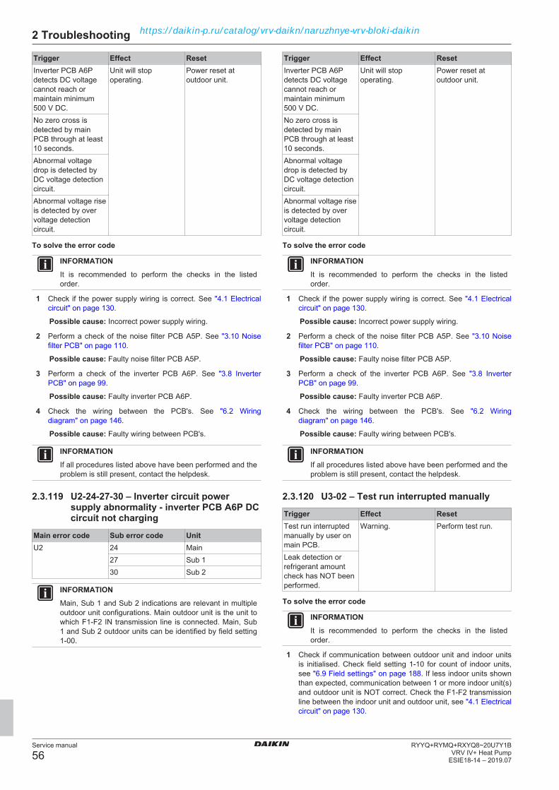
2 Troubleshooting
Service manual
56RYYQ+RYMQ+RXYQ8~20U7Y1B
VRV IV+ Heat PumpESIE18-14 – 2019.07
Trigger Effect ResetInverter PCB A6Pdetects DC voltagecannot reach ormaintain minimum500 V DC.
Unit will stopoperating.
Power reset atoutdoor unit.
No zero cross isdetected by mainPCB through at least10 seconds.Abnormal voltagedrop is detected byDC voltage detectioncircuit.Abnormal voltage riseis detected by overvoltage detectioncircuit.
To solve the error code
INFORMATIONIt is recommended to perform the checks in the listedorder.
1 Check if the power supply wiring is correct. See "4.1 Electricalcircuit" on page 130.
Possible cause: Incorrect power supply wiring.
2 Perform a check of the noise filter PCB A5P. See "3.10 Noisefilter PCB" on page 110.
Possible cause: Faulty noise filter PCB A5P.
3 Perform a check of the inverter PCB A6P. See "3.8 InverterPCB" on page 99.
Possible cause: Faulty inverter PCB A6P.
4 Check the wiring between the PCB's. See "6.2 Wiringdiagram" on page 146.
Possible cause: Faulty wiring between PCB's.
INFORMATIONIf all procedures listed above have been performed and theproblem is still present, contact the helpdesk.
2.3.119 U2-24-27-30 – Inverter circuit powersupply abnormality - inverter PCB A6P DCcircuit not charging
Main error code Sub error code UnitU2 24 Main
27 Sub 130 Sub 2
INFORMATIONMain, Sub 1 and Sub 2 indications are relevant in multipleoutdoor unit configurations. Main outdoor unit is the unit towhich F1‑F2 IN transmission line is connected. Main, Sub1 and Sub 2 outdoor units can be identified by field setting1‑00.
Trigger Effect ResetInverter PCB A6Pdetects DC voltagecannot reach ormaintain minimum500 V DC.
Unit will stopoperating.
Power reset atoutdoor unit.
No zero cross isdetected by mainPCB through at least10 seconds.Abnormal voltagedrop is detected byDC voltage detectioncircuit.Abnormal voltage riseis detected by overvoltage detectioncircuit.
To solve the error code
INFORMATIONIt is recommended to perform the checks in the listedorder.
1 Check if the power supply wiring is correct. See "4.1 Electricalcircuit" on page 130.
Possible cause: Incorrect power supply wiring.
2 Perform a check of the noise filter PCB A5P. See "3.10 Noisefilter PCB" on page 110.
Possible cause: Faulty noise filter PCB A5P.
3 Perform a check of the inverter PCB A6P. See "3.8 InverterPCB" on page 99.
Possible cause: Faulty inverter PCB A6P.
4 Check the wiring between the PCB's. See "6.2 Wiringdiagram" on page 146.
Possible cause: Faulty wiring between PCB's.
INFORMATIONIf all procedures listed above have been performed and theproblem is still present, contact the helpdesk.
2.3.120 U3-02 – Test run interrupted manually
Trigger Effect ResetTest run interruptedmanually by user onmain PCB.
Warning. Perform test run.
Leak detection orrefrigerant amountcheck has NOT beenperformed.
To solve the error code
INFORMATIONIt is recommended to perform the checks in the listedorder.
1 Check if communication between outdoor unit and indoor unitsis initialised. Check field setting 1‑10 for count of indoor units,see "6.9 Field settings" on page 188. If less indoor units shownthan expected, communication between 1 or more indoor unit(s)and outdoor unit is NOT correct. Check the F1‑F2 transmissionline between the indoor unit and outdoor unit, see "4.1 Electricalcircuit" on page 130.
https://daikin-p.ru/catalog/vrv-daikn/naruzhnye-vrv-bloki-daikin

2 Troubleshooting
Service manual
57RYYQ+RYMQ+RXYQ8~20U7Y1BVRV IV+ Heat PumpESIE18-14 – 2019.07
Possible cause: Faulty or interruption in transmission linebetween indoor units and outdoor unit.
2 Perform a test run from the outdoor unit. See installer referenceguide for more information.
3 Check the error history, see "2 Troubleshooting" on page 9.Solve the error code(s) using the error based troubleshooting,see "2.3 Error based troubleshooting" on page 12.
4 System operation is possible but leak detection function willNEVER run.
INFORMATIONIf all procedures listed above have been performed and theproblem is still present, contact the helpdesk.
2.3.121 U3-03 – Test run not performed yet
Trigger Effect ResetTest run NOTperformed.
Unit will NOToperate.
Perform test run.
To solve the error code
INFORMATIONIt is recommended to perform the checks in the listedorder.
1 Check if communication between outdoor unit and indoor unitsis initialised. Check field setting 1‑10 for count of indoor units,see "6.9 Field settings" on page 188. If less indoor units shownthan expected, communication between 1 or more indoor unit(s)and outdoor unit is NOT correct. Check the F1‑F2 transmissionline between the indoor unit and outdoor unit, see "4.1 Electricalcircuit" on page 130.
Possible cause: Faulty or interruption in transmission linebetween indoor units and outdoor unit.
2 Perform a test run from the outdoor unit. See installer referenceguide for more information.
3 Check the error history, see "2 Troubleshooting" on page 9.Solve the error code(s) using the error based troubleshooting,see "2.3 Error based troubleshooting" on page 12.
INFORMATIONIf all procedures listed above have been performed and theproblem is still present, contact the helpdesk.
2.3.122 U3-04 – Test run ended abnormally
Trigger Effect ResetTest run endedabnormally.
Unit will NOToperate.
Restart test run.
To solve the error code
INFORMATIONIt is recommended to perform the checks in the listedorder.
1 Check for an indoor unit related error code. See "2.3.163 Indoorunit related error codes" on page 68 for an overview of theindoor unit related error codes. To solve the error, see theservice manual of the respective indoor unit(s) for moreinformation.
2 Check the error history, see "2 Troubleshooting" on page 9.Solve the error code(s) using the error based troubleshooting,see "2.3 Error based troubleshooting" on page 12.
3 Check if communication between outdoor unit and indoor unitsis initialised. Check field setting 1‑10 for count of indoor units,see "6.9 Field settings" on page 188. If less indoor units shown
than expected, communication between 1 or more indoor unit(s)and outdoor unit is NOT correct. Check the F1‑F2 transmissionline between the indoor unit and outdoor unit, see "4.1 Electricalcircuit" on page 130.
Possible cause: Faulty or interruption in transmission linebetween indoor units and outdoor unit.
4 Perform a test run from the outdoor unit. See installer referenceguide for more information.
INFORMATIONIf all procedures listed above have been performed and theproblem is still present, contact the helpdesk.
2.3.123 U3-05 – Test run aborted on initialtransmission
Trigger Effect ResetTest run could NOTstart or abort due totransmission issues.
Unit will NOToperate.
Restart test run.
To solve the error code
INFORMATIONIt is recommended to perform the checks in the listedorder.
1 Check if communication between outdoor unit and indoor unitsis initialised. Check field setting 1‑10 for count of indoor units,see "6.9 Field settings" on page 188. If less indoor units shownthan expected, communication between 1 or more indoor unit(s)and outdoor unit is NOT correct. Check the F1‑F2 transmissionline between the indoor unit and outdoor unit, see "4.1 Electricalcircuit" on page 130.
Possible cause: Faulty or interruption in transmission linebetween indoor units and outdoor unit.
2 Check the F1‑F2 transmission line between the indoor units andoutdoor unit. See "4.1 Electrical circuit" on page 130.
Possible cause: Faulty or interruption in transmission linebetween indoor units and outdoor unit.
3 Perform a test run from the outdoor unit. See installer referenceguide for more information.
INFORMATIONIf all procedures listed above have been performed and theproblem is still present, contact the helpdesk.
2.3.124 U3-06 – Test run aborted on normaltransmission
Trigger Effect ResetTest run could NOTstart or abort due totransmission issues.
Unit will NOToperate.
Restart test run.
To solve the error code
INFORMATIONIt is recommended to perform the checks in the listedorder.
1 Check if communication between outdoor unit and indoor unitsis initialised. Check field setting 1‑10 for count of indoor units,see "6.9 Field settings" on page 188. If less indoor units shownthan expected, communication between 1 or more indoor unit(s)and outdoor unit is NOT correct. Check the F1‑F2 transmissionline between the indoor unit and outdoor unit, see "4.1 Electricalcircuit" on page 130.
https://daikin-p.ru/catalog/vrv-daikn/naruzhnye-vrv-bloki-daikin
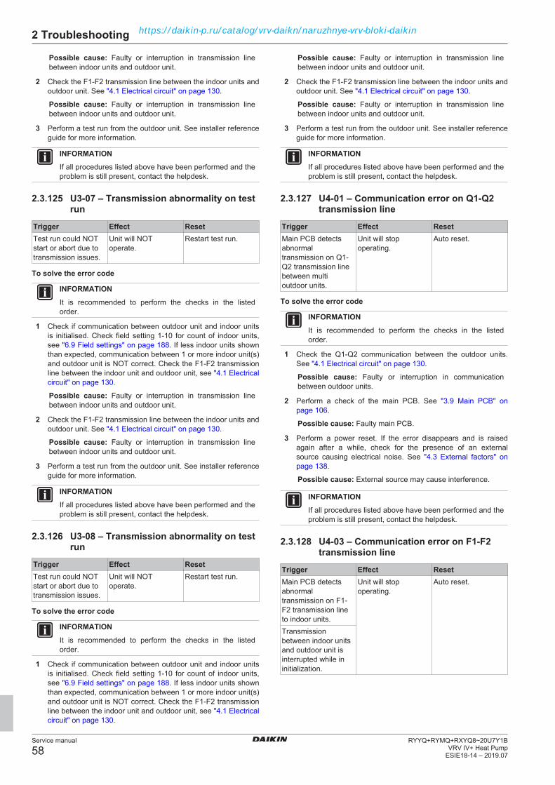
2 Troubleshooting
Service manual
58RYYQ+RYMQ+RXYQ8~20U7Y1B
VRV IV+ Heat PumpESIE18-14 – 2019.07
Possible cause: Faulty or interruption in transmission linebetween indoor units and outdoor unit.
2 Check the F1‑F2 transmission line between the indoor units andoutdoor unit. See "4.1 Electrical circuit" on page 130.
Possible cause: Faulty or interruption in transmission linebetween indoor units and outdoor unit.
3 Perform a test run from the outdoor unit. See installer referenceguide for more information.
INFORMATIONIf all procedures listed above have been performed and theproblem is still present, contact the helpdesk.
2.3.125 U3-07 – Transmission abnormality on testrun
Trigger Effect ResetTest run could NOTstart or abort due totransmission issues.
Unit will NOToperate.
Restart test run.
To solve the error code
INFORMATIONIt is recommended to perform the checks in the listedorder.
1 Check if communication between outdoor unit and indoor unitsis initialised. Check field setting 1‑10 for count of indoor units,see "6.9 Field settings" on page 188. If less indoor units shownthan expected, communication between 1 or more indoor unit(s)and outdoor unit is NOT correct. Check the F1‑F2 transmissionline between the indoor unit and outdoor unit, see "4.1 Electricalcircuit" on page 130.
Possible cause: Faulty or interruption in transmission linebetween indoor units and outdoor unit.
2 Check the F1‑F2 transmission line between the indoor units andoutdoor unit. See "4.1 Electrical circuit" on page 130.
Possible cause: Faulty or interruption in transmission linebetween indoor units and outdoor unit.
3 Perform a test run from the outdoor unit. See installer referenceguide for more information.
INFORMATIONIf all procedures listed above have been performed and theproblem is still present, contact the helpdesk.
2.3.126 U3-08 – Transmission abnormality on testrun
Trigger Effect ResetTest run could NOTstart or abort due totransmission issues.
Unit will NOToperate.
Restart test run.
To solve the error code
INFORMATIONIt is recommended to perform the checks in the listedorder.
1 Check if communication between outdoor unit and indoor unitsis initialised. Check field setting 1‑10 for count of indoor units,see "6.9 Field settings" on page 188. If less indoor units shownthan expected, communication between 1 or more indoor unit(s)and outdoor unit is NOT correct. Check the F1‑F2 transmissionline between the indoor unit and outdoor unit, see "4.1 Electricalcircuit" on page 130.
Possible cause: Faulty or interruption in transmission linebetween indoor units and outdoor unit.
2 Check the F1‑F2 transmission line between the indoor units andoutdoor unit. See "4.1 Electrical circuit" on page 130.
Possible cause: Faulty or interruption in transmission linebetween indoor units and outdoor unit.
3 Perform a test run from the outdoor unit. See installer referenceguide for more information.
INFORMATIONIf all procedures listed above have been performed and theproblem is still present, contact the helpdesk.
2.3.127 U4-01 – Communication error on Q1-Q2transmission line
Trigger Effect ResetMain PCB detectsabnormaltransmission on Q1-Q2 transmission linebetween multioutdoor units.
Unit will stopoperating.
Auto reset.
To solve the error code
INFORMATIONIt is recommended to perform the checks in the listedorder.
1 Check the Q1‑Q2 communication between the outdoor units.See "4.1 Electrical circuit" on page 130.
Possible cause: Faulty or interruption in communicationbetween outdoor units.
2 Perform a check of the main PCB. See "3.9 Main PCB" onpage 106.
Possible cause: Faulty main PCB.
3 Perform a power reset. If the error disappears and is raisedagain after a while, check for the presence of an externalsource causing electrical noise. See "4.3 External factors" onpage 138.
Possible cause: External source may cause interference.
INFORMATIONIf all procedures listed above have been performed and theproblem is still present, contact the helpdesk.
2.3.128 U4-03 – Communication error on F1-F2transmission line
Trigger Effect ResetMain PCB detectsabnormaltransmission on F1-F2 transmission lineto indoor units.
Unit will stopoperating.
Auto reset.
Transmissionbetween indoor unitsand outdoor unit isinterrupted while ininitialization.
https://daikin-p.ru/catalog/vrv-daikn/naruzhnye-vrv-bloki-daikin

2 Troubleshooting
Service manual
59RYYQ+RYMQ+RXYQ8~20U7Y1BVRV IV+ Heat PumpESIE18-14 – 2019.07
To solve the error code
INFORMATIONIt is recommended to perform the checks in the listedorder.
1 Check if the power supply is conform with the regulations. See"4.1 Electrical circuit" on page 130.
Possible cause:▪ Faulty or disturbance of the power supply (imbalance
>10%),▪ Power drop,▪ Short circuit.
2 Check the F1‑F2 transmission line between the indoor units andoutdoor unit. See "4.1 Electrical circuit" on page 130.
Possible cause: Faulty or interruption in transmission linebetween indoor units and outdoor unit.
3 Check field setting 1‑10 to count the indoor units, see "6.9 Fieldsettings" on page 188. If less indoor units detected than itshould be, check the indoor unit(s) that have power black‑out ormalfunctioning PCB. See service manual of the respectiveindoor unit for more information.
Possible cause: Power black‑out or malfunctioning PCB onindoor unit(s).
4 Perform a check of the main PCB. See "3.9 Main PCB" onpage 106.
Possible cause: Faulty main PCB.
5 Perform a power reset. If the error disappears and is raisedagain after a while, check for the presence of an externalsource causing electrical noise. See "4.3 External factors" onpage 138.
Possible cause: External source may cause interference.
6 Set field setting 2‑5 of the outdoor unit to 1 to start the indoorunits connected to that outdoor unit on forced fan operation,see "6.9 Field settings" on page 188. If any of these indoor unitsis NOT operating, check the indoor unit(s) that have powerblack‑out or malfunctioning PCB. See service manual of therespective indoor unit for more information.
Possible cause: Power black‑out or malfunctioning PCB onindoor unit(s).
INFORMATIONIf all procedures listed above have been performed and theproblem is still present, contact the helpdesk.
2.3.129 U4-15 – Unable to start test run
Trigger Effect ResetMain PCB detectsmalfunction on indoorunit(s).
Test run will NOTstart.
Perform test run.
To solve the error code
INFORMATIONIt is recommended to perform the checks in the listedorder.
1 Set field setting 2‑5 of the outdoor unit to 1 to start the indoorunits connected to that outdoor unit on forced fan operation,see "6.9 Field settings" on page 188. If any of these indoor unitsis NOT operating, check the indoor unit(s) that have powerblack‑out or malfunctioning PCB. See service manual of therespective indoor unit for more information.
Possible cause: Power black‑out or malfunctioning PCB onindoor unit(s).
2 Check field setting 1‑10 to count the indoor units, see "6.9 Fieldsettings" on page 188. If less indoor units detected than itshould be, check the indoor unit(s) that have power black‑out ormalfunctioning PCB. See service manual of the respectiveindoor unit for more information.
Possible cause: Power black‑out or malfunctioning PCB onindoor unit(s).
3 Perform a check of the main PCB. See "3.9 Main PCB" onpage 106.
Possible cause: Faulty main PCB.
INFORMATIONIf all procedures listed above have been performed and theproblem is still present, contact the helpdesk.
2.3.130 U7-01 – Transmission abnormalitybetween systems - DTA104A61,62 error
Trigger Effect ResetCommunicationproblem betweensystems.
Unit will stopoperating.
Auto reset whencommunication isnormal.
Conflict in settingsand configuration forDTA104A61,62.
Unit keeps running. Auto reset whencorrect settings applyon DTA104A61,62.
To solve the error code
INFORMATIONIt is recommended to perform the checks in the listedorder.
1 Check the Q1‑Q2 communication between the outdoor units.See "4.1 Electrical circuit" on page 130.
Possible cause: Faulty or interruption in communicationbetween outdoor units.
2 Perform a check of the main PCB. See "3.9 Main PCB" onpage 106.
Possible cause: Faulty main PCB.
3 Check wiring and configuration of option DTA104A61, 62. Seeoption handbook on Business Portal for more information.
4 Check the F1‑F2 OUT transmission line between the outdoorunit main PCB and option PCB DTA104A61, 62. See"4.1 Electrical circuit" on page 130.
Possible cause: Faulty or interruption in transmission linebetween outdoor unit and option DTA104A61, 62.
5 Check that ONLY the master outdoor unit has F1‑F2 INconnection. If another outdoor unit has F1‑F2 IN connection,correct the installation.
6 Check if low noise operation or demand control is active withoutan optional DTA104A61,62 PCB. Field setting 2‑12 CANNOTbe set to 1 if DTA104A61,62 is not present, see "6.9 Fieldsettings" on page 188.
INFORMATIONIf all procedures listed above have been performed and theproblem is still present, contact the helpdesk.
2.3.131 U7-02 – Transmission abnormalitybetween systems - DTA104A61,62 error
Trigger Effect ResetTransmission error onDTA104A61,62initialization.
Forced stop. Auto reset.
https://daikin-p.ru/catalog/vrv-daikn/naruzhnye-vrv-bloki-daikin

2 Troubleshooting
Service manual
60RYYQ+RYMQ+RXYQ8~20U7Y1B
VRV IV+ Heat PumpESIE18-14 – 2019.07
To solve the error code
INFORMATIONIt is recommended to perform the checks in the listedorder.
1 Check if multiple units are wired to the same cool/heat zonewithout cool/heat master set. One main PCB needs to be setcool/heat master (field setting 2‑0 = 1) while all other units needto be set sub (field setting 2‑0 = 2). See "6.9 Field settings" onpage 188.
Possible cause: No cool/heat master set when multiple unitsare wired to the same cool/heat zone.
2 If unified cool/heat selection is NOT present, set theDTA104A61,62 cool/heat setting to IND.
3 Check wiring and configuration of option DTA104A61, 62. Seeoption handbook on Business Portal for more information.
4 Check if low noise operation or demand control is active withoutan optional DTA104A61,62 PCB. Field setting 2‑12 CANNOTbe set to 1 if DTA104A61,62 is not present, see "6.9 Fieldsettings" on page 188.
INFORMATIONIf all procedures listed above have been performed and theproblem is still present, contact the helpdesk.
2.3.132 U7-03 – Transmission abnormalitybetween main outdoor unit and sub 1outdoor unit
Trigger Effect ResetMain PCB on mainoutdoor unit detectstransmissionabnormality on amulti installation.
Forced stop. Auto reset.
To solve the error code
INFORMATIONIt is recommended to perform the checks in the listedorder.
1 Check the Q1‑Q2 communication between the outdoor units.See "4.1 Electrical circuit" on page 130.
Possible cause: Faulty or interruption in communicationbetween outdoor units.
2 Perform a check of the main PCB of the main outdoor unit. See"3.9 Main PCB" on page 106.
Possible cause: Faulty main PCB of the main outdoor unit.
3 Perform a check of the main PCB of the sub 1 outdoor unit. See"3.9 Main PCB" on page 106.
Possible cause: Faulty main PCB of the sub 1 outdoor unit.
4 Check that ONLY the master outdoor unit has F1‑F2 INconnection. If another outdoor unit has F1‑F2 IN connection,correct the installation.
INFORMATIONIf all procedures listed above have been performed and theproblem is still present, contact the helpdesk.
2.3.133 U7-04 – Transmission abnormalitybetween main outdoor unit and sub 2outdoor unit
Trigger Effect ResetMain PCB on mainoutdoor unit detectstransmissionabnormality on amulti installation.
Forced stop. Auto reset.
To solve the error code
INFORMATIONIt is recommended to perform the checks in the listedorder.
1 Check the Q1‑Q2 communication between the outdoor units.See "4.1 Electrical circuit" on page 130.
Possible cause: Faulty or interruption in communicationbetween outdoor units.
2 Perform a check of the main PCB of the main outdoor unit. See"3.9 Main PCB" on page 106.
Possible cause: Faulty main PCB of the main outdoor unit.
3 Perform a check of the main PCB of the sub 2 outdoor unit. See"3.9 Main PCB" on page 106.
Possible cause: Faulty main PCB of the sub 2 outdoor unit.
4 Check that ONLY the master outdoor unit has F1‑F2 INconnection. If another outdoor unit has F1‑F2 IN connection,correct the installation.
INFORMATIONIf all procedures listed above have been performed and theproblem is still present, contact the helpdesk.
2.3.134 U7-05 – Multi system abnormality
Trigger Effect ResetMain PCB on mainoutdoor unit detectstransmissionabnormality on amulti installation.
Forced stop. Auto reset.
To solve the error code
INFORMATIONIt is recommended to perform the checks in the listedorder.
1 Check the Q1‑Q2 communication between the outdoor units.See "4.1 Electrical circuit" on page 130.
Possible cause: Faulty or interruption in communicationbetween outdoor units.
2 Perform a check of the main PCB of the main outdoor unit. See"3.9 Main PCB" on page 106.
Possible cause: Faulty main PCB of the main outdoor unit.
3 Perform a check of the main PCB of the sub 1 outdoor unit. See"3.9 Main PCB" on page 106.
Possible cause: Faulty main PCB of the sub 1 outdoor unit.
4 Perform a check of the main PCB of the sub 2 outdoor unit. See"3.9 Main PCB" on page 106.
Possible cause: Faulty main PCB of the sub 2 outdoor unit.
https://daikin-p.ru/catalog/vrv-daikn/naruzhnye-vrv-bloki-daikin

2 Troubleshooting
Service manual
61RYYQ+RYMQ+RXYQ8~20U7Y1BVRV IV+ Heat PumpESIE18-14 – 2019.07
5 Check that ONLY the master outdoor unit has F1‑F2 INconnection. If another outdoor unit has F1‑F2 IN connection,correct the installation.
INFORMATIONIf all procedures listed above have been performed and theproblem is still present, contact the helpdesk.
2.3.135 U7-06 – Multi system address abnormality
Trigger Effect ResetMain PCB on mainoutdoor unit detectstransmissionabnormality on amulti installation.
Forced stop. Auto reset.
To solve the error code
INFORMATIONIt is recommended to perform the checks in the listedorder.
1 Check the Q1‑Q2 communication between the outdoor units.See "4.1 Electrical circuit" on page 130.
Possible cause: Faulty or interruption in communicationbetween outdoor units.
2 Perform a check of the main PCB. See "3.9 Main PCB" onpage 106.
Possible cause: Faulty main PCB.
3 Check that ONLY the master outdoor unit has F1‑F2 INconnection. If another outdoor unit has F1‑F2 IN connection,correct the installation.
INFORMATIONIf all procedures listed above have been performed and theproblem is still present, contact the helpdesk.
2.3.136 U7-07 – More than 3 outdoor units on Q1-Q2 transmission
Trigger Effect ResetMore than 3 outdoorunits are detected onQ1-Q2 transmissionline.
Forced stop. Power reset atoutdoor unit.
To solve the error code
INFORMATIONIt is recommended to perform the checks in the listedorder.
1 Maximum 3 outdoor units are allowed in the installation.Change the installation if needed.
2 Check the Q1‑Q2 communication between the outdoor units.See "4.1 Electrical circuit" on page 130.
Possible cause: Faulty or interruption in communicationbetween outdoor units.
3 Perform a check of the main PCB. See "3.9 Main PCB" onpage 106.
Possible cause: Faulty main PCB.
INFORMATIONIf all procedures listed above have been performed and theproblem is still present, contact the helpdesk.
2.3.137 U7-11 – Excess indoor units detected ontest run
Trigger Effect ResetTest run detects morethan allowed amountof indoor units orindoor unit totalindex.
Forced stop. Auto reset.
To solve the error code
INFORMATIONIt is recommended to perform the checks in the listedorder.
1 Check total index and total count for indoor units. See Databook on Business Portal for more information.
2 Perform a check of the main PCB. See "3.9 Main PCB" onpage 106.
Possible cause: Faulty main PCB.
3 Check the F1‑F2 transmission line between the indoor units andoutdoor unit. See "4.1 Electrical circuit" on page 130.
Possible cause: Faulty or interruption in transmission linebetween indoor units and outdoor unit.
INFORMATIONIf all procedures listed above have been performed and theproblem is still present, contact the helpdesk.
2.3.138 U7-24 – Duplication of address setting onmultiple DTA104A61,62 installation
Trigger Effect ResetBad configuration ofoptionDTA104A61,62 PCB.
Forced stop. DTA104A61,62power reset.
To solve the error code
INFORMATIONIt is recommended to perform the checks in the listedorder.
1 Check wiring and configuration of option DTA104A61, 62. Seeoption handbook on Business Portal for more information.
2 Perform a check of the main PCB. See "3.9 Main PCB" onpage 106.
Possible cause: Faulty main PCB.
INFORMATIONIf all procedures listed above have been performed and theproblem is still present, contact the helpdesk.
2.3.139 U9-01 – Other indoor unit has error
Trigger Effect ResetSystem mismatch,non‑compatibleindoor units.
Forced stop. Auto reset.
At least one otherindoor unit on sameF1-F2 wiring has anerror.
https://daikin-p.ru/catalog/vrv-daikn/naruzhnye-vrv-bloki-daikin
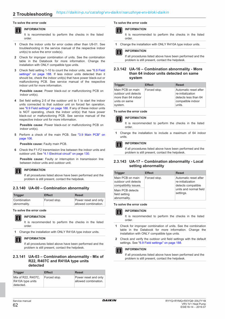
2 Troubleshooting
Service manual
62RYYQ+RYMQ+RXYQ8~20U7Y1B
VRV IV+ Heat PumpESIE18-14 – 2019.07
To solve the error code
INFORMATIONIt is recommended to perform the checks in the listedorder.
1 Check the indoor units for error codes other than U9‑01. Seetroubleshooting in the service manual of the respective indoorunit(s) to solve the error code(s).
2 Check for improper combination of units. See the combinationtable in the Databook for more information. Change theinstallation with ONLY compatible type units.
3 Check field setting 1‑10 to count the indoor units, see "6.9 Fieldsettings" on page 188. If less indoor units detected than itshould be, check the indoor unit(s) that have power black‑out ormalfunctioning PCB. See service manual of the respectiveindoor unit for more information.
Possible cause: Power black‑out or malfunctioning PCB onindoor unit(s).
4 Set field setting 2‑5 of the outdoor unit to 1 to start the indoorunits connected to that outdoor unit on forced fan operation,see "6.9 Field settings" on page 188. If any of these indoor unitsis NOT operating, check the indoor unit(s) that have powerblack‑out or malfunctioning PCB. See service manual of therespective indoor unit for more information.
Possible cause: Power black‑out or malfunctioning PCB onindoor unit(s).
5 Perform a check of the main PCB. See "3.9 Main PCB" onpage 106.
Possible cause: Faulty main PCB.
6 Check the F1‑F2 transmission line between the indoor units andoutdoor unit. See "4.1 Electrical circuit" on page 130.
Possible cause: Faulty or interruption in transmission linebetween indoor units and outdoor unit.
INFORMATIONIf all procedures listed above have been performed and theproblem is still present, contact the helpdesk.
2.3.140 UA-00 – Combination abnormality
Trigger Effect ResetCombinationabnormality.
Forced stop. Power reset and onlyallowed combination.
To solve the error code
INFORMATIONIt is recommended to perform the checks in the listedorder.
1 Change the installation with ONLY R410A type indoor units.
INFORMATIONIf all procedures listed above have been performed and theproblem is still present, contact the helpdesk.
2.3.141 UA-03 – Combination abnormality - Mix ofR22, R407C and R410A type unitsdetected
Trigger Effect ResetMix of R22, R407C,R410A type unitsdetected.
Forced stop. Power reset and onlyallowed combination.
To solve the error code
INFORMATIONIt is recommended to perform the checks in the listedorder.
1 Change the installation with ONLY R410A type indoor units.
INFORMATIONIf all procedures listed above have been performed and theproblem is still present, contact the helpdesk.
2.3.142 UA-16 – Combination abnormality - Morethan 64 indoor units detected on samesystem
Trigger Effect ResetMain PCB on mainoutdoor unit detectsmore than 64 indoorunits on samesystem.
Forced stop. Automatic reset afterre-initializationdetects less than 64compatible indoorunits.
To solve the error code
INFORMATIONIt is recommended to perform the checks in the listedorder.
1 Change the installation to include a maximum of 64 indoorunits.
INFORMATIONIf all procedures listed above have been performed and theproblem is still present, contact the helpdesk.
2.3.143 UA-17 – Combination abnormality - Localsetting abnormality
Trigger Effect ResetMain PCB on mainoutdoor unit detectscompatibility issues.
Forced stop. Automatic reset afterre-initializationdetects compatibleunits and normal fieldsettings.
Main PCB detectsfield settingabnormality.
To solve the error code
INFORMATIONIt is recommended to perform the checks in the listedorder.
1 Check for improper combination of units. See the combinationtable in the Databook for more information. Change theinstallation with ONLY compatible type units.
2 Check and verify the outdoor unit field settings with the defaultsettings. See "6.9 Field settings" on page 188.
INFORMATIONIf all procedures listed above have been performed and theproblem is still present, contact the helpdesk.
https://daikin-p.ru/catalog/vrv-daikn/naruzhnye-vrv-bloki-daikin
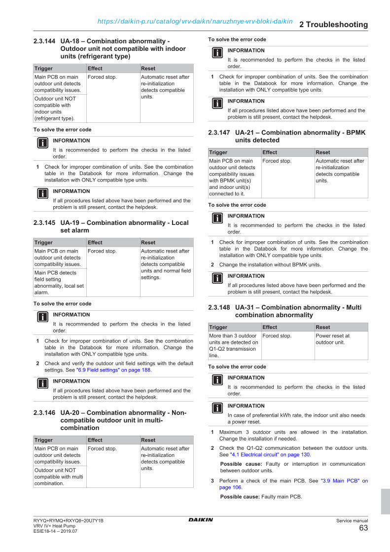
2 Troubleshooting
Service manual
63RYYQ+RYMQ+RXYQ8~20U7Y1BVRV IV+ Heat PumpESIE18-14 – 2019.07
2.3.144 UA-18 – Combination abnormality -Outdoor unit not compatible with indoorunits (refrigerant type)
Trigger Effect ResetMain PCB on mainoutdoor unit detectscompatibility issues.
Forced stop. Automatic reset afterre‑initializationdetects compatibleunits.Outdoor unit NOT
compatible withindoor units(refrigerant type).
To solve the error code
INFORMATIONIt is recommended to perform the checks in the listedorder.
1 Check for improper combination of units. See the combinationtable in the Databook for more information. Change theinstallation with ONLY compatible type units.
INFORMATIONIf all procedures listed above have been performed and theproblem is still present, contact the helpdesk.
2.3.145 UA-19 – Combination abnormality - Localset alarm
Trigger Effect ResetMain PCB on mainoutdoor unit detectscompatibility issues.
Forced stop. Automatic reset afterre‑initializationdetects compatibleunits and normal fieldsettings.
Main PCB detectsfield settingabnormality, local setalarm.
To solve the error code
INFORMATIONIt is recommended to perform the checks in the listedorder.
1 Check for improper combination of units. See the combinationtable in the Databook for more information. Change theinstallation with ONLY compatible type units.
2 Check and verify the outdoor unit field settings with the defaultsettings. See "6.9 Field settings" on page 188.
INFORMATIONIf all procedures listed above have been performed and theproblem is still present, contact the helpdesk.
2.3.146 UA-20 – Combination abnormality - Non-compatible outdoor unit in multi-combination
Trigger Effect ResetMain PCB on mainoutdoor unit detectscompatibility issues.
Forced stop. Automatic reset afterre‑initializationdetects compatibleunits.Outdoor unit NOT
compatible with multicombination.
To solve the error code
INFORMATIONIt is recommended to perform the checks in the listedorder.
1 Check for improper combination of units. See the combinationtable in the Databook for more information. Change theinstallation with ONLY compatible type units.
INFORMATIONIf all procedures listed above have been performed and theproblem is still present, contact the helpdesk.
2.3.147 UA-21 – Combination abnormality - BPMKunits detected
Trigger Effect ResetMain PCB on mainoutdoor unit detectscompatibility issueswith BPMK unit(s)and indoor unit(s)connected to it.
Forced stop. Automatic reset afterre-initializationdetects compatibleunits.
To solve the error code
INFORMATIONIt is recommended to perform the checks in the listedorder.
1 Check for improper combination of units. See the combinationtable in the Databook for more information. Change theinstallation with ONLY compatible type units.
2 Change the installation without BPMK units.
INFORMATIONIf all procedures listed above have been performed and theproblem is still present, contact the helpdesk.
2.3.148 UA-31 – Combination abnormality - Multicombination abnormality
Trigger Effect ResetMore than 3 outdoorunits are detected onQ1-Q2 transmissionline.
Forced stop. Power reset atoutdoor unit.
To solve the error code
INFORMATIONIt is recommended to perform the checks in the listedorder.
INFORMATIONIn case of preferential kWh rate, the indoor unit also needsa power reset.
1 Maximum 3 outdoor units are allowed in the installation.Change the installation if needed.
2 Check the Q1‑Q2 communication between the outdoor units.See "4.1 Electrical circuit" on page 130.
Possible cause: Faulty or interruption in communicationbetween outdoor units.
3 Perform a check of the main PCB. See "3.9 Main PCB" onpage 106.
Possible cause: Faulty main PCB.
https://daikin-p.ru/catalog/vrv-daikn/naruzhnye-vrv-bloki-daikin

2 Troubleshooting
Service manual
64RYYQ+RYMQ+RXYQ8~20U7Y1B
VRV IV+ Heat PumpESIE18-14 – 2019.07
INFORMATIONIf all procedures listed above have been performed and theproblem is still present, contact the helpdesk.
2.3.149 UA-38 – Combination abnormality -Altherma hydro unit detected
Trigger Effect ResetMain PCB on mainoutdoor unit detectsAltherma hydroboxon F1-F2 IN wiring.
Forced stop. Automatic reset afterre-initializationdetects compatibleunits.
To solve the error code
INFORMATIONIt is recommended to perform the checks in the listedorder.
1 Only LT Hydrobox HXY-A unit is allowed in the installation. Seethe Databook for more information.
INFORMATIONIf all procedures listed above have been performed and theproblem is still present, contact the helpdesk.
2.3.150 UA-39 – Combination abnormality -Incorrect combination
Trigger Effect ResetMain PCB on mainoutdoor unit detectscompatibility issues.
Forced stop. Automatic reset afterre-initializationdetects compatibleunits.
To solve the error code
INFORMATIONIt is recommended to perform the checks in the listedorder.
1 Check for improper combination of units. See the combinationtable in the Databook for more information. Change theinstallation with ONLY compatible type units.
INFORMATIONIf all procedures listed above have been performed and theproblem is still present, contact the helpdesk.
2.3.151 UA-49 – Combination abnormality - Wrongunit combination
Trigger Effect ResetMain PCB on mainoutdoor unit detectscompatibility issues.
Forced stop. Automatic reset afterre-initializationdetects compatibleunits.
To solve the error code
INFORMATIONIt is recommended to perform the checks in the listedorder.
1 Check for improper combination of units. See the combinationtable in the Databook for more information. Change theinstallation with ONLY compatible type units.
INFORMATIONIf all procedures listed above have been performed and theproblem is still present, contact the helpdesk.
2.3.152 UF-01 – Wiring and piping mismatch -Auto address inconsistency on F1-F2transmission
Trigger Effect ResetMinimum 1 indoorunit fails to performcross pipe checkduring test run.
Forced stop. Perform test run.
To solve the error code
INFORMATIONIt is recommended to perform the checks in the listedorder.
1 Check that all stop valves of the refrigerant circuit are open.See "4.2 Refrigerant circuit" on page 133.
Possible cause: Closed stop valve in the refrigerant circuit.
2 Check that the refrigerant circuit piping and wiring connectionsof the system are correctly installed.
Possible cause: Refrigerant piping and/or wiring mismatch.
3 Set field setting 2‑5 of the outdoor unit to 1 to start the indoorunits connected to that outdoor unit on forced fan operation,see "6.9 Field settings" on page 188. If any of these indoor unitsis NOT operating, check the indoor unit(s) that have powerblack‑out or malfunctioning PCB. See service manual of therespective indoor unit for more information.
Possible cause: Power black‑out or malfunctioning PCB onindoor unit(s).
4 Check field setting 1‑10 to count the indoor units, see "6.9 Fieldsettings" on page 188. If less indoor units detected than itshould be, check the indoor unit(s) that have power black‑out ormalfunctioning PCB. See service manual of the respectiveindoor unit for more information.
Possible cause: Power black‑out or malfunctioning PCB onindoor unit(s).
5 Perform a check of the indoor unit pipe thermistors, see servicemanual of the respective indoor unit(s) for more information.
Possible cause: Faulty indoor unit pipe thermistor.
INFORMATIONIf all procedures listed above have been performed and theproblem is still present, contact the helpdesk.
2.3.153 UF-05 – Wiring and piping mismatch -Stop valves closed or incorrect
Trigger Effect ResetMinimum 1 indoorunit fails to performcross pipe checkduring test run.
Forced stop. Perform test run.
To solve the error code
INFORMATIONIt is recommended to perform the checks in the listedorder.
1 Check that all stop valves of the refrigerant circuit are open.See "4.2 Refrigerant circuit" on page 133.
Possible cause: Closed stop valve in the refrigerant circuit.
2 Check that the refrigerant circuit piping and wiring connectionsof the system are correctly installed.
Possible cause: Refrigerant piping and/or wiring mismatch.
https://daikin-p.ru/catalog/vrv-daikn/naruzhnye-vrv-bloki-daikin

2 Troubleshooting
Service manual
65RYYQ+RYMQ+RXYQ8~20U7Y1BVRV IV+ Heat PumpESIE18-14 – 2019.07
3 Set field setting 2‑5 of the outdoor unit to 1 to start the indoorunits connected to that outdoor unit on forced fan operation,see "6.9 Field settings" on page 188. If any of these indoor unitsis NOT operating, check the indoor unit(s) that have powerblack‑out or malfunctioning PCB. See service manual of therespective indoor unit for more information.
Possible cause: Power black‑out or malfunctioning PCB onindoor unit(s).
4 Check field setting 1‑10 to count the indoor units, see "6.9 Fieldsettings" on page 188. If less indoor units detected than itshould be, check the indoor unit(s) that have power black‑out ormalfunctioning PCB. See service manual of the respectiveindoor unit for more information.
Possible cause: Power black‑out or malfunctioning PCB onindoor unit(s).
5 Perform a check of the indoor unit pipe thermistors, see servicemanual of the respective indoor unit(s) for more information.
Possible cause: Faulty indoor unit pipe thermistor.
INFORMATIONIf all procedures listed above have been performed and theproblem is still present, contact the helpdesk.
2.3.154 UF-11 – Wiring and piping mismatch -Excess connection ratio
Trigger Effect ResetMinimum 1 indoorunit fails to performcross pipe checkduring test run.
Forced stop. Perform test run.
To solve the error code
INFORMATIONIt is recommended to perform the checks in the listedorder.
1 Check that all stop valves of the refrigerant circuit are open.See "4.2 Refrigerant circuit" on page 133.
Possible cause: Closed stop valve in the refrigerant circuit.
2 Check that the refrigerant circuit piping and wiring connectionsof the system are correctly installed.
Possible cause: Refrigerant piping and/or wiring mismatch.
3 Set field setting 2‑5 of the outdoor unit to 1 to start the indoorunits connected to that outdoor unit on forced fan operation,see "6.9 Field settings" on page 188. If any of these indoor unitsis NOT operating, check the indoor unit(s) that have powerblack‑out or malfunctioning PCB. See service manual of therespective indoor unit for more information.
Possible cause: Power black‑out or malfunctioning PCB onindoor unit(s).
4 Check field setting 1‑10 to count the indoor units, see "6.9 Fieldsettings" on page 188. If less indoor units detected than itshould be, check the indoor unit(s) that have power black‑out ormalfunctioning PCB. See service manual of the respectiveindoor unit for more information.
Possible cause: Power black‑out or malfunctioning PCB onindoor unit(s).
5 Perform a check of the indoor unit pipe thermistors, see servicemanual of the respective indoor unit(s) for more information.
Possible cause: Faulty indoor unit pipe thermistor.
INFORMATIONIf all procedures listed above have been performed and theproblem is still present, contact the helpdesk.
2.3.155 UH-01-02 – Auto-address failure
Trigger Effect ResetMain PCB detectsimproper combinationat indoor unit side.
Forced stop. Reset communicationfrom main PCB.
Missing auto addressof indoor unit(s) afterinitialization.
To solve the error code
INFORMATIONIt is recommended to perform the checks in the listedorder.
1 Set field setting 2‑5 of the outdoor unit to 1 to start the indoorunits connected to that outdoor unit on forced fan operation,see "6.9 Field settings" on page 188. If any of these indoor unitsis NOT operating, check the indoor unit(s) that have powerblack‑out or malfunctioning PCB. See service manual of therespective indoor unit for more information.
Possible cause: Power black‑out or malfunctioning PCB onindoor unit(s).
2 Perform a communication reset of the F1‑F2 transmission, see"4.1 Electrical circuit" on page 130.
3 Check field setting 1‑10 to count the indoor units, see "6.9 Fieldsettings" on page 188. If less indoor units detected than itshould be, check the indoor unit(s) that have power black‑out ormalfunctioning PCB. See service manual of the respectiveindoor unit for more information.
Possible cause: Power black‑out or malfunctioning PCB onindoor unit(s).
4 Check if the power supply is conform with the regulations. See"4.1 Electrical circuit" on page 130.
Possible cause:▪ Faulty or disturbance of the power supply (imbalance
>10%),▪ Power drop,▪ Short circuit.
5 Check the F1‑F2 transmission line between the indoor units andoutdoor unit. See "4.1 Electrical circuit" on page 130.
Possible cause: Faulty or interruption in transmission linebetween indoor units and outdoor unit.
6 Check for improper combination of units. See the combinationtable in the Databook for more information. Change theinstallation with ONLY compatible type units.
INFORMATIONIf all procedures listed above have been performed and theproblem is still present, contact the helpdesk.
2.3.156 E-1 – Refrigerant leak check is notpossible
Trigger Effect ResetTotal refrigerantjudgement isunknown.
Unit will stopoperating.
Manual reset via userinterface.
https://daikin-p.ru/catalog/vrv-daikn/naruzhnye-vrv-bloki-daikin

2 Troubleshooting
Service manual
66RYYQ+RYMQ+RXYQ8~20U7Y1B
VRV IV+ Heat PumpESIE18-14 – 2019.07
To solve the error code
INFORMATIONIt is recommended to perform the checks in the listedorder.
1 Change field setting 2–14. See "6.9 Field settings" on page 188.
Possible cause: No input at field setting 2–14 (2–14 = 0)when field setting 2–88 = 0.
2 Set field setting 2–88 to 0, see "6.9 Field settings" on page 188to enable the outdoor unit to perform long test run to be able tojudge refrigerant amount.
3 Check if test run was interrupted.
4 Check the error history, see "2 Troubleshooting" on page 9.Solve the error code(s) using the error based troubleshooting,see "2.3 Error based troubleshooting" on page 12.
INFORMATIONIf all procedures listed above have been performed and theproblem is still present, contact the helpdesk.
2.3.157 E-2 – Refrigerant leak check cannot beperformed - indoor air temperature is outof range
Trigger Effect ResetAverage indoor unitair temperature<15°C.
Unit will NOT startrefrigerant leak checkmode.
Perform refrigerantleak check whenaverage indoortemperature >15°C.
To solve the error code
INFORMATIONIt is recommended to perform the checks in the listedorder.
1 Perform a check of the indoor unit air thermistors. See servicemanual of the respective indoor unit(s) for more information.
Possible cause: Faulty indoor unit air thermistor(s).
2 Perform refrigerant leak check when the average indoortemperature is above 15°C.
INFORMATIONIf all procedures listed above have been performed and theproblem is still present, contact the helpdesk.
2.3.158 E-3 – Refrigerant leak check cannot beperformed - outdoor air temperature is outof range
Trigger Effect ResetOutdoor airtemperature <20°C.
Unit will NOT startrefrigerant leak checkmode.
Perform refrigerantleak check whenaverage outdoortemperature >20°C.
To solve the error code
INFORMATIONIt is recommended to perform the checks in the listedorder.
1 Perform a check of the outdoor air thermistor. See"3.17 Thermistors" on page 128.
Possible cause: Faulty ambient air thermistor.
2 Perform refrigerant leak check when the outdoor temperature isabove 20°C.
INFORMATIONIf all procedures listed above have been performed and theproblem is still present, contact the helpdesk.
2.3.159 E-4 – Refrigerant leak check is interrupted- too low pressure is detected
Trigger Effect ResetToo low pressure isdetected duringrefrigerant leak checkmode.
Refrigerant leakcheck functionCANNOT beperformed.
Restart leak detectionoperation.
To solve the error code
INFORMATIONIt is recommended to perform the checks in the listedorder.
1 Perform a check of the refrigerant high pressure sensor. See"3.15 Refrigerant high pressure sensor" on page 124.
Possible cause: Faulty refrigerant high pressure sensor.
2 Perform a check of the refrigerant low pressure sensor. See"3.16 Refrigerant low pressure sensor" on page 126
Possible cause: Faulty refrigerant low pressure sensor.
3 Restart leak detection operation.
INFORMATIONIf all procedures listed above have been performed and theproblem is still present, contact the helpdesk.
2.3.160 E-5 – Refrigerant leak check cannot beperformed - a unit which is not compatiblewith leak detection function is installed
Trigger Effect ResetLeak detection isNOT supported forsome of the installedindoor units (e.g.Hydrobox, …).
Refrigerant leakcheck functionCANNOT beperformed.
No reset required.
To solve the error code1 No corrective action needed, unless there is an indoor unit in
the system which is refrigerant leak function incompatible.
2.3.161 NG – Refrigerant leak check functiondetects refrigerant leak
Trigger Effect ResetResult of refrigerantleak check functiondeviates more than15% compared toresult of test run.
Result of last 3refrigerant leak checkfunction is stored onMode 1 items29‑30‑31, see"6.9 Field settings" onpage 188.
No reset required.
To solve the error code
INFORMATIONIt is recommended to perform the checks in the listedorder.
1 Check for leaks in the refrigerant circuit. Look for oil traces onthe unit(s). Check the brazing points on the field piping. Performa leak test, see "4.2 Refrigerant circuit" on page 133.
Possible cause: Leak in the refrigerant circuit.
https://daikin-p.ru/catalog/vrv-daikn/naruzhnye-vrv-bloki-daikin
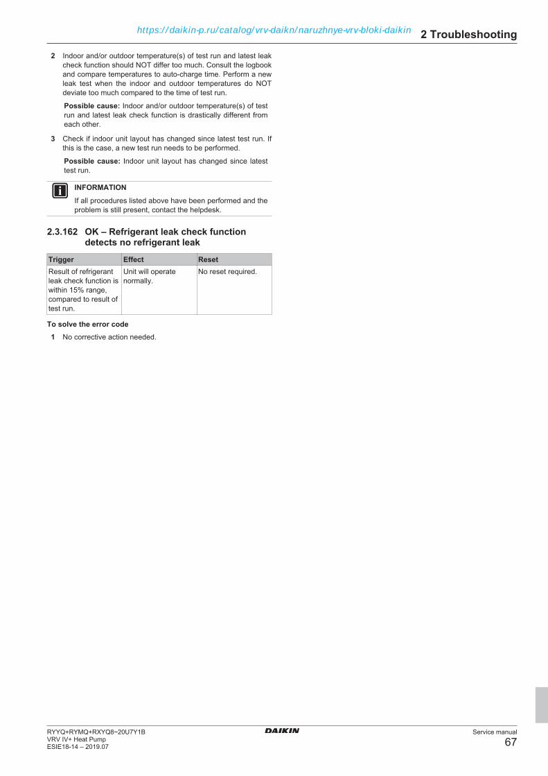
2 Troubleshooting
Service manual
67RYYQ+RYMQ+RXYQ8~20U7Y1BVRV IV+ Heat PumpESIE18-14 – 2019.07
2 Indoor and/or outdoor temperature(s) of test run and latest leakcheck function should NOT differ too much. Consult the logbookand compare temperatures to auto‑charge time. Perform a newleak test when the indoor and outdoor temperatures do NOTdeviate too much compared to the time of test run.
Possible cause: Indoor and/or outdoor temperature(s) of testrun and latest leak check function is drastically different fromeach other.
3 Check if indoor unit layout has changed since latest test run. Ifthis is the case, a new test run needs to be performed.
Possible cause: Indoor unit layout has changed since latesttest run.
INFORMATIONIf all procedures listed above have been performed and theproblem is still present, contact the helpdesk.
2.3.162 OK – Refrigerant leak check functiondetects no refrigerant leak
Trigger Effect ResetResult of refrigerantleak check function iswithin 15% range,compared to result oftest run.
Unit will operatenormally.
No reset required.
To solve the error code1 No corrective action needed.
https://daikin-p.ru/catalog/vrv-daikn/naruzhnye-vrv-bloki-daikin

2 Troubleshooting
Service manual
68RYYQ+RYMQ+RXYQ8~20U7Y1B
VRV IV+ Heat PumpESIE18-14 – 2019.07
2.3.163 Indoor unit related error codes
Error code DescriptionA0-00 Main PCB errorA1-00 EEPROM error on main PCBA3-00 Float switch open during thermo ON in cooling modeA6-01 Fan motor lockedA6-10 Fan motor overcurrentA6-11 Fan motor lockedA7-00 No detection contact swing motorA9-01 Expansion valve motor fault detectionA9-02 Expansion valve bleedingAF-00 Float switch open during thermo OFFAH-03 Transmission error between main PCB and
self‑cleaning PCBAH-04 Dust detection sensor errorAH-05 Dust collection errorAH-06 Air filter rotation errorAH-07 Damper rotation errorAH-08 Filter cleaning time errorAH-09 Auto self‑cleaning disabledAJ-01 Capacity adapter missingAJ-02 Incorrect expansion valve motorC1-01 Transmission error between main PCB and fan
motor PCBC1-02 Transmission error between main PCB and auxiliary PCBC4-02 Liquid thermistor short circuitC4-03 Liquid thermistor open circuitC5-02 Gas thermistor short circuitC5-03 Gas thermistor open circuitC6-01 Combination error: Main PCB – Fan motor PCBC9-02 Air thermistor short circuitC9-03 Air thermistor open circuitCE-01 No signal from optional presence sensorCE-02 No signal from optional floor temperature sensorCE-03 Faulty signal from floor temperature sensorCE-04 High temperature detection or electrical noise on
floor temperature sensorCJ-02 Air thermistor on Remote controller short circuitCJ-03 Air thermistor on Remote controller open circuitU4-01 Communication error between indoor unit and
outdoor unitU9-00 Error on other indoor unitUA-13 Combination error: indoor unit – outdoor unit
(refrigerant)UA-15 Outdoor unit not compatible with self‑cleaning panelUE-00 Communication error with central controller device
https://daikin-p.ru/catalog/vrv-daikn/naruzhnye-vrv-bloki-daikin
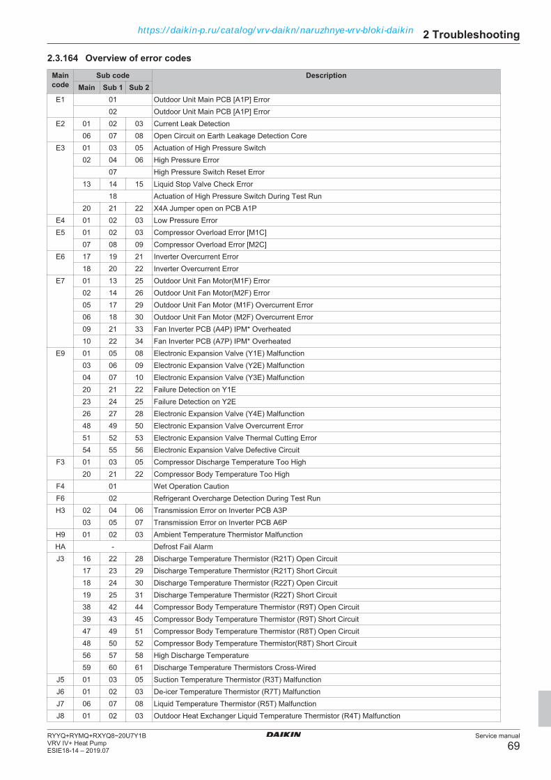
2 Troubleshooting
Service manual
69RYYQ+RYMQ+RXYQ8~20U7Y1BVRV IV+ Heat PumpESIE18-14 – 2019.07
2.3.164 Overview of error codes
Maincode
Sub code DescriptionMain Sub 1 Sub 2
E1 01 Outdoor Unit Main PCB [A1P] Error02 Outdoor Unit Main PCB [A1P] Error
E2 01 02 03 Current Leak Detection06 07 08 Open Circuit on Earth Leakage Detection Core
E3 01 03 05 Actuation of High Pressure Switch02 04 06 High Pressure Error
07 High Pressure Switch Reset Error13 14 15 Liquid Stop Valve Check Error
18 Actuation of High Pressure Switch During Test Run20 21 22 X4A Jumper open on PCB A1P
E4 01 02 03 Low Pressure ErrorE5 01 02 03 Compressor Overload Error [M1C]
07 08 09 Compressor Overload Error [M2C]E6 17 19 21 Inverter Overcurrent Error
18 20 22 Inverter Overcurrent ErrorE7 01 13 25 Outdoor Unit Fan Motor(M1F) Error
02 14 26 Outdoor Unit Fan Motor(M2F) Error05 17 29 Outdoor Unit Fan Motor (M1F) Overcurrent Error06 18 30 Outdoor Unit Fan Motor (M2F) Overcurrent Error09 21 33 Fan Inverter PCB (A4P) IPM* Overheated10 22 34 Fan Inverter PCB (A7P) IPM* Overheated
E9 01 05 08 Electronic Expansion Valve (Y1E) Malfunction03 06 09 Electronic Expansion Valve (Y2E) Malfunction04 07 10 Electronic Expansion Valve (Y3E) Malfunction20 21 22 Failure Detection on Y1E23 24 25 Failure Detection on Y2E26 27 28 Electronic Expansion Valve (Y4E) Malfunction48 49 50 Electronic Expansion Valve Overcurrent Error51 52 53 Electronic Expansion Valve Thermal Cutting Error54 55 56 Electronic Expansion Valve Defective Circuit
F3 01 03 05 Compressor Discharge Temperature Too High20 21 22 Compressor Body Temperature Too High
F4 01 Wet Operation CautionF6 02 Refrigerant Overcharge Detection During Test RunH3 02 04 06 Transmission Error on Inverter PCB A3P
03 05 07 Transmission Error on Inverter PCB A6PH9 01 02 03 Ambient Temperature Thermistor MalfunctionHA - Defrost Fail AlarmJ3 16 22 28 Discharge Temperature Thermistor (R21T) Open Circuit
17 23 29 Discharge Temperature Thermistor (R21T) Short Circuit18 24 30 Discharge Temperature Thermistor (R22T) Open Circuit19 25 31 Discharge Temperature Thermistor (R22T) Short Circuit38 42 44 Compressor Body Temperature Thermistor (R9T) Open Circuit39 43 45 Compressor Body Temperature Thermistor (R9T) Short Circuit47 49 51 Compressor Body Temperature Thermistor (R8T) Open Circuit48 50 52 Compressor Body Temperature Thermistor(R8T) Short Circuit56 57 58 High Discharge Temperature59 60 61 Discharge Temperature Thermistors Cross-Wired
J5 01 03 05 Suction Temperature Thermistor (R3T) MalfunctionJ6 01 02 03 De-icer Temperature Thermistor (R7T) MalfunctionJ7 06 07 08 Liquid Temperature Thermistor (R5T) MalfunctionJ8 01 02 03 Outdoor Heat Exchanger Liquid Temperature Thermistor (R4T) Malfunction
https://daikin-p.ru/catalog/vrv-daikn/naruzhnye-vrv-bloki-daikin

2 Troubleshooting
Service manual
70RYYQ+RYMQ+RXYQ8~20U7Y1B
VRV IV+ Heat PumpESIE18-14 – 2019.07
Maincode
Sub code DescriptionMain Sub 1 Sub 2
J9 01 02 03 Gas Temperature Thermistor MalfunctionJA 06 08 10 High Pressure Sensor (S1NPH) Open Circuit or Out of Range
07 09 11 High Pressure Sensor (S1NPH) Short Circuit or Out of RangeJC 06 08 10 Low Pressure Sensor (S1NPL) Open Circuit or Out of Range
07 09 11 Low Pressure Sensor (S1NPL) Short Circuit or Out of RangeL1 01 07 11 Inverter PCB A3P Malfunction
02 08 12 Inverter PCB A3P Current Detection Primary Circuit03 09 13 Inverter PCB A3P Current Detection Secondary Circuit04 10 14 Power Transistor Error on Inverter PCB A3P05 15 16 Inverter PCB A3P Hardware Fault17 22 42 Inverter PCB A6P Malfunction18 23 43 Inverter PCB A6P Current Detection Primary Circuit19 24 44 Inverter PCB A6P Current Detection Secondary Circuit20 25 45 Power Transistor Error on Inverter PCB A6P21 26 46 Inverter PCB A6P Hardware Fault28 32 34 Fan Inverter PCB A4P EEPROM Error29 33 35 Fan Inverter PCB A7P EEPROM Error36 38 40 Inverter PCB A3P EEPROM Error37 39 41 Inverter PCB A6P EEPROM Error47 49 51 Inverter PCB A3P 16 V DC Abnormality48 50 52 Inverter PCB A6P 16 V DC Abnormality
L2 01 02 03 Power Supply Abnormality During Test Run04 05 06 Power Supply Abnormality During Normal Operation
L4 01 02 03 Inverter PCB A3P High Fin Temperature06 18 20 Fan Inverter PCB A4P High Fin Temperature07 19 21 Inverter PCB A7P High Fin Temperature09 10 11 Inverter PCB A6P High Fin Temperature
L5 03 05 07 Output Overcurrent Detection on Inverter PCB A3P14 15 16 Output Overcurrent Detection on Inverter PCB A6P
L8 03 06 07 Overcurrent on Inverter PCB A3P except start-up11 12 13 Overcurrent on Inverter PCB A6P except start-up
L9 01 05 06 Stall Prevention by Inverter PCB A3P10 11 12 Stall Prevention by Inverter PCB A6P13 14 15 Inverter PCB A3P Output Phase Abnormality16 17 18 Inverter PCB A6P Output Phase Abnormality
LC 01 Transmission Abnormality Main PCB A1P to A3P, A6P, A4P, A7P14 15 16 Transmission Error Main PCB A1P - Inverter PCB A3P19 20 21 Transmission Error Main PCB A1P - Fan Inverter PCB A4P24 25 26 Transmission Error Main PCB A1P - Fan Inverter PCB A7P30 31 32 Transmission Error Main PCB A1P - Inverter PCB A6P
P1 01 02 03 Open Phase or Unbalanced Power Supply Detection by Inverter PCB A3P07 08 09 Open Phase or Unbalanced Power Supply Detection by Inverter PCB A6P
P2 00 Refrigerant Auto-charge InterruptedP4 01 04 05 Fin Thermistor Fault on Inverter PCB A3P
02 15 17 Fin Thermistor Fault on Fan Inverter PCB A4P03 16 18 Fin Thermistor Fault on Fan Inverter PCB A7P06 07 08 Fin Thermistor Fault on Inverter PCB A6P
P8 - Freeze-Up During Refrigerant Auto-ChargeP9 - Refrigerant Auto-Charge Finished NormallyPA - No Refrigerant in Refrigerant Cylinder During Auto-ChargePE - Refrigerant Auto-Charge on Last StagePF - Long Test Run Failed
https://daikin-p.ru/catalog/vrv-daikn/naruzhnye-vrv-bloki-daikin

2 Troubleshooting
Service manual
71RYYQ+RYMQ+RXYQ8~20U7Y1BVRV IV+ Heat PumpESIE18-14 – 2019.07
Maincode
Sub code DescriptionMain Sub 1 Sub 2
PJ 04 05 06 Capacity Setting Mismatch for Inverter PCB A3P09 15 16 Capacity Setting Mismatch for Fan Inverter PCB A4P10 17 18 Capacity Setting Mismatch for Fan Inverter PCB A7P12 13 14 Capacity Setting Mismatch for Inverter PCB A6P
U0 05 Refrigerant Shortage Detection During Cooling06 Refrigerant Shortage Detection During Heating
08 09 10 Refrigerant Shortage Detection by High Pressure SensorU1 01 05 07 Reverse Phase Detection
04 06 08 Reverse Phase DetectionU2 01 08 11 Inverter Circuit Power Supply Abnormality - Inverter PCB A3P Abnormal Voltage
02 09 12 Inverter Circuit Power Supply Abnormality - Inverter PCB A3P Phase Loss03 10 13 Inverter Circuit Power Supply Abnormality - Inverter PCB A3P DC Circuit Not Charging22 25 28 Inverter Circuit Power Supply Abnormality - Inverter PCB A6P Abnormal Voltage23 26 29 Inverter Circuit Power Supply Abnormality - Inverter PCB A6P Phase Loss24 27 30 Inverter Circuit Power Supply Abnormality - Inverter PCB A6P DC Circuit Not Charging
U3 02 Test Run Interrupted Manually03 Test Run Not Performed Yet04 Test Run Ended Abnormally05 Test Run Aborted on Initial Transmission06 Test Run Aborted on Normal Transmission07 Transmission abnormality on Test Run08 Transmission abnormality on Test Run
U4 01 Communication Error on Q1-Q2 Transmission Line03 Communication Error on F1-F2 Transmission Line15 Unable to Start Test Run
U7 01 Transmission Abnormality Between Systems - DTA104A61, DTA104A62 Error02 Transmission Abnormality Between Systems - DTA104A61, DTA104A62 Error03 Transmission Error Between Main Outdoor Unit and Sub 1 Outdoor Unit04 Transmission Error Between Main Outdoor Unit and Sub 2 Outdoor Unit05 Multi System Abnormality06 Multi System Address Abnormality07 More Than 3 Outdoor Units on Q1-Q2 Transmission11 Excess Indoor Units Detected on Test Run24 Duplication of Address Setting on Multiple DTA104A61,62 Installation
U9 01 Other Indoor Unit Has ErrorUA 00 Combination Abnormality
03 Combination Abnormality - Mix of R22, R407C, R410A Type Units Detected16 Combination Abnormality - More Than 64 Indoor Units Detected On Same System17 Combination Abnormality - Local Setting Abnormality18 Combination Abnormality - Outdoor Unit Not Compatible With Indoor Units (Refrigerant Type)19 Combination Abnormality - Local Set Alarm20 Combination Abnormality - Non Compatible Outdoor Unit in Multi Combination21 Combination Abnormality - BPMK Unit(s) Detected31 Combination Abnormality - Multi Combination Abnormality38 Combination Abnormality - Altherma Hydro Unit(s) Detected39 Combination Abnormality - Incorrect Combination49 Combination Abnormality - Wrong unit Combination
UF 01 Wiring and Piping Mismatch - Auto Address Inconsistency on F1-F2 Transmission05 Wiring and Piping Mismatch - Stop Valve(s) Closed or Incorrect11 Wiring and Piping Mismatch - Excess Connection Ratio
UH 01 Auto Address Failure02 Auto Address Failure
E-1 - Refrigerant Leak Check is not possible
https://daikin-p.ru/catalog/vrv-daikn/naruzhnye-vrv-bloki-daikin
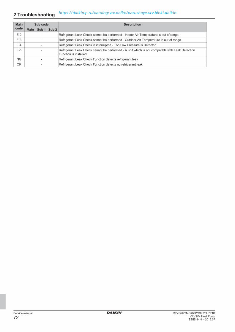
2 Troubleshooting
Service manual
72RYYQ+RYMQ+RXYQ8~20U7Y1B
VRV IV+ Heat PumpESIE18-14 – 2019.07
Maincode
Sub code DescriptionMain Sub 1 Sub 2
E-2 - Refrigerant Leak Check cannot be performed - Indoor Air Temperature is out of range.E-3 - Refrigerant Leak Check cannot be performed - Outdoor Air Temperature is out of range.E-4 - Refrigerant Leak Check is interrupted - Too Low Pressure is DetectedE-5 - Refrigerant Leak Check cannot be performed - A unit which is not compatible with Leak Detection
Function is installedNG - Refrigerant Leak Check Function detects refrigerant leakOK - Refrigerant Leak Check Function detects no refrigerant leak
https://daikin-p.ru/catalog/vrv-daikn/naruzhnye-vrv-bloki-daikin
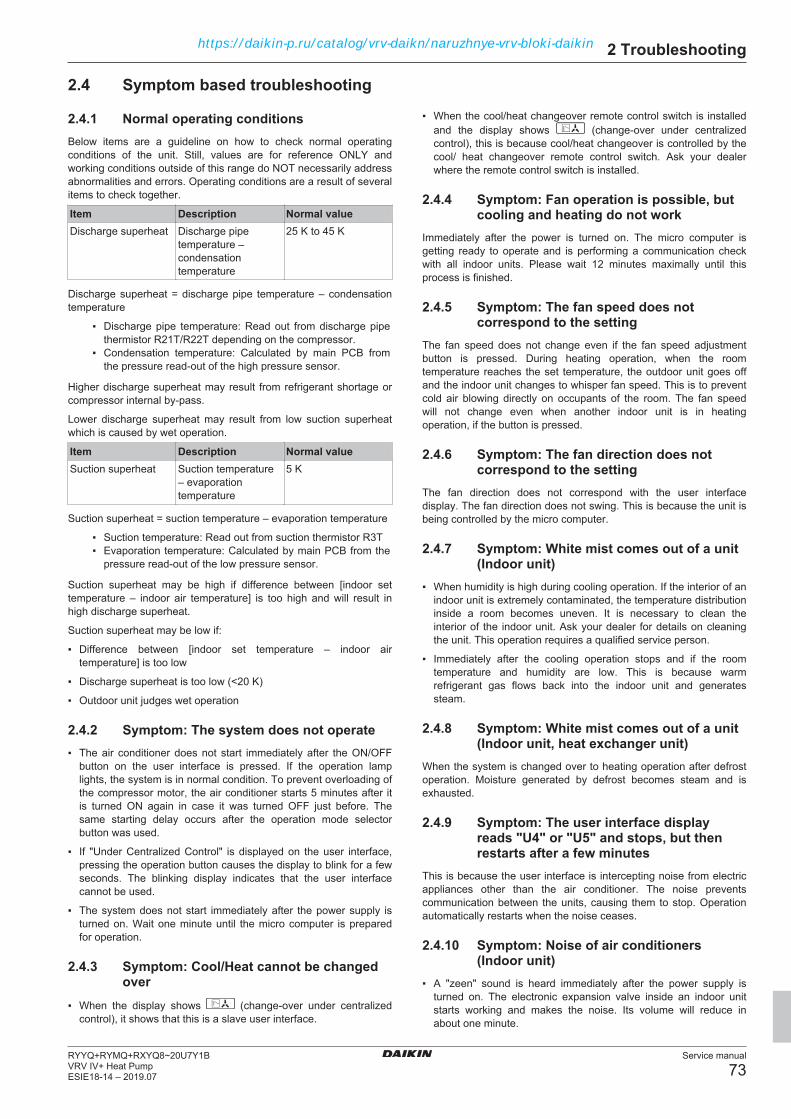
2 Troubleshooting
Service manual
73RYYQ+RYMQ+RXYQ8~20U7Y1BVRV IV+ Heat PumpESIE18-14 – 2019.07
2.4 Symptom based troubleshooting
2.4.1 Normal operating conditionsBelow items are a guideline on how to check normal operatingconditions of the unit. Still, values are for reference ONLY andworking conditions outside of this range do NOT necessarily addressabnormalities and errors. Operating conditions are a result of severalitems to check together.
Item Description Normal valueDischarge superheat Discharge pipe
temperature –condensationtemperature
25 K to 45 K
Discharge superheat = discharge pipe temperature – condensationtemperature
▪ Discharge pipe temperature: Read out from discharge pipethermistor R21T/R22T depending on the compressor.
▪ Condensation temperature: Calculated by main PCB fromthe pressure read‑out of the high pressure sensor.
Higher discharge superheat may result from refrigerant shortage orcompressor internal by‑pass.
Lower discharge superheat may result from low suction superheatwhich is caused by wet operation.
Item Description Normal valueSuction superheat Suction temperature
– evaporationtemperature
5 K
Suction superheat = suction temperature – evaporation temperature
▪ Suction temperature: Read out from suction thermistor R3T▪ Evaporation temperature: Calculated by main PCB from the
pressure read‑out of the low pressure sensor.
Suction superheat may be high if difference between [indoor settemperature – indoor air temperature] is too high and will result inhigh discharge superheat.
Suction superheat may be low if:
▪ Difference between [indoor set temperature – indoor airtemperature] is too low
▪ Discharge superheat is too low (<20 K)
▪ Outdoor unit judges wet operation
2.4.2 Symptom: The system does not operate▪ The air conditioner does not start immediately after the ON/OFF
button on the user interface is pressed. If the operation lamplights, the system is in normal condition. To prevent overloading ofthe compressor motor, the air conditioner starts 5 minutes after itis turned ON again in case it was turned OFF just before. Thesame starting delay occurs after the operation mode selectorbutton was used.
▪ If "Under Centralized Control" is displayed on the user interface,pressing the operation button causes the display to blink for a fewseconds. The blinking display indicates that the user interfacecannot be used.
▪ The system does not start immediately after the power supply isturned on. Wait one minute until the micro computer is preparedfor operation.
2.4.3 Symptom: Cool/Heat cannot be changedover
▪ When the display shows (change-over under centralizedcontrol), it shows that this is a slave user interface.
▪ When the cool/heat changeover remote control switch is installedand the display shows (change-over under centralizedcontrol), this is because cool/heat changeover is controlled by thecool/ heat changeover remote control switch. Ask your dealerwhere the remote control switch is installed.
2.4.4 Symptom: Fan operation is possible, butcooling and heating do not work
Immediately after the power is turned on. The micro computer isgetting ready to operate and is performing a communication checkwith all indoor units. Please wait 12 minutes maximally until thisprocess is finished.
2.4.5 Symptom: The fan speed does notcorrespond to the setting
The fan speed does not change even if the fan speed adjustmentbutton is pressed. During heating operation, when the roomtemperature reaches the set temperature, the outdoor unit goes offand the indoor unit changes to whisper fan speed. This is to preventcold air blowing directly on occupants of the room. The fan speedwill not change even when another indoor unit is in heatingoperation, if the button is pressed.
2.4.6 Symptom: The fan direction does notcorrespond to the setting
The fan direction does not correspond with the user interfacedisplay. The fan direction does not swing. This is because the unit isbeing controlled by the micro computer.
2.4.7 Symptom: White mist comes out of a unit(Indoor unit)
▪ When humidity is high during cooling operation. If the interior of anindoor unit is extremely contaminated, the temperature distributioninside a room becomes uneven. It is necessary to clean theinterior of the indoor unit. Ask your dealer for details on cleaningthe unit. This operation requires a qualified service person.
▪ Immediately after the cooling operation stops and if the roomtemperature and humidity are low. This is because warmrefrigerant gas flows back into the indoor unit and generatessteam.
2.4.8 Symptom: White mist comes out of a unit(Indoor unit, heat exchanger unit)
When the system is changed over to heating operation after defrostoperation. Moisture generated by defrost becomes steam and isexhausted.
2.4.9 Symptom: The user interface displayreads "U4" or "U5" and stops, but thenrestarts after a few minutes
This is because the user interface is intercepting noise from electricappliances other than the air conditioner. The noise preventscommunication between the units, causing them to stop. Operationautomatically restarts when the noise ceases.
2.4.10 Symptom: Noise of air conditioners(Indoor unit)
▪ A "zeen" sound is heard immediately after the power supply isturned on. The electronic expansion valve inside an indoor unitstarts working and makes the noise. Its volume will reduce inabout one minute.
https://daikin-p.ru/catalog/vrv-daikn/naruzhnye-vrv-bloki-daikin
2 Troubleshooting
Service manual
74RYYQ+RYMQ+RXYQ8~20U7Y1B
VRV IV+ Heat PumpESIE18-14 – 2019.07
▪ A continuous low "shah" sound is heard when the system is incooling operation or at a stop. When the drain pump (optionalaccessories) is in operation, this noise is heard.
▪ A "pishi-pishi" squeaking sound is heard when the system stopsafter heating operation. Expansion and contraction of plastic partscaused by temperature change make this noise.
▪ A low "sah", "choro-choro" sound is heard while the indoor unit isstopped. When another indoor unit is in operation, this noise isheard. In order to prevent oil and refrigerant from remaining in thesystem, a small amount of refrigerant is kept flowing.
2.4.11 Symptom: Noise of air conditioners(Indoor unit, outdoor unit)
▪ A continuous low hissing sound is heard when the system is incooling or defrost operation. This is the sound of refrigerant gasflowing through both indoor and outdoor units.
▪ A hissing sound which is heard at the start or immediately afterstopping operation or defrost operation. This is the noise ofrefrigerant caused by flow stop or flow change.
2.4.12 Symptom: Noise of air conditioners(Outdoor unit)
When the tone of operating noise changes. This noise is caused bythe change of frequency.
2.4.13 Symptom: Dust comes out of the unitWhen the unit is used for the first time in a long time. This isbecause dust has gotten into the unit.
2.4.14 Symptom: The units can give off odoursThe unit can absorb the smell of rooms, furniture, cigarettes, etc.,and then emit it again.
2.4.15 Symptom: The outdoor unit fan does notspin
During operation. The speed of the fan is controlled in order tooptimise product operation.
2.4.16 Symptom: The display shows "88"This is the case immediately after the main power supply switch isturned on and means that the user interface is in normal condition.This continues for 1 minute.
2.4.17 Symptom: The compressor in the outdoorunit does not stop after a short heatingoperation
This is to prevent refrigerant from remaining in the compressor. Theunit will stop after 5 to 10 minutes.
2.4.18 Symptom: The inside of an outdoor unit iswarm even when the unit has stopped
This is because the crankcase heater is warming the compressor sothat the compressor can start smoothly.
2.4.19 Symptom: Hot air can be felt when theindoor unit is stopped
Several different indoor units are being run on the same system.When another unit is running, some refrigerant will still flow throughthe unit.
https://daikin-p.ru/catalog/vrv-daikn/naruzhnye-vrv-bloki-daikin

2 Troubleshooting
Service manual
75RYYQ+RYMQ+RXYQ8~20U7Y1BVRV IV+ Heat PumpESIE18-14 – 2019.07
2.4.20 Symptom: Unit operation problems
Symptom Possible failure Root cause RepairUnit(s) do not operate Unit(s) do not operate Missing or abnormal power supply
(reverse phase, missing phase,abnormal voltage…) to the outdoorunit
Check Power Supply. See"4.1 Electrical circuit" on page 130
Indoor unit(s) do not receive powersupply
Check power supply to the indoorunit(s), check if HAP Led blinks,check fuse(s) on indoor unit board.Also check BPMKs in case indoorunit is of RA type.
Mismatch of combination ofoutdoor unit and indoor unit
Check error codes. Checkcompatibility
Out of operation range Check operation range ondatabook
All indoor units show iconblinking continuously
No Cool/Heat master is set Select Cool/Heat Master bypressing Operating Mode buttonon the desired unit. The symbolwill fade-away for Cool/HeatMaster and will be fixed (notblinking) for the remaining indoorunits
Indoor unit(s) show iconblinking temporarily when ONbutton is pressed
The unit(s) are either underCentralized Control and prohibitedto operate or under Forced OFFoperation by T1/T2 input
Release prohibitions from centralcontroller or check T1/T2 contactstatus or check indoor unit fieldsetting for forced off
Indoor units show fan-only mode Transmission initialization notcompleted
See "To check F1-F2transmission" on page 131.Perform transmission re-initializationCheck transmission wiringCheck indoor unit PCBsCheck outdoor unit main PCB, see"3.9 Main PCB" on page 106
Operation sometimes stops Power failure A power failure consecutively morethan 2 cycles may stop the airconditioner operation
Restore power supply. See"4.1 Electrical circuit" on page 130
Operation stops and then restartsafter 3 minutes.
Outdoor unit performing 'retry'operation
Retry mode triggered by an error Check field setting 1-23, 1-24, 1-25for latest retry content. See"6.9 Field settings" on page 188.Refer to error code found forfurther troubleshooting.
Unit operates but does not cool ordoes not heat
Piping or wiring mismatch Tranmission or piping problem Correct piping, wiringAbnormal refrigerant amount Outdoor unit may be overcharged
or lacking refrigerantCheck refrigerant amount. See"4.2 Refrigerant circuit" onpage 133
Incorrect thermistor values Thermistors not in their location,miswiring or faulty thermistor
Check thermistors, see"3.17 Thermistors" on page 128
Incorrect expansion valveoperation
Expansion valve not operatingcorrectly
Check expansion valves. See"3.5 Expansion valve" on page 89
Cross piping/wiring amongdifferent outdoor unit systems
Indoor unit transmission line andpiping is not connected to thesame outdoor unit system
Correct piping, wiring
https://daikin-p.ru/catalog/vrv-daikn/naruzhnye-vrv-bloki-daikin
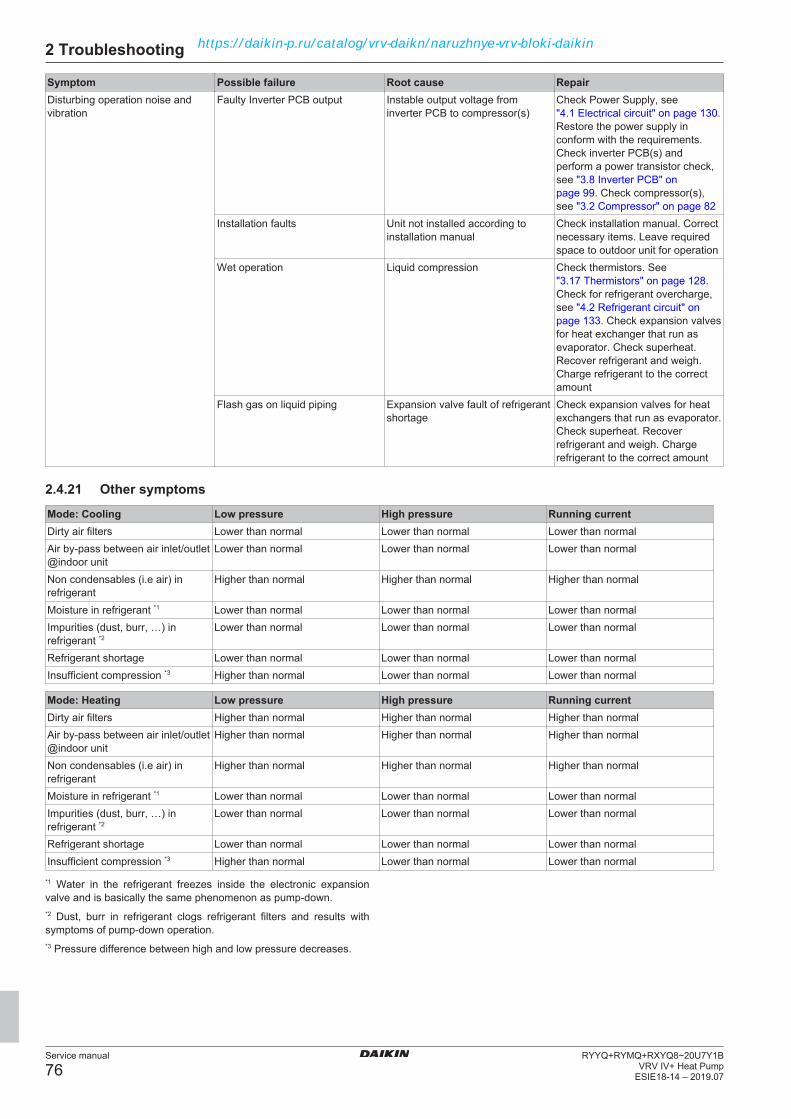
2 Troubleshooting
Service manual
76RYYQ+RYMQ+RXYQ8~20U7Y1B
VRV IV+ Heat PumpESIE18-14 – 2019.07
Symptom Possible failure Root cause RepairDisturbing operation noise andvibration
Faulty Inverter PCB output Instable output voltage frominverter PCB to compressor(s)
Check Power Supply, see"4.1 Electrical circuit" on page 130.Restore the power supply inconform with the requirements.Check inverter PCB(s) andperform a power transistor check,see "3.8 Inverter PCB" onpage 99. Check compressor(s),see "3.2 Compressor" on page 82
Installation faults Unit not installed according toinstallation manual
Check installation manual. Correctnecessary items. Leave requiredspace to outdoor unit for operation
Wet operation Liquid compression Check thermistors. See"3.17 Thermistors" on page 128.Check for refrigerant overcharge,see "4.2 Refrigerant circuit" onpage 133. Check expansion valvesfor heat exchanger that run asevaporator. Check superheat.Recover refrigerant and weigh.Charge refrigerant to the correctamount
Flash gas on liquid piping Expansion valve fault of refrigerantshortage
Check expansion valves for heatexchangers that run as evaporator.Check superheat. Recoverrefrigerant and weigh. Chargerefrigerant to the correct amount
2.4.21 Other symptoms
Mode: Cooling Low pressure High pressure Running currentDirty air filters Lower than normal Lower than normal Lower than normalAir by-pass between air inlet/outlet@indoor unit
Lower than normal Lower than normal Lower than normal
Non condensables (i.e air) inrefrigerant
Higher than normal Higher than normal Higher than normal
Moisture in refrigerant *1 Lower than normal Lower than normal Lower than normalImpurities (dust, burr, …) inrefrigerant *2
Lower than normal Lower than normal Lower than normal
Refrigerant shortage Lower than normal Lower than normal Lower than normalInsufficient compression *3 Higher than normal Lower than normal Lower than normal
Mode: Heating Low pressure High pressure Running currentDirty air filters Higher than normal Higher than normal Higher than normalAir by-pass between air inlet/outlet@indoor unit
Higher than normal Higher than normal Higher than normal
Non condensables (i.e air) inrefrigerant
Higher than normal Higher than normal Higher than normal
Moisture in refrigerant *1 Lower than normal Lower than normal Lower than normalImpurities (dust, burr, …) inrefrigerant *2
Lower than normal Lower than normal Lower than normal
Refrigerant shortage Lower than normal Lower than normal Lower than normalInsufficient compression *3 Higher than normal Lower than normal Lower than normal
*1 Water in the refrigerant freezes inside the electronic expansionvalve and is basically the same phenomenon as pump‑down.*2 Dust, burr in refrigerant clogs refrigerant filters and results withsymptoms of pump‑down operation.*3 Pressure difference between high and low pressure decreases.
https://daikin-p.ru/catalog/vrv-daikn/naruzhnye-vrv-bloki-daikin

3 Components
Service manual
77RYYQ+RYMQ+RXYQ8~20U7Y1BVRV IV+ Heat PumpESIE18-14 – 2019.07
3 Components
3.1 4-way valve
3.1.1 Main 4-way valve
Checking procedures
INFORMATIONIt is recommended to perform the checks in the listedorder.
To perform a mechanical check of the 4-way valve
Prerequisite: Stop the unit operation (via the user interface, centralcontroller, operation switch, …).Prerequisite: Turn OFF the respective circuit breaker.Prerequisite: Remove the required plate work, see "3.13 Platework" on page 118.
1 Verify that the screw is firmly fixing the coil to the valve body.
2 Check if any damage or burst is present.
Is the 4‑way valve coil firmlyfixed and not visuallydamaged?
Action
Yes Perform an electrical check of the4‑way valve, see "Checkingprocedures" on page 77.
No Fix or replace the 4‑way valvecoil, see "Repair procedures" onpage 78.
To perform an electrical check of the 4-way valve
Prerequisite: First perform a mechanical check of the 4-way valve,see "Checking procedures" on page 77.
1 Unplug the 4-way valve connector from the appropriate PCB.
2 Measure the resistance of the 4-way valve coil between thepins of the 4-way valve connector.
Result: The measured value must be 1,7 kΩ ± 10%.
Is the measured value correct? ActionYes Continue with the next step.No Replace the 4‑way valve coil, see
"Repair procedures" onpage 78.
When outdoor temperature is mild and unit can switch betweenheating and cooling
INFORMATIONThis procedure is ONLY possible when the outdoortemperature is within the temperature range for bothHeating and Cooling operation mode. See the databookon Business Portal for the temperature range of theoperation modes.
3 Connect the 4‑way valve connector to the appropriate PCB.
4 Turn ON the unit using the respective circuit breaker.
5 Activate Heating operation via the Cool/Heat master userinterface.
CAUTIONIt is NOT possible to activate operation modes with anotheruser interface than the Cool/Heat master user interface.
6 With the 4‑way valve connector connected to the PCB,measure the voltage on the 4‑way valve connection of the PCB.
Result: The measured voltage MUST be 230 V AC.
7 De-activate Heating and activate Cooling operation via theCool/Heat master user interface.
8 Measure the voltage on the 4‑way valve connection on thePCB.
Result: The measured voltage MUST be 0 V AC.
Are the measured voltagescorrect?
Action
Yes Perform a position check of the4-way valve, see "Checkingprocedures" on page 77.
No Perform a check the main PCB,see "3.9 Main PCB" onpage 106.
When outdoor temperature does not allow the unit to run incooling or heating mode
INFORMATIONFollow this procedure when the outdoor temperature isoutside the temperature range for one of the operationmodes (Heating or Cooling). The unit CANNOT operatein the mode for which the outdoor temperature is outsideits temperature range. See the databook on BusinessPortal for the temperature range of the operation modes.
9 Connect the 4‑way valve connector to the appropriate PCB.
10 Turn ON the unit using the respective circuit breaker.
11 With the unit operating, connect the service monitoring tool tothe unit and check whether the unit is in one of the followingoperation modes in which the 4-way valve is energized:
RXYQ-U units:▪ Heating mode
RYYQ-U units:▪ Heating mode and oil return in heating mode▪ Defrost operation
RYMQ-U units:▪ Heating mode and oil return in heating mode▪ Defrost operation
Is this the case? ActionNo Skip the next step of this
procedure.Yes Perform the next step of this
procedure.
12 With the 4‑way valve connector connected to the PCB,measure the voltage on the 4‑way valve connection of the PCB.
Result: The measured voltage MUST be 230 V AC.
Is the measured voltagecorrect?
Action
Yes Perform a position check of the4-way valve, see "Checkingprocedures" on page 77.
No Perform a check the main PCB,see "3.9 Main PCB" onpage 106.
13 If, according to the service monitoring tool, the unit is in one ofthe following operation modes in which the 4-way valve is NOTenergized:
RXYQ-U units:▪ Oil return operation and defrost operation in heating mode▪ Oil return operation in cooling mode▪ Cooling mode
https://daikin-p.ru/catalog/vrv-daikn/naruzhnye-vrv-bloki-daikin

3 Components
Service manual
78RYYQ+RYMQ+RXYQ8~20U7Y1B
VRV IV+ Heat PumpESIE18-14 – 2019.07
RYYQ-U units:▪ Cooling mode▪ Oil return operation in cooling mode
RYMQ-U units:▪ Cooling mode▪ Oil return operation in cooling mode
14 With the 4‑way valve connector connected to the PCB,measure the voltage on the 4‑way valve connection of the PCB.
Result: The measured voltage MUST be 0 V AC.
Is the measured voltagecorrect?
Action
Yes Perform a position check of the4-way valve, see "Checkingprocedures" on page 77.
No Perform a check the main PCB,see "3.9 Main PCB" onpage 106.
To perform a position check of the 4-way valve
1 First perform an electrical check of the 4‑way valve, see"Checking procedures" on page 77.
When outdoor temperature is mild and unit can switch betweenheating and cooling
INFORMATIONThis procedure is ONLY possible when the outdoortemperature is within the temperature range for bothHeating and Cooling operation mode. See the databookon Business Portal for the temperature range of theoperation modes.
2 Activate Heating operation via the Cool/Heat master userinterface.
CAUTIONIt is NOT possible to activate operation modes with anotheruser interface than the Cool/Heat master user interface.
INFORMATIONIt is recommended to connect the service monitoring tool tothe unit and verify the operation mode of the 4-way valve.
3 Check with a contact thermometer (or by touching) if the flowthrough the 4-way valve corresponds with the flow shown in theflow diagram. (See "6.3 Piping diagram" on page 148).
Is the flow correct? ActionYes Skip the next step of this
procedure.No Perform the next step of this
procedure.
4 Connect a manifold to one of the service ports of the refrigerantcircuit and check the pressure (suction, discharge). Comparewith normal operation conditions of the unit.
Refrigerant pressure correct? ActionYes Replace the body of the 4‑way
valve, see "Repairprocedures" on page 78.
No Leaks may be found in therefrigerant circuit. Perform apressure test of the refrigerantcircuit, see "4.2.1 Checkingprocedures" on page 133.
5 De-activate Heating and activate Cooling operation via theCool/Heat master user interface.
6 Check with a contact thermometer (or by touching) if the flowthrough the 4-way valve corresponds with the flow shown in theflow diagram. (See "6.3 Piping diagram" on page 148).
Is the flow correct? ActionYes 4‑way valve is OK. Return to the
troubleshooting of the specificerror and continue with the nextprocedure.
No Replace the body of the 4‑wayvalve, see "Repairprocedures" on page 78.
When outdoor temperature does not allow the unit to run incooling or heating mode
INFORMATIONFollow this procedure when the outdoor temperature isoutside the temperature range for one of the operationmodes (Heating or Cooling). The unit CANNOT operatein the mode for which the outdoor temperature is outsideits temperature range. See the databook on BusinessPortal for the temperature range of the operation modes.
7 With the unit operating, connect the service monitoring tool tothe unit and check in which of the following operation modesthe unit is operating:
RXYQ-U units:▪ Heating mode and oil return in heating mode▪ Defrost operation▪ Cooling mode▪ Oil return operation in cooling mode
RYYQ-U and RYMQ-U units:▪ Oil return operation and defrost operation in heating mode▪ Heating mode▪ Cooling mode▪ Oil return operation in cooling mode
8 Check with a contact thermometer (or by touching) if the flowthrough the 4-way valve corresponds with the flow shown in theflow diagram of the specific operation mode. (See "6.3 Pipingdiagram" on page 148).
Is the flow correct? ActionYes 4‑way valve is OK. Return to the
troubleshooting of the specificerror and continue with the nextprocedure.
No Perform the next step of thisprocedure.
9 Connect a manifold to one of the service ports of the refrigerantcircuit and check the pressure (suction, discharge). Comparewith normal operation conditions of the unit.
Refrigerant pressure correct? ActionYes Replace the body of the 4‑way
valve, see "Repairprocedures" on page 78.
No Leaks may be found in therefrigerant circuit. Perform apressure test of the refrigerantcircuit, see "4.2.1 Checkingprocedures" on page 133.
Repair proceduresTo remove the 4-way valve coil
Prerequisite: Stop the unit operation (via the user interface, centralcontroller, operation switch, …).Prerequisite: Turn OFF the respective circuit breaker.
https://daikin-p.ru/catalog/vrv-daikn/naruzhnye-vrv-bloki-daikin

3 Components
Service manual
79RYYQ+RYMQ+RXYQ8~20U7Y1BVRV IV+ Heat PumpESIE18-14 – 2019.07
Prerequisite: Remove the required plate work, see "3.13 Platework" on page 118.Prerequisite: If needed, remove any parts to create more space forthe removal of the 4‑way valve coil.
1 Remove the screw and remove the 4‑way valve coil from the4‑way valve body.
c a ba Screwb 4‑way valve coilc 4‑way valve body
2 Cut all tie straps that fix the 4‑way valve coil harness.
3 Disconnect the 4‑way valve coil connector from the appropriatePCB.
4 To install the 4‑way valve coil, see "Repair procedures" onpage 78.
To remove the 4-way valve body
Prerequisite: Recuperate the refrigerant from the refrigerant circuit,see "4.2.2 Repair procedures" on page 136.
1 Remove the 4‑way valve coil from the 4‑way valve body, see"Repair procedures" on page 78.
2 Cut the 4‑way valve pipes using a pipe cutter.
a ac
ab
a
d
a 4‑way valve pipeb 4‑way valvec Puttyd Insulation
3 Remove the 4‑way valve.
4 Keep the putty and the insulation for re-use.
5 To install the 4‑way valve body, see "Repair procedures" onpage 78.
To install the 4-way valve body
1 Install the 4‑way valve in the correct location.
2 Supply nitrogen to the refrigerant circuit. The nitrogen pressureMUST NOT exceed 0.02 MPa.
3 Wrap a wet rag around the 4‑way valve and solder the 4‑wayvalve pipes to the 4‑way valve.
CAUTIONOverheating the valve will damage or destroy it.
4 After soldering is done, stop the nitrogen supply after thecomponent has cooled‑down.
a ac
ab
a
d
a 4‑way valve pipeb 4‑way valvec Puttyd Insulation
5 Install the putty and the insulation in their original location.
6 Install the 4‑way valve coil on the 4‑way valve body, see"Repair procedures" on page 78.
7 Add refrigerant to the refrigerant circuit, see "4.2.2 Repairprocedures" on page 136.
To install the 4-way valve coil
1 Install the 4‑way valve coil on the 4‑way valve body.
c a ba Screwb 4‑way valve coilc 4‑way valve body
2 Install and tighten the screw to fix the 4‑way valve coil.
3 Route the 4‑way valve coil harness towards the appropriatePCB.
4 Connect the 4‑way valve coil connector to the PCB.
WARNINGWhen reconnecting a connector to the PCB, do NOT applyforce, as this may damage the connector or connector pinsof the PCB.
5 Fix the 4‑way valve coil harness using new tie straps.
Is the problem solved? ActionYes No further actions required.No Return to the troubleshooting of
the specific error and continuewith the next procedure.
https://daikin-p.ru/catalog/vrv-daikn/naruzhnye-vrv-bloki-daikin
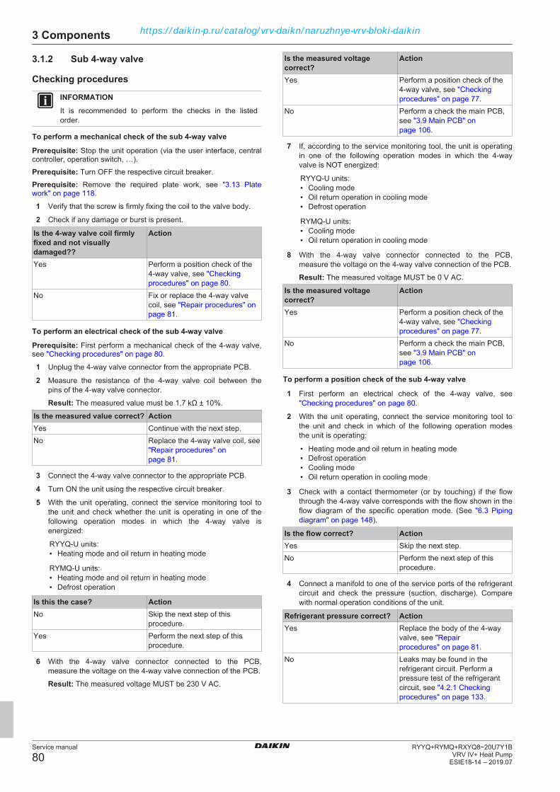
3 Components
Service manual
80RYYQ+RYMQ+RXYQ8~20U7Y1B
VRV IV+ Heat PumpESIE18-14 – 2019.07
3.1.2 Sub 4-way valve
Checking procedures
INFORMATIONIt is recommended to perform the checks in the listedorder.
To perform a mechanical check of the sub 4-way valve
Prerequisite: Stop the unit operation (via the user interface, centralcontroller, operation switch, …).Prerequisite: Turn OFF the respective circuit breaker.Prerequisite: Remove the required plate work, see "3.13 Platework" on page 118.
1 Verify that the screw is firmly fixing the coil to the valve body.
2 Check if any damage or burst is present.
Is the 4‑way valve coil firmlyfixed and not visuallydamaged??
Action
Yes Perform a position check of the4‑way valve, see "Checkingprocedures" on page 80.
No Fix or replace the 4‑way valvecoil, see "Repair procedures" onpage 81.
To perform an electrical check of the sub 4-way valve
Prerequisite: First perform a mechanical check of the 4‑way valve,see "Checking procedures" on page 80.
1 Unplug the 4-way valve connector from the appropriate PCB.
2 Measure the resistance of the 4-way valve coil between thepins of the 4-way valve connector.
Result: The measured value must be 1,7 kΩ ± 10%.
Is the measured value correct? ActionYes Continue with the next step.No Replace the 4‑way valve coil, see
"Repair procedures" onpage 81.
3 Connect the 4‑way valve connector to the appropriate PCB.
4 Turn ON the unit using the respective circuit breaker.
5 With the unit operating, connect the service monitoring tool tothe unit and check whether the unit is operating in one of thefollowing operation modes in which the 4-way valve isenergized:
RYYQ-U units:▪ Heating mode and oil return in heating mode
RYMQ-U units:▪ Heating mode and oil return in heating mode▪ Defrost operation
Is this the case? ActionNo Skip the next step of this
procedure.Yes Perform the next step of this
procedure.
6 With the 4‑way valve connector connected to the PCB,measure the voltage on the 4‑way valve connection of the PCB.
Result: The measured voltage MUST be 230 V AC.
Is the measured voltagecorrect?
Action
Yes Perform a position check of the4-way valve, see "Checkingprocedures" on page 77.
No Perform a check the main PCB,see "3.9 Main PCB" onpage 106.
7 If, according to the service monitoring tool, the unit is operatingin one of the following operation modes in which the 4-wayvalve is NOT energized:
RYYQ-U units:▪ Cooling mode▪ Oil return operation in cooling mode▪ Defrost operation
RYMQ-U units:▪ Cooling mode▪ Oil return operation in cooling mode
8 With the 4‑way valve connector connected to the PCB,measure the voltage on the 4‑way valve connection of the PCB.
Result: The measured voltage MUST be 0 V AC.
Is the measured voltagecorrect?
Action
Yes Perform a position check of the4-way valve, see "Checkingprocedures" on page 77.
No Perform a check the main PCB,see "3.9 Main PCB" onpage 106.
To perform a position check of the sub 4-way valve
1 First perform an electrical check of the 4‑way valve, see"Checking procedures" on page 80.
2 With the unit operating, connect the service monitoring tool tothe unit and check in which of the following operation modesthe unit is operating:
▪ Heating mode and oil return in heating mode▪ Defrost operation▪ Cooling mode▪ Oil return operation in cooling mode
3 Check with a contact thermometer (or by touching) if the flowthrough the 4-way valve corresponds with the flow shown in theflow diagram of the specific operation mode. (See "6.3 Pipingdiagram" on page 148).
Is the flow correct? ActionYes Skip the next step.No Perform the next step of this
procedure.
4 Connect a manifold to one of the service ports of the refrigerantcircuit and check the pressure (suction, discharge). Comparewith normal operation conditions of the unit.
Refrigerant pressure correct? ActionYes Replace the body of the 4‑way
valve, see "Repairprocedures" on page 81.
No Leaks may be found in therefrigerant circuit. Perform apressure test of the refrigerantcircuit, see "4.2.1 Checkingprocedures" on page 133.
https://daikin-p.ru/catalog/vrv-daikn/naruzhnye-vrv-bloki-daikin

3 Components
Service manual
81RYYQ+RYMQ+RXYQ8~20U7Y1BVRV IV+ Heat PumpESIE18-14 – 2019.07
5 Wait for the 4‑way valve to switch to another operation mode(service monitoring tool) with opposite 4‑way valve energizingconditions as the current operation mode and again perform anelectrical check and a position check of the 4‑way valve, see"Checking procedures" on page 80.
Is the flow correct? ActionYes 4‑way valve is OK. Return to the
troubleshooting of the specificerror and continue with the nextprocedure.
No Replace the body of the 4‑wayvalve, see "Repairprocedures" on page 81.
Repair proceduresTo remove the 4-way valve coil
Prerequisite: Stop the unit operation (via the user interface, centralcontroller, operation switch, …).Prerequisite: Turn OFF the respective circuit breaker.Prerequisite: Remove the required plate work, see "3.13 Platework" on page 118.Prerequisite: If needed, remove any parts to create more space forthe removal of the 4‑way valve coil.
1 Remove the screw and remove the 4‑way valve coil from the4‑way valve body.
c a ba Screwb 4‑way valve coilc 4‑way valve body
2 Cut all tie straps that fix the 4‑way valve coil harness.
3 Disconnect the 4‑way valve coil connector from the appropriatePCB.
4 To install the 4‑way valve coil, see "Repair procedures" onpage 81.
To remove the 4-way valve body
Prerequisite: Recuperate the refrigerant from the refrigerant circuit,see "4.2.2 Repair procedures" on page 136.
1 Remove the 4‑way valve coil from the 4‑way valve body, see"Repair procedures" on page 78.
2 Cut the 4‑way valve pipes using a pipe cutter.
a ac
ab
a
d
a 4‑way valve pipeb 4‑way valvec Puttyd Insulation
3 Remove the 4‑way valve.
4 Keep the putty and the insulation for re-use.
5 To install the 4‑way valve body, see "Repair procedures" onpage 81.
To install the 4-way valve body
1 Install the 4‑way valve in the correct location.
2 Supply nitrogen to the refrigerant circuit. The nitrogen pressureMUST NOT exceed 0.02 MPa.
3 Wrap a wet rag around the 4‑way valve and solder the 4‑wayvalve pipes to the 4‑way valve.
CAUTIONOverheating the valve will damage or destroy it.
4 After soldering is done, stop the nitrogen supply after thecomponent has cooled‑down.
a ac
ab
a
d
a 4‑way valve pipeb 4‑way valvec Puttyd Insulation
5 Install the putty and the insulation in their original location.
6 Install the 4‑way valve coil on the 4‑way valve body, see"Repair procedures" on page 81.
7 Add refrigerant to the refrigerant circuit, see "4.2.2 Repairprocedures" on page 136.
To install the 4-way valve coil
1 Install the 4‑way valve coil on the 4‑way valve body.
https://daikin-p.ru/catalog/vrv-daikn/naruzhnye-vrv-bloki-daikin

3 Components
Service manual
82RYYQ+RYMQ+RXYQ8~20U7Y1B
VRV IV+ Heat PumpESIE18-14 – 2019.07
c a ba Screwb 4‑way valve coilc 4‑way valve body
2 Install and tighten the screw to fix the 4‑way valve coil.
3 Route the 4‑way valve coil harness towards the appropriatePCB.
4 Connect the 4‑way valve coil connector to the PCB.
WARNINGWhen reconnecting a connector to the PCB, do NOT applyforce, as this may damage the connector or connector pinsof the PCB.
5 Fix the 4‑way valve coil harness using new tie straps.
Is the problem solved? ActionYes No further actions required.No Return to the troubleshooting of
the specific error and continuewith the next procedure.
3.2 Compressor
3.2.1 Checking procedures
INFORMATIONIt is recommended to perform the checks in the listedorder.
To perform an auditive check of the compressorPrerequisite: First perform a power transistor check of the inverterPCB, see "3.8 Inverter PCB" on page 99. If power transistor is OK,proceed as follows:Prerequisite: Stop the unit operation (via the user interface, centralcontroller, operation switch, …).Prerequisite: Turn OFF the respective circuit breaker.Prerequisite: Remove the required plate work, see "3.13 Platework" on page 118.
1 Open the compressor insulation.
2 Turn ON the unit using the respective circuit breaker.
3 Start the unit operation (via the user interface, operation switch,central controller, …).
4 Listen to the compressor when it tries to operate. Judge if amechanical lock is present.
INFORMATIONIf a mechanical lock is present, also check for the rootcause of impurities in the refrigerant causing mechanicallock of the compressor. See "4.2.1 Checkingprocedures" on page 133.
A mechanical lock is presenton the compressor?
Action
Yes Replace the compressor, see"3.2.2 Repair procedures" onpage 84.
No Perform an mechanical check ofthe compressor, see"3.2.1 Checking procedures" onpage 82.
To perform a mechanical check of the compressor1 First perform an auditive check of the compressor, see
"3.2.1 Checking procedures" on page 82.
INFORMATIONFor outdoor units ≥14 HP, the transportation stay for thecompressor should be removed. Otherwise vibration is notabsorbed, which can lead to pipe crack. See "3.2.2 Repairprocedures" on page 84.
2 Open the compressor insulation.
3 Check the compressor dampers and piping for any damage.
a
a
a Damper
INFORMATIONThe compressor dampers may look different.
Compressor dampers andpiping are in a goodcondition?
Action
Yes Perform an electrical check of thecompressor, see "3.2.1 Checkingprocedures" on page 82.
No Replace the compressor, see"3.2.2 Repair procedures" onpage 84.
To perform an electrical check of the compressor1 First perform a mechanical check of the compressor, see
"3.2.1 Checking procedures" on page 82.
2 [Hz] = [rps] x (number of poles) / 2:
▪ For K-Type Compressor: [Hz] = 3 x [rps]▪ For G-Type Compressor: [Hz] = 2 x [rps]
3 Open the compressor insulation.
https://daikin-p.ru/catalog/vrv-daikn/naruzhnye-vrv-bloki-daikin

3 Components
Service manual
83RYYQ+RYMQ+RXYQ8~20U7Y1BVRV IV+ Heat PumpESIE18-14 – 2019.07
DANGER: RISK OF ELECTROCUTIONConfirm rectifier voltage is below 10 V DC beforeproceeding.
4 Remove the cover of the compressor wire terminals.a
a Compressor wire terminals cover
5 Disconnect the Faston connectors from the compressor wireterminals U, V and W.
INFORMATIONNote the position of the Faston connectors on thecompressor wire terminals to allow correct connectionduring installation.
a a
a
a Faston connectors
6 Measure the resistance between the compressor motorwindings U-V, V-W and U-W. All measurements MUST be thesame.
CAUTIONBefore measuring the compressor motor windingsresistance, measure the resistance of the multimeterprobes by holding the probes against each other. If themeasured resistance is NOT 0 Ώ, this value MUST besubstracted from the measured winding resistance.
Unit Compressor Winding resistancevalue (attemperature of20°C)
RYYQ8~12,RXYQ8~12,RYMQ8~12
M1C 0.26 Ω±5%
RYYQ14~16,RXYQ14~16,RYMQ14~16
M1C + M2C 0.77 Ω±5%
RYYQ18~20,RXYQ18~20,RYMQ18~20
M1C 0.77 Ω±5%M2C 0.26 Ω±5%
Compressor motor windingmeasurements are correct?
Action
Yes Continue with the next step.No Replace the compressor, see
"3.2.2 Repair procedures" onpage 84.
7 Re-connect the Faston connectors and install the cover of thecompressor wire terminals.
8 Install the compressor insulation.
9 Turn ON the unit using the respective circuit breaker.
10 Start the unit operation (via the user interface, operation switch,central controller, …).
11 Once the compressor operates, measure the U-V-W invertervoltages. All measurements MUST be the same.
Inverter voltage measurementsare correct?
Action
Yes Continue with the next step.No Replace the inverter PCB, see
"3.8 Inverter PCB" on page 99.
12 Measure the current in each phase U-V, V-W and U-W. Allmeasurements MUST be the same.
Compressor motor windingcurrent measurements arecorrect?
Action
Yes Perform an insulation check ofthe compressor, see"3.2.1 Checking procedures" onpage 82.
No Preventively replace thecompressor, see "3.2.2 Repairprocedures" on page 84.
To perform an insulation check of the compressorPrerequisite: First perform an electrical check of the compressor,see "3.2.1 Checking procedures" on page 82.Prerequisite: Stop the unit operation (via the user interface, centralcontroller, operation switch, …).Prerequisite: Turn OFF the respective circuit breaker.Prerequisite: Remove the required plate work, see "3.13 Platework" on page 118.
1 Open the compressor insulation.
DANGER: RISK OF ELECTROCUTIONConfirm rectifier voltage is below 10 V DC beforeproceeding.
2 Remove the cover of the compressor wire terminals.
https://daikin-p.ru/catalog/vrv-daikn/naruzhnye-vrv-bloki-daikin

3 Components
Service manual
84RYYQ+RYMQ+RXYQ8~20U7Y1B
VRV IV+ Heat PumpESIE18-14 – 2019.07
a
a Compressor wire terminals cover
3 Disconnect the Faston connectors from the compressor wireterminals U, V and W.
INFORMATIONNote the position of the Faston connectors on thecompressor wire terminals to allow correct connectionduring installation.
a a
a
a Faston connectors
4 Set the Megger voltage to 500 V DC or 1000 V DC.
5 Measure the insulation resistance between the followingterminals. The measured insulation resistance MUST be>3 MΩ.
▪ U–ground,▪ V–ground,▪ W–ground.
Compressor insulationmeasurements are correct?
Action
Yes Compressor is OK. Return totroubleshooting of the specificerror an continue with the nextprocedure.
No Replace the compressor, see"3.2.2 Repair procedures" onpage 84.
3.2.2 Repair procedures
To remove the transportation stayOnly for 14~20 HP
NOTICEIf the unit is operated with the transportation stay attached,abnormal vibration or noise may be generated.
The transportation stay installed over the compressor leg forprotecting the unit during transport must be removed. Proceed asshown in the figure and procedure below.
1 Slightly loosen the fixing nut (a).
2 Remove the transportation stay (b) as shown in the figurebelow.
3 Tighten the fixing nut (a) again.
13 (12.3 N·m)
213 (12.3 N·m)
2 a
b
To remove the compressorPrerequisite: Stop the unit operation (via the user interface, centralcontroller, operation switch, …).Prerequisite: Turn OFF the respective circuit breaker.Prerequisite: Remove the required plate work, see "3.13 Platework" on page 118.Prerequisite: Remove the compressor insulation.Prerequisite: Recuperate the refrigerant from the refrigerant circuit,see "4.2.2 Repair procedures" on page 136.
1 If needed, remove any parts to create more space for theremoval of the compressor.
DANGER: RISK OF ELECTROCUTIONConfirm rectifier voltage is below 10 V DC beforeproceeding.
2 Remove the cover of the compressor wire terminals.a
a Compressor wire terminals cover
https://daikin-p.ru/catalog/vrv-daikn/naruzhnye-vrv-bloki-daikin
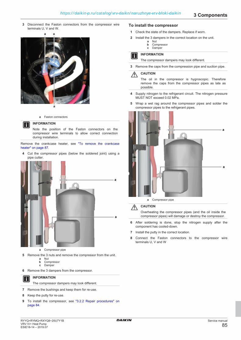
3 Components
Service manual
85RYYQ+RYMQ+RXYQ8~20U7Y1BVRV IV+ Heat PumpESIE18-14 – 2019.07
3 Disconnect the Faston connectors from the compressor wireterminals U, V and W.
a a
a
a Faston connectors
INFORMATIONNote the position of the Faston connectors on thecompressor wire terminals to allow correct connectionduring installation.
Remove the crankcase heater, see "To remove the crankcaseheater" on page 87.
4 Cut the compressor pipes (below the soldered joint) using apipe cutter.
a
a
a Compressor pipe
5 Remove the 3 nuts and remove the compressor from the unit.a Nutb Compressorc Damper
6 Remove the 3 dampers from the compressor.
INFORMATIONThe compressor dampers may look different.
7 Remove the bushings and keep them for re-use.
8 Keep the putty for re-use.
9 To install the compressor, see "3.2.2 Repair procedures" onpage 84.
To install the compressor1 Check the state of the dampers. Replace if worn.
2 Install the 3 dampers in the correct location on the unit.a Nutb Compressorc Damper
INFORMATIONThe compressor dampers may look different.
3 Remove the caps from the compression pipe and suction pipe.
CAUTIONThe oil in the compressor is hygroscopic. Thereforeremove the caps from the compressor pipes as late aspossible.
4 Supply nitrogen to the refrigerant circuit. The nitrogen pressureMUST NOT exceed 0.02 MPa.
5 Wrap a wet rag around the compressor pipes and solder thecompressor pipes to the refrigerant pipes.
a
a
a Compressor pipe
CAUTIONOverheating the compressor pipes (and the oil inside thecompressor pipes) will damage or destroy the compressor.
6 After soldering is done, stop the nitrogen supply after thecomponent has cooled‑down.
7 Install the putty in the correct location.
8 Connect the Faston connectors to the compressor wireterminals U, V and W
https://daikin-p.ru/catalog/vrv-daikn/naruzhnye-vrv-bloki-daikin

3 Components
Service manual
86RYYQ+RYMQ+RXYQ8~20U7Y1B
VRV IV+ Heat PumpESIE18-14 – 2019.07
a a
a
a Faston connectors
9 Install the cover of the compressor wire terminals.a
a Compressor wire terminals cover
10 Add refrigerant to the refrigerant circuit, see "4.2.2 Repairprocedures" on page 136.
11 Install the compressor insulation, see "3.2.2 Repairprocedures" on page 84.
Is the problem solved? ActionYes No further actions required.No Return to the troubleshooting of
the specific error and continuewith the next procedure.
To remove the compressor insulationPrerequisite: Stop the unit operation (via the user interface, centralcontroller, operation switch, …).Prerequisite: Turn OFF the respective circuit breaker.Prerequisite: Remove the required plate work, see "3.13 Platework" on page 118.
1 Detach all the strips (a).
a
a
a
a
a Strip
2 Detach the strip (b) of the top jacket (c).
3 Remove the top jacket (c).
4 Remove the body jacket (d) from the compressor (e).
b
c
e
d
b Stripc Top jacketd Body jackete Compressor
To install the compressor insulation
b
c
e
d
b Stripc Top jacketd Body jackete Compressor
1 Install the body jacket (d) on the compressor (e).
2 Install the top jacket (c).
3 attach the strip (b) to the top jacket (c).
https://daikin-p.ru/catalog/vrv-daikn/naruzhnye-vrv-bloki-daikin

3 Components
Service manual
87RYYQ+RYMQ+RXYQ8~20U7Y1BVRV IV+ Heat PumpESIE18-14 – 2019.07
a
a
a
a
a Strip
4 Attach all the strips (a).
3.3 Crankcase heater
3.3.1 Checking procedures
To perform an electrical check of the crankcaseheaterPrerequisite: Stop the unit operation (via the user interface, centralcontroller, operation switch, …).Prerequisite: Turn OFF the respective circuit breaker.
1 Remove the required plate work, see "3.13 Plate work" onpage 118.
DANGER: RISK OF ELECTROCUTIONConfirm rectifier voltage is below 10 V DC beforeproceeding.
2 Open the compressor insulation.
3 Disconnect the crankcase heater connector from theappropriate PCB.
4 Measure the resistance on the crankcase heater connector: pin1–pin 2. The resistance MUST be 1.8 kΩ±10%.
Is the measured resistancecorrect?
Action
Yes Continue with the next step.No Replace the crankcase heater,
see "3.3.2 Repair procedures" onpage 87.
5 Turn ON the unit using the respective circuit breaker.
6 Start the unit operation (via the user interface, operation switch,central controller, …).
7 With the cranckase heater energised (compressor OFF anddischarge temperature <70°C), measure the voltage on thecranckase heater connector on the PCB. The measured voltageMUST be 230 V AC.
Is the measured voltagecorrect?
Action
Yes Return to the troubleshooting ofthe specific error and continuewith the next procedure.
No Replace the crankcase heater,see "3.3.2 Repair procedures" onpage 87.
To perform an insulation check of the crankcaseheaterPrerequisite: Stop the unit operation (via the user interface, centralcontroller, operation switch, …).Prerequisite: Turn OFF the respective circuit breaker.
1 Remove the required plate work, see "3.13 Plate work" onpage 118.
DANGER: RISK OF ELECTROCUTIONConfirm rectifier voltage is below 10 V DC beforeproceeding.
2 Open the compressor insulation.
3 Set the Megger voltage to at least 500 V DC.
4 Connect the Megger ground test lead directly to the crankcaseheater ground wire.
CAUTIONDo NOT connect the Megger ground test lead to any otherground wire.
5 Measure the insulation resistance between the phase andground wire. The measured insulation resistance MUST be>1 MΩ.
Is the measured voltagecorrect?
Action
Yes Return to the troubleshooting ofthe specific error and continuewith the next procedure.
No Replace the crankcase heater,see "3.3.2 Repair procedures" onpage 87.
3.3.2 Repair procedures
To remove the crankcase heaterPrerequisite: Stop the unit operation (via the user interface, centralcontroller, operation switch, …).Prerequisite: Turn OFF the respective circuit breaker.
1 Remove the required plate work, see "3.13 Plate work" onpage 118.
DANGER: RISK OF ELECTROCUTIONConfirm rectifier voltage is below 10 V DC beforeproceeding.
2 Open the compressor insulation.
3 Detach the spring that fixes the crankcase heater on thecompressor.
https://daikin-p.ru/catalog/vrv-daikn/naruzhnye-vrv-bloki-daikin

3 Components
Service manual
88RYYQ+RYMQ+RXYQ8~20U7Y1B
VRV IV+ Heat PumpESIE18-14 – 2019.07
a b
a Springb Crankcase heater
4 Disconnect the crankcase heater connector from the main PCB.
5 Cut all tie straps that fix the crankcase heater harness.
6 To install the crankcase heater, see "3.3.2 Repairprocedures" on page 87.
To install the crankcase heater1 Install the crankcase heater on the compressor.
2 Attach the spring to fix the crankcase heater.a b
a Springb Crankcase heater
3 Route the crankcase heater harness towards the switch box.
4 Connect the crankcase heater connector to the main PCB.
WARNINGWhen reconnecting a connector to the PCB, do NOT applyforce, as this may damage the connector or connector pinsof the PCB.
5 Fix the crankcase heater harness using new tie straps.
INFORMATIONReplace all cable ties that were cut during removal.
Is the problem solved? ActionYes No further actions required.No Return to the troubleshooting of
the specific error and continuewith the next procedure.
3.4 Current sensor
3.4.1 Checking procedures
To perform an electrical check of the currentsensorPrerequisite: Stop the unit operation (via the user interface, centralcontroller, operation switch, …).Prerequisite: Turn OFF the respective circuit breaker.Prerequisite: Remove the required plate work, see "3.13 Platework" on page 118.
1 Locate the current sensor connector on the main PCB, see"6.2.1 Wiring diagram: Outdoor unit" on page 146.
2 Check that pins 1 and 4 on connector X101A are bridged.
Result: If the pins are not bridged, install the bridge.a
a Connector X101A
3 Check the wiring from pins 2 and 3 of connector X101A to thecurrent sensor.
4 Measure the resistance between pins 2 and 3 of connectorX101A. The measured value should be between 45 and 50 Ω.
Is the measured resistancecorrect?
Action
Yes Return to the troubleshooting ofthe specific error and continuewith the next procedure.
No Replace the current sensor, see"3.4.2 Repair procedures" onpage 88.
3.4.2 Repair procedures
To remove a current sensorPrerequisite: Stop the unit operation (via the user interface, centralcontroller, operation switch, …).Prerequisite: Turn OFF the respective circuit breaker.Prerequisite: Remove the required plate work, see "3.13 Platework" on page 118.
1 Disconnect the current sensor connector from the main PCB.
https://daikin-p.ru/catalog/vrv-daikn/naruzhnye-vrv-bloki-daikin
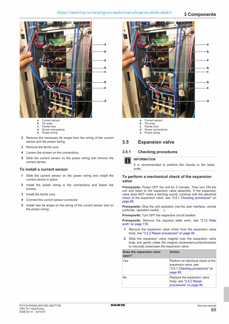
3 Components
Service manual
89RYYQ+RYMQ+RXYQ8~20U7Y1BVRV IV+ Heat PumpESIE18-14 – 2019.07
a
b
c
b
b
d
e
e
a Current sensorb Tie wrapc Ferrite cored Screw connectionse Power wiring
2 Remove the necessary tie wraps from the wiring of the currentsensor and the power wiring.
3 Remove the ferrite core.
4 Loosen the screws on the connections.
5 Slide the current sensor on the power wiring and remove thecurrent sensor.
To install a current sensor1 Slide the current sensor on the power wiring and install the
current sensor in place.
2 Install the power wiring in the connections and fasten thescrews.
3 Install the ferrite core.
4 Connect the current sensor connector.
5 Install new tie wraps on the wiring of the current sensor and onthe power wiring.
a
b
c
b
b
d
e
e
a Current sensorb Tie wrapc Ferrite cored Screw connectionse Power wiring
3.5 Expansion valve
3.5.1 Checking procedures
INFORMATIONIt is recommended to perform the checks in the listedorder.
To perform a mechanical check of the expansionvalvePrerequisite: Power OFF the unit for 3 minutes. Then turn ON theunit and listen to the expansion valve assembly. If the expansionvalve does NOT make a latching sound, continue with the electricalcheck of the expansion valve, see "3.5.1 Checking procedures" onpage 89.Prerequisite: Stop the unit operation (via the user interface, centralcontroller, operation switch, …).Prerequisite: Turn OFF the respective circuit breaker.Prerequisite: Remove the required plate work, see "3.13 Platework" on page 118.
1 Remove the expansion valve motor from the expansion valvebody, see "3.5.2 Repair procedures" on page 90.
2 Slide the expansion valve magnet over the expansion valvebody and gently rotate the magnet clockwise/counterclockwiseto manually close/open the expansion valve.
Does the expansion valveopen?
Action
Yes Perform an electrical check of theexpansion valve, see"3.5.1 Checking procedures" onpage 89.
No Replace the expansion valvebody, see "3.5.2 Repairprocedures" on page 90.
https://daikin-p.ru/catalog/vrv-daikn/naruzhnye-vrv-bloki-daikin
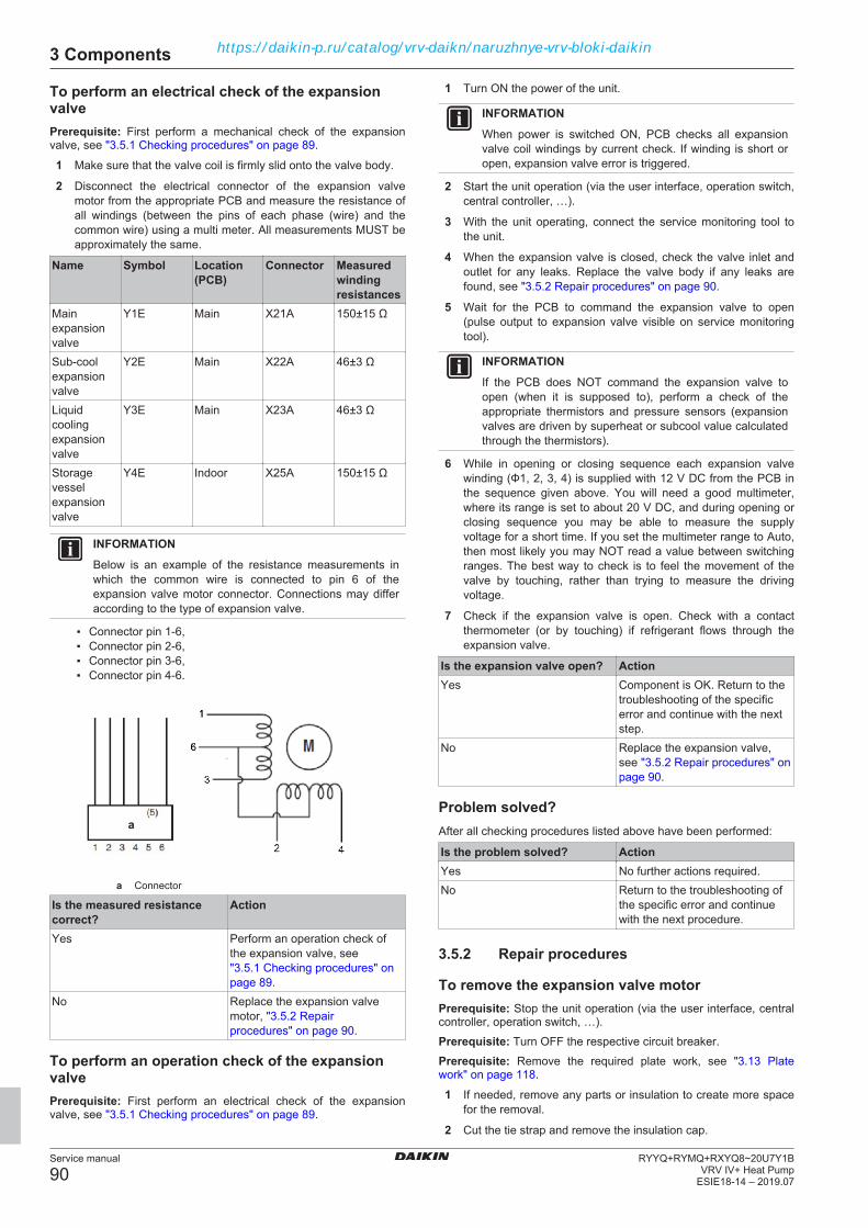
3 Components
Service manual
90RYYQ+RYMQ+RXYQ8~20U7Y1B
VRV IV+ Heat PumpESIE18-14 – 2019.07
To perform an electrical check of the expansionvalvePrerequisite: First perform a mechanical check of the expansionvalve, see "3.5.1 Checking procedures" on page 89.
1 Make sure that the valve coil is firmly slid onto the valve body.
2 Disconnect the electrical connector of the expansion valvemotor from the appropriate PCB and measure the resistance ofall windings (between the pins of each phase (wire) and thecommon wire) using a multi meter. All measurements MUST beapproximately the same.
Name Symbol Location(PCB)
Connector Measuredwindingresistances
Mainexpansionvalve
Y1E Main X21A 150±15 Ω
Sub‑coolexpansionvalve
Y2E Main X22A 46±3 Ω
Liquidcoolingexpansionvalve
Y3E Main X23A 46±3 Ω
Storagevesselexpansionvalve
Y4E Indoor X25A 150±15 Ω
INFORMATIONBelow is an example of the resistance measurements inwhich the common wire is connected to pin 6 of theexpansion valve motor connector. Connections may differaccording to the type of expansion valve.
▪ Connector pin 1‑6,▪ Connector pin 2‑6,▪ Connector pin 3‑6,▪ Connector pin 4‑6.
a
a Connector
Is the measured resistancecorrect?
Action
Yes Perform an operation check ofthe expansion valve, see"3.5.1 Checking procedures" onpage 89.
No Replace the expansion valvemotor, "3.5.2 Repairprocedures" on page 90.
To perform an operation check of the expansionvalvePrerequisite: First perform an electrical check of the expansionvalve, see "3.5.1 Checking procedures" on page 89.
1 Turn ON the power of the unit.
INFORMATIONWhen power is switched ON, PCB checks all expansionvalve coil windings by current check. If winding is short oropen, expansion valve error is triggered.
2 Start the unit operation (via the user interface, operation switch,central controller, …).
3 With the unit operating, connect the service monitoring tool tothe unit.
4 When the expansion valve is closed, check the valve inlet andoutlet for any leaks. Replace the valve body if any leaks arefound, see "3.5.2 Repair procedures" on page 90.
5 Wait for the PCB to command the expansion valve to open(pulse output to expansion valve visible on service monitoringtool).
INFORMATIONIf the PCB does NOT command the expansion valve toopen (when it is supposed to), perform a check of theappropriate thermistors and pressure sensors (expansionvalves are driven by superheat or subcool value calculatedthrough the thermistors).
6 While in opening or closing sequence each expansion valvewinding (Ф1, 2, 3, 4) is supplied with 12 V DC from the PCB inthe sequence given above. You will need a good multimeter,where its range is set to about 20 V DC, and during opening orclosing sequence you may be able to measure the supplyvoltage for a short time. If you set the multimeter range to Auto,then most likely you may NOT read a value between switchingranges. The best way to check is to feel the movement of thevalve by touching, rather than trying to measure the drivingvoltage.
7 Check if the expansion valve is open. Check with a contactthermometer (or by touching) if refrigerant flows through theexpansion valve.
Is the expansion valve open? ActionYes Component is OK. Return to the
troubleshooting of the specificerror and continue with the nextstep.
No Replace the expansion valve,see "3.5.2 Repair procedures" onpage 90.
Problem solved?After all checking procedures listed above have been performed:
Is the problem solved? ActionYes No further actions required.No Return to the troubleshooting of
the specific error and continuewith the next procedure.
3.5.2 Repair procedures
To remove the expansion valve motorPrerequisite: Stop the unit operation (via the user interface, centralcontroller, operation switch, …).Prerequisite: Turn OFF the respective circuit breaker.Prerequisite: Remove the required plate work, see "3.13 Platework" on page 118.
1 If needed, remove any parts or insulation to create more spacefor the removal.
2 Cut the tie strap and remove the insulation cap.
https://daikin-p.ru/catalog/vrv-daikn/naruzhnye-vrv-bloki-daikin
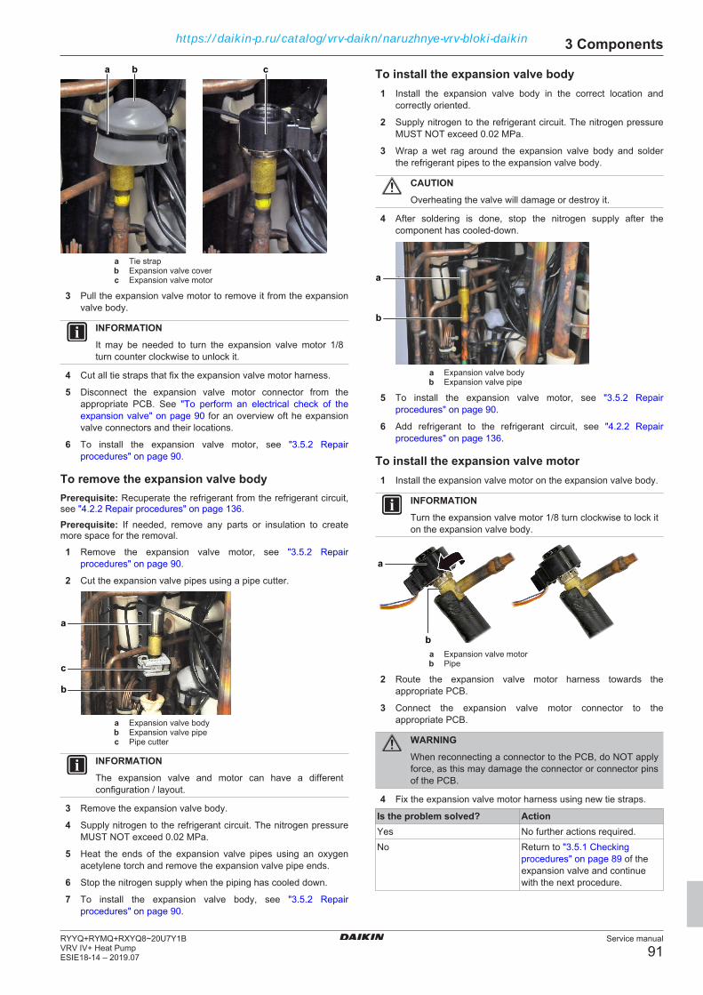
3 Components
Service manual
91RYYQ+RYMQ+RXYQ8~20U7Y1BVRV IV+ Heat PumpESIE18-14 – 2019.07
a b c
a Tie strapb Expansion valve coverc Expansion valve motor
3 Pull the expansion valve motor to remove it from the expansionvalve body.
INFORMATIONIt may be needed to turn the expansion valve motor 1/8turn counter clockwise to unlock it.
4 Cut all tie straps that fix the expansion valve motor harness.
5 Disconnect the expansion valve motor connector from theappropriate PCB. See "To perform an electrical check of theexpansion valve" on page 90 for an overview oft he expansionvalve connectors and their locations.
6 To install the expansion valve motor, see "3.5.2 Repairprocedures" on page 90.
To remove the expansion valve bodyPrerequisite: Recuperate the refrigerant from the refrigerant circuit,see "4.2.2 Repair procedures" on page 136.Prerequisite: If needed, remove any parts or insulation to createmore space for the removal.
1 Remove the expansion valve motor, see "3.5.2 Repairprocedures" on page 90.
2 Cut the expansion valve pipes using a pipe cutter.
a
c
b
a Expansion valve bodyb Expansion valve pipec Pipe cutter
INFORMATIONThe expansion valve and motor can have a differentconfiguration / layout.
3 Remove the expansion valve body.
4 Supply nitrogen to the refrigerant circuit. The nitrogen pressureMUST NOT exceed 0.02 MPa.
5 Heat the ends of the expansion valve pipes using an oxygenacetylene torch and remove the expansion valve pipe ends.
6 Stop the nitrogen supply when the piping has cooled down.
7 To install the expansion valve body, see "3.5.2 Repairprocedures" on page 90.
To install the expansion valve body1 Install the expansion valve body in the correct location and
correctly oriented.
2 Supply nitrogen to the refrigerant circuit. The nitrogen pressureMUST NOT exceed 0.02 MPa.
3 Wrap a wet rag around the expansion valve body and solderthe refrigerant pipes to the expansion valve body.
CAUTIONOverheating the valve will damage or destroy it.
4 After soldering is done, stop the nitrogen supply after thecomponent has cooled‑down.
a
b
a Expansion valve bodyb Expansion valve pipe
5 To install the expansion valve motor, see "3.5.2 Repairprocedures" on page 90.
6 Add refrigerant to the refrigerant circuit, see "4.2.2 Repairprocedures" on page 136.
To install the expansion valve motor1 Install the expansion valve motor on the expansion valve body.
INFORMATIONTurn the expansion valve motor 1/8 turn clockwise to lock iton the expansion valve body.
b
a
a Expansion valve motorb Pipe
2 Route the expansion valve motor harness towards theappropriate PCB.
3 Connect the expansion valve motor connector to theappropriate PCB.
WARNINGWhen reconnecting a connector to the PCB, do NOT applyforce, as this may damage the connector or connector pinsof the PCB.
4 Fix the expansion valve motor harness using new tie straps.
Is the problem solved? ActionYes No further actions required.No Return to "3.5.1 Checking
procedures" on page 89 of theexpansion valve and continuewith the next procedure.
https://daikin-p.ru/catalog/vrv-daikn/naruzhnye-vrv-bloki-daikin
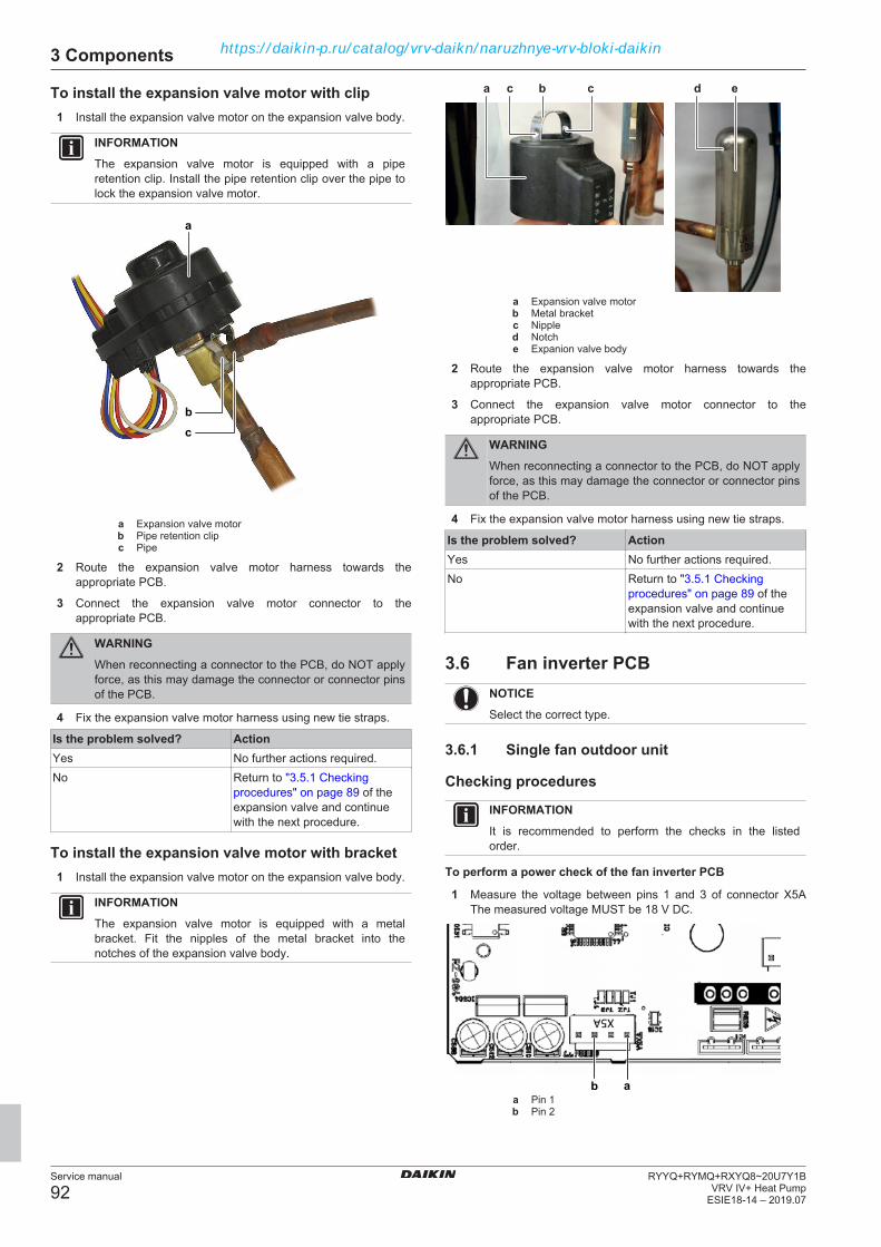
3 Components
Service manual
92RYYQ+RYMQ+RXYQ8~20U7Y1B
VRV IV+ Heat PumpESIE18-14 – 2019.07
To install the expansion valve motor with clip1 Install the expansion valve motor on the expansion valve body.
INFORMATIONThe expansion valve motor is equipped with a piperetention clip. Install the pipe retention clip over the pipe tolock the expansion valve motor.
b
a
c
a Expansion valve motorb Pipe retention clipc Pipe
2 Route the expansion valve motor harness towards theappropriate PCB.
3 Connect the expansion valve motor connector to theappropriate PCB.
WARNINGWhen reconnecting a connector to the PCB, do NOT applyforce, as this may damage the connector or connector pinsof the PCB.
4 Fix the expansion valve motor harness using new tie straps.
Is the problem solved? ActionYes No further actions required.No Return to "3.5.1 Checking
procedures" on page 89 of theexpansion valve and continuewith the next procedure.
To install the expansion valve motor with bracket1 Install the expansion valve motor on the expansion valve body.
INFORMATIONThe expansion valve motor is equipped with a metalbracket. Fit the nipples of the metal bracket into thenotches of the expansion valve body.
bc c d ea
a Expansion valve motorb Metal bracketc Nippled Notche Expanion valve body
2 Route the expansion valve motor harness towards theappropriate PCB.
3 Connect the expansion valve motor connector to theappropriate PCB.
WARNINGWhen reconnecting a connector to the PCB, do NOT applyforce, as this may damage the connector or connector pinsof the PCB.
4 Fix the expansion valve motor harness using new tie straps.
Is the problem solved? ActionYes No further actions required.No Return to "3.5.1 Checking
procedures" on page 89 of theexpansion valve and continuewith the next procedure.
3.6 Fan inverter PCBNOTICESelect the correct type.
3.6.1 Single fan outdoor unit
Checking procedures
INFORMATIONIt is recommended to perform the checks in the listedorder.
To perform a power check of the fan inverter PCB
1 Measure the voltage between pins 1 and 3 of connector X5AThe measured voltage MUST be 18 V DC.
aba Pin 1b Pin 2
https://daikin-p.ru/catalog/vrv-daikn/naruzhnye-vrv-bloki-daikin
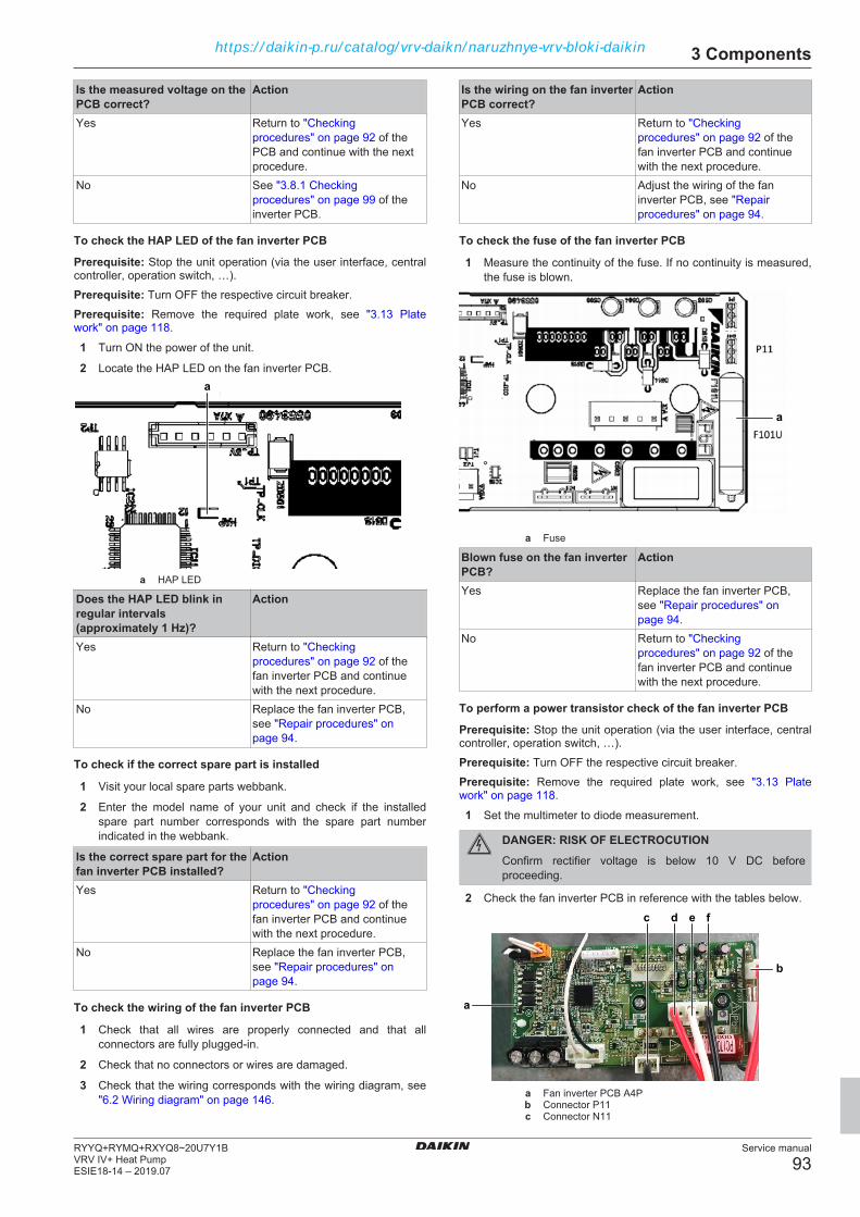
3 Components
Service manual
93RYYQ+RYMQ+RXYQ8~20U7Y1BVRV IV+ Heat PumpESIE18-14 – 2019.07
Is the measured voltage on thePCB correct?
Action
Yes Return to "Checkingprocedures" on page 92 of thePCB and continue with the nextprocedure.
No See "3.8.1 Checkingprocedures" on page 99 of theinverter PCB.
To check the HAP LED of the fan inverter PCB
Prerequisite: Stop the unit operation (via the user interface, centralcontroller, operation switch, …).Prerequisite: Turn OFF the respective circuit breaker.Prerequisite: Remove the required plate work, see "3.13 Platework" on page 118.
1 Turn ON the power of the unit.
2 Locate the HAP LED on the fan inverter PCB.a
a HAP LED
Does the HAP LED blink inregular intervals(approximately 1 Hz)?
Action
Yes Return to "Checkingprocedures" on page 92 of thefan inverter PCB and continuewith the next procedure.
No Replace the fan inverter PCB,see "Repair procedures" onpage 94.
To check if the correct spare part is installed
1 Visit your local spare parts webbank.
2 Enter the model name of your unit and check if the installedspare part number corresponds with the spare part numberindicated in the webbank.
Is the correct spare part for thefan inverter PCB installed?
Action
Yes Return to "Checkingprocedures" on page 92 of thefan inverter PCB and continuewith the next procedure.
No Replace the fan inverter PCB,see "Repair procedures" onpage 94.
To check the wiring of the fan inverter PCB
1 Check that all wires are properly connected and that allconnectors are fully plugged‑in.
2 Check that no connectors or wires are damaged.
3 Check that the wiring corresponds with the wiring diagram, see"6.2 Wiring diagram" on page 146.
Is the wiring on the fan inverterPCB correct?
Action
Yes Return to "Checkingprocedures" on page 92 of thefan inverter PCB and continuewith the next procedure.
No Adjust the wiring of the faninverter PCB, see "Repairprocedures" on page 94.
To check the fuse of the fan inverter PCB
1 Measure the continuity of the fuse. If no continuity is measured,the fuse is blown.
a
a Fuse
Blown fuse on the fan inverterPCB?
Action
Yes Replace the fan inverter PCB,see "Repair procedures" onpage 94.
No Return to "Checkingprocedures" on page 92 of thefan inverter PCB and continuewith the next procedure.
To perform a power transistor check of the fan inverter PCB
Prerequisite: Stop the unit operation (via the user interface, centralcontroller, operation switch, …).Prerequisite: Turn OFF the respective circuit breaker.Prerequisite: Remove the required plate work, see "3.13 Platework" on page 118.
1 Set the multimeter to diode measurement.
DANGER: RISK OF ELECTROCUTIONConfirm rectifier voltage is below 10 V DC beforeproceeding.
2 Check the fan inverter PCB in reference with the tables below.c
a
b
d e f
a Fan inverter PCB A4Pb Connector P11c Connector N11
https://daikin-p.ru/catalog/vrv-daikn/naruzhnye-vrv-bloki-daikin
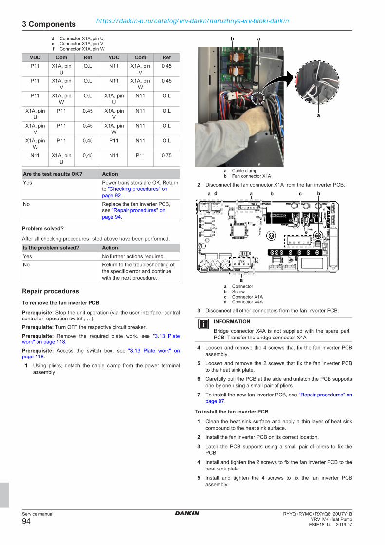
3 Components
Service manual
94RYYQ+RYMQ+RXYQ8~20U7Y1B
VRV IV+ Heat PumpESIE18-14 – 2019.07
d Connector X1A, pin Ue Connector X1A, pin Vf Connector X1A, pin W
VDC Com Ref VDC Com RefP11 X1A, pin
UO.L N11 X1A, pin
V0,45
P11 X1A, pinV
O.L N11 X1A, pinW
0,45
P11 X1A, pinW
O.L X1A, pinU
N11 O.L
X1A, pinU
P11 0,45 X1A, pinV
N11 O.L
X1A, pinV
P11 0,45 X1A, pinW
N11 O.L
X1A, pinW
P11 0,45 P11 N11 O.L
N11 X1A, pinU
0,45 N11 P11 0,75
Are the test results OK? ActionYes Power transistors are OK. Return
to "Checking procedures" onpage 92.
No Replace the fan inverter PCB,see "Repair procedures" onpage 94.
Problem solved?
After all checking procedures listed above have been performed:
Is the problem solved? ActionYes No further actions required.No Return to the troubleshooting of
the specific error and continuewith the next procedure.
Repair proceduresTo remove the fan inverter PCB
Prerequisite: Stop the unit operation (via the user interface, centralcontroller, operation switch, …).Prerequisite: Turn OFF the respective circuit breaker.Prerequisite: Remove the required plate work, see "3.13 Platework" on page 118.Prerequisite: Access the switch box, see "3.13 Plate work" onpage 118.
1 Using pliers, detach the cable clamp from the power terminalassembly
a
ab
a Cable clampb Fan connector X1A
2 Disconnect the fan connector X1A from the fan inverter PCB.
aa bb
a
d c
a Connectorb Screwc Connector X1Ad Connector X4A
3 Disconnect all other connectors from the fan inverter PCB.
INFORMATIONBridge connector X4A is not supplied with the spare partPCB. Transfer the bridge connector X4A
4 Loosen and remove the 4 screws that fix the fan inverter PCBassembly.
5 Loosen and remove the 2 screws that fix the fan inverter PCBto the heat sink plate.
6 Carefully pull the PCB at the side and unlatch the PCB supportsone by one using a small pair of pliers.
7 To install the new fan inverter PCB, see "Repair procedures" onpage 97.
To install the fan inverter PCB
1 Clean the heat sink surface and apply a thin layer of heat sinkcompound to the heat sink surface.
2 Install the fan inverter PCB on its correct location.
3 Latch the PCB supports using a small pair of pliers to fix thePCB.
4 Install and tighten the 2 screws to fix the fan inverter PCB to theheat sink plate.
5 Install and tighten the 4 screws to fix the fan inverter PCBassembly.
https://daikin-p.ru/catalog/vrv-daikn/naruzhnye-vrv-bloki-daikin
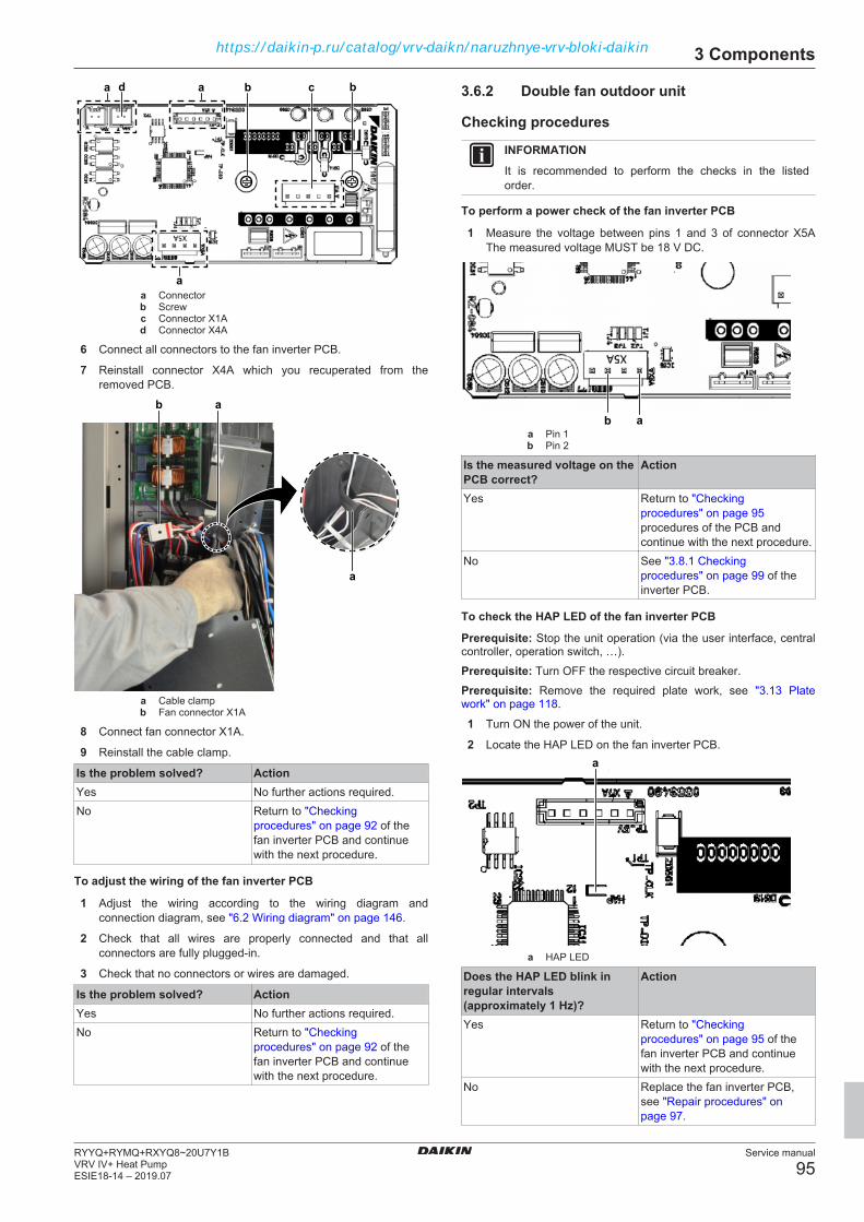
3 Components
Service manual
95RYYQ+RYMQ+RXYQ8~20U7Y1BVRV IV+ Heat PumpESIE18-14 – 2019.07
aa bb
a
d c
a Connectorb Screwc Connector X1Ad Connector X4A
6 Connect all connectors to the fan inverter PCB.
7 Reinstall connector X4A which you recuperated from theremoved PCB.
a
ab
a Cable clampb Fan connector X1A
8 Connect fan connector X1A.
9 Reinstall the cable clamp.
Is the problem solved? ActionYes No further actions required.No Return to "Checking
procedures" on page 92 of thefan inverter PCB and continuewith the next procedure.
To adjust the wiring of the fan inverter PCB
1 Adjust the wiring according to the wiring diagram andconnection diagram, see "6.2 Wiring diagram" on page 146.
2 Check that all wires are properly connected and that allconnectors are fully plugged‑in.
3 Check that no connectors or wires are damaged.
Is the problem solved? ActionYes No further actions required.No Return to "Checking
procedures" on page 92 of thefan inverter PCB and continuewith the next procedure.
3.6.2 Double fan outdoor unit
Checking procedures
INFORMATIONIt is recommended to perform the checks in the listedorder.
To perform a power check of the fan inverter PCB
1 Measure the voltage between pins 1 and 3 of connector X5AThe measured voltage MUST be 18 V DC.
aba Pin 1b Pin 2
Is the measured voltage on thePCB correct?
Action
Yes Return to "Checkingprocedures" on page 95procedures of the PCB andcontinue with the next procedure.
No See "3.8.1 Checkingprocedures" on page 99 of theinverter PCB.
To check the HAP LED of the fan inverter PCB
Prerequisite: Stop the unit operation (via the user interface, centralcontroller, operation switch, …).Prerequisite: Turn OFF the respective circuit breaker.Prerequisite: Remove the required plate work, see "3.13 Platework" on page 118.
1 Turn ON the power of the unit.
2 Locate the HAP LED on the fan inverter PCB.a
a HAP LED
Does the HAP LED blink inregular intervals(approximately 1 Hz)?
Action
Yes Return to "Checkingprocedures" on page 95 of thefan inverter PCB and continuewith the next procedure.
No Replace the fan inverter PCB,see "Repair procedures" onpage 97.
https://daikin-p.ru/catalog/vrv-daikn/naruzhnye-vrv-bloki-daikin

3 Components
Service manual
96RYYQ+RYMQ+RXYQ8~20U7Y1B
VRV IV+ Heat PumpESIE18-14 – 2019.07
To check if the correct spare part is installed
1 Visit your local spare parts webbank.
2 Enter the model name of your unit and check if the installedspare part number corresponds with the spare part numberindicated in the webbank.
Is the correct spare part for thefan inverter PCB installed?
Action
Yes Return to "Checkingprocedures" on page 95 of thefan inverter PCB and continuewith the next procedure.
No Replace the fan inverter PCB,see "Repair procedures" onpage 97.
To check the wiring of the fan inverter PCB
1 Check that all wires are properly connected and that allconnectors are fully plugged‑in.
2 Check that no connectors or wires are damaged.
3 Check that the wiring corresponds with the wiring diagram, see"6.2 Wiring diagram" on page 146.
Is the wiring on the fan inverterPCB correct?
Action
Yes Return to "Checkingprocedures" on page 95 of thefan inverter PCB and continuewith the next procedure.
No Adjust the wiring of the faninverter PCB, see "Repairprocedures" on page 97.
To check the fuse of the fan inverter PCB
1 Measure the continuity of the fuse. If no continuity is measured,the fuse is blown.
a
a Fuse
Blown fuse on the fan inverterPCB?
Action
Yes Replace the fan inverter PCB,see "Repair procedures" onpage 97.
No Return to "Checkingprocedures" on page 95 of thefan inverter PCB and continuewith the next procedure.
To perform a power transistor check of the fan inverter PCB
Prerequisite: Stop the unit operation (via the user interface, centralcontroller, operation switch, …).Prerequisite: Turn OFF the respective circuit breaker.
Prerequisite: Remove the required plate work, see "3.13 Platework" on page 118.
1 Set the multimeter to diode measurement.
DANGER: RISK OF ELECTROCUTIONConfirm rectifier voltage is below 10 V DC beforeproceeding.
2 Check the fan inverter PCB in reference with the tables below.
d’
d
a
b
c
e f g
c’
e’ f’ g’a Fan inverter PCB A4Pb Fan inverter PCB A7P
c / c' Connector P11d / d' Connector N11e / e' Connector X1A, pin Uf / f' Connector X1A, pin V
g / g' Connector X1A, pin W
VDC Com Ref VDC Com RefP11 X1A, pin
UO.L N11 X1A, pin
V0,45
P11 X1A, pinV
O.L N11 X1A, pinW
0,45
P11 X1A, pinW
O.L X1A, pinU
N11 O.L
X1A, pinU
P11 0,45 X1A, pinV
N11 O.L
X1A, pinV
P11 0,45 X1A, pinW
N11 O.L
X1A, pinW
P11 0,45 P11 N11 O.L
N11 X1A, pinU
0,45 N11 P11 0,75
Are the test results OK? ActionYes Power transistors are OK. Return
to "Checking procedures" onpage 95.
No Replace the fan inverter PCB,see "Repair procedures" onpage 97.
Problem solved?
After all checking procedures listed above have been performed:
https://daikin-p.ru/catalog/vrv-daikn/naruzhnye-vrv-bloki-daikin
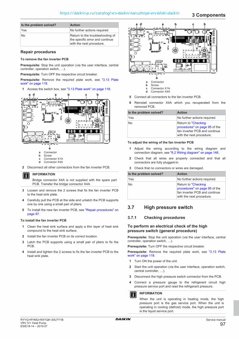
3 Components
Service manual
97RYYQ+RYMQ+RXYQ8~20U7Y1BVRV IV+ Heat PumpESIE18-14 – 2019.07
Is the problem solved? ActionYes No further actions required.No Return to the troubleshooting of
the specific error and continuewith the next procedure.
Repair proceduresTo remove the fan inverter PCB
Prerequisite: Stop the unit operation (via the user interface, centralcontroller, operation switch, …).Prerequisite: Turn OFF the respective circuit breaker.Prerequisite: Remove the required plate work, see "3.13 Platework" on page 118.
1 Access the switch box, see "3.13 Plate work" on page 118.
aa bb
a
d c
a Connectorb Screwc Connector X1Ad Connector X4A
2 Disconnect all other connectors from the fan inverter PCB.
INFORMATIONBridge connector X4A is not supplied with the spare partPCB. Transfer the bridge connector X4A
3 Loosen and remove the 2 screws that fix the fan inverter PCBto the heat sink plate.
4 Carefully pull the PCB at the side and unlatch the PCB supportsone by one using a small pair of pliers.
5 To install the new fan inverter PCB, see "Repair procedures" onpage 97.
To install the fan inverter PCB
1 Clean the heat sink surface and apply a thin layer of heat sinkcompound to the heat sink surface.
2 Install the fan inverter PCB on its correct location.
3 Latch the PCB supports using a small pair of pliers to fix thePCB.
4 Install and tighten the 2 screws to fix the fan inverter PCB to theheat sink plate.
aa bb
a
d c
a Connectorb Screwc Connector X1Ad Connector X4A
5 Connect all connectors to the fan inverter PCB.
6 Reinstall connector X4A which you recuperated from theremoved PCB.
Is the problem solved? ActionYes No further actions required.No Return to "Checking
procedures" on page 95 of thefan inverter PCB and continuewith the next procedure.
To adjust the wiring of the fan inverter PCB
1 Adjust the wiring according to the wiring diagram andconnection diagram, see "6.2 Wiring diagram" on page 146.
2 Check that all wires are properly connected and that allconnectors are fully plugged‑in.
3 Check that no connectors or wires are damaged.
Is the problem solved? ActionYes No further actions required.No Return to "Checking
procedures" on page 95 of thefan inverter PCB and continuewith the next procedure.
3.7 High pressure switch
3.7.1 Checking procedures
To perform an electrical check of the highpressure switch (general procedure)Prerequisite: Stop the unit operation (via the user interface, centralcontroller, operation switch, …).Prerequisite: Turn OFF the respective circuit breaker.Prerequisite: Remove the required plate work, see "3.13 Platework" on page 118.
1 Turn ON the power of the unit.
2 Start the unit operation (via the user interface, operation switch,central controller, …).
3 Disconnect the high pressure switch connector from the PCB.
4 Connect a pressure gauge to the refrigerant circuit highpressure service port and read the refrigerant pressure.
INFORMATIONWhen the unit is operating in heating mode, the highpressure port is the gas service port. When the unit isoperating in cooling (defrost) mode, the high pressure portis the liquid service port.
https://daikin-p.ru/catalog/vrv-daikn/naruzhnye-vrv-bloki-daikin

3 Components
Service manual
98RYYQ+RYMQ+RXYQ8~20U7Y1B
VRV IV+ Heat PumpESIE18-14 – 2019.07
5 Measure the resistance between the pins 1‑2 of the highpressure switch connector to check if it is open or closed.
6 Compare the result with the trigger and reset conditions of thehigh pressure switch (graphic below).
INFORMATIONIf the high pressure switch was triggered open, it will stayopen until the refrigerant pressure drops below the resetpressure of the high pressure switch.
a
bef
d
c
a High pressure switch protection controlb Pressurec High pressure switch closedd High pressure switch opene High pressure switch operating pressuref High pressure switch reset pressure
INFORMATIONSee "6.6 Safety devices" on page 183 for the highpressure switch operating and reset pressure values.
INFORMATIONConnect the service checker tool to the unit or use fieldsettings mode 1‑42 (see "6.9 Field settings" on page 188)to monitor the high pressure.
If the state of the high pressure switch (open or closed)matches the state determined through the measuredpressure, but the pressure is NOT correct on the userinterface display, replace the applicable PCB.
High pressure switchconnector measurements arecorrect?
Then
Yes High pressure switch is OK.Return to the troubleshooting ofthe specific error and continuewith the next procedure.
No Replace the high pressureswitch, see "3.7.2 Repairprocedures" on page 98.
To perform an electrical check of the highpressure switch (detailed procedure)Prerequisite: Stop the unit operation (via the user interface, centralcontroller, operation switch, …).Prerequisite: Turn OFF the respective circuit breaker.Prerequisite: Remove the required plate work, see "3.13 Platework" on page 118.
1 Recuperate the refrigerant from the refrigerant circuit, see"4.2.2 Repair procedures" on page 136.
2 Fill the refrigerant circuit with nitrogen until pressurized justbelow operating pressure of the high pressure switch.
3 Disconnect the high pressure switch connector from the PCB.
4 Measure the resistance between the pins 1‑2 of the highpressure switch connector. The switch MUST be closed.
5 Fill the refrigerant circuit with nitrogen until pressurized justabove operating pressure of the high pressure switch.
6 Measure the resistance between the pins 1‑2 of the highpressure switch connector. The switch MUST be open.
7 Lower the pressure of the nitrogen in the refrigerant circuit justabove reset pressure of the high pressure switch.
8 Measure the resistance between the pins 1‑2 of the highpressure switch connector. The switch MUST be open.
9 Lower the pressure of the nitrogen in the refrigerant circuit justbelow reset pressure of the high pressure switch.
10 Measure the resistance between the pins 1‑2 of the highpressure switch connector. The switch MUST be closed.
High pressure switchconnector measurements arecorrect?
Then
Yes High pressure switch is OK.Return to the troubleshooting ofthe specific error and continuewith the next procedure.
No Replace the high pressureswitch, see "3.7.2 Repairprocedures" on page 98.
3.7.2 Repair procedures
To remove the high pressure switchPrerequisite: Stop the unit operation (via the user interface, centralcontroller, operation switch, …).Prerequisite: Turn OFF the respective circuit breaker.Prerequisite: Remove the required plate work, see "3.13 Platework" on page 118.Prerequisite: Recuperate the refrigerant from the refrigerant circuit,see "4.2.2 Repair procedures" on page 136.
1 If needed, remove any parts to create more space for theremoval of the high pressure switch.
2 Disconnect the high pressure switch connector from the PCB.
a
b
c
c
d
d
e
a High pressure switchb High pressure switch pipec Screwd Clampe Plate
3 Remove the screws, the clamps and the plate.
4 Cut all tie straps that fix the high pressure switch harness.
5 Cut the high pressure switch pipe using a pipe cutter.
6 Remove the high pressure switch from the unit.
7 Supply nitrogen to the refrigerant circuit. The nitrogen pressureMUST NOT exceed 0.02 MPa.
https://daikin-p.ru/catalog/vrv-daikn/naruzhnye-vrv-bloki-daikin
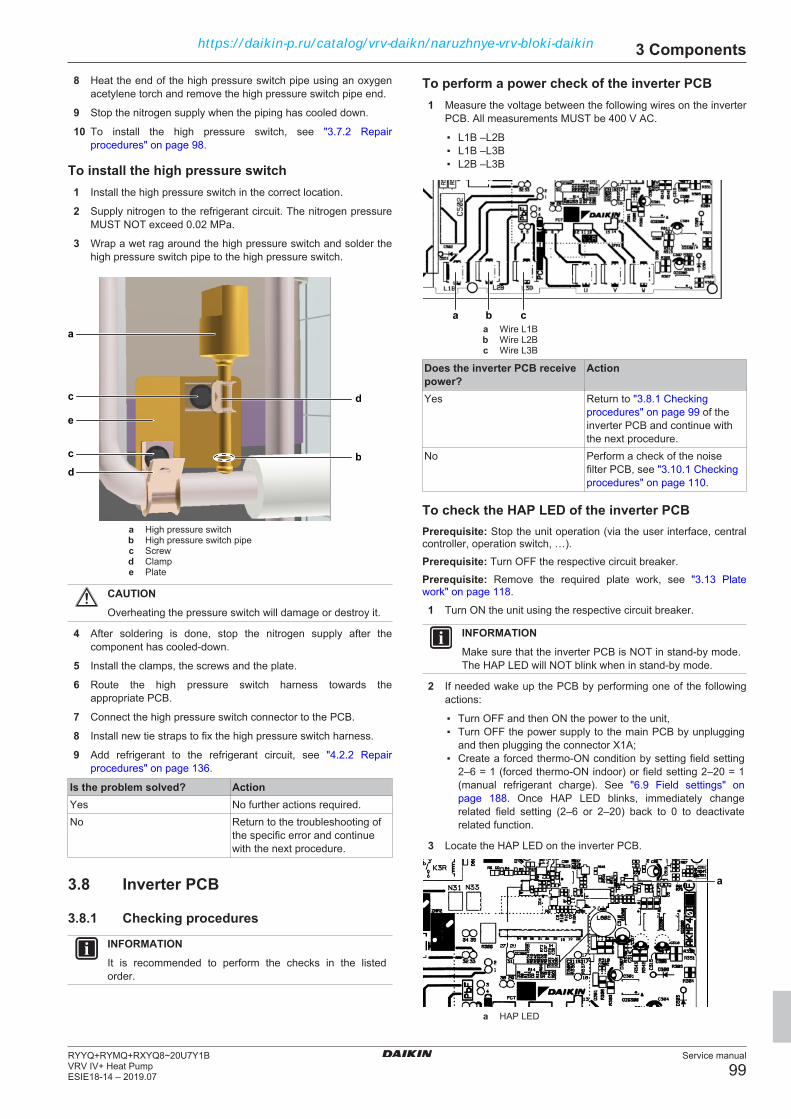
3 Components
Service manual
99RYYQ+RYMQ+RXYQ8~20U7Y1BVRV IV+ Heat PumpESIE18-14 – 2019.07
8 Heat the end of the high pressure switch pipe using an oxygenacetylene torch and remove the high pressure switch pipe end.
9 Stop the nitrogen supply when the piping has cooled down.
10 To install the high pressure switch, see "3.7.2 Repairprocedures" on page 98.
To install the high pressure switch1 Install the high pressure switch in the correct location.
2 Supply nitrogen to the refrigerant circuit. The nitrogen pressureMUST NOT exceed 0.02 MPa.
3 Wrap a wet rag around the high pressure switch and solder thehigh pressure switch pipe to the high pressure switch.
a
b
c
c
d
d
e
a High pressure switchb High pressure switch pipec Screwd Clampe Plate
CAUTIONOverheating the pressure switch will damage or destroy it.
4 After soldering is done, stop the nitrogen supply after thecomponent has cooled‑down.
5 Install the clamps, the screws and the plate.
6 Route the high pressure switch harness towards theappropriate PCB.
7 Connect the high pressure switch connector to the PCB.
8 Install new tie straps to fix the high pressure switch harness.
9 Add refrigerant to the refrigerant circuit, see "4.2.2 Repairprocedures" on page 136.
Is the problem solved? ActionYes No further actions required.No Return to the troubleshooting of
the specific error and continuewith the next procedure.
3.8 Inverter PCB
3.8.1 Checking procedures
INFORMATIONIt is recommended to perform the checks in the listedorder.
To perform a power check of the inverter PCB1 Measure the voltage between the following wires on the inverter
PCB. All measurements MUST be 400 V AC.
▪ L1B –L2B▪ L1B –L3B▪ L2B –L3B
ba ca Wire L1Bb Wire L2Bc Wire L3B
Does the inverter PCB receivepower?
Action
Yes Return to "3.8.1 Checkingprocedures" on page 99 of theinverter PCB and continue withthe next procedure.
No Perform a check of the noisefilter PCB, see "3.10.1 Checkingprocedures" on page 110.
To check the HAP LED of the inverter PCBPrerequisite: Stop the unit operation (via the user interface, centralcontroller, operation switch, …).Prerequisite: Turn OFF the respective circuit breaker.Prerequisite: Remove the required plate work, see "3.13 Platework" on page 118.
1 Turn ON the unit using the respective circuit breaker.
INFORMATIONMake sure that the inverter PCB is NOT in stand‑by mode.The HAP LED will NOT blink when in stand‑by mode.
2 If needed wake up the PCB by performing one of the followingactions:
▪ Turn OFF and then ON the power to the unit,▪ Turn OFF the power supply to the main PCB by unplugging
and then plugging the connector X1A;▪ Create a forced thermo‑ON condition by setting field setting
2–6 = 1 (forced thermo‑ON indoor) or field setting 2–20 = 1(manual refrigerant charge). See "6.9 Field settings" onpage 188. Once HAP LED blinks, immediately changerelated field setting (2–6 or 2–20) back to 0 to deactivaterelated function.
3 Locate the HAP LED on the inverter PCB.
a
a HAP LED
https://daikin-p.ru/catalog/vrv-daikn/naruzhnye-vrv-bloki-daikin

3 Components
Service manual
100RYYQ+RYMQ+RXYQ8~20U7Y1B
VRV IV+ Heat PumpESIE18-14 – 2019.07
Does the HAP LED blink inregular intervals(approximately 1 Hz)?
Action
Yes Return to "3.8.1 Checkingprocedures" on page 99 of theinverter PCB and continue withthe next procedure.
No Replace the inverter PCB, see"3.8.2 Repair procedures" onpage 103.
To check if the correct spare part is installed1 Visit your local spare parts webbank.
2 Enter the model name of your unit and check if the installedspare part number corresponds with the spare part numberindicated in the webbank.
Is the correct spare part for theinverter PCB installed?
Action
Yes Return to "3.8.1 Checkingprocedures" on page 99 of theinverter PCB and continue withthe next procedure.
No Replace the inverter PCB, see"3.8.2 Repair procedures" onpage 103.
To check the wiring of the inverter PCB1 Check that all wires are properly connected and that all
connectors are fully plugged‑in.
2 Check that no connectors or wires are damaged.
3 Check that the wiring corresponds with the wiring diagram, see"6.2 Wiring diagram" on page 146.
Is the wiring on the inverterPCB correct?
Action
Yes Return to "3.8.1 Checkingprocedures" on page 99 of theinverter PCB and continue withthe next procedure.
No Adjust the wiring of the inverterPCB, see "3.8.2 Repairprocedures" on page 103.
To check the fuses of the inverter PCB1 Measure the continuity of the fuse. If no continuity is measured,
the fuse is blown.a
a Fuse
Any blown fuses on theinverter PCB?
Action
Yes Replace the inverter PCB, see"3.8.2 Repair procedures" onpage 103.
Any blown fuses on theinverter PCB?
Action
No Return to "3.8.1 Checkingprocedures" on page 99 of theinverter PCB and continue withthe next procedure.
To check the rectifier voltage of the inverter PCB1 Stop the unit operation (via the user interface, operation switch,
…).
For single fan units2 Measure the voltage on the rectifier voltage check connector (a)
X3A, located above the power terminal assembly (b). Themeasured voltage should be approximately 560 V DC.
a
b
a Connector X3Ab Power terminal assembly
For double fan units3 Measure the voltage on the rectifier voltage check connector (a)
X5A to check inverter PCB A3P (c). The measured voltageshould be approximately 560 V DC.
4 Measure the voltage on the rectifier voltage check connector (b)X6A to check inverter PCB A6P (d). The measured voltageshould be approximately 560 V DC.
a d cb
a Connector X5Ab Connector X6Ac Inverter PCB A3Pd Inverter PCB A6P
Is the measured voltageapproximately 560 V DC?
Action
Yes Diode module and power moduleare OK. Perform a powertransistor check of the inverterPCB, see "3.8.1 Checkingprocedures" on page 99.
https://daikin-p.ru/catalog/vrv-daikn/naruzhnye-vrv-bloki-daikin

3 Components
Service manual
101RYYQ+RYMQ+RXYQ8~20U7Y1BVRV IV+ Heat PumpESIE18-14 – 2019.07
Is the measured voltageapproximately 560 V DC?
Action
No Perform a diode module andpower module check, see"3.8.1 Checking procedures" onpage 99.
To perform a diode module and power modulecheckPrerequisite: Stop the unit operation (via the user interface, centralcontroller, operation switch, …).Prerequisite: Turn OFF the respective circuit breaker.Prerequisite: Remove the required plate work, see "3.13 Platework" on page 118.
1 Open the compressor insulation.
DANGER: RISK OF ELECTROCUTIONConfirm rectifier voltage is below 10 V DC beforeproceeding.
2 Remove the cover of the compressor wire terminals.a
a Compressor wire terminals cover
3 Disconnect the Faston connectors from the compressor wireterminals U, V and W.
INFORMATIONNote the position of the Faston connectors on thecompressor wire terminals to allow correct connectionduring installation.
a a
a
a Faston connectors
ba ced f
g h i
a Wire terminal Ub Wire terminal Vc Wire terminal Wd Wire terminal L1Be Wire terminal L2Bf Wire terminal L3Bg Wire terminal P1h Faston connector terminal N31i Measuring point P
4 Check the diode module and the power module in referencewith the tables below.
Diode module checkVDC Com Ref VDC Com RefP1 L1B O.L N31 L1B 0,50P1 L2B O.L N31 L2B 0,50P1 L3B O.L N31 L3B 0,50
L1B P1 0,50 L1B N31 O.LL2B P1 0,50 L2B N31 O.LL3B P1 0,50 L3B N31 O.L
N31 P1 0,90P1 N31 O.L
Power module checkVDC Com Ref VDC Com Ref
P U O.L N31 U 0,43P V O.L N31 V 0,43P W O.L N31 W 0,43U P 0,43 U N31 O.LV P 0,43 V N31 O.LW P 0,43 W N31 O.L
N31 P 0,78P N31 O.L
Are the test results OK? ActionYes Diode module and power module
are OK. Perform a powertransistor check of the inverterPCB, see "3.8.1 Checkingprocedures" on page 99.
No Replace the inverter PCB, see"3.8.2 Repair procedures" onpage 103.
To perform a power transistor check of theinverter PCBPrerequisite: First perform all previous checks and ensure theinverter PCB is OK.
https://daikin-p.ru/catalog/vrv-daikn/naruzhnye-vrv-bloki-daikin
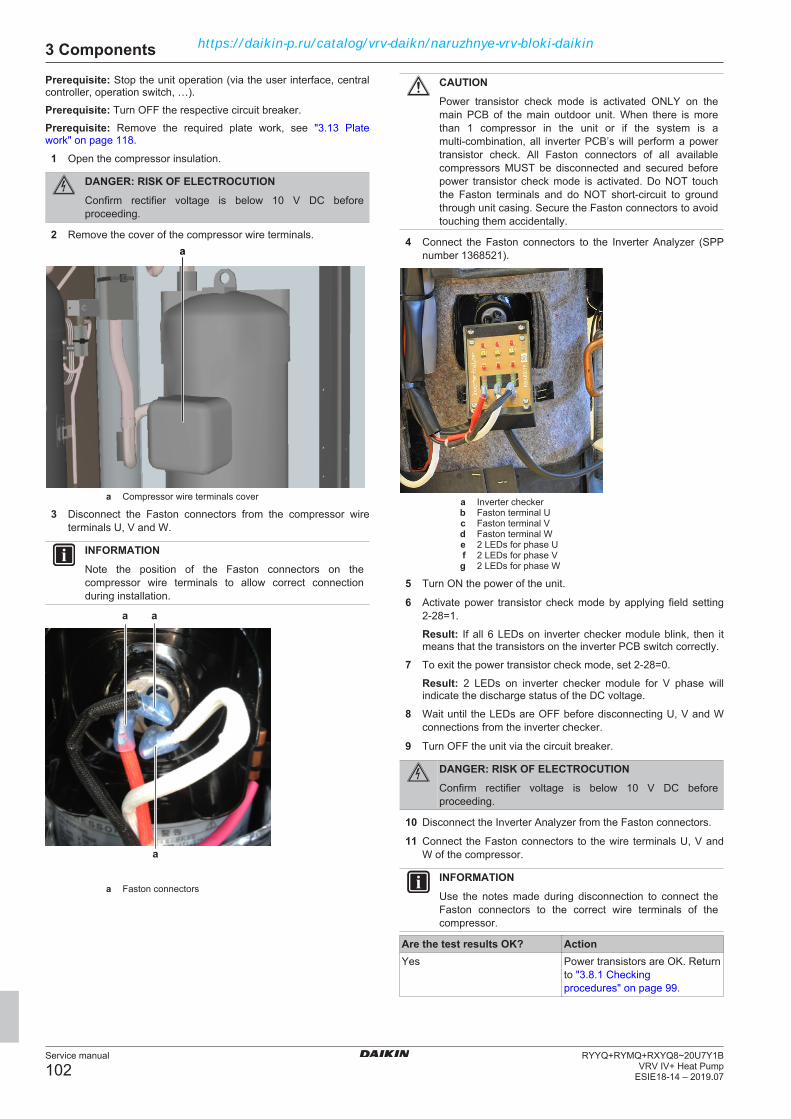
3 Components
Service manual
102RYYQ+RYMQ+RXYQ8~20U7Y1B
VRV IV+ Heat PumpESIE18-14 – 2019.07
Prerequisite: Stop the unit operation (via the user interface, centralcontroller, operation switch, …).Prerequisite: Turn OFF the respective circuit breaker.Prerequisite: Remove the required plate work, see "3.13 Platework" on page 118.
1 Open the compressor insulation.
DANGER: RISK OF ELECTROCUTIONConfirm rectifier voltage is below 10 V DC beforeproceeding.
2 Remove the cover of the compressor wire terminals.a
a Compressor wire terminals cover
3 Disconnect the Faston connectors from the compressor wireterminals U, V and W.
INFORMATIONNote the position of the Faston connectors on thecompressor wire terminals to allow correct connectionduring installation.
a a
a
a Faston connectors
CAUTIONPower transistor check mode is activated ONLY on themain PCB of the main outdoor unit. When there is morethan 1 compressor in the unit or if the system is amulti‑combination, all inverter PCB’s will perform a powertransistor check. All Faston connectors of all availablecompressors MUST be disconnected and secured beforepower transistor check mode is activated. Do NOT touchthe Faston terminals and do NOT short‑circuit to groundthrough unit casing. Secure the Faston connectors to avoidtouching them accidentally.
4 Connect the Faston connectors to the Inverter Analyzer (SPPnumber 1368521).
a Inverter checkerb Faston terminal Uc Faston terminal Vd Faston terminal We 2 LEDs for phase Uf 2 LEDs for phase Vg 2 LEDs for phase W
5 Turn ON the power of the unit.
6 Activate power transistor check mode by applying field setting2-28=1.
Result: If all 6 LEDs on inverter checker module blink, then itmeans that the transistors on the inverter PCB switch correctly.
7 To exit the power transistor check mode, set 2-28=0.
Result: 2 LEDs on inverter checker module for V phase willindicate the discharge status of the DC voltage.
8 Wait until the LEDs are OFF before disconnecting U, V and Wconnections from the inverter checker.
9 Turn OFF the unit via the circuit breaker.
DANGER: RISK OF ELECTROCUTIONConfirm rectifier voltage is below 10 V DC beforeproceeding.
10 Disconnect the Inverter Analyzer from the Faston connectors.
11 Connect the Faston connectors to the wire terminals U, V andW of the compressor.
INFORMATIONUse the notes made during disconnection to connect theFaston connectors to the correct wire terminals of thecompressor.
Are the test results OK? ActionYes Power transistors are OK. Return
to "3.8.1 Checkingprocedures" on page 99.
https://daikin-p.ru/catalog/vrv-daikn/naruzhnye-vrv-bloki-daikin

3 Components
Service manual
103RYYQ+RYMQ+RXYQ8~20U7Y1BVRV IV+ Heat PumpESIE18-14 – 2019.07
Are the test results OK? ActionNo Replace the inverter PCB, see
"3.8.2 Repair procedures" onpage 103.
Problem solved?After all checking procedures listed above have been performed:
Is the problem solved? ActionYes No further actions required.No Return to the troubleshooting of
the specific error and continuewith the next procedure.
3.8.2 Repair procedures
To remove the inverter PCBPrerequisite: Stop the unit operation (via the user interface, centralcontroller, operation switch, …).Prerequisite: Turn OFF the respective circuit breaker.Prerequisite: Remove the required plate work, see "3.13 Platework" on page 118.
1 Access the switch box, see "3.13 Plate work" on page 118.
DANGER: RISK OF ELECTROCUTIONConfirm rectifier voltage is below 10 V DC beforeproceeding.
For single fan units2 Loosen and remove the screws (a) that fix the power terminal
assembly (b).
3 Loosen and remove the 2 screws (c) that fix the cable clamps(d).
4 Unplug the fan connectors X1A and X2A (e).
5 Unplug the wiring (f) from the main board.
6 Detach the tie wrap (g).
ga
ab
dc
dc
e
f
a Screwb Power terminal assemblyc Screwd Cable clampe Connectors X1A and X2Af Wiringg Tie wrap
7 Loosen and remove the screw (a) that fixes the cable clamp (b).
8 Detach the tie wrap (c).
9 Cut the tie wraps (d) on the cable harness.
10 Separate the cables (e) and (f).
11 Loosen and remove the 2 screws (g) that fix the compressorinverter assembly (h).
12 Loosen and remove the screw (i) that fixes the thermistor clamp(j).
13 Loosen and remove the 2 screws (k) that fix the heat pipe (l).
14 Loosen and remove the screw (n) that fixes the ground wire(m).
a
g
b
c
h
d
f
e
g ji
kkl
mna Screwb Cable clampc Tie wrapd Tie wrape Cablesf Cablesg Screwh Compressor inverter assemblyi Screwj Thermistor clamp
k Screwl Heat pipe
m Ground wiren Screw
15 Using a flat screwdriver (a), separate the heat pipe (b) from theheat sink (c).
16 Loosen and remove the screw (d) that fixes the power terminalassembly (e).
17 Move the power terminal assembly (e) to the right.
18 Disconnect connectors X3 (f) and X5 (g) from the fan inverterPCB (h).
hg f
e
a
c
b
d
e
a Flat screwdriverb Heat pipec Heat sinkd Screwe Power terminal assemblyf Connector X3g Connector X5h Fan inverter PCB
19 Turn the power terminal assembly (a) to the left.
20 Remove the 4 screws (b) that fix the heat sink (c).
WARNINGThermal grease is applied to the heat sinks. Use gloveswhen separating the heat sinks from the inverter boards.
https://daikin-p.ru/catalog/vrv-daikn/naruzhnye-vrv-bloki-daikin

3 Components
Service manual
104RYYQ+RYMQ+RXYQ8~20U7Y1B
VRV IV+ Heat PumpESIE18-14 – 2019.07
21 Lift and slightly tilt the compressor inverter PCB assembly (d),guide the compressor cable (e) into the switch box.
22 Put the compressor inverter PCB assembly (d) in horizontalposition.
23 Remove the 4 screws (f) that fix the compressor inverter PCB(d).
f
b
f
d
a
b
b
b
c
ed f fg
g
a Power terminal assemblyb Screwc Heat sinkd Inverter PCBe Compressor cablef Screwg Screw
24 Disconnect all wiring from the compressor inverter PCB.
The compressor inverter PCB is fixed to the heat sink element withscrews (a), through the screw holes on the PCB.
25 Remove the screws (a) to remove the PCB from the heat sinkelement.
26 Unlatch the PCB supports (b) one by one using a small pair ofpliers.
27 Remove the compressor inverter PCB.a
b
b
b
ab
b
b
b
b
a Screwb PCB support
For double fan units28 Disconnect all connectors (a) from the inverter PCB.
29 Disconnect the wire terminals (b) of the inverter PCB.
a
b
a
b b b b b
b
bc c
c c c
c
c a
ac
d
d
a Connectorb Wire terminalc PCB supportd Screw
30 Remove the 4 screws (e) that fix the heat sink (f) to the switchbox.
efe
e e
efe
e e
e Screwf Heat sink
31 Remove the screws (d) that fix the inverter PCB to the heatsink.
WARNINGThermal grease is applied to the heat sinks. Use gloveswhen separating the heat sinks from the inverter boards.
32 Unlatch the PCB supports (c) one by one using a small pair ofpliers.
33 Remove the inverter PCB.
34 To install the new inverter PCB, see "3.8.2 Repairprocedures" on page 103.
To install the inverter PCBFor single fan units1 Clean the heat sink (c) surface and apply a thin layer of heat
sink compound to the heat sink surface.
2 Install the inverter PCB on its correct location.
3 Latch the PCB supports (c) using a small pair of pliers to fix thePCB.
4 Install and tighten the 2 screws (d) to fix the inverter PCB to theheat sink plate.
https://daikin-p.ru/catalog/vrv-daikn/naruzhnye-vrv-bloki-daikin

3 Components
Service manual
105RYYQ+RYMQ+RXYQ8~20U7Y1BVRV IV+ Heat PumpESIE18-14 – 2019.07
a
b
a
b b b b b
b
bc c
c c c
c
c a
ac
d
d
a Connectorb Wire terminalc PCB supportd Screw
5 Install the 4 screws (f) to fix the inverter PCB (d) to the inverterPCB assembly.
f
b
f
d
a
b
b
b
c
ed f fg
g
a Power terminal assemblyb Screwc Heat sinkd Inverter PCBe Compressor cablef Screwg Screw
6 Put the compressor inverter PCB assembly (d) in verticalposition.
7 Install the 4 screws (b) that fix the heat sink (c).
8 Turn the power terminal assembly (a) to the right.
hg f
e
a
c
b
d
e
a Flat screwdriverb Heat pipec Heat sinkd Screwe Power terminal assemblyf Connector X3g Connector X5
h Fan inverter PCB
9 Connect connectors X3 (f) and X5 (g) from to fan inverter PCB(h).
10 Move the power terminal assembly (e) to the left.
11 Install the screw (d) to fix the power terminal assembly (e).
12 Install the heat pipe (b) on the heat sink (c).
a
g
b
c
h
d
f
e
g ji
kkl
mna Screwb Cable clampc Tie wrapd Tie wrape Cablesf Cablesg Screwh Compressor inverter assemblyi Screwj Thermistor clamp
k Screwl Heat pipe
m Ground wiren Screw
13 Install the screw (n) to fix the ground wire (m).
14 Install the 2 screws (k) to fix the heat pipe (l).
15 Install the screw (i) to fix the thermistor clamp (j).
16 Install the 2 screws (g) to fix the compressor inverter assembly(h).
17 Tie the cables (e) and (f) together with tie wraps (c, d).
18 Install the screw (a) to fix the cable clamp (b).
ga
ab
dc
dc
e
f
a Screwb Power terminal assemblyc Screwd Cable clampe Connectors X1A and X2Af Wiringg Tie wrap
19 Install the tie wrap (g).
20 Connect the wiring (f) to the main board.
21 Connect the fan connectors X1A and X2A (e).
https://daikin-p.ru/catalog/vrv-daikn/naruzhnye-vrv-bloki-daikin

3 Components
Service manual
106RYYQ+RYMQ+RXYQ8~20U7Y1B
VRV IV+ Heat PumpESIE18-14 – 2019.07
22 Install the 2 screws (c) to fix the cable clamps (d).
23 Install the screws (a) to fix the power terminal assembly (b).
For double fan units24 Clean the heat sink surface and apply a thin layer of heat sink
compound to the heat sink surface.
25 Install the inverter PCB on its correct location.
26 Latch the PCB supports (c) using a small pair of pliers to fix thePCB.
27 Install and tighten the 2 screws (d) to fix the inverter PCB to theheat sink plate.
a
b
a
b b b b b
b
bc c
c c c
c
c a
ac
d
d
a Connectorb Wire terminalc PCB supportd Screw
28 Install the 4 screws (e) that fix the heat sink (f) to the switchbox.
efe
e e
efe
e e
e Screwf Heat sink
29 Connect all connectors (a) to the inverter PCB.
30 Connect the wire terminals (b) to the inverter PCB.
Is the problem solved? ActionYes No further actions required.No Return to "3.8.1 Checking
procedures" on page 99 of theinverter PCB and continue withthe next procedure.
To adjust the wiring of the inverter PCB1 Adjust the wiring according to the wiring diagram and
connection diagram, see "6.2 Wiring diagram" on page 146.
2 Check that all wires are properly connected and that allconnectors are fully plugged‑in.
3 Check that no connectors or wires are damaged.
Is the problem solved? ActionYes No further actions required.No Return to "3.8.1 Checking
procedures" on page 99 of theinverter PCB and continue withthe next procedure.
3.9 Main PCB
3.9.1 Checking procedures
INFORMATIONIt is recommended to perform the checks in the listedorder.
To perform a power check of the main PCB1 Measure the voltage between the following wires on connector
X1A of the main PCB. All measurements MUST be 230 V AC±10%.
▪ L3 (pin 1)–N (pin 5)▪ L1 (pin 3)–N (pin 5)
a
a Connector X1A
Does the main PCB receivepower?
Action
Yes Return to "3.9.1 Checkingprocedures" on page 106 of themain PCB and continue with thenext procedure.
No Continue with the next step.
2 Check the power supply to the unit, see "4.1.1 Checkingprocedures" on page 130.
Does the unit receive power? ActionYes Correct the wiring from the main
power supply terminal to themain PCB, see "3.9.2 Repairprocedures" on page 108.
No Adjust the power supply to theunit, see "4.1.2 Repairprocedures" on page 133.
To check the power supply to the optional PCBMeasure the voltage on connector X37A of the main PCB. Themeasurement MUST be 16 V DC.
a
a Connector X37A
https://daikin-p.ru/catalog/vrv-daikn/naruzhnye-vrv-bloki-daikin
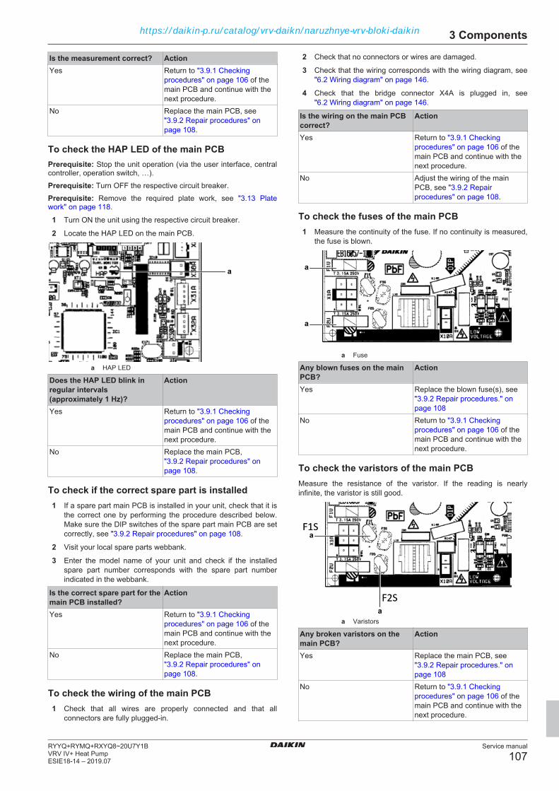
3 Components
Service manual
107RYYQ+RYMQ+RXYQ8~20U7Y1BVRV IV+ Heat PumpESIE18-14 – 2019.07
Is the measurement correct? ActionYes Return to "3.9.1 Checking
procedures" on page 106 of themain PCB and continue with thenext procedure.
No Replace the main PCB, see"3.9.2 Repair procedures" onpage 108.
To check the HAP LED of the main PCBPrerequisite: Stop the unit operation (via the user interface, centralcontroller, operation switch, …).Prerequisite: Turn OFF the respective circuit breaker.Prerequisite: Remove the required plate work, see "3.13 Platework" on page 118.
1 Turn ON the unit using the respective circuit breaker.
2 Locate the HAP LED on the main PCB.
a
a HAP LED
Does the HAP LED blink inregular intervals(approximately 1 Hz)?
Action
Yes Return to "3.9.1 Checkingprocedures" on page 106 of themain PCB and continue with thenext procedure.
No Replace the main PCB,"3.9.2 Repair procedures" onpage 108.
To check if the correct spare part is installed1 If a spare part main PCB is installed in your unit, check that it is
the correct one by performing the procedure described below.Make sure the DIP switches of the spare part main PCB are setcorrectly, see "3.9.2 Repair procedures" on page 108.
2 Visit your local spare parts webbank.
3 Enter the model name of your unit and check if the installedspare part number corresponds with the spare part numberindicated in the webbank.
Is the correct spare part for themain PCB installed?
Action
Yes Return to "3.9.1 Checkingprocedures" on page 106 of themain PCB and continue with thenext procedure.
No Replace the main PCB,"3.9.2 Repair procedures" onpage 108.
To check the wiring of the main PCB1 Check that all wires are properly connected and that all
connectors are fully plugged‑in.
2 Check that no connectors or wires are damaged.
3 Check that the wiring corresponds with the wiring diagram, see"6.2 Wiring diagram" on page 146.
4 Check that the bridge connector X4A is plugged in, see"6.2 Wiring diagram" on page 146.
Is the wiring on the main PCBcorrect?
Action
Yes Return to "3.9.1 Checkingprocedures" on page 106 of themain PCB and continue with thenext procedure.
No Adjust the wiring of the mainPCB, see "3.9.2 Repairprocedures" on page 108.
To check the fuses of the main PCB1 Measure the continuity of the fuse. If no continuity is measured,
the fuse is blown.
a
a
a Fuse
Any blown fuses on the mainPCB?
Action
Yes Replace the blown fuse(s), see"3.9.2 Repair procedures." onpage 108
No Return to "3.9.1 Checkingprocedures" on page 106 of themain PCB and continue with thenext procedure.
To check the varistors of the main PCBMeasure the resistance of the varistor. If the reading is nearlyinfinite, the varistor is still good.
a
a
a Varistors
Any broken varistors on themain PCB?
Action
Yes Replace the main PCB, see"3.9.2 Repair procedures." onpage 108
No Return to "3.9.1 Checkingprocedures" on page 106 of themain PCB and continue with thenext procedure.
https://daikin-p.ru/catalog/vrv-daikn/naruzhnye-vrv-bloki-daikin

3 Components
Service manual
108RYYQ+RYMQ+RXYQ8~20U7Y1B
VRV IV+ Heat PumpESIE18-14 – 2019.07
Problem solved?After all checking procedures listed above have been performed:
Is the problem solved? ActionYes No further actions required.No Return to the troubleshooting of
the specific error and continuewith the next procedure.
3.9.2 Repair procedures
To correct the wiring from the main power supplyterminal to the main PCB1 Correct the wiring from the main power supply terminal to the
PCB, see "6.2 Wiring diagram" on page 146.
Is the problem solved? ActionYes No further actions required.No Return to "3.9.1 Checking
procedures" on page 106 of themain PCB and continue with thenext procedure.
To remove the main PCBPrerequisite: Stop the unit operation (via the user interface, centralcontroller, operation switch, …).Prerequisite: Turn OFF the respective circuit breaker.
1 Remove the required plate work, see "3.13 Plate work" onpage 118.
a
a Cable clamp
2 Unlatch the cable clamp at the top right corner of the main PCBto facilitate the removal of the PCB.
ba
a
a
a
a
a
a
aa ccc
c
cc c
c
a Connectorb Wire terminalc PCB support
3 Disconnect all connectors from the main PCB assembly.
4 Note the field wiring on X1M transmission field wiring terminals.
5 Disconnect wiring connections on wiring terminals.
6 Carefully pull the PCB at the side and unlatch the PCB supportsone by one using a small pair of pliers.
7 Remove the main PCB.
8 To install the new outdoor unit main PCB, see "3.9.2 Repairprocedures" on page 108.
To install the main PCB1 Install the main PCB on its correct location.
2 Latch the PCB supports using a small pair of pliers to fix thePCB.
ba
a
a
a
a
a
a
aa ccc
c
cc c
c
a Connectorb Wire terminalc PCB support
3 Connect all connectors to the main PCB assembly.
https://daikin-p.ru/catalog/vrv-daikn/naruzhnye-vrv-bloki-daikin
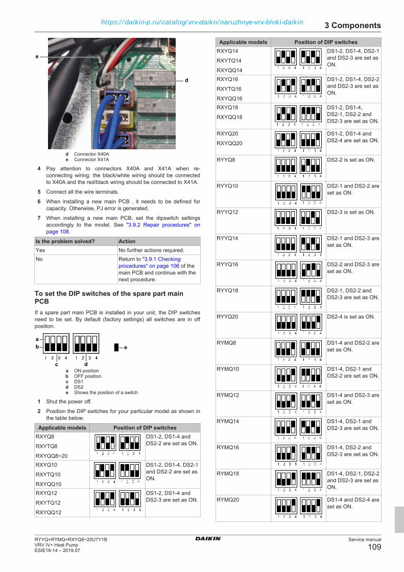
3 Components
Service manual
109RYYQ+RYMQ+RXYQ8~20U7Y1BVRV IV+ Heat PumpESIE18-14 – 2019.07
d
e
d Connector X40Ae Connector X41A
4 Pay attention to connectors X40A and X41A when re-connecting wiring: the black/white wiring should be connectedto X40A and the red/black wiring should be connected to X41A.
5 Connect all the wire terminals.
6 When installing a new main PCB , it needs to be defined forcapacity. Otherwise, PJ error is generated.
7 When installing a new main PCB, set the dipswitch settingsaccordingly to the model. See "3.9.2 Repair procedures" onpage 108.
Is the problem solved? ActionYes No further actions required.No Return to "3.9.1 Checking
procedures" on page 106 of themain PCB and continue with thenext procedure.
To set the DIP switches of the spare part mainPCBIf a spare part main PCB is installed in your unit, the DIP switchesneed to be set. By default (factory settings) all switches are in offposition.
c d
eab
a ON positionb OFF positionc DS1d DS2e Shows the position of a switch
1 Shut the power off.
2 Position the DIP switches for your particular model as shown inthe table below.
Applicable models Position of DIP switchesRXYQ8
RXYTQ8
RXYQQ8~20
DS1-2, DS1-4 andDS2-2 are set as ON.
RXYQ10
RXYTQ10
RXYQQ10
DS1-2, DS1-4, DS2-1and DS2-2 are set asON.
RXYQ12
RXYTQ12
RXYQQ12
DS1-2, DS1-4 andDS2-3 are set as ON.
Applicable models Position of DIP switchesRXYQ14
RXYTQ14
RXYQQ14
DS1-2, DS1-4, DS2-1and DS2-3 are set asON.
RXYQ16
RXYTQ16
RXYQQ16
DS1-2, DS1-4, DS2-2and DS2-3 are set asON.
RXYQ18
RXYQQ18
DS1-2, DS1-4,DS2-1, DS2-2 andDS2-3 are set as ON.
RXYQ20
RXYQQ20
DS1-2, DS1-4 andDS2-4 are set as ON.
RYYQ8 DS2-2 is set as ON.
RYYQ10 DS2-1 and DS2-2 areset as ON.
RYYQ12 DS2-3 is set as ON.
RYYQ14 DS2-1 and DS2-3 areset as ON.
RYYQ16 DS2-2 and DS2-3 areset as ON.
RYYQ18 DS2-1, DS2-2 andDS2-3 are set as ON.
RYYQ20 DS2-4 is set as ON.
RYMQ8 DS1-4 and DS2-2 areset as ON.
RYMQ10 DS1-4, DS2-1 andDS2-2 are set as ON.
RYMQ12 DS1-4 and DS2-3 areset as ON.
RYMQ14 DS1-4, DS2-1 andDS2-3 are set as ON.
RYMQ16 DS1-4, DS2-2 andDS2-3 are set as ON.
RYMQ18 DS1-4, DS2-1, DS2-2and DS2-3 are set asON.
RYMQ20 DS1-4 and DS2-4 areset as ON.
https://daikin-p.ru/catalog/vrv-daikn/naruzhnye-vrv-bloki-daikin
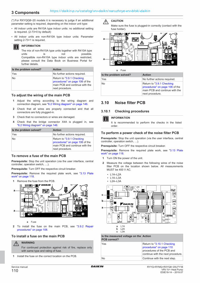
3 Components
Service manual
110RYYQ+RYMQ+RXYQ8~20U7Y1B
VRV IV+ Heat PumpESIE18-14 – 2019.07
(*) For RXYQQ8~20 models it is necessary to judge if an additionalparameter setting is required, depending on the indoor unit type:
▪ All indoor units are R410A type indoor units: no additional settingis required. (2-73=0 by default)
▪ All indoor units are non-R410A type indoor units: Parametersetting 2-73=1 is required.
INFORMATIONThe mix of non-R410A type units together with R410A typeunits is not possible.Compatible non-R410A type indoor units are restricted,please consult the Data Book on Business Portal forfurther details.
Is the problem solved? ActionYes No further actions required.No Return to "3.9.1 Checking
procedures" on page 106 of themain PCB and continue with thenext procedure.
To adjust the wiring of the main PCB1 Adjust the wiring according to the wiring diagram and
connection diagram, see "6.2 Wiring diagram" on page 146.
2 Check that all wires are properly connected and that allconnectors are fully plugged‑in.
3 Check that no connectors or wires are damaged.
4 Check that the bridge connector X4A is plugged in, see"6.2 Wiring diagram" on page 146.
Is the problem solved? ActionYes No further actions required.No Return to "3.9.1 Checking
procedures" on page 106 of themain PCB and continue with thenext procedure.
To remove a fuse of the main PCBPrerequisite: Stop the unit operation (via the user interface, centralcontroller, operation switch, …).Prerequisite: Turn OFF the respective circuit breaker.Prerequisite: Remove the required plate work, see "3.13 Platework" on page 118.
1 Remove the fuse from the PCB.
a
a
a Fuse
2 To install the fuse on the main PCB, see "3.9.2 Repairprocedures" on page 108.
To install a fuse on the main PCB
WARNINGFor continued protection against risk of fire, replace onlywith same type and rating of fuse.
1 Install the fuse on the correct location on the PCB.
CAUTIONMake sure the fuse is plugged‑in correctly (contact with thefuse holder).
a
a
a Fuse
Is the problem solved? ActionYes No further actions required.No Return to "3.9.1 Checking
procedures" on page 106 of themain PCB and continue with thenext procedure.
3.10 Noise filter PCB
3.10.1 Checking procedures
INFORMATIONIt is recommended to perform the checks in the listedorder.
To perform a power check of the noise filter PCBPrerequisite: Stop the unit operation (via the user interface, centralcontroller, operation switch, …).Prerequisite: Turn OFF the respective circuit breaker.Prerequisite: Remove the required plate work, see "3.13 Platework" on page 118.
1 Turn ON the power of the unit.
2 Measure the voltage between the following wires of the noisefilter PCB on the location shown below. All measurementsMUST be 400 V AC.
▪ L1A–L2A▪ L1A–L3A▪ L2A–L3A
a
b
c
a L1Ab L2Ac L3A
Is the measured voltage on thePCB correct?
Action
Yes Return to "3.10.1 Checkingprocedures" on page 110procedures of the PCB andcontinue with the next procedure.
No Continue with the next step.
https://daikin-p.ru/catalog/vrv-daikn/naruzhnye-vrv-bloki-daikin

3 Components
Service manual
111RYYQ+RYMQ+RXYQ8~20U7Y1BVRV IV+ Heat PumpESIE18-14 – 2019.07
3 Check the power supply to the unit, see "4.1.1 Checkingprocedures" on page 130.
Does the unit receive power? ActionYes Correct the wiring from the main
power supply terminal to thenoise filter PCB, see"3.10.2 Repair procedures" onpage 112.
No Adjust the power supply to theunit, see "4.1.2 Repairprocedures" on page 133.
To check if the correct spare part is installedPrerequisite: First perform all earlier checks of the noise filter PCB,see "3.10.1 Checking procedures" on page 110.
1 Visit your local spare parts webbank.
2 Enter the model name of your unit and check if the installedspare part number corresponds with the spare part numberindicated in the webbank.
Is the correct spare part for thenoise filter PCB installed?
Action
Yes Return to "3.10.1 Checkingprocedures" on page 110 of thenoise filter PCB and continuewith the next procedure.
No Replace the noise filter PCB, see"3.10.2 Repair procedures" onpage 112.
To check the wiring of the noise filter PCBPrerequisite: First perform all earlier checks of the noise filter PCB,see "3.10.1 Checking procedures" on page 110.Prerequisite: Stop the unit operation (via the user interface, centralcontroller, operation switch, …).Prerequisite: Turn OFF the respective circuit breaker.
1 Check that all wires are properly connected and that allconnectors are fully plugged‑in.
2 Check that no connectors or wires are damaged.
3 Check that the wiring corresponds with the wiring diagram, see"6.2 Wiring diagram" on page 146.
Is the wiring on the noise filterPCB correct?
Action
Yes Return to "3.10.1 Checkingprocedures" on page 110of thenoise filter PCB and continuewith the next procedure.
No Adjust the wiring of the noisefilter PCB, see "3.10.2 Repairprocedures" on page 112.
To perform an electrical check of the noise filterPCBPrerequisite: First check the power supply to the noise filter PCB,see "3.10.1 Checking procedures" on page 110.
1 Measure the voltage between the following output wires of thenoise filter PCB on the location shown below. All measurementsMUST be 400 V AC.
▪ L1B–L2B▪ L1B–L3B▪ L2B–L3B
a
b
c
a L1Bb L2Bc L3B
Is the output voltage on thenoise filter PCB correct?
Action
Yes Return to "3.10.1 Checkingprocedures" on page 110 of thenoise filter PCB and continuewith the next procedure.
No Replace the noise filter PCB, see"3.10.2 Repair procedures" onpage 112.
To check the fuses of the noise filter PCBPrerequisite: First perform all earlier checks of the noise filter PCB,see "3.10.1 Checking procedures" on page 110.
1 Measure the continuity of the fuse. If no continuity is measured,the fuse is blown.
a a
a a
a Fuse
Blown fuse on the noise filterPCB?
Action
Yes Replace the noise filter PCB, see"3.10.2 Repair procedures" onpage 112.
No Return to "3.10.1 Checkingprocedures" on page 110 of thenoise filter PCB and continuewith the next procedure.
Problem solved?After all checking procedures listed above have been performed:
Is the problem solved? ActionYes No further actions required.No Return to the troubleshooting of
the specific error and continuewith the next procedure.
https://daikin-p.ru/catalog/vrv-daikn/naruzhnye-vrv-bloki-daikin

3 Components
Service manual
112RYYQ+RYMQ+RXYQ8~20U7Y1B
VRV IV+ Heat PumpESIE18-14 – 2019.07
3.10.2 Repair procedures
To correct the wiring from the main power supplyterminal to the noise filter PCB1 Make sure that all wires are firmly and correctly connected, see
"6.2 Wiring diagram" on page 146.
2 Check the continuity of all wires.
3 Replace any damaged or broken wires.
Is the problem solved? ActionYes No further actions required.No Return to "3.10.1 Checking
procedures" on page 110 of thenoise filter PCB and continuewith the next procedure.
To remove the noise filter PCBPrerequisite: Stop the unit operation (via the user interface, centralcontroller, operation switch, …).Prerequisite: Turn OFF the respective circuit breaker.Prerequisite: Remove the required plate work, see "3.13 Platework" on page 118.Prerequisite: Access the switch box, see "3.13 Plate work" onpage 118.
1 Disconnect all the wires of the noise filter PCB.
INFORMATIONThe connectors on the PCB can be screw- or Faston-type,depending on the model.
b b
a
b
bbb
a
a
a
a
a
a
a
a Connectorb PCB supports
2 Carefully pull the PCB at the side and unlatch the PCB supportsone by one using a small pair of pliers.
3 To install the new noise filter PCB, see "3.10.2 Repairprocedures" on page 112.
To install the noise filter PCB1 Install the noise filter PCB on its correct location.
2 Latch the PCB supports using a small pair of pliers to fix thePCB.
b b
a
b
bbb
a
a
a
a
a
a
a
a Connectorb PCB supports
3 Connect all the wires to the connectors of the noise filter PCB.
INFORMATIONThe connectors on the PCB can be screw- or Faston-type,depending on the model.
Is the problem solved? ActionYes No further actions required.No Return to "3.10.1 Checking
procedures" on page 110 of thenoise filter PCB and continuewith the next procedure.
To adjust the wiring of the noise filter PCBPrerequisite: Stop the unit operation (via the user interface, centralcontroller, operation switch, …).Prerequisite: Turn OFF the respective circuit breaker.Prerequisite: Remove the required plate work, see "3.13 Platework" on page 118.
1 Adjust the wiring according to the wiring diagram andconnection diagram, see "6.2 Wiring diagram" on page 146.
2 Check that all wires are properly connected and that allconnectors are fully plugged‑in.
3 Check that no connectors or wires are damaged.
Is the problem solved? ActionYes No further actions required.No Return to "3.10.1 Checking
procedures" on page 110 of thenoise filter PCB and continuewith the next procedure.
3.11 Oil return valve
3.11.1 Checking procedures
INFORMATIONIt is recommended to perform the checks in the listedorder.
To perform a mechanical check of the oil returnvalvePrerequisite: Stop the unit operation (via the user interface, centralcontroller, operation switch, …).Prerequisite: Turn OFF the respective circuit breaker.Prerequisite: Remove the required plate work, see "3.13 Platework" on page 118.
1 Verify that the screw is firmly fixing the coil to the valve body.
2 Check if any damage or burst is present.
https://daikin-p.ru/catalog/vrv-daikn/naruzhnye-vrv-bloki-daikin

3 Components
Service manual
113RYYQ+RYMQ+RXYQ8~20U7Y1BVRV IV+ Heat PumpESIE18-14 – 2019.07
Is the oil return valve coilfirmly fixed and not visuallydamaged?
Action
Yes Perform an electrical check of theoil return valve, see"3.11.1 Checking procedures" onpage 112.
No Fix or replace the oil return valvecoil, see "3.11.2 Repairprocedures" on page 114.
To perform an electrical check of the oil returnvalvePrerequisite: Stop the unit operation (via the user interface, centralcontroller, operation switch, …).Prerequisite: Turn OFF the respective circuit breaker.Prerequisite: Remove the required plate work, see "3.13 Platework" on page 118.
1 Unplug the oil return valve connector from the appropriate PCB.
2 Measure the resistance of the oil return valve coil.
The measured value must be 2,1 kΩ.
Is the measured value correct? ActionYes Continue with the next step.No Replace the oil return valve coil,
see "3.11.2 Repairprocedures" on page 114.
For the Y2S valve3 Turn ON the unit using the respective circuit breaker.
4 Turn ON an indoor unit via remote controller or centralcontroller.
5 Measure the voltage on the Y2S valve connection on the PCB.
Result: The measured voltage MUST be 0 V AC. Y2S is NOTenergized when discharge superheat <15 K or compressor isOFF.
6 Connect the service monitoring tool to the unit and check thedischarge superheat build up. Once discharge superheat >15°Kand compressor is running, Y2S is energized.
7 With the Y2S connector connected to the PCB, measure thevoltage on the Y2S valve connection of the PCB.
Result: The measured voltage MUST be 230 V AC.
Are the measured voltagescorrect?
Action
Yes Perform a position check of theoil return valve, see"3.11.1 Checking procedures" onpage 112.
No Check the main PCB, see"3.9.1 Checking procedures" onpage 106.
For the Y3S and Y4S valves8 Turn ON the unit using the respective circuit breaker.
9 Turn ON an indoor unit via remote controller or centralcontroller.
10 Measure the voltage on the Y3S or Y4S valve connection onthe PCB.
Result: The measured voltage MUST be 0 V AC. Y3S and Y4Sare NOT energized when compressor is OFF and the pressuredifference between the high and low pressure <0,3 MPa.
11 Connect the service monitoring tool to the unit and check thepressure difference between the high and low pressure. Oncethe pressure difference between the high and low pressureexceeds 0,3 MPa and the compressor is running, Y3S and Y4Sare energized.
12 With the Y3S/Y4Svalve connector connected to the PCB,measure the voltage on the Y3S/Y4Svalve connection of thePCB.
Result: The measured voltage MUST be 230 V AC.
Are the measured voltagescorrect?
Action
Yes Perform a position check of theoil return valve, see"3.11.1 Checking procedures" onpage 112.
No Check the main PCB, see"3.9.1 Checking procedures" onpage 106.
To perform a position check of the oil return valve1 Turn ON the unit using the respective circuit breaker.
2 Turn ON an indoor unit via remote controller or centralcontroller.
For the Y2S valve3 Connect the service monitoring tool to the unit and check the
discharge superheat build up. Once discharge superheat >15°Kand compressor is running, Y2S is energized.
4 Try to judge the flow just after Y2S.is energized (has switched)(See "6.3 Piping diagram" on page 148).
Is the flow correct? ActionYes Oil return valve is OK. Return to
the troubleshooting of thespecific error and continue withthe next procedure.
No Replace the body of the oil returnvalve, see "3.11.2 Repairprocedures" on page 114.
For the Y3S and Y4S valves5 Connect the service monitoring tool to the unit and check the
pressure difference between the high and low pressure. Oncethe pressure difference between the high and low pressureexceeds 0,3 MPa and the compressor is running, Y3S and Y4Sare energized.
6 Check with a contact thermometer if the flow through the oilreturn valve corresponds with the flow shown in the flowdiagram. (See "6.3 Piping diagram" on page 148).
Is the flow correct? ActionYes Oil return valve is OK. Return to
the troubleshooting of thespecific error and continue withthe next procedure.
No Replace the body of the oil returnvalve, see "3.11.2 Repairprocedures" on page 114.
Problem solved?After all checking procedures listed above have been performed:
Is the problem solved? ActionYes No further actions required.No Return to the troubleshooting of
the specific error and continuewith the next procedure.
https://daikin-p.ru/catalog/vrv-daikn/naruzhnye-vrv-bloki-daikin

3 Components
Service manual
114RYYQ+RYMQ+RXYQ8~20U7Y1B
VRV IV+ Heat PumpESIE18-14 – 2019.07
3.11.2 Repair procedures
To remove the oil return valve coilPrerequisite: Stop the unit operation (via the user interface, centralcontroller, operation switch, …).Prerequisite: Turn OFF the respective circuit breaker.Prerequisite: Remove the required plate work, see "3.13 Platework" on page 118.Prerequisite: If needed, remove any parts to create more space forthe removal of the oil return valve coil.
1 Remove the screw and remove the oil return valve coil from theoil return valve body.
b
c
a
a Screwb Valve coilc Valve body
2 Cut all tie straps that fix the oil return valve coil harness.
3 Disconnect the oil return valve coil connector from theappropriate PCB.
4 To install the oil return valve coil, see "3.11.2 Repairprocedures" on page 114.
To remove the oil return valve bodyPrerequisite: Recuperate the refrigerant from the refrigerant circuit,see "4.2.2 Repair procedures" on page 136.
1 Remove the oil return valve coil from the oil return valve body,see "3.11.2 Repair procedures" on page 114.
2 Cut the oil return valve pipes using a pipe cutter.
a
b
a
a Oil return valve pipeb Oil return valve body
3 Remove the oil return valve.
4 Keep the insulation for re-use.
5 Supply nitrogen to the refrigerant circuit. The nitrogen pressureMUST NOT exceed 0.02 MPa.
6 Heat the end of the oil return valve pipes using an oxygenacetylene torch and remove the oil return valve pipe ends.
7 Stop the nitrogen supply when the piping has cooled down.
8 To install the oil return valve body, see "3.11.2 Repairprocedures" on page 114.
To install the oil return valve body1 Install the oil return valve in the correct location.
2 Supply nitrogen to the refrigerant circuit. The nitrogen pressureMUST NOT exceed 0.02 MPa.
3 Wrap a wet rag around the oil return valve and solder the oilreturn valve pipes to the oil return valve.
CAUTIONOverheating the valve will damage or destroy it.
4 After soldering is done, stop the nitrogen supply after thecomponent has cooled‑down.
a
b
a
a Oil return valve pipeb Oil return valve body
5 Install the insulation in the original location.
6 Install the oil return valve coil on the oil return valve body, see"3.11.2 Repair procedures" on page 114.
7 Add refrigerant to the refrigerant circuit, see "4.2.2 Repairprocedures" on page 136.
To install the oil return valve coil1 Install the oil return valve coil on the oil return valve body.
b
c
a
a Screwb Valve coilc Valve body
2 Install and tighten the screw to fix the oil return valve coil.
3 Route the oil return valve coil harness towards the appropriatePCB.
4 Connect the oil return valve coil connector to the PCB.
WARNINGWhen reconnecting a connector to the PCB, do NOT applyforce, as this may damage the connector or connector pinsof the PCB.
5 Fix the oil return valve coil harness using new tie straps.
Is the problem solved? ActionYes No further actions required.
https://daikin-p.ru/catalog/vrv-daikn/naruzhnye-vrv-bloki-daikin
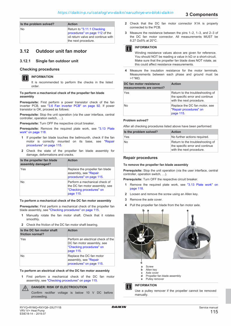
3 Components
Service manual
115RYYQ+RYMQ+RXYQ8~20U7Y1BVRV IV+ Heat PumpESIE18-14 – 2019.07
Is the problem solved? ActionNo Return to "3.11.1 Checking
procedures" on page 112 of theoil return valve and continue withthe next procedure.
3.12 Outdoor unit fan motor
3.12.1 Single fan outdoor unit
Checking procedures
INFORMATIONIt is recommended to perform the checks in the listedorder.
To perform a mechanical check of the propeller fan bladeassembly
Prerequisite: First perform a power transistor check of the faninverter PCB, see "3.6 Fan inverter PCB" on page 92. If powertransistor is OK, proceed as follows:Prerequisite: Stop the unit operation (via the user interface, centralcontroller, operation switch, …).Prerequisite: Turn OFF the respective circuit breaker.Prerequisite: Remove the required plate work, see "3.13 Platework" on page 118.
1 If propeller fan blade touches the bellmounth, check if the fanmotor is correctly mounted on its base, see "Repairprocedures" on page 115.
2 Check the state of the propeller fan blade assembly fordamage, deformations and cracks.
Is the propeller fan bladeassembly damaged?
Action
Yes Replace the propeller fan bladeassembly, see "Repairprocedures" on page 115.
No Perform a mechanical check ofthe DC fan motor assembly, see"Checking procedures" onpage 115.
To perform a mechanical check of the DC fan motor assembly
Prerequisite: First perform a mechanical check of the propeller fanblade assembly, see "Checking procedures" on page 115.
1 Manually rotate the fan motor shaft. Check that it rotatessmoothly.
2 Check the friction of the DC fan motor shaft bearing.
Is the DC fan motor shaftfriction normal?
Action
Yes Perform an electrical check of theDC fan motor assembly, see"Checking procedures" onpage 115.
No Replace the DC fan motorassembly, see "Repairprocedures" on page 115.
To perform an electrical check of the DC fan motor assembly
1 First perform a mechanical check of the DC fan motorassembly, see "Checking procedures" on page 115.
DANGER: RISK OF ELECTROCUTIONConfirm rectifier voltage is below 10 V DC beforeproceeding.
2 Check that the DC fan motor connector X1A is properlyconnected to the PCB.
3 Measure the resistance between the pins 1–2, 1–3, and 2–3 ofthe DC fan motor connector. All measurements MUST be8.27 Ω±5% at 20°C.
INFORMATIONWinding resistance values above are given for reference.You should NOT be reading a value in kΩ or a short‑circuit.Make sure that the propeller fan blade does NOT rotate, asthis could affect resistance measurements.
4 Measure the insulation resistance for the motor terminals.Measurements between each phase and ground must be>1°MΩ.
DC fan motor resistancemeasurements are correct?
Action
Yes Return to the troubleshooting ofthe specific error and continuewith the next procedure.
No Replace the DC fan motor, see"Repair procedures" onpage 115.
Problem solved?
After all checking procedures listed above have been performed:
Is the problem solved? ActionYes No further actions required.No Return to the troubleshooting of
the specific error and continuewith the next procedure.
Repair proceduresTo remove the propeller fan blade assembly
Prerequisite: Stop the unit operation (via the user interface, centralcontroller, operation switch, …).Prerequisite: Turn OFF the respective circuit breaker.
1 Remove the required plate work, see "3.13 Plate work" onpage 118.
2 Loosen and remove the screw using an Allen key.
3 Remove the axle cover.
4 Pull the propeller fan blade from the fan motor axle.
c
b da e
a Screwb Allen keyc Axle coverd Propeller fan blade assemblye Pulley remover
INFORMATIONUse a pulley remover if the propeller cannot be removedmanually.
https://daikin-p.ru/catalog/vrv-daikn/naruzhnye-vrv-bloki-daikin

3 Components
Service manual
116RYYQ+RYMQ+RXYQ8~20U7Y1B
VRV IV+ Heat PumpESIE18-14 – 2019.07
5 To install the propeller fan blade assembly, see "Repairprocedures" on page 115.
To remove the DC fan motor assembly
1 Remove the propeller fan blade assembly from the DC fanmotor assembly, see "Repair procedures" on page 115.
2 Disconnect the DC fan motor connector from the fan inverterPCB.
3 Unlock the ferrite bead.
4 Cut the tie strap.
5 Detach the DC fan motor cable.
b
cd c
acca Fan motor cableb Tie wrapc Screwd Fan motor
6 Remove the 4 screws that fix the DC fan motor assembly.
7 Remove the DC fan motor assembly from the unit.
8 To install the DC fan motor assembly, see "Repairprocedures" on page 115.
To install the DC fan motor assembly
1 Install the DC fan motor assembly in the correct location.
2 Fix the DC fan motor assembly to the unit by tightening thescrews.
3 Route the DC fan motor cable.
4 Attach the DC fan motor cable.
5 Install a new tie strap to fix the DC fan motor cable.
6 Connect the DC fan motor connector to the connector on thefan inverter PCB.
7 Lock the ferrite bead.
8 Install the propeller fan blade assembly, see "Repairprocedures" on page 115.
To install the propeller fan blade assembly
1 Install the propeller fan blade assembly on the DC fan motorassembly.
CAUTIONDo NOT install a damaged propeller fan blade assembly.
2 Install the axle cover.
3 Install and tighten the screw using an Allen key to fix thepropeller fan blade assembly.
c
b da e
a Screwb Allen keyc Axle coverd Propeller fan blade assembly
Is the problem solved? ActionYes No further actions required.No Return to "Checking
procedures" on page 115 of theoutdoor unit fan motor andcontinue with the next procedure.
3.12.2 Double fan outdoor unit
INFORMATIONSee "6.4 Component overview" on page 164 fort he correctlocation of DC fan motors M1F and M2F.
Checking procedures
INFORMATIONIt is recommended to perform the checks in the listedorder.
To perform a mechanical check of the propeller fan bladeassemblies
Prerequisite: First perform a power transistor check of the faninverter PCB, see "3.6 Fan inverter PCB" on page 92. If powertransistor is OK, proceed as follows:Prerequisite: Stop the unit operation (via the user interface, centralcontroller, operation switch, …).Prerequisite: Turn OFF the respective circuit breaker.Prerequisite: Remove the required plate work, see "3.13 Platework" on page 118.
1 If propeller fan blade touches the bellmounth, check if the fanmotor is correctly mounted on its base, see "Repairprocedures" on page 117.
2 Check the state of the propeller fan blade assemblies fordamage, deformations and cracks.
One or both propeller fanblade assemblies aredamaged?
Action
Yes Replace the damaged propellerfan blade assembly, see "Repairprocedures" on page 117.
No Perform a mechanical check ofthe DC fan motor assembly, see"Checking procedures" onpage 116.
https://daikin-p.ru/catalog/vrv-daikn/naruzhnye-vrv-bloki-daikin

3 Components
Service manual
117RYYQ+RYMQ+RXYQ8~20U7Y1BVRV IV+ Heat PumpESIE18-14 – 2019.07
To perform a mechanical check of the DC fan motor assembly
Prerequisite: First perform a mechanical check of the propeller fanblade assembly, see "Checking procedures" on page 116.
1 Manually rotate the fan motor shaft. Check that it rotatessmoothly.
2 Check the friction of the DC fan motor shaft bearing.
Is the DC fan motor shaftfriction normal?
Action
Yes Perform an electrical check of theDC fan motor assembly, see"Checking procedures" onpage 116.
No Replace the DC fan motorassembly, see "Repairprocedures" on page 117.
To perform an electrical check of the DC fan motor assembly
1 First perform a mechanical check of both the DC fan motorassemblies, see "Checking procedures" on page 116.
DANGER: RISK OF ELECTROCUTIONConfirm rectifier voltage is below 10 V DC beforeproceeding.
2 Check that the DC fan motor connector (X1A for M1F and X2Afor M2F) is properly connected to the PCB.
3 Measure the resistance between the pins 1–2, 1–3, and 2–3 ofthe DC fan motor connector. All measurements MUST be4.44°Ω±5% at 20°C.
INFORMATIONWinding resistance values above are given for reference.You should NOT be reading a value in kΩ or a short‑circuit.Make sure that the propeller fan blade does NOT rotate, asthis could affect resistance measurements.
4 Measure the insulation resistance for the motor terminals.Measurements between each phase and ground must be>1°MΩ.
Are the measured valuescorrect?
Action
Yes Return to the troubleshooting ofthe specific error and continuewith the next procedure.
No Replace the DC fan motorassembly, see "Repairprocedures" on page 117.
Problem solved?
After all checking procedures listed above have been performed:
Is the problem solved? ActionYes No further actions required.No Return to the troubleshooting of
the specific error and continuewith the next procedure.
Repair proceduresTo remove the propeller fan blade assembly
Prerequisite: Stop the unit operation (via the user interface, centralcontroller, operation switch, …).Prerequisite: Turn OFF the respective circuit breaker.
1 Remove the required plate work, see "3.13 Plate work" onpage 118.
2 Loosen and remove the screw using an Allen key.
3 Remove the axle cover.
4 Pull the propeller fan blade from the fan motor axle.
c
b da e
a Screwb Allen keyc Axle coverd Propeller fan blade assemblye Pulley remover
INFORMATIONUse a pulley remover if the propeller cannot be removedmanually.
5 To install the propeller fan blade assembly, see "Repairprocedures" on page 117.
To remove the DC fan motor assembly
1 Remove the propeller fan blade assembly from the DC fanmotor assembly, see "Repair procedures" on page 117.
2 Remove the required plate work, see "3.13 Plate work" onpage 118.
3 Disconnect the DC fan motor connector from the fan inverterPCB.
4 Unlock the ferrite bead.
5 Cut the tie strap.
6 Detach the DC fan motor cable.
b
cd c
acca Fan motor cableb Tie wrapc Screwd Fan motor
7 Remove the 4 screws that fix the DC fan motor assembly.
https://daikin-p.ru/catalog/vrv-daikn/naruzhnye-vrv-bloki-daikin

3 Components
Service manual
118RYYQ+RYMQ+RXYQ8~20U7Y1B
VRV IV+ Heat PumpESIE18-14 – 2019.07
8 Remove the DC fan motor assembly from the unit.
9 To install the DC fan motor assembly, see "Repairprocedures" on page 117.
To install the DC fan motor assembly
1 Install the DC fan motor assembly in the correct location.
2 Install and tighten the 4 screws.
3 Route the DC fan motor cable.
4 Attach the DC fan motor cable.
5 Install a new tie strap to fix the DC fan motor cable.
6 Connect the DC fan motor connector to the connector on thefan inverter PCB.
7 Install the propeller fan blade assembly, see "Repairprocedures" on page 117.
8 Install the plate work of the outdoor unit, see "3.13 Platework" on page 118.
To install the propeller fan blade assembly
1 Install the propeller fan blade assembly on the DC fan motorassembly.
CAUTIONDo NOT install a damaged propeller fan blade assembly.
2 Install the axle cover.
3 Install and tighten the screw using an Allen key to fix thepropeller fan blade assembly.
c
b da e
a Screwb Allen keyc Axle coverd Propeller fan blade assembly
Is the problem solved? ActionYes No further actions required.No Return to "Checking
procedures" on page 116 of theoutdoor unit fan motor andcontinue with the next procedure.
3.13 Plate work
3.13.1 To access the switch box on single fanunits
Prerequisite: Stop the unit operation (via the user interface, centralcontroller, operation switch, …).Prerequisite: Turn OFF the respective circuit breaker.
1 Remove the required plate work, see "3.13 Plate work" onpage 118.
DANGER: RISK OF ELECTROCUTIONConfirm rectifier voltage is below 10 V DC beforeproceeding.
a
cd
dd
b
b
b
b
a Main PCBb Screwc Power supply terminal assemblyd Screw
2 Remove the 4 screws that fix the main PCB assembly.
3 Remove the 3 screws that fix the power supply terminalassembly.
a
c
b
a Main PCBb Power input wiringc Noise filter PCB
4 Slightly tilt the main PCB assembly to access the power inputwiring on the noise filter PCB.
5 Remove the power input wiring from the noise filter PCB.
https://daikin-p.ru/catalog/vrv-daikn/naruzhnye-vrv-bloki-daikin

3 Components
Service manual
119RYYQ+RYMQ+RXYQ8~20U7Y1BVRV IV+ Heat PumpESIE18-14 – 2019.07
a
b
c
a Main PCBb Noise filter PCBc Reactor
6 Completely tilt the main PCB assembly to get full access to thenoise filter PCB and the reactor.
7 To install the switch box, see "3.13 Plate work" on page 118.
3.13.2 To access the switch box on double fanunits
Prerequisite: Stop the unit operation (via the user interface, centralcontroller, operation switch, …).Prerequisite: Turn OFF the respective circuit breaker.
1 Remove the required plate work, see "3.13 Plate work" onpage 118.
DANGER: RISK OF ELECTROCUTIONConfirm rectifier voltage is below 10 V DC beforeproceeding.
b a d c e b a e a b e
e fa a a a e
eba
2
1
a Screwb Screwc Short screwd Screwe Screwf Inverter mounting plate
2 Do NOT loosen the screws (a) that fix the inverter PCB's at thisstep. These screws need only be removed when replacing aninverter PCB.
3 Loosen and remove the 4 screws (b) that fix the heat sinks.
4 Loosen and remove the short screw (c) that fixes the groundingwire to the heat sinks.
5 Loosen and remove the screw (d) that fixes the Thermistor R1Tmounting bracket.
6 Using a screwdriver, carefully separate both heat sinks from theinverter PCB’s.
WARNINGThermal grease is applied to the heat sinks. Use gloveswhen separating the heat sinks from the inverter boards.
7 Loosen and remove the 6 screws (e) that fix the invertermounting plate.
ab
a Inverter mounting plateb Liquid cooling piping
8 Carefully pull the inverter mounting plate (a) to the front and tiltit. Pay attention to the liquid cooling piping (b).
9 Disconnect the necessary wiring to have access to noise filterPCB's, the reactors and - on the rear side of the invertermounting plate - the inverter PCB's and fan inverter PCB's.
10 To install the switch box, see "3.13 Plate work" on page 118.
3.13.3 To remove the plate work on single fanunits
1 Stop the unit operation (via the user interface, operation switch,…).
2 Turn OFF the respective circuit breaker.
To remove the service plate
b
aa
a Screwb Service plate
3 Loosen and remove the 2 screws (a) that fix the service plateassembly.
4 Remove the service plate assembly (b) from the unit.
https://daikin-p.ru/catalog/vrv-daikn/naruzhnye-vrv-bloki-daikin
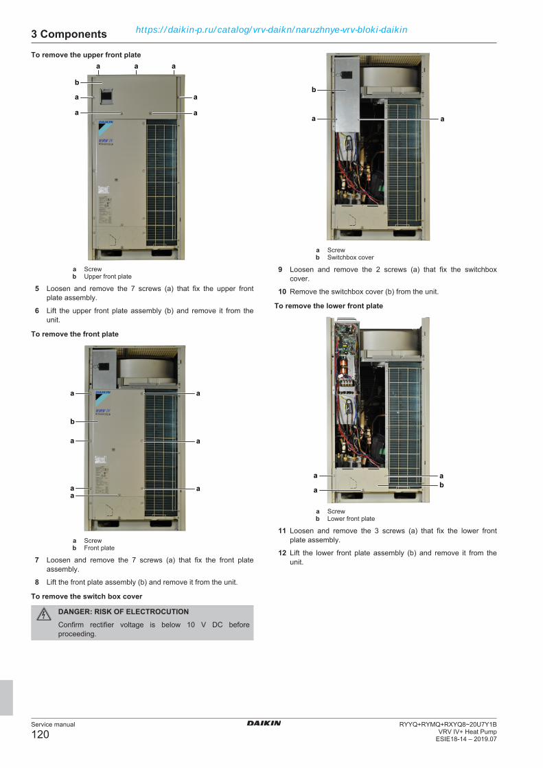
3 Components
Service manual
120RYYQ+RYMQ+RXYQ8~20U7Y1B
VRV IV+ Heat PumpESIE18-14 – 2019.07
To remove the upper front plate
b
aa a
a
a
a
a
a Screwb Upper front plate
5 Loosen and remove the 7 screws (a) that fix the upper frontplate assembly.
6 Lift the upper front plate assembly (b) and remove it from theunit.
To remove the front plate
b
a
a
a
a
a aa
a Screwb Front plate
7 Loosen and remove the 7 screws (a) that fix the front plateassembly.
8 Lift the front plate assembly (b) and remove it from the unit.
To remove the switch box cover
DANGER: RISK OF ELECTROCUTIONConfirm rectifier voltage is below 10 V DC beforeproceeding.
b
aa
a Screwb Switchbox cover
9 Loosen and remove the 2 screws (a) that fix the switchboxcover.
10 Remove the switchbox cover (b) from the unit.
To remove the lower front plate
a a
ab
a Screwb Lower front plate
11 Loosen and remove the 3 screws (a) that fix the lower frontplate assembly.
12 Lift the lower front plate assembly (b) and remove it from theunit.
https://daikin-p.ru/catalog/vrv-daikn/naruzhnye-vrv-bloki-daikin

3 Components
Service manual
121RYYQ+RYMQ+RXYQ8~20U7Y1BVRV IV+ Heat PumpESIE18-14 – 2019.07
To remove the side plate
a a
b
a
a
a
aa
a Screwb Side plate
13 Loosen and remove the 7 screws (a) that fix the side plateassembly.
14 Lift the side plate assembly (b) and remove it from the unit.
To remove the upper side plate
a
ab
a
a a a
a Screwb Upper side plate
15 Loosen and remove the 6 screws (a) that fix the upper sideplate assembly.
16 Lift the upper side plate assembly (b) and remove it from theunit.
To remove the top plateba a a a a ab
a Screwb Top plate
17 Loosen and remove the 12 screws (a) that fix the top plateassembly.
18 Remove the top plate (b) from the unit.
3.13.4 To remove the plate work on double fanunits
1 Stop the unit operation (via the user interface, operation switch,…).
2 Turn OFF the respective circuit breaker.
To remove the service plate
b
aa
a Screwb Service plate
3 Loosen and remove the 2 screws (a) that fix the service plateassembly.
4 Remove the service plate assembly (b) from the unit.
https://daikin-p.ru/catalog/vrv-daikn/naruzhnye-vrv-bloki-daikin

3 Components
Service manual
122RYYQ+RYMQ+RXYQ8~20U7Y1B
VRV IV+ Heat PumpESIE18-14 – 2019.07
To remove the upper front plate
b
aa a
a
a
a
a
a Screwb Upper front plate
5 Loosen and remove the 7 screws (a) that fix the upper frontplate assembly.
6 Lift the upper front plate assembly (b) and remove it from theunit.
To remove the front plate
b
a
a
a
a
a aa
a Screwb Front plate
7 Loosen and remove the 7 screws (a) that fix the front plateassembly.
8 Lift the front plate assembly (b) and remove it from the unit.
To remove the switch box cover
DANGER: RISK OF ELECTROCUTIONConfirm rectifier voltage is below 10 V DC beforeproceeding.
a a
a
b
aa
a Screwb Switchbox cover
9 Loosen and remove the 5 screws (a) that fix the switchboxcover.
10 Remove the switchbox cover (b) from the unit.
To remove the lower front plate
a a
ab
a Screwb Lower front plate
11 Loosen and remove the 3 screws (a) that fix the lower frontplate assembly.
12 Lift the lower front plate assembly (b) and remove it from theunit.
https://daikin-p.ru/catalog/vrv-daikn/naruzhnye-vrv-bloki-daikin

3 Components
Service manual
123RYYQ+RYMQ+RXYQ8~20U7Y1BVRV IV+ Heat PumpESIE18-14 – 2019.07
To remove the side plate
a a
b
a
a
a
a
a
a Screwb Side plate
13 Loosen and remove the 7 screws (a) that fix the side plateassembly.
14 Lift the side plate assembly (b) and remove it from the unit.
To remove the upper side plate
a
ab
a
a a a
a Screwb Upper side plate
15 Loosen and remove the 6 screws (a) that fix the upper sideplate assembly.
16 Lift the upper side plate assembly (b) and remove it from theunit.
To remove the top plateba a a a a ab
a Screwb Top plate
17 Loosen and remove the 12 screws (a) that fix the top plateassembly.
18 Remove the top plate (b) from the unit.
3.14 Reactor
3.14.1 Checking procedures
To perform an electrical check of the reactorPrerequisite: Stop the unit operation (via the user interface, centralcontroller, operation switch, …).Prerequisite: Turn OFF the respective circuit breaker.
1 Remove the required plate work, see "3.13 Plate work" onpage 118.
2 Access the switch box, see "3.13 Plate work" on page 118.
a
a
c
a
c c c
bbc c cca Screwb Faston connectorc Screw
3 Check the connections of the reactor on the inverter PCB('s),see "6.2 Wiring diagram" on page 146.
4 Remove the wiring or Faston connectors from the reactor.
5 Using a megger device of at least 500 V DC, check theinsulation resistance. Make sure there is no earth leakage.
Is the measured insulationresistance correct?
Action
Yes Continue with the next step.No Replace the reactor, see
"3.14.2 Repair procedures" onpage 124.
https://daikin-p.ru/catalog/vrv-daikn/naruzhnye-vrv-bloki-daikin
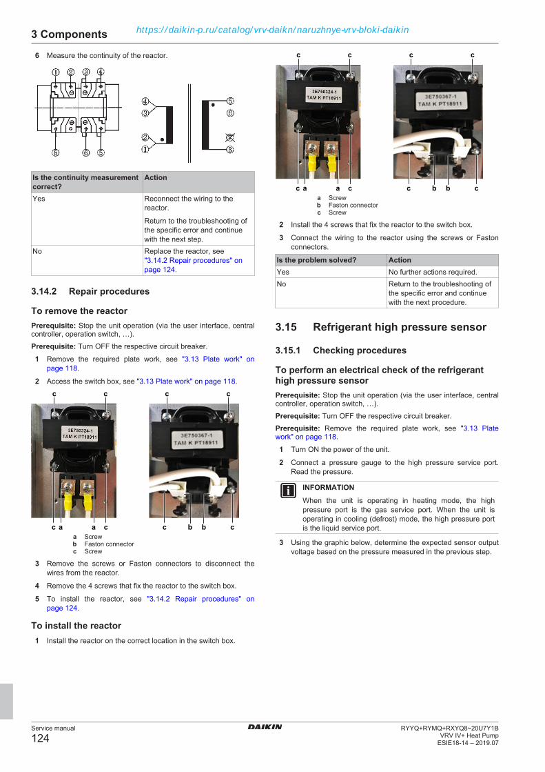
3 Components
Service manual
124RYYQ+RYMQ+RXYQ8~20U7Y1B
VRV IV+ Heat PumpESIE18-14 – 2019.07
6 Measure the continuity of the reactor.
Is the continuity measurementcorrect?
Action
Yes Reconnect the wiring to thereactor.
Return to the troubleshooting ofthe specific error and continuewith the next step.
No Replace the reactor, see"3.14.2 Repair procedures" onpage 124.
3.14.2 Repair procedures
To remove the reactorPrerequisite: Stop the unit operation (via the user interface, centralcontroller, operation switch, …).Prerequisite: Turn OFF the respective circuit breaker.
1 Remove the required plate work, see "3.13 Plate work" onpage 118.
2 Access the switch box, see "3.13 Plate work" on page 118.
a
a
c
a
c c c
bbc c cca Screwb Faston connectorc Screw
3 Remove the screws or Faston connectors to disconnect thewires from the reactor.
4 Remove the 4 screws that fix the reactor to the switch box.
5 To install the reactor, see "3.14.2 Repair procedures" onpage 124.
To install the reactor1 Install the reactor on the correct location in the switch box.
a
a
c
a
c c c
bbc c cca Screwb Faston connectorc Screw
2 Install the 4 screws that fix the reactor to the switch box.
3 Connect the wiring to the reactor using the screws or Fastonconnectors.
Is the problem solved? ActionYes No further actions required.No Return to the troubleshooting of
the specific error and continuewith the next procedure.
3.15 Refrigerant high pressure sensor
3.15.1 Checking procedures
To perform an electrical check of the refrigeranthigh pressure sensorPrerequisite: Stop the unit operation (via the user interface, centralcontroller, operation switch, …).Prerequisite: Turn OFF the respective circuit breaker.Prerequisite: Remove the required plate work, see "3.13 Platework" on page 118.
1 Turn ON the power of the unit.
2 Connect a pressure gauge to the high pressure service port.Read the pressure.
INFORMATIONWhen the unit is operating in heating mode, the highpressure port is the gas service port. When the unit isoperating in cooling (defrost) mode, the high pressure portis the liquid service port.
3 Using the graphic below, determine the expected sensor outputvoltage based on the pressure measured in the previous step.
https://daikin-p.ru/catalog/vrv-daikn/naruzhnye-vrv-bloki-daikin

3 Components
Service manual
125RYYQ+RYMQ+RXYQ8~20U7Y1BVRV IV+ Heat PumpESIE18-14 – 2019.07
-5.1-0.5 0 0.5 1 1.5 2 2.5 3 3.5 4
0
5.1
10.2
15.3
20.4
25.5
30.6
35.7
40.8
45.9
51.0
a
ba Detected pressure (kg/cm²)b Output voltage (V)
V (DC) Detected pressure kg/cm2
0.5 0.000.6 1.430.7 2.860.8 4.280.9 5.711.0 7.141.1 8.571.2 10.001.3 11.421.4 12.851.5 14.281.6 15.711.7 17.141.8 18.561.9 19.992.0 21.422.1 22.852.2 24.282.3 25.702.4 27.132.5 28.562.6 29.992.7 31.422.8 32.842.9 34.273.0 35.703.1 37.133.2 38.563.3 39.983.4 41.413.5 42.843.6 44.273.7 45.70
V (DC) Detected pressure kg/cm2
3.8 47.123.9 48.55
4 Measure the voltage on X32A: pins 1–3 (= refrigerant pressuresensor output signal).
5 Check that the measured voltage is in line with the expectedvoltage through the read refrigerant pressure.
INFORMATIONConnect the service checker tool to the unit or use fieldsettings mode 1‑42 (see "6.9 Field settings" on page 188)to monitor the high pressure.
If the measured output voltage value matches the voltagedetermined through the measured pressure, but thepressure is NOT correct on the user interface display,replace the main PCB.
The measured voltage is insidethe expected range?
Action
Yes Refrigerant pressure sensor isOK. Return to thetroubleshooting of the specificerror and continue with the nextprocedure.
No Continue with the next step.
6 Unplug the refrigerant pressure sensor connector X32A andmeasure the voltage (power supply) between pins 3–4 on mainPCB.
Result: The measured voltage MUST be +5 V DC.
Is the measured voltage+5 V DC?
Then
Yes Replace the refrigerant pressuresensor, see "3.16.2 Repairprocedures" on page 127.
No Perform a check of the mainPCB, see "3.9.1 Checkingprocedures" on page 106.
3.15.2 Repair procedures
To remove the refrigerant pressure sensorPrerequisite: Stop the unit operation (via the user interface, centralcontroller, operation switch, …).Prerequisite: Turn OFF the respective circuit breaker.Prerequisite: Remove the required plate work, see "3.13 Platework" on page 118.Prerequisite: Recuperate the refrigerant from the refrigerant circuit,see "4.2.2 Repair procedures" on page 136.Prerequisite: If needed, remove any parts or insulation to createmore space for the removal.
1 Cut all tie straps that fix the refrigerant pressure sensorharness.
2 Disconnect the refrigerant pressure sensor connector from thePCB.
3 Cut the refrigerant pressure sensor pipe using a pipe cutter.
https://daikin-p.ru/catalog/vrv-daikn/naruzhnye-vrv-bloki-daikin

3 Components
Service manual
126RYYQ+RYMQ+RXYQ8~20U7Y1B
VRV IV+ Heat PumpESIE18-14 – 2019.07
a
b
a Refrigerant pressure sensorb Refrigerant pressure sensor pipe
4 Remove the refrigerant pressure sensor.
5 Supply nitrogen to the refrigerant circuit. The nitrogen pressureMUST NOT exceed 0.02 MPa.
6 Heat the end of the refrigerant pressure sensor pipe using anoxygen acetylene torch and remove the refrigerant pressuresensor pipe end.
7 Stop the nitrogen supply when the piping has cooled down.
8 To install the refrigerant pressure sensor, see "3.15.2 Repairprocedures" on page 125.
To install the refrigerant pressure sensor1 Install the refrigerant pressure sensor in the correct location.
2 Supply nitrogen to the refrigerant circuit. The nitrogen pressureMUST NOT exceed 0.02 MPa.
3 Wrap a wet rag around the refrigerant pressure sensor andsolder the refrigerant pressure sensor pipe to the refrigerantpressure sensor.
a
b
a Refrigerant pressure sensorb Refrigerant pressure sensor pipe
CAUTIONOverheating the pressure sensor will damage or destroy it.
4 After soldering is done, stop the nitrogen supply after thecomponent has cooled‑down.
5 Route the refrigerant pressure sensor harness towards theappropriate PCB.
6 Connect the refrigerant pressure sensor connector to theappropriate PCB.
7 Fix the refrigerant pressure sensor harness using new tiestraps.
8 Add refrigerant to the refrigerant circuit, see "4.2.2 Repairprocedures" on page 136.
Is the problem solved? ActionYes No further actions required.No Return to the troubleshooting of
the specific error and continuewith the next procedure.
3.16 Refrigerant low pressure sensor
3.16.1 Checking procedures
To perform an electrical check of the refrigerantpressure sensorPrerequisite: Stop the unit operation (via the user interface, centralcontroller, operation switch, …).Prerequisite: Turn OFF the respective circuit breaker.Prerequisite: Remove the required plate work, see "3.13 Platework" on page 118.
1 Turn ON the power of the unit.
2 Connect a pressure gauge to the low pressure service port.Read the pressure.
INFORMATIONWhen the unit is operating in heating mode, the lowpressure port is the liquid service port. When the unit isoperating in cooling (defrost) mode, the low pressure portis the gas service port.
3 Using the graphic below, determine the expected sensor outputvoltage based on the pressure measured in the previous step.
20.4
15.3
10.2
5.1
-5.1
0
-0.5 0 0.5 1 1.5 2 2.5 3 3.5 4
a
ba Detected pressure (kg/cm²)b Output voltage (V)
V (DC) Detected pressure kg/cm2
0.5 0.000.6 0.630.7 1.210.8 1.790.9 2.381.0 2.961.1 3.541.2 4.121.3 4.701.4 5.281.5 5.861.6 6.441.7 7.031.8 7.611.9 8.12
https://daikin-p.ru/catalog/vrv-daikn/naruzhnye-vrv-bloki-daikin

3 Components
Service manual
127RYYQ+RYMQ+RXYQ8~20U7Y1BVRV IV+ Heat PumpESIE18-14 – 2019.07
V (DC) Detected pressure kg/cm2
2.0 8.772.1 9.352.2 9.932.3 10.512.4 11.092.5 11.682.6 12.262.7 12.842.8 13.422.9 14.003.0 14.583.1 15.163.2 15.743.3 16.333.4 16.913.5 17.493.6 18.073.7 18.653.8 19.233.9 19.81
INFORMATIONThe refrigerant pressure sensor connector MUST beplugged into the appropriate PCB.
4 Measure the voltage on X31A: pins 2–3 (= refrigerant pressureoutput signal) on the main PCB.
5 Check that the measured voltage is in line with the expectedvoltage through the read refrigerant pressure.
INFORMATIONConnect the service checker tool to the unit or use fieldsettings mode 1‑43 (see "6.9 Field settings" on page 188)to monitor the low pressure.
If the measured output voltage value matches the voltagedetermined through the measured pressure, but thepressure is NOT correct on the user interface display,replace the applicable PCB.
The measured voltage is insidethe expected range?
Action
Yes Refrigerant pressure sensor isOK. Return to thetroubleshooting of the specificerror and continue with the nextprocedure.
No Continue with the next step.
6 Unplug the refrigerant pressure sensor connector X31A andmeasure the voltage (power supply) between pins 3–4 on mainPCB.
Result: The measured voltage MUST be +5 V DC.
Is the measured voltage+5 V DC?
Then
Yes Replace the refrigerant pressuresensor, see "3.16.2 Repairprocedures" on page 127.
No Perform a check of the mainPCB, see "3.9.1 Checkingprocedures" on page 106.
3.16.2 Repair procedures
To remove the refrigerant pressure sensorPrerequisite: Stop the unit operation (via the user interface, centralcontroller, operation switch, …).Prerequisite: Turn OFF the respective circuit breaker.Prerequisite: Remove the required plate work, see "3.13 Platework" on page 118.Prerequisite: Recuperate the refrigerant from the refrigerant circuit,see "4.2.2 Repair procedures" on page 136.Prerequisite: If needed, remove any parts or insulation to createmore space for the removal.
1 Cut all tie straps that fix the refrigerant pressure sensorharness.
2 Disconnect the refrigerant pressure sensor connector from thePCB.
3 Cut the refrigerant pressure sensor pipe using a pipe cutter.
aba Refrigerant pressure sensorb Refrigerant pressure sensor pipe
4 Remove the refrigerant pressure sensor.
5 Supply nitrogen to the refrigerant circuit. The nitrogen pressureMUST NOT exceed 0.02 MPa.
6 Heat the end of the refrigerant pressure sensor pipe using anoxygen acetylene torch and remove the refrigerant pressuresensor pipe end.
7 Stop the nitrogen supply when the piping has cooled down.
8 To install the refrigerant pressure sensor, see "3.16.2 Repairprocedures" on page 127.
To install the refrigerant pressure sensor1 Install the refrigerant pressure sensor in the correct location.
2 Supply nitrogen to the refrigerant circuit. The nitrogen pressureMUST NOT exceed 0.02 MPa.
3 Wrap a wet rag around the refrigerant pressure sensor andsolder the refrigerant pressure sensor pipe to the refrigerantpressure sensor.
https://daikin-p.ru/catalog/vrv-daikn/naruzhnye-vrv-bloki-daikin
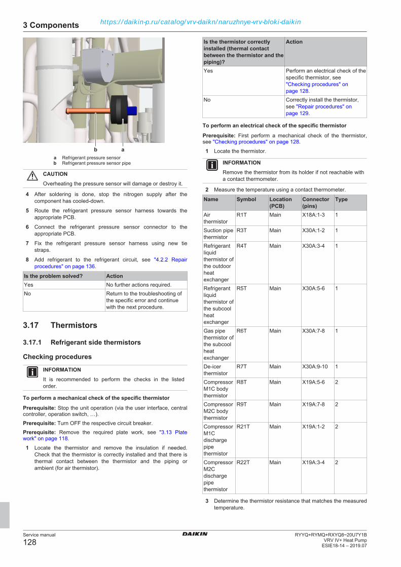
3 Components
Service manual
128RYYQ+RYMQ+RXYQ8~20U7Y1B
VRV IV+ Heat PumpESIE18-14 – 2019.07
aba Refrigerant pressure sensorb Refrigerant pressure sensor pipe
CAUTIONOverheating the pressure sensor will damage or destroy it.
4 After soldering is done, stop the nitrogen supply after thecomponent has cooled‑down.
5 Route the refrigerant pressure sensor harness towards theappropriate PCB.
6 Connect the refrigerant pressure sensor connector to theappropriate PCB.
7 Fix the refrigerant pressure sensor harness using new tiestraps.
8 Add refrigerant to the refrigerant circuit, see "4.2.2 Repairprocedures" on page 136.
Is the problem solved? ActionYes No further actions required.No Return to the troubleshooting of
the specific error and continuewith the next procedure.
3.17 Thermistors
3.17.1 Refrigerant side thermistors
Checking procedures
INFORMATIONIt is recommended to perform the checks in the listedorder.
To perform a mechanical check of the specific thermistor
Prerequisite: Stop the unit operation (via the user interface, centralcontroller, operation switch, …).Prerequisite: Turn OFF the respective circuit breaker.Prerequisite: Remove the required plate work, see "3.13 Platework" on page 118.
1 Locate the thermistor and remove the insulation if needed.Check that the thermistor is correctly installed and that there isthermal contact between the thermistor and the piping orambient (for air thermistor).
Is the thermistor correctlyinstalled (thermal contactbetween the thermistor and thepiping)?
Action
Yes Perform an electrical check of thespecific thermistor, see"Checking procedures" onpage 128.
No Correctly install the thermistor,see "Repair procedures" onpage 129.
To perform an electrical check of the specific thermistor
Prerequisite: First perform a mechanical check of the thermistor,see "Checking procedures" on page 128.
1 Locate the thermistor.
INFORMATIONRemove the thermistor from its holder if not reachable witha contact thermometer.
2 Measure the temperature using a contact thermometer.
Name Symbol Location(PCB)
Connector(pins)
Type
Airthermistor
R1T Main X18A:1‑3 1
Suction pipethermistor
R3T Main X30A:1‑2 1
Refrigerantliquidthermistor ofthe outdoorheatexchanger
R4T Main X30A:3‑4 1
Refrigerantliquidthermistor ofthe subcoolheatexchanger
R5T Main X30A:5‑6 1
Gas pipethermistor ofthe subcoolheatexchanger
R6T Main X30A:7‑8 1
De‑icerthermistor
R7T Main X30A:9‑10 1
CompressorM1C bodythermistor
R8T Main X19A:5‑6 2
CompressorM2C bodythermistor
R9T Main X19A:7‑8 2
CompressorM1Cdischargepipethermistor
R21T Main X19A:1‑2 2
CompressorM2Cdischargepipethermistor
R22T Main X19A:3‑4 2
3 Determine the thermistor resistance that matches the measuredtemperature.
https://daikin-p.ru/catalog/vrv-daikn/naruzhnye-vrv-bloki-daikin

3 Components
Service manual
129RYYQ+RYMQ+RXYQ8~20U7Y1BVRV IV+ Heat PumpESIE18-14 – 2019.07
Type 1 thermistorT °C kΩ T °C kΩ T °C kΩ T °C kΩ–20 197.81 10 39.96 40 10.63 70 3.44–19
–18
–17
–16
–15
–14
–13
–12
–11
186.53
175.97
166.07
156.80
148.10
139.94
132.28
125.09
118.34
11
12
13
14
15
16
17
18
19
38.08
36.30
34.62
33.02
31.50
30.06
28.70
27.41
26.18
41
42
43
44
45
46
47
48
49
10.21
9.81
9.42
9.06
8.71
8.37
8.05
7.75
7.46
71
72
73
74
75
76
77
78
79
3.32
3.21
3.11
3.01
2.91
2.82
2.72
2.64
2.55–10 111.99 20 25.01 50 7.18 80 2.47–9
–8
–7
–6
–5
–4
–3
–2
–1
106.03
100.41
95.14
90.17
85.49
81.08
76.93
73.01
69.32
21
22
23
24
25
26
27
28
29
23.91
22.85
21.85
20.90
20.00
19.14
18.32
17.54
16.80
51
52
53
54
55
56
57
58
59
6.91
6.65
6.41
6.65
6.41
6.18
5.95
5.74
5.140 65.84 30 16.10 60 4.871
2
3
4
5
6
7
8
9
62.54
59.43
56.49
53.71
51.09
48.61
46.26
44.05
41.95
31
32
33
34
35
36
37
38
39
15.43
14.79
14.18
13.59
13.04
12.51
12.01
11.52
11.06
61
62
63
64
65
66
67
68
69
4.70
4.54
4.38
4.23
4.08
3.94
3.81
3.68
3.56
Type 2 thermistorT °C kΩ T °C kΩ T °C kΩ T °C kΩ0
5
10
15
20
25
30
35
635.1
496.6
391
310
247.3
198.5
160.2
130.1
40
45
50
55
60
65
70
75
106.2
87.1
71.8
59.5
49.5
41.4
34.8
29.3
80
85
90
95
100
105
110
115
24.9
21.1
18
15.4
13.3
11.4
9.9
8.6
120
125
130
135
140
145
150
7.5
6.5
5.7
5
4.4
3.9
3.4
4 Measure the resistance between the appropriate pins of thethermistor connector.
5 Check that the measured resistance value matches theresistance determined through the measured temperature(earlier step in the procedure).
▪ E.g. R3T thermistor:▪ Measured temperature with contact thermometer: 23.1°C,▪ Resistance value determined through temperature (using the
table for type 1 thermistors):Resistance at 23°C: 21.85 kΩ,Resistance at 24°C: 20.90 kΩ,
▪ Disconnect connector and measure resistance betweenX30A pin 1‑2:Measured resistance: 21.8 kΩ,
▪ Measured resistance value is inside the range. R3Tthermistor passes the check.
INFORMATIONAll thermistors have a resistance tolerance of 5%.
INFORMATIONConnect the service checker tool to the unit or use fieldsettings mode 1 (see "6.9 Field settings" on page 188) tomonitor the thermistors.
If the measured resistance value matches the resistancedetermined through the measured temperature, but thetemperature for the corresponding thermistor via servicechecker tool or field settings mode 1 is NOT correct,replace the applicable PCB.
Does the measured resistanceof the thermistor match withthe temperature determinedresistance?
Action
Yes Thermistor is OK. Return to thetroubleshooting of the specificerror and continue with the nextprocedure.
No Replace the specific thermistor,see "Repair procedures" onpage 129.
Repair proceduresTo remove the thermistor
Prerequisite: Stop the unit operation (via the user interface, centralcontroller, operation switch, …).Prerequisite: Turn OFF the respective circuit breaker.Prerequisite: Remove the required plate work, see "3.13 Platework" on page 118.
1 Locate the thermistor that needs to be removed.
2 Cut the tie strap that fixes the insulation and the thermistor wire.b
a
b
c
d
ef
a Tie strapb Insulationc Thermistor wired Clipe Thermistor holder
https://daikin-p.ru/catalog/vrv-daikn/naruzhnye-vrv-bloki-daikin
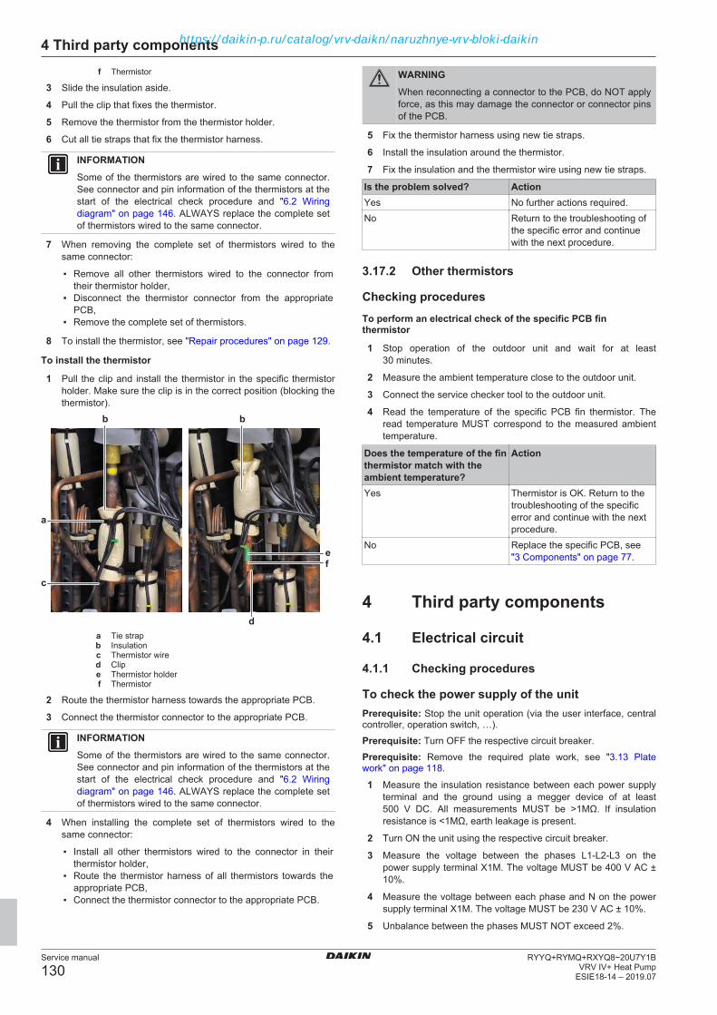
4 Third party components
Service manual
130RYYQ+RYMQ+RXYQ8~20U7Y1B
VRV IV+ Heat PumpESIE18-14 – 2019.07
f Thermistor
3 Slide the insulation aside.
4 Pull the clip that fixes the thermistor.
5 Remove the thermistor from the thermistor holder.
6 Cut all tie straps that fix the thermistor harness.
INFORMATIONSome of the thermistors are wired to the same connector.See connector and pin information of the thermistors at thestart of the electrical check procedure and "6.2 Wiringdiagram" on page 146. ALWAYS replace the complete setof thermistors wired to the same connector.
7 When removing the complete set of thermistors wired to thesame connector:
▪ Remove all other thermistors wired to the connector fromtheir thermistor holder,
▪ Disconnect the thermistor connector from the appropriatePCB,
▪ Remove the complete set of thermistors.
8 To install the thermistor, see "Repair procedures" on page 129.
To install the thermistor
1 Pull the clip and install the thermistor in the specific thermistorholder. Make sure the clip is in the correct position (blocking thethermistor).
b
a
b
c
d
ef
a Tie strapb Insulationc Thermistor wired Clipe Thermistor holderf Thermistor
2 Route the thermistor harness towards the appropriate PCB.
3 Connect the thermistor connector to the appropriate PCB.
INFORMATIONSome of the thermistors are wired to the same connector.See connector and pin information of the thermistors at thestart of the electrical check procedure and "6.2 Wiringdiagram" on page 146. ALWAYS replace the complete setof thermistors wired to the same connector.
4 When installing the complete set of thermistors wired to thesame connector:
▪ Install all other thermistors wired to the connector in theirthermistor holder,
▪ Route the thermistor harness of all thermistors towards theappropriate PCB,
▪ Connect the thermistor connector to the appropriate PCB.
WARNINGWhen reconnecting a connector to the PCB, do NOT applyforce, as this may damage the connector or connector pinsof the PCB.
5 Fix the thermistor harness using new tie straps.
6 Install the insulation around the thermistor.
7 Fix the insulation and the thermistor wire using new tie straps.
Is the problem solved? ActionYes No further actions required.No Return to the troubleshooting of
the specific error and continuewith the next procedure.
3.17.2 Other thermistors
Checking proceduresTo perform an electrical check of the specific PCB finthermistor
1 Stop operation of the outdoor unit and wait for at least30 minutes.
2 Measure the ambient temperature close to the outdoor unit.
3 Connect the service checker tool to the outdoor unit.
4 Read the temperature of the specific PCB fin thermistor. Theread temperature MUST correspond to the measured ambienttemperature.
Does the temperature of the finthermistor match with theambient temperature?
Action
Yes Thermistor is OK. Return to thetroubleshooting of the specificerror and continue with the nextprocedure.
No Replace the specific PCB, see"3 Components" on page 77.
4 Third party components
4.1 Electrical circuit
4.1.1 Checking procedures
To check the power supply of the unitPrerequisite: Stop the unit operation (via the user interface, centralcontroller, operation switch, …).Prerequisite: Turn OFF the respective circuit breaker.Prerequisite: Remove the required plate work, see "3.13 Platework" on page 118.
1 Measure the insulation resistance between each power supplyterminal and the ground using a megger device of at least500 V DC. All measurements MUST be >1MΩ. If insulationresistance is <1MΩ, earth leakage is present.
2 Turn ON the unit using the respective circuit breaker.
3 Measure the voltage between the phases L1‑L2‑L3 on thepower supply terminal X1M. The voltage MUST be 400 V AC ±10%.
4 Measure the voltage between each phase and N on the powersupply terminal X1M. The voltage MUST be 230 V AC ± 10%.
5 Unbalance between the phases MUST NOT exceed 2%.
https://daikin-p.ru/catalog/vrv-daikn/naruzhnye-vrv-bloki-daikin

4 Third party components
Service manual
131RYYQ+RYMQ+RXYQ8~20U7Y1BVRV IV+ Heat PumpESIE18-14 – 2019.07
Is the measured voltage(power supply) correct?
Action
Yes Return to the troubleshooting ofthe specific error and continuewith the next procedure.
No Adjust the power supply, see"4.1.2 Repair procedures" onpage 133.
To check if the power supply is conform with theregulations1 Check that the power source is in line with the requirements
described in the databook.
Is the power supply conformwith the regulations?
Action
Yes Return to the troubleshooting ofthe specific error and continuewith the next procedure.
No Adjust the power supply, see"4.1.2 Repair procedures" onpage 133.
To check if the rectifier voltage of the inverter PCBhas dropped below 10 V DC1 Stop the unit operation (via the user interface, operation switch,
…).
2 Turn OFF the respective circuit breaker.
For single fan units3 Measure the voltage on the rectifier voltage check connector (a)
X3A, located above the power terminal assembly (b). Themeasured voltage should be below 10 V DC.
a
b
a Connector X3Ab Power terminal assembly
For double fan units4 Measure the voltage on the rectifier voltage check connector (a)
X5A to check inverter PCB A3P (c). The measured voltageshould be below 10 V DC.
5 Measure the voltage on the rectifier voltage check connector (b)X6A to check inverter PCB A6P (d). The measured voltageshould be below 10 V DC
a d cb
a Connector X5Ab Connector X6Ac Inverter PCB A3Pd Inverter PCB A6P
DANGER: RISK OF ELECTROCUTIONConfirm rectifier voltage is below 10 V DC beforeproceeding.
To check F1-F2 transmissionTo check the F1-F2 wiring1 Check that the wiring:
▪ is within installation length limits,
▪ is of the proper wire type,
▪ is of the proper wire thickness,
▪ is properly fixed to the terminals,
▪ is executed according to the installation manual, with no starconnections.
2 Check that no shielded cables are used or that shielded cablesare grounded only on one side of the cable.
3 Check that F1-F2 wiring has continuity all over.
Is the wiring correctlyexecuted, as indicated in theinstallation manual?
Action
Yes Continue with the next step inthis checking procedure.
No Modify the wiring, see theinstallation manual.
To measure the F1-F2 transmissionF1-F2 transmission is a D3Net rectangular waveform, 16 VDC ± 5 Vwith 16-5V amplitude that appears on the 16V base line:
5 V
16 V
F1-F2 terminals on indoor units, BP-units, outdoor units and centralcontrollers are all possible measurement points. Use as many pointsas you can and take the time necessary for measurement ifanalyzing with an oscilloscope.
On outdoor units, measurement should be done either at F1-F2 IN orF1-F2 OUT. If the F1-F2 OUT terminal is not used, then measure atthe F1-F2 IN terminal.
You can conduct the measuring with a multimeter or an oscilloscope.
To measure the F1-F2 transmission with a multimeter:4 Set the multimeter to DC Voltage measurement.
https://daikin-p.ru/catalog/vrv-daikn/naruzhnye-vrv-bloki-daikin

4 Third party components
Service manual
132RYYQ+RYMQ+RXYQ8~20U7Y1B
VRV IV+ Heat PumpESIE18-14 – 2019.07
5 Measure on the F1 and F2 terminals.
Result: 16 V DC should be read.
To measure the F1-F2 transmission with an oscilloscope:
INFORMATIONEnsure that probes are securely connected to F1-F2terminals. Otherwise, distortions will be generated resultingin misinterpretation of data. It is recommended to connecttemporary cables to the probes and then connect thecables to the terminals securely.
6 Measure at as many points as you can, this can help todeterminate the problem.
For example: if the measurements at the indoor unit side aredistorted while central controller and outdoor unit seem OK, you cansuppose that the failure in transmission is related to the indoor unitside.
7 Set time base (horizontal) to 50 µs/div to 100 µs. Voltage axis(vertical) should be set to 2V/div to 5V. Set position properly,otherwise the data may appear outside the screen. In AC mode,which is a sampling mode in oscilloscopes, waveforms appearin the middle of the screen. So, it is recommended to use ACmode if possible.
8 Set the triggering mode of the oscilloscope to "Normal". If"Auto" mode is selected, observed waveforms may be clearedinstantaneously leading to misinterpretation of data.
9 Ignore very short-time pulses of 1V amplitude or less, orovershooting at the rising edge may be ignored. Focus on theshown points of the waveform below:
Examples of waveform distortions on D3Net and possiblecauses:
Rounded waveforms at fallingedges.Possible reasons:
▪ Excessive wire length,
▪ Excessive number ofconnected devices,
▪ Branching (star connections).
Ringing.Possible reasons:
▪ Transmission wiring very closeto high voltage cables,
▪ Use of multi-conductor typewires.
Noise.Possible reasons:
▪ Transmission wiring very closeto high voltage cables,
▪ Transmission wiring effectedfrom external equipmentcausing noise.
Faulty Waveform.Possible reasons:
▪ Transmission circuit failure ona PCB.
After checking and correcting possible causes of F1-F2 transmissionproblems, perform a communication reset (see "4.1.2 Repairprocedures" on page 133).
To check the communication between outdoorunitsQ1 and Q2 are connection terminals for the transmission wiringbetween multi outdoor units.
1 Measure the voltage as shown below:
VDC Com. Ref.Q1 X37A ˜ 13 VDCQ2 X37A ˜ 13 VDCQ1 X37A ˜ -3 VDCQ2 X37A ˜ -3 VDC
c
a b
d
a Terminal Q1b Terminal Q2c Connector X37A pin 1d Connector X37A pin 2
Is the measured voltagecorrect?
Action
Yes Return to the troubleshooting ofthe specific error and continuewith the next procedure.
No Perform a check of the mainPCB, see "3.9 Main PCB" onpage 106.
To check the wiring between the outdoor unit andthe indoor unit1 Check that all wires are properly connected and that all
connectors are fully plugged‑in.
2 Check that no connectors or wires are damaged.
https://daikin-p.ru/catalog/vrv-daikn/naruzhnye-vrv-bloki-daikin

4 Third party components
Service manual
133RYYQ+RYMQ+RXYQ8~20U7Y1BVRV IV+ Heat PumpESIE18-14 – 2019.07
3 Check that the wiring corresponds with the wiring diagram, see"6.2 Wiring diagram" on page 146.
Is all wiring between theoutdoor unit and the indoorunit correct?
Action
Yes Return to the troubleshooting ofthe specific error and continuewith the next procedure.
No Adjust the wiring where needed,see "4.1.2 Repair procedures" onpage 133.
4.1.2 Repair procedures
To adjust the power supply1 Make sure that the power source is in line with the requirements
described in the databook.
2 Adjust the power supply within 50 Hz ± 3%.
Is the problem solved? ActionYes No further actions required.No Return to the troubleshooting of
the specific error and continuewith the next procedure.
To adjust the wiring between the outdoor unit andthe indoor unit1 Adjust the wiring according to the wiring diagram and
connection diagram, see "6.2 Wiring diagram" on page 146.
2 Check that all wires are properly connected and that allconnectors are fully plugged‑in.
3 Check that no connectors or wires are damaged.
Is the problem solved? ActionYes No further actions required.No Return to the troubleshooting of
the specific error and continuewith the next procedure.
To perform a communication reset
NOTICEIf an indoor unit is power OFF when communication resetis performed, the outdoor unit will delete this indoor unitinformation since this unit will not be identified during re-initialization. If so, this unit will not be recognized by theoutdoor unit upon power restore to this indoor unit.
1 Set multimeter to V DC measurement. The example below isperformed while COM-F1 and V DC-F2, the polarity will beopposite than the graph below if connected otherwise (which isnot a problem).
y
16 VDC
-16 VDC
x
a b
c d
ef
y Voltage (VDC)
x Time
c
a b
d
a Terminal F1b Terminal F2c 7-segment displayd Push button BS3
2 Push BS3 (RETURN) and hold it for 5 seconds until the 7-segment display shows "000". Then release BS3.
Result: After a while, voltage will drop to almost 0 V DC. At thisstage it means that re-initialization has started.Result: Depending on the system size, voltage will rise to16 V DC and hit 0 V back again several times.
Result: When finished, 7‑Segment Display will turn OFF. Thisindicates that re-initialization has completed.
The time this procedure takes, depends on the amount of indoorunits.
To adjust the wiring between the outdoor units1 Adjust the wiring according to the wiring diagram and
connection diagram, see "6.2 Wiring diagram" on page 146.
2 Check that all wires are properly connected.
3 Check that no wires are damaged.
Is the problem solved? ActionYes No further actions required.No Return to the troubleshooting of
the specific error and continuewith the next procedure.
4.2 Refrigerant circuit
4.2.1 Checking procedures
INFORMATIONIt is recommended to perform the checks in the listedorder.
To check if the stop valves are openPrerequisite: Remove the required plate work, see "3.13 Platework" on page 118.
1 Remove the caps.
https://daikin-p.ru/catalog/vrv-daikn/naruzhnye-vrv-bloki-daikin
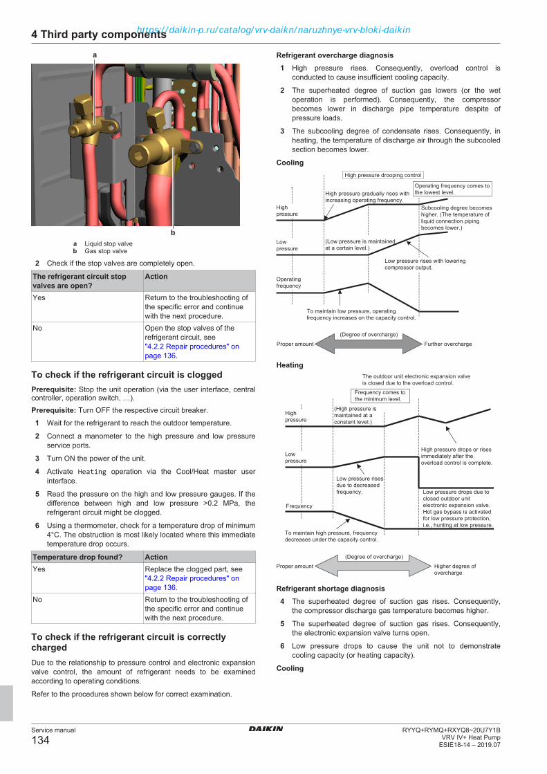
4 Third party components
Service manual
134RYYQ+RYMQ+RXYQ8~20U7Y1B
VRV IV+ Heat PumpESIE18-14 – 2019.07
a
ba Liquid stop valveb Gas stop valve
2 Check if the stop valves are completely open.
The refrigerant circuit stopvalves are open?
Action
Yes Return to the troubleshooting ofthe specific error and continuewith the next procedure.
No Open the stop valves of therefrigerant circuit, see"4.2.2 Repair procedures" onpage 136.
To check if the refrigerant circuit is cloggedPrerequisite: Stop the unit operation (via the user interface, centralcontroller, operation switch, …).Prerequisite: Turn OFF the respective circuit breaker.
1 Wait for the refrigerant to reach the outdoor temperature.
2 Connect a manometer to the high pressure and low pressureservice ports.
3 Turn ON the power of the unit.
4 Activate Heating operation via the Cool/Heat master userinterface.
5 Read the pressure on the high and low pressure gauges. If thedifference between high and low pressure >0.2 MPa, therefrigerant circuit might be clogged.
6 Using a thermometer, check for a temperature drop of minimum4°C. The obstruction is most likely located where this immediatetemperature drop occurs.
Temperature drop found? ActionYes Replace the clogged part, see
"4.2.2 Repair procedures" onpage 136.
No Return to the troubleshooting ofthe specific error and continuewith the next procedure.
To check if the refrigerant circuit is correctlychargedDue to the relationship to pressure control and electronic expansionvalve control, the amount of refrigerant needs to be examinedaccording to operating conditions.
Refer to the procedures shown below for correct examination.
Refrigerant overcharge diagnosis1 High pressure rises. Consequently, overload control is
conducted to cause insufficient cooling capacity.
2 The superheated degree of suction gas lowers (or the wetoperation is performed). Consequently, the compressorbecomes lower in discharge pipe temperature despite ofpressure loads.
3 The subcooling degree of condensate rises. Consequently, inheating, the temperature of discharge air through the subcooledsection becomes lower.
Cooling
Proper amount Further overcharge
(Degree of overcharge)
To maintain low pressure, operatingfrequency increases on the capacity control.
(Low pressure is maintainedat a certain level.)
High pressure drooping control
Operating frequency comes to the lowest level.
Subcooling degree becomes higher. (The temperature of liquid connection piping becomes lower.)
High pressure gradually rises withincreasing operating frequency.
Low pressure rises with loweringcompressor output.
Operatingfrequency
Lowpressure
Highpressure
Heating
Proper amount Higher degree ofovercharge
(Degree of overcharge)
To maintain high pressure, frequencydecreases under the capacity control.
Low pressure drops due toclosed outdoor unitelectronic expansion valve.Hot gas bypass is activatedfor low pressure protection,i.e., hunting at low pressure.
High pressure drops or risesimmediately after theoverload control is complete.
Low pressure risesdue to decreasedfrequency.
Frequency comes tothe minimum level.
The outdoor unit electronic expansion valveis closed due to the overload control.
Frequency
Lowpressure
Highpressure
(High pressure ismaintained at a constant level.)
Refrigerant shortage diagnosis4 The superheated degree of suction gas rises. Consequently,
the compressor discharge gas temperature becomes higher.
5 The superheated degree of suction gas rises. Consequently,the electronic expansion valve turns open.
6 Low pressure drops to cause the unit not to demonstratecooling capacity (or heating capacity).
Cooling
https://daikin-p.ru/catalog/vrv-daikn/naruzhnye-vrv-bloki-daikin
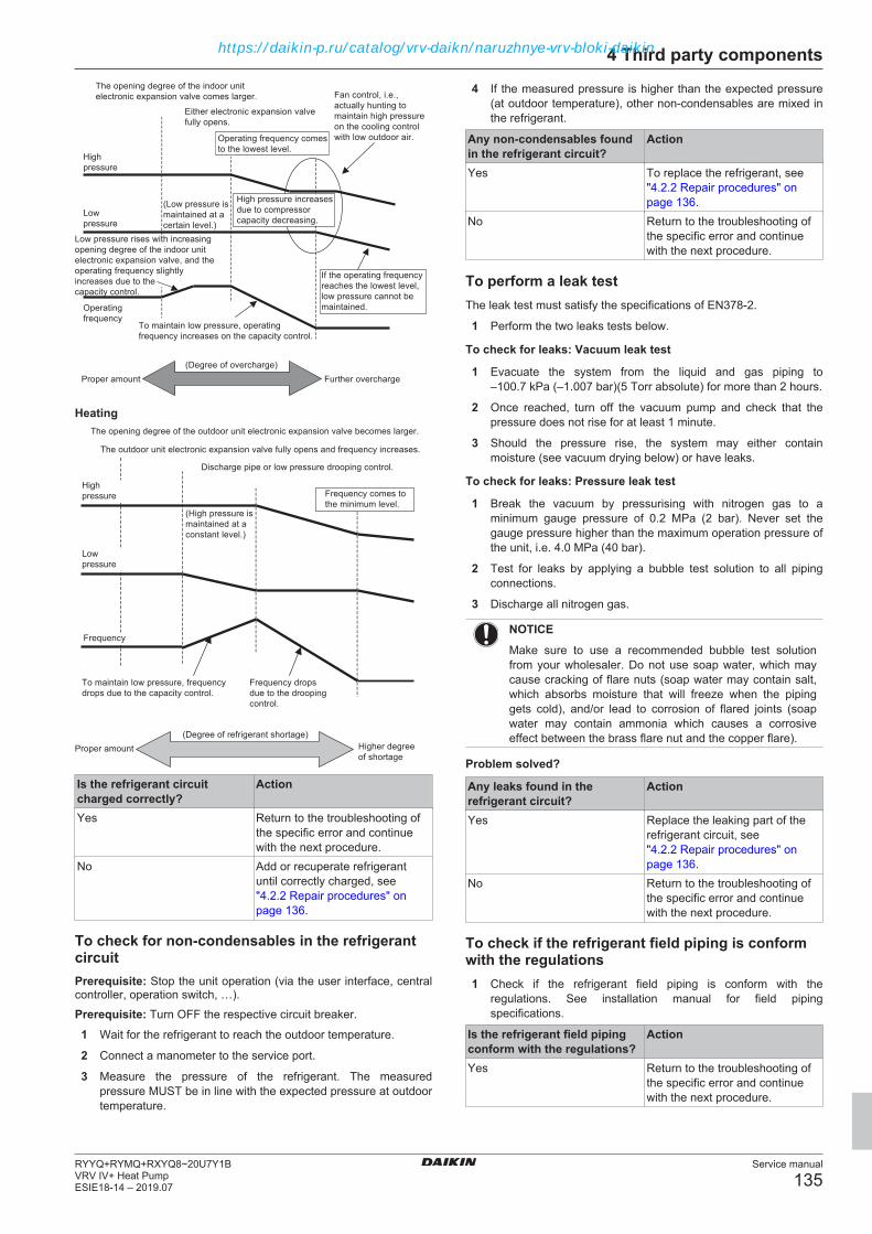
4 Third party components
Service manual
135RYYQ+RYMQ+RXYQ8~20U7Y1BVRV IV+ Heat PumpESIE18-14 – 2019.07
Proper amount Further overcharge(Degree of overcharge)
To maintain low pressure, operatingfrequency increases on the capacity control.
(Low pressure ismaintained at a certain level.)
Operatingfrequency
Lowpressure
Highpressure
If the operating frequency reaches the lowest level,low pressure cannot be maintained.
Either electronic expansion valvefully opens.
The opening degree of the indoor unitelectronic expansion valve comes larger. Fan control, i.e.,
actually hunting to maintain high pressureon the cooling control with low outdoor air.
Low pressure rises with increasingopening degree of the indoor unitelectronic expansion valve, and theoperating frequency slightly increases due to the capacity control.
High pressure increasesdue to compressorcapacity decreasing.
Operating frequency comesto the lowest level.
Heating
Frequency
Lowpressure
Highpressure
Proper amount Higher degreeof shortage
(Degree of refrigerant shortage)
To maintain low pressure, frequencydrops due to the capacity control.
Frequency dropsdue to the droopingcontrol.
(High pressure ismaintained at a constant level.)
Frequency comes tothe minimum level.
Discharge pipe or low pressure drooping control.
The outdoor unit electronic expansion valve fully opens and frequency increases.
The opening degree of the outdoor unit electronic expansion valve becomes larger.
Is the refrigerant circuitcharged correctly?
Action
Yes Return to the troubleshooting ofthe specific error and continuewith the next procedure.
No Add or recuperate refrigerantuntil correctly charged, see"4.2.2 Repair procedures" onpage 136.
To check for non-condensables in the refrigerantcircuitPrerequisite: Stop the unit operation (via the user interface, centralcontroller, operation switch, …).Prerequisite: Turn OFF the respective circuit breaker.
1 Wait for the refrigerant to reach the outdoor temperature.
2 Connect a manometer to the service port.
3 Measure the pressure of the refrigerant. The measuredpressure MUST be in line with the expected pressure at outdoortemperature.
4 If the measured pressure is higher than the expected pressure(at outdoor temperature), other non‑condensables are mixed inthe refrigerant.
Any non‑condensables foundin the refrigerant circuit?
Action
Yes To replace the refrigerant, see"4.2.2 Repair procedures" onpage 136.
No Return to the troubleshooting ofthe specific error and continuewith the next procedure.
To perform a leak testThe leak test must satisfy the specifications of EN378‑2.
1 Perform the two leaks tests below.
To check for leaks: Vacuum leak test
1 Evacuate the system from the liquid and gas piping to–100.7 kPa (–1.007 bar)(5 Torr absolute) for more than 2 hours.
2 Once reached, turn off the vacuum pump and check that thepressure does not rise for at least 1 minute.
3 Should the pressure rise, the system may either containmoisture (see vacuum drying below) or have leaks.
To check for leaks: Pressure leak test
1 Break the vacuum by pressurising with nitrogen gas to aminimum gauge pressure of 0.2 MPa (2 bar). Never set thegauge pressure higher than the maximum operation pressure ofthe unit, i.e. 4.0 MPa (40 bar).
2 Test for leaks by applying a bubble test solution to all pipingconnections.
3 Discharge all nitrogen gas.
NOTICEMake sure to use a recommended bubble test solutionfrom your wholesaler. Do not use soap water, which maycause cracking of flare nuts (soap water may contain salt,which absorbs moisture that will freeze when the pipinggets cold), and/or lead to corrosion of flared joints (soapwater may contain ammonia which causes a corrosiveeffect between the brass flare nut and the copper flare).
Problem solved?
Any leaks found in therefrigerant circuit?
Action
Yes Replace the leaking part of therefrigerant circuit, see"4.2.2 Repair procedures" onpage 136.
No Return to the troubleshooting ofthe specific error and continuewith the next procedure.
To check if the refrigerant field piping is conformwith the regulations1 Check if the refrigerant field piping is conform with the
regulations. See installation manual for field pipingspecifications.
Is the refrigerant field pipingconform with the regulations?
Action
Yes Return to the troubleshooting ofthe specific error and continuewith the next procedure.
https://daikin-p.ru/catalog/vrv-daikn/naruzhnye-vrv-bloki-daikin
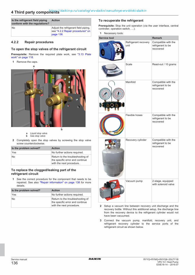
4 Third party components
Service manual
136RYYQ+RYMQ+RXYQ8~20U7Y1B
VRV IV+ Heat PumpESIE18-14 – 2019.07
Is the refrigerant field pipingconform with the regulations?
Action
No Adjust the refrigerant field piping,see "4.2.2 Repair procedures" onpage 136.
4.2.2 Repair procedures
To open the stop valves of the refrigerant circuitPrerequisite: Remove the required plate work, see "3.13 Platework" on page 118.
1 Remove the caps.a
ba Liquid stop valveb Gas stop valve
2 Completely open the stop valves by screwing the stop valvescrew counterclockwise.
Is the problem solved? ActionYes No further actions required.No Return to the troubleshooting of
the specific error and continuewith the next procedure.
To replace the clogged/leaking part of therefrigerant circuit1 See the correct procedure for the component that needs to be
repaired. See also "Repair information" on page 138 for moredetails.
Is the problem solved? ActionYes No further actions required.No Return to the troubleshooting of
the specific error and continuewith the next procedure.
To recuperate the refrigerantPrerequisite: Stop the unit operation (via the user interface, centralcontroller, operation switch, …).
1 Necessary tools:
Service tool RemarkRefrigerant recoveryunit
Compatible with therefrigerant to berecovered
Scale Read-out / 10 grams
Manifold Compatible with therefrigerant to berecovered
Flexible hoses Compatible with therefrigerant to berecovered
Recovery cylinder Compatible with therefrigerant to berecovered
Vacuum pump 2-stage, equippedwith solenoid valve
2 Setup a vacuum line between recovery unit discharge and therecovery bottle. Without this additional setup, the discharge linefrom the recovery device to the refrigerant cylinder would nothave been vacuumed.
3 Connect the vacuum pump, manifold, recovery unit, andrefrigerant recovery cylinder to the service ports of therefrigerant circuit as shown below.
https://daikin-p.ru/catalog/vrv-daikn/naruzhnye-vrv-bloki-daikin

4 Third party components
Service manual
137RYYQ+RYMQ+RXYQ8~20U7Y1BVRV IV+ Heat PumpESIE18-14 – 2019.07
For RYMQ-U units
b
c
a
d
j e f
c c
g h
i
a Liquid service portb Gas service portc Flexible hosed Manifolde Recovery unirf Vacuum pumpg Scaleh Recovery cylinderi Vacuum setupj Equalizing pipe service port
For RXYQ-U and RYYQ-U units
a
d
e f
c c
g h
i
b
a Liquid service portb Gas service portc Flexible hosed Manifolde Recovery unirf Vacuum pumpg Scaleh Recovery cylinderi Vacuum setup
https://daikin-p.ru/catalog/vrv-daikn/naruzhnye-vrv-bloki-daikin

4 Third party components
Service manual
138RYYQ+RYMQ+RXYQ8~20U7Y1B
VRV IV+ Heat PumpESIE18-14 – 2019.07
4 Activate refrigerant recovery / vacuum mode by setting fieldsetting mode 2-21 to 1 (see "6.9 Field settings" on page 188).
To make sure that refrigerant cycle is completely connected andthere are no dead-zones because of closed expansion- or solenoidvalves, entering the refrigerant recovery / vacuum mode ensuresthat:
▪ All indoor unit expansion valves get fully opened,
▪ all outdoor unit expansion valves get fully opened,
▪ the necessary solenoid valves get fully opened.
5 To add refrigerant, see "4.2.2 Repair procedures" on page 136.
Is the problem solved? ActionYes No further actions required.No Return to the troubleshooting of
the specific error and continuewith the next procedure.
To add refrigerant1 See the installer reference guide for the correct procedure.
Is the problem solved? ActionYes No further actions required.No Perform a pressure test of the
refrigerant circuit, see"4.2.1 Checking procedures" onpage 133.
To adjust the refrigerant field piping1 Make sure that the refrigerant field piping is conform with the
regulations. See installation manual for field pipingspecifications.
Is the problem solved? ActionYes No further actions required.No Return to the troubleshooting of
the specific error and continuewith the next procedure.
Repair informationRefrigerant piping handling
▪ Make sure that the applied pressure is never higher than the unitdesign pressure indicated on the nameplate (PS).
▪ Work according to the F‑gas regulation and/or local regulations.
▪ Make sure the correct amount of refrigerant is charged after repairaccording to the F‑gas regulation label on the unit (factory +additional where required).
▪ Make sure to use the appropriate equipment and tools accordingto the refrigerant and unit type.
▪ Charge non‑azeotropic refrigerant (e.g. R410A) always in a liquidstate.
▪ Make sure to use a digital scale (no charging cylinder).
▪ Execute correct vacuum drying procedure after repair:
▪ –0.1 MPa / –760 mm Hg / –750 Torr / –1 bar for at least 1 hour.
▪ Connect the unit according to the available service ports.
▪ Use related field setting where necessary to open expansionvalve / solenoid valve.
Refrigerant piping repair
▪ Make sure to cover open pipe ends during repair so no dust ormoisture can enter.
▪ Make sure to re‑apply insulation removed during repair.
▪ Pipe expansion / flare making:
▪ Remove any burrs on the cut surface using the correct toolsuch as reamer or scraper (note that excessive deburring canthin the pipe walls and cause cracking of the pipe).
▪ Make sure the flare has the correct size (use a flare gauge).
▪ Make sure no particles remain in the piping.
▪ Apply just a drop of refrigerant oil on the inner surface of theflare.
▪ Make sure the flare connection is tightened with the correcttorque (torque values refer to installation manual).
▪ Brazing:
▪ Use the correct brazing tool.
▪ Use a phosphor copper filler metal (silver composition of 0 to2%). Do not use flux material.
▪ Flush the piping before brazing with nitrogen to avoid oxidationof the inside of the copper tubes (nitrogen purity ≥99.99%).
Additional refrigerant charge amount
1 Once automatic or manual additional refrigerant charge iscompleted, it is necessary to give input to the outdoor unit overthe total additional refrigerant charge amount.
2 Set field setting 2–14 according to the table below. See"6.9 Field settings" on page 188.
Mode2-14
R410A[kg]
Mode2-14
R410A[kg]
Mode2-14
R410A[kg]
0 No input 7 30~35 14 65~701 0~5 8 35~40 15 70~752 5~10 9 40~45 16 75~803 10~15 10 45~50 17 80~854 15~20 11 50~55 18 85~905 20~25 12 55~606 25~30 13 60~65
3 Even though they can be selected, 2-14 settings 19, 20, and 21CANNOT be set.
4 Default setting is 0. If set to 0, refrigerant leak check functionwill NOT be available.
5 If set to 0 and field setting 2-88=0, at the end of the test-runerror code U3-02 will indicate that refrigerant leak checkfunction will NOT be available.
4.3 External factors
4.3.1 Checking procedures
To check the outdoor temperature1 The temperature ranges for the different operation modes of the
unit can be found in the databook on Business Portal.
INFORMATIONIf the outdoor temperature is outside the range ofoperation, the unit may NOT operate or may NOT deliverthe required capacity.
INFORMATIONIf difference between the ambient temperature andtemperature at air inlet of the outdoor unit heat exchangeris >5 K, consider mounting an air guide at the air dischargeoutlet of the outdoor unit heat exchanger.
https://daikin-p.ru/catalog/vrv-daikn/naruzhnye-vrv-bloki-daikin

4 Third party components
Service manual
139RYYQ+RYMQ+RXYQ8~20U7Y1BVRV IV+ Heat PumpESIE18-14 – 2019.07
Is the outdoor temperaturewithin the operating range?
Action
Yes Return to the troubleshooting ofthe specific error and continuewith the next procedure.
No Wait for the outdoor temperatureto return within the operatingrange.
To check for objects that may block the airflow1 Check for the presence of objects near the indoor unit that may
block the airflow.
Is an object found that mayblock the airflow?
Action
Yes Remove the object, see"4.3.2 Repair procedures" onpage 139.
No Return to the troubleshooting ofthe specific error and continuewith the next procedure.
To check the required space around the outdoorunit heat exchanger1 Check if the space around the outdoor unit heat exchanger is
sufficient. See the installation manual for the required spacespecifications.
Is the space around theoutdoor unit heat exchangercorrect?
Action
Yes Return to the troubleshooting ofthe specific error and continuewith the next procedure.
No Create sufficient space aroundthe outdoor unit heat exchanger,see "4.3.2 Repair procedures" onpage 139.
To check for an external power source1 Check for the presence of an external power source. This might
cause electrical interference (electrical noise disturbance).
Is an external power sourcefound near the unit?
Action
Yes Remove the external powersource, see "4.3.2 Repairprocedures" on page 139.
No Return to the troubleshooting ofthe specific error and continuewith the next procedure.
4.3.2 Repair procedures
To remove objects that may block the airflow1 Remove objects that may block the airflow from the near
environment of the indoor unit.
Is the problem solved? ActionYes No further actions required.No Return to the troubleshooting of
the specific error and continuewith the next procedure.
To create sufficient space around the outdoor unitheat exchanger1 Create sufficient space around the outdoor unit heat exchanger.
See installation manual for the required space specifications.
Is the problem solved? ActionYes No further actions required.No Return to the troubleshooting of
the specific error and continuewith the next procedure.
To remove the external power source1 Remove the external power source from the near environment
of the unit.
Is the problem solved? ActionYes No further actions required.No Return to the troubleshooting of
the specific error and continuewith the next procedure.
https://daikin-p.ru/catalog/vrv-daikn/naruzhnye-vrv-bloki-daikin
5 Maintenance
Service manual
140RYYQ+RYMQ+RXYQ8~20U7Y1B
VRV IV+ Heat PumpESIE18-14 – 2019.07
5 Maintenance
5.1 Maintenance sheduleTo ensure optimal availability of the unit, certain checks andinspections on the unit and the field wiring have to be carried out atregular intervals. See the checking procedures in this manual forinspection of the components mentioned below.
The intervals depend on:
▪ Local legislation,
▪ the conditions at the installation site (presence of dust, sea salt,harmful gas, oil mist, power supply fluctuation, bumps, vibrationetc.),
▪ how the unit is operated (frequent stop and start, longer operationhours etc.),
▪ total running hours of the unit,
▪ ambient conditions (high heat and humidity load etc.)
Depending on the above mentioned factors, maintenance may berequired sooner than the mentioned interval here below.
The table below also assumes a unit operation of 10 hours/day and2500 hours/year. Normal use of the unit is considered when a unit is not performingthe stop/start cycle (Thermo OFF and then ON) more than 6 times/hour.
Component Inspection MaintenanceElectric Motor 1 year 20.000 hours
PCB 25.000 hoursHeat Exchanger 5 years
Sensor, Thermistor 5 yearsUser Interface,
Switches25.000 hours
Drain Pan 8 yearsExpansion Valve 20.000 hoursSolenoid Valve 20.000 hours
Air Filter 5 yearsHigh Efficiency Filter 1 year
Fuse 10 yearsCrankcase Heater 8 yearsComponents under
pressureIn case of corrosion
Also, the cleaning of air filters, heat exchangers, fan propellers, drainpans etc. has to be carried out at regular intervals, see"5.2 Maintenance procedures for outdoor units" on page 140.
5.2 Maintenance procedures foroutdoor units
5.2.1 To check the general status of the unitPrerequisite: Switch off all the indoor units.Prerequisite: Stop the unit operation (via the user interface, centralcontroller, operation switch, …).
1 Check the rectifier voltage, see "To check if the rectifier voltageof the inverter PCB has dropped below 10 V DC" on page 131.
DANGER: RISK OF ELECTROCUTIONConfirm rectifier voltage is below 10 V DC beforeproceeding.
2 Clean the cover plates, see "5.2.2 To clean the cover plates" onpage 140.
3 Check if any other equipment interferes with the operation ofthe outdoor unit (other device exhaust to outdoor unit heatexchanger, chimney exhaust to outdoor unit, corrosive orexplosive ambient, electrical equipment such as antennas,GSM towers, etc…). Refer to the installation manual.
4 Make sure that there is sufficient air flow or no air by-pass onoutdoor unit heat exchanger in cooling mode. Refer toinstallation manual for required space. Even after outdoor unitheat exchanger is cleaned by maintenance, if differencebetween ambient temperature and air inlet of outdoor unit heatexchanger is 5K or more, consider mounting an air guide at airdischarge outlet of the outdoor unit.
5 Prior to cleaning, check for oil drips on the bottom plate. Iffound, check system for signs of refrigerant shortage, checkpossible leaking points and repair when necessary. Refer toRepair instructions of the component when necessary.
6 Clean the bottom plate.
7 Clean the inside of the unit.
NOTICETo clean the inside of the unit:
▪ Use water or compressed air, not warmer than 50° C.
▪ Do not use any cleaning agents or chemicals.
▪ Do not use pressurized water.
8 Check the general status inside the cover plates.
9 Check the visual appearance of all the components, includingPCBs. Refer to component check methods if any irregularity isfound.
10 Check the electrical connections. Tighten and secure theconnections when necessary.
11 Check if power supply is in conform with legislation. See "Tocheck if the power supply is conform with the regulations" onpage 131.
12 Check and tighten the power supply wiring on the dedicatedterminal.
13 Check insulation on piping and refrigerant branches. Replace orfix insulation where necessary.
14 Make sure that the water drain works properly and is notclogged or does not cause any accumulation of water.
15 Clean outdoor unit heat exchanger see "5.2.3 To clean theoutdoor unit heat exchanger" on page 141.
16 Clean outdoor unit fan propellers.
17 Check latest error codes and latest retries, see "2.2 To checkthe error history" on page 9.
18 Log the maintenance in the log-book.
After outdoor unit and indoor unit (see "5.3 Maintenance proceduresfor indoor units" on page 142) maintenance is performed, check thesystem via Service Checker for normal operation. See "2.4 Symptombased troubleshooting" on page 73.
5.2.2 To clean the cover plates1 Clean the cover plates with a wet cloth.
NOTICETo clean the plate work:
▪ Use water or compressed air, not warmer than 50° C.
▪ Do not use any cleaning agents or chemicals.
▪ Do not use pressurized water.
https://daikin-p.ru/catalog/vrv-daikn/naruzhnye-vrv-bloki-daikin
5 Maintenance
Service manual
141RYYQ+RYMQ+RXYQ8~20U7Y1BVRV IV+ Heat PumpESIE18-14 – 2019.07
5.2.3 To clean the outdoor unit heat exchanger1 Straighten the hair fins.
2 Clear the outdoor unit heat exchanger from dust, leaves,…using a fin-comb or compressed air/N2.
CAUTIONAvoid bending or damaging the hair fins of the outdoor unitheat exchanger during the cleaning process.
Is the problem solved? ActionYes No further actions required.No Return to the troubleshooting of
the specific error and continuewith the next procedure.
https://daikin-p.ru/catalog/vrv-daikn/naruzhnye-vrv-bloki-daikin

5 Maintenance
Service manual
142RYYQ+RYMQ+RXYQ8~20U7Y1B
VRV IV+ Heat PumpESIE18-14 – 2019.07
5.3 Maintenance procedures forindoor units
5.3.1 To check the general status of the unitPrerequisite: Switch off all the indoor units.Prerequisite: Stop the unit operation (via the user interface, centralcontroller, operation switch, …).
1 Clean the cover plates, see "5.3.2 To clean the cover plates" onpage 142.
2 Check if any other equipment interferes with the operation ofthe indoor unit (other device exhaust towards indoor unit heatexchanger, oil mist, water vapour etc, corrosive or explosiveambient, electrical equipment, blocked air outlets or inlets,etc…) Refer to installation manual.
3 Make sure that there is sufficient air flow or no air by-pass onthe indoor unit heat exchanger in cooling mode.
4 Check superheat for refrigerant. Normally the expansion valve for the indoor unit is driven tokeep minimum 3K of superheat. If not, even if the filters are cleaned, it might be that:
▪ the heat exchanger is clogged by dust (see "5.3.3 To clean theindoor unit heat exchanger" on page 142),
▪ an air by-pass is present,
▪ the fan cannot deliver discharge air due to longer supply duct,
▪ expansion valve is malfunctioning (see next step).
5 The best way to judge expansion valve bleeding is to operateindoor units in cooling, set the dedicated indoor unit to Fan onlyoperation and then check refrigerant thermistors by ServiceChecker. Fan only operated indoor unit sets EV to 0 pulse. Ifthe gas thermistor on the indoor unit is close to evaporationtemperature and does not rise to ambient temperature in time,the expansion valve is bleeding and needs to be replaced. Once check is completed switch to other indoor unit and set theoperation to Fan only and proceed in similar manner.
6 Clean the inside of the unit.
NOTICETo clean the inside of the unit:
▪ Use water or compressed air, not warmer than 50° C.
▪ Do not use any cleaning agents or chemicals.
▪ Do not use pressurized water.
7 Check the general status inside the cover plates.
8 Check if the drain is properly drained by pouring water in thedrain pan. Check drain pan and drain piping if this is not thecase.
9 Check the visual appearance of all the components. Refer tocomponent check methods if any irregularity is found.
10 Check the flare connections and their surrounding for oil dripsand signs of leaks.
11 Check the electrical connections. Tighten and secure theconnections when necessary.
12 Check if power supply is in conform with legislation. See "Tocheck if the power supply is conform with the regulations" onpage 131.
13 Check and tighten the power supply wiring on the dedicatedterminal.
14 Check the insulation on piping and refrigerant branches.Replace or fix insulation where necessary.
INFORMATIONDepending on the setting of parameter 20-0 on the indoorunit remote controller, a filter sign is indicated on theremote controller (or central controller if present). Thisindicates that the time that was set by the parameter haspassed and filter cleaning is required. For moreinformation, refer to installation manual for the indoor unit.
15 Remove the air filters. Clean the filter with a vacuum cleaner orwater or compressed air. When the filter is clogged and toodirty, use a soft brush and natural detergent to clean it. Dry thefilter in shade. You may need to remove duct connections forceiling duct type units. Refer to installation manual for theindoor unit.
16 Make sure there is a filter on the air suction line for the indoorunit. Refer to installation manual for the indoor unit.
INFORMATIONWhen air filters are not cleaned at regular intervals, dustbegins to accumulate on the indoor unit heat exchanger.
17 Check the indoor unit heat exchanger and clean him ifnecessary, see "5.3.3 To clean the indoor unit heatexchanger" on page 142.Normally this is not a required step if the unit is not exposed tooil mist alike exhaust and when filters are cleaned regularly.To clean the indoor unit heat exchanger it may be necessary toremove bottom plate, side covers, drain pan, fan propeller andfan motor to gain access to the indoor unit heat exchanger.
18 Check wireless remote controller battery (if present).
19 Log the maintenance in the log-book.
After outdoor unit and indoor unit (see "5.3 Maintenance proceduresfor indoor units" on page 142) maintenance is performed, check thesystem via Service Checker for normal operation. See "2.4 Symptombased troubleshooting" on page 73.
5.3.2 To clean the cover plates1 Clean the cover plates with a wet cloth.
NOTICETo clean the plate work:
▪ Use water or compressed air, not warmer than 50° C.
▪ Do not use any cleaning agents or chemicals.
▪ Do not use pressurized water.
5.3.3 To clean the indoor unit heat exchanger1 Straighten the hair fins.
2 Clear the indoor unit heat exchanger from dust, leaves,… usinga fin-comb or compressed air/N2.
CAUTIONAvoid bending or damaging the hair fins of the indoor unitheat exchanger during the cleaning process.
Is the problem solved? ActionYes No further actions required.No Return to the troubleshooting of
the specific error and continuewith the next procedure.
https://daikin-p.ru/catalog/vrv-daikn/naruzhnye-vrv-bloki-daikin

Direct expansion: Maintenance – VRVInstaller General infoCompany name One time maintenance Contractual maintenanceContact person
Performed byEnd customer CompanyName TechnicianStreet – N° CertificateZip code – City DateCountry
Maintenance
Outdoor unit (air cooled) Outdoor unit (water cooled)Heat exchanger Clean Cleaned Filter water circuit Clean Cleaned
Not OK Not OK
Drainage bottom plate Clean Cleaned PCB's heat sink Clean CleanedNot OK Not OK Not applicable
PCB's heat sink Clean Cleaned Unit outside state Clean CleanedNot OK Not applicable
Unit inside state Clean CleanedUnit outside state Clean Cleaned
Tighten electrical connections OK Not OKUnit inside state Clean Cleaned
Correct/stable water flow OK Not OKTighten electrical connections OK Not OK
Free air circulation OK Not OK
Indoor unit Heat reclaim ventilation unitAir filter Clean Cleaned/replaced Air filter Clean Cleaned/replaced
Not OK Not OK
Heat exchanger Clean Cleaned Heat recovery heat exchanger Clean Cleaned/replacedNot OK Not OK
Drainage drain pan Clean Cleaned Heat exchanger Clean CleanedNot OK Not OK Not applicable
Fan motor/blades Clean Cleaned Drainage drain pan Clean CleanedNot OK Not OK Not applicable
Unit outside state Clean Cleaned Fan motor/blades Clean CleanedNot OK
Unit inside state Clean CleanedUnit outside state Clean Cleaned
Tighten electrical connections OK Not OKUnit inside state Clean Cleaned
Correct air flow OK Not OKTighten electrical connections OK Not OK
Wireless remote controllerbatteries
OK Not OKNot applicable Correct air flow OK Not OK
Service manual
143Direct expansion: Maintenance – VRV
ESIE18-14 – 2019.07
https://daikin-p.ru/catalog/vrv-daikn/naruzhnye-vrv-bloki-daikin
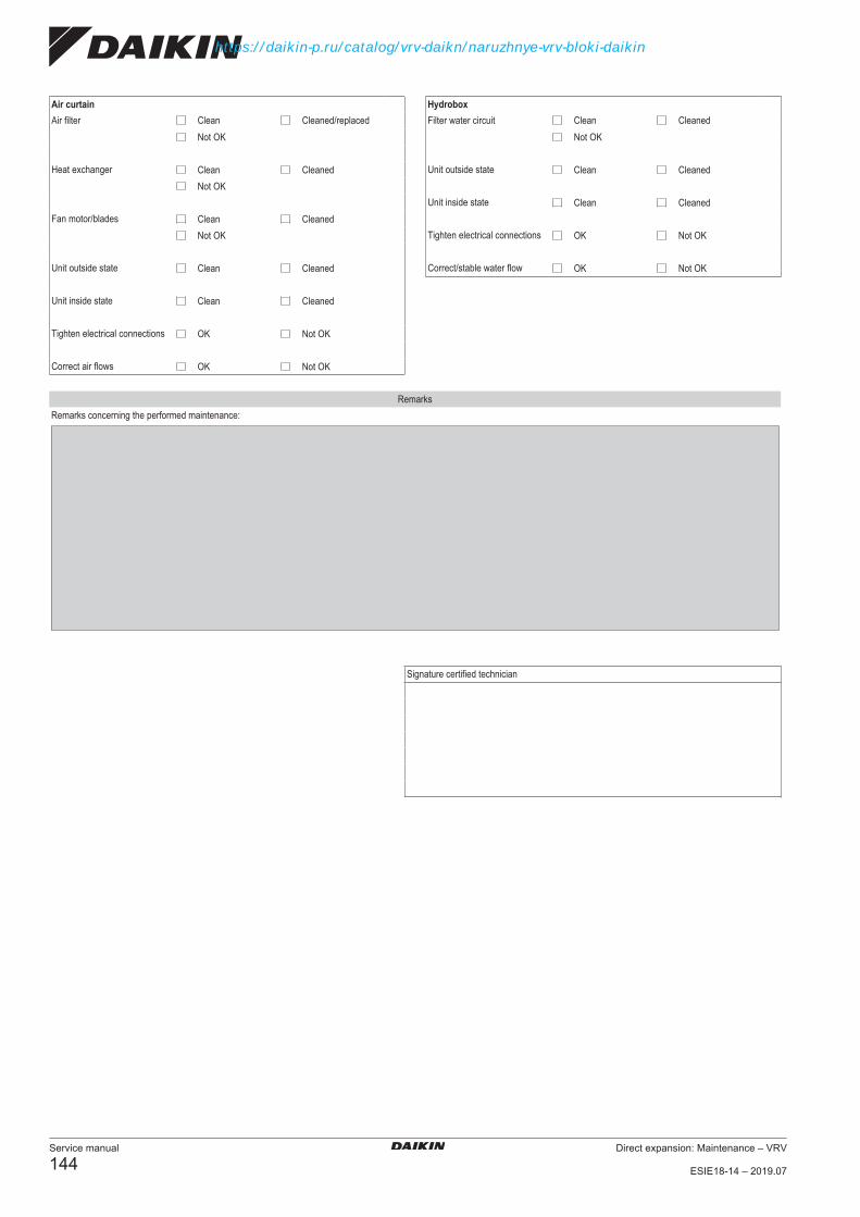
Air curtain HydroboxAir filter Clean Cleaned/replaced Filter water circuit Clean Cleaned
Not OK Not OK
Heat exchanger Clean Cleaned Unit outside state Clean CleanedNot OK
Unit inside state Clean CleanedFan motor/blades Clean Cleaned
Not OK Tighten electrical connections OK Not OK
Unit outside state Clean Cleaned Correct/stable water flow OK Not OK
Unit inside state Clean Cleaned
Tighten electrical connections OK Not OK
Correct air flows OK Not OK
RemarksRemarks concerning the performed maintenance:
Signature certified technician
Service manual
144Direct expansion: Maintenance – VRV
ESIE18-14 – 2019.07
https://daikin-p.ru/catalog/vrv-daikn/naruzhnye-vrv-bloki-daikin

6 Technical data
Service manual
145RYYQ+RYMQ+RXYQ8~20U7Y1BVRV IV+ Heat PumpESIE18-14 – 2019.07
6 Technical data
6.1 Detailed information setting mode
6.1.1 Detailed information setting mode: Outdoor unitSee the installer reference guide on business portal for moreinformation.
6.1.2 Detailed information setting mode: Remote controllerSee the installer reference guide on business portal for moreinformation.
https://daikin-p.ru/catalog/vrv-daikn/naruzhnye-vrv-bloki-daikin

6 Technical data
Service manual
146RYYQ+RYMQ+RXYQ8~20U7Y1B
VRV IV+ Heat PumpESIE18-14 – 2019.07
6.2 Wiring diagram
6.2.1 Wiring diagram: Outdoor unitRefer to the wiring diagram sticker on the unit. The abbreviationsused are listed below:
INFORMATIONThe wiring diagram on the outdoor unit is only for theoutdoor unit. For the indoor unit or optional electricalcomponents, refer to the wiring diagram of the indoor unit.
1 This wiring diagram applies only to the outdoor unit.2 Symbols (see below).3 When using the optional adapter, refer to the installation
manual of the optional adapter4 For connection wiring to indoor–outdoor transmission F1‑F2,
outdoor‑outdoor transmission F1‑F2, outdoor‑multitransmission Q1‑Q2, refer to the installation manual.
5 How to use BS1~BS3 switch, refer to the "ServicePrecaution" label on the electrical component box cover.
6 When operating, do NOT short-circuit the protection devices(S1PH).
7 Only for RYYQ model8 Only for RYYQ/RYMQ model9 For 8~12 HP: Connector X1A (M1F) is white, connector X2A
(M2F) is red.9 For 14~20 HP: Colours (see below).
10 Colours (see below).
Symbols:Field wiringTerminal blockConnectorTerminalProtective earth
Noiseless earth
Earth wiringField supplyPCB
Switch box
Option
Colours:BLK BlackRED RedBLU BlueWHT WhiteGRN Green
Legend for wiring diagram 8~12 HP:A1P Printed circuit board (main)A2P Printed circuit board (noise filter)A3P Printed circuit board (inverter)A4P Printed circuit board (fan)A5P Printed circuit board (ABC I/P) (option)BS1~BS3(A1P)
Push button switch (MODE, SET, RETURN)
C* (A3P) Capacitor
DS1, DS2(A1P)
DIP switch
E1HC Crankcase heaterE3H Drain pan heater (option)F1U, F2U(A1P)
Fuse (T 3.15 A / 250 V)
F3U Field fuseF101U(A4P)
Fuse
F401U,F403U(A2P)
Fuse
F601U,(A3P)
Fuse
HAP (A*P) Pilot lamp (service monitor is green)K3R (A3P) Magnetic relayK4R (A1P) Magnetic relay (Y1S)K5R (A1P) Magnetic relay (Y2S)K6R (A1P) Magnetic relay (E3H)K7R (A1P) Magnetic relay (E1HC)K9R (A1P) Magnetic relay (Y3S)K11R (A1P) Magnetic relay (Y5S)
L1R ReactorM1C Motor (compressor)M1F Motor (fan)PS (A1P,A3P)
Switching power supply
Q1DI Earth leakage circuit breaker (field supply)Q1LD (A1P) Earth current detector (field supply)R24 (A4P) Resistor (current sensor)R300 (A3P) Resistor (current sensor)R1T Thermistor (air)R3T Thermistor (accumulator)R4T Thermistor (heat exchanger, liquid pipe)R5T Thermistor (subcool liquid pipe)R6T Thermistor (heat exchanger, gas pipe)R7T Thermistor (heat exchanger, de-icer)R8T Thermistor (M1C body)R21T Thermistor (M1C discharge)S1NPH Pressure sensor (high)S1NPL Pressure sensor (low)S1PH Pressure switch (discharge)SEG1~SEG3 (A1P)
7-segment display
T1A Current sensorV1D (A3P) DiodeV1R (A3P,A4P)
Power module
X*A ConnectorX1M (A1P) Terminal block (control)X1M (A5P) Terminal block (power supply)(option)Y1E Electronic expansion valve (main)Y2E Electronic expansion valve (sub‑cool)Y3E Electronic expansion valve (liquid cooling)
https://daikin-p.ru/catalog/vrv-daikn/naruzhnye-vrv-bloki-daikin

6 Technical data
Service manual
147RYYQ+RYMQ+RXYQ8~20U7Y1BVRV IV+ Heat PumpESIE18-14 – 2019.07
Y4E Electronic expansion valve (storage vessel)
Y1S Solenoid valve (main)Y2S Solenoid valve (accumulator oil return)Y3S Solenoid valve (oil 1)Y5S Solenoid valve (subcool)
Z*C Noise filter (ferrite core)Z*F (A2P,A5P)
Noise filter (with surge absorber)
Connectors for optional accessories:X10A Connector (drainpan heater)X37A Connector (power adapter)X66A Connector (remote switching COOL/HEAT selector)
Legend for wiring diagram 14~20 HP:A1P Printed circuit board (main)A2P, A5P Printed circuit board (noise filter)A3P, A6P Printed circuit board (inverter)A4P, A7P Printed circuit board (fan)A8P Printed circuit board (ABC I/P) (option)BS1~BS3(A1P)
Push button switch (MODE, SET, RETURN)
C* (A3P,A6P)
Capacitor
DS1 , DS2(A1P)
DIP switch
E1HC Crankcase heaterE3H Drain pan heater (option)F1U, F2U(A1P)
Fuse (T 3.15 A / 250 V)
F3U Field fuseF101U(A4P, A7P)
Fuse
F401U,F403U(A2P, A5P)
Fuse
F601U,(A3P, A6P)
Fuse
HAP (A*P) Pilot lamp (service monitor is green)K3R (A3P,A6P)
Magnetic relay
K3R (A1P) Magnetic relay (Y4S)K4R (A1P) Magnetic relay (Y1S)K5R (A1P) Magnetic relay (Y2S)K6R (A1P) Magnetic relay (E3H)K7R (A1P) Magnetic relay (E1HC)K8R (A1P) Magnetic relay (E2HC)K9R (A1P) Magnetic relay (Y3S)K11R (A1P) Magnetic relay (Y5S)
L1R, L2R ReactorM1C, M2C Motor (compressor)M1F, M2F Motor (fan)PS (A1P,A3P, A6P)
Switching power supply
Q1DI Earth leakage circuit breaker (field supply)Q1LD (A1P) Earth current detector (field supply)
R24 (A4P,A7P)
Resistor (current sensor)
R300 (A3P,A6P)
Resistor (current sensor)
R1T Thermistor (air)R3T Thermistor (accumulator)R4T Thermistor (heat exchanger, liquid pipe)R5T Thermistor (subcool liquid pipe)R6T Thermistor (heat exchanger, gas pipe)R7T Thermistor (heat exchanger, de-icer)R8T, R9T Thermistor (M1C, M2C body)R21T, R22T Thermistor (M1C, M2C discharge)S1NPH Pressure sensor (high)S1NPL Pressure sensor (low)S1PH,S2PH
Pressure switch (discharge)
SEG1~SEG3 (A1P)
7-segment display
T1A Current sensorV1D (A3P) DiodeV1R (A3P,A4P, A6P,A7P)
Power module
X*A ConnectorX1M (A1P) Terminal block (control)X1M (A8P) Terminal block (power supply)(option)Y1E Electronic expansion valve (main)Y2E Electronic expansion valve (sub‑cool)Y3E Electronic expansion valve (liquid cooling)Y4E Electronic expansion valve (storage vessel)
Y1S Solenoid valve (main)Y2S Solenoid valve (accumulator oil return)Y3S Solenoid valve (oil 1)Y4S Solenoid valve (oil 2)Y5S Solenoid valve (subcool)
Z*C Noise filter (ferrite core)Z*F (A2P) Noise filter (with surge absorber)Connectors for optional accessories:X10A Connector (drainpan heater)X37A Connector (power adapter)X66A Connector (remote switching COOL/HEAT selector)
https://daikin-p.ru/catalog/vrv-daikn/naruzhnye-vrv-bloki-daikin

6 Technical data
Service manual
148RYYQ+RYMQ+RXYQ8~20U7Y1B
VRV IV+ Heat PumpESIE18-14 – 2019.07
6.3 Piping diagram
6.3.1 Piping diagram: Outdoor unit
INFORMATIONFor a legend explaining the figures below, refer to the endof this topic.
Piping diagram: RYYQ8~12
sv
sv
M
HPS
INVM1C
R3T
(S1NPL) (S1NPH)
(S1PH)
R6TR5T R7T
R1T
M1FR4T
R8T
R21T
jg
x
i
o
p
k
maf
l
ts
r
vh
wd
e
c
Piping diagram: RYYQ14~20
R3T
R6TR5TR7T
R1T
R21T
a bnm
k k
ed d
e
fl
j
i
o
p
ts
r
vh c
sv
INVINV
HPS
sv
sv
HPS
M2FM
M1FM
M2CM1C
(S1NPH)(S1NPL)
(S1PH) (S2PH)
R22T
R9TR8T
R4T
g
xw
Piping diagram: RYMQ8~12
R8T
R3T
R6TR5T R7T
R1T
R21T
am
k
e
d
fl
o
p
tu
s
r
j
h c
sv
sv
M
INVM1C
M1F
(S1NPH)(S1NPL)
(S1PH)HPS
R4T
g
xw
Piping diagram: RYMQ14~20
R3T
R6TR5T R7T
R1T
R21T R22T
a bnm
k k
fl
j
o
ph
ed d
e
c
sv
M
sv
INV INV
sv
M2FM
M1F
M2CM1C
(S1NPH)
(S1PH) (S2PH)
(S1NPL)
tu
s
HPS
R9TR8T
HPS
r
R4T
g
xw
https://daikin-p.ru/catalog/vrv-daikn/naruzhnye-vrv-bloki-daikin

6 Technical data
Service manual
149RYYQ+RYMQ+RXYQ8~20U7Y1BVRV IV+ Heat PumpESIE18-14 – 2019.07
Piping diagram: RXYQ8~12
R3T
R6TR5T R7T
R1T
R21T
j
h
e
c
o
f
lm
k
a
d
ts
r
INV
M
sv
sv M1C
M1F
(S1NPL) (S1NPH)
(S1PH)HPS
R8T
R4T
g
xw
Piping diagram: RXYQ14~20
a b
k k
nmf
l
j
o
ts
h c
ed d
eM
sv
sv
INV INV
sv
M1C M2C
M1FM
M2F
(S1NPH)(S1NPL)
(S1PH) (S2PH)HPS
R6TR5T
R1T
R9TR8T
R21T R22T
R3T
HPS
r
R4T
g
xw
a Compressor (M1C)b Compressor (M2C)c Heat exchangerd Fane Fan motor (M1F, M2F)f Accumulatorg Expansion valve, main (Y1E)h Expansion valve, subcool heat exchanger (Y2E)i Expansion valve, storage vessel (Y4E)j Subcool heat exchanger
k Oil separatorl Solenoid valve, oil accumulator (Y2S)
m Solenoid valve, oil1 (Y3S)n Solenoid valve, oil2 (Y4S)o 4‑way valve, main (Y1S)p 4‑way valve, sub (Y5S)q Electrical component boxr Service port, refrigerant charges Stop valve, liquidt Stop valve, gasu Stop valve, equalising gasv Heat accumulation elementw Service portx Expansion valve, liquid cooling (Y3E)
https://daikin-p.ru/catalog/vrv-daikn/naruzhnye-vrv-bloki-daikin

6 Technical data
Service manual
150RYYQ+RYMQ+RXYQ8~20U7Y1B
VRV IV+ Heat PumpESIE18-14 – 2019.07
Component functionalitiesSymbol
Component Major function
M1C Compressor Inverter driven compressor operates inmulti-steps according to Te for coolingand Tc for heating.
M2C Compressor Inverter driven compressor operates inmulti-steps according to Te for coolingand Tc for heating.
M1F Fan motor When outdoor coil is used as condenser,the fan is operated maintain Tc, inheating mode operates in full steps.
M2F Fan motor When outdoor coil is used as condenser,the fan is operated maintain Tc, inheating mode operates in full steps.
Y1E Electronicexpansion valve(main)
In cooling: Fully open when compressorruns.
In heating: PI (proportional integral)control to keep superheat constant.
Y2E Electronicexpansion valve(sub-cool)
PI (proportional integral) control to keepoutlet superheat on sub‑cool heatexchanger.
Y3E Electronicexpansion valve(liquid cooling)
Controls the amount of refrigerantflowing through the cooling plate thatcools PCB.
Y4E Electronicexpansion valve(storage vessel)– only for RYYQ-U
Controls refrigerant flow through heatexchanger of the storage vessel duringheating (used as sub-condenser) andduring defrost (used as mainevaporator). Not used in cooling mode.
Y1S 4‑way valve Switches operation mode betweencooling and heating.
Y2S Solenoid valve(accumulator oilreturn)
Controls amount of oil return fromaccumulator to compressor.
Y3S Solenoid valve(oil separator 1oil return)
Controls amount of oil return from oilseparator to compressor.
Y4S Solenoid valve(oil separator 2oil return)
Controls amount of oil return from oilseparator to compressor.
Y5S 4‑way valve(sub) – only forRYYQ-U andRYMQ-U
Switch between outdoor heat exchangerand Phase Changing Material (PCM)vessel (for RYYQ-U). Switch thecondition of outdoor unit heat exchangeras condenser or evaporator (for RYMQ-U)
S1NPH
Pressure sensor(high)
Detects discharge pressure. In cooling:mainly to control fan speed of outdoorunit. In heating: mainly to controlcompressor capacity.
S1NPL
Pressure sensor(low)
Detects suction pressure. In cooling:mainly to control compressor capacity. Inheating: mainly for the calculation ofsuction superheat.
S1PH Pressure switch(high, M1Cdischarge)
Prevents excess high pressure duringmalfunction. Stops operation whentriggered.
S2PH Pressure switch(high, M2Cdischarge)
Prevents excess high pressure duringmalfunction. Stops operation whentriggered.
R1T Thermistor (air) Detects ambient temperature. Used forcorrection of discharge temperature andjudging defrost condition.
Symbol
Component Major function
R21T Thermistor (M1Cdischarge)
Detects discharge temperature of thecompressor
R22T Thermistor (M2Cdischarge)
Detects discharge temperature of thecompressor
R3T Thermistor(accumulator)
Detects gas inlet temperature ofaccumulator. Mainly used to keepsuction superheat constant duringheating operation.
R4T Thermistor (heatexchanger, liquidpipe)
Detects liquid pipe temperature ofoutdoor coil. Mainly used to determinesub‑cool during auto-charge, test-run,leak test and over-charge judgementduring test-run.
R5T Thermistor(subcool, liquidpipe)
Detects liquid pipe temperature ofoutdoor unit to indoor units. Mainly usedto calculate sub-cool.
R6T Thermistor (heatexchanger, gaspipe)
Detects sub‑cool heat exchanger outlettemperature on sub-cool line. Used tokeep the sub‑cool heat exchanger outletsuperheat constant.
R7T Thermistor (HeatExchanger, De-icer)
Detects liquid pipe temperature ofoutdoor heat exchanger. Used to judgedefrost ON and defrost OFF operation.
R8T Thermistor (M1Cbody)
Detects compressor body temperature.Acts as safety for overheated operationof compressor.
R9T Thermistor (M2Cbody)
Detects compressor body temperature.Acts as safety for overheated operationof compressor.
Liquid serviceport
Service port – liquid pipe to field liquidpiping
Gas service port Service port – gas pipe to field gaspiping
Refrigerantcharge port
Service port
Equalizing pipeport – only forRYMQ-U
Service port – equalizing pipe to otherRYMQ-U unit
Accumulator Serves as a storage for not-requiredrefrigerant at partial capacity. Preventsliquid back to the compressor.
Pressureregulating valve
During transportation, storage or stand-still, if pressure > 4.0 MPa, this valveopens to balance pressure inside theunit, to prevent any equipment damagedue to pressure increase.
Double-tubeheat exchanger(subcool heatexchanger)
Sub-cools liquid refrigerant in coolingmode.
Heat sink (PCB) Cools the PCB, through cooling plate,cooled by refrigerant.
Storage vessel –only for RYYQ-U
Phase Changing Material (PCM) Vesselstores heat during heating cycle. Whenabsorbs heat, PCM becomes liquid.During defrost, PCM Vessel is used asevaporator and PCM becomes solidwhen releases heat.
https://daikin-p.ru/catalog/vrv-daikn/naruzhnye-vrv-bloki-daikin

6 Technical data
Service manual
151RYYQ+RYMQ+RXYQ8~20U7Y1BVRV IV+ Heat PumpESIE18-14 – 2019.07
6.3.2 Refrigerant flow diagram: Outdoor unitRYYQ-U / Cooling mode
c
aY2S
M1C M2C
R21T R22T
R9TR8T
R3T
R6TR5T
R4T M1F M2F
R7T
R1T
dM
M M
e
dM
e
dM
321
e
Y1S
Y5S
Y2E Y4E
Y1E
Y3E
Y4SY3S
S1PH
S1NPHS1NPL
HPS
b
S2PHHPS
SV
SV
SVg
h h
k
i
j
Indoor units conditions:• Indoor unit 1: Operation ON, Thermo ON, Fan ON, Expansion valve: normal control• Indoor unit 2: Operation OFF, Fan OFF, Expansion valve: closed (0 pulse)• Indoor unit 3: Operation ON, Thermo OFF, Fan ON, Expansion valve: closed (0 pulse)
https://daikin-p.ru/catalog/vrv-daikn/naruzhnye-vrv-bloki-daikin

6 Technical data
Service manual
152RYYQ+RYMQ+RXYQ8~20U7Y1B
VRV IV+ Heat PumpESIE18-14 – 2019.07
RYYQ-U / Oil return operation in cooling mode
c
aY2S
M1C M2C
R21T R22T
R9TR8T
R3T
R6TR5T
R4T M1F M2F
R7T
R1T
dM
M M
e
dM
e
dM
321
e
Y1S
Y5S
Y2E Y4E
Y1E
Y3E
Y4SY3S
S1PH
S1NPHS1NPL
HPS
b
S2PHHPS
SV
SV
SVg
h h
k
i
j
Indoor units conditions:• Indoor unit 1: Operation ON, Thermo ON, Fan ON, Expansion valve: normal control• Indoor unit 2: Operation OFF, Fan OFF, Expansion valve: 224 pulses• Indoor unit 3: Operation ON, Thermo OFF, Fan ON, Expansion valve: normal control
https://daikin-p.ru/catalog/vrv-daikn/naruzhnye-vrv-bloki-daikin
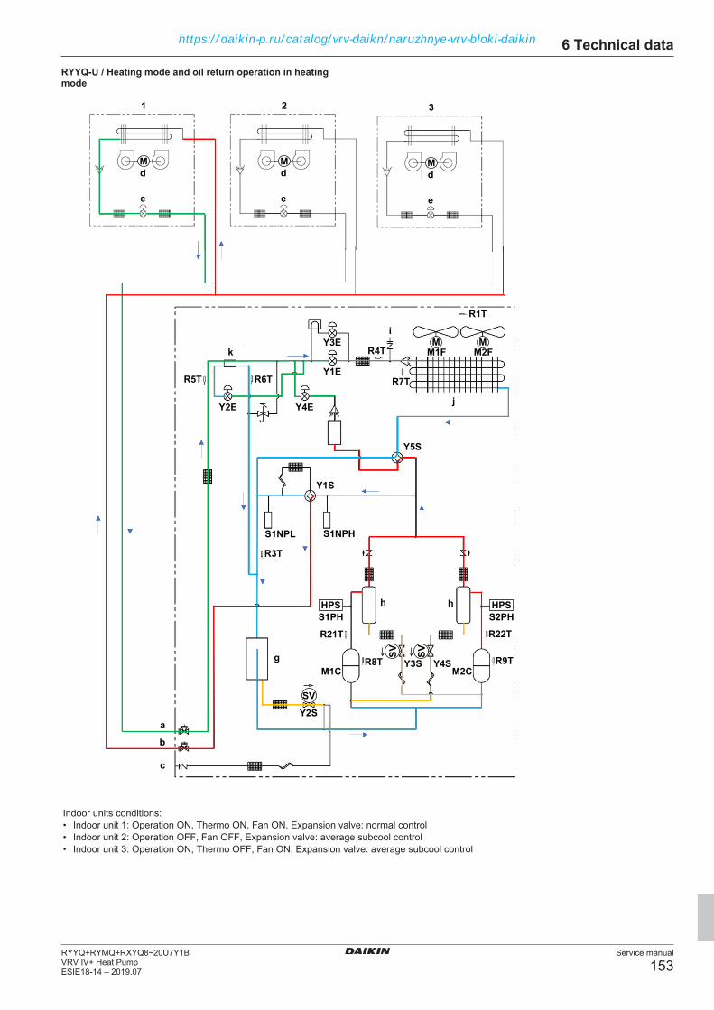
6 Technical data
Service manual
153RYYQ+RYMQ+RXYQ8~20U7Y1BVRV IV+ Heat PumpESIE18-14 – 2019.07
RYYQ-U / Heating mode and oil return operation in heatingmode
c
aY2S
M1C M2C
R21T R22T
R9TR8T
R3T
R6TR5T
R4T M1F M2F
R7T
R1T
dM
M M
e
dM
e
dM
321
e
Y1S
Y5S
Y2E Y4E
Y1E
Y3E
Y4SY3S
S1PH
S1NPHS1NPL
HPS
b
S2PHHPS
SV
SV
SVg
h h
k
i
j
Indoor units conditions:• Indoor unit 1: Operation ON, Thermo ON, Fan ON, Expansion valve: normal control• Indoor unit 2: Operation OFF, Fan OFF, Expansion valve: average subcool control• Indoor unit 3: Operation ON, Thermo OFF, Fan ON, Expansion valve: average subcool control
https://daikin-p.ru/catalog/vrv-daikn/naruzhnye-vrv-bloki-daikin

6 Technical data
Service manual
154RYYQ+RYMQ+RXYQ8~20U7Y1B
VRV IV+ Heat PumpESIE18-14 – 2019.07
RYYQ-U / Defrost operation
c
aY2S
M1C M2C
R21T R22T
R9TR8T
R3T
R6TR5T
R4T M1F M2F
R7T
R1T
dM
M M
e
dM
e
dM
321
e
Y1S
Y5S
Y2E Y4E
Y1E
Y3E
Y4SY3S
S1PH
S1NPHS1NPL
HPS
b
S2PHHPS
SV
SV
SVg
h h
k
i
j
Indoor units conditions:• Indoor unit 1: Operation ON, Thermo ON, Fan ON, Expansion valve: normal control• Indoor unit 2: Operation OFF, Fan OFF, Expansion valve: closed (0 pulse)• Indoor unit 3: Operation ON, Thermo OFF, Fan ON, Expansion valve: closed (0 pulse)
https://daikin-p.ru/catalog/vrv-daikn/naruzhnye-vrv-bloki-daikin

6 Technical data
Service manual
155RYYQ+RYMQ+RXYQ8~20U7Y1BVRV IV+ Heat PumpESIE18-14 – 2019.07
RXYQ-U / Cooling mode
c
aY2S
M1C M2C
R21T R22T
R9TR8T
R3T
R6TR5T
R4T M1F M2F
R7T
R1T
dM
M M
e
dM
e
dM
321
e
Y1S
Y2E
Y1E
Y3E
Y4SY3S
S1PH
S1NPHS1NPL
HPS
b
S2PHHPS
SV
SV
SVg
h h
k
i
j
Indoor units conditions:• Indoor unit 1: Operation ON, Thermo ON, Fan ON, Expansion valve: normal control• Indoor unit 2: Operation OFF, Fan OFF, Expansion valve: closed (0 pulse)• Indoor unit 3: Operation ON, Thermo OFF, Fan ON, Expansion valve: closed (0 pulse)
https://daikin-p.ru/catalog/vrv-daikn/naruzhnye-vrv-bloki-daikin

6 Technical data
Service manual
156RYYQ+RYMQ+RXYQ8~20U7Y1B
VRV IV+ Heat PumpESIE18-14 – 2019.07
RXYQ-U / Oil return operation in cooling mode
c
aY2S
M1C M2C
R21T R22T
R9TR8T
R3T
R6TR5T
R4T M1F M2F
R7T
R1T
dM
M M
e
dM
e
dM
321
e
Y1S
Y2E
Y1E
Y3E
Y4SY3S
S1PH
S1NPHS1NPL
HPS
b
S2PHHPS
SV
SV
SVg
h h
k
i
j
Indoor units conditions:• Indoor unit 1: Operation ON, Thermo ON, Fan ON, Expansion valve: normal control• Indoor unit 2: Operation OFF, Fan OFF, Expansion valve: 224 pulses• Indoor unit 3: Operation ON, Thermo OFF, Fan ON, Expansion valve: normal control
https://daikin-p.ru/catalog/vrv-daikn/naruzhnye-vrv-bloki-daikin

6 Technical data
Service manual
157RYYQ+RYMQ+RXYQ8~20U7Y1BVRV IV+ Heat PumpESIE18-14 – 2019.07
RXYQ-U / Heating mode
c
aY2S
M1C M2C
R21T R22T
R9TR8T
R3T
R6TR5T
R4T M1F M2F
R7T
R1T
dM
M M
e
dM
e
dM
321
e
Y1S
Y2E
Y1E
Y3E
Y4SY3S
S1PH
S1NPHS1NPL
HPS
b
S2PHHPS
SV
SV
SVg
h h
k
i
j
Indoor units conditions:• Indoor unit 1: Operation ON, Thermo ON, Fan ON, Expansion valve: normal control• Indoor unit 2: Operation OFF, Fan OFF, Expansion valve: average subcool control• Indoor unit 3: Operation ON, Thermo OFF, Fan ON, Expansion valve: average subcool control
https://daikin-p.ru/catalog/vrv-daikn/naruzhnye-vrv-bloki-daikin
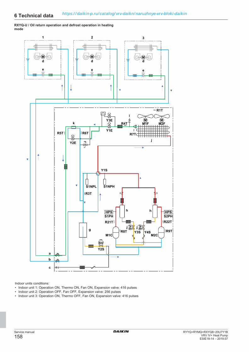
6 Technical data
Service manual
158RYYQ+RYMQ+RXYQ8~20U7Y1B
VRV IV+ Heat PumpESIE18-14 – 2019.07
RXYQ-U / Oil return operation and defrost operation in heatingmode
c
aY2S
M1C M2C
R21T R22T
R9TR8T
R3T
R6TR5T
R4T M1F M2F
R7T
R1T
dM
M M
e
dM
e
dM
321
e
Y1S
Y2E
Y1E
Y3E
Y4SY3S
S1PH
S1NPHS1NPL
HPS
b
S2PHHPS
SV
SV
SVg
h h
k
i
j
Indoor units conditions:• Indoor unit 1: Operation ON, Thermo ON, Fan ON, Expansion valve: 416 pulses• Indoor unit 2: Operation OFF, Fan OFF, Expansion valve: 256 pulses• Indoor unit 3: Operation ON, Thermo OFF, Fan ON, Expansion valve: 416 pulses
https://daikin-p.ru/catalog/vrv-daikn/naruzhnye-vrv-bloki-daikin

6 Technical data
Service manual
159RYYQ+RYMQ+RXYQ8~20U7Y1BVRV IV+ Heat PumpESIE18-14 – 2019.07
RYMQ-U / Cooling mode
f
c
aY2S
M1C M2CR21T R22T
R9TR8T
R3T
R6TR5T
R4T M1F M2F
R7T
R1T
dM
M M
e
dM
e
dM
321
e
Y1S
Y2E
Y1E
Y3E
Y4SY3S
S1PH
S1NPHS1NPL
HPS
b
S2PHHPS
SV
SVSV
f
c
aY2S
M1C M2CR21T R22T
R9TR8T
R3T
R6TR5T
R4T M1F M2F
R7T
R1T
M M
Y1S
Y5S Y5S
Y2E
Y1E
Y3E
Y4SY3S
S1PH
S1NPHS1NPL
HPS
b
S2PHHPS
SV
SVSVg
h h
ki
j
g
h h
ki
j
Indoor units conditions:• Indoor unit 1: Operation ON, Thermo ON, Fan ON, Expansion valve: normal control• Indoor unit 2: Operation OFF, Fan OFF, Expansion valve: closed (0 pulse)• Indoor unit 3: Operation ON, Thermo OFF, Fan ON, Expansion valve: closed (0 pulse)
https://daikin-p.ru/catalog/vrv-daikn/naruzhnye-vrv-bloki-daikin

6 Technical data
Service manual
160RYYQ+RYMQ+RXYQ8~20U7Y1B
VRV IV+ Heat PumpESIE18-14 – 2019.07
RYMQ-U / Oil return operation in cooling mode
f
c
aY2S
M1C M2CR21T R22T
R9TR8T
R3T
R6TR5T
R4T M1F M2F
R7T
R1T
dM
M M
e
dM
e
dM
321
e
Y1S
Y2E
Y1E
Y3E
Y4SY3S
S1PH
S1NPHS1NPL
HPS
b
S2PHHPS
SV
SVSV
f
c
aY2S
M1C M2CR21T R22T
R9TR8T
R3T
R6TR5T
R4T M1F M2F
R7T
R1T
M M
Y1S
Y5S Y5S
Y2E
Y1E
Y3E
Y4SY3S
S1PH
S1NPHS1NPL
HPS
b
S2PHHPS
SVSVSVg
h h
ki
j
g
h h
ki
j
Indoor units conditions:• Indoor unit 1: Operation ON, Thermo ON, Fan ON, Expansion valve: normal control• Indoor unit 2: Operation OFF, Fan OFF, Expansion valve: 224 pulses• Indoor unit 3: Operation ON, Thermo OFF, Fan ON, Expansion valve: normal control
https://daikin-p.ru/catalog/vrv-daikn/naruzhnye-vrv-bloki-daikin

6 Technical data
Service manual
161RYYQ+RYMQ+RXYQ8~20U7Y1BVRV IV+ Heat PumpESIE18-14 – 2019.07
RYMQ-U / Heating mode and oil return in heating mode
f
c
aY2S
M1C M2CR21T R22T
R9TR8T
R3T
R6TR5T
R4T M1F M2F
R7T
R1T
dM
M M
e
dM
e
dM
321
e
Y1S
Y2E
Y1E
Y3E
Y4SY3S
S1PH
S1NPHS1NPL
HPS
b
S2PHHPS
SV
SVSV
f
c
aY2S
M1C M2CR21T R22T
R9TR8T
R3T
R6TR5T
R4T M1F M2F
R7T
R1T
M M
Y1S
Y5S Y5S
Y2E
Y1E
Y3E
Y4SY3S
S1PH
S1NPHS1NPL
HPS
b
S2PHHPS
SV
SVSVg
h h
ki
j
g
h h
ki
j
Indoor units conditions:• Indoor unit 1: Operation ON, Thermo ON, Fan ON, Expansion valve: normal control• Indoor unit 2: Operation OFF, Fan OFF, Expansion valve: average subcool ontrol• Indoor unit 3: Operation ON, Thermo OFF, Fan ON, average subcool control
https://daikin-p.ru/catalog/vrv-daikn/naruzhnye-vrv-bloki-daikin
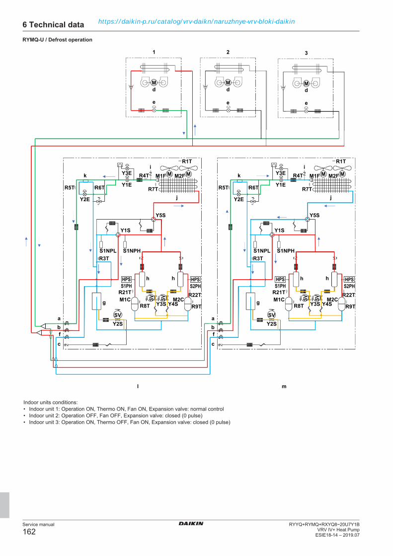
6 Technical data
Service manual
162RYYQ+RYMQ+RXYQ8~20U7Y1B
VRV IV+ Heat PumpESIE18-14 – 2019.07
RYMQ-U / Defrost operation
f
c
aY2S
l m
M1C M2CR21T R22T
R9TR8T
R3T
R6TR5T
R4T M1F M2F
R7T
R1T
dM
M M
e
dM
e
dM
321
e
Y1S
Y2E
Y1E
Y3E
Y4SY3S
S1PH
S1NPHS1NPL
HPS
b
S2PHHPS
SV
SVSV
f
c
aY2S
M1C M2CR21T R22T
R9TR8T
R3T
R6TR5T
R4T M1F M2F
R7T
R1T
M M
Y1S
Y5S Y5S
Y2E
Y1E
Y3E
Y4SY3S
S1PH
S1NPHS1NPL
HPS
b
S2PHHPS
SVSVSVg
h h
ki
j
g
h h
ki
j
Indoor units conditions:• Indoor unit 1: Operation ON, Thermo ON, Fan ON, Expansion valve: normal control• Indoor unit 2: Operation OFF, Fan OFF, Expansion valve: closed (0 pulse)• Indoor unit 3: Operation ON, Thermo OFF, Fan ON, Expansion valve: closed (0 pulse)
https://daikin-p.ru/catalog/vrv-daikn/naruzhnye-vrv-bloki-daikin
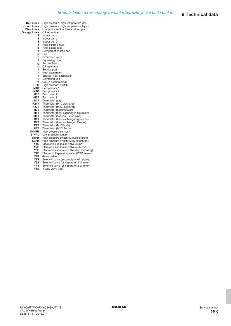
6 Technical data
Service manual
163RYYQ+RYMQ+RXYQ8~20U7Y1BVRV IV+ Heat PumpESIE18-14 – 2019.07
Red Lines High pressure, high temperature gasGreen Lines High pressure, high temperature liquid
Blue Lines Low pressure, low temperature gasOrange Lines Oil return line
1 Indoor unit 12 Indoor unit 23 Indoor unit 3a Field piping (liquid)b Field piping (gas)c Refrigerant charge portd Fane Expansion valvef Equalizing pipeg Accumulatorh Oil separatori Service portj Heat exchanger
k Subcool heat exchangerl Defrosting unit
m Unit in heating modeHPS High pressure switchM1C Compressor 1M2C Compressor 2M1F Fan motor 1
-M2F Fan motor 2R1T Thermistor (air)
R21T Thermistor (M1Cdischarge)R22T Thermistor (M2C discharge)
R3T Thermistor (accumulator)R4T Thermistor (heat exchanger, liquid pipe)R5T Thermistor (subcool, liquid pipe)R6T Thermistor (heat exchanger, gas pipe)R7T Thermistor (heat exchanger, Deicer)R8T Thermistor (M1CBody)R9T Thermistor (M2C Body)
S1NPH High pressure sensorS1NPL Low pressure sensor
S1PH High pressure switch (M1Cdischarge)S2PH High pressure switch (M2C discharge)
Y1E Electronic expansion valve (main)Y2E Electronic expansion valve (sub‑cool)Y3E Electronic expansion valve (liquid cooling)Y4E Electronic Expansion Valve (PCM vessel)Y1S 4‑way valveY2S Solenoid valve (accumulator oil return)Y3S Solenoid valve (oil separator 1 oil return)Y4S Solenoid valve (oil separator 2 oil return)Y5S 4 Way valve (sub)
https://daikin-p.ru/catalog/vrv-daikn/naruzhnye-vrv-bloki-daikin

6 Technical data
Service manual
164RYYQ+RYMQ+RXYQ8~20U7Y1B
VRV IV+ Heat PumpESIE18-14 – 2019.07
6.4 Component overview
6.4.1 Component overview: RXYQ8~12U unitsa
a
fg
b p
hi
l
n
m
g
c
k
j
c
k
o
j
l
s
v
q
t
u
w
de
p
r
i
n
m
a Switchbox, for details see "6.5 Switchbox overview" onpage 182.
b Fan motorc Liquid cooling expansion valve Y3Ed Liquid pipe thermistor, outdoor heat exchanger R4Te Liquid pipe thermistor, sub‑cool heat exchanger R5Tf Oil separatorg Compressor M1Ch Oil return valve Y2Si Charge portj Gas stop valve
k Liquid stop valvel Service port
m Main expansion valve Y1En Sub‑cool expansion Valve Y2Eo Low pressure sensor S1NPL
p 4-way valve Y1Sq Accumulator inlet thermistor R3Tr Refrigerant high pressure sensor S1NPHs High pressure switch S1PHt Compressor (M1C ) discharge thermistor R21Tu Compressor (M1C ) body thermistor R8Tv Filterw Gas pipe thermistor, sub‑cool heat exchanger R6Tx Liquid receivery Heat exchangerz De‑icer thermistor, outdoor heat exchanger R7T
aa Filterab Oil return valve Y3Sac Filter
https://daikin-p.ru/catalog/vrv-daikn/naruzhnye-vrv-bloki-daikin

6 Technical data
Service manual
165RYYQ+RYMQ+RXYQ8~20U7Y1BVRV IV+ Heat PumpESIE18-14 – 2019.07
xa
ab
x
aa hv
mco
z
y
aca Switchbox, for details see "6.5 Switchbox overview" on
page 182.b Fan motorc Liquid cooling expansion valve Y3Ed Liquid pipe thermistor, outdoor heat exchanger R4Te Liquid pipe thermistor, sub‑cool heat exchanger R5Tf Oil separatorg Compressor M1Ch Oil return valve Y2Si Charge portj Gas stop valve
k Liquid stop valvel Service port
m Main expansion valve Y1En Sub‑cool expansion Valve Y2Eo Low pressure sensor S1NPL
p 4-way valve Y1Sq Accumulator inlet thermistor R3Tr Refrigerant high pressure sensor S1NPHs High pressure switch S1PHt Compressor (M1C ) discharge thermistor R21Tu Compressor (M1C ) body thermistor R8Tv Filterw Gas pipe thermistor, sub‑cool heat exchanger R6Tx Accumulatory Heat exchangerz De‑icer thermistor, outdoor heat exchanger R7T
aa Filterab Oil return valve Y3Sac Filter
https://daikin-p.ru/catalog/vrv-daikn/naruzhnye-vrv-bloki-daikin
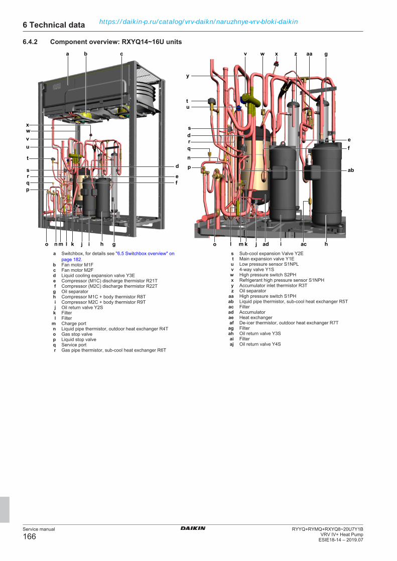
6 Technical data
Service manual
166RYYQ+RYMQ+RXYQ8~20U7Y1B
VRV IV+ Heat PumpESIE18-14 – 2019.07
6.4.2 Component overview: RXYQ14~16U unitsa
gh
c v
m
rs
h
p
e
o
u
j
q
w
ac
t
d
d
f
v
x
i
r
t
b
w
i
q p
n
s
u
x aa
n
l kl k j
y
ab
gz
admo
ef
a Switchbox, for details see "6.5 Switchbox overview" onpage 182.
b Fan motor M1Fc Fan motor M2Fd Liquid cooling expansion valve Y3Ee Compressor (M1C) discharge thermistor R21Tf Compressor (M2C) discharge thermistor R22Tg Oil separatorh Compressor M1C + body thermistor R8Ti Compressor M2C + body thermistor R9Tj Oil return valve Y2S
k Filterl Filter
m Charge portn Liquid pipe thermistor, outdoor heat exchanger R4To Gas stop valvep Liquid stop valveq Service portr Gas pipe thermistor, sub‑cool heat exchanger R6T
s Sub‑cool expansion Valve Y2Et Main expansion valve Y1Eu Low pressure sensor S1NPLv 4-way valve Y1Sw High pressure switch S2PHx Refrigerant high pressure sensor S1NPHy Accumulator inlet thermistor R3Tz Oil separator
aa High pressure switch S1PHab Liquid pipe thermistor, sub‑cool heat exchanger R5Tac Filterad Accumulatorae Heat exchangeraf De‑icer thermistor, outdoor heat exchanger R7Tag Filterah Oil return valve Y3Sai Filteraj Oil return valve Y4S
https://daikin-p.ru/catalog/vrv-daikn/naruzhnye-vrv-bloki-daikin
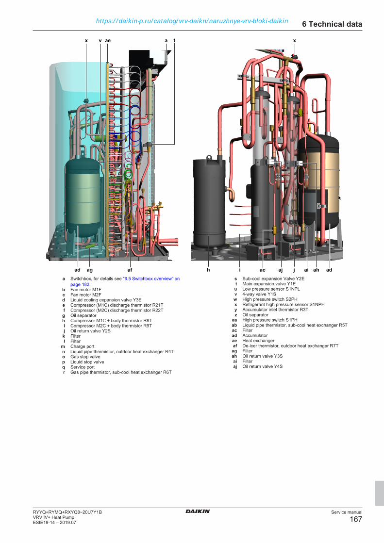
6 Technical data
Service manual
167RYYQ+RYMQ+RXYQ8~20U7Y1BVRV IV+ Heat PumpESIE18-14 – 2019.07
xa
aj
x
ag ji
tv
af
ae
acad h ahai ada Switchbox, for details see "6.5 Switchbox overview" on
page 182.b Fan motor M1Fc Fan motor M2Fd Liquid cooling expansion valve Y3Ee Compressor (M1C) discharge thermistor R21Tf Compressor (M2C) discharge thermistor R22Tg Oil separatorh Compressor M1C + body thermistor R8Ti Compressor M2C + body thermistor R9Tj Oil return valve Y2S
k Filterl Filter
m Charge portn Liquid pipe thermistor, outdoor heat exchanger R4To Gas stop valvep Liquid stop valveq Service portr Gas pipe thermistor, sub‑cool heat exchanger R6T
s Sub‑cool expansion Valve Y2Et Main expansion valve Y1Eu Low pressure sensor S1NPLv 4-way valve Y1Sw High pressure switch S2PHx Refrigerant high pressure sensor S1NPHy Accumulator inlet thermistor R3Tz Oil separator
aa High pressure switch S1PHab Liquid pipe thermistor, sub‑cool heat exchanger R5Tac Filterad Accumulatorae Heat exchangeraf De‑icer thermistor, outdoor heat exchanger R7Tag Filterah Oil return valve Y3Sai Filteraj Oil return valve Y4S
https://daikin-p.ru/catalog/vrv-daikn/naruzhnye-vrv-bloki-daikin
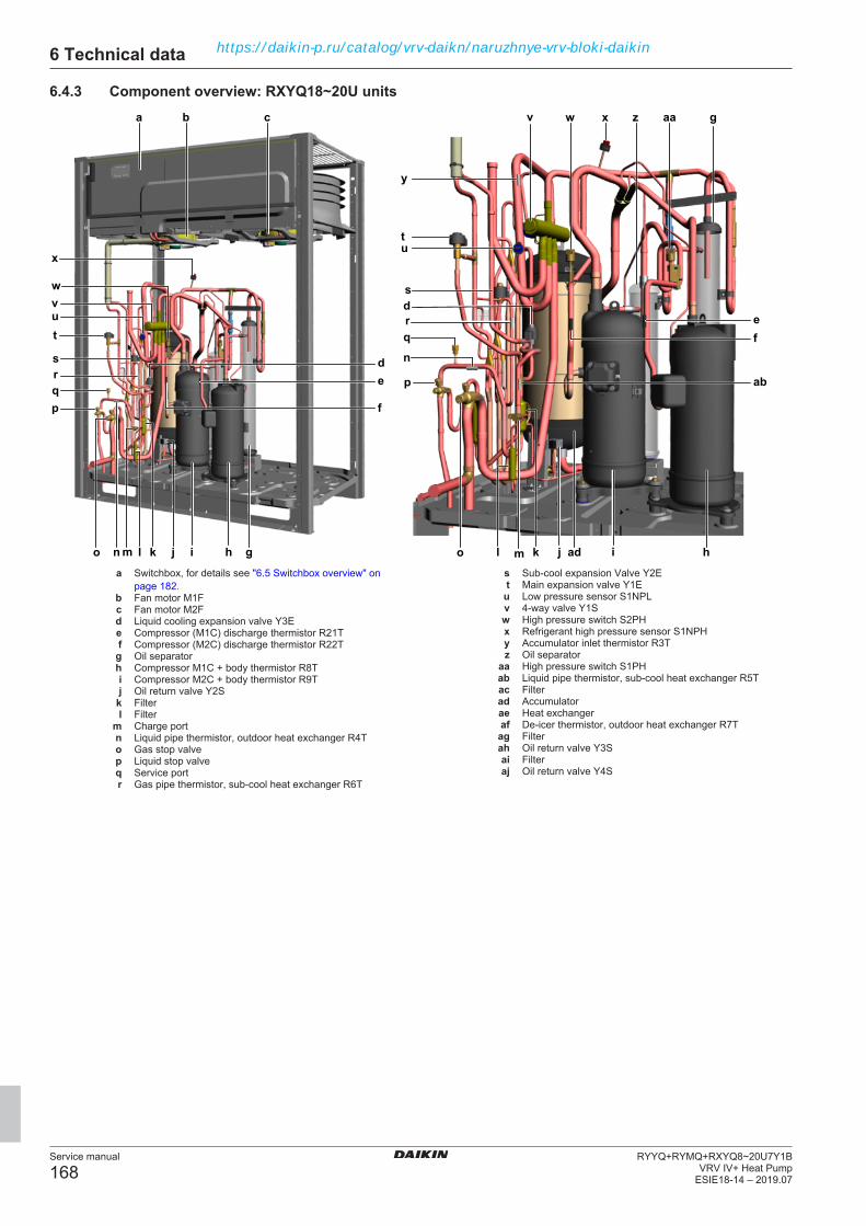
6 Technical data
Service manual
168RYYQ+RYMQ+RXYQ8~20U7Y1B
VRV IV+ Heat PumpESIE18-14 – 2019.07
6.4.3 Component overview: RXYQ18~20U unitsa
gh
c v
m
rs
h
pe
o
u
j
q
w
t
d
d
f
v
x
i
r
t
b
w
i
q p
n
s
u
x aa
n
l kl k j
y
ab
gz
admo
ef
a Switchbox, for details see "6.5 Switchbox overview" onpage 182.
b Fan motor M1Fc Fan motor M2Fd Liquid cooling expansion valve Y3Ee Compressor (M1C) discharge thermistor R21Tf Compressor (M2C) discharge thermistor R22Tg Oil separatorh Compressor M1C + body thermistor R8Ti Compressor M2C + body thermistor R9Tj Oil return valve Y2S
k Filterl Filter
m Charge portn Liquid pipe thermistor, outdoor heat exchanger R4To Gas stop valvep Liquid stop valveq Service portr Gas pipe thermistor, sub‑cool heat exchanger R6T
s Sub‑cool expansion Valve Y2Et Main expansion valve Y1Eu Low pressure sensor S1NPLv 4-way valve Y1Sw High pressure switch S2PHx Refrigerant high pressure sensor S1NPHy Accumulator inlet thermistor R3Tz Oil separator
aa High pressure switch S1PHab Liquid pipe thermistor, sub‑cool heat exchanger R5Tac Filterad Accumulatorae Heat exchangeraf De‑icer thermistor, outdoor heat exchanger R7Tag Filterah Oil return valve Y3Sai Filteraj Oil return valve Y4S
https://daikin-p.ru/catalog/vrv-daikn/naruzhnye-vrv-bloki-daikin
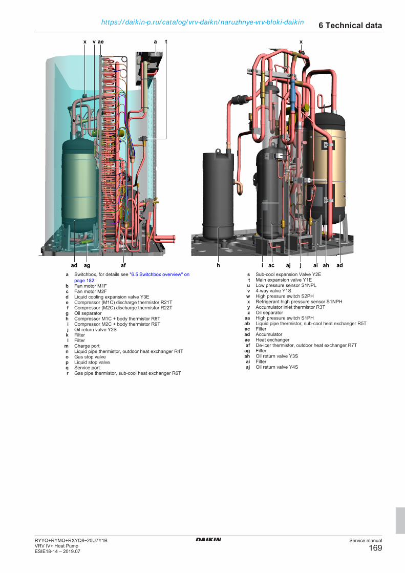
6 Technical data
Service manual
169RYYQ+RYMQ+RXYQ8~20U7Y1BVRV IV+ Heat PumpESIE18-14 – 2019.07
xa
aj
x
ag ji
tv
af
ae
acad h ahai ada Switchbox, for details see "6.5 Switchbox overview" on
page 182.b Fan motor M1Fc Fan motor M2Fd Liquid cooling expansion valve Y3Ee Compressor (M1C) discharge thermistor R21Tf Compressor (M2C) discharge thermistor R22Tg Oil separatorh Compressor M1C + body thermistor R8Ti Compressor M2C + body thermistor R9Tj Oil return valve Y2S
k Filterl Filter
m Charge portn Liquid pipe thermistor, outdoor heat exchanger R4To Gas stop valvep Liquid stop valveq Service portr Gas pipe thermistor, sub‑cool heat exchanger R6T
s Sub‑cool expansion Valve Y2Et Main expansion valve Y1Eu Low pressure sensor S1NPLv 4-way valve Y1Sw High pressure switch S2PHx Refrigerant high pressure sensor S1NPHy Accumulator inlet thermistor R3Tz Oil separator
aa High pressure switch S1PHab Liquid pipe thermistor, sub‑cool heat exchanger R5Tac Filterad Accumulatorae Heat exchangeraf De‑icer thermistor, outdoor heat exchanger R7Tag Filterah Oil return valve Y3Sai Filteraj Oil return valve Y4S
https://daikin-p.ru/catalog/vrv-daikn/naruzhnye-vrv-bloki-daikin

6 Technical data
Service manual
170RYYQ+RYMQ+RXYQ8~20U7Y1B
VRV IV+ Heat PumpESIE18-14 – 2019.07
6.4.4 Component overview: RYMQ8~12U unitsa
a
fg
b p
hi
l
nm
g
c
k
j
c
k
o
j
l
s
v
q
t
u
w
d
e
p
r
i
n
m
r
ad
ad v
v
ae aea Switchbox, for details see "6.5 Switchbox overview" on
page 182.b Fan motorc Liquid cooling expansion valve Y3Ed Liquid pipe thermistor, outdoor heat exchanger R4Te Liquid pipe thermistor, sub‑cool heat exchanger R5Tf Oil separatorg Compressor M1Ch Oil return valve Y2Si Charge portj Gas stop valve
k Liquid stop valvel Service port
m Main expansion valve Y1En Sub‑cool expansion Valve Y2Eo Low pressure sensor S1NPL
p 4-way valve Y1Sq Accumulator inlet thermistor R3Tr Refrigerant high pressure sensor S1NPHs High pressure switch S1PHt Compressor (M1C ) discharge thermistor R21Tu Compressor (M1C ) body thermistor R8Tv Filterw Gas pipe thermistor, sub‑cool heat exchanger R6Tx Liquid receivery Heat exchangerz De‑icer thermistor, outdoor heat exchanger R7T
aa Filterab Oil return valve Y3Sac Filterad 4‑way valve Y5Sae Equalising pipe
https://daikin-p.ru/catalog/vrv-daikn/naruzhnye-vrv-bloki-daikin
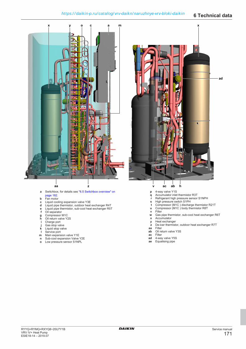
6 Technical data
Service manual
171RYYQ+RYMQ+RXYQ8~20U7Y1BVRV IV+ Heat PumpESIE18-14 – 2019.07
xa
ab
x
aa hv
mco
z
y
ac
ad
a Switchbox, for details see "6.5 Switchbox overview" onpage 182.
b Fan motorc Liquid cooling expansion valve Y3Ed Liquid pipe thermistor, outdoor heat exchanger R4Te Liquid pipe thermistor, sub‑cool heat exchanger R5Tf Oil separatorg Compressor M1Ch Oil return valve Y2Si Charge portj Gas stop valve
k Liquid stop valvel Service port
m Main expansion valve Y1En Sub‑cool expansion Valve Y2Eo Low pressure sensor S1NPL
p 4-way valve Y1Sq Accumulator inlet thermistor R3Tr Refrigerant high pressure sensor S1NPHs High pressure switch S1PHt Compressor (M1C ) discharge thermistor R21Tu Compressor (M1C ) body thermistor R8Tv Filterw Gas pipe thermistor, sub‑cool heat exchanger R6Tx Accumulatory Heat exchangerz De‑icer thermistor, outdoor heat exchanger R7T
aa Filterab Oil return valve Y3Sac Filterad 4‑way valve Y5Sae Equalising pipe
https://daikin-p.ru/catalog/vrv-daikn/naruzhnye-vrv-bloki-daikin

6 Technical data
Service manual
172RYYQ+RYMQ+RXYQ8~20U7Y1B
VRV IV+ Heat PumpESIE18-14 – 2019.07
6.4.5 Component overview: RYMQ14~16U unitsa
gh
c v
m
rs
h
pe
o
u
j
q
w
ac
td
d
f
v
x
i
t
b
w
i
q p
n
s
u
aa
n
l kl k j
y
ab
gz
admo
ef
ak
a Switchbox, for details see "6.5 Switchbox overview" onpage 182.
b Fan motor M1Fc Fan motor M2Fd Liquid cooling expansion valve Y3Ee Compressor (M1C) discharge thermistor R21Tf Compressor (M2C) discharge thermistor R22Tg Oil separatorh Compressor M1C + body thermistor R8Ti Compressor M2C + body thermistor R9Tj Oil return valve Y2S
k Filterl Filter
m Charge portn Liquid pipe thermistor, outdoor heat exchanger R4To Gas stop valvep Liquid stop valveq Service portr Gas pipe thermistor, sub‑cool heat exchanger R6Ts Sub‑cool expansion Valve Y2E
t Main expansion valve Y1Eu Low pressure sensor S1NPLv 4-way valve Y1Sw High pressure switch S2PHx Refrigerant high pressure sensor S1NPHy Accumulator inlet thermistor R3Tz Oil separator
aa High pressure switch S1PHab Liquid pipe thermistor, sub‑cool heat exchanger R5Tac Filterad Accumulatorae Heat exchangeraf De‑icer thermistor, outdoor heat exchanger R7Tag Filterah Oil return valve Y3Sai Filteraj Oil return valve Y4S
ak 4‑way valve Y5S
https://daikin-p.ru/catalog/vrv-daikn/naruzhnye-vrv-bloki-daikin
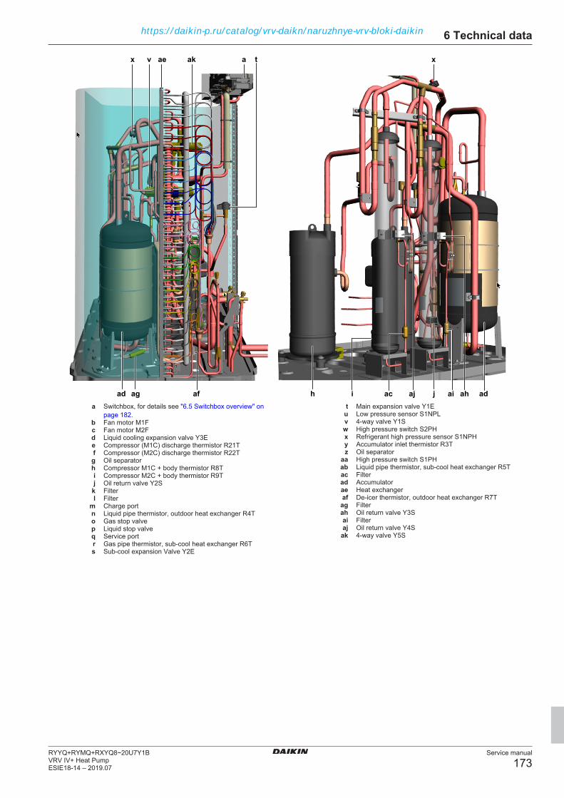
6 Technical data
Service manual
173RYYQ+RYMQ+RXYQ8~20U7Y1BVRV IV+ Heat PumpESIE18-14 – 2019.07
xa
aj
x
ag ji
tv
af
ae
acad h ahai ad
ak
a Switchbox, for details see "6.5 Switchbox overview" onpage 182.
b Fan motor M1Fc Fan motor M2Fd Liquid cooling expansion valve Y3Ee Compressor (M1C) discharge thermistor R21Tf Compressor (M2C) discharge thermistor R22Tg Oil separatorh Compressor M1C + body thermistor R8Ti Compressor M2C + body thermistor R9Tj Oil return valve Y2S
k Filterl Filter
m Charge portn Liquid pipe thermistor, outdoor heat exchanger R4To Gas stop valvep Liquid stop valveq Service portr Gas pipe thermistor, sub‑cool heat exchanger R6Ts Sub‑cool expansion Valve Y2E
t Main expansion valve Y1Eu Low pressure sensor S1NPLv 4-way valve Y1Sw High pressure switch S2PHx Refrigerant high pressure sensor S1NPHy Accumulator inlet thermistor R3Tz Oil separator
aa High pressure switch S1PHab Liquid pipe thermistor, sub‑cool heat exchanger R5Tac Filterad Accumulatorae Heat exchangeraf De‑icer thermistor, outdoor heat exchanger R7Tag Filterah Oil return valve Y3Sai Filteraj Oil return valve Y4S
ak 4‑way valve Y5S
https://daikin-p.ru/catalog/vrv-daikn/naruzhnye-vrv-bloki-daikin

6 Technical data
Service manual
174RYYQ+RYMQ+RXYQ8~20U7Y1B
VRV IV+ Heat PumpESIE18-14 – 2019.07
6.4.6 Component overview: RYMQ18~20U unitsa
gh
c v
m
rs
h
pe
o
u
j
q
w
td
d
f
v
x
i
t
b
w
i
q p
n
s
u
aa
n
l kl k j
y
ab
gz
admo
ef
ak
al
ak
a Switchbox, for details see "6.5 Switchbox overview" onpage 182.
b Fan motor M1Fc Fan motor M2Fd Liquid cooling expansion valve Y3Ee Compressor (M1C) discharge thermistor R21Tf Compressor (M2C) discharge thermistor R22Tg Oil separatorh Compressor M1C + body thermistor R8Ti Compressor M2C + body thermistor R9Tj Oil return valve Y2S
k Filterl Filter
m Charge portn Liquid pipe thermistor, outdoor heat exchanger R4To Gas stop valvep Liquid stop valveq Service portr Gas pipe thermistor, sub‑cool heat exchanger R6Ts Sub‑cool expansion Valve Y2E
t Main expansion valve Y1Eu Low pressure sensor S1NPLv 4-way valve Y1Sw High pressure switch S2PHx Refrigerant high pressure sensor S1NPHy Accumulator inlet thermistor R3Tz Oil separator
aa High pressure switch S1PHab Liquid pipe thermistor, sub‑cool heat exchanger R5Tac Filterad Accumulatorae Heat exchangeraf De‑icer thermistor, outdoor heat exchanger R7Tag Filterah Oil return valve Y3Sai Filteraj Oil return valve Y4S
ak 4‑way valve Y5Sal Equalisation pipe
https://daikin-p.ru/catalog/vrv-daikn/naruzhnye-vrv-bloki-daikin

6 Technical data
Service manual
175RYYQ+RYMQ+RXYQ8~20U7Y1BVRV IV+ Heat PumpESIE18-14 – 2019.07
xa
aj
x
ag ji
tv
af
ae
acad h ahai ad
ak
a Switchbox, for details see "6.5 Switchbox overview" onpage 182.
b Fan motor M1Fc Fan motor M2Fd Liquid cooling expansion valve Y3Ee Compressor (M1C) discharge thermistor R21Tf Compressor (M2C) discharge thermistor R22Tg Oil separatorh Compressor M1C + body thermistor R8Ti Compressor M2C + body thermistor R9Tj Oil return valve Y2S
k Filterl Filter
m Charge portn Liquid pipe thermistor, outdoor heat exchanger R4To Gas stop valvep Liquid stop valveq Service portr Gas pipe thermistor, sub‑cool heat exchanger R6Ts Sub‑cool expansion Valve Y2E
t Main expansion valve Y1Eu Low pressure sensor S1NPLv 4-way valve Y1Sw High pressure switch S2PHx Refrigerant high pressure sensor S1NPHy Accumulator inlet thermistor R3Tz Oil separator
aa High pressure switch S1PHab Liquid pipe thermistor, sub‑cool heat exchanger R5Tac Filterad Accumulatorae Heat exchangeraf De‑icer thermistor, outdoor heat exchanger R7Tag Filterah Oil return valve Y3Sai Filteraj Oil return valve Y4S
ak 4‑way valve Y5Sal Equalisation pipe
https://daikin-p.ru/catalog/vrv-daikn/naruzhnye-vrv-bloki-daikin
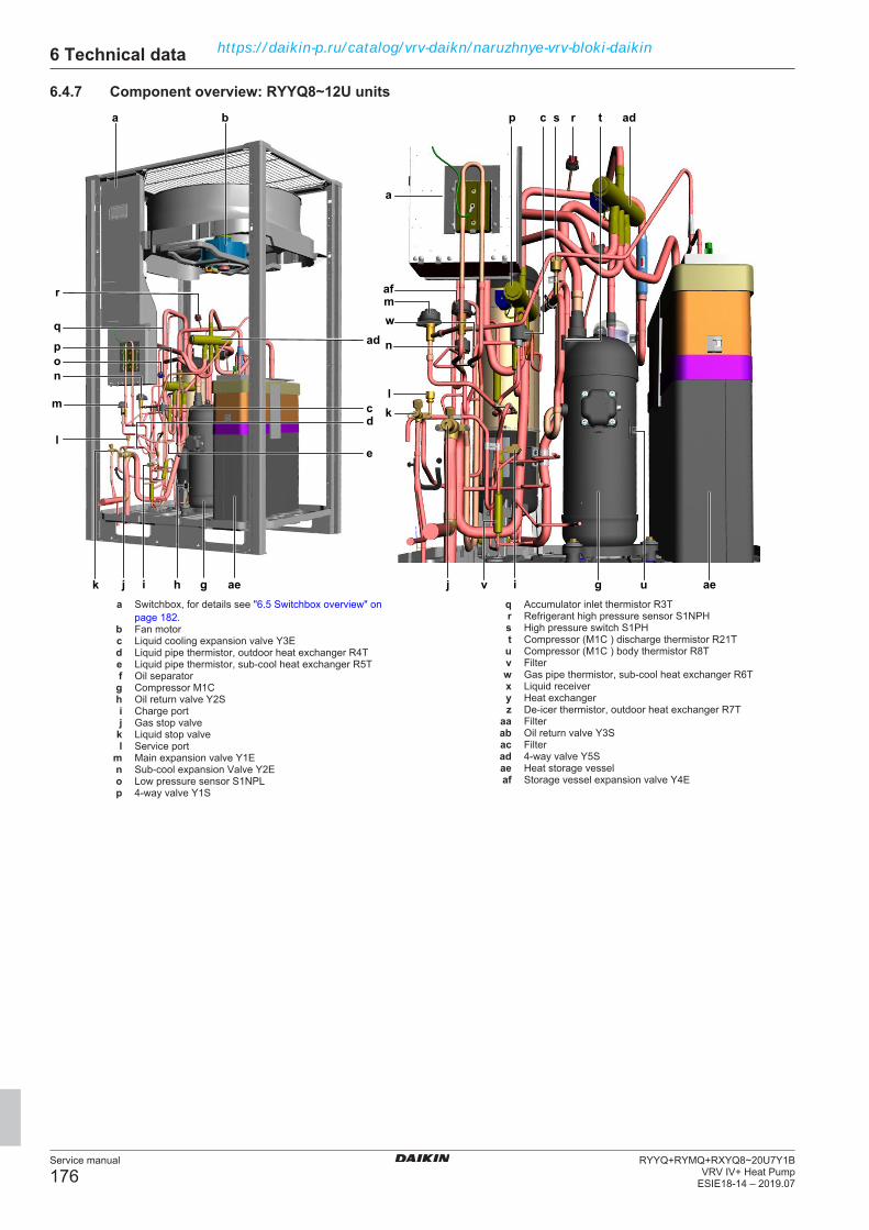
6 Technical data
Service manual
176RYYQ+RYMQ+RXYQ8~20U7Y1B
VRV IV+ Heat PumpESIE18-14 – 2019.07
6.4.7 Component overview: RYYQ8~12U unitsa
a
aeg
b p
hi
l
n
m
g
c
k
j
c
k
o
j
l
s
v
q
t
u
w
d
e
p
r
i
n
m
ad
ae
r ad
af
a Switchbox, for details see "6.5 Switchbox overview" onpage 182.
b Fan motorc Liquid cooling expansion valve Y3Ed Liquid pipe thermistor, outdoor heat exchanger R4Te Liquid pipe thermistor, sub‑cool heat exchanger R5Tf Oil separatorg Compressor M1Ch Oil return valve Y2Si Charge portj Gas stop valve
k Liquid stop valvel Service port
m Main expansion valve Y1En Sub‑cool expansion Valve Y2Eo Low pressure sensor S1NPLp 4-way valve Y1S
q Accumulator inlet thermistor R3Tr Refrigerant high pressure sensor S1NPHs High pressure switch S1PHt Compressor (M1C ) discharge thermistor R21Tu Compressor (M1C ) body thermistor R8Tv Filterw Gas pipe thermistor, sub‑cool heat exchanger R6Tx Liquid receivery Heat exchangerz De‑icer thermistor, outdoor heat exchanger R7T
aa Filterab Oil return valve Y3Sac Filterad 4‑way valve Y5Sae Heat storage vesselaf Storage vessel expansion valve Y4E
https://daikin-p.ru/catalog/vrv-daikn/naruzhnye-vrv-bloki-daikin

6 Technical data
Service manual
177RYYQ+RYMQ+RXYQ8~20U7Y1BVRV IV+ Heat PumpESIE18-14 – 2019.07
xa
ab
x
aa hv
mco
z
y
acaea Switchbox, for details see "6.5 Switchbox overview" on
page 182.b Fan motorc Liquid cooling expansion valve Y3Ed Liquid pipe thermistor, outdoor heat exchanger R4Te Liquid pipe thermistor, sub‑cool heat exchanger R5Tf Oil separatorg Compressor M1Ch Oil return valve Y2Si Charge portj Gas stop valve
k Liquid stop valvel Service port
m Main expansion valve Y1En Sub‑cool expansion Valve Y2Eo Low pressure sensor S1NPLp 4-way valve Y1S
q Accumulator inlet thermistor R3Tr Refrigerant high pressure sensor S1NPHs High pressure switch S1PHt Compressor (M1C ) discharge thermistor R21Tu Compressor (M1C ) body thermistor R8Tv Filterw Gas pipe thermistor, sub‑cool heat exchanger R6Tx Accumulatory Heat exchangerz De‑icer thermistor, outdoor heat exchanger R7T
aa Filterab Oil return valve Y3Sac Filterad 4‑way valve Y5Sae Heat storage vesselaf Storage vessel expansion valve Y4E
https://daikin-p.ru/catalog/vrv-daikn/naruzhnye-vrv-bloki-daikin

6 Technical data
Service manual
178RYYQ+RYMQ+RXYQ8~20U7Y1B
VRV IV+ Heat PumpESIE18-14 – 2019.07
6.4.8 Component overview: RYYQ14~16U unitsa
alh
c v
m
rs
h
pe
o
u
j
q
w
t dd
f
v
x
i
t
b
w
i
q p
n
s
u
aa
n
l kl k j
y
ab
gz
admo
ef
ak
ak
am
a Switchbox, for details see "6.5 Switchbox overview" onpage 182.
b Fan motor M1Fc Fan motor M2Fd Liquid cooling expansion valve Y3Ee Compressor (M1C) discharge thermistor R21Tf Compressor (M2C) discharge thermistor R22Tg Oil separatorh Compressor M1C + body thermistor R8Ti Compressor M2C + body thermistor R9Tj Oil return valve Y2S
k Filterl Filter
m Charge portn Liquid pipe thermistor, outdoor heat exchanger R4To Gas stop valvep Liquid stop valveq Service portr Gas pipe thermistor, sub‑cool heat exchanger R6Ts Sub‑cool expansion Valve Y2Et Main expansion valve Y1E
u Low pressure sensor S1NPLv 4-way valve Y1Sw High pressure switch S2PHx Refrigerant high pressure sensor S1NPHy Accumulator inlet thermistor R3Tz Oil separator
aa High pressure switch S1PHab Liquid pipe thermistor, sub‑cool heat exchanger R5Tac Filterad Accumulatorae Heat exchangeraf De‑icer thermistor, outdoor heat exchanger R7Tag Filterah Oil return valve Y3Sai Filteraj Oil return valve Y4S
ak 4‑way valve Y5Sal Heat storage vessel
am Storage vessel expansion valve Y4E
https://daikin-p.ru/catalog/vrv-daikn/naruzhnye-vrv-bloki-daikin
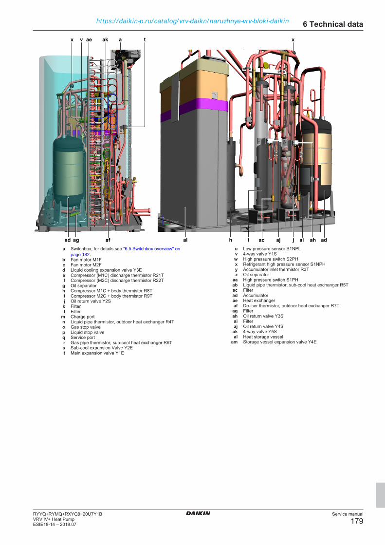
6 Technical data
Service manual
179RYYQ+RYMQ+RXYQ8~20U7Y1BVRV IV+ Heat PumpESIE18-14 – 2019.07
xa
aj
x
ag ji
tv
af
ae
acad h ahai ad
ak
ala Switchbox, for details see "6.5 Switchbox overview" on
page 182.b Fan motor M1Fc Fan motor M2Fd Liquid cooling expansion valve Y3Ee Compressor (M1C) discharge thermistor R21Tf Compressor (M2C) discharge thermistor R22Tg Oil separatorh Compressor M1C + body thermistor R8Ti Compressor M2C + body thermistor R9Tj Oil return valve Y2S
k Filterl Filter
m Charge portn Liquid pipe thermistor, outdoor heat exchanger R4To Gas stop valvep Liquid stop valveq Service portr Gas pipe thermistor, sub‑cool heat exchanger R6Ts Sub‑cool expansion Valve Y2Et Main expansion valve Y1E
u Low pressure sensor S1NPLv 4-way valve Y1Sw High pressure switch S2PHx Refrigerant high pressure sensor S1NPHy Accumulator inlet thermistor R3Tz Oil separator
aa High pressure switch S1PHab Liquid pipe thermistor, sub‑cool heat exchanger R5Tac Filterad Accumulatorae Heat exchangeraf De‑icer thermistor, outdoor heat exchanger R7Tag Filterah Oil return valve Y3Sai Filteraj Oil return valve Y4S
ak 4‑way valve Y5Sal Heat storage vessel
am Storage vessel expansion valve Y4E
https://daikin-p.ru/catalog/vrv-daikn/naruzhnye-vrv-bloki-daikin

6 Technical data
Service manual
180RYYQ+RYMQ+RXYQ8~20U7Y1B
VRV IV+ Heat PumpESIE18-14 – 2019.07
6.4.9 Component overview: RYYQ18~20U unitsa
alh
c v
m
rs
h
pe
o
u
j
q
w
al
t d
d
f
v
x
i
t
b
w
i
q p
n
s
u
aa
n
l kl k j
y
ab
gz
admo
ef
ak
am
ak
a Switchbox, for details see "6.5 Switchbox overview" onpage 182.
b Fan motor M1Fc Fan motor M2Fd Liquid cooling expansion valve Y3Ee Compressor (M1C) discharge thermistor R21Tf Compressor (M2C) discharge thermistor R22Tg Oil separatorh Compressor M1C + body thermistor R8Ti Compressor M2C + body thermistor R9Tj Oil return valve Y2S
k Filterl Filter
m Charge portn Liquid pipe thermistor, outdoor heat exchanger R4To Gas stop valvep Liquid stop valveq Service portr Gas pipe thermistor, sub‑cool heat exchanger R6Ts Sub‑cool expansion Valve Y2Et Main expansion valve Y1E
u Low pressure sensor S1NPLv 4-way valve Y1Sw High pressure switch S2PHx Refrigerant high pressure sensor S1NPHy Accumulator inlet thermistor R3Tz Oil separator
aa High pressure switch S1PHab Liquid pipe thermistor, sub‑cool heat exchanger R5Tac Filterad Accumulatorae Heat exchangeraf De‑icer thermistor, outdoor heat exchanger R7Tag Filterah Oil return valve Y3Sai Filteraj Oil return valve Y4S
ak 4‑way valve Y5Sal Heat storage vessel
am Storage vessel expansion valve Y4E
https://daikin-p.ru/catalog/vrv-daikn/naruzhnye-vrv-bloki-daikin

6 Technical data
Service manual
181RYYQ+RYMQ+RXYQ8~20U7Y1BVRV IV+ Heat PumpESIE18-14 – 2019.07
xa
aj
x
ag ji
tv
af
ae
acad h ahai ad
ak
ala Switchbox, for details see "6.5 Switchbox overview" on
page 182.b Fan motor M1Fc Fan motor M2Fd Liquid cooling expansion valve Y3Ee Compressor (M1C) discharge thermistor R21Tf Compressor (M2C) discharge thermistor R22Tg Oil separatorh Compressor M1C + body thermistor R8Ti Compressor M2C + body thermistor R9Tj Oil return valve Y2S
k Filterl Filter
m Charge portn Liquid pipe thermistor, outdoor heat exchanger R4To Gas stop valvep Liquid stop valveq Service portr Gas pipe thermistor, sub‑cool heat exchanger R6Ts Sub‑cool expansion Valve Y2Et Main expansion valve Y1E
u Low pressure sensor S1NPLv 4-way valve Y1Sw High pressure switch S2PHx Refrigerant high pressure sensor S1NPHy Accumulator inlet thermistor R3Tz Oil separator
aa High pressure switch S1PHab Liquid pipe thermistor, sub‑cool heat exchanger R5Tac Filterad Accumulatorae Heat exchangeraf De‑icer thermistor, outdoor heat exchanger R7Tag Filterah Oil return valve Y3Sai Filteraj Oil return valve Y4S
ak 4‑way valve Y5Sal Heat storage vessel
am Storage vessel expansion valve Y4E
https://daikin-p.ru/catalog/vrv-daikn/naruzhnye-vrv-bloki-daikin

6 Technical data
Service manual
182RYYQ+RYMQ+RXYQ8~20U7Y1B
VRV IV+ Heat PumpESIE18-14 – 2019.07
6.5 Switchbox overview
6.5.1 Single fan units
a
c
b
a
c
bd
F R
e
fgh
i
j
k
l
a Switchboxb Fan motor (M1F)c Compressor (M1C)
F Front viewR Rear viewd Main PCB (A1P)e Optional cool/heat selector PCB (A5P)f Rectifier voltage check connector (X3A)g Main supply connection terminal (X1M)h M1F (X1A)i Reactor (L1R)j Noise filter PCB (A2P)
k Fan inverter PCB (A4P)l Inverter PCB (A3P)
6.5.2 Double fan units
a
d e
a
b
ed
f g h i j k l m n
o p q r s t
cbc
a Switchboxb Fan motor (M1F)c Fan motor (M2F)d Compressor (M2Ce Compressor (M1C)
f Optional cool/heat selector PCB (A8P)g Main PCB (A1P)h M1F (X1A)i Fan inverter PCB (A4P)j Noise filter PCB (A5P)
k Rectifier voltage check connector for A6P (X6A)l Noise filter PCB (A2P)
m Rectifier voltage check connector for A3P (X5A)n Reactor for A6PL2R)o Main supply connection terminal (X1M)p M2F connector (X2A)q Fan inverter PCB for M2F (A7P)r Inverter PCB for M2C (A6Ps Inverter PCB for M1C (A3P)t Reactor for A3P (L1R)
https://daikin-p.ru/catalog/vrv-daikn/naruzhnye-vrv-bloki-daikin

6 Technical data
Service manual
183RYYQ+RYMQ+RXYQ8~20U7Y1BVRV IV+ Heat PumpESIE18-14 – 2019.07
6.6 Safety devicesWiringsymbol
Component Description Trigger Error Action type
T1A Current sensor Earth leakage protection T1A > 75 mA (± 25%) E2 Drop controlS1PH,S2PH
High pressure switch High pressure protection High pressure >4.0 MPa (+0.00, -0.15)Reset: high pressure <3.0 MPa±0.15
E3 Forced stop
S1NPH High pressure sensor High pressure protection High pressure >3.72 MPaRetry 3 times in 40 minutes
E3 Drop control
High pressure >3.55 MPa in cooling modeReset: High pressure <3.04 MPa
Drop control
High pressure >3.04 MPa in cooling modeReset: High pressure <2.89 MPa
Drop control
High pressure >4.15 MPa (means highpressure switch failed to open)
JA Forced stop
S1NPL Low pressure sensor Low pressure protection Low pressure <0.07 MPaRetry 3 times in 60 minutes
E4 Drop control
Low pressure <0.35 MPa in cooling modeReset: Low pressure >0.4 MPa
Drop control
Low pressure <0.17 MPa in heating modeReset: Low pressure >0.23 MPa
Drop control
Low pressure <0.07 MPa4th retry in 60 minutes
E4 Forced stop
M1C, M2C CompressorJT16KBVDYR@S
Current protection Current >28 A Drop control
M1C, M2C CompressorJT16KBVDYR@S
Current protection When current >28 A, three times in60 minutes
L8 Forced stop
M1C, M2C CompressorJT1GUVDYR@BA
Current protection When current >17 A Drop control
M1C, M2C CompressorJT1GUVDYR@BA
Current protection When current >17.6 A, three times in60 minutes
L8 Forced stop
R21T,R22T
Discharge pipethermistor
Overheat protection Temperature >135˚C for 2 times within100 minutesReset: Temperature <95˚C
F3 Forced stop
Temperature >108˚C
Reset: Temperature <95˚C
Drop control
R8T, R9T Compressor bodythermistor
Overheat protection Temperature >108˚C Drop control
R8T, R9T Compressor bodythermistor
Overheat protection Temperature >135˚C for 3 times within100 minutesReset: Temperature <100˚C
F3 Forced stop
R21T,R22T
Discharge pipethermistor
Overheat protection Temperature >120˚C for 2 times within10 minutesReset: Temperature <100˚C
F3 Forced stop
R8T, R9T Compressor bodythermistor
Overheat protection Temperature >120˚C for 2 times within10 minutesReset: Temperature <100˚C
F3 Forced stop
A3P, A6P,A4P, A7P
Radiation fintemperature
Overheat protection Temperature >110˚CReset: Temperature <107˚C
Drop control
Temperature >114˚C L4 Forced stop
Drop control is visible through service checker tool.
Retries are monitored by field setting Mode 1 (monitor mode):1-23/24/25. See "6.9 Field settings" on page 188.
Forced stops will trigger error codes. Active errors are visible on theoutdoor unit 7-Segment LED Display, remote controller displays andcentral controller devices. To consult the error history, see "To checkthe error history" in "2 Troubleshooting" on page 9.
https://daikin-p.ru/catalog/vrv-daikn/naruzhnye-vrv-bloki-daikin

6 Technical data
Service manual
184RYYQ+RYMQ+RXYQ8~20U7Y1B
VRV IV+ Heat PumpESIE18-14 – 2019.07
6.7 Field information reportSee next page.
https://daikin-p.ru/catalog/vrv-daikn/naruzhnye-vrv-bloki-daikin

In case a problem occurred on the unit which could not be resolved by using the content of this service manual or in case you have a problemwhich could be resolved but of which the manufacturer should be notified, we advise you to contact your distributor.To facilitate the investigation, additional information is required. Please fill out the following form before contacting your distributor.
FIELD INFORMATION REPORT
Key person informationName: Company name:Your contact details
Phone number: E-mail address:Site address:
Your reference: Date of visit:
Claim informationTitle:Problem description:
Error code: Trouble date:Problem frequency:Investigation steps done:
Insert picture of the trouble.Current situation (solved, not solved,…):
Countermeasures taken:
Comments and proposals:
Part available for return (if applicable):
https://daikin-p.ru/catalog/vrv-daikn/naruzhnye-vrv-bloki-daikin
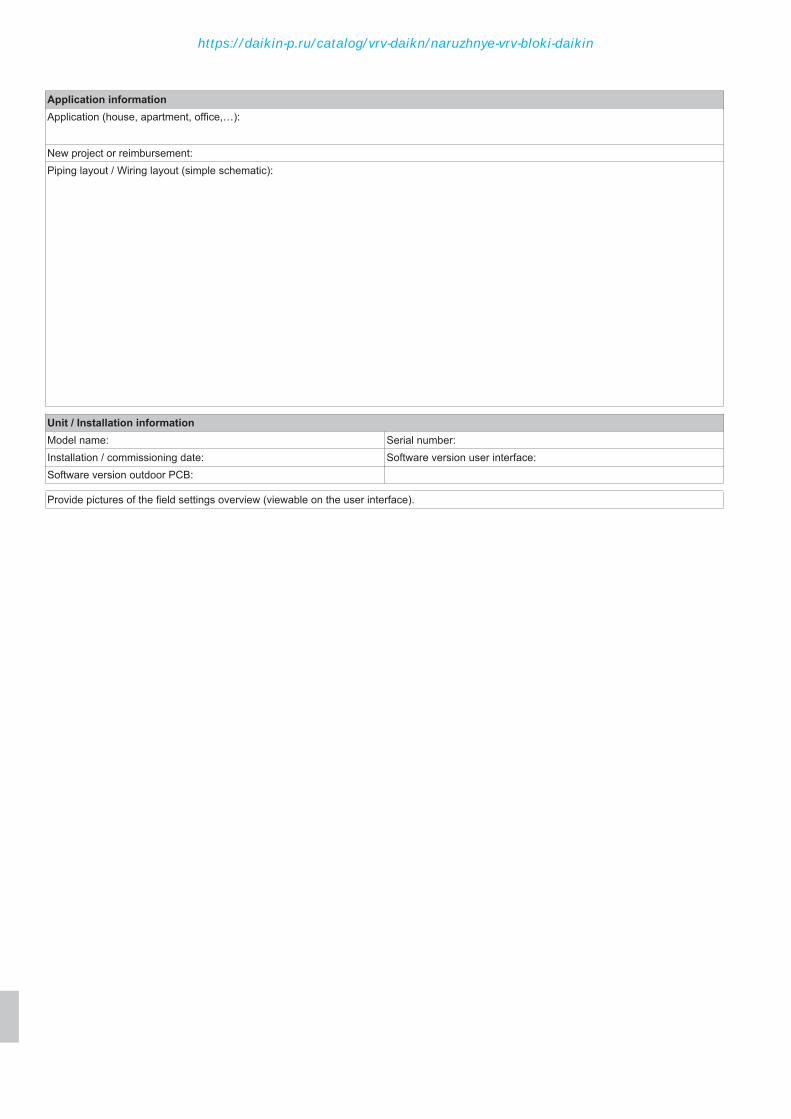
Application informationApplication (house, apartment, office,…):
New project or reimbursement:Piping layout / Wiring layout (simple schematic):
Unit / Installation informationModel name: Serial number:Installation / commissioning date: Software version user interface:Software version outdoor PCB:
Provide pictures of the field settings overview (viewable on the user interface).
https://daikin-p.ru/catalog/vrv-daikn/naruzhnye-vrv-bloki-daikin
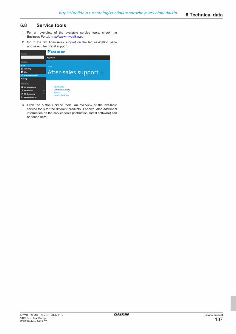
6 Technical data
Service manual
187RYYQ+RYMQ+RXYQ8~20U7Y1BVRV IV+ Heat PumpESIE18-14 – 2019.07
6.8 Service tools1 For an overview of the available service tools, check the
Business Portal: http://www.mydaikin.eu.
2 Go to the tab After-sales support on the left navigation paneand select Technical support.
3 Click the button Service tools. An overview of the availableservice tools for the different products is shown. Also additionalinformation on the service tools (instruction, latest software) canbe found here.
https://daikin-p.ru/catalog/vrv-daikn/naruzhnye-vrv-bloki-daikin
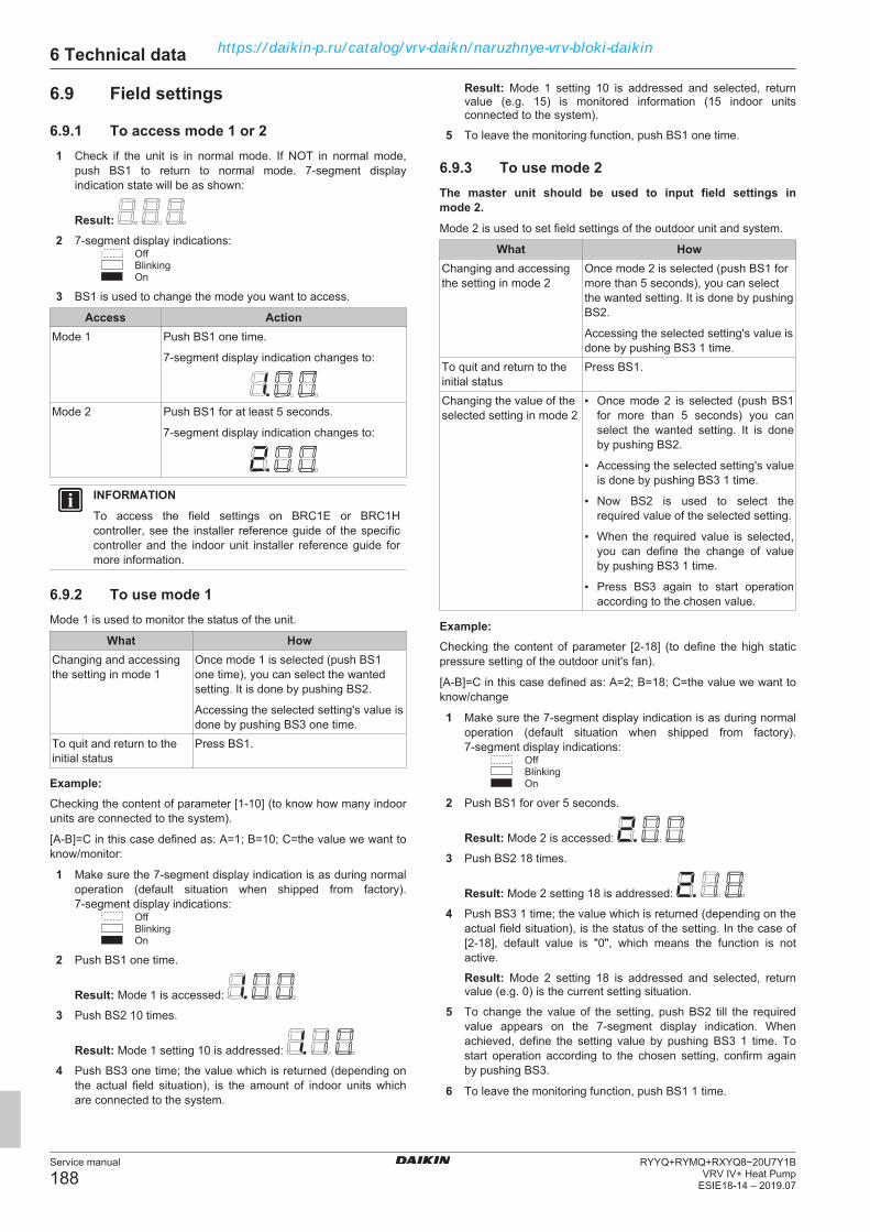
6 Technical data
Service manual
188RYYQ+RYMQ+RXYQ8~20U7Y1B
VRV IV+ Heat PumpESIE18-14 – 2019.07
6.9 Field settings
6.9.1 To access mode 1 or 21 Check if the unit is in normal mode. If NOT in normal mode,
push BS1 to return to normal mode. 7‑segment displayindication state will be as shown:
Result: 2 7‑segment display indications:
OffBlinkingOn
3 BS1 is used to change the mode you want to access.
Access ActionMode 1 Push BS1 one time.
7‑segment display indication changes to:
Mode 2 Push BS1 for at least 5 seconds.
7‑segment display indication changes to:
INFORMATIONTo access the field settings on BRC1E or BRC1Hcontroller, see the installer reference guide of the specificcontroller and the indoor unit installer reference guide formore information.
6.9.2 To use mode 1Mode 1 is used to monitor the status of the unit.
What HowChanging and accessingthe setting in mode 1
Once mode 1 is selected (push BS1one time), you can select the wantedsetting. It is done by pushing BS2.
Accessing the selected setting's value isdone by pushing BS3 one time.
To quit and return to theinitial status
Press BS1.
Example:Checking the content of parameter [1‑10] (to know how many indoorunits are connected to the system).
[A‑B]=C in this case defined as: A=1; B=10; C=the value we want toknow/monitor:
1 Make sure the 7‑segment display indication is as during normaloperation (default situation when shipped from factory).7‑segment display indications:
OffBlinkingOn
2 Push BS1 one time.
Result: Mode 1 is accessed:
3 Push BS2 10 times.
Result: Mode 1 setting 10 is addressed:
4 Push BS3 one time; the value which is returned (depending onthe actual field situation), is the amount of indoor units whichare connected to the system.
Result: Mode 1 setting 10 is addressed and selected, returnvalue (e.g. 15) is monitored information (15 indoor unitsconnected to the system).
5 To leave the monitoring function, push BS1 one time.
6.9.3 To use mode 2The master unit should be used to input field settings inmode 2.Mode 2 is used to set field settings of the outdoor unit and system.
What HowChanging and accessingthe setting in mode 2
Once mode 2 is selected (push BS1 formore than 5 seconds), you can selectthe wanted setting. It is done by pushingBS2.
Accessing the selected setting's value isdone by pushing BS3 1 time.
To quit and return to theinitial status
Press BS1.
Changing the value of theselected setting in mode 2
▪ Once mode 2 is selected (push BS1for more than 5 seconds) you canselect the wanted setting. It is doneby pushing BS2.
▪ Accessing the selected setting's valueis done by pushing BS3 1 time.
▪ Now BS2 is used to select therequired value of the selected setting.
▪ When the required value is selected,you can define the change of valueby pushing BS3 1 time.
▪ Press BS3 again to start operationaccording to the chosen value.
Example:Checking the content of parameter [2‑18] (to define the high staticpressure setting of the outdoor unit's fan).
[A‑B]=C in this case defined as: A=2; B=18; C=the value we want toknow/change
1 Make sure the 7‑segment display indication is as during normaloperation (default situation when shipped from factory).7‑segment display indications:
OffBlinkingOn
2 Push BS1 for over 5 seconds.
Result: Mode 2 is accessed:
3 Push BS2 18 times.
Result: Mode 2 setting 18 is addressed:
4 Push BS3 1 time; the value which is returned (depending on theactual field situation), is the status of the setting. In the case of[2‑18], default value is "0", which means the function is notactive.
Result: Mode 2 setting 18 is addressed and selected, returnvalue (e.g. 0) is the current setting situation.
5 To change the value of the setting, push BS2 till the requiredvalue appears on the 7‑segment display indication. Whenachieved, define the setting value by pushing BS3 1 time. Tostart operation according to the chosen setting, confirm againby pushing BS3.
6 To leave the monitoring function, push BS1 1 time.
https://daikin-p.ru/catalog/vrv-daikn/naruzhnye-vrv-bloki-daikin

6 Technical data
Service manual
189RYYQ+RYMQ+RXYQ8~20U7Y1BVRV IV+ Heat PumpESIE18-14 – 2019.07
6.9.4 Mode 1: Field settingsIn mode 1 you can make field settings to configure the system. The LEDs give a binary representation of the setting/value number.(*) This column shows the number of times you have to push the SET button (BS2) to access the field setting.
N°(*) Item Display Content0 Main/sub outdoor unit 1.00 - Undefined
0 Main unit1 Sub 1 unit2 Sub 2 unit
1 Low noise operation status 1.01 0 Not in low noise operation1 In low noise operation
2 Demand operation status 1.02 0 Not in demand operation1 In demand operation
3 Automatic back up operation status 1.03 0 Off1 On
4 Defrost selection set 1.04 0 Slow1 Normal2 Quick
5 Te set 1.05 0 Automatic1 3 ˚C2 6 ˚C3 7 ˚C4 8 ˚C5 9 ˚C6 10 ˚C7 11 ˚C
6 Tc set 1.06 0 Automatic1 41 ˚C2 42 ˚C3 43 ˚C4 44 ˚C5 45 ˚C6 46 ˚C7 48 ˚C
7 Cool/heat unified address 1.07 Possible 0 ˜ 318 Low noise / demand address 1.08 Possible 0 ˜ 319 Airnet address 1.09 Possible 0 ˜ 63
10 Number of indoor units 1.10 Shows total amount of connected indoor units on a singleF1/F2 in line. Possible 0 ˜ 63
13 Number of outdoor units 1.13 Shows total amount of outdoor units connected on a singleF1/F2 out line. Possible 0 ˜ 63
15 Number of units in zone 1.15 Possible 0 ˜ 6316 Number of all indoor units 1.16 Shows total amount of indoor units of several systems if
F1/F2 out is wired between systems. Possible 0 ˜ 12817 Latest error code 1.17 Displays latest error causing forced stop18 2nd latest error code 1.18 Displays 2nd latest error causing forced stop19 3rd latest error code 1.19 Displays 3rd latest error causing forced stop20 Software ID upper code 1.20 Use set (BS2 ) to view full code21 Outdoor unit capacity 1.21 0 No data
3 8 HP4 10 HP5 12 HP6 14 HP7 16 HP8 18 HP9 20 HP
https://daikin-p.ru/catalog/vrv-daikn/naruzhnye-vrv-bloki-daikin

6 Technical data
Service manual
190RYYQ+RYMQ+RXYQ8~20U7Y1B
VRV IV+ Heat PumpESIE18-14 – 2019.07
N°(*) Item Display Content22 Software id lower code 1.22 Displays lower code for software ID23 Latest retry 1.23 Displays latest reason causing retry24 2nd latest retry 1.24 Displays 2nd latest reason causing retry25 3rd latest retry 1.25 Displays 3rd latest reason causing retry26 Number of D3Net transmission retry 1.26 Possible 0 ˜ 6327 Number of ACCNS transmission retry 1.27 Possible 0 ˜ 6328 Number of outdoor units on a multi system 1.28 Number of outdoor units on Q1/ Q2 line in multi
combination29 Result of last manual refrigerant leak check 1.29 Possible 0 ˜ 9.930 Result of 2nd last manual refrigerant leak check 1.30 Possible 0 ˜ 9.931 Result of 3rd last manual refrigerant leak check 1.31 Possible 0 ˜ 9.932 Outdoor board status judgement 1.32 0 Standart judgement
1 Normal2 Abnormal
33 Number of abnormal outdoor board statusjudgement
1.33 Possible 0 ˜ 15
34 Remaining days until next refrigerant leak checkoperation
1.34 Off: refrigerant leak check not active or possible 1 ˜ 366
35 Result of last automatic refrigerant leak check 1.35 1 Normal2 Outdoor temperature out of range3 Indoor temperature out of range
36 Result of 2nd last automatic refrigerant leak check 1.36 1 Normal2 Outdoor temperature out of range3 Indoor temperature out of range
37 Result of 3rd last automatic refrigerant leak check 1.37 1 Normal2 Outdoor temperature out of range3 Indoor temperature out of range
38 Number of connected RA units 1.38 RA units connected through BP unit. Possible 0 ˜ 6339 Number of connected HXY-A unit 1.39 VRV LT Hydrobox unit. Possible 0 ˜ 6340 Cooling comfort set 1.40 Setting by mode 2-81. Possible 0 ˜ 341 Heating comfort set 1.41 Setting by mode 2-82. Possible 0 ˜ 342 High pressure [MPa] 1.42 S1NPH43 Low pressure [MPa] 1.43 S1NPL44 Compressor frequency [Hz] 1.44 Total frequency of 1 module45 Y1E opening pulse 1.45 Pulses/1046 Discharge temperature [˚C] 1.46 R21T47 Discharge temperature [˚C] 1.47 R22T48 Compressor body temperature [˚C] 1.48 R8T49 Compressor body temperature [˚C] 1.49 R9T50 Ambient temperature [˚C] 1.50 R1T51 Accumulator inlet temperature [˚C] 1.51 R3T52 Gas temperature, subcool outlet [˚C] 1.52 R6T53 De-icing thermistor temperature [˚C] 1.53 R7T54 Compressor operating hours 1.54 Total hours/10055 Automatic charging completion flag 1.55 0 Unfinished
1 Completed56 Y2E opening pulse 1.56 Pulses/10
https://daikin-p.ru/catalog/vrv-daikn/naruzhnye-vrv-bloki-daikin

6 Technical data
Service manual
191RYYQ+RYMQ+RXYQ8~20U7Y1BVRV IV+ Heat PumpESIE18-14 – 2019.07
6.9.5 Mode 2: Field settingsIn mode 2 you can make field settings to configure the system. The LEDs give a binary representation of the setting/value number.(*) This column shows the number of times you have to push the SET button (BS2) to access the field setting.(**) The bold content is the default setting.
N°(*) Item Display Content(**)
0 Cool/heat selection 2.00 0 Individual1 Master (DTA104A6* option required)2 Slave (DTA104A6* option required)
1 Cool/heat unified address 2.01 0 Possible 0-312 Low noise/demand address 2.02 0 Possible 0-315 Indoor unit forced fan H 2.05 0 Disabled
1 Enabled6 Indoor unit forced thermo ON 2.06 0 Disabled
1 Enabled8 Te setting 2.08 0 Auto
1 3 ˚C2 6 ˚C3 7 ˚C4 8 ˚C5 9 ˚C6 10 ˚C7 11 ˚C
9 Tc setting 2.09 0 Auto1 41 ˚C2 42 ˚C3 43 ˚C4 44 ˚C5 45 ˚C6 46 ˚C7 48 ˚C
10 Defrost selection setting 2.10 0 Short1 Normal2 Long
12 Low noise/demand operation by external input 2.12 0 Disabled1 Enabled
13 AirNet address 2.13 0 Possible 0-63 (0 is not a valid airnet address)14 Additional refrigerant charge amount 2.14 0 See "Additional refrigerant charge amount" on
page 13818 Outdoor unit fan high static pressure setting 2.18 0 Deactivated
1 Activated20 Additional refrigerant charge operation 2.20 0 Off
1 On21 Refrigerant recovery mode 2.21 0 Off
1 On22 Nighttime low noise operation level setting
(combined with 2-26 and 2-27) [level1 > level2> level3]
2.22 0 Off1 Level 12 Level 23 Level 3
25 Low noise operation level setting (if LNOtriggered by external input)(combined with2-12) [level1 > level2 > level3]
2.25 1 Level 12 Level 23 Level 3
26 Nighttime low noise operation start time setting(combined with 2-22)
2.26 1 20h002 22h003 24h00
https://daikin-p.ru/catalog/vrv-daikn/naruzhnye-vrv-bloki-daikin
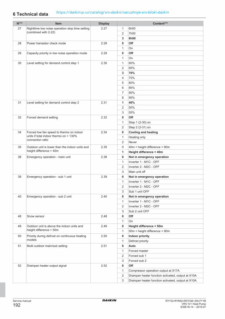
6 Technical data
Service manual
192RYYQ+RYMQ+RXYQ8~20U7Y1B
VRV IV+ Heat PumpESIE18-14 – 2019.07
N°(*) Item Display Content(**)
27 Nighttime low noise operation stop time setting(combined with 2-22)
2.27 1 6h002 7h003 8h00
28 Power transistor check mode 2.28 0 Off1 On
29 Capacity priority in low noise operation mode 2.29 0 Off1 On
30 Level setting for demand control step 1 2.30 1 60%2 65%3 70%4 75%5 80%6 85%7 90%8 95%
31 Level setting for demand control step 2 2.31 1 40%2 50%3 55%
32 Forced demand setting 2.32 0 Off1 Step 1 (2-30) on2 Step 2 (2-31) on
34 Forced low fan speed to thermo on indoorunits if total indoor thermo on > 130%connection ratio
2.34 0 Cooling and heating1 Heating only2 Never
35 Outdoor unit is lower than the indoor units andheight difference > 40m
2.35 0 40m < height difference < 90m1 Height difference < 40m
38 Emergency operation - main unit 2.38 0 Not in emergency operation1 Inverter 1 - M1C - OFF2 Inverter 2 - M2C - OFF3 Main unit off
39 Emergency operation - sub 1 unit 2.39 0 Not in emergency operation1 Inverter 1 - M1C - OFF2 Inverter 2 - M2C - OFF3 Sub 1 unit OFF
40 Emergency operation - sub 2 unit 2.40 0 Not in emergency operation1 Inverter 1 - M1C - OFF2 Inverter 2 - M2C - OFF3 Sub 2 unit OFF
48 Snow sensor 2.48 0 Off1 On
49 Outdoor unit is above the indoor units andheight difference > 50m
2.49 0 Height difference < 50m1 50m < height difference < 90m
50 Priority during defrost on continuous heatingmodels
2.50 0 Indoor priority1 Defrost priority
51 Multi outdoor main/sub setting 2.51 0 Auto1 Forced master2 Forced sub 13 Forced sub 2
52 Drainpan heater output signal 2.52 0 Off1 Compressor operation output at X17A2 Drainpan heater function activated, output at X10A3 Drainpan heater function activated, output at X10A
https://daikin-p.ru/catalog/vrv-daikn/naruzhnye-vrv-bloki-daikin
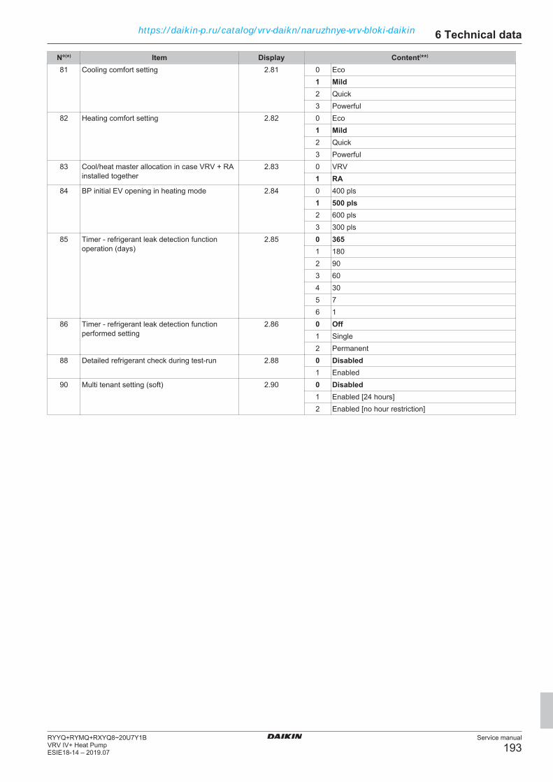
6 Technical data
Service manual
193RYYQ+RYMQ+RXYQ8~20U7Y1BVRV IV+ Heat PumpESIE18-14 – 2019.07
N°(*) Item Display Content(**)
81 Cooling comfort setting 2.81 0 Eco1 Mild2 Quick3 Powerful
82 Heating comfort setting 2.82 0 Eco1 Mild2 Quick3 Powerful
83 Cool/heat master allocation in case VRV + RAinstalled together
2.83 0 VRV1 RA
84 BP initial EV opening in heating mode 2.84 0 400 pls1 500 pls2 600 pls3 300 pls
85 Timer - refrigerant leak detection functionoperation (days)
2.85 0 3651 1802 903 604 305 76 1
86 Timer - refrigerant leak detection functionperformed setting
2.86 0 Off1 Single2 Permanent
88 Detailed refrigerant check during test-run 2.88 0 Disabled1 Enabled
90 Multi tenant setting (soft) 2.90 0 Disabled1 Enabled [24 hours]2 Enabled [no hour restriction]
https://daikin-p.ru/catalog/vrv-daikn/naruzhnye-vrv-bloki-daikin

6 Technical data
Service manual
194RYYQ+RYMQ+RXYQ8~20U7Y1B
VRV IV+ Heat PumpESIE18-14 – 2019.07
6.9.6 Overview of field settings for indoor unitsThe overview lists all possible settings for the indoor units. The availability of the setting depends on the indoor unit type, see "Field settings asper type indoor unit". Bold content is default setting.
Mode 1st code Description function 2nd code Description selection10(20) 0 Filter contamination heavy / light 01 Filter contamination: light LL 2500 hr / flat
200 hr02 Filter contamination: heavy LL 1250 hr /
flat 100 hr1 Long life filter type 01 Long life filter
02 Super long life filter04 Oil guard filter
2 Air thermistor selection 01 Combined control02 Only the return air thermistor03 Only the remote controller thermistor
3 Display filter sign 01 Display02 No display
4 Spare -- --5 Air thermistor selection in group wiring
P1P201 Return air thermistor (individual units)02 Thermistor designated by field set 20-2
(see above)6 Remote controller thermistor visible by
central control device in group wiring P1P201 No02 Yes
7 Absence delay detecting time (presencesensor)
01 30 minutes02 60 minutes
8 Compensation air sensor heating 01 Add 2.0°C to measurement air sensor02 Measurement air sensor
9 Spare -- --11(21) 3 Fan setting of heating 01 Standard
02 Slight increase03 Increase
6 Sensitivity presence sensor 01 High sensitive02 Low sensitive03 Standard04 Disable presence sensor
7 Airflow adjustment 01 Manual setting (see mode 23-6 below)02 ESP auto judgment completed03 Start ESP auto judgment (if control set to
fan only + ON)8 Compensation by floor sensor 01 Floor sensor disabled
02 Air suction temperature priority03 Standard04 Floor temperature priority
9 Compensation of floor temperature 01 -4°C02 -2°C03 No correction04 +2°C
https://daikin-p.ru/catalog/vrv-daikn/naruzhnye-vrv-bloki-daikin

6 Technical data
Service manual
195RYYQ+RYMQ+RXYQ8~20U7Y1BVRV IV+ Heat PumpESIE18-14 – 2019.07
Mode 1st code Description function 2nd code Description selection12(22) 0 Optional board KRP1A… output X1X2 01 Indoor unit turned ON by thermostat
02 --03 Operation output04 Malfunction output05 --
1 T1T2 input signal 01 Forced OFF02 ON/OFFcontrol03 External protection device input04 Forced OFF - multi tenant
2 Thermostat differential to set point 01 1.0°C (FXFQ, FXZQ, FXCQ, FXKQ,FXUQ, FXHQ, VKM, Biddle
02 0.5°C (FXSQ, FXMQ, FXAQ, FXLQ,FXNQ, FXDQ, EKEQM)
3 OFF by thermostat fan speed 01 LL02 Set fan speed03 OFF
4 Automatic mode differential 01 0°C (default when HP outdoor unit)02 1°C03 2°C04 3°C (default when HR outdoor unit)05 4°C (default when VKM unit)06 5°C07 6°C08 7°C
5 Auto restart after power failure 01 Disabled02 Enabled
6 Fan speed in cooling thermo OFF 01 LL02 Set speed03 OFF
9 Forced C/H master 01 Disabled (select by cool / heat selectionbutton controller)
02 ON (not possible by cool / heat selectionbutton controller)
https://daikin-p.ru/catalog/vrv-daikn/naruzhnye-vrv-bloki-daikin

6 Technical data
Service manual
196RYYQ+RYMQ+RXYQ8~20U7Y1B
VRV IV+ Heat PumpESIE18-14 – 2019.07
Mode 1st code Description function 2nd code Description selection13(23) 0 Air flow amount setting (ceiling height) 01 Standard
02 High03 Extra high
1 Number of air outlet 4-blow panel 01 4-blow directions02 3-blow directions03 2-blow directions
2 Swing pattern setting if 4 swing motors 01 All direction simultaneously swing02 --03 Opposite sides synchronization swing
3 Output to flap motor 01 Enabled02 Disabled03 --
4 Air flow position setting 01 Draft prevention02 Standard03 Ceiling soiling prevention
5 ESP setting phase control motor 01 Standard02 Increase step 103 Increase step 204 --
6 External static pressure manual set 01 --02 50 Pa03 60 Pa04 70 Pa05 80 Pa06 90 Pa07 100 Pa08 110 Pa09 120 Pa10 130 Pa11 140 Pa12 150 Pa13 160 Pa14 180 Pa15 200 Pa
7 Thermostat swing 01 Equipped02 Not equipped
15(25) 0 Air cleaner 01 Not equipped02 Equipped
1 Thermostat OFF excess humidity 01 Not equipped02 Equipped
2 Direct duct connection 01 Not equipped02 Equipped
3 Drain pump operation heating operation (ifhumidifier is used)
01 Not equipped02 Equipped
4 Filter sign 01 By timer02 By external input
5 Independent ventilation 01 Not equipped02 Equipped
6 Independent unit 01 No02 Yes
9 Demand control 01 Not equipped02 Equipped
https://daikin-p.ru/catalog/vrv-daikn/naruzhnye-vrv-bloki-daikin
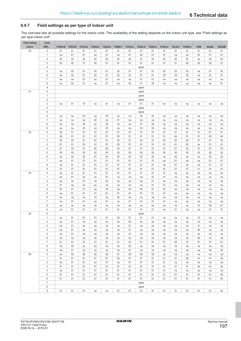
6 Technical data
Service manual
197RYYQ+RYMQ+RXYQ8~20U7Y1BVRV IV+ Heat PumpESIE18-14 – 2019.07
6.9.7 Field settings as per type of indoor unitThe overview lists all possible settings for the indoor units. The availability of the setting depends on the indoor unit type, see "Field settings asper type indoor unit".
Field setting CodeIndoor BRC… FXKQ-M FXFQ-B FXCQ-A FXSQ-A FXUQ-A FXMQ-P FXHQ-A FXDQ-A FXZQ-A FXAQ-A FXLQ-P FXNQ-A VKM Biddle EKEQM
20 0 01 01 01 01 01 01 01 01 01 01 01 01 01 01 011 na 01 01 na 01 na 01 04 01 01 na na 03 01 012 02 02 02 02 02 02 02 01 02 03 02 03 na 03 023 03 02 01 02 01 01 01 01 01 01 01 02 02 02 014 spare5 na 02 01 02 01 02 01 01 01 02 02 02 na 01 026 na 02 01 02 01 02 01 01 01 02 02 02 na 01 017 na na 01 na 01 na na 01 01 na na na na na na8 na 02 01 na 01 na 02 01 02 na na na na na 019 spare
21 0 spare1 spare2 spare3 na 01 01 na 01 na 01 01 01 na na na na na na4 spare5 spare6 na na 03 na 03 na na 04 03 na na na na na na7 na na na 02 na 01 na na na na na na na na na8 na na 03 na 03 na na 01 03 na na na na na na9 na na 03 na 03 na na 03 03 na na na na na na
22 0 02 01 01 01 01 01 01 01 01 01 01 01 01 01 011 02 01 01 01 01 02 01 01 01 01 04 01 01 02 042 02 02 01 02 01 02 01 02 01 02 02 02 01 01 023 01 01 03 01 01 02 01 01 01 01 01 02 na 01 014 01 03 01 02 03 03 01 01 01 01 01 03 01 01 035 02 02 02 02 02 02 02 02 02 02 02 02 02 02 026 na 02 02 01 02 02 02 02 02 na 02 na na 02 027 na 01 01 01 01 01 01 01 01 na 01 na na 01 018 na 01 01 01 01 01 01 01 01 na 01 na na 01 019 01 01 01 01 01 01 01 01 01 01 01 01 01 01 01
23 0 na 01 01 01 01 01 01 01 01 01 na na na na na1 na 01 na na 01 na na na 01 01 na na na na na2 na na 01 na 03 na na na 01 na na na na na na3 01 na na na na na na na 01 01 na na na na na4 02 01 01 na 03 na 03 02 01 02 na na na na na5 na 01 01 01 01 01 01 01 01 01 na na na na na6 na na na 15 na 02 na na na na na na na na na7 na 01 01 na 01 na 01 01 01 01 na na na na na8 na na na na na na na na na na na na 01 02 019 na 01 01 01 01 01 01 01 01 na 01 na na 01 01
24 0 spare1 na 01 01 01 01 02 01 01 01 na na na 13 na na2 na 01 na na na na 02 na na na na na na na na3 na 01 na na na na 01 na na na na na 01 na na4 na 01 na na na na 01 na na na na na 09 na na5 na 01 na na na na 01 na na na na na na na na6 na na na na na na na na na na na na 05 na na7 01 01 01 01 01 01 01 01 01 01 02 01 01 01 018 na 02 na na na na 02 na na na na na na na na9 na 01 na na na na 01 na na na na na na 04 04
25 0 na 02 02 02 02 01 02 02 02 na na na na na na1 01 01 01 01 01 02 01 01 01 01 01 02 01 01 022 na 01 01 na 01 na 01 01 01 01 na na na na na3 01 01 01 01 01 01 01 01 01 01 01 01 02 01 024 na 01 01 01 01 01 01 01 01 01 na na na na na5 01 01 01 01 01 01 01 01 01 01 01 01 01 01 026 01 01 01 01 01 01 01 01 01 01 01 01 01 01 027 spare8 spare9 01 01 01 na na 01 01 01 01 01 01 01 01 01 02
https://daikin-p.ru/catalog/vrv-daikn/naruzhnye-vrv-bloki-daikin
https://daikin-p.ru/catalog/vrv-daikn/naruzhnye-vrv-bloki-daikin

https://daikin-p.ru/catalog/vrv-daikn/naruzhnye-vrv-bloki-daikin

ESIE18-14 2019.07
Cop
yrig
ht 2
019
Dai
kin
https://daikin-p.ru/catalog/vrv-daikn/naruzhnye-vrv-bloki-daikin