Equation Chapter 1 Section 1 13 th World Conference on Earthquake Engineering SEISMIC REPONSE OF...
15
Equation Chapter 1 Section 1 13 th World Conference on Earthquake Engineering Vancouver, B.C., Canada August 1-6, 2004 Paper No. 4004 SEISMIC REPONSE OF GRAVITY-LOAD DESIGN FRAMES WITH MASONRY INFILLS Guido MAGENES 1 and Stefano PAMPANIN 2 SUMMARY Comprehensive experimental-analytical studies on the seismic vulnerability of existing reinforced concrete frame buildings, designed for gravity-loads only as typically found in most seismic prone countries before the introduction of adequate seismic design code provisions, confirmed the inherent weaknesses of these systems, due to inadequate detailing and the lack of capacity design principles. Controversial effects on the global inelastic mechanism can be expected depending on the infills properties (mechanical characteristic and distribution) and the joint damage mechanism. In this contribution, the interaction between un-reinforced masonry infills and r.c. frame systems, when appropriately considering the joint zone non-linear behaviour, is investigated through pushover and non- linear time-history analyses on 2-D frame systems. Preliminary results are critically discussed. A simplified and reliable analytical model based on a concentrated plasticity approach, validated on different experimental tests on beam-column joints and frame systems (with and without infills), is used and proposed for extensive studies on seismic vulnerability assessment. Limit states, based on interstorey drift and related to joint or infills damage levels are also tentatively suggested. INTRODUCTION Special attention has been recently given to the investigation on the seismic vulnerability of existing reinforced concrete buildings, designed for gravity only as typically found in most seismic-prone countries before the introduction of adequate seismic design code provisions in the mid-1970s. Comprehensive experimental-analytical studies have confirmed the expected inherent weaknesses of these systems. As a consequence of poor reinforcement detailing, lack of transverse reinforcement in the joint region as well as absence of any capacity design principles, brittle failure mechanisms are expected at both local and global level. Different damage or failure modes can occur in the beam-column joint panel zone depending on the typology (exterior or interior joint) and on the adopted structural details (i.e. use of plain round or deformed bars, alternative bar anchorage solutions), which ultimately affect the efficiency of the shear transfer mechanisms in the joint region (post-cracking non-linear behaviour). As a result, global response 1 Associate Professor, University of Pavia, Italy. E-mail: [email protected] 2 Senior Lecturer, Univ. of Canterbury, Christchurch, NZ. E-mail: [email protected]
Transcript of Equation Chapter 1 Section 1 13 th World Conference on Earthquake Engineering SEISMIC REPONSE OF...
Equation Chapter 1 Section 1
13th World Conference on Earthquake Engineering Vancouver, B.C., Canada
August 1-6, 2004 Paper No. 4004
SEISMIC REPONSE OF GRAVITY-LOAD DESIGN FRAMES WITH MASONRY INFILLS
Guido MAGENES1 and Stefano PAMPANIN2
SUMMARY Comprehensive experimental-analytical studies on the seismic vulnerability of existing reinforced concrete frame buildings, designed for gravity-loads only as typically found in most seismic prone countries before the introduction of adequate seismic design code provisions, confirmed the inherent weaknesses of these systems, due to inadequate detailing and the lack of capacity design principles. Controversial effects on the global inelastic mechanism can be expected depending on the infills properties (mechanical characteristic and distribution) and the joint damage mechanism. In this contribution, the interaction between un-reinforced masonry infills and r.c. frame systems, when appropriately considering the joint zone non-linear behaviour, is investigated through pushover and non-linear time-history analyses on 2-D frame systems. Preliminary results are critically discussed. A simplified and reliable analytical model based on a concentrated plasticity approach, validated on different experimental tests on beam-column joints and frame systems (with and without infills), is used and proposed for extensive studies on seismic vulnerability assessment. Limit states, based on interstorey drift and related to joint or infills damage levels are also tentatively suggested.
INTRODUCTION Special attention has been recently given to the investigation on the seismic vulnerability of existing reinforced concrete buildings, designed for gravity only as typically found in most seismic-prone countries before the introduction of adequate seismic design code provisions in the mid-1970s. Comprehensive experimental-analytical studies have confirmed the expected inherent weaknesses of these systems. As a consequence of poor reinforcement detailing, lack of transverse reinforcement in the joint region as well as absence of any capacity design principles, brittle failure mechanisms are expected at both local and global level. Different damage or failure modes can occur in the beam-column joint panel zone depending on the typology (exterior or interior joint) and on the adopted structural details (i.e. use of plain round or deformed bars, alternative bar anchorage solutions), which ultimately affect the efficiency of the shear transfer mechanisms in the joint region (post-cracking non-linear behaviour). As a result, global response
1Associate Professor, University of Pavia, Italy. E-mail: [email protected] 2Senior Lecturer, Univ. of Canterbury, Christchurch, NZ. E-mail: [email protected]
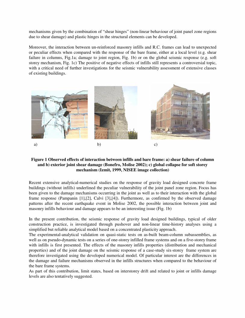
mechanisms given by the combination of “shear hinges” (non-linear behaviour of joint panel zone regions due to shear damage) and plastic hinges in the structural elements can be developed. Moreover, the interaction between un-reinforced masonry infills and R.C. frames can lead to unexpected or peculiar effects when compared with the response of the bare frame, either at a local level (e.g. shear failure in columns, Fig.1a; damage to joint region, Fig. 1b) or on the global seismic response (e.g. soft storey mechanism, Fig. 1c) The positive of negative effects of infills still represents a controversial topic, with a critical need of further investigations for the seismic vulnerability assessment of extensive classes of existing buildings.
Figure 1 Observed effects of interaction between infills and bare frame: a) shear failure of column and b) exterior joint shear damage (Bonefro, Molise 2002); c) global collapse for soft storey
mechanism (Izmit, 1999, NISEE image collection)
Recent extensive analytical-numerical studies on the response of gravity load designed concrete frame buildings (without infills) underlined the peculiar vulnerability of the joint panel zone region. Focus has been given to the damage mechanisms occurring in the joint as well as to their interaction with the global frame response (Pampanin [1],[2], Calvi [3],[4]). Furthermore, as confirmed by the observed damage patterns after the recent earthquake event in Molise 2002, the possible interaction between joint and masonry infills behaviour and damage appears to be an interesting issue (Fig. 1b) In the present contribution, the seismic response of gravity load designed buildings, typical of older construction practice, is investigated through pushover and non-linear time-history analyses using a simplified but reliable analytical model based on a concentrated plasticity approach. The experimental-analytical validation on quasi-static tests on as-built beam-column subassemblies, as well as on pseudo-dynamic tests on a series of one-storey infilled frame systems and on a five-storey frame with infills is first presented. The effects of the masonry infills properties (distribution and mechanical properties) and of the joint damage on the seismic response of a case-study six-storey frame system are therefore investigated using the developed numerical model. Of particular interest are the differences in the damage and failure mechanisms observed in the infills structures when compared to the behaviour of the bare frame systems. As part of this contribution, limit states, based on interstorey drift and related to joint or infills damage levels are also tentatively suggested.
a) b) c)
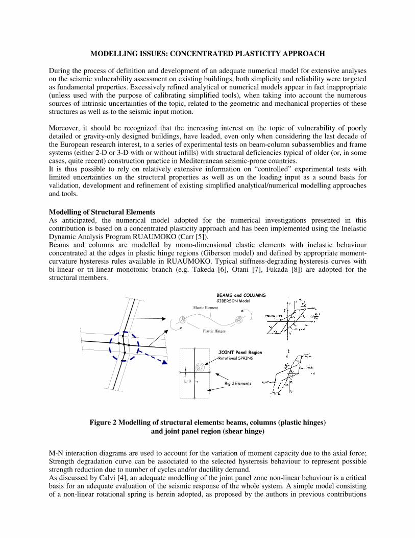
MODELLING ISSUES: CONCENTRATED PLASTICITY APPROACH During the process of definition and development of an adequate numerical model for extensive analyses on the seismic vulnerability assessment on existing buildings, both simplicity and reliability were targeted as fundamental properties. Excessively refined analytical or numerical models appear in fact inappropriate (unless used with the purpose of calibrating simplified tools), when taking into account the numerous sources of intrinsic uncertainties of the topic, related to the geometric and mechanical properties of these structures as well as to the seismic input motion. Moreover, it should be recognized that the increasing interest on the topic of vulnerability of poorly detailed or gravity-only designed buildings, have leaded, even only when considering the last decade of the European research interest, to a series of experimental tests on beam-column subassemblies and frame systems (either 2-D or 3-D with or without infills) with structural deficiencies typical of older (or, in some cases, quite recent) construction practice in Mediterranean seismic-prone countries. It is thus possible to rely on relatively extensive information on “controlled” experimental tests with limited uncertainties on the structural properties as well as on the loading input as a sound basis for validation, development and refinement of existing simplified analytical/numerical modelling approaches and tools. Modelling of Structural Elements As anticipated, the numerical model adopted for the numerical investigations presented in this contribution is based on a concentrated plasticity approach and has been implemented using the Inelastic Dynamic Analysis Program RUAUMOKO (Carr [5]). Beams and columns are modelled by mono-dimensional elastic elements with inelastic behaviour concentrated at the edges in plastic hinge regions (Giberson model) and defined by appropriate moment-curvature hysteresis rules available in RUAUMOKO. Typical stiffness-degrading hysteresis curves with bi-linear or tri-linear monotonic branch (e.g. Takeda [6], Otani [7], Fukada [8]) are adopted for the structural members.
Figure 2 Modelling of structural elements: beams, columns (plastic hinges) and joint panel region (shear hinge)
M-N interaction diagrams are used to account for the variation of moment capacity due to the axial force; Strength degradation curve can be associated to the selected hysteresis behaviour to represent possible strength reduction due to number of cycles and/or ductility demand. As discussed by Calvi [4], an adequate modelling of the joint panel zone non-linear behaviour is a critical basis for an adequate evaluation of the seismic response of the whole system. A simple model consisting of a non-linear rotational spring is herein adopted, as proposed by the authors in previous contributions
Rigid Elements
L=0
Elemento elastico
Molle rotazionali
JOINT Panel Region Rotational SPRING
Elastic Element
Plastic Hinges
BEAMS and COLUMNS GIBERSON Model
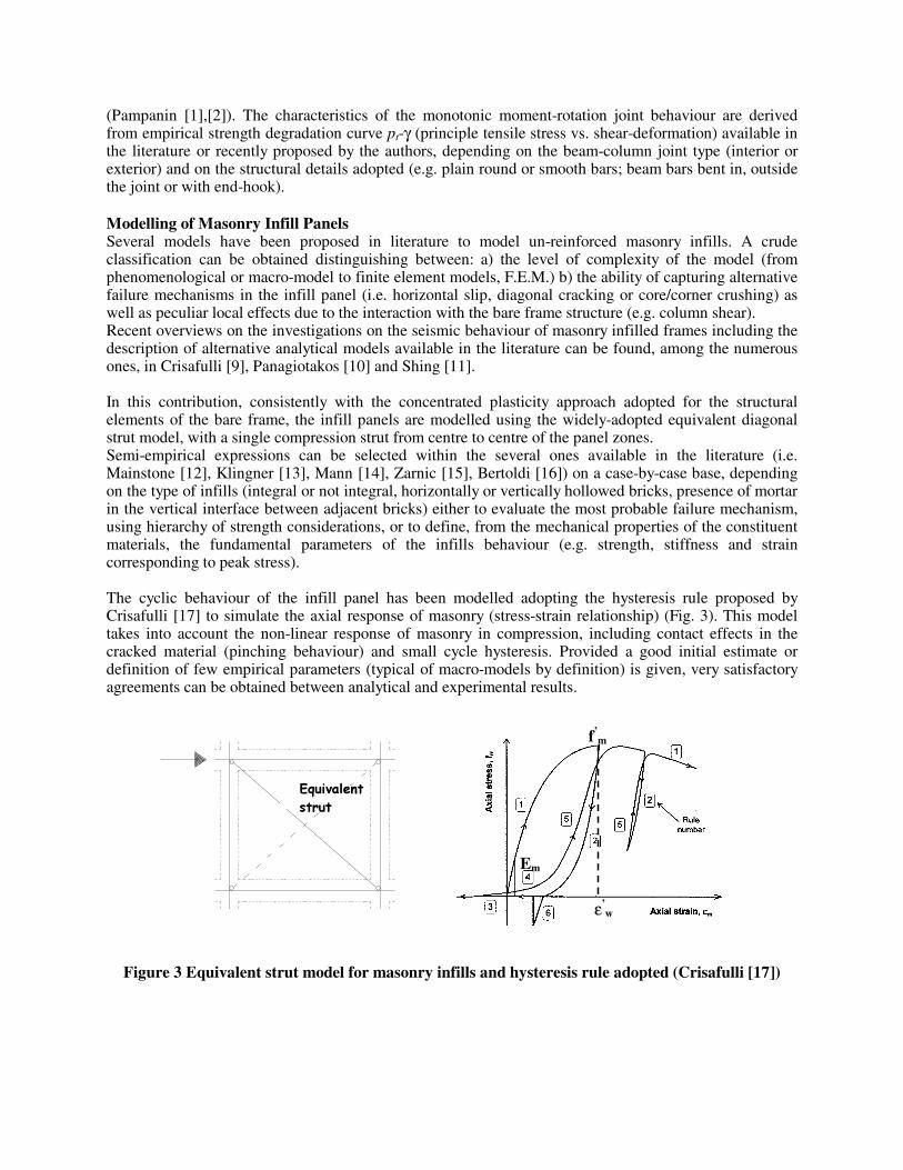
(Pampanin [1],[2]). The characteristics of the monotonic moment-rotation joint behaviour are derived from empirical strength degradation curve pt-γ (principle tensile stress vs. shear-deformation) available in the literature or recently proposed by the authors, depending on the beam-column joint type (interior or exterior) and on the structural details adopted (e.g. plain round or smooth bars; beam bars bent in, outside the joint or with end-hook). Modelling of Masonry Infill Panels Several models have been proposed in literature to model un-reinforced masonry infills. A crude classification can be obtained distinguishing between: a) the level of complexity of the model (from phenomenological or macro-model to finite element models, F.E.M.) b) the ability of capturing alternative failure mechanisms in the infill panel (i.e. horizontal slip, diagonal cracking or core/corner crushing) as well as peculiar local effects due to the interaction with the bare frame structure (e.g. column shear). Recent overviews on the investigations on the seismic behaviour of masonry infilled frames including the description of alternative analytical models available in the literature can be found, among the numerous ones, in Crisafulli [9], Panagiotakos [10] and Shing [11]. In this contribution, consistently with the concentrated plasticity approach adopted for the structural elements of the bare frame, the infill panels are modelled using the widely-adopted equivalent diagonal strut model, with a single compression strut from centre to centre of the panel zones. Semi-empirical expressions can be selected within the several ones available in the literature (i.e. Mainstone [12], Klingner [13], Mann [14], Zarnic [15], Bertoldi [16]) on a case-by-case base, depending on the type of infills (integral or not integral, horizontally or vertically hollowed bricks, presence of mortar in the vertical interface between adjacent bricks) either to evaluate the most probable failure mechanism, using hierarchy of strength considerations, or to define, from the mechanical properties of the constituent materials, the fundamental parameters of the infills behaviour (e.g. strength, stiffness and strain corresponding to peak stress). The cyclic behaviour of the infill panel has been modelled adopting the hysteresis rule proposed by Crisafulli [17] to simulate the axial response of masonry (stress-strain relationship) (Fig. 3). This model takes into account the non-linear response of masonry in compression, including contact effects in the cracked material (pinching behaviour) and small cycle hysteresis. Provided a good initial estimate or definition of few empirical parameters (typical of macro-models by definition) is given, very satisfactory agreements can be obtained between analytical and experimental results.
Figure 3 Equivalent strut model for masonry infills and hysteresis rule adopted (Crisafulli [17])
Biella compressa
ε’w
f’m
Em
Equivalent
strut
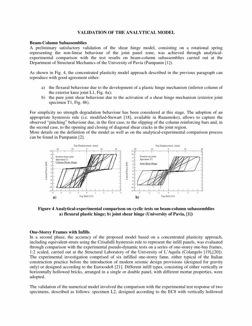
VALIDATION OF THE ANALYTICAL MODEL Beam-Column Subassemblies A preliminary satisfactory validation of the shear hinge model, consisting on a rotational spring representing the non-linear behaviour of the joint panel zone, was achieved through analytical-experimental comparison with the test results on beam-column subassemblies carried out at the Department of Structural Mechanics of the University of Pavia (Pampanin [1]). As shown in Fig. 4, the concentrated plasticity model approach described in the previous paragraph can reproduce with good agreement either:
a) the flexural behaviour due to the development of a plastic hinge mechanism (inferior column of the exterior knee joint L1, Fig. 4a);
b) the pure joint shear behaviour due to the activation of a shear hinge mechanism (exterior joint specimen T1, Fig. 4b).
For simplicity no strength degradation behaviour has been considered at this stage. The adoption of an appropriate hysteresis rule (i.e. modified-Stewart [18], available in Ruaumoko), allows to capture the observed “pinching” behaviour due, in the first case, to the slipping of the column reinforcing bars and, in the second case, to the opening and closing of diagonal shear cracks in the joint region. More details on the definition of the model as well as on the analytical-experimental comparison process can be found in Pampanin [2].
Figure 4 Analytical-experimental comparison on cyclic tests on beam-column subassemblies
a) flexural plastic hinge; b) joint shear hinge (University of Pavia, [1])
One-Storey Frames with Infills In a second phase, the accuracy of the proposed model based on a concentrated plasticity approach, including equivalent-struts using the Crisafulli hysteresis rule to represent the infill panels, was evaluated through comparison with the experimental pseudo-dynamic tests on a series of one-storey one-bay frames, 1:2 scaled, carried out at the Structural Laboratory of the University of L’Aquila (Colangelo [19],[20]). The experimental investigation comprised of six infilled one-storey fame, either typical of the Italian construction practice before the introduction of modern seismic design provisions (designed for gravity only) or designed according to the Eurocode8 [21]. Different infill types, consisting of either vertically or horizontally hollowed bricks, arranged in a single or double panel, with different mortar properties, were adopted. The validation of the numerical model involved the comparison with the experimental test response of two specimens, described as follows: specimen L2, designed according to the EC8 with vertically hollowed
-4 -3 -2 -1 0 1 2 3 4
Top Drif t [%]
-12
-10
-8
-6
-4
-2
0
2
4
6
8
10
Lat
eral
For
ce [
kN]
-40 -20 0 20 40
Top Displacement [mm]
-3 -2 -1 0 1 2 3
Top Drif t [%]
-12
-10
-8
-6
-4
-2
0
2
4
6
8
10
12
Lat
eral
For
ce [
kN]
-80 -40 0 40 80
Top Displacement [mm]
Exterior knee joint Specimen L1 Column Plastic Hinge
Exterior tee.joint Specimen T1
Joint Shear Hinge
a) b)
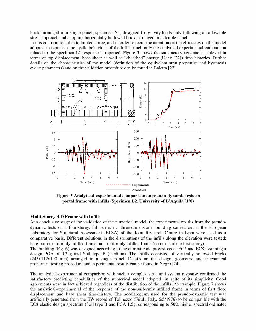
bricks arranged in a single panel; specimen N1, designed for gravity-loads only following an allowable stress approach and adopting horizontally hollowed bricks arranged in a double panel In this contribution, due to limited space, and in order to focus the attention on the efficiency on the model adopted to represent the cyclic behaviour of the infill panel, only the analytical-experimental comparison related to the specimen L2 response is reported. Figure 5 shows the satisfactory agreement achieved in terms of top displacement, base shear as well as “absorbed” energy (Uang [22]) time histories. Further details on the characteristics of the model (definition of the equivalent strut properties and hysteresis cyclic parameters) and on the validation procedure can be found in Baletta [23].
Figure 5 Analytical-experimental comparison on pseudo-dynamic tests on portal frame with infills (Specimen L2, University of L’Aquila [19])
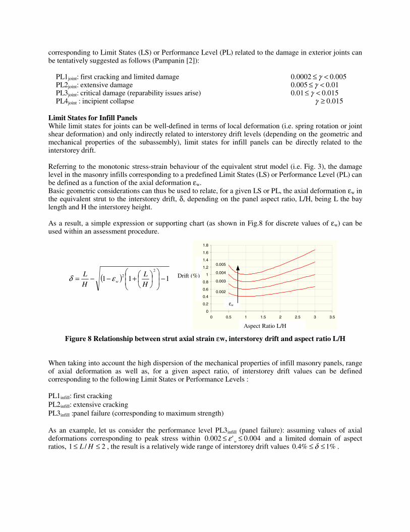
Multi-Storey 3-D Frame with Infills At a conclusive stage of the validation of the numerical model, the experimental results from the pseudo-dynamic tests on a four-storey, full scale, r.c. three-dimensional building carried out at the European Laboratory for Structural Assessment (ELSA) of the Joint Research Centre in Ispra were used as a comparative basis. Different solutions in the distributions of the infills along the elevation were tested: bare frame, uniformly infilled frame, non-uniformly infilled frame (no infills at the first storey). The building (Fig. 6) was designed according to the current code provisions of EC2 and EC8 assuming a design PGA of 0.3 g and Soil type B (medium). The infills consisted of vertically hollowed bricks (245x112x190 mm) arranged in a single panel. Details on the design, geometric and mechanical properties, testing procedure and experimental results can be found in Negro [24]. The analytical-experimental comparison with such a complex structural system response confirmed the satisfactory predicting capabilities of the numerical model adopted, in spite of its simplicity. Good agreements were in fact achieved regardless of the distribution of the infills. As example, Figure 7 shows the analytical-experimental of the response of the non-uniformly infilled frame in terms of first floor displacement and base shear time-history. The accelerogram used for the pseudo-dynamic test was artificially generated from the EW record of Tolmezzo (Friuli, Italy, 6/5/1976) to be compatible with the EC8 elastic design spectrum (Soil type B and PGA 1.5g, corresponding to 50% higher spectral ordinates
0 1 2 3 4 5 6 7
Time (sec)
0
2
4
6
8
10
12
Ene
rgy
(kJ
)
0 1 2 3 4 5 6 7
Time (sec)
-1.5
-1
-0.5
0
0.5
1
1.5
Dri
ft
(%)
Experimental
Analytical
0 1 2 3 4 5 6 7
Time (sec)
-300
-200
-100
0
100
200
300B
ase
Shea
r (
kN)
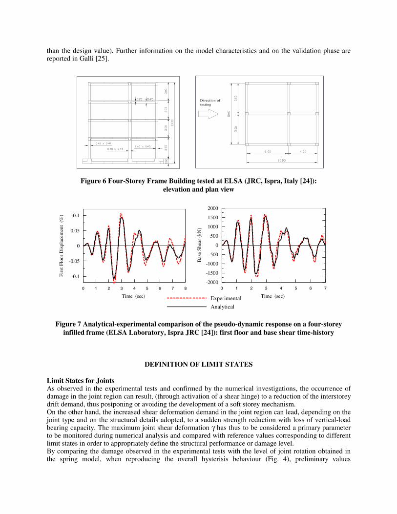
than the design value). Further information on the model characteristics and on the validation phase are reported in Galli [25].
Figure 6 Four-Storey Frame Building tested at ELSA (JRC, Ispra, Italy [24]):
elevation and plan view
Figure 7 Analytical-experimental comparison of the pseudo-dynamic response on a four-storey
infilled frame (ELSA Laboratory, Ispra JRC [24]): first floor and base shear time-history
DEFINITION OF LIMIT STATES Limit States for Joints As observed in the experimental tests and confirmed by the numerical investigations, the occurrence of damage in the joint region can result, (through activation of a shear hinge) to a reduction of the interstorey drift demand, thus postponing or avoiding the development of a soft storey mechanism. On the other hand, the increased shear deformation demand in the joint region can lead, depending on the joint type and on the structural details adopted, to a sudden strength reduction with loss of vertical-load bearing capacity. The maximum joint shear deformation γ has thus to be considered a primary parameter to be monitored during numerical analysis and compared with reference values corresponding to different limit states in order to appropriately define the structural performance or damage level. By comparing the damage observed in the experimental tests with the level of joint rotation obtained in the spring model, when reproducing the overall hysterisis behaviour (Fig. 4), preliminary values
Direction of testing
0 1 2 3 4 5 6 7 8
Time (sec)
-0.1
-0.05
0
0.05
0.1
Fir
st F
loor
Dis
plac
emen
t (%
)
0 1 2 3 4 5 6 7
Time (sec)
-2000
-1500
-1000
-500
0
500
1000
1500
2000
Bas
e S
hear
(kN
)
Experimental
Analytical
corresponding to Limit States (LS) or Performance Level (PL) related to the damage in exterior joints can be tentatively suggested as follows (Pampanin [2]):
PL1joint: first cracking and limited damage 005.00002.0 <≤ γ PL2joint: extensive damage 01.0005.0 <≤ γ PL3joint: critical damage (reparability issues arise) 015.001.0 <≤ γ PL4joint : incipient collapse 015.0≥γ
Limit States for Infill Panels While limit states for joints can be well-defined in terms of local deformation (i.e. spring rotation or joint shear deformation) and only indirectly related to interstorey drift levels (depending on the geometric and mechanical properties of the subassembly), limit states for infill panels can be directly related to the interstorey drift. Referring to the monotonic stress-strain behaviour of the equivalent strut model (i.e. Fig. 3), the damage level in the masonry infills corresponding to a predefined Limit States (LS) or Performance Level (PL) can be defined as a function of the axial deformation εw. Basic geometric considerations can thus be used to relate, for a given LS or PL, the axial deformation εw in the equivalent strut to the interstorey drift, δ, depending on the panel aspect ratio, L/H, being L the bay length and H the interstorey height. As a result, a simple expression or supporting chart (as shown in Fig.8 for discrete values of εw) can be used within an assessment procedure.
Figure 8 Relationship between strut axial strain εw, interstorey drift and aspect ratio L/H When taking into account the high dispersion of the mechanical properties of infill masonry panels, range of axial deformation as well as, for a given aspect ratio, of interstorey drift values can be defined corresponding to the following Limit States or Performance Levels : PL1infill: first cracking PL2infill: extensive cracking PL3infill :panel failure (corresponding to maximum strength) As an example, let us consider the performance level PL3infill (panel failure): assuming values of axial deformations corresponding to peak stress within 004.0'002.0 ≤≤ wε and a limited domain of aspect ratios, 2/1 ≤≤ HL , the result is a relatively wide range of interstorey drift values %1%4.0 ≤≤ δ .
( ) 1112
2 −
+−−=H
L
H
Lwεδ
0
0.2
0.4
0.6
0.8
1
1.2
1.4
1.6
1.8
0 0.5 1 1.5 2 2.5 3 3.5
fattore di forma [L/H]
dri
ft in
terp
ian
o [
%]
0.005
0.004
0.003
0.002
Aspect Ratio L/H
Drift (%)
εw
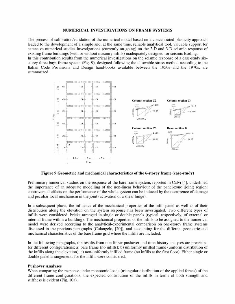
NUMERICAL INVESTIGATIONS ON FRAME SYSTEMS The process of calibration/validation of the numerical model based on a concentrated plasticity approach leaded to the development of a simple and, at the same time, reliable analytical tool, valuable support for extensive numerical studies investigations (currently on-going) on the 2-D and 3-D seismic response of existing frame buildings (with or without masonry infills) inadequately designed for seismic loading. In this contribution results from the numerical investigations on the seismic response of a case-study six-storey three-bays frame system (Fig. 9), designed following the allowable stress method according to the Italian Code Provisions and Design hand-books available between the 1950s and the 1970s, are summarized.
Figure 9 Geometric and mechanical characteristics of the 6-storey frame (case-study)
Preliminary numerical studies on the response of the bare frame system, reported in Calvi [4], underlined the importance of an adequate modelling of the non-linear behaviour of the panel-zone (joint) region: controversial effects on the performance of the whole system can be induced by the occurrence of damage and peculiar local mechanism in the joint (activation of a shear hinge). In a subsequent phase, the influence of the mechanical properties of the infill panel as well as of their distribution along the elevation on the system response has been investigated. Two different types of infills were considered: bricks arranged in single or double panels (typical, respectively, of external or internal frame within a building). The mechanical properties of the infills to be assigned to the numerical model were derived according to the analytical-experimental comparison on one-storey frame systems discussed in the previous paragraphs (Colangelo, [20]), and accounting for the different geometric and mechanical characteristics of the bare frame grid where the infills are included. In the following paragraphs, the results from non-linear pushover and time-history analyses are presented for different configurations: a) bare frame (no infills); b) uniformly infilled frame (uniform distribution of the infills along the elevation); c) non-uniformly infilled frame (no infills at the first floor). Either single or double panel arrangements for the infills were considered. Pushover Analyses When comparing the response under monotonic loads (triangular distribution of the applied forces) of the different frame configurations, the expected contribution of the infills in terms of both strength and stiffness is evident (Fig. 10a).
C4
C3
C4
C4
C3
C2 C2
C3
C4
C3 C3
C4
C4
C3
C4
C4
C4
C4
C4
C4 C4
C4 C4
C4
B
17.7
5 m
3 m
3 m
3 m
2.75
m
4.5 m
11 m
2 m 4.5 m
3 m
3 m
Beam section BColumn section C3
20 mm
350
mm
350 mm
tie φ6
4 φ18
Column section C4Column section C2
300
mm
300 mm
4 φ16 tie φ6
500
mm
300 mm
tie φ6
6 φ16
250 mm
20 mm
250
mm
tie φ6
4 φ14
cover cover
20 mmcover
20 mmcover
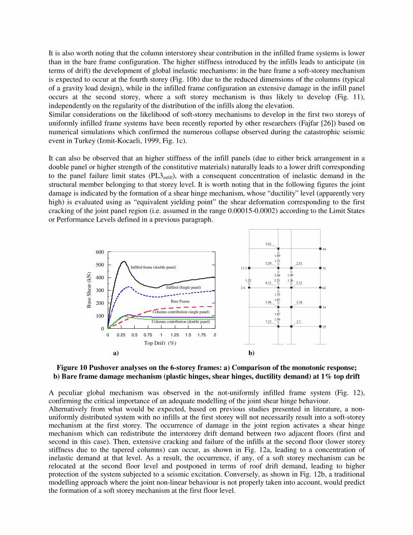
It is also worth noting that the column interstorey shear contribution in the infilled frame systems is lower than in the bare frame configuration. The higher stiffness introduced by the infills leads to anticipate (in terms of drift) the development of global inelastic mechanisms: in the bare frame a soft-storey mechanism is expected to occur at the fourth storey (Fig. 10b) due to the reduced dimensions of the columns (typical of a gravity load design), while in the infilled frame configuration an extensive damage in the infill panel occurs at the second storey, where a soft storey mechanism is thus likely to develop (Fig. 11), independently on the regularity of the distribution of the infills along the elevation. Similar considerations on the likelihood of soft-storey mechanisms to develop in the first two storeys of uniformly infilled frame systems have been recently reported by other researchers (Fajfar [26]) based on numerical simulations which confirmed the numerous collapse observed during the catastrophic seismic event in Turkey (Izmit-Kocaeli, 1999, Fig. 1c). It can also be observed that an higher stiffness of the infill panels (due to either brick arrangement in a double panel or higher strength of the constitutive materials) naturally leads to a lower drift corresponding to the panel failure limit states (PL3infill), with a consequent concentration of inelastic demand in the structural member belonging to that storey level. It is worth noting that in the following figures the joint damage is indicated by the formation of a shear hinge mechanism, whose “ductility” level (apparently very high) is evaluated using as “equivalent yielding point” the shear deformation corresponding to the first cracking of the joint panel region (i.e. assumed in the range 0.00015-0.0002) according to the Limit States or Performance Levels defined in a previous paragraph.
Figure 10 Pushover analyses on the 6-storey frames: a) Comparison of the monotonic response;
b) Bare frame damage mechanism (plastic hinges, shear hinges, ductility demand) at 1% top drift A peculiar global mechanism was observed in the not-uniformly infilled frame system (Fig. 12), confirming the critical importance of an adequate modelling of the joint shear hinge behaviour. Alternatively from what would be expected, based on previous studies presented in literature, a non-uniformly distributed system with no infills at the first storey will not necessarily result into a soft-storey mechanism at the first storey. The occurrence of damage in the joint region activates a shear hinge mechanism which can redistribute the interstorey drift demand between two adjacent floors (first and second in this case). Then, extensive cracking and failure of the infills at the second floor (lower storey stiffness due to the tapered columns) can occur, as shown in Fig. 12a, leading to a concentration of inelastic demand at that level. As a result, the occurrence, if any, of a soft storey mechanism can be relocated at the second floor level and postponed in terms of roof drift demand, leading to higher protection of the system subjected to a seismic excitation. Conversely, as shown in Fig. 12b, a traditional modelling approach where the joint non-linear behaviour is not properly taken into account, would predict the formation of a soft storey mechanism at the first floor level.
0 0.5 1 1.5 20.25 0.75 1.25 1.75
Top Drif t (%)
0
100
200
300
400
500
600
Bas
e S
hear
(kN
)
1.67
1.567.27 3.7
2.4
17.2
1.22
1.67
1.75
2.21
2.44
3.96
6.11
3.36
5.311.26
1.49
1.71
1.69
2.59
2.01
2.51
34.
25.
75.
62.
44.
Infilled frame (double panel)
Columns contribution (single panel)
Columns contribution (double panel)
Infilled (Single panel)
Bare Frame
a) b)
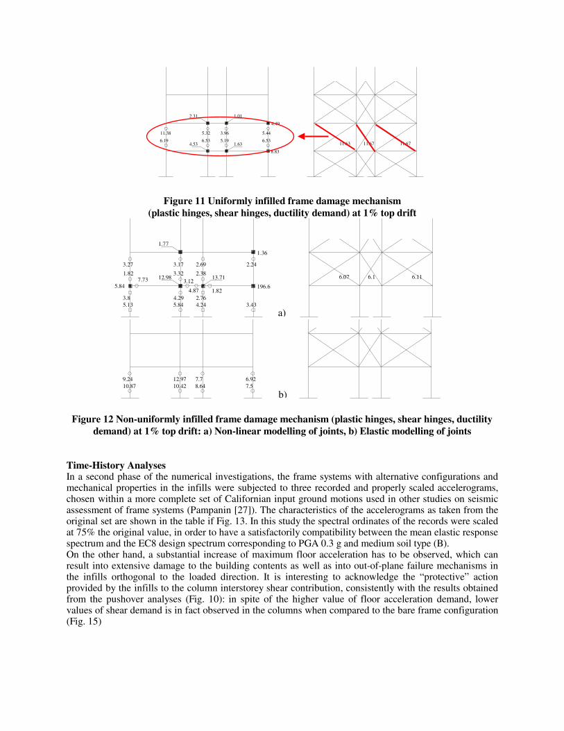
Figure 11 Uniformly infilled frame damage mechanism
(plastic hinges, shear hinges, ductility demand) at 1% top drift
Figure 12 Non-uniformly infilled frame damage mechanism (plastic hinges, shear hinges, ductility
demand) at 1% top drift: a) Non-linear modelling of joints, b) Elastic modelling of joints Time-History Analyses In a second phase of the numerical investigations, the frame systems with alternative configurations and mechanical properties in the infills were subjected to three recorded and properly scaled accelerograms, chosen within a more complete set of Californian input ground motions used in other studies on seismic assessment of frame systems (Pampanin [27]). The characteristics of the accelerograms as taken from the original set are shown in the table if Fig. 13. In this study the spectral ordinates of the records were scaled at 75% the original value, in order to have a satisfactorily compatibility between the mean elastic response spectrum and the EC8 design spectrum corresponding to PGA 0.3 g and medium soil type (B). On the other hand, a substantial increase of maximum floor acceleration has to be observed, which can result into extensive damage to the building contents as well as into out-of-plane failure mechanisms in the infills orthogonal to the loaded direction. It is interesting to acknowledge the “protective” action provided by the infills to the column interstorey shear contribution, consistently with the results obtained from the pushover analyses (Fig. 10): in spite of the higher value of floor acceleration demand, lower values of shear demand is in fact observed in the columns when compared to the bare frame configuration (Fig. 15)
8.83
4.49
5.443.9611.38 5.32
6.536.194.53 1.63
5.19 6.53
2.31 1.01
11.6711.63 11.67
9.2410.87
7.78.64
12.9710.42
6.927.5
12.98
5.84
5.13
1.82
3.8
7.73
1.82
5.844.29
3.32
4.242.76
2.383.12
4.87
13.71
196.6
3.43
1.77
3.27 2.693.17 2.24
1.36
6.16.07 6.11
a)
b)
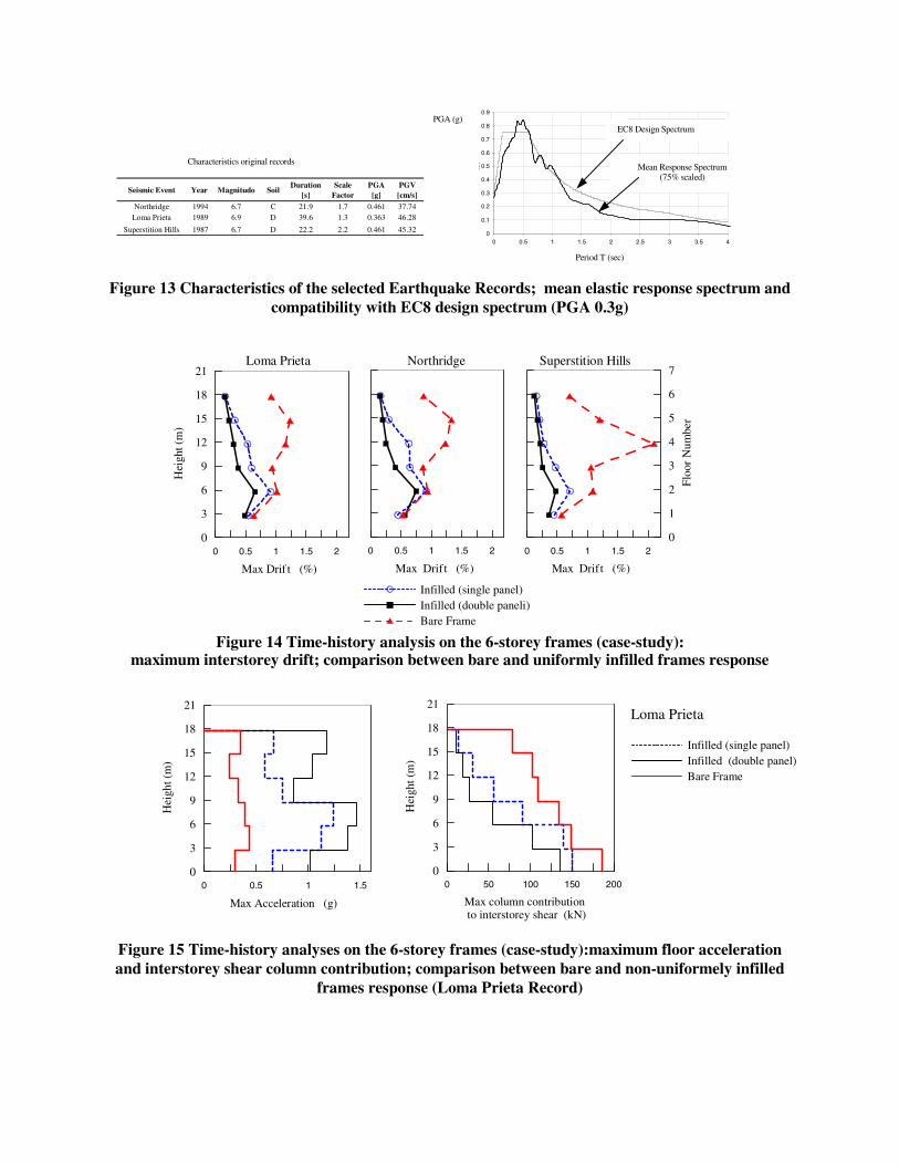
Figure 13 Characteristics of the selected Earthquake Records; mean elastic response spectrum and compatibility with EC8 design spectrum (PGA 0.3g)
Figure 14 Time-history analysis on the 6-storey frames (case-study): maximum interstorey drift; comparison between bare and uniformly infilled frames response
Figure 15 Time-history analyses on the 6-storey frames (case-study):maximum floor acceleration and interstorey shear column contribution; comparison between bare and non-uniformely infilled
frames response (Loma Prieta Record)
0 0.5 1 1.5 2
Max Drif t (%)
0
3
6
9
12
15
18
21
Hei
ght (
m)
0 0.5 1 1.5 2
Max Drift (%)
0 0.5 1 1.5 2
Max Drift (%)
0
1
2
3
4
5
6
7
Flo
or N
umbe
r
Loma Prieta Northridge Superstition Hills
Infilled (single panel) Infilled (double paneli) Bare Frame
0
0.1
0.2
0.3
0.4
0.5
0.6
0.7
0.8
0.9
0 0.5 1 1.5 2 2.5 3 3.5 4
Tempo [sec]
PS
A [g
]
Spettro elastico EC8
Spettro elastico medio
Mean Response Spectrum (75% scaled)
Periodo (sec)
EC8 Design Spectrum
Period T (sec)
PGA (g)
Seismic Event Year Magnitudo SoilDuration
[s]Scale
Factor PGA [g]
PGV [cm/s]
Northridge 1994 6.7 C 21.9 1.7 0.461 37.74Loma Prieta 1989 6.9 D 39.6 1.3 0.363 46.28
Superstition Hills 1987 6.7 D 22.2 2.2 0.461 45.32
Characteristics original records
Infilled (single panel) Infilled (double panel) Bare Frame
Loma Prieta
0 0.5 1 1.5
Max Acceleration (g)
0
3
6
9
12
15
18
21
Hei
ght (
m)
0 50 100 150 200
Max column contribution to interstorey shear (kN)
0
3
6
9
12
15
18
21
Hei
ght (
m)

CONCLUSIONS In this contribution recent findings on the controversial effects of masonry infills in the seismic response of gravity load designed r.c. frame buildings, typical of older construction practice, have been discussed. Preliminary results on extensive numerical investigations, currently on-going, either based on pushover and non-linear time-history analyses on frame system buildings have been presented (focusing on the 2-D response) confirming the inherent weakness of these systems as well as the complexity of infills-bare frame interaction phenomena, even when limiting the attention to global system inelastic mechanisms. A simple and reliable analytical model, based on a concentrated plasticity approach, has been developed and presented. The non-linear behaviour of the joint panel zone is modelled through an equivalent rotational spring based on principal tensile stresses considerations, as suggested by the authors in previous works. An equivalent strut-model with appropriate hysteresis rule, available in literature, was adopted to represent the cyclic behaviour of under-reinforced masonry infills. The satisfactory results from an extensive validation on experimental results consisting of quasi-static tests on beam-column subassemblies as well as pseudo-dynamic tests on one-storey infilled frames and on a five-storey frame with different infills configurations, have been reported. In a second phase, the effects of the infills characteristics (distribution and mechanical properties) and of the joint damage were investigated for a case-study six-storey frame system, using the developed numerical model. As expected, the presence of infills can guarantee higher overall stiffness and strength, reducing the inter-storey drift demand, while increasing the maximum floor accelerations. A further “protective” action of the infills has to be recognized, when considering the column interstorey shear contribution (consistently lower in the infilled solutions in spite of the higher interstorey shear demand) as well as the possible delay of a soft-storey mechanism which might instead develop in a bare frame. On the other side, the sudden reduction of storey stiffness due to the damage of the infills can still lead to the formation of a soft storey mechanism, which, due to the interaction with joint damage, can occur not necessarily at the first floor level and independently of the regular or irregular distribution of the infills along the elevation. It should be noted that the effects of local damage and failure (i.e. shear in the columns, joint-infills interactions) due to the interaction between bare system and infills were not properly accounted for in this study due to the use of a single strut model. Future investigations, adopting more refined multi-strut models, should address this topic. As part of this contribution, limit states, based on interstorey drift and related to joint or infills damage levels have also been tentatively suggested for a simple assessment evaluation of the internal hierarchy of strength and sequence of events.
REFERENCES 1. Pampanin, S., Moratti, M., Calvi,. G.M., “Seismic Behaviour of R.C. Beam-Column Joints
Designed for Gravity Loads”, 12th European Conference on Earthquake Engineering, London, paper n. 726, 2002.
2. Pampanin, S. Magenes, G., Carr, A., “Modelling of Shear Hinge Mechanism in Poorly Detailed RC Beam/Column Joints”, fib Symposium on Concrete Structures in Seismic Regions, Athens, paper n.171, 2002.
3. Calvi, G.M., Magenes, G., Pampanin, S. “Experimental Test on a Three Storey R.C. Frame Designed for Gravity Only”, 12th European Conference on Earthquake Engineering, London, paper n. 727, 2002.
4. Calvi G.M., Magenes G. and Pampanin S. “Relevance of Beam-Column Damage and Collapse in RC Frame Assessment” Journal of Earthquake Engineering, Special Issue, sup6(2), 2002.
5. Carr, A., J. “Ruaumoko Program for Inelastic Dynamic Analysis – Users Manual”, Department of Civil Engineering, University of Canterbury, Christchurch, New Zealand, 2003.
6. Takeda, T., Sozen, M. and Nielsen, N. “Reinforced Concrete Response to Simulated Earthquake”, ASCE Journal of Structural Division, (96(12), 1970.
7. Otani, S. Sake, A. “A Computer Program for Inelastic Response of R/C Frames to Earthquakes”, Report UILU-ENG-74-2029, Civil Engng. Studies, Univ. of Illinois at Urbana-Champaign, 1974.
8. Fukada, Y. “Study on the Restoring Force Characteristics of Reinforced Concrete Buildings” (in Japanese). Proc. Kanto District Symposium, Architectural Institute of Japan, Tokyo, 1969.
9. Crisafulli, F.-, Carr, A. and Park, R. “Analytical Modelling of Infilled Frame Structures – a General Review”, Bulletin of the NZ Society for Earthquake Engineering, 33(1), 30-47.
10. Panagiotakos T.B. and Fardis M.N. “Seismic Response of Infilled R.C. Frames Structures”, 11th World Conference on Earthquake Engineering, Acapulco, 1996, paper n.225.
11. Shing, P.B. and Mehrabi, A.B. “Behaviour and Analysis of Masonry Infilled Frames”, Progress in Structural Engineering and Materials, 4, 320-331, 2002.
12. Mainstone R.J. “Supplementary Note on the Stiffness and Strength of Infilled Frames”, Current paper CP13/74, Buildings Research Establishment, London, 1974.
13. Klingner R.E. and Bertero V.V. “Earthquake Resistance of Infilled Frames”, ASCE Journal of the Structural Division, 104(6), 973-989, 1978.
14. Mann W. and Muller H. “Failure of Shear Stressed Masonry – an Enlarged Theory, Tests and Application to Shear Walls”, Proceedings of The British Ceramic Society, 1982, 30, 223-235.
15. Zarnic, R. and Tomazevic, M. “An Experimentally Obtained Method for Evaluation of the Behaviour of Masonry Infilled R/C Frames”, 9th World Conference on Earthquake Engineering, San Francisco, USA, Vol. VI, 863-870, 1984.
16. Bertoldi S.H., Decanini L.D. and Gavarini C. “Telai Tamponati Soggetti ad Azione Sismica, un Modello Semplificato: Confronto Sperimentale e Numerico”, 6th National Conference on Earthquake Engineering (ANIDIS),2, 815-824, Perugia, 1993.
17. Crisafulli, F.J. “Seismic Behaviour of Reinforced Concrete Structures with Masonry Infills”, Ph.D. Thesis, Department of Civil Engineering, University of Canterbury, July 1997.
18. Stewart, W.G. “The Seismic Design of Plywood Sheathed Shear Walls”, Ph.D. Thesis, Department of Civil Engineering, University of Canterbury, March 1987, 395 pp.
19. Colangelo, “Experimental Evaluation of Member-by-Member Models and Damage Indices for Infilled Frames”, Journal of Earthquake Engineering, 2003, 7 (1), 25-50.
20. Colangelo, F. “Qualificazione, Risposta Sismica Pseudodinamica e Modelli Fenomenologici di Portali di c.a. Tamponati con Laterizio”, DISAT, University of L’Aquila, Research Report, 1999.
21. Eurocodice 8 (EC8) “Design Provisions for Earthquake Resistance of Structures”, European Committee for Standardization, Brussels, 1998.
22. Uang, C.-M., and Bertero, V.V., Evaluation of Seismic Energy in Structures”, Earthquake Engineering and Structural Dynamics, 19(1), 77-90.
23. Baletta, G., “Risposta Sismica di Edifici a Telaio in c.a. con Tamponature Progettati per Soli Carichi da Gravità”. Laurea Thesis, Dept. of Structural Mechanics, University of Pavia, 2003.
24. Negro P., Anthoine A., Combescure D., Magonette G., Molina J., Pegon P., Verzeletti G. “Tests on Four-Storey Full-Scale Reinforced Concrete Frame with Masonry Infills” Preliminary Report, Special publication No. I.95.54, European Commission, Joint Research Centre, Ispra, Italy, 1995
25. Galli, M., “Metodi per l’Analisi della Risposta Sismica di Risposta Sismica di Edifici a Telaio in c.a. con Tamponature Progettati per Soli Carichi da Gravità”, Laurea Thesis, Department of Structural Mechanics, University of Pavia, 2002.
26. Dolsek, M and Fajfar, P. “Soft Storey Effects in Uniformly Infilled Reinforced Concrete Frames”, Journal of Earthquake Engineering, 2001 5 (1), 1-12.

27. Pampanin, S., Christopoulos, C. and Priestley M.J.N. “Performance-Based Seismic Response of Frame Structures Including Residual Deformations. Part II: Multi-Degree-of-Freedom Systems”, Journal of Earthquake Engineering, 2003 Vol. 7 (1), 119-147.