Environmental Baseline - Cold War Energy Workers
363
Lockheed Martin Specialty Components U.S. Department of Energy Pinellas Plant I Environmental Baseline Report June 1997 LOCKHEED MARTIN +
-
Upload
khangminh22 -
Category
Documents
-
view
4 -
download
0
Transcript of Environmental Baseline - Cold War Energy Workers

Lockheed Martin Specialty Components U.S. Department of Energy
Pinellas Plant I
Environmental Baseline
Report June 1997
L O C K H E E D M A R T I N +

NOncE
TRi8 re+ wa8 prepared as m ~ c o u n f ot work rponrond by an
Wnc), Of m w e d -8 N*llh.r Lh. w d -08
-m#meni nor any ag.ncy U18nol. nor any d Ih.k empbper nor
m y d L h . i r c ~ c ) # r w k o n p . c l o n . w ~ i r o m ~ & ~ o 8
my-, e s p m r e r k n p l k d . o r a . u m s 8 n y & # 8 / I k ~ o r
fea#odmly k r me 8Ccuwy. ComphmWU w u8elhrknu d m y
inbfmdon, app8mW. producf w proc.88 Wu&8ed. er ropwwla
U w h u 8 e w v l d n o l ~ p r i * . t d y o r r r n d r i g M t . Retsmwe
hnin lo any o p e d c comnnrci8l prodwf proceu. or sewice by
W8d.MlW8. Wbr.d.mUk -r. Or 0 L h . m . dD88
m ~ ~ ~ ~ o n d h # 8 ~ ~ k 8 ~ ~ 8 ~ ~ n c o m n n n d . C i o n , ~
t . r o r i n g b y m C W . d s m e s ~ w . y a 9 m c y ~ .
T h . r i . r r . n d o p i n i o b u d ~ m ~ d h r r i n & n o c
~ n u # y # a t e w # d 8 ~ t ~ d U W 8 ~ d S U ( r 8 ~ 0 r
-Y.o.ncy-- A

Title: Pinellas Plant Environmental Baseline Report
Number: MMSC-EM-97013
Issue Date: June 1997
DOCUMENT CONTROL
This document will be maintained in accordance with the sitewide document control procedures. Document control measures include unique issue numbers, document identification, numbered pages, document distribution, and a document master copy filing system.
The Pinellas Plant P. 0. Box 2908 Largo, Florida 33779-2908

Prepared By:
Lockheed Martin Specialty Components, Inc. Environmental, Safety and Health Division for
The U. S. Department of Energy Pinellas Area Office
REVIEWED FOR CLASSIFICATION:
Classification Officer/Analyst/Derivative Classifier
,
Date
Classification Level

TABLE OF CONTENTS
Section
1.0 OVERALL SUMMARY .............................................................................................. 1-1 . .
1.1 fistoncal Operation .......................................................................................... 1-1
l .2 Plant Property ..................................................................................................... 1-2
1.3 Buildings ............................................................................................................. 1-2
1.4 Environmental Monitoring and Protection ........................................................ 1-2
....................... ............................. 1.5 Environmental Restoration ........................... 1-5
2.0 OVERVIEW OF BUILDINGS 400. 1200. AND 1400 .............................................. 2-1
2.1 Building 400 ..................................................................................................... 2 - 1
2.2 Building 1200 ................................................................................................... 2-4
2.3 Building 1400 ..................................................................................................... 2-5
3.0 OVERVIEW OF BUILDING 100 ......................................................................... 3-1
3.1 Building Summary .............................................................................................. 3-1
3.2 Historical Information and Present Status of Building 100 Areas ....................... 3-4
4.0 o~ERVIEW OF ALL OTHER BUILDINGS .......................................................... 4-1
4.1 Building 200 ....................................................................................................... 4-1
4.2 Building 500 ...................................................................................................... 4-2
4.3 Building 550 ................................................................................................... 4-2
4.4 Building 600 ....................................................................................................... 4-2
...................................................................................................... '4.5 Building 700 4-3
4.6 Building 720 ...................................................................................................... 4 - 4
...................................................................................................... 4.7 Building 800 4 - 4
...................................................................................................... 4.8 Building 900 4 - 4
..................................................................................................... 4.9 Building 1000 4-4
4.10 Building 10 10 .................................................................................................... 4 -5
..................................................................................................... 4.1 1 Building 1040 4-5
4.12 Building 1 100 .................................................................................................... 4 -5
4.13 Building 1500 and 1600 ..................................................................................... 4 - 6

TABLE OF CONTENTS (CONTINUED)
Section Page
5.0 UTILITIES .................................................................................................................... 5-1
5.1 Electrical Power Distribution System ................................................................. 5-1
5.2 Chilled Water System .......................................................................................... 5-1
Condenser Water System ................................................................................. 5-1
Hot Water Systems ............................................................................................. 5-1
.............................. ............................................ Domestic Cold Water Systems :. 5-2
...................................................................................... Compressed Air System 5-2 . .
..................................................................................... Delomzed Water System 5-2
Fuel Distribution and Storage Batteries .............................................................. 5-2
............................................................................................... Bulk Gas Systems 5-4
...................................................................................... Pollutant Storage Tanks 5-4
6.0 OVERVIEW OF THE EXISTING AIR. WATER. SOIL. AND HAZARDOUS .. 6-1 WASTE ACTIVITIES
6.1 Radiological Monitoring ..................................................................................... 6-1 . .
................................................................................ 6.2 Nonradiological Monltonng 6-6
6.3 Waste Management ............................................................................................ 6-8
7.0 OVERVIEW OF BUILDING CLEANUP AND ....................................................... 7-1 CHARACTERIZATION ACTIVITY
7.1 Hazardous Contamination Cleanup and Characterization ................................... 7-1
7.2 Radiological Contamination Cleanup and Characterization ................................ 7-3
8.0 OVERVIEW OF EXISTING SITE ENVlRONMENTAL ...................................... 8-1 RESTORATION PROGRAM
. . . 8.1 Assessment Activities.. .................................................................................... 8-1
........................................................................................ 8.2 Remediation Activities 8-6
8.3 4.5-Acre Site ...................................................................................................... 8-9
............................. 9.0 LIST OF HAZARDOUS SUBSTANCES AND EXTREMELY 9-1 HAZAR?OUS SUBSTANCES

TABLE OF CONTENTS (CONTINUED)
........ 10.0 COMMON SYNONYMS FOR CHEMICALS USED AT TETE PINELLAS 10-1 PLANT
............................................................................................................. 11.0 REFERENCES 11-1
........................................................................................ 11.1 Additional Documents 11-3
APPENDIXES
........... Letter Dated July 25. 199 1 . United States Department of the Interior Fish and A- 1 Wildlife Services
................. Letter Dated September 12. 1991 . Florida Department of State Division of B-1 Historical Resources
........................................................................... Radiological Disposition Program Plan C- 1 ................................................... Pinellas Plant Industrial Wastewater Discharge Permit D-1
..................................... Pinellas Plant Hazardous and Solid Waste Amendments Permit E-1
................................................................ Pinellas Plant Air Emissions Operating Permit F- 1
.......................................................... Pinellas Plant Hazardous Waste Operating Permit G-1
................................................................. Final Radiological Status of the Pinellas Plant H-1
..................................................................................... Health Physics Desk Procedures J- 1 ............................. List of Hazardous Substances and Extremely Hazardous Substances K-1
..................................................................................... Generic Area Cleanup Activities L-1 ..................................................... General Operating Procedure G.7.45, Area Closeout M-1
................................................ Standard Operating Procedure G.7.45- 1, Area Closeout N-1
FIGURES
................................................................................................ Pinellas Plant Site Layout 1-3 ........................................................ Map of PCIC Facilities and DOE Leased Facilities 2-2
...................................................................................................... Pinellas Plant Growth 2-3 ..................................................... Pinellas Plant RMMAs in Existing First Floor Layout 3-3
Building 100 Layout . First Floor .................................................................................... 3-7 ............................................................................... Building 100 Layout . Second Floor 3.8
.................................... On-site Exhaust Stack Ambient Air Sampling Station Locations 6.2
...................... .................................. Radiological and Nonradiological Liquid Effluent .: 6-3 Sampling Zocations
................................................. Location of the West Stack and its Connecting Ducting 7-5
L:\Pubs\E~70 13\Front
vii

TABLE OF CONTENTS (CONTINUED)
TABLES
No. 3-1 Building 100 Areas that Pose No Impact to the Environment ......................................... 3-4
............................................................ 6-1 Environmental Radiological Monitoring Program 6-1 ..................................................... 6-2 Environmental Nonradiological Monitoring Program 6-6 ..................................................... 7- 1 Asbestos Abatement Projects Completed Since 1992 7-1
........................................................ 8-1 Pinellas Plant SWMUs Investigated During the RFI 8-1

ACRONYMS . . -
ACM AHERA AHU A I P - ALARA CAS CERCLA
CFC CFR CMS CMIP CMTS D&C DI DOE DOT EBR EPA EPCRA ER FAC FDEP FPC GE GEND HAP HEPA HFC HCFC HRS HSWA ICP IWNF LAC LAMB
Asbestos Containing Material Asbestos Hazard Emergency Response Act Air Handling Unit Agreement In Principle As Low As Reasonably Achievable Chemical Abstract Service Comprehensive Environmental Response Compensation and Liabiity Act
~hlorofluorocarbon Code of Federal Regulations Corrective Measures Study Corrective Measures Implementation Plan Chemical Material Tracking System Deactivation and Compliance Deionized Water Department of Energy Department of Transportation Environmental Baseline Report Environmental Protection Agency Emergency Planning and Community Right-to-Know Act Environmental Restoration Florida Administrative Code Florida Department of Environmental Protection Florida Power Corporation General Electric GE Neutron Devices Hazardous Air Pollutant High Efficiency Particulate Air Hydrofluorocarbon Hydrochlorofluorocarbon State of Florida Department of Health and Rehabilitative Services Hazardous and Solid Waste Amendment Inductive Coupled Plasma Industrial Wastewater Neutralization Facility Lightning Arrestor Connector Lithium Ambient Battery

ACRONYMS (Continued)
M&O MCL MDA MSDS -
NFPA OC OSHA PA0 PCB PCIC PCU PM POTW RAP
R&D RCRA RFA RFI RMMA RTG RTV SARA SDWA SECS \
STP SWMU TCLP TIG TRS UPS USFWS USGS
Management and Operating Maximum Contaminant Level Methylene Dianiline Material Safety Data sheets National Fire Protection Association Organic Compound Occupational Safety and Health Administration Pinellas Area Office Polychlorinated Biphenyls Pinellas County Industry Council Pinellas County Utilities Particulate Matter Publicly Owned Treatment Works Remedial Action Plan Research and Development Resource Conservation and Recovery Act RCRA Facility Assessment RCRA Facility Investigation Radioactive Materials Management Areas
Radioisotopicdy-powered Thermoelectric Generator Room Temperature Vulcanizing Rubber Superfbnd Amendment and Reauthorization Act Safe Drinking Water Act Stack Emission Control System Site Treatment Plan Solid Waste Management Unit Toxicity Characteristic Leaching Procedure Tungsten Inert Gas Tritium Recovery System Unintermptible Power Source U.S. Fish and Wildlife Service United States Geological Survey
UST Underground Storage Tank < 5

1.0 OVERALL SUMMARY
The Pinellas Plant has been part of the Department of Energy's (DOE) nuclear weapons complex since the plant opened in 1957. In March 1995, the DOE sold the Pinellas Plant to the Pinellas County Industry Council (PCIC). DOE has leased back a large portion of the plant site to facilitate transition to alternate use and safe shutdown. The current mission is to achieve a safe transition of the facility from defense production and prepare the site for alternative uses as a community resource for economic development. Toward that effort, the Pinellas Plant Environmental Baseline Report (EBR) discusses the current and past environmental conditions of the plant site.
Information for the EBR is obtained from plant records. Historical process and chemical usage information for each area is reviewed during area characterizations. The inforrnation obtained is documented in an Area Characterization and Closeout Report. The area characterization and closeout process is described in more detail in Section 7.0. Updated information from area characterizations and closeout reports published through May 30, 1997 is included in this report.
More detailed information can be obtained from the documents referred to throughout the EBR, as well as from the documents listed in the Reference Section of this report. Specifically, the Pinellas Plant Annual Sitewide Environmental Report for Calendar Year 1996, the Pinellas Plant Environmental Monitoring Plan, and the Pinellas Plant Statement of Basis for Twelve Solid Waste Management Units ( S W s ) Recommended for No Further Action contain additional environmental information surrounding the Pinellas Plant. These three documents, as well as characterization and closeout reports finalized after May 30, 1997, may be requested from Mr. David Ingle, DOE'S Pinellas Area Office (PAO) Environmental Restoration Program Manager, c/o Pinellas County Industry Council, 7990 - 114 Avenue North, Suite 1, Largo, Florida 33733, telephone (813) 541-8943.
The Pinellas Plant EBR is intended to satis@ the Comprehensive Environmental Response, 'Compensation, and Liability Act's (CERCLA's) requirements stated in Section 120(h) for property transferred by Federal Agencies.
1.1 Historical Operation
General Electric (GE) constructed the Pinellas Plant in 1956 for the production of neutron generators for the nation's nuclear weapons program. The Atomic Energy Commission purchased the Pinellas Plant from GE in 1957 and contracted them to manage and operate the site. GE Neutron Devices (GEND) served in this capacity until June 1992, at which time Lockheed Martin Speciahy Components, Inc., (Specialty Components) (formerly Martin Marietta Specialty Components, Inc.) assumed operation of the plant. The major product lines at the plant included the following: neutron generators and detectors, Radioisotopically-powered Thermoelectric Generators (RTGs), specialty capacitors, vacuum switch tubes,
electromagnetic devices, thermal batteries, thermal ambient temperature batteries, frequency control devices, quartz digital accelerometers, Lightning Arrestor Connectors (LACS), ceramics, ferroelectric ceramics, foam support pads, and optoelectronics.
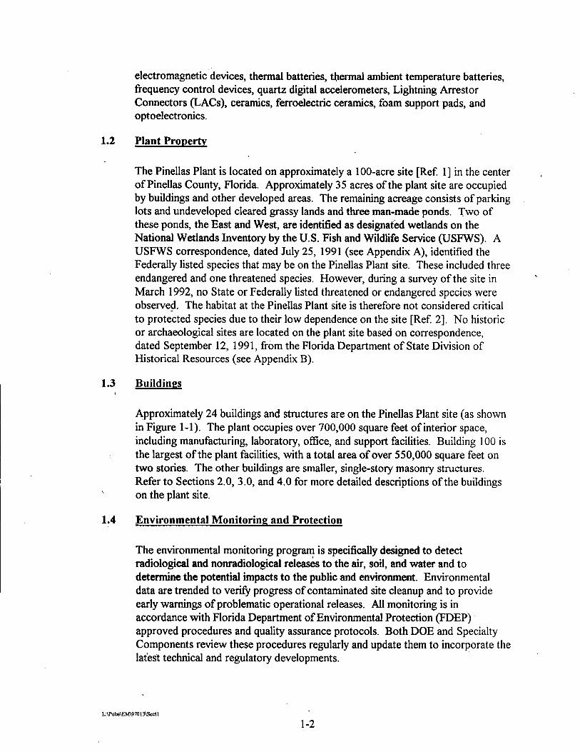
1.2 Plant Property
The Pinellas Plant is located on approximately a 100-acre site [Ref 11 in the center of Pinellas County, Florida. Approximately 35 acres of the plant site are occupied by buildings and other developed areas. The remaining acreage consists of parking lots and undeveloped cleared grassy lands and three man-made ponds. Two of these ponds, the East and West, are identified as designated wetlands on the National Wetlands Inventory by the U.S. Fish and Wildlife Service (USFWS). A USFWS correspondence, dated July 25, 1991 (see Appendix A), identified the Federally listed species that may be on the Pinellas Plant site. These included three endangered and one threatened species. However, during a survey of the site in March 1992, no State or Federally listed threatened or endangered species were observed. The habitat at the Pinellas Plant site is therefore not considered critical to species due to their low dependence on the site [Ref 21. No historic or archaeological sites are located on the plant site based on correspondence, dated September 12, 1991, from the Florida Department of State Division of Historical Resources (see Appendix B).
1.3 Buildings t
Approximately 24 buildings and structures are on the Pinellas Plant site (as shown in Figure 1-1). The plant occupies over 700,000 square feet of interior space, including manufacturing, laboratory, office, and support facilities. Building 100 is the largest of the plant facilities, with a total area of over 550,000 square feet on two stories. The other buildings are smaller, single-story masonry structures. Refer to Sections 2.0, 3 .O, and 4.0 for more detailed descriptions of the buildings
\ on the plant site.
1.4 Environmental Monitoring and Protection
The environmental monitoring program is specifically designed to detect radiological and nonradiological releases to the air, soil, and water and to determine the potential impacts to the public and environment. Environmental data are trended to verifjr progress of contaminated site cleanup and to provide early warnings of problematic operational releases. All monitoring is in accordance with Florida Department of Environmental Protection (FDEP) approved procedures and quality assurance protocols. Both DOE and Specialty Components review these procedures regularly and update them to incorporate the latest technical and regulatory developments.

North Boundary (Fence)

1.4.1 Environmental Radiological~Monitoring Program
Until March 30, 1997, the radiological monitoring program was conducted in accordance with the Pinellas Plant Environmental Monitoring Plan [Ref 31. The radiological monitoring program at the Pinellas Plant will be phased out by the end of the DOE'S presence on September 30, 1997. With the removal of radiological materials from the site, the DOE approved reductions in the monitoring program in accordance with local, State, and Federal regulations.
Both on site and in the environment surrounding the Pinellas Plant, the radiological monitoring program included the sampling and analysis of: 1) air for tritium and plutonium, 2) wastewater and surface water for tritium, and 3) soil for plutonium. Plant personnel used this information to determine potential impacts to the public and the environment from plant operations. The plutonium monitoring program was terminated after
-March 1997. Off-site surface water and air are no longer monitored. The on-site air monitoring stations are being phased out to coincide with the removal of radioactive waste fiom the site by September 30, 1997.
The Pinellas Plant also maintains an active As Low As Reasonably Achievable (ALARA) program for environmental releases of radioisotopes that sets emission goals significantly lower than the amounts permitted by regulations.
In 1990, the DOE executed an Agreement In Principle (AIP) [Ref 41 with the State of Florida Department of Health and Rehabilitative Services (HRS) for oversight of environmental radiological monitoring at the Pinellas Plant. The HRS operates an on-site sampling station that continuously samples the ambient air for tritium and plutonium and collects and analyzes on- and off-site surface water samples for tritium and on-site soil samples for plutonium.
1.4.2 Environmental Nonradiological Monitoring Program
The nonradiological monitoring program includes routine characterization of groundwater and wastewater. The program is designed to: 1) veri@ compliance with the plant wastewater discharge permit, 2) detect contamination of groundwater, 3) determine the effectiveness of groundwater cleanup actions, and 4) demonstrate compliance 'with applicable regulations.
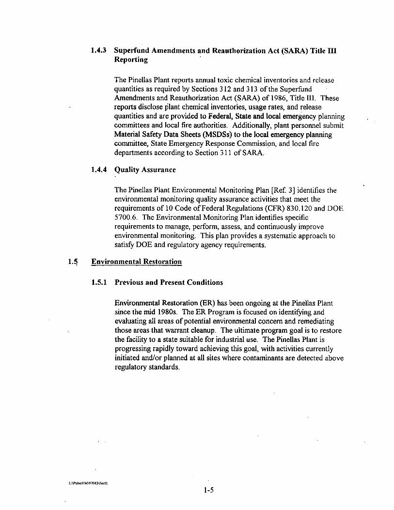
1.4.3 Superfund Amendments and Reauthorization Act (SARA) Title I11 Reporting
The Pinellas Plant reports annual toxic chemical inventories and release quantities as required by Sections 3 12 and 3 13 of the Superfind .
Amendments and Reauthorization Act (SARA) of 1986, Title 111. These reports disclose $ant chemical inventories, usage rates, and release quantities and are provided to Federal, State and local emergency planning committees and local fire authorities. Additionally, plant personnel submit Material Safety Data Sheets (MSDSs) to the local emergency planning committee, State Emergency Response Commission, and local fire departments according to Section 3 1 1 of SARA.
1.4.4 Quality Assurance
The Pinellas Plant Environmental Monitoring Plan [Ref. 31 identifies the environmental monitoring quality assurance activities that meet the requirements of 10 Code of Federal Regulations (CFR) 830.120 and DOE 5700.6. The Environmental Monitoring Plan identifies specific requirements to manage, perform, assess, and continuously improve environmental monitoring. This plan provides a systematic approach to satisfy DOE and regulatory agency requirements.
1.5 Environmental Restoration
1.5.1 Previous and Present Conditions
Environmental Restoration (ER) has been ongoing at the Pinellas Plant since the mid 1980s. The ER Program is focused on identifjling and evaluating all areas of potential environmental concern and remediating those areas that warrant cleanup. The ultimate program goal is to restore the facility to a state suitable for industrial use. The Pinellas Plant is progressing rapidly toward achieving this goal, with activities currently initiated andlor planned at all sites where contaminants are detected above regulatory standards.

2.0 OVERVIEW OF BUILDINGS 400,1200, AND 1400
Based on the Pinellas Plant's transition to alternate use, parts of the facility will be used by the PCIC, and other parts will be leased by the DOE until the end of its presence at the Pinellas Plant. Figure 2-1 shows the planned facility usage. Section 2.0 includes an overview of Buildings 400, 1200, and 1400. Figure 2-2 shows the historical Pinellas Plant growth and details each building's square footage and the year it was built.
Building 400 is centrally located on the plant site and contains approximately 'C
15,000 square feet. The original building had about 2,500 square feet and was built in 1968. Additions were made in 1978 (1,500 square feet), 1982 (7,000 square feet), and 1986 (3,500 square feet) (see Figure 2-2). It formerly contained facilities for the assembly and testing of RTGs. Production of these devices at the Pinellas Plant was stopped in 1992, and all plutonium heat sources were removed and shipped off site.
~urin~-1994, activities were initiated to prepare Building 400 for occupancy by a commercial tenant. These activities included removing the utilities and communications that supported the building's independent security system, slightly modifj4ng and increasing the size of the parking lot, flushing and characterizing drains, and abating all asbestos in the facility.
' To date, Specialty Components personnel have not detected any lead-based paint inside or outside of Building 400. An indoor radon study, fiom late 1989 to early 1990, showed radon lovels in Building 400 to be below the action levels of the Indoor Radon Abatement Act [Ref. 51. The radiation exhaust ducting and stacks fiom past manufacturing processes were removed and properly disposed of. Radiological surveys of the building were performed by Specialty Components and the HRS, Office of Radiation Control. The results of these surveys show agreement between the two sets of data and radiation levels within regulatory limits. The facility was upgraded to meet Federal, State, and local codes, such as National Fire Protection Association (NFPA) and Occupational Safety and Health Administration (OSHA) codes. There are no electrical transformers containing Polychlorinated Biphenyls (PCBs) in or around the building. Building 400 has been released to the PCIC for occupancy. Commercial tenants presently reside in Building 400.

, Figure 2- 1. Map of PCIC F&es and DOE Leased Facilities - -- ---- - -- --- -----
i A

PLANT GROWTH BY D E W
PINELLAS PLANT GROWTH LARGO, FLORIDA
. BUILDINGS ARE NOT IN PROPER GEOGRAPHIC PERSPECTIVE
PLANT GROWTH BY YEAR 1957 IWSQO so. R. 1977 1,wo so. n. 1- 3M 1976 6.879 1959 1m lolo 7300 1- S,sS, 1 6,174 1- 3,341 18.2 40,341 1- 71,260 1- 41,- loes %sa 1 lSl.rs3 loes ~ s a o , / 1 a e 400 1- m 1916 10,551 1- 71,SOl 1987 S1,WO 1971 1.706 1- $,SO0 1972 em 1- &ooo 1975 693 loo0 12.m la75 1,000 1-1 4-
*TOTAL 7a7a
+ t O t A L l W C U l O L I u , l 9 1 ~ ~ O C ~ S (WT~MOrrUrour)
-- Figure 2-2. Pinellas Plrmt Growth
FEBRUARY '1991

Building 1200
Building 1200 housed the Pinellas Plant security and communications operations, which included the following areas: locker rooms, shower, fitness room, eatingfbreak room, meeting and office areas, indoor firing range and armory, and covered garages. Building 1200 was completed, in 1988 and is approximately 28,250 square feet in sue. This building formerly provided the security force with centralized operations. A commercial tenant presently resides in Building 1200.
Building 1200 included an armory containing weapons storage lockers, a workstation for the armorer, weapons cleaning equipment and solvents,-and an ammunition storage vault. The indoor six-man firing range contains an auxiliary ventilation system, which becomes operational when the range is in use to maintain airborne lead levels below the OSHA personal exposure limit of 50 micrograms per cubic meter. This system has a flow rate of approximately 20,000 cubic feet per minute that exhausts air to the outside through a stack. This stack extends approximately 10 feet above the roof of the building. The ventilation system is considered an insignificant source of air pollution. It has not operated since October 1993. The firing range and ventilation ducts contain some surface contamination from unburned gun powder and lead, and the bullet trap contains lead from spent bullets; however, it is still serviceable as a small arms range.
To date, lead-based paint has not been detected inside or outside of Building 1200. An indoor radon study from late 1989 to early 1990 showed radon levels in Building 1200 to be below the action levels of the Indoor Radon Abatement Act lpef 51. No radiological material has ever been present in Building 1200. In addition, there are no electrical transformers containing PCBs in or around the building. The only sources of asbestos were identified in putty on floor drains and mastic behind the baseboard. These'are considered nonfiiable and not a hazard to human health [Ref. 61.
t The interior of the building also contains an emergency generator and a 30-gallon and a 15-gallon diesel fuel tank for the generator. An exterior 1,000-gallon diesel fuel tank, which currently contains fuel, resides on the north side of the building [Ref. 71.
All drains fiom the building run into the plant's sanitary drain system. Analyses of the building's discharge to the sanitary drain were within the limits set by the Pinellas County Utilities (PCU).
Building 1200 has been released to the PCIC for occupancy.

2.3 Building 1400 4
Constructed in 1989, Building 1400 is a 7,175-square foot concrete block facility formerly used for shipping and receiving materials at the Pinellas Plant. This facility was built to enhance plant security by allowing fill on-site inspection of incoming material remote from sensitive and sec.ure storage or manufacturing areas. The area around the building has ample parking and turn around space for deliveries.
The building had a conveyor system for automatic routing of packages to designated inspection stations. Building 1400's conveyor system has been removed, and portions of the building were remodeled for occupancy by a commercial tenant. There are no electrical transformers containing PCBs in or around the building.
Specialty Components personnel have not detected any lead-based paint inside or outside of Building 1400. An indoor radon study from late 1989 to early 1990 showed radon levels in Building 1400 to be below the action levels of the Indoor Radon Abatement Act [Ref 51. In addition, Building 1400 does not contain any asbestos [Ref 61.
Also, Building 1400 has a drum storage area that was built to contain any releases from receipt of leaky drums. The containment for this area drains into a holding tank on the outside of the building. According to interviews with employees who worked in Building 1400, this containment system was never used.
Building 1400 has been released to the PCIC for occupancy.

3.0 OVERVIEW OF BUILDING 100
Section 3.0 includes an overall summary of the Pinellas Plant's Building 100 areas that have been characterized. Building 100 is the largest of the Pinellas Plant facilities, with a total area of 550,000 square feet on two stories. Building 100 area information includes processes and operations, chemical usage, exhausts, drains, and the area's current status. A list of chemical name synonyms is presented in Section 10 because the same chemicals were listed by various names in the chemical lists used to compile the Area Closeout ,
Reports.
3.1 Building Summary
Building 100 provides space for manufacturing, engineming, and administrative support services. The basic structure of Building 100 consists of a steel frame with moment resisting trusses; some portions have a cross-braced frame. Perimeter shear walls are , vertically reinforced approximately every 4 feet. The roof system is metal deck with insulation and built-up roofing. Interior walls are a combination of concrete masonry unit, metal steel, and gypsum wallboard.
Lead-based paint is also assumed to be present in Building 100. Internal abatement of lead-based paint is performed as it is discovered. All lead-based paint on the exterior of Building 100 was removed in 1991.
An indoor radon study from late 1989 to early 1990, showed radon levels in Building 100 <
to be below the action levels of the Indoor Radon Abatement Act [Ref. 51. There are no electrical transformers containing PCBs in or around the building.
Chlorofluorocarbon (CFC) refrigerants are used in heat pumps, air conditioners, freezers, refrigerators, and other similar equipment that support Building 100 operations. The Clean Air Act Amendments of 1990 require a cessation in production of CFCs in the United States by the end of 1995. The affected CFC refrigerants used in the above
\ mentioned equipment are: R-1 1, R-12, R- 13, R-22, R-114, R- 123, R- 1344 R-502, and R-503. As CFC refrigerant shortcomings occur, the Pinellas Plant will use the remaining new and recovered refrigerants and will convert to alternate or approved substitute refrigerants when appropriate [Ref 81.
Radioactive materials existing in Building 100 are associated with laboratory activities for product testing. One area within Building 100 is considered a Radioactive Materials Management Area (RMMA), which indicates the potential for unconfined radioactive materials or emissions [Ref. 91. See Figure 3-1, which shows the one RMMA that is located on the first floor of Building 100.
Area 182 has ceased production and has undergone closure activities. Areas 107, 108 and8109 ceased production in 1996, and the last tritiuin bed (source of tritium for production) was shipped from the plant on June 19, 1996. For more information regarding cleanup of these areas, see Section 3.2.

The following processes were conducted in.Building 100: . .
Neutron generator manufacturing Neutron detector manufacturing Thermal battery manufacturing Specialty capacitor manufacturing Calcium chromate manufc~cruring . crystal resonatdr manufacturing LAC manufacturing Vacuum switch tube manufacturing Ceramics manufacturing Magnetics manufacturing Foam support pad manufacturing Resonant accelerometer manufacturing Clock oscillator manufacturing Iron dim@& processing Resin casting Machine shop operations -Tool room operations Spray painting (in booth) Research and development (R&D) Test equipment construction Metalizing, plating, chemical processing, and furnace firing

1 0 f ~ u b e Assembly
109 product Analysis
I 182 C ~ u b i Assembly 1 08 Tube Exhaust
Figure 3-1. Pinellas Plant RMMAs in Existing First Floor Layout

3.2 Historical Information and PresCnt'Status of Building 100 Areas
Some areas within Building 100 do not warrant a detailed description due to their low hazard activities (i.e., offices, cafeteria, storage, etc.); such areas would not pose any greater impact to the environment than a standard office complex. These nbndescript areas include personnel offices, telephone equipment rooms, records storage, food service areas, break rooms, janitorial supply areas, restrooms, conference rooms, and copier and computer rooms. Janitorial supplies include, but are not limited to, detergents,' cleaners, bleach, and floor stripper. Standard office supplies used in these areas include, but are not limited to, copier toner and printer cartridges, correction fluid, marker board cleaner, and glue. Area Characterization and Closeout Reports were prepared for these areas, but no detailed information is provided in this report. These areas, however, are identified in Table 3- 1.
Table 3-1. Building 100 Areas that Pose No Impact to the Environment

173
173
174
176 -
179
188
189
190
190
190
194
325
35 1
357
102 Mezzanine
103 Mezzanine
104 Mezzanine
105 Mezzanine
106 Mezzanine
112 Mezzanine
150 Mezzanine
19 1 Mezzanine
A
B
A-L, N-AD
R1, R2
JJ, R2 H-L, N-P
A-K
A-D, 0, P, R
E-L, N, Q ,S, U T
JJ, R1, R2 JJ, R1, R2
R1, R2 A-L, N-T, JJ, R1, R2
A-F, JJ
A-G
A-F
A-J, V V A-G
A-D
A-L, N, South Maintenance Chase
W
February 28, 1997 -
February 21, 1997
March 7, 1996
February 5, 1996
January 17, 1996
May 28, 1997
February 26, 1996
June 24,1996
March 26, 1996
January 17, 1997
February 12, 1996
May 29, 1997
March 1 1, 1997
March 26, 1997
May 17,1996
July 16, 1996
July 22, 1996
February 21, 1997
July 16, 1996
July 16, 1996
May 23, 1996
Final
Final
Final
Final
Final
Final
Final
Final
Final
Final
Final
Final
Final
Env. Health
Final
Final
Final
Final
Final
Final
Final

This subsection provides historical information on the areas that have been characterized, to date, within Building 100. Processes that may impact the environment are discussed. The information regarding the areas is provided for assessment and evaluation of the area. Discussed below is an explanation of, and the sources of information used for, each category describing the areas.
Area Number - The area number is the current'designation of the area as indicated on Building 100 layout plans (see Figures 3-2 and 3-3). Only areas with environmental , impacts are included. Areas Numbered 306 through 353 are located in the former Building 300, which is now considered part of Building 100. Most areas are divided into subareas and are also indicated on the layouts.
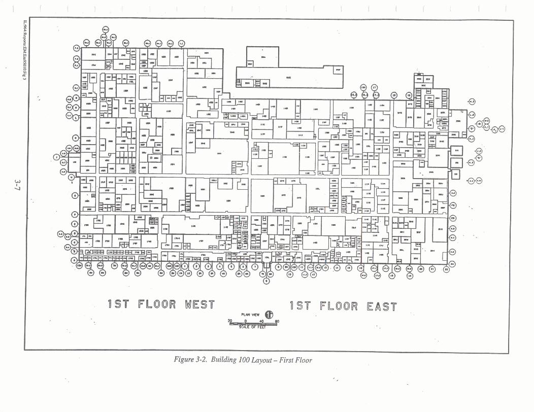
UST FLOOR EAST
I I Figure 3-2. Building I00 Layout - First Floor

2ND FLOOR MEST P N D . FLOOR EAST "
I ,
Figure 3-3. Building 100 Layout - Second Floor

Processes and Operations - This.is a desciiption of the types of processes and operations performed in the area during years representative of normal production (pre 1992). This is not intended to be a chronological perspective of all activities performed in a given area since it was built. Some areas have changed operations many times, making a chronological history difficult. In general, the operations and prokss descriptions include the most recent and significant use of the area. This information was obtained primarily through personnel interviews and from the building characterization files.
Chemical Usage - The chemical usage list information is primarily from the building characterization files. It is not intended to be a complete list of all the chemicals ever used in a particular area. However, this report does include a list of all the chemicals known to have been used in significant quantities and those that are known to have the greatest toxicity or hazard associated with their use. Also, the chemicals were not necessarily used at the same time as the processes and operations described above. , Knowledge of chemical uses is important for characterization of potential contamination of equipment and area surfaces. For more information regarding chemical usage, refer to the building characterization files.
Exhausts - This information describes the roof openings that were used for discharging air emissions from the area. The information gives a general idea of the number of chemical and radiological exhaust connections present during years representative of normal production. It does not give an accurate description of the current configuration of the chemical and radiological exhaust systems, as these are very dynamic, changing
t
with plant rearrangements and with preparations of areas for future use. Exhaust information was obtained from the Air Construction Permit Application [Ref. 101, which was submitted to the FDEP in October 1992, and from area drawings prepared for Area Closeout Reports.
Drains - The Pinellas Plant had four drain systems: the storm drains, sanitary drains, chemical drains, and radiological drains (also known as health physics drains). In 1994,
< an above-ground radiological drain system was installed to replace the old underground system, but was removed in 1997. The old underground radiological drain system has been flushed, sampled, permanently sealed with grout, and labeled. A project to install an above-ground chemical drain system is complete. The underground chemical drains have been flushed, capped, and abandoned. For more information on chemical and radiological drain decontamination, see Chapter 7. Storm drains collect and drain precipitation from the roo& and paved areas of the plant. All process wastewater discharges to the storm drain and storm water collection systems were eliminated. For more information about the storm drain system, refer to the Pinellas Plant National Pollutant Discharge Elimination System Storm Water Discharge Permit Application submitted to the Environmental Protection Agency (EPA) in 1992 and revised in 1994 mef 1 11.

Status - Status is a summary of each area, including its current or planned use. For additional information on Deactivdion and Compliance @&C) activities and the Area Characterization and Final Closeout Report, see Section 7.
3.2.1 Area 103A-G
Processes and Operations
Area 103A-G operations involved subassembly of mechanical and electrical components, including printed circuit boards, for product testers prior to final assembly in Area 150. A portion of the area was also a stockroom for mechanical and electrical components. Processes included electroplating, electroless plating, photolithography developing, drilling, routing, engraving, bead blasting, spray painting, aluminum anodizing (Iridite), etching, and oven curing and drying.
-Chemical Usage
A review of Specialty Components records indicated that the following chemicals may have been used or handled:
trichloroethane diethanolamine sulhric acid nitric acid ammonium hydroxide flammable liquids mercury photographic developer methylene chloride tritium ammonia acetic acid acetone ammonium chloride arnyl acetate barium carbonate barium nitrate copper chloride copper oxide powder Cuposit 328 ethanolamine fluoboric acid gold cyanide
sodium hydroxide hydrochloric acid chromic acid ammonium persulfate potassium hydroxide lead silver vanadate alkaline strippe solder trichloroethylene alcohol hydrofluoric acid Metex Etchant 9 1 10 methylethyl ketone peptone solution phosphoric acid plating chemicals (Cu, Ni, Sn/Pb, Au) potassium permanganate sodium bichromate sodium gluconate stannuous chloride potassium ferricyanide asbestos (insulation in overhead-abated) '

Exhausts
Exhaust from the paint spray booth discharged through a filter to roof opening 535. Other equipment was exhausted through roof opening 285.
Drains
Connections to the chemical drain system were above floor level and have been removed back to Area 150, where the drain pipes entered the underground chemical drain system.
Status
In 1996, Area 103A-G (Equipment Fabrication and Test, Areas 103 and 150) was relocated to Areas 325,327,330,33 1, and 336. Area 103 has been cleaned, -characterized, and closed out as part of D&C. Characterization and Final Closeout Report for Area 103A was issued July 16, 1996. Rooms 103B-F have\ been consolidated into a single Room B as a result of D&C cleanup activities. The Area Characterization and Final Closeout Report for Areas 103B-G was -issued October 17, 1996.
3.2.2 Area 104A-L, N-R
Processes and Operations
The Machine Shop was used to ikbricate metal components for many Pinellas Plant product lines. Processes included cutting, milling, grinding, deburring, sandblasting, vapor blasting, solvent degreasing, aqueous degreasing, hydroforming, soldering, brazing, welding, electropolishing, and oven drying.
In 1988, a trim (machine coolant) treatment process was installed in Subarea 104H to eliminate machine coolant waste. An acid is added to precipitate heavy metals, the pH is adjusted, and then a coagulant is added to bind the metals. The coolant is then filtered and the wastewater'is tested and discharged into the chemical drain system. The solid residue is tested for and passes the Toxicity Characterization Leaching Procedure (TCLP) test and is disposed of as a nonhazardous waste.
Chemical Usage A review of Specialty Components records indicated that the following chemicals may have been used or handled:
sulfbxic acid mercury methylene chloride trichloroethane lead sodium hydroxide methyl ethyl ketone trichlorotrifluoroethane (Freon@)
* > phosphoric acid boron nitrite hydrofluoric acid nitric acid

acetic acid . .
acetone alcohol aluminum oxide cadmium dioxide potassium femcyanide asbestos . trichloroethylene hydrochloric acid tritium phosphorous photoresist diala oil Gulf Harmony 68
- Gulf Harmony 46 Mobilrama Vacauline oil dental ply Nyoil flux plastic polish Armstrong adhesive electrolyte Super Edge lube Speedfam lapping compound Moly Dee tapping compound honing oil Actrel epoxy polymide resin polymide surface plate cleaner Trim aluminum cln.nst
Duralube MP moly DTE oil medium gear oil Vaculine 1409 Gulfbay 68 Vactra #1 Gulf Spin # 1 5 transmission fluid eye saver Dryerase surface cleaner micro finish Safe Tap Tapmatic Vactra #2 hydraulic oil Gulf cutting oil Hexan Cindol3 103 anti-wear hydraulic oil Cool Tool Cut Max 105 anti-sieze compound PVC cement Winslomatic oil blackening solution Kling black silicon carbide powder grease Alconox powder Chemtrol sludge buster tablets Dykem dye
Exhausts Chemical exhaust was vented through roof openings 153,292,295,366,367, 372, and 375.
Drains There are connections to the sanitary drain system. Chemical Liftstation Number 9 is located in the area. Connections to the chemical drain system have been flushed, sampled, and capped.

Status . .
Area 104A-L, N-R has been cleaned, characterized, and closed out as part of D&C. The Area Characterization and Final Closeout Report was issued November 26, 1996.
3.2.3 Area 105A-K
Processes and Operations Area 105 had multiple uses. In Subareas A-D, ceramic logs were manufactured for use in other products throughout the plant. Ceramic powders were mixed and weighed in an exhaust hood and processed (mixed with water) in a ball mill. The resulting powder slurry was then pressurized and fed to a spray dryer, where it was atomized, using compressed air and dried to a powder with hot air fiom a natural gas fired burner. The dry ceramic powder was then formed into pellets and logs, using stokes (punch and die) and isostatic (wet process) presses. . Additional processes performed in the area included pre-firing, green machining (machining prior to firing), and oven drying. Further ceramics processing (metalizing, firing, and final machining) was performed in Areas 117, 145, and 146. Subareas E-H were used for incoming test and inspection (mechanical and electrical testing), and Subareas I-K were used for shipping and receiving. Subarea L was used for incoming test and inspection.
Chemical Usage
A review of Specialty Components records indicated that the following chemicals may have been used or handled:
silica magnesium hydroxide amyl acetate trichloroethane trichloroethene (trichloroethylene) methylene chloride butyl carbitol acetate butyl stearate dimethylsiloxane hydraulic fluid methyl cellulose mill powders polyethylene glycol P O ~ Y ~ ~ Y col primers wax emulsion alumina powder polypropylene glycol
aluminum oxide calcium carbonate Freon@ silicone fluid alcohol acetone antifoam fluid crystalline silica (Si02) dispersing agent mercury hydroxypropyl cellulose perfluoropolyether primers moly powder stearic add Klucel 95ND2 alumina
These chemicals were used in the ceramics area. Chemicals passing through Shipping and Receiving are not listed.
Exhausts
Equipment was exhausted through roof openings 234,352,353,354,392 and 393.
Drains
There are connections to the sanitary drain system. Connections to the chemical drain system have been flushed and capped.
Status
The area has been cleaned, characterized, and closed out as part of D&C. The -Area Characterization and Final Closeout Report was issued October 16, 1996 for Subarea A and was issued May 29, 1997 for Subareas B-L.
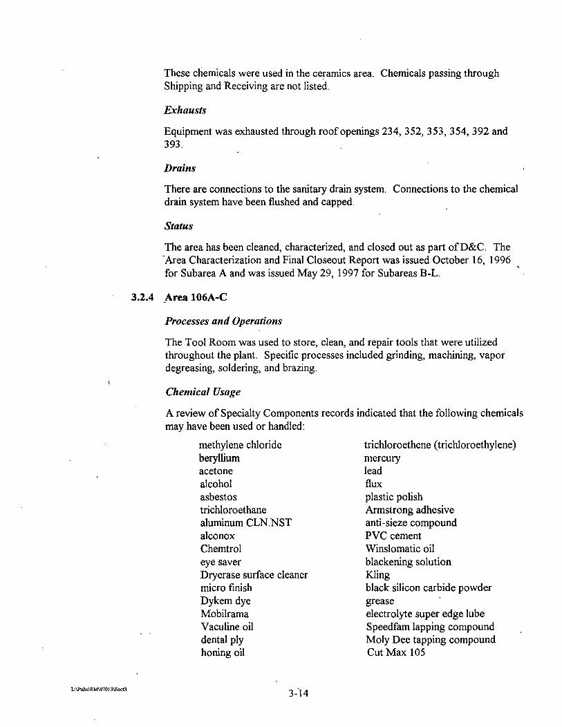
Processes and Operations
The Tool Room was used to store, clean, and repair tools that were utilized throughout the plant. Specific processes included grinding, machining, vapor degreasing, soldering, and brazing.
Chemical Usage
A review of Specialty Components records indicated that the following chemicals may have been used or handled:
methylene chloride beryllium acetone alcohol asbestos trichloroethane aluminum CLN.NST alconox Chemtrol eye saver Dryerase surface cleaner micro finish Dykem dye Mobilrama Vaculine oil dental ply honing oil
trichloroethene (trichloroethylene) mercury lead flux plastic polish Armstrong adhesive anti-sieze compound PVC cement Winslomatic oil blackening solution Kling black silicon carbide powder grease electrolyte super edge lube Speedfam lapping compound ,
Moly Dee tapping compound Cut Max 105

Actrel epoxy polymide resin polyrnide surface plate cleaner sludge buster tablets Safe Tap tap ma ti^ Vactra #2 hydraulic oil Gulf cutting oil Hexan Cindol3 103 anti-wear hydraulic oil cool tool Trim
diala oil Gulf harmony 68 Gulf harmony 46 Duralube MP moly DTE oil medium gear oil Vaculine 1409 Gulfway 68 Vactra # 1 Gulf Spin # 1 5 transmission fluid 7-11 spray oil tritium Nyoil
Exhausts
Chemical exhaust was vented through roof opening 88A.
Drains
Connections to the chemical drain system have been flushed and capped.
Status
Area 106A-C has been cleaned, characterized, and closed out as part of D&C. The Area Characterization and Final Closeout Report was issued November 25, 1996.
3.2.5 Area 107A-G
Processes and Operations
This was the neutron generator tube assembly and component preparation area, and contained a clean room (Subarea 107B) and a downflow room (Subarea 107E). Processes included mechanical assembly, Tungsten Inert Gas (TIG) and plasma welding, x-ray analysis, metal evaporation, and vacuum firing.
Chemical Usage
A review of Specialty Components records indicated that the following chemicals may have been used or handled:
alcohol tritium oxalic acid arnyl acetate titanium vanadium pellets trichlorotrifluoroethane (Freon@) Fluorinert

acetone mercury hydrofluoric acid nitric acid
Exhausts
Radiological exhaust in the area was discharged through roof opening 82, which was the main radiological exhaust stack.. There was a potential for tritium or tritium oxide release.
Drains
Connections to the above-ground radiological drain systems have been removed. Connections to the old underground radiologica1,and chemical drain systems have been flushed and permanently sealed with grout.
Operations in this area ceased in 1996. A project to dismantle and clean the arei by September 1997 is in progress. For additional information, see Section 7.2.5, -Area 108 Cleanup Project, and Appendix C, Pinellas Plant Radiological Area Disposition Program Plan.
3.2.6 Area 108A-L, N
Processes and Operations
The Tube Exhaust area performed vacuum processes to tritium load neutron tubes. Processes included tritium film loading, deuterium film loading and bulk sample loading, trace gas analysis, tritium bed loadinghank unloading, tritium bed sample analysis, tritium loaded thin film analysis, loading and unloading of special tritium storage fixtures that contained depleted uranium, uranium bed oxidation, and laser welding.
Chemical Usage
A review of Specialty Components records indicated that the following chemicals may have been used or handled:
alcohol scandium boric acid tapping compound methylene chloride hydrochloric acid sulfuric acid titanium mercury
tritium silicone toluene desiccant silica gel trichlorotrifluoroethane (Freon@) hydrofluoric acid nitric acid acetone depleted uranium deuterium

Exhausts . .
Loaders and other exhaust systems were vented through the TRS to the main radiological exhaust stack. Room air was vented directly through the main radiological exhaust stack. The area was maintained under negative pressure to prevent the spread of radiological contaminants.
Drains
Connections to the above-ground radiological drain system have been removed. '
Connections to the old underground radiological and chemical drain systems have been flushed and permanently sealed with grout.
Status
Operations in this area ceased in 1996. A project is in progress to dismantle and -clean this area by September 1997. For additional information, see Section 7.2.2, Area 108 Cleanup Project, and the Pinellas Plant Radiological Area Disposition Program Plan (Appendix C).
3.2.7 Area 109A-J
Processes and Operations
This area was used for the production of magnetics. Parts and materials manufactured in this area were sent to other areas for assembly and testing. Processes included chemical mixing, vacuum de-aerating, encapsulating, oven curing, machining, laser marking, and component testing. The area was also used for radiological components leak testing.
Chemical Usage
A review of Specialty Components records indicated that the following chemicals may have been used or handled:
trichloroethene (trichloroethylene) tritium Freon@ methylene dianiline (MDA) polyurethane encapsulant urethane casting elastomer urethane resin toluene diisocyanate N-Methylpyrrolidinone lead Isoverre (chemical stripper) thinner krypton-85
Exhausts
There were chemical and radiological exhausts in the area. he chemical exhaust was discharged through roof openings 527 and 528; the radiological exhaust
% vented to the main stack.

Drains
Connections to the above-ground radiological drain system have been removed. Connections to the old underground radiological drain system have been flushed, permanently sealed with grout, and labeled.
Status
Specialty Components continues to occupy this area. Subareas 109 F, G, H, I, and J are being cleaned as part of the Area 108 Cleanup Project. Equipment is being removed from the remaining subareas of 109 to make the area available for D&C.
3.2.8 Area 11OA-L
Processes and Operations
This area had multiple uses. Subareas A-D were used as an optoelectronics *
production facility. Processes included vapor degreasing, ultrasonic degreasing, assembly, laser welding, laser engraving, hydrogen firing, helium leak detection, epoxy encapsulation, and soldering. Subarea 11 OC contains a downflow tent. Subareas E, F, G, and I were used for magnetics development. Processes included coil winding, lead stripping and tining, lead cleaning of solder residue, soldering, resin casting, curing, assembly, and testing. Subareas H, J, K, and L served as production stockrooms and were used to receive, store, and issue war reserve production parts, explosives, and refrigerated chemicals. Subarea 1 10F contained a calcium chromate waste tank prior to 1984.
Chemical Usage
A review of Specialty Components records indicated that the following chemicals may have been used or handled:
trichloroethane polyurethane encapsulant polysiloxane lithium chloride fluorocarbon release agent heat powder calcium chromate hydrofluoric acid triethylenetetramine diethanolamine ESD hand lotion cho-bond adhesive bar solder solder acetone
Isoverre (chemical stripper) iron disulfide flammable liquids trichloroethene (trichloroethylene) trichlorotrifluoroethane (Freon@) toluene methylene chloride xylene toluene diisocyanate mercury non-contaminating hand cleanser aremco bond solder paste alcohol explosive

flux remover methylene dianiline polysulfide S ylgard TETA uranium glass flux loctite sealing compound primer loctite 404 diacetone alcohol isopropyl alcohol D-limonene antistatic. spray sealing locking & retaining compound
grade H and grade CV
Exhausts
Equipment exhaust discharged through roof openings 90, 520, 521, 522, 523, 524, 525, 526, 527, 528,637, and 1287.
Drains
Connections to the chemical drain system have been flushed and capped.
Status
Operations have ceased. Subareas 11OA-L have been cleaned, characterized, and closed out as part of D&C. The Area Characterization and Final Closeout Reports have been issued as follows:
Subareas 1 1 OE, F and I - February 26, 1996 Subareas 1 1 OA-D, H, K, and L - December 13, 1996
Subarea 1 10J - January 3 1, 1997
Subarea 1 1 OG - April 9, 1997
3.2.9 Area 111A-H
Processes and Operations
This area was used for magnetics production. Processes included coil winding, encapsulation (resin mixing, de-aerating, mold pouring, and curing), soldering, machining, cutting, laser marking, assembly, spray coating, ultrasonic cleaning, plasma cleaning, lead stripping and tining, and thermal testing. Processes in Subarea 11 1H used MDA, a suspected carcinogen.
Chemical Usage
A review of Specialty Components records indicated that the following chemicals may have been used or handled:
methylene chloride Adiprene toluene diisocyanate Isoverre (chemical stripper) halogenated degreasers trichloroethene (trichloroethylene) Freon@ methylene dianiline (MDA) polyurethane coating ammonium bifluoride
polysiloxane alcohol acetone trichlorotrifluoroethane (Freon@) Fluorinert toluene flammable liquids mercury lead xylenes formaldehyde
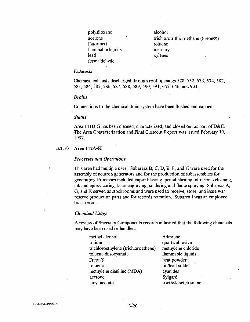
Exhausts
Chemical exhausts discharged through roof openings 528, 532, 533, 534, 582, 583, 584,585,586, 587, 588, 589, 590,591,645,646, and 903.
Drains
Connections to the chemical drain system have been flushed and capped.
Status
Area 11 1B-G has been cleaned, characterized, and closed out as part of D&C. -The Area Characterization and Final Closeout Report was issued February 19, 1997.
3.2.10 Area 112A-K
Processes and Operations
This area had multiple uses. Subareas B, C, D, E, F, and H were used for the assembly of neutron generators and for the production of subassemblies for generators. Processes included vapor blasting, pencil blasting, ultrasonic cleaning, ink and epoxy curing, laser engraving, soldering and flame spraying. Subareas A, G, and K served as stockrooms and were used to receive, store, and issue war reserve production parts and for records retention. Subarea I was an employee breakroom.
Chemical Usage
A review of Specialty Components records indicated that the following chemicals may have been used or handled:
methyl alcohol tritium trichloroethylene (trichloroethene) toluene diisocyanate FreonB toluene methylene dianiline (MDA) acetone amyl acetate
Adiprene quartz abrasive methylene chloride flammable liquids heat powder tinllead solder '
cyanides Sylgard triethylenetetramine

methyl ethyl ketone diethanolamine CIBA gold arsenide lead nitric acid TETA ethane gold cyanide
piperidine isopropyl alcohol explosive hydrochloric acid mercury potassium permanganate tricloroethane sulhric acid
Chemical exhausts discharged through roof opeings 42,43, 82; 99, 108, 166, 202,244,245,270,344,364,443, 541, 574,641, 649, 530B, 1263, 1264, and 1265.
-Drains
Chemical drains in Subarea 112B have been flushed and capped.
Status
Operations have ceased. The area has been cleaned, characterized, and closed out as part of D&C. The' Area Characterization and Final Closeout Reports were issued as follows:
Subareas B, D, E, F and H - May 30, 1996
Subareas 4 C, G, I, and K - December 19, 1996
The Final Radiological Status Report for Subareas A, C, G, I, K, and JJ was issued March 1 1, 1997.
3.2.11 Area 113A-C
Processes and Operations
This second floor area was used as an environmental chemistry laboratory, contamination control laboratory, and later as a solder training facility.
Chemical Usage
A review of Specialty Components records indicated that the following chemicals may have been used or handled:
alcohol D-limonene lead solder toluene Freon69 1 13 acetone asbestos (floor tile mastic) tritium
, , acids Plutonium 242 (trace amounts) liquid scintillation fluid chromerge

Exhausts
Chemical exhausts were discharged through roof openings 1 and 1249
Drains
There are connections to the sanitary drain system.
Status
Operations have ceased. The area has been cleaned, characterized, and closed out as part of D&C. The Area Characterization and Final Closeout Report was issued July 9, 1996.
3.2.12 Area 114A-J
-Processes and Operations
The operation of this area was final inspection and test. Processes included x-ray analysis, film developing, and film reading. Subarea 114E contains a silver
-recovery unit for processing photographic chemicals prior to release to the chemical drain system. Subarea I was used for product storage and Subarea J was a shelf life room used to store products under the Shelf Life and Stockpile Evaluation Programs.
Chemical Usage
A review of Specialty Components records indicated that the following chemicals may have been used or handled:
explosives Industrex Developer and Replenisher, Part A Industrex Fixer and Replenisher, Part A Intervent Fixer Additive Industrex Developer Starter Industrex Fixer and Replenisher, Part B Industrex Developer and Replenisher, Part C Simichrome polish bromine nitric acid sulhric acid phosphoric acid toluene alcohol ammonium hydroxide potassium hydroxide sodium hydroxide diethanolamine ferric ammonium sulfate
Freon@ EDTA calcium hydroxide hydrochloric acid hydrobromic acid acetic acid silver nitrate lead nitrate potassium dichromate sodium nitrite magnesium perchlorate pH 4.0 buffer solution pH 7.0 buffer solution potassium iodate manganese dioxide methyl purple lead acetate sodium chromate

ammonia aluminum oxide DETA ethanolamine ammonium bifluoride barium chloride lithium metabocate potassium chloride soluble starch potassium hydrogen phthalate lithium carbonate cesium chloride zirconium selenide ammonium dihydrogen phosphate
_ zirconium bromide zirconium nitride benzoic acid magnaflux spray developer sodium thiosulfate mercuric chloride potassium sulfate sodium oxalate static free spray barium chloride zinc metal p-methoxyphenol n-vinyl pyrollidone zirconium fluoride zinc sulfate thyodene pH 10 buffer ZnBrCr04 heat source powder isopropyl alcohol hexane kerosene m-xylene toluene/isopropyl alcohol n-nonane isopentyl acetate glycerol butyl acetate trichloroethylene chlorobenzene
% > ethyl alcohol toluene
thyodene mannitol stannous chloride potassium hydrogen sulfate potassium iodide potassium phosphate bromothymol blue potassium chromate diphenylamine magnesium sodium-EDTA arsenic trioxide zirconium carbide carbon tetrachloride potassium sodium tartrate potassium nitrate methylene chloride sodium bicarbonate 2-pyrollidone sodium borate potassium phosphate ammonium thiocyanate sodium iodide tris buffer potassium thiocyanate silver nitrate carbon tetrachloride ammonium chloride sulfkr tetrachlorotehylene ethylene glycol chloroform hydrochloric acid acetic acid methyl alcohol pyridine isooctane dibutyl arnine acetone acetonitrile p-xylene pentyl acetate Karl ~ i scher reagent tetrahydrohran 2-propanol 1 -methoxy, 2-propanol

Exhausts . .
Chemical exhausts discharged through roof openings 6 15, 127 1, 1272, 1273, 1274, and 1276.
Drains
There are connections to the new, above-ground chemical drain system.
Status
Area 114A-J has been cleaned, characterized, and closed out as part of D&C. The Area Characterization and Final Closeout Report was issued September 27, 1996.
3.2.13 Area 115A-J
Processes and Operations
This second floor area was a laboratory for photographic developing, layout, and photo finishing. Adhesive spray was applied to posters prepared for visual presentation. Equipment included developer tanks, film processors, and an adhesive spray station.
Chenzicnl Usage
A review of Specialty Components records indicated that the following chemicals may have been used or handled:
photographic chemicals activators fixers
alcohol developers
Exhausts
Equipment vented through roof openings 2, 92, 94, and 6 15.
Drains
Connections to the chemical drain system were flushed and capped.
Status
Area 115A-J has been cleaned, characterized, and closed out as part of D&C. The Area Characterization and Final Closeout Report was issued March 19, 1997.
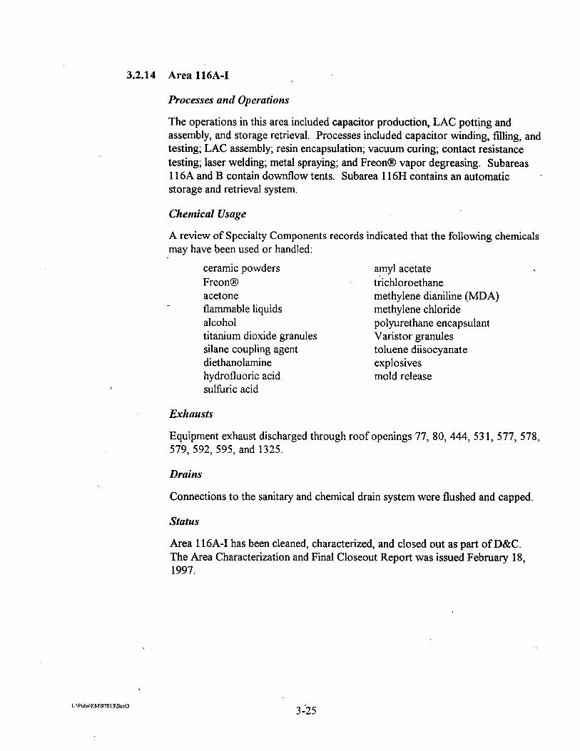
3.2.14 Area 116A-I
Processes and Operations
The operations in this area included capacitor production, LAC potting and assembly, and storage retrieval. Processes included capacitor windin& filling, and testing; LAC assembly; resin encapsulation; vacuum curing; contact resistance testing; laser welding; metal spraying; and Freon@ vapor degreasing. Subareas 116A and B contain downflow tents. Subarea 116H contains an automatic storage and retrieval system.
Chemical Usage
A review of Specialty Components records indicated that the following chemicals may have been used or handled:
ceramic powders Freon@ acetone flammable liquids alcohol titanium dioxide granules silane coupling agent diethanolamine hydrofluoric acid sulhric acid
amyl acetate trichloroethane methylene dianiline (MDA) methylene chloride polyurethane encapsulant Varistor granules toluene diisocyanate explosives mold release
Exhausts
Equipment exhaust discharged through roof openings 77, 80,444, 53 1, 577, 578, 579, 592,595, and 1325.
Drains
Connections to the sanitary and chemical drain system were flushed and capped.
Status
Area 116A-I has been cleaned, characterized, and closed out as part of D&C. The Area Characterization and Final Closeout Report was issued February 18, 1997.

3.2.15 Area 117A-E
Processes and Operations
This area was used for ceramics production and subassembly. The south half of Subarea C (formerly 117P) was a downflow room, where ceramic parts were plated with nickel, gold, and copper. Subarea D and north half of C (formerly 117C) were for metalizing, a process where liquid slurry is applied to ceramic parts in preparation for plating. Subarea F (now divided into Subareas A and B) '
was the hrnace room, where hydrogen firing, vacuum firing, and sintering were performed. Other processes performed in Area 117 included gold stripping and screen printing.
Chemical Usage
-A review of Specialty Components records indicated that the following chemicals may have been used or handled:
methlyene chloride alcohol amyl acetate methyl ethyl ketone ammonium bifluoride potassium gold cyanide sulhric acid nitric acid potassium hydroxide toluene diisocyanate boric acid ammonium fluoride ammonium persulfate arsenic butyl alcohol formaldehyde phosphoric acid sodium hydroxide thinner solvent trichloroethane mercury gold cyanide lead oxalic acid barium glacial acetic acid cadmium chromium
trichloroethene (trichloroethylene) acetone Bright Dip potassium permanganate nickel cyanide hydrochloric acid hydrofluoric acid flammable liquids toluene copper pyrophosphate ammonium hydroxide silver nickelous chloride potassium dichromate cuposit copper mix alumina dispersing agent kerosene surfactant ethyl acetate ethylene glycol machine oil tungsten powder Nyoil spray lubricants '
lubricating grease delrin sheet, rods ceramic logs

cellosolve acetate ceramic blanks 4 - selenium metallize powder
Exhausts
Equipment vented through roof openings 1 14, 136, 3 8 1, 3 85, and 3 89.
Drains
There are connections to the sanitary drain system. Connections to the chemical drain systems have been flushed and capped.
Status
Area 1 17A-E has been cleaned, characterized, and closed out as part of D&C. The Area Characterization and Final Closeout Report was issued October 11, 1996.
3.2.16 Area 118A and MA
Processes and Operations
This area is a maintenance stockroom with a mezzanine (1 18MA) for additional storage space and it also contains a laundry area. At one time, it was also used for incoming test and inspection. No production activity occurred in the area.
Chemical Usage
A review of Specialty Components records indicated that the following chemicals may have been used or handled:
Freon@ methyl ethyl ketone
Exhausts
There are no chemical exhausts in the area.
Drains
Connections to the chemical drain system have been flushed and capped.
Status
Areas 1 18 and 124 have been converted into a large storage area occupied by Specialty Components. The mezzanine (1 18MA) was removed.
3.2.17 Area 11-90
Processes and Operations
This area was used to house a silver recovery system to process photographic chemicals from the Area 1 15 Photolab.
Chemical Usage
A review of Specialty Components records indicated that the following chemicals may have been used or handled:
photographic chemicals (fixer, developer) asbestos (nonfriable floor tiles)
Exhausts
There are no chemical exhausts in the area.
Drains
Connections to the chemical drains system have been flushed and capped.
Status
The area has been cleaned, characterized, and closed out as part of D&C. An Interim Characterization and Closeout Report was issued November 27, 1996.
Processes and Operations
Subarea B was a laboratory involved in air sampling and analysis, particulate identification, and contamination control. Other areas were used for offices and storage.
Chemical Usnge
A review of Specialty Components records indicated that the following chemicals may have been used or handled:
Freon@ alcohol uranyl acetate diethanolamine epoxy resin and hardener chloroform glutaraldehyde SAE30 motor oil spray paint marker board cleaner methanol copier toner '
polychlorinated biphenyls tapmatic lubricant (oil leaked from Area 137; has been remediated)

Exhausts . .
Chemical exhaust vented through roof opening 404, 657, and 1254.
Drains
There are connections to the sanitary drain system. Connections to the old underground radiological drain system have been flushed, permanently sealed with grout, and labeled.
Status
Subarea B has been relocated in Area 348D to support D&C cleanup. Subareas A-C have been cleaned, characterized, and closed out as part of D&C. The Area Characterization and Final Closeout Report was issued October 3, 1996.
-Specialty Components continues to occupy Subareas 122D and E. An Area Characterization Report and Interim Certificate of Conformance for Subareas 122D and E was issued October 3, 1996.
3.2.19 Area 123A-D
Processes and Operitions
Subareas A and B were ofices for utilities personnel. The Equipment Calibration and Maintenance Shop was located in Subareas C and D. Equipment Calibration and Maintenance repaired, calibrated, and maintained electromechanical and vacuum equipment used throughout the plant.
Chemical Usage
A review of Specialty Components records indicated that the following chemicals may have been used or handled:
acid mercury acetone alcohol developer dimethyl polysiloxne silane ethanediamine hydrogen sulfide ferric oxide
adhesive potassium hydroxide propenoic acid, butyl ester sodium hypochlorite silicon dioxide lead solder styrene butadiene copolymer toluene
Chemical exhaust discharged through roof opening 307.

Drains
There are connections to the sanitary drain system. Connections to the chemical drain system have been flushed and capped.
Status
In 1996, computer Services was relocated to Area 13 1. This area has been cleaned, characterized, and closed out as part of D&C. The Area Characterization and Final Closeout Report was issued February 26, 1996.
3.2.20 Area 124A-G
Processes and Operations
-Facilities Maintenance was responsible for operation, maintenance, and repair of equipment and systems (air conditioning, piping, electrical, etc.). They also 8
performed small construction projects and plant rearrangements. This area contained a carpentry shop, sheet metal shop, weld shop, electrical shop, and
-ofice space for the Facilities Maintenance organization. Processes included cutting, drilling, laminating, painting, metal bending, metal braking, metal shearing, hole punching, pipe cutting and threading, welding (arc, mig, and TIG), metal burning, and soldering. There was also a mezzanine (Areas 124 MA, MB, and MC) above the south end of the shop, which provided office space for maintenance personnel.
Chenzical Usage
A review of Specialty Components records indicated that the following chemicals may have been used or handled:
lead methylene chloride Freon@ trichloroethane toluene asbestos
adhesives mercury methyl ethyl ketone various acids alcohol
Exhausts
Equipment exhaust was discharged through roof openings 306, 307, and 3 13
Drains
There are connections to the sanitary drain system. Connections to the chemical drain system have been flushed and capped.

status
This area was converted into a large storage area. The mezzanine was removed. Facilities Maintenance was relocated to Area 116 in 1995. Subarea A has been cleaned, characterized, and closed out as part of D&C. The Area .
Characterization and Final Closeout Report for Subarea A was issued April 24, 1997.
3.2.21 Area 125A
Processes and Operations
Originally, this area was a health physics laboratory and later a chemistry laboratory. More recently, it has been used as ofice space for various departments.
Chemical Usage
Many chemicals were used in small quantities when the area served as a laboratory. However, this was many years ago (1957 to 1964). A review of Specialty Components records indicated that the following chemicals may have been used or handled:
acetone ammonia developers tritium
fixers methyl ethyl ketone toners
Exhausts
There is currently no chemical exhaust in the area
Drains
There are connections to the sanitary drain system. Connections to the old radiological drain system have been flushed, permanently sealed with grout, and labeled.
Status
Area 125A has been cleaned; characterized, and closed out as part of D&C. The Area Characterization and Final Closeout Report was issued April 22, 1997.

3.2.22 Area 126A
Processes and Operations
This area was used as a glass shop and for neutron generator tube processing. Processes included vacuum firing, vapor blasting, and ultrasonic cleaning. The operation was moved to Area 107 in 1988, and the area was then used for storage and as a construction staging area for subcontractors.
Chemical Usage
A review of Specialty Components records indicated that the following chemicals may have been used or handled:
alcohol acetone
-Exhausts
There is currently no chemical exhaust in the area.
Connections to the chemical drain system have been flushed and capped.
status
Specialty Components continues to use the area for equipment storage. In 1994, I a liftstation was installed in the north east corner, as part of the new above-
ground radiological drain system. The lifistation received radiological wastewater from various sumps on the east end of Building 100 and pumped it to the health physics storage tanks west of Building 100. The liftstation and the above-ground radiological drain system have been removed. The project was completed in March 1997.
3.2.23 Area 127A.C
Processes and Operations
Subarea A was used as a mailroom from 1962 to 1997. Subarea B was used as a polymer lab from 1960 to 1964, as a technical support office area from 1965 to 1995, and as a mail services and reprographics area from 1996 to 1997.
Subarea C was part of the Standards Laboratory (from 1960 to 1964) and was used for calibrating optoelectronic devices (e.g., laser detectors and photo diodes). Subarea C was used for offices.

Chemical Usage
A review of Specialty Components records indicated that the following chemicals may have been used or handled:
methyl ethyl ketone toners developek tritium
acetone ammonia fixers
Exhausts
There is currently no chemical exhaust in the area.
Drains
-Connections to the old underground radiological drain system have been flushed, permanently sealed with grout, and labeled. .
Status
Area 127A-C has been cleaned, characterized, and closed out as part of D&C. The Area Characterization and Final Closeout Report was issued April 22, 1997.
3.2.24 Area 128A/131A
Processes and Operations
Final Test and Assembly was used for testing neutron tubes, neutron generators, and electronic components.
Chemical Usage
A review of Specialty Components records indicated that the following chemicals may have been used or handled:
lead alcohol toluene tritum thrichloroethene
Freon@ Fluorinert methylene chloride trichloroethane
Exhausts
There were no chemical exhausts in the area.
Drains
* > Area 13 1 has connections to the sanitary drain system.

Status
The area has been cleaned, characterized, and closed out as part of D&C. The Area Characterization and Final Closeout Report was issued May 5, 1997.
3.2.25 Area 130A-C
Processes and Operations
There were several operations in this area. Subarea 130A was an instrumentation lab from 1957 to 1958, a chemical cleanindtube lablstandards lab from 1959 to 1963, a test lablcalibration lab from 1964 to 1976, a quartz crystal fabricationlresonator area from 1977 to 1984, and a product tester support area from 1985 to 1994. Subarea 130B was an engineerng tube lablstandards lab from 1957 to 1983, a resonators/clockslfrequency devices process area from 1983 to
-1988, and an ofice area from 1983 to 1994. Subarea 130C was used as a conference room.
Chemical Usage
A review of Specialty Components records indicated that the following chemicals may have been used or handled:
acetone alcohol ammonia ammonium bifloride developers Freon@ methylene chloride
toluene toners tritium trichloroethane trichloroethene mercury
There were no chemical exhausts in the area.
Drains
There are no connections to the drain systems.
Status
The area has been cleaned, characterized, and closed out as part of D&C. An Area Characterization and Final Closeout Report was issued April 30, 1997.

3.2.26 Area 132 J, K, L, and N
Processes and Operations
Subareas J, K, and L contained TRS equipment for monitoring Areas 107, 108 and 109 and for monitoring air exhausted through the main (east) radiological stack. Subarea N was the east stack fadroom.
Chemical Usage
There are no records available for chemical usage in this area.
Exhaust
There are no connections to the exhaust systems.
Drains
Connections to the above-ground radiological drain system have been removed.
Status
This area will be dismantled and cleaned as part of the Area 108 Cleanup Project. For more information, see Section 7.2.5, Area 108 Cleanup Project, and the Pinellas Plant Radiological Disposition Program Plan (Appendix C).
, 3.2.27 Area 137 A-G
Processes and Operations
This area housed electrical transformers, switchgears, telephone batteries and rectifiers, and the public address support system.
Chemical Usage
A review of Specialty Components records indicated that the following chemicals may have been used or handled:
friable asbestos (in overhead) transformer oil polychlorinated biphenyls lead/sulfuric acid batteries potassium hydroxide nickeVcadmium batteries
Exhausts
There is currently no chemical exhaust in the area.
Drains
There are connections to the sanitary drain system.

Status
The area has been cleaned, characterized, and closed out as part of D&C. The Area Characterization and Interim Closeout Report was issued July 26, 1996. The Final Closeout Report was issued September 6, 1996, following completion of wall repairs.
3.2.28 Area 138A-G
Processes and Operations
There were several operations in this area. Subareas A-C were used for final assembly of neutron generators. Processes included electron beam welding, vapor blasting, adiprene potting (encapsulation), laser engraving, ink stamping, painting, and final machining. Subarea D was used for classified parts production -and Subarea F was a liquid nitrogen filling station. Subareas E and G were the defect analysis laboratory for LACS, capacitors, optoelectronics, and electronic component analyses.
-Chemical Usage
A review of Specialty Components records indicated that the following chemicals may have been used or handled:
alcohol methylene dianiline (MDA) toluene diisocyanate lead acetone tritium trichloroethane paints methylene-bis-orthochloroaniline
methylene chloride flammable liquids epoxy resin piperidine diethanolamine aluminum oxide Freon@ nitric acid
Exhausts
Equipment was vented through roof openings 85, 1 16, 1 17, 169, 274, 648, 922, 923, 924, and 1330.
Drains
Connections to the chemical drain system have been flushed and capped.
status
The area has been cleaned, characterized, and closed out as part of D&C. The Area Characterization and Final Closeout Report was issued February 24, 1997..
< ,

3.2.29 Area 139A-L, N-S
Processes and Operations
The primary operations were neutron generator and magnetics production. Processes included encapsulation, oven curing, flame spraying, sandblasting, vapor blasting, mold cleaning, timerldriver assembly, support pad assembly, machining, and testing.
Chemical Usage
A review of Specialty Components records indicated that the following chemicals may have been used or handled:
epoxy methlyene chloride butanediol toluene diisocyanate flammable liquids Freon@ lead alcohol benzene trichloroethene titanium dioxide aluminum oxide paints tritium methyl ethyl ketone
methylene dianiline (MDA) acetone silane calcium chromate epoxy resin explosives diethanolamine methylene-bis-orthochloroaniline zinc chromate trichloroethane battery acid zinc metal powder aluminum metal powder TETA
Equipment exhausts discharge through roof openings 23, 74, 75, 80, 119, 120, 225,229,237, 365, 368, 371, 386, 390, 478, 650, 651, 652, 655, 849, 852, 854, 857,861, 1239, and 1240.
Drains
There are connections to the sanitary drain systems. Connections to the chemical drain system have been flushed and capped.
Status
The area has been cleaned, characterized, and closed out as part of D&C. The Area Characterization and Final Closeout Report for Subarea P was issued May 14, 1997. The Area Characterization and Final Closeout Report for the remaining
' . subareas was issued February 24, 1997.

3.2.30 Area 140A/141A/142A and B
Processes and Operations
The operation of these areas was subassembly of metal and ceramic parts. Area 140 is the furnace room, where hydrogen and electric furnaces are used for brazing, vacuum firing, sintering, and annealing of ceramics and other parts. Area 141 was for inspection and testing of subassemblies after firing, and later for metals processing and welding. Area 142 was the subassembly area, where metal and ceramic parts were assembled prior to firing.
Chemical Usage
A review of Specialty Components records indicated that the following chemicals may have been used or handled:
alcohol nitric acid trichloroethene (trichloroethylene) hydrochloric acid phosphoric acid Ruby fluid potassium permanganate asbestos insulation methyl isobutyl ketone
acetone trichloroethane amyl acetate acetic acid copper oxide powder Epoxi-patch Tapmatic aluminum oxide
Exhausts
Equipment exhaust was discharged through roof openings 66, 68, 71, 72, 84, 265,374,375,376,377,398, and399.
Drains
Connections to the chemical drain system have been flushed and capped.
status
In 1995, plant consolidation projects moved ceramics metalizing operations into Area 142A (from 117C), created a metals processing shop (including laser welding) in Area 1414 and consolidated furnace operations from other areas of the plant into Area 140. The area has been cleaned, characterized, and closed out as part of D&C. The Area Characterization and Final Closeout Report for Area 140A was issued October 30, 1996. The Area Characterization and Final closeout Report for Areas 1414 1 4 2 4 and 142B was issued November 8, 1996. The area is occupied by a PCIC tenant.

3.2.31 Area 143A-E, 143M(A) .
Processes and Operations
The chemical process area cleaned ceramic and metal parts and subassemblies to support defense production. Processes included ultrasonic cleaning, acid cleaning, cascade rinsing, aluminum etching, alcohol rinsing, and vapor degreasing. Subarea 143 contains a downflow tent.
Chemical Usage
A review of Specialty Components records indicated that the following chemicals may have been used or handled:
trichloroethene (trichloroethylene) Freon@ sulhric acid hydrochloric acid toluene acetone mercury ammonium bifluoride ammonium hydroxide ammonium persulfate amyl acetate copper etchant gold cyanide copper oxide powder metex etchant 9 1 10 metex MU- 14 stannous chloride
trichloroethane methylene chloride alcohol hydrofluoric acid methyl ethyl ketone cyanides acetic acid nickel chloride nickel sulfamate nitric acid oxalic acid phosphoric acid plating chemicals (Cu, Ni, SnfPb, Au) potassium dichromate potassium permanganate sodium hydroxide
Exhausts
Equipment in Subarea 143A, C, and E vented to roof opening 387 and then through Scrubber Number 1. Other equipment exhausts discharged through roof openings 3 82 and 3 83. Scrubber Number 2 was relocated to the roof over Subarea 143B (roof opening 3 82).
Drains
Connections to the chemical drain system have been flushed and capped.

status
In 1995, plating and chemical cleaning operations were relocated from Areas 103, 1 17, and 163 into Area 143. The area has been cleaned, characterized, and closed out as part of D&C. The Area Characterization and Final Closeout Report was issued February 5, 1997.
3.2.32 Area 145A and Bl146A
Processes and Operations
These areas are used for the production and testing of ceramic parts. Subarea 145A is a machine shop for slicing, grinding, polishing, degreasing, and ultrasonic cleaning of ceramics. Subarea 145B is for inspection of ceramics after metalizing and plating processes are performed. Subarea 146A is primarily ofices and
-Subareas 146B and D are used for powder batching, powder pressing, air firing, hydrogen firing, and inspecting.
A review of Specialty Components records indicated that the following chemicals may have been used or handled:
Freon@ ceramic powders butyl carbital acetate nitric acid lead amyl acetate ceramic powders Ultemate cleaner tumbling media modeling compound parafine stacking wax Trim coolant Oakite Citridet way lubricant Dyken spray - steel blue 77 spray adhesive dry erase cleaner Dyken steel blue liquid Chesterton spray grip Nyoil Spulkonzentrat Tapmatic cutting fluid Coors USA ceramic marking ink
trichloroethane alcohol hydrofluoric acid trichloroethene (trichloroethylene) acetone magnesium hydroxide 7 1 1 demoisturant Lime A Way Dupont electronic comp thinner Starrett cleaner Alconox detergent Hydrolubic 120-B boron carbide US 40B abrasive for lapping Loctite dielectric composition 5704 conductor composition 7095 thick film conductor comp 5956 Dupont electronic composition Micro Lap . Hyprez W lubricant .Aquasol lapping lubricant Turco Dy-Chek remover #3

iust inhibitor NR18 Turco Dy-Chek penetrant
Exhausts
Chemical exhaust discharged through roof openings 130, 223, 441, 673, 1267, and 1268.
Drains
Connections to the chemical drain system have been flushed and capped.
Status
These area have been cleaned, characterized, and closed out as part of D&C. The Area Characterization and Final Closeout Report was issued October 16, 1996 and updated on October 22, 1996.
3.2.33 Area 150A-C
Processes ant1 Operations
The operation in this area was final assembly and testing of mechanical and electrical product testers. Processes included soldering, milling, drilling, mechanical assembly, and electronic testing.
Chemical Usage
A review of Specialty Components records indicated that the following chemicals may have been used or handled:
tritium toluene diisocyanate hydrochloric acid methylene chloride acetone trichloroethane isopropyl alcohol
lead alcohol hydrofluoric acid sodium hydroxide Freon@ sulhric acid
Exhausts
Chemical exhaust discharged.through roof openings 568 and 759
Drains
There are connections to the sanitary drain. Connections to the chemical drain system have been flushed and capped.

Status
In 1996, Equipment Fabrication and Test (Areas 103 and 150) was relocated to Areas 325, 327, 330, 33 1, and 336. Operations have ceased. The area has been cleaned, characterized, and closed out as part of D&C. The Area Characterization and Final Closeout Report was issued April 11, 1996. A correction to the Closeout Report was issued October 1, 1996, to include a list of chemicals.
3.2.34 Area 151A and MA/152A, B, and MA
Processes and Operations
Area 152 was the general stockroom and Area 15 1 was the war reserve production stockroom. Both areas have mezzanines (1 5 1MA and 152MA),
-which provide additional storage space.
Chemical Usage
_A review of Specialty Components records indicated the following chemicals may have been used or handled:
acetone gold cyanide lead methyl ethyl ketone trichloroethane metal bar stock standard ofice supplies, including toner
Exhausts
There are no chemical exhausts in either areas.
Drains
There are connections to the sanitary drain system in both areas. Connections to the chemical drain system in Area 15 1 have been flushed and capped.
Status
The general stockroom (Area 152) is planned for relocation to Area 105. Specialty Components continues to occupy Area 15 1, which was provisionally accepted in an interim characterization and closeout report, dated May 17, 1996. The final report will be published when the relocation is completed and the remaining DOE-owned barstock and racks are sold.

3.2.35 Area 154A-C
Processes and Operations
This area had two uses, transducer production and testing and model shop activities. The processes included grinding, sanding, cutting, and drilling. In addition, there were two small vaults, where neutron devices were detonated by computer control.
Chemical Usage
A review of Specialty Components records indicated that the following chemicals may have been used or handled:
explosives (HMX and PETN) alcohol trichloroethane tritium methyl ethyl ketone
- hydrochloric acid lithium niobate trichloroethylene (trichloroethene) uranium friable asbestos (in overhead)
nitric acid acetone lead methylene dianiline (MDA) cyanides hydrofluoric acid asbestos (floor tile mastic adhesive) Freon@ methylene chloride sulfbric acid
Exhausts
Equipment exhaust was discharged through roof openings 139 and 267.
Drains
There are connections to the sanitary drain systems. Connections to the chemical drain system have been flushed and capped. Connections to the old radiological drain system have been flushed, permanently sealed with grout, and labeled.
status
Operations have ceased. Subareas 154 A, B, and C have been cleaned, characterized, and closed out as part of D&C. The Area Characterization and Final Closeout Report for these subareas was issued April 26, 1996. .
3.2.36 Area 155A-D
Processes and Operations
The chemistry laboratory activities included sample preparation (acid digestionldilution) and analyses. The lab had an Inductive Coupled Plasma (ICP) unit for analyses of metals. Other equipment was used for titrations, gas chromatography, and atomic absorption spectrophotometry.

Chemical Usage
A review of Specialty Components records indicated that the following chemicals may have been used or handled:
hydrochloric acid phosphoric acid oxalic acid polyurethane encapsulant toluene potassium hydroxide aluminum oxide acetic acid mercury toluene diisocyanate I S 0 - amyl acetate trichloroethene (trichloroethylene) methylene chloride perchloric acid phenyl isothiocyanate N,N-dimethylformamide methyl alcohol lead nitrate hydrogen peroxide nitrous oxide zinc potassium cyanide sulfamic acid thallium metal uranium (metal) asbestos (floor tile mastic) carbon tetrachloride arsenic trioxide chloroform acetic anhydride ammonium dihydrogen arsenate fluoroboric acid hydrobromic acid
nitric acid hydrofluoric acid silicone boric acid flammable liquids sodium hydroxide Conathane tritium methylene dianiline (MDA) Isoverre (chemical stripper) trichloroethane glacial acetic acid sulfuric acid phosphonic acid phenol nitric acid magnesium perchlorate lead acetate acetylene argon potassium chromate pyridine tetrahydrofiran thorium nitrate tritium uranium oxide chlorobenzene bromine ammonium metavanadate chromium trioxide acetone cobalt chloride formic acid acetonitrile
Three radiological exhaust hoods were ducted to the west radiological exhaust stack (roof opening 89). The duct work was removed during the West Stack Removal Project. Other chemical exhaust hoods and equipment vented through roof openings 378 and 379.

Drains
Connections to the old radiological drain system have been flushed, permanently sealed with grout, and labeled.
status
The chemistry laboratory has been relocated to Area 350. Operations in Area 155 have ceased. The area has been cleaned, characterized, and closed out as part o f , D&C. The Area Characterization and Final Closeout Report was issued May 3, 1996.
3.2.37 Area 157A and B1158A and B
Processes and Operations
-These areas were used as a gas analyses laboratory and for the disassembly of neutron tubes. Processes included gas analyses, using mass spectrometers, solid; analyses, using inert gas fbsion, thermal desorption analyses, gas monitor _calibration, and various machining techniques for tube disassembly.
Chemical Usage
A review of Specialty Components records indicated that the following chemicals may have been used or handled:
hydrochloric acid tritium methylene chloride trichloroethane ammonium bifluoride magnesium perchlorate
hydrogen sulfide mercury trichloroethene (trichloroethylene) asbestos (floor tile mastic) N-methylpyrrolidinone
Radiological exhaust hoods were ducted to the west radiological exhaust stack (roof opening 89). The duct work was removed during the West Stack Removal Project.
Drains
There are connections to the sanitary drain system. Connections to the old radiological drain system have been flushed, permanently sealed with grout, and labeled.
Status
The laboratory has been relocated to Area 350. The area has been cleaned, characterized, and closed out as part of D&C. The Area Characterization and Final Closeout Report was issued May 3, 1996.

3.2.38 Area 159A-D
Processes and Operations
Subarea 159A was used as an advanced analyses laboratory, and Subareas B, C, and D were offices. Processes in the analyses laboratory included nuclear magnetic resonance spectrometry, gas chromatography, and mass spectrometry.
Chemical Usage
A review of Specialty Components records indicated that the following chemicals may have been used or handled:
nitric acid hydrochloric acid methylene chloride phenylene diamine chloroform mercury acetone tetrahydrohran n-phenylenediamine dioxane heptachlor hexane methyl sulfoxide methylene dianiline (MDA) napthalene p-xylene pyridine acetonitrile dimethylformamide toluene trichloroethylene (trichloroethene) trimethylphosphite cyanides carbon disulfide dichlorobenzene
phosphoric acid hydrofluoric acid carbon tetrachloride chrysene benzene bismuth sodium hydroxide n-diethylet hanolamine endrin hexachlorobutadine isopropanol methyl alcohol monoethylamine o-xylene phenol silver nitrate acetic anhydride Sylon-CT toxaphene triethylamine tritium butanone cyclohexane diethylamine pentafluoropropionic anhydride
Exhausts
Radiological exhaust hoods were ducted to the west radiological exhaust stack (roof opening 89). The duct work was removed during the West Stack Removal Project. Chemical exhaust was vented through roof opening 373.
Drains
There are connections to the sanitary drain system.

Status
The laboratory has been relocated to Area 350. The area has been cleaned, characterized, and closed out as part of D&C. The Area Characterization and Final Closeout Report was issued June 7, 1996.
3.2.39 Area 160A-E
Processes and Operations
The Chemistry Laboratory performed sample analyses using liquid, gas, and ion chromatography. Other processes included thermal analyses of polymers, wet chemistry analyses of plating solutions, and analyses of battery materials.
Chemical Usage
-A review of Specialty Components records indicated that the following chemicals may have been used or handled:
methyl ethyl ketone trichloroethene lithium tetrachloroaluminate methylene chloride methylene dianiline (MDA) acetone acetic acid (glacial) hydrochloric acid sulhric acid nitric acid alcohol potassium cyanide mercuric chloride tritium lithium thionyl chloride potassium gold cyanide acetic anhydride acetonitrile ammonia ammonium hydroxide amyl acetate arsenic trioxide butanol butyl acetate cellusolve acetate chloroform epichlorohydrin ethyl benzene ethylene glycol hexane hydrofluoric acid isopentyl acetate isopentyl alcohol m-xylene magnesium hydroxide mercury methyl alcohol monoethylamine nonanol p-xylene pentyl acetate perchloroethylene phosphoric acid potassium chromate potassium dichromate pyridine nitrobenzene potassium hydroxide sodium cyanide sodium hydroxide tetrahydrohran asbestos (walls, floor tiles, and overhead)

Radiological exhaust hoods were ducted to the west radiological exhaust stack (roof opening 89). The duct work was removed during the West Stack Removal Project. Chemical exhaust was vented through roof opening 373.
Drains
There are connections to the old radiological drain system. Connections to the chemical drain system have been flushed and capped.
Status
The chemistry laboratory has been relocated to Area 350. Area 160A has been cleaned by Specialty Components personnel, characterized, and closed out as part
-of D&C. The Area Characterization and Final Closeout Report for Area 160A , was issued June 7, 1996.
3.2.40 Prea 161A and B
Processes and Operations
This area served as a surface science and x-ray laboratory. Activities included surface analyses, thin film analyses, x-ray analyses, and process development.
Chenzical Usage
A review of Specialty Components records indicated that the following chemicals may have been used or handled:
tritium acetic acid, glacial asbestos (floor tiles, walls, overhead) ammonium hydroxide amyl acetate butanol butyl acetate cellusolve acetate chloroform epichlorohydrin ethyl benzene ethylene glycol hydrochloric acid hydrofluoric acid isopentyl acetate isopentyl alcohol lithium thionyl chloride m-xylene mercury chloride mercury methyl alcohol methylene chloride methylene dianiline (MDA) methyl ethyl ketone monoethylamine nitrobenzene nonanol p-xylene pentyl acetate perchloroethylene phosphoric acid potassium chromate potassium gold cyanide potassium dichromate potassium hydroxide pyridine

sodium hydroxide toluene diisocyanate hexane acetonitrile
tetrahydrofbran trichloroethylene (trichloroethene) acetone acetic anhydride
Exlzausts
Vacuum pump exhaust was ducted to the west radiological exhaust stack (roof opening 89). The duct work was removed during the West Stack Removal Project.
Drains
There are connections to the sanitary drain system. Connections to the chemical drain system have been flushed and capped.
Status
The laboratory has been relocated to Areas 350 and 114. The area has been cleaned by Specialty Components personnel, characterized, and closed out as part of D&C. The Area Characterization and Final Closeout Report was issued June 7, 1996.
3.2.41 Area 162A-F
Processes and Operations
This area was used as a metallurgy laboratory. Processes performed included potting, grinding, milling, machining, drilling, sanding, cutting, brazing, welding, spectra analyses, metallographic etching, heat treating, hardness testing, tensile testing, electron microscopy, and targetlsource scanning electron microscopy analyses.
Chentical Usrrge
A review of Specialty Components records indicated that the following chemicals may have been used or handled:
trichloroethene (trichloroethylene) hydrochloric acid nitric acid xylene amyl acetate alcohol copper sulfate diethanolamine heavy metals (powdered) methylene chloride
acetone sulhric acid hydrofluoric acid cyanides tritium alodine cyansol Freon@ lead fluoroborate nickel mercury

nickel chloride nickel sulfate phosphoric acid oxalic acid potassium hydroxide potassium permanganate sodium hydroxide tin fluoroborate toluene diisocyanate ammonium bifluoride acetic acid gallium asbestos,. nonfriable (in fiberboard wall cores) asbestos (floor tile and mastic adhesive)
Exhausts
Radiological exhaust hoods were ducted to the west radiological exhaust stack (roof opening 89). The duct work was removedduring the West Stack Removal Project. Chemical exhaust was vented through roof openings 110, 134, and 192.
There are connections to the sanitary drain system. Connections to the chemical drain system have been flushed and capped.
Operations have ceased. The area has been cleaned by Specialty Components personnel, characterized, and closed out as part of D&C. The Area Characterization and Final Closeout Report was issued June 7, 1996.
' 3.2.42 Area 163A-K
Processes and Operations
This area was used as a materials and process technology development laboratory. Subarea 163H is a downflow tent. Processes included plating, sintering, brazing, thin film measuring, electron beam welding, vapor blasting, vapor degreasing, aluminum etching, acid cleaning, ultrasonic cleaning, and ink spraying.
Chemicnl Usage
A review of Specialty Components records indicated that the following chemicals may have been used or handled:
trichloroethene (trichloroethylene) nitric acid hydrochloric acid nickel chloride lead fluoroborate nickel methylene chloride oxalic acid chromic acid
sodium hydroxide zinc oxide copper sulfate tin fluoroborate phosphoric acid tritium amyl acetate mercury

cyanides various heavy metals (powdered) alcohol alodine cyansol Freon@ nickel sulfate gallium asbestos (floor tile, mastic, baseboard)
diethanolamine toluene diisocyanate potassium hydroxide potassium permanganate ammonium bifluoride sulhric acid acetic acid nickel
A radiological exhaust hood was ducted to the west radiological exhaust stack (roof opening 89). The duct work was removed during the West Stack Removal Project. Chemical exhaust was vented through roof openings 192, 195, 196, 198, -402, 497, 53 1, 540, 542, 543, and 576. Scrubber Number 2 (roof opening 543) was relocated to the roof over Area 143.
There are connections to the sanitary drain system. Connections to the chemical drain system have been flushed and capped. Connections to the old radiological drain system have been flushed, permanently sealed with grout, and labeled.
status
Operations have been relocated to Areas 141 and 143. The area has been cleaned, characterized, and closed out as part of D&C. The Area Characterization and Final Closeout Report was issued April 19, 1996.
3.2.43 Area 164A-D
Processes and Operations
This area had multiple uses; Subarea A was a weld shop, Subarea B was a glass shop, and Subareas C and D were encapsulation materials and processing areas. Processes included arc welding, glass blowing, glass forming, glass firing, resin mixing, vacuum de-aeration, grinding, and sanding.
CIzenzical Usage
A review of Specialty Components records indicated that the following chemicals may have been used or handled:
toluene diisocyanate methylene chloride acetone silane alcohol butanediol trimethylolpropane mica powdered adiprene asbestos

Freon@ solder tritium
Exhausts
Equipment exhaust discharged through roof openings 536, 537, 545, 546, 547, 548, 549, 560, 570, 571, and 572.
Drains
Connections to the chemical drain system have been flushed and capped.
status
Operations have been relocated. The area has been cleaned, characterized, and closed out as part of D&C. The Area Characterization and Final Closeout Report -was issued April 1 1, 1996. A correction to the Final Closeout Report was issued October 1, 1996, to include the chemical list. .
3.2.44 prea 168A and B
Processes and Operations
The operation in this area was resonator development. Processes consisted of resonator/clock testing, quartz sweeping, hardness verification, parametric measuring, and spin testing. Subarea 168B was a vault, where classified parts were tested.
Chenzical Usage
A review of Specialty Components records indicated that the following chemicals may have been used or handled:
alcohol lead solder mercury acetone barium- 13 3
flammable liquids methylene chloride benzene tritium epoxy stripper
Exhausts
Chemical exhaust was discharged through roof opening 555.
Drains
There are connections to the sanitary drain system.

Status . .
Operations have ceased. The area has been cleaned, characterized, and closed out as part of D&C. The Area Characterization and Final Closeout Report was issued April 11, 1996. A correction to the Closeout Report was issued October 1, 1996, to include a chemical list.
3.2.45 Area 175A-C
Processes and Operations
This area served as a quartz devices laboratory to support the design, development, fabrication, and testing of resonators, clocks, sensors, and related products based on the piezoelectric phenomena. Processes included quartz cleaning and etching, plating, photolithography, vapor degreasing, vacuum
-evaporation, machine welding, laser cutting and trimming, and vacuum sealing.
Chemical Usage
-A review of Specialty Components records indicated that the following chemicals may have been used or handled:
alcohol acid etching solution methylene chloride potassium hydroxide acetone Fluorinert ferric chloride ammonium fluoride toluene ethylene glycol monoethyl potassium hydroxide hydrochloric acid plating solutions (gold, chrome-gold, and cyanide)
Oreotemp 24 layout dye plastic polish Lyoll Lube iodine freon 1 13 Dyed System 8 12L Photores photoresist sulhr dioxide
Freon@ trichloroethene (trichloroethylene) hydrofluoric acid trichloroethane methanol ammonium bifluoride sulfuric acid potassium iodide xylene silicon tetrachloride sodium hydroxide perchloric acid alconox solder 71 1 lube alkaline liquids (MF 32 1, 1 1 12A) Dyken Steel Blue Chromium Photomsk (CR7,
CR12, and CR14) fomblin microposit primer resist aid microposit photoresist Liqui Nox

Exhausts . .
Chemical exhaust was discharged through roof opening 566.
Drains
There are connections to the sanitary drain system. Connections to the chemical drain system have been flushed and capped.
Status
Operations have ceased, and the area has been cleaned, characterized, and closed out as part ofD&C. The Final Closeout Report was issued September 21, 1995.
3.2.46 Area 176A-G
-Processes and Operations
Area 176 had various uses. Subareas A, I, and H were used for the Environmental Chemistry Laboratory to provide radiological analyses in support of Health Physics, ER, Environmental Compliance, Industrial Hygiene, and Waste Management. In addition, the Environmental Radiological Laboratory performed research to develop new radiological procedures and to insure state-of-the-art analytical capabilities. Subarea B was used for quartz processing (wafer sawing, grinding, lapping, polishing, and cutting). Subarea C was a development area for LACS. Processes included vacuum curing, assembly, and thermal and electrical testing. Subarea D served as an electrical test laboratory. Subareas E and F were offices, and Subarea G was the Technical Information Center.
Clzemical Usage
A review of Specialty Components records indicated that the following chemicals may have been used or handled:
alcohol hydrofluoric acid methylene chloride ammonium molybdate boric anhydride calcium carbonate Eriochrome Black T glutamic acid potassium chloride potassium hydrogen sulfate potassium sulfate sodium chloride thyodene cadmium nitrate
nitric acid hydrochloric acid ammonium iodide ammonium sulfate Bromthymol Blue D Glucose Anhydrous ferric chloride Methyl Orange KCVAgCl fill solution potassium iodide sodium bicarbonate sodium sulfite zinc sulfate heptahydrate calcium nitrate

potassium dichromate potassium nitrate . potassium persulfate sodium nitrate sodium hydroxide ammonium hydroxide sodium bisulfite nitromethane Scintillation Mix (long chain
alkylbenzenes) 1 -Methyl-2-Pyrrolidinone pump oil Resin: Anion exchange 7 1 1 Lubricant Rust-oleum polyurethane varnish lead acetate test paper sodium bisulfate tetrahydrate nitrification inhibitor
potassium iodate potassium permanganate silver nitrate lithium hydroxide boric acid sulhric acid glycerin silica gel tritium plutonium isotopes
PU-23 8, PU-239 air dry plastic coat- Balsam Canada Nyoil paint sodium nitrate resin acetonitrile BOD Nutrient Pillows dextrose
Exhausts
Chemical exhaust was discharged through roof openings 4 13 and 4 14. Other chemical exhaust was vented through roof opening 5 19 and Scrubber Number 4. Scrubber Number 4 was relocated to the roof above area 350 (roof opening 609).
Drains
There are connections to the sanitary drain system. Connections to the chemical drain system have been flushed and capped. Connections to the old radiological drain system have been flushed, permanently sealed with grout, and labeled.
status
The Environmental Chemistry Laboratory was relocated to Area 350, and all other operations have ceased. The area has been cleaned, characterized, and closed out as part of D&C. The Area Characterization and Final Closeout Report was issued February 5, 1996.
3.2.47 Area 179A-Cl180A and B
Processes and Operations
These areas were used as a capacitor development laboratory. Subarea 180A contained a downflow tent. Processes included assembly, winding, field testing, ,

cleaning, arc spraying, bead blasting, soldering, baking, leak testing, liquid filling, and field testing capacitors:
Chemical Usage
A review of Specialty Components records indicated that the following chemicals may have been used or handled:
Freon@ chlorotrifluromethane alcohol antimony lead formaldehyde toluene diisocyanate epoxy diethanolamine acetone
sulhr hexafluoride Mylar@ film tin copper arsenic tritium Fluorinert RTV methylene dianiline (MDA) mercury
Chemical exhaust was discharged through roof openings 249, 252, 321, and 530
Drains
There are connections to the sanitary drain system. Radiological drain connections in Area 180 have been flushed, permanently sealed with grout, and labeled.
Status
Operations have ceased, and the areas have been cleaned, characterized, and closed out as part of D&C. The Area Characterization and Final Closeout Report was issued January 17, 1996.
3.2.48 Area 181A and B
Processes and Operations
The area was used as a surface mounting facility for assembling small electrical parts and for neutron tube development. Processes included wave soldering, printed circuit board cleaning, vapor degreasing, gold and nickel plating, glass/metal bonding, vapor blasting, and ultrasonic degreasing.
Chemical Usage
A review of Specialty Components records indicated that the following chemicals < s may have been used or handled:
alcohol D-limonene methylene chloride trichloroethane Freon@ flammable liquids hydrochloric acid nitric acid tritium sulhric acid lead mold release potassium per manganate
Exhausts
Chemical exhaust was discharged through roof openings 259,260,261, and 761.
Drains
There are connections to the sanitary drain'system.
Status
Operations have ceased and the area has been cleaned, characterized, and closed aut as part of D&C. The Area Characterization and Final Closeout Report was issued January 17, 1995.
3.2.49 Area 182A-F
Processes and Operations
The mission of the Tube Development, Exhaust, and Assembly Area was to assemble neutron tubes, sources, targets, and special samples. These products were used for weapon reserves, special tests, and evaluations for R&D contract work in association with weapons design and other laboratories inside and outside of the DOE complex. Processes included neutron tube assembly, tube exhaust, vacuum processing, source grinding, hydrogen firing, vacuum firing, brazing, laser welding, testing, and inspection. Subarea 182D contained two downflow tents.
Clzenzicnl Usage f
A review of Specialty Components records indicated that the following chemicals may have been used or handled:
tritium alcohol Freon@ methylene chloride acetone rare earth metals dielectric oil Fluorinert boron powder chromium trioxide uranium 23 8 mercury asbestos (floor tiles-A182E)
Radiological exhaust hoods and other equipment were ducted to the west radiological exhaust stack (roof opening 89). The duct work was removed during the West Stack Removal Project. Chemical exhaust was discharged through roof opening 65.
Drains
There are connections to the sanitary drain system. Connections to the old radiological drain system have been flushed and capped.
Status
Area 182A-F has been cleaned, characterized, and closed out as part of D&C. The Area Characterization and Final Closeout Report was issued September 27, 1996.
3.2.50 Area 183A-E
Processes and Operations
This area was used for ferroelectric generator development and engineering. Tube storage vaults were located in Subareas A and E. Processes included flame spraying, machining, vapor blasting, sandblasting, oven curing, soldering, and ultrasonic cleaning.
A review of Specialty Components records indicated that the following chemicals may have been used or handled:
flammable liquids alcohol methylene chloride trichloroethene (trichloroethylene) trichlorophenol Freon@ acetone dielectric oil tritium curing agent lead solder Isoverre (chemical stripper) methylene dianiline o A ) epoxy
Exhausts
The paint spray booth was vented to roof opening 1364 and other equipment exhaust was discharged through roof openings 241,242,243,244,245,342, and 344.

Drains
There are connections to the sanitary drain system. Connections to the chemical drain system have been flushed and capped. Connections to the old radiological drain system have been flushed, permanently sealed with grout, and labeled.
Status
Operations have ceased, and the area has been cleaned, characterized, and closed out as part of D&C. The Final Closeout Report was issued December 21, 1995.
3.2.51 Area 184
Processes and Operations
.This area was used for the final inspection and testing of neutron tubes, using a neutron tube tester.
Chenzical Usage
A review of Specialty Components records indicated that the following chemicals may have been used or handled:
alcohol methylene chloride tritium Marc01 Oil
Fluorinert toluene Freon@
Exhausts
There was no chemical exhaust in the area.
Drains
There are connections to the sanitary drain system. Connections to the chemical drain system have been flushed and capped.
status
Operations have ceased, and the area has been cleaned, characterized, and closed out as part of D&C. The Area Characterization and Final Closeout Report was issued January 12, 1996.
3.2.52 Area 185A-F, 185C Pump Shed
Processes and Operations
The mission of the Polymer Technology Laboratory was to provide technical * , leadership to production and development operations in the area of organic
materials technology. Included in this support were the identification and

evaluation of organic materials, the development of processes, the transfer of processes to production, and the definitioddesign of appropriate fixtures and tooling for development and production applications of organic materials. Subarea 185C served as an MDA process area and was isolated from the other 185 areas. Specific processes included encapsulation (MDA and non-MDA), vapor blasting, oven curing, foam encapsulation, foam dispensing, resin mixing, mold cleaning, Tetra-etching, epoxy stripping, vacuum pumping, pellet pressing, hydraulic testing, vapor degreasing, plasma cleaning, cut-off sawing, drilling, belt, sanding, gradient curing, ultrasonic cleaning, pencil blasting, viscosity measuring, potting, and testing.
Chemical Usage
A review of Specialty Components records indicated that the following chemicals may have been used or handled:
methylene dianiline (MDA) methylene chloride aluminum oxide Freon@ calcium carbonate titanium hydride molybdenum metal powder nickel chloride polyurethane foam triethylenetetramine isoamyl acetate sealant (liquid chlorinated parafin with asbestos fibers) trichloroethane N-methylpyrrolidone dimethyl formamide methyl ethyl ketone vacuum oil contaminated with MDA
ester alcohol toluene diisocyanate amyl acetate isopentyl alcohol acetone potassium gold cyanide nitric acid manganese powder ethylcellulose aqualon sodium dichromate diethanolamine hydrochloric acid tritium RAM 225 ethylene glycol 2-ethoxyethyl acetate sulhric acid toluene
Exhausts
The hoods associated with bakeout ovens and MDA were vented through roof opening 530. Other exhaust hoods vented through roof opening 253.
Drains
There are connections to the sanitary drain system. Connections to the chemical drain system have been flushed and capped. Connections to the old radiological drain system have been flushed, permanently sealed with grout, and labeled.

status
Operations have ceased, and the area has been cleaned, characterized, and closed out as part of D&C. The Area Characterization and Final Closeout Report for Area 185A-F was issued January 12, 1996. The Area 185C Pump Shed Characterization and Final Closeout Report was issued June 28, 1996.
3.2.53 Area 186A
Processes and Operations
As an outdoor area, this space was used for radiological decontamination of equipment located in tritium areas. In 1988, the area was constructed as an electrical switchgear room.
-Chenzical Usage
A review of Specialty Components records indicated the following chemicals had been used or handled:
tritium
Exhausts
There are no chemical exhausts in this area.
Drains
There are no chemical or sanitary drains in this area.
status
This area has been cleaned, characterized, and closed out as part of D&C. The Area Characterization and Final Closeout Report was issued June 7, 1996.
3.2.54 Area 191A-I
Processes and Operations
The operations in this area were neutron tube development, neutron generator and magnetics engineering, and defect analysis. Subareas A, D, and I were offices, Subarea B was a stockroom, Subarea C was a shelf life vault, Subarea E was for quality assurance inspection, Subarea F was a breakroom, Subarea G was a hood room. Subarea H was a machine shop, and prior to 1984, it was used as a chemical storage pit area.
Chemical Usage
A review of Specialty Components records indicated that the following chemicals may have been used or handled:

flammable liquids adhesives resins alcohol trichlorotrifluoroethane (Freon@) tritium Sylgard . lead
Curing Agent V-40 hardeners acetone methylene chloride trichloroethene (trich10,roethylene) flux silver asbestos mastic
Exhausts
There are no chemical exhausts in the area.
Drains
-There are connections to the chemical drain system. Connections to the chemical drain system have been flushed and capped.
status
Operations have ceased, and the area has been cleaned, characterized, and closed out as part of D&C. The Area Characterization and Final Closeout Report was issued February 16, 1996.
3.2.55 Area 192A-N
Processes and Operations
This area was the Ceramics and Deposition Technology Laboratory. Processes included alumina machining (milling, drilling, and grinding), powder preparation, powder pressing, tape casting, air and hydrogen firing, spray drying, machining, header assembly (optoelectronics and batteries), particle sizing, injection molding, metalizing, leak testing, vapor degreasing, pencil blasting, and acoustical testing.
Chenzical Usage
A review of Specialty Components records indicated that the following chemicals may have been used or handled:
lead alumina trichloroethane methyl alcohol asbestos roofing cement acetone toluene tricholoroethylene Diala Oil
copper nitrate copper metal powder nickel metal powder silver powder barium carbonate potassium hydroxide barium nitrate aluminum nitrate manganous nitrate
Freon@ nonchromate mercury metal powder methylene chloride ammonia amyl acetate barium carbonate boric acid calcium carbonate kerosene nitric acid hydrochloric acid iron (111) oxide phosphoric acid dibutyl phthalate sulfuric acid
radioactive waste* Dearcide lead oxide zinc oxide iron disulfide sodium nitrite calcium chromate trichorethane diversey brightener hydrofluoric acid cobalt oxide lead (11) oxide phosphonate gold cyanide acetone (high purity) hydraulic fluid barium oxide
*Production debris in sealed drums
Exhausts
Chemical exhaust was vented through roof openings 3 59, 36 1, 397, 449, 559, 560, 562, 567, 709, 71 1, and 712.
Drains
Connections to the chemical drain system have been flushed and capped.
status
Operations have ceased, and the area has been cleaned, characterized, and closed out as part of D&C. The Area Characterization and Final Closeout Report for Areas A-E and G-N was issued March 4, 1996. The Area Characterization and Final Closeout Report for Area 192F was issued June 7, 1996.
3.2.56 Area 193A-I
Processes and Operations
Subareas A, B and I were the Magnetics Engineering Laboratory for the design, development, and assembly of magnetics components for weapons reserve and field test systems. Processes included magnetic winding, resin curing, baking mold release agents, thermal cycling, and soldering. sub are as'^ - H were used for defect analysis (scanning electron microscopy and energy dispersive analysis) of electronic components.

Chenzical Usage
A review of Specialty Components records indicated that the following chemicals may have been used or handled:
methylene chloride Isoverre (chemical stripper) flammable liquids . alcohol trichloroethene (trichloroethylene) Freon@ epoxy lead solder RTV tritium
Exhausts
Chemical exhaust was vented through roof opening 4 1 1.
-Drains
Connections to the chemical drain system have been flushed and capped.
Operations have ceased, and the area has been cleaned, characterized, and closed out as part of D&C. The Area Characterization and Final Closeout Report was issued January 30, 1996.
3.2.57 Area 194A-K
Processes and Operations
There were three different operations in this area. Subareas A-D were occupied by the Nondestructive Testing Laboratory. Processes included transducer testing, ultrasonic testing, film and image processing, and x-ray analysis. There was a silver recovery unit for processing photographic chemicals located in a metal shed outside of Subarea 194G. Subareas E-H were used by the Active Ceramics Laboratory for research and process development. Processes included chemical preparation powder processing, LAC powder processing, powder calcination, powder pressing, oven drying, pulse testing, and powder firing and sintering. Subareas I-K were used for components and products evaluation (capacitor acceptance testing, field test products testing, and magnetics testing), environmental testing, and neutron detector monitor acceptance testing. The following testing processes were used in the area: vibration, thermal cycling, thermal shock, mechanical shock, humidity, altitude, and acceleration.
Chemical Usage
A review of Specialty Components records indicated that the following chemicals ' , may have been used or handled:

acetone alcohol lead isopropanol sodium nitrite sodium oxalate sodium sulfite bismuth metal powder buffer solutions CoCl2 hexahydrate niobium pentoxide metal oxides photographic chemicals Fluorinert lithium chloride zinc chloride barium chloride silver RTV curing agent V-40 hydrochloric acid asbestos mastic
butyl acetate isobutanol lead oxide methanol solder thinner trichloroethane aluminum metal powder Dy-Chek Penetrant Dy-Chek Remover Mn C12 tetrahydrate oxalic acid dihydrate various acids various ceramic powders Freon@ sodium hydroxide ammonium hydroxide potassium hydroxide dental cement hardener and
base desiccant stearic acid zirconium titanate
Chemical exhaust was discharged through roof openings 5 14, 5 15, 5 16, and 5 17.
Drains
There are connections to the sanitary drain system. Connections to the chemical drain system have been flushed and capped.
Status
Equipment from Subareas 194A-D have been moved to Area 114 and environmental testing equipment (Subareas 1941-K) was moved to Building 200. The Area Characterization and Final Closeout Report was issued February 12, 1996.
3.2.58 Area 195A-I, Platform MA-MC
Processes and Operations
This area had several different uses: Subarea A was an instrument and computer maintenance laboratory; Subarea B was a dryroom for processing Lithium
, batteries; Subarea C was a furnace room; Subareas D and G were storage rooms. for facilities maintenance; Subarea 195E was a battery room; and Subarea 195F
contained Uninterruptible Power Source (UPS) equipment. Area 195 Platform was designated MA-MC. Subarea MA was used to store maintenance equipment. Air handler units were housed in Subarea M3. Subarea MC was used as a mechanical equipment room.
Chemical Usage
A review of Specialty Components records indicated that the following chemicals may have been used or handled:
acid lead-acid batteries (sulfuric acid) butanediol asbestos alcohol lithium bromide lithium chloride iron disulfide lithium fluoride lead lithex Li-thionyl chloride
dimethyl polysiloxane lithium thionyl chloride solder flux lithium silicon alloy powder Nyoil lithium oxide iron powder magnesium oxide potassium chloride potassium perchlorate sulfur dioxide gas 7-1 1 spray lubricant
Exhausts
A dehumidifier vented through roof openings 435 and 436, and the remaining equipment vented through roof opening 440 to Scrubber Number 3 .
Drains
Connections to the chemical drain system have been flushed and capped.
Status
Subareas D through G and Mezzanines A and B have been cleaned, characterized, and closed out as part of D&C. The Area Characterization and Final Closeout Report for Subareas D, G, and MA was issued March 22, 1996. Subareas E, F, and MB Area Characterization and Final Closeout Report was issued August 30, 1996. Subareas 195A-C, H, I, and MC have been cleaned, characterized, and closed out as part of D&C. The Area Characterization and Final Closeout Report was issued January 17, 1997.
3.2.59 Area 196A-E
Processes and Operations
This area had several different uses: Subarea 196A was for neutron generator testing; Subarea 196B was for clock/resonator testing; Subarea 196C was a

computer room; Subarea 196D was,an incoming inspection laboratory; and Subarea 196E was an office.
A review of Specialty Components records indicated that the follow'lng chemicals may have been used or handled:
mercury Freon@ solder
methylene chloride alcohol
Exhausts
Chemical exhaust was vented through roof opening 4 10.
Connections to the chemical drain system have been flushed and capped.
Operations have ceased, and the area has been cleaned, characterized, and closed out as part of D&C. The Area Characterization and Final Closeout Report was issued February 2, 1996.
, 3.2.60 Area 306A-B
Processes and Operations
This area was used for LAC operations. More recently, it has been used for ofices and as a breakroom.
Chemical Usage
A review of Specialty Components records indicated that the following chemicals may have been used or handled:
sealant powder hydrochloric acid
Exhausts
There are no chemical exhausts in the area.
trichloroethene (trichloroethylene) hydrofluoric acid
Drains
There are no drain connections in the area.

Status
Specialty Components continues to occupy the area.
3.2.61 Area 307A and 349A and B
Processes and Operations
Both areas contain a dry room for the production and testing of thermal batteries.< Thermal batteries are manufactured, using a lithium/silicon (LiISi) alloy, iron disulfide (FeSZ), potassium perchlorate, and other powder materials. Thermal batteries are reserve sources of power in which the solid-cell electrolyte is nonconducting at ambient temperatures. The bakery is activated by melting the electrolyte, thus making it conductive. Activation is achieved by igniting pyrotechnic heat sources within the battery. Processes included powder processing (mixing, fusing, hydraulic pressing (pelletizing), grinding, and vacuum , drying), vapor degreasing, header assembly (resistance welding), and final assembly (TIG welding on stainless steel battery casing). Capacitor development testing was also performed in the area.
Chenzical Usage
A review of Specialty Components records indicated that the following chemicals may have been used or handled:
iron/potassium perchlorate heat powder (FeKC104) heat paper flammable liquids calcium chromate trichloroethane trichloroethene (trichloroethylene) hydrochloric acid hydrofluoric acid calcium bimetal lithium silicon iron disulfide alcohol
Exhausts
Chemical exhaust was discharged through roof openings 688 and 689.
Drains
There are no drain connections in the area.
Status
Specialty Components continues to occupy the area.

3.2.62 Area 313A, 314A, and 31SA
Processes and Operations
The operations in these areas were in support of classified component production. Subarea 3 13A was a chemical cleaning room for glass cleaning and etching, and
assembly, and subassembly cleaning. Subarea 3 14A was an inspection room for visual and dimensional analysis using microscopes and a comparator. Subarea 3 15A was a staking (mechanical process inserting 1 component inside of another ' component) room.
Chemical Usage
A review of Specialty Components records indicated that the following chemicals may have been used or handled:
methylene chloride acetone mercury
alcohol various acids trichloroethene (trichloroethylene)
Exhausts
Chemical exhausts were discharged through roof openings 462 and 463.
Drains
There are connections to the sanitary drain system. Connections to the chemical drain system have been flushed and capped.
status
Specialty Components continues to occupy the area.
3.2.63 Area 316A-C
Processes and Operations
The operation in this area was Lithium Ambient Battery (LAMB) development, assembly, and testing, and double layer capacitor pack development. Processes included mechanical assembly and thermal testing of lithium batteries under varying loads.
Chemical Usage
A review of Specialty Components records indicated that the fpllowing chemicals may have been used or handled:
< , lithium hydride acetonitrile li-thionylchloride
sulhr dioxide thionyl chloride alcohol

encapsulants lithium silicon polyurethane trichloroethylene powders
lithium methyl cyanide trichloroethane toluene diisocyanate
Exhausts
Chemical exhausts were discharged through roof openings 486 and 487.
Drains
Connections to the chemical drain system have been flushed andcapped.
status
Subareas A and B have been cleaned, characterized, and closed out as part of D&C. The Area Characterization and Final Closeout Report for Subareas A and B was issued March 20, 1997.
3.2.64 Area 325A
Processes and Operations
Subarea A was an equipment calibration and maintenance shop. Work performed included mechanical and electrical repair of vacuum pumps, high pressure pumps, hydraulic equipment, leak detectors, and welding machines.
Chenzical Usage
A review of Specialty Components records indicated that the following chemicals may have been used or handled in the area:
acetone adiprene alcohol calcium carbonate cutting oil Freon@ heat powder hydrochloric acid iron disulfide isoverre lithium chloride lubricants V-40
magnesium oxide mercury methyl pyrrolidinone methylene chloride mineral spirits natural uranium in glass paints photographic chemicals potassium chloride potassium hydroxide solder trichloroethank trichloroethene
Exhausts
There are no chemical exhausts in the area.
Drains
There are connections to the sanitary drain system.
Status
The area has been cleaned, characterized, and closed out as part of D&C. An Area Characterization and Final Closeout Report was issued May 29, 1997.
3.2.65 Area 327A-C and 330A
Processes and Operations
Subarea 327A was a clean room for fabricating glass piece parts and subassemblies. Lathes and torches were used to assist in glass blowing processes. Subareas 327B and C were nonproduction areas. Area 330A was also a clean
room and glass shop. Torches and COz lasers were used for further glass processing. Mechanical assembly was also performed to combine glass parts with other components to be sent to Area 33 1A for welding.
A review of Specialty Components records indicated that the following chemicals may have been used or handled:
acetone adiprene alcohol calcium carbonate curing agent cutting oil Freon@ heat powder hydrochloric acid hydrofluoric acid iron disulfide isoverre lithium chloride trichloroethene V-40
lubricants magnesium oxide mercury methyl pyrrolidinone methylene chloride mineral spirits natural uranium in glass nitric acid paints photographic chemicals potassium chloride potassium hydroxide solder trichloroethane

Exhausts
There are no chemical exhausts in the area.
Drains
There are no drain system connections.
Status
Subareas 327A-C have been cleaned, characterized, and closed out as part of D&C. The Area Characterization and Final Closeout Report was issued May 24, 1997.
3.2.66 Area 331A
-Processes and Operations
This area was an electron beam welding shop for fabricating parts and subassemblies in support of classified components and neutron generator production. There was also a wire saw workstation used for glass cutting (some glass contained naturally occurring uranium oxide), a vacuum pump, and an electric oven located in the area.
Chenzical Usage
A review of Specialty Components records indicated that the following chemicals may have been used or handled:
Isoverre (chemical stripper) mercury hydrofluoric acid glass containing naturally occurring uranium oxide
acetone methylene chloride nitric acid
Exhausts
Equipment exhaust was vented through roof opening 452.
Drains
There are connections to the sanitary drain system.
Status
In 1996, Equipment Fabrication and Test was relocated to this area.

3.2.67 Area 336 A-L, N
Processes and Operations
The area was used for the testing and inspection of classified components. Subarea B was a paint room. Subareas D-K were test cells constructed with reinforced concrete walls for high-pressure testing. Other testing performed included thermal, mechanical shock, vibration, ultrasonic, and vacuum leak. Subareas C, L, and N were used for x-ray inspection and x-ray film processing,
'
respectively, with the latter area containing a silver recovery system.
Chemical Usage
A review of Specialty Components records indicated that the following chemicals may have been used or handled:
acetone adiprene alcohol calcium carbonate cutting oil Freon@ glycerol heat powder hydrochloric acid hydrofluoric acid iron disulfide isoverre lithium chloride trichloroethene V-40
lubricants magnesium oxide mercury methyl pyrrolidinone methylene chloride mineral spirits natural uranium in glass nitric acid paints photographic chemicals potassium chloride potassium hydroxide silver solder trichloroethane
Exhausts
Equipment exhaust was vented through roof openings 45 1 and 992.
Drains
Connections to the chemical drain system have been cleaned and capped. There are connections to the sanitary drain system.
status
The area has been cleaned, characterized, and closed out as part of D&C. The Area Characterization and Final Closeout Report was issued May 24, 1997.

3.2.68 Area 347A-C, and M(A)
Processes and Operations
This area had three different uses: Subareas A and M(A) were used for the packaging and shipping of war reserve parts; Subarea B was an electrical switchgear room, and Subarea C was a utilities room.
Chemical Usage
A review of Specialty Components records indicated that the following chemicals may have been used or handled:
methylene dianiline (MDA) flammable liquids
alcohol mold release
Exhausts
There are no chemical exhausts in the area.
Drains
There are connections to the sanitary drain system.
The area has been cleaned, characterized, and closed out as part of D&C. The Area Characterization and Final Closeout Report was issued May 16, 1997.
3.2.69 Area 348A-F
Processes and Operations
This area had several different uses. Subareas 348A-C were the optoelectronics development laboratory used to assemble and test prototype devices and to study laser beams. These subareas contained optoelectronic characterization equipment, life test equipment, and lasers. Processes included assembly, soldering, helium leak detection, failure analysis, and visual analysis. Operations in Subarea 348D included production support and process enhancement. This subarea was used primarily for inspecting raw materials, including glass, to be used in other parts of the plant. Lathes and torches were also utilized in this subarea. Subarea 348E was a storage room, and Subarea 348F was used for product acceptance inspection.
Chemical Usage
A review of Specialty Components records indicated that the following chemicals may have been used or handled:

alcohol perchloroethane .
methylene chloride tritium duct seal marker board cleaner Buehler Fibermet polishing extender Buehler Merimet cerium oxide polishing compound Nordland optical adhesive Nordland index matching liquid water soluble adhesive Duz-all flux Kodak lens cleaner red epoxy part A red epoxy part B optical coupling gel Tra-bond epoxy BA-F230AMP Epo-tek 3 53nd part A Epo-tek 353nd part B UV curable coating laser liquid Fujimi abrasive semichrome polish isopropyl alcohol
Freon@ trichloroethane acetone Nyoil glass microshperes Reztore cleaner zero charge anti-stat Resque 2 topical anti-stat Hewlett Packard staticide Cramolin liquid R- 100 anti-oxidant Nova plastic polish #2 epoxy patch H~SOI- 608 epoxy patch Hysol 1C RTV 108 RTV 102 aero-duster solder Indium corp. solder kit Comet cleaner Vibri-clean hand cleaner staticide wipes no clean flux flux flux RMA 1 85 Cladding solution part A Cladding solution part B
Exhausts
Chemical exhausts were discharged through roof openings 3 15 and 6 1 1
Drains
Connections to the chemical drain system have been flushed and capped.
Status
Area 348A-F has been cleaned, characterized and closed out as part of D&C. The Area Characterization and Final Closeout Report for Area 348A-C was issued October 7, 1996. The Area Characterization and Final Closeout Report for Area 348D-F was issued May 16, 1997.

3.2.70 Area 350A-Y, MA
Processes and Operntions
This area had multiple operations. Subareas A, C, and D were occupied by the Equipment Calibration and Instrumentation Laboratory for repairing and calibrating benchtop electronic equipment (i.e., oscilloscopes, digital and analog meters) and instrumentation. Subareas 350B and Q were used for LAMB production and testing. A LAMB battery combines high capacity in a compact
'
size. Processes included lock foam encapsulating, contact assembly deflashing, soldering, resistance welding, cable assembly, cable canister assembly, cell assembly, unit assembly, LAMB cell pack testing; LAMB cell inspection, and LAMB cell storage. There was a walk-in freezer in the southwest corner of the room for storing raw materials. Subarea E was a breakroom and Subarea I was -the plant's computer based training room. Subareas R-Y were the Standards Laboratory for high accuracy calibration of other calibration equipment, instrumentation (vacuum gages, temperature gages, thermocouples, pressure gages, flow meters, etc.), tools, and weights used throughout the plant. Processes included soldering and vacuum pumping.
A review of Specialty Components records indicated that the following chemicals may have been used or handled:
lithium hydride methyl ethyl ketone acetonitrile Freon@ sulhr dioxide acetone lead white correction fluid resin core solder Gentle lotion cleanser RTV silicone stamp pad ink Stay Clean paste flux liquid solder flux cleaning solution potassium carbonate Locktite 222 Chem-Wik 15-5L Dow Corning 200 Drake01 5 LT mineral oil dip seal S-300
mercury sulhr dioxide alcohol methylene chloride toluene diisocyanate flammable liquids activated detergent Static Free Elmers Glue All Di-2 ethyl hexyl sebacate RTG universal grease cleanser and polish Energrease LS-EP Hitempco 1000 Wite Out air dry touch up paint Utilac flat black spray enamel metal primer almond paint glass cleaner

Hi-Tek hand and body lotion cleanerlgran. sur. plates 7 1 1 lubricant stenciling and marking ink Dykem steel blue layout fluid Liquid Paper Aero-Duster MS-222 adhesive material base material solder trichloroethane
flux-off gold guard Kontact restorer Kontact clean tuner renu Opex MGO black lacquer acetone marc01 90 mineral spirits impression material
Chemical exhausts were discharged through roof openings 442,489, 605, 606, 607, 608,609, and 699.
Drains
There are connections to the sanitary and new overhead chemical drain systems. Connections to the overhead radiological drain system have been removed.
Status
In 1995, plant consolidation projects moved Chemical Laboratory operations from Areas 155 and 157 through 161 to Area 3 50 B through E, I, and Q (see Sections 3.2.35 and 3.2.37 through 3.2.39). Specialty Components continues to occupy Area 350. A PCIC tenant is scheduled to occupy this area after October 1, 1996. The Area Characterization and Final Closeout Report for Subareas 350A, X, and MA was issued September 23, 1996. An Interim Characterization and Closeout Report for Subareas 350R-W and Y was issued September 12, 1996.
Area 351A-N
Processes and Operations
There were two operations in this area. Subareas A-H were used for resonator/clock manufacturing and testing. Quartz resonators are high-accuracy timing devices used in weapons production. Processes included quartz etching, quartz cleaning, vacuum firing, polyimide application, resonator/clock assembly, thin film metal deposition, vacuum sealing, epoxy encapsulation, laser marking, laser trimming, soldering, ozone cleaning, and resonator/clock testing. Subareas I-N were occupied by Equipment Calibration and Maintenance. Processes were for repairing, maintaining, and calibrating process and test equipment used throughout the plant. Subarea 35 11 was used specifically for vacuum maintenance. Five 150-gallon tanks were used to clean vacuum systems and

components. The tanks were enclosed, hooded, and exhausted through Acid Scrubber Number 5. Other vacuum maintenance processes included sandblasting to clean parts, vapor degreasing, and ultrasonic degreasing.
Chenzical Usage
A review of Specialty Components records indicated that the following chemicals may have been used or handled:
nitric acid hydrofluoric acid trichloroethane alcohol Freon@ sulfkric acid S ylgard toner tinllead solder
hydrochloric acid methylene chloride ammonium bifluoride diethanolamine flammable liquids trichloroethene (trichloroethylene) asbestos (floor tile mastic) acetone mercury
Exhausts
Chemical exhausts were discharged through roof openings 488, 596, 614, 618, 628, and 639. Exhaust from the acid tanks were vented through roof opening 690 to Scrubber Number 5.
Drains
There are connections to the sanitary drain system. Connections to the chemical drain system have been flushed and capped.
status
Operations have ceased. Subareas 35 1A through H have been cleaned, characterized, and closed out as part of D&C. The Area Characterization and Final Closeout Report for Subareas 35 1A through H was issued August 26, 1996.
3.2.72 Area 353A-D
Processes and Operations
Iron disulfide used in thermal battery production is processed in this area. The iron disulfide is processed in a vibratory mill to reduce the particle size and then treated with a mixture of acids to remove impurities. The acid treatment is performed in small hooded tanks, which vent to acid-resistant fans on the roof The tank exhaust is not equipped with a scrubber. There is also a graphite lathe and several other machine tools in the area. Subarea D was an acid storage shed attached to the outside of the building. The acid storage shed was removed in 1997.
' ,

Chenzical Usage
A review of Specialty Components records indicated that the following chemicals may have been used or handled:
calcium chromate heat powder hydrochloric acid alcohol trichloroethene
iron disulfide hydrofluoric acid acetone trichloroethane toluene diisocyanate
Exhausts
Exhaust from the acid storage shed was discharged through roof opening 83 to Scrubber Number 6. Other chemical exhausts discharged through roof openings 484 (Scrubber Number 7) and 485.
Drains
Connections to the chemical drain system have been flushed and capped.
Status
Area 353A-D has been cleaned, characterized, and closed out as part of D&C. The Area Characterization and Final Closeout Report was issued April 4, 1997.
3.2.73 Area 377A
Processes ant1 Operations
This area housed mechanical equipment and Uninterruptable Power Supply (UPS) batteries.
Chenzical Usage
A review of Specialty Components records indicated that the following chemicals may have been used or handled:
lead in wet lead-acid batteries sulfuric acid asbestos insulation (remediated)
Exhausts
There are no chemical exhausts in the area.
Drains
Chemical drains were rerouted to the new overhead chemical drain system.
status
The area has been cleaned, characterized, and closed out as part of D&C. A Characterization and Final Closeout Report was issued September 27, 1996.

4.0 OVERVIEW OF ALL OTHER BUILDINGS
Section 4.0 is a summary of the remaining Pinellas Plant buildings, including operations, processes, and building description.
Processes and Operations
Quality control environmental tests designed to simulate operational environments are performed in Building 200. This building occupies approximately 12,000 square feet of floor space. Some of these tests were petformed on neutron generators, which contained detonators. To mitigate the potential for accidental detonation, conductive flooring was used throughout the facility.
During testing of DOE products, the Building 200 radiological stack vented very low quantities of tritium oxide and gas from three boom boxes (firing chambers) and one radiological waste drum. The boom boxes were considered a Pinellas Plant RhlMA [Ref. 91. Neutron generator units were detonated in the firing chambers. The chambers were designed for 100 percent containment of the explosion in the chamber and collection barrel. A High Efficiency Particulate Air (HEPA) filter in the exhaust stack prevented particulates from the explosion from entering the environment. The radiological exhaust duct, HEPA filter, and exhaust stack were removed in September 1995.
,
Chemical Usage
A review of Specialty components records indicated the following chemicals may have been used or handled in Building 200:
alcohol methylene chloride asbestos (pipe insulation) radioactive waste explosives (Areas A, B, D, E, & L) resin, curing agent Fluorinert solder Freon sodium hydroxide Sylgard tritium
Exhausts
The radiological exhaust duct, HEPA filter, and exhaust stack were removed in September 1995. All equipment exhausts associated with Subareas A-L, N-2, AA-AH, AJ, R1, and R2 were removed and capped. The single c h e ~ c a l exhaust for the thermal battery vent test has been removed and capped.
Drains
There are connections to the sanitary drain system.

Status
Subareas 200 A-L, N-Z, AA-AH, AJ, R1, and R2 have been cleaned, characterized, and closed out as part of D&C. The Area Characterization and Final Closeout Report was issued March 22, 1996. The Area Characterization and Final Closeout Report for Subareas AA-AH, AJ, J, K, N-Z, R1, and R2 was issued March 24, 1997.
Building 500 is the utility support building servicing the Pinellas Plant and occupies over 17,650 square feet. The building houses heating arid air conditioning systems, emergency generators, and a demineralization water system. Building 500 is constructed of a steel frame with moment-resisting trusses. During 1993, 2 of the 900-ton chillers in the building were converted to use Hydrofluorocarbon (HFC) R134A. In 1994, a new chiller was installed, which utilizes Hydrochlorofluorocarbon (HCFC) R123. In 1994, Building 500 underwent modifications due to transition activities, including the installation of communications equipment formerly housed in Building 1200. The Deionized @I) Water Plant was decommissioned on August 14, 1996 and subsequently dismantled.
4.3 Building 550
Building 550 was constructed in 1958 of concrete block and currently serves as the Utilities support building for the Industrial Wastewater Neutralization Facility (IWNF). The building and Subarea A occupy approximately 330 square feet. Subareas C and D are outdoor areas bounding the IWNF neutralization and equalization tanks, wastewater pits, and health physics holding tanks.
4.4 Building 600
Processes and Operations
Building 600 occupies an area of approximately 7,200 square feet and served as the Pinellas Plant Chemical Storage Building. Individual storage rooms, called bays, were established in Building 600 for the following materials:
Room A - Toxic Materials Room B - Oxidizers Room C - Acids Room D - Flammables Room E - Heat Paper and Powder Room F - Offices Room G - Alkalies Room R2 - Restroom

Production and general stockroom chemicals were stored in rooms segregated by chemical class. Safety systems in Building 600 included automatic high-capacity fire sprinklers, high-capacity portable fire extinguishers, overflow sumps, bonded and grounded storage and pouring systems, explosion proof electrical service, and a lightning protection system.
Concrete floors in each storage room are sloping and graded to contain all spilled material. Most bays contain sumps. Blowout panels (skylights) are in place in all rooms. Telephones and all electrical fixtures in Building 600 are explosion-proof.
Building 600 was redesigned and renovated in 1992, to include storage for all major types of chemicals used at the plant, including those that required-storage under a narrow range of temperature conditions.
Chemical Usage
A review of Specialty Components records indicated that the following chemicals may have been used or handled:
acetone methyl alcohol amyl acetate nitric acid calcium chromate trichloroethene methylene chloride trichloroethane mercury toluene diisocyanate acetic acid hydrochloric acid
!
Exhausts
Equipment exhausts associated with Building 600 were 106 1, 1062, 1063, 1064, 1065, 1066, 1067, 1068, 1247, and 1248.
Drains
There is a connection to the sanitary drain system.
Status
Building 600 has been cleaned, characterized, and closed out as part of D&C. The Area Characterization and Final Closeout Report was issued April 1, 1997.
Building 700
Building 700 contains approximately 4,900 square feet. This building has a waste paper shredding machine, a painting booth, and housed various maintenance functions. It formerly housed the plant fire brigade. Specialty Components continues to occupy this area.
< !

4.6 Building 720
Building 720 was constructed in 1983. The total floor area encompassed by the two rooms of Building 720 is 738 square feet. The building was used as a temporary incoming and receiving area from 1983 to 1987, and as a storage area for facilities maintenance materials from 1987 to 1997.
Review of Specialty Components records indicated that aluminum oxide, spray paint, and plumbing adhesive were used in Building 720. The building has been cleaned, characterized, and closed out as part of D&C. The Area Characterization and Final Closeout Report for Building 720 was issued May 19, 1997.
4.7 Building 800
Building 800 housed a 200-kiloelectron volt (keV) ion accelerator and contains approximately 2,900 square feet. Test cells in the building are constructed of 3,000 psi reinforced concrete. Access to the test cells'from the control room is through a 4- by 8-foot opening in the west wall of the test cell with a door constru-cted of 3,000 psi reinforced concrete that is framed in steel. The ion accelerator has been removed.
The Building 800 stack vented gaseous tritium or tritium oxide emissions from the Building 800 accelerator. The accelerator primarily accelerated deuterium ions to determine the neutron output of various types of tritium targets. Workstation
, hoods that vent radiological emissions were located in the accelerator facility and control room. The Building 800 accelerator room is considered a Pinellas Plant RMMA [Ref. 91. Radioactive Waste Packaging operations now occupies the area.
Building 900 is a concrete block tower designed and operated as a training facility to reproduce, as nearly as possible, the conditions that a fire fighter would encounter during a fire emergency. Minor modifications to this facility include installation of a railing on the top of the building and replacement of existing piping. Due to the nature of this facility, alternate plans are not identified.
4.9 Building 1000
Building 1000 is a concrete block structure set on a reinforced concrete foundation approximately 3 inches above the surrounding surface grade. The design elevation of the building prevents storrnwater run-in. The overall area of Building 1000 is approximately 3,200 square feet. The building is divided into three bays for storage of low-level solid radioactive waste, solidified waste oil, mixed radiological and hazardous waste, and used equipment. Specialty Components continues to occupy this area.

4.10 Building 1010
Building 10 10 is constructed of concrete block and is set on a reinforced concrete foundation, which slopes to a collection drain and sump system. The building is divided into two bays that are separated by concrete block fire partitions extending from floor to ceiling. Within the building, Bay Number 1 is normally used for empty noncontaminated.container storage and is temporarily being used for radioactive waste storage. Bay Number 2 is used for 90-day temporary storage of hazardous regulated waste prior to disposition. Specialty Components continues to occupy this area.
4.11 Building 1040
Building 1040 is a 2,000-square foot concrete block structure set on a reinforced concrete foundation. The foundation slopes to a collection bay and sump. The interior of the building is divided into three bays. Bay.Number 1 contains all liquid drummed wastes. Bay Number 2 is used for reactive waste storage. Bay Number 3 contains miscellaneous laboratory chemicals that are stored in the area until they can be properly identified and classified for packaging, shipping, and disposal. Specialty Components continues to occupy this area.
Associated with Building 1040 was a tank storage area, which had the capacity to store ignitable liquids and halogenated waste solvents, machine shop cutting fluids, and waste lubricating oils. The tanks were located on pads with concrete dikes to
' contain spills and prevent runoff. The tanks were removed in September 1995, in accordance with clean closure requirements. Building 1040 contains one active chemical emissions source, which is connected to a chemical exhaust hood for storing small volumes of Volatile Organic Compounds (VOCs) before disposal.
Constructed in 1985, this 400-square foot facility stored water-reactive metals. The floor of Building 1100 is constructed of concrete, the walls are concrete block with vertical reinforcing every 4 feet, and the roof is a metal deck with insulation and built-up roofing. Operations have ceased, and the building is available for D&C.
Chemical Usage
A review of Specialty Components records indicated that the following chemicals may have been used or handled:
alcohol magnesium oxide lithium bromide lithium oxide
* , lithium chloride iron powder iron disulfide potassium perchlorate lithium fluoride potassium chloride
lithex lithium silicon alloy powder
Status
Operations have ceased and the area has been cleaned, characterized, and closed out as part of D&C. The Area Characterization and Final Closeout Report'was issued January 15, 1997.
4.13 Building 1500 and 1600
Processes and Operations
Constructed in 1990, this 10,300-square foot facility was the New Directions in Learning (NDL) school. The school was designed as a day-care facility for infants and toddlers and an elementary school for Grades 1 to 4.
Chemical Usage
A review of Specialty Components records indicated that the following chemicals may have been used or handled:
standard oflice supplies, including toner
Ejchausts
There are no exhausts associated with Building 1500 and 1600. t
Drains
There is a connection to the sanitary drain system.
Status
Specialty Components continues to occupy this area. An Interim Characterization t and Closeout Report was issued November 25, 1996. The Area Characterization
and Final Closeout Report was issued May 13, 1997.

5.0 UTILITIES
Section 5 is a summary of Pinellas Plant utilities. Utility systems equipment is primarily located in Building 500 and at the Industrial Wastewater Neutralization Facility (IWNF). Utilities consist of electrical systems; air conditioning, heating, and ventilation systems; water supplies; cryogenic and gas systems; he1 distribution systems; and energy management.
5.1 Electrical Power Distribution System
The Pinellas Plant receives its electrical service fiom a Florida Power Corporation- (FPC) owned substation that is located on plant property near the west boundary. Transformers receive their power supply via overhead pole lines fiom FPC7s Cross Bayou substation, located 1.2 miles to the south. An alternate feed is brought in fiom FPC'S Largo substation, located 3.2 miles to the north. Emergency electrical , power consists of three 844-kilo volt-amps, diesel-driven electrical generators in Building 500, one diesel-driven generator in Building 1200, and a battery-powered emergency lighting system.
5.2 Chilled Water System
The chilled water system provides cooling for air conditioning units (air handling units [AHUS]) and for some process equipment. The chilled water system consists
I of 6 centrifbgal chillers with cooling capacities up to 900 tons each located inside Building 500. During 1993, two 900-ton chillers were converted to use HFC R134A. In 1994, one 900-ton chiller unit was replaced.
5.3 Condenser Water System
The condenser water system is mainly located outside Building 500, except for the condenser piping that supplies the evaporation-cooled water to the chillers and heat pumps. The system includes provisions for the automatic addition of concentrated sulfuric acid to the cooling tower basin for pH control of the condensate. The sulhric acid is stored in a 200-gallon horizontal plastic tank with secondary containment that is designed to hold its contents without any pressurization.
5.4 Hot Water Systems
Hot water systems at the Pinellas Plant consist of a process water system and domestic hot water system. The process hot water system provides hot water for plant manufacturing operations and equipment, AKUs, and serves as the heat sQurce for the domestic hot water system. The hot water system is located inside Building 500, except for the heating water expansion tank and various loops of the

distribution piping. The primary source of beat for the hot water heating system is a boiler with a heat pump for backup.
5.5 Domestic Cold Water System
The domestic cold water system supplies water to each building of the plant from either a Pinellas County-Water System 48-inch diameter line at Belcher Road, or a 24-inch diameter line at Bryan Dairy Road. Each main water supply enters the property through a metered pit and into a domestic water main that is 6 inches in diameter.
5.6 Compressed Air System
The compressed air system provides shop-quality air (80 to 90 psi) to production areas of the plant and control air (approximately 20 psi) to instrumentation loops , in the plant. The compressed air system is located inside and outside Building 500.
5.7 Deionized Water System
The DI water system was decommissioned on August 14, 1996 and has since been dismantled. DI water was historically necessary for providing high-quality water to many production operations at the plant. The DI water system treated the incoming county water supply to provide DI water suitable for plant process operations. The primary users of DI water were quartz crystal resonator production, tube assembly (cleaning), and tube engineering. The DI water system was located in a building adjoining the north side of Building 500. The system had a 6,000-gallon storage tank for hydrochloric acid, a 6,000-gallon storage tank for sodium hydroxide, and a 3,300-gallon storage tank for waste neutralization.
5.8 Fuel Distribution and Storage Batteries
Energy to power various boilers, stationary engines, and vehicles is produced by diesel fuel, liquid propane, gasoline, natural gas, and lead acid batteries.
5.8.1 Diesel Fuel
Diesel fuel is stored outside in two 6,000-gallon vertical, cylindrical, above- ground tanks north of Building 500, a 2,000-gallon tank west of Building 920, and a 500-gallon horizontal, cylindrical, above-ground tank west of Building 200. Inside Building 500, two smaller tanks store diesel fuel to operate the plant's diesel engines and the hot water boiler for a several- month period. The two 6,000-gallon tanks provide fuel directly to two rectangular day tanks for three stationary diesel engines that drive emergency power generators and to the burners of a hot water boiler inside Building 500. The two rectangular day tanks, located inside Building 500,

store a minimum of 1 day's supply o,f &el to operate the three emergency power generator diesel engines [Ref. 71.
Inside Building 920, two 100-hp diesel engines are supplied fuel by a 2,000-gallon horizontal cylindrical carbon steel tank with flat ends. A 2- foot high dike is present to contain the entire contents of the tank should it rupture. One 500-gallon fiberglass above-ground storage tank provides diesel fuel for the plant's vehicles through a service station-type pump and hose. This horizontal cylinder is supported 2 feet above grade by two concrete saddles. The tank is designed for atmospheric pressures and has a 12-foot high vent pipe capped by a screen outlet covered tee. The line has a downcomer to provide an overflow into the diked area. The same type of saddle supports two 500-gallon gasoline tanks 3 feet away; one tank is on each side. The area around the tanks is enclosed by a dike to capture any
_spills from a single tank inside the dike [Ref. 71.
5.8.2 Liquid Propane
Propane gas provides fkel for the pilot burner for an oil-fueled hot water boiler and for industrial, internal-combustion-powered vehicles designed to operate on vapors from Department of Transportation (DOT)-approved transportable containers. Propane is only used in the hot water boiler to ignite the boiler when natural gas is not available, and fkel oil is burned. Liquid propane is stored above ground, outside the north wall of Building 500.
I
5.8.3 Gasoline
Gasoline for the plant's road vehicles and maintenance equipment is stored in two above-ground tanks that are located west of Building 200. One 549-gallon capacity, above-ground tank contains regular unleaded gasoline, and the other 549-gallon capacity, above-ground tank contains premium unleaded gasoline. An additional 549-gallon capacity, above-ground tank provides diesel he1 for vehicles [Ref. 71. Each tank is a horizontal cylinder made of fiberglass-reinforced plastic with a 12-foot high vent pipe capped by a tee with outlets screened on each end. Two concrete saddles support each tank 2 feet above the grade elevation. An 8-inch dike surrounds the storage area to contain any possible spills.
5.8.4 Natural Gas
Natural gas is supplied by a local utility through a 4-inch main line from the west side of the plant at Belcher Road; the line surfaces just outside the north wall of Building 500. The natural gas main then divides to reach the areas inside Building 500 and inside the west areas of Building 100.

5.8.5 Battery Power
Nickel-cadmium or lead-acid batteries provide electrical power to operate a 500-pound manlift, a small fire truck, aid several four-wheeled, two-seat carts, as well as each of the four emergency electrical power diesel engines.
5.9 Bulk Gas Systems
The Pinellas Plant has bulk gas utilities in the form of argon, hydrogen, nitrogen, and oxygen storage and distribution systems. All the bulk gas tanks, except one nitrogen storage tank, have been removed from the site. The remaining nitrogen tank is a 1.0 million-cubic foot Dewar (Tank Number 2)- located east of ~uilding 200. High-pressure nitrogen gas, at approximately 2000 psi, is provided by two arrays of cylinders. Nitrogen is supplied to Building 200.
5.10 Pollutant Storage Tanks
All pollutant storage tanks at the Pinellas Plant are above ground, with secondary containment and administrative controls to prevent a release [Ref. 71. The tanks include petroleum products (gasoline and diesel &el), acids, and sodium hydroxide. There are no Underground Storage Tanks (USTs) at the Pinellas Plant. The last UST was removed from the plant in September 1991, in accordance with Pinellas County Public Health Unit regulations.

6.0 O W R V I E W O F THE CURRENT AIR, WATER, SOIL, AND HAZARDOUS WASTE ACTIVITIES
Section 6.0 includes an overall summary of Pinellas Plant current air, water, soil, and hazardous waste activities. This summary is based on 1996 data as presented in the Annual Site Environmental Report for Calendar Year 1996, [Ref 121.
As part of the downsizing and cleanup of the Pinellas Plant and the removal of plutonium and tritium from the site, the DOE approved reductions in the monitoring of plutonium and tritium in accordance with State and Federal regulations. The plutonium, off-site surface water, and off-site air monitoring programs were stopped at the end of March 1997. The remaining monitoring programs will be phased out by the end of the DOE'S presence at the Pinellas Plant on September 30, 1997.
6.1 Radiological Monitoring
Table 6-1 summarizes radiological air, water, and soil monitoring activities.
Table 6-1. Environmental Radiological Monitoring Program
Soil
Water
*Split among the 170 groundwater monitoring wells.
Monitoring Stations
Air Monitoring
Stations
Top Soil and Subsoil
Top Soil and Subsoil
Wastewater
Surface Water
Surface Water
Groundwater
1 (IWNF)
3 (ponds)
Discontinued
Discontinued
Discontinued
Discontinued
Discontinued
Continuous
Bi-weekly
Discontinued
Discontinued
Plutonium
Tritium
Plutonium
Plutonium
Plutonium
Tritium
Tritium
Tritium
Tritium
Off site
On site
Off site
On site
On site
off site
On site
6-2
1-1
*

A BUILDING 800 EXHAUST STACK
B FLORIDA DEPARTMENT OF HEALTH AND REHABILITATNE SERVICES SAMPLING STATION
c HEALTH PHYSICS SUPPORT LABORATORY EXHAUST (WO X489)
- AIR SAMPLING STATION
0 - EXHAUST STACK
(SQUARE & CIRCLE SYMBOLS INDICATE APPROX. LOCATIONS.)
North Boundary (Fence)
Figure 6-1. On-Site Exhaust Stack and Ambient Air sampling Station Locations -
I I I I I 1 i I

North Boundary (Fence)
Building 100
0 100 SOP
APPROXIMATE SCALE IN FEET
Pinellas Plant Site
Figure 6-2. Radiological and Nonradiological Liquid Effluent Sampling Locations

6.1.1 Air
The Pinellas Plant started 1996 with three radiological exhaust stacks subject to the National Emission Standards for Hazardous Air Pollutants (NESHAP) regulations for radionuclides. By December 1996, the Building 100 Main Radiological ~xhaust Stack and associated ducts were dismantled and have since been decontaminated and disposed.
Sampling
During cleanup activities, small quantities of radioactive tritium and krypton-85 are discharged from radiological exhaust stacks. The plant's primary sampling stations quantifL the amount of tritium that is discharged. Primary sampling stations collect samples directly from the stacks. Ambient air is collected from secondary sampling stations located around the perimeter of the plant and from tertiary sampling stations
_ located throughout the county in a circular pattern around the plant (see Table 6-1). Krypton-85 releases are estimated from mass balance calculations and reported in the Pinellas Plant Annual Site Environmental Report [Ref. 121. No plutonium release has ever been detected from past manufacturing. All plutonium-related manufacturing operations ceased in 1991 [Ref. 121. Tritium and krypton-85 releases continue to be well below standards set by the DOE and the EPA [Ref. 121. Based on the plant's low emissions and efficient recovery of these emissions, the EPA designated the Pinellas Plant as a minor source of radionuclide emissions. An EPA inspection verified the plant's compliance with 40 CFR Part 61 Subpart H, the National Emission Standards for Emissions of Radionuclides other than Radon from DOE Facilities.
Title V Permitting Activities
During 1996, radionuclide emissions, halogenated solvent degreasing, and chromium anodizing operations were conducted at the Pinellas Plant. Since these processes are regulated by the NESHAP regulations, the plant is designated as a Title V source. Beginning in 1995 and continuing into 1996, the Pinellas Plant's actual and potential air emissions were characterized, and plant personnel developed a Title V Air Operating Permit application. The Title V application was submitted to the FDEP on June 6, 1996. The chromium anodizing and halogenated solvent degreasing processes have since been discontinued.
Plant personnel continue to monitor changes in plant processes and % , update the Title V permit application when requested by the FDEP. The
Pinellas Plant continues to operate within the limits of the existing Air

Operating Permit A052-233355 with no adverse impacts to the environment or human health.
6.1.2 Water
Wastewater
Small quantities of radioactive tritium are present in the plant's sanitary sewage, radiological, and industrial wastestreams; however, as previously stated, tritium releases continue to be well below standards set by the DOE and the EPA. Very small quantities of naturally occurring uranium were previously discharged in rinsewater from glass cutting operations, but this process was terminated in 1994. Just before leaving the IWNF, the sanitary sewage, radiological, and industrial wastestreams are
- combined and discharged to the PCU7s Publicly Owned Treatment Works (POTW). As specified in the Pinellas Plant Environmental Monitoring Plan [Ref. 41, a 24-hour composite sample is collected each day of the
_ year from the sanitary, industrial, and combined wastestreams and analyzed for tritium. The PCU routinely inspects the plant and oversees the discharge self-monitoring efforts. To date, the Pinellas Plant has never exceeded Federal, State, or local discharge standards for radioisotopes. The total tritium discharge for 1996 was less than the permissible discharge [Ref. 121. Refer to Appendix D for the Pinellas Plant Industrial Wastewater Discharge Permit.
Surface Water
With the right meteorological conditions, airborne tritium can be deposited into surface waters. Prior to April 1997, Pinellas Plant personnel sampled both on-site and off-site surface waters on a regular basis. Off-site monitoring has been discontinued. Plant chemists analyzed the samples for tritium to determine the extent of potential deposition. The 1996 analyses show nondetectable concentrations of tritium in the on-site and off-site ponds. Refer to Reference 12 for more details.
Groundwater
Tritium has been detected in the Pinellas Plant groundwater. Plant personnel sample and analyze groundwater for tritium as needed from selected wells in both the surficial and Floridan aquifers. The highest concentration of tritium detected in samples from the surficial aquifer in 1996 was 2.9 pCi/ml, which is significantly below the Safe Drinking Water Act (SDWA) Maximum Contaminant Level (MCL) of 20 pCi/ml. Therefore, tritium is not a contaminant of concern in the site's ER

program. Samples in the Floridan.aquifer were below detectable limits. Refer to Reference 12 for more details.
6.1.3 Soil
All plutonium, except small sealed check sources, was removed from the plant in February 199 1. In accordance with an Agreement-In-Principle with the HRS and as specified in the Pinellas Plant Environmental Monitoring Plan [Ref. 41, plant personnel continued to collect and analyze soil samples for plutonium annually from on- and off-site locations. Plutonium from plant operations has never been detected in soil samples [Ref. 121. The plutonium monitoring program was discontinued after March 1997.
6.2 Nonradiological Monitoring
Table 6-2 summarizes the existing nonradiological water monitoring activities.
Table 6-2. ~ n v i r o h e n t a l on radiological on it or in^ program
Surface Water
Stormwater
Groundwater
*Split among the 170 groundwater monitoring wells.
3 (ponds)
3 outfalls
170
150
Quarterly
Once
Quarterly
Biannually
Wastewater Discharge Permit
VOCs, Metals
Analysis of pollutants for permit
application
VOCs
Metals
On site
On site
On site and Off site
6-2
1-1
*

6.2.1 Air
Sources of nonradiological emissions at the Pinellas Plant include: boilers, acid scrubbers, fume hoods, and other process and testing-related exhausts from production and utility areas located throughout the plant site. The majority (approximately 80 percent) of air emission point sources on the site are associated with manufacturing and engineering operations in Building 100. An operating permit was issued by the FDEP in February 1994. The Pinellas Plant Air Emissions Operating Permit (Appendix E) regulates the quantities of various VOCs, Organic Compounds (OCs), and HAPS that the plant may release to the environment and limits the total VOCIOC emissions to 41.1 tons per year. Total VOCIOC emissions for 1996 were approximately 2.78 tons
- [Ref. 121. Compliance oversight is conducted through routine annual inspections by the FDEP. These annual inspections establish that the plant is operated in full compliance with the provisions of the permit and State regulations.
6.2.2 Water
Wastewater
The Pinellas Plant discharges liquid effluent consisting of sanitary sewage and pH-neutralized industrial process wastewaters to the POTW. Samples are automatically collected and subsequently analyzed for the parameters specified in the plant's Industrial Wastewater Discharge Permit (Appendix D). The plant maintains charts to show when permit limits are being approached and proactively implements corrective actions to prevent permit limit excursions.
The PCU maintains a secured sampling station on the Pinellas Plant site. Samples of the plant's combined effluent from this station are collected on an irregular, unannounced basis and analyzed by the county to verify compliance with the permit. The PCU also performs routine site inspections of the IWNF operations, the self-monitoring data and analysis records, and the permit conditions. An excellent compliance history exists due to diligent engineering and administrative controls over all wastewater discharges and pH treatment processes.
Surface Water
Plant personnel sample the three on-site ponds quarterly for VOCs and metal compounds. Analytical results for 1996 showed VOCs and metals below regulatory levels. The only metal parameter detected above

standards was iron. It exceeded the standard in both sampling periods and was attributed to natural environmental conditions. All other metal parameters remained below the detection level.
Stormwater
Pinellas Plant personnel sampled and analyzed stormwater discharges from two outfalls, and in September 1992, plant personnel.submitted an individual permit application for stormwater discharges associated with industrial activity to the EPA, as required by 40 CFR Part 122 Subpart A. In 1993, an additional outfall was discovered, sampled, and analyzed. Plant personnel revised and resubmitted the application, but a permit has not yet been received.
- Groundwater
Plant personnel monitor groundwater and provide evaluations of implemented interim measures and surveillance of potential groundwater contamination sites. These sites include the 4.5 Acre Site and other sites identified in the plant's Hazardous and Solid Waste Amendment (HSWA) Permit. Approximately 170 groundwater monitoring wells are sampled quarterly for VOC analysis. About 150 monitoring wells are sampled and analyzed for metals twice per year. The primary constituents of concern at the plant are solvent compounds and their decomposition products.
6.3 Waste Management
Waste Management activities are conducted in strict compliance with Title 40 CFR, Parts 260-268, as administered by the EPA and the FDEP under Chapter 403.722, Florida Statutes, and Florida Administrative Code (FAC) Rules under Chapter 62; applicable DOE Orders; and the Pinellas Plant Hazardous Waste
\ Operating Permit (see Appendix G).
The Pinellas Plant's Hazardous Waste Facility Permit was renewed by the FDEP in 1994. The effective date of the permit was December 8, 1994. The permit will expire August 15, 1998. All sections of the permit application, except those dealing with Subpart X, Miscellaneous Treatment Units, were approved by the FDEP. Subpart X operations have ceased, and Pinellas Plant personnel submitted the RCRA closure report in October 1996 for the thermal treatment and reactive metals treatment units.

Types of Waste
The types of waste generated at the Pinellas Plant included the following:
Radioactive wastes, including material contaminated with tritium.
Hazardous wastes, including containerized liquid waste, laboratory chemicals, and spent hazardous articles, such as batteries.
Nonhazardous wastes, including general trash, waste oils, and spent material associated with testing.
Fluorescent light bulbs, printed circuit boards, scrap metal, and cardboard; all these wastes are recycled.
Mixed wastes, two drums of HEPA filters included in the Site Treatment Plan (STP). This mixed waste was removed from the Pinellas Plant and treated off-site. No other known mixed waste is on-site.
Water treatment sludge.
Demolition debris.
6.3.1 Resource Conservation and Recovery Act (RCRA)
The Pinellas Plant's Hazardous Waste operations achieve compliance with the CFR 40, Parts 260-264,266,268, and 270, Chapter 403.722 of the Florida Statutes, FAC Rules under Chapter 62, and the plant's Hazardous Waste Facility Permit, H052-228925, issued by the FDEP in December 1994 (Appendix G).
The Pinellas Plant stores hazardous wastes, but no hazardous wastes are disposed of on the plant site. All hazardous wastes are shipped off site for disposal at a RCRA-approved disposal site. Hazardous waste storage at the Pinellas Plant falls under 2 categories, 90-day accumulation for hazardous waste, or permitted storage of hazardous waste not to exceed 1 year. Permitted storage for hazardous waste is identified in the Hazardous Waste Facility Permit. Treatment operations formerly included thermal treatment of small charge explosives and chemical treatment of water reactive compounds, such as calcium metal, calcium bimetals, and solid wastes contaminated with lithium metal. These treatment operations were discontinued in 1995 and was forrinally closed in October 1996.
The FDEP andlor the EPA inspect the plant's hazardous waste operations at least annually to assure compliance with governing regulations.

6.3.1.a RCRA Permit
The Pinellas Plant currently possesses a dual RCRA Part B Permit, with the FDEP administering the hazardous waste treatment and storage requirements and the EPA administering the HSWA portion for the assessment and remediation of Solid Waste Management Units (SWMUs). A dual permit was issued because the FDEP does not have the EPA's authorization to administer the HSWA provisions of RCRA.
The plant's HSWA Permit, FL6 890-090-008, issued by the EPA, Region IV, on February 9, 1990, requires the permittee to investigate any releases or potential releases of hazardous waste or hazardous constituents from any SWMU at the plant regardless of the time the waste was placed in the unit (Appendix E). The permit requires
- appropriate corrective actions for any releases.
6.3.1.b Hazardous Waste Functions
Hazardous Waste
Hazardous waste responsibility is mandated by DOE Orders, operating procedures, and Federal regulations, which delineate generator responsibility in compliance with the EPA's Hazardous Waste Management System. Waste Management is responsible for the removal, transport, and transfer of hazardous waste to the Hazardous Waste Management and Storage Facility and for the storage, treatment, and shipping of mixed, radioactive, hazardous, and nonhazardous waste.
Waste reactive metals and lithium-contaminated solids, generated from laboratory and battery production areas, were transferred under oil by WM to the reactive metals treatment area. Explosive materials (i.e., heat powder, heat paper, and primer squibs) were treated at the thermal treatment facility.
Waste Treatment Methods
Chemical and thermal treatment of reactive and division 1.3 and 1.4 explosive materials, in accordance with the plant's Hazardous Waste Operating Permit (Appendix G), were performed in on-site treatment facilities. Reactive metals and lithium-contaminated solids were treated in the reactive metals treatment facility, located north of Building 700. The facility consisted of a concrete basin with 55-gallon steel drum reaction vessels.

The thermal treatment area was located next to the reactive metals facility. The thermal treatment area consisted of a metal reaction pan, 2 feet long and 6 inches deep, used as an open burning area, where explosive materials were burned. The heat paper combustion residue was placed in drums for disposal as a toxic hazardous waste.
Spent machine shop coolant was treated at the point of generation in Building 100. The heavy metals were flocculated and filtered out of the coolant, allowing the liquid filtrate waste to be discharged to the sewer. The filtered solids were not hazardous and were disposed of with the nonhazardous wastes.
Treatment operations were discontinued in 1995 and were formally closed in 1996. Pinellas Plant personnel submitted the RCRA closure report in October 1996 for the thermal treatment and reactive metals treatment units. Hazardous materials will be shipped off site to RCRA- approved disposal facilities.
- Waste Minimization
In 1990, the Pinellas Plant formalized a waste minimization program. This program is coordinated by WM and initiates or improves waste minimization technologies and efforts, including, but not limited to, the following:
Employee training.
Sale or exchange of reusable excess materials/scrap.
Process changes and material substitution, including replacement of halogenated and flammable cleaners with aqueous-based cleaners, to reduce and/or eliminate employee exposure to hazardous materials.
Recycling.
Decontamination of tools and equipment contaminated with low-level radiation.
Reuse/recycling of excess ofice supplies and laboratory equipment that result from cleanup/transition activities.
6.3.2 Low-level Radioactive Waste
' L The DOE Order 5820.2 regulates Low-Level Waste (LLW). The Pinellas Plant's LLW consists of small quantities of tritium contaminated classified

weapons components and compatible solid wastes. These wastes are disposed of at the DOE's'Savannah River Site. In support of the DOE reconfiguration process, all radioactive waste will be removed from the Pinellas Plant site by September 30, 1997.
Low-level radioactive waste material, such as scrapped equipment and by-products oE decontamination procedures, is packaged into 55-gallon steel drums or B-25 boxes and stored in the WM facility before shipment to another DOE site for permanent storage/disposal. Waste oil contaminated with tritium is generated from routine maintenance of equipment in areas contaminated with tritium. This oil is treated with an absorbent and stored in the WM radiologically controlled storage facility prior to off-site shipment for disposal.
6.3.3 - Mixed Wastes
Two drums of HEPA filters, which contain lead above regulatory levels, have been identified and reported to the FDEP. An STP was submitted and approved for the disposal of the wastestream after treatment. The drums were sent to a commercial facility for macroencapsulation and were disposed on August 2, 1996.
Additional streams of mixed waste could be generated during plant closing. The waste will be reported to the FDEP on a case-by-case basis in accordance with the existing contingency plan.

7.0 OVERVIEW OF BUXLDING CLEANUP AND 'CHARACTERIZATION ACTIVITY
Section 7.0 describes the current status and fbture plans of Pinellas Plant contamination cleanup and characterization activities. The section is divided into two subsections, hazardous contamination cleanup and characterization and radiological contamination cleanup and characterization.
7.1 Hazardous Contamination Cleanup and Characterization
7.1.1 Asbestos Abatement
Table 7-1. Asbestos Abatement Projects Completed Since 1992
660, 161 (Building
352 (Building 100)
Building 100 Roof
117 & 336 (Building 100)
West Stack (Building 100)
Building 100
Building 200
Building 400
Building 500 ' >
removed.
Removed desiccant wheel, which contained asbestos, from dry room air handler.
Removed approximately 4,500 lineal feet of pipe insulation.
Removed pipe insulation above ceiling.
Transite pipe removed. See West Stack Removal Project, Subsection 7.2.1 for more information.
Multiple floor tile removal projects, as needed.
Removed Transite soundproofing wallboard.
Removed pipe insulation and floor tile that contained asbestos.
Removed Chiller Number 3 that had insulation containing asbestos.
The ~ndustrial Hygiene Internal Asbestos Survey began in April 1995. The purpose of this survey is to'comprehensively locate friable Asbestos Containing Materials (ACMs) found at the Pinellas Plant.
To date, approximately 90 percent of the Building 100 (west end) areas have been assessed by Specialty Components State certified asbestos inspectors, utilizing the Asbestos Hazard Emergency Response Act (AHERA) sampling protocol as a guidance. The AHERA sampling protocol is outlined in the 40 CFR part 763. Small amounts of friable asbestos have been discovered and abated. It is expected that all significant quantities of friable asbestos have already been identified. Assessments are progressing from west to east and are expected to be completed-by September 30, 1997. All friable asbestos has been abated from Building 100.
7.1.2 Chemical Drain Decontamination
The below-ground chemical drain lines in Building 100 were abandoned in '1996. The chemical drains in both the west and east sides of Building 100 were flushed, sampled to verify that the discharges were below wastewater discharge standards, and capped by grouting them shut. Any future connections to the chemical drain system in Building 100 will be made to the new above-ground chemical drain system, which was installed in the east side of Building 100 during 1996. Gravity drain lines were installed above the ceiling. A force main transfers the chemical wastewater to the industrial lift station. Chemical drain sumps are located at floor level in the manufacturing areas in the east end of Building 100, as required, to collect wastewater from processes and pump it to the above-ground gravity system. A gravity drain line was added on the roof for fbture use on the west end of Building 100. This line will run to the IWNF.
7.1.3 West Fire Tank Cleanup
A project to clean the West Fire Tank was completed in 1996. This project encompassed draining water from the tank, sampling and analyzing the interior grease and paint coatings for lead, removing and disposing of all grease and paint coating from the tank interior, preparing and resurfacing the interior with epoxylpolyamide base coating, and rebuildinglupgrading the cathodic protection systems for both tanks.
7.1.4 Area Closeout Program
A building characterization team has been assembled to assess the Pinellas Plant for hazardous chemical and radiological (see Subsection 7.2.7 for discussion on the radiological closeout program) contamination. The

Facilities Transition Planning Department is responsible for the program; the team also consists of representatives from Waste Management and Industrial Hygiene. Areas are selected for characterization on a priority basis, with a general trend in Building 100 from west to east. The program will cover all areas of Building 100 and all out buildings, including areas previously cleaned by other projects. Cleanup is progressing on schedule to meet the completion date of September 30, 1997.
The Area Closeout Program consists of equipment disposition/removal, area cleanup, and area characterization. The work is performed in accordance with the Generic Area Cleanup Activities (Appendix L), General Operating Procedure G.7.45, Area Closeout (AppendiiM), and Standard Operating Procedure G. 7.45- 1 (Appendix N). M e r an area has been cleaned and characterized, Facilities Characterization and Closeout
_issues an Area Characterization and Final Closeout Report to Transitions Programs and PAO. Facilities Characterization and Closeout then schedules a final walkthrough with PAO. The'Closeout Reports include the following:
Introduction (including a list of subareas with square footage)
Description (historical use of space)
Chemicals used (list of chemicals used in the area)
Personal property (including a drawing of remaining equipment)
Facility drawing list
Industrial Hygiene sampling results
List of corrective actions performed per characterization walkthrough
Certificate of Conformance
7.2 Radiological Contamination Cleanup and Characterization
7.2.1 Radiological Drain Decontamination
Each leg of the underground radiological (Health Physics) drain system has been flushed, permanently sealed (grouted 'and capped), and labeled. The above-ground vents have been removed.
Samples taken during and after flushing indicate that tritium activity levels are well below wastewater discharge permit limits and Pinellas Plant

ALARA objectives. Analysis for metals initially indicated that several samples had copper, zinc, and mercury concentrations slightly above POTW permit limits. However, samples taken after additional flushing indicated that results were below permit limits for all criteria. The project was completed in 1996.
7.2.2 West Stack Removal
The west radiological exhaust stack and all associated ducting and equipment were removed on August 12, 1995. The West Stack served Areas 155, 157, 158, 159, 160, 161, 162, 163, 182, and 191. Figure 7-1 shows the previous location of the stack and its connecting duc&ng.
In addition, Areas 157, 158, 159, 160, 161, and 182 have been characterized for radiological contamination and cleaned as part of the Area Closeout Program. This work has been performed in accordance with the Pinellas Plant Radiological Area Disposition Program Plan (Appendix C) and the Survey Plan for Determining Final R a d i o l o d
-Status of the Pinellas Plant (Appendix H).
7.2.3 Building 200 Radiological Exhaust System Cleanup
The Building 200 Radiological Exhaust System Cleanup Project characterized, decontaminated, and removed the radiological exhaust stack and associated ducting that served Building 200. The system consisted of approximately 200 linear feet of small diameter ducting, one HEPA filter, one fan, three sets of roughing and prefilters, and an exhaust stack. The affected areas have been characterized and cleaned for radiological contamination as part of the Area Closeout Program. See Section 4.1
7.2.4 Main Stack Removal
By December 1996, the Building 100 Main Radiological Exhaust Stack and associated ducts were dismantled and have since been decontaminated and disposed.

Figure 74. Location of the West Stack and its Conne~n'ng Du&ng

7.2.5 Building 800 Radiological ~xhaus t System Cleanup
The Building 800 Radiological Exhaust System Cleanup Project will characterize, decontaminate, and remove the radiological exhaust stack and associated ducting and fan that serves Building 800.
7.2.6 Area 108 Cleanup Project
The Area 108 Radiological Cleanup Project will consist primarily of the decontamination and/or removal of contaminated materials from-areas within Building 100, which were formerly used to process radioactive components. The project started in 1996 and will be completed in 1997. The following areas will be included in the project:
Area 132J, K, L & 0 (TRS Rooms)
Area 132N (East Stack Fan Room)
Area 107B (Pure Zone)
Area 108
Area 112
Area 109
The first phase of work, equipment removal, was completed in 1996. Subsequent work includes the removal of contaminated materials, removal of nonessential service piping, removal of the radioactive exhaust ducting, and restoration of systems and structures. The main exhaust stack, stack fans, and above-ground radiological drain system have been removed. For more information, see the Pinellas Plant Area 108 Radiological Cleanup Project; Volume I - Technical Plan; Volume II - Cost and Schedule (Ref. 13).
7.2.7 Radiological Waste Repacking Project
Waste Management has completed repacking radiological waste that was packed prior to the Pinellas Plant's receiving approval to ship waste to the Savannah River Site. Container contents were checked to verify compliance with the Savannah River Waste Acceptance Criteria.

7.2.8 Area Closeout Program
In parallel with the building characterization team (Subsection 7.1.4), the Radiological Operations Department performs radiological characterization of areas as they become available for closeout. They work in accordance with the Health Physics Desk Procedure Final Area Survevs (Appendix J), the Pinellas Plant Radiological Area isp position Program Plan (Appendix C) and the Survey Plan for Determining Final Radiological Status of the '
Pinellas Plant (Appendix H). At the conclusion of the characterization, Radiological Operations issues the Final Radiological Status Report to Facilities Transition Planning for transmittal to PAO.

8.0 OVERVIEW OF EXISTING SITE ENVIRONMENTAL RESTORATION PROGRAM
Section 8.0 is an overall summary of the ER activities at the Pinellas Plant. Section 8.0 outlines the pre-cleanup activities, discusses plant sites that are deemed "no further action" by the EPA, and summarizes the ongoing cleanup initiatives.
8.1 Assessment Activities
The HSWA portion of the Pinellas Plant RCRA permit identifies the corrective action process that must be performed at permitted SWMUs (Refer to Appendix E). The RCRA corrective action process was initiated at the plant in 1988, with the performance of a RCRA Facility Assessment (RFA). Data collected as part of the RFA identified 14 SWMUs that required further assessment and characterization at the site [Ref. 141. These SWMUs were identified as locations where past handling and disposal of wastes from manufacturing at the Pinellas Plant may have resulted in releases of hazardous waste or hazardous constituents to the environment.
Based on the RFA, a RCRA Facility Investigation (RFI) was performed by the Pinellas Plant from 1990 to 1992, to hrther characterize conditions at each of the SWMUs [Ref 151. During performance of the RFI, a 15th SWMU was added. Table 8- 1 provides details from the RFI on the 15 original SWMUs.
Table 8-1. Pinellas Plant SH%?Us Investigated Dzrring the RFI
This SWMU is a 2.6-million-gallon, man-made pond (DOE 1983) that was constructed as a borrow pit in 1956 and enlarged in 1966 to its current surface area of 1.63 acres. Between 1972 and 1982, the pond received tertiary-treated sanitary sewage and pH-neutralized industrial waste. In addition to liquid wastes, lumber contaminated with tritium and sulhric acid was discarded in the southern third of the pond in 1974 or 1975. Currently, the West Pond is not receiving effluent or waste, but does receive

Spray Irrigation Site
Metallic Anomaly
Trenches
Old Drum Storage Site
Pistol Range
rhis site is a 10-acre tract of land with an lnderground drainage system. It was a laxid :reatment site for pH-neutralized industrial zffluent and tertiary-treated sanitary sewage from 1972 to 1982. The underground drainage system remains intact.
Metallic anomaly is an area, north of Building 600, at the southwest .edge of the spray Irrigation Site. A metallic anomaly was identified during an electromagnetic survey conducted by the U.S. Geological Survey (USGS) in 1985. The anomaly was found to correspond to the location of a utility pipe discovered during the RFI.
This SWMU consists of several trenches thought to have received slurry waste from water softeners in the late 1950s. The trenches are believed to have been excavated west of the West Pond. The depth and other features of the trenches are unknown.
This SWMU was a storage pad (since removed) for drums containing waste solvents. The 18-by- 18-A pad was located near the northwest comer of Building 100 and was present for an unknown period of time. The pad was steam cleaned and removed in October 1983, in accordance with an FDEP closure permit.
This Pistol Range was a former small-arms firing range for plant security guards. The Pistol Range Site was located west of the West Pond and operated from 1972 to 1987. This site consisted of a covered firing area with an earthen backstop behind the large area. Most of the backstop was removed in 1987, and the remaining structures were demolished and removed in 1988.

This SWMU was a former location of a fire department training tank used by the Pinellas
1973, the Pinellas Plant Fire Department practiced firefighting techniques near Building 400 by extinguishing buming flammable liquids and oil in a 12-ft-diameter tank. There is no
incinerators formerly located at the Pinellas Plant.
PIN10
PIN1 1
Incinerator Ditch
Diesel Fuel Spill
From 1956 to 1982, paper, dried sewage sludge, and flammable liquids were bumed in three incinerators. Two of the incinerators were used to burn solid material, while the third was used to bum flammable liquids. The liquids incinerator and the second solids incinerator operated from 1973 to 1982. The incinerator site was closed in accordance with an approved FDEP permit.
The Incinerator Ditch is a northeast-southwest trending ditch located north of Building 700 and west of PIN09 that formerly received incinerator scrubber water. This site is also a suspected disposal location of small quantities of waste solvents. The site's primary function was to serve as a channel for stormwater runoff. From 1965 to 1970, the ditch received effluent from the solids incinerator scrubber. In the early 1960s, for a 2- to-3 year period, small quantities of acids and solvents were emptied into the ditch. The incinerator ditch was closed in accordance with an approved FDEP permit.
The Diesel Fuel Spill Site is where between 10,000 and 12,000 gallons of No. 2 diesel fuel leaked from a broken pipe on January 21, 1983, near the northwest comer of the north parking lot. Fuel impregnated soil was excavated; the contaminated area was backfilled.

and health physics drain system. The potential leaks occurred due to possible pipe corrosion. The drain system was originally composed of two piping systems: standard and chemical. The chemical system handled fluids that might potentially come in contact with either tritium or hazardous wastes. The industrial system disposes of approved liquids, such as acids, caustics, and
PIN14
PIN15
Current Fire Department Training Tank
Northeast Site, including the East Pond
and sanitary effluent outfalls from the Pinellas Plant. From 1957 to 1968, pH-neutralized industrial wastewater, tertiary-treated sewage effluent, low-level tritiated wastewater, and surface runoff flowed into the ditch. The ditch also received runoff from PIN 10.
The Current Fire Department Training Tank used by the plant's fire department was located east of the West Pond. From 1972 to 1988, this area was used for fire training exercises involving diesel fuel, used crankcase oil, and other flammable liquids or solvents. From 1975 to 1983, the area was also used for the thermal treatment of explosives.
The Northeast Site is associated with the location of a former waste solvent staging and storage area. The East Pond received pH-neutralized industrial waste and tertiary-treated sanitary waste from 1968 to 1972. Currently, the East Pond has a 3.25-million gallon capacity and receives only stormwater mnoff from the north and east Pinellas Plant parking lots.

This site is the former location of an oil drain associated with compressor blowdown north of Building 500. The compressor operated in Building 500 from 1964 to 198 1 and was removed in 198 1. Approximately 750 cubic feet of stained soils were discovered during the excavation of water pipes. On June 12, 1990, notification was given to the EPA that a new SWMU was identified north of Building 500. The
Environmental investigations and completed cleanups during the RFI indicate that ,
12 of these SWMUs do not pose a current or fbture threat to the public or the environment. Based on these findings, the Pinellas Plant recommended the 12 SWMUs for no fbrther action. These 12 SWMUs are listed below:
West Pond Spray Irrigation Site Metallic Anomaly Trenches Pistol Range Closed Fire Department Training Tank Incineration Site Incinerator Ditch Diesel Fuel Spill Southwest Ditch Current Fire Department Training Tank Building 500 Spill Site.
At the remaining SWMUs, VOCs in the shallow groundwater aquifer are the primary contaminants.
The Production Components Scrap Area is located immediately west of the West Pond. In January 1993, during an unrelated activity, several discarded epoxy and epoxy-encased electronic parts, which contained some solder, were identified in the soil. A geophysical survey identified the extent of the area containing components. An analysis for lead and other hazardous constituents determined that contaminants in the soil in this area were below applicable regulatory standards. The DOE recommended no further action for this site, and the EPA concurred that no RFI was required at this time. During 1996, an excavation and removal < , project was performed at the Production Components Scrap Area to

ensure removal of buried debris at the site. 'This area was never added to the plant's HSWA permit as a SWMU.'
In October 1991 and January 1992, during routine monitoring of perimeter wells at the west-central boundary of the Pinellas Plant, vinyl chloride contamination was detected in the groundwater. An RFA was subsequently performed, which identified a material storage area that was used until 1986; however, it is not known whether the storage activities contributed to the identified contamination. In July 1992, the Pinellas Plant characterized the extent of groundwater contamination at the West Fenceline Area. The surficial aquifer groundwater contained vinyl chloride levels above drinking water standards, and further action was required by the EPA. The area was subsequently added to the HSWA permit list of SWMUs.
Groundwater sampling conducted at the Pinellas Plant in 1992 indicated the presence of trichloroethene and arsenic near Building 200 and the IWNF. Further investigation revealed specific areas of contamination. ' Because this contamination was not determined to be associated with any other Pinellas Plant SWMU, the plant reported these results to the EPA and an RFA was performed. Analytical results from groundwater samples indicated that elevated levels of arsenic, vinyl chloride, and trichloroethene.are present in the area and exceed regulatory levels [Ref. 161. The Wastewater Neutralization/Building 200 Area has been added to the HSWA Permit. The RFI confirmed the findings of the RFA, and a Corrective Measures Study (CMS) is in process.
i
8.2 Remediation Activities
As a result of the RFI process, currently five sites (West Fenceline, Northeast, Old Drum Storage, Industrial Drain Leaks - Building 100, and Wastewater Neutralization/Building 200 Area) were identified for further action. The following information summarizes each of these areas:
West Fenceline Area
Given the proximity of the West Fenceline Area to the Pinellas Plant property boundary, the plant prepared an interim measures plan that recommended an air sparging and soil vapor extraction system as the appropriate interim cleanup measure [Ref. 171. Construction of this system was initiated in March 1995 and completed in August 1995. The air sparging technology was successful in removing vinyl chloride contamination. An Interim Measures Report was submitted to the FDEP and the EPA in April 1997, documenting completion of cleanup activities for the West Fenceline Area.
Northeast Site (Including the East Pond)'
The Northeast Site, which is in the northeast section of the Pinellas Plant property, has elevated levels of solvent contamination in the surficial aquifer groundwater [Ref. 151. Drums of production related materials were historically stored and disposed there. From 1968 to 1972, the East Pond received stormwater runoff and pH-neutralized industrial wastewater (currently, the East Pond receives only stormwater runoff from the north and east Pinellas Plant building roofs and parking lots). Before construction of the East Pond, all drums were supposedly removed; however, in 1984, three drums were discovered buried near the pond; two were empty, and one contained construction debris. Based on these discoveries, fbrther investigations were performed. Groundwater analyses from the site showed VOC concentrations greatly exceeding drinking water standards.
In 1991, based on concerns that the contamination was spreading and could migrate off site, the plant installed groundwater recovery wells as an interim measure. The extracted contaminated groundwater was routed from the Northeast Site to an existing on-site treatment system near the northwest corner of the
This existing groundwater treatment system is primarily for DOE'S remediation of an adjacent piece of property known as the 4.5-Acre Site. A new groundwater treatment system has been constructed at the Northeast Site. The system contains holding tanks and an air stripper. A construction permit application for the air stripper was submitted to the FDEP in July 1996, and a construction permit was issued by the FDEP on December 17, 1996.
In January 1994, additional drums and debris were discovered at the Northeast Site during the installation of recovery well piping. An interim measures addendum was prepared to address the location and methods for removing the drums and debris at the site. This addendum was submitted to the EPA and the FDEP for review and approval. The debris removal activities were completed in October 1995 and were performed concurrent with the ongoing interim measures. Final site cleanup will be completed based on the EPA-approved CMS, the Corrective Measures Implementation Plan (CMIP), and the HSWA permit. Construction of the approved corrective measure system was initiated in 1995, including installation of a slurry wall, which acts as a hydraulic barrier along the northern boundary of the Northeast Site. This slurry wall was completed in November 1995. Concurrently, a number of innovative technology studies and pilot tests are conducted at this site under a nationally recognized DOEIEPAlIndustry program. Results of these studies will enhance, expedite, and reduce costs of cleanup actions at this site and at similar VOC-contaminated sites. A solvent extraction and recovery pilot alternative to air stripping of recovered groundwater was completed in early 1996. In-situ steam stripping ofthe subsurface soils and groundwater was completed in early 1997. Enhanced anqerobic biodegradation is currently in progress.

Old Drum Storage SiteAndustrial Drain Leaks - Building 100
The Old Drum Storage Site, an 18-by-18-ft concrete storage pad with a drain and containment system, was located near the northwest corner of Building 100. Hazardous waste, including dichloromethane, arsenic, ignitable liquids, calcium chromate solids, and resins were stored on this pad. The pad was steam cleaned and removed in October 1983 [Ref. 151.
During the RFI, a soil contaminant (dieldrin) and surficial aquifer groundwater contaminants (vinyl chloride, trichloroethene, 1,l -dichloroethane, 1,l- dichloroethene, 1,1,1 -trichloroethane, and tetrachloroethene) around the Old Drum Storage Site were detected above their respectiveregulatory limits.
The Industrial Drain Leaks Site is an area beneath Building 100 where possible leaks in the Pinellas Plant drain system exist [Ref. 181. As part of the RFI, a network of 12 groundwater monitoring wells was installed around the perimeter of ,
Building 100 for monitoring potential transport of contaminants fi-om beneath the building. Sampling of these wells revealed benzene and vinyl chloride exceeding their regulatory limits.
The Old Drum Storage and Industrial Drain Leaks - Building 100 SWMUs were combined due to their proximity and similar contaminants. A CMS of the two areas recommended that two pumping wells be installed along the northwest corner of the building and that the monitoring well network be expanded. The EPA approved this CMS, and the wells were installed during 1995. Additionally, during 1995, an extensive soil and groundwater sampling program was implemented for Building 100. As safe shutdown of the plant areas was completed, selected areas were sampled by coring through the building foundation. Samples of soil and groundwater were collected, and the foundation was repaired. Also, included in this project was the installation of eight permanent monitoring wells within Building 100. Data from this study, completed in 1995, identified the extent of soil and groundwater contamination beneath the building. In response to
\
the FDEP7s comments, additional groundwater sampling, including installation of six well clusters in and around Building 100 was initiated in 1996. Final site cleanup will be completed in accordance with the CMS, CMIP, and HSWA permit.
Wastewater Neutralization/Building 200 Area
This site consists of widespread, low concentrations of solvent compounds and a small, shallow area contaminated with arsenic. The CMS and CMIP (a combined document) for this area was submitted to the FDEP and the EPA in June 1997.

Pinellas Plant Radiological Area Disposition
Program Plan - July 24, 1995
Introduction
The purpose of Pinellas Plant Radiological Area Disposition (RAD) Program Plan is to describe a program for cleaning radioactively contaminated areas at the Pinellas Plant by September 30, 1997, when the Lockheed Martin Specialty Components (LMSC) M&O contract expires. This Radiological Area Disposition Program Plan identifies constraints, issues, responsibilities and resource requirements for accomplishing the work scope. Earlier drafts of this Radiological Area Disposition Program Plan were used to prepare for F Y 97 budget submission to EM.
Elements of the Plan
The RAD Plan defines the areas to be cleaned, the activities to accomplish this work and the desired end state when cleaning is finished. Human resources and the responsibilities of both line and staff are identified for the work effort. The RAD Plan describes general Technical Criteria for managing, conducting and certifying completion of the RAD work. The Costs, Schedule land the major milestones for the project are also discussed. Finally, due to the complexity of the undertaking, a section of the RAD Plan is also devoted to issues and barriers which might adversely impact accomplishing the work scope.
Assumptions
The RAD Plan is based upon assumptions which are valid as of this writing. Some of the assumptions (e.g., Assumption #4) are in the future and represent the "worst case" planning basis for estimating the work to be done within the time constraints imposed by various factors. In the case of Assumption #4, LMSC ,is assumed to decide to abandon use of tritium in its new business at the last possible moment, thereby adversely affecting the time available for disposition of the radiologically contaminated areas. Of course, if LMSC decides to continue work with tritium elsewhere, or decides to end tritium work earlier, then the impact of #4 would be reassessed.
Following is an itemization of the planning assumptions that conditioned the elements of the Plan described above.

1. Shutdown and Deactivation and Compliance will continue to be funded by DOE throughout F Y 95-96-97.
2. DOE funds will be all~cated to perform tasks.described in this Program Plan within the timeframes required.
3. Tritium work (supporting an ICO contract with Sandia National Laboratory) in building 100 by LMSC will continue until 3/31/96.
LMSC decides on 1131196 to discontinue all other tritium-related commercial business activities.
LMSC goal is to complete clean up of Pinellas Plant by 9130197. This includes , decontamination of all radiological areas and disposal of contaminated equipment.
All Radiological wastes must be removed from the site by 9130197. The site includes any and all areas of the real property being transferred to the County, with the exception of below ground pipes and contamination that may exist under buildings.
Pinellas County Industry Council does not exercise option to demolish building 100.
Below ground piping and associated soil contamination, if any, will be left in place, since building 100 will not be demolished.
All DOE Order requirements are still to be met for the duration of the M&O contract (i.e., push back initiatives are not approved by DOE).
The current HP Drain cleanup project will be completed, so it is not part of the scope of this plan.
11. Areas 108, 132, 109 have asbestos tile that will be removed before 9-30-97.
12. All contaminated equipment will be removed from contaminated areas by 9-30-96. Radiologically contaminated equipment that cannot be cleaned (to below the ALARA goal of 220 dpm1100 square centimeters) will be scrapped; due to the time and expense to decontaminate such equipment, it will not be excessed or any other type of disposition.

13. Security will have negligible impact on clean up.
14. East Stack can be cleaned to reduce waste disposition costs.
15. Local, State and Federal Pegulators will accept these assumptions as a planning - basis for transfer of the facility to the PCIC on or before 10-1-97.
16. Assume that concrete below the flooring will not have to be removed in radiological areas.
Program Plan
The scope of the Program Plan to disposition radiological areas is defined as follows: Buildings: 800, 1010, 200, 1040, 1000 Areas in building 100: 107,108, 109, 132J-K-L-N-0, 182C, 350, 158A, 158B System:
HP drains system including Lift Stations and HP Holding Tanks; Radiological Exhaust System and the main stack, building 200 and 800 stacks, stack monitoring systems, associated stack equipment;
r Ductwork in buildings 200 and 800 and ductwork associated with radiological areas in building 100, especially Area 108;
r Tritium Recovery System (TRS), TRS Plant piping outside of 1327, K, L, , Tritium sniffer piping outside monitored areas, SECS components;
Equipment: Contaminated equipment will be dispositioned subject to the Assumptions described above.
The activities to accomplish this Plan will include the following:
Flush, characterize and cap drain system below ground; remove above ground system; remove vents through the roof;
'
r Characterize and cap roof penetrations; Characterize soil and groundwater under buildings 200 and 100. Remove walls, ceilings, flooring tiles, ducts in areas that cannot be cleaned in place; sand blast structural members that cannot be removed;
r Purge equipment to reduce contamination levels to acceptable level for disassembly and shipment offsite for burial/disposal.
r Disposition contaminated waste water sludge.
The objective of these activities will be to bring the areas (walls, floors and ceilings) to an end state available for alternate use. Equipment will be disposed of as waste if it is contaminated. Systems will be disposed of as waste if they are contaminated, consistent with

the site's High Risk Property Procedures. LMSC has defined this to mean that when the radioactive systemslcomponents are cleaned or removed, the areas will be available for alternative uses and will have no radiological control requirements imposed. In other words, the end state of an area after it is cleaned shall leave it free and clear of any radiological control requirement.. It is the intent of DOE that the CRO assume no liability for hazardous or radioactive materialslwastes when the cleanup is completed, and that such areas as described above are acceptable for industrial use.
Since contamination below the buildings, if any, will not be remediated, the release of areas will be restricted to the extent that if, in the future, there is a need to excavate below the buildings, under the concrete flooring, or the buildings are removed, then additional assessment for radiological contamination will be necessary prior to implementing alternate uses. The possibility of future discovery of contamination is discussed in the Sale Agreement between the PCIC and the DOE, and DOE agrees to remediate such contamination if any is discovered and it can be shown that it is linked to the former DOE operations on the site.
Health Physics has issued a plan that determines when cleanup of residual contamination has been completed to a level that is acceptable given the above paragraph. The Survey Plan for Determining Final Radiological Status of the Pinellas Plant @art I. covers areas ventilated by the West Stack Exhaust System) calls out the NUREGICR-5849 Manual for Conducting Radiological Surveys in Support of License Termination. See the Survey Plan for the technical release criteria. Generally the cleaning of radiological contamination is based on the site standard of 1000 dpm1100 square centimeters for exposure limits. The site ALARA goal is 220 dph1100 square centimeters. For more information, see the Pinellas Plant's RadCon Manual, Table 2-2.
Roles and Responsibilities \
Disposition of contaminated areas will involve several oversight organizations as well as line organizations performing the actual cleaning tasks. These general responsibilities are described below by organization.
Plant Engineering Layout and design engineering for the facilities work will be performed. This work will include maintenance of the Plant as-built drawings to ensure any modifications to the facility are reflected in the drawings and receive proper change authorization. Additional support services will include definition of conceptual layouts, providing any engineering cost estimates as options are explored for disposition of an area and technical support to other Facilities
organizations.
Facilities Maintenance Purchase necessary equipment for cleanup actions, schedule personnel to perform the cleaning work. Provide time and material contractor for all cleanup or demolition of facilities and/or plant equipment that is associated with plant radiological areas.
Shutdown Operations Shutdown of operating equipment in the areas. Initiate the Preliminary Change Decision Form process and secure its resolution. Complete Area Shutdown project plan to identify schedule for activities to remove equipment, documents, wastes and materials. Complete all Area Shutdown tasks leading to turnover of the area to Facilities for final disposition. ( See the Shutdown Project Planning Template for activities.) The Radiochemistry lab will analyze tritium smears during the clean up.
Environmental Restoration and Permitting This organization, within the consolidated Environment Safety and Health division, provides oversight for the stack monitoring system operation and ensures compliance with Clean Air Act, Clean Water Act and StateILocal requirements, if any, related to radiological air and water effluents.
Additional activities managed by this group include characterizing and documenting building penetrations, the state of the ground under building 100 and the as-left condition of the areas following clean up.
The ER&P department provides consultation regarding clean up activities to maintain ALARA releases of tritium and krypton, asbestos abatement certification and final authorization for any Plant project which could change
' (whether to increase or decrease) the output of radiological and non-radiological air and wastewater effluents.
v Wmte Management This organization is also located within the consolidated Environment Health and Safety Division. Its responsibilities include provision of radiological waste containers for waste disposal, procedures for specific cleanup and packaging activities, characterizing waste generated by Waste Management and disposal of any mixed waste. Waste Management also provides oversight concerning proposed project plans and procedures for cleanup activities.

r ComplianceManagemenr Ensures that Safe Shutdown activities are in compliance with DOE Orders and regulations.
Health Physics - Health Physics, within thk Quality, Ethics and Compliance department, ensures
compliance with DOE Orders 5480.11 and 5400.5, DOE rule 10 CFR 835 and State of Florida regulations 10D-91. HP will direct the radiological operations to ensure work is conducted in an ALARA manner. HP operations are covered by the LMSC Radiological Control Manual issued by the site radiological control manager. HP will provide training to all personnel involved with operations to carry out this plan.
Risk Martagement This organization, within the consolidated Environment Safety and Health division, reviews Preliminary Change Analyses to determine whether preventive/corrective change analysis is required, to determine whether a change requires safety evaluation and to coordinate the change analysis with other divisions to ensure comprehensive review prior to initiation of the change.
r Industrial Hygiene This organization, within the consolidated Environment Safety and Health division, ensures compliance with DOE Order 5480.10, 29 CFR 1910 and 40
' CFR 61. In addition, Industrial Hygiene personnel assist in hazard assessment, assess non-routine work, identify administrative, engineering and physical controls required, determine level of cleanliness of equipmentlmaterials leaving the facility, assist in defining decontamination procedures and specify personal protective equipment to minimize exposure to chemical, physical and/or biological hazards. Industrial Hygiene also manages the Plant programs for Asbestos, Hazard Communications, Respiratory Protection, and Confined Space and provide oversight to hazardous waste operations and emergency response (HAZWOPER).
r Business Management This division establishes projects in the financial systems, reporting variances between actual and planned performance. Business Management also coordinates operatinglcapital budgeting, submits funding requests, communicates funding status to DOE and manages both the Work Authorization Directive and Activity Data Sheet processes.
r EM Transition Program Manager Definition of programmatic requirements for transition of the Plant from its

Defense mission to alternate use is the responsibility of the EM Transition Program Manager. Shutdown/Reconfiguration activities are coordinated with these programmatic requirements. The Program Manager also integrates such activities with the plans of the Community Reuse Organization. The EM Transition Program Manager is the current owner of this Radiological Area
- Disposition Plan.
v Quality Assurance Ensure compliance with DOE Order 5700.6C and 10 CFR 830-120 and determine the need for additional quality plans.
Technical Criteria
Specific DOE Orders and DOE Standards will be relevant to 'the clean up action. Following is a list of the Orders and Standards identified:
v DOE Orders: 4300.1C; 5820.2A; 5400.5; 5700.6C; 5400.1; 5400.5; 5480.10; 5000.3C; 5480.19; 5480.26
v DOE Standards: DOEJCH-8901; DOEIEP-0100; DOE EH-0173T; DOE and ALO Outleasing Policies
~o l lowin~ are regulatory/statutory requirements relevant to clean up action:
v Federal: 40 CFR 300 (CERCLA); 40 CFR 373, 42 USC 9620.S~. 120(h), and PL 102-426 (CERFA); 4 1 CFR 101-47.202-2, 10 CFR 830-120; 29 CFR 1910; 40 CFR 61; 10 CFR 834; 40 CFR 63;
v Local: Pinellas County Ordinance. 91-26; State DEP Rule 62-213- 100(19), FAC. (Clean Air Act)
Multiple administrative controls are in place to ensure technical requirements are met during the disposition of the radiological areas. Several administrative controls ensure compliance with regulations. They include the Preliminary Change Decision Analysis, the Special Work Permit Process, Environmental Assessments, Record KeepingILog Keeping, NEPA Documentation, the EM and ES&H Procedures and the GOPISOP'S.
Reports, permits, plans, legal documents and other pertinent information may be required to be modified or created to ensure compliance.
v LMSC Health Physics has developed the Survey Plan for Determining Final
7
Radiological Status of the Pinellas Plant @art I. covers areas ventilated by the West Stack Exhaust System), which calls out the NUREGICR-5849 Manual for Conducting Radiological Surveys in Support of License Termination. This document is the technical basis (along with the Pinellas Plant RadCon ~an'ual) for determining when areas in the Plant may be released for alternate uses.
r Wastewater Permit #153-IE; Stormwater Permit (Pending)
r Air Permit #A052-233355 and subsequent modifications
r NEPA Environmental Assessments @&D, Commercializations and Programmatic Non Nuclear Consolidation Environmental Assessment).
r Annual-Radiological Air Emissions Report
Radiological EffluenUOn-site Discharge Report.
Costs
Funding for the removal of wastes, both hazardous and radioactive, has been requested in the Waste Management Activity Data Sheet submission. Funding for the removal of conpminated equipment and the cleanup of contaminated areas has been requested in the Deactivation and Compliance Activity Data Sheet submission. Following is a summary of the funds targeted by BRMD in the FY 1997 Budget and what LMSC has estimated is required to finish the Plant transition work by the end of FY 1997.
1996 Funding Tar& Fundinp Reauested Deactivation $10,427,000 $16,620,000
Waste Mgt. $2,409,000 $ 4,152,000
FY 1997 Deactivation
Funding Tamet Funding Reauested $12,004,000 $21,300,000
Waste Mgt. $2,OO0,000 $ 3,063,000
The analysis of the impacts of funding Deactivation at the target level are included in the Activity Data Sheet submitted in the FY 1997 for Pinellas Plant. Essentially, the impact will be with respect to schedule and cost, not compliance, insofar as .insufficient funding in FY 1996 andlor FY 1997 will cause cleanup work to carryover into FY
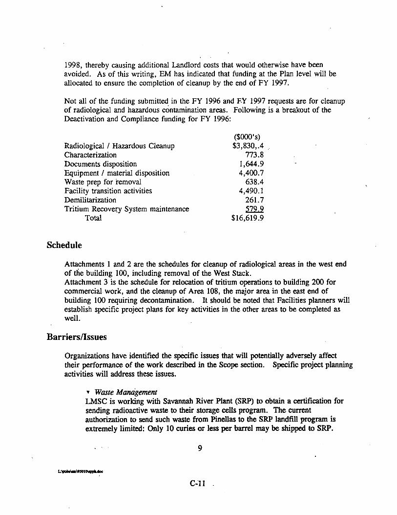
1998, thereby causing additional Landlord costs that would otherwise have been avoided. As of this writing, EM has indicated that funding at the Plan level will be allocated to ensure the completion of cleanup by the end of FY 1997.
Not all of the funding submitted in the FY 1996 and F.Y 1997 requests are for cleanup of radiological and hazardous contamination areas. Following is a breakout of the Deactivation and Compliance funding for FY 1996:
Radiological / Hazardous Cleanup Characterization Documents disposition Equipment / material disposition Waste prep for removal Facility transition activities Demilitarization Tritium Recovery System maintenance
Total
Schedule
Attachments 1 and 2 are the schedules for cleanup of radiological areas in the west end of the building 100, including removal of the West Stack. Attachment 3 is the schedule for relocation of tritium operations to building 200 for commercial work, and the cleanup of Area 108, the major area in the east end of building 100 requiring decontamination. It should be noted that Facilities planners will establish specific project plans for key activities in the other areas to be completed as well.
Organizations have identified the specific issues that will potentially adversely affect their performance of the work described in the Scope section. Specific project planning activities will address these issues.
r Waste Management LMSC is working with Savannah River Plant (SRP) to obtain a certification for sending radioactive waste to their storage cells program. The current authorization to send such waste from Pinellas to the SRP landNl program is extremely limited: Only 10 curies or less per barrel may be shipped to SRP.

Current Pinellas Plant Radiological storage areas are full. The certification for storage of radiological waste in the SRP storage cells will probably solve this problem before 1995 ends. LMSC is also working with the Nevada Test Site (NTS) to gain approval for shipment of radioactive waste oil to NTS. Approval is expected by end of 1995. LMSC is working on a contingency plan for mixed waste disposal.
r Occurrence Reporting/DNFSB A higher Occurrence Reporting frequency is expected during this project. Such reports, corrective actions and operational readiness checks may impact- schedules. Involvement of the Defense Nuclear Facilities Safety Board (DNFSB) could also delay implementation and push up support and administrative costs if numerous reviews are required. Their past visits have resulted in significant costs to supply them with information.
Safety, Risk Management, EnvironmeruaI Management Recent experiences with the removal of the West Stack have provided insight with respect to the numerous issues and activities that must be coordinated. It has become apparent that the time it takes to complete such projects is significantly impacted when there is a new and/or unknown risk factor involved.
Facilities Cleanup of radioactive areas will be to the flooring layer; LMSC has not budgeted for excavation and removal of concrete below the flooring. Should it become necessary to remove the concrete below the flooring, then additional funding may be required. The assumption is that the PCIC will continue to use the facility and hence removal of the concrete below will not be necessary between now and FY 1997's end.
Organizations were asked to identify issues concerning capabilities or capacities that will constrain meeting the program scope within the Assumptions. For example, are there limits established by our Permits that would inhibit accomplishment of the work by 9-30-97 within the Assumptions? Each organization shall clearly define these limitations and how they will be addressed in their respective plans to ensure completion by 9-30-97 within the Assumptions.
r Facilities Maintenance Insufficient funding in FY 96 may result in loss of technical facilities personnel

. -
who would be needed in FY 97 for cleanup work to proceed. Current schedules and capacity are not sufficient to remove concrete below the flooring layer in radiological areas.
Shutdown Operations Equipment that is contaminated must be purged to the Tritium Recovery System prior to its being opened. The TRS can currently purge two to four items at once, so additional capacity is needed. A request to fund building a portable TRS system to add the required capacity has been approved by DOE.
r Environmental Restoration and Permitting Any resultant air and waste water discharge must remain below permit limits. There is currently adequate margin within existing permits to accommodate increases -in emissions.
The ALARA process will be used to minimize radiological emissions. EM has identified, however, that extensive radiological sampling and monitoring will be required to ensure compliance with permits for waste assessment and worker safety. To meet scheduled milestones, it will be necessary to maintain internal radiological analysis capability.
DOE may require that additional NEPA documentation be developed to characterize the environmental impacts of disposition of the radiological areas prior to initiation of some tasks of the project.
Environmental Monitoring will continue for some period after 9/97 to document successful completion of the project, as required by CERCLA and existing DOE Orders.
' Waste Management . A destination for all radiological wastes from Pinellas is not yet identified.
Assumption 6 will not be satisfied if a radiological waste site is not available.
Walls, ceiling and ductwork will be disposed of in some of the areas. Much of this will have been painted to fix contamination and will not be cleanable. This waste will be voluminous, and access to a sufficient number of containers for transport could be a serious capacity issue.
r Industrial Hygiene Work that requires asbestos abatement will be subcontracted; funding required will depend on the quantity in these areas, which is not known.

Health Physics Currently the site has a limit on the number of contamination smears that & be conducted each work day.. The limitation is due. to having insufficient volume of
- counting equipment and lab personnel. LMSC is in the process of acquiring more equipment and evaluating the need for adding laboratory personnel to increase capacity for smears analysis.

APPENDIX D
Pinellas Plant Industrial Wastewater Discharge Permit

This page left blank intentionally


SECTION A. STANDARD CONDITIONS
PROHIBITIONS
The -permittee shall comply with all the prohibitions and limitations on discharge, as stated in Section 5 of the Pinellas County Sewer Use Ordinance #91-26.
2. DUTY TO COMPLY
The permittee must comply with all conditions of this permit. Failure to comply with the requirements of this permit may be grounds for administrative action, or enforcement proceedings including civil or criminal penalties, injunctive relief and service termination.
3. PERMIT DURATION
This permit shall be issued for a time period not to exceed THRF,E (3) years. The terms and conditions of the permit may be subject to modification by the Director during the term of the permit as limitations or requirements of this agreement are modified, as stated in Section A, #12. The permittee shall have an opportunity to discuss proposed changes in the permit at least thirty (30) days prior to the effective date of change. Any changes or new conditions in the permit shall include a reasonable time schedule for compliance.
The permittee shall allow the County or its representatives, exhibiting proper credentials to enter upon the premises of the permittee, at all reasonable hours, for the purposes of inspection, sampling, or records inspection. Reasonable hours in the context of inspection and sampling includes any time the permittee is operating any ,process which results in a process wastewater discharge to the County's Wastewater Treatment Facility, as defined in Section 8 of the County's Ordinance.
5. RECORDS m E N T I m
The permittee shall retain and preserve for a period of no less than three (3) years, all records, books, documents, memoranda, reports, correspondence, and any and all summaries thereof, relating to monitoring, sampling, chemical analyses, and this permit and application, made by or in behalf of the permittee in connection with its discharge. All records that pertain to matters that are the subject of special orders or any other enforcement or litigation activities brought by the County shall be retained and preserved by the permittee until all enforcement activities have concluded and all periods of limitation with respect to any and all appeals have expired.
page 1 of 11 D-5

SECTION A. (Continued)
6. CONFIDENTIAL INFORMATION
Except for data determined to be confidential under Section 12 of County's ordinance, all reports required by this permit shall be available for public inspection at the office of the Director.
the
7. RECORDING OF RESULTS
For each measurement of sample taken pursuant-to the requirements of this permit, the permittee shall record the following information:
a) The exact place, date, and time of sampling; b) The sampling methodology, including preservation techniques
or procedures; c) Who performed the sampling or measurements; d) The date(s) the analyses were performed; e) The person (s) who performed the analyses; f) The analytical techniques or methods used; and g) The results of all required analyses.
No permittee shall increase the use of potable or process water or, in any way, attempt to dilute a discharge as a partial or complete subsditute for adequate treatment to achieve compliance with the limitations contained in this permit.
PROPER DISPOSAL OF PREXREATMENT SLUDGES AND SPENT CHEMICALS
The disposal of sludges and spent chemicals generated shall be done in accordance with applicable Federal regulations, specifically section 405 of the Clean Water A c t and State regulations, specifically Subtitles C and D of the Resource Conservation and Recovery Act.
10. -CATION OF PERMIT
The permit issued to the permittee by the County may be revoked in whole or in part during its term for the following causes:
a) If, after inspection, monitoring, or analysis it is determined that the discharge of wastewater to the sanitary sewer is in violation of Federal, State, or local laws, ordinances, or regulations,
b) If the permittee knowingly makes any false statement on any report or other document required by this permit.
c) If the permittee knowingly renders any monitoring device or 'method inaccurate.

SECTION A. (Continued)
. .
d) If a permittee fails to pay sewer charges or fines, fails to meet compliance schedules, orzefuses to allow timely access to the facility premises and records.
These actions may also.result in punishment as violations of County Ordinances, as well as being subject to civil penalties and relief.
W I T A T I O N ON PERMIT TRANSFER
Wastewater discharge permits are issued to a specific user for a specific operation. The permittee must give at least a thirty (30) days advanced-notice of the proposed transfer to the Director. This notice must be a written certification by the prospective new owner which:
a) States what the new owner's immediate intent is rega*ing the facility's operations and processes.
b) Identifies the specific date on which the transfer is to occur.
c) Acknowledges full responsibility for complying with the permit.
A pe-it shall not be reassigned, transferred, or sold to a new owner, new facility, different premises, or a new operation without the prior written approval of the Director. If transfer or reassignment is approved, any succeeding owner or user shall also comply with the terms and conditions of the existing permit.
his permit may be modified or revised for good causes including, but not %limited to, the following:
a) To incorporate any new or revised Federal, State, or local pretreatment standards or requirements.
b) Material or substantial alterations or additions to the permittee's operation processes, or discharge volume or character which were not considered in drafting the effective permit.
c) A change in any condition in either the permittee or the County that requires either a temporary or permanent reduction or elimination of the authorized discharge.
d) Information indicating that the permitted discharge poses a threat to the Pinellas County's Sewer System, the County's personnel, or the receiving waters.
e) Violation of any terms or conditions of the permit. f) isr representation or failure to disclose fully all relevant
facts in the permit application or in any required reporting.
page 3 of 11 D-7

SECTION A. (continued),
g) To correct typographical or other errors in the pe'rmit. h) To reflect transfer of the facility ownership and/or
operation to a new owner/operator. i) Upon request by the permittee, provided such request does not
create a violation of any applicable requirements, standards, laws, or rules and regulations.
Any permit modifications which result in new conditions-in the permit shall include an opportunity for the permittee to discuss any proposed changes, and a reasonable time schedule for compliance, as necessary.
13. DUTY TO REAPPLY . The County shall notify the permittee pinetv (90) days prior to the expiration of the permittee's permit. Within (30) days of the notification,- the permittee shall reapply for reissuance of the permit on a form provided by the County.
SEXERABILITY
The provisions of this permit are severable, and if any provision of this permit, or the application of any provision of this permit to any c i r ~ t a n c e s , is held invalid, the application of such provision to other circumstances, and the remainder of this permit shall not be affected thereby.
The issuance of this permit does not convey any property rights in either real or personal property, or any exclusive privileges, nor does it authorize any invasion of personal rights, nor any ineringement of Federal, State, or local laws or regulations.
CONTINUATION OF ,EXPIRED PERMIT
An expired permit will continue to be effective and enforceable until the permit is reissued if:
a) The permittee has submitted a complete permit application at least S ~ X ~ V (60) days prior to the expiration date of the permittee's existing permit.
b) The failure to reissue the permit, prior to expiration of the previous permit, is not due to any act or failure to act on
. the part of the permittee.
page 4 of 11 D-8

SECTION B. DEFINITIONS
The meaning of terms or abbreviations used in this permit shall be as defined in Section 2 of -the Pinellas County Sewer Use Ordinance #91-26. Additional terms are defined below:
1. Com~osite Sam~le - the accumulation of grab samples collected at equal intervals and combined proportional to flow; a sample continuously collected proportional to flow; or equal volumes taken at varying time intervals.
2. Pailv Maximum - the maximum allowable discharge of pollutant during a calendar day. Where daily maximum limitations are expressed in terms of concentration, the daily discharge is the arithmetic average measurement of the pollutant concentration derived from all measurements taken that day.
3 . Pirector - means the Director of the PCSS or the auly authorized representative. The duly authorized representative of the Director fo; all matters related 50 the ~ndustrial Monitoring Program is the Industrial Program Supervisor.
4. Four-Dav Averaae - an arithmetic average calculated from the independent results of four consecutive sampling days. These sampling days are not necessarily calendar days, but reflect the sampling frequency .
5 . Grab Sample - an individual sample collected over a peziod of time not exceeding 15 minutes, without regard to flow or time.
6. Nonthlv Averaae - an arithmetic average calculated from the results of all sampling events performed in a calendar month.
7. Total Metals - the sum of the concentration or mass of Copper, Chromium (total), Nickel, and Zinc.
8. Toxic Oraanic Manaaement Plan (TOMPI - a management plan that must specify the toxic organic compounds used, the method of disposal used and procedures for assuring that toxic organics do not routinely spill or leak into wastewater discharged to the PCSS. A certification statement must also be submitted with this plan.
9. Total Toxic Oraanic (TTOI Standard - the sum of the concentrations of individual toxic organic compounds when they are present in a regulated waste stream in a concentration greater than '0.01 mg/l.
page 5 of 11 D-9

SECTION C. WASTEWATER DISCHARGE STANDARDS
The permittee is authorized to discharge process wastewater to the Pinellas County Sewer System (SCSS) in accordance with: a) Categorical Pretreatment Standards [40 CF'R 4331 developed by the United States Environmental Protection Agency (US EPA), and b) local standards set forth in the Pinellas County Sewer Use Ordinance #91-26. The permittee shall comply with the effluent standards specified below:
(m) mineral (a) animal/vegetable
* Categorical Standards adjusted using Combined Wastestream Formula See Attachment A for calculations of adjusted standards.
Local Daily Maximum Discharge Stds.
0.2 mg/l 2.6 mg/l 1.0 mg/l --- 1.0 mg/l 0.6 mg/l 0.1 mg/l 1.0 mg/l 0.4 mg/l 1.0 mg/l --- --- 250 mg/l 250 mg/l 50 mg/l 100 mg/l - < 65.5Oc
5.5 - 9.5 units
The permitteets discharge shall comply with all other applicable laws, regulations, standards, and requirements contained in the Countyts Ordinance, and any applicable Federal laws, regulations, standards, and requirements, including those which may become effective during the term of this permit.
Adj. Categorical Monthly Average Discharge Stds.*
0.10 mg/l 0.68 mg/l 0.83 mg/l ---- mg/l 0.26 mg/l 0.17 mg/l ---- mg/l 0.95 mg/l 0.10 mg/l 0.59 mg/l ---- mg/l ---- mg/l ---- mg/l -0-- mg/l ---- mg/l ---- mg/l
C ---- --.- units
Parameter
Cadmium Chromium copper Cyanide,' A - Cyanide, T Lead Mercury Nickel Silver Zinc Total Metals TTO
BOD TSS Oil/Grease (m)
(a) Temperature PH ,
These effluent standards are applied to the permitteets discharge at the sampling point(s) specified in Section D. The Categorical Standards apply to wastewater discharges after pretreatment: whereas, the local standards apply to wastewater discharges at the point of entry into the PcSS. Where both Categorical Standards and local standards limit a pollutant, the more stringent of the two shall be used to assess compliance.
Adj. Categorical Daily Maximum Discharge Stds.*
0.28 mg/l 1.10 mg/l 1.35 mg/l ---- mg/ 1 0.48 mg/l 0.28 mg/l ---- mg/l 1.59 mg/l 0.17 mg/l 1.04 mg/l ---- mg/l 0.85 mg/l
0--- mg/l ---- mg/l ---- mg/l ---- mg/l .--- C ---- units
page 6 of 11 D-10

SECTION D. WASTEWATER MONITORING REQUIREMENTS
In accordance with Section 6(e)(1) of the Pinellas County Sewer.Use Ordinance #91-26, the permittee is required to sample, analyze, and report on the volume and quality of its wastewater discharge to the PCSS. The required information shall be reported for each sampling event on the report forms provided by the PCSS, and in accordance with the schedule set forth in Section E. The self-monitoring requirements for the permittee are defined below.
MONITORING SITE DESCRIPTION
The permittee shall provide and maintain a suitable sampling point or points at a specified location to observe, measure, and sample the discharged wastewater to the PCSS. The sampling point(s) and monitoring equipment shall be subject to approval by the Director, as stated in Section 6 (e) (lb) & (e) (3) of the County's Ordinance.
All monitoring of the permittee's wastewater discharge shall be performed at the sampling point(s) specified in this permit. The sampling point(s) shall not be changed without notification to, and approval by, the Director. The permitted sampling' point (s) is (are) as follows:
The permittee shall monitor the combined wastestream at the neutralization facility. PCSS will monitor the combined wastestream at the,flume located to the northwest of the neutralization facility.
SAMPLE COLLECTION METHOD
Samples shall be collected by the method appropriate for the type of analyses to be performed, taking into consideration the type and frequency of the discharge.
Grab samples are required when analyzing wastewater for cyanide, oil/grease, pH, sulfides, temperature, total phenols, and volatile organics. Cyanide samples must be. collected in accordance with Federal regulations. Grab samples for pH analyses shall be collected at the beginning and at the end of a compositing period, and every two (2) hours throughout the compositing period. ALTERNATE METHOD: if preferred, the permittee shall monitor the pH of its regulated waste stream continuously by installing a continuous pH recorder.
Composite samples are required when analyzing for metals, TSSOs, and BODOs. Composite samples shall consist of individual grabs collected at least once an hour; the volume of each grab shall be no less than 100 m l . The total volume of the composite sample shall be no less than two (2) liters. Samples may be composited manually or using an automatic sampler. Where applicable, composite samples shall be flow proportional.
ALL SAMPLES SHALL BE COLLECTED DURING NORMAL OPERATIONAL HOURS AT A TIME WHEN THE FIDW IS REPRESENTATIVE OF THE DISCHARGE- OPERATIONAL HOURS SHALL INCLUDE ALL CLEANING ACTIVITIES THAT GENERATE WASTEWATER.
page 7 of 11 D-11

SECTION D. (Continued)
SAMPLING AND ANALYSIS
The sampling procedure, p rese .ka t ion , handling, and ana ly t i ca l methods used by t h e permittee s h a l l conform t o the methods spec i f ied by t h e PCSS i n , accordance with Section 304(h) of t h e Federal Clean Water A c t and with t h e techniques prescribed i n 40 CFR 136.
PARAMETERS
Cadmium Chromium - Copper Cyanide, A Cyanide, T Lead Mercury Nickel S i l v e r Zinc Total Metals Total Toxic Organics
~ O D TSS Oil/Grease
Temperature PH
FREOUENCY
* twice/vear monthlv
+ weeklv ----- monthlv montfilv
* twice/vear monthlv monthlv monthlv -----
* twice/vear
# A s defined i n Section B.
* One sampling event s h a l l t a k e place during the f i r s t s i x (6) months of t h e year , and t h e second sampling event s h a l l take place during t h e l a t t e r s i x (6) months of the year.
+ See Section F. - Specia l Conditions #a.
A A s spec i f ied i n "Sample Collect ion Method".
I n accordance w i t h Sect ion 6 (e) (1) (a) of the countyis Ordinance (91-26, manual pH meters must be c a l i b r a t e d d a i l y and continuous pH meters must be ca l ib ra t ed weekly, using a 2-point ca l ibra t ion. Records of c a l i b r a t i o n s h a l l be kept i n a bound ledger and made ava i lab le f o r review by t h e PCSS a t a l l t i m e s .
page 8 of 11 D-12

8.3 4.5-Acre Site
In addition to the SWMUs previously discussed, the Pinellas Plant is implementing a voluntary CERCLA type corrective action on an adjacent parcel of land located along the northwestern portion of the plant site. During the 1960s, the 4.5 Acre Site was a part of the plant site and was used for subsurface disposal of drummed solvent and resinous materials waste. In 1972, the DOE sold the 4.5 Acre Site to a private individual.
In 1985, during site clearning for a geophysical survey, a drum of methylene chloride was discovered [Ref. 191. In response to this discovery, GEND, the Pinellas Plant's Management and Operating (M&O) contractor at the time, contracted the excavation and removal of the drums and contaminated soils.
A contamination assessment report [Ref. 201 was completed, which identified the presence of surficial aquifer groundwater contamination (primarily composed of vinyl chloride, toluene, trichloroethene, and 1,2-trans-dichloroethene) above regulatory levels [Ref. 211. Lead, mercury, selenium, and silver were also detected above their regulatory levels [Ref. 221. Lead and selenium have high naturally occurring concentrations in Pinellas County; therefore, they are not considered contaminants of concern.
In December 1988, based on the concern that the contamination would migrate off site, the interim groundwater recovery treatment system began operating at the 4.5
I Acre Site. The treatment system for this site is located on the northwest corner of the Pinellas Plant property and discharges to the Plant's IWNF. The discharge from this treatment system is in compliance with PCU discharge requirements [Ref. 231.
Cleanup goals for the site are consistent with Federal and State standards. A Remedial Action Plan (RAP) was prepared during 1995 that evaluated, screened, and proposed a selected final remedial technology for the site. The DOE is negotiating a consent agreement with the FDEP and property owner, which addresses agency review and approval of the RAP and establishes site cleanup levels and completion criteria. Interim voluntary corrective actions continue during consent agreement negotiations. Improvements and modifications to the existing systems are anticipated for installation in 1997, and include a 22-well dual airlwater phase extraction system to accelerate and enhance containment recovery and treatment.

9.0 LIST OF HAZARDOUS SUBSTANCES AND EXTREMELY HAZARDOUS SUBSTANCES
Section 9.0 is a summary, which explains the List of Hazardous Substances and Extremely Hazardous Substances that is included in this EBR as Appendix K.
-Appendix K is a list of the following: 1) known hazardous substances and radioisotopes as identified in 40 CFR Part 302.4 and Appendix B to Part 302.4, and 2) extremely hazardous substances as identified by Appendix A to 40 CFR Part 355, which, to the best of Specialty Components knowledge, are currently or were historically used at the Pinellas Plant. Appendix K identifies the chemicals, synonyms, Chemical Abstract Services (CAS) registry number, the hazardous waste number, if applicable, whether the chemical is a hazardous or extremely hazardous substance, and whether the material was stored or processed in excess of 1000 kilograms (kg) for hazardous substances, the curie regulatory reporting limit-for radioisotopes, andlor one kilogram for the extremely hazardous substances.
Information in-Appendix K was developed from the SARA Title I11 and the Emergency Planning and Community Right to Know Act (EPCRA) reports, the Pinellas Plant Chemical Material Tracking System (CMTS), the air emissions construction and operation permit applications, the hazardous waste operations records, and the epidemiology feasibility study [Ref. 241.
Because no computerized tracking systems existed prior to 1986, and material purchase records were not routinely maintained in files or archives, this list of chemical substances is not complete for the full 40 years of plant operations. In addition, many commercial chemical products consist of proprietary mixtures, which may contain one or more hazardous or extremely hazardous substance(s). A list of over 7000 of these products used at the plant is available, but has not been included. Finally, since many chemicals are purchased in box, drum, can, gallon, kit, or other unit lots, whether the substance exceeded the 1000 kilograms or 1 kilogram limit cannot always be readily determined.
'The list of radioisotopes is considered complete since carehl records of the management of these substances are available from 1957 to the present.

10.0 COMMON SYNONYMS FOR CHEMICALS USED AT THE PINELLAS PLANT
2-propanol
2-pyrollidone .
acetic acid acetone acetonitrile alcohol alumina powder aluminum oxide ammonia ammonium bifluoride ammonium dihydrogen phosphate ammonium chloride ammonium hydroxide ammonium thiocyanate
arsenic trioxide
1
asbestos benzoic acid beryllium boric acid bromothymol blue
butyl acetate
butyl stearate calcium carbonate calcium chromate calcium hydroxide carbon tetrachloride
chlorobenzene chloroform
isopropyl alcohol; isopropanol; secondary propyl alcohol; dimethyl carbinol; petrohol 2-pyrrolidinone; 2-oxypyrrolidine; 2-ketopyrrolidine glacial acetic acid 2-propanone methyl cyanide; cyanomethane; ethanenitrile ethanol; ethyl alcohol aluminum oxide alumina powder ammonium hydroxide acid ammonium fluoride; ammonium hydrogen fluoride monobasic ammonium phosphate; ammonium biphosphate; primary ammonium phosphate ammonium muriate ammonia in water thiocyanic acid ammonium salt; ammonium rhodanide; ammonium sulfocyanate; ammonium sulfocyanide arsenous acid; arsenous acid anhydride; arsenous oxide; arsenic sesquioxide; white arsenic arnianthus; fibrous mineral silicates benzenecarboxylic acid; phenylformic acid; dracyclic acid glucinium boracic acid; orthoboric acid; borofax 4,4'-(3H-2,l-benzoxathiol-3-ylidene)bis[2- bromo-3- methyl-6-(1 - methylethyl)phenol]S,S-dioxide; 3,3'- dibromothymol-oxy-o-toluenesulfonic acid; 3,3'- dibromothymolsulfonphthalein acetic acid butyl ester; acetic acid 1- methylpropyl ester; acetic acid sec-butyl ester; acetic acid 1,l-dimethylethyl ester; acetic acid tert-butyl ester octadecanoic acid butyl ester carbonic acid calcium salt calcium chrome yellow; gelbin; yellow ultramarine calcium hydrate; slaked lime tetrachloromethane; perchloromethane; ne~atorina; benzinoform monochlorobenzene; benzene chloride trichloromethane

d-limonene
DETA
a
diacetone alcohol dibutyl amine diethanolamine
diphenylamine EDTA
ethanolamine-
ethylene glycol ferric ammonium sulfate fluoroboric acid formaldehyde
Freon
glycerol gold cyanide hydrochloric acid hydrofluoric acid hydroxypropyl cellulose
isooctane isopropyl alcohol
kerosene lead acetate
1 -methyl-4-(1 -methylethenyl)cyclohexene; p-mentha- 1,8,-diene; cinene; cajeputene; kautschin deet; N,N-diethyl-3-methylbenzamide; N,N- diethyl-m- toluamide; M-det; m-DETA, ENT 2021 8; autan; m- delphene; detarnide; dieltamid; flypel; metadelphene; off, repel 4-hydroxy-4-methyl-2-pentanone; pyranton n-dibutylamine; N-butyl-1 -butanamine 2,2'-iminobisethanol; 2,2'-iminodiethanol; diethylolamine; bis(hydroxyethy1)amine; 2,2'-dihydroxydiethylamine N-phenylbenzeneamine edetic acid; N,N- l,2-ethanediylbis[N- (carboxymethy1)glycine); (ethylenedinitri1o)tetraacetic acid; ethylenediaminetetraacetic acid; deathamil; havidote; versene acid 2-aminoethanol; monoethanolarnine; 2- hydroxyethylamine; ethylolamine; colamine I,%-ethanediol ammonium ferric sulfate hydrogen tetrafluoroborate methanal; oxomethane; oxyrnethylene; methylene oxide; formic aldehyde; methyl aldehyde trichlorotrifluoromethane; trichloromonofluoromethane; fluorotrichloromethane; Freon; Frigen; Arcton; Genetron; Halon; Isotron; dichlorodifluoromethane; difluorodichloromethane; carbon tetrafluoride; tetrafluoromethane; cryoflurane; 1,2-dichloro- 1,1,2,2- tetrafluoroethane; octafluorocyclobutane; peduorocyclobutane 1,2,3-propanetriol; glycerin; trihydroxypropane; gold monocyanide; aurous syanide muriatic acid fluohydric acid cellulose 2-hydroxypropyl ether; oxypropylated cellulose; klucel; lacrisert 2,2,4-trimethylpentane; isobutyltrimethylmethane 2-propanol; isopropanol; secondary p~~pyl,alcohol; dimethyl carbinol; petrohol kerosine natural lead acetate; normal lead acetate; sugar of lead; salt of Saturn

lithium carbonate
m-xylene manganese dioxide
- mannitol
mercuric chloride
mercury methyl alcohol methyl cellulose
methyl ethyl ketone methylene chloride
methylene dianiline
n-methylpyrrolidinone
n-vinyl pyrollidone
\
oxalic acid p-xylene phosphoric acid piperidine polyethylene glycol
polyglycol
polysulfide
Camcolit; Candamide; Carbolith; Ceglution; Eskalith; ~ypnorex; Limas; Liskonum; Lithane; Lithobid; Lithonate; Lithotabs; Plenur; Priadel; Quilonium retard dimethylbenzene; xylol manganese binoxide; manganese peroxide; manganese superoxide; black manganese oxide d-mannitol; mannite; manna sugar; cordycepic acid; manicol; mannidex; diosmol; osmitrol; osmosal mercury bichloride; corrosive sublimate; mercury perchloride; corrosive mercury chloride hydrargyrum; liquid silver; quicksilver; methanol; carbinol; wood spirit; wood alcohol cellulose methyl ether; methocel; cellothyl; syncelose; bagolax; cethylose; cethytin; cologel; cellumeth; hydrolose; nicel; tearisol; tylose 2-butanone, ethyl methyl ketone dichloromethane; methylene dichloride; methylene bichloride methylene diamine p,pt-diaminodiphenylmethane; 4,4'-methylene bis[benzenarnine] ; 4,4'-methylenedianiline n-methylpyrrolidone; methylpyrrolidone; 1 -methyl-2-pyrrolidinone; n-methylpyrrolidone; 1 -methyl-5-pyrrolidinone; 1 -methyl-5-pyrrolidinone; 2-sec-butyl-4; 6-dinitrophenylisopropyl carbonate
~~~~~
povidone; 1 -ethenyl-2-pyrrolidinone polymers; 1 - v i n y l y pyrrolidinone polymers; poly[l -(2-oxo- 1 - pyrrolidiny1)ethylene; polyvinylpyrrolidone; polyvidone ethanedioic acid dimethylbenzene; xylol orthophosphoric acid hexahydropyridine macrogol; PEG; carbowaz; jeffox; nycolline; pluracol E; Poly-G; polyglycol E; solbase macrogol; PEG; carbowaz; jeffox; nycolline; pluracol E; Poly-G; polyglycol E; solbase thiokol; thiorubber

potassium chloride
. potassium dichromate potassium ferricyanide
potassium hydrogen phthalate
potassium hydrogen sulfate
potassium hydroxide potassium iodide potassium nitrate potassium permanganate potassium phosphate
potassium sodium tartrate potassium thiocyanate silica (crystalline) sodium bicarbonate
sodium bichromate sodium gluconate sodium nitrite sodium oxalate
, sodium thiosulfate
sodium borate sodium iodide sodium hydroxide soluble starch stannous chloride stearic acid
sulhr sulhric acid tetrachloroethylene tetrahydrohran
camcopot; chloropotassuril; chlorvescent; enseal potassium chloride; kaleorid; kalitabs; kaskay kayback kay cee 1; k- contin; klor-con; ktab; peterkal; pfiklor; potavescent; rekawan; repone k; slow-k tablets; span-k potassium bichromate tripotassium hexakis(cyan0-c)ferrate (3-) potassium hexacyanoferrate(II1) potassium biphthalate; phthalic acid potassium acid salt; potassium acid phthalate; acid potassium phthalate potassium bisulfate; potassium hydrosulfide; potassium sulfhydrate potassium hydrate; caustic potash; potassa knollide saltpeter; niter permanganic acid potassium salt potassium biphosphate; potassium acid phosphate; potassium dihydrogen phosphate; potassium hydrogen phosphate rochelle salt; seignette salt potassium sulfocyanate; potassium rhodanide; rhocya silicon dioxide; silicic anhydride sodium hydrogen carbonate; sodium acid carbonate; baking soda sodium dichromate (VI); bichromate of soda gluconic acid sodium salt nitrous acid sodium salt; erinitrit ethanedioic acid disodium salt sodium hyposulfite; hypo antichlor; sodothiol; sulfothiorine; ametox sodium biborate; sodium pyroborate; sodium tetraborate ioduril; anayodin caustic soda; soda lye; sodium hydrate amylodextrin; amylogen tin dichloride; tin protochloride; Stannochlor octadecanoic acid; emersol 1 3 2; promulsin; proviscol Wax brimstone; sulphur oil of vitriol perchloroethylene; ethylene tetrachloride diethylene oxide; tetramethylene oxide

toluene toluene diisocyanate
trichloroethane trichloroethene
trichloroethylene
trichlorotrifluoromethane
triethylenetetramine
tris buffer
xylene zinc sulfate
zirconium fluoride
methyl benzene; tolulol; phenylmethane; methacide 2,4-diisocyanatotoluene; 2,4-tolyene diisocyanate; TDI; nacconate 100 methyl chloroform; chloroethene; vinyl trichloride trichloroethylene; ethinyl trichloride; triclene; trielene; trilene; trichloran; trichloren; algylen; trimar; triline; tri; trethylene; westrolsol; chlorylen; gemalgene; germalgene trichloroethene; ethinyl trichloride; triclene; trielene; trilene; trichloran; trichloren; algylen; trimar; triline; tri; trethylene; westrolsol; chlorylen; gemalgene; germalgene trichloromonofluoromethane; fluorotrichloromethane; Freon 11; Frigen 11; Arcton 9 N,N-bis(2-aminoethyl- 1 ,Zethanediamine; 1,8-diamino- 3,6-diazaoctane; 3,6- diazaoctane- l,8-diamine; 1,4,7,lO- tetraazadecane; trientine; trien; ETEA, TECZA tromethamine; 2-amino-2-hydroxymethyl- 1,3- propanediol; trimethylol aminomethane; tris(hydroxymethyl)aminomethane; trisamine; trometamol; tromethane dimethyl benzene; xylol white vitriol; zinc vitriol; medizinc; optraex; solvezink; zincate; zincomed zirconium tetrafluoride

11.0 REFERENCES
1. General Electric Neutron Devices. Pinellas Plant Site Development Plan. GEPP- SP-7566, Largo: Pinellas Plant, 1986.
2. United States. Department of Energy. Environmental Assessment for Commercialization of the Pinellas Plant. DOEIEA-0950, Largo: Pinellas Area Ofice, 1994.
3 . Lockheed Martin Specialty Components, Inc. Pinellas Plant Environmental Monitoring Plan. Largo: 1997.
4. State of Florida, U.S. Department of Energy. Agreement in Principle Between the United States Department of Energy and the State of Florida for Environmental Oversight, Monitoring, and Emergency Response Associated with the DOE Pinellas Plant. September 1990.
6' UNC Geotech. Letter to Adam Weaver from Mark K. Pearson, dated 4/12/90, re: ! ,/ LA radon measurements made at the Pinellas Plant.
6. ERCE. Asbestos-Containing Materials Survey and Bulk Sampling Report. Prepared for General Electric Neutron Devices Department. Largo: 1990.
7. Lockhed Martin Specialty Components, Inc. Spill Prevention Control and I Countermeasures Plan. Largo: Pinellas Plant, 1996.
8. Martin Marietta Specialty Components, Inc. Pinellas Plant Refrigerant Management Plan, MMSC-FAC-95078, Largo: Pinellas Plant, 1995.
9. Martin Marietta Specialty Components, Inc. Moratorium Documentation Manual for the Pinellas Plant. Largo: Pinellas Plant, 1995.
' 0 United States. Department of Energy. Air Construction Permit Applications. In association with Koogler and Associates. Largo: Pinellas Area Ofice, 1992.
1 1. United States. Department of Energy. Pinellas Plant National Pollutant Discharge Elimination System Storm Water Discharge Permit Application. Largo: Pinellas Area Ofice, 1994.
12. Lockheed Martin Specialty Components, Inc. Pinellas Plant Annual Site Environmental Report for Calendar Year 1996. Largo: Pinellas Plant, 1997.
13. Parsons Engineering Science, Inc. Pinellas Plant Area 108 Radiological Cleanup Project. Vol I - Technical Plan, Vol. I1 - Cost and Schedule. Oak Ridge: 1995.

13. United States. Environmental Protection Agency, Region IV FloridaJGeorgia Unit. RCRA Facility Assessment Report: Department of Energy Memorandum. Date stamped June 17, FL6-890-090-008, Largo: Pinellas Plant, 1988.
14. United States. Department of Energy. RCRA Facilitv Investigation Report. Vols.1, 11, and 111. Environmental Restoration Program, Albuquerque: ~ l b u ~ u e r ~ u e Field Office, 1991.
15. United States. Department of Energy. RCRA Facility Assessment Report, Wastewater Neutralization Area and Building 200. Pinellas Plant, Albuquerque: Albuquerque Operations Ofice, 1993.
16. United States. Department of Energy. West Fenceline Interim Measures at Pinellas Plant. Environmental Restoration Program, Largo: Pinellas Plant, 1994.
17. IMC Engineers, Inc. Conceptual Design Report to Upgrade the Existing Drain System. Prepared for General Electric Neutron Devices, Largo: Pinellas Plant, 1989.
18. United States. Geological Survey. Reconnaissance of Water Quality at a U.S. Department of Energy Site. Report 85-4062. Pinellas County, 1985.
19. Soil and Material Engineers, Inc. Contamination Assessment Report. General Electric, Pinellas County, Florida. 1175-85-1344, Prepared for General Electric Company. Atlanta: 1986.
I
20. United States. Department of Energy. 4.5 Acre Site Interim Remedial Assessment Work Plan. Pinellas Plant. Environmental Restoration Program, Albuquerque: Albuquerque Operations Ofice, 199 1.
21. CH2M-Hill, Inc. Predesign Technical Memorandum: 4.5 Acre Site Interim Groundwater Recovery and Treatment System. FCR 26042.C1, Prepared for General Electric Neutron Devices, Largo: Pinellas Plant, 1988.
\ - 22.) United States. Department of Energy. Air Permit Study. Refined Industrial Source C Complex Short T e n (ISCST) and Carcinogenic Risk Assessment Modeling
Report. Largo: Pinellas Plant, 1992.
1 Martin Marietta Specialty Components, Inc. Support of HRS Epidemiology Feasibility Study. Largo: Pinellas Plant, 1993.

11.1 Additional Documents -
Martin Marietta Specialty Components, Inc. Industrial Wastewater Permit Application. Largo: Pinellas Plant, 1994.
CH2M-Hill, Inc.. Interim Corrective Measures Study Northeast Site. TAP26350.BO.01. Tampa: 1991.
United States. Department of Energy. Interim Measures Report. Former Pistol Range. Largo: Pinellas Plant, 1993.
United States. Department of Energy. Phase 1 Installation Assessment Pinellas Plant. Comprehensive Environmental Assessment and Response Program. Albuquerque: Albuquerque Operations Office, 1987.
United States. Department of Energy. Corrective Measures Study Report- Industrial Drain Leaks-Building 100 Area and Old Drum Storage Site. Pinellas Plant, Albuquerque: Albuquerque Operations Office, 1994.
United States. Department of Energy. Baseline Risk Assessment for the Industrial Drain Leaks-Building 100 Area and Old Drum Storage Site. Pinellas Plant, Albuquerque: Albuquerque Operations Office, 1994.
Haztech Inc. Identification and Removal of Waste. Department of Energy, I Tampa: Pinellas Plant, 1985.
United States. Fish and Wildlife Service. Correspondence from J.D. Carroll (USF&WS) to P.J. Behrens (Systematic Management Services, Inc.). July 25, 1991.
Martin Marietta Specialty Components, Inc. Environmental Restoration Program Solid Waste Management Units Information Booklet. Largo: Pinellas Plant, 1994.
Koogler and Associates. Air Construction Permit Application. Largo: Pinellas Plant, 1992.
United States. Department of Energy, Environmental Survey Preliminarv Report. Largo: Pinellas Plant, 1987.
Martin Marietta Specialty Components, Inc. Pinellas Plant NPDES Individual Permit Application for Stormwater Discharge Associated with Industrial Activity. Largo: Pinellas Plant, 1994.
United States. Department of Energy. Pinellas Area Office letter to the State Emergency Response Commission, Florida Department of

Community Affairs from Mr. David. Ingle, dated 6/28/94, re: SARA Section 3 13 report for the pinellas Plant.
United States. Department of Energy, Pinellas Area Office letter to the EPCRA Reporting Center from Mr. David Ingle, dated 6/28/94, re: SARA Section 3 13 report for the Pinellas Plant.
United States. Department of Energy, Pinellas Area Office letter to the State Emergency Response Commission from David S. Ingle, dated 2/28/94, re: SARA Section 3 1 1 and 3 12 report for the Pinellas Plant.
Koogler and Associates. Application for Air Operatinn Permit, Largo: Pinellas Plant, 1993.
DOEIEA-0792, Nonnuclear Consolidation Environmental Assessment, Volumes I and 11, U. S. Department of Energy Office of Defense Programs: , June 1993.
United States. Department of Energy, Draft RCRA Facility Investigation Report. Addendum I, Environmental Restoration Program. Albuquerque: Albuquerque Field Office, 1992.
United States. Department of Energy, Investigation Report, Addendum XI, Environmental Restoration Program. Albuquerque: Albuquerque Field Office, 1993.
!

APPENDIX A
Letter Dated July 25,1991 - United States Department of the Interior Fish and Wildlife Services

Uni ted States D e p a r t n ~ e n t of the 1nt.r-ior FISH A N D WILDLIFE SERVICE
P.O. BOX 2676 VERO BEACH. FLORLDA 32961-2676
July 25,'1991
Mr. Paul J. Ekhrens Senior Environmental Scientist Systematic Management Services, Inc. 1 1701 Belcher Road Suite 103 Largo, FL 34643
Dear Mr. khrens:
This responds to your-letter, dated July 17, 1991, regarding threatened or endange~d species that may be present on the U.S. Department of Energy's Pinellas Plant in Largo, Pinellas County, Florida.
The property is within-the historic range of the endangered Florida golden aster (Chrvso~sis flondana). The species was recorded historically from St. Petersburg Beach and from Seminole, but urban development has apparently extirpated the species from those two sites. If a remnant of pine scrub vegetation is present on the property, it should be thoroughly searched for the species. If sand pine scrub is not present on the property, it is unlikely that the specits is present there.
The nearest bald eagle nest (designated PI-19 by the Florida Game and Fresh Water Fish Commission) is located about 2 miles southwest of the propew, near Cross Bayou. Although the eagles could feed as far north as the retention ponds on the property, their feeding is most likely concentrated in Cross Bayou. If contaminants from the plant are entering the Cross Bayou Watershed, some adverse effect on the eagles may occur. Othenvise, activities within the property are not likely to have a direct effect on the - ~ t c ~ p 0 PC'-
-O *
The threatened Eastern indigo snake may inhabit the property. Detailed study of the site would be required to determine its presence or absence.
The en&ny-:rpd wood stork may feed seasonally in the retention ponds on the prc???.
No other Federally listed species are likely to occur near the property. You should contact the Florida Game and Fresh Water Fish Commission regarding species listed by the State.

If the Department of Energy defermines that an action is likely to adversely affect a Federally listed species, they should notify this office in writing to request consultation under Scction 7 of the Endangered Species Act.
Thank you for the opportunity to comment.
Sincerely yours,
CC:
FG&FWFC, Tallahassee, .kL FWS, Jacksonville, FL

APPENDIX B
Letter Dated September 12,1991 - Florida Department of State
Division of Historical Resources

FL.ORIDA DEPARTMENT OF STATE JimSrnith ,
Secrctary.of State
DIVISION OF HISTORlCAL RESOURCES R.A. Crry Building XM South Bronough
Tallahrucc. Florida 323W-0250
Director's Office Tdecopia Number ,(FAX) (904) 488-1480 ~'334)488-3353
September 12, 1991
Mr. Paul J. Behrens In Reply Ref er-To: Systematic Management Services, Inc. Denise M. Breit 11701 Belcher ~ o a d , Suite 103 Historic Sites Largo, Florida 34643 Specialist
(904) 487-2333 Project File No. 912413
RE: Cultural Resource Assessment Request Site-Wide Environmental Documentation for the Department of Energyts Pinellas Plant
Largo, Pinellas County, Florida
Dear Mr. Behrens :
In accordance with the procedures contained in 36 C.F.R., part 800 ("Protection of Historic Propertiesn), we have reviewed the above referenced project(s) for possible impact to archaeological and historical sites or properties listed, or eligible for listing, in the National R e u e r of Historic Places. The - authority for this procedure is the National Historic Preservation Act of 1966 (public Law 89-665), as amended.
A review of the Florida Master Site File indicates that no significant archaeological or historical sites are recorded for or considered likely to be present within the project area. Furthermore, it is the opi~ion of this agency that because of the project location and/or nature it is considered unlikely thatany such sites will be affected. Therefore, it is the opinion of '
this office that the proposed project will have no effect on any sites listed, or eligible for listing, in the ~ational Register. The project is consistent with the histaric preservation aspects of Florida's coastal zone program, and may proceed withouf further involvement with this agency-
Archaeologicd Researe Florida Folkiife Programs Historic Preservation Museum of Florida ~ i ~ t ~ ~ (-1 587-2299 iCYF1J 307-2192 . feel) 487-1333 (904) 4(UI-l4&I

Mr. Behrens September 12, 1991 Page 2
If you have any questions concerning our comments, please do not hesitate to contact us. Your interest in protecting Florida's archaeological and historic resources'is appreciated.
Sincerely, n
W. Percy, Director of Historical Resources and
State Historic Preservation Officer

APPENDIX C
Radiological Disposition Program Plan

SECTION E. REPORTING REQUIREMENTS
1. The permittee shall submit the self-monitoring results obtained during the previous ONE month to.the Director on the provided report forms. The reports shall be post marked no later than the 15th day of the month following the completed reporting period. If no discharge ' occurs during the reporting period, "no dischargev shall be reported. The first report is due on Selstember 15. 1994.
2 . The permittee is required to sample its wastewater for the pollutants specified in section Dl and report on compliance. Any reason(s) for non-compliance and any step(s) being taken by the pernittee to comply shall be a part of this compliance report. In addition to the non-compliance-report, the permittee must resample its waste stream within thirty (30) days of any noted violation. The permittee muse also notify the Director within twenty-four (24) hours upon becoming aware of such violation. This requirement is in accordance with 40 CFR 403.12(g) .-
3. If the permittee monitors any pollutant more frequently than is required by this permit, in accordance with 40 CFR 136 or other EPA approved methods, the results of such monitoring shall also be submitted with the permittee's self-monitoring reports.
4. The PCSS may require more frequent monitoring, or the monitoring of other pollutants not required in this permit by written notification.
5. The permittee shall implement an adequate quality assurance and quality control program. The permittee shall calibrate, inspect, and perform maintenance procedures on all monitoring and analytical instruments at regular intervals to ensure the accuracy of measurements. These records and procedures shall be made available to the PCSS at all times.
t
6 . The permittee shall maintain all records concerning any monitoring and sampling activity of its industrial wastewater discharge in accordance with section 6(e)(1) of the County's Ordinance. These records shall be made available to the PCSS at all times.
7 . The permittee shall provide a summary of all pH excursions lasting greater than ten (10) minutes and less than or equal to one (1) hour in duration. This summary shall include the date, time, duration, and a brief description of the cause of each excursion. This summary is to be submitted with the monthly self-monitoring report. The ~ermittee shall follow procedures as stated in Section E. 8 or 9 for reporting pH excursions-lasting more than one (1) hour in duration, and include a copy of the,pH strip chart indicating'the excursion, time of day,,and chart scale.
page 9 of 11 D-13

SECTION E. (continued)
8 . The permittee shall notify the Director by phone immediately upon the occurrence of an accidental discharge to.the PCSS in accordance with Sect-ion 6(f) of the county's Ordinance. A detailed, written report describing the circumstances, causes, and remedies must be submitted to the Director within five (5) calendar days of the occurrence. A copy of the Accidental Spill Notification Procedure is included with this permit.
9 . Any upset experienced by the permittee of its operations or pretreatment system that places it in a temporary state of non-compliance with wastewater discharge standards contained in this permit or other limitations specified in the County's Ordinance, shall be reported to the Director within twenty-four (24) hours of first. awareness of the upset. A detailed report shall be submitted within five (5) calendar days.
10. The permittee shall notify the Director prior to the introduction of new wastewater or pollutants, or any changes/additions to the pretreatment process, or any substantial change (>lo%) in the volume or characteristics of the wastewater being introduced into the PCSS from the permittee's industrial processes. A formal written notification shall be submitted to the Director thirty (30) days prior to such introduction.
11. All reports required herein shall be submitted to the following address :
Industrial Pretreatment Program Water Quality Management Division
Pinellas County Sewer System 14850 118th Avenue North Largo, Florida 34644 phone: (813) 582-2282
page 10 of 11 D-14
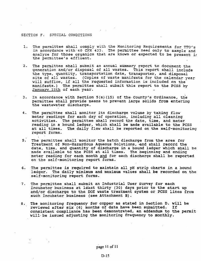
SECTION F. STECIAL CONDITIONS
1. The permit tee s h a l l comply w i t h t h e Monitoring Requirements f o r TTofs i n accordance with.40 CFR 433. The permittee need only t o sample and analyze f o r those organics t h a t a r e kxiown o r expected t o be p resen t i r &e permi t tee ' s e f f l u e n t .
2. The permittee s h a l l submit an annual summary repor t t o document t h e generat ion and/or d i sposa l of a l l wastes. This r epor t s h a l l include t h e type, quan t i ty , t r anspor ta t ion da te , t r anspor te r , and d i sposa l s i t e of a l l wastes. (Copies of waste manifests f o r t h e ca lendar year w i l l s u f f i c e , if a l l t h e requested information is included on t h e manifests . ) The permi t tee s h a l l submit t h i s r epor t t o t h e PCSS by Janua rv 1 5 t h of each year .
3. I n accordance with Sect ion 5 ( a ) (15) of t h e Countyrs ord inance , th'e permit tee s h a l l provide means t o prevent l a r g e s o l i d s from e n t e r i n g the wastewater discharge.
4 . The permit tee s h a l l monitor i ts discharge volume by t a k i n g flow meter readings f o r each day of operat ion, including a l l c l ean ing a c t i v i t i e s . The permi t tee s h a l l record t h e da te , t i m e , and meter reading i n a bound l edger , which s h a l l be made a v a i l a b l e t o t h e PCSS a t a l l times. The d a i l y flow s h a l l be reported on t h e self-monitor ing r e p o r t f o m s .
t
5. The permit tee s h a l l monitor t h e batch discharge from the a r e a f o r Treatment of Non-Hazardous Aqueous Solut ions, a n d s h a l l r ecord t h e d a t e , t ime, and q u a n t i t y of discharge i n a bound ledger which s h a l l be made a v a i l a b l e t o t h e PCSS a t a l l times. The beginning and ending meter reading f o r each month and f o r each discharge s h a l l be r epor ted on t h e self-monitor ing r e p o r t forms.
6. The permi t tee is requi red t o maintain a l l pH s t r i p c h a r t s i n a bound ledger . The d a i l y minimum and maximum values s h a l l be recorded on t h e self-monitor ing r e p o r t forms.
7 . The permit tee s h a l l submit an I n d u s t r i a l U s e r Survey f o r each Incubator bus iness a t l e a s t t h i r t y (30) days p r i o r t o t h e start up and/or d ischarge t o t h e DOE waste t reatment system o r PCSS l i n e s from such Incubator bus iness ( see Attachment B ) .
8. The monitoring frequency f o r copper as s t a t e d i n Sect ion D. w i l l be ' reviewed a f t e r s i x (6 ) months of d a t a have been submitted. If
c o n s i s t e n t compliance h a s been demonstrated, an addendum t o the permit w i l l . b e i s sued a d j u s t i n g t h e monitoring frequency t o nionthly.
page El of 11 --
D-15

ATTACHMENT A
Indus t ry : U . S . Department of Enerav Permit # : 153-IE
C a l c u l a t i o n s of a d j u s t e d C a t e g o r i c a l P re t r ea tmen t S tandards f o r N e w Source Metal F i n i s h e r s - 40 CFR 433, u s i n g t h e Combined Wastestream Formula (CWF).
Ft = 209.149 gpd (To ta l Flow = regula ted /unregula ted p r o c e s s e s , s an i t a ry , c l ean ing , d i l u t i o n )
Fd = 125,644 gpd ( D i l u t i o n = s a n i t a r y , coo l ing t o w e r / b o i l e r blow down, noncontact cooling, 40 CFR 403 Appendix D )
Ft - Fd X -S tandard Limit = 209,149-125.644 = ,. 0.39926
209,149 CWF CON/FAC
Da i ly M a x i m u m (mg/l)
p o l l u t a n t S t anda rd Limit CWF Conversion F a c t o r CWF Adjusted L i m i t
Maximum Monthly Average ( m g / l )
P o l l u t a n t S t anda rd L i m i t p F Conversion Fac to r gWF Adiusted L i m i t
Cd C r Cu Pb .Ni A s n . 6
Cn(T1 TTO

Attachment B
PINELLAS COUNTY SEWER SYSTEM INDUSTRIAL PRETREATEMENT PROGRAM
INDUSTRIAL USER SURVEY FOR INCUBATOR BUSINESSES AT U. S. DOE
Please complete this discharge application with all information available. Where additional space is needed, attach extra pages. Please indicate estimated values with an "EN following the number. For information which is not yet available, indicate when you expect to obtain the information.
A. GENERAL INFORMATION
1. Company Name:
Mailing Address :
City, State, Zip:
Telephone Number: f 1
2. On site person authorized to represent company.
Name :
Title:
3. ~ r i e f description of the manufacturing, industrial processes, production, or business activities conducted by this company:
4. Indicate applicable Standard Industrial Classification (SIC) for all processes :
5 . Are any of these activities regulated under Federal Categorical Pretreatment Standards? Yes No Unsure
6 . projected hours of operation and number of employees per shift':
Sun. Mon. Tues. Wed. Thurs. Fri. Sat. 1st Shift 2nd Shift - 3rd Shift

. .
B. WATER USAGE AND WASTEWATER DESCRIPTION
1. What is the projected average water use for this company: gallons/month
2. Will any water be recycled?: Yes - No If yes, please give a brief description of recycling processes.
3. Will this company discharge any wastewater other than from restrooms to the Pinellas County Sewer System? ,- Yas No
If yes, please indicate the source(s) of the wastewater:
[-~~ooling-water, non-contact [-]Boiler/Tower blowdown [-]Cooling Water, contact [-]Pollution Control Unit [-I Process (Specify) : [- ] Other (Specify) :
4. What is the projected daily discharge flow rate: g ~ d -
5 . Will any form of wastewater treatment be used prior to combining with the wastewater discharge from the Deptartment of Energy?
Yes No.
If yes, briefly describe the operation of the wastewater treatment system. Include chemicals used and what they are used for. \
6. Schematic Process Flow Diagram: For each major activity in which wastewater will be generated or treated, draw a diagram of the flow of materials, products, water, and wastewater from the start of the activity to its completion, showing all unit processes. Indicate which processes use water and which generate waste streams. Include the average daily volume and maximum daily volume of each waste stream.

7. Please list ALL chemicals (in quantities greater than one gallon) used and/or stored on site:
Chemical Will this chemical be in
Averaue ~uantitv wastewater discharged to (on site) Pinellas County Sewer?
8. Are there-any floor drains in the manufacturing or chemical storage area (s) ? Yes No
If yes, briefly describe where these floor drains discharge to:
9. Will any liquid or solid wastes be generated and NOT disposed of in the Pinellas County Sewer System? Yes No
If yes, indicate the type(s) of waste generated:
[-]Acids, Alkalies [- 1 Dyes, Inks [- ] Heavy Metals [-]Inorganic Compounds [-]Oil/Grease [-]Organic Compounds [-I Paints ' [-I Pesticides 1-1 Sludge
, [-I Solvents [-I Other (Specify) :
How will the indicated waste(s) be disposed of? (provide name and address of waste haulers) .
C. CERTIFICATION
I hereby state that the information contained on this survey is familiar to mei and to the best of my knowledge and belief, such information is true, complete, and accurate.
Authorized Facility Rep. (print) Signature of Authorized Rep.
Title D-2 1 Date

COUNTY COMMISSIONERS PINELLAS COUNTY, FLORIDA
PINELLAS COUNTY SEWER SYSTEM 310 COURT STRE--
CLEARWATER. FLORIDA 34616
GEORGE GREER - C ~ U R M A N JOHN CHESNUT. JR. - VICE Cn1lAMu4
CHARLES E RAlNEY BARBARA SHEEN TODD BRUCE TYNDAU -
ACCIDENTAL DISCHARGE NOTIFICATION PROCEDURE Pinellas County Sewer Use Ordinance $91-26, Section 6 (f)
In the event of an accidental discharge to the Pinellas county Sewer System (PCSS) , the following must be met.
Notification must be made immediately by contacting one of the following, in the order given below:
Industrial Pretreatment Program: 582-2282 (Water Quality Management Division)
South Cross Bayou WWTF: (Operators on duty 24 hrs/day)
Director, Sewer System: (Main off ice)
WRITTEN NOTIFICATION \
A detailed written report describing the cause of the discharge and corrective measures taken must be submitted to the PCSS within five ( -5) calendar days following such accidental discharge. This report is to be submitted to the following address :
Industrial Pretreatment Program Water Quality Management Division
Pinellas County Sewer System 14850 118th Avenue North Largo, Florida 34644

ANALYTICAL METHODS
The permittee may use any of the approved methods referenced in 40 CFR 136, including the following methods: A - Methods for Chemical Analyses of Water and Waste, EPA 600/4-79-020., ~evised 1983; or B - Standard Methods for the Examination of Water and Wastewater, 17th Edition, 1989.
Cadmium - Ref A: 213.1 (F1) , 213.2 (Fr) , 200.7 (ICP) Ref B: 3111 B/C(Fl), 3113 B(Fr) , 3500 Cd-D(C1) , 3120 B(ICP)
Chromium - Ref A: 218.1(F1) , 218.2 (Fr) , 200.7 (ICP) Ref B: 3111 B/C(Fl), 3113 B(Fr) , 3500 Cr-D(C1) , 3120 B(1CP)
copper - Ref A: 220.1 (Fl) , 220.2 (Fr) , 200.7 (ICP) Ref B: 3111 B/C(Fl), 3113 B(Fr), 3500 Cu-D(Cl), 3120 B(1CP)
Lead - Ref A: 239.1 (Fl) , 239.2 (Fr) , 200.7 (ICP) Ref B: 3111 B/C(Fl) , 3113 B(Fr) , 3500 Pb-D(C1) , ' 3120 B(1CP)
Mercury - Ref A: 245.l(cold vapor), 245.2(automated) , Ref B: 3112 B (cold vapor)
Molybdenum - Ref A: 246.1(F1), 246.2 ( F r ) , 200.7 (ICP) Ref-B: 3111 D(Fl), 3113 B(Fr), 3120 B(1CP)
Nickel - Ref A: 249.1(F1) , 249.2 (Fr) , 200.7 (ICP) Ref B: 3111 B/C(Fl) , 3113 B(Fr) , 3500 Ni-D(C1) , 312.0 B(1CP)
Silver - Ref A: 272.1 (Fl) , 272.2 (Fr) , 200.7 (ICP) Ref B: 3111 B/C(Fl) , 3113 B(Fr)
in= - Ref A: 289.1(F1), 289.2(Fr), 200.7(ICP) Ref B: 3111 B/C(Fl), 3500 Zn-E(C1) , 3120 B(1CP)
Cyanide(T) - Ref A: 335.2(spectrophotometric), 335.3(automated) Ref B: 4500 Cn-D (titrimetric) , 4500 Cn-E (spectrophotometric)
Cyanide(A) - Ref A: 335~1(titrimetric/spectrophotometric) Ref B: 4500 cn-G (titrimetric/spectrophotometric)
BOD - Ref A: 405.1 Dissolved Oxygen Depletion(B0D ) Ref B: 5210 Dissolved Oxygen ~ e ~ l e t i o n ( ~ 0 ~ ~ ~ 7
Oil/Grease - Ref A: 413.1 (gravimetric) Ref B: 5520 B(gravimetric)
'TSS - Ref A: 160.2 (gravimetric) Ref B: 2540 D(gravimetric)
pH - Ref A: 150,l(electrometric) Ref B: 4500 H(e1ectrometric)
Temperature - Ref A: 170.1 (thermometric) R e f B: 2550 B (thermometric)
TTO's - EPA Methods 601-613, 624-625. TTO analyses must be performed in accordance with 40 CFR 136.3.
\
Fl=Flame, Fr=Furnace,'~~P=Inducti~ely Coupled Plasma, Cl=Colorimetric

INDUSTRIAL USER SELF-MONITORING REPORT FORM
INDUSTRY: U.S. De~artment of Enersv MONTH, YEAR: PERMIT NUMBER: 153-IE
DAILY AVERAGE
Samples collected by:
Samples analyzed' by:
If an outside lhboratory performed any of the analyses contained in this report, give the name and address of the laboratory and specify the data they supplied.
MI certify under penalty of law that this document and all attachments were prepared under my direction or supervision in accordance with a system designed to assure that qualified personnel properly gathered and evaluated the information submitted. Based'on my inquiry of the person or persons directly responsible for gathering the information, the information - submitted is to the best of my knowledge and belief, true, accurate, and complete. I am aware that there are significant penalties for submitting false information, including the possibility of fines and imprisonment for knowing vi~lation.~
Authorized Representative/Title Date
(FOR PCSS USE ONLY) * G=GRAB, TCsTIME COMPOSITE, FC-FLOW COMPOSITE + TIME IN MILITARY NOTATION Checked by: Date:
sm-forms: 900614 1 of 3

INDUSTRIAL USER SELF-MONITORING REPORT FORM
INDUSTRY: U.S. Department of E n e r q ~ MONTH, YEAR: PERMIT NUMBER: 153-IE
PARAMETERS (mg/l) ,
+ Sample temperature - OC (if applicable) * If applicable sm-forms: 900614
0
DAY 1 2 - 3 4 5 6 7 8 9
10 11 12 13 14
p 15 16 00 17 18 19 20 21 22 23 24 25 26 27 28 29 30 3 1
*TOTAL METALS Cd
pH RANGE MIN - MAX -
- - - - - - - - - - - - - - - - - - - - - - - - - - - - - -
TEMP MAX+ Cr
*MONTHLY AVERAGE
Cu Cn, T Pb I I q N i Aq
,
Zn

I N D U S T R I A L U S E R SELF-MONITORING REPORT FORM
I N D U S T R Y : U . S . D e ~ a r t m e n t of E n e r q v MONTH, YEAR: PERMIT NUMBER: 153-'IE
I F A N A L Y S E S ARE PERFORMED ON PARAMETERS NOT S P E C I F I E D ON T H I S REPORT FORM, L I S T PARAMETERS AND , T H E I R R E S P E C T I V E VALUES BELOW.
OTHER PARAMETERS (mg/l)
DAY 1 2 3 4 5 6 7 8 9 10 11 12 13
u 14 b 15 V)
16 17 18 19 20 21 2 2 23 24 25 2 6 27 2 8 29 30 3 1
T T O
'
Cn, A
1
TSS BOD O/G, m O/G. a ,
I

APPENDIX E
Pinellas Plant Hazardous and Solid Waste Amendments Permit

Department of Energy .- t o s t . Ider l t i f icat ion No. FL6 890 090 008 U.S. D3E - pine l las -Plan t 3- '*, Permit No. FIb 890 090 008
I ' 3_ 7887 Bryan Dairy Road 2 5 -
Largo, Florida 34294-290 0
Pursuant t o the Sol id W s t e Disposal A c t , as mended by the Rescurce Conser- vation and Recovery Act of 1976, as ~~lended (42 E C S6901 e t seq., c-ly k n m as RCRA) and regulations prarulgated thereunder & the U.S. Environ- r e n t a l Protection Agency (=A) (cai i f ied and t o be codified i n T i t l e 40 of the Code of Federal Regulations) a pennit is issued t o U.S. M3E (hereaf ter c a l l e d the Permittee), who p r a t e s a hazardous waste treatrrrtnt and s torage f a c i l i t y located i n Largo, Florida l a t i t M e 27?52'30n North and longitude 82°45'00n West.
This Permit, i n conjunction wi th the Hazardcus Waste Management Permit issued by the Sta te o f Florida, cons t i tu tes the F!CRA permit fo r t h i s f a c i l i t y . ?he Permittee s h a l l be required t o investigate any releases of hazardous waste o r hazardcus-constituents f ran any s o l i d waste .management u n i t a t the f a c i l i t y regardless of t he time a t which waste was placed i n such u n i t and t o take appropriate corrective action for any such releases. The Permit also requires t h e Permittee t o ce r t i fy annually tha t on-site generation of h a z a r d a s waste is minimized to the extent practicable.
The Permittee mst camlv w i t h a l l telms and conditions of this wanit. This permit cons i s t s 2 h e conditions contained herein (including those i n anlJ a t t a c h e n t s ) and applicable regulations contained i n 40 CFR Par t s 260 t h k g h 264 , 266, 268,- 270, and 124 as specif ied i n the permit and s ta tu tory requirarrents of RCRA, a s amended by 'the Hazardous and Solid Waste Ame-nts of 1984, P. L. 98-616, ( the RCRA e n d m n t s ) . Nothing in this permit s h a l l preclude t h e Regional Administratar frcm reviewing and modifying the perxui t a t ary the during its term i n accardance with 40 CFR S270.41.
This Permit is based on the a s s u p t i o n that the information and reports submitted to da te , and subsequent to issuance of this permit by the Permittee are accurate. . Any inaccuracies fcund i n t h i s infomation may be grcunds f o r te rn ina t ion o r rtlodification of this permit in accordance w i t h 40 CE'R S270.4 1, S270.42, and 5270.4 3 and poten t ia l enforcement action, The Permittee rmst inform EPA uf any deviation f ran or changes i n the infomation i n t h e appl ica t ion which w u l d a f f e c t t he Pennittee's ability t o carply with the appl icable regulaticns or permit conditions.
This Permit is ef fec t ive as o f ~ e b . 9, 19,90 , and shall remain i n effect ' u n t i l Feb. 8, 2000 , unless revoked and reissued, or terminated under 40 CFR SS270.41 and -43 o r contimed i n accordance with 40 CFR 5270.51(a).
i . Patrick M. Tobin
Director Waste Management Division
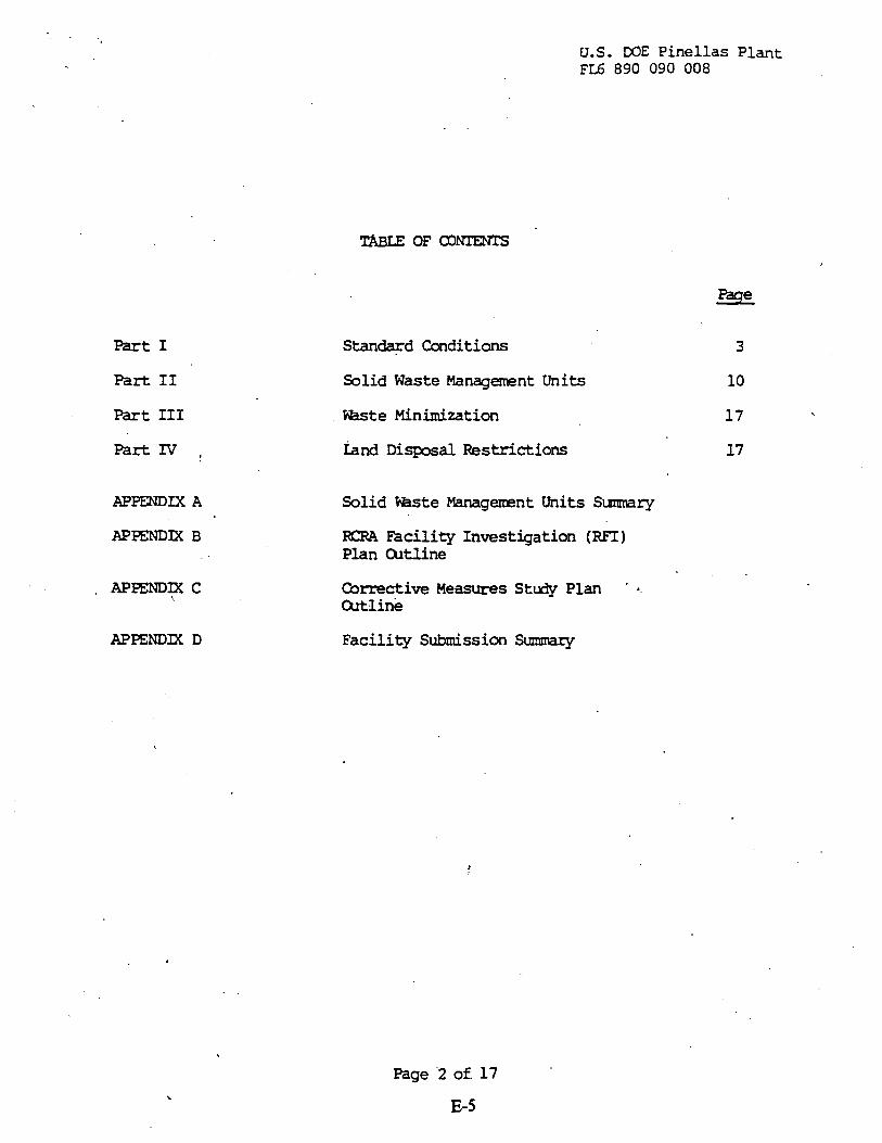
Part I
Part I1
Part I11
Pa* IV ,
APPENDIX A
U.S. DOE Pinellas Plant FL6 890 090 008
TABLE OF amTms
Page
Stanwd Conditions
Solid Waste Management Units
Waste Minimization
Land Disposal Restrictions
Solid Waste Managerrent Units Sumnary
EMRA Facility Investigation (RFI ) Plan atline
Corrective Measures Study Plan . &.
atline
Facility Submission S m m r y
Page '2 of. 17
E-5

U.S. COE P i n e l l a s P l a n t EL6 890 090 008
Ccsopliance with this RCRA pennit constitutes carpliance, f o r p-es uf enforcarrent, with Subtit le C of RI=RA except f o r thcse
. requirements not included i n the perni t which becane effective by s t a tu te o r which are p r d g a t e d under 40 CE'R Part 268 res t r i c t ing
-placement of hazardcus waste in or on the land. Issuance of t h i s permit does not convey prcperty r ights of any sor t or any exclusive privilege; nor does it authorize any injury t o persons o r property, any invasion of other private rights, or any infringement of s t a t e o r local law or regulations. Conpliance with the terms of t h i s permit does not const i tute a defense t o any order issued o r any action brcught under Section 3013 o r Section 7003 of RCRA, Sections 106(a), 104, o r 107 of the Comprehensive Enviromntal Response, m n s a t i o n , and Liabi l i ty A c t of 1980 (42 U.S.C. 9601 et seq., camonly k n m as CERCLA), or .any other law providing f o r protectson of public health o r the e n v i r o m n t .
I.B.
?his permit may be modifiedr- revdced and reissued, o r terninated f o r cause as specified i n 40 CFR SQ70.41, 270.42, and 270.43. Ihe f i l i n g of a request f o r a modification, revocation and reissuance, o r termination, o r the notification of planned m e s f o r anticipated noncatpliance on the part of the Permittee does.not s tay the applicabi l i ty a- enforceabil i ty of any p e d t condition.
I.C. SEVERABILITY
The provisions of this permit are severable, a s specified i n 40 CFR S124.16 and i f any provision of t h i s permit o r the application of any provision of this permit t o any circumstance is held irwalid, the application of such provision to other circumstances and the remainder
,of this pennit sha l l not be affected thereby.
I.D.
Rlty to canply
The Pennittee shal l m l y with a l l conditions of this permit, except t o the extent and f o r the duration such noncoqliance is authorized & an emergency p e d t . Any permit noncarpliance, other than nonc-liance authorized by an emergency permit, cons t i tu tes a violation of RCRA and is grcunds f o r enforcement action, p e d t t e a t i o n , revocation and reissuance, Wifica- tion, or denial of a permit renewal application.
h t y t o Reapply
If the Pennittee w i l l continue an ac t iv i ty a l lwed by t h i s permit a f t e r the expiration date of t h i s permit, the Permittee

U.S. COE - Pinellas Plant FL6 890 090 008
I.D.S.
I.D. 6.
sha l l submit a camplete application for a new permit a t l e a s t 180 days before this pernit expires, unless permission for a l a t e r date has been granted by the Regional Xiministrator.
Permit Expiration
I f the Sta te does not have RCRA hazardous waste permitting authority under 40 CFR Par t 271 for the 1984 RCRA Amendnents, th is permit and a l l conditions herein w i l l remain in effect beyond the pennit's expiration date, as specified i n 40 CFR 5270.51. This applies only i f the Permittee has submitted a timely, c q l e t e application i n accordance with 40 CFR 5270.10 ( c and, throu* no fault- uf the Pennittee, the Regimal Administrator has not issued a new permit with an effective date under 40 CE'R 5124.15 on or before the expira- t ion date of the previous permit.
If the State does have RCRA hazardous waste permitting authority under 40 CFR Part 271 fo r the 1984 RCRA bendrents and i f the errni t tee has submitted a timely and ccmplete application under applicable s ta te la+ and regulations, the term and conditions of t h i s permit continue in force beymd the expiration date of the pemi t , but only unti l the effective date of the s ta te ' s issuance o r denial af a s t a t e RCRA permit.
Need t o Halt or Reduce Activity Not a Defense
It sha l l not be a defense for the Permittee in an enforce~nent action that it would have been necessary t o halt o r reduce the permitted activity in order t o maintain canpliance w i t h the condi- t ions of this pennit.
IXlty t o Mitiqate
In the event of noncarpliance with the permit, the Pennittee shall take a l l reasonable s t e p t o minimize releases to the envirormrent, and shall carry at such measures as are reasonable to prevent significant aderse ixpacts on human health or the environmsrit.
Proper Operation and Maintenance
The Permittee shall a t a l l times '@rqerly aperate and maintairi al l f a c i l i t i e s and system of treatmmt and control (and related a p purtenances) which are installed or used by the Pemdttee to achieve coql iance w i t h the conditions of this permit. Pr- -ration and mintenance includes effective perfomarm, adequate funding, adequate cperator staff ing and training, and adequate laboratory and process controls, including apprqr ia te . quality assurance procedures. This provision requires the -ration of backup or a u x i l i a q fac i l i t i es o r similar systems only. when necessary to achieve compliance with the conditions of the permit.
Page '4 of 17 E-7

U.S. W E - Pinnellas P l a n t EL6 890 090 008
I.D.7. EUty t o Provide ~ n f o m t i o n '
The Permittee shall furnish to the Regional Administrator, within a reasonable time, any relevant informtion which the Regional Administrator my request to determine whether cause exists for rmdifying, revdcing, and reissuing, or terminating th i s permit , o r t o determine ccrrpli&nce with th is permit. The Permittee shal l a lso furnish to the Regional Actministrator, upon request, ccpies of records required t o be kept by th is permit.
I.D. 8. Inspection and Entry
The Permittee shall all- the Regional Administrator, o r an authorized representative, upon the presentation of credentials and other documents as may be required by l a w to:
I.D.8.a. Enter a t reasonable tims upon the Fennittee's premises where a regulated activity is located or conducted, o r where records mst be kept under the conditions of this permit;
I.D. 8.b. Bave access t o and Cqyr a t reasonable times, any records that rmst be kept under the conditions of this permit;
I. D. 8 .c. Inspect a t reasonable times any faci l i t ies , equipnent (including mnitoring and control e q u i p n t ) , practices, o r -rations regu- lated, o r required under th is permit; and
I.D.8.d. Sample o r m i t o r , a t reasonable times, for the purposes of assurirg permit ccrrpliance or as otherwise authorized by RCRA, any suktance, or parameters a t any location.
I.D.9. Monitorinq and Records
I.D. 9.a. Samples and masuranents taken for the purpose of mnitoring sha l l be representative of the d t o r e d activity. The method used t o
t obtain a representative smrple t o be analyzed mst be the apprcpri- ate mth& fran Appendix I of 40 CFR Part 261 or an equivalent method approved by the Regional Administrator. Laboratory methods rmst be those specified the mst recent edition of ~ e & Methods
I.D. 9.b. Ple Permittee shall retain a t the faci l i ty , or other appropriate location as provided for under '40 CFR Part 264, records of a l l monitoring information required under the terns of t h i s permit, including all calibration and maintenance records, records of all data used t o prepare documents required ty this permit, q i e s of all reprts and records required by this permit, the cert if icat ion required by 40 CFR 264.73(b) (9) , and records of a l l data used t o ccnplete the application for th is permit fo r a period af a t leas t 3 years from the date of the sample, rneasurernent, report, c e r t i f i -
Page 5 of 17 - E-8

U.S. DOE Pinellas Plant EL6 890 090 008
cation or application, o r un t i l corrective action is conpleted, whichever date is la ter . These pericds m y be extended by request of the Regional Administrator a t any tim and a re autanatically extended &ring the c a r s e of any unresolved enforcanent action regarding this fac i l i ty .
I.D.9.c. - Records ofmoni tor ing ' in fo~t ionsha l l spec i fy :
I.D. 9.c. i. The dates, exact place, and t i m e s of s e l i n g , o r measurenrents;
I D 9 . c i . The individuals who performed the s q l i n g o r masuranents;
I.D.9.c.iii. The dates analyses were p e r f o m d ;
I.D. 9 .c. iv. The individuals who performed the analyses;
I.D.9.c.v. The analytical techniques o r rrethods used; and
I.D.9.c.vi. % r e s u l t s af such analyses.
Reportins Planned Qlanqes
The Permittee sha l l give notice to the Regional Administrator as soon as possible a€ any planned physical al terat ions or additions t o .the pexnitted fac i l i ty . mis wculd apply t o all contiguous land, structures, other appurtenances and irrproverrrents on the land, used f o r the t r eahen t , storage o r disposal' of sol id waste.
Anticipated Noncanpliance
Ihe Permittee shall give adwince notice to the Regional Admini- s t r a t o r af any planned changes in the permitted f a c i l i t y or ac t iv i ty which may resul t i n nonca~pliance with permit requirements.
I.D.12. Transfer of Permits \ . .
This p e d t may be transferred to a new mer = cperator only if it is mdif ied or revdced and reissued pursuant t o 40 CFR S27O041(b)(2) o r S270.42(d). Before transferring mership or -ration of the f a c i l i t y during its -rating life, the Permittee shall not ify we new owner o r q e r a t o r i n writirg of t h e requhmnts of 40 CFR Parts 264 and 270, the 1984 RCRA PrmenaEnts and this permit.
Caupliance Schedules
Reports of carpliance o r noncmpliance with, or any progress reports on, interim and f i n a l requiremnts contained in any carpliance schedule of this permit s h a l l be submitted no l a t e r
' than 14 days follawing each schedule date.

U.S. COE Pinellas Plant F L ~ 890 090 008
I.D.14. Twenty-four Hour Reparting
I.D. 14.a. The Permittee sha l l report any noncarpliance which may endanger human health o r the env i romnt . Any such infomation s h a l l be reported orally within 24 hours fran the time the Permittee becanes aware of the circumsbyces. 'Ihis repor t -shal l include:
I.D. 14.a. i. Informtion concerning the release of any hazardas waste or hazard- constituents which nay endanger public drinking water supplies.
I .D. 14.a. ii. Information concerning the release o r discharge of any hazardous waste or hazardcus constituents, o r of a f i r e o r explosion a t the f a c i l i t y , which c a d threaten the env i romnt o r h m n health outside the fac i l i ty .
I.D. 14.b. The description of the occurrence and its cause shall include:
I.D.14.b. i. N e e , address, and telephone nunber of the m r o r e r a t o r ;
I.D.14.b.ii. Name, address, and telephone rnmnber of t h e f a c i l i t y ;
I.D.14.b.iii. Date, time, and type of incident;
I. D. 14.b. iv. Name and quantity of materials involved;
I.D.14.b.v. , ?he extent of in jur ies , if any;
I.D.14.b.vi. An assessnent of actual o r potential hazard t o the environment and h m health cutside the fac i l i ty , where this is applicable; and
I.D.14.b.vii. Estimated quantity and disposition of recovered nraterial that resul ted f ran the incident.
'I.D. 14.c. \ A writ ten report s h a l l also be m d e d t o the Regiondl Administrator within 15 days of the time the Permittee b e c m aware of the circunrjtances. The written report sha l l contain the information specified under Condition I.D.14a. and b.; a description of the noncarpliance and its cause; the periods of noncatpliance (including exact dates and t h s ) ; whether the m m p l i a n c e has been corrected; and if not, the anticipated time it is expected t o continue; and steps taken on: plapned t o reduce, eliminate, and prevent recurrence of the m c a q l i a n c e .
I.D.15. Other Noncacpliance
The P e d t t e e s h a l l r-rt a l l other instances of nonuxpliance not otherwise required t o be reported above, a t the time written repar ts as required ty t h i s permit are submitted. The reports shall contain the information listed i n Condition I.D.14.b. a s apprqr ia te .
Page 7 o f 17
E- 10

U.S. DOE Pinellas Plant FL6 890 090 008
Other Inform t ion
Whenever the Permittee becws aware tha t it failed t o submit any relevant facts or submitted incorrect information in any d o m n t ( s ) submitted t o the Regional Administrator, the Permittee sha l l pronptly submit such facts or informtion.
Al l applications, reports, o r information submitted t o the Regional Administrator shall be signed and cert if ied in accordance with 40 CE'R s270.11.
I.F. CONFIDEmIAL INFmwrION
The Permittee may claim confidential any information required t o be submitted ly th is permit in accordance with 40 CFR 5270.12.
I.G.
For purposes of t h i s penait, tenas used herein shall have the same maning as thcse i n RCRA and 40 CFR Parts 124, 260, 261, 264, and 270, unless th is permit specifically provides otherwise; where terms are not defined in the regulation, the pennit, o r EPA guidances o r publications, the manirg associated with such terms shall be defined by a standard dictionary reference or the generally accepted sc ien t i f i c o r i n a s t r i a l lrreaning of the texn. I
I.G.1. ?he term "solid waste" mans any garbage, refuse, sludge f r a n a waste trealment plant, water supply treatment plant, o r a i r pollution control f ac i l i t y and other discarded material, including solid, liquid, semisolid, o r contained gaseous material resulting f ran industr ial , camercial, mining, and agricultural -rations, and from camunity activi t ies, but does not include solid or dissolved material i n d m s t i c sewage, or solid or dissolved mter ia l s i n irr igation
. , return flws o r industrial discharges which are point scurces subject t o permits under section 402 of the Federal Wter Pollution Control kt, a s anended (86 Stat, 880), o r sxrce, special nuclear, o r bypro- duct rrraterial as defined by the Atomic Ehergy Pct of 1954, as mnded (68 Stat. 923).
I .G. 2. A "hazaxdcus constituent" fo r purposes of this p e d t are those substances l i s ted i n 40 CFR Part 261 Appendix VIII.
I.G. 3. A "solid waste manaqement unit" f o r the purposes of th i s p e d t includes any unit which has been used fo r the treatment, storage, o r disposal o f solid waste a t any time, irrespective of whether. the unit is o r ever was intended for the m a g e m n t of solid waste. RCFtA regulated hazardcus waste management uni ts are also solid waste managqsn t units .
Page 8 of. 17 E-11

U.S. COE Pinellas Plant FL6 890 090 008
I.G. 4. A "unit" - for the purpcses of his permit includes, but is not l imited to, any landf i l l , surface impoundment, waste pile, land treatment uni t , incinerator, injection ell, tank, container storage area, s e p t i c tank, drain f ield, wastewater treatment unit, elementary neutralization . . uni t , t ransfer s ta t ion , o r recycling unit.
I.G. 5. A "release" f o r p w e s af this peanit includes any spill ing, leaking, punping, pcuring , d t t ing , enpt$ing, discharging, injecting, escaping, l each iq , dumping, o r disposing in to the environment of any hazardous waste o r hazardous constituents.
I.G.6. "Contaminationn f o r purposes of t h i s permit refers t o the presence of any hazardcus constituent i n a concentration which exceeds the naturally ocarring concentration of that constituent in the immediate vicini ty cf the f a c i l i t y ( i n areas not affected by the faci l i ty-) .
I.G.7. "Corrective action, " f o r purposes of t h i s p e b t , may include all corrective masures necessary t o protect human health and t h e e&rorment f o r all releases of hazardaxs waste o r hazardcus constituents fran any sol id waste roanag-nt unit a t t h e s f a c i l i t y , regardless of the t i m e a t which waste was placed i n the unit , as required under 40 CFR S264.101. Corrective measures m y address releases to a i r , so i l s , surface water o r gramdater .
Page 9 of. 17 E-12

U.S. COE Pinellas Plant FL6 890 090 008
Par t I1 - Solid Mste Managent Units
Applicability
The. Conditions of t h i s Part apply to:
I I A 1 The s o l i d waste nanagemnt units ident if ied i n Appendix A. Paragraph I.
I I.A.2. Any additional sol id waste nranagement units or releases of -
hazardous waste o r hazardcus constituents other than those referenced above, discovered &ring the m e of gram&ater mnitoring, f i e l d investigations, envirorrmental audits, o r other means. -
II.A.3. For releases fran sol id o r hazardcus waste management units a t the f a c i l i t y that migrate o f f s i t e , the Permittee shall w e m n t corrective actions beyond the f a c i l i t y boundary, where necessazy t o protect h m health and the e n v i r o m n t , unless the, permittee demonstrates t o the sat isfact ion of the Regional Administrator that, despite the permittee's best e f for ts , the pernittee was unable to obtain the necessary permission t o undertake such actions. The permittee is not relieved of all responsibility to clean up a re lease that has migrated beyond t h e fac i l i ty boundary where off- s i te access is denied. O n s i t e measures t o address such releases w i l l be detenained on a case-by-case basis.
RCRA Faci l i ty Assessment (RFA)
1 . B . l The Permittee shall notify the Regional Administrator of any addit ional so l id waste management unit(s) with releases of hazardcus const i tuents or hazardas waste not identified i n Condition II.A.l., discovered during the course of gramdwater mnitoring, f i e l d investigations, envirornnenta.1 suits o r other means within f i f t e e n (15) days of discovery.
11. B .2. The P e d t t e e shall prepare and subit t o the Regional Administra- tar a RCRA Facil i ty Pssessaent (MA) Plan with a pmposed schedule of implanentation and ccapletion for any additiandl sol id w a s t e managemnt un i t (s ) or release(s which is discovered suksequent t o t h e issuance of this permit. 2he Plan shall include methods and spec i f i c actions as necessary to:deternine whether a pr ior or cont iming release of hazard- waste or hazardous constituents has ocaxred a t each s o l i d vmste management unit. The plan rmst also include, a t a mininarm, the f o l l w i n g infomation f o r ,a& unit:
(1) b c a t i o n of uni t ( s ) on a t w a p h i c map of a p p r q r i a t e scale such as required under 40 CFR S270.14(b) (19).
(2 ) Designation of type and function of uni t (s ) . (3) General d h n s i o n s , capacities and structural description
, of un i t ( s ) (supply any available plans/drawing).
Page 10 of ' 17 E-13

U.S. D3E Pinellas Plant FL6 890 090 008
( 4 ) Dates that the unit (s) was -rated. (5) Specif icat im of a l l wastes -that have been managed at/in
the un i t ( s ) . (6) A l l available information pertaining t o any release of
hazardous waste o r hazardous constituents fran such un i t (s) ( t o include groundwater data, soil analyses, and/or surface water data ) .
(7) Results af s a p l i n g and analysis of g r a m h a t e r , landsurface and subsurface s t r a t a , surface water o r air requested by t h e Regional Administrator.
1I.B. 3. If the tinre required t o conduct the RFA is greater than 180. days, the Permittee sha l l p r a i d e the EPA with quarterly Prcgress Reports (90 day intervals ) beginning ninety (90 days fran i r p l m n t a t i o n of the approved plan containing:
description the portion of the RFA
b. Summaries af findings; . . c. --ries of - all deviations " f r a n the approved RFA Plan during
the reporting period;
d. Summaries of - all problms or potential prcblacs encamtered during the reporting period;
e. Projected work f o r the next reporting period; and ' I
f . Copies of daily reports, inspection reports, laboratory/ mni tor ing data, e tc .
I I.B. 4 The Permittee shall prepare and submit to the Regional Administra- tor a RCRA Facili ty Assessment Report of the results of the REA required under Condition II.B.2 i n accordance with the schedule(s ) under Condition 1I.H. Ple RFA Fkport rmst incl&e a t a m i n h the infonuation l i s t e d under Condition II.B.2. and other apprcpriate infomation necessary t o detexaine the need f o r a RFI under Condition II.C.2,
FCRA ~ ' a c i l i t y Investbat ion (RE'I)
I I C The Permittee s h a l l prepare and subxnit t o the Rqional Mminisi&a- tor a RCRA Facil i ty Investigation (RE'I) Plan or plans fo r those uni ts indicated i n Appendix A paragraph I as subject to t h e RFI, which includes schedules of irplementation and c a p l e t i o n of spec i f i c actions necessary to d e t e m h e the nature and extent of releases and the potential pathways of containant releases t o the air, land, surface water, and groundwater. ?he Ekrxdttee 'rmst provide suff icient jus t i f icaticn and/or doamentation tha t a release is not prabable i f a media/pathmy associated with a uni t (grmdwater , surface water, s o i l or a i r ) is not included in the RE'I Plan(s) . Such deletions of a d a or pathway f r m the RE'I are subject t o the a p p r m l of the mima1 Administrator.
II.C.2. The Permittee sha l l prepare and submit to the Regional Administrator
page 1 1 of 17 E-14

U.S. DOE Pinellas Plant FL6 890 090 008
a RCRA Facility Investigation (WI) Plan for those units identified under Condition 1 I . B . which includes schedules of implementation and completion of specific actions necessary to determine the nature and extent of releases indicated by the assessment, and the potential pathways of contaminant releases to the a i r , land, surface water, and gramdwater. The Permittee mst provide suffi- c i en t justification and/or dccumentatiori that a release is not probable i f a unit identified under Conditim 11. B. o r a media/pathway associated w i t h such unit (gramdwater, surface water, soil o r a i r ) is not included in the RFI plan. Such deletions of a unit, d a o r pathway fran the RFI are subject t o the approval af the Regional Administrator.
II.C.3. The RFI Plan(s) shall m e t L!e requirements of Appendix B a t a minimum. The RFI shall be conducted in accordance w i t h the approved RF'I Plan(s) and Appendix B. The Permittee shall provide written
. sufficient justification for any omissions or deviations f ran the d n b requiranents of Appendix B. Such auissions or deviations are subject t o the approval of the kgional Administrator. ?he
. socpe of the RFI Plan(s) shal l include all investigations necessary j t o ens- ccqliance with 40 CFR §264.101(c).
II.C.4. If the t i m e required t o con&ct the FlFI is greater than 180 days, the Permittee sha l l provide the EPA with quarterly RFI Atogress Reports (90 day intenmls) beginning ninety (90) days frcm irrple- mntation of the approved plan containing:
a. A description of the porticn uf the RFI carpleted;
b. Sucmries of findings;
c. Summaries of deviations f rcm the approved REX Plan during the reporting period;
d. summaries uf al l problem or potential problem encamtered during the reporting period;
\
e. Projected work for the next reporting period; and
f . Capies of daily reports, inspection reports, laborataq/ mnitoring data, etc.
11. C. 5. The P e d t t e e shall prepare and submit t o the Regional Administrator a =aft and Final RCRA mci l i t y Investigation I&-. The RE'I Reports shall be submitted in accordance with the schedule(s 1 under Condition 1I.H.S. m e RFI: Rqort shall include an analysis and srnmrary of a l l required investigations of solid waste manaprent units and their results. ?he suurmry shall include a report on
, the type and extent of contanination a t the faci l i ty , including sources and migration pathways, and a description of actual o r potential receptors. ?he report shall also describe the extent of contanination (qualitative/quantitative in relation t o backgramd levels indicative for the area. Ple objective of this task sha l l
Page 12 of '17 E-15

U.S. COE Pinel las Plant FL6 890 090 008
be t o ensure that the investigation data are suff ic ient i n qua l i ty (e.g. , quality assurance prodedures have been follcwed) and quantity t o describe the nature and extent of contamination, potent ia l threat t o hunan health and/or the envirornraent, and t o support a Corrective Measures Study and/or a Corrective Action Plan, i f necessary.
Interim Measures
II.D.1. The P e d t t e e , (upon approval by the Regional Administrator), may conduct interim masures t o contain, r a v e or treat contamination resul t ing fran the release of hazardas constituents f ran a sol id waste m a g m e n t unit in order t o protect public health and the e n v i r o m n t . Such interim masures may be conducted concurrently w i t h investigations required under the t e r n af t h i s permit.
1I.D. 2. The Permittee sha l l notify the Regional Administrator of any prcposed interh/corrective measures a t l e a s t thirty (30) days pr ior t o hplementation. The notice shal l in'clude a description and a &e&le of i r p l e n t a t i o n of any prqosed i n t e r h measures.
II.D.3. The Permittee shal l give notice t o t h e Regional Pdministrator a s soon as possible of any planned changes, reduction or additions t o the interim measures.
-
1I.D. 4. Final approval of interim neasures as corrective act ion required under 40 CFR S264.101 shall be in accordance with 40 CFR 5270.41 and Conditim II.E.2. a s a permit d f ication.
11. D. 5 If the tinre required f o r cople t ion of an Interim Measure is grea te r than 180 days, the Permittee shall provide €PA with guarter ly progress reports (90 day intervals) beginning ninety (90) days after in i t ia t ion af the Interim Measure(s ) . Such reports shall include:
a. A description af the portion uf the Interim Measure ccnpleted;
b. Sunrraries of - all deviations fran the Interim Measures Plan- . during the reporting period;
c. Summaries of - all problem o r potential problems encamtered during the reporting period;
d. Projected work f o r the next rewrt ing period; and
e. Capies af laboratory/mnitoring data.
II.D.6. Upon completion of Interim k a m e s ccnducted under t h i s Condition, the Permittee sha l l submit an Interim Measures R e p o r t to €PA t h a t
' contains:
Page 1'3 of. 17
E-16

U.S. COE Pinellas Plant FL6 890 090 008
a. A description of measure(s) implemnted;
b. Summaries of results;
c. S m r i e s of a l l problem enccuntered;
d. Summaries of accarpl ishents and/or effectiveness of interim masure; and
e. Copies of a l l relevant laboratory/mnitoring data, etc. i n accordance with Condition I.D.9.
I I E l The Regional Administrator w i l l review the f i n a l RFI r e p r t ( s ) required under a n d i t i o n 1I.C. 5 . and notify the Fennittee af the need f o r fu r the r investigative actions and/or the need f o r a Corrective .Wasures Study (CMS) t o meet the r e q u i r m n t s of CFR S264.101.
1I.E. 2. Within 90 days of the notification by the Regional Administrator tha t a Corrective Measures Study (CMS is required, the hrmittee s h a l l prepare and submit a CMS Plan o r Plans f o r thcse un i t s requiring a CMS. The P l a n k ) developed t o met the requirerents of Condition II.E.3.
1I.E. 3. The CMS Plan(s) s h a l l met the requirements of Appendix C a t a . minimum. P l i s Plan sha l l include schedules of imrplementation and
c a p l e t i o n of specific actions necessary t o ccrrplete a CMS. The CMS s h a l l be canducted in accordance with the approved CMS Plan and Appendix C. The Permittee shall provide suff icient written jus t i f ica t ion f o r any clnissions or deviations, which are subject t o t h e approval of the Regional Administrator. The sccpe of the CMS Plan s h a l l include all investigations necessary to ensure c w l i a n c e w i t h 40 CFR §264.101(c).
II.E.4 ?he Pennittee shall prepare and submit t o the Regiondl. Administrator a draft and f i n a l Corrective Measures Report for the study conducted pursuant to the Plan submitted under Conditions II.E.2.- and 1I.E. 3. ?he &aft CMS Report shall be submitted to EPA far review i n accordance with the schedule in the CMS Plan(s) approved under. Condition II.E.3. lbe f i n a l CMS Report(s) shall sunmarize the r e s u l t s of the investigations fo r each ranedy studied and of any bench-scale or p i lo t tests conducted. Ihe CkS &port (s) rmst include an evaluation of ea& remedial alternative. The CMS &port shall present all information gathered under the approved CMS Plan. The Reportrmst contain adequate information to support the Regional Administrator in the approval of the recamended remdy.
Page 1 4 of-17
E-17

U.S. COE Pinellas Plant EL6 890 090 008
11,F.l The Regional Administrator shal l approve a remedy f r m the remedial al ternat ives e m l u t e d in the CMS tha t w i l l
(1) protect h u n health and the enviromnt ; (2 ) meet the approved clean-up levels; (3 control the '=rce(s of release(s 1 s o as t o reduce
or eliminate t o the maxirmxn extent practicable, fur ther releases t h a t may p s e a threat t o human health and the e n v i r o m n t ; and
( 4 ) meet a l l applicable waste management requirements.
II.F.2. A nrodification t o this Fermit w i l l be in i t ia ted by the Regional Pdministrator a f t e r approval of a remedy under Condition 1I.F.I.
1I.G. Imninent Hazards
11.G. 1. The Permittee sha l l report t o the Regional Administrator any imminent or existing hazard t o public health or 'the e n v i r m n t f r a a any release of -hazardcus waste o r hazardas constituents frm a sol id waste magextent unit. Such information s h a l l be r e ~ o r t e d orally within 24 hours f r a n such ti= the Permittee . beccnnes a- of the circlmstances. This report shall include the informtion specified under Conditions I.D. 14.a. and b.
II.G.2. A written report shall also be provided t o the Regional Mainis- - .-tor within f i f teen (15) days- of the time the Permittee becanes ' aware of the circlmstances. The written report shall contain
the infomaticxl specified under Conditions I.D.14.a. and b.; a description of the release and its cause; the period of t h e release; whether the release has been stqped; and if not, the anticipated the it is e-ed t o continue; and steps taken o r planned t o reduce, eliminate, and prevent recurrence of the release.
1I.H. , Schedule of Canpliance and Report Requirements
II.H.1. The Permittee shall submit the RFA Plan(s ) f o r so l id waste manage- m n t un i t s o r releases discovered a f t e r the effective date of t h i s permit required under Condition II.B.2. t o the Regianal Administrator within s ix ty (60) days of the notification requiked under Condition 1I.B -1.
1I.H. 2. ?he Permittee shall subxdt the I&A &port required under Condition II.B.4. within s ix ty (60) days a f t e r carpletion crf al l a c t i v i t i e s conac ted under the approved RFA Plan.
II.H.3. The Fkrmittee s h a l l submit the RFI Plan required by Condition 1 1 . C . l and the associated doa~nentation t o the Regiondl Adminis- t r a t o r within 120 days of the effect ive date of t h i s permit.
Page 15 of 17 E-18

U.S. DOE Pinellas Plant FL6 890 090 008
II.H.4. The e r m i t t e e shall submit the &'I Plan(s) required under Condition 11. C .2. f o r solid waste management uni t s o r releases discovered a f t e r the effective date of th is permit within ninety (90) days of submission of the RFA repor t required under Condition II.B.4.
1I.H.S. The Permittee shall submit the C r a f t RET Report required under . Condition II.C.5. t o EPA f o r review ninety (90) days after carpletion
of t h e RFI. me Final RFI: Report s h a l l be submitted t o EPA within thirty (30) days of receipt of EPA camtents on the Draft W I Report.
1I.H. 6. The Permittee s h a l l submit the CMS Plan(s ) required under -Condition II.E.2. t o the EPA for review within ninety (90) days of the not i f ica t ion fran the Regional Administrator under Condition II.E.1.
I H . 7 A l l plans and schedules sha l l be subject t o approval by the F&gional '
Pdministrator pr ior t o implenentation. The Permittee shall revise all submittals and schedules as specified by the Regional Administrator.
Upon approval the Permittee sha l l kplenent a l l plans and schedules a s written. h
II.H.8. ?he resu l t s of a l l plans and reports sha l l be submitted i n accordance with the a ~ ~ r o ~ e d schedule. Extensions of the due date f o r submittals may be gra%ed ty the R e g i d Administrator based on the Permittee's
daaonst ra t ion that suff icient just i f icat ion f o r the . extension .
' exists .
1I.H. 9. If the Permittee a t any time detemines that the RFA o r RFI plans required under Conditions 1I.B. or 1I.C. no longer sa t i s fy the requirarvants of 40 CFR 5264.101 o r this p e d t f o r pr ior o r continuing releases of hazardcus waste ar hazard- constituents fron sol id waste management units, he sha l l submit an amended plan(s) t o the Regional Administrator within ninety (90) days of such determination.
I I H 1 All reports shall be signed and c e r t i f i e d i n accordance with 40 CFR 5270.11.
1 I . H . 11. Three ( 3 ) cqies of a l l reports and plans shall be provided by. the Pennittee to U.S. EPA a t the f o l l d n g address:
Mr . Jams 8. Scarbraqh, P.E. . Rwirormental Ro tec t i an Agency Chief, RCRA Branch Region IV Waste Management Division 345 Courtland Street , N.E.
Atlanta, Georgia 30365
Page 16 of. 17 E-19

U.S. MIE P ine l l as Plant FL6 890 090 008
PAKT I11 - WSTE MINIMIZATION
WAmZ MINIMIZATION cExTIFICATION
U n t i l cer t i f icat im of closure the Permittee shall certify no less often than annually that the Permittee has a progran in place t o reduce the volume and toxicity of hazardcus mste that he generates to the degree determined by the Permittee t o be e c o n ~ c a l l y practicable and the prcposed method of treatnent, storage or disposal is that practicable method-currently a ~ i l a b l e t o the F e d t t e e which minimizes the present and future threat t o hunan health and the envimnnent.
The Permittee shall mintain ccpies of the certification i n the faci l i ty -rating record as required under 40 CE'R 5264.73 (b) (9).
PART IV - LAND DISPOSAL FIESTRICTIONS
40 CFR Part S268 identifies- hazard- wastes that are restricted fran land disposal ;?nd defines thcse limited circumstances ynder which an otherwise prohibited waste my continue to be placed on or i n a land treabnent, storage or disposal unit. The Permittee shall mintdin caqliance w i t h the requirenrents of 40 CFR S268. Where the Permittee has applied for an extension, waiver or variance under 40 CFR Part S268 the Permittee shall comply hrith a l l restric- tions on land disposal under this Par t once the effective date for the waste has been reached pending final approval of such application.
11- B. For the purposes of 40 CFR Part 5268 "Land Disposal" means placement in or on the land and includes, ht is not limited to, placemnt in a elandfill, surface ixpoundumt, waste pile, injection w e l l , land trea-nt facil i ty, salt dcrme formation, underground mine o r cave, o r concrete vault or bunker intended for disposal purposes.
n7.C. A restricted waste identified in 40 CFR Part 5268 C m y not be placed in a land disposd unit wi tha t further treatment unless the requirements of 40 CFR Part S268 Subparts C and/or D are met-
IV.D. The storage of hazardous wastes restricted frcm land disposal under 40 CFR Par t 5268 is prohibited unless the requirements of
Page 17 of 17 E-20

Appendix A
Sol id Waste manageanent U n i t Summary
I. List of Sol id Waste Xaaagement U n i t s r aquk ing an RFI:
'1. Went pond - 2. Northeamt site - 3. Spray i r r i g a t i o n mite - 4. Trenches 1 5. Old drum storage m i t e
6. Former p i a t o l range 7. Closed f i r e department training tank
. 8. Current f i r e department training tank - 9. Metallic anomaly sits ' 10. Incinerator site -11. IncineratPr d i tch .12. D i e s e l f u e l s p i l l .13. Indumtri a1 drain l e b -14. Southweet d i t ch
11. Limt of Sol id Waste Management U n i t s with no known releasee (no R F I required)

I. RFT WRKPLAN F£QUIEMErn
The Permittee s h a l l prepare a RCRA ~ a c i l i t y Inves t iga t im (RFT) Workplan tha t meets the requirements of Part 11 of this document and the - R F I Guidance, EPA-530/SW-87-001. This Workplan s h a l l a l s o include the d e v e l p n t of the f ollcwirq plans, which s h a l l be prepared concurrently:
A. Project Managanent Plan
The Permittee s h a l l p rewre a Project Management-plan which w i l l include a discussicn of the technical approach, schedules, and pekcnnel . The Project Management Plan w i l l a l s o include a descripficn af qual i f ica t ions of persamel performing o r direct ing the RFT, inc lud im ccntractor persamel. This plan s h a l l also dccument the
a overal l managemnt apprach t o the RCRA Faci l i ty Inves t iga t im.
B. Samlinq and Analysis Plan(s1
The Pennittee s h a l l prepare a plan t o doarment all monitoring pro- cedures: f i e l d sanpliq, -ling procedures and m l e ana lys i s performed duri rg the investigation t o characterize t h e envirannental setting, scurce, and releases cd hazard- cansti tuents, so as t o ensure t h a t a l l infomtim and data a r e val id and prcperly documented. The Samling Stategy and Procedures shall be i n accordance with Character izat im of Hazardars Waste S i tes A Methods Manual: Volume 11. Available S a m l i r q Methcds, EPA-600/4-84-076, or EPA Region IN Tqineer i rxj Support Branch's Standard mratirq ProFedure and Quality Assurance Manual (SOP). Any deviatians frcm these references must be requested bv the aml i can t and amraved bv EPA. The S a m l i w and Analysis Plan m k t specif icdly dis&ss the f &lawirg unless- the- €PA-600/4-84-076 or SOP praedures are spec i f ica l ly referenced.
1. Samlinq Strategy
a. Selecting apprcpriate sanplirg locaticns, depths, etc.;
b. Obtainirg all necessary ancil lary data;
c. Detedniq ccnd i t ims under which s a n p l i q s h a l d be c-cted ;
e. Determining which media are t o be sanpled (e.g., grandwater, a i r , soil, sed imnt , etc. ) ;
f. Deteanining hi& parameters a r e - t o be measured and where; 4 1

g. Selecting the frequency of sampling and length af sq l ina pericd;
h. Selectirg the types of samples (e.g., canpasites vs. g r a b ) and m m h r of samples to be collected.
2. Sampling Procedures
a. Documentirq field samplirq aperations and procedures, including;
i) Documentatim d.pra=edures for 'preparatim af reagents or sumlies which becane an inteqral part of the sample (egg., f i l t e s , preservatives, a d absorbirg reaqents) ;
ii) Procedures and forms for recordirq the exact locatim and specific c m i d e r a t i m associated with sample acquisition;
iii) Dccumentaticn of specific sample preservaticn method;
iv) Calibratim of field instruments;
- V) Submissicn af field-biased blanks, where appwriate;
v i ) Potential interferences present a t the facility:
v i i ) Constructim materials and techniques, Associated w i t h m i t o r i n g wells and piezcmeters;
v i i i ) Field e q u i p & listirq and sampling cmtainers;
ix) Sapling order; and
x) Decccltami~ticn procedures.
b. Selecting a p p r ~ r i a t e q l e ccntainers;
c. -Samplirg presemtim: and
i ) Standardized field tradcixq reportirrg f oms t o establish - sample custody i n the field prior t o shipment; and
ii) Pre-prepared s ~ l e labels cmtaining a l l infonnatim necessary for effective sample tracking.

3. Sample Analysis
Sample analysis s h a l l be ccnducted i n accordance with SW.846: "Test Methcds f o r ~ v a l u a t i w - s o l i d Waste - Physical/Chemical Methcds" (third edi t icn) . The sanrple analysis sectim of the Samplirg and Ahalysis Plan s h a l l specify the followirq:
i) Ident i f ica t icn of a responsible party t o a c t as s a p l i n g custcdian a t the laboratory f a c i l i t y authorized t o sign f o r incanirq f i e l d samples, cbtain doamrents of shipnent, and ver i fy the data entered onto the smle custcdy records;
- ii) P r w i s i m f o r a laboratory sample custcxly l cg c m s i s t i r g of s e r i a l l y ranbered standard l ab t r ack ing report sheets; a d
iii) Specif icat icn d laboratory s q l e custcdy procedures f o r _ . sample handling, storage, and dispersement f o r analysis.
b. Sample storage;
c. Sample preparation methods;
i) S c u x and application of the procedure;
ii) Sample matrix; . .
iii ) Poten t ia l interferences ; '>#
iv ) Precisicn and accuracy d the methodology; and
V) Method d e t e c t i m limits.
d. Analytical procedures, including:
i) S c p and applicaticn of the procedure;
ii) m l e matrix;
iii) Potent ia l interferences;
i v ) Precision and accuracy of the methcddlcgy; and
v Method d e t e c t i m limits.
e. Calibration procedures and frequency;
< . f. Data reduction, v a l i d a t i m and reportirg;

g. ~ n t e r n a l quality cmtrol checks, laboratory wrfomnce and systems audits and f rquency , inc ludiq :
i) Method blank(s1;
ii) Laboratory control sample(s);
iii) Calibraticn check saw?les(s) : -
iv) Replicate sample( s) ;
v i i ) Cmtrol charts; v i i i ) Surrogate samples;
&) Zem and span gases; and
x) Reagent quality ccntrol checks-
h . Preventive maintenance procedures and schedules ;
i . Corrective ac t icn - ( fo r laboratory prcblems 1 ; and
j. Turnarcund time.
. C. Data Manaqemnt Plan t
The Pennittee sha l l develcp and i n i t i a t e a Data Management Plan t o document and track investigaticn data and results. This plan s h a l l ident ify and set -up data doarmentatim materials and prccedures, project f i l e requirements, and project-related prcgress reporting procedures and documents. The plan sha l l a l so provide the f o m t to be used t o present the raw data and ccnclusiocls of the investi-
. gati.cn. I
1. Data Record
, The data record sha l l include the follawing:
a. Unique sanple o r f ie ld measurement code;
b. Sampling o r f i e ld meaquraaent location and sample or measure- '
ment type;
c. Sawling or f i e l d measuranent raw data;
d. Laboratory analysis ID rnrmber;
e. P r q e r t y o r c v n t masclred; and
f. Result of analysis (e.g. cmcentraticn).

2. Tabular Dimlays
The f d l l w i r g data s h a l l be presented in tabular displays:
a. Unsorted (raw) data;
b. Results f o r each medium, or f o r each ca t s t i t uen t monitored; ,
c. Data reduction f o r statistical analysis, as apprcpriate;
d. so r t i rg of data by poten t ia l s t r a t i f i c a t i m fac tors (e. g., locaticn, soil layer, tcpcgraphy); and
e. Sumnary da ta
3. Graphical Displays
The f d l l ~ r g data shall be presented i n graphical formats Ze. g., bar graphs, l i n e graphs, area o r plan e s , i s q l e t h p lo t s , crass-sectid plots or transects, three d i m e n s i d graphs, etc.):
location and saapling grid:
b. Indicate banda r i e s of -ling area, ard area where more data a r e w i r e d ;
c. Display gecgraphical extent of contamination;
d. I l l u s t r a t e changes in concentration in r e l a t i cn to distances f rcm the sarrce, time, depth o r other parameters; and
e. Indicate features affect ing intramedia transport and s h w potential receptors. . .
11. RCRA bcility Investiqatim (RE) Requiranents
RCRA m c i l i t y Investiqatim:
The Pexai t tee shall cmduct those inves t iga t ims necessary to: characterize the f a c i l i t y (Envirannental Set t ing) ; def ine the scurce (Saurce ~ h a r a c t e r i z a t i c n j ; define ' the degree a d extent of release of hazardcus ccllstituents (Cantamination Characterizaticn) ; and ident i fy actual or potent ia l receptors.
The investigatiols shar ld result i n data d adequate technical ccntent and quality t o support the develcpaent and evaluation of the correct ive a c t i o n plan if necessary. The i n f o r s ~ t i c n cmtained i n a RCRA Par t B permit applicatim and/or RCRA S e c t i a 3019 Expasure Infozmaticn Report may be referenced as apprcpriate.

A l l sawling and analyses shall be conducted in accordance with the Samplin~ and Analysis Plan. A l l samplirq lccations shall be documented in a 1- and identified cm a detailed s i t e map.
The Permittee shal l collect informatim t o su~plement and/or verify Part B infonnaticn cn the envircrwntal setting a t the faci l i ty . The Permittee shall characterize the follavixq as they relate t o identif id scurces, pathways and areas of releases of hazardcus constituents f r m Solid Waste Management Units.
The Permittee s h a l l ccclduct a prqram t o evaluate hydrcgeolcgic conditions a t the facility. This program shall prwide the
a. A description cb the regicndl and fac i l i ty specific g e o l q i c and hydrqedlcg i c characteristics af fectirg grcund-water f l w beneath the facil i ty, includirg:
i) Regiondl and faci l i ty specific stratigraphy: description cb strata including s t r ike and dip, ident i f icat im of stratigraphic cantaw:
ii) ~ t r u c t u r d geolegy: descripticn of locdl. and regicnal structural features (e. g., folding, faultirg, t i l t i ng , jointing, etc. ;
iii) ~epasi t iondl history;
iv) Regiaxd and faci l i ty specific graud--water f l w patterns; d
I . .
V) Identif icatim and characterization of areas and amants of recharge and discharge.
b. An analysis of any twographic features that might influence the grrxlnd water flaw system.'
c. Based a-i f ie ld data, tests, and cores, a representative and accurate classificaticn and descripticn of the hydrcgeolcyic units hi& may be part of the dgratim pathways a t the fac i l i ty (i. e. , the aquifers and any intervenirg saturated and unsaturated units) , including:
i) Hydraulic conductivity and porasity (total and effective);
ii) Litholqy, grain size, sorting, degree of canentaticn;

iii) An i n t e r p r e t a t i m of hydraulic in tercomect icns between saturated zmes; a d
iv) The attenuaticn capacity and mechanisms uf the natural earth materials ( e . g . , im exchange capacity , organic ~~ content, mineral ccntent etc.) .
d. Based an data obtained f r m grcundwater m m i t o r i q w e l l s and p i e z m t e r s ins ta l led upgradient and damgradient of the
pa ten t ia l contaninant s c u m , a .representat& description of water l eve l o r f l u id pressure m a i t o r i r q including:
i) Water leve l cmtcxlr and/or p a t e n t i m e t r i c maps;
ii) ~ f i t o l c g i c crass sectim shclwirg ve r t i ca l gradients;'
iii) The f l w system, including t h e ve r t i ca l and horizcntal cauponents of f l w ; ard
i v ) Any temporal changes i n hydraulic gradients, f o r exanple, tidal o r s e a s a d influences.
-.,-. - .... e. A description d mamde influences that may a f f e c t the hydro1
of the site, identifying:
r i) Local water-supply and producticn wells with an approximatt schedule af pumping; and
ii) Mamde hydraulic s t ruc tures (pipelines, french drains, ditches, etc. 1.
2. S o i l s
The Pennittee shall ccnduct a prcgram t o characterize the soil and units above t h e water table in the v i c i n i t y uf ccntaminant release( Such characterization may include, but not be l imited to, t h e follcw types of information as --rapdate:
a. Surface soil d i s t r i bu t im; b. S o i l p rof i le , including ASI'M classif i ca t i cn of soils; c. Transects of soil strat igraphy; d. Hydraulic c a d u c t i v i t y (sa turated and unsaturated ; e. Relative permeability; f. Bulk density; g. P o m i t y ; h. Soil sorpt ive capacity; i . Catiar exchange capacity (CEC 1 ; j. Soi l organic cmtent ; k. So i l pR; 1. Par t ic le s i z e dis t r ibut ion; m. Depth of water table;

n. Moisture cmtent; o. Effect af s t ra t i f i ca t ion on unsaturated f l w ; p. Inf i l t ra t ion; q. Evapotranspiration; r. Storage capacity; s. Vertical f l w rate; and t. Mineral content.
3 .. Surface Water and Sediment
The Pennittee sha l l ccnduct a prcgran t o characterize the surface water bodies in the vicini ty of the fac i l i ty . -Such characterization may include, but not be limited to, the fo l lwing a c t i v i t i e s and
- informaticn: . .
a. Descriptian of the tempordl and permanent surface water bodies includirq :
i) For lakes and estuaries: location, eleGtim, surface area, inflw, mtflaw, depth, t e q e r a t u r e s t r a t i f i ca t i cn , and volume
ii) Fbr hpamdments: loca t im, elevation, surface area, depth, v o l m , freeboard, and cmstructicn and purpcse;
iii) Fbr stzeams-, ditches, a d channels: locaticn, elevaticn, flm velocity, depth, width, seasanal f luctuaticns , floadirq tendencies ( i. e., 100 year event 1, discharge point ( s 1 , and general contents.
iv) Drainqe patterns; and
b. Descr ip t ia af the chemistry of the natural surface water and \ sediments. This includes determining the pA, total dissolved
solids, tatdl suspended solids, biological oxygen dernand , alkalinity, cmduct&yity, dissalved axygen prof i les , nutr ients (NE , W3-/@33 -, PO 1, chemical w e n demard, total organic A, speci t ic cataninant concentzaticni, etc.
c. Descriptim of sediment characteristics including:
i) Depaitim area;
ii) Thickness profile; and
iii) Physical and chdcal parameters (e. g., gra in s i ze , density, organic carbm cmtent , icn excharrge capacity, pH, etc.)

4. Air - The Permittee shal l provide infomat im characterizing the climate i n the vicinity of the fac i l i ty . Such infomat im may include, but not be limited. to:
a. A descripticn af the f o l l a ~ i r q parameters:
i) Annual ard m t h l y rainfall averages;
ii) ~ m t h l y temperature averages and extrenes;
iii 1 Wind speed and
- iv) Relative humidity/dew point;
V ) ~tmcspheric pressure:
- v i ) Evaporaticn data;
v i i ) Develcpnrent of i n v e r s i m ; and
v i i i ) Climate extrmes that have been kncw t o occur i n the vicinity of the fac i l i ty , including frequency of occurrence. (i. e. Hurricanes)
b. A description of tcpqraphic and marmade features w h i h affect a i r flcw and emission patterns, includirq:
i Ridges, hills or mamtain areas;
ii) Carry- o r valleys;
iii) Surface water bcdies (e. g. r ivers , lakes, bays, etc. 1 ;
for thase sarces € r a n which releases of hazard- constituents have been detected the P e n i t t e e shall collect analytic data t o c m l e t e l y characterize the w a s t e s and the areas where wastes have been placed, to the degree that is pcssible withart undue safety risks, including: type, quantity; physical fona; d i spos i t im ( c a n t a i m n t or nature of deposits ; and f a c i l i t y characteristics affecting release (e. g. , f a c i l i t y security, and etlgineering barriers). This shall include quantif icatim of the f o l l d r q specific characteristics, a t each sarrce a m :
1. Unit/Dispasal Area Characteristics :
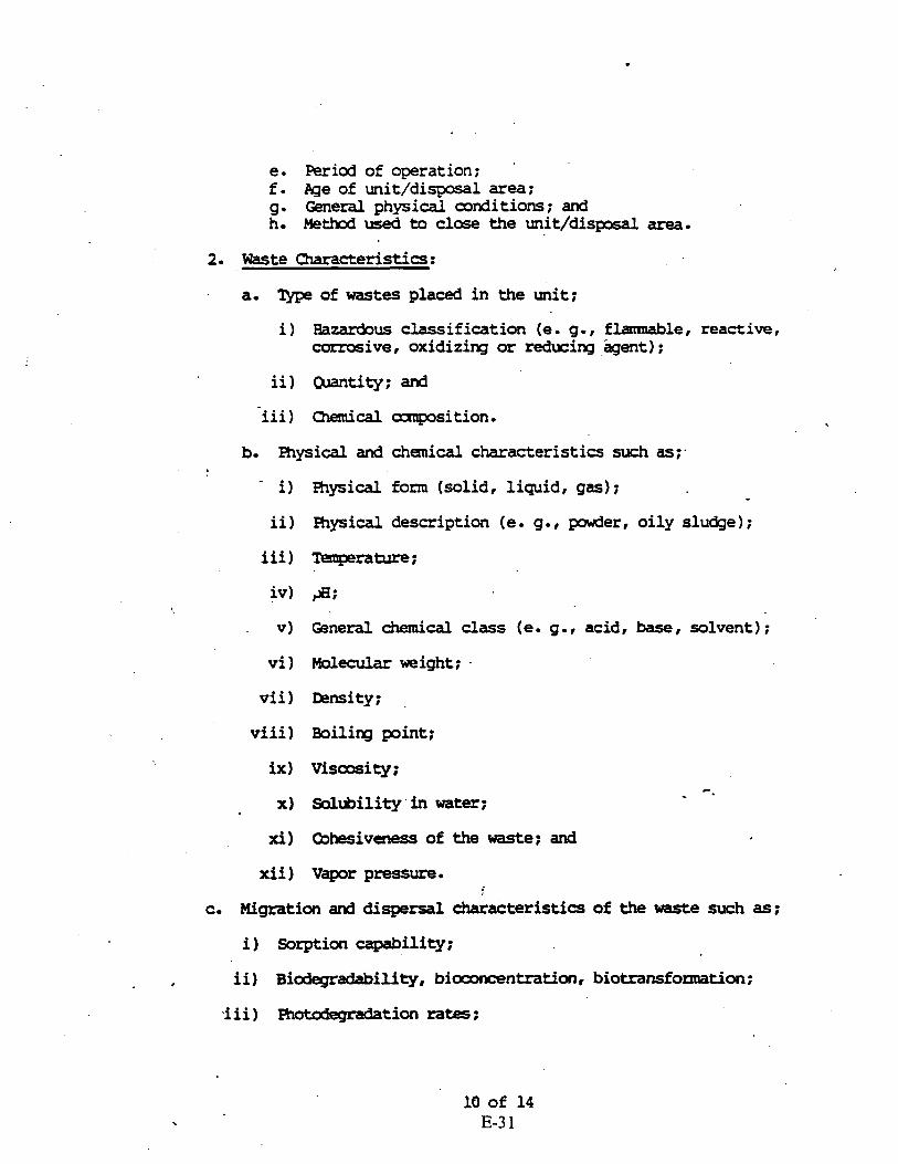
e. Period of operation; f . Pge of unit/disp#al area ; g. General physicdl conditions ; and h. Method used to close the unit/disposdl area.
2. Waste Characteristics:
a. of wastes placed in the unit;
i ) Hazardous classification (e, g. , flamnable, reactive, corrosive, oxidizing or reducing agent) ;
ii) Qmntity; and
iii) Chemical -sition.
b. Physical and chanical characteristics such as;.
i) Physical form (solid, liquid, gas) ;
ii) Fhysical description (e. g., powder, oily sludge);
iii) Temperature;
V) Qneral chemical class (e. g . , acid, base, solvent) ; vi ) Molecular weight;
vii) Density; .
viii) Boilirq point;
ix) Viscosity;
x) Solubility in water;
xi) Cbhesiveness of the waste; and
xii) Vapor pressure.
c. Migration and dispersal characteristics of the waste such as;
i) Sorption capability;
ii) Biodegradability, bioooncentration, biotransfomation;
'iii) m-tion rates;

iv) Hydrolysis rates; and '
transformations.
The Permittee shall document 'the procedures used in making the above determinations.
C wcterization of Releases of Hazardous Constituents
The Pennittee shall collect analytical data on groundwater, soils, surface water, sediment, and subsurface gas contamination in the vicinity of the facility in accordance with the sampling and analysis plan as required above. These data shall be sufficient to define the extent, origin,,direction, and rate of -anent of contamination. mta shall include time and location of sampling, media sampled, concentrations found, conditions during sampling, and the identity of the individuals prfonning the sampling and anaylsis. 7be Permittee shall address the following types'of contamination at the facility:
1. Grourdwater &ntwination :
?he Permittee shall. conduct a groundwater investigation to characterize any plmes of contamination detected at the facility. This investigation shall at a minima provide the following information:
! a. A description of the horizontal and vertical extent of any plme(s) of hazardous constituents originating fran the facility;
b. The horizontal and vertical direction of contamination n-nt ;
c. The velocity of contaminant -nt;
d. The horizontal and vertical concentration profiles of hazardous constituents in the plm(s);
e. An evaluation of factors influencing the plme xnovanent; and
f. An extrapolation of fu- contaminant movaaent.
The Pennittee shall docwnent the procedures used in makirg the above determinations (e. g., well design, w e l l construction, geophysics, modeling, etc. 1 .

2. Soil Contamination
'The Fennittee shall conduct an investigation to characterize the contamination of the soil and rock units above the saturated zone in the vicinity of any contaminant release. The investi- gation may include the following information:
a. A description of the vertical and horizontal extent of contamination ;
b. A description of appropriate contaminant and soil-chemical properties within the contaminant source area and plune. This may include contaminant solubility, speciation, absorption, leachability , excharqe capacity , biodegradability , hydrolysis,
_ photolysis, oxidation and other factors that might affect contaminant migration and transformation;
c. Specific contaminant conkentrations; , . I .
: d.- 'Ihe velocity and direction of contamination movement ; and . .
e. An extrapolation of future contaminant movement . The Fernittee shall doctrment the procedures used in making the above deteiminations . 3. Surface Water and Sediment Ccntamination
Ihe Permittee shall conduct a sukace water investigation to characterize contamination in surface water bodies resulting from releases of hazardous constituents at the facility.
The investigation may include, but not be limited to, the following information:
a. A description of the horizontal and vertical extent of any p l w ( s ) originating from the facility, and the extent of cartamination in underlying sediments;
. b. ake horizontal and vertical direction of contaminant movement;
c. 'Ihe contaminant velocity;
d. An evaluation of the physical, biological and chemical factors influencing contaminant mavenent;
e. Zh extrapolation of future contaminant mvemnt; and
f. A description of the chemistry of the contminated surface waters and sediments. This includes determining the pH, total dissolved solids, specific contaminant concentrations, etc.
4. Air Contaminati.on
The Fermittee shall conduct an investigation to characterize gaseous releases of hazardous constituents into the atmosphere or any structures or buildings. This investigation may provide the following information:
a. A description of the horizontal and verticdl direction and velocity of contaminant matenent;
b.- The rate and amunt of the release ; and
c. Ihe chemical and physical canposition of the contaminants(s1 released, including horizontal and vertical concentration
- profiles.
lhe Permittee shall dcmmnt the procedures used in making the above determinations,
D. Potential Receptors
, The mrmittee shall collect data describi q the h u ~ n populations and envirormental systaas that are susceptible to contaminant exposure from the facility. Chemical analysis of biological samples and/or data on observable effects in ecosystems may also be obtained as appropriate. Ihe following characteristics shall be identified:
1. Current local uses and planned future uses of groundwater:
a. Type of use (e. g . , drinking water source : micipal ar residential, agricultural, daestic/mn-potable, and industrial) ; and
.be IPcation of ground water users, to include withdrawal and discharge wells, within one mile of the impacted area.
Zhe above information should also indicate the aquifer or hydrqeolcgic unit used and/or impacted gar each item.
2. Current local uses and planned future uses of surface waters directly impacted by the facility:
a. &tic and municipal (em g., potable and lawn/gardening watering ) ;
,b. -tianal (e. g. swimning, fishing);
c. Pgricultural; d. Industrial ; and e. Enviromntal (e. g., fish and wildlife propagation).
3 H u n a n use of or access to the facility and adjacent lands, including but not limited to:
a. %creation; b. Hunting; c. Msidential; d. Ccmnercial; and e. &lationship betwen population locations and prevailing wind
direction.
4. A-general description of the biota in surface water bodies on, adjacent to, or affected by the facility.
5. A general description of the ecology within and edjacent to the facility. .
6. A general d-aphic profile of the people who use or have access to the facility and adjacent land, including, but not limited to: age; sex: and sensitive subgroups.
'7. A description of any kmwn or dccmtented endangered or threatened species near the facility.
APPENDIX C
Corrective Measures Study (CMS ) Plan Outline,

CORRECTIVE MEASURE STUDY PLAN OUTLINE . .
SCOPE
The Corrective Measure Study consists of four tasks:
Task VIII: ~dentification and Devalopxnent of the Corrective Measure Alternatives
Task IX:
Task g:
A. Description of Current Situation B. Establishment of Corrective Action Objectives C. Screening of Corrective Measures Technologies D. Identification of the Corrective Measure Alternative: - Evaluation of the Corrective Measure Alternatives
A. ~echnical/Environmental/Human Health/Institutiohal B. Cost Estimate
Justification and Recommendation of the Corrective Measure or Heasures
A. Technical B. Environmental C. Human Health
Reports
A. Progress B. Draft C. Final . D. Public Review and Final Selection of Corrective
Measure

TASK V I I I : IDE-IFTCATTON AND DEVELOPMENT OF THE CORRECTIVE ACTION A L T E R N A T I V E S . .
Based on the results of the RCRA Facility Investigation and consideration of the identified potential corrective measure technologies (Task 11), the Permittee shall identify, screen and develop the alternatives for removal, containment, treatment and/or other remediation of the contamination based on the objectives established for the corrective action.
A. Descri~tion of Current Situation
The Permittee shall submit an update to the infognation describing the current situation at the facility and the known nature and extent of the contamination as documented by the RCRA Facility Investigation Report. The Permittee shall provide an update to information presented in Task I of the RFI to the Agency-regarding previous response activities and in interim measures which have or are being implemented at the facility. The Permittee shall also make a facility-specific statement of the purpose for the response, based on the results of the RCRA Facility Investigation. The statement of purpose should identif! the actual or potential exposure pathways that should be addressed by corrective measures.
B. Establishment of Corrective Action Objectives
The Permittee shall propose for EPA review and approval , facility-specific objectives for the corrective action. These ' objectives-shall be based on public health and environmental criteria, information gathered during the RCRA Facility Investigation, EPA guidance, and the requirements of any applicable Federal statutes. At a minimum, all corrective actions concerning ground water releases from regulated units must be consistent with, and as stringent as, those required under 40 CFR 264.100.
Cb ,,Screenina of Corrective Measure Technoloaies
The Permittee shall review the results of the RCR+ Facility Investigation and reassess the technologies specified in Task 11 and to identify additional technologies which are applicable at the facility. The Respondent shall screen the preliminary corrective measure technologies identified in Task 11 of the-RCR Facility Investigation and,any supplemental technologies to eliminate thoie that may prove infeasible to implement, that re11 on technologies d i k e l y to perfoxm satisfactorily or reliably, or that do not achieve the corrective measure objective within a reasonalbe time period. This screening process lfocuses on eliminating those technologies which have severe limitations for
' a given set of waste and site-specific conditions. The screenin step pray also eliminate technologies based on inherent technolog- limitations.

Site, waste, and technology characteristics which are used to scree inapplicable technologies are described in more detail below:
I. Site Characteristics
Site data should be reviewed to identify conditions that may limit or promote the use of certain technologies. Technologies whose use is cleazly precluded by site characteristics should bl eliminated from iurther consideration;
2. Waste Characteristics
Identification of waste characteristics that limit the effectiveness or feasibility of technologies is an important pa: of the screening process. Technologies clearly limited by thesc waste characteristics should be eliminated from consideration. Waste characteristics particularly affect the feasibility of in-siau methods, direct treatment methods, and land disposal (on/off-site); and
3. Technology Limitations
During the screening process, the level of technology development, performance record, and inherent construction, operation, and maintenance problems should be identified for eac technology considered. Technologies that are unreliable, perf01 poorly, or are not fully demonstrated may be eliminated in the screening process. For example, certain treatment methods have 'been developed to a Point where they can be implemented in the field without extensive technology transfer or development.
D. Identification of the Corrective Measure Alternatives
The Permittee shall develop the Corrective measure alternatives based on the corrective action objectives and analysis of potential corrective measure technologies, as presented in Task I1 of the RCRA Facility investigation and as supplemented
\ following the preparation of the RPI Report. The Respondent shall rely on engineering practice to determine which of the previously identified technologies appear most suitable for the site. Technologies can be combined to form the overall corrective action alternatives. The alternatives developed should represent a workable number of option(s) that each appea to adequately address all site problems and corrective action .objectives. Each alternative may consist of an individual - technology or a combination of techaologies. The Respondent shall document the reasons for excluding technologies, idenrific in Task 11, as supplemented in the development of the alternatives.
TASK IX: EVALUATION OF THE CORRECTIVE MEASURE ALTERNATIVES
The peattee shall describe each corrective measure alternative thi passes through the Initial Screening in Task VIII and evaluate
C - 3 of 11
E-39 .

Each corrective measure alternative and it's components. The evaluation shall be based on technical, environmental, human health and institutional concerns. The Permittee shall also develop cost estimates of each corrective measure.
The Permittee shall provide a description of each corrective measure alternative which includes but is not limited to the folloiring: preliminary process flow sheets; preliminary sizihg and type of construction for buildings and structures; and roug:. quantities of utilities required. The Permittee shall evaluate each alternative in the four following areas:
1. Technical; - The Permittee shall evaluate each corrective measure alternative based on performance, reliability, implementability and safety.
a. The Permittee shall evaluate performance based on the , effectiveness and useful life of the corrective measure:
i) ~f'fectiveness shall be evaluated in terms' of the ability tr perform intended functions, such as containment, diversion, removal, destruction, or treatment. The effectiveness of each corrective measure shall be determined either through design specifications or by performance evaluation. Any specific waste or site characteristics which could 'potentially impede effectiveness ahal1.h considered: The- evaluation should also consider the effectiveness of combinations of technologies; and
ii) Useful life is defined as the length of time the level of desired effectiveness can be maintained. Most corrective measure technologies, with the exception of destruction, deteriorate with time. Often, deterioration can be slowed through proper system operation and maintenance, but the technology eventually may require replacement. Each corrective measure shall be evaluated in tenns of the projected nerrrice lives of its life of the project.
b. The Permittee shall provide information on the .reliability of each corrective measure including their operation and maintenance requirements and their demonstrated reliabiliq
i) Operation and maikenance requirements include the frequency and complexity of necessary operation and maintenance. Technologies requiring frequent or complex operation and maintenance activities should bt regarded as less reliable than technologies requiring little or straightforward operation and maintenance. The availability of labor and materials to meet these requirements shall also be considered; and

ii) Demonstrated pnd expected reliability is a way of measuring the risk and effect of failure. The Respondent should evaluate whether the technologies have been used effectively under analogous conditions whether the combination of technologies have been use together effectively; whether failure of any one technology has an immediate impact on receptors; and whether the corrective measure has the flexibility to deal with uncontrollable changes at the site.
c. The Permittee shall describe the implementability of each corrective measure including the relative ease of installation (constructability) and the tiaie required to achieve a given level of response:
i) Constructability is determined by conditions-both internal and external to the facility conditions and include such items as location of underground . utilities, depth to water table, heterogeneity of subsurface matemials, and location of the facility (i.e., remote location vs. a congested urban area). The Permittee shall evaluate what measures can be takt to facilitate construction under these conditions.
. External factors which affect implementation include the need for special permits or agreements, equipment availability, and the location of suitable off-site treatment or disposal facilities; and
ii) Time has two components that shall be addressed: the time it takes to implement a corrective measure and tl time it takes to actually see beneficial results. Beneficial results are defined as the reduction of contaminants to some acceptable, pre-established leve:
d. The Peanittee shall evaluate each corrective measure alternative with regard to safety. This evaluation shall include threats to the safety of nearby communities and \
environments as well as those to workers during hplementation. Factors to consider are fire, explosion,
. and exposure to hazardous substances. Environmental;
The Pennittee shall p$rfonn an Environmental Assessment- fol each alternative. The Environmental Assessment shall focu: on the facility conditions and pathways of contamination actually addressed by each alternative. The Envisonmental Assessment for each alternative will include, at a minimum, an evaluation of: the short- and long-term beneficia1,and adverse effects of the response alternative; andy adverse
. b effects on environmentally sensitive areas; and an analysi: of measures to mitigate adverse effects.

3 . Human Health; and . The Permittee shall assess each alternative in terms of tf extent to which it mitigates short-and long-term potential exposure to any residual contamination and protects human health both during and after implementation the corrective measure. The assessment will describe the concentrations and characteristics of the contaminants on-site, potential exposure routes, and potentially affected population. ' ~ a c alternative will be evaluated to determine the level of exposure to contaminants and the reduction over time. For management of mitigation measures, the relative reduction impact will be detenained by comparing residual levels of each alternative with existing criteria, standards, or guidelines acceptable to EPA. -
4. Institutional.
The Permittee shall assess relevant institutional needs for eac- alternative. Specifically, the effects of Federal, state and local environmental and public health standards, regulations, guidance, advisories, ordinances, or cornunity relations on the design, operation, and timing of each alternative.
B. Cost Estimate
.The Permittee shall develop an estimate of the cost of each corrective measure alternative (and for each phase or segment of
' the alternative). The cost estimate shall include both capital and operation and maintenance costs.
1. Capital costs consist of direct (construction) and indirect (nonconstruction and overhead) costs.
a. Direct capital costs include:
t i) Construction costs: Coszs of materials, labor ( including fringe benefits and worker ?s campensation), and equipment required to install the corrective measure.
ii) Equipment costs: Costs of treatment, containment, disposal and/or service equipment necessary to implement the. action; these materials remain uriti: the corrective action is complete;
iii) Land and site-development costs: Expenses associated with purchase of land and development of existing property; and
iv) Buildings and sersrices costs: Costs of process ar nonprocess buildings, utility connections, purchased services, and disposal costs.

b. Indirect capital costs include : 4 .
i) Engineering expenses: Costs of administration, design, construction supervision, drafting, and testing of corrective measure alternatives;
ii) Legal fees and license or pemit costs: Administrative and technical costs necessary to obtain licenses and permits for installation ,and operation;
iii) Startup and shakedown costs: Costs incurred during corrective measure startup; and
iv) Contingency allowances: Funds to cover costs resulting from unforeseen cir&mstancesT such as adverse weather conditions, strikes, and inadequate facility characterization.
2. Operation and maintenance costs are post~construction costs ! necessary to ensure continued effectiveness of a corrective
measure. The Permittee shall consider the following operation and maintenance cost components:
a. Operating labor costs : Wages, salaries, training, overhead, and fringe benefits associated with the labo. needed for post-construction operations;
I b. Maintenance materials and labor costs: Costs for labor, parts, and other resources required for routine maintenance of facilities and equipment;
c. Auxiliary materials and energy: Costs of such items a: chemicals and electricity for treatment plant operations, water and sewer service, and fuel;
d. Purchased services: Sampling costs, laboratory fees, and professional fees for which the need can be predicted;
' e Disposal and treatment costs: Costs of transporting, treating, and disposing of waste materials, such as treatment plant residues, generated during opesations;
f . Admfnistrative costs: Costs associated with administration of corrective measure operation and maintenance not included under other categories;
g. Insurance, taxes, and licensing costs:. Costs of such items as liability and sudden accident insurance; real estate taxes on purchased land or right-of-way;
. % licensing fees for certain technologies; and permit renewal and reporting costs;

h. Maintenance reserve and contingency funds: Annual payments into escrow funds to cover (1) costs of anticipated replacement or rebuilding of equipment anc (2) any large unanticipated operation and maintenance costs; and
i. Other costs: Items that do not fit any of the above categories.
TASK X: JUSTIFICATION AND RECOXMENDATION OF THE CORRECTIVE URE OR MEASURES
The Permittee shall justify and recommend a corrective measure alternative using technical, human health, and environmental criteria. This recommendation shall include summary tables which allow the alternative or alternatives to be understood eas~ly. Tradeoffs among health risks, environmental effects, and other pertinent factors shall be highlighted. The U.S. EPA will seleat thr corrective measure alternative or alternatives to be implemented based on the results of Task IX and X. At a minimum, the following criteiia will be used to justify the final corrective measure or measures.
A. Technical
1. Performance - corrective measure or measures which are most effective at performing their intended functions and maintaining the performance over extended periods of time
t will be given preference;
Reliabilitv - corrective measure or measures which do require frequent or activities and that facility conditions
complex operation and maintenance have proved effective under waste similar to those anticipated will
not
and be
given pkeference; -
3. Im~lementabilitv - corrective measure or measures which can be-constructed h d operating t o reduce levels of contamination to attain or exceed applicable standards in .the shortest period of time will be-preferred; and
4 . Safety - corrective measure or measures which pose the least threat to the safety of nearby residents and environments be well as workers during implementation will be preferred.-
B. Human Health
The corrective measure or measures must comply with existing U.S EPA criteria, standards, or guidelines for the protection of human health. Correctivemeasures which provide the minimum level of exposure to contaminants and the maximum reduction in expdsbre with time are preferred.
C. Environmental . .
The corrective measure or measures posing the least adverse impact (or greatest improvement) over the shortest period of timc on the environment will be favored.
TASK XI: REPORTS
The Permittee shall prepare a Corrective Measure Study Report presenting the results of Task VIII through X and recommending a corrective measure alternative. Copies of the preliminary report shall be provided by the Permittee to EPA for review and EPA for approval.
The Per'mittee shall at a minimum provide the EPA with signed,, monthly progress reports containing:
1? A description and estimate of the percentage of the US completed;
2. - Summaries of findings;
3 . Summaries of all changes made in the CMS during the reportinc . . period;
Summaries of & contacts with representative. of the commumity, public interest groups or State government the reporting period;
local , durin~
5. Summaries of problems or potential problems encountered . during the reporting period;
Actions being taken to rectify problems;
7. Changes in the personnel involved with the CMS during reporting period;
8. 'Projected'work for the next reporting period; and
9. Copies of daily reports, inspection reports, laboratory/ monitoring data, etc.
B. Draft
The Report shall at a minimum include:
1. A description of the facility;
a. Site topotgraphic map .& preliminary layouts.

-2. A summary of the corrective measure or measures and rationale for selection;
a. Description of the corrective measure or measures and rationale for selection;
b. Perfonnance expectations;
c. Preliminary design criteria and rationale;
d. General operation and maintenance requirements; and
e. Long-term monitoring requirements.
3 . A summary of the RCRA Facility Investigation and impact on - the selected corrective measure or measures;
a. Field studies (ground-water, surface water, soil, air); and
b. Laboratory studies (bench scale, pick scale).
4. Design and Implementation Precautions;
a. Special technical problems ;
b. Additional engineering data required;
c . Pennfts and. regulatory requirements ;
d. Access, easements, right-of-way;
e. Health and safety requirements; and
f . Conmuunity relations activities . 5. Cost Estimates and Schedules;
t
a. Capitol cost estimate;
b. Operation and maintenance cost estimate; and.
c. Project schedule (design, construction, operation).
Copies of the draft shall bk provided by the Permittee to EPA .
' C. Final
The Permittee shall finalize the Corrective Measure Study Report incorporating comments received from EPA on the Draft Corrective Measure Study Report. The report shall become final upon EPA approval.

D. Public Review and Final Selection of Corrective Measures . -
Upon receipt of the Final Corrective Measure Study Report, EPA shall announce its availability to the public for review and comment. At the end of the comment period, EPA shall review th. comments and then inform the Permittee of its final decision as to the approved Corrective Measures to be implemented.

Appendix D
F a c i l i t y Submission' Summary
A summary of the planned report ing requirements contained in the EPA RCRA Permit i s presented below:
F a c i l i t y Submission Requirements Due Date I
RFI Plan f o r SWM'U(s) i d e n t i f i e d a t time of 1 120 days a f t e r
I of RFI Plan* D r a f t RFI Report 90 days a f t e r -
penni t issuance i n Condition 1 I . A . 1. RFI Progress Reports
e f f e c t i v e date of penni t Quarterly, beginning 90
Condition I1 .C.4. ( days from implementation
Condition II.C.5. F ina l RFI Repor-t Condi t i o a II.C.5.
In te r im yeasures Not i f i ca t ion
- RFI completion Thir ty (30) days a f t e r r ece ip t of E P A comments on Draft RFI Report 30 days pr ior to imple-
Condition I1 .D.2. I mentation . In te r im Measures Progress Reports Condition I1 . D . 5 .
I n t e r i m Measur* Report ' Condition II.D.6.
Correct ive Measures Study Plan Condition II.E.2. Imminent Hazard Report
Semi-annually, beginning 180 days from fmplementation of Interim measures * Within 90 days of completion of Interim Measures Within 90 days of n o t i f i c a t i o n by EPA Oral ly within 24 hours
Conditions 1I.P.l.- and ~I .P.z . N o t i f i c a t i o n of t h e discovery of addi t ional SWMJs
Condi t i o n I1 .B.2. ( n o t i f i c a t i o n BPA, Progress Reports I Quarter ly . beginning 90
w r i t t i n within 15 days Within 15 days
n o t a l ready i d e n t i f i e d i n Condition 1I.A.l . Condition I I . B . 1 RPA Plan (SIJMUs discovered a f t e r permit issuance)
cond i t ion II.B.~. I days from-implementation
of discovery
Within 60 days of
I of RFA Plan* RFA Report . - I Within 60 days of RFA
Condit ion II.C.2. 1 the RPA Report Under II.B.4. .
The above r e p o r t s must be signed and c e r t i f i e d i n accordance with 40 CPR 5270.11.
Condition I I ~ B . ~ . RPI Plan (SWHUs discovered a f t e r permit issuance)
* This a.pplfes t o RFI/WA/~nterirn Measures execution t h a t requires f o r more thap 180 days.
Compl e t i on Withia.45 days of submitting

APPENDIX F
Pinellas Plant Air Emissions Operating Permit

Department of
Environmental Protection
Lawcon Chiles Governor
Southwest District 3804 Coconut Palm Drive
Tampa. Florida 336 19
NOTICE OF PERMIT AMENDMENT
CERTIFIED MAIL
PERMITTEES:
OWNER-OPERATOR
Mr. Charles E. Rainey, Chairman Pinellas County Industry Council 2200 Tall Pines Drive, Suite 100 Largo, FL 34641
Mr. Richard E. Glass Area Manager U.S. Department of Energy P.O. Box 2900 Largo, FL 34649
Mr. Edward E. Mayer Dir. Environmental Management Lockheed Martin Specialty Components
P.O. Box 2908 Largo, FL 34649
Dear Mr. Rainey:
Re: Letters dated 07/10/95, 08/07/95, 09/08/95, and- 09/12/95 DEP Permit No. A052-233355
Enclosed is amended Permit No. A052-233355 for the operation of a specialty components manufacturing facility, issued pursuant to Section 403.087, Florida Statutes.
A person whose substantial interests are affected by this amended permit may petition for an administrative proceeding (hearing) in accordance with Section 120.57, Florida Statutes. The petition must contain the information set forth below and must be filed (received) in the Office of General Counsel of the Department at 2600 Blair Stone Road, Tallahassee, Florida 32399-2400, within 14 days of receipt of this amended permit. Petitioner shall mail a copy of the petition to the applicant at the address indicated above at the time of filing. Failure to file a petitionewithin this time period shall constitute a waiver of any right.such . . person may have to request an administrative determination (hearing) under section 120.57, Florida Statutes.
Page 1 of 4

Pinellas County Industry Council &
U.S. Department of Energy &
Lockheed Martin Specialty Components
Page 2 of 4
The Petition shall contajn the following. information;
(a) The name, address, and telephone number of each petitioner, the applicant's name and address, the Department Permit File Number and the county in which the project is proposed;
(b) A statement of how and when each petitioner received notice of the Department's action or proposed action;
(c) A statement of how each petitioner's substantial interests are affected by the Department's action or proposed action;
(d) A statement of the material facts disputed by Petitioner, if any;
(e) A statement of facts which petitioner contends warrant reversal or modification of the Department's action or
(f) A statement of which rules or statutes petitioner contends require reversal or modification of the Department's action or proposed action; and
(g) A' statement of the relief sought by petitioner, stating precisely the action petitioner wants the Department to take with respect to the Department's action or proposed action.
If a petition is filed, the administrative hearing process is designed to formulate agency action. Accordingly, the Department's final action may be different from the position taken by it in this amended permit. Persons whose substantial interests will be affected by any decision of the Department with regard to the application have the right to petition to become a party to the proceeding. The petition must conform to the requirements specified above and be filed (received) within 14 days of receipt of this notice in the Office of General Counsel at the above address of the Department. Failure to petition within the allowed time frame constitutes a waiver of any right such person has to request a hearing under Section 120.57, F.S., and to participate as a party to this proceeding. Any subsequent intervention will only be at the approval of the presiding officer upon motion filed pursuant to Rule 28-5.207, F.A.C.
This amended permit is final and effective on the date filed with the Clerk of the Department unless a petition is filed in accordance with the above paragraphs or unless'a request for extension of' time in which to file a petition is filed within the time specified for filing a petition and conforms to Rule 17-

Pinellas County Industry Council &
U.S. Department of Energy &
Lockheed Martin specialty Components
Page 3 of 4
103.070, F.A.C. . Upon timely filing of a petition or a request for-an extension of time this amended permit will not be effective until further Order of the Department.
When the Order (Amended Permit) is final, any party to the Order has the right to seek judicial review of the Order pursuant to Section 120.68, Florida Statutes, by the filing of a Notice of Appeal pursuant to Rule 9.110, Florida Rules of Appellate procedure, with the Clerk of the Department in the Office of General Counsel, 2600 Blair Stone Road, Tallahassee, Florida 32399-2400; and by filing a copy of the Notice of Appeal accompanied by the applicable filing fees with the appropriate District Court of Appeal. The Notice of Appeal must be filed within 30 days from the date the Final Order is filed with the Clerk of the Department.
This letter must be attached to and becomes a part of permit A052-233355. If you have any questions, please call Mr. Jim McDonald of my staff at (813)744-6100 extension 106.
STATE OF FLORIDA DEPARTMENT OF ENVIRONMENTAL PROTECTION
. ? .+,-.& p+L:,JLI James L. McDonald Air Permitting Engineer
cc: PCDEM David A. Buff, P.E. Richard E. Glass Edward E. Mayer

Pinellas County ~ndustry Council &
U.S. Department of Energy &
Lockheed Martin Specialty Components
Page 4 of 4
CERTIFICATE OF SERVICE
This is to certify that this NOTICE OF AMENDED PERMIT and all mailed by certified mail before the close of business '
on C b 3 9 2 to the listed persons. .
Clerk Stamp
FILING AND ACKNOWLEDGEMENT FILED, on this date, pursuant to Section 120.52 (11) , Florida Statutes, with the designated-Department Clerk, receipt of which is hereby acknowledge.
. .
Department of
Environmental Protection
Lawton Chiles Governor
Sourhwesr Disrricr 3804 Coconuc Palm Dr ive
Tampa. Florida 336 19
PERMITTEES:
OWNER-OPERATOR
Pinellas County.Industry Council 2200 Tall Pines Drive, Suite 100 Largo, FL 34641
CO-OPERATOR U.S. Department of Energy P.O. Box 2900 Largo, F1 34649
CO-OPERATOR Lockheed Martin Specialty Components
P.O. Box '2908 Largo, FL 34649
Permit No.: A052-233355 County: Pinellas Originally Issued: 04/24/94 1st Amended Date: 06/22/95 2nd Amended Date: 10/03/95 Expiration Date: 01/25/99 ~rojdct: Specialty Components Manufacturing Facility
This amended permit is issued under the provisions of Chapter 403, Florida Statutes, and Florida Administrative Code Rules 62- 209 through 62-297 & 62-4. The above named permittee is hereby authorized to perform the work or operate the facility shown on
'the application and approved 'drawing(s), plans, and other docpments, attached hereto or on file with the department and made a part hereof and specifically described as follows:
For the operation of a specialty components manufacturing facility engaged in the design, development and production of specialized electronic and mechanical equipment. The usages of these specialty components include applications in support of the nation's defense program and other commercialized products. During the manufacturing of the components, specific chemical constituents and volatile organic compound/organic chemicals are emitted from buildings/areas as listed below and in Table 1 (pages 26 & 27) attached to the application dated October 8 & 13, 1992. The buildings/areas are further described in Section 3 and Appendix 1, as amended in a June 23, 1993 response, a February 7, 1995 response, an ~ p r i l 20 , 1995 r e s p o n s e , and a September 12 , 1995 re sponse .
Page 1 of 11
Printed on recyckd popcr
F-7

PERMITTEES: PERMIT No.: A052-233355 Pinellas County Industry council PR,OJECT: Specialty Components
& . Manufacturing Facility U.S. Department of Energy
& Lockheed Martin Specialty Components
BUILDING'100 - Area Nos.
103 - Test Equipment construction (w/paint spray booth) 104 - Machine Shop 105 - Ceramics Manufacture 106 - Tool and Grinding Room 108 - Tube Exhaust 109 - Manufacturing Area 110 - Optoelectronics Production 111 - Magnetics Transfer Presses/Encapsulation 112 - Generator Assemble, FE Assembly and Blast Room 113 - Solder Training Area (wldegreaser) 115 - Audio Visual Photo Laboratory 116 - Capacitor Assemble and Potting 117 - Metalizing and Plating 122* - Particulate Contamination Control Laboratory 123 - Calibration/Vacuum and Maintenance 138 - Vapor Blast and Resin Casting 139 - Vapor Blast and Resin Casting 142 - Assembly 143A 7 Clean Room (w/Scrubber fl) 143B - Chemical Cleaning (Scrubber #2) 145 - Ceramics (N/A, DEEMED INSIGNIFICANT SOURCE) 146 - Hydrogen Furnace 148* - Environmental, Health and Safety Offices 150 - Assembly and Test (N/A, DEEMED INSIGNIFICANT SOURCE) 154 - Transducer, Film Development, and Model Shop Areas 155* - Chemistry Laboratory 157* - Gas Analysis Laboratory 159*.- Advanced Analysis Laboratory 160* - Polymers and Chemistry Laboratory 161* - Surface Analysis 162* - Metallurgy Laboratory 163* - Materials and Processes Laboratory 164* - Process Support Laboratory 168 - Oscillators 175 - Quartz Devices (w/cleaning console) 176* - Environmental Radiological Laboratory (Moved to Area 350) 179 - Field Test Systems Area 180 - Capacitor Areas 181 - Surface Mount Facility . _
182 - Tube Development 183 - Generator (w/paint spray booth)
Page 2 of 11

PERMITTEES: PEWIT NO.: A052-233355 Pinellas County Industry Council . P~OJECT: specialty Components
& ~anufacturing Facility U.S. Department of Energy
& Lockheed Martin Specialty Components
1 8 5 * - Polymers-Foam Encapsulation 192 - Ceramic Areas 193 - Magnetics and FT Generators 194 - Ceramics Processing 1 9 5 - Lithium Battery (w/Sc.rWer f 3 for dry room) 1 9 6 * - Component Product Evaluation Laboratory 307 - Power Sources Development Dry Room 313 - Special Components Production 3 1 6 - LAMB-Lithium Ambient Batteries Test and Development Areas 3 3 0 - Glassing Area 3 3 1 - E.B. Weld 333 - Glassing, Test and Inspection 3 3 6 - Glassing, Test and Inspection 348 - Optoelectronics and Pre-Pack Magnetics 349 - Power Sources Development Dry Room 3 5 0 * - Standard Lab,.Instrumentation Lab, Ambient Battery, QA Areas,
Environmental Radiological Laboratory (w/Scrubber # 4 ) 3 5 1 - Calibration Maintenance/Resonator Clock, Maintenance Vacuum
(w/Scrubber f 5 ) 353 - Iron Disulfide (w/Scrubber #6 and Scrubber #7)
, Buildins 2 0 0 - General VOC/OC and HAP usage
Buildins 4 0 0 - General VOC/OC and HAP usage
Buildins 5 0 0 - Utility Building (w/Scrubber f 8 )
Buildins 7 0 0 - Maintenance Shop (w/paint spray booth & degreaser)
~uiidins 8 0 0 - General VOC/OC and HAP usage 4
Buildins 1 0 4 0 * - Chemical Storage, Handling, Treatment and Shipping Buildins 1 2 0 0 - General VOC/OC and HAP Usage
- Shooting Range (N/A, DEEMED INSIGNIFICANT SOURCE) Buildins 1 4 0 0 - General VOC/OC and HAP Usage Open Area 9999 - Thermal Treatment of RCRA Waste
(N/A, DEEMED INSIGNIFICANT SOURCE) . .
The most recent updated equipment list should be used to accurately determine where the above equipment and processes are located.
5 .
Page 3 of 11
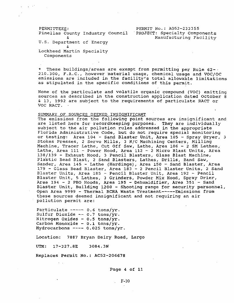
PERMITTEES: PERMIT NO.: A052-233355 Pinellas County Industry Council 'PROJECT: Specialty Components
& Manufacturing Facility U.S. Department of Energy
& Lockheed Martin Specialty Components
* These buildings/areas are exempt from permitting per Rule 62-j 210.300, F.A.C., however material usage, chemical usage and VOC/OC emissions are included- in the facility's total allowable limitations as stipulated in the specific conditions of this permit.
None of the particulate and volatile organic compound (VOC) emitting sources as described in the construction application dated October 8 & 13, 1992 are subject to the requirements of particulate RACT or VOC RACT. -
SUMMARY OF SOURCES DEEMED INSIGNIFICANT The emissions from the following point sources are insignificant and are listed here for recordkeeping purposes. They are individually subject to the air pollution rules addressed in the appropriate Florida Administrative Code, but do not require special monitoring or testing: Area 104 - Sand Blaster Unit, Area 105 - Spray Dryer, 3 Stokes Presses, 2 Servo Mills, 3 N/C Machining Centers, Milling Machine, Tracer Lathe, Cut Off Saw, Lathe, Area 106 - 2 SM Lathes, Lathe, Area 111 - Power Hood, Area 112 - 2 Micro Blast Units, Area 138/139 - Exhaust Hood, 3 Pencil Blasters, Glass Blast Machine, Pla'stic Bead Blast, 2 Sand Blasters, Lathes, Drills, Band Saw, Sander, Area 145 - Lathe (Hardinge), Area 150 - Sand Blaster, Area 179 - Glass Bead Blaster, Area 183 - 2 Pencil Blaster Units, 2 Sand Blaster Units, Area 185 - Pencil Blaster Unit, Area 192 - Pencil Blaster Unit, 5 Lathes, 3 Grinders, Powder Mix Hood, Spray Drier, Area 194 - 2 PBO Hoods, Area 195 - Dehumidifier, Area 351 - Sand Blaster Unit, Building 1200 - Shooting range for security personnel, Open Area 9999 - Thermal RCRA Waste Treatment----- Emissions from these sources deemed insignificant and not requiring an air pollution permit are:
Particulate ----- 0.6 tons/yr. Sulfur Dioxide -- 0.7 tons/yr. Nitrogen Oxides - 0.5 tons/yr. Carbon Monoxide - 0.1 tons/yr. Hydrocarbons ---- 0.025 tons/yr. Location: 7887 Bryan Dairy Road, Largo
UTM: 17-327.8E 3084.3N
Replaces Permit No.: AC52-206678
Page 4 of 11

PERMITTEES: PEWIT No.: A052-233355 Pinellas County Industry council. PROJECT: specialty Components
& ~anufacturing Facility U.S. Department of Energy
&
Lockheed Martin Specialty Components
ARMS Facility ID: 0220
ARMS Emission Unit ID: 001 - 002 - 003 - 004 - 005 - 006 - 007 - 008 - 009 -
General VOC1s Area 143A, Acid Scrubber #l Area 350, Acid Scrubber # 4 Area 351, Acid Scrubber #5 Area 353, Acid Scrubber #6 Area 353., Acid Scrubber #7 Building 500, Acid Scrubber #8 Area 143B, Acid Scrubber #2 Area 195, Acid Scrubber #3
NOTE: Please -reference the Permit No., Facility ID, and Emission Unit ID in all correspondence, test report submittals, applications, etc.
SPECIFIC CONDITIONS:
OPERATING LIMfTATIONS
1. A part of this permit is the attached 15 General Conditions. [Rule 62-4.160, F.A.C. ]
2. All applicable rules of the Department along with design discharge and operating limitations specified in the application shall be adhered to. The permit holders may also need to comply
' with county, municipal, federal, or other state regulations. [Rule 62-$. 070(7), F.A.C. ]
3. Operation of this facility shall not exceed 8760 hrs./yr. [Permit AC52-2066781
4. No person shall cause, suffer, allow or permit the discharge of air pollutants which cause or contribute to an objectionable odor. [Rule 62-296.320, F.A.C. and Pinellas County Code, section 58-178)
5 . Pursuant to Rule 62-296.320, F.A.C., this facility shall comply with the following:
A. All equipment, pipes, hoses, lids, fittings, etc., shall be operated /maintained in such a manner as to minimize leaks, fugitive emissions and spills of VOC/OC materials.
< $
Page 5 of 11

PERMITTEES: PERMIT NO.: A052-233355 Pinellas County Industry Council. PROJECT: Specialty Components
& Manufacturing Facility U.S. Department of Energy
& Lockheed Martin Specialty Components
B. All solvents from solvent washings (equipment clean-up) shall, be directed .into containers that prevent evaporation into the atmosphere.. vapor at ion from the alcohol wipes, during production, is specifically excluded from this requirement, however it shall be accounted for within.the plant-wide VOC/Oc emissions total.
UTILIZATION AND EMISSION LIMITS
6. The total maximum VOC/OC usage rate for this facility is 49.8 , tons per any 12 consecutive month period as 'stated in Appendix 3 of the construction application dated October 8 & 13, 1992. [Permit AC52-2066781 _
7 . Pursuant to the construction application dated October 8 & 13, 1992, the maximum volatile.organic compounds (VOC) and organic chemicals (OC) emissions from this facility shall not exceed 19.52 tons of VOC and 21.58 tons of OC per any 12 consecutive month period. [Permit AC52-2066781
8. The maximum allowable emission for each chemical constituent identified as a Florida Air Toxic, VOC, OC, or other regulated pollutant from this facility shall not exceed the corresponding lbs./day and lbs./yr. value as listed in Appendix No. 6 which was originally submitted with the construction application dated October 8 & 13, 1992 and amended in an October 3, 1995 letter. Appendix 6 may be amended in accordance with Specific Condition No. 10.
s [Permit AC52-2066781
9. 'The maximum usage rate for each chemical constituent from this facility shall not exceed the corresponding lbs./day and lbs./yr. value as listed in the amended Appendix No. 6 (10/02/95) in an October 3, 1995 letter and made an attachment to this amended permit. [Permit AC52-2066781
10. At the request of the permittee(s) dated April 11, 1995, May 25, 1995, and the May 24, 1995 amended format of Appendix 6, usages and emissions of new chemicals or increases in usages of other chemicals may be implemented as follows:
A. Provided VOC/OC and HAP total usages and emissions'do not contravene other permit conditions or Department rules, new chemicals currently not used (with 0.0 usages in Appendix 6)
' .
Page 6 of 11

PERMITTEES: PERMIT No.: A052-233355 Pinellas County Industry council . PROJECT: specialty Components
& ~anufacturing Facility U.S. Department of Energy
& Lockheed Martin Specialty Components
may be used upon submittal of a revised Appendix 6 to the Pinellas County Department of Environmental Management (PCDEM) and this office. The new emission shall not be above the Appendix 6 Impact Based Maximum Emission Rates (lb/hr and lb/yr). Immediate tracking of usage and emissions and its related equipment shall be followed pursuant to Specific Condition Nos. 16 and 17 upon said notification.
B. Provided-VOC/OC and HAP total usages and emissions do not contravene other permit conditions or Department rules, currently permitted chemical usages and emissions may be increased upon submittal of a revised Appendix 6 to the PCDEM and this-office. The revised Appendix 6'with the requested changes shall demonstrate compliance with Florida's Air Toxic Strategy version 3.0.
11. Visible emissions from each of the 8 acid scrubbers shall not be equal to or greater than 20% opacity in accordance with Rule 62- 296.310, F.A.C.
12. pursuant to Rule 62-296.310, F.A.C., as an indicator the unconfined particulate emissions from the paint spray booths are being adequately controlled, there shall be no visible emissions. If visible emissions are observed, it will not be a violation in an of itself, but an indicator that additional controls devices and/or measures may be necessary.
COMPLIANCE TESTING
13. Each of the 8 acid scrubbers shall be tested for visible emissions annually within 60 days prior to the date of March 10. The test reports shall be submitted to this office and the Pinellas County Department of Environmental Management (PCDEM) within 45 days of testing. [Rules 62-297.340(1)(c) and 62-297.570(2), F.A.C.]
14. Compliance with the visible emission limitation of Specific Condition No. 11 shall be determined using EPA Method 9 contained in 40 CFR 60, Appendix A (July 1, 1991) and adopted by reference in Rule 62-297.401, F.A.C. Each test shall be at least 30 minutes in duration and conducted when the sources controlled by the scrubber being tested are in normal operation. The minimum requirements for
Page 7 of 11
F-13

PERMITTEES: PERMIT No.: A052-233355 Pinellas County Industry Counci 1 PROJECT: specialty Components
& . . Manufacturing Facility
U.S. Department of Energy &
Lockheed Martin Specialty Components
stationary point source emissions test procedures and reporting shall be in accordance with 40 CFR 60, Appendix A and Rule 62- 297.570(3), F.A.C.
15. The permittee(s) shall notify in writing the PCDEM and this office at least 15 days prior to the date on which each formal compliance test is to begin of the date, time, and place of each such test, and the test contact person who will be responsible for coordinating and having such test conducted. [Rule 62- 297.340(1) (i) , F.A.c.]
RECORDKEEPING REOUIREMENTS
16. Pursuant -to Rule 62-4.070(3), F.A.C., monthly logs and Chemical Usage Budgets (CMTS, Chemical Usage Issuance Logs), as submitted in the October 13 and December 17, 1993 responses, shall be kept for this facility to document compliance with the limitations of Specific Condition Nos. 6, 7, 8, and 9 and retained on file for at least 2 years. Monthly logs shall be completed by the end of the following month. At a minimum, for each chemical constituent listed in Appendix No. 6, the log shall include the following:
Usase Information
A. At the end of each month, the total of each of chemical constituents used in lbs./month with a 12 consecutive month total, except those non-VOC/OC constituents which do not exceed 25% of the No Threat Level (NTL) value for that chemical.
B. 'At the end of each month, the total of all VOC/OC chemical constituents used with a 12 consecutive month total.
C. At the end of each calendar,year, the total for each of the chemical constituents used, including those non-VOC/OC constituents which were excluded in A. above.
Emission Information
D. At the end of each month, the total emissions of each chemical constituent used in lbs./month with a 12 consecutive month total, except those non-VOC/OC constituents which do not exceed 25% of the No Threat Level (NTL) value for that chemical.
< ,
Page 8 of 11
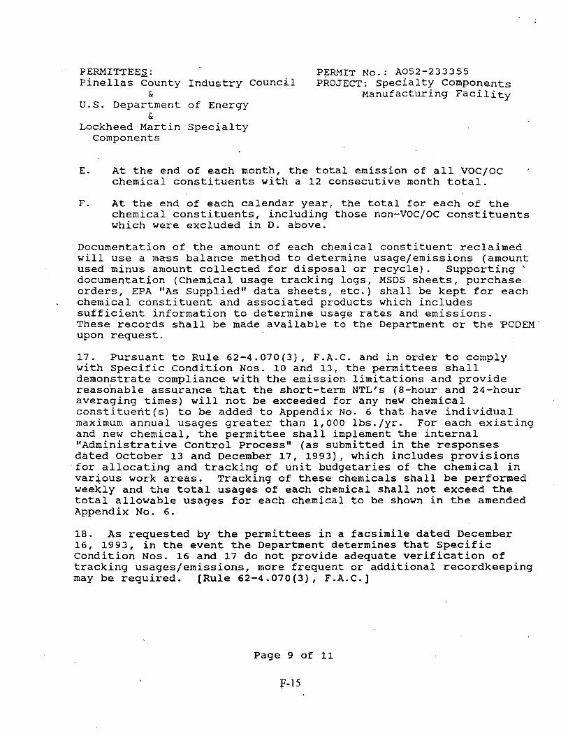
PERMITTEES: PERMIT NO.: A052-233355 Pinellas County Industry council PROJECT: specialty Components
& ~anufacturing Facility U.S. Department of Energy
& Lockheed Martin Specialty Components
E. At the end of each month, the total emission of all VOC/Oc ' chemical constituents with a 12 consecutive month total.
F. At the end of each calendar year, the total for each of the chemical constituents, i.ncluding those non-VOC/OC constituents which were excluded in D. above.
Documentation of the amount of each chemical constituent reclaimed will use a mass balance method to determine usage/emissions (amount used minus amount collected for disposal or ,recycle). Supporting ' documentation (Chemical usage tracking logs, MSDS sheets, purchase orders, EPA "As Suppliedtt data sheets, etc.) shall be kept for each
. chemical constituent and associated products which includes sufficient information to determine usage rates and emissions. These records shall be made availab1.e to the Department or the 'PCDEM upon request.
17. Pursuant to Rule 62-4.070 (3) , F.A.C. and in order to comply with Specific Condition Nos. 10 and 13, the permittees shall demonstrate compliance with the emission limitations and provide reasohable assurance that the short-term NTLfs (8-hour and 24-hour averaging times) will not be exceeded for any new chemical constituent(s) to be added to Appendix No. 6 that have individual maximum annual usages greater than 1,000 lbs./yr. For each existing and new chemical, the permittee shall implement the internal "Administrative Control Processtt (as submitted in the responses dated October 13 and December 17, 1993), which includes provisions for allocating and tracking of unit budgetaries of the chemical in varjous work areas. Tracking of these chemicals shall be performed weekly and the total usages of each chemical shall not exceed the total allowable usages for each chemical to be shown in the amended Appendix No. 6.
18. As requested by the permittees in a facsimile dated December 16, 1993, in the event the Department determines that Specific Condition Nos. 16 and 17 do not provide adequate verification of tracking usages/emissions, more frequent or additional recordkeeping may be required. [Rule 62-4.070(3), F.A.C. ]
Page 9 of 11
F-15

PERMITTEES: PERMIT No.: A052-233355 Pinellas County Industry counciL PROJECT: Specialty Components
& Manufacturing Facility U.S. Department of Energy
& Lockheed Martin Specialty Components
19. Pursuant to Pinellas County Code, section 58-128, the permittees shall comply with the "Operation and Maintenance Planw (O&M) Plan dated. August 30, 1995 for all 8 scrubbers. The O&M Plan documentation logs shall be maintained at the facility for a minimum of two years. At a minimum the O&M Plan shall include:
A. The operating parameters of the pollution control devices.
B. Time table for routine maintenance of the pollution control devices as specified by the manufacturer.
C. Time table of routine weekly, bi-weekly, or monthly observations of the pollution control device.
D. A list of the type and quantity of required spare parts for the pollution control devices which are stored on the premises.
E. A record log which will indicate, at a minimum:
1. When maintenance was performed. , 2. What maintenance was performed. 3. Who performed the maintenance.
20. Submit to the PCDEM and this office for this facility, each calendar year and on or before March 1, an annual operating report ~ which,includes the Emissions Report Section [DEP Form 62-210.900(5)] for the preceding calendar year pursuant to Rule 62-210.370(3), F.A.C.
OTHER REOUIREMENTS
21. At the requests of the permittee dated May 13, 1993 and April 11, 1995 and based on the modeling results submitted in the June 23 and October 13, 1993 responses, existing equipment may be moved as follows:
A. Equipment not associated with compounds requiring vent-specific ISCST modeling, may be relocated without further modeling.
B. Equipment associated with compounds, requiring vent-specific ISCST modeling, may be moved after appropriate modeling verifies that the associated NTL values are not exceeded.
Page 10 of 11

PERMITTEES: PEWIT No.: A052-233355 Pinellas County Industry council PROJECT: specialty Components
& ~anufacturing Facility U.S. Department of Energy
& Lockheed Martin Specialty
Components
C. Written notification of equipment relocations to areas or buildings included as part of this permit shall be made within 30 days to the PCDEM and this office. The written notification shall include a copy of modeling performed, if required.
22. Replace in kind of equipment may be installed at the facility as long as the associated chemical usages and emissions shall be limited to allow continued compliance with the total maximum material usage and emission limitations specified elsewhere in this, permit. [Rule 62-4.070(3), F.A.C. ]
23. An application to renew this operating permit shall be submitted to the Southwest District Office of the Department and one copy to the PCDEM at least 60 days prior to the expiration date of this permit pursuant to Rule 62-4.090(1), F.A.C. The renewal operating permit application shall include the 2 most recent calendar months of the monthly and weekly logs required by Specific Condition Nos. 16 and 17. One copy of the application (w/attachments) should also be submitted to the PCDEM, pursuant to Rule 6,2-209, F.A.C. Note, the requirements of Rules 62- 210.300(2)(b) and 62-213.420, F.A.C. may supersede this requirement.
I
STATE OF FLORIDA DEPARTMENT OF ENVIRONMENTAL PROTECTION
g-J#z&- , - W. C. Thomas, P.E. District ~ i r Program Administrator
Page 11 of 11
F-17

ATTACHMENT - GENERAL CONDITIONS: . -
1. The terms, conditions, requirements, limitations, and restrictions set forth in this permit are "permit Conditions" and are binding and enforceable pursuant to Sections 403.141, 4 03.727, or 403.859 through 403.861, Florida Statutes. The permittee is placed on notice that the Department will review this. permit periodically and may initiate enforcement action for any violation of these conditions.
2 . This permit is valid only for the specific processes and , operations applied for and indicated in the approved drawings or exhibits. Any uhauthorized deviation from the approved drawings, exhibits, specifications, or conditions of this permit may constitute grounds for revocation and enforcement action by the Department.
3. As provided in Subsections 403.087(6) and 403.722(5), F.S., the issuance of this permit does not convey any vested rights or any exclusive privileges. Neither does it authorize any injury to, public or private property or any invasion of personal rights, nor any infringement of federal, state or local laws or regulations. This permit is not a waiver of or approval of any other Department permit that may be required for other aspects of the total project which are not addressed in the permit.
4. This permit conveys no title to land or water, does not constitute State recognition or acknowledgement of title, and does not constitute authority for the use of submerged lands unless herein provided and the necessary title or leasehold interests have been obtained from the State. Only the Trustees of the Internal Improvement Trust Fund may express State opinion as to title.
5. This permit does not relieve the permittee from liability for harm or injury to human health or welfare, animal, or plant life, or property caused by the construction or operation of this permitted source, or from penalties therefore; nor does it allow the permittee to cause pollution in contravention of Florida Statutes and Department rules, unless specifically authorized by an order from the Department.
<
6. The permittee shall properly operate and maintain the facility and systems of treatment and control (ahd related appurtenances 1 that are installed or used by the permittee to achieve compliance with the conditions of this permit, as required by Department rules. This provision includes the operation of backup or auxiliary facilities or similar systems when necessary to achieve compliance with the conditions of the permit and when required by Department rules.
7. The permittee, by accepting this permit, specifically agrees to allow authorized Department personnel, upon presentation of credentials or other documents as may be required by law and at a reasonable time, access to the premises, where the permitted activity is located or conducted to:
GENERAL CONDITIONS-REG Page 1 of 3 09/93

GENEFSL CONDITIONS : . -
a. Have access to and copy any records that must be kept under the conditions of the permit;
b. Inspect the facility, equipment, practices, or operations regulated or required under this permit; and
c. Sample or monitor any substances or parameters at any location reasonably necessary to assure compliance with this permit or Department rules.
Reasonable time may depend on the nature of the concern being investigated.
8. If, for any reason, the permittee does not comply with or will be unable to comply with any condition or limitation specified in this permit, the permittee shall immediately provide the Department with the following information:
a. a description of and cause of non-compliance; and
b. the period of noncompliance, including dates and times; or, if not corrected, the anticipated time the non-compliance is expected to continue, and steps being taken to reduce, eliminate, and prevent recurrence of the non-compliance.
The permittee shall be responsible for any and all damages which may result and may be subject to enforcement action by the Department for penalties or for revocation of this permit.
9. In accepting this permit, the permittee understands and agrees that all records, notes, monitoring data and other information relating to the construction or operation of this permitted source which are submitted to the Department may be used by the Department as evidence in any enforcement case involving the permitted source arising under the Florida Statutes or Department rules, except where such use is prescribes by Sections 403 -73 and 403 -111, F.S. Such evidence shall only be used to the extent it is consistent with the Florida Rules of Civil Procedure and appropriate evidentiary rules.
10. The permittee agrees to comply with changes in Department rules and Florida Statutes after a reasonable time for compliance, provided, however, the permittee does not waive any other rights granted by Florida Statutes or Department rules.
11. This permit is transferable only upon Department approval in accordance with Florida Administrative Code Rules 62-4.120 and 62 -730.300, F.A.C., as applicable. The permittee shall be liable for any non-compliance of the permitted activity until the transfer is approved by the Department.
GCNERAL CONDITIONS-REG Page 2 of 3
F-20

GENERAL CONDITIONS:
12. This permit or a copy thereof shall be kept at the work site of the permitted activity.
13. This permit also constitutes:
( ) Determination of Best Available Control Technology ( BACT )
( ) Determination of' Prevention of Significant Deterioration (PSD)
( 1 Compliance with New Source Performance Standards (NSPS) .
14. The permittee shall comply with the following:
a. Upon request, the permittee shall furnish all records and plans required under Department rules. During enforcement actions, the retention period for all records will be extended automatically unless otherwise stipulated by the Department.
b. The permittee shall hold at the facility or other location designated by this permit records of all monitoring information (including all calibration and maintenance records and all original strip chart recordings for continuous monitoring instrumentation) required by the permit, copies of all reports required by this permit, and records of all data used to complete the application for this permit. These materials shall be retained at least three years from the date of the sample, measurement, report, or application unless otherwise specified by Department rule.
c. Records of monitoring information shall include:
- the date, exact place, and time of sampling or measurements;
- the person responsible for performing the sampling or measurements;
L - the dates analyses were performed; - the person responsible for performing the analyses; - the analytical techniques or methods used; and - the results of such analyses.
15. When requested by the Department, the permittee shall within a reasonable time furnish any information required by law which is needed to determine compliance with the permit. If the permittee becomes aware that relevant facts were not submitted or were incorrect in the permit application or in any report to the Department, such facts or information shall be corrected promptly.
Page 3 of 3
~F-2 1

1 C 1 1 I I ( I I I I I 1 f I I I I APPblDU( 6- MAXIMUM ANNUAL AN0 HOVRLY M M I C A L USAGES. MAXIMUM ANNUAL AND HOURLY EMISSIONS. AM) IMPACT ANALYSIS RESULTS USING ISCST2 MOOEL FOR DOE PINELLAS PUNT RlCVlSEO (4117198)
-WA WA 8.17 WA 4.U WA
0 . w WA 1.44 WA
0 . o w WA 802.2 WA
NIA WA 1 . 8 WA
802.2 WA 0.498 NIA
1.81 NIA WA WA
289 M 17.1 WA a 1 WA 1.H WA
0.Y1 WA 2.80 M S.41 M 1.30 M 1 . n M 18.8 M 1.44 WA 1.18 WA
0.U9 WA 2.80 WA
WA WA L49 WA S.48 NIA 110 MI* 1.12 NIA
WA M WA WA
0.01M NIA o.m WA 0341 M
WA M 1.M M Y.4 M
0.549 M 0.217 M 0.111 WA
l.S.04 WA 0.111 M 1.11 M
n 4 n WA 42.8 WA 11.5 NIA 1.15 NIA 1.03 M 21.1 WA a.15 WA
0.130 NIA 1.03 NIA
o o l n ~ l r 2.24 M
0.101 M 2.24 M
0 . m WA NIA WA WA WA
o.ni WA a n 4 NIA
0.OlM WA 2 4 . WA
l U . l WA 3.54 M
0.0184 NIA l .X-01 M
1.W WA
ti111 136)
l t 4 . m 4 . m
Y.W 3.004
11.4ZO 705.8
11.420 WA
11.414 18.814 n1.o 1.154
11.101 NIA
11.42 111.1 2.-
NIA 1.454
4S.8 170.645 45.601
tor.on 1.m 2 . m
45.0% 20.214 270.1 2.29 150.2
i t 4 . m 210.3 30.20 811.0
NIA
2S U NTL
L NIA NIA WA WA WA WA WA WA WA NIA WA WA WA NIA WA WA WA NIA WA WA WA WA NIA MIA WA M WA NIA NIA NIA NIA NIA NIA WA NIA NIA WA WA NIA WA M WA M WA WA WA WA NIA M NIA WA WA WA MI* NJA NIA WA M M NIA M )(M
NIA WA M WA M MfA NIA MIA NIA

APPP(MX 0- MAXIMUM ANNUAL AN0 HOURLY CHEMICAL USAGES. MAXIMUM ANNUAL AN0 HOURLY EMISSIONS. AN0 IMPACT ANALYSIS RESULTS USING lSCST2 MOOEL FOR DOE PINELLAS PLANT RMSED (4/l1/96)
h d Baud Mulmm M l d m m PefWled Enltc)on R8lcr (a)
hw4 Man .ay Mar Duty Man H w t y (W) (WJ (MY) (bk)
0 0 0 0 0 0 0 0
1.12 WA NIA NU
0.0)(2 NU 148.7 NIA 14.9 NIA 7m rur,
145.8 NM 248.4 NIA
17.2 - NIA 0.0241 M o . a i NIA
2.08 M 3.03 Nm
174.1 NIA 1 . 9 NIA 2.17 WA 81.9 NM 10.1 NM 1.12 WA 2.60 WA 1.30 NIA
449.1 M 6 . 1 NIA
o . m NIA 1 8 NIA 3.U NIA
2715 NIA 1.95 NIA
107.) NIA 1.44 , NIA 4 NIA 84.3 NIA 18.9 NIA
301.2 NIA 21.9 NIA 1 N*, 31.3 NIA
WA ' PUA 0 . m NIA 9.17 NIA 1.73 NIA
NIA NIA o m 5 NIA 0.130 NlA
56 5 NIA 181 NIA
0 OM0 NIA 1.30 NIA
0.510 NIA 2 . 0 NIA 64.3 NIA
NIA NIA 29.2 NIA
236.8 NIA 12.7 NIA
0.111 NIA 3.47 NIA
0.01M NIA 38.4 NIA 11.5 NIA 20.1 NIA 11.0 NlA
1W.2 NIA 71.0 NIA
11.2 NIA 17.2 NIA
0 . W NIA 0 ?ZZ NIA 0.Y) NIA 4.33 NIA
17.1s NIA 41.681 NIA 1126 NIA
308.171 NIA 30.07 NIA 1IRI8 NIA
m.* M 518.020 NM 15.741 NIA 51.W NIA 1,292 NIA 1.71 NIA
6 . m NIA 363.41 NIA 1W.877 NIA
4.- NIA 128.W NIA 2 i .n r NIA 3.1% NIA 1 WA 2.703 NU
bY.121 NIA 11.116 NU 11.410 NIA w.992 Nm 7.980 Nm
#rm NIA 4 NIA
432.519 NM 3 . m WA
19.8?4 NIA 1D.811 NIA 35.142 WA
5,710,113 NIA 45 .m NIA 2.10) Nm
571,011 NIA NIA r NIA
4S.6 NIA o.on NIA 3.834 NIA
11.410 NIA 132.2 MIA 0 NIA
121.648 NIA 3.715 WA 43.97 NIA 2.703 NlA 1.1M NIA 8.007 NIA
131.MO NIA NIA NIA
80.873 NIA 492.591 NIA 114.101 NJA 11.410 M 7.208 NIA Y.W NIA
79.098 NIA tot.on NIA Y.211 NIA
t 7 i . m lur,
312.371 NIA 147.027 NIA 312.05 N* 35.743 NIA 1 . m NIA 1 . m NIA 473.9 N* 9.011 NIA
srsr;cr*a -
22zz-m. mr*a - 2.-am MopoACnk dn*ll)(- - DIOO(AWC - spoprt- m- Ellwlok rmOXrmm ACnATE.2 E lWl XETATE w- is*(mrtmar-.vM.ptna w- ww--H.Dmc*r .qt- w- -
4- b- b -myKXX--'='
@m@mn*AE*hr-* ETHVMM QLKXX UONOMlM ETHER --I-) -- ard&ne- -n 1.1-m


APPENDIX 6- MAXIMUM ANNUAL AN0 HOURLY CHEMICAL USAGES. MAXIMUM ANNUAL AND HOURLY EMISSIONS. AND IMPACT ANALYSIS RESULTS USING ISCSTZ MOOEL FOR DOE PINELLAS P U N T REVISED (41171961
-n.ud M.* -. - - -- - - - . . . -. . -. . US- (a) W ~ d m Rnr (b Ma- PwlWlcd Entrdon U r n (8) Roddad Mldmm m S brpRn7 (C)
ANI W I W Wry nou?# l00UNTL Z U N T 25 U N I L *m*l ~ a ; . .ldl Me;. mlty Ma1 no& WIN.* L- swum 8md.tn kwi (Mr) (Mr) (arrl @Fur) (WJ 1-1 (MY) ( M r J &War ZCnar Arrml bHov 2CNw
42.6 NIA 710 NIA 2.52 o to o 019 2 .4~4) w o tr1r.o 10.0 o l b 0.05 0.004 tkm(lylw(am mummwmN Tam mm-#rr*
0.0108 NIA 22.U NIA 0.0 00 0 0 0 0 15 0.36 0.578 NIA 1301 NIA 0.0 00 0 0 0.0 W 19.2 2 0 NIA 171.W NIA 227.0 8.7 I ? 022 3770.0 8M 0 m . 0 n.2 w 171.¶03 NIA 0 0 00 0 0 0 0 3170 W.8 3.=*02
NIA NIA NIA NIA NIA NIA NIA NIA NIA NIA NIA WA NIA NIA NIA WA NIA NIA
NIA NIA M NIA NIA NIA NIA NIA NIA WA NIA NIA W NIA NIA NIA WA NIA
2.57 NIA
11.420 171.3 30.04
MIA 871.0
NIA m . 3 1 . m 86.08 420.5 30.04 2.10) 1211.3
17.130 1 r43
1 .m 1.113 1.142
NIA 1.502
57.101 182.7 7s.m 1.502
NIA NIA N M
730.9 NIA NIA . 33.04
121.8 1 . m 30.04
NIA 534.642
s.710 2.10) 0.440 1 . m 0.120 71.m 75.0) 730.0
For Organlc Compounds (VOC) 0 0 0 0 00 0 0 0 0 00 0 0 0 0 00 00 0 0 00 00 0 0 00 0 0 0 0 00 0 0 0 0 0 0 00 0 0 00 0 0 0 0 00 00 0 0 00 00 0 0 00 00 0 0 00
0 0 O 0 00
00 0 0 0 0 00 0 0 0 0 0 0 0 0 0 0 0 0 00 0 0 00 00 00 00 Ofl 0 0 00 00 0 0 00 0 0 0 0 00 0 0 0 0 00 0 0 0 0 0 0 00 0 0 00 00 ' 00 00 00 0 0 0 0 00 0 0 00 0 0 0 0 00 0 0 0 0 0 0 00 0 0 00 0 0 e 0 00 00 0 0 0 0 oe 0 0 0 0 00 0 0 0 0 00 0 0 00 00 0 0 0 0 00 0 0
6948 4 267 2 53 4
1000 38E-80 7 7E.OI 00 00 0 0 00 00 0 0 00 00 0 0 00 00 C 0 00 00 P 0 0 0 00 G J 0 0 00 3 L
- Scr Notr (r) 0 0 0.0 0 0 0 0 0 0 0 0 0 0 00 0 0 0 0 00 0 0 0 0 0 0 0 0 0 0 00 00 00 00 0 0 0 0 00 00 0 0 .OO~ 0 0 ' 00 0 0 0 0 00 00 00 00 00 00 00 1
6 7 S 6E42
0 0 00 0 0 0 0 0 0 0 0 0 0
1 0.0 WA 1 0.0 NIA 1 0.0 1.11 1 0.0 NIA . 1 0.0 0.0144 1 0.0 NIA 1 0.0 0.40 1 0.0 NIA 1 0.0 0.117 1 0.0 0.722 I 0.0 0.0118 I 0.0 0 . m I 0.0 0.0144 1 0.0 1.01 1 0.0 0. lM I 0.0 NIA I 0.0 NIA I 0.0 o . m I 0.0 NIA ' ' I 0.0 NIA 1 0.0 NIA I 0.0 o.7n 1 0.0 NIA 1 0.0 NIA I 0.0 0.0361 1 0.0 0.722 I 0.0 NIA 1 0.0 NIA I 0.0 NIA 1 0.0 0.11 1 0.0 NIA I 0.0 WA I 0.0 0.0159 1 0.0 0 .ow I 0.0 0.722 I 0.0 0.0144 1 0.0 WA
8.80 257.0 9.8501 4.84
I 0.b 1.01 I 0.0 2.K.03 I 0.0 0.886 I 0.0 NIA I 0.0 0.036 1 I 0.0 0.0361 I 0.0 0.11
NIA NIA W W W NM NIA NIA NIA M NIA NIA WA NIA NIA NIA NIA M NIA NM NIA NIA NIA NIA NIA NIA NIA WA NIA NIA WA NIA NIA NIA NIA NIA NIA NIA NIA NM NIA NI* NIA NIA NIA NIA
NIA NIA NIA NIA NIA NIA NIA NIA NIA NIA NIA MIA NI* NIA NIA NIA NIA NIA NIA MI* NIA NIA NIA NIA MIA WA NIA NIA NIA NIA Nm N/A NIA NIA WA WA MI* NIA NIA NIA NIA NIA NIA NIA NIA NIA
- - 1 mi -
B.M*W 3.K.00 I.8E-01 0.0 0.0 - 0.0 0.0 0.0 0.0 all -

I I I I I I I I I I I I I i I I I I
APPENDM 6- MAXIMUM ANNUL AND W R L Y CHEMICAL USAGES. MAXIMUM ANNUAL AN0 HWRLY EMISSIONS. AM) IMPACT ANALYSIS RESULTS USING lSCST2 MODEL FOR DOE PlNELlAS PLANT REVISED (4117lOb)
hmed b r a d Mldmm Ma- Wgw (a)
AM1 W W IMP WI (w) w w i
0 0 0 0 0 0
I%rM Rue (b) 100 Y NTL 25 Y NTL 0 I*)
0.3111 NIA . 0,0144 NIA
M m n m P m e a Ems* R a l o (a) &nnl Mar M u 01* Man Hout#
1 m w (WVI ( M J 0 0 0 0 0 0 0 0 0 0 0 0 0 0 0 0 0 0 0 0 0 0 0 0 0 0 0 0 0.0 0 0 00 0 0 0 0 0 0 0 0 0 0 0 0 0 0 0 0 0 0 0 0 0 0 0 0 0 0 0 0 ' 0 0 0 0 0 0 0 0 0 0 0 0 0 0 0 0 0 0 0 0 0 0 0 0 0 0 0 0 0 0 0 0 0.0 5 0 0.0 0.0 0.0 0 0 0.0 0.0 0.0 0 0 0 0 0.0 0.0 0 0 ' 0 0 0 0 1 0 0 $00 0 0 0.0 0.0 0 0 0 0 0.0 0.0 00 0 0 0.0 0.0 0 0 0.0 0.0 0.0 0 0 0.0
4S.1 18.3¶0 1278 4 (€41 0.0 0.0 0 0 0.0 0 0 0.0 0 0 0.0 0.0 0 0 0 0 0.0
688 2 8 53E41 8.6E42 0 0 0 0 0 0 0 0 0.0 0 0 0 0 0 0 0.0 0 0 0 0 0 0 0 0 0 0 0 0 0 0 0 0 0 0 0 0 0 0 0 0 0 0 0 0 0 0
. 0.0 0 0 0 0 0 0 0 0 0 0 0 0 0 0 0 0 0 0 0 0 0 0 0 0 0 0 0 0 0 0 0 0 0 0 0 0 0 0 0 0 0 0 0 0 0 0 0 0 0 0 0 0 0 0 0 0 do 0 0 0 0 0 0 0 0 0 0 0 0 0 0 0 0 0 0 0 0 0 0 'Q 0 0 0 0 0 0 0 'a 0 0 0 0 0
1405 11091 2619 13E41 lODO I IE-01 1 1E.02 96E.03
0 0 no 0 0 0 0 0 0 0 0 0 0 0 0 0 0 DO 0 0 0 0 36 0 l4 0 016 3 5E.01 0 0 0 0 ' 0 0 0 0 0 0 0 0 0 0 00..
16E42 9 1 - 0 4 20€,04 2 5E.05 )YE43 2OE44 4OE.35 SOE.06
0 0 4 0 0 0 0 0 0 0 0 0 0 0 0 0 0 0 0 0 9 0 0 0 0 0 4 0 0 0 0 0 00 0 0 0 0 0 0 0 0 D 0 0 0 0 0
t4E41 5 4E-05 I 1E.05 1 lE46 0 0 0 0 0 0 0 0 0 0 0 0 0 0 0 0 0 0 0 0 0 0 0 0 0 0 0 0 0 0 0 0 0 0 0 0 0 0 0 0 0 0 0 0 0 0 0 0 0 0 0 0 0 0 0 0 0 0 e 0 0 0 0 0 0 0 0 0 0 0 0 0 0 0 0 0 0 0 0 0 0 0 0 0 U O 0 0
WA WA WA NIA NIA NIA
0.361 NIA NIA WA NIA M WA WA
0.09lS M M M
0 M 7.2E.03 NIA
0 NIA 0381 WA
1 2 E m WA NIA WA
0.0301 NIA 0.0301 WA
N a M WA W
511.2 M 0 . o m M 0 . ~ 1 NIA
HM M 0.)128 W
0.0144 NIA M NIA 7 . x m M
o s 1 W 0.144 M 0.11 PYA 2.90 M
0.101 NIA 14.7 WA
0.11 NIA NIA W
0.0722 W 7 . X 4 3 M
WA NIA WA WA
0 . 1 lur,
0.%1 WA 0.0282 NIA 714.8 NIA
1009.4 NIA 1 . n NIA
o . m M 0.0181 Nm 0.939 WA 0.381 NIA
NIA Nm 3.47 NIA
O.Jo1 NIA WA NIA
0 . 0 m WA 0144 NIA
NIA NIA WA NIA WA NIA
2.17 NIA 0.0375 NIA
NIA WA 31.3 NIA
0 .11 M WA HM
0 .11 NIA o . o m NIA
NIA NIA 0.0144 NIA
43.8 NIA OO%t NIA
20.551 NIA .8.8€43 NIA
NIA NIA 150.0.) NIA
NIA HM 0 . m WA
1 NIA 1n . r t u ~
11.130 NIA 1.802 M 15.02 N14 1S.0.) NIA 7 0 . ) NIA 15.02 M
NIA NIA 1.54 WA
75.08 NIA M M NIA M
t.CSl.276 NIA 0.474 NIA 0.474 NM o a t M
1.rn.278 NM m.04 M
WA NIA 15.02 NIA 750.0.) M m . 4 NIA
11.410 NIA L157 NIA m . 3 M
30,487 NIA 750.0.) NIA
NtA NIA 5.71 WA
15.0) IY* NIA MIA NIA NIA
525.0 WA 51.101 M 58.57 M
114.m NIA 2.099.510 MA
4 . NIA 1 .m ru* 0 . 1 1 NM 1 .W NIA
456.308 NIA NIA W
7.200 NIA 830.1 NIA
4 1E.00 WA nao NIA 360.4 WA 4#8 MIA
N* N* WA NIA
17.130 WA 76.01 NI*
NIA NIA 45.881 . NIA 7500.) M
NIA NIA 750.0.) NIA 150.2 NIA
NIA NIA Jo.04 Nm
91.00) NIA 7508 tg,,
6em-e- 7 r --- h) Dot
4 z 3 w . m
100 2 5
t w o 50
Moo 5 2
4MO 50
50 10
2 606o
5

APPENDIX b MAXIMUM ANNUAL AN0 HOURLY CHEMICAL USAGES. MAXIMUM ANNUAL AND HOURLY EMISSIONS. AND IMPACT ANALYSIS RESULTS USING lSCST2 MODEL FOR DOE PINELLAS P U N T REVISED (4/17/96)
h d 8.4 M8&lUn M a r h m U u g c r ( a J
knrl we* D.Er L 25% NTL (arr) IWI
473.9 NIA
Ma- P m e d blr im Rner (a] AJVUI Ma1 + Max. 01111 Mas nod,
I W J 1-1 ( W W l I-) 24 7 0.95 375 0 024 0.0 0 0 0 0 0 0 - NIA NIA NIA NIA
0.0224 WA NIA NIA
811.6 NIA NIA NIA
0.F92 NIA o.7n NIA
NIA NIA 0.0361 NIA
NIA NIA NIA NIA
0.01s2 WA 7.N.01 NIA
NIA NIA 0.700 IUA
0.0144 NIA NIA NIA
0.0491 NIA 2 s - WA
I(M m 8.74 NIA
Nu NIA 0.354 NIA 0.144 WA 0 . m NIA
18.2 NIA 2.01 NIA
3.lE9) NIA 7.65 m
0 .m1 NIA 7.lE.01 NIA o.m NIA o.om NIA 0.181 WA o.m WA
NIA NIA 0.0361 NIA 0 . 1 I NIA
16.9 NIA 50.9 NIA
0.0144 NIA 0 . 4 s NIA
1 NIA NIA WA
0.657 WA l.KQ3 M 1.7E.01 NIA
@ . $ a NIA 0.540 WA 0 . m NIA 0 .03 m
7.lE.01 NIA 12.7 NIA 3.75 NIA 2.11 m
WA NIA 0.0361 WA 0 NM
0.0312 WA NIA NIA NIA MIA NIA M NIA NIA NIA NIA HM NIA 7.2E.03 NIA
NIA NIA 7.lEQ3 NIA
0.144 NIA 0.0144 WA
12.6 NIA
48% NIA NIA NIA
171.301 WA NIA NIA
1 n . 1 NIA 4.502 NIA 171.1 WA 0.440 NIA 0.217 WA
1 . NIA 25.70 NIA 2.15$ NIA
4.4E44 NIA 142.8 NIA 30.04 WA 171.3 NIA 101.1 NIA 1.11 NIA
NIA NIA 11.172 NIA 0.114 WA 7 9 NIA 4 NIA 1.502 NIA
39348 NIA 4 NIA 8.78 NIA
15.S19 NIA 129.2 WA 15.02 NIA 1.502 NIA
$7.101 NIA 11.410 NIA 3.551 NIA
571.011 WA 71.09 WA m.1 WA
34142 NIA 10$.877 NIA
171 1 NIA -1 1 NIA
36.144 NIA 2M.)W WA
1 . 7 NIA 8 1 1 . N* 766 WA
8.448 NIA m . 2 NIA 7 8 NIA 9.311 Nm 2.855 NIA
3.412 WA 1.m N* 4 . m WA
11.410 NIA 75.09 NIA 1.652 WA 89.Q NIA
0.0131 MIA NIA NIA
0 . m - WA NIA Nm
OJ14 NIA WA M
15.02 M NIA M
15.01 NIA m . 4 NIA M.04 WA S.710 NIA
- - o4aMern pmcn pm(k-- pdadnle PAM m-s cod tu mch w * W . s panocoamn

FOR DOE PINELUS PLANT
Redad Madmm kpMI Olpmr7 Ic) NDTtre* Lcrr(( ipgml') gawm shM4rm Arm*
bnnr ZCMW ~ r m * ~ n a r ZCWU
Pmlldon Rue (b) NTL 25% NIL
m tMr) WA WA
o.OW1 WA 0.0361 WA o. f f l1 WA o.m WA
O a n l WA 0.361 WA 0 . W WA 0.40 NIA 0.166 WA
WA WA 0.0166 WA
64E43 Nm . 0.440 WA
7.K43 WA 1.143 WA
O.%l WA 0.217 n*
0.0462 W 0 . m WA M M NIA M
0.166 Nm Nm WA
0.m1 NM 0.024) WA
6 WA 0.as Nm 0 . m luA
1.66 M WA WA
O.Ql8 WA s.n WA
0.Xl WA m . 6 . WA
WA WA 0.722 WA
0.- WA 3.8643 )ur
O01W WA NIA WA
0.339 NIA 1 lE4l WA
0.144 NIA TIE43 WA
om1 W 0361 N*
WA WA 0274 H* om WA
26EQ3 WA O.OY1 Nm 0.484 WA 1 WA 811.8 WA
WA NIA 1101.6 WA m . 4 WA
WA MIA 2.OS43 WA
141 WA 7 . M WA
0 1 WA 0.2V WA
1 1 4 3 WA 0.t81 WA
WA WA WA WA
WA WA WA NIA WA WA WA WA NIA WA NIA WA WA WA WA WA WA WA '
M WA WA WA Nm Nm WA WA Nm WA M WA MIA WA WA NIA NIA WA WA N* NIA NIA NIA NIA NIA N* NIA WA WA WA WA WA WA N* WA NIA WA WA NIA WA WA NIA WA WA WA NIA NI* WA NIA
Ma- Parmtcd Wcwm R z , Anul M u dtv Mar On85
-%k-=%- Wrlo b-
o o o o o o 0 0 0 0 0 0 0 0 0 0 0 0 0 0 0 0 0 0 0 0 0 0 0 0 0 0 0 0 0 0 0 0 0 0 0 0 0 0 0 0 0 0 0 0 0 0 0 0 0 0 0 0 0 0 0 0 0 0 0 0 0 0 0 0 0 0
6 5E44 2 5E45 5OE.06 0 0 0 0 0 0 0 0 0 0 0 0 0 0 0 0 0 0 ' 0 0
, o o 0 0
0 0 0 0 0 0 0 0 0 0 0 0 0 0 0 0 0 0 0 0 0 0 0 0 0 0 0 0 0 0 0 0 0 0 0 0 0 0 0 0 0 0 0 0 0 0 0 0 0 0 0 0 0 0 0 0 0 0 0 0 0 0 0 0 0 0 0 0 0 0 0 0 0 0 0 0 0 0 0 0 0 0 0 0 0 0 0 0 0 0 0 0 0 0 0 0 0 0 0 0 0 0 0 0 0 0 0 0 0 0 0 0 0 0 0 0 0 0 0 0 0 0 0 0 0 0 0 0 0 0 0 0 0 0 0 0 0 0 0 0 6 0 0 0 0 0 0 0 0 0 0 0 0 0 3 0 0 0 0 0 0 0 0 0 6 0 0 0 0 0 0 0 0 0 0 0 0 0 0 C 0 0 0 0 0 0
130 88E.01 16E 01 ? 5 O(0 . 0019 0 0 0 0 0 0 0 0 0 0 0 0
XKKY)O 769 23 15) 85 18000 69 13 0 8 5 0 118 46E43 9 1E 04 WOO W 01 6 91
0 0 0 0 0 0 0 0 e 0 0 0 0 0 0 0 0 0 0 0 0 0 0 0 0 0 0 0 0 0 0 0 0 0 0 0 0 0 0 0 0 0 0 0 0 0 0 0 0 0 0 0 0 0 0 0 0 0
5800 0 -- '' a 4 6 113 1 193 TPY
- - HAP prr-w 7. prrrdlorarrobcmr* Y v Y - m w - m m o o h n r m Y
'
m- mm- ma- w-* mwmom- dmmn-mrrlrr(lor .
1.502 43.55 751
17t 3 NIA
705 6 0.02 300.4 0.051 410.5 150.9 285.1 $10.1 733.9 6.41 1.77
1.008 573.888 171.m
162.7 2.303.765 1.8'29.1V5
NIA $ . I
18.4~2 1r.m 750.) 4ao.I 171.3 375.)
WA NIA
TOTAL OF OCNOC: 41.s TPY

AWENDlX &- MAXIMUM ANNUAL AN0 HOURLY CHEMICAL USAGES. MAXIMUM ANNUAL AND HOURLY EMISSIONS. AND IMPACT ANALYSIS RESULTS USING lSCST2 MOM1 REVISED (U171W)
kOId B 8 S d ed8dmm UUWS (a) EHSSIOII RBI* (b) Mlllf~~I! P m c d I ? W S V ~ ~ R 8 l o (8)
knrl ww ~ l l ~ a # i y -TWWNTL 25WNTL 100WNTL 25lbNTL #mu81 M I ~ a r . DUV MII WQY CMak 'M FOEsCeI- (by
0 I M r I A~ue~nour aneous o a s a C R R i 3 , eases MxT lCA00~ 43.8 18.8 3.33 0.42 - 1.81 0.451 3.755 939 8 8 0 3 0068 OE-03 llderb 0.0 0.0 0.0 0.0 2.17 0.542 571.0 142 753 0 0 0 0 0 0 0 0
0.0118 0.722 0.144
3.Q-03 NIA
o .om NIA
0.0722 0.0144 0.0111
7.- 7.W.03 0.0850 0.0181
NIA 0.144
0 . m 0.181
NIA 0.181 O .m 0.307 0.181 0.002 0.181. 0.00) 0.00) 0.005
NIA NIA
0 . m 0 . m
NIA 0.181 0.00) 0.181 0 . m 0.181 0 . m 0.018 0.181 0.111 0.051 0.181 0.011 0.013 0.001 0.001 0.181 0 . m 0.00) 0.090 00% 0 181 0 181 0 1 1 0 081
NIA 0.0% 0 027 o m 0.007 0.001 0.011 0.001 0.00) 0 . m 0.181 0.0% 0 001 om 0.016
WA 0.018 O . m 0 . m 0.002 0.001 0.018 0.005
NIA 0.036 0002 0.181 0.181
im.5 1.502 99.12 108.1 0.310 0.310 1.501 0.150 75.09 750 9 m . 4 1.502 1.502 3.004 525 8
NIA m 4 228.4 114.2 57.07 7.51 1.14
0.0474 75 0) 24.03 1 . m m . 4 7.51
0.091 150.2 2,859 150.2 30.04 37.55 18.52 16.S2 135.2 37.55 513.8 m . 4 lA02 1 .w 1.502
0.029 315.451 42.826
375.451 7.509
14215 282 375.451
3.755 375.451 42 826 18.771 11.264
NIA NIA
0.033 6.007
NIA 375.451
7137.641 371 451
o m 375 451 181.725 37 545
375 451 375 451 1 1 126 375 451 24 780 27 032 o m o m
375 451 0 OM
18 773 187 725 75 090
315 451 375 451 750 #)I 131 408
NIA 75 090 57 101 28 551 14 267 1877 0 286 0012
18 771 8 001
37) 431 75 0#) 1 877 0 023
37 545 113 764 37 545 7 m 8 % 4 130 4 130
33 791 8 %
128 478 75 090 3755
375 451 315 451
. FOR W E PINELUS PUNT
RmaM M l k m kpra~ (c) N o M L M O l p Y SaUm Morl4mll knnl
b n w 24.- M u I b H w 2 C W
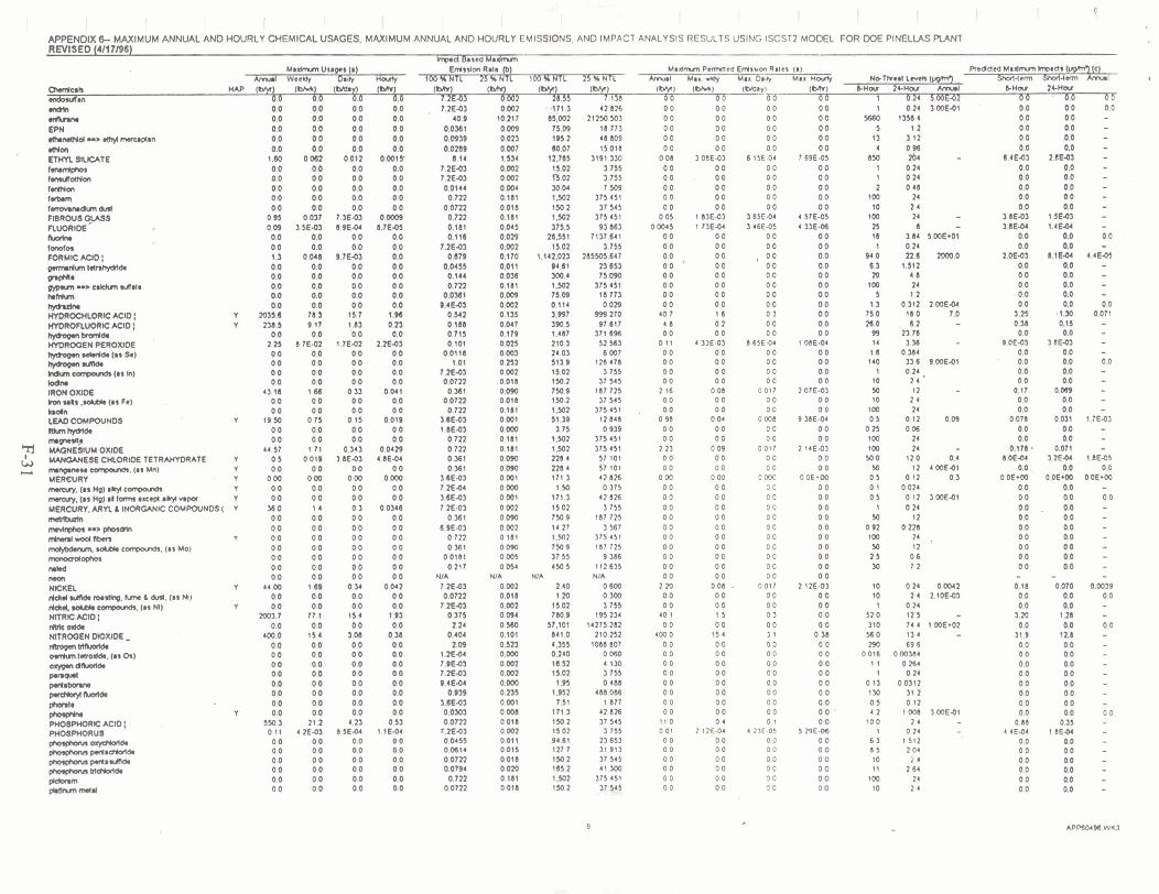
I I I I I [ I , I I I I I I APPENOIX 6- MAXIMUM ANNUAL AND HOURLY CHEMICAL USAGES. MAXIMUM ANNUAL AND HOURLY EMISSIONS. AND IMPACT ANALYSIS RESULTS USING ISCST2 MOOEL FOR DOE PINELLAS PUNT REVISED (4117196)
trprd b r e d Ma- M o h m Vsogls (0) Wrslm Rmr p) ~ o d m m Perrnned Emsron Rwes lo) m a ~ ~ a h m ~ d s le)
knrl WoelOy D.YI 3% NTL B Y NIL 100XNTL knA Max. q Mar Do* Max t4- Sha(4mn sslH*m k n r l hnrak 0 (srR W) MI &Ma# 2CMnr
-b6 m68SL#10 7.2E.03 002 28.55 7.1M 0 0 rndk 0.0 0.0 0.0 0.0 7 . ~ 9 1 0.002 mi.^ 4 1 . 8 ~ 0 0 0 0 0 0 o o 1 0.24 3.60E.01 0.0 0.0 0.0 m 0.0 0.0 0.0 0.0 40.9 10117 1.002 21230503 0 0 0 0 0 0 0 0 S O 13584 0.0 0.0 -
0.00) 75.0) 0 . m i n . 2 0.001 60.07 4 ims 0 . m 11.01 0 . m B.01 0 . m 30.04 0.181 1,502 0.018 150.2 0.181 1.502 0 .00 375.1 0 . m 2a.551 0.002 11.02 0.170 1.142.m 0.01 1 M.81 0.0% lw.4 0.181 1.502 0.001 71.0) 0.002 0.114 0.135 3 . W 0.047 390.5 0.179 1.487 0.015 210.3 0 . M 24.03 o.at s1r.s 0.002 15.01 0418 150.2 0 . m 150,s 0.011 150.2 0.111 t . m 0.001 5 1 3 0.000 3.75 0.181 1 . m 0.181 1 ,502 0 . m mc 0 . m m a 0.001 171 3 0000 1.50 0.001 171.3 0.002 0 0 2 0 . m 150 9 0.002 14.27 0 181 1.502 0090 750 9 0 . W 37.55 00% 450 5
NIA NIA 0.002 2.40 0.018 1.20 0.001 11.01 0 . m 760.9 0 . W 57.101 0.101 841.0 0.1n 4,355 0.000 0.240 0 . m n.12 0 . m n.02 0 . m 1 H o.ns c .nz 0.001 7.51 0.008 1713

A P P W 6- W M U M ANNW AM) HOURLY CHEMICAL USAGES. MAXIMUM ANMAL AND HOURLY EMISSIONS. AND IMPACT ANALYSIS RESULTS USING lSCSl2 MOML FOR DOE PINELUS PLAM REVISED f4H7IW)
h w d Baud Mudmm M ~ a n m Won (a) ~ a u n m ~ r n e a ~ s u o n R ~ I W p) R a o d ma- hwcw (c)
LMUllw..ldy W 25 U NTL M Mar. r(dy Man hi Max n- NolhalLmkbrpmr) Sh01l4mn sholl4um Cmrl q
Owrrlcll, W M ( o m ) o 0 0 (Mr) 0 W ) W ) (w) WY) (Mr) bnw 24-Mu M bHw 2CHar p ~ ~ l ~ u a YLS (IS RI 0.0 0.0 0.0 0.0 1 . ~ ~ 4 0 . m 0 . m 0.071 0.0 0.0 0 0 0.0 0.02 0 . m 8 0.0 0.0
o.m 0.144
NIA NIA o.om 0.0722
7.2€44 0.722
NIA 0.0144 0.0118 0.477 0.722 0.722 0.722
3.8M3 7.X5Y 7.W.03 3.m.03 7.X.03 o.m o . m 0.477 0.722
7.X* NIA l.X.03 7.X.M
0.11 NIA
0.#1 0 . 0 ~ 0.0144 0.375 0.l97
7.2E-01 0.0318 I 1 . 8
0.0722 152
o . o m 0 %l
0.0144 7.2E.03 7.2EQ3
o . m 3.4E43
0.1W WA NIA NIA WA WA 7.KO)
NIA 0.0722 0.144
7.W.03 0.722
NIA 0 . m onm 0.0144
3.8E-03 0.0722 0.0722
7.2E.04 NIA
0.361 NIA
0.%1
0.181 O .m
NIA NIA
0.018 0.018 0.000 0.181
NIA 0 . m 0,003 O.lt9 0.181 0.181 0.181 0.00 1 0.002 0.003 0.001 0 002 0381 0.111 0.119 0.181 0.002
NIA 0.001 0 . m 0 . m
NIA 0.090 0.009 0.004 0.094 0 4 9 0.002 0 . m
215.448 0.018 0 179 0.011 0.090 0 . m 0.003 0003 0.181 0.001 0 027
NIA NIA NIA NIA NIA
0.003 NIA
0.00 0.0% 0.003 0.181
NIA 0.090 0.018 O . m 0.001 0.018 0.018 O . m
NIA 0.090 O . m O . m
375.451 15.090
NIA NIA
37 545 I ? 545 0 375
375.451 4 a . m
7.509 8007
247 197 375 451 375 451 175 451
1 877 1.755 3.755 1 877 1.755
175 451 175 451 247 791 175 451 428 2%
14275.282 4 a . m
0.375 1 8 r . m
MIA 187.725 19 148 7509
195.2% 106 498
3 755 $8 5m
448111 %2 37 545
7M 446 I7 545
107 7 n 7509 3 755. 3 755
375 451 1 765
56 318 42 a x 42826 42.826 71.376 71 176 71 176 10 706 37 545 75 090 1.155
175.451 NIA 1or .m 37 545 7509
2855.0% 37.545 37 545 0 175
7137 641 187 7 n 42826
117 725

APPENDIX 6- MAXIMUM ANNUAL AND HOURLY CHEMICAL USAGES. MAXIMUM ANNUAL AND HOURLY EMISSIONS. AND IMPACT ANALYSIS RESULTS USING ISCST2 MODEL FOR DOE PINELLAS PLANT REVISED 14/17/96) .
Invan Based Maaimm Ma- Usages (a) Emsum Rate lb) - Maomm pmned Emrsnon Rater (a) RIclded M8Mnm kwads orprm7 (c)
*rul WeeUy D3y Harry lOO% NTL 25UNTL 100% NIL 25% NIL *muat Mas y Max Datb Max Hc&y NoThsH L e e WPRn.) Sal.tn Shol(4m knal NAP (*I IDWJ (May1 I ~ I i?_h) ~bh) I*) ' (WI IWJ- (Wa*rr I ~ I CHW 2&nw -I b H W 24-War
OASES AND CY: 6S.M TPV t u ?PI
8 U m U R TOTAL OC VOC: TOTAL OC OC: T O l A L ~ ~ a A N O P M :
21.58 TPY 1S.Q TPV 69.50 T W
21 58 TPY 1949 I P I 164 TPY
OMRALL TOTAL USAOES AND CYSSONS: 11LlT TPY 42.72 TPY
(1) LU8*OM CALCULATION NOTES I L W U N O AVLIIAONO T U C S r a ~ h n 3 o ~ ~ m w u . n d m k a t a n :
@I WCACT MSKD etaram MTKS: n* kpcr b a d .QnJlkn)lN k ea*rY.OMud m m mdmm hvu is h a gamk edsskm I! vomhl. race# rcn we& nvaebng has hen ~rtormd la mthyYn cNm0c a d cnomc acod Ved ~ K C I ~ C nmlq cm#oyed mdmm wnrdltrd d s ~ m b n l w k D O L m s R r l . Th l O O w H T L h a y d s h n ( o k h n u Y M I M I W d I ~ e c o r r g ( ~ o r h l u y l o l ( l n m N T L s n * l m H n w n J d ~ h M h W n u Y M I ~ W . U ~ l o c a n g ( u r e W m ~ N T L ~ R 1 a ~ n s b ~ b ~ H p . n ( * r ( a k m h m h a r k d s ~ t d r ( k r d a s I x M d s W o u * 2 . O W ~ l . a d m d m m ~ m * t n n s Y o m
(el CRKOKIEO YUUWY W A C 7 NOTES:
;rl R~P- r ) ~ ~ r m ( ~ o v w 2 e h . ~ t OW tonym I . ~ * Q mwns we bawd m on p w c pumccis ole58 03 u& and 263 01 t@+ IU mr bmaa md ~ c h w awapng r m s am 10 €11 imm9 tor IN a m u ~ ammpng pen- T h ~ h a r c y m l s ~ r * e l ~ ~ I Q - o m m a ( . n n n u . m m ~ $ l h . n u d m m - h p . O a b 8 % . d m W m m m ~ n n s ~ o n t ~ e
.c! E,,mb-laWIQut
M S W CALCUUtK)II NOTLS AND AIIUwPTION8: (d) n*YOC.QJarnrsur*d lobarar lukncuap. ( Iswnc8s . r rcony)
(0 WsW d g@ur m 1- d wagas. Emsclonr ol a d d h paling Mln w8 MsM m 10 mnr MpaaNm lrom H*llm bath and M)Y cmrol emclmcy By the rou*mr Maumm PM emsum llm w(hO barn are asUmcO to be 5% ol nuloc(*d k PM vugrs wa Wdkqedms ol )unbmr.d m*mah: Aurelae. a n d PM ms$lan va KI pnnated By mr praesrnp mmm Chmrcad as pan~cdalcs horn nw blast mtba are Cmrokd By,bagmar win
w bra ))Y cam^ rcllci*r). Enis* d W(\K add wr based on woersung Im panmtns (I e, ar(8ce 81~8. CCncn(r8hon t m a l u e . uc I
kil Uup. d m h w p U ) L COnpQIlOI are m ahuurd am nrralar m s u a are m o

APPENDIX G
Pinellas Plant Hazardous Waste Operating Permit

Department of
Environmental protection
b w o n Chiles Governor
Southwest District 3804 Coconut Palm Drive
Tampa. Florida 336 19 Vtrgtn~a 6. Werherell
, Secretary
PERMITTEE: PERMITICERTIFICATION:
Facility OwnerlOperator/Landowner
U.S. Department of Energy EPA ID No: FL6890090008 Pinellas Plant Permit No.: H052 - 228925
Pinellas Post Office Box 2908 County: Largo, Florida 34649 - 2900 Issue Date: August 16,1993 &: Richard E. Glass, Area Manager Expiration Date: August 16,1998
Martin Marietta Specialty Components Latitude I ' Longitude Post Office Box 2908 27O523OnN 1 82'45'00 W Largo, Florida 34649-2908 Sedion I Township1 Range Attn: Edward E. Mayer ' - 13 30s 1 5E
Director - Environmental Management Project: Operation of a Hazardous Wade Storage Facility
This permit is issued under the provisions of Chapter 403.722. Florida Statutes. and Florida Administrative Code Rules 17-730. The above named permittee is hereby authorized to perform the work or operate the facility shown on the application and approved drawings, plans, and other documents, attached hereto or on tile with the Department and made a part hereof and specifically described as follows:.
To operate hazardous waste storage tank and container storage units at the U.S. Department of Energy's Pinellas Plant located at 7887 Bryan Dairy Road, Largo, Pinellas County. Hazardous wastes are generated during the production and demiiiiariration and declassification of seled nuclear ' weapons components including neutron generaton, lightning arrestor connectors, capacitors, magnetics, optoelectronics and other components andlor subassemblies. The Pinellas Plant's primary function is changing from USDOE sponsored-defense programs to transition activities such as disposition of materials, equipment, and inventory from defense production and suppdrt areas. Areas will be transitioned to similar manufacturing operations, made available for economic development, or deactivated, or decommissioned. The Pinellas Plant only aorcrs hazardous waste generated at or by the facility. No hazardous waste is managed by the Pinellas Plant which wru not generated at the Pinellas Plant. Hazardous wastes 8re stored in tanks and colltainan.
Hazardous wastes are also accumulated and managed in a 90 day storage a m at Building 1010. Hazardous wastes in this building are accumulated in accordance with 40 CFR 26234 regulations for generators. Other activities in Building 1010 indude lab padring, fluorescent light bulb cashing,
. and non-harardous wastewater treatment. Wastes managed in accardance with 40 CFR 262.34 are not regulated under this permit.
G-3
"~rotec; Conserve and ~ o t ~ o ~ e Flopdc;.s Er~v~ronrncl~c ond Natural Resotrrces"
Pmced on q d e d paper.

PERMTTTEE: U.S. Department of Energy I.D. Number: FL6 890 090 008 Pinellas Phnt P e w No. H052-228925 post 0mce BOX 2908 Date of Issue: August 16.1991 Largo. Florida 34649 - 2908 Expiration Date: August 16, 1998
Permitted hazardous waste container storage facilities are authorized in Buildings 1040 and 1000. Building 1040 has three storage bays designated as Bay Numbers 1, 2, and 3. Hazardous waste storage in Building 1000 is permitted in.Bay No. 2 only. Building 1000 is designated specifically for storage of low level mixed wades ajntaining RCRA metals above TCLP limits. Non-hazardous low level radioactive wastes are also stored in Bay 2. This hazardous waste permit regulates only the hazardous waste component of the mixed waste and not the radiological component. The radiological component is regulated by the U.S. Department 'of Energy. The management of unknown wastes/materials in any of these bays is not permitted. Capacities and waste placement within each permitted unit are shown as follows:
Building 1040 - Bay Number 1 (SolidLiquid Wades and Lab Packs)
Capacity Dimensions 64 - 55 gallon containers or a total 5 1'4" by 23'4: of 3,520 gallons, 28 - 55 gallon containers of which or a total of 1,540 gallons may be liquid waste !
Bay 1 may be used for transferring penitted wastes from small containers into 55 gallon collection containers. Bay 1 may also be used as a transfer point for transferring waste from collection containers to the permitted hazardous wade tanks. Bay 1 receives and stores waste halogenated solvents and ignitable liquids from various generating points in the Pinellas Plant by pumping.
Building 1040 - Bay Number 2 (Non-liquid Readive Wastes and Lab Packs) . - . . -. -- . .. .----- - . - . . . - .. .. -.. - . .- .--.--. . - ! . ' . - '
Ca~ac i t y Dimensions 32 - 55 gallon containers or a total of 9'4" by 23'4" 1,760 gallons of non-liquid readive waste and lab pack waste combined. Lab pack waste shall not exceed 32-55 gallon containers each container having no more than 15 gallons of liquids.
Building 1040 - Bay Number 3 (Laboratory Wastes and Small Quantities of < Known Miscellaneous Liquid Materials)
Capacity Dimensions 12 - 55 gallon containers of hazardous 11'4" by 23'4" wastes and non-regulated materials or a total volume equivalent of 660 Gallons.
Bay 3 may also be used for bulking and lab packing hazardous wastes into containers up to 55 gallons. Bay Number 3 may also be used to condud pH rdjustment of cyanidminlng wastes and preparation of nitrocellulose waste for off-site transportatron via the addhn of bpmpyl alcohol. These operations shall all be conducted under one ventilated chemical hood located inside.
Approved Waste Codes for Blda. 1040. Bays 1.2. and 3
"Fa Wastes F001, F002, ~Ob3, F004, F005, F006, F007, F008, F009, F010, FOl1, F012, F019, F024, F025, F032,
Page 2 of 15
G-4 *

PERMITTEE: U.S. Department of ~ n & y Pinelhs Plant Pod Office Box 2908 Largo. Florida 34649 - 2908
LO. Numb~r. FL6 890 090 008 Pennit No. H052-228925 Dq$e of Issue: August 16.1991
. . Expiration Date: August 16.1998
"On Wastes D001,D002, D003, D004, 0005, 0006, D007, D008, D009, D010, Dol l , D018, D019,D022, 0023,
'P' Wastes pool. ~ 0 0 2 . p003. P004. P005. P006. P007. P008. P009. P010. Pol l . P012. P013, po14. pols.
"U" Wastes U001, U002. U003. U004. U005, U006. U007, U008, U009, UOlO, U011, U012, U013, U014, U015, U016. U017:, U018. U019. U020. U021, UO22, U023, U024, U025, U026. U027. U028, U029, U030, U031, U032, U033, UO34, U035. U036. U037, U038, U039, U041, U042, U043, U044, U045. U046, U047. U048. U049, U050, UO51. U052, U053, U054, U055. U056, U057. U058, U059, U060, U061, U062. U063. UO64, U066, U067. U068, U069, U070, U071, U072, U073, U074, U075, U076, UO77, U078, U079, U080, U081, U082, U083, U084, U085, U086, U087, U088, U089, U090, U091. U092,
Building 1000 - Bay Number 2 . (Laboratory, Produdion, and Miscellaneous Wastes. No Free Liquids Stored)
<
Ca~ac i fy 6 - 673 gallon B-25 boxes. or
Dimensions 22'8" by 1 7'4"
cornbinitions of 8-25 boxes and 55 gallon containers not to exceed a total of 4,038 gallons, or 48 - 55 gallon containers.
A ~ ~ r o v e d Wastes for Blda. 1000. Bay 2
Low Level Radioadive Mixed Waste, hazardous for any of D004, DOOS, 0006, D007. D008. D009. DO1 0, DO1 1 or any combination thereof. No free liquids.
TANK SYSTEMS STORAGE
Hazardous T q e storage in tanks is permitted in four hor[tontal'above ground hazardous waste storage tanks designated as Tank Numbers 1, 3, 4. and 5. ihese tank systems are equipped with
"
secondary containment structures, having the noted specifications below:
Page 3 of 15
G- 5

PERMTTTEE: U.S. Department of Energy Pinellas Plant Pod Office Box 2908 Largo. Florida 34649 - 2908
1.0. Number: FL6 890 090 008 Permit No. H052-228925 Dpte of Issue: Augud 16,1991
4 . Expiration Date: August 16. 1998
Tank 1 has an available secondary containment stmdure capacity of 6,043 gallons, which is only 96% of the necessary capacity; as such, annual integrity testing shall be conducted.
Tanks 4 and 5 are utilized as reserve storage capacity for liquid hazardous wastes identified for Tanks 1 and 3. Tanks 3, 4 and 5 are served by the same secondary containment strudure. Tank 1 has its own secondary writainment.
Aooroved Waste Codes for Tank Systems Storaae
MATERIAL
Carbon Steel ' Stainless
Steel Carbon Steel Carbon Steel
CAPACIN (GALLONS)
5,000 2,000
5,000 5,000
' TANK I 1 I 3
1 4 5
Operation and management practices concerning units regulated under 40 CFR 264, Subpart X are not addressed in this operating permit as additional reviews related to groundwater, air monitoring, environmental impact analysis, and risk assessment may take additional time to complete, review and approve. This permit shall be modified in the Mure to include spedfic conditions as well as process descriptions for each Subpart X activity. The Subprt X activities as lislsd in Page 1l.l.-1 of the permit application include the thermrl treatment unit (pertaining to waste explosives: heat paper, heat powder and detonators) and the chemical (reactive metal) tmatment unit for calcium metal. calcium bimetal, and lithium metal. Until this pennit is modified, operation of these units are subject to the Thermal Treatment and Chemical Treatment sphdfic conditions noted in the previous permit H052- 159339. These conditions are shown in Sections V. and VI. of this pennit.
WALL THICKNESS 1
-375" I .375" f
i .375" t .375" a
, Operation and management of equipment regulated under 40 CFR 264, Subpart B8 are also not covered in this permit as the Department is not yet authorized to enforce this regulation. USEPA currently enforces this rule. Subpart BB equipment is to be addressed under the facility's Hazardous and Solid Waste Amendments (HSWA) permit or when Florida receives authofkatjon.
LENGTH
14' - 10 518" 9' - 9"
14' - 10 518" 14' - 10.518"
The following submittals were utilized in the preparation of this permit and are considered part of the permit:
DIAMETER (INNER)
8' - 0." 6'- 0"
8' - 0" 8' - 0"
A~~l icat ion for a Hazardous Waste Facilitv Pennit on DER Form 17-?30.900(2) submitted April 1, 1993.
Page twelve of the application submitted April 16. 1993. Response to first notice of defiaency submitted October 12,1993. Response to second notice of defiaency submitted January 19.1994. Response clarifying tank management practices submitted March 9,1994. ,
Completed waiver of the 135 day time limit submitted June 1,1994. ; Additional replacement pages to the permit application submitted June 10,1994.
Additional replacement pages to the permit application submitted August 11,1994.
Replaces Permit Number H052-159339, except as noted in Specific Conditions V. and VI. below.
Page 4 of 15
G-6.

PERMITEE: US- k w r t m e n t of Energy LD. Number: FL6 890 090 008 Pinellas Plant Permit No. H052-228925 Port office Box 2908 of Issue: August 16. 1993 Lrgo. Florida 34649 - 2908 - Gpiration Date: August 16. 1998
GENERAL CONDITIONS:
The terms. conditions. requirements. limitations. and re~tridions Set forth in this permit are "permit conditions" and are binding and enforceable punuant to Sections 403.141, 403.727, or 403.859 through 403.861, F.S.. The permittee is placed on notice that the Department will review this permit periodically and may initiate enforcement action for any violation of these conditions.
This permit is valid only for the specific processes and operations applied for and indicated in the approved drawings or exhibits. Any unauthorized deviation from the approved drawings, exhibits. specifications, or conditions of this permit may constitute grounds for revocation and enforcement action by the Department.
As provided in Subsections 403.087(6) and 403.722(5). F.S.. the issuance of this permit does not convey any vested rights or any exclusive privileges. Neither does it authorize any injury to public or private property or any invasion of personal rights, nor infringement orfederal, state, or , local laws or regulations. This permit is not a waiver of or approval of any other Department permit that may be required for other aspects of the total project which are not addressed in the permit:
This permit conveys no title to land or water. does not constitute State recognition or acknowledgment of title. and does not, constitute authority for the use of submerged lands unless herein provided and the necessary title or leasehold interests have been obtained from the state. Only the TIUsteeS of the Internal Improvement Trust Fund may express State opinion as to title.
This permit does not relieve the permittee from liability for harm or injury to human health or wplfare. animal, or plant life or property catised by the ccnstrrlction or operation of this pcmitted source, or from penalties therefore; nor does it allow the permittee to cause pollution in contravention of Florida Statues and Department rules, unless specifically authorized by an order from the Department.
The permittee shall properly operate and maintain the facility and systems of treatment and control (and related appurtenances) that are installed and used by the permittee to achieve compliance with the conditions of this permit, as required by Department rules. This provision includes the operation of backup or auxiliary facilities or similar systems when necessary to achieve compliance with the conditions of the permit and A e n requ'ited by Department rules.
The permittee, by accepting this permit. speafically agrees to allow authorized Department personnel. upon presentation of credentials or other documents as may be required by law and at reasonable times access to the premises where the permitted activity is located or conducted to:
(a) Have access to and copy any records that must be kept under conditions of the permit;
@) Inspect the facility, equipment, practices, or operations regulated'or required under this permit; and
(c) Sample and monitor any substances or parameters at any location reasonably necessary to assure compliance with this permit or Department rules.
deasonable time may depend on the nature of the concern being,investigated.
8. I f for any reason, the permittee does not comply with, or will be unable to comply with, any condition or limitation specified in this permit, the permittee shall immediately provide the Department the following information:
Page 5 of 15

PERMfTTEE: U.S. D e p a m n t of Energy . LO. Number: FL6890090008 Pinellas Pknt Pe- No. HOSZ-228925 post 0mce ox 2908 Date of Issue: August 16,1993 largo. Florida 34649 - 2908 Expiration Date: August 16. 1998
(a) A description of and cause of non-compliance; and
@) The period of non-compliance including dates and times; or. if not corrected, the anticipated time the non-compliance is expected to continue, and steps taken to reduce, eliminate, and prevent recurrence of the non-compliance.
The permittee shall be responsible for any and all damages which may result and may be subject to enforcement action by the Department for penalties or revocation of this permit.
9. In accepting this perinii, the permittee understands and agrees that all records, notes, monitoring data. and other information relating to the construction or operation of this permitted source which are submitted to the Department may be used by the Department as evidence in any enforcement case involving the permitted source arising under the Florida Statutes or Department ntles, except where such use is prescribed by Sections 403.1 11, and 403.73, F.S.. Such evidence shall only be used to the extent it is consistent with the Florida Rbles of Civil Procedure and appropriate evidentiary rules.
10. The permittee -agrees to comply with changes in Department mles and Florida Statutes after a reasonable time for compliance, provided, however, the permittee does not waive any other rights granted by Florida Statutes or Department ntles. A reasonable time for compliance with a new or amended surface water quality standard, other than those standards addressed in Rule 17- 302.500, F.A.C.. shall indude a reasonable time to obtain or be denied a mixing zone for the new or amended standard.
11. This permit is transferable only upon Department approval in accordance with Rules 174.120 and -- -- - . -. .-. -
.17-730.300, FAG., as applicable. The permittee shall be liable for any noncompliance of the - - permitted activity until the transfer is approved by the Department.
12. This permit or a copy thereof is required to be kept at the work site of the permitted activity.
13. This permit also constitutes:
( ) Determination of Best Available Control Technology (BACT) ( ) Determination of Prevention of Significant Determination (PSD) , ( ) Certification of Compliance with State Water Quality Standards
(Section 401, P t 92-500) ( ) Compliance with New Source Performance Standards
14. The permittee shall comply with the following:
(a) Upon request, the permittee shall fumish all records and plans required under Department rules. During enforcement actions, the retention period for all records will be extended automatically unless otherwise stipulated by the Department.
(b) The permittee shall hold at the facility or other location designated by this permit records of all monitoring infomtion (including all calibration and maintenance records and all original strip chart recordings for continuous monitoring irutrumentation) requipd by this
- permit, and records of all data used to complete the application for this permit. These materials shall be retained at least three years from the date of the sample, measurement, report or application unless othelwise speafied by Department mle.
Page 6 of 15
c-- pu.

P E R M r n E : U.S. Department of Energy Pintllas Plant Pod Office Box 2908 brgo. Florida 34649 - 2908
LO. Number: FL6 890 090 008 Pennit No. H052-228925 Date of Issue: August 16.1993 . . Gpiration Date: August 16.1998
(c) Records of monitoring shall include:
1. the date. exact place, and time of sampling or measurements; 2. the person responsible for performing the sampling or measurements; 3. the dates analyses were performed; 4. the person responsible for performing the analyses; 5. the analytical techniques or methods used; and 6. the results of such analyses.
15. When requested by the Department, the permittee shall, within a reasonable time, fumish any information required by law which is needed to determine wmplianci with the permit. If the permittee becomes aware that the relevant fads were not submitted or were incorrect in the permit application or in any report to the Department, such facts or information shall be corrected promptly.
16. The following conditions shall also apply to a hazardous waste facility permit:
(a) The following reports shall be submitted to the Department:
1. Manifest discrepancy report. If a significant discrepancy in a manifest is discovered. the permittee shall attempt to rectify the discrepancy. If not resolved within 15 days after the waste is received. the permittee shall immediately submit a letter report, including a copy of the manifest. to the Department.
2. Unmanifesieci waste report. he permiltee shall submit an unmanifested waste I report to the Department within 15 days of receipt of unmanifested waste.
3. Biennial report. A biennial report covering facility activities during the previous calendar year shall be submitted to the Department by March 1, of each even numbered year pursuant to Chapter 17-730, FA-C..
@) Notification of any non-compliance which may endanger health or the environment including the release of any hazardous waste that may endanger public drinking water supplies, or the occurrence of a fire or explosion from the facility which could threaten the environment or human
'health outside the facility, shall be reported verbally to the Department within 24 hours, and a written report shall be provided pithin 5 days. The verbal report within 24 hours shall contain the name, add-. 1.0. number and telephone number of the facility, its owner orbperator. the name and quantiiy of materials involved, the ex!ent of any injuries. an assessment of actual or potential hazards, and the estimated quantity and disposition of recovered material. The written submission shall contain:
1. A description of and cause of non-compliance. 2. If not corrected. the expected time of correction and steps being taken to reduce,
eliminate, and prevent recurrence of non-compliance.
(c) Reports of compliance or non-compliance with, or any progress reports on, requirements contained in any compliance schedule shall be submitted no laterthan 14 days after each schedule date.
(d) All teports or information required by the Department by a hazardous waste permittee . shall be signed by a person authorized to sign a permit application.
Page 7 of 15

PERMTTrrE: US. Department of Energy Pinellas Plant Pod Office Box 2908 Largo, Florida 34649 - 2908
LO. Number: FL6 P90 090 008 Pennit No. H052-228925 Date of Issue: August 16.1991 Expiration Date: August 16,1998
SPECIFIC CONDITIONS:
I. GENERAL
1. The permittee shall operate the herein permitted facility in accordance with 40 CFR 264. the conditions of this pennit, the permit application and other submittals considered part of this permit.
2. The permittee is allowed to operate only the hazardous waste storage units specified in pages 1. 2.3, and 4 of 15 of this permit and as further described in the permb application.
3. The permittee is allowed to manage only those hazardous waste codes as lisied and in the manner described in Pages 1.2. 3, and 4 of 15 of this permit. The permittee must obtain a permit modification prior to storage of new hazardous wastes.
4. The permittee shall comply with the required notice of 40 CFR 264.12(c) before transferring ownership or operation of the facility during the duration its operating life.
5 In the'event that the permittee submits an application sole for a pemit transfer to Martin Marietta Specialty Components or a permit transfer to an organization that is no longer a state or federal government. the application shall include documented demonstration that the organization taking over complies with all the requirements of 40 CFR 264, Subpart H. Financial Requirements. This transfer application. including attachments. shall be submitted to the Department in triplicate as per Specific Condition 1.12 and 1.32. of this permit.
-- . 6. f h e permittee shall maintain a written operatingrecord dowmenting the movement of each - hazardous waste into and out of permitted storage units and movement of hazardous waste from storage or directly to bulking, lab packing, cyanide waste pH adjustment, nitrocellulose waste preparation and vice versa , as desalbed and required in 40 CFR 264.73@)(1) and (2).
7. The permittee shall comply with the record keeping requirements of 40 CFR 264.73,264.74, 264.75 and all other records required to be maintained per the permit application.
8. The permittee shall apply for a dosur6 permit at least 180 days prior to beginning dosure at the. +, facility pursuant to Section 17-730260, FAC..
9. The permittee shall apply for renewal of this pennit or shall apply for a dosun permit whichever is applicab!e, at least 180 days prior to the expiration date of this permit pursuant to Section 17- 730.300, FAC..
10. The Department may modify the conditions of this permit if any conditions of Sedion 17-730290, FA.C. applies.
11. All documents submitted pursuant to the conditions of this permit shall be accompanied by a cover letter stating the name and date of the document submitted, the spedfic condition number(s) affected, this pennit number and the facility P A ID number.
Page 8 of 15

PERMrnE: U.S. Department of Energy I.D. Number: FL6 890 090 008 Pinellas Plant Permit No. H052-228925 Post Oftice Box 2908 Date of Issue: August 16.1991 b q o . Florida 34643 - 2908 . . Expiration Date: August 16, 1998
12. Documents to be submitted in response to the conditions of this permit shall be submitted in triplicate as follows. Each copy shall specify its distribution to other parties.
a. One copy to: Director of District ~ana~ement Southwest District Office Florida Department of Environmental Pmtection 3804 Coconut Palm Drive Tampa, Florida 3361 9-821 8
One copy to: Environmental Administrator Hazardous Waste Regulation Section Bureau of Solid and Hazardous Waste Pmtedion Depzrtnent of Environmental Protection 2600 Blair Stone Road Tallahassee, Florida 32399-2400
c. One copy to: Chief, Waste Management Division United States Envimnmental Protection Division Region IV 345 Courtland Street. N.E. Atlanta, Georgia 30365
.. 13. As per Ssdion IIA.l(c) o! the permit.app!icatjon. the total-number of hazardous waste shipments over the course of a calendar year outside the Pinellas Plant shall not exceed 365.
14. Pursuant to 40 CFR 268.50, the permittee may store hazardous waste or the hazardous waste component of the mixed waste as permitted for more than one year only if the permittee can demonstrate that such storage is solely for the purpose of accumulation of such quantities of hazardous waste as are necessary to fadlitate proper recovery, treatment, or disposal.
Facilitv Security
1 The permittee shall prevent the unauthorized entry of persons into the hazardous waste uni? to comply with the security requirements of 40 CFR 264.14. The permittee shall follow security pmcedures.and maintain security equipment as described in llA.4.(a) of the permit application.
Continaencv Plan and Ememencv Procedures
16. The permittee shall adhere to all of the operating and emergency pmcedures desuibed in the Contingency Plan as written in Appendix B of the permit application and in 40 CFR 264.56.
17. The permittee shall give proper notification if an emergency situation arises and within 15 days shall submit to the Department a written report which indudes all information required under 40 CFR 264.560 and as described in the Contingency Plan.
18. he permittee shall post next to each telephone shown in Figure ll-A-9, a list containing the names and telephone numbers of all emergency coordinators, including facility emergency coordinatk, local aid agencies, public utilities, environmental agencies, and clean-up contractors
'
as listed in Appendix B of the permit application. The lii shall be a one page list to facilitate contacting affected parties in the event of an emergency.
Page 9 of 15

PERMITEE: U-S- Deparbnent of Energy LO. Number: FL6 890 090 008 Pinellas Plant Permit Na H052-228925 Post office Box 2908 . .
Date of Lssue: August 16. 1993 hrgo. Flo& W - 2908 Expiration (kte: August 16. 1998
19. Revisions to the contingency plan which meet any of the criteria listed in 40 CFR 264.54 and Appendix I to 40 CFR 270.42 shall be submitted to the Department as a permit modification request requiring prior Department approval pursuant to Section 17-730.290. FA.C..
20. - The contingency plan and all its revisions shall be maintained at the facility and shall be submitted to the local police department. fire department, hospital, state and local emergency response teams.
Pte~atedness and Prevention
21. Daily, weekly. biweekly, monthly, quarterly, and annual inspections of the hazardous waste facility, preparedness and prevention equipment, and operating equipment Shall be conducted as described in Section ll.A.4(d) of the permit application. Inspection records shall be maintained in accordance with 40 CFR 264.15(d).
22. Preparedness and Prevention Procedures (40 CFR 264, Subpart C), General Inspection Requirements (40 CFR 264.15). and General Requirements for Ignitable, Reactive. and Incompatible Wastes (40 CFR 264.17), and other procedures as desaibed in Sedion llA.4(d) of the permit application and as stated in the aforementioned regulations shall be followed.
Waste Analvsis Plan
23. As stated in Page 1.0.2-2 of the permit application, the permittee is not authorized to accept any hazardous wastes from outside the Pinellas Plant.
-- - - 24. ?he permittee shall manage only those wastes applicable for container and 4ank storage as listed - in Section D., Page 4 of 6.5 of 6, and 6 of 6, DER Form# 17-730.900(2)(a) and as desaibed in pages 2.3. and 4 of 15 of this permit.
25. Sampling and analysis of permitted and new hazardous wastes shall be conducted in accordance with Appendix D. Waste Analysis Plan of the permit application.
26. New hazardous waste streams generated at the Pinellas Plant and resulting from new processes and process changes shall undergo the permitted waste sampling and analysis prior to managing the waste for permitted storage.
I
Miscellaneous chemical wastes shall undergo sampling, analysis, and management as descn'bed in Section VI.. Appendix 0. wade Analysis Plan of the permit application prior to managing the waste for permitted storage. Pursuant to 40 CFR 2621 1, reasonable effort to identify the unknown waste shall also include determining whether each waste is listed in 40 CFR 261, Subpart D. The opening, storing. or management of unknown wastes in any of the permitted bays is not allowed.
28. There shall be no treatment of hazardous wastes or hazardous materials in the permitted tank or container storage areas except for the transfer of hazardous wastes from inside containers to the permitted storage tanks. Pursuant to 40 CFR 268.7(a)(4), other treatment such as resin solidification and fluorescent light bulb crushing shall be conducted outside of the permitted units and only in tanks and containers regulated under 40 CFR 262.34 (90 day generator storage).
Page 10 of 15

PERMRTEE: U.S. Deparbnent of Energy LD. Number: FL6 890 090 008 Pineltas Plant Permit No. H052-228925 post 0mce BOX 2908 Date of Issue: August 16.1993 largo, Florida 34649 - 2908 mirat ion Date: August 16, 1998
29. Pursuant to 40 CFR 268.3, the permittee shall not in any way dilute a land disposal restricted hazardous waste or the residual from the treatment of a land disposal restricted hazardo,us waste as a substitute for adequate treatment to achieve compliance with 40 CFR 268. Subpart D, to circumvent the effective date of a prohibition in 40 CFR 268, Subpart C, or to circumvent a land
. disposal prohibition imposed by RCRA Sedion 3004.
30. Table 3, Page WAP-9. Appendix D of the permit application shall be updated every calendar quarter to include all types of hazardous wastes currently generated at the Pinellas Plant. The individual additions/deletions to Table 3 shall be shaded to facilitate Department review. Updates shall be submitted no later than 30 days from the end of each calendar quarter. -
Personnel Traininq
31. Personnel training shall be conducted as described in Sedion llA.4(e) of the permit application and in accordance with the training requirements of 40 CFR 264.16.
Financial Reauirements
32. The pehnitteeshall maintain compliance with the financial requirements of 40 CFR 264 Subpart H. All submittals in response to this Specific Condition shall be submitted to:
Financial Coordinator Hazardous Waste Regulation Section Department of Environmental Protection 2600 Blair Stone Road Tallahasse??, Florida 32399-2400 .
!
11. CONTAINERS
1. The permittee shall comply with the type, quality, and specification of d ~ m ~ utllued for storing hazardous wastes as d-bed in Attachment IIBA. of the permit application. Any change in container type must be previously approved by the Department.
2. The permittee shall use containers which are compatible with the hazardous waste to be stored to comply with the requirements of 40 CFR 264.173.
3. Containers shall be kept dosed except when adding or removing waste and shall be handled in a manner that will not. a l l w the containen to Npture or leak If a container holding hazardous waste is not 1n good condition, or begins to It!& the waste shall be transferred to another container in good condition to comply with 40 CFR 264.171.
4. Container storage and management shall be conducted in accordance with Part 1l.B.. Attachment l.D2 and other applicable parts of the petmit application.
5. Incompatible wastes shail not be stoned in the same bay or in bays having the same containment system unless physically separated by a dike, berm. or other approved device in accordance with 40 CFR 264.1 TI(c).
6.. Signs showing the hazardous waste storage capacity shall be placed in a highly visible location in each bay. 'No Smoking' signs shall be conspimusly posted at each location where ignitable wastes are stored and whenever flammable gases are generated.
Page 11 of 15
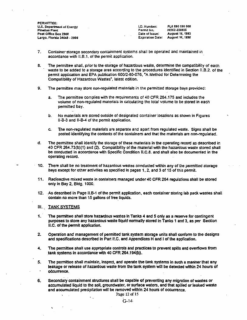
PERMITEE: US. k p ; l m n t of Energy Pinellas Plant post omce BOX 2908 largo, Florida 34649 - 2908
LD. Number: FL6 890 090 008 Permit NO. H052-228925 Date of Issue: Augud 16.1993 Expiration Date: August 16.1998
7. Container storage secondary containment systems shall be operated and maintained in accordance with 11.8.1. of the permit application.
8. The permittee shall, prior to the storage of hazardous wade, determine the compatibility of each waste to be added to a storage area according to the procedures identified in Sedion 11.8.2. of the permit application and €PA publication 60012-80-076, "A Method for Determining the Compatibility Of Hazardous Wastes", latest edition.
9. The permittee may store non-regulated materials in the permitted storage bays provided:
a. The permittee complies with the requirements of 40 CFR 264.175 and includes the volume of non-regulated materials in calculating the total volume to be stored in each permitted bay.
b. No materials are stored outside of designated container locations as shown in Figures 11-8-3 and 11-64 of the permit application.
c. The non-regulated materials are separate and apart from regulated waste. Signs shall be posted identifying the contents of the containers and that the materials are non-regulated.
d. The permittee shall identify the storage of these materials in the operating record as described in 40 CFR 264.73(b)(1) and (2). Compatibility of the material with the hazardous waste stored shall be conducted in accordance with Specific Condition ll.C.8. and shall also be documented in the operating record.
- 10. jhere shall be no treatment of hazardous wastes conducted within any of L?e permitted storage bays except for other activities as specified in pages 1.2, and 3 of 15 of this permit.
11. Radioactive mixed waste in containers managed under 40 CFR 264 regulations shall be stored only in Bay 2, Bldg. 1000.
12. .,As described in Page 11.6-1 of the permit application, each container storing lab pack wastes shall contain no more than 15 gallons of free liquids.
1 The permittee shall store hazardous wastes in Tanks 4 and 5 only as a reserve for contingent purposes to store any hazardous waste liquid normally stored in Tanks 1 and 3, as per Sedion 1I.C. of the brrnit application.
2. Operation and management of permitted tank system storage units shall conform to the designs and specifications described in Part 1I.C. and Appendices H and I of the application.
4. The permittee shall use appropriate controls and pradices to prevent spills and overflows from tank systems in accordance with 40 CFR 264.194@).
5. The permittee shall maintain, inspect, and operate the tank systems in such a man'ner that any leakage or release of hazardous waste from the tank system will be detected within 24 hours of okcurrence.
6. ~econda;~'containment structures shall be capable of preventing any migration of wastes or accumulated liquid to the soil, groundwater, or surface waters, and that spilled or leaked waste and accumulated precipitation will be removed within 24 hours of occumnce.
I Page 12 of 15

PERMTTTEE: U.S. Department of Energy Pinellas Plant Post Ofice Box 2908 brgo. Florida 34649 - 2908
I.D. Number: FL6 890 090 008 Pennit NO. H052-228925 Date of Issue: August 16.1991 Expiration Date: August 16. 1998
7. As described in Section I1.C. of the penit application, the pennittee shall install overfill protection controls as required under 40 CFR 264.1 94(b)(2) in each permitted tank in addition to the existing level sight glass by June 30. 1995. Proof of installation shall be shown in Sedion II.C.4 of the
- application and shall be submitted no later than 30 days from installation.
8. Radioactive mixed waste shall not be stored in the permitted storage tanks.
IV. CLOSURE
1. The permittee shall manage all hazardous waste. residues, sludges, spilled or leaked waste, or contaminated liquids and soils removed during closure of the units in accordance with the applicable provisions of 40 CFR 260 through 270 and 17-730, including the manifest requirements. A copy of each manifest required as a result of closure activities shall be submitted to the Department with the closure certification.
2. The permittee shall close the hazardous waste units in a manner that minimizes or eliminates, to the extent necessary to protect human health and the environment, post closure escape of hazardous waste, hazardous waste constituents, leachate, contaminated rainfall. or waste decomposition products to the groundwater. surface waters, or to the atmosphere (40 CFR 264.1 11).
3. The permittee shall submit a written request for a permit modification to authorize a change in the closure plans in accordance with the procedures in Chapter 17-730, F A G . The written request must include a copy of the amended closure plan for Department approval (40 CFR 264.1 12).
4. The permittee shall notify the Department at least 45 days prior to the date on which he expects to begin partial closure or final closure of a unit(s) (40 CFR 264.1 12).
5. The permittee must complete closure activities within 180 days after Department approval of the closure plan. Any changes in the time allowed for closure of the units after approval shall require prior Department approval (40 CFR 264.1 13).
, 6. The permittee shall decontaminate or dispose of all facility equipment, structures, and residues resulting from the closure activities as required under 40 CFR 264.114.
I
7. Within 60 days after completion,of closure, the permittee shall submit to the Department. by certified maail or hand delivery, a letter signed by the permittee and an independent Professional Engineer registered in the State of Florida, stating that the facility has been dosed in compliance with .the closure plan (40 CFR 264.1 15 and Section 17-730220(7), FA.C.).
8. The permitted units shall undergo partial or final closure as per Part 1I.K of the permit application and 40 CFR 264, Subpart G.
V. Thermal Treatment Conditions
u h e specific conditions below shall apply until this permit is modified to operate the Thermal Treatment Subpart X Units in accordance with the application submitted on April 1,1993.)
1. The permittee is allowed to treat two (2) pounds per batch for heat powder, 1R pound per batch for heat paDer. and ten (10) explosive squib charges at a time. The pennittee is not allowed to treat more than one type of waste at a time.
Page 13 of 15
G-15

PERMITEE: U.S. Department of Energy Pinellas Plant Post Oftice Box 2908 Largo. Florida 34649 - 2908
LO. Number: FL6 890 090 008 Permit No. HOSZ-228925 Date of Issue: August 16.1993 Expiration Date: August 16, 1998
2. The thermal treatment unit shall conform to the description and design provided in Section I-D- 2(9 and Figure IX-A-1 of the permit application for H052-159339.
3. - The permittee shall manage and operate the thermal treatment unit as described in Section IX-A- 1 of the permit application for H052-159339.
4. The permittee shall comply with the open burning requirements for wade explosive of 40 CFR 265.382. and as specified in Section IX-A-4 of the permit application for H052-159339.
5. The permittee shall prevent the migration of residues resulting from the thermal treatment operation into the soil, groundwater, or surface water. Contaminated soils and residues removed from the thermal treatment area shall be properly managed and disposed of in accordance with 40 CFR 262 and 263.
6. The pernittee shall monitor the thermal treatment operation and insped the thermal treatment units in accordance with 40 CFR 265.377, and as indicated in Sedion IX-A-3 and Exhibit IX-A-1 of the permit application for H052-159339.
7. The permittee shall ensure that the wastes have undergone a complete treatment and reactive characteristic remains prior to disposal of the treatment residues.
VI. Chemical Treatment Conditions
m e specific conditions below shall apply until this permit is modified to operate the Chemical Treatment Subpart X Units in accordance with the application submitted on April 1, 1993.)
1. The permittee is not allowed to treat two or more different wastes in the same reaction vessel at one time.
2. The permittee shall allow the treatment operation sufficient time to achieve a complete reaction. No treatment residues exhibiting reactive characteristics shall be disposed of without undergoing a complete reaction.
3. The permittee shall store and transport the reactive wastes. prior to treatment, in accordance with ' Section X-8-1 of the permit application for H052-159339.
4. The chemical treatment unit shall canform to the description and design provided in Section X-& 1 and Figure X-E l of the permit application for H052-159339.
5. The permittee shall manage and operate the chemical treatment as described in Sections I-D-2(e) and X-El of the permit application for H052-159339 and in compliance with 40 CFR 265.401.
6. The permittee shall prevent the migration of residues resulting from the chemical treatment operation into the soil, groundwater or surface Water. Contaminated soils and residue removed from the chemical treatment operation shall be properly managed and disposed of in accordance with 40 CFR 262 and 263.
7: Tlie permittee shall monitor the chemical treatment operation and inspect the chemical treatment units in accordance with 40 CFR 265.403, and as indicated in Sedion X-B-3 and Exhibit X - E l of . the permit application for H052-159339.
Page 14 of 15
G-16

PERMITEE: US. Department of Energy Pinellas Plant Pod Omce Box 2908 b u O , Florib 3(649 - 2908
LD. Number: FL6890 090b08 Permit No. H052-228925 Date of Iswe: August 16.1993
4 Gpiration Date: August 16.1998
8. The permittee is allowed to treat only those wastes shown in Table I-D-1 (T22). and Sedions I-D- 30) and I-0-3(m) of the permit application for H052-159339.
9. The permittee shall ensure that the'wastes have undergone a complete treatment and that no . reactive characteristic remain prior to disposal of the treatment residues.
Issued this 7 day of ? ? ? ,1994.
Richard D. Garrity, Ph. D. 0 Director of District Management - Southwest District
CERTIFICATION OF SERVICE
The undersigned duly designated deputy clerk hereby certifies that t emit was ailed by certified mail and all copies mailed before the close of business on />RM . Y$ to the listed persons.
FILING AND ACKNOWLEDGMENT FILED, On this date, pursuant to 5120.52 (1 1). Florida Statutes. with the designated Department Clerk, receipt of which k h e ~ b y Acknowledged.
Clerk
Copies fumishtid'to: Alan Farmer, EPA Region IV w1Attachments Satiih Kastury. DEPKallahassee w1Attachments
Page 15 of 15
G- 17 8

APPENDIX H
Final Radiological Status of the Pinellas Plant

Survey Plan for Determining Final Radiological Status of the Pinellas Plant
Part I: Areas Ventilated by the West Stack Exhaust System - (7195)
The purpose of this survey plan is to document the programs in place and processes to be performed to evaluate the radiological status of areas served by the West Stack Exhaust System. The long-term goal which this plan supports is the cleanup and dispositioning of all areas of the Pinellas Plant in compliance with applicable state and federal regulations.
1.1 Background and Descriptive Information
The Pinellas Plant was constructed by General Electric (GE) in 1956 for the production of neutron generators for the nation's nuclear weapons program. The Atomic Energy Commission purchased the property from GE in 1957 and contracted them to manage and operate the site. GE Neutron Devices (GEND) served in this capacity until June, 1992, at which time Martin Marietta Specialty Components (MMSC) assumed operation of the plant. The major product lines at the plant have included: neutron generators and detectors, Radioisotopic Thermoelectric Generators (RTG), specialty capacitors, vacuum switch tubes, electromagnetic devices, quartz digital accelerometers, lightning arrestor connectors, ceramics, ferroelectric ceramics, foam support pads, and optoelectronics.
The Pinellas Plant property is located on an approximately 100-acre site in the center of Pinellas County, Florida. Approximately 35 acres of the plant site are occupied by buildings and other developed areas. (See Figure 1). The remaining acreage consists of parking lots and undeveloped cleared 'grassy lands and three manmade ponds. Building 100 is the largest of the 24 buildings on site, with a total area of over 600,000 square feet on two stories. The interior space includes areas used for manufacturing, laboratory, office, maintenance, and other support facilities.
A large portion of the western section of Building 100 was ventilated through a radiological exhaust system known as the West or Laboratory Stack. The stack, constructed in 1964, is 5 feet in diameter, and 100 feet high. The stack is fed by 2 large blowers located on the building roof, and several hundred feet of exhaust ducting which carry the exhaust air from individual rooms within the building. (See Figure 2).

Additional background information on the history and operation of the Pinellas Plant, as well as detailed Site Descriptions, can be found in a number of published documents including References 5-9.
1.2 Site Conditions at Time of Final Survey
At the present time, the Pinellas Plant is undergoing conversion to - nongovernment ownership and operation. The property has already been officially sold to the Pinellas County Industry Council (PCIC), although a large portion of the plant is still being leased by the Department of Energy (DOE). As part of the sales contract, and in keeping with Federal Regulations, the DOE has agreed to clean up all areas contaminated during past performance of- government-funded work as consistent with planned future use (industrial applications).
Most of the production equipment has now been removed from the west half of the . main operating facility, Building 100, as part of safe shutdown. This effort has also resulted in space being freed for other tenants. One major activity in progress in support of the safe shutdown initiative is the removal of the West Stack, and associated fans and ducting.
2.0 Final Status Survey Overview
2!1 Survey Objectives
Sixty-four areas have been identified as affected to some degree by the operation of the West Stack Exhaust System. Each of these areas will be separately evaluated to verify the absence of residual radioactivity. In addition to surface contamination surveys, all areas will be scanned using a Micro-R survey meter to verify that dose levels due to any residual gamma radiation are less than applicable limits. This survey will serve to document the expected absence of gamma emitting residues.
It is intended that the survey data thus obtained will be used as the basis for recommendations on dispositioning areas relative to radiological concern. Disposition options are assumed to include:
release for unrestricted use - Residual contamination is within release limits and future potential doses from all pathways are less than 10 mremlyr to an exposed individual
restricted release - Residual contamination or projected dose levels require the imposition of conditions or restrictions on the future use of all or part of ,

an area. Such restrictions are normally, communicated to future owners through notices attached to deeds; etc.
Note: Due to the lack of comprehensive sub-surface contamination information, all area releases per this plan will be considered to be restricted to above-ground building surfaces such as floors, walls, and overhead areas. Any disturbance to the soil or other materials under the concrete flooring will require further radiological evaluation.
3.0 Identity of Contaminants
Exhaustive review of the nuclides handled over the history of the Pinellas Plant, has revealed that only tritium, krypton-85, and uranium were handled in sufficient quantity and form to present a concern for residual radioactivity.
Two chemical forms of tritium are anticipated in removable radioactive residues: the oxide - HTO (water), and the hydride (primarily ScT2, ErT2, and TiT2). The tritium used in the Pinellas Plant was only handled as a gas (T2 or HT) or a solid hydride. A third compound, tritium oxide, is formed naturally whenever quantities of tritium come into contact with air. The tritium (radioactive hydrogen) exchanges with non-radioactive hydrogen in air moisture. From the air, the tritium oxide may deposit on surfaces such as floors and walls where further exchange with hydrogen-containing materials may occur.
As mentioned above, tritium was handled in the hydride (metal-bound) form during some production operations at this facility. The gas was allowed to react with solid metal surfaces, thin metal coatings, and metal powders for various purposes. In some cases the metal powders were spilled. In addition, some metal surfaces and coatings were-known to have degraded into flakes which were ,subsequently spread onto other surfaces.
The krypton-85 was used in leak test equipment in one area of the plant. Krypton is a noble gas and is therefore only considered a concern due to external exposure. Only extremely small amounts of krypton45 remain, associated with oil residues which were spilled onto floor and equipment surfaces during mechanical pump use and maintenance.
Uranium was used in four forms at the Pinellas Plant: Metal chunks were used as scale countenveights; Small metal bars of depleted uranium were ,stored prior to cleaning in an acid bath and use in tritium storage containers; Metal- hydride powders were used for tritium and deuterium storage; and glass tubing containing$ small quantities of natural uranium was cut to meet length requirements.

4.0 Organization and ~es~ons ib i l i t i es . .
A partial depiction of the organizational structure supporting the West stack removal is provided in Figure 3. Some non-radiological support activities expected to be completed prior to radiological area evaluations (such as rigging and asbestos control during duct removal) have been omitted for clarity. The following responsibilities have been assigned relative to radiological decommissioning:
Project Manager - Overall control of the project and areas involved
Project Planner - Maintain project schedule Track costs Coordinate various group activities
Survey QA Coordinator - Develop QA plan for final surveys Track and verify completion of QA activities
Health Physics Manager - Serve as interface between Facilities and ES&H personnel Establish release criteria
Health Physicists - lssue Special Work Permits for control of stack removal activities Monitor contamination levels on all wastes and assoc. surfaces Minimize further contamination of building surfaces during stack removal Coordinate final survey activities
HP Support Aides - Perform and document surveys as directed
Chemists - Coordinate sample analysis Direct the activities of the Chemistry Technicians
Chemistry Technicians - Perfonn radiological analyses as directed
Waste Mgmt Spec.- Coordinate decontamination and removal of radioactive waste materials
Waste Facility Oper. - Perform decontamination and waste removal as directed
Safety Programs < , - Issue Special Work Permits for asbestos floor tile removal

5.0 Laboratory services
All tritium analyses are performed by the in-house Radioanalytical Laboratory (RAL) using liquid scintillation counting. The RAL also performs Kr-85 analyses using the same liquid scintillation equipment. Uranium analyses are performed by the RAL using an EG&G Ortec Model 920-16 Alpha counter.
The RAL works to documented procedures and a strict quality assurance program involving routine counting of blanks, standards, and intercomparison samples. The RAL QA program is described in their Quality Program Plan, MMSC-QPP- 0025.
6.0 General Survey Plan
This survey plan consists of systematic processes and.procedures as described in NUREGICR-5849 which have been deemed acceptable by industry standards. Activities have been defined and tasks have been delegated to the appropriate team m e m b k . Table 1 shows the activities and tasks that are currently part of the survey plan.
Table 1: Overview of Major Activities and Tasks I
Activities: Evaluate Contamination Potential (Manager, Risk and Rad. Protection)
Perform Direct Measurements (Health Physics)
Tasks: 1. Review operating history with respect to
facility use, spills, releases, etc. 2. Review radiological data 3. Identify nuclides of concern and determine
guidelines 4. Classify areas as "affected" or "unaffected" 1. Determine frequency and location of
measurements to meet criteria 2. Conduct surface activity measurements 3. Measure exposure rates
3. Analyze Samples (RAL) 1. Count smears and swabs
4. Interpret Data 1. Calculate average levels (Manager, Risk and Rad. Protection) 2. Compare data with criteria in Section 10
5. Prepare Report (Manager, Risk and Rad. Protection)
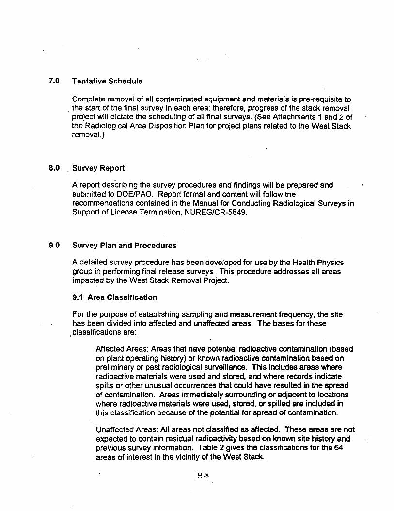
7.0 Tentative Schedule
Complete removal of all contaminated equipment and materials is pre-requisite to . the start of the final survey in each area; therefore, progress of the stack removal project will dictate the scheduling of all final surveys. (See Attachments 1 and 2 of the Radiological Area Disposition Plan for project plans related to the West Stack removal. )
8.0 Survey Report
A report describing the survey procedures and findings will be prepared and . . submitted to DOEIPAO. Report format and content wili follow the recommendations contained in the Manual for Conducting Radiological Surveys in Support of License Termination, NUREGICR-5849.
9.0 Survey Plan and Procedures
A detailed survey procedure has been developed for use by the Health Physics gr'oup in performing final release surveys. This procedure addresses all areas impacted by the West Stack Removal Project.
9.1 Area Classification
For the purpose of establishing sampling and measurement frequency, the site has been divided into affected and unaffected areas. The bases for these
,classifications are:
Affected Areas: Areas that have potential radioactive contamination (based on plant operating history) or known radioactive contamination based on preliminary or past radiological surveillance. This includes areas where radioactive materials were used and stored, and where records indicate spills or other unusual occurrences that could have resulted in the spread of contamination. Areas immediately surrounding or adjacent to locations where radioactive materials were used, stored, or spilled are included in this classification because of the potential for spread of contamination.
Unaffected Areas: All areas not classified as affected. These areas are not expected to contain residual radioactivity based on known site history and previous survey information. Table 2 gives the classifications for the 64 areas of interest in the vicinity of the West Stack.

The major source of information used to make the above classifications was the Building Characterization Team (BCT) data collected between April 1994 and February 1995. This data set comprises input from review of more than 15 data sources including interviews with 275 current and previous employees, and is considered to be the most reliable source of historical information available.
9.2 Instrumentation
The Liquid Scintillation units used for analyzing smears and swabs will be Beckman Models LS-5000TA, 5801,6000, and 6500. These instruments are calibrated in-house using NIST-traceable calibration standards.
TSA Systems Model HHD-440A micro-R meters will be used for all area scanning. These instruments are maintained and used in accordance with Sections 5.9 and 5.10 of the Pinellas Plant RadCon Manual. These instruments are calibrated by vendors to meet ANSI-N323 requirements.
9.3 Surface Activity Measurements
The surface contamination survey method used for tritium will be the same method in use at this facility for many years and described in the Pinellas Plant RadCon Manual (ES&H Standards Manual - Section 5, paragraph 2.3.2). The smears are either water-moistened cotton balls or Q-tips transported in numbered cdps or vials. All surface surveys will be documented using area layout maps showing the smear locations. Q-tips will be used when there is a likelihood that the contamination is in an insoluble form such as a metal hydride. The survey area is 1000 sq. crn. for cotton balls and 100 sq. cm. for Q-tips and alpha smears. The result is reported as disintegrations per minute (dpm)/I 00 square centimeters (sq. cm.). Cotton ball smears are analyzed using a sample of the water on the cotton, while Q-tips are counted whole in vials to retain particles or oils. t
Any areas found to be contaminated above the limits in Section 10 will be cleaned as necessary to allow release. Decontamination methods will be consistent with the instructions in RadCon Manual Section 5.8 "Decontamination."
9.4 Exposure Rate Measurements
Area scans for gamma radiation will be conducted at a height of 3 feet with a Micro-R meter as described in the RadCon Manual Section 5.10 Attachment on use of the Model HHD-440A.

10.0 Data Interpretation
10.1 Release Criteria
The radiological release criteria for tritium, uranium, and krypton-85 surface 'contamination are taken from RadCon Manual Table 2-2 and DOE.Order 5400.5 as:
Site limit: 1000 dpm1100 sq. cm. ALARA Objective: 220 dprn/100 sq. cm.
For direct radiation exposure:
DOE Order 5400.5 limit: 20 microremlhr above background ALARA Objective: 5 microremlhr above background
The ALARA Objective is defined as the level to which reasonable decontamination efforts are directed, above and beyond the legal limits.
10.2 Statistical Analysis
Following preliminary review of survey data for areas found less than 1000 dprnI100 square centimeters, a statistical analysis will be performed to verify that the average contamination level is less than the limit with 95% confidence.
I
11.0 Records
All smears are documented on the FC-232 Radioactive Contamination Smear Survey Form and an area map. Analysis results are documented on standard report forms which are reviewed by the chemist, the surveyor, and the Health Physicist prior to filing with the original survey maps in the Health Physics files. Copies of all analysis results are also maintained in the Chemistry Lab. ,
Radiation surveys are documented using a Health Physics Radiation Survey Form (RadCon Manual Section 5.6 - Attachment 2) and an area map. Reviews of results and record retention will be performed as stated in RadCon Manual Paragraphs 5.6.4.6.

12.0 References
1. MMSC-ESH-0006 ES&H Standards Manual, Section 5 Radiological Controls
2. NUREGICR-5849 Manual for Conducting Radiological Surveys in Support of - License Termination (6192)
3. DOE Order 5400.5 Radiation Protection of the Public and the Environment
4. DOEIEP-0100 Guide for Radiological Characterization and Measurement for Decommissioning of US DOE Surplus Facilities (8183)
5. Annual Pinellas Plant Site Environmental Reports
6. Pinellas Plant Site-Wide Environmental Information Document - (3193)
7. Pinellas Plant Environmental Baseline Report - MMSC-EM-95010 (218195)
8. Historical Report on Radiation Protection at GE Neutron Devices (7190)
9. Pinellas Plant Radiological Area Disposition Program Plan (Draft 4/6/95)
10. DOE Order 5820.2 Radioactive Waste Management
11. 42USC9620 Section 120 CERCLA paragraph (h) as amended by Public Law 102-426 (CERFA) 1011 9192.

APPENDIX J
Health Physics Desk Procedures

Health Physics Desk Procedure
Approved: Date: /2- 7 - Y.5 Radiological Control Manager Revision: B
Final Area Surveys 1.0 Purpose
The purpose of this procedure is to document the process of performing final-evaluations to support unrestricted radiological release of Pinellas Plant areas.
2.0 Scope
This procedure applies to the final radiological release of Pinellas Plant areas. It is intended to complement other procedures for non-radiological evaluation and release of the same plant areas.
3.0 Definitions
Affected Areas: Areas that have potential radioactive contamination (based on plant operating history) or known radioactive contamination based on preliminary or past radiological surveillance. This includes areas where radioactive materials were used and stored, and where records indicate spills or other unusual occurrences that could have resulted in the spread of contamination. Areas immediately surrounding or adjacent to locations where radioactive materials were used, stored, or spilled are included in this classification because of the potential for spread of contamination.
Unaffected Areas: All areas not classified as affected. These areas are not expected to contain residual radioactivity based on known site history and previous survey information.
Note: Besides the Health Physics survey files, the major source of information used to make the above classifications will be the Building Characterization Team (BCT) data collected between
s April 1994 and February 1995. This data set comprises input from review of more than 15 different data sources including interviews with 275 current and previous employees, and is considered to be the most reliable source of historical information available.
4.0 Responsibilities
4.1 Radiological Control Manager (RCM):
Evaluate the potential for, and form of, residual area contamination by reviewing operating histories and available prior survey information and categorize each area as appropriate
Approve final survey results and formally approve radiological release of . areas for unrestricted use

4.2 Health Physicist - . .
Review area status and plan out survey locations and have smears conducted as needed with the RCM.
Direct the performance of surveys and as appropriate review and evaluate all survey results.
4.3 Health Physics Support Aides -
Perform radiation and contamination surveys as directed. Area release smear survey data and maps MUST be performed using the smear identification key and example maps in attachment 3.
5.0 Requirements
5.1 A "Notice: No Radioactive Material Allowed in Area" sign must be posted on all entrances to the area prior to final release surveys of an area.
5.2 As shown in Attachment 1, the steps involved in evaluating areas for radiological release are:
1. Review operating history and previous survey records to determine the likelihood that residual radioactive contamination may be present in an area. Attachment 2, details how many smears should be taken to release an area based on it past history.
I
2. Classify each area as either "Affected" or "Unaffected" and particle or oil bearing. All areas will be surveyed for tritium. Only areas where krypton-85 or uranium were known to have been present ("Affected Areas")ill be surveyed for those nuclides (RCM)
3. For Unaffected Areas: Survey the floor using cotton balls at appropriate intervals and proceed to Step 5. (HP)
< 4. For Affected re as: Determine the likelihood that particulate or oil-bome (Krypton 85)
contamination may be present in the area. (RCM)
a. For non-particle, non-oily areas: Survey the floor and walls using cotton balls at appropriate intervals and proceed to step 5. (HP)
b. For particle or oily areas: Survey the floor and walls with cotton balls at appropriate intervals and use Q-tips at joints. (HP)
5. If contamination levels are below 220 dprn/100crn2, proceed to step 6, otheiwise:
IF RESULT ARE NOT EXPECTED: Prior to cleaning, mark 100 ft2 arourid the smear location, take at least 50 smears per 1000 ft2 to confirm result.
a. Have the area cleaned and resurvey with at lease 50 smears per 1000 ft2. (HP)

b. Repeat Step a. until less than 1000 dpml100cm2. Note: If more than 2 cleanings are required or cleaning fails.to further'reduce the contamination levels contact the RCM for further evaluation. (HP)
6 . Perform a Micro-R survey of the area (SA or HP)
7. For Unaffected Areas proceed to step 10.
8. For Affected re as: determine the likelihood that contamination is present under floor tiles or (unlikely) trapped under painted surfaces (RCM)
a. For areas unlikely to have contamination under tiles, proceed to step 10.
b. For areas where contamination is suspected to be present under tiles or paint: Remove random tiles or paint and survey using cotton balls at appropriate intervals or use Q-tips. (HP)
9. If contamination levels are below 220 dpml100cm2, proceed to step 10, otherwise:
a. Based on survey results have all contaminated tile removed and dispose of as radioactive waste. (HP)
b. Have newly exposed surfaces cleaned and survey with cotton balls at appropriate intervals. (HP)
c. Repeat Step b. until less than 220 dpmJ100cm2. Area can be released at the 1000 dpm/100cm2 limit with the approval of the RCM.(HP)
Note: If more than 2 cleanings are required or cleaning fails to further reduce the contamination levels contact the Manager, Risk and Radiation Protection for further evaluation. (HP)
10. a. Document all results on area maps and annotate (highlight) the path to release which was actually followed on the Flow Sheet, Attachment 1. (HP)
b. Have the RCM review survey data and sign the Flow Sheet documenting the process as performed for that area and place in permanent HP area closure file. (HP)
5.3 Surface Contamination Surveys
5.3.1 The surface contamination survey method used for tritium and krypton-85 will be the routine method in use at this facility for many years and described in the Pinellas Plant RadCon Manual (ES&H Standards Manual - Section 5, paragraph 2.3.2). The smears are either water-moistened cotton balls or Q-tips transported in numbered cups or vials.
5.3.2 All surface surveys will be documented using FC-232 forms and-area layout maps showing the smear locations.
5.3.3 Q-tips will be used when there is a likelihood that the contaminati0n.i~ in an < ,
insoluble form such as a metal hydride or oil residue.

5.3.5 The survey area is 1000 sq. cm. for cotton balls and 100 sq. cm. for alpha smears and Q-tips. The result in both .casesis reported as dpm1100 sq.cm.
5.4 Direct Radiation Measurements
5.4.1 Area scans for gamma radiation will be conducted at a height of 3 feet with a Micro-R meter as described in the RadCon Manual Section 5.10 Attachment on use of the Model HHD-440~.
5.4.2 Radiation surveys are documented using a Health Physics Radiation Survey Form (RadCon Manual Section 5.6 - Attachment 2) and an area map.
5.5 Evaluation of Results
5.5.1 Reviews of results and record retention will be performed as stated in RadCon Manual Paragraphs 5.6.4.6.
5.5.2 ' Following preliminary review of survey data for areas found less than 1000 dpm/lOOcm2, a statistical analysis will be performed to verify that the average
_ contamination level is less than the limit with 95% confidence. The formula is: -
~h = x + t (I,* (s,/dn where
is the estimated upper bound of the true mean at the 95% confidence level
t is the 95% confidence level obtained from Table 1 df is the number of degrees of freedom = n-1
is the probability of a false positive determination - x is the mean of the survey results in dpm/100cm2 in an area s, is the standard deviation of the survey results n is the number of smears taken in the area
If is less than 1000 dpml100cm2, then the area being tested meets this guideline at the 95% confidence level and can be released. If is greater than 1000 dpm/100cm2 then the area must either be cleaned and resurveyed, or additional smears must be taken to demonstrate compliance.
5.6 Overhead surveys
5.6.1 The overhead of affected areas must be surveyed for removal contamination.
5.6.2 Only overhead areas that can be safely accessed are surveyed.
5.6.3 Areas surveyed should be near where RadExh ductwork was lodted, based on process knowledgelhistory.

6.0 References
6.1 MMSC-ESH-0006 ES&H Standards Manual, Section 5 Radiological Controls
6.2 NUREGICR-5849 Manual for Conducting Radiological Surveys in Support of License Termination (6192) .
6.3 DOE Order 5400.5 Radiation Protection of the Public and the Environment
6.4 DOUEP-0100 Guide for Radiological Characterization and Measurement for Decommissioning of US DOE Surplus Facilities (8183)

Table 1
Fadors for Comparison of Survey Data with Guidelines and Determining Additional Data Needs
Pegne of freedom is the number of items of data minus 1; for values of dcgms of fnedom not in table, interpolate b m w m values listed.
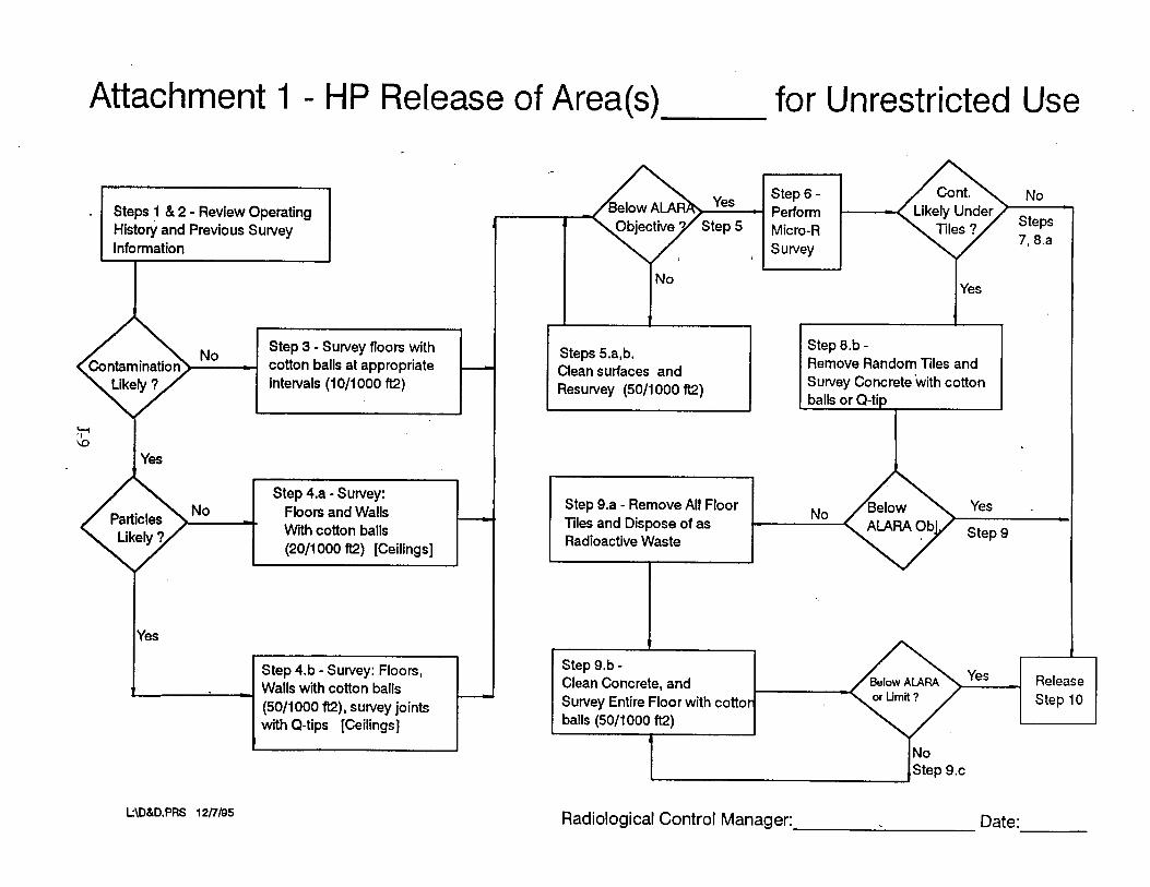
Attachment 1 - HP Release of Area(s) for Unrestricted Use
Radiological Control Manager: Date:
Step 6 - No Perform Micro-R Steps
7, 8.a Survey
?
Steps I & 2 - Review Operating ~ i s t o j and Previous Survey Information
Yes - 1 tep 5
No Contamination -
No Yes
1
Steps 5.a,b. Clean surfaces and Resurvey (50/1000 ft2)
Step 3 - Survey floors with cotton balls at appropriate
with Q-tips [Ceilings]
Step 8.b - Remove Random Tiles and Survey Concrete with cotton balls or Q-tip
- 0 intervals (1 011 000 ft2)
7 \O
Yes
balls (5011 000 ft2)
No .I.
Step 9.a - Remove All Floor Tiles and Dispose of as Radioactive Waste
Step 4.a - Survey: Floors and Walls Wth cotton balls (2011 000 ft2) [Ceilings]
No I
Step 9.b - Clean Concrete, and Release Survey Entire Floor with cottor Step 10
Yes
1
Step 4.b - Survey: Floors, Walls with cotton balls (5011000 ft2), survey joints
-

Attachment 2, HP desk "final area surveys"
Smears per area
Tvpe of area LOCATION examl~les Noteslsmear amounts
Rated as a:
HIGH prob YYY or YYN
Mod prob YNN
Lgw prob NNN
108,107,157 1571158,182 RMMA
Handled NG, NGT 112,183,184,1281131
Most office areas, 117,110, 134,170 Computor Rms.
* Detail smearing needed to locate past LTA habits
* At least 50 per 1000 ft2
* Smears will be based process knowledge, history where parts were used
* At least 20 per 1000 sq ft
* Smears will be RANDOM . using history of past uses
* At least 10 per 1000 sq. ft
KEY: - NG = neutron generator NGT = NG tube Prob = probability LOCATION = Pinellas Plant locations LTA = Less ~ h a n Acceptable

ATTACHMENT 3 . .
FINAL AREA RELEASE SURVEY
MAP KEY
(Smear #)F= Floor
(Smear #)W = Wall survey 1-3 feet above the floor
(Smear #)* = Wall survey 3-5 feet above the floor
(Smear #) # = Wall survey 5-10 feet above the floor
(Smear # )C= ceiling
SEE EXAMPLE MAPS


APPENDIX K
List of Hazardous Substances and Extremely Hazardous Substances

This page left blank intentionally

Page 1 of 1
Hazardous
Chemical Name (Radionuclides)
AMERICIUM-24 1 BARIUM- 133 BISMUTH-2 10 CADMIUM-109 CARBON-14 CESIUM-137 COBALT-57 COBALT-60 CURIUM-244 GADOLINlUM-148 HYDROGEN-3 IRON-55 KRYPTON-85 LEAD-2 10 MANGANESE-54 NICKEL-59 NICKEL-63 PLUTONIUM-23 8 PLUTONIUM-239 POLONIUM-2 10 PROMETHIUM-147 PROTACTINIUM-234 RADIUM-226 SODIUM-22 STRONTIUM-90 THALLIUM-204 THORIUMa230 LJWWUh4-238
Synonym
TIUTIUM
Substances as dejned in
CAS # -
7440-35-9 7440-39-3 7440-69-9 7440-43-9 74440-44-0 7440-46-2 7440-48-4 7440-48-4 7440-5 1-9 7440-54-2 1333-74-0 7439-89-6 7439-90-9 7439-92-1 7439-964 7440-02-0 7440-02-0 7440-07-5 7440-07-5 7440-08-6 7440-12-2 7440-13-3 7440-14-4 7440-23-5 7440-24-6 13494-80-9 7440-29-1 7440-61-1
40 CFR, (302.4,
RCRA Hazardous Waste #
NIA NIA Nl A NIA NIA NIA NIA NIA NIA NIA NIA NIA NIA NIA NIA NIA NIA NIA NIA NIA NIA NIA NIA NIA NIA NIA NIA NIA
Appendix B) as of
>Ci Limit
YES NO NO NO NO YES NO NO NO NO YES NO NO NO NO NO NO YES YES YES NO NO NO NO NO NO NO NO
07/01/94
Data Source
INVENTORY INVENTORY INVENTORY INVENTORY INVENTORY INVENTORY INVENTORY INVENTORY INVENTORY INVENTORY INVENTORY INVENTORY INVENTORY INVENTORY TNVENTORY INVENTORY
-- INVENTORY INVENTORY INVENTORY INVENTORY INVENTORY INVENTORY INVENTORY -- INVENTORY
INVENTORY INVENTORY INVENTORY WVENTORY

Chemical Name
Page I of 25 E I I I
>
Hazardous Substances as defined in 40 CFR, (Table 302.4) as of 07/01/94 ,
(l.I'-BmmM+4,4lXAMNE-3,3'DICHU)RO
( ~ . v - ~ + ~ , - u D I M ~ o ~ -
( ~ . ~ - - M - ~ Y L
~~~~0~
O . ~ ~ P H O S P H O R ~ T H I O A ~
1.1-
I.I---
I . I ~ O P R O T A N e
I . 1 - m HTDMmE
I.Ia--IU--- -
Synonym
33-DICHUIIIOBENZJDENE
3 3 - D I M m l o X Y B E N ~
W-MMETHYLBENIIDINE
PHOSPHOR~IOIC ACD
ETHYUDENE DICMDWD€
EIHENE. 1.1-DICHLMl~, VWYUDR(e CHLORIDE
-
I f . & T n m U m ~
It-
l s s P a m s r m c r u s o x n r c A C I D I I s Y , ~ ) l ESTER
I f ~ ~ O C A N f !
11-
1 7 -
I ~ O P A N K ~ ? m #
I.CDIOXAN~
IJ-NAMIOQUPSONa
I . A C R l G 2 - m
I . N m A u l N 6
I-MtOPA l . & % D l B R ~ , ~ 7 E V I )
I--A l. 24El I lYL
l.111oTANAUlNE
v- l . Z - m O P U m ACID
v.4-
w- U6--0PHENoL
~ ~ ~ O P E N R
IIOR-I
s s 5 . 3
11111.7
%I21
nsu 14-IS9
mdb9
11S71-4
1 ~ 9 1 - I
I S I W
591461
13431-1
IMR-1
7b.W
1OI.IM
1-53-J
75.99.4
15950.66.0
9 3 s m
933-1S.S
n ) ~ -
-am BIS ( 2 - E f H Y L H E X n . m l €
PROPANE I ~ - W B R O M O ~ O
mRnnNE I-METHYL
1-1-m
I l 4 X A m U-DlOXlDE
I . ~ Y L N E M O X I D B
I.N-MONE
AClElrcrry N w i W J l W O m Y L b
ALPHA-NAPHmWINE
IRIS C D - M I ) R O ~ ~ ~ ~ ~ O I ~ . ) PHOSPHATE
lSOgVrnALCOHOL ,
N-PROIZAMME
1.2 3.4MEPoXYBWANE
193.394
CAS #
91.941
119404
119-93-1
%IS3
l9141-I
lSW3
n 3 u
-9
51-14.1
KI3-I
i
I.lo(l$- l~~~~
RcRA HAZARDOUS
WASTE #
F002
> 1000
Kg

Chemical Name
Page 2 of 25
Hazardous Substances
ZWTA'JD
%w- ZWT-
w~=n 2 r - '
24DACtD
240 - 24-
2- -- I$.nniusolasr.
z-- v-mmR- MnawrI-0.
2 - m m
1-
2-
I - N A P m W U m a
2-
2-ANa
1-rlCUmE
1U.v-
3.4-
x 4 ~ o m n m 3 . 4 - m
4.4 .rWmRZLNB Blf -- 4.6- AND == 4--
4 c U W R O . m
*NIIILOIWXX.
A&-
as defined in 40 CFR, (Table 302.4) as of
Synonym
2, 4.5-1. ACmC ACID. @,YTlllCHLOltOPHE XY)
ACEIlC ACID ~ 4 ~ O P l I E XY)Z4D. SALT3 AND ESEW
moZacDIMmlyL.
PmNOl. %CDRrrmO
MALEIC ANHYDlllM
PlKNOl. 2.6DICHUn.O
I.4DICHLOR@2-WlENE
~ ~ c ~ u ) ~ o r m o r n - IFTACIK.OROMWWAUNE
FuUmUa
IRA-NA)MHILIU(Me
OM'I~WHENOL .
maem 2 - m o
PYNDINE. 2-MlmIYb
B E N 4 W C w
BENWAPYUENE
,
PHENOL, 2 - m c D I N I T R e
cIYIIIMN-
~ ~ M - C R E S O L
p~~~~ PHENU. +me
01/01/94
CAS #
93-765
1 1 3 1 4 7
2518154
1 3 ~ ~ 9 - I
nn+95-5
94-75-7
w 1 s n 7 - 9
51-28.5
329-71 4
IOC3Id
874S-O
m#l 764-414
110751
91-S-7
98.01-1
91-594
n7s.5
Me)
10PWI
609.194
2 2 ~ 1 - l
sna 6lb39-9
101-144
53452-1
%I45
S9-s7
7005-n-3
1 m - 7
0 3 2 - 9
RcRA HAZARDOUS
WASTE #
> 1000
Kg

Synonym Chemical Name
--
Gn- ~-PROPEN-IU 101-184
u n - E 107os.1
IumAm- B ~ Z E N E ~ ~ U P H ~ W - M M R H Y G lnmd
UW-IIlfC 3I9d4-6
UIHA--AN 9%9W
AMU-NmnTIMXIILEA ANN M.88-4 - Page 3 of 25
I I I

Chemical Name
Page 4 of 25

Chemical Name
MIIDMYCIN C 5047-7
AzmDm
MNuu CAmmATB
BAlllVM CTANIDE
B n q l ~ n m S 1.2--.+u-
BE~ZALCHU,W
E l ' t l V I m l r n
SMrnYLCHOLANIHIIENE
BENZENE, D I C H U ) R O M ~ I Z
151-#4
U24-l
5649-5
5317-3
Do05
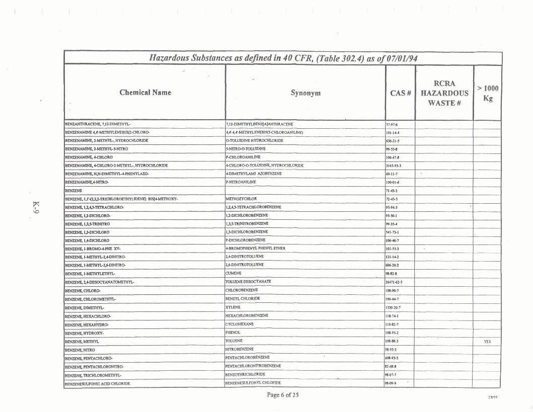
Page 6 of 25
Hazardous Substances ,
Chemical Name
EENUMHMCENE 7.12-DIMETHYL-
BENZENAMINE 4 # - W l W E N E B l X ( 2 ~ R O -
6- 2 -MmMc, HYDR-
~ 2 - M E r W L ~ O --- B E N Z E N ~ ~ ~ 2 ~ Y L r . H Y D l l O C H l O l l l D e
B T N . N - P H E N Y l A ? D
BENZENAMN&CNmO-
EmmN6
~ E N ~ R ~ . ~ ~ ~ m ~ m ~ r n n r e ) a q c m m .
sENmR ~t.u.m-O-
sasmc~~a-a sasmcQ 1s-
muD4S.I-
sasmcQ1-0
BEtaN&l-x1.
m u D 4 S . ~ ~ Z ~ O -
sasmcQI--Q
muD4S.t-
B E t U R a f ~ ~ ~
~ Q I L O I L o . -- BENzE'wDIMrnM
mwNgllExAcHU)xO-
B E W N I L ~ O .
BBNpNILIIIDM))[I-
ammi&- BLNzpRNll l lO
B m m J E l E H T A m
- m A c H U ) x m @
B ~ ~ -
6-m-
as deJined in 40 CFR, (Table 302.4) as of
,-
Synonym
7.12-DIMETHYLBEN~A~RACENE
~#4#-MmmENEBly l~HWROANILWE)
SlDLUlDlNE HYDR0CHU)RlDE
S N l T R O O ~
P ~ ~ O ~
44mLORQ(1-HYDllM:-
CDMrmYUMlAZOBENZME
P-NITROANILINE - 1L.43-m--
I ~ ~ ~ E N Z E N E
r ~ m o B m E N E
13.LWMUXOB-
P-DfcHLQROBM~
&BROwMiENYL PHEmL ElHER
2,&DMlR-
2.64)-
CUhtENE
KnUENE MlsoCYANATE
ClaQRm-
BENZntXL.ORm
XYLEm
n m a o e m m c- ,
PHEW.
Toumrr
moBENmJl?
F ~ ~ A C H L O R ~ M L E N ~
~ A C H L O R O ~ O B ~
B E N ~ C H W ~ ~ ~ D E
BENZ€NESILFOHYL CHLOnDE
07/OI/94
CAS #
51-W4
101-IU
636.21-9
99-554
l w n l
3165-933
W11-1
IOBQ14
llUt
n u 5
95-94-3
9 s - 5 ~
99-3s4
541-T)I
I 0 6 4 1
101-5M
121-14-2
606W
9M1-l
26471-624
1-7
100-4+1
13W207
11I-741
110-82-1
10-95-2
IOM63
9CW3
608.93.5
Il-684
w 1 . 7
9849.9 -
HAZARDOUS WASTE #
> 1000
Kg
YES

Synonym
Page 7 of 25 I I I
Hazardous Substances ,
Chemical Name
BEN-
BpltlMNe
e m 4 3 [all] rmvLENe - B-
-JL- BENMlCAClD
B-
~ps~n-
~ ~ u ~ u n n 4 '
BrnnlnJM
BEIYLulMCHLOllfDe
BERYLulMFUIOlllDE
B E W u f U M ~ ~
BCreAalX
BETA-ENDOWWAN
slro-)m -mm IIIIcmm - BaomFouM ~~ BUM AQTATE
m~~~ EannmmE* m A C l D
CADMIUM AChTAlE
CADMmfIIII-
WMNMCHLOllfML
CAtClllM -ATE
as de/ined in 40 CFR, (Table 302.4) as
THIOPHRI~ ,
(1.1-B!PHEN~MCauMRIE
FLUOMNlmNB
BERYUIUM DUST
LllclwxOmMfMER
DlCmLmoh4mlOXIrmANE
2 . P R O P ~ I-BROM[Z
m l n m R O M Q - -
m w m m - ~ ~ m m -
0/07/01/94
CAS#
IOe9bS
9211-5
191-242
205.99-2
20148-9
2 w
6 U S 4
100474
9ubl
7440-41-1
m m - 5
m 4 9 - 7
13597-99-4
31945.7
3321345.9
Ill444
11131-1
m 3 l - 2
7 s n 2
351-57-3
1-
8%l
109-73.9
Iol.924
1440-43-9
n3.W
ma4
10lw.ua - 7778441 -
RCRA HAZARDOUS WASTE #
POI5
m
WOb
--- - --
> 1000
Kg

Page 8 of 25
Hazardous Substances as dejinrd in 40 CFR, (Table 302.4) as of 07/01/94
,-
Chemical Name
CALCNM msmm CALQUM-
CALCM(cARBIDE
CALCNLa-TE
CMCM(ml 'F .
CALCluLICHllOMATEMllElllES
CALQUMCT-
~ W D E C Y U I ~ S U L F O N A T E
Synonym
,
CHROMlC ACID. CAWWM SALT
CAS#
S21016-6
15-2&1
1316S19.0
592414
262b+061
RCRA HAZARDOUS
WASTE #
WOI. Do03
War. UD32
m. W32.
> 1000
Kg
YES
YES
YES

Chemical Name
Page 9 of 25 I I I
Hazardous Substances as deflned in 40 CFR, (Table 302.4) as of 01/01/94
m m m E R
-C ACID
CHROHfCAQTAfl
CHLOL(ICAQD
CHROHK:AClD
CHllOMtCWATE
CHllOMlLlM
CHMMlUMCOWDEl
CHRoMousCHLOlllDE
Synonym
MEIHANE, CIiWROMrmOJCY
-0QVB-
CORR~QVB-
CRF.SOL
cREmL.0
CRm-
CUPRCACETAl6
C U P U C m m
N)IIICMLOILIDB
CUIIIlCNmUtE
cu)lucoXUAm
CAS #
107-30-2
7790-945
2921-8-2
1066m-4
IlllS-14s
10101434
1 W - 3
CWYUC ACID
2-lWlMAL
PAUS OMM
RcRA HAZARDOUS
WASTE #
Ooot. WOZ DoM. Doo5. DO07
m1. 0003. m 7
> 1000
Kg
YES
544-92-3
5672-4
M0I.m-9
1319-n-3
9-7
4170-303
142-714
1200243J
7447-39-4
3251-234
s89-3 -
m 1 . m2. m 3 . DOOl WO5, OoOs. WOl. DLW. Dog, FWl. FWP.UO8O.UI22,UlM.UlEd
w02 m 3 . waa
Y€S
ns

Chemical Name
Page 10 of 25

Synonym
Page 11 of 25 I I I
.
Hazardous Substances
Chemical Name
r
m o ~ m t n r m ~
D l C l n . O R v
DICHWROPRWANB
D l c H U X O P l l W A N b - - 0 I l l O P E N E O
D l c l l l m O P l l ~
MeOTDL
DIELDRIN
Mrmn?lmNAE
D m i W L P - m m
DlECHPWmSD
DlEnmEHa
-a MHrrmOdAFllOUl
omm0m-n uhmmn utmm-n DMEIHYL m.FAln
MLlEnmAHMll
-0
DmmmmmL DlNmclPmNoL-
DlNrlR-
DINOSEB
- m m DlPHHc#MlolUCACID.-LSlER
D r n o p Y U m a
W A T
Dlsmmm
Dlnmmmm DnJRON
as dejinpd in 40 CFR, (Table 302.4) as of
,-
M ~ M L
ARSONOUS MCHLOIL1De. PHENYL
f 7.3.6DlNElXA NAPUlWSBPxlRE. 3 ,V .W-HEXAM(UIRQlW.666h ' I ' I ' IA - OCTAHWROXIMLPHh3BETWPllryBETh6UPHh'IB~h1~)
IJB- ACID. D~ETHYL ESTER
PlWSHOW ACID, ortnm. 4- ESIER
PHENOL, 4rat~mn1a-mmn~w1~.0 I > B E N ~ x o l Q UILOPYL
PHOSPH(M-ACR)
~ ~ ~ P H O R ~ ~ ~ O I C A C K . ~ ~ yl+mwu~~ ~mxomnm~ I ~ - B ~ D I C A U B O X Y U C ACID m n E ~ ~ E R
s U N I C A C 1 4 ~ m R
MEniANAMMfN-MRHYG
PHPIOI. ~ < I - H ~ M P R o P ~ ~ . ~ ~ o
0cTAhmwLpm-E
TEIIUrmn ~ O P H O J P H A T h
I-PROPANAMIN6 N-PROPYL
o . o D m n s - ~ ~ y r n r n m r o ) ~ ~ ~ ~ ~
T H I O I M I D O D I ~ DlAMIDE
07/01/94
CAS#
m-88-I 696216
1663S-19-1
1003-19-9
16952-l34
1 1 l-32-2
844.1
311454
1W-W-1
ss3-I
94-S6
5-14
~ S I - s 131-11-3
77-78.1
1 2 W 3
'lSIYS4-5
2SSO.Sl
2 m l - I M
m s - 7
In-169
10149.3
l a 4 4 1
1SOQl
m.044
541.S3-1
330.541
RcRA HAZARDOUS
WASTE #
Do02
Po4
> 1000
Kg

Page 12 of 25
Hazardous Substances r
Chemical Name
mecn~- ACID
ENDOWWAN
W A N W A l Z
~ S M ~ U U
ENDRIN
~~ EPK~UXOHYDNN
EmyIEPlfNNE
E n W W m E , N - ~ ~ O S O
ElmN& I.I'OxYms
ETHANE. I . I . I~-~M-
ElmN& 1,I.I--
ElmN& I,Iaa-TFlMQMllQ.
ElmN& I.l.l--
lxmm 12-
lxmml lExA-6
E l m N & m D EMAHBnaOAMDlt
rmANOL
~ v ' 6 m n o s a r o ) s b R T m m ~ c f l W U O
F m E m 1 . l ~ ~
-cHLoM).
RHKIN
EllWL M Z T A K
hnmAQYLAK
EllWLllMWII
ImYLCYANlDE
h l W n h l f m A C I I n A n
rmnwlwws~m~~e r r m L L N e D l B R ~
as de/ned in 40 CFR, (Table 302.4) as of 07/01/94
Synonym
4 C M m -14+B~K)XAWEPR(.6~~.~9.IO.I~HEXOC~OI>3h699&- HEXAH171O. +OXIDE.
7 a r ~ ~ l c v n o IUII mprmwrncmoxwc ACW
ENDRIN, a WXABOL~S
omw. wmmimn)- I>-BENZF€DIol. yl-HYDROXI-1-YLAM ) m m b
N-NrmOSC'-
m n N l r m m E J l E R
~.~.u-mm- C l G n m C n W R ~
I.I#-mCHUM-
l . l f -T l l lQa010~
I>--
HEXACHU)ROElHANE
P E N r A C H L a ~
llmACETAMlDE
CAS#
27176.~74
11Sl9-7
I031474
1 e n 3
n-m 7 4 1 3 3 4
106.~4
51-434
55.18-5
661)-1
m0.w
1 I J M
79-34.5
-5
107961
67-7l-l
KOl-1
61-55-5
-- -
RcRA HAZARDOUS WASTE #
DWI. F003. F005
N-NR11-
pEluXUX-E
~ a - - n m n ~ ~ U ~ Y L C H L O ~ '
ACElK! ACID
l-PIIOPaSolc ACID
PMmMmm l-)II-ACID, 1-MmMr
wmmswow ACID, mn ESTER
EfMNE, 13-DIBROMO
> 1000
Kg
YES
11165&7
117-1U
1~6.m.s 1M1-4
563.12.1
141-TU
IQICS
100-41-4
107-124
9743-1
6 1 - m
106-93-4
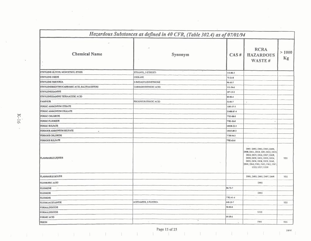
Chemical Name Synonym
Hazardous Substances ,
EmnENEOLYanhfmmEmnmI
E n m a s E O % m
EmnENE-
EmnENEBMDrmmmMMC ACID, MLn L ESlEW - ~ ~ C E m A C l D
FMBHUll
FERNCM(MONNMQIUTE
FElUlcMRlONNMoxAuTe
FEmlcCHUIUOe
FEMICb.umNlx
FEMIC W A S
F E l U O U 1 ~ ~ A l m
F E R U O U S ~
F E M ~ S U U A ~
MMMMLtUPU[W
M M M M L t e
as defined in 40 CFR, (Table 302.4) as
ETHANOL. 2 - m x y - ,
OXIlUHE
1-IMIDmmlNEmoNE
~ANMOWWIOIC A C ~
~ P H O R U l H I M C ACID
0/07/01/94
CAS #
110605
7S-214
964.7
Ill-54d
IOT-IS3
604w
52-7
11nn.5
5sebw-4
7mMM
~~ 1mm-22.5
1 0 0 1 ~ 3
n s c ~
nndso
RcRA HAZARDOUS
WASTE #
ml m2. m3. m5, wos. Da4 WII. WlS.Ws. W22.DO21.
W24W25, W26.0027.007.8, oms. WW, Lm3& w33, ww 0035. WM. DOB. W39. Wro.
DWl. 0042 Fool. F003. FW5. m07. U223. U227. U239
DoOl. DOo). Wo5. m7. Wcn
> 1000
Kg
YES
YES

Page 14 of 25
Chemical Name
t w m x N A 1 L D u Y r m ~
- w ~ ~
~ W r n 8 0 U W
lIWmCmm
H e r T M I L O I I m
-IBHI
P
ilmw3Um-m HEXA- --
4.7-MmU - 1 H - ~ I 0 ~ 7 ~ A ~ O U . ~ 7 , 7 A - ~ O
I>ARADlENS 1 . 1 , ? 3 , 4 ~
Is-= 1U.W-O
U - - B n ( l 4 C m O
I-PILOPEN6 1.1UUHMA-
KlLt
102447-3
W e 3
60CRI
77474
7bW
IBC7I-7 -
m t k wax mu. mzr mzs. m 7 . mm. mw.
W%.DO(I.OMt DO43.m1, F m m 3 . nos
mOOO4WO7.Wa*DOo9. Do10, mil. 0019. W2f W23, W ~ I oms. m4 m 7 . wx Don. Doq DO32 W 3 l B3S. ~ 0 o n . m % m 3 9 . o o o .
WCI. ~ 0 4 rn m l . ma m 3 . moJ.mw.Plar.vPso.val.m2%
una. ma
WOl m WOS. wos. 0007. m o a a . w l l . w l 8 . m 3 s ,
m ~ , ~ o q m o , m 3 . FO~J. m, W32
YU
"

Page 15 of 25 I
Synonym Chemical Name

Chemical Name
Page 16 of 25
Hazardous Substances
WD
WDACETAn
W A u s m u T E
LFADQlLOIlDB
WDFLammuTB
W D F L a m m u T E
LEmhUOlllDE
WDmLnKm
WDNfnuls
~w-n ~ L T M M ~
WDlRDACPTATH
l ~ ~ ~ n LEADmmDE
W - A N A n
MIIU(
unmmmown UIMUII-MTIEILILt
UBENma-
L(CIIFbOL - -- MWIIMDUWNB
wm LULQEAQD
~~ Nhmmmaa
MEILCUIIICcYmam
MmamJcMIMTH
wsiarruc W A T H
as d e m d in 40 CFR, (Table 302.4) as of
Synonym
ACEl'lCACto.LW(W)SALT
~ m ~ s ~ m r m c ACID. LWO+)SALTQ.S
LEAD, W s ( A C E T A w 0 m -
M-XYLEHE
M4xESYLCACID
3 , C P w J D ~ 1.2-MHYDIIO
mo?ANEDlNnuw
L ~ y s n n - o m M m I
01/01/94
CAS#
1439.91-1
# l a 2
IIU.0.p
mb9s4
111*)6S
m 3 4 2
101014M
IWPP-7u
?446-n-i
~ m - ~ S I 1335-114
~ 6 . 1 ~
1 3 1 m
S9l474
1401-sf4
IOb3b3
IC&M
994-
5SC(+l
990)-1
111-%S
llCl6-7
IlH3.I
109-W-3
I L n - 3
203245-7
mo*l
10609CO
TmW) -
RcRA HAZARDOUS
WASTE #
DOOI
. ~ 1 . W 3
wol . 0003. wor
> 1000
Kg
YES
YES
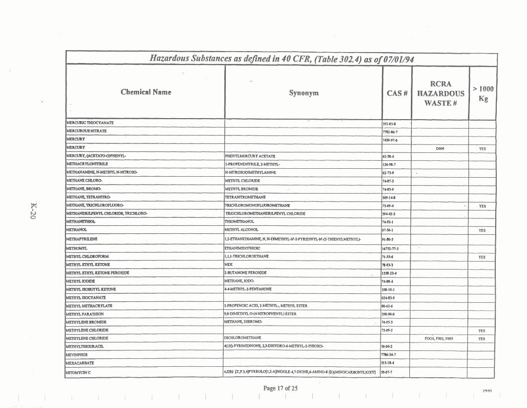
Chemical Name Synonym
Page 17 of25 I
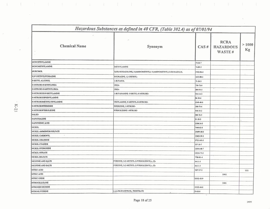
Chemical Name
Page 18 of 25
Hazardous Substances ac defined in 40 CFR, pable 302.4) ar of07/01/4 ,-
MONOElllYLAMDSE - L(IRCMOL
NE9-
N - B U ~ A L C O ~ ~
N--
N p
N---
N P
-Nnmosmmnm.- N--
N-NmOSOrYma.UMNE
?
Synonym
urn-
WWlSO- -). Y ~ ~ k ~ ~ ~
HYDMZlNE I.2-DmIIYb
I-nurm UllLA
UREA
I-WrANAMlNS. N g U M N - N n U 0 9 1
~ N ~ o s o .
P m U m m . 1 - m
PIMOIXDME I-NmOSO
CAS#
1MCl
14s-5
2'763.964
161SI&1
n-sf mm 68493.5
924.16-3
Sm.6
U(P-QO
100ls.4
930SS.1
RCRA HAZARDOUS
WASTE #
> 1000
Kg

Chemical Name Synonym
Page 19 of 25 I I I
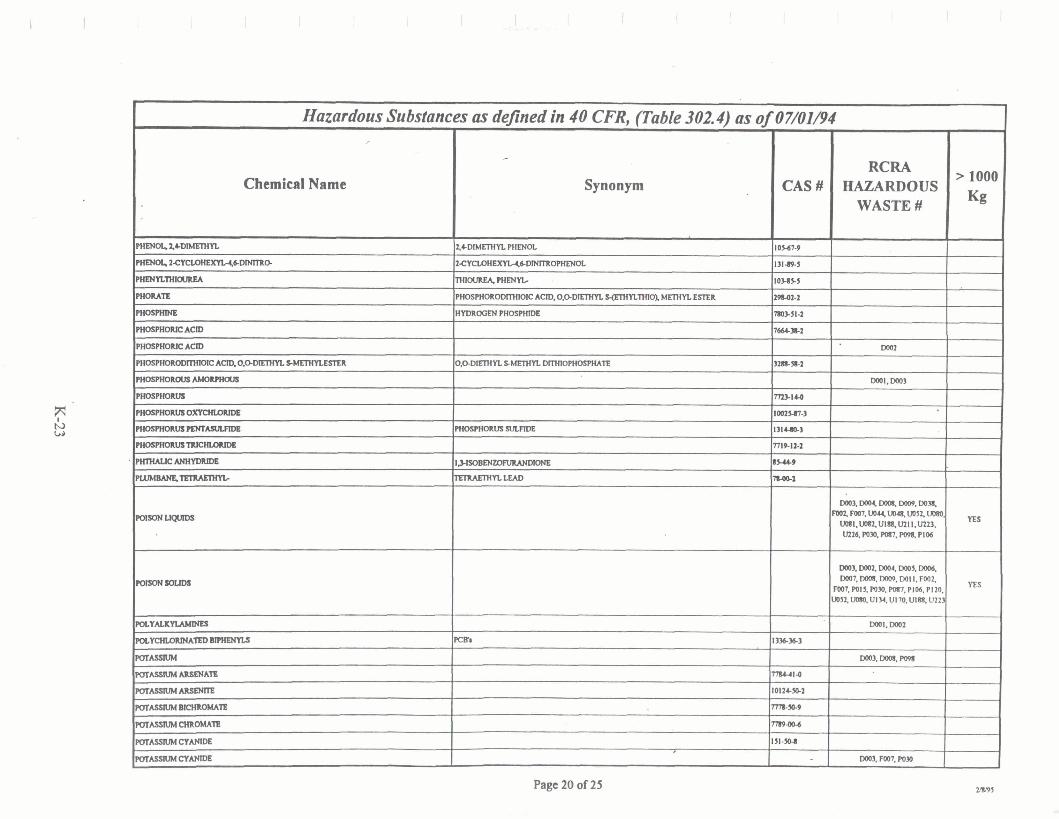
Chemical Name
Page 20 of 25
- - \
Hazardous Substances
PHRJOLZ-
PlmOl.1-6D-0
F . H E N Y L ~
PHOMlE
pllOmme
PHOSPHOlllC ACID
PHOSPmMlCAClO
F W S M X ~ ~ ~ ~ ~ I C ACID, O,ODEIIW s~mm~mr ~ ~ M ( O I V H O C
Pl#omfoxU1
PliommwS-
P H O S P H o R M ~ ~
FIKBP~RUSTIIIQILOIIIW
Plmw.lc-
n-
m-upMw
~~
nJLYAU(YLAMDILS
F U - l E D m
POTASSIUM
POTAsmMARS€NATs
POT--
POT--lE
POTASSIUMCHIIOIM~
POTWSrUMCYANlDh
POTAsmMcYANlDh
as defined in 40 CFR, (Table 302.4) as
*
Synonym
X + D I M ~ ~ PHENOL
2 C Y M I I W O Z l C D l N l T m ~
m o u R E A . m n
PHOSPHORODllHION: ACID. 0,ODIEWYL s(mmrmol METlM ESTER
H Y D l t ~ P I l O S P n l D e
o . a m n SMETHYL DITHIOFWOSPHATE
n t O S I H O l l V S ~
I1-no- LEAD
PCWn
,
0/07/01B4
CAS#
l o w - 9
13149-5
IOUSS
29842-2
WSSI-2
7-2
~ ~ J C Z
ZMI4.4
l M 2 M - 3
131-3
~ISII-Z
IW
n40-1
l3%3&3
7784-414
lOl24.B.2
mm.9
2119046
ISl-S0-l
RCRA HAZARDOUS WASTE #
Do02
WOI,D003
m x m m m . o o s . Foq FW. uou, Wm. uo5f uma
v o l l . ~ u l q m l i . v w . ' W26. Porn. POt7. Po4 PI06
m. Dog war. m 5 , wos. D007, m, DOO9. W l I. F00f
Fm7.wlS.mr.m,PIW.P120. U)5%W,Ul34,UI70.UlCS, U213
mI.m
m 3 , m. Po96
m 3 , Foot m r
> 1000
Kg
YES
YES

Chemical Name Synonym
. Hazardous Substances as defined in 40 CFR, (Table 302.4) as of 07/0I/94
,
PQT-HYDROxn#
P Q T ~ I f Y D R o ~
P Q T A S S n J M V T E
PQTm-TE
PQTAdSMlllLVRCYANlbe
PRONALmX
W m -
WMOIlB
WAMYLALCOHOL
PRommKACID
m ~ ~ 1 0 . ~ ~ ~
ARGENTATE (I-). BIS(CTNJ0C). rOTASSlUM
BENUMlOE
7-
2-PROrYN-IOL
SILVEX
IIlIP(amma
lllSOllQFOl
SAcQUILpJmuLn
- . SeGALRLAcsrATB
SECdum =ATE
SeGwmAulNa
SaENWlUIAaD
Sa851111#0]rma
SBLLNIIIManmDa
SeLWlllllW
CAS#
1316SC3
ma7
-14
2399jS.S
S42-%7
DIZ-3H
101-19-7
W4P.4
wn-I
yannmm-~-xn.w ~a~.ll.l~mmmorn-~q~~mm~)m
I-
t>---MNE.1.l-DIOm-
I,B- m - m m b '
JnENnJMO)(IDE
RcRA HAZARDOUS
WASTE #
W02
WOI. Do01
> 1000
Kg
S0.ss.s
IOB4-3
8101-2
9 ~ 9 . 7
10-
sIH9-s - 7-
1-m
Qo.Ia-4
WOI

Chemical Name
Page 22 of25
Hazardous Substances as defined din 40 CFR, (Table 302.4) as of 01/01/94 ,
SILVER
SILVER CtANlDE
Samm1F:
SmMM
,-
Synonym
I
CAS#
7 ~ ~ 2 2 4
SObU9
7761-
1 L o p . S
RcRA HAZARDOUS WASTE #
> 1000
Kg

Chemical Name

Page 24 of 25
Hazardous Substances ,
Chemical Name
mc- ~ R J C H W R ~
l m K ! H U m m
-imanoR--
mHuJa- l N E l M A N ~ ~ A T 0
lluFm- ~ Y l A M I N E
MAN&U~
UXACIL MUSTAllD
UMNYLACETATB
U M N n N l l M T e
VANADIUM OXIm
VANADYL SUIATB
VMYL ACErATE
WARFAWN, Ir SALTS, WHEN =AT CONCEHlMTlONS > 03%
WASTE WA'IEIISUIWE
XlLENC
XILENE
XILENOL
msc ZNCACBTATE
7mcAMMONRRI-
Z m C M M T B
mscBuOwD8
msccAm5mA.n WCCHLOUW
W C k u n N M !
Z m C H Y D I I m
m c NIIMTB
WCpllmoSmFQNAfl
as defined in 40 CFR, (Table 302.4) as of
Synonym
'TIIIcHLOllPHON ,
EWEN&TRICHUIIIO
l u C H U J R O r m m TCE
~ ~ O F U J o R O
Z,T-NA~ULEN~~SILFONIC ACID
W m C H L O R O m l m ~ l -
VANADlllU ENTOXlOE
VwnACETAlEMoNoMER
2H-I-BENZDIW-Z.ONE
-0
*
--- --
> 1000
Kg
n s YW
YES
07/01/94
CAS#
nded
79.014
7-
U1611)-2
1732341-7
12I44-l
7SB-3
n-9-1 6h7S-I
m 7 & 9
131462-I
1 7 7 7 4 1 ~
loCOS4
8111-2
1330247
1300714
7440666
$57-34d
SY2a-n4
1332474
76994.u
3486.354
764HS-7
m3.49-s
7779464
n79a-6
In*-1
RCRA HAZARDOUS
WASTE #
W.Oaa
-
Food
mOl. Wl8. mol. FW3. FOOOO,

Chemical Name Synonym
Hazardous Substances as defined in 40 CFR, (Table 302.4) as of 07/01/94
ZlNC-
WC W A T B
ZRCONNHmAm
ZRCQNKIM-
> 1000
Kg CAS #
16111-71-9
TmaZO
1161C61.z
10026116
RCRA HAZARDOUS
WASTE #

Page 1 of 12
- Extremely Hazardous Substances as deJined in 40 CFR, (355, Appendix A) as of07/01/94
,-
Chemical Name
1.1-DMETHYL HYDlUZME
la--
111-ANE
4&- AND U1TZ
4ALWOrYWDINE
AcEKmCYANOHYDNN
AcEKm-
ACILOLEIN
AcIIYLAMm
ACR-
mnnamum ALmmmu
,.
Synonym
A E I L M M E t m
PnEWl. I-HEInn-4.C-0.
4PYNDNAMlNE
)IIOPANENnNLE
1-PI1OPMAL
2-PROPENAMIDE
2-F'R-
AWaSDVIOXlDB
AWE NO US^
AWMB
v
CAS #-
Sl-I47
1ssS-s
1464.RS
534-9-1
W14-S
1-S
ln1-363
101421
7946.1
101.111
~ I M C I
11149-3
l3ll-53-3
II)+34-I
tn+4l-l
264l.71-9
nm -
RCRA HAZARDOUS
WASTE #
> 1
Kg
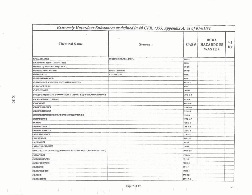
Chemical Name

Synonym Chemical Name
tlmluxm- I l l 4 4
DlcHmROWmM~ W2&I
149-14.6
Page 3 of 12

Page 4 of I2 I I I
Extremely Hazardous Substances as deflned in 40 CFR, (355, Appendix A) as 0/07/01/94
Chemical Name
Dlcmonn'nos m ~ ~ P I U T E
Synonym
,
160-54.2
MGIlDXM
CAS#
14141
8I4-49-l
-U
IxmEmm uwsm LUmmm
m n a o ~ - -0~1-
InmmmN u n n l l -
lmIlmmm EmmfL-
-AN
l m m l .
~ U r Y D N r J - EROUrAMNIITAlmlAT8
-cHmNm-
!nnmol. I f - , m A m
rrmON
RCRA HAZARDOUS
WASTE #
OIDIIM.kMETAmNlES
> 1
Kg
sns u44u
zIJ.7
Iawl-1
nwa ad64 . IS-la,
HSd4.4
SICZU
MI-Rl
3164-1
1 1 s ~ ~
2 W 3
R-)Ol
Ie4.89J
*I46
3l9-m-3
101-n-8
lOlOn-1
%%12-2

Page 5 of 12
W e m e & Hazardous Substances
Chemical Name
ETHOPllOllKM
~ ~ O l M n U N
ETHnaRaXlDh - v RHYLllUOWANATE
~uammmm FmsamwmON
FWENmL
~ ~ u a m a ~TU~OAC~TM
Fl.uDRoACmCAcr0
F l . u ) u O ~ C H L O I I l D E
FUlDllOUMQL
~cwo~os 7
m c % - F~RME~~WATB ~~mocltmum Fonuomm mummuun Kmlll6rN nmmDMaa NMN
c w l . L n M ~
l l E X M m l - m
- N w - m
HYDlUWB
H Y D M C Y A N l c ~
m w e ~ m ~ o l l t ~ ( a r u a n
I m m o O E N m
HYDR0CiEN-h
as dejned in 40 CFR, (355, Appendix
,-
Synonym
,
OXlRANE
M X r D z I-FWORO.
RJlumAN
IX-ADIENF. l~ ,V>HEXACHU)RO ,
HYDRO33 CYANIDE
HYDROFLUORIC AM)
> 1 Kg
ns
-
-- YES
YES
A) ar of
CAS#
1319444
371424
1S21 J
IOhlS3
1SI-s64
542-94S
~n-14s 11%942
4301-s2
nn414 6019.7
lU49.a
3 w
31-214
w n - 9
50400
10)-164
1 3 ~ - n 9
2nw2- 1
~ n m - n - 7
2IYC32-3
-19-1
1 Io-004
I 3 4 ~ 9 0 . 3
214-4
~ S l 1 - 4
30241-2
74904
1647414
7-39-3
n t l o t . 3
07/01/94
RCRA HAZARDOUS
WASTE #
--

Page 6 of 12 I I I
. &&erne& ~azardous Substances as deflned in 40 CFR, (355, Appendix A) as 0/07/01/94
,
Chemical Name
HrrmOOENLUIMB - Ra(mrr-
Synonym
,
CAS#
7m.064
123-314
IM63.404
RCR4 HAZARDOUS
WASTE #
> 1 Kg
YES

Chemical Name
Page 7 of I2

Chemical Name
Page 8 of 12
Extremely Hazardous Substances as defined in 40 CFR, (355, Appendrk A) as of 07/01/94
o m ~ v ) . O r m w s n F o l o N
cvma
P-T
P-T-ATE
PARATHION
PARATHIONLamm.
PANSGREEN
MAEOXAN6
rn- PEMCFllCAClD
P A N
Synonym -
PHENQL
-=-- P H E N O Z w I 1 . u B n m p l w n s . - ~
PIiENOXARm& 1% IU4mDc
PmNn-
-HYDILOMU]IIIDB
-YAQTATE
PImYLmlMNH
PliENYLTIoamW
PuouATB
CAS#
UIJS224
l8.71-7
IOeP+2
UlMtLO
6uo.6
%366
-21-6
s9-m-I
6%-
2091-194
103.654
298.02-2
41W14-7
PHosmAN 94742.4 - w s 732-1 14
,
COPPWAcEmARsENm
RCRA HAZQRDOUS
WASTE #
--- UPI.074
10021.1%
19104-5
2 0 7 ~ ~ 2
S S 2
29wo4
llootdll
19624-22-7
2ss2&s
79-214
S9U2-3
> 1
Kg

Synonym
Page 9 of 12
Chemical Name
lwEuDna
w m~AmsENIn
m A s s a M c Y A N l W
~ ~ ~ V P J L ~ A N I D ~
malEcmB
rn0rMbn- --A
PmpDNmn8
pummnuw- ammlmma I-mum pu0m-n ~0~
mmom
rYNm&a-mnm-%m
ryIIIDpsB4.NlnLQl-
PYUMIm
SAUN
.
l lOM
USOUI-1
IOl14-SO-1
Ill-Yo4
-1.4
2631-ffQ
1-7
ST-S?.#
107-110
nl-76-7
1DbP-P
10wt.s
n%9
~ I M
Iz9.004
1076-1
1114-1+4
USSbZFI
6 3 4 . 4
107w

Synonym
Page 10 of 12 rns I
I I I I I I I 1 I I C
Extremely Hazardous Substances as dejned in 40 CFR, (355, Appendix A) as of 01/01/94
Chemical Name
SELE?llaJsAQD
&LPIIM(-
SmmuBmh-
s n u s g t - 7
.sAwOMm
s0DR.M-18
90D(U(msENns
--@wm S O D U M ~ A ~ ~ ~ A T I I
~~~~ SOOIUL( F L W w A C m A n
S M m M ~ R
~~ S Q D I I A ( r r u u m
=-- rn- mmmmzuw~~~
--OCrn 3 m n - I
amuxDIoxm# ' 7 u 4 9 - 5
amux- 7mao
P
CAS#
?muu 7n1-=3
36341-7
m7.n-7
14167-18-1
1631J9-2
-5
MdZLn.8
IWSSZ
1U33-9
a - 7 ~
I W l M 1 4
IOI02-1u
10102.20.1
9mm4
n-20
60-41-3
3S9.24-S
RCRA HAZARDOUS
WASTE #
.
> 1 Kg

Chemical Name

Synonym
Extremely Hazardous Substances as deflned in 40 CFR, (355, Appendix A) 0s of 07/01/94
Page 12 of 12 I I t
,
Chemical Name
wAIFAMS(ODIIII(
m L m ~
--u-um'x<-s
CAS#
1-
m - I W
fllOM
RCRA HAZARDOUS WASTE #
> 1 Kg

APPENDIX L
Generic Area Cleanup Activities

Generic Area Cleanup Activities:
Prior to Area Characterization Walkthrough:
Remove:
non-applicable signage residues left from removed signs light-weight groundwires unsupported:
conduit piping ducting wiring stanch~ons
holes in walls and floors damaged carpeting damaged floor tiles damaged ceiling tiles baseboard molding ceiling lights electrical box covers
Label per plant procedures:
All floor drains All piping Any chem exhaust ducting left in the area including the overhead
Tagout all breakers where wall panel boxes are turned off.
Flush and cap all chem drainslpiping
Keep: working wall clocks good shape wall shelving Liquid Nitrogen piping door alarms motion detectors card readers All active utilities
Following the Characterization Walkthrough:
Damp mop floors and brush or wash walls to remove loose materials
lndustrial Hygiene will perform air and surface sampling as required
Clear all planned application of surface coatings, such as paint, varnish, and floor stripperlwax, ' , with Industrial Hygiene prior to work
Paint individual walls as needed to cover patchesldamage
L-3 genclean.doc rab 111 7/96

APPENDIX M
General Operating Procedure 6.7.45, Area Closeout
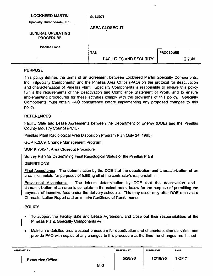
PURPOSE
LOCKHEED MARTIN
Specialty Components, Inc.
GENERAL OPERATING PROCEDURE
Pinellas Plant
This policy defines the terms of an agreement between Lockheed Martin Specialty Components, Inc., (Specialty Components) and the Pinellas Area Office (PAO) on the protocol for deactivation and characterization of Pinellas Plant. Specialty Components is responsible to ensure this policy fulfills the requirements of the Deactivation and Compliance Statement of Work, and to ensure implementing procedures for these activities comply with the provisions of this policy. Specialty Components must obtain PA0 concurrence before implementing any proposed changes to thk policy.
REFERENCES
SUBJECT
AREA CLOSEOUT . .
Facility Sale and Lease Agreements between the Department of Energy (DOE) and the Pinellas County Industry Council (PCIC)
TAB
FACILITIES AND SECURITY
Pinellas Plant Radiological Area Disposition Program Plan (July 24, 1995)
PROCEDURE
G.7.45
GOP K.2.09, Change Management Program
SOP K.7.45-1, Area Closeout Procedure
Survey Plan for Determining Final Radiological Status of the Pinellas Plant
DEFINITIONS
Final Acceptance - The determination by the DOE that the deactivation and characterization of an area is complete for purposes of fulfilling all of the contractor's responsibilities.
~rovisional Acceptance - The interim determination by DOE that the deactivation and characterization of an area is complete to the extent noted below for the purpose of permitting the payment of incentive fees under the delivery schedule. This may occur only after DOE receives a Characterization Report and an Interim Certificate of Conformance.
POLICY
To support the Facility Sale and Lease Agreement and close out their responsibilities at the
I Pinellas Plant, Specialty Components will:
Maintain a detailed area closeout procedure for deactivation and characterization activities, and provide PA0 with copies of any changes to this procedure at .the time the changes are issued.
APPROVED BY
I Executive Office
DATE ISSUED
5/28/96
SUPERSEDES
12/18/95
PAGE
1 OF 7

I GENERAL OPERATING PROCEDURE NO. G.7.45 REVISION DATE 5/28/96 PAGE 2 OF 7
( . Schedule, plan, and control work and resources to integrate DOE objectives and complete facility closeout and turnover in time to all~w~waste disposal by September 30, 1997.
Maintain a Transition Master Schedule for the characterization, cleanup, and closeout of all interior areas of the facility.
Submit an update of the Transition Master Schedule, or a statement that the current schedule is still valid, to PA0 during the first Wo weeks of each calendar quarter.
Maintain detailed project schedules for completion of all required tasks in each area.
PA0 shall provide future use preferences/plans of PClC to Specialty Components Facility Transition Planning. Specialty Components shall be responsible for maintaining a liaison with the PClC to keep them informed concerning the deadlines and to facilitate their providing input to the deactivation plan for areas. Specialty Components shall provide dates to PA0 when the information must be provided for each set of areas on the Master Schedule. If PA0 fails to provide this data, then the areas shall be cleaned to the standard and all excess property in the areas shall be left in place. Changes to the plan after the date specified shall be considered additional work scope.
NOTE: PA0 will provide signature documents from the PClC if the PClC accepts hazardous materials being left in place in an area. If no such documents are provided by the dates when the PClC plans for an area must be communicated to Specialty Components, then the hazardous materials shall be removed by Specialty Components. Specialty Components shall be responsible for maintaining a liaison with the PClC to help them understand where hazardous materials might need to be retained for economic development.
Remediate all known sources of hazardous or radioactive material contamination not identified
I for retention by the PClC to the criteria defined in the Deactivation and Compliance Statement of Work.
Perform housekeeping activities, as needed, to prepare the area for inspection and sampling, a such as removing floor and ceiling tiles, cleaning floors and walls, and disposing of debris or
unqeeded materials.
Maintain a general sampling plan outlining the objectives Specialty Components intends to accomplish when sampling each area.
Develop area-specific sampling plans adequate to demonstrate compliance with the hazardous material and radiological cleanup standards.
Complete the tests defined in the sampling plan and complete any additional decontamination efforts needed to ensure compliance with the hazardous material and radiological cleanup standards.

GENERAL OPERATING PROCEDURE NO. G .7.45 REVISION DATE 5/28/96 PAGE 3 OF 7
.a Prepare areas for turnover to DOE, ensuring that material condition of area is consistent with good industrial practice by replacing floor ,and ceiling tiles, painting, patching walls, etc., as described in the Area Restoration Standard (Attachment A). All waste will be removed and the area will be left in broom-clean condition.
Provide PA0 a Health Physics release for each area, including historical information, sampling and test results, and a description of decontamination completed. The Health Physics release will -include a certification that the area is being left in compliance with the requirements of DOE 5400.5 or documentation of any radioactive materials remaining in the area.
I Provide an Area Characterization Report containing the following information:
- the Health Physics release;
- an inventory of any hazardous materials that remain in the area;
- a cross reference of all materials left in the area to the functional capabilities or specific equipment idintified by the PClC for retention;
- a description of the decontamination efforts completed;
- the test results showing Specialty Components completed all sampling plan requirements and showing the area meets the hazardous material clean up criteria; and
- any other information Specialty Components deems appropriate for the report.
Deliver the Area Characterization Report and a signed Certificate of Conformance or an Interim Certificate of Conformance to the PA0 front desk for date stamp.
Control areas accepted by DOE until DOE transfers the area to the PClC to preclude subsequent contamination by Specialty Components or other tenants.
PA0 ACCEPTANCE OF WORK
Specialty Components will schedule a walkthrough of the area with PA0 and the PClC to explain the Area Characterization Report. If PA0 does not attend the walkthrough within ten working days after PA0 date stamps the Area Characterization Report, PA0 will waive the walkthrough for that area.
PA0 will issue the Final Acceptance Form, or notify Specialty Components of the pending rejection of the Certificate of Conformance, within fifteen working days after the PA0 date stamp on the Certificate of Conformance. The notification by PA0 of a pending rejection of a Certificate of Conformance will be in writing and will state reasons for the potential rejection. Such reasons might include contamination being detected in the area(s) in question, incomplete documentation provided with the Certificate or Characterization Report, etc. Specialty Components will have ten working days from the receipt of the notification to rectify the problem. If the problem is rectified in ten days, then PA0 will issue the Final Acceptance Form within three working days after Specialty Components demonstrates they have fixed the problem. If the problem is not rectified in ten working days from the receipt of the notification, the Certificate of Conformance is rejected, and Specialty Components must submit a new one after completing work to rectify the problem.

I GENERAL OPERATING PROCEDURE NO. G.7.45 REVISION DATE 5/28/96 PAGE 4 O F 7
One reason for rejection may- be the discovery of unanticipated contamination which may not reasonably be expected to have been discovered by the sampling done by Specialty Components. It is the responsibility of Specialty Components to indicate for PA0 the basis for this contention. Should PA0 accept this assertion by Specialty Components, the only further action required by Specialty Components shall be the actual remediation associated with the work. The characterization report shall not be redone. The Certification of Conformance will not be considered to have been submitted improperly and may be withdrawn by Specialty Components.
If PAC) does not provide the Final Acceptance Form in fifteen days after the receipt of the Area Characterization Report, any additional work required in the area will be considered additional wok scope, unless the work is needed to rectify a problem which PA0 concludes was caused by Specialty Components malfeasance, negligence or failure to dean to the standards.
All issues relating to compliance with local codes, ordinances, engineering principles, or other regulations are responded to in the sale agreement between the PClC and the DOE. Plantwide systems (e.g., drains) will be addressed as separate closeout items rather than piecemeal (area by area).
I PA0 PROVISIONAL ACCEPTANCE OF AREAS
DOE may agree to- provisionally accept administrative areas that will continue to be used by Specialty Components. These areas will be provisionally accepted only if: (a) Specialty Components delivers an Area Characterization Report and an Interim Certificate of Conformance to DOE; (b) Specialty Components delivers a Health Physics release in the Area Characterization Report for the areas; (c) the Area Characterization Report notes that the Certificate of Conformance will be issued following the delivery of hazardous contamination sampling data that shows the area is ready ,for alternate uses. DOE will note on its acceptance form that acceptance is provisional; final acceptance will be made on a second DOE Acceptance Form.
Final Acceptance of an administrative area by DOE can occur after the area has been vacated by Specialty Components and hazardous contamination sample data are delivered for the areas with a Certificate of Conformance to DOE.
RESPONSIBILITIES \
AREA CHARACTERIZATION GROUP LEADER
I Coordinate generation of Area Characterization Reports.
Serve as a liaison between Specialty Components and the DOE to ensure they are involved in the cleanup decision making and concur with the initial decontamination efforts prior to issue of Area Characterization Report.
SUPPORT ORGANIZATIONS
Environmental, Safety and Health (ES&H) organizations (Industrial Hygiene, Waste Management, and Environmental Restoration and Permitting) will participate in the walkthroughs, submit written inputs to the Area Characterization Group Leader, and will conduct sampling activities, as required. '

I GENERAL OPERATING PROCEDURE NO. G.7.45 REVISION DATE 5/28/96 PAGE 5 O F 7
FACILITY TRANSITION PLANNING ORGANIZATIONS
Provide information to the Area Characterization Group ~eader to schedule areas, define the scope of the walkthrough, the sites to be covered, and personal property issues, etc.
ENVIRONMENTAL MANAGEMENT TRANSITION PROGRAM MANAGER
Report the status of characterization and closeout actions to .the DOE and the PCIC.
~nsure- the integration of the PCIC and environmental management objectives.
Maintain the official record copy of the Final Closeout Report. This information will be used to update the plant's database concerning the status of areas during transition.

( GENERAL OPERATING PROCEDURE NO. G.7.45 REVISION DATE 5/28/96 PAGE 6 O F 7
I - Attachment A
I Area Restoration standard
Area Restoration following the decontamination of an area shall be governed by the following standard effective April 1, 1996. Any additions in the work scope to restore the areas shall be separately directed and funded by PAO.
I. - Restoration of Flooring
A. Tile Flooring
I 1. Floor tile removed as a result of decontamination shall be replaced.
2. Tile flooring will be left in a broom-clean condition; this will include sweeping, mopping, stripping, waxing, and buffing the tile.
3. With the exception of No. 1 above, tile will be replaced only if it is broken or - loose. Color match with remaining tile is desirable, but not required.
I B. Carpet
I 1. Carpet shall be vacuumed and cleaned.
2. Tom carpet shall be patched; color match with remaining carpet is desirable, but not required.
C. Baseboard
1. Baseboard shall not be repaired or replaced.
I 11. Restoration of Walls
I A. Holes
1. Patch all holes.
2. Paint all patched holes.
6. Painting <
1. When painting patches on walls, color match is desirable, but not required.
2. The entire wall shall be painted only if the patched area is greater than or equal to 10 percent of the entire wall area.
I C. Other 1. No work will be done to correct existing code deficiencies; however,
deficiencies which arise due to deactivation activities will be corrected.
2. Removal of walls that are not radiologically contaminated shall be considered additional work scope.
3. Reconstruction of walls removed for any reason shall be considered additional . work scope.

I GENERAL OPERATING PROCEDURE NO. G.7.45 REVISION DATE 5/28/96 PAGE 7OF7 I
Ill. Restoration of Ceilings
A. Ceiling Tile Replacement
1. Ceiling tiles removed due to decontamination shall be replaced.
2. Damaged ceiling tiles (e.g., broken holes) and missing ceiling tiles shall be replaced. Color match with remaining tiles is desirable, but not required.
3. Discolored ceiling tiles shall not be replaced.
4. All ceilings shall be vacuumed and dusted.

APPENDIX N
Standard Operating Procedure 6.7.45-1, Area Closeout Procedure

-
1.0 PURPOSE
LOCKHEED MARTIN Specialty Components, Inc.
STANDARD OPERATING PROCEDURE
Pinellas Plant
The purpose of the area closeout procedure is to meet the intent of the Facility Sale and Lease Agreement with respect to transfer of the facility from the Department of Energy (DOE) to the new owner, the Pinellas County Industry Council (PCIC). Specifically, the agreement requires DOE to clean the facility of hazardous and radiological contamination consistent with its planned future industrial uses by the end of the lease period on September 30, 1997.
2.0 SCOPE
SUBJECT
AREACLOSEOUTPROCEDURE
The area closeout procedure addresses the identification and cleanup of chemical contamination, definition of more extensive cleanup options (if any), and the deliverables for closing out Lockheed Martin Specialty Components, Inc., (Specialty Components) responsibilities at the Pinellas Plant.
TAB
SOP
Exceptions
Radiological cleanup requirements are addressed by other plant procedures, but this procedure applies to all other aspects of area closeout. In order to make the final closeout a single process, the radiological survey and release information will be integrated with the chemical contamination cleanup data in the final report.
PROCEDURE
G.7.45-1
Issues related to compliance with local codes, ordinances, or other regulations, and
I removal of friable asbestos, were dealt with separately in the sale agreement between the PCIC and the DOE; therefore, they are excluded from this process. Removal of friable
I 'asbestos is separate from decontamination andlor area closeout.
Plantwide systems (e.g., drains) will be addressed as separate closeout items rather than piecemeal (area by area). Generally, the Area Characterization and Final Closeout Report
I will cover evaluation and decontamination of walls, floors, ceilings, and exhaust ducting. Equipment cleaning is addressed in other procedures.
3.0 REFERENCES
DOE 5400.5, Radiological Protection of the Public and the Environment
DOE 5820.2AI Radioactive Waste Management
Facility Sale and Lease Agreements between the DOE and the Pinellas County Industry Council (PCIC).
- --
APPROVED BY
I Executive Office
- - - I DATE M D 1-m 7:

I STANDARD OPERATING PROCEDURE NO. G.7.45-1 REVISION DATE 07/29/96 PAGE 2 OF 7
DOUEM-0142P, DOE Decommissioning Handbook - March 1994
DOE/EP-0100, Guide for Radiological Characterization and Measurements for Decommissioning of U.S. DOE Surplus Facilities - August 1983
GOP K.2.09, Change Management Program
GOP K.7.45, Area Closeout
Survey Plan for Determining Final Radiological Status of the Pinellas Plant
WM 5.07, Environmental Management Area Assessments
WM 5.14, Area Surveys During Safe Shutdown
WM 5.17, Safe Shutdown Procedure
WM 5.18, Characterization of Equipment and Areas
IH Instruction 28
29 CFR 1910.1000 Table Z, Permissible Exposure Levels for Air Contaminants
ACGIH Threshold Limit Values for Chemical Substances
4.0 DEFINITIONS 0
Characterization: The gathering of descriptive information pertaining to the type and quantity of contamination in a system, structure, area, etc.
Area Closeout: The process of formally transmitting historical and current information cdinceming chemical usage, residual contamination, and hazardous material inventory to the DOE.
Decontamination: The removal of contamination from facilities or equipment by washing, heating, chemical action, mechanical cleaning, or other techniques. Decontamination also includes dismantlement or segmenting of walls, ducting, etc. The two basic goals of Specialty Components decontamination efforts are:
k A. The removal of contaminants potentially present at levels which could result in measurable exposures:
1. For those hazardous materials for which a Permissible Exposure Level (PEL) has been established by the Occupational Safety and Health Administration (OSHA), a Threshold Limit Value (TLV) has been published by the American Conference of Governmental Industrial Hygienists (ACGIH), a Workplace Environmental Exposure Level (WEEL), or an Emergency Response Planning Guideline (ERPG) has been published by the American Industrial Hygiene Association (AIHA), The goal of cleanup activities shall be to ensure that exposure levels will be at or below ten percent (10%) of the most restrictive established or published value.
2. For those hazardous materials for which no recommended exposure restriction has been established by OSHA, ACGIH, or AIHA, the Material Safety Data Sheet (MSDS) recommended exposure level will

I STANDARD OPERATING PROCEDURE NO. G.7.45-1 REVISION DATE 07/29/96 PAGE 3 OF 7
be used to establish the acceptable exposure level goal at 10 percent of the recommended level.
B. Low costlimpact remedial/housekeeping activities such as mopping, scrubbing, floor stripping, duct removal, floorlceiling tile replacement, etc., in accordance with as low as reasonably achievable (ALARA) principles. These activities will result in the "as'decontaminatedn designation in the Area Characterization Report.
5.0 RESPONSIBILITIES
Facility Transition Planning Manager
Lead the closeout process.
Create and maintain a master schedule for timely completion of characterization and closeout activities.
Maintain and update schedules for actual work required in the areas for progress tracking reports to DOE.
Ensure timely transfers of area'ownership and maintenance of area controls for areas accepted by DOE.
Support Or~anizations
Environmental, Safety and Health (ES&H) organizations (Industrial Hygiene, Waste Management, and Environmental Restoration and Permitting)
Participate in walkthroughs.
Submit written inputs to the Area Characterization Group Leader.
Conduct sampling activities, as required, to establish the extent of chemical \
contamination and friable asbestos (if any) in the area.
Provide support to dewntaminationJremediation efforts as appropriate to ensure safety worker and cleanup effectiveness.
Facility Transition Planninn Group Leader
Lead the Area Characterization Team in the conduct of preliminary closeout walkthroughs in each area, per steps 6.2 below.
Verify completion of all required cleanup activities, coordinate timely submittal of all required inputs, and prepare area characterization and final closeout reports for General Manager signoff and submittal to DOE.
I Conduct final acceptance walkthroughs with DOE and PClC for each area.

I STANDARD OPERATING PROCEDURE NO. G.7.45-1 REVISION DATE 07/29/96 PAGE 4 OF 7
Distribute final acceptance documentation to the Facility Transition Program Manager and the Facility lnformation System Coordinator.
Maintain the official record copy of the signed Final Closeout Report. This information will be used to update the plant's database concerning the status of areas during transition.
Facility Transition Program Manager
Report the status of characterization and closeout actions to the DOE and the PCIC.
Coordinate PA0 involvement in cleanup decision-making.
Serve as owner of this procedure to ensure the integration of the PCIC and DOE objectives,
Facility Transition Operations Manager
Conduct decontamination activities as identified by the Area Characterization Team, under the direction of Industrial Hygiene.
6.0 PROCEDURE
6.1 AREA SELECTION AND PREPARATION
I I 6.1.1 Information on intended use plans will be obtained from the DOE. Any equipment and/or ducting to remain in the area will be identified and marked as such.
I 6.1.2 All areas to be characterized and closed out should have previously undergone the safe shutdown process, including:
a) Removal of any stored hazardous materials.
b) Disposition of all related personal plant property and records. \
c) Transfer to facilities ownership, as appropriate.
6.1.3 Facility Transition Planners will schedule areas by priority for characterization and closeout.
6.1.4 Personal property transfer issues will be resolved prior to closeout; all DOE- owned property and any other property not scheduled for continued use in the area will have been removed.
6.1.5 Preparations for area characterization will include the following, as appropriate, to intended future use:
a) Disconnection of utilities and equipment.
* a b) Evaluation, cleaning, and removal of equipment.
c) Remediation of any known hazardous chemical or radioactive residues.
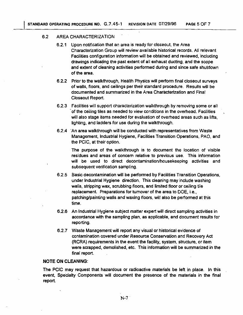
I STANDARD OPERATING PROCEDURE NO. G.7.45-1 REVISION DATE 07/29/96 PAGE 5 OF 7
6.2 AREA CHARACTERIZATION
6.2.1 Upon notification that an area is ready for closeout, the Area Characterization Group will review available historical records. All relevant Facilities configuration information will be obtained and reviewed, 'including drawings indicating the past extent of all exhaust ducting, and the scope and extent of cleaning activities performed during and since safe shutdown of the area.
6.2.2 Prior to the walkthrough, Health Physics will perform final closeout surveys of walls, floors, and ceilings per their standard procedure. Results will be documented and summarized in the Area Characterization and Final Closeout Report.
6.2.3 Facilities will support characterization walkthrough by removing some or all -of the ceiling tiles as needed to view conditions in the overhead. Facilities will also stage items needed for evaluation of overhead areas such as lifts, lighting, and ladders for use during the walkthrough.
6.2.4 'An area walkthrough will be conducted with representatives from Waste Management, lndustrial Hygiene, Facilities Transition Operations, PAO, and the PCIC, at their option.
The purpose of the walkthrough is to document the location of visible residues and areas of concern relative to previous use. This information will be used to direct decontamination/housekeeping activities and subsequent verification sampling.
6.2.5 Basic decontamination will be performed by Facilities Transition Operations, under lndustrial Hygiene direction. This cleaning may include washing walls, stripping wax, scrubbing floors, and limited floor or ceiling tile replacement. Preparations for turnover of the area to DOE, i.e., patchinglpainting walls and waxing floors, will also be performed at this time.
6.2.6 An lndustrial Hygiene subject matter expert will direct sampling activities in accordance with the sampling plan, as applicable, and document results for reporting.
6.2.7 Waste Management will report any visual or historical evidence of contamination covered under Resource Conservation and Recovery Act (RCRA) requirements in the event the facility, system, structure, or item were scrapped, demolished, etc. This information will be summarized in the final report.
NOTE ON CLEANING:
The PCIC may request that hazardous or radioactive materials be left in place. In this event, Spe'cialty Components will document the presence of the materials in the final report.

I STANDARD OPERATING PROCEDURE NO. G.7.45-1 REVISION DATE 07/29/96 PAGE 6 OF 7
6.3 AREA CHARACTERIZATION AND CLOSEOUT REPORT
A report summarizing the results of the characterization and cleanup will be prepared by the Facility Transition Planning Group Leader for submittal to PAO.
The report will:
Be based upon inputs from the various support organizations;.
Contain a narrative section that describes the available history of the area(s) and the current state of the area(s) with respect to hazardous contamination;
Describe the extent of chemical contamination and cleanup activities conducted to date in the area(s) (see Attachment A);
Include a Certification of Conformance signed by the General Manager Specialty Components, or a designee;
Document the final as-left condition of the area;
lnclude Specialty Components radiological survey and release data with a summary statement of release from Health Physics;
lnclude results of third-party verifications of radiological status only if available within 10 days of Specialty Components Health Physics release;
, Clearly state that all personal property remaining in the area has been properly prepared for transfer of ownership;
lnclude a request to conduct a final closeout review.
6.4 DOEIPCIC RESPONSE
1. PA0 and the PClC will determine acceptability of the Area Characterization and Final Closeout Report and provide a written response to Specialty Components within 15 working days of receipt of the report.
2. The Area Characterization Group Leader will conduct a closeout review with PA0 and the PClC and obtain formal DOE concurrence that cleanup of the area has been completed and no further action is required by Specialty Components. The area will then be either released to the PClC or put into surveillance and maintenance mode until such time the PClC is ready to use it.
6.5 RECORDS 1. The Facility Transition Planning Department will maintain files of all data
used to generate the Area Characterization and Final Closeout Reports.
2. , PAO's written response are sent to the Facility Transition Program Manager to update the plant's database concerning the status of areas during transition.
3: A copy of the final acceptance letter will be sent to the Facilities Information Systems Coordinator to update that records system.

I STANDARD OPERATING PROCEDURE NO. G.7.45-1 REVISION DATE 07/29/96 PAGE 7 OF 7
ATTACHMENT A - AREA 183 CLOSEOUT SUMMARY