Environmental assessment of external wall cladding construction
13
This article was downloaded by: [Istanbul Technical University] On: 12 February 2014, At: 02:11 Publisher: Taylor & Francis Informa Ltd Registered in England and Wales Registered Number: 1072954 Registered office: Mortimer House, 37-41 Mortimer Street, London W1T 3JH, UK Architectural Science Review Publication details, including instructions for authors and subscription information: http://www.tandfonline.com/loi/tasr20 Environmental assessment of external wall cladding construction Buket Metin a & Aslihan Tavil a a Department of Architecture, Faculty of Architecture, Istanbul Technical University, Taskisla, Taksim, 34437 Istanbul, Turkey Published online: 07 Feb 2014. To cite this article: Buket Metin & Aslihan Tavil , Architectural Science Review (2014): Environmental assessment of external wall cladding construction, Architectural Science Review, DOI: 10.1080/00038628.2013.862610 To link to this article: http://dx.doi.org/10.1080/00038628.2013.862610 PLEASE SCROLL DOWN FOR ARTICLE Taylor & Francis makes every effort to ensure the accuracy of all the information (the “Content”) contained in the publications on our platform. However, Taylor & Francis, our agents, and our licensors make no representations or warranties whatsoever as to the accuracy, completeness, or suitability for any purpose of the Content. Any opinions and views expressed in this publication are the opinions and views of the authors, and are not the views of or endorsed by Taylor & Francis. The accuracy of the Content should not be relied upon and should be independently verified with primary sources of information. Taylor and Francis shall not be liable for any losses, actions, claims, proceedings, demands, costs, expenses, damages, and other liabilities whatsoever or howsoever caused arising directly or indirectly in connection with, in relation to or arising out of the use of the Content. This article may be used for research, teaching, and private study purposes. Any substantial or systematic reproduction, redistribution, reselling, loan, sub-licensing, systematic supply, or distribution in any form to anyone is expressly forbidden. Terms & Conditions of access and use can be found at http:// www.tandfonline.com/page/terms-and-conditions
Transcript of Environmental assessment of external wall cladding construction

This article was downloaded by: [Istanbul Technical University]On: 12 February 2014, At: 02:11Publisher: Taylor & FrancisInforma Ltd Registered in England and Wales Registered Number: 1072954 Registered office: Mortimer House,37-41 Mortimer Street, London W1T 3JH, UK
Architectural Science ReviewPublication details, including instructions for authors and subscription information:http://www.tandfonline.com/loi/tasr20
Environmental assessment of external wall claddingconstructionBuket Metina & Aslihan Tavilaa Department of Architecture, Faculty of Architecture, Istanbul Technical University,Taskisla, Taksim, 34437 Istanbul, TurkeyPublished online: 07 Feb 2014.
To cite this article: Buket Metin & Aslihan Tavil , Architectural Science Review (2014): Environmental assessment of externalwall cladding construction, Architectural Science Review, DOI: 10.1080/00038628.2013.862610
To link to this article: http://dx.doi.org/10.1080/00038628.2013.862610
PLEASE SCROLL DOWN FOR ARTICLE
Taylor & Francis makes every effort to ensure the accuracy of all the information (the “Content”) containedin the publications on our platform. However, Taylor & Francis, our agents, and our licensors make norepresentations or warranties whatsoever as to the accuracy, completeness, or suitability for any purpose of theContent. Any opinions and views expressed in this publication are the opinions and views of the authors, andare not the views of or endorsed by Taylor & Francis. The accuracy of the Content should not be relied upon andshould be independently verified with primary sources of information. Taylor and Francis shall not be liable forany losses, actions, claims, proceedings, demands, costs, expenses, damages, and other liabilities whatsoeveror howsoever caused arising directly or indirectly in connection with, in relation to or arising out of the use ofthe Content.
This article may be used for research, teaching, and private study purposes. Any substantial or systematicreproduction, redistribution, reselling, loan, sub-licensing, systematic supply, or distribution in anyform to anyone is expressly forbidden. Terms & Conditions of access and use can be found at http://www.tandfonline.com/page/terms-and-conditions

Architectural Science Review, 2014http://dx.doi.org/10.1080/00038628.2013.862610
Environmental assessment of external wall cladding construction
Buket Metin∗ and Aslihan Tavil
Department of Architecture, Faculty of Architecture, Istanbul Technical University, Taskisla, Taksim, 34437 Istanbul, Turkey
(Received 8 February 2013; final version received 20 October 2013 )
Decisions made during design, construction and operation phases have effects on the environmental impacts of buildingsthroughout their life cycles. However, environmental impacts of construction process are often ignored. Construction tech-niques affect the overall environmental impacts of construction process by determining the materials, the equipment and thelabour to be utilized for the constructability, which in return affects the amount of energy use and emissions and constructionwastes generated during the construction process. This study proposes a model (environmental assessment of external wallcladding construction, EACC) to assess the effect of external wall cladding construction techniques on environmental impactsduring their construction process. In this context, first- and second-level indicators, environmental impact benchmarks andcontributing factors were defined and scores of the contributing factors were calculated. The pilot study of the EACC sug-gests that construction techniques affect not only resource and energy usage, labour health and safety during the constructionprocess, but also reuse, remanufacturing and recycling possibilities of the materials at the end of their useful life.
Keywords: external wall cladding; construction technique; construction process; environmental impact; environmentalassessment
1. IntroductionThe construction industry causes environmental problemsdue to its high consumption of the global resources andits contribution to the environmental pollution through thebuilding construction and operation activities. According toEdwards (1999), in the European Union countries, buildingsuse 50% of total energy and 40% of raw material, release50% of chemicals harmful to the ozone layer, consume 50%of water and cause 80% of land loss to agriculture fields.In the Organization for Economic Co-operation and Devel-opment (OECD) area, the building sector’s share of totalenergy consumption is between 25% and 40% (Ryghaugand Sørensen 2009). Negative effects of buildings on thenatural environment mainly occur during their construc-tion, as well as their operation and demolition phases.There are many studies that have explored the relation-ships between building operation and demolition phases,and their impacts on the natural environment. However,there is still a gap in the current body of knowledge aboutmanaging the environmental impacts of construction activ-ities prior to the construction, and more importantly duringthe design phase of a building. This leads to a gap in under-standing the whole spectrum of the built environment andits potential environmental effects. The interaction betweenthe building construction process and the environment isdiscussed by some studies in certain aspects. Pollo andRivotti (2004) focus on building site and maintenance workswhile developing their approach for the optimization of
∗Corresponding author. Email: [email protected]
design choices from the sustainability evaluation point ofview in the context of the construction process. Shen et al.(2005) present a computer-based scoring method for theenvironmental performance of the contractors during theconstruction process. Rivotti (2005) develops a methodthat evaluates the eco-compatibility of the technical ele-ments used for construction activities on-site. Li, Zhu, andZhang (2010) develop an integrated life cycle environmen-tal impact assessment model for construction process toexamine the two aspects, in terms of the construction equip-ment and the ancillary materials. Gangolells et al. (2011)propose a method to determine and rank the significance ofdefined environmental impacts in a particular constructionproject on the basis of their severity and the concerns ofvarious interested parties. Chen, Okudan, and Riley (2010)focus on prefabrication and on-site construction methodsin the concrete buildings and investigate the awareness andenvironmental concerns of the stakeholders on constructionmethod selection.
The construction process comprises the initial construc-tion activities as well as the activities during maintenance,rehabilitation and renewal processes. Pollo and Rivotti(2004) indicate that the building process has four mainstages as off-site production, on-site production, useand maintenance, and demolition and recycling. Theydefine construction and maintenance stages under on-siteproduction stage and estimate a building’s impact on thenatural environment during its life cycle approximately as
© 2014 Taylor & Francis
Dow
nloa
ded
by [
Ista
nbul
Tec
hnic
al U
nive
rsity
] at
02:
11 1
2 Fe
brua
ry 2
014
2 B. Metin and A. Tavil
being 15% during the construction stage, 15% during themaintenance stage and 10% during the demolition stage.Furthermore, assessing the environmental impacts of theconstruction process is difficult due to the fact that theconstruction process consists of many sub-processes andthere is no recorded data of the comprehensive amounts ofenergy use, emissions and construction wastes (Bilec 2007).Therefore, assessing the construction process by analysingdifferent construction techniques at a building element levelwould provide opportunities to assess the construction pro-cess in the context of environmental sustainability withinthe life cycle of buildings.
Previous studies approach the construction process in aholistic view by considering the environmental impacts ingeneral, but only a few of them investigate the problemsarising from the effect of construction techniques on theenvironment. The construction technique itself has severalimpacts on the environment by pointing out the inputs ofthe construction process as material, equipment and labour,which increase energy use, emissions and constructionwastes. Consequently, analysing the environmental impactof the construction process with regard to the construc-tion technique of a particular building component is alsoimportant from holistic point of view.
External wall and roof systems are the two main ele-ments of the building envelope. External wall claddingsystem design and selection is one of the complicatedstages of the building envelope design, since innovation inthe building material industry and technological develop-ments has led to a broader range and number of optionsfor the cladding materials as well as the constructiontechniques.
This study introduces a model to be used during thedesign process, which is developed to analyse the externalwall cladding construction techniques, in order to assessthe environmental impacts of the construction processes.The model aims to assist decision-makers, including butnot limited to the architects, contractors and owners, whoplay an important role on many decisions during the designphase regarding the construction processes. As an initialstep in this study, external wall cladding construction tech-niques were classified by reviewing the catalogues of thecompanies which are external cladding materials and sys-tem producers in the Turkish construction sector (Metin2010). Following the initial step, interviews with the exter-nal wall cladding contractors were carried out in order todefine the environmental sustainability indicators, bench-marks and contributing factors of the particular constructiontechniques (Metin 2010). In addition, the score of each con-tributing factor of the construction technique was calculatedby using Benefit-Value Analysis (Tapan 1980, 2004), whichuses subjective assessment and calculates the relative valuesof the parameters developed through the assessors’ experi-ence. In the end, a pilot study is conducted to demonstratethe application of the model and to evaluate the resultsaccordingly.
2. Classification of the external wall claddingconstruction techniques
Buildings’ faces have been changing due to the advancesin building technology and external wall cladding mate-rials. Every new wall cladding material brings its ownconstruction technique and each technique may be differentdepending on the material’s properties such as dimensions,unit weight, connection type and detail design. The term“cladding” is often used as a general reference to a widevariety of naturally occurring and synthetic, or man-made,building envelope materials, components and systems. Inbuilding terminology, cladding is a non-structural material,a protective layer or covering that is fixed on the outersurface of a building or a structure to protect the build-ing envelope against moisture and foreign elements, and toprovide aesthetic purposes. Often in building construction,cladding or application of one material over another is doneto complete the cladding as a system. Typically, these ele-ments are quarried, manufactured or otherwise developedand/or altered to render them suitable for use on the exter-nal of a building or structure. The essential processes ofwall construction are cutting and assembling, plus form-casting the cladding material by using ancillary materialswhenever necessary. Those applications have different envi-ronmental impacts during construction process dependingon the cladding system and its construction technique inparticular.
External wall cladding materials can be assembled onthe building surface/shell by using different constructiontechniques. Construction techniques differ according todimension, form and unit weight of the cladding material,type and dimensions of the sub-construction and installa-tion materials, building height, layers of the cladding systemsuch as thermal insulation, waterproofing, sealing, etc. Inthe context of this study, cladding construction techniquesare classified according to their installation types as follows(Table 1):
• Installing to a sub-construction (metal/woodenframe etc.)(1) with screw (Sa)(2) with special anchorages (Sb)(3) with standard anchorages (Sc)(4) by welding (Sd)(5) with adhesive (Se)
• Installing to a wall core (masonry etc.),(1) with special anchorages (Wa)(2) with adhesive (Wb)
External wall cladding materials can be assembled ona metal/wooden frame or metal angle/sheet, which canbe installed to the components of building structural sys-tem (floors/columns etc.) with screws, special anchorages,standard anchorages, by welding or with adhesive. Theseconstruction techniques require a wooden/metal frame,metal angle/sheet for the installation of the cladding and
Dow
nloa
ded
by [
Ista
nbul
Tec
hnic
al U
nive
rsity
] at
02:
11 1
2 Fe
brua
ry 2
014

Architectural Science Review 3
Table 1. Classification of cladding construction techniques.
Construction technique details
Construction technique Plan Section Elevation
Sa Installing to a sub-construction with screw
Sb Installing to a sub-construction with special anchorages
Sc Installing to a sub-construction with anchorages
Sd Installing to a sub-construction by welding
Se Installing to a sub-construction with adhesive
Wa Installing to a wall core with special anchorages
Wb Installing to a wall core with adhesives
cannot be installed directly on the structural system or coresuch as a direct installation on masonry.
Claddings can be assembled on a metal/wooden framewith screws (Sa) by using three different ways such as con-cealed screwing, visible screwing or embedded screwingaccording to the vision that screws generate on the cladding
surface. Metal and wooden panels, cement-bonded par-ticleboards and polyvinyl chloride (PVC) panels are thecommon types of cladding systems that are assembled byusing this technique.
Claddings can also be mounted on vertical and/or hori-zontal components by using special anchorages (Sb), which
Dow
nloa
ded
by [
Ista
nbul
Tec
hnic
al U
nive
rsity
] at
02:
11 1
2 Fe
brua
ry 2
014

4 B. Metin and A. Tavil
are designed and produced by the cladding companies forthe specific cladding component. Sb is applied by using twodifferent ways. Claddings can be installed with the anchor-ages fixed on sub-construction. In addition, the anchoragescan be fixed on the sub-construction as well as reverseside of the cladding and then they are tightened together.Metal panels, clinker/terracotta tiles, ceramic tiles/panels,porcelain tiles, marble, granite and PVC panels areassembled by Sb.
Installing claddings with standard anchorages (Sc) isespecially used for glass fibre-reinforced concrete (GFRC)panels. Metal angles are fixed on the floors or columnsand GFRC panels are assembled on these angles by usingstandard anchorages. GFRC panels produced with specialmetal skeleton system can also be mounted to a metal sheetinstalled on the floors or columns by welding (Sd).
Claddings can also be installed to a frame with adhe-sives (Se). A polyurethane-based adhesive is applied to thereverse side of the cladding and assembled to the frame. Seis generally used with a metal sub-construction. Woodenpanels and porcelain cladding tiles are generally installedusing this technique.
Wall cladding materials can also be mounted on thewall core by using special anchorages (Wa) or adhesive(Wb) without including a sub-construction. The claddingmaterials such as granite and marble panels are preparedwith riffles on the upper and lower surfaces for providingtheir assembly to the anchorages (Wa). Cement-based adhe-sives are used for joining the small-sized cladding materialssuch as brick veneers on brown-coated masonry (Wb).Clinker/terracotta tiles, brick veneers, ceramic tiles/panelsand porcelain tiles are assembled by using Wb, while Waand Wb can be options for installing marble and granitepanels.
3. MethodologyEnvironmental assessment of external wall cladding con-struction (EACC) aims to analyse different cladding con-struction techniques in design phase to assess and comparetheir environmental impacts during construction process.The model focuses on the construction activities, whichcan be realized during construction, use and end-of-lifephases, in order to analyse different construction tech-niques of external wall claddings. Construction techniquesare analysed regarding their role on resource consump-tion (RC), energy consumption (EC), labour health (LH)and waste generation (WG) during the construction activ-ities considering their on-site application features, basedon material/equipment usage, supplementary applicationrequirements, installation method, labour type/safety andwaste management patterns.
The development of EACC consists of two basic stages:first the environmental assessment parameters and secondtheir scores were determined. During the first stage, theinterviews with cladding contractors were conducted and
the data on the construction technique inputs, basicallymaterial, equipment and labour were obtained. Afterwards,on-site application features of the cladding constructiontechniques were defined according to the interviews. Sub-sequently, the assessment parameters were attributed asthe first- (In) and the second- (In−n) level indicators, envi-ronmental assessment benchmarks (Bn) and contributingfactors (CFn) in a hierarchical order. Finally, the scoreswhich are the weights of the contributing factors weredetermined to develop EACC, to provide the assessmentand comparison of the cladding construction techniques inenvironmental sustainability point of view.
3.1. Identification of environmental assessmentindicators
Gangolells et al. (2011), Chen, Okudan, and Riley (2010),Bilec (2007) and Kim and Rigdon (1998) defined the fac-tors affecting the environment on the basis of energy, waterand material conservation, emissions to air and wastes.Construction techniques designate material, equipment andlabour inputs that affect the amount of energy, water andmaterial used, emissions and wastes created during theconstruction process. Thus, previous studies of Pollo andRivotti (2004), Shen et al. (2005), Rivotti (2005), Li, Zhu,and Zhang (2010), Gangolells et al. (2011), Chen, Okudan,and Riley (2010), Bilec (2007), Kim and Rigdon (1998),Sev (2008), Peterson and Dorsey (2000), Kibert, Sendzimir,and Guy (2000, 2002) and Kibert (2007) were reviewedand the environmental assessment indicators were set intwo levels as first- and second-level indicators in the con-text of the model according to the data about material,equipment and labour inputs related to various construc-tion techniques. First-level indicators (In) are designated asRC, EC, LH and WG. Material, water, electricity and oil use,site conditions, emission, noise and dust generation, land,water and air pollution and recovery options are attributedas second-level indicators (In−n) and they identify in whatway the first-level indicators affect the environment. The on-site application feature of cladding construction techniquesare designated as the contributing factors (CFn) since eachtechnique affects the environmental sustainability depend-ing on its process. Second-level indicators are designatedfor each benchmark by considering the contributing fac-tors. The scores of the contributing factors with regardto the environmental sustainability benchmarks are allo-cated according to the second-level indicators on which thecalculations are based (Table 2).
RC and EC during the construction process shouldbe controlled in order to reduce environmental impacts.According to Edwards and Hyett (as cited in Sev 2008),approximately 50% of all global resources are consumedby the construction industry. All building activities involveuse, redistribution and concentration of some componentsof the earth’s resources, such as water, energy and materi-als (Sev 2008). LH is also important during construction
Dow
nloa
ded
by [
Ista
nbul
Tec
hnic
al U
nive
rsity
] at
02:
11 1
2 Fe
brua
ry 2
014

Architectural Science Review 5
Table 2. Environmental assessment indicators.
First-level Second-level Environmentalindicator indicator assessment(In) (In−n) benchmark (Bn)
I1 RC I1−1 material use B1 construction typeI1−2 water use B2 installation method
B3 supplementaryapplications
B4 labourI2 EC I2−1 electricity use B3 supplementary
applicationsI2−2 oil use B4 labour
B5 equipmentI3 LH I3−1 safety precautions B5 equipment
I3−2 site conditions B6 installation materialI3−3 emission generation B7 safety managementI3−4 noise generationI3−5 dust generation
I4 WG I4−1 land pollution B6 installation materialI4−2 water pollution B8 waste managementI4−3 air pollution B9 reuse possibilityI4−4 recovery B10 recycling possibility
B11 remanufacturingpossibility
process. Volatile organic compounds (VOCs), dust andother pollutants produced during the construction processmay be hazardous for labour and public health (Ko andAlberico, n.d.). Dust generation, which originates from theconstruction activities and vehicle emissions, threatens thehealth of the laborers. Noise and vibration impacts associ-ated with the construction activities are also hazardous forlabourers (Ko and Alberico, n.d.). WG during the construc-tion process is another environmental problem. Althoughquantity and quality of waste generated from any specificconstruction project would vary depending on the project’scircumstances and types of materials used, handling of thewastes should be taken into account carefully (El-Haggar2007).
3.2. Identification of environmental assessmentbenchmarks and contributing factors
Environmental assessment benchmarks (Bn) defines on-siteapplication features and end-of-life patterns of construc-tion techniques. During the construction process of externalwall claddings, RC, EC, LH and WG are directly relatedto the construction type, installation method and mate-rials, supplementary applications, labour type and train-ing, equipment, safety precaution, waste management, andreuse, recycling and remanufacturing opportunities that areall benchmarks affecting environmental sustainability. Thecontributing factors (CFn) are the options of benchmarksaccording to on-site application features and end-of-lifepatterns of different construction techniques. The contribut-ing factors define the environmental impact of construction
techniques according to their relation with second-levelindicators (Table 3).
Definition of the benchmarks associated with the con-tributing factors and their relations with the second-levelindicators are explained as:
• Construction type (B1) is related with the com-ponents (building structure/core/sub-construction)where the cladding is mounted. Claddings can bemounted on load-bearing building structural ele-ments such as columns/beams/floors directly or ona cast-in/masonry/frame wall core without usingany sub-construction or by using a sub-constructionconsists of the metal/wooden frame system. The dif-ference between the components where the claddingis mounted affects the amount of the material used.
• Installation method (B2) is related to the technique,which is used for assembling the cladding on build-ing structure, core or sub-construction. Mounting thecladding with screws/anchorages allows ready-madematerial usage, while bonding agents such as mortarrequires on-site preparation. Therefore, installationtype affects the resource used for the preparation pro-cess. Screws/anchorages can be used without thenecessity of any extra preparation process; however,water and energy have to be used for preparing thebinding agents.
• Supplementary applications (B3) affect the materialconsumption and in case of the necessity of anyextra application such as painting, sealing, etc., theamount of the material used for assembling increases.Supplementary applications may require energy forpreparation of some components on-site to be usedin bonding and installation.
• Labour (B4) is also related to the labour type andtraining. Trained labour for a specific constructiontechnique not only affects the RC, EC and LH, but italso affects the installation time and the quality of theentire system. The trained and experienced workerscan provide proper use of resource and energy. More-over, the same job can be accomplished at a qualifiedlevel in a shorter time compared with an unskilledlabour.
• Equipment (B5) used for the assemblage and mate-rial handling at construction site affects RC and ECduring construction. For instance, certain mechanicalequipments may cause more environmental damagesand emissions due to fuel-oil consumption. Equip-ment also affects LH due to the high noise levels theymay create.
• Installation material (B6) affects the LH directly.Bonding agents can consist of dust, VOCs and otherchemical components, which might cause hazardousemissions.
• Safety management (B7) is related to the site con-ditions, which can be hazardous and dangerous for
Dow
nloa
ded
by [
Ista
nbul
Tec
hnic
al U
nive
rsity
] at
02:
11 1
2 Fe
brua
ry 2
014
6 B. Metin and A. Tavil
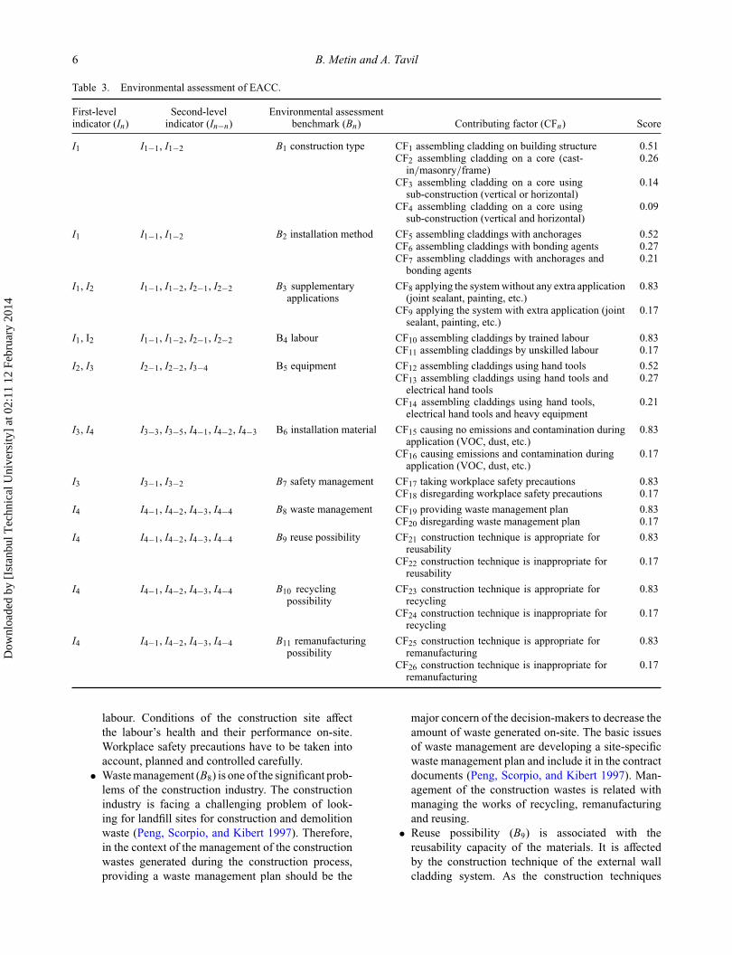
Table 3. Environmental assessment of EACC.
First-level Second-level Environmental assessmentindicator (In) indicator (In−n) benchmark (Bn) Contributing factor (CFn) Score
I1 I1−1, I1−2 B1 construction type CF1 assembling cladding on building structure 0.51CF2 assembling cladding on a core (cast-
in/masonry/frame)0.26
CF3 assembling cladding on a core usingsub-construction (vertical or horizontal)
0.14
CF4 assembling cladding on a core usingsub-construction (vertical and horizontal)
0.09
I1 I1−1, I1−2 B2 installation method CF5 assembling claddings with anchorages 0.52CF6 assembling claddings with bonding agents 0.27CF7 assembling claddings with anchorages and
bonding agents0.21
I1, I2 I1−1, I1−2, I2−1, I2−2 B3 supplementaryapplications
CF8 applying the system without any extra application(joint sealant, painting, etc.)
0.83
CF9 applying the system with extra application (jointsealant, painting, etc.)
0.17
I1, I2 I1−1, I1−2, I2−1, I2−2 B4 labour CF10 assembling claddings by trained labour 0.83CF11 assembling claddings by unskilled labour 0.17
I2, I3 I2−1, I2−2, I3−4 B5 equipment CF12 assembling claddings using hand tools 0.52CF13 assembling claddings using hand tools and
electrical hand tools0.27
CF14 assembling claddings using hand tools,electrical hand tools and heavy equipment
0.21
I3, I4 I3−3, I3−5, I4−1, I4−2, I4−3 B6 installation material CF15 causing no emissions and contamination duringapplication (VOC, dust, etc.)
0.83
CF16 causing emissions and contamination duringapplication (VOC, dust, etc.)
0.17
I3 I3−1, I3−2 B7 safety management CF17 taking workplace safety precautions 0.83CF18 disregarding workplace safety precautions 0.17
I4 I4−1, I4−2, I4−3, I4−4 B8 waste management CF19 providing waste management plan 0.83CF20 disregarding waste management plan 0.17
I4 I4−1, I4−2, I4−3, I4−4 B9 reuse possibility CF21 construction technique is appropriate forreusability
0.83
CF22 construction technique is inappropriate forreusability
0.17
I4 I4−1, I4−2, I4−3, I4−4 B10 recyclingpossibility
CF23 construction technique is appropriate forrecycling
0.83
CF24 construction technique is inappropriate forrecycling
0.17
I4 I4−1, I4−2, I4−3, I4−4 B11 remanufacturingpossibility
CF25 construction technique is appropriate forremanufacturing
0.83
CF26 construction technique is inappropriate forremanufacturing
0.17
labour. Conditions of the construction site affectthe labour’s health and their performance on-site.Workplace safety precautions have to be taken intoaccount, planned and controlled carefully.
• Waste management (B8) is one of the significant prob-lems of the construction industry. The constructionindustry is facing a challenging problem of look-ing for landfill sites for construction and demolitionwaste (Peng, Scorpio, and Kibert 1997). Therefore,in the context of the management of the constructionwastes generated during the construction process,providing a waste management plan should be the
major concern of the decision-makers to decrease theamount of waste generated on-site. The basic issuesof waste management are developing a site-specificwaste management plan and include it in the contractdocuments (Peng, Scorpio, and Kibert 1997). Man-agement of the construction wastes is related withmanaging the works of recycling, remanufacturingand reusing.
• Reuse possibility (B9) is associated with thereusability capacity of the materials. It is affectedby the construction technique of the external wallcladding system. As the construction techniques
Dow
nloa
ded
by [
Ista
nbul
Tec
hnic
al U
nive
rsity
] at
02:
11 1
2 Fe
brua
ry 2
014

Architectural Science Review 7
cause less damage during the construction and demo-lition phases, the possibility of reusing the materialsand the installation components for another wallcladding system would increase.
• Recycling possibility (B10) is also affected by the con-struction technique and the components of the exter-nal wall system. This factor is directly associated withthe recyclability of materials, construction framesand connectors of lesser quality for either the sameor different purposes by the end of their useful life.
• Remanufacturing possibility (B11) is also directlyrelated to the construction technique. It has the samepurpose with recycling. However, it differs fromrecycling, since it means remanufacturing of betteror equal quality and only to be used for the samefunction.
3.3. Formulating scores of the contributing factorsThe model consists of environmental assessment parame-ters, which are set up in a hierarchical order. Thus, organi-zation of the parameters provides using the “Benefit-ValueAnalysis” method for the assessment of the alternatives(Tapan 1980, 2004). The Benefit-Value Analysis is a toolfor preparing decisions systematically, which takes intoaccount non-quantitative criteria. It uses a multidimen-sional method to integrate quantitative criteria of manydifferent perspectives to measure effectiveness and becomesmore distinctive by using various criteria. (Schulze n.d.).It uses subjective assessment and calculates the relativevalues of the parameters developed through the experienceof assessors. Relative values of parameters are calculatedby weighting them according to their relative importance(Tapan 1980). According to “Benefit-Value Analysis”, rel-ative values of the alternatives can be calculated by usingdifferent methods such as Von Neumann and Morgensternmethod and Churchman and Ackoff method (Tapan 1980,2004).
Von Neumann and Morgenstern method is used whenan alternative is preferred to another and the alternativescan be ranked by the decision-maker (Ackoff, Gupta, andMinas 1962). This method assumes that the true probabili-ties are known by the decision-makers and they can identifytheir preferences for the possibilities of different combi-nations (Ackoff, Gupta, and Minas 1962; Fishburn 1964;Tapan 2004).
Churchman and Ackoff method is used for weightingthe sub-goals which have a hierarchical order (Churchman,Ackoff, and Arnoff 1957; Tapan 1980, 2004). Accordingto this method, the parameters can be ranked due to theirimportance and the numbers are assigned with respect totheir relative evaluation. The method makes no assumptionsabout subjective probability or maximization of expectedvalue. It only resembles a procedure for estimating valuesof set of objects where only comparative evaluations arepossible (Ackoff, Gupta, and Minas 1962).
In this study, Churchman and Ackoff method, whichis recommended for determining the weight of sub-goalsand for comparative assessment, is used since the assess-ment parameters are in a hierarchical order and thenecessity of comparative assessment (Churchman, Ackoff,and Arnoff 1957; Tapan 1980, 2004). Subjective values areused in developing a quantitative method for the compar-ison of the construction techniques of the external wallcladdings. Relative values were given to the contributingfactors by taking account of the effect of the second-levelindicators on the particular construction technique. Subse-quently, scores of the contributing factors, which are thesub-goals for reaching the minimum environmental impactduring the construction process, are calculated.
The EACC consists of the environmental sustainabilitybenchmarks having two, three or four contributing factors(Table 3). Two contributing factors determine a bench-mark’s effect on the environment at an extreme level, whichcan be either positive or negative. Therefore, they areregarded as the extreme values. The other contributing fac-tors, which are more than two, affect the environment atdifferent levels from positive to negative. Consequently, thecalculation of the scores can be derived from two differentmodels as calculation of the extreme values (1) and the othervalues (2).Extreme values (1):
nCF = 2,
Vmax > Vmin,
Vmax = 1.00,
Vmin = 0.20.
Other values (2):
2 < nCF ≤ n,
nCF max = 4,
V1 > (V2 − 2) + · · · + (Vn − (2n − 2)),
V sn = Vn
∑V
.
The calculation of the scores of the contributing fac-tors (CFn) for the extreme values requires a definition ofa maximum value (Vmax) and a minimum value (Vmin)depending on the number of the contributing factors (nCF )(1). According to the Churchman and Ackoff method, Vmax,which has the most positive effect, has to be maximum 1.00(Churchman, Ackoff, and Arnoff 1957; Tapan 1980, 2004).The value of Vmin is defined associated with the other val-ues. The difference between the values (V ) of contributingfactors and the total value of them should be equal in order toprovide the consistency of the benchmarks for the assess-ment. For this reason, the difference is regarded as 2 andVmin is defined as 0.20 in order to point out the extremity(1). The other values are calculated by comparing the valueswith each other and the value of CFs are adjusted after each
Dow
nloa
ded
by [
Ista
nbul
Tec
hnic
al U
nive
rsity
] at
02:
11 1
2 Fe
brua
ry 2
014

8 B. Metin and A. Tavil
comparison (2). Finally, adjusted values are normalized bydividing with sum of the values (�V ) and the standardizedvalues of CFs (V s
n ) are calculated (Churchman, Ackoff, andArnoff 1957; Tapan 1980, 2004).
4. Application of the EACCIn the context of the study, an application is performed toshow the usability of the model. For this purpose, a spe-cific external wall cladding material was chosen for each ofthe construction technique considering the probability of theinstallation varieties of the wall cladding material during theconstruction process. Widely used cladding materials forthe commercial and residential building facades in the Turk-ish construction sector were selected for the application.Interviews were conducted with the relevant companies tocollect data for the assessment of the construction process inparticular. Environmental impact of the construction tech-niques of cladding materials was assessed by using EACCand results were interpreted according to the features ofeach technique. Finally, results were interpreted accordingto the first-level indicators, which determine the environ-mental sustainability of construction techniques during theconstruction process.
4.1. ResultsThe collected data from the interviews were used for EACCand appropriate contributing factors for each of the bench-mark were selected from the assessment table for each ofthe construction technique. Then the total score of eachfirst-level indicator was calculated according to the relatedbenchmarks. For example, for a construction technique,appropriate contributing factors of B1, B2, B3 and B4 bench-marks were selected and sum up to get the RC (I1) EACCresult. Finally, the results are interpreted (Figure 1). Theresults of each construction technique are explained below.• Installing to a sub-construction with screw (Sa): Cement-bonded particleboards are assembled to a vertical metalsub-construction with screws (Sa) followed by joint sealantapplication and painting. Both electrical and hand toolsare used during the process. The cladding company pro-vides security requirements, but waste management pre-cautions are not taken into consideration on-site. The Satechnique for cement-bonded particleboard needs supple-mentary applications which make the recovery optionsimpossible, since the degrading process during reuse,remanufacturing and recycling processes is inconvenient.Therefore, Sa application for cement-bonded particleboardhas a higher score of 1.66 for RC. EC and LH have the samescore of 1.27, while the lowest score for WG is calculatedas 0.85 (Figure 1).• Installing to a sub-construction with special anchorages(Sb): Porcelain tiles are mounted to a vertical and horizon-tal metal sub-construction (Sb), with a special anchorage
type. Both electrical and hand tools are used for the applica-tion. The cladding company provides security requirementsbut waste management precautions are not taken into con-sideration on-site. Sb does not require any supplementaryapplication, which makes the recovery options possible andprovides an easier recovery process. According to theseproperties, Sb application for porcelain tiles received higherscore of 3.49 for WG. EC and LH yield the same lowestscore of 1.93 and RC has the score of 2.27 (Figure 1).• Installing to a sub-construction with standard anchor-ages (Sc) and installing to a sub-construction by welding(Sd): GFRC panels can be mounted on the metal sheet,which is fixed to the columns and floors by using standardanchorages (Sc) or by welding (Sd). During the constructionprocess, besides electrical and hand tools, heavy equip-ments are used for lifting the panels depending on thesize and weight of the panels. The cladding company pro-vides security requirements but does not take into accountthe waste management precautions on-site. Sc techniquerequires only joint sealant application, which does not affectthe recovery process directly. Although a different installingmethod is needed for installing using standard anchoragesor welding, Sc and Sd techniques for GFRC panels have thesame EACC results because of the similarities in the princi-ples of the application process. Hence, EC and LH yield thesame and the lowest score of 1.21, while RC has the scoreof 2.03 and WG has the highest score of 2.83 (Figure 1).• Installing to a sub-construction with adhesive (Se): Lami-nated wooden panels are assembled to a vertical metal sub-construction by using polyurethane-based adhesive (Se).Electrical and basic hand tools are used for this technique.The cladding company provides security requirements butwaste management precautions are not taken into considera-tion on-site. The Se technique for laminated wooden panelsdoes not require any supplementary applications, whichmake the recovery options possible. Consequently, EC andLH have the lowest score of 1.93, while RC has the scoreof 2.01. WG yields the highest score of 2.83 (Figure 1).• Installing to a wall core with special anchorages (Wa):Granite panels are mounted to the wall core by using specialanchorages (Wa). The anchorages installed on the wall coreand the granite panels, which are prepared with riffles onthe upper and lower surfaces, are assembled to the anchor-ages. Electrical and hand tools are used for the technique.The cladding company provides security requirements, butwaste management precautions are not taken into consid-eration on-site. Wa does not require any supplementaryapplication, which makes the recovery options possible.Therefore, EC and LH receive the lowest score of 1.93,while WG has the highest score of 3.49 and RC has thescore of 2.44 (Figure 1).• Installing to a wall core with adhesive (Wb): Granite pan-els can also be installed on the wall core by using cement-based adhesive (Wb) and hand tools are used during theconstruction process. The cladding company provides secu-rity requirements but waste management precautions are not
Dow
nloa
ded
by [
Ista
nbul
Tec
hnic
al U
nive
rsity
] at
02:
11 1
2 Fe
brua
ry 2
014

Architectural Science Review 9
Figure 1. Assessment of construction techniques.
taken into consideration on-site. Granite panels mountedwith the Wb technique cannot be recovered because of adhe-sive usage for installation and joint sealant application. Thissituation makes reuse, remanufacturing and recycling pro-cesses inconvenient for the Wb technique. Hence, RC hasthe highest score of 1.53, while WG has the lowest score of0.85. EC and LH have the same score of 1.52 (Figure 1).
4.2. DiscussionAfter the assessment of each construction technique, theywere compared with each other according to the first-levelindicators to explore their impact on environmental sus-tainability. For this purpose, first-level indicator results ofeach construction technique were used as the variables for astatistical analysis, and then means of the first-level indica-tors were calculated (Figure 2). According to the statisticalanalysis, the mean of RC, EC, LH and WG indicators were
calculated as 1.996, 1.571, 1.571 and 2.453, respectively.The means of each indicator were used as the comparisonlevel and the construction techniques were compared witheach other (Figure 3).• I1 Resource consumption: RC indicator has a mean of1.996 (Figure 2). Installing to a sub-construction with screw(Sa) and installing to a wall core with adhesive (Wb) arebelow the mean with 1.66 and 1.53 scores, respectively.Installing the cladding material to a sub-construction withspecial anchorages (Sb), with standard anchorages (Sc), bywelding (Sd), with adhesive (Se) and to the core with specialanchorages (Wa) are above the mean with the scores of 2.27,2.03, 2.01 and 2.44, respectively (Figure 3).
Construction type (B1), installation method (B2), sup-plementary applications (B3) and labour (B4) benchmarksaffect the results of RC indicator. Wa, which has the highestscore, uses wall core for assemblage without requiring anysub-construction thus consuming less material during theassembly. Since only the anchorages are used without thenecessity of any supplementary materials, water and mate-rial consumption is reduced. On the other hand, in spite ofusing wall core for the assembly, Wb has the lowest scorefor requiring supplementary applications and using bondingagents. This causes an increase in its resource usage. Labouris directly related to labour training and the trained labourerusage during the construction process. All the interviewedcompanies have labour training programmes which showpositive contributions on the overall results.• I2 Energy consumption: EC indicator has a mean of 1.571(Figure 2). Installing the cladding to a sub-constructionwith screw (Sa), with standard anchorages (Sc), by weld-ing (Sd) and installing to a wall core with adhesive (Wb)
Figure 2. Statistical analysis of results.
Dow
nloa
ded
by [
Ista
nbul
Tec
hnic
al U
nive
rsity
] at
02:
11 1
2 Fe
brua
ry 2
014
10 B. Metin and A. Tavil
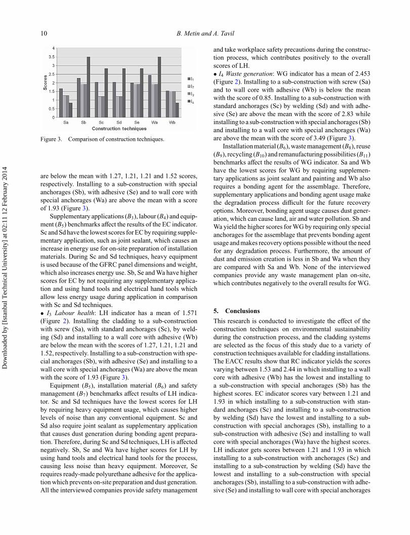
Figure 3. Comparison of construction techniques.
are below the mean with 1.27, 1.21, 1.21 and 1.52 scores,respectively. Installing to a sub-construction with specialanchorages (Sb), with adhesive (Se) and to wall core withspecial anchorages (Wa) are above the mean with a scoreof 1.93 (Figure 3).
Supplementary applications (B3), labour (B4) and equip-ment (B5) benchmarks affect the results of the EC indicator.Sc and Sd have the lowest scores for EC by requiring supple-mentary application, such as joint sealant, which causes anincrease in energy use for on-site preparation of installationmaterials. During Sc and Sd techniques, heavy equipmentis used because of the GFRC panel dimensions and weight,which also increases energy use. Sb, Se and Wa have higherscores for EC by not requiring any supplementary applica-tion and using hand tools and electrical hand tools whichallow less energy usage during application in comparisonwith Sc and Sd techniques.• I3 Labour health: LH indicator has a mean of 1.571(Figure 2). Installing the cladding to a sub-constructionwith screw (Sa), with standard anchorages (Sc), by weld-ing (Sd) and installing to a wall core with adhesive (Wb)are below the mean with the scores of 1.27, 1.21, 1.21 and1.52, respectively. Installing to a sub-construction with spe-cial anchorages (Sb), with adhesive (Se) and installing to awall core with special anchorages (Wa) are above the meanwith the score of 1.93 (Figure 3).
Equipment (B5), installation material (B6) and safetymanagement (B7) benchmarks affect results of LH indica-tor. Sc and Sd techniques have the lowest scores for LHby requiring heavy equipment usage, which causes higherlevels of noise than any conventional equipment. Sc andSd also require joint sealant as supplementary applicationthat causes dust generation during bonding agent prepara-tion. Therefore, during Sc and Sd techniques, LH is affectednegatively. Sb, Se and Wa have higher scores for LH byusing hand tools and electrical hand tools for the process,causing less noise than heavy equipment. Moreover, Serequires ready-made polyurethane adhesive for the applica-tion which prevents on-site preparation and dust generation.All the interviewed companies provide safety management
and take workplace safety precautions during the construc-tion process, which contributes positively to the overallscores of LH.• I4 Waste generation: WG indicator has a mean of 2.453(Figure 2). Installing to a sub-construction with screw (Sa)and to wall core with adhesive (Wb) is below the meanwith the score of 0.85. Installing to a sub-construction withstandard anchorages (Sc) by welding (Sd) and with adhe-sive (Se) are above the mean with the score of 2.83 whileinstalling to a sub-construction with special anchorages (Sb)and installing to a wall core with special anchorages (Wa)are above the mean with the score of 3.49 (Figure 3).
Installation material (B6), waste management (B8), reuse(B9), recycling (B10) and remanufacturing possibilities (B11)benchmarks affect the results of WG indicator. Sa and Wbhave the lowest scores for WG by requiring supplemen-tary applications as joint sealant and painting and Wb alsorequires a bonding agent for the assemblage. Therefore,supplementary applications and bonding agent usage makethe degradation process difficult for the future recoveryoptions. Moreover, bonding agent usage causes dust gener-ation, which can cause land, air and water pollution. Sb andWa yield the higher scores for WG by requiring only specialanchorages for the assemblage that prevents bonding agentusage and makes recovery options possible without the needfor any degradation process. Furthermore, the amount ofdust and emission creation is less in Sb and Wa when theyare compared with Sa and Wb. None of the interviewedcompanies provide any waste management plan on-site,which contributes negatively to the overall results for WG.
5. ConclusionsThis research is conducted to investigate the effect of theconstruction techniques on environmental sustainabilityduring the construction process, and the cladding systemsare selected as the focus of this study due to a variety ofconstruction techniques available for cladding installations.The EACC results show that RC indicator yields the scoresvarying between 1.53 and 2.44 in which installing to a wallcore with adhesive (Wb) has the lowest and installing toa sub-construction with special anchorages (Sb) has thehighest scores. EC indicator scores vary between 1.21 and1.93 in which installing to a sub-construction with stan-dard anchorages (Sc) and installing to a sub-constructionby welding (Sd) have the lowest and installing to a sub-construction with special anchorages (Sb), installing to asub-construction with adhesive (Se) and installing to wallcore with special anchorages (Wa) have the highest scores.LH indicator gets scores between 1.21 and 1.93 in whichinstalling to a sub-construction with anchorages (Sc) andinstalling to a sub-construction by welding (Sd) have thelowest and installing to a sub-construction with specialanchorages (Sb), installing to a sub-construction with adhe-sive (Se) and installing to wall core with special anchorages
Dow
nloa
ded
by [
Ista
nbul
Tec
hnic
al U
nive
rsity
] at
02:
11 1
2 Fe
brua
ry 2
014

Architectural Science Review 11
(Wa) have the highest scores. WG indicator scores are cal-culated between 0.85 and 3.49 in which installing to asub-construction with screw (Sa) and installing to a wallcore with adhesive (Wb) have the lowest and installingto a sub-construction with special anchorages (Sb) andinstalling to a wall core with special anchorages (Wa) havethe highest scores.
Results of this study demonstrate that the RC indica-tor is mostly defined by the construction type and by thesupplementary application requirement of the constructiontechniques, which affect water and material uses as thesecond-level indicators. Results of the EC indicator aremostly determined by the supplementary application andthe equipment requirement of the construction techniques,which affect electricity and oil uses as the second-levelindicators. Equipment and installation material require-ments affect the scores of LH indicator basically with theirinfluence on the second-level indicators that are emission,noise and dust generation. When construction techniquesare compared, the biggest differences among the scoresare observed on the WG indicator. Supplementary appli-cations and bonding agent usage make the recovery optionsimpossible, since degrading process during reuse, reman-ufacturing and recycling processes becomes inconvenient.Moreover, all of the companies, which the interviews wereconducted with, declared that they do not provide anywaste management plan for the construction site during theconstruction process. Therefore, these properties cause abig difference between the construction techniques, whichonly include anchorage usage or require bonding agent andsupplementary application usage.
This study shows that the effect of the construction pro-cess on the environmental sustainability can be assessed byweighting the process of various construction techniqueswith the help of comprehensive analysis of the particulartechnique. Despite the fact that the construction processcomprises a relatively short time period of the buildinglife cycle, it affects the environment and human, and itsrole on the building life cycle cannot be underestimated.The EACC method provides assessment and comparisonof external wall cladding construction techniques duringthe design process and it helps decision-makers in reduc-ing environmental impacts of the construction process. Thestudy also shows that the construction process has negativeeffects on environment regarding its various aspects, suchas material and equipment inputs and construction tech-niques, which should not be underestimated to achieve aholistic environmental sustainability in the building sector.
The EACC method considers only the external wallcladding construction techniques. The development ofexternal wall cladding materials and their construc-tion techniques are in progress and their environmen-tal impacts of the construction process can be assessedduring the design phase with this method. The methoddepends on a subjective assessment methodology; there-fore, a methodology, which relies on quantitative data
obtained from the stakeholders of the construction indus-try such as material producers, vendors and constructorscan also be developed. Further research is also neededto provide a holistic assessment of the construction pro-cess, which considers other construction techniques usedin buildings. Thus, environmental sustainability of theconstruction process can be better assessed and con-trolled prior to the construction process and during thedesign phase.
References
Ackoff, R. L., S. K. Gupta, and J. S. Minas. 1962. ScientificMethod: Optimizing Applied Research Decisions. New York:John Wiley & Sons.
Bilec, M. M. 2007. “A Hybrid Life Cycle Assessment Model forConstruction Processes.” PhD diss., University of PittsburgSchool of Engineering, USA.
Chen, Y., G. E. Okudan, and D. R. Riley. 2010. “SustainablePerformance Criteria for Construction Method Selection inConcrete Buildings.” Automation in Construction 19 (2):235–244. doi:10.1016/j.autcon.2009.10.004.
Churchman, C. W., R. L. Ackoff, and E. L. Arnoff. 1957. Intro-duction to Operations Research. New York: John Wiley &Sons.
Edwards, B. 1999. Sustainable Architecture: European Directivesand Building Design. Oxford: Architectural Press.
El-Haggar, S. 2007. “Sustainability of Construction and Demo-lition Waste Management.” Chap. 8 in Sustainable Indus-trial Design and Waste Management: Cradle-to-Cradle forSustainable Development. Burlington: Elsevier AcademicPress.
Fishburn, P. C. 1964. Decision and Value Theory. New York: JohnWiley & Sons.
Gangolells, M., M. Casals, S. Gasso, N. Forcada, X. Roca,and A. Fuertes. 2011. “Assessing Concerns of InterestedParties when Predicting the Significance of EnvironmentalImpacts Related to the Construction Process of ResidentialBuildings.” Building and Environment 46 (5): 1023–1037.doi:10.1016/j.buildenv.2010.11.004.
Kibert, C. J. 2007. Sustainable Construction: Green BuildingDesign and Delivery. Hoboken, NJ: John Wiley & Sons.
Kibert, C. J., J. Sendzimir, and G. B. Guy. 2000. “Construc-tion Ecology and Metabolism: Natural System Analoguesfor a Sustainable Built Environment.” Construction Man-agement and Economics 18 (8): 903–916. doi:10.1080/014461900446867.
Kibert, C. J., J. Sendzimir, and G. B. Guy. 2002. ConstructionEcology: Nature as the Basis for Green Buildings. London:Spon Press.
Kim, J. J., and B. Rigdon. 1998. Sustainable Architecture Mod-ule: Introduction to Sustainable Design. Ann Arbor: NationalPollution Prevention Center for Higher Education, Universityof Michigan. http://www.umich.edu/∼nppcpub/resources/compendia/ARCHpdfs/ARCHdesIntro.pdf
Ko, D., and J. Alberico. n.d. “Reducing Environmental ImpactsDue to Construction Activities.” Technotes, Issue No. 31.RWDI Consulting Engineers and Scientists. http://www.rwdi.com/cms/publications/50/t31.pdf
Li, X., Y. Zhu, and Z. Zhang. 2010. “An LCA Based Envi-ronmental Impact Assessment Model for ConstructionProcesses.” Building and Environment 45 (3): 766–775.doi:10.1016/j.buildenv.2009.08.010.
Dow
nloa
ded
by [
Ista
nbul
Tec
hnic
al U
nive
rsity
] at
02:
11 1
2 Fe
brua
ry 2
014

12 B. Metin and A. Tavil
Metin, B. 2010. “Assessing the Construction Process of theCladding Systems in the Context of Environmental Sus-tainability.” Master thesis (in Turkish), Istanbul TechnicalUniversity, Institute of Science and Technology, Istanbul,Turkey.
Peng, C., D. E. Scorpio, and C. J. Kibert. 1997. “Strategiesfor Successful Construction and DemolitionWaste Recycling Operations.” Construction Managementand Economics 15 (1): 49–58. doi:10.1080/014461997373105.
Peterson, K. L., and J. A. Dorsey. 2000. Road Mapfor Integrating Sustainable Design into Site-level Oper-ations. Report No. PNNL-13183. Pacific NorthwestNational Laboratory Operated By Battelle for the UnitedStates Department of Energy. http://infohouse.p2ric.org/ref/14/13645.pdf
Pollo, R., and A. Rivotti. 2004. “Building Sustainability Evalua-tion in the Building Process: The Construction Phase.” Paperpresented at the Regional Central and Eastern European Con-ference on Sustainable Building, Building Research Institute,Warsaw, October 27–29.
Rivotti, A. 2005. “Evaluating the Eco-compatibility of the Tech-nical Elements Used in On-site Construction Works.” Paper
presented at the World Sustainable Building Conference,Tokyo, September 27–29.
Ryghaug, M., and K. H. Sørensen. 2009. “How Energy EfficiencyFails In The Building Industry.” Energy Policy 37 (3): 984–991. doi:10.1016/j.enpol.2008.11.001.
Schulze, L. n.d. “Value Benefit Analysis.” Chap. 6 in Basicsfor Planning of Logistical Systems. Capacity Building Inter-national. Accessed July 4. https://gc21.giz.de/ibt/en/opt/site/ilt/ibt/regionalportale/sadc/inhalt/logistics/module_03/61_value_benefit_analysis.html
Sev, A. 2008. “How Can the Construction Industry Contribute toSustainable Development? A Conceptual Framework.” Sus-tainable Development 17 (3): 161–173. doi:10.1002/sd.373.
Shen, L. Y., W. S. Lu, H. Yao, and D. H. Wu. 2005. “A Computer-based Scoring Method for Measuring Environmental Perfor-mance of Construction Activities.” Automation in Construc-tion 14 (3): 297–309. doi:10.1016/j.autcon.2004.08.017.
Tapan, M. 1980. Benefit-value Analysis as an Assessment Tool inArchitecture (A book in Turkish). Istanbul; Istanbul TechnicalUniversity.
Tapan, M. 2004. Assessment in Architecture (A book in Turkish).Istanbul: Istanbul Technical University.
Dow
nloa
ded
by [
Ista
nbul
Tec
hnic
al U
nive
rsity
] at
02:
11 1
2 Fe
brua
ry 2
014