
ENSC 405W Grading Rubric for Design Specification
47
ENSC 405W Grading Rubric for Design Specification Criteria Details Marks Introduction/Background Introduces basic purpose of the project. /05% Content Document explains the design specifications with appropriate justification for the design approach chosen. Includes descriptions of the physics (or chemistry, biology, geology, meteorology, etc.) underlying the choices. /20% Technical Correctness Ideas presented represent design specifications that are expected to be met. Specifications are presented using tables, graphs, and figures where possible (rather than over-reliance upon text). Equations and graphs are used to back up/illustrate the science/engineering underlying the design. /25% Process Details Specification distinguishes between design details for present project version and later stages of project (i.e., proof-of-concept, prototype, and production versions). Numbering of design specs matches up with numbering for requirements specs (as necessary and possible). /15% Test Plan Appendix Provides a test plan outlining the requirements for the final project version. Project success for ENSC 405W will be measured against this test plan. /10% User Interface Appendix Summarizes requirements for the User Interface (based upon the lectures and the concepts outlined in the Donald Norman textbook). Graded Separately 440 Plan Appendix Analyses progress in 405W and outlines development plans for 440. Includes an updated timeline, budget, market analysis, and changes in scope. Analyses ongoing problems and proposes solutions. Graded Separately Conclusion/References Summarizes functionality. Includes references for information sources. /05% Presentation/Organization Document looks like a professional specification. Ideas follow logically. /05% Format/Correctness/Style Includes letter of transmittal, title page, abstract, table of contents, list of figures and tables, glossary, and references. Pages are numbered, figures and tables are introduced, headings are numbered, etc. References and citations are properly formatted. Correct spelling, grammar, and punctuation. Style is clear, concise, and coherent. Uses passive voice judiciously. /15% Comments
-
Upload
khangminh22 -
Category
Documents
-
view
2 -
download
0
Transcript of ENSC 405W Grading Rubric for Design Specification

ENSC 405W Grading Rubric for Design Specification
Criteria Details Marks
Introduction/Background
Introduces basic purpose of the project.
/05%
Content
Document explains the design specifications with appropriate justification for the design approach chosen. Includes descriptions of the physics (or chemistry, biology, geology, meteorology, etc.) underlying the choices.
/20%
Technical Correctness
Ideas presented represent design specifications that are expected to be met. Specifications are presented using tables, graphs, and figures where possible (rather than over-reliance upon text). Equations and graphs are used to back up/illustrate the science/engineering underlying the design.
/25%
Process Details
Specification distinguishes between design details for present project version and later stages of project (i.e., proof-of-concept, prototype, and production versions). Numbering of design specs matches up with numbering for requirements specs (as necessary and possible).
/15%
Test Plan Appendix
Provides a test plan outlining the requirements for the final project version. Project success for ENSC 405W will be measured against this test plan.
/10%
User Interface Appendix
Summarizes requirements for the User Interface (based upon the lectures and the concepts outlined in the Donald Norman textbook).
Graded
Separately
440 Plan Appendix
Analyses progress in 405W and outlines development plans for 440. Includes an updated timeline, budget, market analysis, and changes in scope. Analyses ongoing problems and proposes solutions.
Graded
Separately
Conclusion/References
Summarizes functionality. Includes references for information sources.
/05%
Presentation/Organization
Document looks like a professional specification. Ideas follow logically.
/05%
Format/Correctness/Style
Includes letter of transmittal, title page, abstract, table of contents, list of figures and tables, glossary, and references. Pages are numbered, figures and tables are introduced, headings are numbered, etc. References and citations are properly formatted. Correct spelling, grammar, and punctuation. Style is clear, concise, and coherent. Uses passive voice judiciously.
/15%
Comments

March 31st, 2018
Dr. Andrew Rawicz School of Engineering Science Simon Fraser University 8888 University Dr. Burnaby, British Columbia V5A 1S6
Re: ENSC405W/440 Design Specifications for CidaFrame
Dear Dr. Rawicz,
The following document contains the design specifications for the proof of concept of CidaFrame, prepared as a course requirement for Team 6 of the ENSC 405W portion of the capstone course. Our goal with CidaFrame is to create a cost-effective, modular, and smartphone compatible alternative to automatic camera tracking of a subject.
The document will cover the mechanical, electronic, and software design of CidaFrame. Thorough technical detail along with justification for our choices for the proof of concept is included. This outlines how we built our proof of concept, and will prove valuable for our prototype at the end of the 8-month capstone course.
Contained within the these specifications are details about the CidaFrame system, such as the electronic and software design behind the IR sensing and tracking system, the motor systems and physical design for panning and tilting the camera, the software design for quick control of the motors, and the modularity for compatibility with different cameras and tripods/stands/tabletops. Additionally, an appendix detailing the user experience we intended to create, as well as one containing our plan for the 440 portion of the course is included at the end..
We are Telaio Technologies, a diverse group of five students with Systems, Electronics, and Computer Engineering backgrounds: Reese Erickson, Waez Dewan, Neijer Shokri, Jon De Guzman, and Jason Liu. Thank you for your time in reviewing the design specifications of CidaFrame. Feel free to contact us at [email protected] if you have any additional questions.
Sincerely,
Reese Erickson
CEO

Design Specifications
Telaio Technologies Group 6
Reese Erickson Neijer Shokri Jason Liu Waez Dewan Jon De Guzman
Date
March 31, 2018
Contact Person
Jon De Guzman [email protected] 778-388-0580
Submitted To
Mr. Steve Whitmore Dr. Andrew Rawicz School of Engineering Science Simon Fraser University

Abstract
Modern consumption of digital multimedia is a large part of all of our lives. The backbone of this consumption are the creators of all of the videos we watch, of which there are many. The Internet and modern smartphones facilitate a large number of people to create and share video with their friends and family, and the public, for any purpose. These videographers range from amateurs with simple smartphones, to professionals with high-end recording equipment. Some of the conveniences available to the professionals aren’t currently available to regular consumers, and the members of Telaio Technologies believe that our skills and experiences will allow us to fill a gap in the market, for cheaper, cost-effective automated camera tracking of a subject.
This document contains details on Telaio Technologies’ design for the proof of concept of our automatically tracking camera mount, CidaFrame. Consideration regarding the design of aspects of our device, ranging from physical shape to tracking software, is contained within. Furthermore, our expectations of work to come in the future will also be contained within. From this document, the reader should be able to grasp a very full, detailed description of the entire CidaFrame system.
CidaFrame consists of two physically separate components, one of which is the camera mount, and the other being the tracking device. The physical design, controls, electronics, and tracking software of both components will be described in depth within this design specification document. Additionally, work to be completed in the future will also be described, within a future planning appendix.
Telaio Technologies is dedicated to creating a cheaper, modular, cost-effective tracking camera mount to allow for use with both smartphones and digital/other cameras. This document is our description of a proof of concept of such a product.
1

Table of Contents
Abstract 1
Table of Contents 2
List of Figures 4
List of Tables 4
1. Introduction 5
2. Glossary 6
3. System Functional Specifications 7
a. Structural Specifications 8
b. Electrical Specifications 10
i. Tracker Base 10
ii. User-end Receiver 17
c. Software Specifications 18
i. Tracker Base 18
ii. User-end Receiver 22
4. Process Details 24
a. Present Version - Proof of Concept 24
b. Future Versions 25
5. Conclusion 26
6. References 27
7. Appendix A: Test Plan 29
8. Appendix B: User Interface 30
a. Introduction 30
b. User Analysis 30
c. Technical Analysis 31
2

d. Engineering Standards 33
e. Analytical Usability Testing 34
f. Empirical Usability Testing 34
g. Conclusion 35
h. References 35
9. Appendix C: ENSC 440 Planning 36
a. Introduction 36
b. Market Analysis 38
c. Personnel Management 39
d. Time Management 39
e. Budgetary Management 40
f. Conclusion 41
g. References 42
3

List of Figures
Figure 3.0 - Overview of CidaFrame system components 7
Figure 3.a.1 - IR LED setup orientation 8
Figure 3.a.2 - Tracker proof of concept testbed framework 9
Figure 3.b.1 - Motor control breakout board for operation of three different motors 11
Figure 3.b.2 - Simple BJT motor driver for IR beacon motor 12
Figure 3.b.3 - CidaFrame full system diagram with power regions 13
Figure 3.b.4 - Distance vs IR sensor reading graph... 14
Figure 3.b.5 - Angle of rotation vs IR sensor reading graph... 15
Figure 3.b.6 - Noise reduction circuit for RF receiver 16
Figure 3.b.7 - Arduino pin assignments for mount of CidaFrame’s POC model 16
Figure 3.b.8 - Arduino pin assignments for receiver of CidaFrame’s POC model 18
Figure 3.c.1 - Main loop algorithm flow for mount in CidaFrame’s POC model 20
Figure 3.c.2 - IR directional sensing algorithm 21
Figure 3.c.3 - Motor encoder ISR algorithm flow 22
Figure 3.c.4 - Main loop algorithm flow for receiver in CidaFrame’s POC model 23
Figure 4.a.1 - Wiring diagram for tracker system 24
Figure 4.a.2 - Standard drawing layout outlining size of testbed assembly 25
Figure 9.d.1 - Proposed Gantt chart for ENSC 440 40
List of Tables
Table 3.b.1 - Important pan/tilt motor specs of DFRobot FIT0487 [1] 10
Table 3.b.2 - Important specs of SN754410 Quadruple Half-H driver [2] 11
Table 3.b.3 - Important specs of Adafruit 711 toy motor [5] 13
Table 9.e.1 - Estimated cost breakdown for prototype 40
4
1. Introduction
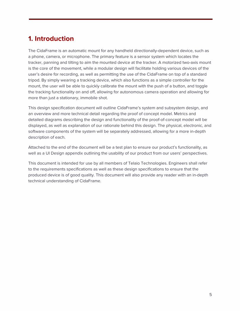
The CidaFrame is an automatic mount for any handheld directionally-dependent device, such as a phone, camera, or microphone. The primary feature is a sensor system which locates the tracker, panning and tilting to aim the mounted device at the tracker. A motorized two-axis mount is the core of the movement, while a modular design will facilitate holding various devices of the user’s desire for recording, as well as permitting the use of the CidaFrame on top of a standard tripod. By simply wearing a tracking device, which also functions as a simple controller for the mount, the user will be able to quickly calibrate the mount with the push of a button, and toggle the tracking functionality on and off, allowing for autonomous camera operation and allowing for more than just a stationary, immobile shot.
This design specification document will outline CidaFrame’s system and subsystem design, and an overview and more technical detail regarding the proof of concept model. Metrics and detailed diagrams describing the design and functionality of the proof-of-concept model will be displayed, as well as explanation of our rationale behind this design. The physical, electronic, and software components of the system will be separately addressed, allowing for a more in-depth description of each.
Attached to the end of the document will be a test plan to ensure our product’s functionality, as well as a UI Design appendix outlining the usability of our product from our users’ perspectives.
This document is intended for use by all members of Telaio Technologies. Engineers shall refer to the requirements specifications as well as these design specifications to ensure that the produced device is of good quality. This document will also provide any reader with an in-depth technical understanding of CidaFrame.
5

2. Glossary
ASK - Amplitude Shift Keying, a form of amplitude modulation in which digital data is transmitted as changes in amplitude of a given carrier wave.
DC - direct current
EM - electromagnetic
I/O - Input/Output
IR - infrared
ISR - interrupt service routine
LED - Light-Emitting Diode
OOK - On-Off Keying, one of the simplest forms of ASK, which is to simply transmit a carrier to represent a ‘1’, and not transmit the carrier to represent a ‘0’. [9]
POC - Proof of Concept
PWM - Pulse Width Modulation
“Mount” - portion of CidaFrame which holds the smartphone/camera and may be on a tripod
“Receiver” - portion of CidaFrame attached to a moving subject
RPM - Rotations Per Minute
Slip ring - a component which allows electric current to be passed to a rotating shaft through brushes with a fixed position
USB - Universal Serial Bus
6

3. System Functional Specifications
The CidaFrame system has various structural, electronic, and software components to it, and to simply this, Figure 3.0 shows a general overview of each individual component of the CidaFrame system, as well as the modular physical interfaces which allow CidaFrame to be compatible with any tripod, as well as with modern cameras. Note that packaged with any prototype/final product version of CidaFrame will be a phone holder with a tripod screw hole to allow easy attachment to the top of the mount. The main structural component to be described for the proof of concept will be the physical frame of the CidaFrame mount. The electronic systems in place in the proof of concept will be an RF emitter/receiver pair, an IR emitter with a motor to create a beacon, an IR receiver, and a dual-axis pan/tilt motor system. The major software systems which will interface both remotely with each other (between the receiver and mount) and directly (between the main loop and the motor encoder ISR) in the proof of concept need to be written to fit within the memory constraints of the microcontroller, and with adequate timings to permit quick, accurate tracking.
Figure 3.0 - Overview of CidaFrame system components
7

3.a. Structural Specifications
All of the hardware for the tracker base will be enclosed in a framework structure that will make the test fixture for the proof of concept. Inside the framework structure will house the pan and tilt motors, two perforated prototyping boards, an Arduino Uno microcontroller, and the IR beacon motor and assembly. The framework will serve as the integration testbed for the proof of concept, and will allow a structurally sound implementation of the tracker base at this stage of the design.
When using moving parts, it is crucial to identify possible situations where the load on the actuator performing the movement or rotation is outside of normal operations, and/or may cause additional stresses or strains. In the case of the proof of concept, the actuators being used are motors, which need attention to axial loads, and varying torques required to perform their rotations.
While the IR beacon motor will be kept relatively standard to its performance requirements over ranges of use cases, when designing the IR beacon assembly it will be important to keep the assembly’s center of gravity as centric as possible. For the assembly, it will be connected at two opposite sides; one side will be connected directly to a DC motor, while the other will be connected to a slip ring. The slip ring will allow three IR LEDs to be powered inside the rotating portion of the beacon. The three IR LEDs will be positioned vertically in a row, with an offset of 10 degrees, each with a viewing angle of 30 degrees, as illustrated in Figure 3.a.1 below. With the three LEDs mounted on one side of rotating portion of the beacon, a counterweight must be designed in order to centralize the center of gravity, and to reduce mechanical vibrations to the system.
Figure 3.a.1 - IR LED setup orientation for IR beacon
With respect to the pan and tilt functionalities provided by the two DC gear motors, their rotations cause a change in the system’s structural characteristics, where the center of gravity may be moved further from their axes of rotations, introducing variable axial loads. To offset the direct loading onto the shaft of the actuator, ball bearings will be placed at points of rotation. In addition to reducing axial and radial loading on the shaft of the actuators, friction between rotation will
8

also be minimized. There will be four ball bearings used; two bearings for the tilt axis, one for the pan axis, and one where the beacon will be rotated.
Regarding the organization of the tracker base’s internals, with two prototyping PCBs and an Arduino, the electronics will be placed flat to the bottom of the base, layered on top of each other vertically. Sufficient room will be needed in order for the placement of the boards, and such that they don’t interfere with the others. Additionally, the motors will also have to be mounted in such a way that they do not interfere with any other component, but are size efficient. The pan motor will be oriented such that its shaft is directly connected to the stationary base which the tracker moves about. The electronics will be above this motor. The tilt motor will be above the electronic boards, but mounted horizontally in order to achieve the tilting motion. Further, the IR beacon assembly will be mounted to the front of the tracker, where the DC motor will be mounted on the bottom with its shaft pointing up, rotating the beacon which is also held by the slip ring, mounted at the top of the beacon assembly. With the general layout and organization of components, the testbed framework for the proof of concept will meet the requirements RP.1 - 1, and RP.1 - 2.
Figure 3.a.2 - Tracker proof of concept testbed framework
As per ISO 1222:2010 [15], the standard tripod screw thread is either a 1/4-20 UNC thread or a 3/8-16 UNC thread. Wikipedia states that most common consumer cameras are fitted with the former thread size, and this is confirmable through common knowledge and experiences with using consumer cameras and tripods [14]. This is a common, widely available screw size. To ensure the physical modularity goal of CidaFrame, a screw on the top of the mount as well as a screw socket at the bottom of the mount will both be threaded with 1/4-20 UNC threads, enabling an easy connection to a consumer tripod and consumer cameras.
9

3.b. Electrical Specifications
3.b.i. Tracker Base
The proof of concept will use an Arduino Uno, with an Atmel ATmega328P microcontroller. The Arduino requires 5V power, which can be supplied either through a USB port or a DC power supply. The Uno has enough I/O pins (both PWM and non-PWM) to support two panning and tilting motors with encoders, and a rotating IR beacon. Additionally, the 32kB of on-board flash memory on the device will safely allow the necessary tracking software to fit on the device, rendering RE.1 - 11 no longer a concern.
The very core of CidaFrame is the panning and tilting to achieve accurate tracking of our subject/receiver. In order to perform accurate tracking, a dual-axis motor system is required to pan and tilt the mount. Additionally, the dual-axis system will have enough torque in the motors to support and turn the weight of a modern smartphone for our proof-of-concept. Modern smartphones generally have a mass in the range of 100-200g, which translates to approximately 1-2 N of weight. As the smartphone will be mounted directly on top of our mount, the distance of the center of gravity from any of the axes of rotation will be less than 10cm. This means that the phone itself will require at most 100-200 Nm of torque from the motors. We chose to use DFRobot FIT0487 micro metal gear motors with built-in encoders to have the required torque [1]. Table 3.b.1 below highlights the important specs of this motor, along with a description of why that spec is important to our design. These specs will allow us to meet our requirements of RE.1 - 6, RE.1 - 7, and RE.1 - 8.
Name Spec Relevant description
Rated Torque 2.5 kg cm = 245.17 mNm
This torque allows the motor to easily move the weight of the mount and a 100-200g modern smartphone.
Encoder Resolution 5320/rev, quadrature encoders
A high encoder resolution is essential to accurate control of the exact angle of a motor, providing accurate tracking. Specifically, having 5320 encoder ticks within a revolution is around 360/5320 = 0.06 degrees per encoder tick.
Maximum RPM 41 RPM A higher than necessary RPM will allow for full control of the motor while staying within the operating limits of the motor.
Operating Voltage 6 V Requires a separate power source from the Arduino itself.
Operating Current 70mA no load. 170mA rated current.
Currents are not very high, which limits the power consumption as well as the potential risk for electrical hazard from shock or overheating.
Operating Directions
Bidirectional This is essential to being able to easily track in both directions.
Table 3.b.1 - Important pan/tilt motor specs of DFRobot FIT0487 [1]
10

A driver along with a separate power source is needed to drive the motors. The proof-of-concept will utilize the Texas Instruments SN754410 Quadruple Half-H driver (orderable and marked as the SN754410NE). The relevant specs are highlighted in the following table.
Name Spec Relevant description
Maximum current
Bi-directional, up to 1A
The maximum current of the driver is far greater than necessary for the motors, easily staying within safe operating limits.
Voltage ratings 3.5 - 36V The operating voltage of our motors (6V) is contained within this range.
Delay 800ns Very short delay will allow for quick motor response times to a given input, further tightening the tracking capability in both pan and tilt directions.
Table 3.b.2 - Important specs of SN754410 Quadruple Half-H driver [2]
Additionally, these maximum current draws of the motors, which will likely be the most heavy power-drawing portion of the system, are capped at 6V*0.170A * 2 motors = 2 W. This allows us to safely staying within the power draw limitation of RE.1 - 2 (20 watts). The motor driver requires both a logical power supply (which can be shared with the Arduino’s 5V power supply), and a motor driving power supply. As our proof of concept will not use portable battery power, a 6V DC power supply will be utilized to drive the motors. A small motor control board was soldered with power supply wires, terminal blocks, and a chip socket for the driver to allow for easy swapping out of components in case any of these parts fail.
Figure 3.b.1 - Motor control breakout board for operation of three different motors
11

In Figure 3.b.1, VCC2 drives the motors directly, and VCC1 is a logical switching source required for the H-bridge operation. VCC2 is to be a separate 6V power supply, and VCC1 will be wired to the logical +5V provided by the Arduino. Enable signals on the H-bridge motor driver were hard-wired to VCC1 (hard-wired to enable) to preserve Arduino pins, although in hindsight this wasn’t wholly necessary (as we have enough Arduino pins for the enable signals as well). Disabling the enable signal puts the motor output pins in a high-impedance state, while enabling them causes them to be in-phase with the input pins. Since the gear motors themselves are quite difficult to manually turn (due to the 380:1 gear ratio), it will be unlikely to be manually turned, and as such will not necessarily require the high-impedance state from sending a logical OFF to the enable pin. Simply sending a logical OFF (PWM of duty cycle 0) to the Arduino output pin will achieve nearly the same result, as the output will simply stop driving the motor. Regardless, our proof of concept does not require robustness to manual rotation (that requirement is only for the final product, RP.3 - 1002). Furthermore, this breakout board creates a division of two power regions for the mount portion, fulfilling requirement RE.1 - 1. Having different power regions allows for electrical isolation of the microcontroller board from the components requiring a higher power draw, namely the motors. A diagram of the power regions can be seen in Figure 3.b.3.
After some revision, we found RE.1 - 9 (beacon shall spin at 300 RPM minimum) to be too high of a requirement. Slip rings that were commercially available for reasonable costs had a maximum RPM rating of around 250-300 RPM [3] [4]. We decided that the requirement was also somewhat excessive, as tracking a normally moving human subject with an IR beacon need only occur twice or three times a second for the perception of smooth tracking, especially for the proof of concept model. The beacon motor will still be driven by a toy motor in the proof of concept model - Adafruit Industries product 711 [5]. Table 3.b.3 highlights the main specs relevant to our choice. Moreover, Figure 3.b.2 shows the simple BJT motor driver circuit from Figure 3.b.1 in detail, to be used to drive the beacon motor.
Figure 3.b.2 - Simple BJT motor driver for IR beacon motor
12

Name Spec Description
Rated Voltage 6V This is the same rated voltage as the other motors, so they can be driven from the same power source.
Current 70 mA no load. 250 mA max.
Similar currents as the pan/tilt motors, so this will not cause any further power draw issues. 6V*0.25A = 1.5W max.
Speed 9100 +- 1800 no load 4500 +/- 1500 with load
The RPM is too fast for the purposes of the IR beacon, but we plan to reduce this using a low PWM duty cycle.
Starting Torque 20g*cm High enough to spin the IR beacon up quickly
Dimensions 27.5mm x 20mm x 15mm Shaft is 8mm long, 2mm diameter.
The dimensions of the toy motor are small enough for the proof of concept model of CidaFrame. Ideally, for a prototype/working model, if the IR beacon is to be used, a much smaller brushless DC motor is desired for lower noise and compactness.
Table 3.b.3 - Important specs of Adafruit 711 toy motor [5]
Figure 3.b.3 - CidaFrame full system diagram with power regions
13

To perform tracking, directional IR emitters will be used in the mount for line-of-sight tracking with the receiver. We purchased some inexpensive IR emitters to test how their ranges worked. Some smaller IR emitters we tested did not have a high enough current limit (Lite-On LTE-302) and were not bright enough for a range greater than a meter, but the highly directional Vishay TSAL6100 emitters have a high enough brightness due to a higher forward current and burst current rating [6]. The IR receivers used in the proof of concept in both the mount and receiver are the TSL260R-LF-ND [7]. The Arduino powers them with a 5V logical input, and the receiver outputs a voltage between 0 and 5V based on the intensity of IR light received. For testing the range, we wired 5 of the IR LEDs in parallel, at 6V with a series resistance of 100Ω (6V / 100Ω = 60mA per LED). A similar kind of wiring for the IR beacon will allow our proof of concept model to easily have the range required, but may prove too inefficient to be viable for a battery-powered later model and may need to be revised. From reading the analog voltage value of the IR receiver on an Arduino, our tests found that until a range of around 1.5m, directly pointing the IR emitter array at the receiver read a voltage of around 4V, which fell relatively non-linearly down to around 1-1.5V at distances of 2-3m. Additionally, from placing the receiver at 1.5m from the same LED array, we found that the receiver was able to produce a reading of 3.5-4V up until the emitter array was more than 30 degrees off-angle, at which point the received intensity quickly diminished to 0.5V at 60 degrees. The plots for our measured data are shown below.
Figure 3.b.4 - Distance vs TSL260R-LF-ND IR sensor reading for 5x TSAL6100 IR emitters at 100Ω, 6V supply.
The distance measurements in Figure 3.b.4 confirms that the LEDs in a static parallel DC configuration will be capable of the 3m range we desire for the IR beacon, satisfying requirement RE.1 - 4, and also satisfying RG.1 - 2, as our testing was done indoors. Pulsing the LED at a higher current (the LEDs are rated for up to 200 mA forward current, with 1.5A of surge forward current) may allow for an even longer range in a prototype/future model. The measurements in Figure
14

3.b.5 also somewhat confirms the datasheet-provided 20 degree viewing angle of the LEDs (the intensity quickly diminishes anywhere past 30 degrees off axis) which allows for relatively accurate direction tracking. Processing the received intensity as the LED rotates will allow the system to relatively accurately pinpoint the location of the receiver.
Figure 3.b.5 - Angle of rotation vs TSL260R-LF-ND IR sensor reading (at 1.5m) for 5x TSAL6100 IR emitters, 100Ω, 6V
Finally, regarding the RF transmitter/receiver pair in the proof of concept model, our choice was to not worry too much about this component and to get a simple form of communication working. We chose to use the Mantech Electronics 433MHz XD-RF-5V and the XD-FST, made for Arduino [8]. The pair operates based on the simplest form of Amplitude Shift Keying (ASK), known as On-Off Keying (OOK) [9]. Essentially, if a logical 1 bit is to be sent, the carrier is broadcast, and if logical 0 is to be sent, no carrier is broadcast. Within the mount, one of the analog pins is assigned to the RF receiver, to which the XD-RF-5V receiver will be attached. From testing, we found that the receiver picks up a fair bit of electrical noise. The noise is showing values varying wildly between 0 and 5V without a noise reduction circuit when logical 0 is being “sent”. A simple noise reduction circuit is to be used on the receiver in the mount to make the received RF signal much steadier and simpler to read from the Arduino [10], to require less software processing to detect a valid data signal. Shown in Figure 3.b.6 is the noise reduction circuit to be used in the mount for the RF receiver.
15

Figure 3.b.6 - Noise reduction circuit for RF receiver
Shown in Figure 3.b.7 are the pin assignments on the Arduino board for the various components within the mount for the proof of concept model. A wiring diagram showing what components the wires connect to is available in the process details in Figure 4.1. Not shown in the pin assignments are pins for the motor’s VCC and GND, but these are to be supplied by the corresponding + and - pins from the motor driver board in Figure 3.b.1. The individual pins for controlling each motor indicate that RE.1 - 10 has been successfully achieved.
Figure 3.b.7 - Arduino Pin assignments for mount of CidaFrame’s POC model
16

The pin assignments are primarily based on necessity of our various components. The motor control signals require PWM-enabled pins to be able to control the drive strength of the motor, so all of the motor controls are wired to PWM-enabled pins. For the encoders, only one encoder line from each of the motors was necessary to be wired to an external interrupt pin to catch all 5320 possible encoder increment ticks. Since there are exactly two external interrupt pins, each of these pins was wired to one motor encoder signal. The other pin assignments (limit switches for tilt, IR transmitters, and other motor encoder signal) are simply on any digitally readable/writeable pin on the Arduino. All of the pins on the Arduino are digitally readable and writable. Lastly, the RF and IR receivers are wired to analog-readable pins, as their outputs are analog voltage values in the range of 0-5V.
3.b.ii. User-end Receiver
In the proof-of-concept model, the receiver will be using an Arduino Nano, with the same ATmega328P microprocessor. The primary reason for this was the existing availability of this device to our team members, to save on cost for the proof of concept. As the receiver is a relatively simpler device in terms of pin usage, the abundant pins and memory of the same microcontroller are not necessary, but will prove valuable in easing development. One foreseeable use for these extra pins in future iterations is to add control button inputs for the receiver to be able to send data back to the mount.
As previously mentioned, the IR receiver in the receiver is the TSL260-R-LF-ND [7]. This requires a logical 5V supply and a ground pin, and outputs a 0-5V output based on intensity of IR light received. This supply and ground can be supplied by the Arduino. The output will be wired to an analog-readable pin of the Arduino Nano within the receiver, so that the analog voltage value can be read accurately by the microcontroller.
The RF transmitter in the CidaFrame receiver is the XD-FST [8]. As it relies on OOK modulation, as previously mentioned, the data port of the transmitter can simply be wired to a digital output pin of the Arduino. Writing a logical ‘0’ to the pin will shut off the carrier, and writing a logical ‘1’ will enable the carrier signal. This simple form of communication will be used to send whether the received IR intensity is surpassing a threshold value. This transmitter can simply be wired to a digitally-writable pin on the Arduino, to transmit logical OFF and ON signals. As the RF transmitter has a much greater range than the tested range of our 3m IR beacon, this once again confirms that our requirement RE.1 - 5 is met.
Shown in Figure 3.b.8 are the pin assignments for the proof of concept model of the receiver.
17

Figure 3.b.8 - Arduino Pin assignments for the receiver in the proof of concept model
3.c. Software Specifications
3.c.i. Tracker Base
The software in the tracker base will be running on the Atmel ATMega328P microcontroller, within the Arduino Uno board, which runs at 16MHz [11]. This microcontroller allows us to easily satisfy requirement RS.1 - 1, as from our testing, the Arduino Uno takes around 3 to 4 seconds to start running the pre-loaded program after being powered on. The main function of the software will be to accurately detect the location of the receiver, and tightly control the motors to smoothly pan and tilt to face the front of the mount toward the receiver. In order to satisfy the memory constraint requirement, the size of the software must be small enough to fit within the Arduino. As the code for the proof of concept is able to be run on the Arduino microcontroller, which has only 32kB of program memory available to it, our written proof of concept software confirms that we have satisfied requirement RS.1 - 3. This software will be described in this section.
Using the on-board timer built into the microcontroller, the main loop code of the Arduino will poll the mount-side IR receiver, which will compute a period for which the IR beacon is rotating (should be around 5RPM, so 200ms). Additionally, it will also poll the RF receiver for the received IR signal intensity sent by the user-worn receiver. The calculations dealing with the polled data can easily be in line with requirement RS.1 - 5. As the microcontroller runs at a frequency of
18

16MHz, the 100ms requirement translates to a maximum of 1.6 million processor cycles per loop. This is quite easy to stay within by performing a fixed number of data reads, storing a small number of previously recorded periods to average over, and storing the times at which the receiver notified the mount of a higher-than-normal received IR intensity. With this data, the mount can compute the angle of the receiver relative to the front-facing normal direction of the mount. This target angle will then be computed to an appropriate number of encoder ticks over which to actuate the motors, which will then be set as a target position for the motor control algorithm. A flow diagram for this algorithm is shown in Figure 3.c.1. This main microcontroller loop will satisfy requirement RS.1 - 2.
To convert the angle to a target position to provide to the motor encoder ISR routine, the sign of the angle can be taken as the sign of the target position. The degrees themselves can be converted to a count of encoder ticks via the simple calculation [Degrees]/360 * 5320. Rounding this result in this case will not result in an error greater than 1/5320th of a full rotation, which is around 360/5320 = 0.068 degrees. An example calculation is show in Figure 3.c.2.
The motors will be controlled by the software in the microcontroller using 2 of the PWM output pins per motor, meeting requirement RS.1 - 4. The software is able to set a value between 0 and 255 to the pin which corresponds to the duty cycle of the PWM out of 255 (for example, setting a value of 80 to a pin corresponds to 80/255 = 31% duty cycle, and 255 is equivalent to driving a logical HIGH output) [12]. Setting the output value from 0 to a value under 50, from our experiments, showed that the motor sometimes struggled to start up, and above 200 seemed to produce too much noise and also rotate too quickly for simply turning the mount. For this reason, we chose to limit the values the software writes to the pins to either a 0, or a value in the range of 50-200. The only exception to this is when kick-starting the motors from a standstill by powering them with a HIGH signal (255).
The Arduino Uno with the 328P microcontroller has 6 PWM-capable output pins (pins 3, 5, 6, 9, 10, and 11), and 2 external interrupt capable pins (pin 2 and 3) [11]. Each of the external interrupt pins on the controller can be configured to trigger an ISR on both signal states and signal transitions. Each of the external interrupt pins will be wired to one of each of the motor encoder pins, with the interrupt configured to trigger on any change in pin input level, while the other encoder pin will simply be on a readable pin. This will allow an interrupt service routine (ISR) to run every time an incremental change of the motor’s angle is detected by the encoder. The motor encoder resolution is 5320 ticks per revolution, so essentially, the ISR will run at every 1/5320ths of a revolution [1]. This allows the software to precisely know the change in position of the motor as it is happening, which translates to the change in directional facing of the mount as it occurs. The ISR attached to the encoder’s pin will also track the velocity of the motor by storing the time intervals between each encoder interrupt, while also quickly computing any necessary adjustments to the PWM drive to the motor to speed up or slow down the motor.
19
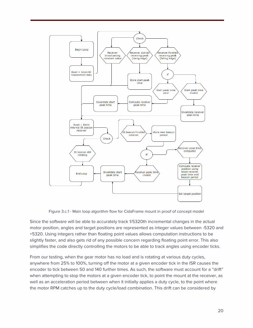
Figure 3.c.1 - Main loop algorithm flow for CidaFrame mount in proof of concept model
Since the software will be able to accurately track 1/5320th incremental changes in the actual motor position, angles and target positions are represented as integer values between -5320 and +5320. Using integers rather than floating point values allows computation instructions to be slightly faster, and also gets rid of any possible concern regarding floating point error. This also simplifies the code directly controlling the motors to be able to track angles using encoder ticks.
From our testing, when the gear motor has no load and is rotating at various duty cycles, anywhere from 25% to 100%, turning off the motor at a given encoder tick in the ISR causes the encoder to tick between 50 and 140 further times. As such, the software must account for a “drift” when attempting to stop the motors at a given encoder tick, to point the mount at the receiver, as well as an acceleration period between when it initially applies a duty cycle, to the point where the motor RPM catches up to the duty cycle/load combination. This drift can be considered by
20

converting the target position (which is in “encoder ticks”) to a drive strength more or less linearly in that direction, which results in slowing down the motors as they approach the target position.
Figure 3.c.2 - IR directional sensing algorithm
Additionally, a “dead zone” of target positions under a certain threshold (within an acceptable error) can be in which the motors will simply be turned off. To meet our directional facing requirement of RG.1 - 4, we decided the maximum dead zone of 15/360*5320 = 221 encoder ticks was a bit too much. This “dead zone” is adjustable, but for the proof of concept, was set to 80 encoder ticks (approximately 5.5 degrees in either direction).
For smooth control of the motors, the duty cycle of the drive should not be adjusted all too suddenly. This is a little complex, so the ISR algorithm flow detailed in Figure 3.c.3 excludes this detail. The algorithm takes into account what the current drive of the motors is, and only periodically adjusts the duty cycle by an amount proportional to how far off the current drive of the motors is relative to the desired drive as computed by a linear conversion from the target position to a target duty cycle. The linear conversion is decided by the formula (target position)*150/5320 + 50. This is a linear mapping of target position values between 0-5320 to values in the range of 50-200, to be set as the Arduino’s PWM duty cycle value (which ranges from 0-255).
21

One concern after all of this is the run time of the ISR and the tickrate of the encoder, as all ISRs should be fast and not block other interrupts from occurring for too long, or too often [13]. For testing, we ran the motor encoder ISR 10,000 times manually on the Arduino, simulating regular actuation circumstances by setting arbitrary target positions (the circumstances themselves don’t affect the performance of the ISR much, but this was done just in case). Over multiple test runs, the ISR, including the pin reads and motor control writes, took anywhere in the range of 16.1 to 16.2 microseconds. The motor itself has a maximum rated RPM of 41, which translates to a maximum rotations per second of 0.6833. With 5320 encoder ticks per rotation, this can be reduced to a maximum of 3635 encoder ticks per second, or an average of one encoder tick per 275 microseconds. At this speed, which is not going to be used in any case, each of the motor ISRs will occupy approximately 16.2/275 = 5.9% of the total available computing time due to the frequency of the encoder interrupt, not including missed encoder ticks due to overlapping interrupts (interrupts occurring within 16 microseconds of each other). As a result of these simple calculations, we concluded that using the programmed ISR will be at most of minor concern regarding timings in the proof-of-concept. This can, of course, be improved in later iterations.
Figure 3.c.3 - Motor encoder ISR algorithm flow
3.c.ii. User-end Receiver
For the proof-of-concept, the receiver will be an Arduino Nano, and the software will be running on the same chip, an ATMega328P. The only attached peripherals for the software to manage in this case are the IR receiver from which to grab data, and the RF transmitter to transmit the data back to the mount. The software for this can be quite simple, as it simply needs to read the received IR intensity, process the IR intensity values to detect whether a ‘peak’ was received (i.e. the beacon passing over the receiver), and send back a ‘true’ signal over the RF transmitter whenever a peak is detected. A simple method of implementing a peak detection algorithm would be to simply compare the received IR intensity to a threshold value, although this may be
22

prone to error, and also limit the maximum operating range of the device. This method was used for the proof-of-concept, however this decision will be reviewed and potentially adjusted in the future, for the prototype and any future iterations. From our measured data in Figure 3.b.5 and Figure 3.b.6, a reasonable threshold would be to include all voltages which indicate direct-beam IR from up to 3 meters away. As such, a threshold between 0.5V and 1V will be adequate for the receiver to report that it is detecting the beacon’s IR beam. This threshold should be easily tunable in the software. The algorithm in the mount can then use the middle of the range of time for which the receiver was broadcasting a ‘1’ signal as the “peak” time that the receiver was able to see the IR beacon.
Figure 3.c.4 - Main loop algorithm flow for CidaFrame receiver in proof of concept model
23

4. Process Details
4.a. Present Version - Proof of Concept
With a full system consisting of mechanical, electrical, and software components and aspects, a clean integration is achieved through a clean organization and outline of each component’s control, feedback, and connection. The wiring diagram diagram, shown in Figure 4.1 below, illustrates how all of the components of the mount are wired together as a system.
Figure 4.a.1 - Wiring diagram for tracker system
Additionally, for the structural housing of the proof of concept, where all of the electrical and mechanical components will be held, a standard drawing layout for the assembly can show how much space it will occupy, and can demonstrate how and where each component will be situated. Displayed in Figure 4.a.2, the proof of concept testbed is shown in a standard drawing which will be used for referencing any future revisions, and where future iterations will be displayed in a similar format to easily compare current versions to previous versions.
24

Figure 4.a.2 - Standard drawing layout outlining size of testbed assembly
4.b. Future Versions
For future iterations of design after the proof of concept, such as the prototype, the requirements to be met have been established. Learning from the proof of concept development, key considerations have been identified in order to meet these requirements. For instance, in terms of spatial requirements, the size of the product can be reduced by using one consolidated custom PCB instead of multiple separate ones. Additionally, through the use of gearing, the position of motors being used can be efficiently placed in order to reduce the size of the product — bevel gears can translate rotation to a different axis allowing motors to be arranged sideways instead of upright, conserving space.
Furthermore, as design version iterations continue, the selection of parts being used should transition from off the shelf electronics to more custom electronics developed in house to meet spatial requirements and specific needs of the product with less overhead of extra, unused capabilities of off the shelf components. By keeping this in mind, cost can be further driven down when thinking of production, which would further achieve our main goal of creating a cost-effective solution and alternative in the market.
25

5. Conclusion
The goal with the proof-of-concept of CidaFrame is to demonstrate the feasibility of an automatically tracking camera mount. Telaio Technologies believes that with the outlined process details, an effective realization of the determined functionalities can be achieved for future design iterations. By outlining requirements at designated design stages, goals are set at each step to achieve. Through the documentation of pin assignments, algorithm flow charts, functional block diagrams, and other methods of design documentation, requirements can be timely met, and it can be easily identified where improvements can be made in the future iterations.
As we are using the ATMega328P processor onboard the Arduino microcontroller to a justifiably full potential, using the Arduino in future versions will not provide a large overhead of cost or wasted functionalities going forward with the prototype. It may be explored to use a custom integration of the open-source Arduino electrical layout combined with our application specific needs for motor controls and wireless communication.
The CidaFrame is to be an affordable, modular, and simple solution to provide automated tracking for a camera. With the help of this device, general users can add automatic pan and tilt tracking to their videos using their smartphones and not spend large sums of money on professional equipment to achieve the same results.
26

6. References
[1] DFRobot, “Micro DC Geared Motor W/ Encoder” (Datasheet). DFRobot. [online] Available at: https://www.dfrobot.com/product-1437.html. [Accessed 30 Mar 2018].
[2] Texas Instruments, “SN754410 Quadruple Half-H Driver” (Datasheet). Texas Instruments. January 2015. [online] Available at: http://www.ti.com/lit/ds/symlink/sn754410.pdf. [Accessed 30 Mar 2018].
[3] Adafruit Industries, “SRC022A-6” (Datasheet). Adafruit Industries. [online] Available at: https://cdn-shop.adafruit.com/datasheets/SRC022A-6.pdf. [Accessed 30 Mar 2018].
[4] Sparkfun Electronics, “SNM022A-12” (Datasheet). Sparkfun Electronics. [online] Available at: https://cdn.sparkfun.com/datasheets/Robotics/SNM022A-12%20updated.pdf. [Accessed 30 Mar 2018].
[5] Adafruit Industries, “DC Toy / Hobby Motor - 130 Size”. Adafruit Industries. [online] Available at: https://www.adafruit.com/product/711. [Accessed 30 Mar 2018].
[6] Vishay Semiconductors“TSAL6100 High Power Infrared Emitting Diode”. Vishay Semiconductors. 13 Mar 2014. [online] Available at: http://www.vishay.com/docs/81009/tsal6100.pdf. [Accessed 30 Mar 2018].
[7] ams electronics, “TSL260R-LF Datasheet”. ams. [online] Available at: http://ams.com/eng/content/download/250428/976477/142384. [Accessed 30 Mar 2018].
[8] Mantech Electronics, “433 MHz RF TX&RX”. Mantech Electronics. [online] Available at: http://www.mantech.co.za/Datasheets/Products/433Mhz_RF-TX&RX.pdf. [Accessed 30 Mar 2018].
[9] “On-Off Keying”. Wikipedia. [online] Available at: https://en.wikipedia.org/wiki/On-off_keying. [Accessed 29 Mar 2018].
[10] Mohankumar, D. “How to remove noise from 433 MHz receiver” D.Mohankumar. 16 Mar 2015. [online] Available at: [https://dmohankumar.wordpress.com/2015/03/16/how-to-remove-noise-from-433-mhz-receiver-design-note-13/ [Accessed 29 Mar 2018].
[11] Atmel, “ATmega328/P” (Datasheet). Atmel. 2016. [online] Available at: http://ww1.microchip.com/downloads/en/DeviceDoc/Atmel-42735-8-bit-AVR-Microcontroller-ATmega328-328P_Datasheet.pdf [Accessed 30 Mar 2018].
[12] Arduino, “Arduino Reference”. Arduino.cc. 2018. [online] Available at: https://www.arduino.cc/reference/en/ [Accessed 29 Mar 2018].
27

[13] Arduino, “Arduino Reference”. Arduino.cc. 2018. [online] Available at: https://www.arduino.cc/reference/en/language/functions/external-interrupts/attachinterrupt/ [Accessed 30 Mar 2018].
[14] Wikipedia, “Tripod (photography)”. Wikipedia. [online] Available at: “https://en.wikipedia.org/wiki/Tripod_(photography)” [Accessed 31 Mar 2018]
[15] ISO 1222:2010. Photography -- Tripod Connections. Standard, International Organization for Standardization, Geneva, CH.
28

7. Appendix A: Test Plan
Test Case Expected Results Result (Pass/Fail) and comments
Electrical System
The CidaFrame batteries are continuously used for at least 0.5 hours
The batteries inside CidaFrame supplies power for 0.5 hours
The CidaFrame draws power from the wall adapter whenever it is connected
The Cidaframe stops using the batteries and uses the wall adapter power supply
The CidaFrame charges batteries when connected to wall adapter
The batteries are charging while the CidaFrame is connected to the wall adapter power supply
The batteries are being overcharged
The batteries will stop charging after they are fully charged and the CidaFrame is still connected to the wall adapter power supply
Mechanical System
Motor movement sound should be minimized
Motors will not be louder than 50 decibels (dB) from outside of CidaFrame
Motors should be able to turn the entire mount and recording device attached
Motors will have enough torque to rotate the entirety of the device
Software System
Infrared receiver becomes blocked
The CidaFrame stops moving when the wearable infrared receiver is blocked
Start up time Software system should start up within 10 seconds
Calibration time Software system should be able to detect receiver and center itself within 10 seconds
29

ENSC 405W Grading Rubric for User Interface Design
(5-10 Page Appendix in Design Specifications)
Criteria Details Marks
Introduction/Background
Appendix introduces the purpose and scope of the User Interface Design.
/05%
User Analysis
Outlines the required user knowledge and restrictions with respect to the users’ prior experience with similar systems or devices and with their physical abilities to use the proposed system or device.
/10%
Technical Analysis
Analysis in the appendix takes into account the “Seven Elements of UI Interaction” (discoverability, feedback, conceptual models, affordances, signifiers, mappings, constraints) outlined in the ENSC 405W lectures and Don Norman’s text (The Design of Everyday Things). Analysis encompasses both hardware interfaces and software interfaces.
/20%
Engineering Standards
Appendix outlines specific engineering standards that apply to the proposed user interfaces for the device or system.
/10%
Analytical Usability Testing
Appendix details the analytical usability testing undertaken by the designers.
/10%
Empirical Usability Testing
Appendix details completed empirical usability testing with users and/or outlines the methods of testing required for future implementations. Addresses safe and reliable use of the device or system by eliminating or minimizing potential error (slips and mistakes) and enabling error recovery.
/20%
Graphical Presentation
Appendix illustrates concepts and proposed designs using graphics.
/10%
Correctness/Style
Correct spelling, grammar, and punctuation. Style is clear concise, and coherent. Uses passive voice judiciously.
/05%
Conclusion/References
Appendix conclusion succinctly summarizes the current state of the user interfaces and notes what work remains to be undertaken for the prototype. References are provided with respect to standards and other sources of information.
/10%
CEAB Outcomes: Below Standards, Marginal, Meets, Exceeds
1.3 Engineering Science Knowledge: 4.1 Requirement and Constraint Identification: 5.4 Documents and Graphic Generation: 8.2 Responsibilities of an Engineer:

8. Appendix B: User Interface
8.a. Introduction
The CidaFrame is an automatic mount for any handheld directionally-dependent device, such as a phone, camera, or microphone. By wearing a tracking device, which also functions as a simple controller for the mount, the user will be able to quickly calibrate the mount with the push of a button, and toggle the tracking functionality on and off, allowing for autonomous camera operation and allowing for more than just a stationary, immobile shot.
8.a.i. Scope
The scope of this document is to specify the technical and user analysis as well as detailed testing plans for analytical and empirical usability testings. For the analytical usability, the device will be tested against the UI requirements to make sure the user’s needs have been met, and for the empirical usability, few potential users will be asked to try out the device.
8.a.ii. Intended Audience
The UI Design Document is for all the group members at Telaio Technologies to use as a guideline in developing and improving of the CidaFrame. The document can also be used during the test phase as a guideline of how the device should behave.
8.b. User Analysis
With the growing popularity in streaming services and sharing recorded videos through social media, the expectation is that the users who would be more inclined to use the product would be video bloggers (i.e. vloggers) and streamers. Being already familiar with recording devices they currently use, they will definitely have an advantage over those without previous experience using such devices. However, CidaFrame is designed with a focus of making it easily accessible for all audiences. Though having previous experience with using a tripod and other recording aid device will help with the setup of the product, it will not be necessary for those who have not. Right out the box the CidaFrame should be intuitive enough for the users to utilize the product as their is hardly any setup on the users end. When the device is powered on, the user will need to mount their recording device (e.g. smartphone or camera), wear the emitter included, and then toggle either on or off for the automatic tracking to take place.
As the CidaFrame will be attached to either a tripod or mounted directly to a surface, it has the ability to be used both indoors and outdoors. This gives the user freedom of how they wish to mount the product to get the optimal position of their choosing before they utilize the auto tracking capabilities. When operating in an indoor setting, the user does not have worry about much restrictions. As the distance between the user and the mount will most likely not exceed the range of the device, the user should be able to freely use how they see fit. However when operating in a outdoor setting, the limitations start to become apparent. As the wearable emitter needs to maintain visibility to the mount, being outdoors there is a chance that the line of sight
30

between the two can be obstructed. Additional, the range on how far the user can be from the mount is limited. From testing outline in section 3.b, the distance the user can be while the mount can still maintain a reading is roughly 3m. Also, being away from the recording device, the user cannot adjust the zoom on their device if they were to greatly distance themselves from the mount.
8.c. Technical Analysis
This section will highlight the features of our product and how it interfaces with the user. The analysis will be based of Norman’s seven fundamental principles of design which are [1]:
1. Discoverability - It is possible to determine what actions are possible and the current state of the device
2. Feedback - There is full and continuous information about the results of actions and the current state of the product or service. After an action has been executed, it is easy to determine the new state
3. Conceptual Models - The design projects all the information needed to create a good conceptual model of the system, leading to understanding and a feeling of control. The conceptual model enhances both discoverability and evaluation of results
4. Affordances - The proper affordances exist to make the desired actions possible 5. Signifiers - Effective use of signifiers ensures discoverability and that the feedback is well
communicated and intelligible 6. Mappings - The relationship between controls and their actions follows the principles of
good mapping, enhanced as much as possible through spatial layout and temporal contiguity
7. Constraints - Providing physical, logical, semantic, and cultural constraints guides actions and eases interpretation
8.c.i. Discoverability
As the CidaFrame looks to be a cost effective product for a more amateur audience, one of its main features is that it will be easily operable right out the box. The only responsibility the user will have is the mounting of their smartphone/camera device on the tilt platform which is attached to the base of the product. The components themselves will be closed off from the user as there is no need for extra fiddling with the product beyond mounting their device. The tilt platform where their device will be mounted on should fit a variety of commercially available smartphones/cameras. After powering on the product, the user will need to wear the emitter (while maintaining visibility to the base) and the automatic tracking will take place. The user can now move around in the given area and the product will keep you in frame of your recording device.
8.c.ii. Feedback
As the main feature of the CidaFrame is autonomous tracking, there is constant feedback to the mount in order to correctly adjust to the proximity of the user wearing the emitter. As the user powers on the device, with a push of a button they will be able to see the mount both pan and tilt
31

their recording device in the direction they are moving to remain in frame. As mentioned previously, this automatic tracking can be both toggled on and off to the users desire giving them the option of a steady shot.
Since the mount is planned to have a rechargeable battery, an indicator (LED) will be visible to the user indicating when the mount is low-battery. The user will need attach the provided charging cable to the mount and plug into a wall outlet. Once done charging, the indicator will change colour to inform the user the mount has been fully charged.
8.c.iii. Conceptual Models
CidaFrame’s intuitive design will allow users to easily pick up and use the product right away. Again, the target audience is towards amateur audiences who have become interested in making use of automatic tracking technology for their recording needs. As users will be using their own personal smartphones/cameras, they should already be familiar with their device and would only have to worry about mounting it properly on the device. After powering on the device and with a press of a button, the user will take advantage of the auto tracking capabilities the CidaFrame has to offer.
8.c.iv. Affordances
CidaFrame allows the user to mount their own smartphone or other smaller handheld device onto the top of the tracker base. Additionally, the tracker base affords the user to mount it onto a tripod, or onto a table. CidaFrame allows a user to track the receiver wherever it is placed, or worn. When a user wears the receiver, the tracker base will orient the mounted device to face the receiver and, in turn, the user.
8.c.v. Signifiers
The communication between the user and CidaFrame will be mainly through LEDs signifying what state the device is in. LEDs will be use to notify the user when:
● The device is powered on/off ● When the device is at low power and when fully charged ● When the device is charging ● When automatic tracking is toggled on/off
This constant feedback to the user will ensure discoverability and guide the user when operating the device.
8.c.vi. Mappings
The controls for the CidaFrame will be somewhat intuitive to users, as they will be able to operate the device seamlessly right out of the box. The user will only need to familiarize themselves with properly attaching their recording device to the base, powering on the device and charging cables, and toggling the automatic tracking technology which will be located on the wearable emitter. The top of the tracker base will be where the user will attach their recording device and
32

should fit most commercial smartphones and small cameras. Both the power button and areas to attach charging cables will be clearly indicated on the base of the device for the user to easily find. A simple button on the emitter side will clearly be distinguishable by the user which will enable the tracking functionality.
8.c.vii. Constraints
By adding constraints to the design of the CidaFrame, it defines the intended use of the product for the user. All electrical components will be encased within the tracker base and the wearable emitter to prevent the user from accessing them through regular means for their own safety. Though the CidaFrame is designed to hold most smartphones and small recording devices, larger devices will not be advertised to fit on the tracker base as they may prevent the mount from performing the panning and tilting required for automatic tracking.
8.d. Engineering Standards
Engineering standards are documents that specify technical details and characteristics that must be met by the products, systems and processes. During the design process, the team has to consider the integration of physical design and technology in a way to achieve the goal of the device without confusing the user.
There are 6 guidelines to follow in a good user interface design that apply in designing this device [2]:
1. Visibility of system status: Users should always be informed of system operations with easy to understand and highly visible status displayed on the screen within a reasonable amount of time.
2. Match between system and the real world: Designers should endeavor to mirror the language and concepts users would find in the real world based on who their target users are.
3. User control and freedom: Offer users a digital space where backward steps are possible, including undoing and redoing previous actions.
4. Error prevention: Design systems so that potential errors are kept to a minimum. 5. Flexibility and efficiency of use: With increased use comes the demand for less
interactions that allow faster navigation. 6. Aesthetic and minimalist design: Keep clutter to a minimum.
Engineering standards:
1. IEC 62530 Unified Hardware Design, Specification, and Verification Language
2. IEC 129090 Guidance on Usability
3. IEC 60417 Graphical symbols for use on equipment
4. IEC 102287 Word Choice
33

5. IEC 60034 Rotating electrical machinery
6. IEC 60065 Audio, video and similar electronic apparatus – Safety requirements
8.e. Analytical Usability Testing
For the analytical usability testing, the team proposed the following tests based on the device performance and functionality requirements:
[UT.1 - 1001] The mount should be able to do a 360o panning while carrying the recording device without dropping.
[UT.1 - 1002] The mount should be able to return to the original location after panning the 360o in the opposite direction.
[UT.1 - 1003] The mount should be able to tilt negative and positive 30o while carrying the recording device.
[UT.1 - 1004] The mount should be compatible to function on a table top and a tripod.
[UT.1 - 1005] The mount should not get detached from the tripod when performing a 360o
panning.
[UT.1 - 1006] The mount should not get alarmingly hot (higher than 50oC) while in operation
[UT.2 - 1001] The mount should be able to continue carrying the recording device while the mount has been moved by the user or is on a vibrating surface.
[UT.2 - 1002] The mount and the receiver should have a smooth surface and edges to not cause any harm to the user while handling.
[UT.2 - 1003] None of the electronic parts of the receiver or the mount should be visible to the user.
8.f. Empirical Usability Testing
[UT.3 - 1001] The mount and the receiver's performance will be tested by two general users to make sure it meets all their needs.
[UT.3 1002] The mount electrical and physical components should withstand the manual rotation by the user.
[UT.4 1003] The mount should update the current location if manually rotated by the user.
[UT.5 1004] The mount should follow the user who is wearing the receiver.
These tests will be completed at the final stage of prototype development.
34

ENSC 405W Grading Rubric for ENSC 440 Planning Appendix
(5-10 Page Appendix in Design Specifications)
Criteria Details Marks
Introduction/Background
Introduces basic purpose of the project. Includes clear project background.
/05%
Scope/Risks/Benefits
Clearly outlines 440 project scope. Details both potential risks involved in project and potential benefits flowing from it.
/10%
Market/Competition/ Research Rationale
Describes the market for the proposed commercial project and details the current competition. For a research project, the need for the proposed system or device is outlined and current solutions are detailed.
/10%
Personnel Management
Details which team members will be assigned to the various tasks in ENSC 440. Also specifically details external resources who will be consulted.
/15%
Time Management
Details major processes and milestones of the project. Includes both Gantt and Milestone charts and/or PERT charts as necessary for ENSC 440 (MS Project). Includes contingency planning.
/15%
Budgetary Management
Includes a realistic estimate of project costs for ENSC 440. Includes potential funding sources. Allows for contingencies.
/15%
Conclusion/References
Summarizes project and motivates readers. Includes references for information from other sources.
/10%
Rhetorical Issues
Document is persuasive and demonstrates that the project will be on time and within budget. Clearly considers audience expertise and interests.
/10%
Format/Correctness/Style
Pages are numbered, figures and tables are introduced, headings are numbered, etc. References and citations are properly formatted. Correct spelling, grammar, and punctuation. Style is clear, concise, and coherent.
/10%
Comments:

8.g. Conclusion
Currently the team is working on the proof of concept deliverables to showcase that our concepts are achievable. The goal is to showcase the CidaFrame as an affordable, modular, and simple solution in providing automated tracking for a handheld directional device, such as a smartphone, camera, or microphone. With the help of this device, users can add automatic pan and tilt tracking to their videos when using their devices without the need of spending large sums of money on professional equipment to achieve the same results.
8.h. References
[1] D. A. Norman, The design of everyday things, New York: Doubleday, 1990
[2] Euphemia Wong, “User Interface Design Guidelines: 10 Rules of Thumb. [online] Available at: https://www.interaction-design.org/literature/article/user-interface-design-guidelines-10-rules-of-thumb [Accessed 31 March 2018]
35

9. Appendix C: ENSC 440 Planning
9.a. Introduction
The CidaFrame is a dual-axis automatic tracking mount for any handheld device that is reliant on a direction. Examples of handheld devices are, but are not limited to: smartphones, cameras, or microphones. CidaFrame’s main feature is a sensor system which locates a subject. After a subject has been located, the mount will then pan and tilt the mounted device to aim it at the subject. The subject is located by wearing a tracking device which also acts as a controller for the mount. The benefits of this controller is that the user will be able to calibrate and make fine-tune adjustments with the use of buttons. Additionally, the user can decide whether or not to track the subject. This allows the user the flexibility in choosing a mode of operation which best suits their needs for a given scenario.
CidaFrame is a cost-effective solution that is aimed towards amateurs and hobbyist that are interested in having an automated tracking mount. CidaFrame can be attached to a tripod or potentially wall/table mounted, provided a physical adapter is present for mounting. With a modular design and a simple user interface, CidaFrame will be a tool that users can rely upon for their video taking needs.
The rest of Appendix C will look into the details for the prototype that will be produced in ENSC 440. The scope, risks, and benefits of the prototype will be mentioned in the next sections. Additionally, market analysis, personnel management, time management, and budget management will be revisited but in perspective of the prototype.
9.a.i. Scope
For the prototype, the scope remains similar in terms of the proof of concept; that is, designing a modular pan and tilt tracker base that follows a user-worn tracking device. The prototype will also be designed to be able to be mounted on a tripod, and will allow a directional handheld device to be mounted on itself. With the functionalities remaining similar to the proof of concept, the main difference that will be explored will be through the further utilization of smartphones’ capabilities.
The method of tracking a subject from the base will expand to having two options. While keeping the IR beacon functionality for use with devices that aren’t smartphones, the second method to be explored is to use Bluetooth communications and computer vision as the wireless means of tracking. Modern smartphones have a large amount of processing power which can be used to perform computer vision-based tracking. As smartphones have built-in Bluetooth communication functionalities, the user-worn will need to have an added Bluetooth module for the communication, but not the tracker base.
The use of Bluetooth as an added method of communication can increase the range of functionalities available to the product. With the development of a smartphone app that will interface with the tracker itself, it will be easier to allow video to start and stop remotely, along
36

with the remote capabilities of taking single pictures. The user worn receiver can be explored to be used as the remote controller of the device.
9.a.ii. Risks
While the team intends to extend the list of functionalities for the prototype, risks associated with the use and development of the product may increase as well. Similar risks with the proof of concept development will be prevalent in the sense of expected scheduling delays, component malfunctions, and potential budget and funding problems. With these having been addressed in the proof of concept, a brief overview will be presented in terms of remediation for some potential situations.
In events of scheduling conflicts or delays, the team is expected to help out in any other tasks that may be the bottleneck of development processes in order to continue moving smoothly and timely towards the end stages of development. In cases of component malfunctions, testing will begin as soon as possible in order to sort out potentially faulty components. Additionally, extra components will be purchased if not readily available to reduce any hold ups waiting for shipments of any orders to arrive. With regards to budgetary and funding problems, where parts may be more expensive than projected, or funding is not enough to cover expenses, the expected costs of the prototype are low enough to be covered by the team personally if absolutely necessary.
In regards to potential risks associated to the use of the prototype when user testing, the main risk would be the falling or tipping of the device during operation which could damage the user’s property, or fall on someone. Additionally, we want to make sure that the prototype is structurally sound such that it does not fail to hold the device being mounted. Furthermore, in terms of wireless communication, the intensity of IR and RF emission is identified to be below any concern for health and safety of users. However, the interference of environmental factors that use IR and RF communications should be identified and addressed such that the prototype does not react unfavourably or in an undetermined manner.
9.a.iii. Benefits
The goal of CidaFrame is to be a cost-effective solution and alternative to an expensive market. Amateur users that would want to enter the market would be hesitant due to the prices of existing products. By achieving our goal, users could see an increase in their production value of their videos used for their own projects with a reduced cost, and a reduced need for hiring personnel. By tracking a subject automatically, a need for a cameraperson is less of a necessity, and the user can track themselves when taking a time lapse, Youtube video, or doing a presentation.
Apart from the intended operation of the device, users can find other ways to use the functionalities of the product. For example, security systems could make use of the system by monitoring a field of view based on the position of the tracker. Another use of the system could be used to monitor mischievous pets that are suspected of getting into things that they aren’t
37

supposed to. More use cases can arise from ingenuities of various users, and this is the intent of CidaFrame — to allow more users to express their creativity without needing to spend too much.
9.b. Market Analysis
9.b.i. Market
While auto tracking camera mount technology does already exist and is commercially available, CidaFrame aims to be a inexpensive alternative to these products. The target audience is more for casual users who have become interested and wish to experiment with the technology but do not want to pay such high prices [1] [2] [3]. The more expensive products offer highly accurate but redundant systems as they incorporate dedicated recording hardware within their device. This is unreasonable for a casual user to pay such high amounts if they just want to experiment with the technology. There is a noticeable growth in popularity in streaming services and sharing recorded videos on social media, and so the ideal consumer of the product will be vloggers, streamers, and hobbyists. We saw that there is this potential for improvement in cost-effectiveness and believe CidaFrame is that device.
9.b.ii. Competition
Jigabot was founded in 2012 and produces products that track moving objects [1]. They claim to be first in market for the following: automatically panning & tilting a camera indoors or outdoors, easy-to-use one button simple operation without the need for setup, ability to mount different types of cameras, and highly responsive, smooth, and quick or slow motions [4]. By attaching an emitter to oneself or the subject desired and a camera to either one of their products, the device will they automatically tilt and pan to capture the content. Their device tracks the emitter by utilizing IR tracking technology. Both Jigabot1 and Jigabot5 are professional camera mounts that automatically aim objects such as cameras, light sources, and microphones towards the tracking device. They are sold at $1299USD and $1999USD respectively. AIMe was made for smaller devices such as smartphones or cameras under 300g, which is the most similar to our product. AIMe was first unveiled at CES 2014 but still has yet to hit the market.
SOLOSHOT started as a Kickstarter project that received enough crowdfunding to be able to produce such a product. Their product accomplishes the auto tracking by pairing an armband mounted sensor to the device’s base. Any camera will fit on a tripod will then be able to mount to their device and begin tracking the armband. They have also taken into consideration the possibility of multiple users using their device but are afraid some interference may occur. They avoided this issue by claiming that each base will only follow the associated armband to which it is paired [2]. Their product is sold alongside their camera, at a price of $700 to $900 depending on the model, and is also intended for outdoor use only. Additional trackers for their device cost $150, which is quite expensive.
MOVE ‘N SEE was founded in 2011 and developed Pixio to be the one of the first robot camerapersons for both indoor and outdoor use [3. The device utilizes the same IR technology as the previous two companies mentioned with the user wearing an emitter on their wrist but also uses three beacons that the user will set up to triangulate the position of the emitter on the user
38

in the area where the beacons were set up. Cameras up to 2.5kg can be attached to the robot as it has a standard 1⁄4’ screw on the device. The base device which includes just the Pixio with the emitter and three beacons is sold at $799 excluding tax, and an extra watch tracker costs $175.53, excluding tax.
9.c. Personnel Management
With our team’s diverse background, and identifying the different functionalities of CidaFrame, the main division of tasks for the prototype will be categorized into structural, electrical, and software. These categories have established requirements for the prototype stage of development. The team will work within their respective engineering specialties, overlapping with the other categories as well in order to maintain communication of what is expected and required from each other, and their respective tasks.
The management of the team’s individual tasks will vary over the course of the prototyping period, as there will be tasks to be accomplished requiring prerequisites before other tasks can be started. For example, integration testing can only be completed after unit testing, and program development, along with the structural development for the prototype. That being said, for each categories’ respective tasks, completion time will vary, and members will have to help in the completion of other categories’ tasks in order to transition into next iterations of development smoothly and as fast as possible.
As the proof of concept has progressed through its development, the team has been efficient in the completion of tasks by working together in all categories’ tasks; completion of unit testing was completed with efforts by everyone in order to move forward with the development process. Continuing with an integrated team effort will result in continued success throughout the future design iterations involved in the prototype.
9.d. Time Management
During the first week of ENSC 440, the team will review the proof of concept design taking into consideration feedback received from the end of ENSC 405w. During the first week of review, any new design considerations for the prototype will be consolidated with existing considerations developed throughout the proof of concept. In the second week, details of the implementation for the prototype will be researched and documented in order to get an accurate parts list for ordering as early as possible. The sooner parts are ordered and delivered, the sooner the design process can continue moving forward.
When parts have arrived, unit testing can begin. An estimated 2-3 weeks will be allocated to unit testing, followed by integration testing. Integration testing will be allocated another 2-3 weeks, where the remaining time will be allocated to the prototype final assembly and final functional testing, along with prototype user testing.
39

Figure 9.d.1 - Proposed Gantt chart for ENSC 440
9.e. Budgetary Management
The following cost estimation in Table 9.e.1 takes into account the required components for the prototype based on required components of the the proof of concept. As some of the components can be reused from the proof of concept, the actual cost that can be expected may be reduced from the estimated cost.
Table 9.e.1 - Estimated cost breakdown for prototype
Additionally, taking into account any unforeseen events that require additional costs to be accrued, an extra amount will be added to the budget for the prototype. Using the estimated total cost for the prototype as $125, with a cushion of $25, utility costs (which include batteries and associated protection, potential set up costs, tools, etc) of $100 and an emergency fund of $50, the budget will be set to be $250, plus the emergency fund of $50.
As addressed for the proof of concept, funding was provided by the team, where reimbursement and funding for the prototype will be sought from the IEEE and ESSS.
40

9.f. Conclusion
The engineers of today work on everything to improve the lives of people in our society, putting convenience, cost efficiency, and many other factors as their goal. Telaio Technologies hopes to make an impact, putting our skills to the test while using them to make a product we feel will be useful, and that we might even use for our own future video projects.
CidaFrame will be the product of our work, which will put together automatic camera tracking and affordability in a cohesive, usable package. The two-axis movement and the IR tracking allows for filming video clips without the user having to constantly move the camera, put the camera in focus and track the person. Our approach is more cost effective than similar existing systems by allowing users to take advantage of the available camera in their smartphone, using our modular mount and cost-efficient IR tracking system.
Telaio Technologies is dedicated in applying technology to help reduce cost of high quality recordings. The result of our goal is financially beneficial to film industry, single production companies (vloggers) and families. Along with the financial savings come a better quality and more entertaining recording with a fraction of the cost compared to the other available automated tracking solutions, of adding more cameras, or hiring photographers or camera people.
41

9.g. References
[1] Jigabot, LLC, “Jigabot, LLC”. [online] Available at: http://www.jigabot.com/ [Accessed 31 Mar 2018]
[2] SOLOSHOT, “SOLOSHOT® Robot Cameraman”. [online] Available at: https://soloshot.com/ [Accessed 31 Mar 2018]
[3] Pixio, “PIXIO: votre robot caméraman personnel”. [online] Available at: https://shop.movensee.com/ [Accessed 31 Mar 2018]
42