
LOGISTICS CENTER GRADING PLAN
69
LOGISTICS CENTER GRADING PLAN LOGISTICS CENTER VII AREA B: PARCEL B21 TRADEPOINT ATLANTIC SPARROWS POINT, MARYLAND Prepared For: ENVIROANALYTICS GROUP 1515 Des Peres Road, Suite 300 Saint Louis, Missouri 63131 Prepared By: ARM GROUP LLC 9175 Guilford Road Suite 310 Columbia, Maryland 21046 ARM Project No. 20010221 Respectfully Submitted, Taylor R. Smith, P.E. T. Neil Peters, P.E. Project Engineer Senior Vice President Revision 0 – April 1, 2020
-
Upload
khangminh22 -
Category
Documents
-
view
7 -
download
0
Transcript of LOGISTICS CENTER GRADING PLAN

LOGISTICS CENTER GRADING PLAN
LOGISTICS CENTER VII
AREA B: PARCEL B21
TRADEPOINT ATLANTIC
SPARROWS POINT, MARYLAND
Prepared For:
ENVIROANALYTICS GROUP
1515 Des Peres Road, Suite 300
Saint Louis, Missouri 63131
Prepared By:
ARM GROUP LLC
9175 Guilford Road
Suite 310
Columbia, Maryland 21046
ARM Project No. 20010221
Respectfully Submitted,
Taylor R. Smith, P.E. T. Neil Peters, P.E.
Project Engineer Senior Vice President
Revision 0 – April 1, 2020
Tradepoint Atlantic Grading Plan – Area B: Parcel B21
EnviroAnalytics Group Revision 0 – April 1, 2020
ARM Project No. 20010221 i
TABLE OF CONTENTS
2.1. Site Description ................................................................................................................ 2
2.2. Site History ....................................................................................................................... 2
3.1. Summary of Soil Investigations ....................................................................................... 3
3.2. Summary of Groundwater Investigations ........................................................................ 4
4.1. Groundwater Network Abandonment and Retention ....................................................... 6
4.2. Grading and Site Preparation ........................................................................................... 7
5.1. Fill .................................................................................................................................... 8
5.2. Dust Control ..................................................................................................................... 9
5.3. Health and Safety ........................................................................................................... 10
FIGURES
Figure 1 Tradepoint Atlantic: Area A & Area B Parcels ................................. Following Text
Figure 2 Logistics Center VII: Grading Plan ................................................... Following Text
Figure 3 Logistics Center VII: Soil Boring Locations ..................................... Following Text
Figure 4 Logistics Center VII: Groundwater Locations .................................. Following Text
Figure 5 Logistics Center VII: Locations of Potential Concern ...................... Following Text
APPENDICES
Appendix A Proposed Rough Grading Plan ........................................................ Following Text
Appendix B Health and Safety Plan .................................................................... Following Text

Tradepoint Atlantic Grading Plan – Area B: Parcel B21
EnviroAnalytics Group Revision 0 – April 1, 2020
ARM Project No. 20010221 1
1.0 INTRODUCTION
ARM Group LLC (ARM), on behalf of EnviroAnalytics Group, LLC (EAG), has prepared this
Logistics Center Grading Plan for a portion of the Tradepoint Atlantic property located within
Parcel B21 and the northern portion of Parcel B2 that is currently designated as Logistics Center
VII (the Site). The Site comprises approximately 27.17 acres of the 3,100-acre former plant
property located as shown on Figure 1.
The conduct of any environmental assessment and cleanup activities on the Tradepoint Atlantic
property, as well as any associated development, is subject to the requirements outlined in the
following agreements:
• Administrative Consent Order (ACO) between Tradepoint Atlantic (formerly Sparrows
Point Terminal, LLC) and the Maryland Department of the Environment (MDE), effective
September 12, 2014; and
• Settlement Agreement and Covenant Not to Sue (SA) between Tradepoint Atlantic
(formerly Sparrows Point Terminal, LLC) and the United States Environmental Protection
Agency (USEPA), effective November 25, 2014.
The majority of the Site remains subject to the requirements of the Multimedia Consent Decree
between Bethlehem Steel Corporation, the USEPA, and the MDE (effective October 8, 1997) as
documented in correspondence received from the USEPA on September 12, 2014. The far
southern portion of the Site (within Parcel B2 and along the southern edge of Parcel B21) is
comprised of acreage that was removed from the Multimedia Consent Decree (the Carveout Area).
The USEPA determined that no further investigation or corrective measures will be required under
the terms of the Consent Decree for the Carveout Area. However, the property within the Carveout
Area remains subject to the USEPA's Resource Conservation and Recovery Act (RCRA)
Corrective Action authorities.
An application to enter the full Tradepoint Atlantic property (3,100 acres) into the Maryland
Department of the Environment Voluntary Cleanup Program (MDE-VCP) was submitted to the
MDE and delivered on June 27, 2014. The property’s current and anticipated future use is Tier 3
(Industrial), and plans for the property include demolition and redevelopment over several years.
The Site consists of 27.17 acres currently slated for grading (site preparation) for the future
construction of a large warehouse building designated as Logistics Center VII. The proposed
rough grading plan for this project is provided in Appendix A, and is also shown on Figure 2.
This site preparatory work is not intended to be the basis for the issuance of a No Further Action
Letter (NFA) or a Certificate of Completion (COC). Future development and construction of the
warehouse building will be subject to the submission of a separate Response and Development
Work Plan (RADWP), which will evaluate the environmental condition of the Site and provide
the standard requirements that have been approved for construction projects on the property.

Tradepoint Atlantic Grading Plan – Area B: Parcel B21
EnviroAnalytics Group Revision 0 – April 1, 2020
ARM Project No. 20010221 2
2.0 SITE DESCRIPTION AND HISTORY
2.1. SITE DESCRIPTION
The Site consists of 27.17 acres, including the majority of Parcel B21 and the northeastern portion
of Parcel B2. The position of the Site within the greater Tradepoint Atlantic property is provided
on Figure 1. The proposed rough grading plan for the Site is provided in Appendix A, and is also
shown on Figure 2. The Site is currently zoned Manufacturing Heavy-Industrial Major (MH-IM),
and is not occupied. All former buildings at the Site have been demolished, and the Site has been
cleared of all significant vegetation. There is no groundwater use on-site or within the surrounding
Tradepoint Atlantic property.
According to Figure B-2 of the Stormwater Pollution Prevention Plan (SWPPP) Revision 6 dated
February 22, 2018, stormwater from the majority of the Site is discharged through the permitted
National Pollution Discharge Elimination System (NPDES) Outfall 014 at the end of the Tin Mill
Canal (TMC), which discharges into Bear Creek to the west. Stormwater from the far southern
portion of the Site is discharged through NPDES Outfall 017 into Jones Creek to the east.
2.2. SITE HISTORY
From the late 1800s until 2012, the production and manufacturing of steel was conducted at
Sparrows Point. Iron and steel production operations and processes at Sparrows Point included
raw material handling, coke production, sinter production, iron production, steel production, and
semi-finished and finished product preparation. In 1970, Sparrows Point was the largest steel
facility in the United States, producing hot and cold rolled sheets, coated materials, pipes, plates,
and rod and wire. The steel making operations at the facility ceased in fall 2012.
As stated above, the Site encompasses portions of Parcel B21 and Parcel B2. Parcel B21 was
formerly occupied by a portion of the Finishing Mills Area including the Continuous Tin Mill,
which itself contained numerous steel facilities. These former facilities included the No. 3 Pickler,
the 48-inch Tandem Mill, the No. 6 Washer, the No. 5 Continuous Anneal and the batch Box
Annealing operation, the No. 6 Skin Pass Mill, the No. 3 Duo Mill, Coil Preparation Lines, Tin
Plate Lines, and the No. 8 Chrome Line. The processes associated with each of these mills and
operations are further described in the Parcel B21 Phase II Investigation Work Plan (Revision 1)
dated June 28, 2018. The portion of Parcel B2 covered by this Grading Plan did not historically
include any significant steel making processes.
Tradepoint Atlantic Grading Plan – Area B: Parcel B21
EnviroAnalytics Group Revision 0 – April 1, 2020
ARM Project No. 20010221 3
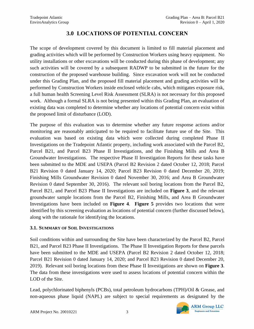
3.0 LOCATIONS OF POTENTIAL CONCERN
The scope of development covered by this document is limited to fill material placement and
grading activities which will be performed by Construction Workers using heavy equipment. No
utility installations or other excavations will be conducted during this phase of development; any
such activities will be covered by a subsequent RADWP to be submitted in the future for the
construction of the proposed warehouse building. Since excavation work will not be conducted
under this Grading Plan, and the proposed fill material placement and grading activities will be
performed by Construction Workers inside enclosed vehicle cabs, which mitigates exposure risk,
a full human health Screening Level Risk Assessment (SLRA) is not necessary for this proposed
work. Although a formal SLRA is not being presented within this Grading Plan, an evaluation of
existing data was completed to determine whether any locations of potential concern exist within
the proposed limit of disturbance (LOD).
The purpose of this evaluation was to determine whether any future response actions and/or
monitoring are reasonably anticipated to be required to facilitate future use of the Site. This
evaluation was based on existing data which were collected during completed Phase II
Investigations on the Tradepoint Atlantic property, including work associated with the Parcel B2,
Parcel B21, and Parcel B23 Phase II Investigations, and the Finishing Mills and Area B
Groundwater Investigations. The respective Phase II Investigation Reports for these tasks have
been submitted to the MDE and USEPA (Parcel B2 Revision 2 dated October 12, 2018; Parcel
B21 Revision 0 dated January 14, 2020; Parcel B23 Revision 0 dated December 20, 2019;
Finishing Mills Groundwater Revision 0 dated November 30, 2016; and Area B Groundwater
Revision 0 dated September 30, 2016). The relevant soil boring locations from the Parcel B2,
Parcel B21, and Parcel B23 Phase II Investigations are included on Figure 3, and the relevant
groundwater sample locations from the Parcel B2, Finishing Mills, and Area B Groundwater
Investigations have been included on Figure 4. Figure 5 provides two locations that were
identified by this screening evaluation as locations of potential concern (further discussed below),
along with the rationale for identifying the locations.
3.1. SUMMARY OF SOIL INVESTIGATIONS
Soil conditions within and surrounding the Site have been characterized by the Parcel B2, Parcel
B21, and Parcel B23 Phase II Investigations. The Phase II Investigation Reports for these parcels
have been submitted to the MDE and USEPA (Parcel B2 Revision 2 dated October 12, 2018;
Parcel B21 Revision 0 dated January 14, 2020; and Parcel B23 Revision 0 dated December 20,
2019). Relevant soil boring locations from these Phase II Investigations are shown on Figure 3.
The data from these investigations were used to assess locations of potential concern within the
LOD of the Site.
Lead, polychlorinated biphenyls (PCBs), total petroleum hydrocarbons (TPH)/Oil & Grease, and
non-aqueous phase liquid (NAPL) are subject to special requirements as designated by the

Tradepoint Atlantic Grading Plan – Area B: Parcel B21
EnviroAnalytics Group Revision 0 – April 1, 2020
ARM Project No. 20010221 4
agencies. Data from within, and in close proximity to, the Logistics Center VII were evaluated to
determine presence or absence of any locations of potential concern including: lead concentrations
above 10,000 mg/kg, PCB concentrations above 50 mg/kg, TPH/Oil & Grease concentrations
above 6,200 mg/kg, and physical evidence of NAPL.
Based on the Phase II Investigations, there were no notable concentrations of lead, PCBs, TPH, or
evidence of NAPL detected in soil at the Site. A boring located outside the southwestern corner
of the Site in Parcel B2 (B2-051-SB) was identified as a location of potential concern due to
evidence of trace NAPL observed in a narrow interval within the soil core. A piezometer was
installed at this location and gauged at 0-hours and 48-hours with an oil-water interface probe.
However, the piezometer was abandoned at the request of Tradepoint Atlantic before the standard
30-day gauging measurement due to its location in a high traffic area. A final gauging
measurement was not recorded on the abandonment date (MDE guidance has since been updated
to require a gauging event immediately prior to abandonment), but no visible product was noted
in or on the PVC casing once the piezometer was withdrawn from the ground. One soil sample
within the LOD of the Site (B21-012-SB-1) was also identified as a location of potential concern
due to an elevated concentration of Oil & Grease (19,200 mg/kg) that exceeded the criterion of
6,200 mg/kg. The underlying soil sample (5-foot depth; above the observed water table) had a
significantly lower concentration of Oil & Grease (215 mg/kg). Given the lack of physical
evidence of NAPL and the lack of significant Oil & Grease impacts in deeper soil, further
delineation was not warranted. No additional response actions or monitoring are anticipated at
these locations, although the locations will be considered for proximity to proposed utilities in the
future RADWP. The locations of the identified soil borings are shown on Figure 5.
3.2. SUMMARY OF GROUNDWATER INVESTIGATIONS
Groundwater at the Site has already been characterized by the Parcel B2 Phase II Investigation,
Finishing Mills Groundwater Investigation, and Area B Groundwater Investigation. The Phase II
Investigation Reports for these investigations have been submitted to the MDE and USEPA (Parcel
B2 Revision 2 dated October 12, 2018; Finishing Mills Groundwater Revision 0 dated November
30, 2016; and Area B Groundwater Revision 0 dated September 30, 2016). Groundwater sample
locations from these investigations are shown on Figure 4.
The localized data from the Finishing Mills and Area B Groundwater Investigations were
evaluated to determine whether the detected groundwater concentrations are indicative of potential
vapor intrusion (VI) risks. Total cyanide had previously been identified as a potential VI risk
within both the Finishing Mills and Area B Groundwater Phase II Investigation Reports, but the
screening level for cyanide has since been adjusted upward by the USEPA, eliminating this
concern for all but one location relevant for the proposed work area (SW-081-MWS). The VI risks
were initially screened using total cyanide rather than free cyanide or cyanide amenable to
chlorination, and the concentrations of available cyanide that could contribute to VI risks would
be expected to be significantly lower than the reported total cyanide concentrations. SW-081-

Tradepoint Atlantic Grading Plan – Area B: Parcel B21
EnviroAnalytics Group Revision 0 – April 1, 2020
ARM Project No. 20010221 5
MWS was resampled to determine the concentration of available cyanide at this location, and the
concentration was well below the screening level representing a potential VI risk. There were no
additional VI risks identified from among the groundwater points relevant for this Grading Plan.
Each monitoring well and temporary groundwater sample collection point included in the Parcel
B2, Finishing Mills, and/or Area B Groundwater Investigations was checked for the potential
presence of NAPL using an oil-water interface probe prior to sampling, and any detections of
NAPL would also be notable for future development planning. NAPL has not been detected in
any of the monitoring wells or temporary groundwater sample collection points that were included
in these preceding investigations.

Tradepoint Atlantic Grading Plan – Area B: Parcel B21
EnviroAnalytics Group Revision 0 – April 1, 2020
ARM Project No. 20010221 6
4.0 PROPOSED GRADING PLAN
Tradepoint Atlantic is proposing to perform material placement and grading on the designated
27.17 acres of Parcel B21 and Parcel B2 in preparation for the future construction of a warehouse
building (Logistics Center VII). The proposed future use of the Site is Tier 3 (Industrial).
The scope of development covered by this document is limited to fill material placement and
grading activities which will be performed by Construction Workers inside the enclosed vehicle
cabs of heavy equipment. Therefore, it is not expected that significant exposures to potentially
contaminated soil or groundwater will occur during the work proposed under this Grading Plan.
The proposed rough grading plan is provided in Appendix A. No utility installations or other
excavations will be conducted during this phase of development; any such activities will be
covered by a project-specific RADWP. The use of enclosed vehicles mitigates, but does not
completely eliminate, potential exposure risks for Construction Workers. General health and
safety controls (level D protection) outlined in the property-wide Health and Safety Plan (HASP
provided in Appendix B) will mitigate any potential incidental risk to Construction Workers
during fill material placement and grading activities. A perimeter fence will be installed
surrounding the LOD once the grading is completed to restrict access to the Site.
The process of completing the proposed activities at the Site involves the tasks listed below. As-
built and regulatory documentation for the outlined tasks and procedures related to site grading
will be provided in an Interim Completion Report. A final Development Completion Report will
be necessary following the construction of Logistics Center VII, as will be specified within the
RADWP associated with the project. Depending on the schedule of subsequent development, the
preparatory grading work discussed herein may be incorporated into the final Development
Completion Report in lieu of an interim report.
4.1. GROUNDWATER NETWORK ABANDONMENT AND RETENTION
There is one permanent monitoring well (FM01-PZM003) currently located within the proposed
LOD as shown on Figure 4. An intermediate monitoring well (FM01-PZM041) was historically
located directly adjacent, also within the LOD, but it was observed in 2017 to have been previously
abandoned. The shallow well FM01-PZM003 will be properly abandoned in accordance with
COMAR 26.04.04.34 through 36. The monitoring well will be gauged on the abandonment date
using an oil-water interface probe to confirm that NAPL has not accumulated. If NAPL has
accumulated, the MDE must be notified and the abandonment may not move forward at that time
(pending coordination with the MDE).
The abandonment of FM01-PZM003 should be completed prior to starting grading activities to
ensure that the casing is not damaged/destroyed prior to abandonment. If the well cannot be
abandoned prior to the start of grading, temporary protective measures (flagging, barriers, etc.)

Tradepoint Atlantic Grading Plan – Area B: Parcel B21
EnviroAnalytics Group Revision 0 – April 1, 2020
ARM Project No. 20010221 7
may be installed as necessary to protect the well. It is understood that the agencies may require
the installation of additional permanent wells in the future following development.
There are two other shallow monitoring wells (SW-079-MWS and SW-081-MWS) located near
the western perimeter of the Site, as shown on Figure 4, which are not expected to be impacted by
the proposed grading work. The shallow piezometers shown on Figure 4 have already been
properly abandoned.
The abandonment of any permitted monitoring wells must be reported to the Water Management
Administration as per COMAR 26.04.04, and records of all monitoring well and piezometer
abandonments (including abandonment forms, if available) will be included in the Development
Completion Report.
4.2. GRADING AND SITE PREPARATION
As indicated on the proposed rough grading plan in Appendix A, fill material will be placed to
raise the elevation at the Site. The current and final (proposed) ground surface elevations are
indicated on the grading plan. The proposed work will require importing material to the Site. No
excavations are planned to be conducted during this phase of the project. It is not anticipated that
unsuitable materials (i.e., poor soils) will be encountered.
Processed slag aggregate sourced from the Tradepoint Atlantic property will be used as the fill
material for this project, and the placement of this material will necessitate that the Site will be
subject to surface engineering controls (i.e., capping) in the future when the RADWP is prepared
for Logistics Center VII. No other fill materials will be used at the Site without the approval of
the MDE. Fill sources shall be free of organic material, frozen material, or other deleterious
material.

Tradepoint Atlantic Grading Plan – Area B: Parcel B21
EnviroAnalytics Group Revision 0 – April 1, 2020
ARM Project No. 20010221 8
5.0 GRADING IMPLEMENTATION PROTOCOLS
This plan specifically discusses protocols for the handling of fill materials in association with the
planned grading and site preparation activities at the Site. In particular, this plan highlights the
minimum standards for construction practices to reduce potential risks to workers and the
environment. No utility installations or other excavations will be conducted during this phase of
development. On-site rough grading activities for Logistics Center VII will consist of fill material
placement and subsequent grading by Construction Workers inside the enclosed vehicle cabs of
heavy equipment, which mitigates exposure risk. Therefore, it is not expected that significant
exposures to potentially contaminated soil or groundwater will occur during the work proposed
under this Grading Plan. A perimeter fence will be installed surrounding the LOD once the grading
is completed to restrict access to the Site.
Groundwater conditions throughout the Site have already been characterized by the Parcel B2,
Finishing Mills, and Area B Groundwater Investigations, and soil conditions have already been
characterized by the Parcel B2, Parcel B21, and Parcel B23 Phase II Investigations. One location
from the investigation of Parcel B2 and one location from the investigation of Parcel B21 were
identified as locations of potential concern, as shown on Figure 5.
Trace NAPL was observed in a narrow interval within the soil core at B2-051-SB. A piezometer
was installed at this location and NAPL was not observed to accumulate in the casing. Soil sample
B21-012-SB-1 had an elevated concentration of Oil & Grease (19,200 mg/kg) that exceeded the
criterion of 6,200 mg/kg. The underlying soil sample (5-foot depth; above the observed water
table) had a significantly lower concentration of Oil & Grease (215 mg/kg). Physical evidence of
NAPL was not observed at B21-012-SB. These locations will be considered for proximity to
proposed utilities when the RADWP is submitted in the future. As outlined by the Parcel B2 and
Parcel B21 Phase II Investigation Reports, appropriate protocols for the mitigation of potential
product (NAPL) mobility should be specified in the RADWP.
5.1. FILL
Processed slag aggregate sourced from the Tradepoint Atlantic property will be used as the fill
material for this project. No other fill materials will be used at the Site without the approval of the
MDE. Processed slag aggregate can be used as structural fill under areas to be capped without any
additional required testing or approvals. Tradepoint Atlantic understands that the placement of
slag aggregate at the Site will necessitate that Logistics Center VII will be subject to a capping
requirement when it is evaluated in a subsequent RADWP for construction of the warehouse
building, unless separate approvals are received from the MDE following appropriate laboratory
testing of the material.
Tradepoint Atlantic Grading Plan – Area B: Parcel B21
EnviroAnalytics Group Revision 0 – April 1, 2020
ARM Project No. 20010221 9
5.2. DUST CONTROL
General construction operations, including grading, will be performed at the Site. These activities
are anticipated to be performed in areas of soil impacted with constituents of potential concern
(COPCs). Best management practices should be undertaken at the Sparrows Point property as a
whole to prevent the generation of dust which could impact other areas of the property outside of
the immediate work zone. To limit worker exposure to contaminants borne on dust and windblown
particulates, dust monitoring will be performed in the immediate work zone and at the upwind and
downwind perimeter of the Site, and dust control measures will be implemented if warranted based
on the monitoring results. The action level proposed for the purpose of determining the need for
dust suppression techniques (e.g. watering and/or misting) during the development activities at the
Site will be 3.0 mg/m³. The lowest of the site-specific dust action levels, OSHA PELs, and ACGIH
TLV was selected as the proposed action level.
The Environmental Professional (EP) will be responsible for the dust monitoring program. Air
monitoring will be performed using Met One Instruments, Inc. E-Sampler dust monitors or
equivalent real-time air monitoring devices. The EP will set-up dust monitoring equipment at the
outset of grading work or other dust-generating activities, and continuous dust monitoring will be
performed during this work. In addition to work area monitoring, a dust monitor will be placed at
selected perimeter locations that will correspond to the upwind and downwind boundaries based
on the prevailing wind direction predicted for that day. The prevailing wind direction will be
assessed during the day, and the positions of the perimeter monitors will be adjusted if there is a
substantial shift in the prevailing wind direction. Once all dust-generating activities are complete,
the dust monitoring program may be discontinued. If additional dust-generating activities
commence, additional dust monitoring activities will be performed.
If sustained dust concentrations exceed the action level (3.0 mg/m³) at any of the monitoring
locations as a result of conditions occurring at the Site, operations will be stopped temporarily until
dust suppression can be implemented. The background dust concentration will be utilized to
evaluate whether Site activities are the source of the action level exceedance. Background
concentrations will be based on measurements over a minimum of a 1-hour period at the upwind
Site boundary. This upwind data will be used to calculate a time weighted average background
dust concentration. The background dust concentration may need to be recalculated periodically
during the work day, based on changed upwind conditions. Operations may be resumed once
monitoring indicates that dust concentrations are below the action level.
As applicable, air monitoring will be conducted during grading activities in the immediate work
zones and surrounding areas to assess levels of exposure to Site workers, establish that the work
zone designations are valid, and verify that respiratory protection being worn by personnel, if
needed, is adequate. Concurrent with the work zone air monitoring, perimeter air monitoring will
also be performed to ensure contaminants are not migrating off-site. The concentration measured
Tradepoint Atlantic Grading Plan – Area B: Parcel B21
EnviroAnalytics Group Revision 0 – April 1, 2020
ARM Project No. 20010221 10
in the downwind portion of the Site shall not exceed the concentration in the upwind portion, or
3.0 mg/m³, unless caused by background dust from upwind of the Site. If exceedances attributable
to Site conditions are identified downwind for more than five minutes, dust control measures and
additional monitoring will be implemented. The dust suppression measures may include wetting
or misting through the use of a hose connected to an available water supply or a water truck
stationed at the Site.
Dust control measures will be implemented as described above to address dust generated as a result
of grading activities conducted at the Site. However, based on the nature of the area and/or on-
going activities surrounding the Site, it is possible that windblown particulates may come from
surrounding areas. As discussed above, the dust concentration in the upwind portion of the Site
will be considered when monitoring dust levels in the work zone. A pre-construction meeting will
be held to discuss the potential of windblown particulates from other activities impacting the air
monitoring required for this response plan. Site contact information will be provided to address
the possibility of upwind dust impacts. If sustained dust is observed above the action level (3.0
mg/m³) and it is believed to originate from off-site (i.e., upwind) sources, this will immediately be
reported to the MDE-VCP project team, as well as the MDE Air and Radiation Administration
(ARA).
5.3. HEALTH AND SAFETY
A property-wide HASP (provided as Appendix B) has been developed and is attached to this plan
to present the minimum requirements for worker health and safety protection for the project. The
proposed fill material placement and grading activities will be performed by Construction Workers
inside enclosed vehicle cabs, which mitigates exposure risk. General health and safety controls
(level D protection) will mitigate any potential incidental risk to Construction Workers during fill
material placement and grading activities. All contractors working on the Site must prepare their
own HASP that provides a level of protection at least as much as that provided by the attached
HASP. Alternately, on-site contactors may elect to adopt the HASP provided.
Prior to commencing work, the contractor must conduct a pre-construction safety meeting for all
personnel. All personnel must be made aware of the HASP. Although intrusive work is not
anticipated to be required for this grading project, safety information shall be provided to personnel
who may have incidental exposures to soils which could be impacted by COPCs. Workers will be
responsible for following safety procedures to prevent contact with potentially contaminated soil
or groundwater (not anticipated).

Tradepoint Atlantic Grading Plan – Area B: Parcel B21
EnviroAnalytics Group Revision 0 – April 1, 2020
ARM Project No. 20010221 11
6.0 PERMITS, NOTIFICATIONS, AND CONTINGENCIES
The participant and their contractors will comply with all local, state, and federal laws and
regulations by obtaining any necessary approvals and permits to conduct the activities contained
herein. Any permits or permit modifications from State or local authorities will be provided as
addenda to this Grading Plan.
There are no wetlands identified within the project area, so no permits are required from the MDE
Water Resources Administration.
Contingency measures will include the following:
1. The MDE will be notified immediately of any previously undiscovered contamination,
previously undiscovered storage tanks and other oil-related issues, and citations from
regulatory entities related to health and safety practices.
2. Any significant change to the implementation schedule will be noted in the progress reports
to MDE.

Tradepoint Atlantic Grading Plan – Area B: Parcel B21
EnviroAnalytics Group Revision 0 – April 1, 2020
ARM Project No. 20010221 12
7.0 IMPLEMENTATION SCHEDULE
Progress reports will be submitted to the MDE on a quarterly basis. Each quarterly progress report
will include, at a minimum, a discussion of the following information regarding tasks completed
during the specified quarter:
• Grading Progress
• Dust Monitoring
• Soil Management (imported materials, stockpiling)
• Notable Occurrences (if applicable)
• Additional Associated Work (if applicable)
The proposed implementation schedule is shown below.
Task Proposed Completion Date
Anticipated Plan Approval April 17, 2020
Well Abandonment April 24, 2020
Slag Delivery & Placement April 29, 2020 (start)

FIGURES

VII
Parcel B12
Parcel B11
Parcel B10Parcel B13
Parcel B20
Parcel B18
Parcel B9
Parcel B4 Parcel B5
Parcel B17
Parcel B19
Parcel B3Parcel B2Parcel B1
Parcel B23Parcel B15
Parcel B25
Parcel B24
Parcel B8
Parcel B7
Parcel B14
Parcel B21
Parcel B22
Parcel B16
Parcel B6
Parcel A10Parcel A3 Parcel A1
Parcel A4
Parcel A6Parcel A16
Parcel A17Parcel A18
Parcel A2
Parcel A8
Parcel A15Parcel A12
Parcel A7Parcel A11
Parcel A14
Parcel A5 Parcel A13
Parcel A9
Logistics Center Boundary
Site Boundary
Parcel Boundaries
Private Property
Area B: Project 200102
Tradepoint AtlanticArea A and Area B Parcels
Area A: Project 200101EnviroAnalytics GroupBaltimore County, MD
1Figure
Tradepoint Atlantic
q 0 1,000 2,000500Feet ARM Project 20010221
March 25, 2020
Parcel B2
Parcel B23
Parcel B15Parcel B21
Parcel B22
Parcel B16
Logistics Center VII LOD
Parcel Boundary
Tradepoint Atlantic
Baltimore County, MD
EnviroAnalytics Group
ARM Project 20010221
Logistics Center VIIGrading Plan 2
Figure
March 25, 2020
0 100 20050Feetq
@A
@A
@A@A
@A@A
@A@A @A @A
@A
@A@A
@A @A
@A@A
@A @A
@A
@A
@A
@A
@A
@A
@A
@A
@A
@A@A
@A
@A
@A
@A
@A@A
@A@A
@A@A
@A@A
@A@A
@A
@A@A
@A
@A
@A
@A
B21-061-SB
B21-055-SB
B21-040-SB
B21-001-SB
B21-029-SB
B2-050-SB
B21-007-SB
B21-051-SBB21-052-SB
B21-062-SB
B21-009-SB
B21-010-SBB21-056-SB
B21-025-SB
B21-039-SB
B21-011-SBB21-012-SB
B21-002-SB
B21-003-SB
B21-004-SB
B21-036-SB
B21-037-SB
B21-026-SB
B21-027-SB
B21-028-SBB21-030-SB
B21-005-SB
B21-006-SB
B21-008-SB
B21-038-SB
B21-065-SB
B21-066-SB
B21-043-SB
B21-044-SB
B21-045-SB
B21-046-SB
B21-015-SB
B21-016-SB
B21-017-SB
B21-018-SB
B21-047-SB
B21-048-SB
B21-064-SB
B21-031-SB
B21-067-SB
B21-068-SB
Parcel B2
Parcel B23
Parcel B15
Parcel B21
Parcel B22
Parcel B16
@A Phase II Soil Boring
Logistics Center VII LOD
Parcel Boundary
Tradepoint Atlantic
Baltimore County, MD
EnviroAnalytics Group
ARM Project 20010221
Logistics Center VIISoil Boring Locations 3
Figure
March 25, 2020
0 100 20050Feetq
B2-051-SB
B21-069-SB
B23-035-SB
B23-036-SB
@A
@A
@A
!?
!?
!?
@A
Parcel B15
Parcel B22
FM-003-PZS
FM-004-PZS
FM-016-PZS
FM01-PZM003
SW-079-MWS
SW-081-MWS
B2-051-PZ
@A Phase II Piezometer
!? Permanent Well
Logistics Center VII LOD
Parcel Boundary
Tradepoint Atlantic
Baltimore County, MD
EnviroAnalytics Group
ARM Project 20010221
Logistics Center VIIGroundwater Locations 4
Figure
March 25, 2020
0 100 20050Feetq
Parcel B2
Parcel B21
Parcel B16
Parcel B23

@A
@A
Parcel B15
Parcel B22
B21-012-SBOG (1ft): 19,200 mg/kg
B2-051-SBTrace NAPL Observed
@ALocation of PotentialConcernLogistics Center VII LOD
Parcel Boundary
Tradepoint Atlantic
Baltimore County, MD
EnviroAnalytics Group
ARM Project 20010221
Logistics Center VIILocations of Potential Concern 5
Figure
March 25, 2020
0 100 20050Feetq
Parcel B16
Parcel B23
Parcel B2
Parcel B21

APPENDIX A
DD
FB
FB
FB
FB
FB
FBFB
FBFBFBFBFBFBFBFBFBFBFBFBFB
D
W
W
W
D
D
S
S
S
S
D
D
W
C
C
D
D
W
TRADEPOINT AVENUE
PROP. SAWCUT
LODLODLODLODLODLODLOD
LOD
LOD
LOD
LOD
LOD
LOD
LOD
LOD
LOD
LOD
LOD
LOD
LOD
LOD LOD LOD LOD LOD LOD LOD LOD LOD LOD LOD LOD LOD LOD LOD LOD LOD LOD LOD LOD LOD LOD LOD LOD LOD LOD LOD LOD LOD LOD LOD LOD LOD LOD LOD LOD LOD LOD LOD LOD LOD LOD LOD LOD LOD LOD LOD LOD
LODLOD
LODLOD
LODLOD
LODLOD
LODLOD
LODLOD
LODLOD
LODLODLODLODLODLODLODLODLODLODLODLODLODLODLODLODLODLODLODLODLODLODLODLODLODLODLODLODLODLODLODLODLODLODLODLODLODLODLODLODLODLO
D
PROP. SAWCUT
N43°05'27"W 679.95'
R=20.00'Δ=081°47'12"
L=28.55'CHB=N02°11'51"W
CHD=26.19'
R=85.00'Δ=170°08'58"
L=252.42'CHB=N46°22'44"W
CHD=169.37'R=20.00'Δ=071°06'32"L=24.82'CHB=S84°06'03"WCHD=23.26'
R=20.00'Δ=017°15'14"
L=6.02'CHB=N51°43'04"W
CHD=6.00'
N43°05'27"W 10.00'
S46°54'33"W 61.00'
S43°05'27"E 49.96'
R=35.00'Δ=048°55'04"
L=29.88'CHB=S18°37'56"E
CHD=28.98'
S43°05'27"E 822.49'
20
20
18
18
19
19
20
20
18
18
19
19
20
20
18
18
19
19
15
20
1213
1416
1718
19
15
20
1112
1314
1617
1819
15
1213141617
15
1213141617
15
1213141617
15
12 13 1416 17
15
12 13 1416 17
15
12 13 1416 17
4:1
4:1
4:1 4:1
4:1
4:1
4:1
4:1
4:1
4:1
G 20.25G 20.25G 20.25G 20.25
ALWAYS CALL 811It's fast. It's free. It's the law.
901 DULANEY VALLEY ROAD, SUITE 801TOWSON, MARYLAND 21204
Phone: (410) 821-7900Fax: (410) [email protected]
NOT APPROVED FORCONSTRUCTION
ORG. DATE -
REVISIONS
REV DATE COMMENTDRAWN BY
CHECKED BY
2/14/20
TM
THE
INFO
RMAT
ION,
DES
IGN
AND
CONT
ENT
OF T
HIS
PLAN
ARE
PRO
PRIE
TARY
AND
SHA
LL N
OT B
E CO
PIED
OR
USED
FOR
ANY
PUR
POSE
WIT
HOUT
PRI
OR W
RITT
ENAU
THOR
IZAT
ION
FROM
BOH
LER.
ONL
Y AP
PROV
ED, S
IGNE
D AN
D SE
ALED
PLA
NS S
HALL
BE
UTILI
ZED
FOR
CONS
TRUC
TION
PUR
POSE
S©
SITE
CIV
IL A
ND
CO
NSU
LTIN
G E
NG
INEE
RIN
GLA
ND
SU
RVE
YIN
GPR
OG
RAM
MAN
AGEM
ENT
LAN
DSC
APE
ARC
HIT
ECTU
RE
SUST
AIN
ABLE
DES
IGN
PER
MIT
TIN
G S
ERVI
CES
TRAN
SPO
RTA
TIO
N S
ERVI
CES
BOH
LER
PROFESSIONAL CERTIFICATION
PROFESSIONAL ENGINEER
M.J. GESELL
I, MICHAEL J. GESELL, HEREBY CERTIFY THAT THESEDOCUMENTS WERE PREPARED OR APPROVED BY ME, AND
THAT I AM A DULY LICENSED PROFESSIONAL ENGINEERUNDER THE LAWS OF THE STATE OF MARYLAND,
LICENSE NO. 44097, EXPIRATION DATE: 6/9/21
MARYLAND LICENSE No. 44097
1
ROUGHGRADING PLAN
GDP-
GENERAL GRADING NOTES1. IT IS THE CONTRACTOR'S RESPONSIBILITY TO REVIEW ALL CONSTRUCTION CONTRACT DOCUMENTS INCLUDING, BUT NOT LIMITED TO, ALL OF THE DRAWINGS AND SPECIFICATIONS ASSOCIATED WITH THE
PROJECT WORK SCOPE PRIOR TO THE INITIATION AND COMMENCEMENT OF CONSTRUCTION. SHOULD THE CONTRACTOR FIND A CONFLICT AND/OR DISCREPANCY BETWEEN THE DOCUMENTS RELATIVE TO THESPECIFICATIONS OR THE RELATIVE OR APPLICABLE CODES, REGULATIONS, LAWS, RULES, STATUTES AND/OR ORDINANCES, IT IS THE CONTRACTOR'S SOLE RESPONSIBILITY TO NOTIFY THE PROJECT ENGINEER OFRECORD, IN WRITING, OF SAID CONFLICT AND/OR DISCREPANCY PRIOR TO THE START OF CONSTRUCTION. CONTRACTOR'S FAILURE TO NOTIFY THE PROJECT ENGINEER SHALL CONSTITUTE CONTRACTOR'SFULL AND COMPLETE ACCEPTANCE OF ALL RESPONSIBILITY TO COMPLETE THE SCOPE OF WORK AS DEFINED BY THE DRAWINGS AND IN FULL COMPLIANCE WITH ALL FEDERAL, STATE AND LOCAL REGULATIONS,LAWS, STATUTES, ORDINANCES AND CODES AND, FURTHER, CONTRACTOR SHALL BE RESPONSIBLE FOR ALL COSTS ASSOCIATED WITH SAME.
2. SITE GRADING MUST BE PERFORMED IN ACCORDANCE WITH THESE PLANS AND SPECIFICATIONS AND THE RECOMMENDATIONS PROVIDED BY THE GEOTECHNICAL ENGINEER. THE CONTRACTOR IS RESPONSIBLEFOR REMOVING AND REPLACING UNSUITABLE MATERIALS WITH SUITABLE MATERIALS AS SPECIFIED IN THE GEOTECHNICAL REPORT. ALL EXCAVATED OR FILLED AREAS MUST BE COMPACTED AS OUTLINED IN THEGEOTECHNICAL REPORT. MOISTURE CONTENT AT TIME OF PLACEMENT MUST BE SUBMITTED IN A COMPACTION REPORT PREPARED BY A QUALIFIED GEOTECHNICAL ENGINEER, REGISTERED WITH THE STATEWHERE THE WORK IS PERFORMED, VERIFYING THAT ALL FILLED AREAS AND SUBGRADE AREAS WITHIN THE BUILDING PAD AREA AND AREAS TO BE PAVED HAVE BEEN COMPACTED IN ACCORDANCE WITH THESEPLANS, SPECIFICATIONS AND THE RECOMMENDATIONS SET FORTH IN THE GEOTECHNICAL REPORT AND ALL APPLICABLE REQUIREMENTS, RULES, STATUTES, LAWS, ORDINANCES AND CODES. SUBBASEMATERIAL FOR SIDEWALKS, CURB, OR ASPHALT MUST BE FREE OF ORGANICS AND OTHER UNSUITABLE MATERIALS. SHOULD SUBBASE BE DEEMED UNSUITABLE BY OWNER/DEVELOPER, OR OWNER/DEVELOPER'SREPRESENTATIVE, SUBBASE IS TO BE REMOVED AND FILLED WITH APPROVED FILL MATERIAL COMPACTED AS DIRECTED BY THE GEOTECHNICAL REPORT. EARTHWORK ACTIVITIES INCLUDING, BUT NOT LIMITEDTO, EXCAVATION, BACKFILL, AND COMPACTING MUST COMPLY WITH THE RECOMMENDATIONS IN THE GEOTECHNICAL REPORT AND ALL APPLICABLE REQUIREMENTS, RULES, STATUTES, LAWS, ORDINANCES ANDCODES. EARTHWORK ACTIVITIES MUST COMPLY WITH THE STANDARD STATE DOT SPECIFICATIONS FOR ROADWAY CONSTRUCTION (LATEST EDITION) AND ANY AMENDMENTS OR REVISIONS THERETO.
3. THE CONTRACTOR MUST COMPLY, TO THE FULLEST EXTENT, WITH THE LATEST OSHA STANDARDS AND REGULATIONS, AND/OR ANY OTHER AGENCY WITH JURISDICTION FOR EXCAVATION AND TRENCHINGPROCEDURES. THE CONTRACTOR IS RESPONSIBLE FOR DETERMINING THE “MEANS AND METHODS” REQUIRED TO MEET THE INTENT AND PERFORMANCE CRITERIA OF OSHA, AS WELL AS ANY OTHER ENTITY THATHAS JURISDICTION FOR EXCAVATION AND/OR TRENCHING PROCEDURES AND CONSULTANT SHALL HAVE NO RESPONSIBILITY FOR OR AS RELATED FOR OR AS RELATED TO EXCAVATION AND TRENCHINGPROCEDURES.
4. PAVEMENT MUST BE SAW CUT IN STRAIGHT LINES, AND EXCEPT FOR EDGE OF BUTT JOINTS, MUST EXTEND TO THE FULL DEPTH OF THE EXISTING PAVEMENT. ALL DEBRIS FROM REMOVAL OPERATIONS MUST BEREMOVED FROM THE SITE AT THE TIME OF EXCAVATION. STOCKPILING OF DEBRIS WILL NOT BE PERMITTED.
5. THE TOPS OF EXISTING INLET STRUCTURES, AND SANITARY CLEANOUT TOPS MUST BE ADJUSTED, AS NECESSARY, TO MATCH PROPOSED GRADES IN ACCORDANCE WITH ALL APPLICABLE STANDARDS,REQUIREMENTS, RULES, STATUTES, LAWS, ORDINANCES AND CODES. FOR WATER AND SEWER IN BALTIMORE COUNTY, WORK MUST BE COMPLETED IN ACCORDANCE WITH A PLUMBING PERMIT. EXISTING ANDPROPOSED SEWER MANHOLE RIMS NOT LOCATED WITHIN PAVEMENT SHOULD BE CONSTRUCTED TO BE A MINIMUM 1-FOOT ABOVE GRADE. ALL MANHOLES SHALL BE PROPERLY MARKED WITH HIGH VISIBILITYORANGE FENCE AND PROTECTED DURING CONSTRUCTION ACTIVITY.
6. THE CONTRACTOR IS FULLY RESPONSIBLE FOR VERIFICATION OF EXISTING TOPOGRAPHIC INFORMATION AND UTILITY INVERT ELEVATIONS PRIOR TO COMMENCING ANY CONSTRUCTION. CONTRACTOR MUSTCONFIRM AND ENSURE 0.75% MINIMUM SLOPE AGAINST ALL ISLANDS, GUTTERS, AND CURBS; 1.0% ON ALL CONCRETE SURFACES; AND 1.0% MINIMUM ON ASPHALT (EXCEPT WHERE ADA REQUIREMENTS LIMITGRADES), TO PREVENT PONDING. CONTRACTOR MUST IMMEDIATELY IDENTIFY, IN WRITING TO THE ENGINEER, ANY DISCREPANCIES THAT MAY OR COULD AFFECT THE PUBLIC SAFETY, HEALTH OR GENERALWELFARE, OR PROJECT COST. IF CONTRACTOR PROCEEDS WITH CONSTRUCTION WITHOUT PROVIDING PROPER NOTIFICATION, MUST BE AT THE CONTRACTOR'S OWN RISK AND, FURTHER, CONTRACTOR SHALLINDEMNIFY, DEFEND AND HOLD HARMLESS THE DESIGN ENGINEER FOR ANY DAMAGES, COSTS, INJURIES, ATTORNEY'S FEES AND THE LIKE WHICH RESULT FROM SAME.
7. IN THE EVENT OF DISCREPANCIES AND/OR CONFLICTS BETWEEN PLANS OR RELATIVE TO OTHER PLANS, THE SITE PLAN WILL TAKE PRECEDENCE AND CONTROL. CONTRACTOR MUST IMMEDIATELY NOTIFY THEDESIGN ENGINEER, IN WRITING, OF ANY DISCREPANCIES AND/OR CONFLICTS.
8. CONTRACTOR IS REQUIRED TO SECURE ALL NECESSARY AND/OR REQUIRED PERMITS AND APPROVALS FOR ALL OFF SITE MATERIAL SOURCES AND DISPOSAL FACILITIES. CONTRACTOR MUST SUPPLY A COPY OFAPPROVALS TO ENGINEER AND OWNER PRIOR TO INITIATING ANY WORK.
9. CONSULTANT IS NEITHER LIABLE NOR RESPONSIBLE FOR ANY SUBSURFACE CONDITIONS AND FURTHER, SHALL HAVE NO LIABILITY FOR ANY HAZARDOUS MATERIALS, HAZARDOUS SUBSTANCES, OR POLLUTANTSON, ABOUT OR UNDER THE PROPERTY.
LIMIT OF DISTURBANCE: 1,183,426 S.F. OR 27.17 AC.
CONTRACTOR TO TEST PIT 2 FEET BELOWPROPOSED UTILITY OR UNTIL EXACT LOCATION OFEXISTING UTILITY IS IDENTIFIED AND SUBMIT ANYDISCREPANCIES TO BOHLER IN WRITING.
TEST PIT NOTETP
PROPOSED NOTETYPICAL NOTE TEXT
LEGEND
ONSITE PROPERTYLINE / R.O.W. LINE
E
G
OH
T
UNDERGROUND WATER LINE
UNDERGROUNDELECTRIC LINE
UNDERGROUNDGAS LINE
OVERHEADWIRE
UNDERGROUNDTELEPHONE LINE
STORMSEWER
TCBC
516.00515.50
516.00TC
120CONTOURLINE
SPOTELEVATIONS
121
LOD LODLIMIT OF DISTURBANCE
SAWCUT
CURB AND GUTTER
SPILL CURB
CONCRETE CURB &GUTTER
SANITARY FORCE MAIN
INDUSTRIAL WATER LINE
FLOODPLAIN FP FP
SANITARY SEWER MAINW W W W W W
SFM
SFM
SFM
SFM
SFM
SFM
IIIIII
D D D D D D
LOCATION MAPCOPYRIGHT ADC THE MAP PEOPLE
PERMIT USE NO. 20602153-5SCALE: 1"=2000'
BCO#1433
GIS-2
BENCHMARK INFORMATIONELEVATIONS ARE BASED ON NAVD 88, COORDINATES ANDMERIDIAN ARE BASED ON THE MARYLAND COORDINATE SYSTEM(MCS) PER THE FOLLOWING MONUMENTS:
BCO# 1433 (CAPPED REBAR)N 571,683.79, E 1,466,230.69, ELEV. 16.59IN MEDIAN OF NORTH POINT BLVD SOUTH OF NORTH SNYDER AVE.
GIS #2 (BRASS DISK)N 565,182.39, E. 1,464,480.72, ELEV. 9.95EAST SIDE OF WHARF ROAD 420'± NORTH OF LIGHT TOWER
1"= 60'
0 60153060
DISC
LAIM
ERTh
is dr
awing
and/o
r file
has b
een p
repa
red b
y Boh
ler a
t the r
eque
st of
the P
rojec
t Own
er or
his R
epre
senta
tive a
nd is
being
prov
ided s
olely
as a
conv
enien
ce to
the r
ecipi
ent. B
ohler
mak
es no
repr
esen
tation
rega
rding
the s
uitab
ility f
or th
e inte
nded
use b
y the
recip
ient. F
urthe
r, Bo
hler
make
s no
H:\1
6\M
D16
2066
29\D
RAW
ING
S\PL
AN S
ETS\
RO
UG
H G
RAD
ING
PLA
NS\
MD
1620
6629
-GD
P-0-
---->
LAYO
UT:
1 -
LOG
ISTI
CS
CEN
TER
VII
EXPA
NSI
ON
RO
UG
H G
RAD
ING
PLA
N
IL
PROJECT No.:DRAWN BY:CHECKED BY:DATE:CAD I.D.:
PROJECT:
FOR
THIS DRAWING IS INTENDED FOR MUNICIPAL AND/OR AGENCYREVIEW AND APPROVAL. IT IS NOT INTENDED AS A CONSTRUCTION
DOCUMENT UNLESS INDICATED OTHERWISE.
SHEET NUMBER:
SHEET TITLE:
MD1620029ISL
MJG2/14/20
0
LOGISTICSCENTER VII
ROUGH GRADING PLANS
LOGISTICS CENTER VIITAX MAP 111, PARCEL 318
BALTIMORE, MD 21219BALTIMORE COUNTY
OWNERTRADEPOINT ATLANTIC, LLC
1600 SPARROWS POINT BLVDBALTIMORE, MD 21219
CONTACT: JOHN MARTIN III, PEPHONE: 301-651-3656
DEVELOPERTRADEPOINT DEVELOPMENT, LLC
1600 SPARROWS POINT BLVDBALTIMORE, MD 21219
CONTACT: JOHN MARTIN III, PEPHONE: 301-651-3656
AutoCAD SHX Text
PART OF MAP 111, GRD 14 PARCEL 318 LANDS N/F TRADEPOINT ATLANTIC, LLC D.B. 35478, PG. 379 ZONE: MH IM
AutoCAD SHX Text
PRIVATE ROAD SPEED LIMIT=35 MPH
AutoCAD SHX Text
EXISTING NOTE
AutoCAD SHX Text
W
AutoCAD SHX Text
E
AutoCAD SHX Text
G
AutoCAD SHX Text
OH
AutoCAD SHX Text
T
AutoCAD SHX Text
120
AutoCAD SHX Text
121
AutoCAD SHX Text
OR
AutoCAD SHX Text
516.4
AutoCAD SHX Text
TC 516.4
AutoCAD SHX Text
I
AutoCAD SHX Text
FM

APPENDIX B

HEALTH AND SAFETY PLAN
SPARROWS POINT TERMINALSPARROWS POINT, MARYLAND
Prepared by:
January 2015
TABLE OF CONTENTS
1.0 Introduction 5
1.1 Background 5
1.2 Historic Operations 5
2.0 Purpose, Scope and Organization 6
2.1 Scope 6
2.2 Organization of Documents 7
2.3 EAG Health and Safety Personnel 7
3.0 Hazard Analysis 8
3.1 Hazard Analysis 8
3.1.1 Chemical Hazards 8
3.1.2 Physical Hazards 8
3.1.3 Biological Hazards 9
4.0 Health Hazard Information 9
4.1 Chemical Hazards 9
4.2 Physical Hazards 14
4.2.1 Heat Stress 14
4.2.2 Cold Stress 16
4.2.3 Lifting Hazards 16
4.2.4 Slips, Trips and Falls 17
4.2.5 Buried Hazards 17
4.2.6 Electrical Hazards 17
4.2.7 Heavy Equipment Operations 17
4.2.8 Drilling and Excavation Safety 18
4.2.9 Use of Hand Tools and Portable Power Tools 21
4.2.10 Noise 21
4.2.11 Work Zone Traffic Control 21
4.2.12 Work Over Water 21
4.2.13 Vehicle Use 22
4.3 Biological Hazards 22

5.0 Personal Protective Equipment 23
5.1 Level D Protection 23
5.2 Modified Level D Protection 23
5.3 Level C Protection 23
5.4 First Aid, Emergency and Safety Equipment 24
6.0 Personnel Training and Standard Safety Procedures 24
6.1 Onsite Safety, Health and Emergency Response Training 24
6.2 Standard Safety Procedures 25
6.2.1 General Safety Work Practices 25
6.2.2 Hand Safety 25
6.2.3 Respiratory Protection 26
6.2.4 Personal Hygiene Practices 27
6.2.5 Electrical Safety 27
6.2.6 Fire Safety 27
6.2.7 Illumination 27
6.2.8 Sanitation 28
7.0 Exposure Monitoring Plan 28
7.1 Air Monitoring 28
7.1.1 Combustible Gas and Oxygen Deficiency/Excess Monitoring 28
7.1.2 Organic Vapor Concentrations 29
7.2 Physical Conditions Monitoring 30
8.0 Medical Surveillance 30
8.1 Medical Surveillance Program 30
8.2 Physician Review 33
9.0 Site Control Measures and Decontamination 31
9.1 Site Control Measures 31
9.1.1 Work Zone Delineation 31
9.1.2 Communications 32
9.1.3 Site Security 32

9.2 Decontamination Procedures 33
9.2.1 Personal Decontamination 33
9.2.2 Equipment Decontamination 33
9.2.3 Waste Management 34
10.0 Emergency Response and Contingency Procedures 34
10.1 Emergency Phone Numbers 35
10.2 Injury/Illness Treatment 35
10.3 Occupational Health Clinic and Hospital Information 36
10.4 Accident and Emergency Medical Response 38
10.4.1 Chemical Exposure 38
10.4.2 Decontamination During Medical Emergency 38
10.4.3 Small or Incipient Fire 39
10.4.4 Large Fire or Explosion 39
10.4.5 Adverse Weather Conditions 39
10.4.6 First Aid for Heat Stress/Cold Stress 40
10.4.7 Snake Bites 40
10.4.8 Animal Bites 40
10.4.9 Insect Bites and Stings 41
10.4.10 Poisonous Plants 41
10.4.11 Ticks 41
ATTACHMENTS
Attachment A – EAG Acknowledgment Form
Attachment B – MSDSs

5 | P a g e
1.0 INTRODUCTION1.1 Background
The Sparrows Point Terminal site has historically been a steel making facility. It is located in BaltimoreCounty, Maryland in the southeast corner of the Baltimore metropolitan area (approximately 9 milesfrom the downtown area), on the Sparrows Point Peninsula in the Chesapeake Bay watershed. Thefacility occupies the entire peninsula and is bounded to the west by Bear Creek; to the south byPatapsco River; and to the east by Jones Creek, Old Road Bay and residential areas of the City ofEdgemere. The facility is bounded to the north by the Sparrows Point Country Club. The site isapproximately 3,100 acres in size.
Pennsylvania Steel built the furnace at Sparrows Point in 1887 and the first iron was cast in 1889.Bethlehem Steel Corporation (BSC) purchased the facility in 1916 and enlarged it by building additionaland plating facilities. BSC filed for bankruptcy in 2001. A series of entities has owned the site betweenthen and now: the International Steel Group (ISG), Mittal Steel, ISG Sparrows Point, LLC, SeverstalSparrows Holding LLC, which was renamed to Severstal Sparrows Point, LLC, RG Steel Sparrows Point,LLC, and then a joint venture to Sparrows Point LLC (SP) and HRE Sparrows Point LLC. Most recently, in2014, the property and assets were sold to Sparrows Point Terminal LLC (SPT). Environmental liabilitywas retained by SP and work is currently being conducted by EnviroAnalytics Group, LLC (EAG) on behalfof SP.
In addition to the current environmental investigation and remediation being conducted onsiteby EAG and their consultants, there are other entities conducting work on the facility.Demolition of the remaining structures is currently ongoing at the site, and those contractorsare being managed by SPT.
The purpose of this document is to provide an overall health and safety plan (HASP) for EAGpersonnel and EAG directed contractors who are engaging in environmental investigation andremediation activities onsite. EAG directed contractors will also be expected to have their ownHealth and Safety Program, and they may opt to draft their own site specific HASP, provided itmeets the requirements in this HASP.
1.2 Historic Operations
Steel manufacturing involves handling vast amounts of raw material including coke, iron ore, limestoneand scrap steel, as well as recovering byproducts and managing waste materials. The operations listedbelow either were or are currently performed at the Sparrows Point Facility.
Iron and steel production Coal chemical recovery system Other byproducts recovery systems Wastewater treatment systems Solid waste management Air pollution control

6 | P a g e
A number of site-specific environmental and hydrogeologic investigations have been prepared for theSparrows Point facility. For the purposes of this HASP, information was obtained from the “SpecialStudy Area Release Site Characterization” completed in 2001 by CH2MHill, as well as additionaldocuments submitted since that time. There are five separate Special Study Areas as put forth in theConsent Decree:
Humphrey Impoundment, Tin Mill Canal/Finishing Mills Areas, Coke Oven Area, Coke Point Landfill, and Greys Landfill.
Contaminated soils and groundwater may be present at the site. This plan was prepared based on anassessment of hazards expected to be present and a review of data from the previous site investigationsand groundwater sampling events.
During the current investigations and remedial efforts, all related work will be performed in accordancewith the requirements of this HASP and Occupational Safety and Health Administration (OSHA)regulations as defined in 29 Code of Federal Regulations (CFR) 1910.120 and 1926.65.
2.0 PURPOSE, SCOPE AND ORGANIZATIONThis section describes the purpose, scope and organization of this HASP and the health and safetyresponsibilities of EAG, their employees, and their subcontractors involved in the field investigation andremediation activities at the Sparrows Point facility.2.1 Scope
Field investigation and remediation activities for this project may include, but are not limited to:
Groundwater sampling and monitoring, Groundwater and remediation well installation, Groundwater and remediation well repairs, Groundwater and remediation well closure and abandonment, Surface water sampling, Sediment sampling, Soil boring and subsurface soil sampling, Soil excavations for remedial purposes, Installation and operation of remediation systems for soil, soil vapor, and groundwater, Decommissioning and closure of remediation systems, Soil excavations for remedial purposes, Insitu soil mixing/soil stabilization, Exsitu soil mixing/soil stabilization, Dredging operations along Tin Mill Canal, Insitu chemical and/or biological injections, and Recovery of non-aqueous phase liquids (NAPL)

7 | P a g e
When EAG personnel are providing oversight of subcontractors, they will attend the safety and healthbriefings held by the contractor. EAG personnel will follow the requirements of this HASP, as well as anypotentially more stringent requirements of the contractor’s health and safety plan.
When EAG personnel are conducting tasks on their own, with or without subcontractors, they will followthe requirements of this HASP. EAG contractors, such as drillers, will also be required to follow therequirements of this HASP, as well as any more stringent requirements of the contractor’s health andsafety plan.
All EAG field personnel, including subcontractors to EAG, will be required to read and understand thisHASP and agree to implement its provisions. All site personnel will sign the Acknowledgement Formincluded in Attachment A stating that they have read, understood, and agree to abide by the guidelinesand requirements set forth in this plan.
2.2 Organization of Document
This HASP includes health and safety procedures for all generally anticipated project field activities. Thisplan also meets the OSHA requirements contained in the CFR, specifically 29 CFR 1910.120 and 29 CFR1926, by including the following items:
A description of staff organization, qualifications and responsibilities (Section 2.3), Hazard analysis (Section 3.0), Health hazard information (Section 4.0), Personal protective equipment (PPE), including available first aid, emergency, and safety
equipment (Section 5.0), Employee and subcontractor training and standard safety procedures (section 6.0), Exposure monitoring plan (Section 7.0), Medical surveillance (Section 8.0), Site control measures and decontamination procedures for personnel and equipment (Section
9.0), Emergency response and contingency procedures (section 10.0), and Material Safety Data Sheets (MSDSs) for chemicals used on-site (Attachment B).
2.3 EAG Health and Safety Personnel
Personnel responsible for implementing this HASP include:EAG Contacts for Sparrows Point Project Work
VP Remediation, Russ Becker (314) 686-5611Senior Project Manager, James Calenda (314) 620-3056Senior Project Engineer, Elizabeth Schlaeger (314) 307-1732Josh Burke – Field Operations Manager (314) 686-5623Project Field Team Members, Jeff Wilson and Bill Trentzsch (314) 620-3135, (314) 686-5598

8 | P a g e
3.0 HAZARD ANALYSISThis section outlines the potential hazards related to the field activities listed in Section 2.1.3.1 Hazard Analysis
The field activities planned for this project pose potential health and safety hazards for field teammembers. This section describes the hazards associated with the above-listed field activities. Detailedchemical, physical, and biological hazards information is provided in Section 4.0 (Health HazardInformation).
Hazards to which employees and subcontractors may be exposed to as a result of the above-listedactivities include potential chemical exposures, lacerations, excessive noise, thermal stress, lifting ofexcessive weight or bulk, hand tools and heavy equipment, drilling and slips, trips and falls.
3.1.1 Chemical Hazards
Potential exposures to chemicals in the soil or groundwater include the possibility of dermal exposure(contact and/or absorption), inhalation of chemical contamination that may be encountered duringsampling or during equipment decontamination activities, or ingestion of contaminants if good personalhygiene practices are not followed.Benzene, naphthalene, and various metals are the major contaminants that have been identified ingroundwater during previous investigations at the site In addition, light NAPL (LNAPL – benzene, inparticular) and dense NAPL (DNAPL – naphthalene, in particular) have also been identified or are heavilysuspected in various locations in the Coke Oven Area. Dissolved metals the chemicals of concernprimarily located in the area of Tin Mill Canal and the Rod and Wire Mill Area. Treatment chemicals,such as sulfuric acid, are currently being used in remediation systems. All appropriate MSDS sheets willbe reviewed that apply to the investigation or remedial tasks being conducted. MSDS sheets are locatedin Attachment B. It should be noted that this is a dynamic document: should any additional chemicalsbe introduced or discovered, the MSDS sheets will be added to Attachment B, as necessary.
3.1.2 Physical Hazards
The potential physical hazards associated with field activities include: Excessive lifting Slips, trips, and falls Working at heights Exposure to extreme outside temperatures and weather Equipment hazards Drilling Hazards Noise Dust and fumes Injury from tools, equipment, rotating parts Electrical hazards Buried and overhead hazards Work over water Driving to, from, and around the site (including working in trafficked areas)

9 | P a g e
Additional hazards may be encountered based on the various task at hand. It will be the responsibilityof the site manager, with the help of field staff, to identify and address any additional hazards on a “pertask or job” basis. A Job Safety Analyses (JSA) may need to be conducted prior to the start of varioustasks. Safety meetings will be conducted with all staff in attendance, before the start of any new task orwhen any significant personnel or other changes (such as a swift change in weather, for example) occur.Updated information relating to physical hazards will be presented during these meetings in an effort tofamiliarize the crew with potential hazards, discuss new situations, and determine how the associatedrisks can be reduced. Further, good housekeeping practices will be enforced to preclude other risksresulting from clutter and inattention to detail. In addition, internal field audits will be randomlyconducted to ensure adherence to all procedures are being followed.
3.1.3 Biological Hazards
Biological hazards that may be encountered when conducting field activities include the following: Poisonous snakes and spiders Ticks and tick-borne diseases Stinging insects such as chiggers, bees, wasps, etc. Various viruses and diseases spread via animal to human contact such as West Nile virus or
rabies Various viruses and diseases spread via human to human contact such as colds or the flu Dermal contact with poison ivy, oak, and/or sumac Bloodborne pathogens when administering first aid
First aid kits will be available on-site. It is crucial to note that any site personnel who has significantallergies should communicate that information to the field team they are working with, along with thelocation of their auto-injector pen (such as an Epi-Pen) for use in case of going into anaphylactic shockfrom something that would cause such a reaction (like a bee sting, for example). Personnel who sufferfrom such allergies are responsible for providing their own auto-injector devices as those are typicallyprescription based as well as specific to their particular allergy.
4.0 HEALTH HAZARD INFORMATIONThis section provides chemical hazard information for those potentially hazardous materials expected tobe present at the facility. Potential physical and biological hazards are also discussed in this section.4.1 Chemical Hazards
Exposure to chemicals through inhalation, ingestion, or skin contact may result in health hazards to fieldworkers. Hazards associated with exposure will be evaluated using OSHA Permissible Exposure Limits(PELs) and the American Conference of Governmental Industrial Hygienists (ACGIH) Threshold LimitValues (TLVs). Each of these values are 8-hour, time-weighted averaged (TWAs) above which anemployee cannot be exposed. EAG may also use the National Institute of Occupational Safety andHealth (NIOSH) Recommended Exposure Limits (RELs) where applicable. Although the OSHA PELs arethe only exposure limits enforceable by law, the most stringent of exposure limits will be used as theEAG-enforced exposure criteria during field activities.

10 | P a g e
The following is a summary of the potential hazards created by the compounds that may beencountered during field activities. Data from sampling of groundwater wells was reviewed to identifypotential contaminants at the site. Contaminants of concern may include benzene, toluene,ethylbenzene and xylenes (BTEX), polycyclic aromatic hydrocarbons (PAHs), phenols, metals and watertreatment chemicals. Table 4-1 contains chemical information and exposure limits for various chemicalsthat may be expected to be present in the investigation and remediation efforts. During the recoveryof NAPL, the major contaminants of concern are benzene and naphthalene. It is possible that carbonmonoxide may also be encountered from the use of various internal combustion engines (vehicular orotherwise); however, it is anticipated that since any such engine will be used outdoors, it is not expectedthat concentrations of concern will accumulate. With the use of any such engine, the engine should bepositioned such that site personnel are upwind of the engine exhaust.
If any chemicals are brought on-site, MSDS must be made available and added to Attachment B.Personnel must be trained in the hazards and use of chemicals.

11 | P a g e
Table 4-1Chemical Contaminants of Potential Concern
Chemical NameSynonyms
(trade name)Exposure Limits Characteristics Route of
ExposureSymptoms of
Exposure
Benzene
PEL: 1PPMREL: 0.1 CA
TLV: 0.5PPMSTEL: 1PPM (NIOSH)
Skin: YES
Colorless to light-yellowliquid with aromatic odor.
LEL: 1.2%UEL: 7.8%VP: 75mmFI.P: 12°F
INHABSINGCON
Irritation of eyes, skin, nose,respiratory system, giddiness,
headache, nausea, fatigue,anorexia, dermatitis, bone
marrow depression
Ethylbenzene
PEL: 100PPMREL: 100PPMTLV: 100PPMSTEL: 125PPMIDLH: 800PPM
Skin: NO
Colorless liquid with anaromatic odor.
LEL: 0.85UEL: 6.7%IP: 8.76EVVP: 7mmFI.P: 55°F
INHINGCON
Irritation of eyes, skin, mucousmembranes; headache;
dermatitis
1,1 dichloroethane
PEL: 100PPMREL: 100PPMTLV: 100PPM
STEL: NAIDLH: 3000PPM
Skin: NO
Colorless, oily liquid witha chloroform-like odor.
LEL: 6.2%UEL: 16%
IP: 11.05EVVp: 64mmFI.P: 56°F
INHINGCON
Irritation of eyes, CNSdepression, liver, kidney, lung
damage
Phenol
PEL: 5PPMREL: 5PPM, 15.6PPM (C)
TLV: 5PPMSTEL: NA
IDLH 250PPMSkin: YES
Colorless to light pinkcrystalline solid with a
sweet, acrid odor.LEL: 1.8%UEL: 5.9%IP: 8.12EV
Vp: 0.08mmFI.P: 175°F
INHINGCONABS
Irritated eyes, nose, throat,anorexia, weakness, muscular
ache, pain, dark urine,cyanosis, liver, kidney damage,skin burns, dermatitis, tremor,
convulsions, twitch
Naphthalene
PEL: 10PPMREL: 10PPMTLV: 10PPMSTEL: 15PPM
IDLH: 250PPMSkin: YES
Colorless to brown solidwith an odor of mothballs
LEL: 0.9%UEL: 5.9%IP: 8.12EV
Vp: 0.08mmFI.P: 174°F
INHABSINGCON
Irritation of eyes, headache,confusion, excitement,
malaise, nausea, vomiting,abdominal pain, irritated
bladder, profuse sweating,jaundice, hematuria, renal
shutdown, dermatitis, opticalneuritis, corneal damage
Toluene
PEL: 200PPM, 300PPM (C)REL: 100PPMTLV: 20PPM
STEL: 150PPMIDLH: 500PPM
Skin: YES
Colorless liquid with asweet, pungent benzene-
like odor.LEL: 1.1%UEL: 7.1%IP: 8.82EVVP: 21MMFI.P: 40°F
INHABSINGCON
Irritation of eyes, nose,fatigue, weakness, confusion,euphoria, dizziness, headache,
dilated pupils, lacrimation,nervousness, muscle fatigue,insomnia, dermatitis, liver,
kidney damage
Xylenes
PEL: 100PPMREL: 100PPMTLV: 100PPMSTEL: 150PPMIDLH: 900PPM
Skin: NO
Colorless liquid with anaromatic odor.
LEL: 0.9%UEL: 6.7%IP: 8.40EVVP: 5MMFI.P: 88°F
INHABSINGCON
Irritated eyes, nose,respiratory system, headache,fatigue, dizziness, confusion,
malaise, drowsiness,incoherence, staggering gait,
corneal vacuolization,anorexia, nausea, vomiting,abdominal pain, dermatitis

12 | P a g e
Chemical NameSynonyms
(trade name)Exposure Limits Characteristics Route of
ExposureSymptoms of
Exposure
Styrene
PEL: 100PPM, 200PPM (C)REL: 50PPMTLV: 20PPMSTEL: 40PPM
IDLH: 700PPMSkin: NO
Colorless to yellow, oilyliquid with a sweet, floral
odor.LEL: 0.9%UEL: 6.8%IP: 8.40eVVP: 5MMFI.P: 88°F
INHABSINGCON
Irritated eyes, nose,respiratory system, headache,fatigue, dizziness, confusion,
malaise, drowsiness,weakness, narcosis, dermatitis
Chlorodiphenyl(54% chlorine)(11097-69-1)
PEL: 0.5mg/mᶟREL: 0.001mg/mᶟ
TLV: 0.5mg/mᶟSTEL: N/A
IDLH: 5mg/mᶟ(CA)Skin: YES
Colorless to pale yellowviscous liquid with a mild
hydrocarbon odor.LEL: NAUEL: NA
IP: UNKNOWNVP: 0.00006MM
FI.P: NA
INHABSINGCON
Irritated eyes, chloracne, liverdamage, reproductive effects
(carcinogen)
Polynuclear aromatichydrocarbons (PAHs)
(coal tar pitchvolatiles)
(65996-93-2)
PEL: 0.2mg/mᶟREL: 0.1mg/mᶟTLV: 0.2 mg/mᶟ
STEL: N/AIDLH: 80mg/mᶟ(CA)
Skin: NO
The pitch of coal tar isblack or dark brown
amorphous residue thatremains after the
redistillation process.LEL: N/AUEL: N/A
IP: VARIESVP: VARIESFI.P: VARIES
INHCON
Direct contact or exposure tovapors may be irritating to the
eyes. Direct contact can behighly irritating to the skin andproduce dermatitis. Exposureto vapors may cause nauseaand vomiting. A potential
human carcinogen.
Arsenic (inorganic)
PEL: 0.01mg/mᶟREL: NONE
TLV: 0.5 mg/mᶟSTEL: N/A
IDLH: 5mg/mᶟ (CA)Skin: NO
Silver-gray or tin-whitebrittle odorless solid. Air
odor threshold: N/D.
INHABSCONING
Symptoms include ulcerationof nasal septum,
gastrointestinal disturbances,respiratory irritation andperipheral neuropathy.Potential occupational
carcinogen.
Barium
PEL: 0.5mg/mᶟREL: 0.5mg/mᶟTLV: 0.5mg/mᶟ
STEL: N/AIDLH: 50mg/mᶟ
Skin: NO
White, odorless solid. Airodor threshold: N/D.
INHINGCON
Irritated eyes, skin, upperrespiratory system, skin burns,gastroenteritis, muscle spasm,slow pulse, cardiac arrhythmia
Cadmium (elemental)
PEL: 0.005mg/mᶟREL: CA
TLV: 0.01mg/mᶟSTEL: N/A
IDLH: 9mg/mᶟ (CA)Skin: NO
Silver-white, blue-tingedlustrous, odorless solid.Air odor threshold: N/D.
INHING
Symptoms include pulmonaryedema, cough, tight chest,
head pain, chills, muscle aches,vomiting and diarrhea.Potential occupational
carcinogen.
Chromium (Metal)
PEL: 1.0mg/mᶟREL: 0.5mg/mᶟTLV: 0.5mg/mᶟ
STEL: N/AIDLH: 250mg/mᶟ
Skin: NO
Blue-white to steel-graylustrous, brittle, hard
odorless solid. Air odorthreshold: N/D.
INHINGCON
Symptoms may includeirritated eyes and skin, lung
fibrosis.
Chromium (ChromiumIII inorganiccompounds)
PEL: 0.5mg/mᶟREL: 0.5mg/mᶟTLV: 0.5mg/mᶟ
STEL: N/AIDLH: 25mg/mᶟ
Skin: NO
Varies depending onspecific compound.
INHINGCON
Irritation of eyes, sensitivitydermatitis

13 | P a g e
Chemical NameSynonyms
(trade name)Exposure Limits Characteristics Route of
ExposureSymptoms of
Exposure
Copper
PEL: 1mg/mᶟREL: 1mg/mᶟTLV: 1mg/mᶟ
STEL: N/AIDLH: 100mg/mᶟ
Skin: NO
Reddish, lustrous,malleable, odorless solid
INHINGCON
Irritation of eyes, nose,pharynx, nasal septum
perforations, metallic taste,dermatitis
Lead (Elemental &Inorganic as Pb)
PEL: 0.05mg/mᶟREL0.1mg/mᶟ
TLV: 0.05mg/mᶟSTEL: N/A
IDLH: 100mg/mᶟSkin: NO
A heavy, ductile soft graysolid. Air odor threshold:
N/D.
INHINGCON
Accumulative poison maycause weakness, insomnia,
facial pallor, anorexia,malnutrition, constipation,abdominal pain, anemia,
gingival lead line, paralysis ofwrists and ankles,
hypertension and kidneydisease.
Nickel
PEL: 1mg/mᶟREL: 0.015mg/mᶟ (Ca)
TLV: 0.1mg/mᶟSTEL: N/A
IDLH: 10mg/mᶟSkin: NO
Lustrous, silvery, odorlesssolid. Air odor threshold:
N/AVP: 0mm
INHCONING
Sensitivity dermatitis, allergicasthma, pneumonitis
Vanadium pentoxidedust
PEL: 0.5mg/mᶟ (C)REL: 0.05mg/mᶟ (C)
TLV: 0.05mg/mᶟSTEL: N/A
IDLH: 35mg/mᶟSkin: NO
Yellow-orange powder ordark gray, odorless flakes
dispersed in air.VP: 0mm
INHINGCON
Irritated eyes, skin, throat,green tongue, metallic taste,
eczema, cough, fine rales,wheezing, bronchitis
Zinc oxide
PEL: 5mg/mᶟREL: 5mg/mᶟTLV: 2mg/mᶟ
STEL: 10mg/mᶟIDLH: 500mg/mᶟ
Skin: NO
White, lustrous solid INH
Metal fume fever, chills,muscular ache, nausea, fever,dry throat, cough, weakness,
metallic taste, headache,blurred vision, low back pain,
vomiting, fatigue, malaise
Sulfuric Acid (watertreatment chemical)
PEL: 1mg/mᶟTLV: 0.2mg/mᶟ
Skin: YES
Oily, colorless to slightlyyellow, clear to turbid
liquid
IHNABSINGCON
Can cause irritation orcorrosive burns to the upper
respiratory system, lungirritation, pulmonary edema,burns to mouth throat andstomach, erode teeth, skin
lesions
Antiscale (watertreatment chemical)
PEL: 1mg/mᶟTLV: 0.2mg/mᶟ
Skin: YESLiquid, colorless, clear
IHNABSINGCON
May cause severe skin burnsand eye damage, can causecancer, fatal if inhaled, may
damage organs throughprolonged exposure
Antifoam (watertreatment chemical) N/E Liquid emulsion,
white, opaque
IHNABSINGCON
May be harmful to skin, ifinhaled and if swallowed
Gases
Carbon Monoxide
PEL: 50PPMREL: 35PPMTLV: 25PPM
STEL: 200PPM (C)IDLH: 1200PPM
Skin: NO
Colorless, odorless gasLEL: 12.5%UEL: 74%
IP: 14.01eVVP: >35atm
FI.P: N/A
INHHeadache, rapid breathing,
nausea, tiredness,dizziness, confusion

14 | P a g e
NOTES:OSHA PEL Occupational Safety and Health administration Final Rule Limits, Permissible Exposure Limit for an
eight=hour, time-weighted averageACGIH TLV American Conference of Governmental Industrial Hygienists, Threshold Limit Value for eight-hour, time-
weighted averageSTEL Short-term Exposure Limit for a 15-minute, time-weighted averageNIOSH IDLH National Institute for Occupational Safety and Health, Immediately Dangerous to Life or Health
concentrationPPM Part of vapor or gas per millions parts of air by volume at 25°Celsius and 760mm Hg mg/mᶟ (milligram of
substance per cubic meter of air)CA NIOSH has identified numerous chemicals that it recommends to be treated as potential or confirmed
human carcinogens.(C) The (ceiling) concentration that should not be exceed during any part of the working exposure.Skin Refers to the potential contribution to the overall exposure by the cutaneous (absorption) route, including
mucous membranes and eye, either by airborne or more particularly by direct contact with the substance.UEL Upper Explosive Limit – the highest concentration of a material in air that produces an explosion in fire or
ignites when it contacts an ignition source.LEL Lower Explosive Limit – the lowest concentration of the material in air that can be detonated by spark,
shock, fire, etc.INH InhalationABS Skin absorptionING IngestionCON Skin and/or eye contact
4.2 Physical Hazards
Field employees and subcontractors may be exposed to a number of physical hazards during thisproject. Physical hazards that may be encountered include the following:
Heat and cold stress Lifting hazards Slips, trips and falls Working around heavy equipment Drilling hazards Noise Use of hand and power tools Buried hazards Electrical hazards Underground and overhead utilities Working over water Travel to and from site
4.2.1 Heat Stress
Local weather conditions may produce an environment that will require restricted work schedules inorder to protect employees from heat stress. The Project Manager or the Field Lead Team Member willobserve workers for any potential symptoms of heat stress. Adaptation of work schedules and trainingon recognition of heat stress conditions should help prevent heat-related illnesses from occurring. Heatstress controls will be stated at 70°F for personnel in protective clothing and at 90°F for personnel inregular work clothing. Heat stress prevention controls include:

15 | P a g e
Allow workers to become acclimatized to heat (three to six days) Provide rest breaks in a shaded or air-conditioned break area Provide sun screen to prevent sun burn Provide drinking water and electrolyte-replenishing fluids Keep ice readily available to rapidly cool field team members
The following Heat Stress Index should be used as a guide to evaluate heat stress situations. If the HeatStress exceeds 105 degrees Fahrenheit, contact the project manager prior to conducting work fordetailed guidance.
Heat Stress IndexTemp. Relative Humidity
°F 10% 20% 30% 40% 50% 60% 70% 80% 90%105 98 104 110 120 132102 97 101 108 117 125100 95 99 105 110 120 132
98 93 97 101 106 110 12596 91 95 98 104 108 120 12894 89 93 95 100 105 111 12292 87 90 92 96 100 106 114 12290 85 88 90 92 96 100 106 114 12288 82 86 87 89 93 95 100 106 11586 80 84 85 87 90 92 96 100 10984 78 81 83 85 86 89 91 95 9982 77 79 80 81 84 86 89 91 9580 75 77 78 79 81 83 85 86 8978 72 75 77 78 79 80 81 83 8576 70 72 75 76 77 77 77 78 7974 68 70 73 74 75 75 75 76 77
NOTES: Add 10° F when protective clothing is being used; Add 10° F when in direct sunlight
HSITemp Category Injury ThreatAbove130° F
ExtremeDanger
No work unless emergency exists. Contact Cardno ATC RSC and Corporate RiskManagement Department prior to proceeding. Heat cramps or exhaustion likely, heatstroke possible if exposure is prolonged and there is physical activity.
105° to130° F Danger
Contact RSC prior to proceeding. Requires strict adherence to ACGIH Heat StressGuidelines, including use of on-site WBGT equipment. Heat cramps or exhaustionlikely, heat stroke possible if exposure is prolonged and there is physical activity.
90° to105° F
ExtremeCaution
Heat cramps or exhaustion likely, heat stroke possible if exposure is prolonged andthere is physical activity.
80° to90° F Caution
Heat cramps or exhaustion likely, heat stroke possible if exposure is prolonged andthere is physical activity.
Below80° F
NormalRange
Typical conditions for time of year. Little or no danger under normal circumstances. Asalways, anticipate problems and work safely.

16 | P a g e
4.2.2 Cold Stress
Frostbite and hypothermia are two types of cold injury that personnel must be protected against duringthe performance of field duties. The objective is to prevent the deep body temperature from fallingbelow 96.8° F and to prevent cold injury to body extremities. Two factors influence the development ofa cold injury the ambient temperature, and wind velocity. Reduced body temperature will very likelyresult in reduced mental alertness, reduction in rational decision making, and/or loss of consciousnesswith the threat of death.
Use appropriate cold weather clothing when temperatures are at or below 40⁰ F as exposed skinsurfaces must be protected. These protective items can include facemask, hand wear, and foot wear.Workers handling evaporative solvents during cold stress conditions will take special precautions toavoid soaking gloves and clothing because of the added danger of prolonged skin contact andevaporative cooling. Personnel will wear protective clothing appropriate for the level of cold andplanned physical activity. The objective is to protect all parts of the body, with emphasis on the handsand feet. Eye protection against glare and ultraviolet light should be worn in snowy and icy conditions.
The work rate should not be so great as to cause heavy sweating that could result in wet clothing. Ifheavy work must be done, opportunities for rest breaks will be provided where workers have theopportunity to change into dry clothing. Conversely, plan work activities to minimize time spent sittingor standing still. Rest breaks should be taken in a warm, dry area. Windbreaks can also be used toshield the work area from the cooling effects of wind.
If extreme cold-related weather conditions occur, EAG field personnel and subcontractors will take thefollowing precautions:
Wear adequate insulated clothing when the air temperature drops below 40°F Reduce work periods in extreme conditions to allow adequate rest periods in a warm area Change clothes when work clothes become wet Avoid caffeine (which has diuretic and circulatory effects)
4.2.3 Lifting Hazards
Field personnel may be exposed to injury caused by lifting heavy objects and various pieces large orunwieldy pieces of equipment. All field team members will be trained in the proper methods for liftingheavy and/or large equipment and are cautioned against lifting objects that are too heavy or too big forone person. Proper lifting techniques include the following:
Keep feet approximately shoulder width apart Bend at the knees Tighten abdominal muscles Lift with the legs Keep the load close to the body Keep the back upright Use the buddy system for larger or heavy pieces of equipment

17 | P a g e
All drums will be staged using an approved drum dolly or other appropriate equipment. Proper care willbe taken in the use of this equipment. Healthy employees with no medical restrictions may lift and carrya maximum of 50 pounds using proper lifting and carrying techniques. This recommended weight limitmay be reduced depending on physical and workplace factors.
4.2.4 Slips, Trips and Falls
The most common hazards that will be encountered during field activities will be slips, trips and falls.Field team members are trained to use common sense to avoid these hazards such as using workboots/safety shoes with nonskid soles. When working on slippery surfaces, tasks will be planned todecrease the risk of slipping via avoiding the slippery areas, if possible, or utilizing engineering controls.Engineering controls may involve the placement of supplemental material such as boards, gravel, or icemelt should be utilized to mitigate slippery conditions. Other engineering controls may involve the useof footgear traction control devices. Employees and subcontractors will avoid slippery surfaces, useengineering controls as appropriate, not hurry, and maintain good housekeeping.
4.2.5 Buried Hazards
Whenever the ground is penetrated, the potential for contacting buried hazards exists. During theplanning/mobilization phase, prior to drilling or other excavation activities, EAG personnel and/or theircontractors will establish the location of underground utility lines (gas, electrical, telephone, fiber opticcable, etc.) and/or substructures or other potential buried hazardous items. This may be conducted byreview of historic utility and substructure maps, private utility locates, ground penetrating radar, orother technologies. If there is any evidence of utilities or subsurface objects/structures, drilling orexcavation activities may be offset. If activities cannot be offset, measures will be taken to remove,disconnect, and/or protect the utilities and/or subsurface structures and/or objects. Every reasonableeffort will be made to clear the area of intrusive work prior to fieldwork being started.
4.2.6 Electrical Hazards
It may be possible that overhead power lines will be in proximate locations during drilling or excavationactivities. At least a 20 foot clearance must be maintained from overhead power lines. No equipmentsuch as drill rigs or dump trucks can be moved while masts or buckets are in the upright position. Fieldpersonnel and subcontractors performing electrical work are required to be appropriately trained towork on the electrical systems in question prior to start of work. Authorization from projectmanagement personnel is required prior to any electrical work or work near overhead power lines. .When using extension cords, all field workers will ensure that they are in good working condition, arecorrectly rated for use, and do not contain abrasions such that bare wires could be exposed to theenvironment. Extension cords will not be used in wet areas without plugging the extension cord into aground fault circuit interrupter (GFCI). GFCIs will detect a short circuit and cut power.
4.2.7 Heavy Equipment Operations
Heavy equipment must be operated in a safe manner and be properly maintained such that operatorsand ground personnel are protected.

18 | P a g e
Requirements for Operators
Only qualified, trained, and authorized operators are allowed to operate equipment Seat belts will be used at all times in all equipment and trucks Operators will stop work whenever ground personnel or other equipment enter their work area;
work will resume only when the area has been cleared No personnel may ride on equipment other than the Authorized Operator No personnel may be carried or lifted in the buckets or working “arms” of the equipment Spotters will be used when ground personnel are in the vicinity of heavy equipment work areas
and/or when an operator is backing equipment near other structures or congested area
Requirements for Ground Personnel
All ground personnel must wear orange protective vests in work areas with any operating heavyequipment
Ground personnel will stay outside of the swing zone or work area of any operating equipment Ground personnel may only enter the swing or work area of any operating equipment when:
-They have attracted the operators attention and made eye contact-The operator has idled the equipment down and grounded all extensions-The operator gives the ground personnel permission to approach
Ground personnel shall never walk or position themselves between any fixed object and runningequipment or between two running pieces of equipment
Equipment
Maintain operations manuals at the site for each piece of equipment that is present and in use Ensure operators are familiar with the manual for the equipment and operate the equipment
within the parameters of the manual Ensure all equipment is provided with roll-over protection systems Verify that seatbelts are present and functional in all equipment Prohibit the use of equipment that has cab glass which is broken or missing Ensure that backup alarms are functional on all trucks and equipment Require all extensions such as buckets, blades, forks, etc. to be grounded when not in use Require brakes to be set and wheels chocked (when applicable) when not in use
Daily inspections of equipment are required using a Daily Heavy Equipment Safety Checklist. Equipmentdeemed to be unsafe as a result of daily inspection will not be used until required repairs ormaintenance occurs. During maintenance/repair, ensure that motors are turned off, all extensions aregrounded or securely blocked, controls are in a neutral position, and the brakes are set.
4.2.8 Drilling and Excavation Safety
Prior to any intrusive work, as previously mentioned, the location of underground utilities, such assewer, telephone, gas, water and electric lines must be determined and plainly staked. Necessaryarrangements must be made with the utility company or owner for the protection, removal orrelocation of the underground utilities. In such circumstances, excavation will be done in a manner that

19 | P a g e
does not endanger the field personnel engaged in the work or the underground utility. Utilities left inplace will be protected by barricading, shoring, suspension or other measures, as necessary.
The use of unsafe or defective equipment is not permitted. Equipment must be inspected regularly. Iffound to be defective, equipment must be immediately removed from use and either repaired orreplaced prior to resuming work with that equipment. Field personnel will be familiar with the locationof first-aid kits and fire extinguishers. Telephone numbers for emergency assistance must beprominently posted and kept current.
Good housekeeping conditions will be observed in and around the work areas. Suitable storage placeswill be provided for all materials and supplies. Pipe, drill rods, etc. must be securely stacked on solid,level sills. Work surfaces, platforms, stairways, walkways, scaffolding, and access ways will be kept freeof obstructions. All debris will be collected and stored in piles or containers for removal and disposal.
The area of the site to undergo intrusive activity must be walked over with the drillers and/or heavyequipment operators to identify all work locations, as well as making sure all marked utilities are seen bythose doing the intrusive work.
Drilling Specific Concerns:
In areas where utilities have been identified or may be suspected, pre-drilling clearance such hand-augering, hand excavation (with shovels or post-hole diggers), or air-knifing to a depth of at least 5’below ground surface (BGS) may be required. The Project Manager will provide guidance in thoseinstances on what has been determined as an acceptable means of clearing drilling locations. It shouldbe noted that if the soil lithology changes to gravel within those 5 feet, that may be an indication of autility trench and extreme caution should be taken OR the drilling location should be offset 5 horizontalfeet from the original location. Should 3 consecutive attempts be made without success to offset aparticular drilling location, the field personnel should stop and contact the Project Manager for furtherinstruction.
Special precaution must be taken when using a drill rig on a site within the vicinity of electrical powerlines and other overhead utilities. Electricity can shock, burn and cause death. When overheadelectrical power lines exist at or near a drilling site, all wires will be considered dangerous.
A check will be made for sagging power lines before a site is entered. Power lines will not be lifted togain entrance. The appropriate utility company will be contacted and a request will be made that it liftor raise cut off power to the lines.
The area around the drill rig will be inspected before the drill rig mast (derrick) is raised at a site in thevicinity of power lines. The minimum distance from any point on the drill rig to the nearest power linewill be determined when the mast is raised or is being raised. The mast will not be raised and the drillrig will not be operated if this distance is less than 20 feet, because hoist lines and overhead power linescan be moved toward each other by the wind.
20 | P a g e
Before the mast is raised, personnel will be cleared from the immediate area, with the exception of theoperator and a helper, when necessary. A check will be made to ensure safe clearance from energizedpower lines or equipment (minimum 20-foot clearance). Unsecured equipment must be removed fromthe mast and cables, mud lines and catline ropes must be adequately secured to the mast before raising.After it is raised, the mast must be secured to the rig in an upright position with steel pins.
Excavation Specific Concerns:
For excavation work, entry into an excavated area or trench will only be allowed when:
Shoring, sloping, and spoil pile placement is in conformance with 29 CFR 1926 Subpart P, and Personal protection and monitoring, as detailed in this HASP, has been implemented.
All excavation contractors are required to provide an OSHA trained and certified Competent Person.Daily inspections of excavations, the adjacent areas, and protective systems shall be made by theCompetent Person for evidence of a situation that could result in a possible cave-in, indications of failureof protective systems, hazardous atmospheres, or other hazardous conditions. An inspection shall beconducted by the Competent Person prior to the start of work and as needed throughout each shift.Inspections shall also be made after every rainstorm or other hazard increasing occurrence. Allinspections made by the Competent Person should be recorded in the field log book. No personnel shallperform work in a trench or excavation that contains accumulated water (any accumulated water willneed to be either pumped out until the trench/excavation is dry, or the accumulated water is allowed todisperse naturally). Each employee in an excavation shall be protected from cave-ins by an adequateprotective system except when excavations are made entirely in stable rock or the excavation is lessthan 5 feet in depth and examination by the Competent Person provides no indication of a potentialcave-in. Protective systems consist of sloping or benching, use of trench boxes or other shieldingmechanisms, or the use of a shoring system in accordance with the regulations.
When mobile equipment is operated adjacent to an excavation and the operators/drivers do not have aclear and direct view of the edge of the excavation, a warning system such as barricades, hand ormechanical signals, or spotters are required.
Adequate protection shall be provided to protect employees from loose rock or soil that could pose ahazard to personnel in the excavation. All temporary spoil piles shall be kept at least 2 feet away fromthe edge of the excavation. Spoil piles should be placed to channel rainwater or other run-off wateraway from the excavation.
All excavations deeper than 4 feet deep and which have the potential to have a hazardous atmosphereor oxygen deficient atmospheres (less than 19.5% oxygen) must be tested to ensure safe workingconditions, prior to entry.
4.2.9 Use of Hand Tools and Portable Power Tools
Hand tools will be kept in good repair and used only for their designed purposes. Proper protectiveeyewear will be worn when using hand tools and portable power tools. Unguarded sharp-edged or
21 | P a g e
pointed tools will not be carried in field personnel’s pockets. The use of tools with mushroomed heads,split or defective handles, worn parts, or other defects will not be permitted. Inspect all tools prior tostart-up or use to identify any defects. Tools that have become unsafe will be reconditioned beforereissue or they will be discarded and replaced. Throwing or dropping of tools from one level to anotherwill not be permitted; rather, containers and hand lines will be used for transporting tools from onelevel to another if working at heights.Non-sparking tools will be used in atmospheres where sources of ignition may cause fire or explosion.Electric-powered shop and hand tools will be of the double-insulated, shockproof type, or they will beeffectively grounded. Power tools will be operated only by designated personnel who are familiar andtrained with their use. When not in use, tools will not be left on scaffolds, ladders or overhead workingsurfaces.
4.2.10 Noise
Exposure to high levels of noise may occur when working near drill rigs or other heavy equipment. Also,depending upon where the work is being performed, local equipment (e.g., airports, factory machines,etc.) may produce high levels of noise. A good indication of the need for hearing protection is whenverbal communication is difficult at a distance of 2-3 feet. Personnel will be provided with ear plugsand/or earmuffs when exposed to noise levels in excess of the 8-hour Permissible Exposure Limit (PEL)of 90 decibels.
4.2.11 Work Zone Traffic Control
Personnel will exercise caution when working near areas of vehicular traffic. Work zones will beidentified by the use of delineators (traffic cones, flags, vehicles, DOT approved devices, temporary orpermanent fencing, and/or safety barrier tape). Personnel will wear reflective vests when working inthese areas. Depending on frequency, proximity, and nature of traffic, a flag person may also beutilized.
4.2.12 Work Over Water
If personnel will be working near, above or immediately adjacent to or within 6 feet of water that is 3feet or more deep or where water presents a drowning hazard (e.g., fast-moving stream, water bodywith a soft bottom), employees are required to a U.S. Coast Guard (USCG) approved personal flotationdevice (PFD). All PFDs must have reflective tape on them to facilitate visibility. Employees must inspectPFDs daily before use for defects. Do no use defective PFDs.
4.2.13 Vehicle Use
Personnel must use caution when driving to, from, and across the site, paying special attention to othersite traffic, as well as weather and road conditions. Heavy equipment should be transported during non-rush hour traffic.
4.3 Biological Hazards

22 | P a g e
Site activities on this Site may expose workers to other hazards such as poisonous plants, insects,animals, and indigenous pathogens. Protective clothing and respiratory protection equipment, andbeing capable of identifying poisonous plants, animals, and insects, can greatly reduce the chances ofexposure. Thoroughly washing any exposed body parts, clothing, and equipment will also protectagainst infections. Avoiding contact with biological hazards is the best way to prevent potential adversehealth effects. Recognition of potential hazards is essential. When avoidance is impractical orimpossible, PPE, personal hygiene, good general health and awareness must be used to prevent adverseeffects. If working in wooded/grassy areas, use appropriate insect repellants (containing DEET and/orPermethrin) and apply them per the manufacturers’ directions. The following is a list of biologicalhazards that may be encountered while performing field activities at the project site and surroundingareas:
BIOLOGICAL HAZARD and LOCATION CONTROL MEASURES
Snakes typically are found in underbrushand tall grassy areas.
If you encounter a snake, stay calm and look around;there may be other snakes. Turn around and walkaway on the same path you used to approach thearea. If a person is bitten by a snake, wash andimmobilize the injured area, keeping it lower than theheart if possible. Seek medical attention immediately.DO NOT apply ice, cut the wound or apply atourniquet. Carry the victim or have him/her walkslowly if the victim must be moved. Try to identify thesnake: note color, size, patterns and markings.
Poison ivy, poison oak and poison sumactypically are found in brush or woodedareas. They are more commonly found inmoist areas or along the edges ofwooded areas.
Become familiar with the identity of these plants.Wear protective clothing that covers exposed skin andclothes. Avoid contact with plants and the outside ofprotective clothing. If skin contacts a plant, wash thearea with soap and water immediately. If the reactionis severe or worsens, seek medical attention.
Exposure to bloodborne pathogens mayoccur when rendering first aid or CPR, orwhen coming into contact with medicalor other potentially infectious material orwhen coming into contact with landfillwaste or waste streams containing suchinfectious material.
Training is required before a task involving potentialexposure is performed. Exposure controls andpersonal protective equipment (PPE) area required.Hepatitis B vaccination must be offered before theperson participates in a task where exposure is apossibility.
Bees, spiders and other stinging insectsmay be encountered almost anywhereand may present a serious hazardparticularly to people who are allergic.
Watch for and avoid nests. Keep exposed skin to aminimum. Carry a kit if you have had allergicreactions in the past and inform the Project Managerand/or the buddy. If a stinger is present, remove itcarefully with tweezers. Watch for allergic reaction;seek medical attention if a reaction develops.
Ticks typically are in wooded areas,bushes, tall grass and brush. Ticks areblack, black and red or brown and can beup to one-quarter inch in size.
Avoid tick areas. Wear tightly woven, light-coloredclothing with pants tucked into boots or socks. Sprayoutside of clothing with insect repellent containingpermethrin. Check yourself for ticks often. If bitten,carefully remove tick with tweezers. Report the bit tothe Project Manager. Look for symptoms of Lyme

23 | P a g e
disease that include a rash that looks like a bulls eyeand chills, fever, headache, fatigue, stiff neck or bonepain. If symptoms appear, seek medical attention.
5.0 PERSONAL PROTECTIVE EQUIPMENTPPE ensembles are used to protect employees and subcontractors from potential contamination hazardswhile conducting project field activities. Level D is expected to be used for most activities at the site.The following subsections describe the PPE requirements for the field activities.
5.1 Level D Protection
When the atmosphere contains no known hazards and work functions preclude splashes, immersions orthe potential for unexpected inhalation of or contact with hazardous levels of any chemicals, Level Dprotection may be used. Level D does not provide respiratory protection and only provides minimaldermal protection. The Level D ensemble consists of the following:
Work clothes that may consist of a short or long-sleeved cotton shirt and cotton pants, cottonoveralls, or disposal overalls such as Tyvek™
Steel-toe/steel-shank work boots Safety glasses with side shields Hearing protection, as necessary Hand protection, as appropriate Hard hat when working around overhead equipment such as a drilling rig Reflective vests when working around heavy equipment or near roadways Body harness and life vests when working on or within 6 feet of bulkheads, at heights, or in 3
feet or more of standing water (such as in Tin Mill Canal)
5.2 Modified Level D Protection
This is the level of protection that may be needed for material handling, sampling operations, andoperation of remediation equipment when splash hazards are present. Modified Level D protectionconsists of the following:
Disposable overalls such as polyethylene-coated Tyvek™ Latex, vinyl, or nitrite inner gloves when handling liquids/fluids Nitrile outer gloves (taped to outer suit) Chemical-protective over-boots (taped to outer suit) Steel-toe/steel-shank, high-ankle work boots Hard hat with face shield Safety glasses with side shields or goggles
5dzǎǘ aŀǎƪHearing protection, as necessary

24 | P a g e
Level C protection will be used when site action levels are exceeded and respiratory protection isrequired. The Level C ensemble consists of Modified Level D with the following modifications:
Half or full-face air-purifying respirator (APR) equipped with appropriate cartridges/filters Chemical resistant clothing such as poly-coated Tyvek™ Inner and outer nitrile gloves Chemical-resistant safety boots or boot covers to go over safety boots
Upgrading or downgrading the level of protection used by EAG employees and subcontractors is adecision made by EAG based on the air monitoring protocols presented in Section 7.0 for respiratoryprotection, the potential for inhalation exposure to toxic chemicals, and the need for dermal protectionduring the activity.
5.4 First Aid, Emergency and Safety Equipment
The following first aid, emergency and safety equipment will be maintained onsite at the work area:
A portable eye wash Appropriate ABC-type fire extinguishers (minimum of 10 pounds; remediation systems to house
individual 20 pound extinguishers) carried in every vehicle used during field operations Industrial first-aid kit (one 16-unit that complies with American National Standards Institute
(ANSI) Z308A for every 25 persons or less) Bloodborne pathogen precaution kit with CPR mouth shield Instant cold packs Soap or waterless hand cleaner and towels American Red Cross First Aid and CPR Instruction Manuals
6.0 PERSONNEL TRAINING AND STANDARD SAFETY PROCEDURES
Employees must have received, at the time of project assignment, a minimum of 40 hours of initialOSHA health and safety training for hazardous waste site operations. Personnel who have not met therequirements for the initial training will not be allowed in the Exclusion Zone (EZ) or ContaminationReduction Zone (CRZ) of any active work area. A copy of each subcontractor site worker’s 40-hourtraining certificate must be sent to the Project Manager for review prior to the start of the site work.
The 8-hour refresher training course must be taken at a minimum of once per year. At the time of thejob assignment, all site workers must have received 8 hours of refresher training within the past year.This course is required of all field personnel to maintain their qualifications for hazardous waste sitework. A copy of each subcontractor site worker’s most recent 8-hour refresher training certificate mustbe sent to the Project Manager for review prior to the start of the site work.
A site-specific safety orientation will be conducted by EAG for all EAG employees and subcontractorsengaged in fieldwork.
6.1 Onsite Safety, Health and Emergency Response Training
5.3 Level C Protection
25 | P a g e
The OSHA 1910.120 standard requires that site safety and health training be provided by a trained,experienced supervisor. “Trained” is defined to mean an individual that has satisfactorily completed theOSHA 40-hour Hazardous Waste Operations and Emergency Response (HAZWOPER) course and 8-hoursite supervisor training. Training will be offered at the time of the initial task assignment and/orwhenever new chemicals are introduced into the workplace. Training will include all applicableregulatory requirements, location of the program, inventory and MSDSs, chemicals used and theirhazards (chemical, physical, and health), how to detect the presence or release of chemicals, safe workpractices and methods employees can take to protect themselves from hazards, how to read MSDSs andsite or project specific information on hazard warnings and labels in use at that location. All training willbe documented and training certificates will be kept in the employee’s permanent training file. Allapplicable training will also require annual refreshers.
EAG qualified personnel must also provide safety meetings.
6.2 Standard Safety Procedures
This section describes the standard safety procedures that EAG requires all onsite personnel to followduring site activities.
6.2.1 General Safety Work Practices
All onsite employees and subcontractors will observe the following general safety work practices: Health and safety tailgate briefings will occur to introduce new activities, any new safety issues,
and emergency egress routes for work areas; any significant change (added personnel, change inscope, or change in field conditions) will trigger a second (or more) tailgate meeting to addresswhatever change occurred
No food, drink, or tobacco products will be allowed in the Exclusion and ContaminationReduction Zones
Loose clothing, hair, and/or jewelry will not be permitted around moving or rotating equipment The “buddy system” will be implemented as necessary whereby a pair of co-workers watches
out for each other while in proximity of potential physical work hazards Good housekeeping of all work areas will be maintained on an ongoing basis
6.2.2 Hand Safety
This standard is intended to protect employees from activities that may expose them to injury. Thisstandard provides information on recognizing those conditions that require personal protectiveequipment (PPE) or specific work practices to reduce the risk of hand injury.
Appropriate gloves must be worn when persons work with materials or equipment that presents thepotential for hand injury due to sharp edges, corrosives, flammable and irritating materials, extremetemperatures, splinters, etc.
Guidelines for Working With and Around Equipment (Hand Tools, Portable Powered Equipment): Employees should be trained in the use of all tools. Keep hand and power tools in good repair and use them only for the task for which
they were designed.

26 | P a g e
Inspect tools before use and remove damaged or defective tools from service. Operate tools in accordance with manufacturer’s instructions. Do not remove or bypass a guarding device for any reason. Keep surfaces and handles clean and free of excess oil to prevent slipping. Wear proper PPE, including gloves, as necessary. Do not carry sharp tools in pockets. Clean tools and return to the toolbox or storage area upon completion of a job. Before applying pressure, ensure that wrenches have a good bite. Brace yourself by placing your body in the proper position so you will not fall if the tool
slips. Make sure hands and fingers have sufficient clearance in the event the tool slips. Always pull on a wrench, never push. When working with tools overhead, place tools in a holding receptacle when not in
use. Do not throw tools from place to place or from person to person, or drop tools from
heights. Inspect all tools prior to start-up or use to identify any defects. Powered hand tools should not be capable of being locked in the ON position. Require that all power-fastening devices be equipped with a safety interlock capable of
activation only when in contact with the work surface. Do not allow loose clothing, long hair, loose jewelry, rings, and chains to be worn while
working with power tools. Do not use cheater pipes. Make provisions to prevent machines from restarting through proper lockout/tagout.
Guidelines for using Cutting Tools:
Always use the specific tool for the task. Tubing cutters, snips, self- retracting knives,concealed blade cutters, and related tools are task specific and minimize the risk ofhand injury. For more information about cutting tools, see Supplemental InformationA.
Fixed open-blade knives (FOBK) are prohibited from use. Examples of fixed open-bladeknives include pocket knives, multitools, hunting knives, and standard utility knives.
When utilizing cutting tools, personnel will observe the following precautions to thefullest extent possible:
Use the correct tool and correct size tool for the job. Cut in a direction away from yourself and not toward other workers in the area. Maintain the noncutting hand and arm toward the body and out of the direction of the
cutting tool if it were to slip out of the material being cut. Ensure that the tool is sharp and clean; dirty and dull tools typically cause poor cuts
and more hazard than a sharp, clean cutting tool. Store these tools correctly with covers in place or blades retracted, as provided by the
manufacturer. On tasks where cutting may be very frequent or last all day (e.g., liner samples),
consider Kevlar® gloves in the PPE evaluation for the project. Do not remove guards on paper cutters.

27 | P a g e
6.2.3 Respiratory Protection
Based on air monitoring, an upgrade to Level C protection may be indicated. Half or full-face APRs willbe utilized for protection against organic vapors and particulates. All employees required to wearrespirators will be need to be medically cleared, in writing to do so by a qualified OccupationalPhysician.
All respirator users must be trained before they are assigned a respirator, annually thereafter, whenevera new hazard or job is introduces and whenever employees fail to demonstrate proper use orknowledge. Training will include, at a minimum:
Why the respirator is necessary and what conditions can make the respirator ineffective. What limitation and capabilities of the respirators area. How to inspect, put on and remove and check the seals of the respirator. What respirator maintenance and storage procedures are. How to recognize medicals signs and symptoms that may limit or prevent effective use of the
respirator. The engineering and administrative controls being used and the need for respirators. The hazards and consequences of improper respirator use. How to recognize and handle emergency situations.
Training will be documented and training certificated will be kept in the employee’s permanent trainingfile.
6.2.4 Personal Hygiene Practices
The field team must pay strict attention to sanitation and personal hygiene requirements to avoidpersonal contamination. The following instructions will be discussed and must be followed:
During field activities, never put anything in the mouth, including fingers All employees must wash their hands, forearms, face, and neck before eating drinking, smoking
or using the restroom Smoking is prohibited except in designated areas outside the work zone At the end of the day, all employees will shower upon returning home or to their hotel
6.2.5 Electrical Safety
All extension cords used onsite must be heavy-duty variety and must be properly grounded. Alltemporary circuitry must incorporate the use of GFCI devices. Refer to electrical safety in Section 4.2.6,Electrical Hazards.
6.2.6 Fire Safety
All flammable liquids will be used only for their intended purpose and stored and handled only inapproved containers. Portable containers must be the approved red safety containers equipped withflame arresters and self-closing lids. All transfers of flammable liquids must be made with thecontainers grounded or bonded. Also, gasoline containers will be clearly labeled and storage areas (if

28 | P a g e
applicable) will be posted with “No Smoking” signs. Fire extinguishers will be stalled in all areas thatcontain flammable liquids.
6.2.7 Illumination
All work is planned for daylight hours. No special requirements are anticipated. However, should anywork take place outdoors after daylight hours, suitable lighting will be required. In addition, suitablelighting is to be provided in each remediation system building or enclosure.6.2.8 Sanitation
Potable water and toilet facilities will be provided in compliance with the OSHA 1926.51 standard. Anycontainer used to distribute drinking water shall be clearly marked and not used for any other purpose.Single drinking cups will be supplied, both a sanitary container for the unused cups and a receptacle fordisposed of the used cups will also be provided. Port-a-johns will be provided since there are nosanitary sewers on the job site.
7.0 EXPOSURE MONITORING PLAN
This section describes air and personnel monitoring protocols, sampling methods, and instrumentationto be used, as well as the methods and frequency of sampling instrument calibration and action levelsfor potential work site hazards. When engaged in air monitoring, EAG personnel and subcontractorsmust use the forms to record air monitoring data and air monitoring instrument calibration records. Allmonitoring records/forms are to be maintained in the project file by the EAG Project Manager.
7.1 Air Monitoring
The surveillance program is established to detect changes in the ambient air at the work site and toensure the continuing safety of the work zones and adequacy of the level of worker protection. Duringfield activities, the designated field team member will monitor the work site for combustible gasconcentrations and organic vapors. Calibration of all monitoring equipment will be performed inaccordance with the manufacturers’ procedures by trained EAG employees and subcontractors. TheProject Manager, Project Field Team Leader or representative will be notified immediately of anycontaminant levels that could trigger an upgrade in PPE or cause a suspension of site activities.
One or more of the following direct-reading instruments may be used to aid in thisdetermination. Photoionization Detectors (PID) and Flame Ionization Detectors (FID) willmeasure non-specific organic gases and vapors. Combustible Gas Indicators (CGI) will detectexplosive atmospheres. Oxygen (O2) meters will detect fluctuations in oxygen concentrations.These instruments should be calibrated or bump tested daily and whenever the readings may beerratic. All readings should be recorded in the field log books.
Air monitoring results obtained from the breathing zone during field activities will be recorded in fieldlog books. All such records will also include the location, date/time, weather conditions, personmonitored, background concentration, and identification of specific contaminant whenever possible.Air monitoring information will be utilized to evaluate personnel exposure and assess theappropriateness of PPE for Site conditions.
7.1.1 Combustible Gas and Oxygen Deficiency/Excess Monitoring
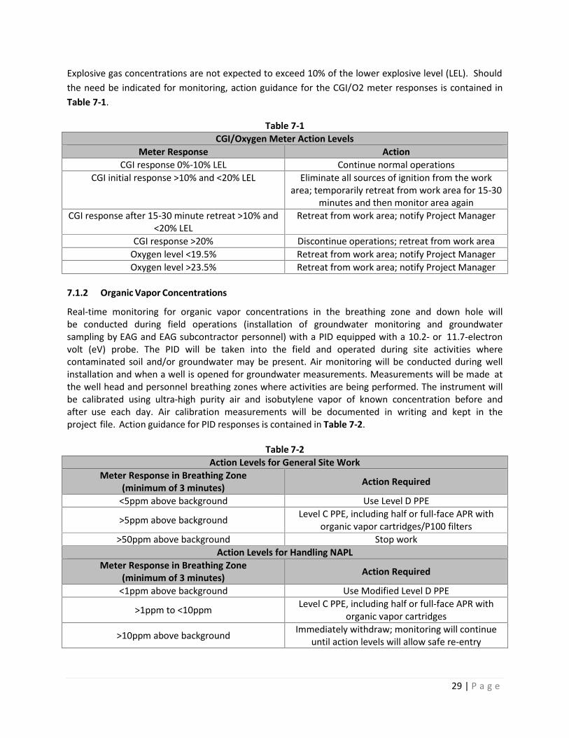
29 | P a g e
Explosive gas concentrations are not expected to exceed 10% of the lower explosive level (LEL). Shouldthe need be indicated for monitoring, action guidance for the CGI/O2 meter responses is contained inTable 7-1.
Table 7-1CGI/Oxygen Meter Action Levels
Meter Response ActionCGI response 0%-10% LEL Continue normal operations
CGI initial response >10% and <20% LEL Eliminate all sources of ignition from the workarea; temporarily retreat from work area for 15-30
minutes and then monitor area againCGI response after 15-30 minute retreat >10% and
<20% LELRetreat from work area; notify Project Manager
CGI response >20% Discontinue operations; retreat from work areaOxygen level <19.5% Retreat from work area; notify Project ManagerOxygen level >23.5% Retreat from work area; notify Project Manager
7.1.2 Organic Vapor Concentrations
Real-time monitoring for organic vapor concentrations in the breathing zone and down hole willbe conducted during field operations (installation of groundwater monitoring and groundwatersampling by EAG and EAG subcontractor personnel) with a PID equipped with a 10.2- or 11.7-electronvolt (eV) probe. The PID will be taken into the field and operated during site activities wherecontaminated soil and/or groundwater may be present. Air monitoring will be conducted during wellinstallation and when a well is opened for groundwater measurements. Measurements will be made atthe well head and personnel breathing zones where activities are being performed. The instrument willbe calibrated using ultra-high purity air and isobutylene vapor of known concentration before andafter use each day. Air calibration measurements will be documented in writing and kept in theproject file. Action guidance for PID responses is contained in Table 7-2.
Table 7-2Action Levels for General Site Work
Meter Response in Breathing Zone(minimum of 3 minutes) Action Required
<5ppm above background Use Level D PPE
>5ppm above background Level C PPE, including half or full-face APR withorganic vapor cartridges/P100 filters
>50ppm above background Stop workAction Levels for Handling NAPL
Meter Response in Breathing Zone(minimum of 3 minutes) Action Required
<1ppm above background Use Modified Level D PPE
>1ppm to <10ppm Level C PPE, including half or full-face APR withorganic vapor cartridges
>10ppm above background Immediately withdraw; monitoring will continueuntil action levels will allow safe re-entry

30 | P a g e
If air concentrations of organic vapors are greater than 5 ppm above background in the breathing zonefor a 3-minute period, personnel will stop work, retreat from site, and allow time (at least 15minutes) for vapors to dissipate. If monitoring indicates that concentrations still exceed 5 ppm,workers will upgrade to Level C PPE. If monitoring indicates that concentrations exceed 50 ppm, workwill be stopped until site conditions can be re-evaluated.
These action levels are based on the assumption that the major component of free product beingrecovered will be benzene or naphthalene.
Work involving NAPL recovery from monitoring wells will be conducted in Level C PPE. This levelmay be downgraded based on air monitoring data and actual field conditions. Downgrading of PPE mustbe approved by the PM and HSE staff. If ventilation is conducted, additional air monitoring will beperformed to the resumption of work to determine the level of PPE required.
7.2 Physical Conditions Monitoring
Site workers will be monitored by the Project Manager for signs of weather-related symptoms fromexposure to excessive heat or cold.
Whenever the air temperature exceeds 70°F for personnel wearing chemical protective clothing or90°F for personnel wearing regular work clothes, the Project Manager will assess conditions that maycause heat stress in site workers.
8.0 MEDICAL SURVEILLANCE
This section discusses the medical surveillance program, how the results are reviewed by a physician andhow participation is documented.
8.1 Medical Surveillance Program
All personnel who will be performing any task where potential exposure to hazardous materialexists will undergo medical surveillance as outlined in OSHA 29 CFR 1910.120(f). All personnelperforming tasks in the Exclusion Zone or Contamination Reduction Zone will be required to havepassed the EAG medical surveillance examination (or equivalent), performed by a licensedOccupational Physician. The Project Manager will verify that all EAG and subcontractor personnel meetapplicable OSHA medical surveillance requirements.
Applicable field employees will undergo an annual comprehensive medical examination, including acomprehensive health history, blood chemistry with complete blood count and differential, urinalysis,medical history, required chest x-rays, audiogram, pulmonary function testing, testing for heavymetals (as needed), and a physician's interpretation of each employee's medical surveillanceexamination, including the ability of the employee to wear a respirator. A comprehensivemedical examination will be performed if an employee develops signs or symptoms indicatingpossible overexposure to hazardous substances and/or heat or cold stress.
8.2 Physician Review

31 | P a g e
All medical surveillance and examination results are reviewed by a licensed physician who is certified inOccupational Medicine by the American Board of Preventive Medicine. EAG employee participation inthe medical surveillance program is a part of their permanent medical record maintained in theemployee's home office. A copy of the current medical clearance signed by the occupational healthphysician for all EAG employees must be maintained at the home office.
9.0 SITE CONTROL MEASURES AND DECONTAMINATIONTo provide for the protection of public health and safety and minimize the possibility of transferringhazardous substances from the site, contamination control procedures are required. Theseprocedures consist of site control measures (which entail the delineation of work zones,communications, and site security) and decontamination procedures (which are necessary for bothpersonnel and equipment). Contaminants that may be uncovered during sampling operations mustnot be transferred outside the work zone unless properly containerized, and must be removedfrom clothing, personnel, and equipment prior to relocation from that zone. This section discusses sitecontrol measures and decontamination procedures to be used during the collection of samples,the installation of soil borings and/or groundwater monitoring/remediation wells, excavations, andother intrusive work where contact with impacted soils and groundwater could occur by EAG and/or EAGsubcontractor personnel.
9.1 Site Control Measures
Site control can be achieved by effectively delineating the work zone, providing appropriatecommunication, and establishing site security.9.1.1 Work Zone Delineation
To minimize the transfer of hazardous substances from the site and to ensure proper protectionof employees and subcontractors, work zones will be established by the Field Project Team Leader.Applicable site work and the associated requirement for work zones will be determined by the ProjectManager. The work area will be divided into an Exclusion Zone (EZ), a Contamination Reduction Zone(CRZ), and a Support Zone (SZ). A typical work zone delineation setup is shown as Figure 9-1, below.
Exclusion Zone (EZ)Contamination does or could exist in this zone. Only properly authorized and trained individuals (refer toSection 6.0) wearing appropriate PPE will be allowed to enter and work in this zone. All people enteringthe EZ must wear, at a minimum, Level D protection. An entry and exit point for personnel andequipment will be established at the periphery of the EZ (between the EZ and the CRZ) to regulate theflow of personnel and equipment.
Contamination Reduction Zone (CRZ)Between the EZ and the SZ will be the CRZ, which will provide a transition between the potentiallycontaminated EZ and the clean SZ. The CRZ (located upwind of the EZ, if possible) will be a corridorleading from the EZ and will serve as a buffer to further reduce the probability of the SZ becomingcontaminated. Exit from the EZ will only be allowed through this CRZ. The CRZ will provide additionalassurance that the physical transfer of contaminating substances on people, equipment, and/or inthe air will be limited through a combination of decontamination and zone restrictions. Within thiszone, employees and subcontractors may perform personal decontamination (e.g., face and handwashing), and certain PPE and small equipment decontamination. Buckets or wash basins for boot

32 | P a g e
washing and equipment decontamination will be stationed on a sheet of plastic (a minimum of 8 feetby 8 feet), the boundaries of which will constitute the CRZ.Support Zone (SZ)The Support Zone will be considered a non-contaminated area. The location of support facilities in the SZwill be upwind of the EZ (where possible) and readily accessible to the nearest road. The fieldoffice/support facilities, equipment vehicles, a first aid station and a visitors/personnel entry and exit logfor the work site will be located in this zone. Potentially contaminated personal clothing, equipment andsamples are not permitted in this zone unless properly containerized.
Figure 9-1Typical Exclusion, Contamination Reduction, and Support Zone setups
9.1.2 Communications
A loud and clear form of communication should be made available for Site personnel entering the workzones. Site communication may be in the form of hand signals, voice, or other communication devices.All forms of communication should be understood by all workers on the Site prior to starting work.Offsite communications may be conducted with mobile phones or walkie-talkies only if the atmospherehas been deemed non-explosive, and the person using the mobile device is in the SZ while placing thecall, or inside the cab of a stationary vehicle.
9.1.3 Site Security
The Sparrows Point facility is not open to the public, and there is a strictly monitored main entrance witha security guard on duty at all times who only allows authorized personnel onto the Site. This limitedaccess to the facility should eliminate the need for many requirements for specific site security exceptthose needed to maintain work zone integrity, such as visible barriers around open excavations or EZsand CRZs. No site visitors will be allowed to travel unescorted by EAG or subcontractor personnelaround the facility.
Once site visitors arrive at their intended work zone, they must check in with the Field Team Lead. Ifvisitors are authorized to enter the CRZ and/or the EZ, they must have completed OSHA 1910.120medical surveillance and training requirements (refer to Section 8.0 and Section 6.0). Visitors must wear
DRILL RIG
Contamination Reduction Zone
Drill rig, backhoe, etc.
Support Zone
Exclusion Zone

33 | P a g e
appropriate PPE before they will be allowed to enter the CRZ and/or the EZ. They must also be takenthrough this HASP during a brief tail-gate meeting and sign the Acknowledgement page in the back priorto engaging in any activities inside the CRZ or the EZ. All site visitors must follow the same site controlmeasures and decontamination procedures as EAG personnel and subcontractors. The Project Managermust also be informed of each visitor’s name, purpose for their visit, time of entry (and exit), location oftasks they wish to perform, whether they completed their intended task(s), and any other relevantinformation pertaining to their visit.
9.2 Decontamination Procedures
Decontamination of employees, subcontractors, and equipment leaving the EZ will be performedto minimize human exposure to hazardous substances and to minimize the spread ofcontamination to surrounding areas. The purpose of the CRZ is to provide a location to performlimited personnel decontamination and certain PPE and small equipment decontamination.
9.2.1 Personnel Decontamination
Persons leaving the EZ must pass through the CRZ and follow decontamination procedures beforeentering the SZ. Hand tools and other sampling equipment used in the EZ and reusable PPE (boots, safetyglasses, etc.) will be appropriately cleaned prior to removal from the site each day. The step-by-step sequence for personnel decontamination is as follows:
Remove boot covers (if used) at the boot washing station and place them in the disposalcontainer provided
Wash outer gloves and chemical resistant boots (if used) at the boot washing station Remove wrist tape (if used) and outer gloves and place them in the disposal container
provided Remove ankle tape (if used) and disposable coveralls (if used) and place them in the disposal
container provided Remove respirators (if used) and place each in designated locations in the CRZ Remove inner gloves and discard in the disposal container provided Wash hands and face and proceed to the SZ
Respirators must be fully decontaminated after each use by the personnel who previously wore them.All project employees and subcontractors are required to take a thorough soap and water showerin their home or motel room at the end of each workday. If monitoring or a general exposureassessment indicates that an employee has become contaminated, the employee or subcontractor willnotify the EAG Project Manager and the Field Team Lead as soon as the contaminated state has beendiscovered.
9.2.2 Equipment Decontamination
All equipment leaving the EZ must be decontaminated either within the CRZ or at the centraldecontamination area. Small equipment, such as hand tools, will be thoroughly decontaminated withinthe CRZ before being placed in the SZ. The field tools may be scrubbed visually clean using a detergentsolution (Alconox/Liquinox) with water and a stiff, long-bristled scrub brush. Following the solutionscrubbing, the tools may be rinsed with distilled water or isopropyl alcohol. Any vehicle working in an EZwill be decontaminated before leaving the site. The vehicle will be cleaned by sweeping excess soil anddebris off the wheels. A high-pressure sprayer will then be used to wash the wheels, if necessary.

34 | P a g e
Each piece of equipment will be inspected after cleaning for any soil remaining on the tires orelsewhere. All vehicles will be cleaned to the satisfaction of the Field Team Lead or a designatedassistant prior to entering the SZ or leaving the site. Employees or subcontractors performingdecontamination shall wear the appropriate level of PPE (refer to Section 5.0).
9.2.3 Waste Management
The Project Manager and the Field Team Leads will be responsible for overseeing the containerizationand disposal of any field derived wastes. Contaminated or suspected contaminated field derived wastesshall be disposed of in accordance with all local, state, and/or federal regulations. Field derived wastesinclude decontamination rinse waters and other related decontamination generated wastes.
Soils and groundwater expected to be encountered during any sampling or intrusive work not to becontaminated, based on existing data, may be discharged to the ground surface in the immediatevicinity of the monitoring well. However, any known or suspected to be contaminated soil (insmall quantities) or groundwater will be containerized for future removal, likely in 55-gallondrums or other approved storage vessels. Depending on the suspected contaminants, the recoveredgroundwater may be sent through one of the onsite groundwater treatment units. However, thetreatment unit must be designed to address the contaminants of concern in the groundwater beingtreated. Otherwise, the liquid must be staged onsite for eventual offsite disposal at an approved facility.
Impacted soil, if in drums, will be staged in an area designated by the Project Manager or Field Team Leadfor eventual disposal. For large excavations, where excavated soil is stockpiled, it may be necessary toplace soils on plastic and cover with plastic to prevent any potential leachable runoff. The ProjectManager and/or Field Team Lead will provide the proper guidance necessary for handling bulk soil piles.
Any NAPL recovered via remediation systems or manual recovery efforts will be properly containerizedand either disposed of offsite as a recyclable material, if possible, or as a hazardous waste. The receivingfacility must be an approved facility.
10.0 EMERGENCY RESPONSE AND CONTINGENCY PROCEDURESThe objective of emergency response and contingency procedures is to ensure that effective actionsare implemented in a timely manner to minimize or control the effects of adverse events (e.g.,potential chemical exposures, personal injuries, fires/explosions, and spills/releases). The followingsubsections describe the basic emergency responses required should an emergency take place during fieldinvestigation or remedial effort activities.
10.1 Emergency Phone Numbers
Emergency telephone numbers are listed in Table 10-1.

35 | P a g e
Table 10-1Emergency Telephone Numbers and Agencies
Agency Telephone NumberSecurity (Sparrows Point facility) (410) 388-7761Ambulance 911Fire 911Occupational Health Clinic (410) 633-3600Hospital (410) 550-0100 (general)
(410) 550-0350 (emergency)National Response Center (800) 424-8802Poison Control Center - Maryland (800) 222-1222
EAG Main ContactVP Remediation, Russ Becker (314) 686-5611Project Manager, James Calenda (314) 620-3056
10.2 Injury/Illness Treatment
In the event of illness or injury, the following steps will be taken:
Evaluate the extent of injuries or seriousness of illness. When employees require urgent medical attention, call for emergency assistance. First aid
should be administered while awaiting an ambulance or paramedics. All emergency medicaltreatment, other than first aid, will be administered by the local paramedics. Table 10-1 listssite emergency telephone numbers. In all cases, critical injuries must be immediately referredfor professional medical attention.
For a non-critical injury/illness, first aid will be administered by onsite personnel. Anyonesustaining a non-critical injury/illness who continues to work will be monitored by the FieldTeam Lead for any signs of worsening condition, if it is deemed that the person can return towork by the Team Lead and Project Manager. Injured personnel who later suffer any worseningchange in status are to immediately notify the Team Lead or the Project Manager.
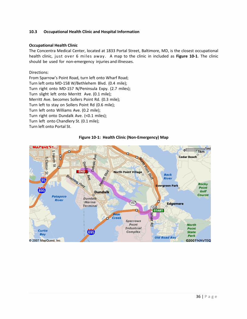
36 | P a g e
10.3 Occupational Health Clinic and Hospital Information
Occupational Health ClinicThe Concentra Medical Center, located at 1833 Portal Street, Baltimore, MD, is the closest occupationalhealth clinic, just over 6 mi les away. A map to the clinic in included as Figure 10-1. The clinicshould be used for non-emergency injuries and illnesses.
Directions:From Sparrow’s Point Road, turn left onto Wharf Road;Turn left onto MD-158 W/Bethlehem Blvd. (0.4 mile);Turn right onto MD-157 N/Peninsula Expy. (2.7 miles);Turn slight left onto Merritt Ave. (0.1 mile);Merritt Ave. becomes Sollers Point Rd. (0.3 mile);Turn left to stay on Sollers Point Rd (0.6 mile);Turn left onto Williams Ave. (0.2 mile);Turn right onto Dundalk Ave. (<0.1 miles);Turn left onto Chandlery St. (0.1 mile);Turn left onto Portal St.
Figure 10-1: Health Clinic (Non-Emergency) Map
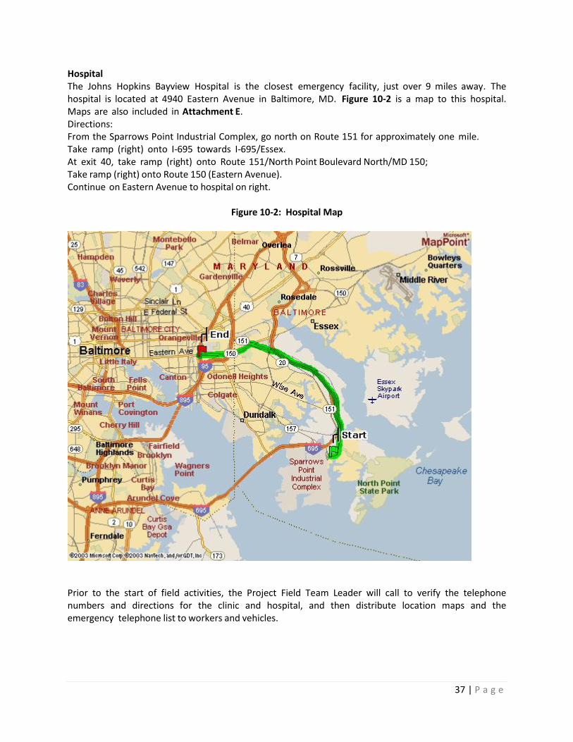
37 | P a g e
HospitalThe Johns Hopkins Bayview Hospital is the closest emergency facility, just over 9 miles away. Thehospital is located at 4940 Eastern Avenue in Baltimore, MD. Figure 10-2 is a map to this hospital.Maps are also included in Attachment E.Directions:From the Sparrows Point Industrial Complex, go north on Route 151 for approximately one mile.Take ramp (right) onto I-695 towards I-695/Essex.At exit 40, take ramp (right) onto Route 151/North Point Boulevard North/MD 150;Take ramp (right) onto Route 150 (Eastern Avenue).Continue on Eastern Avenue to hospital on right.
Figure 10-2: Hospital Map
Prior to the start of field activities, the Project Field Team Leader will call to verify the telephonenumbers and directions for the clinic and hospital, and then distribute location maps and theemergency telephone list to workers and vehicles.

38 | P a g e
10.4 Accident and Emergency Medical Response
All field team members will be aware of the location of a first aid kit kept onsite. All vehicles used totransport injured persons to an offsite medical facility will be provided with directions and a map tothe medical facility.
If treatment beyond first aid is required, emergency response personnel will be contacted forassistance and transport. Before beginning site activities, the Project Field Team Leader will ensurethat each field team member knows where the nearest emergency medical facilities are and how to getthere. The closest hospital will be used in cases of life-threatening emergencies at the direction of theProject Field Team Leader. The telephone numbers of the local emergency services will be availablein the SZ, and the Project Field Team Leader will brief the field team on the procedures for calling forhelp in an emergency.
Site personnel will inform the Project Manager of any medications, allergies, or other medicalinformation that may be applicable for their medical treatment. The Project Manager will supply thisinformation to emergency response personnel, and will accompany the victim to the hospital, if possible.
10.4.1 Chemical Exposure
In case of accidental overexposure to a hazardous material (groundwater, soil, and/or off-gas materials),guidelines shown in Table 10-2 will be used.
Table 10-2Chemical Exposure Guidelines
Type of Overexposure First Aid Guidelines
Skin Contact Skin: Wash/rinse the affected area thoroughly with copious amounts of soapand water.
Eyes: Eyes should be rinsed for at least 15 minutes following chemicalcontamination.Contact emergency response personnel if required, or transport victim tothe hospital.
Inhalation Move the victim to fresh air.Contact emergency response personnel if required, or transport victim tothe hospital.
Ingestion Contact Poison Control Center.Contact emergency response personnel, or transport victim to the hospital.
10.4.2 Decontamination During a Medical Emergency
For minor medical problems or injuries, regular decontamination procedures will be followed. Ifemergency, life-saving first aid and/or medical treatment are required, regular decontaminationprocedures may need to be abbreviated or omitted:
Do not attempt to wash or rinse an unresponsive victim unless the victim has beencontaminated with an extremely toxic or corrosive chemical that may cause injury or loss oflife to emergency response personnel.
Outer garments can be removed if it does not cause a delay, interfere with treatment, oraggravate the problem.
39 | P a g e
PPE can be cut away and respiratory protective equipment must always be removed. If contaminated clothing cannot be safely removed, then the victim should be wrapped in a
blanket or plastic sheeting to prevent contamination to the inside of the ambulance and/oremergency response personnel.
The Project Manager or Field Team Lead will advise the medical staff as to the type of contaminationpossibly involved.
10.4.3 Small or Incipient Fire
A small fire is defined as a fire that can be extinguished with an available 20 pound type ABCfire extinguisher. An incipient fire is a fire that is small because it has just started. In the event of asmall or incipient fire, the following minimum actions will be taken:
Evacuate nearby personnel from the area, if possible, to an upwind location or to an area notaffected by smoke or hazardous decomposition products if an upwind location is not feasible.
Attempt to extinguish fire using portable fire extinguisher or by smothering. Contact emergency response personnel, as needed, for any injuries or exposures to hazardous
decomposition products, or if fire cannot be put out. After the fire has been extinguished, or emergency response personnel have been contacted,
notify the following project personnel:The Project Manager
10.4.4 Large Fire or Explosion
An explosion, large fire or a small fire which cannot be extinguished is beyond the first line capabilitiesof EAG personnel. Professional emergency response personnel would be needed to provideemergency assistance for these types of incidents. In the event of a large fire, explosion or a small firethat cannot be extinguished, the following minimum actions will be taken:
Evacuate all personnel from the site, if possible, to an upwind location, or to an area notaffected by smoke or hazardous decomposition products if an upwind location is not feasible
Perform a quick role call to account for all site personnel Contact the fire department Contact emergency response personnel, as needed, for any injuries or exposures to hazardous
decomposition products After emergency response personnel have been contacted, notify the following project
personnel:The Project Manager
10.4.5 Adverse Weather Conditions
In the event of adverse weather conditions, the Project Manager will determine if work cancontinue without sacrificing the health and safety of site personnel. Threatening weather conditionswill be monitored by the Project Manager and possibly the Team Lead via radio, television, internet,and/ or calls to the National Weather Service. Some of the conditions to be considered include:
Potential for heat or cold stress Limited visibility

40 | P a g e
Electrical storms Treacherous weather-related working conditions (i.e., heavy rainfall, icy conditions causing
slippery footing hazards, etc.).
10.4.6 First Aid for Heat Stress/Cold Stress
First aid treatment for heat cramps includes shade, rest and fluid replacement. If available, theindividual should drink electrolyte replacement fluids (e.g., Gatorade, Squincher or 10-K). Theindividual should recover within half an hour.
First aid treatment for heat exhaustion includes cooling the victim, elevating the feet and fluidreplacement. If the individual has not recovered within half an hour, then transport the victim tothe hospital for medical attention.
Heat stroke is a medical emergency, requiring the immediate cooling of the victim and transport to thehospital for medical treatment immediately.
First aid treatment for frost nip and frostbite includes covering the affected area with warmth andretreating to a warm area. If the individual has not recovered within half an hour, then transportthe victim to the hospital for medical attention.
Frozen tissue is a medical emergency and the victim must receive medical attention immediately.Contact emergency response personnel immediately or transport the victim to the hospital.
First aid treatment of mild hypothermia includes using heat to raise the individual’s body temperature.Heat may be applied to the victim in the form of heat packs, hot water bottles and blankets. If theindividual has not recovered within half an hour, then transport the victim to the hospital formedical attention.
Severe hypothermia is a medical emergency and the victim must be transported to the hospitalimmediately. First aid treatment for severe hypothermia includes handling the victim very gently; roughhandling may set off of an irregular heartbeat. DO NOT attempt to re-warm the severelyhypothermic victim; re-warming may cause the development of an irregular heartbeat.
10.4.7 Snake Bites
If bitten, lower the extremity below the heart to reduce the poison's dissemination through thebody. Remain calm, try to keep the heart rate reduced and seek medical attention immediately. Do notcut the wound or attempt to suck out the venom. Note any physical features (e.g., shape of headand color or pattern on body) of the snake.
10.4.8 Animal Bites
All bites should be treated as contaminated soft tissue injuries. Bites should be washed immediatelywith large amounts of soap and water. If soap is not available, flush the wound with water. Theseverity and onset of any infection is dependent upon the number of organisms (viruses or bacteria)introduced into the wound. Washing saliva out of the wound immediately will reduce the number ofbacteria or viruses that can enter the tissue. Medical attention must be sought if rabies is suspected orthe individual has not had a recent tetanus booster.

41 | P a g e
10.4.9 Insect Bites and Stings
Emergency care for insect bites and stings depends on the individual’s reaction. To treat a sting thatresults in a minor reaction, remove the stinger by gently scraping it off the skin. Do not try to grasp thesac or stinger, because this forces the remaining venom into the skin. Once the stinger has beenremoved, clean the wound and surrounding area. Apply cold packs to slow the absorption of the venomand reduce pain and swelling. The treatment for a severe reaction to insect stings includes the following:
Confirm with the victim whether they are highly allergic to the insect that stung themo If victim has gone into anaphylactic shock, retrieve their epi pen or other auto-injector and
administer per the directions as hastily as possible Assuming the victim remains conscious, ask them to refrain from moving around, and to lie down Immobilize the injured area immediately If an extremity is involved, remove any rings or watch Keep the affected part low, below the level of the heart Apply cold compresses to the affected area If possible, try to identify the type of insect that inflicted the sting Transport the victim to a medical facility immediately, continuing supportive measures en
route.
All employees and subcontractors must report severe reactions to insect stings prior to the beginning ofwork to both the Project Manager and Field Team Lead.
10.4.10 Poisonous Plants
Decontamination: Wash the skin immediately after contact with the plant. Proper washing may notbe practical in the middle of the woods, but a product such as Technu or a small wash-up kit withprepackaged, alcohol-based cleansing tissues can be effective. Employees and subcontractors shouldnot forget to wash contaminated clothing and clean up contaminated equipment prior to re-use.
Treatment: Options are as follows: Home treatment: Calamine lotion and an oatmeal bath (one cup to a tub full of water) can
help relieve itching. To prevent secondary skin infection, scratching is not helpful and thefingernails should be cut to avoid damage to the skin. Over-the-counter hydrocortisonecream can decrease inflammation and itching; however, the label should be read and thecream used according to directions.
When to see the doctor: Severe cases may require further treatment. A physician should beseen if the rash appears infected, is on the face or other sensitive body areas, or is tooextensive to be easily treated at home.
10.4.11 Ticks
To remove an attached tick: Use fine-tipped tweezers or a “tick tool” to grasp the tick at the surface of the skin If tweezers are not available, use a tissue to protect the fingers (exposure to the tick's body
fluid may lead to transmission of disease) With a steady motion, pull the tick straight out

42 | P a g e
Disinfect the bite site and the tweezers. Wash your hands thoroughly with soap and water. Save thetick if you can by placing it in a Ziploc bag in the freezer; this may help with diagnosis in the future.
If flu-like symptoms such as fatigue, headache, neck-stiffness or jaw discomfort begin following a tickbite, seek medical attention.

APPENDICES
TITLE 5
ATTACHMENT A
COMPLIANCE AGREEMENT

EAG HEALTH AND SAFETY PLAN
ACKNOWLEDGEMENT FORM
I, , have read (or had read to me), EAG’s health and safety plan.(Print Name)
I understand my responsibilities as they are defined in this plan and will abide by these rules andprocedures, as well as any regulations or otherwise governing safety. When in doubt concerning safejob performance, I will speak to my immediate supervisor and/or Project Manager.
I understand EAG reserves the right to change or amend the HASP at any time.
I understand any violation to the plan policies or procedures will be cause for disciplinary action up toand including termination.
Employee Signature Date
EAG Supervisor/Project Manager Signature Date
ATTACHMENT B
Material Safety Data Sheets (MSDSs)