WiMsh: a simple and efficient tool for simulating IEEE 802.16 wireless mesh networks in ns-2
Upload
khangminh22Category
view
4download
0
Enhancing the ns-3 IEEE 802.11ad Model Fidelity: BeamCodebooks, Multi-antenna Beamforming Training, and
Quasi-deterministic mmWave ChannelHany Assasa
IMDEA Networks Institute andUniversidad Carlos III de Madrid
Madrid, [email protected]
Joerg WidmerIMDEA Networks Institute
Madrid, [email protected]
Tanguy RopitaultNational Institute of Standards and Technology
Gaithersburg, MD, [email protected]
Nada GolmieNational Institute of Standards and Technology
Gaithersburg, MD, [email protected]
ABSTRACTNext generation wireless local area networks are envisioned toserve a high number of devices with heterogeneous capabilities andservice requirements. Millimeter-wave technology is expected to beable to satisfy these demands and complement the highly congestedwireless networks operating in the sub-6 GHz band. However, real-world experimentation with millimeter-wave communications isnot always feasible due to the significant amount of resourcesrequired and its associated costs. For these reasons, researchersresort to high fidelity system-level simulators which provide ahigh degree of flexibility to test complex network deploymentswith a reasonable level of abstraction at the physical layer. Thens-3 IEEE 802.11ad model allows researchers to study large-scalewireless networks operating in the 60 GHz band, taking into accountall of the essential features supported by the standard. However,the beamforming capabilities in the current implementation stilllack both the flexibility and the agility that commercial of-the-shelf devices offer. Additionally, the model relies on a simplifiedchannel model that does not accurately reflect the characteristicsof a millimeter-wave channel. In this paper, we augment our ns-3IEEE 802.11ad model with novel features that enhance its fidelityand provide the user fine grained control over physical and MAClayer aspects of 802.11ad devices. These features include beamcodebooks, multi-antenna beamforming training, beam refinementand beam tracking capabilities, and a quasi-deterministic channelmodel. Our work paves the way for a future implementation of thenext generation wireless gigabit standard, IEEE 802.11ay.
Permission to make digital or hard copies of all or part of this work for personal orclassroom use is granted without fee provided that copies are not made or distributedfor profit or commercial advantage and that copies bear this notice and the full citationon the first page. Copyrights for components of this work owned by others than ACMmust be honored. Abstracting with credit is permitted. To copy otherwise, or republish,to post on servers or to redistribute to lists, requires prior specific permission and/or afee. Request permissions from [email protected] 2019, June 19–20, 2019, Florence, Italy© 2019 Association for Computing Machinery.ACM ISBN 978-1-4503-7140-7/19/06. . . $15.00https://doi.org/10.1145/3321349.3321354
CCS CONCEPTS•Networks→Network simulations;Wireless local area net-works;
KEYWORDSMillimeter Wave, IEEE 802.11ad, IEEE 802.11ay, 60 GHz, WiGig,ns-3, Simulations
ACM Reference Format:Hany Assasa, Joerg Widmer, Tanguy Ropitault, and Nada Golmie. 2019.Enhancing the ns-3 IEEE 802.11ad Model Fidelity: Beam Codebooks, Multi-antenna Beamforming Training, and Quasi-deterministic mmWave Channel.In 2019Workshop on ns-3 (WNS3 2019), June 19–20, 2019, Florence, Italy.ACM,New York, NY, USA, 8 pages. https://doi.org/10.1145/3321349.3321354
1 INTRODUCTIONWireless communication in the millimeter-wave (mmWave) bandis a key enabler for the next generation wireless technologies suchas 5G Mobile Networks. Thanks to the huge amount of spectrumavailable, mmWave can be used for a wide range of scenarios where,traditionally, wired solutions have been utilized, such as ultra-highdefinition video streaming, virtual-reality headsets, or wirelessfront-hauling and back-hauling in mobile networks. The Wi-Fialliance realized the potential capabilities of the under-utilizedmmWave band and ratified in 2012 the IEEE 802.11ad standard [8],the first gigabit wireless local area networks (WLAN) standard thatoperates in the 60 GHz band.
In 2015, the Wi-Fi Alliance started to revise the IEEE 802.11adstandard to cope with new emerging applications. The new 802.11amendment, known as IEEE 802.11ay, can yield data rates up to300 Gb/s compared to 6.75 Gb/s for IEEE 802.11ad. This is mainlyachieved by adding SU/MU-MIMO techniques and the ability tobond up to four 2.16 GHz channels, resulting in a channel width of8.64 GHz. To reach the envisioned data-rates of hundreds of Gb/s,IEEE 802.11ay devices will need to embed multiple antennas toexploit MIMO techniques.
The current implementation of the 802.11ad model [2, 3] in ns-3 limits the wireless devices to a single antenna array using asimple analytical model [7]. This design choice has been made as

all the available commercial of-the-shelf (COTS) devices [10, 14]are confined to a single phased antenna array. Nonetheless, thosedevices use a complex antenna array that has unique radiationpatterns whose properties cannot be reflected using a simple ana-lytical model. Furthermore, the radiation patterns of this antennaarray have to be defined in advance and cannot be modified duringthe course of the simulation. Regarding propagation, the modelrelies on a simple Line-of-sight (LoS) channel for communicationthat compromises physical (PHY) layer accuracy. Thus, the currentimplementation neither reflects the effects of the propagation envi-ronment nor the properties of the simulated scenario with sufficientaccuracy. These limitations lead us to extend our implementationwith new features to improve its realism. The main contributionsof our the paper are as follows:
• We provide the design and implementation of various typesof beam codebooks. The beam codebooks allow a wirelessdevice to incorporatemultiple phased antenna arrays andma-nipulate their radiation patterns similarly to COTS 801.11addevices.
• We implement a Codebook Generator application in MAT-LAB® to facilitate the generation of the codebooks. Theuser can generate multiple codebook instances to simulatenetworks of devices using different types of antennas.
• We add support for multiple antenna beamforming training.This paves the way to add support for the IEEE 802.11aystandard in the future, which relies on multiple antennaarrays to realize MIMO.
• We extend the beamforming capabilities and provide a moreaccurate model of the PHY layer for both beam tracking andbeam refinement phases. We provide the user with the abilityto manipulate the antenna weight vectors (AWVs) utilizedin those phases.
• Finally, we implement a Quasi-deterministic (Q-D) wire-less channel model in ns-3 that can interface with com-mercially available ray tracers. The Q-D channel realizationallows the user to simulate complex propagation environ-ments and frequency-selective channels. Additionally, theuser can study the coexistence between 802.11ad devices andother systems that operate in the 60 GHz band such as IEEE802.15.3c and IEEE 802.11ay standards.
We believe that these new features will not only improve thefidelity of the IEEE 802.11ad model, but also pave the way for thedevelopment of the IEEE 802.11ay standard inside ns-3.
The paper structure is as follows: Section 2 provides design andimplementation details of new features in the ns-3 IEEE 802.11admodel. Section 3 validates the new features for different scenarios.Finally, Section 4 concludes the paper and presents our future plans.
2 IMPLEMENTATIONIn the following section, we provide the design and the implemen-tation details of the new features and their integration within ourmodel. Our implementation is publicly available on GitHub [1].
2.1 Beam CodebooksThe current implementation of the ns-3 IEEE 802.11ad model al-lows to attach a single phased antenna array per directional multi-gigabit (DMG) station (STA) using the DirectionalAntenna class.A realistic model should provide the possibility to use multipleantenna arrays per DMG STA to properly simulate IEEE 802.11adcharacteristics (e.g., multiple antenna arrays improve the resiliencyagainst blockage typically encountered in the 60 GHz band [4]). TheDirectionalAntenna class operates by dividing the azimuth planeinto a number of equally sized sectors, with each DMG STA beingable to configure its number of sectors. The sector antenna radiationpatterns are implemented using a Gaussian radiation antenna pat-tern [7] in our current implementation. In practice, phased antennaarrays have complex radiation patterns depending on the type andthe placement of the antenna elements which cannot always be cap-tured by theoretical models. Additionally, the DirectionalAntennaclass enforces the same set of sectors to be used during BeaconHeader Interval (BHI), Sector Level Sweep (SLS), beam refinementprotocol (BRP), and beam tracking (BT) phases and does not pro-vide flexibility to change the order and the shape of those sectorsduring simulation run-time.
To overcome the aforementioned limitations, we extended thebeamforming capabilities of the ns-3 802.11ad model by introduc-ing a new class named Codebook which deprecates the Direction-alAntenna class and provides more flexibility to define and manipu-late all the beamforming aspects of DMG STA. Unlike the Direction-alAntenna class which provides only theDmgWifiMac class with thedirectivity of the antenna array, the Codebook class encapsulates allthe functionalities related to beamforming training (e.g., initiatingbeamforming, tracking active antenna and sector, switching amongsectors) and decouples it from from the DmgWifiMac class. Thisnot only improves code usability but also lays the foundation for afuture IEEE 802.11ay implementation.
The implementation of the Codebook class is inspired by thedesign of the board file used by the firmware of the QCA9500 [12]chipset from Qualcomm. Figure 1 depicts the general architectureof the Codebook class. A codebook is designed for a number ofRadio Frequency (RF) chains where each RF chain is connected toone or more phased antenna arrays. Only a single antenna array isactive per RF chain. This emulates the Hybrid Beamforming withPartially Connected RF Architecture [15]. While an 802.11ad deviceis limited to a single RF chain where up to four antenna arrayscan be connected, our implementation allows to have more thanone RF chain to facilitate 802.11ay integration with our codebookarchitecture. Indeed, 802.11ay devices can contain up to 8 digital RFchains. Each phased antenna array in turns consists of a number ofpredefined sectors where each sector is composed of a set of cus-tom antenna weight vectors (AWVs). The user can decide whetherto pre-define those AWVs in advance or in an adaptive mannerduring the course of the simulation based on the channel measure-ments. The DmgWifiHelper class attaches a Codebook instance toeachWifiNetDevice during the initialization phase. The Codebookclass contains a list of virtual PhasedAntennaArrayConfigurationstructures which represent the phased antenna arrays. For eachphased antenna array structure, the user must define the followingset of attributes:

RF Chain N
RF Chain 1 Antenna Array 1
Antenna Array 2
Antenna Array N
Sector 1
Sector 2
Sector M
AWV 1
AWV 2
AWV L
Global Beamforming List
Antenna 1, Sector 1
Antenna 1, Sector 2
Antenna N, Sector M
Antenna 1, Sector 1
Antenna 1, Sector 2
Antenna N, Sector M
Antenna 1, Sector 1
Antenna 1, Sector 2
Antenna N, Sector M
Custom Beamforming List
Antenna 1, Sector 1
Antenna 1, Sector 2
Antenna N, Sector M
Figure 1: Codebook Architecture with Beamforming Lists
• A list of sectors using the virtual SectorConfig structure. Thestandard limits the number of sectors per antenna array to64 sectors. The maximum total number of sectors across allphased antenna arrays is 128.
• The orientation of the phased antenna array in both theazimuth and the elevation planes.
Each sector takes the following set of parameters:• Sector type which indicates whether the sector is used fortransmission, reception, or for both.
• Sector usage to specify whether the sector is used duringBHI, SLS, or both access periods.
• A list of virtual AWV_Config structures representing customAWVs. These AWVs will be probed during both BRP andBT phases. The number of AWVs should be multiple of 4according to 802.11ad [5].
Based on the Sector usage and Sector type parameters, the code-book generates multiple generic beamforming training lists thatfacilitate the beamforming operations during both BHI and SLSphases with all the DMG STAs. In addition, the user can customizebeamforming training lists and generate a unique list per peer de-vice. Both SectorConfig and AWV_Config structures are derivedfrom a parent structure named PatternConfig since both structuresrepresent the shape of the beam pattern generated by the phasedantenna array. Our newly introduced codebook architecture canuse three different types of beamforming codebook, based on boththe level of fidelity and the complexity required by the simulations.Each codebook has its own unique definition for each one of theprevious structures.
2.1.1 Analytical Codebook. The analytical codebook is the most-basic codebook implementation where the user can either use it todivide the azimuth plane into a number of equally spaced sectors,or manually define the radiation pattern of each sector using a pre-defined formula. Our implementation uses the Gaussian directionalpattern formula to define the shape of our beam patterns [7].
2.1.2 Numerical Codebook. With the numerical codebook, auser can import custom radiation patterns obtained through eithercommercial simulators like HFSS, antennas data-sheets, or antennabeam pattern measurements. We provide a MATLAB® script thatimports the radiation patterns [13] of the TP-Link TALON Router
AD7200 and generates a codebook file that can be used by thenumerical codebook. The TALON router uses a single beam pat-tern for reception (quasi-omni pattern), 32 sectors for transmittingDMG Beacons, and 35 sectors for transmit beamforming trainingin the SLS phase. Both the Analytical Codebook and the NumericalCodebook classes interface with the DmgWifiPhy class only.
2.1.3 Parametric Codebook. The parametric codebook is a state-of-the-art beamforming codebook that mimics the behaviour of802.11ad COTS devices. This is the most-realistic and complicatedcodebook implementation in our model. A user can synthesizebeam shapes with high granularity and flexibility as it relies onphased antenna array theory. In theory, the radiation pattern Y ofan antenna array is computed using Eq. 1:
Y (k,θ ,ϕ) = R(θ ,ϕ)AF (k,θ ,ϕ) (1)
whereR(θ ,ϕ) is the radiation pattern of a single element in the arrayconsidering the array has identical antenna elements, AF (k,θ ,ϕ)stands for the array factor, i.e., the antenna response, and k is thewave number. Both radiation pattern and array factor depend on θand ϕ, i.e., the azimuth and elevation angle respectively. The wavenumber k is equal to 2π/λ where λ is the wavelength. The arrayfactor is obtained using Eq. 2.
AF (k,θ ,ϕ) =WT S(k,θ ,ϕ) (2)
whereWT is the transpose of the antenna weights vector, the an-tenna weight vector representing the phase and amplitude excita-tion between antenna elements, and S(k,θ ,ϕ) is the steering vectorwhich represents phase delay among antenna elements for eachincoming electromagnetic plane wave impinging on the antennaarray. The steering vector S(k,θ ,ϕ) depends on the geometry of thephased antenna array, the placement of the antenna elements, andthe carrier frequency. In theory, the steering vector should have aconstant amplitude across all the elements. In practice, however,the amplitude of the steering vector has non-uniform values due tothe mutual coupling between antenna elements and non-idealitiesin the antenna design.
To make our implementation agnostic to the type of antennaarray, the Parametric Codebook requires the user to provide thefollowing group of parameters:
• The steering vector of the antenna array in the form of a3D complex matrix of sizeMxNxL, where L is the numberof antenna elements.M and N represent the number of az-imuth and elevation angles. In our implementation, we limitthe angle resolution to one degree. In addition, the steeringvector is considered constant across the whole frequencyrange of the channel.
• The radiation pattern of a single antenna element as a 2Dcomplex matrix of sizeMxN .
• A list of complex AWVs defining the excitation of the an-tenna elements. The size of each vector is L.
To facilitate the generation of those parameters and the usage ofthis Codebook, we developed a MATLAB® application named IEEE802.11ad Codebook Generator [1]. With this application, the usercan choose either among a set of MATLAB® phased antenna arraymodels such as Uniform Linear Array (ULA), Uniform Rectangu-lar Array (URA), and Uniform Circular Array (UCA) or upload a

custom steering vector obtained from antenna measurements. Inaddition, the user can visualize the 2D/3D directivity of the antennaarray and define the parameters of each sector and custom AWV in-dependently. When using MATLAB® phased antenna array models,the user can select between different sets of antenna elements suchas omni-element, micro-strip, etc. In contrast, in the case of cus-tom phased antenna arrays, the steering vector already comprisesthe effects of the antenna element pattern. The ns-3 ParametricCodebook class parses the file generated by the application and au-tomatically calculates and stores the directivity of each sector andAWV according to Eq. 1. The decoupling of the antenna responseand the weights of the antenna elements allows the user to adaptthe beam pattern within the course of the simulation based on thethe state of the wireless channel. For example, the user can suppressinterference and have a null in the direction of a certain stationwhile increasing the power towards the intended receiver. Simula-tions utilizing the Parametric Codebook have a high computationaloverhead due to the matrix operations which in turn increases therun-time compared to the other two codebooks.
In addition, the user can emulate the procedure of Channel StateInformation (CSI) measurements supported in the latest firmware(5.2.0.15) [11] of the Qualcomm chipset. Basically, the firmwareutilizes the BRP protocol to report the complex Channel ImpulseResponse (CIR) of the strongest path for each antenna element inthe antenna array. Since ns-3 does not model symbol-level signalsand only provides packet-level simulations, the same procedurewould provide the user with the Signal-to-Noise Ratio (SNR) mea-surements per antenna element.
Using either the Numerical Codebook or the Parametric Codebookprovides high fidelity simulations and results. Indeed, the mutualcoupling among antenna elements and non-idealities in the elec-tronics are not reflected in the analytical models (e.g., the mutualcoupling among antenna elements has significant impact on theresulting beam pattern).
In practice, when a phased antenna array is deployed in a field,the radiation pattern of the phased antenna array differs from theone reported in the simulations or the antenna data-sheets. As amatter of fact, the reflections coming from a real environment mightinteract with the signal coming from the direct path in a destructiveway, thus attenuating the signal. To simulate this behaviour, we in-tegrate a Q-D Channel Model in our implementation that interfaceswith the Parametric Codebook as described in Section 2.4.
2.2 Multi-antenna Beamforming TrainingSupport
Commercial-grade access points (APs) operating in the mmWaveband are envisioned to incorporate multiple antennas to provideubiquitous coverage for clients in the network. The multi-antennasupport is not limited to APs only. Qualcomm proposed the inclu-sion of two antenna arrays in mobile handsets to provide resiliencyand increase spatial diversity against self-blockage [4]. Further-more, IEEE 802.11ay mandates all the devices to have multi-antennato support MIMO communication. We extend the beamforming
The identification of any commercial product or trade name does not imply endorse-ment or recommendation by the National Institute of Standards and Technology, noris it intended to imply that the materials or equipment identified are necessarily thebest available for the purpose.
training procedure in the current implementation to support multi-antenna beamforming training during Beacon Transmission Inter-val (BTI), Association Beamforming Training (A-BFT) and DataTransmission Interval (DTI) channel access periods for both trans-mit and receive beamforming training.
For beamforming training in the BTI and A-BFT access periods,the IEEE 802.11ad standard states that only a single phased antennaarray is used for probing Sector Sweep (SSW) frames to obtain thebest sector for communication within the same Beacon Interval (BI).However, since this sector might not be the best one among all thephased antenna arrays, a device can send a request to the AP toallocate a service period (SP) during DTI to continue beamformingtraining using the remaining phased antennas arrays. Once a DMGSTA has contended successfully in an A-BFT access period andobtained the best sector for transmission, it does not participatefurther in any future A-BFT access periods. This reduces contentionin A-BFT and allows more stations to associate successfully withthe AP. A device can later switch its current active phased antennaarray at the beginning of the next BI to listen for incoming DMGBeacons. This ensures that if one antenna array is blocked andcannot detect those DMG Beacons, another antenna array withdifferent field of view (FOV) can take over.
For beamforming training in the DTI period, the two DMG STAsinvolved in the beamforming training need to be aware of thebeamforming capabilities of each other. This includes first reportingboth the number of supported transmit and receive antennas, andthe number of transmit and receive sectors in the DMG CapabilitiesElement to the AP. Then, the beamforming initiator can retrievethis information from the AP and calculates the exact duration ofan SP allocation to complete the beamforming training with thebeamforming responder. In our implementation, we consider allthe possible beamforming training scenarios based on the numberof antennas of both the initiator and the responder and the type ofthe beamforming training, either transmit sector sweep (TxSS) orreceive sector sweep (RxSS). For brevity, Figure 2 shows the generalcase when both initiator and responder have multiple antennaarrays.
In Figure 2(a), both the initiator and the responder perform TxSSduring an SLS phase. During the initiator TxSS (I-TxSS) phase, theresponder activates one of its antennas and sets it to receive inquasi-omni mode. At the same time, the initiator starts probing SSWframes across all its antenna arrays until it has covered all its sectors.Then, the responder switches to the next antenna array and theinitiator sweeps again across all its antenna arrays. The operationcontinues until the responder has used all its antenna arrays. Inthe responder TxSS (R-TxSS), both the initiator and the responderexchange their roles and perform the same operations as in theI-TxSS phase. At the end, both the initiator and the responder obtainthe best transmit sector for communication across all their antennaarrays. In Figure 2(b), both the initiator and the responder performRxSS during an SLS phase. It is worth mentioning that in orderto perform the RxSS phase, a DMG STA should have successfullyrealized the TxSS phase. In the initiator RxSS (I-RxSS) phase, wetrain the receive antenna of the responder. For each receive antennaat the responder side, the initiator iterates over its transmit antennas.For each transmit antenna, the receiver switches among its receivesectors while the initiator transmits SSW frame using the best

Initiator Transmit Sector Sweep
F F F F
Initiator
Responder
Tx Antenna ID=0 Tx Antenna ID=1
Quasi Omni Antenna ID=0
Tx Antenna ID=0
...
SSW Feedback
SSW-ACK
FQuasi Mode Antenna ID=0
F F F F
(a) I-TxSS & R-TxSS with Multiple Antennas at the Initiator and Responder
Tx Antenna ID=0 Tx Antenna ID=1
Quasi Omni Antenna ID=1
Tx Antenna ID=1
F F F F
Tx Antenna ID=0
Quasi Mode Antenna ID=1
F F F F
Tx Antenna ID=1
Responder Transmit Sector Swe ep
Initiator Receive Sector Sweep
Initiator
Responder Tx Antenna ID=0
(b) I-RxSS & R-RxSS with multiple antennas at the Initiator and Responder
Responder Receive Sector Sweep
S: 0 S: 15...
C: 15S: 10 ...
C: 0S: 10
Receive Antenna ID=0
S: 0 S: 20...
Receive Antenna ID=1
Tx Antenna ID=1
C: 20S: 15 ...
C: 0S: 15
C: 47S: 5
Tx Antenna ID=0
S: 0
C: 16S: 5
S: 31
Receive Antenna ID=0
C: 15S: 10
S: 0
C: 0S: 10
S: 31
Tx Antenna ID=1
C: 39S: 8
Tx Antenna ID=0
S: 0
C: 20S: 8
S: 19
Receive Antenna ID=1
C: 19S: 11
S: 0
C: 0S: 11
S: 19
Tx Antenna ID=1
... ......
... ... ... ...
... ... ... ...
... ... ... ...
SSW Feedback
SSW-ACK
F
F: Feedback the Best SectorS: Sector IDC: Count Down
Figure 2: Multi-antenna Beamforming Training Examples: (a) I-TxSS & R-TxSS with Multiple Antennas at the Initiator andResponder (b) I-RxSS & R-RxSS with Multiple Antennas at the Initiator and Responder
transmit sector for this particular antenna. In the responder RxSS(R-RxSS) phase, we perform the same operations as before but withthe purpose of training the receive antenna of the initiator.
2.3 AGC and TRN Fields ModelingThe IEEE 802.11ad standard defines a mandatory phase named BRPto refine the selected sector obtained from a previous SLS phase.The SLS phase is a time consuming process as a DMG STA has toprobe with an independent SSW frame for each sector. Each SSWframe consists of 26 Bytes and takes around 14.9 µs when transmit-ted using the Control PHY. As a result, the duration to complete anSLS increases tremendously for massive antenna arrays, whereasin the BRP phase, evaluating a custom beam pattern takes around713 ns . This duration is shorter since in the BRP phase, a DMGSTA switches between multiple beam patterns during the courseof a single frame transmission. For this reason, DMG STAs typi-cally probe few sectors with wide beams during an SLS phase toestablish a directional communication link at relatively low datarate. Later, in the BRP phase, each DMG STA refines its selectedsector and generates a much narrower beam that yields a highergain and thus higher throughput. As a result, combining both SLSand BRP phases significantly reduces the total duration to establisha directional link. However, utilizing the BRP protocol requires aphased antenna array with fast switching capabilities in the orderof sub-nanoseconds. In contrast, in an SLS phase, switching speedis more relaxed as the standard gives a gap of 1 µs to switch a beampattern before either DMG Beacon or SSW frame transmission.
Figure 3 illustrates the general structure of a DMG packet withboth automatic gain control (AGC) Field and training (TRN) Fieldappended at the tail of a BRP-TX packet. A DMG packet can containup to 64 TRN subfields. If the TRN Field is used for transmit training,then each TRN subfield is used to evaluate a custom AWV.Whereasfor receive training, each TRN subfield is transmitted using the sameAWV and the receiver switches its receive pattern at the beginningof each TRN subfield. The TRN Field can contain up to 16 TRNUnitswhere each TRN Unit consists of a Channel Estimation Field (CEF)
AGCSubfield
AGCSubfield
AGCSubfield
AGCSubfield
TRN Subfield
TRN Subfield
TRN Subfield
TRN Subfield
STF PHY Header MAC Header MAC Payload CRC
PPDU (PLCP Protocol Data Unit)
CEF AGC TRN
TRN Unit (1) TRN Unit (16)AGC Field (1) AGC Field (16)
186 ns
TRN-CE
655 ns
AWV (1) AWV (2) AWV (3) AWV (4) AWV (1) AWV (2) AWV (3) AWV (4)
364 ns
CEF AWV
TRN Unit Duration = 2111 ns
AGC Training Field TRN Field
Preamble Data
Figure 3: DMGFrame StructurewithAGCandTRNSubfieldsfor BRP-TX Packet
that has a similar structure as the preamble followed by 4 TRNsubfields. The preamble (short training field (STF) and CEF), thePHY Header, and the Data Part are transmitted/received using thesame AWV. The TRN Field is preceded by AGC Fields which areused to allow the receiver to reconfigure its AGC. As a result, eachAGC subfield is transmitted/received using the same AWV usedby its corresponding TRN subfield. By applying different AWVs, astation can steer its antenna array into different directions in space.
According to the IEEE 802.11ad standard, DMG STAs may utilizethe SLS phase for transmit beamforming (TxBF) and the BRP phaseto perform receive beamforming (RxBF). In our implementation, weprovide the userwith the flexibility to decide the role of SLS and BRPphases. The TRN Field can also be utilized for beam tracking (BT)during data transmission between two communicating devices. Inthis case, the TRN field is used for tracking the movement/rotationof the peer device and compensating for link quality degradation bychoosing a different AWV which yields higher SNR value. Trigger-ing the beam tracking during data transmission is implementationdependent and we leave the choice to the user through a customTraceSource. We implement the corresponding state machines for
transmitting and receiving AGC and TRN subfields as shown onFigure 4. The Codebook class takes care of iterating over the customAWVs during AGC and TRN subfields transmission and reception.
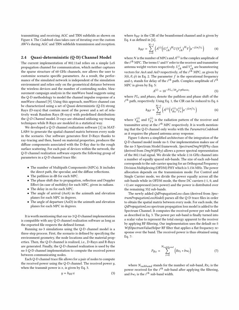
2.4 Quasi-deterministic (Q-D) Channel ModelThe current implementation of 802.11ad relies on a simple LoSpropagation channel for communication, which neither capturesthe sparse structure of 60 GHz channels, nor allows the user tocustomize scenario specific parameters. As a result, the perfor-mance of the simulated network is independent of the simulationenvironment and relies only on the geometrical distance betweenthe wireless devices and the number of contending nodes. Mea-surement campaign analysis in the mmWave band suggests usingthe Q-D methodology to model the channel impulse response of ammWave channel [9]. Using this approach, mmWave channel canbe characterized using a set of Quasi-deterministic (Q-D) strongRays (D-rays) that contain most of the power and a set of rela-tively weak Random Rays (R-rays) with predefined distribution:the Q-D Channel model. D-rays are obtained utilizing ray-tracingtechniques while R-Rays are modeled in a statistical way.
We developed a Q-D channel realization software [1] in MAT-LAB® to generate the spatial channel matrix between every nodein the scenario. Our software generates first D-Rays thanks toray-tracing and then, based on material properties, produces thediffuse components associated with the D-Ray due to the roughsurface scattering. For each pair of devices within the network, theQ-D channel realization software exports the following group ofparameters in a Q-D channel trace file:
• The number of Multipath Components (MPCs). It includesthe direct path, the specular, and the diffuse reflections.
• The pathloss in dB for each MPC.• The phase shift due to propagation, reflection and DopplerEffect (in case of mobility) for each MPC, given in radians.
• The delay in ns for each MPC.• The angle of arrival (AoA) in the azimuth and elevationplanes for each MPC in degrees.
• The angle of departure (AoD) in the azimuth and elevationplanes for each MPC in degrees.
It is worthmentioning that our ns-3 Q-D channel implementationis compatible with any Q-D channel realization software as long asthe exported file respects the defined format.
Running ns-3 simulations using the Q-D channel model is athree-step process. First, the scenario is defined by specifying theenvironment geometry, the node locations and the material prop-erties. Then, the Q-D channel is realized, i.e., D-Rays and R-Raysare generated. Finally, the Q-D channel realization is used by thens-3 Q-D channel implementation to compute the received powerbetween communicating nodes.
Each Q-D channel trace file allows for a pair of nodes to computethe received power using the Q-D channel. The received power y,when the transmit power is x , is given by Eq. 3.
y = hBF x (3)
where hBF is the CIR of the beamformed channel and is given byEq. 4 as defined in [6].
hBF =N−1∑i=0
(A(i)
((U i
ch )HU
(V ich)H
V)e−j2π f ti
)(4)
whereN is the number ofMPCs andA(i) is the complex amplitude ofthe ith MPC. The termsU andV refer to the receiver and transmitterantenna weight vectors respectively.U i
ch andV ich are beamsteering
vectors for AoA and AoD respectively, of the ith MPC, as given byS(k,θ ,ϕ) in Eq. 2. The parameter f is the operational frequencyand ti stands for delay of the ith path. Complex amplitude of ithMPC is given by Eq. 5:
A(i) = 10−PLi /20e j∗phasei (5)where PLi and phasei denote the pathloss and phase shift of theith path, respectively. Using Eq. 1, the CIR can be reduced to Eq. 6
hBF =N−1∑i=0
(A(i)
(Y(i)RxY
(i)Tx
)e−j2π f ti
)(6)
where Y (i)Rx and Y
(i)Tx is the radiation pattern of the receiver and
transmitter array at the ith MPC respectively. It is worth mention-ing that the Q-D channel only works with the ParametricCodebookas it requires the phased antenna array response.
Figure 5 shows a simplified architecture of the integration of theQ-D channel model inside ns-3. Our implementation makes use ofthe ns-3 Spectrum Model framework. SpectrumDmgWifiPhy class(derived from DmgWifiPhy) allows a power spectral representationof the 802.11ad signal. We divide the whole 2.16 GHz channel intoa number of equally spaced sub-bands. The size of each sub-bandcorresponds to the sub-carrier spacing for an Orthogonal FrequencyDivisionMultiplexing (OFDM) PHYwhich is 5.156 MHz. The powerallocation depends on the transmission mode: For Control andSingle Carrier mode, we divide the power equally across all thesub-bands while in OFDM mode, the three DC carriers (-1, 0, and+1) are suppressed (zero power) and the power is distributed overthe remaining 352 sub-bands.
The newly added QdPropagationLoss class (derived from Spec-trumPropagationLossModel) parses all the Q-D trace files in orderto obtain the spatial matrix between every node. For each node, theQdPropagationLoss spectrum propagation loss model is added to theSpectrum Channel. It computes the received power per sub-bandas described in Eq. 3. The power per sub-band is finally turned intoa scalar value to represent the total energy apparent to the receiverby applying RF filtering. Our implementation uses the default ns-3WifiSpectrumValueHelper RF filter that applies a flat frequency re-sponse over the band. The received power is thus obtained usingEq. 7:
PRx =
Nsubband∑i=0
(Rxi ∗ bwi
)(7)
where Nsubband stands for the number of sub-band, Rxi is thepower received for the ith sub-band after applying the filtering,and bwi is the ith sub-band width.

Select Custom AWV
AGC Subfields Tx, completed?
Tx AGC Subfield
Start 4*N AGC SFs Tx
Select Preamble’s AWV
Select Custom AWV
Tx Single TRN Unit
TRN Unit Tx completed?
Start N TRN Units Tx
Tx TRN-CE Subfield
Tx TRN Subfield Append TRN Field
NoYes
NoYes
No
Select Custom AWV
AGC Subfields Rx, completed?
Rx AGC Subfield
Start 4*N AGC SFs Rx
Select Preamble’s AWV
Select Custom AWV
Rx Single TRN Unit
TRN Unit Rx completed?
Start N TRN Units Rx
Rx TRN-CE Subfield
Rx TRN SF & Store SNR Receive TRN Field
NoYes
NoYes
No
(a) (b)
TRN Field Tx Completed
Yes
N TRN Units Tx completed?
TRN Field Rx Completed
N TRN Units Rx completed?
Yes
Figure 4: State Machines for AGC and TRN Subfields (a) Transmission and (b) Reception
SpectrumChannel
Q-D Channel Realization Software
Q-D Channel Trace Files
SpectrumDmgWifiPHY
CodebookParametric
MacLow
Upper MAC
QdPropagationLoss
Figure 5: Q-D Channel Integration with ns-3 802.11adModel
10 20 30 40 50 60Number of Sectors/AWVs
0
200
400
600
800
1000
Tot
al D
urat
ion
[s]
Sector Level Sweep (SLS)Beam Refinement Protocol (BRP)
Figure 6: Beamforming Duration for BRP and SLS
3 VALIDATIONIn this section, we validate the behaviour and the output of ournewly developed mechanisms for a simple set of scenarios. All ourscenarios consider a single DMG STA communicating with a singleDMG AP.
3.1 Beamforming Training in SLS vs BRPIn this simulation, we compare the duration of the beamformingtraining when solely using the SLS mechanism with respect tothe case when utilizing the BRP protocol. Figure 6 depicts the to-tal beamforming duration for both SLS and BRP mechanisms forvariable number of sectors/custom AWVs. All the frames are trans-mitted using MCS 0. The BRP protocol is simulated by transmittinga BRP packet with TRN-TX Subfields appended to it. The BRP pro-tocol assesses the custom AWVs in a group of 4 elements. Probing64 SSW frames using SLS takes around 1 ms compared to 67 µswhen using the BRP protocol.
To validate that our implementation changes the power dur-ing the course of a frame transmission when TRN Subfields are
appended to that frame, we extended the current ASCII tracingsystem in the 802.11ad module. The new ASCII tracing systemtracks PHY layer activities for all the DMG STAs operating on thesame channel. The tracing system outputs the following set ofinformation for each activity on the channel:
• The starting time of the activity in ns.• The type of the channel activity (transmission or reception).• The ID of the transmitting node.• The ID of the receiving node.• The duration of the activity in ns.• The type of the Physical Layer Convergence Protocol (PLCP)part that we are transmitting/receiving either Preamble,Header, Data, AGC-SF, TRN-CE, or TRN-SF.
• The Equivalent Isotropically Radiated Power (EIRP) for thecorresponding PLCP part for the transmission activity in dBior the total received power for the reception activity (EIRP+ Receive Antenna Gain) in dBm.
The previous information is stored in a text file using the comma-separated values (CSV) format. Using this tracing capability, we runa simulation where a DMG STA transmits an 802.11ad frame to aDMG AP with the training field length set to 1 which correspondsto 4 TRN Subfields. Both the DMG STA and the DMG AP utilize theanalytical codebook for synthesizing their beam patterns. The EIRPis evaluated at the receiver. Figure 7(a) shows EIRP variations overthe transmitted frame. We can see that based on the AWV used,the EIRP is varying over different parts of the transmitted frame.The Frame part in the legend corresponds to the preamble, the PHYheader, and the data part as they are transmitted using a specificsector. In addition, the TRN-CE is transmitted using the previousspecific sector. The custom AWVs provides a 6 dBi gain comparedto the sector and they steer toward different directions in space.Each TRN Subfield together with its corresponding AGC Subfieldare transmitted using a custom AWV as shown in Figure 7(b).
3.2 Quasi-deterministic (Q-D)-Channel ModelThe Q-D channel Model implementation allows to compute thereceived power by relying not only on the LoS propagation butalso on the specular reflections coming from the simulation en-vironment. In order to demonstrate this ability, we developed a

Time [ s]0
30
32
34
36
EIR
P (
dBi)
FrameAGC-SF1AGC-SF2AGC-SF3AGC-SF4
TRN-CETRN-SF1TRN-SF2TRN-SF3TRN-SF4
1 32 54 76
120
Directivity (dBi)
150
9060
180
30
210
240270
-10
0
10
20
0
300
330
(a) (b)
Receiver Direction
Figure 7: (a) 802.11ad Frame with AGC and TRN SubfieldsHighlighted (b) Directivity of the Sector and the CustomAWVs(a) (b)
STASTA
AP AP
Figure 8: Q-D Visualizer Software. (a) AP I-TxSS using allMPCs (b) AP I-TxSS using one MPC
proof-of-concept 3D visualizer: the Q-D Visualizer. The Q-D Visu-alizer, developed with Mayavi Python’s library, allows to visualize:
• The geometry of the environment, the nodes’ positions andthe MPCs corresponding to the direct path and specularreflections (obtained from the Q-D channel realization soft-ware).
• The 3D antenna response pattern corresponding to eachsector/AWV (provided by the IEEE 802.11ad Codebook Gen-erator).
The visualizer uses the ns-3 output traces and can be used to vi-sualize 802.11ad beamforming phases, i.e., SLS and BRP. Figure 8(a)presents a screenshot of the Q-D Visualizer. The simulated envi-ronment is a rectangular room. There are 6 MPCs between the APand the STA (1 direct path represented by the thick black line and5 specular reflections depicted with black thin lines). The visual-izer displays the outcome of the AP and the STA TxSS SLS phasesimulated in ns-3 using the Q-D channel model (the TxSS phase de-termines the best transmit sector that a node must use to establish adirectional communication link with another node). We can clearlysee that the chosen sector 3D response patterns are aligned withthe direct path to yield a maximum gain. Figure 8(b) presents thesame scenario except that we configure the Q-D channel realizationsoftware to generate the channel only with a specular reflection(the one bouncing in the front wall of the room). We can see that
the TxSS chosen antenna patterns are steered along the specularreflection, showing that the Q-D channel in ns-3 makes use of thespatial path diversity to compute the received power.
4 CONCLUSION AND FUTUREWORKIn this paper, we described the implementation of novel featuresthat improve the reliability and fidelity of the ns3 IEEE 802.11admodel. Our work is a tremendous step towards reducing the dis-crepancies between the results coming from practical testbeds andthe results obtained through system-level simulations. In addition,we developped a set of powerful software tools that facilitate theusage of the newly implemented features and provide the user withunprecedented capabilities to mimic real networks. Finally, our im-plementation of the beam codebooks, multi-antenna support, andQ-DmmWave channel paves the way for the future implementationof the IEEE 802.11ay standard once its final draft is approved.
ACKNOWLEDGMENTSThis article is partially supported by the European Research Councilthrough SEARCHLIGHT (ERC CoG 617721) and the Region ofMadrid through the TAPIR-CM project (S2018/TCS-4496).
REFERENCES[1] H. Assasa and T. Ropitault. 2019. A Collection of Open-source Tools to Simulate
IEEE 802.11ad/ay WLAN Networks in ns-3. https://github.com/wigig-tools[2] H. Assasa and J. Widmer. 2016. Implementation and Evaluation of a WLAN IEEE
802.11ad Model in ns-3. In Proceedings of the 2016 Workshop on ns-3. Seattle, USA.[3] H. Assasa and J. Widmer. 2017. Extending the IEEE 802.11Ad Model: Sched-
uled Access, Spatial Reuse, Clustering, and Relaying. In Proceedings of the 2017Workshop on ns-3. Porto, Portugal.
[4] G. Brown, O. Koymen, and M. Branda. 2016. The Promise of 5G mmWave – HowDo We Make It Mobile? https://www.qualcomm.com/media/documents/files/the-promise-of-5g-mmwave-how-do-we-make-it-mobile.pdf
[5] IEEE P802.11 Group for Wireless Local Area Networks (LANs). 2016. IEEEStandard for Information Technology–Telecommunications and InformationExchange between Systems Local and Metropolitan Area Networks–Specific Re-quirements - Part 11: Wireless LAN Medium Access Control (MAC) and PhysicalLayer (PHY) Specifications. IEEE Std 802.11-2016 (Revision of IEEE Std 802.11-2012)(2016).
[6] IEEE P802.11 Group for Wireless Local Area Networks (LANs). 2017. ChannelModels for IEEE 802.11ay.
[7] IEEE P802.15 Working Group for Wireless Personal Area Networks (WPANs).2006. Reference Antenna Model with Side Lobe for TG3c Evaluation.
[8] IEEE. 2012. Wireless LAN Medium Access Control (MAC) and Physical Layer(PHY) Specifications Amendment 3: Enhancements for Very High Throughputin the 60 GHz Band. IEEE Std 802.11ad-2012 (2012).
[9] A. Maltsev, A. Pudeyev, I. Karls, I. Bolotin, G. Morozov, R. Weiler, M. Peter, and W.Keusgen. 2014. Quasi-deterministic Approach to mmWave Channel Modeling ina Non-stationary Environment. In 2014 IEEE Globecom Workshops (GC Wkshps).Austin, USA.
[10] NETGEAR. 2016. Nighthawk X10 Smart WiFi Router. https://www.netgear.com/landings/ad7200/?cid=wmt_netgear_organicl
[11] Qualcomm. 2017. Linux Wil6210 Driver. https://github.com/torvalds/linux/tree/master/drivers/net/wireless/ath/wil6210
[12] Qualcomm. 2019. QCA9500 SoC. https://www.qualcomm.com/products/qca9500[13] D. Steinmetzer, D.Wegemer, M. Schulz, J. Widmer, andM. Hollick. 2017. Compres-
sive Millimeter-Wave Sector Selection in Off-the-Shelf IEEE 802.1 Lad Devices.In Proceedings of the 13th International Conference on Emerging Networking EX-periments and Technologies. Incheon, Republic of Korea.
[14] TP-Link. 2016. Talon AD7200 Multi-Band Wi-Fi Router. http://www.tp-link.com/us/products/details/cat-5506_AD7200.html
[15] D. Zhang, Y. Wang, X. Li, and W. Xiang. 2018. Hybridly Connected Structure forHybrid Beamforming in mmWave Massive MIMO Systems. IEEE Transactions onCommunications (2018).
Copyright © 2022 FDOKUMEN