
Enhanced Generalized Alpha Plane for Numerical Differential ...
11
1 Enhanced Generalized Alpha Plane for Numerical Differential Protection Applications Rˆ omulo G. Bainy, Member, IEEE, and Kleber M. Silva, Senior Member, IEEE Abstract—This paper revisits the generalized alpha plane (GAP) formulation applied to differential protection of multi- terminal apparatus. The GAP formulation is improved by aiming for three main goals: 1) control over the internal fault settlement region (FSR); 2) enabling a simple operation characteristic instead of a restraint characteristic; and, 3) The adjustments are not dependent to the device type. For this purpose, the GAP formulation is redefined in terms of two settings, which transform the FSR into a circumference with a controllable center and radius. Thereby, a circular operation characteristic with an adjustable radius is enabled around the FSR, for to improve security. To validate and test the performance of the improved GAP, numerous computer simulations have been carried out using Alternative Transients Program on different multi-terminal equipment (i.e., busbars, transmission lines, and power transformers). Furthermore, massive data analysis is held as a means to highlight the GAP’s sensibility. The obtained results demonstrate a well-stable pre-fault point, a consistent circular FSR, and the effectiveness of the improved GAP even under severe conditions. Index Terms—Power system protection, differential protection, multi-terminal apparatus, alpha plane, generalized alpha plane. I. I NTRODUCTION E LECTRICAL power systems have progressively become interconnected, with new delivery paths inserted through- out these systems. Transmission lines play a major role in providing bulk power transmission from huge power plants to load centers; substations tend to create complex busbar arrangements aiming to provide flexible ways to operate the system. Additionally, power transformers are extremely important, but are susceptible to catastrophic internal faults. Disturbances caused in one or more devices can instantly prop- agate throughout the system, requiring reliable and selective protection schemes capable of clearing faults and avoiding widespread blackouts [1]. Differential protection can selectively protect a specified zone and has several advantages when compared with other functions, such as the distance element [2]. Typically, it is implemented as a percentage differential restraint element and has been widely used as a reliable and selective protection scheme for transformers rated from 10 MVA [3], [4]. However, the basic differential scheme has some shortcomings, such as during inrush currents and internal some short-circuits conditions. [5] reported the use of harmonic restraining and/or This work was supported by the Brazilian National Research Council (Capes). Rˆ omulo G. Bainy is with the University of Idaho, Moscow, ID 83844-1023 USA (e-mail: [email protected]). Kleber M. Silva is with the University of Brasilia, Bras´ ılia, DF 70910-900 Brazil (e-mail: [email protected]). blocking methods to ensure security and overcome false trip due to inrush currents. Enhanced algorithms use external fault detectors and wavelet transform to better differentiate external faults with CT saturation from internal ones [6], [7]. Some internal faults can be quite challenging to detect, for instance turn-to-turn ones that involve few turns are significantly diffi- cult to be detected by phase elements [8]. Therefore, several manufacturers have used the negative sequence and restricted earth-fault (REF) elements in order to overcome this condition [8]–[10]. The busbar differential protection improvements are diverse, and have led to reduced fault clearing times [11]–[14]. Over the last few years, technological breakthroughs, along with the installation of optical fiber composite overhead ground wires, have made new solutions possible for transmission lines differential protection [15]–[20]. In fact, the differential line protection was the first one to use the complex plane, where instead of representing the operating and restraint currents (hereafter named as operational plane), a ratio between the currents of each terminal is used [20]–[23]. This form of representation was originally proposed by [24], and was called alpha plane. One of its main features is the possibility to use different restraint characteristics. The well-know rainbow restraint characteristic was proposed by Tziouvaras et al., and is based on line operation features: outfeed conditions, data misalignment, etc [25]. Line differential protection has some challenges, such as the requirement for charging current compensation. Additionally, some outfeed conditions can be quite challenging to detect and may require highly sensitive schemes [16], [26]. Conversely, power swing oscillations may result in missoperation of the phase elements. In that regard, the sequence elements are widely used whenever the phase elements cannot be relied, or to provide more sensitivity during severe outfeed conditions [16], [22], [27]. Another way to improve sensibility and security, is by modifying the rainbow restraint characteristic using an adaptive setting [28], [29]. Multi-terminal apparatus can also use the alpha plane by means of the Generalized Alpha Plane (GAP) formulation proposed by [21]. The GAP corresponds to a mathematical transformation that maps all the measured currents of a multi- terminal transmission line into only two equivalent currents. One of its benefits, is to enable the use of the rainbow characteristic [25]. Its performance was thoroughly discussed for transmission line differential protection in [20], [22], and it has been used by a well-know manufacturer [30]. Never- theless, the GAP reported in [21] has sensitivity limitations that limits its performance during certain fault conditions [23]. This is the author's version of an article that has been published in this journal. Changes were made to this version by the publisher prior to publication. The final version of record is available at http://dx.doi.org/10.1109/TPWRD.2020.2985019 Copyright (c) 2020 IEEE. Personal use is permitted. For any other purposes, permission must be obtained from the IEEE by emailing [email protected].
-
Upload
khangminh22 -
Category
Documents
-
view
0 -
download
0
Transcript of Enhanced Generalized Alpha Plane for Numerical Differential ...

1
Enhanced Generalized Alpha Plane forNumerical Differential Protection Applications
Romulo G. Bainy, Member, IEEE, and Kleber M. Silva, Senior Member, IEEE
Abstract—This paper revisits the generalized alpha plane(GAP) formulation applied to differential protection of multi-terminal apparatus. The GAP formulation is improved by aimingfor three main goals: 1) control over the internal fault settlementregion (FSR); 2) enabling a simple operation characteristicinstead of a restraint characteristic; and, 3) The adjustmentsare not dependent to the device type. For this purpose, theGAP formulation is redefined in terms of two settings, whichtransform the FSR into a circumference with a controllablecenter and radius. Thereby, a circular operation characteristicwith an adjustable radius is enabled around the FSR, forto improve security. To validate and test the performance ofthe improved GAP, numerous computer simulations have beencarried out using Alternative Transients Program on differentmulti-terminal equipment (i.e., busbars, transmission lines, andpower transformers). Furthermore, massive data analysis is heldas a means to highlight the GAP’s sensibility. The obtained resultsdemonstrate a well-stable pre-fault point, a consistent circularFSR, and the effectiveness of the improved GAP even undersevere conditions.
Index Terms—Power system protection, differential protection,multi-terminal apparatus, alpha plane, generalized alpha plane.
I. INTRODUCTION
ELECTRICAL power systems have progressively becomeinterconnected, with new delivery paths inserted through-
out these systems. Transmission lines play a major role inproviding bulk power transmission from huge power plantsto load centers; substations tend to create complex busbararrangements aiming to provide flexible ways to operatethe system. Additionally, power transformers are extremelyimportant, but are susceptible to catastrophic internal faults.Disturbances caused in one or more devices can instantly prop-agate throughout the system, requiring reliable and selectiveprotection schemes capable of clearing faults and avoidingwidespread blackouts [1].
Differential protection can selectively protect a specifiedzone and has several advantages when compared with otherfunctions, such as the distance element [2]. Typically, it isimplemented as a percentage differential restraint element andhas been widely used as a reliable and selective protectionscheme for transformers rated from 10 MVA [3], [4]. However,the basic differential scheme has some shortcomings, suchas during inrush currents and internal some short-circuitsconditions. [5] reported the use of harmonic restraining and/or
This work was supported by the Brazilian National Research Council(Capes).
Romulo G. Bainy is with the University of Idaho, Moscow, ID 83844-1023USA (e-mail: [email protected]).
Kleber M. Silva is with the University of Brasilia, Brasılia, DF 70910-900Brazil (e-mail: [email protected]).
blocking methods to ensure security and overcome false tripdue to inrush currents. Enhanced algorithms use external faultdetectors and wavelet transform to better differentiate externalfaults with CT saturation from internal ones [6], [7]. Someinternal faults can be quite challenging to detect, for instanceturn-to-turn ones that involve few turns are significantly diffi-cult to be detected by phase elements [8]. Therefore, severalmanufacturers have used the negative sequence and restrictedearth-fault (REF) elements in order to overcome this condition[8]–[10].
The busbar differential protection improvements are diverse,and have led to reduced fault clearing times [11]–[14]. Overthe last few years, technological breakthroughs, along withthe installation of optical fiber composite overhead groundwires, have made new solutions possible for transmission linesdifferential protection [15]–[20]. In fact, the differential lineprotection was the first one to use the complex plane, whereinstead of representing the operating and restraint currents(hereafter named as operational plane), a ratio between thecurrents of each terminal is used [20]–[23]. This form ofrepresentation was originally proposed by [24], and was calledalpha plane. One of its main features is the possibility touse different restraint characteristics. The well-know rainbowrestraint characteristic was proposed by Tziouvaras et al., andis based on line operation features: outfeed conditions, datamisalignment, etc [25].
Line differential protection has some challenges, such as therequirement for charging current compensation. Additionally,some outfeed conditions can be quite challenging to detect andmay require highly sensitive schemes [16], [26]. Conversely,power swing oscillations may result in missoperation of thephase elements. In that regard, the sequence elements arewidely used whenever the phase elements cannot be relied, orto provide more sensitivity during severe outfeed conditions[16], [22], [27]. Another way to improve sensibility andsecurity, is by modifying the rainbow restraint characteristicusing an adaptive setting [28], [29].
Multi-terminal apparatus can also use the alpha plane bymeans of the Generalized Alpha Plane (GAP) formulationproposed by [21]. The GAP corresponds to a mathematicaltransformation that maps all the measured currents of a multi-terminal transmission line into only two equivalent currents.One of its benefits, is to enable the use of the rainbowcharacteristic [25]. Its performance was thoroughly discussedfor transmission line differential protection in [20], [22], andit has been used by a well-know manufacturer [30]. Never-theless, the GAP reported in [21] has sensitivity limitationsthat limits its performance during certain fault conditions [23].
This is the author's version of an article that has been published in this journal. Changes were made to this version by the publisher prior to publication.The final version of record is available at http://dx.doi.org/10.1109/TPWRD.2020.2985019
Copyright (c) 2020 IEEE. Personal use is permitted. For any other purposes, permission must be obtained from the IEEE by emailing [email protected].
2
The GAP [21] was applied to a busbar differential protectionin [31], where some drawbacks, such as external faults withCT saturation were discussed. The use of GAP algorithm forbusbar protection [21] was reported in [32], the results showedhigher sensitivity in case of internal faults, and better stabilityduring external fault with CT saturation. An alternative GAPfor multi-terminal transmission lines differential protectionapplications was reported in [23]. It provides a more simpleformulation when compared with the one proposed in [21],and improves the sensibility for internal faults during outfeedconditions. In this paper, we improve the GAP formulationreported in [23].The foremost feature is the control over faultsettlement region (FSR) in the right-half of the alpha plane,which enables the use of an operation characteristic instead ofa restraint characteristic as it has been traditionally done.
II. IMPROVED GAP FORMULATION
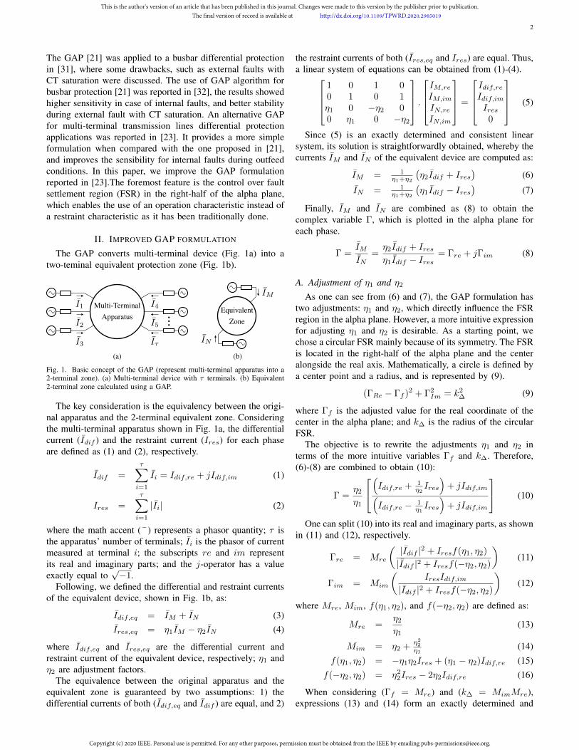
The GAP converts multi-terminal device (Fig. 1a) into atwo-teminal equivalent protection zone (Fig. 1b).
I1
I2
I3
I4
I5
Iτ
...
Multi-TerminalApparatus
(a)
IM
IN
EquivalentZone
(b)
Fig. 1. Basic concept of the GAP (represent multi-terminal apparatus into a2-terminal zone). (a) Multi-terminal device with τ terminals. (b) Equivalent2-terminal zone calculated using a GAP.
The key consideration is the equivalency between the origi-nal apparatus and the 2-terminal equivalent zone. Consideringthe multi-terminal apparatus shown in Fig. 1a, the differentialcurrent (Idif ) and the restraint current (Ires) for each phaseare defined as (1) and (2), respectively.
Idif =τ∑i=1
Ii = Idif,re + jIdif,im (1)
Ires =τ∑i=1
|Ii| (2)
where the math accent (¯ ) represents a phasor quantity; τ isthe apparatus’ number of terminals; Ii is the phasor of currentmeasured at terminal i; the subscripts re and im representits real and imaginary parts; and the j-operator has a valueexactly equal to
√−1.
Following, we defined the differential and restraint currentsof the equivalent device, shown in Fig. 1b, as:
Idif,eq = IM + IN (3)Ires,eq = η1IM − η2IN (4)
where Idif,eq and Ires,eq are the differential current andrestraint current of the equivalent device, respectively; η1 andη2 are adjustment factors.
The equivalence between the original apparatus and theequivalent zone is guaranteed by two assumptions: 1) thedifferential currents of both (Idif,eq and Idif ) are equal, and 2)
the restraint currents of both (Ires,eq and Ires) are equal. Thus,a linear system of equations can be obtained from (1)-(4).
1 0 1 00 1 0 1η1 0 −η2 00 η1 0 −η2
.IM,re
IM,im
IN,reIN,im
=
Idif,reIdif,imIres
0
(5)
Since (5) is an exactly determined and consistent linearsystem, its solution is straightforwardly obtained, whereby thecurrents IM and IN of the equivalent device are computed as:
IM = 1η1+η2
(η2Idif + Ires
)(6)
IN = 1η1+η2
(η1Idif − Ires
)(7)
Finally, IM and IN are combined as (8) to obtain thecomplex variable Γ, which is plotted in the alpha plane foreach phase.
Γ =IMIN
=η2Idif + Iresη1Idif − Ires
= Γre + jΓim (8)
A. Adjustment of η1 and η2
As one can see from (6) and (7), the GAP formulation hastwo adjustments: η1 and η2, which directly influence the FSRregion in the alpha plane. However, a more intuitive expressionfor adjusting η1 and η2 is desirable. As a starting point, wechose a circular FSR mainly because of its symmetry. The FSRis located in the right-half of the alpha plane and the centeralongside the real axis. Mathematically, a circle is defined bya center point and a radius, and is represented by (9).
(ΓRe − Γf )2 + Γ2Im = k2
∆ (9)
where Γf is the adjusted value for the real coordinate of thecenter in the alpha plane; and k∆ is the radius of the circularFSR.
The objective is to rewrite the adjustments η1 and η2 interms of the more intuitive variables Γf and k∆. Therefore,(6)-(8) are combined to obtain (10):
Γ =η2
η1
(Idif,re + 1
η2Ires
)+ jIdif,im(
Idif,re − 1η1Ires
)+ jIdif,im
(10)
One can split (10) into its real and imaginary parts, as shownin (11) and (12), respectively.
Γre = Mre
(|Idif |2 + Iresf(η1, η2)
|Idif |2 + Iresf(−η2, η2)
)(11)
Γim = Mim
(IresIdif,im
|Idif |2 + Iresf(−η2, η2)
)(12)
where Mre, Mim, f(η1, η2), and f(−η2, η2) are defined as:
Mre =η2
η1(13)
Mim = η2 +η2
2
η1(14)
f(η1, η2) = −η1η2Ires + (η1 − η2)Idif,re (15)f(−η2, η2) = η2
2Ires − 2η2Idif,re (16)
When considering (Γf = Mre) and (k∆ = MimMre),expressions (13) and (14) form an exactly determined and
This is the author's version of an article that has been published in this journal. Changes were made to this version by the publisher prior to publication.The final version of record is available at http://dx.doi.org/10.1109/TPWRD.2020.2985019
Copyright (c) 2020 IEEE. Personal use is permitted. For any other purposes, permission must be obtained from the IEEE by emailing [email protected].
3
consistent linear system of equations. Thereby, expressions forη1 and η2 in terms of Γf and k∆ are obtained and shown in(17) and (18), respectively. The values for Γf and k∆ arechosen provided that two requirements are fulfilled: 1) Γf isgreater than one (Γf > 1), and 2) k∆ is set to a value lessthan 5% of Γf . The first requirement enables good securitylevel because of the minimum distance from the pre-fault point(−1, 0). The second requirement is important for guaranteeinga small circular FSR, and consequently near values for Γ inall phase differential element (i.e., ΓA, ΓB , and ΓC).
η1 = 1k∆
(1 + Γf ) (17)η2 = Γf · η1 (18)
B. GAP Analysis
The GAP was analyzed in two conditions: pre-fault andpost-fault (steady state). A generic multi-terminal device wasconsidered for this study; the differential and restraint currentswere considered as (1) and (2), respectively. Firstly, (6)-(8)were combined with (17) and (18), yielding:
Γ =Γf (1 + Γf )Idif + k∆Ires
(1 + Γf )Idif − k∆Ires(19)
The first analyzed condition was normal operation, orexternal fault with no current transformer (CT) saturation.The differential current is approximately null and thereforedisregarded. Thereby (19) becomes (20). As one can see, withthese conditions, Γ becomes equal to −1, and settles in thestability point (−1; 0).
Γ =k∆Ires−k∆Ires
= −1 (20)
The second analyzed condition involved an internal fault.Equation (19) is reorganized as follows:
Γ =Γf (αIdif )2 + α2k∆IresIdif + (k∆Ires)
2
(αIdif )2 − (k∆Ires)2(21)
where α is defined by (1 + Γf ).Further simplification of (21) was enabled by defining a
maximum value for k∆. Aiming for a small circular FSR, k∆
is set to less than 5% of Γf . Thus, the maximum radius forthe FSR is achieved when k∆ is adjusted to (0.05Γf ). As aresult of k∆ value, it is possible to assume that α2 >> k2
∆,which yields to:
Γ = Γf + k∆Ires|Idif |
∠δ +
(k∆
α
Ires|Idif |
∠δ
)2
(22)
where δ is the phase angle of I−1dif .
The ratio k∆
α was analyzed considering (23). Thus, it issimplified to the interval (24). Consequently, the squaredoperation led to the interval (25).
1 ≤ Γf ≤ ∞ (23)
0.025 ≤ k∆
α ≤ 0.05 (24)
0.0625× 10⁻³ ≤(k∆
α
)2 ≤ 2.5× 10⁻³ (25)
The ratio Ires|Idif | was analyzed using the triangle inequality
property (26), thus resulting in (27).∣∣∣∣∣τ∑i=1
Ii
∣∣∣∣∣ ≤τ∑i=1
|Ii| (26)
Ires|Idif |
≥ 1 (27)
By means of (25) and (27), it is possible to simplify (22)into (28):
Γ ≈ Γf + k∆ε (28)
where ε is an error/deviation from Γf equal to Ires|Idif |∠δ.
Through (27), one can observe that ε modulus is greateror equal to one (|ε| ≥ 1), and the its phase angle is equalto δ (∠ε = δ). Therefore, ε results in the desired circularcharacteristic around the center point (Γf ; 0). During non-critical internal faults, the modulus of ε is near to 1 and itsargument depends on the phase of Idif .
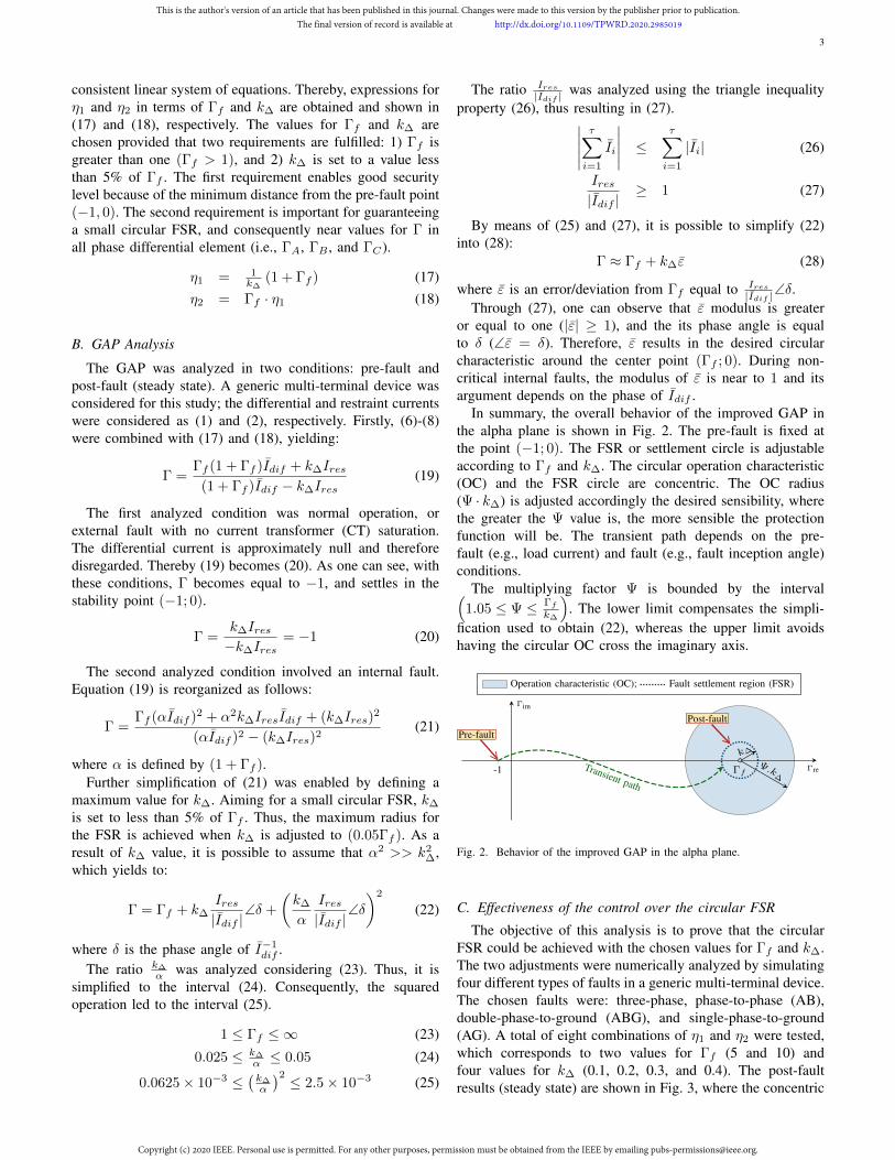
In summary, the overall behavior of the improved GAP inthe alpha plane is shown in Fig. 2. The pre-fault is fixed atthe point (−1; 0). The FSR or settlement circle is adjustableaccording to Γf and k∆. The circular operation characteristic(OC) and the FSR circle are concentric. The OC radius(Ψ · k∆) is adjusted accordingly the desired sensibility, wherethe greater the Ψ value is, the more sensible the protectionfunction will be. The transient path depends on the pre-fault (e.g., load current) and fault (e.g., fault inception angle)conditions.
The multiplying factor Ψ is bounded by the interval(1.05 ≤ Ψ ≤ Γf
k∆
). The lower limit compensates the simpli-
fication used to obtain (22), whereas the upper limit avoidshaving the circular OC cross the imaginary axis.
k∆
Ψ.k∆
-1 ΓfΓre
Γim
Operation characteristic (OC); Fault settlement region (FSR)
Pre-fault
Post-fault
Transient path
Fig. 2. Behavior of the improved GAP in the alpha plane.
C. Effectiveness of the control over the circular FSR
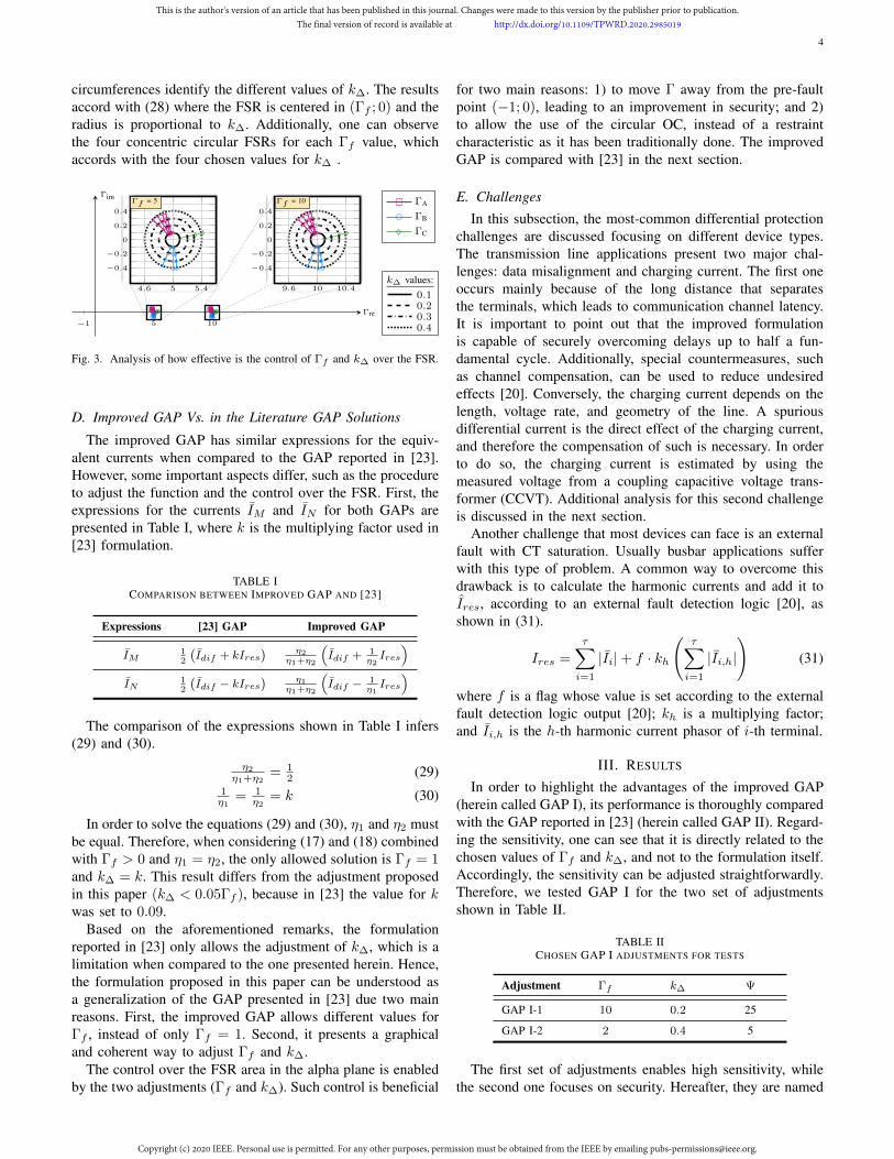
The objective of this analysis is to prove that the circularFSR could be achieved with the chosen values for Γf and k∆.The two adjustments were numerically analyzed by simulatingfour different types of faults in a generic multi-terminal device.The chosen faults were: three-phase, phase-to-phase (AB),double-phase-to-ground (ABG), and single-phase-to-ground(AG). A total of eight combinations of η1 and η2 were tested,which corresponds to two values for Γf (5 and 10) andfour values for k∆ (0.1, 0.2, 0.3, and 0.4). The post-faultresults (steady state) are shown in Fig. 3, where the concentric
This is the author's version of an article that has been published in this journal. Changes were made to this version by the publisher prior to publication.The final version of record is available at http://dx.doi.org/10.1109/TPWRD.2020.2985019
Copyright (c) 2020 IEEE. Personal use is permitted. For any other purposes, permission must be obtained from the IEEE by emailing [email protected].
4
circumferences identify the different values of k∆. The resultsaccord with (28) where the FSR is centered in (Γf ; 0) and theradius is proportional to k∆. Additionally, one can observethe four concentric circular FSRs for each Γf value, whichaccords with the four chosen values for k∆ .
−1 5 10
Γre
ΓimΓA
ΓB
ΓC
9.6 10 10.4
0.4
0.2
0
−0.2
−0.4
Γf = 10
4.6 5 5.4
0.4
0.2
0
−0.2
−0.4
Γf = 5
k∆ values:0.10.20.30.4
Fig. 3. Analysis of how effective is the control of Γf and k∆ over the FSR.
D. Improved GAP Vs. in the Literature GAP Solutions
The improved GAP has similar expressions for the equiv-alent currents when compared to the GAP reported in [23].However, some important aspects differ, such as the procedureto adjust the function and the control over the FSR. First, theexpressions for the currents IM and IN for both GAPs arepresented in Table I, where k is the multiplying factor used in[23] formulation.
TABLE ICOMPARISON BETWEEN IMPROVED GAP AND [23]
Expressions [23] GAP Improved GAP
IM12
(Idif + kIres
) η2η1+η2
(Idif + 1
η2Ires
)IN
12
(Idif − kIres
) η1η1+η2
(Idif − 1
η1Ires
)
The comparison of the expressions shown in Table I infers(29) and (30).
η2
η1+η2= 1
2 (29)1η1
= 1η2
= k (30)
In order to solve the equations (29) and (30), η1 and η2 mustbe equal. Therefore, when considering (17) and (18) combinedwith Γf > 0 and η1 = η2, the only allowed solution is Γf = 1and k∆ = k. This result differs from the adjustment proposedin this paper (k∆ < 0.05Γf ), because in [23] the value for kwas set to 0.09.
Based on the aforementioned remarks, the formulationreported in [23] only allows the adjustment of k∆, which is alimitation when compared to the one presented herein. Hence,the formulation proposed in this paper can be understood asa generalization of the GAP presented in [23] due two mainreasons. First, the improved GAP allows different values forΓf , instead of only Γf = 1. Second, it presents a graphicaland coherent way to adjust Γf and k∆.
The control over the FSR area in the alpha plane is enabledby the two adjustments (Γf and k∆). Such control is beneficial
for two main reasons: 1) to move Γ away from the pre-faultpoint (−1; 0), leading to an improvement in security; and 2)to allow the use of the circular OC, instead of a restraintcharacteristic as it has been traditionally done. The improvedGAP is compared with [23] in the next section.
E. Challenges
In this subsection, the most-common differential protectionchallenges are discussed focusing on different device types.The transmission line applications present two major chal-lenges: data misalignment and charging current. The first oneoccurs mainly because of the long distance that separatesthe terminals, which leads to communication channel latency.It is important to point out that the improved formulationis capable of securely overcoming delays up to half a fun-damental cycle. Additionally, special countermeasures, suchas channel compensation, can be used to reduce undesiredeffects [20]. Conversely, the charging current depends on thelength, voltage rate, and geometry of the line. A spuriousdifferential current is the direct effect of the charging current,and therefore the compensation of such is necessary. In orderto do so, the charging current is estimated by using themeasured voltage from a coupling capacitive voltage trans-former (CCVT). Additional analysis for this second challengeis discussed in the next section.
Another challenge that most devices can face is an externalfault with CT saturation. Usually busbar applications sufferwith this type of problem. A common way to overcome thisdrawback is to calculate the harmonic currents and add it toIres, according to an external fault detection logic [20], asshown in (31).
Ires =τ∑i=1
|Ii|+ f · kh
(τ∑i=1
|Ii,h|
)(31)
where f is a flag whose value is set according to the externalfault detection logic output [20]; kh is a multiplying factor;and Ii,h is the h-th harmonic current phasor of i-th terminal.
III. RESULTS
In order to highlight the advantages of the improved GAP(herein called GAP I), its performance is thoroughly comparedwith the GAP reported in [23] (herein called GAP II). Regard-ing the sensitivity, one can see that it is directly related to thechosen values of Γf and k∆, and not to the formulation itself.Accordingly, the sensitivity can be adjusted straightforwardly.Therefore, we tested GAP I for the two set of adjustmentsshown in Table II.
TABLE IICHOSEN GAP I ADJUSTMENTS FOR TESTS
Adjustment Γf k∆ Ψ
GAP I-1 10 0.2 25
GAP I-2 2 0.4 5
The first set of adjustments enables high sensitivity, whilethe second one focuses on security. Hereafter, they are named
This is the author's version of an article that has been published in this journal. Changes were made to this version by the publisher prior to publication.The final version of record is available at http://dx.doi.org/10.1109/TPWRD.2020.2985019
Copyright (c) 2020 IEEE. Personal use is permitted. For any other purposes, permission must be obtained from the IEEE by emailing [email protected].
5
GAP I-1 and GAP I-2, respectively. Aiming to improvesecurity during situations such as external faults with CTsaturation, the harmonic restraining (31) is always enabled forAdjustment 1.
Each adjustment of GAP I is compared to GAP II side-by-side in terms of their performance in four different multi-terminal devices: two-terminal and three-terminal transmissionlines, a busbar arrangement, and a power transformer. Thestudies are summarized in two different categories: transientanalysis and massive data analysis. The first compares bothGAPs for the same fault in terms of their respective transientpath and number of samples to definitely cross the restraint oroperational characteristic. The second is an extensive study totest the sensibility limits of each GAP.
The GAP proposed by [23] used the enhanced rainbowrestraint characteristics [25] and k adjusted to 0.09. It isimportant to mention that both GAPs are different in termsof how each operates. When considering the GAP II, thedifferential function detects an internal fault when Γ liesoutside the restraint characteristics. Conversely, GAP I uses anOC so that it detects an internal fault when Γ lies inside theOC. The results were accomplished by using the AlternativeTransients Program (ATP) and by considering a time-step of1 µs. The current and voltage measurements were processedusing an anti-aliasing low-pass third-order Butterwoth filter,with the cutoff frequency tuned to 180 Hz. The signals wereresampled into 16 samples per cycle. The voltage and currentphasors were estimated using the discrete signal and a full-cycle cosine filter [33]. The fundamental frequency is 60 Hz.
A. Preliminary analysis: Data misalignment
A common problem faced by transmission line differentialprotection is the occurrence of misalignment of samples be-tween the local and remote terminals. Aiming to clarify theeffects over the proposed GAP, the transmission line shown inFig. 4 was simulated for eight different cases with a single-phase external fault at phase A, where the misalignment variedfrom 1 to 8 samples (i.e., half a fundamental cycle consideringthe sampling rate of 16 samples/cycle). The Table III presentsthe value of ΓA for the GAPs I-1 and I-2. One can observethat the values for Γ are close to the stability point (-1; 0) atthe alpha plane for misalignment up to half a cycle.
LocalSource 1 Source 2
Transmission Line
Remote
midpoint (50% of the line)external
CT CT
CCVT CCVT
Fig. 4. Device 1 - 500 kV 200km two-terminal transmission line.
B. Preliminary analysis: Charging Current Compensation
Transmission line differential protection requires specialalgorithms that estimate and compensate the charging currentby using the measured voltage. Moreover, if not compensated,the charging current directly affects the value of Γ. and maycause the relay to missoperate during external faults.This
TABLE IIIDATA MISALIGNMENT ANALYSIS FOR AN EXTERNAL FAULT ON PHASE A
Misalignment(of a cycle) GAP I-1 (ΓA) GAP I-2 (ΓA)
0 −1.1192 + 0.0649i −1.0221 + 0.0120i116
−1.0475 + 0.0585i −0.9568 + 0.0098i18
−0.9703 + 0.0518i −0.8866 + 0.0076i316
−0.9567 + 0.0453i −0.8743 + 0.0039i14
−0.9612 + 0.0473i −0.8786 + 0.0051i516
−0.9734 + 0.0457i −0.8904 + 0.0038i38
−0.9385 + 0.0426i −0.8596 + 0.0027i716
−0.8897 + 0.0401i −0.8153 + 0.0024i12
−0.8300 + 0.0386i −0.7616 + 0.0030i
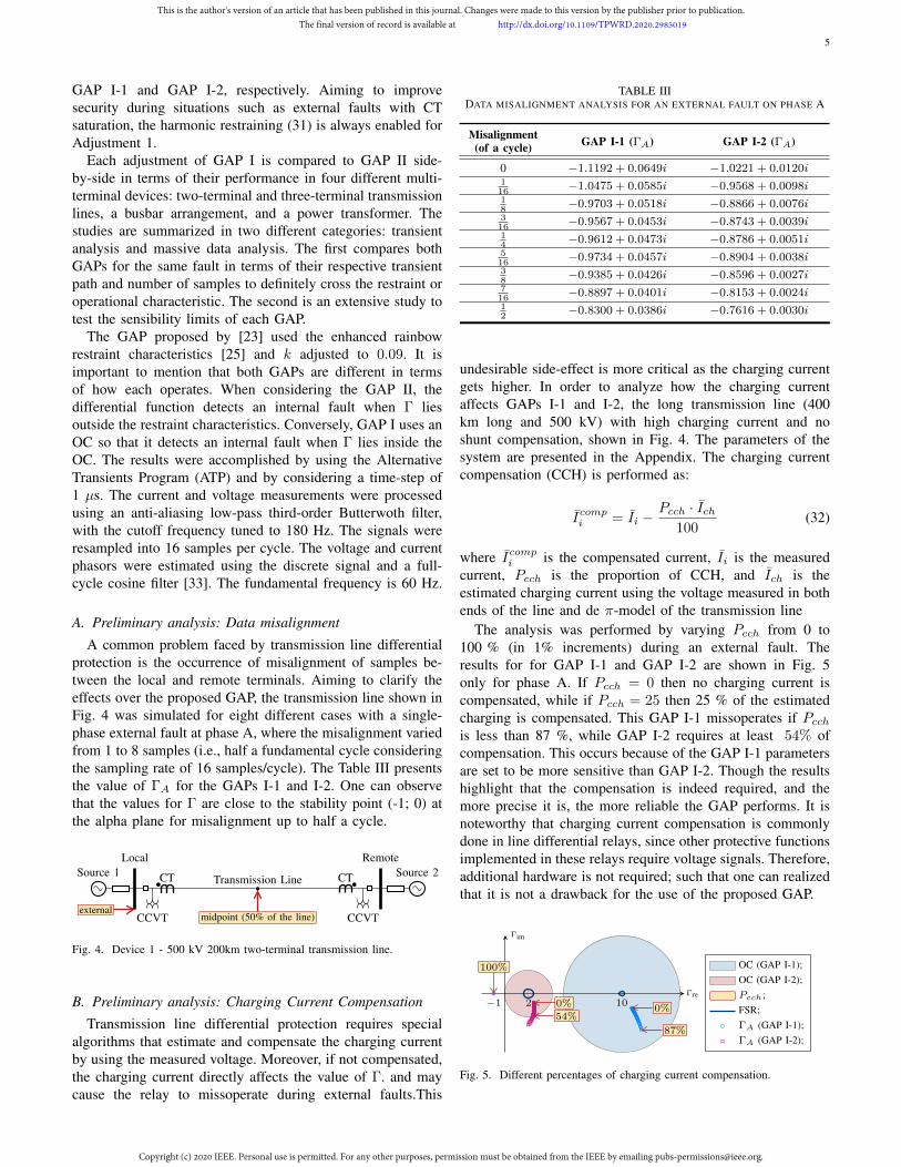
undesirable side-effect is more critical as the charging currentgets higher. In order to analyze how the charging currentaffects GAPs I-1 and I-2, the long transmission line (400km long and 500 kV) with high charging current and noshunt compensation, shown in Fig. 4. The parameters of thesystem are presented in the Appendix. The charging currentcompensation (CCH) is performed as:
Icompi = Ii −Pcch · Ich
100(32)
where Icompi is the compensated current, Ii is the measuredcurrent, Pcch is the proportion of CCH, and Ich is theestimated charging current using the voltage measured in bothends of the line and de π-model of the transmission line
The analysis was performed by varying Pcch from 0 to100 % (in 1% increments) during an external fault. Theresults for for GAP I-1 and GAP I-2 are shown in Fig. 5only for phase A. If Pcch = 0 then no charging current iscompensated, while if Pcch = 25 then 25 % of the estimatedcharging is compensated. This GAP I-1 missoperates if Pcchis less than 87 %, while GAP I-2 requires at least 54% ofcompensation. This occurs because of the GAP I-1 parametersare set to be more sensitive than GAP I-2. Though the resultshighlight that the compensation is indeed required, and themore precise it is, the more reliable the GAP performs. It isnoteworthy that charging current compensation is commonlydone in line differential relays, since other protective functionsimplemented in these relays require voltage signals. Therefore,additional hardware is not required; such that one can realizedthat it is not a drawback for the use of the proposed GAP.
−1 2 10Γre
Γim
OC (GAP I-1);OC (GAP I-2);Pcch;FSR;ΓA (GAP I-1);ΓA (GAP I-2);
87%
0%54%
0%
100%
Fig. 5. Different percentages of charging current compensation.
This is the author's version of an article that has been published in this journal. Changes were made to this version by the publisher prior to publication.The final version of record is available at http://dx.doi.org/10.1109/TPWRD.2020.2985019
Copyright (c) 2020 IEEE. Personal use is permitted. For any other purposes, permission must be obtained from the IEEE by emailing [email protected].
6
no trip; OC; FSR; ΓA; ΓB; ΓC
GAP I: (Γf = 10, k∆ = 0.2, Ψ = 25) GAP I: (Γf = 2, k∆ = 0.4, Ψ = 5) GAP II: (k= 0.09)
10 20
5
10
15
Γre
Γim
9 10 11
−1
0
1
10 20
5
10
15
Γre
Γim
1 2 3
−1
0
1
10 20
5
10
15
Γre
Γim
−1 0 1
−1
0
1
(a) Case 1.1: Massive Data Analysis (316 simulations).
10 20
−5
5
10
Γre
Γim
6 8 10 12
−4
−2
0
10 20
−5
5
10
Γre
Γim
−0.5 0 0.5
−2
−1.5
−1
−0.5
−5 5 10 15 20
−5
5
10
Γre
Γim
−1−0.5 0−0.5
0
0.5
1
(b) Case 1.2: Internal single-phase fault at midpoint (High load and fault resistance).
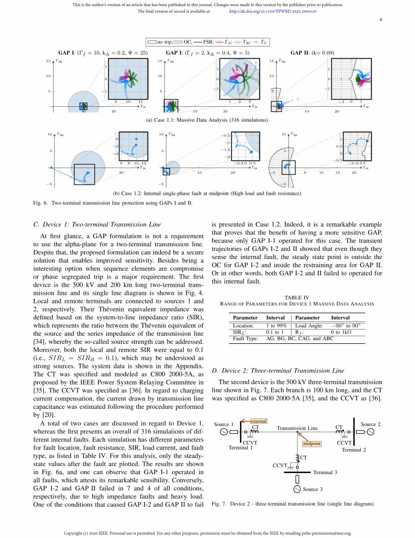
Fig. 6. Two-terminal transmission line protection using GAPs I and II.
C. Device 1: Two-terminal Transmission Line
At first glance, a GAP formulation is not a requirementto use the alpha-plane for a two-terminal transmission line.Despite that, the proposed formulation can indeed be a securesolution that enables improved sensitivity. Besides being ainteresting option when sequence elements are compromiseor phase segregated trip is a major requirement. The firstdevice is the 500 kV and 200 km long two-terminal trans-mission line and its single line diagram is shown in Fig. 4.Local and remote terminals are connected to sources 1 and2, respectively. Their Thevenin equivalent impedance wasdefined based on the system-to-line impedance ratio (SIR),which represents the ratio between the Thevenin equivalent ofthe source and the series impedance of the transmission line[34], whereby the so-called source strength can be addressed.Moreover, both the local and remote SIR were equal to 0.1(i.e., SIRL = SIRR = 0.1), which may be understood asstrong sources. The system data is shown in the Appendix.The CT was specified and modeled as C800 2000-5A, asproposed by the IEEE Power System Relaying Committee in[35]. The CCVT was specified as [36]. In regard to chargingcurrent compensation, the current drawn by transmission linecapacitance was estimated following the procedure performedby [20].
A total of two cases are discussed in regard to Device 1,whereas the first presents an overall of 316 simulations of dif-ferent internal faults. Each simulation has different parametersfor fault location, fault resistance, SIR, load current, and faulttype, as listed in Table IV. For this analysis, only the steady-state values after the fault are plotted. The results are shownin Fig. 6a, and one can observe that GAP I-1 operated inall faults, which attests its remarkable sensibility. Conversely,GAP I-2 and GAP II failed in 7 and 4 of all conditions,respectively, due to high impedance faults and heavy load.One of the conditions that caused GAP I-2 and GAP II to fail
is presented in Case 1.2. Indeed, it is a remarkable examplethat proves that the benefit of having a more sensitive GAP,because only GAP I-1 operated for this case. The transienttrajectories of GAPs I-2 and II showed that even though theysense the internal fault, the steady state point is outside theOC for GAP I-2 and inside the restraining area for GAP II.Or in other words, both GAP I-2 and II failed to operated forthis internal fault.
TABLE IVRANGE OF PARAMETERS FOR DEVICE 1 MASSIVE DATA ANALYSIS
Parameter Interval Parameter IntervalLocation: 1 to 99% Load Angle: −90 to 90
SIRL: 0.1 to 1 Rf : 0 to 1kΩFault Type: AG, BG, BC, CAG, and ABC
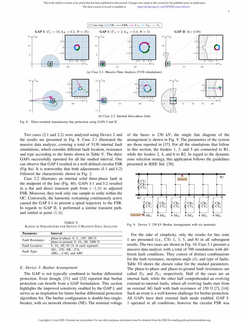
D. Device 2: Three-terminal Transmission Line
The second device is the 500 kV three-terminal transmissionline shown in Fig. 7. Each branch is 100 km long, and the CTwas specified as C800 2000-5A [35], and the CCVT as [36].
Terminal 1
Source 1 Source 2
Source 3
Transmission Line
midpoint
external
Terminal 2
Terminal 3
CT CT
CT
CCVT CCVT
CCVT
Fig. 7. Device 2 - three-terminal transmission line (single line diagram).
This is the author's version of an article that has been published in this journal. Changes were made to this version by the publisher prior to publication.The final version of record is available at http://dx.doi.org/10.1109/TPWRD.2020.2985019
Copyright (c) 2020 IEEE. Personal use is permitted. For any other purposes, permission must be obtained from the IEEE by emailing [email protected].
7
no trip; OC; FSR; ΓA; ΓB; ΓC
GAP I: (Γf = 10, k∆ = 0.2, Ψ = 25) GAP I: (Γf = 2, k∆ = 0.4, Ψ = 5) GAP II: (k= 0.09)
10 20
5
10
15
Γre
Γim
9.5 10 10.5
−0.5
0
0.5
10 20
5
10
15
Γre
Γim
1.5 2 2.5
−0.5
0
0.5
10 20
5
10
15
Γre
Γim
0 0.5 1
−0.5
0
0.5
(a) Case 2.1: Massive Data Analysis (5130 simulations).
10 20
−5
5
10
Γre
Γim
9.5 1010.5
−0.5
0
0.5
10 20
−5
5
10
Γre
Γim
1.5 2 2.5
−0.5
0
0.5
−5 5 10 15 20
−5
5
10
Γre
Γim
−1 0 1
−0.5
0
0.5
(b) Case 2.2: Internal three-phase fault.
Fig. 8. Three-terminal transmission line protection using GAPs I and II.
Two cases (2.1 and 2.2) were analyzed using Device 2 andthe results are presented in Fig. 8. Case 2.1 illustrated themassive data analysis, covering a total of 5130 internal faultsimulations, which consider different fault location, resistanceand type according to the limits shown in Table V. The threeGAPs successfully operated for all the studied interval. Onecan observe that GAP I resulted in a well-defined circular FSR(Fig 8a). It is noteworthy that both adjustments (I-1 and I-2)followed the characteristic shown in Fig. 2.
Case 2.2 illustrates an internal solid three-phase fault atthe midpoint of the line (Fig. 8b). GAPs I-1 and I-2 resultedin a flat and direct transient path from (−1; 0) to adjustedFSR. Moreover, they took only one sample to settle within theOC. Conversely, the harmonic restraining continuously activecaused the GAP I-1 to present a spiral trajectory to the FSR.In regards to GAP II, it performed a similar transient path,and settled at point (1; 0).
TABLE VRANGE OF PARAMETERS FOR DEVICE 2 MASSIVE DATA ANALYSIS
Parameter Interval
Fault Resistance: phase-to-phase: 0, 5,..,195, 200 Ωphase-to-ground: 0, 10,..,90, 1000 Ω
Fault Location: 5, 10,..,90, 95 (% of each segment)
Fault Type: AG,...,CG, AB,...,CA,ABG,...,CAG, and ABC
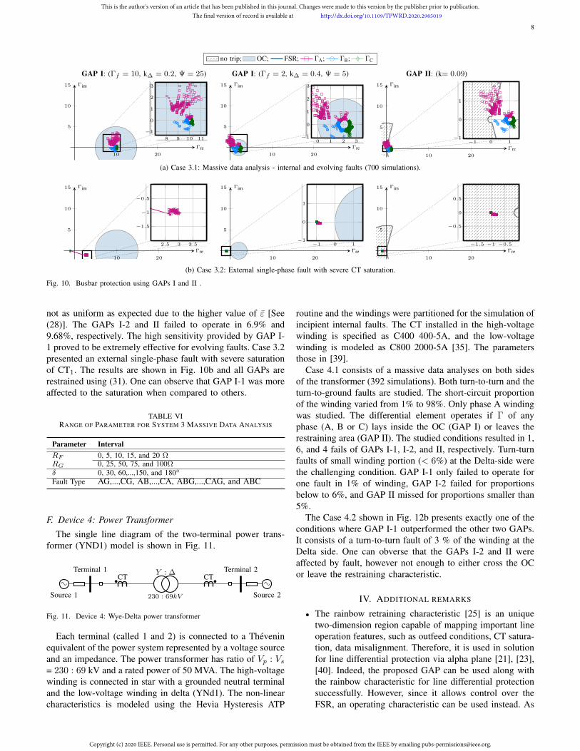
E. Device 3: Busbar Arrangement
The GAP is not typically combined to busbar differentialprotection. Even though, [31] and [32] reported that busbarprotection can benefit from a GAP formulation. This sectionhighlights the improved sensitivity enabled by the GAP I, andserves as an inspiration for future busbar differential protectionalgorithms for. The busbar configuration is double-bus-single-breaker, with six network elements (NE). The nominal voltage
of the buses is 230 kV; the single line diagram of thearrangement is shown in Fig. 9. The parameters of the systemare those reported in [37]. For all the simulations that followin this section, the feeders 1, 3, and 5 are connected to B1,while the feeders 2, 4, and 6 to B2. In regard to the dynamiczone selection strategy, this application follows the guidelinespresented in IEEE Std. [38].
B2
B1internal
CB1
NE1external
CT1
CB2
NE2
CT2
CB3
NE3
CT3
CB4
NE4
CT4
CB5
NE5
CT5
CB6
NE6
CT6
CB7
CT7
CT8
Fig. 9. Device 3: 230 kV Busbar Arrangement with six terminals.
For the sake of simplicity, only the results for bus zone1 are presented (i.e., CTs 1, 3, 5, and 8) in all subsequentresults. The two cases are shown in Fig. 10. Case 3.1 presents amassive data analysis with a total of 700 simulations with dif-ferent fault conditions. They consist of distinct combinationsfor the fault resistance, inception angle (δ), and type of faults.Table VI shows the chosen value for the studied parameters.The phase-to-phase and phase-to-ground fault resistances arecalled RF and RG, respectively. Half of the cases are aninternal fault, while the other half comprehended an evolvingexternal-to-internal faults, where all evolving faults start froman external AG fault with fault resistance of 150 Ω [7], [14].Such an event is a well-known challenge for busbar protection.All GAPs have their external fault mode enabled. GAP I-1 operated in all conditions, however the circular FSR was
This is the author's version of an article that has been published in this journal. Changes were made to this version by the publisher prior to publication.The final version of record is available at http://dx.doi.org/10.1109/TPWRD.2020.2985019
Copyright (c) 2020 IEEE. Personal use is permitted. For any other purposes, permission must be obtained from the IEEE by emailing [email protected].
8
no trip; OC; FSR; ΓA; ΓB; ΓC
GAP I: (Γf = 10, k∆ = 0.2, Ψ = 25) GAP I: (Γf = 2, k∆ = 0.4, Ψ = 5) GAP II: (k= 0.09)
10 20
5
10
15
Γre
Γim
8 9 10 11
−1
0
1
2
3
10 20
5
10
15
Γre
Γim
0 1 2 3−1
0
1
2
3
10 20
5
10
15
Γre
Γim
−1 0 1−1
0
1
(a) Case 3.1: Massive data analysis - internal and evolving faults (700 simulations).
10 20
5
10
15
Γre
Γim
2.5 3 3.5
−0.5
−1
−1.5
10 20
5
10
15
Γre
Γim
−1 0 1−1
0
1
10 20
5
10
15
Γre
Γim
−1.5 −1 −0.5
−0.5
0
0.5
(b) Case 3.2: External single-phase fault with severe CT saturation.
Fig. 10. Busbar protection using GAPs I and II .
not as uniform as expected due to the higher value of ε [See(28)]. The GAPs I-2 and II failed to operate in 6.9% and9.68%, respectively. The high sensitivity provided by GAP I-1 proved to be extremely effective for evolving faults. Case 3.2presented an external single-phase fault with severe saturationof CT1. The results are shown in Fig. 10b and all GAPs arerestrained using (31). One can observe that GAP I-1 was moreaffected to the saturation when compared to others.
TABLE VIRANGE OF PARAMETER FOR SYSTEM 3 MASSIVE DATA ANALYSIS
Parameter IntervalRF 0, 5, 10, 15, and 20 ΩRG 0, 25, 50, 75, and 100Ωδ 0, 30, 60,...,150, and 180
Fault Type AG,...,CG, AB,...,CA, ABG,...,CAG, and ABC
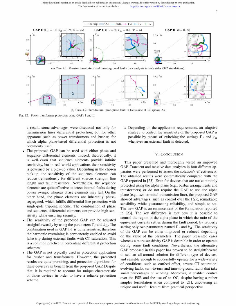
F. Device 4: Power Transformer
The single line diagram of the two-terminal power trans-former (YND1) model is shown in Fig. 11.
Terminal 1
Source 1 Source 2230 : 69kV
Y : ∆ Terminal 2CT CT
Fig. 11. Device 4: Wye-Delta power transformer
Each terminal (called 1 and 2) is connected to a Theveninequivalent of the power system represented by a voltage sourceand an impedance. The power transformer has ratio of Vp : Vs= 230 : 69 kV and a rated power of 50 MVA. The high-voltagewinding is connected in star with a grounded neutral terminaland the low-voltage winding in delta (YNd1). The non-linearcharacteristics is modeled using the Hevia Hysteresis ATP
routine and the windings were partitioned for the simulation ofincipient internal faults. The CT installed in the high-voltagewinding is specified as C400 400-5A, and the low-voltagewinding is modeled as C800 2000-5A [35]. The parametersthose in [39].
Case 4.1 consists of a massive data analyses on both sidesof the transformer (392 simulations). Both turn-to-turn and theturn-to-ground faults are studied. The short-circuit proportionof the winding varied from 1% to 98%. Only phase A windingwas studied. The differential element operates if Γ of anyphase (A, B or C) lays inside the OC (GAP I) or leaves therestraining area (GAP II). The studied conditions resulted in 1,6, and 4 fails of GAPs I-1, I-2, and II, respectively. Turn-turnfaults of small winding portion (< 6%) at the Delta-side werethe challenging condition. GAP I-1 only failed to operate forone fault in 1% of winding, GAP I-2 failed for proportionsbelow to 6%, and GAP II missed for proportions smaller than5%.
The Case 4.2 shown in Fig. 12b presents exactly one of theconditions where GAP I-1 outperformed the other two GAPs.It consists of a turn-to-turn fault of 3 % of the winding at theDelta side. One can obverse that the GAPs I-2 and II wereaffected by fault, however not enough to either cross the OCor leave the restraining characteristic.
IV. ADDITIONAL REMARKS
• The rainbow retraining characteristic [25] is an uniquetwo-dimension region capable of mapping important lineoperation features, such as outfeed conditions, CT satura-tion, data misalignment. Therefore, it is used in solutionfor line differential protection via alpha plane [21], [23],[40]. Indeed, the proposed GAP can be used along withthe rainbow characteristic for line differential protectionsuccessfully. However, since it allows control over theFSR, an operating characteristic can be used instead. As
This is the author's version of an article that has been published in this journal. Changes were made to this version by the publisher prior to publication.The final version of record is available at http://dx.doi.org/10.1109/TPWRD.2020.2985019
Copyright (c) 2020 IEEE. Personal use is permitted. For any other purposes, permission must be obtained from the IEEE by emailing [email protected].
9
no trip; OC; FSR; ΓA; ΓB; ΓC
GAP I: (Γf = 10, k∆ = 0.2, Ψ = 25) GAP I: (Γf = 2, k∆ = 0.4, Ψ = 5) GAP II: (k= 0.09)
20 40
10
20
Γre
Γim
8 10 12 14−4
−2
0
2
4
fail
20 40
10
20
Γre
Γim
1 2 3
−1
0
1
10 20
5
10
15
Γre
Γim
0 1 2
−1
0
1
(a) Case 4.1: Massive turn-to-turn and turn-to-ground faults data analysis in both sides (392 simulations).
10 20
5
10
15
Γre
Γim
9 10 11
0
1
2
3
10 20
5
10
15
Γre
Γim
−1.5 −1
−0.5
0
0.5
10 20
5
10
15
Γre
Γim
−1−0.50
−0.5
0
0.5
(b) Case 4.2: Turn-to-turn three-phase fault in Delta-side at 3% (phase A).
Fig. 12. Power transformer protection using GAPs I and II.
a result, some advantages were discussed not only fortransmission lines differential protection, but for otherapparatus such as power transformers and busbar, forwhich alpha plane-based differential protection is notcommonly used.
• The proposed GAP can be used with either phase andsequence differential elements. Indeed, theoretically, itis well-kwon that sequence elements provide infinitesensitivity, but in real-world applications their sensitivityis governed by a pick-up value. Depending in the chosenpick-up, the sensitivity of the sequence elements canreduce tremendously for different sources strength, linelength and fault resistance. Nevertheless, the sequenceelements are quite effective to detect internal faults duringpower swings, whereas phase elements may fail. On theother hand, the phase elements are inherently phase-segregated, which fulfills differential line protection withsingle-pole tripping scheme. The combination of phaseand sequence differential elements can provide high sen-sitivity while ensuring security.
• The sensitivity of the proposed GAP can be adjustedstraightforwardly by using the parameters Γf and k∆. Thecombination used in GAP I-1 is quite sensitive, thereforethe harmonic restraining is permanently enabled to avoidfalse trip during external faults with CT saturation. Thisis a common practice in percentage differential protectionschemes.
• The GAP is not typically used in protection applicationfor busbar and transformers. However, the presentedresults are quite promising, and protection algorithms forthese devices can benefit from the proposed GAP. Despitethat, it is required to account for unique characteristicof those devices in order to have a reliable protectionscheme.
• Depending on the application requirements, an adaptivestrategy to control the sensitivity of the proposed GAP ispossible by means of switching the settings Γf and k∆
whenever an external fault is detected.
V. CONCLUSION
This paper presented and thoroughly tested an improvedGAP. Transient and massive data analyses in four different ap-paratus were performed to assess the solution’s effectiveness.The obtained results were systematically compared with theGAP reported in [23]. Even for devices that are not commonlyprotected using the alpha plane (e.g., busbar arrangements andtransformers) or do not require the GAP to use the alphaplane (e.g., two-terminal transmission line), the proposed GAPshowed advantages, such as control over the FSR, remarkablesensibility while guaranteeing reliability, and simple to set.The new GAP is an enhancement of the formulation reportedin [23]. The key difference is that now it is possible tocontrol the region in the alpha plane in which the ratio of theequivalent currents settles during the fault period, by properlysetting only two parameters named Γf and k∆. The sensitivityof the GAP can be either improved or reduced dependingon the value of the parameters. The paper presented caseswhereas a more sensitivity GAP is desirable in order to operateduring some fault conditions. Nevertheless, the alternativeGAP proposed in this paper has proven to be straightforwardto set, an all-around solution for different type of devices,and sensible enough to successfully operate for a wide-varietyof conditions, such as outfeed effect, severe CT saturation,evolving faults, turn-to-turn and turn-to-ground faults that takesmall percentages of winding. Moreover, it enabled controlover the FSR and the use of an OC, despite having a rathersimpler formulation when compared to [21], uncovering anunique and useful feature from practical perspective.
This is the author's version of an article that has been published in this journal. Changes were made to this version by the publisher prior to publication.The final version of record is available at http://dx.doi.org/10.1109/TPWRD.2020.2985019
Copyright (c) 2020 IEEE. Personal use is permitted. For any other purposes, permission must be obtained from the IEEE by emailing [email protected].
10
APPENDIX
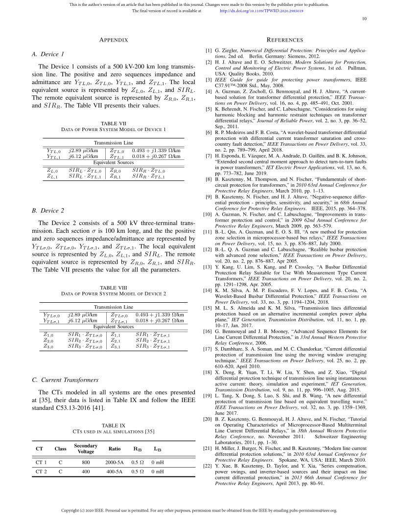
A. Device 1
The Device 1 consists of a 500 kV-200 km long transmis-sion line. The positive and zero sequences impedance andadmittance are YTL,0, ZTL,0, YTL,1, and ZTL,1. The localequivalent source is represented by ZL,0, ZL,1, and SIRL.The remote equivalent source is represented by ZR,0, ZR,1,and SIRR. The Table VII presents their values.
TABLE VIIDATA OF POWER SYSTEM MODEL OF DEVICE 1
Transmission LineYTL,0 j2.89 µf/km ZTL,0 0.493 + j1.339 Ω/kmYTL,1 j6.12 µf/km ZTL,1 0.018 + j0.267 Ω/km
Equivalent SourcesZL,0 SIRL · ZTL,0 ZR,0 SIRR · ZTL,0ZL,1 SIRL · ZTL,1 ZR,1 SIRR · ZTL,1
B. Device 2
The Device 2 consists of a 500 kV three-terminal trans-mission. Each section σ is 100 km long, and the the positiveand zero sequences impedance/admittance are represented byYTLσ,0, ZTLσ,0, YTLσ,1, and ZTLσ,1. The local equivalentsource is represented by ZL,0, ZL,1, and SIRL. The remoteequivalent source is represented by ZR,0, ZR,1, and SIRR.The Table VII presents the value for all the parameters.
TABLE VIIIDATA OF POWER SYSTEM MODEL OF DEVICE 2
Transmission LineYTLσ,0 j2.89 µf/km ZTLσ,0 0.493 + j1.339 Ω/kmYTLσ,1 j6.12 µf/km ZTLσ,1 0.018 + j0.267 Ω/km
Equivalent SourcesZ1,0 SIR1 · ZTLσ,0 Z1,1 SIR1 · ZTLσ,1Z2,0 SIR2 · ZTLσ,0 Z2,1 SIR2 · ZTLσ,1Z3,0 SIR3 · ZTLσ,0 Z3,1 SIR3 · ZTLσ,1
C. Current Transformers
The CTs modeled in all systems are the ones presentedat [35], their data is listed in Table IX and follow the IEEEstandard C53.13-2016 [41].
TABLE IXCTS USED IN ALL SIMULATIONS [35]
CT Class SecondaryVoltage Ratio RB LB
CT 1 C 800 2000-5A 0.5 Ω 0 mH
CT 2 C 400 400-5A 0.5 Ω 0 mH
REFERENCES
[1] G. Ziegler, Numerical Differential Protection: Principles and Applica-tions, 2nd ed. Berlin, Germany: Siemens, 2012.
[2] H. J. Altuve and E. O. Schweitzer, Modern Solutions for Protection,Control and Monitoring of Electric Power Systems, 1st ed. Pullman,USA: Quality Books, 2010.
[3] IEEE Guide for guide for protecting power transformers, IEEEC37.91™-2008 Std., May, 2008.
[4] A. Guzman, Z. Zocholl, G. Benmouyal, and H. J. Altuve, “A current-based solution for transformer differential protection,” IEEE Transac-tions on Power Delivery, vol. 16, no. 4, pp. 485–491, Oct. 2001.
[5] K. Behrendt, N. Fischer, and C. Labuschagne, “Considerations for usingharmonic blocking and harmonic restraint techniques on transformerdifferential relays,” Journal of Reliable Power, vol. 2, no. 3, pp. 36–52,Sep., 2011.
[6] R. P. Medeiros and F. B. Costa, “A wavelet-based transformer differentialprotection with differential current transformer saturation and cross-country fault detection,” IEEE Transactions on Power Delivery, vol. 33,no. 2, pp. 789–799, April 2018.
[7] H. Esponda, E. Vazquez, M. A. Andrade, D. Guillen, and B. K. Johnson,“Extended second central moment approach to detect turn-to-turn faultsin power transformers,” IET Electric Power Applications, vol. 13, no. 6,pp. 773–782, June 2019.
[8] B. Kasztenny, M. Thompson, and N. Fischer, “Fundamentals of short-circuit protection for transformers,” in 2010 63rd Annual Conference forProtective Relay Engineers, March 2010, pp. 1–13.
[9] B. Kasztenny, N. Fischer, and H. J. Altuve, “Negative-sequence differ-ential protection - principles, sensitivity, and security,” in 68th AnnualConference for Protective Relay Engineers. IEEE, 2015, pp. 364–378.
[10] A. Guzman, N. Fischer, and C. Labuschagne, “Improvements in trans-former protection and control,” in 2009 62nd Annual Conference forProtective Relay Engineers, March 2009, pp. 563–579.
[11] B.-L. Qin, A. Guzman, and E. O. S. III, “A new method for protectionzone selection in microprocessor-based bus relays,” IEEE Transactionson Power Delivery, vol. 15, no. 3, pp. 876–887, July 2000.
[12] B.-L. Q. A. Guzman and C. Labuschagne, “Realible busbar protectionwith advanced zone selection,” IEEE Transactions on Power Delivery,vol. 20, no. 2, pp. 876–887, Apr 2005.
[13] Y. Kang, U. Lim, S. Kang, and P. Crossley, “A Busbar DifferentialProtection Relay Suitable for Use With Measurement Type CurrentTransformers,” IEEE Transactions on Power Delivery, vol. 20, no. 2,pp. 1291–1298, Apr. 2005.
[14] K. M. Silva, A. M. P. Escudero, F. V. Lopes, and F. B. Costa, “AWavelet-Based Busbar Differential Protection,” IEEE Transactions onPower Delivery, vol. 33, no. 3, pp. 1194–1204, 2018.
[15] M. L. S. Almeida and K. M. Silva, “Transmission lines differentialprotection based on an alternative incremental complex power alphaplane,” IET Generation, Transmission Distribution, vol. 11, no. 1, pp.10–17, Jan. 2017.
[16] G. Benmouyal and J. B. Mooney, “Advanced Sequence Elements forLine Current Differential Protection,” in 33rd Annual Western ProtectiveRelay Conference, 2006.
[17] S. Dambhare, S. A. Soman, and M. C. Chandorkar, “Current differentialprotection of transmission line using the moving window averagingtechnique,” IEEE Transactions on Power Delivery, vol. 25, no. 2, pp.610–620, April 2010.
[18] X. Deng, R. Yuan, T. Li, W. Liu, Y. Shen, and Z. Xiao, “Digitaldifferential protection technique of transmission line using instantaneousactive current: theory, simulation and experiment,” IET Generation,Transmission Distribution, vol. 9, no. 11, pp. 996–1005, Aug. 2015.
[19] L. Tang, X. Dong, S. Luo, S. Shi, and B. Wang, “A new differentialprotection of transmission line based on equivalent travelling wave,”IEEE Transactions on Power Delivery, vol. 32, no. 3, pp. 1359–1369,June 2017.
[20] B. Z. Kasztenny, G. Benmouyal, H. J. Altuve, and N. Fischer, “Tutorialon Operating Characteristics of Microprocessor-Based MultiterminalLine Current Differential Relays,” in 38th Annual Western ProtectiveRelay Conference, no. November 2011. Schweitzer EngineeringLaboratories, 2011, pp. 1–30.
[21] H. Miller, J. Burger, N. Fischer, and B. Kasztenny, “Modern line currentdifferential protection solutions,” in 2010 63rd Annual Conference forProtective Relay Engineers. Spokane, WA, USA: IEEE, March 2010.
[22] Y. Xue, B. Kasztenny, D. Taylor, and Y. Xia, “Series compensation,power swings, and inverter-based sources and their impact on linecurrent differential protection,” in 2013 66th Annual Conference forProtective Relay Engineers, April 2013, pp. 80–91.
This is the author's version of an article that has been published in this journal. Changes were made to this version by the publisher prior to publication.The final version of record is available at http://dx.doi.org/10.1109/TPWRD.2020.2985019
Copyright (c) 2020 IEEE. Personal use is permitted. For any other purposes, permission must be obtained from the IEEE by emailing [email protected].

11
[23] K. M. Silva and R. G. Bainy, “Generalized Alpha Plane for Numeri-cal Differential Protection Applications,” IEEE Transactions on PowerDelivery, vol. 31, no. 6, pp. 2565–2566, Dec. 2016.
[24] A. R. C. Warrington, Protective Relays: Their Theory and Practice,Volume one, 1st ed. London: Chapman & Hall, 1962.
[25] D. A. Tziouvaras, H. Altuve, G. Benmouyal, and J. Roberts, “Line dif-ferential protection with an enhanced characteristic,” in 3rd Conferenceand Exhibition on Power Generation, Transmission, Distribution andEnergy Conversion, 2002.
[26] D. Tziouvaras, H. Altuve, G. Benmouyal, and J. Roberts, “The effect ofmultiprinciple line protection on dependability and security,” SchweitzerEngineering Laboratories Inc., Pullman, WA, Tech. Rep., 2001.
[27] G. Benmouyal and T. Lee, “Securing Sequence-Current Differential El-ements,” in 31st Annual Western Protective Relay Conference, Spokane,Washington, 2004.
[28] S. Sarangi and A. K. Pradhan, “Adaptive α-plane line differentialprotection,” IET Generation, Transmission Distribution, vol. 11, no. 10,pp. 2468–2477, July 2017.
[29] M. Hossain, I. Leevongwat, and P. Rastgoufard, “Revisions on alphaplane for enhanced sensitivity of line differential protection,” IEEETransactions on Power Delivery, vol. 33, no. 6, pp. 3260–3262, Dec2018.
[30] B. Z. Kasztenny and N. Fischer, “Equivalent Alpha Plane Fault Deter-mination for a Multi-Terminal Power Apparatus,” U.S. Patent 8,649,142B2, Feb. 11, 2014.
[31] R. G. Bainy and K. M. Silva, “Busbar differential protection basedon generalized alpha plane,” in 2017 Workshop on CommunicationNetworks and Power Systems (WCNPS), Nov 2017, pp. 1–4.
[32] S. Jena and B. R. Bhalja, “Numerical busbar differential protection usinggeneralised alpha plane,” IET Generation, Transmission Distribution,vol. 12, no. 1, pp. 227–234, Feb. 2018.
[33] D. G. Hart, D. Novosel, and R. A. Smith, “Modified Cosine Fiters,”U.S. Patent 6,154,687, Nov.28, 2000.
[34] M. Thompson and A. Somani, “A tutorial on calculating sourceimpedance ratios for determining line length,” in Protective RelayEngineers, 2015 68th Annual Conference for, 2015, pp. 833–841.
[35] EMTP Reference Models for Transmission Line Relay Testing, IEEEPower System Relaying Committee, 2004.
[36] E. Pajuelo, G. Ramakrishna, and M. S. Sachdev, “Phasor estimationtechnique to reduce the impact of coupling capacitor voltage transformertransients,” IET Generation, Transmission & Distribution, vol. 2, no.July 2007, pp. 588–599, 2008.
[37] E. Vazquez, I. I. Mijares, O. L. Chacon, and A. Conde, “Transformerdifferential protection using principal component analysis,” IEEE Trans-actions on Power Delivery, vol. 23, no. 1, pp. 67–72, Jan. 2008.
[38] IEEE Guide for Protective Relay Applications to Power System Buses,IEEE C37.234™-2009 Std., Sep. 2009.
[39] R. P. Medeiros, F. B. Costa, and K. M. Silva, “Power transformerdifferential protection using the boundary discrete wavelet transform,”IEEE Transactions on Power Delivery, vol. 31, no. 5, pp. 2083–2095,Oct 2016.
[40] H. J. Altuve, G. Benmouyal, J. Roberts, and D. A. Tziouvaras, “Trans-mission line differential protection with an enhanced characteristic,” inEighth IEE International Conference on Developments in Power SystemProtection, vol. 2004, no. 1. IET, 2004, pp. 414–419.
[41] IEEE Standard Requirements for Instrument Transformers, IEEEC53.13™-2016 Std., June 2016.
Romulo G. Bainy received the B.Sc. and M.Sc. de-grees in electrical engineering from Western ParanaState University, Brazil, and his Ph.D. degree fromthe University of Brasılia (UnB), Brazil in 2012,2014, and 2019, respectively. He was a visitingscholar in Washington State University (WSU),USA, in 2018. Since 2019, he is a postdoctoralfellow at the University of Idaho, Moscow, USA.His interests are in power system protection, faultlocation, electromagnetic transients, and renewableenergy.
Kleber M. Silva received the B.Sc., M.Sc., andPh.D. degrees in electrical engineering from the Uni-versity of Campina Grande, Brazil, in 2004, 2005,and 2009, respectively. Since 2009, he has been aprofessor with the University of Brasılia, Brazil, andthe Head of the Power System Protection Group. Heis an Associate Editor for the IEEE Transactions onPower Delivery and Member of SC B5-Protectionand Automation Committee of CIGRE Brazil. Hisresearch interests focus on power system protection,fault location, and electromagnetic transients.
This is the author's version of an article that has been published in this journal. Changes were made to this version by the publisher prior to publication.The final version of record is available at http://dx.doi.org/10.1109/TPWRD.2020.2985019
Copyright (c) 2020 IEEE. Personal use is permitted. For any other purposes, permission must be obtained from the IEEE by emailing [email protected].