ENERGY EFFICIENCY - BOPA
60
VALVES & ACTUATORS 2018 ENERGY EFFICIENCY CONTROL SOLUTIONS FOR HVAC-R AND BUILDING AUTOMATION
-
Upload
khangminh22 -
Category
Documents
-
view
0 -
download
0
Transcript of ENERGY EFFICIENCY - BOPA

VALVES & ACTUATORS 2018ENERGYEFFICIENCY
CONTROL SOLUTIONS FOR HVAC-R AND BUILDING AUTOMATION

Sensors & Controllers
Valves & Actuators
DOWNLOAD OUR CATALOGUES IN PDF FROM OUR WEBSITE WWW.CONTROLLI.EU
OR USE THESE QR CODES.

3* The port of Genoa
CONTROLLIControllers & field devices for HVAC
CONTROLLI was established in Genoa in 1936 and was the first Italian company to manufacture a complete range of controllers, ac-tuators and control valves for heat-ing and air-conditioning systems.Since 1950 the product range was improved by widening the range of control equipments and systems for industrial application.In the 80s CONTROLLI consolidates its position as the most important Italian manufacturer, with special regard to climate controls, thanks to the development of analogue and digital electronic devices.In the 90s CONTROLLI gains a posi-tion also in the Building Automation market.From 1996 to July 2005 CONTROLLI has been part of the Invensys multi-national group. From 2005 to August 2011 CON-TROLLI has been part of Schneider Electric S.A.
CONTROLLI core business consists of products and systems for the control and supervision of HVAC plants and industrial processes. CONTROLLI products are the result of mechanical - electric - electronic technology integration, supported by a 80-years experience in HVAC applications.
Controlli is recognised today as an Italian leader in the Building Auto-mation market and a benchmark in the segment of valves and ac-tuators for the HVAC market.Business with OEMs (Original Equip-ment Manufacturers) is more than 30% of our turnover. System integra-tion for BMS is part of our business too. Our Building Automation team develops control software for free programmable controllers accord-ing to customers’ specifications. Since several years we are mainly focusing on cutting-edge solutions aiming at guaranteeing the high-est level of comfort but keeping a close eye on energy saving tech-nologies. Some of these technolo-gies refer to: heat metering sys-tems, control devices with wireless communication, circuit balancing and more.
COMPANY PROFILE CORE BUSINESS PRODUCT QUALITY IS CONTROLLI N°1 COMMITMENT
3
SINCE 1936 A LEADING COMPANY
IN HVAC AND BUILDING AUTOMATION

4
MANUFACTURING SITE CONTROLLI
An industrial area of 6,000 m2 in Sant’Olcese (Genoa) is CONTROLLI head office. Production is highly automated with robotic devices for the assembly and calibration of mechanical and electronic spare parts and finished products.It is worth mentioning the robotic plant for processing, mounting and testing of valve bodies and the robotized workcell for assembly, testing and certification of fan
coil valve actuators. CONTROLLI has adopted the SIX SIGMA procedures, further elevating the quality standard of its products. CONTROLLI operates under ISO9001-2008 Quality Certificate System. All CONTROLLI valves are PED (Pressure Equipment Directive) compliant.Products are tested 100%.
4

5
SALES ORGANIZATION
Sales & Marketing Dept. is in Sant’Olcese (Genoa).
Italian sales network consist of Sales-Offices in Milan, Genoa, Rome and Padova, 45 representatives and 75 authorised dealers throughout the Ital-ian territory.
Abroad CONTROLLI operates through a widespread network of distribu-tors and agents in Europe, Africa, Middle East, Far East, North and South America. By getting in touch with the nearest CONTROLLI sales point, the customers will find solution to any technical and commercial issue
Offices
Hotels
Industrialplants
ResidentialData Centres
Hospitals
ResearchInstitutes
PublicAreas
Schools andUniversities
Pools and Spas Transportations Malls
FIELDS OF APPLICATION CONTROLLI
TECHNICAL SUPPORT
Our offices will provide a continuous technical assistance and support for systems and devices, application information, quotations and wiring dia-grams.
Moreover, CONTROLLI holds periodically training courses for different lev-els of technical expertise and class of customers.
5

6
Controlli S.p.a.
Via Carlo Levi, 52
16010 Sant’Olcese
Genova - Italy
Controlli is located 10 Km north of Genova.
CONTROLLIGENOA
GENOA AIRPORT CONTROLLI
A7Highway 16min13,7Km
LINATE AIRPORT CONTROLLI
A7 Highway 1h e 13min149Km
PISA AIRPORT CONTROLLI
A12 Highway + E80 1h e 35min172Km
MALPENSA AIRPORT CONTROLLI
A7 Highway + E62 1h e 53min181Km
BERGAMO AIRPORT CONTROLLI
A7+A4 Highway 2h e 2min195Km
NICE AIRPORT CONTROLLI
A10 Highway + E80 2h e 5min206Km
A7 Highway
take the A7 highway (genova-milano) and exit at Genova Bolzaneto.
44.4862, 8.9223
Closest Railway Station: Genova Piazza Principe
WHERE TO FIND US CONTROLLI
6

7
DATA SHEETS Specify manufacturing and technical characteristics of products and their application, installation, wiring connections and start-up instruc-tions.
PRODUCT SELECTION GUIDE Gives a brief description of Controlli product range according to differ-ent applications.
USERS’ INSTRUCTIONS Provide the information for the correct use of the equipment and for its maintenance.
BROCHURES Advertise single Controlli products or control systems.
APPLICATION DIAGRAMS Illustrate the most common applications, indicating the equipment of control system, basic system and wiring diagram.
PRICE LIST Lists the prices and sales conditions.
CATALOGUE Our product range catalogue is also available on controlli website
APPLICATION ENGINEERING OFFICE Available for technical information, selection, application and quota-tions of equipment and complete control systems.
SALES SERVICE Consisting of our technical staff and authorised assistants for technical support, commissioning, repairs and maintenance.
TECHNICAL TRAINING COURSES Courses are held periodically for both technical and commercial staff on equipment and control systems. Moreover, there are courses aimed at the users of digital supervision systems.
WEB SITE Check our total portfolio by visiting www.controlli.eu, which gives direct access to the latest version of all our data sheets.
Controlli provides a series of resources to make it as easy as possible for you to identify the products you need.
WEBUP.CONTROLLI.EUOur customers have free access to our WEBUP online ser-vice, where they can check the updated situation for any order, shipment, as well as download documents and invoices.
TECHNICAL SUPPORT CONTROLLI
7
8
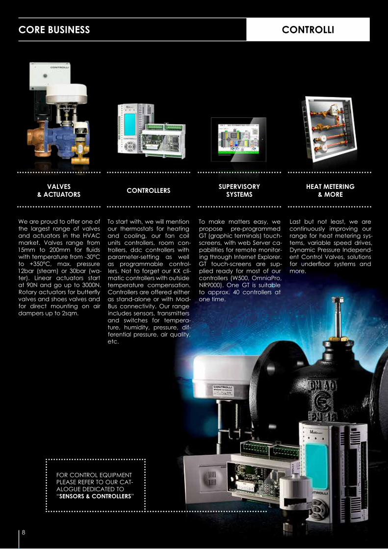
CORE BUSINESS CONTROLLI
8
FOR CONTROL EQUIPMENT PLEASE REFER TO OUR CAT-ALOGUE DEDICATED TO “SENSORS & CONTROLLERS”
VALVES & ACTUATORS
SUPERVISORY SYSTEMS
HEAT METERING & MORECONTROLLERS
We are proud to offer one of the largest range of valves and actuators in the HVAC market. Valves range from 15mm to 200mm for fluids with temperature from -30°C to +350°C, max. pressure 12bar (steam) or 30bar (wa-ter). Linear actuators start at 90N and go up to 3000N. Rotary actuators for butterfly valves and shoes valves and for direct mounting on air dampers up to 2sqm.
To start with, we will mention our thermostats for heating and cooling, our fan coil units controllers, room con-trollers, ddc controllers with parameter-setting as well as programmable control-lers. Not to forget our KX cli-matic controllers with outside temperature compensation. Controllers are offered either as stand-alone or with Mod-Bus connectivity. Our range includes sensors, transmitters and switches for tempera-ture, humidity, pressure, dif-ferential pressure, air quality, etc.
To make matters easy, we propose pre-programmed GT (graphic terminals) touch-screens, with web Server ca-pabilities for remote monitor-ing through Internet Explorer. GT touch-screens are sup-plied ready for most of our controllers (W500, OmniaPro, NR9000). One GT is suitable to approx. 40 controllers at one time.
Last but not least, we are continuously improving our range for heat metering sys-tems, variable speed drives, Dynamic Pressure Independ-ent Control Valves, solutions for underfloor systems and more.

AN EXTENSIVE SELECTION OF CONTROL VALVES CONTROLLI
MICRA® MOTORIZED VALVES FOR FCUs
Brass valves for FCUs 2way, 3way, 3way + bypass, Kvs 0,25 to 6, with On-Off / Modulating thermic actuators (90N & 140N force) and 3 pos. / Modulating electric actuators (300N force).
GLOBE VALVES WITH THREADED CONNECTIONS
Cast iron or bronze PN16 valve bodies with threaded connections ½” up to 2” for fluids from -10 °C to +150 °C.
GLOBE VALVE ACTUATORS
Linear actuators from 450N to 3000N, with or without spring re-turn. Includes MVE range of new generation actuators 400N, 600N, 1000N, 1500N & 2200N force with self adjusting and auto dignostic capabilities.
GLOBE VALVES WITH FLANGED CONNECTIONS
PN16, PN25, PN40 globe valves with flanged connections DN15mm to DN200mm, suitable to fluids (water, glycol, steam, ther-mal oil) from -30 °C to +350 °C.
BUTTERFLY VALVES
PN16 butterfly valves, 100% tight close-off, DN25mm to DN200mm to be motorized by MDL or MDA actuators (up to 40Nm).
PICVs
PN16 / PN25 dynamic pressure in-dependent control valves 1/2” to 2” and DN65 to DN125 with On/Off or proportional actuators suitable to fluids up to 120 °C.
9

10
PERFORMANCE (KVS/PRESSURE/TEMPERATURE)
FCUs, zone valves
AHUs, air conditioning, heating
Industrial processes / steam
PRICE
GLOBE VALVES PRICE / PERFORMANCE
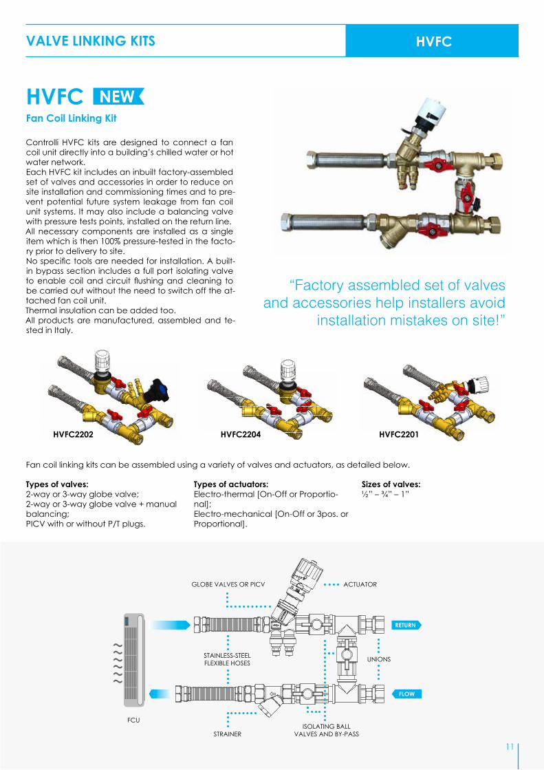
VALVE LINKING KITS HVFC
HVFCFan Coil Linking Kit
11
RETURN
FLOW
STAINLESS-STEEL FLEXIBLE HOSES UNIONS
ISOLATING BALL VALVES AND BY-PASS
GLOBE VALVES OR PICV
STRAINER
FCU
ACTUATOR
25
NEW
HVFC2202 HVFC2204 HVFC2201
Controlli HVFC kits are designed to connect a fan coil unit directly into a building’s chilled water or hot water network.Each HVFC kit includes an inbuilt factory-assembled set of valves and accessories in order to reduce on site installation and commissioning times and to pre-vent potential future system leakage from fan coil unit systems. It may also include a balancing valve with pressure tests points, installed on the return line.All necessary components are installed as a single item which is then 100% pressure-tested in the facto-ry prior to delivery to site.No specific tools are needed for installation. A built-in bypass section includes a full port isolating valve to enable coil and circuit flushing and cleaning to be carried out without the need to switch off the at-tached fan coil unit.Thermal insulation can be added too.All products are manufactured, assembled and te-sted in Italy.
Fan coil linking kits can be assembled using a variety of valves and actuators, as detailed below.
Types of valves: 2-way or 3-way globe valve; 2-way or 3-way globe valve + manual balancing; PICV with or without P/T plugs.
Types of actuators:Electro-thermal [On-Off or Proportio-nal]; Electro-mechanical [On-Off or 3pos. or Proportional].
Sizes of valves:½” – ¾” – 1”
“Factory assembled set of valves and accessories help installers avoid
installation mistakes on site!”
12
VALVES MICRA®
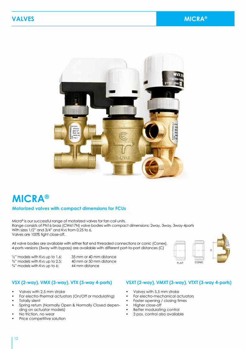
Micra® is our successful range of motorized valves for fan coil units.Range consists of PN16 brass (CW617N) valve bodies with compact dimensions: 2way, 3way, 3way-4portsWith sizes 1/2” and 3/4” and Kvs from 0,25 to 6.Valves are 100% tight close-off.
All valve bodies are available with either flat end threaded connections or conic (Conex).4-ports versions (3way with bypass) are available with different port-to-port distances (C)
½” models with Kvs up to 1,6: 35 mm or 40 mm distance¾” models with Kvs up to 2,5: 40 mm or 50 mm distance¾” models with Kvs up to 6: 44 mm distance
VSX (2-way), VMX (3-way), VTX (3-way 4-ports)
• Valves with 2,5 mm stroke• For electro-thermal actuators (On/Off or modulating)• Totally silent• Spring return (Normally Open & Normally Closed depen-
ding on actuator models)• No friction, no wear• Price competitive solution
VSXT (2-way), VMXT (3-way), VTXT (3-way 4-ports)
• Valves with 5,5 mm stroke• For electro-mechanical actuators• Faster opening / closing times • Higher close-off• Better modulating control• 3 pos. control also available
MICRA®
Motorized valves with compact dimensions for FCUs

13
VALVES AND ACTUATORS
Actuators series MVX Electrothermal actuator for V.X valves with Kvs from 0,25 to 6 Stroke end indicator - 2 m. bipolar/tripolar cable - Protection IP44.
1) These models are also available with 40mm port-to-port distance (C). When ordering 40mm distance version, add “4” at theend of the model code e.g. VTX21P4. See also picture on pag. 12
Series V.X. - PN16 brass valve bodies - Tight close-off both on direct and angle way - PPS plug with double EPDM o-ring - Fluid: water and water+glycol 30% max. - Temperature 5 to 95 °C - Stroke 2,5 mm - Threaded connections for conic and flat tight - Motorised by MVX-MVR.
MODELKVS
CLOSE OFF [bar]
ACTION TYPE ON DIRECT
WAYTHREADED CONNECTIONS TIGHTDIRECT
WAYANGLE WAY
VSX09P 0,25 - 4
2-way n.c.
G 1/2” M flat
VSX10P 0,4 - 4 G 1/2” M flat
VSX11P 0,6 - 4 G 1/2” M flat
VSX12P 1 - 3,5 G 1/2” M flat
VSX13 1,6 - 3,5 G 1/2” M conic
VSX13P 1,6 - 3,5 G 1/2” M flat
VSX21 2,5 - 3,5 G 3/4” M conic
VSX21P 2,5 - 3,5 G 3/4” M flat
VMX09P 0,5 0,25 4
3-way
G 1/2” M flat
VMX10P 0,4 0,4 4 G 1/2” M flat
VMX11P 0,6 0,6 4 G 1/2” M flat
VMX12P 1 0,6 3,5 G 1/2” M flat
VMX13 1,6 1 3,5 G 1/2” M conic
VMX13P 1,6 1 3,5 G 1/2” M flat
VMX21 2,5 1,6 3,5 G 3/4” M conic
VMX21P 2,5 1,6 3,5 G 3/4” M flat
VTX09P1) 0,25 0,25 4
3-way 4-port
G 1/2” M flat
VTX10P1) 0,4 0,4 4 G 1/2” M flat
VTX11P1) 0,6 0,6 4 G 1/2” M flat
VTX12P1) 1 0,6 3,5 G 1/2” M flat
VTX13 1,6 1 3,5 G 1/2” M conic
VTX13P1) 1,6 1 3,5 G 1/2” M flat
VTX21 2,5 1,6 3,5 G 3/4” M conic
VTX21P1) 2,5 1,6 3,5 G 3/4” M flat
1) These models are also available with auxiliary microswitch. When ordering this version, add the letter “M” at the end of the model code, e.g. MVR230M.
MVR series Electrothermal actuator for V.X valves with reverse action - 0,65 m cable - IP44 protection.
MODEL STARTING TIME [s]
POWER SUPPLY [Vac] FORCE [N] ACTION
MVR230V1) 60 110-230 90 on-off - normally open for Micra® valve
MVR24V1) 60 24 90 on-off - normally open for Micra® valve
90 N
VALVES MICRA®
MODEL STARTING TIME [s]
POWER SUPPLY [Vac] FORCE [N] ACTION
MVX22R 90 110-230 140 on-off
MVX42R 90 24 140 on-off, PWM
MVX52 90 24 140 proportional 0-10 Vdc
140 N
Valve Bodies with 2.5 mm stroke for fan coil units: Kvs 0.25 ÷ 2.5
1) The values in brackets refer to the angle way.
MODELKVS
CLOSE OFF [bar]
ACTION TYPE ON DIRECT
WAY
THREADED CONNECTIONS TIGHTDIRECT
WAYANGLE WAY
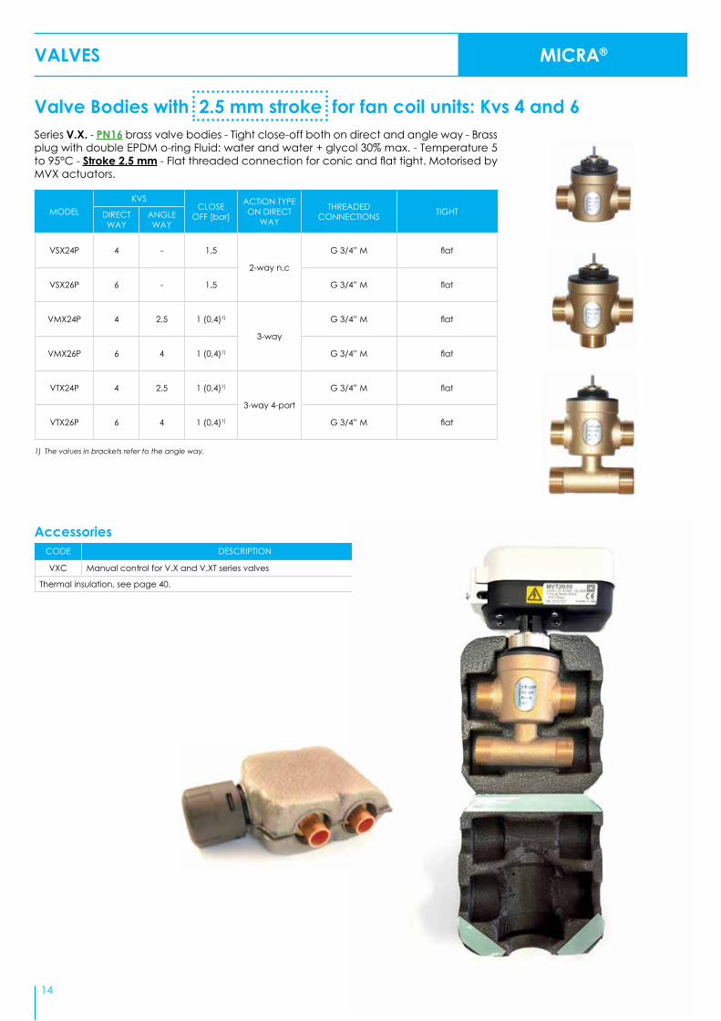
VSX24P 4 - 1,5
2-way n.c
G 3/4” M flat
VSX26P 6 - 1,5 G 3/4” M flat
VMX24P 4 2,5 1 (0,4)1)
3-way
G 3/4” M flat
VMX26P 6 4 1 (0,4)1) G 3/4” M flat
VTX24P 4 2,5 1 (0,4)1)
3-way 4-port
G 3/4” M flat
VTX26P 6 4 1 (0,4)1) G 3/4” M flat
VALVES MICRA®
14
AccessoriesCODE DESCRIPTION
VXC Manual control for V.X and V.XT series valves
Thermal insulation, see page 40.
Series V.X. - PN16 brass valve bodies - Tight close-off both on direct and angle way - Brass plug with double EPDM o-ring Fluid: water and water + glycol 30% max. - Temperature 5 to 95°C - Stroke 2,5 mm - Flat threaded connection for conic and flat tight. Motorised by MVX actuators.
Valve Bodies with 2.5 mm stroke for fan coil units: Kvs 4 and 6

All V.XT valves are available with conic connection. When ordering this version, ignore the letter “P” at the end of the model code; e.g. VSXT21.
1) The values in brackets refer to the angle way.2) These models are also available with 40mm port-to-port distance (C). When ordering 40mm distance version, add “4” at the end
of the model code e.g. VTXT21P4. See also picture on pag. 12
Valve Bodies with 5,5mm stroke for fan coil unitsSeries V.XT - PN16 forged brass valve body - Tight close-off both on direct and angle way - Plug with double EPDM OR - Fluid: water and water+glycol 30% max., temperature 2 to 95°C - Stroke 5,5 mm - Flow characteristic: equal-percentage direct way, linear angle way. To be motorised with MVT actuator.
MODEL1)
KVSCLOSE
OFF [bar]ACTION TYPE DIRECT WAY
THREADED CONNECTIONS TIGHTDIRECT
WAYANGLE WAY
VSXT09P 0,25 - 4
2-way n.c
G 1/2” M flat
VSXT10P 0,4 - 4 G 1/2” M flat
VSXT11P 0,6 - 3,5 G 1/2” M flat
VSXT12P 1 - 3,5 G 1/2” M flat
VSXT13P 1,6 - 3,5 G 1/2” M flat
VSXT1P 2 - 3,5 G 1/2” M flat
VSXT21P 2,5 - 3,5 G 3/4” M flat
VSXT24P 4 - 1,5 G 3/4” M flat
VSXT26P 6 - 1,5 G 3/4” M flat
VMXT09P 0,25 0,25 4
3-way
G 1/2” M flat
VMXT10P 0,4 0,25 4 G 1/2” M flat
VMXT11P 0,6 0,4 3,5 G 1/2” M flat
VMXT12P 1 0,6 3,5 G 1/2” M flat
VMXT13P 1,6 1 3,5 G 1/2” M flat
VMXT1P 2 1,6 3,5 G 1/2” M flat
VMXT21P 2,5 1,6 3,5 G 3/4” M flat
VMXT24P 4 2,5 1 (0,4)1) G 3/4” M flat
VMXT26P 6 4 1 (0,4)1) G 3/4” M flat
VTXT09P2) 0,25 0,25 4
3-way 4-port
G 1/2” M flat
VTXT10P2) 0,4 0,25 4 G 1/2” M flat
VTXT11P2) 0,6 0,4 3,5 G 1/2” M flat
VTXT12P2) 1 0,6 3,5 G 1/2” M flat
VTXT13P2) 1,6 1 3,5 G 1/2” M flat
VTXT1P2) 2 1,6 3,5 G 1/2” M flat
VTXT21P2) 2,5 1,6 3,5 G 3/4” M flat
VTXT24P 4 2,5 1 (0,4)1) G 3/4” M flat
VTXT26P 6 4 1 (0,4)1) G 3/4” M flat
VALVES MICRA®
15
For MVT actuators(pages 34-35)

THERMIC ACTUATORS MCA
16
Protection from condensation and from leaking regardless of the valve position (throughout 360°)Function Indicator Pin visible from any direction.Fast installation thanks to our Manual Override Position.MCA has not only a protection from condensation and from water leak whichever is the mounting position (IP54 also up side down), but it is designed to be adapted to the majority of underfloor heating manifolds and zone valves up to 4 mm stroke available on the market without the need of any
adapters. Another peculiarity of MCA is the Manual Override position, which allows opening and closing the valve/manifold through an easy operation and without powering the actuator. Last but not least, the MCA is equipped with an ON/OFF Position Indicator, visible from any directions, which allows an easy and fast installation.As for any other Controlli product, the reliability and quality are key requirements, that’s why our products continuously undergo life tests and each MCA is tested before being
shipped to the customer.MCA is available with or without a end-stroke switch contact and with the possibility to be powered with 110/220Vac or 24Vac/dc. MCA is then the ideal product for installers and distributors who can use it on any manifolds/valves but also for OEMs thanks to its high performances, its installation quickness as well as the possibility to be customized for example with the customer’s logo.
MODEL CONTROL SIGNAL [Vac] AUXILIARY MICROSWITCH POWER [N] STROKE [mm] PROTECTION
MCA230L110÷230
--
140 4 IP54MCA230LM ●
MCA24L24
--MCA24LM ●
MCAValve Adaptive concept without adapters
By a simple rotation of the actuator cover the installer can adjust it to manifolds or valves without the need of adapters (that are usually and easily lost).
THERMIC ACTUATOR
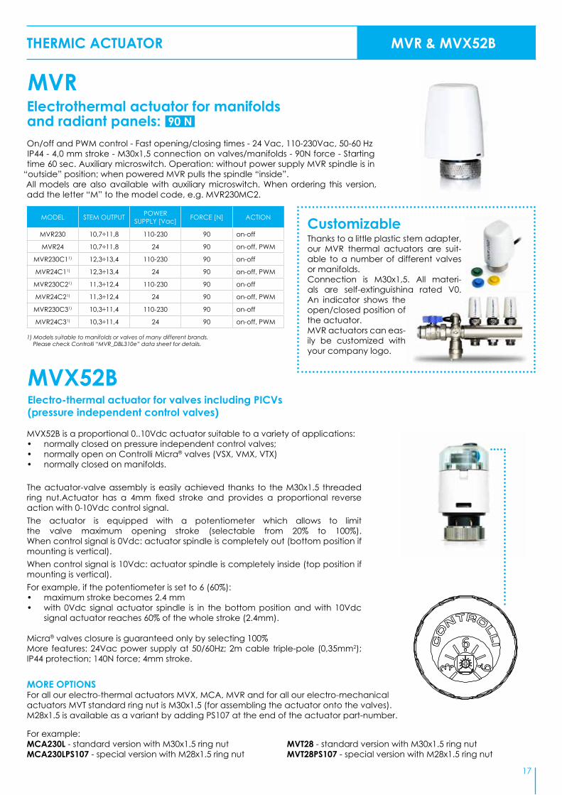
Electrothermal actuator for manifoldsand radiant panels:On/off and PWM control - Fast opening/closing times - 24 Vac, 110-230Vac, 50-60 HzIP44 - 4,0 mm stroke - M30x1,5 connection on valves/manifolds - 90N force - Starting time 60 sec. Auxiliary microswitch. Operation: without power supply MVR spindle is in
“outside” position; when powered MVR pulls the spindle “inside”.All models are also available with auxiliary microswitch. When ordering this version, add the letter “M” to the model code, e.g. MVR230MC2.
MODEL STEM OUTPUT POWER SUPPLY [Vac] FORCE [N] ACTION
MVR230 10,7÷11,8 110-230 90 on-off
MVR24 10,7÷11,8 24 90 on-off, PWM
MVR230C11) 12,3÷13,4 110-230 90 on-off
MVR24C11) 12,3÷13,4 24 90 on-off, PWM
MVR230C21) 11,3÷12,4 110-230 90 on-off
MVR24C21) 11,3÷12,4 24 90 on-off, PWM
MVR230C31) 10,3÷11,4 110-230 90 on-off
MVR24C31) 10,3÷11,4 24 90 on-off, PWM
90 N
1) Models suitable to manifolds or valves of many different brands. Please check Controlli “MVR_DBL310e” data sheet for details.
MVR & MVX52B
17
MVX52B is a proportional 0..10Vdc actuator suitable to a variety of applications:• normally closed on pressure independent control valves;• normally open on Controlli Micra® valves (VSX, VMX, VTX)• normally closed on manifolds.
The actuator-valve assembly is easily achieved thanks to the M30x1.5 threaded ring nut.Actuator has a 4mm fixed stroke and provides a proportional reverse action with 0-10Vdc control signal.The actuator is equipped with a potentiometer which allows to limit the valve maximum opening stroke (selectable from 20% to 100%). When control signal is 0Vdc: actuator spindle is completely out (bottom position if mounting is vertical).When control signal is 10Vdc: actuator spindle is completely inside (top position if mounting is vertical).For example, if the potentiometer is set to 6 (60%):• maximum stroke becomes 2.4 mm• with 0Vdc signal actuator spindle is in the bottom position and with 10Vdc
signal actuator reaches 60% of the whole stroke (2.4mm).
Micra® valves closure is guaranteed only by selecting 100%More features: 24Vac power supply at 50/60Hz; 2m cable triple-pole (0,35mm2); IP44 protection; 140N force; 4mm stroke.
MVX52B
MVR
Electro-thermal actuator for valves including PICVs (pressure independent control valves)
MORE OPTIONSFor all our electro-thermal actuators MVX, MCA, MVR and for all our electro-mechanical actuators MVT standard ring nut is M30x1.5 (for assembling the actuator onto the valves).M28x1.5 is available as a variant by adding PS107 at the end of the actuator part-number.
For example:MCA230L - standard version with M30x1.5 ring nutMCA230LPS107 - special version with M28x1.5 ring nut
MVT28 - standard version with M30x1.5 ring nutMVT28PS107 - special version with M28x1.5 ring nut
Thanks to a little plastic stem adapter, our MVR thermal actuators are suit-able to a number of different valves or manifolds.Connection is M30x1,5. All materi-als are self-extinguishing rated V0. An indicator shows the open/closed position of the actuator.MVR actuators can eas-ily be customized with your company logo.
Customizable

2-WAY GLOBE VALVES
Series 2T (threaded) - PN16 - Stroke 11,5 mm. To be motorised by MVB (2TGB.B) or MVE.S (2TGB.F) actuators.
Values in brackets are max close-off differential pressure. In applications with steam, the value in brackets is not applicable. In order to avoid seat & plug wearing issues we recommend not to exceed 2 bar differential pressure.
Tight Close-offSeries VSBPM threaded valves - Modulating tight close-off valves PN16 - Stroke 16,5 mm. Thermal insulation available - To be motorised by MVB actuators.
MODEL DN KVS MAX DIFFERENTIAL PRESSURE [bar] OTHER FEATURES
VSBP3M 3/4" 6,3 2 (8,8)
• G 25 cast-iron body • Fluid temperature -5 to 95°C• Leakage 0% Kvs
VSBP4M 1" 10 2 (5,5)
VSBP5M 1 ¼” 16 2 (5,5)
VSBP6M 1 ½” 25 2 (2,5)
VSBP8M 2” 40 1,8
By spring return MVHFA closed, MVHFC open. In order to avoid seat & plug wearing issues we recommend not to exceed 2 bar differential pressure.1) For applications with ice formation on stem and packing, use the stem heater.
MOD. DN KVSMAX DIFFERENTIAL PRESSURE [bar]
OTHER FEATURESMVB MVE506 MVE510 MVE515 MVH MVH56EA
MVH56EC MVE522
VSB3 3/4” 6,3 10,8 16 16 16 16 16 16• G 25 cast-iron body • Brass internal parts• Female threaded connections: fluid
temperature -101) to 150 °C, with MVB max 120°C (140°C with MVB+MVBHT)
• Equal-percentage control flow cha-racteristic
• Leakage 0,03% Kvs• For MVE actuator, add AG52 linkage • For MVH actuator, add AG62 linkage
VSB4 1” 10 6,8 11,9 16 16 16 13,8 16
VSB5 1 ¼” 16 4,1 7,2 12,1 16 16 8,4 16
VSB6 1 ½” 22 2,9 5 8,6 13 11,7 5,9 16
VSB8 2” 30 2,1 3,7 6,4 9,6 8,7 4,4 14,3
VSB8A 2” 40 2,1 3,7 6,4 9,6 8,7 4,4 14,3
VSB3F 20 6,3 10,8 16 16 16 16 16 16
• As above but with slip-on flanges
VSB4F 25 10 6,8 11,9 16 16 16 13,8 16
VSB5F 32 16 4,1 7,2 12,1 16 16 8,4 16
VSB6F 40 22 2,9 5 8,6 13 11,7 5,9 16
VSB8F 50 30 2,1 3,7 6,4 9,6 8,7 4,4 14,3
VSB8AF 50 40 2,1 3,7 6,4 9,6 8,7 4,4 14,3
Series VSB (threaded) - VSB.F (flanged) - PN16 - Stroke 16,5 mm. To be motorised by MVB - MVE - MVH actuators - Thermal insulation available.
MODEL DN KVS MAX DIFFERENTIAL PRESSURE [bar] OTHER FEATURES
2TGB15BR00 1/2" 0,4
16
• GJL-250 cast-iron body • Brass internal parts• Equal-percentage control flow characteristic • Leakage 0 to 0,001% Kvs• Female threaded connections: fluid temp. -52) to 140 °C,
with MVB max 120°C (140 °C with MVB+MVBHT)• For MVB actuator• For MVT203,403,503 actuators using AG74-03 adapter
2TGB15BR0 1/2” 0,63
2TGB15BR1 1/2” 1
2TGB15BR2 1/2" 1,6
2TGB15BR3 1/2” 2,5
2TGB15B 1/2” 4
2TGB15FR00 1/2" 0,4
16
• GJL-250 cast-iron body • Brass internal parts• Equal-percentage control flow characteristic • Leakage 0 to 0,001% Kvs• Female threaded connections: fluid temp. -51) to 140 °C• For MVE.S actuator
2TGB15FR0 1/2” 0,63
2TGB15FR1 1/2” 1
2TGB15FR2 1/2" 1,6
2TGB15FR3 1/2” 2,5
2TGB15F 1/2” 4
In order to avoid seat & plug wearing issues we recommend not to exceed 4 bar differential pressure.3) For applications with ice formation on stem and packing, use the stem heater.
VALVES
18

Series VSB.T in G25 cast-iron PN16 - Stroke 5,5mm - To be motorised by MVT203,403,503 actuators.
MODEL DN KVSMAX DIFFERENTIAL PRESSURE [bar]
MVE506 MVE510 MVE515 MVE522 MVH56EA MVH56EC
2TBB15R1 1/2” 0,2 16 16 16 16 16
2TBB15R2 1/2” 0,5 16 16 16 16 16
2TBB15R3 1/2” 1 16 16 16 16 16
2TBB15 1/2” 2,5 16 16 16 16 16
2TBB20 3/4” 4 16 16 16 16 16
2TBB25 1” 8 11,3 16 16 16 13,2
2TBB32 1 ¼” 12 7,1 12,2 16 16 8,4
2TBB40 1 ½” 21 4,9 8,4 12,8 16 5,7
2TBB50 2” 33 2,7 4,6 7,1 10,2 3,2
2TBB Series 2-way valves, bronze body, with threaded connections up to 2”, brass plug, stainless steel stem. Temperature applications -10°C to 120°C. Rangeability 50:1.To be motorised by MVE and MVH actuators (no adapter needed).1/2” and 3/4” models are tight close-off. Maximum leakage on 1” to 2” models is 0,1% of Kvs.Stroke on 1/2” and 3/4” models is 9,5mm. Stroke on 1” to 2” models is 16mm.
MODEL DN KVS MAX. DIFFERENTIAL PRESSURE WITH MVT ACTUATORS OTHER FEATURES
2TGA20B 3/4” 5
10 barStainless steel internal parts (seat, plug, stem)
2TGA25B 1” 10
2TGA32B 1 ¼” 13
2TGA40B 1 ½” 18
2TGA50B 2” 30
2-way Globe Valves with high performances2TGA.B Series 2-way valves PN16 with pressure balanced plug, compact dimensions, threaded connections up to 2”, maximum temperature 130°C, suitable to applications with high close-off pressure: up to 10 bar close-off. 8,5mm stroke for MVT28, MVT44, MVT203S, MVT403S, (3 pos.) and MVT56L, MVT503S (pro-portional) actuators.
2-WAY GLOBE VALVES
OLD VSBT3, VSBT4, VSBT5, VSBT6 (MOTORIZED BY MVT44,28,56,57 ACTUATORS) STILL AVAILABLE AS SPARE PARTS
VALVES 2-WAY GLOBE VALVES
MODELS DNKVS MAX DIFF. PRESSURE [bar]
OTHER FEATURESA-AB A-AB
VSB3T 3/4" 6,3 9• G25 cast iron body• Fluid temperature 5 to 95 °C• Linear control characteristic• Leakage: direct way <0.03%
Kvs, angle way < 2% Kvs
VSB4T 1" 10 5,5
VSB5T 1-¼” 14 3,5
VSB6T 1 ½” 18 2,5
VSB8T 2" 25 1,9
NEWMODELS WITHOUTSPRING
19
UPON REQUESTVariants available to
be motorized with MVT 300N actuators (see
page 35) by means of AG73 linkage kit.

MVGS2 is a motorized valve designed to modulate fuel gas sup-ply in industrial burners / ovens.It is possible to calibrate the minimum fluid (gas or liquid) flow rate through a pin on the valve body.The minimum calibration allows bypass control until complete close-off.Valve is motorized by MVB46P actuator with 3-point control, 24Vac power supply and 1kΩ feedback signal.On request, it is possible to motorize this valve with any other MVB actuator model. (See page 34)
MVGS22-way control valve for applications with gas or liquid hydrocarbons
VALVES 2-WAY GLOBE VALVES
PN: 10 bar (1000kPa)Connections: G1”FKvs: 10 m3/hStroke: 20 mmPlug: NBR suitable to hydrocarbons, metane, propane, butane, etc.Control characteristics: (Kvs/Kvm) > 50Leakage: 0% (tight close-off, if bypass is closed)Fluid temperature: -10 / +90 °C according to the type of fluid
20
VALVE SIZERSoftware assistant for selecting the correct model and size of valve
for: water, superheated water, steam, heat-transfer oil.
Selection of the correct size of valves is very important when designing energy-efficient HVAC plants.
With Controlli Valve Sizer selection of globe control valves and matching actuators
becomes easy and fast.This software is available from our web site.

21
VALVES
FLANGED GLOBE VALVES SELECTION CHART
CONTROLLI
BODY
X F X X XX X
2 = 2 way3 = 3 way
A = Steel PN40G = Cast iron PN16
I = Stainless steel PN16, PN40 S = Spheroidal cast
iron PN25
15-200 = DN according to the model
B = Balanced plugP= Extended neck for high temp.Rx = Reduced diameter (x=Kvs)S = Bellows seal for high temp.T = Extended neck and low temp.L = Low leak rate (0,01% of the Kvs)
PS73 = 2FGB / 3FGB with stainless-steel plugPS89 = 2FGB / 3FGB with grooved con-nections suitable to Victaulic clamps
PLUG
F = Flanged connectionsT = Threaded connections
21
VARIANTS
A= Stainless steelB= Brass
In order to avoid seat & plug wearing issues we raccomend not to exceed 2 bar (2FGB) & 6 bar (2FGA) differential pressure.1) For applications with possible ice formation on stem and packing, use the stem heater.
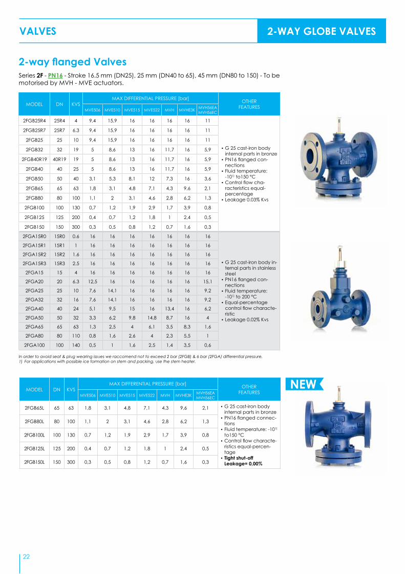
2-way flanged ValvesSeries 2F - PN16 - Stroke 16.5 mm (DN25), 25 mm (DN40 to 65), 45 mm (DN80 to 150) - To be motorised by MVH - MVE actuators.
MODEL DN KVSMAX DIFFERENTIAL PRESSURE [bar] OTHER
FEATURESMVE506 MVE510 MVE515 MVE522 MVH MVHE3K MVH56EA MVH56EC
2FGB25R4 25R4 4 9,4 15,9 16 16 16 16 11
• G 25 cast-iron body internal parts in bronze
• PN16 flanged con-nections
• Fluid temperature: -101) to150 °C
• Control flow cha-racteristics equal-percentage
• Leakage 0.03% Kvs
2FGB25R7 25R7 6.3 9,4 15,9 16 16 16 16 11
2FGB25 25 10 9,4 15,9 16 16 16 16 11
2FGB32 32 19 5 8,6 13 16 11,7 16 5,9
2FGB40R19 40R19 19 5 8,6 13 16 11,7 16 5,9
2FGB40 40 25 5 8,6 13 16 11,7 16 5,9
2FGB50 50 40 3,1 5,3 8,1 12 7,3 16 3,6
2FGB65 65 63 1,8 3,1 4,8 7,1 4,3 9,6 2,1
2FGB80 80 100 1,1 2 3,1 4,6 2,8 6,2 1,3
2FGB100 100 130 0,7 1,2 1,9 2,9 1,7 3,9 0,8
2FGB125 125 200 0,4 0,7 1,2 1,8 1 2,4 0,5
2FGB150 150 300 0,3 0,5 0,8 1,2 0,7 1,6 0,3
2FGA15R0 15R0 0.6 16 16 16 16 16 16 16
• G 25 cast-iron body in-ternal parts in stainless steel
• PN16 flanged con-nections
• Fluid temperature: -101) to 200 °C
• Equal-percentage control flow characte-ristic
• Leakage 0.02% Kvs
2FGA15R1 15R1 1 16 16 16 16 16 16 16
2FGA15R2 15R2 1.6 16 16 16 16 16 16 16
2FGA15R3 15R3 2.5 16 16 16 16 16 16 16
2FGA15 15 4 16 16 16 16 16 16 16
2FGA20 20 6.3 12,5 16 16 16 16 16 15,1
2FGA25 25 10 7,6 14,1 16 16 16 16 9,2
2FGA32 32 16 7,6 14,1 16 16 16 16 9,2
2FGA40 40 24 5,1 9,5 15 16 13,4 16 6,2
2FGA50 50 32 3,3 6,2 9,8 14,8 8,7 16 4
2FGA65 65 63 1,3 2,5 4 6,1 3,5 8,3 1,6
2FGA80 80 110 0,8 1,6 2,6 4 2,3 5,5 1
2FGA100 100 140 0,5 1 1,6 2,5 1,4 3,5 0,6
VALVES 2-WAY GLOBE VALVES
22 22
MODEL DN KVSMAX DIFFERENTIAL PRESSURE [bar] OTHER
FEATURESMVE506 MVE510 MVE515 MVE522 MVH MVHE3K MVH56EA MVH56EC
2FGB65L 65 63 1,8 3,1 4,8 7,1 4,3 9,6 2,1 • G 25 cast-iron body internal parts in bronze
• PN16 flanged connec-tions
• Fluid temperature: -101) to150 °C
• Control flow characte-ristics equal-percen-tage
• Tight shut-off Leakage= 0,00%
2FGB80L 80 100 1,1 2 3,1 4,6 2,8 6,2 1,3
2FGB100L 100 130 0,7 1,2 1,9 2,9 1,7 3,9 0,8
2FGB125L 125 200 0,4 0,7 1,2 1,8 1 2,4 0,5
2FGB150L 150 300 0,3 0,5 0,8 1,2 0,7 1,6 0,3
NEW
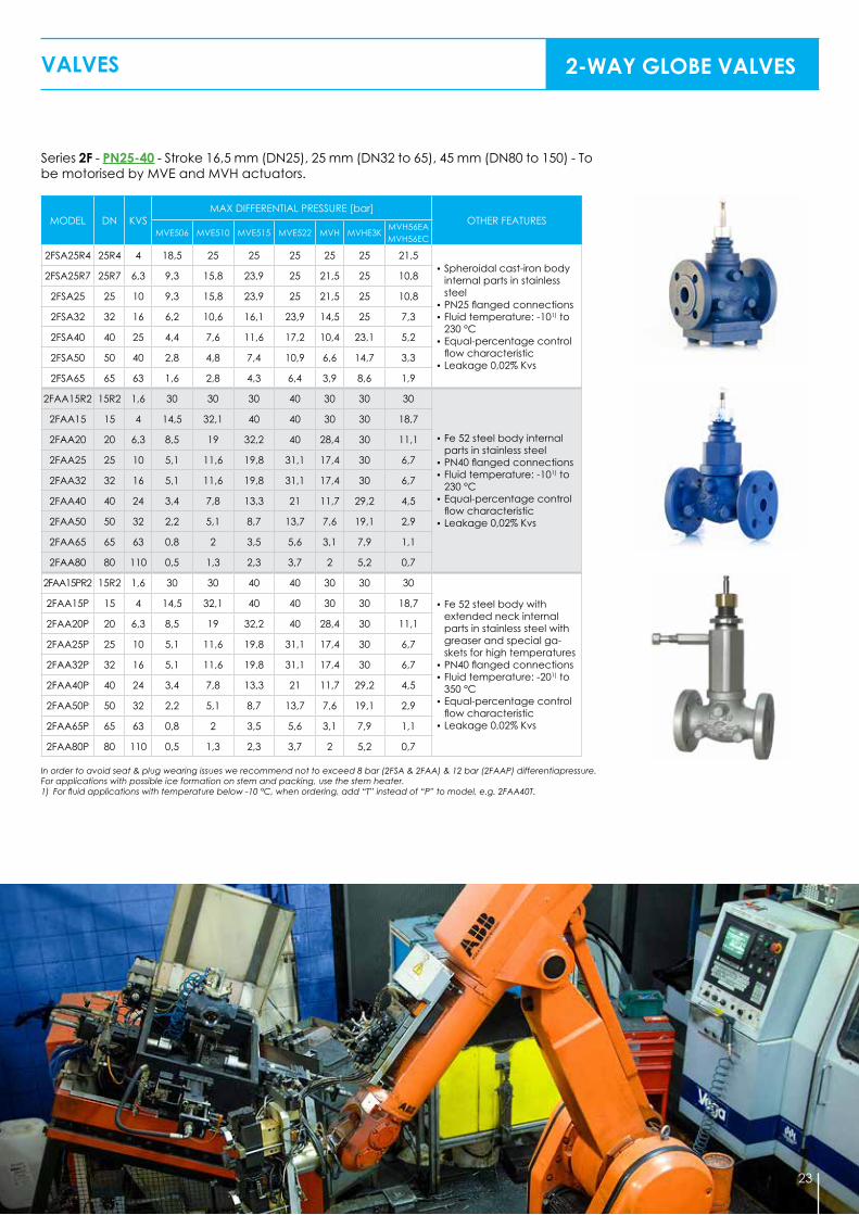
Series 2F - PN25-40 - Stroke 16,5 mm (DN25), 25 mm (DN32 to 65), 45 mm (DN80 to 150) - To be motorised by MVE and MVH actuators.
MODEL DN KVSMAX DIFFERENTIAL PRESSURE [bar]
OTHER FEATURESMVE506 MVE510 MVE515 MVE522 MVH MVHE3K
MVH56EA MVH56EC
2FSA25R4 25R4 4 18,5 25 25 25 25 25 21,5• Spheroidal cast-iron body
internal parts in stainless steel
• PN25 flanged connections• Fluid temperature: -101) to
230 °C• Equal-percentage control
flow characteristic • Leakage 0,02% Kvs
2FSA25R7 25R7 6,3 9,3 15,8 23,9 25 21,5 25 10,8
2FSA25 25 10 9,3 15,8 23,9 25 21,5 25 10,8
2FSA32 32 16 6,2 10,6 16,1 23,9 14,5 25 7,3
2FSA40 40 25 4,4 7,6 11,6 17,2 10,4 23,1 5,2
2FSA50 50 40 2,8 4,8 7,4 10,9 6,6 14,7 3,3
2FSA65 65 63 1,6 2,8 4,3 6,4 3,9 8,6 1,9
2FAA15R2 15R2 1,6 30 30 30 40 30 30 30
• Fe 52 steel body internal parts in stainless steel
• PN40 flanged connections• Fluid temperature: -101) to
230 °C• Equal-percentage control
flow characteristic• Leakage 0,02% Kvs
2FAA15 15 4 14,5 32,1 40 40 30 30 18,7
2FAA20 20 6,3 8,5 19 32,2 40 28,4 30 11,1
2FAA25 25 10 5,1 11,6 19,8 31,1 17,4 30 6,7
2FAA32 32 16 5,1 11,6 19,8 31,1 17,4 30 6,7
2FAA40 40 24 3,4 7,8 13,3 21 11,7 29,2 4,5
2FAA50 50 32 2,2 5,1 8,7 13,7 7,6 19,1 2,9
2FAA65 65 63 0,8 2 3,5 5,6 3,1 7,9 1,1
2FAA80 80 110 0,5 1,3 2,3 3,7 2 5,2 0,7
2FAA15PR2 15R2 1,6 30 30 40 40 30 30 30
• Fe 52 steel body with extended neck internal parts in stainless steel with greaser and special ga-skets for high temperatures
• PN40 flanged connections• Fluid temperature: -201) to
350 °C• Equal-percentage control
flow characteristic• Leakage 0,02% Kvs
2FAA15P 15 4 14,5 32,1 40 40 30 30 18,7
2FAA20P 20 6,3 8,5 19 32,2 40 28,4 30 11,1
2FAA25P 25 10 5,1 11,6 19,8 31,1 17,4 30 6,7
2FAA32P 32 16 5,1 11,6 19,8 31,1 17,4 30 6,7
2FAA40P 40 24 3,4 7,8 13,3 21 11,7 29,2 4,5
2FAA50P 50 32 2,2 5,1 8,7 13,7 7,6 19,1 2,9
2FAA65P 65 63 0,8 2 3,5 5,6 3,1 7,9 1,1
2FAA80P 80 110 0,5 1,3 2,3 3,7 2 5,2 0,7
2-WAY GLOBE VALVES
In order to avoid seat & plug wearing issues we recommend not to exceed 8 bar (2FSA & 2FAA) & 12 bar (2FAAP) differentiapressure.For applications with possible ice formation on stem and packing, use the stem heater.1) For fluid applications with temperature below -10 °C, when ordering, add “T” instead of “P” to model, e.g. 2FAA40T.
VALVES 2-WAY GLOBE VALVES
23

In order to avoid seat & plug wearing issues we recommend not to exceed 2 bar (2FGBB) & 8 bar (2FSA) & 12 bar (2FAAB) differen-tial pressure.1) For applications with possible ice formation on stem and packing, use the stem heater.
1) For applications with possible ice formation on stem and packing, use the stem heater.
2-way Balanced Plug ValvesSeries 2F.B PN16-25-40 Stroke 16,5 mm (DN25), 25 mm (DN40 to 65) 45 mm (DN80 to 150). To be motorised by MVH-MVE actuators.
MODEL DN KVSMAX DIFFERENTIAL PRESSURE [bar]
OTHER FEATURESMVE506 MVE510 MVE515 MVE522 MVH MVH56EA
MVH56EC
2FGB65B 65 63 10,8 16 16 16 16 14 • G25 cast iron body, brass plug• PN16 flanged connections• Fluid temperature: -101) to
150°C • Equal-percentage control
characteristic • Leakage 0,03% Kvs
2FGB80B 80 100 8 16 16 16 16 10,6
2FGB100B 100 130 5,3 13,9 16 16 16 7,4
2FGB125B 125 200 3,5 10,4 16 16 16 5,1
2FGB150B 150 300 2,1 7,8 15 16 12,9 3,5
2FSA25BR4 25R4 4 25 25 25 25 25 25
• Spheroidal cast iron body, stainless steel internal parts
• PN25 flanged connections • Fluid temperature: -101) to
230°C• Equal-percentage control
characteristic • Leakage 0,02% Kvs
2FSA25BR7 25R7 6,3 25 25 25 25 25 25
2FSA25B 25 10 25 25 25 25 25 25
2FSA32B 32 16 25 25 25 25 25 25
2FSA40B 40 25 24,9 25 25 25 25 25
2FSA50B 50 40 18,3 25 25 25 25 25
2FSA65B 65 63 12,2 25 25 25 25 17,6
2FSA80B 80 100 8,3 25 25 25 25 12,8
2FAA25B 25 10 30 30 30 40 30 30
• Steel body and stainless steel internal parts
• PN40 flanged connections• Fluid temperature: -201) to
230°C• Equal-percentage control
characteristic • Leakage 0,02% Kvs
2FAA32B 32 16 30 30 30 40 30 30
2FAA40B 40 25 27,6 30 30 40 30 30
2FAA50B 50 40 21 30 30 40 30 28,1
2FAA65B 65 63 14,9 30 30 40 30 20,4
2FAA80B 80 100 11 29,6 30 40 30 15,5
2FAA100B 100 160 6,5 19,1 30 34,9 30 9,5
2FAA125B 125 200 4,2 14,3 27,6 27 23,3 6,6
2-way Double-seat ValvesSeries 2FGA.B - 2FAA.B - Stroke 45 mm - To be motorised by MVH-MVE actuators.
MODEL DN KVSMAX DIFFERENTIAL PRESSURE [bar]
OTHER FEATURESMVE510 MVE515 MVE522 MVH MVH56EA
MVH56EC
2FAA150B(PN25) 150 300 9,5 20,3 25 17,1 2,9
• Fe 52 Steel body and stainless steel internal parts
• PN40 flanged connections• Fluid temperature: -101) ÷ 230°C• Equalpercentage control characteristic• Leakage 0,12% Kvs
2FGA200B(PN16) 200 500 12 16 16 16 3,7
• G25 cast iron body, stainless steel inter-nal parts
• PN16 flanged connections• Fluid temperature: -101) to 200°C • Equalpercentage control characteristic• Leakage 0,02% Kvs
2-WAY GLOBE VALVES2-WAY GLOBE VALVESVALVES 2-WAY GLOBE VALVES
24

2-WAY GLOBE VALVESVALVES 2-WAY GLOBE VALVES
2FIA series2-way globe valves PN16 and PN40 with stainless steel body and internal parts.Fluid temperature range: –30 to +180 °CPN16 models: DN65, 100PN40 models: DN25, 32, 40, 50, 80Linear flow characteristic, V-port plug2FIA valves are motorized by MVE actuators(assembled on the valve in our factory, please include “MVEAV-10” code).
MODEL DN [inches] FLOW RATEKVS [m3/h]
STROKE[mm]
2FIA25 1” 10
20
2FIA32 1” 1/4 16
2FIA40 1” 1/2 24
2FIA50 2” 42
2FIA65 2” 1/2 63
2FIA80 3” 91
2FIA100 4” 138
MODEL DNMAX DIFFERENTIAL PRESSURE [bar]
MVE506 MVE510 MVE515 MVE522
2FIA25 25 10 - - -
2FIA32 32 5,7 - - -
2FIA40 40 4 6,7 - -
2FIA50 50 2,3 3,9 - -
2FIA65 65 - 2,4 3,6 -
2FIA80 80 - - 2,9 4,3
2FIA100 100 - - - 2,4
25
Valve Body: Stainless steel AISI 316 ASTM CF8MTrim (plug-seat): 316LStem: 316LStem Packing: PTFEPlug and Seat sealing: PTFEActuator: See data sheets for MVE actuator and MVH actuatorActuator Yoke: AluminiumValve/Actuator connection: U-bolt connection

VALVES PICVs
Dymanic pressure independent control valveswith threaded connectionsVSX..PB/VSXT..PB PN25 pressure independent balancing & control valves can be used in heating and cooling systems in applications with Fan Coil Units, Chilled Beams or other termi-nal units applications. VSX..PB/VSXT..PB valves provide modulating control with full authority regardless of any fluctuations in the differential pressure of the system.VSX..PB/VSXT..PB valves combine an externally adjustable automatic balancing valve, differ-ential pressure control valve and a full authority modulating control valve.VSX..PB/VSXT..PB valves make it simple to achieve 100% control of the water flow in the build-ing, while creating high comfort and energy seving at the same time. An additional benefit is that no balancing is required if further stages are added to the system, or if the dimensioned capacity is changed.Energy saving is due to optimal control, lower flow and pump pressure. Maximized ΔT is due to faster response and increased system stability.
MODEL P/T PLUGS CONNECTION DIMENSIONS STROKE [mm]
MIN. FLOW [l/h]
MAX. FLOW [l/h]
MAX. DIFF. PRESSURE [kPa]
VSX03PB -G1/2” M DN10
2,5 30 200
600
VSXT03PB - 5 65 370
VSX05PB -G3/4” M DN15
2,5 100 575
VSXT05PB - 5 220 1330
VSX06PB -G1” M DN20
2,5 100 575
VSXT06PB - 5,5 330 1800
VSX03PBP ●G1/2” M DN10
2,5 30 200
VSXT03PBP ● 5 65 370
VSX05PBP ●G3/4” M DN15
2,5 100 575
VSXT05PBP ● 5 220 1330
VSX06PBP ●G1” M DN20
2,5 100 575
VSXT06PBP ● 5,5 300 1800
VSXT07PBP ● G1 ¼” M DN25 5,5 600 3609800
VSXT08PBP ● G1”½ M DN32 5,5 550 4001
VSXT09PBP ● G1 ½”F DN40 15 1370 9500800
VSXT10PBP ● G2”F DN50 15 1400 11500
Valves with 2,5mm stroke: to be motorized by MCA24L, MCA230L, MVX52B actuators
Valves with 5 and 5,5mm stroke: to be motorized by MVT403S, MVT203S, MVT503S actuators. They can also be motorized by MCA24L, MCA230L, MVX52B actuators but in this case the actual max. flow is 75% of the max. flow values written in the spreadsheet above.
Valves with 15mm stroke: to be motorized by MVE_S actuators with 600N force
CAST IRON P/TPLUGS
If MVX52B is not powered PICV is OPENIf MCA24L/MCA230L is not powered PICV is CLOSEDATTENTION
26

27
VALVES
Dymanic pressure independent control valveswith flanged connectionsBV..P valves can be used in heating and cooling systems that require high flows together with an accurate control; they provide modulating control with full au-thority regardless of any fluctuations in the differential pressure of the system.PICVs are 3 devices in one:• Static Flow limiting valve: the flow of the fully open valve can be selected in a range from 30% to 100% by adjusting the setting wheel on the valve.• Globe Valve: the flow can be controlled from 0 up to the maximum set flow by moving the valve plug.• Differential Pressure Controller with the main objective of keeping the pressure drop constant across the valve plug and consequently a flow control not depend-ent on differential pressure.BV valves have an equipercentage characteristic.
Dynamic balancing eliminates overflows, regardless of fluctuating pressure conditions in the system.BV..P valves can be supplied with the proper actuator already assembled on the valve.Pressure Independent Control Valve with diaphragm structure.BV..P are equipped with pressure plugs, useful to measure the real differential pressure across the valve.
Valve body: ductile cast ironValve trim: stainless steelValve stem: stainless steelMembrane: EPDMLeakage rate: 0,01% of the KvsFluids: chilled water, hot water, glycol (50% max.), from -10°C to 120°C.
MODEL PN P/TPLUGS DN STROKE
[mm]
MAX. DIFF. PRESSURE
[kPa]
MIN. FLOW [l/h]
MAX. FLOW [l/h]
BV65P 16 ● 65 20 400 4200 24100
BV80P 16 ● 80 20 400 5900 37300
BV100P 25 ● 100 20 1600 1620 50630
BV125P 25 ● 125 20 1600 2800 66840
MODEL WITH
P/T PLUGS
MODEL WITHOUT
P/T PLUGS
VALVE CONNEC-
TION
COMPATIBLE ACTUATORS AND MAXIMUM FLOW RATES [l/h]
MCA230L MCA24L MVX52B
MVT203S MVT403S MVT503S
MVE204S MVE504S
MVE210 MVE510
MVE215 MVE515
ELECTRO-THERMAL 140N
ELECTRO-MECHANICAL 300N
ELECTRO-MECHANICAL 400N
ELECTRO-MECHANICAL 1000N
ELECTRO-MECHANICAL 1500N
VSX03PBP VSX03PB 1/2” M 200 - - - -
VSXT03PBP VSXT03PB 1/2” M 300 370 - - -
VSX05PBP VSX05PB 3/4” M 575 - - - -
VSXT05PBP VSXT05PB 3/4” M 1000 1330 - - -
VSX06PBP VSX06PB 1” M 575 - - - -
VSXT06PBP VSXT06PB 1” M 1350 1800 - - -
VSXT07PBP - 1 ¼”M 2400 3600 - - -
VSXT08PBP - 1 ½”M 2700 4000 - - -
VSXT09PBP - 1 1/2”F - - 9500 - -
VSXT10PBP - 2”F - - 11500 - -
BV65P - DN65mm - - - 24100 -
BV80P - DN80mm - - - 37300 -
BV100P - DN100mm - - - - 50630
BV125P - DN125mm - - - - 66840
PICVs

28
VALVES
In order to avoid seat & plug wearing issues we recommend not to exceed 4 bar differential pressure.1) For applications with possible ice formation on stem and packing, use the stem heater.
In order to avoid seat & plug wearing issues we recommend not to exceed 2 bar differential pressure.1) For applications with possible ice formation on stem and packing, use the stem heater.
Series VMB (threaded) - VMBF (flanged) - PN16. To be motorised by MVB - MVE - MVH actuators. - Thermal insulation available.
MODEL DN KVSMAX DIFFERENTIAL PRESSURE [bar] OTHER
FEATURESMVB MVE506 MVE510 MVE515 MVE522 MVH MVH56EA MVH56EC
VMB3 3/4” 6,3 2,6 13,1 16 16 16 16 15,6 • G 25 cast-iron body• Brass internal parts• Female threaded connections• Fluid temperature: -101)÷150°C
(with MVB max 120 °C, with MVB+MVBHT max 140 °C)
• Control characteristic: equal-percentage on direct way, linear on angle way
• Leakage 0,03% Kvs• For MVE actuator, add AG52
linkage • For MVH actuator, add AG62
linkage
VMB4 1” 10 1,7 8,7 15,6 16 16 16 10,3
VMB5 1 ¼” 16 1,1 5,4 9,8 15,4 16 13,7 6,5
VMB6 1 ½” 22 0,8 3,9 7,1 11,1 16 9,9 4,7
VMB8 2” 30 0,6 2,9 5,4 8,4 14,3 7,5 3,5
VMB8A 2” 40 0,6 2,9 5,4 8,4 14,3 7,5 3,5
VMB3F 20 6,3 2,6 13,1 16 16 16 16 15,6
• As above with PN16 slip-on flanges
VMB4F 25 10 1,7 8,7 15,6 16 16 16 10,3
VMB5F 32 16 1,1 5,4 9,8 15,4 16 13,7 6,5
VMB6F 40 22 0,8 3,9 7,1 11,1 16 9,9 4,7
VMB8F 50 30 0,6 2,9 5,4 8,4 14,3 7,5 3,5
VMB8AF 50 40 0,6 2,9 5,4 8,4 14,3 7,5 3,5
In order to avoid seat & plug wearing issues we reccomend not to exceed 2 bar differential pressure.
Tight Close-OffSeries VMBPM threaded valves - Tight close-off modulating valves PN16 - Thermal insula-tion available - To be motorised by MVB actuators.
Series 3T (threaded) - PN16 - Stroke 11,5 mm. To be motorised by MVB (3TGB.B) - MVE.S (3TGB.F) actuators.
MODEL DN KVS MAX DIFF. PRESSURE [bar] ACTUATORS OTHER FEATURES
3TGB15BR2 1/2" 1,6
16For MVB actuator
(or MVT203,403,503 using AG74 adapter)
• GJL-250 cast-iron body • Brass internal parts• Equal-percentage control flow
characteristic • Leakage 0 to 0,001% Kvs• Female threaded connections:
fluid temperature -51) to 140 °C, with MVB max 120°C (140 °C with MVB+MVBHT)
3TGB15BR3 1/2” 2,5
3TGB15B 1/2” 4
3TGB15FR2 1/2" 1,6
16 For MVE.S actuator3TGB15FR3 1/2” 2,5
3TGB15F 1/2” 4
3-WAY GLOBE VALVES
MODEL DN KVS STROKE [mm] MAX DIFFERENTIAL PRESSURE [bar] OTHER FEATURES
VMBP3M 3/4” 6.3 16.5 8.8
• G25 cast iron valve body• Fluid temperature -5 to 95°C• Leakage 0% Kvs
VMBP4M 1" 10 16.5 5.5
VMBP5M 1 ¼” 16 16.5 3.5
VMBP6M 1 ½” 25 16.5 2.5
VMBP8M 2” 40 16.5 1.8

Series VMB.T in G25 cast-iron PN16 Stroke 5,5mm - To be motorised by MVT203,403,503 actuators
MODEL DN KVSMAX DIFFERENTIAL PRESSURE [bar]
MVE506 MVE510 MVE515 MVE522 MVH56EA MVH56EC
3TBB15 1/2” 2 16 16 16 16 16
3TBB20 3/4” 5 16 16 16 16 16
3TBB25 1” 10 9,7 16 16 16 11,7
3TBB32 1 ¼” 16 6,1 11,2 16 16 7,3
3TBB40 1 ½” 25 4,2 7,7 12,1 16 5
3TBB50 2” 38 2,3 4,2 6,7 10,6 2,8
3TBB Series 3-way valves, mixing or diverting, bronze valve bodies with threaded connections, brass plug, stainless steel stem. Temperature applications 2°C to 200°C. Rangeability 50:1.To be motorised by MVE and MVH actuators (no adapter needed).1/2” and 3/4” models are tight close-off. Maximum leakage on 1” to 2” models is 0,1% of Kvs.Stroke on 1/2” and 3/4” models is 9,5mm. Stroke on 1” to 2” models is 16mm.
3-WAY GLOBE VALVES
Old VMBT3, VMBT4, VMBT5, VMBT6, (motorized by MVT44,28,56,57 actuators) still available as spare parts.
2-WAY GLOBE VALVES2-WAY GLOBE VALVESVALVES 3-WAY GLOBE VALVES
MODEL DNKVS MAX DIFF. PRESSURE [kPa]
OTHER FEATURESA-AB A-AB B-AB
VMB3T 3/4" 6,3 900 700• G25 cast iron body• Fluid temp. 5 to 95 °C• Linear control characteristic• Leakage: direct way <0.03% Kvs,
angle way < 2% Kvs
VMB4T 1" 10 550 450
VMB5T 1 ¼” 14 350 300
VMB6T 1 ½” 18 250 200
VMB8T 2" 25 190 160
NEWMODELS WITHOUTSPRING
VSB/VMB valves with male threaded connections “PS150”
29
UPON REQUESTVariants available to
be motorized with MVT 300N actuators (see
page 35) by means of AG73 linkage kit.

In order to avoid seat & plug wearing issues we recommend not to exceed 2 bar (3FGB) & 8 bar (3FSA & 3FSAS) differential pressure.1) For applications with possible ice formation on stem and packing, use the stem heater.
Series 3F PN16-25 - Stroke 16,5 mm (DN25), 25mm (DN32-65), 45mm (DN80-150) - To be motor-ised by MVE-MVH actuators.
MODEL DN KVSMAX DIFFERENTIAL PRESSURE [bar]
OTHER FEATURESMVE506 MVE510 MVE515 MVE522 MVH MVHE3K MVH56EA
MVH56EC
3FGB25R4 25R4 4 7 12,7 16 16 16 16 8,4
• G25 cast-iron body brass internal parts
• PN16 flanged connections• Fluid temp.: - 101) to 150 °C• Control flow characteristic:
direct way: equal-percen-tage, angle way: linear
• Leakage: direct-way: 0,03% Kvs, angle way: 2% Kvs
3FGB25R7 25R7 6,3 7 12,7 16 16 16 16 8,4
3FGB25 25 10 7 12,7 16 16 16 16 8,4
3FGB32 19 19 3,9 7,1 11,1 16 9,9 16 4,7
3FGB40R19 40R19 19 3,9 7,1 11,1 16 9,9 16 4,7
3FGB40 40 25 3,9 7,1 11,1 16 9,9 16 4,7
3FGB50 50 40 2,5 4,5 7,1 12 6,3 14,4 3
3FGB65 65 63 1,5 2,7 4,2 7,1 3,7 8,5 1,7
3FGB80 80 100 0,9 1,7 2,7 4,6 2,4 5,6 1,1
3FGB100 100 130 0,6 1,1 1,7 2,9 1,5 3,6 0,7
3FGB125 125 200 0,4 0,7 1,1 1,8 1 2,3 0,4
3FGB150 150 300 0,2 0,5 0,7 1,2 0,7 1,6 0,3
3FSA25R4 25R4 4 9,5 22,2 25 25 25 25 12,5
• G-308 spheroidal cast-iron body stainless steel internal parts
• PN25 flanged connections• Fluid temp.: -101) to 230 °C• Control flow characte-
ristic: equalpercentage (DN25÷65) linear (DN80), angle way: linear
• Leakage 0,02% Kvs
3FSA25R7 25R7 6,3 4,7 11,2 19,3 25 16,9 25 6,3
3FSA25 25 10 4,7 11,2 19,3 25 16,9 25 6,3
3FSA32 32 19 3,1 7,5 13 23,9 11,4 25 4,2
3FSA40 40 25 2,2 5,4 9,4 17,2 8,2 20,8 3
3FSA50 50 40 1,3 3,4 5,9 10,9 5,2 13,3 1,8
3FSA65 65 63 0,7 1,9 3,4 6,4 3 7,8 1
3FSA80 80 100 0,7 1,5 2,2 4,2 2,2 5,3 0,9
3FSA25SR4 25R4 4 5 5 5 5 5 5 5
• G 308 spheroidal cast-iron body stainless steel internal parts with bellows seal
• PN25 flanged connections • Fluid temp.: -101) to 300 °C• Control flow characteri-
stic: equal percentage (DN25÷65) linear (DN80), angle way: linear
• Leakage 0,02% Kvs
3FSA25SR7 25R7 6,3 5 5 5 5 5 5 5
3FSA25S 25 10 5 5 5 5 5 5 5
3FSA32S 32 16 4,7 5 5 5 5 5 5
3FSA40S 40 25 3,4 5 5 5 5 5 4,2
3FSA50S 50 40 2,2 4,2 5 5 5 5 2,7
3FSA65S 65 63 1,3 2,5 4 5 3,5 5 1,6
3FSA80S 80 100 0,8 1,6 2,6 4,2 2,3 5 1
MODEL DN KVSMAX DIFFERENTIAL PRESSURE [bar]
OTHER FEATURESMVE506 MVE510 MVE515 MVE522 MVH MVHE3K MVH56EA
MVH56EC
3FGB65L 65 63 1,5 2,7 4,2 7,1 3,7 8,5 1,7 • G25 cast-iron body brass internal parts
• PN16 flanged connections• Fluid temp.: - 101) to 150 °C• Control flow characteristic:
direct way: equal-percen-tage, angle way: linear
• Tight shut-off Leakage = 0,00%
3FGB80L 80 100 0,9 1,7 2,7 4,6 2,4 5,6 1,1
3FGB100L 100 130 0,6 1,1 1,7 2,9 1,5 3,6 0,7
3FGB125L 125 200 0,4 0,7 1,1 1,8 1 2,3 0,4
3FGB150L 150 300 0,2 0,5 0,7 1,2 0,7 1,6 0,3
3-WAY GLOBE VALVESVALVES 3-WAY GLOBE VALVES
30
NEW

In order to avoid seat & plug wearing issues we recommend not to exceed 12 bar differential pressure.1) For fluid applications with temperature below -10 °C, when ordering, add “T” , instead of “P” to model, e.g. 3FAA40T
Series 3F PN40 - Stroke 16,5 mm (DN25), 25mm (DN32-65), 45mm (DN80-125) - To be mo-torised by MVE-MVH actuators.
MODEL DN KVSMAX DIFFERENTIAL PRESSURE [bar]
OTHER FEATURESMVE506 MVE510 MVE515 MVE522 MVH MVHE3K MVH56EA
MVH56EC
3FAA25R4 25R4 4 6 13 21,7 35,3 19,2 30 7,7
• Fe 52 steel body stainless steel internal parts
• PN40 flanged connections• Fluid temperature: -101) to
230 °C• Control flow characteristic:
linear• Leakage 0,02% Kvs
3FAA25R7 25R7 6,3 6 13 21,7 35,3 19,2 30 7,7
3FAA25 25 10 6 13 21,7 35,3 19,2 30 7,7
3FAA32 32 16 3,8 8,2 13,7 23,9 12,1 30 4,8
3FAA40 40 25 2,4 5,3 9 15,6 7,9 19,4 3,1
3FAA50 50 40 1,7 3,7 6,3 10,9 5,6 13,7 2,2
3FAA65 65 63 1 2,2 3,7 6,4 3,3 8,1 1,3
3FAA80 80 100 0,6 1,4 2,4 4,2 2,1 5,3 0,8
3FAA100 100 140 0,4 0,9 1,5 2,6 1,4 3,4 0,5
3FAA125 125 250 0,2 0,6 1 1,7 0,8 2,1 0,3
3FAA25PR4 25R4 4 6 13 21,7 35,3 19,2 30 7,7• Fe 52 steel body internal
parts in AISI 316 stainless steel with grease-cap and special seals for high temperature
• PN40 flanged connections• Fluid temperature: - 201) to
350 °C• Control flow characteri-
stics: linear• Leakage 0,02% Kvs
3FAA25PR7 25R7 6,3 6 13 21,7 35,3 19,2 30 7,7
3FAA25P 25 10 6 13 21,7 35,3 19,2 30 7,7
3FAA32P 32 16 3,8 8,2 13,7 23,9 12,1 30 4,8
3FAA40P 40 25 2,4 5,3 9 15,6 7,9 19,4 3,1
3FAA50P 50 40 1,7 3,7 6,3 10,9 5,6 13,7 2,2
3FAA65P 65 63 1 2,2 3,7 6,4 3,3 8,1 1,3
3FAA80P 80 100 0,6 1,4 2,4 4,2 2,1 5,3 0,8
3FAA100P 100 140 0,4 0,9 1,5 2,6 1,4 3,4 0,5
3FAA125P 125 250 0,2 0,6 1 1,7 0,8 2,1 0,3
3-WAY GLOBE VALVES2-WAY GLOBE VALVES2-WAY GLOBE VALVESVALVES 3-WAY GLOBE VALVES
“PS89”2FGB - 3FGB valves with grooved connections suitable to Victauilic clampsFor example: 3FGB65PS89
31
3FGB valves with stainless steel plug3FGB valves are also available with stainless steel plug and stainless steel stem packing, both AISI 304. Just add PS73 at the end of the part-number, for example: 3FGB65PS73

32
3-WAY GLOBE VALVES
3FIA series3-way mixing globe valves PN16 and PN40 with stainless steel body and internal parts.Fluid temperature range: –30°C to +180 °CPN16 models: DN65, 100PN40 models: DN25, 32, 40, 50, 80Linear flow characteristic, V-port plug3FIA valves are motorized by MVE actuators(assembled on the valve in our factory, please include “MVEAV-10” code).
MODEL DN [inches] KVS [m3/h] STROKE [mm]
3FIA25 1” 10
20
3FIA32 1” 1/4 16
3FIA40 1” 1/2 24
3FIA50 2” 42
3FIA65 2” 1/2 63
3FIA80 3” 91
3FIA100 4” 138
VALVES
Valve Body: Stainless steel AISI 316 ASTM CF8MTrim (plug-seat): 316LStem: 316LStem Packing: PTFEPlug and Seat sealing: PTFEActuator: See data sheets for MVE actuator and MVH actuatorActuator Yoke: AluminiumValve/Actuator connection: U-bolt connection
MODEL DNMAX DIFFERENTIAL PRESSURE [bar]
MVE506 MVE510 MVE515 MVE522
3FIA25 25 10 - - -
3FIA32 32 5,7 - - -
3FIA40 40 4 6,7 - -
3FIA50 50 2,3 3,9 - -
3FIA65 65 - 2,4 3,6 -
3FIA80 80 - - 2,9 4,3
3FIA100 100 - - - 2,4
32

33
90N-140N 300N600N
450N 1500N
3000N
FCUs, zone valves
AHUs, air conditioning, heating
Industrial processes / steam
PRICE
ACTUATORS OVERVIEW
FORCE

ACTUATORS MVT AND MVB
Actuators for Zone Valves and Terminal Unit ValvesSeries MVT2./4. - Bidirectional type - Stroke 5,5 mm, stroke time 117 s. - For V.XT - V.BT valve bodies - Protection IP43. Series MVT5. - Bidirectional type with microprocessor module for proportional signal Vdc - 24 Vac power supply - Stroke 5 mm to 5,5 mm, stroke time 117 s. - For V.XT - V.BT valve bodies - Protection IP43.
MODELPOWER SUPPLY [Vac]
CONSUMPTION VA OTHER FEATURES
MVT28 230 5 3-position control
MVT44 24 0,5 3-position control
MVT56 24 1 0 to 10 / 6 to 10 / 1 to 5 / 2 to 10 / 4 to 7 / 6 to 9 / 8 to 11 Vdc proportional control - direct/reverse action
MVT56L 24 1 Same as MVT56 but Stroke 8,5 mm
MVT56S 24 1 Same as MVT56 but Stroke 5 mm
MVT57 24 1 0 to 10 Vdc - proportional control - only direct action
Globe Valve ActuatorsSeries MVB - Bidirectional motor for V.B threaded ½” to 2” and flanged 15 to 50 mm valve bodies - Supplied with linkage for mounting on 2T-3T and V.B-V.BF valve bodies - IP50 protection.
MODEL TIMING [s] POWER SUPPLY [Vac]
COSUMPTION VA OTHER FEATURES
MVB22 37 230 5
on/off, floatingMVB26 60 230 5
MVB28 370 230 5
MVB46 60 24 5
MVB46P As MVB46 with 1 kOhm auxiliary potentiometer
MVB36 60 24 5 proportional potentiometric
MVB52 37 24 5 Vdc/ current proportional control. Ranges: 6 to 9, 4 to 7, 8 to 11, 0 to 10, 2 to 10, 1 to 5 Vdc, 4 to 20 mA. Default setting: 0 to 10Vdc MVB56 60 24 5
MVBAV MVB mounting on valve body
200 N
450 N
34

ACTUATORS MVT 300N
Electric bidirectional actuator with compact dimensions suitable to valves with hot or cool water used in a variety of applications including FCUs, AHUs, zone control systems, solar plants, small heating and cooling plants, small re-he-ating and dehumidification coils.Force is 300N i.e. it provides 50% more force than standard MVT actuators that means higher close-off performances. It is easy to fit the actuator on Controlli valves.Further more, thanks to self-stroking fea-ture and 17mm long stroke, these new MVT 300N actuators can be used to retrofit actuators from other manufac-turers, for example actuators for MZX, VZX, MEU, FEU, VEU Satchwell valves. Additionally, they can be used to mo-torize a number of PICVs available in the market.Please contact [email protected] for
a comprehensive list of manufacturers. MVT 300N actuators can be controlled by either proportional (modulating) si-gnals or by an increase/decrease (flo-ating) signal.On all models, PC Board is equipped with two micro-switches detecting the complete open and complete closed positions. Two versions are available:SHORT: up to 9mm yoke, self stroking, only pushingLONG: up to 17mm yoke, self stroking, push & pull Timing:60seconds on 5,5 mm stroke valves e.g. VMBT90seconds on 8,5 mm stroke valves e.g. 2TGA..B
IP43 protection class.Manual override by means of a 3mm Allen key. Proportional actuators can be con-nected to any controller with 0..10Vdc, 2..10Vdc, 0..5Vdc, 6..10Vdc, 4..20mA signal.Feedback signal: 2..10Vdc (2V=fully re-tracted; 10V= fully extended) Proportional actuators are equipped with 3 LEDs visible under the cover• Green for Power On• Yellow for opening action• Red for closing action Direct / reverse action: actuator move-ment direction can be selected via a dip-switch.
MVT 300 NewtonCompact Actuator
35
VALVES WITH SPRING VALVES WITHOUT SPRINGVSXT/VMXT/VTXT
VALVES FOR FCUS
1/2” TO 3/4”STROKE 5,5mm
VSXT..PBPICVS
1/2” TO 1” 1/2STROKE 5,0mm
VSBT_ / VMBT_GLOBE VALVES3/4” TO 1” 1/2STROKE 5,5mm
2TGA..BVALVES WITH
HIGH CLOSE-OFF3/4” TO 2”
STROKE 8,5mm
VSB_T / VMB_TGLOBE VALVES
3/4” TO 2”STROKE 5,5mm
VALVES FROM OTHER MANU-
FACTURERS UP TO 17 mm
STROKE
2TGB15B3TGB15B
GLOBE VALVES STROKE 11,5 mmMODEL CONTROL
SIGNAL
POWER SUPPLY[Vca]
IP
SHORT YOKE,ONLY
PUSHING
MVT203S3POS.
230
IP43MVT403S24
MVT503S PROP.
LONG YOKE,
PULLING & PUSHING
MVT2033POS.
230
IP43
(AG74-03)
MVT40324
(AG74-03)
MVT503 PROP. (AG74-03)

MVE
The MVE is a flexible electro-mechani-cal actuator for the control of two and three way globe valves in: Heating and Cooling systems, Air handling units, District Heating plants, Industrial Temperature Control systems. The MVE can be controlled either by a propor-tional (modulating) signal or by an in-crease/decrease (Floating) signal sim-ply changing switch settings on the field. It is designed for an easy instal-lation to any CONTROLLI flanged val-ve. Linkage kits are available for threa-ded valves as well as for valves of other manufacturers.The Actuator has a fine resolution (500 steps on the full stroke range) for a very accurate fluid control and it is able to self-calibrate on a different stroke wi-thout the need of any user action. A Plug&Play function is available as well calibrating the actuator on the valve at the very first power-on only. The MVE implements an smart control algorithm with self diagnostic and alarm functio-nality in case of unexpected operation,
feedback of alarms to the user is provided by LEDs (Green and Red) on the control board.MVE is available with stan-dard yoke and with a com-pact yoke for applications where compact dimensions are required and each ver-sion can be available with clo-se-off force 400 N, 600 N, 1000 N, 1500 N and 2200 N.
Universal Actuator for globe valves
ACTUATORS
36
MODELTIMING [s] POWER SUPPLY
[Vca] FORCE [N] IP MORE FEATURESSTROKE [mm]
3P.5/15 15/25 25/60 MVE5.. MVE2..
MVE504 MVE204*
15 s 20 s 30 s 60 s 24 230
400
IP54
Control 3p floating and proportional switch selectable. Control range 0..10 Vdc, 2..10 Vdc, 0..5 Vdc, 5..10 Vdc, 2..6 Vdc, 6..10 Vdc and 4-20 mA STROKE 5-60 mm
MVE506 MVE206* 600
MVE510 MVE210* 1000
MVE515 MVE215* 1500
MVE522 MVE222* 2200
MVE504S MVE204S*
15 s 20 s 30 s 60 s 24 230
400
IP54
Control 3p floating and proportional switch selectable. Control range 0..10 Vdc, 2..10 Vdc, 0..5 Vdc, 5..10 Vdc, 2..6 Vdc, 6..10 Vdc and 4-20 mA STROKE 5-30 mm Short Yoke
MVE506S MVE206S* 600
MVE510S MVE210S* 1000
MVE515S MVE215S* 1500
MVE522S MVE222S* 2200
MVEAV MVE assembly on valve body
MVE5.. - MVE5..SMVE is available with very low voltage power supply 24 Vac or 24Vdc.MVE2.. - MVE2..SMVE is also available with high voltage power supply 230Vac with the same functionality of the 24Vac/dc* MVE2... - MVE2...S are not UL Listed.
MVE.R
MODELTIMING [s]
POWER SUPPLY FORCE [N] IP MORE FEATURESSTROKE [mm]
3P5/15 15/25 25/60 MVE5.. MVE2..
MVE504R MVE204R
15 s 20 s 25 s 60 s 24Vac/dc
230Vac
400
IP54
Control 3p floating and proportional switch selectable. Control range 0..10 Vdc, 2..10 Vdc, 0..5 Vdc, 5..10 Vdc, 2..6 Vdc, 6..10 Vdc and 4-20 mA STROKE 5-60 mmEmergency position (stem up / stem down) selectable with jumper setting on the PCBA. Supercapacitor charging time after power off 130s
MVE506R MVE206R 600
MVE510R MVE210R 1000
MVE515R MVE215R 1500
MVE504SR MVE204SR
15 s 20 s 25 s 60 s 24Vac/dc
230Vac
400
IP54
Control 3p floating and proportional switch selectable. Control range 0..10 Vdc, 2..10 Vdc, 0..5 Vdc, 5..10 Vdc, 2..6 Vdc, 6..10 Vdc and 4-20 mA STROKE 5-30 mm Short YokeEmergency position (stem up / stem down) selectable with jumper setting on the PCBA. Supercapacitor charging time after power off 130s
MVE506SR MVE206SR 600
MVE510SR MVE210SR 1000
MVE515SR MVE215SR 1500
MVEAV MVE assembly on valve body
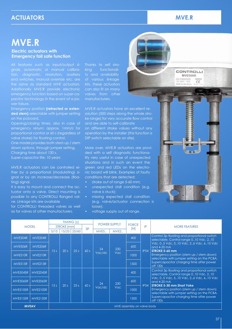
Electric actuators with Emergency fail safe function
ACTUATORS
All features such as input/output si-gnals, automatic or manual calibra-tion, diagnostic, resolution, auxiliary end switches, manual override etc. are the same as standard MVE actuators. Additionally MVE.R provide electronic emergency function based on super-ca-pacitor technology in the event of a po-wer failure. Emergency position (retracted or exten-ded stem) selectable with jumper setting on the pcboard. Opening/closing times, also in case of emergency return: approx. 1mm/s for proportional control or 60 s (regardless of valve stroke) for floating control. One model provides both stem up / stem down options, through jumper setting.Charging time about 130 s. Super-capacitor life: 10 years MVE.R actuators can be controlled ei-ther by a proportional (modulating) si-gnal or by an increase/decrease (floa-ting) signal.It is easy to mount and connect the ac-tuator onto a valve. Direct mounting is possible to any CONTROLLI flanged val-ve. Linkage kits are availablefor CONTROLLI threaded valves as well as for valves of other manufacturers.
Thanks to self stro-king functionali-ty and availability of various linkage kits, these actuators can also fit on many valves from other manufacturers. MVE.R actuators have an excellent re-solution (500 steps along the whole stro-ke range) for very accurate flow control and are able to self-calibrateon different stroke values without any operation by the installer (this function is DIP switch selectable on site). More over, MVE.R actuators are provi-ded with a self diagnostic functiona-lity very useful in case of unexpected situations and in such an event the green and red LEDs on the electro-nic board will blink. Examples of faulty conditions that are detected:• stroke out of range 5-60 mm;• unexpected stall condition (e.g.
valve is stuck);• missing expected stall condition
(e.g. valve/actuator connection is loose);
• voltage supply out of range.
37
CABLE GLAND
ACTUATORS
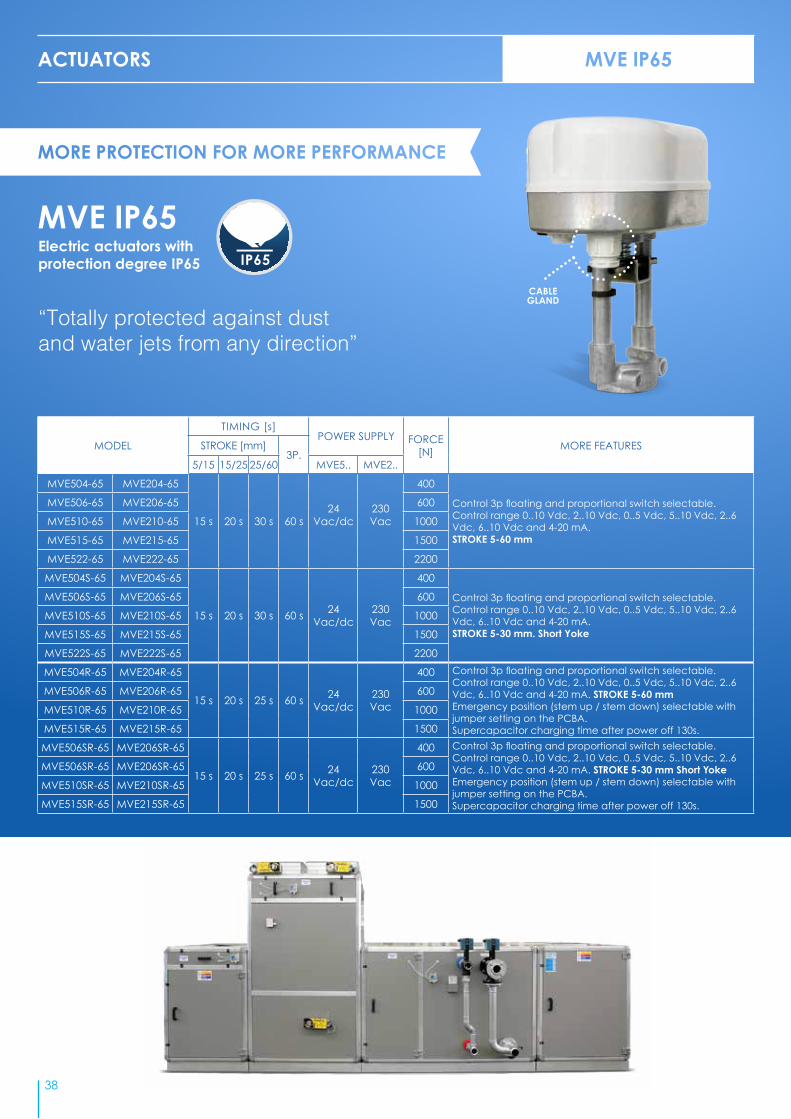
MVE IP65Electric actuators with protection degree IP65
“Totally protected against dust and water jets from any direction”
MODEL
TIMING [s]POWER SUPPLY FORCE
[N] MORE FEATURESSTROKE [mm]3P.
5/15 15/25 25/60 MVE5.. MVE2..
MVE504-65 MVE204-65
15 s 20 s 30 s 60 s24
Vac/dc230Vac
400
Control 3p floating and proportional switch selectable. Control range 0..10 Vdc, 2..10 Vdc, 0..5 Vdc, 5..10 Vdc, 2..6 Vdc, 6..10 Vdc and 4-20 mA. STROKE 5-60 mm
MVE506-65 MVE206-65 600
MVE510-65 MVE210-65 1000
MVE515-65 MVE215-65 1500
MVE522-65 MVE222-65 2200
MVE504S-65 MVE204S-65
15 s 20 s 30 s 60 s 24Vac/dc
230Vac
400
Control 3p floating and proportional switch selectable. Control range 0..10 Vdc, 2..10 Vdc, 0..5 Vdc, 5..10 Vdc, 2..6 Vdc, 6..10 Vdc and 4-20 mA.STROKE 5-30 mm. Short Yoke
MVE506S-65 MVE206S-65 600
MVE510S-65 MVE210S-65 1000
MVE515S-65 MVE215S-65 1500
MVE522S-65 MVE222S-65 2200
MVE504R-65 MVE204R-65
15 s 20 s 25 s 60 s 24Vac/dc
230Vac
400 Control 3p floating and proportional switch selectable. Control range 0..10 Vdc, 2..10 Vdc, 0..5 Vdc, 5..10 Vdc, 2..6 Vdc, 6..10 Vdc and 4-20 mA. STROKE 5-60 mmEmergency position (stem up / stem down) selectable with jumper setting on the PCBA.Supercapacitor charging time after power off 130s.
MVE506R-65 MVE206R-65 600
MVE510R-65 MVE210R-65 1000
MVE515R-65 MVE215R-65 1500
MVE506SR-65 MVE206SR-65
15 s 20 s 25 s 60 s 24Vac/dc
230Vac
400 Control 3p floating and proportional switch selectable. Control range 0..10 Vdc, 2..10 Vdc, 0..5 Vdc, 5..10 Vdc, 2..6 Vdc, 6..10 Vdc and 4-20 mA. STROKE 5-30 mm Short YokeEmergency position (stem up / stem down) selectable with jumper setting on the PCBA.Supercapacitor charging time after power off 130s.
MVE506SR-65 MVE206SR-65 600
MVE510SR-65 MVE210SR-65 1000
MVE515SR-65 MVE215SR-65 1500
38

Globe Valve ActuatorsSeries MVH - For all valve bodies, self-adjusting stroke 10 to 45 mm (9 to 50 mm for MVH56E) - For VSB-VSB.F VMB-VMB.F valves only, add linkage AG62, - Manual override - Protection IP55.
MODEL
TIMING DEPENDING ON VALVE STROKE
[seconds]SUPPLY [Vac]
CON-SUMPTION
[VA]
FORCE[N] ACTION
16,5 25 45
MVH26 22 33 60 230 12
1500
on/off floatingMVH46 22 33 60 24 12
MVH36 22 33 60 24 12 proportional potentiometric
MVH56 22 33 60 24 12 proportional control selectable rangefor industrial applications
MVH56E 26 40 70 24 12 3-position and/or proportional control (selec-table) Ranges: 6 to 9/4 to 7/8 to 11/0 to 10/2 to 10/1 to 5 Vdc; current 4 to 20 mA. Default
setting: 0 to 10VdcMVHE3K 26 40 70 24 25 3000
MVHAV MVH assembly on valve body
1) The values in brackets indicate the return time by spring return. By spring return: MVHFA closes two-way valves and direct way in three-way valves, MVHFC opens two-way valves and direct way in three-way valves. This is valid for all valves except 2FGA-2FGA.B-2FAA-2FAA150B in which it happens the opposite.
MODEL
TIMING DEPENDING ON VALVE STROKE
[seconds]1SUPPLY [Vac]
CON-SUMPTION
[VA]ACTION OTHER FEATURES
16,5 25 45
MVH56EA 17 (45)
25 (60)
48 (114) 24 15 Vdc/mA proportional control
or floating control. Default setting: 0 to 10Vdc
with spring return stem up
MVH56EC 17 (45)
25 (60)
48 (114) 24 15 with spring return
stem down
Globe Valve Actuators with Spring ReturnSeries MVH - For all valve bodies, self-adjusting stroke 9 to 50 mm - Direct-reverse action - For VSB-VSBF VMB-VMBF valves only, add linkage AG62 - Protection IP55.
1500 N-3000 N
700 N
2 WAY VALVES
SPRING ACTION ON POWER FAILURE
VALVE MVH56EA MVH56EC
VSB VALVE CLOSED VALVE OPEN
VSB.F VALVE CLOSED VALVE OPEN
2TBB VALVE CLOSED VALVE OPEN
2FGB VALVE CLOSED VALVE OPEN
2FGA VALVE OPEN VALVE CLOSED
2FSA VALVE CLOSED VALVE OPEN
2FAA VALVE OPEN VALVE CLOSED
2FAA.P VALVE OPEN VALVE CLOSED
2FGB.B VALVE CLOSED VALVE OPEN
2FSA.B VALVE CLOSED VALVE OPEN
2FAA.B VALVE CLOSED VALVE OPEN
2FAA150B/2FGA200B VALVE OPEN VALVE CLOSED
3 WAY VALVES
SPRING ACTION ON POWER FAILURE
VALVE MVH56EA MVH56EC
VMB DIRECT WAY CLOSED DIRECT WAY OPEN
VMB.F DIRECT WAY CLOSED DIRECT WAY OPEN
3TBB DIRECT WAY CLOSED DIRECT WAY OPEN
3FGB DIRECT WAY CLOSED DIRECT WAY OPEN
3FSA DIRECT WAY CLOSED DIRECT WAY OPEN
3FSA.S DIRECT WAY CLOSED DIRECT WAY OPEN
3FAA DIRECT WAY CLOSED DIRECT WAY OPEN
3FAA.P DIRECT WAY CLOSED DIRECT WAY OPEN
Action of spring return on power failure
ACTUATORS MVH
NEW PCB for models
MVH56E, MVHE3K, MVH56EA,MVH56EC
see alsopage 53
39

VALVES & ACTUATORS LINKAGE KITS ACCESSORIES
40
MODEL DESCRIPTION
54304-01 THERMAL INSULATION FOR VSXT09P-VSXT10P-VSXT11P-VSXT12P-VSXT13P-VSXT1P AND VSX09P-VSX10P-VSX11P-VSX12P-VSX13P-VST1P
54304-02 THERMAL INSULATION FOR VSXT21P AND VSX21P
54304-03 THERMAL INSULATION FOR VMXT09P-VMXT10P-VMXT11P-VMXT12P-VMXT13P-VMXT1P AND VMX09P-VMX10P-VMX11P-VMX12P-VMX13P-VMX1P
54304-04 THERMAL INSULATION FOR VMXT21P AND VMXT21P
54304-05 THERMAL INSULATION FOR VTXT09P-VTXT10P-VTXT11P-VTXT12P-VTXT13P-VTXT1P AND VTX09P-VTX10P-VTX11P-VTX12P-VTX13P-VTX1P
54304-06 THERMAL INSULATION FOR VTXT09P4-VTXT10P4-VTXT11P4-VTXT12P4-VTXT13P4 AND VTX09P4-VTX10P4-VTX11P4-VTX12P4-VTX13P4
54304-07 THERMAL INSULATION FOR VTXT21P AND VTX21P
54304-08 THERMAL INSULATION FOR VSXT24P-VSXT26P AND VSX24P-VSX26P
54304-09 THERMAL INSULATION FOR VMXT24P-VMXT26P AND VMX24P-VMX26P
54304-10 THERMAL INSULATION FOR VTXT24P-VTXT26P AND VTX24P-VTX26P
GVB15 THERMAL INSULATION FOR 3TGB15B/F
GVB3 THERMAL INSULATION FOR VSB3-VMB3-VSB3F-VMB3F-VSBT3-VMBT3 DN3/4”2-3TBB20
GVB4 THERMAL INSULATION FOR VSB4-VMB4-VSB4F-VMB4F-VSBT4-VMBT4 DN1” 2-3TBB25
GVB5 THERMAL INSULATION FOR VSB5-VMB5-VSB5F-VMB5F-VSBT5-VMBT5 DN1 ¼” 2-3TBB32
GVB6 THERMAL INSULATION FOR VSB6-VMB6-VSB6F-VMB6F-VSBT6- VMBT6 DN1 ½” 2-3TBB40
GVB8 THERMAL INSULATION FOR VSB8-VMB8 VSB8F- VM8F DN2” KV30 2-3TBB50
GVB8A THERMAL INSULATION FOR VSB8A-VMB8A-VSB8AF-VMB8AF DN2” KV40
GVB50 THERMAL INSULATION FOR 2FGB50 AND 3FGB50
GVB65 THERMAL INSULATION FOR 2FGB65 AND 3FGB65
GVB80 THERMAL INSULATION FOR 2FGB80 AND 3FGB80
GVB100 THERMAL INSULATION FOR 2FGB100 AND 3FGB100
GVB125 THERMAL INSULATION FOR 2FGB125 AND 3FGB125
GVB150 THERMAL INSULATION FOR 2FGB150 AND 3FGB150
Insulation Jackets for 2 & 3 way valves(Supplied separately from the valve body, mounting to be arranged by the user)
MODEL DESCRIPTION
AF24 LINKAGE KIT FOR MDL ON VALVES VFA DN25-100
AF25 LINKAGE KIT FOR MDL ON VALVES VFA DN125-200
AG22 LINKAGE KIT FOR MVB ON V500
AG40 LINKAGE KIT FOR MVB ON VB7200/7300
AG51 LINKAGE KIT FOR MVE-MVH ON VALVES SS-VS-DS-VM-3V AND VMB16-VBG-VSG
AG52 LINKAGE KIT FOR MVE ON THREADED VALVES VSB-VMB AND VSB.F-VMB-F
AG53 LINKAGE KIT FOR MVE ON VALVES SATCHWELL
AG54 LINKAGE KIT FOR MVH ON VALVES SATCHWELL
AG60-07 LINKAGE KIT FOR MVE ON VALVES DANFOSS
AG60-10/79 LINKAGE KIT FOR MVE ON VALVES HONEYWELL
AG62 LINKAGE KIT FOR MVH ON VALVES THREADED VSB-VMB AND VSB.F-VMB-F
AG63 LINKAGE KIT FOR MVE.S ON VALVES THREADED VSB-VMB E VSB.F-VMB-F
AG64 LINKAGE KIT FOR MVH ON OLD VALVES SS-DS-VM-3V DN15÷65 LINKAGE KIT FOR MVLHT
AG65 LINKAGE KIT FOR MVH ON OLD VALVES SS-DS-VM-3V DN >80 LINKAGE KIT FOR MVLHT
AG66 LINKAGE KIT FOR MVE ON VALVES JOHNSON CONTROL VB7816
AG69 LINKAGE KIT FOR MVE ON VALVES MUT
AG72 LINKAGE KIT FOR MVA ON VALVES MICRA®
AG73 LINKAGE KIT FOR MVT203, MVT403, MVT503 ON VALVES SATCHWELL MZX, VZX, FEU, MEU, VEU
AG70-10/70-14 LINKAGE KIT FOR MVE ON VALVES SIEMENS
AM71 LINKAGE KIT FOR MDB ON SHOE VALVES LAZZARI
AM72 LINKAGE KIT FOR MDB ON SHOE VALVES M3 & M4
AG74-03 LINKAGE KIT FOR MVT203/403/503 ON VALVES 2/3TGB.B
VALVES & ACTUATORS ACCESSORIES
41
Insulation jackets
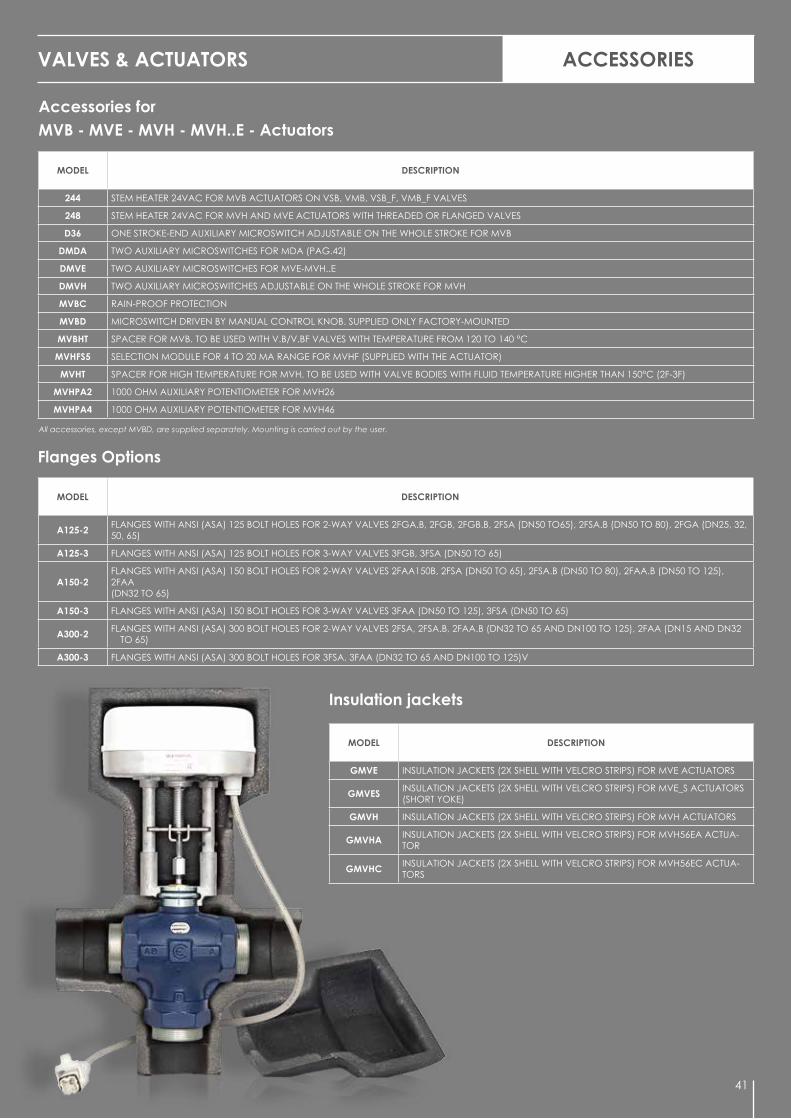
Accessories for MVB - MVE - MVH - MVH..E - Actuators
All accessories, except MVBD, are supplied separately. Mounting is carried out by the user.
Flanges Options
MODEL DESCRIPTION
GMVE INSULATION JACKETS (2X SHELL WITH VELCRO STRIPS) FOR MVE ACTUATORS
GMVES INSULATION JACKETS (2X SHELL WITH VELCRO STRIPS) FOR MVE_S ACTUATORS (SHORT YOKE)
GMVH INSULATION JACKETS (2X SHELL WITH VELCRO STRIPS) FOR MVH ACTUATORS
GMVHA INSULATION JACKETS (2X SHELL WITH VELCRO STRIPS) FOR MVH56EA ACTUA-TOR
GMVHC INSULATION JACKETS (2X SHELL WITH VELCRO STRIPS) FOR MVH56EC ACTUA-TORS
MODEL DESCRIPTION
A125-2 FLANGES WITH ANSI (ASA) 125 BOLT HOLES FOR 2-WAY VALVES 2FGA.B, 2FGB, 2FGB.B, 2FSA (DN50 TO65), 2FSA.B (DN50 TO 80), 2FGA (DN25, 32, 50, 65)
A125-3 FLANGES WITH ANSI (ASA) 125 BOLT HOLES FOR 3-WAY VALVES 3FGB, 3FSA (DN50 TO 65)
A150-2FLANGES WITH ANSI (ASA) 150 BOLT HOLES FOR 2-WAY VALVES 2FAA150B, 2FSA (DN50 TO 65), 2FSA.B (DN50 TO 80), 2FAA.B (DN50 TO 125), 2FAA(DN32 TO 65)
A150-3 FLANGES WITH ANSI (ASA) 150 BOLT HOLES FOR 3-WAY VALVES 3FAA (DN50 TO 125), 3FSA (DN50 TO 65)
A300-2 FLANGES WITH ANSI (ASA) 300 BOLT HOLES FOR 2-WAY VALVES 2FSA, 2FSA.B, 2FAA.B (DN32 TO 65 AND DN100 TO 125), 2FAA (DN15 AND DN32 TO 65)
A300-3 FLANGES WITH ANSI (ASA) 300 BOLT HOLES FOR 3FSA, 3FAA (DN32 TO 65 AND DN100 TO 125)V
MODEL DESCRIPTION
244 STEM HEATER 24VAC FOR MVB ACTUATORS ON VSB, VMB, VSB_F, VMB_F VALVES
248 STEM HEATER 24VAC FOR MVH AND MVE ACTUATORS WITH THREADED OR FLANGED VALVES
D36 ONE STROKE-END AUXILIARY MICROSWITCH ADJUSTABLE ON THE WHOLE STROKE FOR MVB
DMDA TWO AUXILIARY MICROSWITCHES FOR MDA (PAG.42)
DMVE TWO AUXILIARY MICROSWITCHES FOR MVE-MVH..E
DMVH TWO AUXILIARY MICROSWITCHES ADJUSTABLE ON THE WHOLE STROKE FOR MVH
MVBC RAIN-PROOF PROTECTION
MVBD MICROSWITCH DRIVEN BY MANUAL CONTROL KNOB. SUPPLIED ONLY FACTORY-MOUNTED
MVBHT SPACER FOR MVB. TO BE USED WITH V.B/V.BF VALVES WITH TEMPERATURE FROM 120 TO 140 °C
MVHFS5 SELECTION MODULE FOR 4 TO 20 MA RANGE FOR MVHF (SUPPLIED WITH THE ACTUATOR)
MVHT SPACER FOR HIGH TEMPERATURE FOR MVH. TO BE USED WITH VALVE BODIES WITH FLUID TEMPERATURE HIGHER THAN 150°C (2F-3F)
MVHPA2 1000 OHM AUXILIARY POTENTIOMETER FOR MVH26
MVHPA4 1000 OHM AUXILIARY POTENTIOMETER FOR MVH46

42
VALVES AND ACTUATORS MOTORIZED BALL VALVES
Motorized Ball Valves with characterized flow control
“New performing range of brass valves with chrome plated brass balls and electric rotary actuators with high IP level”
• 2-way and 3-way valves (mixing/diverting) with high Kvs values• Tight close-off (0% leakage)• Fluids temperature from -20°C to +130°C• 10 bar close-off pressure and 3.5 bar max differential pressure during modulation• Valve bodies with high pressure rates PN32 and PN40• Equal percentage flow curve for modulating models
Ball valves range
MODEL TYPE DN KVS P MAX ACTUATOR DELTA PFLUID TEMPERATURE
MIN. MAX.
ON
-OFF
VSS2
2-way
1/2” 20
32 bar 10 Nm 10 bar -20 °C +130 °CVSS3 3/4” 45
VSS4 1” 60
VSS5 1 ¼” 100
VSS6 1 ½” 12016 bar 16 Nm 3,5 bar -15 °C +110 °C
VSS8 2” 220
VSD3
3-waydiverting
3/4” 9,632 bar 10 Nm 10 bar -20 °C +130 °C
VSD4 1” 11,3
VSD5 1 ¼” 19,2
16 bar 16 Nm 3,5 bar -15 °C +110 °CVSD6 1 ½” 27,7
VSD8 2” 57
0 ÷
10 V
dc
VSC2
2-way
1/2” 4
16 bar 16 Nm 3,5 bar -10 °C +130 °C
VSC3 3/4” 6,3
VSC4 1” 10
VSC5 1 ¼” 16
VSC6 1 ½” 25
VSC8 2” 40
VDC2
3-way mixing
1/2” 4
VDC3 3/4” 6,3
VDC4 1” 10
VDC5 1 ¼” 16
VDC6 1 ½” 25
VDC8 2” 40

43
VALVES AND ACTUATORS MOTORIZED BALL VALVES
• 10 bar close-off pressure and 3.5 bar max differential pressure during modulation
• No need of stem heater with fluids below 0 °C: the actuator has its own system to prevent ice
• High protection degree IP65 on most actuators• Auxiliary micro-switches on all actuators• Opening or closing time: 40 seconds (10 Nm models) or 60 seconds (16 Nm
models)• Manual override
Actuators range
MODEL POWER SUPPLY TORQUE [Nm]OPENING AND CLOSING TIME
[seconds]
AUX. END SWITCH IP RATING MANUAL
OVERRIDE
ON
-OFF
MVS210 230 Vac10 40
YES
IP 42 NOMVS410 24 Vac
MVS216 230 Vac16 60 IP 65 YES
MVS416 24 Vac
0 ÷
10
Vdc
MVS516 24 Vac/dc 16 60 NO IP 65 YES
VALVES SERIES CONTROL TYPE DN KVS
ACTUATORS
MVSx1010 Nm
MVSx1616 Nm
MVS51616 Nm
ON - OFF 0 ÷10 Vdc
VSS..
On - Off
2-way
1/2” ÷ 1 ¼” 20 ÷ 100
1 ½” ÷ 2” 120 ÷ 220
VSD.. 3-waydiverting
3/4” ÷ 1” 9.6 ÷ 11.3
1 ¼” ÷ 2” 19.2 ÷ 57
VSC..
0 ÷ 10 Vdc
2-way 1/2” ÷ 2” 4 ÷ 40
VDC.. 3-waymixing 1/2” ÷ 2” 4 ÷ 40
Valves / Actuators cross reference
AccessoriesCODE DESCRIPTION
MVSHT Spacer for MVSx16 actuator useful in case of high temperature fluids or when insulation is needed (chilled water)
10 Nm
16 Nm

44
VALVES AND ACTUATORS
Shoe ValvesSeries M - Cast-iron PN6 - To be motorised by MDB24-44-54 actuators, fitted with AM72.
MODEL TYPE DN Kvs MAX DIFFERENTIAL PRESSURE [bar] OTHER FEATURES
M31PM3
(PN6)threaded
1” 30 1 • THREE-WAY• PN 6 cast-iron valve body• Female threaded connections• Outlet from angle-way• Fluid temperature: 110 °C max
M31P1/4 11/4” 37 1
M31P1/2 11/2” 38 1
M32P 2” 45 1
M340
M3(PN6)
flanged
40 38 1
As above, with flanged connec-tions
M350 50 70 1
M365 65 80 0,8
M380 80 90 0,5
M3100 100 110 0,3
M3125 125 120 0,2
M41PM4
(PN6)threaded
1” 30 1• FOUR-WAY• PN 6 cast-iron valve body• Female threaded connections• Fluid temperature: 110 °C max
M41P1/4 11/4” 37 1
M41P1/2 11/2” 40 1
M42P 2” 45 1
M450M4
(PN6)flanged
50 70 1
As above, with flanged connec-tions
M465 65 80 1
M480 80 90 0,8
M4100 100 110 0,3
Butterfly ValvesSeries VFA - The valves are ready for mounting on MDA actuators. They can also be motorized by MDL actuators (page 45) by means of AF24 and AF25 adapters.
MODEL DN Kvs
MAX DIFFERENTIAL PRESSURE [bar]
OTHER FEATURESMDA22/42/52 MDA24/44/54
MDL24/44/54 20Nm
MDL26/46/56 30Nm
VFA
25 26
6
-
• PN16 (PN6, PN10)• Spheroidal cast-iron body (EN-JS1030)• Shaft tight O-Ring• Seat EPDM• Fluid temp.: -10 to 100°C• Close-off leakage: leakage rate A (DIN
EN 12266-1)
32 27 -
40 50 -
50 116 -
65 259 -
80 377 -
100 763 -
125 1030 - 6
150 1790 -3
200 3460 -
BUTTERFLY/SHOE VALVES
MORE OPTIONS
Larger motorized butterfly valves from DN250 to DN500 available on request.

45
MODEL DESCRIPTION
MDLS5 Electronic card input signal, range 6 to 9, 4 to 7, 8 to 11, 1 to 5 V d.c., 4 to 20 mA for MDL32/34/36
MDLV5 Electronic card input signal, range 0 to 10 V d.c., 4 to 20 mA with adjustable start point and span for MDL32/34/36
DMDL Two auxiliary microswitches SPDT 10 (3) A - 240 V a.c. adjustable on the whole stroke for MDL
MDLA1 Damper drive linkage for MDL
MDLA2 Linkage for mounting MDL when replacing SL
MDLPA2 Board with 1 K Ohm auxiliary potentiometer for MDL2
MDLPA4 Board with 1 K Ohm auxiliary potentiometer for MDL4
MDLPA6 Board with 1 K Ohm auxiliary potentiometer for MDL6
YS7 Crank-arm in addition to MDLA1 composed of 2 joints and 8-mm rod for dampers with 10 to 18mm shaft with MDL actuator
DMDA Two auxiliary microswitches
ROTARY ACTUATORS
Actuators for Butterfly ValvesSeries MDA - Bidirectional actuator for VFA butterfly valves - Floating (MDA2.-4.) or propro-tional 0-10 V (MDA5.) control signal - Angular stroke 90° - Manual control - Supplied with linkage for mounting on valve body - Protection IP54.
Options
MODEL TIMING[s]
POWEER SUPPLY [Vca]
TORQUE [Nm] OTHER FEATURES
MDA22 90230
20 For VFA valves up to DN100
MDA24 150 40 For VFA valves from DN125 to DN200
MDA42 90
24
20 For VFA valves up to DN100
MDA44 150 40 For VFA valves from DN125 to DN200
MDA52 90 20 For VFA valves up to DN100
MDA54 150 40 For VFA valves from DN125 to DN200
MDAV1MDA actuators are supplied NOT mounted on valve bodies. In case the actuator-valve assem-bly is required, order the specific part number MDAV1 together with the models of actuator and valve body.
MDAV2 DMDA microswitch assembling on MDA actuator
VARIANTS: in case the MDL2./4. actuators are needed to be supplied with 1 KOhm auxiliary potentiometer, add PA2 for MDL2”.”, PA4 for MDL4”.” and PA6 for MDL6”.”: e.g. MDL24PA2, MDL46PA4 or MDL66PA6. In special applications, the actuators can be sup-plied with 2 or 3 auxiliary potentiometers.
Actuators for Butterfly valves, dampers, burnersSeries MDL - Bidirectional motor- Input signal P.C. board - Power consumption 12VA - 2 output shafts: main and secondary shaft Ø 9,5 x 9,5 mm - MDL30-50 angular travel set at 90°adjustable between 55 and 160°- MDL20-40-60 angular travel set at 90°adjustable between 0 and 160° - Force 500 N - Manual override - IP 55.
MODEL TIMING[s. FOR 90°]
TORQUE [Nm]
ADJUSTABLE ANGULAR
TRAVEL
SUPPLY [Vac]
MAX DAMPER SURFACE [m2] ACTION
MDL22 15 - 27 6 0 to 160 230 1,2 on/off, floating
MDL24 45 - 80 20 0 to 160 230 4 “
MDL26 60 - 107 30 0 to 160 230 6 “
MDL42 15 - 27 6 0 to 160 24 1,2 “
MDL44 45 - 80 20 0 to 160 24 4 “
MDL46 60 - 107 30 0 to 160 24 6 “
MDL62 15 - 27 6 0 to 160 110 1,2 “
MDL64 45 - 80 20 0 to 160 110 4 “
MDL66 60 - 107 30 0 to 160 110 6 “
MDL32 15 - 27 6 55 to 160 24 1,2proportional-potentiometric
(165 Ohm)MDL34 45 - 80 20 55 to 160 24 4
MDL36 60 - 107 30 55 to 160 24 6
MDL52 15 - 27 6 55 to 160 24 1,2 Vdc/current proportional control. Ranges: 6 to 9, 4 to 7, 8 to 11, 0 to 10, 1 to 5 Vdc, or
current 4 to 20 mA
MDL54 45 - 80 20 55 to 160 24 4
MDL56 60 - 107 30 55 to 160 24 6
ACTUATORS ROTARY ACTUATORS

46
VALVES AND ACTUATORS
MODEL TORQUE [Nm] POWER SUPPLY [Vac] CONTROL ACTION MICRO-SWITCH
MDB42
5 242-3 pos.
-
MDB42M 2
MDB52 0-10 Vdc proportional -
MDB24
8
230
2-3 pos.
-
MDB24M 1
MDB44
24
-
MDB44M 1
MDB54 0-10 Vdc proportional -
MDB26
15
230
2-3 pos.
-
MDB26M 2
MDB46
24
-
MDB46M 2
MDB56 0-10 Vdc proportional -
MDB28
20
230
2-3 pos.
-
MDB28M 2
MDB48
24
-
MDB48M 2
MDB58 0-10 Vdc proportional -
Without Spring Return MDB Series. Maximun rotation 95°. For air dampers up to 2sqm. IP54
AIR DAMPER ACTUATORS
With Spring Return DuraDrive series. Protection IP54 (for 7-15 Nm only with con-duit connector downwards, otherwise IP30).
4 Nm
7 and 15 Nm
MODEL CONTROL SIGNAL
TORQUE [Nm]
SUPPLY [Vac]
AUXILIARYMICRO-SWITCH
MAX DAMPER SURFACE [m2]
TIMING[s. FOR 90°]
MA40-7041-G00 2 pos. 4 230 0.74 50
MA40-7041-G01 2 pos. 4 230 1 0.74 50
MA40-7043-G00 2 pos. 4 24 0.74 50
MA40-7043-G01 2 pos. 4 24 1 0.74 50
MA41-7071-G00 2 pos. 7 230 1.39 80
MA41-7071-G02 2 pos. 7 230 2 1.39 80
MA41-7073-G00 2 pos. 7 24 1.39 80
MA41-7073-G02 2 pos. 7 24 2 1.39 80
MA41-7151-G00 2 pos. 15 230 3.25 190
MA41-7151-G02 2 pos. 15 230 2 3.25 190
MA41-7153-G00 2 pos. 15 24 3.25 190
MA41-7153-G02 2 pos. 15 24 2 3.25 190
MF40-7043-G00 floating 4 24 0.74 130
MF40-7043-G01 floating 4 24 1 0.74 130
MF41-7073-G00 floating 7 24 1.39 195
MF41-7073-G02 floating 7 24 2 1.39 195
MF41-7153-G00 floating 15 24 3.25 190
MF41-7153-G02 floating 15 24 2 3.25 190
MS40-7043-G00 2-10 V 4 24 0.74 130
MS40-7043-G01 2-10 V 4 24 1 0.74 130
MS41-7073-G00 2-10 V 7 24 1.39 195
MS41-7073-G02 2-10 V 7 24 2 1.39 195
MS41-7153-G00 2-10 V 15 24 3.25 190
MS41-7153-G02 2-10 V 15 24 2 3.25 190

47
VALVES AND ACTUATORSVALVES AND ACTUATORS
A
A
A
B
AB
AB
AB
A
B
AB
A
B
AB
SELECTION & SIZING
For a proper valve selection we need to define:
• Hydraulic circuit: constant flow (3-way) or variable flow (2-way)
• Max Hydraulic pressure for the circuit -- > PN• Maximum and minimum fluid temperature• Fluid type (e.g. water, water+glycol, steam, thermal oil,
...)• Valve function: on/off control, linear flow control or EQM
flow control. Once we have identified the type of valve, we need to select its size and the actuator that will motorize it. To select the correct type and size of valve the following factors need to be taken into consideration:
• Max working pressure to select the proper PN• Max temperature and type of fluid• Max differential pressure achievable by the valve/ac-
tuator assembly• Pressure drop as a consequence of the flow rate• Flow characteristic, Rangeability, Authority Each valve is identified by its FLOW COEFFICIENT called Kvs.Kvs, in metric system, represents the flow in m3/h of water (specific weight=1) at the temperature of 15.5°C which causes a pressure drop of 1Kg/cm2 (1 bar) when the valve is fully open.In the USA flow coefficient is called Cv where Kvs = 0.865 Cv The value of Kvs represents the valve size: -- > control valves size needs to be chosen according to the calculated Kvs and not according to the pipe size.In any case, valve size must not be larger than pipe size. For calculating the Kvs, we need to know: flow rate and differential pressure. Differential pressure can be selected equal to the pressure drop in the heat exchanger.Kvs can be calculated:
• using the appropriate formulas available on page 54 for water or steam;
• using the diagrams on pages 52 and 53;• using our dedicated software for PC (available online). Each type of valve is subject to a max pressure value = no-minal working pressure, indicated by PN (Kg/cm2) depen-ding on valve raw material. The max differential pressure value represents the max diffe-rential pressure between inlet and outlet of the valve, when the valve is fully closed. This value depends on both the actuator power, which must provide full opening and full closing, and on the mechani-cal-structural limitations of the valve, as construction type and valve body material, stem and plug type and material, stem packing, etc. After having selected the necessary Kvs value, we should select the size of the valve matching a Kvs value as close as possible to the calculated Kvs.
The identified valve size can achieve several values of max. differential pressure according to the actuator.Max. differential values are listed in columns in the previous pages of this book.The actuator needs to be selected in terms of force as to:
• guarantee the effective differential pressure across the valve in case of a 3way valve;
• guarantee the effective differential pressure across the valve and the maximum pressure, at the inlet port of the valve, available from the pump, in case of 2way valves. Consequently 2way valves usually require actuators stronger than those necessary for 3way valves.
As a consequence of the differential pressure across the valve the flow is always trying to open the valve.To keep the plug in the closed position the actuator must exceed this force (close-off pressure).Depending on the valve size and on the differential pres-sure across the valve we need to select an actuator with a close-off higher than the differential pressure.The larger is the valve the more is the force that the actua-tor needs to have to achieve the close-off.For 2-way valves with high differential pressure we recom-mend using our pressure balanced plug valves 2TGA.B (from ¾” to 2” -- > page 21) and 2FGB.B, 2FSA.B, 2FAA.B, 2FGA200B (from DN65 to 200 -- > page 25).This is a cost effective alternative to selecting a standard valve with a strong actuator. Complete details of differential pressure values for all our valves are listed in our data sheet Valves_DBL337E.pdf avai-lable online on our web site
[1]
[2]
[3]
[4]
[5]
We recommend using our 3way valves as mixing, when used as diverting max. differential pressure has to be limited to the 40% of the values listed in our data sheets. If used as diverting, inlet port is AB.B.
[1] 2-way valve: variable flow to the heat exchanger[2] 2-way valve: constant flow to the heat exchanger[3] 3-way valve MIXING: variable flow to the heat exchanger[4] 3-way valve MIXING: constant flow to the heat exchanger[5] 3-way valve DIVERTING: variable flow to the heat exchanger
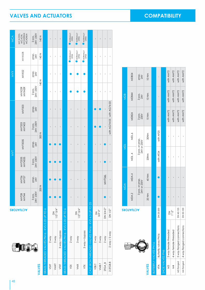
MD
AM
DL
MD
B
MD
A.2
MD
A.4
MD
L .4
MD
L.6
MD
B24
MD
B44
MD
B54
3 po
s. or
pro
p.24
V o
r 230
V3
pos.
or p
rop.
24V
or 2
30V
3 po
s. 23
0V3
pos.
24V
prop
. 24
V
20 N
m40
Nm
20N
m30
Nm
10 N
m10
Nm
10 N
m
BUTT
ERFL
Y V
ALV
ES P
N16
VFA
Butte
rfly
valv
es P
N16
DN
25-
200
with
AF2
4 w
ith A
F25
--
-
SHO
E V
ALV
ES P
N6
M3
3 w
ay fe
mal
e th
read
edD
N
1”-2
”-
--
- w
ith A
M72
with
AM
72 w
ith A
M72
M4
4 w
ay fe
mal
e th
read
ed-
--
- w
ith A
M72
with
AM
72 w
ith A
M72
M3
flang
ed3
way
flan
ged
con
nect
ions
DN
40-
125
--
--
with
AM
72 w
ith A
M72
with
AM
72
M4
flang
ed4
way
flan
ged
con
nect
ions
DN
50-
100
--
--
with
AM
72 w
ith A
M72
with
AM
72
VALV
ES
VALV
ES
ACTUATORS ACTUATORS
MV
TM
VX
MC
A
MV
T28
MV
T44
MV
T56
MV
T57
MV
T203
SM
VT4
03S
MV
T503
SM
VT2
03M
VT4
03M
VT5
03M
VX2
2R
MV
X42R
MV
X52
MV
X52
B
MC
A23
0LM
CA
24L
MC
A23
0LM
MC
A24
LM
3 p
os.
24V
; 230
Vpr
op.
24V
3 p
os.
24V
; 230
Vpr
op.
24V
3 p
os.
24V
; 230
Vpr
op.
24V
2 po
s. 24
V; 2
30V
prop
. 24
Vpr
op.
24V
2 po
s. 24
V; 2
30V
200
N30
0 N
140
N14
0 N
140
N
BRA
SS T
HREA
DED
VA
LVES
PN
16 -
KVS
0.25
UP
TO 6
VSX
T2
way
DN
1/
2”-3
/4”
--
--
--
VM
XT3
way
--
--
--
VTX
T3
way
+ b
ypas
s-
--
--
-
BRA
SS T
HREA
DED
VA
LVES
PN
16 -
KVS
0.25
UP
TO 6
VSX
2 w
ay
DN
1/
2”-3
/4”
--
--
--
NO
RMA
LLY
OPE
N N
ORM
ALL
Y O
PEN
VM
X3
way
--
--
--
NO
RMA
LLY
OPE
N N
ORM
ALL
Y O
PEN
VTX
3 w
ay +
byp
ass
--
--
--
NO
RMA
LLY
OPE
N N
ORM
ALL
Y O
PEN
CA
ST IR
ON
THR
EAD
ED V
ALV
ES P
N16
- KV
S 6.
3 UP
TO
25
VSB
.T2
way
DN
3/
4”-2
”-
--
--
-
VM
B.T
3 w
ay-
--
--
-
2TG
A_B
2 w
ayD
N 3
/4-2
”M
VT5
6L-
--
--
-
2-3T
GB.
B2
way
/ 3
way
DN
1/2
”-
--
-w
ith A
G74
-03
with
AG
74-0
3-
--
-
VALVES AND ACTUATORS COMPATIBILITY
48

*1 -
Ava
ilabl
e on
requ
est
*2 -
Also
2FA
A.P
, 2FA
A.T
, 3FA
A.P
, 3FA
A.T
, 3FS
A.S
MV
BM
VE
MV
E.R
(with
em
erge
ncy
retu
rn)
MV
H
MV
B22
MV
B26
MV
B28
MV
B46
MV
B52
MV
B56
MV
E.04
MV
E.06
MV
E.10
MV
E.15
MV
E.22
MV
E.04
S M
VE.
06S
MV
E.10
SM
VE.
15S
MV
E.22
S
MV
E.04
R M
VE.
06R
MV
E.10
RM
VE.
15R
MV
E.04
SR
MV
E.06
SRM
VE.
10SR
MV
E.15
SR
MV
H26
MV
H46
MV
H36
MV
H56
MV
H56E
M
VHE
3KM
VH5
6EA
M
VH5
6EC
2 - 3
pos
. 24
V; 2
30V
prop
. 24
V3
pos.
& p
rop.
24V
; 230
V
3 po
s. &
pro
p.24
V; 2
30V
sh
ort b
rack
et
3 po
s. &
pro
p. 2
4V; 2
30V
3 po
s. &
pro
p.24
V; 2
30V
sh
ort b
rack
et
2 - 3
pos
. 24
V; 2
30V
Prop
. pot
.or
Vd
c-m
A;
24V
3 po
s. &
pro
p.24
V
3 po
s. &
pro
p.24
Vsp
ring
retu
rn
450
N40
0 N
, 600
N,
1000
N, 1
500
N, 2
200
N40
0 N
, 600
N,
1000
N, 1
500
N, 2
200
N15
00 N
1500
N15
00 N
3000
N70
0 N
PN16
THR
EAD
ED V
ALV
ES
2TG
B.B
2 w
ay th
read
ed M
VB
DN
1/
2”-
--
--
--
-
3TG
B.B
2 w
ay th
read
ed M
VB
--
--
--
--
2TG
B.F
2 w
ay th
read
ed M
VE.
SD
N
1/2”
--
--
--
--
3TG
B.F
2 w
ay th
read
ed M
VE.
S-
--
--
--
-
VSB
2 w
ay th
read
edD
N
3/4"
- 2"
with
AG
52w
ith A
G63
with
AG
52w
ith A
G63
with
AG
62w
ith A
G62
with
AG
62w
ith A
G62
VM
B3
way
thre
aded
with
AG
52w
ith A
G63
with
AG
52w
ith A
G63
with
AG
62w
ith A
G62
with
AG
62w
ith A
G62
VSB
P. M
2 w
ay th
read
ed ti
ght c
lose
-off
DN
3/
4” -
2”-
--
--
--
-
VM
BP. M
3 w
ay th
read
ed ti
ght c
lose
-off
--
--
--
--
2TBB
2 w
ay b
ronz
eD
N 1
/2”
- 2”
*1 *1
*1 *1
no M
VH3
K
3TBB
3 w
ay b
ronz
e *1
*1 *1
*1no
MV
H3K
PN16
FLA
NG
ED V
ALV
ES
VSB
. F2
way
slip
-on
flang
esD
N
20 -
50w
ith A
G52
with
AG
63w
ith A
G52
with
AG
63w
ith A
G62
with
AG
62w
ith A
G62
with
AG
62
VM
B. F
3-w
ay sl
ip-o
n fla
nges
with
AG
52w
ith A
G63
with
AG
52w
ith A
G63
with
AG
62w
ith A
G62
with
AG
62w
ith A
G62
PN16
, 25,
40
FLA
NG
ED V
ALV
ES
2FG
B2
way
flan
ged
val
ves P
N16
DN
25
-150
--
--
3FG
B3
way
flan
ged
val
ves P
N16
--
--
2FG
A2
way
flan
ged
val
ves P
N16
DN
15-
100
--
--
2FSA
2 w
ay fl
ange
d v
alve
s PN
25D
N 2
5-65
--
--
3FSA
*2
3 w
ay fl
ange
d v
alve
s PN
25D
N 2
5-80
--
--
2FA
A *
22
way
flan
ged
val
ves P
N40
DN
15-
80-
--
-
3FA
A *
23
way
flan
ged
val
ves P
N40
DN
25-
125
--
--
PN16
, 25,
40
FLA
NG
ED V
ALV
ES F
OR
HIG
H C
LOSE
-OFF
PRE
SSUR
E
2FG
B.B
2 w
ay fl
ange
d v
alve
s PN
16D
N 6
5-15
0-
--
-
2FSA
.B2
way
flan
ged
val
ves P
N25
DN
25-
80-
--
-
2FA
A.B
2 w
ay fl
ange
d v
alve
s PN
40D
N 2
5-12
5-
--
-
2FA
A15
0B2
way
dou
ble
seat
PN
25D
N15
0-
--
-
2FG
A20
0B2
way
dou
ble
seat
PN
16D
N20
0-
--
-
VALV
ES
ACTUATORS
49

50
VALVES AND ACTUATORS
MANUFACTURER MODEL WAY TYPE MVE MVH MVH56EA/C
SCHNEIDERELECTRIC
V241 2way threaded compatible compatible compatible
V211T 2way threaded compatible compatible compatible
V212T 2way threaded compatible compatible compatible
V211 2way flanged compatible compatible compatible
V212 2way flanged compatible compatible compatible
VG211 2way flanged compatible compatible compatible
VG222 2way flanged compatible compatible compatible
V231 2way flanged compatible compatible compatible
V232 2way flanged compatible compatible compatible
V292 2way flanged compatible compatible compatible
V341 3way threaded compatible compatible compatible
V311T 3way threaded compatible compatible compatible
V311 3way flanged compatible compatible compatible
VG321 3way flanged compatible compatible compatible
V321 3way flanged compatible compatible compatible
SATCHWELL
VZ 2way threaded AG53 AG54 AG54
VSF DN15-50 2way flanged AG53 AG54 AG54
VZF DN65 150 2way flanged AG53 AG54 AG54
MZ 3way threaded AG53 AG54 AG54
MJF DN15-50 3way flanged AG53 AG54 AG54
MZF DN 65-150 3way flanged AG53 AG54 AG54
HONEYWELL
V176A,B 2way flanged AG60-10 X X
V5011A 2way flanged AG60-10 X X
V5011R 2way threaded AG79 X X
SIEMENS
VVF21 DN 25..80 2way flanged AG70-10 AG70-10 AG70-10
VVF21DN ≥100 2way flanged AG70-14 AG70-14 AG70-14
VVF31 DN 15..80 2way flanged AG70-10 AG70-10 AG70-10
VVF31DN 150 2way flanged AG70-14 AG70-14 AG70-14
VVF40 DN 15..80 2way flanged AG70-10 AG70-10 AG70-10
VVF40 DN 150 2way flanged AG70-14 AG70-14 AG70-14
VVF41 DN 50 2way flanged AG70-14 AG70-14 AG70-14
VVF41 DN 65..150 2way flanged AG70-14 AG70-14 AG70-14
VVF45 DN 50 2way flanged AG70-14 AG70-14 AG70-14
VVF45 DN65..150 2way flanged AG70-14 AG70-14 AG70-14
VVF51DN15..40 2way flanged AG70-10 AG70-10 AG70-10
VVF52 DN 15..40 2way flanged AG70-10 AG70-10 AG70-10
VVF53 DN 15..50 2way flanged AG70-10 AG70-10 AG70-10
VVF53 DN 65..150 2way flanged AG70-10 AG70-10 AG70-10
VVF61 DN 15..25 2way flanged AG70-10 AG70-10 AG70-10
VVF61 DN 40..50 2way flanged AG70-14 AG70-14 AG70-14
VVF61 DN 65..150 2way flanged AG70-14 AG70-14 AG70-14
VVF61_2 DN 15..50 2way flanged AG70-10 AG70-10 AG70-10
VVF61_2 DN 65..150 2way flanged AG70-10 AG70-10 AG70-10
VVG41 DN 15.50 2way threaded AG70-10 AG70-10 AG70-10
VVG11 DN 25..40 2way threaded AG70-10 AG70-10 AG70-10
VXF21DN 25..80 3way flanged AG70-10 AG70-10 AG70-10
COMPATIBLE VALVES / LINKAGE KITS
RETROFITTING

51
VALVES AND ACTUATORS
MANUFACTURER MODEL WAY TYPE MVE MVH MVH56EA/C
SIEMENS
VXF21DN 100 3way flanged AG70-14 AG70-14 AG70-14
VXF31 DN 15..80 3way flanged AG70-10 AG70-10 AG70-10
VXF31 DN 100..150 3way flanged AG70-14 AG70-14 AG70-14
VXF40 DN 15..80 3way flanged AG70-10 AG70-10 AG70-10
VXF40 DN 100..150 3way flanged AG70-14 AG70-14 AG70-14
VXF41 DN 50 3way flanged AG70-14 AG70-14 AG70-14
VXF41 DN 65..150 3way flanged AG70-14 AG70-14 AG70-14
VXF45 DN 50 3way flanged AG70-14 AG70-14 AG70-14
VXF45 DN 65..150 3way flanged AG70-14 AG70-14 AG70-14
VXF51 DN 15..40 3way flanged AG70-10 AG70-10 AG70-10
VXF52 DN 15..40 3way flanged AG70-10 AG70-10 AG70-10
VXF53 DN 15..50 3way flanged AG70-10 AG70-10 AG70-10
VXF53 DN 65..150 3way flanged AG70-10 AG70-10 AG70-10
VXF61 DN 15..25 3way flanged AG70-10 AG70-10 AG70-10
VXF61 DN 40..50 3way flanged AG70-14 AG70-14 AG70-14
VXF61 DN 65..150 3way flanged AG70-14 AG70-14 AG70-14
VXF61_2 DN 15..50 3way flanged AG70-10 AG70-10 AG70-10
VXF61_2 DN 65..150 3way flanged AG70-10 AG70-10 AG70-10
VXG41 DN 15..50 3way threaded AG70-10 AG70-10 AG70-10
VXG11 DN 25..40 3way threaded AG70-10 AG70-10 AG70-10
BELIMOH6..N DN 15..100 2 way flanged AG70-10 X X
H7..N DN 15..100 3 way flanged AG70-10 X X
JOHNSONCONTROLS VB7816 3way threaded AG66 X X
DANFOSSVF2 2way flanged AG60-07 X X
VF3 3way flanged AG60-07 X X
MUT MK DN50 - 150 3way flanged AG69 X X
x = link not available
RETROFITTING

VALVES AND ACTUATORS
OLD MODEL NEW MODEL
2 WAY VALVES PN16
Cas
t iro
n va
lves
with
s/st
eel in
tern
al
parts
SSGA11 2FGA15R0SSGA12 2FGA15R1
SSGA15R 2FGA15R2SSGA1 2FGA15R3SSGA15 2FGA15SSGA20 2FGA20SSGA25 2FGA25SSGA32 2FGA32SSGA40 2FGA40SSGA50 2FGA50SSGA65 2FGA65SSGA80 2FGA80
SSGA100 2FGA100
Cas
t iro
n va
lves
VSG25R 2FGB25R4VSG25I 2FGB25R7VSG25 2FGB25VSG40 2FGB40VSG50 2FGB50VSG65 2FGB65VSG80 2FGB80
VSG100 2FGB100VSG125 2FGB125
VSG150 2FGB150
Bala
nced
plu
g va
lves
VBG65 2FGB65BVBG80 2FGB80B
VBG100 2FGB100BVBG125 2FGB125B
VBG150 2FGB150B
DSGA200 2FGA200B
3 WAY VALVES PN16
Cas
t iro
n va
lves
VMB1625R 3FGB25R4VMB1625I 3FGB25R7VMB1625 3FGB25
VMB1640R 3FGB40R19VMB1640 3FGB40VMB1650 3FGB50VMB1665 3FGB65VMB1680 3FGB80VMB16100 3FGB100VMB16125 3FGB125VMB16150 3FGB150
OLD MODEL NEW MODEL
2 WAY VALVES PN25
Sphe
roid
al c
ast i
ron
valv
es
VSS25R 2FSA25R4VSS25I 2FSA25R7VSS25 2FSA25VSS32 2FSA32VSS40 2FSA40VSS50 2FSA50VSS65 2FSA65
Bala
nced
plu
g va
lves
VBS25R 2FSA25BR4VBS25I 2FSA25BR7VBS25 2FSA25BVBS32 2FSA32BVBS40 2FSA40BVBS50 2FSA50BVBS65 2FSA65BVBS80 2FSA80B
DSAA150 2FAA150B3 WAY VALVES PN40
Stee
l val
ves
3VAA25R 3FAA25R43VAA25I 3FAA25R73VAA25 3FAA253VAA32 3FAA323VAA40 3FAA403VAA50 3FAA503VAA65 3FAA653VAA80 3FAA80
3VAA100 3FAA1003VAA125 3FAA125
Stee
l val
ves f
or v
ery
high
te
mpe
ratu
res
3VAACP25R 3FAA25PR43VAACP25I 3FAA25PR73VAACP25 3FAA25P3VAACP32 3FAA32P3VAACP40 3FAA40P3VAACP50 3FAA50P3VAACP65 3FAA65P3VAACP80 3FAA80P3VAACP100 3FAA100P3VAACP125 3FAA125P
Stee
l val
ves f
or v
ery
low
te
mpe
ratu
res
3VAACP25RB 3FAA25TR43VAACP25IB 3FAA25TR73VAACP25B 3FAA25T3VAACP32B 3FAA32T3VAACP40B 3FAA40T3VAACP50B 3FAA50T3VAACP65B 3FAA65T3VAACP80B 3FAA80T3VAACP100B 3FAA100T3VAACP125B 3FAA125T
OLD MODEL NEW MODEL
2 WAY VALVES PN40
Stee
l val
ves
SSAA15R 2FAA15R2SSAA15 2FAA15SSAA20 2FAA20SSAA25 2FAA25SSAA32 2FAA32SSAA40 2FAA40SSAA50 2FAA50SSAA65 2FAA65SSAA80 2FAA80
Stee
l val
ves f
or v
ery
high
te
mpe
ratu
res
SSAACP15R 2FAA15PR2SSAACP15 2FAA15PSSAACP20 2FAA20PSSAACP25 2FAA25PSSAACP32 2FAA32PSSAACP40 2FAA40PSSAACP50 2FAA50PSSAACP65 2FAA65PSSAACP80 2FAA80P
Stee
l val
ves f
or v
ery
low
tem
pera
ture
s
SSAACP15RB 2FAA15TR2SSAACP15B 2FAA15TSSAACP20B 2FAA20TSSAACP25B 2FAA25TSSAACP32B 2FAA32TSSAACP40B 2FAA40TSSAACP50B 2FAA50TSSAACP65B 2FAA65TSSAACP80B 2FAA80T
Bala
nced
plu
g va
lves
VBAA25 2FAA25BVBAA32 2FAA32BVBAA40 2FAA40BVBAA50 2FAA50BVBAA65 2FAA65BVBAA80 2FAA80B
VBAA100 2FAA100B
VBAA125 2FAA125B
3 WAY VALVES PN25
Sphe
roid
al c
ast i
ron
valv
es
VMS25R 3FSA25R4
VMS25I 3FSA25R7
VMS25 3FSA25
VMS32 3FSA32
VMS40 3FSA40
VMS50 3FSA50
VMS65 3FSA65
3VSA80 3FSA80
High
tem
pera
ture
val
ves
VMSTS25R 3FSA25SR4
VMSTS25I 3FSA25SR7
VMSTS25 3FSA25S
VMSTS32 3FSA32S
VMSTS40 3FSA40S
VMSTS50 3FSA50S
VMSTS65 3FSA65S
3VSATS80 3FSA80S
OLD MODEL NEW MODEL
MVL-SH ACTUATORS MVH-MVE ACTUATORS DESCRIPTION
245248 Stem heater for MVH-MVE with flanged valves
245F
246 244 Stem heater for MVH-MVE with VSB-VMB-VSBF-VMBF valves
AG31 AG62 Linkage for MVH actuators with VSB-VMB-VSBF-VMBF valves
DMVL DMVH Aux. microswitches for MVH
MVLFS5 MVHFS5 4-20 mA input signal
MVLPA2 MVHPA2 1kOhm aux. potentiometer for MVH26
MVLPA4 MVHPA4 1kOhm aux. potentiometer for MVH46
MVLHT MVHT High temperature spacer
2F & 3F VALVES CROSS REFERENCE WITH OLD CONTROLLI VALVES
RETROFITTING
52

53
VALVES AND ACTUATORSVALVES AND ACTUATORS
OLD MODEL = NEW MODEL (VALVE + LINKAGE KIT)
SH242 = MVH26
+ AG51 / AG62
SH222 = MVH46
SH522 = MVH56
MVL26 = MVH26
MVL36 = MVH36
MVL46 = MVH46
MVL56 = MVH56
MVL56F = MVH56E
MVL56A / MVL56FA/MVL46A = MVH56EA
MVL56C / MVL56FC/MVL46C = MVH56EC
MVL3K = MVHE3K
MVF54 = MVE506
WITHOUT LINKAGE KIT
MVF58 = MVE510
MVF515 = MVE515
MVF54S = MVE506S
MVF58S = MVE510S
MVF515S = MVE515S
MVH56F = MVH56E
MVH56FA = MVH56EA
MVH56FC = MVH56EC
MVH3K = MVHE3K
In the event of replacing an old Controlli actuator mounted on one of the old valves listed below, here is the equivalent MVH actuator model to be used:
REPLACING OLD CONTROLLI ACTUATORS
RETROFITTING
CONTROLLI VALVES MODELS MVH MVE MVB
OBSOLETE MODELSS300 x x AG40
V500 x x AG22
OLD FLANGED VALVESVSG, VMB16, VBG, SS, DS, VSS, VBS, VBAA, 3V, VMS AG51 x
SS, DS, VS, VBS, 3V, VM + MVLHT DN15÷65mm AG64 x x
SS, DS, VS, VBS, 3V, VM + MVLHT DN80÷200mm AG65 x x
EXISTING THREADED VALVES2TGB.B, 3TGB.B x x compatible
2TGB.F, 3TGB.F x compatible x
VSB, VMB AG62 AG52 / AG63 * compatible
EXSISTING VALVES WITH SLIP-ON FLANGESVSB_F, VMB_F AG62 AG52 / AG63 * compatible
EXSISTING FLANGED VALVES
2F, 3F compatible compatible x
*AG52 (MVE) & AG63 (MVE.S)
MVH, MVE, MVB ACTUATORSLINKAGE KITS FOR

Valve Sizing Diagram for Fluids
Water flow rate in m3/h Flow rate in m3/h
Pressure drop kPa(100 kPa = 1 bar = ~ 10 m H2O)
Liquids with volume different from 1kg/dm3
The recommended valve pressure drop must be at least equal to the load.Example for fluids with relative density1 kg/dm3 (water) In order to size a control valve with: FLOW RATE: 7,5 m3/h of waterPRESSURE DROP: 55 kPaUse the diagram as follows:- Identify the crossing point between the line starting from the flow
rate value (7,5 m3/h) and from the pressure drop value (55 kPa).This point corresponds to the required flow coefficient, i.e. Kvs 10. Therefore, the control valve must have Kvs 10. Example for liquids having relative density different from 1 kg/dm3
In order to size a control valve with:FLOW RATE : 150 m3/h having (0,9 kg/dm3) relative densityPRESSURE DROP: 80 kPa
Use the diagram as follows:Identify the crossing point (right side of the diagram) between the line starting from the relative density value (0,9 kg/dm3) and the in-clined line starting from the flow rate value (150 m3/h).Identify the crossing point between the line starting from the crossing point above and the other from the pressure drop value (80 kPa).This point corresponds to the required flow coefficient. Therefore, the control valve must have approximately kvs 160.Example with diathermic oil.It could be convenient to size the valve on diathermic oil using the water diagram. To do this, it is necessary to apply the following con-version formula, which takes into account the mass and the “aver-age” specific heat of diathermic oil:
Q = K calories in m3/h = water ∆t 500
VALVES AND ACTUATORS VALVES SIZING
Kvs = Q10∆pv
Q = flow rate in m3/h∆pv = pressure drop in kPa
54

55
VALVES AND ACTUATORS VALVES SIZING
Valve Sizing Diagram for Steam
Saturated steam flow rate kg/h Overheated steam flow rate kg/hPr
essu
re d
rop
Critical p
ressure drop
Overheating degree
NOTE: The recommended valve presssure drop is about 30% of the absolute supply pressure.
Example for saturated steam:FLOW RATE: 4700 Kg/h of saturated steamABSOLUTE PRESSURE UPSTREAM: 850 kPaPRESSURE DROP: 160 kPaUse the diagram as follows:- Identify the crossing point between the line starting from absolute
pressure upstream the valve (850 kPa) and the inclined line cor-responding to the pressure drop value (160 kPa).
- Identify the crossing point between the line starting from the cross-ing point above and the line from the flow rate value (4700 Kg/h).
This point corresponds to the required flow rate coefficient: Kvs 63.
Example for overheated steam:FLOW RATE: 140 Kg/h of overheated steamABSOLUTE PRESSURE UPSTREAM: 350 kPaTEMPERATURE: 209 °CPRESSURE DROP: 100 kPaCalculate the overheating degree of steam as follows:- On the left side of the diagram, read the temperature value cor-
responding to 350 kPa (139 °C). The overheating degree is: 209 – 139 = 70 °CUse the diagram as follows:- Identify the crossing point “A” (right side of the diagram) between
the line starting from the overheating value (70 °C) and the in-clined line corresponding to the flow rate value (140 Kg/h).
- Identify the crossing point “B” between the line starting from the value of pressure upstream (350 kPa) and the inclined line corre-sponding to the value of pressure drop (100 kPa).
- Identify the crossing point between the line starting from the points “A” and “B”.
22.8 • ∆pv • PuQ
Kvs =

How to Calculate KvsFlow coefficient Kvs is the flow rate of water in m3/h passing through a fully open valve at a 100 kPa pressure drop.
a) Liquids kvs = 10 x Q x r
Dp
Q = flow rate m3/h
Dp = pressure drop (kPa) r = relative density
The Dp pressure drop should be determined as follows:- Equal or higher than the Dp of the circuit under control, in case of variable flow applications- Equal or higher than the Dp of the supply circuit, in case of constant flow applications
b) Steam kvs = 100 x G x C
20.3 P2 x Dpv
G = flow rate (kg/h) C = 1 + 0.0013 (t-ts) t = steam temperature in working conditions ts = saturated steam temperature at P2 pressure P2 = pressure downstream (kPa) Dpv = pressure drop (kPa)
Choose the valve with the Kvs closest to the calculated one.
Water Systems Two-way valve
For this application the pressure drop through the valve must be high, in order to have a good control flow characteristic and a properly working system.1) The valve pressure drop must be 30 to 50% of the pressure upstream the valve.2) The valve pressure drop must be equal to, or higher than the pressure drop of the coil or heat
exchanger under control, in particular:
TEMPERATURE DROP OF HEAT EXCHANGER DESIGN OF VALVE PRESSURE DROP
30 °C Equal to pressure drop of heat exchanger20 °C Twice as pressure drop of heat exchanger10 °C Three times as pressure drop of heat exchanger
Three-way mixing valveFor mixing valve a high pressure drop is not normally required even when used in primary and secondary water circuits to control supply temperature to users.As a general rule, the valve must have a pressure drop similar to the one of the heat exchanger.
Three-way diverting valveThree-way diverting valves are used to control flow to heat exchanger and, therefore, the pres-sure drop through the valve. For proportional systems it must be high.
Note: When selecting pressure drop, you must not exceed the above-mentioned values because an undersized valve could produce:
- Noisy operation and vibration of the plug - Rapid wear of plug and seat due to high speed of the fluid through the valve.
VALVES AND ACTUATORS VALVES SIZING
56
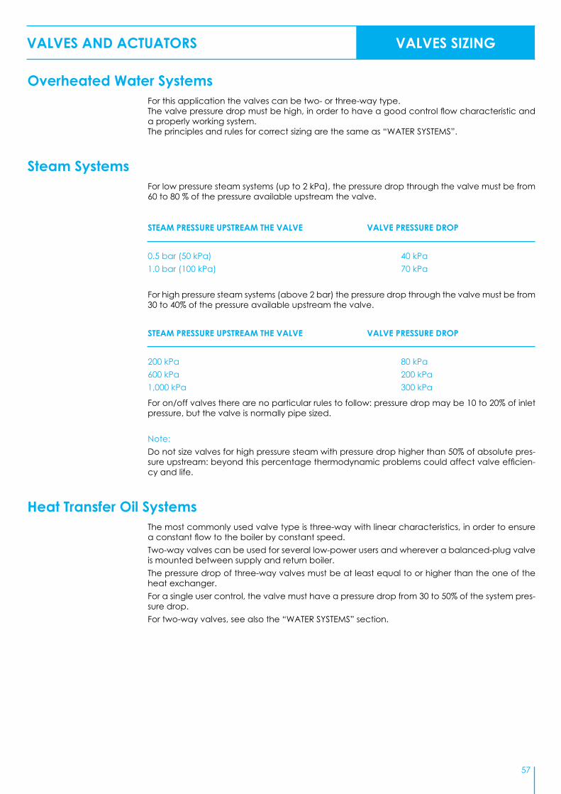
57
VALVES AND ACTUATORS VALVES SIZING
Overheated Water SystemsFor this application the valves can be two- or three-way type.The valve pressure drop must be high, in order to have a good control flow characteristic and a properly working system.The principles and rules for correct sizing are the same as “WATER SYSTEMS”.
Steam SystemsFor low pressure steam systems (up to 2 kPa), the pressure drop through the valve must be from 60 to 80 % of the pressure available upstream the valve.
STEAM PRESSURE UPSTREAM THE VALVE VALVE PRESSURE DROP
0.5 bar (50 kPa) 40 kPa1.0 bar (100 kPa) 70 kPa
For high pressure steam systems (above 2 bar) the pressure drop through the valve must be from 30 to 40% of the pressure available upstream the valve.
STEAM PRESSURE UPSTREAM THE VALVE VALVE PRESSURE DROP
200 kPa 80 kPa600 kPa 200 kPa1,000 kPa 300 kPa
For on/off valves there are no particular rules to follow: pressure drop may be 10 to 20% of inlet pressure, but the valve is normally pipe sized.
Note:Do not size valves for high pressure steam with pressure drop higher than 50% of absolute pres-sure upstream: beyond this percentage thermodynamic problems could affect valve efficien-cy and life.
Heat Transfer Oil SystemsThe most commonly used valve type is three-way with linear characteristics, in order to ensure a constant flow to the boiler by constant speed.Two-way valves can be used for several low-power users and wherever a balanced-plug valve is mounted between supply and return boiler.The pressure drop of three-way valves must be at least equal to or higher than the one of the heat exchanger.For a single user control, the valve must have a pressure drop from 30 to 50% of the system pres-sure drop.For two-way valves, see also the “WATER SYSTEMS” section.

NOTE

NOTE

Controlli S.p.A.Via Carlo Levi 52,16010 Sant’Olcese (Genova)ITALYTel +39 010 73 06 229Tel +39 010 73 06 208Tel +39 010 73 06 288Tel +39 010 73 06 [email protected]
Our distributor:
v. 0
3/18