Energy Audit, Level 3 - Rye NH |
33
Lakes Region ThermalScan 68 Heath Drive Gilmanton Iron Works, NH 03837 603 366-1552 www.LRThermalScan.com Energy Audit, Level 3 9 November, 2011 Prepared For: Town of Rye Property Address: 10 Central Street Rye, New Hampshire 03870
-
Upload
khangminh22 -
Category
Documents
-
view
1 -
download
0
Transcript of Energy Audit, Level 3 - Rye NH |

Lakes Region ThermalScan 68 Heath Drive Gilmanton Iron Works, NH 03837 603 366-1552 www.LRThermalScan.com
Energy Audit, Level 3
9 November, 2011
Prepared For: Town of Rye Property Address:
10 Central Street Rye, New Hampshire 03870

Page 2 of 33
Table of Contents EXECUTIVE SUMMARY............................................................................................................................................. 3 OVERVIEW................................................................................................................................................................. 4 BUILDING DIAGRAMS .................................................................................................................................................... 5 BUILDING PICTURES ..................................................................................................................................................... 5
OBSERVATIONS & TEST DATA................................................................................................................................. 6 BUILDING ENVELOPE AIR LEAKAGE TESTING ................................................................................................................... 6 HEATING FUEL CONSUMPTION ANALYSIS ........................................................................................................................ 6 ESTIMATED HEATING CONSUMPTION BY BUILDING COMPONENT........................................................................................ 6 ANNUAL ENERGY COSTS .............................................................................................................................................. 7 BUILDING SHELL MEASUREMENTS AND RATIOS ............................................................................................................... 7
ESTIMATED SAVINGS & ENVIRONMENTAL IMPACT............................................................................................... 8 ANNUAL BUILDING ENERGY CONSUMPTION..................................................................................................................... 8 HEATING FUEL CONSUMPTION....................................................................................................................................... 8 IMPROVEMENTS MODELED TO CALCULATE ESTIMATED ENERGY SAVINGS .......................................................................... 8 COMPARISON OF IMPROVED BUILDING TO CURRENT BUILDING CONDITION ......................................................................... 9
THERMAL BOUNDARY REPORT............................................................................................................................. 11 MAIN ATTIC SPACES................................................................................................................................................... 11 ATTIC HATCHES......................................................................................................................................................... 14 EXTERIOR WALLS ...................................................................................................................................................... 15 FOUNDATION WALLS .................................................................................................................................................. 20 SLAB FLOORS............................................................................................................................................................ 21 WINDOWS ................................................................................................................................................................. 22 EXTERIOR DOORS ...................................................................................................................................................... 23
AIR BARRIER / AIR LEAKAGE REPORT.................................................................................................................. 24 SYSTEMS REPORT ................................................................................................................................................. 25 HEATING SYSTEM ASSESSMENT .................................................................................................................................. 25 AIR CONDITIONING ASSESSMENT ................................................................................................................................. 26 AIR DUCT ASSESSMENT.............................................................................................................................................. 26 DOMESTIC HOT WATER ASSESSMENT .......................................................................................................................... 27 MECHANICAL VENTILATION ASSESSMENT ..................................................................................................................... 27
OTHER IMPROVEMENTS, RECOMMENDATIONS & CONSIDERATIONS............................................................... 28 HEALTH, SAFETY & BUILDING DURABILITY .......................................................................................................... 29 SELECTED INFRARED IMAGES............................................................................................................................. 30 SELECTED DIGITAL IMAGES................................................................................................................................. 32

Page 3 of 33
Executive Summary
This is an 1800’s church that has been converted into a municipal building. A lighting audit had previously been accomplished with lighting improvements implemented. The Town’s intent is to reduce heating and air conditioning fuel consumption by installing a geothermal system to replace the existing conditioning systems. The current systems have been inspected and a geothermal system designed to carry the current building loads. Due to the previous lighting audit and systems inspection, this report focuses primarily on the building’s shell and air barrier to assess energy saving opportunities. A comparison of reported annual heating fuel consumption to data provided by the US Information Administration, for office buildings within the appropriate climatic zone, reveals that this building consumes 41.5% more heating fuel per square foot of conditioned space than average. Not surprisingly the calculated heating season fuel consumption, if all recommended thermal boundary and air barrier improvements were implemented, reduces the expected fuel consumption by 53%. The building’s air barrier was assessed using a dual fan calibrated blower door. Due to the metal ceiling in the main building section, the building was pressurized to +50 Pa with reference to the exterior for infiltration rate testing and then depressurized to -12 Pa for thermal imaging inspection. Air leakage tested at 10,980 CFM @ +50 Pa. This level of air leakage indicates that significant energy savings can be achieved through moderate air sealing efforts and cost. Infrared imaging and visual inspection was accomplished of the entire building shell. A significant percentage of the building’s thermal boundary was found without insulation. Many building assemblies were found lacking a proper air barrier contributing significantly to the building’s energy load due to excessive air exchange. It should be noted that if the recommended building shell improvements are implemented the size of the new geothermal system can be significantly and proportionately reduced to address the reduced heating and cooling loads with the improved thermal boundary and air barrier. Energy modeling was conducted to simulate the building’s expected fuel burn with the recommended improvements. The modeled improvements to the thermal boundary and air barrier include:
• 40% reduction in infiltration
• Insulating all wall and attic assemblies that are currently uninsulated
• Improving the insulated attics to achieve R50
• Adding R10 foundation / slab perimeter insulation to 2’ below grade
• Insulating the Attic side walls with cavity insulation, plus R10 continuous insulation
• Improving the attic hatches to R40 weather-stripped hatches The estimated cost of the thermal boundary and air barrier improvements noted in this report is $27,500.00 with an expected annual energy savings of $4,365.00. This provides a 15.8% return on investment and a simple payback of 6.3 years. Additionally the reduced fuel burn would reduce carbon dioxide emissions by 14.3 tons annually. The slab and foundation wall improvements are the highest cost per square foot, significantly higher then the attic and wall improvements. Estimated costs included a reasonable sum to excavate the perimeter of the foundation to install slab and foundation insulation below grade. Future expansion plans may result in the complete removal of the Eastern section of the building. This may discourage investment into improvements for that section. It is estimated that the recommended attic and wall improvements for that section would pay for itself in approximately one heating season. Unless the expansion plans are implemented within the next 18 months, the investment into the thermal boundary and air barrier improvements for the Eastern section would be a cash positive transaction.

Page 4 of 33
OVERVIEW
For each section of the report thermal images from the inspected building were used unless annotated as “file images.” The “comments” for each section specifically pertain to the inspected building and are used for additional clarification or explanations. Assessed R values are for “whole wall R values” which is a total R value for the assembly as a whole. This takes into account the type, amount, and quality of the existing insulation, incorporates the thermal resistance of the existing framing and incorporates the percentage of total framing area compared to insulated cavity area. R values recommended for improvements are considered minimum R values that are currently cost effective with consideration to current fuel prices and the type of insulation contemplated. Greater R values will reduce energy losses further but at diminishing returns on investment. Installing greater R values than recommended is encouraged particularly if you believe energy prices will significantly rise in the future. The data collected from testing, deficiencies found during inspection, and recommendations are organized, cataloged and presented in seven separate sections at the beginning of this report. These sections include:
o Observations and Test Data Section o Estimated Energy Savings & Environmental Impact o Air Infiltration Report – Total Air Leakage Calculated o Thermal Boundary Report o Air Barrier Report o Other Improvements and Considerations Section o Health Safety & Building Durability Section
It is important to note that a quality contractor may have different methods or ideas to remediate the problems noted in this report and may make additional recommendations to achieve the same objective towards air sealing and improving the thermal boundary. Contractors that have achieved the Building Performance Institute’s (BPI) certification in their field have demonstrated advanced proficiency and are highly qualified. A gravity draft boiler and furnace is located in the building. You should be aware that air sealing could impact the pressures in this zone which could affect the draft of combustion appliances, such as your boiler, particularly when dryers, fans or other draft appliances are running. Please refer to the warning concerning this possibility at the bottom of the air infiltration report.
Page 5 of 33
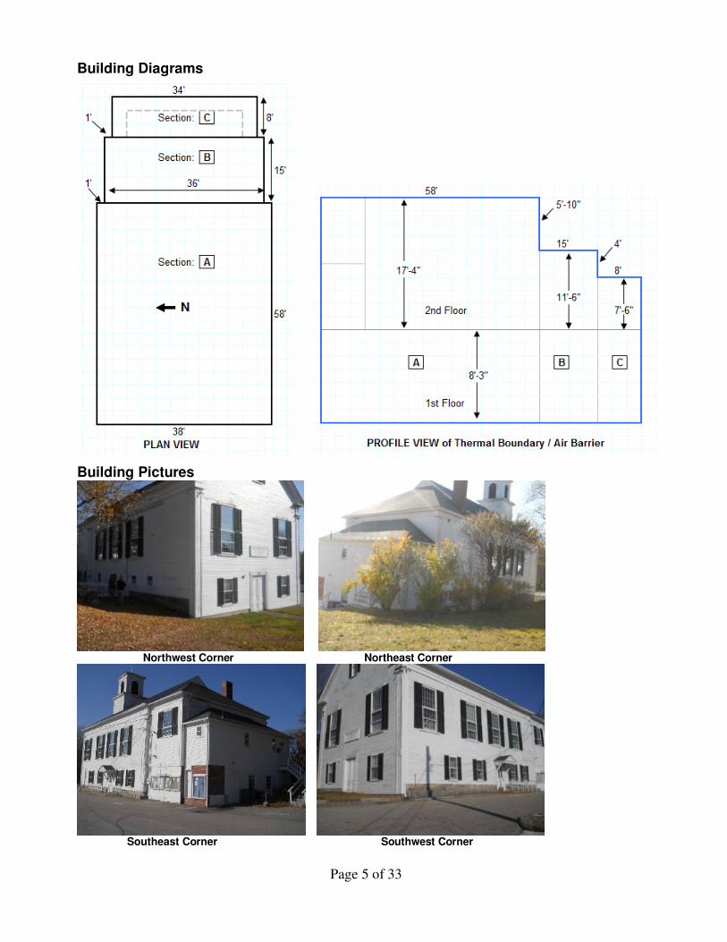
Building Diagrams
Building Pictures
Northwest Corner Northeast Corner
Southeast Corner Southwest Corner

Page 6 of 33
OBSERVATIONS & TEST DATA
Building Envelope Air Leakage Testing
Air leakage testing was accomplished utilizing a calibrated blower door to determine the structure’s overall air leakage rate. This test requires a 50 Pascal (Pa) pressure differential with reference to outside and adjusted for the normal baseline pressure of the structure. Test data, and the data normalized to various denominations are provided below.
Section Sq. Feet Volume
CFM 50
CFM / ft2
ACH 50 ACHn
Leakage Area Sq. Inches
Leakage Area Sq. Ft
Entire Structure 6032 74196 10980 1.82 6.76 0.68 1465 10.17
CFM50: The amount of air flow in cubic feet per minute (CFM) required to maintain a structure at -50 Pascals pressure, with reference to outside and
adjusted for structure’s normal base line pressure.
ACH50: Number of air exchanges per hour at 50 Pascal pressure differential.
ACHn: Air Changes per Hour. The annual average rate of exchange of conditioned inside air with outside air on an hourly basis at normal pressure, considering structure elevation and exposure. Determined by calculations utilizing structure volume and calibrated blower door measurements.
Leakage Area: An equivalent sharp edge single hole area that would leak at the same flow rate when the hole is subject to the same target test pressures.
Heating Fuel Consumption Analysis
An analysis was conducted using the fuel consumption for the 2010 heating season with a reported consumption of 2152 gallons. Occupants reported the use of electric space heaters during winter months to supplement zonal heating. Gallons consumed were adjusted by 10 % to account for and convert the supplemental electric heating fuel.
BTUs Per Sq-Ft of Conditioned Space Gallons of Fuel
Consumed Converted to
Millions of BTUs Sq-FT of Heated
Space BTUs per
Sq-ft Average For Climate Zone
Difference From Average
2367 331.8 MBtus 6032 55,006 38,860* + 41.5% Note: Data from U.S. Energy Information Administration for Non-Mall Commercial Buildings for Climate Zone with greater than 7000 Heating Degree Days
Estimated Heating Consumption by Building Component
In MBtu/yr

Page 7 of 33
Annual Energy Costs
Annual Energy Cost ($/yr)
Total 11847
Heating 8132
Cooling 433
Lights & App 3175
Service Charge 107
Building Shell Measurements and Ratios
Page 8 of 33
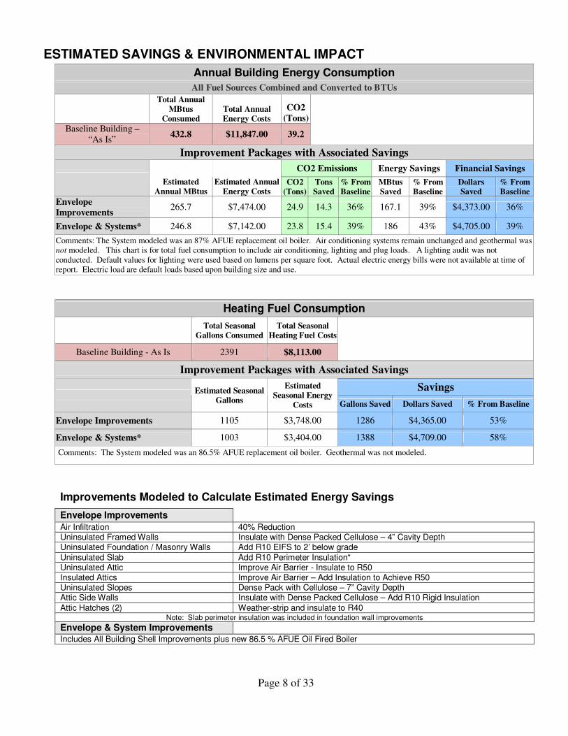
ESTIMATED SAVINGS & ENVIRONMENTAL IMPACT
Annual Building Energy Consumption
All Fuel Sources Combined and Converted to BTUs
Total Annual
MBtus Consumed
Total Annual Energy Costs
CO2 (Tons)
Baseline Building – “As Is”
432.8 $11,847.00 39.2 Improvement Packages with Associated Savings
CO2 Emissions Energy Savings Financial Savings Estimated
Annual MBtus Estimated Annual
Energy Costs CO2
(Tons) Tons Saved
% From Baseline
MBtus Saved
% From Baseline
Dollars Saved
% From Baseline
Envelope Improvements
265.7 $7,474.00 24.9 14.3 36% 167.1 39% $4,373.00 36%
Envelope & Systems* 246.8 $7,142.00 23.8 15.4 39% 186 43% $4,705.00 39%
Comments: The System modeled was an 87% AFUE replacement oil boiler. Air conditioning systems remain unchanged and geothermal was not modeled. This chart is for total fuel consumption to include air conditioning, lighting and plug loads. A lighting audit was not conducted. Default values for lighting were used based on lumens per square foot. Actual electric energy bills were not available at time of report. Electric load are default loads based upon building size and use.
Heating Fuel Consumption
Total Seasonal
Gallons Consumed Total Seasonal
Heating Fuel Costs
Baseline Building - As Is 2391 $8,113.00
Improvement Packages with Associated Savings
Savings
Estimated Seasonal Gallons
Estimated Seasonal Energy
Costs Gallons Saved Dollars Saved % From Baseline
Envelope Improvements 1105 $3,748.00 1286 $4,365.00 53%
Envelope & Systems* 1003 $3,404.00 1388 $4,709.00 58%
Comments: The System modeled was an 86.5% AFUE replacement oil boiler. Geothermal was not modeled.
Improvements Modeled to Calculate Estimated Energy Savings
Envelope Improvements Air Infiltration 40% Reduction Uninsulated Framed Walls Insulate with Dense Packed Cellulose – 4” Cavity Depth Uninsulated Foundation / Masonry Walls Add R10 EIFS to 2’ below grade
Uninsulated Slab Add R10 Perimeter Insulation* Uninsulated Attic Improve Air Barrier - Insulate to R50 Insulated Attics Improve Air Barrier – Add Insulation to Achieve R50 Uninsulated Slopes Dense Pack with Cellulose – 7” Cavity Depth Attic Side Walls Insulate with Dense Packed Cellulose – Add R10 Rigid Insulation
Attic Hatches (2) Weather-strip and insulate to R40 Note: Slab perimeter insulation was included in foundation wall improvements
Envelope & System Improvements
Includes All Building Shell Improvements plus new 86.5 % AFUE Oil Fired Boiler

Page 9 of 33
Comparison of Improved building to Current Building Condition
In MBtu/yr
Page 10 of 33
AIR INFILTRATION REPORT
An air infiltration Report created from TECTITE Software is provided separately
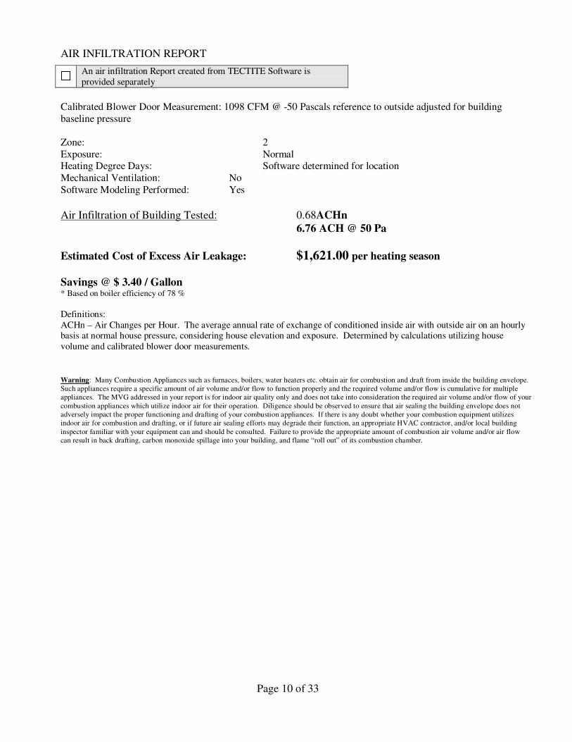
Calibrated Blower Door Measurement: 1098 CFM @ -50 Pascals reference to outside adjusted for building baseline pressure Zone: 2 Exposure: Normal Heating Degree Days: Software determined for location Mechanical Ventilation: No Software Modeling Performed: Yes
Air Infiltration of Building Tested: 0.68ACHn 6.76 ACH @ 50 Pa
Estimated Cost of Excess Air Leakage: $1,621.00 per heating season Savings @ $ 3.40 / Gallon * Based on boiler efficiency of 78 %
Definitions: ACHn – Air Changes per Hour. The average annual rate of exchange of conditioned inside air with outside air on an hourly basis at normal house pressure, considering house elevation and exposure. Determined by calculations utilizing house volume and calibrated blower door measurements.
Warning: Many Combustion Appliances such as furnaces, boilers, water heaters etc. obtain air for combustion and draft from inside the building envelope. Such appliances require a specific amount of air volume and/or flow to function properly and the required volume and/or flow is cumulative for multiple appliances. The MVG addressed in your report is for indoor air quality only and does not take into consideration the required air volume and/or flow of your
combustion appliances which utilize indoor air for their operation. Diligence should be observed to ensure that air sealing the building envelope does not adversely impact the proper functioning and drafting of your combustion appliances. If there is any doubt whether your combustion equipment utilizes indoor air for combustion and drafting, or if future air sealing efforts may degrade their function, an appropriate HVAC contractor, and/or local building
inspector familiar with your equipment can and should be consulted. Failure to provide the appropriate amount of combustion air volume and/or air flow can result in back drafting, carbon monoxide spillage into your building, and flame “roll out” of its combustion chamber.
Page 11 of 33
THERMAL BOUNDARY REPORT
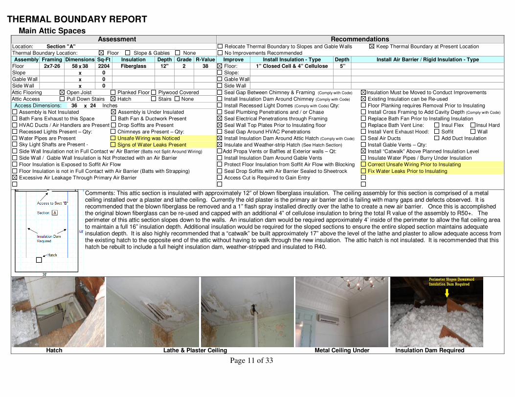
Main Attic Spaces Assessment
Location: Section "A"
Thermal Boundary Location: Floor Slope & Gables None
Assembly Framing Dimensions Sq-Ft Insulation Depth Grade R-Value
Floor 2x7-26 58 x 38 2204 Fiberglass 12" 2 38
Slope x 0
Gable Wall x 0
Side Wall x 0
Attic Flooring Open Joist Planked Floor Plywood Covered
Attic Access Pull Down Stairs Hatch Stairs None
Access Dimensions: 36 x 24 Inches
Assembly is Not Insulated Assembly is Under Insulated
Bath Fans Exhaust to this Space Bath Fan & Ductwork Present
HVAC Ducts / Air Handlers are Present Drop Soffits are Present
Recessed Lights Present – Qty: Chimneys are Present – Qty:
Water Pipes are Present Unsafe Wiring was Noticed Sky Light Shafts are Present -
Qty Signs of Water Leaks Present
Side Wall Insulation not in Full Contact w/ Air Barrier (Batts not Split Around Wiring)
Side Wall / Gable Wall Insulation is Not Protected with an Air Barrier
Floor Insulation is Exposed to Soffit Air Flow
Floor Insulation is not in Full Contact with Air Barrier (Batts with Strapping)
Excessive Air Leakage Through Primary Air Barrier
Recommendations Relocate Thermal Boundary to Slopes and Gable Walls Keep Thermal Boundary at Present Location
No Improvements Recommended
Improve Install Insulation - Type Depth Install Air Barrier / Rigid Insulation - Type
Floor: 1” Closed Cell & 4” Cellulose 5”
Slope:
Gable Wall
Side Wall
Seal Gap Between Chimney & Framing (Comply with Code) Insulation Must be Moved to Conduct Improvements
Install Insulation Dam Around Chimney (Comply with Code) Existing Insulation can be Re-used
Install Recessed Light Domes (Comply with Code) Qty: Floor Planking requires Removal Prior to Insulating
Seal Plumbing Penetrations and / or Chase Install Cross Framing to Add Cavity Depth (Comply with Code)
Seal Electrical Penetrations through Framing Replace Bath Fan Prior to Installing Insulation
Seal Wall Top Plates Prior to Insulating floor Replace Bath Vent Line: Insul Flex Insul Hard
Seal Gap Around HVAC Penetrations Install Vent Exhaust Hood: Soffit Wall
Install Insulation Dam Around Attic Hatch (Comply with Code) Seal Air Ducts Add Duct Insulation
Insulate and Weather-strip Hatch (See Hatch Section) Install Gable Vents – Qty:
Add Propa Vents or Baffles at Exterior walls – Qt: Install “Catwalk” Above Planned Insulation Level
Install Insulation Dam Around Gable Vents Insulate Water Pipes / Burry Under Insulation
Protect Floor Insulation from Soffit Air Flow with Blocking Correct Unsafe Wiring Prior to Insulating
Seal Drop Soffits with Air Barrier Sealed to Sheetrock Fix Water Leaks Prior to Insulating
Access Cut is Required to Gain Entry
Comments: This attic section is insulated with approximately 12” of blown fiberglass insulation. The ceiling assembly for this section is comprised of a metal ceiling installed over a plaster and lathe ceiling. Currently the old plaster is the primary air barrier and is failing with many gaps and defects observed. It is recommended that the blown fiberglass be removed and a 1” flash spray installed directly over the lathe to create a new air barrier. Once this is accomplished the original blown fiberglass can be re-used and capped with an additional 4” of cellulose insulation to bring the total R value of the assembly to R50+. The perimeter of this attic section slopes down to the walls. An insulation dam would be required approximately 4’ inside of the perimeter to allow the flat ceiling area to maintain a full 16” insulation depth. Additional insulation would be required for the sloped sections to ensure the entire sloped section maintains adequate insulation depth. It is also highly recommended that a “catwalk” be built approximately 17” above the level of the lathe and plaster to allow adequate access from the existing hatch to the opposite end of the attic without having to walk through the new insulation. The attic hatch is not insulated. It is recommended that this hatch be rebuilt to include a full height insulation dam, weather-stripped and insulated to R40.
Hatch Lathe & Plaster Ceiling Metal Ceiling Under Insulation Dam Required
Page 12 of 33
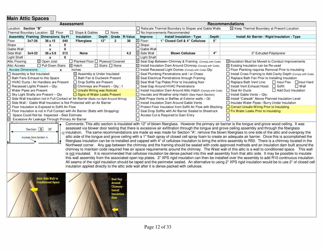
Main Attic Spaces Assessment
Location: Section "B"
Thermal Boundary Location: Floor Slope & Gables None
Assembly Framing Dimensions Sq-Ft Insulation Depth Grade R-Value
Floor 2x7-26 36 x 15 540 Fiberglass 12" 2 38
Slope x 0
Gable Wall x 0
Side Wall 3x4-32 36 x 5.9 212 None 4.2
Light Shaft x 0
Attic Flooring Open Joist Planked Floor Plywood Covered
Attic Access Pull Down Stairs Hatch Stairs None
Access Dimensions: x Inches
Assembly is Not Insulated Assembly is Under Insulated
Bath Fans Exhaust to this Space Bath Fan & Ductwork Present
HVAC Ducts / Air Handlers are Present Drop Soffits are Present
Recessed Lights Present – Qty: Chimneys are Present – Qty: :1
Water Pipes are Present Unsafe Wiring was Noticed
Sky Light Shafts are Present – Qty Signs of Water Leaks Present
Side Wall Insulation not in Full Contact w/ Air Barrier (Batts not Split Around Wiring)
Side Wall / Gable Wall Insulation is Not Protected with an Air Barrier
Floor Insulation is Exposed to Soffit Air Flow
Floor Insulation is not in Full Contact with Air Barrier (Batts with Strapping)
Space Could Not be Inspected – Best Estimate
Excessive Air Leakage Through Primary Air Barrier
Recommendations Relocate Thermal Boundary to Slopes and Gable Walls Keep Thermal Boundary at Present Location
No Improvements Recommended
Improve Install Insulation - Type Depth Install Air Barrier / Rigid Insulation - Type
Floor: 1” Closed Cell & 4” Cellulose 5”
Slope:
Gable Wall
Side Wall Blown Cellulose 4" 2" Extruded Polystyrene
Light Shaft
Seal Gap Between Chimney & Framing (Comply with Code) Insulation Must be Moved to Conduct Improvements
Install Insulation Dam Around Chimney (Comply with Code) Existing Insulation can be Re-used
Install Recessed Light Domes (Comply with Code) Qty: Floor Planking requires Removal Prior to Insulating
Seal Plumbing Penetrations and / or Chase Install Cross Framing to Add Cavity Depth (Comply with Code)
Seal Electrical Penetrations through Framing Replace Bath Fan Prior to Installing Insulation
Seal Wall Top Plates Prior to Insulating floor Replace Bath Vent Line: Insul Flex Insul Hard
Seal Gap Around HVAC Penetrations Install Vent Exhaust Hood: Soffit Wall
Install Insulation Dam Around Attic Hatch (Comply with Code) Seal Air Ducts Add Duct Insulation
Insulate and Weather-strip Hatch (See Hatch Section) Install Gable Vents – Qty:
Add Propa Vents or Baffles at Exterior walls – Qt: Install “Catwalk” Above Planned Insulation Level
Install Insulation Dam Around Gable Vents Insulate Water Pipes / Burry Under Insulation
Protect Floor Insulation from Soffit Air Flow with Blocking Correct Unsafe Wiring Prior to Insulating
Seal Drop Soffits with Air Barrier Sealed to Sheetrock Fix Water Leaks Prior to Insulating
Access Cut is Required to Gain Entry
Comments: This attic section is insulated with 12" of blown fiberglass. However the primary air barrier is the tongue and grove wood ceiling. It was assessed via blower door testing that there is excessive air exfiltration through the tongue and grove ceiling assembly and through the fiberglass insulation. The same recommendations are made as was made for Section "A”, remove the blown fiberglass to one side of the attic and overspray the attic side of the tongue and grove ceiling with a 1" flash spray of closed cell spray foam to create an adequate air barrier. Once this is accomplished the fiberglass insulation can be re-installed and capped with 4" of cellulose insulation to bring the entire assembly to R50. There is a chimney located in the Northwest corner. Any gap between the chimney and the framing should be sealed with code approved methods and an insulation dam built around the chimney to maintain code required free air space requirements around the chimney. The West wall of this attic is a wall to conditioned space. This wall is not insulated. It is recommended that cellulose insulation be dense packed into this wall assembly from that attic side. It may be possible to insulate this wall assembly from the associated open top plates. 2" XPS rigid insulation can then be installed over the assembly to add R10 continuous insulaiton. All seams of the rigid insulation should be taped and the perimeter sealed. An alternative to using 2” XPS rigid insulation would be to use 2” of closed cell insulation applied directly to the attic side wall after it is dense packed with cellulose.

Page 13 of 33
Main Attic Spaces Assessment
Location: Section “C”
Thermal Boundary Location: Floor Slope & Gables None
Assembly Framing Dimensions Sq-Ft Insulation Depth Grade R-Value
Floor 2x3-53 6.9 x 31.5 217 None
Slope 2x6-21 1.5 x 49 73 None
Gable Wall x 0
Side Wall 3x4-32 34 x 4 136 None
Attic Flooring Open Joist Planked Floor Plywood Covered
Attic Access Pull Down Stairs Hatch Stairs None
Access Dimensions: 16" x 16" Inches
Assembly is Not Insulated Assembly is Under Insulated
Bath Fans Exhaust to this Space Bath Fan & Ductwork Present
HVAC Ducts / Air Handlers are Present Drop Soffits are Present
Recessed Lights Present – Qty: Chimneys are Present – Qty: :
Water Pipes are Present Unsafe Wiring was Noticed
Sky Light Shafts are Present – Qty Signs of Water Leaks Present
Side Wall Insulation not in Full Contact w/ Air Barrier (Batts not Split Around Wiring)
Side Wall / Gable Wall Insulation is Not Protected with an Air Barrier
Excessive Air Leakage Through Primary Air Barrier
Floor Insulation is not in Full Contact with Air Barrier (Batts with Strapping)
Recommendations Relocate Thermal Boundary to Slopes and Gable Walls Keep Thermal Boundary at Present Location
No Improvements Recommended
Improve Install Insulation - Type Depth Install Air Barrier / Rigid Insulation - Type
Floor: 1” Closed Cell & 4” Cellulose 16"
Slope: Blown Cellulose 4"
Gable Wall
Side Wall Blown Cellulose 4" 2" Extruded Polystyrene
Seal Gap Between Chimney & Framing (Comply with Code) Remove and Discard Old Insulation Prior to Insulating
Install Insulation Dam Around Chimney (Comply with Code) Remove / Discard FG Batts within 4’ of perimeter
Install Recessed Light Domes (Comply with Code) Qty: Floor Planking requires Removal Prior to Insulating
Seal Plumbing Penetrations and / or Chase Install Cross Framing to Add Cavity Depth (Comply with Code)
Seal Electrical Penetrations through Framing Replace Bath Fan Prior to Installing Insulation
Seal Wall Top Plates Prior to Insulating floor Replace Bath Vent Line: Insul Flex Insul Hard
Seal Gap Around HVAC Penetrations Install Vent Exhaust Hood: Soffit Wall
Install Insulation Dam Around Attic Hatch (Comply with Code) Seal Air Ducts Add Duct Insulation
Insulate and Weather-strip Hatch (See Hatch Section) Install Gable Vents – Qty:
Add Propa Vents or Baffles at Exterior walls – Qt: Install “Catwalk” Above Planned Insulation Level
Install Insulation Dam Around Gable Vents Insulate Water Pipes / Burry Under Insulation
Protect Floor Insulation from Soffit Air Flow with Blocking Correct Unsafe Wiring Prior to Insulating
Seal Drop Soffits with Air Barrier Sealed to Sheetrock Fix Water Leaks Prior to Insulating Comments: This attic space was found uninsulated. Occupants report water leaks from this attic section. Interview with workers that utilize this space stated that most of the water leaks seemed to occur during the winter months. It is possible that these leaks are actually the result of condensation from warm interior air condensing in the cold space; however the workers also reported leaks during the recent hurricane. Before any improvements are completed in this space the roof shingles and associated flashing should be inspected by a qualified roofer with appropriate repairs made as necessary. This ceiling assembly is uninsulated tongue and grove wood with short uninsulated slopes around the exterior perimeter. There is an attic side wall on the West side that separates this attic space from the conditioned space of Section “B”. Inspection revealed this side attic wall to be mostly uninsulated. Rosin paper installed on this side attic wall was used as the original air barrier. This paper has failed and provides little air barrier value. Both this ceiling and the side attic wall contribute significantly to the overall air leakage of this building in that neither has an appropriate air barrier. The framing of the flat ceiling area is assessed as inadequate to support a worker. This can be corrected by the installation of 2x6 framing between the ceiling rafters and the side wall to create solid support for work to be accomplished. This framing should be installed 15” above the ceiling level so future access can be gained after the insulation is installed. As with the recommendations for the previous attic spaces, it is recommended that an adequate air barrier be established by installing 1” closed cell insulation on the attic side of the flat ceiling area. This would then be capped with 14” of blown cellulose to bring the ceiling to R50. The side attic wall would require a dense packed cellulose blow. Once the cavities are fully insulated than 2” XPS rigid insulation should be installed over the side wall to create an adequate air barrier and to provide a layer of
continuous R10 insulation. All seams should be taped and the perimeter sealed. A 2” application of closed cell insulation could be substituted for the XPS rigid insulation. The small sloped assembly surrounding the exterior perimeter of this space would require a dense packed cellulose blow. Due to the limited cavity depth of these slopes the maximum R-value achievable by dense packing alone would be R20. Consideration should be given to installing 2” polyisocyanurate on the interior sides of the sloped assemblies to be covered by sheetrock. This combination of dense packing the slopes and the additional R13 provided by the continuous insulation would provide R33. The hatch assembly would require full R40 Insulation, weather-stripping and an insulation dam.
Section “C” Flat Attic Short Slopes Side Wall to Section “B” Inadequate Air Barrier Small Hatch to Space
Page 14 of 33
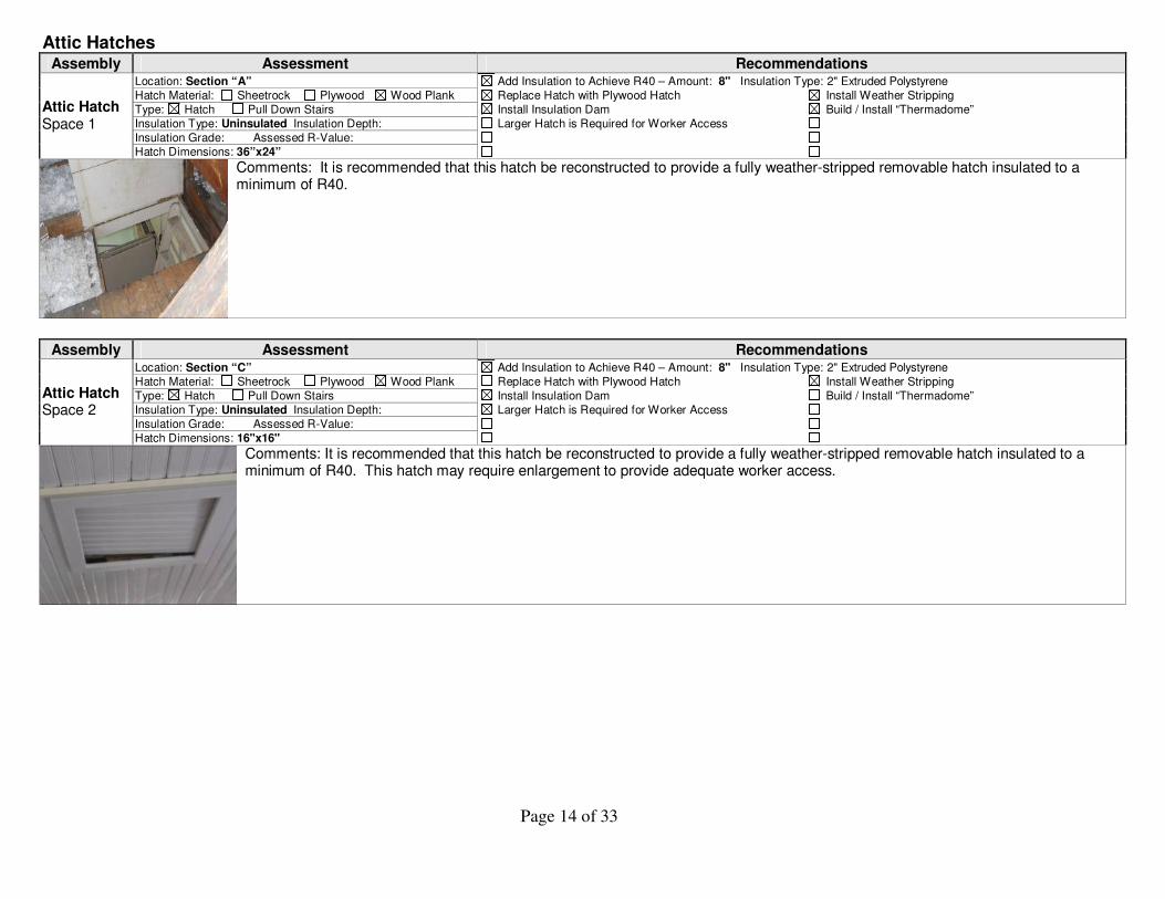
Attic Hatches
Assembly Assessment Recommendations Location: Section “A” Add Insulation to Achieve R40 – Amount: 8" Insulation Type: 2" Extruded Polystyrene Hatch Material: Sheetrock Plywood Wood Plank Replace Hatch with Plywood Hatch Install Weather Stripping
Type: Hatch Pull Down Stairs Install Insulation Dam Build / Install “Thermadome”
Insulation Type: Uninsulated Insulation Depth: Larger Hatch is Required for Worker Access
Insulation Grade: Assessed R-Value:
Attic Hatch Space 1
Hatch Dimensions: 36”x24”
Comments: It is recommended that this hatch be reconstructed to provide a fully weather-stripped removable hatch insulated to a minimum of R40.
Assembly Assessment Recommendations
Location: Section “C” Add Insulation to Achieve R40 – Amount: 8" Insulation Type: 2" Extruded Polystyrene Hatch Material: Sheetrock Plywood Wood Plank Replace Hatch with Plywood Hatch Install Weather Stripping
Type: Hatch Pull Down Stairs Install Insulation Dam Build / Install “Thermadome”
Insulation Type: Uninsulated Insulation Depth: Larger Hatch is Required for Worker Access
Insulation Grade: Assessed R-Value:
Attic Hatch Space 2
Hatch Dimensions: 16"x16"
Comments: It is recommended that this hatch be reconstructed to provide a fully weather-stripped removable hatch insulated to a minimum of R40. This hatch may require enlargement to provide adequate worker access.

Page 15 of 33
Exterior Walls
Assessment Location: Framed Walls – Sections “A” & B” - 1
st Floor Only
Framing Dimensions Sq-Ft Insulation Depth Grade R-Value
3x4-32 170 X 8.25 1402 Blown Fiberglass 4" 2 12.7
Interior Surface: Sheetrock Exterior Cladding: Wood Clap
Assembly is Not Insulated Assembly is Under Insulated
Insulation is Not Protected from Air Flow
Chimneys are Present – Qty:
Excess Air Exchange w/ Exterior Signs of Water Leaks Present
Wall is “Balloon” Framed Unsafe Wiring is Present
Associated Rim Band Between Conditioned Floor Levels N (Not Basement or Crawlspace Rim Bands)
Framing Linear Ft Insulation Depth Grade R-Value
6x6 238 None 7
Assembly is Not Insulated Assembly is Under Insulated
Excess Air Exchange w/ Exterior Signs of Water Leaks Present
Wall is “Balloon” Framed Unsafe Wiring is Present
Not able to Assess Wood Rot is Present
Recommendations Recommend Improvements – For Areas Described in Comments No Improvements Recommended
Install Cavity Insulation - Type Depth Install Interior Air Barrier / Rigid Insulation - Type
Exterior Paint Should be Checked for Lead Add Exterior Insulation when Exterior Siding is Replaced
Air Seal Interior Penetrations Requires an Interior Insulation Blow
Requires an Exterior Insulation Blow Comply with Lead Paint Abatement Procedures
Batts can be Installed from Interior Fix Water Leaks Prior to Insulating
Air Seal Exterior Penetrations Correct Unsafe Wiring Prior to Insulating
Associated Rim Band Between Conditioned Floor Levels N Recommend Improvements No Improvements Recommended
Install Insulation - Type Depth Install Interior Air Barrier / Rigid Insulation - Type
Air Seal Penetrations Ensure Rim Insulation Ties into Foundation Insulation
Air Seal Gaps Fix Water Leaks Prior to Insulating
Requires an Exterior Insulation Blow Correct Unsafe Wiring Prior to Insulating
Ensure Rigid Insulation is Sealed in Place Correct Wood Rot Prior to Insulating
Remove and Discard Existing Insulation
Comments: The walls for sections “A” and “B” are comprised of an elevated foundation wall with a framed wall above. The framed section of these walls has been retrofitted with blown fiberglass insulation. A defect was found with the wall bays associated with the stair well on the North side. The interior wall section below the stairwell did not have interior sheathing and the insulation fell out of these bays after installation. Access to the underside of the stairs is by an opening from the boiler room. It is recommended that OSB sheathing be installed on the interior wall side and the specific bays dense packed with cellulose insulation. No notable defects were found with the remaining framed walls for sections “A” and “B”. However the lower half of these walls has an elevated foundation that is framed on the interior. Some sections of Section “B” have full height brick walls. It was assessed through infrared imaging that the interior framed portions of these masonry walls are not insulated. The “Foundation Wall” section of this report will describe the recommended remedial measures for those specific assemblies.

Page 16 of 33
Exterior Walls Assessment
Location: Section “C” – 1st
Floor only
Framing Dimensions Sq-Ft Insulation Depth Grade R-Value
2X4-16 36 x 6.5 234 Fiberglass 4" 2 1.6 - 10.2
Interior Surface: Sheetrock Exterior Cladding: Wood Clap
Assembly is Not Insulated Assembly is Under Insulated
Insulation is Not Protected from Air Flow
Chimneys are Present – Qty:
Excess Air Exchange w/ Exterior Signs of Water Leaks Present
Wall is “Balloon” Framed Unsafe Wiring is Present
Recommendations Recommend Improvements No Improvements Recommended
Install Cavity Insulation - Type Depth Install Interior Air Barrier / Rigid Insulation - Type
Exterior Paint Should be Checked for Lead Add Interior Insulation to Uninsulated Masonry Surfaces
Air Seal Interior Penetrations Comply with Building Code Thermal Barrier Requirements
Requires an Exterior Insulation Blow Comply with Lead Paint Abatement Procedures
Batts can be Installed from Interior Fix Water Leaks Prior to Insulating
Air Seal Exterior Penetrations Correct Unsafe Wiring Prior to Insulating
Comments: This section appears to have been an open porch that has been framed in. The framed portions of this section’s walls were determined to be insulated via infrared imaging and visual inspection and are assessed at R10.2 for “whole wall” R-value. The Southern closet however has uninsulated masonry walls and a very low R-value and leaky door. The uninsulated brick is assessed an R-value of 1.6 and the door is approximately R1. The East wall of this section has uninsulated brick pillars, and the North wall has uninsulated exposed concrete on the lower half. The foundation wall section of this report provides improvement recommendations that include exterior insulation for the masonry foundations / walls. For this particular section of the building there is an option to put insulation on the interior of the masonry walls instead of the exterior, or both could be accomplished. 2.5” extruded polystyrene protected with a code approved thermal barrier, such as sheetrock, would be appropriate and provide an R13 insulation level. The brick pillars in the East wall and the exposed concrete on the North wall should also be covered with 2.5” rigid foam board with sheetrock. It appears that the exterior door in the South closet is not used and is sealed shut. If this door is not required then it is recommended that this door be fully sealed to create a weather tight barrier then insulated over with rigid insulation and a thermal barrier.
Uninsulated / Leaky Door Uninsulated Brick Pillars Uninsulated Concrete

Page 17 of 33
Exterior Walls Assessment
Location: Section “A” - 2nd
Floor
Framing Dimensions Sq-Ft Insulation Depth Grade R-Value
3x4-32 17.33 x 156 2309 None 4.2
Interior Surface: Sheetrock Exterior Cladding: Wood Clap
Assembly is Not Insulated Assembly is Under Insulated
Insulation is Not Protected from Air Flow
Chimneys are Present – Qty:
Excess Air Exchange w/ Exterior Signs of Water Leaks Present
Wall has open top plates Unsafe Wiring is Present
Recommendations Recommend Improvements No Improvements Recommended
Install Cavity Insulation - Type Depth Install Interior Air Barrier / Rigid Insulation - Type
Exterior Paint Should be Checked for Lead Add Exterior Insulation when Exterior Siding is Replaced
Air Seal Interior Penetrations Requires an Interior Insulation Blow
Requires an Exterior Insulation Blow Comply with Lead Paint Abatement Procedures
Batts can be Installed from Interior Fix Water Leaks Prior to Insulating
Air Seal Exterior Penetrations Correct Unsafe Wiring Prior to Insulating
Comments: The Sq-Ft of the wall surface area listed above excludes the surface areas of the windows and is the actual surface area of the wall cavities that require insulation. Infrared imaging and visual inspection from the attic revealed these bays to be void of insulation. Due to the open wall top plates, minor amounts of blown fiberglass have fallen into these bays when the blown fiberglass was installed in the attic. Improvements to these walls will require an exterior cellulose blow. Due to the age of this structure, lead paint abatement procedures would be applicable unless approved RRP testing determines the absence of lead. The interior sheetrock has many unsealed gaps and seams. Interior air sealing should first be accomplished prior to dense packing cellulose to prevent excessive dust and debris from entering the office spaces and to reduce infiltration. Of important note is that there are air ducts in both the North and South Walls. It was not determined during the audit if there is actual ductwork installed in the wall cavity or if the wall cavity itself was panned off and used as the air duct. It is extremely important that the follow on insulation contractor first determine if actual air ducts are present in these wall bays prior to blowing insulation into these wall cavities. For either scenario it is highly inefficient to have ductwork inside an exterior wall cavity, and would be significantly worse if the cavity itself was used as the air duct. Even with perfectly tight ductwork (highly doubtful) these specific wall bays can not be properly insulted while the ductwork remains. It is highly recommended that this particular ductwork be re-routed to the interior of the primary air barrier (interior sheetrock).
Infrared Images Showing Uninsulated Walls

Page 18 of 33
Exterior Walls Assessment
Location: Section “B” – 2nd
Floor
Framing Dimensions Sq-Ft Insulation Depth Grade R-Value
3x4-32 11.5 x 32 340 None 4.9
Interior Surface: 3/4" Wood Panel Exterior Cladding: Wood Clap
Assembly is Not Insulated Assembly is Under Insulated
Inadequate Air Barrier Chimneys are Present – Qty:
1
Excess Air Exchange w/ Exterior Signs of Water Leaks Present
Wall has open top plates Unsafe Wiring is Present
Recommendations Recommend Improvements No Improvements Recommended
Install Cavity Insulation - Type Depth Install Interior Air Barrier / Rigid Insulation - Type
Dense Packed Cellulose 4"
Exterior Paint Should be Checked for Lead Add Exterior Insulation when Exterior Siding is Replaced
Air Seal Interior Penetrations Requires an Interior Insulation Blow
Requires an Exterior Insulation Blow Comply with Lead Paint Abatement Procedures
Batts can be Installed from Interior Fix Water Leaks Prior to Insulating
Air Seal Exterior Penetrations Correct Unsafe Wiring Prior to Insulating
Comments: This section’s walls were determined to be uninsulated via infrared inspection. The interior wall surfaces are tongue and grove wood which provides an inadequate air barrier. In addition these walls have many “cut outs” through which wiring had been run. These walls would require and exterior cellulose blow after the holes have been sealed. Lead paint abatement procedures would apply unless the exterior paint tested negative for lead using approved RRP lead testing procedures. The installation of interior 2” extruded polystyrene rigid insulation over the tongue and grove is an additional efficiency upgrade to be considered. This would significantly improve the air barrier reducing infiltration along with providing a layer of continuous R10 insulation. The wall currently is assessed at R5. Dense packing the cavities with cellulose would bring the wall assembly to R14. Dense packing the cavities and adding a layer of R10 interior insulation and sheetrock would bring the assembly to R25 and would provide a superior air barrier. This interior insulation would require a code approved thermal barrier, such as sheetrock. This interior insulation recommendation was not modeled into the energy saving calculations provided previously in this report due to the unlikelihood that this particular improvement would be conducted at this time, but should be considered if funding allows. The square feet provided in the table above are for the opaque wall area exclusive of windows.

Page 19 of 33
Exterior Walls Assessment
Location: Section “C” – 2nd
Floor
Framing Dimensions Sq-Ft Insulation Depth Grade R-Value
2X4-16 6.5 x 50 292 None 4.9
Interior Surface: 3/4" Wood Panel Exterior Cladding: Wood Clap
Assembly is Not Insulated Assembly is Under Insulated
Inadequate Air Barrier Chimneys are Present – Qty:
Excess Air Exchange w/ Exterior Signs of Water Leaks Present
Wall has open top plates Unsafe Wiring is Present
Recommendations Recommend Improvements No Improvements Recommended
Install Cavity Insulation - Type Depth Install Interior Air Barrier / Rigid Insulation - Type
Dense Packed Cellulose 4"
Exterior Paint Should be Checked for Lead Add Exterior Insulation when Exterior Siding is Replaced
Air Seal Interior Penetrations Requires an Interior Insulation Blow
Requires an Exterior Insulation Blow Comply with Lead Paint Abatement Procedures
Batts can be Installed from Interior Fix Water Leaks Prior to Insulating
Air Seal Exterior Penetrations Correct Unsafe Wiring Prior to Insulating
Comments: The same recommendations are made for this section as were made for building section “B”. These walls were determined to be uninsulated and the tongue and grove provides a poor air barrier. As seen in the associated sections of this report this entire 2
nd floor section of this building has
uninsulated assemblies to include walls, the sloped ceiling sections and the flat attic section. The door to exterior is a very low R-value door and would be a candidate for replacement. The square feet provided in the table above are for the opaque wall area exclusive of windows and the door.
Page 20 of 33
Foundation Walls
Assessment Location: Sections: All – Lower Sections with Masonry or Stone
Framing Dimensions Sq-Ft Insulation Depth Grade R-Value
Masonry x 674 None 1.5 – 3.0
Interior Surface: Finished Exterior Cladding: Exposed Masonry or Stone
Assembly is Not Insulated Assembly is Under Insulated
Insulation is Not Protected from Air Flow
Chimneys are Present – Qty:
Excess Air Exchange w/ Exterior Signs of Water Leaks Present
Wall is “Balloon” Framed Unsafe Wiring is Present
Recommendations Recommend Improvements No Improvements Recommended
Install Cavity Insulation - Type Depth Install Exterior Rigid Insulation
R 10 EIFS
Improve Existing Insulation to Grade 1 Ensure Ceiling Insulation is in Full Contact with Subfloor
Remove and Discard Old Insulation Leave Bottom 6” Uninsulated Due to Dampness
Cover Exposed Wall Insulation with Air Barrier
Tape Seams of Rigid Insulation and Seal Perimeter
Air Seal Penetrations Moisture Problems Must be Corrected Prior to Insulating
Insulate Hatch / Door Correct Unsafe Wiring Prior to Insulating
Weather-Strip Hatch / Door Vent Dryer to Exterior
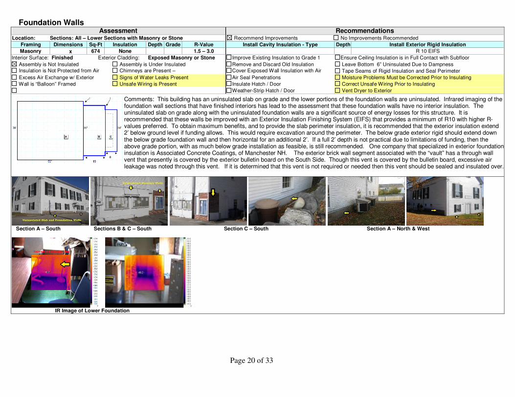
Comments: This building has an uninsulated slab on grade and the lower portions of the foundation walls are uninsulated. Infrared imaging of the foundation wall sections that have finished interiors has lead to the assessment that these foundation walls have no interior insulation. The uninsulated slab on grade along with the uninsulated foundation walls are a significant source of energy losses for this structure. It is recommended that these walls be improved with an Exterior Insulation Finishing System (EIFS) that provides a minimum of R10 with higher R-values preferred. To obtain maximum benefits, and to provide the slab perimeter insulation, it is recommended that the exterior insulation extend 2’ below ground level if funding allows. This would require excavation around the perimeter. The below grade exterior rigid should extend down the below grade foundation wall and then horizontal for an additional 2’. If a full 2’ depth is not practical due to limitations of funding, then the above grade portion, with as much below grade installation as feasible, is still recommended. One company that specialized in exterior foundation insulation is Associated Concrete Coatings, of Manchester NH. The exterior brick wall segment associated with the “vault” has a through wall vent that presently is covered by the exterior bulletin board on the South Side. Though this vent is covered by the bulletin board, excessive air leakage was noted through this vent. If it is determined that this vent is not required or needed then this vent should be sealed and insulated over.
Section A – South Sections B & C – South Section C – South Section A – North & West
IR Image of Lower Foundation
Page 21 of 33
Slab Floors
Assembly Assessment Recommendations Location: Entire Structure Add Perimeter Insulation – R-Value: 10 Recommended Type: EIFS Quantity:
Covering: Combination Floor Dimensions: Recommend Rigid Insulation Installed Between Sleepers when Carpet is Replaced or Space Finished
LF On Grade: 238 LF Below Grade: 73 Cover Exterior Insulation with UV Protection
Insulation Under: No Perimeter Insulation: No
Insulation Depth: Assessed R-Value: < 1
Assembly is Under Insulated
Assembly Is Not Insulated
Above Grade Exterior Insulation is not Protected
Slab Floor Space 1
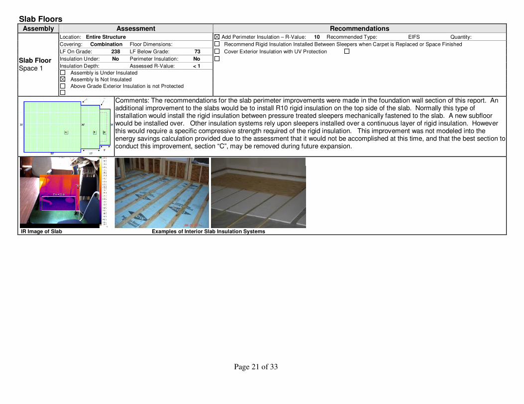
Comments: The recommendations for the slab perimeter improvements were made in the foundation wall section of this report. An additional improvement to the slabs would be to install R10 rigid insulation on the top side of the slab. Normally this type of installation would install the rigid insulation between pressure treated sleepers mechanically fastened to the slab. A new subfloor would be installed over. Other insulation systems rely upon sleepers installed over a continuous layer of rigid insulation. However this would require a specific compressive strength required of the rigid insulation. This improvement was not modeled into the energy savings calculation provided due to the assessment that it would not be accomplished at this time, and that the best section to conduct this improvement, section “C”, may be removed during future expansion.
IR Image of Slab Examples of Interior Slab Insulation Systems

Page 22 of 33
Windows
Assembly Assessment Recommendations Locations: Throughout Building Add Exterior Storm Window Add Interior Storm Install Weather-Striping Consider Replacement
Assessed U Value: 0.58
Single Pane Double Pane Triple Pane Wood Metal Vinyl < ½ Air Space ½ “ Air Space > ½ “ space
Low E Coatings:
Windows Type 1
Storm Window: Yes
Comments: Building has significant glazing area. The majority of the windows were single pane wood with storm windows and were assessed as fairly tight. Occupants report that the large 2
nd floor windows are very difficult to operate and do not have a counterweight system.
New recoil style counter weights systems area available. It is recommended that client consult a contractor that specializes in historic windows to install a counterbalance system to allow windows to be used for ventilation. With these windows operable natural ventilation could be used to a greater extend reducing air conditioning loads.
Page 23 of 33
Exterior Doors
Door Type 1 Assessment Recommendations
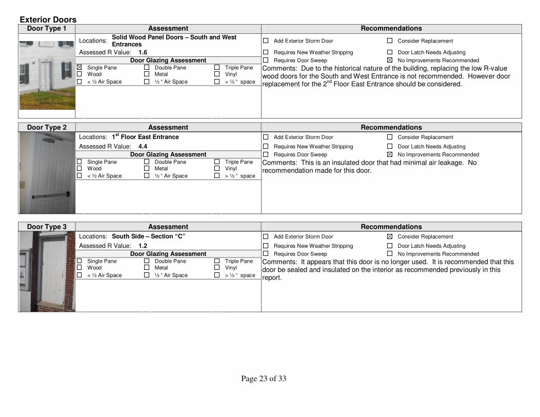
Locations: Solid Wood Panel Doors – South and West Entrances
Add Exterior Storm Door Consider Replacement
Assessed R Value: 1.6 Requires New Weather Stripping Door Latch Needs Adjusting
Door Glazing Assessment Requires Door Sweep No Improvements Recommended
Single Pane Double Pane Triple Pane
Wood Metal Vinyl
< ½ Air Space ½ “ Air Space > ½ “ space
Comments: Due to the historical nature of the building, replacing the low R-value wood doors for the South and West Entrance is not recommended. However door replacement for the 2
nd Floor East Entrance should be considered.
Door Type 2 Assessment Recommendations
Locations: 1st
Floor East Entrance Add Exterior Storm Door Consider Replacement
Assessed R Value: 4.4 Requires New Weather Stripping Door Latch Needs Adjusting
Door Glazing Assessment Requires Door Sweep No Improvements Recommended
Single Pane Double Pane Triple Pane
Wood Metal Vinyl
< ½ Air Space ½ “ Air Space > ½ “ space
Comments: This is an insulated door that had minimal air leakage. No recommendation made for this door.
Door Type 3 Assessment Recommendations
Locations: South Side – Section “C” Add Exterior Storm Door Consider Replacement
Assessed R Value: 1.2 Requires New Weather Stripping Door Latch Needs Adjusting
Door Glazing Assessment Requires Door Sweep No Improvements Recommended
Single Pane Double Pane Triple Pane
Wood Metal Vinyl
< ½ Air Space ½ “ Air Space > ½ “ space
Comments: It appears that this door is no longer used. It is recommended that this door be sealed and insulated on the interior as recommended previously in this report.
Page 24 of 33
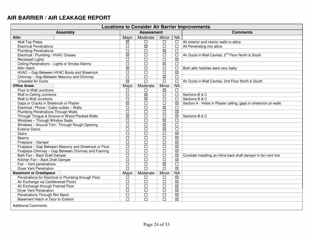
AIR BARRIER / AIR LEAKAGE REPORT
Locations to Consider Air Barrier Improvements Assembly Assessment Comments
Attic Major Moderate Minor NA
Wall Top Plates All exterior and interior walls to attics
Electrical Penetrations All Penetrating into attics
Plumbing Penetrations
Electrical / Plumbing / HVAC Chases Air Ducts in Wall Cavites, 2nd
Floor North & South
Recessed Lights
Ceiling Penetrations – Lights or Smoke Alarms
Attic Hatch Both attic hatches were very leaky
HVAC – Gap Between HVAC Boots and Sheetrock
Chimney – Gap Between Masonry and Chimney
Unsealed Air Ducts Air Ducts in Wall Cavites, 2nd Floor North & South
Office Areas Major Moderate Minor NA
Floor to Wall Junctions
Wall to Ceiling Junctions Sections B & C
Wall to Wall Junctions Sections B & C
Gaps or Cracks in Sheetrock or Plaster Section A - Holes in Plaster ceiling, gaps in sheetrock on walls
Electrical / Phone / Cable outlets – Walls Plumbing Penetrations Through Walls Through Tongue & Groove or Wood Planked Walls Sections B & C
Windows – Through Window Seals
Windows – Around Trim / Through Rough Opening
Exterior Doors
Stairs
Beams
Fireplace – Damper
Fireplace – Gap Between Masonry and Sheetrock or Floor
Fireplace Chimney – Gap Between Chimney and Framing
Bath Fan – Back Draft Damper Consider installing an inline back draft damper in fan vent line
Kitchen Fan – Back Draft Damper
Fan – Vent penetrations
Dryer Vent Penetration
Basement or Crawlspace Major Moderate Minor NA
Penetrations for Electrical or Plumbing through Floor
Air Exchange via Cantilevered Floors
Air Exchange through Framed Floor
Dryer Vent Penetration
Penetrations Through Rim Band
Basement Hatch or Door to Exterior
Additional Comments:

Page 25 of 33
SYSTEMS REPORT
Heating System Assessment
Forced Hot Air Forced Hot Water Hydro / Air Electric Baseboard Steam Geothermal Air Source Heat Pump
Type of System
Other
Oil Propane Kerosene Electric Nat. Gas
Cord wood
Wood Pellets
Wood Chips Other Fuel Type
Estimated System Efficiency 78% AFUE Manufacturer Model Number
Estimated Age 16-18 Years
Programmable Thermostats Yes Weil-McLain 578
Note: Refer to “Health & Safety” Section for Results of Combustion Safety Testing Refer to “Other Improvements Recommendations” For Hydronic Pipe Insulation Recommendations
System should be serviced Additional Inspection is recommended by a HVAC technician
Consider replacement with a high efficiency system Replace with high efficiency system at end of current system’s useful life
Comments: Detailed inspection of the existing heating systems was not accomplished due to previous contractor evaluating the building's systems and plan to enstall new geothermal system.

Page 26 of 33
Air Conditioning Assessment
Central Air – Air Source Central Air – Ground Source Window Units Floor Units Type of System
Mini Split Multiple Systems are Used Other:
Programmable Thermostats Yes
Age Efficiency Size Manufacturer Model Number
System 1 16 yrs 10.2 SEER 1.5 Ton Sanyo C1822
System 2 16 yrs 10.0 SEER 2 Ton Sanyo C2422
System 3 16 yrs 10.0 SEER 2 Ton Sanyo C2422
System 4 16 yrs 10.0 SEER 2 Ton Sanyo C2422
System 5 16 yrs 10.0 SEER 2 Ton Sanyo C2422
System 6 16 yrs 10.0 SEER 5 Ton American Standard 7A0060A100A
System should be serviced Additional Inspection is recommended by a HVAC technician
System is oversized for building Consider replacement with a high efficiency system Replace with high efficiency system, that is appropriately sized for building, at end of current system’s useful life
No Improvements Recommended
Comments: Systems 1-5 are ductless mini-splits. All systems are low efficiency compared to current systems available. Due to plans to have systems replaced with geothermal system, no recommendations are made for the air conditioning systems.
Air Duct Assessment
No Air Ducts Present Air Ducts Are Not Sealed Air Ducts Are Under Insulated
Leakage Noted by Feel or IR Air Ducts Tested Leaky Air Ducts Located in Exterior Wall Cavities
Tested CFM 25 Leakage of Ducts: Not Tested Total Leakage Test Leakage to Outside
Recommendations for Air Ducts Seal air ducts with mastic Insulate with R9 minimum Burry under attic insulation
Seal ducts with closed cell Recommended Inches of closed cell:
Comply with building code and manufacturer’s recommendation for application of insulation in proximity of heating system / plenum
Comments: The air duct system used for the Hydro air and the 5 ton air conditioning system was not tested. As noted in previous sections of this report additional inspection is recommended to determine if the ducts registers on on the upper level of Section "A" North and South Walls have ductwork inside the walls or if the wall cavity was used without dedicated dutwork. It is highly recommended that these wall cavities not be used for duct work and that the ducts be re-routed to remain inside the primary air barrier / thermal boundary. Once this is done then these wall cavities can be completely dense packed with cellulose insulation.
Page 27 of 33
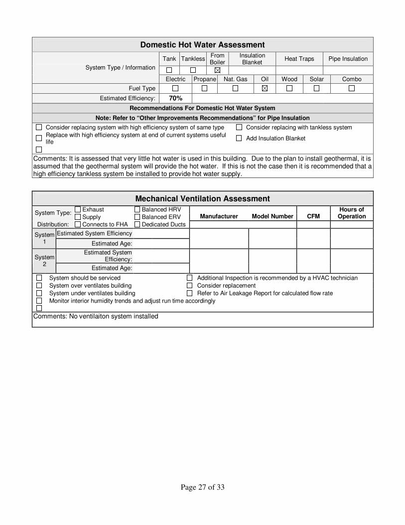
Domestic Hot Water Assessment
Tank Tankless From Boiler
Insulation Blanket
Heat Traps Pipe Insulation
System Type / Information
Electric Propane Nat. Gas Oil Wood Solar Combo
Fuel Type
Estimated Efficiency: 70%
Recommendations For Domestic Hot Water System
Note: Refer to “Other Improvements Recommendations” for Pipe Insulation
Consider replacing system with high efficiency system of same type Consider replacing with tankless system
Replace with high efficiency system at end of current systems useful life
Add Insulation Blanket
Comments: It is assessed that very little hot water is used in this building. Due to the plan to install geothermal, it is assumed that the geothermal system will provide the hot water. If this is not the case then it is recommended that a high efficiency tankless system be installed to provide hot water supply.
Mechanical Ventilation Assessment
Exhaust Balanced HRV System Type:
Supply Balanced ERV Manufacturer Model Number CFM Hours of
Operation
Distribution: Connects to FHA Dedicated Ducts
Estimated System Efficiency System 1 Estimated Age:
Estimated System Efficiency:
System 2
Estimated Age:
System should be serviced Additional Inspection is recommended by a HVAC technician
System over ventilates building Consider replacement
System under ventilates building Refer to Air Leakage Report for calculated flow rate
Monitor interior humidity trends and adjust run time accordingly
Comments: No ventilaiton system installed
Page 28 of 33
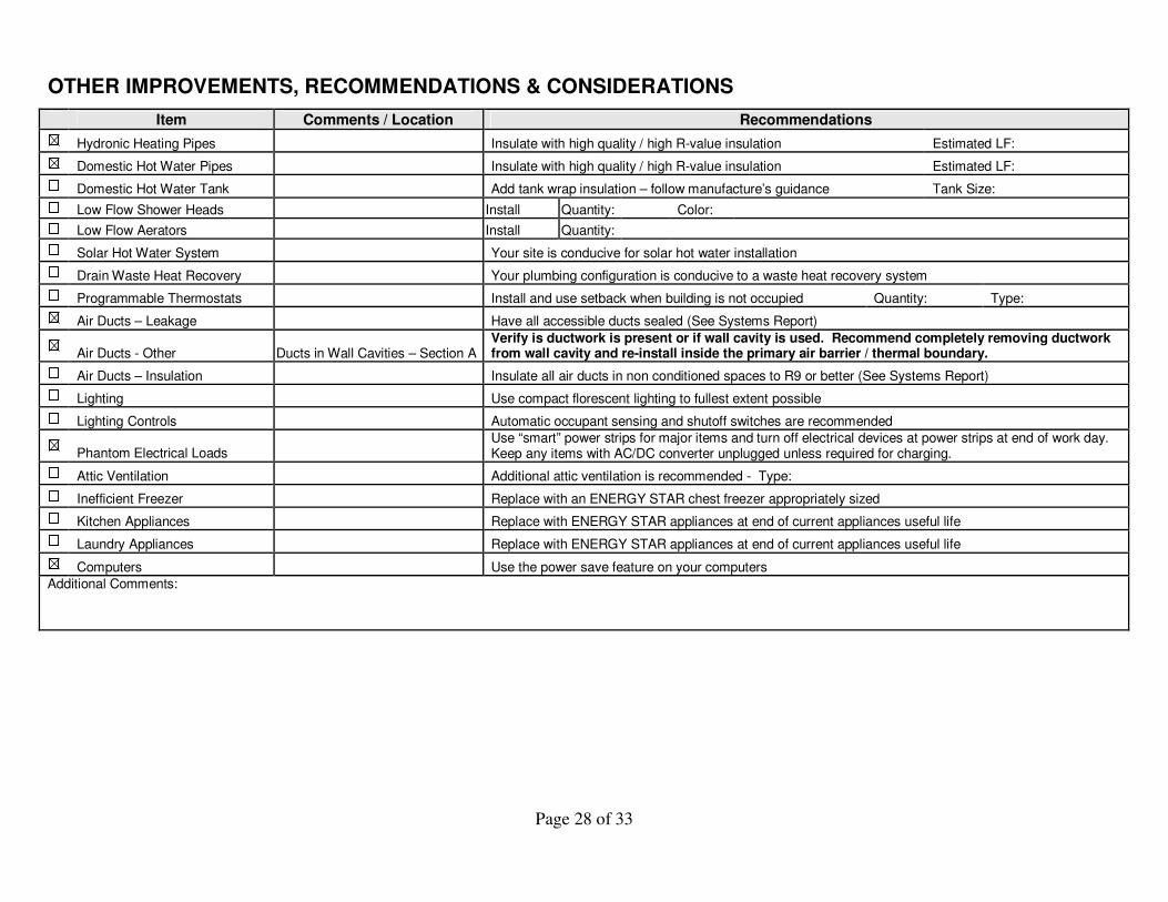
OTHER IMPROVEMENTS, RECOMMENDATIONS & CONSIDERATIONS
Item Comments / Location Recommendations
Hydronic Heating Pipes Insulate with high quality / high R-value insulation Estimated LF:
Domestic Hot Water Pipes Insulate with high quality / high R-value insulation Estimated LF:
Domestic Hot Water Tank Add tank wrap insulation – follow manufacture’s guidance Tank Size:
Low Flow Shower Heads Install Quantity: Color:
Low Flow Aerators Install Quantity:
Solar Hot Water System Your site is conducive for solar hot water installation
Drain Waste Heat Recovery Your plumbing configuration is conducive to a waste heat recovery system
Programmable Thermostats Install and use setback when building is not occupied Quantity: Type:
Air Ducts – Leakage Have all accessible ducts sealed (See Systems Report)
Air Ducts - Other Ducts in Wall Cavities – Section A
Verify is ductwork is present or if wall cavity is used. Recommend completely removing ductwork from wall cavity and re-install inside the primary air barrier / thermal boundary.
Air Ducts – Insulation Insulate all air ducts in non conditioned spaces to R9 or better (See Systems Report)
Lighting Use compact florescent lighting to fullest extent possible
Lighting Controls Automatic occupant sensing and shutoff switches are recommended
Phantom Electrical Loads
Use “smart” power strips for major items and turn off electrical devices at power strips at end of work day. Keep any items with AC/DC converter unplugged unless required for charging.
Attic Ventilation Additional attic ventilation is recommended - Type:
Inefficient Freezer Replace with an ENERGY STAR chest freezer appropriately sized
Kitchen Appliances Replace with ENERGY STAR appliances at end of current appliances useful life
Laundry Appliances Replace with ENERGY STAR appliances at end of current appliances useful life
Computers Use the power save feature on your computers
Additional Comments:
Page 29 of 33
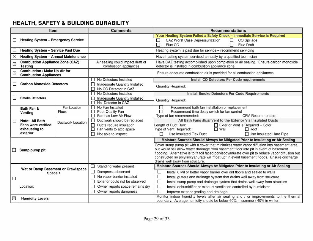
HEALTH, SAFETY & BUILDING DURABILITY
Item Comments Recommendations
Your Heating System Failed a Safety Check – Immediate Service is Required
CAZ Worst Case Depressurization CO Spillage Heating System – Emergency Service
Flue CO Flue Draft
Heating System – Service Past Due Heating system is past due for service – recommend servicing
Heating System – Annual Maintenance Have heating system serviced annually by a qualified technician
Combustion Appliance Zone (CAZ) Testing
Air sealing could impact draft of combustion appliances
Have CAZ testing accomplished upon completion or air sealing. Ensure carbon monoxide detector is installed in combustion appliance zone.
Combustion / Make Up Air for Combustion Appliances
Ensure adequate combustion air is provided for all combustion appliances.
No Detectors Installed Install CO Detectors Per Code requirements
Inadequate Quantity Installed Carbon Monoxide Detectors
No CO Detector in CAZ Quantity Required:
No Detectors Installed Install Smoke Detectors Per Code Requirements
Inadequate Quantity Installed Smoke Detectors
No Detector in CAZ Quantity Required:
Fan Location No Fan Installed Recommend bath fan installation or replacement Floor: Poor Quality Fan Recommend time delay switch for fan control
Fan has Low Air Flow Type of fan recommended: CFM Recommended:
Ductwork should be replaced All Bath Fans Must Vent to the Exterior Via Insulated Ducts Ductwork Location
Ducts require insulation Length of Duct Run: Exterior Vent is Required – Color: Fan vents to attic space Type of Vent Required: Wall Roof
Bath Fan & Venting Note: All Bath Fans were verified exhausting to exterior
Not able to inspect Use Insulated Flex Duct Use Insulated Hard Pipe
Moisture Sources Should Always be Mitigated Prior to Insulating or Air Sealing
Sump pump pit
Cover sump pump pit with a cover that minimizes water vapor diffusion into basement area but would still allow water drainage from basement floor into pit in event of basement flooding. Alternative is to fit foil faced polyisocyanurate over pit to reduce vapor diffusion but constructed so polyisocyanurate will “float up” in event basement floods. Ensure discharge drains well away from structure.
Standing water present Moisture Sources Should Always be Mitigated Prior to Insulating or Air Sealing
Dampness observed Install 6 Mil or better vapor barrier over dirt floors and sealed to walls Wet or Damp Basement or Crawlspace
Space 1 No vapor barrier installed Install gutters and drainage system that drains well away from structure
Exterior could not be observed Install sump pump and drainage system that drains well away from structure
Owner reports space remains dry Install dehumidifier or exhaust ventilation controlled by humidistat
Location:
Owner reports dampness Improve exterior grading and drainage
Humidity Levels Monitor indoor humidity levels after air sealing and / or improvements to the thermal boundary. Average humidity should be below 60% in summer / 40% in winter.
Page 30 of 33
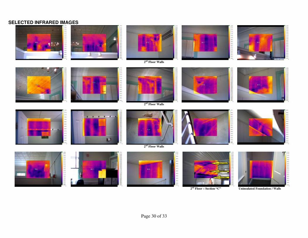
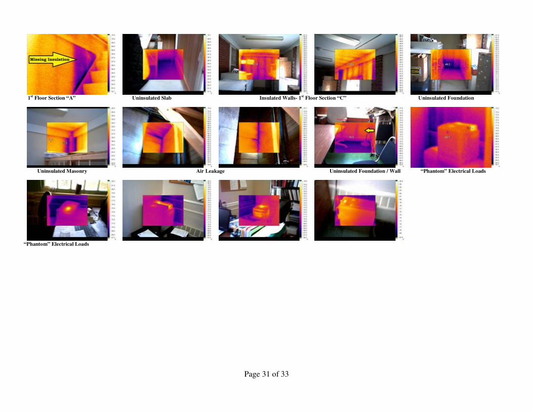
SELECTED INFRARED IMAGES
2nd Floor Walls
2nd Floor Walls
2nd Floor Walls
2nd Floor – Section “C” Uninsulated Foundation / Walls
Page 31 of 33
1st Floor Section “A” Uninsulated Slab Insulated Walls- 1st Floor Section “C” Uninsulated Foundation
Uninsulated Masonry Air Leakage Uninsulated Foundation / Wall “Phantom” Electrical Loads
“Phantom” Electrical Loads
Page 32 of 33
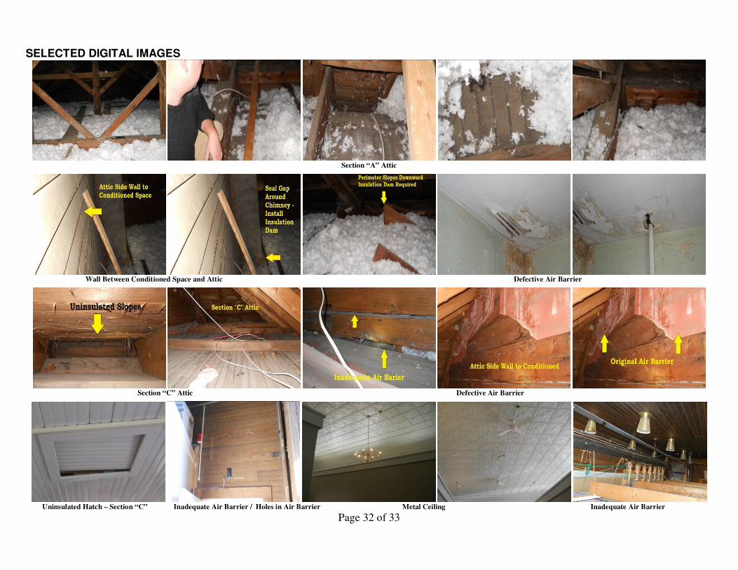
SELECTED DIGITAL IMAGES
Section “A” Attic
Wall Between Conditioned Space and Attic Defective Air Barrier
Section “C” Attic Defective Air Barrier
Uninsulated Hatch – Section “C” Inadequate Air Barrier / Holes in Air Barrier Metal Ceiling Inadequate Air Barrier
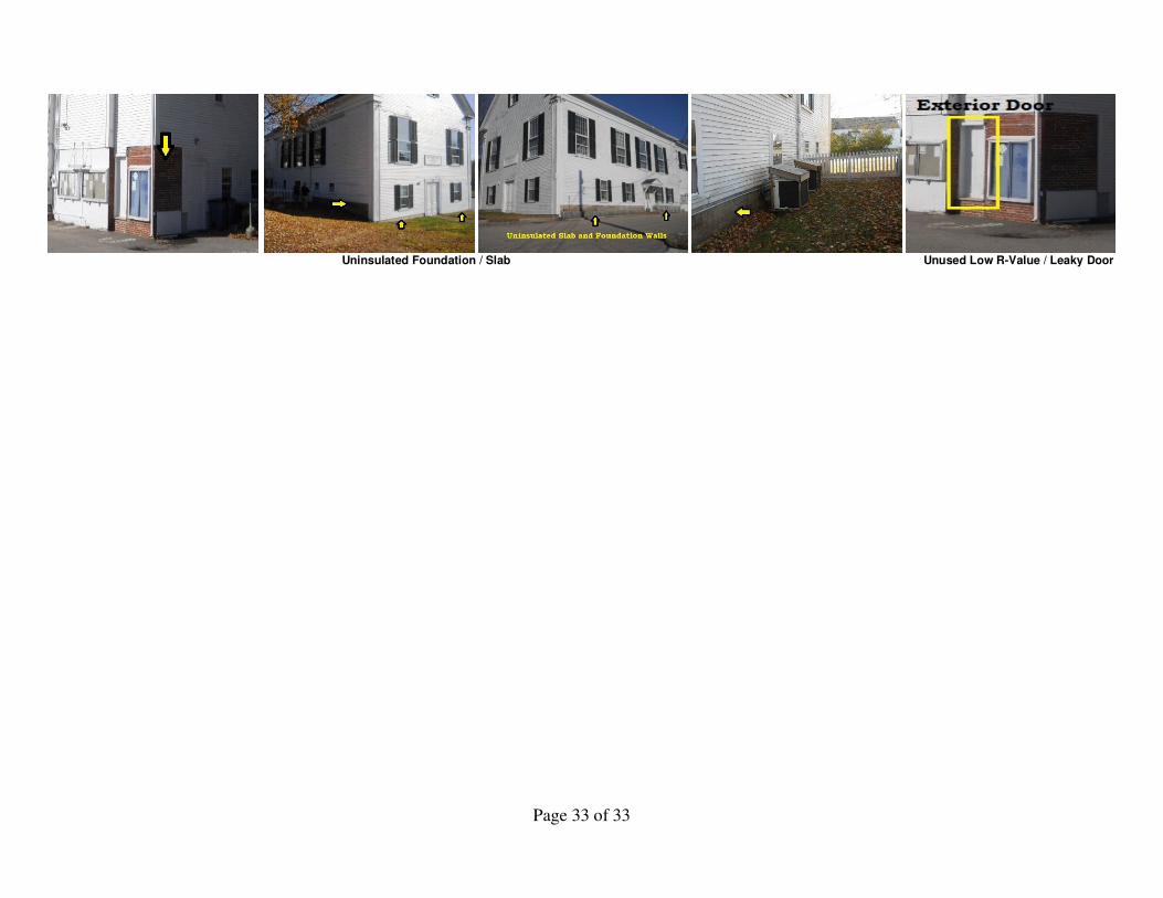
Page 33 of 33
Uninsulated Foundation / Slab Unused Low R-Value / Leaky Door