End-To-End Security For Mobile Devices MASTER of SCIENCE
142
End-To-End Security For Mobile Devices By Barış KAYAYURT A Dissertation Submitted to the Graduate School in Partial Fulfillment of the Requirements for the Degree of MASTER of SCIENCE Department: Computer Engineering Major: Computer Software Izmir Institute of Technology Izmir, Turkey July, 2004 brought to you by CORE View metadata, citation and similar papers at core.ac.uk provided by DSpace@IZTECH Institutional Repository
-
Upload
khangminh22 -
Category
Documents
-
view
2 -
download
0
Transcript of End-To-End Security For Mobile Devices MASTER of SCIENCE
End-To-End Security For Mobile Devices
By
Barış KAYAYURT
A Dissertation Submitted to the
Graduate School in Partial Fulfillment of the
Requirements for the Degree of
MASTER of SCIENCE
Department: Computer Engineering
Major: Computer Software
Izmir Institute of Technology
Izmir, Turkey
July, 2004
brought to you by COREView metadata, citation and similar papers at core.ac.uk
provided by DSpace@IZTECH Institutional Repository

ii
ACKNOWLEDGEMENTS
I would like to give my deepest thanks to my thesis advisor Asst. Prof. Dr.
Tuğkan Tuğlular, Ph.D., for his encouragement on this subject, for his valuable review
and comments on this study and for all of his supervisioning and support on me.
Also, I would like to thank all my employers and colleagues for the time they
gave me for this thesis; all the academic staff on my department for their encouragement
and my family and my friends for their patience.

iii
ABSTRACT
End-to-end security has been an emerging need for mobile devices with the
widespread use of personal digital assistants and mobile phones. Transport Layer
Security Protocol (TLS) is an end-to-end security protocol that is commonly used in
Internet, together with its predecessor, SSL protocol. By using TLS protocol in mobile
world, the advantage of the proven security model of this protocol can be taken.
J2ME™ (Java 2 Micro Edition) has been the de facto application platform used in
mobile devices. This thesis aims to provide an end-to-end security protocol
implementation based on TLS 1.0 specification and that can run on J2ME™ MIDP
(Mobile Information Device Profile) environment. Because of the resource intensive
public-key operations used in TLS, this protocol needs high resources and has low
performance. Another motivation for the thesis is to adapt the protocol for mobile
environment and to show that it is possible to use the protocol implementation in both
client and server modes. An alternative serialization mechanism is used instead of the
standard Java object serialization that is lacking in MIDP. In this architecture, XML is
used to transmit object data.
The mobile end-to-end security protocol has the main design issues of
maintainability and extensibility. Cryptographic operations are performed with a free
library, Bouncy Castle Cryptography Package. The object-oriented architecture of the
protocol implementation makes the replacement of this library with another cryptography
package easier.
Mobile end-to-end security protocol is tested with a mobile hospital reservation
system application. Test cases are prepared to measure the performance of the protocol
implementation with different cipher suites and platforms. Measured values of all
handshake operation and defined time spans are given in tables and compared with
graphs.
iv
ÖZ
Kişisel sayısal asistanlar ve mobil telefonların yaygın olarak kullanılmasıyla
birlikte uçtan uca güvenlik, mobil cihazlar için acil bir ihtiyaç haline gelmiştir. Taşıma
Katmanı Protokolü (TLS), atası olan SSL protokolü ile birlikte, Internet’te yaygın olarak
kullanılan bir uçtan uca güvenlik protokolüdür. TLS protokolü mobil dünyada
kullanılarak, bu protokolün kanıtlanmış güvenlik modeli avantajından yararlanılabilir.
J2ME™ (Java 2 Micro Edition) mobil cihazlar için defakto uygulama platformu
olmuştur. Bu tez, TLS 1.0 spesifikasyonuna dayalı ve J2ME MIDP (Mobil Bilgi Cihaz
Profili) ortamında çalışabilecek, uçtan uca güvenlik protokolü gerçekleştirimi sağlamayı
hedefler. TLS içinde kullanılan kaynak yoğun açık anahtar işlemleri nedeniyle, bu
protokol yüksek kaynaklara ihtiyaç duyar ve düşük bir performansa sahiptir. Tez için
diğer bir motivasyon da, protokol gerçekleştiriminin istemci ve sunucu modda
kullanımının mümkün olduğunu göstermektir. MIDP ortamında eksik olan standart Java
nesne dizi yayınlaması yerine, alternatif bir dizi yayınlama mekanizması kullanılmıştır.
Mobil uçtan uca güvenlik protokolünün sürdürülebilirlik ve genişletilebilirlik gibi
ana tasarım hususları bulunmaktadır. Kriptografi işlemleri ücretsiz bir dışsal kütüphane
olan Bouncy Castle Kriptografi Paketi tarafından gerçekleştirilmektedir. Protokol
gerçekleştiriminin nesneye yönelik mimarisi, bu kütüphanenin başka kriptografi
paketleriyle değiştirilmesini kolaylaştırır.
Mobil uçtan uca güvenlik protokolü, mobil hastane rezervasyon sistemi
uygulaması ile test edilmiştir. Test vakaları, protokol gerçekleştirimin farklı şifre
takımları ve platformları ile performansını ölçmek için hazırlanmıştır. El sıkışma
operasyonu ve belirlenen zaman aralıklarının ölçülen değerleri tablolarla verilmiş ve
grafiklerle karşılaştırılmıştır.
v
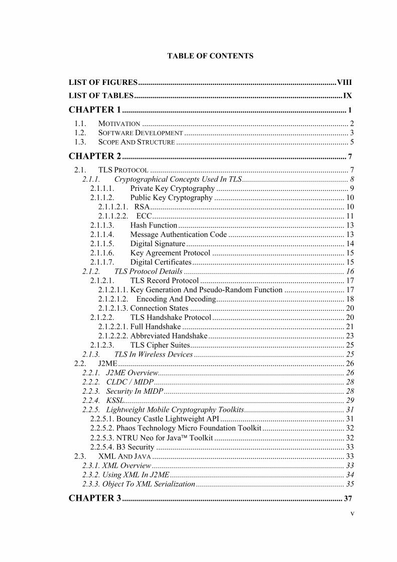
TABLE OF CONTENTS
LIST OF FIGURES...................................................................................................VIII
LIST OF TABLES........................................................................................................IX
CHAPTER 1................................................................................................................ 1
1.1. MOTIVATION ....................................................................................................... 2 1.2. SOFTWARE DEVELOPMENT .................................................................................. 3 1.3. SCOPE AND STRUCTURE ...................................................................................... 5
CHAPTER 2................................................................................................................ 7
2.1. TLS PROTOCOL ................................................................................................... 7 2.1.1. Cryptographical Concepts Used In TLS..................................................... 8
2.1.1.1. Private Key Cryptography .................................................................. 9 2.1.1.2. Public Key Cryptography ................................................................. 10
2.1.1.2.1. RSA................................................................................................. 10 2.1.1.2.2. ECC................................................................................................ 11
2.1.1.3. Hash Function ................................................................................... 13 2.1.1.4. Message Authentication Code .......................................................... 13 2.1.1.5. Digital Signature ............................................................................... 14 2.1.1.6. Key Agreement Protocol .................................................................. 15 2.1.1.7. Digital Certificates............................................................................ 15
2.1.2. TLS Protocol Details ................................................................................ 16 2.1.2.1. TLS Record Protocol ........................................................................ 17
2.1.2.1.1. Key Generation And Pseudo-Random Function .............................. 17 2.1.2.1.2. Encoding And Decoding................................................................ 18 2.1.2.1.3. Connection States ............................................................................. 20
2.1.2.2. TLS Handshake Protocol .................................................................. 20 2.1.2.2.1. Full Handshake ................................................................................. 21 2.1.2.2.2. Abbreviated Handshake.................................................................... 23
2.1.2.3. TLS Cipher Suites............................................................................. 25 2.1.3. TLS In Wireless Devices ........................................................................... 25
2.2. J2ME................................................................................................................. 26 2.2.1. J2ME Overview............................................................................................. 26 2.2.2. CLDC / MIDP............................................................................................... 28 2.2.3. Security In MIDP.......................................................................................... 28 2.2.4. KSSL.............................................................................................................. 29 2.2.5. Lightweight Mobile Cryptography Toolkits.................................................. 31
2.2.5.1. Bouncy Castle Lightweight API .............................................................. 31 2.2.5.2. Phaos Technology Micro Foundation Toolkit ......................................... 32 2.2.5.3. NTRU Neo for Java™ Toolkit ................................................................. 32 2.2.5.4. B3 Security .............................................................................................. 33
2.3. XML AND JAVA ................................................................................................ 33 2.3.1. XML Overview ................................................................................................ 33 2.3.2. Using XML In J2ME....................................................................................... 34 2.3.3. Object To XML Serialization .......................................................................... 35
CHAPTER 3.............................................................................................................. 37

vi
3.1. MOBILE DEVICE ARCHITECTURE........................................................................... 37 3.1.1. J2ME™ Mobile Devices................................................................................. 37 3.1.2. Mobile Device Operating Systems................................................................ 39
3.1.2.1. PALM OS® ............................................................................................ 39 3.1.2.2. Symbian OS ........................................................................................... 40
3.1.3. Mobile Device JVM Layer ............................................................................ 42 3.1.3.1. KVM ...................................................................................................... 42 3.1.3.2. CLDC HI................................................................................................ 44 3.1.3.3. IBM J9 VM............................................................................................ 45
3.1.4. Mobile Device Configuration Layer ............................................................. 46 3.1.5. Mobile Device Profile Layer......................................................................... 47
3.2. MOBILE APPLICATION ARCHITECTURE.................................................................. 48 3.2.1. Client/Server Architecture ........................................................................ 48 3.2.2. Peer To Peer Architecture ........................................................................ 49
3.3. MOBILE DEVICE CONNECTION ARCHITECTURE..................................................... 50 3.3.1. Wireless LAN ............................................................................................ 50 3.3.2. Bluetooth................................................................................................... 52 3.3.3. GPRS......................................................................................................... 54
CHAPTER 4.............................................................................................................. 55
4.1. MOBILE END-TO-END SECURITY PROTOCOL DESIGN ISSUES ............................ 55 4.1.1. J2ME™ Compatibility................................................................................ 55 4.1.2. Mobile Adaptation .................................................................................... 56 4.1.3. Secure Object Transmission ..................................................................... 57 4.1.4. Full Abstraction ........................................................................................ 57 4.1.5. Complete Solution..................................................................................... 58
4.2. MAIN ARCHITECTURE........................................................................................ 58 4.3. HANDSHAKE LAYER ARCHITECTURE................................................................. 63
4.3.1. Handshake Message Classes .................................................................... 63 4.3.2. Key Exchange And Authentication Classes .............................................. 68
4.4. RECORD LAYER ARCHITECTURE........................................................................ 70 4.4.1. Encryption................................................................................................. 71 4.4.2. Message Authentication Code .................................................................. 72 4.4.3. Compression ............................................................................................. 72
4.5. UTILITY CLASSES ARCHITECTURE ..................................................................... 72 4.6. EXCEPTION CLASSES ARCHITECTURE................................................................ 74 4.7. OBJECT TO XML SERIALIZER............................................................................ 75
4.7.1. XML Serializer Design Issues........................................................................ 76 4.7.2. XML Serializer Architecture.......................................................................... 78
CHAPTER 5.............................................................................................................. 80
5.1. DEVELOPMENT ENVIRONMENT.......................................................................... 80 5.2. IMPLEMENTATION ISSUES .................................................................................. 81
5.2.1. Programming Language ........................................................................... 81 5.2.2. Coding Standards ..................................................................................... 82
5.2.2.1. Naming Conventions ........................................................................ 82 5.2.2.2. Package Hierarchy ............................................................................ 83
5.2.3. Implementation Versions .......................................................................... 84 5.3. IMPLEMENTATION OF THE SECURITY PROTOCOL .............................................. 85
vii
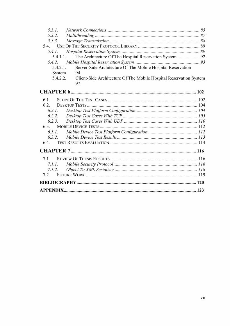
5.3.1. Network Connections................................................................................ 85 5.3.2. Multithreading .......................................................................................... 87 5.3.3. Message Transmission.............................................................................. 88
5.4. USE OF THE SECURITY PROTOCOL LIBRARY ..................................................... 89 5.4.1. Hospital Reservation System .................................................................... 89
5.4.1.1. The Architecture Of The Hospital Reservation System ................... 92 5.4.2. Mobile Hospital Reservation System ........................................................ 93
5.4.2.1. Server-Side Architecture Of The Mobile Hospital Reservation System 94 5.4.2.2. Client-Side Architecture Of The Mobile Hospital Reservation System 97
CHAPTER 6............................................................................................................ 102
6.1. SCOPE OF THE TEST CASES ............................................................................. 102 6.2. DESKTOP TESTS ............................................................................................... 104
6.2.1. Desktop Test Platform Configuration..................................................... 104 6.2.2. Desktop Test Cases With TCP ................................................................ 105 6.2.3. Desktop Test Cases With UDP ............................................................... 110
6.3. MOBILE DEVICE TESTS.................................................................................... 112 6.3.1. Mobile Device Test Platform Configuration .......................................... 112 6.3.2. Mobile Device Test Results..................................................................... 113
6.4. TEST RESULTS EVALUATION ........................................................................... 114
CHAPTER 7............................................................................................................ 116
7.1. REVIEW OF THESIS RESULTS ........................................................................... 116 7.1.1. Mobile Security Protocol ........................................................................ 116 7.1.2. Object To XML Serializer ....................................................................... 118
7.2. FUTURE WORK ................................................................................................ 119
BIBLIOGRAPHY....................................................................................................... 120
APPENDIX.................................................................................................................. 123

viii
LIST OF FIGURES Figure 2.1 The Layered Structure Of TLS Protocol ......................................................... 17 Figure 2.2 Structure Of A TLS Record............................................................................. 17 Figure 2.3 Encoding And Decoding Of Data In Record Layer ........................................ 20 Figure 2.4 Full Handshake Steps In TLS Protocol ........................................................... 24 Figure 2.5 Java™ And J2ME™ Technologies [23] ............................................................. 27 Figure 3.1 J2ME™ Device Architecture [28] .................................................................... 38 Figure 3.2 Environment Of A Typical Networked Wireless Application [39] ................ 48 Figure 3.3 Bluetooth Protocol Stack [40] ......................................................................... 53 Figure 4.1 Main Object Model Of The Mobile End-To-End Security Protocol............... 59 Figure 4.2 Object Model Of Handshake Message Classes............................................... 64 Figure 4.3 Object Model Of Public Key Model Classes .................................................. 69 Figure 4.4 Object Model Of Record Layer Classes.......................................................... 70 Figure 4.5 Object Model Of Utility Classes ..................................................................... 73 Figure 4.6 Object Model Of Exception Classes ............................................................... 74 Figure 4.7 General XML Serializer Diagram ................................................................... 75 Figure 4.8 Pre-processing Step Before Serialization ........................................................ 77 Figure 4.9 Applying Field Conversion Rules In J2ME™ Environment ............................ 78 Figure 4.10 Object Model Of XML Serializer ................................................................. 79 Figure 5.1 Reservation Request Screen Of The Hospital Reservation System ................ 90 Figure 5.2 Reservation Evaluation Screen Of The Hospital Reservation System............ 91 Figure 5.3 Doctor Info Screen Of The Reservation System............................................. 92 Figure 5.4 Architecture Of The Hospital Reservation Application .................................. 92 Figure 5.5 Architecture Of The Server Side Of Mobile Hospital Reservation System.... 95 Figure 5.6 Architecture Of Client Side Of Mobile Hospital Reservation System............ 98 Figure 5.7 User Interface Screens Of Mobile Hospital Reservation System.................... 99 Figure 6.1 Ephemeral Client Average Handshake Between J2SE-J2SE Platforms ....... 106 Figure 6.2 Ephemeral Server Average Handshake Between J2SE-J2SE Platforms....... 107 Figure 6.3 Non-Ephemeral Server Average Handshake Between J2SE-J2SE............... 107 Figure 6.4 Handshake Times Of TLS_ECDHE_ECDSA_WITH_AES_SHA Suite ..... 109 Figure 6.5 Average Object Send Times With TLS_ECDHE_WITH_AES_SHA Suite 109 Figure 6.6 Ephemeral Cipher Suite Handshake Between J2SE-J2SE With UDP .......... 111 Figure 6.7 Ephemeral Cipher Suite Handshake Between J2SE-J2SE With UDP .......... 111 Figure 6.8 Handshake Times With TLS_RSA_WITH_AES_SHA Cipher Suite .......... 112 Figure 6.9 Client Average Handshake Times On Nokia 6600 Mobile Phone................ 113

ix
LIST OF TABLES Table 2.1 Comparable Key Sizes (in bits) [17] ................................................................ 12 Table 2.2 Performance Of KSSL Primitives On PDAs [20] ............................................ 31 Table 2.3 XML Libraries Used In J2ME MIDP Environment ......................................... 35 Table 3.1 Some Of The Mobile Devices Having Built-in MIDP Support [29]................ 38 Table 4.1 Symmetric Algorithms And Model Classes ..................................................... 71 Table 6.1 Mobile Security Protocol Time Spans Used In Tests ..................................... 102 Table 6.2 Cipher Suites Used In Protocol Tests ............................................................. 103 Table A.1 Cryptographic Operations Between J2SE-J2SE With TCP For Ephemeral.. 124 Table A.2 Cryptographic Operations Between J2SE-J2SE With TCP For RSA ........... 125 Table A.3 Cryptographic Operations Between J2SE-J2ME With TCP For Ephemeral 126 Table A.4 Cryptographic Operations Between J2SE-J2ME With TCP For RSA.......... 127 Table A.5 Cryptographic Operations Between J2ME-J2ME With TCP For Ephemeral128 Table A.6 Cryptographic Operations Between J2ME-J2ME With TCP For RSA......... 129 Table A.7 Cryptographic Operations Between J2SE-J2SE With UDP For Ephemeral . 130 Table A.8 Cryptographic Operations Between J2SE-J2SE With UDP For RSA........... 131 Table A.9 Cryptographic Operations In The Mobile Device Tests For Ephemeral ....... 132 Table A.10 Cryptographic Operations In The Mobile Device Tests For RSA............... 133

1
CHAPTER 1
INTRODUCTION
Computers are regarded as one of the biggest revolutions in the previous
century. These high technology devices made people’s lives easier and helped the
development of science, technology and industry. Since their first widespread use in
1950s, computers had a long evolution. For many years, computers were big and fixed
at a place. Microcomputers after 1980s decreased the sizes, but did not change the fixed
style use of computers. Another big revolution in computer history has been the use of
computers in small, resource-constraint, mobile devices.
Two common examples of mobile devices are mobile phones and personal
digital assistants (PDA). PDAs are small, hand-held computers that can be used online
(connected to a network) or offline (standalone). Two major PDA manufacturers are
PALM and Pocket PC. The devices of these manufacturers have their own hardware,
operation system and application programs. Mobile phone technology is newer than
PDA technology. The first mobile phones were dedicated to talk and message and had a
few applications of a standard computer. The newer models used in nowadays have
their own operating systems and various installed applications. The smart phones have a
great range of applications from word processing to multimedia.
The first kind of applications used in both PDAs and mobile phones were for
personal use and had rarely needed to network connections. In time, trend in mobile
applications have been the enterprise-style applications that needed high-capacity,
network-connected devices. Financial applications like banking and stock trading are
common examples of these kinds of applications. More and more network connected
applications caused one concept to be popular in mobile community: security.
Mobile security deals mainly with two issues:
• Security of the physical device and its contents
• Security of the data in network communication
Security of the physical device and its contents is provided with many
techniques like locking device, encrypting device content, etc. The more critical
problem is providing security in data communication. This master thesis aims providing

2
a security solution for mobile data communication at application level. The target
platform for the solution is J2ME™ MIDP platform, which has been the de facto
application environment since a few years.
This introduction chapter covers the motivation behind a mobile data
communication security solution, the tasks and the description of the project and the
scope and structure of this master thesis report.
1.1. Motivation
The communication of data in mobile devices is provided by the mobile
networks. Mobile networks are open to many kinds of attacks. The open data
communication in these networks may cause attacks against the secrecy, integrity and
authenticity of data. Many vendors have proposed solutions against these security
vulnerabilities. Most of these solutions are vendor-specific proprietary products or
libraries.
Many mobile networks have proxy-based architecture. In this architecture,
security between the mobile device and the proxy server is provided with a solution and
the security between the proxy server and the destination server is provided with
another solution. WTLS, announced as the security solution of WAP protocol is such a
protocol. There are two problems with proxy-based solutions. First, it decreases
performance. As the data is decoded and reencoded at proxy server, it may cause
latency. Another big problem is security attacks against the proxy server. These attacks
may threat the data security between the period it is decoded and encoded.
The alternative of proxy based security solutions is end-to-end security. End-to-
end security refers to the securely encoding of data at the source host and decoding at
the destination host. The data will not travel unencoded at any part of the
communication. TLS (Transport Layer Security Protocol) and its predecessor SSL
(Secure Sockets Layer) protocols are end-to-end security solutions that are commonly
used in wired world. There are a number of reasons to use these protocols in the mobile
world:
• TLS and SSL protocols have been used for many years, so the security of them
are tested by the community and accepted as secure enough to be used by
financial data communication.
• TLS and SSL protocols are common in wired world and may be accepted as the

3
security protocol of Internet. Using these in mobile applications will make the
integration between mobile applications and Internet easier.
• TLS and SSL have open specifications and may implementations. It may be
relatively easy to implement these for specific needs.
J2ME™ is the small, resource constraint device platform of Java™ technologies.
MIDP (Mobile Information Device Profile) is a profile developed mainly for mobile
phones and PDAs under J2ME™. MIDP implementers have considered the reasons to
use TLS in data communication and have provided an API to use TLS in MIDP
applications. MIDP end-to-end security API called KSSL is a lightweight API, but has a
number of drawbacks:
• KSSL is only a client-side implementation of TLS (and SSL)
• KSSL supports only a few cipher suites
• KSSL has no support for new algorithms like Elliptic Curve Cryptography
• KSSL is considered to have a poor performance related to other SSL
implementation
The need for an end-to-end security API for MIDP and the drawbacks of KSSL
library have motivated for a new end-to-end security library that would be fully
compliant with MIDP 1.0 and 2.0. The security solution was proposed to resemble TLS
and make some changes where necessary. However, the base of the implemented
protocol would be TLS 1.0 specification [2]. The protocol was renamed as mobile end-
to-end security protocol to differentiate it from the original TLS protocol.
The other source of motivation for the thesis has been the secure object
transmission between the mobile device and the destination server. The lack of object
serialization and RMI in MIDP API prevents objects to be transmitted between the
peers. A general solution for object transmission was proposed to be found. The
integration of this solution with the end-to-end security solution would result to a secure
object transmission mechanism.
1.2. Software Development
The end-to-end security solution for mobile devices is implemented in order to
show that it is possible and efficient. The steps of the software development phase,
which may be considered as a project, are as follows:
• Literature survey about security, mobile devices and J2ME™ technologies

4
• Analysis of the TLS protocol (by reading TLS 1.0 specification [2] and other
TLS related documents)
• Design of the new protocol to be developed (defining additions and subtractions
from the original TLS protocol)
• Design of the object transmission library
• Implementation of the object transmission library
• Design of the protocol implementation (object-oriented design)
• Implementation of the mobile end-to-end security protocol
• Implementation of a sample application using the implemented protocol for data
communication
• Test of the mobile end-to-end security protocol
• Documentation
The project was proposed to be designed in Rational Rose™ design tool in an
object-oriented architecture. The implementation language was chosen as Java™ that
would be limited to MIDP 1.0 API. The final product was planned to be compliant to
both J2ME™ and J2SE™ platforms.
After the literature survey and analysis of TLS protocol phases, the major
attributes of the proposed protocol implementation was defined as follows:
• The implementation will cover both the client and server versions of the TLS
protocol.
• The implementation will support RSA, DHE and ECC cipher suites.
• The implementation will support UDP network communication as an alternative
to standard TCP communication.
• The implementation will not implement optional TLS specifications like client
authentication, session resumption and compression.
• The implementation will be designed as a library and will be able to be used by
higher-level applications. The underlying communication method, cipher suites
used and the protocol details will be transparent to these applications.
• The implementation will run on J2SE™ and J2ME™ MIDP platforms (including
all mobile phones and PDAs supporting these platforms)
• The implementation will be used with the developing object transmission library
As a parallel activity, the object transmission library was designed and
5
implemented. The object transmission library was designed to use XML in transmitting
bean-style data objects. It included both the serialization of objects into XML and
deserialization of XML into objects.
The mobile protocol library was designed and implemented in an object-oriented
architecture. The pattern used in design and development resembles the famous MVC
(Model-View-Controller) pattern, except it does not have a view part. After the
completion of the protocol implementation, a sample application was needed to test the
protocol implementation. The hospital reservation system, developed by B.Kayayurt, K.
Şimşek, E.Sülün [42] was used for this target. A new plug-in was designed,
implemented and integrated into the old system to support mobile clients as well as
existing web clients. The developed protocol was used in data transmission between the
mobile device of the client J2ME™ application and the server of the running J2EE™
application.
After all, the mobile protocol was tested in both emulator and real device
environments. Different test cases were prepared, and the results were measured and
evaluated.
1.3. Scope And Structure
In chapter 1, a brief introduction is made about the motivation behind the master
thesis, the project steps performed and the structure of the thesis report.
In chapter 2, the details of the TLS protocol are explained and cryptographic
used in TLS are introduced. Chapter 2 also gives an introduction to J2ME™ platform,
security in MIDP and cryptography toolkits available in J2ME™ MIDP. The last part of
this chapter gives brief information about XML and using XML in J2ME™ and
discusses the issue of object to XML serialization.
In chapter 3, the architecture of the target platform is mentioned. This chapter
explains J2ME™ device architecture, mobile device operating systems supporting
J2ME™, mobile device JVM layer and the mobile configurations and profiles. Mobile
application architecture and mobile network architecture issues are also discussed and
explained in this chapter.
In chapter 4, the architectures of the developed mobile security protocol and
object transmission library are explored. Design issues behind the architectures are
explained and object models designed are given in figures. The chapter gives core
6
information about the developed protocol.
In chapter 5, the implementation of the protocol is explained and some code
examples are given. This chapter also mentions about the mobile hospital reservation
system, developed to test the security protocol implementation in a real life application.
Chapter 6 covers the test results obtained with the protocol implementation. Test
platform configuration, test cases prepared, test results measured are explained where
the results are given in tables and graphics. The chapter also includes the evaluation of
the test results.
In chapter 7, the conclusion of the master thesis is given, where the results of the
thesis are evaluated and expect ratio of the results are discussed. The thesis is completed
by discussing the further work to be done at the proceeding projects.
7
CHAPTER 2
TLS AND MOBILE SECURITY
TLS (Transport Layer Security Protocol) is one of the most common protocols
used to provide secure communication in Internet. J2ME™ is the de facto standard used
in mobile phones nowadays. This chapter explains the details of TLS protocol, the
cryptographic concepts used in TLS and its internal working principles. The chapter
also introduces J2ME™ platform, security in mobile devices and XML serialization
concepts.
2.1. TLS Protocol
Transport Layer Security (TLS) Protocol is a client-server security protocol
specified by IETF1. The primary goal of the TLS Protocol is to provide privacy and data
integrity between two communicating applications.
TLS Protocol is the minor update of the Secure Sockets Layer (SSL) 3.0
protocol defined by Netscape Incorparation [1]. Current specification of the protocol
was published as RFC22462 document on January, 1999. The version of the TLS
Protocol that is discussed in this thesis is TLS 1.0, defined in [2].
Some of the goals that the TLS protocol tries to satisfy are the following:
Privacy, the data sent over the channel should be kept secret for an
eavesdropper.
Authentication, the applications should know that they are talking to the
intended recipient and not an imposer.
Transparency, it could be used like a normal TCP connection after the setup is
done.
Integrity, the integrity of the channel should be maintained. It should be
infeasible to alter or counterfeit messages on the channel.
TLS Protocol is composed of two layers: the TLS Record Protocol and the TLS
Handshake Protocol. The record protocol provides a private and reliable connection. 1 Internet Engineering Task Force, a large open community of network designers, operators, vendors and researchers concerned with the evolution of the Internet architecture and the smooth operation of the Internet. 2 Requests For Comments, set of technical and organizational notes about the Internet (originally the ARPANET), beginning in 1969.
8
Thus, the record protocol provides the confidentiality and integrity security services.
The handshake protocol provides peer identification and key exchange. Thus, the
handshake protocol provides the authentication security service.
Originally, TLS Protocol operates on transport layer and can be used with any
reliable transport protocol. It is typically used with TCP on Internet [3]. However, TLS
derivative protocols like WTLS (Wireless Tranport Layer Security) Protocol can
operate on unreliable tranport protocols like UDP3 [4].
TLS is application protocol independent. Higher level protocols can layer on top
of TLS Protocol independently, e.g. HTTP. However, TLS specification [2] does not
define how these protocols use TLS to provide connection security.
2.1.1. Cryptographical Concepts Used In TLS
Cryptography can be defined as study of techniques and applications that depend
on the existence of difficult problems [5]. The oldest methods used in cryptography
included encryption and decryption. Encryption is the transformation of data into a form
that is impossible to read without a secret knowledge. Decryption is the reverse of
encryption and is the transformation of encrypted data back to meaningful form. Except
for encryption and decryption, modern cryptography has another aspect: authentication.
Today, digital signatures are commonly used for authentication purposes.
One of the greatest strengths of TLS is that it is not dependent on a specific
algorithm or standard. TLS Protocol implementations may use many types of
cryptographic algorithms and standards. By the help of cipher suites defined, users of
TLS protocol may use either DES4 or IDEA standards as private key algorithm and
either SHA (Secure Hash Algorithm) or MD55 standards as hash algorithm. The
extensibility is not limited to existing standards; new coming standards may also be
added to the protocol implementations as new cipher suites.
In TLS, the Record Protocol uses private-key cryptography, message
authentication code (MAC) and hash functions and the Handshake Protocol uses public
key cryptography and digital certificates.
3 User Datagram Protocol, a transaction-oriented communication protocol that does not guarantee connection reliability. 4 Data Encryption Standard, a private-key cryptography standard specified as Federal Information Processing Standard (FIPS) 46-3, defined in [6] 5 Message Digest Algorithm, a hash algorithm developed by R.L. Rivest and published as RFC1321 [7]
9
2.1.1.1. Private Key Cryptography
Private key cryptography, also referred as symmetric cryptography, is the more
traditional form of cryptography, in which a single key can be used to encrypt and
decrypt a message. The main problem with private key cryptosystems is getting the
sender and receiver to agree on the private key without anyone else finding out. This
requires a method by which the two parties can communicate without fear of
eavesdropping. However, the advantage of private key cryptography is that it is
generally faster than public key cryptography.
The most common techniques in private key cryptography are block ciphers and
stream ciphers. A block cipher is a type of symmetric-key encryption algorithm that
transforms a fixed-length block of plaintext (unencrypted text) data into a block of
cipher text (encrypted text) data of the same length. A stream cipher is a type of
symmetric encryption algorithm. While block ciphers operate on large blocks of data,
stream ciphers typically operate on smaller units of plaintext, usually bits. A stream
cipher generates what is called a keystream (a sequence of bits used as a key).
Encryption is accomplished by combining the keystream with the plaintext, usually with
the bit-wise XOR operation.
Most common used private key cipher algorithms are DES, 3DES, AES, RC2
and RC4.
DES, an acronym for the Data Encryption Standard, is the name of the Federal
Information Processing Standard (FIPS) 46-3 [6], which describes the data encryption
algorithm (DEA). The DEA is a symmetric cryptosystem having a 64-bit block size and
uses a 56-bit key during execution (8 parity bits are stripped off from the full 64-bit
key).
The ANSI X9.52 standard [8] defines triple-DES encryption with keys k1; k2;
k3 as
C = Ek3 (Dk2 (Ek1 (M)));
where Ek and Dk denote DES encryption and DES decryption, respectively, with the
key k.
The AES is the Advanced Encryption Standard. The AES was issued as a FIPS
standard and will replace DES.
RC2 is a variable key-size block cipher designed by Ronald Rivest for RSA
Data Security Incorporation. It has a block size of 64 bits and is about two to three times

10
faster than DES in software. RC4 is a stream cipher designed by Rivest for RSA Data
Security Incorporation. It is a variable key-size stream cipher with byte-oriented
operations.
2.1.1.2. Public Key Cryptography
In a public key cryptosystem each participant have a key pair that consists of a
public key and a private key. The public key of a participant is via some mechanism
available to anyone. It can for example be published in something corresponding to a
phone book. Messages encrypted with a specific public key can only be decrypted with
the corresponding private key. Private key is always linked mathematically to the public
key.
Traditionally the two participants in a communication are called Bob and Alice.
Alice's secret and public key is denoted SA and PA, Bob's corresponding keys are called
SB and SA.
In a cryptosystem like RSA, there are for the public key and the secret key two
functions called SA() and PA() which are easily computable given their corresponding
keys SA and SB. For a message m in a given domain the following property hold:
m = PA(SA(m))
If Bob wants to send a message to Alice he encrypts his message with Alice's
public key. Only Alice can decrypt that message since she is the only one that has
access to her private key, and her private key is the only key that can be used to decrypt
the message.
The functions S and P must be easily computable given the secret and public
key. They must also have the property that it is infeasible to calculate the secret key
given m and the values S(m) and/or P(m) to form a good public key cryptosystem.
Most common used public key cryptosystems are RSA, ECC and DSA.
2.1.1.2.1. RSA
The RSA cryptosystem is a public-key cryptosystem that offers both encryption
and digital signatures (authentication). Ronald Rivest, Adi Shamir, and Leonard
Adleman developed the RSA system in 1977, in their book [10].
In the RSA cryptosystem the participants creates their public and private keys
with the following procedure [11]:
11
1. Select randomly two large prime numbers p and q.
2. Compute n by the equation n = pq.
3. Select a small odd integer e that is relatively prime to (p - 1)(q - 1).
4. Compute d as the multiplicative inverse of e, modulo (p - 1)(q - 1):
5. Publish the pair P = (e; n) as the RSA public key.
6. Keep the private pair S = (d; n) as the RSA secret key.
The transformation of a message M associated with the public key pair P = (e;n)
is
P(M) = Me(mod n).
The transformation of a cipher text C associated with a private key pair S = (d;n)
is
S(C) = Cd(mod n).
To see how encryption and digital signatures work with RSA, we will again use
Alice and Bob. Suppose Alice wants to send a message m to Bob. Alice creates the
cipher text c by exponentiating:
c = me mod n,
where e and n are Bob's public key. She sends c to Bob. To decrypt, Bob also
exponentiates:
m = cd mod n.
The relationship between e and d ensures that Bob correctly recovers m. Since
only Bob knows d, only Bob can decrypt this message.
Suppose Alice wants to send a message m to Bob in such a way that Bob is
assured the message is both authentic, has not been tampered with, and from Alice.
Alice creates a digital signature s by exponentiating:
s = md mod n,
where d and n are Alice's private key. She sends m and s to Bob. To verify the
signature, Bob exponentiates and checks that the message m is recovered:
m = se mod n,
where e and n are Alice's public key.
2.1.1.2.2. ECC
Elliptic curve cryptosystems were first proposed independently by Victor Miller
[12] and Neal Koblitz [13] in the mid-1980s. At a high level, they are analogs of
12
existing public-key cryptosystems in which modular arithmetic is replaced by
operations defined over elliptic curves.
Elliptic curve arithmetic is based on an operation called scalar point
multiplication, which computes Q = kP (a point P multiplied k times resulting in another
point Q on the curve). The security of ECC relies on the hardness of solving the Elliptic
Curve Discrete Logarithm Problem (ECDLP), which states that given P and Q = kP, it
is hard to find k.
An important elliptic curve parameter is the base point, G, which is fixed for
each curve. In the Elliptic Curve Cryptosystem, the large random integer k is kept
private and forms the secret key, while the result Q of multiplying the private key k with
the curve's base point G serves as the corresponding public key.
Elliptic Curve Diffie Hellman (ECDH) [14] and Elliptic Curve Digital Signature
Algorithm (ECDSA) [15] are the Elliptic Curve counterparts of the Diffie-Hellman key
exchange and Digital Signature Algorithm, respectively. According to [14], in ECDH
key agreement, two communicating parties A and B agree to use the same curve
parameters. They generate their private keys, kA and kB and corresponding public keys
QA = kA:G and QB = kB:G. The parties exchange their public keys. Finally each
multiplies its private key and the other's public key to arrive at a common shared secret
kA:QB = kB:QA = kA:KB:G. The flow of ECDSA parallels DSA.
As the methods for computing general elliptic curve discrete logarithms are
much less efficient than those for factoring or computing conventional discrete
logarithms, elliptic curve cryptosystems are especially useful in applications for which
memory, bandwidth, or computational power is limited. This results smaller key sizes of
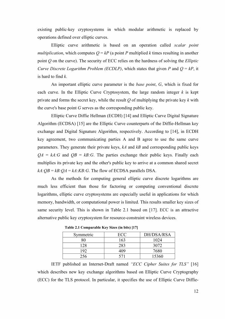
same security level. This is shown in Table 2.1 based on [17]. ECC is an attractive
alternative public key cryptosystem for resource-constraint wireless devices.
Table 2.1 Comparable Key Sizes (in bits) [17]
Symmetric ECC DH/DSA/RSA 80 163 1024 128 283 3072 192 409 7680 256 571 15360
IETF published an Internet-Draft named “ECC Cipher Suites for TLS” [16]
which describes new key exchange algorithms based on Elliptic Curve Cryptography
(ECC) for the TLS protocol. In particular, it specifies the use of Elliptic Curve Diffie-
13
Hellman (ECDH) key agreement in a TLS handshake and the use of Elliptic Curve
Digital Signature Algorithm (ECDSA) as a new authentication mechanism.
2.1.1.3. Hash Function
A hash function H is a transformation that takes an input m and returns a fixed-
size string, which is called the hash value h (that is, h = H(m)). The main role of a
cryptographic hash function is in the provision of message integrity checks and digital
signatures.
The basic requirements for a cryptographic hash function are as follows.
The input can be of any length.
The output has a fixed length.
H(x) is relatively easy to compute for any given x.
H(x) is one-way.
H(x) is collision-free.
The hash value represents concisely the longer message or document from
which it was computed; this value is called the message digest. One can think of a
message digest as a digital fingerprint of the larger document. Examples of well-known
hash functions are MD5 and SHA.
MD5 was developed by Rivest in 1991. It takes a message of arbitrary length
and produces a 128-bit message digest. Description and source code of the algorithm
can be found in [7].
The Secure Hash Algorithm (SHA), the algorithm specified in the Secure Hash
Standard (SHS, FIPS 180), was developed by NIST [18]. The algorithm takes a
message of less than 264 bits in length and produces a 160-bit message digest. The
algorithm is slightly slower than MD5, but the larger message digest makes it more
secure against brute-force collision and inversion attacks.
2.1.1.4. Message Authentication Code
A message authentication code (MAC) is an authentication tag (also called a
check sum) derived by applying an authentication scheme, together with a secret key, to
a message. Unlike digital signatures, MACs are computed and verified with the same
key, so that only the intended recipient can verify them.
There are four types of MACs:

14
Unconditionally secure, in which the cipher text of the message authenticates
itself, as nobody else has access to the one-time pad.
Hash function-based MACs (often called HMACs), in which a key or keys are
used in conjunction with a hash function stream cipher-based.
Stream cipher based, in which secure stream cipher is used to split a message
into two sub-streams and each sub-stream is fed into a LFSR.
Block cipher-based, in which message blocks are encrypted using block cipher
and final block in the cipher text is used as the checksum.
TLS uses HMAC in the handshake with two different algorithms: MD5 and
SHA-1, denoting these as HMAC_MD5(secret, data) and HMAC_SHA(secret, data)
[2].
2.1.1.5. Digital Signature
A digital signature is a cryptographic means through which many of these may
be verified. The digital signature of a document is a piece of information based on both
the document and the signer's private key. It is typically created through the use of a
hash function and a private signing function (encrypting with the signer's private key),
but there are other methods.
When public-key cryptography is used to calculate a digital signature, the sender
encrypts the digital fingerprint of the document with his or her own private key.
Anyone with access to the public key of the signer may verify the signature.
DSA (Digital Signature Algorithm) is the most common digital signature used.
DSA was published by NIST6 in the Digital Signature Standard (DSS), which is a part
of the U.S. government's Capstone project. DSA is based on the discrete logarithm
problem. While the RSA system can be used for both encryption and digital signatures,
the DSA can only be used to provide digital signatures. For a detailed description of
DSA, see [19].
In DSA, signature generation is faster than signature verification, whereas with
the RSA algorithm, signature verification is very much faster than signature generation
(if the public and private exponents, respectively, are chosen for this property, which is
the usual case). DSA is, at present, considered to be secure with 1024-bit keys.
6 The National Institute of Standards and Technology, a US government agency responsible for defining standards.

15
2.1.1.6. Key Agreement Protocol
A key agreement protocol, also called a key exchange protocol, is a series of
steps used when two or more parties need to agree upon a key to use for a secret-key
cryptosystem. These protocols allow people to share keys freely and securely over any
insecure medium, without the need for a previously-established shared secret.
In many cases, public-key cryptography is used in a key agreement protocol.
One example of such a protocol is called the Diffie-Hellman key agreement.
The Diffie-Hellman key agreement protocol (also called exponential key
agreement) was developed by Diffie and Hellman in 1976 and published in the paper
“New Directions in Cryptography'' [9]. The protocol allows two users to exchange a
secret key over an insecure medium without any prior secrets.
The protocol has two system parameters p and g. They are both public and may
be used by all the users in a system. Parameter p is a prime number and parameter g
(usually called a generator) is an integer less than p, with the following property: for
every number n between 1 and p_1 inclusive, there is a power k of g such that
n = g^k mod p.
The protocol depends on the discrete logarithm problem for its security. It
assumes that it is computationally infeasible to calculate the shared secret key
k = g^ab mod p
given the two public values g^a mod p and g^b mod p when the prime p is sufficiently
large.
2.1.1.7. Digital Certificates
A public-key certificate is a digitally signed statement from one entity, saying
that the public key (and some other information) of another entity has some specific
value. Basically, public key cryptography requires access to users' public keys. In a
large-scale networked environment it is impossible to guarantee that prior relationships
between communicating entities have been established or that a trusted repository exists
with all used public keys. Certificates were invented as a solution to this public key
distribution problem.
The data in a certificate is encoded using two related standards called
ASN.1/DER. Abstract Syntax All Notation 1 describes data. The Definite Encoding

16
Rules describe a single way to store and transfer that data.
The most commonly used digital certificates are X.509 certificates. The X.509
standard defines what information can go into a certificate, and describes how to write it
down (the data format). X.509 certificates have 3 versions.
2.1.2. TLS Protocol Details
TLS is a protocol that consists of several layers of protocols. At the bottom of
these layers, there is the TLS Record Protocol. The Record Protocol is responsible for
taking messages to be transmitted, fragmenting into blocks, optionally compressing,
applying MAC to protect data integrity, encrypting the block and transmitting the result
to higher level clients. Received data is then decrypted; applied MAC is verified to
protect data integrity; optionally decompressed; reassembled and then delivered to
higher level clients by the Record Protocol. TLS Record Protocol blocks are transported
over a reliable transport protocol like TCP.
There are four clients of record protocol: TLS Handshake Protocol, TLS Alert
Protocol, TLS Change Cipher Spec Protocol and application data. TLS 1.0
Specification, defined in [2], allows new record protocol clients to be supported by the
record protocol.
TLS Handshake Protocol is used to allow peers to authenticate each other and to
exchange cryptographic parameters that are used in TLS Protocol. TLS Handshake is
performed in the beginning of a session before the application data is transmitted or
received. The Change Cipher Spec Protocol is used to start to use new keys and
encryption methods that the Handshake Protocol has established. TLS Alert Protocol is
used to send warning and fatal level errors that could occur in TLS session. After the
handshake is performed, application data is taken by Record Layer and sent securely to
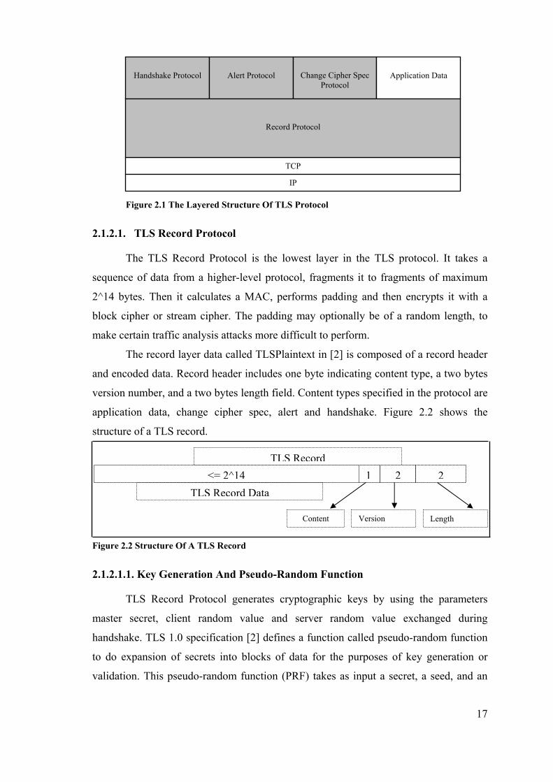
the other peer. HTTP is a typical application data that is used on web. Figure 2.1 shows
the layered structure of TLS Protocol.
17
Figure 2.1 The Layered Structure Of TLS Protocol
2.1.2.1. TLS Record Protocol
The TLS Record Protocol is the lowest layer in the TLS protocol. It takes a
sequence of data from a higher-level protocol, fragments it to fragments of maximum
2^14 bytes. Then it calculates a MAC, performs padding and then encrypts it with a
block cipher or stream cipher. The padding may optionally be of a random length, to
make certain traffic analysis attacks more difficult to perform.
The record layer data called TLSPlaintext in [2] is composed of a record header
and encoded data. Record header includes one byte indicating content type, a two bytes
version number, and a two bytes length field. Content types specified in the protocol are
application data, change cipher spec, alert and handshake. Figure 2.2 shows the
structure of a TLS record.
Figure 2.2 Structure Of A TLS Record
2.1.2.1.1. Key Generation And Pseudo-Random Function
TLS Record Protocol generates cryptographic keys by using the parameters
master secret, client random value and server random value exchanged during
handshake. TLS 1.0 specification [2] defines a function called pseudo-random function
to do expansion of secrets into blocks of data for the purposes of key generation or
validation. This pseudo-random function (PRF) takes as input a secret, a seed, and an
Handshake Protocol
Alert Protocol
Change Cipher Spec
Protocol
Application Data
Record Protocol
TCP
IP
TLS Record
TLS Record Data
Content Version Length
<= 2^14 1 2 2

18
identifying label and produces an output of arbitrary length.
The PRF is defined as the result of mixing the two pseudorandom streams by
exclusive-or'ing them together.
PRF(secret, label, seed) = P_MD5(S1, label + seed) XOR
P_SHA-1(S2, label + seed);
We define a data expansion function, P_hash(secret, data) which uses a single
hash function to expand a secret and seed into an arbitrary quantity of output:
P_hash(secret, seed) = HMAC_hash(secret, A(1) + seed) +
HMAC_hash(secret, A(2) + seed) +
HMAC_hash(secret, A(3) + seed) + ...
where + indicates concatenation. A() is defined as:
A(0) = seed
A(i) = HMAC_hash(secret, A(i-1))
P_hash can be iterated as many times as is necessary to produce the required
quantity of data. S1 is the first half of the secret and S2 is the second half.
TLS 1.0 Specification [2] calculates cryptographic keys according to the
following formula:
key_block = PRF(SecurityParameters.master_secret,
"key expansion",
SecurityParameters.server_random +
SecurityParameters.client_random);
Then, the key_block is partitioned as follows:
client_write_MAC_secret[SecurityParameters.hash_size]
server_write_MAC_secret[SecurityParameters.hash_size]
client_write_key[SecurityParameters.key_material_length]
server_write_key[SecurityParameters.key_material_length]
client_write_IV[SecurityParameters.IV_size]
server_write_IV[SecurityParameters.IV_size]
The client_write_IV and server_write_IV are only generated for non-export
block ciphers. For exportable block ciphers, the initialization vectors are generated later.
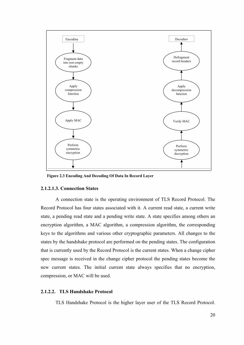
2.1.2.1.2. Encoding And Decoding
TLS Record Layer encodes data fragmented into TLS record blocks before

19
transmitting and decodes the encoded data after receiving. The basic operations applied
in encoding are compression, applying the MAC and encryption; the decoding
operations are the reverse of encoding operations.
Compression is an optional operation defined in TLS 1.0 specification [2]. All
records are compressed using the compression algorithm defined in the current session
state. If compression is used, received record blocks are decompressed using the same
algorithm.
After compression (if applied), a MAC (see Section 2.1.1.4, “Message
Authentication Code”) is applied to the record data to protect the integrity. The MAC
of the record also includes a sequence number so that missing, extra or repeated
messages are detectable. According to [2], the MAC is generated as:
HMAC_hash(MAC_write_secret, seq_num + TLSCompressed.type +
TLSCompressed.version + TLSCompressed.length +
TLSCompressed.fragment));
where "+" denotes concatenation. Seq_num is the 64-bit sequence number incremented
for each record sent. TLSCompressed is the compressed form of TLS data (if applied).
Hash is the hashing algorithm specified by SecurityParameters.mac_algorithm. The
MAC computed is appended to the end of the record data. When the record is received,
the same MAC calculation is performed and compared with the appended MAC to
verify integrity.
Encryption is performed after compression and MAC calculation. Encryption is
done with symmetric algorithms, either block or stream cipher (see Section 2.1.1.1,
“Private Key Cryptography”). The stream cipher encrypts the entire block, including the
MAC. In block ciphers, padding is added to force the length of the plaintext to be an
integral multiple of the block cipher's block length. Decryption is the reverse of
encryption and uses the same secret key.
Figure 2.3 illustrates the operations performed during record encoding and
decoding.
20
Figure 2.3 Encoding And Decoding Of Data In Record Layer
2.1.2.1.3. Connection States
A connection state is the operating environment of TLS Record Protocol. The
Record Protocol has four states associated with it. A current read state, a current write
state, a pending read state and a pending write state. A state specifies among others an
encryption algorithm, a MAC algorithm, a compression algorithm, the corresponding
keys to the algorithms and various other cryptographic parameters. All changes to the
states by the handshake protocol are performed on the pending states. The configuration
that is currently used by the Record Protocol is the current states. When a change cipher
spec message is received in the change cipher protocol the pending states become the
new current states. The initial current state always specifies that no encryption,
compression, or MAC will be used.
2.1.2.2. TLS Handshake Protocol
TLS Handshake Protocol is the higher layer user of the TLS Record Protocol.
Fragment data into non-empty
chunks
Apply compression
function
Apply MAC
Perform symmetric encryption
Defragment record headers
Apply decompression
function
Verify MAC
Perform symmetric decryption
Encoding Decoding
21
The goal of the handshake protocol is to set up a session and agree upon cryptographic
parameters. It is also used to exchange certificates, which authenticate the peers for each
other. Public key encryption techniques are used to establish a shared secret between the
peers that is used for cryptographic keys and MAC secrets (see Section 2.1.2.1.1, “Key
Generation And Pseudo-Random Function”). When the handshake is finished and the
normal communication can start, the state of the handshake is said to be in its finished
state.
TLS Handshake Protocol is composed of handshake messages. TLS 1.0
specification [2] defines two kinds of handshakes: full handshake and abbreviated
handshake.
2.1.2.2.1. Full Handshake
TLS Handshake Protocol performs handshake with a series of steps. The
handshake steps begin when a secure connection request is received and ends when the
secure connection between two peers is established. In full handshake, all steps in the
Handshake Protocol are performed.
Full handshake starts when a client sends a client hello message to the server.
The server responds to this message with a server hello message or a fatal error. With
client hello message, the client sends the list of cipher suites it supports, compression
method to be used and a random value. The server chooses the cipher suite to be used
(by selecting one from client’s cipher suites) in connection and sends this to the client
with server hello message, which also includes the compression algorithm and a random
value.
After the hello messages, the server sends its public key certificate, if server
authentication is necessary. A server key exchange message may also be sent if the
server certificate is not sent or does not contain enough information. For example, when
ephemeral key exchange algorithms7 are used, public keys generated in server are sent
with server key exchange message. After these two messages, the server sends server
hello done message, indicating that the hello message phase of handshake is complete.
If the server has requested a certificate, the client sends a client certificate
message. Client certificate message is an optional step that is rarely performed in TLS
implementations. After that, the client sends a client key exchange message. The content 7 Ephemeral key exchange algorithms, algorithms which generate key pair at runtime, specific to a session, DHE(Ephemeral Diffie-Hellman) e.g.
22
of that message depends on the public key algorithm selected for key exchange. If RSA
is being used as key exchange algorithm (for RSA, see Section 2.1.1.2.1, “RSA”), a 48-
byte random number (the pre- master secret) is generated; encrypted with server’s
public key and sent to the client with client key exchange message. The server then uses
its RSA private key to decrypt the pre-master secret. If ECDH is being used as key
exchange algorithm (for ECDH, see Section 2.1.1.2.2, “ECC”), the server certificate
message contains the server's Elliptic Curve Diffie-Hellman (ECDH) public key signed
by a certificate authority using the Elliptic Curve Digital Signature Algorithm
(ECDSA).
After validating the ECDSA signature, the client conveys its ECDH public-key
to the server in the client key exchange message. Next, each entity uses its own ECDH
private-key and the other's public-key to perform an ECDH operation and arrive at a
shared pre-master secret, as described in section 2.1.1.2.2, “ECC”. Either with RSA,
DH, or ECDH; the both ends agree on a pre-master secret, the agreed upon pre-master
secret is converted to a master secret by using the pseudo-random function, described in
Section 2.1.2.1.1, “Key Generation And Pseudo-Random Function”. TLS 1.0
specification [2] defines the formula to arrive at master secret as follows:
master_secret = PRF(pre_master_secret,
"master secret",
ClientHello.random + ServerHello.random)
The master secret is used to derive the cipher keys, initialization vectors and
MAC (Message Authentication Code) keys by the Record Layer, as described in
2.1.3.1.1.
If the client has sent a certificate with signing ability, a digitally-signed
certificate verify message is sent to explicitly verify the certificate.
After key exchange and authentication phases are completed, client sends a
change cipher spec message. Then, it calculates the TLS Record Layer keys (see
2.1.3.1.1) and activates them for only its write-side (for connection states in TLS, see
Section 2.1.2.1.3, “Connection States”). After that, it sends a client finished message.
The client finished message is the first message sent with the new negotiated algorithms
and generated key values. During this time, the client still uses old session parameters
for its read-side.
After receiving change cipher spec message, server calculates the TLS Record

23
Layer keys (see 2.1.3.1.1) and activates them for its read side. Then it verifies client’s
finished message. If it is correct, it sends a change cipher spec message itself, activates
the new security parameters for its write side and sends a finished message. After all, it
can start sending application data with the new security parameters.
When the client receives the server’s change cipher spec message, it activates
the new security parameters for its read side, verifies the server’s finished message and
starts to send application data with the new security parameters. Both the server finished
and client finished messages contain the hash of handshake messages. The receiver of
the handshake message calculates the same hash to see if a man-in-the-middle attack
occurred during handshake. Figure 2.4 shows all the steps in a full handshake.
2.1.2.2.2. Abbreviated Handshake
An abbreviated handshake can be used if a secure connection was previously
established. The peers cache a previous session and use the same security parameters of
this session when this session is requested to be resumed.
The client hello message includes a session id. If the server supports abbreviated
handshake, it looks for this session id in its list of cached sessions. If it finds, it starts an
abbreviated handshake and the handshake will immediately follow with change cipher
spec messages after client and server hello messages (see Section 2.1.2.2.1, “Full
Handshake”).
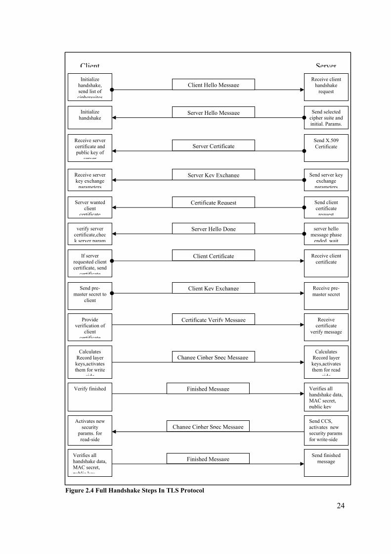
24
Figure 2.4 Full Handshake Steps In TLS Protocol
Initialize handshake, send list of ciphersuites
Receive client handshake
request Client Hello Message
Initialize handshake
Send selected cipher suite and initial. Params.
Server Hello Message
Receive server certificate and public key of
server
Send X.509 Certificate Server Certificate
Receive server key exchange
parameters
Send server key exchange
parameters
Server Key Exchange
Send client certificate
request
Server wanted client
certificate
Certificate Request
server hello message phase
ended, wait
verify server certificate,check server param
Server Hello Done
If server requested client certificate, send
certificate
Receive client certificate
Client Certificate
Receive pre-master secret
Send pre-master secret to
client
Client Key Exchange
Receive certificate
verify message
Provide verification of
client certificate
Certificate Verify Message
Calculates Record layer keys,activates them for write
side
Calculates Record layer keys,activates them for read
side
Change Cipher Spec Message
Verify finished Verifies all handshake data, MAC secret, public key
Finished Message
Activates new security
params. for read-side
Send CCS, activates new security params for write-side
Change Cipher Spec Message
Send finished message
Verifies all handshake data, MAC secret, public key
Finished Message
Client Server
25
2.1.2.3. TLS Cipher Suites
TLS is an extensible protocol. It achieves this by using cipher suites that is
composed of a unique id, key exchange and authentication method, symmetric
encryption method and MAC algorithm. Cipher suites are named using the scheme
TLS_asym_WITH_sym_mac, e.g. TLS_RSA_WITH_3DES_EDE_CBC_SHA. If a
new symmetric encryption algorithm method is developed and expected to be used in
TLS; a new cipher suite is defined using this symmetric encryption algorithm as the
encryption method. The same scheme can be applied to key exchange and
authentication method and MAC algorithm as well.
A list of cipher suites defined is given in TLS 1.0 Specification [2]. Additional
cipher suites can be registered by publishing an RFC which specifies the cipher suites,
including the necessary TLS protocol information, including message encoding, pre-
master secret derivation, symmetric encryption and MAC calculation. “ECC Cipher
Suites for TLS” Internet Draft, defined in [16], was published to define new cipher
suites for ECC (see section 2.1.1.2, “ECC”).
2.1.3. TLS In Wireless Devices
The use of TLS protocol in wireless devices has been a concern for many years.
TLS was not found suitable for resource-constraint wireless devices for a variety of
reasons:
High CPU-intensive public key operations performed during TLS handshake
The verbosity of X.509 encoding
The chattiness (multiple round trips) of the handshake protocol
The large size of existing TLS implementations
Generally, not matching TLS need for reliable transport
However, these reasons did not prevent researchers try to adopt TLS protocol
(and SSL protocol) to wireless environments. The main reason behind these efforts has
been the proven security and the common usage of the protocol in the wired-world. The
use of standard Internet protocols would extend the Internet to future mobile devices.
Researches showed that the use of TLS in wireless devices was possible as some
constraints eased others. According to Gupta brothers [20], slow network speed in
wireless networks lets the CPUs not to be very fast to perform bulk encryption and
authentication. Also as TLS clients only perform public key operations for signature

26
verification and encryption and the relative speed of public key operations over private
key operations make wireless devices suitable as TLS clients.
WTLS (Wireless Transport Layer Security), specified in [4], is one of the first
efforts to adopt TLS protocol for wireless environments. WTLS was developed as the
security layer of the WAP8 Protocol. It was based on TLS 1.0 specifications [2] but a
number of changes have been made to the protocol by the WAP Forum.
The WTLS incorporated new features such as datagram support, optimized
packet size and handshake, and dynamic key refreshing. It has been optimized for low-
bandwidth bearer networks with relatively long latency. Fast algorithms were chosen
into the algorithm suite.
In time, some problems occurred with WTLS protocol. Many of the changes that
were made by WAP Forum have led to security problems including the chosen plaintext
data recovery attack, the datagram truncation attack, the message forgery attack and the
key-search shortcut for some exportable keys. [21] tells some security problems with
WTLS.
WTLS did not provide an end-to-end security. It was based on a proxy/gateway
architecture where encrypted data sent from a WAP phone using WTLS was decrypted
and re-encrypted using SSL [1] before sent to the real destination. This proxy
architecture led to performance and “man-in-the-middle” attack drawbacks.
WTLS was developed for WAP protocol suite. But the use of WAP in wireless
world was limited. These problems with WTLS caused it to lose its popularity in the
wireless industry. Instead, end-to-end security solutions were developed based on SSL
and TLS. KSSL developed by Sun Microsystems for J2ME devices is an example
implementation to provide end-to-end security (see section 2.2.4, “KSSL”).
2.2. J2ME
2.2.1. J2ME Overview
The biggest benefit of using Java™ technologies is producing platform
independent code. But even with this advantage, wireless devices offer a vast range of
capabilities in terms of memory, processing power, battery life, display size, and
8 Wireless Application Protocol, a protocol developed by WAP Forum industry association to provide specifications for the applications that operate over wireless communication networks.

27
network bandwidth. “One size does not fit all” approach resulted Java™ technologies to
be separated into three main platforms.
J2ME (Java™ 2 Micro Edition) is the Java™ platform for small wireless devices.
J2ME is divided into several different configurations and profiles. Configurations
contain Java™ language core libraries for a range of devices. Currently there are two
configurations: Connected Device Configuration (CDC) is designed for relatively big
and powerful devices such as high-end PDAs, set-top boxes, and network appliances;
Connected Limited Device Configuration (CLDC) is designed for small, resource-
constrained devices such as cell phones and low-end PDAs. CDC has far more
advanced security, mathematical, and I/O functions than does CLDC.
On top of each configuration, there are profiles. Profiles define more advanced,
device-specific API libraries, including GUI, networking, and persistent-storage APIs.
Each profile has its own runtime environment and is suited for a range of similar
devices. Java™ applications written for a specific profile can be ported across all the
hardware/OS platforms supported by that profile. The Mobile Information Device
Profile (MIDP) and the and PDA Profile are two of the more significant profiles for the
CLDC. The Foundation Profile and the Personal Profile are two important profiles for
the CDC. Figure 2.5 [23] shows the place of J2ME technologies on Java™ platforms.
Figure 2.5 Java™ And J2ME™ Technologies [23]

28
2.2.2. CLDC / MIDP
Connected Limited Device Configuration(CLDC) defines a standard, minimum-
footprint Java™ platform for small, resource-constrained, connected devices. CLDC 1.0
specification [22] characterizes these devices as follows:
160 kB to 512 kB of total memory budget available for the Java™ platform
a 16-bit or 32-bit processor
low power consumption, often operating with battery power
connectivity to some kind of network, often with a wireless, intermittent
connection and with limited (often 9600 bps or less) bandwidth
CLDC 1.0 specification was published by Java™ Community Process (JCP) with
the code JSR-30. Cell phones, two-way pagers, personal digital assistants (PDAs),
organizers, home appliances, and point of sale terminals are some of the devices
supported by this specification.
A J2ME profile defines a more comprehensive and focused Java™ platform for a
particular vertical market, device category or industry [22]. Mobile Information Device
Profile (MIDP) is the first profile developed under CLDC configuration. MIDP Version
1.0 provides APIs for application lifecycle, HTTP network connectivity, user interface,
and persistent storage. MIDP 2.0 includes many enhancements and additions like secure
networking, multimedia, the game API, RGB images, permissions and code signing.
2.2.3. Security In MIDP
As the comprehensive security solutions provided in Java™ 2 Standard Edition
(J2SE) exceeds CLDC / MIDP devices’ capabilities, a simpler but effective security
model was needed. CLDC 1.0 specification [22] defines two levels of security:
Low-level virtual machine security
Application-level security
Low-level virtual machine security ensures applications cannot harm device by
ensuring that the Java™ byte codes and other items stored in Java™ class files cannot
contain references to invalid memory locations or memory areas that are outside the
Java™ object memory (the Java™ heap).
Application-level security controls access to external resources, e.g. files by
using a simple sandbox model. CLDC sandbox model ensures that class files have been

29
properly verified and guaranteed to be valid Java™ applications. Applications can only
access to APIs defined by CLDC, profiles and licensee open classes. Programmers
cannot override, modify or add system classes (classes under java. or javax. packages
and sub-packages) or modify/bypass VM's standard class loading mechanism. Access to
device’s native functions is prohibited; JNI (Java™ Native Interface) is not allowed.
MIDP 1.0 specification [24] does not define any low-level or application-level
security features except CLDC. MIDP 2.0 specification [25] extends sandbox model:
trusted MIDlets can access restricted APIs and provides mechanisms for secure network
communication. These mechanisms are midlet signing, midlet access control and
permissions.
MIDP 1.0 specification did not have an obligatory end-to-end security
mechanism although some implementations, including Sun’s, supported SSL client
protocol in the form of HTTPS. MIDP 2.0 specification [25] required an obligatory
HTTPS support, which is basically HTTP over one of the protocols below:
TLS 1.0 (see Section 2.1, “TLS Protocol”)
SSLv3
Wireless Transport Layer Security (WTLS) (see Section 2.1.3, “TLS In Wireless
Devices)
In MIDP 1.0, obtaining an HTTPS connection is just like obtaining an HTTP,
except for the URL:
HttpConnection hc = null;
hc = (HttpConnection)Connector.open("https://www.xyz.org/");
MIDP 2.0 specifies new classes for use of HTTPS connections. The connection
above could be established with the following code:
String url = "https://www.xyz.org/";
HttpsConnection hc = null;
hc = (HttpsConnection)Connector.open(url);
MIDP 2.0 does support server authentication with HTTPS, but still lacks
mechanisms for client authentication.
2.2.4. KSSL
KiloByte SSL (KSSL), is a small footprint, SSL client for the Mobile
Information Device Profile (MIDP).

30
The list of features offered by KSSL, defined in [20], are as follows:
Keys: Symmetric keys of different lengths and RSA Public/Private keys with
modulus lengths up to and including 1024-bits.
Ciphers: RSA (for key exchange)(see Section 2.1.1.2.1, “RSA”) and RC4 (for
bulk encryption) (see Section 2.1.1.1, “Private Key Cryptography”).
_ Message Digests: MD5 and SHA (see Section 2.1.1.3, “Hash Function”).
Signatures: RSA with both MD5 and SHA (see Section 2.1.1.5, “Digital
Signature”).
Certificates: Only X.509 certificates containing RSA keys and signed using
RSA with MD5 or SHA are supported (see Section 2.1.1.7, “Digital
Certificates”).
KeyStore: Only supports certificate storage (currently, private keys or symmetric
keys cannot be stored).
SSL: KSSL is a client-side only implementation of SSLv3.0 Other versions,
SSLv2.0 or SSLv3.1 (aka TLS1.0) are not currently supported.
The KSSL client offers two cipher suites, RSA_RC4_128_MD5 and
RSA_RC4_40_ MD5 since they are fast and common. Client-side authentication is not
implemented as it requires (highly CPU intensive) private-key RSA operations on the
client. The KSSL client also supports session reuse.
According to an experiment published in [20], a full handshake (see Section
2.1.2.2.1, “Full Handshake”) took 10-13 seconds with KSSL running on MIDP for Palm
platform on a 20MHz Palm device over a CDPD9 network. Caching the server
certificate (indexed by an MD5 hash) eliminated the overhead of certificate parsing and
verification and reduced the full handshake latency to 7-8 seconds. An abbreviated
handshake (see Section 2.1.2.2.2, “Abbreviated Handshake”) took only 2 seconds.
Table 2.2 shows the performance of KSSL primitives on a 20 Mhz Palm Vx and 33
Mhz Visor, based on [20].
9 Cellular Digital Packet Data, a specification for supporting wireless access to the Internet and other public packet-switched networks.

31
Table 2.2 Performance Of KSSL Primitives On PDAs [20]
Palm Vx (20Mhz) Visor (33Mhz) RSA (1024-bit) Verify Sign
1433 ms 80.91 sec
806 ms 45.11 sec
RSA (768-bit) Verify Sign
886 ms 36.22 sec
496 ms 20.19 sec
MD5 1024 bytes 4096 bytes
292 Kbits/s 364 Kbits/s
512 Kbits/s 655 Kbits/s
SHA-1 1024 bytes 4096 bytes
124 Kbits/s 140 Kbits/s
227 Kbits/s 256 Kbits/s
RC4 1024 bytes 4096 bytes
117 Kbits/s 190 Kbits/s
215 Kbits/s 351 Kbits/s
2.2.5. Lightweight Mobile Cryptography Toolkits
2.2.5.1. Bouncy Castle Lightweight API
Bouncy Castle (BC) started out as a community effort to implement a free,
clean-room, open source JCE provider. BC developers developed their own lightweight
API (BC lightweight crypto API) to be wrapped in BC JCE provider classes. The BC
lightweight API can also be used standalone, with minimum dependence on other J2SE
classes. The Bouncy Castle J2ME download package contains the implementation of
the BC lightweight API as well as two core Java™ classes not supported in
J2ME/CLDC:
java.math.BigInteger and java.security.SecureRandom.
Advantages of Bouncy Castle API are as follows:
Open source development model
Support for a range of well-known algorithms
Free distribution
Disadvantages of Bouncy Castle API are as follows:
Lack of optimizations for some algorithms (e.g. public key alg.)
Lack of API documentation
Bouncy Castle Lightweight API supports the following algorithms:
Diffie-Hellman Key Agreement (see Section 2.1.1.4,“Key Agreement Protocol”)
32
Elliptic Curve Diffie-Hellman(ECDH) Key Agreement
SHA-1 and MD5 Digests (see Section 2.1.1.3, “Hash Functions”)
AES (see Section 2.1.1.1, “Private Key Cryptography”)
DES, 3DES (see Section 2.1.1.1, “Private Key Cryptography”)
IDEA
RC2, RC4, RC5, RC6
RSA (see Section 2.1.1.2.1, “RSA”)
DSA, ECDSA Digital Signatures (see Section 2.1.1.5, “Digital Signature”)
El Gamal
HMac (see Section 2.1.1.4, “Message Authentication Code”)
Key Generators for the above algorithms
2.2.5.2. Phaos Technology Micro Foundation Toolkit
Phaos Technology is a Java™ and XML security solution provider. It offers
toolkits for secure XML Java™ APIs, J2ME lightweight crypto APIs, and one of the
first implementations of the SSL protocol on J2ME/CLDC.
Advantages of Phaos Library are as follows:
The Phaos MF runs on both CLDC and CDC.
Comes with excellent documentation and code examples.
Phaos MF supports a set of frequently used cryptographic algorithms (including
AES, DES (Data Encryption Standard), RC2, and RC4, DSA (Digital Signature
Algorithm) and RSA)
Disadvantage of Phaos Library are as follows:
Not free (But, available for free evaluaion)
2.2.5.3. NTRU Neo for Java™ Toolkit
NTRU PKI algorithms include an encryption algorithm NTRUEncrypt and a
signature algorithm NTRUSign, invented and developed by four math professors at
Brown University.
Advantages of NTRU Neo for Java™ toolkit are as follows:
NTRU algorithms have better performance compared to other PKI algorithms
The Neo for Java™ package runs on CLDC, CDC, and J2SE platforms.

33
Disadvantages of NTRU Neo for Java™ toolkit are as follows:
Security weaknesses were identified in NTRUEncrypt as late as May 2001.
Not free (has an evaluation version)
2.2.5.4. B3 Security
B3 Security is a San Jose, Calif. startup that specializes in developing new
lightweight security infrastructures that minimize the current overhead associated with
PKI. It has the products B3 Tamper Detection and Digital Signature (B3Sig) SDK and
B3 End-to-End (B3E2E) Security SDK available for J2ME.
The B3E2E SDK (still in beta) provides features equivalent to SSL in the PKI
world, but with a shorter handshake, faster session key establishment, and less
management overhead, especially for pushed messages.
B3 scheme has the following advantages:
Speed: Cryptographic hash and HMAC algorithms can run 1,000 times faster
than public key algorithms.
Strong two-factor authentication: Only the person who has access to the specific
device and knows her application password can generate the correct shared and
non-shared secrets to sign messages.
Tamper detection: B3Sig SDK has a conservative design: It assumes that no
algorithm is permanently secure, including its own.
2.3. XML And Java
2.3.1. XML Overview
The extensible markup language (XML) is a set of syntax rules and guidelines
for defining text-based markup languages. XML is a simplification of the complex
SGML standard. SGML, the Standard Generalized Markup Language, is an
international (ISO) standard for marking up text and graphics. The best-known
application of SGML is HTML.
XML languages have a number of uses including:
Exchanging information
Defining document types
Specifying messages
34
XML data is structured as a tree of entities. An entity can be a string of character
data or an element, which can contain other entities. Elements can optionally have a set
of attributes. Attributes are key/value pairs, which set some properties of an element.
The following example shows some XML data:
<book>
<chapter id="my chapter">
<title>The title</title>
Some text.
</chapter>
</book>
At the root of the tree, there is the element “book”. This element contains one
child element: “chapter”. The chapter element has one attribute that maps the key “id”
to “my chapter”. The chapter element has two child entities: the element “title” and the
character data “Some text”. Finally, the title element has one child, the string “The
title”.
There are two approaches to parse an XML document:
SAX Approach: The parser starts at the beginning of the document and passes each
piece of the document to the application in the sequence it finds it. Nothing is saved
in memory.
DOM Approach: The parser creates a tree of objects that represents the content and
organization of data in the document. In this case, the tree exists in memory. The
application can then navigate through the tree to access the data it needs, and if
appropriate, manipulate it.
2.3.2. Using XML In J2ME
The use of XML is a requirement in J2ME platforms for a variety of reasons:
XML is a good messaging format with its standard, self-describing structure.
J2ME applications can communicate with back-end servers and each other using
XML data formats over the HTTP protocol.
XML is the communication data format of choice for the new generation of
open, interoperable Web services.
Use of XML in Java™ 2 Standard Edition (J2SE) and Java™ 2 Enterprise Edition
(J2EE) is possible through a set of standard APIs. Unfortunately, these APIs are not
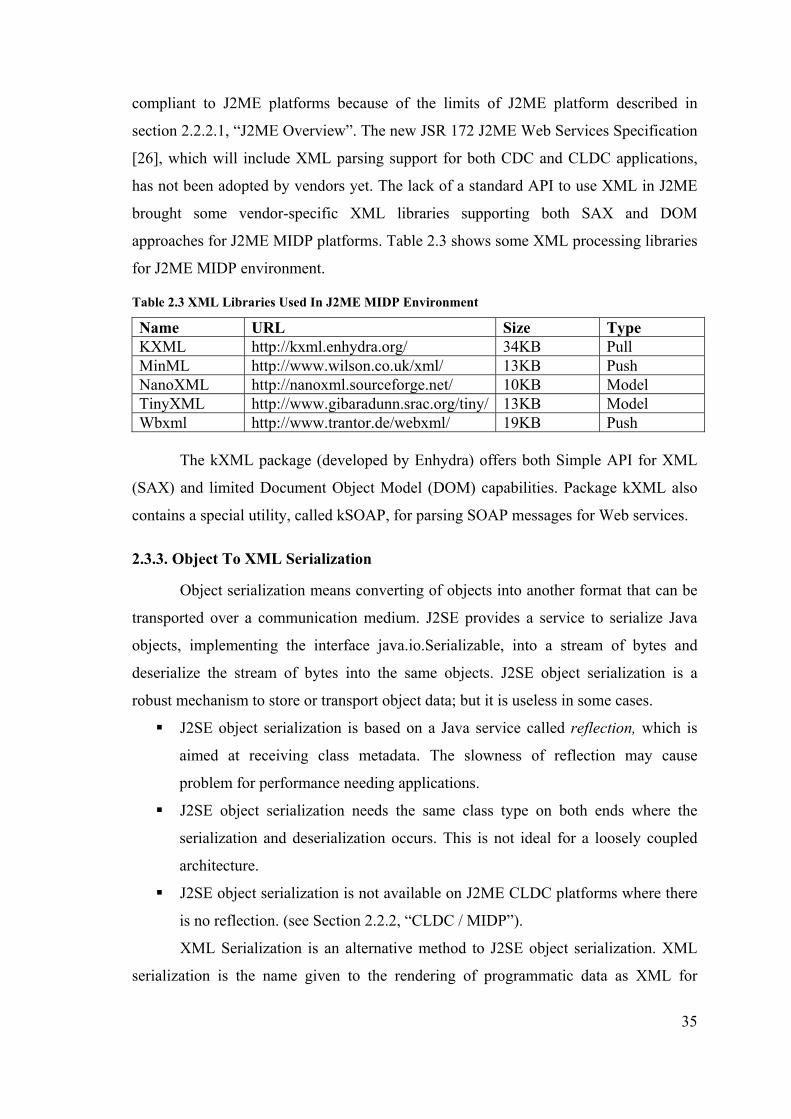
35
compliant to J2ME platforms because of the limits of J2ME platform described in
section 2.2.2.1, “J2ME Overview”. The new JSR 172 J2ME Web Services Specification
[26], which will include XML parsing support for both CDC and CLDC applications,
has not been adopted by vendors yet. The lack of a standard API to use XML in J2ME
brought some vendor-specific XML libraries supporting both SAX and DOM
approaches for J2ME MIDP platforms. Table 2.3 shows some XML processing libraries
for J2ME MIDP environment.
Table 2.3 XML Libraries Used In J2ME MIDP Environment
Name URL Size Type KXML http://kxml.enhydra.org/ 34KB Pull MinML http://www.wilson.co.uk/xml/ 13KB Push NanoXML http://nanoxml.sourceforge.net/ 10KB Model TinyXML http://www.gibaradunn.srac.org/tiny/ 13KB Model Wbxml http://www.trantor.de/webxml/ 19KB Push
The kXML package (developed by Enhydra) offers both Simple API for XML
(SAX) and limited Document Object Model (DOM) capabilities. Package kXML also
contains a special utility, called kSOAP, for parsing SOAP messages for Web services.
2.3.3. Object To XML Serialization
Object serialization means converting of objects into another format that can be
transported over a communication medium. J2SE provides a service to serialize Java
objects, implementing the interface java.io.Serializable, into a stream of bytes and
deserialize the stream of bytes into the same objects. J2SE object serialization is a
robust mechanism to store or transport object data; but it is useless in some cases.
J2SE object serialization is based on a Java service called reflection, which is
aimed at receiving class metadata. The slowness of reflection may cause
problem for performance needing applications.
J2SE object serialization needs the same class type on both ends where the
serialization and deserialization occurs. This is not ideal for a loosely coupled
architecture.
J2SE object serialization is not available on J2ME CLDC platforms where there
is no reflection. (see Section 2.2.2, “CLDC / MIDP”).
XML Serialization is an alternative method to J2SE object serialization. XML
serialization is the name given to the rendering of programmatic data as XML for
36
transmission between computers or storage on some external system [27]. An object can
be marshaled (or serialized) as a XML stream, and at the other end, an XML stream can
be un-marshaled (or deserialized) back to an object. This allows programmers to work
naturally in the native code of the programming language, while at the same time
preserving the logical structure and the meaning of the original data.
While offering a loosely coupled architecture, XML Serialization has an
important disadvantage: size. As XML is a text format, the size of an object serialized
into XML may be more than the size of the same object serialized with standard object
serialization. This brings a great disadvantage in limited bandwidth wireless networks.
One solution to this problem is good XML document design.
There are a variety of libraries that may perform XML Serialization, but all of
them work on J2SE platform. An XML Serializer running on CLDC / MIDP platform
was developed and described in Chapter 4.
37
CHAPTER 3
APPLICATION PLATFORM ARCHITECTURE
Mobile Java applications run on mobile devices, mostly mobile phones and PDA
devices. Whatever the device is, the application platform has a unique architecture. This
chapter explains the architecture where mobile Java applications run. This architecture
consists of the device’s architecture (hardware, OS, JVM, etc.), network connection
architecture that connects the mobile device to the outside world and the application
architecture. The mobile security protocol developed will run on the architecture
mentioned in this chapter.
3.1. Mobile Device Architecture
3.1.1. J2ME™ Mobile Devices
J2ME™ is the Java platform for small, resource constraint devices (see Chapter
2, Section 2.2.1, “J2ME Overview”). With J2ME™, Sun Inc. provides a complete end-
to-end solution for creating dynamically extensible, networked products and
applications for the consumer and embedded market. J2ME™ is currently targeted at two
categories of products [28]:
Shared, fixed, connected information devices
Personal, mobile, connected information devices
Shared, fixed, connected information devices have high capacity memories, fast
processors and high-bandwidth network connections. With these properties, they have
similar properties to desktop computers; so they are out of the scope of this thesis.
CLDC (Connected, Limited Device Configuration) is the J2ME™ configuration
that covers personal, mobile, connected information devices (see Chapter 2, Section
2.2.2, “CLDC / MIDP”). Cell phones, pagers and personal digital assistants (PDAs) are
examples of devices in this category. These devices have simpler user interfaces, low
memories and low-bandwidth network connections. MIDP is a profile under CLDC
configuration (see Chapter 2, Section 2.2.1, “J2ME Overview”). CLDC / MIDP devices
are the target devices where the proposed end-to-end security solution will run on.
Today, many cell phones and PDAs support MIDP technology. Usually, cell

38
phones have built-in support for either MIDP 1.0 or 2.0; and PDAs (mostly PALM™
based PDAs) support MIDP after installing the KVM (Kilobyte Virtual Machine)
specific for these devices. Table 3.1 shows some of the devices that have MIDP support,
based on [29].
Table 3.1 Some Of The Mobile Devices Having Built-in MIDP Support [29]
Manufacturer Model Java Support Nokia 6600 MIDP 2.0 Sony Ericsson P800 MIDP 1.0 + Personal Java Nokia 7650 MIDP 1.0 Motorola i85s MIDP 1.0 Nokia 9210 Communicator MIDP 1.0 + Personal Java Siemens SL45i/6688i MIDP 1.0 LG Electronics C-nain 2000 MIDP 1.0 Samsung SCH-X230 MIDP 1.0 Casio C452CA MIDP 1.0 Sharp J-SH07 MIDP 1.0
Also any PDA having Palm OS® 3.5 or over as the operating system may have
MIDP support after the installation of a KVM like “MIDP for PALM” from Sun
Microsystems or other KVMs from other vendors.
As shown in table 3.1, a variety of devices from different vendors have J2ME™
MIDP support. In order to support this kind of flexibility and customization need,
J2ME™ architecture is designed to be modular and scalable. Figure 3.1 shows the
general architecture of a J2ME™ MIDP device with its layered approach, based on [28].
Figure 3.1 J2ME™ Device Architecture [28]
In this architecture, the host operating system communicates with the device
hardware and provides services for the Java Virtual Machine layer. JVM layer is the

39
implementation of a Java virtual machine that is customized for a particular device’s
host operating system and supports a particular J2ME™ configuration. The configuration
layer defines the minimum set of Java virtual machine features and Java class libraries
available on a particular category of devices. The profile layer defines the minimum set
of Application Programming Interfaces (APIs) available on a particular family of
devices. The layer where Java applications are written is the Profile Layer.
3.1.2. Mobile Device Operating Systems
Mobile device operating systems control the mobile device hardware and
provide services for the Java Virtual Machine Layer. Although MIDP applications run
on top of a JVM and is independent of the operating system, the implementation of the
JVM is customized for the operating system. So the operating systems capabilities
define the MIDP application capabilities.
The most common operating systems in MIDP supporting devices are PALM
OS® and Symbian OS.
3.1.2.1. PALM OS®
Palm OS® is the operating system developed specifically for personal digital
assistants (PDAs) by Palm Inc. The latest release is Palm OS® 5. Palm OS® is the
operating system of most Palm Inc. or other vendors’ PDAs as well as a number of
smart phones.
The key features of Palm OS® are:
Supports ARM®-compliant processors from industry leaders Intel, Motorola,
and Texas Instruments.
System-wide strong encryption (128-bit) as a standard feature; includes RC4,
SHA-1, and signature verification using RSA-verify.
Provides a set of APIs and drivers that support 802.11b solutions at the system
level.
Supports Bluetooth, GSM, CDMA, and 2.5G/3G networks.
Offers 128-bit Secure Sockets Layer encryption services (SSL 3.0/TLS 1.0) for
secure end-to-end connections.
The first implementation of Palm OS® only supported a 16 MHz Motorola®
68000 type processor with a minimum of 128K of nonvolatile storage memory and 512
40
KB of ROM. ARM®-compliant processors are supported with Palm OS® 5. Palm OS®
has a preemptive multitasking kernel that provides basic task management [30]. Only
system software can launch a separate task. The multi-tasking API is not available to
developer applications.
Palm OS® provides network services with its net library for TCP and UDP via a
socket API. The Internet library builds on the net library to provide a socket-like API to
high-level Internet protocols such as HTTP [31].
The Palm OS® features two database types: resource and record databases [32].
Each database consists of a header block, followed by an arbitrary data block. The
header block contains the name, creator ID, type, number of records and last
synchronization date. A creator ID is a four-character piece of code that can be
registered with Palm™ to ensure uniqueness. Each record in the data block contains a
record ID, record category index, record attributes and record data.
Palm OS® do not have native Java support. However, it is possible to run MIDP
applications on Palm OS® after installing a J2ME™ VM for Palm OS® (see Section
3.1.3, “Mobile Device JVM Layer”). Palm™ JVM implementations directly access Palm
OS® APIs for network connection, record store management and UI creation.
3.1.2.2. Symbian OS
Symbian OS is an operating system developed specifically for small, embedded
environments. The operating system is especially specialized in data-enabled 2G, 2.5G,
3G mobile phones [33]. Some of the devices that use Symbian OS as the operating
system are Ericsson R380, Sony-Ericsson P800, the Nokia 9200 Communicator series,
Nokia 6600, Nokia 7650, Nokia 3650, Nokia N-Gage, NTT DoCoMo F2051, Siemens
SX1, BenQ P30 and Samsung SGH-D700. The latest version of Symbian OS is v7.0s.
The key features of Symbian OS are [33]:
Application engines: Includes engines for contacts, schedule, messaging,
browsing, utility and system control
Browsing: WAP stack provided with support for WAP 1.2.1 for mobile
browsing
Messaging: Multimedia messaging (MMS), enhanced messaging (EMS) and
SMS; internet mail using POP3, IMAP4, SMTP and MHTML
41
Multimedia: Audio and video support for recording, playback and streaming;
image conversion
Graphics: Direct access to screen and keyboard for high performance; graphics
accelerator API
Communications protocols: Wide-area networking stacks including TCP/IP
(dual mode IPv4/v6) and WAP, personal area networking support include
infrared (IrDA), Bluetooth and USB.
Mobile telephony: Supports GSM circuit switched voice and data (CSD and
EDGE ECSD) and packet-based data (GPRS and EDGE EGPRS); CDMA
circuit switched voice, data and packet-based data (IS-95, cdma2000 1x, and
WCDMA); SIM, RUIM and UICC Toolkit
International support: Conforms to the Unicode Standard version 3.0
Data synchronization: Supports PC-based synchronization over serial,
Bluetooth, Infrared and USB
Java Support: v6.0 has no built-in Java support, but the device manufacturer
may add MIDP support, v7.0 has integrated MIDP 1.0 support, v7.0s has
integrated MIDP 2.0 support
User Inputs: Generic input mechanism supporting full keyboard, voice,
handwriting recognition
The Symbian OS kernel is a compact pre-emptive multitasking operating system
with very little dependence on peripherals [34]. The Symbian OS kernel runs in
privileged mode, owns device drivers, implements the scheduling policy, does power
management and allocates memory to itself and user-mode (that is, unprivileged)
processes. The kernel implements a message-passing framework for the benefit of user-
side servers (such as the networking and telephony stacks and the file system). The
client-server architecture supports both thread-relative and process-relative client
resource ownership. The latter is to ease porting of code written for other platforms to
Symbian OS, and delivers considerably enhanced Java performance [33].
Symbian OS has a broad networking support. It supports TCP, UDP, ICMP,
PPP, DNS, Telnet and FTP protocols and IPv4/v6 stack. It also provides a HTTP
transport framework that presents a unified, high level API. MIDP applications may
have network support by using TCP/IP stack and HTTP transport framework. Thus all
devices having Symbian OS have HTTP network support. Java MIDP implementations
42
may use IPv4 or IPv6 addressing on the operating system.
The Symbian OS v7.0s implementation supports MIDP 2.0, CLDC 1.0 with
Sun's CLDC HI Java VM, Bluetooth 1.0, and Wireless Messaging 1.0. It also includes
PersonalJava with the JavaPhone APIs. Symbian’s JVM implementation lets the MIDP
applications, specifically developed for the Symbian OS to benefit from many of the
features of Symbian OS.
3.1.3. Mobile Device JVM Layer
As in desktop, Java applications on mobile devices run on top of a virtual
machine called Java Virtual Machine (JVM). The virtual machine is implemented in
native code and may directly use operating system services. The VM of mobile devices
are different from J2SE JVM because of the limited resources and device architectures
of mobile devices.
3.1.3.1. KVM
The K Virtual Machine (KVM) is a highly portable Java virtual machine
designed from the ground up for small memory, limited-resource and network-
connected devices such as cellular phones, pagers, and personal organizers [28]. KVM
is the result of a research called Spotless at Sun Microsystems Laboratories in 1998
[35]. As it is the first VM for constrained devices, the term “KVM” is sometimes used
for all J2ME™ VMs although it is only the name of the Sun Inc.’s J2ME™ VM
implementation.
The “K” in KVM stands for “kilo”. It was named like that because KVM is
suitable for 16/32-bit RISC/CISC microprocessors with a total memory budget of no
more than a few hundred kilobytes (potentially less than 128 kilobytes) [28]. A more
typical implementation requires a total memory budget of 256 kB, of which half is used
as heap space for applications, 40 to 80 kB is needed for the virtual machine itself, and
the rest is reserved for configuration and profile class libraries. This applies to digital
cellular phones, pagers, personal organizers, and small retail payment terminals.
The actual role of a KVM technology in target devices can vary significantly. In
some implementations, the KVM technology is used on top of an existing native
software stack to give the device the ability to download and run dynamic, interactive,
secure Java content on the device. In other implementations, the KVM technology is

43
used at a lower level to also implement the lower-level system software and applications
of the device in the Java programming language. Several alternative usage models are
possible.
Historically, KVM is the VM of CLDC configuration. For a long time, CLDC
technology ran on top of KVM, but now other J2ME™ virtual machines may also
support CLDC (see Section 3.1.3.2, “CLDC HI”).
The KVM is implemented in the C programming language, so it can easily be
ported onto various platforms for which a C compiler is available. Solaris, Windows or
Palm OS® are some of these platforms.
KVM implementations on desktop operating systems (Windows or Solaris) are
executed from command line like normal J2SE applications. If the mobile device has a
user interface to launch native applications, KVM can be configured to run like that (for
example: KVM for Palm OS®). If the mobile device does not have such a user interface,
KVM provides a facility called Java Application Manager™ (JAM™), which reads the
contents of a jar file launches the KVM with the main class in that jar file as a
parameter.
The KVM technology does not support the Java Native Interface™ (JNI™).
Instead, native code called from the VM must be linked to the virtual machine at
compile time. There are four ways in which notification and handling of events can be
done in the KVM [28]:
Synchronous notification (blocking)
Polling in Java code
Polling in the byte code interpreter
Asynchronous notification
KVM makes use of the new “stack map” method attribute in order to quickly
and efficiently verify class files. A pre-verification tool written in C is supplied with the
KVM reference implementation. The KVM supports a utility called JavaCodeCompact
(JCC) (also known as the class prelinker, preloader or ROMizer) which allows Java
classes to be linked directly in the virtual machine, reducing VM startup time
considerably.
“MIDP for PALM” uses a version KVM specific to Palm OS® (see Section
3.1.2.1, “Palm OS®”). Most mobile phones have KVM technology below the CLDC
configuration.
44
3.1.3.2. CLDC HI
CLDC HI (CLDC Hotspot Implementation) is the new generation VM for
J2ME™ devices. KVM technology was designed for small resource constraint devices.
The limits of the KVM technology caused performance problems as the MIDP
applications running on top of KVM extended to enterprise uses. The Hotspot™
performance engine was developed to address the perception that Java virtual machine
performance was insufficient for many mainstream applications especially on big
servers [36]. CLDC HI is the combination of KVM technology with the Hotspot™
architecture.
CLDC HI is a 32-bit virtual machine that complies with the CLDC 1.0
Specification [22]. Different from KVM implementations, CLDC HotSpot
Implementation has no restrictions on the number of loaded classes or the size of the
object heap. The total memory requirement for CLDC HI VM and the software is less
than 1 MB; including CLDC HotSpot Implementation virtual machine, the CLDC class
libraries, the MIDP class libraries, and Java applications.
CLDC HI supports a compact object layout to reduce general memory
consumption. It uses only one word for the object header10 while most other virtual
machines use at least two words.
CLDC HI allocates all data (Java level objects; reflective objects such as
methods and classes), compiler generated code and virtual machine internal data
structures) inside the object heap, called unified resource management. An important
advantage of this unification is that the same garbage collector takes care of cleaning up
all allocated resources.
CLDC HI uses an accurate, two generational, mark-sweep-compact garbage
collector, which results fast object allocation and small garbage collection pauses. An
accurate garbage collector knows where all pointers are when garbage collection takes
place. The object heap is segmented into old generation, new generation and as-yet-
unused portions of memory. Short-lived objects are allocated in new generation area
and compacted to the old generation area when all memory in the object heap is
consumed.
10 The part of the Java object that provides reflective information and contains hash code and locking status.
45
CLDC HI includes a dynamic compiler to provide fast byte code execution. The
compiler is a simple one-pass compiler that utilizes the following basic optimizations:
constant folding, constant propagation, loop peeling.
Symbian OS (see Section 3.1.2.2, “Symbian OS”) uses CLDC HI as the Java
VM. Symbian OS’s Java VM has the following features [33]:
Supports the OTA recommended practice document for MIDlet installation
Heap size, code size, and persistent storage are unconstrained, allowing larger,
more compelling MIDlets to be run
MIDlets look and behave very much as native applications: they use the native
application installer and launcher, and native UI components
Supports native color depth (4096 colors)
Generic Connection Framework implementation including sockets, server
sockets, datagram sockets, secure sockets, HTTP and HTTPS
Implements Bluetooth (excluding push and OBEX)
Implements wireless messaging
3.1.3.3. IBM J9 VM
J9 is the virtual machine from IBM that may work on a wide range of mobile
and non-mobile operating systems (Palm OS®, PocketPC, QNX, MontaVista Linux,
OSE, ITRON, etc.) [37]. J9 VM is a very portable VM that may work with both CLDC
and CDC profiles.
The J9 virtual machine is configurable over a wide range of settings, including
the following:
Supported function (like dynamic class loading)
Memory usage and stack size
Incremental allocation sizes of memory, ROM and RAM sizes for class loading
J9 VM is the JVM of IBM’s Websphere Micro Environment (WME). WME has
limits far beyond the traditional Palm™ implementations for MIDP. For example, WME
has access to the entire dynamic and storage heap currently available on a Palm
handheld while “MIDP for Palm” from Sun Inc. has the dynamic heap size limit of 64
K. WME also has the support of CLDC 1.1 and MIDP 2.0 which is not available in
“MIDP for Palm”.

46
3.1.4. Mobile Device Configuration Layer
Configuration Layer defines the minimum set of Java virtual machine features
and Java class libraries available on a particular “category” of devices.
Connected, Limited Configuration Layer (CLDC) is the configuration specified
for small, resource constraint mobile devices (see Chapter 2, Section 2.2.2, “CLDC /
MIDP”). CLDC specification defines Java™ language and virtual machine features,
core libraries, input/output, networking, security and internationalization.
CLDC configuration does not address application life-cycle management
(installation, launching, deletion), user interface, event handling and high level
application model. These features are addressed by profiles implemented on top of the
CLDC.
KVM and CLDC are closely related, as KVM has been the only VM under
CLDC configuration for a long time. Now, there are other VMs that are compliant with
the CLDC, CLDC HI e.g. (see Section 3.1.3.2, “CLDC / HI”).
CLDC has a general goal of full Java™ programming language and Virtual
Machine Specification compatibility. Connected Limited Device Configuration 1.0a
Specification [22] defines the main differences as follows:
No floating point support: CLDC 1.0 has no floating-point support. The new
CLDC 1.1 specification has the floating-point support.
No Java™ Native Interface (JNI): Eliminated because of sandbox security model
and memory constraints of CLDC target devices.
No reflection: The lack of reflection causes CLDC not to support RMI, object
serialization, JVMDI (Debugging Interface), JVMPI (Profiler Interface) or any
other advanced features of J2SE that depend on the presence of reflective
capabilities.
No user defined class loaders: Eliminated because of sandbox security model.
No thread groups and daemon threads.
No weak references. The new CLDC 1.1 specification has the weak reference
support.
No finalization.
As the standard J2SE class file verification approach is too memory consuming
for small devices, CLDC uses an alternative mechanism for class file verification. In
this alternative, each method in a downloaded Java class file contains a “stackmap”

47
attribute, which is newly-defined in CLDC specification. This attribute is added to
standard class files by a pre-verification tool that analyzes each method in the class file.
The presence of this attribute enables a CLDC-compliant Java VM to verify Java class
files much more quickly and with substantially less VM code and dynamic RAM
consumption than the standard Java VM verification step, but with the same level of
security.
CLDC defines two types of class libraries:
Classes inherited from J2SE
Classes specific to CLDC
Classes inherited from J2SE are subsets of the corresponding class in J2SE.
Only those methods and fields those are appropriate for “connected, limited devices”
are specified by CLDC.
Classes specific to CLDC are required, as the classes with similar functionality
do not fit to the limits of small devices. Networking and I/O classes are examples of
CLDC specific classes.
CLDC specifies a Generic Connection framework, which enables consistent way
of supporting various protocols. General form of GCF is,
Connector.open("<prot>://<addr>:<params>").
For example:
Files: Connector.open("file://readme.txt");
HTTP: Connector.open("http://www.iyte.edu.tr");
Sockets: Connector.open("socket://155.223.64.1:80");
Communication ports: Connector.open("comm://4800:18N");
3.1.5. Mobile Device Profile Layer
Profile Layer defines the minimum set of Application Programming Interfaces
(APIs) available on a particular family of devices. Profiles are implemented on top of
configurations. A device can support multiple profiles.
Mobile Information Device Profile (MIDP) is the most common profile
implemented in all J2ME™ profiles (see Chapter 2, Section 2.2.2, “CLDC / MIDP”).
MIDP applications, or "MIDlets", move from state to state in their lifecycle
according to a state diagram. MIDlet states include:
Paused - initialized and quiescent (waiting)

48
Active - has resources and is executing
Destroyed - has released all resources, destroyed threads, and ended all activity
MIDlets use the "Record Management System", or RMS, to access and store
data on the device. Network connectivity in MIDlets is supported with the Generic
Connection framework (GCF) of the CLDC configuration.
MIDP defines a very limited API because of size and performance reasons.
However, it can be extended with various optional packages. Bluetooth (JSR 82), Web
services (JSR 172), wireless messaging (JSR 120), multimedia (JSR 135), and database
connectivity are some of the optional packages developed for CLDC / MIDP
environments. Device manufacturers may or may not include optional packages in their
device implementations.
3.2. Mobile Application Architecture
3.2.1. Client/Server Architecture
Client/server architecture is the main architecture for mobile network
applications. In this architecture, a network-aware application residing on a wireless
device, client, connects with back-end applications and servers behind a firewall or
proxy gateway over a wireless network and Internet and corresponding communication
protocols. Figure 3.2 [38] shows the client/server architecture of a mobile application.
Figure 3.2 Environment Of A Typical Networked Wireless Application [39]
In figure 3.2, the wireless devices can be mobile phones, PDAs or two-way
pagers. They have the mobile applications on top of MIDP and communicate with an

49
antenna over a wireless communication protocol. These protocols can be 802.11b on a
small area (see Section 3.3.1, “Wireless LAN”), or GPRS on a wide area (see Section
3.3.3, “GPRS”). The antenna is directly connected to a wired network like Internet,
which connects the mobile device to the back-end server systems.
Mobile applications typically use HTTP as the application-level communication
protocol as it is common and can pass firewalls. HTTP is the mandatory protocol in
MIDP 1.0 [24] and MIDP 2.0 specifications [25]. With MIDP 2.0, low-level socket
APIs can also be used to directly communicate with the server application below the
application level.
TLS may provide an application-level end-to-end security on top of sockets in
this architecture. The TLS implementation developed in this thesis runs on top of pure
sockets and provides an application level security between a MIDP application and
server back-end application. The MIDP version of the developed TLS protocol
communicates with the J2SE version of the protocol and sends object data over the
secure connection. The mobile device always runs the client version of TLS protocol
and back-end server always runs the server version of the TLS protocol.
3.2.2. Peer To Peer Architecture
Peer To Peer Architecture is an alternative and new architecture for wireless
devices. In this architecture, the two devices communicate directly with each other. This
communication may be the direct communication of the devices over a communication
medium like Bluetooth (see Section 3.3.2,”Bluetooth”); or it may be an application level
communication with the two mobile applications communicating over a central server.
The client side of the application is same with Client/Server Architecture. It uses
either HTTP or low-level socket APIs, either stream-based or datagram-based, for
network communication. The difference is in server side. In this architecture, the server
is also a mobile device. MIDP 2.0 has an API for server socket that may be used for this
purpose.
The TLS implementation to work in this architecture needs both client and
server versions of TLS to work in the mobile device. This may be impractical for two
reasons.
Resource constraints of mobile devices may cause performance problems for
server side implementation of the TLS protocol
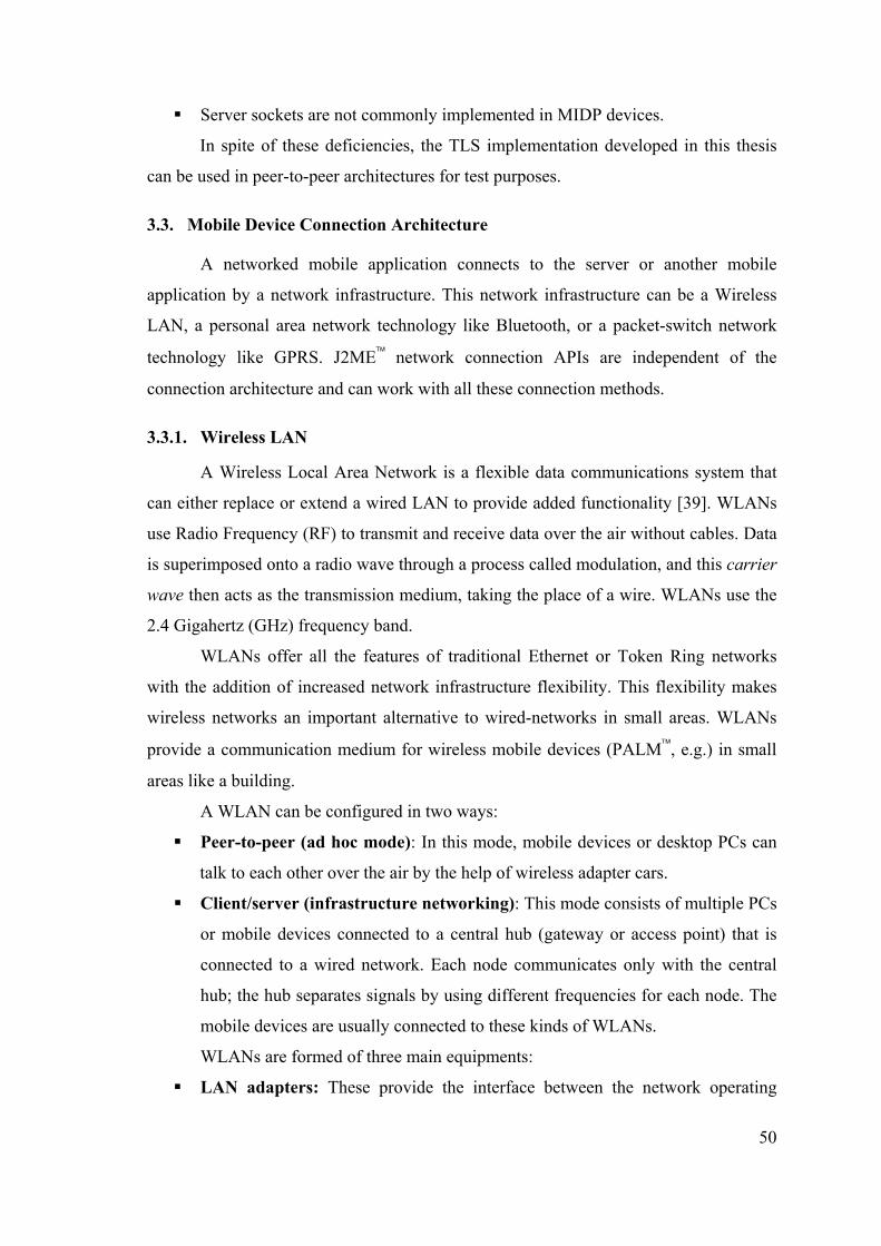
50
Server sockets are not commonly implemented in MIDP devices.
In spite of these deficiencies, the TLS implementation developed in this thesis
can be used in peer-to-peer architectures for test purposes.
3.3. Mobile Device Connection Architecture
A networked mobile application connects to the server or another mobile
application by a network infrastructure. This network infrastructure can be a Wireless
LAN, a personal area network technology like Bluetooth, or a packet-switch network
technology like GPRS. J2ME™ network connection APIs are independent of the
connection architecture and can work with all these connection methods.
3.3.1. Wireless LAN
A Wireless Local Area Network is a flexible data communications system that
can either replace or extend a wired LAN to provide added functionality [39]. WLANs
use Radio Frequency (RF) to transmit and receive data over the air without cables. Data
is superimposed onto a radio wave through a process called modulation, and this carrier
wave then acts as the transmission medium, taking the place of a wire. WLANs use the
2.4 Gigahertz (GHz) frequency band.
WLANs offer all the features of traditional Ethernet or Token Ring networks
with the addition of increased network infrastructure flexibility. This flexibility makes
wireless networks an important alternative to wired-networks in small areas. WLANs
provide a communication medium for wireless mobile devices (PALM™, e.g.) in small
areas like a building.
A WLAN can be configured in two ways:
Peer-to-peer (ad hoc mode): In this mode, mobile devices or desktop PCs can
talk to each other over the air by the help of wireless adapter cars.
Client/server (infrastructure networking): This mode consists of multiple PCs
or mobile devices connected to a central hub (gateway or access point) that is
connected to a wired network. Each node communicates only with the central
hub; the hub separates signals by using different frequencies for each node. The
mobile devices are usually connected to these kinds of WLANs.
WLANs are formed of three main equipments:
LAN adapters: These provide the interface between the network operating

51
system and an antenna, to create a transparent connection to the network.
Access Points: It is the wireless equivalent of a LAN hub. It is connected to the
wired network through an Ethernet cable and has an antenna to communicate
with the wireless devices. It has a range of 20-500 meters.
Outdoor LAN bridges: Used to connect LANs in different buildings. With
FHSS11, the signal hops from one frequency to another at a predetermined rate
known only to the transmitter and receiver. With DSSS12, a redundant “chipping
code” is sent with each signal burst, and only the transmitter and receiver know
the chipping sequence [39]. Of importance for today’s wireless uses, DSSS has
much greater range characteristics and higher throughput potential.
IEEE13 published IEEE 802.11 standard for wireless networks. 802.11 standard
focuses on the physical layer and data link layer of the ISO model. Thus, any
application or protocol running on traditional networks will also work on 802.11
WLAN. The 802.11 standard support two types of transmissions: Frequency Hopping
Spread Spectrum (FHSS) and Direct Sequence Spread Spectrum (DSSS). 802.11b
standard provides data rate of 11Mbps over DSSS, which is equal to Ethernet data rate.
The 802.11b standard specifies optional encryption using a shared-key RC4 algorithm.
Mobile devices can connect to the 802.11b (also called WiFi) WLANs by the
help of a third party wireless LAN module or with their built-in WiFi antennas.
PALM™ or PocketPC™ devices are common clients of WLANs. As 802.11b operates
below ISO transport layer, a PALM™ client e.g. may use of any transport, network or
application layer protocol including TCP, IP, HTTP and SMTP. Recently, by the use of
multiple access points, public areas like airports, restaurants and some streets have
begun to support WiFi communication. New PALM™ devices automatically detect the
connection and ready to transmit data over WLAN.
11 Frequency Hopping Spread Spectrum, a transmission technology used in LAWN transmissions where the data signal is modulated with a narrowband carrier signal that hops in a random but predictable sequence from frequency to frequency as a function of time over a wide band of frequencies 12 Direct Sequence Spread Spectrum, a transmission technology used in LAWN transmissions where a data signal at the sending station is combined with a higher data rate bit sequence, or chipping code, that divides the user data according to a spreading ratio 13 Institute of Electrical and Electronics Engineers, a non-profit, technical professional association working in technical areas ranging from computer engineering, biomedical technology and telecommunications

52
3.3.2. Bluetooth
An alternatively new technology in mobile device communication is Bluetooth.
Bluetooth provides short-range wireless connectivity over radio-frequency technology
that uses the 2.4 GHz Industrial-Scientific-Medical (ISM) band [40]. Bluetooth lets
mobile devices to communicate with each other up to 10 meters range and 1 Mbit/sec
speed. The IEEE has designated its version of Bluetooth with 20Mbit/sec speed, as the
IEEE 802.15 standard.
Some important features of Bluetooth are as follows:
Bluetooth is wireless and automatic.
The ISM band that Bluetooth uses is regulated, but unlicensed.
Bluetooth handles both data and voice.
Signals are omni-directional and can pass through walls and briefcases.
Bluetooth uses frequency hopping.
Bluetooth-enabled devices are organized in groups called piconets. A piconet
consists of a master and up to seven active slaves. A master unit is the device that
initiates the communication. A device in one piconet can communicate to another
device in another piconet, forming a scatternet. Bluetooth has a the following layers in
its protocol stack:
The Radio Layer: Provides the physical connection. 2.4 GHz frequency band is
divided into 79 channels 1 MHz apart (from 2.402 to 2.480 GHz).
The Baseband Layer: Controls and sends data packets over the radio layer.
Provides transmission channels for both data and voice. The baseband layer
maintains Synchronous Connection-Oriented (SCO) links for voice and
Asynchronous Connectionless (ACL) links for data.
The Link Manager Protocol (LMP): Responsible from establishing
connections, manage piconets, authentication, security services and monitoring
of service quality.
The Host Controller Interface (HCI): Divides software and hardware. The
HCI is the driver interface for the physical bus that connects these two
components.
The Logical Link Control and Adaptation Protocol (L2CAP): Receives
application data and converts it to the Bluetooth format.
Figure 3.3 shows the Bluetooth Protocol Stack [40].
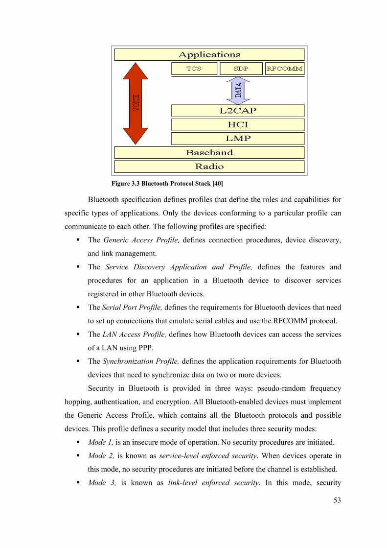
53
Figure 3.3 Bluetooth Protocol Stack [40]
Bluetooth specification defines profiles that define the roles and capabilities for
specific types of applications. Only the devices conforming to a particular profile can
communicate to each other. The following profiles are specified:
The Generic Access Profile, defines connection procedures, device discovery,
and link management.
The Service Discovery Application and Profile, defines the features and
procedures for an application in a Bluetooth device to discover services
registered in other Bluetooth devices.
The Serial Port Profile, defines the requirements for Bluetooth devices that need
to set up connections that emulate serial cables and use the RFCOMM protocol.
The LAN Access Profile, defines how Bluetooth devices can access the services
of a LAN using PPP.
The Synchronization Profile, defines the application requirements for Bluetooth
devices that need to synchronize data on two or more devices.
Security in Bluetooth is provided in three ways: pseudo-random frequency
hopping, authentication, and encryption. All Bluetooth-enabled devices must implement
the Generic Access Profile, which contains all the Bluetooth protocols and possible
devices. This profile defines a security model that includes three security modes:
Mode 1, is an insecure mode of operation. No security procedures are initiated.
Mode 2, is known as service-level enforced security. When devices operate in
this mode, no security procedures are initiated before the channel is established.
Mode 3, is known as link-level enforced security. In this mode, security
54
procedures are initiated before link setup is complete.
Many mobile devices including mobile phones and personal digital assistants
(PDA) have built-in Bluetooth support. These devices use Bluetooth communication to
connect to other Bluetooth enabled devices.
3.3.3. GPRS
GPRS (General Packet Radio Service) is an enhancement of core GSM (Global
System for Mobile Communications) networks that allows the rapid transfer of data
bundled into packets, separate from voice or data call circuits [41].
GPRS is a 2.5 Generation (2.5G) technology that is the last stone before the
coming 3G networks that will give high speed access allowing live video.
GPRS data is transmitted in packets, up to the 20 or 30 Kbps speed though the
theoretical maximum speed is 171.2 Kbps. GPRS set-up time is short and connection is
always on.
The Network Operation Mode, or NOM, is responsible for the capabilities of a
GPRS network, while the class indicates the mobile phone capabilities. On NOM 1
networks, mobile phones with the right capabilities can have simultaneous circuit- and
packet-switched connections. On NOM 2 networks, mobile phones can remain attached
to the GPRS networks when in a voice call but they can't transmit data at the same time.
On NOM 3 networks, mobile phones can either establish a packet-switched data
connection or a circuit-switched voice one but they need to disconnect from one to
establish another.
Class A phones can make full use of NOM 1 networks: they can use circuit-
switched voice and GPRS data services at the same time. Class B phones can register
circuit-switched voice and packet-switched data services at the same time but may only
use one at a time. Class C phones can only register for packet-switched data or for
circuit-switched voice services.
55
CHAPTER 4
MOBILE SECURITY PROTOCOL ARCHITECTURE
In the application part of this thesis, a mobile end-to-end security protocol is
developed and implemented. The protocol resembles TLS protocol, but has differences
from it in architecture. This chapter explains the architecture of the developed security
protocol. The architecture involves both the architectural analysis and design of the
protocol, object models of the implementation and the classes that will be used in
implementation. The XML serializer library developed to transmit objects as an
alternative to standard Java object serialization is also explained in this chapter.
4.1. Mobile End-To-End Security Protocol Design Issues
The security protocol implemented in this thesis is an end-to-end security
protocol based on TLS 1.0 specifications and adopted to work on J2ME™ mobile
devices as well as standard Java™ VMs. The protocol implementation itself is also an
application although high-level applications may use it through its APIs to transmit data
and objects securely.
The security protocol architecture developed covers both TLS protocol
architecture and the necessary APIs architecture. TLS protocol architecture is based on
TLS 1.0 specification and has some additions and subtractions. The necessary APIs
architecture involves cryptography model classes that abstract the real implementations
of cryptography packages; socket classes that abstract TCP or UDP based socket
implementations and the serialization of object data; XML Serializer architecture that is
a standalone API incorporated into the protocol implementation.
The main design issues taken into consideration during the definition of the
architecture of protocol implementation are J2ME™ compatibility, mobile adaptation,
secure object transmission, full abstraction and complete solution.
4.1.1. J2ME™ Compatibility
The protocol implementation is designed to be compatible with J2ME™ CLDC /
MIDP environments as well as standard Java Virtual Machines. The target platform for
56
the security protocol is MIDP supporting devices. To achieve this aim, the design and
implementation both respect to MIDP APIs. The version of MIDP based on is MIDP
1.0 as it has a broad industry support. MIDP 2.0 is only supported by a limited number
of mobile devices.
Although the target platform for the protocol is J2ME™ MIDP, it is also aimed to
work on standard J2SE environment. It is needed, as the server side of the protocol will
probably work on desktop machines. The protocol architecture implemented involves
socket implementations that send secure data to the other side. However, socket APIs in
J2ME™ and J2SE™ are different. This need results two versions of the protocol
implementation although it does not differ the main architecture. The only change is
done in socket classes explained in Section 4.2, “Main Architecture”. The rest of the
code is identical in two versions.
4.1.2. Mobile Adaptation
Although the mobile security protocol is based on TLS 1.0 specification, it is not
a full implementation of the protocol. It is adopted for mobile devices. The main
differences are as follows:
Client Authentication: TLS 1.0 requires client authentication optionally. Client
authentication is a resource intensive operation and is not included in this mobile
security protocol implementation.
Compression: TLS 1.0 needs compression of data records optionally. It is not
added to the developed protocol to improve performance. But the architecture of
Record Layer is designed to add the compression feature later without great
change.
Session Resumption: TLS 1.0 requires resumption of sessions established with
the same security parameters. Session resumption needs the storage of security
parameters in a secure environment. The limited resources of mobile devices
may not let this storage. Thus, this feature was not added to the developed
protocol implementation.
Socket Type: TLS 1.0 requires a TLS implementation to work over a reliable
protocol, like TCP. TCP is implemented as stream-based sockets in Java
programming language and is included into the protocol implementation as the
main communication method. However, some mobile networks may not have
57
TCP support. Although they have, TCP is a heavy protocol requiring long
connection establishment times. These facts resulted the addition of datagram-
based socket to the protocol implementation. The use of UDP for
communication is not a secure way, but it is added for test purposes.
Elliptic Curve Cipher Suites: Elliptic Curve Cryptography is an emerging
public key cryptography method that matches the needs of resource constraint
environments. This matching is resulted from the smaller key sizes with same
security level when compared with older public key methods, like RSA. The use
of ECC in TLS implementations will bring better performance results, especially
in resource constraint mobile environments. The TLS 1.0 specification does not
mention ECC, but there is an Internet Draft telling the use of ECC in TLS
implementations. The developed protocol supports ECC based cipher suites as
key exchange algorithms and is implemented according to [16].
4.1.3. Secure Object Transmission
TLS 1.0 is a security protocol for the secure transmission of data. It is not related
to the content of this application-level data. Mobile security protocol developed
enhances this feature and lets the objects to transmitted in a secure way. These objects
are data classes having private attributes and getter and setter methods, in a bean style.
The objects are serialized into XML as told in Section 4.7, “Object To XML Serializer”
and the result XML data is securely sent to the other peer. The other peer decodes XML
data and deserializes into objects. This method is an important enhancement for J2ME™
CLDC / MIDP environment that does not have Java Serialization and RMI facilities.
The object transmission APIs may also be used independent from the security protocol
by high-level applications.
4.1.4. Full Abstraction
The mobile security protocol uses some cryptography APIs from Bouncy Castle
cryptography package. However, these APIs are not directly used in the protocol
implementation classes. There is always a layer of classes that include these APIs and
provide methods for the use of these functions. For example, there are symmetric
encryption model classes, mentioned in Section 4.4.1, “Encryption” that includes
encryption APIs from Bouncy Castle Cryptography package. This design issue abstracts

58
the cryptography APIs from the rest of the code and eases the change of the
cryptography package used.
4.1.5. Complete Solution
The security protocol developed is a complete end-to-end solution. This
completeness comes from existence of TLS specifications, socket implementations and
application level APIs. It can be readily used by other mobile applications to transmit
secure data. There are also other SSL and TLS implementations for mobile
environments and most of them support only client version of TLS. The developed
protocol may operate in both client and server modes in both J2ME™ and J2SE™
environments.
4.2. Main Architecture
The main architecture of the mobile end-to-end security protocol is based on the
TLS 1.0 protocol specification (see Chapter 2, Section 2.1.3, “TLS Protocol Details”).
In the main model, the Record Layer behavior is implemented in the class
RecordLayerImpl and the Handshake Layer behavior is implemented in the class
HandshakeLayerImpl. HandshakeLayerImpl class has two instances of class
RecordLayerImpl; one for current state and one for pending state (see Chapter 2,
Section 2.1.3.1.3, “Connection States”). Both HandshakeLayerImpl and
RecordLayerImpl classes are transparent of the underlying socket implementations and
talk to the peer classes in both side of the communication.
The classes TLSClientSocket and TLSServerSocketListener are the only classes
needed to be known by the applications that will use this implementation of the
protocol. An application that needs to be the client in the secure communication must
use the class TLSClientSocket; and an application that needs to be the server in the
secure communication must use the class TLSServerSocketListener. The class
TLSServerSocket is used to handle a secure connection session in the server-side as a
separate thread. An application may use the class TLSSocketFactory to obtain either a
TLSClientSocket class instance or a TLSServerSocketListener class instance.
The mobile secure application is designed as the protocol implementation
separate from the underlying communication model. This is achieved by the interface
TLSSocketImpl. This interface defines the operations needed for sending and receiving
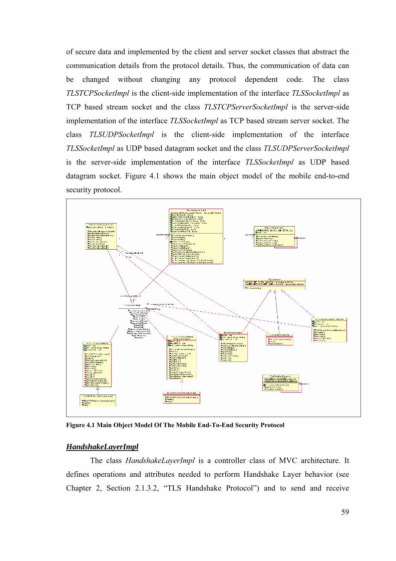
59
of secure data and implemented by the client and server socket classes that abstract the
communication details from the protocol details. Thus, the communication of data can
be changed without changing any protocol dependent code. The class
TLSTCPSocketImpl is the client-side implementation of the interface TLSSocketImpl as
TCP based stream socket and the class TLSTCPServerSocketImpl is the server-side
implementation of the interface TLSSocketImpl as TCP based stream server socket. The
class TLSUDPSocketImpl is the client-side implementation of the interface
TLSSocketImpl as UDP based datagram socket and the class TLSUDPServerSocketImpl
is the server-side implementation of the interface TLSSocketImpl as UDP based
datagram socket. Figure 4.1 shows the main object model of the mobile end-to-end
security protocol.
Figure 4.1 Main Object Model Of The Mobile End-To-End Security Protocol
HandshakeLayerImpl
The class HandshakeLayerImpl is a controller class of MVC architecture. It
defines operations and attributes needed to perform Handshake Layer behavior (see
Chapter 2, Section 2.1.3.2, “TLS Handshake Protocol”) and to send and receive
60
application-level data after the establishment of a secure session. Each secure session
has one instance of class HandshakeLayerImpl and the class instances at both side of
the communication talk to each other.
As the Handshake Layer in TLS Protocol communicates with the Record Layer
to send and receive data, the HandshakeLayerImpl class uses RecordLayerImpl class to
send and receive data. The class has two instances of the class RecordLayerImpl; one
for the current state and one for the pending state. The instance of RecordLayerImpl for
pending state is used for pending state of TLS Record Layer and the instance of
RecordLayerImpl for current state is used for current state of TLS Record Layer. The
pending state instance stores the security parameters exchanged during handshake steps.
These security parameters are copied to the current state instance after the successful
completion of the handshake steps. The sending and receiving of data is achieved with
the current layer instance of class RecordLayerImpl with the active security parameters.
HandshakeLayerImpl class defines two methods for the realization of handshake
steps. The method makeHandshake is used by client-side of the protocol
implementation to start the handshake procedure. The handshake procedure starts with
the ClientHello request sent by the client and continues with the steps mentioned in
Chapter 2, Section 2.1.3.2.1, “Full Handshake”. The method negotiateHandshake is
used by server-side of the protocol implementation to receive ClientHello request and to
perform server-side steps of the handshake procedure. Both methods do not include the
protocol implementation details, but calls to Handshake Protocol message objects (see
Section 4.3, “Handshake Layer Architecture”). The sending and receiving of handshake
message objects is performed by the current state instance of RecordLayerImpl.
HandshakeLayerImpl class defines the method sendData(java.io.InputStream i)
to send application data in a secure session and sendData(TLSHandshakeMessage m) to
send handshake messages during handshake procedure. Similarly the method
receiveObject() is used to receive data in a secure session and the method receiveData()
is used to receive handshake messages.
RecordLayerImpl
The class RecordLayerImpl is a controller class in MVC architecture. It defines
operations and attributes needed to perform Record Layer behavior (see Chapter 2,
Section 2.1.3.1, “TLS Record Layer”). The responsibilities of RecordLayerImpl class
are to send and receive application and Handshake Layer data after encoding and

61
decoding; generate new TLS keys according to the exchanged security parameters; copy
security parameters from pending state to current state and activate new TLS keys for
read side and write side. Major attributes of this class are as follows:
public TLSRecordLayerSpecs writeSideSpecs : Defines the properties of
Record Layer for the writing side. These properties are encryption algorithm,
MAC algorithm, protocol version, client random number, server random
number, cipher suite and master secret.
public TLSRecordLayerSpecs readSideSpecs : Defines the properties of
Record Layer for the reading side. These properties are encryption algorithm,
MAC algorithm, protocol version, client random number, server random
number, cipher suite and master secret.
public SecurityParameters parameters : Defines the security parameters
exchanged during handshake procedure. These parameters are cipher suite,
client random, server random, pre-master secret and connection end.
public Vector hanshakeMessagesVector : This attribute stores the handshake
messages exchanged during handshake steps which are used to verify if a man-
in-the-middle attack occurred during handshake.
private RecordGenerator generator : This instance of class RecordGenerator
is used to fragment and defragment data to send and receive in secure session.
private TLSSocketImpl socketImpl : This instance attribute is used to read
and write data from the underlying socket implementation. The use of the
interface as the variable abstracts the implementation class from
RecordLayerImpl class.
Major methods of this class are as follows:
public void sendData(InputStream instream) throws Exception : Used to
send data after encoding. This encoding involves fragmenting the data to
maximum of 2^14 bytes, creating a record header, forming a record by
combining the record header and the data, forming a MAC of this record and
adding the MAC value to the record, encrypting the record using the symmetric
cipher exchanged during handshake and adding a sequence number to the record
header.
public Object receiveObject() throws Exception : Used receive data after
decoding. The decoding involves the reverse of the operations told in the

62
encoding. Each TLS Record is received independently; decrypted according to
the symmetric cipher exchanged during handshake and MAC is verified.
public void generateNewTLSKeys() throws Exception : Used to generate the
master secret from the security parameters exchanged according to the master
secret derivation formula given in Chapter 2, Section 2.1.3.2.1, “Full
Handshake”. This method also generates the cryptographic keys used as
encryption key, MAC key and initialization vector (IV).
public void activateNewTLSKeysForReadSide(RecordLayerImpl
currentImpl) throws Exception : Used to activate security parameters of
pending state for read side.
public void activateNewTLSKeysForWriteSide(RecordLayerImpl
currentImpl) throws Exception : Used to activate security parameters of
pending state for write side. Thus the pending state becomes the current state.
TLSSocketImpl
The interface TLSSocketImpl defines the common operations for the TLS socket
implementations. The term TLS socket here means the underlying communication of
data below the secure protocol. This communication can be stream-based, datagram-
based or an alternative way. This is achieved with the use of polymorphic variables of
type TLSSocketImpl in the related classes. Major methods of this interface are as
follows:
public void openConnection() throws Exception : Used to open a real
connection. This connection can be a stream socket or a datagram socket in the
implementing classes.
public void closeConnection() throws Exception : Used to close the real
connection.
public void sendTLSData(TLSRecord obj) throws Exception : Used to send
TLSRecord object to the other side of the communication. The record header
data and the encoded data are written to a stream or datagram based socket.
public Object getTLSData() throws Exception : Used to receive data from the
underlying socket. This data is the TLSRecord object data sent with the method
sendTLSData(). This method reforms the TLSRecord object after receiving its
data and return this object for high-level clients.
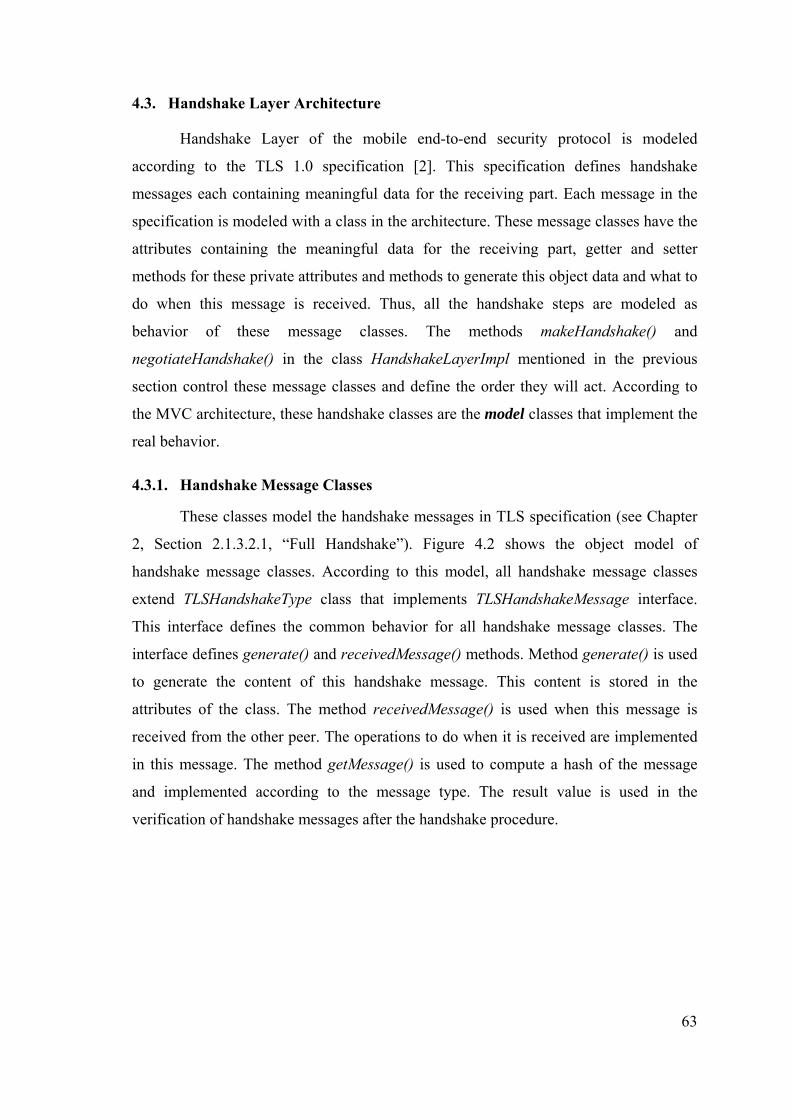
63
4.3. Handshake Layer Architecture
Handshake Layer of the mobile end-to-end security protocol is modeled
according to the TLS 1.0 specification [2]. This specification defines handshake
messages each containing meaningful data for the receiving part. Each message in the
specification is modeled with a class in the architecture. These message classes have the
attributes containing the meaningful data for the receiving part, getter and setter
methods for these private attributes and methods to generate this object data and what to
do when this message is received. Thus, all the handshake steps are modeled as
behavior of these message classes. The methods makeHandshake() and
negotiateHandshake() in the class HandshakeLayerImpl mentioned in the previous
section control these message classes and define the order they will act. According to
the MVC architecture, these handshake classes are the model classes that implement the
real behavior.
4.3.1. Handshake Message Classes
These classes model the handshake messages in TLS specification (see Chapter
2, Section 2.1.3.2.1, “Full Handshake”). Figure 4.2 shows the object model of
handshake message classes. According to this model, all handshake message classes
extend TLSHandshakeType class that implements TLSHandshakeMessage interface.
This interface defines the common behavior for all handshake message classes. The
interface defines generate() and receivedMessage() methods. Method generate() is used
to generate the content of this handshake message. This content is stored in the
attributes of the class. The method receivedMessage() is used when this message is
received from the other peer. The operations to do when it is received are implemented
in this message. The method getMessage() is used to compute a hash of the message
and implemented according to the message type. The result value is used in the
verification of handshake messages after the handshake procedure.
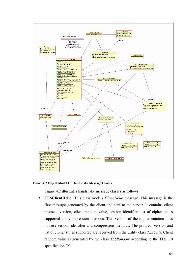
64
Figure 4.2 Object Model Of Handshake Message Classes
Figure 4.2 illustrates handshake message classes as follows:
TLSClientHello: This class models ClientHello message. This message is the
first message generated by the client and sent to the server. It contains client
protocol version, client random value, session identifier, list of cipher suites
supported and compression methods. This version of the implementation does
not use session identifier and compression methods. The protocol version and
list of cipher suites supported are received from the utility class TLSUtils. Client
random value is generated by the class TLSRandom according to the TLS 1.0
specification [2].

65
TLSServerHello: This class models ServerHello message. This message is the
response of the server to the ClientHello message. It contains server protocol
version, server random value, session identifier, cipher suites selected and
compression method selected. This version of the implementation does not use
session identifier and compression method selected. The protocol version is
received from the utility class TLSUtils. The server random value is generated
by the class TLSRandom according to TLS 1.0 specification [2]. The cipher suite
is selected as the first cipher suite in the ClientHello cipher suite list supported
by the server.
TLSServerHelloDone: This class models ServerHelloDone message. This
message is sent from client to server to notify that server hello message was
received. When this message class is received, a client key exchange message
class is generated with its attributes set, sent to server, client change cipher spec
message is generated and sent to server, new TLS keys are generated and
activated for write-side, handshake messages sent during handshake procedure
are calculated by using the message classes’ getMessage() methods and the
result value is sent to server with the ClientFinished message.
TLSServerCertificate: This class models ServerCertificate message. The
message is sent from server to client to convey server’s public key certificate.
The certificate may be either RSA or DSS signed. The class either contains RSA
public key or DSS public key as an attribute. The class also contains X.509
certificate info like country, organization, location, street, email, start-date, end-
date, serial number and signature as private attributes. The certificate signature
is verified when it is received and a VerificationException is thrown if
unsuccessful.
TLSServerKeyExchange: This class models ServerKeyExchange message.
This message is sent from server to client to convey server public key
parameters. The content of this depends on the key exchange and authentication
method negotiated during cipher suite selection. If it is RSA, this class contains
an attribute to contain RSA public key generated at run-time. If it is Diffie-
Hellman, it contains an attribute to contain DH domain parameters and public
key. If it is Elliptic Curve Diffie-Hellman, it contains an attribute to contain
ECDH public key. One of these key values is sent to the client with the class.

66
This class also signs the server’s certificate either with RSA or DSS digital
signature algorithms. The signature values are conveyed to the client as
attributes of this class.
TLSClientKeyExchange: This class models ClientKeyExchange message. This
message is sent from client to server to convey generated pre-master secret or
public key parameters. The content of this class depends on the key exchange
and authentication method negotiated during cipher suite selection. If this is
RSA, it generates a pre-master secret according to TLS 1.0 specification and
stores and encrypts this pre-master secret with a RSA public key sent either with
the server certificate or standalone in the ephemeral way. The encoded pre-
master secret is stored in a byte array private attribute. If the key exchange
method was chosen as Diffie-Hellman, a new Diffie-Hellman key pair is
generated at run-time according to the Diffie-Hellman key exchange parameters
sent from the server and the premaster secret is generated according to the DH
premaster secret generation specified in TLS 1.0 specification [2]. The Elliptic
Curve Diffie-Hellman key exchange method operates similar to Diffie-Hellman
except it uses Elliptic Curve parameters, generates EC key pair and generates
ECDH pre-master secret. The ECDH is not specified in the original TLS 1.0
specifications [2], but added to the mobile security protocol from the “ECC
Cipher Suites for TLS Internet Draft” [16]. This class also verifies server public
key digital signatures. If the digital signature algorithm used is RSA, it verifies
both SHA and MD5 digital signatures; if the algorithm is DSS, it verifies only
SHA digital signature. The class also includes the operations when this class is
received as a handshake message. When it is received, if the key exchange and
authentication algorithm is RSA the pre-master secret is decrypted with server’s
private key and used as the negotiated pre-master secret. If the key exchange and
authentication method is Diffie-Hellman or Elliptic Curve Diffie-Hellman, the
same domain parameters are reformed and the pre-master secret is generated.
This pre-master secret is same as the one generated at client. The pre-master
secret generation for Diffie-Hellman is taken from TLS 1.0 specification [2] and
the pre-master secret generation for Elliptic Curve Diffie-Hellman is done
according to [16].
TLSClientFinished: This class models ClientFinished message. This message

67
is sent from client to server to notify that client side of the handshake procedure
completed and includes the sum of handshake messages negotiated during
handshake. This class contains an attribute to contain the hash of the handshake
messages. This hash is calculated with the pseudo-random function taking the
master secret, “client finished” label and the concatenation of MD5 and SHA-1
digests of handshake messages as its parameters. The pseudo-random function is
the same as the one to generate master secret and mentioned in Chapter 2,
Section 2.1.3.1.1, “Key Generation And Pseudo-Random Function”. When this
class is received as a message, the same hash value is recalculated and compared
with the hash value, which is the attribute of the class. If they are not the same,
handshake messages were corrupted, so a HandshakeMessagesCorrupted
exception is thrown. If it is successful, a server change cipher spec message
class is generated and sent to server, new security parameters are activated for
write side, a ServerFinished message is generated and sent to the server.
TLSServerFinished: This class models ServerFinished message. This message
is sent from server to client to notify that server side of the handshake procedure
completed and includes the sum of handshake messages negotiated during
handshake. This class contains an attribute to contain the hash of the handshake
messages. This hash is calculated with the pseudo-random function taking the
master secret, “server finished” label and the concatenation of MD5 and SHA-1
digests of handshake messages as its parameters. The pseudo-random function is
the same as the one to generate master secret and mentioned in Chapter 2,
Section 2.1.3.1.1, “Key Generation And Pseudo-Random Function”. When this
class is received as a message, the same hash value is recalculated and compared
with the hash value, which is the attribute of the class. If they are not the same,
handshake messages were corrupted, so a HandshakeMessagesCorrupted
exception is thrown.
TLSClientChangeCipherSpec: This class models ChangeCipherSpec message
sent from client to server. When this message is received, new TLS security
parameters are generated and activated for write side. This class does not contain
any private attributes to convey message data.
TLSServerChangeCipherSpec: This class models ChangeCipherSpec message
sent from server to client. When this message is received, new security

68
parameters are activated for write side. This class does not contain any private
attributes to convey message data.
The classes TLSCertificateRequest, TLSCertificateVerify in Figure 4.2 are
related to client authentication and are not used in the protocol implementation. They
were added to the model to support extension needs.
Handshake message classes are transmitted between the peers by using the
Object To XML Serializer library, mentioned in Section 4.7, “Object To XML
Serializer”. The class objects are serialized to XML; XML data is received by the
Record Layer; sent to the other peer by using the underlying socket implementation.
The other peer makes the reverse operations and reforms the same object when it
receives the XML data. By this way, handshake message data is conveyed at object
level between the peers.
4.3.2. Key Exchange And Authentication Classes
Mobile end-to-end security protocol supports RSA (see Chapter 2, Section
2.1.2.2.1, “RSA”), Diffie-Hellman (see Chapter 2, Section 2.1.2.6, “Key Agreement
Protocol”) and Elliptic Curve Diffie-Hellman (see Chapter 2, Section 2.1.2.2.2, “ECC”)
methods for key exchange and authentication. It can use RSA and DSA digital signature
algorithms (see Chapter 2, Section 2.1.2.5, “Digital Signature”) when cipher suites need
them.
Figure 4.3 shows the object model of classes modeling public key encryption,
key exchange and digital signature algorithms. These classes are the model classes in
MVC architecture and used to encapsulate the real implementations of these public key
algorithms. This is based on the full abstraction design issue mentioned in Section 4.1,
“Mobile End-To-End Security Protocol Design Issues”.
Key classes abstract public or private keys. All key classes implement interface
Key. DHKey is the key class for Diffie-Hellman keys, RSAKey is the key class for RSA
keys and DSAKey is the key class for DSA keys. All these key classes have attributes to
store key parameters.
RSAEncryption is the class that provides public key encryption and decryption
functions. This class is used by handshake message classes to encrypt and decrypt pre-
master secret. The class RSASigner provides methods for RSA signature generation and
verification. The class DSSSigner provides methods for DSA signature generation and
69
verification. Both these classes implement the interface Signer. Elliptic Curve
parameters are stored and conveyed in the class ServerECDHParams. This class has
attributes to contain elliptic curve’s domain parameters and public key derived. The
domain parameters are represented by the class ECParameters and the public key class
is ECPoint.
All these classes use Bouncy Castle Cryptography Package APIs to perform the
necessary operations. With this architecture, the change of the real cryptography
implementation will not affect the rest of the architecture.
Figure 4.3 Object Model Of Public Key Model Classes

70
4.4. Record Layer Architecture
Record Layer of mobile end-to-end security protocol is based on TLS 1.0
specifications (see Chapter 2, Section 2.1.3.1, “TLS Record Layer”). According to the
architecture, there is the class RecordLayerImpl, mentioned at section 4.2, “Main
Architecture”, at the backbone of the Record Layer. This class is a controller class that
provides the functionality of record layer to handshake layer. Figure 4.4 shows the
object model of Record Layer classes.
TLSRecorddata[] : byte
TLSRecordHeaderTYPE_CCS : short = 20TYPE_ALERT : short = 21TYPE_HANDSHAKE : short = 22TYPE_APPLICATION : short = 23contentType : bytevers ion : shortlength : intsequence : java. lang.String
-header
SHAMac(f rom m ac)
MD5Mac(from mac)
GeneralMac(from mac)
TreeDESEncryption(from encryption)
DESEncryption(from encryption) AESEncryption
(f rom e ncrypt ion)
RC2Encryption(f ro m en crypt io n)
IdeaEncryption(from encryption)
TLSMac
applyMAC()verifyMAC()getSize()
setWriteSecret()setReadSecret ()getWriteSecret()getReadSecret ()
TLSEncyption
encrypt()decrypt()
getKeySize()getIVSize()
setWriteParameters()getWriteParameters()setReadParameters()getReadParameters()
isBlockCipher()
CipherType(f rom parameters)
TLSCompression
compress()decompress()
ConnectionEnd(from parameters)
CipherSuite(from parameters)
TLSRecordLayerSpecsprotocolVersion : shortclientRandomNumber[] : by tesessionIdentifier[] : by teserverRandomNumber[] : bytemasterSecret [] : byte
-mac-encryption
-compression
-cipherSuite
SecurityParameters
key_material_length : intmaster_sec ret [] : bytepreMasterScret[] : byteclient_random[] : byteserver_random[] : byte
(from parameters)
-cipher_type
-compression_algorithm
-cipherSuite
BulkCipherAlgorithm(from parameters)
MacAlgorithm(from parameters)
HandshakeLayerImpl(from implementation)
RecordLayerImpl(from implementation)
+writeSideSpecs+readSideSpecs
+parameters
bulkAlgmacAlg
+pendingImpl
11 1
+currentImpl
1
Figure 4.4 Object Model Of Record Layer Classes
In TLS 1.0 specification [2], each TLS record contains its version number,
content type, length as well as its data. This is modeled as the TLSRecord data class.
TLSRecord contains a byte array of encoded data and an instance of TLSRecordHeader
class as its attributes.
In TLS 1.0, the Record Layer performs encryption, MAC and compression
functions according to the algorithms exchanged during handshake procedure. The
Record Layer architecture of the mobile protocol is modeled to support this need in an
extensible way. This achieved with the use of the interfaces TLSEncryption, TLSMac
and TLSCompression. These interfaces define the base methods to perform encryption,
decryption, adding MAC, verifying MAC, compression and decompression.

71
Algorithms are implemented in the classes implementing these interfaces. This method
eases the addition of a new algorithm to the protocol implementation.
4.4.1. Encryption
Mobile end-to-end security protocol performs symmetric encryption and
decryption operations in its Record Layer. A record is encrypted before sent to the other
peer and decrypted as soon as received from the communication channel. The same
symmetric algorithm and cryptographic keys are used at both sides.
During the handshake procedure, the cipher suite name is negotiated between
the peers. This cipher suite contains the name of the symmetric cipher algorithm. The
class BulkCipherAlgorithm matches the right algorithm model class for this symmetric
cipher algorithm, if it is supported; and returns an instance of this class. All algorithm
model classes implement an interface. This interface is called TLSEncrption. Record
Layer controller class RecordLayerImpl knows only this interface and uses its methods
to perform encryption and decryption. The actual implementation of algorithms is
provided in the classes that implement this interface. There is one class for each
symmetric algorithm in the real implementation. The implemented architecture supports
DES, 3DES, AES, RC2 and IDEA symmetric algorithms, but other symmetric
algorithms may also be added to the implementation source code easily. If the
encryption algorithm in cipher suite name is NULL, no encryption and decryption is
applied, which is controlled by the RecordLayerImpl class. Table 4.1 shows the
algorithm model classes and the matching algorithms.
Table 4.1 Symmetric Algorithms And Model Classes
Symmetric Algorithm Algorithm Model Class DES DESEncryption 3DES ThreeDESEncryption AES AESEncryption RC2 RC2Encryption IDEA IDEAEncryption
This layered architecture provides a layer between the main architecture and real
algorithm implementations. For example, in the implementation, Bouncy Castle
cryptography package was used to provide encryption and decryption operations with
the mentioned symmetric algorithms. As the Bouncy Castle APIs are only used in the
encryption model classes (classes implementing interface TLSEncryption), it will be
72
possible to change the Bouncy Castle APIs with others easily.
4.4.2. Message Authentication Code
Applying Message Authentication Code (MAC) and verifying MAC is an
important feature of TLS 1.0 specification [2]. MAC application verifies man-in-the-
middle attacks. Mobile end-to-end security protocol supports MAC as with TLS.
Similar to encryption and compression models, the Record Layer architecture
defines MAC model classes. MAC model classes implement the interface TLSMac that
includes methods for applying and verifying MAC. The Record Layer controller class
RecordLayerImpl knows only the interface TLSMac and uses its operations. The real
implementation includes two model classes for MACs: MD5Mac for MD5 and SHAMac
for SHA algorithms. The cipher suite name negotiated during handshake procedure
defines the actual MAC algorithm. As with class BulkCipherAlgorithm, the class
MacAlgorithm matches the right model class with the MAC algorithm and returns an
instance of it. If the MAC algorithm in cipher suite name is NULL, no MAC is applied
and verified, which is controlled by the RecordLayerImpl class.
The implementation of MAC operations is provided with the APIs from Bouncy
Castle cryptography package. As most of the operation of MAC functions are same,
MAC model classes does not directly implement TLSMac interface, but extend a class
called GeneralMac that implements TLSMac. GeneralMac class provides the general
operations of MAC model classes. This class uses TLSUtils class to perform the real
HMAC operation.
4.4.3. Compression
TLS 1.0 specification [2] defines compression as an optional operation. Mobile
end-to-end security protocol defines an interface TLSCompression for compression
model classes, but does not provide any model classes in the implementation. The
current implementation does not support compression of records, but it may be added
later with the use of the interface without changing the architecture.
4.5. Utility Classes Architecture
Mobile end-to-end security protocol architecture uses some utility classes to
perform their functionality. These utility classes are stateless objects that provide
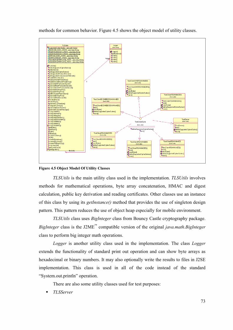
73
methods for common behavior. Figure 4.5 shows the object model of utility classes.
Figure 4.5 Object Model Of Utility Classes
TLSUtils is the main utility class used in the implementation. TLSUtils involves
methods for mathematical operations, byte array concatenation, HMAC and digest
calculation, public key derivation and reading certificates. Other classes use an instance
of this class by using its getInstance() method that provides the use of singleton design
pattern. This pattern reduces the use of object heap especially for mobile environment.
TLSUtils class uses BigInteger class from Bouncy Castle cryptography package.
BigInteger class is the J2ME™ compatible version of the original java.math.BigInteger
class to perform big integer math operations.
Logger is another utility class used in the implementation. The class Logger
extends the functionality of standard print out operation and can show byte arrays as
hexadecimal or binary numbers. It may also optionally write the results to files in J2SE
implementation. This class is used in all of the code instead of the standard
“System.out.println” operation.
There are also some utility classes used for test purposes:
TLSServer

74
TLSClientRSAWithDES
TLSClientRSAWith3DES
TLSClientRSAWithAES
TLSClientRSAWithIDEA
TestClientDHERSAWithDES
TestClientECDHEECDSAWithAES
All these classes implement the interface TLSClientSuite. The class TLSServer is
used to test the protocol implementation as the server. It listens for an incoming
connection request and operates in the server mode of the protocol.
TLSClientRSAWithDES is a test case client with the public key algorithm RSA and
symmetric key algorithm DES. TLSClientRSAWith3DES is a test case client with the
public key algorithm RSA and symmetric key algorithm 3DES. TLSClientRSAWithAES
is a test case client with the public key algorithm RSA and symmetric key algorithm
AES. TestClientDHERSAWithDES is a test case client with the public key algorithm
DHE RSA and symmetric key algorithm DES. TestClientECDHEECDSAWithAES is a
test case client with the public key algorithm ECDHE ECDSA and symmetric key
algorithm AES.
4.6. Exception Classes Architecture
The protocol implementation defines some exception classes used for special
purposes. These exception classes match to different alert types in TLS protocol and
sent to the other peer as a warning or fatal error when occurs. Figure 4.6 shows the
object model of exception classes.
Figure 4.6 Object Model Of Exception Classes
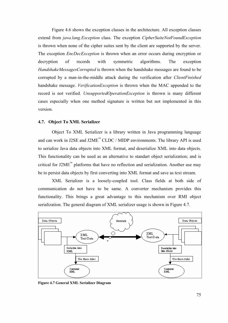
75
Figure 4.6 shows the exception classes in the architecture. All exception classes
extend from java.lang.Exception class. The exception CipherSuiteNotFoundException
is thrown when none of the cipher suites sent by the client are supported by the server.
The exception EncDecException is thrown when an error occurs during encryption or
decryption of records with symmetric algorithms. The exception
HandshakeMessagesCorrupted is thrown when the handshake messages are found to be
corrupted by a man-in-the-middle attack during the verification after ClientFinished
handshake message. VerificationException is thrown when the MAC appended to the
record is not verified. UnsupportedOperationException is thrown is many different
cases especially when one method signature is written but not implemented in this
version.
4.7. Object To XML Serializer
Object To XML Serializer is a library written in Java programming language
and can work in J2SE and J2ME™ CLDC / MIDP environments. The library API is used
to serialize Java data objects into XML format, and deserialize XML into data objects.
This functionality can be used as an alternative to standart object serialization; and is
critical for J2ME™ platforms that have no reflection and serialization. Another use may
be to persist data objects by first converting into XML format and save as text stream.
XML Serializer is a loosely-coupled tool. Class fields at both side of
communication do not have to be same. A converter mechanism provides this
functionality. This brings a great advantage to this mechanism over RMI object
serialization. The general diagram of XML serializer usage is shown in Figure 4.7.
Figure 4.7 General XML Serializer Diagram
76
4.7.1. XML Serializer Design Issues
XML serializer is a library that is designed to work on J2ME™ environment as
well as J2SE™ environment and let field types to be loosely-coupled. To match these
needs, the library should work on minimal subset. The library was written to fulfill this
need. The main design issues of this need are as belows:
XML Parser: The library needs an XML parser to deserialize XML. This
should have to work on CLDC environment as well. There are a few third party
XML parsers for this environment like KXML, Tiny XML, Nano XML. In the
implementation, KXML’s DOM parser was used.
Reflection: Reflection is a standart API is J2SE that is used to gather
information about the class, its fields and methods. In XML serializer,
Reflection property is necessary while generating XML and while deserializing
XML into objects. Unfortunately, there is no Reflection in J2ME™ CLDC /
MIDP. To fulfill reflection need, a preprocessing step was added to serialization
steps. Before using a used-defined data class with this tool, you must generate a
java source code that includes needed reflection properties of this class. This
source code is generated by another library written for this aim. For example, if
you have a class X to be used in serialization, your must add this class name to
an XML file and run source code generator. This process will create a file
named XReflection.java in the same package with X class. Then you must put
both these source files’ compiled .class files into both environments where
serialization and deserialization will be done. Reflection source code generation
process must be done in J2SE environment and the classes must be put into
J2ME™ environment if necessary. In fact, this pre-processing was not needed for
J2SE™ environment but for compatibility, it was added as well. Figure 4.8 shows
the pre-processing step before serialization.
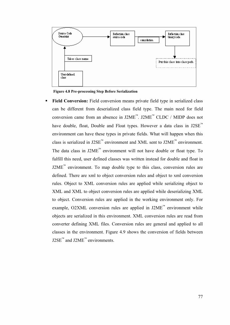
77
Figure 4.8 Pre-processing Step Before Serialization
Field Conversion: Field conversion means private field type in serialized class
can be different from deserialized class field type. The main need for field
conversion came from an absence in J2ME™. J2ME™ CLDC / MIDP does not
have double, float, Double and Float types. However a data class in J2SE™
environment can have these types in private fields. What will happen when this
class is serialized in J2SE™ environment and XML sent to J2ME™ environment.
The data class in J2ME™ environment will not have double or float type. To
fulfill this need, user defined classes was written instead for double and float in
J2ME™ environment. To map double type to this class, conversion rules are
defined. There are xml to object conversion rules and object to xml conversion
rules. Object to XML conversion rules are applied while serializing object to
XML and XML to object conversion rules are applied while deserializing XML
to object. Conversion rules are applied in the working environment only. For
example, O2XML conversion rules are applied in J2ME™ environment while
objects are serialized in this environment. XML conversion rules are read from
converter defining XML files. Conversion rules are general and applied to all
classes in the environment. Figure 4.9 shows the conversion of fields between
J2SE™ and J2ME™ environments.

78
Figure 4.9 Applying Field Conversion Rules In J2ME™ Environment
4.7.2. XML Serializer Architecture
XML Serializer is formed of 3 tags in XML structure:
Elements: Written as ‘c’ in the xml. Has no attributes. Represents Vector,
Collection(LinkedList, ArrayList, etc..) or array types in Java. Elements object
encapsulates elements tag. Includes element or field objects.
Element: Written as ‘e’ in the xml. Has ‘c’ attribute that holds the class name of
the element. Represents any used-defined object that is serialized into XML.
Element object encapsulates element tag. Includes field objects. These fields are
private attributes in the object that have getter and setter methods.
Field: Written as ‘f’ in the xml. Has ‘n’ attribute that holds the name of the
field; has ‘t’ attribute that holds the class type of the field; has ‘v’ attribute that
holds the value of attribute; has ‘a’ attribute that shows if the field is an array
type. Represents a private field in a user defined object that have getter and
setter methods, or wrapper types(like Integer, Long, String) in a collection or
array type.
As described, every tag in XML structure is represented by an object. The object
representing the tag is responsible of generating the part of XML text while serializing
and generating the corresponding object while deserializing. For example, object Field
is responsible for generating XML for the field mapping while serializing, and
generating field object while deserializing. Object model of tag representing objects is
shown in Figure 4.10.
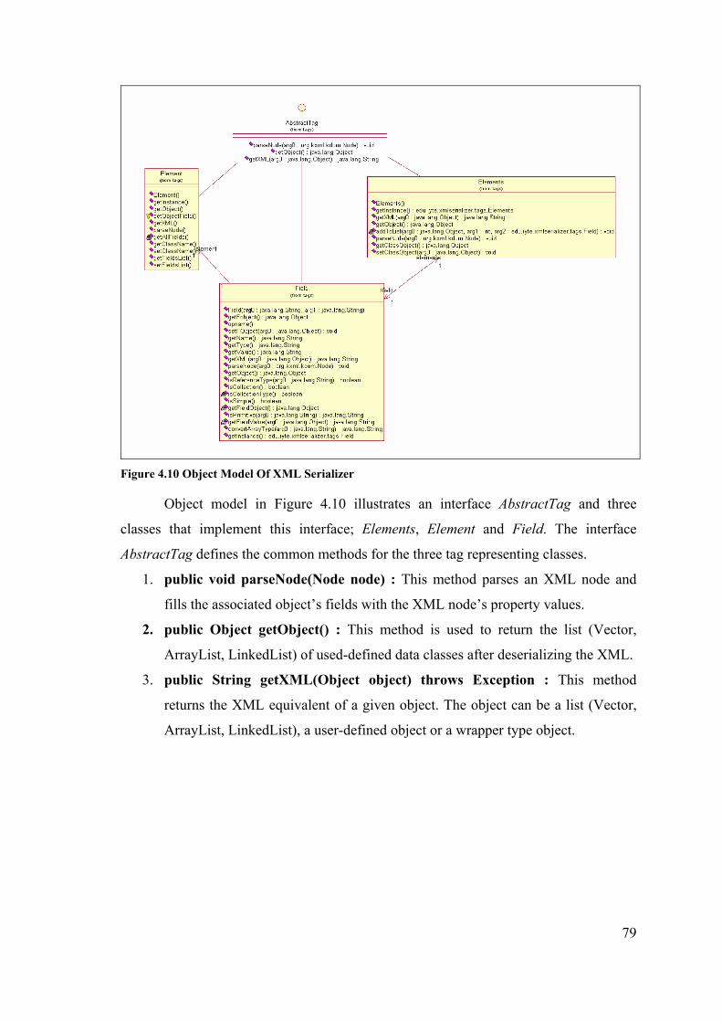
79
Figure 4.10 Object Model Of XML Serializer
Object model in Figure 4.10 illustrates an interface AbstractTag and three
classes that implement this interface; Elements, Element and Field. The interface
AbstractTag defines the common methods for the three tag representing classes.
1. public void parseNode(Node node) : This method parses an XML node and
fills the associated object’s fields with the XML node’s property values.
2. public Object getObject() : This method is used to return the list (Vector,
ArrayList, LinkedList) of used-defined data classes after deserializing the XML.
3. public String getXML(Object object) throws Exception : This method
returns the XML equivalent of a given object. The object can be a list (Vector,
ArrayList, LinkedList), a user-defined object or a wrapper type object.

80
CHAPTER 5
MOBILE SECURITY PROTOCOL IMPLEMENTATION
The mobile end-to-end security protocol is implemented in Java to be compliant
to both J2ME and J2SE platforms. This chapter mentions the implementation details of
the protocol; the development environment, implementation issues and some specific
implementation examples. The chapter includes some coding examples and explains
them. The mobile reservation system developed to test the developed protocol is also
introduced and explained in this chapter.
5.1. Development Environment
The development environment for mobile end-to-end security protocol is
JBuilder 8.0 Enterprise MobileSet 3 Integrated Development Environment. The
development environment was chosen because it has an integrated MIDP application
development support. A project may be compiled with MIDP libraries by changing the
project JDK to J2MEWTK from project properties window. JBuilder IDE was also
chosen for its high performance, code completion feature and user-friendly interface.
JBuilder IDE uses Sun Microsystem’s J2ME Wireless Toolkit for MIDP
development. J2ME Wireless Toolkit (J2MEWTK) is a toolkit that can be used separate
or plugged into a development IDE. It provides development tools and emulators for
MIDP application development. The latest version of J2MEWTK is version 2.1 and this
version is used in the development and test of the developed protocol for mobile
environments. J2MEWTK 2.1 supports MIDP 2.0, CLDC 1.1, optional Wireless
Messaging API (JSR 120), Mobile Media API (JSR 135) and Web Services Access for
J2ME API (JSR 172).
J2ME Wireless Toolkit has the tool Ktoolbar that manages MIDP application
development. Ktoolbar has menu options for creating a new MIDP application, opening
an existing one, compiling and running the application with the set up MIDP version,
changing the J2MEWTK and application preferences. A project created with the
Ktoolbar consists of the following directories:
bin: Includes MIDP application JAD and JAR files.

81
classes: Includes the compiled and pre-verified class files of the application.
lib: Includes the library files used in the application.
res: Includes the resource files used in the applications. These resource files may
be image files that are displayed on the screen and usually accessed with the
following code
Class.getResourceAsStream(“/[resourceName]”)
src: Includes source files of the application
J2MEWTK uses device emulators to run MIDP applications. Device emulators
are software implementations of mobile devices to run and test applications before the
real deployment. Device emulators provide a faster and easier development for mobile
applications. Most mobile phones and PALM™ devices have their emulator software.
Mobile phone emulators are distributed by phone vendors freely. They have the same
operating system and visual interface with the original phone. PALM emulators emulate
PALM OS®. A ROM file is taken from a real PALM™ device with Hotsync connection
and loaded into the emulator software. This gives all the features of the PALM™ device
to the emulator software including program installation and uninstallation.
5.2. Implementation Issues
5.2.1. Programming Language
The programming language used in the implementation of protocol is Java™
programming language. Java™ language was chosen, as it is a widespread and powerful
language. Also as the target platform for the developed protocol application is mobile
devices and the de facto standard for mobile devices has been J2ME affected the choice
of Java programming language.
The advantages of using Java language in the implementation are as follows:
Object-oriented language enables easy architecture development and
implementation.
Java language has a broad support of industry from high-end server
implementations to small wireless device applications.
Java language runs on top of a VM on all platforms that abstracts the language
from the device specific APIs and makes the Java applications portable.
The disadvantages of using Java language in the implementation are as follows:

82
Java language has less performance than native languages like C, in spite of new
performance enhancements with Hotspot™ technology (CLDC HI, e.g.). This is
especially an obstacle for protocol implementations that need high performance.
Java language has a limited API. It can not operate on hardware directly. The
used CLDC / MIDP has the smallest set of API in all Java platforms that
constraints the programmer. The API has been reduced because of size and
performance reasons.
Java has been divided into three platforms: J2EE for server side development,
J2SE for standard desktop applications and J2ME for small, embedded devices. J2ME
has its own configurations and profiles (see Chapter 3, Section 3.1.4, “Mobile Device
Configuration Layer”). Each configuration and profile has its own library APIs. The
main target Java platform for the mobile security protocol is J2ME platform. The
configuration is CLDC and the profile is MIDP. This fact caused CLDC / MIDP APIs
to be used in the implementation of the protocol.
Most CLDC / MIDP language APIs are also valid in J2SE platform, that makes
the developed protocol also compliant to this platform. However, because of the limits
of mobile devices, network connection library has been changed. J2ME uses Generic
Connection Framework (GCF) for all kinds of connections including network and file
connections. This brings a lighter connection API when compared with the heavy
network API of J2SE platform. J2ME version of the protocol uses GCF and the J2SE
version uses java.net package for network connections.
5.2.2. Coding Standards
Coding standards are the base rules that an application code must obey. Coding
standards are necessary for a readable and maintainable code. The mobile end-to-end
security protocol implementation code obeys the following coding standards: naming
conventions and package hierarchy.
5.2.2.1. Naming Conventions
Naming of the files and variables is very important for the readability of the
code. Names must be meaningful and must give info about its owner. The protocol
application has its own naming conventions. Package names give information about the
aim of its class files. Most Java class file names start with “TLS” that gives a

83
standardization to file names. Handshake message classes take the name of the
matching message name after the “TLS” extension. For example, the message
ClientFinished has the class file TLSClientFinished. Implementation classes have the
extension “Impl” at the end of the class names. These classes have the code segments
that have business logic and that mainly behaves as the controller. Class
HandshakeLayerImpl, RecordLayerImpl, TLSTCPSocketImpl are examples of these
classes. Variable and method names in classes have mostly meaningful English names.
5.2.2.2. Package Hierarchy
Classes in protocol implementation are organized as packages. Packages have
meaningful names and reflect the content of its classes. The protocol application has
two main groups of packages: Packages starting with “edu” and packages starting with
“org”. Packages starting with “edu” have been developed for the protocol application.
They have two main sub-packages:
edu.iyte.crypto
edu.iyte.xmlserializer
The package “edu.iyte.crypto“ includes class files for security protocol and
cryptography abstraction classes. It has the following sub-packages in hierarchy:
edu.iyte.crypto.micro
edu.iyte.crypto.micro.tls
edu.iyte.crypto.micro.tls.exception: Includes protocol layer exception classes
(see Chapter 4, Section 4.6, “Exception Classes Architecture”).
edu.iyte.crypto.micro.tls.handshakelayer: Includes handshake layer message
classes (see Chapter 4, Section 4.3.1, “Handshake Message Classes”).
edu.iyte.crypto.micro.tls.handshakelayer.encryption: Includes handshake layer
public key encrption classes (see Chapter 4, Section 4.3.2, “Key Exchange And
Authentication Classes”).
edu.iyte.crypto.micro.tls.handshakelayer.keyagreement: Includes handshake
layer key agreement classes (see Chapter 4, Section 4.3.2., “Key Exchange And
Authentication Classes”).
edu.iyte.crypto.micro.tls.handshakelayer.signer: Includes handshake layer digital
signature classes (see Chapter 4, Section 4.3.2., “Key Exchange And
Authentication Classes”).
84
edu.iyte.crypto.micro.tls.implementation: Includes main controller classes for
the protocol application (see Chapter 4, Section 4.2., “Main Architecture”).
edu.iyte.crypto.micro.tls.recordlayer: Includes record layer classes (see Chapter
4, Section 4.4., “Record Layer Architecture”).
edu.iyte.crypto.micro.tls.recordlayer.encryption: Includes record layer private
key encryption classes (see Chapter 4, Section 4.4.1., “Encryption”).
edu.iyte.crypto.micro.tls.recordlayer.mac: Includes record layer MAC classes
(see Chapter 4, Section 4.4.2., ”Message Authentication Code”).
edu.iyte.crypto.micro.tls.recordlayer.parameters: Includes record layer parameter
classes.
edu.iyte.crypto.micro.tls.utils: Includes utility classes for security protocol (see
Chapter 4, Section 4.5, “Utility Classes Architecture”).
edu.iyte.crypto.micro.utils: Includes utility classes for test cases and other uses.
The package “edu.iyte.xmlserializer” includes class files for object to xml
serialization and deserialization. It has the following sub-packages in hierarchy:
edu.iyte.xmlserializer.parser: Includes main API class XMLParser.
edu.iyte.xmlserializer.tags: Includes xml serializer tag representing classes.
edu.iyte.xmlserializer.util: Includes utility classes for field conversion.
Packages starting with “org” are libraries developed by third parties and used by
the implementation. The package “org.bouncycastle” is the main package for Bouncy
Castle Cryptography Library class files and the package org.kxml is the main package
for KXML library class files.
5.2.3. Implementation Versions
The mobile end-to-end security protocol implementation has two versions: one
for J2ME platform and one for J2SE platform. The two versions have the same
architecture and very similar implementations. The core of the protocol implementation
is based on J2ME CLDC / MIDP Java language rules and libraries that are also
compliant to J2SE platform. The following issues were regarded in implementation to
provide the compliant versions:
Vector class type was used instead of List or Collection interfaces implementing
classes that are missing in J2SE environment.
No double or float data types were used, as they are missing in CLDC profile.

85
Both third-party libraries used (KXML and Bouncy Castle) were chosen as they
can work on both J2SE and J2ME platforms.
No class type java.io.File was used in the code to write logs. This class type is
not present in MIDP.
No serialization or reflection feature was used in the implementation. To avoid
these, a new method that was used instead of reflection was developed in the
XML Serializer library design and implementation.
The main difference between two versions is network connection application
programming interfaces.
5.3. Implementation Of The Security Protocol
5.3.1. Network Connections
The security protocol implementation needs secure network connections to send
and receive data between peers. Network connection implementations are abstracted
from business logic classes and appear in socket classes that are used by other classes
(see Chapter 4, Section 4.2, “Main Architecture”).
J2ME uses Generic Connection Framework (GCF) and J2SE uses java.net
package network connection classes to provide network connections. The protocol
implementation may use TCP and UDP sockets and server sockets for network
connections between client and server. The socket connection type is determined by the
following constants in class TLSSocket:
SOCKET_IMPL_CLASS
SERVERSOCKET_IMPL_CLASS
These constants define the socket implementation classes for socket and server
socket. The default value of SOCKET_IMPL_CLASS constant is
“edu.iyte.crypto.micro.tls.implementation.TLSTCPSocketImpl” and the default value of
SERVERSOCKET_IMPL_CLASS is “edu.iyte.crypto.micro.tls.implementation.
TLSTCPServerSocketImpl”. The socket implementation classes may be changed to
other socket connections by only changing these constant values. For example,
connection may be UDP based by changing the value of SOCKET_IMPL_CLASS to
“edu.iyte.crypto.micro.tls.implementation.TLSUDPSocketImpl”. Other socket
implementation classes may also be added later.
86
In J2SE version, the following code is used to provide a stream-based (for TCP
connection) connection:
Socket socket = new Socket(url, port);
DataInputStream in = new DataInputStream(socket.getInputStream());
DataOutputStream out = new DataOutputStream(socket.getOutputStream());
This code segment opens a socket connection with the specified host at a
requested port and takes input and output streams for reading and writing data. This
code is used to provide a connection from client side of the protocol to the server side.
The same operation is done with the following code in J2ME MIDP version of the
protocol implementation:
StreamConnection socket = (StreamConnection)Connector.open(url + port);
DataInputStream in = new DataInputStream(socket.openInputStream());
DataOutputStream out = new DataOutputStream(socket.openOutputStream());
As it can be seen from the code segments, the only difference between two
versions is in the first line of the code. J2ME version uses the class Connector and gives
the parameters url and port to it to provide a parametric connection. The syntax of the
url is “socket://[remote adress]:” and the port can be 5000 for an application using the
protocol implementation. The class StreamConnection was used instead of the class
Socket for socket type as class StreamConnection is present in MIDP 1.0 while class
Socket has been added since MIDP 2.0.
Server sockets are used in server side of the protocol to receive connection
requests and to establish a connection with the client. The following code segment is
used to provide a server socket and to receive connections in J2SE version of the
implementation:
ServerSocket serverSocket = new ServerSocket(this.getPort());
while (true)
{
Socket socket = serverSocket.accept();
this.in = new DataInputStream(socket.getInputStream());
this.out = new DataOutputStream(socket.getOutputStream());
}
The code segment above listens for connection requests at a specified port,
opens a socket connection for the connections and receives the input and output streams
for of the connection. The same operation is performed with the following code in
87
J2ME version:
StreamConnectionNotifier serverSocket =
(StreamConnectionNotifier)Connector.open(this.getUrl() + this.getPort() );
while (true)
{
StreamConnection socket = serverSocket.acceptAndOpen();
this.in = new DataInputStream(socket.openInputStream());
this.out = new DataOutputStream(socket.openOutputStream());
}
The code segment above uses Generic Connection Framework for listening to
socket. It uses the class StreamConnectionNotifier instead of the class ServerSocket as
the class StreamConnectionNotifier is present in both MIDP 1.0 and MIDP 2.0 while
class ServerSocket has been added since MIDP 2.0. The syntax of the url is “socket://:”.
An alternative way of network connections in mobile security protocol
implementation is datagram-based UDP sockets. UDP is not reliable protocol and the
implementation does not guarantee its reliability. The following code segment was used
to provide a datagram connection from client to server in J2SE environment:
DatagramSocket socket = new DatagramSocket(localPort);
DatagramPacket sendPacket = new DatagramPacket(b, b.length);
sendPacket.setAddress(InetAddress.getByName(url));
sendPacket.setPort(port);
The code above opens a datagram socket connection at a specified port and
creates a datagram packet to send from that port to the requested url. The same
operation is performed with the following code in J2ME MIDP version:
DatagramConnection socket = (DatagramConnection)Connector.open(url + port);
Datagram sendPacket = socket.newDatagram(b, b.length);
This code also uses GCF to provide a datagram-based connection. The syntax of
the url is “datagram://[remote adress]:”.
5.3.2. Multithreading
Multithreading is the concurrent execution of threads. The mobile end-to-end
security protocol has a multithreaded implementation for its server socket classes.
Server socket classes need to listen for a connection request and open a socket for each
connection. A single-threaded implementation would be able to handle only one secure

88
connection. This problem is solved by server socket classes running in separate threads.
Classes TLSTCPServerSocketImpl and TLSUDPServerSocketImpl listen for
connections. When they receive a connection, they create an instance of the class
TLSServerSocket and run it in a separate thread. This is achieved as the class
TLSServerSocket implements the interface java.lang.Runnable. TLSServerSocket
manages the handshake and data transmission of one client at server side. There is the
number of TLSServerSocket thread instances as much as the number of active clients.
The classes TLSTCPServerSocketImpl and TLSUDPServerSocketImpl also run
in separate thread from the main thread as they block the execution. However, they have
only one instance of thread at a time.
5.3.3. Message Transmission
Message transmission involves the transmission of messages at application
level. These messages are handshake messages and user data messages sent over secure
protocol.
Handshake messages are designed as classes in the architecture (see Chapter 4,
Section 4.3.1, “Handshake Message Classes”). The data of the messages was put as
private attributes of these classes. The class objects are sent from one side of the
communication to the other side by using the XML serializer library, mentioned in
Chapter 4, Section 4.7, “Object To XML Serializer”.
XML Serializer needs the class metadata at runtime. The lack of reflection API
in J2ME platform caused a new method to be developed instead of reflection. This
method involves the source code generation for class metadata. There is a class called
SourceGenerator that generates a class file having the metadata info of the class, in
J2SE version of the implementation. SourceGenerator generates a Java file with the
class file’s name having the extension “Reflection” at the end. The reflection class is put
at the same directory with the original class. While the original class is serialized or
deserialized, the reflection file is looked up and the referencing class file metadata info
is taken.
XML Serialization is used to serialize handshake message classes in the protocol
implementation. The reflection class files for all handshake message classes are
generated by the SourceGenerator code generator tool. The following steps were done
to provide the serialization of message classes:

89
Put the names of the handshake message classes in reflection.xml file, between
convert tags.
Run SourceGenerator class file. This produces class files with the end of names
as “Reflection” in the same packages.
Put XML serialization and deserialization codes in socket implementation
classes. These codes serialize objects into XML byte streams and the reverse.
The following code segment serializes a given object into XML:
XMLParser parser = XMLParser.getInstance();
String xml = parser.generateXML(object);
ByteArrayInputStream stream = new ByteArrayInputStream(xml.getBytes());
The following code segment deserializes XML data into objects:
XMLParser parser = XMLParser.getInstance();
is.reset(); //is is a variable of type InputStream
Vector vector = (Vector) parser.consumeXML(is);
5.4. Use Of The Security Protocol Library
Mobile end-to-end security protocol was implemented to be used in high-level
applications for secure transmission of object data. In this section, a sample application
will be introduced that uses the developed security protocol implementation. The
application is a web-based hospital reservation system that was designed and developed
by the author of this thesis [42]. The hospital reservation system was chosen as the
sample application as it has a working and extensible architecture. The application was
developed to be reached over web browsers, but in this work it is extended to support
mobile client as well. The integration to support this extensibility for both client and
server-side will also be explained in the proceeding subsections.
5.4.1. Hospital Reservation System
Hospital Reservation System is a web-based J2EE (Java 2 Enterprise Edition)
application. This application has three related parties:
Patient: Hospital reservation system lets patients to take reservation from the
doctors over a web browser. The user registers and logs into a web site where he
has access only to his information. In this web site, the user (patient) may take
reservation from any of the listed doctors he wants, at the requested date and
time; browse his reservation requests and the current states of them; the

90
available units and doctors for reservation system and his personal information.
After the patient requests a reservation by using this web application, he may
learn the result of the reservation request in three ways:
o By looking at the same web site
o By the e-mail reaching to him
o By phoning the phone number given to him at the end of the reservation
request process
Figure 5.1 shows the reservation request screen of the patient web site of the
application.
Figure 5.1 Reservation Request Screen Of The Hospital Reservation System
Unit Secretary: Each unit has its own web site that they can see the reservation
requests filled for the doctors of the unit. Unit secretary side may be a real
secretary or the doctor himself; this fact does not affect the application. Unit
secretary may either accept or deny the reservation requests. He may also query
the patients, learn and change the reservation system related information of the
physicians (like examination costs) and unit. Figure 5.2 shows the reservation
request evaluation screen of the unit secretary web site of the application.
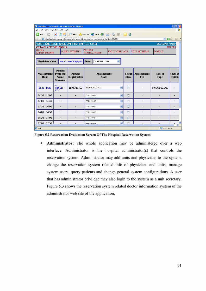
91
Figure 5.2 Reservation Evaluation Screen Of The Hospital Reservation System
Administrator: The whole application may be administered over a web
interface. Administrator is the hospital administrator(s) that controls the
reservation system. Administrator may add units and physicians to the system,
change the reservation system related info of physicians and units, manage
system users, query patients and change general system configurations. A user
that has administrator privilege may also login to the system as a unit secretary.
Figure 5.3 shows the reservation system related doctor information system of the
administrator web site of the application.
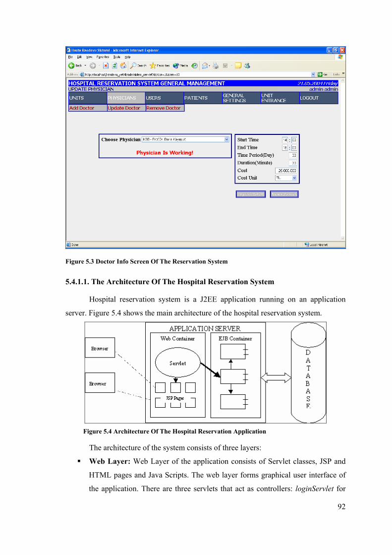
92
Figure 5.3 Doctor Info Screen Of The Reservation System
5.4.1.1. The Architecture Of The Hospital Reservation System
Hospital reservation system is a J2EE application running on an application
server. Figure 5.4 shows the main architecture of the hospital reservation system.
Figure 5.4 Architecture Of The Hospital Reservation Application
The architecture of the system consists of three layers:
Web Layer: Web Layer of the application consists of Servlet classes, JSP and
HTML pages and Java Scripts. The web layer forms graphical user interface of
the application. There are three servlets that act as controllers: loginServlet for

93
the patient side, yetkiliServlet for the unit secretary side and adminServlet for the
administrator side. Each servlet directs the requests to the requested JSP pages
which are the view part of the MVC (Model-View-Controller) architecture.
EJB Layer: EJB Layer of the application consists of EJB (Enterprise Java
Beans) components. There are 7 of them: 2 of them as stateful session bean, 3 of
them as stateless session bean and 2 of them as entity beans. These EJB
components access the database and perform the business related tasks. EJB
components are lightweight versions of its predecessor CORBA components and
run in the server-side. EJB components are multithreaded, have their security
model and usable by both web applications (Servlets) and desktop applications.
Hospital Reservation System accesses these enterprise beans from web
applications.
Database Layer: Database Layer of the application consists of database tables
and data. The application uses Oracle Database, but is not dependent on database
vendor. The data in the database tables is accesses and updated by SQL scripts
in EJB components.
5.4.2. Mobile Hospital Reservation System
Although the hospital reservation system application was web-based, it was
designed to be scalable and support other access media as well. Mobile devices are
among these access media. These mobile devices are mainly mobile phones that will
access the main system over GPRS.
Mobile hospital reservation system is an extension to the hospital reservation
system to support the mobile devices to access the main system. The extension was
designed to match the following issues:
The mobile hospital reservation system must use the same architecture and
components as the web-base hospital reservation system. The existing EJB
components must be used for business operations and database transactions. No
new business code must be added.
The mobile application must be a part of the main hospital reservation system.
Users must be able to access the system via mobile phones as well as web
browsers. Two media must have similar user interfaces, as much as possible.
The mobile application must be a separate layer in the whole hospital

94
reservation system in the server side. It must be plugable and must not interfere
with the already existing application components.
The mobile clients must have thick-client user interfaces; that would be ideally
developed with J2ME MIDP.
The mobile client application must communicate with the server-side mobile
application layer with the proposed and developed mobile security protocol. The
mobile client must request an action and the server must perform the action by
using the EJB components of the hospital reservation system. Results must be
sent to the client at object level by using the established secure connection.
The establishment of the secure connection must be performed before login
operation and closing of the secure connection must be performed after logout
operation.
Mobile version of the hospital reservation system was aimed to support the
patients’ reservation requests from the doctors. The patients will login to the system as
in the web application, choose the unit, doctor and time duration they want to have
examination and will request for a reservation. The selected attributes will be sent to the
main system over the secure connection protocol implemented; the desired operations
will be performed by the EJB component and the result will be sent to the mobile device
over the secure connection. As the secure connection will be at application level, it can
be over GPRS connection that provides the real communication. The mobile application
scenario is small as it is used to provide a scalable architecture and to test the developed
mobile end-to-end security protocol.
The architecture of the mobile hospital reservation system does not change the
hospital reservation system architecture, shown in Figure 5.4, but has some additions to
it. The architecture consists of two parts:
Server-Side Of The Mobile Application
Client-Side Of The Mobile Application
5.4.2.1. Server-Side Architecture Of The Mobile Hospital Reservation System
The server-side architecture of the mobile application is shown in Figure 5.5.

95
Figure 5.5 Architecture Of The Server Side Of Mobile Hospital Reservation System
The server side of the mobile hospital reservation system is included in the
hospital reservation system web application. The integration is provided by the servlet
MobileServlet. This servlet is initialized when the hospital reservation system
application is invoked. The MobileServlet runs the MobileAdapter in a separate thread.
The class MobileAdapter is the class where the server socket listener is set. By this way,
the server listens for secure connection requests at the specified port. This done by the
following code segment in the run method of MobileAdapter class.
TLSSocketFactory factory = TLSSocketFactory.getInstance();
TLSServerSocketListener listener = (TLSServerSocketListener) factory.
createSocket(TLSSocketFactory.SERVER_SOCKET);
listener.setURL("localhost");
listener.setPort(5002);
listener.setLocalPort(5001);
TLSSocketImpl impl = listener.accept(this);
impl.addConnectionNotifier(this);

96
The code segment above creates a server socket by using the mobile security
protocol library at port 5001. The last line of code adds this class as the connection
notifier for mobile security application. The connection notifier is the application of the
observer pattern in mobile security application. The security protocol application calls
the following method when the secure connection is established between a client and a
server.
public void connectionStarted(TLSSocket socket)
{
System.out.println("connection started");
MobileUser user = new MobileUser(socket);
}
In the code segment above, a mobile user instance is created when a secure
connection starts, and a TLSServerSocket class instance is given as a parameter. The
class MobileUser is the server-side representative of a mobile client. Each mobile client
has an instance of class MobileUser in the server-side. This class also implements the
ConnectionNotifier interface and listens to secure connection events. The used event in
this class is receiving of objects in the secure session, as shown in the code segment
below:
public void objectReceived(Object object)
{
if (object instanceof Action)
{
long actionNo = ( (Action) object).getActionNo();
HandlerManager manager = new HandlerManager();
manager.process((int)actionNo, socket);
}
}
The code segment above receives the action from the client and sends this action
and the user’s active socket to the HandlerManager classes’s process method. The
model between a mobile client and a server is a request-response oriented model. This
model is achieved by the actions and the associated action handler classes defined. The
class HandlerManager is a controller class that directs the actions to the associated
action handler classes. The actions defined for the developed mobile application are as
follows:
97
public static final int PATIENT_LOGIN_VERIFY = 1;
public static final int GET_ALL_UNITS = 2;
public static final int GET_PHYSICIANS = 3;
public static final int GET_ PHYSICIANS_FREE_HOURS = 4;
public static final int MAKE_RESERVATION = 5;
Each action has an associated action handler class. As shown in Figure 5.5, all
action handler classes implement the interface RequestHandler. This interface has a
method
public Object processRequest(TLSSocket socket) throws Exception
that is called by the HandlerManager class to process the action requests.
Action handler classes receive the object data sent from mobile clients over the
secure connection established. They use the TLSServerSocket classe’s receiveObject()
method for this target. Each action handler class has an instance of class MobileUtils
that is used as a proxy between the hospital reservation system EJB layer and the mobile
application layer. The class MobileUtils accesses the ReservationEJB,
SystemTransactionsEJB and UserEJB enterprise beans to add the reservation request, to
query physicians and units and to verify login info. The result data is sent to mobile
clients over the secure connection by using the TLSServerSocket classe’s sendObject()
method. The data sent can be either a user-defined object type, or a wrapper type like
java.lang.Boolean.
5.4.2.2. Client-Side Architecture Of The Mobile Hospital Reservation System
The client side of the mobile hospital reservation system is a J2ME MIDP
application that is aimed to work on mobile phones supporting MIDP 1.0. The user
interfaces of the application are implemented with the MIDP’s lcdui API. The
connection with the server is established with the mobile end-to-end security protocol
implementation proposed in this thesis. The client-side architecture of the mobile
application is shown in Figure 5.6.
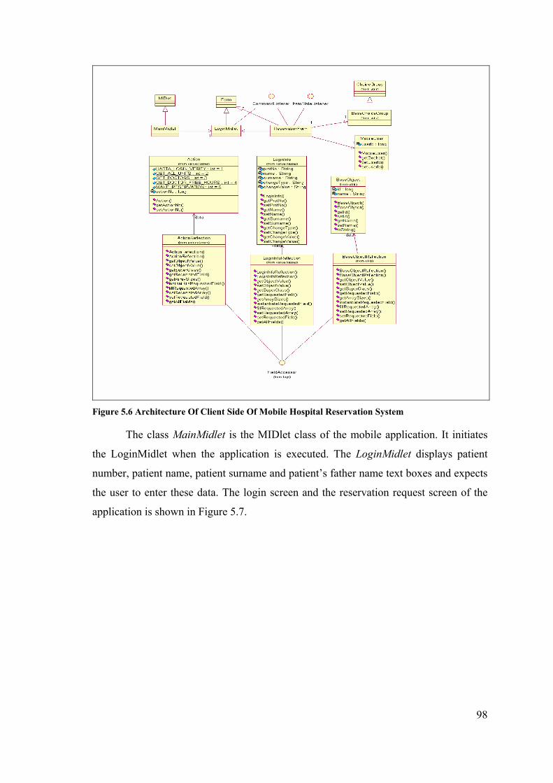
98
Figure 5.6 Architecture Of Client Side Of Mobile Hospital Reservation System
The class MainMidlet is the MIDlet class of the mobile application. It initiates
the LoginMidlet when the application is executed. The LoginMidlet displays patient
number, patient name, patient surname and patient’s father name text boxes and expects
the user to enter these data. The login screen and the reservation request screen of the
application is shown in Figure 5.7.

99
Figure 5.7 User Interface Screens Of Mobile Hospital Reservation System
The screens above were taken by running the program on an MIDP device
emulator.
As the user requests to log in to the system, the user information entered is
received and stored in the LoginInfo class object. A secure connection is established by
using the secure connection protocol library developed. The code segment below does

100
the connection establishment work:
TLSSocketFactory factory = TLSSocketFactory.getInstance();
TLSClientSocket clientSocket = (TLSClientSocket)
factory.createSocket(TLSSocketFactory.CLIENT_SOCKET);
clientSocket.setPort(5002);
clientSocket.setLocalPort(5001);
clientSocket.setUrl("socket://localhost:");
clientSocket.performHandshake();
The code segment above creates a client socket for secure connection and
performs handshake procedure with the server side secure connection listener. If the
handshake steps are successful, a TLSClientSocket instance is returned to the mobile
application. This TLSClientSocket instance is used to send and receive object data.
These object data can be user-defined objects or wrapper types (like java.lang.Boolean).
As mentioned in Section 5.4.2.1, “Server Side Architecture Of Mobile Hospital
Reservation System”, the communication between client and server has a request-
response oriented model. This is achieved by sending the object Action with the
requested action parameter over the TLSClientSocket class instance’s sendObject()
method. The second object sent is application-screen defined. In the login scenario, it is
the LoginInfo object. The mobile security protocol implementation receives the
LoginInfo object, serializes it into XML by using the XML serializer library and sends
the XML data to the server by encoding it with the security parameters generated during
handshake. All these steps are transparent to the application and occur at mobile
security application level. The class LoginInfoReflection, shown in Figure 5.6, is a
generated class to give the reflection properties of LoginInfo class used during XML
serialization (see Section 5.3.3, “Message Transmission”).
The user sees the reservation request screen as he logs in to the system. At this
screen, the list of units available for reservation is queried from the server reservation
system and displayed. As the user selects a unit, the physicians of this unit are displayed
and as the user selects a physician, the free hours of this physician are shown in the
screen. All the data transfer between the client and the server is performed with the
secure connection established. After selection operation is completed, the user may
request a reservation. At this time, the reservation request action is sent before the
selected reservation request parameters. The server performs the reservation process by

101
using the EJB components of hospital reservation system and returns the result state to
the mobile client. The user may close the secure connection by logging out the
application.

102
CHAPTER 6
MOBILE END-TO-END SECURITY PROTOCOL TEST RESULTS
Mobile end-to-end security protocol was designed and implemented to have a
reliable and maintainable protocol implementation that would have acceptable
performance results. This chapter mentions about the tests made to the protocol
implementation to measure the performance averages. The chapter presents the scope of
tests, the platform tests were performed, different test cases prepared and the evaluation
of the test results. The result values of those test cases are given in Appendix.
6.1. Scope Of The Test Cases
The mobile end-to-end security protocol tests involve the running performance
tests of both the client and server modes of the protocol with different cipher suites and
in different Java VMs. Tests will be made in both J2SE and J2ME platforms. The secure
connection will be established with different cipher suites and both TCP and UDP will
be used as the underlying network connection protocol.
The tests of the protocol is divided into two main sections:
Test of the handshake procedure
Test of the application level object transmission and receiving
As the handshake procedure has many steps, it is divided into different time
spans. By this way, it is aimed to measure the real performance of the steps and to
define bottlenecks in the protocol implementation. Some time spans will only be
available in specific cipher suites. Table 6.1 shows the time spans in both server and
client modes of the protocol.
Table 6.1 Mobile Security Protocol Time Spans Used In Tests
Operation Server Client Public key signing √ Public key verification √ Key pair generation √ √ Pre-master secret generation √ √ Master secret generation √ √ TLS keys generation √ √ All handshake √ √

103
Tests will be performed by using different cipher suites. The naming convention
of the cipher suites was explained in chapter 2, section 2.1.2.3, “TLS Cipher Suites”.
Server side of the test program supports all cipher suites available to the mobile security
protocol implementation. Each test client supports only one cipher suite and requests the
handshake to be performed with this cipher suite when it sends ClientHello message to
to the server. Thus, the connection will be established with this cipher suite. Table 6.2
shows cipher suites used in the protocol tests. The first cipher suite in table 6.2 is non-
ephemeral that means asymmetric keys are not generated at run-time. The other cipher
suites in table 6.2 are ephemeral that means asymmetric keys are generated at run-time.
Test results given in Appendix are organized to compare ephemeral cipher suite results
with each other. The other comparison given in tables in Appendix is between non-
ephemeral RSA and ephemeral RSA.
Table 6.2 Cipher Suites Used In Protocol Tests
Cipher Suite Authentication & Key Exchange Algorithm
Symmetric Algorithm
Hash Algorithm
TLS_RSA_WITH_AES_CBC_SHA RSA AES SHA TLS_RSA_EXPORT_WITH_RC2_CBC_40_MD5 RSA_EXPORT RC2 MD5 TLS_DHE_RSA_WITH_DES_CBC_SHA DHE_RSA DES SHA TLS_ECDHE_ECDSA_WITH_AES_128_CBC_SHA ECDHE_ECDSA AES SHA
The same test cases will be repeated with both TCP and UDP network protocols
behind the secure protocol. TCP (Transmission Control Protocol) is the recommended
network protocol to be used with TLS in TLS 1.0 Specification [2]. It establishes a
secure connection between the peers and guarantees data packet delivery. UDP (User
Datagram Protocol) does not establish connections and is an unreliable protocol. TLS
1.0 Specification does not mention the use of UDP with TLS, but it was added to the
protocol implementation for test purposes. As the UDP protocol does not establish a
connection, it is expected that UDP tests will have better performance results.
Mobile end-to-end security protocol was designed and implemented to be run on
J2ME CLDC / MIDP platforms including cellular phones and PALM PDAs. But by its
extensible architecture, it may also run on J2SE VMs that allows the protocol
implementation to be used in desktop server machines. By taking care of these issues,
the following architectures are defined for protocol tests:
J2SE–J2SE: Both server and client applications of the protocol implementation
run on J2SE platform.
104
J2SE–J2ME: Server side of the protocol implementation run on J2SE platform
and client side of the protocol implementation run on J2ME platform.
J2ME–J2ME: Both server and client applications of the protocol implementation
run on J2ME platform.
The tests will be performed according to the following test scenario:
A server listening to secure connection requests
A client requesting a connection with the server
Performance of the handshake procedure
Sending of a test object from client to server over the secure connection
established. The test object is called Person that has the private attributes id,
name and surname.
6.2. Desktop Tests
Desktop tests are performed on a standalone personal computer. Both the client
and server test programs run on this computer, whether on J2SE VMs or on the device
emulator environment. There is no network between client and server programs, so no
network overhead is measured. The measured values are the exact running times of the
mobile security protocol implementation.
6.2.1. Desktop Test Platform Configuration
The test programs on the desktop computer are run on a Pentium-III with 256
MB RAM and 20 GB HD space. Different test platforms are established for different
architectures mentioned in Section 6.1, “Scope Of The Tests”.
J2SE-J2SE architecture will be tested by running client and server test programs
on J2SE VMs on the desktop tests. The version of Java VM used is “Java Hotspot™
Client VM (build 1.4.0-rc-b91, mixed mode)”. Test programs were written to run the
protocol implementation in both server and client modes. These programs are run from
batch files (.bat) prepared. Both server and client programs will be run on the same
computer to prevent network overheads and to be able to measure the real performance
of the protocol implementation. Some logging code was added to the protocol
implementation code to be able to measure the performance times of time spans defined
and show them in standard output. The test scenario given in Section 6.1 will be
105
repeated 100 times one after each other and the highest (max), lowest (min) and average
(total / 100) values will be measured.
J2SE-J2ME architecture will be tested by using the server program used in
J2SE-J2SE architecture for server-side and a J2MEWTK (Wireless Toolkit) device
emulator for client side on the desktop tests. The server program will be run from the
batch file and the client will be run from the device emulator environment. The same
test scenario will be used with J2SE-J2SE architecture and the results will be measured
as the average, highest and lowest values of 100 times running of the test scenario in a
loop.
J2ME-J2ME architecture will be tested by running both server and client test
programs on device emulators on desktop tests. At this case, one device emulator will
run the server test program and the other device emulator will run the client test
program. The same test scenario will be used with J2SE-J2SE architecture and the
results will be measured as the average, highest and lowest values of 100 times running
of the test scenario in a loop.
6.2.2. Desktop Test Cases With TCP
Tests were performed in the scope and configuration told in Section 6.1 and
6.2.1. This section mentions about the test case results measured when the tests are
performed on a single desktop PC and the underlying transport protocol between is
TCP. Thus, the constant parameter in tests is TCP transport protocol; the other
parameters are variable. The test case results will be explained in tables according to the
architectures they were made and the cipher suites agreed upon. Same tests were
repeated for 100 times. The average, max and min values of time spans defined are
given in Appendix and the related charts will be given to compare the results. All the
values in tables and charts are milliseconds (ms). “0” value in tables mean that the time
duration is below milliseconds. N/A value in tables means that the time span is not
applicable in the cipher suite.
Table A.1 and table A.2 in Appendix chapter show the secure communication
time span durations when both client and server side of the implementation run on J2SE
platform and transport protocol between is TCP. Table A.1 compares ephemeral cipher
suites. This comparison is made as all ephemeral cipher suites generate asymmetric
keys at run-time. Table A.2 compares ephemeral RSA (RSA export) and non-ephemeral
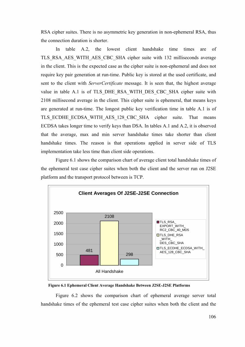
106
RSA cipher suites. There is no asymmetric key generation in non-ephemeral RSA, thus
the connection duration is shorter.
In table A.2, the lowest client handshake time times are of
TLS_RSA_AES_WITH_AES_CBC_SHA cipher suite with 132 milliseconds average
in the client. This is the expected case as the cipher suite is non-ephemeral and does not
require key pair generation at run-time. Public key is stored at the used certificate, and
sent to the client with ServerCertificate message. It is seen that, the highest average
value in table A.1 is of TLS_DHE_RSA_WITH_DES_CBC_SHA cipher suite with
2108 millisecond average in the client. This cipher suite is ephemeral, that means keys
are generated at run-time. The longest public key verification time in table A.1 is of
TLS_ECDHE_ECDSA_WITH_AES_128_CBC_SHA cipher suite. That means
ECDSA takes longer time to verify keys than DSA. In tables A.1 and A.2, it is observed
that the average, max and min server handshake times take shorter than client
handshake times. The reason is that operations applied in server side of TLS
implementation take less time than client side operations.
Figure 6.1 shows the comparison chart of average client total handshake times of
the ephemeral test case cipher suites when both the client and the server run on J2SE
platform and the transport protocol between is TCP.
Client Averages Of J2SE-J2SE Connection
481
2108
298
0
500
1000
1500
2000
2500
All Handshake
TLS_RSA_EXPORT_WITH_RC2_CBC_40_MD5TLS_DHE_RSA_WITH_DES_CBC_SHATLS_ECDHE_ECDSA_WITH_AES_128_CBC_SHA
Figure 6.1 Ephemeral Client Average Handshake Between J2SE-J2SE Platforms
Figure 6.2 shows the comparison chart of ephemeral average server total
handshake times of the ephemeral test case cipher suites when both the client and the
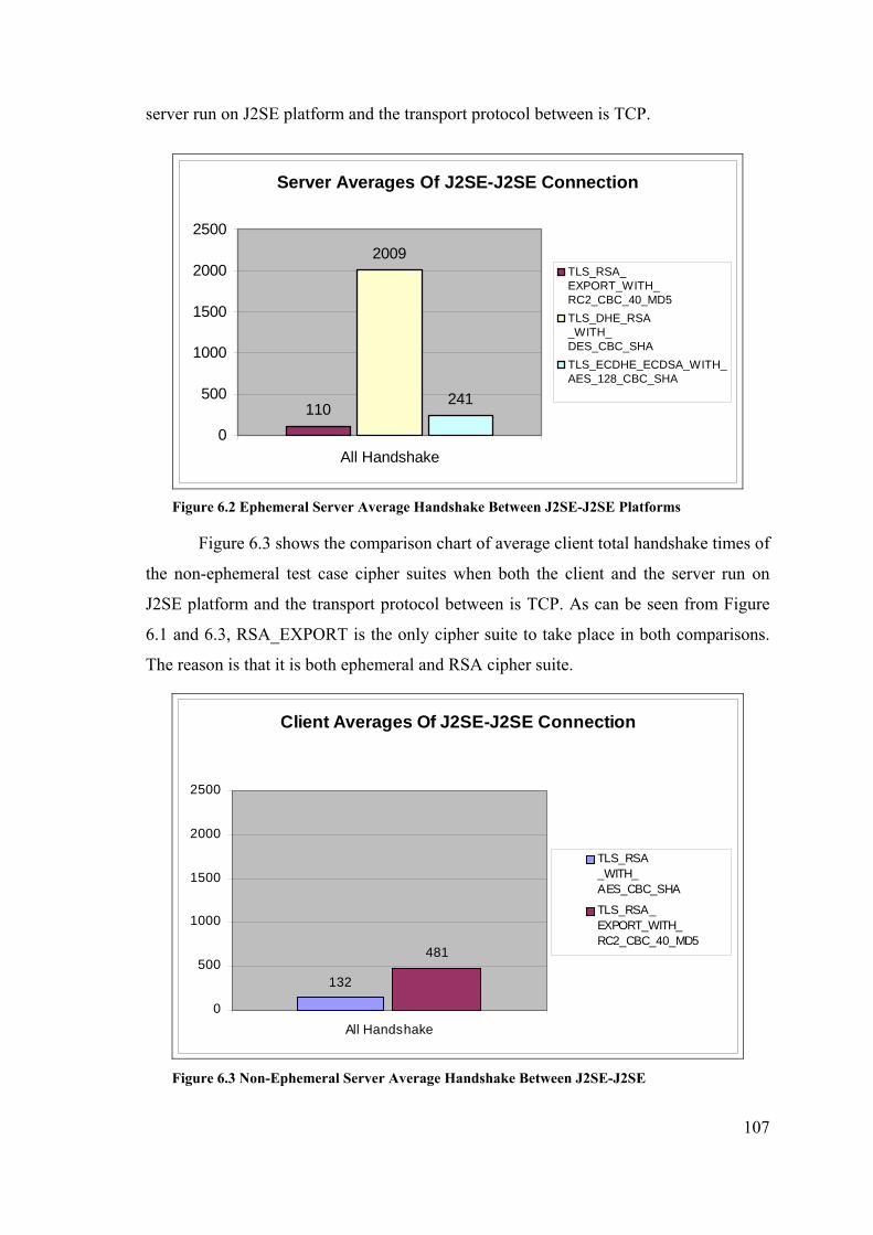
107
server run on J2SE platform and the transport protocol between is TCP.
Server Averages Of J2SE-J2SE Connection
110
2009
241
0
500
1000
1500
2000
2500
All Handshake
TLS_RSA_EXPORT_WITH_RC2_CBC_40_MD5TLS_DHE_RSA_WITH_DES_CBC_SHATLS_ECDHE_ECDSA_WITH_AES_128_CBC_SHA
Figure 6.2 Ephemeral Server Average Handshake Between J2SE-J2SE Platforms
Figure 6.3 shows the comparison chart of average client total handshake times of
the non-ephemeral test case cipher suites when both the client and the server run on
J2SE platform and the transport protocol between is TCP. As can be seen from Figure
6.1 and 6.3, RSA_EXPORT is the only cipher suite to take place in both comparisons.
The reason is that it is both ephemeral and RSA cipher suite.
Client Averages Of J2SE-J2SE Connection
132
481
0
500
1000
1500
2000
2500
All Handshake
TLS_RSA_WITH_AES_CBC_SHA
TLS_RSA_EXPORT_WITH_RC2_CBC_40_MD5
Figure 6.3 Non-Ephemeral Server Average Handshake Between J2SE-J2SE

108
Table A.3 and table A.4 in Appendix show the secure communication time span
durations when the client runs on J2ME MIDP Platform of the device emulator and the
server side of the implementation runs on J2SE platform. Both processes run on the
same desktop personal computer. Transport protocol between is TCP. Table A.3
compares ephemeral cipher suites. This comparison is made as all ephemeral cipher
suites generate asymmetric keys at run-time. Table A.4 compares ephemeral RSA (RSA
export) and non-ephemeral RSA cipher suites. All the result values are milliseconds.
The average, max and min values were found at the end of 100 times of handshake
procedure between the client and the server.
The values in tables A.3 and A.4 are by far higher than the values in tables A.1
and A.2, especially in client side. The results show that the device emulator
environment processes very slowly. The slowest cipher suite in table A.3 is
TLS_ECDHE_ECDSA_WITH_AES_ 128_CBC_SHA. The reason for this slowness is
ECDSA public key verification and elliptic curve key pair generation operations.
Another attention point in table A.3 is high handshake times in server side results. In
fact, the server side test program in this configuration runs on J2SE environment and
expected to give similar results to server side results in table A.4. The unexpected
results are because of the latencies in the client side operations as the protocol
operations are processed in sequence.
Tables A.5 and A.6 in Appendix show the secure communication time span
durations when both the client and server side implementation of the protocol run on
J2ME MIDP Platform of the device emulator. Both processes run on the same desktop
personal computer. The transport protocol between is TCP. Table A.5 compares
ephemeral cipher suites. This comparison is made as all ephemeral cipher suites
generate asymmetric keys at run-time. Table A.6 compares ephemeral RSA (RSA
export) and non-ephemeral RSA cipher suites. All the result values are milliseconds.
The average, max and min values were found at the end of 100 times of handshake
procedure between the client and the server.
In tables A.5 and A.6, the measured values in both client and server side are
lower than the values in tables A.3 and A.4. The reason is that both client and server test
programs are run on device emulator environment which has slow processing speed.
Besides cryptographic operations, big number operations like “TLS Keys Generation” is
also very slow in this table. This result gives the idea that big number operations require
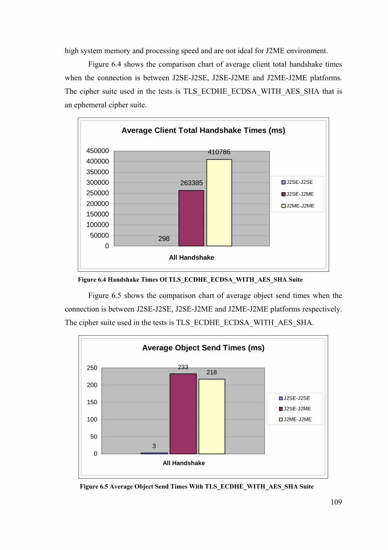
109
high system memory and processing speed and are not ideal for J2ME environment.
Figure 6.4 shows the comparison chart of average client total handshake times
when the connection is between J2SE-J2SE, J2SE-J2ME and J2ME-J2ME platforms.
The cipher suite used in the tests is TLS_ECDHE_ECDSA_WITH_AES_SHA that is
an ephemeral cipher suite.
Average Client Total Handshake Times (ms)
298
263385
410786
050000
100000150000200000250000300000350000400000450000
All Handshake
J2SE-J2SE
J2SE-J2ME
J2ME-J2ME
Figure 6.4 Handshake Times Of TLS_ECDHE_ECDSA_WITH_AES_SHA Suite
Figure 6.5 shows the comparison chart of average object send times when the
connection is between J2SE-J2SE, J2SE-J2ME and J2ME-J2ME platforms respectively.
The cipher suite used in the tests is TLS_ECDHE_ECDSA_WITH_AES_SHA.
Average Object Send Times (ms)
3
233218
0
50
100
150
200
250
All Handshake
J2SE-J2SE
J2SE-J2ME
J2ME-J2ME
Figure 6.5 Average Object Send Times With TLS_ECDHE_WITH_AES_SHA Suite
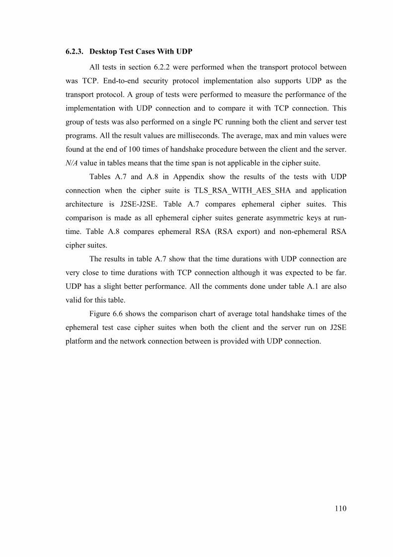
110
6.2.3. Desktop Test Cases With UDP
All tests in section 6.2.2 were performed when the transport protocol between
was TCP. End-to-end security protocol implementation also supports UDP as the
transport protocol. A group of tests were performed to measure the performance of the
implementation with UDP connection and to compare it with TCP connection. This
group of tests was also performed on a single PC running both the client and server test
programs. All the result values are milliseconds. The average, max and min values were
found at the end of 100 times of handshake procedure between the client and the server.
N/A value in tables means that the time span is not applicable in the cipher suite.
Tables A.7 and A.8 in Appendix show the results of the tests with UDP
connection when the cipher suite is TLS_RSA_WITH_AES_SHA and application
architecture is J2SE-J2SE. Table A.7 compares ephemeral cipher suites. This
comparison is made as all ephemeral cipher suites generate asymmetric keys at run-
time. Table A.8 compares ephemeral RSA (RSA export) and non-ephemeral RSA
cipher suites.
The results in table A.7 show that the time durations with UDP connection are
very close to time durations with TCP connection although it was expected to be far.
UDP has a slight better performance. All the comments done under table A.1 are also
valid for this table.
Figure 6.6 shows the comparison chart of average total handshake times of the
ephemeral test case cipher suites when both the client and the server run on J2SE
platform and the network connection between is provided with UDP connection.
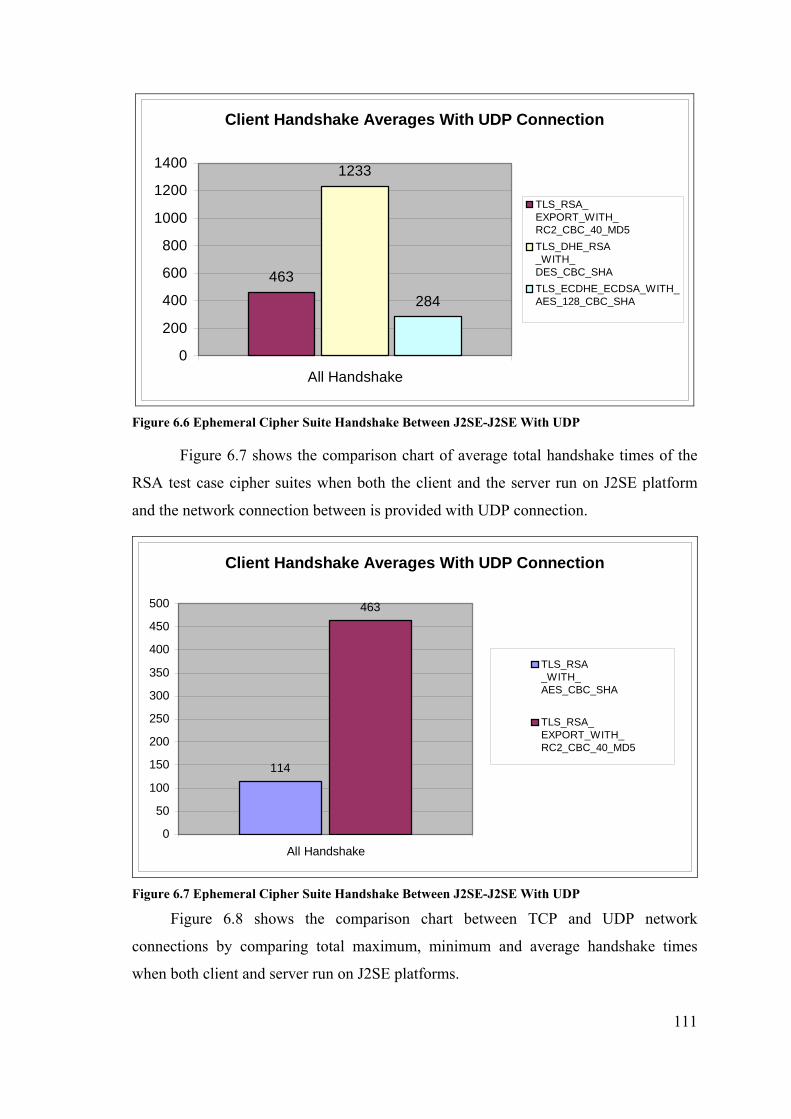
111
Client Handshake Averages With UDP Connection
463
1233
284
0
200
400
600
800
1000
1200
1400
All Handshake
TLS_RSA_EXPORT_WITH_RC2_CBC_40_MD5TLS_DHE_RSA_WITH_DES_CBC_SHATLS_ECDHE_ECDSA_WITH_AES_128_CBC_SHA
Figure 6.6 Ephemeral Cipher Suite Handshake Between J2SE-J2SE With UDP
Figure 6.7 shows the comparison chart of average total handshake times of the
RSA test case cipher suites when both the client and the server run on J2SE platform
and the network connection between is provided with UDP connection.
Client Handshake Averages With UDP Connection
114
463
0
50
100
150
200
250
300
350
400
450
500
All Handshake
TLS_RSA_WITH_AES_CBC_SHA
TLS_RSA_EXPORT_WITH_RC2_CBC_40_MD5
Figure 6.7 Ephemeral Cipher Suite Handshake Between J2SE-J2SE With UDP
Figure 6.8 shows the comparison chart between TCP and UDP network
connections by comparing total maximum, minimum and average handshake times
when both client and server run on J2SE platforms.

112
J2SE-J2SE TLS_RSA_WITH_AES_SHA Cipher Suite With TCP/UDP Connections
132 114
11011031
100 90
0
200
400
600
800
1000
1200
TCP UDP
AverageMaxMin
Figure 6.8 Handshake Times With TLS_RSA_WITH_AES_SHA Cipher Suite
6.3. Mobile Device Tests
The mobile end-to-end security protocol was implemented mainly to be used in
mobile devices, PDAs and mobile phones e.g. The implemented protocol library is
tested on a real mobile phone to show that it can run on a resource-constraint
environment and establish network connection on a real wireless network.
6.3.1. Mobile Device Test Platform Configuration
The tests with a real mobile device are performed by running the client test
program on a mobile phone and server test program on a desktop PC. The mobile phone
is a Nokia™ 6600 smart phone with ARM9 104 Mhz CPU, 6 MB of storage memory,
GPRS (see Chapter 3, Section 3.3.3, “GPRS”) and Bluetooth connectivity and
Symbian™ Os 7.0s operating system (see Chapter 3, Section 3.1.2.2, “Symbian OS”)
with MIDP 2.0 support. The network connection between the mobile phone and the
desktop PC is provided with the GPRS connection provided by Turkcell mobile service
carrier. The application architecture used in this test platform is explained in Chapter 3,
Section 3.2.1, “Client/Server Architecture”. The transport protocol used in the tests is
TCP.
Mobile device tests are performed only on J2SE-J2ME architecture mentioned
in Section 6.1, “Scope Of The Test Cases”. The test programs used in Section 6.2 are
also used in this group of tests. Test programs are run 10 times and the highest (max),

113
lowest (min) and average time durations are measured.
6.3.2. Mobile Device Test Results
Mobile device tests were performed according to the configuration told in
Section 6.3.1. There was no problem in establishing communication with GPRS and all
tests succeeded.
Tables A.9 and A.10 in Appendix show the secure communication time span
durations when the client test program runs on a Nokia 6600 mobile phone and the
server test program runs on J2SE platform and transport protocol between is TCP. Table
A.9 compares ephemeral cipher suites. This comparison is made as all ephemeral cipher
suites generate asymmetric keys at run-time. Table A.10 compares ephemeral RSA
(RSA export) and non-ephemeral RSA cipher suites. All the values in tables are
milliseconds (ms). “0” value in tables means that the time duration is below
milliseconds. N/A value in tables means that the time span is not applicable in the cipher
suite.
The comparison of results in table A.9 and table A.3 show that the real device
operates slower than the emulator environment. The difference comes from both the
processing speed of the device and the network connection overheads. However
unexpectedly, TLS_ECDHE_ECDSA_WITH_AES_128_CBC_SHA cipher suite has a
better performance in real device environment.
Figure 6.9 shows the comparison chart of average client total handshake times of
the ephemeral test case cipher suites when the client runs on a Nokia 6600 mobile
phone and the server runs on J2SE platform and the transport protocol between is TCP.
Client Handshake Averages On Nokia 6600 Mobile Phone
19756 20706
30596
0
5000
10000
15000
20000
25000
30000
35000
All Handshake
TLS_RSA_EXPORT_WITH_RC2_CBC_40_MD5TLS_DHE_RSA_WITH_DES_CBC_SHATLS_ECDHE_ECDSA_WITH_AES_128_CBC_SHA
Figure 6.9 Client Average Handshake Times On Nokia 6600 Mobile Phone

114
6.4. Test Results Evaluation
The performance results of the tests performed were shown in tables in
Appendix and compared in charts in Section 6.3 and Section 6.4. The performance
results were measured by dividing the handshake procedure into time spans. Each time
span is an important step in handshake that was expected to take a measurable time. The
tests were repeated for a definite number for each test case and the result average, max
and min values were noted.
Test results will be evaluated according to the following criteria:
Defined Time Spans
Running Platform
Network Protocol
Cipher Suite
As can be seen from tables A.2 and A.8, the average total handshake time
between two J2SE peers when TLS_RSA_WITH_AES_SHA cipher suite is used, is
132 milliseconds with TCP connection and 114 milliseconds with UDP connection.
These values are the lowest values in all test cases and both results are of non-
ephemeral RSA cipher suite. This shows the relative performance of non-ephemeral
cipher suites over ephemeral cipher suites. In all time spans, there are great differences
between average and max values. It is observed that these max values are generally
results of the first connections. The handshake times decrease with the repetitive
connections. The reason behind these two facts is supposed to be because of the caching
systems of computers. The average values are between max and min values and close to
the min values. The reason behind this fact is that repetitions of the tests estimate the
average values to min values.
The highest average total handshake time is result of the test with
TLS_DHE_RSA_WITH_DES_CBC_SHA cipher suite. The reason of this is the Diffie-
Hellman key pair generation time, which exceeds other time span values by far.
TLS_ECDHE_ECDSA_WITH_AES_SHA cipher suite average, min and max total
handshake times are between RSA and DHE_RSA handshake times. The time
consuming time spans are key pair generation and public key verification. As the cipher
suite is ephemeral, a key pair is generated at run-time, which takes a long time.
However, in standard RSA, key pair is not generated at run-time; generated and stored
at the certificate before which reduces the total handshake time by far.

115
All the average, min and max values increase in the J2SE-J2ME test results
shown in tables A.3 and A.4. This architecture includes a client in J2ME platform and a
server in J2SE platform and expected to be widely used in real life. No network
transmission times are included in the results as the tests were made with the MIDP
device emulator. The lowest average total handshake value in this architecture is 4748
milliseconds of TLS_RSA_WITH_AES_SHA cipher suite between RSA cipher suites.
The highest average total handshake value between ephemeral cipher suites is 263385
milliseconds of TLS_ECDHE_ECDSA_WITH_AES_SHA cipher suite. This shows
that Elliptic Curve Diffie-Hellman operations have a poor performance on J2ME
platform. This result is shown in the chart in Figure 6.5.
The results in tables A.5 and A.6 were measured when both client and server run
on J2ME platform. This is the most unexpected case in real use, but can be applied in
the future with higher capacity mobile phones. The tests were performed in device
emulator environment. As expected, the results in this architecture are the lowest values
between all architectures. The average total handshake time becomes 13166
milliseconds with TLS_RSA_WITH_AES_SHA cipher suite, which is approximately
100 times of the 132 milliseconds average total handshake time of J2SE-J2SE
architecture. The average total handshake time with
TLS_ECDHE_ECDSA_WITH_AES_SHA cipher suite is 410786 milliseconds, which
is the highest average value in all tests. The greatest time span in this cipher suite is
public key verification.
A test case was prepared to measure the performance of the protocol with UDP
connection. The target for this test was to understand the difference between TCP and
UDP. Test results on table A.1 and A.7 show that UDP connections make better
performance results when compared with TCP connections. However, the differences
are not so high. This result shows that using the unreliable UDP connection just for
performance results is not realistic.
The test cases evaluated up to now were performed according to configuration
told on Section 6.2.1. Another configuration was also prepared to fulfill the requirement
that the security solution could run on a real mobile device. As told on Section 6.3.1, in
this configuration, a mobile phone was used as the client device. The test results in
tables A.9 and A.10 show that the real device environment operates slower than the
emulator environment when the architecture is J2SE-J2ME in both cases.

116
CHAPTER 7
CONCLUSION
End-to-end security is an emerging need for mobile devices. Banking, military
and other enterprise applications need more and more security to run on mobile devices.
This master thesis aimed at developing an extensible end-to-end security protocol
implementation that could be used by both mobile and desktop applications. TLS
protocol that is commonly used in Internet was chosen as the base of the developed
protocol implementation.
The proposed protocol was designed and implemented. The implementation was
tested with different test cases and the result values were measured. The protocol
implementation was also run on a real Nokia 6600 mobile phone and established a
secure connection with a server computer connected to the Internet over GPRS. All the
tests were successfully completed that showed the protocol was properly designed and
implemented with respect to specifications. However, no attacks have been carried out
on the cipher text transmitted in these test cases. The implementation guarantees the
security of transmission at most as much as TLS. The security weaknesses of TLS still
exist in this implementation.
7.1. Review Of Thesis Results
Thesis project may be sub-divided into two sections to review the results:
• Mobile security protocol
• Object to XML serializer
7.1.1. Mobile Security Protocol
Mobile security protocol is the core of the thesis project. The architecture of the
mobile security protocol is designed to be extensible, to support different cipher suites,
run on different platforms and operate transparent to the user applications. One of the
motivation reasons of the thesis is to show that TLS like protocols could be adapted to
resource-constraint mobile devices. Results in Chapter 6 show that the protocol
implementation has an acceptable level of performance when running on J2SE platform.
The performance results depend on the cipher suite chosen. The lowest values were
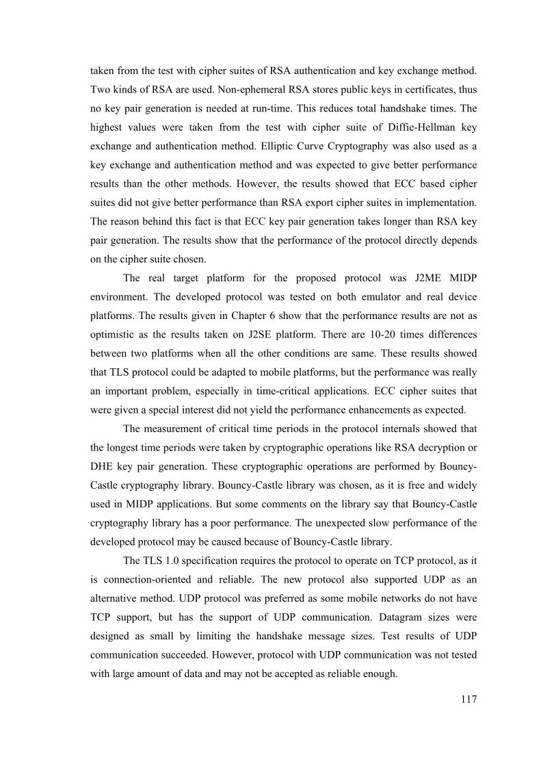
117
taken from the test with cipher suites of RSA authentication and key exchange method.
Two kinds of RSA are used. Non-ephemeral RSA stores public keys in certificates, thus
no key pair generation is needed at run-time. This reduces total handshake times. The
highest values were taken from the test with cipher suite of Diffie-Hellman key
exchange and authentication method. Elliptic Curve Cryptography was also used as a
key exchange and authentication method and was expected to give better performance
results than the other methods. However, the results showed that ECC based cipher
suites did not give better performance than RSA export cipher suites in implementation.
The reason behind this fact is that ECC key pair generation takes longer than RSA key
pair generation. The results show that the performance of the protocol directly depends
on the cipher suite chosen.
The real target platform for the proposed protocol was J2ME MIDP
environment. The developed protocol was tested on both emulator and real device
platforms. The results given in Chapter 6 show that the performance results are not as
optimistic as the results taken on J2SE platform. There are 10-20 times differences
between two platforms when all the other conditions are same. These results showed
that TLS protocol could be adapted to mobile platforms, but the performance was really
an important problem, especially in time-critical applications. ECC cipher suites that
were given a special interest did not yield the performance enhancements as expected.
The measurement of critical time periods in the protocol internals showed that
the longest time periods were taken by cryptographic operations like RSA decryption or
DHE key pair generation. These cryptographic operations are performed by Bouncy-
Castle cryptography library. Bouncy-Castle library was chosen, as it is free and widely
used in MIDP applications. But some comments on the library say that Bouncy-Castle
cryptography library has a poor performance. The unexpected slow performance of the
developed protocol may be caused because of Bouncy-Castle library.
The TLS 1.0 specification requires the protocol to operate on TCP protocol, as it
is connection-oriented and reliable. The new protocol also supported UDP as an
alternative method. UDP protocol was preferred as some mobile networks do not have
TCP support, but has the support of UDP communication. Datagram sizes were
designed as small by limiting the handshake message sizes. Test results of UDP
communication succeeded. However, protocol with UDP communication was not tested
with large amount of data and may not be accepted as reliable enough.

118
Another motivation behind the mobile security protocol was to develop both the
client and server version TLS for mobile devices. The goal has been achieved. The
server version was tested on J2SE platform and J2ME emulators and completed
successfully with all cipher suites. The initial target was to run the server version on a
real device, but this aim could not be performed because of technical reasons. The
device must have a known IP address to access. The phones of 2.5G do not have this
facility. It is expected that every node on the networks will have IP address with the
general use of IPv6 protocol instead of IPv4.
The design of the security protocol is based on MVC architecture. The internal
details of the protocol and cryptographic calls are implemented on model classes.
Controller classes locate which model class to use. This architecture provides an
extensible and transparent structure. Each handshake message class is encapsulated with
a message class. Each symmetric encryption, asymmetric encryption and hash
algorithms are encapsulated in model classes. This structure makes the management of
the code possible and makes the change of underlying cryptography library easier.
7.1.2. Object To XML Serializer
Object To XML Serializer is a library developed to provide object transmission
on network. The serializer was needed because of the lack of standard Java object
serialization on J2ME MIDP. Data communication problem in MIDP applications is
commonly solved by implementer specific solutions. The motivation behind the object
serializer has been to develop a standard, high performance, general use architecture for
data transmission. Data in Java programs are generally stored in bean style Java objects.
These objects have private attributes and getter/setter methods. The XML serializer
developed serializes bean style Java objects into XML and vice versa. XML was chosen
because of its structure and easy customizability. A third party library, KXML, is used
to parse XML data.
Object To XML Serializer was successfully designed and implemented. Because
of the lack of reflection API in MIDP, a pre-processing step was added to
implementation. This pre-processing is source generating of the reflection properties of
the class requested to be used. A tool was also developed to generate this source code.
The generation of source code has both advantages and disadvantages. The advantage is
that it results better performance than standard object serialization. The disadvantage is
119
that the extra step in object transmission causes latency although it is performed only
once. However, when the source object class is changed, the source generator must be
rerun. This causes a problem in practical use. The other disadvantage is that extra
source code’s class files take extra space in device memory and increase the total size of
the application. This is especially a concern in low memory mobile phones and PDA
devices.
In spite of its deficiencies, it is believed that object to XML serializer is a useful
work in creating a standard communication between the mobile device and the server.
7.2. Future Work
The mobile end-to-end security protocol is aimed at providing an architecture
for end-to-end security in mobile devices. The project can be extended by further work.
Some suggestions for future projects or additions are as follows:
• The Bouncy-Castle cryptography library may be changed. The performance
problem of the application is caused because of the poor performance of this
library. Bouncy-Castle library may be replaced with other J2ME cryptography
libraries mentioned in Chapter 2.
• The certificates used in the protocol implementation have the format of X.509
certificates. However, the protocol implementation can not directly use these
certificates; instead a certificate object is generated and serialized into XML
text. This certificate XML is stored in the mobile device within the .jar file and
used as the certificate. This mechanism is useful is development and test; but is
not proper in real applications. The protocol must be able to use real X.509
certificates directly.
• The implemented protocol supports only ephemeral types of Elliptic Curve and
Diffie-Hellman cipher suites. Ephemeral cipher suites were chosen as they do
not require ECC or DH certificates. Key pair is generated at run-time. This
increases security but decreases performance. Non-ephemeral ECC and DH
cipher suites may also be added to the protocol implementation.
• Object To XML Serializer only supports the serialization of bean style Java data
objects. It may be extended to support other Java objects as well.

120
BIBLIOGRAPHY [1] A. O. Freier, P. Karlton and P. C. Kocher, “The SSL Protocol Version 3.0", 1996, http://www.netscape.com/eng/ssl3/draft302.txt
[2] Dierks T, Allen C, “The TLS Protocol Version 1.0", RFC 2246, 1999, http://www.ietf.org/rfc/rfc2246.txt
[3] IAIK TUG, “Transport Layer Security (TLS) Protocol 1.0”, IT-Sicherheit / BS2, 2001
[4] WAP Forum, “Wireless Application protocol - Wireless Transport Layer Security Specification, Version 12-Feb-1999", 1999, http://www.wapforum.org
[5] RSA Laboratories, “RSA Laboratories' Frequently Asked Questions About Today's Cryptography, Version 4.1”, RSA Security Inc., 2000
[6] FIPS, Federal Information Processing Standarts Publication, “Data Encryption Standart, Fips 46-3”, Reaffirmed 1999 October 25 U.S. Department of Commerce/National Institute of Standarts and Technology
[7] R.L. Rivest, “RFC 1321: The MD5 Message-Digest Algorithm”, Internet Activities Board, 1992
[8] ANSI X9.52, “Triple Data Encryption Algorithm Modes of Operation”, American Bankers Association, 1998
[9] W. Diffie and M.E. Hellman, “New directions in cryptography”, IEEE Transactions on Information Theory, 1976
[10] R.L. Rivest, A. Shamir, and L.M. Adleman, “A method for obtaining digital signatures and public-key cryptosystems”, Communications of the ACM, 1978
[11] Cormen T, Leiserson C, Rivest R, “Introduction to Algorithms", MIT press, 1998
[12] V.S. Miller, “Use of elliptic curves in cryptography”, Advances in Cryptology Crypto '85, Springer-Verlag, 1986
[13] N. Koblitz, “Elliptic curve cryptosystems”, Mathematics of Computation, 1997
[14] ANSI X9.63, “Elliptic Curve Key Agreement and Key Transport Protocols", American Bankers Association, 1999
[15] ANSI X9.62, “The Elliptic Curve Digital Signature Algorithm (ECDSA)", American Bankers Association, 1999
[16] V. Gupta, S. Blake-Wilson, B. Moeller, C. Hawk, “ECC Cipher Suites for TLS Internet Draft”, 2002
[17] Lenstra, A. and E. Verheul, "Selecting Cryptographic Key Sizes", Journal of Cryptology, 2001
[18] National Institute of Standards and Technology (NIST), “FIPS Publication 180: Secure Hash Standard (SHS)”, 1993
[19] National Institute of Standards and Technology (NIST), “FIPS Publication 186: Digital Signature Standard (DSS)”, 1994
[20] V.Gupta, S.Gupta, “KSSL : Experiments in Wireless Internet Security”, Sun

121
Microsystems, Inc., 2001
[21] M.J. Saarinen, “Attaks Against The WAP WTLS Protocol”, University of Jyvaskyla, Finland
[22] Sun Microsystems, “Connected, Limited Device Configuration 1.0a Specification”, Sun Microsystems Inc., 2000
[23] V. Gupta, “Developing Secure Web Applications for Constrained Devices”, Sun Microsystems Inc., 2002
[24] Sun Microsystems, “JSR-000037 Mobile Information Device Profile (MIDP) 1.0 Specification”, Sun Microsystems Inc.
[25] Sun Microsystems, “JSR-000118 Mobile Information Device Profile 2.0 Specification”, Sun Microsystems Inc.
[26] J. Ellis, M. Young, “J2ME Web Services Specification Public Review Draft (v0.7)”, Sun Microsystems Inc., 2002
[27] M. Palermo, “Professional ASP.Net 1.0 With C#, Chapter 1 : Introduction to XML Technologies”, 2004, http://www.perfectxml.com/XMLIntro.asp
[28] Sun Microsystems, “Java. 2 Platform Micro Edition (J2ME) Technology for Creating Mobile Devices White Paper”, Sun Microsystems Inc., 2000
[29] J. Knudsen, “J2ME Devices”, Java Wireless Developer Website, http://wireless.java.sun.com/device
[30] C. Bey, E. Freeman, G. Hillerson, “Palm OS® Programmer’s Companion Volume I”, Palm Inc., 2001
[31] C. Bey, E. Freeman, G. Hillerson, “Palm OS® Programmer’s Companion Volume II Communications”, Palm Inc., 2001
[32] J. Beich, “Sync up Palm OS with J2ME”, 2002, http://www.javaworld.com/javaworld/jw-05-2002/jw-0531-palm-p2.html
[33] K. Dixon, “Symbian OS Version 7.0s Functional Description”, 2003, http://www.symbian.com/technology/symbos-v7s-det.html
[34] P. Sanders, “Creating Symbian OS phones”, 2002 http://www.symbian.com/technology/create-symb-OS-phones.html
[35] Sun Microsystems, “The CLDC HotSpot™ Implementation Virtual Machine”, Sun Microsystems Inc., 2002
[36] Sun Microsystems, “The Java HotSpot™ Virtual Machine, v1.4.1, d2”, Sun Microsystems Inc., 2002
[37] J. Knudsen, “Wireless Development Tutorial”, 2002 http://wireless.java.sun.com/midp/articles/tutorial2/
[38] E. Ortiz, “The Complexity of Developing Mobile Networked Data Services, J2ME Wireless Connection Wizard For Sun ONE Studio”, 2003, http://wireless.java.sun.com/midp/articles/wizard/
[39] Intel, “IEEE 802.11b High Rate Wireless Local Area Networks”, Intel Corporation, 2000
[40] Q. H. Mahmoud, “Wireless Application Programming with J2ME and Bluetooth”,

122
2003, http://wireless.java.sun.com/midp/articles/bluetooth1/
[41] Symbian, “Symbian on GPRS”, 2001, http://www.symbian.com/technology/standard-gprs.html
[42] B. Kayayurt, K. Şimşek, E. Sülün, “Hospital Reservation System”, B.S. Thesis, Ege University, 2002
123
APPENDIX
The results of performance tests mentioned in Chapter 6 are given in tables in
this section. These results are measured time values for different architectures and
cipher suites. Tables are organized to compare values of ephemeral cipher suites and
RSA cipher suites in different tables. N/A values in tables mean that time span is not
applicable in the cipher suite. Result values of 0 are time durations below milliseconds.
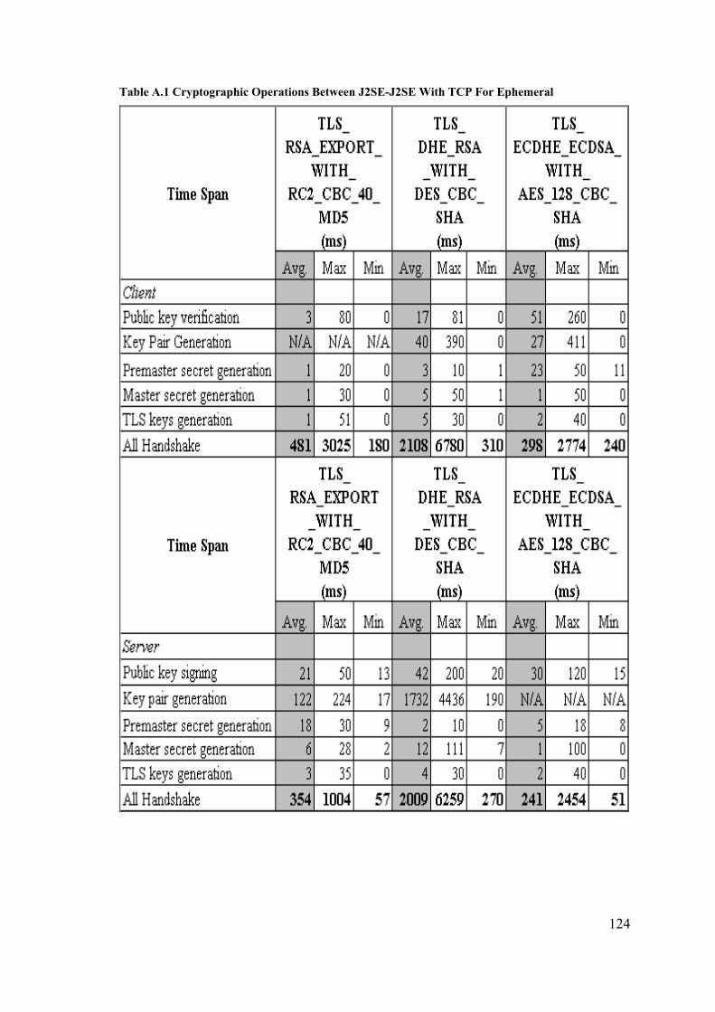
124
Table A.1 Cryptographic Operations Between J2SE-J2SE With TCP For Ephemeral

125
Table A.2 Cryptographic Operations Between J2SE-J2SE With TCP For RSA
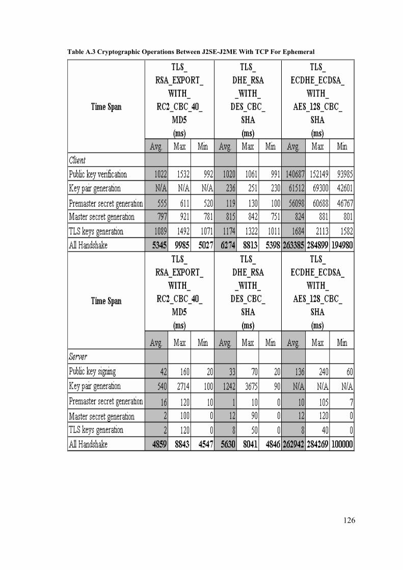
126
Table A.3 Cryptographic Operations Between J2SE-J2ME With TCP For Ephemeral
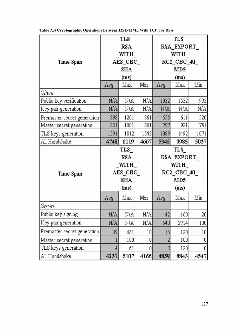
127
Table A.4 Cryptographic Operations Between J2SE-J2ME With TCP For RSA

128
Table A.5 Cryptographic Operations Between J2ME-J2ME With TCP For Ephemeral

129
Table A.6 Cryptographic Operations Between J2ME-J2ME With TCP For RSA

130
Table A.7 Cryptographic Operations Between J2SE-J2SE With UDP For Ephemeral

131
Table A.8 Cryptographic Operations Between J2SE-J2SE With UDP For RSA

132
Table A.9 Cryptographic Operations In The Mobile Device Tests For Ephemeral

133
Table A.10 Cryptographic Operations In The Mobile Device Tests For RSA