
— Drives industriais ABB ACS880, drives únicos 0.55 to 3200 ...
Upload
khangminh22Category
view
1download
0
—ABB INDUSTRIAL DRIVES
ACS880-17LC drivesHardware manual


ACS880-17LC drivesHardware manual
Table of contents
1. Safety instructions
4. Mechanical installation
6. Electrical installation
9. Start-up
3AXD50000250295 Rev BEN
Original instructionsEFFECTIVE: 2022-04-20


Table of contents
1 Safety instructions
13Contents of this chapter ... . . . . . . . . . . . . . . . . . . . . . . . . . . . . . . . . . . . . . . . . . . . . . . . . . . . . . . . . . . . . . . . . . . . . . . . .13Use of warnings and notes .... . . . . . . . . . . . . . . . . . . . . . . . . . . . . . . . . . . . . . . . . . . . . . . . . . . . . . . . . . . . . . . . . . . .14General safety in installation, start-up and maintenance .... . . . . . . . . . . . . . . . . . . . . . . . . . . . . . . . .16Work on the liquid cooling system ..... . . . . . . . . . . . . . . . . . . . . . . . . . . . . . . . . . . . . . . . . . . . . . . . . . . . . . .17Electrical safety in installation, start-up and maintenance .... . . . . . . . . . . . . . . . . . . . . . . . . . . . . . . .17Electrical safety precautions .... . . . . . . . . . . . . . . . . . . . . . . . . . . . . . . . . . . . . . . . . . . . . . . . . . . . . . . . . . . . . . .18Additional instructions and notes .... . . . . . . . . . . . . . . . . . . . . . . . . . . . . . . . . . . . . . . . . . . . . . . . . . . . . . . . . .19Optical components .... . . . . . . . . . . . . . . . . . . . . . . . . . . . . . . . . . . . . . . . . . . . . . . . . . . . . . . . . . . . . . . . . . . . .19Printed circuit boards .... . . . . . . . . . . . . . . . . . . . . . . . . . . . . . . . . . . . . . . . . . . . . . . . . . . . . . . . . . . . . . . . . . . .19Grounding .... . . . . . . . . . . . . . . . . . . . . . . . . . . . . . . . . . . . . . . . . . . . . . . . . . . . . . . . . . . . . . . . . . . . . . . . . . . . . . . . . . . .20General safety in operation .... . . . . . . . . . . . . . . . . . . . . . . . . . . . . . . . . . . . . . . . . . . . . . . . . . . . . . . . . . . . . . . . . . . .20Additional instructions for permanent magnet motor drives .... . . . . . . . . . . . . . . . . . . . . . . . . . . . . .20Safety in installation, start-up, maintenance .... . . . . . . . . . . . . . . . . . . . . . . . . . . . . . . . . . . . . . . . . . . . .21Safety in operation .... . . . . . . . . . . . . . . . . . . . . . . . . . . . . . . . . . . . . . . . . . . . . . . . . . . . . . . . . . . . . . . . . . . . . . . . . .
2 Introduction to the manual
23Contents of this chapter ... . . . . . . . . . . . . . . . . . . . . . . . . . . . . . . . . . . . . . . . . . . . . . . . . . . . . . . . . . . . . . . . . . . . . . . . .23Target audience .... . . . . . . . . . . . . . . . . . . . . . . . . . . . . . . . . . . . . . . . . . . . . . . . . . . . . . . . . . . . . . . . . . . . . . . . . . . . . . . . .23Categorization by frame size and option code ..... . . . . . . . . . . . . . . . . . . . . . . . . . . . . . . . . . . . . . . . . . . . .24Use of component designations .... . . . . . . . . . . . . . . . . . . . . . . . . . . . . . . . . . . . . . . . . . . . . . . . . . . . . . . . . . . . . .24Quick installation, commissioning and operation flowchart ... . . . . . . . . . . . . . . . . . . . . . . . . . . . . . . .25Terms and abbreviations .... . . . . . . . . . . . . . . . . . . . . . . . . . . . . . . . . . . . . . . . . . . . . . . . . . . . . . . . . . . . . . . . . . . . . . .25Related manuals .... . . . . . . . . . . . . . . . . . . . . . . . . . . . . . . . . . . . . . . . . . . . . . . . . . . . . . . . . . . . . . . . . . . . . . . . . . . . . . . .
3 Operation principle and hardware description
27Contents of this chapter ... . . . . . . . . . . . . . . . . . . . . . . . . . . . . . . . . . . . . . . . . . . . . . . . . . . . . . . . . . . . . . . . . . . . . . . . .27Supply unit .. . . . . . . . . . . . . . . . . . . . . . . . . . . . . . . . . . . . . . . . . . . . . . . . . . . . . . . . . . . . . . . . . . . . . . . . . . . . . . . . . . . . . . . . .28AC voltage and current waveforms ..... . . . . . . . . . . . . . . . . . . . . . . . . . . . . . . . . . . . . . . . . . . . . . . . . . . . . .28Charging .... . . . . . . . . . . . . . . . . . . . . . . . . . . . . . . . . . . . . . . . . . . . . . . . . . . . . . . . . . . . . . . . . . . . . . . . . . . . . . . . . . . . . .28Inverter unit .. . . . . . . . . . . . . . . . . . . . . . . . . . . . . . . . . . . . . . . . . . . . . . . . . . . . . . . . . . . . . . . . . . . . . . . . . . . . . . . . . . . . . . . .29Overview circuit diagram of the drive .... . . . . . . . . . . . . . . . . . . . . . . . . . . . . . . . . . . . . . . . . . . . . . . . . . . . . . . .30Cabinet line-up and layout examples .... . . . . . . . . . . . . . . . . . . . . . . . . . . . . . . . . . . . . . . . . . . . . . . . . . . . . . . .30Frame 2×R8i+2×R8i line-up .... . . . . . . . . . . . . . . . . . . . . . . . . . . . . . . . . . . . . . . . . . . . . . . . . . . . . . . . . . . . . . .31Frame 2×R8i+2×R8i layout ... . . . . . . . . . . . . . . . . . . . . . . . . . . . . . . . . . . . . . . . . . . . . . . . . . . . . . . . . . . . . . . . .32100 kA input cubicle (option +F274) .... . . . . . . . . . . . . . . . . . . . . . . . . . . . . . . . . . . . . . . . . . . . . . . . . . . . . .33Overview of power and control connections .... . . . . . . . . . . . . . . . . . . . . . . . . . . . . . . . . . . . . . . . . . . . . . . .34Door switches and lights .... . . . . . . . . . . . . . . . . . . . . . . . . . . . . . . . . . . . . . . . . . . . . . . . . . . . . . . . . . . . . . . . . . . . . . .34Main disconnecting device [Q1] .... . . . . . . . . . . . . . . . . . . . . . . . . . . . . . . . . . . . . . . . . . . . . . . . . . . . . . . . . . .34Auxiliary voltage switch [Q21] .... . . . . . . . . . . . . . . . . . . . . . . . . . . . . . . . . . . . . . . . . . . . . . . . . . . . . . . . . . . . .34Grounding (earthing) switch [Q9], optional ... . . . . . . . . . . . . . . . . . . . . . . . . . . . . . . . . . . . . . . . . . . . . . .34Other devices on the door .... . . . . . . . . . . . . . . . . . . . . . . . . . . . . . . . . . . . . . . . . . . . . . . . . . . . . . . . . . . . . . . . . .35Control panel ... . . . . . . . . . . . . . . . . . . . . . . . . . . . . . . . . . . . . . . . . . . . . . . . . . . . . . . . . . . . . . . . . . . . . . . . . . . . . . . . . .35Control by PC tools .... . . . . . . . . . . . . . . . . . . . . . . . . . . . . . . . . . . . . . . . . . . . . . . . . . . . . . . . . . . . . . . . . . . . . .
Table of contents 5

36Descriptions of options .... . . . . . . . . . . . . . . . . . . . . . . . . . . . . . . . . . . . . . . . . . . . . . . . . . . . . . . . . . . . . . . . . . . . . . . . .36Degree of protection .... . . . . . . . . . . . . . . . . . . . . . . . . . . . . . . . . . . . . . . . . . . . . . . . . . . . . . . . . . . . . . . . . . . . . . . .36Definitions .... . . . . . . . . . . . . . . . . . . . . . . . . . . . . . . . . . . . . . . . . . . . . . . . . . . . . . . . . . . . . . . . . . . . . . . . . . . . . . . . .36Marine construction (option +C121) .... . . . . . . . . . . . . . . . . . . . . . . . . . . . . . . . . . . . . . . . . . . . . . . . . . . . . .36UL Listed (option +C129) .... . . . . . . . . . . . . . . . . . . . . . . . . . . . . . . . . . . . . . . . . . . . . . . . . . . . . . . . . . . . . . . . . . .36Plinth height (options +C164 and +C179) .... . . . . . . . . . . . . . . . . . . . . . . . . . . . . . . . . . . . . . . . . . . . . . .37du/dt filter ... . . . . . . . . . . . . . . . . . . . . . . . . . . . . . . . . . . . . . . . . . . . . . . . . . . . . . . . . . . . . . . . . . . . . . . . . . . . . . . . . . . . . .37Common mode filter (option +E208) .... . . . . . . . . . . . . . . . . . . . . . . . . . . . . . . . . . . . . . . . . . . . . . . . . . . . . .37Cabinet heater with external supply (option +G300) .... . . . . . . . . . . . . . . . . . . . . . . . . . . . . . . . . . .37Cabinet lighting (option +G301) .... . . . . . . . . . . . . . . . . . . . . . . . . . . . . . . . . . . . . . . . . . . . . . . . . . . . . . . . . . .37Terminals for external control voltage (option +G307) .... . . . . . . . . . . . . . . . . . . . . . . . . . . . . . . . .37Output for motor space heater (option +G313) .... . . . . . . . . . . . . . . . . . . . . . . . . . . . . . . . . . . . . . . . .38Halogen-free wiring and materials (option +G330) .... . . . . . . . . . . . . . . . . . . . . . . . . . . . . . . . . . . . .38V-meter with selector switch (option +G334) .... . . . . . . . . . . . . . . . . . . . . . . . . . . . . . . . . . . . . . . . . . . .38Wire markings .... . . . . . . . . . . . . . . . . . . . . . . . . . . . . . . . . . . . . . . . . . . . . . . . . . . . . . . . . . . . . . . . . . . . . . . . . . . . . . . .38Standard wiring .... . . . . . . . . . . . . . . . . . . . . . . . . . . . . . . . . . . . . . . . . . . . . . . . . . . . . . . . . . . . . . . . . . . . . . . . . .39Additional wire markings .... . . . . . . . . . . . . . . . . . . . . . . . . . . . . . . . . . . . . . . . . . . . . . . . . . . . . . . . . . . . . . . .39Voltage measurement with BAMU auxiliary measurement unit (option +G442) .... . .40Bottom cable entry/exit (options +H350 and +H352) .... . . . . . . . . . . . . . . . . . . . . . . . . . . . . . . . . . .40Top cable entry/exit (options +H351 and +H353) .... . . . . . . . . . . . . . . . . . . . . . . . . . . . . . . . . . . . . . .40Common motor terminal cubicle (option +H359) .... . . . . . . . . . . . . . . . . . . . . . . . . . . . . . . . . . . . . . .
40Thermal protection with PTC relays (options +L505, +2L505, +L513, +2L513, +L536,+L537) .... . . . . . . . . . . . . . . . . . . . . . . . . . . . . . . . . . . . . . . . . . . . . . . . . . . . . . . . . . . . . . . . . . . . . . . . . . . . . . . . . . . . . . . .
40+L505, +2L505, +L513, +2L513 ..... . . . . . . . . . . . . . . . . . . . . . . . . . . . . . . . . . . . . . . . . . . . . . . . . . . . . .41+L536, +L537 ..... . . . . . . . . . . . . . . . . . . . . . . . . . . . . . . . . . . . . . . . . . . . . . . . . . . . . . . . . . . . . . . . . . . . . . . . . . . .41Thermal protection with Pt100 relays (options +nL506, +nL514) .... . . . . . . . . . . . . . . . . . . .42Starter for auxiliary motor fan (options +M600…M610) .... . . . . . . . . . . . . . . . . . . . . . . . . . . . . . .42What the option contains .... . . . . . . . . . . . . . . . . . . . . . . . . . . . . . . . . . . . . . . . . . . . . . . . . . . . . . . . . . . . . . .42Description .... . . . . . . . . . . . . . . . . . . . . . . . . . . . . . . . . . . . . . . . . . . . . . . . . . . . . . . . . . . . . . . . . . . . . . . . . . . . . . . .43Type designation label ... . . . . . . . . . . . . . . . . . . . . . . . . . . . . . . . . . . . . . . . . . . . . . . . . . . . . . . . . . . . . . . . . . . . . . . . . .43Type designation key .... . . . . . . . . . . . . . . . . . . . . . . . . . . . . . . . . . . . . . . . . . . . . . . . . . . . . . . . . . . . . . . . . . . . . . . . . . .44Option codes .... . . . . . . . . . . . . . . . . . . . . . . . . . . . . . . . . . . . . . . . . . . . . . . . . . . . . . . . . . . . . . . . . . . . . . . . . . . . . . . . .
4 Mechanical installation
49Contents of this chapter ... . . . . . . . . . . . . . . . . . . . . . . . . . . . . . . . . . . . . . . . . . . . . . . . . . . . . . . . . . . . . . . . . . . . . . . . .49Examining the installation site .... . . . . . . . . . . . . . . . . . . . . . . . . . . . . . . . . . . . . . . . . . . . . . . . . . . . . . . . . . . . . . . .49Necessary tools .... . . . . . . . . . . . . . . . . . . . . . . . . . . . . . . . . . . . . . . . . . . . . . . . . . . . . . . . . . . . . . . . . . . . . . . . . . . . . . . . .50Examining the delivery .... . . . . . . . . . . . . . . . . . . . . . . . . . . . . . . . . . . . . . . . . . . . . . . . . . . . . . . . . . . . . . . . . . . . . . . . .51Moving and unpacking the drive .... . . . . . . . . . . . . . . . . . . . . . . . . . . . . . . . . . . . . . . . . . . . . . . . . . . . . . . . . . . . . .51Moving the drive in its packaging .... . . . . . . . . . . . . . . . . . . . . . . . . . . . . . . . . . . . . . . . . . . . . . . . . . . . . . . . .51Lifting the crate with a forklift . . . . . . . . . . . . . . . . . . . . . . . . . . . . . . . . . . . . . . . . . . . . . . . . . . . . . . . . . . . . . .52Lifting the crate with a crane .... . . . . . . . . . . . . . . . . . . . . . . . . . . . . . . . . . . . . . . . . . . . . . . . . . . . . . . . . . .53Moving the crate with a forklift . . . . . . . . . . . . . . . . . . . . . . . . . . . . . . . . . . . . . . . . . . . . . . . . . . . . . . . . . . . .53Removing the transport package ..... . . . . . . . . . . . . . . . . . . . . . . . . . . . . . . . . . . . . . . . . . . . . . . . . . . . . . . .54Moving the unpacked drive cabinet ... . . . . . . . . . . . . . . . . . . . . . . . . . . . . . . . . . . . . . . . . . . . . . . . . . . . . . . .54Lifting the cabinet with a crane .... . . . . . . . . . . . . . . . . . . . . . . . . . . . . . . . . . . . . . . . . . . . . . . . . . . . . . . .55Moving the cabinet on rollers .... . . . . . . . . . . . . . . . . . . . . . . . . . . . . . . . . . . . . . . . . . . . . . . . . . . . . . . . . .55Moving the cabinet on its back .... . . . . . . . . . . . . . . . . . . . . . . . . . . . . . . . . . . . . . . . . . . . . . . . . . . . . . . . .56Final placement of the cabinet ... . . . . . . . . . . . . . . . . . . . . . . . . . . . . . . . . . . . . . . . . . . . . . . . . . . . . . . . . .57Attaching the cabinet to the floor and wall or roof ... . . . . . . . . . . . . . . . . . . . . . . . . . . . . . . . . . . . . . . . . . .57General rules .... . . . . . . . . . . . . . . . . . . . . . . . . . . . . . . . . . . . . . . . . . . . . . . . . . . . . . . . . . . . . . . . . . . . . . . . . . . . . . . . .
6 Table of contents

58Attaching the cabinet (non-marine units) ... . . . . . . . . . . . . . . . . . . . . . . . . . . . . . . . . . . . . . . . . . . . . . . . .58Alternative 1 – Clamping .... . . . . . . . . . . . . . . . . . . . . . . . . . . . . . . . . . . . . . . . . . . . . . . . . . . . . . . . . . . . . . . .59Alternative 2 – Using the holes inside the cabinet ... . . . . . . . . . . . . . . . . . . . . . . . . . . . . . . . . . .60Attaching the cabinet (marine units) ... . . . . . . . . . . . . . . . . . . . . . . . . . . . . . . . . . . . . . . . . . . . . . . . . . . . . . .61Joining cabinet sections together .... . . . . . . . . . . . . . . . . . . . . . . . . . . . . . . . . . . . . . . . . . . . . . . . . . . . . . . . . . . . .66Miscellaneous .... . . . . . . . . . . . . . . . . . . . . . . . . . . . . . . . . . . . . . . . . . . . . . . . . . . . . . . . . . . . . . . . . . . . . . . . . . . . . . . . . . .66Cable duct in the floor below the cabinet ... . . . . . . . . . . . . . . . . . . . . . . . . . . . . . . . . . . . . . . . . . . . . . . . .66Arc welding .... . . . . . . . . . . . . . . . . . . . . . . . . . . . . . . . . . . . . . . . . . . . . . . . . . . . . . . . . . . . . . . . . . . . . . . . . . . . . . . . . . .67Lifting lugs and bars .... . . . . . . . . . . . . . . . . . . . . . . . . . . . . . . . . . . . . . . . . . . . . . . . . . . . . . . . . . . . . . . . . . . . . . . . . . . .67Certificate of conformity .... . . . . . . . . . . . . . . . . . . . . . . . . . . . . . . . . . . . . . . . . . . . . . . . . . . . . . . . . . . . . . . . . . . .67Declarations of conformity .... . . . . . . . . . . . . . . . . . . . . . . . . . . . . . . . . . . . . . . . . . . . . . . . . . . . . . . . . . . . . . . . .
5 Guidelines for planning the electrical installation
71Contents of this chapter ... . . . . . . . . . . . . . . . . . . . . . . . . . . . . . . . . . . . . . . . . . . . . . . . . . . . . . . . . . . . . . . . . . . . . . . . .71Limitation of liability ... . . . . . . . . . . . . . . . . . . . . . . . . . . . . . . . . . . . . . . . . . . . . . . . . . . . . . . . . . . . . . . . . . . . . . . . . . . . . .71Selecting the supply disconnecting device .... . . . . . . . . . . . . . . . . . . . . . . . . . . . . . . . . . . . . . . . . . . . . . . . . .71Selecting the main breaker option .... . . . . . . . . . . . . . . . . . . . . . . . . . . . . . . . . . . . . . . . . . . . . . . . . . . . . . . . . . . .72Examining the compatibility of the motor and drive .... . . . . . . . . . . . . . . . . . . . . . . . . . . . . . . . . . . . . . . .72Protecting the motor insulation and bearings .... . . . . . . . . . . . . . . . . . . . . . . . . . . . . . . . . . . . . . . . . . .72Requirements table .... . . . . . . . . . . . . . . . . . . . . . . . . . . . . . . . . . . . . . . . . . . . . . . . . . . . . . . . . . . . . . . . . . . . . . . . .75Availability of du/dt filter and common mode filter by drive type .... . . . . . . . . . . . . . . . . .75Additional requirements for explosion-safe (EX) motors .... . . . . . . . . . . . . . . . . . . . . . . . . . .
75Additional requirements for ABB motors of types other than M2_, M3_, M4_, HX_and AM_ ..... . . . . . . . . . . . . . . . . . . . . . . . . . . . . . . . . . . . . . . . . . . . . . . . . . . . . . . . . . . . . . . . . . . . . . . . . . . . . . . . . .
75Additional requirements for the regenerative and low harmonics drives .... . . . . . . .75Additional requirements for ABB high-output and IP23 motors .... . . . . . . . . . . . . . . . . . .75Additional requirements for non-ABB high-output and IP23 motors .... . . . . . . . . . . . . .76Additional note for sine filters .... . . . . . . . . . . . . . . . . . . . . . . . . . . . . . . . . . . . . . . . . . . . . . . . . . . . . . . . . .76Selecting the power cables .... . . . . . . . . . . . . . . . . . . . . . . . . . . . . . . . . . . . . . . . . . . . . . . . . . . . . . . . . . . . . . . . . . . .76General guidelines .... . . . . . . . . . . . . . . . . . . . . . . . . . . . . . . . . . . . . . . . . . . . . . . . . . . . . . . . . . . . . . . . . . . . . . . . . .77Typical power cable sizes .... . . . . . . . . . . . . . . . . . . . . . . . . . . . . . . . . . . . . . . . . . . . . . . . . . . . . . . . . . . . . . . . . .77Power cable types .... . . . . . . . . . . . . . . . . . . . . . . . . . . . . . . . . . . . . . . . . . . . . . . . . . . . . . . . . . . . . . . . . . . . . . . . . . .77Preferred power cable types .... . . . . . . . . . . . . . . . . . . . . . . . . . . . . . . . . . . . . . . . . . . . . . . . . . . . . . . . . . .77Alternate power cable types .... . . . . . . . . . . . . . . . . . . . . . . . . . . . . . . . . . . . . . . . . . . . . . . . . . . . . . . . . . . .78Not allowed power cable types .... . . . . . . . . . . . . . . . . . . . . . . . . . . . . . . . . . . . . . . . . . . . . . . . . . . . . . . .78Power cable shield .... . . . . . . . . . . . . . . . . . . . . . . . . . . . . . . . . . . . . . . . . . . . . . . . . . . . . . . . . . . . . . . . . . . . . . . . . .79Grounding requirements .... . . . . . . . . . . . . . . . . . . . . . . . . . . . . . . . . . . . . . . . . . . . . . . . . . . . . . . . . . . . . . . . . . . . . . .80Additional grounding requirements – IEC ..... . . . . . . . . . . . . . . . . . . . . . . . . . . . . . . . . . . . . . . . . . . . . . .80Additional grounding requirements – UL (NEC) .... . . . . . . . . . . . . . . . . . . . . . . . . . . . . . . . . . . . . . . .80Selecting the control cables .... . . . . . . . . . . . . . . . . . . . . . . . . . . . . . . . . . . . . . . . . . . . . . . . . . . . . . . . . . . . . . . . . . .80Shielding .... . . . . . . . . . . . . . . . . . . . . . . . . . . . . . . . . . . . . . . . . . . . . . . . . . . . . . . . . . . . . . . . . . . . . . . . . . . . . . . . . . . . . .81Signals in separate cables .... . . . . . . . . . . . . . . . . . . . . . . . . . . . . . . . . . . . . . . . . . . . . . . . . . . . . . . . . . . . . . . . .81Signals that can be run in the same cable .... . . . . . . . . . . . . . . . . . . . . . . . . . . . . . . . . . . . . . . . . . . . . . .81Relay cable .... . . . . . . . . . . . . . . . . . . . . . . . . . . . . . . . . . . . . . . . . . . . . . . . . . . . . . . . . . . . . . . . . . . . . . . . . . . . . . . . . . .81Control panel to drive cable .... . . . . . . . . . . . . . . . . . . . . . . . . . . . . . . . . . . . . . . . . . . . . . . . . . . . . . . . . . . . . . . .81PC tool cable .... . . . . . . . . . . . . . . . . . . . . . . . . . . . . . . . . . . . . . . . . . . . . . . . . . . . . . . . . . . . . . . . . . . . . . . . . . . . . . . . .81Routing the cables .... . . . . . . . . . . . . . . . . . . . . . . . . . . . . . . . . . . . . . . . . . . . . . . . . . . . . . . . . . . . . . . . . . . . . . . . . . . . . .81General guidelines – IEC ..... . . . . . . . . . . . . . . . . . . . . . . . . . . . . . . . . . . . . . . . . . . . . . . . . . . . . . . . . . . . . . . . . .
82Continuous motor cable shield/conduit or enclosure for equipment on the motorcable .... . . . . . . . . . . . . . . . . . . . . . . . . . . . . . . . . . . . . . . . . . . . . . . . . . . . . . . . . . . . . . . . . . . . . . . . . . . . . . . . . . . . . . . . . . .
82Separate control cable ducts .... . . . . . . . . . . . . . . . . . . . . . . . . . . . . . . . . . . . . . . . . . . . . . . . . . . . . . . . . . . . . .
Table of contents 7

83Protecting the drive, input power cable, motor and motor cable in short circuit situationsand against thermal overload .... . . . . . . . . . . . . . . . . . . . . . . . . . . . . . . . . . . . . . . . . . . . . . . . . . . . . . . . . . . . . . . . .
83Protecting the input cabling and the drive upon a short-circuit .. . . . . . . . . . . . . . . . . . . . . . . . .83Protecting the motor and motor cable in short-circuits ... . . . . . . . . . . . . . . . . . . . . . . . . . . . . . . . . .83Protecting the drive and the power cables against thermal overload .... . . . . . . . . . . . . . . .83Protecting the motor against thermal overload .... . . . . . . . . . . . . . . . . . . . . . . . . . . . . . . . . . . . . . . . . .83Protecting the motor against overload without thermal model or temperature sensors .84Protecting the drive against ground faults .... . . . . . . . . . . . . . . . . . . . . . . . . . . . . . . . . . . . . . . . . . . . . . . . . . .84Residual current device compatibility ... . . . . . . . . . . . . . . . . . . . . . . . . . . . . . . . . . . . . . . . . . . . . . . . . . . . . .84Implementing the emergency stop function .... . . . . . . . . . . . . . . . . . . . . . . . . . . . . . . . . . . . . . . . . . . . . . . . .84Implementing the Safe torque off function .... . . . . . . . . . . . . . . . . . . . . . . . . . . . . . . . . . . . . . . . . . . . . . . . . .84Implementing the Prevention of unexpected start-up function .... . . . . . . . . . . . . . . . . . . . . . . . . . .85Implementing an ATEX-certified motor thermal protection .... . . . . . . . . . . . . . . . . . . . . . . . . . . . . . . .85Implementing the functions provided by the FSO safety functions module .... . . . . . . . . . . .85Implementing the power loss ride-through function .... . . . . . . . . . . . . . . . . . . . . . . . . . . . . . . . . . . . . . . .86Implementing a bypass connection .... . . . . . . . . . . . . . . . . . . . . . . . . . . . . . . . . . . . . . . . . . . . . . . . . . . . . . . . . .86Supplying power for the auxiliary circuits ... . . . . . . . . . . . . . . . . . . . . . . . . . . . . . . . . . . . . . . . . . . . . . . . . . . . .86Using power factor compensation capacitors with the drive .... . . . . . . . . . . . . . . . . . . . . . . . . . . . . .87Using a safety switch between the drive and the motor .... . . . . . . . . . . . . . . . . . . . . . . . . . . . . . . . . . .87Implementing the control of a contactor between drive and motor .... . . . . . . . . . . . . . . . . . . . . .87Protecting the contacts of relay outputs .... . . . . . . . . . . . . . . . . . . . . . . . . . . . . . . . . . . . . . . . . . . . . . . . . . . . .88Implementing a motor temperature sensor connection .... . . . . . . . . . . . . . . . . . . . . . . . . . . . . . . . . . .89Connecting a motor temperature sensor to the drive through an option module .... .
6 Electrical installation
91Contents of this chapter ... . . . . . . . . . . . . . . . . . . . . . . . . . . . . . . . . . . . . . . . . . . . . . . . . . . . . . . . . . . . . . . . . . . . . . . . .91Warnings .... . . . . . . . . . . . . . . . . . . . . . . . . . . . . . . . . . . . . . . . . . . . . . . . . . . . . . . . . . . . . . . . . . . . . . . . . . . . . . . . . . . . . . . . .91Measuring the insulation .... . . . . . . . . . . . . . . . . . . . . . . . . . . . . . . . . . . . . . . . . . . . . . . . . . . . . . . . . . . . . . . . . . . . . . .91Measuring the insulation resistance of the drive .... . . . . . . . . . . . . . . . . . . . . . . . . . . . . . . . . . . . . . . .91Measuring the insulation resistance of the motor and motor cable .... . . . . . . . . . . . . . . . . .92Measuring the insulation resistance of the input power cable .... . . . . . . . . . . . . . . . . . . . . . . .93Connecting the control cables .... . . . . . . . . . . . . . . . . . . . . . . . . . . . . . . . . . . . . . . . . . . . . . . . . . . . . . . . . . . . . . . .93Control cable connection procedure .... . . . . . . . . . . . . . . . . . . . . . . . . . . . . . . . . . . . . . . . . . . . . . . . . . . . . .93Grounding the outer shields of the control cables 360° at the cabinet entry .... . . .94Routing the control cables inside the cabinet ... . . . . . . . . . . . . . . . . . . . . . . . . . . . . . . . . . . . . . . . .95Connecting control cabling .... . . . . . . . . . . . . . . . . . . . . . . . . . . . . . . . . . . . . . . . . . . . . . . . . . . . . . . . . . . . .96Connecting the motor cables (units without common motor terminal cubicle) ... . . . . . . . . .96Motor connection diagram (without option +H366) .... . . . . . . . . . . . . . . . . . . . . . . . . . . . . . . . . . . . .97Procedure .... . . . . . . . . . . . . . . . . . . . . . . . . . . . . . . . . . . . . . . . . . . . . . . . . . . . . . . . . . . . . . . . . . . . . . . . . . . . . . . . . . . .100Connecting the motor cables (units with common motor terminal cubicle) ... . . . . . . . . . . . . .100Output busbars .... . . . . . . . . . . . . . . . . . . . . . . . . . . . . . . . . . . . . . . . . . . . . . . . . . . . . . . . . . . . . . . . . . . . . . . . . . . . . .100Connection diagram ..... . . . . . . . . . . . . . . . . . . . . . . . . . . . . . . . . . . . . . . . . . . . . . . . . . . . . . . . . . . . . . . . . . . . . . . .101Procedure .... . . . . . . . . . . . . . . . . . . . . . . . . . . . . . . . . . . . . . . . . . . . . . . . . . . . . . . . . . . . . . . . . . . . . . . . . . . . . . . . . . . .102Connecting the input power cables .... . . . . . . . . . . . . . . . . . . . . . . . . . . . . . . . . . . . . . . . . . . . . . . . . . . . . . . . . . .102Connection diagram ..... . . . . . . . . . . . . . . . . . . . . . . . . . . . . . . . . . . . . . . . . . . . . . . . . . . . . . . . . . . . . . . . . . . . . . . .102Layout of the input cable connection terminals and cable entries .... . . . . . . . . . . . . . . . . . . .102Connection procedure .... . . . . . . . . . . . . . . . . . . . . . . . . . . . . . . . . . . . . . . . . . . . . . . . . . . . . . . . . . . . . . . . . . . . . .105Connecting input power cables - cable entry in 100 kA input cubicle (option +F274) ...105Connection diagram ..... . . . . . . . . . . . . . . . . . . . . . . . . . . . . . . . . . . . . . . . . . . . . . . . . . . . . . . . . . . . . . . . . . . . . . . .105Connection procedure .... . . . . . . . . . . . . . . . . . . . . . . . . . . . . . . . . . . . . . . . . . . . . . . . . . . . . . . . . . . . . . . . . . . . . .109Connecting a PC ..... . . . . . . . . . . . . . . . . . . . . . . . . . . . . . . . . . . . . . . . . . . . . . . . . . . . . . . . . . . . . . . . . . . . . . . . . . . . . . .109Panel bus (Control of several units from one control panel) ... . . . . . . . . . . . . . . . . . . . . . . . . . . . . . .
8 Table of contents

112Installing option modules .... . . . . . . . . . . . . . . . . . . . . . . . . . . . . . . . . . . . . . . . . . . . . . . . . . . . . . . . . . . . . . . . . . . . . .
112Mechanical installation of I/O extension, fieldbus adapter and pulse encoder interfacemodules .... . . . . . . . . . . . . . . . . . . . . . . . . . . . . . . . . . . . . . . . . . . . . . . . . . . . . . . . . . . . . . . . . . . . . . . . . . . . . . . . . . . . . . .
112Installation of an FSO safety functions module onto BCU ..... . . . . . . . . . . . . . . . . . . . . . . . . . .114Wiring of option modules .... . . . . . . . . . . . . . . . . . . . . . . . . . . . . . . . . . . . . . . . . . . . . . . . . . . . . . . . . . . . . . . . . . .
7 Control units of the drive
115Contents of this chapter ... . . . . . . . . . . . . . . . . . . . . . . . . . . . . . . . . . . . . . . . . . . . . . . . . . . . . . . . . . . . . . . . . . . . . . . . .115General ... . . . . . . . . . . . . . . . . . . . . . . . . . . . . . . . . . . . . . . . . . . . . . . . . . . . . . . . . . . . . . . . . . . . . . . . . . . . . . . . . . . . . . . . . . . .116BCU-x2 layout ... . . . . . . . . . . . . . . . . . . . . . . . . . . . . . . . . . . . . . . . . . . . . . . . . . . . . . . . . . . . . . . . . . . . . . . . . . . . . . . . . . . .118Default I/O diagram of the supply control unit .. . . . . . . . . . . . . . . . . . . . . . . . . . . . . . . . . . . . . . . . . . . . . . . .121Default I/O diagram of the inverter control unit (A41) .... . . . . . . . . . . . . . . . . . . . . . . . . . . . . . . . . . . . . .125Additional information on the connections .... . . . . . . . . . . . . . . . . . . . . . . . . . . . . . . . . . . . . . . . . . . . . . . . . .125External power supply for the control unit (XPOW) ..... . . . . . . . . . . . . . . . . . . . . . . . . . . . . . . . . . .125DI6 as a PTC sensor input ... . . . . . . . . . . . . . . . . . . . . . . . . . . . . . . . . . . . . . . . . . . . . . . . . . . . . . . . . . . . . . . . . .125AI1 or AI2 as a Pt100, Pt1000, PTC or KTY84 sensor input ... . . . . . . . . . . . . . . . . . . . . . . . . . .126DIIL input ... . . . . . . . . . . . . . . . . . . . . . . . . . . . . . . . . . . . . . . . . . . . . . . . . . . . . . . . . . . . . . . . . . . . . . . . . . . . . . . . . . . . . .126The XD2D connector ... . . . . . . . . . . . . . . . . . . . . . . . . . . . . . . . . . . . . . . . . . . . . . . . . . . . . . . . . . . . . . . . . . . . . . . .127Safe torque off (XSTO, XSTO OUT) .... . . . . . . . . . . . . . . . . . . . . . . . . . . . . . . . . . . . . . . . . . . . . . . . . . . . . .127FSO safety functions module connection (X12) .... . . . . . . . . . . . . . . . . . . . . . . . . . . . . . . . . . . . . . . .127SDHC memory card slot ... . . . . . . . . . . . . . . . . . . . . . . . . . . . . . . . . . . . . . . . . . . . . . . . . . . . . . . . . . . . . . . . . . . . .128Connector data .... . . . . . . . . . . . . . . . . . . . . . . . . . . . . . . . . . . . . . . . . . . . . . . . . . . . . . . . . . . . . . . . . . . . . . . . . . . . . . . . . .131BCU-x2 ground isolation diagram ..... . . . . . . . . . . . . . . . . . . . . . . . . . . . . . . . . . . . . . . . . . . . . . . . . . . . . . . .
8 Installation checklist
133Contents of this chapter ... . . . . . . . . . . . . . . . . . . . . . . . . . . . . . . . . . . . . . . . . . . . . . . . . . . . . . . . . . . . . . . . . . . . . . . . .133Checklist .. . . . . . . . . . . . . . . . . . . . . . . . . . . . . . . . . . . . . . . . . . . . . . . . . . . . . . . . . . . . . . . . . . . . . . . . . . . . . . . . . . . . . . . . . . . .
9 Start-up
135Contents of this chapter ... . . . . . . . . . . . . . . . . . . . . . . . . . . . . . . . . . . . . . . . . . . . . . . . . . . . . . . . . . . . . . . . . . . . . . . . .135Start-up procedure .... . . . . . . . . . . . . . . . . . . . . . . . . . . . . . . . . . . . . . . . . . . . . . . . . . . . . . . . . . . . . . . . . . . . . . . . . . . . . .137Switching off the drive .... . . . . . . . . . . . . . . . . . . . . . . . . . . . . . . . . . . . . . . . . . . . . . . . . . . . . . . . . . . . . . . . . . . . . . . . . .
10 Fault tracing
139Contents of this chapter ... . . . . . . . . . . . . . . . . . . . . . . . . . . . . . . . . . . . . . . . . . . . . . . . . . . . . . . . . . . . . . . . . . . . . . . . .139Control unit LEDs ..... . . . . . . . . . . . . . . . . . . . . . . . . . . . . . . . . . . . . . . . . . . . . . . . . . . . . . . . . . . . . . . . . . . . . . . . . . . . . .139Control panel and panel platform/holder LEDs ..... . . . . . . . . . . . . . . . . . . . . . . . . . . . . . . . . . . . . . . . . . . .140Warning and fault messages .... . . . . . . . . . . . . . . . . . . . . . . . . . . . . . . . . . . . . . . . . . . . . . . . . . . . . . . . . . . . . . . . . .
11 Maintenance
141Contents of this chapter ... . . . . . . . . . . . . . . . . . . . . . . . . . . . . . . . . . . . . . . . . . . . . . . . . . . . . . . . . . . . . . . . . . . . . . . . .141Maintenance intervals .... . . . . . . . . . . . . . . . . . . . . . . . . . . . . . . . . . . . . . . . . . . . . . . . . . . . . . . . . . . . . . . . . . . . . . . . . .141Description of symbols .... . . . . . . . . . . . . . . . . . . . . . . . . . . . . . . . . . . . . . . . . . . . . . . . . . . . . . . . . . . . . . . . . . . . .142Recommended maintenance intervals after start-up .... . . . . . . . . . . . . . . . . . . . . . . . . . . . . . . . . . .144Cabinet ... . . . . . . . . . . . . . . . . . . . . . . . . . . . . . . . . . . . . . . . . . . . . . . . . . . . . . . . . . . . . . . . . . . . . . . . . . . . . . . . . . . . . . . . . . . .144Cleaning the interior of the cabinet ... . . . . . . . . . . . . . . . . . . . . . . . . . . . . . . . . . . . . . . . . . . . . . . . . . . . . . . .144Cleaning the exterior of the drive .... . . . . . . . . . . . . . . . . . . . . . . . . . . . . . . . . . . . . . . . . . . . . . . . . . . . . . . . .145Power connections and quick connectors .... . . . . . . . . . . . . . . . . . . . . . . . . . . . . . . . . . . . . . . . . . . . . . . . . . .145Retightening the power connections .... . . . . . . . . . . . . . . . . . . . . . . . . . . . . . . . . . . . . . . . . . . . . . . . . . . . .
Table of contents 9

145Fans .... . . . . . . . . . . . . . . . . . . . . . . . . . . . . . . . . . . . . . . . . . . . . . . . . . . . . . . . . . . . . . . . . . . . . . . . . . . . . . . . . . . . . . . . . . . . . . .145Frame R8i fan replacement .... . . . . . . . . . . . . . . . . . . . . . . . . . . . . . . . . . . . . . . . . . . . . . . . . . . . . . . . . . . . . . . .147Replacing the heat exchanger fan in the filter cubicle .... . . . . . . . . . . . . . . . . . . . . . . . . . . . . . . . .148Replacing the fan in the incoming cubicle .... . . . . . . . . . . . . . . . . . . . . . . . . . . . . . . . . . . . . . . . . . . . . . .150Replacing the fan in the auxiliary control cubicle .... . . . . . . . . . . . . . . . . . . . . . . . . . . . . . . . . . . . . . .150Replacing the common motor terminal cubicle fan .... . . . . . . . . . . . . . . . . . . . . . . . . . . . . . . . . . . . .152Supply and inverter modules .... . . . . . . . . . . . . . . . . . . . . . . . . . . . . . . . . . . . . . . . . . . . . . . . . . . . . . . . . . . . . . . . . .152Assembling the service platform ..... . . . . . . . . . . . . . . . . . . . . . . . . . . . . . . . . . . . . . . . . . . . . . . . . . . . . . . . .152Replacing a supply or inverter module .... . . . . . . . . . . . . . . . . . . . . . . . . . . . . . . . . . . . . . . . . . . . . . . . . . .153Removing the module .... . . . . . . . . . . . . . . . . . . . . . . . . . . . . . . . . . . . . . . . . . . . . . . . . . . . . . . . . . . . . . . . . . .155Reinstalling the module .... . . . . . . . . . . . . . . . . . . . . . . . . . . . . . . . . . . . . . . . . . . . . . . . . . . . . . . . . . . . . . . . .156Capacitors .... . . . . . . . . . . . . . . . . . . . . . . . . . . . . . . . . . . . . . . . . . . . . . . . . . . . . . . . . . . . . . . . . . . . . . . . . . . . . . . . . . . . . . . .156Reforming the capacitors .... . . . . . . . . . . . . . . . . . . . . . . . . . . . . . . . . . . . . . . . . . . . . . . . . . . . . . . . . . . . . . . . . . .157Fuses .... . . . . . . . . . . . . . . . . . . . . . . . . . . . . . . . . . . . . . . . . . . . . . . . . . . . . . . . . . . . . . . . . . . . . . . . . . . . . . . . . . . . . . . . . . . . .157Replacing the AC and DC fuses in cabinet ... . . . . . . . . . . . . . . . . . . . . . . . . . . . . . . . . . . . . . . . . . . . . . .158Replacing AC fuses - 100 kA input cubicle (option +F274) .... . . . . . . . . . . . . . . . . . . . . . . . . . .159Control panel ... . . . . . . . . . . . . . . . . . . . . . . . . . . . . . . . . . . . . . . . . . . . . . . . . . . . . . . . . . . . . . . . . . . . . . . . . . . . . . . . . . . . .159Control units .... . . . . . . . . . . . . . . . . . . . . . . . . . . . . . . . . . . . . . . . . . . . . . . . . . . . . . . . . . . . . . . . . . . . . . . . . . . . . . . . . . . . .159BCU control unit types .... . . . . . . . . . . . . . . . . . . . . . . . . . . . . . . . . . . . . . . . . . . . . . . . . . . . . . . . . . . . . . . . . . . . . .160Replacing the memory unit .. . . . . . . . . . . . . . . . . . . . . . . . . . . . . . . . . . . . . . . . . . . . . . . . . . . . . . . . . . . . . . . . . .160Replacing the BCU control unit battery .... . . . . . . . . . . . . . . . . . . . . . . . . . . . . . . . . . . . . . . . . . . . . . . . . .161Functional safety components .... . . . . . . . . . . . . . . . . . . . . . . . . . . . . . . . . . . . . . . . . . . . . . . . . . . . . . . . . . . . . . . .
12 Internal cooling circuit
163Contents of this chapter ... . . . . . . . . . . . . . . . . . . . . . . . . . . . . . . . . . . . . . . . . . . . . . . . . . . . . . . . . . . . . . . . . . . . . . . . .163Applicability ... . . . . . . . . . . . . . . . . . . . . . . . . . . . . . . . . . . . . . . . . . . . . . . . . . . . . . . . . . . . . . . . . . . . . . . . . . . . . . . . . . . . . . .163Internal cooling system ..... . . . . . . . . . . . . . . . . . . . . . . . . . . . . . . . . . . . . . . . . . . . . . . . . . . . . . . . . . . . . . . . . . . . . . . .165Connection to a cooling unit .. . . . . . . . . . . . . . . . . . . . . . . . . . . . . . . . . . . . . . . . . . . . . . . . . . . . . . . . . . . . . . . . . . . . .165Connection to an ACS880-1007LC cooling unit .. . . . . . . . . . . . . . . . . . . . . . . . . . . . . . . . . . . . . . . . . .165Connection to a custom cooling unit .. . . . . . . . . . . . . . . . . . . . . . . . . . . . . . . . . . . . . . . . . . . . . . . . . . . . . . . .165General requirements .... . . . . . . . . . . . . . . . . . . . . . . . . . . . . . . . . . . . . . . . . . . . . . . . . . . . . . . . . . . . . . . . . . .165Coolant temperature control .. . . . . . . . . . . . . . . . . . . . . . . . . . . . . . . . . . . . . . . . . . . . . . . . . . . . . . . . . . . . . .166Filling up and bleeding the internal cooling circuit .. . . . . . . . . . . . . . . . . . . . . . . . . . . . . . . . . . . . . . . . . . .166Drive line-ups with an ACS880-1007LC cooling unit .. . . . . . . . . . . . . . . . . . . . . . . . . . . . . . . . . . . . .166Drive line-ups with a custom cooling unit .. . . . . . . . . . . . . . . . . . . . . . . . . . . . . . . . . . . . . . . . . . . . . . . . . .168Draining the internal cooling circuit .. . . . . . . . . . . . . . . . . . . . . . . . . . . . . . . . . . . . . . . . . . . . . . . . . . . . . . . . . . . . .168Maintenance intervals .... . . . . . . . . . . . . . . . . . . . . . . . . . . . . . . . . . . . . . . . . . . . . . . . . . . . . . . . . . . . . . . . . . . . . . . . . .168Technical data .... . . . . . . . . . . . . . . . . . . . . . . . . . . . . . . . . . . . . . . . . . . . . . . . . . . . . . . . . . . . . . . . . . . . . . . . . . . . . . . . . . .168Coolant specification .... . . . . . . . . . . . . . . . . . . . . . . . . . . . . . . . . . . . . . . . . . . . . . . . . . . . . . . . . . . . . . . . . . . . . . . .168Coolant type .... . . . . . . . . . . . . . . . . . . . . . . . . . . . . . . . . . . . . . . . . . . . . . . . . . . . . . . . . . . . . . . . . . . . . . . . . . . . . .168Temperature limits .... . . . . . . . . . . . . . . . . . . . . . . . . . . . . . . . . . . . . . . . . . . . . . . . . . . . . . . . . . . . . . . . . . . . . . . . . . .170Pressure limits .... . . . . . . . . . . . . . . . . . . . . . . . . . . . . . . . . . . . . . . . . . . . . . . . . . . . . . . . . . . . . . . . . . . . . . . . . . . . . . .170Coolant flow rate limits .... . . . . . . . . . . . . . . . . . . . . . . . . . . . . . . . . . . . . . . . . . . . . . . . . . . . . . . . . . . . . . . . . . . . .170Cooling circuit materials .... . . . . . . . . . . . . . . . . . . . . . . . . . . . . . . . . . . . . . . . . . . . . . . . . . . . . . . . . . . . . . . . . . . .
13 Technical data
173Contents of this chapter ... . . . . . . . . . . . . . . . . . . . . . . . . . . . . . . . . . . . . . . . . . . . . . . . . . . . . . . . . . . . . . . . . . . . . . . . .173Ratings .... . . . . . . . . . . . . . . . . . . . . . . . . . . . . . . . . . . . . . . . . . . . . . . . . . . . . . . . . . . . . . . . . . . . . . . . . . . . . . . . . . . . . . . . . . .174Definitions .... . . . . . . . . . . . . . . . . . . . . . . . . . . . . . . . . . . . . . . . . . . . . . . . . . . . . . . . . . . . . . . . . . . . . . . . . . . . . . . . . . . .174Derating .... . . . . . . . . . . . . . . . . . . . . . . . . . . . . . . . . . . . . . . . . . . . . . . . . . . . . . . . . . . . . . . . . . . . . . . . . . . . . . . . . . . . . . .174Surrounding air temperature derating .... . . . . . . . . . . . . . . . . . . . . . . . . . . . . . . . . . . . . . . . . . . . . . . . .
10 Table of contents

175Coolant temperature derating .... . . . . . . . . . . . . . . . . . . . . . . . . . . . . . . . . . . . . . . . . . . . . . . . . . . . . . . . . .175Antifreeze content derating .... . . . . . . . . . . . . . . . . . . . . . . . . . . . . . . . . . . . . . . . . . . . . . . . . . . . . . . . . . . . .175Altitude derating .... . . . . . . . . . . . . . . . . . . . . . . . . . . . . . . . . . . . . . . . . . . . . . . . . . . . . . . . . . . . . . . . . . . . . . . . . .175Switching frequency derating .... . . . . . . . . . . . . . . . . . . . . . . . . . . . . . . . . . . . . . . . . . . . . . . . . . . . . . . . . .175Output frequency derating .... . . . . . . . . . . . . . . . . . . . . . . . . . . . . . . . . . . . . . . . . . . . . . . . . . . . . . . . . . . . . .175Frame sizes and power module types .... . . . . . . . . . . . . . . . . . . . . . . . . . . . . . . . . . . . . . . . . . . . . . . . . . . . . . .176Fuses .... . . . . . . . . . . . . . . . . . . . . . . . . . . . . . . . . . . . . . . . . . . . . . . . . . . . . . . . . . . . . . . . . . . . . . . . . . . . . . . . . . . . . . . . . . . . .176AC fuses .... . . . . . . . . . . . . . . . . . . . . . . . . . . . . . . . . . . . . . . . . . . . . . . . . . . . . . . . . . . . . . . . . . . . . . . . . . . . . . . . . . . . . .177DC fuses .... . . . . . . . . . . . . . . . . . . . . . . . . . . . . . . . . . . . . . . . . . . . . . . . . . . . . . . . . . . . . . . . . . . . . . . . . . . . . . . . . . . . . .178Charging circuit fuses .... . . . . . . . . . . . . . . . . . . . . . . . . . . . . . . . . . . . . . . . . . . . . . . . . . . . . . . . . . . . . . . . . . . . . . .178Dimensions and weights .... . . . . . . . . . . . . . . . . . . . . . . . . . . . . . . . . . . . . . . . . . . . . . . . . . . . . . . . . . . . . . . . . . . . . . .178Free space requirements .... . . . . . . . . . . . . . . . . . . . . . . . . . . . . . . . . . . . . . . . . . . . . . . . . . . . . . . . . . . . . . . . . . . . . .178Cooling data, noise .... . . . . . . . . . . . . . . . . . . . . . . . . . . . . . . . . . . . . . . . . . . . . . . . . . . . . . . . . . . . . . . . . . . . . . . . . . . . .180Typical power cable sizes .... . . . . . . . . . . . . . . . . . . . . . . . . . . . . . . . . . . . . . . . . . . . . . . . . . . . . . . . . . . . . . . . . . . . . .182Terminal and cable entry data for the power cables .... . . . . . . . . . . . . . . . . . . . . . . . . . . . . . . . . . . . . . .182Terminal data for the supply and inverter control units .... . . . . . . . . . . . . . . . . . . . . . . . . . . . . . . . . . . .182Electrical power network specification .... . . . . . . . . . . . . . . . . . . . . . . . . . . . . . . . . . . . . . . . . . . . . . . . . . . . . . .183Motor connection data .... . . . . . . . . . . . . . . . . . . . . . . . . . . . . . . . . . . . . . . . . . . . . . . . . . . . . . . . . . . . . . . . . . . . . . . . .183Relay contact data for control of external main contactor/breaker .... . . . . . . . . . . . . . . . . . . . . .183General ... . . . . . . . . . . . . . . . . . . . . . . . . . . . . . . . . . . . . . . . . . . . . . . . . . . . . . . . . . . . . . . . . . . . . . . . . . . . . . . . . . . . . . . .184K3 contact data .... . . . . . . . . . . . . . . . . . . . . . . . . . . . . . . . . . . . . . . . . . . . . . . . . . . . . . . . . . . . . . . . . . . . . . . . . . . . . .184K62 contact data .... . . . . . . . . . . . . . . . . . . . . . . . . . . . . . . . . . . . . . . . . . . . . . . . . . . . . . . . . . . . . . . . . . . . . . . . . . . . .184Efficiency .... . . . . . . . . . . . . . . . . . . . . . . . . . . . . . . . . . . . . . . . . . . . . . . . . . . . . . . . . . . . . . . . . . . . . . . . . . . . . . . . . . . . . . . . .185Energy efficiency data (ecodesign) .... . . . . . . . . . . . . . . . . . . . . . . . . . . . . . . . . . . . . . . . . . . . . . . . . . . . . . . . . . .185Optical components .... . . . . . . . . . . . . . . . . . . . . . . . . . . . . . . . . . . . . . . . . . . . . . . . . . . . . . . . . . . . . . . . . . . . . . . . . . . .185Protection classes .... . . . . . . . . . . . . . . . . . . . . . . . . . . . . . . . . . . . . . . . . . . . . . . . . . . . . . . . . . . . . . . . . . . . . . . . . . . . . .186Ambient conditions .... . . . . . . . . . . . . . . . . . . . . . . . . . . . . . . . . . . . . . . . . . . . . . . . . . . . . . . . . . . . . . . . . . . . . . . . . . . . .186Colors .... . . . . . . . . . . . . . . . . . . . . . . . . . . . . . . . . . . . . . . . . . . . . . . . . . . . . . . . . . . . . . . . . . . . . . . . . . . . . . . . . . . . . . . . . . . . .187Materials .... . . . . . . . . . . . . . . . . . . . . . . . . . . . . . . . . . . . . . . . . . . . . . . . . . . . . . . . . . . . . . . . . . . . . . . . . . . . . . . . . . . . . . . . . .187Drive .... . . . . . . . . . . . . . . . . . . . . . . . . . . . . . . . . . . . . . . . . . . . . . . . . . . . . . . . . . . . . . . . . . . . . . . . . . . . . . . . . . . . . . . . . . .187Packaging of drive .... . . . . . . . . . . . . . . . . . . . . . . . . . . . . . . . . . . . . . . . . . . . . . . . . . . . . . . . . . . . . . . . . . . . . . . . . . .187Packaging of options .... . . . . . . . . . . . . . . . . . . . . . . . . . . . . . . . . . . . . . . . . . . . . . . . . . . . . . . . . . . . . . . . . . . . . . . .187Manuals .... . . . . . . . . . . . . . . . . . . . . . . . . . . . . . . . . . . . . . . . . . . . . . . . . . . . . . . . . . . . . . . . . . . . . . . . . . . . . . . . . . . . . . .187Disposal ... . . . . . . . . . . . . . . . . . . . . . . . . . . . . . . . . . . . . . . . . . . . . . . . . . . . . . . . . . . . . . . . . . . . . . . . . . . . . . . . . . . . . . . . . . .188Applicable standards .... . . . . . . . . . . . . . . . . . . . . . . . . . . . . . . . . . . . . . . . . . . . . . . . . . . . . . . . . . . . . . . . . . . . . . . . . . .188Markings .... . . . . . . . . . . . . . . . . . . . . . . . . . . . . . . . . . . . . . . . . . . . . . . . . . . . . . . . . . . . . . . . . . . . . . . . . . . . . . . . . . . . . . . . . .189EMC compliance (IEC/EN 61800-3) .... . . . . . . . . . . . . . . . . . . . . . . . . . . . . . . . . . . . . . . . . . . . . . . . . . . . . . . . .189Definitions .... . . . . . . . . . . . . . . . . . . . . . . . . . . . . . . . . . . . . . . . . . . . . . . . . . . . . . . . . . . . . . . . . . . . . . . . . . . . . . . . . . . .189Category C3 ..... . . . . . . . . . . . . . . . . . . . . . . . . . . . . . . . . . . . . . . . . . . . . . . . . . . . . . . . . . . . . . . . . . . . . . . . . . . . . . . . .190Category C4 ..... . . . . . . . . . . . . . . . . . . . . . . . . . . . . . . . . . . . . . . . . . . . . . . . . . . . . . . . . . . . . . . . . . . . . . . . . . . . . . . . .191UL checklist .. . . . . . . . . . . . . . . . . . . . . . . . . . . . . . . . . . . . . . . . . . . . . . . . . . . . . . . . . . . . . . . . . . . . . . . . . . . . . . . . . . . . . . . .192Tightening torques .... . . . . . . . . . . . . . . . . . . . . . . . . . . . . . . . . . . . . . . . . . . . . . . . . . . . . . . . . . . . . . . . . . . . . . . . . . . . . .192Electrical connections .... . . . . . . . . . . . . . . . . . . . . . . . . . . . . . . . . . . . . . . . . . . . . . . . . . . . . . . . . . . . . . . . . . . . . . .192Mechanical connections .... . . . . . . . . . . . . . . . . . . . . . . . . . . . . . . . . . . . . . . . . . . . . . . . . . . . . . . . . . . . . . . . . . . .192Insulation supports .... . . . . . . . . . . . . . . . . . . . . . . . . . . . . . . . . . . . . . . . . . . . . . . . . . . . . . . . . . . . . . . . . . . . . . . . . .192Cable lugs .... . . . . . . . . . . . . . . . . . . . . . . . . . . . . . . . . . . . . . . . . . . . . . . . . . . . . . . . . . . . . . . . . . . . . . . . . . . . . . . . . . . .192Disclaimers .... . . . . . . . . . . . . . . . . . . . . . . . . . . . . . . . . . . . . . . . . . . . . . . . . . . . . . . . . . . . . . . . . . . . . . . . . . . . . . . . . . . . . .192Generic disclaimer .... . . . . . . . . . . . . . . . . . . . . . . . . . . . . . . . . . . . . . . . . . . . . . . . . . . . . . . . . . . . . . . . . . . . . . . . . .193Cybersecurity disclaimer .... . . . . . . . . . . . . . . . . . . . . . . . . . . . . . . . . . . . . . . . . . . . . . . . . . . . . . . . . . . . . . . . . . .
Table of contents 11

14 Dimensions
195Cabinet line-up dimensions .... . . . . . . . . . . . . . . . . . . . . . . . . . . . . . . . . . . . . . . . . . . . . . . . . . . . . . . . . . . . . . . . . . . .197Dimension drawing examples .... . . . . . . . . . . . . . . . . . . . . . . . . . . . . . . . . . . . . . . . . . . . . . . . . . . . . . . . . . . . .197ACS880-17LC-0390A-7 with main contactor ... . . . . . . . . . . . . . . . . . . . . . . . . . . . . . . . . . . . . . . . .198ACS880-17LC-1270A-7 with common motor terminal cubicle .... . . . . . . . . . . . . . . . . . . .199ACS880-17LC-1940A-7 with common motor terminal cubicle .... . . . . . . . . . . . . . . . . . . .200Cabinet height and depth .... . . . . . . . . . . . . . . . . . . . . . . . . . . . . . . . . . . . . . . . . . . . . . . . . . . . . . . . . . . . . . .202Location and size of input terminals .... . . . . . . . . . . . . . . . . . . . . . . . . . . . . . . . . . . . . . . . . . . . . . . . . . . . . . . . . .203100 kA input cubicle (option +F274) .... . . . . . . . . . . . . . . . . . . . . . . . . . . . . . . . . . . . . . . . . . . . . . . . . . . . .204Location and size of output terminals .... . . . . . . . . . . . . . . . . . . . . . . . . . . . . . . . . . . . . . . . . . . . . . . . . . . . . . . .204Units without common motor terminal cubicle .... . . . . . . . . . . . . . . . . . . . . . . . . . . . . . . . . . . . . . . . . .204Inverter module cubicle with one R8i module, bottom cable exit .. . . . . . . . . . . . . . . . . . .205Inverter module cubicle with two R8i modules, bottom cable exit .. . . . . . . . . . . . . . . . . .206Inverter module cubicle with three R8i modules, bottom cable exit .. . . . . . . . . . . . . . . .207Units with common motor terminal cubicle (+H359) .... . . . . . . . . . . . . . . . . . . . . . . . . . . . . . . . . . .207Cubicle width 300 mm, bottom cable exit .. . . . . . . . . . . . . . . . . . . . . . . . . . . . . . . . . . . . . . . . . . . . . .208Cubicle width 300 mm, top cable exit .. . . . . . . . . . . . . . . . . . . . . . . . . . . . . . . . . . . . . . . . . . . . . . . . . . .209Cubicle width 400 mm, bottom cable exit .. . . . . . . . . . . . . . . . . . . . . . . . . . . . . . . . . . . . . . . . . . . . . .210Cubicle width 400 mm, top cable exit .. . . . . . . . . . . . . . . . . . . . . . . . . . . . . . . . . . . . . . . . . . . . . . . . . . .211Cubicle width 600 mm, bottom cable exit .. . . . . . . . . . . . . . . . . . . . . . . . . . . . . . . . . . . . . . . . . . . . . .212Cubicle width 600 mm, top cable exit .. . . . . . . . . . . . . . . . . . . . . . . . . . . . . . . . . . . . . . . . . . . . . . . . . . .
15 The Safe torque off function
213Contents of this chapter ... . . . . . . . . . . . . . . . . . . . . . . . . . . . . . . . . . . . . . . . . . . . . . . . . . . . . . . . . . . . . . . . . . . . . . . . .213Description .... . . . . . . . . . . . . . . . . . . . . . . . . . . . . . . . . . . . . . . . . . . . . . . . . . . . . . . . . . . . . . . . . . . . . . . . . . . . . . . . . . . . . . .
214Compliance with the European Machinery Directive and the UK Supply of Machinery(Safety) Regulations .... . . . . . . . . . . . . . . . . . . . . . . . . . . . . . . . . . . . . . . . . . . . . . . . . . . . . . . . . . . . . . . . . . . . . . . .
215Wiring .... . . . . . . . . . . . . . . . . . . . . . . . . . . . . . . . . . . . . . . . . . . . . . . . . . . . . . . . . . . . . . . . . . . . . . . . . . . . . . . . . . . . . . . . . . . . .215Activation switch .... . . . . . . . . . . . . . . . . . . . . . . . . . . . . . . . . . . . . . . . . . . . . . . . . . . . . . . . . . . . . . . . . . . . . . . . . . . . .215Cable types and lengths .... . . . . . . . . . . . . . . . . . . . . . . . . . . . . . . . . . . . . . . . . . . . . . . . . . . . . . . . . . . . . . . . . . . .215Grounding of protective shields .... . . . . . . . . . . . . . . . . . . . . . . . . . . . . . . . . . . . . . . . . . . . . . . . . . . . . . . . . . .216Dual-channel connection with internal power supply .... . . . . . . . . . . . . . . . . . . . . . . . . . . . . . . . . .217Single-channel connection of activation switch .... . . . . . . . . . . . . . . . . . . . . . . . . . . . . . . . . . . . . . . . .218Multiple drives .... . . . . . . . . . . . . . . . . . . . . . . . . . . . . . . . . . . . . . . . . . . . . . . . . . . . . . . . . . . . . . . . . . . . . . . . . . . . . . . .218Internal power supply .... . . . . . . . . . . . . . . . . . . . . . . . . . . . . . . . . . . . . . . . . . . . . . . . . . . . . . . . . . . . . . . . . . .219External power supply .... . . . . . . . . . . . . . . . . . . . . . . . . . . . . . . . . . . . . . . . . . . . . . . . . . . . . . . . . . . . . . . . . . .220Operation principle .... . . . . . . . . . . . . . . . . . . . . . . . . . . . . . . . . . . . . . . . . . . . . . . . . . . . . . . . . . . . . . . . . . . . . . . . . . . . . .221Start-up including validation test ... . . . . . . . . . . . . . . . . . . . . . . . . . . . . . . . . . . . . . . . . . . . . . . . . . . . . . . . . . . . . . .221Competence .... . . . . . . . . . . . . . . . . . . . . . . . . . . . . . . . . . . . . . . . . . . . . . . . . . . . . . . . . . . . . . . . . . . . . . . . . . . . . . . . . .221Validation test reports .... . . . . . . . . . . . . . . . . . . . . . . . . . . . . . . . . . . . . . . . . . . . . . . . . . . . . . . . . . . . . . . . . . . . . . .221Validation test procedure .... . . . . . . . . . . . . . . . . . . . . . . . . . . . . . . . . . . . . . . . . . . . . . . . . . . . . . . . . . . . . . . . . . .223Use ..... . . . . . . . . . . . . . . . . . . . . . . . . . . . . . . . . . . . . . . . . . . . . . . . . . . . . . . . . . . . . . . . . . . . . . . . . . . . . . . . . . . . . . . . . . . . . . .225Maintenance .... . . . . . . . . . . . . . . . . . . . . . . . . . . . . . . . . . . . . . . . . . . . . . . . . . . . . . . . . . . . . . . . . . . . . . . . . . . . . . . . . . . . .225Competence .... . . . . . . . . . . . . . . . . . . . . . . . . . . . . . . . . . . . . . . . . . . . . . . . . . . . . . . . . . . . . . . . . . . . . . . . . . . . . . . . . .226Fault tracing .... . . . . . . . . . . . . . . . . . . . . . . . . . . . . . . . . . . . . . . . . . . . . . . . . . . . . . . . . . . . . . . . . . . . . . . . . . . . . . . . . . . . . .227Safety data .... . . . . . . . . . . . . . . . . . . . . . . . . . . . . . . . . . . . . . . . . . . . . . . . . . . . . . . . . . . . . . . . . . . . . . . . . . . . . . . . . . . . . . .228Terms and abbreviations .... . . . . . . . . . . . . . . . . . . . . . . . . . . . . . . . . . . . . . . . . . . . . . . . . . . . . . . . . . . . . . . . . . .229TÜV certificate .... . . . . . . . . . . . . . . . . . . . . . . . . . . . . . . . . . . . . . . . . . . . . . . . . . . . . . . . . . . . . . . . . . . . . . . . . . . . . . .230Declarations of conformity .... . . . . . . . . . . . . . . . . . . . . . . . . . . . . . . . . . . . . . . . . . . . . . . . . . . . . . . . . . . . . . . . .
Further information
12 Table of contents

Safety instructions
Contents of this chapterThis chapter contains the safety instructions which you must obey when you install, start-up,operate and do maintenance work on the drive. If you ignore the safety instructions, injury,death or damage can occur.
Use of warnings and notesWarnings tell you about conditions which can cause injury or death, or damage to theequipment. They also tell you how to prevent the danger. Notes draw attention to a particularcondition or fact, or give information on a subject.
The manual uses these warning symbols:
WARNING!Electricity warning tells about hazards from electricity which can cause injury ordeath, or damage to the equipment.
WARNING!General warning tells about conditions other than those caused by electricity, whichcan cause injury or death, or damage to the equipment.
WARNING!Electrostatic sensitive devices warning tells you about the risk of electrostaticdischarge which can cause damage to the equipment.
1Safety instructions 13

General safety in installation, start-up and maintenanceThese instructions are for all personnel who do work on the drive.
WARNING!Obey these instructions. If you ignore them, injury or death, or damage to theequipment can occur.
• Keep the drive in its package until you install it. After unpacking, protect the drive fromdust, debris and moisture.
• Use the required personal protective equipment: safety shoes with metal toe cap, safetyglasses, protective gloves and long sleeves, etc. Some parts have sharp edges.
• Lift a heavy drive with a lifting device. Use the designated lifting points. See thedimension drawings.
• Incorrect lifting can cause danger or damage. Obey the local laws and regulationsapplicable to lifting, such as requirements for planning the lift, for capacity and conditionof lifting equipment, and for training of personnel.
• The lifting bars attached to large drive cabinets are heavy. Be careful when removingor reinstalling the bars. Whenever possible, use a lifting device attached to thedesignated lifting points.
• Attach the drive cabinet to the floor to prevent it from toppling over. The cabinet has ahigh center of gravity. When you pull out heavy components or power modules, thereis a risk of overturning. Attach the cabinet also to the wall when necessary.
• Do not stand or walk on the cabinet roof. Make sure that nothing presses against theroof, side or back plates or door. Do not store anything on the roof while the drive is inoperation.
• Be careful when handling a tall module. The module overturns easily because it is heavyand has a high center of gravity. Whenever possible, secure the module with chains.Do not leave an unsupported module unattended especially on a sloping floor.
14 Safety instructions
3

• Beware of hot surfaces. Some parts, such as heatsinks of power semiconductors, andbrake resistors, remain hot for a while after disconnection of the electrical supply.
• Make sure that debris from drilling, cutting and grinding does not enter the drive duringthe installation. Electrically conductive debris inside the drive may cause damage ormalfunction.
• Make sure that there is sufficient cooling. See the technical data.
• Keep the cabinet doors closed when the drive is powered. With the doors open, a riskof a potentially fatal electric shock, arc flash or high-energy arc blast exists. If you cannotavoid working on a powered drive, obey the local laws and regulations on live working(including – but not limited to – electric shock and arc protection).
• Before you adjust the drive operation limits, make sure that the motor and all drivenequipment can operate throughout the set operation limits.
• Before you activate the automatic fault reset or automatic restart functions of the drivecontrol program, make sure that no dangerous situations can occur. These functionsreset the drive automatically and continue operation after a fault or supply break. Ifthese functions are activated, the installation must be clearly marked as defined inIEC/EN/UL 61800-5-1, subclause 6.5.3, for example, "THIS MACHINE STARTSAUTOMATICALLY".
• The maximum number of drive power-ups is five in ten minutes. Too frequent power-upscan damage the charging circuit of the DC capacitors.
• If you have connected safety circuits to the drive (for example, Safe torque off oremergency stop), validate them at start-up. See separate instructions for the safetycircuits.
Note:• If you select an external source for the start command and it is on, the drive will start
immediately after fault reset unless you configure the drive for pulse start. See thefirmware manual.
• If the drive is in remote control mode, you cannot stop or start the drive with the controlpanel.
• Only authorized persons are allowed to repair a malfunctioning drive.
Safety instructions 15

■ Work on the liquid cooling systemThese instructions are intended for all personnel that do installation, commissioning andmaintenance work on the liquid cooling system.
WARNING!Obey these instructions. If you ignore them, injury or death, or damage to theequipment can occur.
• Use the required personal protective equipment. See the Safety data sheet forAntifrogen® L coolant by Clariant (www.clariant.com) for the instructions on therespiratory, hand and eye protection when handling the coolant.
• Beware of hot, high-pressure coolant (6 bar, max. 50 °C) that is present in the internalcooling circuit when it is in operation. Before you disconnect a pipe, release the pressure.Close the appropriate stop valve(s). If necessary, stop the cooling circuit pumps.
• Avoid skin contact with coolant. If coolant splashes onto the skin or in the eyes, rinseimmediately with plenty of water. Do not syphon it by mouth. If you swallow or get itinto the eyes, seek medical advice.
• Before the drive power up, make sure that the internal cooling circuit is filled up withcoolant, and the cooling is in operation (coolant is circulating).
• Make sure that coolant meets the ABB specification. See the appropriate hardwaremanual of the drive/unit.
• To avoid breaking the coolant pipes, do not overtighten the nuts of the unions. Leave2 to 3 millimeters (0.08 to 0.12 inches) of thread visible.
2…3 mm (0.08 … 0.12″)
• Do not drain coolant into the sewer system.
• If you need to store the drive in temperature below -15 °C (5 °F), drain the coolingcircuit, or make sure that it is filled with the coolant specified by ABB.
• Drives with the cooling unit: Do not open the cooling unit pump inlet or outlet valvesbefore filling up the coolant circuit. The pumps are filled with a mixture at the factory toprevent corrosion and the valves are closed at the factory.
• Drives with the cooling unit: Do not run the cooling unit pump dry.
16 Safety instructions
3

Electrical safety in installation, start-up and maintenance■ Electrical safety precautionsThese electrical safety precautions are for all personnel who do work on the drive, motorcable or motor.
WARNING!Obey these instructions. If you ignore them, injury or death, or damage to theequipment can occur.
If you are not a qualified electrical professional, do not do installation or maintenancework.
Do these steps before you begin any installation or maintenance work.
1. Clearly identify the work location and equipment.
2. Disconnect all possible voltage sources. Make sure that re-connection is not possible.Lock out and tag out.
• Open the main disconnecting device of the drive.
• Open the charging switch if present.
• Open the disconnector of the supply transformer. (The main disconnecting devicein the drive cabinet does not disconnect the voltage from the AC input powerbusbars of the drive cabinet.)
• Close the grounding switch or switches ([Q9], option +F259) if present. Do not useexcessive force as the switch has electromagnetic interlocking.
• Open the auxiliary voltage switch-disconnector (if present), and all other possibledisconnecting devices that isolate the drive from dangerous voltage sources.
• In the liquid cooling unit (if present), open the switch-disconnector of the coolingpumps.
• If you have a permanent magnet motor connected to the drive, disconnect themotor from the drive with a safety switch or by other means.
• Disconnect all dangerous external voltages from the control circuits.
• After you disconnect power from the drive, always wait 5 minutes to let theintermediate circuit capacitors discharge before you continue.
3. Protect any other energized parts in the work location against contact.
4. Take special precautions when close to bare conductors.
5. Measure that the installation is de-energized. Use a quality voltage tester. If themeasurement requires removal or disassembly of shrouding or other cabinet structures,obey the local laws and regulations applicable to live working (including – but not limitedto – electric shock and arc protection).
• Before and after measuring the installation, verify the operation of the voltage testeron a known voltage source.
• Make sure that the voltage between the drive input power terminals (L1, L2, L3)and the grounding (PE) busbar is zero.
• Make sure that the voltage between the drive output terminals (T1/U, T2/V, T3/W)and the grounding (PE) busbar is zero.
Safety instructions 17

Important! Repeat the measurement also with the DC voltage setting of the tester.Measure between each phase and ground. There is a risk of dangerous DC voltagecharging due to leakage capacitances of the motor circuit. This voltage can remaincharged for a long time after the drive power-off. The measurement discharges thevoltage.
• Make sure that the voltage between the drive DC terminals (UDC+ and UDC-) andthe grounding (PE) terminal is zero. In cabinet-built drives, measure between thedrive DC busbars (+ and -) and the grounding (PE) busbar.
WARNING!The busbars inside the cabinet of liquid-cooled drives are partially coated.Measurements made through the coating are potentially unreliable, so onlymeasure at uncoated portions. Note that the coating does not constitute a safeor touch-proof insulation.
6. If the drive is not equipped with a grounding switch, install temporary grounding asrequired by the local regulations.
7. Ask for a permit to work from the person in control of the electrical installation work.
■ Additional instructions and notes
WARNING!Obey these instructions. If you ignore them, injury or death, or damage to theequipment can occur.
If you are not a qualified electrical professional, do not do installation or maintenancework.
• Keep the cabinet doors closed when the drive is powered. With the doors open, a riskof a potentially fatal electric shock, arc flash or high-energy arc blast exists.
• Make sure that the electrical power network, motor/generator, and environmentalconditions agree with the drive data.
• Do not do insulation or voltage withstand tests on the drive.
• If you have a cardiac pacemaker or other electronic medical device, keep away fromthe area near motor, drive, and the drive power cabling when the drive is in operation.There are electromagnetic fields present which can interfere with the function of suchdevices. This can cause a health hazard.
• ABB does not recommend attaching the cabinet by arc welding. If you have to, obeythe welding instructions in the drive manuals.
Note:• When the drive is connected to the input power, the motor cable terminals and the DC
bus are at a dangerous voltage.After disconnecting the drive from the input power, these remain at a dangerous voltageuntil the intermediate circuit capacitors have discharged.
• External wiring can supply dangerous voltages to the relay outputs of the control unitsof the drive.
• The Safe torque off function does not remove the voltage from the main and auxiliarycircuits. The function is not effective against deliberate sabotage or misuse.
18 Safety instructions
3

Optical components
WARNING!Obey these instructions. If you ignore them, damage to the equipment can occur.
• Handle the fiber optic cables with care.
• When you unplug the fiber optic cables, always hold the connector, not the cable itself.
• Do not touch the ends of the fibers with bare hands as the ends are extremely sensitiveto dirt.
• Do not bend the fiber optic cables too tightly. The minimum allowed bend radius is35 mm (1.4 in).
Printed circuit boards
WARNING!Use a grounding wristband when you handle printed circuit boards. Do not touchthe boards unnecessarily. The boards contain components sensitive to electrostaticdischarge.
■ GroundingThese instructions are for all personnel who are responsible for the grounding of the drive.
WARNING!Obey these instructions. If you ignore them, injury or death, or equipment malfunctioncan occur, and electromagnetic interference can increase.
If you are not a qualified electrical professional, do not do grounding work.
• Always ground the drive, the motor and adjoining equipment. This is necessary for thepersonnel safety.
• Make sure that the conductivity of the protective earth (PE) conductors is sufficient andthat other requirements are met. See the electrical planning instructions of the drive.Obey the applicable national and local regulations.
• When using shielded cables, make a 360° grounding of the cable shields at the cableentries to reduce electromagnetic emission and interference.
• In a multiple-drive installation, connect each drive separately to the protective earth(PE) busbar of the power supply.
Safety instructions 19

General safety in operationThese instructions are for all personnel that operate the drive.
WARNING!Obey these instructions. If you ignore them, injury or death, or damage to theequipment can occur.
• Keep the cabinet doors closed when the drive is powered. With the doors open, a riskof a potentially fatal electric shock, arc flash or high-energy arc blast exists.
• If you have a cardiac pacemaker or other electronic medical device, keep away fromthe area near motor, drive, and the drive power cabling when the drive is in operation.There are electromagnetic fields present which can interfere with the function of suchdevices. This can cause a health hazard.
• Give a stop command to the drive before you reset a fault. If you have an externalsource for the start command and the start is on, the drive will start immediately afterthe fault reset, unless you configure the drive for pulse start. See the firmware manual.
• Before you activate the automatic fault reset or automatic restart functions of the drivecontrol program, make sure that no dangerous situations can occur. These functionsreset the drive automatically and continue operation after a fault or supply break. Ifthese functions are activated, the installation must be clearly marked as defined inIEC/EN/UL 61800-5-1, subclause 6.5.3, for example, "THIS MACHINE STARTSAUTOMATICALLY".
Note:• The maximum number of drive power-ups is five in ten minutes. Too frequent power-ups
can damage the charging circuit of the DC capacitors. If you need to start or stop thedrive, use the control panel keys or commands through the I/O terminals of the drive.
• If the drive is in remote control mode, you cannot stop or start the drive with the controlpanel.
Additional instructions for permanent magnet motor drives■ Safety in installation, start-up, maintenanceThese are additional warnings concerning permanent magnet motor drives. The other safetyinstructions in this chapter are also valid.
WARNING!Obey these instructions. If you ignore them, injury or death, or damage to theequipment can occur.
If you are not a qualified electrical professional, do not do installation or maintenancework.
• Do not do work on the drive when a rotating permanent magnet motor is connected toit. A rotating permanent magnet motor energizes the drive including its input and outputpower terminals.
20 Safety instructions
3

Before installation, start-up and maintenance work on the drive:
• Stop the drive.
• Disconnect the motor from the drive with a safety switch or by other means.
• If you cannot disconnect the motor, make sure that the motor cannot rotate during work.Make sure that no other system, like hydraulic crawling drives, can rotate the motordirectly or through any mechanical connection like felt, nip, rope, etc.
• Do the steps in section Electrical safety precautions (page 17).
• Install temporary grounding to the drive output terminals (T1/U, T2/V, T3/W). Connectthe output terminals together as well as to the PE.
During the start-up:
• Make sure that the motor cannot run overspeed, for example, driven by the load. Motoroverspeed causes overvoltage that can damage or destroy the capacitors in theintermediate circuit of the drive.
■ Safety in operation
WARNING!Make sure that the motor cannot run overspeed, for example, driven by the load.Motor overspeed causes overvoltage that can damage or destroy the capacitors inthe intermediate circuit of the drive.
Safety instructions 21

22

Introduction to the manual
Contents of this chapterThis chapter describes the manual. It contains a flowchart of steps in checking the delivery,installing and starting up the drive. The flowchart refers to chapters/sections in this manualand to other manuals.
Target audienceThis manual is intended for people who plan the installation, install, commission and domaintenance work on the drive, or create instructions for the end user of the drive concerningthe installation and maintenance of the drive.
Read the manual before you work on the drive. You are expected to know the fundamentalsof electricity, wiring, electrical components and electrical schematic symbols.
Categorization by frame size and option codeSome instructions, technical data and dimension drawings which concern only certain framesizes are marked with the symbol of the frame size. The frame size indicates the numberof power modules that form the supply and inverter units respectively.
For example, the marking “2×R8i + 2×R8i” refers to a drive that has a supply unit consistingof two frame R8i supply modules and an inverter unit consisting of two frame R8i invertermodules. The frame size is marked on the type designation label, and can also be determinedfrom the type code.
The instructions, technical data and dimension drawings which only concern certain optionalselections are marked with option codes (such as "+E205"). The options included in thedrive can be identified from the option codes visible on the type designation label. The optionselections are listed in section Type designation key (page 43).
2Introduction to the manual 23

Use of component designationsSome device names in the manual include the item designation in brackets, for example[Q20], to make it possible to identify the components in the circuit diagrams of the drive.
Quick installation, commissioning and operation flowchartSeeTask
Guidelines for planning the electrical install-ation (page 71)
Plan the electrical installation and acquire the accessories needed(cables, fuses, etc.).Check the ratings, required cooling air flow, input power connec-tion, compatibility of the motor, motor connection, and othertechnical data.
Technical data (page 173)
Ambient conditions (page 186)Check the installation site.
Mechanical installation (page 49)Unpack and check the drive (only intact units may be started up).Make sure that all necessary optional modules and equipmentare present and correct.Install the drive mechanically.
Routing the cables (page 81)Route the cables.
Electrical installation (page 91)Connect the power cables.Connect the control cables.
Installation checklist (page 133)Check the installation.
If the drive has been non-operational formore than one year, reform the DC link ca-pacitors. See Converter module capacitorreforming instructions (3BFE64059629[English]).
Start-up (page 135)Start the drive up.
ACS880 quick start-up guide, firmwaremanual
Operate the drive: start, stop, speed control etc.
24 Introduction to the manual

Terms and abbreviationsDescriptionTerm/
Abbreviation
Type of control unitBCUAn enclosure that consists of one or more cubiclesCabinetI/O module for controlling cooling fansCIOOne section of a cabinet-installed drive. A cubicle is typically behind a door of its own.CubicleFrequency converter for controlling AC motorsDriveElectromagnetic compatibilityEMCElectromagnetic interferenceEMIOptional TTL incremental encoder interface moduleFEN-01Optional TTL absolute encoder interface moduleFEN-11Optional resolver interface moduleFEN-21Optional HTL incremental encoder interface moduleFEN-31Optional analog I/O extension moduleFIO-11Optional thermistor protection moduleFPTC-01Optional ATEX-certified thermistor protection module for potentially explosive atmospheresFPTC-02Physical size of the drive or power moduleFrame, frame
sizeOptional functional safety modulesFSO-12, FSO-
21Insulated gate bipolar transistorIGBTInverter module(s) under control of one control unit, and related components. One inverterunit typically controls one motor.
Inverter unit
Common term for drive module, inverter module, supply module, brake chopper module etc.Power moduleRadio-frequency interferenceRFISafe torque off (IEC/EN 61800-5-2)STOSupply module(s) under control of one control unit, and related components.Supply unit
Related manualsYou can find manuals and other product documents in PDF format on the Internet atwww.abb.com/drives/documents.
The code below opens an online listing of the manuals applicable to this product.
ACS880-17LC manuals
Introduction to the manual 25

26

Operation principle and hardwaredescription
Contents of this chapterThis chapter briefly describes the operation principle and construction of the drive.
The ACS880-17LC is a four-quadrant, liquid-cooled, cabinet-installed drive for controllingasynchronous AC induction motors, permanent magnet synchronous motors, AC inductionservomotors and ABB synchronous reluctance (SynRM) motors.
The drive consists of several cubicles that contain
• the supply and motor terminals
• 1 to 8 IGBT supply module(s) forming the supply unit (line-side converter)
• 1 to 8 inverter modules forming the inverter unit (motor-side converter)
• optional equipment.
The actual arrangement of the cubicles varies from type to type and the selected options.Some optional equipment require additional cubicles. See chapterDimensions for examplesof cabinet line-ups.
Supply unitThe supply unit rectifies three-phase AC current to direct current for the intermediate DClink of the drive. The supply unit is also capable of regenerating, ie. feeding braking energyback into the supply network.
The following figure shows the simplified main circuit diagram of the supply unit. Largerdrives have supply units that consist of multiple supply modules connected in parallel. Thesupply unit is controlled by a type BCU control unit [A51].
3Operation principle and hardware description 27

1
2 3
4 DC3 ~
5
5
AC fuses1
LCL filter2
Supply module (with IGBTs)3
DC capacitors with discharge resistors4
DC fuses5
■ AC voltage and current waveformsThe AC current is sinusoidal at a unity power factor. The LCL filter suppresses the ACvoltage distortion and current harmonics. The high AC inductance smooths the line voltagewaveform distorted by the high-frequency switching of the converter. The capacitivecomponent of the filter effectively filters the high-frequency (over 1 kHz) harmonics.
■ ChargingCharging is needed to power up the DC link capacitors smoothly. Discharged capacitorscannot be connected to the full supply voltage. The voltage must be increased graduallyuntil the capacitors are charged and ready for normal use. The drive contains a resistivecharging circuit consisting of fuses, contactor and charging resistors. The charging circuitis in use after start-up until the DC voltage has risen to a predefined level.
Inverter unitThe inverter unit converts the DC back to AC that rotates the motor. It is also able to feedthe braking energy from a rotating motor back into the DC link. The inverter unit is controlledby a type BCU control unit [A41].
28 Operation principle and hardware description

Overview circuit diagram of the drive
~ 3
M3~
3
4
5
9
102
1
14
12 1211
1212
15
6
11 13 13
7
8
R
Auxiliary voltage transformer(s)1
Auxiliary voltage switch [Q21]2
*Main switch/disconnector [Q1.1]3
*AC fuses [F1.x]. If the drive has multiple LCL filters, there are additional AC fuses at the input ofeach filter.4
*Main contactor [Q2]5
*Some drive types can be ordered with a main circuit breaker (or are equipped with a main circuit breaker asstandard) [Q1]. In that case, the AC fuses are located at the input of each LCL filter.
Charging switch [Q3] and fuses6
Charging contactor [Q4]7
Charging resistors [R4.x]8
LCL filter9
Supply module(s) [T1.x]. The diagram shows two modules connected in parallel.10
Common mode filters [R1.x] at the output of each supply module11
DC fuses at the output of each supply module [F2.x], and at the input of each inverter module [F11.x].12
Common mode filters [R11.x] at the input of each inverter module13
Inverter unit consisting of one or several inverter modules [T11.x]14
Motor15
Operation principle and hardware description 29

Cabinet line-up and layout examples■ Frame 2×R8i+2×R8i line-up
BA C D E
Cabinet line-up example
Auxiliary control unit (ACU). Contains control electronics.A
Input cubicle (IPU). Contains the input power cable terminals.B
LCL filter cubicle (LCL).C
Supply module cubicle (ISU).D
Inverter module cubicle (INU). Contains the motor cable terminals.E
See also sections Door switches and lights (page 34) and Control panel (page 35).
30 Operation principle and hardware description
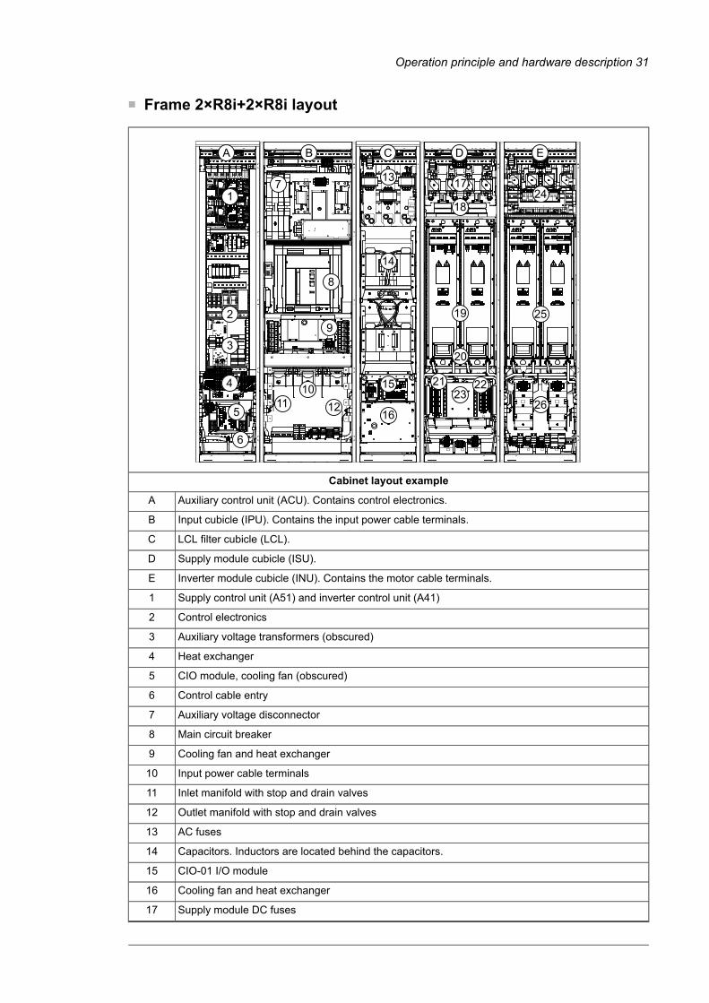
■ Frame 2×R8i+2×R8i layout
A B C D E
13
14
15
16
104
5
2
1
8
7
919
17
23
20
24
25
26
6
3
11 12
18
21 22
Cabinet layout example
Auxiliary control unit (ACU). Contains control electronics.A
Input cubicle (IPU). Contains the input power cable terminals.B
LCL filter cubicle (LCL).C
Supply module cubicle (ISU).D
Inverter module cubicle (INU). Contains the motor cable terminals.E
Supply control unit (A51) and inverter control unit (A41)1
Control electronics2
Auxiliary voltage transformers (obscured)3
Heat exchanger4
CIO module, cooling fan (obscured)5
Control cable entry6
Auxiliary voltage disconnector7
Main circuit breaker8
Cooling fan and heat exchanger9
Input power cable terminals10
Inlet manifold with stop and drain valves11
Outlet manifold with stop and drain valves12
AC fuses13
Capacitors. Inductors are located behind the capacitors.14
CIO-01 I/O module15
Cooling fan and heat exchanger16
Supply module DC fuses17
Operation principle and hardware description 31

Common mode filters18
IGBT supply modules of frame size R8i19
Coolant connections20
Air-to-liquid heat exchanger installed below each module21
(Behind the mounting plate) Fan. Forces air inside the cubicle through the heat exchanger.22
Mounting plate with terminal blocks for customer connections23
Inverter module DC fuses24
Inverter modules25
Inverter module cooling fan. A heat exchanger is located between the fan and the module.26
See also sections Door switches and lights (page 34) and Control panel (page 35).
■ 100 kA input cubicle (option +F274)100 kA input cubicle (option +F274) increases the short-circuit withstand rating of the drive.The cubicle contains extra fuses. The 100 kA cubicle is installed beside the standard 65 kAincoming cubicle or input cubicle at the factory. The input power cables enter the 100 kAinput cubicle. All other customer cables enter the auxiliary control cubicle or other supplyunit cubicles. The factory installs no optional door devices (such as meters, etc.) on thedoor of the 100 kA cubicle. No UL version (option +C129) is available.
The layout drawing presents the bottom power cable entry version.
2
1
3
45 6
Fan1.
AC fuses2.
Input power cable terminals [L1, L2, L3]3.
32 Operation principle and hardware description

Protective earth (ground)4.
Inlet manifold with stop and drain valves5.
Outlet manifold with stop and drain valves6.
Overview of power and control connectionsThe diagram shows the power connections and control interfaces of the drive.
L1
L2
L3
PE
U2
V2
W2
M 3 ~
L1
L2
L3
PE
FxxSlots 1, 2 and 31
7
......
....
......
....
.......... ..........
.....
.....
6
. .
.
. . .10
......
....
......
....
4
2 3
Slot 45
X205
X12
X13
8
Inverter control unit [A41]
Supply control unit [A51]
V1T/R…9
11 13
12
Drive
Fxxx
Option modules can be inserted into slots 1, 2, 3 and 4 as follows:1
SlotsModule type
1, 2, 3Analog and digital I/O extension modules
1, 2, 3Feedback interface modules
1, 2, 3Fieldbus communication modules
4RDCO-04 DDCS communication option module (standard equipment). As standard,a fiber optic link connects the supply and inverter control units.
234
Additional modules can be installed on an optional FEA-03 extension adapter connected to an RDCOmodule on slot 4.
Memory unit5
Connection for FSO safety functions module6
Control panel and PC connection7
Terminal blocks on the inverter control unit.8
Operation principle and hardware description 33

Fiber optic link to each inverter module. Similarly, each supply module is connected to the supplycontrol unit by fiber optic cables.
9
Terminal blocks for customer connections installed in the drive cabinet.10
Supply unit (consisting of one or more supply modules)11
DC intermediate link12
Inverter unit (consisting of one or more inverter modules)13
Door switches and lights■ Main disconnecting device [Q1]The drive is equipped with a main circuit breaker [Q1]. Units with 12-pulse supply connection(option +A004), as well as some of the largest 6-pulse types, have two breakers, [Q1.1] and[Q1.2]. To close the main breaker, auxiliary voltage must be switched on, and the groundingswitch (if present) must be open.
By racking out the breaker, you can isolate the main circuit of the drive from the power line.
WARNING!Themain disconnecting device does not isolate the input power terminals, AC voltagemeters, or the auxiliary voltage circuit from the power line. To isolate the auxiliaryvoltage circuit, open the auxiliary voltage switch [Q21]. To isolate the input powerterminals and AC voltage meters, open the main breaker of the supply transformer.
■ Auxiliary voltage switch [Q21]The auxiliary voltage switch controls the supply to the internal auxiliary voltage transformers.The transformer feeds the control circuits inside the drive such as cooling fans, relays andmeasuring equipment.Note: Frame 1×R8i+1×R8i units are not fitted with an auxiliary voltage switch. The auxiliaryvoltage is switched on and off by the main disconnecting device [Q1], and protected by fusedisconnectors F20.1…F20.3.
■ Grounding (earthing) switch [Q9], optionalThe grounding switch [Q9] (option +F259) connects the main AC power bus to the PEbusbar.
To close the grounding switch, auxiliary voltage must be switched on, and the maindisconnecting device must be open.
WARNING!The grounding switch does not ground the input power terminals of the drive or theauxiliary (control) voltage circuits.
■ Other devices on the door• Voltmeter (option +G334); comes with a phase selector switch.
Note: The voltage is measured on the supply side of the main switch or breaker.• AC current meter (option +G335) on one phase.
• AC current meter (option +3G335) on three phases.
34 Operation principle and hardware description

■ Control panelThe ACS-AP-W is the user interface of the drive. It provides the essential controls such asStart/Stop/Direction/Reset/Reference, and the parameter settings for the inverter controlprogram.
The control panel can be removed by pulling it forward by the top edge and reinstalled inreverse order. For the use of the control panel, see ACS-AP-I, -S, -W and ACH-AP-H, -WAssistant control panels user’s manual (3AUA0000085685 [English]) and the firmwaremanual.
Control by PC tools
There is a USB connector on the front of the panel that can be used to connect a PC to thedrive. When a PC is connected to the control panel, the control panel keypad is disabled.
Operation principle and hardware description 35

Descriptions of optionsNote: All options are not available for all drive types, do not coexist with certain other options,or may require additional engineering. Check actual availability with ABB.
■ Degree of protectionThe standard degree of protection is IP42 (UL type 1). IP54 (UL type 12) is available asoption +B055.
Definitions
According to IEC/EN 60529, the degree of protection is indicated by an IP code where thefirst numeral means protection against ingress of solid foreign objects, and the secondnumeral protection against ingress of water. The IP codes of the standard cabinet andoptions covered in this manual are defined below.
The equipment is protected …IP code
Second numeralFirst numeral
against dripping (15° tilting) wateragainst ingress of solid foreign objects > 1 mmIP42
against splashing waterdust-protectedIP54
■ Marine construction (option +C121)The option includes the following accessories and features:
• reinforced mechanics
• grab railings
• door flush bolt which allows the door to open 90 degrees and prevents it from slammingclose
• self-extinctive materials
• flat bars at base of the cabinet for fastening
• fastening brackets at the top of the cabinet.
Additional wire markings may be required for classification. See sectionWiremarkings (page 38).
■ UL Listed (option +C129)The cabinet contains the following accessories and features:
• top entry and exit with US cable conduit entries (plain plate without ready-made holes)
• all components UL/CSA Listed/Recognized
• maximum supply voltage 600 V
• US-type main switch and fuses.
■ Plinth height (options +C164 and +C179)These options specify a plinth height of 100 mm (+C164) or 200 mm (+C179).
36 Operation principle and hardware description

■ du/dt filterThe du/dt filter protects the motor insulating system by reducing the voltage rise speed atthe motor terminals. The filter also protects the motor bearings by reducing the bearingcurrents.
More information on when the option is required: See section Examining the compatibilityof the motor and drive (page 72).
■ Common mode filter (option +E208)The common mode filter contains ferrite rings mounted around the AC output busbars inthe drive module. The filter protects the motor bearings by reducing the bearing currents.
More information on when the option is required: See section Examining the compatibilityof the motor and drive (page 72).
■ Cabinet heater with external supply (option +G300)The option contains:
• heating elements in the cubicles or supply/inverter modules
• load switch for providing electrical isolation during service
• miniature circuit breaker for overcurrent protection
• terminal block for external power supply.
The heater prevents condensation inside the cabinet when the drive is not in operation. Thepower output of the heating elements increases when the surrounding air temperature islow and decreases when the surrounding air temperature is high. The customer must stopthe heating when it is not needed by disconnecting the heater supply voltage.
The customer must supply the heater from an external 110…240 V AC power source.
For the actual wiring, see the circuit diagrams delivered with drive.
■ Cabinet lighting (option +G301)This option contains LED lighting fixtures in each cubicle (except joining and brake resistorcubicles) and a 24 V DC power supply. The lighting is powered from the same external110…240 V AC power source as the cabinet heater (option +G300).
■ Terminals for external control voltage (option +G307)The option provides terminals for connecting an external uninterruptible control voltage tothe control unit and control devices when the drive is not powered.
See also:
• Supplying power for the auxiliary circuits (page 86)
• circuit diagrams delivered with drive for the actual wiring.
■ Output for motor space heater (option +G313)The option contains:
• load switch for providing electrical isolation during service
• miniature circuit breaker for overcurrent protection
• terminal block for heater and external heater supply connection.
Operation principle and hardware description 37

When the drive is powered (and not faulted), the heater is switched off. Otherwise, the heateris controlled by the external supply voltage.
The power and voltage of the heater depend on the motor.
See also:
• Supplying power for the auxiliary circuits (page 86)
• circuit diagrams delivered with drive for the actual wiring.
■ Halogen-free wiring and materials (option +G330)The option provides halogen-free cable ducts, control wires and wire sleeves, thus reducingtoxic fire gases.
■ V-meter with selector switch (option +G334)The option contains a voltmeter and a selector switch on the cabinet door. The switch selectsthe two input phases across which the voltage is measured.
■ Wire markings
Standard wiring
Color
The standard color of the wiring is black, with the following exceptions:
• PE wiring: Yellow/Green, or yellow/green sleeving
• UPS input wiring (option +G307): Orange
• Pt100 sensor wiring with ATEX-certified thermal protection (option +nL514): Light blue.
Markings
As standard, wires and terminals are marked as follows:
• Main circuit terminals: Connector identifier (eg. "U1") marked on terminal, or on insulatingmaterial close to the terminal. Input and output main circuit cables are not marked.
• Plug-in connectors of wire sets (except those that require special tools to disconnect)are labeled with connector designation (eg. "X1"). The marking is either directly on theconnector, or near the connector on printed sleeving or tape.
• Grounding busbars are marked with stickers.
• Fiber optic cable pairs and data cables have component designation and connectordesignations (eg. "A1:V1", "A1:X1") marked with rings or tape.
• Data cables are marked with tape.
• Ribbon cables are marked with either labels or tape.
• Customer-specific (engineered) wiring (option +P902) is not marked.
38 Operation principle and hardware description

Additional wire markings
The following additional wire markings are available.
Additional markingsOption
Equipment pin identifiers are marked with printing (or equivalent) on conductors that connectto equipment, or are part of the wiring between power modules. (Short, obvious connections,main circuit conductors, and conductors going to terminal blocks or plug-type connectors arenot marked.)
+G338(class A1)
T3/S
Equipment pin identifiers are marked with printing (or equivalent) on conductors that connectto equipment or terminal blocks, or are part of the wiring between power modules. Main circuitconductors are marked with white tape or printing. (Short, obvious connections, or conductorsgoing to plug-type connectors are not marked.)
+G339(class A2)
T3/S
Single wires not attached to plug-in connectors are marked with component pin numbers onsnap-on or ring markers. Plug-in connectors are marked with an identification label placed onthe wires near the connector (individual wires are not marked). Short, obvious connectionsare not marked. PE wires are not marked unless connected directly to components.
+G340(class A3)
9. 7 7
Equipment designations and pin identifiers are marked with snap-on markers (or equivalent)on conductors that connect to equipment, terminal blocks or detachable plug-type connectors,or are part of the wiring between power modules. Fiber optic cables are marked in the sameway. Plug-type connector identifications are marked on labels near the connectors. The labelholders are attached around conductor bundles. Main circuit conductors are marked with whitetape or printing. Short and obvious connections are marked with printing (or equivalent) only.
+G341(class B1)
K1 24 K 1 2 4
Note: Even wires with equipment and pin identifiers printed on the wire insulation are markedwith rings or tubing.Single wires connected to components, between modules, or to terminal blocks are markedwith component identification and pin numbers for both ends. The marking is printed onsleeving or, if necessary, snap-on markers. Plug-in connectors are marked with an identificationlabel (or snap-on markers) placed on the wires near the connector (individual wires are notmarked). Short, obvious connections are not marked. PE wires are not marked unless connec-ted directly to components.
+G342(class C1)
K1 24 K 1 2 4
K1 24 K1 24 T2 3
T 2 3 T2 3
T2 3
■ Voltage measurement with BAMU auxiliary measurement unit (option+G442)In weaker supply networks with a short-circuit ratio less than 8, it is highly recommendedto install a BAMU auxiliary measurement unit to the drive. In such networks, there is a risk
Operation principle and hardware description 39

of nuisance DC overvoltage tripping due to disturbances caused by probable high-voltageTHD in the supply voltage.
Short-circuit ratio is defined as the supply network's apparent short-circuit power Sk,net Vdivided by the drive's nominal apparent power Sn.
■ Bottom cable entry/exit (options +H350 and +H352)For UL Listed (+C129) units, the default input and output cabling direction is through theroof of the cabinet. The bottom entry (+H350) and bottom exit (+H352) options providepower and control cable entries at the floor of the cabinet. The entries are equipped withgrommets and 360° grounding hardware.
For non-UL Listed units, bottom entry/exit is the default cabling arrangement.
■ Top cable entry/exit (options +H351 and +H353)The top entry (+H351) and top exit (+H353) options provide power and control cable entriesat the roof of the cabinet. The entries are equipped with grommets and 360° groundinghardware.
■ Common motor terminal cubicle (option +H359)As standard, each inverter module must be individually cabled to the motor. This optionprovides an additional cubicle containing a single set of terminals for the motor cables.
The width of the cubicle and the size of the terminals within depend on the power rating ofthe drive.
■ Thermal protection with PTC relays (options +L505, +2L505, +L513,+2L513, +L536, +L537)PTC thermistor relay options are used for overtemperature supervision of motors equippedwith PTC sensors. When the motor temperature rises to the thermistor wake-up level, theresistance of the sensor increases sharply. The relay detects the change and indicatesmotor overtemperature through its contacts.
+L505, +2L505, +L513, +2L513
Option +L505 provides a thermistor relay and a terminal block. The terminal block hasconnections for the measuring circuit (one to three PTC sensors in series), an outputindication of the relay, and an optional external reset button. The relay can be reset eitherlocally or externally, or the reset circuit can be jumpered for automatic reset.
By default, the thermistor relay is wired internally to digital input DI6 of the drive control unit.The loss of the input is set to trigger an external fault.
The output indication on the terminal block can be wired by the customer, for example, toan external monitoring circuit. See the circuit diagrams delivered with the drive.
Option +L513 is an ATEX-certified thermal protection function that has the same externalconnectivity as +L505. In addition, +L513 comes with +Q971 (ATEX-certified safedisconnection function) as standard and is wired at the factory to activate the Safe torqueoff function of the drive in an overtemperature situation. A manual reset for the protectionfunction is required by Ex/ATEX regulations. For more information, see ATEX-certified motorthermal protection functions for cabinet-built ACS880 drives (options +L513+Q971 and+L514+Q971) user's manual (3AXD50000014979 [English]).
Options +2L505 and +2L513 duplicate options +L505 and +L513 respectively, containingthe relays and connections for two separate measurement circuits.
40 Operation principle and hardware description

+L536, +L537
An alternative to a thermistor relay option is the FPTC-01 (option +L536) or FPTC-02 (option+L537, also requires option +Q971) thermistor protection module. The module mounts ontothe inverter control unit, and has reinforced insulation to keep the control unitPELV-compatible. The connectivity of the FPTC-01 and the FPTC-02 is the same, but theFPTC-02 is Type Examined as a protective device within the scope of the European ATEX(and UKEX) Product Directive.
For protection purposes, the FPTC has a "fault" input for the PTC sensor. An overtemperaturesituation executes the SIL/PL-capable SMT (Safe motor temperature) safety function byactivating the Safe torque off function of the drive.
The FPTC also has a "warning" input for the sensor. When the module detectsovertemperature through this input, it sends a warning indication to the drive.
For more information and wiring examples, see the module manuals and the circuit diagramsdelivered with the drive.
See also
• firmware manual for parameter settings
• FPTC-01 thermistor protection module (option +L536) for ACS880 drives user's manual(3AXD50000027750 [English])
• FPTC-02 ATEX-certified thermistor protectionmodule, Ex II (2) GD (option +L537+Q971)for ACS880 drives user's manual (3AXD50000027782 [English])
• circuit diagrams delivered with the drive for the actual wiring.
■ Thermal protection with Pt100 relays (options +nL506, +nL514)Pt100 temperature monitoring relays are used for overtemperature supervision of motorsequipped with Pt100 sensors. For example, there can be three sensors to measure thetemperature of the motor windings and two sensors for the bearings. As the temperaturerises, the sensor resistance increases linearly. At an adjustable wake-up level, the monitoringrelay de-energizes its output.
The standard Pt100 relay options include three (+3L506), five (+5L506) or eight (+8L506)relays.
By default, the relays are wired internally to digital input DI6 of the drive control unit. Theloss of the input is set to trigger an external fault. The options include a terminal block forsensor connection. The output indication on the terminal block can be wired by the customer,for example, to an external monitoring circuit. See the circuit diagrams delivered with thedrive.
Options +3L514 (3 relays), +5L514 (5 relays) and +8L514 (8 relays) are ATEX-certifiedthermal protection functions that have the same external connectivity as +nL506. In addition,each monitoring relay has a 0/4…20mA output that is available on the terminal block. Option+nL514 comes with +Q971 (ATEX-certified safe disconnection function) as standard andis wired at the factory to activate the Safe torque off function of the drive in anovertemperature situation. As the monitoring relay does not have a reset functionality, themanual reset required by Ex/ATEX regulations must be implemented using drive parameters.For more information, see ATEX-certified motor thermal protection functions for cabinet-builtACS880 drives (options +L513+Q971 and +L514+Q971) user's manual (3AXD50000014979[English]).
See also
Operation principle and hardware description 41

• firmware manual for parameter settings
• ATEX-certified motor thermal protection functions for cabinet-built ACS880 drives(options +L513+Q971 and +L514+Q971) user's manual (3AXD50000014979 [English])
• Pt100 relay alarm and trip limit setting instructions in the start-up instructions
• circuit diagrams delivered with the drive for the actual wiring.
■ Starter for auxiliary motor fan (options +M600…M610)
What the option contains
The option provides switched and protected connections for 3-phase auxiliary motor fans.Each fan connection is equipped with:
• fuses
• a manual motor starter switch with an adjustable current limit
• a contactor controlled by the drive, and
• terminal block X601 for customer connections.
Description
The output for the auxiliary fan is wired from the 3-phase supply voltage to terminal blockX601 through a motor starter switch and a contactor. The contactor is operated by the drive.The 230 V AC control circuit is wired through a jumper on the terminal block; the jumpercan be replaced by an external control circuit.
The starter switch has an adjustable trip current limit, and can be opened to permanentlyswitch the fan off.
The statuses of both the starter switch and the fan contactor are wired to the terminal block.
See the circuit diagrams delivered with the drive for the actual wiring.
42 Operation principle and hardware description

Type designation labelThe type designation label includes ratings, appropriate markings, a type designation anda serial number, which allow the identification of each unit. A sample label is shown below.
Quote the complete type designation and serial number when contacting technical support.
Jl 1111 ,., .•.. MADE IN FINLAND
��o8m�X. 13
00380 Helsinki Finland
FRAME
8xR8I +8xR8I
liquid cooling lcw 155 kA IP54
Input
Output
UL/CSA: max. 1500 VAC
AC$880-17LC-6260A·7+A012+B055+C138+C141+ E205+E210+F255+F276+G307+G315+G316+G320+ G330+G336+G341+G344+G437+G450+H350+H353+ H368+J400+K450+K454+K473+L502+3l506+l509
U1 3~ 525/600/690 VAC 11 5810 A 11 50/60 Hz U2 3~ 0 ... U1 12 6260 A 12 0 ... 500 Hz Sn 7481 kVA
111111111111111111mn S/N: 1183605236
1
2
3
4
5
6
Type designation (see section Type designation key)1
Frame size2
Short-time withstand current rating (see chapter Technical data (page 173)); degree of protection;UL/CSA specifications
3
Ratings. See also chapter Technical data (page 173).4
Valid markings5
Serial number. The first digit of the serial number refers to the manufacturing plant. The next four digitsrefer to the unit’s manufacturing year and week, respectively. The remaining digits complete the serialnumber so that there are no two units with the same number.
6
Type designation keyThe type designation contains information on the specifications and configuration of thedrive. The first digits from left express the basic drive type. The optional selections are giventhereafter, separated by plus signs, eg, +E202. Codes preceded by a zero (eg. +0J400)indicate the absence of the specified feature. The main selections are described below. Notall selections are available for all types. For more information, refer to the ordering instructionsavailable separately on request.
DescriptionCode
Basic code
Product seriesACS880
Default configuration: liquid-cooled cabinet-installed drive, IP42 (UL Type 1), main switch-discon-nector (and contactor) or breaker, aR fuses, ACS-AP-W assistant control panel (with Bluetooth),EMC filter (category 3, 2nd Environment), du/dt filters, common mode filtering, standard wiremarkings, ACS880 primary control program, Safe torque off function, coated circuit boards, bottomentry and exit of cables with lead-through-type entries, USBmemory stick containing circuit diagrams,dimension drawings and manuals.
ACS880-17LC
Size
Refer to the rating tablesxxxxx
Voltage range
525…690 V AC. This is indicated in the type designation label as typical input voltage levels(3~ 525/600/690 V AC)7
Operation principle and hardware description 43

■ Option codes
DescriptionCode
50 Hz supply frequencyA012
60 Hz supply frequencyA013
IP42 (UL Type 1 Filtered)B054
IP54 (UL Type 12)B055
Marine construction. See section Marine construction (option +C121) (page 36).C121
UL Listed (evaluated to both U.S. and Canadian safety requirements). See sectionUL Listed (option+C129) (page 36).
C129
Marine type approval. Refer to ACS880 +C132marine type-approved cabinet-built drives supplement(3AXD50000039629 [English]).C132
ACS880-1007LC cooling unit as part of line-upC138
ACS880-1007LC cooling unit separate from line-up (stand-alone)C139
Single-pump cooling unitC140
Redundant (twin-pump) cooling unitC141
Pipe connection through bottomC142
Pipe connection on rightC143
Pipe connection on leftC144
ANSI flange pipe connectionC145
External cooling circuit suitable for sea waterC146
Plinth height 100 mm. See section Plinth height (options +C164 and +C179) (page 36).C164
Door hinges on leftC176
Plinth height 200 mm. See section Plinth height (options +C164 and +C179) (page 36).C179
Marine product certification issued by DNV GLC205
Marine product certification issued by the American Bureau of Shipping (ABS)C206
Marine product certification issued by Lloyd's Register (LR)C207
Marine product certification issued by Bureau VeritasC209
Cooling unit pumps can run simultaneouslyC213
Marine product certification issued by China Classification Society (CCS)C228
Marine product certification issued by Russian Maritime Register of Shipping (RS)C229
2-way valve in a dedicated cubicleC242
du/dt filteringE205
Common mode filteringE208
EMC/RFI filter for 2nd environment TN (grounded) or IT (ungrounded) system, category C3E210
Disconnect switchF253
Grounding (earthing) switchF259
Output grounding terminalsF271
100 kA short-circuit rating (100 kA input cubicle)F274
Cabinet and module heating elements (external supply). See section Cabinet heater with externalsupply (option +G300) (page 37).
G300
Cabinet lighting. See section Cabinet lighting (option +G301) (page 37).G301
Control (auxiliary) voltage 115 V ACG304
44 Operation principle and hardware description

DescriptionCode
Terminals for connecting external control voltage (230 V AC or 115 V AC, eg. UPS). See sectionTerminals for external control voltage (option +G307) (page 37).
G307
Output for motor space heater (external supply)G313
Aluminum busbarsG314
Tin-plated copper DC busbarsG315
Cable supply conductorsG316
Control (auxiliary) voltage 230 V ACG320
Halogen-free wiring and materialsG330
Electrical disconnect push button on the door (black, opens main contactor / ACB)G332
kW-meter on doorG333
V-meter with selector switchG334
A-meter in one phaseG335
A-meter in three phases3G335
Wire marking class A1. See sectionWire markings (page 38).G338
Wire marking class A2. See sectionWire markings (page 38).G339
Wire marking class A3. See sectionWire markings (page 38).G340
Wire marking class B1. See sectionWire markings (page 38).G341
Wire marking class C1. See sectionWire markings (page 38).G342
Auxiliary voltage transformerG344
Frequency monitoring device. Only for installation altitudes up to 2000 meters (6561 ft).G432
BAMU auxiliary measurement unit. See section Voltage measurement with BAMU auxiliary meas-urement unit (option +G442) (page 39).
G442
Power cabling entry from bottom. See section Bottom cable entry/exit (options +H350 and+H352) (page 40).
H350
Power cabling entry from top. See section Top cable entry/exit (options +H351 and +H353) (page 40).H351
Power cabling exit from bottom. See section Bottom cable entry/exit (options +H350 and+H352) (page 40).
H352
Power cabling exit from top. See section Top cable entry/exit (options +H351 and +H353) (page 40).H353
Common motor terminal cubicle. See section Common motor terminal cubicle (option+H359) (page 40).
H359
Cable gland plates (3 mm aluminum, undrilled)H364
Control cabling through floor of cabinetH367
ACS-AP-W control panel (with Bluetooth)J400
FDNA-01 DeviceNet™ adapter moduleK451
FLON-01 LonWorks® adapter moduleK452
FPBA-01 PROFIBUS DP adapter moduleK454
FCAN-01 CANopen adapter moduleK457
FSCA-01 RS-485 (Modbus/RTU) adapter moduleK458
FCNA-01 ControlNet™ adapter moduleK462
FECA-01 EtherCAT adapter moduleK469
FEPL-02 Ethernet POWERLINK adapter moduleK470
FENA-11 Ethernet adapter module for EtherNet/IP™, Modbus TCP and PROFINET IO protocolsK473
Operation principle and hardware description 45

DescriptionCode
FENA-21 Ethernet adapter module for EtherNet/IP™, Modbus TCP and PROFINET IO protocols,2-portK475
FIO-11 analog I/O extension moduleL500
FIO-01 digital I/O extension moduleL501
FEN-31 HTL incremental encoder interface moduleL502
Thermal protection with PTC relays (1 or 2 pcs). See section Thermal protection with PTC relays(options +L505, +2L505, +L513, +2L513, +L536, +L537) (page 40).
L505
Thermal protection with Pt100 relays (3, 5 or 8 pcs). See section Thermal protection with Pt100relays (options +nL506, +nL514) (page 41).
L506
ATEX-certified thermal protection with PTC relays (1 or 2 pcs)L513
ATEX-certified thermal protection with Pt100 relays (3, 5 or 8 pcs)L514
FSE-31 pulse encoder interface moduleL521
FPTC-01 thermistor protection moduleL536
FPTC-02 ATEX-certified thermistor protection moduleL537
Starter for auxiliary motor fan, trip limit 1.6 … 2.5 AM601
Starter for auxiliary motor fan, trip limit 2.5 … 4 AM602
Starter for auxiliary motor fan, trip limit 4 … 6.3 AM603
Starter for auxiliary motor fan, trip limit 6.3 … 10 AM604
Starter for auxiliary motor fan, trip limit 10…16 AM605
Starter for auxiliary motor fan, trip limit 16…20 AM606
Pump motor in delta connectionM633
Pump motor in star connectionM634
Winder control programN5000
Crane control programN5050
Winch control programN5100
PCP (Progressive Cavity Pump) control programN5200
Test bench control programN5300
Override control programN5450
ESP (Electrical Submersible Pump) control programN5600
Position control programN5700
Control program for synchronous reluctance motors (SynRM)N7502
IEC 61131-3 application programmabilityN8010
CustomizedP902
Special color (RAL Classic)P913
Prevention of unexpected start-up with FSO safety functions module, by activating the Safe torqueoff functionQ950
Emergency stop (category 0) with safety relays, by opening the main breaker/contactorQ951
Emergency stop (category 1) with safety relays, by opening the main breaker/contactorQ952
Earth fault monitoring for IT (ungrounded) systemsQ954
Prevention of unexpected start-up with safety relays, by activating the Safe torque off functionQ957
Emergency stop (category 0) with safety relays, by activating the Safe torque off functionQ963
Emergency stop (category 1) with safety relays, by activating the Safe torque off functionQ964
Safely-limited speed with FSO-21 and encoderQ965
46 Operation principle and hardware description

DescriptionCode
Safely-limited speed without encoderQ966
ATEX-certified safe disconnection functionQ971
FSO-21 safety functions moduleQ972
FSO-12 safety functions moduleQ973
Emergency stop (configurable for category 0 or 1) with FSO safety functions module, by openingthe main breaker/contactorQ978
Emergency stop (configurable for category 0 or 1) with FSO safety functions module, by activatingthe Safe torque off functionQ979
PROFIsafe with FSO safety functions module and FPNO-21 Ethernet adapter moduleQ982
Emergency stop button monitoringQ984
FSPS-21 PROFIsafe safety functions moduleQ986
Operation principle and hardware description 47

48

Mechanical installation
Contents of this chapterThis chapter describes the mechanical installation procedure of the drive.
Examining the installation siteExamine the installation site. Make sure that:
• The installation site is sufficiently ventilated or cooled to remove heat from the drive.See the technical data.
• The ambient conditions of the drive meet the specifications. See the technical data.
• There is sufficient free space above the drive for cooling, maintenance, and operationof the pressure relief (if present).
• The floor that the drive cabinet is installed on is of non-flammable material, as smoothas possible, and strong enough to support the weight of the unit. Check the floor flatnesswith a spirit level. The maximum allowed deviation from the surface level is 5 mm (0.2 in)in every 3 meters (10 ft). Level the installation site, if necessary, as the cabinet is notequipped with adjustable feet.
Necessary toolsThe tools required for moving the unit to its final position, fastening it to the floor and walland tightening the connections are listed below:
• crane, fork-lift or pallet truck (check load capacity!), slate/spud bar, jack and rollers
• Pozidriv and Torx screwdrivers
• torque wrench
• set of wrenches or sockets.
4Mechanical installation 49
10

Examining the deliveryThe drive delivery contains:
• drive cabinet line-up
• optional modules (if ordered) installed onto the control unit(s) at the factory
• appropriate drive and optional module manuals
• delivery documents.
Make sure that there are no signs of damage. Before attempting installation and operation,see the information on the type designation labels of the drive to verify that the delivery isof the correct type.
50 Mechanical installation
4

Moving and unpacking the driveMove the drive in its original packaging to the installation site as shown below to avoiddamaging the cabinet surfaces and door devices. When you are using a pallet truck, checkits load capacity before you move the drive.
The drive cabinet is to be moved in the upright position.
The center of gravity of the cabinet is high. Be therefore careful when moving the unit. Avoidtilting.
■ Moving the drive in its packaging
Lifting the crate with a forklift
WARNING!Incorrect lifting can cause danger or damage. Obey the local laws and regulationsapplicable to lifting, such as requirements for planning the lift, for capacity andcondition of lifting equipment, and for training of personnel.
Mechanical installation 51
10

Lifting the crate with a crane
WARNING!Incorrect lifting can cause danger or damage. Obey the local laws and regulationsapplicable to lifting, such as requirements for planning the lift, for capacity andcondition of lifting equipment, and for training of personnel.
max 20
b
a
Lifting pointa
Optimal position for the lifting sling: as close to the traverse board as possibleb
52 Mechanical installation
4

Moving the crate with a forklift
Mechanical installation 61
Moving the crate with a forklift
750 mm (29.5'')
■ Removing the transport packageRemove the transport package as follows:
1. Undo the screws that attach the wooden parts of the transport crate to each other.
2. Remove the wooden parts.
3. Remove the clamps with which the drive cabinet is mounted onto the transport palletby undoing the fastening screws.
4. Remove the plastic wrapping.
Mechanical installation 53
10

■ Moving the unpacked drive cabinet
Lifting the cabinet with a crane
WARNING!Incorrect lifting can cause danger or damage. Obey the local laws and regulationsapplicable to lifting, such as requirements for planning the lift, for capacity andcondition of lifting equipment, and for training of personnel.
Lift the drive cabinet by its designated lifting points. Depending on the size of the cabinet,it has either bolt-on lifting lugs, or lifting bars with lifting holes.Note: The minimum allowed height of the lifting slings with IP54 units is 2 meters (6’7”).
62 Mechanical installation
Removing the transport packageRemove the transport package as follows:
1. Undo the screws that attach the wooden parts of the transport crate together.
2. Remove the wooden parts.
3. Remove the clamps with which the drive cabinet is mounted onto the transport pallet by undoing the fastening screws.
4. Remove the plastic wrapping.
Moving the unpacked drive cabinet
Lifting the cabinet with a crane
Lift the drive cabinet using its lifting eyes. The lifting eyes can be removed after the cabinet is in its final position, but their mounting holes must be blocked to retain the degree of protection.
Note: The minimum allowed height of the lifting slings with IP54 units is 2 meters (6’7”).
IP54
54 Mechanical installation
4

Moving the cabinet on rollers
WARNING!Do not move marine versions (option +C121) on rollers.
Lay the cabinet on the rollers and move it carefully until close to its final location. Removethe rollers by lifting the unit with a crane, forklift, pallet truck or jack.
Moving the cabinet on its back
WARNING!Do not transport the drive with an LCL or L filter on its back. It will damage the filter.
If the cabinet needs to be laid on its back, support the cabinet from below alongside thecubicle seams.
1 2
Cabinet back panel1
Support2
Mechanical installation 55
10

Final placement of the cabinet
Move the cabinet into its final position with a slate bar (spud bar). Place a piece of woodbetween the edge of the cabinet and the bar to protect the cabinet frame.
56 Mechanical installation
4

Attaching the cabinet to the floor and wall or roof■ General rules• The drive must be installed in an upright vertical position.
• Leave 250 mm (9.85”) of free space above the cabinet for maintenance, and to allowpressure relief operation.
• The cabinet can be installed with its back against a wall (a), or back-to-back with anotherunit (b).
• Leave some space (w) at the side where the cabinet outmost hinges are to allow thedoors to open sufficiently. The doors must open 120° to allow module replacement.
a
b
120°
w> 250 mm (9.85”)
Note 1: Any height adjustment must be done before attaching the cabinet sections to thefloor or to each other. Height adjustment can be done by using metal shims between thecabinet bottom and floor.
Note 2: Depending on the size of the cabinet, it has either bolt-on lifting eyes, or lifting barswith lifting holes. Bolt-on lifting eyes need not be removed unless the holes are used forattaching the cabinet. If the cabinet is delivered with lifting bars, either remove them or letthem remain attached to the cabinet. If removed, store the bars for decommissiong. If thelifting bars have been removed, plug any unused holes using the existing bolts and sealingrings included. Tighten to 70 N·m (52 lbf·ft).
Mechanical installation 57
10

■ Attaching the cabinet (non-marine units)
Alternative 1 – Clamping
1. Insert the clamps (included) into the twin slots along the front and rear edges of thecabinet frame body and fasten them to the floor with a bolt. The recommendedmaximumdistance between the clamps in the front edge is 800 mm (31.5”).
2. If floor mounting at the back is not possible, attach the top of the cabinet to the wallwith L-brackets (not included in the delivery) bolted to the lifting eye/bar holes, andsuitable hardware.
Attaching top to wallClamping bottom to floor
M16
58 Mechanical installation
4

Alternative 2 – Using the holes inside the cabinet
1. Attach the cabinet to the floor through the bottom fastening holes with size M10…M12(3/8”…1/2”) bolts. The recommended maximum distance between the front edgefastening points is 800 mm (31.5”).
2. If the back fastening holes are not accessible, attach the top of the cabinet to the wallwith L-brackets (not included in the delivery) bolted to the lifting eye/bar holes.
Attaching cabinet top to wallAttaching bottom to floor
M16
Mechanical installation 59
10
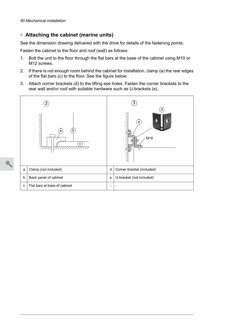
■ Attaching the cabinet (marine units)See the dimension drawing delivered with the drive for details of the fastening points.
Fasten the cabinet to the floor and roof (wall) as follows:
1. Bolt the unit to the floor through the flat bars at the base of the cabinet using M10 orM12 screws.
2. If there is not enough room behind the cabinet for installation, clamp (a) the rear edgesof the flat bars (c) to the floor. See the figure below.
3. Attach corner brackets (d) to the lifting eye holes. Fasten the corner brackets to therear wall and/or roof with suitable hardware such as U-brackets (e).
M16
3
e
d
a b
c
2
Corner bracket (included)dClamp (not included)a
U-bracket (not included)eBack panel of cabinetb
--Flat bars at base of cabinetc
60 Mechanical installation
4

Joining cabinet sections togetherWide cabinet line-ups are delivered in multiple sections. The sections are to be joined on-siteusing a joining cubicle at the end of one section (a common motor terminal cubicle can alsoact as a joining cubicle). The screws required for the joining are enclosed in a plastic baginside the cabinet.
1. Fasten the first section to the floor.
2. Remove any plates covering the rear post of the joining cubicle.
3. Slide Axilock connectors onto the coolant pipes at the joint.
4. Align the two sections.The coolant pipe ends must be aligned as shown.
5…15 mm (0.2…0.6")
< 2°
< 3 mm (0.12")
Mechanical installation 61
10

5. Center the Axilock connectors onto the gaps between coolant pipe ends. Tighten theconnector screws to the torque indicated on the connector label.
6. Fasten the front and rear posts of the joining cubicle to the posts of the other sectionwith 16 screws (8 per post). Tighten the screws to 5 N·m (3.7 lbf·ft).
7. Fasten the second section to the floor. The numbers in the figure below refer to theinstallation steps.
1 3
5
44
4 7
6
6
64
62 Mechanical installation
4

8. Connect the PE busbars using the M10 bolts included. Tighten to 35…40 N·m(25…30 lbf·ft).
Side
Above
a
b
c
a
b
c
Plain washera
Spring washerb
Boltc
9. Remove the shroud covering the DC busbars in the joining cubicle.
Mechanical installation 63
10

10. Connect the DC and AC busbars. Tighten the bolts to 55…70 N·m (40…50 lbf·ft).
aa
aa
aa
aa
aa
ab
ad
aa
abac
ad
aa
ac
aa
Units with single DC busbars
Units with double DC busbars
Joint piecea
Plain washer with electroplated zinc coating and blue chromate passivationb
Spring washer with mechanically sprayed zinc coatingc
Nut (M12)d
64 Mechanical installation
4

Units with single AC busbars
Units with double AC busbars
a
c d ef
b
Bolt (M12)a
Bolt (M12)b
Joint piecec
Plain washer with electroplated zinc coating and blue chromate passivationd
Spring washer with mechanically sprayed zinc coatinge
Nut (M12)f
WARNING!Make sure you install the washers in the correct order as shown. For example,placing an unpassivated zinc-coated spring washer directly against the jointpiece will cause corrosion.
WARNING!Do not use any joining parts other than those delivered with the unit. The partsare carefully selected to match the material of the busbars. Other parts ormaterials can form a galvanic couple and cause corrosion.
11. Reinstall any shrouding removed earlier.
12. Repeat procedure for any further sections.
Mechanical installation 65
10

Miscellaneous■ Cable duct in the floor below the cabinetA cable duct can be constructed below the 500 mm wide middle part of the cabinet. Thecabinet weight lies on the two 50 mm wide transverse sections which the floor must carry.
Prevent the cooling air flow from the cable duct to the cabinet by bottom plates. To ensurethe degree of protection for the cabinet, use the original bottom plates delivered with theunit. With user-defined cable entries, take care of the degree of protection, fire protectionand EMC compliance.
500 (19.68”) 50 (1.97”)
500
(19.
68”)
50 (1.97”)
■ Arc weldingABB does not recommend attaching the cabinet by arc welding. However, if arc welding isthe only option, connect the return conductor of the welding equipment to the cabinet frameat the bottom within 0.5 meters (1’6”) of the welding point.Note: The cabinet frame is zinc-plated.
WARNING!Make sure that the return wire is connected correctly. Welding current must notreturn via any component or cabling of the drive. If the welding return wire isconnected improperly, the welding circuit can damage electronic circuits in thecabinet.
WARNING!Do not inhale the welding fumes.
66 Mechanical installation
4

Lifting lugs and bars■ Certificate of conformityThe certificate is available in ABB Library at www.abb.com/drives/documents (documentnumber 3AXD10001061361).
■ Declarations of conformity
Mechanical installation 67
10

68 Mechanical installation
4

1/2 3AXD10001329600 rev.A
Declaration of Conformity Supply of Machinery (Safety) Regulations 2008 We Manufacturer: ABB Oy Address: Hiomotie 13, 00380 Helsinki, Finland. Phone: +358 10 22 11
declare under our sole responsibility that the following products:
Lifting bars, identified with material codes
64300971
64301047
64301063
64301080
64301101
64301136
64301152
64301187
64301209
64301250
64301268
64301276
64301284
64301306
64301314
64301322
64301331
64301349
64301357
64301365
64301373
64301381
64301390
64301403
64301411
64456695
64456725
64456822
64456881
64456890
64456920
64485296
64485300
64485318
64485326
64485334
64485342
64485351
64485369
64485377
64485458
68775558
68775540
3AUA5000013498
3AUA5000013504
3AUA0000055356
3AXD50000435524
3AXD50000435548
Lifting lugs, identified with material codes
64302621 64327151
used for lifting the following frequency converters and frequency converter components
ACS800LC types –x7LC, LC multidrives, -x07LC
ACS580, ACH580, ACQ580 types -07
ACS880 types –x7, multidrives, -x07, -xx07
ACS880LC types –x7LC, LC multidrives, -x07LC, -xx07
identified with serial numbers beginning with 1 or 8
Mechanical installation 69
10

2/2 3AXD10001329600 rev.A
are in conformity with all the relevant lifting accessory requirements of the Supply of Machinery (Safety) Regulations 2008.
Authorized to compile the technical file: ABB Oy, Hiomotie 13, 00380 Helsinki, Finland
Helsinki, 28 May 2021
Signed for and on behalf of:
Peter Lindgren Vesa Tiihonen Vice President, ABB Oy Manager, Reliability and Quality, ABB Oy
70 Mechanical installation
4

Guidelines for planning the electricalinstallation
Contents of this chapterThis chapter contains instructions for planning the electrical installation of the drive. Someinstructions are mandatory to follow in every installation, others provide useful informationthat only concerns certain applications.
Limitation of liabilityThe installation must always be designed and made according to applicable local laws andregulations. ABB does not assume any liability whatsoever for any installation which breachesthe local laws and/or other regulations. Furthermore, if the recommendations given by ABBare not followed, the drive may experience problems that the warranty does not cover.
Selecting the supply disconnecting deviceThe drive is equipped with a main disconnecting device as standard. Depending on the sizeof the drive, and the selected options, the type of disconnecting device may vary. Examples:switch-disconnector, withdrawable air circuit breaker, etc.
Selecting the main breaker optionThe drive is equipped with an air circuit breaker in the incoming cubicle as standard (+F255).
Optionally, the drive may be ordered without an air circuit breaker (+F255disabled/deselected). In this case, the supply panel of the drive must be equipped with amain breaker. The control interface for this external breaker is located in the drive’s inputcubicle.
5Guidelines for planning the electrical installation 71

For connecting to power networks with a short rating from 65 kA up to 100 kA, the drive canbe ordered with option +F274, which adds an additional 100 kA rated input cubicle to theinput section of the drive.
Examining the compatibility of the motor and driveUse asynchronous AC induction motors, permanent magnet synchronous motors, ACinduction servomotors or ABB synchronous reluctance motors (SynRM motors) with thedrive.
Select the motor size and drive type from the rating table on basis of the AC line voltageand motor load. You can find the rating table in the appropriate hardware manual. You canalso use the DriveSize PC tool.
Make sure that the motor can be used with an AC drive. See Requirements table (page 72).For basics of protecting the motor insulation and bearings in drive systems, see Protectingthe motor insulation and bearings (page 72).
Note:• Consult the motor manufacturer before using a motor with nominal voltage that differs
from the AC line voltage connected to the drive input.
• The voltage peaks at the motor terminals are relative to the supply voltage of the drive,not to the drive output voltage.
■ Protecting the motor insulation and bearingsThe drive employs modern IGBT inverter technology. Regardless of frequency, the driveoutput comprises pulses of approximately the drive DC bus voltage with a very short risetime. The pulse voltage can almost double at the motor terminals, depending on theattenuation and reflection properties of the motor cable and the terminals. This can causeadditional stress on the motor and motor cable insulation.
Modern variable speed drives with their fast rising voltage pulses and high switchingfrequencies can generate current pulses that flow through the motor bearings. This cangradually erode the bearing races and rolling elements.
du/dt filters protect motor insulation system and reduce bearing currents. Common modefilters mainly reduce bearing currents. Insulated N-end (non-drive end) bearings protect themotor bearings.
■ Requirements tableThese tables show how to select the motor insulation system and when a drive du/dt andcommon mode filters and insulated N-end (non-drive end) motor bearings are required.Ignoring the requirements or improper installation may shorten motor life or damage themotor bearings and voids the warranty.
72 Guidelines for planning the electrical installation

This table shows the requirements when an ABB motor is in use.
Requirement forNominal AC linevoltage
Motor type
ABB du/dt and common mode filters, insulatedN-end motor bearings
Motor insula-tion system
Pn ≥ 350 kWor
frame size ≥IEC 400
100 kW ≤ Pn <350 kW
orIEC 315 ≤ framesize < IEC 400
Pn <100 kW andframe size< IEC 315
Pn ≥ 469 hpor
frame size >NEMA 580
134 hp ≤ Pn <469 hp
orNEMA 500 ≤frame size ≤NEMA 580
Pn < 134 hpand frame
size <NEMA 500
+ N + CMF+ N-StandardUn ≤ 500 VRandom-woundM2_,M3_ and M4_ + N + du/dt +
CMF+ N + du/dt+ du/dtStandard500 V < Un ≤ 600 V
or
+ N + CMF+ N-Reinforced
+ N + du/dt +CMF
+ N + du/dt+ du/dtReinforced600 V < Un ≤ 690 V(cable length ≤
150 m)
+ N + CMF+ N-Reinforced600 V < Un ≤ 690 V(cable length >
150 m)
Pn < 500 kW:+N + CMF
+ N + CMFn.a.Standard380 V < Un ≤ 690 VForm-wound HX_and AM_
Pn ≥ 500 kW:+N + du/dt + CMF
+ N + du/dt with voltages over 500 V + CMFCheck with themotor manu-facturer.
380 V < Un ≤ 690 VOld1) form-woundHX_ and modular
+ N + CMFEnamelledwire with fiberglass taping
0 V < Un ≤ 500 VRandom-woundHX_and AM_ 2)
+ N + du/dt + CMF500 V < Un ≤ 690 V
Consult the motor manufacturer.HDP
1) manufactured before 1.1.19982) For motors manufactured before 1.1.1998, check for additional instructions with the motor manufacturer.
Guidelines for planning the electrical installation 73

This table shows the requirements when a non-ABB motor is in use.
Requirement forNominal AC linevoltage
Motor type
ABB du/dt and common mode filters, insulatedN-end motor bearings
Motor insula-tion system
Pn ≥ 350 kWor
frame size ≥IEC 400
100 kW ≤ Pn <350 kW
orIEC 315 ≤ framesize < IEC 400
Pn <100 kW andframe size< IEC 315
Pn ≥ 469 hpor
frame size >NEMA 580
134 hp ≤ Pn <469 hp
orNEMA 500 ≤frame size ≤NEMA 580
Pn < 134 hpand framesize <NEMA 500
+ N + CMF+ N or CMF-Standard:ÛLL = 1300 V
Un ≤ 420 VRandom-wound andform-wound
+ N + du/dt +CMF
+ du/dt + (N orCMF)
+ du/dtStandard:ÛLL = 1300 V
420 V < Un ≤ 500 V
or
+ N + CMF+ N or CMF-Reinforced:ÛLL = 1600 V,0.2 micro-second risetime
+ N + du/dt +CMF
+ du/dt + (N orCMF)
+ du/dtReinforced:ÛLL = 1600 V
500 V < Un ≤ 600 V
or
+ N + CMF+ N or CMF-Reinforced:ÛLL = 1800 V
+ N + du/dt +CMF
+ du/dt + N+ du/dtReinforced:ÛLL = 1800 V
600 V < Un ≤ 690 V
+ N + CMF+ N + CMF-Reinforced:ÛLL = 2000 V,0.3 micro-second risetime1)
1) If the intermediate DC circuit voltage of the drive is increased from the nominal level due to long term resistor brakingcycles, check with the motor manufacturer if additional output filters are needed.
The abbreviations used in the tables are defined below.
DefinitionAbbr.
Nominal AC line voltageUn
Peak line-to-line voltage at motor terminals which the motor insulation must withstandÛLL
Motor nominal powerPndu/dt filter at the output of the drivedu/dt
Common mode filter of the driveCMF
N-end bearing: insulated motor non-drive end bearingN
Motors of this power range are not available as standard units. Consult the motor manu-facturer.
n.a.
74 Guidelines for planning the electrical installation

Availability of du/dt filter and common mode filter by drive type
Availability of common mode filter(CMF)Availability of du/dt filterProduct type
StandardStandardACS880-17LC
Additional requirements for explosion-safe (EX) motors
If you use an explosion-safe (EX) motor, follow the rules in the requirements table above.In addition, consult the motor manufacturer for any further requirements.
Additional requirements for ABB motors of types other than M2_, M3_, M4_, HX_ andAM_
Use the selection criteria given for non-ABB motors.
Additional requirements for the regenerative and low harmonics drives
It is possible to increase the intermediate circuit DC voltage from the nominal (standard)level with a parameter in the control program. If you choose to do this, select the motorinsulation system which withstands the increased DC voltage level.
Additional requirements for ABB high-output and IP23 motors
The rated output power of high output motors is higher than what is stated for the particularframe size in EN 50347 (2001).
This table shows the requirements for protecting the motor insulation and bearings in drivesystems for ABB random-wound motor series (for example, M3AA, M3AP and M3BP).
Requirement forNominal AC supplyvoltage
ABB du/dt and common mode filters, insulated N-end motorbearings
Motor insulationsystem
Pn ≥ 200 kW100 kW ≤ Pn <200 kW
Pn < 100 kW
Pn ≥ 268 hp140 hp ≤ Pn <268 hp
Pn < 140 hp
+ N + CMF+ N-StandardUn ≤ 500 V
+ du/dt + N + CMF+ du/dt + N+ du/dtStandard500 V < Un ≤ 600 V
or
+ N + CMF+ N-Reinforced
+ du/dt + N + CMF+ du/dt + N+ du/dtReinforced600 V < Un ≤ 690 V
Additional requirements for non-ABB high-output and IP23 motors
The rated output power of high-output motors is higher than what is stated for the particularframe size in EN 50347 (2001).
If you plan to use a non-ABB high-output motor or an IP23 motor, consider these additionalrequirements for protecting the motor insulation and bearings in drive systems:
• If motor power is below 350 kW: Equip the drive and/or motor with the filters and/orbearings according to the table below.
• If motor power is above 350 kW: Consult the motor manufacturer.
Guidelines for planning the electrical installation 75

Requirement forNominal AC supplyvoltage
ABB du/dt and common mode filters, insulated N-end motor bearings
Motor insulation system
100 kW < Pn < 350 kW orIEC 315 < frame size <
IEC 400
Pn < 100 kW or frame size< IEC 315
134 hp < Pn < 469 hp orNEMA 500 < frame size <
NEMA 580
Pn < 134 hp or frame size< NEMA 500
+ N or CMF+ N or CMFStandard: ÛLL = 1300 VUn ≤ 420 V
+ N + du/dt + CMF+ du/dt + (N or CMF)Standard: ÛLL = 1300 V420 V < Un < 500 V
or
+ N or CMF+ N or CMFReinforced: ÛLL = 1600 V,0.2 microsecond rise time
+ N + du/dt + CMF+ du/dt + (N or CMF)Reinforced: ÛLL = 1600 V500 V < Un ≤ 600 V
or
+ N + CMF+ N or CMFReinforced: ÛLL = 1800 V
+ N + du/dt + CMF+ N + du/dtReinforced: ÛLL = 1800 V600 V < Un ≤ 690 V
+ N + CMF+ N + CMFReinforced: ÛLL = 2000 V,0.3 microsecond risetime1)
1) If the intermediate DC circuit voltage of the drive is increased from the nominal level due to long term resistor brakingcycles, check with the motor manufacturer if additional output filters are needed.
Additional note for sine filters
A sine filter also protects the motor insulation system. The peak phase-to-phase voltagewith a sine filter is approximately 1.5 · Un.
Selecting the power cables■ General guidelinesSelect the input power and motor cables according to local regulations.
• Current: Select a cable capable of carrying the maximum load current and suitable forthe prospective short-circuit provided by the supply network. The method of installationand ambient temperature affect the cable current carrying capacity. Obey localregulations and laws.
• Temperature: For an IEC installation, select a cable rated for at least 70 °C (158 °F)maximum permissible temperature of conductor in continuous use.For North America, select a cable rated for at least 75 °C (167 °F).Important: For certain product types or option configurations higher temperature ratingmay be required. See the technical data for details.
• Voltage: 600 V AC cable is accepted for up to 500 V AC. 750 V AC cable is acceptedfor up to 600 V AC. 1000 V AC cable is accepted for up to 690 V AC.
To comply with the EMC requirements of the CEmark, use one of the preferred cable types.See Preferred power cable types (page 77).
Symmetrical shielded cable reduces electromagnetic emission of the whole drive systemas well as the stress on motor insulation, bearing currents and wear.
76 Guidelines for planning the electrical installation

Metal conduit reduces electromagnetic emission of the whole drive system.
■ Typical power cable sizesSee the technical data.
■ Power cable types
Preferred power cable types
This section presents the preferred cable types. Make sure that the selected cable type alsocomplies with local/state/country electrical codes.
Use as motor cablingUse as input power cablingCable type
YesYesPE
Symmetrical shielded (or armored)cable with three phase conductorsand concentric PE conductor as
shield (or armor)
YesYesPE
Symmetrical shielded (or armored)cable with three phase conductorsand symmetrically constructed PEconductor and a shield (or armor)
YesYes
PE
Symmetrical shielded (or armored)cable with three phase conductorsand a shield (or armor), and separ-
ate PE conductor/cable1)
1) A separate PE conductor is required if the conductivity of the shield (or armor) is not sufficient for the PE use.
Alternate power cable types
Use as motor cablingUse as input power cablingCable type
Yes with phase conductor smallerthan 10 mm2 (8 AWG) Cu, or motorsup to 30 kW (40 hp)
Yes
EMT
Four-conductor cabling in metalconduit (three phase conductors andPE). For example, EMT, or four-
conductor armored cable
Guidelines for planning the electrical installation 77

Use as motor cablingUse as input power cablingCable type
Yes with motors up to 100 kW(135 hp). A potential equalizationbetween the frames of motor anddriven equipment is required.
Yes
Shielded (Al/Cu shield or armor)1)four-conductor cable (three phase
conductors and a PE)
NoYesPE
WARNING!If you use unshielded single-core cables in an IT network,make sure that the non-con-ductive outer sheath (jacket)of the cables have good con-tact with a properly groundedconductive surface. For ex-ample, install the cables on aproperly grounded cable tray.Otherwise voltage may be-come present on the non-conductive outer sheath of thecables, and there is even arisk of an electric shock.
A single-core cable system: threephase conductors and PE conductor
on cable trayL1
L3L2L2
L1L3L3
L2L1
Preferable cable arrangement toavoid voltage or current unbalance
between the phases
1) Armor may act as an EMC shield, as long as it provides the same performance as a concentric EMC shield of a shieldedcable. To be effective at high frequencies, the shield conductivity must be at least 1/10 of the phase conductor conductivity.The effectiveness of the shield can be evaluated based on the shield inductance, which must be low and only slightlydependent on frequency. The requirements are easily met with a copper or aluminum shield/armor. The cross-section ofa steel shield must be ample and the shield helix must have a low gradient. A galvanized steel shield has a betterhigh-frequency conductivity than a non-galvanized steel shield.
Not allowed power cable types
Use as motor cablingUse as input power cablingCable type
NoNoPE
Symmetrical shielded cable with in-dividual shields for each phase
conductor
■ Power cable shieldIf the cable shield is used as the sole protective earth (PE) conductor, make sure that itsconductivity agrees with the PE conductor requirements.
To effectively suppress radiated and conducted radio-frequency emissions, the cable shieldconductivity must be at least 1/10 of the phase conductor conductivity. The requirementsare easily met with a copper or aluminum shield. The minimum requirement of the motorcable shield of the drive is shown below. It consists of a concentric layer of copper wireswith an open helix of copper tape or copper wire. The better and tighter the shield, the lowerthe emission level and bearing currents.
78 Guidelines for planning the electrical installation

1 3 4 52
Insulation jacket1
Helix of copper tape or copper wire2
Copper wire shield3
Inner insulation4
Cable core5
Grounding requirementsThis section gives general requirements for grounding the drive.When you plan the groundingof the drive, obey all the applicable national and local regulations.
The conductivity of the protective earth conductor(s) must be sufficient.
Unless local wiring regulations state otherwise, the cross-sectional area of the protectiveearth conductor must agree with the conditions that require automatic disconnection of thesupply required in 411.3.2 of IEC 60364-4-41:2005 and be capable of withstanding theprospective fault current during the disconnection time of the protective device. Thecross-sectional area of the protective earth conductor must be selected from the table belowor calculated according to 543.1 of IEC 60364-5-54.
This table shows the minimum cross-sectional area of the protective earth conductor relatedto the phase conductor size according to IEC/UL 61800-5-1 when the phase conductor(s)and the protective earth conductor are made of the same metal. If this is not so, thecross-sectional area of the protective earth conductor must be determined in a mannerwhich produces a conductance equivalent to that which results from the application of thistable.
Minimum cross-sectional area of the correspondingprotective earth conductor
Sp (mm2)
Cross-sectional area of the phase conductorsS (mm2)
S1)S ≤ 16
1616 < S ≤ 35
S/235 < S
1) For the minimum conductor size in IEC installations, refer to Additional grounding requirements – IEC.
If the protective earth conductor is not part of the input power cable or input power cableenclosure, the minimum permitted cross-sectional area is:
• 2.5 mm2 if the conductor is mechanically protected,or
• 4 mm2 if the conductor is not mechanically protected. If the equipment is cord-connected,the protective earth conductor must be the last conductor to be interrupted if there is afailure in the strain relief mechanism.
Guidelines for planning the electrical installation 79

■ Additional grounding requirements – IECThis section gives grounding requirements according to standard IEC/EN 61800-5-1.
Because the normal touch current of the drive is more than 3.5 mA AC or 10 mA DC:
• the minimum size of the protective earth conductor must comply with the local safetyregulations for high protective earth conductor current equipment, and
• you must use one of these connection methods:
1. a fixed connection and:
• a protective earth conductor with a minimum cross-sectional area of 10 mm2
Cu or 16 mm2 Al (as an alternative when aluminum cables are permitted),or
• a second protective earth conductor of the same cross-sectional area as theoriginal protective earth conductor,or
• a device that automatically disconnects the supply if the protective earthconductor is damaged.
2. a connection with an industrial connector according to IEC 60309 and a minimumprotective earth conductor cross-section of 2.5 mm2 as part of a multi-conductorpower cable. Sufficient strain relief must be provided.
If the protective earth conductor is routed through a plug and socket, or similar means ofdisconnection, it must not be possible to disconnect it unless power is simultaneouslyremoved.Note: You can use power cable shields as grounding conductors only when their conductivityis sufficient.
■ Additional grounding requirements – UL (NEC)This section gives grounding requirements according to standard UL 61800-5-1.
The protective earth conductor must be sized as specified in Article 250.122 and table250.122 of the National Electric Code, ANSI/NFPA 70.
For cord-connected equipment, it must not be possible to disconnect the protective earthconductor before power is removed.
Selecting the control cables■ ShieldingOnly use shielded control cables.
Use a double-shielded twisted pair cable for analog signals. ABB recommends this type ofcable also for the pulse encoder signals. Use one individually shielded pair for each signal.Do not use common return for different analog signals.
80 Guidelines for planning the electrical installation

A double-shielded cable (a) is the best alternative for low-voltage digital signals, butsingle-shielded (b) twisted pair cable is also acceptable.
a b
■ Signals in separate cablesRun analog and digital signals in separate, shielded cables. Do not mix 24 V DC and115/230 V AC signals in the same cable.
■ Signals that can be run in the same cableIf their voltage does not exceed 48 V, relay-controlled signals can be run in the same cablesas digital input signals. The relay-controlled signals should be run as twisted pairs.
■ Relay cableThe cable type with braidedmetallic shield (for example ÖLFLEX by LAPPKABEL, Germany)has been tested and approved by ABB.
■ Control panel to drive cableUse EIA-485, Cat 5e (or better) cable with male RJ-45 connectors. The maximum length ofthe cable is 100 m (328 ft).
■ PC tool cableConnect the Drive Composer PC tool to the drive through the USB port of the control panel.Use a USB Type A (PC) - Type Mini-B (control panel) cable. The maximum length of thecable is 3 m (9.8 ft).
Routing the cables■ General guidelines – IEC• Route the motor cable away from other cables. Motor cables of several drives can be
run in parallel installed next to each other.
• Install the motor cable, input power cable and control cables on separate trays.
• Avoid long parallel runs of motor cables with other cables.
• Where control cables must cross power cables, make sure that they are arranged atan angle as near to 90 degrees as possible.
• Do not run extra cables through the drive.
• Make sure that the cable trays have good electrical bonding to each other and to thegrounding electrodes. Aluminum tray systems can be used to improve local equalizingof potential.
The following figure illustrates the cable routing guidelines with an example drive.
Guidelines for planning the electrical installation 81

min. 300 mm (12 in)
min. 300 mm (12 in) min. 500 mm (20 in)
min. 500 mm (20 in)min. 200 mm (8 in)
90°
1
2 4
4
32
1
32
3
Motor cable1
Input power cable2
Control cable3
Brake resistor or chopper cable (if any)4
■ Continuous motor cable shield/conduit or enclosure for equipmenton the motor cableTo minimize the emission level when safety switches, contactors, connection boxes orsimilar equipment are installed on the motor cable between the drive and the motor:
• Install the equipment in a metal enclosure.
• Use either a symmetrical shielded cable, or install the cabling in a metal conduit.
• Make sure that there is a good and continuous galvanic connection in the shield/conduitbetween drive and motor.
• Connect the shield/conduit to the protective ground terminal of the drive and the motor.
■ Separate control cable ductsPut 24 V DC and 230 V AC (120 V AC) control cables in separate ducts, unless the 24 V DCcable is insulated for 230 V AC (120 V AC) or insulated with an insulation sleeving for230 V AC (120 V AC).
24 V DC230 V AC
(120 V AC)
230 V AC(120 V AC)
24 V DC
82 Guidelines for planning the electrical installation

Protecting the drive, input power cable, motor and motorcable in short circuit situations and against thermaloverload■ Protecting the input cabling and the drive upon a short-circuitTo protect the input cable in short-circuit situations, install fuses or a suitable circuit breakerat the supply side of the cabling.
The drive is equipped with fuses as standard. In case of a short-circuit inside the drive, thefuses protect the drive, restrict drive damage, and prevent damage to adjoining equipment.
■ Protecting the motor and motor cable in short-circuitsThe drive protects the motor cable and motor in a short-circuit situation when the motorcable is sized according to the nominal output current of the drive.
■ Protecting the drive and the power cables against thermal overloadThe drive protects itself and the input and motor cables against thermal overload when thecables are sized according to the nominal current of the drive. No additional thermal protectiondevices are needed.
WARNING!If the drive is connected to multiple motors, use a separate circuit breaker or fusesfor protecting each motor cable and motor against overload. The drive overloadprotection is tuned for the total motor load. It may not trip due to an overload in onemotor circuit only.
■ Protecting the motor against thermal overloadAccording to regulations, the motor must be protected against thermal overload and thecurrent must be switched off when overload is detected. The drive includes a motor thermalprotection function that protects the motor and switches off the current when necessary.Depending on a drive parameter value, the function either monitors a calculated temperaturevalue (based on a motor thermal model) or an actual temperature indication given by motortemperature sensors.
Themotor thermal protectionmodel supports thermal memory retention and speed sensitivity.The user can tune the thermal model further by feeding in additional motor and load data.
The most common temperature sensor types are PTC or Pt100.
For more information, see the firmware manual.
■ Protecting the motor against overload without thermal model ortemperature sensorsMotor overload protection protects the motor against overload without using motor thermalmodel or temperature sensors.
Motor overload protection is required and specified by multiple standards including the USNational Electric Code (NEC) and the common UL/IEC 61800-5-1 standard in conjunctionwith UL/IEC 60947-4-1. The standards allow for motor overload protection without externaltemperature sensors.
Guidelines for planning the electrical installation 83

The protection feature allows the user to specify the class of operation in the same manneras the overload relays are specified in standards UL/IEC 60947-4-1 and NEMA ICS 2.
The motor overload protection supports thermal memory retention and speed sensitivity.
For more information, see drive firmware manual.
Protecting the drive against ground faultsThe drive is equipped with an internal ground fault protective function to protect the unitagainst ground faults in the motor and motor cable. This function is not a personnel safetyor a fire protection feature. See the firmware manual for more information.
An optional ground fault monitoring device (+Q954) is available for IT (ungrounded) systems.The option includes a ground fault indicator on the drive cabinet door.
■ Residual current device compatibilityThe drive is suitable for use with residual current devices of Type B.Note: As standard, the drive contains capacitors connected between the main circuit andthe frame. These capacitors and long motor cables increase the ground leakage currentand may cause nuisance faults in residual current devices.
Implementing the emergency stop functionYou can order the drive with an emergency stop function (option).
See the appropriate option manual for more information.
CodeName
3AUA0000119895Emergency stop, stop category 0 (option +Q951) for ACS880-07/17/17LC/37/37LC drivesuser's manual
3AUA0000119896Emergency stop, stop category 1 (option +Q952) for ACS880-07/17/17LC/37/37LC drivesuser's manual
Implementing the Safe torque off functionSee chapter The Safe torque off function (page 213).
Implementing the Prevention of unexpected start-upfunctionYou can order the drive with a Prevention of unexpected start-up (POUS) function. ThePOUS function disables the control voltage of the power semiconductors of the drive (inverter)output stage. This prevents the drive from generating the torque required to rotate the motor.POUS enables a short-time maintenance work (like cleaning) on the non-electrical parts ofthe machinery without switching off and disconnecting the drive.
See the appropriate option manual for more information.
Manual code(English)
User’s manualOptioncode
3AUA0000145922Prevention of unexpected start-up, with FSO-xx safety functions module+Q950
3AUA0000119910Prevention of unexpected start-up, with safety relay+Q957
84 Guidelines for planning the electrical installation

Implementing an ATEX-certified motor thermal protectionWith option +Q971, the drive provides ATEX-certified safe motor disconnection withoutcontactor using the drive Safe torque off function. To implement the thermal protection ofa motor in explosive atmosphere (Ex motor), you must also:
• use an ATEX-certified Ex motor
• order an ATEX-certified thermistor protection module for the drive (option +L537), oracquire and install an ATEX-compliant protection relay
• do the necessary connections.
For cabinet-built drives, an ATEX-certified motor thermal protection function is also available(option +L513+Q971, or +L514+Q971). The drive is equipped with an ATEX-certified Safemotor disconnection function and with ATEX-compliant protection relays for PTC or Pt100temperature sensors.
For more information, see:
Manual code(English)
User's manual
3AUA0000132231ATEX-certified Safe disconnection function, Ex II (2) GD for ACS880 drives (+Q971)application guide
3AXD50000027782FPTC-02 ATEX-certified thermistor protection module, Ex II (2) GD (option +L537+Q971)for ACS880 drives user's manual
3AXD50000014979ATEX-certifiedmotor thermal protection functions for cabinet-built ACS880 drives (options+L513+Q971 and +L514+Q971) user’s manual
Implementing the functions provided by the FSO safetyfunctions moduleYou can order the drive with an FSO-12 safety functions module (option +Q973) or FSO-21safety functions module (option +Q972). An FSO module enables the implementation offunctions such as Safe brake control (SBC), Safe stop 1 (SS1), Safe stop emergency (SSE),Safely limited speed (SLS) and Safe maximum speed (SMS).
The settings of the FSO module have default values when delivered from the factory. Thewiring of the external safety circuit and configuration of the FSOmodule are the responsibilityof the user.
The FSOmodule reserves the standard Safe torque off (STO) connection of the drive controlunit. STO can still be utilized by other safety circuits through the FSO module.
See the appropriate manual for more information.
CodeName
3AXD50000015612FSO-12 safety functions module user's manual
3AXD50000015614FSO-21 safety functions module user's manual
Implementing the power loss ride-through functionIf the incoming supply voltage is cut off, the drive will continue to operate by utilizing thekinetic energy of the rotating motor. The drive will be fully operational as long as the motorrotates and generates energy to the drive.
Guidelines for planning the electrical installation 85

If the drive is equipped with a main contactor or breaker, it restores the drive input powerafter a short break. The contactor re-connects after the break automatically. If the drive isequipped an external uninterruptible auxiliary power supply (option +G307), it keeps themain contactor closed in power-loss situationsNote: If the power loss lasts so long that the drive trips on undervoltage, a fault reset anda fresh start command is required to continue operation.
Implement the power-loss ride-through function as follows:
1. Enable the power-loss ride-through function of the drive (parameter 30.31).
2. Enable the automatic restart of the motor after a short power supply break:
• Set the start mode to automatic (parameter 21.01 or 21.19, depending on the motorcontrol mode being used).
• Define the automatic restart time (parameter 21.18).
WARNING!Make sure that a flying restart of the motor will not cause any danger. If you are indoubt, do not implement the power loss ride-through function.
Implementing a bypass connectionIf bypassing is required, employ mechanically or electrically interlocked contactors betweenthe motor and the drive and between the motor and the power line. Make sure withinterlocking that the contactors cannot be closed simultaneously. The installation must beclearly marked as defined in IEC/EN/UL 61800-5-1, subclause 6.5.3, for example, “THISMACHINE STARTS AUTOMATICALLY”.
Bypass connection is available as a factory-installed option for some cabinet-installed drivetypes. Consult ABB for more information.
WARNING!Never connect the drive output to the electrical power network. The connection maydamage the drive.
Supplying power for the auxiliary circuitsPower for the auxiliary circuits and cooling fans must be supplied externally, unless thedrive has an auxiliary voltage transformer (option +G344) and cooling fan transformer(s)(option +G451).
The user must supply these options from external power sources:
• +G300/+G301: Cabinet heaters and/or lighting
• +G307: Connection for an external uninterruptible power supply
• +G313: Power supply connection for a motor space heater output
For the voltages and fuse sizes, refer to the circuit diagrams delivered with the drive.
Using power factor compensation capacitors with the drivePower factor compensation is not needed with AC drives. However, if a drive is to beconnected in a system with compensation capacitors installed, note the following restrictions.
86 Guidelines for planning the electrical installation

WARNING!Do not connect power factor compensation capacitors or harmonic filters to themotor cables (between the drive and the motor). They are not meant to be used withAC drives and can cause permanent damage to the drive or themselves.
If there are power factor compensation capacitors in parallel with the input of the drive:
1. Do not connect a high-power capacitor to the power line while the drive is connected.The connection will cause voltage transients that may trip or even damage the drive.
2. If capacitor load is increased/decreased step by step when the AC drive is connectedto the power line, make sure that the connection steps are low enough not to causevoltage transients that would trip the drive.
3. Make sure that the power factor compensation unit is suitable for use in systems withAC drives, ie, harmonic generating loads. In such systems, the compensation unitshould typically be equipped with a blocking reactor or harmonic filter.
Using a safety switch between the drive and the motorABB recommends to install a safety switch between the permanent magnet motor and thedrive output. The switch is needed to isolate the motor from the drive during maintenancework on the drive.
Implementing the control of a contactor between drive andmotorImplementing the control of the output contactor depends on the motor control mode andstopping method selected.
When you select the DTC motor control mode and the motor ramp stop mode, use thisoperation sequence to open the contactor:
1. Give a stop command to the drive.
2. Wait until the drive decelerates the motor to zero speed.
3. Open the contactor.
WARNING!If DTCmotor control mode is in use, do not open the output contactor while the drivecontrols the motor. The motor control operates faster than the contactor, and triesto maintain the load current. This can cause damage to the contactor.
When you select the DTC motor control mode and the motor coast stop mode, you canopen the contactor immediately after the drive has received the stop command. This is thecase also if you use the scalar motor control mode.
Protecting the contacts of relay outputsInductive loads (relays, contactors, motors) cause voltage transients when switched off.
The relay contacts on the drive control unit are protected with varistors (250 V) againstovervoltage peaks. In spite of this, it is highly recommended that inductive loads are equippedwith noise attenuating circuits (varistors, RC filters [AC] or diodes [DC]) to minimize theEMC emission at switch-off. If not suppressed, the disturbances may connect capacitively
Guidelines for planning the electrical installation 87

or inductively to other conductors in the control cable and form a risk of malfunction in otherparts of the system.
Install the protective component as close to the inductive load as possible. Do not installprotective components at the relay outputs.
230 V AC
230 V AC
+ 24 V DC
12
3
4
Relay output1
Varistor2
RC filter3
Diode4
Implementing a motor temperature sensor connectionWARNING!IEC 61800-5-1 requires double or reinforced insulation between live parts andaccessible parts when:
• the accessible parts are not conductive, or
• the accessible parts are conductive, but not connected to the protective earth.
Obey this requirement when you plan the connection of the motor temperaturesensor to the drive.
You have these implementation alternatives:
1. If there is double or reinforced insulation between the sensor and the live parts of themotor: You can connect the sensor directly to the analog/digital input(s) of the drive.See the control cable connection instructions. Make sure that the voltage does notexceed the maximum allowed voltage over the sensor.
2. If there is basic insulation between the sensor and the live parts of the motor, or if theinsulation type is not known: You can connect the sensor to the drive via an optionmodule. The sensor and themodule must form a double or reinforced insulation betweenthe motor live parts and the drive control unit. See Connecting a motor temperaturesensor to the drive through an option module (page 89). Make sure that the voltagedoes not exceed the maximum allowed voltage over the sensor.
3. If there is basic insulation between the sensor and the live parts of the motor, or if theinsulation type is not known:You can connect a sensor to a digital input of the drive viaan external relay. The sensor and the relay must form a double or reinforced insulation
88 Guidelines for planning the electrical installation

between the motor live parts and the digital input of the drive. Make sure that the voltagedoes not exceed the maximum allowed voltage over the sensor.
■ Connecting a motor temperature sensor to the drive through an optionmoduleThis table shows:
• option module types that you can use for the motor temperature sensor connection
• insulation or isolation level that each option module forms between its temperaturesensor connector and other connectors
• temperature sensor types that you can connect to each option module
• temperature sensor insulation requirement in order to form, together with the insulationof the option module, a reinforced insulation between the motor live parts and the drivecontrol unit.
Temperature sensor insu-lation requirement
Temperature sensor typeOption module
Pt100,Pt1000
KTYPTCInsulation/IsolationType
Reinforced insulationxxxGalvanic isolation between sensorconnector and drive control unit con-nector. No isolation between sensorconnector and other I/O connectors.
FIO-11
Reinforced insulationxxxGalvanic isolation between sensorconnector and other connectors (includ-ing drive control unit connector).
FIO-21
Reinforced insulation--xGalvanic isolation between sensorconnector and drive control unit con-nector. No isolation between sensorconnector and TTL encoder emulationoutput.
FEN-01
Reinforced insulation-xxGalvanic isolation between sensorconnector and drive control unit con-nector. No isolation between sensorconnector and TTL encoder emulationoutput.
FEN-11
Reinforced insulation-xxGalvanic isolation between sensorconnector and drive control unit con-nector. No isolation between sensorconnector and TTL encoder emulationoutput.
FEN-21
Reinforced insulation-xxGalvanic isolation between sensorconnector and drive control unit con-nector. No isolation between sensorconnector and other connectors.
FEN-31
Reinforced or basic insula-tion. With basic insulation,the other I/O connectorsof the option module mustbe kept disconnected.
xxxBasic insulation between sensor con-nector and drive control unit connector.No insulation between sensor connect-or and other I/O connectors.
FAIO-01
Guidelines for planning the electrical installation 89

Temperature sensor insu-lation requirement
Temperature sensor typeOption module
Pt100,Pt1000
KTYPTCInsulation/IsolationType
No special requirement--xReinforced insulation between sensorconnector and other connectors (includ-ing drive control unit connector).
FPTC-01/021)
1) Suitable for use in safety functions (SIL2 / PL c rated).
For more information, refer to the applicable option module user's manual.
90 Guidelines for planning the electrical installation

Electrical installation
Contents of this chapterThis chapter gives instructions on the wiring of the drive.
WarningsWARNING!Obey the safety instructions of the drive. If you ignore them, injury or death,or damage to the equipment can occur. If you are not a qualified electricalprofessional, do not do installation, commissioning or maintenance work.
Measuring the insulation■ Measuring the insulation resistance of the drive
WARNING!Do not do any voltage withstand or insulation resistance tests on any part of thedrive as testing can damage the drive. Every drive has been tested for insulationbetween themain circuit and the chassis at the factory. Also, there are voltage-limitingcircuits inside the drive which cut down the testing voltage automatically.
■ Measuring the insulation resistance of the motor and motor cable
WARNING!Obey the safety instructions of the drive. If you ignore them, injury or death,or damage to the equipment can occur. If you are not a qualified electricalprofessional, do not do installation, commissioning or maintenance work.
6Electrical installation 91
11

1. Do the steps in section Electrical safety precautions (page 17) before you start thework.
2. Make sure that the motor cable is disconnected from the drive output terminals.
3. Measure the insulation resistance between each phase conductor and the protectiveearth conductor. Use a measuring voltage of 1000 V DC. The insulation resistance ofan ABB motor must be more than 100 Mohm (reference value at 25 °C [77 °F]). Forthe insulation resistance of other motors, refer to the manufacturer’s instructions.Note: Moisture inside the motor reduces the insulation resistance. If you think that thereis moisture in the motor, dry the motor and do the measurement again.
1000 V DC,> 100 Mohm
U1-PE, V1-PE, W1-PE
ohm
M3~
U1
V1
W1PE
■ Measuring the insulation resistance of the input power cableBefore you connect the input power cable to the drive, measure its insulation resistanceaccording to local regulations.
92 Electrical installation

Connecting the control cablesSee chapterControl units of the drive (page 115) for the default I/O connections of the inverterunit (with the ACS880 primary control program). The default I/O connections can be differentwith some hardware options, see the circuit diagrams delivered with the drive for the actualwiring. For other control programs, see their firmware manuals.
■ Control cable connection procedure
WARNING!Obey the safety instructions of the drive. If you ignore them, injury or death,or damage to the equipment can occur.
1. Do the steps in section Electrical safety precautions (page 17) before you start thework.
2. Run the control cables into the cabinet as described in section Grounding the outershields of the control cables 360° at the cabinet entry below.
3. Route the control cables as described in section Routing the control cables inside thecabinet (page 94).
4. Connect the control cables as described in sectionConnecting control cabling (page 95).
Grounding the outer shields of the control cables 360° at the cabinet entry
Ground the outer shields of all control cables 360 degrees with the EMI conductive cushionsat the cabinet entry. The grounding principle is the same for top and bottom entry cables.The illustrations show the bottom entry. The actual design details can vary.
1. If necessary, remove the shrouding in front of the cable entry.
2. Put the cables in sequence from the smallest to the largest. This will help to achieve agood contact with the cushions.
3. Loosen the tightening bolts of the EMI conductive cushions and pull them apart.
4. Cut holes in the grommets and put the cables through the grommets.
5. Peel the insulation from the part of the cable that will be in contact with the EMIconductive cushion.
6. Put the cables between the cushions and attach them with cable ties for strain relief.
7. Move the cushions back together.
8. Tighten the bolts to make sure that the EMI conductive cushions press tightly aroundthe peeled part of the cables.
Electrical installation 93
11

If the outer surface of the shield is non-conductive:
• Cut the shield at the midpoint of the peeled part. Be careful not to cut the conductorsor the grounding wire.
• Turn the conductive side of the shield inside out over the insulation.
• Cover the exposed shield and the peeled cable with copper foil to keep the shieldingcontinuous.
1
A B C
2 23
4
Stripped cableA
Conductive surface of the shield exposedB
Stripped part covered with copper foilC
Cable shield1
Copper foil2
Shielded twisted pair3
Grounding wire4
Routing the control cables inside the cabinet
Use the existing trunking in the cabinet wherever possible. Use sleeving if cables are laidagainst sharp edges. When running cables to or from a swing-out frame, leave enoughslack at the hinge to allow the frame to open fully.
94 Electrical installation

Connecting control cabling
Connect the conductors to the appropriate terminals. Refer to the wiring diagrams deliveredwith the drive.
Connect the inner twisted pair shields and all separate grounding wires to the groundingclamps closest to the terminals.
The drawing below represents the grounding of the control cabling when connecting to aterminal block inside the cabinet. The grounding is done in the same way when connectingdirectly to a component such as the control unit.
Notes:• Do not ground the outer shield of the cable here since it is grounded at the cable entry.
• Keep any signal wire pairs twisted as close to the terminals as possible. Twisting thewire with its return wire reduces disturbances caused by inductive coupling.
At the other end of the cable, leave the shields unconnected or ground them indirectly viaa high-frequency capacitor with a few nanofarads, eg. 3.3 nF / 630 V. The shield can alsobe grounded directly at both ends if they are in the same ground line with no significantvoltage drop between the end points.
Electrical installation 95
11

Connecting the motor cables (units without common motorterminal cubicle)On units without a common motor terminal cubicle, the motor cables connect to busbarslocated in the inverter module cubicles. To access the terminals, the cooling fans and otherequipment in front of the terminals must be removed from the cubicle.
The location and dimensions of the busbars are visible in the dimension drawings deliveredwith the drive, and in the dimension drawing examples shown in this manual.
If the drive is equipped with a common motor terminal cubicle (option +H359), follow theinstructions in section Connecting the motor cables (units with common motor terminalcubicle) (page 100).
■ Motor connection diagram (without option +H366)All parallel-connected inverter modules are to be cabled separately to the motor.
360° earthing is to be used at the cable entries.
U2V2W2
PE
U2V2W2
M3~
U1
W1V1
PE
Inverter unit cubicle(s)
The recommended cable types are given in the technical data.
WARNING!The cabling from all inverter modules to the motor must be physically identicalconsidering cable type, cross-sectional area, and length.
PE
U2V2
W2
U2V2
W2
M3~
U1
W1V1
PE
Inverter unit cubicle(s)
96 Electrical installation

■ ProcedureThe illustration below shows the parts to be removed.
Inner shroud
Fan
Lower front mountingplate
Fan retaining screws
WARNING!Obey the safety instructions of the drive. If you ignore them, injury or death,or damage to the equipment can occur.
1. Do the steps in section Electrical safety precautions (page 17) before you start thework.
2. Open the inverter module cubicle door.
3. Remove the outer shroud at the lower part of the cubicle (not shown).
4. Disconnect the wiring from the lower front mounting plate. Remove the plate.
5. Disconnect the wiring from the cooling fans.
6. Remove the two retaining screws of each fan.
7. Pull each fan outwards to separate them from the heat exchanger housing.
8. Remove the inner shroud.
9. Peel off 3 … 5 cm (1.2 … 2 inches) of the outer insulation of the cables above the cableentry plate for 360° high-frequency grounding.
10. Prepare the ends of the cables.
WARNING!Apply grease to stripped aluminum conductors before attaching them tonon-coated aluminum cable lugs. Obey the grease manufacturer’s instructions.Aluminum-aluminum contact can cause oxidation in the contact surfaces.
Electrical installation 97
11

PEPE
11. Remove the rubber grommets from the cable entries for the cables to be connected.Cut adequate holes into the rubber grommets. Slide the grommets onto the cables.Slide the cables into the cubicle through the conductive sleeves and attach the grommetsto the holes.
98 Electrical installation

12. Attach the conductive sleeves to the cable shields with cable ties. Tie up the unusedconductive sleeves with cable ties.
13. Connect the twisted shields of the cables to the PE busbar of the cabinet.
14. Connect the phase conductors of the cables to the appropriate terminals. Tighten thescrews to the torque given in section Tightening torques (page 192).
15. Install the inner shroud.
16. With each fan, align the guide pins (b) at the rear of the fan cowling with the slots (c)in the module bottom guide, then reinstall the retaining screws (a).
a b
c
17. Install the lower front mounting plate. Connect the wiring to the components on themounting plate.
18. Install the outer shroud.
Electrical installation 99
11

19. Make sure there are no tools, debris or any other foreign objects in the cubicle. Closethe cubicle door.
20. At the motor, connect the cables according to instructions from the motor manufacturer.Pay special attention to the phase order. For minimum radio-frequency interference,ground the cable shield 360 degrees at the cable entry of the motor terminal box, orground the cable by twisting the shield so that the flattened shield is wider than 1/5 ofits length.
Connecting the motor cables (units with common motorterminal cubicle)■ Output busbarsIf the drive is equipped with option +H359, the motor cables connect to a common motorterminal cubicle.
The location and dimensions of the busbars are visible in the dimensional drawings deliveredwith the drive.
■ Connection diagram
U2
V2W2
PE
M3~
U1
W1V1
PE
Inverter unit cubicle Common motor terminalcubicle
The recommended cable types are given in the technical data.
100 Electrical installation

■ Procedure
WARNING!Obey the safety instructions of the drive. If you ignore them, injury or death,or damage to the equipment can occur.
1. Do the steps in section Electrical safety precautions (page 17) before you start thework.
2. Open the door of the cubicle and remove the shrouding.
3. Lead the cables into the cubicle. Make the 360° earthing arrangement at the cable entryas shown.
Grommet
4. Cut the cables to suitable length. Strip the cables and conductors.
5. Twist the cable screens into bundles and connect the bundles to the PE busbar in thecubicle.
6. Connect any separate ground conductors/cables to the PE busbar in the cubicle.
7. Connect the phase conductors to the output terminals. Use the tightening torquesspecified in section Tightening torques (page 192).
8. Refit any shrouding removed earlier and close the cubicle doors.
9. At the motor, connect the cables according to instructions from the motor manufacturer.Pay special attention to the phase order. For minimum radio-frequency interference,ground the cable shield 360 degrees at the cable entry of the motor terminal box, orground the cable by twisting the shield so that the flattened shield is wider than 1/5 ofits length.
Electrical installation 101
11

Connecting the input power cables■ Connection diagram
1)
2a)
2b)
LCL filter IGBT supply modules
Componentsfor charging
circuit
ISU cubicleICU cubicle
Notes:1) Fuses or other protection means.
Use a separate grounding (PE) cable (2a) or a cable with separate PE conductor (2b) if theconductivity of the shield does not meet the requirement for the PE conductor. See sectionSelecting the power cables (page 76).
■ Layout of the input cable connection terminals and cable entriesThe location and dimensions of the busbars are visible in the dimensional drawings deliveredwith the drive. Alternatively, see the example dimension drawings in the manual.
■ Connection procedure
WARNING!Obey the safety instructions of the drive. If you ignore them, injury or death,or damage to the equipment can occur.
1. Do the steps in section Electrical safety precautions (page 17) before you start thework.
2. Open the door of the incoming cubicle.
3. Remove the shrouding covering the input terminals.
4. Peel off 3 … 5 cm (1.2 … 2 inches) of the outer insulation of the cables above the cableentry plate for 360° high-frequency grounding.
5. Prepare the ends of the cables.
WARNING!Apply grease to stripped aluminum conductors before attaching them tonon-coated aluminum cable lugs. Obey the grease manufacturer’s instructions.Aluminum-aluminum contact can cause oxidation in the contact surfaces.
102 Electrical installation

PEPE
6. Remove rubber grommets from the cable entries for the cables to be connected. Cutadequate holes into the rubber grommets. Slide the grommets onto the cables. Slidethe cables into the cubicle through the conductive sleeves and attach the grommets tothe holes.
7. Attach the conductive sleeves to the cable shields with cable ties. Tie up the unusedconductive sleeves with cable ties.
Electrical installation 103
11

8. Connect the twisted shields of the cables to the PE busbar of the cabinet.
9. Connect the phase conductors of the input cable to the L1, L2 and L3 terminals. Tightenthe screws to the torque given under Tightening torques (page 192).
10. Reinstall the shrouding removed earlier.
11. Close the cubicle door.
104 Electrical installation

Connecting input power cables - cable entry in 100 kA inputcubicle (option +F274)■ Connection diagram
1
PE
2
100 kA input cubicle1
Incoming cubicle2
Note: This diagram shows the installation with shielded single core cables. The shields are grounded at bothends and they operate as the PE conductors of the drive. Make sure that the shields meet the conductivityrequirement for the drive protective earth conductor. If that is not the case, install separate PE cabling. Forthe conductivity requirements, refer to (3AXD50000048634 [English])the electrical planning instructions in thismanual.
■ Connection procedure
WARNING!Obey the safety instructions of the drive. If you ignore them, injury or death,or damage to the equipment can occur.
1. Do the steps in section Electrical safety precautions (page 17) before you start thework.
2. Open the door of the 100 kA input cubicle.
Electrical installation 105
11

3. Remove the shrouding and assembly plates covering the input terminals.
3
4. Remove the beams in front of the input terminals.
5. Peel off 3 … 5 cm (1.2 … 2 in) of the outer insulation of the cables above the cableentry plate for 360° high-frequency grounding.
6. Prepare the ends of the cables.
WARNING!Apply grease to stripped aluminum conductors before attaching them tonon-coated aluminum cable lugs. Obey the grease manufacturer’s instructions.Aluminum-aluminum contact can cause oxidation in the contact surfaces.
7. Remove rubber grommets from the cable entries for the cables to be connected. Cutadequate holes into the rubber grommets. Slide the grommets onto the cables. Startingfrom back, slide the cables into the cubicle through the conductive sleeves and attachthe grommets to the holes.
106 Electrical installation

8. Attach the conductive sleeves to the bare cable shields with cable ties. Tie up theunused conductive sleeves with cable ties.
9. Connect the twisted shields of the cables to the PE busbar of the cabinet. Tighten thescrews to the torque given in section Tightening torques (page 192).
10. Connect the phase conductors of the input cable to the L1, L2 and L3 terminals. Tightenthe screws to the torque given in section Tightening torques (page 192).
11. Reinstall the shrouding and assembly plates removed earlier.
12. Close the cubicle door.
Electrical installation 107
11

10
108 Electrical installation

Connecting a PCWARNING!Do not connect the PC directly to the control panel connector of the control unit asthis can cause damage.
A PC (with, for example, the Drive composer PC tool) can be connected as follows:
1. Connect a ACS-AP-… or ACH-AP-… control panel to the unit either
• by inserting the control panel into the panel holder or platform, or
• by using an Ethernet (eg, Cat 5e) networking cable.
2. Remove the USB connector cover on the front of the control panel.
3. Connect an USB cable (Type A to Type Mini-B) between the USB connector on thecontrol panel (3a) and a free USB port on the PC (3b).
4. The panel will display an indication whenever the connection is active.
5. See the documentation of the PC tool for setup instructions.
?
StartStop Loc/Rem
?
StartStop Loc/Rem
USB connected
3a
4
3b
2
2
Panel bus (Control of several units from one control panel)One control panel (or PC) can be used to control several drives (or inverter units, supplyunits etc.) by constructing a panel bus. This is done by daisy-chaining the panel connectionsof the drives. Some drives have the necessary (twin) panel connectors in the control panelholder; those that do not require the installation of an FDPI-02 module (available separately).For further information, see the hardware description and FDPI-02 diagnostics and panelinterface user’s manual (3AUA0000113618 [English]).
The maximum allowed length of the cable chain is 100 m (328 ft).
1. Connect the panel to one drive using an Ethernet (for example Cat 5e) cable.
• Use Menu - Settings - Edit texts - Drive to give a descriptive name to the drive
• Use parameter 49.01* to assign the drive with a unique node ID number
• Set other parameters in group 49* if necessary
• Use parameter 49.06* to validate any changes.*The parameter group is 149 with supply (line-side), brake or DC/DC converter units.Repeat the above for each drive.
2. With the panel connected to one unit, link the units using Ethernet cables.
Electrical installation 109
11

3. Switch on the bus termination on the drive that is farthest from the control panel in thechain.
• With drives that have the panel mounted on the front cover, move the terminatingswitch into the outer position.
• With an FDPI-02 module, move termination switch S2 into the TERMINATEDposition.
Make sure that bus termination is off on all other drives.
4. On the control panel, switch on the panel bus functionality (Options - Select drive -Panel bus). The drive to be controlled can now be selected from the list under Options- Select drive.
If a PC is connected to the control panel, the drives on the panel bus are automaticallydisplayed in the Drive composer tool.
With twin connectors in the control panel holder:
1 2 3
1
110 Electrical installation

With FDPI-02 modules:
OPENTERMINATED
1
1
2 2
OPENTERMINATED
3
Electrical installation 111
11

Installing option modules■ Mechanical installation of I/O extension, fieldbus adapter and pulseencoder interface modulesSee hardware description for the available slots for each module. Install the option modulesas follows:
WARNING!Obey the safety instructions of the drive. If you ignore them, injury or death,or damage to the equipment can occur.
1. Stop the drive and do the steps in section Electrical safety precautions (page 17) beforeyou start the work.
2. Open the door of the auxiliary control cubicle (ACU).
3. Remove the shrouding at the top of the cubicle.
4. Locate the inverter control unit (A41).
5. Insert the module carefully into its position on the control unit.
6. Fasten the mounting screw.Note: The screw secures and grounds the module. It is essential for fulfilling the EMCrequirements and for proper operation of the module.
■ Installation of an FSO safety functions module onto BCU
WARNING!Obey the safety instructions of the drive. If you ignore them, injury or death,or damage to the equipment can occur.
This procedure describes the installation of an FSO safety functions module onto the BCUcontrol unit. As an alternative, the FSO module can be installed adjacent to the control unit,which is the standard method for factory-installed FSO modules. For instructions, refer tothe applicable FSO module user's manual.
1. Stop the drive and do the steps in section Electrical safety precautions (page 17) beforeyou start the work.
2. The FSO module comes with alternative bottom plates for installation onto differentcontrol units. For installation onto a BCU control unit, the mounting points should belocated at the long edges of the module as shown in the illustration below. If necessary,replace the bottom plate of the FSO module.
112 Electrical installation

3. Attach the FSO module onto slot 3 of the BCU control unit [A41] with four screws.
4. Tighten the FSO module electronics grounding screw.Note: The screw tightens the connections and grounds the module. It is essential forfulfilling the EMC requirements and for proper operation of the module.
5. Connect the FSOmodule data cable between FSO connector X110 and BCU connectorX12.
6. To complete the installation, refer to the instructions in the applicable FSO moduleuser's manual.
Electrical installation 113
11

■ Wiring of option modulesSee the appropriate optional module manual for specific installation and wiring instructions.
114 Electrical installation

Control units of the drive
Contents of this chapterThis chapter
• describes the connections of the control unit(s) used in the drive,
• contains the specifications of the inputs and outputs of the control unit(s).
GeneralThe drive utilizes BCU-x2 control units. The BCU-x2 consists of a BCON-12 control board(and a BIOC-01 I/O connector board and power supply board) built in a metal housing.
The supply and inverter units of the drive are each controlled by a dedicated BCU-x2 controlunit. The designation of the supply control unit is A51; the inverter control unit is A41. Bothare connected to the power modules (ie. supply and inverter modules respectively) by fiberoptic cables.
In this manual, the name "BCU-x2” represents the control unit types BCU-02 and BCU-12.These have a different number of power module connections (2 and 7 respectively) but areotherwise similar.
7Control units of the drive 115

BCU-x2 layout
Description
I/O terminals (see following diagram)I/O
I/O extension, encoder interface or fieldbusadapter module connection. (This is thesole location for an FDPI-02 diagnosticsand panel interface.)
SLOT 1
I/O extension, encoder interface or fieldbusadapter module connection
SLOT 2
I/O extension, encoder interface, fieldbusadapter or FSO safety functions moduleconnection
SLOT 3
RDCO-0x DDCS communication optionmodule connection
SLOT 4
Memory unit connectionX205
Holder for real-time clock battery (BR2032)BATTERY
Mode selector for analog input AI1 (I =current, U = voltage)
AI1
Mode selector for analog input AI2 (I =current, U = voltage)
AI2
Termination switch for drive-to-drive link(D2D)
D2D TERM
Ground selection. Determines whetherDICOM is separated from DIOGND (ie. thecommon reference for the digital inputsfloats). See the ground isolation diagram.
DICOM=DIOGND
7-segment displayMulticharacter indications are displayed as repeated se-quences of characters
(“U” is indicated briefly before “o”.)Control program running
Control program startup in progress
(Flashing) Firmware cannot be started.Memory unit missing or corrupted
Firmware download from PC to control unitin progress
At power-up, the display may show shortindications of eg. “1”, “2”, “b” or “U”. Theseare normal indications immediately afterpower-up. If the display ends up showingany other value than those described, it in-dicates a hardware failure.
116 Control units of the drive

Description
Analog inputsXAI
Analog outputsXAO
Digital inputs, Digital input interlock (DIIL)XDI
Digital input/outputsXDIO
Drive-to-drive linkXD2D
+24 V output (for digital inputs)XD24
Ethernet port – Not in useXETH
External power inputXPOW
Relay output RO1XRO1
Relay output RO2XRO2
Relay output RO3XRO3
Safe torque off connection (input signals)XSTO
Safe torque off connection (to inverter mod-ules)
XSTO OUT
(On the opposite side) Connection for FSOsafety functions module (optional)
X12
Control panel / PC connectionX13
Not in useX485
Fiber optic connection to modules 1 and 2(VxT = transmitter, VxR = receiver)
V1T/V1R,V2T/V2R
Fiber optic connection tomodules 3…7 (BCU-12/22 only)(VxT = transmitter, VxR = receiver)
V3T/V3R…V7T/V7R
Fiber optic connection to modules 8…12(BCU-22 only)(VxT = transmitter, VxR = receiver)
V8T/V8R…V12T/V12R
Data logger memory card for inverter modulecommunication
SD CARD
Real-time clock battery voltage is higher than2.8 V. If the LED is off when the control unitis powered, replace the battery.
BATT OK
The control program has generated a fault.See the firmware manual of the supply/invert-er unit.
FAULT
Internal voltage supply is OKPWR OK
Writing to memory card in progress. Do notremove the memory card.
WRITE
XDI
XSTO
X485
XD2D
XRO1
XRO2
XRO3
XDIO
XD24
XSTOOUT
XAI
XAO
XPOW
Control units of the drive 117

Default I/O diagram of the supply control unitThe diagram below shows the default I/O connections on the supply control unit (A51), anddescribes the use of the connections in the supply unit. Under normal circumstances, thefactory-made wiring should not be changed.
The wire size accepted by all screw terminals (for both stranded and solid wire) is0.5 … 2.5 mm2 (22 … 12 AWG). The tightening torque is 0.45 N·m (4 lbf·in).
DescriptionTerminal
Drive-to-drive linkXD2D
Not in use by default
B11234
A2
BGND3
Shield4
Drive-to-drive link termination switch1)D2D.TERMON
OFF
RS485 connectionX485
Cooling fan monitoring (CIO module)
B55678
A6
BGND7
Shield8
Relay outputsXRO1, XRO2, XRO3
XRO1: Charging2) (Energized = Closescharging contactor.)250 V AC / 30 V DC, 2 A
Norm. closedNC11
22233132
11121321
33
CommonCOM12
Norm. openNO13
XRO2: Fault (-1)3) (Energized = Indicatesno fault.)250 V AC / 30 V DC, 2 A
Norm. closedNC21
CommonCOM22
Norm. openNO23
XRO3: MCB ctrl2) (Energized = Closesmain contactor/breaker.)250 V AC / 30 V DC, 2 A
Norm. closedNC31
CommonCOM32
Norm. openNO33
Safe torque off4)XSTO, XSTO OUT
XSTO: Factory connection. Both circuits (power module, control unit) must beclosed for the supply unit to start (IN1 and IN2 must be connected to OUT).
OUT1
5678
1234
SGND2
IN13
IN24
XSTO OUT: Not in use.
IN15
SGND6
IN27
SGND8
Digital inputsXDI
118 Control units of the drive

DescriptionTerminal
Temp fault3) (0 = overtemperature)DI11
567
1234
Run / enable3) (1 = run / enable)DI22
MCB feedback2) (0 = main contactor/breaker open)DI33
Not in use by default. Can be used for eg, auxiliary circuit breaker fault.DI44
Not in use by default. Can be used for eg, earth fault monitoring.DI55
Reset3) (0 -> 1 = fault reset)DI66
Not in use by default. Can be used for eg, emergency stop.DIIL7
Digital input/outputsXDIO
Not in use by defaultDIO111234
Not in use by defaultDIO22
Digital input/output groundDIOGND3
Digital input/output groundDIOGND4
Auxiliary voltage outputXD24
+24 V DC 200 mA5)+24VD15678
Digital input groundDICOM2
+24 V DC 200 mA5)+24VD3
Digital input/output groundDIOGND4
Ground selection switch6)DICOM=DIOGNDON
OFF
Analog inputs, reference voltage outputXAI
10 V DC, RL 1…10 kohm+VREF1
567
1234
-10 V DC, RL 1…10 kohm-VREF2
GroundAGND3
Not in use by default. 0(2)…10 V, Rin > 200 kohm7)AI1+4
AI1-5
Not in use by default. 0(4)…20 mA, Rin = 100 ohm8)AI2+6
AI2-7
AI1 current/voltage selection switchAI1I U
AI2 current/voltage selection switchAI2I U
Analog outputsXAO
Zero (no signal indicated)3) 0…20 mA, RL < 500 ohmAO111
234
AGND2
Zero (not signal indicated)3) 0…20 mA, RL < 500 ohmAO23
AGND4
External power inputXPOW
24 V DC, 2.05 A
+24VI11234
GND2
+24VI3
GND4
Safety functions module connection (not in use in supply units)X12
Control panel connectionX13
Control units of the drive 119

DescriptionTerminal
Memory unit connectionX205
1) Must be set to ON when the supply unit is the first or last unit on the drive-to-drive (D2D) link. On intermediate units, settermination to OFF.
2) Use of the signal in the control program. When parameter 120.30 External charge enable has value Yes (default setting),the control program reserves this I/O terminal for external charging circuit control and monitoring, and parameters 110.24RO1 source and 110.30 RO3 source are write-protected. If the value is No, you can use the I/O terminal for other purposes.
3) Use of the signal in the control program (fixed). See also the delivery-specific circuit diagrams.4) This input only acts as a true Safe torque off input in inverter units. In other applications (such as a supply or brake unit),de-energizing the IN1 and/or IN2 terminal will stop the unit but not constitute a true safety function.
5) Total load capacity of these outputs is 4.8 W (200 mA at 24 V) minus the power taken by DIO1 and DIO2.6) Determines whether DICOM is separated from DIOGND (ie, common reference for digital inputs floats). ON: DICOMconnected to DIOGND. OFF: DICOM and DIOGND separate.
7) Current [0(4)…20 mA, Rin = 100 ohm] or voltage [0(2)…10 V, Rin > 200 kohm] input selected by switch AI1. Change ofsetting requires reboot of control unit.
8) Current [0(4)…20 mA, Rin = 100 ohm] or voltage [0(2)…10 V, Rin > 200 kohm] input selected by switch AI2. Change ofsetting requires reboot of control unit.
120 Control units of the drive

Default I/O diagram of the inverter control unit (A41)The table below describes the use of the connections in the inverter unit. Under normalcircumstances, the factory-made wiring should not be changed.
The wire size accepted by all screw terminals (for both stranded and solid wire) is0.5 … 2.5 mm2 (22…12 AWG). The tightening torque is 0.45 N·m (4 lbf·in).
DescriptionTerminal
Drive-to-drive linkXD2D
Drive-to-drive link. Refer to section The XD2D connector (page 126).
B11234
A2
BGND3
Shield4
Drive-to-drive link termination switch. Must be set to ON when the inverter unitis the first or last unit in the drive-to-drive (D2D) link. On intermediate units, settermination to OFF.
D2D.TERMON
OFF
RS485 connectionX485
Not in use by default
B55678
A6
BGND7
Shield8
Relay outputsXRO1, XRO2, XRO3
XRO1: Ready (Energized = Ready)250 V AC / 30 V DC, 2 A
Norm. closedNC11
22233132
11121321
33
CommonCOM12
Norm. openNO13
XRO2: Running (Energized = Running)250 V AC / 30 V DC, 2 A
Norm. closedNC21
CommonCOM22
Norm. openNO23
XRO3: Fault (-1) (Energized = No fault)250 V AC / 30 V DC, 2 A
Norm. closedNC31
CommonCOM32
Norm. openNO33
Safe torque offXSTO, XSTO OUT
XSTO: Factory connection. Both circuits must be closed for the drive to start(IN1 and IN2 must be connected to OUT). Refer to chapter The Safe torque offfunction.
OUT1
5678
1234
SGND2
IN13
IN24
XSTO OUT: Safe torque off output to inverter modules.
IN15
SGND6
IN27
SGND8
Digital inputsXDI
Control units of the drive 121

DescriptionTerminal
Stop (0) / Start (1)DI11
567
1234
Forward (0) / Reverse (1)DI22
ResetDI33
Acceleration & deceleration select1)DI44
Constant speed 1 select (1 = on)2)DI55
Not in use by default.DI66
Run enable3)DIIL7
Digital input/outputsXDIO
Output: ReadyDIO111234
Output: RunningDIO22
Digital input/output groundDIOGND3
Digital input/output groundDIOGND4
Auxiliary voltage outputXD24
+24 V DC 200 mA4)+24VD55678
Digital input groundDICOM6
+24 V DC 200 mA4)+24VD7
Digital input/output groundDIOGND8
Ground selection switch. Determines whether DICOM is separated fromDIOGND(ie, common reference for digital inputs floats). ON: DICOM connected toDIOGND. OFF: DICOM and DIOGND separate.
DICOM=DIOGNDON
OFF
Analog inputs, reference voltage outputXAI
10 V DC, RL 1 … 10 kohm+VREF1
567
1234
-10 V DC, RL 1 … 10 kohm-VREF2
GroundAGND3
Speed reference. 0(2)…10 V, Rin > 200 kohm5)AI1+4
AI1-5
Not in use by default. 0(4)…20 mA, Rin = 100 ohm6)AI2+6
AI2-7
AI1 current/voltage selection switchAI1I U
AI2 current/voltage selection switchAI2I U
Analog outputsXAO
Motor speed rpm 0 … 20 mA, RL < 500 ohmAO111
234
AGND2
Motor current 0 … 20 mA, RL < 500 ohmAO23
AGND4
External power inputXPOW
24 V DC, 2.05 A
+24VI11234
Two supplies can be connected for redundancy.
GND2
+24VI3
GND4
Safety functions module connectionX12
122 Control units of the drive

DescriptionTerminal
Control panel connectionX13
Memory unit connectionX205
1) 0 = Acceleration/deceleration ramps defined by parameters 23.12/23.13 in use.1 = Acceleration/deceleration ramps defined by parameters 23.14/23.15 in use.
2) Constant speed 1 is defined by parameter 22.26.3) The DIIL input is configured to stop the unit when the input signal is removed. This input does not have a SIL or PLclassification.
4) Total load capacity of these outputs is 4.8 W (200 mA at 24 V) minus the power taken by DIO1 and DIO2.5) Current [0(4)…20 mA, Rin = 100 ohm] or voltage [0(2)…10 V, Rin > 200 kohm] input selected by switch AI1. Change ofsetting requires reboot of control unit.
6) Current [0(4)…20 mA, Rin = 100 ohm] or voltage [0(2)…10 V, Rin > 200 kohm] input selected by switch AI2. Change ofsetting requires reboot of control unit.
Control units of the drive 123

The diagram below shows the default I/O connections on the inverter control unit (A41).
NC 11COM 12NO 13NC 21
COM 22NO 23NC 31
COM 32NO 33
XRO1…XRO3
XDI1ID2ID3ID
DI4DI5
6IDDIIL
1234567XD24
+24VDMOCID
+24VDDNGOID
5678
1)
XAI1234567
FERV+FERV-DNGA
AI1+AI1-AI2+AI2-
XAO1234
AO1AGNDAO2
AGND
XSTO1234
OUTSGND
IN1IN2
2)
Fault1)
If necessary, you can connect an emergency stop button to the XSTO terminal. Refer to chapter TheSafe torque off function.
2)
124 Control units of the drive

Additional information on the connections■ External power supply for the control unit (XPOW)The control unit is powered from a 24 V DC, 2 A supply through terminal block XPOW. Witha type BCU control unit, a second supply can be connected to the same terminal block forredundancy.
Using an external supply is recommended if
• the control unit needs to be kept operational during input power breaks, for example,because of continuous fieldbus communication
• immediate restart is needed after a power break (that is, no control unit power-up delayis allowed).
■ DI6 as a PTC sensor inputPTC sensors can be connected to this input for motor temperature measurement as follows.The sensor can alternatively be connected to a FEN encoder interface module or FPTCthermistor protection module (option +L536) or PTC relay (option +L505). At the sensor endof the cable, leave the shields unconnected or ground them indirectly via a high-frequencycapacitor with a few nanofarads, for example 3.3 nF / 630 V. The shield can also be groundeddirectly at both ends if they are in the same ground line with no significant voltage dropbetween the end points. See the firmware manual of the inverter unit for parameter settings.
1
...
+24V
DI6+t°+t°+t°+t°+t°
+t°
One to six PTC thermistors connected in series1
WARNING!As the inputs pictured above are not insulated according to IEC 60664, the connectionof the motor temperature sensor requires double or reinforced insulation betweenmotor live parts and the sensor. Make sure that the voltage does not exceed themaximum allowed voltage over the PTC sensor.
■ AI1 or AI2 as a Pt100, Pt1000, PTC or KTY84 sensor inputSensors for motor temperature measurement can be connected between an analog inputand output, an example connection is shown below. (Alternatively, you can connect theKTY to an FIO-11 or FAIO-01 analog I/O extension module or a FEN encoder interfacemodule.) At the sensor end of the cable, leave the shields unconnected or ground themindirectly via a high-frequency capacitor with a few nanofarads, for example 3.3 nF / 630 V.The shield can also be grounded directly at both ends if they are in the same ground linewith no significant voltage drop between the end points.
Control units of the drive 125

...
AI1+AI1-
AO1AGND
2
1
3
TTT
One, two or three Pt100, Pt1000 or PTC sensors; or one KTY84 sensor1
Set the input type to voltage with the appropriate switch or jumper on the control unit. Make the corres-ponding setting in the control program in parameter group 12 Standard AI.
2
Select the excitation mode in parameter group 13 Standard AO.3
WARNING!As the inputs pictured above are not insulated according to IEC/EN 60664, theconnection of the motor temperature sensor requires double or reinforced insulationbetween motor live parts and the sensor. Make sure that the current does not exceedthe maximum allowed current through the Pt100/Pt1000 sensor.
■ DIIL inputThe DIIL input is used for the connection of safety circuits. The input is parametrized to stopthe unit when the input signal is lost.Note: This input is NOT SIL or PL certified.
■ The XD2D connectorThe XD2D connector provides an RS-485 connection that can be used for
• basic master/follower communication with one master drive and multiple followers,
• fieldbus control through the embedded fieldbus interface (EFB), or
• drive-to-drive (D2D) communication implemented by application programming.
See the firmware manual of the drive for the related parameter settings.
Enable bus termination on the units at the ends of the drive-to-drive link. Disable bustermination on the intermediate units.
Use shielded twisted-pair cable with a twisted pair for data and a wire or another pair forsignal ground (nominal impedance 100… 165 ohm, for example Belden 9842) for the wiring.For best immunity, ABB recommends high quality cable. Keep the cable as short as possible.Avoid unnecessary loops and parallel runs near power cables such as motor cables.
The following diagram shows the wiring between control units.
126 Control units of the drive

BCU-x2
XD
2D
XD
2D
XD
2D1 2 3 4
B A
BGN
D
SH
IELD
1 2 3 4
B A
BGN
D
SH
IELD
1 2 3 4
B A
BGN
D
SH
IELD
Termination ON Termination ONTermination OFF
■ Safe torque off (XSTO, XSTO OUT)See chapter The Safe torque off function (page 213).Note: The XSTO input only acts as a true Safe torque off input on the inverter control unit.De-energizing the IN1 and/or IN2 terminals of other units (supply, DC/DC converter, or brakeunit) will stop the unit but not constitute a true safety function.
■ FSO safety functions module connection (X12)Refer to the applicable FSO module user's manual.
■ SDHC memory card slotThe BCU-x2 has an on-board data logger that collects real-time data from the power modulesto help fault tracing and analysis. The data is stored onto the SDHC memory card insertedinto the SD CARD slot and can be analyzed by ABB service personnel.
Control units of the drive 127
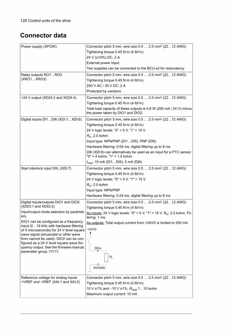
Connector dataConnector pitch 5 mm, wire size 0.5 … 2.5 mm2 (22…12 AWG)Power supply (XPOW)Tightening torque 0.45 N·m (4 lbf·in)24 V (±10%) DC, 2 AExternal power input.Two supplies can be connected to the BCU-x2 for redundancy.
Connector pitch 5 mm, wire size 0.5 … 2.5 mm2 (22…12 AWG)Relay outputs RO1…RO3(XRO1…XRO3) Tightening torque 0.45 N·m (4 lbf·in)
250 V AC / 30 V DC, 2 AProtected by varistors
Connector pitch 5 mm, wire size 0.5 … 2.5 mm2 (22…12 AWG)+24 V output (XD24:2 and XD24:4)Tightening torque 0.45 N·m (4 lbf·in)Total load capacity of these outputs is 4.8 W (200 mA / 24 V) minusthe power taken by DIO1 and DIO2.
Connector pitch 5 mm, wire size 0.5 … 2.5 mm2 (22…12 AWG)Digital inputs DI1…DI6 (XDI:1…XDI:6)Tightening torque 0.45 N·m (4 lbf·in)24 V logic levels: “0” < 5 V, “1” > 15 VRin: 2.0 kohmInput type: NPN/PNP (DI1…DI5), PNP (DI6)Hardware filtering: 0.04 ms, digital filtering up to 8 msDI6 (XDI:6) can alternatively be used as an input for a PTC sensor."0" > 4 kohm, "1" < 1.5 kohm.Imax: 15 mA (DI1…DI5), 5 mA (DI6)
Connector pitch 5 mm, wire size 0.5 … 2.5 mm2 (22…12 AWG)Start interlock input DIIL (XDI:7)Tightening torque 0.45 N·m (4 lbf·in)24 V logic levels: "0" < 5 V, "1" > 15 VRin: 2.0 kohmInput type: NPN/PNPHardware filtering: 0.04 ms, digital filtering up to 8 ms
Connector pitch 5 mm, wire size 0.5 … 2.5 mm2 (22…12 AWG)Digital inputs/outputs DIO1 and DIO2(XDIO:1 and XDIO:2) Tightening torque 0.45 N·m (4 lbf·in)Input/output mode selection by paramet-ers.
As inputs: 24 V logic levels: "0" < 5 V, "1" > 15 V. Rin: 2.0 kohm. Fil-tering: 1 ms.
DIO1 can be configured as a frequencyinput (0…16 kHz with hardware filteringof 4 microseconds) for 24 V level squarewave signal (sinusoidal or other waveform cannot be used). DIO2 can be con-figured as a 24 V level square wave fre-quency output. See the firmware manual,parameter group 111/11.
As outputs: Total output current from +24VD is limited to 200 mA
RL
DIOx
DIOGND
+24VD
Connector pitch 5 mm, wire size 0.5 … 2.5 mm2 (22…12 AWG)Reference voltage for analog inputs+VREF and -VREF (XAI:1 and XAI:2) Tightening torque 0.45 N·m (4 lbf·in)
10 V ±1% and –10 V ±1%, Rload 1…10 kohmMaximum output current: 10 mA
128 Control units of the drive

Connector pitch 5 mm, wire size 0.5 … 2.5 mm2 (22…12 AWG)Analog inputs AI1 and AI2(XAI:4 … XAI:7). Tightening torque 0.45 N·m (4 lbf·in)Current/voltage input mode selection byswitches
Current input: –20…20 mA, Rin = 100 ohmVoltage input: –10…10 V, Rin > 200 kohmDifferential inputs, common mode range ±30 VSampling interval per channel: 0.25 msHardware filtering: 0.25 ms, adjustable digital filtering up to 8 msResolution: 11 bit + sign bitInaccuracy: 1% of full scale range
Connector pitch 5 mm, wire size 0.5 … 2.5 mm2 (22…12 AWG)Analog outputs AO1 and AO2 (XAO)Tightening torque 0.45 N·m (4 lbf·in)0…20 mA, Rload < 500 ohmFrequency range: 0…500 HzResolution: 11 bit + sign bitInaccuracy: 2% of full scale range
Connector pitch 5 mm, wire size 0.5 … 2.5 mm2 (22…12 AWG)XD2D connectorTightening torque 0.45 N·m (4 lbf·in)Physical layer: RS-485Transmission rate: 8 Mbit/sCable type: Shielded twisted-pair cable with a twisted pair for dataand a wire or another pair for signal ground (nominal impedance100 … 165 ohm, for example Belden 9842)Maximum length of link: 50 m (164 ft)Termination by switch
Connector pitch 5 mm, wire size 0.5 … 2.5 mm2 (22…12 AWG)RS-485 connection (X485)Tightening torque 0.45 N·m (4 lbf·in)Physical layer: RS-485Cable type: Shielded twisted-pair cable with a twisted pair for dataand a wire or another pair for signal ground (nominal impedance100 … 165 ohm, for example Belden 9842)Maximum length of link: 50 m (164 ft)
Connector pitch 5 mm, wire size 0.5 … 2.5 mm2 (22…12 AWG)Safe torque off connection (XSTO)Tightening torque 0.45 N·m (4 lbf·in)Input voltage range: -3…30 V DCLogic levels: "0" < 5 V, "1" > 17 V.
Note: For the unit to start, both connections must be “1”. This appliesto all control units (including drive, inverter, supply, brake, DC/DCconverter etc. control units), but true Safe torque off functionality isonly achieved through the XSTO connector of the drive/invertercontrol unit.Current consumption: 66 mA (continuous) per STO channel per R8imoduleEMC (immunity) according to IEC 61326-3-1
See also chapter The Safe torque off function (page 213).
Connector pitch 5 mm, wire size 0.5 … 2.5 mm2 (22…12 AWG)Safe torque off output (XSTO OUT)Tightening torque 0.45 N·m (4 lbf·in)To STO connector of inverter module.
Connector: RJ-45Control panel connection (X13)Cable length < 3 m (9.8 ft)
Connector: RJ-45Ethernet connection (XETH)This connection is not supported by the firmware.
Control units of the drive 129

Memory card type: SDHCSDHC memory card slot (SD CARD)Maximum memory size: 4 GB
The terminals of the control unit fulfill the Protective Extra Low Voltage (PELV) requirements. The PELV re-quirements of a relay output are not fulfilled if a voltage higher than 48 V is connected to the relay output.
130 Control units of the drive

■ BCU-x2 ground isolation diagram
XPOW+24VI 1GND 2+24VI 3GND 4
XAI+VREF 1-VREF 2AGND 3AI1+ 4AI1- 5AI2+ 6AI2- 7
XAOAO1 1
AGND 2AO2 3
AGND 4XD2D
B 1A 2
BGND 3SHIELD 4
XRO1, XRO2, XRO3NC 11
COM 12NO 13NC 21
COM 22NO 23NC 31
COM 32NO 33
XD24+24VD 5DICOM 6+24VD 7
DIOGND 8XDIO
DIO1 1DIO2 2
DIOGND 3DIOGND 4
XDIDI1 1DI2 2DI3 3DI4 4DI5 5DI6 6DIIL 7
XSTOOUT 1
SGND 2IN1 3IN2 4
XSTO OUTIN1 5
SGND 6IN2 7
SGND 8
*
**
*Ground selector (DICOM=DIOGND) settings
DICOM=DIOGND: ONAll digital inputs share a common ground (DICOM connected to DIOGND). This is the default setting.
DICOM=DIOGND: OFFGround of digital inputs DI1…DI5 and DIIL (DICOM) is isolated from DIO signal ground (DIOGND). Isolationvoltage 50 V.
**The maximum common mode voltage between each AI input and AGND is +30 V
Control units of the drive 131

132

Installation checklist
Contents of this chapterThis chapter contains a checklist of the mechanical and electrical installation of the drive.
ChecklistExamine the mechanical and electrical installation of the drive before start-up. Go throughthe checklist together with another person.
WARNING!Obey the safety instructions of the drive. If you ignore them, injury or death,or damage to the equipment can occur. If you are not a qualified electricalprofessional, do not do installation, commissioning or maintenance work.
WARNING!Stop the drive and do the steps in section Electrical safety precautions (page 17)before you start the work.
Make sure that …
The ambient operating conditions meet the drive ambient conditions specification and enclosure rating(IP code).
The supply voltage matches the nominal input voltage of the drive. See the type designation label.
The insulation resistance of the input power cable, motor cable and motor is measured according tolocal regulations and the manuals of the drive.
The drive cabinet is attached to the floor, and if necessary due to vibration etc, also by its top to thewall or roof.
If the drive is connected to a network other than a symmetrically grounded TN-S system: You havedone all the required modifications (for example, you may need to disconnect the EMC filter or ground-to-phase varistor). See the electrical installation instructions.
8Installation checklist 133

Make sure that …
There is an adequately sized protective earth (ground) conductor(s) between the drive and theswitchboard, the conductor is connected to correct terminal, and the terminal is tightened to the correcttorque.Proper grounding has also been measured according to the regulations.
The input power cable is connected to the correct terminals, the phase order is correct, and the terminalsare tightened to the correct torque.
There is an adequately sized protective earth (ground) conductor between the motor and the drive,and the conductor is connected to the correct terminal, and the terminal is tightened to the correcttorque.Proper grounding has also been measured according to the regulations.
The motor cable is connected to the correct terminals, the phase order is correct, and the terminalsare tightened to the correct torque.
The motor cable is routed away from other cables.
No power factor compensation capacitors are connected to the motor cable.
The control cables are connected to the correct terminals, and the terminals are tightened to the correcttorque.
The voltage setting of the auxiliary voltage transformers (if any) is correct. See the electrical installationinstructions.
If a drive bypass connection will be used: The Direct On Line contactor of the motor and the drive outputcontactor are either mechanically and/or electrically interlocked, that is, they cannot be closed at thesame time. A thermal overload device must be used for protection when bypassing the drive. Refer tolocal codes and regulations.
There are no tools, foreign objects or dust from drilling inside the drive.
Cover(s) of the motor connection box are in place. Cabinet shrouds are in place and doors are closed.
The motor and the driven equipment are ready for power-up.
The coolant connections between cubicles (if any) and to the cooling circuit are tight.
If the drive is equipped with a cooling unit: Make sure that the mechanical and electrical installation ofthe cooling unit is completed. Refer to the cooling unit documentation.
134 Installation checklist

Start-up
Contents of this chapterThis chapter contains the start-up and switch-off procedures of the drive.
Start-up procedureThe tasks which are needed in certain cases only are marked with underlining, and optioncodes are given in brackets. Default device designations (if any) are given in brackets afterthe name, for example “main switch-disconnector [Q1]”. The same device designations arealso used in the circuit diagrams.
These instructions cannot and do not cover all possible start-up tasks of a customized drive.Always refer to the delivery-specific circuit diagrams when proceeding with the start-up.
WARNING!Only qualified electrical professionals are permitted to do the work described in thischapter.
Note: For certain options (such as functional safety options +Q950, +Q951, +Q952, +Q957,+Q963, +Q964, +Q978, +Q979), additional start-up instructions are given in their separatemanuals.
Action
Safety
WARNING!Obey the safety instructions during the start-up procedure. See chapter Safety instruc-tions (page 13).
Checks/Settings with no voltage connected
Make sure that the disconnector of the supply transformer is locked to the off (0) position, ie. no voltageis, and cannot be connected to the drive accidentally.
9Start-up 135
12

Action
Make sure that the main switch-disconnector [Q1.1] is switched off, or the main breaker [Q1] is rackedout.
Check that the grounding switch [Q9.1] (option +F259) is switched on.
Check the mechanical and electrical installation of the drive. See Installation checklist (page 133).
Check the settings of breakers/switches in the auxiliary circuits. See the circuit diagrams delivered withthe drive.
Check the settings of the auxiliary voltage transformers (either internal or external).
Disconnect any unfinished or uninspected auxiliary voltage (115/230 V AC) cables that lead from theterminal blocks to the outside of the equipment.
Check that both channels of the Safe torque off circuit connected to the STO inputs of both the supplycontrol unit [A51] and the inverter control unit [A41] are closed. Refer to the wiring diagrams deliveredwith the drive.
Drives with ground fault monitoring for IT (ungrounded) systems (option +Q954): Adjust the settings ofthe ground fault monitor to suit the installation. See the circuit diagrams of the delivery and IRDH275BGround Fault Monitor Operating Manual by Bender (code: TGH1386en).
Drives with Pt100 relays (option +(n)L506):• Check the connections against the circuit diagrams of the delivery.• Set the alarm and trip levels of the Pt100 relays.Set the alarm and trip levels of the Pt100 relay as low as possible based on the operating temperatureand test results of the machine. The trip level can be set, for example, 10 °C higher than what thetemperature of the machine is at maximal load in the maximum environmental temperature.ABB recommends to set the operating temperatures of the relay, typically for example, as follows:• 120…140 °C when only tripping is in use• alarm 120…140 °C and trip 130…150 °C when both alarm and tripping are used.
Powering up the auxiliary circuit of the drive
Make sure that it is safe to connect voltage. Make sure that:• nobody is working on the drive or circuits that have been wired from outside into the drive cabinet• the cover of the motor terminal box is in place.
Drives with an ACS880-1007LC cooling unit (as part of line-up or standalone): Do the start-up tasksof the cooling unit. Refer to ACS880-1007LC liquid cooling unit user's manual (3AXD50000129607[English]).
Drives with a voltmeter (option +G334): Make sure that the circuit breaker of the measuring circuit(F5.1) is closed.
Close the circuit breakers and/or fuse disconnectors supplying the auxiliary voltage circuits.
Close the cabinet doors.
Close the main breaker of the supply transformer.
Switch on the auxiliary voltage [Q21].Drives of frame size 1×R8i + 1×R8i: Close the main switch-disconnector [Q1.1]. This will power up themain circuit of the drive as well as the auxiliary voltage circuit.
Setting up the supply unit parameters
Check the voltage range setting in parameter 195.01 Supply voltage.For more information on setting up the supply control program, refer to ACS880 IGBT supply controlprogram firmware manual (3AUA0000131562 [English]).If you need more information on the use of the control panel, refer to ACS-AP-I, -S, -W and ACH-AP-H, -W Assistant control panels user's manual (3AUA0000085685 [English]).
Setting up the inverter unit parameters, and performing the first start
Set up the inverter control program. See the appropriate start-up guide and/or firmware manual. Thereis a separate start-up guide only for some control programs.
Check that parameter 95.09 Switch fuse controller is set to Disabled.
136 Start-up

Action
Drives with an fieldbus adapter module (optional): Set the fieldbus parameters. Activate the appropriateassistant (if present) in the control program, or see the user’s manual of the fieldbus adapter module,and the drive firmware manual. Check that the communication works between the drive and the PLC.
Drives with an encoder interfacemodule (optional): Set the encoder parameters. Activate the appropriateassistant (if present) in the control program, or see the user’s manual of the encoder interface module,and the drive firmware manual.
Powering up the main circuit of the drive
Switch off the grounding switch [Q9.1] (option +F259).
Close the main switch-disconnector [Q1.1] or main breaker [Q1].
Note: Do not use excessive force. The main switch-disconnector (or main breaker) can only be closedwhen• the main input terminals [L1, L2, L3] are powered, and• auxiliary voltage is switched on [Q21], and• grounding switch is off [Q9.1, Q9.2] (option +F259).
Turn the operating switch (S21) to the ON (1) position to activate the run enable signal. Depending oncontrol source settings, this may also close the main contactor (if present). If a main contactor is presentand does not close, refer to the circuit diagrams delivered by the drive as well as the appropriate firmwaremanuals.
On-load checks
Start the motor to perform the ID run.
Check that the cooling fans rotate freely in the right direction, and the air flows upwards.
Check that themotor starts. stops and follows the speed reference in the correct direction when controlledwith the control panel.
Check that themotor starts. stops and follows the speed reference in the correct direction when controlledthrough the customer-specific I/O or fieldbus.
Drives in which the Safe torque off control circuit is in use: Test and validate the operation of the Safetorque off function. See section Start-up including validation test (page 221).
Drives with an emergency stop circuit (options +Q951, +Q952, +Q963, +Q964, +Q978, +Q979, +Q984):Test and validate the operation of the emergency-stop circuit. See the delivery specific circuit diagramsand wiring, start-up and operating instructions of the option.
Drives with the Prevention of unexpected start-up with safety relay (option +Q957): Test and validatethe operation of the Prevention of unexpected start-up circuit. See the delivery specific circuit diagramsand wiring, start-up and operating instructions of the option.
Drives with the Prevention of unexpected start with FSO safety functions module (option +Q950): Testand validate the operation of the Prevention of unexpected start-up circuit. See the delivery specificcircuit diagrams and wiring, start-up and operating instructions of the option.
Drives with the Safely-limited speed with the encoder interface (option +Q965): Test and validate theoperation of the Safely-limited speed circuit. See the delivery specific circuit diagrams and wiring, start-up and operating instructions of the option.
Drives with a motor thermal protection function (options +L513, +L514, +L536, +L537): Test and validatethe operation of the motor thermal protection function. See the delivery specific circuit diagrams andwiring, start-up and operating instructions of the option.
Switching off the drive1. Stop the motor.
2. Turn the Run enable switch (S21) to the off (0) position to deactivate the Run enablesignal and to switch the main contactor/breaker off.
Start-up 137
12

138

Fault tracing
Contents of this chapterThis chapter describes the fault tracing possibilities of the drive.
Control unit LEDs
IndicationColorLED
Battery voltage of the real-time clock is OK (higher than 2.8 V).When the LED is not lit,
GreenBATT OK
• battery voltage is below 2.8 V,• the battery is missing, or• the control unit is not powered.
Internal voltage OKGreenPWR OK
The control program indicates that the equipment is faulty. Seethe appropriate firmware manual.
RedFAULT
Writing to SD card in progress.YellowWRITE
Control panel and panel platform/holder LEDsThe ACS-AP-… control panel has a status LED. The control panel mounting platform orholder has two status LEDs. For their indications, see the following table.
10Fault tracing 139

IndicationLEDLocation
The unit is functioning normally.Continuous greenControl panel
Data is transferred between the PC and the unit through the USBconnection of the control panel.
Flickering green
There is an active warning in the unit.Blinking green
There is an active fault in the unit.Continuous red
There is a fault that requires the stopping and restarting of thedrive/converter/inverter.
Blinking red
The Bluetooth interface is enabled, in discoverable mode, andready for pairing.
Blinking blue (ACS-AP-W only)
Data is being transferred through the Bluetooth interface of thecontrol panel.
Flickering blue(ACS-AP-W only)
There is an active fault in the unit.RedControl panelmounting platform orholder (with thecontrol panelremoved)
Power supply for the control unit is OK.Green
Warning and fault messagesSee the firmware manual for the descriptions, causes and remedies of the drive controlprogram warning and fault messages.
140 Fault tracing

Maintenance
Contents of this chapterThis chapter contains maintenance instructions.
Maintenance intervalsThe tables below show the maintenance tasks which can be done by the end user. Thecomplete maintenance schedule is available on the Internet(https://new.abb.com/drives/services/maintenance/preventive-maintenance). For moreinformation, consult your local ABB Service representative (www.abb.com/searchchannels).
■ Description of symbols
DescriptionAction
Inspection (visual inspection and maintenance action if needed)I
Performance of on/off-site work (commissioning, tests, measurements or other work)P
ReplacementR
11Maintenance 141

■ Recommended maintenance intervals after start-up
Years from start-upMaintenance task/object
…1211109876543210
Coolant
PPPPPPPPPPPPPChecking coolant antifreeze concentration
PPPPPPChecking coolant quality
RRCoolant draining and replacement
See ACS880-1007LC liquid cooling unit user's manual(3AXD50000129607 [English])ABB cooling unit (if present)
Cooling fans
RSupply module cubicle fan (230 V)
RRSupply module cubicle fan (115 V)
RInverter module fan (230 V)
RRInverter module fan (115 V)
Batteries
RControl panel battery
RRControl unit battery
Connections and environment
PPPPPPPPPPPPPQuality of supply voltage
Spare parts
IIIIIIIIIIIIISpare parts
PPPPPPPPPPPPPDC circuit capacitor reforming (spare invert-er modules and spare capacitors)
Inspections
IIIIIIIIIIIIIChecking tightness of cable and busbarterminals. Tightening if needed.
IIIIIIIIIIIIIChecking ambient conditions (dustiness,corrosion, temperature)
IIIIIIIIIIIIIChecking coolant pipe connections
Functional safety
ISee the maintenance information of the safety function.Safety function test
20 yearsSafety component expiry (Mission time, TM)
3AXD10000578918 F
Note:
142 Maintenance

• Maintenance and component replacement intervals are based on the assumption thatthe equipment is operated within the specified ratings and ambient conditions. ABBrecommends annual drive inspections to ensure the highest reliability and optimumperformance.
• Long term operation near the specified maximum ratings or ambient conditions mayrequire shorter maintenance intervals for certain components. Consult your local ABBService representative for additional maintenance recommendations.
Maintenance 143

Cabinet■ Cleaning the interior of the cabinet
WARNING!Obey the safety instructions of the drive. If you ignore them, injury or death,or damage to the equipment can occur. If you are not a qualified electricalprofessional, do not do installation, commissioning or maintenance work.
WARNING!Use a vacuum cleaner with antistatic hose and nozzle, and wear a groundingwristband. Using a normal vacuum cleaner creates static discharges which candamage circuit boards.
1. Stop the drive and do the steps in section Electrical safety precautions (page 17) beforeyou start the work.
2. Open the cabinet door.
3. Clean the interior of the cabinet. Use a vacuum cleaner and a soft brush.
4. Clean the air inlets of the fans and air outlets of the modules (top).
5. Clean the air inlet gratings (if any) on the door.
6. Close the door.
■ Cleaning the exterior of the drive
WARNING!Obey the safety instructions of the drive. If you ignore them, injury or death,or damage to the equipment can occur. If you are not a qualified electricalprofessional, do not do installation, commissioning or maintenance work.
1. Stop the drive and do the steps in section Electrical safety precautions (page 17) beforeyou start the work.
2. Clean the exterior of the drive. Use:
• vacuum cleaner with an antistatic hose and nozzle
• soft brush
• dry or damp (not wet) cleaning cloth. Moisten with clean water, or mild detergent(pH 5-9 for metal, pH 5-7 for plastic).
WARNING!Prevent water from entering the drive. Never use excessive amount of water, a hose,steam, etc.
144 Maintenance

Power connections and quick connectors■ Retightening the power connections
WARNING!Obey the safety instructions of the drive. If you ignore them, injury or death,or damage to the equipment can occur. If you are not a qualified electricalprofessional, do not do installation, commissioning or maintenance work.
1. Stop the drive and do the steps in section Electrical safety precautions (page 17) beforeyou start the work.
2. Examine the tightness of the cable connections. Use the tightening torques given inthe technical data.
FansThe lifespan of the cooling fans of the drive depends on the running time, ambienttemperature and dust concentration. See the firmware manual for the actual signal whichindicates the running time of the cooling fan. Reset the running time signal after fanreplacement.
Replacement fans are available from ABB. Do not use other than ABB specified spare parts.
■ Frame R8i fan replacement
WARNING!Obey the safety instructions of the drive. If you ignore them, injury or death,or damage to the equipment can occur. If you are not a qualified electricalprofessional, do not do installation, commissioning or maintenance work.
WARNING!Use the required personal protective equipment. Wear protective gloves and longsleeves. Some parts have sharp edges.
1. Stop the drive and do the steps in section Electrical safety precautions (page 17) beforeyou start the work.
2. Remove any shrouding in front of the cooling fan in case of marine construction (+C121).
3. Disconnect the fan wiring. Remove the CIO module.
4. Undo the two retaining screws (a).
5. Pull the fan outwards to separate it from the heat exchanger housing.
6. Install new fan in reverse order. Align the guide pins (b) at the rear of the fan cowlingwith the slots (c) in the module bottom guide, then reinstall the retaining screws (a).
Maintenance 145

a b
c
146 Maintenance

■ Replacing the heat exchanger fan in the filter cubicle
WARNING!Wear protective gloves and long sleeves. Some parts have sharp edges.
1. Repeat the steps described in section Electrical safety precautions (page 17) beforeyou start the work.
2. Remove the shrouding in front of the fan (if any).
3. Disconnect the fan wiring. Remove the CIO module.
4. Remove the four screws and pull the fan unit out.
5. Remove the two screws in front of the heat exchanger.
6. Install a new fan in reverse order.
4
5
Maintenance 147

■ Replacing the fan in the incoming cubicle
WARNING!Obey the safety instructions of the drive. If you ignore them, injury or death,or damage to the equipment can occur. If you are not a qualified electricalprofessional, do not do installation, commissioning or maintenance work.
WARNING!Use the required personal protective equipment. Wear protective gloves and longsleeves. Some parts have sharp edges.
1. Stop the drive and do the steps in section Electrical safety precautions (page 17) beforeyou start the work.
2. Remove the shrouding in front of the fan (if any).
3. Disconnect the fan wiring. Remove the CIO module.
4. Remove the two screws and slide the fan unit out.
5. Remove the four screws to detach the fan from the fan unit.
6. Remove the eight screws surrounding the fan unit.
7. Install a new fan in reverse order.
148 Maintenance

4
5
6
Maintenance 149

■ Replacing the fan in the auxiliary control cubicleAuxiliary control cubicle has a fan in the lower part of the cubicle.
WARNING!Wear protective gloves and long sleeves. Some parts have sharp edges.
1. Repeat the steps described in section Electrical safety precautions (page 17) beforeyou start the work.
2. Open the door of the auxiliary control cubicle.
3. Disconnect the fan wiring. Remove the CIO module.
4. Remove the fastening screws of the fan collar and slide the fan with the collar out.
5. Detach the fan from the collar and replace the fan.
6. Install the new fan in reverse order.
4
■ Replacing the common motor terminal cubicle fan
WARNING!Obey the safety instructions of the drive. If you ignore them, injury or death,or damage to the equipment can occur. If you are not a qualified electricalprofessional, do not do installation, commissioning or maintenance work.
WARNING!Use the required personal protective equipment. Wear protective gloves and longsleeves. Some parts have sharp edges.
1. Stop the drive and do the steps in section Electrical safety precautions (page 17) beforeyou start the work.
2. Remove any shrouding in front of the cooling fan.
150 Maintenance

3. Disconnect the fan wiring. Remove the CIO module.
4. Undo the fastening screws.
5. Pull the fan housing up and out.
6. Install a new fan in reverse order to the above.
Maintenance 151

Supply and inverter modules■ Assembling the service platformThe service platform is included in the cabinet delivery. It can be used when installing orservicing liquid-cooled R8i modules.
1. Fasten the triangular supports to the cabinet frame (5 × M6 screws for each support).Make sure that the guide pins are properly inserted in the holes of the frame. Tightenthe screws to torque (max 5.5 N·m / 4 lb·ft).
2. Select the braces (4 pcs) according to the width of the cubicle and attach them to thesupports.
3. Attach the support feet to the platform and adjust them to the correct height.
4. Attach the slide plate. Put the hooks (a) at the back of the slide plate through the holesin the cabinet frame. Align the slots (b) in the slide plate with the braces.
5. Fix the slide plate into place with the index screws (c) at the bottom of the slide plate.
1 2
3 4
ab
c
■ Replacing a supply or inverter module
WARNING!Make sure the replacement module has exactly the same type code as theold module.
152 Maintenance

WARNING!Obey the safety instructions of the drive. If you ignore them, injury or death,or damage to the equipment can occur.
WARNING!Make sure that the replacement module has exactly the same type code as the oldmodule.
WARNING!Beware of hot coolant. Do not work on the liquid cooling system until the pressureis lowered down by stopping the pumps and draining the coolant. High-pressurewarm coolant (6 bar, max. 50 °C) is present in the internal cooling circuit when it isin operation.
WARNING!To avoid breaking the coolant pipes, do not overtighten the nuts of the unions. Leave2 to 3 millimeters (0.08 to 0.12 inches) of thread visible.
2…3 mm (0.08 … 0.12″)
WARNING!Use the required personal protective equipment. Wear protective gloves and longsleeves. Some parts have sharp edges.
Removing the module
1. Do the steps in section Electrical safety precautions (page 17).
2. Assemble the service platform delivered with the drive. For instructions, see Assemblingthe service platform for R8iLC cabinets.
3. Remove the shrouding in front of the module.
4. Undo the locking screws of the swing-out frame (if present) and open it.
5. Unplug the wiring from the module and move it aside. Use cable ties to keep the wiringout of the way.
Maintenance 153

6. Remove the L-shaped DC busbars at the top of the module. Make note of the orientationof the screws as well as the order of the washers.
7. Close the inlet valve (a) and outlet valve (located on the right-hand side of the cubicle).Lead the drain hoses (b, on both sides of the cubicle) into a suitable container. Openthe drain valves (c, on both sides of the cubicle). This will drain all modules in the cubicle.
a
b
c
8. After the module has drained, disconnect the piping from the module.
154 Maintenance

9. Remove the module retaining screws at the top and the bottom of the module.
10. Pull the module carefully out onto the service platform. Keep the module secured to ahoist or equivalent to prevent the module from falling. For information on using the liftingdevice, see Converter module lifting device for drive cabinets hardware manual(3AXD50000210268 [English]).
Reinstalling the module
1. Push the module carefully into its bay.
2. Fasten the retaining screws at the top and the bottom of the module.
3. Reinstall the DC busbars at the top of the module.
4. Reconnect the coolant pipes to the module.
Maintenance 155

WARNING!To avoid breaking the coolant pipes, do not overtighten the nuts of the unions.Leave 2 to 3 millimeters (0.08 to 0.12 inches) of thread visible.
2…3 mm (0.08 … 0.12″)
5. Reconnect the control wiring to the module.
6. Fill up the cooling system. For instructions, see section Filling up and bleeding theinternal cooling circuit.
7. Close the swing-out frame (if present). Reinstall all shrouds removed earlier.
8. If the module is an inverter module, and the Safe torque off function is in use, performa validation test as described under Start-up including validation test (page 221).
CapacitorsThe DC link of the drive contains several electrolytic capacitors. Operating time, load, andsurrounding air temperature have an effect on the life of the capacitors. Capacitor life canbe extended by decreasing the surrounding air temperature.
Capacitor failure is usually followed by damage to the unit and an input cable fuse failure,or a fault trip. If you think that any capacitors in the drive have failed, contact ABB.
■ Reforming the capacitorsThe capacitors must be reformed if the drive has not been powered (either in storage orunused) for a year or more. The manufacturing date is on the type designation label. Forinformation on reforming the capacitors, refer to Capacitor reforming instructions(3BFE64059629 [English]).
156 Maintenance

Fuses■ Replacing the AC and DC fuses in cabinetThis procedure instructs how to replace the drive AC and DC fuses inside the cabinet. Thelocation of the fuses vary depending on the drive type and options. Locate the fuses to bereplaced using the delivery-specific layout drawings and circuit diagrams.
WARNING!Obey the instructions in chapter Safety instructions. If you ignore them,injury or death, or damage to the equipment can occur.
1. Stop the drive and do the steps in section Electrical safety precautions (page 17) beforeyou start the work.
2. Open the door of the cubicle in which the fuses are.
3. Remove the shrouding from in front of the fuses.
4. Slacken the nuts of the headless screws of the fuses so that you can slide out the fuseblocks. Make note of the order of the washers on the screws.
5. Remove the screws, nuts and washers from the old fuses and attach them to the newfuses. Make sure to keep the washers in the original order.
6. Insert the new fuses into their slots in the cubicle. Pre-tighten the nuts first by hand orby applying a torque of no more than 5 N·m (3.7 lbf·ft).
7. Tighten the nuts to torque as follows:
Maintenance 157

• Bussmann fuses: 50 N·m (37 lbf·ft)
• Mersen (Ferraz-Shawmut): 46 N·m (34 lbf·ft)
• Other: Refer to the fuse manufacturer’s instructions.
8. Reinstall the shroud and close the door.
4
■ Replacing AC fuses - 100 kA input cubicle (option +F274)
WARNING!Obey the safety instructions of the drive. If you ignore them, injury or death,or damage to the equipment can occur. If you are not a qualified electricalprofessional, do not do installation, commissioning or maintenance work.
WARNING!Use the required personal protective equipment. Wear protective gloves and longsleeves. Some parts have sharp edges.
1. Stop the drive and do the steps in section Electrical safety precautions (page 17) beforeyou start the work.
2. Open the door of the 100 kA input cubicle.
3. Remove the shrouding in front of the fuses.
158 Maintenance

4. Check the condition of the fuses. If a fuse is blown, replace all fuses with similar fusesas follows:
• Loosen the nuts of the fuses and pull the fuses out. Do not remove the nutscompletely. If you remove the nuts completely, there is a risk that they fall insidethe cubicle.
• Install the new fuses. Tighten the nuts first by hand or applying maximum 5 N·mforce. Tightening torques for M12 nuts are 50 N·m (37 lbf·ft) for Bussmann fuses,and 46 N·m (34 lbf·ft) for Mersen (Ferraz-Shawmut) fuses.
5. Attach the shrouding and close the door.
4
3
Control panelRefer to ACS-AP-I, -S, -W and ACH-AP-H, -W Assistant control panels user’s manual(3AUA0000085685 [English]).
Control units■ BCU control unit typesThere are three variants of the BCU control unit used in ACS880 drives: BCU-02, BCU-12and BCU-22. These have a different number of converter module connections (2, 7 and 12respectively) but are otherwise identical. The three BCU types are interchangeable as longas the number of connections is sufficient. For example, the BCU-22 can be used as a directreplacement for both BCU-02 and BCU-12.
Maintenance 159

■ Replacing the memory unitAfter replacing a control unit, you can keep the existing parameter settings by transferringthe memory unit from the defective control unit to the new control unit.
WARNING!Do not remove or insert the memory unit when the control unit is powered.
1. Stop the drive and do the steps in section Electrical safety precautions (page 17) beforeyou start the work.
2. Make sure that the control unit is not powered.
3. Remove the fastening screw and pull the memory unit out.
4. Install a memory unit in reverse order.
■ Replacing the BCU control unit batteryReplace the real-time clock battery if the BATT OK LED is not illuminated when the controlunit is powered.
1. Stop the drive and do the steps in section Electrical safety precautions (page 17) beforeyou start the work.
2. Undo the fastening screw and remove the battery.
3. Replace the battery with a new BR2032 battery.
160 Maintenance

4. Dispose of the old battery according to local disposal rules or applicable laws.
5. Set the real-time clock.
Functional safety componentsThe mission time of functional safety components is 20 years which equals the time duringwhich failure rates of electronic components remain constant. This applies to the componentsof the standard Safe torque off circuit as well as any modules, relays and, typically, anyother components that are part of functional safety circuits.
The expiry of mission time terminates the certification and SIL/PL classification of the safetyfunction. The following options exist:
• Renewal of the whole drive and all optional functional safety module(s) and components.
• Renewal of the components in the safety function circuit. In practice, this is economicalonly with larger drives that have replaceable circuit boards and other components suchas relays.
Note that some of the components may already have been renewed earlier, restarting theirmission time. The remaining mission time of the whole circuit is however determined by itsoldest component.
Contact your local ABB service representative for more information.
Maintenance 161

162

Internal cooling circuit
Contents of this chapterThe cooling system of a liquid-cooled drive consists of two circuits: the internal cooling circuitand the external cooling circuit. The internal cooling circuit covers the heat-generatingelectrical components of the drive and transfers the heat to the cooling unit. In the coolingunit, the heat is transferred to the external cooling circuit which is usually part of a largerexternal cooling system. This chapter deals with the internal cooling circuit.
ApplicabilityThe information in this chapter is applicable to cabinet-built ACS880 liquid-cooled drives.Except where otherwise indicated, the information is also applicable to drives built out ofACS880 liquid-cooled multidrive modules.
Internal cooling systemEach cubicle has an inlet and an outlet manifold, fitted with a stop valve and a drain valve.The stop valves can be closed to isolate all modules in the cubicle from the main coolingcircuit.
In cabinet line-ups built by ABB, valves are color-coded:
• Blue – Open during operation
• Red – Closed during operation
The following diagram shows the coolant pipe connections in a drive system consisting ofa supply unit and an inverter unit. Other units, such as brake units, DC/DC converter unitshave similar cooling arrangements. Other cubicles containing components that requirecooling may also contain heat exchangers.
12Internal cooling circuit 163

A/L
HS HS
a cdba db c
A/L A/L
A/L
A/L
3
1
HS
2 2
HS
Supply modules. The drawing shows the configuration of a diode supply unit with two modules, ie.there is a common air-to-liquid exchanger in the cubicle. With an IGBT supply unit, each module hasa dedicated air-to-liquid exchanger as shown for item 2.
1
Inverter modules2
To/From cooling unit3
Air-to-liquid heat exchangerA/L
Heat sinkHS
Inlet valvea
Inlet-side drain valveb
Outlet valvec
Outlet-side drain valved
The coolant used with ACS880 liquid-cooled drive systems is Antifrogen® L 25% or 50%mixture. See Coolant specification (page 168).
164 Internal cooling circuit

Connection to a cooling unit■ Connection to an ACS880-1007LC cooling unitRefer to ACS880-1007LC cooling unit user’s manual (3AXD50000129607 [English]).
■ Connection to a custom cooling unit
General requirements
Equip the system with an expansion vessel to damp pressure rise due to volume changeswhen the temperature varies. Equip the system with a pump that provides a nominal flowand pressure. Keep the pressure within the limits specified in Technical data (page 168).Install a pressure regulator to make sure that the maximum permissible operating pressureis not exceeded.
Install a bleed valve at the highest point of the cooling circuit, and a drain valve at the lowestpoint.
The materials that can be used are listed in Cooling circuit materials (page 170).
Coolant temperature control
The temperature of the coolant in the internal cooling circuit must be kept within the limitsspecified in Technical data (page 168). Note that the minimum temperature is dependent onambient temperature and relative humidity.
Internal cooling circuit 165

Filling up and bleeding the internal cooling circuitBoth the drive and coolant must be at room temperature before filling up the cooling circuit.
WARNING!Make sure that the maximum permissible operating pressure is not exceeded. Whennecessary regulate the pressure to appropriate level by draining excess coolant outof the system.
WARNING!Bleeding of the cooling circuit is very important and has to be done with great care.Air bubbles in the cooling circuit may reduce or completely block coolant flow andlead to overheating. Let the air out of the cooling system while filling in coolant and,eg. after any power module replacements.
■ Drive line-ups with an ACS880-1007LC cooling unitObey the filling up and bleeding instructions in ACS880-1007LC cooling unit user’s manual(3AXD50000129607 [English]).
■ Drive line-ups with a custom cooling unit
Note:• In filling up the system, the drain valves in the line-up are used only to vent the air from
the circuit so that it can be displaced by the coolant. The actual bleeding of the circuitmust be done via an external bleed valve installed at the highest point of the coolingcircuit. The most practical location for the valve is usually near or at the cooling unit.
• Observe the instructions given by the manufacturer of the cooling unit. Pay specialattention to filling up and bleeding the pumps properly as they may be damaged ifoperated when dry.
• Draining coolant into the sewer system is not allowed.
1. Open the bleed valve at the cooling unit.
2. Open the inlet valve and the outlet-side drain valve of one cubicle. Keep the outlet valveand the inlet-side drain valve closed.
3. Attach a hose to the outlet-side drain valve and lead it into a suitable container.
4. Fill the circuit with coolant. For coolant specification, seeCoolant specification (page 168).To minimize foaming, do not exceed the filling flow rate of 5 l/min (1.3 US gallon/min).
5. As the piping and modules in the cubicle fills up, coolant starts to flow from the hose.Let some coolant flow out, then close the drain valve.
6. Close the inlet valve.
7. Repeat steps 2 to 6 for all cubicles in the line-up.
8. Open the inlet and outlet valves in all cubicles. Let any air remaining in the system outthrough the bleed valve at the cooling unit.
9. Close the bleed valve at the cooling unit.
10. Continue to fill in coolant until a base pressure of 100…150 kPa is achieved.
11. Open the bleed valve of the pump to let out any air.
166 Internal cooling circuit

12. Re-check the pressure and add coolant if necessary.
13. Start the coolant pump. Let any air remaining in the system out through the bleed valveat the cooling unit.
14. After one to two minutes, stop the pump or block the coolant flow with a valve.
15. Re-check the pressure and add coolant if necessary.
16. Repeat steps 13 to 15 a few times until all air is let out of the cooling circuit. Listen fora humming sound and/or feel the piping for vibration to find out if there is still air left inthe circuit.
Internal cooling circuit 167

Draining the internal cooling circuitThe modules in each cubicle can be drained through the drain valves without draining thewhole internal cooling circuit.
WARNING!Hot, pressurized coolant can be present in the cooling circuit. Do not work on thecooling circuit before the pressure is released by stopping the pumps and drainingcoolant.
1. Attach hoses to each drain valve in the cubicle to be drained. Lead the hoses into asuitable container. Make sure the ends of the hoses are not immersed in coolant at anypoint so that air can displace the coolant in the system.
2. Open the drain valves. Wait until all coolant has drained.Note: Draining coolant into the sewer system is not allowed.
3. If required, dry the piping with compressed oil-free air of less than 6 bar.
4. If the drive is to be stored in temperatures below 0 °C (32 °F),
• dry the cooling circuit with air,
• fill the cooling circuit with coolant specified under Coolant specification (page 168).
• drain the cooling circuit again.
Maintenance intervalsAs a general rule, the quality of the coolant should be checked at intervals of two years.This can be done by distributors of Antifrogen® L (see www.clariant.com) if a 250 millilitersample is provided.
Technical data■ Coolant specification
Coolant type
Antifrogen® L (by Clariant International Ltd, www.clariant.com) 25% or 50%mixture, availablefrom Clariant distributors and ABB Service representatives.Note: Do not dilute the coolant. It is ready to use.
Antifrogen® L 25% mixture is usable in storage temperatures down to -16 °C (3.2 °F).Antifrogen® L 50% mixture is usable in storage temperatures down to -40 °C (-40 °F).
Note that operation below 0 °C (32 °F) is not permitted regardless of the freezing point ofthe coolant.
WARNING!The warranty does not cover damage that occurs from the use of incorrect coolant.
■ Temperature limitsAmbient temperature: See the technical data of the drive/unit.
168 Internal cooling circuit

Freeze protection: The freezing point of the coolant is determined by the concentration ofheat transfer fluid in the mixture.
The higher the concentration of heat transfer fluid, the higher the viscosity of the coolant.This results in a higher pressure loss in the system. See Pressure limits (page 170).
The nominal current ratings of drive system modules apply to an Antifrogen® L / watersolution of 25/75% (volume). With the Antifrogen® L concentration between 25% and 50%,the drive output current must be derated by 1/3 percentage point per 1 p.p. increase inAntifrogen® L concentration. The drawing below shows the derating factor (k) in relation toAntifrogen® L concentration.
1.00
0.95
25%
k
0.9030% 35% 40% 45% 50% Antifrogen® L concentration
Incoming coolant temperature:• 0…40 °C (32…104 °F): no drive output current derating required
• 40…45 °C (104…113 °F): drive output current must be derated by 2 percentage pointsper 1 °C (1.8 °F) temperature increase, as shown by curve (a).
• 45…50 °C (113…122 °F):
• If components with a maximum operating temperature of 55 °C (131 °F) are installedin the same space as the drive modules, drive output current must be derated by6 percentage points per 1 °C (1.8 °F) temperature increase, as shown by curve(c).
• If there are no components with a maximum operating temperature of 55 °C (131 °F)installed in the same space as the drive modules, drive output current must bederated by 2 percentage points per 1 °C (1.8 °F) temperature increase, as shownby curve (b).
The drawing below shows the derating factor (k) in relation to coolant temperature.
T
1.00
0.90
+40 °C+104 °F
k
0.80
0.70
0.60
+45 °C+113 °F
+50 °C+122 °F
(a)
(b)
(c)
Condensation is not permitted. The minimum coolant temperature to avoid condensation(at an atmospheric pressure of 1 bar) is shown below as a function of relative humidity (RH)and ambient temperature (Tair).
Internal cooling circuit 169

Min. Tcoolant (°C)Tair(°C)
RH = 40%RH = 50%RH = 65%RH = 80%RH = 95%
-7.4-4.5-0.91.94.35
-3.0-0.13.76.79.210
1.54.68.411.514.215
6.09.413.216.519.220
10.513.817.921.424.125
15.018.422.726.229.130
19.423.027.431.134.135
23.827.632.235.939.040
28.232.136.840.844.045
32.836.741.645.649.050
37.142.246.350.453.955
= Not permitted as standard but the coolant temperature must be 0 °C (32 °F) or more.
At an air temperature of 45 °C and relative humidity of 65% the coolant temperature mustnot be less than +36.8 °CExample:
Maximum temperature rise: Depends on heat losses and mass flow. Typically 10 °C (18°F) with nominal losses and flow.
■ Pressure limitsBase pressure: 250 kPa (recommended); 300 kPa (maximum). “Base pressure” denotesthe pressure of the system compared with the atmospheric pressure when the cooling circuitis filled with coolant.
Air counterpressure in expansion vessel (with ACS880-1007LC cooling unit): 80 kPa
Design pressure (PS): 600 kPa
Nominal pressure difference: 120 kPa with Antifrogen® L 25% coolant solution, 140 kPawith Antifrogen® L 50% coolant solution. This has to be taken into account whendimensioning the liquid cooling circuit.
Maximum pressure difference: 160 kPa
■ Coolant flow rate limitsThe maximum coolant flow rate for all drive equipment is 1.3 × nominal. See the technicaldata chapter for nominal values.
■ Cooling circuit materialsMaterials used in the internal cooling circuit are listed below.
• stainless steel AISI 316L (UNS 31603)
• heavy gauge aluminum
• plastic materials such as PA, PEX and PTFE
170 Internal cooling circuit

Note: PVC hoses are not suitable for use with antifreeze.
• rubber gasketing NBR (nitrile rubber).
WARNING!If you connect external piping to the internal cooling circuit, use only materialsthat are specified above. Other materials can cause galvanic corrosion. If theexternal piping contains other materials, use a cooling unit with a heat exchanger(for example, ACS880-1007LC) to keep the external piping separate from theinternal cooling circuit.
Internal cooling circuit 171

172

Technical data
Contents of this chapterThis chapter contains the technical specifications of the drive, for example, the ratings, fusedata, sizes and technical requirements, provisions for fulfilling the requirements for CE andother markings.
RatingsThe nominal ratings for the drives with 50 Hz and 60 Hz supply are given below. The symbolsare described below the table.
Output ratingsInputrating
ACS880-17LC-…
Heavy-duty useLight-overload useNo-overload use
PHdIHdPLdILdSNPNImaxI2I1hpkWAhpkWAkVAhpkWAAA
UN = 690 V
3002502923503553744664003555903903600390A-7
3002503224003554135144504006504304000430A-7
3503153594504004615745004507204804500480A-7
4003553895004504996215505007805204800520A-7
4504004496005005767176005609006005600600A-7
50045050170056064380170063010106706200670A-7
60050056170063072089680071011307507000750A-7
60056062190071079799290080012508307700830A-7
8007107481000900960119510001000150010009301000A-7
9008008751000100011231398125011001760117010901170A-7
10009009501250120012191518125012001910127011801270A-7
13Technical data 173

Output ratingsInputrating
ACS880-17LC-…
Heavy-duty useLight-overload useNo-overload use
PHdIHdPLdILdSNPNImaxI2I1hpkWAhpkWAkVAhpkWAAA
1000100011001500120014111757150014002210147013601470A-7
1250120012121750140015551936175016002430162015001620A-7
1500140014512000180018622319200018002910194018001940A-7
17501600163120002093260520003270218020202180A-7
20001800178822002294285623003590239022202390A-7
2000215426002765344227004320288026702880A-7
2300236429003034377730004740316029303160A-7
2500267832003437427934005370358033203580A-7
2800302936003888484038006080405037604050A-7
3400351644004512561744007050470043604700A-7
4000422650005424675252008480565052405650A-7
4500468260006010748160009390626058106260A-7
■ Definitions
Supply voltage range.UN
Nominal rms input currentI1Nominal output current (available continuously with no over-loading)I2Maximum output current. Available for 10 seconds at start, then as long as allowed by drive temper-ature.
Imax
Typical motor power in no-overload use. The horsepower ratings are typical NEMA motor sizes at575 V.
PN
Apparent power in no-overload use.SNContinuous rms output current allowing 10% overload for 1 minute every 5 minutes.ILdTypical motor power in light-overload usePLdContinuous rms output current allowing 50% overload for 1 minute every 5 minutes.IHdTypical motor power in heavy-duty usePHd
Note 1: The ratings apply at an ambient temperature of 40 °C (104 °F).Note 2: To achieve the rated motor power given in the table, the rated current of the drive must be higher thanor equal to the rated motor current.The DriveSize dimensioning tool available from ABB is recommended for selecting the drive, motor and gearcombination.
■ Derating
Surrounding air temperature derating
In the temperature range +45…55 °C (+113…131 °F), the rated output current is deratedby 0.5 percentage points for every added 1 °C (1.8 °F). The output current can be calculatedby multiplying the current given in the rating table by the derating factor (k):
174 Technical data

T
1.00
0.95
+45 °C+113 °F
+55 °C+131 °F
k
0.90
Coolant temperature derating
See section Temperature limits (page 168).
Antifreeze content derating
See section Temperature limits (page 168).
Altitude derating
At altitudes above 1000 m (3281 ft) above sea level, the output current derating is 1percentage point for every added 100 m (328 ft). For example, the derating factor for 1500 m(4921 ft) is 0.95. The maximum permitted installation altitude is given in the technical data.
For a more accurate derating, use the DriveSize PC tool.
Switching frequency derating
In the switching frequency range of 3.0 to 7.5 kHz, the output current is derated by 8percentage points per each kHz. For example, the derating factor for 5 kHz is 0.84.
Output frequency derating
Below the output frequency of 12 Hz, the output current is derated by 3.5 percentage pointsper each Hz. For example, the derating factor for 9 Hz is 0.895.
Above the output frequency of 150 Hz, the output current is derated by 1 percentage pointper each 10 Hz. For example, the derating factor for 175 Hz is 0.975.
Frame sizes and power module typesInverter modules usedLCL filter(s) usedSupply module(s) used
Frame sizeACS880-17LC-… Type
ACS880-104LC-…QtyTypeQty
TypeACS880-104LC-…
Qty
UN = 690 V
0390A-7+E2051BLCL-15LC-710390A-711×R8i + 1×R8i0390A-7
0430A-7+E2051BLCL-15LC-710430A-711×R8i + 1×R8i0430A-7
0480A-7+E2051BLCL-15LC-710480A-711×R8i + 1×R8i0480A-7
0530A-7+E2051BLCL-15LC-710530A-711×R8i + 1×R8i0520A-7
0600A-7+E2051BLCL-15LC-710600A-711×R8i + 1×R8i0600A-7
0670A-7+E2051BLCL-15LC-710670A-711×R8i + 1×R8i0670A-7
0750A-7+E2051BLCL-15LC-710750A-711×R8i + 1×R8i0750A-7
0850A-7+E2051BLCL-15LC-710850A-711×R8i + 1×R8i0830A-7
0530A-7+E2052BLCL-24LC-710530A-722×R8i + 2×R8i1000A-7
Technical data 175

Inverter modules usedLCL filter(s) usedSupply module(s) usedFrame sizeACS880-
17LC-… TypeACS880-104LC-…
QtyTypeQtyType
ACS880-104LC-…Qty
0600A-7+E2052BLCL-24LC-710600A-722×R8i + 2×R8i1170A-7
0670A-7+E2052BLCL-24LC-710670A-722×R8i + 2×R8i1270A-7
0750A-7+E2052BLCL-25LC-710750A-722×R8i + 2×R8i1470A-7
0850A-7+E2052BLCL-25LC-710850A-722×R8i + 2×R8i1620A-7
0670A-5+E2053BLCL-24LC-720670A-733×R8i + 3×R8i1940A-7
0750A-7+E2053BLCL-24LC-720750A-733×R8i + 3×R8i2180A-7
0850A-7+E2053BLCL-24LC-720850A-733×R8i + 3×R8i2390A-7
0750A-7+E2054BLCL-25LC-720750A-744×R8i + 4×R8i2880A-7
0850A-7+E2054BLCL-25LC-720850A-744×R8i + 4×R8i3160A-7
0750A-7+E2055BLCL-24LC-730750A-755×R8i + 5×R8i3580A-7
0850A-7+E2055BLCL-24LC-740850A-766×R8i + 5×R8i4050A-7
0850A-7+E2056BLCL-24LC-740850A-766×R8i + 6×R8i4700A-7
0850A-7+E2057BLCL-25LC-740850A-788×R8i + 7×R8i5650A-7
0850A-7+E2058BLCL-25LC-740850A-788×R8i + 8×R8i6260A-7
Fuses■ AC fusesNotes:• Fuses with higher current rating than the recommended ones must not be used.
• Fuses from other manufacturers can be used if they meet the ratings and the meltingcurve of the fuse does not exceed the melting curve of the fuse mentioned in the table.
AC fusesACS880-17LC-… TypeManufacturerVA2s at
660 VAQty
UN = 690 V
170M6410Bussmann69021000063030390A-7
170M6411Bussmann69030000070030430A-7
170M6412Bussmann69046500080030480A-70520A-7
170M6413Bussmann69067000090030600A-7
170M6414Bussmann690945000100030670A-7
170M6416Bussmann6901950000125030750A-7
170M6417Bussmann6902450000140030830A-7
170M7061Bussmann6902050000160031000A-7
170M7062Bussmann6903950000200031170A-71270A-7
170M7063Bussmann6907800000250031470A-71620A-7
170M7061Bussmann6902050000160061940A-7
176 Technical data

AC fusesACS880-17LC-… TypeManufacturerVA2s at
660 VAQty
170M7062Bussmann6903950000200062180A-72390A-7
170M7063Bussmann6907800000250062880A-73160A-7
170M7062Bussmann6903950000200093580A-7
170M7061Bussmann69020500001600124050A-7
170M7062Bussmann69039500002000124700A-7
170M7063Bussmann69078000002500125650A-76260A-7
■ DC fusesThe drives has DC fuses at the output of each supply module and at the input of eachinverter module.
Notes:• Fuses with higher current rating than the recommended ones must not be used.
• Fuses from other manufacturers can be used if they meet the ratings and the meltingcurve of the fuse does not exceed the melting curve of the fuse mentioned in the table.
DC fuses at inverter module input
ACS880-17LC-… TypeManufacturerV
A2s(Clearingat 1000
V)
AQty
UN = 690 V
170M6546Bussmann12509950008002 + 20390A-70430A-7
170M6547Bussmann110015000009002 + 20480A-7
170M6548Bussmann1100215000010002 + 20520A-7
170M6549Bussmann1000280000011002 + 20600A-7
170M6500Bussmann1100395000012502 + 20670A-7
170M6501Bussmann1100600000014002 + 20750A-70830A-7
170M6548Bussmann1100215000010004 + 41000A-7
170M6549Bussmann1000280000011004 + 41170A-7
170M6500Bussmann1100395000012504 + 41270A-7
170M6501Bussmann1100600000014004 + 41470A-71620A-7
170M6500Bussmann1100395000012506 + 61940A-7
Technical data 177

DC fuses at inverter module input
ACS880-17LC-… TypeManufacturerV
A2s(Clearingat 1000
V)
AQty
170M6501Bussmann110060000001400
6 + 62180A-72390A-7
8 + 82880A-73160A-7
10 + 103580A-7
12 + 104050A-7
12 + 124700A-7
16 + 145650A-7
16 + 166260A-7
■ Charging circuit fusesBussmann 170M4831 (3 pcs).
Dimensions and weightsSee chapter Dimensions (page 195).
Free space requirementsThe values are as required by cooling, maintenance and/or operation of the pressure relief(if present). Also obey the general mechanical installation instructions.
AboveSidesFront
in.mmin.mmin.mm
9.8525000591500
Cooling data, noise
NoiseHeat dissipa-tionCoolant flowCoolant volume
ACS880-17LC-…dB(A)kWUS gal/minl/minUS gall
UN = 690 V
681518.0683.2120390A-7
681718.0683.2120430A-7
681918.0683.2120480A-7
682118.0683.2120520A-7
682418.0683.2120600A-7
682718.0683.2120670A-7
683118.0683.2120750A-7
683518.0683.2120830A-7
703831.71205.0191000A-7
704431.71205.0191170A-7
178 Technical data

NoiseHeat dissipa-tionCoolant flowCoolant volume
ACS880-17LC-…dB(A)kWUS gal/minl/minUS gall
705031.71205.0191270A-7
705531.71205.0191470A-7
706331.71205.0191620A-7
7270511927.7291940A-7
7281511927.7292180A-7
7293511927.7292390A-7
731055922410.0382880A-7
731215922410.0383160A-7
741327829612.7483580A-7
751519536013.7524050A-7
751829937615584700A-7
7620811242418685650A-7
7628613350420896260A-7
Technical data 179

Typical power cable sizesThe tables below give current carrying capacity (ILmax) for aluminum and copper PVC/XLPEinsulated cables. A correction factor K = 0.70 is used. Time const is the temperature timeconstant of the cable.
The cable sizing is based on max. 9 cables laid on the cable trays side by side, three laddertype trays one on top of the other, ambient temperature 30 °C (EN 60204-1 andIEC 60364-5-52).
XLPE insulationConductor temperature 90 °C
PVC insulationConductor temperature 70 °C
Aluminum cable
Time const. [s]ILmax [A]Time const. [s]ILmax [A]⌀ [mm]Size
6698741079137616371881223727403229
84102131159184213243286330
7369591182149217762042242229673478
6782105128148171196231267
262932384144495458
3 × 35 + 10 Cu3 × 50 + 15 Cu3 × 70 + 21 Cu3 × 95 + 29 Cu3 × 120 + 41 Cu3 × 150 + 41 Cu3 × 185 + 57 Cu3 × 240 + 72 Cu3 × 300 + 88 Cu
1079137616371881223727403229
262318368425486572659
1182149217762042242229673478
210256297343392462533
2 × 322 × 382 × 412 × 442 × 492 × 542 × 58
2 × (3 × 70 + 21 Cu)2 × (3 × 95 + 29 Cu)2 × (3 × 120 + 41 Cu)2 × (3 × 150 + 41 Cu)2 × (3 × 185 + 57 Cu)2 × (3 × 240 + 72 Cu)2 × (3 × 300 + 88 Cu)
1881223727403229
638728859989
2042242229673478
514588693800
3 × 443 × 493 × 543 × 58
3 × (3 × 150 + 41 Cu)3 × (3 × 185 + 57 Cu)3 × (3 × 240 + 72 Cu)3 × (3 × 300 + 88 Cu)
223727403229
97111451319
242229673478
7849241067
4 × 494 × 544 × 58
4 × (3 × 185 + 57 Cu)4 × (3 × 240 + 72 Cu)4 × (3 × 300 + 88 Cu)
223727403229
121414311648
242229673478
98011551333
5 × 495 × 545 × 58
5 × (3 × 185 + 57 Cu)5 × (3 × 240 + 72 Cu)5 × (3 × 300 + 88 Cu)
27403229
17181978
29673478
13861600
6 × 546 × 58
6 × (3 × 240 + 72 Cu)6 × (3 × 300 + 88 Cu)
27403229
20042308
29673478
16171867
7 × 547 × 58
7 × (3 × 240 + 72 Cu)7 × (3 × 300 + 88 Cu)
27403229
22902637
29673478
18482133
8 × 548 × 58
8 × (3 × 240 + 72 Cu)8 × (3 × 300 + 88 Cu)
27403229
25772967
29673478
20792400
9 × 549 × 58
9 × (3 × 240 + 72 Cu)9 × (3 × 300 + 88 Cu)
27403229
28673297
29673478
23102667
10 × 5410 × 58
10 × (3 × 240 + 72 Cu)10 × (3 × 300 + 88 Cu)
180 Technical data

XLPE insulationConductor temperature 90 °C
PVC insulationConductor temperature 70 °C
Copper cable
Time const. [s]ILmax [A]Time const. [s]ILmax [A]⌀ [mm]Size
67881331862683915987609901230155118592139252530993636
16233038537089110134171209241279319376435
85121175251359514791100013081613204624412820332940734779
1318243042567188107137167193223255301348
13141618212324262932384144505558
3 × 1.5 + 1.53 × 2.5 + 2.5(3 × 4 + 4)3 × 6 + 63 × 10 + 103 × 16 + 163 × 25 + 163 × 35 + 163 × 50 + 253 × 70 + 353 × 95 + 503 × 120 + 703 × 150 + 703 × 185 + 953 × 240 + 1203 × 300 + 150
1230155118592139252530993636
342418482558638752869
1613204624412820332940734779
274334386446510602696
2 × 322 × 382 × 412 × 442 × 502 × 552 × 58
2 × (3 × 70 + 35)2 × (3 × 95 + 50)2 × (3 × 120 + 70)2 × (3 × 150 + 70)2 × (3 × 185 + 95)2 × (3 × 240 + 120)2 × (3 × 300 + 150)
18592139252530993636
72383795711281304
24412820332940734779
5796697659031044
3 × 413 × 443 × 503 × 553 × 58
3 × (3 × 120 + 70)3 × (3 × 150 + 70)3 × (3 × 185 + 95)3 × (3 × 240 + 120)3 × (3 × 300 + 150)
2139252530993636
1116127615041304
2820332940734779
892102012041391
4 × 444 × 504 × 554 × 58
4 × (3 × 150 + 70)4 × (3 × 185 + 95)4 × (3 × 240 + 120)4 × (3 × 300 + 150)
252530993636
159518802173
332940734779
127515051739
5 × 505 × 555 × 58
5 × (3 × 185 + 95)5 × (3 × 240 + 120)5 × (3 × 300 + 150)
252530993636
191422562608
332940734779
153018062087
6 × 506 × 556 × 58
6 × (3 × 185 + 95)6 × (3 × 240 + 120)6 × (3 × 300 + 150)
30993636
26323043
40734779
21072435
7 × 557 × 58
7 × (3 × 240 + 120)7 × (3 × 300 + 150)
30993636
30083477
40734779
24082783
8 × 558 × 58
8 × (3 × 240 + 120)8 × (3 × 300 + 150)
Technical data 181

Terminal and cable entry data for the power cablesThe locations and sizes of the cable entries are shown in the dimension drawings deliveredwith the drive, and the dimension drawing examples in this manual.
Busbar terminal material: Tin-plated copper.
Terminal data for the supply and inverter control unitsSee chapter Control units of the drive (page 115).
Electrical power network specification690 V units: 525…690 V AC 3-phase ± 10% (525…600 V AC ± 10% in UL/CSAinstallations, or corner-grounded TN systems). This is indicated in the type desig-nation label as typical input voltage levels (3~ 525/600/690 V AC).
Voltage (U1)
TN (grounded) and IT (ungrounded) systemsNetwork type
50/60 Hz, variation ± 5% of nominal frequencyFrequency
Max. ± 3% of nominal phase-to-phase input voltageImbalance
With main circuit breaker (option +F255) and without grounding/earthing switch(without option +F259):
Short-circuit withstandstrength (IEC/EN 61439-1)
Rated peak withstand current (Ipk): 143 kARated short-time withstand current (Icw): 65 kA/1 sAll other configurations:Rated peak withstand current (Ipk): 105 kARated short-time withstand current (Icw): 50 kA/1 s
Rated peak withstand current (Ipk): 220 kAShort-circuit withstandstrength for supply unit with100 kA input unit (option+F274) (IEC/EN 61439-1)
Rated short-time withstand current (Icw): 100 kA/1 s
Note: Options +F259 and +F274 are mutually exclusive for some drive types.Consult ABB for availability.The drive is suitable for use on a circuit capable of delivering not more than100,000 rms symmetrical amperes at 600 V maximum when the input cable isprotected with class T fuses.
Short-circuit current protec-tion (UL 508A, CSA C22.2No. 14-13)
0.99Fundamental power factor(cos phi1)
182 Technical data

Harmonics are below the limits defined in IEEE519.Harmonic distortion
THD Current [%]THD Voltage [%]Rsc
2.51)320
2.5 (4.0 with types-0390A…-0520A-7) 1)
0.8100
1) Other loads may influence the THD value.THD = Total Harmonic Distortion (THD). The voltage THD depends on the short-circuit ratio (Rsc). The spectrum of the distortion also contains interharmonics.Rsc = Isc/INIsc = short-circuit current at point of common coupling (PCC)IN = supply unit nominal currentIn = nth harmonic current component
Motor connection dataAsynchronous AC induction motors, permanent magnet synchronous motors andAC induction servomotors, ABB synchronous reluctance (SynRM) motors
Motor types
0 … U1, 3-phase symmetrical, Umax at the field weakening pointVoltage (U2)
0…500 HzFrequency (f2)• For higher operational output frequencies, please contact your local ABB repres-
entative.• Operation outside the range of 12…150 Hz requires derating. See the derating
information.
See the rating tables.Current
3 kHz (typical). The switching frequency can vary per frame and voltage. For exactvalues, contact your local ABB representative.
Switching frequency
500 m (1640 ft).Maximum recommendedmotor cable length Note: Longer cables cause a motor voltage decrease which limits the available
motor power. The decrease depends on the motor cable length and characteristics.Contact ABB for more information.Note:With motor cables longer than 150 m (492 ft) the EMCDirective requirementsmay not be fulfilled.
Relay contact data for control of external maincontactor/breaker■ GeneralThe external main contactor or breaker is controlled by the drive through relay K3. The relayhas one normally-open (NO) and one normally-closed (NC) contact.
Emergency stop options add a relay (K62) to the drive. To trip the main breaker upon anemergency stop, one of the output switchover contacts of the relay must be wired to theundervoltage coil.
Technical data 183

The contacts of both relays are wired to a terminal block in the drive cubicle; see thedrive-specific circuit diagrams for details. The external voltage switched by the contacts isto be connected to the same terminal block.
■ K3 contact data• Rated operational AC current (Ie) (IEC/EN 60947-5-1 AC 15):
• 24…127 V, 50/60 Hz: 6 A
• 220…240 V, 50/60 Hz: 4 A
• 400…440 V, 50/60 Hz: 3 A
• 500 V, 50/60 Hz: 2 A
• 690 V, 50/60 Hz: 2 A
• Rated making/breaking capacity (IEC/EN 60947-5-1 AC 15): 10 × Ie AC
• Rated operational DC current (Ie) (IEC/EN 60947-5-1 DC 13):
• 24 V DC: 6 A / 144 W
• 48 V DC: 2.8 A / 134 W
• 72 V DC: 1 A / 72 W
• 110 V DC: 0.55 A / 60 W
• 125 V DC: 0.55 A / 69 W
• 220 V DC: 0.27 A / 60 W
• 250 V DC: 0.27 A / 68 W
• 400 V DC: 0.15 A / 60 W
• 500 V DC: 0.13 A / 65 W
• 600 V DC: 0.1 A / 60 W
• Rated short-time withstand current: 100 A for 1.0 s, 140 A for 0.1 s
• Minimum switching capacity: 12 V / 3 mA
■ K62 contact data• Switching power: 3 VA or 3 W minimum, 2000 VA or 200 W maximum
• Switching capacity, AC (IEC/EN 60947-5-1 AC 15):
• NC: 230 V, 1 A
• NO: 230 V, 3 A
• Switching capacity, DC (IEC/EN 60947-5-1 DC 13):
• NC / NO: 24 V, 2 A
• Switching capacity (UL 508): R300
Efficiency96.8 … 98.6% at nominal power level depending on drive type
The efficiency is not calculated according to the ecodesign standard IEC 61800-9-2.
184 Technical data

Energy efficiency data (ecodesign)Energy efficiency data is not provided for the drive. The regenerative drives are exemptfrom the EU ecodesign requirements (Regulation EU/2019/1781, §2.3.c) and the UKecodesign requirements (Regulation SI 2021 No. 745).
Optical componentsThe specifications of the optic cable are as follows:
• Storage temperature: -55 … +85 °C (-67 … +185 °F)
• Installation temperature: -20 … +70 °C (-4 … +158 °F)
• Maximum short-term tensile force: 50 N (11.2 lbf)
• Minimum short-term bend radius: 25 mm (1.0 in)
• Minimum long-term bend radius: 35 mm (1.4 in)
• Maximum long-term tensile load: 1 N (3.6 ozf)
• Flexing: Max. 1000 cycles
ABB drive products in general utilize 5 and 10 MBd (megabaud) optical components fromAvago Technologies’ Versatile Link range. Note that the optical component type is notdirectly related to the actual communication speed.Note: The optical components (transmitter and receiver) on a fiber optic link must be of thesame type.
Plastic optical fiber (POF) cables can be used with both 5 MBd and 10 MBd opticalcomponents. 10 MBd components also enable the use of Hard Clad Silica (HCS®) cables,which allow longer connection distances thanks to their lower attenuation. HCS® cablescannot be used with 5 MBd optical components.
The maximum lengths of fiber optic links for POF and HCS® cables are 20 and 200 meters(65.6 ft and 656 ft) respectively.
Protection classesIP42 (standard), IP54 (option +B055)Degrees of protection
(IEC/EN 60529)
UL Type 1 (standard), UL Type 12 (option +B055). For indoor use only.Enclosure types (UL50)
III, except for auxiliary power connections (fan, control, heating, lighting, coolingunit pump etc) which are category II.
Overvoltage category(IEC/EN 60664-1)
IProtective class(IEC/EN 61800-5-1)
Technical data 185

Ambient conditionsEnvironmental limits for the drive are given below. The drive is to be used in a heated,indoor, controlled environment.
Transportationin the protective package
Storagein the protective package
Operationinstalled for stationary
use
--0…2000 m (0…6562 ft)above sea level. For alti-tudes over 2000m, contact
ABB.
Installation site altitude
Output derated above 1000m (3281 ft).
-40 to +70 °C-40 to +70 °C0 … +45 °C(+32 … +113 °F), no con-densation allowed. Output
derated in the range+45 … +55 °C
(+113 … +131 °F).
Air temperature(-40 to +158 °F)(-40 to +158 °F)
For UL and CSA compliantinstallations, the maximumsurrounding air temperat-ure is 40 °C (104 °F).
Max. 95%Max. 95%Max. 95%Relative humidity
No condensation allowed. Maximum allowed relative humidity is 60% in the presenceof corrosive gases.
IEC 60721-3-2:1997IEC 60721-3-1:1997IEC/EN 60721-3-3:2002ContaminationChemical gases: Class
2C2Chemical gases: Class
1C2Chemical gases: Class
3C2Solid particles: Class 2S2Solid particles: Class 1S3
(packing must support this,otherwise 1S2)
Solid particles: Class 3S2.No conductive dust al-
lowed.
2Pollution degreeIEC/EN 60664-1
IEC/EN 60721-3-2:1997IEC/EN 60721-3-1:1997IEC/EN 60721-3-3:2002Vibration2…9 Hz: max. 3.5 mm
amplitude10…57Hz:max. 0.075mm
amplitude10…57Hz:max. 0.075mm
amplitudeIEC/EN 61800-5-1IEC 60068-2-6:2007,EN 60068-2-6:2008 9…200 Hz: 10 m/s2
(32.8 ft/s2)57…150 Hz: 1 g57…150 Hz: 1 g
Units with marine construc-tion (option +C121): Max.
1 mm (0.04 in)(5 … 13.2 Hz), max. 0.7 g(13.2… 100 Hz) sinusoidal
With packing max.100 m/s2 (328 ft/s2) 11 ms
With packing max.100 m/s2 (328 ft/s2) 11 ms
Not allowedShockIEC 60068-2-27:2008, EN60068-2-27:2009
ColorsRAL Classic 7035, RAL Classic 9017.
186 Technical data

Materials■ DriveRefer to Recycling instructions and environmental information for ACS880 cabinet-installeddrives and multidrive modules (3AXD50000153909 [English]).
■ Packaging of drive• Plywood1)
• Wood
• PET (strapping)
• PE (VCI foil)
• Metal (fixing clamps, screws)
• VCI emitter capsules
• Clay desiccant.1) Seaworthy package only
■ Packaging of options• Cardboard
• Kraft paper
• PP (straps)
• PE (foil, bubble wrap)
• Plywood, wood (only for heavy components).
Materials vary according to the item type, size and shape. Typical package consists of acardboard box with paper filling or bubble wrap. ESD-safe packing materials are used forprinted circuit boards and similar items.
■ ManualsPrinted product manuals are recyclable paper. Product manuals are available on the Internet.
DisposalThe main parts of the drive can be recycled to preserve natural resources and energy.Product parts and materials should be dismantled and separated.
Generally all metals, such as steel, aluminum, copper and its alloys, and precious metalscan be recycled as material. Plastics, rubber, cardboard and other packaging material canbe used in energy recovery. Printed circuit boards and large electrolytic capacitors needselective treatment according to IEC 62635 guidelines. To aid recycling, plastic parts aremarked with an appropriate identification code.
Contact your local ABB distributor for further information on environmental aspects andrecycling instructions for professional recyclers. End of life treatment must follow internationaland local regulations. See ACS880 cabinet-installed drives and multidrive modules recyclinginstructions and environmental information (3AXD50000153909 [English]).
Technical data 187

Applicable standardsInformationStandard
European electrical safety
Adjustable speed electrical power drive systems - Part 5-1: Safety re-quirements – Electrical, thermal and energy
EN 61800-5-1:2007IEC 61800-5-1:2007 + Amd1:2016
Safety requirements for power electronic converter systems and equip-ment - Part 1: General
EN 62477-1:2012 + Amd11:2014IEC 62477-1:2012 + Amd1:2016
EMC performance
Adjustable speed electrical power drive systems - Part 3: EMC require-ments and specific test methods
EN 61800-3:2004 + A1:2012*IEC 61800-3 ed. 2.1 (2007 +Amd1:2011) *For compliance with IEC 61800-3 ed. 3.0 (2017), please contact ABB.
Electrical and electronic installations in ships - Electromagnetic compat-ibility (EMC) - Ships with a metallic hull
IEC 60533:2015
Product requirements in North America
Industrial Control PanelsUL 508A: 2nd edition
Industrial Control EquipmentCSA C22.2 No. 14-18, 13th edition
Enclosure and environmental protection
Degrees of protection provided by enclosures (IP code)EN 60529:1991 + A2:2013 + AC:2019IEC 60529:1989 + Amd1:1999 +Amd2:2013
Enclosures for Electrical Equipment, Non-Environmental ConsiderationsUL 50: 12th edition
Enclosures for Electrical Equipment, Environmental ConsiderationsUL 50E: 1st edition
Enclosures for Electrical Equipment, Non-Environmental ConsiderationsCSA C22.2 No. 94.1-15
Enclosures for Electrical Equipment, Environmental ConsiderationsCSA C22.2 No. 94.2-15
MarkingsThese markings are attached to the drive:
CE markProduct complies with the applicable European Union legislation. For fulfilling the EMC requirements,see the additional information concerning the drive EMC compliance (IEC/EN 61800-3).
UKCA (UK Conformity Assessed) markProduct complies with the applicable United Kingdom’s legislation (Statutory Instruments). Markingis required for products being placed on the market in Great Britain (England, Wales and Scotland).
UL Listed mark for USA and CanadaProduct has been tested and evaluated against the relevant North American standards by the Un-derwriters Laboratories. Valid with rated voltages up to 600 V.
TÜV Safety Approved mark (functional safety)Product contains Safe torque off and possibly other (optional) safety functions which are certifiedby TÜV according to the relevant functional safety standards. Applicable to drives and inverters;not applicable to supply, brake or DC/DC converter units or modules.
188 Technical data

EAC (Eurasian Conformity) markProduct complies with the technical regulations of the Eurasian Customs Union. EACmark is requiredin Russia, Belarus and Kazakhstan.
Electronic Information Products (EIP) symbol including an Environment Friendly Use Period (EFUP)Product is compliant with the People’s Republic of China Electronic Industry Standard (SJ/T 11364-2014) about hazardous substances. The EFUP is 20 years.
RCM markProduct complies with Australian and New Zealand requirements specific to EMC, telecommunica-tions and electrical safety. For fulfilling the EMC requirements, see the additional information con-cerning the drive EMC compliance (IEC/EN 61800-3).
WEEE markAt the end of life the product should enter the recycling system at an appropriate collection pointand not placed in the normal waste stream.
EMC compliance (IEC/EN 61800-3)■ DefinitionsEMC stands for Electromagnetic Compatibility. It is the ability of electrical/electronicequipment to operate without problems within an electromagnetic environment. Likewise,the equipment must not disturb or interfere with any other product or system within its locality.
First environment includes establishments connected to a low-voltage network which suppliesbuildings used for domestic purposes.
Second environment includes establishments connected to a network not supplying domesticpremises.
Drive of category C1: drive of rated voltage less than 1000 V and intended for use in thefirst environment.
Drive of category C2: drive of rated voltage less than 1000 V and intended to be installedand started up only by a professional when used in the first environment.
Note: A professional is a person or organization having necessary skills in installing and/orstarting up power drive systems, including their EMC aspects.
Drive of category C3: drive of rated voltage less than 1000 V and intended for use in thesecond environment and not intended for use in the first environment.
Drive of category C4: drive of rated voltage equal to or above 1000 V, or rated current equalto or above 400 A, or intended for use in complex systems in the second environment.
■ Category C3The drive complies with the standard with the following provisions:
1. The drive is installed according to the instructions given in the appropriate drive hardwaremanual.
2. Maximum motor cable length is 100 meters (328 ft).
Technical data 189

WARNING!A drive of category C3 is not intended to be used on a low-voltage public networkwhich supplies domestic premises. Radio frequency interference is expected if thedrive is used on such a network.
■ Category C4The drive complies with the C4 category with these provisions:
1. It is ensured that no excessive emission is propagated to neighboring low-voltagenetworks. In some cases, the natural suppression in transformers and cables is sufficient.If in doubt, the supply transformer with static screening between the primary andsecondary windings can be used.
1
2
3
4
5
6
7
8
9
4
6
Equipment6Medium voltage network1
Supply transformer7Neighboring network2
Static screen8Point of measurement3
Drive9Low voltage4
--Equipment (victim)5
2. An EMC plan for preventing disturbances is drawn up for the installation. A template isavailable in Technical guide No. 3 EMC compliant installation and configuration for apower drive system (3AFE61348280 [English]).
3. The motor and control cables are selected, and routed according to the electricalplanning guidelines of the drive. The EMC recommendations are obeyed.
4. The drive is installed according to its installation instructions. The EMC recommendationsare obeyed.
WARNING!A drive of category C4 is not intended to be used on a low-voltage public networkwhich supplies domestic premises. Radio frequency interference is expected if thedrive is used on such a network.
190 Technical data

UL checklistWARNING!Operation of this drive requires detailed installation and operation instructionsprovided in the hardware and software manuals. The manuals are provided inelectronic format in the drive package or on the Internet. Keep the manuals with thedrive at all times. Hard copies of the manuals can be ordered through themanufacturer.
• Make sure that the drive type designation label includes the applicable marking.
• DANGER - Risk of electric shock. After disconnecting the input power, always waitfor 5 minutes to let the intermediate circuit capacitors discharge before you start workingon the drive, motor or motor cable.
• The drive is to be used in a heated, indoor controlled environment. The drive must beinstalled in clean air according to the enclosure classification. Cooling air must be clean,free from corrosive materials and electrically conductive dust.
• The maximum surrounding air temperature is 45 °C at rated output current. The outputcurrent is derated for 45…55 °C.Note: For cabinet-built drives, the maximum surrounding air temperature is 40 °C(104 °F).
• The drive is suitable for use in a circuit capable of delivering not more than 100 kA rmssymmetrical amperes, 600 Vmaximumwhen protected by the UL fuses given elsewherein this chapter.
• The cables located within the motor circuit must be rated for at least 75 °C inUL-compliant installations.
• The input cable must be protected with fuses or circuit breakers. These protectivedevices provide branch circuit protection in accordance with the national regulations(National Electrical Code (NEC) or Canadian Electrical Code). Obey also any otherapplicable local or provincial codes.
WARNING!The opening of the branch-circuit protective device may be an indication that afault current has been interrupted. To reduce the risk of fire or electric shock,current-carrying parts and other components of the device should be examinedand replaced if damaged.
• The drive is equipped with UL listed fuses which provide branch circuit protection inaccordance with the National Electrical Code (NEC) and Canadian Electrical Code.The fuses are listed elsewhere in this chapter.
• The drive provides motor overload protection. The protection is not enabled when thedrive leaves the ABB factory. For enabling the protection, see the firmware manual.
• The drive overvoltage category according to IEC 60664-1 is III, except for auxiliarypower connections (fan, control, heating, lighting, cooling unit pump etc) which are ofcategory II.
Technical data 191

Tightening torquesUnless a tightening torque is specified in the text, the following torques can be used.
■ Electrical connections
Strength classTorqueSize
4.6...8.80.5 N·m (4.4 lbf·in)M3
4.6...8.81 N·m (9 lbf·in)M4
8.84 N·m (35 lbf·in)M5
8.89 N·m (6.6 lbf·ft)M6
8.822 N·m (16 lbf·ft)M8
8.842 N·m (31 lbf·ft)M10
8.870 N·m (52 lbf·ft)M12
8.8120 N·m (90 lbf·ft)M16
■ Mechanical connections
Strength classMax. torqueSize
8.86 N·m (53 lbf·in)M5
8.810 N·m (7.4 lbf·ft)M6
8.824 N·m (17.7 lbf·ft)M8
■ Insulation supports
Strength classMax. torqueSize
8.85 N·m (44 lbf·in)M6
8.89 N·m (6.6 lbf·ft)M8
8.818 N·m (13.3 lbf·ft)M10
8.831 N·m (23 lbf·ft)M12
■ Cable lugs
Strength classMax. torqueSize
8.815 N·m (11 lbf·ft)M8
8.832 N·m (23.5 lbf·ft)M10
8.850 N·m (37 lbf·ft)M12
Disclaimers■ Generic disclaimerThe manufacturer shall have no obligation with respect to any product which (i) has beenimproperly repaired or altered; (ii) has been subjected to misuse, negligence or accident;(iii) has been used in a manner contrary to the manufacturer’s instructions; or (iv) has failedas a result of ordinary wear and tear.
192 Technical data

■ Cybersecurity disclaimerThis product can be connected to and to communicate information and data via a networkinterface. The HTTP protocol, which is used between the commissioning tool (DriveComposer) and the product, is an unsecured protocol. For independent and continuousoperation of product such connection via network to commissioning tool is not necessary.However it is Customer's sole responsibility to provide and continuously ensure a secureconnection between the product and Customer network or any other network (as the casemay be). Customer shall establish and maintain any appropriate measures (such as but notlimited to the installation of firewalls, prevention of physical access, application ofauthentication measures, encryption of data, installation of anti-virus programs, etc.) toprotect the product, the network, its system and the interface against any kind of securitybreaches, unauthorized access, interference, intrusion, leakage and/or theft of data orinformation.
Notwithstanding any other provision to the contrary and regardless whether the contract isterminated or not, ABB and its affiliates are under no circumstances liable for damagesand/or losses related to such security breaches, any unauthorized access, interference,intrusion, leakage and/or theft of data or information.
Technical data 193

194

Dimensions
Cabinet line-up dimensionsThe drive consists of cubicles built into a cabinet line-up. The table below shows the widthand weight of basic drive types without options (for example, the cooling unit is not included).The table is followed by selected dimension drawing examples.
The dimensions are in millimeters (for inches, divide by 25.4).
The data given is preliminary. ABB reserves the right to modify the design at any time withoutnotice. Consult ABB for up-to-date, drive-specific information.
WeightWidthACS880-17LC-…
lbskgmm
UN = 690 V
450020402000
0390A-70430A-70480A-70520A-70600A-70670A-70750A-70830A-7
5070230024001000A-71170A-71270A-7
5400245025001470A-71620A-7
7250329032001940A-72180A-72390A-7
9060411040002880A-73160A-7
14Dimensions 195

WeightWidthACS880-17LC-…
lbskgmm
10470475046003580A-7
13600617058004050A-7
13980634060004700A-7
17020772073005650A-7
17590798076006260A-7
Note: The 100 kA input cubicle (option +F274) adds 600 mm to the width.
196 Dimensions

■ Dimension drawing examples
ACS880-17LC-0390A-7 with main contactor
Dimensions 197

ACS880-17LC-1270A-7 with common motor terminal cubicle
198 Dimensions

ACS880-17LC-1940A-7 with common motor terminal cubicle
Dimensions 199
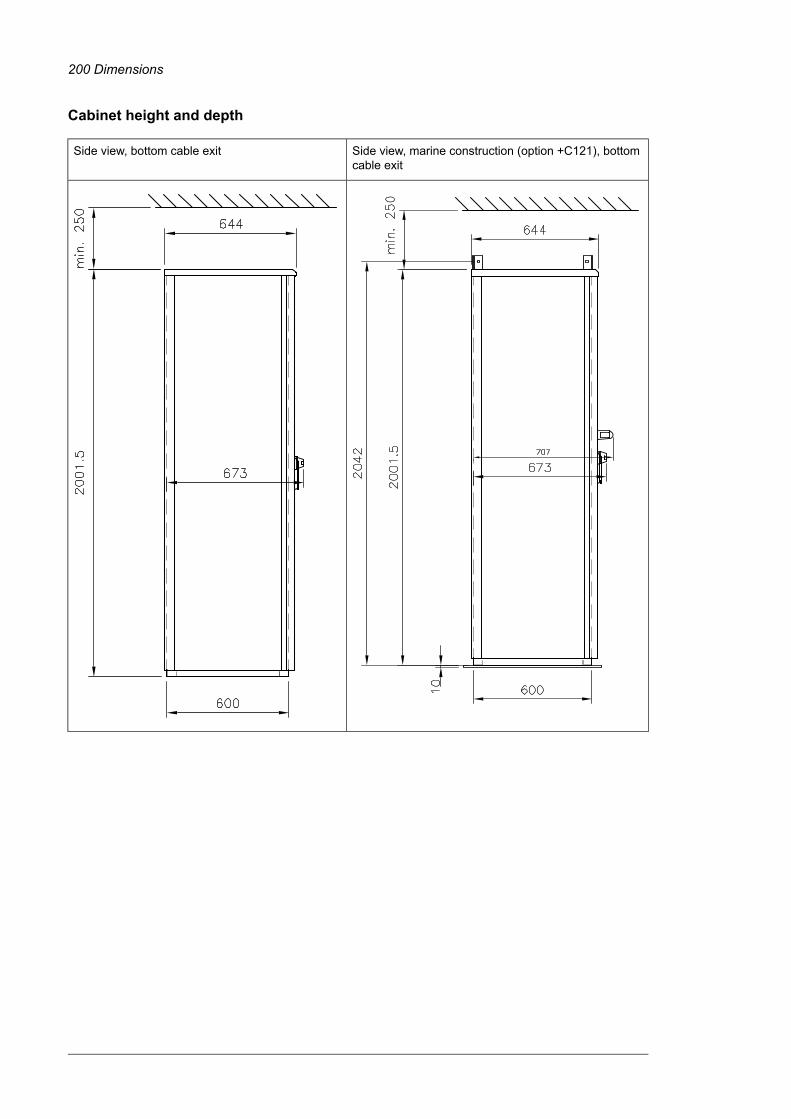
Cabinet height and depth
Side view, marine construction (option +C121), bottomcable exit
Side view, bottom cable exit
200 Dimensions

Side view, top cable exit without common motor terminalcubicle
Side view, top cable exit with commonmotor terminalcubicle
Dimensions 201

Location and size of input terminalsContact ABB for details.
202 Dimensions

■ 100 kA input cubicle (option +F274)
Dimensions 203

Location and size of output terminals■ Units without common motor terminal cubicle
Inverter module cubicle with one R8i module, bottom cable exit
204 Dimensions

Inverter module cubicle with two R8i modules, bottom cable exit
Dimensions 205

Inverter module cubicle with three R8i modules, bottom cable exit
206 Dimensions

■ Units with common motor terminal cubicle (+H359)
Cubicle width 300 mm, bottom cable exit
Dimensions 207

Cubicle width 300 mm, top cable exit
208 Dimensions

Cubicle width 400 mm, bottom cable exit
Dimensions 209

Cubicle width 400 mm, top cable exit
210 Dimensions

Cubicle width 600 mm, bottom cable exit
Dimensions 211

Cubicle width 600 mm, top cable exit
212 Dimensions

The Safe torque off function
Contents of this chapterThis chapter describes the Safe torque off (STO) function of the drive and gives instructionsfor its use.
DescriptionWARNING!In case of parallel-connected drives or dual-winding motors, the STO must beactivated on each drive to remove the torque from the motor.
The Safe torque off function can be used, for example, as the final actuator device of safetycircuits that stop the drive in case of danger (such as an emergency stop circuit). Anothertypical application is a prevention of unexpected start-up function that enables short-timemaintenance operations like cleaning or work on non-electrical parts of the machinery withoutswitching off the power supply to the drive.
When activated, the Safe torque off function disables the control voltage for the powersemiconductors of the drive output stage, thus preventing the drive from generating thetorque required to rotate the motor. If the motor is running when Safe torque off is activated,it coasts to a stop.
The Safe torque off function has a redundant architecture, that is, both channels must beused in the safety function implementation. The safety data given in this manual is calculatedfor redundant use, and does not apply if both channels are not used.
The Safe torque off function complies with these standards:
NameStandard
Safety of machinery – Electrical equipment of machines – Part 1: Generalrequirements
IEC 60204-1:2016EN 60204-1:2018
15The Safe torque off function 213

NameStandard
Electromagnetic compatibility (EMC) – Part 6-7: Generic standards – Im-munity requirements for equipment intended to perform functions in asafety-related system (functional safety) in industrial locations
IEC 61000-6-7:2014
Electrical equipment for measurement, control and laboratory use – EMCrequirements – Part 3-1: Immunity requirements for safety-related systemsand for equipment intended to perform safety-related functions (functionalsafety) – General industrial applications
IEC 61326-3-1:2017
Functional safety of electrical/electronic/programmable electronic safety-related systems – Part 1: General requirements
IEC 61508-1:2010
Functional safety of electrical/electronic/programmable electronic safety-related systems – Part 2: Requirements for electrical/electronic/program-mable electronic safety-related systems
IEC 61508-2:2010
Functional safety – Safety instrumented systems for the process industrysector
IEC 61511-1:2017
Adjustable speed electrical power drive systems – Part 5-2: Safety require-ments – Functional
IEC 61800-5-2:2016EN 61800-5-2:2007
Safety of machinery – Functional safety of safety-related electrical, elec-tronic and programmable electronic control systems
IEC 62061:2021EN 62061:2005 + AC:2010 +A1:2013 + A2:2015
Safety of machinery – Safety-related parts of control systems – Part 1:General principles for design
EN ISO 13849-1:2015
Safety of machinery – Safety-related parts of control systems – Part 2:Validation
EN ISO 13849-2:2012
The function also corresponds to Prevention of unexpected start-up as specified byEN ISO 14118:2018 (ISO 14118:2017), and Uncontrolled stop (stop category 0) as specifiedin EN/IEC 60204-1.
■ Compliance with the European Machinery Directive and the UK Supplyof Machinery (Safety) RegulationsSee the technical data.
The Declarations of conformity are shown at the end of this chapter.
214 The Safe torque off function

WiringFor the electrical specifications of the STO connection, see the technical data of the controlunit.
■ Activation switchIn the wiring diagrams, the activation switch has the designation [K]. This represents acomponent such as a manually operated switch, an emergency stop push button switch, orthe contacts of a safety relay or safety PLC.
• In case a manually operated activation switch is used, the switch must be of a type thatcan be locked out to the open position.
• The contacts of the switch or relay must open/close within 200 ms of each other.
• An FSO safety functions module, an FSPS safety functions module or an FPTCthermistor protection module can also be used. For more information, see the moduledocumentation.
■ Cable types and lengths• Double-shielded twisted-pair cable is recommended.
• Maximum cable lengths:
• 300 m (1000 ft) between activation switch [K] and drive control unit
• 60 m (200 ft) between multiple drives
• 60 m (200 ft) between external power supply and first control unit
• 30 m (100 ft) between BCU control unit and last inverter module in the chain.
Note: A short-circuit in the wiring between the switch and an STO terminal causes adangerous fault. Therefore, it is recommended to use a safety relay (including wiringdiagnostics) or a wiring method (shield grounding, channel separation) which reduces oreliminates the risk caused by the short-circuit.Note: The voltage at the STO input terminals of the control unit (or frame R8i inverter module)must be at least 17 V DC to be interpreted as “1”.The pulse tolerance of the input channels is 1 ms.
■ Grounding of protective shields• Ground the shield in the cabling between the activation switch and the control unit at
the control unit only.
• Ground the shield in the cabling between two control units at one control unit only.
• Do not ground the shield in the cabling between BCU and R8i module, or between R8imodules.
The Safe torque off function 215

■ Dual-channel connection with internal power supply
+24 V OUT
SGND
IN1IN2
XSTO
K
IN1SGND
XSTO OUT
IN2SGND
24VDC CH1GND CH1
STO IN (X52)
24VDC CH2
FEGND CH2
24VDC CH1GND CH1
STO OUT (X51)
24VDC CH2
FEGND CH2
24VDC CH1GND CH1
STO IN (X52)
24VDC CH2
FEGND CH2
24VDC CH1GND CH1
STO OUT (X51)
24VDC CH2
FEGND CH2
1
2
2
3
Drive control unit1
Inverter module(s)2
To remaining inverter modules3
Activation switchK
216 The Safe torque off function

■ Single-channel connection of activation switch
+24 V OUT
SGND
IN2
K
IN1
1
2
Note:• Both STO inputs (IN1, IN2) must be connected to the activation switch. Otherwise, no SIL/PL classification
is given.• Pay special attention to avoiding any potential failure modes for the wiring. For example, use shielded cable.
For measures for fault exclusion of wiring, see eg. EN ISO 13849-2:2012, table D.4.
Drive1
Control unit2
Activation switchK
The Safe torque off function 217
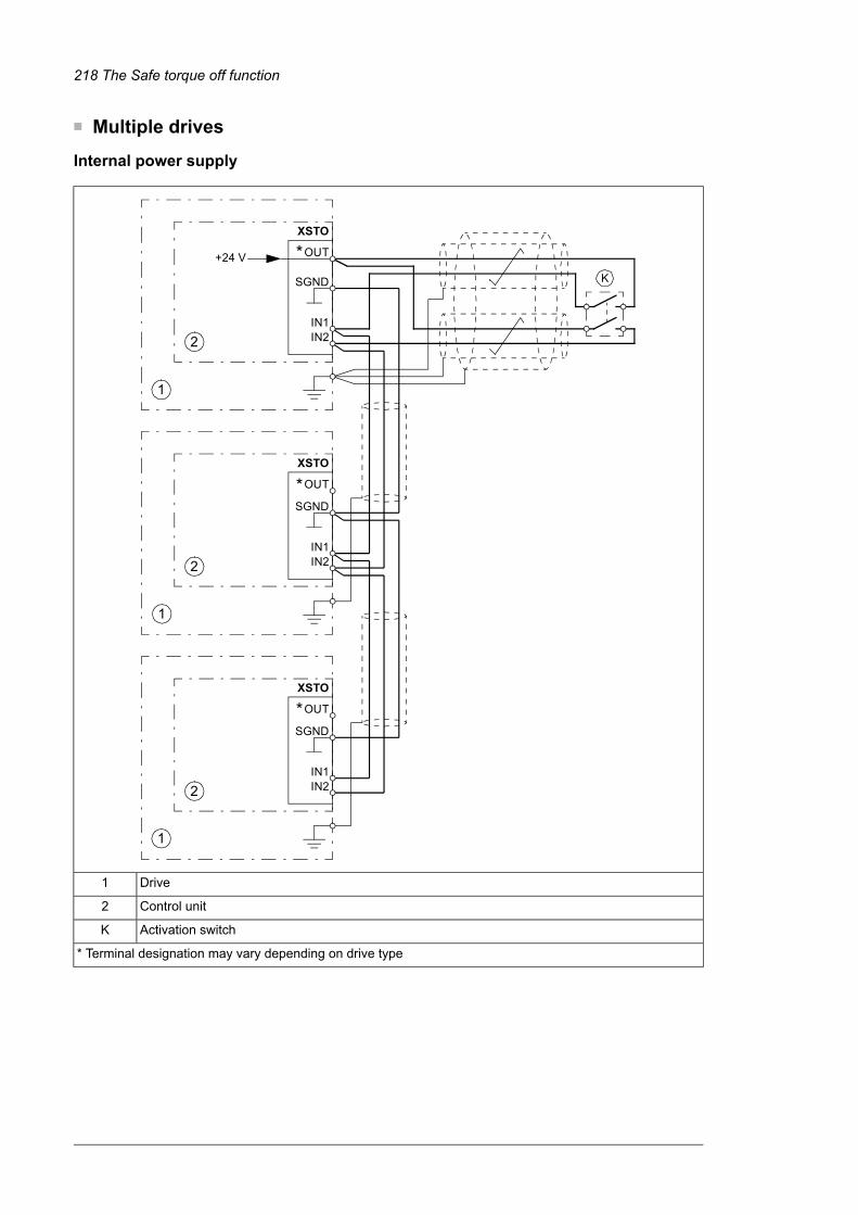
■ Multiple drives
Internal power supply
+24 V OUT
SGND
IN1IN2
OUT
SGND
IN1IN2
OUT
SGND
IN1IN2
K
XSTO
XSTO
XSTO
1
1
1
2
2
2
*
*
*
Drive1
Control unit2
Activation switchK
* Terminal designation may vary depending on drive type
218 The Safe torque off function

External power supply
OUT
SGND
IN1IN2
OUT
SGND
IN1IN2
OUT
SGND
IN1IN2
+24 V
24 V DC– +
K
XSTO
XSTO
XSTO
1
2
1
2
1
2
*
*
*
Drive1
Control unit2
Activation switchK
* Terminal designation may vary depending on drive type
The Safe torque off function 219

Operation principle1. The Safe torque off activates (the activation switch is opened, or safety relay contacts
open).
2. The STO inputs of the drive control unit de-energize.
3. The control unit cuts off the control voltage from the output IGBTs.
4. The control program generates an indication as defined by parameter 31.22 (see thefirmware manual of the drive).The parameter selects which indications are given when one or both STO signals areswitched off or lost. The indications also depend on whether the drive is running orstopped when this occurs.Note: This parameter does not affect the operation of the STO function itself. The STOfunction will operate regardless of the setting of this parameter: a running drive will stopupon removal of one or both STO signals, and will not start until both STO signals arerestored and all faults reset.Note: The loss of only one STO signal always generates a fault as it is interpreted asa malfunction of STO hardware or wiring.
5. The motor coasts to a stop (if running). The drive cannot restart while the activationswitch or safety relay contacts are open. After the contacts close, a reset may be needed(depending on the setting of parameter 31.22). A new start command is required tostart the drive.
220 The Safe torque off function

Start-up including validation testTo ensure the safe operation of a safety function, validation is required. The final assemblerof the machine must validate the function by performing a validation test. The test must beperformed
• at initial start-up of the safety function
• after any changes related to the safety function (circuit boards, wiring, components,settings, etc.)
• after any maintenance work related to the safety function
• at the proof test of the safety function
• after a drive firmware update.
■ CompetenceThe validation test of the safety function must be carried out by a competent person withadequate expertise and knowledge of the safety function as well as functional safety, asrequired by IEC 61508-1 clause 6. The test procedures and report must be documentedand signed by this person.
■ Validation test reportsSigned validation test reports must be stored in the logbook of the machine. The report shallinclude documentation of start-up activities and test results, references to failure reportsand resolution of failures. Any new validation tests performed due to changes or maintenanceshall be logged into the logbook.
■ Validation test procedureAfter wiring the Safe torque off function, validate its operation as follows.Note: If the drive is equipped with safety option +L513, +L514, +L536, +L537, +Q950,+Q951, +Q952, +Q957, +Q963, +Q964, +Q965, +Q978, +Q979 or +Q984, also do theprocedure shown in the documentation of the option.If an FSPS-21 module is installed, refer to its documentation.Note: All inverter modules of the drive must be powered and connected to the STO circuitduring the validation test.
Action
WARNING!Obey the safety instructions. If you ignore them, injury or death, or damage to the equipmentcan occur.
Make sure that the drive can be run and stopped freely during start-up.
Stop the drive (if running), switch the input power off and isolate the drive from the power line using adisconnector.
Check the STO circuit connections against the wiring diagram.
Close the disconnector and switch the power on.
The Safe torque off function 221

Action
Test the operation of the STO function when the motor is stopped.• Give a stop command for the drive (if running) and wait until the motor shaft is at a standstill.Make sure that the drive operates as follows:• Open the STO circuit. The drive generates an indication if one is defined for the 'stopped' state in
parameter 31.22 (see the firmware manual).• Give a start command to verify that the STO function blocks the drive's operation. The drive generates
a warning. The motor should not start.• Close the STO circuit.• Reset any active faults. Restart the drive and check that the motor runs normally.
Test the operation of the STO function when the motor is running.• Start the drive and make sure the motor is running.• Open the STO circuit. The motor should stop. The drive generates an indication if one is defined
for the 'running' state in parameter 31.22 (see the firmware manual).• Reset any active faults and try to start the drive.• Make sure that the motor stays at a standstill and the drive operates as described above in testing
the operation when the motor is stopped.• Close the STO circuit.• Reset any active faults. Restart the drive and check that the motor runs normally.
Test the operation of the failure detection of the drive. The motor can be stopped or running.• Open the 1st channel of the STO circuit. If the motor was running, it should coast to a stop. The
drive generates a FA81 Safe Torque Off 1 loss fault indication (see the firmware manual).• Give a start command to verify that the STO function blocks the drive's operation. The motor should
not start.• Close the STO circuit.• Reset any active faults. Restart the drive and check that the motor runs normally.• Open the 2nd channel of the STO circuit. If the motor was running, it should coast to a stop. The
drive generates a FA82 Safe Torque Off 2 loss fault indication (see the firmware manual).• Give a start command to verify that the STO function blocks the drive's operation. The motor should
not start.• Close the STO circuit.• Reset any active faults. Restart the drive and check that the motor runs normally.
Document and sign the validation test report which verifies that the safety function is safe and acceptedfor operation.
222 The Safe torque off function

Use1. Open the activation switch, or activate the safety functionality that is wired to the STO
connection.
2. The STO inputs on the drive control unit de-energize, and the control unit cuts off thecontrol voltage from the output IGBTs.
3. The control program generates an indication as defined by parameter 31.22 (see thefirmware manual of the drive).
4. The motor coasts to a stop (if running). The drive will not restart while the activationswitch or safety relay contacts are open.
5. Deactivate the STO by closing the activation switch, or resetting the safety functionalitythat is wired to the STO connection.
6. Reset any faults before restarting.
WARNING!The Safe torque off function does not disconnect the voltage of the main and auxiliarycircuits from the drive. Therefore maintenance work on electrical parts of the driveor the motor can only be carried out after isolating the drive from the supply and allother voltage sources.
WARNING!The Safe torque off functionality is only achieved through the XSTO connector ofthe inverter control unit (A41). True Safe torque off functionality is not achievedthrough the XSTO connectors of other control units (such as the supply control unitor the brake control unit).
The Safe torque off function is supported by any ACS880 inverter or drive controlprogram. It is not supported by supply, DC/DC converter or brake firmware.
WARNING!The drive cannot detect or memorize any changes in the STO circuitry when thedrive control unit is not powered. If both STO circuits are closed and a level-typestart signal is active when the power is restored, it is possible that the drive startswithout a fresh start command. Take this into account in the risk assessment of thesystem.
WARNING!(With permanent magnet or synchronous reluctance [SynRM] motors only)
In case of a multiple IGBT power semiconductor failure, the drive can produce analignment torque which maximally rotates the motor shaft by 180/p degrees (withpermanent magnet motors) or 180/2p degrees (with synchronous reluctance [SynRM]motors) regardless of the activation of the Safe torque off function. p denotes thenumber of pole pairs.
Notes:• If a running drive is stopped by using the Safe torque off function, the drive will cut off
the motor supply voltage and the motor will coast to a stop. If this causes danger or is
The Safe torque off function 223

not otherwise acceptable, stop the drive and machinery using the appropriate stopmode before activating the Safe torque off function.
• The Safe torque off function overrides all other functions of the drive.
• The Safe torque off function is ineffective against deliberate sabotage or misuse.
• The Safe torque off function has been designed to reduce the recognized hazardousconditions. In spite of this, it is not always possible to eliminate all potential hazards.The assembler of the machine must inform the final user about the residual risks.
224 The Safe torque off function

MaintenanceAfter the operation of the circuit is validated at start-up, the STO function shall be maintainedby periodic proof testing. In high demand mode of operation, the maximum proof test intervalis 20 years. In low demand mode of operation, the maximum proof test interval is 5 or 2years; see section Safety data (page 227). It is assumed that all dangerous failures of theSTO circuit are detected by the proof test. To perform the proof test, do the Validation testprocedure (page 221).Note: See also the Recommendation of Use CNB/M/11.050 (published by the Europeanco-ordination of Notified Bodies) concerning dual-channel safety-related systems withelectromechanical outputs:
• When the safety integrity requirement for the safety function is SIL 3 or PL e (cat. 3 or4), the proof test for the function must be performed at least every month.
• When the safety integrity requirement for the safety function is SIL 2 (HFT = 1) or PLd (cat. 3), the proof test for the function must be performed at least every 12 months.
The STO function of the drive does not contain any electromechanical components.
In addition to proof testing, it is a good practice to check the operation of the function whenother maintenance procedures are carried out on the machinery.
Include the Safe torque off operation test described above in the routine maintenanceprogram of the machinery that the drive runs.
If any wiring or component change is needed after start-up, or the parameters are restored,do the test given in section Validation test procedure (page 221).
Use only spare parts approved by ABB.
Record all maintenance and proof test activities in the machine logbook.
■ CompetenceThe maintenance and proof test activities of the safety function must be carried out by acompetent person with adequate expertise and knowledge of the safety function as well asfunctional safety, as required by IEC 61508-1 clause 6.
The Safe torque off function 225

Fault tracingThe indications given during the normal operation of the Safe torque off function are selectedby drive control program parameter 31.22.
The diagnostics of the Safe torque off function cross-compare the status of the two STOchannels. In case the channels are not in the same state, a fault reaction function isperformed and the drive trips on an “STO hardware failure” fault. An attempt to use the STOin a non-redundant manner, for example activating only one channel, will trigger the samereaction.
See the firmware manual of the drive control program for the indications generated by thedrive, and for details on directing fault and warning indications to an output on the controlunit for external diagnostics.
Any failures of the Safe torque off function must be reported to ABB.
226 The Safe torque off function
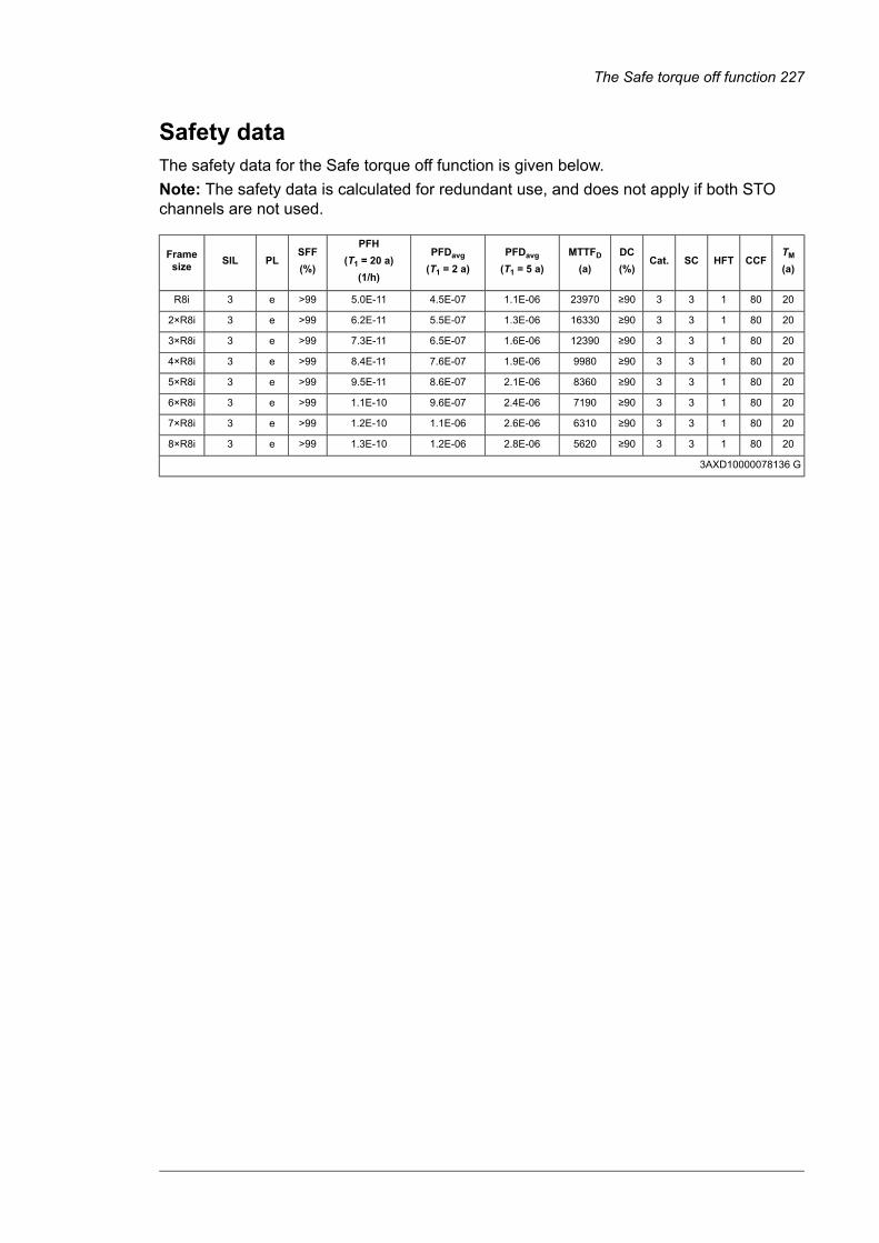
Safety dataThe safety data for the Safe torque off function is given below.Note: The safety data is calculated for redundant use, and does not apply if both STOchannels are not used.
TM
(a)CCFHFTSCCat.
DC(%)
MTTFD
(a)PFDavg
(T1 = 5 a)PFDavg
(T1 = 2 a)
PFH(T1 = 20 a)
(1/h)
SFF(%)
PLSILFramesize
2080133≥90239701.1E-064.5E-075.0E-11>99e3R8i
2080133≥90163301.3E-065.5E-076.2E-11>99e32×R8i
2080133≥90123901.6E-066.5E-077.3E-11>99e33×R8i
2080133≥9099801.9E-067.6E-078.4E-11>99e34×R8i
2080133≥9083602.1E-068.6E-079.5E-11>99e35×R8i
2080133≥9071902.4E-069.6E-071.1E-10>99e36×R8i
2080133≥9063102.6E-061.1E-061.2E-10>99e37×R8i
2080133≥9056202.8E-061.2E-061.3E-10>99e38×R8i
3AXD10000078136 G
The Safe torque off function 227

• The following temperature profile is used in safety value calculations:
• 670 on/off cycles per year with ΔT = 71.66 °C
• 1340 on/off cycles per year with ΔT = 61.66 °C
• 30 on/off cycles per year with ΔT = 10.0 °C
• 32 °C board temperature at 2.0% of time
• 60 °C board temperature at 1.5% of time
• 85 °C board temperature at 2.3% of time.
• The STO is a type B safety component as defined in IEC 61508-2.
• Relevant failure modes:
• The STO trips spuriously (safe failure)
• The STO does not activate when requested
• A fault exclusion on the failure mode “short circuit on printed circuit board” hasbeen made (EN 13849-2, table D.5). The analysis is based on an assumption thatone failure occurs at one time. No accumulated failures have been analyzed.
• STO response times:
• STO reaction time (shortest detectable break): 1 ms
• STO response time: 2 ms (typical), 25 ms (maximum)
• Fault detection time: Channels in different states for longer than 200 ms
• Fault reaction time: Fault detection time + 10 ms
• Indication delays:
• STO fault indication (parameter 31.22) delay: < 500 ms
• STO warning indication (parameter 31.22) delay: < 1000 ms
■ Terms and abbreviations
DescriptionReferenceTerm or abbre-viation
Classification of the safety-related parts of a control system in respectof their resistance to faults and their subsequent behavior in the faultcondition, and which is achieved by the structural arrangement of theparts, fault detection and/or by their reliability. The categories are: B,1, 2, 3 and 4.
EN ISO 13849-1Cat.
Common cause failure (%)EN ISO 13849-1CCF
Diagnostic coverageEN ISO 13849-1DC
Hardware fault toleranceIEC 61508HFT
Mean time to dangerous failure: (Total number of life units) / (Numberof dangerous, undetected failures) during a particular measurementinterval under stated conditions
EN ISO 13849-1MTTFD
Average probability of dangerous failure on demand, that is, meanunavailability of a safety-related system to perform the specified safetyfunction when a demand occurs
IEC 61508PFDavg
Average frequency of dangerous failures per hour, that is, averagefrequency of a dangerous failure of a safety related system to performthe specified safety function over a given period of time
IEC 61508PFH
228 The Safe torque off function

DescriptionReferenceTerm or abbre-viation
Average frequency of dangerous failures per hour for the diagnosticfunction of STO
IEC/EN 62061PFHdiag
Performance level. Levels a…e correspond to SILEN ISO 13849-1PL
Periodic test performed to detect failures in a safety-related systemso that, if necessary, a repair can restore the system to an "as new"condition or as close as practical to this condition
IEC 61508, IEC 62061Proof test
Systematic capabilityIEC 61508SC
Safe failure fraction (%)IEC 61508SFF
Safety integrity level (1…3)IEC 61508SIL
Safe torque offIEC/EN 61800-5-2STO
Proof test interval. T1 is a parameter used to define the probabilisticfailure rate (PFH or PFD) for the safety function or subsystem. Per-forming a proof test at a maximum interval of T1 is required to keepthe SIL capability valid. The same interval must be followed to keepthe PL capability (EN ISO 13849) valid.
IEC 61508-6T1
See also section Maintenance.
Mission time: the period of time covering the intended use of the safetyfunction/device. After the mission time elapses, the safety device mustbe replaced. Note that any TM values given cannot be regarded as aguarantee or warranty.
EN ISO 13849-1TM
Dangerous failure rate (per hour) of the diagnostics function of STOIEC 61508-6λDiag_dSafe failure rate (per hour) of the diagnostics function of STOIEC 61508-6λDiag_s
■ TÜV certificateThe TÜV certificate is available on the Internet at www.abb.com/drives/documents.
The Safe torque off function 229

■ Declarations of conformity
1/2 3AXD10000105027 Rev. W
EU Declaration of Conformity Machinery Directive 2006/42/EC
We Manufacturer: ABB Oy Address: Hiomotie 13, 00380 Helsinki, Finland. Phone: +358 10 22 11 declare under our sole responsibility that the following products:
Frequency converters and frequency converter components
ACS880-04, -14, -34 (frames nxR8i)
ACS880-04XT, -04FXT
ACS880-07, -17, -37, -107
ACS880-104
ACS880 multidrives
ACS880-104LC (frames nxR8i)
ACS880-07CLC, -07LC, -17LC, -37LC, -107LC (frames nxR8i)
ACS880 liquid-cooled multidrives
identified with serial numbers beginning with 1 or 8
with regard to the safety functions
Safe torque off
Safe motor temperature with FPTC-01 module (option code +L536)
Safe Stop 1 (SS1-t) with FSPS-21 module (+Q986)
Safe stop 1 (SS1-t and SS1-r), Safe stop emergency, Safely-limited speed, Safe maximum speed, Safe brake control, Prevention of unexpected start-up, with FSO-12 module (option code +Q973)
Safe stop 1 (SS1-t and SS1-r), Safe stop emergency, Safely-limited speed, Safe maximum speed, Safe brake control, Safe Speed monitor, Safe direction, Prevention of unexpected start-up, with FSO-21 and FSE-31 modules (option codes +Q972 and +L521)
230 The Safe torque off function

2/2 3AXD10000105027 Rev. W
ACS880-07, -17, -37, -07CLC, -07LC, -17LC, -37LC, ACS880 multidrives and ACS880 liquid-cooled multidrives: Prevention of unexpected start-up (option codes +Q950; +Q957), Emergency stop (option codes +Q951; +Q952; +Q963; +Q964; +Q978; +Q979), Safely-limited speed (option codes +Q965; Q966)
are in conformity with all the relevant safety component requirements of EU Machinery Directive 2006/42/EC, when the listed safety functions are used for safety component functionality.
The following harmonized standards have been applied:
EN 61800-5-2:2007 Adjustable speed electrical power drive systems – Part 5-2: Safety requirements - Functional
EN 62061:2005 + AC:2010 + A1:2013 + A2:2015
Safety of machinery – Functional safety of safety-related electrical, electronic and programmable electronic control systems
EN ISO 13849-1:2015 Safety of machinery – Safety-related parts of control systems. Part 1: General principles for design
EN ISO 13849-2:2012 Safety of machinery – Safety-related parts of the control systems. Part 2: Validation
EN 60204-1:2018 Safety of machinery – Electrical equipment of machines – Part 1: General requirements
The following other standard has been applied:
IEC 61508:2010, parts 1-3 Functional safety of electrical / electronic / programmable electronic safety-related systems
IEC 61800-5-2:2016 Adjustable speed electrical power drive systems – Part 5-2: Safety requirements - Functional
The products referred in this Declaration of conformity fulfil the relevant provisions of other European Union Directives which are notified in Single EU Declaration of conformity 3AXD10000497305.
Authorized to compile the technical file: ABB Oy, Hiomotie 13, 00380 Helsinki, Finland
Helsinki, 28 May 2021
Signed for and on behalf of:
Peter Lindgren Vesa Tiihonen Vice President, ABB Oy Manager, Reliability and Quality, ABB Oy
The Safe torque off function 231

1/2 3AXD10001326695 Rev. A
Declaration of Conformity Supply of Machinery (Safety) Regulations 2008 We Manufacturer: ABB Oy Address: Hiomotie 13, 00380 Helsinki, Finland. Phone: +358 10 22 11
declare under our sole responsibility that the following products:
Frequency converters and frequency converter components
ACS880-04, -14, -34 (frames nxR8i)
ACS880-04XT, -04FXT
ACS880-07, -17, -37, -107
ACS880-104
ACS880 multidrives
ACS880-104LC (frames nxR8i)
ACS880-07CLC, -07LC, -17LC, -37LC, -107LC (frames nxR8i)
ACS880 liquid-cooled multidrives
identified with serial numbers beginning with 1 or 8
with regard to the safety functions
Safe torque off
Safe motor temperature with FPTC-01 module (option code +L536)
Safe Stop 1 (SS1-t) with FSPS-21 module (+Q986)
Safe stop 1 (SS1-t and SS1-r), Safe stop emergency, Safely-limited speed, Safe maximum speed, Safe brake control, Prevention of unexpected start-up, with FSO-12 module (option code +Q973)
Safe stop 1 (SS1-t and SS1-r), Safe stop emergency, Safely-limited speed, Safe maximum speed, Safe brake control, Safe Speed monitor, Safe direction, Prevention of unexpected start-up, with FSO-21 and FSE-31 modules (option codes +Q972 and +L521)
232 The Safe torque off function

2/2 3AXD10001326695 Rev. A
ACS880-07, -17, -37, -07CLC, -07LC, -17LC, -37LC, ACS880 multidrives and ACS880 liquid-cooled multidrives: Prevention of unexpected start-up (option codes +Q950; +Q957), Emergency stop (option codes +Q951; +Q952; +Q963; +Q964; +Q978; +Q979), Safely-limited speed (option codes +Q965; Q966)
are in conformity with all the relevant safety component requirements of the Supply of Machinery (Safety) Regulations 2008, when the listed safety functions are used for safety component functionality.
The following designated standards have been applied:
EN 61800-5-2:2007 Adjustable speed electrical power drive systems – Part 5-2: Safety requirements - Functional
EN 62061:2005 + AC:2010 + A1:2013 + A2:2015
Safety of machinery – Functional safety of safety-related electrical, electronic and programmable electronic control systems
EN ISO 13849-1:2015 Safety of machinery – Safety-related parts of control systems. Part 1: General principles for design
EN ISO 13849-2:2012 Safety of machinery – Safety-related parts of the control systems. Part 2: Validation
EN 60204-1:2018 Safety of machinery – Electrical equipment of machines – Part 1: General requirements
The following other standards have been applied:
EN 61508:2010, parts 1-3 Functional safety of electrical / electronic / programmable electronic safety-related systems
EN 61800-5-2:2017 Adjustable speed electrical power drive systems – Part 5-2: Safety requirements - Functional
The products referred in this declaration of conformity fulfil the relevant provisions of other UK statutory requirements, which are notified in a single declaration of conformity 3AXD10001346556.
Authorized to compile the technical file: ABB Limited, Daresbury Park, Cheshire, United Kingdom, WA4 4BT
Helsinki, 28 May 2021
Signed for and on behalf of:
Peter Lindgren Vesa Tiihonen Vice President, ABB Oy Manager, Reliability and Quality, ABB Oy
The Safe torque off function 233

234

Further information—
Product and service inquiriesAddress any inquiries about the product to your local ABB representative, quoting the typedesignation and serial number of the unit in question. A listingof ABBsales, support and servicecontacts can be found by navigating to www.abb.com/searchchannels.
Product trainingFor information on ABB product training, navigate to new.abb.com/service/training.
Providing feedback on ABB manualsYour comments on our manuals are welcome. Navigate tonew.abb.com/drives/manuals-feedback-form.
Document library on the InternetYou can find manuals and other product documents in PDF format on the Internet atwww.abb.com/drives/documents.
a2 (frozen)PDF-A4Created 2022-04-20, 14:04:58

www.abb.com/drives
3AXD50000250295B
© Copyright 2022 ABB. All rights reserved.Specifications subject to change without notice. 3AXD50000250295Rev
B(EN)2022-04-20
Copyright © 2022 FDOKUMEN