
Emmanuel Kofi Amissah(10506982).pdf - University of Ghana ...
102
A STUDY ON THE PROPERTIES OF BLENDED REGENERATED SPENT CATALYST AND CEMENT SANDCRETE BLOCKS A THESIS SUBMITTED TO THE DEPARTENT OF NUCLEAR ENGINEERING COLLEGE OF BASIC AND APPLIED SCIENCE SCHOOL OF NUCLEAR AND ALLIED SCIENCES UNIVERSITY OF GHANA BY EMMANUEL KOFI AMISSAH, (ID: 10506982) BSc. (KUMASI), 2009 IN PARTIAL FULFILMENT OF THE REQUIREMENT FOR THE DEGREE OF MASTERS OF PHILOSOPHY IN NUCLEAR TECHNOLOGY APPLICATIONS IN PETROLEUM AND MINING INDUSTRIES JULY 2016 University of Ghana http://ugspace.ug.edu.gh
-
Upload
khangminh22 -
Category
Documents
-
view
1 -
download
0
Transcript of Emmanuel Kofi Amissah(10506982).pdf - University of Ghana ...

A STUDY ON THE PROPERTIES OF BLENDED REGENERATED SPENT
CATALYST AND CEMENT SANDCRETE BLOCKS
A THESIS SUBMITTED TO THE DEPARTENT OF NUCLEAR ENGINEERING
COLLEGE OF BASIC AND APPLIED SCIENCE
SCHOOL OF NUCLEAR AND ALLIED SCIENCES
UNIVERSITY OF GHANA
BY
EMMANUEL KOFI AMISSAH, (ID: 10506982)
BSc. (KUMASI), 2009
IN PARTIAL FULFILMENT OF THE REQUIREMENT FOR THE DEGREE OF
MASTERS OF PHILOSOPHY
IN
NUCLEAR TECHNOLOGY APPLICATIONS IN PETROLEUM
AND
MINING INDUSTRIES
JULY 2016
University of Ghana http://ugspace.ug.edu.gh
ii
DECLARATION
This thesis is the result of research work undertaken by Emmanuel Kofi Amissah in the
Department of Nuclear Engineering, School of Nuclear and Allied Sciences, University
of Ghana, under the supervision of Dr. A. Abugre and Dr. K. A. Danso.
.
……………………………… Date:……………………….
EMMANUEL KOFI AMISSAH
(STUDENT)
………………………………. Date:………………………..
DR. A. ABUGRE
(PRINCIPAL SUPERVISOR)
………………………………. Date:………………………..
DR. K. A. DANSO
(CO-SUPERVISOR)
University of Ghana http://ugspace.ug.edu.gh

iii
DEDICATION
To my heavenly Father be all the glory, honour and praise. This work is dedicated to my
parents, Mr. John Kojo Amissah and Madam Gifty Acquah, and my lovely wife
Elizabeth Arkoh for having provide me with rich education and fulfilling my spiritual
needs throughout their immeasurable support, encouragement, love, care and prayers.
University of Ghana http://ugspace.ug.edu.gh

iv
ACKNOWLEDGEMENT
I would like to express my utmost gratitude and appreciation to my supervisors Dr. A.
Abugre(Lecturer, Nuclear Engineering Department, School of Nuclear and Allied Sciences,
University of Ghana, Legon), Dr. K. A. Danso(Lecturer, Nuclear Engineering Department,
School of Nuclear and Allied Sciences, University of Ghana, Legon)and Dr. Andrew
Nyamful(Lecturer, Nuclear Engineering Department, School of Nuclear and Allied
Sciences, University of Ghana, Legon) for their immeasurable and valuable contributions,
guidance, patience, encouragement and suggestions in the preparation of this thesis.
I am also grateful to Ghana Standard Authority (GSA) particularly to Mr. Mawuli and
Mr. Nimako of Engineering Department, for their time and support and for making the
facilities available for this research work.
University of Ghana http://ugspace.ug.edu.gh

v
TABLE OF CONTENTS
DECLARATION ................................................................................................................ ii
DEDICATION ................................................................................................................... iii
ACKNOWLEDGEMENT ................................................................................................. iv
TABLE OF CONTENTS .................................................................................................... v
LIST OF FIGURES ........................................................................................................... ix
LIST OF TABLES ............................................................................................................. xi
LIST OF ABBREVIATION ............................................................................................. xii
LIST OF SYMBOLS ....................................................................................................... xiv
ABSTRACT ........................................................................................................................ 1
CHAPTER ONE ................................................................................................................. 2
INTRODUCTION .............................................................................................................. 2
1.1 BACKGROUND ....................................................................................................... 2
1.2 Statement of Problem ................................................................................................ 5
1.3 Objectives .................................................................................................................. 6
1.4 Relevance and Justification ....................................................................................... 6
1.5 Scope and Delimitation ............................................................................................. 7
1.6 Organization of Thesis .............................................................................................. 7
CHAPTER TWO ................................................................................................................ 8
LITERATURE REVIEW ................................................................................................... 8
2.1 Background ............................................................................................................... 8
2.2 Catalytic Cracking ..................................................................................................... 9
2.2.1 Catalyst Structure and Reaction Mechanism .................................................... 10
2.2.2 Characterization of Catalyst ............................................................................. 11
2.2.3 Changes in Catalyst Properties ......................................................................... 12
2.2.4 Pozzolanic Activity and Mechanical Properties ............................................... 12
2.3 Sandcrete ................................................................................................................. 16
2.3.1 Composition of Sandcrete ................................................................................ 17
2.3.2 Properties of Sandcrete ..................................................................................... 19
2.3.3 Useful Life ........................................................................................................ 22
2.3.4 Impact of Modern Sandcrete Use ..................................................................... 22
University of Ghana http://ugspace.ug.edu.gh
vi
2.4 Importance of Measurements & Expression of Results in Reporting ..................... 24
2.4.1 Quality Management Systems and Accreditation ............................................ 25
2.4.2 The Importance of Quality ............................................................................... 27
2.5 Cement in Ghana ..................................................................................................... 30
2.5.1 Why Check the Quality of Cement ................................................................... 31
2.5.2 Important Physical Properties of Cement ......................................................... 32
2.5.3 Chemical Properties of Cement ........................................................................ 33
2.5.4 Standard Strength of Cement ............................................................................ 34
2.5.5 Testing of Cement ............................................................................................ 35
2.5.6 Physical Test ..................................................................................................... 36
2.5.7 Standard Consistency Test................................................................................ 36
2.5.8 Setting Times .................................................................................................... 37
2.5.9 Fineness of Cement .......................................................................................... 37
2.5.10 Compressive Strength ..................................................................................... 38
2.5.10.1 Effect of Cement Variations on Compressive Strength ........................... 38
2.5.11 Deterioration of Cement with Storage ............................................................ 38
2.5.12 The Importance of Curing .............................................................................. 39
2.5.13 Quality Management System in the Testing Laboratory ................................ 41
2.5.14 Benefits of Standards ...................................................................................... 41
2.5.15 Evolution of ISO 17025 and Its Importance ................................................... 42
2.5.16 Benefits of Accreditation and the Accreditation Process ............................... 43
2.5.17 Importance of Accurate and Reliable Data ..................................................... 44
CHAPTER THREE .......................................................................................................... 47
RESEARCH METHODOLOGY...................................................................................... 47
3.0 Introduction ............................................................................................................. 47
3.2 The study Area ........................................................................................................ 47
3.3 The Research Approach and Strategy ..................................................................... 48
3.4 Research Procedure ................................................................................................. 48
3.5 Data Collection and Experimentations .................................................................... 49
3.5.1 Primary Data Collection ................................................................................... 49
3.5.2 Secondary Data ................................................................................................. 50
University of Ghana http://ugspace.ug.edu.gh
vii
3.6 Data Collection Techniques .................................................................................... 52
3.7 Methods for Testing and Determining of Strength of Samples .............................. 54
3.8 Laboratory and Equipment ...................................................................................... 54
3.8.1 Mixer ................................................................................................................ 55
3.8.2 Preparation of Sandcrete, Placing, Conditioning and Testing .......................... 55
3.8.3 Determination of Setting Times and Standard Consistence Test ..................... 58
3.8.3.1 Principles.................................................................................................... 58
3.8.3.2 Standard Consistence Test ......................................................................... 58
3.8.3.3 Setting Times Test; Initial and Final .......................................................... 59
3.8.4 Chemical Analysis of Cement .......................................................................... 60
3.8.4.1 Blank Determinations ................................................................................ 60
3.8.4.2 Preparation of Test Samples ...................................................................... 60
3.8.5 Specification of Standard Sand......................................................................... 61
3.8.6 Analysis of Data ............................................................................................... 61
CHAPTER FOUR ............................................................................................................. 63
RESULTS AND DISCUSSIONS ..................................................................................... 63
4.1 Compressive Strength ............................................................................................. 63
4.1.1 Effect of Regenerated Spent Catalyst on Compressive Strength ..................... 65
4.2 Setting Time ............................................................................................................ 66
4.2.1 Effect of Regenerated Spent Catalyst on Setting Time .................................... 66
4.3 Water Absorption .................................................................................................... 67
4.3.1 Effect of Regenerated Spent Catalyst on Water Absorption ............................ 67
4.4 Chemical Analysis................................................................................................... 68
4.5.1 Effect of Regenerated Spent Catalyst on Compressive Strength versus Setting
................................................................................................................................... 69
4.5.2 Effect of Regenerated Spent Catalyst on Compressive Strength versus water 70
4.5.3 Effect of Regenerated Spent Catalyst on Water Absorption versus Setting..... 71
CHAPTER FIVE .............................................................................................................. 72
CONCLUSIONS AND RECOMMENDATIONS ........................................................... 72
5.1 Conclusion ............................................................................................................... 72
5.2 Recommendations ................................................................................................... 73
University of Ghana http://ugspace.ug.edu.gh

viii
REFERENCES ................................................................................................................. 74
APPENDIX ....................................................................................................................... 82
University of Ghana http://ugspace.ug.edu.gh
ix
LIST OF FIGURES
Figure 2.1: ISO/IEC 17025 Requirements for Testing Laboratories…………………30
Figure 2.2: Some Cement Manufactured and Imported In Ghana……………………32
Figure 2.3: A Cement Properly and B. Improperly Stored ………………………….40
Figure 2.4: Typical Process of Accreditation………………………………………..45
Figure 3.1: Flow chart for preparing and crushing sandcrete cubes…………………54
Figure 3.2: Mortar Mixer……………………………………………………………..56
Figure 3.3: Compression Test Machine ……………………………………………...57
Figure 3.4: Set of sandcrete cubes ready for crushing……………………………….57
Figure 3.5: Curing Tank for sandcrete cubes storage…………………………………58
Figure 3.6: A Vicat Apparatus Accessories…………………………………………...60
Figure 3.7: Sample being tested for its chemical composition……………………….61
Figure 4.1: Compressive strength curve of various samples for 2daysCuring Period…64
Figure 4.2: Compressive strength curve of various samples for 7daysCuring Period….64
Figure 4.3: Compressive strength curve of various samples for 28 daysCuring Period…65
Fig 4.4: Setting Time curves for various samples……………………………………..66
Figure 4.5: Water absorption curve for various samples……………………………..67
Figure 4.6 Chloride Content curve for various samples……………………………..68
Fig.4.7. A graph of Compressive Strength against Setting Time at different RSC
replacement in cement……………………………………………………………….69
Fig.4.8. A graph of Compressive Strength against water Absorption at different RSC
replacement in cement……………………………………………………………….70
University of Ghana http://ugspace.ug.edu.gh

x
Fig.4.9. A graph of water Absorption against Setting Time at different RSC replacement
in cement……………………………………………………………………………….71
University of Ghana http://ugspace.ug.edu.gh
xi
LIST OF TABLES
Table 2.1: Chemical Requirements of Cement…………………………………………..35
Table 3.1: Proportion of materials in sandcrete mixture…………………………………51
Table 3.2:Chemical Composition of Portland Ghacem Cement……....................…….52
Table 3.3:Physical Properties Portland Ghacem Cement……………………………...52
Table 3.4 Chemical Composition of Regenerated Spent Catalyst (RSC)……………….52
Table 3.5 Physical Properties of Regenerated Spent Catalyst (RSC)…………………....53
Table 3.6: Standard sand requirement………………………………………………….62
University of Ghana http://ugspace.ug.edu.gh

xii
LIST OF ABBREVIATION
AR Atmospheric Residue
AAS Atomic Absorption Spectrometry
CDU Crude Distillation Unit
CMT Construction Materials Testing
ECAT Equilibrium Catalyst
FCC Fluid Catalytic Cracking
GHAIP Ghanaian Italian Petroleum Company
LPG Liquefied Petroleum Gas
LCO Light Cycle Oil
MES Minimum Efficient Scale
OCM Organization Change Management
OD Organization Development
OPC Ordinary Portland Cement
PM Pozzolanic material
PLC Portland Lime stone Cement
RSC Regenerated Spent Catalyst
University of Ghana http://ugspace.ug.edu.gh

xiii
RFCC Residue Fluid Catalytic Cracking
TOR Tema Oil Refinery
TQM Total Quality Management
XRF X- Ray Flourescence
University of Ghana http://ugspace.ug.edu.gh

xiv
LIST OF SYMBOLS
% percentage
μ linear attenuation coefficient
A ampere
mm millimeter
mm2 square millimeter
wt weight
MPa mega Pascal
N Newton
k kilo
kN kilo Newton
N/ mm2 Newton per square millimeter
min minute
oC degree celsius
K Kelvin
g grams
m2/kg square metre per kilogram
cm3/g cube centime per gram
m2/g square metre per gram
kP kilo Pascal
University of Ghana http://ugspace.ug.edu.gh

1
ABSTRACT
Sandcrete is widely used as building material. Its properties greatly depend on the
properties and proportions of its constituents. The main binder material to produce
sandcrete is the Portland cement. The uncertainty about future availability of commonly
used Portland materials concomitantly with the environmental problems such as
greenhouse gases emissions and high cost of clinker consumption are highlighting the
need of identifying other materials for the construction industry, which will aid in
minimizing the clinker consumption and reduce the greenhouse gas emissions and cost in
the production of cement. The purpose of this study is to examine the properties of
sandcrete blocks produced with blended Regenerated Spent Catalyst and cement. In this
work, two different series of sandcrete mixtures in which cement was partially replaced
with Regenerated Spent Catalyst(RSC) within the range of 5% to 20% (by mass) with
an increment of 5%. 100% cement sandcrete was also prepared as reference sandcrete.
The physical properties studied were compressive strength, water absorption and setting
time. Chemical property studied was chloride content. Comparison of data between the
control and that of cement with additives were made. The results obtained in this study
clearly indicated that substituting Portland cement up to 20wt. % RSC gave sandcrete
strengths higher than the 32.5 N/mm2, which corresponds to that of Portland cement. The
replacement of Portland cement with 10 wt. % of RSC gave the highest strength of 34.0
N/mm2. Thus, Regenerated Spent Catalyst may be utilized as effective mineral additive
for designing durable sandcrete structures. The optimum amount of RSC recommended
to be added as an additive to the Portland cement is 10%.
University of Ghana http://ugspace.ug.edu.gh

2
CHAPTER ONE
INTRODUCTION
1.1 BACKGROUND
The Construction industry is important in the development of the building and
construction sector in any economy, especially in the provision of infrastructure such as
harbours, airports and roads, simple residential buildings, high rise buildings, and
massive structures like dams, flyovers and bridges.
The widely used building material is sandcrete or concrete. Its properties greatly depend
on the properties and proportions of its constituents. As cement is the major component
of concrete or sandcrete, the choice of its proper type and use has vital importance in
obtaining the right balance of its desired properties in the most economical way.
Sandcreteis a composite material composed of aggregate bonded together with
fluidcement which hardens over time. Most use of the term "concrete" refers to Portland
cement concrete or concretes made with other hydraulic cements, such as cimentfondu.
Type I/II Portland cements, which provide sufficient levels of strength and durability, are
the most common cements used by sandcrete or concrete users However, road surfaces
are also a type of concrete, "asphaltic concrete", where the cement material is bitumen.
In Portland sandcrete (and other hydraulic cement sandcrete), when the aggregate is
mixed together with the dry cement and water, they form a fluid mass that is easily
molded into shape. The cement reacts chemically with the water and other ingredients to
form a hard matrix which binds all the materials together into a durable stone-like
material that has many uses. Often, additives (such as pozzolans or superplasticizers) are
University of Ghana http://ugspace.ug.edu.gh

3
included in the mixture to improve the physical properties of the wet mix or the finished
material. Most sandcrete or concrete is poured with reinforcing materials (such as rebar)
embedded to provide tensile strength, yielding reinforced concrete or sandcrete
Reinforced sandcrete is still the protagonist in the construction of structures, due to its
numerous advantages over other materials (Fernández, 2002). It is the most widely used
material in the construction industry in developed and developing countries; compared
with other materials it is cheaper and has adequate strength and durability (Malhotra&
Mehta, 1996).
The main binder material to produce sandcrete or concrete is the Portland cement;
however, its production generates large amounts of greenhouse gases (Gartner, 2004).
The reduction of these gaseous emissions can be achieved by increasing the efficiency in
the cement production process through reduction in fuel consumption and in the use of
clinker (Price et al., 1999).
The reduction in the use of clinker can be achieved through the incorporation of mineral
admixtures at the time of manufacturing sandcrete or concrete, besides, the use of mineral
admixtures is an alternative to improve concrete resistance to different aggressive
environments (Lothenbachet al., 2011). For this reason it has become a common practice
to use additions of cementitious materials, which usually are byproducts of industrial
processes or other materials of natural origin ( Sánchez de Rojas et al., 1996).
There are several benefits associated with the use of pozzolans in sandcrete and concrete,
including improved mechanical strength and increased durability (Lothenbachet al.,
University of Ghana http://ugspace.ug.edu.gh
4
2011). Additionally, the use of pozzolans brings in many cases economic and
environmental benefits. It is considered that in the future, a concrete without pozzolanic
or cementitious additions will be an exception to the rule (Malhotra& Mehta, 1996). The
use of these pozzolanic waste materials brings environmental two-fold benefits: on one
hand the substitution of a portion of cement, and on the other hand, the consumption of
waste materials from other industrial processes, which when not used, would have to be
stored in landfills (Roskovic&Bjegovic, 2005).
There is another pozzolanic material that is able to improve the performance of binders. It
is the Spent Catalyst in the process of Catalytic Cracking of oil (FCC - Fluid Catalytic
Cracking) which has been used on research in pastes, sandcretes and concrete
(Castellano,2014). It has been found that this material acts as a very active pozzolan since
the early ages of curing, as indicated by Soriano, 2008; Payáet al., 2001; Antiohoset al.,
2006. Its activity is due to its ability to react with the calcium hydroxide (portlandite)
released in the hydration of Portland cement and form compounds with hydraulic
properties. This behavior causes additional increase in the mechanical strength of
sandcrete and concrete (Borrachero et al, 2002). Since FCC catalyst has a high reactivity
at an early age, it may improve the mechanical properties and durability of Portland
cement sandcretes or concretes when added as cementing material (Morozovet al., 2013).
From environmental and economic points of view, the use of this residue could contribute
to the conservation and preservation of the environment as well as obtaining better
performance sandcrete or concrete.
University of Ghana http://ugspace.ug.edu.gh
5
This research presents a studyon the properties ofsandcrete blocks with Regenerated
Spent Catalyst blended cement. It compares also optimal ratios for maintaining cement
quality or properties and identifies and compares the relevant quality properties.
1.2 Statement of Problem
The main binder material to produce sandcrete or concrete is the Portland cement;
however, its production generates large amounts of greenhouse gases (Gartner, 2004).
The reduction of these gaseous emissions can be achieved by increasing the efficiency in
the cement production process, through reduction in fuel consumption and the use of
clinker (Price et al., 1999).
The reduction in the use of clinker can be achieved through the incorporation of mineral
admixtures at the time of manufacturing sandcrete or concrete, besides, the use of mineral
admixtures is an alternative to improve sandcrete resistance to different aggressive
environments (Lothenbach et al., 2011).
For this reason, it has become a common practice to use additions of cementitious
materials, some of which are byproducts of industrial processes or other materials of
natural origin.
However as a result of the increase in cement demand in the Ghanaian economy, there is
the need for the use of supplementary cementing material which will aid in minimizing
the clinker consumption and reduce the greenhouse gas emissions and cost in the
production of cement.
University of Ghana http://ugspace.ug.edu.gh
6
It is against this background that this work is identifying additional materials which
bring both environmental and financial benefits such as the substitution of a portion of
cement which is able to comply with standard construction materials and it performance
target as well, reduction in the cost of production of clinker and greenhouse gas
emissions particularly CO2 and to add value to the Regenerated Spent Catalyst(RSC)
obtained from Residue Catalytic Cracking Unit of Tema Oil Refinery(TOR) Limited,
which when not used, would have to be environmentally disposed off.
1.3 Objectives
This research presents a study on the properties of sandcrete blocks produced with
regenerated spent catalyst blended cement.
The specific objectives are:
1. Establish the Compressive Strength of the sandcrete blocks
2. Establish the Initial and Final setting times of the sandcretemixture
3. Evaluate the Water Absorption of the control sandcrete blocks
4. Evaluate the chloride content of thesandcretemixture
5. To compare the calculated values with the standard specification.
6. To Identify optimal ratios for maintaining cement quality or properties
1.4 Relevance and Justification
The uncertainty about future availability of commonly used Portland materials
concomitantly with the environmental problems such as greenhouse gases emissions and
high cost of clinker consumption are highlighting the need of identifying other materials
for the construction industry.
University of Ghana http://ugspace.ug.edu.gh

7
1.5 Scope and Delimitation
The area of study is within the capital Accra where samples for testing was collected.
This research work will be limited to few parameters such as Compressive Strength,
Setting Time, Water Absorption, and chloride content due to the period allocated for
conducting this research work. The experiment was conducted in the Engineering
Department of the Ghana Standard Authority (GSA) since they are legally mandated to
ensure safety and standard of goods.
1.6 Organization of Thesis
The thesis is arranged in five chapters. Chapter One provides an introduction including
problem statement, objectives, relevance and scope of the study. Chapter Two reviews
the existing literature relevant to the research problem. Chapter Three focuses on the
materials and the analytical techniques used in the study. The results obtained are
presented and discussed in Chapter Four. Conclusion of the study, recommendations and
suggestions for further study are presented in chapter five.
University of Ghana http://ugspace.ug.edu.gh

8
CHAPTER TWO
LITERATURE REVIEW
2.1 Background
The refinery is in Tema, the most industrialized city in Ghana. It is 24 kilometres (15 mi)
from Accra, the capital of Ghana. The refinery was first named the Ghanaian Italian
Petroleum Company (GHAIP). It was licensed as a public limited liability company in
1960 as a fully owned Italian company – ANIC Societa per Azioni and AGIP Societa per
Azioni of Italy were its major shareholders. In 1977, the Government of Ghana became
the sole shareholder. The name of the refinery was changed to the Tema Oil Refinery in
1991.TOR is authorized by law to operate both as a refiner of crude oil and seller of
petroleum products.
In the mid 1970’s and 1990’s it was realised that the capacity of the Refinery will be
unable to support the growing increase of the market demand for white petroleum
products( Gasoline/ Petrol, Diesel/ Gas oil and kerosene) and Liquefied Petroleum Gas
(LPG) respectively. Therefore the Refinery embarked on a ModernisationProgramme in
Phases in 1966.
In Phase I, the Crude Distillation Unit (CDU) was revamped. The revamp project
increased the processing capacity of the CDU from 28,000 Barrels Per Stream Day
(BPSD), an equivalent of 1,250,000 metric tons of crude oil per year to 45,000 BPSD,
that is 2,000,000 metric tons of crude oil per year.
Tema Oil Refinery (TOR) Limited undertook the Phase II of theModernisation
University of Ghana http://ugspace.ug.edu.gh
9
Programme by constructing and commercially commissioning the Residue Fluid
Catalytic Cracking (RFCC) unit in 2002.
The RFCC Unit converts low value Atmospheric Residue (AR) in to high value
Petroleum products namely LPG, Gasoline and Light Cycle Oil (LCO) using large
quantities of Catalytic Cracking Catalysts. The operation of the RFCC unit generates 2-3
metric tons of used catalyst termed Regenerated Spent Catalyst (RSC) daily. The RSC is
considered as a waste product.
2.2 Catalytic Cracking
Catalytic cracking is a process aimed at modifying the molecular structure of certain
hydrocarbons, to obtain high quality petroleum products. The catalyst used for cracking
process is a material consisting of a type Y zeolite which is a microporous crystalline
aluminosilicate consisting of tetrahedra [SiO4] 4-
and [AlO4,]5-
. The catalyst undergoes
rigorous treatments in the regenerator during the catalytic cracking process which
changes its behaviour, forming an amorphous material with consequent loss of activity
for the cracking process (AgamezPertuz et al., 2006). Some of these Equilibrium
Catalyst(ECAT) are removed in the cracking units as they present low activity and are
replaced by new catalysts.(Garcia et al., 2006).
Studies on materials manufactured with this by-product have shown that they are not
dangerous as they comply with environmental requirements (Furimsky, 1996, Su et al.,
2000).
University of Ghana http://ugspace.ug.edu.gh
10
2.2.1 Catalyst Structure and Reaction Mechanism
The first cracking catalysts were natural clays. These were used in their original forms
after activation by acid treatment. Acid treatment increased the surface area and porosity
of the clays and this considerably modified their physical and chemical properties.
Crystalline clays of bentonite type were mostly used. The main component of benetonite
is montmorillonite, Al2O3.4SiO2.2H2O.n H2O. Activated minerals of kaolinite
Al2O3.2SiO2.2H2O and halloysite Al2O3.2SiO2.2H2O.H2O were also used. Natural clays
were soon replaced with synthetic catalysts consisting of amorphous alumina-silica.
Comparatively, amorphous alumina-silica, with better thermal stability and mechanical
strength produced higher octane gasoline.
As far as gasoline production is concerned, the technology of catalytic cracking
underwent a drastic change in 1962 with the advent of the third generation catalyst
known as zeolites and based on crystalline alumina-silica with better kinetic properties
(activity, selectivity and stability) are 10-100 times more active than the conventional
catalysts. Mordernite and faujasite are examples. Some zeolites occur naturally whilst the
synthesized are known as synthetic zeolites.
The basic structural element of alumina –silica is a tetrahedron, the nucleus of which is a
silicon (4Si4+
) or aluminium (Al3+
) ion with an oxygen atom at each corner. The
association of elementary tetrahedral [SiO4]4-
and [AlO4]5+
with common oxygen atom
linkages form complex three-dimensional structures. The isomorphic displacement of
Si4+
and Al3+
ions due to negative charge of the framework is compensated by cations,
such as Na+ .
however, zeolites crystalline in nature have more pronounced three
dimensional structure with repetitive identical structural patterns. In the petroleum
University of Ghana http://ugspace.ug.edu.gh

11
industry the most important of such patterns are based on a sodalite cage, a hollow
truncated octahedron with 8 hexagonal rings and 6 square rings on its surface.
Solid phase reaction , occurring between the zeolites and matrix, can be represented as
follows:
(Me3+
Na+)Y + H.Gel (Sol)
-3/4 (Me
3+H) Y + H.Gel (Sol). The Na+ Gel (Sol) is distributed
throughout the matrix. As a rule, modern cracking catalysts contain 10-20 wt.% of
zeolites type REHY that is the active component during synthesis
2.2.2 Characterization of Catalyst
Knowledge of chemical, structural and surface characteristics of catalyst is essential for
understanding the catalytic phenomena taking place on its surface controlling reaction the
measurement of catalyst surface area and pore volume is the first step in characterizing
the catalyst behavior. The well-known BET method, developed by Brunauer et al (1938)
is used in determining the adsorption isotherm graph from which the catalyst surface
area, pore size, shape and volume can be extracted from the isotherm.
The chemical characterization refers to the examination of the compositional, structural,
morphological and surface properties of catalyst. Techniques such as Atomic Absorption
Spectrometry (AAS) and X-flourescence (XRF) are used for this purpose. Whilst AAS
uses the the absorption of incident radiation by the vaporized atoms of the elements being
analyzed, XRF is based on the emission of characteristic secondary X-rays (fluorescence)
when the sample is irradiated with X-ray beam. The structural and morphological
University of Ghana http://ugspace.ug.edu.gh
12
information can also be determined by use of electron microscopy techniques such as
Scanning Electron Microscopy (SEM) and transmission Electron Microscopy (TEM).
2.2.3 Changes in Catalyst Properties
The industrial Catalytic Cracking Units, the catalyst operates continuously in a cycle,
reactor-regenerator – reactor and undergoes significant changes in activity, selectivity,
composition, mechanical strength, apparent density, pore structure and other properties.
During operations the catalyst undergoes changes in structure and texture and active sites
due to deactivation by coke deposits and poisoning by metal- organic sulphur and
nitrogen containing compounds (A. Abugre, 1986)
The development of a more effective catalyst for a given feedstock can significantly
increase the performance of catalyst cracking unit, i.e. increase the conversion of feed
stock and consequently yield large volumes of high quality products (Stiles, 1987).
Examples of some cracking catalysts for residual oils, gas oils and mixtures.
DAB, GX, RC, Super-D,KMZ,ULTRASIN,MAGNASIV for gas oil, residue and
mixtures thereof
XI, MRZ, HFZ, HEZ, DOC, HA, and HAY for gas oil cracking
2.2.4 Pozzolanic Activity and Mechanical Properties
A pozzolanic material is by definition capable of binding calcium hydroxide in the
presence of water. Therefore, the chemical measurement of this pozzolanic activity
University of Ghana http://ugspace.ug.edu.gh
13
represents a way of evaluating pozzolanic materials. This can be done by directly
measuring the amount of calcium hydroxide a pozzolan consumes over time.
The pozzolanic activity is a measure for the degree of reaction over time or the reaction
rate between a pozzolan and Ca2+
or Ca (OH)2 in the presence of water. The rate of
the pozzolanic reaction is dependent on the intrinsic characteristics of the pozzolan such
as the specific surface area, the chemical composition and the active phase content.
The rate of the pozzolanic reaction can also be controlled by external factors such as the
mix proportions, the amount of water or space available for the formation and growth of
hydration products and the temperature of reaction. Therefore, typical blended cement
mix design properties such as the replacement ratio of pozzolan for Portland cement, the
water to binder ratio and the curing conditions strongly affect the reactivity of the added
pozzolan.
Mechanical evaluation of the pozzolanic activity is based upon a comparison of
the Compressive Strength of sandcrete or mortar bars containing pozzolans as a partial
replacement for Portland to reference mortar bars containing only Portland cement as
binder. The sandcrete or mortar bars are prepared, cast, cured and tested following a
detailed set of prescriptions. Compressive Strength testing is carried out at fixed
moments, typically 2, 7, and 28 days after mortar preparation. A material is
consideredpozzolanically active when it contributes to the compressive strength, taking
into account the effect of dilution.
The following are the results of investigations characterising the residue and its inclusion
as a replacement for cement to measure its reactivity.
University of Ghana http://ugspace.ug.edu.gh

14
Pacewska compared the lime fixation in several cement paste pozzolans, including FCC,
silica fume (SF) and fly ash (FA) (Pacewska et al., 1998).
They concluded that setting time seemed to have been accelerate by the presence of
pozzolans, especially FCC. They found that 28 days of curing fixed lime was similar for
HS and FCC. Pastes having added FCC resistance showed improved mechanical strength
after 7 days of curing, this being superior to the other pastes tested.
In a later study, Pacewska studied the influence of different percentages regarding FCC
substitution for cement (Pacewska et al.,2000). They concluded that a small addition of
FCC (5-10% cement substitution) acted as a system accelerator. However, higher
additions of catalyst (over 10%) led to the heat released after 72 hours decreasing,
probably because of smaller amounts of calcium silicate hydrate (CSH) phase being
formed.
Studies have also been conducted on the influence of particle size from the two wastes
generated in the process Equilibrium Precipitator Catalyst (EPCAT) and Equilibrium
Catalyst (ECAT). Pacewska concluded from calorimetry studies that if the substitution of
cement by EPCAT was between 5%-10%, then the hydration process became accelerated
(Pacewska et al., 2002).
Wang-Lung characterised EPCAT and studied lime fixation in pozzolan-added cement
pastes (Wang-Lung et al., 2003). Following characterisation, the authors reported that the
residue contained irregular shaped particles and were mainly composed of faujasite,
silica, kaolinite and mullite. They concluded that lime fixation increased percentage
EPCAT substitution. Similar results were found by Hsiu-Jung, Wu et al., (2003). Kung-
University of Ghana http://ugspace.ug.edu.gh
15
Chung et al.,(2005) found that mortars containing this residue exhibited greater resistance
to compression due to their high reactivity.
Yun-Sheng subjected the material to 650°C to increase ECAT reactivity (Yun-Sheng et
al., 2005). The authors reported an increase in mechanical strength of between 8% and
18% for mortars and 7% and 11% in added concrete compared to reference samples.
Similarly, Nan Su studied EPCAT and ECAT properties (Su et al,, 2000) and reported
that mortars replaced by EPCAT (5% to 15%) showed greater resistance than mortars
replaced with ECAT because EPCAT particles are much smaller than those of ECAT.
The same conclusion was reached by Hsiu-Liang (Hsiu-Liang et al., 2004).
Pacewska has studied the benefits it can have on FCC milling (Pacewska et al., 2002
pp.133-142). The authors found that the pastes added to the catalyst powder consumed
more calcium hydroxide Ca(OH)2 than control sample and those added to the original
catalyst. Other authors have recommended reducing FCC particle size to increase the
compressive strength of mortars containing it (Payá J et al., 1999; Basaldella E et al.,
2006; Pacewska B et al., 2002). Torres made a preliminary study of the
pozzolanicactivity of a catalyst residue from a Colombian petroleum industry (Torres et
al., 2008, 2009). Compressive strength and lime consumption were measured.
The authors concluded that this material presented good reactivity, thereby making it
suitable for producing pozzolan-added sandcretes and concretes.
Currently, oil-refineries worldwide generate around 500,000 metric tons/year of waste
catalyst in their fluid catalytic cracking units and, therefore, it is available in significant
amounts. FCC catalysts are typically ―taylor-made‖ for each oil-refinery based on the
feed composition and desired products spectra. Despite not being a commodity, the
University of Ghana http://ugspace.ug.edu.gh

16
chemical-mineralogical and physical properties—namely the particle size distribution—
of a given wFCC catalyst generated in the same oil-refinery remain almost constant for
some years. As such, this by-product can be a steady supply for the construction materials
industry.
By-products such as silica fumes, fly ashes and ground blast-furnace slags have been
extensively used in past decades to replace part of the cement as PMs for different uses in
construction industry Aïtcin, P-C. (2007)Siddique, R. and Khan, M.I. (2011). However,
the uncertainty about future availability of commonly used PMs concomitantly with the
aforementioned environmental and technological reasons are highlighting the need of
identifying additional PMs able to comply with construction materials standards,
performance targets as well as market needs. In this scope, the waste catalyst originated
in the fluid catalytic cracking (RFCC) units by oil-refinery companies is being
investigated. This study focuses on this purpose.
2.3 Sandcrete
Sandcrete is a composite material composed of aggregate bonded together with a fluid
cement which hardens over time. Most use of the term "concrete" refers to Portland
cement concrete or to concretes made with other hydraulic cements, such as cimentfondu.
However, road surfaces are also a type of concrete, "asphaltic concrete", where the
cement material is bitumen.
In Portland cement sandcrete (and other hydraulic cement concretes), when the aggregate
is mixed together with the dry cement and water, they form a fluid mass that is easily
moulded into shape. The cement reacts chemically with the water and other ingredients to
University of Ghana http://ugspace.ug.edu.gh
17
form a hard matrix which binds all the materials together into a durable stone-like
material that has many uses. Often, additives (such as pozzolans or superplasticizers) are
included in the mixture to improve the physical properties of the wet mix or the finished
material. Most sandcrete is poured with reinforcing materials (such as rebar) embedded to
provide tensile strength, yielding reinforced concrete.
Famous concrete structures include the Hoover Dam, the Panama Canal and the Roman
Pantheon. The earliest large-scale users of concrete technology were the ancient Romans,
and sandcrete or concrete was widely used in the Roman Empire. The Colosseum in
Rome was built largely of sandcrete or concrete, and the concrete dome of the Pantheon
is the world's largest unreinforced concrete dome. Today, large sandcrete or concrete
structures (for example, dams and multi-storey car parks) are usually made with
reinforced sandcrete or concrete.
After the Roman Empire collapsed, use of sandcrete or concrete became rare until the
technology was redeveloped in the mid-18th century. Today, concrete is the most widely
used man-made material (measured by tonnage).
2.3.1 Composition of Sandcrete
Sandcrete is made up of three main ingredients: water, Portland cement, and aggregates.
The ratio of the ingredients changes the properties of the final product, which allows the
engineer to design sandcrete that meets their specific needs. . Admixtures are added to
adjust the sandcrete mixture for specific performance criteria.
University of Ghana http://ugspace.ug.edu.gh
18
Aggregate consists of large chunks of material in a concrete mix, generally a coarse
gravel or crushed rocks such as limestone, or granite, along with finer materials such as
sand which help increase the strength of the concrete beyond what cement can provide on
its own.
Cement, most commonly Portland cement, is associated with the general term "concrete."
A range of materials can be used as the cement in sandcrete or concrete. One of the most
familiar of these alternative cements is asphalt. Other cementitious materials such as fly
ash and slag cement, are sometimes added as mineral admixtures (see below) - either pre-
blended with the cement or directly as a concrete component - and become a part of the
binder for the aggregate.
To produce sandcrete or concrete from most cements (excluding asphalt), water is mixed
with the dry powder and aggregate, which produces a semi-liquid that workers can shape,
typically by pouring it into a form. The concrete or sandcrete solidifies and hardens
through a chemical process called hydration. The water reacts with the cement, which
bonds the other components together, creating a robust stone-like material.
Sandcrete has relatively high compressive strength, but significantly lower tensile
strength, and as such is usually reinforced with materials that are strong in tension (often
steel). The elasticity of concrete or sandcrete is relatively constant at low stress levels but
starts decreasing at higher stress levels as matrix cracking develop. Sandcrete has a very
low coefficient of thermal expansion, and as it matures concrete or sandcrete shrinks. All
concrete structures will crack to some extent, due to shrinkage and tension. Sandcrete,
which is subjected to long-duration forces, is prone to creep.
University of Ghana http://ugspace.ug.edu.gh

19
Tests can be made to ensure the properties of sandcrete correspond to specifications for
the application. The density of concrete varies, but is around 2,400 kilograms per cubic
metre. As a result, without compensating, concrete would usually fail from tensile
stresses even when loaded in compression. The practical implication of this is that
concrete elements subjected to tensile stresses must be reinforced with materials that are
strong in tension.
Sandcrete or concrete can also be prestressed (reducing tensile stress) using internal steel
cables (tendons), allowing for beams or slabs with a longer span than is practical with
reinforced sandcrete alone. Inspection of existing concrete structures can be non-
destructive if carried out with equipment such as a Schmidt hammer, which is sometimes
used to estimate relative concrete strengths in the field.
Admixtures accomplish a variety of goals. This can be as simple as adding a pigment to
colour the sandcrete. Other admixtures are used for faster curing times in cold weather or
as may require in some cases, creating extremely high-strength sandcrete, or for
increasing the flowable nature of sancrete without compromising the strength.
2.3.2Properties of Sandcrete
Sandcrete has relatively high compressive strength, but much lower tensile strength. For
this reason it is usually reinforced with materials that are strong in tension (often steel).
The elasticity of concrete is relatively constant at low stress levels but a start decreasing
at higher stress levels as matrix cracking develops. Sandcrete has a very low coefficient
University of Ghana http://ugspace.ug.edu.gh

20
of thermal expansion and shrinks as it matures. All concrete structures crack to some
extent, due to shrinkage and tension. Sandcrete that is subjected to long-duration forces is
prone to creep.
The ultimate strength of concrete is influenced by the water-cementitious ratio (w/cm),
the design constituents, and the mixing, placement and curing methods employed. All
things being equal, concrete with a lower water-cement (cementitious) ratio makes a
stronger concrete than that with a higher ratio. The total quantity of cementitious
materials (portland cement, slag cement, pozzolans) can affect strength, water demand,
shrinkage, abrasion resistance and density. All concrete will crack independent of
whether or not it has sufficient compressive strength. In fact, high Portland cement
content mixtures can actually crack more readily due to increased hydration rate. As
concrete transforms from its plastic state, hydrating to a solid, the material undergoes
shrinkage. Plastic shrinkage cracks can occur soon after placement but if the evaporation
rate is high they often can actually occur during finishing operations, for example in hot
weather or a breezy day. In very high-strength concrete mixtures (greater than 70 MPa)
the crushing strength of the aggregate can be a limiting factor to the ultimate compressive
strength. In lean concretes (with a high water-cement ratio) the crushing strength of the
aggregates is not so significant. The internal forces in common shapes of structure, such
as arches, vaults, columns and walls are predominantly compressive forces, with floors
and pavements subjected to tensile forces. Compressive strength is widely used for
specification requirement and quality control of concrete. Engineers know their target
tensile (flexural) requirements and will express these in terms of compressive strength.
University of Ghana http://ugspace.ug.edu.gh

21
Different mixes of sandcrete ingredients produce different strengths. Sandcrete strength
values are usually specified as the compressive strength of either a cylindrical or cubic
specimen.
Different strengths of sandcreteare used for different purposes. Very low-strength -
14 MPa (2,000 psi) or less - concrete may be used when the concrete must be lightweight.
Lightweight concrete is often achieved by adding air, foams, or lightweight aggregates,
with the side effect that the strength is reduced. For most routine uses, 20 MPa
(2,900 psi) to 32 MPa (4,600 psi) concrete is often used. Readily commercially available
concrete is 40 MPa (5,800 psi) as a more durable, although more expensive option.
Higher-strength concrete is often used for larger civil projects. Strengths above 40 MPa
(5,800 psi) are often used for specific building elements. For example, the lower floor
columns of high-rise concrete buildings may use concrete of 80 MPa (11,600 psi) or
more, to keep the size of the columns small. Bridges may use long beams of high-
strength concrete to lower the number of spans required. Occasionally, other structural
needs may require high-strength concrete. If a structure must be very rigid, concrete of
very high strength may be specified, even much stronger than is required to bear the
service loads. Strengths as high as 130 MPa (18,900 psi) have been used commercially
for these reasons.
University of Ghana http://ugspace.ug.edu.gh
22
2.3.3 Useful Life
Sandcrete can be viewed as a form of artificial sedimentary rock. As a type of mineral,
the compounds of which it is composed are extremely stable. Many concrete structures
are built with an expected lifetime of approximately 100 years, but researchers have
suggested that adding silica fume could extend the useful life of bridges and other
concrete uses to as long as 16,000 years. Coatings are also available to protect concrete
from damage, and extend the useful life. Epoxy coatings may be applied only to interior
surfaces, though, as they would otherwise trap moisture in the sandcrete.
2.3.4 Impact of Modern Sandcrete Use
Sandcrete is widely used for making architectural structures, foundations, brick/block
walls, pavements, bridges/overpasses, highways, runways, parking structures, dams,
pools/reservoirs, pipes, footings for gates, fences and poles and even boats. Concrete is
used in large quantities almost everywhere mankind has a need for infrastructure.
Reinforced concrete is one of the most widely used materials today due to its numerous
advantages. It has been concluded that the product most consumed by man, after water, is
concrete by simple comparison between overall concrete production and the world's
population (Fernández, 2002).
The main cementitious material is currently Portland cement; however, its production
produces large amounts of greenhouse gas (Gartner, 2004). The emission of these gases
University of Ghana http://ugspace.ug.edu.gh
23
can be decreased by reducing fuel consumption or reducing clinker production by
incorporating mineral admixtures when manufacturing mortar or concrete (Price et al.,
1999). It is thus a common practice to use additions to and replacement for cementitious
material in mixtures which are usually by-products from other processes or natural
materials.
It is generally accepted that the incorporation of pozzolanic materials (PMs) in cement
based materials plays a crucial role towards sustainable development of the construction
industry by addressing environmental and performance issues in an integrated way. In
fact, partial replacement of cement with PMs reduces the use of non- renewable raw
materials and energy as well as decreases the CO2 footprint in cement plants,(Aïtcin, P-C.
(2007). In addition, if the surrogate material is a waste from other industry it would also
contribute to mitigate solid waste disposal of in landfills and to turn a polluting waste
from one industry into a product with added-value for cement industry, Naik, T.R. and
Moriconi G. (2005) . Furthermore, PMs, typically, lead to performance and durability
enhancement due to the formation of additionally strength-providing hydrated calcium
aluminosilicates (C-A-S-H) products during PMs reaction with the Ca(OH)2 (liberated
upon cement hydration), Massazza, F. (2004) .
The most noteworthy benefits obtained by using pozzolans are improved mechanical
strength in mortars and concretes and increased durability (ACI 201, 2001). It is
considered that using concrete lacking adding pozzolanic or cementitious materials will
be an exception to the rule in the future (Malhotra and Mehta, 1996).
University of Ghana http://ugspace.ug.edu.gh

24
Using waste pozzolanic materials brings a double environmental benefit, first by
replacing cement and other waste material consumption from other industrial processes
and being stored in landfills when not used (Roskovic and Biegovic, 2005).
Sandcrete properties greatly depend on the properties and proportions of its constituents.
As cement is the major component of concrete, the choice of its proper type and use has
vital importance in obtaining the right balance of its desired properties in the most
economical way.
Type I/II Portland cements, which provide sufficient levels of strength and durability, are
the most common cements used by concrete users. The selection of a type of cement,
involves the exact knowledge of the connection between the cement and performance
required and, in particular, between the kind of cement and either strength or durability or
both properties of concrete (Akroyd, 1962).
During the literature review, the author Akroyd, 1962 came to the conclusion that there is
hardly any work carried out by researchers to investigate the application and benefits of
ISO 17025 in relation to the evaluation of cement in Ghana, however there is enough
literature available on the implementation, benefits, and improvement of the quality of
cement. Studies carried out by researchers in the related area are highlighted below.
2.4 Importance of Measurements & Expression of Results in Reporting
Institutions used to operate the ISO/IEC Guide 25 and EN 45001 but the introduction of
the ISO 17025 brought in a new approach to the testing industry (Anon, 2001). The later
University of Ghana http://ugspace.ug.edu.gh
25
had no processes for the expression of opinions and the interpretation of results and did
not also allow for the inclusion of such opinions but the ISO 17025 came to correct that
and had uniform rules to the expression of personal opinion and interpretation of results
and the onus now lies on individual laboratories to get accreditation for that or not.
Expression of opinions and interpretations relating to results are considered to be an
inherent part of testing and calibration.
A range of measurements are dependent on socio-economic activities such as food safety,
health, environmental protection and chemical analyses (F &Balgobin, 2011). Confidence
in chemical measurements can only be boosted by their accuracy as we rely heavily on
them. Laboratory accreditation, achieved through the implementation of the ISO/IEC
17025:2005
standard is the process that determines the competence of staff and laboratories in
delivering accurate results consistently. Using accurate and reliable data, obtained from
an internationally recognised accredited laboratory, eliminates the need for retesting.
2.4.1 Quality Management Systems and Accreditation
The use of quality management systems and laboratory accreditation is now acquiring
significance in various sectors and quite a number of Companies are now aware of the
benefits of implementing quality management systems and acquiring accreditation.
Though the process of implementation and maintenance involves a lot of investment,
organisations have become a lot more conscious of the fact that customer satisfaction is
of top most importance to their businesses. Most government agencies are often more
likely to seek the services of an accredited laboratory knowing that their decisions will be
University of Ghana http://ugspace.ug.edu.gh

26
more accurate and reliable. Unlike the previous papers reviewed, this one indicates the
benefits of implementing the ISO/IEC 17025:2005 in testing laboratories. Accredited
laboratories benefit from international recognition of their results which ultimately
represents an advantage for those accredited laboratories. Standard (SPIN, 2012), dwelt
on the methods and procedures of testing cement to the same standard across Africa.
Each laboratory was provided with the same set of cement samples and tests were
conducted on them using the same set of standards and procedures.
Results obtained indicated that most laboratories did not perform the required tests in the
proficiency testing scheme under the approved standard temperatures but conclusion
drawn indicated that 89.29% of all tests conducted on the cement sample fell within the
limits given.
Malik & Khan, 2011, focused on the cement industry, specifically measuring the critical
factors of Total Quality Management (TQM). The findings showed the extent and
intensity of mapping the total quality management practice in the Pakistani cement
industry. They also found that the cement industry needed to be careful for practices and
putting in place improvement plans. The tools identified, will have to be utilized to
compare and evaluate within the organizations the Total Quality Management practices.
As compared to the previous studies reviewed, the study used only a small sample size
and was limited to only the cement industry.
Similarly R &Chakrabarty, 2011 states that TQM and business performance has a
positive and significant relationship. This relationship is based on the three concepts
underpinning the theory of management; Organization Management (OM), Organization
Change Management (OCM), and Organization Development (OD). Organizational
University of Ghana http://ugspace.ug.edu.gh

27
Management refers to the management of organizational activities towards meeting the
customers‟ requirements while addressing other aspects of the organization.
Organizational Management according to Tunaly, 1992, is used for improving efficiency
and effectiveness of an organization. Organization Change Management covers the entire
aspects of organizational performance measures. Planned and emergent changes are
reviewed under this theory. Planned change is further divided into two sub-categories,
namely evolutionary and revolutionary under which we have various other approaches
(Wiklund, 1999). Organization Development on the other hand, is a common approach to
managing change in organizations and helps improve the functioning of the total
organization by educating all stakeholders how to continuously improve their own
functioning. Total Quality Management (TQM) practices and performance in the cement
industry have important relationships to assure and enhance the level of performance of
management through the effective and efficient application of TQM including processes
for continuous improvement and implementation of the quality system and procedure in
accordance with the customers’ requirements. (R &Chakrabarty, 2011)
2.4.2 The Importance of Quality
The Indian Concrete Journal, (Sarkar, 2007) looked at the importance of quality and the
fact that quality is a philosophy rather than an attribute. It further indicated that the
application of quality management is now not only common, but now mandatory in the
construction industry. Knowing some quality control methods is just not good enough.
Adoption and implementation of all the control methods and tools is now the key to the
success of the organization. Quality control thus means a control of all resources, and the
University of Ghana http://ugspace.ug.edu.gh
28
implementation of appropriate procedures. The journal sums up the causes of poor
quality as ignorance, poor materials, poor detailing and poor workmanship, and lack of
technical knowledge in the construction industry.
Cement can thus be defined as a fine mineral powder which when mixed with water,
transforms into a paste that binds and hardens when submerged in water. Cement is the
main component of concrete and it is an economical, high-quality construction material
used in construction projects across the country.
The Construction Materials Testing ISO/IEC 17025 application document (2013)
provides a criteria for the application of ISO/IEC 17025 in the field of Construction
Materials Testing (CMT) for both applicant and accredited facilities. Applicant and
accredited facilities must also comply with standard application documents and, policies
(NATA, 2013) in providing testing and calibration laboratories with superior
accreditation services,
Timely response is of top priority. Most laboratories are tied to time-sensitive mandates,
schedule and timetables. The goal of every laboratory is to process reports and issue
certificates with very little delays. (ISO/IEC, 2015)
University of Ghana http://ugspace.ug.edu.gh
29
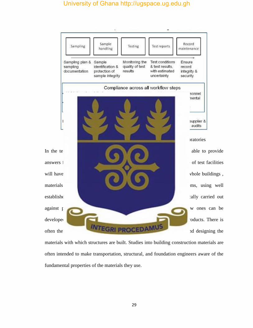
Figure 2.1: ISO/IEC 17025 Requirements for Testing Laboratories
In the testing of building materials, one will pride himself on being able to provide
answers for virtually any construction-related testing question. A range of test facilities
will have to be acquired, and experts employed to test this individual whole buildings ,
materials and products ,engineering structures and, building systems, using well
established methods , research tests and simulations. Tests are typically carried out
against published standards, and where standards do not exist, new ones can be
developed with dedicated procedures for new, unique or innovative products. There is
often the responsibility of civil engineers specifying, manufacturing and designing the
materials with which structures are built. Studies into building construction materials are
often intended to make transportation, structural, and foundation engineers aware of the
fundamental properties of the materials they use.
University of Ghana http://ugspace.ug.edu.gh
30
2.5 Cement in Ghana
Types of building materials i.e. Portland cements are manufactured to meet various
physical and chemical requirements for purposes, such as durability and high-early
strength etc. Cement which is a common building material is made from rock and widely
used in the construction of most buildings in the world. The market studied, according to
K & R Singh, 2010 is the market for Ordinary Portland Cement (OPC), Portland Lime
stone Cement (PLC). PLC is cheaper to produce and generally durable for most
construction work and is more commonly used in most developing countries than OPC.
An important input for construction and infrastructure development, the commodity
cement, underpins growth and industrialisation. Thus the price and availability of cement
is very important. The cement sector is one that often suffers from limited competition
and has been a source of concern for authorities in many countries across the world.
There is significant scope for anti-competitive practices in the cement industry to result in
much higher prices than would otherwise be the case, with negative economic
consequences.
In the cement market there is a high Minimum Efficient Scale (MES) which means that
large players have a significant cost advantage, which generates a concentrated market
structure with relatively few players. However, having fewer players in the market
reduces competition, and makes the sector vulnerable to anti-competitive practices, which
is likely to result in higher prices. The high risk of anti-competitive practices suggests
there is a need for careful monitoring of the cement sector by competition authorities.
Prices of cement doubled in 2007 causing great concern in the building industry.
Stakeholders alleged that because the few companies producing in Ghana enjoys strong
University of Ghana http://ugspace.ug.edu.gh

31
market power they are able to set higher prices without fear of losing customers. Most
Stakeholders have also alleged that the dominant players block their attempts to import
cement into the country through informal means. This assertion is however not true
because the monopoly Ghacem cement had, had been broken about fifteen years ago.
Figure 2.2: Some Cement Manufactured and Imported In Ghana
2.5.1 Why Check the Quality of Cement
Savitha (2012) gives the importance of testing materials in particular cement. In the
building industry. This is because an incorrect assessment of a material would ultimately
be harmful to people and to the environment. The infrastructural development of a nation,
eventually leads to the growth of that country. The use of high quality construction
materials leads to high quality infrastructures. The quality of such materials should be
assessed properly in an accredited and an accepted laboratory, using standard test
University of Ghana http://ugspace.ug.edu.gh

32
methods and specifications. Building materials should be chosen to comply with the
relevant standards i.e. BS, EN, IS, GS and ASTM standards.
2.5.2 Important Physical Properties of Cement
ASTM C150, 2012 has identified some requirements regarding the physical properties for
cement. These properties comprise: fineness, specific gravity, soundness, and standard
consistency, setting time, compressive strength, heat of hydration and loss of ignition. In
general sense, cements are cohesive and adhesive materials in nature which are normally
capable of bonding together particles of solid matter into a solid durable mass. For civil
engineering works, they are restricted to calcareous cements containing compounds of
lime as their chief constituent; the primary function is to bind the fine and coarse
aggregate particles together. In the use of cement in the construction industry, one can
classify it as hydraulic or non-hydraulic. The latter does not set and harden in water such
as non-hydraulic lime or which are unstable in water, e g. Plaster of Paris. Hydraulic
cement sets and hardens in water and gives the product which is stable. Care must be
exercised in proportioning the raw materials so that the clinker of proper constitution may
be obtained after burning.
The properties of cement conforming to the GS: 22: 2011 Standard shall when
appropriately batched and mixed with aggregates and water be capable of producing
mortar or concrete which retains its workability for a sufficient time and shall after a
defined period attain specific strength levels and also possess long term volume stability.
University of Ghana http://ugspace.ug.edu.gh

33
The sum of the proportions of reactive calcium oxide and reactive silicon dioxide shall
not be less than 50 %( m/m). Cement conforming to the standard shall consist of
individual small production, in particular grinding and homogenisation processes.
In the manufacture of cement, clinker shall be made by burning , a specific mixture of
raw materials which shall consist of not less than two thirds(2/3) by mass of calcium
silicate , some aluminium , iron oxide and other oxides. The ratio by mass of calcium and
silicon oxide shall not be less than 2.0 and magnesium oxide shall also not exceed 5.0%
m/m by mass (Viyors, 2014) there are other additional minor constituents i.e. granulated
blast furnace slag, pozzolana and fly ash. These additional constituents should not
promote corrosion of the reinforcement or impair the properties of the cement or of the
mortar or concrete made from the cement.
Calcium sulphate or gypsum has to be added in small quantities in order to control the
setting time of the cement, and the total sulphates shall not exceed 3 to 5% m/m of the
final cement. (Papadakis, 2005)
2.5.3 Chemical Properties of Cement
According to Anon, 2013, The Chemical Properties of cement are also checked to
determine presence of certain properties like the Loss on ignition where a known weight
of cement is heated until a constant weight is obtained. A high loss on ignition shows that
the cement was inappropriately stored. This document also describes the reference
methods and, in certain cases, an alternative method which can be considered to be
equivalent. The loss on ignition shows the extent of carbonation and hydration of free
lime and free magnesia due to the exposure of cement to the atmosphere. The insoluble
residue, determined by treating with hydrochloric acid, is a measure of adulteration of
University of Ghana http://ugspace.ug.edu.gh
34
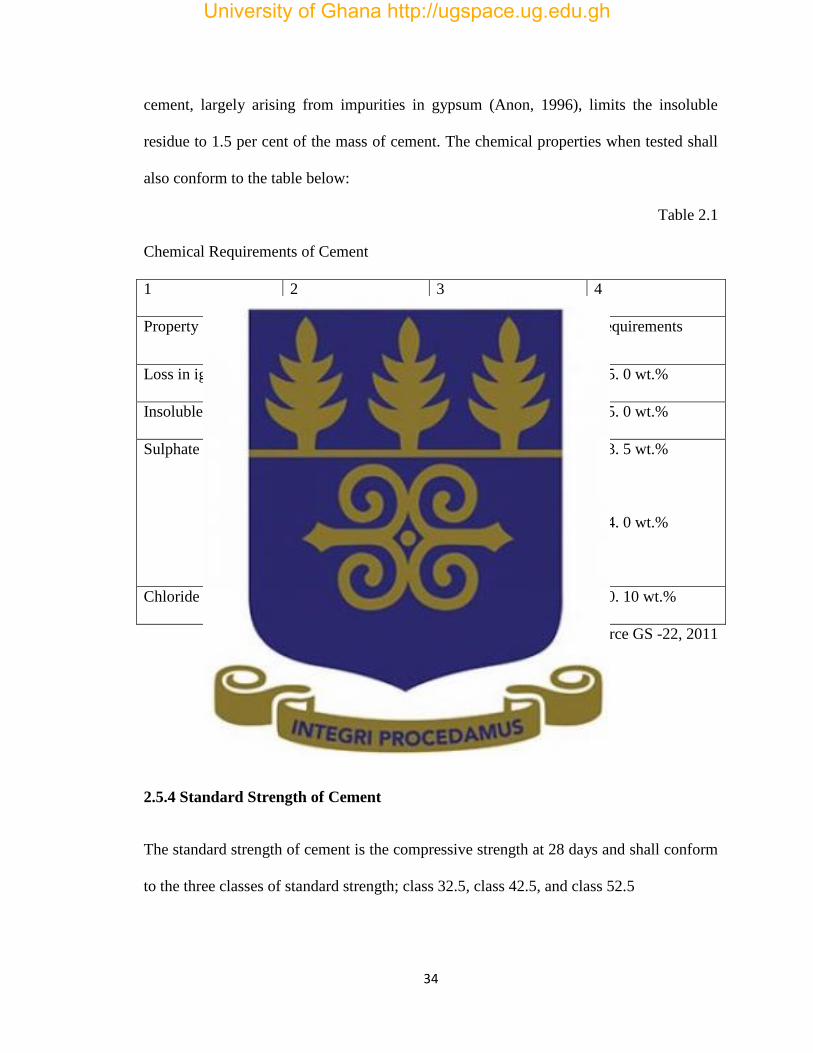
cement, largely arising from impurities in gypsum (Anon, 1996), limits the insoluble
residue to 1.5 per cent of the mass of cement. The chemical properties when tested shall
also conform to the table below:
Table 2.1
Chemical Requirements of Cement
1 2 3 4
Property Test reference Strength class Requirements
Loss in ignition ISO 680 All < 5. 0 wt.%
Insoluble residue ISO 680 All < 5. 0 wt.%
Sulphate content
ISO 680
32.5N, 32. 5R, 42. 5
N
42. 5 R, 52. 5 R ,52. 5
N
< 3. 5 wt.%
< 4. 0 wt.%
Chloride content EN 196-21 All < 0. 10 wt.%
Source GS -22, 2011
2.5.4 Standard Strength of Cement
The standard strength of cement is the compressive strength at 28 days and shall conform
to the three classes of standard strength; class 32.5, class 42.5, and class 52.5
University of Ghana http://ugspace.ug.edu.gh

35
The early strength of cement is the compressive strength at two(2) days or seven(7) days.
Two classes of early strength are included for class of standard. A class with ordinary
early strength is classified as N and a class with high early strength is indicated by R
2.5.5 Testing of Cement
There are two methods for testing cement, one performed in the laboratory, and the other
performed on the field. According to Anon, 2010, Field Tests are a convenient way of
initial inspection of cement when used in small scale works or when decision has to be
made quickly during purchase. The following steps can be used to ensure a good quality
cement.
1. There should not be any lumps formation inside the bag when it is first opened for
visual inspection.
2. Put your hand inside the bag of cement. This should give you a feel of a cool sensation
around your hands.
3. A sample of cement in your hand, rubbed in between your fingers should give you a
feel of smoothness.
4. Take another handful sample of cement and throw it on the surface of a bucket full of
water. Particles of cement should float a while before sinking down.
The Field Tests only indicate that cement is not bad and can be used for small scale
works. More detailed tests is conducted in the laboratory to determine the quality of
University of Ghana http://ugspace.ug.edu.gh
36
cement. Laboratory tests according to (ISO/IEC, 2005) are necessary to confirm that the
cement is good in nature and can be used. The following tests are conducted on cement in
the laboratory.
2.5.6 Physical Test
The physical properties tested for are fineness which can also be termed as the particle
size distribution of the cement. This affects the rate of hydration and directly impacts the
rate of strength gain. Another property is the soundness which is the ability of a harden
cement paste to retain its volume after it has set. The presence of excessive hard burnt
free lime results in a lack of soundness.
2.5.7 Standard Consistency Test
Consistency of cement refers to the ability of the cement paste to flow and is said to have
normal consistency when the plunger of the Vicat apparatus penetrates it by 10 plus or
minus one(10 ±1) Consistency indicates the degree of density of cement. Therefore, it is
necessary to determine the amount of water for a given cement to get a mixture of the
required consistency. Consistency of cement is measured by the Vicat apparatus. The
paste is said to be of standard consistency, when the penetration of the plunger, is 33-35
mm. (Neville, 2010).
University of Ghana http://ugspace.ug.edu.gh

37
2.5.8 Setting Times
To enable the concrete to be laid in position properly the initial setting of cement should
not start too quickly. Once the concrete is laid it should harden rapidly so that the
structure could be put to use early. Initial setting of cement is that step in the process of
setting, after which if any cracks appear do not reunite and the final setting is that time
when sufficient strength and hardness is attained. Setting thus, describes ―The strength of
the cement paste‖. During setting, the paste attains some strength. But it is different from
hardening, which refers to the increase of strength of a set cement paste. The setting
process is associated with temperature changes in the cement paste. Initial set is related to
a quick increase in temperature and final set to the highest temperature. Akroyd, 1962.
2.5.9 Fineness of Cement
Fineness of cement is the total surface area of cement grains available for hydration. It
also determines the level of grinding of cement clinker and affects the rate of hydration.
The Greater the fineness, the more the surface available for hydration, resulting in greater
early strength and a more rapid release of heat .The fineness of cement is measured as
specific surface by observing the time taken for a fixed quantity of air to flow through a
compacted cement bed of specified dimensions and porosity. Under standardized
conditions the specific surface of cement is proportional to √ where the time is for a
given quantity of air to flow through the compacted cement bed. The number and size
range of individual pores in the specified bed are determined by the cement particle size
distribution, which also determines the time for the specified air flow, (Anon, 2013).
University of Ghana http://ugspace.ug.edu.gh
38
2.5.10 Compressive Strength
The compressive strength test of cement is defined in Mega Pascal (MPa) or Newton (N
/mm2 ) and is carried out to check the strength of cement. For example Portland cement of
grade 32.5R, the strength should be 35MPa or 2 N /mm 2
in 28 days. In this case the
cement is mixed with sand and water to the standard measurement, the paste is then put
in the mould, demouldedafter 24 hours and cured for 28 days. After which it is crushed
and the strength determined.
2.5.10.1 Effect of Cement Variations on Compressive Strength
The strength of concrete largely depends on the water-cement ratio, the quality and
characteristics of cement, the degree of compaction, curing and the age of the concrete.
Strength increases, as the concrete becomes old. Generally, the strength of concrete is
largely dependent of the type of aggregate used and the mix proportions or ratio. These
factors influence the amount of water required to produce. The degree of flow of concrete
affects its strength indirectly. Too much water will destroy your concrete (Akroyd, 1962).
2.5.11 Deterioration of Cement with Storage
Cement readily absorbs moisture from the atmosphere or from any damp material in
contact with it. When cement is stored in sacks, absorption takes place from the air and
strength of the cement is considerably reduced. The absorption by cement, of 1 or 2
University of Ghana http://ugspace.ug.edu.gh

39
percent of water, has no appreciable effect, but further amounts of absorption retard the
hardening of cement and reduce its strength.
Cement stored in bulk or in air-tight containers does not deteriorate. It can be stored in
covered barrels, bins and polythene bags. Cement thus stored up to about 2 meters or
more in depth can lie for longer than a year with no more damage than the formation of a
crust on the surface about 5 centimetres (cm) thick, which should be removed before it is
taken for use. Portland cement may be stored indefinitely without loosening its quality, if
it is protected from moisture. (Akroyd, 1962)
A B
Figure 2.3: A. Cement Properly and B. Improperly Stored
2.5.12 The Importance of Curing
Usual concrete must be cured. No one has doubts about it. But this does not mean that
concrete is always well cured, if it is cured at all. For usual concretes, water curing is
necessary to ensure the highest degree of hydration possible in order to obtain the highest
University of Ghana http://ugspace.ug.edu.gh

40
strength and the lowest permeability (Neville, 1995). Uncured concrete dries more or less
rapidly, depending on its water/binder ratio, since it never even approaches its full
strength and durability potential. Early curing is always better than late curing, and in the
case of usual concretes late curing is better than no curing at all.
There are different ways to water-cure concrete: fog misting, wet burlap, water ponding,
water spraying and curing membranes. No one will argue that it is absolutely necessary to
protect the top surface of the deck of a bridge built with concrete from drying shrinkage
and early drying. Nobody will argue for long that it is very useful to wet-cure the top
surface of column made of concrete that is exposed to drying for 7 days or more after
being cast. It is absolutely necessary to understand what is happening when the hydration
reaction develops in high concrete in order to take the appropriate measures to reduce as
much as possible the shrinkages that will develop in any uncured concrete.
The concrete skin is always the first line of attack, if there is an attack, its weakening due
to the lack of appropriate curing can be critical for the durability of the structure. So it is
always important to evaluate the risk taken in weakening the concrete skin when there is
improper curing. In any case, too much curing is always better than no curing at all, but it
must also be recognized that proper curing is not always practical if it has not been well
planned before the start of the construction. When it has been planned well ahead of
schedule, there is never a problem in carrying out proper curing, because it only involves
adding an almost free material to concrete: water.
Curing is carried out for two reasons: to hydrate as much as possible the cement present
in the mix and, what is sometimes forgotten, to minimize shrinkage (Aitcin, 1998).
University of Ghana http://ugspace.ug.edu.gh
41
2.5.13 Quality Management System in the Testing Laboratory
A quality management system in a testing laboratory is a way of indicating that the
quality of the final test results can be relied upon. The use of appropriate procedures and
management methods, guarantees clients that errors in test results are minimal. The
quality management system provides the laboratory with measurement traceability
systems, and the use of preventive actions provides the possibility of initiating corrective
action when errors are detected (F &Balgobin, 2011).
2.5.14 Benefits of Standards
A standard is a document that provides requirements, specifications, guidelines or
characteristics that can be used consistently to ensure that materials, products, processes
and services are fit for their purpose (Anon, 2015). In essence, a standard is an agreed
way of doing something and is designed for voluntary use so it’s up to you - you’re
offered ways to do your work better.
Standards ensure the safety of products and services are of good quality and are reliable.
For business, they are strategic tools that reduce costs by minimizing waste and errors,
and increasing productivity. A standard helps companies to enter new markets and
provides a level playing field for developing countries thus facilitating free and fair
global trade (Anon, 2015). Standards cover a wide range of subjects, they can be very
specific to a particular type of product, or general such as management practices.
The aim of a standard is to provide a very reliable basis for people to share the same
expectations about a product or service from construction to nanotechnology, from
University of Ghana http://ugspace.ug.edu.gh

42
energy management to health and safety and from cricket balls to goalposts. This helps to
facilitate trade, provide a framework for achieving economies, efficiencies and enhance
consumer protection and confidence. (British Standards Institution, 2015)
2.5.15 Evolution of ISO 17025 and Its Importance
The first edition (1999) of this international Standard was produced as a result of
extensive experience in implementation of ISO /IEC Guide 25 and EN 45001, both of
which are replaced. It contained all of the requirements that testing and calibration
laboratories have to meet if they wish to demonstrate that they operate a management
system, are technically competent and are able to generate technically valid results.
These standards have been superseded by ISO9001:2000, which made an alignment of
ISO/IEC 17025 necessary. In the second edition, clauses have been amended or added
only when considered necessary in the light of 9001:2000. Accreditation bodies that
recognize the competence of testing and calibration laboratories use this standard as the
biases for their accreditation. Clause four specifies the requirements for sound
management and clause 5 specifies the requirements for technical competence for the
type of tests and/or calibrations the laboratory undertakes.
Growth in the use of management systems generally has increased the need to ensure that
laboratories which form part of larger organizations or offer other services can operate to
a quality management system that is seen as compliant with ISO 9001 that are relevant to
the scope of testing and calibration services that are covered by the laboratories
management system. Testing and calibration laboratories that comply with this
International Standard will therefore also operate in accordance with ISO 9001.
University of Ghana http://ugspace.ug.edu.gh

43
The acceptance of testing and calibration results between countries should be facilitated if
laboratories comply with this international standard and if they obtain accreditation from
bodies which have entered into mutual recognition agreements with equivalent bodies in
other countries using these International Standards. The use of International Standard
facilitates cooperation between laboratories and bodies that assist in the exchange of
information and experience and in the harmonisation of Standards and Procedures.
2.5.16 Benefits of Accreditation and the Accreditation Process
Accreditation is the process by which the quality of a laboratory or an institution, public
or private is formally recognized as having met certain pre‐determined minimal criteria or
standards. The result of this process is usually the awarding of a status of recognition
with sometimes a license to operate within a period of validity (VLĂSCEANU, 2007).
Accreditation gives confidence in results obtained. There is public and industry
acceptance of results, there is also an increase in competitiveness and market share and
there is also an Assurance to customers of good laboratory practices. Competence and
experience of staff is assured, and there is an Integrity and traceability of equipment and
materials
After receiving the application for accreditation, a quotation is sent to the laboratory and
arrangements made for a preliminary assessment. This assessment is then conducted by a
team of technical assessors, who are drawn from the technical community, either within
the country or outside. When the laboratory has demonstrated compliance with all
necessary requirements, it is recommended for accreditation. Once approved, a certificate
is given for accreditation (Anon, 2014).
University of Ghana http://ugspace.ug.edu.gh

44
Figure 2.4: Typical Process of Accreditation
2.5.17 Importance of Accurate and Reliable Data
Accurate, timely and reliable data is very important for effective decision making in
virtually all aspects of human endeavour irrespective of who undertakes it, be it in an
organisation, individual or government. According to Eslake, 2006, it is very important
and an essential component in persuading businesses, individuals and governments to
make decisions from the ones which they might make in the absence of a particular piece
of information. It is an integral part of any attempt to hold those who make decisions,
accountable for the consequences of the decisions they make. It is important to know how
ISO 17025 2005 benefits the laboratory. It ensures we provide products and services that
support safety world-wide, it identifies laboratories specific competencies, there is an
assurance of acceptance of data, also, there is an assurance to meet the quality
managements requirements of consumers, and lastly it establishes minimum competency.
University of Ghana http://ugspace.ug.edu.gh

45
2.5.18 Importance of Testing, Personnel and Equipment in Cement Analysis
Several tests are performed to determine the characteristics of cement and its
compatibility with other materials in a concrete mix design. Testing of mortar cubes at 2 -
days, 7 - days and 28-days is used to observe the development of strength gained over
time. An analysis of the cement provides a reasonable estimate of the composition of the
cement (Anon, 2008).
Portland cements are characterized by their physical properties for quality control
purposes. Their physical properties can be used to classify and compare Portland
cements. The Challenge in physical property characterization is the development of
physical tests methods that can satisfactorily characterize these properties. These are just
a few of the tests that can be used to determine the quality of the cement.
These physical properties are the Setting Time which according to Anon, 2009 is
determined using the Vicat apparatus with a plunger properly marked, calibrated and a
Vicatmould. The cement is weighed and made into a paste and the plunger is dropped to
determine the initial and final set times.
In checking the Soundness of cement, the Le Chatelier apparatus is used. The mould shall
be of spring brass with indicator needles. A pair of plane glass base and cover plates shall
be provided. There is the need for a water bath and a humidity chamber adequate enough
to maintain a temperature of 20oC and not less than 98 % relative humidity. The cement
paste is placed in the slightly oiled mould without shaking the mould, level the top and
cover the mould. After 24 hours, measure to find if there is any change in dimensions.
Heat for 3 hours, allow cooling and measuring again. This assesses the possible risk of
expansion due to hydration.
University of Ghana http://ugspace.ug.edu.gh

46
Fineness: the method of checking for the fineness of cement is by weighing an amount of
cement to the nearest 0.01g (gram) and place it on the sieve. It is then agitated until no
fines passes through it. The residue is then weighed and expressed as a percentage of the
quantity
placed on the sieve to the nearest 0.1 % (Anon, 2014) .
The strength of the cement is tested by preparation of mortar cubes and curing them.
After which they are crushed to determine their strength as declared.
In order to gain accreditation for laboratory, a person must be available who has relevant
qualifications (e.g. a geologist) or has extensive experience in Construction Materials
Testing identifying, quarry and 'source material'. Where the qualification requirements
are not met, accreditation may be granted for a single source only. This will be included
in the scope of accreditation, NATA 2013.
University of Ghana http://ugspace.ug.edu.gh

47
CHAPTER THREE
RESEARCH METHODOLOGY
3.0 Introduction
In this work, Regenerated Spent Catalyst (RSC) from the Residue Catalytic Cracking
(RFCC) Unit of Tema Oil Refinery (TOR) Limited located in the city Temawas used as
part replacement by 5 to 20% wt. of Portland cement from Ghacem. The desirable
properties of Regenerated Spent Catalyst are: Average thermal stability, average activity,
large pore sizes, average resistance to attrition and low coke formation.
Studies on the properties of replacement samples were carried out. The physical
properties studied were Compressive Strength, Setting Times and Water Absorption.
Chemical property studied was the chloride content. Comparison of data between the
Control, that is 100% cement and with additive was made. The procedure adopted in
achieving the goals and objectives of this research are listed in the Chapter One. This
procedure includes the methodology adopted for the research, data collection and lastly
the method of analysing the data.
3.2 The study Area
The Civil Engineering Laboratory under the testing division of the Engineering
Department of Ghana Standards Authority (GSA) was chosen for this study. The
Engineering Department is involved mainly in the testing of building materials for the
Building and Construction Industry, Consultants in the industry, pre-mix concrete supply
Companies and Research institutions in the industry.
University of Ghana http://ugspace.ug.edu.gh
48
3.3 The Research Approach and Strategy
This research is to study on the properties of sandcrete blocks produced with Regenerated
Spent Catalyst. All Testing procedures relevant to the research were carried out in order
to make a detailed analysis of the data obtained from the experiment. The Civil
Engineering Laboratory provided the tests methods used to determine the properties of
the prepared samples. This topic was chosen because of the importance of cement in the
Ghanaian economy and also to add value to the Regenerated Spent Catalyst, generated as
waste from Tema Oil Refinery (TOR) Ltd.
3.4 Research Procedure
The research was carried out by the collection of data relevant to the work, namely
information from dissertations/ thesis, technical reports, articles, foreign and local
standards, specification, the internet and some codes related to the field of study.
Standards, Codes or Best Practices used included the following:
-ISO / IEC 17025, 2005 – General Requirements for the competence of Testing and
Calibration Laboratories.
- GS 22 2011 – Building and Construction Materials-Specification for Ordinary
Portland Cement CEM I
- GS 766 2011 - Building and construction materials- Specification for Portland
Limestone Cement CEM II
- BS EN197-1:2011 – Cement Composition, Specifications and Conformity
Criteria for Common Cements
- DIN EN196-3 2009 – Determination of Setting Times and Soundness.
University of Ghana http://ugspace.ug.edu.gh

49
- ASTM C 778-06 – Standard Specification for Standard Sand
- DIN EN196-2 2013 – Methods of Testing Cement; Chemical Analysis of Cement
- DIN EN196-1 2005 – Methods of Testing Cement, Part I; Determination of
Strength.
3.5 Data Collection and Experimentations
3.5.1 Primary Data Collection
Primary data involved laboratory specimen tests for the physical and chemical properties
of sandcrete sampled. Sandcrete were prepared from Ghacem 32.5R cement (600 g),
standard quartz-sand (1800 g) and tap water (300 mls). In case of sandcrete with addition,
part of the cement was replaced by 5 to 20% mass of Regenerated Spent Catalyst. A total
of 45sandcrete cubes measuring 70mm x 70mm x 70mm sandcretemoulds were prepared,
cast and cured at 2 days, 7 days and 28 days. The prepared samples were tested in the
laboratory.
In the determination of the setting time 600 grams of cement and the Regenerated Spent
Catalyst was sampled for use. Chemical analysis on the control, 5% RSC, 10% RSC,
15% RSC and 20% RSC samples at the Chemistry Laboratory to determine the chloride
content.
University of Ghana http://ugspace.ug.edu.gh
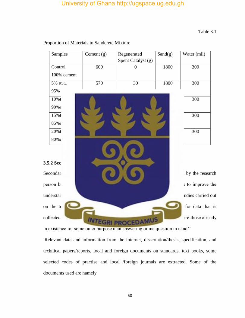
50
Table 3.1
Proportion of Materials in Sandcrete Mixture
Samples Cement (g) Regenerated
Spent Catalyst (g)
Sand(g) Water (mil)
Control
100% cement
600 0 1800 300
5% RSC,
95% cement
570 30 1800 300
10%RSC,
90%cement
540 60 1800 300
15%RSC,
85%cement
510 90 1800 300
20%RSC,
80%cement
480 120 1800 300
3.5.2 Secondary Data
Secondary data refers to the statistical material which is not originated by the research
person but obtained from someone else’s record. Secondary data helps to improve the
understanding of the problem, prevent any repetition or duplication of studies carried out
on the topic under consideration and provides basis for comparison for data that is
collected by the researcher. According to M. M. Blair, ―secondary data are those already
in existence for some other purpose than answering of the question in hand’’
Relevant data and information from the internet, dissertation/thesis, specification, and
technical papers/reports, local and foreign documents on standards, text books, some
selected codes of practise and local /foreign journals are extracted. Some of the
documents used are namely
University of Ghana http://ugspace.ug.edu.gh

51
- GS 22 2011 building and construction materials-specification for Portland cement
CEM I
- DIN EN 196 1-6 Methods of testing cement
Table 3.2
Chemical CompositionofPortland Ghacem Cement
Properties SiO2
Content
Al2O3
Content
Fe2O3
Content
CaO
content
MgO
Content
SO3
Content
Composition
(wt. %)
21.9 6.9 3 63 2.5 1.7
Table 3.3
Physical Properties Portland Ghacem Cement
Property Specific surface
(m2/kg)
Specific gravity
Quantity
370 3.15
Table 3.4
Chemical Composition of Regenerated Spent Catalyst (RSC)
Properties Al2O3
Content
(wt. %)
Fe2O3
Content
(wt. %)
CaO
Content
(wt. %)
Hydrogen
Content
(wt.%)
Carbon
Content
(wt. %)
Composition
(wt. %)
48.5 0.54 1.01 0.242 0.04
University of Ghana http://ugspace.ug.edu.gh
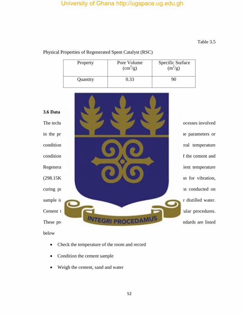
52
Table 3.5
Physical Properties of Regenerated Spent Catalyst (RSC)
Property Pore Volume
(cm3/g)
Specific Surface
(m2/g)
Quantity
0.33 90
3.6 Data Collection Techniques
The technique adopted to collect data was by direct observation of the processes involved
in the preparation of sandcrete cubes from the selected samples. Some parameters or
conditions observed at the cube preparation stages were the general temperature
conditions under which the cubes were being prepared, the measuring of the cement and
Regenerated Spent Catalyst samples, storage temperature, that is ambient temperature
(298.15K), pressure (100kP), mixing procedures, sandcrete preparation for vibration,
curing procedures and lastly the crushing process. Other investigations conducted on
sample included the Setting Time Test, Chemical Test and the Test for distilled water.
Cement test as already described in the standard has to follow particular procedures.
These procedures which are guided by ISO 17025 and the various standards are listed
below
Check the temperature of the room and record
Condition the cement sample
Weigh the cement, sand and water
University of Ghana http://ugspace.ug.edu.gh

53
Replaced part of the cement was replaced by 5 to 20% mass of Regenerated Spent
Catalyst
Oil the moulds to be used
Transfer the samples and water into the mixing bowl and mix for 90s
Transfer the mortar into the mould, vibrate and cover the sandcrete for 24 hours
Demould the sandcrete cubes, weigh and transfer them into the Curing Tank for
specific period
On the due date 2, 7 and 28 days, remove the cube from the Curing Tank, weigh
and crush to determine Compressive Strength.
Record the crushing forces and calculate the Compressive Strength by dividing
force by area.
Check for markings
Calculate results
The flow chart showing the stages of preparing sandcrete cubes, crushing by exerting a
load on it and calculating the Compressive Strength of samples is described below.
University of Ghana http://ugspace.ug.edu.gh

54
Figure 3.1: Flow chart for preparing and crushing sandcrete cubes.
3.7 Methods for Testing and Determining of Strength of Samples
The samples were cast from a batch of sandcrete containing one(1) part by mass of
cement or the Regenerated Spent Catalyst, three(3) parts of standard sand and one
half(1/2) part of water. The sandcrete was prepared by mechanical mixing and
compacted in a mould using a Jolting Apparatus. These samples were kept in the mould
in a moist atmosphere for 24 hours, then and demoulded and stored under water until they
were due for testing.
3.8 Laboratory and Equipment
The laboratory test conditions were maintained at a temperature of (20±2) oC and a
relative humidity not less than 50%. The temperature of the room was recorded at least
once a day during working hour’s whiles the humidity of air was recorded every 4 hours.
Regenerate
d
Regenerated Regenerated
Regenerated Regenerated Regenerated
University of Ghana http://ugspace.ug.edu.gh

55
The tolerance of the equipment used was considered as it was important for the correct
operation of the equipment. The control measures were carried out regularly.
3.8.1 Mixer
The mixer consists essentially of a stainless steel bowl with a blade revolving about its
own axis at a controlled speed and scarpers
Figure 3.2: Mortar Mixer
3.8.2 Preparation of Sandcrete, Placing, Conditioning and Testing
By means of a balance weigh the water and sample, place both in the mixing bowl, taking
care to avoid loss of water or sample. Immediately start the mixer at low speed. After 30
seconds of mixing, add the sand steadily during the next 30 seconds. Switch the mixer to
high speed and continue for another 30 seconds. Mould the sample immediately after the
preparation of the sandcrete paste and compact using the Jolting Apparatus.
Mortar mixer
University of Ghana http://ugspace.ug.edu.gh

56
Lift the moulds gently after wiping off excess sandcrete and mark or label the moulds
respectively for identification purposes. Cover each mould with a woollen material
without delay and wait for 24 hours.
Submerge the marked samples in tap water for curing at (20±1.0) ºC. Remove the
samples from water 15 minutes before each test is due. Subject the samples to stress
using the Compressive Test Machine increasing the load progressively. Where the load
increase is regulated by hand, care must be taken when making adjustments for the
decrease of the loading rate near fracture load as this could affect the results. (DIN EN
196-1,2005)
Figure 3.3: Compression Test Machine
Compression
testing
machine
University of Ghana http://ugspace.ug.edu.gh
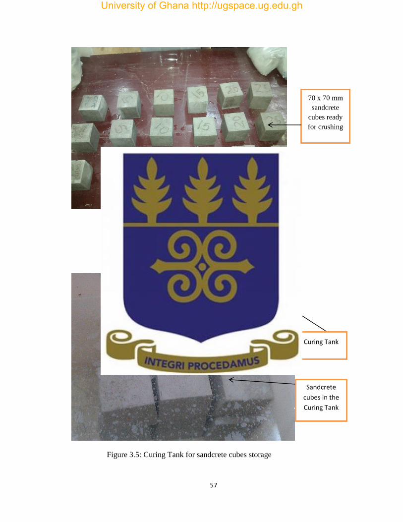
57
Figure 3.4: Set of sandcrete cubes ready for crushing
Figure 3.5: Curing Tank for sandcrete cubes storage
Sandcrete
cubes in the
Curing Tank
Curing Tank
70 x 70 mm
sandcrete
cubes ready
for crushing
University of Ghana http://ugspace.ug.edu.gh

58
3.8.3 Determination of Setting Times and Standard Consistence Test
3.8.3.1 Principles
Cement paste or the Regenerated Spent Catalyst paste of Standard Consistence has a
specified Resistance to penetration by a Standard Plunger.
The water required for such a paste was determined by trial penetrations of paste with
different contents. The Setting Times were thus determined by observing the penetration
of a needle into the cement paste of Standard Consistence until it reached a specific
value.
3.8.3.2 Standard Consistence Test
The manual Vicat Apparatus with a plunger was used to weigh a total of 300±1 g. The
movement of the Vicat Apparatus with plunger was kept truly vertical. The mould to
contain the paste is made of rubber or brass placed on glass flat base. In mixing the
cement paste, weigh to an accuracy of ±1g by means of the balance, 500g of cement or
Regenerated Spent Catalyst and a quantity of water e.g. 125g. The weighed items were
mixed using the mixer at low speed. The paste produced was immediately transferred into
a lightly oiled mould; any voids were removed in the paste by gently tapping the sides of
the mould and levelling to the top surface.
Immediately after levelling the paste, it was transferred onto the Vicat Apparatus and the
plunger dropped intermittently. This was repeated until the distance between the plunger
and paste was (6±2) mm.
University of Ghana http://ugspace.ug.edu.gh

59
3.8.3.3 Setting Times Test; Initial and Final
The filed mould and base plate were placed in a container filled with water at a controlled
temperature of 20±1 ºC. After a period of time the sample was removed and placed under
the Vicat and the needle dropped gently onto the paste. The scale was read when
penetration had ceased or 30 seconds after the release of the needle. The scale readings,
which indicated the distance between the needle and the base plate, were recorded. The
penetration was repeated on the same sample until the time where the distance between
the needle and the base plate was 6 ± 3 mm measured to the nearest minute. This is the
Initial Setting Time of the cement or Regenerated Spent Catalyst and is reported to the
nearest 5 minutes.
In the determination of the Final Setting Time, the paste in mould used for the Initial
Setting Time was inverted and again immersed under water. This time the needle was
dropped until a reading of 0.5 mm was recorded. This indicates the Final Setting Time
has been achieved. (DIN EN 196-9, 2009)
Figure 3.6: A Vicat Apparatus Accessories
Needle for
checking
initial setting
time
Needle for
final setting
time
Vicat
Apparatus
Mould
University of Ghana http://ugspace.ug.edu.gh
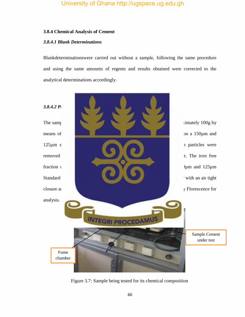
60
3.8.4 Chemical Analysis of Cement
3.8.4.1 Blank Determinations
Blankdeterminationswere carried out without a sample, following the same procedure
and using the same amounts of regents and results obtained were corrected to the
analytical determinations accordingly.
3.8.4.2 Preparation of Test Samples
The samples were treated to a homogenous test sample by taking approximately 100g by
means of a sample divider or by quartering. This portion was sieved on a 150µm and
125µm standard sieve until residue remained constant. Metallic iron particles were
removed from the metal retained in the sieve by means of a magnet. The iron free
fraction of the retained material was ground so that it passed the 150µm and 125µm
Standard Sieve. The sample was then transferred to a clean dry container with an air tight
closure and vigorously mixed thoroughly. This was now sent to the X-ray Florescence for
analysis. (DIN EN 196-2, 2013)
Figure 3.7: Sample being tested for its chemical composition
Fume
chamber
Sample Cement
under test
University of Ghana http://ugspace.ug.edu.gh

61
3.8.5 Specification of Standard Sand
Standard sand shall meet the requirements in the table below with respect to grading,
source of sand and absence of air entraining characteristics (ASTM C778-06, 2006).
Table 3.4.
Standard Sand Requirement
Characteristics 20-0 sand Graded Sand
Grading sieve sizes
1.18mm(No. 16) 100 100
850µm (No.20) 85 to 100
600µm (No.30) 0 to 5 96 to 100
425µm (No.40) 65 to 75
300µm (No.50) 20 to 30
150µm um (No.100) 0 to 4
Source of Sand Ottawa, IL OR Le Suer,MN Ottawa,IL
Source ASTM C778-06
3.8.6 Analysis of Data
The data was analysed using simple percentage statistical method of data analysis to
indicate the strength and significance of each set of mortar cube crushed.
University of Ghana http://ugspace.ug.edu.gh

62
Data was analysed through the whole case study and was not limited to any one chapter.
In the analysis made, discussions of data obtained from the experiments conducted was
analysed. Additional use of tables and graphs were made.
University of Ghana http://ugspace.ug.edu.gh
63
CHAPTER FOUR
RESULTS AND DISCUSSIONS
4.1 Compressive Strength
In order to check if the strength of the sandcrete cube achieved is in conformity with the
standard, the crushing strength value recorded in kN is divided by the area (mm²) of the
sandcrete cube.
In all, forty five (45) cubes were prepared, cast, cured and crushed according to the BS
1881 Part 116. (BS,1983). At two, seven and twenty-eight days, due samples were
removed dried and crushed to the point of failure by a load and the value at failure
recorded. This is used in the calculation of the Compressive Strength using the formula
fc =
Where,
fc Compressive Strength (N /mm²)
P load at failure (N)
A surface area of the sandcrete cube (mm²)
The results obtained for the various samples are presented below:
University of Ghana http://ugspace.ug.edu.gh
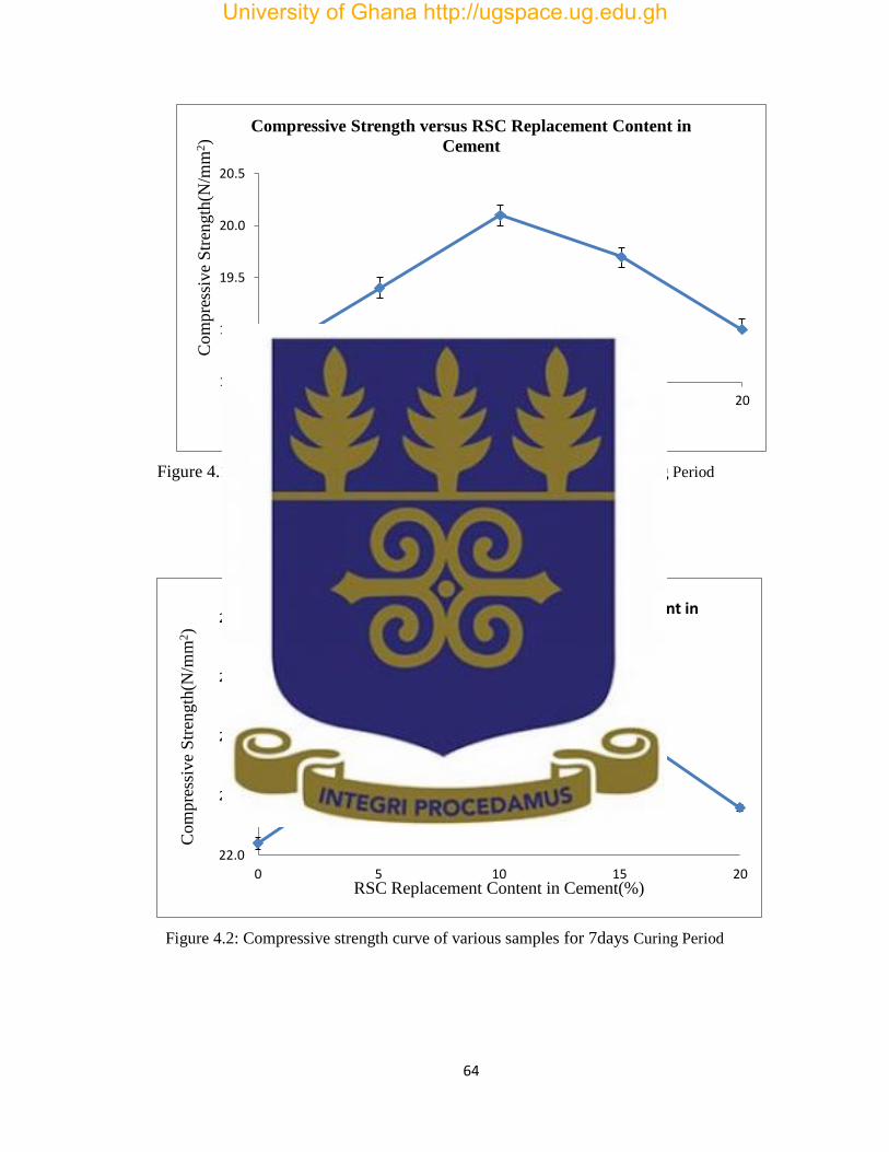
64
Figure 4.1: Compressive strength curve of various samples for 2daysCuring Period
Figure 4.2: Compressive strength curve of various samples for 7days Curing Period
18.5
19.0
19.5
20.0
20.5
0 5 10 15 20
Com
pre
ssiv
e S
tren
gth
(N/m
m2)
RSC Replacement Content in Cement(%)
Compressive Strength versus RSC Replacement Content in
Cement
22.0
22.5
23.0
23.5
24.0
0 5 10 15 20
Com
pre
ssiv
e S
tren
gth
(N/m
m2)
RSC Replacement Content in Cement(%)
Compressive Strength versus RSC Replacement Content in Cement
University of Ghana http://ugspace.ug.edu.gh

65
Figure 4.3: Compressive strength curve of various samples for 28 days Curing Period
4.1.1 Effect of Regenerated Spent Catalyst on Compressive Strength
Figure 4.1, 4.2 and 4.3 showed the Compressive Strength curves of various samples for the
two (2) days, seven (7) days and twenty eight (28) days curing periods.
Comparison of the data for 2,7 and 28 days of curing period showed that the Compressive
Strength increased when the Regenerated Spent Catalyst was added to sandcrete,
especially as a 10% replacement for cement. The Regenerated Spent Catalyst (RSC)
activity is due to its ability to react with the calcium hydroxide (portlandite) released in
the hydration of Portland cement and form compounds with hydraulic properties. This
behavior causes additional increase in the mechanical strength of sandcrete (Borrachero
et al, 2002).
Also the high specific area of Regenerated Spent Catalyst (RSC) led to a number of
nucleation sites for additional hydration products. This increased the hydration heat all
32.5
33.0
33.5
34.0
34.5
0 5 10 15 20Com
pre
ssiv
e S
tren
gth
(N/m
m2)
RSC Replacement Content in Cement(%)
Compressive Strength versus RSC Replacement Content in Cement
University of Ghana http://ugspace.ug.edu.gh
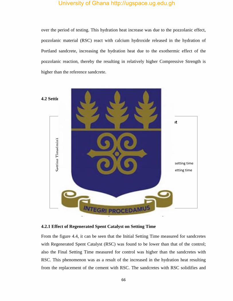
66
over the period of testing. This hydration heat increase was due to the pozzolanic effect,
pozzolanic material (RSC) react with calcium hydroxide released in the hydration of
Portland sandcrete, increasing the hydration heat due to the exothermic effect of the
pozzolanic reaction, thereby the resulting in relatively higher Compressive Strength is
higher than the reference sandcrete.
4.2 Setting Time
Figure 4.4: Setting Time curves for various samples
4.2.1 Effect of Regenerated Spent Catalyst on Setting Time
From the figure 4.4, it can be seen that the Initial Setting Time measured for sandcretes
with Regenerated Spent Catalyst (RSC) was found to be lower than that of the control;
also the Final Setting Time measured for control was higher than the sandcretes with
RSC. This phenomenon was as a result of the increased in the hydration heat resulting
from the replacement of the cement with RSC. The sandcretes with RSC solidifies and
50
100
150
200
250
300
350
0 5 10 15 20
Set
ting T
ime(
min
)
Regenerated Spent Catalyst (RSC) Replacement Content in
Cement (%)
Setting Time versus RSC Replacement Content in Cement
initial setting time
Final setting time
University of Ghana http://ugspace.ug.edu.gh
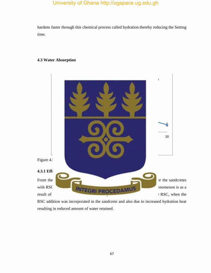
67
hardens faster through this chemical process called hydration thereby reducing the Setting
time.
4.3 Water Absorption
Figure 4.5: Water Absorption curve for various samples
4.3.1 Effect of Regenerated Spent Catalyst on Water Absorption
From the figure 4.5, it could be observed that the Water Absorption for the sandcretes
with RSC was found to be lower compared to control sandcrete. This phenomenon is as a
result of the molecules of water in the hydrated form in zeolites of the RSC, when the
RSC addition was incorporated in the sandcrete and also due to increased hydration heat
resulting in reduced amount of water retained.
2.5
3.0
3.5
4.0
4.5
0 5 10 15 20
Wat
er A
bso
rpti
on (
10
-3kg)
RSC Replacement Content in Cement (%)
Water Absorption versus RSC Replacement Content in Cement
University of Ghana http://ugspace.ug.edu.gh
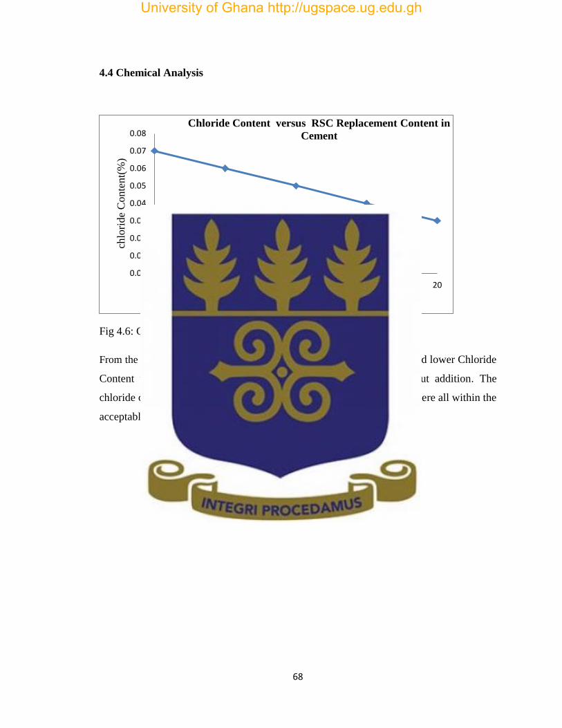
68
4.4 Chemical Analysis
Fig 4.6: Chloride Content curve for various samples
From the figure 4.6, it could be observed that the samples with RSC showed lower Chloride
Content values when compared with their equivalent mixture without addition. The
chloride content for the control sandcrete and sandcretes with the RSC were all within the
acceptable levels. (EN 196-21).
0.00
0.01
0.02
0.03
0.04
0.05
0.06
0.07
0.08
0 5 10 15 20
chlo
ride
Conte
nt(
%)
RSC Replacement Content in Cement (%)
Chloride Content versus RSC Replacement Content in
Cement
University of Ghana http://ugspace.ug.edu.gh
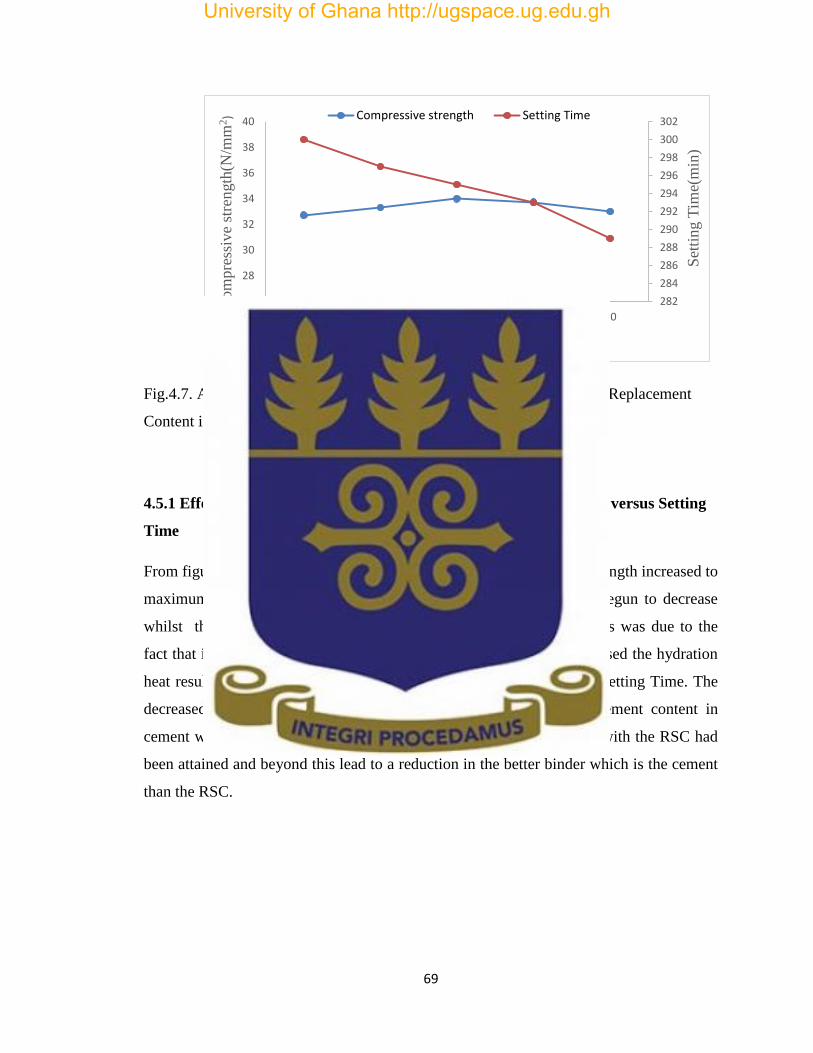
69
Fig.4.7. A graph of Compressive Strength and Setting Time versus RSC Replacement
Content in Cement
4.5.1 Effect of Regenerated Spent Catalyst on Compressive Strength versus Setting
Time
From figure 4.7 above, it could be observed that as the Compressive Strength increased to
maximum strength at 10% RSC replacement content in cement and begun to decrease
whilst the Setting Time decrease throughout the specified period. This was due to the
fact that increases in the RSC replacement content in the cement increased the hydration
heat resulting in increased compressive strength thereby reducing the Setting Time. The
decreased in the compressive strength beyond the 10% RSC replacement content in
cement was due to the fact that the optimum for replacing the cement with the RSC had
been attained and beyond this lead to a reduction in the better binder which is the cement
than the RSC.
282
284
286
288
290
292
294
296
298
300
302
26
28
30
32
34
36
38
40
0 5 10 15 20
Set
ting T
ime(
min
)
Com
pre
ssiv
e st
rength
(N/m
m2)
RSC Replacement Content in Cement(%)
Compressive strength Setting Time
University of Ghana http://ugspace.ug.edu.gh
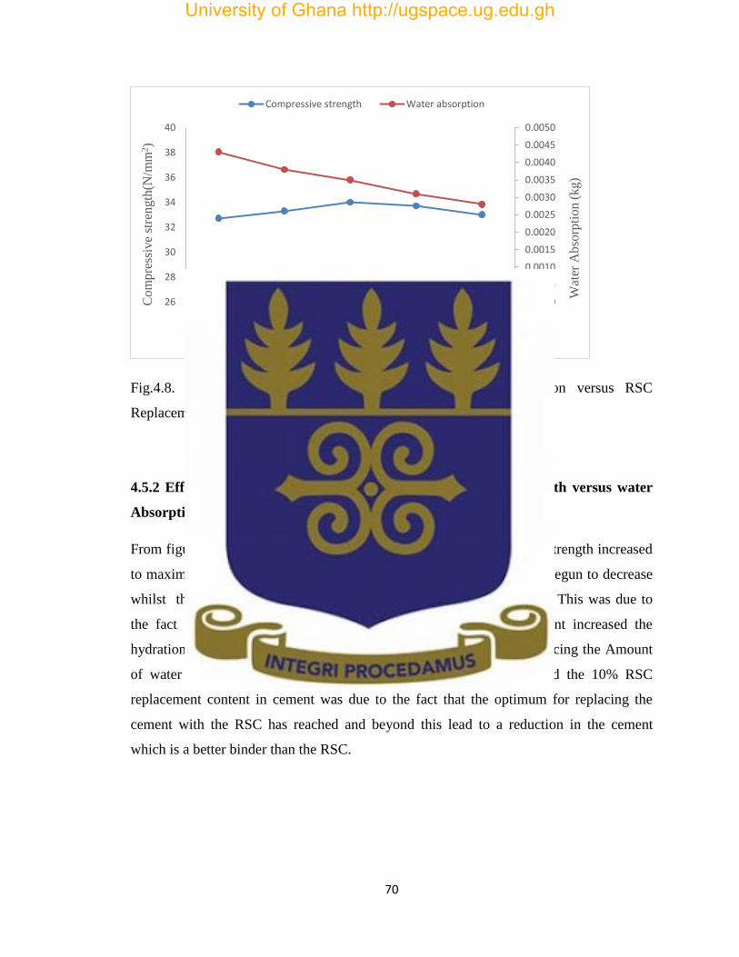
70
Fig.4.8. A graph of Compressive Strength and Water Absorption versus RSC
Replacement Content in Cement
4.5.2 Effect of Regenerated Spent Catalyst on Compressive Strength versus water
Absorption
From figure 4.8 above, , it could be observed that as the Compressive Strength increased
to maximum strength at 10% RSC replacement content in cement and begun to decrease
whilst the Water Absorption decrease throughout the specified period. This was due to
the fact that increases in the RSC replacement content in the cement increased the
hydration heat resulting in increased compressive strength thereby reducing the Amount
of water retained. The decreased in the compressive strength beyond the 10% RSC
replacement content in cement was due to the fact that the optimum for replacing the
cement with the RSC has reached and beyond this lead to a reduction in the cement
which is a better binder than the RSC.
0.0000
0.0005
0.0010
0.0015
0.0020
0.0025
0.0030
0.0035
0.0040
0.0045
0.0050
26
28
30
32
34
36
38
40
0 5 10 15 20
Wat
er A
bso
rpti
on
(kg)
Co
mp
ress
ive
stre
ngth
(N/m
m2)
RSC Replacement Content in Cement(%)
Compressive strength Water absorption
University of Ghana http://ugspace.ug.edu.gh

71
Fig.4.9. A graph of Water Absorption and Setting Time versus RSC Replacement
Content in Cement
4.5.3 Effect of Regenerated Spent Catalyst on Water Absorption versus Setting
Time
From figure 4.9 above, it could be observed that as the amount of water retained in the
sandcrete decreases, the setting time also decreases as the RSC replacement content in
cement increases. This is due to the fact that an increase in the RSC content in the
sandcrete increased the hydration heat resulting in less amount of water and the
sandcretes with RSC solidifies and hardens faster through this chemical process called
hydration as such reducing the setting time
282
284
286
288
290
292
294
296
298
300
302
0.0000
0.0005
0.0010
0.0015
0.0020
0.0025
0.0030
0.0035
0.0040
0.0045
0.0050
0 5 10 15 20
Set
tin
g T
ime(
min
)
Wat
er A
bso
rpti
on
(kg
)
RSC Replacement Content in Cement(%)
Water Absorption Setting Time
University of Ghana http://ugspace.ug.edu.gh

72
CHAPTER FIVE
CONCLUSIONS AND RECOMMENDATIONS
5.1 Conclusion
Comprehensive experimental/ laboratory and field analysis indicate RSC, also
referred to as ECAT consist mainly of Silica (49 wt. %), alumina (45wt. %) and
minerological constituents of zeolites, kaolinites and quartz. RSC has some
prozzolanic properties and can be used for part cement substitution.
Substituting Portland cement up to 20wt. % RSC gave sandcrete strengths higher
than the 32.5 N/mm2, which corresponds to that of Portland cement. This
phenomenon is largely attributed to the structure and texture of the RSC due to
bonding between the zeolites and the alumina – silica matrix during manufacture.
The replacement of Portland cement with 10 wt. % of RSC gave the highest
strength of 34.01 N/mm2.
The setting times of RSC-Portland mixture (sandcrete) decreased with increased
substitution of Portland cement with RSC. This was as a result of the increased in
the hydration heat in the sandcrete with RSC which solidifies and hardens faster
through a chemical process called hydration. However, they were within limit
specified by (GS 22 and EN 197-1).
Water absorption of RSC-Portland cement mixtures (sandcrete) decreased with
increased substitution of Portland cement with RSC. This phenomenon is as a
result of the molecules of water in the hydrated form in zeolites of the RSC ,
which is at 235 for faujasite[(Na2,K2,Ca)29.5 (AlO2)59 (SiO2)133 ] and 264 each for
zeolite X [( Na86 (ALO2)86 (SiO2)106 ]and zeolite Y[ ( Na56 (ALO2)56
University of Ghana http://ugspace.ug.edu.gh
73
(SiO2)136](A.G Oblad, Oil and Gas Journal 1972, and C. Marcilly, Les
tamimoleculaires, IFP Report 18859, 1971 and Les zeolithes, description et
principles applications en sorption et catalyse, IFP Report 28913, 1981).In
addition the structural patterns of the zeolites produce more complex structures,
resulting in the formation of crystalline solids with high surface area and high
standard-size porosity.
The chloride content of RSC-Portland cement mixtures (sandcrete) decreased as
the quantity of RSC replacing Portland cement increased within the limits studied.
However, the chloride content were within the limits specified by (EN 196-21).
Regenerated Spent Catalyst can be used to replace up to 20 wt. % of Portland cement
without compromising the properties and consequently the quality of sandcrete used in
manufacturing blocks for construction.
Consequently, this is of immersed economic benefit to the construction industry and
reduction in the use of clinker in cement production as well disposal quantities of RSC
5.2 Recommendations
It is recommended that further studies be carried out on the:
Durability of Regenerated Spent Catalyst as a cementitious material.
Aggregate substitution of RSC in sandcrete masonry systems.
Use of RSC as a glazing material in ceramic wares.
Health hazards associated with the use of RSC.
University of Ghana http://ugspace.ug.edu.gh
74
REFERENCES
1. ASTM C778-06 – Standard Specification for Standard Sand. West
Conshohocken.
2. ASTM C150-2012 –Standard Specification for Portland cement, West
Conshohocken.
3. AgamezPertuz et al., 2013.Análisis de la microporosidad de catalizadores de
FCC., Rev. Acad. Colomb. Cienc., Vol. 30, No. 115, 2006, pp. 271-278.
4. A. Abugre, 1986. Journal of the Ghana Institution of engineers, vol. 4, No. 1,
2006, pp. 1-6
5. Anthiohos et al., Re-use of spent catalyst from oil-cracking refineries as
supplementary cementing material., J. China Particuology, Vol.4, No. 2, 2006, pp.
73-76
6. Anon, 2001. UKAS Guidance on the Application of ISO/IEC 17025 Dealing with
Expression of Opinions and Interpretations, Feltham Middlesex: UKAS
Publication .
7. Anon, 1996. BS 12 Specification for Portland cement ,: British Standards
Institution.
8. Anon, 2008. TEC Services. [Online] Available at: http://www.tecservices.com
[Accessed 3-9-2015].
9. Anon, 2010. CementPedia. [Online] Available at: http://cement-solution.com
[Accessed 02-09- 2015].
10. Anon, 2013. DIN EN 196-2 Method of testing cement Part 2: Chemical analysis
of cement, Berlin: DIN.
University of Ghana http://ugspace.ug.edu.gh

75
11. Anon, 2013. DIN EN 196-6-Methods of testing cement-Part 6: Determination of
fineness, Berlin: DIN.
12. Anon, 2014. civil engineering portal. [Online] Available at:
http://www.engineeringcivil.com[Accessed 4 September, 2015].
13. Anon, 2014. Testing &Caliberation of Construction Materials.:ISO/IEC.
14. Anon, 2015. ASTM International,.[Online] Available at: http://www.astm.org
[Accessed 3 September, 2015].
15. Anon, 2015. concrete construction. [Online] Available at:
http://www.concreteconstruction.net [Accessed 3 4 2016].
16. Anon, 2015. Standards. [Online] Available at: http://www.iso.org [Accessed 3
September, 2015].
17. Anon,2015.The Reader's Digest Association, Inc. [Online] Available at:
http://www.readersdigest.com.au/types-of-building-materials [Accessed 01
September 2015].
18. Aïtcin, P-C. (2007)Siddique, R. and Khan, M.I. (2011)
19. Aitcin, P.-C., 1998. High Strength Concrete. London: CRC Press.
20. Akroyd, T., 1962. Concrete. London: Pergamon.
21. BS EN 196-1:2011-Cement composition, Specification and Conformity Criteria
for Common Cement
22. British Standards Institution, 2015.The British Standards Institution. [Online]
Available at: http://www.bsigroup.com [Accessed 3 September, 2015].
University of Ghana http://ugspace.ug.edu.gh

76
23. BS, 1983. Testing concrete method of determination of compressive strength of
concrete cubes. 116 ed. Hemel Hempstead: British Standards Institution.
24. Basaldella, E., Paladino, J., Solari, M., Valle, G., Exhausted fluid catalytic
cracking catalyst as raw materials for synthesis., Applied Catalysis, Vol. 66, 2006,
pp. 186-191.
25. Borrachero, M., Amahjour, F., Girbés, I., Velázquez, S., Ordóñez, L., Advantages
in the use of fly ashes in cements containigpozzolanic combustion residues: silica
fume, sewage sludge ash, spent fluidized bed catalyst and rice husk ash.,
Chemical Technology and Biotechnology, No. 77, 2002, pp. 331-335.
26. Castellanos, N.T., IzquierdoGarcía, S., Agredo, J.T. and Mejía de Gutierrez, R.
(2014) Resistance of Blended Concrete Containing an Industrial Petrochemical
Residue to Chloride Ion Penetration and Carbonation. Ingeniería e Investigación,
34, 11-16.
27. DIN EN196-3 2009 – Determination of Setting Times and Soundness
28. DIN EN196-2 2013 – Methods of Testing Cement; Chemical Analysis of Cement
29. DIN EN196-1 2005 – Methods of Testing Cement, Part I; Determination of
Strength.
30. Eslake, S., 2006. The Importance of Accurate , Reliable and Timely Data.
Victoria, s.n.
31. F, K. &Balgobin, 2011. Implementation and Practical Benefits of ISO/IEC 17025
:2005 in a Testing Laboratory. UNIVERSITY OF MAURITIUS RESEARCH
JOURNAL, Volume 17, pp. 27 - 34.
University of Ghana http://ugspace.ug.edu.gh
77
32. Fernández, M., Hormigón.,Colegio de Ingenieros de Caminos, Canales y Puertos,
Sextaedición, Enero, 2002.
33. Furimsky, E., Review of spent refinery catalyst: environment, safety and
utilization., Catalysis Today, Vol. No.30, 1996, pp. 223-286.
34. Gartner, E., Industrially Interesting Approaches to Low CO2 Cements., Cement
and Concrete Research, Vol. 34, 2004, pp. 1489-1498.
35. GS 22 2011 – Building and Construction Materials-Specification for Ordinary
Portland Cement CEM I
36. GS 766 2011 - Building and construction materials- Specification for Portland
Limestone Cement CEM II
37. García de Lomas, Comportamientocientífico-técnico de los
cementosPórtlandelaborados con catalizadorFCC.,Monografía No. 412, Instituto
de Ciencias de la Construcción Eduardo Torroja, CSIC, 2006.
38. Hsiu- Jung, W., Wu, W., Hsu, K., The effect of waste oil-cracking catalyst on the
compressive strength of cement pastes and mortars., Cement and Concrete
Research, No. 33, 2003, pp. 245-253.
39. Hsiu Liang, Ch., Tseng, Y., Hsu, K., Spent FCC catalyst as a pozzolanic material
for high-performance mortars., Cement and Concrete Composites, Vol.26, 2004,
pp. 657-664.
40. ISO/IEC, 2005. ISO/IEC 17025 General requirements for the competence of
testing and calibration laboratories. [Online] Available at: http://www.iso.org
[Accessed 4 April 2015].
University of Ghana http://ugspace.ug.edu.gh

78
41. ISO/IEC, 2015. Application of ISO/IEC 17025 for Asbestos Sampling and
Testing. [Online] Available at: http://www.ukas.com
42. K, E. & R Singh, 2010. Assessing the Economic Impact of Competition, London:
Overseas Development Institute.
43. Lothenbach, B., Scrivener, K, Hooton, R.D., Supplementary cementitious
materials, Cement and Concrete Research, Vol. 41, Dec. 2011, pp. 1244-1256.
44. Malik, M. & Khan, 2011. Total Quality Management in Manufacturing Industry
of Pakistan: A Case Study of Cement Industry. Bangkok, s.n.
45. Malhotra, V. M, Metha, P. K., Pozzolanic and cementitious material., Gordon and
Breach Publishers, Ottawa, 1996.
46. NATA, 2013. Construction Materials Testing ISO/IEC 17025 Application
Document, Australia: s.n.
47. Massazza, F. (2004) Pozzolana and Pozzolanic Cements. In: Hewlett, P.C., Ed.,
Lea’s Chemistry of Cement and Concrete, 4th Edition, Elsevier Science &
Technology Books, 471-631.
48. Neville, A. M., 2010. Properties of concrete. 4th ed. Essex.: Longman Group.
49. Papadakis, G., 2005. ESTIMATION OF CONCRETE SERVICE LIFE The
Theoretical Background. 1st edition ed. Patras: V.G. Papadakis& Associates.
50. Pacewska, B., Wilinska, I., Kubissa, J., Use of spent catalyst from catalytic
cracking in fluidized bed as a new concrete additive., Termochimicaacta, No. 322,
1998, pp. 175-181.
University of Ghana http://ugspace.ug.edu.gh

79
51. Pacewska, B., Wilinska, I., Bukowska, M., Hydration of cement slurry in the
presence of spent cracking catalyst., Thermal Analysis and Calorimetry, No. 60,
2000, pp. 71-78.
52. Pacewska, B., Wilinska, I., Bukowska, M., Nocún, W., Effect of waste
aluminosilicate material on cement hydration and properties of cement mortar.,
Cement and Concrete Research, No, 32, 2002, pp. 1823-1830.
53. Pacewska, B., Wilinska, I., Bukowska, M., Blonkowski, G., An attempt to
improve the pozzolanic activity of waste aluminoslicate catalyst., Thermal
Analysis and Calorimetry, No. 77, 2002, pp. 133-142.
54. Pacewska, B., Burowska, M., Ska, I., Swat, M., Modification of properties of
concrete by a new pozzolan a waste catalyst from the catalytic process in a
fluidized bed., Cement and Concrete Research, Vol. 32, 2002, pp. 145-152.
55. Pacewska B., Bukowska, M., Wilinska, I., Influence of some aggressive media on
corrosion resistance of mortars with spent cracking catalyst., Thermal Analysis
and Calorimetry, Vol. 60, 2000, pp. 257-264.
56. Payá, J., Monzó, J., Borrachero, M., Fluid catalytic cracking catalyst residue
(FC3R) an excellent mineral by-product for improving early strength
development of cement mixtures., Cement and Concrete Research, Vol. 29, 1999,
pp.1773-1779.
57. Payá, J., Monzó, J., Borrachero, M., Physical, chemical and mechanical properties
of fluid catalytic cracking catalyst residue (FC3R) blended cements., Cement and
concrete research, Vol. 31, 2001, pp. 57-61.
University of Ghana http://ugspace.ug.edu.gh

80
58. Price, L., Worrell, E., Phylipsen, D., Energy Use and Carbon Dioxide Emissions
in Energy-Intensive Industries in Key developing Countries., Proceedings of the
1990 Earth Technologies Forum, Washington, DC, September, 1999, pp.27-29.
59. Roskovic, R, Bjegovic, D., Role of mineral additions in reducing CO2 emission.,
Cement and Concrete Research, Vol. 35, 2005, pp. 974-978.
60. R, D. &Chakrabarty , 2011. ROLE OF INNOVATIVE SUPPLY CHAIN
PRACTICES AND TOTAL QUALITY MANAGEMENT (TQM) ON
PERFORMANCE OF INDIAN CEMENT MANUFACTURING FIRMS.
POLISH JOURNAL OF MANAGEMENT STUDIES, Volume 4, pp. 98-119.
61. Sarkar, A., 2007. Quality management in concrete construction. The Indian
Concrete Journal, pp. 38-41.
62. Sánchez de Rojas and M. Frías,Cement and ConcreteRes.,26 (1996) 203.
63. Siddique, R. and Khan, M.I. (2011) Supplementary Cementing Materials.
Engineers Materials Series No. 37, Springer, Berlin, Heidelberg.
http://dx.doi.org/10.1007/978-3-642-17866-5.
64. SPIN, 2012. Cement Proficiency Testing Scheme, Dares Salaam: PTB.
65. Su, N, Fang, H., Chen, Z., Liu, F., Reuse of waste catalysts from petrochemical
industries for cement substitution., Cement and Concrete Research, Vol. No. 30,
2000, pp. 1773-1783.
66. Su, N., Chen, Z., Fang, H., Reuse of spent catalyst as fine aggregate in cement
mortar., Cement and concrete composites, Vol. No. 23, 2001, pp. 111-118.
67. Stiles, A.B. (1987). Catalyst Supports and Supported Catalysts, Butterworths,
Stoneham MA.
University of Ghana http://ugspace.ug.edu.gh
81
68. Tunaly, C., 1992. ―Manufacturing Strategy – Plans and Business Performance.
International Journal of Operation & Production Management, 12(3), pp. 4-24.
69. Torres, J., Evaluación de la actividadpuzolánica de un residuo de un residuo de la
industria del petróleo.,RevistaDyna, Año. 76, No. 158, 2009, pp. 49-53.
70. Torres, J., Baquero, E., Silva, A., Mejía, R., Estudio del desempeñopuzolánico de
un residuo de la industrial del petróleo., Memorias Tenth International confrence
on non-conventional materials and technologies, NOCMAT 2008, Cali,
Universidad del Valle, Noviembre, 2008, Cali, Colombia, 12-14 Noviembre,
2008.
71. Viyors, 2014. PortlandCement. [Online] Available at: http://viyorsgroup.com
[Accessed 02 April 2015].
72. VLĂSCEANU, L. e. a., 2007. Quality Assurance and Accreditation: A Glossary
of Basic Terms and Definitions. 1st ed. Bucharest: UNESCO.
73. Wu et al., W., Hsu, K., The effect of waste oil-cracking catalyst on the
compressive strength of cement pastes and mortars., Cement and Concrete
Research, No. 33, 2003, pp. 245-253.
74. Wiklund, J., 1999. ―The sustainability of the Entrepreneural Orientation –
Performance Relationship. Entrenreneurship Theory and Practice, 24(1), pp. 37-
48.
University of Ghana http://ugspace.ug.edu.gh

82
APPENDIX
Appendix A
Chemical Requirements of Cement
1 2 3 4
Property Test reference Strength class Requirements
Loss in ignition ISO 680 All < 5. 0 % wt.
Insoluble residue ISO 680 All < 5. 0 % wt.
Sulphate content
ISO 680
32.5N, 32. 5R, 42. 5
N
42. 5 R, 52. 5 R ,52. 5
N
< 3. 5 % wt.
< 4. 0 % wt.
Chloride content EN 196-21 All < 0. 10 % wt.
Source GS -22, 2011
Appendix B
Proportion of Materials in Sandcrete Mixture
Samples Cement (g) Regenerated
Spent Catalyst (g)
Sand(g) Water (mil)
Control
100% cement
600 0 1800 300
5% RSC,
95% cement
570 30 1800 300
University of Ghana http://ugspace.ug.edu.gh
83
10%RSC,
90%cement
540 60 1800 300
15%RSC,
85%cement
510 90 1800 300
20%RSC,
80%cement
480 120 1800 300
Appendix C
Chemical Composition of Portland Ghacem Cement
Properties SiO2
Content
Al2O3
Content
Fe2O3
Content
CaO
content
MgO
Content
SO3
Content
Composition
(wt. %)
21.9 6.9 3 63 2.5 1.7
Appendix D
Physical PropertiesofPortland Ghacem Cement
Property Specific surface
(m2/kg)
Specific gravity
Quantity
370 3.15
Appendix E
Chemical CompositionofRegenerated Spent Catalyst (RSC)
Properties Al2O3
Content
(wt. %)
Fe2O3
Content
(wt. %)
CaO
Content
(wt. %)
Hydrogen
Content
(wt.%)
Carbon
Content
(wt. %)
Composition
(wt. %)
48.5 0.54 1.01 0.242 0.04
University of Ghana http://ugspace.ug.edu.gh
84
Appendix F
Physical PropertiesofRegenerated Spent Catalyst (RSC)
Property Pore Volume
(cm3/g)
Specific Surface
(m2/g)
Quantity
0.33 90
Appendix G
Standard Sand Requirement
Characteristics 20-0 sand Graded Sand
Grading sieve sizes
1.18mm(No. 16) 100 100
850µm (No.20) 85 to 100
600µm (No.30) 0 to 5 96 to 100
425µm (No.40) 65 to 75
300µm (No.50) 20 to 30
150µm um (No.100) 0 to 4
Source of Sand Ottawa, IL OR Le
Suer,MN
Ottawa,IL
Source ASTM C778-06
University of Ghana http://ugspace.ug.edu.gh

85
Appendix H
Compressive Strength Test Results Obtained for two (2) days Curing Period
Samples
Crushing
value
(kN)
Crushing
value
(kN)
Crushing
value
(kN)
Crushing
value(kN)
(Average)
Area of
sample
(mm2)
Compressive
strength
(N/mm2)
Standard
specification
(N/mm2)
Test 1 Test 2 Test 3
Control
100% cement
95 90 90 91.7 4900 18.7 ≥10
5% RSC,
95% cement
100 95 95 95.0 4900 19.4 ≥10
10%RSC,
90%cement
95 100 100 98.3 4900 20.1 ≥10
15%RSC,
85%cement
95 95 100 96.7 4900 19.7 ≥10
20%RSC,
80%cement
95 90 95 93.3 4900 19.0 ≥10
Appendix I
Compressive Strength Test Results Obtained for seven (7) days Curing Period
Samples Crushing
value(N)
Crushing
value(kN)
Crushing
value(kN)
Crushing
value(kN)
(Average)
Area
of
sample
(mm2)
Compressive
strength
(N/mm2)
Standard
Specification
(N/mm2)
Test 1 Test 2 Test 3
Control
100%cement
110 105 110 108.0 4900 22.1 -
5% RSC,
95%cement
110 110 115 111.7 4900 22.8 -
10%RSC,
90%cement
115 115 115 115..0 4900 23.5 -
15% RSC,
85%cement
110 115 115 113.3 4900 23.1 -
University of Ghana http://ugspace.ug.edu.gh

86
20%RSC,
80%cement
110 110 110 110.0 4900 22.4 -
Appendix J
Compressive Strength Test Results Obtained for twenty-eight (28) Curing Period
samples Crushing
value(kN
Crushing
value(kN
Crushing
value(kN
Crushing
value(kN)
Average
Area of
sample
(mm2)
Compressive
strength
(N/mm2)
Standard
specification
(N/mm2)
Test 1 Test 2 Test 3
Control
100%cement
160 160 160 160.0 4900 32.7 x ≥32.5
5%RSC,
95%cement
165 160 165 163.3 4900 33.3 x ≥32.5
10%RSC,
90%cement
170 165 165 166.7 4900 34.0 x ≥32.5
15%RSC,
85%cement
165 165 165 165.0 4900 33.7 x ≥32.5
20%RSC,
80%cement
160 165 160 161.7 4900 33.0 x ≥32.5
Appendix K
Setting Time Test Results of Samples
Samples Initial Setting Time
(min)
Final Setting Time
( min)
0% RSC, 100%cement 135 300
5% RSC,95% cement 131 297
10% RSC,90% cement 129 295
15% RSC,85% cement 126 293
University of Ghana http://ugspace.ug.edu.gh
87
20% RSC,80% cement 124 289
Appendix L
Result of Amount of water contained for 28 days Curing Period
Samples Amount of water absorbed
after 28 days (kg)
0% RSC, 100% cement 0.0043
5% RSC, 95% cement 0.0038
10% RSC, 90% cement 0.0035
15% RSC, 85% cement 0.0031
20% RSC, 80% cement 0.0028
Appendix M
Chemical Analysis on the Control
Tests Conducted Chloride Content
(%) Control (100%cement) 0.07
5% RSC,95% cement 0.06
10% RSC,90% cement 0.05
15% RSC,85% cement 0.03
20% RSC,80% cement 0.02
University of Ghana http://ugspace.ug.edu.gh

88
University of Ghana http://ugspace.ug.edu.gh