EMD-78-28 Liquefied Energy Gases Safety, Volumes 1, 2, and 3
1242
DOCUMENT RESUME 06794 - [B2307379J Liquefied Energy Gases Safety, Volumes 1, 2, and 3. EMD-78-28; B-178205. July 31, 1978. 3 vols. (vaxicus pagings). Report to the Coagress; by Elmer B. Staats, Comptroller General. Issue Area: Energy: Role of Fossil Fuels in Meeting Future Needs (1609); Consumer and Worker Protection (900);TransFcrtation Systems and Policies (2400). Contact: Energy and Minerals Div. Budget Function: Natural Resources, Environment, and Energy: Energy (305); Ccmmerce and Transccrtation: Other Advancement and Regulation of Commerce (403); Commerce and Transportation: Ground Transportation (404). Organization Concerned: Department of Commerce; Department of Energy; Department of Transportation; Interstate Ccmmerce Commission. Congressional Relenance: Congress. Authority: Transportation of Explosives Act of 1908 (18 U.S.C. 831). Hazardous Materials Transportation Act (49 O.S.C. 1301). Natural Gas Act of 1938 (15 0.SC. 717). Department of Transportation Act of 1966, as amended (49 U.S.C. 1651). Ports and Waterways Safety Act of 1972, title I. 30 U.S.C. 1. 33 U.S.C. 401. 49 U.S.C. 1. 16 U.S.C. 1451. =46 C.F.R. 151. =46 C.F.R. 152. =33 C.F.R. 6. =33 C.F.R. 124. =46 C.F.R. 30. =49 C.F.R. 171. =18 C.E.R. 3. =33 C.F.R. 209. =14 C.F.R. 139. =40 C.F.R. 5). =40 C.F.R. /9. =40 C.F.B. 55. =40 C.F.R. 116. =40 C.F.R. 1310. =49 C.F.P, 177. In this 3-volume report, the results are presented of an analysis of the critical safety issues in transporting and storing liquefied energy gases--liquefied natural gas and liquefied petroleum gases (propane and butane). Volume 1 of tge report contains the Executive Summary and 21 chapters, as follows: Introduction; Primer; Vulnera>ility of Storage lanks and Containment Dikes to Natural Forces; Crack-Induced Failure of Metal LNG Tanks; Flow Over Containment Dikes; Ship Design, Personnel, and Operations; Truck Shipments; Train Shipments; Vulnerability of LEG Facilities to Sabotage; The Cleveland LNG Accident of 1944; Liability and Compensation; DetonaticL and Flame Propagation Research; The Capability of Non-Urban Sites To Meet Total U.S. Import Requiresents for LEG; The Capacity of Non-Urban Sites To Meet Total U.S. Import Requirements for LNG; Federal, State, and Local Regulations; Federal Regulaticn of LEG Trucks and Railcars; The Federal Power Commission; LNG Use in Japan; Overall Conclusions and Recommendations; and GAO Treatment of Agency and Company Comments. Volume 2 is comprised of 14 appendices that support and supplement tke cba-ters. In Volume 3, comments on a draft of the report by the Departments of Commerce, EDergy, State, and Tranarcrtat on, the Interstate Coamerce Commission, and the National Transportation Safety Board are provided. (SC)
-
Upload
khangminh22 -
Category
Documents
-
view
1 -
download
0
Transcript of EMD-78-28 Liquefied Energy Gases Safety, Volumes 1, 2, and 3
DOCUMENT RESUME
06794 - [B2307379J
Liquefied Energy Gases Safety, Volumes 1, 2, and 3. EMD-78-28;B-178205. July 31, 1978. 3 vols. (vaxicus pagings).
Report to the Coagress; by Elmer B. Staats, Comptroller General.
Issue Area: Energy: Role of Fossil Fuels in Meeting Future Needs(1609); Consumer and Worker Protection (900);TransFcrtationSystems and Policies (2400).
Contact: Energy and Minerals Div.Budget Function: Natural Resources, Environment, and Energy:
Energy (305); Ccmmerce and Transccrtation: Other Advancementand Regulation of Commerce (403); Commerce andTransportation: Ground Transportation (404).
Organization Concerned: Department of Commerce; Department ofEnergy; Department of Transportation; Interstate CcmmerceCommission.
Congressional Relenance: Congress.Authority: Transportation of Explosives Act of 1908 (18 U.S.C.
831). Hazardous Materials Transportation Act (49 O.S.C.1301). Natural Gas Act of 1938 (15 0.SC. 717). Departmentof Transportation Act of 1966, as amended (49 U.S.C. 1651).Ports and Waterways Safety Act of 1972, title I. 30 U.S.C.1. 33 U.S.C. 401. 49 U.S.C. 1. 16 U.S.C. 1451. =46 C.F.R.151. =46 C.F.R. 152. =33 C.F.R. 6. =33 C.F.R. 124. =46C.F.R. 30. =49 C.F.R. 171. =18 C.E.R. 3. =33 C.F.R. 209. =14C.F.R. 139. =40 C.F.R. 5). =40 C.F.R. /9. =40 C.F.B. 55. =40C.F.R. 116. =40 C.F.R. 1310. =49 C.F.P, 177.
In this 3-volume report, the results are presented ofan analysis of the critical safety issues in transporting andstoring liquefied energy gases--liquefied natural gas andliquefied petroleum gases (propane and butane). Volume 1 of tgereport contains the Executive Summary and 21 chapters, asfollows: Introduction; Primer; Vulnera>ility of Storage lanksand Containment Dikes to Natural Forces; Crack-Induced Failureof Metal LNG Tanks; Flow Over Containment Dikes; Ship Design,Personnel, and Operations; Truck Shipments; Train Shipments;Vulnerability of LEG Facilities to Sabotage; The Cleveland LNGAccident of 1944; Liability and Compensation; DetonaticL andFlame Propagation Research; The Capability of Non-Urban Sites ToMeet Total U.S. Import Requiresents for LEG; The Capacity ofNon-Urban Sites To Meet Total U.S. Import Requirements for LNG;Federal, State, and Local Regulations; Federal Regulaticn of LEGTrucks and Railcars; The Federal Power Commission; LNG Use inJapan; Overall Conclusions and Recommendations; and GAOTreatment of Agency and Company Comments. Volume 2 is comprisedof 14 appendices that support and supplement tke cba-ters. InVolume 3, comments on a draft of the report by the Departmentsof Commerce, EDergy, State, and Tranarcrtat on, the InterstateCoamerce Commission, and the National Transportation SafetyBoard are provided. (SC)
BY THE CJOMPTROLLEP GENERAL.
Report To The CongressOF THE UNITED STATES
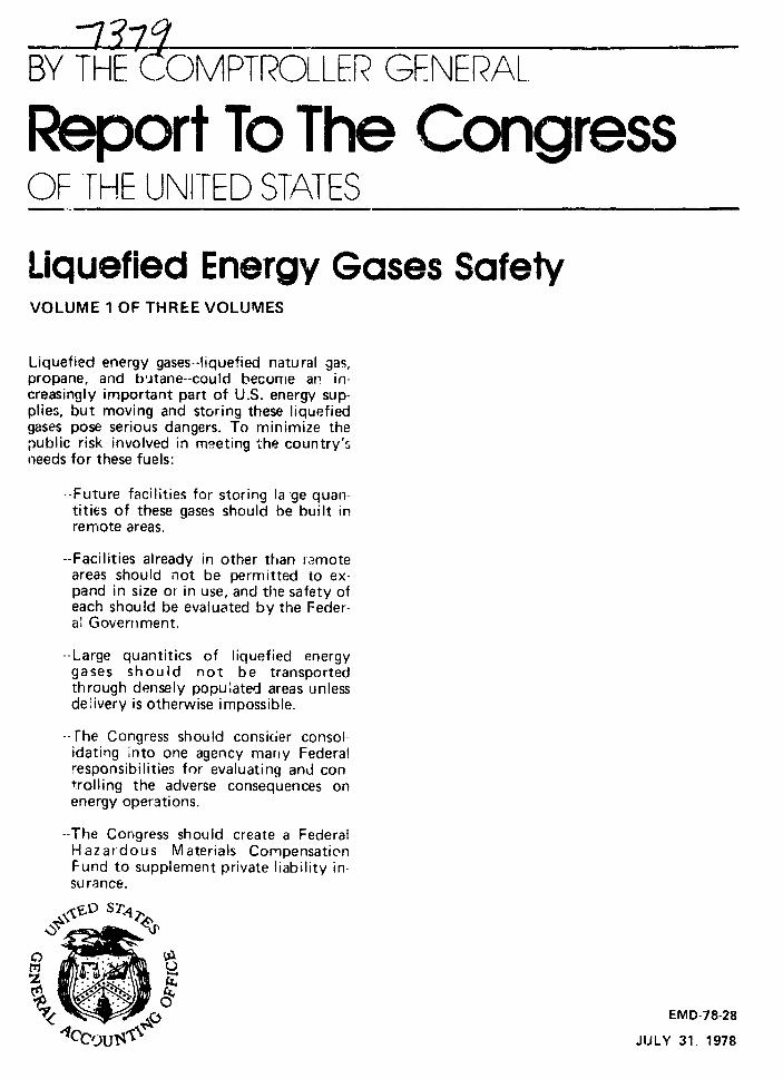
Liquefied Energy Gases SafetyVOLUME 1 OF THREE VOLUMES
Liquefied energy gases--liquefied natural gas,propane, and butane--could becomre an in-creasingly important part of U.S. energy sup-plies, but moving and storing these liquefiedgases pose serious dangers. To minimize thepublic risk involved in meeting the country'sneeds for these fuels:
--Future facilities for storing la ge quan-tities of these gases should be built inremote areas.
--Facilities already in other than :rmoteareas should not be permitted to ex-pand in size or in use, and the safety ofeach should be evaluated by the Feder-al Government.
--Large quantities of liquefied energygases should not be transportedthrough densely populated areas unlessdelivery is otherwise impossible.
-- rhe Congress should consider consolidating into one agency marny Federalresponsibilities for evaluating and controlling the adverse consequences onenergy operations.
--The Congress should create a FederalHazardous Materials CompensationFund to supplement private liability in-su rance.
S @
"0< .. ,, _ ~ ~o ,=EMD-78-28
"fCcUBIu JULY 31, 1978

U%5¢~ ~COMPTROLLER GENERAL OP THE UNITED STATESWASHINGTON, D.C. "4Us
B-178205
To the President of the Senate and theSpeaker of the House of Representatives
This report presents our analysis of the critical safetyissues in transporting and storing liquefied energy gases--liquefied natural gas and liquefied petroleum gases (propaneand butane). We have identified what we believe to be signi-ficant problem areas that warrant the immediate attention ofthe Congress and the cognizant Federal agencies.
We made the review pursuant to our authority in the Budgetand Accounting Act, 1921, 31 U.SC. 53 (1970); the LegislativeReorganization Act of 1370, 31 U.S.C. 1154 (Supp. V 1975); andthe Federal Energy Administration Act of 1974, 15 U.S.C. 771(Supp. V 1975), made applicable to all of the Department ofEnergy by Section 207 of the Department of Energy OrganizationAct (Public Law No. 95-91).
If liquefied energy gases spill from their tanks, theyvaporize rapidly and become highly flammable and explosive. Amajor spill in a densely populated area--whether by acc.dent,natural forces, or sabotage--could result in a catastrophe.Because of the potential danger and the possible increase inthe use of these liquefied gases, we believe that it isappropriate now to take any needed actio. s to protect thepublic.
We believe that future, large-scale liquefied energy gasesfacilities should be located away from densely populated areas;tiat any such existing facilities should not be permitted toexpand, in size or in use; and that present urban facilitiesshould be carefully evaluated to ensure that they do not poseundue risk to the public.
We believe that large quantities of these substancesshould not be transported through densely populated areasunless they cannot otherwise be delivered. We also see theneed for the Congress to consider consolidating in a singleFederal Energy Health and Safety Regulatory Agency many suchresponsibilities currently scattered throughout many depart-ments and agencies.
B-178205
The report is presented in three volumes. Volume 1contains the Executive Summary and the report chapters; Volume
2, the appendixes that support and supplement the chapters;
and Volume 3, the full texts of the official comments we re-ceived from Federal agencies.
In the Executive Summary, we have attempted to summarize
and simplify the most significant points from the chapters.
Copies of this report are being sent to the Secretariesof Commerce, Energy, State, and Transportation; the Ch-irman
of the Interstate Commerce Commission; the National Transpor-
tation Safety Board; and the chairmen of energy related
congressional committees and subcommittees.
Comptroller Generalof the United States
2
EXECUTIVE SUMMARY
0 F
L I QU E F I E D ENERGY GAS S SAFET Y
CONTENTS
SECTION Paae
1 INTRODUCTION 1Contents 1Purpose of the Study 1A Erief Primer 2
2 LEG STORAGE FACILITIES 7Vulnerability to Natural Forces 7The Ability of Dikes to Contain
Large Spills 9The Advantage of Inground LNG
Storage 10Vulnerability to Sabotage 10Major Conclusions and Recommendations 11
3 LEG TRANSPORTATION 14LEG Ships 14LEG Trucks 16LPG Railcars 18The Location of Import Terminals 21Major Conclusions and Recommendations 21
4 THE POTENTIAL CONSEQUENCES 24The Effects of a Large LEG Spill 24The Cleveland Accident 25
5 LIABILITY, RESEARCH, AND REGULATION 28Liability and Compensation 28LEG Safety Research 29Federal, State, and Local Regulations 31Major Conclusions and Recommendations 33
6 THE BrSIS AND SCOPE OF GAO'S.STUDY 37Comments from the Industry and
Federal Agencies 38

ABBREVIATIONS
DOE Department of Energy
DOT Department of Transportation
FPC Federal Power Commission
GAO General Accounting Office
ICC Interstate Commerce Commission
LEG Liquefied Energy Gas (LNG and LPG)
LNG Liquefied Natural Gas
LPG Liquefied Petroleum Gas (Propane and Butane)
OHMO Office of Hazardous Materials Operations (DOT)
UBC Uniform Building Code
ii
SECTION 1
INTRODUCTION
CONTENTS
Thic Executive Summary contains brief discussions of the
critical safety and security issues covered in GAO's full
report, Liauefied Energy Gases Safety (EMD-78-28). The report
consists of three voluimies.
-- Volume 1, the Executive Summary and the ma;: text.
-- Volume 2, appendixes that support and supplement themain text.
-- Volume 3, comments on a draft of this report by theDepartments of Commerce, Energy, State, and Transper-tation, the Interstate Commerce Commission, and theNational Transportation Safety Board.
This Executive Summary highlights GAO's findings, con-
clusions, and recommendations. the body of the report con-
tains the full supporting data and additional, more detailed
conclusions and recommendations.
PURPOSE c? THE STUDY
Energy gases are liquefied in order to reduce their volume
hundreds of times. This facilitates their transportation and
storage, but magnifies the potential hazard.
Liquefied energy gases (LEG) are often transported and
s, .red in densely populated area,. If these liquids spill

from their containers, they rapidly vaporize and become highly
flammable and explosive gases. One cLbit meter of liquefied
natural gas (LNG) makes 424,000 cubic feet of highly flammable
natural gis-air mixture. One cubic meter of liquefied petro-
leum gas (LPG) makes a slightly larger volume of flammable
gas-air mixture. A major spill in a densely populated area,
whether by accident, natural forces, or sabotage, could be
catastrophic.
Because of this potential danger and the possible increase
in the use of these liquefied gases, LEG safety issues should
now be carefully examined and any needed actions taken to pro.-
tect the public.
This report analyzes these safety issues, i'--tifies
problem areas, and recommends corrective actions to the
Congress and the cognizant Federal agencies. We believe that
the Nation's LEG needs can be met without posing undue risk
to the public if the recommendations developed in this report
are adopted by the Congress and the Federal agencies involved.
A BRIEF PRIMER
Although there are many differences in their physical
properties and technologies, LNG and LPG are similar substances
and have many safety and security problems in common. This has
made it convenient to consider them together as LEG. Naphtha,
2
a less hazardous substance, is included in the report to
compare its regulations and handling with those of LEG.
LNG, LPG, and naphtha together make up about 3 percent of
the energy used in this country. They are produced domestic-
ally and are imported. All three aLe used to supplement
domestic natural gas supplies. As America's energy demand
grows, imported LNG and LPG are likely to become increasingly
important energy sources. LPG and naphtha also have important
industrial applications.
Physical Poperties of LEG and Naphtha
Natural gas is an odorless, colorless mixture of hydro-
carbons, 65 to 99 percent methane, with smaller amounts of
ethane, propane. and butane. Chilled to -260 degrees (F), the
gas becomes a liquid about one-600th of its volume at atmos-
pheric pressure. Therefore, a tank of LNG has 600 times as
much energy as an equal-sized tank of natural gas.
LPG (propane and/or butane) is processed from natural gas
or crude oil. Both propane and butane liquefy under pressure
at atmospheric temperature, or when cooled at atmospheric pres-
sure. Propane liquefies at -44 degrees (F); butane at 31
degrees (F).
Naphtha is a group of heavier hydrocarbons separated from
crude oil in the refining process. It is transported and
stored as a liquid at atmospheric temperature and pressure.
LNG and LPG will only burn at the surface of the liquid.
When spilled, however, both substances quickly vaporize.
3

Because LPG vapor and cold LNG vapor are heavier than air, a
spill forms a low spreading cloud, which becomes highly flam-
mable as it mixes with air. An LNG vapor cloud is flammable
when the LNG concentration is between 5 and 14 percent (the
talance being air). The flam-able range of an LPG cloud is
between 2 and 9 percent LPG.
Naphtha is between kerosene and gasoline in volatility.
All three, being liquids at atmospheric temperatures and pres-
sures, are much less volatile than LNG and LPG; that is, they
evaporate much more slowly.
Overview of LNG Storage and Transportation
In the summer, when natural gas demand is low, some excess
gas i.s liquefied and stored in highly insulated tanks. A typi-
cal LNG storage tank can hold 95,000 cubic meters--enough to
make nearly 2 billion cubic feet of natural gas. When demand
peaks in cold weather, the LNG is either regasified and pumped
through gas pipelines to customers, or delivered by truck to
other gas companies where it is similarly processed.
Such "peaksnaving" plants have been operating in the
United States for several years. Most large LNG storage facil-
ities are for peakshaving. There are currently 45 of these
which hold more than 23,000 cubic meters. There are about 75
LNG trucks, each with about 40 cubic meters capacity.
Recently, LNG has been imported in ships. These imports,
which now supply less than one-tenth of one percent of U.S.
4
natural gas demand, could supply up to 15 percent by 1985.*
This would require more than 40 LNG tanKerc to operate regu-
larly in and out of U.S. harbors. A typical new LNG tanker
carries about 125,000 cubic meters.
The 14 major LNG import terminals now operating throughout
the world are "base-load" facilities. The LNG is piped from
the ship to storage tanks from which it is constantly regasi-
fled or re-shipped, instead of being saved for peak demand
periods.
There are two LNG import terminals currently operating
in this country. The Everett, Massachusetts terminal began
operations in 1971. The new Cove Point, Maryland terminal
began operations in March 1978, and the Elba Island, Georgia
terminal i;: ready to begin. One other terminal is under con-
struction, and several more have been proposed.
Overview of LPG Storage and Transportation
The much greater use of LPG has drawn less public atten-
tion than the relatively new LNG industry. LPG has been used
for many years for a variety of purposes, including making
synthetic natural gas and providing power on farms.
About 85 percent of the LPG in bulk storage is kept under
pressure in underground salt domes or mined caverns. LPG is
also stored in aboveground tanks, many of which are small.
-wb-~I~-~Te Tec--y a" ssessmen t, Transportat iJon -- l- e idNatural Gas, September 1977, p.5.
5
There are only 20 LPG aboveground storage facilities that hold
more than 23,000 cubic meters.
Domestic transportation of LPG is mostly by pipeline,
with the remainder distributed in trucks or railcars. There
are 70,000 miles of LPG high-pressure pipeline, 16,000 LPG rail
cars, and 25,000 LPG transport and delivery vehicles. A large
LPG truck trailer holds about 40 cubic meters.
Ten major LPG import terminals are now operating in the
United States, and imports of LPG may rise substantially. LPG
ships are smaller than LNG ships; typical new ones hold 75,000
cubic meters.
6

SECTION 2
LEG STORAGE FACILITIES
VULNERABILITY TO NATURAL FORCES
LEG storage tanks are usually designed to the Uniform
Building Code (UBC) standards for their particular geographic
areas, the same standards used for most inhabited buildings.
They essentially require that LEG tanks be able to withstand
tne largest earthquake, wind, flood, etc., locally experienced
in the last 50, 100, or 200 years.
The probability of these natural forces exceeding UBC
standards at a given site in a given year is low. However, the
probability that the standards will be exceeded some time at
some facility increases with the number of facilities and with
the number of years each facility operates.
Because there are already many large LEG facilities, it
is virtually certain that during their lifetime many of them
will experience natural forces greater than those the UBC stan-
dards require them to withstand. This does not necessarily
mean that the facilities will fail. The UBC standards are
minimum criteria, and most structures have built-in "safety
margins"--they are designed to be stronger than the standards
require.
By "failure" of a tank, we mean a permanent distortion or
rupture that causes significant leakage of the contained fluid.
A failure is not necessarily a complete collapse.
7
We evaluated the LEG tank designs at five sites and found
that, while they were adequately designed for the UBC earth-
quake and 100-year wind criteria, tanks at three of the sites
had very small earthquake safety maLgins--two of these three
sites, containing three large tanks, are located next to each
other in Boston Harbor.
Nuclear power plants are built to higher standards than
any other type of enerqv installation, much higher than those
for LEG installations. Nevertheless, they are never located in
densely populated areas. We believe that new large LEG facili-
ties also should not be located in densely populated areas.
Most LNG storage tanks have double metal walls with
insulation in between. Some are made of prestressed concrete.
LPG and naphtha tanks have single walls.
The outer steel walls of LNG tanks are not normally made
to withstand intense cold. Thus, if the inner tanK alone fails
for any reason, it is almost certain that the outer tank will
rupture from the pressure and thermal shock.
The most likely cause of failure of large steel LEG tanks
in an earthquake appears to be from breaking the steel straps
which anchor the steel tank sides to the concrete foundation.
The tank's walls will then se-.arate froin its bottom, causing a
massive spill.
Large LEG tanks made of prestressed concrete are usually
much more resistant to natural forces than those made of steel.
8
THE ABILITY OF DIKES TO CONTAIN LARGE SPILLS
National Fire Protection Association standards require
that each large LEG tank, or group of tanks, be surrounded by
a dike which can hold at least the volume of the largest tank.
However, most of these dikes are only designed to contain LEG
spilled from relatively slow leaks. They cannot contain the
surge of LEG from a massive rupture or collapse of a tank wall.
We selected six LEG facilities--with dikes built to
National Fire Protection Association criteria--and calculated
how much liquid could escape over the dikes. Our calculations
were verified by experiments.
Our results indicate that a massive rupture or collapse
of a tank wall could spill over 50 percent of the LEG at five
of the facilities. The sixth facility would probably spill no
more than 13 percent of its LEG, because it has a close, high
dike--however, a force that could destroy the tank might also
destroy this dike.
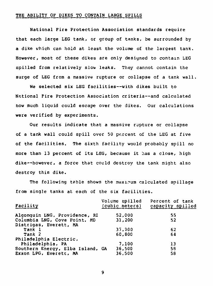
The following table shows the maximum calculated spillage
from single tanks at each of the six facilities.
Volume spilled Percent of tankFacility (cubic meters) capacity spilled
Algonquin LNG, Providence, RI 52,000 55Columbia LNG, Cove Point, MD 31,200 52Distrigas, Everett, MA
Tank 1 37,200 62Tank 2 60,800 64
Philadelphia Electric,Philadelphia, PA 7,100 13
Southern Energy, Elba Island, GA 36,500 58Exxon LPG, Everett, MA 36,500 58
9
Our calculations assumed an immediate, total spill of a
full tank, with the fluid moving toward the nearest dike wall.
Such an LNG spill occurred in Cleveland in 1944. A similar,
much larger LPG spill occurred in the country of Qatar in 1977.
THE ADVANTAGE OF INGROUND LNG STORAGE
Liquid spills from inground tanks are nearly impossible.
Many LNG tanks in Japan, the world's largest importer of LNG,
are built in the ground for greater safety. Japanese inground
tanks are operating satisfactorily and cost about the same
there as aboveground tank and dike installations.
VULNERABILITY TO SABOTAGE
Public utilities and petroleum companies in this country
have often been the targets of sabotage. Many domestic and
foreign groups have the weapons, explosives, and ability to
sabotage LEG facilities. Successful sabotage of an LEG facil-
ity in an urban area could cause a catastrophe.
We found that security procedures and physical barriers
at LEG facilities are generally not adequate to deter even an
untrained saboteur.
None of the LEG storage tanks we examined are impervious
to sabotage, and most are highly vulnerable. Some designs
provide greater protection than others against explosive pene-
tration. Stronger designs complicate sabotage by requiring
10
specially designed charges, more powerful explosives, and more
on-site preparation. Concrete tanks are much more resistant to
penetration than single-wall LPG tanks. Double-wall metal LNG
tanks fall in between.
In many facilities, by manipulating the equipment, it is
possible to spill a large amount of fluid outside the diked
area through the draw-off lines.
LEG storage facilities in cities are often adjacent to
sites that store very large quantities of other hazardous sub-
stances, including other volatile liquids. Thus, a single
cause might simultaneously destroy many tanks, or a spill at
one facility might cause further failures at adjacent facili-
ties.
MAJOR CONCLUSIONS AND RECOMMENDATIONS
Conclusions
-- It is virtually certain that the level of natural
forces LEG facilities are required to withstand will.
be exceeded at many facilities in the next 50 years.
This could lead to tank failure, particularly where
safety margins are low.
-- Little attention has been paid to sabotage at LEG
facilities, and most of them are inadequately protected
and highly vulnerable to sabotage. Sabotage could also
lead to tank failure.
11
-- If an LEG tank fails in a densely-populated urban area,
it could cause a catastrophe.
-- In the event of a massive rupture .r collapse of a tankwall, over 50 percent of the LEG could escape over thedikes at five of t.lf six LEG facilities we examined.
Recommendations to Federal Agencies
1. We recommend that the Secretaries of Transportation
and Energy and the Federal Energy Regulatory Commission takesteps to ensure that
-- all new, large LEG storage facilities are built in
remote areas; and
-- no existing, large LEG storage facilities in other than
remote areas are expanded in size or in use.
2. If, despite our recommendation, new, large LEG storagefacilities are built in other than remote areas, or existingones are expanded in size or use, we recommend that
--all storage tanks be in the ground with the highest
level of fluid below ground level; or
--all storage tanks be built and operated to standards
similar to those applied to the construction and opera-tion of nuclear plants.
3. We recommend that the Secretary of Energy evaluate
each existing, large LEG storage facility and recommend to thePredident and the Congress the actions necessary to protect
the public from the hazards associated with them.
12
Recommendations to the Congress
We recommend that the Congress;
-- Enact legislation requiring that guards at LEG facili-
ties carry weapons and be authorized to use them if
necessary to avert sabotage.
-- Enact legislation extending Federal authority to cover
large LEG storage facilities which are presently not
covered by Federal regulation.
13
SECTION 3
LEG TRANSPORTATION
LEG SHIPS
LNG ships, which hol- up to 165,000 cubic meters, are
probably the least vulnerable of all the systems involved in
LNG transportation and storage. They are double-hulled and
have insulated cargo tanks made of welded 9 percent nickel-
alloy steel or aluminum alloy, both of which can withstand
intense cold. Two basic types of tanks are used--free standing
tanks which are anchored in the ship's hull, and "membrane"
tanks supported by insulation lining the hull. The double hull
helps protect against collisions or sabotage.
On the other hand, most LPG and naphtha ships are single-
hulled, and are thus much less resistant to collisions and
sabotage than LNG tankers. The largest new LPG ships hold
100,000 cubic meters.
Ships are most susceptible to collision while entering
ports through narrow, winding ship channels. They are most
vulnerable to sabotage while tied up at terminals.
Since human error is a contributing factor in 85 percent
of all marine casualties and operating problems, the best pre-
caution against accidents and sabotage is to have highly-
skilled, well-trained personnel operating the ships, po-ts,
and terminals.
14
We have studied the Coast Guard's port operating proced-
ures, and the training requiremerts for LEG ships' crews, and
believe that they need to be imprr .d.
Most Coast Guard personnel, including some Hazardous
Materials Officers, heve little training in LEG hazards.
Some training for ships' crews is covered in the Coast
Guard's proposed Tankerman Requirements. We do not believe
these proposed requirements will be adequate, because
-- only one or two crew members responsible for cargo
handling are required to receive formal training;
-- requirements for practical experience are inadequate;
and
-- instruction in emergency procedures is not required.
We found similar weaknesses in the training requirements
being considered for LNG tern nal personnel. These are includ-
ed in the Coast Guard's contemplated Waterfront Facilities
Regulations for LNG in Bulk, and in the LNG terminal regula-
tions being considered by the Office of Pipeline Safety
Operations of tne Department of Transportation (DOT). Similar
regulations for LPG waterfront facilities have not yet been
proposed.
The Coast Guard inspects all LNG ships before they enter
U.S. harbors. These inspections do not Tnclude the operating
condition of control equipment such as steering engines, pro-
pulsion machinery, and electronic devices.
In February 1976, the Coast Guard issued Liauefied Natural
Gas - Views and Practices, Poiicy_and Safety. The publication
15
offers valuable guidance, but its procedures are not mandatory.
Its implementation is left to the discretion of each Captain of
the Port. It is the Captain of the Port who decides whether
malfunctions in ships' safety systems are serious enough to bar
their entry into a U.S. harbor. There are no specific Coast
Guard guidelines covering LPG.
Another problem is the proximity of some shipping channels
to airports. For example, LEG tankers regularly enter Boston
Harbor through a shipping channel adjacent to Logan Interna-
tional Airport. On one occasion, an airplane crashed into the
seawall of the shipping channel. The Federal Aviation Admin-
istration plans to adopt our suggestion that landings on the
adjacent runway be suspended during the few minutes that an
LEG ship in the channel is in line with the runway.
LEG TRUCKS
While LEG trucks carry only 40 cubic meters, far less than
LEG ships, they move routinely through major metropolitan
areas, where a relatively small spill can have very serious
consequences.
LNG truck trailers have a higher center of gravity than
most tank trucks, which makes them particularly susceptible to
rolling over. However, they have inner and outer tanks with
insulation in between and thus are quite resistant to puncture
and cargo loss. LPG trucks also have a high center of gravity,
although lower than LNG trucks; but they are single-walled and
16

pressurized, and are therefore more vulnerable than LNG trucks
to cracks and punctures and more likely to explode in fires.
We confirmed through discussions with LNG transport
companies at least 12 LNG trailer accidents. Two of the acci-
dents, which led to LNG spills, pointed out two vulnerable
areas on LNG truck tanks--the unprotected portion of the trai-
ler face, and the rear piping.
There have been many LPG truck accidents, some with
severe consequences. For example, a 1975 LPG truck accident
near Eagle Pass, Texas, caused explosions which killed 16
people and injured 45.
If an LEG truck fell from an urban elevated highway, it
would probably split open on the street below. LEG and its
vapors could then flow down into sewers, subways, and basements.
Because of its low boiling point, LEG would quickly vaporize,
generating a pressure which would spread the invisible, odor-
less, explosive gas. The 40 cubic meters of LNG in one truck,
vaporized and mixed with air in flammable proportions, are
enough to fill more than 110 miles of 6-foot diameter sewer
line, or 15 miles of a 16-foot diameter subway system. Other
types of large trucks have fallen off urban elevated highways.
DOT has no special inspection program for LEG trucks.
For all U.S. trucking, there are only 128 inspectors to monitor
160,000 licensed carriers and 3 million commercial vehicles.
The Interstate Commerce Commission (ICC) issues special
certificates for LNG transport, but LNG can also be hauled
17
under ICC certificates for the bulik transportation of petroleum
products or liquid chemicals. An ICC certified company can
hire 'leased operators' to operate under its certificate. This
means that LNG may be trucked by companies which have not had
to prove their competence to ICC. ICC certificates do not
restrict truck routes.
LEG trucks could be easily hijacked or sabotaged. A truck
might be hijacked for extortion or for malicious use of the
cargo. Trucks that routinely operate over established routes
are easy targets for saboteurs. LEG trucks are particularly
dangerous, because they allow the easy capture, delivery, and
release of a large amount of explosive material any place the
terrorist chooses.
LPG RAILCARS
Ten percent of America's 1.7 million railroad freight cars
are hazardous materials tank cars. About 16,000 of these, each
with approximately 115 cubic meters capacity, carry LPG. LNG
is not transported by rail.
LPG cars are involved in many of the 10,000 railroad
accidents that occur in this country each year. There are
often more than 10 consecutive LPG cars on a train. If vapors
from one LPG car ignite, the fire may cause a second, unpunc-
tured car to rupture in a "Boiling Liquid Expanding Vapor
Explosion," or BLEVE. Each fire and explosion contributes to
18

the heating and weakening of neighboring cars and makes addi-
tional explosions more likely. A BLEVE can rocket a 45,000
pound steel section of a tank for a quarter of a mile. This
is what happened in a derailment near Oneonta, New York, in
1974. LPG vapor from a crushed LPG car quickly ignited and
formed a fireball. Fire fighters attempting to cool down
several other LPG cars were caught in a subsequent explosion;
54 were injured.
Other types of LPG railroad accidents have also occurred.
In a 1974 railyard accident near Decatur, Illinois, an LPG
railcar was punctured; the resulting cloud did not ignite
immediately, but spread and then exploded other an area one-
half by three-quarters of a mile. There were 7 deaths, 349
injuries, and $24 million in damages. Litter and debris from
the fire and explosion covered 20 blocks of the city.
The latest LPG railroad catastrophe occurred February
1978, in Waverly, Tennessee. An LPG car exploded two days
after a derailment, apparently as a result of internal damage
during the accident and a rise in the atmospheric temperature.
Fifteen were killed and %ver 40 injured.
LPG railcars travel through densely populated areas of
cities, even cities which prohibit LPG storage. If these LPG
railcar accidents (or the LEG truck accidents) had occurred
in densely populated areas, far greater damage might have
resulted.
19
The LPG industry and DOT recognize the danger in LPG rail
movement, and have collaborated in identifying and correcting
deficiencies in tank car design. In September 1977, as a
result of a long inquiry, DOT amended its regulations to
require that all LPG tank cars have safer couplers, head-
shields, and thermal protection; old cars were required to have
the safer couplers by June 30, 1979, and headshields and ther-
mal protection by December 31, 1981. However, after the Waver-
ly accident, subsequent recommendations from the National
Transportation Safety Board, and Congressional inquiries, DOT
has proposed regulations to require the couplers by December
31, 1978, and the other features by December 31, 1980.
DOT and the industry oppose restrictions on LPG railcar
routing for several reasons. These include:
-- it is simpler and cheaper to regulate tank car design
than tank car movement;
-- trains move more slowly in congested areas, decreasing
the chance of an accident; and
-- some accidents occur while handling and switching cars,
more of which would be necessary in circuitous routing.
DOT believes that the new regulations for tank car
construction are sufficient for their safe ope.ation. We
believe that restriction of routes is also necessary.
LPG tank cars are as vulnerable to sabotage as LPG trucks.
The tanks can be breached with readily available weapons and
20
explosives, and the cars can be derailed at predetermined
times and places. The fact that they must stay on the tracks,
however, greatly limits the possibility of hijacking and the
places they can be taken.
THE LOCATION OF IMPORT TERMINALS
Locating LEG import terminals in non-urban areas would be
an important safety step.
Existing and planned non-urban LPG import terminals will
have the capacity to receive all projected LPG imports in 1985.
We did not determine the cost of distributing the LPG from
those terminals.
With some expansion, existing and planned non-urban LNG
terminals could handle all of the LNG imports projected between
now and 1990. We did not look at the capacity of the main gas
transmission lines to distribute this gas to customers. To our
knowledge, the Federal Power Commission (disbanded with the
formation of DOE) has not considered the alternative of using
only non-urban sites to receive all LNG imports.
MAJOR CONCLUSIONS AND RECOMMENDATIONS
LNG ships are probably the least vulnerable of all the
systems involved in LNG storage and transportation. LPG and
naphtha ships with single hulls are more vulnerable than LNG
21

ships in the event of an accident or sabotage. No plans or
equipment exist to cope wita a major LEG spill. If the Coast
Guard is to effectively supervise the increasing number of LEG
cargo transfer operations, it will need more money and man-
power, revised regulations, and new plans and policies.
LEG trucks and railcars moving through densely populated
areas pose a serious threat to public safety. The dangers
present in trucking LEG are far greater than those involved
in trucking less volatile petroleum products such as fuel oil,
naphtha, and gasoline. Both LEG trucks and LPG railcars are
vulnerable to accidents and sabotage. An LEG spill in a
densely populated area could lead to a catastrophe.
We recommend that the Secretary of Transportation and the
ICC:
-- Prohibit trucking of LEG through densely populated
areas and any areas that have features that increase
the vulnerability to a major LEG spill (e.g., sewer
systems, tunnel openings, subways) unless delivery is
otherwise impossible. DOT should also give particular
attention to avoiding routes with highway configurations
which make tank rupture accidents likely (e.g., elevated
roadways, overpasses, high-speed traffic, roadside abut-
ments).
-- Prohibit the travel of LPG railcars through densely
populated areas unless it is impossible to deliver the
LPG otherwise.
22
We also recommend that the Secretary of Transportation:
--Develop a computer program able to analyze the capabil-
ity of the national LPG storage and distriDution system.
Such a program should be able to determine the rate at
which LPG can be delivered (as LPG or as synthetic
natural gas) from any point to any other point and the
cost to increase this capability by any desired amount.
We recommend that the Secretary of Energy and the Federal
Energy Regulatory Commission:
-- Require a staff study of the feasibility of using only
non-urban sites to receive all LNG imports and develop-
ing a gas exchange program using existing pipelines to
ensure appropriate distribution of gas supplies.
23
SECTION 4
THE POTENTIAL CONSEQUENCES
THE EFFECTS OF A LARGE LEG SPILL
While LEG storage and transportation in densely populated
areas are very hazardous, it is difficult to estimate the
effect of a large LEG spill.
The only significant U.S. LNG spill, in Cleveland in 1944,
involved a relatively small amount compared to the quantities
stored in urban areas today, about one-fifteenth of one large
modern tank.
Some insight can be gained from the spill of naphtha into
the sewers of Akron, Ohio, in June 1977. Although naphtha is
much less volatile than LEG and less than 15 cubic meters were
spilled, the incident caused violent explosions more thcn 8
miles from the point of the spill.
LEG vapors are highly explosive in confinement, and can
explode in the open air--although the conditions which allow
this are not completely understood. In Port Hudson, Missouri,
in 1970, a relatively small propane leak from a pipeline break
led to a large detonation propagating through the open air.
If LEG spreads across a city through sewers, subways, or
other underground conduits, or if a massive burning cloud it
blown along by a strong wind, a city may be faced with a very
large number of ignitions and explosions across a wide area.
24

No present or foreseeable equipment can put out a very large
LEG fire.
THE CLEVELAND ACCIDENT
The only major LNG spill in the United States occurred in
Cleveland, on October 20, 1944. It resulted in fires and
explosions that killed 130 people, injured 225 more, and
resulted in property damage estimated at $7 million.
Casualties could have been much higher if the spill had
taken place at a different time of day. At the time of the
fire, most children were at school and most men were at work.
Furthermore, the National Fire Protection Association News-
letter of November 1944 said:
"The fact that the wind was blowing away from the
congested part of the area is believed to have been
a major factor in prevention of an even more devas-
tating conflagration which could have destroyed a
very large part of the East Side."
The Cleveland accident virtually halted LNG use in this
Nation for 20 years.
This disaster demonstrates the danger of a spill in an
urban area, and gives some indication of the potential conse-
quences of a major LNG accident. It was the subject of three
independent studies:
--A Technical Consultants Board of Inquiry for the Mayor
of Cleveland.
25
-- The Bureau of Mines of the U.S. Department of the
Interior.
-- The Coroner of Cuyahoga County, Ohio--whose conclusions
anc recommendations were included in the Mayor's report.
The accident occurred in the liquefaction, storage, and
regasification (peakshaving) plant of L;,e East Ohio Gas Com-
pany, the first peakshaving plant built in America.
At 2:40 p.m., a 4,200 cubic meter LNG tank collapsed.
Although that tank and the three others were surrounded by
dikes and had individual drains leading to a pit, some of thke
liquid escaped the site and spread into streets, storm sewers,
and basements. The vapors quickly ignited, setting off explo-
sions and fires.
About 20 minutes later, the legs holding a second tank
failed from the heat, releasing another 2,100 cubic meters of
LNG. The subsequent explosion shot flames more than half a
mile into the air. The temperature in some areas reached 3000
degrees (F).
The following facts are significant.
---Both the tank manufacturer and the gas company assumed
that a small leak would precede any more serioLs spill,
and that it would be detected and repaired.
--The gas company took precautions to control small and
moderate rates of LNG spillage. They ass2med that a
sudden, massive spill was extremely unlikely and,
26
therefore, not a matter for concern. The same assumpti(r
is made today in designing dikes around LEG facilitjin.
---The plant site was selected because it was already
company property and was appropriately located on the
gas distribution system. The company felt it was build-
ing a safe plant that could be located anywhere. Simi-
lar assumptions about the safety of LEG plants in urban
areas are made today.
-- The proximity of other industrial facilities, residen-
ces, storm sewers, or other conduits was not considered.
-- The Cleveland accident was caused by an amount of LNG
which is very small by modern standaras. Less than
6,300 cubic meters of LNG spilled and a large portion
of that remained on the company property. Typical large
LNG storage tanks today can hold up to 95,000 cubic
meters, and one site may have several tanks.
The 1945 Bureau of Mines study of the Cleveland accident
contained the following recommendations, which have yet to be
generally adopted.
1. Plants dealing with large quantities of liquefied
flammable gases should be isolated at considerable
distance from inhabited areas.
2. Extreme caution should be taken to prevent spilied
gas from entering storm sewers or other underground
conduits.
27
SECTION 5
LIABILITY, RESEARCH, AND REGULATION
LIABILITY AND COMPENSATION
A major LEG accident could cause damage of such severity
that injured parties could not be fully compensated under
existing arrangements. Present corporate structures and legal
limits on liability offer great protection to the parent cor-
porations. This may diminish their incentives for safety. At
present, no Federal agency addresses the question of offsite
liability for LEG accidents.
Each LNG ship is usually owned or leased by a separately
incorporated subsidiary of a parent firm, and the LNG is stored
in terminals owned by other subsidiaries. In many cases, the
parent firms are wholly-owned subsidiaries of still larger
firms.
Most of the assets in the system are protected by these
corporate chains, and the top corporations, which derive all of
the profits, would generally not be liable for the consequences
of an accident. The front-line companies, which are most vul-
nerable to liability claims, are usually the most thinly
capitalized in the chain. Most of their assets may be the ship
or terminal itself, which is unlikely to survive an accident
that does extensive offsite damage.
28

The liability of shipowners and bareboat ship charterers
is limited by U.S. statute to the post-accident value of tne
vessel, plus any amounts owing for freight, if they can prove
that they did not know about the causes of the accident.
Claimants after a major LNG accident would face long,
complex, and expensive litigation involving potential compli-
cations at every step in the legal process. If the defendant
corporation is foreign-owned, it and its assets may be out of
reach--in fact, it may be impossible to serve legal papers on
the corporation unless it maintains an agent in the United
States.
It is not always possible to prove the primary cause of
a major accident, since critical evidence may be d itroyed by
the accident itself. If the accident resulted from sabotage
or natural forces, the company may not be liable at all.
Present and planned liability coverage for LNG import
terminals ranges from $50 million to $190 million per incident.
Ten states require proof of liability insurance for LPG facili-
ties, but the maximum required is only $100,000 per incident.
LEG SAFETY RESEARCH
All LEG safety research has involved quantities which are
very small compared to those in large commercial facilities.
The Coast Guard has done some good quality hazard analyses,
primarily on the effects of small LEG spills on the water.
29

Isolated pieces of research of varying quality have been done
by other government and private laboratories around the world.
We believe that much more research needs to be done, on an
expedited basis, in many areas of LEG safety. In particular,
the following areas nLeed much more attention:
-- The interaction of spilled LEG with man-made structures,
such as buildings, subways, sewers, and ships.
--The conditions under which a large LEG cloud ignited on
its downwind side will burn back to its source.
-- The conditions under which LEG clouds can retonate.
--The distances that large LEG clouds can travel, under
varying atmospheric conditions, before they are safely
dispersed.
The present plan to channel the bulk of LNG safety
research through the Department of Energy (DOE) is faulty and
will not produce timely or useful safety results. DOE plans to
support LNG research in a manner analogous to its support of
basic research in other areas. This is entirely inappropriate
because of the number of facilities now under development,
under construction, or in use. LNG facilities may only be
importing for the next 20 or 30 years. The research needed for
current, temporary technology is different from that which is
needed for long-term and not yet perfected technologies. At
the same time, the organizations responsible for safety regula-
tions and enforcement have inadequate budgets and personnel to
make informed technical judgments on safety.
30
LEG risk assessment studies have not reached a stage where
they give confidence in their conclusions. Therefore, safety
decisions cannot logically be based on them. Regulatory agen-
cies will have to attempt to make timely, prudent decisions
with the realization that many important questions cannot cur-
rently be answered with confidence.
FEDERAL, STATE, AND LOCAL REGULATIONS
LNG and LPG are very hazardous substances. Federal
regulation and inspection of their importation, transportation,
and storage have not been adequate to ensure the public safety.
Federal safety responsibilities are shared by many
departments and agencies.
The Department of Transportation has overall authority for
the movement of hazardous materials. Specific authority has
been delegated to several agencies within the Department.
Among them:
---The Materials Transportation Bureau promulgates regula-
tions for all hazardous materials transportation. It
includes the Office of Pipeline Safety Operations which
regulates and inspects pipelines and] connected storage
facilities; and the Office of Hazardous Materials Oper-
ations (OHMO) which prescribes regulations for other
modes of transportation.
31
-- The Coast Guard promulgates regulations for ships and
waterfront facilities. It also has broad enforcement
authority for its own regulations, and for OHMO's.
--The Federal Railroad Administration and the Federal
Highway Administration prescribe and enforce regula-
tions, including OHMO's, in their respective juris-
dictions.
The Department of Energy has the authority to certificate
some LNG facilities. This authority is vested in the Economic
Regulatory Administration and the Federal Energy Regulatory
Commission, which zan impose requirements beyond the DOT mini-
mum standards on facilities under their jurisdiction.
The interstate Commerce Commission has economic authority
over interstate trucks and railroads, and can consider safety
matters in its certification process.
These agencies have generally failed to give adequate
attention to the unique dangers presented by LEG. Rulemaking
has been too slow. Regulations for LEG facilities have been
partly based on outdated National Fire Protection Association
standards, some of which we have shown to be inadequate. Many
LEG facilities have not been subjected to Federal regulation at
all, partly because of a failure of the cognizant agencies to
fully assert their authority.
The regulation of LEG and naphtha by state and local
governments varies widely. Some jurisdictions have no specific
regulations other than normal fire hazard restrictions.
32

Others, such as the New York State Public Service Commission
and New York City Fire Department, have more stringent regula-
tions than the Federal Government.
The problem is further aggravated by a shortage of trained
inspectors at all levels of government.
MAJOR CONCLUSIONS AND RECOMMENDATIONS
Liability and Compensation
The present liability and compensation system is not
equitable and does not provide sufficient incentives for
safety. We believe that the corporate owners who profit from
LEG operations should bear liability for a major accident.
The banks and insurance companies which finance LEG ships
and terminals insist that all companies in the corporate chain
co-sign notes. This insures that, in the event of a catastro-
phic accident, the lending institutions will be protected by
the assets of the whole corporate chain. Public safety
deserves no less protection.
Recommendations to the Congress
We recommend that the Congress enact legislation which
would:
-- Require corporations transporting, storing, or using
significant amounts of flammable materials to (1) carry
the maximum liability insurance available from the
private sector, and (2) contribute money to a Federal
Hazardous Materials Compensation Fund.
33
-- Provide that the United States be subrogated to the
rights of injured persons compensated by the fund so
that the Attorney General of the United States can sue
the companies or persons responsible for an LEG incident
to recover whatever monies the fund has oaid out.
--Allow injured parties to sue all companies in the cor-
porate chain for all damages beyond those covered by
insurance and the fund.
We also recommend that the Congress:
-- Enact legislation which requires that strict liability
be applied in all accidents involving LNG and LPG, and
consider requiring that strict liability be applied to
other highly hazardous materials.
-- Amend the 1851 Act (46 U.S.C. 183) which limits the
liability of owners and bareboat charterers of ships
and barges by substantially raising the statutory limit
for vessels carrying hazardous materials.
Recommendations to the Secretary of Energyand-the Fed erEner qy_Rg-tory ommlsslon
We recommend that the Secretary of Energy and the Federal
Energy Regulatory Commission:
-- Ensure that adequate compensation for offsite damage
will be available to injured parties before permitting
LNG projects to proceed.
-- Use their authority to require that importers and LNG
tanker companies maintain agents for the receipt of
legal documents in all states in which they operate.
34
LEG Safety Research
The limited research that has been carried out on LEG
spills and LEG vapor clouid behavior does not provide a sound
basis for assessing LEG hazards.
LEG risk assessment studies have not reached a stage where
their conclusions can be relied on. Until they do, regulators
will have to attempt to make timely, prudent, siting and other
critical judgments with the realization that many important
safety questions cannot yet be answered with confidence.
DOE's currently planned LNG safety research program will
not provide answers soon enough. We believe that an effective
safety research program, focusing on those issues most impor-
tant to decision makers, can be carried out within two years
for less than one-fifth of the $50 million DOE is planning to
spend on long-term LNG research. We have made detailed sugges-
tions for such a program in the body of the report.
Federal Regulation of LEG and Naphtha
Present Federal efforts to regulate LEG and naphtha do not
adequately protect the public. We believe that many Federal
regulatory responsibilities for energy health and safety should
be consolidated into a single, independent agency. This was
one of the options for Congressional consideration provided in
GAO's 1977 report, "Energy Policy Decisionmaking, Organization,
and National Energy Gouls".
35
With a mandate to adequately protect the public health
and safety, such an agency could assemble a technical staff
capable of developing appropriate regulations and inspecting
and enforcing the implementation of those regulations.
We recommend that the Congress:
--Consider creating an Energy dealth and Safety Regulatory
Agency. The new agenc, could include the Nuclear Regu-
latory Commission; the pipeline safety aspects of fuel
transportation on land, now handled by DOT; and safety
aspects of importing energy, now handled by DOE, plus
all safety responsibilities formerly carried out by the
Federal Power Commission.
-- Consider including within the Energy Health and Safety
Regulatory Agency the safety regulation of LEG carried
by truck and train. DOT would continue to be responsi-
ble for all safety regulation of motor carriers and
railroads, except those transporting nuclear materials
and LEG. The Environmental Protection Agency should
retain the responsibility for setting air and water
quality standards impacting on energy development, use,
and waste disposal.
-- Consider making the Energy Health and Safety Regulatory
Agency completely independent of DOE, or including it
within DOE with strong statutory provisions to insure
its independence.
36
SECTION 6
THE BASIS AND SCOPE OF GAO'S STUDY
For GAO, this study was unique in several ways. It
covered highly complex subject matter, required the use of many
technical consultants and contractors, and involved laboratory
and field experiments to verify certain calculations.
The purpose of the study was to determine whether, under
current practices and regulations, the public is adequately
protected from the dangers of LNG and LPG. Naphtha, a much
less volatile mixture of hydrocarbons, was included to permit
comparisons of its handling with that of LNG and LPG.
We conducted an extensive review of LEG safety literature,
including previous studies, company literature, government
reports, and technical journals.
We visited 37 import, storage, shipyard, transportation,
and design facilities in the United States and Japan, and made
a detailed study of the blueprints of many of them. We spoke
with concerned Federal, state, and local officials, and indus-
try and citizen organizations. Each group we visited was
offered a briefing on the problems we were examining, and we
suggested that they look into t' : same areas so they would be
in a position to comment on our findings. On the whole, we
received excellent cooperation from companies, organizations,
and Federal agencies.
37
COMMENTS FROM THE INDUSTRYAND FEDERAL AGENCIES
In keeping with GAO policy, we provided a draft of the
full report to all cognizant Federal agencies for their review
and comment. In addition, we provided over 50 LEG companies
with ccpies of those chapters of the draft in which they were
disc s -;ed.
We received official comments from six Federal agencies,
and 34 private LEG organizations. We considered all of these
comments before preparing the final report.
While we can only briefly summarize the comments here,
many of them are addressed on a chapter-by-chapter basis in the
full report. The final chapter discusses general concerns of
agencies and companies that are not covered in specific chap-
ters. In addition, the full texts of the Federal agencies'
comments have been printed as Volume 3 of this report. Many of
the LEG companies' comments also are addressed in the report
chapters; the full texts of those comments are available for
review at the U.S. General Accounting Office, 441 G Street,
N.W., Washington, D.C.
We greatly appreciate the time and effort that many of
these organizations spent on the report. Their comments con-
tributed significantly toward assuring the quality and accuracy
of the report, and in lending balance to the positions we have
taken.
38
The comments generally fell into the following four
categories:
1. Concern that GAO had singled out LEG, to theexclusion i-oF ir-hazardous substances.
Yes, we did single out LEG for this study, because it
is an important energy source, its use may increase
substantially, and it is potentially very hazardous.
We do not, however, mean to suggest that LEG is the
only commodity for public concern. There are other
hazardous substances that may pose considerable threat
to the public, and many of the issues discussed in
this report are applicable to them.
2. Concern that GAO had overlooked the safety recordof the LEG industry.
There is a long history of accidents in all aspects of
LPG use. There have been fewer accidents in the rela-
tively new LNG industry. Nonetheless, there have been
many documented incidents in LF-C production, storage,
and transportation.
The only catastrophic LNG accident occurred in
Cleveland, in 1944. We discuss that accident for two
reasons. While the amount spilled is small compared
to the quantities stored in urban areas today, it
gives some indication of what the effects of a major
accident in a metropolitan area might be; and it still
offers lessons to be learned.
39
The Cleveland facility was the first U.S. LNG plant.
After the plant has destroyed, LNG was not used in
this country for 20 years.
3. Concern about the discussion of sabotage.
We believe that the possibility of sabotage must be
considered and carefully treated in any complete eval-
uation of LEG safety.
In preparing the report, we tried to ensure that the
sabotage discussions were free of inflammatory state-
ments or expressions, and that they contained no
detailed information that could be used by saboteurs
or terrorists.
4. Disagreement with specific statements in the draft.
Where comments pointed out errors in the draft, we
have made the appropriate corrections. Some of the
comments with which we disagreed are evaluated in the
chapters of the report.
40

CONTENTS
VOLUME I
EXECUTIVE SUMMARY
CHAPTER*
1 INTRODUCTION
2 PRIMER
3 VULNERABILITY OF STORAGE TANKS AND
CONTAINMENT DIKES TO NATURALFORCES
4 CRACK-INDUCED FAILURE OF METAL LNG
TANKS
5 FLOW OVER CONTAINMENT DIKES
6 SHIP DESIGN, PERSONNEL, ANDOPERATIONS
7 TRUCK SHIPMENTS
8 TRAIN SHIPMENTS
9 VULNERABILITY OF LEG FACILITIESTO SABOTAGE
10 THE CLEVELAND LNG ACCIDENT OF 1944
11 LIABILITY AND COMPENSATION
12 SAFETY RESEARCH AND DISPERSIONMODELS
13 DETONATION AND FLAME PROPAGATIONRESEARCH
*A more detailed table of contents is provided at the beginning of most
of the individual chapters.
CHAPTER
14 THE CAPABILITY OF NON-URBAN SITESTO MEET TOTAL U.S. IMPORTREQUIREMENTS FOR LPG
15 THE CAPACITY OF NON-URBAN SITES TOMEET TOTAL U.S. IMPORTREQUIREMENTS FOR LNG
16 FEDERAL, STATE, AND LOCAL REGULATIONS
17 FEDERAL REGULATION OF LEG TRUCKS ANDRAILCARS
18 THE FEDERAL POWER COMMISSION
19 LNG USE IN JAPAN
20 OVERALL CONCLUSIONS ANDRECOMMENDATIONS
21 GAO TREATMENT OF AGENCY AND COMPANYCOMMENTS
VOLUME 2
APPENDIX
NOTE: For ease of reference the
appendixes are numbered tocorrespond with the chapters
they support or expand. Thereare no Appendixes VIII, XI,
XIII, XV, XVII, XX, or XXI.
I-1 MAJOR CONTRIBUTORS TO THE LIQUEFIEDENERGY GASES SAFETY REPORT
I-2 SITE VISITS
II U.S. LEG AND NAPHTHA CONSUMPTION, 1976
III-1 LEG STORAGE SITE EVALUATIONQUESTIONNAIRE
APPENDIX
III-2 EVATLUATION OF 300,000 BARREL PETROILANE,
INC. LIQUID PROPANE STORAGE TANKFACILITIES, SAN PEDRO, CALIFORNIA,TO WITHSTAND EARTHQUAKE LOADINGWITHOUT RUPTURE
III-3 DESIGN EVALUATION OF TANKS
IV CRACK-INDUCED FAILURE OF METAL LNCTANKS
V-1 OVERFLOW
V-2 COMPUTATIONAL METHOD
V-3 SPIGOT FLOW
VI-1 REACTIVE SAFETY EQUIPMENT ON LNGTANKERS
VI-2 LEG CONTAINMENT SYSTEMS
VI-3 LNG INCIDENT EXPERIENCE TO DATE
VI-4 OPERATING PROBLEMS AND SHIP DELAYS
VI-5 SUMMARY OF PORT CHARACTERISTICS
VII-1 SOME LNG TRUCK ACCIDENTS
VII-2 ANALYSIS OF CAUSES OF SOY- UNDER-GROUND EXPLOSIONS
IX RECENT BOMBING INCIDENTS
X TANK DESIGN AND OPERATING EXPERIENCE,
EAST OHIO GAS COMPANY
XII FEDERAL FUNDING OF SAFETY RESEARCH
APPENDIX
XIV-1 LPG DEMAND
XIV-2 LPG MARINE IMPORT TERMINALS
XVI-1 IDENTIFICATION OF FACILITIES
XVI-2 DESCRIPTION OF 12 LEG FACILITIES
XVI-3 FEDERAL REGULATIONS
XVI-4 STATE REGULATORY SUMMARY
XVI-5 SPECIAL ISSUES ANALYSES
XVI-6 SOME PERTINENT STATUTORY CITATIONS
XVIII-1 APPLICATIONS TO THE FEDERAL POWERCOMMISSION FOR LNG TERMINALFACILITIES
XVIII-2 LIST OF SAFETY EVIDENCE PRESENTEDTO THE FEDERAL POWER COMMISSION
XIX JAPANESE ENERGY USE
VOLUME 3
FEDERAL AGENCY COMMENTS
DEPARTMENT OF COMMERCE
DEPARTMENT OF ENERGY
DEPARTMENT OF STATE
DEPARTMENT OF TRANSPORTATION
INTERSTATE COMMERCE COMMISSION
NATIONAL TRANSPORTATION SAFETY BOARD
ACRONYMS
AAR Association of American RailroadsACI American Concrete InstituteALJ Administrative Law Judge
ANSI American National Standards Institute
API American PetrGieum InstituteASLAB Atomic Safety and Licensing Appeals Board
ASLB Atomic Safety and Licensing Board
ASME American Society of Mechanical Engineers
BLEVE Boiling Liquid Expanding Vapor Explosion
BMCS Bureau of Motor Carrier Safety, DOT
BNG Bureau of Natural Gas, FPC
CBI Chicago Bridge and Iron CompanyCFR Code of Federal RegulationsCOTP Captain of the Port, U.S. Coast Guard
CPUC California Public Utilities Commission
CTIAC Chemical Transportation Industry AdvisoryCommittee
DEIS Draft Environmental Impact StatementDH decision heightDOD Department of Defense
DOE Department of Energy
DOT Department of Transportation
EHSRA Energy Health and Safety Regulatory Agency(proposed)
EIS Environmental Impact Statement
EOG East Ohio Gas Company
EPA Environmental Protection Agency
ERDA Energy Research and DevelopmentAdministration
FBI Federal Bureau of InvestigationFERC Federal Energy Revitlatory Commission
FHWA Federal Highway 7- ,4 nistration, DOT
FPC Federal Po.:er ' mm-.ssi.on
FRA Federal Railroad Ad,ministration, DOT
HMD Hazardous Materials Division, FRA
HMCF Hazardous Materials Compensation Fund(proposed)
HMO hazardous materials officer, Coast Guard
ICC Interstate Commerce Commission
IHI Ishikawajima-Harima Heavy IndustriesCompany
IMCO Intergovernmental Maritime ConsultativeOrganization
LEG liquefied energy gasesLNG liquefied natural gasLOC I tter of ComplianceLPG 1 'uefied petroleum gases
MHI Mitsubishi Heavy IndustriesMSA Maritime Safety Agency, JapanMTB Materials Transportation Bureau, DOT
NASA National Aeronautics and SpaceAdministration
NBS National Bureau of Standards, DOCNFPA National Fire Protection AssociationNFPCA National Fire Prevention and Control
Administration, DOCNHTSA National Highway Traffic Safety
Administration, DOTNRC Nuclear Regulatory CorimissionNNG Northern National Gas CompanyNTIS National Technical Information ServicesNTSB National Transportation Safety BoardNYCFD New York City Fire Department
OCA Office of Crash Avoidance, NHTSAOHMC Office of Hazardou:; Materials Operations,
MTROPSO Office of Pipeline Safety Operations, MTB
PAD Petroleum Administration for DefensePDM Pittsburgh-Des Moines Steel CompanyPWSA Ports 3nd Waterways Safety Act of 1972
SAI Science Applications, Inc.SNG synthetic natural gasSSE safe shutdown earthquake
TET Texas Eastern Transmission CorporationTID Technology Information Division, Atomic
Energy Commission
UBC Uniform Building CodeUSC United States Code
VTS Vessel Traffic Service

ABBREVIATIONS OF UNITS
BBL = barrelsBTU = British thermal units
cal = calibercm = centimeterscps = cycles per secondCV _ horsepower (metric)
d = days
ft = feetoF = degrees Fahrenheit
g = acceleration of gravity (32 ft/sec2)gm = gramsgpm = gallons per minute
hp = horsepowerhr = hourHz = hertz
in = inches
kcal = 1000 caloriesk-ft = 1000 foot-poundskg = kilogramskip = 1000 poundskm = kilometersksi = kips per square inchkt = 1000 metric tonskts = knots
lbs = poundsLT = long tons (2240 lbs)
m3 = metersm = cubic metersMBBL = 1,000 barrelsMCF = 1,000 cubic feetMCM = 1,000 cubic metersmin = minutesmm = millimetersMM = 1,000,000MMCF = 1,000,000 cubic feetMMCjD - 1,000,000 cubic feet per dayMMm = 1,000,000 cubic metersmph = miles per hour

MMSCF = 1,000,000 standard cubic feetMMSCFD = 1,000,000 standard cubic feet per dayMT = metric tons (1,000 kilograms)MW = 1,000,000 watts
NM = nautical miles
psf = pounds per square footpsi = pounds per square inchpsia = pounds per square inch (absolute)psig = pounds per square inch (gauge)
SCFM = standard cubic feet per minutesec = seconds
T = tons
yr = years

CHAPTER 1
INTRODUCTION
Liquefied natural gas (LNG), liquefied petroleum gas
(LPG), and naphtha together make up about 3 percent of the
energy we use. All three are used to supplement natural
gas. LPG and naphtha also have other important uses. This
study is about the safety of these fuels.
Outside their containers, LNG and LPG rapidly
vaporize and become highly flammable and explosive gases.
A major spill in a densely populated area could be
catastrophic. The report examines whether these fuels are
being stored and moved without undue risk to the public.
Although thei mnrry differences in their physical
properties and technologies, LNG and LPG are similar sub-
stances and have many safety and security problems in com-
mon. This often makes it convenient to speak of them to-
gether as liquefied energy gases (LEG).
Naphtha, a mixture of hydrocarbons between kerosene
and gasoline in volatility, was included to allow us to
compare this much less dangerous material with LNG and LPG.
LNG and LPG are not the only highly dangerous mate-
rials which are transported and stored in large quantities,
and some of our work is applicable to a broader class of
hazardous materials. We have made more general conclusions
and recommendations where they were warranted.
1-1
The report is intended to serve two purposes: to
discuss issu--, and to serve as a source of basic, relevant
information. :t is divided into three volumes. The
executive summary and the main text appear in Volume 1.
The appendixes, containing basic information which
supplements the text or technical material which supports
it, appear in Volume 2. The comments we received on our
draft from Federal agencies make up Volume 3.
The second chapter is a brief primer to introduce the
basic concepts on which the rest of the chapters are based.
We strongly urge any reader not already familiar with this
area to read it before reading the later chapters.
The next three chapters deai with the potential for
large spills from LEG storage tanks. Cihapter 3 examines
the vulnerability of storage tanks to earthquakes and other
natural forces. Chapter 4 estimates the "critical crack
length" of metal LNG tanks. Cracks larger than this may
cause a tank wall to suddenly unzip, immediately releasing
all the enclosed fluid. Chapter 5 calculates the amount of
fluid that could vault over the dike if there is a sudden,
massive spill from an LEG tank, even though the dike meets
current safety standards.
Chapters 6,7, and 8 explore safety problems of LEG
ships, trucks, and railcars. Chapter 9 analyzes the vul-
nerabilities of LEG storage and transportation systems to
sabotage, and the level of current safeguards.
Chapter 10 covers the only catastrophic LNG accident,
which occurred in Cleveland, Ohio in 1944. While the
amount of LNG involved is much smaller than that stored in
current facilities, it indicates the type of effects that
1-2
can occur in a major LEG spill in an urban area. Chapter
11 examines the adequacy of present LNG liability and
compensation arrangements.
LEG research (including LEG cloud dispersion models
and detonation and flame propagation in LEG clouds) is
evaluated in Chapters 12 and 13.
Chapters 14 and 15 discuss the ability of non-urban
terminals to handle all needed LEG imports.
Chapters 16 and 17 deal with LEG regulations: Fed-
eral, state, and local regulations in Chapter 16, and Fed-
eral regulation of LEG trucks and railcars in Chapter 17.
The Federal Power Commission's performance is evaluated in
Chapter 18.
LEG systems used in Japan, the world's largest im-
porter of LNG, are covered in Chapter 19, including a dis-
cussion of Japanese LNG inground storage tanks.
A _.iy chapters include specific recommendations to
improve the safety and s$curity of LEG operations. Each
chapter, however, focuses on a narrow aspect. Chapter 20
draws general overall conclusions and recommendations,
based on the findings and recommendations in the previous
chapters.
Chapter 21 discusses the general comments on the re-
port that were submitted to GAO by Federal agencies and by
companies. Comments on specific chapters are han-
dled at the end of those chapters.
1-3
Methodology
We started by isolating what we believed to be thecritical questions about LEG and naphtha safety. We thendetermined what answers were available to these questionsand on what the answers were based. On this basis we de-cided how deeply to explore each question. Because thisexploration often needed skills beyond those available atGAO, a great deal of the work was done by contractors andconsultants. We demanded that such companies and consul-tants meet two criteria: that they be eminently qualifiedin the area they were investigating and that they be inde-pendent, having no financial or intellectual stake in theanswer. The major exception was that companies with pre-vious activity in the area were allowed to bid competitive-ly on a contract to compare Federal, state, and local regu-lations. The contractors and consultants who made majorcontributions to the study are listed in Appendix I-1.
The reports received from companies and consultantswere broken up, edited, added to, corrected, and incorpo-rated into various places in the final document. The GAOstaff planned the study, hired the participants, and wrotethe text, findings, conclusions, and recommendations. Nochapter is the responsibility of any particular consultant,company, or staff member.
We visited 37 import, storage, shipyard, design, andtransportation facilities in the United States and Japan(listed in Appendix I-2), and made a detailed study of theplans and blueprints of many of them. We spoke with Fed-eral, state, and local agencies, industry and citizen or-ganizations, and members of Congress, We offered eachgroup we visited a full (more than one hour) briefing on
1-4

the problems we were examining. We suggested to each of
them that they .ook into the same problems, so that they
would have substantive comments to make. On the whole, we
received excellent cooperation from companies, organiza-
tions, and Federal agencies,and we are most grateful. We
could not have done the study without it.
Because of the innovative nature of this report, a
number of eminently qualified consultants were asked to re-
view the accuracy of the material and provide us with their
criticisms, comments, or recommendations. They include
present or former leaders of industry, labor, government,
consumer groups, science, law, and security. (See Appendix
I-1.) None had any other interaction with the study.
Further, they were not asked to evaluate findings, conclu-
sions, or recommendations.
Eight Federal agencies have reviewed the entire re-
port, and 52 companies and industry organizations were sent
the parts of it in which they were mentioned. We received
extensive comments from both groups. Formal comments, re-
ceived from six agencies, are reproduced in full in Volume
3. Company, industry, and organization comments will be
available at GAO to interested readers.
We have carefully considered all the comments and
made revisions where appropriate.
Although this report has looked deeply into highly
technical areas, we have tried to make the text understand-
able to non-t-chnica' readers. A few chapters required
highly technical discussions. We have put these sections
in italics, to indicate that non-technical readers may wish
to omit them.
1-5
CHAPTER 2
PRIMER
This primer is meant to give an overall view of a
very complex subject in a few pages. As such, it has less
precision than the rest of the report and should be read
only as a general introduction to the field. It does not
summarize the rest of the report.
Energy gases are liquefied in order to reduce their
volume. This facilitates transportation and storage, but
increases the potential hazard. Liquefied natural gas
(LNG) and liquefied petroleum gas (LPG)-- together called
liquefied energy gases (LEG)--are produced domestically and
imported. As the nation's natural gas supplies dwindle,
imported LEG could become an increasingly important source
of energy.
Natural gas is a mixture of hydrocarbons, 65 to 99
percent methane, with smaller amounts of ethane, propane,
and butane. Chilled to -260 degrees Fahrenheit (OF),
natural gas becones an odorless, colorless liquid one-600th
of its volume at atmospheric pressure. Thus, a 150,000
cubic meter LNG tanker can carry the equivalent of 3.2
billion cubic feet of natural gas. (Table 2-1 provides a
volumetric conversion table.) When LNG is warmed, it turns
into natural gas again.
LPG---propane and butane--is processed from natural
gas or crude oil. LPG liquefies and contracts in volume
when stored under pressure at ambient temperatures, or when
cooled at atmospheric pressure. Propane, for example, is
reduced to one-270th of its volume at normal temerature
2-1
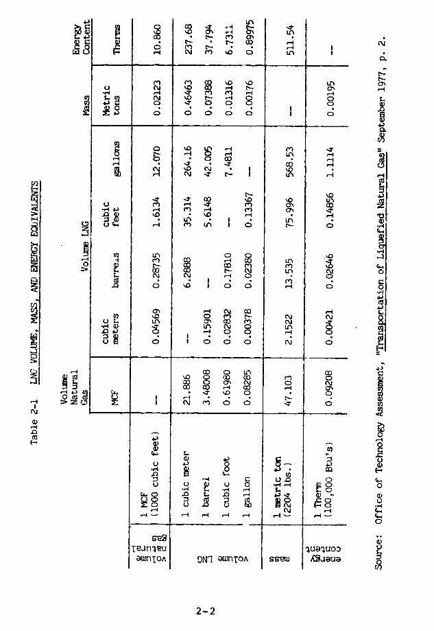
N 0 A -4 0 - L A
.m~~ .d~0.
m rn 'o Ln m
*,- , .' I ,- -.S LP- 4 -4 P - O
~~~~~~~~~~US r O t O O Ol °,H
0 c-.
~ , ddodo n~~S o
4 4 CO ' ' r0 o L * I , L * U)
rl O : e n a~ LOn 04 G8O I O 0 0
> X $ o O4 .c ·LO L L) _ a 0D nL '.0D -i (~1~- -. 4 ,- o.8
. .o I * C~.,-0I 0- 0o 0
asX~~~~~~~o :o
0' N C£ 0 O -- C0 0 r-4~~~~
C\DC
C 0
u E 8 04 0
8 3p 2 a 0 .u
2-2

and atmospheric pressure so it can be transported easily.
Propane liquefies at -44 F; butane, at 31 F. Methane
cannot be liquefied by pressure at ;emperatures above
-116°F.
LPG vapor is heavier than air. Any spill or leak
will collect on the ground or wate.r and form a derse,
spreading cloud which is explosive. The flammable ange in
an LPG vapor cloud is between 2 and 9 percent. very cold
natural gas is also heavier than air and forms a low,
spreading cloud. When the natural gas content of the cloud
is between 5 and 14 percent, the mixture is flammable.
Eventually both types of clouds will dissipate. Both LPG
and LNG clouds can explode in confined spaces. Table 2-2
gives the physical properties of LEG.
Naphtha is a generic term for various mixtures of
hydrocarbons extracted from crude oil in the refining
process. Its physical properties are not defined
precisely. Naphtha is denser than LNG and LPG, and its
vapor is heavier 1than air. The boiling point of naphtha
ranges from 1000 to 5000°F. This means that, when exposed
to the atmosphere, it evaporates slowly-at about the rate
of water on a dry day. Naphtha is between kerosene and
gasoline in volatility.
LNG has been used for several years in this country
to supplement natural gas supplies. During the summer,
when demand is lo,., utilities liquefy and store gas in
specially designed tanks. When the weather is cold and
demand is high, the LNG is regasified and pumped through
gas mains to consumers. More than 100 of these
"peakshaving" plants are operating throughout the United
States, including 45 that hold at least 23,000 cubic
meters.
2-3
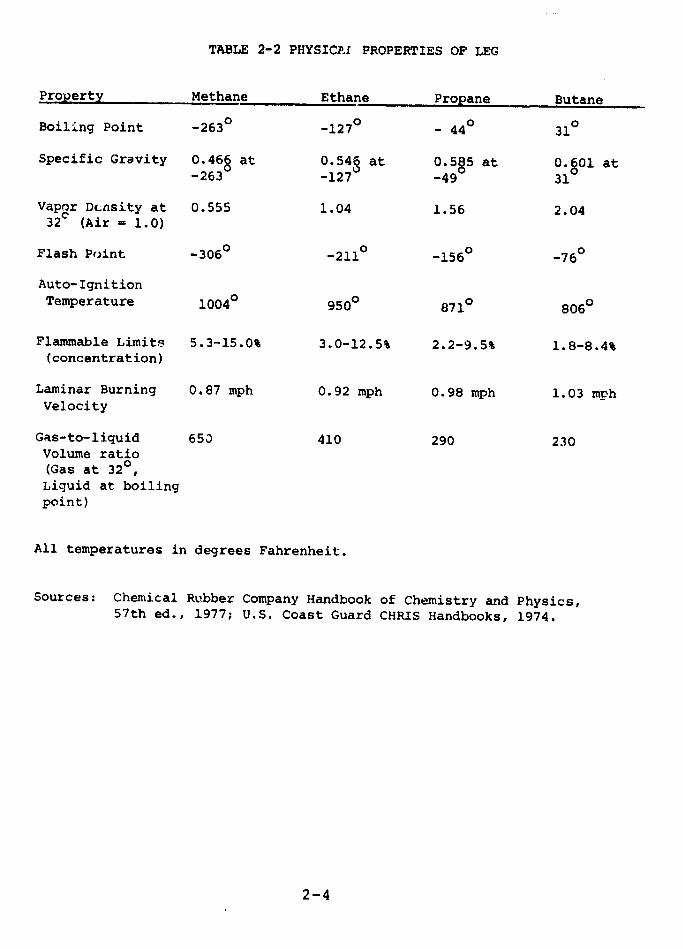
TABLE 2-2 PHYSICP.A PROPERTIES OF LEG
Property Methane Ethane Propane Butane
Boiling Point -2630 -1270 - 440 310
Specific Gravity 0.466 at 0.54' at .585 at 0.501 at-2630 -127 -49 31
Vapor DLnsity at 0.555 1.04 1.56 2.0432C (Air - 1.0)
Flash Point -3060 -211 ° -1560 -760
Auto-Ignition
Temperature 10040 9500 8710 8060
Flammable Limits 5.3-15.0% 3.0-12.5% 2.2-9.5% 1.8-8.4%(concentration)
Laminar Burning 0.87 mph 0.92 mph 0.98 mph 1.03 mphVelocity
Gas-to-liquid 653 410 290 230Volume ratio(Gas at 32°,Liquid at boiling
point)
All temperatures in degrees Fahrenheit.
Sources: Chemical Rubber Company Handbook of Chemistry and Physics,57th ed., 1977; U.S. Coast Guard CHRIS Handbooks, 1974.
2-4
Propane is also used to supplement natural gas
supplies. Since propane gas is heavier in molecular weight
and has up to three times the energy density of natural
gas, it is diluted with air or converted into synthetic
natural gas (SNG) before being added to the gas stream.
There are more than 450 domestic propane/air plants for
standby and full-time use,2 and five SNG plants use propane
as a feedstock component. A new method injects liqui I LPG
directly into a passing gas stream.
Some 13 million customers used LPG in 1976. Most of
these customers are in rural areas, including approximately
1.4 m 4llion farms. Many factories also rely on propane as
a back-up fuel in case their natural gas supplies are
reduced.
LPG and naphtha are used as feedstocks for
petrochemicals. Naphtha is also used as jet fuel. Butane
is a feedstock for aviation fuel, high octane gasoline, and
synthetic rubber.
About 2 percent of the nation's energy is supplied by
LPG, primarily propane. (LEG and naphtha consumption data
are contained in Appendix II.) Over the years, a widespread
LPG storeqe and distribution network has developed in the
United States: 16 import terminals, 70,000 miles of
cross-country pipelines, 16,300 LPG rail tank cars in
service, and 25,000 LPG transport and delivery trucks. In
addition, more than 8,000 LPG storage and distribution
facilities are scattered throughout the country.
About 86 percent of the LPG in bulk storage is kept
under pressure in underground salt domes or mined caverns.
LPG is also stored at -44 F in large, steel, single-walled,
2-5
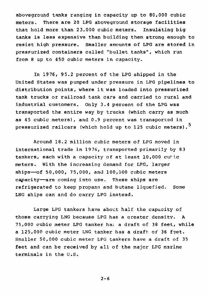
aboveground tanks ranging in capacity up to 80,000 cubic
meters. There are 20 LPG aboveground storage facilities
that hold more than 23,000 cubic meters. Insulating big
tanks is less expensive than building them strong enough to
resist high pressure. Smaller amounts of LPG are stored in
pressurized containers called "bullet tanks", which run
from 8 up to 450 cubic meters in capacity.
In 1976, 95.2 percent of the LPG shipped in the
United States was pumped under pressure in LPG pipelines to
distribution points, where it was loaded into pressurized
tank trucks or railroad tank cars and carried to rural and
industrial customers. Only 3.4 percent of the LPG was
transported the entire way by trucks (which carry as much
as 45 cubic meters), and 0.9 percent was transported in
pressurized railcars (which hold up to 125 cubic meters).5
Around 18.2 million cubic meters of LPG moved in
international trade in 1976, transported primarily by 83
tankers, each with a capacity of at least 10,000 curic
meters. With the increasing demand for LPG, larger
ships--of 50,000, 75,000, and 100,000 cubic meters
capacity-are coming into use. These ships are
refrigerated to keep propane and butane liquefied. Some
LNG ships can and do carry LPG instead.
Large LPG tankers have about half the capacity of
those carrying LNG because LPG has a qreater density. A
75,000 cubic meter LPG tanker hag a draft of 38 feet, while
a 125,000 cubic meter LNG tanker has a draft of 36 feet.
Smaller 50,000 cubic meter LPG tankers have a draft of 35
feet and can be received by all of the major LPG marine
terminals in the U.S.
2-6
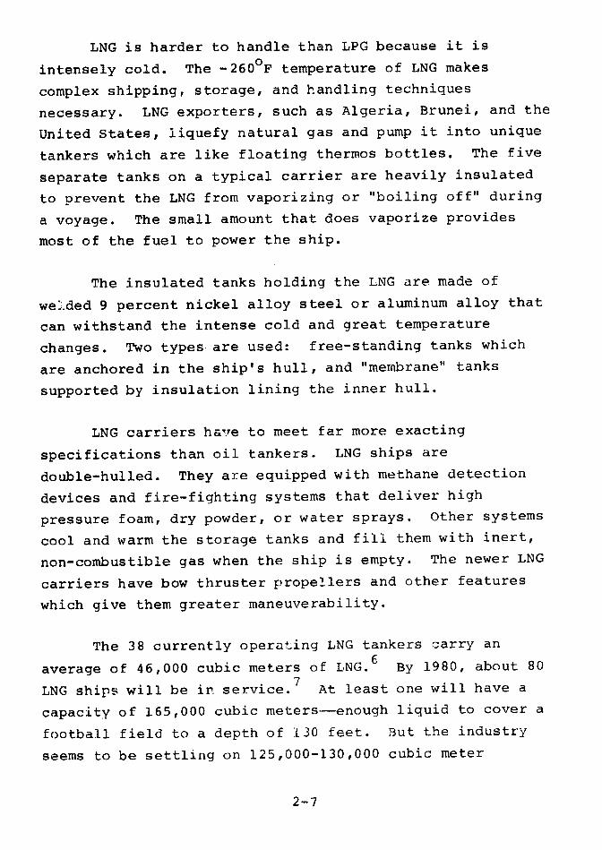
LNG is harder to handle than LPG because it is
intensely cold. The -2600F temperature of LNG makes
complex shipping, storage, and handling techniques
necessary. LNG exporters, such as Algeria, Brunei, and the
United States, liquefy natural gas and pump it into unique
tankers which are like floating thermos bottles. The five
separate tanks on a typical carrier are heavily insulated
to prevent the LNG from vaporizing or "boiling off" during
a voyage. The small amount that does vaporize provides
most of the fuel to power the ship.
The insulated tanks holding the LNG are made of
welded 9 percent nickel alloy steel or aluminum alloy that
can withstand the intense cold and great temperature
changes. Two types are used: free-standing tanks which
are anchored in the ship's hull, and "membrane" tanks
supported by insulation lining the inner hull.
LNG carriers have to meet far more exacting
specifications than oil tankers. LNG ships are
double-hulled. They are equipped with methane detection
devices and fire-fighting systems that deliver high
pressure foam, dry powder, or water sprays. Other systems
cool and warm the storage tanks and fill them with inert,
non-combustible gas when the ship is empty. The newer LNG
carriers have bow thruster propellers and other features
which give them greater maneuverability.
The 38 currently operating LNG tankers carry an
average of 46,000 cubic meters of LNG. 6 By 1980, about 80
LNG ships will be in service. 7 At least one will have a
capacity of 165,000 cubic meters--enough liquid to cover a
football field to a depth of 130 feet. But the industry
seems to be settling on 125,000-130,000 cubic meter
2-7

capacity vessels as a standard. Such tankers will be 1,000
feet long, 150 feet wide, and able to cruise at 20 knots.
When an LNG carrier reaches an import terminal, it
unloads in 10-15 hours at a rate of up to 190 cubic meters
a minute. Jointed marine loading arms on the dock are
attached to the ship and the LNG is pumped into huge
storage tanks. The insulated piping is made of
cold-resistant (cryogenic) steel or aluminum alloy.
Emergency shutdown systems automatically cut off the LNG
flow in case of a mishap.
Major LNG terminals generally have more than one
storage tank. A typical tank has a capacity of 95,000
cubic meters of LNG. Such a tank is 140 feet high and 190
feet in diameter. Its inner walls are made of cryogenic 9
percent nickel alloy steel, aluminum alloy, or pre-stressed
concrete. Surrounding this inner tank is about 3 feet of
perlite, a non-flammable insulating material. The tank's
outer wall is usually built of non-cryogenic carbon steel.
Inside the tank's dome is an insulated, suspended ceiling.
LNG storage tanks in this country are built
aboveground, and most are enclosed by earthen dikes. The
volume of the diked area is usually equal to the volume of
the fluid in the largest tank enclosed by the dike. The
Japanese, however, are constructing many new LNG storage
tanks in the ground. The cryogenic inner liner is
surrounded by thick insulation and a concrete outer shell.
Many Japanese engineers say that such below-ground tanks
are intrinsically safer.
The 14 major LNG import terminals now operating
throughout the world are "base load" facilities in which
2-8
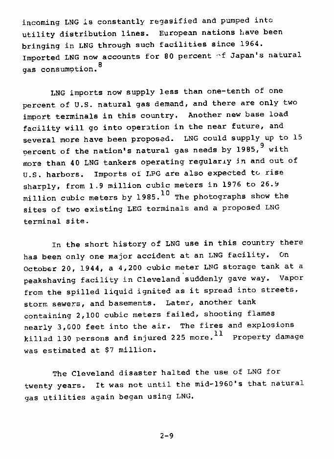
incoming LNG is constantly regasified and pumped into
utility distribution lines. European nations have been
bringing in LNG through such facilities since 1964.
Imported LNG now accounts for 80 percent -f Japan's natural
gas consumption.8
LNG imports now supply less than one-tenth of one
percent of U.S. natural gas demand, and there are only two
import terminals in this country. Another new base load
facility will go into operation in the near future, and
several more have been proposed. LNG could supply up to 15
percent of the nation's natural gas needs by 1985,9 with
more than 40 LNG tankers operating regularly in and out of
U.S. harbors. Imports of LPG are also expected to rise
sharply, from 1.9 million cubic meters in 1976 to 26.9
million cubic meters by 1985.1 0 The photographs show the
sites of two existing LEG terminals and a proposed LNG
terminal site.
In the short history of LNG use in this country there
has been only one major accident at an LNG facility. On
October 20, 1944, a 4,200 cubic meter LNG storage tank at a
peakshaving facility in Cleveland suddenly gave way. Vapor
from the spilled liquid ignited as it spread into streets.
storm sewers, and basements. Later, another tank
containing 2,100 cubic meters failed, shooting flames
nearly 3,000 feet into the air. The fires and explosions
killed 130 persons and injured 225 more.1 1 Property damage
was estimated at $7 million.
The Cleveland disaster halted the use of LNG for
twenty years. It was not until the mid-1960's that natural
gas utilities again began using LNG.
2-9
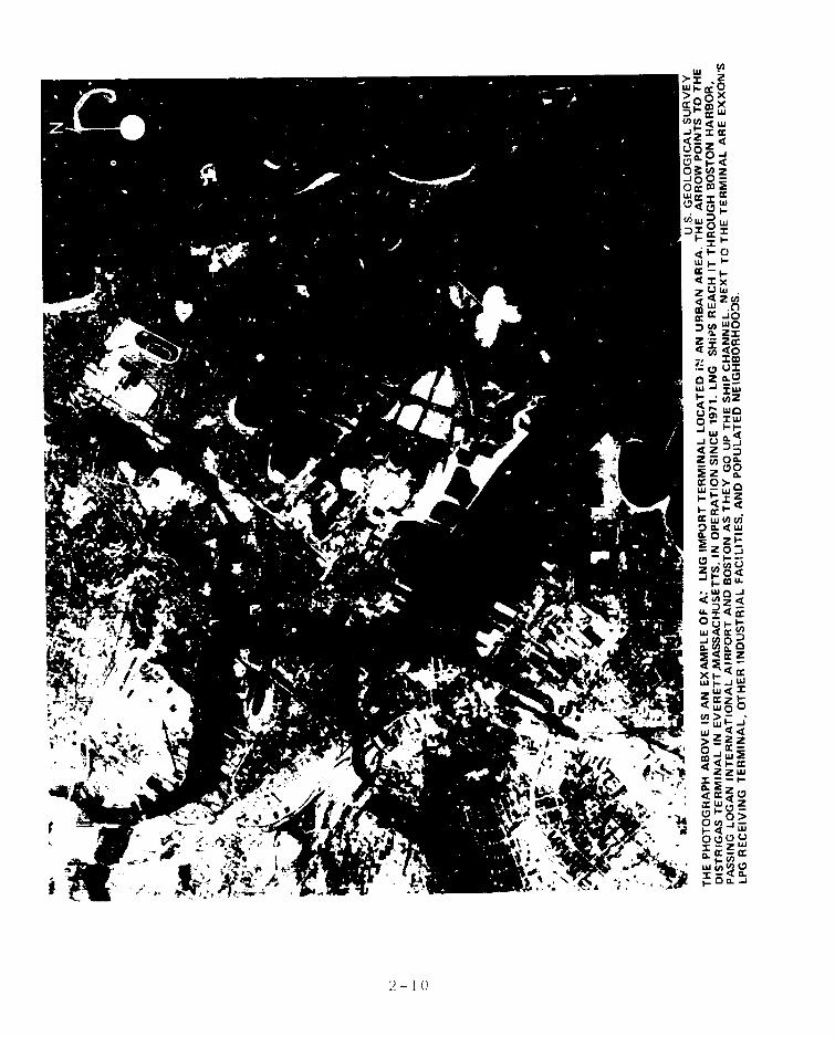
wn
> oxcr0 xx
w~~
00
OMW2
(/Lf CC w
Icr
OrrOW
wcr
<<ZcnL 0
L~CC Jo
CA Wcr-1x
4cn 4
sw E
0m2
-. ~~~~~~~~~~~~~~~~~~~~~4 zo4
0 20.W
Ez .
CCC
:r,~~~~~~~~~~~~~~~~ CL < LCL 0z P
zo
1-~cnZ
i0 4U.0 -
4i-cr
- 4,~'Y
6I~~ ~ ~~~~~~~~~~~~~~~ -· I (
'Y ct. · Q~~~~~~~~~~~~~~~~~- LUb
,t- 3= ~ ~ ~ ~ C·~~~tf~~;· 9 z~~~Fce~Z M
I ~~~ZZZ
i';Z 4rr~~~~~~~~~~~~~~
t -k oot 00
z W
,I'Ir Ix: n -II - · · V )~~~2: C~~ ulv,~~
ui cn0I ... I~~~~~~~~~~~~~~~~~~~
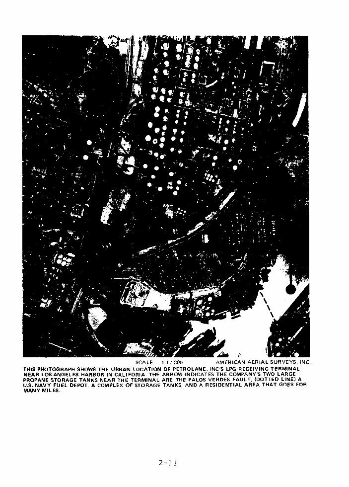
ii ...
Asl;
SCALE 1:12,000 AMERICAN AERIAL SURVEYS, INC.THIS PHOTOGRAPH SHOWS THE URBAN LOCATION OF PETROLANE, INC'S LPG RECEIVING TERMINALNEAR LOS ANGELES HARBOR IN CALIFORIA. THE ARROW INDICATES THE COMPANY'S TWO LARGEPROPANE STORAGE TANKS NEAR THE TERMINAL ARE THE PALOS VERDES FAULT, (DOTTED LINE) AU.S. NAVY FUEL DEPOT. A COMPLEX OF STORAGE TANKS, AND A RESIDENTIAL AREA THAT GOES FORMANY MILES.
2-1. 1

SCALE 1: 80,000 MARK HURD AERIAL SURVEYS. INC.
POINT CONCEPTION, CALIFORNIA, SHOWN IN THE PHOTOGRAPH ABOVE, IS AN EXAMPLE OF A PROPOSED
LNG IMPORT TERMINAL SITE WHICH HAS A VERY LOW POPULATION DENSITY FOR MANY MILES AROUND
IT. THE PROJECT IS A PROPOSAL OF WESTERN LNG TERMINAL ASSOCIATES, INC.
2-12
The first U.S. LNG import terminal began operations
at Everett, Mass., in 1971. In 1973 the Federal Power
Commission asserted jurisdiction over the Everett facility
and any new LNG import terminals. Although FPC has been
disbanded, its functions have been assumed by the Federal
Energy Regulatory Commission (FERC) and other parts of the
Department of Energy (DOE). The U.-. Coast Guard and the
Office of Pipeline Safety Operations (OPSO), both in the
Department of Transportation (DOT), also have regulatory
responsibilities for LNG import terminals.
LNG peakshavinc plants involved in interstate
commerce come under the jurisdiction of both DOE and OPSO.
OPSO also regulates LPG and naphtha pipeline facilities in
interstate commerce.
LEG trucks and railcars under Federal jurisdiction
are regulated by a number of agencies within DOT. The
Interstate Commerce Commission (ICC) is also involved,
since only it can revoke or suspend the certificates of
interstate motor carriers found to be unsafe.
The U.S. Coast Guard has been given broad authority
to regulate all aspects of LEG shipping, including the
design and construction of vessels, the training of crew
members, the movement of vessels in U.S. ports and
waterways, and harbor security.
Throughout the report liquid volumes are given in
cubic meters, in order to make it easier to compare the
volumes held or carried in various storage and
transportation systems. All temperatures are given in
degrees Fahrenheit (F).
2-13
REFERENCES
1. "Scorecard," Pipeline and Gas Journal, November,1977.
2. Solomon and Scherb, Chapter 5 (Draft), CaliforniaEnergy Resources Conservation and DevelopmentBiennial Report, November 30, 1976, p. 36.
3. See Chapter 14.
4. American Petroleum Institute, "API Monthly ReportCovering Inventories of LP-Gas and LR-Gas as ofSeptember 30, 1977," October 25, 1977.
5. National LP-Gas Association, "1976 LP-Gas MarketFacts," p. 7.
6. E. Drake and R. Reid, "The Importation of LiquefiedNatural Gas", Scientific American, April, 1977, p.24.
7. Office of Technology Assessment, "Transportationof Liquefied Natural Gas," September 1977, p. 12.
8. Drake and Reid, p. 22.
9. Office of Technology Assessment, p. 5.
10. See Chapter 14.
11. Coroner's Report on East Ohio Gas Company Disaster,Cuyahoga County, Cleveland, Ohio, July 1945.
2-14

CHAPTER 3
VULNERABILITY OF STORAGE TANKS AND CONTAINMENT
DIKES TO NATURAL FORCES
CONTENTS PAGE
3-1INTRODUCTION
SITE LOCATION AND DESCRIPTION 3-1
EARTHQTrAKES AND TORNADOES 3-11
Earthquakes 3-12
3-16Tornadoes
Design Evaluation of Tanks
3-25Seismic Design
Steel Tanks Containing StoredLiquid 3-26
Steel Outer Tanks 3-27
Concrete Tanks Containing Stored Liquid 3-28
Concrete High Dikes 3-28
Earthen Dikes 3-28
Tornado Design 3-29
UBC Earthquake and 100-Year Wind 3-30
Nuclear Standards: Safe Shutdown Earthquakeand Tornado 3-30
LIQUEFACTION 3-31
FLOODING AND TSUNAMI 3-31.
Evaluation 3-32
CONTENTS PAGE
3-37FINDINGS
3-40CONCLUSION
3-41REFERENCES

INTRODUCTION
The first part of this chapter evaluates the ability
of selected LEG storage facilities to withstand earthquakes
and tornadoes. The conclusions reached should be generally
applicable to U.S. LEG storage facilities, since most
designers use the same codes and standards and employ
similar analytical methods and design assumptions.
The second part of the chapter evaluates the effects
of flooding and the pot .tial for foundution failure from
ground liquefaction in eartnquakes. These phenomena tend
to be highly site dependent and site specific.
SITE LOCATION AND DESCRIPTION
The specific storage facilities evaluated are
described in Table 3-1. We consider them representative of
the types of storage facilities currently in use or planned
in the United States:
Insulated Storage tanks and Containment
Double-Wall Steel LNG Tank - Figure 3-1.
Prestressed Concrete LNG ,k - Figure 3-2.
Prestressed Concrete High Dike - Figure 3-3.
Single-Wall Steel Propane Tank - Figu.e 3-4.
Pressure Storage Tanks
Vertical Steel Propane Tank - Figure 3-5.
3-1
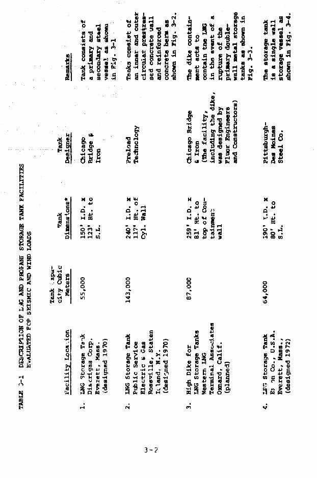
0 0 .. - 8" -P a r 13' 4 a
w 0 MI . 4 ~ 8 . 4:
0 h0 0 0
o o
o~
4-l ~ .n 4o4) w
"4 "' U" o-, 5?4S4
' , . , .a14 I -. o0 - -P4 1°3
0 -.4 -r.4 s 0 o4 0 u o .
p, | S hI OE4 O O
o o o o
w 4j 0 v 0 t o
D~~ -
d 3 Q s a-iOt ·oU SO 0 0 3 d
14 o Z
ald w >) rl 4 1O
4-4 C-I t-4 C-1 P4 (I _- la I L I W - 4 > w t
I , ' 4u 0 ,4 r-I -" Z 0 J: E Id -
.% Cl W =-M % P 1 4 P;W H P -4 W
3 - 2
'0 00 3 '
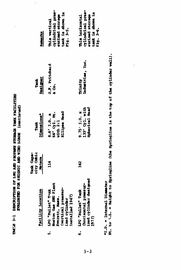
I ii.IIIs~
"4
U S X , 4J
04~~~~~~~~~~~~4
'I P a'
ii"- P1 1 -
*0 '0 'I -CI 9n- n3
ii~~ ~ .4l
I · J'·1'UT
4J b P -. o
9 ~~~~~~~~~~~~~~~~~~~~~~E 1~~~~~~~~~~~~~~~~~~~~~~!~~~~~~A., <
3-3
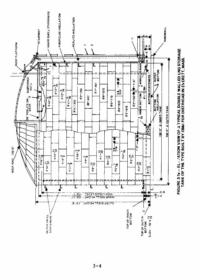
Li Z
LL
s~~~~~~~~~~~-i J t :
-1
I r , 7 I-
Lu ~ ~ ~ ~ ~ ~ ~ ~ ~ ~ ~ ~~~~~~~~h~
E O ZW
W W cc c
X z
IL3 I
1w I~~~~~~~~~~~~~~~~~~~-j In
I z u N \I I I1.IP~~~~~~~~~~~~z I J
o.~ ~ ~ o
- 0~~~~~~~~~~~~~~~~~~ jL
0 -
In-
3-45 0 -iZu 4~- i 30c(C Wu v W
=a z M a W z~ n
a.~~~~~~~~~~~~~~~~~~~~~~a
# > tj~~0
r''N ~ ~ rl
I~~~~~~~~~~~~
0,
" 1~~~~~~~~~~~~~~~~~U
L L L O m u, It t~~~~~L61i133aiD-1H1H9 1.
o a tt a 11 g~~~~~~~~~~~~~~~~zo CC m
e __ o~~~~~~~~~
.1L1611- ~3A~ 0ln~l~ HDI '~L;1 s0 >G.0Co
.. L.E L III~3- 4 UNN
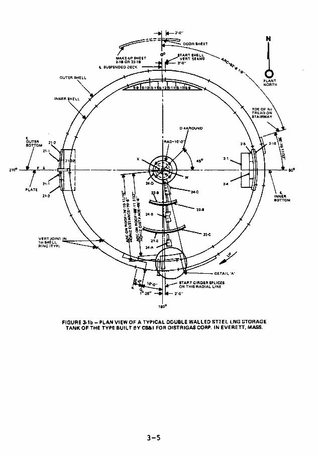
DOOR SHET
MAKEUP SHEET VERT SEA
" SUSPENDED DECK
OUTER SHELLPLANTNORTH
INNER SHELL
TOE OF TREAO ON/TAIRWAY
OUTER 212 1/A-10'4' 2BOTTOM 2
3 _X 4 5 2 .1
PLATE
21-2 - ee VE OF INNER
1st SHELLRING (TYPI.
~ J -- -DETAIL 'A'
~'~"-~./i t I00., . STAP.T GIRDER SPLICESON THIS RADIAL LINE
FIGURE 3-lb - PLAN VIEW OF A TYPICAL DOUBLE WALLED STEEL LNG STORAGE
TANK OF THE TYPE BUILT SY CB&I FOR DISTRIGAS CORP. IN EVERETT, MASS.
3-5

0
La~ ~ ~ 0C
Ii 2
0 w~-
o 0
o La~~~~~~~~~~~~~~~~~~~~~~~
z 0~~~~~
0~~~~~~~~~~~~~6 4 EE La 0 2~~~~~~~~~~~&
04 J W lu
ED 4 C
-Ed C9O~~ ~~~~ ~~ ~~~~~~~~~~ CCW ~ 4
3~~uPu =I I~~II I\Y 078 8
z Z
0~~~~~~~~~
Li 8~~~~~~~~~~~~~~~~~~~~~
OF-~~~~~~~~~O~
P~~~~~~~~~~~~~~~~~~~~~~~~~~~ wW
0 a
JJ
c '2~~~~~~~~~~~~~~~
LU.
3-6~~~~~~~~~~~~-
r 006 z I~~~~~SWz
a -~~~~~a · · ~~~~~~~a i"oilzSua L O LL P b~~~~~~~I I-../c-
r J X1 tew~~~UVHSN j Y I--I~~~~~~~~~~~~~~~~~~~~~~~~ Ip~~~~c
D
LY~~~~~~~~~~~~~~~~~~~L
3-6g
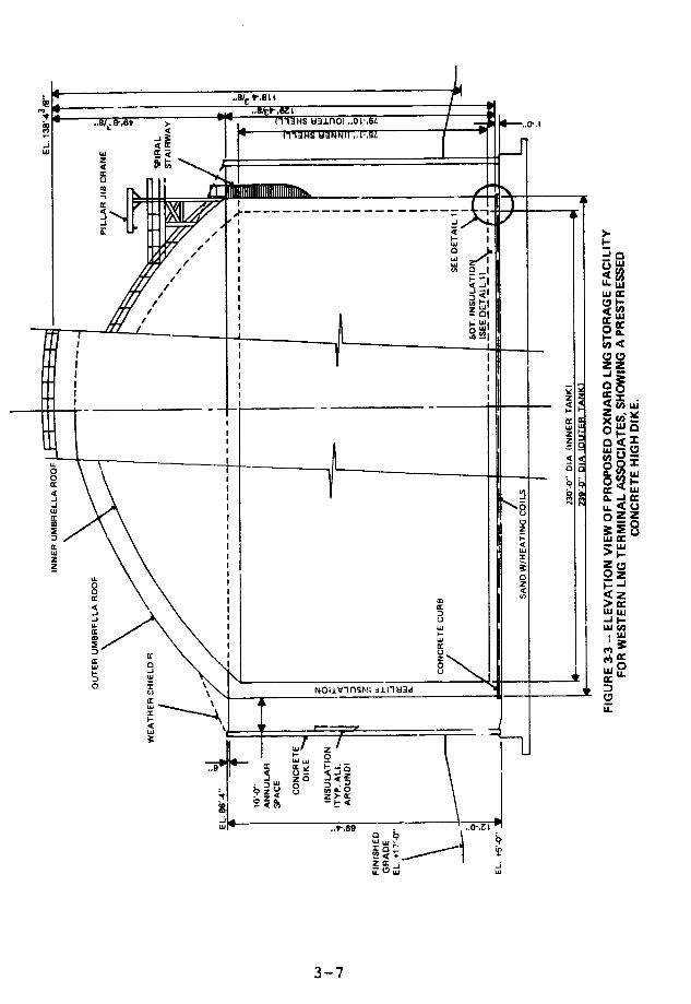
.sr- .,~ .1> (113HS 53156) .. OI'.B.GL.
-J ~~~~~~3HS Wi3NNIO VOL S
-j
z
C~~~~~~~~~~~~~~ki~~~~~~~~~~~~~~~~~~~~~~~~~~~~~~~~3u
UJI~~~~~~I
'Y I - I-
I _ _ _ _ _ _ _ _ _ _ _ _ _4 4
)
CiCD
z 4
oo~~~~~~~~~~
C~~~~~~ *. u w
-j - A.II -
w~~~~~~~~~~~~~~~~~~~~~ w
a. 4 ~~~~~~~~~~~~~~~~~~~~~~~~~~~~~~~ -.
zc,z
~cui
4z
C~~~~~~~~~C
w w ~~~~~~~~~~~~~~~~~~~~.Jwuw~~~~~~~~~~~~~~~~
C CL
0 I 0~~~~~~~~~~~~~~
W J
C ~~ ~~~~~~~~~~~~~~DUCu
cr~~
C.)~~~~~~~~~~~L
~~~~~~~~LI Y~~~~~~~~~~~~~~~~~~~~~~~~L
0 N~avinsp!: ji lwa
.4~~~~~~~~~~~~~~~~~~~~~~~U
t: w~~~
w~~~ ..-,9r~~~~~~~~~~ 1uf -7r
z >>L
g~~~~~
w L, ~ ~ ~r P~~~~~~~~~~~~~' :
o NOIIV~~~~~~~~~nS~~~~Z j J~3
3-7~~~~~~~~~~~~~(
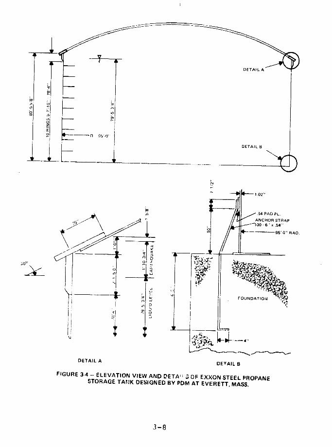
0 ~~~~~~~~~~~~~~~DETAIL B
-N
'"' '- 0 1,02"
.54 PAD PL
-1~~~~~~~~ ~ANCHOR STRAP
00 -6" x .54"
DETAIL A
FIGURE 3-4- ELEVATION VIEW AND DETA; : a OF EXXON STEEL PROPANESTORAGE TANK DESIGNED BY PDM AT EVERETT, MASS.

3"
2:1 ELLIPSE
TANK & SKIRTASTM A2.2 GR B
103"
lA ,2:1 ELLIPSE1"
2:1 ELLIP S E 8'-1 2 ANCHOR BOLTS
FIGURE 3-5 - ELEVAl ION VIEW OF BOSTON GAS COMPANY STEEL VERTICALPRESSURIZED PROPANE "BULLET" TANK AT EVERETT, MASS.
MANUFACTURED BY J. F. PRITCHARD & CO.
3-9
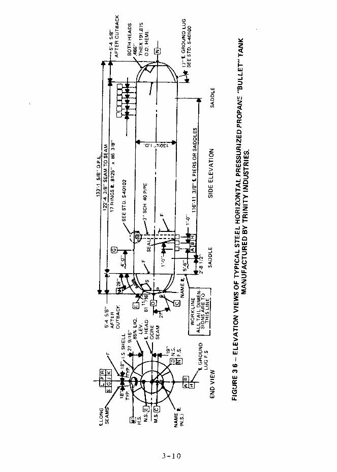
v< W m Dc a fn -j
00 N9zwD ~~~0-T u :5 I
*I I: Xf ~LO L- W L a:d
4 L En~~~~I
-J-i
w-J
.4>
uj V)~~~~~~~~U
w 0~
-w U
-J wo ~N
op
~~~~~ ~~~~~~~L
0 w0:
U) z
00 -16 , . I f .4 U l
Fco~ cI < W
0 -
- ILi
v U < L
-i u) m O XI
Z'IL
0 LL
I~~~~~~~~~L LUP
z ui -
(9~~~v
0 < Ln) viLL
w w Pw
-j LU~~~ L
z C3 I 0 w
3-10u
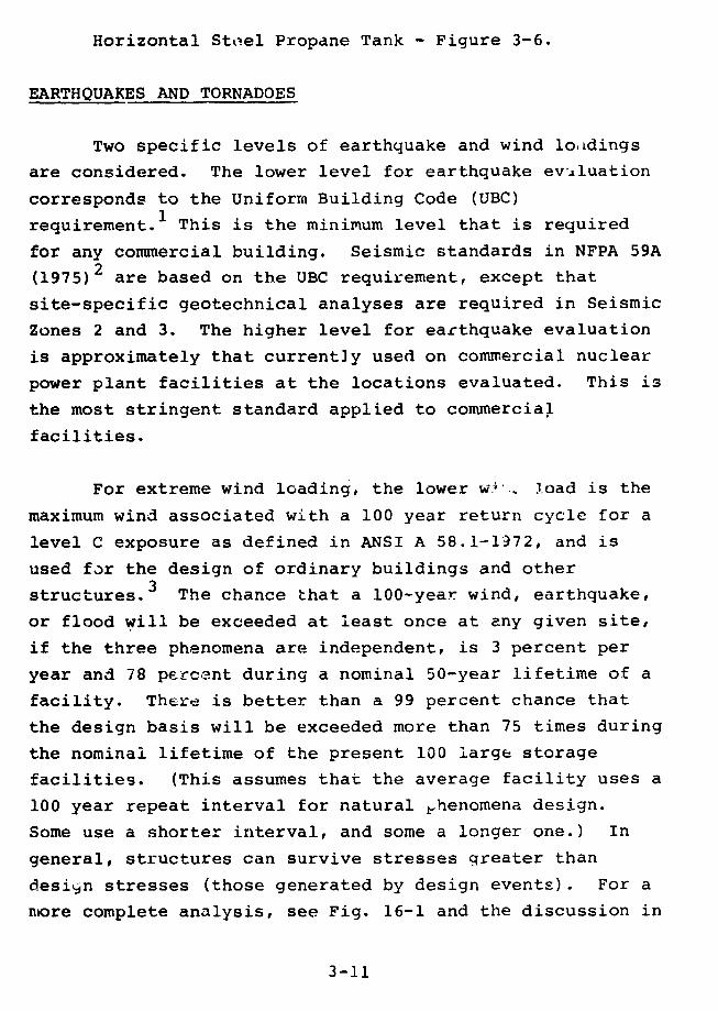
Horizontal Steel Propane Tank - Figure 3-6.
EARTHQUAKES AND TORNADOES
Two specific levels of earthquake and wind loadings
are considered. The lower level for earthquake evaluation
corresponds to the Uniform Building Code (UBC)
requirement.l This is the minimum level that is required
for any commercial building. Seismic standards in NFPA 59A
(1975)2 are based on the UBC requirement, except that
site-specific geotechnical analyses are required in Seismic
Zones 2 and 3. The higher level for earthquake evaluation
is approximately that currently used on commercial nuclear
power plant facilities at the locations evaluated. This is
the most stringent standard applied to commercial
facilities.
For extreme wind loading, the lower wi., load is the
maximum wind associated with a 100 year return cycle for a
level C exposure as defined in ANSI A 58.1-1972, and is
used for the design of ordinary buildings and other
structures.3 The chance that a 100-year wind, earthquake,
or flood will be exceeded at least once at any given site,
if the three phenomena are independent, is 3 percent per
year and 78 percent during a nominal 50-year lifetime of a
facility. There is better than a 99 percent chance that
the design basis will be exceeded more than 75 times during
the nominal lifetime of the present 100 large storage
facilities. (This assumes that the average facility uses a
100 year repeat interval for natural Phenomena design.
Some use a shorter interval, and some a longer one.) In
general, structures can survive stresses greater than
design stresses (those generated by design events). For a
more complete analysis, see Fig. 16-1 and the discussion in
3-11
Chapter 16 of requirements for resistance to natural
phenomena (special issue 5).
The higher wind loading, that associated with nuclear
power plant design, is a tornado so large that there is
only one chance in 10 million that one at least that large
would hit the site in a given year.4
Earthquakes
While earthquakes can be caused by volcanic action,
water inclusion (such as pumping water into deep wells),
and major changes in loading (such as filling a dam with
water), the cause of most damaging earthquakes is believed
to be tectonic in origin (e.g., as the result of fault
movement). Modern seismology views earth's cr:'lst as a
series of large plates which are in motion relative to each
other and the semi-liquid magma underneath. There are
seismically active zones along the U.S. West Coas:.
Although most damaging earthquakles originate at plate
boundaries, about 5 percent of all earthquakes have
occurred in regions located within plates where there had
been little known seismic activity or active faulting.
Within the past 250 years, at least five major earthquakes
in the United States have followed this pattern-Boston
(Cape Ann), Massachusetts in 1755; New Madrid, Missouri, 3
earthquakes within a six month period in 1811 and 1812; and
Charleston, South Carolina in 1876. The New Madrid and
Charleston earthquakes were of major magnitude, causing
either significant epicentral* damage or changes in
*The epicenter is the part of the earth's surface directly above theorigin of the earthquake.
3-12
topography. Each was felt over an area of 2,000,000 square
miles. West Coast earthquakes caused by fault movement,
even those which do considerable local damage, are seldom
felt over an area of more than a few thousand square miles.
Seismologists and geologists have generally not been
able to identity tectonic structures which cause the
earthquakes east of the Rocky Mountains. It is the
existence of this unexpected and usually unexplained 5
percent which has prompted regulating authorities,
industrial standards, and prudent owners to insist upon
earthquake or seismic design requirements being
incorporated into hazardous facilities design regardless of
the recorded seismic history of the site.
The earthquake design criteria we used in evaluating
storage facilities were in accordance with the UBC
requirements and the U.S. Nuclear Regulatory Guide 1.60,
Horizontal Response Spectrum5 as shown in Fig. 3-7 for 5.0
percent critical damping for steel and 7.0 percent for
concrete. The zero period surface accelerations (the
acceleration of a particle rigidly attached to the ground)
assumed in the evaluation as a function of geographic
location, are shown in Fig. 3-8, which is a modification of
the current zone map which appears in the UBC.1
' - maximum seismic acceleration which nuclear power
plant -re designed to withstand is known as the Safe
Shutdown Earthquake (SSE). At the 6 sites examined in this
chapter, the chance that there will be an earthquake at
least as large as an SSE in a given year varies from one in
10,000 to one in 10 million.6
3-13
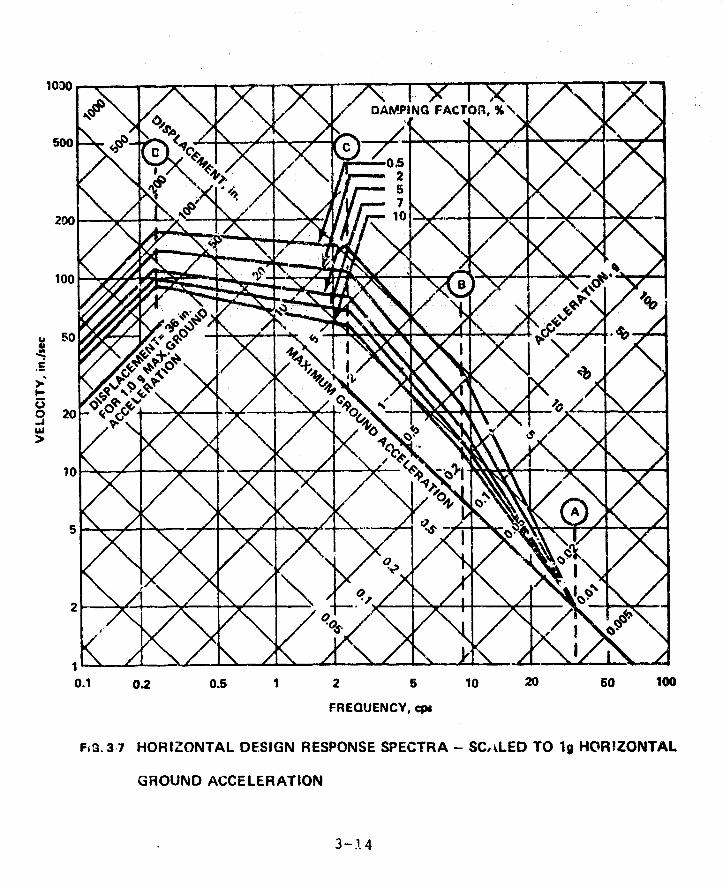
1030
DAMPING FACTOil, % N
500 i 7
2002 0.5 1 2 10 20 50 100
03--4
0.1 0.2 0.5 1 2 5 10 20 50 100
FREOUENCY, cps
F=G. 37 HORIZONTAL DESIGN RESPONSE SPECTRA - SC,%LED TO 1g HORIZONTAL
GROUND ACCELERATION
3-1.4
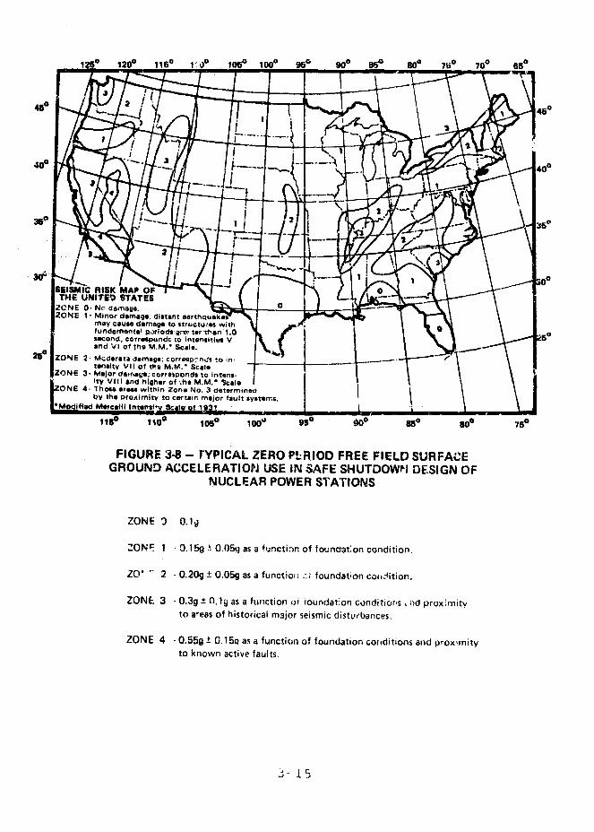
120 1200 1160 ° a )O 10e 9, go 900 W 750 700 650
400
ZONE 1- Minor damage; distant a
tandi V1 of thie M M. Scale
2 ZONE 2- Nr data ge. corre" _-t o in
tnsitv Vll of tiut M. 1im. sc Ia
ZONE 3. Major da lpa&-*; corrrtponds to intent-itV Vlli and higher of ;ho M.M.* SC:,e-
NE 4- Those arqr within Zone No. 3 determined
GROUND ACCELERATION USE IN SAFE SHUTDOWN DESIGN OFNUCLEAR POWER STATIONS
ZONE ' 0.1q
ZONF 1 - .15g ± 0.051 as a functi. of founat:on condition.
ZO' - 2 -0.209 + O.05g as a functioo -.; foundation cotrdition.
ZONE 3 -0.39 .l19 as a function oi ioundat'on conditiorns nd prox'mityto areas of historical major seismic disturbances.
ZONE 4 -O.55 +± 0.15a as a function of foundation conditions and proximityto known active faults.
i-- i5

Tornadoes
Nuclear power plants are designed tc withstand thewind pressi :e and differential pressure drop from a "dasigntornado." The design tornado is chosen so that a nuclearpower plant at a particular site will have only one chancein 10 million of being hit by a tornado at least that largein any given year. 4 To simplify design, the United Statesis divided into three regions as shown in Fig. 3-98, InRegion I the design wind speed is 360 MPH. In Regions 2and 3 the design wind speed is 300 and 240 MPH,respectively. Differential negative pressure design variesfromn 3.0 psi at 360 MPH to 1.5 psi at 240 MPH.
Design Evaluation of Tar.kz
Design calculations, specifications, and drawingsassociated with the facilities described in Table 3-1 wereobtained directly from owners or designers. We did notevaluate their numerical-accuracy, but only theapplicability of the calculations to current methods ofanalysis and to the design assumptions used for nuclearpower plants.
The results in Tables 3-2, 3-3, and 3-4 are basedupon stress levels. The "design load stress" in astructure is the stress produced by the force (i.e., normalload, earthquiake, wind) which a building code requires astructure to withstand. The code also specifies the"allowable stress." The ratio of the allowable stress tothe corresponding design load stress is called the "safetyfactor". A safety factor greater than one indicates that astructure is stronger than required by a partictlar code.If the safety factor is less than one, then the structure
3-16
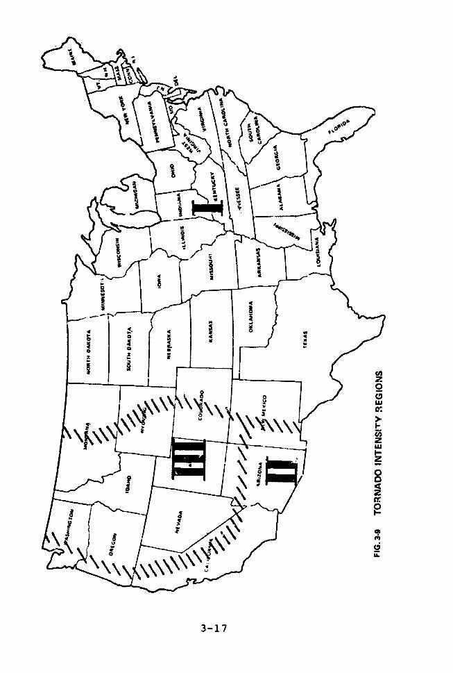
r*~~~~~~~~~~~~~~d
$ · ~~~~~~~~~~~~7
*% 't~~~~~~~~
~~~~ B~~~~
~~~~ a 8:~~~~~ -""~~L
o\\' cr'a Tr t~~~~~
P r 1~~~~~~~~~~~~r
5 1 I a~~~~1

TABLE 3-2 STEEL TANK SEISMIC DESIGN PARAMETERS, FAILURE MODES, AN) SA'ETY V'ACTORS
NUCLEAR PLANT MOMENT OF
FACILITY )ESCRIPTION ORIGINAL SEISMIC CRITEFIA SEISMIC CRITERIA LIMITING FAILURE MODE FACTOR or SAFETY
(10 K-ft.) All. Stress in Tie Down Straps or Bolts Design Load Stress in Tie Down Straps or Bolts
Nuclear NuclearNuclear UBC Criteria UP' Criteria
UBC Critfria Kip/Sq. in. (Ksi) Kip/Sq. in. (Ksi)
1 LNG Marine Terminal for | S, m3
UBC Zone 2 0.05g static load 0.20g Safe Shtown 25 241 Material: 1.2 f (2)-36.0 Ksi 23.8 Ksi 153.9 Ksi3 )
Distrigas Corporation 150 ft. dia. x 123 ft in accordance with TID 7024 Earthquake ero Period ASTM TP 30 9 .S. = 1s
Everett, Massachusetts ht. to Springline chapter 6 f(Rigid Tank) Ground Acce'.eration fa -22 .5 Ksi
Designed - 1970 (Inner Tank) method of analysis. 5.0% Damping for Reg. f 75.0 KsiGuide 1.60 Response fy -75.0 Ksi (1)
Spectrum. 1.33 x 22.5 - 29.9 Ksi
2 LPG Marine Terminal fo. 64,0i00 m3 Same as 1. above Same as 1. above 293 875 Material: .7 f (2) 49.0 Ks 25.1 Ksi64.3 Ksi(3 )
(4)
Exx on C.., U.S.A. 190 ft. dia. x 80 ft. ASTM A 537 B F.S. = 1.23 F.S. - 0.76
Everett, Mass. ht. to Springline fa - 50.0 Ksi
Designed - 1972 f 70.0 Ksi
l 1'33 * 23.3 - 31.0 Ksi
3. Vertical Pressurized | 114 m3 None specified but assL.med Same as 1. above. 0.463 5.14 Material: (AISC) 7 f ) = 87.5 Ksi Act. M = 463 K-ft. 1541 Ksi
LPG "Bullet" tanks fcr cylinder 66 ft. lonq for evaluation purpose: the ASTM A 193 Bolts u Lim. M = 3150 K-ft. F.S. = 0.57
Boston Gas SNG Plant with 2:1 elliptical same as 1. above, except f = 63.0 Ksi (7)
Everett, Mass. he=t closure supported sloshing neglected. f l15.0 Ksi P.S. - 6.8
Designed - 1947 on a 5 ft. high, 3/4 fY = 12.0 Xsiin. thick skirt 1.33 x 63.0 - 83.8 Ksi
anchored by 8 - 1-1/2"A 193 bolts.
(I1 (5)
4. Typical Horizontal 342 m3
None specified but assumed Same as 1. above. 0.32.10 5.55( Material: (ASMC See. .7 f (6.7 Ksi 18.6 Ksi
Pressurized LPG "Bullet" horizontal cylinder for evaluation purpose!, the ASTM SA 612 PL (VIII) u (6 )
Tanks Supported by Ivo rwith hemispherical same as 1. above, except f 20.2 KsS. - 1.42
Piers Designed by ends, 116 ft. between sloshing is neglected. fa = 50.0 K.si
Trinity Industries, 1977 support saddles. fY 81.0 KsiTotal length is E .Q. All.-20.2Ksi iv. 1133 ft. I.D. of E.Q. All.=27.IKsl Div. 2cylinder is 130 in.
(1) Allowable stress for both Earthqtake and Wind based on 1.33 times normal allowable in accordance with 2.06.5 of API 620 Sup, No. 3.(2) Based on Faulted Condition of Appendix F, ASME Section III Criteria for Crmaponent Supports.
(3) Note that this comparison is based on simple tensile strss calculation, neglecting shear carried by tie uown straps cr bolts. If two horizontal com-
ponents of motion are considered such that significant s' Iw and tension o cur simultaneously and the friction capacity between the tank bottom and
foundation are exceeded, tie dowl straps or bolts requiresu - carry seismi shear, all safety margins shown for nuclear criteria would be reduced by
at least a factor of 2.(4) Tie down straps assumed to carry both internal pressure uplift and seismic with thermal stress neglected.
(5) Limiting Failure mode for Tank 1, 2, and 3 base overtur. ;ng moment to be carried by anchor straps or bolts. For tank 4 limiting failure mode is bendingmoment plus pressure tensile strusses at center of span of tank. No saddle designs were evaluated.
,6! This Safety factor is based on ASiE Sec.-on VIII Div. 1 allowables; if Din 2 allowables are used, F.S. is increased as shown.(7) With UBC E.Q. Base Moment = 5.56 K-ft, -here is no up-lift on bolts. F.S. .s ratio of the base moment to moment required to overstress anchor bolts.
(8) F.S. = Safety Factor - Allowable Stress/resicn Loai Stress.
(9) fa = normal load al)owable stress
fy = yield stress
f - ultimate stressU
1.33 x fa = earthquake/wind load allowable stress
3-19
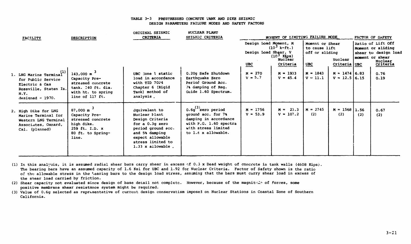
TABLE 3-3 PRESTRESSED CONCRETE TANK AND DIKE SEISMIC
DESIGN PARAMETERS FAILURE MODES AND SAFETY FACTORS
ORIGINAL SEISMIC NUCLEAR PLANT
FACILITY DESCRIPTION CRITERIA SEISMIC CRITERIA MW)IENT OF LIMITING FAILURE MODE FACTOR OF SAFETY
Design Load Moment, M Moment or Shear Ratio of Lift Off(103 k-ft.) to cause lift Moment or sliding
Design Load Shear, V off or sliding shear to design load
(10 Kp)Nuclear moment or shearNuclear nuclear Nuclear
UBC Criteria UBC Criteria UBC Criteria
1. LNG Marine Terminal 143,000 m 3 UBC 3one I static 0.20g Safe Shutdown M = 270 M - 1933 M = 1843 M = 1474 6.83 0.76for Public Service Capacity Pre- load in accordance Earthquake Zero V = 5.7 V = 45.4 V - 11.1 V = 12.5 6.15 0.19
Electric & Gas stressed concrete with TID 7024 Period Ground Acc.Rossville, Staten Is. tank. 240 ft. dia. Chapter 6 (Rigid 7% damping of Reg.N.Y. with ht. to spring Tank) method of Guide 1.60 Spectrum.desiqned - 1970. line of 117 ft. analysis.
3 (3)2. High Dike for LNG 87,000 m Equivalent to 0.6g zero period M = 1756 M = 23.3 M = 2745 M = 1568 1.56 0.67
Marine Terminal for Capacity Pre- Nuclear Plant ground acc. for 7% V = 53.9 V = 107.2 (2) (2) (2) (2)Western LNG Terminal stressed concrete Design Criteria damping in accordanceAssociates, Oxnard, high dike. for a 0.3g zero with P.G. 1.60 spectra
Cal. (planned) 259 ft. I.D. x period ground acc. with stress limited80 ft. to Spring- and 5% damping to 1.f x allowable.line. expect allowable
stress limited to1.33 x allowable .
(1) In this anall'sis, it is assumed radial shear bars carry shear in excess Ocf 0.3 x Dead weight of concrete in tank walls (4608 Kipsj.The bearing bars have an assumed capacity of 1.6 Ksi for UBC and 1.92 for Nuclear Criteria. Factor of Safety shown is the ratioof the allowable stress in the 'earing bars to the design load stress, assuming that the bars must carry shear load in excess ofthe shear load carried by friction.
(2) Shear capacity not evaluated since design of base detail not complete. However, because of the magnitr:n? of forces, somepositive membrane shear resistance system might be required.
(3) Value of 0.6g selected as representative of current design conservatism imposes on Nuclear Stations in Coastal Zone of SouthernCalifornia.
3-21
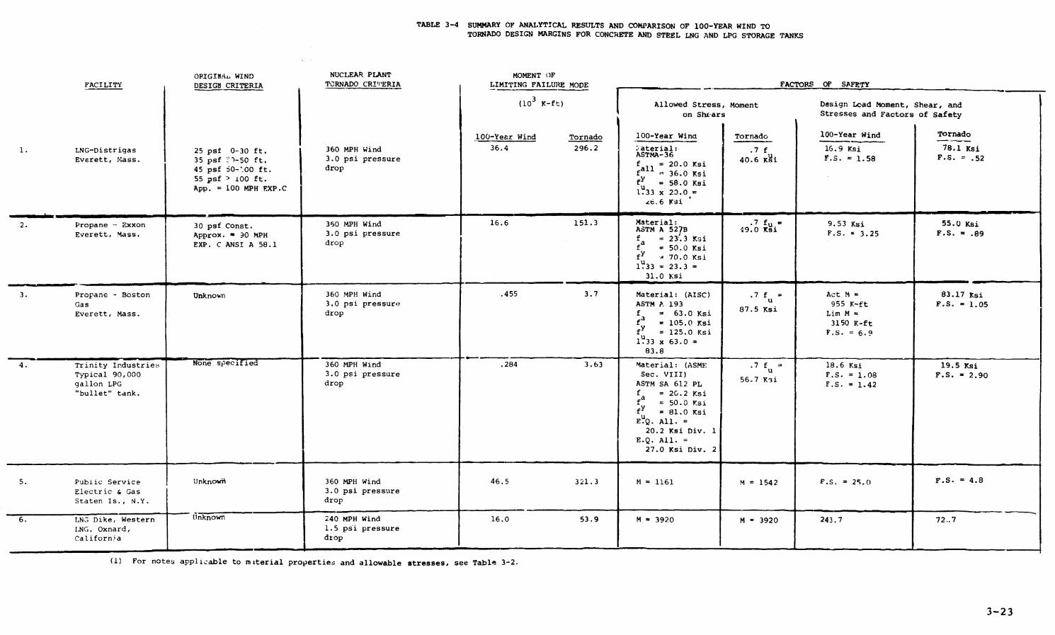
TABLE 3-4 SUMMARY OF ANALYTICAL RESULTS AND COMPARISON OF 100-YEAR WIND TOTORNADO DESIGN MARGINS FOR CONCRETE AND STEEL LNG AND LPG STORAGE TANKS
OPIGINA. WIND NUCLEAR PLANT MOMENT OFFACILITY DESIGI CRITERIA TCRNADO CRI'IERIA { LIMITING FAILUR MOE _ FACTORS OF SAFETY
(103 K-ft) Allowed Stress, Moment Design Lead Moment, Shear, and
on Shtars Stresses and Factors of Safety
100-Year Wind Tornado 100-Year Wind Tornado 100-Year Wind Tornado
1. LNG-Distrigas 25 psf 0-30 ft. 360 MPH Wind 36.4 296.2 :aterial: .7 f 16.9 Ksi 78.1 KsiEverett, Mass. 35 psf Y'7-50 ft. 3.0 psi pressure f TMA-3200 Ksi 40.6 Ksi F.S. 1.58 .52f = 20.0 Ksi
45 psf 50-'00 ft. drop fall l 36.0 Ksi55 psf > 100 ft. fy 58.0 KsiApp. = 100 MPH EXP.C 133 x 23.0 =
IE.6 isi
2. Propane -- Exxon 30 psf Const. 360 MPH Wind 16.6 151.3 Msterial: .7 fu 9.53 Ksi 55.0 KsiASTM A 527 B 49.0 Ksi
Everett, Mass. Approx. - 30 MPH 3.0 psi pressure = 233 i.S. 3.25 F.S. = .89EXP. C ANSI A 58.1 drop fa = 50.0 Ksi
fY - 70.0 Ksil?33 23.3
31.0 Ksi
3. Propane - Boston Unknown 360 MPH Wind .455 3.7 Material: (AISC) .7 f = Act M = 83.17 KsiGas 3.0 psi pressure ASTM A 193 u 955 K-ft F.S. = 1.05Everett, Mass. drop f = 63.0 Ksi Lim M =
fa = 105.0 Ksi 3150 K-ftfY = 125.0 Ksi F.S. = 6.9lU33 x 63.0 83.8
4. Trinity Industries None specified 360 MPH Wind .284 3.63 Material: (ASME .7 f = 18.6 Ksi 19.5 KsiTypical 90,000 3.0 psi pressure Sec. VIII) u.S
56.7 K'igallon LPG drdrop ASM ASTM SA 612 PL F.S. = 1.42"bullet" tank. f = 20.2 Ksi
fa = 50.0 KsifY = 81.0 Ksi
E.Q. All. =20.2 Ksi Div. 1
E.Q. All. =27.0 Ksi Div. 2
5. Public Service Unknow~i 360 MPH Wind 46.5 321.3 M = 1161 M = 1542 F.S. = 25.0 F.S. = 4.8Electric & Gas 3.0 psi pressureStaten Is., N.Y. drop
6. LN3 Dike, Western unknown 240 MPH Wind 16.0 53.9 M = 3920 M - 3920 243.7 72..7ING, Oxnard, 1.5 psi pressureCalifornia drop
(1) For notes applicable to miterial properties and allowable stresses, see Table 3-2.
3-23
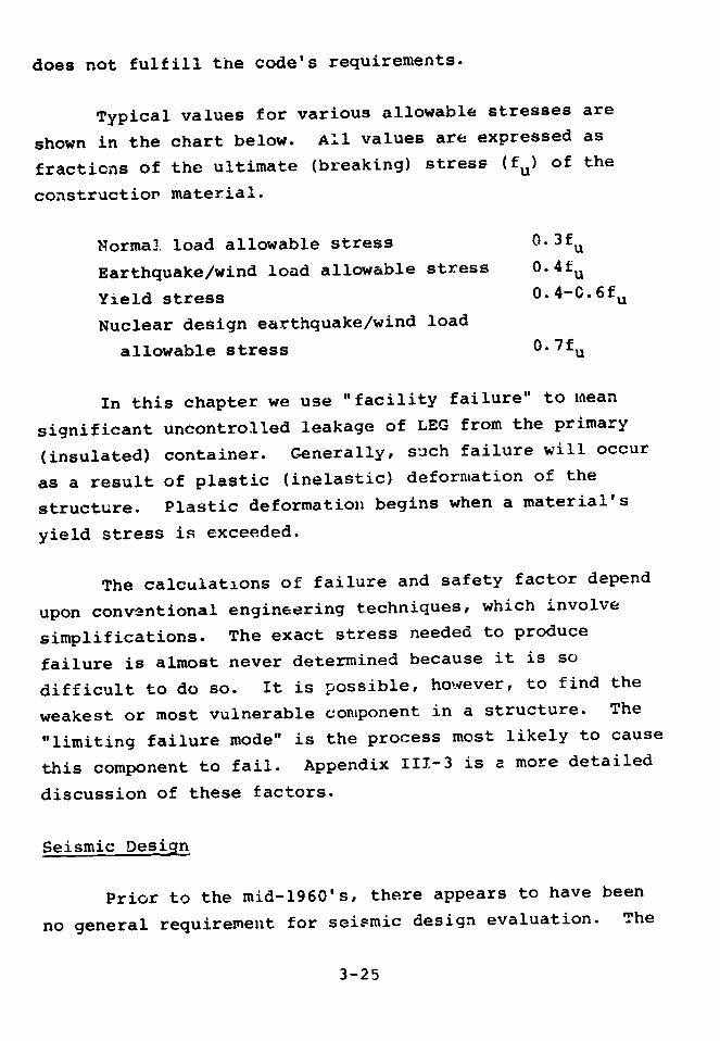
does not fulfill the code's requirements.
Typical values for various allowable stresses are
shown in the chart below. All values are expressed as
fractions of the ultimate (breaking) stress (fu) of the
construction material.
Normal load allowable stress 0.3fu
Earthquake/wind load allowable stress 0.4fu
Yield stress 0.4-C.6 fu
Nuclear design earthquake/wind load
allowable stress 0.7fu
In this chapter we use "facility failure" to mean
significant uncontrolled leakage of LEG from the primary
(insulated) container. Generally, such failure will occur
as a result of plastic (inelastic) deformation of the
structure. Plastic deformation begins when a material's
yield stress is exceeded.
The calculations of failure and safety factor depend
upon conventional engineering techniques, which involve
simplifications. The exact stress needed to produce
failure is almost never determined because it is so
difficult to do so. It is possible, however, to find the
weakest or most vulnerable component in a structure. The
"limiting failure mode" is the process most likely to cause
this component to fail. Appendix III-3 is a more detailed
discussion of these factors.
Seismic Design
Prior to the mid-1960's, there appears to have been
no general requirement for seismic design evaluation. The
3-25
seismic designs of those tanks designed after the
mid-1960's meet or exceed the UBC requirements for the area
in which they are built and use a seismic static horizontal
coefficient. 2 The proposed Oxnard LNG facility has design
criteria which generally follow and are equivalent to those
required for nuclear power plants. It is not, however,
designed to withstand as large an earthquake as would a
nuclear plant at the same site.
Steel Tanks Containing Stored Liquid
In general, our evaluations of tanks and dikes for
seismic loads follow the same procedures used in the
original design and are described in TID 7024,9 which has
been used as a standard method for several years, except
that we considered tanks to be flexible rather than rigid*10
(as discussed by Veletsos and Yang). As can be seen from
Fig. 3-7; the dynamic response of flexible tanks can
increase response inertia shear and moment by a factor of
two or three times over that used in the rigid assumption.
The most likely cause of failure due to seismic loads
on steel tanks containing LNG or liquefied propane appears
to be shear and overturning moment induced forces in the
steel straps that anchor the steel cylinder sides of the
tanks to the concrete flat bottom foundation. In other
words, if a tank fails because of an earthquake, it is
likely to be by tensile rupture of the hold-down straps,
which would permit the tank walls to lift off and separate
from the tank bottom. The next most likely cause of
*The impulse mass of the fluid in a rigid tank is assumed to have -hesame acceleration -s the ground. In a flexible tank the fluid massacceleration is - fur:ction of the tank frequencies, including theeffective mass of both tank and fluid. Typical flexible tank funda-mental frequencies occur between 1 and 4 cycle. per second.
3-26
failure would probably be buckling of the walls due to
overturning moment compression. However, since failure of
the anchor straps would occur at much lower acceleration
and would result in a significant spill of the contained
fluid, the effect of less likely failure causes has not
been evaluated in detail.
The base shear, overturning moments, and safety
factors determined for the UBC seismic criteria and those
determined for nuclear plant seismic criteria are
summarized in Table 3-2. The full SSE earthquake has ten
assumed in the "Nuclear Criteria" column. The results : ow
that the tanks, while adequate using the UBC criteria, come
nowhere near meeting nuclear seismic criteria.
Steel Outer Tanks
Many LNG storage vessels consist of two steel tanks
with the outer tank protecting the insulation and the inner
tank from the weather and wind. In general, if the inner
tank fails due to seismic effects, the outer tank will fail
also. The outer Distrigas tank, for example, was evaluated
for seismic load assum' g thc inner tank had failed and the
LNG was bearing on the outer tank. In such an instance,
the factor of safety against outer tank lift-off failure
for the SSE event is 0.28, compared to 0.24 for the inner
tank; and for the UBC earthquake, the factor of safety is
0.70 for the outer tank compared to 1.16 for the inner
tank. Furthermore, the outer tanks are not normally made
of cryogenic material. If the inner tank fails, the outer
tank is almost certain to rupture from the resulting
pressure and thermal shock.
3-27
Concrete Tanks Containing Stored Liquid
Under the UBC criteria, concrete tanks for containing
stored liquid use their own dead weight to resist seismicoverturning moment; hence, no tensile or uplift ties areprovided to anchor the concrete cylinder to the base mat.These two-way prestressed tanks are generally fabricatedfrom precast, vertically prestressed panels. Aftererection, the panels are spirally wound to providehorizontal prestress. Radial shear lugs are used toprovide seismic shear resistance. As in the case of steeltanks, seismic-induced lift-off of the tank walls and shearappear to be the most likely failure modes. The seismicbase shear and overturns .g moment safety factors determinedfor the actual UBC design criteria and those determined fornuclear plant seismic criteria are summarized in Table 3-3.
Concrete High Dikes
The design details of concrete high dikes are similar
to those used for concrete tanks, except that the
insulation details between the wall and base mat can bemuch simpler, and radial shear lugs may not be requiredsince overall height to width ratios have beensignificantly reduced. It was assumed, in performing theearthquake analysis shown in Table 3-3, that the diked areawas filled with LNG.
Earthen Dikes
Earthen dikes are normally made of selected
engineered backfill designed for optimum density and slopestability, which precludes their failure during
earthquakes. Usually they are significantly more
3-28

earthquake resistant than the surrounding foundation media,
unless that is also engineered fill.
Tornado Design
The tanks analyzed were designed as detailed in ANSI
A 58.1-1972, to withstand a wind which has only one chance
in 100 per year of occurring at the site, except that
velocity is considered constant with height and the gust
factor is taken as a constant 1.0. Tornado design wind
speeds typically range, as a function of location, from 240
to 360 MPH, while normal design wind velocity ranges from
100 to 130 MPH. Since wind loads vary as the square of
velocity, tornado wind loads are typically 5 to 10 times
greater in magnitude than normal 100-year wind design load.
Tornado design also considers differential pressures.
Tornado winds have been known to generate sianif'-ant
missiles. A 360 MPH tornado wind can propel missiles at
velocities between 200 and 300 MPH. We have not done a
detailed evaluation of tornado-borne missiles, but, in
general, to stop missiles at these velocities, cylindrical
shells require a thickness between 1.0 and 1.5 inches of
steel, or between 18 and 24 inches of concrete. LNG and
LPG steel outer tanks would be penetrated by some
tornado-borne missiles.
Table 3-4 summarizes and compares overturning
moments, shear, forces in tie-downs, and factors of safety
for the ANSI A 58.1-1972 design for the 100-year wind with
nuclear plant tornado design requirements. For double-wall
tanks, this analysis is applicable to the outer tank. Two
of the six facilities evaluated fail to meet the tornado
resistance requirements demanded of nuclear plants.
3-29

UBC Earthquake and 100-Year Wind Evaluation
All the LNG and LPG tanks and dikes we evaluated, as
summarized in Tables 3-2, 3-3, and 3-4, were adequately
designed for the UBC earthquake and the 100-year maximum
wind design criteria. The smallest factor of safety was
1.08. This is i.:t to say that, if this 8 percent margin
were exceeded, failure would result. Given the stress
levels which were allowed for this load case, gross failure
would probably not occur until loads exceeded by 30 to 75
percent those loads which would be determined with a safety
factor of 1.0. However, when overturning moment or gross
stability values are the limiting behavior or failure mode,
there is little excess capacity and the 30 to 75 percent
margin should not be assumed available.
In addition to meeting the minimum UBC earthquake and
100-year wind criteria, all the tanks and dikes were
adequately designed for their own facility specific
criteria, which were in some instances more stringent than
the UBC requirement; the Oxnard concrete dike is an
example.
Nuclear Standards: Safe Shultdown Earthquake and Tornado
These input loads are significantly larger than the
UBC earthquake and 100-year wind, in many cases more than
10 times greater. In general, the tanks evaluated fail to
meet these standards. Also, since the allowable stresses
permitted for this load case are significantly greater than
those used for the UBC earthquake and 100-year wind, the
additional margin above a 1.0 safety factor on stresses to
actual failure has probably been reduced to the 20 to 40
percent range. The results of this evaluation indicate
3-30
that mnost LNG and LPG storage facilities %ould fail if they
were subject to the same seismic load phenomena that
nuclear power plants are designed to resist. The limiting
seismic and wind loads used in the design of nuclear plant
facilities have a probability of occurrence between
1/100,000 to 1/10,000 per year.
LIQUEFACTION
The specific earthquake phenomenon called
liquefaction has been generally considered in seismic
design only in the past ten to fifteen years. The term
liquefaction refers to the development (due to cyclic
loads) of pore water pressure equal to the confining
pressure in sands and silts. When this happens,
particularly in relatively loose soils, very large
deformations can occur, and the foundation acts like water,
with little or no shear strength. This can result in
catastrophic failure of the building foundation.
Liquefaction normally occurs in poorly graded, saturated
sands and silts, with a relative density from 35 to 70
percent. Since most engineered or selected backfill is
made up of relatively well-graded materials and is
compacted to a relative density between 70 and 90 percent,
it is unlikely such materials will liquefy.
FLOODING AND TSUNAMI
Flooding and tsunami at a site could cause a tank to
shift or lift off from its foundation, causing a massive
spill. This could be caused by the buoyancy of the tank or
by the drag resistance of the tank to the flow of the flood
water. The procedure normally followed to prevent this is
to locate the tank above the flood plain, or to use high
3-31
enough dikes or levees to keep potential flood water from
reaching the storage tanks.
Evaluation
From the responses we received to the questionnaire
in Appendix III-1, we determined the site conditions and
the design procedures that were followed at a number of LEG
storage facilities. A summary of the responses is given in
Table 3-5 for liquefaction and Table 3-6 for flooding and
tsunami.
When liquefaction analysis was done for a site, it
was generally done in accordance with the simplified
procedures of Seed and Idriss,ll which have been used as
more or less standard practice in the industry for
evaluating liquefaction potential since their publication
in 1971.
Sites on rock or on cohesive clay type foundations
are generally not susceptible to liquefaction, and no such
evaluation is made inl these cases.
For one of the two facilities built on piles, no
evaluation was made of the potential loss of lateral pile
support due to liquefaction. This could lead to
significant lateral deformation of the tank.
Some evaluations of the forces associated with
liquefaction, flood, and tsunami on LEG storage facilities
have been much better than others. The facilities whose
design work began after the period 1972 to 1974 have had
much more attention devoted to extreme natural loads and
hazards than have the tanks designed earlier. In many
3-32

TABLE 3-5 SUMMARY OF LIQUEFACTION EVALUATION PERFORMEDAT TYPICAL LNG AND LPG STORAGE TANK SITES
MINIMUMFOUNDATION POTENTIALLY FACTOR OF
FACILITY AND LOCATION SUSCEPTIBLE TO LIQUEFACTION ANALYSIS PERFORMED SAFETY RUEARKS
1. Port O'Conror, Tex., Yes Seed & Idriss (11) 2.0 Based on 0.07g Zero Period Ground Accel-Proposed LNG Marine eration. Final foundation system -Terminal, E1 Paso LNG Flexible mat or piles.Terminal Co.
2. Cove Point, Md., LI Yes Liquefaction analysis made N/A No analysis available for review.Marine Terminal, Columbia in accordance with Seed &LNG Corp. (Designed - 1972) Idriss (11) with conclusion
reached that there waslittle potential for lique-faction. However, noanalysis available forreview.
3. Oxnard, Cal. Yes, Top 20 ft. of founda- Seed & Idriss (11) 1.44 Based on free field ground accelerationProposed LNG Marine tion material was determined Donovan (12) 1.21 of 0.37g and acceleration at tankTerminal, Western LNG to licuefy and is to be foundation level of 0.21g.Terminal Associates removed and replaced with
selected backfill.
4. Staten Island, N.Y. Yes Apparently no specific N/A The selected backfill is underlaid with!2NG Peakshaving Facility liquefaction evaluation approximately 17 feet of well-gradedTexas Eastern Transmis- was made. Site employs sand. Potential for liquefaction in thission Co. (Designed - selected backfill for 25 layer is unknown based on data supplied.1972) feet below tank. This
backfill should not besusceptible to liquefaction.
5. Lake Charles, La. A friction pile founds- Seed & Idriss (11) N/A Analysis not available for review. NotProposed LNG Marine tion was used. Opinion of design engineer clear how the capacity stated comparesTLrminal was that foundation could with potential lateral earthquake load.Trunkline LNG Co. take 4 Kip/pile lateral
transient load.
6. Elba Island, Ga. A friction pile founda- Lateral capacity of pile N/A Not enough data furnished to evaluate eitherLNG Marine Termiral tion was used not stated. liquefaction potential or lateral load cape-Southern Energy Co. city of the pile system. UBC Zone III used(Designed - 1972) in design of facility although it is in Zone II.
7. Plymouth, Wash. Probably not. Foundation No N/ALNG Peakshaving Facility media is gravel 50 ft.Northwest Pipeline Corp. deep over basalt rock.(Designed - 1975)
8. Everett, Mass. Probably not since founda- Not apparent from data N/A Site design for UBC Zone 2.LNG Marine Terminal tion below fill either stiff furnished.Distrigas Corp. clay or dense coarse sand.(Designed - 1970)
9. Houston (Galena Park), Yes Not performed. N/A Potential for tank foundation liquefactionTex., LPG Marine Terminal not considered as a design parameter.Warren Petroleum Co.
10 West Deptford, N.!. Yes, Founded on sand. Not performed. N/A UBC Seismic Zone I.Proposed LNG Marine%'erminalTeneco LNG Corp.
3-33
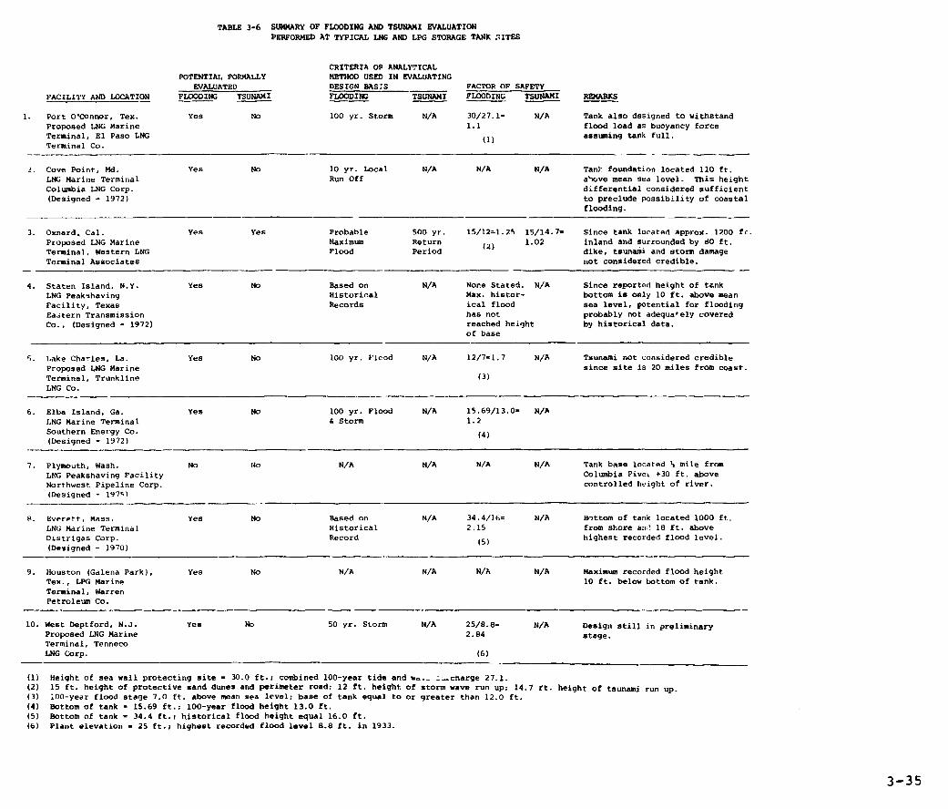
TABLE 3-6 SUMMARY OF FLOODING AND TSUNAMI EVALUATIONPERFORMED AT TYPICAL LNG AND LPG STORAGE TANK SITES
CRITERIA OP ANALYTICALPOTENTIAL FORMALLY METHOD USED IN EVALUATING
EVALUATED DESIGN BAS;S FACTOR OF SAFETY
FACILITY AND LOCATION FLOODING TSUNAMI FLOODING TSUNAMI FLOODING TSUNAMI REMARKS
1. Port O'Connor, Tex. Yes No 100 yr. Storm N/A 30/27.1= N/A Tank also designed to withstand
Proposed LNG Marine 1.1 flood load as buoyancy forceTerminal, El Paso LNG assuming tank full.
Terminal Co.
2. Cove Point, Md. Yes No 10 yr. Local N/A N/A N/A Tan): foundation located 110 ft.
LNG Marine Terminal Run Off above mean sea level. This height
Columbia LNG Corp. differential considered sufficient(Designed - 1972) to preclude possibility of coastal
flooding.
3. Oxnard. Cal. Yes Yes Probable 500 yr. 15/12=1.25 15/14.7= Since tank located approx. 1200 ft.
Proposed LNG Marine Maximum Return 1.02 inland and surrounded by dO ft.
Terminal, Western LNG Flood Period dike, tsunami and storm damage
Terminal Associates not considered credible.
4. Staten Island, N.Y. Yes No Based on N/A None Stated. N/A Since reported height of tank
LNG Peakshaving Historical Max. histor- bottom is only 10 ft. above mean
Facility, Texas Records ical flood sea level, potential for flooding
Ea.tern Transmission has not probably not adequately covered
Co., (Designed - 1972) reached height by historical data.of base
5. Lake Charles, La. Yes No 100 yr. Flcod N/A 12/7=1.7 N/A Tsunami not considered credible
Proposed LNG Marine since site is 20 miles from coast.
Terminal, Trunkline (3)
LNG Co.
6. Elba Island, Ga. Yes No 100 yr. Flood N/A 15.69/13.0- N/A
LNG Marine Terminal & Storm 1.2
Southern Energy Co. (4)
(Designed - 1972)
7. Plymouth, Wash. No No N/A N/A N/A N/A Tank base located % mile from
LNG Peakshaving Facility Columbia Pivei +30 ft. above
Northwest Pipeline Corp. controlled height of river.
(Designed - 1979'
8. Everett, Mass. Yes No Based on N/A 34.4/16= N/A Bottom of tank located 1000 ft.
LNG Marine Terminal Historical 2.15 from shore and 18 ft. above
Distrigas Corp. Record (5) highest recorded flood level.
(Designed - 1970)
9. Houston (Galena Park), Yes No N/A N/A N/A N/A Maximum recorded flood height
Tex., LPG Marine 10 ft. below bottom of tank.
Terminal, WarrenPetroleum Co.
10. West Deptford, N.J. Yes No 50 yr. Storm N/A 25/8.8= N/A Design still in preliminaryProposed LNG Marine 2.84 stage.
Terminal, Tenneco
LNG Corp. (6)
(1) Height of sea wall protecting site - 30.0 ft.; combined 100-year tide and Aw._ a charge 27.1.
(2) 15 ft. height of protective sand dunes and perimeter road; 12 ft. height of storm wave run up; 14.7 rt. height of tsunami run up.
(3) iO0-year flood stage 7.0 ft. above mean sea level; base of tank equal to or greater than 12.0 ft.
(4) Bottom of tank - 15.69 ft.; 100-year flood height 13.0 ft.
(5) Bottom of tank - 34.4 ft.; historical flood height equal 16.0 ft.(6) Plant elevation - 25 ft.; highest recorded flood level 8.8 ft. in 1933.
3-35
cases these higher levels of concern may be associated with
increased State and Federal regulatory interest. However,
in some cases (e.g., the proposed Port O'Connor Terminal,
El Paso LNG Terminal Company). the level of engineering
effort appears to significantly exceed the efforts expended
on similar facilities anywhere in the United States, except
California. This great variation in engineering effort
appears to result partly from the lack of consistent State
or Federal regulatory requirements in tbehe areas.
Most LEG storage facilities are being designed for at
least the 100-year flood and associated storm. The
potential for seismic-induced flooding, separate from storm
flooding, is currently being evaluated only in the
recognized high seismic zones, such as the California
coast. The evaluation of the potential for liquefaction
due to seismic excitation also seems to be restricted in
general to high seismic sites, although it is interesting
to note that a low seismic site, Magnitude 4.8 in Texas,
was also formally evaluated for liquefaction.
FINDINGS
About 5 percent of all earthquakes in the United
States hav- occurred in regions located within
tectonic plates where there had been little known
seismic- activity or active faulting. Within the pa3t
250 years, at least five major earthquakes have
followed this pattern. The ones at New Madrid,
Missouri, and Charleston, South Carolina, were each
felt over an area of two million square miles. On
the other hand, West Coast earthquakes which do
considerable local damage are seldom felt over an
3-37
area of more than a few thousand square miles.
It is very likely that many large LEG facilities will
be impacted by winds, floods, or earthquakes greater
than those they are required to withstand. However,
structures can gercr.c> .y withstand stresses somewhat
greater than those required by regulations.
If a tank fails because of an earthquake, high wind,
or flood, it is likely to be by tensile rupture of
the hold-down straps, which would permit the tank
walls to lift off and separate from the tank bottom.
This would result in a massive spill of the contained
fluid.
The seismic designs of those tanks designed after the
mid-1960's meet or exceed the requirements of the
Uniform Building Code used in the area in which they
are built. Prior to this period, there appears to
have been no general requirement for seismic design
evaluation.
All the LEG tanks we evaluated at five sites were
adequately designed for the Uniform Building Code
earthquake and the 100-year maximum wind design
criteria, but tanks at three of the five sites had
earthquake safety margins less than 25 percent. Two
of these sites (a total of three tanks), the
Distrigas LNG import terminal and the Exxon propane
import terminal, are next to one another in Boston
Harbor.
Most LEG storage facilities come nowhere near meeting
nuclear criteria and would fail if they were subject
3-38
to the same load phenomena that nuclear power plants
are designed to resist.
Large LEG tanks made of steel a-e usually much less
resistant to natural forces than those made of
prestressed concrete.
Steel outer tanks could be penetrated by some
tornado-borne missiles.
The outer steel walls in double-wall tanks are not
normally made of material designed to withstand
intense cold. Thus, if the inner tank fails, the
outer tank is almost certain to rupture from the
pressure and thermal shock.
There is a very large difference in the level of
engineering effort that has been expended by owners
in evaluating the extrewmn natural forces associated
with liquefaction, flood, and tsunami on LEG storage
facilities. This difference appears to result partly
from the lack of consistent State or Federal
regulatory requirements in these areas.
3-39
CONCLUSION
There is no reason why storage tanks in denselypopulated areas, holding large amounts of highly hazardousmaterials, should have to satisfy very much weakerstandards for resistance to natural phenomena or sabotage(see Chapter 9) than do nuclear plants in remote areas.
3-40
REFERENCES
1. Uniform Building Code, 1973 Edition, Volume 1,International Conference of Building Officials, 1973.
2. Storage and Handling of Liquefied Natural Gas, NFPANo. 59A, National Fire Protection Association, 1975.
3. ANSI Standard A 58.1-1972, Building Code Requirementsfor Minimum Design Loads in Buildings and OtherStructures, American National Standards Institute,1972.
4. Markee, E.H., Jr., Beckerley, J.G., and Sanders, K.E."Technical Basis for Interim Regional TornadoCriteria," U.S. Atomic Energy Commission, Office ofRegulation, WASH-1300, May 1974.
5. NRC Regulatory Guide 1.60, "Design Response Spectrafor Nuclear Power Plants," Division of Standards,U.S. Nuclear Regulatory Commission, 1973.
6. ANSI Standard N-635, "Guidelines for CombiningNatural and External Manmade Hazards at Power ReactorSites," (DRAFT) - May 1976.
7. Stevensor, J.D. "Rational Determination of theOperational Basis Earthquake and Its Impact onOverall Safety and Cost of Nuclear Facilities,"Nuclear Engineering and Design, Vol. 35 (1975) NorthHolland Publishing Company.
8. NRC Regulatory Guide 1.76, "Design Basis Tornado forNuclear Power Plants," U.S. Atomic Energy Commission,Directorate of Regulatory Standards, April 1974.
9. Nuclear Reactors and Earthquakes, TID 7024, 1963.
10. Veletsos, A.S. and Yang, J.Y. "Dynamics of Fixed-BaseLiquid Storage Tanks," Presented at U.S.-JapanSeminar for Earthquake Engineering with Emphasis onLifeline Systems, Tokyo, Japan, November 8-12, 1976.
11. Seed, H.B., and Idriss, I.M. "Simplified Proceduresfor Evaluating Soil Liquefaction Potential," Journalof the Soil Mechanics and Foundation Division, ASCE,Vol. 97.
3-41

12. Donovan, N.C. "A Stochastic Approach to the SeismicLiquefaction Problem," Statistics and Probability inCivil Engineering, Hong Kong, September 1971.
3-42
CHAPTER 4
CRACK-INDUCED FAILURE OF METAL LNG TANKS
CONTENTS PAGE
DISCUSSION 4-1
CONCLUSION 4-2
RECOMMENDATION 4-2
AGENCY COMMENTS AND OUR EVALUATION 4-3

DISCUSSION
Our assessments of the vulnerability of LNG systems
in Chapters 3, 6, 7, 8 and 9 are partly based on our
calculations of crack behavior in the spherical and
cylindrical il.etal tanks used for transporting and storing
LNG.* It is generally accepted that the two materials
currently used for LNG tanks, 5083 aluminum alloy and 9%
nickel alloy steel, are very resistant to crack growth
under cryogenic conditions. Most small-scale tests (with
some significant exceptions) have produced very stable
tearing of cracks, rather than rapid crack propagation.
Nevertheless, under the dead weight of LNG, a large, fully-
loaded tank can suffer catastrophic failure (immediate,
total collapse) if a sufficiently long crack is suddenly
created by sabotage or natural forces. Cracks long enough
to cause catastrophic failure are called "critical".
Federal agencies responsible for LEG safety have not
made calculations of critical crack lengths of LEG tanks.
The critical crack lengths we calculated range
between 4-1/2 and 8-1/2 feet. These calculations are far
from exact, but we have done them in a way that we believe
is conservative. We have neglected plasticity, and
inertial thermal and slosh loading stresses in our
calculations. The inclusion of these would make the
calculated critical crack lengths shorter.
The catastrophic failure we observed in our sabotage
experiments further strengthens our belief that our
*The technical discussion that goes with this chapter is given in
Appendix IV.
4-1

estimates are conservative. They imply that a perfect
crack is not needed for catastrophic failure; a hole with
jagged edges may be sufficient.
Moreover, the numbers we have calculated for critical
crack length should not be interpreted as saying that
shorter cracks will be "safe", i.e., non-propagating.
Present technical knowledge is insufficient to support such
a claim in the crack-size range we are discussing.
Columbia LNG Corporation, in reviewing a draft of
this chapter, commented that the critical crack lengths for
cylindrical tanks are between 1 and 1-1/2 feet for 9%
nickel alloy steel tanks and between 3 and 4 feet for
aluminum alloy tanks.
CONCLUSION
We estimate that crack lengths between 4-1/2 and
8-1/2 feet are long enough to cause catastrophic failure in
cylindrical and spherical LNG tanks. We believe these
estimates to be conservative. (Lengths calculated by
Columbia LNG Corporation are much shorter).
RECOMMENDATION
We recommend that the Secretary of Energy institute a
testing program to accurately determine the critical crack
lengths for the various types of tanks used to store and
transport LNG and LPG. The critical crack lengths should
be determined for real types of tanks under real types of
static and dynamic stresses, including those that might be
caused by sabotage.
4-2
AGENCY COMMENTS AND OUR EVALUATION
The Coast Guard comments on this chapter make three
points:
(1) Although the Coast Guard has not determined
critical crack lengths of ship cargo tanks, it does require
such calculations from ship designers.
(2) Testing and inspection during tank construction
insure that flaws are limited to a very small size.
(3) If a crack were to grow, a leak would be
detected before the critical length was reached.
The Coast Guard approach may be adequate for cracks
that develop in ordinary use, but it ignores the
possibility that grounding, collision, or sabotage may
produce a sudden, large crack. The danger of catastrophic
failure from these causes cannot be adequately assessed
until critical crack lenths are adequately determined.
4-3
CHAPTER 5
FLOW OVER CONTAINMENT DIKES
CONTENTS PAGE
INTRODUCTION 5-1
FLOWS OVER DIKES 5-4
RESULTS 5-9
CONCLUSIONS 5-26
AGENCY COMMENTS AND JUR EVALUATION 5-27
REFERENCES 5-28
INTRODUCTION
National Fire Protection Association safety standards
require that every group of LNG storage tanks be surrounded
by a dike which can contain at least the volume of the
largest tank. Dikes have not been designed to prevent the
overflow of a rushing liquid, and, in fact, little is known
about such problems. We examined the consequences of a
massive rupture or collapse of the tank wall which releases
a large amount of liquid in a short period of time. We
found that a substantial part of the stored fluid can surge
over the dike and escape the containment area. Design
criteria will have to be modified if such surges are to be
contained.
It is not improbable that the same natural or man-made
cause could rupture more than one tank. If more than one
tank ruptures within the same dike, the overflow would be
even greater. In our analysis, however, we assumed that
only one tank is enclosed by the dike. A dike may be
constructed with either vertical or sloping sides. A
schematic configuration is shown in Fig. 5-1.
We also examined the possibility of Zluid spurting
over the dike from a sizable puncture of the tank at some
distance above ground level. Figure 5-2 demonstrates such
"spigot" flow where all "dike" dimensions meet or exceed
safety requirements. The volume of the demonstration "tank"
pictured is two quarts. This is slightly less than the
containment capacity of the surrounding "dike". A puncture
results in a fluid jet whose parabolic arc easily clears the
safety barrier. We calculated the amount of spillage from a
puncture in the wall of actual facilities and its dependence
on geometrical parameters.
5-1
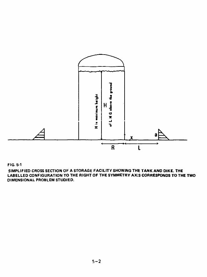
H |
SIMPLIFIED CROSS SECTION OF A STORAGE FACILITY SHOWING THE TANK AND DIKE. THELABELLED CONFIGURATION TO THE RIGHT OF THE SYMMETRY AX:S CORRESPONDS TO THE TWODIMENSIONAL PROBLEM STUDIED.
5-2
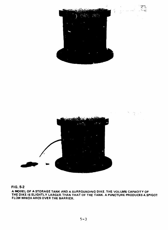
FIG. 5-2A MODEL OF A STORAGE TANK AND A SURROUNDING DIKE. THE VOLUME CAPACITY OFTHE DIKE IS SLIGHTLY LARGER THAN THAT OF THE TANK. A PUNCTURE PRODUCES A SPIGOTFLOW WHICH ARCS OVER THE BARRIER.
5-3

The theoretical work and computer model we developed
for the analysis in this chapter were validated by
experiment.
Although the relevant mathematical formalism, the
details of the analysis, and the computer program results
appear in Appendix V, much of the discussion in this chapter
is still quite technical. The highly technical sections are
italicized. Non-technical readers may omit them.
FLOWS OVER DIKES
If a tank wall ruptures or collapses because of an
earthquake, flood, high wind, or sabotage, a mound of liquid
will move rapidly and hit the containment dike. The way in
which the fluid surmounts the barrier depends in part on the
design of the dike. The rushing liquid may simply vault an
inclined side, or it may pile up very rapidly at the face of
a vertical wall and then flow over the top. In either case,
a strong shock wave forms at the dike and returns towards
the storage tank. The process is a very complicated, highly
non-linear, dynamical interaction. However, the essential
features of surge and overflow can be explained by examining
the fluid motion in simpler and closer to ideal conditions.
To do this, we built a two-dimensional model whose cross
section is shown in Fig. 5-1. Liquid is released when the
wall of the tank at x = O collapses (vanishes) at time zero.
In the experimental arrangement the tank is a cube 9 inches
on a side. The inner wall is a movable slide which is
pulled out quickly to simulate a massive rupture. The fluid
released flows along a 48 inch long channel that is open at
(he other end. A vertical dike of height a is placed at
x = L. The specific dike height that satisfies the two
safety crj: .'ria-equal storage and containment volume, and
5-4
L=.6 (H-a)--will be referred to as the "prescribed height"
and written ap. Flow against inclined dikes is examined
below.
Since no exotic properties of the liquid were
considered in this analysis of dynamical effects (e.g.,
evaporation of LNG), water was used as the fluid in
the experiments.
Fig. 5-3 is a typical sequence of photographs showing
the fluid motion after the wall of the tank is pulled out.
(The total time period involved is about one second.) Water
rushing towards the dike at high speed catapults high into
the air upon impact. The fluid piles up and pours over the
dike as a shock returns to the region of collapse. The
overflow, designated by Q 0, and defined as the fraction ,f
the original fluid volume that escapes upon impact, is tne
primary quantity that is measured in these experiments.
Shock reverberations between dike and wall may involve
additional spillage. However, the total overflow, denoted
by Q1, is found to differ little from Q0. For L/R = 2, the
maximum difference is 5% of the fluid in the tank.
Overflow is also calculated on the basis of a
theoretical model. The comparison of theory and experiment
for the same simple geometry establishes the accuracy of the
model and the specific apprcximations used.
The description of impact provided by the theoretical
and numerical analysis is reasonably accurate as indicated
by the comparison of Figs. 5-3 and 5-4. An account. of the
quantitative agreement achieved is given after the following
general discussion of the theoretical model.
5-5
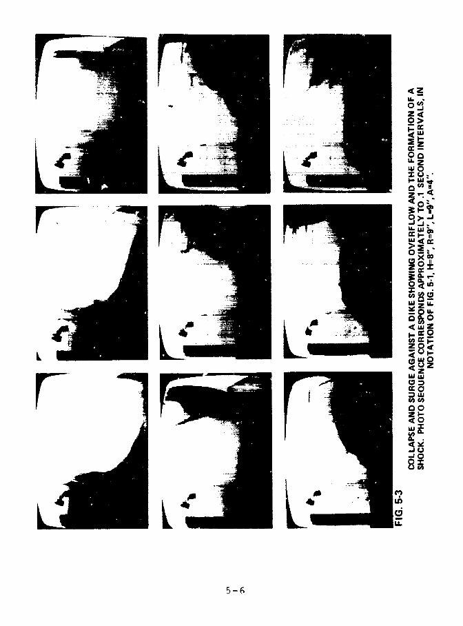
20>
U. 2
40>-'-uJ
r ~~~~~~~~~~~~~~~~~~~~~~~~~~~~~~~~~~~~~~~~~~~~~LL,~~
0 IOZU.
-OIL&0.0
L LLwaw
c002I-Owj
cr 0
zle
-'0
LL
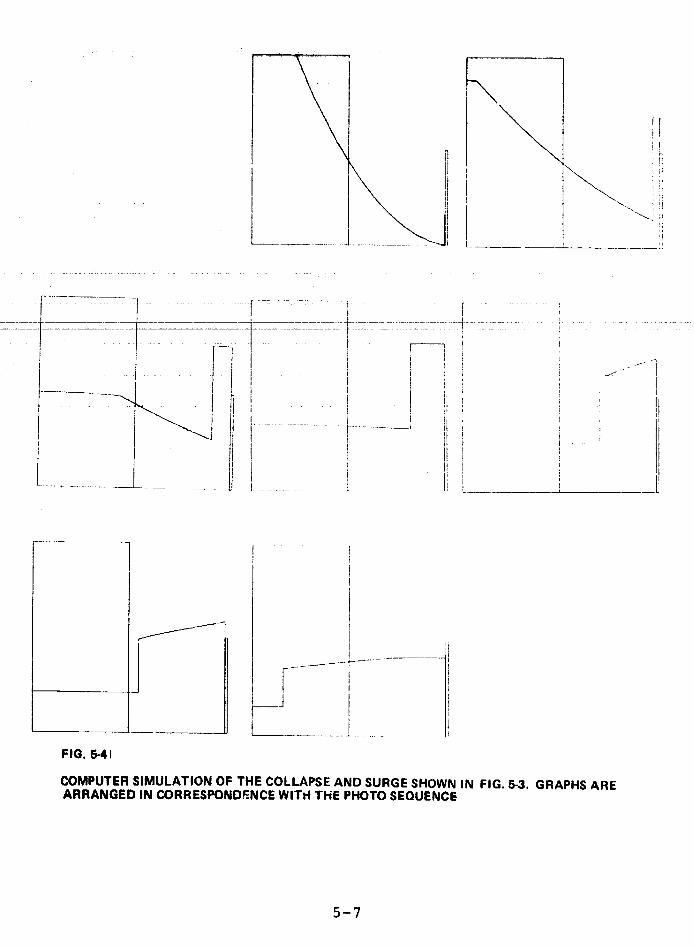
I !FIG. 5 .=41
FIG. 5-41
COMPUTER SIMULATION OF THE COLLAPSE AND SURGE SHOWN IN FIG. -3. GRAPHS AREARRANGED IN CORRESPONDENCE WITH THE PHOTO SEQUENCE
5-7
The fluid velocity in the idealized geometry has only
x and y components and all physical quantities are
independent of the third coordinate that measures horizontal
distance along the wall (ie., perpendicular to the plane of
the page). However, the exact theory is still intractable
and we employ instead the non-linear shallow water equations
which are essentially depth-averaged versions of the
conservation laws of mass and momentum. The vertical
coordinate is thereby eliminated from the formulation and a
much simplified problem is obtained for the mean horizontal
velocity and free surface height as functions of distance x
and time t. A dimensionless notation is adopted to render
z-c,;l]vs independent of scale and directly applicable to
otheLr geomecries.
Non-linear shallow water theory has had a' long and
fruitful history in hydraulicsl, and it has been applied
with remarkable success in "dam-break" problems of the type
under investigation.
The fluid is assumed to be inviscid; turbulence and
ground resistance are also neglected. The errors introduced
by these approximations are small, although the theory can
be modified to account for such effects.2'3
An exact theoretical solution exists for the initial
phase of collapse which lasts until the surging water meets
the dike. This allows a detailed check of the numerical
program that is used to determine the motion in later and
more difficult stages. Analysis of the initial impact and
shock formation provides the information and conditions that
are required to start the computer routine. The theory
yields an accurate approximate solution for large times as
well, as long as no spillage occurs. Only then does the
5-8
computer become invaluable. The boundary condition to
describe overflow states that the wave speed and local fluid
velocity are equal atop the dike. This means that fluid
which passes over the wall ceases to influence the main body
of water still within the containment area.
Experiments were performed to motivate, verify, and
assess theoretical hypotheses, approximations, and
conclusions and also to explore quickly a number of
modifications of the basic configuration. Among these
variants are inclined dikes, multiple barriers, partial wail
collapse, and lateral spread of the surge.
RESULTS
The principal finding concerning flow over a vertical
dike is that, within the parameter range studied, the volurie
fraction of fluid that escapes depends mainly on a/H, the
ratio of the dike height to that of the fluid level in the
tank. Fig. 5-5 shows the volume fraction that escapes, Q 0,
versus ap/H in the situation where containment and storage
capacities are equal. Theory is in good agreement with
observations; the larger values of Q0 predicted are due in
part to having neglected ground resistance and turbulence.
The amount of fluid that escapes increases as the dike is
placed further from the wall and its height decreased
accordingly. Ground friction ultimately negates this
finding when extremely large distances are involved, but
this is not the case in existing facilities. Fig. 5-6
indicates that the overflow Qo is mainly a function of a/H
for all combinations of barrier and maximum liquid heights,
--L <4. In fact the calculations show very little3 Rdependence on L/R. Fig. 5-6a compares the curve fit to the
experimental data wheze the dike holds the same volume as
5-9
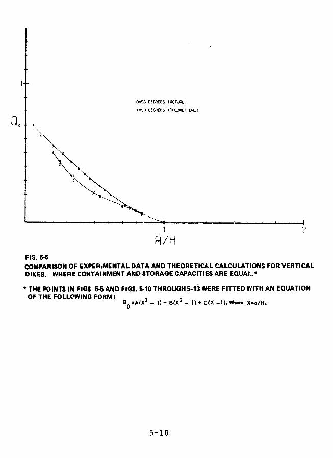
0=90 DEGREES (ACTURLI
X=90 OEOREES (THEORETIC)LI
Q2
1 2
R/HFIG. 5-5
COMPARISON OF EXPERtMENTAL DATA AND THEORETICAL CALCULATIONS FOR VERTICALDIKES, WHERE CONTAINMENT AND STORAGE CAPACITIES ARE EQUAL.-
* THE POINTS IN FIGS. 565 AND FIGS. 5-10 THROUGH 5-13 WERE FITTED WITH AN EQUATIONOF THE FOLLOWING FORM:
Q0A(X3 - 1) + B(X2 - 1) + C(X -1), Whwer X=a/H.
5-10
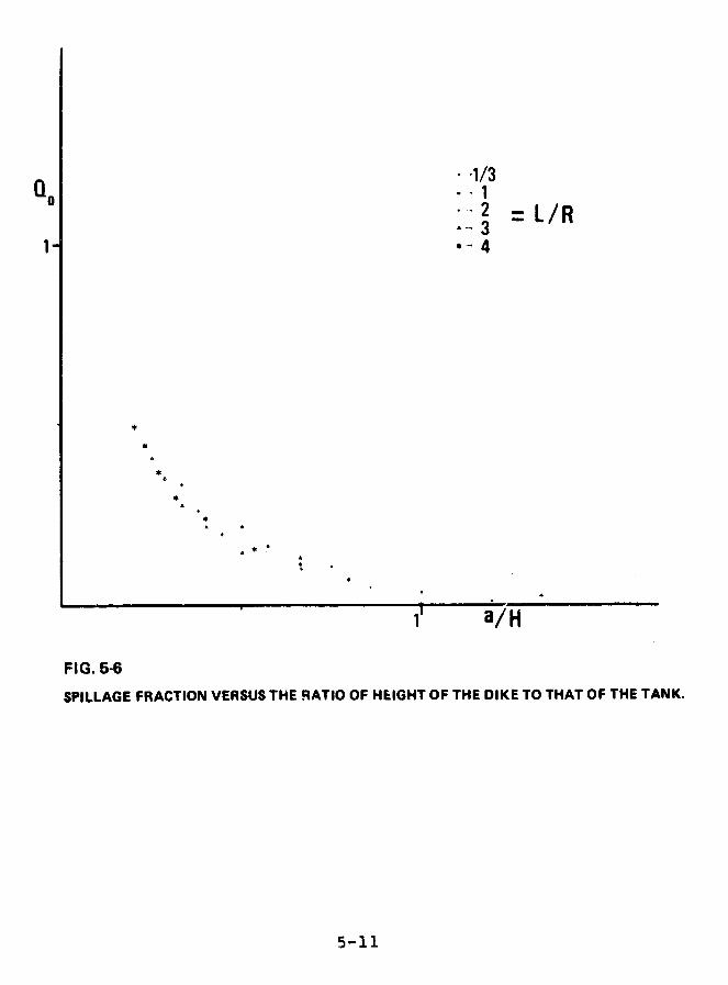
-1/3
* I2 =L/R*- 3
+*
SiLL a/H
FIG. 5-6
SPILLAGE FRACTION VERSUS THE RATIO OF HEIGHT OF THE DIKE TO THAT OF THE TANK.
5-11

0= 90 DEGREES (EXPERIMENTAL),DIKE VOLUME=TANK VOLUMEX- 90 DEGREES (EXPERIt 4ENTAL),DIKE VOLUMEFTANK VOLUME
t
4o
x x
-- I- I + i + f I - t --- - -.~i~ t -- - i ---- ---T
]~~~~~~~~ 2FIG. 5-6a /HCOMPARISON OF EXPERIMENTAL RESULTS FOR OVERFLOW OF VERTICAL DIKES WHEN DIKEVOLUME EQUALS TANK VOLUME AND WHEN DIKE VOLUME IS GREATER THAN OR EQUAL TOTANK VOLUME
5-12
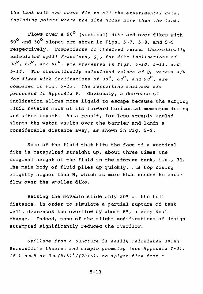
the tank with the curve fit to all the experimental data,
including points where the dike holds more than the tank.
Flows over a 9G0 (vertical) dike and over dikes with
600 and 300 slopes are shown in Figs. 5-7, 5-8, and 5-9
respectively. Comparisons of observed versus theoretically
calculated spill fract ons, Qo, for dike inclinations of
30 , 60 , and 90 , are presented in Figs. 5-10, 5-11, and
5-12. The theoretically calculated values of Qo versus a/H
for dikes with inclinations of 300, 60 °, and 90 , are
compared in Fig. 5-13. The supporting analyses are
presented in Appendix V. Obviously, a decrease of
inclination allows more liquid to escape because the surging
fluid retains much of its forward horizontal momentum during
and after impact. As a result, for less steeply angled
slopes the water vaults over the barrier and lands a
considerable distance away, as shown in Fig. 5-9.
Some of the fluid that hits the face of a vertical
dike is catapulted straight up, about three times the
original height of the fluid in the storage tank, i.e., 3H.
The main body of fluid piles up quickly, ..ts top rising
slightly higher than H, which is more than needed to cause
flow over the smaller dike.
Raising the movable slide only 30% of the full
distance, in order to simulate a partial rupture of tank
wall, decreases the overflow by about 6%, a very small
change. Indeed, none of the slight modifications of design
attempted significantly reduced the overflow.
Spillage from a puncture is easily calculated using
Bernoulli's theorem and simple geometry (see Appendix V-3).
If L+a> H or H< (R+L)2/(2R+L), no spigot flow from a
5-13
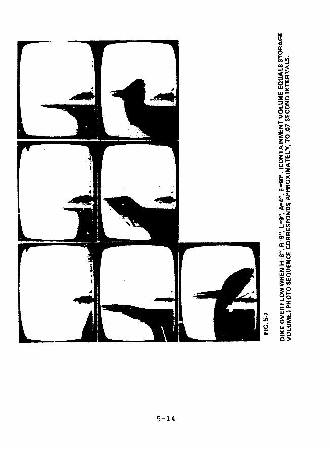
uj04a:
0
wz
Z
Ca
i..-Z th
X
0I
~5-1].~4 ~
CO$
Z
0.
c>

4 zZo
i0
LU
ZI
mi-z-L
c.
U.J
Je
U.
5-1 5 ~ ~ ~ ~ rw
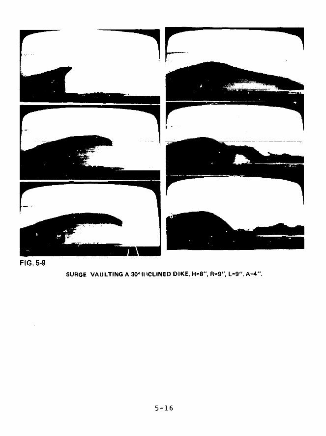
FIG. 5-9
SURGE VAULTING A 3011 ICLINED DIKE, H=8", R=9", L=9". A-4".
5-16
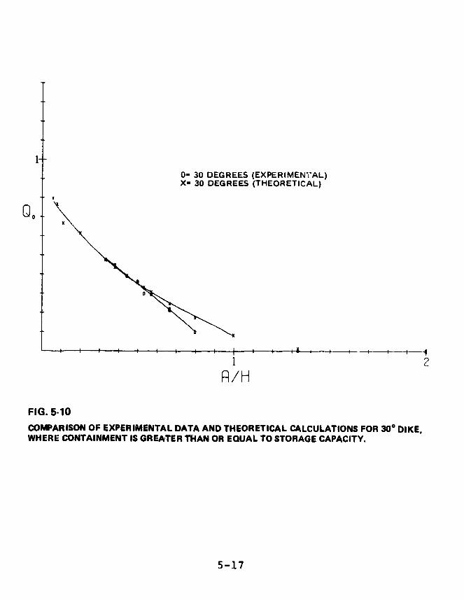
0- 30 DEGREES (EXPERIMENAL)X= 30 DEGREES (THEORETICAL)
1 2P/H
FIG. 5-10
COMPARISON OF EXPERIMENTAL DATA AND THEORETICAL CALCULATIONS FOR 300 DIKE,WHERE CONTAINMENT IS GREATER TIAN OR EQUAL TO STORAGE CAPACITY.
5-17
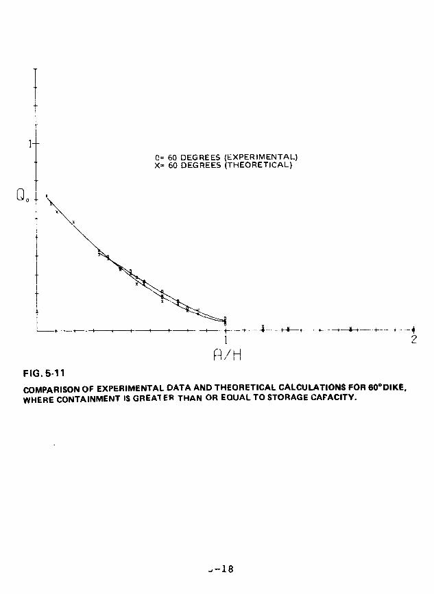
0= 60 DEGREES (EXPERIMENTAL)X= 60 DEGREES (THEORETICAL)
R/HFIG. 5-11
COMPARISON OF EXPERIMENTAL DATA AND THEORETICAL CALCULATIONS FOR 600DIKE,WHERE CONTAINMENT IS GREAl ER THAN OR EQUAL TO STORAGE CAPACITY.
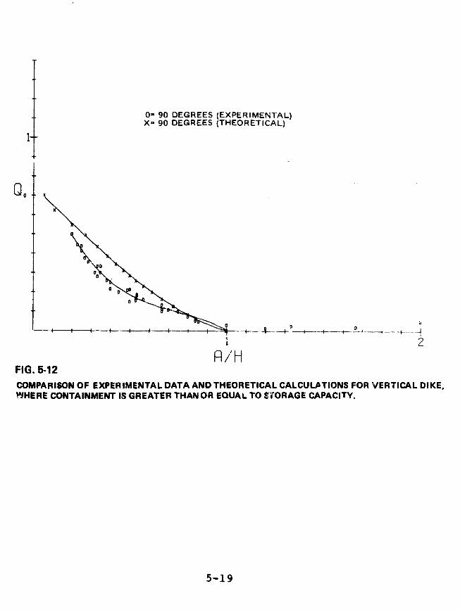
0= 90 DEGREES (EXPERIMENTAL)X= 90 DEGREES (THEORETICAL)
0o
2/iH
FIG. 5-12COMPARISON OF EXPERIMENTAL DATA AND THEORETICAL CALCULATIONS FOR VERTICAL DIKE,WHERE CONTAINMENT IS GREATER THAN OR EQUAL TO STORAGE CAPACITY.
5-19
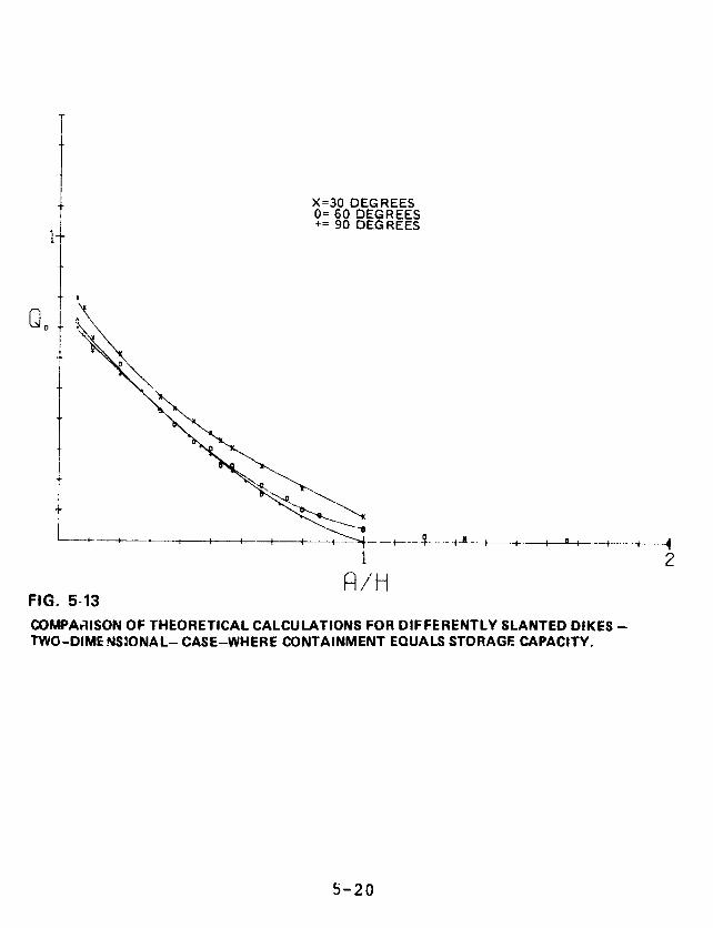
I X=30 DEGREES0= 60 DEGREES+= 90 DEGREES
1 -2
A/HFIG. 5-13COMPARISON OF THEORETICAL CALCULATIONS FOR DIFFERENTLY SLANTED DIKES -TWO-DIME NS:ONAL-CASE-WHERE CONTAINMENT EQUALS STORAGE CAPACITY.
5-20

puncture at any location can clear a dike of height a (see
Fig. 5-14). However, if these absolute criteria are not
met, the fluid can arc over the dike. Dikes built under the
NFPA standard, L>.6(H-a), therefore, do not necessarily
prevent spigot overflows. The maximum possible spillage
fraction Qm (the ratio of spillage to storage volumes) is
given as a function of R/H in Fig. 5-14. The same figure
also shows thes height, z, of the puncture that produces this
maximum overflow. Slight modifications of configuration, to
include a tank pedestal for example, lead to small changes
in these results.
Table 5-1, based on spigot flow calculations in
Appendix V-3, shows the maximum possible spillage from tanks
at certain existing LEG facilities. The maximum spillage
amount ranges from 0 to 46 percent of tank volume.
Friction, viscosity, air resistance, and vaporization would
reduce the amount of spill, but the effects are impossible
to determine accurately, and are not included in the
calculations. In double-wall tanks, the insulation could
significantly affect the flow.
Table 5-2, based on the calculations in Appendix V-1
and V-2, shows the maximum calculated overflow fiom tanks at
certain existing LEG facilities. The maximum overflow
ranges from 13 to 64 percent of tank volume. The
calculations do not include viscosity, ground friction, and
turbulence. These would all lessen the overflow. Ir
addition, since the calculations are two-dimensional, the
spreading of the wave front is also neglected. This would
also reduce the overflow. However, for a given tank and
distance to a dike, the required height of the dike for a
three-dimensional model is always less than the dike height
in the corresponding two-dimensional case.
5-21

Z/H
o'I R/H 2
FIG. 5-14.MAXIMUM SPILLAGE FRACTION QM ANP (HE RELATIVE HEIGHT OF THE PUNCTUREVERSUS R/H. NO LIQUID ESCAPES THE CONTAINMENT AREA WHEN aaap AND R/H, 2.
5-22

Table 5-1. Maximum Possible Spillage from Horizontal Spigot
Flow for Tanks at Certain LEG Facilities.*
Volume Spilled Percent ofFacility (cubic meters) Volume Spilled
Algonquin LNG 26,300 28
Columbia LNG 12,000 20
Distrigas, Everett, Mass.
Tank 1 27,800 46
Tank 2 17,700 19
Philadelphia Electric 10,600 19
Southern Energy 0 0
Exxon LPG 0 0
* Friction, viscosity, air resistance, and vaporization would reducethe amount of spill, but the effects are impossible to determineaccurately, and are not included in these calculations. The calcu-lations also assume the optimal height for the hole on the side ofthe tank closest to the dike.
5-23
We believe that this difference between two- and
three-dimensional models more than makes up for -the neglect
of viscosity, ground friction, turbulence, and wave
spreading. Thus, we think our results are at least as
likely to understate as to overstate the amount going over
the dike. In addition, we plot Q 0, the fraction of the
original value that escapes upon initial impact, rather than
Q1, the total overflow. And in those cases where tanks rest
on pedestals, we considered the pedestal height to br. zero.
These factors make the overflow estimates even more
conservative. The calculation may not be conservative in
the case of a high, close-in dike, such as at Philadelphia
Electric, where shallow water theory is not as good an
approximation.
5-25
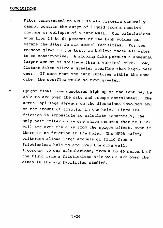
CONCLUSIONS
Dikes constructed to NFPA safety criteria generally
cannot contain the surge of liquid from a massive
rupture or collapse of a tank wall. Our calculations
show from 13 to 64 percent of the tank volume can
escape the dikes in six actual facilities. For the
reasons given in the text, we believe these estimates
to be conservative. A sloping dike permits a somewhat
larger amount of spillage than a vertical dike. Low,
distant dikes allow a greater overflow than high, near
ones. If more than one tank ruptures within the same
dike, the overflow would be even greater.
Spigot flows from punctures high up on the tank may be
able to arc over the dike and escape containment. The
actual spillage depends on the dimensions involved and
on the amount of friction in the hole. Since the
friction is impossible to calculate accurately, the
only safe criterion is one which ensures that no fluid
will arc over the dike from the spigot effect, ever if
there is no friction in the hole. The NFPA safety
criterion allows large amounts of fluid from a
frictionless hole to arc over the dike wall.
According to our calculations. from 0 to 46 percent of
the fluid from a frictionless hole would arc over the
dikes in the six facilities studied.
5-26

AGENCY COMMENTS AND OUR EVALUATION
The Department of Commerce comments that the
methodology by which we calculated overflow for various
facilities is unclear. The calculations are all based upon
design specifications of the facilities, which we obtained
from the facility operators or designers. The spigot flow
was calculated with the theoretical results derived in
Appendix V-3. The dike overflow was estimated by using
Figs. 5-3.0, 5-11, and 5-12, which are based upon the
theoretical calculations and experimental verifications
described in this chapter and in Appendix V-1 and V-2.
Commerce suggests Lhat we should estimate the chance
of a massive failure occurring. We do not believe that such
a probability can be calculated. For example, causes such
as sabotage cannot be treated probabilistically.
Commerce also comments that dikes at new LEG storage
facilities will generally be able to hold a volume greater
than the lume of the enclosed tank. As we have shown in
this chapter, it is not the volume contained by the dike
which is the important factor in overflow, but the
ratio of the height of the fluid in the tank to
the height of the dike. Within the scale that LEG
facilities are being built or planned, the distance from. the
tank to the dike has little effect on this overflow.
The Department of Energy asks what changes in dike
design would ameliorate the overflow problem. Building
dikes vertically and higher would be one improvement; but
more research needs to be done to determine the most
effective and efficient way to design enclosure systems.
5-27

REFERENCES
1. Henderson, F.M. (1966), Open Channel Flow, MacMillan,NY.
2. Dressier, R.F. (1950), J. Res. Nat. Bur. Stud. 49,217.
3. G.B. Whitham (1955), Proc. Roy. Soc. 227, 399.
5-28

CHAPTER 6
SHIP DESIGN, PERSONNEL, AND OPERATIONS
CON ENTS PAGE
INTRODUCTION 6-1
SECTION I. SHIP DESIGN 6-1
LNG SHIPS 6-1
Design Considerations for LNG Ships 6-2
Reactive Safety Equipment 6-3
Preventive Safety Design Characteristics 6-4
LPG SHIPS 6-6
SHIP HAZARD .SCENARIOS - TANK RUPTURES 6-7
Collision Hazards 6-7
Tank Failure 6-10
Over-pressure 6-10
Failure to Take Prompt Action 6-11
Fire Hazard 6-12
REGULATION OF SHIP DESIGN 6-13
SECTIOC II. PERSONNEL TRAINING 6-14
TRAINING PHILOSOPHY 6-16
Design 6-16
Operation 6-16

CONSTRAINTS 6-i9
TRAINING CRITERIA 6-20
PROPOSED REGULATIONS 6-21
Shore Terminals 6-21
Ships 6-22
EXISTING ;,D PLANNED TRAINING 6-24
Shore Terminals 6-24
Ships 6-25
SECTION III. SHIP OPERATIONS 6-27
HISTORICAL BACKGROUND 6-28
NEED FOR SPECIFIC LEG DIRECTIVES FROM COAST GUARDHEADQUARTERS 6-29
COAST GUARD PERSONNEL TRAINING 6-31
COAST GUARD PORT ACTIVITIES 6-33
LNG Offloading in Boston Harbor 6-33
Security Authority 6-33
Minor LNG Spills 6-34
Coast Guard Inspections 6-35
Visibility Considerations 6-3.7
Aircraft Hazard Assessed 6-38
OFFLOADING GROUNDED LEG TANKERS 6-42
COMPARATIVE RISKS IN SELECTED PORTS 6-42
FINDINGS 6-44
Ship Design 6-44
Crew Training 6-45
Ship Operations 6-47
RECOMMENDATIONS 6-50
Ship Design 6-50
Crew Training 6-51
Ship Operations 6-53
AGENCY COMMENTS AND OUR EVALUATION 6-56
REFERENCES 6-66
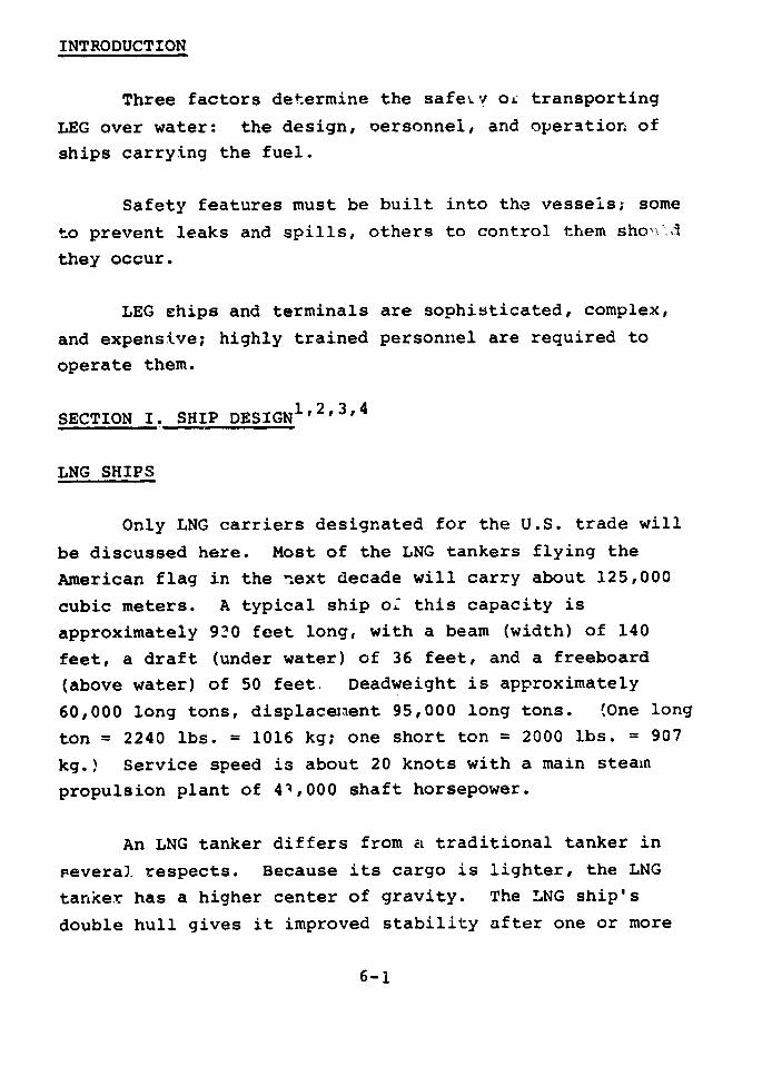
INTRODUCTION
Three factors determine the safeiv oi transporting
LEG over water: the design, personnel, and operation of
ships carrying the fuel.
Safety features must be built into the vessels; some
to prevent leaks and spills, others to control them shored
they occur.
LEG ships and terminals are sophisticated, complex,
and expensive; highly trained personnel are required to
operate them.
SECTION I. SHIP DESIGN1' 2'3' 4
LNG SHIPS
Only LNG carriers designated for the U.S. trade will
be discussed here. Most of the LNG tankers flying the
American flag in the next decade will carry about 125,000
cubic meters. A typical ship o. this capacity is
approximately 920 feet long, with a beam (width) of 140
feet, a draft (under water) of 36 feet, and a freeboard
(above water) of 50 feet, Deadweight is approximately
60,000 long tons, displacemient 95,000 long tons. (One long
ton = 2240 lbs. = 1016 kg; one short ton = 2000 lbs. = 907
kg.) Service speed is about 20 knots with a main steam
propulsion plant of 4',000 shaft horsepower.
An LNG tanker differs from a traditional tanker in
Feveral. respects. Because its cargo is lighter, the LNG
tanker has a higher center of gravity. The LNG ship's
double hull gives it improved stability after one or more
6-1

compartments have been filled with sea water and provides
it "-ih greater collision resistance. The double hull is
also used to carry ballast water, which allows the vessel
to reach full draft when cargo tanks are empty.
LNG ships are usually equipped with bow thrusters,
which improve maneuverability. Other measures that can
improve maneuverability include precision position fixing
equipment, bridge control of main engine, and collision
avoidance systems. LNG ships built under the Maritime
Administration program all have, or will have, this
equipment on board. Ships that are not built under this
program are not required to have it.
An LNG tanker's relatively high freeboard limits the
view from the bridge and exposes a greater proportion of
the ship to wind. Both characteristics could add to
navigational risks.
Only limited inspections can be made of cargo
containment systems, but several leak detection systems
have been developed.
In U.S. waters, the U.S. Coast Guard has devised
several navigational traffic control procedures which can
reduce the chances of collision or grounding. (See Section
III.)
Design Considerations for LNG Ships
From a designer's point of view, the most important
hazards piesented by the transportation of LNG are:
6-2
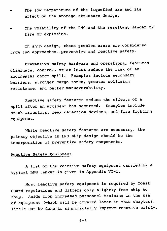
The low temperature of the liquefied gas and its
effect on the storage structure design.
The volatility of the LNG and the resultant danger o2
fire or explosion.
In ship design, these problem areas are considered
from two approaches-preventive and reactive safety.
Preventive safety hardware and operational features
eliminate, control, or at least reduce the risk of an
accidental cargo spill. Examples include secondary
barriers, stronger cargo tanks, greater collision
resistance, and better manueverability.
Reactive safety features reduce the effects of a
spill after an accident has occurred. Examples include
crack arrestors, leak detection devices, and fire fighting
equipment.
While reactive safety features are necessary, the
primary objective in LNG ship design should be the
incorporation of preventive safety components.
Reactive Safety Equipment
A list of the reactive safety equipment carried by a
typical LNG tanker is given in Appendix VI-1.
Most reactive safety equipment is required by Coast
Guard regulations and differs only slightly from ship to
ship. Aside from increased personnel training in the use
of equipment (which will be covered later in this chapter),
little can be done to significantly improve reactive safety.
6-3
Preventive Safety Design Characteristics
The containment system for an LNG carrier consists
mainly of those structural and outfit items associated with
the storage of cargo. It is made up of three major
components-the primary barrier, insulation, and the
secondary barrier.
Current LNG ships have one of two basic contaiament
designs. In the self-supporting (or free-standing) deslin,
the cargo tank itself has sufficient structural strength to
withstand the loads imposed by the cargo. In a membrane
(or integrated) design, the cargo is contained in a thin
metallic liquid-tight lining supported completely by a load
bearing insulation, which in turn is supported by the
ship's structure.
Each of the basic designs has two variations. The
self-supporting type is constructed either with spherical
tanks (the Moss Rosenberg design) or with prismatic tah.:s
(the Conch II design), both of which use aluminum alloy for
the primary barrier. The difference between the two
membrane designs lies in the materiel used to construct the
primary barrier. In the Technigaz Jesign it is made of
corrugated stainless steel; in the Gaz Traasport design it
is made of flat Invar steel (an alloy of nickel and iron).
The primary barrier of an LNG containment system
ccntains the cargo. The insulation protects the ship's
hull from the extremely low temperatures of the liquefied
gas and reduces the flow of heat into the cargo tanks,
thereby cutting down boil-off (the generation of vapor).
Many different insulation materials are used. The
insulation must:
6-4

- be impervious to water;
possess good aging properties;
be flexible enough to withstand dimensional
changes and remain elastic; and
be able to bear heavy loads in some design
systems.
Insulation is either loadbearing, such as balsa and
plywood, or non-loadbearing, such as fiberglass, mineral
wool, and perlite. Polyurethane foam and polyvinyl
chloride may be loadbearing or non-loadbearing.
If the primary barrier fails, the secondary barrier
must contain the cargo safely for at least 15 days, and
insulate the ship's structure against the low temperatures
of the LNG. Among materials used to construct the
secondary barrier are hardwood, plywood, polyurethane,
Invar steel, and stainless steel.
The size and shape of the spherical tanks, and the
greater average transverse distance between the tank and
the ship's side, suggest that they are the least
vulnerable of all designs in the event of a collision (as
discussed in more detail below). However, other designs
offer other safety advantages. The Conch II's
self-supporting design, with its internal bulkheads,
reduces free surface effects* as well as the amount of LNG
spill in case of a tank rupture. The membrane designs
*Free surface effects are those due to sloshing of fluid in the tanks.
6-5
provide good hull utilization, good visibility from thebridge, and a reduced windage area. Appendix VI-2 providesdetailed descriptions and diagrams of the four containment
systems.
LPG SHIPS
A typical LPG carrier is usually smaller and slower
than its LNG counterpart. Because it has a lower center ofgravity (higher cargo density) than an LNG tanker, an LPGship has greater initial stability, better visibility fromthe bridge, and a reduced windage area.
LPG carriers are built in a great variety of sizesand designs. Unlike LNG ships, they are not required tohave double hulls, and most do not. A typical ship has50,000 cubic meters capacity, 34,000 tons deadweight, 615'length, 100' beam, 35' draft, and 26' freeboard. They
usually have independent, prismatic cargo tanks, and theLPG is carried refrigerated at atmospheric pressure. Shiptanks are usually designed for a minimum temperature of-58 F and a maximum working pressure of 4 pounds per square
inch above atmospheric pressure (psig). The tanks are ofthe A type in the Intergovernmental Maritime Consultative
Organization (IMCO) gas code. This means that stressanalysis is less stringent than for LNG ships. Typical
tank material is 2.5% nickel alloy steel. A full secondary
barrier is required. The tanks are usually divided intotwo compartments, liquid-tight below liquid level, toreduce free surface effects. The tanks usually rest on topof the double bottom tanks and are supported by wood-linedbeds and longitudinal and transverse "slides."
6-6
Appendix VI-2 provides a detailed description and
shows diagrams of an American-designed, double-hulled LPG
tanker offered by Avondale Shipyard.
SHIP HAZARD SCENARIOS - TANK RUPTURES
As long as liquefied gas is contained in a ship's
tanks, it poses no danger to the public. The hazard a gas
carrier poses to people, ports, and surrounding facilities
lies in the possibility of a spill or uncontrolled leak,
which could lead to a fire or explosion.
The most serious potential accident would follow the
rupture of a cargo tank. This can be caused by a
collision, grounding, tank failure, or sabotage.
Collision Hazards
In order to minimize the danger of ship collisions,
any U.S. Coast Guard's Captain of the Port (the commanding
officer in each major harbor area) may require special
vessel traffic control systems. These regulations are
discussed in Section III of this chapter.
Nevertheless, the resistance of these vessels to a
collision is an important consideration. So far as we
cou'd determine, the only published studies of collision
resistance have been done on ships with spherical tanks,
which appear to be the least vulnerable to collisions.
Similar studies on the other three major tanks designs are
needed.
6-7
Studies on theoretical collision damage to shirs with
spherical tanks have been carried out by the Norwegian
classification society, Det Norske Veritas (unpublished,
but discussed in Ref. 6); General Dynamics; and by P.S.
Allan, A.A. Brown, and P. Athens. The Coast Guard has done
a study on Tanker Structure Analysis (NTIS AD-A03-103), but
this also dealt only with spherical tanks.
Figure 6-1 shows some results of the Norske Veritas
study. Two impact locations were assumfd, one at a main
transverse bulkhead between cargo tanks and one at the
center of a tank. The latter case is worse because the
distance between the shipside and cargo is least. The
"hump" in critical speeds for striking vessels of more than
50,000 ton displacement is due to the bulbous bow fitted on
the larger vessels.
Two main observations may be made:
1) The critical speed and/or the displacement of the
striking vessel would have to be much higher to
penetrate an LNG vessel's tank than to penetrate an
oil tanker.
2) Buckling and/or tearing of the side structure need
not have any direct effect on the structural
integrity of the spherical cargo tani
Ship collision analysis must also consider ship
survivability in the event of flooding. All new gas
carriers must meet the IMCO and Coast Guard rules on
two-compartment subdivision and limited heel stability.
6-8

SPEED KNOTS
F 0 ~ ~ Ul 0
VI O V, ~o f31 o
O.. n~~~~
o
m 0~~~~~~~
-I__
z g
fn 3 Az V fr _a ?" 0
_ o , ;.
~~~~~~~~~~~-I
*1I~~~~~~~~~~~~~~~~~~~~~~~~~~~~~~~~~ "'
2D
M rpv u)---t C mC Ir-v
>~~~~~~~~~~~~~~~~~
C, ~ * .0 - - _ _ _ _ _-
m i~~~~~cgqZ e~ >Z z~~~~~~1
mo o3 S 00o >
1~~~~~~~~~~~~~~-
o,~ ~ o
SL w X 6 CD m
rn 0~~~~~~~~
m x -- X
3 -n o-a >
X. - z
0-~ -h 0_7C~~~~
- 0 1U2 D
1w m
0 C~~ -~ I --C a C )-
flo G gu
(P' ~k ~ h) O 6 9

Tank Failure
Cargo tanks may also rupture from either general
fatigue failure or over-pressure. Fatigue failure refers
to the possibility of a defect, present in the tank on
delivery, growing to a critical size as a result of fatigue
from service. Howard and Kvamsdal6 suggest that a crack of
this type will grow slowly, leaving time to detect the leak
through sampling instrumentation (gas detectors and liquid
and temperature sensors in cargo holds) and remedy the
situation. Under the Coast Guard'; Letter of Compliance
program and the proposed Coast Guara rules, tank design
load calculations must include plastic deformation and
fatigue life, combining strains from static, dynamic, and
thermal loads. However, data on buckling of membrane
designs are not required. (Proposed 46 CFR Parts 154.428
and 429). In 1969 the Polar Alaska experienced bulging of
the Primary Membrane of No. 1 Cargo Tank "due to crew
negligence during gas freeing operations ... Bulging caused
by overpressuring the barrier space with nitrogen." See
Appendix VI-3.
Over-pressure
Pressure is one of the crucial factors affecting the
safety of an LEG ship. The formation of a flammable
mixture in the cargo tanks is prevented by nlaintaining a
positive pressure differential between the cargo tanks and
the atmosphere, and between the cargo holds and the
atmosphere.
6-10

The required tank-to-atmosphere differential pressure
is maintained by the vapori.er and the gas compressors
control system (LNG) or the riliquefaction control system
(LPG). The required hold-to-atmosphere differential
pressure is maintained by a nitrogen make up system (LNG)
or an inert gas generator system (LPG) and an automatic
system of innerbarrier pressure reli. F valves. Tt is
critical to maintain these differential pressures close to
their design values.
An LEG carrier can be sabotaged by improperly
operating the pressure control systems to overpressurize
the cargo tanks or cargo holds.
According to their LNG ship specifications, a General
Dynamics LNG ship's vaporizer can generate 12,000 cubic
meters of LNG vapor per hour, with a vapor temperature of
1840 F, which can be handled by the safety valves. A
saboteur would have to close the relief valves, either by
blocking the valves (which can be done on some of the
free-standing tank design ships), or by blind-flanging the
vapor outlets. The actual bursting or buckling pressures
of the cargo tanks are not published, since these
calculations are not required by regulatory bodies.
Failure to Take Prompt Action
A minor LNG spill can escalate to a major spill
through failure to take prompt corrective action. The
ability to prevent a larger spill depends on a ship's
operational and emergency procedures and the training of
its crew.
6-11

Fire Hazard
The major threat of fire on an LNG ship comes from a
collision with another vessel. During general LNG ship
operations, small leaks in the cargo handling system
usually will cause at most only relatively small gas fires
on deck or near the ship. Because of the inert atmosphere
maintained by nitrogen, it is unlikely that a fire would
take place between the cargo tanks and the cargo hold. A
collision, on the other hand, could lead to larger oil/gas
fires enveloping major portiL ; of the ship. Such large
fires may be difficult to control and could endanger the
ship.
Analyses done by Det Norske Veritas8 show that most
gas carriers can sustain extremely large fires without hull
and tank breakdown as long as only one side of the ship is
exposed to the fire. This study indicated that a free
standing cargo tank would probably contain its cargo (LNG)
during and after the fire. A membrane design, however,
would release the cargo into the cargo hold or ballast
tanks. This would probably cause the hull to rupture.
The effects of such a collision-induced fire on cargo
tank insulation have also been studied. Results show that
insulation, even fire-resistant insulation, may be
subjected to temperatures that would cause it to
deteriorate or to melt.
For example, Det Norske Veritas research showed that
in the event of fire the ship's inner and outer hull might
become hotter than 1,4720F. At temperatures in the 2120°F
6-12
to 392°F range, most ordinary plastic foam materials
experience deterioration of mechanical and thermal
properties. At higher temperatures, such as over 5720F,
comp'ete thermal decomposition takes place.
The results of a similar study are discussed in the
LNG Safety Manual issued by Energy Transportation Corp. for
its LNG ships. If a tank fails, according to the manual,
the spilled LNG will take six minutes to burn. The
temperature at the wing tanks (ballast tanks between the
inner and outer hull) could reach 7000 F, and the
temperature of the tank covers of the LNG cargo tanks could
reach 716°F.
A possible way to reduce the effects of a fire might
be to pump water rapidly into strategically located ballast
tanks. This will require a higher ballast pump capacity
than is presently common. Fire resistant insulation in
critical places would also be useful.
REGULATION OF SHIP DESIGN
LEG ship design is influenced by a code adopted by
IMCO and by regulations promulgated by the U.S. Coast
Guard.
IMCO, whose purpose is to provide internationally
agreed standards on design, construction, and operation of
ships, adopted a code for gas ships (Resolution A.328 (IX))
in late 1975. Although IMCO resolutions are only advisory,
they are usually incorporated into the national regulations
of member governments and thus have a strong impact on the
international shipping industry.
6-i3
The Coast Guard, which was actively involved in the
development of the IMCO Code, published its proposed
rulemaking (46 CFR, Parts 31, 34, 54, 98, 154) in October
1976. Although the proposed Coast Guard rules correspond
closely to the IMCO Code, they go beyond the Code in that
they would require a lower ambient design temperature,
better steel grades in crack arrestors, cargo venting
restrictions in port, and a higher safety factor for
allowable tank stresses.
Reaction to the stronger rules proposed by the Coast
Guard included a joint protest from nine foreign
governments. According to an Aide-Memoire received by the
Coast Guard's Marine Safety Council February 17, 1977, the
governments of Denmark, Finland, the Federal Republic of
Germany, Greece, Italy, Japan, Ncrway, Sweden, and the
United Kingdom joined in the opinion that national
regulations concerning the design, construction equipment,
and manning applicable to foreign vessels should be based
on internationally agreed standards formulated after
consideration within IMCO. They asked that the proposed
regulations be amended so as nau to exceed the code.
SECTION II. PERSONNEL TRAINING
Well-trained personnel reduce the chance of an
unintentional release of LEG. They are also more capable
of controlling the situation once an incident has occurred.
6-14

An LEG tanker is a highly sophisticated and expensivetranrportation system. Ships and terminals are complex andheavily instrumented; cargo handling is complicated andhazardous. Skilled operators are neede. for safeoperations.
Soma companies have designed training programs thatexceed the present and proposed requirements of regulatorybodies. Other companies, however, have done very littleabout personnel qualific Aions, particuldrly training.Some of the reasons are:
Marine transportation of liquefied gas is a
relatively new technology. Lack of operationalexperience is typical for the i.idustry, includingmanagement personnel.
Human factors a-e difficult to quantify. It
sometimes seems easier to reduce the possibility ofhuman error by increasing automation.
Training regulations coverin- LEG personnel are
lacking.
A study sponsored by the t !time Administration,
entitled "A Model Economic a,,. Safet- Analysis of theTransportation of Hazardous Substances in Bulk," concludedthat marine transport was the safest method if moving suchproducts. But the data collected on marine casualties alsoindicated that human error was the contributing factor in85 percent of all casualties and operating problems.
6-15
TRAINING PHILOSOPHY
In order to establish qualifications needed by
personnel involved in LEG marine transportation, it is
necessary to know the design and operation of the ships,
terminals, and equipment they will be dealing with, as well
as the constraints under which their ships operate.
Design. Because LEG must be kept fully enclosed and
separated from the atmosphere, monitoring internal
pressures and maintaining ti.em are extremely important to
the safety of the system. The relationship between the LEG
terminal and ship involves a two-way flow of information
and an interconnection of safety and control subsystems.
Therefore, a terminal operator should be familiar with the
ship subsystems, and ship personnel should at least know
the shore systems that will influence their actions.
ODeration. A sumewhat simplified typical operational
schedule is shown in Fig. 6-2. The diagram demonstrates
clearly the efforts made to prevent the mixing of air and
cargo vapor,
A cargo transfer is further subdivided into the
different events shown on Fig. 6-3, where the relationship
between the terminal and the ship is shown in some uetail.
.in exte.nsive task analysis for pers.onnel on LNG ships
and barges (NTIS-AD-A026108) was sponsored by the Coast
Guard in 1976. The project was conducted by Operations
Research, Inc. and Engineering Computer Optecnomics, 'nc.
See the biblioaraphy ,: the end of the refereinces for other
studies.
6-16
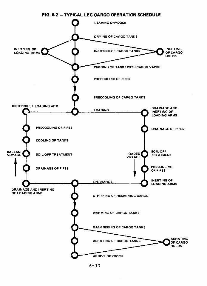
FIG. 6-2 - TYPICAL LEG CARGO OPERATION SCHEDULE
LEAVING DHYDOCK
DRYING OF CARGO TANKS
INERTING OF INERTINGLOADING ARMS INERTING OF CARGO
HOLDS
PURGING 3F TANKS WiTH CARGO VAPOR
PRECOOLING OF PIPES
PRECOOLING OF CARGO TANKS
INERTING )F LOADING AM DRAINAGE ANDDRAINAGE AND~~~LOADING - INERTING OF
LOADING ARMS
PRECOOLING OF PIFES DRAINAGE OF PIPES
COOLING OF TANKS
BALLAST BOIL-OFFVOYAGE BOIL-OFF TREATMENT LOADED TREATMENT
VOYAGE T
OF PIPES
_ _ _ __ ^ DISCHARGE INERTING OFDI SC HAE LOADING ARMS
DRAINAGE AND INERTINGOF LOADING ARMS
STRIPPING OF REMAINING CARGO
WARMING OF CARGO TANKS
GAS-FREEING OF CARGO TANKS
AERATING OF CARG A AT N C
HOLDS
ARRIVE DRYDOCK
6-17
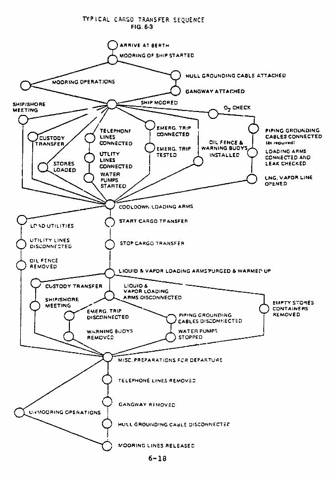
TYPICAL CARGO TRANSFER SEQUENCEFIG. 6.3
ARRIVE AT BERTH
MOORING OF SHIP STARTED
HULL GROUNDING CABLE ATTACHEDMOORING OPERATIONS
GANGWAY ATTACHED
SHIP/SHORE HIP MMEETING 02 CHECK
/ TELEPHONF NNECTE PIPING GROUNDINGCSO LINES CABLES CONNECTED
iRANSf E'TR / "' CONNECTED , OIL FENCE & /( r"ou"ird)IrLITY )EMERG. TRIP WARNING BUOYS LOADING ARMS
/ ( ) LINES STESTED INSTALLEC CCONNECTED AND
s, O ARES ''O~EE.J CN LEAK CHECKED
LNG, VAPOR LINE
OPENED
COOLOOWN LOADING ARMS
rr START CARGO TPANSFER-L.O~D UTILITIES
DISCONNE CTED
OIL FENC£J REMOVEDO
(_ REMOVE~LIUID & VAPOR LOADING ARMSPURGED & WARMEr UP
Y TRANSFERA LUVAPOR LOADING
_ T HLPfSHORIE DJ AflRNNMS DISCONNECTED DAR
R~ GG REMEERG TRIPONEI L DISCONNE D O APIPING GROUNrING REMOVED
_ ULL GR-UD!NG yCABLES DISCON/ECTED
WARNING 8B;0YS WATER PUMP,\ REMOVCC STOPPED
MlSC. PREPARAT;ONS FCR DEPARTURE
/C) TELEPHONE LINES REMOVE=
/ 0 GANGWAY R EMOEVED
\ .~.MO RI~ HULL GROUNDING CABLE DISCONNECTEC
MOORING LINES RELEASEC
6-18
CONSTRAINTS
Personnel aboard LEG ships operate under more
difficult conditions than workers at LEG terminals.
Hazards, for example, are greater aboard ship because a
vessel operates in an environment that is continually
changing and that cannot be accurately predicted.
Nevertheless, many members of an LEG ship's crew have a
less technical background than the engineers and
technicians who typically operate an LEG terminal.
Furthermore, members of a ship's crew may not have the same
opportunity to specialize in LEG operations as do their
counterparts ashore. A deck officer aboard an LEG tanker
must consider gas cargo handling as only one of his many
assigned duties, along with ship handling, navigation, and
other tasks. In addition, there may be times when a ship's
officers work longer hours than permitted under
regulations, and may be physically and mertally less
prepared for a given cargo handling operation.
On U.S. flag LNG ships the Coast Guard requires that
the ship have a non-watchstanding Chief Mate to serve as
the cargo officer, and a non-watchstanding 1st Assistant
Engineer to serve as the cargo system engineer. The Coast
Guard imposes these requirements, under 46 U.S.C. 222, in
issuing thW ship's certificate of inspection. Only two out
of 38 current LNG ships are U.S. flag. There are no U.S.
flag LPG ships.
There are no similar non-watchstanding requirements
for cargo officers and engineers on foreign flag LEG ships.
IMCO has not addressed this issue, although it may be
discussed in its June 1978 meeting.
6-19
TRAINING CRITERIA
As part of our study we made an extensive review of
existing and proposed industry training criteria and those
proposed and required by U.S. and foreign governments. The
criteria below seem to us to be particularly important.
1. Advanced, formalized shore-based training should be
given to all personnel with duties connected with
handling LEG.
2. The training should provide a basic understanding of
LEG behavionr under all conditions.
3. The unusual hazards of LEG and the preventive and
reactive safety features involved should be
emphasized throughout the training.
4. Hands-on training should be provided in fighting
fires on water and high-pressure-vapor fires.
5. Supervisory personnel should be required to
understand the operations of all components and
instruments involved, even if they are actually
operated by others.
6. Training in emergency procedures should be
emphasized.
7. Training in teamwork situations should be provided,
involving personnel with responsibility for different
subsystems, such as ship and shore terminals, and
personnel with different professional training. This
6-20
could be done on the job, but can be done more
efficiently on a simulator.
8. Personnel should be trained to use their acquired
knowledge in realistic operations, including
troubleshooting and decision-making in emergency
situations. This training can only be done in a
simulated environment.
Although the above list indicates a sophisticated and
demanding training program, the general concept is accepted
by the industry; each of the criteria can be found in
existing and planned training programs, even if few
companies have adopted all of them. Thev should be
required for both marine terminals anid tne ships.
PROPOSED REGULATIONS
Shore Terminals Two regulations concerning
personnel qualifications at LNG terminals have been
proposed:
1. The Coast Guard is considering a proposal developed
by the Chemical Transportation Industry Advisory
Committee (CTIAC) for revising 33 CFR Part 126,
entitled Waterfront Facility Regulation , Liquefied
Natural Gas in Bulk, October 1977. The proposed
revisions describe three levels of training for
supervisory, operating, and maintenance personnel
respectively. According to the Coast Guard, however,
no "approval" of training programs is ei jisioned, and
the training "requirements" will not be enforced.
The proposed revisions are general in scope, and do
not cover criteria 7 and 8, above.
6-21
2. The Office of Pipeline Safety Operations' proposed
rules (49 CFR Part 193), Liquefied Natural Gas
Facilities, cover operations only to a limited
extent. They state that an initial training program
shall provide instructions in the characteristics and
hazards of LNG, in the operation of plant equipment,
and in emergency procedures. The Office of Pipeline
Safety Operations has not proposed requiring
that training programs be approved. Finally,
criteria 2, 4, 7 and 8 are not covered.
No regulations setting forth qualifications of
personnel working at LPG waterfront facilities have as yet
been proposed. However, CTIAC is planning such work for
all liquefied gases, including LPG, after the final LNG
regulations are adopted.
Shps Both the U.S. Coast Guard and IMCO have
developed proposals for the training of LEG ship personnel.
IMCO's detailed recommendations will be evaluated by the
government members before the IMCO Convention in London,
June 1978.
Acceptance by the Convention is important to the
United States; if IMCO member governments in turn
incorporate the training recommendations in their national
regulations, their enforcement would assure that personnel
operating foreign flag carriers have received acceptable
trainincg The Coast Guard need not wait, however, for
member governments to 'ake this step. Once the IMCO
Convention has adopted these recommendations, the Coast
Guard could require that all foreign flag vessels operating
in U.S. ports meet the new IMCO standards.
6-22
The IMCO recommendations include three levels of
training directed at:
a) all crew members;
b) those with duties specifically involving the
cargo; and
c) the person in charge of cargo handling.
All crew members would receive a basic shore-based
training course, including hands-on fire fighting, prior to
assignment to a ship. Those involved in cargo handling
would have more in-depth training and would be required to
serve aboard a gas carrier for at least two months. This
training for group "c" would satisfy all of the crittria
except No. 8.
The U.S. Coast Guard has proposed training regulations
(46 CFR Parts 10, 12, 30, 31, 35, 70, 90, 98, 105, 151 and
157), Tankerman Requirements. These regulations would
attempt to put IMCO approved recommendations into effect.
However, the proposed Coast Guard regulations differ from
the proposed IMCO rules in that:
Formalized training would be required only for a
limited numbeL of personnel who have duties in
connection with the cargo. The regulations are
unclear on this point, but they would probably
include only the person in charge and his assistant.
Instructions concentrate on cargo transfer operations
(loading and discharging). The regulations do not
6-23
reflect the fact that these operations are only a
part of LEG carrier operations.
Instruction in emergency procedures is not required.
In addition, the Coast Cuard's proposed requirements
for practical experience would enable a person to qualify
by participating in relatively brief discharge operations.
The proposed regulations are not found to cover
satisfactorily training criteria Nos. 1, 6, 7, and 8.
EXISTING AND PLANNED TRAINING
Training of both ship and shore personnel is
characterized by the lack of regulatory guidelines and thewide variety of training approaches. Comments on someapproaches follow.
Shore Terminals. Most operating LPG receiving
terminals use principally on-the-job training without anyspecified training schedules. Key personnel are givenhands-on fire fighting training in designated schools. TheDistrigas LNG terminal in Everett, in addition toon-the-job training, periodically conducts a 16-hour
formalized course in safety and plant operation. All
operating personnel are sent to fire fighting school.
Columbia LNG's Cove Point terminal provided a
six-week course for all operating personnel, including fourhours a day of classroom instruction and four hours a dayof hands-on experience. Further training was given in a"simulated" cmrgo transfer operation, using an empty LNGship berthed at the dock. Cove Point also held three two-day fire fighting sessions, which included small LNG pool fires.
6-24

Southern Energy's Elba Island LNG terminal is
planning a similar training program. An interesting
feature is the intended use of the control room console in
training exercises, simulating plant conditions by means of
a computer.
Improved training courses are now being conducted by
the equipment manufacturers. All of the training criteria
discussed above are satisfied collectively by the planned
training programs of the Cove Point and Elba Island
terminals. This indicates that these criteria are
realistic.
Ships A great majority of the LPG carriers and
approximately 50% of the LNG fleet to be involved in U.S.
trade will be of foreign flag. The French Gazocean
Company, one of the largest gas ship operators in the
world, is representative of the companies that offer no
organized training in the field, except on-the-job
indoctrination.
The British P & O Steam Navigation Company provides a
one-week classroom course in handling of liquefied cargoes
at the Southhampton School of Navigation, operated by the
General Council of British Shipping. In addition, P & O
requires two months of on-the-job training and a four-day
safety course in Leith, Scotland.
Norwegian companies also provide on-the-job training
in addition to a two-week gas carrier safety course at the
state operated School of Shipn Safety and Damage Control in
Haiigesund. Some of the companies sporadically offer a one
week cargo-handling course, conducted by the shipping
industry.
6-25
The Algerian state-owned iompany, CNAN, is expected
to carry about 20% of the expected LNG to be imported to
the United States. In sharp contrast to the more
established European companies, CNAN is planning a training
institute outside Arzew to provide a 1-1/2 year extensive
training program for deck officers, marine engineers, shore
officers, and management personnel. The institute plans to
have a $2 million cargo handling simulator, as well as fire
fighting facilities, a number of laboratories, and a
complete loading arm set up. The simulator will provide
training in teamwork situations for all personnel involved
with the cargo. Training in troubleshooting and emergency
situations will be emphasized. As far as we know, the
training program is the most extensive planned today.
In the United States, maritime training at this level
is generally provided by the maritime unions. Since 1974
the Maritime Institute of Technology and Graduate Studies,
operated by the International Organization of Masters,
Mates, and Pilots, and the shipping companies, has had a
four-week course in gas carrier operations, including fire
fighting. The school plans to incorporate a simulator
comparable to the Algerian model.
More recently a six-week LNG fundamentals course,
including fire fighting, has been offered by the Calhoon
MEBA Engineering School, operated by the Marine Engineers
Beneficial Association. The Energy Transportation
Corporation requires its deck, engine, and radio offic'ers
to be graduates of this program.
Both of these courses seem to meet the standards
contained in the IMCO recommendations as well as the
proposed Coast Guard Tankerman Requirements.
6-26
The Seafarers International Union's Harry Lundeberg
School also gives a four-week LNG program for unlincesed
ship personnel.
In addition to these training facilities, the El Paso
Company will conduct its own training program. Expected to
cost $9 million over a five-year period, it will be carried
out on the ships and at shk)reside facilities. It will
include the use of a LNG cargo handling simulator and a
shiphandling simulator, both to be operated by Marine
Safety International.
SECTION III. SHIP OPERATIONS
The safety of domestic LEG ship operations depends
heavily on the Coast Guard's management of LEG traffic and
off-loading operations. Assessing the quality of that
management is the purpose of this section.
LPG maritime traffic in this country is steadily
growing and involves many ports, but until early 1978 the
only active LNG import terminal was in Boston Harbor, where
one LNG ship docks ever, three weeks. An LNG export
terminal at Kenai, P'aska has been operating since 1968.
Consequently, the Coast Guard has had limited operating
experience with LNG. it is important for the Coast Guard
to promptly develop operating and contingency procedures
for LNG, because LNG traffic is beginning to grow. The new
LNG terminal at Cove Point, Md. has received its first
shipload of LNG, and will eventually be receiving one LNG
ship every 2-1/2 to 3 days. The Elba Island, Georgia
terminal is also expected to begin operations in 1978.
6-27
LPG vapor has significantly different density,vaporization temperature, detonatability, and burningcharacteristics than LNG vapor. Current Coast Guardoperating procedures do not reflect these differences.
Under Title I of the Ports and Waterways Safety Actof 1972, the Coast Guard has certain powers to preventdamage to land structures and shore areas immediatelyadjacent to U.S. navigable waters resulting from vessel orstructure damage, destruction, or loss. The Coast Guardinformed us, however, that it is not currently capable ofmonitoring all the land-side dangers from hazardousmaterials. In the case of LNG storage tanks, for example,it examines only the peril the tanks pose to ships anddocks but not to surrounding communities. After more thanthree years of discussions, the Coast Guard and theMaterials Transportation Bureau have recently agreed on atwo-page Memorandum of Understanding which clarifies theirrespective responsibilities for regulation of waterfrontLNG facilities and sets forth procedures for cooperating incarrying out those responsibilities. A more extensivediscussion of this issue is given in Appendix XVI-3.
HISTORICAL BACKGROUND
Large-scale petrochemical trade between America andEurope and Japan began in 1964. The Coast Guard soonbecame concerned that the ships involved in the t:' de, allof which were of foreign registry, would not be equippedwit-h the safeguards necessary to ensure conL-inment ofhazardous cargo. Consequently, the Coast Guard requiredthat any ship planning to carry hazardous cargo in U.S.
6-28
ports submit plans of the vessel's containment area,
related piping, and electrical systems for review and
approval by the Coast Guard's staff of technical personnel.
This submission of plans was tne forerunner of the
Coast Guard's current Letter of Compliance (LCC) program.
Under the LCC program all foreign vessels of novel design
that carry hazardous bulk liquid cargo must be inspected by
Coast Guard personnel and issued a Letter of Compliance
before they are permitted to transport these cargoes in
U.S. waters. The inspection takes about 4½ hours and the
Letter of Compliance is valid for two years. All foreign
tankers are given a navigation safety examination at least
once a year.
NEED FOR SPECIFIC LEG DIRECTIVES
FROM COAST GUARD HEADQUARTERS
Discussions with senior officials at Coast Guard
Headquarters showed their awareness of the agency's
statutory responsibilities for the safe operation of
vessels transporting hazardous materials such as LEG. The
Coast Guard's publication CG-478, "Liquefied Natural Gas -
Views and Practices, Policy and Safety," dated February 1,
1976, gives a comprehensive, technical discussion of most
aspects of the procedures recommended for the movement and
transfer of LNG in U.S. ports. However, this publication
is a statement of policy and not a directive. It
specifically states that implementation of the policies
contained therein is at the discretion of the local Captain
of the Port (COTP). Since each port has different
geographic features, patterns of harbor traffic density,
and prevai'iLng weather conditions, a large delegation of
authority and responsibility appears to be justified.
6-29

Furthermore, most local regulations issued by the COTP'sencompass the guidance in CG-478. (See the discussionbelow on LNG inspections in Boston Harbor.)
On September 22, 1977, the Coast Guard published anamendment that more clearly defines the jurisdiction ofeach COTP and Officer in Charge, Marine Inspection (OCMI),and delegates more authority to each COTP. One of thechanges strengthens the COTP's ability to manage LEG andother hazardous materials moved or stored in his area. TheCommandart iof the Coast Guard, however, has retained theauthority to prescribe minimum safety equipmentrequirements.
While most regulations generally conform to thepolicies set forth in CG-478, there are inconsistencies.One involves the means by which COTP's redirect harbortraffic when an LEG vessel is arriving or departing. SomeCOTP's alert ships in the area through publication of Llocal Notice to Mariners. A Notice to Mariners becomes amatter of record. It also is likely to be received byvessels that may not be monitoring local harbor radiofrequencies. Local security broadcasts, on the other hand,provide instantaneous information. Using both of thesemethods would enhance navigational safety.
The Coast Guard is experienced and capable incarrying out its responsibilities for vessel traffic,communications, and compliance with accepted marinenavigational procedures. It is less experienced in dealingwith LEG cargo transfer operations. It presently hasinsufficient resources for supervising these operations andpreparing to deal with LEG emergencies.
6-30
Planning for a local disaster such as a major LEG
spill varies among the COTP's but generally places heavy
reliance on industrial (terminal) resources and local fire
departments. No specific plans exist for coping with a
major LEG spill and there appears to be little agreement
among respunsiole officials as to what should be done if
one occurs.
Although some COTP's have adapted CG-478 for LPG as
well as LNG, no similar document has been issued by the
Commandant, U.S. Coast Guard, specifically for the movement
and transfer of LPG.
COAST GUARD PERSONNEL TRAINING
The Coast Guard has no mandatory training program in
LEG hazards except that included in the Marine Safety Basic
Indoctrination Course required for officers and werrant
officers. This is a 12-week survey course. The only
safety training offered to enlisted personnel is a five-week
Marine Safety Petty Officer Course.
The Coast Guard has several times offered a four-day
training course on liquefied gas carriers in Yorktown, Va.
It has also offered a thre.-week hazardous chemicals course
in Yorktown of which one week focuses on LEG training.
Both courses cover cargo operations only supe -ficially.
The Coast Guard is also aware of and has recourse to the
training courses being given outside the Coast Guard,
described earlier.
The Coast Guard does not require the officers and
enlisted personnel who are involved in LEG ship operations
to attend any of these specialized LEG courses. Of
6-31
particular concern are the qualifications of the Hazardous
Materials Officers (hMO's) on the staff of each COTP.
Although some of the HMO's we interviewed were
well-qualified by experience or education, most had little
training in the hazards of LEG. For example, the HMO of a
port that imports both LNG and LPC told us, incorrectly,
that propane is lighter than air at ambient temperatures
and that the vapors from a spill would rise up and disperse
in the upper atmosphere as it warmed u.. On the basis of
this he said his advice to the COTP would be the same for
an LPG spill as for an LNG spill.
Coast Guard people responsible for LEG ship movements
may be unaware of the conclusions of the Coast Guard's own
research. Coast Guard researchers told us, for example,
that, if there is a large LEG spill (25,000 cubic meters or
more) from a ship, nothing useful can be done about the
resulting vapor cloud, whether or not it is ignited. If
Coast Guard personnel were aware of this and other
pertinent information, they would understand better the
reed for extreme care in LEG cargo handling.
The Coast Guard's annual operational readiness
inspection at each port is only an administrative
evaluation of prescribed procedures, rather that an actual
test at ports hanidling LEG. An adequate test would requir'
manning of Coast Guard emergency stations and equipment in
a simulated LEG spill situation, in order to judge the
training and performance of personnel and the efficiency of
equipment.
6-32

COAST GUARD PORT ACTIVITIES
The discussion in this subsection is based on
meetings with personnel on the headquarters staff of the
Commandant, and with COTP's or their designated
representative at the following six ports: Boston, New
York, Philadelphia, Baltimore, Houston, and Savannah. We
made several visits to Boston Harbor, since it was the only
port through which LNG was then being imported.
In addition, we reviewed various documents including
the regulations on LEG safety issued by the COTP's, and
harbor navigational charts for the ports, issued by the
National Oceanic and Atmospheric Administration.
LNG Offloading in Boston Harbor
During our visits to the Port of Boston we observed
offloading from three LNG carriers: the Descartes, a
50,000-cubic meter French flag ship, owned by Gazocean; the
Kenai Multina, a 35,000-cubic meter Liberian flag ship,
owned by Multi-Meyer; and the Lucian, a 29,000-cubic meter
Norwegian flag ship, owned by Reksten.
Security Authority
Under 33 CFR Parts 125 to 127, the Commandant, U.S.
Coast Guard, is authorized to require certain precautions
against the sabotage of vessels and waterfront facilities
handling explosives, or flammable or combustible liquids or
fuels. Nevertheless, no COTP has made any specific
provisions to prevent or mitigate the consequences of
sabotage of an LEG ship or terminal. They rely on the
6-33
minimal industrial security forces at each terminal and on
the ship's masters. The inadequacy of the present security
arrangement is discussed in Chapter 9.
Minor LNG Spills
On both the Lucian and the Kenai Multina we observed
small leaks due to malfunction of equipment. The Lucian
had two minor gasket leaks, both of which were stopped by
tightening bolts.
On April 3, 1977, we saw several gallons of LNG
spilled on the deck of the Kenai Multina as the result of a
leaky gasket in the liquid line from tank no. 5. The crew
sprayed water throughout the discharge operation, which
probably prevented the deck from cracking.
Last winter the Descartes spilled about 3ne cubic
meter (264 gallons) of LNG, when valves in the ship's
liquid lines were left open. The ship's plates did not
crack, although a similar accident in Stade, Germany,
involving ethylene (-155°F) caused damage which required
replacement of several steel plates on the deck and the
ship.
The Lucian had a minor spill on March 8 caused by a
poor connection with the loading arms; another occurred on
March 9, due to cpen valves in the ship's liquid lines.
Smaller ships, such as the Kenai Multina and the
Lucian, face an additional hazard. The berth and mooring
system at the terminal is designed for larger ships, such
6-34
as the Descartes, and does not provide the same support for
shorter vessels, which can use only one of the two 52 ton
breasting dolphins.
Coast Guard Inspections
The Coast Guard carries out a 2-1/2 hour inspection
before an LNG ship is permitted to enter Boston Harbor, but
it does not include the operating condition of ship control
equipment such as steering engines, propulsion machinery,
and electronic devices. Coast Guard policy also leaves
critical safety decisions to the discretion of the COTP.
The inspection itself is one of the 18 requirements
which the COTP, at his discretion, may place upon LNG
transit operations, according to CG 478.9 In Boston, under
the LNG-LPG Operation/Emergency Plan, the COTP has the
right to prohibit a ship from entering the port, if there
are serious discrepancies in safety systems. If a safety
subsystem is not in good working order, it is the COTP who
decides whether the condition is serious enough to warrant
keeping the ship out of the harbor.
This arrangement is unsatisfactory for three reasons.
(1) Since Coast Guard personnel do not have to be trained
in LEG properties, hazards, technology, and cargo
operations, they may not be fully qualified to judge the
significance: or consequences of a malfunction. (2) Without
specific requirements, there may be a tendency to give
undue weight to the large, certain, economic impact of the
ship's delayed entry against the uncertain possibility of
harm posed by the malfunction. (3) The lack of specific
6-25

requirements results in confusion in the world shippingindustry as to the U.S. Coast Guard's safety standards foradmitting LNG ships.
The following two examples illustrate the kind ofdecision a COTP must make under current regulations. Eachinvolved a fault in one of the major safety subsystems ofan LEG carrier.
The IPG carrier Faraday, carrying 27,500 cubic metersof propane, was inspected on March 5, 1977, outside BostonHarbor. The ship uses inert gas consisting of 85 percentnitrogen and 15 percent carbon dioxide in the cargo holdsurrounding cargo tanks. The carbon dioxide absorbedinfrared light, triggering the ship's gas alarm. Thisproblem was discovered on a previous trip to the UnitedStates by the Faraday. With a crew member visuallymonitoring the gas detector dial, the ship was allowed toenter the port. This decision involved some risk. Ifpropane did begin leaking into the hold, the gas indicationcould have been difficult to separate from the "false"reading caused by carbon dioxide. A sufficiert leak ofcargo can cause the hull to crack, thus allowing cargo tospill.
On April 3, the Coast Guard inspected the Lucian,which was carrying 28,000 cubic meters of LNG. Althoughthe seals on two of the ship's relief valves were broken,it was allowed to enter. In such instances, there is ar.'sk, however unlikely, that the relief valves have beentampered with, rather than that the seals were accidentallybroken. There is no way to check whether the relief valveshave been changed to a higher pressure setting which, asdiscussed in Section I, could lead to tank rupture andcargo spill. The incident underscores the need for a
6-36
regulation requiring pressure switches that automatically
shut off relevant equipment in case of high differential
pressures.
These were both difficult decisions which worked out
satisfactorily, but we believe the COTP should not have had
to make them. Coast Guard requirements should specify
which faults are sufficiently serious to prevent a ship's
entry. The COTP should not have to weigh the dollar costs
of a delay against the potential risk posed by a safety
fault. Although it is true that, if the COTP is undecided,
he may request the Commandant to advise him o' to furnish a
technical representative, a COTP may be reluctant to admit
more technically qualified assistance is needed.
As noted, specific requirements would also be to the
advantage of the LEG shipping industry. Otherwis ' -he
present confusion may increase as more ports are involved
in LNG shipping, and ship captains may face the possibility
of inconsistent implementation of the guidelines by various
COTP's.
Visibility Considerations
According to the Coast Guard's regulations for Boston
Harbor, if the visibility is less than 2 miles, an LEG ship
is not permitted to enter the harbor. However, if a ship
has reached a point east of Fort Point Channel, and the
visibility drops below 2 miles, the ship is allowed to
continue to the ship's berth. This was the case last
winter when the Lucian arrived in a heavy snowfall.
6-37
According to the visibility requirements, a vessel
must begin transit of the harbor at least 2 hours before
sunset. The 10 miles from Broad Sound to the Everett
Terminal usually takes 1-1/2 hours. On April 4, the Lucian
arrived at the dock at 6:35 p.m. and was moored at 7:15
p.m. Sunset on that day was 6:13 p.m. If the trip took
1-1/2 hours the Lucian would have had to begun transit
almost an hour beyond the Coast Guard deadline. Although
local port regulations call for a minimum of 3 tugboats,
the Lucian %as assisted by only two on that transit.
Aircraft Hazard Assessed
While on board one of the LNG carriers, we noted how
close the ship was to Boston's Lcgan Airport. On
investigation we found that planes approaching the
airport's Runway 4-R fly over the ship channel used by both
LNG and LPG tankers. On July 31, 1973, a Delta DC-9
executing an instrument landing approach to this runway
crashed into the seawall.1 0 We examined the circunmstances
of this crash to assess the danger of an airplane colliding
with a gas tanker in the channel.
In Fig. 6-4 the prescribed flight path and the flight
track of the crashing plane are plotted on a nautical chart
of Boston Inner Harbor. The numbers given on the map are
channel depths. The flight profiles are shown on Fiy. 6-5.
Correct flight procedure calls for altitude to be
maintained within 100 feet of prescribed altitude during
initial approach. This should decrease to approximately 50
feet at decision height (DH), the height at which the pilot
should decide whether to continue or abandon his approach.
6-38
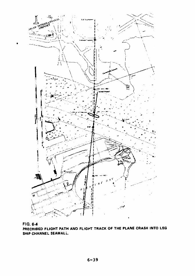
ffi ,\(S ;\ i - e I
, ]~ , 6,
u-i - ~ ....6 -. ~. ..... 5 / =. ...
i i ."~',. -"2 .X, -:l- . .. ' 0 "; ~'---'c'
S `f '.._ ., , " -= I
F \__ \ -'
,-t7---- - '-
', . l ,, Ij , _=. I
/I I
p~''_ r\- -- ,Ii ',, \ "
| t- , .. pb.'_ - ,. ., 2 I
FI.. 6 -4iS *0* _ ,*
Ii ~~~*ti * : i~
PRCIE F -_ L IGNH T P., AIGH T RC 0 .PNE C RS
SiP CHANE SE xk _ AWAL.e
6-39
I..-,< <1 a~a,....
Z>; 0 , ., \\ _
,r -1- · r+v_13~~ \
FIG,. 6-4PRECRIBED FLIGHT PATH AND FLPIGHT TRACK OF THE PLANE CRASH INTO LEGSHIP CHANNEL SEAWAL,
6-39
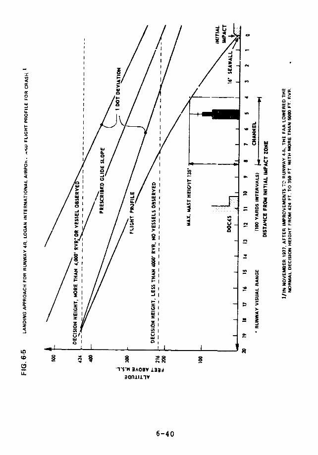
-a,
If,~~~~f-o c
4-~~I I Mar
± 0/ I ~
LI~~~~~~~~~~~~~~~~~~~~~~~~~~~~~~~~~~~~~~~~~.,
vr~~~~~~~~~~~~~~~~~~~~~~~~~~~e
4U I 4C., I ~~~~~~~~~~~~~~~~~~~~~~~~~~~~~~~~~~~~~~LUMa~~~~~~~~~~~~~~~~~~~~~~~~L
I [i ~~~~~~~~~~~~~~~~~Ii
IL~~~ - LU"
o
I0- .a -
z~~~~~~~~~~~~~~~0 1g
i ki \II-( oi? I Yt~~~~~~~~~~~~~~~~~~~~~~~~~~~~~~~~~~aI
xI
/~~~~~~~~~~~~~~~~~~~
z
/ l/ :"L i4t
o r~~~~~~~~~~~~~~~~~~~~~i
w~~~~~~~~~~~~~~~~"
U 0 a oC
0 cc~I gm I2 lI - I ..-
VI~Iz in -J us (4 C,4
Z ~~~~~~~~~~~~~~~~~~~~~~~~~~~~~~c 04
z c.
ag U. _ I
Q cI I. IM 0cc U,, .~
4: ~ ~ W ui 84 .U
~4 ~ ~ ~ -I.,
o
zJ -Iz l
0 ,
-- 'I'S'Y lAOG¥ U.:,
o rI -A
u. ~ ~ ~ ~ ~ ~ ~ ~ ~ ~ ~ ~ ~ ~~ ~~~~~~~~~~~~~~~~~~~~~U
0.t 4- -
:3an. i.l4o~ z~~I6-4
2 Iw - r 31 z
ItI IY ICD I/
~SW3AO9V±33jU- 3Gfl.IJ.>
Z O O a~~~~-4
The horizontal distance is given from the edge of the
seawall, where the crash took place. As can be seen from
the diagram, the ship will never be closer than 400 yards
from this point.
The maximum mast height is set to 135 feet, which is
the vertical clearance under the Mystic River Bridge. Some
ships are slightly taller, such as the Charles Tellier (137feet). These taller ships have to lower their masts and/or
be brought under low tide conditions.
If an LEG tanker had been in the channel, would the
DC-9 have crashed into it? According to our calculations,
probably not, but clearance could have been a matter of
only a few feet.
When an LEG ship is scheduled to pass through the
channel, the airport will be notified.11 When visibility
is better than 2 miles, however, no advisories to aircraft
are issued. A "regular" flight profile could bring a plane
in as low as 100 feet above the mast of an LEG ship. This
clearance seems to be in accordance with our visual
observations. It is interesting to note that the airport
considers vessel height of 132 feet or greater to
constitute a hazard,1 2 indicating it is aware of the danger
posed by ships to aviation traffic.
Flights approaching Runway 33-L also go over the ship
channel, further east. Thbse flights do not seem to
represent a hazard to LFG ships ir transit.
There is no planning or coordination with the Federal
Aviation Aei.nistration or the Department of Defense to
6-41
minimize the chance of a disaster resulting from the crash
of an aircraft into an T.EG ship or facility.
OFFLOADTNG GROUNDED LEG TANKERS
There are no contingency plans or pre-positioned
equipment to partially offload and thus lighten an LEG ship
that has gone hard aground in inland waters. Because LNG
is extremely cold, special cryogenic equipment and ships
must be used to offload it. LPG also requires special
equipment for offloading. They must be planned for and
positioned in advance if they are to be available on short
notice.
COMPARATIVE RISKS IN SELECTED PORTS
Based on our examination of local harbor conditions,
traffic density, and navigational features, we believe that
the potential for the collision or grounding of LEG ships
varies for each port. A detailed summary of port
characteristics is given in Appendix VI-5. Here are our
findings in brief:
Because of the depth and wide expanse of Chesapeake
Bay the approach to the terminal at Cove Point, Md.,
appears to be the safest of the ports we examined
from a navigational standpoint. The transit of the
lower Chesapeake Bay, with its large volume of
commercial and naval traffic in and out of the
Hampton Roads area, may be more of a problem.
6-42
The Savannah River Channel's record of collisions and
groundings is excellent to outstanding, but because
the channel is serpentine, special precaution should
be taken for the passage of LNG ships.
The harbor depths and minimal current conditions
indicate that the ports of Boston, Mass., and Staten
Island, N.Y., are low to medium navigational risks.
The proposed sites in Los Angeles Harbor and Oxnard,
Calif., seem to have a relatively low navigational
risk.
Ports with long, narrow, or winding channels and
dense shipping present high risks of collisons and
groundings, as shown by the recent accident history
of the Houston and Philadelphia channels.
The Houston Ship Channel is one of the ports for
which the Coast Guard has installed a Vessel Traffic
Service (VTS). The service---manned by Coast Guard
personnel--utilizes radar, radio, closed circuit
television, and a computer information system for
monitoring traffic in the 55-mile ship channel. VTS
appears to be a valuable and effective aid in support
of safe navigation, not only for LEG shipping but for
all sea-going ships. Its use is not mandatory.
However, Coast Guard personnel in Houston say that 95
percent of the ships do use it. Coast Guard
personnel also told us that there are so many LPG
barges operating in the port that the Coast Guard
does not attempt to introduce all of them into the
service.
6-43
There is no specific requirement which spells out theconditions under which an LEG ship with amalfunctioning safety system should not be allowed toenter a port.
Local COTP regulations are rot necessarily reviewedby or approved by the Commandant, U.S. Ccast Guard.
FINDINGS
Ship Design
Cargo containment systems for LPG ships are not builtto the same safety standard as LNG carriers. Adouble hull is not required.
The critical speed and/or the displacement of thestriking vessel would have to be much higher topenetrate an LNG vessel than to penetrate an oiltanker.
To our knowledge, the only collision resistance
analysis for LNG ships has dealt with sphericaltanks. Yet the size and shape of these tanks, andthe greater average transverse distance between thetank and the ship's side suggest that they are theleast vulnerable of all designs in the event of acollision.
Other designs, although presumably less collision-
resistant, offer other safety advantages. The ConchII's self-supporting design, with its internalbulkheads, reduces free surface effects as well as
6-44

the amount of LNG spill in case of a tank rupture.The membrane designs provide good stability, goodhull utilization, good visibility from the bridge,and a reduced windage area.
The Coast Guard's proposed rules for LEG ship designdo not require that tank design load calculations formembrane tanks include data on buckling. Arelatively low overpressure of the cargo hold couldcause buckling and possibly rupture of the primarybarrier.
LNG ships are vulnerable to sabotage throughtampering with their safety relief valves andpressure control systems.
Research suggests that a large fire on an LNG shipexposes present cargo tank insulation to temperaturesthat cause it to partly deteriorate or to melt.
Crew Training
LEG ships need highly skilled operators for safeoperation. Data collected on general marinecasualties show that human error was a contributingfactor in 85 percent of all casualties and operatingproblems.
The CTIAC proposal being considered by the CoastGuard for Waterfront Facility Regulations for LNG inBulk (which would revise 33 CFR Part 126) do not meettwo of the criteria we believe necessary: team work
6-45

training, and training in trouble-shooting and
emergency decision making.
The rules for LNG terminal facilities proposed by the
Office of Pipeline Safety Operations (49 CFR Part
193) cover operations only to a limited extent. They
omit the saime criteria as the CTIAC proposal, do not
include training to provide a basic understanding of
LEG behavior under all conditions, and do not
specifically provide for nands-ui training in
fighting fires.
Both sets of proposed rules will lack effectiveness,
because neither the Coast Guard nor the Office of
Pipeline Safety Operations plans to require that
training programs for waterfront facilities be
submitted for approval.
Regulations for personnel qualifications of LPG
waterfront facilities have not yet been proposed.
The U.S. Coast Guard's proposed tankerman regulations
will require training only for one or two crew
members responsible for cargo handling, and will
concentrate on loading and discharging operations.
Instruction in emergency procedures is not required,
and requirements for practical experience are
inadequate. The proposed rules do not satisfactorily
meet four of our eight criteria.
Private training of both ship and shore personnel is
characterized by the lack of regulatory guidelines
6-46
and the wide variety of training approaches.
All of our criteria are satisfied collectively by the
training programs of the Cove Point and Lioa Tsland
terminals. Some ship companies have designed
training programs that far exceed the present and
proposed requirements of regulatory bodies.
Because of the variety of LEG ships and ports and
because crew training depends so heavily on the
company operating the ship and the flag under which
it sails, we believe that studies done for one port,
ship design, and flag cannot be used to judge tl.a
safety of any other combination of port, type of
ship, and flag.
Ship Operations
To effectively supervise LEG cargo transfer
operations in U.S. waters and ports, the Coast Guard
will need more money and manpower, revised
regulations, and new plans and policies.
Existing procedures for handling LPG need more
attention. The Coast Guard has not issued any
document, similar to CG-478, as guidance for the
movement and transfer of LPG.
LPG vapor has significantly different density,
vaporization temperature, detonatability, and burning
characteristics than LNG vapor. Current Coast Guard
6-47
operating procedures do not reflect these
differences.
No COTP has used his authority under 33 CFR Parts 125
to 127 to require that guards provided by the owner
or operator of an LEG facility be in such numbers and
of such qualifications as to assure adequate
surveillance and to prevent unlawful entrance, nor to
designate an LEG facility as a security zone.
The Coast Guard does not require the officers and
enlisted personnel who are involved in LEG ship
operations to attend any specialized LEG courses.
Although some Hazardous Materials Officers are
well-qualified by experience or education, most have
had little training in the hazards of LEG.
The Coast Guard carries out a lengthy inspection
before an LNG ship is permitted to enter Boston
Harbor, but the inspection does not include the
operating condition of ship control equipment such as
steering engines, propulsion machinery, and
electronic devices.
If a safety subsystem is not in good working order,
it is the COTP who decides whether the condition is
serious enough to warrant keeping the ship out of the
harbor. Tha.s arrangement is unsatisfactory for three
reasons. (1) Si.nce Coast Guard personnel do not have
to be adequately trained in LEG properties, hazards,
technology, and cargo operations, they may not be
fully qualified to judge the significance or
consequences of a malfunction. (2) Without specific
requirements, there may be a tendency to give undue
6-48
weight to the large, certain, economic impact of t'
ship's delayed entry against the uncertain
possibility of harm posed by a malfunction. (3) The
lack of specific requirements results in confusion in
the world shipping industry as to the U.S. Coast
Guard's safety standards for admitting LNG ships.
There are nc contingency plans or pre-positioned
equipment to partially offload and thus lighten an
LEG ship that has gone hard aground in inland waters.
Both LNG and I.PG require special equipment.
No specific plans exist for coping with a major LEG
spill, and there appears to be little agreement among
responsible officials as to what should be done, if
one occurs.
The Coast Guard's operational readiness :nspections
are not actual tests of the training and performance
of LEG personnel and the efficiency of equipment.
The Delta Airlines DC-9 which crashed into the
seawall of Boston's Logan Airport on July 31, 1973
would probably have cleared an LNG tanker in the
adjacent channel by only a few feet. We believe this
represents an unnecessary and unacceptable risk.
There is no planning or coordination with the Federal
Aviation Administration or the Department of Defense
to minimize the chance of a disaster resulting from
the crash of aircraft into an LEG ship or facility.
6-49
RECOMMENDATIONS
Ship Design
To the Commandant, U.S. Coast Guard
We recommend that the Commandant, U.S. Coast Guard:
require calculations on collision resistance for all
vessels carrying hazardous cargoes.
require an analytic and accurate determination of
tank stresses be made on all types of LEG carriers to
provide a better understanding of fatigue life and
tank bursting and buckling pressures.
require a double-hull for all LEG carriers.
conduct a study of the different ways a tank might be
ruptured by pressure. This could lead to development
of protection systems, such as pressure switches that
would automatically shut off relevant equipment in
case of high differential pressures, in addition to
existing safety relief valves.
requir" precision position fixing equipment, bridge
control of main engine, and collision avoidance
systems as a means of improving the maneuverability
6-50

of gas carriers, many of which already have this kind
of equipment.
require that cargo containment systems be able to
contain the cargo during and after a specified fire,
and that insulation in critical places be able to
withstand high temperatures; the Coast Guard should
sponsor research if necessary to meet this goal.
Crew Training
To The Commandant, U.S. Coast Guard
We recommend that the Commandant, U.S. Coast Guard:
expand the Coast Guard's proposed tankerman
requirements to include a wider scope of training for
all personnel involved in cargo handling, and enforce
the expanded requirements.
include in the Coast Guaid's training requirements
for LEG marine terminals and ships the 8 criteria we
list in the Training Criteria section.
continue to require that the deck officer and
engineer in charge of cargo operations aboard U.S.
flag LNG ships be non-watchstanding, and work through
IMCO for similar requirement for foreign flag LNG
ships.
assure cnat licensed officers are in compliance with
codes which limit their working hours (46 USC 235 and
46 USC 673).
6-51
assure that employees and advisers who write and
those who enforce training regulations have a
thorough understanding of LEG ship operations and LEG
properties.
assure that any LEG safety analyses of a particular
port be based on studies of that specific port and
the type and nationality of ships used.
continue the Coast Guard's efforts to bring about the
adoption of new IMCO training standards for ship
personnel.
To the Secretary of Transportation
We recommend that the Secretary of Transportation
through the Office of Pipeline Safety Operations:
require and enforce for LEG terminal personnel the
same 8 training requirements we have recommended for
LEG ship personnel, possibly including the licensing
of supervisory personnel.
consult with the U.S. Coast Guard about the means
both agencies could employ to familiarize terminal
and ship personnel with each ot'.er's LEG operations.
To the Secretary of State
We recommend that the Secretary of State:
give strong eupport to the Coast Guard's efforts to
bring about the adoption of new IMCO training
standards for ship personnel.
6-52
Ship Operations
To the Commandant, U.S. Coast Guard
We recommend that the Commandent, U.S. Coast Guard:
issue a policy document for LPG, similar to CG-478
for LNG. The documert should clearly reflect the
differences between LPG and LNG in density,
vaporization rate, detonatability, and burning
characteristics. The policy should be mandatory
except where differences in port conditions clearly
make flexibility desirable.
vigorously exercise the Coast Guard's authority,
pursuant to 33 CFR Parts 125 to 127, to improve
security at LEG facilities adjacent to navigable
waters. In particular, it should enforce subsection
126.15(a) and require owners and operators of
waterfront 7 EG facilities to have guards in such
numbers and of such qualifications as to assure
adequate surveillance and to prevent unlawful
entrance.
make the guidance in CG-478 mandatory, except where
differences in port conditions clearly make
flexibility desirable.
establish a formal, mandatory training and
qualifications program for officers and enlisted
personnel involved in LEG ship operations.
6-53

require an examination of the operating condition of
ship control equipment such as steering engines,
propulsion machinery, and electronic devices as part
of its inspection of LEG ships before they enter a
U.S. port.
issue specific requirements that spell out which
faults are sufficiently serious to prevent a ship's
entry into a U.S. port.
require the preparation of contingency plans and the
pre-positionin? of equipment to partially offload an
LEG ship that has gone aground in inland waters.
require the preparation of specific plans for coping
with a major LEG spill, both when the vapor ignites
at the ship and when it does not.
require that surprise operational readiness
inspections be conducted, including simulating
serious problems, to evaluate the LEG personnel and
resources assigned to COTP's.
review local port regr-lations to assess their
adequacy.
arrange with the Federal Aviation Administration and
the Department of Defense to prohibit landing and
taking off planes from flying low over LEG tankers
and storaca tanks.
require pressure-activated switches on LEG ships
entering U.S. waters that automatically shut off
relevant equipment in case there is too high a
6-54
differential pressure between the cargo tdnks and the
atmosphere, or between the cargo holds and the
atmosphere.
improve control of ships carrying hazardous cargo in
U.S. coastal waters and harbors through selective
implementation of Vessel Traffic Services, and use
both Notices to Mariners and local security
broadcasts when LEG ships are in transit.
To the Administrator, Federal Aviaticn Administration
We recommend that the Administrator, Federal Aviation
Administration:
halt landing approaches to Runway 4-R of Logan
International Airport in Boston during the time an
LEG ship is in transit in the ship channel beneath
the flight path. (Following -ur recommendation, the
Federal Aviation Administration plans to prohibit
aircraft frcn flying directly over large LEG vessels
to land on Runway 4-R.)
6-55

AGENCY COMMENTS AND OUR EVALUATION
The detailed comments of the Departments of Commerce
and Transportation on this chapter deal principally with
regulations and the hazards of oJerpressure, fire, and
collisions.
Re gulations
1. Commerce states:
". .The thrust of the GAO report on directives
is that hard and fast rules need to beestablished and that these safety rules must berpplied rigidly in all instances. We disagree.
VWe believe that a more flexible approach with
the Coast Guard's Captain of the Port having thefinal decision based on regulations, guidelines,
experience and the events at hand is proper and
has proven effective in the past. .
DOT makes a similar comment.
GAO response:
We do not suggest totally rigid regulations. We
suggest, rather, that the Coast Guard guidelines on LNG be
made mandatory except in instances where flexibility is
clearly desirable. In those instances the Captain of the
Port would be the controlling authority.
2. DOT makes the following comments on our
recommendations that the Commandant of the Coast Guard
issue a similar guideline statement on LPG:
. . .The report emphasizes the fact that CG-478
addresses only LNG and not LPG. The reason for
6-56

this is the inordinate public, Cor.gressionarl,and news media interest in LNsc. The Coast Guardfound it beneficial to publish this informationto satisfy repeated inquiries. The Coast Guardis aware of the hazards of LPG and many otherliquefied gases, but because there has not beenthe same overwhelming cry for information, ithas not been deemed necessary to publish apamphlet for each liquefied gas carried in bulkmarine shipments.
. . .The Coast Guard is revising CG-478 andwill include a chapter on LPG. .
GAO response:
DOT seems to be of a divided mind on this issue. In
these comments DOT argues that there is no present need for
publishing LPG guidelines, but it announces that it also
plans to publish them.
3. DOT states:
".. Since Coast Guard regulations andoperating procedures are all directed atpreventing the release of liquefied gases, it isunclear how the properties of LPG in the vaporphase (i.e., after release) should influencethese procedures. . ."
GAO response:
This is not true. Part II of the Coast Guard, Port
of Boston LNG-LPG Operation/Emergency Plan concerns
procedures to be followed after an LNG/LPG incident has
taken place.
6-57
4. DOT states:
". . .{The} instruction, training, experience{of key Coast Guard personnel] combine tcprovide a COTP with sufficient expertise to makerational decisions concerning vessel andfacility safety. .
GAO response:
This is contradicted by our interview with theHazardous Materials Officer stationed at a major I.NG port,which is included in this chapter.
5. In another comment DOT does not contradict ourstatement that, although local port regulations call for aminimum of 3 tugboats, the Lucian was assisted by only twoon the transit we observed. DOT does say, however, that:
.Perhaps the fact that LUCIAN is a muchsraller vessel (29,000 m compared to the 50,000m DESCARTES) was considered when allowing twotugs {instead of} three. .
GAO response:
The Coast Guard's LNG-LPG Operation/Emergency Planfor the Port of Boston requires that "a minimum of (3) tugsof suitable horsepower will attend the needs of each LNGship regardless of size." (The words are underlined in theOperation Plan.)
6-58
Ship Technology
Overpressure
6. Commerce states:
".. .Even where the safety valves were lockedclosed, a tank would not rupture anywhere from afew days to a couple of weeks depending on thetype of containment system. ."
GAO response:
This is true only if pressure is built up solely by
normal evaporation. It does not contradict our suggestion
that saboteurs could manipulate the pressure control system
to overpressurize the cargo tanks or cargo holds.
7. DOT states:
"The Coast Guard does not directly requireburstinr pressure calculations for LNG tanks orpressure vessels. The design of an LNG tank (orpressure vessel) inherently limits the maximumallowable stress experienced by the tank to aspecified percentage of the ultimate strength ofthe tank material, leading to a safety factor ofat least four on tank bursting pressure.Requiring the submission of e calculation forthe actual bursting pressure would besuperfluous."
The issue is not the maximum allowable stress
experienced under normal conditions but the stress that
could be produced by someone purposely misusing the
pressure control systems to overpressurize the cargo tanks
or cargo holds. It is necessary to know the bursting
6-59
pressure in order to tell how long it would take a saboteur
to rupture a tank by such means and to devise appropriate
protective measures.
8. DOT also states:
". . .There are high pressure alarms on the shipto indicate excessive tank pressure. There isno 'relevant equipment' to be shut down in theevent of high pressure cn the LUCIAN. The onlyequipment affecting tank pressure on the LUCIANserves to lower tank pressure; therefore whyshut it down?. .
". .. Finding 6 is oversimplified and indicatesa basic minunderstanding of liquefied gas shipdesign. There are many ways that a gas shipcould be sabotaged-just as there are manyways that any ship could be sabotaged. Themethod indicated is probably one of the mostunlikely. It is very difficult to tamper withrelief valves to the extent necessary to causecatastrophic destruction of the ship. Pressurealarms are available to alert the crew thatsomething is wrong. Pressure control systems ongas ships are installed to reduce pressure, notincrease it.
GAO response:
High pressure alarms can be disabled. The statement
that the only equipment affecting tank pressures serves to
lower it is not true. Two systems raise pressure. The
system for purging cargo tanks sends vaporized LNG into the
tanks, and the emergency cargo discharge system uses a
compressor to overpressurize the tanks after the safety
valves are manually closed.
6-60

Fire
9. Commerce states:
"It is unlikely that insulation, except for thaton -he tank dome, would be exposed to fireexcept where the hold was already breached."
DOT states:
". . a cargo fire around an LNG ship isdescribed while the findings mentioned a fire onthe LNG ship. Only the tank dome extends abovethe deck and the safety valve calculationsconsider the fire situation.
GAO response:
As ship drawings in Appendix VI-1 illustrate, the
statement that "only the tank dome extends above the decks"
is not true for three of the four types of LNG ships --
Moss-Rosenberg, Technigaz, and Gaz Transport.
10. DOT states:
". . .Cargo containment systems are required tobe able to withstand fire exposure withoutfailure. Cargo vapors, however, will be ventedby relief valves. Insulation i; normallyprotected by steel sheathing or -he vessel'shull. The scenario the recommendation envisionsapparently is one where fire is surrounding theship, the inner and outer hulls have beenbreached, and the tank insulation is exposed.To design to such criteria is notpractical. .
6-61
GAO response:
We did not suggest that insulation would be exposeddirectly to fire. We suggested that it might be exposed tohigh temperatures that could cause it to deteriorate. TheDet Norske Veritas analyses discussed in the "Fire Hazard"section show that in a fire where neither the outer norinner hulls has been breached, the insulation might stillbe subjected to temperatures far higher than those neededto decompose it completely.
Collision
11. Commerce states:
"Presently, there are no requirements orcriteria for determining what {collision}resistance is needed. .The assumptionsconcerning the structural configuration, speed,angle of incidence, and a number of otherfactors make such calculations largely anacademic exercise.
GAO response:
We do not agree. We are disturbed by the lack ofrequirements or criteria for determining what resistance isneeded, and we believe collision analyses can be done withsufficient precision to aid rulemaking and design.
12. DOT states:
".· . It is not clear what would be achievedwith similar studies on other designs. Theminimum distances between Quter hull and tankboundaries are, by regulat:on, the same for alltypes. The difference lies in some variation in
6-62
probability that a tank boundary will beinvolved with certain penetrations onto the LEGvessel. ."
GAO response:
The comment is not relevant. We recommend that the
Coast Guard calculate collision resistance for all vessels
carrying hazardous materials. Vessels of different design
have different tank suspension systems, and these affect
their collision resistance. Det Norske Veritas calculated
the resistance of LNG ships with spherical tanks. We
believe the Coast Guard should develop similar data for all
ships carrying highly hazardous cargoes.
13. DOT states:
. . .Delete the sentence, 'However, data onbuckling of membrane designs are not required.'Membranes by definition cannot withstandcompressive loads. ."
GAO response:
The buckling of the Polar Alaska's membrane suggest
that it would be worthwhile to know what pressures will
buckle particular tank construction.
OTHER COMMENTS
LEG Crew Training
14. Commerce states:
" .The draft report stresses the need forformal training of all shipboard personnel
6-63

having LEG responsibilities and in this weconcur. Eight criteria for training are given.While the majority of the criteria areacceptable and reasonable, we find that thereferences to 'simulator' and 'simulatedenvironment' to be vague with regard to meaning.Simulators can be extremely costly, both tocreate and to operate. .
GAO response:
Several simulators are in operation, and we believe
their cost is justified by their value in training key
personnel in critical areas of safety. The value of
simulators has long been recognized in training aircraft
pilots.
Aircraft Collision Hazard
15. Commerce states:
. . .The extent of control of air trafficalluded to in the report is excessive. The factthat one aircraft crashed in making a landingshould not lead to the conclusion that it can beexpected that additional crashes will happenfurther from the airport in the ship'schannel. .
GAO response:
The Federal Aviation Administration, on the other
hand, agrees with our recommendation. FAA states:
"We agree that there is a potential forwidespread disaster in the event of an accidentinvolving an aircraft landing on Runway 4i atBoston and a Liquefied Energy Gases (LEG) shipin transit through the shipping channel.
6-64
"The air traffic control tower at Logan
International Airport has a program for
detection of ships in Boston Harbor. The system
makes use of radar, closed circuit television,
and verbal communications to detect, track, andidentify ships with tall masts. Such vessels
can be an obstruction to aircraft making
instrument approaches to Runway 4R. We will
expand our tall mast detection program and clear
aircraft landing on Runway 4R at Logan Airport
so that the aircraft will not fly directly over
large LEG vessels operating within theboundaries of the instrument landing system
protected airspace trapezoid. TheCaptain of the Port, U.S. Coast Guard, has
assured us the U.S. Coast guard will provide
sufficient advance warning of the LEG vessels
with cargo. Implementation of the service will
require at least two months for completion of
procedural arrangements and controller training.
"We are confident that establishment of this
additional service will meet the GAO safety
recommendations and reduce to the minimum any
chance of incident between aircraft and surfacevessels."
LNG Vapor Boil)ff
16. DOT states:
. . .the cited value of 12,000 cubic meters of
liquid per hour is much larger than any
reasonable estimate.
GAO response:
The final report refers to the 12,000 cubic meters of
LNG vapor that can be generated by a ship's vaporizer.
This value is from the specifications for General Dyramics'
LNG ships.
6-65
REFERENCES
1. Several blueprints and operation manuals for gas
carriers.
2. "Whither the LNG Ship," W. B. Thomas- paper given at
Royal Institution of Naval Architects, October 1974,
London.
3. Update: Domestic LNG Vessel Construction, T. G.
Conners; Maritime Administration, May 1977.
4. U.S. Gas Shipbuilding-Present and Future Prospects,
E. M. Hood, F. P. Eisenbiegler, A. O. Winall and M.
Lee Rice; a panel discussion at GasTech Conference,October 1976, New York City.
5. Risks Associated with an LNG Ship Operation, P.S.
Allan, A.A. Brown and P. Athens; paper given atFourth International Symposium on Transport of
Hazardous Cargoes, October 1975, Jacksonville.
6. LNG Ship Safety Enhanced by Research and Development,
J. L. Howard and R. Kvamsdal; paper given at SNAME
Spring Meeting, May 1977, San Francisco.
7. Analysis of LNG Marine Transportation for the
Maritime Administration, Booz-Allen Applied Research,
Inc., November 1973, COM-74-11684.
8. Gas Carriers--Effects of Fire on the Cargo
Containment System, T. K. AuCten, E. Skramstad and
J. Nylund, GasTech 1976, New York City.
6-66
9. The Coast Guard's authority to require these safety
measures by an LNG vessel or waterfront facility
owner or operator comes from 33 CFR 6.04 and 6.14.
10. Aircraft Accident Report, National Transportation
Safety Board (NTSB-AAR-74-3), Delta Airlines DC-9,
Boston, July 31, 1973.
11. Prior to and during an LEG ship's harbor transit a
security broadcast will have been issued by the Coast
Guard on Channel 16 FM. The Coast Guard will also
notify Logan (Massport) Fire Department of each LEG
vessel transit. Logan Fire Department is responsible
for notifying the flight tower of any incident that
possibly could affect flight patterns. In addition
to these communication channels, the airport uses
radar and closed circuit television to detect, track,
and identify ships with tall masts.
12. Letter to Airmen 77-3, Subject: Boston Tower
Advisories of Tall Masted Vessels.
ADDITIONAL REFERENCES
Section I
Algeria I. An El Paso Information Booklet, April 1977.
LPG and Chemical Gas Carriers. A Fairplay Report, London,
1976.
The LNG ship and Changing Energy Environment, W.B. Thomas,
paper given at SNAME Spring M.eting, May 1977, San
Francisco.
6-67

BIBLIOGRAPHY
Section II
Fire Safety Aboard LNG Vessels, University Engineers, Inc.,January 1976, AD-A030-619.
Handbook for the Development of Qualifications forPersonnel in New Technology Systems, Operations Research,Inc., February 1976, AD-A027-525.
Manpower Analysis in Transportation Safety, FloridaTechnological University, May 1977, DOT-TST-77-40.
Recommendations for Qualifications of Liquefied Natural GasCargo Personnel, Engineering Computer Optecnomics, Inc.,April 1976, AD-A027-108, 109, 110.
6-68
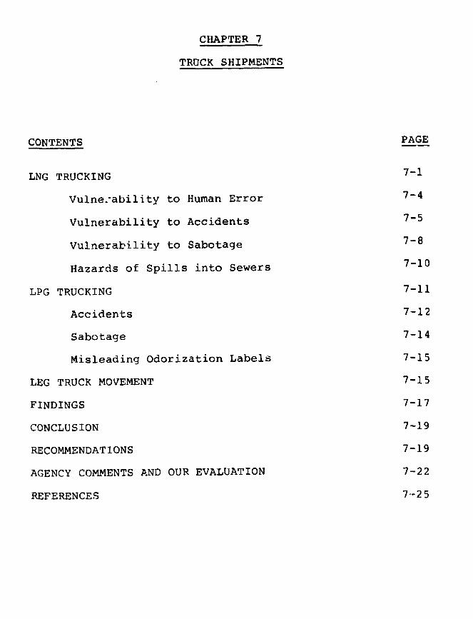
CHAPTER 7
TRUCK SHIPMENTS
CONTENTS PAGE
LNG TRUCKING 7-1
Vulne.-ability to Human Error 7-4
Vulnerability to Accidents 7-5
Vulnerability to Sabotage 7-8
Hazards of Spills into Sewers 7-10
LPG TRUCKING 7-11
Accidents 7-12
Sabotage 7-14
Misleading Odorization Labels 7-15
LEG TRUCK MOVEMENT 7-15
FINDINGS 7-17
CONCLUSION 7-19
RECOMMENDATIONS 7-19
AGENCY COMMENTS AND OUR EVALUATION 7-22
REFERENCES 7--25

LNG trucks that move routinely through highly
populated cities are vulnerable to accidents and sabotage
that could cause major damage. The far more extensive
trucking of LPG, in single-walled trucks under pressure, is
also vulnerable to major accidents and sabotage. The main
features of the trucks are shown in Figures 7-la and 7-lb.
LNG TRUCKING
Each LNG truck working out of the Distrigas terminal
in Everett, Massachusetts, carries 40 cubic meters of LNG
in a vacuum insulated tank at -2600F. More than 90 such
truckloads may come out of the Everet: terminal in a single
day. The gas companies which purchase LNG from Distrigas
Corporation transport it from the Everett terminal to their
own satellite tanks which tie into their distribution
i3ystems. When an LNG ship arrives at the terminal, the gas
companies notify their truckers who usually run every
available LNG trailer on a 24-hour schedule until the
transfer is completed. The Distrigas contracts call £or
customers to remove half of their allotment within the
first 10 days after the LNG ship's arrival and to remove
the second half before the ship returns with another cargo
(approximately one month).
LNG can be hauled by companies which have Interstate
Commerce Commission (ICC) authority for the bulk transport
of petroleum products or liquid chemicals. These companies
can lease the trucks and drivers of other companies which
do not have such authority. The ICC also certifies
companies specifically for LNG transport.
The ICC has granted specific LNG rights in the
Northeast to three companies: Gas Incorporated,
7-1
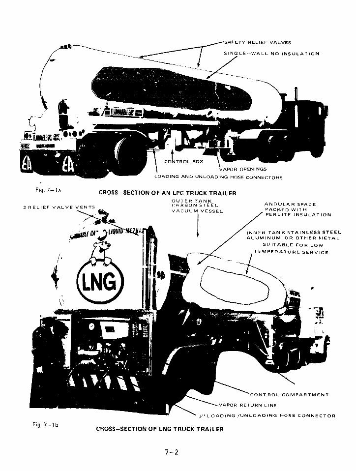
SAFETY RELIEF VALVES
SINGLE--WALL NO INSULATION
/E -
CONTROL BOX
VAPOR OPENINGS
LOADING AND UNLOAD'NG HOSE CONNECTORS
Fig. 7-la CROSS--SECTION OF AN LP TRUCK TRAILEROUTER TANKCARBON STEEL ANDULAR SPACE
2 RELIEF VALVE VENTS2 RELIEF VALVE VENTS VA"UUM VESSEL PACKED WITHPERLITE INSULATION
,.EcA.)L^IQ A l; l , / INNER TANK STAINLESS STEEL,ALUMINUM, OR OTHER hIETAL
S(UITABLE FOR LOW
TEMPERATURE SERVICE
j LOADING /UN LOADING HOSE CONNECTOR
Fig. 7-lb CROSS-SECTION OF LNG TRUCK TRAILER
7-2'7-2

Indianhead, and Capitol Truck Lines. They all own theirown trailers. Most LNG trucking in the Northeast under ICCauthority for bulk transport of petroleum products is doneby either Chemical Leaman or Gault Transportation.
Chemical Leaman 3 for the most part uses its own tractorsand specially trained drivers, but supplements its smallfleet of cryogenic trailers by lease arrangements. Whileit does subcontract some business to "leased operators",Chemical Leaman deals directly with the gas companies inmaking arrangexments for LNG transportation.
Gault Transportation Company4 owns no LNG trailersand does all LNG business through "leased operator"
arrangements with other trucking companies. In thesecases, the gas company makes arrangements with a trucking
company 5 which will operate under Gault's ICC.certification. Gault assumes major financial
responsibility in the case of an accident, providesliability insurance for injuries, fatalities, and propertydamages, and receives 10-15 percent of the truckingrevenues. It is also Gault's duty to ensure that driversare familiar with the Motor Carrier Safety Regulations ofthe Federal Highway Administration. In most cases, these"leased operators" have no LNG trailers but lease them fromthe gas company for which they are moving the LNG.6 ' 7 Withthis arrangement, the lessee is responsible for all aspectsof the trailer including operation, maintenance, andvehicle insurance.
LNG trailers are far more resistant to ruptures thanthose carrying fuel oil or gasoline, but the potentialdanger from an LNG accident is far greater than from oneinvolving a less volatile petroleum product. We believethat LNG should be hauled exclusively under a certificate
7-3

specifically for LNG.
An LNG trucker usually carries about one million
dollars in liability insurance.4 '5 '6 ' 8 These policies name
the gas company for which the gas is hauled as co-insured.
The gas company also requires that the trucker, or the
company holding the ICC certificate, carry additional
liability insurance of $10-30 million. 1' 3' 4 The gas
company may have additional liability insurance to cover
the losses in a major catastrophe. '
The ICC does not allow companies transporting LPG to
ship it by trucking subsidiaries. Such subsidiaries are
considered separate entities in terms of accident
liability. If a company does ship LPG by a subsidiary, the
subsidiary automatically becomes a contract carrier which
must meet full ICC financial and disclosure requirements.
In Massachusetts the tariff for LNG trucking is set
by the State's Department of Public Utilities. Half of
this revenue goes to the truck driver as salary, and
another 10-15 percent passes to the common carrier. The
remaining 35-40 percent goes to the trucking company.
Vulnerability to Human Error
Many trucking companies in the Northeast have viewed
LNG transport as an auxiliary enterprise to keep men and
equipment in use during the slower hinter months. The
erratic nature of this business has made drivers prefer the
more regular hours and income of gasoline tank trucking.l
Trained dependable drivers have therefore been hard to keep
in the LNG business.
7-4
LNG truck drivers may be better trained and
supervised if companies licensed by the ICC to carry LNG
are not allowed to lease drivers and trucks from companies
which do not have such a license.
It may be that the drivers' lack of experience was
responsible for some highway accidents, since the high
center of gravity of LNG trailers makes them difficult to1,10
handle and prone to rolling over. With the increased
availability of LNG in recent years, many companies have
found LNG transport to be a full-year dependable business.
This may improve the LNG trucking safety record.
Vulnerability to Accidents
Because LNG trailers have an inner and an outer tank
with insulation in between, they are quite resistant to
puncture and cargo loss. In several accidents they have
withstood rollovers, head-on collisions, and fires which
have destroyed the tractors. The trucks are also equipped
with heavy rear bumpers whicn can withstand considerable
impact.
Nevertheless, two accidents in 1971 which did involve
cargo loss point up two vulnerable features. (1) While the
tractor provides considerable protection in a head-on
collision, a portion of the trailer face remains
unprotected and vulnerable. (2) Even if the tank does not
rupture, rear piping may be punctured. One of the
accidents also demonstrates the role of human error.
The accidents occurred in Vermont1 1 and New
Hampshire. In the Vermont countryside a tractor tire
blew out at 50 mph. The driver lost control and the head
7-5
of the trailer hit a rock ledge on the side of the road.
This torE a hole in the head of the trailer, which lost
approximately 8 cubic meters of LNG. The remaining cargo
could not be pumped out because the punctured tank could
not hold pressure. The remaining LNG had to be slowly
drained through several connected hoses into a nearby
gully, where it vaporized and eventually dissipated.
Fortunately, there was no ignition source and no nearby
city sewers. An industry official involved in this
emergency operation recently said that, while each accident
had to be dealt with individually, an urban accident like
this might best be handled in the same way by slowly
dumping the LNG into the streets. He stated that pumps
were neither safe nor available in most locations.1 3 An
industry group is currently looking at this problem.
The New Hampshire accident occurred a few months
later when the driver "either fell asleep or blacked out
for reasons unknown". His LNG truck ran off the side of
the road, rolled over down an embankment, and finally
landed on its wheels. The rolling apparently twisted the
rear bumper and loosened some fittings in the control
section at the rear of the trailer. The resulting LNG leak
never ignited and was sealed off when representatives from
the trucking company arrived. A DOT investigator found
that the driver had been on duty 60 hours in 6 days, and
had probably been driving 10½-11½ hours at the time of the12
accident.2 he DOT report noted that the driver had
falsified the Driver Log, and that other LNG truck drivers
were also violating limits on hours of service.
A similar (insulated, double-wall) cryogenic trailer
carrying ethylene crashed into a brick house in Spain in
1974. The small amount of material that escaped eventually
7-6

caught fire, causing the tank and remaining cargo to
explode. A similar accident involving an LNG trailer is
possible.14
Since LNG has a low density, LNG trailers can be
built higher than most tank trucks to provide extra volume,
without violating the legal limits on length, width, and
cargo weight. The resulting high center of gravity 1 0 makes
them particularly susceptible to rolling over in high-speed
turns, when swerving to avoid other vehicles, or when
struck from the rear.
An ammonia t-actor trailer which rolled over a bridge
barrier in Houston (1976) had a center of gravity of 68.5
inches high.1 5 A typical propane tractor trailer's center16
of gravity is 84 inches high. An LNG tractor trailer has12
a center of gravity 93 inches high. There have been at
least 12 LNG trailer accidents, as described in Appendix
VII-1.
While the LNG trailers have been able to withstand
the few rollovers that have occurred so far, tank rupture
is still quite possible in such accidents. If a rolled LNG
truck was struck by a fast moving car or truck it might
cause cargo loss and fire. If a truck went over the
barrier of an elevated roadway and fell to the street below
it would almost certainly rupture. This is particularly
significant since the majority of LNG trucked out of the
Everett facility travels through Boston on the elevated
Southeast Expressway. These trucks pass within a few
blocks of the crowded Government Center area, which is
laced with sewer and subway tunnels as well as other
subterranean structures. Since very cold natural gas is
heavi:er than air, both the LNG and the vapor will go down
7-7

into sewers, subways, and basements through any openingavailable. Due to its very low boiling point, the LNG willquickly vaporize, generating a pressure that will spreadthe invisible, odorless gas throughout the structure. Inenclosed spaces, appropriate mixtures of natural gas and
air are explosive.
In the first 6 months of 1977, there were four
serious acci-e;.ts involving tractor-trailer trucks on theSoutheast Expressway. 17 One of these trucks went over the
guard rail, plunged to the streets below, and overturned.
Although none of these trucks were carrying hazardous
cargoes, they could have been. If the truck which fell hadbeen carrying LNG instead of paper products, the
consequences could have been very serious.
Trucking ING over expressways is not unique to
Boston. In New York City during February, 1977, for
example, LNG was trucked across the Goethals andVerranzano-Narrows bridges and the Staten Island
Expressway. A Brooklyn Union Gas spokesman noted thatalthough the trucking of LNG may be somewhat unusual forNew York City, it is common throughout the country.18
Vulnerability to Sabotage
LNG trucks are highly vulnerable to mischief and
sabotage. A large unlocked cabinet houses the control
piping and valves. Inside, a large, clearly labeled mainvalve is attached to an exit pipe which is loosely capped
by an easily removed dust cover. Opening the main valveallows the entire contents of the trailer to run out on theground. A remote controlled shut off valve is also built
into this line. Regulations (49 CFR 177.840 (9)) require
7-8
that the valve be closed during transportation, but we were
told that it is routinely left in the open position. If
the "pressure building valve" (a smaller but well-labeled
valve) were opened, the tank would empty at a rate of 350
gallons per minute (total tank load in 1/2 hour). Some
trailers also carry flexible hoses to connect to the exit
pipe and use of these hoses can direct the LNG flow into
any nearby opening. However, since most storage areas have
hoses, many trucks do not bother to carry them.
No special effort is made to prevent LNG trucks from
being hijacked. When a driver leaves the Distrigas
terminal, for example, he is entirely on his own. There is
no surveillance, scheduling, or communication system
associated with his trip. Drivers are given no protective
equipment or instructions to deal with a hijacking. LNG
trucking firms believe that the LNG cargo is notl marketable
and therefore not attractive to hijackers.
If two trained drivers were required for each
tractor, safety would be improved. One could remain with
the trailer at all times in the event of an accident or
maintenance problem.
There have been no cases of LNG hijacking, but
vandalism and sabotage of energy and petrochemical
facilities is common. LNG is an increasingly publicized
commodity. It would not take great scientific knowledge to
realize that a great deal of damage cculd result from
dumping a 40 cubic meter truckload of LNG into sewer lines
or subways. LEG truck sabcaige is also discussed in
Chapter 9.
7-9
Hazards of Spills into Sewers
The National Fire Protection Association in 1975
published a list of recent accidents involving explosions
in underground structures. These accidents are described
in Appendix VII-2.
The accident on the list involving the most
casualties is the one in Cleveland, Ohio, in 1953. One
person was killed and 58 were hospitalized after a
tremendous underground explosion in a combination storm and19,20sanitation sewer.
The Cleveland disaster of October, 1944, in which LNG
spilled into sewers and basements, was not on the list.
The Bureau of Mines investigation21 found that the gas from
the LNG "mixed with the air in the storm sewer system and
formed an explosive mixture which subsequently ignited."
One-hundred thirty people were killed and millions of
dollars of damage was done. The Bureau of Mines report
concluded that: "Extreme precaution should be taken to
prevent spilled liquefied gas from entering storm sewers or
other underground conduits."
An LNG truck carries 40 cubic meters. Vaporized and
mixed with air in flammable proportions, the resulting
:1ixture could fill a 6-foot diameter sewer line for a
distance of 110 miles.
The subway system of Boston consists of 16-foot22
diameter tunnels. A flammable air-gas mixture from one
LNG truck could fill such tunnels for 16 miles, virtually
the entire subway system of Boston. In practice the vapor
would leak out of openings and would not go this far.
7-10
Since some methane is normally found in sanitary
sewers, all buildings are required to have a trap in their
sewer lines leading to the sewer system.2 3 The trap is a
U-shaped pipe which normally contains a few inches of water
as a seal to prevent the backup of gas into the building.
An LNG spill into a sanitary sewer would vaporize very
quickly, generating high gas pressures which might blow out
the water seal and lead to easy gas access into basements.
The entrances to Boston's Sumner and Callahan tunnels
are only a few hundred feet downhill from the elevated
Southeast Expressway. Although LNG trucks are not allowed
in these tunnels, a major spill could lead to the flow of
LNG or cold vapor into both of these openings.
LPG TRUCKING
Pipelines handle most long-distance transportation of
LPG, but in 1976, 3.4 percent of long-distance LPG movement
(2.6 million cubic meters) was completed solely by trucks.
The average haul was 122 miles.2 4 ' 2 5 Trucks carry at some
time over 90 percent of the LPG produced in the U.S., and
most local distribution is by truck. Truck shipment is the
only practical means of delivery for many LPG users,
especially small ones.
Since 1963, about 4,600 LPG tank trucks with
capacities between 28 and 46 cubic meters have been
manufactured.2 4 These are xiostly class MC 331 tanks, as
specified by 49 CFR 178.337, and most of them are still
active today. There are also many smaller tank trucks.
7-11
Accidents
In 1976 there were 25,666 commercial motor carrier
accidents; of these, 1,427 involved hazardous materials and
led to 168 deaths, 1,385 injuries, and 14.1 million dollars
worth of damage. In 475 accidents, some hazardous material
was released. LPG is one of these hazardous materials and
is involved in about one percent of all hazardous materials
accidents. Statistics for previous years are very
similar. 26
The dangers inherent in LPG truck accidents are
illustrated by the following two examples.
At 2:30 p.m., May 24, 1973, an MC 331
tractor-semitrailer carrying 34 cubic meters of LPG was
traveling north on U.S. Route 501, a winding, two lane
mountain road above Lynchburg, Virginia. While rounding
a 48 degree curve to the left at 25 miles per hour, the
driver moved the truck into the opposite lane in order to
maximize the turning radius. However, the driver soon saw
a car approaching in this lane, and, in a violent maneuver
to return to the proper lane, the truck overturned and slid
twenty-five feet into a rock outcropping. The impact
ruptured the tank and the LPG began to evaporate, the vapor
spreading along the road and down the hill adjacent to the
roadway. Approximately two minutes later, the vapor cloud
was ignited and formed a fireball about 135 yards in
diameter, enveloping the fleeing driver and three occupants
of a house down the hill from the accident. Radiant heat
burned three more people who had stopped on the road
because of the mishap. The house, several outbuildings,
and about twelve acres of wood also burned down.
7-12
A much more destructive acciden occurred near Eagle
Pass, Texas, on April 29, 1975.2 8 At 4:20 p.m., a 3o cubicmeter, MC 330 tractor-semitrailer, filled with 33 cubic
meters of LPG, heading west at 55 miles per hcur on U.S.Route 277, swerved to avoid a slowing car. The tank
separated from the tractor during the evasive maneuvers,
overturned, crashed into the concrete headwall of an
irrigation canal, and split open. Two explosions quicklyfollowed: the front section of the tank rocketed 1,650
feet and demolished three mobile homes; the aft section
broke into three pieces which each flew about 800 feet.
The resulting fireballs destroyed a nearby used car
facility and fifty cars. In all, 16 people were killed and35 were injured.
LPG trucks are subject to many of the hazards whichcan affect LNG trucking. For example, LPG trucks have a
destabilizing high center of gravity, though not as high asLNG trucks. LPG trucks have exterior valves which are
vulnerable in accidents. Furthermore, LPG tanks are
pressurized, have single wall construction, and have noinsulation. This makes them more vulnerable to cracks and
punctures than LNG trucks, and more likely to explode in
fires.
In addition to traffic accidents, many incidents
happen during deliveries or during repair work to trucks. 29
Drivers sometimes pull the truck away after wiaking adelivery without disconnecting the supply hose. 3 0 Often anaccident of this sort releases only a few gallons of LPG
which harmlessly disperse. However, the conjuntion of a
spill and an ignition source can be disasterous. Va2vesare sometimes accidently or mistakenly opened, with similar
results.
7-13
LPG is often delivered to populated areas. An
accident in West St. Paul, Minnesota, on January 11, 1974,illustrates how residential areas can be affected.3 1 Aroundmidnight a tank truck carrying 36 cubic meters of LPG wastransferring its load into a 42 cubic meter storage tankserving an apartment complex. Auxiliary equipment to thetank included three vaporizers. After twenty minutes ofpumping, a leak developed. LPG vaporized and was ignitedby one of the vaporizers. Firemen responded to theresulting fire and attempted to shut off the flow of LPG.Before they could stop the flow, a connecting hose burnedthrough and created a torch directed on the storage tank.The firefighters worked to establish cooling sprays on thetank and to evacuate nearby apartment buildings. Thirteenminutes later, a BLEVE (Boiling Liquid Expanding VaporExplosion) occurred. Sections of the storage tankdemolished apartments and fire vehicles. Four people werekilled, ten injureu, and large sections of three apartmentbuildings were destroyed. The local fire department haddetailed plans to deal with an LPG fire at this location,but snow conditions prevented carrying them out.
Sabotage
LPG trucks are even more vulnerable to sabotage than
LNG trucks because they have a single wall and are underhigh pressure. LPG is heavier than air at ambienttemperatures, thus it will flow down into sewers, subways,
basements, or an; other opening below ground. The gas isodorless and colorless, and can detonate.
7-14
Misleading Odorization Labels
At a California LPG storage terminal we observed
trailer trucks, carrying non-odorized propane, that were
painted with large signs saying "ODORIZED". We were told
by one driver that this was common practice in California,
because the signs have to be painted on the trucks,
although the trucks carry odorized or non-odorized propane
at random. The implications of this are serious. Firemen
approaching an accident which had caused a leak from such a
truck would not be able to see the extent of the invisible,
explosive cloud. Seeing the sign "ODORIZED" they would
assume that they could smell any cloud that was
concentrated enough to burn or explode. Such
misinformation might cause a large number of unnecessary
deaths. All signs should indicate that the LPG might not
be odorized.
LEG TRUCK MOVEMENT
LEG truck movement is not generally restricted.
Local officials can prohibit LEG movement through tunnels.
but further restriction is governed by Federal reglilation
49 CFR 397.9, which states:
"Unless there is no practicable alternative, a motorvehicle which contains hazardous materials must beoperated over routes which do not go through or nearheavily populated areas, places where crowds areassembled, tunnels, narrow streets, or alleys.Operating convenience is not a basis for determiningwhether it is practicable to operate a motor vehiclein accordance with this paragraph."
Local Federal Highway Administration officials apply
this regulation in negotiating an agreement with trucking
companies and local governments on satisfactory routes for
7-15

regular truck movement. Enforcement, as such, or
legislation specifically prohibiting certain routes isusually left to local governments.
It is virtually impossible for action to be taken onirregular or infrequent t ick shipments. Furtheimore, theabove regulation is limited by the tacit recognition thatonce a need for LPG or LNG has been established, it has tobe delivered. The safest possible route is not necessarilya safe one.
The ICC regulates entry into the interstate truckingindustry. Certificates issued by it have not restricted
LEG truck routes. Instead, ICC has granted "irregular"route authority.
7-16
FINDINGS
LNG truck trailers have a higher center of gravy .ty
than most tank trucks, which makes them particularly
susceptible to rolling over. This leaves the tank
vulnerable to collisions with other traffic.
Because LNG trailers have an inner and outer tank
with insulation in between, they are quite resistant
to puncture and cargo loss.
A portion of an LNG trailer face is not protected by
the tractor and is vulnerable to head-on collisions
with other traffic or fixed objects.
LPG trucks have a high center of gravity, although
not as high an LNG trucks.
LPG trucks are more vulnerable to cracks and
punctures and more likely to explode in fires than
LNG trucks.
Many LPG accidents occur during transfer operations.
LPG trucks in California sometimes carry painted
signs saying "ODORIZED", when their LPG is not
odorized. In the event of an accident, this
misinformation could lead to many otherwise avoidable
casualties.
7-17

By opening a few valves in an unlocked cabinet at the
back of an LNG trailer, anyone can empty the tank at
a rate of 350 gallons per minute. Using the flexible
hose that some trailers carry, one can direct the LNG
into any nearby opening. LPG trucks are equally easy
to empty.
LNG trucks are vulnerable to sabotage. LPG trucks
are more vulnerable than LNG trucks.
LEG trucking companies take no precautions to prevent
hijacking or sabotage.
The intentional urban release of LEG from one or more
trucks by terrorists could cause a catastrophe.
LEG truck accidents occur frequently and often
involve losses of life and property.
Driving LEG trucks on elevated urban highways is very
dangerous because one might go through the guard rail
and split open on the street below. This could fill
sewers, highway tunnels, subways, and basements with
invisible, odorless, explosive gas. The LNG traffic
on the Southeast Expressway through Boston is an
example.
The 40 cubic meters of LNG in one truck, vaporized
and mixed with air in flammable proportions, could
fill 110 miles of 6-foot diameter sewer line, or 15
miles of a 16-foot diameter subway system.
ICC certificates for LEG trucking have not restricted
truck routes.
7-18
- LEG trucks move routinely through large cities.
CONCLUSION
The dangers present in trucking LEG are far greater
than those involved in trucking petroleum products
such as fuel oil, naphtha, and gasoline. The trucks
are highly vulnerable to sabotage, hijacking, and
certain types of accidents. LEG trucking in densely
populated areas is very dangerous.
RECOMMENDATIONS
We recommend that the Interstate Commerce Commission:
not allow LEG to be carried under a certificate for
petroleum products. ICC should require a special
certificate for LNG and a separate special
certificate for LPG. This would limit LEG
transportation to fewer carriers with more
experience.
not allow trucking companies which are licensed to
carry LNG to lease trucks and drivers of other
companies which have not demonstrated their
competence to the ICC.
7-19

We recommend that the Secretary of Transportation:
prohibit trucking of LEG through densely populated
areas and any areas that have features which are very
vulnerable to a major LEG spill (e.g., sewer systems,
tunnel openings, subways) unless delivery is
otherwise impossible. DOT should also give
particular attention to restricting travel on routes
with highway configurations which make tank rupture
accidents likely (e.g., elevated roadways,
overpasses, high-speed traffic, roadside abutments).
require that the relatively vulnerable front end of
LEG trailers be protected with heavier steel, and
cushioning material or shock absorbing equipment.
Similarly protecting the entire tank should be
considered.
require that the cabinet housing the control valves
of LEG trucks and the valves themselves be kept
locked.
forbid LNG trucks to carry hoses. The hoses should
remain attached to the storage facilities.
require LLC hoses to have positive coupling devices
which would override a required check valve in the
exit line. The check valve would prevent the outflow
of the fluid into anything other than the special
coupline hoses.
develop emergency procedures, teams, and equipment to
deal with LEG trailer rollovers and spills.
Equipment should include empty trailers and portable
7-20

pumps suitable for transferring LEG from a ruptured
vessel. Different equipment will be needed for LNG
and LPG.
require LEG truck drivers to receive more extensive
instruction on the properties of LEG, proper handling
of LEG trucks, proper transfer procedures, and
appropriate damage and fire control procedures.
require LPG trailer tanks to be insulated to help
prevent explosions.
require all LPC trailers to have an easily visible
sign on each side indicating that the LPG may not be
odorized.
require that all LEG trucks have a radio
communications system.
require that all long-distance LEG truck shipments be
made wi-h two drivers.
7-21
AGENCY COMMENTS AND OUR EVALUATION
The Department of Commerce comments that, before
describing the effects of LNG truck spills into sewers, GAO
should present evidence that such accidents could occur.
We have presented such evidence. LNG truck rollovers are
described in this chapter and in Appendix VII-1. One
incident of a large trailer-truck falling off an elevated
roadway is mentioned in this chapter, and other accidents
of this type have occurred on roads where LNG trucks are
known to travel. Spills into sewers and their effects are
described in Chapter 9 and Appendix VII-2.
Commerce says further that "the record seems to
indicate that present construction of trailers is rather
good and seems sufficient for the service," and that 'no
fires or explosions resulted" from the accidents listed in
Appendix VII-1. We agree that LNG truck trailers are
sturdy, but rollovers and spills have occurred, and LNG
trailers are vulnerable to more serious accidents. Because
of the potential consequences of an accident, we believe
our recommendations are warranted.
We recommend that the Secretary of Transportation
prohibit LEG traffic in densely populated areas, unless
delivery is otherwise impossible. Both the Materials
Transportation Bureau and the Federal Highway
Administration suggest that this type of routing be done by
local jurisdictions. We agree that local governments
should take an active role in this area, but local power is
limited by Federal prerogatives in interstate commerce.
For this reason it is important that DOT impose the
restrictions we suggest.
7-22
M'Y'B claims that our recommendation that hoses remain
attached to LNG storage facilities could be financially
burdensome to small facilities and could aggravate
vandalism problems at unattended facilities. We do not
think that the cost of a hose would represent a major
expenditure in relation to any LNG facility. Securely
stored hoses at unattended facilities would be no more
vulnerable to vandalism than other equipment at the
facilities.
MTB says that requiring LEG hoses and truck valves to
have positive coupling devices would be carrying sabotage
protection to an extreme, because the other measures we
recommend should be enough to discourage vandalism.
Although removing the hoses from the trucks would be a step
in the right direction, LEG could still be released from a
truck just by opening the valves, unless positive coupling
devices are installed.
The cost of insulating LPG trailer tanks would not be
justified when compared to the "good safety record of these
vehicles," according to FHWA. We do not believe the safety
record has been that good, as the accidents discussed in
the chapter indicate. FHWA itself points out the benefits
of insulation: longer exposure to fires necessary to
produce BLEVE's and less severe explosions when they do
occur. It is for the same reasons that the Federal
Railroad Administration is requiring insulation of LPG
railcars on an accelerated schedule.
The Interstate Commerce Commission, in its comments,
questions the need for requiring LEG haulers to have a
specific certificate to do so. The ICC notes that
companies hauling chemicals and petroleum products have
7-23
extensive experience with specialized carriers carrying
dangerous commodities. We do not believe this is
sufficient. Expertise in handling gasoline, for example,
is not proof of expertise in handling LNG, which involves
unique problems. If a company does have special
competence, it can qualify for an ICC certificate for LNG.
The ICC a o comments that, because more than half of
the trucks carrying petroleum products are in private or
exempt operations, these companies would be unaffected by
such a restriction. Further, according to the ICC, leasing
arrangements for trucks and drivers are necessary to
provide flexible operations, to meet urgent demands for
equipment, and to eliminate deadhead mileage.
We do not believe these points are relevant to LNG
trucking. Most LNG trucking is not private nor exempt from
ICC regulation. The LNG trailers, however, are often owned
by the gas companies, rather than by the truckers, which
allows the flexible use of the equipment.
The ICC suggests that safety regulations should focus
on the driver-equipment level. We have recommended
improvements in the training of LEG truck drivers and in
the equipment, but supervision of drivers has proven to be
difficult. We believe that LNG truck drivers are likely to
be better trained and supervised if they are employed by
companies certified by the ICC specifically to carry LNG.
The ICC also urges greater emphasis on DOT's
participation in safety fitness proceedings before the ICC.
We agree.
7-24

REFERENCES
1. Statement of official, Gas Incorporated, ininterview, April 1977, in telephone conversation, May1977, in letter, May 1977.
2. Interstate Commerce Commission Initial Decision No.MC-13884 (Sub. No. 1), Gas Incorporated CommonCarrier Application.
3. Statement of official, Chemical Leaman Tank Lines,Inc., in telephone conversation, June 1977.
4. Statement of official, Gault Transportation Co., intelephone conversation, May 1977.
5. Statement of official, Fairside Trucking Co., ininterview, May 1977.
6. Statement of official, Andrews and Pierce, ininterview, April 1977.
7. Statement of official, Boston Gas Company, intelephone conversation, April 1977, and letter, May1977.
8. Statement of official, Northeast Utilities, intelephone conversation, April 1977.
9. Statement of official, Bay State Gas Col, intelephone conversation, April 1977.
10. Statement of official, Russell Engineering Works, intelephone conversation, May 1977.
11. Hazardous Materials Incident Report DOT #1080070.
12. DOT Accident Investigation Report No. 228.
13. Statement of official, Distrigas of Massachusetts, intelephone conversation, April 1977.
14. Statement of official, National Fire ProtectionAssociation, in interview, April 1977, in telephoneconversation, May 1977.
15. NTSB Report #HAR 77-1.
16. NTSB Report #HAR 73-4.
7-25

17. Statement of official, Metropolitan District Police,in telephone conversation, April 1977, in letter,April 1977.
18. Staten Island Advance, February 2, 1977.
19. Report on the Investigation of the West 117th StreetSewer Explosion of September 10, 1953.
20. "Blast Rips Cleveland Streets," NFPS Quarterly,October, 1953, pp 1535. NFPA #328 FlammableCombustible Liquids and Gdses in Manholes, Sewers,1975.
21. Report on the Investigation of the Fire at the
Liquefaction, Storage and Regasification Plant of theEast Ohio Gas Company, Cleveland, Ohio, October 20,1944. U.S. Department of the Interior, Bureau ofMines.
22. Statement of official, Civil and Design EngineeringDivision, Massachusetts Bay Transportation Authority,in telephone conversation, April 1977.
23. Statement of official, Public Works Department,Boston, Mass., in interview, April 1977, in telephoneconversation, April 1977.
24. "1976 LP-Gas Market Facts", National LP-GasAssociation
25. "Energy Required to Supply Propane" and "PropaneTransportation, 1974" by O.N. McClanahan for TexasLP-Gas Association, June 1976.
26. Annual Reports on Hazardous Material Control,1970-1976, Department of Transportation; 1976Accidents of Motor Carriers of Property, Departmentof Transportation.
27. Highway Accident Report 73-3, National TransportationSafety Board, May 24, 1973.
28. Highway Accident Report 76-4, National TransportationSafety Board, May 5, 1976.
29. "Fires Involving LP-Gas Tank Trucks in RepairGarages," Fire Journal, Sept., 1974, p. 18-20.
7-26
30. Risk Assessment of Storage and Transport of LNGand LPG, Science Applications, Inc., Nov. 25, 1974,p. 68-73.
31. "The Terrible Blast of a Bleve," Fire Conmand, May1974, p. 14-17.
7-27
CHAPTER 8
TRAIN SHIPMENTS
CONTENTS PAGE
INTRODUCTICN 8-1
ACCIDENTS 8-2
T'E RAILROAD TANK CAR 8-3
ACCIDENT RESPONSE 8-5
NEW SAFETY REQUIREMENTS 8-8
TANK CAR MAINTENANCE 8-10
TANK CAR MOVEMENT 8-10
FINDINGS 8-15
RECOMMENDATIONS 8-17
AGENCY COMMENTS AND OUR EVALUATION 8-19
REFERENCES 8-21
INTRODUCTION
Railroads handle about 5 percent of the primary
long-distance LPG transportation in the United States,
approximately 4 million cubic meters annually. Total
railroad movement in 1977 involved about 100,000 carloads
of LPG. 2 The percentage carried by railroad and truck has
been decreasing as LPG pipeline systems have been expanded
and extended. Nevertheless, railroads continue to have a
part in LPG movement because of easy access to some
locations and the convenience of using tank cars for
on-site storage.
Ten percent of America's 1.7 million freight cars are
hazardous materials tank cars.3 About 16,000 of these,
each with a capacity of approximately 115 cubic meters,
carry most of the railroad LPG. The movement of hazardous
materials is the most dangerous aspect of railroad cargo
transportation.
All LPG railroad traffic is part of interstate
commerce and not subject to local regulation. Federal
regulations4 (see Chapter 17) are enforced by the Hazardous
Materials Division (HMD) of the Federal Railroad
Administration, (FRA), of the Department of Transportation.
HMD has eighteen full-time inspectors and uses the 180
general railroad inspectors employed by the FRA on a
part-time basis.
HMD works closely with the Association of American
Railroads (AAR), an industry organization which is given
large oversight responsibilities by 49 CFR 179.3. Under
this regulation, the AAR's Tank Car Committee approves all
designs of tank cars to ensure that they conform to Federal
8-1
and industry standards. The Railway Progress Institute, anorganization established by railroad equipmentmanufacturers, also cooperates with the FRA in testing tankcars and developing better regulations and designs.
ACCIDENTS
In 1976 there were 10,248 railroad accidents, whichcaused 158 deaths and 1,282 injuries-a rate of 1.54 deathsand 12.52 injuries per hundred accidents. There were 1,368collisions and 7,934 derailments. Human error led to 2,360accidents, while 6,434 resulted from defects in railroadequipment or in the track and roadbed. These statisticsare representative of the past several years.5
In the six years, 1971-1976, an average of 129accidents occurred annually involving one or more hazardousmaterials tank cars, which led to a yearly average of 2.5deaths, 250 injuries, and 10,750 persons evacuated---a rateof 1.7 deaths and 166 injuries per hundred accidents.6 Many
other hazardous materials incidents produced spillage orleakage of material without further damage. The followingtwo examples show the danger of LPG railroad accidents.
On February 12, 1974, at 1:55 p.m., freight trainNWB-4, consisting of three locomotives and 122 railzars,left Binghamton, N.Y., bound for Mechan.cville, N.Y. Cars20 through 27 were 115 cubic meter tank cars filled withLPG. At 4:20 p.m. while rounding a 3 30' curve nearOneonta, N.Y'., at 32 mph, the fourth car, a grain hopper,fell over and derailed. The locomotives and first threecars proceeded down the track, but the cars behind thehopper derailed and piled up. Car 21 was crushed and splitopen, releasing LPG which quickly ignited and formed a
9-2
fireball. Firemen from local departments moved in to try
to cool down the remaining LPG cars, but fire officials
decided that the situation was dangerous and thirty minutes
after the fire began, ordered -hem to withdraw.
The absence of an efficient communications system
caused the order to come too late. As the firemen beaan to
pull back, one of the LPG tanks exploded: 54 men were
injured in the blast. Three more explosions occurred in
the next half-hour. Some tank car halves were propelled a
quarter-mile away from the fire site. One ruptured tank
car continued burning for seven days.7
The second accident took place in a railyard in
Decatur, Illinois, on July 19, 1974. At 4:50 a.m., 5
freely-rolling 115 cubic n-ter LPG cars were switched onto
a track where the lead car collided with an empty,
freestanding box car, punching a 22" x 26" hole in the LPG
car. For 13 minutes LPG vaporized. Then the cloud ignited
and exploded over an area one-half by three-quarters of a
mile. The explosion was felt 45 miles away. Fire
fighters' efforts to control the yard fire were largely
successful; more tank car explosions were prevented. There
were 7 deaths, 349 injuries, and $24 million of damage.
Litter and debris from the fire and explosions covered 20
blocks of the city. 8
THE RAILROAD TANK CAR
The Code of Federal Regulations specifies the various
classes of tank cars and their permitted cargo. LPG is
mostly carried in 15,000 Class 112 and 114 cars and
sometimes in 1,000 Class 105 cars. The 112 cars and the
11i4 cars, which differ only in their loading and unloading
8-3
apparatus, were not required to be insulated until
recently. Class 105 cars have been so required.
All LPG cars are cylindrical and made from 9/16- or
11/16-inch thick steel. They are designed to hold
pressures of 500-1000 psi, although safety relief valves
generally release at 250-300 psi, depending on the
sub-class. The maximum volume is 130 cubic meters, but
most cars hold only 115 cubic meters. The maximum loaded
gross weight is 263,000 pounds. All cars carrying LPG are
required to carry diamond-shaped placards 10-3/4" on a side
saying "Flammable Gas," and to be labelled on both sides
with 4" lettering identifying the gas.
Originally, all LPG tanks were required to have
insulation to keep the gas cool under ordinary conditions.
However, it was shown that in normal circumstances
insulation is superfluous, which led to the creation of the
uninsulated 112/114 Class in 1959. The absence of
insulation permitted bigger and cheaper cars to be built,
but has led to serious problems after accidents.
The following is a typical scenario of an LPG
railroad accident, fire, and explosion. In a collision or
derailment a tank car is crushed or punctured by a
disengaged coupler, and the LPG begins to vaporize. If
ignition of the LPG cloud is delayed for sever:a] minutes,
the initial explosion can cover an extensive area, such as
occurred in Decatur. If ignition is immediate, there is
usually no imminent danger from the first car alone. The
danger arises if the fire impinges on a second, unpunctured
LPG car, which is not unlikely since the cars often run in
groups of more than ten. The heat raises the pressure
inside the second car; after some time the safety valve
8-4

will release, but, if the fire continues, the second tank
will. rupture and cause a "Boiling Liquid Expanding Vapor
Explosion," or BLEVE. Each explosion contributes to the
heating and weakening of neighboring tanks and makes
additional explosions more likely. As noted previously, a
BLEVE can rocket a 45,000 pound steel section of the tank
for a quarter of a mile.
It is not a massive build-up of internal pressure
which causes a BLEVE. Tests have shown that the required
safety valves are generally adequate to maintain the
pressure close to some threshold value, usually 250 psi, in
most LPG fires. Indeedi, prior to explosions, observers
have seen safety valves close during fires, indicating that
the internal pressure had dropped below the threshold
value. Rather, the weakening of the steel wall as the
temperature rises is the immediate cause of the explosion.
The steel attains its maximum strength near 4000 F, but the
wall weakens as the temperature rises, and at 900-11000F it
is not able to contain the pressure maintained by the
relief valve, and the BLEVE occurs.
When the tank does begin to fracture, no matter what
the orientation of the initial crack, the internal
structure of the rolled steel forces the rupture to11
propagate circumferentially. This makes the end of the
tank car rocket forward.
ACCIDENT RESPONSE
Firefighting at LPG accidents is directed toward
c0 ng undamaged tanks, since an LPG-fed fire is virtually
impossible to extinguish. Several factors inhibit the safe
and efficient application of cooling water streams:
8-5
accidents often occur far from adequate water supply; many
fire departments have not been trained to recognize and
respond appropriately to LPG fires; and the timing of a
BLEVE is unpredictable. Explos4 ons have taken place from
several minutes to several hours after a fire's
commencement. Misjudgment can be fatal. For the past
several years, the National Fire Preventicn Association has
sponsored a program to teach fire fighters how to handle
LPG fires, alerting them to the danger of BLEVE's and
demonstrating the most effective cooling maneuvers.l2
Explosions can occur without the presence of a fire,
as demonstrated by an accident in Waverly, Tennessee, on
February 22-24, 1978. There, two LPG cars were scraped and
dented in a derailment, but there was no leak and no fire.
Two days later, a few hours before transfer operations to
er.mpty the damaged cars were scheduled to begin, one of the
tanks ruptured. The vaporizing gas ignited and the
resulting fireball caused 15 deaths and more than 40
injuries. Prompt and courageous action by the volunteer
fire department (which was trained in LPG fire fighting
procedures) helped to prevenJ a BLEVE of the second tank
car.
The probable cause of the rupture was an internal
crack produced by the derailment. When the ambient
temperature at Waverly reached 52°F, 200 higher than the
previous day's, the weakened tank shell was unable to
withstand the 50 percent rise in internal pressure and
exploded.
The apparent stability of the LPG tank cars and the
absence of a leak had persuaded officials at the accident
scene, including local firemen, Tennessee Civil Defense
8-6
personnel, and railroad employees, that there was no
immediate danger from the derailed LPG cars. As a result,
there was no water deluge of the tanks (which would have
had little effect, in any case); evacuation limits were
relaxed; and equipment to transfer LPG with pressure pumps
was brought in. Even if the temperature had remained low,
the increase in pressure during transfer might have split
the tank.
The Waverly incident points up several deficiencie.
in emergency response to LPG train accidents. First, there
is no way to test quickly the structural integrity of a
derailed tank car. A technique for this purpose would alsj
be a valuable adjunct to the regular static pressure test:
which may not reveal small cracks or weaknesses that could
be dangerous in extreme conditions. Second, there is no
safe and efficient method for quickly unloading a tank car,
without moving it and without pressure. Strategically-
placed, quick-connecting fittings and valves and easily
transported, temporary tanks could provide an alternative
to permitting damaged cars to remain full for several days.
Finally, with a large number of independent organizations
present at railroad accidents, it is not always clear how
lines of authority run and who has final responsibility for
directing an operation. These problems suggest the need
for Railroad Disaster Control Response Teams, which would
be capable of reacting immediately to hazardous materials
accidents with the special expertise and equipment
necessary to prevent disasters.
Several sources of information are currently
available for firefighters approaching hazardous materials
accidents. The NFPA's Fire Protection Handbook and the
Coast Guard's Chemical Hazards Response Information System
8-7
both detail the properties and dangers of, and recommendedemergency responses to, hundreds of hazardous materials.Additionally, several groups, such as the ManufacturingChemists Association, maintain 24-hour emergency responsecenters, which can be called for immediate information.
NEW SAFETY REQUIREMENTS
The LPG industry, HMD, and the railroads recognizethe danger in LPG movement and have collaborated inidentifying and correcting deficiencies in tank car design.On September 9, 1977, as a result of a long inquiry, HMD,through the Materials Transportation Bureau (MTB), amendedthe specifications for 112/114 LPG tank cars (Docket No.HM-144). The new regulations require all LPG tank cars tohave a three-part safety system--consisting of shelfcouplers, a tank head puncture resistance system, andthermal protection--designed to prevent accidents andleaks, and to prevent explosions if a fire does occur.l 3
The new regulations specify a schedule for theretrofitting of older tank cars, which requires shelfcouplers to be installed by June 30, 1979, and the tankhead and thermal protecti3n by December 31, 1981. However,after the Waverly accident, subsequent recommendations fromthe National Transportation Safety Board, and congressionalinquiries, MTB has proposed to shorten the retrofitschedule to require shelf couplers by December 31, 1978,and the other equipment by December 31, 1980. A completeretrofit will cost $9-12,000, and new cars--current priceabout $50,000--will cost $4-8,000 more.
Shelf couplers inhibit the vertical separation ofrailroad cars more effectively than standard couplers.
8-8

Since mcst punctures are made by free couplers, the use of
shelf couplers should help prevent releases. The tank head
puncture resistance system will generally be a head shield,
a steel plate mounted on either eid of a tank car in a
position to resist most coupler thrusts. If an LPG railcar
is in a fire, thermal protection, such as insulation, can
prevent BLEVE's by retarding the heating of the steel
walls. This allows more time to extingui h the fire and to
vent the tank before the steel is weakened enough to fail.
All the new features must meet strict performance
standards. HMD expects these measures to reduce
significantly tank car accidents and LPG spills.
Shelf couplers and thermal protection systems are
already used by railroads and are proven technologies. HMD
has listed four commercially available thermal protection
systems as conforming to the new standards. The LPG and
railroad industries favored the standards for shelf
couplers and insulation, but had reservations about the
head shield requirement. They believed that head shields
were not proven and could break or fall off and themselves
cause tank car accidents. Tests run by the FRA and the
AAR-RPI suggest that these fears are unfounded.1 4
There are several problems which the new regulations
do not address. No actions have been taken to improve the
strength or fracturing properties of the steel used, or to
protect the sides of a tank car from punctures. Present
regulations requiring static pressure testing of tank cars
every 10 yearsr and safety valves every 5 years, do not
ensure that tank cars are safe in extreme conditions.
8-9
TANK CAR MAINTENANCE
If tank cars receive proper maintenance and are not
in an accident, the tank rhell should easily last 40 years.
Tank cars are not necessarily maintained well, however. At
one site we found rusted propane cars waiting to be loaded.
See the photographs on the next page. We were told by the
management that since the cars had arrived they would have
to be loaded, but that the company would ask never to have
those particular cars sent again. They could, of course,
be sent elsewhere. We did not determine the depth of the
rust. Improperly maintained tank cars holding hazardous
materials under high pressure are a sizable and unnecessary
danger to the public.
TANK CAR MOVEMENT
Most freight cars are owned by the railroads, but
tank cars are owned by shippers or tank car companies which
lease the cars to shippers. Railroads charge the shippers
for hauling the loaded cars on a per ton-mile basis. Once
a tank cai meets the design and loading specifications set
out in Title 49 of the Code of Federal Regulations, there
are few restrictions on its actual movement. Therefore,
the most direct route is usually chosen, although both the
shipper and the carrier have some discretion in specifying
alternatives. The average distance of an LPC railroad
shipment is 276 miles.l5
The free movement of LPG is sometimes in apparent
conflict with local restrictions. For example, with one
exception, the New York City Fire Department (NYCFD)
prohibits storage of LPG in the City. Nevertheless, as
shown in the photographs, LPG cars have traveled througn
8-1 0
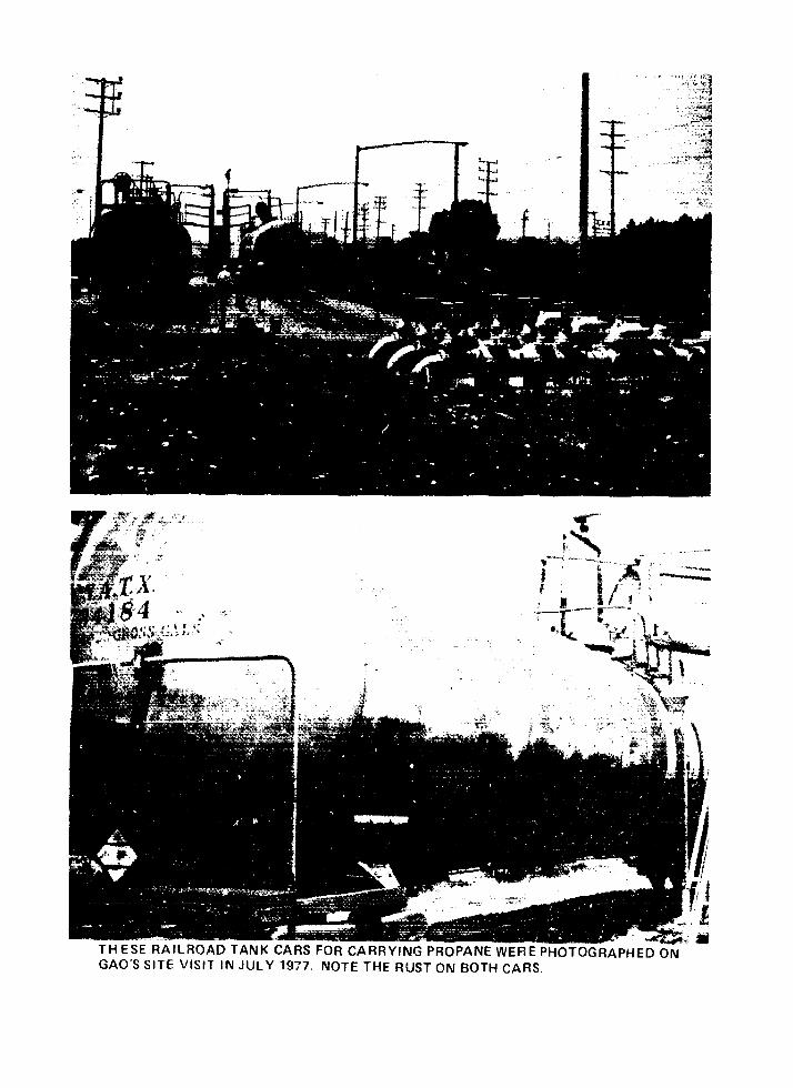
~~~~~~~~~~~~~~~"-t~~~~~~~~~~~~~~~~~~~~~~~~~~~~~~~~~~~~~~A
_t LI 3I : t" :~' .~ ~ t~w- _r
11
_~~~~~
_ ~~~~~~~~~~~~~~~~~~~_-
- ,:
I ~~~~~ ~ ~~~~~~~.~ ; I . "
, . .. ,
g7rx = j/ f t X _- ~ ~ ~ ~ ~ ~ ~ ~ ~ ~ ~ ~ ~ ~ ~ ' 4,, t . .
THESE RAILROAD TANK CARS FOR CARRYING PROPANE WERE PHOTOGRAPHED ONGAO'S SITE VISIT IN JULY 1977. NOTE THE RUST ON BOTH CARS.
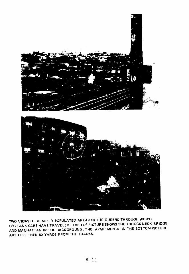
TWO VIEWS OF DENSELY POPULATED AREAS IN THE QUEENS THROUGH WHICH
LPG TANK CARS HAVE TRAVELED. THE TOP PICTURE SHOWS THE THROGS NECK BRIDGE
AND MANHATTAN IN THE BACKGROUND. THE APARTMENTS IN THE BOTTOM PICTURE
ARE LESS THEN 50 YARDS FROM THE TRACKS.
8-13

densely populated areas of the city, over bridges and
elevated railways. The NYCFD is not alerted to the passage
of these cars and only becomes aware of a specific movement
if there is an accident. There have been LPG incidents,
including derailments, to which the Fire Department has had
to respcnd. The Fire Department has objected to LPG
transportation through New York City, but has been unable
to prevent it because that would be interference with
interstate commerce. Although there apparently has been no
L'G rail traffic through New York City in the past year,
the Fire Department is still concerned. There is nothing
to prevent such traffic from resuming at any time.
The danger from an LPG spill would be particularly
acute in a densely populated area, such as New York City:
propagation of explosions in urban canyons, sewers, or
subways, and the impossibility of quickly evacuating
thousands of people multiply the hazards. It is fortunate
that most la;ge accidents have occurred in relatively
unpopulated areas; that they do not always do so is shown
by the Decatur fire.
As shown in Chapter 9, sabotage of LPG cars would not
be difficult. Youth gangs frequently place obstacles on
tracks which delay freight trains in New York City just to
harass the trainmen. The potential danger from moving LPG
through urban areas is very great.
HMD ha¶ jursliction in this area, but o~;poses
restrictions on LPG movement for several reasons with which
the industry generally agrees- it is simpler and more
--ionomical to regulatr tank car desian than tank car
mo'ement; trains move mole slowly in congested areas,
decreasing the ch nce of an accident; there is an accidert.
8-14
rate associated with handling and switching cars, more of
which would be necessary in circuitous routing. For
similar reasons, there is little regulation of the position
of LPG cars in a train. Although LPG cars cannot be placed
next to explosives, radioactive materials, o. poison gas,
LPG cars are shipped consecutively, which has frequently
caused a domino effect in accidents. HMD believes that the
new regulations for tank car construction are sufficient
for their safe operation. We believe restriction of routes
is also necessary.
FINDINGS
Boiling Tiqu' Expanding Vapor Explosions (BLEVE's)
are not caused by overpressurized LPG tanks, but by
the steel of the uninsulated, single-wall tanks
weakening from intense heat to the point where it can
no longer hold the normal tank pressure.
By December 31, 1981, all 112/114 LPG cars will be
required to have shelf couplers, tank head resistance
systems, and thermal protection. DCT has proposed to
shorten this schedule.
DOT has taken no action to improve the strength or
fracturing properties of the steel used in tank cars,
or to protect the sides of tank cars from punctures.
The static pressure tests required of tank cars every
10 years and of safety valves every 5 years are not
adequate to ensure that the cars are safe in e. treme
conditions.
2-15

Rusted tank cars holding propane under high pressure
are currently being used.
LPG cars travel through densely populated areas of
cities, even cities which prohibit LPG storage. If
large amounts of LPG or its vapor get into the
sewers, subways, and other subterranean ducts in a
big city, it could lead to a catastrophe.
Sabotage of LPG cars or the trains they are part of
would not be difficult.
Current practices of emergency response to railroad
LPC accidents are inadequate to protect the public.
8-16
RECOMMENDATIONS
We recommend that the Secretary of Transportation:
require a large increase in the size of the placards
saying "Flammable Gas" so that they can be more
easily read from a considerable distance in the
jumble and possible fire of a train wreck.
require that all LPG cars be prominently labeled
"Insulated" or "Non-Insulated" until thermal
protection is required on all of them. This
information will be of great help to firemen
confronted with a train wreck involving LPG cars and
may save many lives.
consider requiring tougher steel in tank cars, or
additional puncture protection for the sides of tank
cars.
take immediate action to inspect hazardous materials
tank cars and remove from service those that are
obviously not being maintained properly.
require more frequent inspection and tescing of all
safety-related features of LEG tank trucks and
railcars.
prohibit the travel of LPG railroad cars to or
thr ugh densely populated areas unless it is
impossible to deliver it without going through
densely populated areas.
8-17
require that the Bills of Lading on any train
containing hazardous materials have detailed
instructions on fire fighting and other emergency
measures which should be taken in the event of a
wreck. The telephone numbers of 24-hour emergency
response centers, such as the Manufacturing Chemists
Association "Chemtrec", should also be shown. If the
train is to go through any densely populated a:eas,
the instructions should explicitly address the
dangers peculiar to such areas.
establish Railroad Disaster Cclitrol Response teams,
capable of quickly responding to railroad hazardous
materials accidents with the knowledge and equipment
necessary to prevent disasters.
investigate methods of quickly determining the
structured integrity of damaged tank cars and methods
cf emergency transfer of material.
8-18

AGENCY COMMENTS AND OUR EVALUATION
We recommend that the size of identifying placards on
LPG tank cars be increased. The Materials Transportation
Bureau in DOT comments that "because of the unique shape
and current size of the placard, it is recognizable from a
distance sufficient, in most cases, to provide safety to
the view-r." On the other hand, the Federal Railroad
Administration, also in DOT, comments that "there is no
practical size placard that can be read safely in an
accident," and that the placard is for other purposes.
We stand by our original recommendation. Enough
train accidents involving LPG cars have occurred in just
the last few months to underline the importLa..e of being
able to identify quickly and clearly derailed LPG cars.
Both MTB and FRA comment that a requirement for
tougher steel in tank cars would not be cost-effective.
The accidents we have noted, especially the one in Waverly,
Tennessee, demonstrate that improving steel properties
could be an important step in reducing injuries and deaths.
We have made no attempt to calculate the value of reducing
injuries and deaths.
FRA states that our recommendation-requirinr
immediate action to inspect hazardous materials tank cars
and remove those not being maintained properly--is not
needed since such action is already being taken.
FRA also says that "firefighters would receive no
useful information" if LPG cars were labeled 'Insulated'
and 'Non-insulated', and that they "do not believe there
8-19
need be special information for handling accidents in
densely populated areas."
We disagree. MTB's new regulations point out the
advantages of insulated tank cars, and firefighters should
be aware of the conditions of railcars they approach. We
have also shown that populated areas present especially
hazardous situations (e.g., sewers), and special
precautions do need to be taken to prevent catastrophes.
FRA disagrees with the recommendation to prohibit LPG
rail traffic through densely populated areas unless it
cannot be delivered by another route. MTB also notes that
we have riot defined precisely "densely populated area."
In this report we identify movements and storage of
LEG ti4cu'gh major urban areas. In Implementing our
recommendation, the responsible Federal agency will have to
define densely populated areas.
8-20
REFERENCES
1. 1976 LP-Gas Market Facts, National LP-GasAssociation.
2. Association of American Railroads.
3. Yearbook of Railroad Facts - 1977, Association of
American Railroads.
4. 49 Code of Federal Regulations, Transportation, Parts
1I-0o 199, Dec. 31 76, Office of the Federal
ReGister, General Services Administration.
5. Accident Bulletin, 1973, 1974, 1975, and 1976,Federal Railroad Adm-instrationn--epartment of
Transportation.
6. Annual Reports on the Hazardous Materials Control,1970-1976, Secretary of Transportation, Department of
Transportation.
7. "Railroad Accident Report: Derailment and Subsequ .nt
Burning of Delawar- -nd Hudson Railway Freight Trai.,
at Oneonta, New York - February 12, 1974," National
Transportation Safety Board, October 17, 1974, Report
Number: NTS13-RAR-74-4.
8. "Hazardous Materials Incident sport #4080869" to the
Department of Transportations '?oordinated Attack' in
Fire Command:, July 1975, p. 14-17.
9. 49 CFR Parts 172, 173, and 179.
10. "Lessons - An NFPA Staff Report." in Fire Command',-ril, 1972, p. 18-25.
11. .nalysis of Findings of Four Tank-Car i,ccidcnt
Reports," Report Number FRA-OR&D 75-50, C.
Interrante, G. Hicho, D. Harne, January, 1975.
12. Fire Protection Handbook, NFPA, Boston, 1976, p.
3-40-3-47.
13. Docket Number HM-144; Amendment Numbers 173-108,
179-19, September 9, 1977.
14. "Phase 5 Report on June 9, 1974, Accident Involving
Head Shields," August 72, 1974, RA-05-2-29; "Phase 5
Report on Head Shield Fatigue Tests," November 10,
8-21
1975, RA-05-3-35; Railroad Tank Car Safety Researchand Test Project, RPI-AAR.
15. "Energy Required to Supply Propane" and "PropaneTransportation, 1974," by D.N. McClanahan for TexasLP-Gas Association, June, 1976.
8-22

CHAPTER 9
VULNERABILITY OF LEG FACILITIES TO SABOTAGE
CONTENTS PAGE
INTRODUCTION 9-1
THE THREAT TO LEG FACILITIES 9-2
Availability of Weapons 9-3
The Introduction of LEG or Naphtha into
Underground Conduits 9-4
VULNERABILITY OF FACILITIES TO SABOTAGE 9-8
Urban Area Facilities 9-9
Storage Tanks and Dikes 9-11
Concrete LNG Tanks 9-11
Double-Wall Metal Tanks 9-12
Single-Wall Metal Tanks 9-12
Tanks Built on Piles 9-13
Underground Storage 9-13
Close High Dikes 9-14
Piping 9-14
SECURITY EVALUATION OF LEG TERMINALS 9-15
VULNERABILITY OF LEG TRUCK TRAILERS AND
RAIL TANK CARS TO SABOTAGE 9-17
LPG Vehicle Tanks 9-18
LNG Trailer Trucks 9-19

VULNERABILITY OF LEG AND NAPHTHA SHIPS TOSABOTAGE
9-19External Attacks
9-19Vulnerability
9-20FINDINGS
9-22GENERAL CONCLUSION
9-25RECOMMENDATIONS
9-259-25AGENCY COMMENTS AND OUR EVALUATION
9-29REFERENCES
9-34
INTRODUCTION
We have tried in this chapter to discuss the possible
effects of sabotage on LEG and naphtha transportation and
storage facilities in a way which does not substantially
contribute to the ability of malicious persons to carry out
such acts.
To consider the possible effects of sabotage on LEG
and naphtha transportation and storage facilities we:
a. Assessed the current security levels of trucks,
tank cars, terminals, storage sites, and
processing facilities.
b. Evaluated the sabotage vulnerability of ships,
trucks, tank cars, pipelines, terminals, and
storage sites.
c. Determined what weapons, explosives, and other
materials are available to potential saboteurs.
d. Assessed possible effects on ships, trucks, tank
cars, pipelines, terminals, and storage sites of
various sabotage scenarios.
e. Conducted charge calculations for ships, trucks,
tank cars, pipelines, and storage tanks to
determine the type, configuration, and amount of
explosive materials/weapons required to
accomplish the necessary penetration.
f. Conducted experiments with munitions known to be
in the hands of terrorist organizations to
9-1
validate ce:tain of our calculations and
evaluations.
To collect the data for this chapter, we made acomprehensive literature review, visited sites andfacilities, studied detailed company plans and blueprints,and held discussions with industry, government, and otherpersonnel.
THE THREAT TO LEG FACILITIES
A typical sabotage threat analysis would ch--acterizepotential saboteurs according to their attributes,capabilities, and motivations. Although the potentialthreateners to LEG facilities have not been previouslystudied, there is no reason to believe they wouldconstitute a very different group than those for nuclear orother large facilities. Detailed threat studies have beendone for nuclear facilities.l In addition, there are manydocuments available which discuss typical perpetrators ofmalicious actions. Thus, we have concentrated our effortson assessing the resources available to saboteurs and thevulnerability of LEG transportation and facilities tosabotage.
Groups which might try to sabotage LEG transportationor facilities can be divided into four categories: foreigngovernments, foreign subnational groups, domestic criminalgroups, and domestic political dissident groups. There areelements in each category which have the necessarycapabilities and might have the motivation.l' 2
additio'i, an isolated, knowledgeable, capable psychoticmight 'ry ILEG sabotage.
9-2

Appendix IX is a compilation of recent bombing
incidents Obtained from the FBI Bomb Data Program Incident
Summaries for the period 1974 through 1977, including a
selected list of incidents which occurred on public utility
and oil company properties. The number of attempted and
actual bombing incidents reached a peak of 2,074 in 1975
and then dropped to 1,314 in 1977, the lowest number in
several years.
Availability of Weapons
In addition to commercially available weapons and
explosives, an impressive array of weaponry has been stolen
from military installations and National Guard armories.
The losses include small arms, automatic weapons,
recoilless rifles, anti-tank weapons, mortars, rocket
launchers, and demolition charges.
A large number of commercially available publications
provide detailed instructions on the home manufacture of
explosives, incediaries, bombs, shaped charges, and various
other destructive devices. All the required material can
be bought at hardward stores, drug stores, and agricultural
supply outlets. Many of the manuals also discuss tactics
and techniques for sabotage operations. These types of
books are readily available at libraries across the
country, including the Library of Congress.
It is not unusual for international terrorist groups
to be armed with the latest military versions of fully
automatic firearms, anti-aircraft or anti-tank rockets. and
sophisticated explosive devices.
9--3
The mobility of international terrorists and the easewith which they acquire and transport weapons is a matterof serious concern. Our inability to cntrol thecross-border drug traffic, and the continuing large inflowof illegal aliens indicate that weapons and small terroristunits could also be infiltrated into the United States.
The Introduction of LEG or Naphtha into Underground
Cond-uits
LEG coulc be used as an ignition material for fires.A hijacking of one or more tanker rucks would provide asignificant, uncontrellable source of ignition andexplosions. If LEG were released into a sewer system orsubway, a disaster could result. Even naphtha, a much lessdangerous mate~ial, can cause extensive damage, as a recentincident in Akron, Ohio showed.
Around 2:30 a.m. on June 23, 1977, a major sewer liner ining beneath Akron's Glendale Cemetary exploded. Thestieet outside the entrance to the cemetary collapsed.(The photograph shows the resulting damage.) Water from aruptured pipe enlarqce the crater into a huge trench. Asthe blast rolled through nearly 7,000 feet of sewer main,other sections of pavement buckled and caved in. Cast-ironmanhole coffers were hurled into the air. Storm drains werecracked. Fortunately, much of the force of the explosionwas vented through the manholes and storm drains orabsorbed by the old-fashioned 13-inch brick wails of thesewer. Otherwise, the explosive mixture would havedetcnated, according to the City's investigators. 3 As itwas, there was little damage to nearby homes except forsome broken windows. If the explosion had occurred at abusier time, such as during rush hour traffic, damage would
9-4
ujz
I
Ia
Inw
LU
U.
cc
w
z20t
uj
Lii
L-
j
I. 7~~~~~~~~~~~~~~~ 4
La.
9- 5
have been greater, and injuries may have resulted. A sewerexplosion in Cleveland in 1953 killed one person andhospitalized 58 others. 4
The Akron blast was caused by naphtha. Atapproximately 8 o'clock the previous night, a disgruntledformer employee broke into the Patch Rubber Company andopened several storage tanks. In all, 11 cubic meters(3,000 gallons) of naphtha and 3.5 cubic meters (900gallons) of other volatile liquids spilled on the plantfloor.
The naphtha poured down a drain in the floor andflowed into the sanitary sewer system at the rate of 64liters (17 gallons) a minute. After about 3-1/2 miles,this line widens into the main bricklined storm andsanitary sew:er. As the naphtha passed through this 10-footdiameter main line, there was enough air to dilute the richvapor to the flammable range. The explosion came six hoursafter the naphtha was dumped, and eight miles from thepoint of entry. The route of the spill is shown on themap. The inset indicates the site of major damage.
Investigators suspect that the hot catalyticconverter of a police car that had stopped close to amanhole opening set off the explosion. The engineersestimated that only 2.2 cubic meters of naphtha wasrequired to fill the 6625 foot section of the main lineinvolved in the explosion. Akron officials estimate thatcomplete repairs of the streets and the sewer line willtake at least a year and cost more than $10 million.
9-6
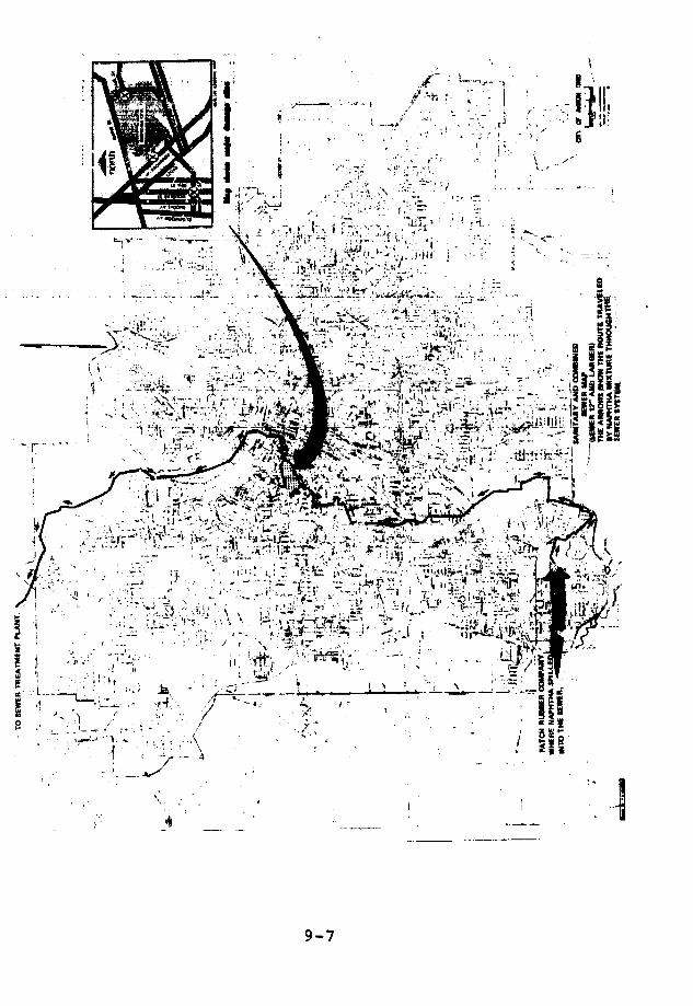
.i'- .... -"-i ,: -' i . '
.=
.- . .;. ~ ,,~ -, ..t .. :
N ~ ~~~~~~~' 4
V .~~~~~~~;1
~~~~~~~~~~~~~~~~ . 7dd_:
· ~~~~~~~~~~~~t ,, : ~
.: i!~ : .~'. ,- .~ ..~, .. .-. ,, _..... ',
It ; i- i' i ' 9
· '.-~ ;,-,~--' ~ ·. .,i .", .-';' r.,.t ?,-q,-- I .·'.'--ix '.: =.: :
14 ; t w > \ f'·- 1 ¼ --S-
' L; ~' t' "-:;tl,~l~[I ' 4.; g
, :.~- ,,' .
X - -;~~~~t~, r ''-, ';t.; ,,1'
', -' ,, '-' '' <,, l ................................. ,'..l
:1L ;..-qpF 1s;23 a II
' '<¢>~~~1 'ss 4t ;2*1->X!*1
N\t i H> f)5~~~~~~~~~~5
,-'-=,--~~'~ "~' 11~ -~,e. ~.J ,'.-;'';, ,~,~
~~~~~~~~~~~~~~~~~~~~I_,i " -~ ' "X2A
~6 -! ' .. ~ . ,' ., .4 .. .. . _~ . . , ~ . ' . . ....." ~ ~ ~ ~ ~ ~ ~ ~ ~ ~ ~"~-'~ !'.... :.~.t 'l a )-, ', ''
.. ..
II,~ ~ ~ ~ 'I
. .....:9
"t ~~~~~~~~~~~~~~.--. j.-'~'"
~\·L? ·--" _, .':';· l ' '
'' :t . -1'I9
,,, 1~_ '-
~- ~ ~ 4C' tI1. ~ ~~~~~~~~~ : : ~. ~ ~ "·_l·ik:'~
a .i; 1·:~~~~' ...;·C
2'-~~~~~~""i
~~~~~~~~~~~~~~~~~~~~~~~~~~~~~~~~~~~~~~~~~~~~~~~~~~~---:rl~i;
1L1 tl· g-? i
An investigation of the 1953 Cleveland blast4
concluded that the most probable cause was eitherindustrial wastes, or gasoline leaking into the sewer, or acombination of these. The investigators found that therate of vaporization of flammables and tie length of timethey remain in the sewer are critical factors in explosionsof this kind. They also found that volatile flammableliquids in surprisingly small quantities may producedevastatingly destructive effects if the structures ale notsuitably drained or ventilated. They said that gasolineleakage of five gallons per day into the sewer for about amonth, a total leakage of about one-half cubic meter, wouldhave provided an explosive mixture sufficient to cause thedisaster.
VULNERABILITY OF FACILITIES rTO SABOTAGE'
All our findings Jn the vulnerabilities of LEG andnaphtha facilities to sabotage have been thoroughlycorroborated by reference data, calculations on individualcomponents, or actual test. The assessments are presentedto provide a better understanding of the potentialvulnerabilities of LEG system components. To avoidincreasing the danger, none of the systems is identifiedwith a specific site.
Our vulnerability assessment considers malicious actsby an individual or groups of individuals which couldthreaten offsite lives and property. The assessment waslimited to the damage that might be caused by a sabotagegroup of no more than six outside individuals with theassistance of two insiders. The group's resources werelimited to those known to be available, as discussedearlier. The actual threat could be considerably greater.
9-8
There are two basic types of LEG facilities: base
load plants, including import terminals; and peakshaving
plants. The storage and processing facilities of both
types are similar in physical layout. The design of
individual components (e.g.. storage tanks, piping,
processing equipment, dikes), however, varies with location
and manufacturer, as shown in Appendix XVI-2. Peakshaving
plants can be located in any area with access to
transmission lines or truck transportation. Import
terminals must have onshore pier facilities or offshore
terminals with connecting pipeline trestles or tunnels.
Urban Area Facilities
Urban LEG facilities are usually located in heavy
industrial developments predominantly occupied by petroleum
product storage and processing. LEG storage facilities are
often adjacent to other facilities which store very large
quantities of LEG or other volatile liquids. Some are next
to sewer plants which store large amounts of deadly
chlorine gas. This proximity means that a single cause,
such as an earthquake or an attack might simultaneously
destroy many tanks, thus increasing the damage and
casualties many times. A major incident at one facility
might cause further failure at adjacent facilities and set
off a chain reaction. For example, a detonation in a
propane cloud might initiate a detonation in a natural gas
cloud.
Urban area facilities are attractive targets for
saboteurs, particularly terrorists, because of the
immediate impact of any significant incident on large
numbers of people. The normal workday congestion and
confusion provide excellent cover for daytime infiltration,
9-9

observation, sele-tion cf targets and determination ofaccess and escape routes. One possible form of sabotageinvolves selectively disabling critical components. Thus,it is important to carefully screen site personnel who haveaccess to plant monitoring and control equipment. Ifinsiders disable key components at the same time thatoutsiders breach a pipeline, a major spill could result.Certain tank designs and piping configurations we examinedwould facilitate causing a spill outside the containmentarea.
At one terminal we visited, police and Coast Guardsecurity are routinely provided during LNG unloadingoperations, but this is not the practice at most LEGterminals.
We observed a salvage yard crane operating close tothe pier-tc-plant pipeline at this plant during theunloading of an LNG ship There. An error by the craneoperator could have caused a large amount of metal scrap todrop on the pipeline. This could have released asignificant quantity of LNG outside the diked area.
The extensive tank truck and rail car traffic betweenimport terminals and other storage facilities provides amalicious group with three options. It can:
Hijack one or more trucks and use the contents formalicious action.
Conceal a time-delay d2vice on a truck or rail carset to detonate at a critical time and location.
9-10
Use a truck as a means of plant entry or possible
extortion.
Storage Tanks and Dikes
The primary considerations in determining LEG
container vulnerability are:
a. Tank design and materials.
b. The size and depth of penetration required to cause
massive release of the contents.
The predominant materials used in tank construction
are steel, aluminum and concrete. However, as shown in
Appendix XVI-2, container designs and dimensions vary
considerably between sites. Although non a* the tanks we
examined are impervious to sabotage, some designs do
provide a greater degree of protection against explosive
penetration than others. Stronger designs also complicate
the sabotage operation by requiring specially designed
charges, more explosive materials, and more onsite
preparation time. Concrete tanks have much more resistance
to penetration than single wall LPG tanks; double wall
metallic tanks fall in between.
Concrete LNG Tanks
The depth of the concrete berm around a typical
concrete tank provides fairly effective protection against
explosive breaching of the tank walls. It would require
close to 1,500 pounds of explosive placed .In direct contact
with the outside wall, to cause significant damage to a
concrete tank of this size. If the walls were constructed
9-11
entirely of reinforced concrete, the explosive requirements
would be increased by a factor of 1.5. The depth of the
concrete berm also makes these tanks highly resistant to
shaped charge penetration. There are currently ro known
weapons in the terrorist arsenal that are capable of on_
shot penetration of a concrete tank. The addition of a
high contiguous sloped earthen berm around these tanKs
provides an almost impenetrable barrier against sabotage.
Double-Wall Metal TanAs
Because limited data are available on explosive
effects against typical metal double-wall LNG tanks we
conducted live firing tests against a full scale tank
section with an inner tank of cryogenic aluminum. The
tests confirmed that the double-wall structure of these
tanks affords limited protection even against non-militiry
small arms projectiles, and that devices used by terrorists
could cause a catastrophic failure of Lhe inner wall. The
rapid release of LNG (at -260 F) against the outer carbon
s-eel wall could result in extensive crack propagation and
possible collapse of that wall as well.
Double-wall tanks which permit access to the
insulation space through near ground level manholes are
particularly vulnerable to explosive damage. Interior
placement of charges would more than double their
effectiveness.
Single-Wall Metal Tanks
The single-wall metal tank is the most vulnerable to
sabotage. The critical crack length (see Chapter 4) for
typical large single-walled tanks is small enough so that
9-12

prcperly placed charges could cause their complete
catastrophic 'ollapse. This would cause a large amount of
the contained fluid to escape the dike (see Chapter 5).
Tanks Built on Piles
Some large storage tanks are supported on pile
foundations. We observed one design with about 1.5 feet of
air space between the bottom of the tasLk and the ground
surface. This design can reduce by 67 percent the amount
of explosives required for extensive rupture of the tank
floor. Ground wave reflection and the tamping effect of a
partially enclosed space significantly increase the peak
pressure of the blast wave. The partial confinement of the
resulting gases sustains the pressure on the tank bottom,
which can cause more damage than the initial blast wave.
There is also a danger of LEG and LEG vapor
accumulating under the tank in the event of a spill. The
gases, if ignited, might explode and cause an extensive
rupture of the tank floor. No one has looked into this
possibility.
Underground Storage
The pipes connected to mined caverns are vulnerable
to both accidental and malicious actions, but redundant
automatic safety devices provide an almost instantaneous
water seal to control vapor release to the atmosphere.
Liquid hydrocarbons can be released by overfilling,
however, as has happened in Marcus Hook on January 28,
1978.
9-13
Close High Dikes
A typical thin high dike wall can be easily breachedby a small amount of explosives and properly placed chargeswould blow out a very l6rge section of the bottcm of thewall.
Earthen dikes are much more resistant to sabotagethan thin, high concrete dikes, Even the smaller earthendikes are relatively difficult to breach unless boreholingtechniques are used.
Piping
The liquid pipelines which fill and empty LEG tanksare extremely vulnerable, but there are few circumstancesin which their rupture would result in offsite damage. Tocause offsite damage would require careful planning,timaing, and execution, and the assistance of at least oneemployee with a thorough knowledge of control paneloperations and automatic safety valves. To avert such anincident, tank connections and pipeline routing should beexamined to determine the possibility of:
Inducing, from the head in the tank, a
self-sustaining flow through the bottom draw-offlines to a point outside the diked area.
Intentional pumping of LEG or naphtha to the samepoint.
9-14
In many facilities fluid can be sent beyond the dikes
both ways. This is particularly critical in plants with
concrete tanks and no containment area, or those with close
high dikes.
SECURITY EVALUATION OF LEG TERMINALS
The most effective deterrent to sabotage is a well
organized physical security program. In addition to a
security plan which details responsibilities, procedures,
and countermeasures, the need for the following factors
should be determined for each facility:
Physical barriers, guards, guard dogs, random roving
patrols, and alarm systems.
Area surveillance devices and intrusion detection
systems; including terrestrial, in-water, and
waterfront sensors.
Specialized and redundant communications and lighting
systems.
Hardening of specific structures to reduce the ease
of damage and control forceful entry.
Security escorts for ships, trucks, and tank cars.
Traffic control, air and underwater surveillance,
unique security procedures and countermeasures for
waterfront and :bore facilities.
Special damage controi equipment and procedures.
9-15

Personnel screening procedures.
Visitor clearance and control.
Special training requirements.
Authority for 9sards to carry and use weapons.
Training staff to avoid loose talk and to report
suspicious persons.
Access to all of the facilities we visited would be
easy, even for untrained personnel. At the LPG facilities,
in particular, there was an apparent sense of complacency
about security. The only special precaution we observed
during our visits was the use of local police support for
traffic control while the Descartes was offloading' at the
Everett LNG terminal. Only one site provided a detailed
security plan in writing. The rules for LNG facilities
under consideration by the Office of Pipeline Safety
Operations, however, require that each LNG operator prepare
and follow written security procedures.5
All of the 16 LEG storage facilities we visited are
fenced and most of the plants have gate guards and routine
visitor check-in procedures during daylight hours, but none
of the guards are armed. Two sites use closed-circuit TV
to monitor traffic at the main gate. There appears to be
heavy reliance on the closed-circuit Low Light Level TV
system on those sites where it is installed. Procedures
for internal patrols seem to depend on the individual
initiative of the crew foreman or night watch, particularly
during plant "idle-time" periods. On one night neither wenor company personnel were able to establish phone contact
9-16

with anyone at an urban, operating LNG plant. There is no
intrusion/detection alarm system at any of the
installations.
The lack of redundancy of certain facility
installations and equipment contributes to overall plant
vulnerability. Emergency power supplies and communications
are two critical areas. Because even untrained saboteurs
recognize the importance of severing all communications and
power supply lines, battery operated radios with a 24-hour
emergency channel to police should be available at key
locations throughout plant areas. Emercency generators
should be located away from hazardous areas, with a fuel
supply that is well protected from fire and exp osions.
Security procedures for truck trailer and railcar
operations are inadequate. Drivers are not identified nor
are vehicles and railcars inspected, before loading or
offloading. This is of particular concern because trucks
are vulnerable to hijacking and unguarded railcars are
attractive targets for terrorist groups.
VULNERABILITY OF LEG TRUCK TRAILERS
AND RAIL TANK CARS TO SABOTAGE
Truck trailers are used to transport both LNG and
LPG; rail tank cars are used only for LPG.
The extended exposure of these mobile LEG containers
increases their vulnerability to sabotage. A truck or rail
car which operates over an established route between fixed
points is an easy target for a saboteur. A truck can be
hijacked for extortion, or for malicious use of -- e cargo;
a group of tank cars can be derailed at a predetermined
9-17
time and place. Both are very vulnerable to improvised
explosive devices and other weapons comiionly used by
terrorists, including high-powered small arms. Truck
trailers are particularly dangerous because they allow the
easy capture, delivery, and discharge of a large amount of
explosive substance to a point or points of the hijacker's
choosing.
Container design is a critical factor in determining
the vulnerability of a vehiclz to destruction.
LPG Vehicle Tanks
The LPG containers used on tank cars and truck
trailers are single wall, cylindrical, steel pressure
vessels, mounted horizontally. The standard railroad tank
cars hold 115 cubic meters, while the truck trailers hold
40 cubic meters. Tank car fittings and liquid lines are
top mounted at the tank center, while trailers have bottom
rear lines.
The same techniques can be used to penetrate or
rupture LPG trailers or tank cars. The 5/8 inch steel wall
can be easily cut with pocket size explosive devices, and
many other weapons commonly used by terrorists would also
be effective.
LPG vehicle tanks are especially hazardous because
the LPG is stored under pressure, 255 psig at 115 F for
propane. Any tank penetration causes an LPG discharge and
an associated fire hazard. LPG tanks frequently explode
9-18
when exposed to fire. The pressurized storage also causes
LPG to discharge if any tank valve is opened, including the
top mounted valves on tank cars.
LNG Trailer Trucks
LNG is currently carried overland only by trailer
trucks. The tanks are slightly less vulnerable than LPG
tanks because they are double-walled. The walls are
relatively thin, however, and can be penetrated by a fairly
small improvised shaped charge. Properly placed, such a
charge would cause LNG to discharge into the insulation
space, causing the outer jacket to fracture and
disintegrate.
VULNERABILITY OF LEG AND NAPHTHA SHIPS TO SABOTAGE
External Attacks
There are very few alternatives available to a
saboteur of an LEG ship if he is denied on-board access to
vulnerable areas. The placement of explosive charges on a
ship's hull requires diver training and specially designed
devices or significant amounts of military type explosives
to be effective. The sabota.ge operation would have to be
conducted while the ship is anchored or alongside the pier.
Improvised limpet mines can cause critical damage and
flooding in single hull ships, including many LPG carriers.
Several single hulled merchant ships were sunk in Vietnam
with crude home-made limpet devices. Improvised limpet
mines could cause extensive, but not critical damage to a
double hull LNG ship.
9-]9

Effective port surveillance during LEG carrier
operations can minimize the threat. The Coast Guard should
also be prepared to take appropriate action in the event of
a suspected attack. This includes a ship bottom and pier
area search by qualified explosive ordnance disposal
experts.
Boarding a ship in a roadstead or even at anchor is
very difficult without crew assistance. However, saboteurs
might use various ruses, such as feigning injury or
distress, to gain this assistance. Unless pier access is
restricted, a saboteur might be able to board a ship at the
pier under some guise. Effective surveillance and
awareness of the dangers by the ship's crew could prevent
these unauthorized boardings.
Another potential sabotage threat comes from the
crew. Only an expert would recognize some types of
explosive material as explosives. One LNG ship crew
member, trained in the use of explosives, could cause
simultaneous tank and hull damage below the water line,
with proper charge placement. In the absence of effective
damage control, this might initiate an extremely hazardous
sequenre of events. A crew member of a single hull LPG
tanker could do even more damage to the ship.
Vulnerability
The double hull of the LNG tanker provides a higher
degree of resistance tc external blast damage than the
single hull of a LPG ship or a conventional tanker. It
also provides reserve buoyancy and stability control in the
event of extensive damage and flooding. We believe that an
LNG tanker would survive a swimmer sapper attack by a
9-20

terrorist group without significant tank damage. The
spherical tank configuration appears to be the least
vulnerable to this type of attack because of the hull
stand-off distance and skirt support structure.
All four tank designs allow for internal access below
the storage containers. The pipeline tunnels or duct keels
run the entire length of the cargo area with open trunks at
both ends. (See Appendix VI-2.) These tunnels might
become liquid distribution systems in the event of
deliberate explosive rupture of a tank.
9-21
FINDINGS
THE THREAT
Public utilities and petroleum companies have
been often targeted by terrorism groups and
individuals.
A large range of firearms, ammunition, and
explosives is available in this country to
potential saboteurs. Instructions for the
construction and use of appropriate explosives
from easily available materials are widely
available in open literature.
The existence of highly trained, international
terrorist groups armed with sophisticated
weapons and explosive devices, combined with the
openness of our borders, poses a serious threat
to the safety of LEG and naphtha facilities.
Recent and future technological advancements in
weaponry will eventually increase the threat to
LEG and naphtha facilities.
STORAGE FACILITIES AND DIKES
Except during ship unloading at one site, the
security procedures and physical barriers at LEG
and naphtha facilities we visited aze not
adequate to deter even an untrained saboteur.
9-22

Most LEG and naphtha storage tanks are highly
vulnerable to sabotage. Metal tanks are the
most vulnerabla. Underground storage or
concrete tanks with a sloped earthen berm from
ground level to tank top provide the most
protection against explosive penetration.
Sabotage of single or double wail metal tanks
could lead to complete catastrophic failure of
the wall(s) and subsequent massive spilling of
the contents. The level of sabotage needed is
within the capabilities of terrorist groups.
Properly placed charges would blow out a very
large section of the bottom of a high, thin
concrete dike. Properly designed earthen dikes
are extremely difficult to breach.
In many facilities, through manipulation of
equipment, it is possible to spill a large
amount of fluid outside the diked areas through
the draw off lines.
ADJACENT ACTIVITIES
Even a few cubic meters of LEG or naphtha in a
sewer system can cause many casualties and do a
great deal of damage.
LEG storage facilities in cities are often
adjacent to sites which store very large
quantities of chlorine, LEG, or other volatile
liquids. Thus, a single cause might
simultaneously destroy many tanks, or an
9-23
incident at one facility might cause further
failures at adjacent facilities.
LEG VEHICLES
LEG trucks are highly vulnerable to sabotage and
hijacking; tank cars are also highly vulnerable
to sabotage.
Small charges can penetrate the one or two walls
of LEG vehicle tanks, as can other weapons.
LEG can easily be discharged from vehicles, just
by opening unlocked valves.
LNG vehicle tanks are slightly less vulnerable
to sabotage than LPG vehicle tanks.
LEG AND NAPHTHA SHIPS
LNG ships are vulnerable to sabotage, but unless
explosives are used on-board or the ship is
hijacked, massive spillage into the water is
unlikely.
Improvised limpet mines placed oin a single hull
LPG ship, while it is anchored or alongside tne
pier, could result in a massive LPG release and
the sinking of the ship. On-board explosives
could sink the ship even more easily.
9-24
No governmental body has made a comprehensive
effort to determine critical shipboard
vulnerabilities to malicious action.
GENERAL CONCLUSION
The vulnerability to sabotare of LEG facilities and
transportation in urban areas is a serious danger to
offsite lives and property.
RECOMMENDATIONS
TO THE SECRETARY OF TRANSPORTATION
We recommend that the Secretary of Transportation:
enforce the requirement, stated in 33 CFR Part
126.15(a), that guards provided by the owner or
operator of an LEG facility be in such numbers and of
such qualifications as to assure adequate
surveillance and to prevent unlawful entrance. In
particular we recommend that the Secretary make and
enforce regulations requiring:
1) - that every truck and train car is carefully
checked for weapons and explosives before it
enters the facility.
2) - that every driver and passenger in a vehicle is
positively identified before they enter the
facility. Picture badges should be issued to
all frequent visitors.
9-25
3) - surveillance of site boundaries and key
components on a 24-hour basis.
4) - that devices be installed which can immediately
detect unauthorized entry. These should include
completely lighted fences, intrusion alarm
systems which can detect if the fence is damaged
or crossed, and low light television camera3
which can see any area of the boundary.
5) - battery powered redundant communications through
which security personnel at any point on the
facility can communicate to each other and to
local law enforcement officials.
6) - employee screening and training procedures. The
training should include threat awareness,
recognition of hazardous devices, special safety
precautions, and preventive actions that can be
taken.
7) - a written security plan which details
appropriate procedures for all of the above and
is routinely promulgated to all employees.
require that loaded LEG trucks and loaded, stationary
railroad cars not be left unattended outside the
plant area.
determine what security procedures are necessary to
prevent LEG trucks from being sabotaged or hijacked
and used for destruction. Particular attention
should be paid to unavoidable movements of LEG
through densely populated areas.
9-26

identify all the specific design vulnerabilities to
sabotage at each facility and determine the amount of
hardening of key components that is needed to reduce
facility vulnerability to sabotage and to control
forceful entry.
require that emergency generators be located away
from hazardous areas, with a fuel supply that is well
protected from fire and explosions.
require that automatic shut-off or isolation valves
be placed along pipelines which run from piers to
storage tanks.
prohibit the transmission of LEG through pipelines
whose integrity is threatened by nearby offsite
industrial activity.
examine the total handling and storage system at each
facility to see if an external pipeline breach in
conjunction with the misuse or disabling of
appropriate system components could cause a major
spill outside the containment area. DOT should
require whatever modifications are needed to make
this impossible.
examine all facilities near LEG storage sites to see
the consequences of simultaneous failures at several
sites from a single cause and whether failures at one
facility could cause failures at others.
determine whether LEG or LEG vapor accumulating under
a tank elevated on piles could cause an explosion
that could rupture the tank bottom.
9-27
systematically determine the critical vulnerabilities
to sabotage of ships carrying hazardous materials in
U.S. ports and require appropriate preventive and
mitigating measures.
implement eftictive nort surveillance during LEG
carrier operations.
be prepared to take appropriate action in the event
of a suspected attack including a ship bottcm and
pier search by qualified explosive ordnance disposal
experts.
develop contingency plans and emergency procedures
for individual ports in the event of a ship
hijacking.
TO THE SECRETARY OF ENERGY
We recommend that the Secretary of Energy:
establish a comprehensive program to determine the
vulnerability of LEG tanks to sabotage. This program
should include the effect of:
o External explosives, including shaped charges.
o internal explosives.
o Firearms and light anti-tank weapons.
o Introduction of other chemicals.
9-28
TO THE CONGRESS
We recommend that the Congress-
enact legislation requiring that facility guards
carry weapons and be authorized to use them if
necessary to prevent sabotage. This recommendation
is similar to one that GAO made in 1977 for
commercial nuclear fuel facilities.6
AGENCY COMMENTS AND OUR EVALUATION
The Departments of Transportation and Commerce
question the need for much of the material in this chapter.
They express concern that the chapter could provide
material for potential saboteurs. Many industry corrments
reflected similar concerns.
Unfortunately, instances of sabotage and terrorism
occur so frequently in today's world that the potential
cannot be ignored in any serious treatment of Lhe safety of
highly dangerous substances such as liquefied energy gases.
Nor would it be sufficient merely to say that LEG
facilities are vulnerable to sabotage. In making a
realistic assessment of this vulnerability. we have
attempted to show that malicious groups could sabotage LEG
facilities and that current safeguards should be upgraded
substantially. We have been careful not to give any
information which would significantly increase the ability
of potential saboteurs.
Notwithstanding its overall concern, the Department
of Transportation agrees with many of GAO's recommendations
9-29
and points to several comparable provisions for LNG
facilities in an Advance Notice of Proposed Rulemaking
(ANPR) published by OPSO on April 21, 1977.
In several instances the ANPR addresses generally,
but not specifically, an issue dealt with in our
recommendations. They would require, for example, a
written security plan, employee screening and training
procedures, locating emergency generators away from
hazardous areas, and written procedures for dealing with
possible damage effects. DOT agrees that more specific
requirements can reasonably be included in its regulations.
We believe the specific requirements we recommend are
necessary.
One section of the ANPR partially satisfies our
recommendation that DOT prohibit the transmission of LEG
through pipelines whose integrity is threatened by nearby,
offsite industrial activity. Only new LNG facilities
connected to natural gas pipelines are covered, however.
We believe that existing LNG facilities and new and
existing LPG sites should also be covered.
ANPR provisions would also require 24-hour
surveillance of site boundaries and key components,
battery-powered redundant communications, and, at
facilities storing 250,000 barrels (40,000 cubic meters) or
more, intrusion devices. DOT's comment, however, notes
that alternate provisions for small, remote sites may be
needed or appropriate. We agree that it may be appropriate
to consider special provisions for remote sites, but such
provisions are not included in the ANPR.
9-30
Even though DOT agree-- in o'neral with a number of
our recommendati,ons and points to its ANPR as corrective
action already underway, we should point out that the ANPR
was issued over one year ago and is just that, an advance
notice. No proposed rules have been issued, and DOT
officials could not tell us when they may be.
DOT disagrees with our recommendation that it
determine whether LEG or LEG vapor accumulating under a
tank elevated on piles could cause an explosion that could
rupture the tank bottom. DOT states that ". . .safety is
more effectively and efficiently served by prohibiting such
designs of new facilities, as provided in the ANPR."
Even if the building of new LNG tanks on piles is
prohibited, it still is necessary, in our opinion, Lo
determine the vulnerability of existing tanks built on
piles. DOT states that such research would be "extremely
costly". Experts we consulted indicate that the kind of
structural analysis and explosion effect calculations
needed to carry out our recommendations would not require a
sizeable expenditure of money or time.
DOT objects to our recommendation that it require
modifications in facilities to prevent a major spill from a
combination of an external pipeline break and the misuse or
disabling of appropriate system components. DOT states
that: ". . .in the absence of any showing of an imminent
hazard, we believe the intended retrofitting of existing
facilities is unjustified, and short of shutting down a
large number of facilities, implementation is not possible.
Such action could have a dire impact on public welfare with
9-31
associated greater risk than continued operation of thefacility. . ." They agree that such modifications shouldbe made for new facilities, however.
We believe the existing facilities would need to beshut down only a short time, at most, in order to implementthis recommendation. This could be done during a period oflow demand. The grave danger which could be caused from amajor spill generated in this manner is the same forexisting and new facilities, and greatly outweighs anyinconvenience involved.
DOT isagrees with our recommendation that it requireevery truck and train car to be carefully checked forweapons and explosives before entering a facility. DOTquestioned whether such a check would be effective in lightof the potential for concealment and resulting lost timeand cost.
In some ways such checks would be similar to baggageand passenger checks at airports. Once LEG checks arestandardized, they would require relatively little time andshould prove to be very effective.
DOT states that some efficient steps can be taken toreduce the risks to LEG trucks of sabotage, hijacking, anddestructive use. These include requiring vehicles to beattended, use of driver-initiated engine breakdowncontrols, manual reset wheel locks, locked valves, theinstallation of tire pressure release devices, gas tankwater injectors, "on only" visual audible alarms, andautomatic emergency signal transmitters. We agree thatthese measures should be required.
9-32
In a general comment on this chapter, DOT states:
"The security measures proposed for LEG facilities, if
imposed continually, are a classic example of an 'overkill'
approach to protect one possible terrorist target while
leaving other equally desirable targets unguarded.
Furthermore, the recommended security measures would not
deter the effective use of the mortar and rocket weapons
which the report states are in the hands of potential
saboteurs. Neither would these precautions at LEG
facilities in any way affect the availability to saboteurs
of gasoline or their access to drains for introducing many
times the required 1/2 cubic meter into every sewer system
in this country." Some industries made similar comments.
We do not agree for these reasons:
(1) Gasoline, because it is a liquid under normal
conditions, is much less dangerous in sewers and
elsewhere than LEG.
(2) Adequate security measures would offer qreat
protection against the worst sort of
sabotage--which requires entry to the site.
(3) Our work was directed to liquefied energy gases.
The dangers are clear, and the measures needed
are effective and appear to cost relatively
little. If there are other equally grave
dangers to public safety, corrective measures
for them should also be considered.
9-33

REFERENCES
1. Mitre Corporation, "The Threat to Licensed NuclearFacilities" MTR 7022, September 1975.
2. LEAA National Advisory Committee on Criminal JusticeStandards and Goals, "Disorders and Terrorism"Washington, DC 1976.
3. "Investigation of June 23, 1977 Willow Run SewerExplosion," HRC Report 3876, Hazards ResearchCorporation, Denville, N.J.
4. Investigation conducted by a committee of CaseInstitute of Technology professors, retained asconsultants by the cities of Cleveland and Lakeland,Ohio.
5. Department of Transportation (OPSO), Advance Noticeof Proposed Rulemaking, "Liquefied Natural GasFacilities (LNG); Federal Safety Standards",Development of New Standards. Federal Register, Vol.42, No. 77, April 21, 1977.
6. An Unclassified Digest of a Classified ReportEntitled "Commercial Nuclear Fuel Facilities NeedBetter Security." EMD-77-40a. May 2, 1977.
9-34
CHAPTER 10
THE CLEVELAND LNG ACCIDENT OF 1944
CONTENTS PAGE
INTRODUCTION 10-1
BACXGROUND 10-2
DESIGN, CONSTRUCTION, AND OPERATION 10-3
Site Selection 10-3
Tank Design 10-4
External Tank Frosting 10-5
Provisions for Spills 10-5
AN ACCOUNT OF THE SPILLS 10-6
FIRE BEHAVIOR AND FIREFIGHTING 10-8
CORONER'S REPORT 10-9
FINDINGS 10-10
AGENCY COMMENTS AND OUR EVALUATION 10-17
REFERENCES 10-20
INTRODUCTION
The accident in the liquefaction, storage, and
regasification plant of the East Ohio Gas Company on
October 20, 1944, was the first and only LNG accident in
this country to cause off-site damage and injury. Several
major investigations were therefore undertaken.
This chapter reviews the circumstances of the
accident and the principal findings of the investigations.
There are still lessons to be learned. LNG technology has
changed since 1944, but it has not changed radically. The
people who planned, built, and operated the Cleveland
facility were trained, experienced, and reputable. They
believed their plant was safe enough to be located in a
populated area.
On October 23, the Mayor of Cleveland established a
Board of Inquiry which produced the "REPORT OF THE
TECHNICAL CONSULTANTS BOARD OF INQUIRY FOR THE MAYOR OF
CLEVELAND ON THE EAST OHIO GAS COMPANY FIRE". This report,
submitted in July 1945, addressed a broad range of
questions relating to the design, construction, and
operation of the plant. It included a narrative of the
disaster that incorporated several eyewitness accounts of
the early sequence of events.
In addition, the Federal Government's Bureau of Mines
had a responsibility to obtain technical information on the
causes of such disasters.1 Its investigations produced
"BUREAU OF MINES REPORT OF INVESTIGATIONS 3867".
10-1
The Coroner of Cuyahoga County also prepared a report
whose recommendations and conclusions were included in the
Mayor's Board Report.
The synopsis of the report of the Mayor's Board said:
. . .partly owing to the fact that there is no evidence of
warning or irregularity in the behavior of the plant up to
the moment of failure, the specific and direct cause of the
failure may never be known exactly." It also noted that a
number of possibilities were developed in the inquiry
which, separately or in combination, could be the cause of
the disaster.
BACKGROUND
The East Ohio Gas Company (EOG) supplied fuel to the
growing Cleveland metropolitan area. The company examined
ways to meet the increasing peak demaid for gas, including
the large requirements of war industries, and ultimately
selected liquefied natural gas as the best solution. It
built a new plant on the site of an older one that had been
used for 50 years as a conventional gas plant with
water-sealed compressed gas tanks. The new plant received
natural gas from fields in West Virginia, liquefied it for
storage, and regasified it for distribution through the
regular gas distribution system when needed.
The commercial liquefaction process for natural gas
they used was patented by a California inventor in 1937.
The Hope Natural Gas Company initiated intensive laboratory
study of the process and constructed a small pilot plant in
the summer of 1939. Its operation led to the definition
and solution of a number of technical problems. During six
months of operation, the pilot plant prodiuced about 22,600
10-2
cubic meters of LNG which was temporarily stored in a
horizontal cylinder eight feet in diameter and 18 feet long
holding about 26 cubic meters.2 The EOG Cleveland plant
was the first large operation anywhere.
The EOG plant, completed in January, 1941, had three
spherical tanks. A fourth cylindrical tank was built two
years later. The collapse of this cylindrical tank caused
the disaster.
DESIGN, CONSTRUCTION, AND OPERATION
The people involved in planning, designing,
constructing, and operating the EOG LNG plant were
competent and reputable. Mr. H.C. Cooper, President of the
Hope Natural Gas Company, testifying before the Mayor's
Board, said that the extent to which engineering skill
could prevent such disasters was an open question.
Site Selection
The site for the LNG plant was selected because it
was already EOG property and was appropriately located on
the gas distribution system. The storage tanks were placed
on a small site in the middle of a densely populated and
highly industrialized section. Mr. W.G. Hagan,
Vice-President and General Manager of the EOG, told the
Mayor's Board that the company felt it was building a safe
plant that could be located anywhere. Ground tremors
generated by activities within and outside the plant were
not considered significant. Although the bearing capacity
of the ground was low, the foundations of the tanks were
built to compensate for this and remained stable throughout
the disaster. No action was taken to prevent any material
10-3
spilled over the dikes from entering sewers. 3 During theOctober 20 incident, LNG was seen flowing in gutters, andseveral structures exploded or burned from the inside out.This suggests very strongly that sizeable amounts of LNGwent i-to sewers and basements.
Tank Design
The original plant, with three 2,359 cubic meterspherical LNG tanks, produced its first LNG on February 7,1941. By April 1942, EOG found it necessary to expand thestorage capacity. Designs and bids for spherical andcylindrical storage vessels were called for. ThePittsburgh Des Moines Steel Company (PDM) told the gascompany that a cylinder was as satisfactory as a sphere andcheaper. Mr. J.O. Jackson, Chief Engineer of PDM. latersaid that he had not recommended a cylinder over a spherebecause of cost, but because a stress analysis of acylinder could be made with greater certainty.4 Appendix Xcontains a detailed discussion of the tank designs andtesting.
The building permit for Tank 4, a cylinder of 70 footdiameter with a working depth of 43 feet and a capacity of4,248 cubic meters, was issued in August 1942. It was putinto service in the fall of 1943.
In both the spherical and cylindrical designs theinner tanks were made of a nickel alloy steel having atleast 3.5% nickel and less than .09% carbon. Present daytanks are built of 9% nickel alloy steel. The sphericaltanks were insulated with cork; the cylindrical tank, withrock wool. Present day tai.'-s are insulated with perlite orpolyurethaae foam.
10-4
External Tank Frosting
Frost spots appeared on the bottom of Tank 4 several
months before the failure. Mr. Jackson suggested
ventilating the tank bottoms with heated air. This did
away with the frost, but not, of course, with the cause of
the frost. The spots returned when the air flow was
stopped. Frost spots also appeared on the top of Tank 4,
but disappeared when rock wool was added. Frost spots had
previously appeared on the top of one of the spheres, but
disappeared when granular cork was added.
Provisions for Spills
A failure of the metal during initial testing of Tank
4 (see Appendix X) led EOG to consider the possibility and
effects of leaks or spills. It was decided to use an idle
pit as a sump with drains running to it from all tanks.5
Dike walls were also built around each tank, but their
capacity was not adequate to contain and carry off to the
sump a sudden large flow from one or more tanks. Little
thought was given to massive spills because PDM said they
were installing a tank that could not leak.6 Thus,
provisions were made only for relatively slow leaks.
(Current LNG storage site dikes are also designed to
contain only relatively slow leaks (see Chapter 5).
The spillage sump was covered by a steel top, grouted
in around its circumference, and topped with a forty-foot
stack. There was no burning taper, no flashback screen,
and no provision for purging the sump with inert gas. The
top collapsed inward in the disaster.
10-5

AN ACCOUNT OF THE SPILLS
In the afternoon of October 20, when Tank 4 failed,employees were performing their normal duties in shuttingdown the plant. They appear to have been well-trained andconscientious. No unusual conditions or causes for alarmcame to their attention.
When the catastrophe began, the wind was from thenorth and northeast at 12 to 16 mph. The temperature wasaround 50 F.
First vapor and liquid came from the south side ofthe cylindrical tank.7 Then it collapsed. There was a"whoosh," a dull red glow, and a slight earth shock. Thevapor clouds spread in all directions, some hugging theground while others rose above it. The clouds suddenlyignited with orange-yellow flashes. Then a great rush offlames generated waves of heat powerful enough to blisterbuildings half a mile away.
When Tank 4 failed, it released about 4,200 cubicmeters of LNG at -260 F.8 Vaporization began at once, butthe lay of the land caused most of the liquid to flow southand southeast. The map shows the area involved in theaccident. The plant was in a slight depression, but thegeneral slope of the ground was downward from north tosouth with about a four-foot drop from the north side ofthe plant proper to a point 100 yards from the GasAssociation Building. The liquid moved down East 62ndStreet where some entered the storm sewer, vaporized, andexploded. The vapor moved along 62nd Street and ignited.
10-6
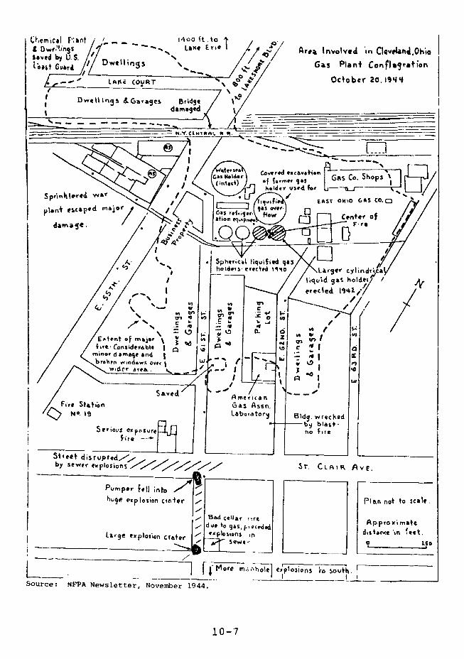
AemicaI F'Unt Lli E AreaL Involved in Ctevrlanj.Ohia* Dwf"'!tfg5 aeEisaved by U.S. -
(estGu,~/DweIlings '. . a Plant ConfJsgvatiaw'4ait GV&T 4
-- -, LAKE COURT October 20.19 4
n ..D&jwellings .Garages B!dged am aged _- __ __ __ __ _ __ __ __ _ __ __ __ _ __ __ __
damCaI % ,IIt a
oesea Ceovere d v iorcar dion
Ho Ed GAS Co. ShopsII
I way VIiS 1
SavedklShvc J iE
yl~no ercaped m~jhLabo,. erectedor %4d40 cyldnd
re.
Pt.rnper f.I,~ intod r9 Lrerclndin
n a m j I a l ''cc
in r xierbl
W IOn
SC4 - 250 ~
firr· ConridcrablArnerican
Fire St Gao Asn . I o I oe A Newsletter, November 1944.
10-S70fiFItl et disr opt Asn
Purnper fell into
bI Srwpr 9e imlloson ciaivrPI an notto scale
Bad Cellar ,rt p ro imt,due to gas, F·, eci rproxfat
Large explosion crater explosions init~~, C-
-- `~~~~~~~~~~~~~~~- - - - - -~ ~ ~ ~ ~ ~ ~ ~ ~ ~ ---- ---- --
L~~------i r"·····~~~~~~--I \ 0] 1405iins t oll
Source: NFPA Newsletter, November 1944.
1 0 -
About 20 minutes after Tank 4 failed, the legs
holding Tank 3 collapsed from the heat, releasing another
2,100 cubic meters of LNG. 9 The subsequent explosion shot
flames more than half a mile into the air. The temperature
in soIae areas reached 3000°F.1 0
Some 10 minutes later another huge blast in the yard
area began a series of explosions in sewers, underground
conduits, and basements. Streets were blown up, manhole
covers hurled into the air, water lines broken, and windows
shattered. One explosion opened a crater 25 feet deep, 30
feet wide, and 60 feet long swallowing a fire department
pumper and rioping a hole in one of the main intercept
sewers. Smaller blasts continued for several hours.
FIRE BEHAVIOR AND FIREFIGHTING
The LNG spills produced explosions and rapid burning
in gas clouds, large gas flames, and the burning of gas
which evaporated as the liquid ran over the ground and
found ignition points. There were fires and explosions in
confined spaces, ignition of materials by radiant heat, and
secondary fires started by LNG-soaked rock wool. Drops of
liquid gas fell on roofs and ignited. Some buildings in
the middle of areas of intense fire escaped almost
undamaged while their immediate neighbors were almost
totally destroyed. The photograph: on the next two pages
show the damage done.
The first fire alarm sounded almost immediately. The
fire spread rapidly and eventually 8 alarms were struck.
Before fire trucks arrived houses on both sides of East
61st and East 62nd Streets were burning. Those nearest the
10-8
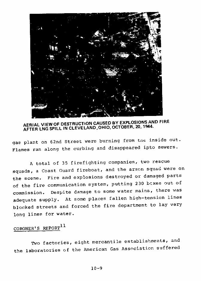
AERIAL VIEW OF DESTRUCTiON CAUSED BY EXPLOSIONS AND FIRE
AFTER LNG SPILL IN CLEVELAND,OHIO, OCTOBER, 20, 1944.
gas plant on 62nd Street were burning from tnre inside out.
Flames ran along the curbing and disappeared into sewers.
A total of 35 firefighting companies, two rescue
squads, a Coast Guard fireboat, and the arson squad were on
the scene. Fire and explosions destroyed or damaged parts
of the fire communication system, putting 230 boxes out of
commission. Despite damage to some water mains, there was
adequate supply. At some places fallen high-tension lines
blocked streets and forced the fire department to lay very
long lines for water.
CORONER'S REPORT11
Two factories, eight mercantile establishments, and
the laboratories of the American Gas Association suffered
10-9

VIEW OF THE REMAINS OF THE PLANT AND LNG STORAGE TANKS.
REMAINS OF MAIN BUILDING OF EAST OHIO GAS COMPANY'S LNGFACILITY, AFTER 1944 DISASTER.
10-10
critical damage. The Cleveland Fire Chief gave these
figures:12
Totally Destroyed Partially Destroyed
79 houses 35 houses
2 factories 13 factories
217 automobiles
7 trailers
1 tractor
The area directly involved was about one-half-mile
square, of which about 30 acres were completely devastated;
everything combustible burned. Some nearby dwellings
suffered little damage while some farther away were
destroyed.
At least 14 of 39 large industrial users of gas were
temporarily shut down. Rail services passing through the
area were rerouted. City transit services were halted by
street damage and destruction of track. Electric cables
serving the area were burned and poles destroyed. Some
underground cables were damaged, and power was cut off as a
safety measure. Telephone circuits were damaged and 878
telephones were put out of commission.
A thorough survey was made to locate and examine the
parts and fittings from Tanks 3 and 4. The violence and
speed with which Tank 4 collapsed was demonstrated by the
fact that it broke up into hundreds of fragments, varying
in size from 38' x 16' to pieces the size of a man's hand,
which were distributed over thousands of square feet. One
piece weighing several hundred pounds was thrown about 200
feet and smaller pieces traveled twice that distance.
10-11

Consultants to the Mayor's Board suggested that the initialfailure of Tank 4 took place at the top center of the innershell and that the possibilities of shock or stress in thatpart of the tank required particular examination.1 3 TheBureau of Mines said that fragments from Tank 4 appeared tobe of the type induced by embrittlement.1 4
According to early reports, 136 people were listed asdead and an additional 77 as missing.1 5 The coroner'sfinal tally was 130 deaths, and 225 injuries.1 6
The National Fire Protection Association (NFPA)
Newsletter of November 1944 said that ". . .there mighthave been much more extensive loss of life had theexplosion occurred an hour later". At the time of the firemost children were in school and most men were at work.The NFPA Newsletter also said: "The fact that the wind wasblowing away from the congested part of the area isbelieved to have been a major factor in prevention of aneven more devastating conflagration which could havedestroyed a very large part of the East Side."
FINDINGS
It is not certain what factor or combination of
factors caused the collapse of Tank 4.
Before the East Ohio Gas Company facility was
constructed extensive research had been carried outand a pilot plant was built and operated.
Before cylindrical rank 4 was built, three spherical
tanks had been operating without difficulty at thefacility for more than two years.
10-12
There is no reason to believe that the choice of a
cylindrical shape for Tank 4 had any connection with
the accident. All large LI'G tanks today are
cylinders.
The staff and management of the East Ohio Gas Company
who operated the facility, and the Pittsburgh Des
Moines Steel Company (PDM) who built it were trained,
experienced, and reputable.
The East Ohio Gas Company took precautions to control
small and moderate rates of LNG spillage. They
assumed that a sudden massive spill was not credible.
The same assumption is made today in designing dikes
around LNG facilities. In fact, it is made in
designing dikes around most facilities which store
large amounts of all dangerous fluids.
Both PDM and the East Ohio Gas Company assumed that a
small leak would precede a catastrophic collapse.
They also assumed that the small leak would be
noticed and corrected before it became serious.
Frost spots were noticed on the top and bottom of
Tank 4 and had previously appeared at the top tf one
of the spherical tanks. The frost spots at the top
of the tanks were caused by the settling of the
insulation and disappeared when more insulation was
added. Mr. J.O. Jackson, Chief Engineer of PDM,
advised the East Ohio Gas Company to eliminate the
frost spot at the bottom of Tank 4 by continuously
ventilating it with warm air. It disappeared
whenever this was done and reappeared when the
ventilating was stopped.
10-13

No thought was given to the nearby presence of other
industrial facilities, residences, storm sewers, or
other conduits. Little thought is given to similar
neighbors in planning some facilities today.
Less than 6,300 cubic meters of LNG spilled and a
large part of that remained on Gas Company property.
This is a very small amount compared to the capacity
of today's facilities, which often store more than
100,003 cubic meters.
The final death toll was 130. There were 225
injuries.
The National F're Protection Association (NFPA) said
that casualties could have been much higher if the
explosion had taken place at a different time of day.
At the time of the fire most children were in school,
and most men were at work.
The NFPA also said that, if the wind had been blowing
in the opposite direction, a very large part of the
East Side of Cleveland could have been destroyed.
Among the conclusions and recommendations of the
Mayor's Board of Inquiry were the following:
o "The obvious teaching of the. . .disaster is
that insufficient attention was given by the
public authorities and by the industry alike to
the restrictions that were necessary for safety
in the storage of this material; and that a
false sense of security had been
engendered. ."
10-14

o An application for construction should include a
full statement of the energy content and maximum
possible rate of energy dissipation.
o The application should shows proof that the
design provides for the contingency of failure
of each and every component, and for the
consequences of failure.
o The owner should be required to prove that he
offers no hazard to the surroundings and that
firefighting and emergency provisions are
adequate.
Among the recommendations of the Bureau of Mines were
the following:
o Plants dealing with large quantities of
liquefied inflammable gases should be isolated
at considerable distance from inhabited areas.
o Containers for the liquefied gas should be
isolated from other parts of the plant and
provided with dikes large enough to contain the
entire contents of the tank.
o Extreme caution should be taken to prevent
spilled gas from entering storm sewers or other
underground conduits.
The Coroner's final conclusion was:
"In.view of the destruction by this disaster, the
Coroner must come to the conclusion that no plant or
10-15
structure of any kind which, by reason of its
inherent nature may be explosive or inflammable, or
which may present any hazard which would endanger
life and property in its vicinity, should be
permitted to be built in a residential,
semi-residential, business or congested factory
district."
10-16

AGENCY COMMENTS AND OUR EVALUATION
The Departments of Commerce and Transportation and
the Federal Preparedness Agency of the General Services
Administration comment that cryogenics technology, storage
tank fabrication, and construction techniques have
substantially improved since the Cleveland accident. DOT
states: "The inclusion of an account of the 1944 Cleveland
LNG incident in this report without stressing the fact that
the apparent causes of this mishap do not exist at today's
LNG facilities is misleading."
The actual cause of the Cleveland accident has never
been determined. There is no reason to believe that
cryogenics was the primary problem. LNG technology in use
today is still relatively new. We are not sure what effect
many years of exposure tc very cold temperatures will have
on modern LNG tanks. The industry did not discover the
"rollover effect" of combining different LNG mixtures in a
storage tank until after an August, 1971 incident in La
Spezia, Italy in which about 220 cubic meters of LNC were
released through safety valves. There is still much that
needs to be learned about LEG properties and behavior. For
example, much uncertainty still exists on the distance an
LNG cloud may travel in a flammable state, as we discuss in
Chapter 12.
Both Commerce and DOT emphasize the more recent LEG
safety record. Commerce says that our analysis of an
accident that took place 34 years ago points out the recent
safety record of LEG facilities. Commerce also says that
the serious oversights that contributed to the Cleveland
accident could not happen with modern technology, strict
construction safety codes, and sophisticated and redundant
10-17

monitoring equipment. They said, for example, that any
facility would be immediately shut down if frost developedon the outer tank walls, and the defect corrected.
The LEG industry's safety record has not been perfect
over the last 34 years. There is a long history of
accidents in all aspects of LPG use. Although there havebeen no major LNG accidents since the one in Cleveland,there have been documented incidents in LNG production,
storage, and distribution in the United States and abroad.
There is no evidence that present day technology,
stricter construction safety codes, and sophisticated andredundant monitoring equipment can certainly prevent
another major catastrophe. Present safety codes will notnecessarily prevent flows over dikes, as we have shown inChapter 5. Two major LEG storage facilities overseas haveblown up as a result of accidents, including one in Qatar,in 1977.
In January, 1978, a 40,000 cubic meter butane storage
cavern at the Sun Oil refinery in Marcus Hook, Pa., wasoverfilled despite three monitoring methods and a safety
relief valve.
The cavern was excavated in granite more than 300
feet underground. The main device to measure the butanelevel in the cavern, a manometer, malfunctioned and
indicated that the cavern contained only 10,000 cubicmeters of butane. A vapor pressure gauge at the wellhead
also malfunctioned, and company bookkeeping records,showing how much butane was pumped into and out of the
cavern, were very inaccurate. The safety relief valve, set
10-18
at 175 pounds per square inch, never operated because the
cavern pressure never reached that level.
The escaping butane caused fires that destroyed five
houses only 100 feet from the outer wall of the cavern.
Since 1956 there have been at least four other overspills
from mined caverns.
The conclusions of those who investigated the
Cleveland accident are still highly relevant: that plants
dealing with large quantities of liquefied flammable gases
should be isolated at considerable distance from inhabited
areas, and that extreme caution should be taken to prevent
spilled gas from entering storm sewers or other underground
conduits.
10-19
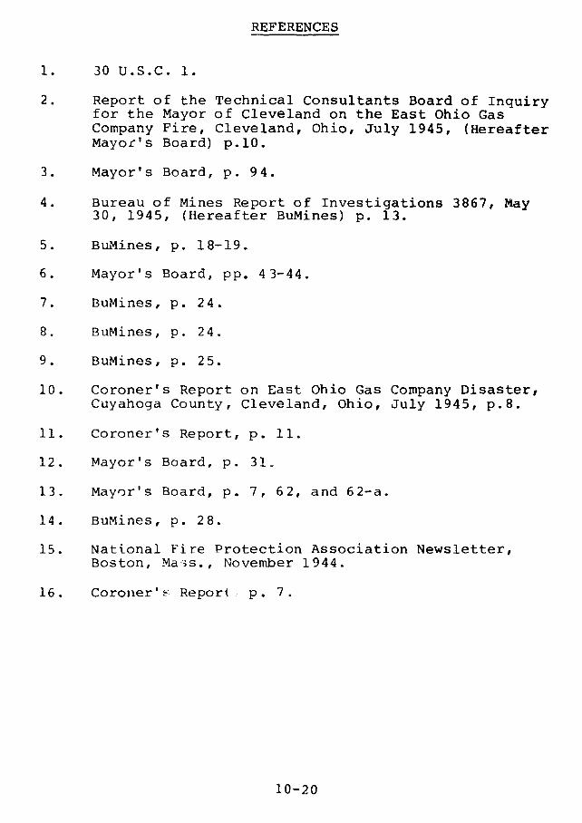
REFERENCES
1. 30 U.S.C. 1.
2. Report of the Technical Consultants Board of Inquiryfor the Mayor of Cleveland on the East Ohio GasCompany Fire, Cleveland, Ohio, July 1945, (HereafterMayor's Board) p.10.
3. Mayor's Board, p. 94.
4. Bureau of Mines Report of Investigations 3867, May30, 1945, (Hereafter BuMines) p. 13.
5. BuMines, p. 18-19.
6. Mayor's Board, pp. 43-44.
7. BuMines, p. 24.
8. BuMines, p. 24.
9. BuMines, p. 25.
10. Coroner's Report on East Ohio Gas Company Disaster,Cuyahoga County, Cleveland, Ohio, July 1945, p. 8 .
11. Coroner's Report, p. 11.
12. Mayor's Board, p. 31.
13. Mayor's Board, p. 7, 62, and 62-a.
14. BuMines, p. 28.
15. National Fire Protection Association Newsletter,Boston, Mass., November 1944.
16. Coroner'F Report - p. 7.
10-20
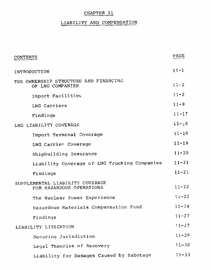
CHAPTER 11
LIABILITY AND COMPENSATION
CONTENTS PAGE
INTRODUCTION 11-1
THE OWNERSHIP STRUCTURE AND FINANCINGOF LNG COMPANIES 11-2
Import Facilities 11-2
LNG Carriers 11-9
Findings 11-17
LNG LIABILITY COVERAGE 11-.8
Import Terminal Coverage 11-18
LNG CarrieY Coverage 11-19
Shipbuilding Insurance 11-20
Liability Coverage of LNG Trucking Companies 11-21
Findings 11-21
SUPPLEMENTAL LIABILITY COVERAGE
FOR HAZARDOUS OPERATIONS 11-22
The Nuclear Power Experience 1t-22
Hazardous Materials Compersation Fund 11-24
Findings 11-27
LIABILITY LITIGATION 11-27
Securing Jurisdiction 11-28
Legal Theories of Recovery 11-30
Liability for Damages Caused by Sabotage 11-33

CONTENTS PAGE
Liability for "Acts of God" 11-33
Findings 11-34
FAILURE OF AGENCIES TO EXERT FEDERAL JURISDICTION
OVER LNG OFFSITE LIABILITY 11-35
Findings 11-37
RECOMMENDATIONS 11-39
AGENCY COMMENTS AND OUR EVALUATION 11-41
REFERENCES 11-43

INTRODUCTION
A major LNG accident in a densely populated area
could cause damage of such severity that injured parties
could not be fully compensated under current insurance
arrangements.
Claimants would face a complicated legal and
financial situation. In some instances liability would be
limited by statute. The long and complex litigation
necessary would be burdensome and perhaps futile since
neither the insurance nor the reachable assets of the
corporation may cover the damages.
Companies that transport and store LNG are typically
part of intricate corporate structures, which sharply limit
the liability of the parent corporations for offsite
damage. Most of the assets of the frontline company (the
company actually owning or operating the facility or
vessel) may be destroyed in a major accident. Moreover,
the insurance policies the companies carry are inadequate
to cover the claims that could result from a major accident
in a densely populated area.
Although highly destructive materials are transported
by ship or barge through city harbors and rivers, stored in
tank complexes in or near densely populated cities, and
carried by truck and train through large cities, the
Federal Government has neglected the issue of offsite
liability of hazardous enterprises. No Federal agency
assumes responsibility for assuring adequate compensation
of victims.
11-1

THE OWNERSHIP STRUCTURE AND FINANCING OF LNG COMPANIES
Import Facilities
LNG is imported and stored by wholly owned,
separately capitalize subsidiaries of larger firms. The
structure places "corporate veils" between parent firms and
those subsidiaries most vulnerable to liability. The most
thinly capitalized level in this structure is ustally the
subsidiary most directly involved in LNG operations, and
most vulnerable to liability. To the extent that debt to
equity ratios increase, claimants have fewer assets to
proceed against, assuming the assets of corporate parents
are out of reach.
Table 11-1 shows the ownership structure and
financing of LNG import facilities. Figure 11-1
illustrates typical corporate structures. Meaningful
financial figures are not available for some companies
whose facilities are far from start-up.
If the insurance coverage and surviving assets of a
company are inadequate, claimants would have to obtain any
additional recovery from tke assets of a parent firm. This
would be difficult, because claimants would have to
persuade a court to hold the parent company accountable for
acts of 1Ls subsidiary. Courts do so only if they find: a)
the primary firm has not been run as a separate entity, but
is completely controlled and financed by the parent; b) it
has been so thinly capitalized that it cannot withstand
normal business risks; c) it has substantially no business
except with the parent corporation, or no assets except
those received from the parent.
11-2
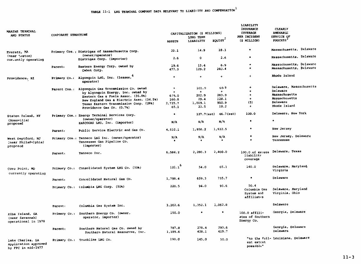
TABLE 11-1 LNG TERMINAL COMPANY DATA RELEVANT TO LIABITLITY AND COMPENSATION 1
LIABILITY
MARINE TERMINAL INSURANCE CLEARLY
AND STATUS CORPORATE STRUCTURE CAPITALIZATION ($ MILLIONS) COVERAGE AMENABLELONG TERM 2 PER INCIDENT SERVICE QF
ASSETS LIABILITY EQUITY ($ MILLION) PROCESSj
Everett, MA Primary Cos.: Distrigas of tassachusetts Corp. 33.1 14.9 18.3 * Massachusetts, Delaware
(near 5oston) (owner/operator)
currently operating Distrigas Corp. (importer) 2.6 0 2.6 * Massachusetts, Delaware
Parent: Eastern Energy Corp. owned by 19.6 13.4 6.9 * Massachusetts, Delaware
Cabot Corp. 477.3 129.2 240.4 * Massachusetts, Delaware
Providence, RI Primary Co.: Algonquin L4G, Inc. (lessee, + + + + Rhode Island
operator)
Parent Cos.: Algonquin Gas Transmission Co. owned + 101.9 69.9 + Delaware, Massachusetts
by Algonquin Energy, Inc. owned by + + + + Delaware
Eastern Gas & Fuels Assoc. (36.8%) 675.0 202.9 283.9 + Massachusetts
New England Gas & Electric Assn. (34.5%) 160.8 29.4 128.1 + Massachusetts
Texas Eastern Transmission Corp. (28%) 2,725.7 1,019.1 900.9 (5) Delaware
Providence Gas Co. (0.7%) 65.1 23.5 18.2 + Rhode Island
Staten Island, NY Primary Cos.: Energy Terminal Services Corp. * 127.7(est) 46.7(est) 100.0 Delaware, New York
(Rossville) (owner/operator)proposed EASCOGAS LNG, Inc. (importer) N/A N/A N/A *
Parent: Public Service Electric and Gas Co. 4,532.1 1,958.2 1,932.5 * New Jersey
West Deptford, NJ Primary Cos.: Tenneco LNG Inc. (owner/operator) N/A N/A N/A New Jersey, Delaware
;near Philadelphia) Tennessee Gas Pipeline Co. Tennessee
proposed (importer)
Parent: Tenneco Inc. 6,584.2 2,280.3 2,400.0 100.0 of excess Delaware, Texasliabilitycoverage
Cove Point, MD Primary Co.: Consolidated System LNG Co. (50%) 121.1 54.0 65.1 140.0 Delaware, Maryland
currently operating Virginia
Parent: Consolidated Natural Gas Co. 1,798.4 639.3 755.7 * Delaware
Primary Co.: Columbia LNG Corp. (50%) 220.5 94.0 95.6 50.4Columbia Gas Delaware, Maryland
System and Virginia, Ohioaffiliatfes
Parent: Columbia Gas System Inc. 3,202.6 1,352.1 1,062.8 Delaware
Elba Island, GA Primary Co.: Southern Energy Co. (owner, 150.0 * * 100.0 affili- Georgia, Delaware
(near Savannah) operator, importer) ates of Southern
operational in 1978 Energy Co.
Parent: Southern Natural Gas Co. owned by 787.8 278.4 293.6 Georgia, Delaware
Southern Natural Resources, Inc. 1,189.6 428.1 419.7 Delaware
Lake Charles, LA Primary Co.: Trunkline LNG Co. 190.0 145.0 50.0 "to the full- Louisiana, Delaware
application approved est extcnt
by FPC in mid-1977 possible"
11-3

TABTr 11-1 LNG TERMINAL COMPANY DATA RELEVANT TO LIABILIkY AND COMPENSATION (CONTINUED)
LIABILITY
MARINE TERMINAL INSURANCE CLEARLY
AND STATUS CORPORATE STRUCTURE CAPITALIZATION ($ MILLIONS) COVERAGE AMENABLE
LONG TERM PER INCIDENT SERVICE OF
ASSETS LIABILITY EQUITY2 ($ MILLION) PROCESS
3
Parent: Trunkline Gas Co. owned by 628.2 284.4 222.5 planned Texas, Delaware7
Panhandle Eastern Pipe Line Co. 1,694.6 798.7 490.7 * Texas, Delaware
Port O'Connor, TX Primary Cos.: El Paso LNG Terminal Co. Expects $457 million capital invest- * Texas, Delaware
(owner/operator) ment, 75% long term debt and 25% equity
El Paso Atlantic Co. (importer) N/A N/A N/A Delaware
Parent: El Paso LNG Co. owned by * * *
The El Paso Co. 2,410.1 1,201.8 529.5 * Texas, Delaware
Ingleside, TX Primary Cos.: NGP-LNG Inc. (owner/operator) N/A N/A N/A * Texas, Delaware
(near Corpus Christi) Natural Gas Pipeline Co. of 1,410.7 586.9 526.1 * Illinois
proposed America (proposed importer)
Parent: Peoples Gas Company 2,198.8 973.2 1,368.1 * Illinois
Southern California8 Primary Co.: Western LNG Terminal Associates 379.4 284.6 94.8 50 minimum California
Oxnard (owner/operator) (75% debt with project revenues for third
Los Angeles as the chief security to lenders) party and
Point Conception property
proposed Parent Co.: Western LNG Terminal Co. 16.2 - - California
(50%) owned by Pacific 1,662.8 697.1 614.4 * California
Lighting Corp.
Pacific Gas LNG Terminal Co. + + + + California
(J0%) owned by Pacific Gas 6,620.9 3 5.6 2,993.3 + California
& Electric Co.
1. Sources; Company letters, FERC records, Moody's Public Utility and Industrial Manuals for 1976.
2. Common and preferred stock and retained earnings.
3. This column indicates states in which the company in column 2 is incorporated or doing business, or maintaining agents to receive service of summons and
-complaint.
4. The property is owned by Providence Gas Co.
5. Texas Eastern maintains $75 million property damage coverage and $100.5 million general liability coverage per incident.
6. Capitalization is expected to be $200 million when the facility begins operation.
7. Trunkline Gas is also subject to process service in Louisiana, Arkansas, Tennessee, Kentucky, Illinois, and Indiana. Panhandle Eastern is also
subject to process service in Oklahoma, Wyoming, Kansas, Missouri, Illinois, Indiana, Ohio, and Michigan.
8. In September 1977, the State of California enacted a law authorizing only one LNG terminal site in the State.
* Company would not disclose this informat'on.
+ No letter was sent to the company.
N/A Not appropriate.
11-5
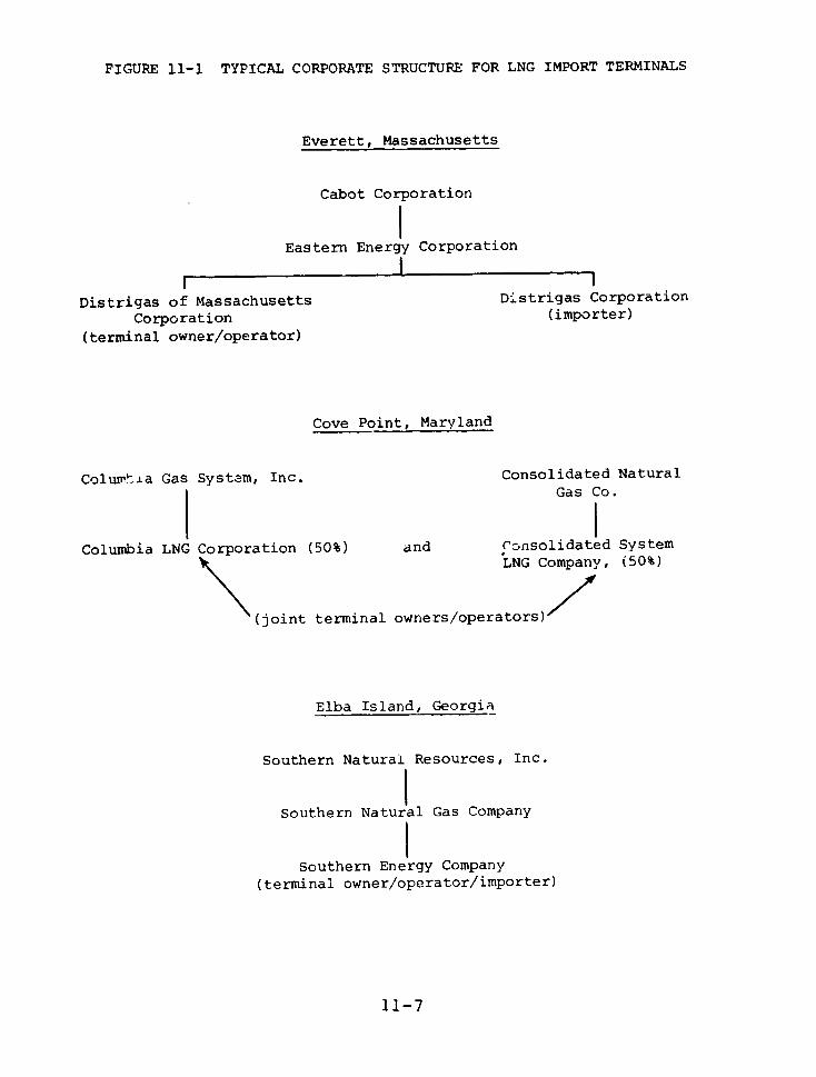
FIGURE 11-1 TYPICAL CORPORATE STRUCTURE FOR LNG IMPORT TERMINALS
Everett, Massachusetts
Cabot Corporation
Eastern Energy Corporation
Distrigas of Massachusetts Distrigas Corporation
Corporation (importer)
(terminal owner/operator)
Cove Point, Maryland
Colurmia Gas System, Inc. Consolidated Natural
Gas Co.
Columbia LNG Corporation (50%) and Consolidated System
LNG Company, (50%)
(joint terminal owners/operators)/
Elba Island, Georgia
Southern Natural Resources, Inc.
Southern Natural Gas Company
Southern Energy Company
(terminal owner/operator/importer)
11-7

FIGURE 11-1 (continued)
Southern California
Pacific Lighting Corporation Pacific Gas & ElectricCompany
Western .NG Terminal Company Pacific Gas LNG Terminal(50%) Company (50%)
Western LNG Terminal Associates(terminral owner/operator)
Pacific Indonesia LNG Company(importer for Pac-Indonesia project)
11-8
If the defendant frontline firm has independent
assets and/or insurance, even though these may be
inadequate to satisfy the judgment, a court may not be
convinced that it should pierce the corporate veil. In any
case, the question may require extensive litigation.
Claimants who can convince a court to pierce the
corporate veil still face stiff and extended litigation to
prove the liability of the frontline and parent companies.
LNG Carriers
Each U.S. and foreign flag LNG vessel is ordinarily
owned, leased, or chartered by a separate subsidiary
company of a larger firm, as shown in Table 11-2. This
structure is designed to limit liability exposure to the
subsidiary company's assets. There is a statutory
limitation (46 U.S.C. 183) on the liability that can be
imposed on the owners and bareboat charterers* of ships and
barges. The limitation, enacted in 1851, was intended to
promote national fleets and international commerce. Many
precedents date from a period when shipping was more simply
organized than today's LNG trade, with its multi-layered,
multi-national corporations.
Under the 1851 statute, the liability of both owners
and bareboat charterers is limited to the salvage value of
the vessel plus the amount owing for freight, if they can
prove that they did not know about the causes of an
accident. If injuries or deaths occur, however, the limit
*A bareboat charterer charters the hull, anl mans and victuals the
vessel. A time charterer hires the services of a vessel for a period
of time, leaving its operation to others.
11-9
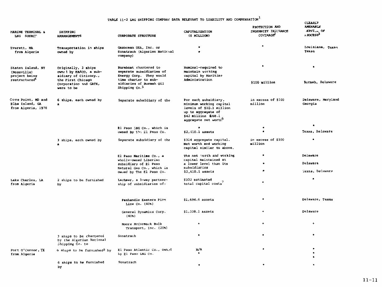
TABLE 11-2 LNG SHIPPING COMPANW DATA RELEVANT TO LIABILITY AND COMPENSATION1
CLEARLYPROTECTION AND AMENABLE
MARINE TERMINAL & SHIPPING CAPITALIZATION INDEMNITY INSURANCE ERVI.r OP
LNG SOURC7 ARRANGEMENTS CORPORATE STRUCTURE ($ MILLION) COVRAGI2 ROCESS3
Everett, MA Transportation in ships Gazocean USA, Inc. or * * Louisiana, Texas
from Algeria owned by Sonatrach (Algerian Natic¢ial C Texascompany)
Staten Island, NY Originally, 3 ships Bareboat chartered to Nominal-required to
(Rossville) own i by EASCO, a sub- separate subsidiaries of maintain workingproject beinq sidiary of Citicorp., Energy Corp. They would capital by Maritime
restructured4 the First Chicago time charter to sub- AdministrationCorporation ,nd GATX, sidiaries of Burmah Oil $100 million Burmah, Delawarewere to be Shipping Co.5
Cove Point, MD and 6 ships, each owned by Separate subsidiary of the For each subsidiary, in excess of $100 Delaware, MarylandElba Island, GA a minimum working cafital million Georgiafrom Algeria, 1978 levels of $10.1 million
up to aggregate of
$42 million a68.1aggregate net wort-
6
El Paso :NG Co., which is *
owned by a'h':- E1 Paso Co. $2,410.1 assets * Texas, Delaware
3 ships, each owned by Separate subsidiary of the $314 aggregate capital. in excess of $100
a Net worth and working millioncapital similar to above.
El Paso Maritime Co., a The net worth and working * Delawarewholly-owned Liberian capital maintained atsubsidiary of El Paso a lower level than its * Delaware
Natural Gas Co., which is subsidiariesowned by The El Paso Co. $2,410.1 assets * Texas, Delaware
Lake Charles, LA 2 ships to be furnished Lachmar, a 3-way partner- $332 estimated *from Algeria by ship of subsidiaries of: total capital costs
7*
Panhandle Eastern Pire $1,694.6 assets * Delaware, Texas
Line Co. (40%)
General Dynamics Corp. $1,338.1 assets + Delaware
(40%)
Moore McCormack Bulk + + +
Transport, Inc. (20%)
3 ships to be chartered Sonatrachby the Algerian NationalJhipping Co. to
Port O'Connor, TX 6 ships to be furnished8 by El Paso Atlantic Co., own-d N/Afrom Algeria by El Paso LNG Co. *
6 ships to be furnished Sonatrach
by
11-11

TABLE 11-2 LNG SHIPPING COMPANY DATA RELEVANT TO LIABILITY AND COMPENSATION (CONTINUED)
CLEARLYPROTECTION AND AMENABLEMARINE TERHINAL & SHIPPIN;G CAPITALIZATION INDEMNITY INSURANCE SERVICE OFLNG SOURCE ARRANGEMENTS CORPORATE STRUCTURE ($ MILLION) COVERAGE PROCESS 2
Southern Californiafrom Indonesia 9 snips to be tima- Pacific Indonesia LNG Co. O.b assets Value of vessel Californiachartered by owned by Pacific Lighting 1,662.8 assets * California
Corp. and by Pacific 6,620.9 assets + CaliforniaGas and Electric Co.
3 ships from Ogden Marine Indonesia, + + DelawareInc., owned byOgden Marine, Inc., + +owned by Ogden Corp. 926.0 assets + Delaware
3 ships from Zapata Western LNG, Inc. + + Delawareowned by Zapata Corp. 796.6 assets + Delaware
1 ship from zodiac Shipping Co., N.V. + + Netherlandsowned by N.V. Neder- + + Netherlandslandsthe Scheepvaart Un.e.
1 ship from Gazocean S.A. + 4 France
1 ship from Odessay Trading Co., Ltd. + + Bermudaowned by Ocean Transport + + United King domand Trading, Ltd.
from South Alaska 2 ships built for Pacific Marine Associates e *
owned 50% by Pacific Lichting 12.8 assets CaliforniaMarine Co. owned byPacific Lighting Corp. &nd 1662.8 assets California50% by Pacific Gas Marire Co. + + Californiaowned by Pacific Gas and 6620.9 assets + CaliforniaElectric Co.
1. Sources: Company letters, FERC records, Moody's Public utilities and Indus rial Manuals, 1976.2. Insurance clubs place no fixed limit on the protection and indemnity coverage available to foreign flag ships, but until a recent change ownersof U. S. flag LNG vessels could get this insurance only up to $200 million. British insurance clubs announced in February '8 that they wouldoffer unlimited protection and indemnity insurance to U. S. flag entries without regard to the value of the hull.
3. This column indicates states in which the company in Column 3 is incorporated or doing business, or maintains agents to receive service ofsunmons and complaint.
4. In May 1977, FASCOGAS withdrew from its contract with Burmah Oil Shipping Company because its Gas Sales Contract with Sonatrach was terminated(the contract required EASCOGAS to obtain FPC approval by May 31, 1977).
5. A bareboat charterer not only charters the hull but also mans and victuals the vessel. Time-charterers hire the services of a vessel for aperiod of time, leaving its operation to others. Time charterers do nct have to carry protection and indemnity insurance because they arenot liable for faulty operations.
6. Each ship-owning subsidiary is required by MarAd to have these minimum levels of capitalization.
7. Anticipated sources of capital are: $50 million MarAd construction differential subsidy, $211.5 million from sale of long term debt, and$70.5 million from equity. The debt carries a MarAd guarantee.
8. The El Paso Atlantic Co. will either contract with affiliates or make arrangements with third parties.
* Company would not disclose this information. No letter was sent to the companyN/A Not appropriate.
11-13
is raised to $60 per ton of cargo. The 1851 limitation
might not be applicable if LEG shipping were declared an
abnormally hazardous activity, enabling recovery by
injured parties on the basis of strict liability. For a
large LEG ship this would be about $3,500,000.
Commerce's Assistant Secretary fcr Maritime Affairs,
in an April 29, 1977, letter to us, described how the
ownership structure of LNG vessels is utilized:
. . .In general, the ownership of LNG's {ships},whether they be leased or owned, is by a trust orsingle-purpose corporation with only one vessel in
each trust or corporation. If the vessels aresubsequently bareboat or time chartered, they are
likewise chartered to single purpose corporations.This structure is specifically utilized to attempt tolimit third party liability to the value of the asset{vessel} with no recourse to any other assets.Usually, the obligations of these corporations arenot guaranteed by any other party. Guarantees ofcharter hire or of freights payable under a
transportation agreement may be guaranteed by aparent corporation to induce lenders. However, the
limit of liability iof parent firms under theseagreements} is only Lo the amount of hire or freightspayable and would nut in any way guarantee any thirdparty as a result of a casualty. In theory, aninjured third party would only have recourse to thevalue of the vessel and insurance carried by theowner or bareboat charterer. . ."
An LNG ship corporation's major asset is the shil
itself. Most of these corporations are not required to
carry specified amounts of net worth and working capital.
Such requirements are, however, among the conditions
imposed under Title XI of the Merchant Marine Act of 1936,
as amended, under which a qualified candidate may have the
U.S. Government guarantee loans up to 87½ percent of a
ship's costs for construction, reconstruction, or
reconditioning. The program is administered by the
11-15

Maritime Administration in the Department of Commerce.
Sixteen U.S. flag LNG carriers are being constructed under
this program.
Under this program, the El Paso Company (parent of
the El Paso LNG Company) has committed itself to cause each
of its LNG ship-owning subsidiaries to have a specified net
worth on the delivery date of its tanker, and, if called
upon, to make additional specified contributions of capital
to each subsidiary for working capital purposes. The
aggregate amount of the first of these commitments for all
six subsidiaries is approximately $168.1 million, including
minimum working capital requirements of $16.1 million. The
aggregate maximum amount of the second of these commitments
for all six subsidiaries is $42.1 million.
The mortgages on these six tankers will be in favor
of the United States, as collateral fo] the government
guarantees. Similar arrangements are required for ships
being built for other companies.
When shipc:ners are required to have substantial net
worth, as they are under the Title XI program, injured
parties enjoy better prospects of finding assets from which
claims might be paid. However, if claims exceed the level
of assets required by the Maritime Administrationi.. a court
might be less likely to assert jurisdiction over the parent
company than it would if no government regulation was
involved. A court might seriously consider and defer to
that agency's judgment on the adequacy of capitalization of
the subsidiary.
11-16

Recovery can be difficult if the defendant is a
foreign corporation. Foreign nations or nationals own, or
expect to own, LNG ships for use in conjunction with
terminals in Everett, Staten Island, Cove Point, Elba
Island, Lake Charles, and Southern California. Unless a
liable corporation has other assets in this country, the
ability to recover will depend on whether a U.S. court
decree is honored in a foreign court. This may be less
likely if the liable corporation is owned by a foreign
government.
In order to recover damages, a plaintiff must first
locate assets here or abroad. Such a wide-ranging search
for proof of assets might be beyond the resources of many
plaintiffs.
Findings
LNG is imported on ships, each owned or leased by a
separate subsidiary corporation, and stored in
terminals owned by subsidiaries. Parent firms are,
in many cases, wholly-owned subsidiaries of still
larger firms, which may themselves be wholly-owned or
under another firm's corporate control.
The level most vulnerable to liability is usually the
most thinly capitalized. LEG terminal companies
generally have no limit on their ratio of debt to
equity, and only those ship-owning subsidiaries whose
ships are being built under the Title XI program are
required to carry specified minimum amounts of net
worth and working capital.
11-17

In many cases the major assets may be the ship or
terminal itself, which may not survive an accident
which does extensive offsite harm.
Most of the assets in the system are protected by the
corporate layers. It would be difficult for
claimants to litigate the liability of parent firms
for damage caused by an LNG accident. If they did,
the litigation would be a long and expensive process,
which many litigants could not afford.
The ownership structure of LNG carriers is designed
to protect the assets of owners and bareboat
charterers. The statutory limitation on liability
further benefits these single-ship corporations or
trusts. Even if personal liability is established,
available assets may not be sufficient to satisfy
claims.
Claimants attempting to recover damages through
foreign assets of foreign corporations will encounter
special difficulties, particularly if the foreign
corporations are government owned.
LNG LIABILITY COVERAGE
Import Terminal Coverage
Table 11-1 includes data on insurance coverage
provided by companies at our requesc. Among those which
responded fully, present or planned terminal coverage
ranges from $50 million per incident for Pacific Lighting
Corporation's proposed Western LNG Company terminal, to
$190.4 million total coverage per incident carried by the
11-18
co-owners of the Cove Point, Maryland terminal. The
$100 million insurance coverage for the Elba Island,
Georgia terminal is carried by affiliates of Southern
Energy Company, the terminal owner. Southern plans to
obtain additional liability coverage before operations
begin in 1978.
We could not obtain detailed insurance information
for the Everett, Massachusetts terminal, which has been
operating since 1971. The terminal is owned and operated
by Distrigas Corporation of Massachusetts. The president
of Eastern Energy Corporation, Distrigas' corporate parent,
replied to our letter to Eastern's corporate parent, Cabot
Corporation.
"The insurance coverage carried by the Cabot LNGcompanies is in layers, and different policies wouldrespond, depending on the specific circumstances ofany particular claim. It is not corporate policy todisclose details or limits of insurance coverage, butwe do carry amounts of insurance representing what webelieve reasonably prudent management requires."
None of the 50 states requires proof of public
liability insurance as a prerequisite to obtaining a permit
for dealing, storing, or handling LNG. Ten states do
require such proof from LPG companies, but the amount
required may be as low as $10,000 per incident; the maximum
required anywhere is only $100,000 for any one incident.
LNG Carrier Coverage
Insurance clubs place no fixed limit on the
protection and indemnity (liability) coverage available to
foreign flag vessels, but until a recent change owners of
U.S. flag LNG vessels could get this insurance only up to
11-19
$200 million. British insurance clubs announced in
February 1978 that they would offer unlimited protection
and indemnity insurance to U.S. flag entries without regard
to the value of the hull. The insurance data in Table 11-2
were provided in 1977. El Paso LNG informed us that all of
its ships are insured against accidents to the maximum
extent available in the market, and that in every case this
is "in excess of $100 million." Pacific Lighting plans
carrier coverage "at least equal to the value of the
vessel."
In states which have "direct action" statutes,
injured parties can sue the insurers directly, prior to the
rendering of a judgment against the owner or charterer. In
Independent Towing Company, 242 F. Supp. 950 (E.D. La.
1965), the court held that liability limitation proceedings
do not exclude direct action against an insurance company
as permitted by Louisiana state law. It held further that
insurers, unlike vessel owners and bareboat charterers,
cannot claim the protection of the limited liability
statute. In states without a direct action statute (for
example, Maryland, Massachusetts, and New York) injured
parties do not have this recourse.
Shipbuilding Insurance
Prior to navigation, shipyard risks are imposed upon
builders, subject to normal contract exoneration terms.
Ship-building contractors give a six-month to one-year
warranty that does not cover design defects. Design defect
liability eight be imposed upon marine architects, who are
insured independently.
11-20

Liability Coverage of LNG Trucking Companies
Under Interstate Commerce Commission (ICC)
regulations, LNG trucking companies are required to carry
only minimal amounts of liability insurance, but they
ordinarily carry much more than the required amount. The
ICC regulations call for policies of $100,000 (maximum
liability for any one person), $300,000 (maximum liability
for one incident), and $50,00i (property damage for one
incident). This subject is discussed in more detail in
Chapter 7.
Findings
Present and planned liability coverage for LNG .import
terminals ranges from $50 million to $190 million per
incident. Ten states require proof of liability
insurance for LPG facilities, bu2 the maximum
required is $100,000 per incident.
Where there have been no injuries or deaths, the
liability of shipowners and bareboat charterers may
be limited to the post-accident value of the vessel
plus the freight then pending, if they can prove that
they did riot know of the factors that caused the
accident. If there are injuries or deaths the limit
is raised to $60 per ton of cargo. For a large LEG
ship this would be about $3,500,000.
The amount of liability insurance coverage the ICC
requires trucks under its jurisdiction to carry (up
to a total of $350,000 for one incident) is much
lower than the amount some gas companies require LNG
trucking firms to carry ($10-30 million). A trucker
11-21

may also be covered under the gas company's liability
policies, but if a liable trucker is not acting as
the agent of the gas company, claimants may not have
access to this coverage.
A major accident could cause damage of such severity
that injured parties could not be fully compensated
under exis-ting insurance policies.
SUPPLEMENTAL LIABILITY COVERAGE FOR HAZARDOUS OPERATIONS
The Nuclear Power Experience
The question of how to handle the potentially large
but unpredictable liability from public utility
installations using new technology confronted Congress in
the 1950's with the advent of commercial nuclear power.
Congress found that the size of the liability which could
result from a nuclear accident and the lack of available,
adequate commercial liability insurance were major
obstacles to the commercial development of nuclear power.
The Price-Anderson Act, Section 170 of the Atomic
Energy Act of 1954, as amended (42 U.S.C. 2210), was
enacted in 1957 to solve this problem. It established a
combination of private financial protection and government
indemnity amounting to a maximum $560 million to cover
liability claims that might arise from a nuclear accident
at a commercial nuclear facility.
The objectives were (1) to assure the availability of
funds to satisfy liability claims in the event of a
catastrophic nuclear accident and (2) to remove the
11-22
deterrent to private investment of possibly enormous
liability claims.
The 1957 Price-Anderson Act was regarded as temporary
legislation and was written for only a 10-year term. In
1965 the Act was extended an additional 10 years by P.L.
89-210. A second 10-year extension, until August 1, 1987,
was enacted by P.L. 94-197.
P.L. 94-197 continues to limit the amount of
liability protection (and the liability that may be
imposed) to $560 million, even though estimates of economic
losses alone range as high as $14 billion. The new
amendments spell out for the first time, however, that in
the event of a nuclear incident involving damages in excess
of $560 million, "the Congress will thoroughly review the
particular incident and will take whatever action is deemed
necessary and appropriate to protect the public from the
consequences of a disaster of such magnitude."
Nuclear power plants must be licensed by the Nuclear
Regulatory Commission (NRC). Owners of power reactors are
required (10 CFR 140) to have and maintain financial
protection in the amount of $125 million for each nuclear
reactor with a rated capacity of 100 electrical megawatts
or more. Liability insurance is available from two
insurance pools: the Nuclear Energy Liability-Property
Insurance Association and the Mutual Atomic Energy
Liability Underwriters. The amount of financial protection
required of reactors of less than 100 megawatts is
established with a formula that takes into account the
population near the reactor. The amount cannot be less
than $4.5 million nor more than $74 million.
11-23
The first $140 million of damages from a nuclearincident would be paid out of insurance pool funds. Tocover additional damages, the pools could collect up to $5million for each licensed reactor. With 65 reactorspresently operating, these "retrospective premiums" couldtotal $325 million.2 The Act requires owners to maintainproof of their ability to pay these retrospective premiums.
The Price-Anderson Act requires that the reactorowners ulluL execute dna llaUllldln anl indemnity agreementwith NRC, under which NRC will indemnify the owner for allpublic liability claims exceeding these two levels offinancial protection, up to $560 million per nuclearaccident. The Act authorizes the NRC to collect indemnityfees of $30 per year per thousand kilowatts of thermalenergy authorized in the reactor's license, with a minimumfee of $100 per year. The annual fee for a 1,000 megawatt(electric) power plant would be about $104,000.
The Supreme Court, in a June 26, 1978 decision,upheld the constitutionality of the Price-Anderson ceilingon nuclear liability. The court reversed a district courtruling that the limitation violates due process. 3
Hazardous Materials Compensation Fund
We believe that a more adequate liability insurancesystem is needed for non-nuclear hazardous operations, andthat the arrangements should be considered from tneviewpoints of both accident prevention and equity.Accident prevention requires that the system providemaximum incentives for safe operations. Equity requiresthat those harmed are fairly and promptly compensated.
11-24
We propose a system somewhat similar to that created
by the Price-Anderson Act for nuclear power. Corporations
transporting, storing, or using significant quantities of
flammable hazardous materials would be required to: (1)
carry the maximum liability insurance &aailable from the
private sector, and (2) contribute a fixed sum per BTU to a
Federal Hazardous Materials Compensation Fund (HMCF). The
Fund would pay claims (beyond those paid by private
liability insurance) up to a fixed ceiling for any one
incident. Non-energy L -ardous materials corporations
could contribute to the Fund on a different basis.
All the consumers of the gas that goes through a
particular facility would bear the costs of private
insurance for that facility. All those receiving service
from an operation would pay to cover the risks incurred by
those near the operation.
All LEG useLs (and eventually, perhaps, all users of
other hazardous materials) would share the cost of building
and maintaining the Fund. This is not completely
equitable, since customers of safer facilities would be
subsidizing customers of less safe facilities. We feel,
however, that only through such a Fund will those harmed
in
an accident, particularly the without large intact
resources, be able to get - , fair compensation for
claims against very large corporations and insurance
companies. The Fund's only task after an accident is to
assure that all monies paid out are warrn 'ted by the damage
done.
In order to make the implicit subsidy involved in the
Fund more equitable, we propose that the United States be
subrogated to the rights of injured persons compensated by
11-25
the Furnd so that the Attorney General of the United Statescan sue the companies cr persons responsible for theaccident for whatever monies the Fund has paid out. TheAttorney General will have many more resources available tohim for such a suit than will a shopkeeper or homeowner.
The problem with the Price-Anderson Act is that, ifan incident causes more than $560 million dollars ofdamage, there is no assurance that all legitimate claimantswill be fully compensated. This is clearly inequitable,and since the costs of their liability insurance and theircontributions to the Fund will be passed on to theircustomers, this provides no incentive for public utilitiesto improve the safety of their operations.
In order to remedy this concern, we propose thatCongress consider legislation which would allow injuredparties in a hazardous materials accident to sueindividually, or as a class, when permitted by thejurisdiction's rules of civil procedure, for damages beyondLnose covered by insurance and the Fund, all the companiesin the corporate chain back to the beneficial corporateowners (but not including individuals who arestockholders).
In - typical LEG corporate chain the "benefitedcorporation" at the top controls the lower companies andreceives aiL Lhe profits. An LEG disaster in which theclaims exceed the limit that the Fund can pay, wouldprobably destroy most or all of the assets of the frontlinecompeny. ThuL the benefited corporation, which rec- vesall the profits, may have little more to lose from adisaster i iat does enoreous damage to the general publicthan from one that only destroys tihe facilities of the
11--26

frontline company. This gives it little extra incentive to
prevent such a disaster. We think this shows up in the
fact that facility components such as dikes are built under
standards which are adequate to control small accidents,
but are not adequate to stop offsite damage from very large
ones.
No expense or administrative burden will be placed on
anyone by this provision unless a disaster involving very
large damage to the general public occurs. Every company
we have talked to considers the possibility of such a
disaster to be extremely small. Thus they should have
little objection to a requirement that the assets of a
benefited corporation be on the line in the event one does
occur. Such a provision would improve the equity of the
situation and give benefited corporations a strong
incentive to prevent such disasters. It would help to
remove the burden of possible uncompensated risk from
segments of the general public. Some of the risk would be
placed directly on the benefited corporationr, whose
officials could lower the risk by ordering their frontline
subsidiaries to build and locate facilities prudently.
Findings
A more adequate liability insurance system is needed
for non-nuclear hazardous operations. The system
should include incentives for safe operation and
prompt, fair compensation for anyone injured.
LIABILITY LITIGATION
Most of the problems we have discussed have been
those that claimants might face once a company's liability
11-27

had been established in court and a judgment awarded.Claimants' problems in reaching that point are often muchgreater. It is often difficult to establish the primarycause of a major accident because critical evidence isdestroyed. This type of litigation is usually long,complex, and expensive; plaintiffs may encounter
jurisdictional problems and hostile legal precedents.
Securing J -isdiction
The process begins with securing a court's
jurisdiction. If the defendant is incorporated or doingbusiness in the state in which a suit is brought, this canbe done by serving a summons and complaint.
Owners/operators of LNG terminals, for example, mustmaintain agents to receive such documents in the statewhere their terminals are located (see Table 11-1), andU.S. flag LNG tanker subsidiaries must also maintain suchagents. El Paso LNG Company noted that its various LNGtanker subsidiaries could be sued as a matter of course irDelaware, Maryland, and Georgia, and that, if suchcompanies commit a tort in any other coastal state, theycould be sued in that state also. It may not be possibleto serve legal documents on some foreign flag vessel
owners. Sonatrach, Algeria's national company, doesmaintain agents in Texas. As noted earlier, foreign assetsof foreign corporations are difficult to reach, e.speciallyif the foreign corporation is government owned.
If a defendant is not doing business within The statein which a suit is brought, the service necessary to securejurisdiction must be made under state "long-arm" statutes.To legally extend such an erm, the defendant must be deemed
11-28

under state law to have "sufficient" contact with the state
in which suit is brought.
If the defendant is reached by serving documents on
his legal agent, the resulting judgment can be enforced so
as to reach all the defeid ant's assets to satisfy claims.
When jurisdiction is secured by attaching an object such as
a ship, however, the court is only empowered to dispose of
the ship to satisfy claims.
Plaintiffs could face a spectrum of state, and
maritime and other Federal laws. Jurisdiction would be
complicated if an incident affected persons and property in
more than one state: New York and New Jersey, for example,
or Maryland and Virginia. Separate trials in both states
might be necessary. Some claimants might be able to sue in
Federal court, while others coukd not.
When an administrative agency--for instance, the
Federal Energy Regulatory Commission--has jurisdiction over
some aspects of ; facility at which an accident has
occurred, a court nay defer judicial proceedings pending
the outcome of administrative proceedings. Thiis deferral
arises from employment of the doctrine of "primary
jurisdiction," so called because the agency originally
certifi 1 the facility as necessary and reasonable. The
doctrine is used because the administrative agency may have
the capacity to provide expert insights to the court.
However, the delay of judicial proceedings and the need to
participate in agency proceedings may work great hardship
on a plaintiff because it delays his ultimate recovery and
forces him to retain additional counsel, fund additional
litigation, and assume additional burdens of proof. If a
plaintiff's case is to benefit from a showinj that
11-29
defendant failed to adhere to regulatory requirements, itmust also be shown that those requirements were intended toprotect persons in the plaintiff's position.
Legal Theories of Recovery
A plaintiff must establish a legal theory permittingrecovery which is recognized by the court in which the suitis filed. These include: (1) the attribution ofnegligence on the part of an LNG operator and (2) strictliability-the assertion that the risk factor in LNGoperations is so great thai- liability for any accident thatmay occur, regardless of fault, must be accepted by theoperator. The availability of non-negligence causes ofaction (theories of recovery) varies among the states,
A plaintiff may assert that a defendant is liableirrespective of fault because an LNG operation is anultra-hazardous undertaking, as in McLane v. NorthwestNatural Gas Co., 467 P. 2d 635 (Or., 1970), a case arisingfrom the death of a workman at an LNG site. In this casethe court held that the storage of natural gas in apopulated area is abnormally dangerous because of theinherent risk and not the frequency of harm. The fact thatthe defendant held a certificate or franchise for theactivity was not allowed to bar liability. Similarly, inYommer v. McKenzie, 257 A. 2d 138 (Md., 1969) the courtimposed strict liability in consequence of damagesresulting from the leakage of a gasoline tank located neara residential well.
The decision in Doundoulakis v. Town of Hempstead,381 N.Y.S. 2d 287 (App. niv., 1976) supports imposition ofstrict liability upon those who engage in an activity which
11-30
poses a great danger of invasion of the land of others.
The court held that it matters little whether the force
used is dynamite, gunpowder, or pressure created by
accumulating, massing, and diverting large amounts of
water, or whether the invasion is by objects protected by
explosion. It was noted that a deliberate manipulation of
natural forces or resources-f requent'y on a massive
scale -often underlies these invasion-causing activities.
The State of New York has recently enacted
legislation which applies strict liability to LNG and LPG
operations. The Liquefied Natural and Petroleum Gas Act,
1976 Laws, Chapter 892, determines the storage,
transportation, and conversion of LNG and LPG within the
state to be hazardous, entailing zt ict liability on the
part of any person who undertakes such activities. Neither
regulatory compliance nor the exercise of due care can
prevent recovery for personal or property damage caused by
the accidental release of LNG or LPGo In addition, Maine
imposes strict liability for damages resulting from natural
gas operations generally, without specifying any
applicability to LNG.
A variant of the theory of inherent risk is the
theory of enterprise liability in which a defendant is
found to have created, in the course of P profit-seeking
undertaking, an unavoidable risk to a plaintiff, and thus
to be responsible for the cost of damages that result when
that risk materializes.
According, to the Restatement of Torts (Second), risks
requiring the imposition of strict liability due to
abnormally dangerous activity on the site, arise from a
meld of factors (Sec. 520): high degree of risk of harm,
11-31
gravity of potential harm, risk not eliminated by
reasonable care, activity not a matter of common usage,
activity inappropriate to its location and its value to the
community is outweighed by its dangerous attributes.
The 1851 statutory limitation on the liability of
shipowners and bareboat charterers might not apply if LEG
shipping were declared an abnormally hazardous activity,
enabling recovery by injured parties on the basis of strict
liability.
The doctrine of res ipsa loquitur (the thing speaks
for itselF) may be available to help a plaintiff establish
liability for negligence. Under this theory, liability for
negligence is imputed in the event of an occurrence which
would not have happened under normal circumstances without
negligence on the part of defendant, to which plaintiff did
not contribute, and concerning which defendants are likely
to have more information or access to information than is
available to the plaintiff. If there are multiple
defendants, application of this doctrine requires that
defendants jointly control the instrumentality which caused
the accident.
For purposes of determining neqligence it may be
stated that:
P.A sipowner is not liable for the negligence of a
harbour pilot if the use of such a pilot is
mandatory, but the ship is liable in rem. 2 Benedict
on Admiralty §11 (7th Ed. revised).
Shculd an accident result from negligence by a ship's
ma.ster, claims for damage may be brought against him,
11-32
against the vessel involved, or against the ship's
owner personally. (Supra.)
Liability for Damages Caused by Sabotage
Damages resulting from sabotage of an LNG operation
constitute a special category. Assignment of liability in
such cases would have to be premised on the existence of a
duty of care owed to the injured plaintiff. A duty to
maintain adequate security is owed to employees and
invitees on the premises of a facility or vessel, and may
be owed to others offsite. Of course, in the absence of
other evidence, a duty of reasonable care would not
necessarily be breached by an incident. Even where
security measures were less than "adequate," an owner might
not be held liable if it appeared that "aaeguate" security
would not have afforded protection. This line of Reasoning
assumes, of course, that the defendant is not liable .nder
the enterprise theory simply because he caused the
dangerous facility to be placed in the community.
Neither the Congress nor the courts have viewed the
risk of harm being inflicted intentionally upon a facility
or vessel as properly assignable to the owner or operator,
unless one or the other is negligent.
Liability for "Acts of God"
Companies are not liable for damages resulting solely
from lightning, earthquakes, and other "acts of God."
Injured parties would not be compensated.
11-33

Findings
There is no simple procedure for claimants co recoverdamages from a major LNG accident. Instead,claimants face long, complex, and expensivelitigation involving potential complications at everystep in the legal process.
If the defendant corporation is foreign-owned, thecorporation may be out of reach.
Even when it is possible to summon defendants,claimants may encounter a spectrum of stare, andmaritime and other Federal laws.
In some states claimants mayr be able to establish anon-negligence legal theory such as that theoperation was an ultra-hazardous undertaking, orcreated an unavoidable risk to the plaintiff. Inother states where such theories are not available,plaintiffs will have to prove that the accident wasdue to want of care on the Part of defendants.
If damages result from an act of sabotage, liabilitywill be difficult to prove.
Companies are not liable for damage caused bylightning, earthquakes, or other "acts of God."Injured parties would not be compensated.
It is not always possible to prove the primary causeof a major accident. Critical evidence may bec .stroyed in the accident itself.
11-34
FAILURE OF AGENCIES TO EXERT FEDERAL
JURISDICTION OVER LNG OFFSITE LIABILITY
No Federal agency considers the issue of offsite
liability in dealing with LNG operations.
The Federal Power Commission, which had jurisdiction
over LNG imports and import facilities, informed us: "No
studies have been done by this commission on legal
liability of owners and operators. We believe the Courts
have the responsibility to decide the liability issue."
We do not agree., Under Section 7 of the Natural Gas
Act, projects approved for certification by the Commission
must comport with "the public convenience and necessity".
We believe the availability of adequate compensation for
offsite damage is as much a matter of public convenience
and necessity as other safety and environmental issues
which the courts and the Federal Power Commission have
recognized as the Commission's responsibility.
The courts have construed Section 7 broadly. Among
the issues raised in relevant decisions:
1. The Commission may consider the impact a proposed
project would have on air quality. See FPC v.
Transcontinental Gas Pipeline, 365 U.S. 1 (1961).
With the passage of the National E..vironmental Policy
Act, a project's impact on the human environment has
become an even clearer element of public convenience
and necessity.
2. The Commission is authorized to require that a
proposed project be financially feasible and
11-35
reliable, and that the applicant be sufficientlyfinancially responsible to support the undertaking.See Kansa_ Pipeline and Gas Co., 2 FPC 29(1939). Theexistence or absence of liability can materiallyaffect all of these factors, although the Commissionhas not yet so viewed it. A liable company withinadequate insurance or resources could be forcedinto bankruptcy or reorganization, to the detrimentof its level of service.
The Commission itself has recognized that it has anobligation to consider the safety of projects coming beforeit. See, for example, recent decisions in TrunklineLNG Company, Docket No. CP 74-138 (February 18, 1977) andin the Initial Decision in El Paso Alaska Co., et al.,Docket No. CP 75-96, et al., (February 1, 1977).
The possibility of public exposure to uncompensatedrisk is a matter affecting the safety practices and plansof an applicant. It appears that the Commission has not somuch rejected, as overlooked, the relevance of compensationfor offsite damage. The subject was raised in onei:nterrogatory to the Commission, from the HonorableJohn Murphy, Member of Congress, regarding LNG imports intoNew York and Boston. See Distrigas Corporation et al., FPCDocket No. 73-78 et al., and Eascogas LNG, Inc., FPC DocketNo. CP 73-47 et al., interrogatory filed June 16, 1976.Representative Murphy asked detailed questions about thekinds of issues examined in our analysis. We believe thatsuch questions should be answered in testimony before theCommission under oath for every LNG facility and terminal.In addition the Commission could require that: (1) aproject's Environmental Impact Statement includeinformation about the applicant's ability to compensate for
11-36

offsite damage; (2) LNG applicants post liability bonds as
a condition of certification.
The Commission also has jurisdiction over the LNG
importer, who may be a separate entity from the terminal
owner or operator. Under Section 3 of the Natural Gas Act,
persons wishing to import natural gas must obtain the
Commiission's permission on such conditions as it finds
consistent with the public interest. The Commission has
not asserted jurisdiction over the parent corporations of
importers. This means that the Commission might require an
importer to maintain an agent for receipt of service in a
state, but not the importer's parent company.
We believe the Commission could require that LNG
applications include all of the real parties at interest
(including owners of tankers) and that it should condition
the permits upon all parties assuming liability for damages
resulting from accidents they cause. This would not be
unreasonable; banks which finance ships and terminals
require parent corporations up the line to co-sign notes.
{FPC's Section 3 authority over imports was
transferred to DOE. The Secretary may assign these
functions to either the Federal Energy Regulatory
Commission or to the Economic Regulatory Administration.
The final distribution of responsibilities within DOE has
not been completed. The substance of the discussion above
remains valid.}
Findings
No Federal agency considers the question of offsite
liability of LNG operations. This includes the
11-37
Federal Energy Regulatory Commission which is
responsible for granting Certificates of Public
Convenience and Necessity or licenses for LNG
facilities. The Commission's position is that the
liability issue is solely for the courts to decide.
The courts have not precluded the Federal Power
Commission from considering environmental and safety
issues under Section 7 of the Natural Gas Act. We
believe the availability of adequate compensation for
offsite LNG damage falls within this range.
The DOE agency with Section 3 responsibilities could
require importers to maintain agents for the receipt
of legal documents in all states in which they
operate. We believe Section 3 also confers
sufficient authority on the agency to assert
jurisdiction over LNG tanker companies transporting
imported natural gas.
11-38

RECOMMENDATIONS
TO THE SECRETARY OF ENERGY AND THE
FEDERAL ENERGY REGULATORY COMMISSION
We recommend that the Secretary of Energy and the
Federal Energy Regulatory Commission take steps to:
ensure that adequate compensation for offsite damage
is available before permitting LNG projects to
proceed.
use their authority to require that importers
and LNG tanker companies maintain agents for the
receipt of legal documents in all states in which
they operate.
consider their possible authority to require the
parent corporations of LNG tanker companies, which
apply to transport imported natural gaq, to assume
joint liability with the applicant for damages
resulting from accidents they cause.
TO THE CONGRESS
We recommend that the Congresst
enact legislation which requires that strict
liability be applied in all accidents involving LNG
and LPG.
amend the 1851 Act (46 U.S.C. 183) which limits the
liability of owners and bareboat charterers of ships
11-39

and barges by substantially raising the statutorylimit for vessels carrying hazardous materials.
enact legislation creating a more adequave liabilityinsurance system for non-nuclear nazardous materialoperations that would:
1) - Require corporations transporting, storing, orrusing significant quantities of flammable
hazardous materials to
-carry the maximum liability insurance availablefrom the private sector.
-contribute a fixed sum per BTU to a FederalHazardous Materials Compensation Fund (HMCF).
2) - Provide that the United States be subrogated tothe rights of injured persons compensated by theFund, to allow the Attorney General of theUnited States to sue the companies or personsresponsible for an LEG accident to recoverwhatever monies the Fund has paid out.
3) - Allow injured paities in a hazardous materials
accident to sue individually, or as a class whenpermitted by the jurisdiction's rules of civilprocedure, for all damages beyond those coveredby insurance and the Fund, all of the companiesin the corporate chain.
11-40

AGENCY COMMENTS AND OUR EVALUATION
The Department of Commerce states:
". . The conclusions and recommendations withrespect to statements requiring that the companiesinvolved in supplying LNG and LPG be liable to the
full extent of the assets of their parentcorporations would be totally unacceptable to anycorporate board of directors. If the liabilityconditions suggested by the GAO were to be imposed onthe industry, the effect would surely be the totalwithdrawal and disinvolvement of private enterprise
with LEG projects or any project that has unlimitedrisk. No private corporation could assume that typeof exposure in any one element of its overallbusiness activities. Such a requirement would have
the same effect on the industry as the Clevelanddisaster in 1944, which as the report indicatesvirtually halted the use of LNG for 20-years. .
Commerce aisc states:
" . .it is illogical to believe tnat governmentofficials from the many agencies that are involved in
regulating liquefied energy gases would permitparticipating companies to engage in unsafe operatingprocedures that would prove ultimately inadequate andutnsafe to the public. . ."
If the risk of an accident involving extensive
offsite damage and injury is negligible, it is difficult to
see why extending liability to the corporations which get
all the profits would make a profitable venture "totally
unacceptable to any corporate board of directors".
Corporate boards frequently take very substantial risks for
profit. It is at the heart of the free enterprise system.
If, on the other hand, the risk of extensive offsite damage
and injury is not negligible, it seems unfair that those
who happen to live or work near a facility and get no
11-41
profits should have to risk their lives and property, while
the corporations which receive guaranteed profits do not
even have to assume the financial risk of liability for the
damage.
The Federal Preparedness Agency states:
"We agree with GAO that there is insufficientliability protection on LNG facilities. Therecorummendations appear well founded with an urgentrequirement that they be acted on to assure adequateprotection for this public. . ."
The Department of Transportation states:
". . A nunber of statements concerning liability areinaccurate or overly broad. However, it is likelythat there is a need for a new liability andcompensation system. Such a system should beestablished by a comprehensive Federal statuteaddressing preemption, liability, liability limits,creation of a compensation fund, and other necessarylegal issues. . .
11-42

REFERENCES
1. Reactor Safety Study: An Assessment of AccidentRisks in U.S. Commercial Nuclear Power Plants. U.S.Nuclear Regulatory Commission, WASH-1400, October1975.
2. Telephone conversation with ar official of theNuclear Regulatory Commission, April 5, 1978.
3. Carolina Environmental Study Group v. United States,431 F. Supp. 203 (W.D.N.C. 1977), prob. juris. noted,434 U.S. 937 (Nos. 77-262 and 77--735, arguedMarch 20, 1978. Duke Power Company v. CarolinaEnvironnmental Study Group, Inc., Nos. 77-262 and77-375, U.S.L.W. 2845 (June 26, 1978).
11-43
CHAPTER 12
SAFETY RESEARCH AND DISPERSION MODELS
CONTENTS PAGE
INTRODUCTION 12-1
BRIEF OUTLINE OF RESEARCH ACTIVITIES 12-1
AIMS 12-2
NATURE OF THE PROBLEM 12-3
HAZARD ASSESSMENT 12-3
Flame Propagation Models 12-4
Finding 12-5
Large Pool Fires 12-5
Findir. g 12-6
Land Spill Hazards 12-6
Finding 12-3
Federal Plans for Hazard Assessment 12-P.
Finding 12-10
RISK ASSESSMENT 12-10
SAI Risk Studies 12-11
SAI's Dispersion Model 12-12
Finding 12-i4
Storage Tank Rupture 12-15
DAMAGE ASSESSMENT 12-18
EFFECTIVENESS OF SAFETY SYSTEMS 12-19
CONTENTS PAGE
ADEQUACY OF SAFETY REGULATIONS 12-19
LONGEVITY OF LNG OPERATIONS 12-19
CONCLUSIONS 12-21
RECOMMENDATIONS 12-23
REFERENCES 12-25

INTRODUCTION
This chapter gives a methodology for LEG safety
research, discusses important past Federal and private
studies, and evaluates current Federal programs and
proposals. The next chapter reviews past work in two
related critical areas: detonation and flame propagation in
LEG clouds. The highly technical part:; of both chapters are
printed in italics. Non-technical readers may omit them.
Because we are critical of the direction, level, and
duration of Federal research plans, and because the time
when the result will he most useful is short, we make
detailed suggestions in this and the following chapter for
a program that would cost much less, take less time, ind
get more useful results. This research needs to be
undertaken as soon as possible.
BRIEF OUTLINE OF RESEARCH ACTIVITIES
A number of civilian government agencies have been
involved with LEG safety research. These include the
Federal Power Commission (FPC), the National Bureau of
Standards (NBS), the Energy Research and Development
Administration (ERDA), the National Aeronautics and Space
Administration (NASA), the National Science Foundation
(NSF), and several offices of the Department of
Transportation (DOT), including the Office of Pipeline
Safety Operations (OPSO) and the U.S. Coast Guard. See
Appendix XII.
NBS has been primarily concerned with properties of
materials, literature surveys, and data retrieval. NASA
12-1

has maintained a bibliography of relevant published
material. OPSO has sponsored state of the art studies and
analyses of incidents. Studies of vehicle accidents have
been made elsewhere in DOT. The Coast Guard has sponsored
a considerable body of LEG research as part of its
responsibilities for marine transportation. For some tim,
they have been funding studies of dispersion, flame
propagation, and detonation, at the U.S. Naval Weapons
Center at China Lake, California. NSF has sponsored
research, and the Department of Energy (DOE) is currently
planning a program of LNG research evaluated below.
In addition, a large amount of research has been
carried out under private sponsorship, and in the
preparation of Environmenltal Impact Statements by FPC.
AIMS
In order to assess the worth of past and projected
research activities, it is necessary to consider the
purposes they are intended to serve.
The primary goals if Federal research in this area
should be:
To clarify the hazards, risks, and consequences of LEG
operations so that appropriate regulations can protect
the public, i.e., as an aid in formulating or
modifying regulations.
Tco aid in assuring that the plans and practices of
operating facilities are adequate to satisfy the
regulations.
12-2

NATURE OF THE PROBLEM
It is convenient to divide safety research problems
into three ca egories: hazard assessment, risk assessment,
and damage assessment. These respectively address the
questions:
1. What hazards could lead to a disaster?
2. a) In what ways can each disaster occur?
b) What is the chance of each of these ways
occurring?
3. What damage can be expected from various levels of
disaster?
In addition to these questions, research can directly
address such questions as:
4. Will current or planned safety systems provide the
safety expected of them?
5. Do current regulations and procedures adequately
ensure safety in specific areas?
6. What steps can be taken to reduce risks and what are
the relative costs of such steps?
Comments on the status of each of these areas follow.
HAZARD ASSESSMENT
If an evaporating LNG spill does not catch fire, the
resulting cloud of vapor will eventually dissipate. Four
12-3
key questiozn are:
1. How long will it take for an LNG spill to disperse
harmlessly?
2. How far can a cloud of vapor travel bef)re it becomes
harmless?
3. Under what circumstances can such a cloud detonate?
4. What sort of combustion takes place if the cloud
ignites at various stages?
There has been some research effort and controversy
over these questions. In particular, there is considerable
disagreement over the distance a cloud might move and still1-12be flammable, and uncertainty as to the behavior of
Very large clouds. Detonation is discussed in detail in
Chapter 13.
Flame Propagation Models
Most discussions of hazards from LNG-air clouds
assume that a flame ignited on the downwind edge of the
cloud will burn back to the source. A flame propagates in
a natural gas-air cloud at 6-12 miles per hour. High wind
speeds increase air turbulence and thus flame propagation
speeds. But it is not possible from present knowledge to
tell whether a flame front ignited on the downwind edge of
a cloud in a high wind would burn back to the source or be
carried forward by the wind. In a recent test at China
Lake, the cloud from a small spill on the pond spread onto
the land in a light wind. After ignition on the land, the
flame front burned back to the shoreline and then stayed
12-4
burning there until almost all the vapor was consumed. It
then burned back to the source. This tutally unexpected
effect has not yet been explained. In another test, a
spill un the pond was ignited at its center and the flame
remained there without spreading. The explanation for this
is also unknown. The appearance of these unexpected
phenomena during relatively few, quite small tests further
illustrates how little is understood about flame
propagation in such clouds.
Much less research has been done on dispersion and
flame propagation :.n LPG clouds than in LNG clouds. Thus,
these phenomena are even less understood for LPG t .in for
LNG.
Findinq
Very little reliance shculd be placed on present
models of flare propagation in LEG-air clouds in
evaluating the dangers of possible spills during
operations.
Iarge Pool Fires
Most discuss ons of the consequences of an LEG ship
tank rupture assume that a large pool fire will result. It
is not presently known, however, whether a very large pool
of burning LNG on the water could produce a large fireball
in the air. A large cloud of LPG might produce a fireball
or detonate. A fireball or a detonation would be much more
dangerous than a pool fire.
12-5
Findinu
It is not prudent to assume that a very large poolfire cannot form a fireball.
Land Spill Hazards
While there has been some research done on clouddispersion and flame propagation from water spills, thereare hazards associated with land spills from storage tanks,railcars, or trucks on which almost no research has beendone. For example:
1. Spillage of LEG into sewers, subway tunnels, orother conduits. In the previously discussed1944 Cleveland incident, much of the destructionwas caused by LNG and cold natural gas enteringsewers and basements where it produced explosionsand fire . Among the questions associated withLEG hazards of this kind are:
a) Assuming a spill into a sewer system, howfar can LEG flow before vaporizing?
b) Under what circumstances will the gas enterbuildings and explode?
c) What are the consequences of a spill into asubway, railroad, or highway tunnel? Inparticular, how wide an area would beaffected? What would the effects be?
d) What are the effects of LEG or gas in thebasement of a modern multi-story structure?
12-6

e) What configurations or environments are
particularly vulnerable to spills of this
kind?
f) What is the credible damage from an
accident in each of se, ,£al possible
environments?
2. Secondary fires and explosions. Under what
circumstances will secondary effects amplify the
hazards from a fire caused by a spill? Will the
secondary effects feed back and enhance the
direct destructive effect of the spill?
Questions of this kind depend on the site
involved. The danger of secondary fires and
explosions is greater if the surrounding area
contains flammable materials and structures.
Junk yards, for example, present this kind of
hazard. An important question is whether or not
LEG poses a significantly higher danger than
gasoline or petrochemicals in generating
secondary effects.
3. Neighboring facilities containing nazardous
materials. LEG facilities are sometimes located
near other tank storage sites, sewer plants, or
other places that store hazardous materials. An
earthquake, sabotage, or some other cause could
result in a combined spill and conflagration
involving several facilities. Also, fire or a
shock wave from one facility could spread to
another, producing a higher level of hazard than
from any one alone. The existence and nature of
12-7
the augmented hazard from different types of
neighboring sites should be investigated.
4. Sabotage. An individual or group intent on
causing public damage may be able to create
hazards at LEG facilities that might otherwise
be so unlikely as to be ignored. It is
important to explore such potential hazards.
Finding
There has been no effoit in recent years by the
Federal Government to answer questions of the kind
described in 1-4 above, nor is any contemplated as far
as we can tell.
Federal Plans for Hazard Assessment
DOE is presently planning a $50 million program of
research over the next 5 years which will be focused13
primarily on LNG hazard assessment. The major expenditure
($35 million) is for building storage tanks and facilities
at a testing ground in order to produce and analyze very
large (1,000 cubic meter) spills.
Investigations of vapor dispersion and flame
propagation characteristics, and of potential control
techniques are also planned. There have already been a
number of conflicting studies of vapor dispersion, and
specific recommendations for future research have been
published. Vapor dispersion and flame propagation problems
are important, and clearly deserve further swidy.
Unfortunately, however, large scale experimentation is not
12-8
scheduled until FY-1982. By the time the results are
available, the questions may be moot since most facilities
will have already been approved. Further, it is not clear
how the experiments will produce useful information. (Will
large-scale releases be sudden? Will they be allowed to
drift? Will they be over land or water? What wind
conditions will be tested?)
Current fluid dynamical modeling of LNG spills has
little sophistication. The magnitude of the potential
hazard requires much better effort than various current
estimates of downstream methane concentration, which differ
by more than a thousand percent. The credibility of
predictions from future models will depend on successful
scaling tests comparing numerical experiments with
laboratory and field experiments. To establish the
validity of the scale dependence and hypotheses contained
in the models, extensive small scale studies of all
parameters are needed, followed by a few critical larger
scale (350 cubic meter) tests.
DOE's program uses an unnecessarily long time to
develop credible models for spills, vapor dispersion, and
flame propagation. We believe that all needed small scale
experiments could be finished by mid-1979, leading to a
highly plausible prediztion scheme for the few large scale
field tests in late 1979.
The differences in the predictions of the
vaporization rate of spills are perhaps the easiest factor
in previous calculations to improve upon, with a more
complete parameterization of convective heat flux from
ocean and air into the spreading LNG layer.
12-9
Finding
DOE's research plans will take too long to carry outto have much impact on the siting or design of mostfacilities. Its research program aims to subsidize
the general development of LNG use and increase basicscientific knowledge rather than quickly attackspecific safety issues. The necessary development ofaccurate spill models could be completed by late1979.
RISK ASSESSMENT
Research on the risk of LNG spillage from tankers hasbeen carried out under Coast Guard sponsorship. Studies ofthe risks of LNG shipping and storage tanks at proposedterminals at Los Angeles, Point Conception, and Oxnard, allin California, were done by Science Applications, Inc.(SAI) under sponsorship of the proposers of the projects.The FPC has studied the risk at several facilities. Theseand similar studies are summarized in Reference 1.
Risk assessment first lists all possible sequences ofevents that can produce disaster, and then attempts toassign probabilities to each element of these sequences andthus to entire sequences.
The validity of risk assessment depends on the
following factors:
Have all significant disaster paths been identified?
Have the probabilities of all the sequence elements
been accvrately assigned?
12-10
Have the couplings and interactions among these
sequence elements been correctly analyzed?
Typically, a poor risk assessment study underestimates
risks because it overlooks disaster paths and underestimates
couplings among elements.
SAI Risk Studies
The most comprehensive risk studies to appear so far
are the SAI studies of Los Angeles, Oxnard, and Point
Conception.
The SAI study of the proposed Los Angeles LNG
facility finds that the probability of a tank rupture on a
ship is rather high, approximately one in ten offer the
twenty year lifetime of the facility. SAI, h: ever, uses
a model in which vapor typically spreads 1.2 miles in a
flammable state. Thus, they find the onshore risk from
such spills to be small since they claim the likely
collision region is 2 to 7 miles offshore.
J. Havens assessed SAI's estimate of flammable cloud
dispersion distance and comparable estimates made by other
investigators: .75 miles (Federal Power Commission); 5.2
miles (American Petroleum Institute); 11.5 miles (Cabot
Corporation); 16.3 miles (U.S. Coast Guard CHRIS); 17.4
miles (Professor James Fay); and 25.2-50.3 miles (U.S.
Bureau of Mines).2 According to Havens: "The FPC
estimate, in the author's opinion, is not justified. . .In
the author's opinion, the predicted maximum distances of
about 5 miles by Feldbauer and about 1 mile by
SAI. . .cannot be rationalized on the basis of any
argument thus far advanced except that of gravity spread/air
12-11
entrainment effects and experimental verification of thoseeffects has not been adequately demonstrated."
SAI's Dispersion Model
A spill from a ship tank rupture has three phases.
1. The spilling out of liquid over the water, an(, its
spread and evaporation.
2. Propagation of the vapor when the liquid has allevaporated, but the resulting cloud of vapor is stillheavier than air.
3. The subsequent spreading and dispersion of the vaporwhen, through increase in temperature, it has becomeno more dense than air.
There is not much controversy about the first phase;the liquid would be heated very rapidly by the water andwould evaporate at a rate of roughly an inch per minute,according to most experts. The FPC model, however, uses amuch lower evaporation rate which causes its very smalldistance to nonflammability.
The third phase represents a phenomenon that is lessunderstood, but there are vapor dispersion models that applyto similar phenomena. Models such as SAI's can be checkedand calibrated for behavior in this phase.
Models of the second phase, however, are
controversial. There is a cloud or fog of heavy vaporabove the water, undergoing rapid heating from the 32°F
12-12
water below and gravitational slumping. The vapor mixes
with the atmosphere, which is cooled and stratified by it.
In describing the second and third phases, SAI uses
numerical computations based upon conservation laws and
empirical eddy transport equations in the average
concentration of vapor. SAI's calculations involve average
quantities only.
The crucial assumption in SAI's approach which
results in a short distance to the lower flammable limit is
probably wrong. In their model the rate of vertical mixing
of concentration is related by a 'vertical eddy
difft;sivity" to the rate of change of concentration with
heigyht. A similar model is used for momentum diffusion.
As defined, these diffusivities are complicated functions
of the entire system. SAI models the momentum diffusivity
at a point as a function of height above the ground and the
computed temperature gradient. The diffusivity for
momentum is chosen to match normal atmospheric experiments.
The normal atmosphere value is also chosen to calibrate the
concentration diffusivity. The consequence of these
assumptions is that there is no clear boundary between the
vapor cloud and the air, and enormous mixing is predicted
at the edge of the vapor cloud.
This phenomenon is not suggested by any experiment.
It stems, rather, from the use of a mathematically simple
model for diffusivity in a range where it has not been
tested. One would, on the basis of physical intuition,
rather assume that the local wind shear at the top of the
dense vapor cloud determines the magnitude of vertical
mixing.
12-13
California's Energy Resources Conservation andDevelopment Commission, in its August, 1977 draft report,"LNG Siting: An Assessment of Risks", also was skepticalof the manner in which entrainment and mixing are modeledin SAI's code.
There are alternate simple diffusivity models. Anopposite extreme from SAI's would be a model in which thediffusivity is related to the distance from the top of thecloud rather than from the sea. Such a model for phase twowould have very different consequences than SAI's,
As a result of the large amount of mixing predictedby SAI'r diffusivity model, vapor concentration fallsrapidly from vertical mixing and there is comparativelylittle spreading before it is diluted.
Data from small scale confined spills suggests thatthe diffusivity assumptions in the SAI model could bemodified empirically to deal adequately with large scalespills. However, careful scaling from a series ofdifferent size spills is needed. It should be possible todetermine the validity of these assumptions instead ofguessing about them.
Estimates made by our consultants indicate that SAI'sresults for distance to flammability (1.2 miles) are likelyto be five to ten times too low, i.e., the distance toflammability is probably 6 to 12 miles.
Findinq
SAI's dispersion distance computations are based onmodels chosen for mathematical simplicity and have no
12-14
experimental basis. Because of their models' short
distance to the lower flammability limit, SAI may
have seriously underestimated the onshore risk of
tank rupture at sea. Testing of models and suitable
improvements to them can be made by small scale
experiments along with larger size tests of staling.
Results should be obtainable in one to two years.
At Oxnard and Point Conception, SAI's calculation of
risk does not take into account possible collisions in the
shipping channels. Ignoring this risk may be unjustified
in light of the previous discussion. On the basis of its
computations, SAI finds that no more than 97,000 fatalities
would occur in an incident and this number has a
probability of only 5 x 10 per year. (Apparently SAI
considers the probability that its dispersion computations
are wrong and one of the others right to be less than
10 40.) On the other hand, T. Needels2 of FPC agrees that
FPC dispersion calculations may be wrong, but suggests that
the chance of a major tank rupture is very small. In
reference to Havens' report he writes, "Your otherwise fine
report may therefore permit misleading information because
it analyzes essentially impossible events."
Finding
The short SAI dispersion distance is crucial to the
low risk reported by SAI. A substitution of 6 or 12
miles for the 1.2 miles used would dramatically
increase estimates of LNG risks at Los Angeles.
Storage Tank Rupture
SAI essentially rules out storage tank rupture from
normal use by the following reasoning. Since critical
12-15

crack length greatly exceeds tank thickness, cracks willleak long before they pose a danger of rupture. There is aone in a thousand chance per year of a leaking crack, butonly a one in a million chance that the leak will fail tobe detected and the crack repaired before rupture.Earthquakes are assumed to reduce critical crack length,but could, according to SAI, shatter a tank only if thequake reduced critical crack length to tank thickness.This would require an extraordinary earthquake. However,this reasoning does not apply to outer tanks which do notleak if cracked, and which have the potential to damage orcrack the inner tank if they collapse. SAI does notconsider this possibility. What is more, as is shown inChapter 3, if a tank fails in an earthquake, the mostlikely mode of failure is for the tank walls to lift offand separate from the tank bottom, spilling the contents.SAI also ignores the possibility that a crack of criticallength might be induced by sabotage, as discussed inChapter 9.
Another difficulty in SAI's risk analysis is that itwas made before the proposed facilities were fullydesigned. Thus, flaws in design, construction, oroperation that would lead to safety problems were ignored.
The SAI studies conclude, therefore, that the primarymeans by which a land facility can fail and cause adisaster is by being hit by an airplane. Such an eventcould rupture inner and outer tanks and dikes as well.Many other possible disasters are considered, but all arecalculated to have very much smaller chances of occurringthan a plane hitting a facility (which is estimated tooccur once in a million years).
12-16
In part, the small probability calculated for most
disaster sequences in LNG risk analyses stems from the fact
that at least two simultaneous unlikely events are required
for them to occur.
Unfortunately, it is possible for a single initiating
event to produce simultaneous failures. Indeed, it is
typical that failure of one component or system produces
failures of others, and one cause may produce several
failures. SAI's assumption that a disaster requires a
number of independent occurrences is questionable, because
several systems can fail from one source.
For example, in the 1944 Cleveland incident (see
Chapter 10), shocks of some sort apparently produced a
small crack in one inner tank. It may be that leakage
through this crack over a relatively long time eventually
led to exposure of the outer tank and a massive spill.
Fire from this spill then produced rupture of another inner
and outer tank. Thus four tanks, two inner and two outer,
probably ruptured from a sequence started by one cause.
If 1944 data and the SAI study methods were used to
compute the probabilities of a tank rupture, the
probability associated with four tanks rupturing at roughly
the same time (even including the "common mode"
computations used) would be less than one in ten million.
Yet four tanks did rupture at roughly the same time
probably as a result of a perfectly natural and niot
unlikely sequence of events, starting from not very
improbable small cracks. Even though For a long time there
was substantial evidence of a small leak, which was
investigated by the gas company and the tank builders, the
leak was not repaired. In the light of what happened in
12-17

Cleveland, it is hard to justify SAI's probability of one
in a million for leaks not being detected and repaired
before rupture.
The low dikes used in many facilities will not hold
all the LEG that would emerge in a sudden massive tank
rupture. As shown in Chapter 5, a high percentage of the
fluid could surge over Lh- dike. All the risk assessments
so far have assumed that such spills would be confined to
the enclosed diked area, unless the dike also failed.
None of the probabilities calculated in any of the
LNG risk assessments consider sabotage. Thus, the chance
of failure from malicious action has to be added to the
calculation. We do not think that thi3 can be done with
present knowledge, but without sabotage probabilities, 'any
total risk calculation lacks much usefulness.
DAMAGE ASSESSMENT
Damage assessment has been examined under contract to
the Coast Guard and as part of several risk assessment
studies.
Among the major problems not adequately addressed in
these assessments are the following:
- Secondary fires.
- Dike overflows.
- Presence of other hazardous materials nearby.
- Problems associated with sewers and other underground
structures.
Effects of sabotage.
12-18
EFFECTIVENESS OF SAFETY SYSTEMS
In the past, OPSO and the Coast Guard have studied
the effectiveness of proposed proc. ures, equipment, and
safety devices, but their research h lgets are no longer
adequate for them to pursue such research effectively. It
is important that these studies be done by the agencies
involved in regulating the areas. Only they have the
direct hands-on knowledge that makes such research to the
point.
ADEQUACY OF SAFETY REGULATIONS
Provisions in OPSO's Advance Notice of Proposed
Rulertaking would strengthen the previous LNG safety
stan!ards in many respects and may be controversial.
Neither OPSO nor the Coast Guard have enough research funds
to evaluate the adequacy of the existing industry codes or
the proposed standards.
LONGEVITY OF LNG OPERATIONS
Large-scale LNG operations will probably be over by
the end of this century. Most large LNG facilities have
already been planned, licensed, or built. Five years from
now there will be few, if any, left to build. A very
expensive research plan such as DOE's, which aims at
increasing basic knowledge over a five year period (to
start sometime in the future) instead of concentrating on
answers in the next two years, is a misuse of resources.
DOE has already spent one critical year planning such a
program. It is unlikely to publish substantial results
much before 1980. Most results will probably come after
that. These will nave little effect on what is actually
built.
12-19

In several chapters of this report we have suggestedother specific research items and programs. Most of thesecan be carried out in the next two years.
12-20

CONCLUSIONS
The present plan to chaitnel the balk of LNG safety
research through DOE is faulty and will not produce
timely or useful safety results. DOE plans to
support LNG research in a manner analogous to its
support of research in other areas. This is entirely
inappropriate in relation to the safety of facilities
now under development, under construction, or in use.
The research needed for current, temporary technology
is different from that which is needed for long-term
and not yet perfected technologies. At the same
time, the organizations directly responsible for
safety have inadequate budgets and personnel to make
informed technical judgments on safety.
Good quality hazard analysis has been carried on
primarily by the Coast Guard. Its emphasis, however,
has been on the effects of a spill on water. There
is a need for much more thorough hazard analysis of
the interaction of LEG spills with man-made structures
such as buildings, subways, sewers, and ships.
Building expensive, new facilities for very large
(1,000 cubic meter) experimental spills is not a
sensible way to spend LNG safety research funds. It
is unlikely that any results can be obtained in this
manner soon enough to affect the design of most
facilities.
LEG risk assessment studies have not reached a stage
where they give confidence in their conclusions.
Therefore, safety decisions cannot logically be based
on them. Regulatory agencies will have to make
12-21

timely, prudent decisions with the realization that
many important questions cannot presently be answered
with confidence.
12-22

RECOMMENDAT IONS
TO THE CONGRESS
We recommend that the Congress provide to the
organizations directly responsible for LEG safety (OPSO,
FERC, ERA, NHTSA, OHMO, Coast Guard, etc.) adequate budgets
and personnel to make informed technical judgments and do
research on saf'ety procedures and equipment to be used
under their jurisdiction. Adequate funding should
eliminate the need for agencies to share costs of hazard
studies with private industry.
TO THE SECRETARY OF ENERGY AND THE SECRETARY OF
TRANSPORTATION
We recommend to the Secretary of Energy and the
Secretary of Transportation that:
The primary goals of Federal research on hazardous
materials be to: (1) clarify the hazards, risks, and
consequences of their use, so that appropriate
regulations can protect the public; (2) aid in
assuring that the plans and practices of operating
facilities are adequate to satisfy the regulations;
and (3) investigate techniques to reduce the risk of
their storage and transportation.
An immediate., significant research program be focused
on the interaction of spills of hazardous substances
with man-made structures such as buildings, subways,
sewers, and ships.
12-23
An immediate program be started to investigate the
possibility of preventing or mitigating the effects
of sabotage on the storage and transportation of
hazardous materials in populated areas.
TO THE SECRETARY OF ENERGY
We recommend that the Secretary of Energy replace
immediately the department's present LEG safety research
plans with a less costly, two-year effort focused on the
sort of studies of detonation, fire characteristics, flame
propagation, vapor dispersion, crack propagation, and
interaction with man-made structures that we have outlined
in this and other chapters. The research program should
also seek to determine the best remedial measures for
dealing with fires from LEG spills.
NOTE: Agency comments on LEG research and our evaluation
of the comments follow the recommendations in Chapter 13.
12-24
REFERENCES
1. "Draft LNG Siting: An Assessment of Risks," State
of California Energy Resources Conservation and
Development Commission, Facility Siting Division
(August 1977).
2. Hnvens, J., "Predictability of LNG Vapor Dispersion
frmin Catastrophic Spills into Water: An Assessment,"
U.S. Coast Guard (April 1977).
3. "LNG Terminal Risk Assessment Study for Los Angeles,
California," SAI-75-616-LJ (January 1976).
4. "LNG Terminal Risk Assessment Study for Oxnard,
California," SAI-75-615-LJ (December 1975).
5. "LNG Terminal Risk Assessment Study for Point
Conception, California," SAI-75-616-LJ (January
1976).
6. Burgess, D.S., J.N. Murphy, and M.G. Zabetakis,
"Hazards of LNG Spillage in Marine Transportation,"
U.S. Bureau of Mines, performed for the Tr.S. Coast
Guard (NTIS AD-705078) (1970).
7. Burgess, D.S., J. Biordi, and J. Murphy, "Hazards of
Spillage of LNG into Water," U.S. Bureau of Mines,
performed for the U.S. Coast Guard (NTIS AD-754498)
(1972).
8. Feldbauer, G.F., J.J. Heigl, W. McQueen, R.H. Whipp,
and W.G. May, "Spills of LNG on Water -Vaporization
and Downwind Drift of Combustible Mixtures," Esso
Research and Engineering Company Report No. EE61E-72
(performed for the American Petroleum Institute 24
November 1972).
9. Germeles, A.E. and E.M. Drake- "Gravity Spreading and
Atmospheric Dispersion of LNG .'apor Clouds," Fourth
International Symposium on Transport of Hazardous
Cargoes by Sea and Inland Waterways, sponsored by
U.S. Department of Transportation (U.S. Coast Guard),
Jacksonville, Florida, 26-30 October 1975.
12-25

10. Raj, P.P.K. and A.S. Kalelkar, "Assessment Models inSupport of the Hazards Assessment Handbook(CG-446-3)," prepared for DOT, U.S. Coast GuardJanuary 1974 (NTIS AD-776617).
11. Fay, James A. and David H. Lewis, Jr., "TheInflammability and Dispersion of LNG Vapor Clouds,"Fourth International Symposium on Transport ofHazardous Cargoes by Sea and Inland Waterways,sponsored by U.S. Coast Guard, Jacksonville, Florida26-30 October 1975.
12. "Draft Environmental Impact Statement for theConstruction and Operation of an LNG ReceivingTerminal at Los Angeles, California, Volume II,"Federal Power Commission, Western LNG TerminalAssociates Docket No. CP 75-83-2 (September 1976).
13. Draft ERDA LNG Safety and Environment Control Program.
12-26
CHAPTER 13
DETONATION AND FLAME PROPAGATION RESEARCH
CONTENTS PAGE
INTRODUCTION 13-1
STATEMENT OF THE PROBLEM 13-3
PAST INVESTIGATIONS RELEVANT TO
LEG CLOUD DETONATIONS 13-5
Detonation of Essentially UnconfinedMixtures of LEG Vapor 13-5
Detonation of Confined Mixtures of LEG and Air 13-12
Distribution of Detonatable Mixtures in anLEG Vapor Cloud 13-14
FLAME PROPAGATION 13-15
Finding 13-16
GENERAL CCNCLUSIONS 13-18
SPECIFIC TECHNICAL CONCLUSIONS 13-20
RECOMMENDATIONS 13-22
AGENCY COMMENTS AND OUR EVALUATION 13-31
REFERENCES 13-34
INTRODUCTION
The purpose of this chapter is to review the most
pertinent experimental research that has bacn performed on
the detonatability of LNG and LPG vapor-air ;rMxtures, to
suggest the critical unanswered questions, and to recommend
research which would answer these questions within the next
1 to 2 years. Certain recent theoretical models are also
briefly reviewed. In the closing section we analyze the
possibility.of a flame propagating upwind through an LEG
vapor-air cloud. The highly technical parts are
italicized. Non-technical readers may omit them.
A detonation is a combustion (burning) wave moving
supersonically. The combustion is so rapid that a high
temperature is reached before the mixture has much chance
to expand, thus producing a high pressure that is
essentially independent of the presence of confining walls.
(The maximum detonation pressure is 250 pounds per square
inch (psi).) In contrast, a deflagration is a flame front
which moves at subsonic speed, generally building up little
pressure unless the mixture is confined in a closed or
nearly-c'osed structure. The more general term explosion
usually denotes any sudden gaseous expansion which produces
a loud noise. Explosions include detonations as well as
milder events such as the bursting of buildings due to
deflagrations inside, or pressurized gas bottles blowing
up.
The planned rapid increase in the domestic shipment
and storage of LEG makes urgent the question of whether
destructive detonations are possible. Very large amounts,
150,000 cubic meters or more, will be shipped or stored in
one place. If even a small part of this amouint were
13-1

spilled and the ensuing vapor-air cloud detonated, the
resulting blast wave could injure people and damage
structures miles from the cloud center.
LNG is primarily methane (65 to 99% by volume), with
smaller amounts of the heavier hydrocarbons ethane and
propane.1 Methane burns when mixed with air within the
flammability limits (5.3 to 15.0% methane 2), but
methane-air mixtures are very difficult to detonate. This3,4,5is supported by laboratory and field experiments ' and
by the fact that no accidental detonations are known to
have occurred over decades of commercial and residential
usage of natural gas. However, experiments have shown that
methane-air mixtures in large pipes can be made to3,6detonate. And very recently it has been shown that even
unconfined homogeneous mixtures will detonate, if they are
large enough in volume and initiated with several kilograms
of high explosive. 5,7 Moreover, in contrast to natural gas
at room temperature, the cold vapor from an LTNG spill is
denser than air. Thus, a large cloud may be formed near
the ground. A large cloud may be detonatable. Finally,
boil-off of spilled LNG may result in fractional
distillation,8 so that the last part of the vapor cloud to
be formed contains principally ethane and propane, which
are considerably easier to detonate than methane. 9
LPG is composed primarily of propane and butane, in
relative proportions that may vary widely.l0 These gases
have similar detonation properties, when concentrations are
measured relative to the stoichiometric* value for each9,11mixture, and both are significantly easier to detonate
*A stoichiometric mixture is one that has exactly the amount nfoxygen needed for complete burning.
13-2
than methane.9 There has been at least one
well-investigated accidental detonation of an unconfined
propane-air cloud, which was released by a break in a
pressurized propane pipe. The detonation was apparently
initiated by the explosion of a concrete warehouse.12 There
is no doubt that for comparable amounts LPG presents a
greater detonation hazard than LNG.
STATEMENT OF THE PROBLEM
The general problem addressed in this chapter is
whether large releases of LNG or LPG can lead to
detonations, initiated by sources that might be present in
the vicinity of LEG storage facilities or transportation
routes, and if so, what fraction of the total fuel spilled
would contribute to the detonation. This general problem
can be subdivided into the following technical questions:
1. If LNG is spilled on water or land, is there
significant separation of the hydrocarbon
components during the boiloff?
2. What are the spatial and temporal variations of
the fuel vapor concentration in the vapor-air
cloud formed when LNG or LPG is spilled and the
variations in the hydrocarbon composition for
LNG if differential boil-off occurs?
3. What types of sources could initiate detonation
in the vapor-air cloud formed by an LNG or LPG
spill, or in the aerosol cloud of liquid
droplets fc.'med by the violent disruption of an
LNG or LPG container? For experimental
13-3
convenience in preliminary investigations, thisquestion may be replaced by the question: Willany of these sources detonate homogeneousvapor-air or uniform liquid droplet-air
mixtures? Such homogeneous situations represent"worst cases", and the large vapor clouds fromactual releases may contain nearly uniformregions, at least part of the time. Two otherimportant questionis are:
a. Since it is ,-ell established that explosive
gases can be detonated more readily inlarge tubes than in unconfined regions, isit possible that in an LEG release adetonation might be started in a stormdrain, tunnel, or similar structure andpropagate from there to the unconfined
cloud?
b. Since mixtures of air with LEG vapor aremuch easier to ignite than to detonate, andsince many explosive mixtures are known tomake a transition from a deflagiation to adetonation if a long enough burning path isavailable, can such a transition also occurafter a large LNG or LPG release, either inthe unconfined cloud or in a storm drain ortunnel?
4. If a detonation occurs, what fraction of thevapor cloud (or aerosol cloud) actuallydetonates and contributes to the explosiveyield? This depends on the spatial and temporal
13-4
variations of the fuel concentration in the
cloud and on the characteristics of a detonation
in an inhomogenous mixture (the answer to
Question 2). Clearly, there will always be a
cloud "fringe region" where the fuel is too
diluted to detonate, and, if detonation
initiation occurs before considerable mixing
with air has taken pla,:e, there will be an inner
region too rich to detonate. In the
intermediate region, where the fuel
concentration may vary back and forth across the
nominal detonation limits due to incomplete
mixing, the situation is more complex.
PAST INVESTIGATIONS RELEVANT TO LEG CLOUD DETONATIONS
Detonation of Essentially Unconfined Mixtures
of LEG Vapor with Air
The experiments most relevant to the present problem
are those on completely unconfined (and therefore
inhomogeneous) hydrocarbon-air clouds released in the open,
but very few such experiments have been carried out.
Benedick et al.l produced propane-air clouds by releasing
gaseous propane on calm days. They successfully detonated
the clouds using 0.8 kilograms (kg) of sheet explosive as
initiator, but they made no quantitative measurements.
Also, propane aerosol clouds produced by explosive
disruption of a liquid propane container have been
detonated by an explosive charge, but again no measurements
were made.13
Another relevant observation comes from an accident
that occurred in 1970 near Port Hudson, Missouri. 12 A
13-5
pipeline carrying liquid propane under pressure broke and
about 90 cubic meters escaped into the open in the next 24
minutes. A large detonation then occurred, probably
initiated by pressure build-up after ignition in a concrete
warehouse about 300 meters downwind and downhill from the
pipe break. An analysis of the blast damage indicated that
the explosive yield corresponded to detonation of about
7.5% of the total propane which had escaped. 1 2 Similar
analyses of the accidental detonation of other large vapor
clouds (most of them not LEG) give explosive yields less
than 10% of the total fuel energy.1 4 All these clouds were
very small compared to the contents of modern storage tanks
or ships. Much larger clouds might give substantially
greater percentage explosive yields if initiated near the
time when the maximum volume of the cloud lies within the
explosive limits.
A pertinent "negative" observation is that a number
of small test spills of LNG on land and water have been
deliberately ignited and none of them detonated.
In the majority of "unconfined" detonation
experiments, the fuel-air mixture was contained in a thin
rubber or plastic bal,7.on or bag. Usually the mixture was
initiated by high-explosive charges of varying sizes. In
such an arrangement, theory and observations show that if
the bag is large enough the detonation will either
propagate or die out before any disturbance reaches the
container walls. Accordingly, the results are the same as
fcr a completely unconfined fuel-air mixture, except that
the mixture is more uniform than one resulting from an LEG
release in the open.
Early investigations of essentially unconfined
fuel-air detonations were carried out in the USSR by
13-6
Kogarko, Adushkin and Lyamin on stoichiometric mixtures of
methane, propane, and acetylene with air, in spherical
rubber balloons up to 3 meters (m) in diameter. As
initiators, they used TNT charges of various sizes placed
in the balloon center, and they determined the progress of
the detonation by means of photographs and pressure sensors
at various distances from the center. They concluded that
propane-air mixtures could be detonated by a 155 gram (gm)
TNT charge, but methane-air mixtures required a 1 kg charge
(the largest they tried). ThIeir result for propane appears
to be reasonably accurate, but their result for methane is
questicnable. The 1 kg initiator needed to detonate the
methane-air mixture contained 8% as much energy as that in
the entire balloon, and this energy may have been enough to
detonate the gas locally without producing a
self-propacating detonation.
During the years since Kogarko's work there have been
a ;number of investigations of gas detonations in spherical
geometry using as initiators sigh explosives of only a few
grains, or electric sparks of evei less energ,,. Most
involved hydrogen-oxygen cr hydrocarbon-oxygen mixtures,
although in some cases increasing amounts of nitrogen
dil,'ent here added. With these small initiators some
invescigators obtained detonations in propane-oxygen
mixtures, but, as expected from Kogarko's results,
detonations were no longer obtained after addition of only
a moderate amount of nitrogen (much less than that in a
propane-air mixture).
The next relevant investigation was carried out by
TRW under sponsorship of the American Gas Association. 5
In 6.1 m diameter balloons filled with a stoichiometric
mixture of air and natural gas (88.4% methane, 8.2% ethane
13-7

and 1.2% propane), they were unable to produce propagating
detonations with a 0.48 kg charge of C-4 explosive placed
either in the balloon center or 15 centimeters (cm) above
the ground. Since in the latter geometry reflections from
the ground should roughly double the effective initiator
energy, and since C-4 has about 30% more energy than the
same mass of TNT, the TRW results tend to confirm the
conclusion that Kogarko did not actually obtain a
propagating detonation in his methane-air mixture with 1 kg
of TNT.
Results of large-scale experiments on propane and
butane, conducted at Albuquerque, New Mexico, were
published in 1970 by Benedick, Kennedy and Morosin.ll Using
long rectangular plastic bags (1.8 m x 1.8 m x 7.6 m or 1.2
m x 1.2 m x 6.1 m) and an initiator of up to 0.8 kg of
Dupont EL 506-A.5 sheet explosive at one end, they were
able to detonate propane-air mixtures with fuel
concentrations between 3t and 7%, and butane-air mixtures
with fuel concentrations between 2. 5 and 5.2*.
A few years later similar tests were made at Eglin
AFB, Florida by Vanta, Foster and Parsons on natural
gas-air mixtures in bags 1.2 m x 1.2 m x 6 m and 2.4 m x
2.4 m x 2.4 m. They observed "erratic" detonations for
near-stoichiometric mixtures initiated by sheet explosives
of about 1 kg. It is not necessary to discuss the validity
of their conclusions, since their work has been superseded
by very recent unpublished experiments by Benedick and
colleagues, who definitely observed a propagating
detonation in a stoichiometric methane-air mixture
contained in a 2.4 m x 2.4 m x 12 m bag and initiated by 4
kg of sheet explosive backed by a large plywood sheet and
placed over one end. This is the first known propagation
13-8
of a sustained detonation in an "unconfined" (bagged) cloud
of methane/air. While active instrumentation was limited
to high-speed photography, we believe the quality of the
data to be excellent. Benedick also produced a detonation
over about three-fourths the length of a 1.7 m x 1.7 m x
9.5 m bag containing a slightly richer mixture using 2 to 4
kg of sheet explosive; however, .t appeared that the 1.7 m
dimension was marginal to support a sustained detonation.
A more extensive investigation, using compact rather
than sheet explosive charges, has recently been carried out
by Bull et al. in Great Britain. 5 They exposed
stoichiometric hydrocarbon-oxygen-nitrogen mixtures in thin
plastic bags 1 m diameter x 3 m long to shock waves from
square cylinders of high explosive (Tetryl) of several
sizes ranging up to 0.52 kg. By interpolation or
extrapolation against the nitrogen concentration, the
minimum charges necessary to detonate stoichiometric
mixtures of air with methane, ethane, propane and butane
were determined to be 22, 0.04, 0.08 and 0.08 kg,
respectively. The minimum charge for mixtures of methane
and ethane fell between the values of the two pure gases;
for 65% methane and 35X ethane (within the possible LNG
range, if the differences between ethane and the heavier
hydrocarbons are neglected) the minimum charge was about
0.3 kg. Deviations from a stoichiometric mixture by 20%
toward the lean side or 50% toward the rich side increased
the minimum charge by about a factor of 3. These
experiments were well instrumented and carefully performed.
The results appear to be quite reliable.
Very recently, Lind has investigated detonation
initiation in hemispherical balloons of 10 m diameter at16China Lake, California. Using a hemispheric Composition
13-9
B charge placed in the center on top of a steel plate
(which should approximately double its effective energy),
with 1.4 and 2 kilogram charges he did not obtain
detonation in stoichiometric mixtures of air with natural
gas (96% methane, 3% ethane, 1X propane), or with 86%
methane/3% ethane/ll1 propane (1.4 kg charge). He did
obtain detonation with an 81% methane/3% ethane/16% propane
mixture (1.4 kg charge). His results, though less
complete, are consistent with those of Bull et al. '
Lind also ignited methane-air and propane-air
mixtures in the center of the hemisphere with a spark, but
he did not observe any transition from deflagration to
detonation in 5 m or 10 m paths. In such slow flame
experiments the plastic container may have a significant
influence by temporarily holding in the pressures built up
by the flame, but this can only assist in the transition to
detonation. Lind's work appears to be of high quality and
reliable.
Some recent theoretical papers pertinent to
unconfined vapor-air explosions are worth mentioning.
Kuhl, Kamel, and Oppenheiml analyzed the pressure waves
that would be produced by a steadily expanding spherical
deflagration front. Their results show that for the usual
flame speed the pressure waves would be quite weak, but if
the flame speed could be considerably increased (by
turbulence, for example), destructive pressure waves would
be produced even without a true detonation. The immediate
usefulness of this work is limited by our lack of knowledge
of what flame velocities might be attained in realistic
situations.
Williams, 1 8 Strehlow,l9 Oppenheim et al., 2 0 and
others have developed simplified models which also show a
13-10
strong dependence of the overpressure produced by a
non-ideal explosion on flame speed and combustible cloud
shape. These models indicate that if flame speeds of about
35 m/sec or more are present, damaging overpressures can be
produced even though such speeds are far below those
associated with a detonation.
21Very recently Boni et al. calculated the tendency
of flames in unconfined methane-air mixtures to accelerate
and make a transition to detonation. They used a
simplified chemical kinetics scheme and assumed various
values of the turbulent eddy diffusivity. These numerical
calculations indicate that such a transition will occur
only if unreasonably high levels of turbulence are
initially present or are generated by the flame. Similar
calculations with a more complete chemical kinetics scheme
might suggest whether ethane-air or propane-air mixtures
would make the deflagration to detonation transition.
However, because of the simplified and parametric treatment
of turbulence, the results could not be relied upon without
experimental confirmation.
In a recent theoretical analysis, Sichel 2 has
expressed the minimum energy required for the blast
initiation of detonation in planar, cylindrical and
spherical geometry in terms of a parameter which can be
evaluated for any fuel/air ratio of a given hydrocarbon if
the minimum initiation energy is known for any one geometry
and fuel/air ratio of the same hydrocarbon. Most of the
results pertinent to LEG detonations that his theory could
give have already been obtained experimentally by Bull et
al. 5 9 However, Sichel's equations, with the parameter
evaluated from the data of Bull et al., can be used to show
that lightning bolts must have energy densities of 4 x 10
13-11

and 4 x 10⁵ Joules/m in order to detonate stoichiometric
methane-air and ethane-air mixtures, respectively. The
ethane-air value falls within the upper range of typical
23lightning bolts , but the methane-air value is almost as
large as that for lightning "superbolts", which occur about
once in every two million strokes.
Detonation of Confined Mixtures of LEG and Air
Essentially all quantitative investigations of
detonations in confined hydrocarbon-air mixtures have dealt
with the mixtures in pipes and tubes. These investigations
are pertinent to LEG cloud detonations because the heavy
vapor may seep into storm drains, sewers, tunnels, or
similar structures, and a detonation started there may
propagate out into the free cloud.
In early work; Henderson2 5 determined that in a 10 cm
diameter pipe 75 m long, closed at both ends and filled
with a stoichiometric mixture of air and natural gas (91%
methane, 8.5% ethane), deflagrations made transitions to
detonations in a distance of 100 to 200 pipe diameters, but
only when the fuel-air mixture was initially flowing at
over 1.3 m/sec (apparently creating the required
turbulence). Later, Gerstein, Carlson and Hill 6 observed
that a similar mixture (90% methane, 8% ethane) in a 61 cm
diameter closed pipe 93 m long made such a transition in 50
to 150 pipe diameters when the mixture was initially
stationary, but the detonation velocity oscillated about
the theoretical value, a "galloping" detonation. This work
was actually carried out at initial pressures of 0.2 to 0.4
atmosphere, but the results were rather insensitive to
pressure variations.
13-12

Kogarko3 determined that a stoichiometric methane-air
mixture in a 30.5 cm diameter pipe could be initiated by a
0.05 kg high-explosive charge inside the closed end, while
a 0.07 kg charge detonated considerably leaner and richer
mixtures (almost to the flammability limits). A
detonations could be obtained in a pipe of only 2 cm
diameter. Similar experiments with propane-oxygen-nitrogen26
mixtures by Manson et al. in tubes up to 5.2 cm diameter
gave detonations only for mixtures with slightly less
nitrogen than in propane-air mixtures, but a short
extrapolation indicated that propane-air detonations could
be produced in tubes of 6 cm diameter or larger.
Benedick obtained detonation of stoichiometric
methane-air mixtures over the entire length of open-ended
wooden boxes about 0.6 m x 0.6 m x 9.8 m by detonating 250
gm of sheet explosive inside the fuel-air mixture, but
about 0.5 m outside of one erd of the box. He did not,
however, get a detonation in similar tests with the mixture
ignited by either 32 gm of explosive or by a glowing
filament placed at the end of the box.
Observations on an accidental explosion that occurred
near Port Huron, Michigan are also pertinent. Methane gas
seeped into a 4.9 m diameter water tunnel that was under
construction. Apparently the gas was accidentally ignited
near the closed end. This produced a "galloping"
detonation with regions of high pressure occurring about
every 60 tunnel diameters (along a 5 km length of tunnel),
where it blew holes in the 30 cm thick concrete tunnel
liner.27
Apparently no studies of the deflagration to
detonation transition for ethane-air and propane-air
13-13
mixtures in tubes have been published. However, numerouslaboratory experiments, using more easily detonated gasesin small tubes, have shown that such transitions generallyoccur if the tube is wide enough to allow a detonation,
long enough to permit a complete transition, ana if thegases are ignited either near a closed end or a longdistance from both ends. Ignition with a weak sourcenear an open end does not yield a detonation.
Distribu,.iun of Detonatable Mixtures in an LEG Vapor Cloud
An important consideration for estimating the effectsof an unconfined LEG vapor cloud fire or explosion is themass fraction and location of that portion of the cloudbetween the flammable or detonatable concentration limits(the detonatable limits are presumably close to theflammable limits when a sufficiently large initiator isinvolved). Although a number of methane concentrationmeasurements were made during a series of small LNG testspills in earthen dikes,29 and also in wind tunnel vapordispersion simulation studies,30,31 the data are notextensive enough to provide good estimates of vapor cIoudconcentration contours.
If it is assumed, as many of the available vaporcloud dispersion models do , that the concentrationstructure of these vapor clouds can be described as agaussian distribution in space, one can easily demonstratethat, regardless of the form of the gaussian dispersioncoefficients, the maximum mass fraction of the methanecloud between the 5 and 15 percent concentration contoursis approximately 45%,14 whereas for propane a maximum ofapproximately 65% of the cloud mass can lie between the 2and 10% flammability limits. The maximum flammable
13-14
mass fraction occurs approximately when the maximum
concentration in the cloud reaches the upper flammability
limit. Thus, the maximum mass fraction occurs at only one
instant in time; at both earlier and later times, the
flammable mass fraction is less. We emphasize, however,
the the gaussiaan assumption ignores smaller-scale
concentration variations due to irregular turbulent mixing,
and, even as an approximation to the mean concentration
profile, it has not been verified by adequate measurements
on a large, negatively-buoyant vapor cloud.
FLAME PROPAGATION
It has often been stated that if an LEG vapor cloud
is ignited at its edge, the flame will burn back to the
site of the spill. This may not be true if the cloud is
ignited on the downwind edge in a strong wind.
Relevant observations have recently been made by
Lind, who spilled 5.7 cubic meters of LNG in 1-1/2 minutes
on a 50 m x 50 m pond, and ignited the vapor a short
distance outside and downwind of the pond, in winds of 2.5
to 5 m/s (5.5-11 mph). The fire burned back to the edge of
the pond (a 2-1/2 foot drop), paused, and then burned more
slowly back across the water. Most of the LNG had been
consumed before the flame left the edge of the pond. LPG
spills gave similar results, but the pause was shorter.
Laboratory measurements give laminar flame speeds for
these mixtures of only 0.5 m/s (1 mph) or less, but in
turbulent flows the flame speeds often reach 5 to 10 m/s
(11 to 22 mph) and occasionally faster. On a windy day the
atmosphere is quite turbulent, so flame propagation in a
combustible mixture against a moderate wind may be
13-15

possible. However, the flame plume formed initially near
the ignition point produces an updraft which draws in airfrom the sides, giving a velocity which adds to the wind
velocity and makes upwind flame propagation more difficult.
Near the water or land, friction prevents the gases from
moving with the full wind speed, so upwind propagation mayoccur. However, when ignition occurs before the bulk of
the vapor has mixed much with air (which is generally true
while the liquid is still boiling off, as in these test
spills), the vapor near the ground is too rich to burn. Anexception is the fringe region where the edge of the cloud
touches the ground.
For a considerably larger spill, the flame plume
formed near the ignition point may be so large that it willcreate its own strong inward winds, pulling almost all of
the flammable vapor to it without the plume moving much.
If ignition is delayed until most of the vapor is
diluted into the flammability region (which has not been
attempted in any of the test spill ignitions that we know
of), upwind propagation should be easier. There is also a
chance of a propagating detonation as discussed earlier.
It is also possible that a sufficiently strong wind will
carry the flame front away from the spill.
Finding
Current knowledge of flame propagation in an LEG
vapor/air cloud is insufficient to determine whether
the flame will burn back to its source if a large
cloud is ignited on its downwind edge in a strong
13-16

wind. It is possible that the flame will stay at the
ignition point, or that it will be carried downwind.
In a recent test in a low wind at China Lake, LEG
vapor/air clouds generated on the water were ignited
on land and burned back to the water's edge. They
stopped and burned there for some time before
continuing across the water. This unexpected result
shows again how little is understood about such
problems.
13-17
GENERAL CONCLUSIONS
Flame Propagation
Little reliance should be placed on statements that
if an LEG vapor/air cloud is ignited on its perimeterthe flame front will burn back to the source,
regardless or the wind conditions.
TEG Vapor-Air Detonations
In a large release of LEG, it is possible that theresulting vapor-air cloud will detonate and produce ablast wave that could injure people and damage
structures out to a large distance. Experiments havedemonstrated that essentially unconfined mixtures ofair with the LNG and LPG hydrocarbons will detonate
if initiated by a large enough charge of high
explosive. Moreover, at least one carefully analyzedaccident involved the detonation of a medium-sized
cloud of propane (a major LPG and minor LNG
constituent). What has not yet been determined iswhat sources are sufficient to cause detonation of anIEG vapor cloud (either directly or indirectly by amultiple-stage process, such as starting a detonation
in a confined region, or in a region e'riched withthe more easily detonatable hydrocarbons from the
spill, and then propagating through the main cloud).In addition, tne maximum fraction of the cloud whichis properly mixed and detonatable at one time is notwell established. In accidental detonations this
fraction is not believed to have exceeded about 10%,but dispersion theory suggests that it could reach
45% or more.
13-1E
The critical questions concerning LEG detonation can
be answered in 1 to 2 y ars if a vigorous research
program is undertaken. The emphasis of the program
must be on experimental studies, since the physical
problems involve the interaction of turbulent flu d
mechanics with complex chemical kinetics. These
problems cannot, with high confidence, be solved
theoretically at any time in the near future.
Moreover, most of the experiments must be done on a
size scale of meters to tens of meters because they
must be much larger than the detonation induction
length, which is relatively long for hydrocarbon-air
mixtures (especially for methane).
13-19
SPECIFIC TECHNICALI CONCLUSIONS
LEG Vapor-Air Detonations
Theory suggests and preliminary laboratory
experiments support the idea that considerable
fractionation occurs when spilled LNG boils off, with
methane primarily boiling off first, then ethane,
then propane. This result is important because the
latter two hydrocarbons are considerably easier to
detonate than methane; accordingly, it needs
confirmation by further laboratory and field tests.
If it is confirmed, wind tunnel and field tests are
needed to determine if the components remain separate
during cloud dispersion and mixing with air.
An explosive source too weak to start a detonation in
an unconfined hydrocarbon-air mixture might initiate
detonation in a large pipe or tunnel, and the
detonation then might propagate from the pipe to the
unconfined cloud. Such a process has been observed
in small-scale experiments using fuel-oxygen
mixtures, but not in fuel-air mixtures. Experiments
on the latter are needed.
Information is not readily available on the presence
near possible LEG release areas of stored high
explosives, acetylene or other compressed gas
bottles, sewers, subways, storm drains, subsurface
conduits, vulnerable high voltage lines, tall
structures where lightning is likely to strike, and
other objects that might contribute to detonation
initiation. Such information is critical for safety
evaluations and Federal agencies should require it
13-20
before they make any determination of the safety of a
proposed facility.
Very few experiments have been carried out on the
detonation of mixtures of air with methane, ethane,
and propane, either unconfined or in large pipes, by
the weaker sources mentioned above (sparks, exploding
bottles, etc.). A more complete matrix of
measurements is needed.
Practically nothing is known about the propagation of
detonations through inhomogeneous regions, where
either the fuel/air ratio, or the proportions of the
different fuels, vary. Relevant experiments are
badly needed, especially on mixtures containing small
regions where the concentrations lie outside the
detonation limits.
No information is available on the ease of detonation
of LEG aerosols; a quick experimental survey is
needed.
Information on the spatial and temporal variation of
the fuel/air ratio in a large LNG or LPG vapor cloud
is inadequate to predict with confidence what
fraction of the cloud is detonatable. Wind tunnel
and field tests are required to answer this question.
13-21
RECOMMENDATIONS
LEG DETONATION RESEARCH
TO THE SECRETARY OF ENERGY
We recommenf, to the Secretary of Energy that hisdepartment focus i 3 LEG detonation research to answercritical questions on LNG cloud detonation as quickly aspossible and to provide important information on theinitiation of detonation in LPG clouds. The physicsassociated with these questions is so complex that toobtain a complete, quantitative understanding of thephenomena both detailed theoretical modeling and extensivelaboratory and field experiments are necessary. Butcomplete, quantitative understanding is not needed for thepolicy decisions about LEG use that have to be made. Fornear-term results on detonatability (obtainable over thenext 1 to 2 years), we recommend that emphasis be placed onrelatively large-scale (350 cubic meters) field experimentssupplemented by wind tunnel investigations. Continuationof some of the laboratory experiments and approximatetheoretical modeling currently being pursued, however, canbe useful to help plan the field experiments and interprettheir results.
We believe that such a program could be conductedwithin two years and would involve less than a fifth of the$50 million DOE is planning to spend on LNG research. Asuggested program devised by us is presented below,including rough cost estimates. DOE has questioned whetherthe program can be carried out at these cost levels. Wehave reviewed our estimates carefully and believe that,with prudent use of public funds, the estimates are valid.
13-22

See the section on Agency Comments below.
The ultimate scope and extent of the experiments
described will depend upon what is learned as each part of
the work is completed. If, for pxample, it is found from
early experiments that differential boiloff of the liquid
does not occur under field conditions with LNG spills, then
detonation experiments might be limited to three fuels:
methane, methane with 35% ethane, and pure propane (for LPG
applications). Should the converse prove to be the case,
then testing of a larger range of fuel mixtures with
various initiation sources might be necessary,
substantially expanding the test matrix.
The first four research tasks described and the
preliminary two-phase cloud experiments would provide
answers to critical questions on LEG vapor cloud detonation
within about one year, provided the work is well
coordinated and conducted in parallel where possible. The
estimated cost for these tasks is $1..5 million.
In one additional year, at an estimated cost of $3
million, 350 cubic meter field tests could provide
increased confidence in the answers obtained during the
first year. They would also provide information on
downwind combustible vapor cloud travel and possibly
fireball radiation. (If an initial set of explosively
dispersed LEG experiments were conducted, add roughly
$800,000 to the second year's cost.)
Differential Boiloff of LNG Constituents
Perform field experiments spilling LNG on unconfined
areas of salt water and measuring spatial and
13-23

temporal concentrations of methane, ethane, andpropane in the vapor above the evaporating liquid.Perform similar experiments for spills on soil.
This work, some of which has begun at the Naval WeaponsCenter, China Lake, California, with 6 cubic meter spills,will provide a check of MIT laboratory work to determine ifa strong fractionation process also occurs under fieldconditions. Tests should be run in the size range of 1 to35 cubic meters (1 truckload) to provide as wide a range ascan be obtained relatively rapidly and inexpensively. Ifenrichment in ethane or propane is found, the large vaporcloud field tests should also be instrumented to givemeasurements of differential boiloff over an experimentalrange of 3 orders of magnitude.
We estimate that these differential boiloff tests wouldrequire about $300,000 and eight months time. Conductedearly, the output could have a substantial influence on thetype and scope of further detonation experiments.
Detonation Initiation Sources
Survey, compile, and physically describe all current
and foreseeable sources of rapid energy
release which might be located up to about 5 km fromLEG marine terminals and major storage areas.
Determine through analysis and screening experimentswhich of these energy sources are potentially capableof detonating methane-, propane-, and perhaps
ethane-air mixtures. Select those potential
initiation sources believed most likely to produce adetonation in LEG vapor clouds for use in clouddetonation experiments.
13-24
These potential initiation sources should include
electrical discharge sources (including lightning), high
pressure gas containers, highly flammable stored gases and
stored oxygen, machinery capable of exploding, condensed
explosives, etc. The study should evaluate the effects of
confining structures such as large metal and concrete pipes
open to the atmosphere (storm drains), and underground
conduits and shafts into which gas might flow. Whether
ethane is considered should depend on the findings of this
work and that of the preceding experiment.
About six months and $10C,000 are required for this effort.
Wind Tunnel Vapor Plume Tests
Conduct vapor dispersion experiments in a
meteorological wind tunnel to define the existence
and distribution of detonatable hydrocarbon
concentrations in the dispersing LEG vapor cloud.
If the LNG boiloff tests show that little fractional
distillation occurs, these experiments need to simulate
only methane and propane clouds. If fractional
distillation does occur, the tests should also include
releases that simulate the fractional distillation found in
the experiment on boiloff, using downstream sensors that
can distinguish the different gases. The results would
determine whether high concentrations of the heavier
hydrocarbons persist in sizeable regions of the cloud as it
disperses downwind, in time to provide inputs to the field
detonation experiments discussed below. They would also
provide a measure of the possibly detonatable fraction of
the cloud as a function of time after spill, whether or not
strong species separation persists. Finally, the results
13-25

would be useful for planning and evaluating the large-scalefield tests discussed below.
We estimate that the wind tunnel experiments can beconducted in eight months for $200,000, with useful dataproduced as early as four months from the beginning oftesting.
Detonation Initiation and Propagation Experiments UsingPlastic Bags
Perform experiments to determine if the sourcesselected in the ignition source study producedetonations in a range of methane/ethane mixturescontained in large plastic bags, and in mixtures ofair with methane, 65% methane/35% ethane, andpropane.
These experiments should include a range of ethane-airmixtures only if the boiloff and wind tunnel investigationsshow that LNG boiloff produced nydrocarbon fractionationthat persisted while the fractions were mixed with air todetonatable concentrations. Although some of these bagexperiments, using high explosive initiators, have alreadybeen carried out by investigators at China Lake,Albuquerque, and in Great Britain, more are required usingother types of initiators that might be present near LEGreleases, including multiple stage processes such aspropagation from a pipe to a bag, and from a bag of ethaneto one of methane. Both stoichiometric andoff-stoichiometric mixtures should be Iincluded in theinvestigation. If carried out in rectilinear bags, theexperiment will provide a measure of the lateral dimensionsrequired to propagate a detonation in a geometry similar to
13-26

that of the cloud from a spill. Bags of dimensions up to 3
or more meters on a side and 30 meters long should be used.
The experiments should also investigate propagation in
inhomogeneous fuel/air mixtures by use of partitioned or
multiple bags, with adjacent compartments filled with
mixtures having different fuel/air ratios.
In addition to direct-initiation experiments, a number of
tests should be conducted to determine if transition from
deflagration to detonation (or to a near-detonation that
produces destructive overpressures) can occur when the
mixture is ignited with a weak source. The effects of
turbulence, dust, and partial confinement should be
included. The linear dimensions of the bags required for
the tests might be three or more times greater than those
for the direct-initiation experiments.
The cost of these "bag" experiments is difficult to
estimate accurately because of uncertainties in the number
and sizes of tests ultimately required. However, if 100
separate tests are assumed, about $750,000 and 8 to 12
months would be required.
These bag experiments, together with the wind tunnel tests,
will be the culmination of the first year's effort and
should provide initial answers to the basic detonation
questions. An assessment should be made of the results at
this juncture and a decision made as to whether large spill
detonation tests are essential to provide answers with
higher confidence. If deemed so, the following
experimental program should be undertaken (for which
planning would have been completed during the first year).
13-27
Large Vapor Cloud Field Experiments
Conduct a set of experiments in which about 350 cubicmeters of LNG and about 150 cubic meters of propaneare spilled on water and soil, and attempt todetonate them with appropriately chosen initiators.
These experiments would integrate all the phenomena testedseparately in the earlier experiments. Detonation wouldnot be attempted in the first tests for water or for soilspills, but measurements would be made to describe thespatial and temporal concentrations and hydrocarbon
composition. These first tests would serve to check thedifferential boiloff and wind-tunnel experiments, therebyincreasing confidence in the description of dispersing
vapor clouds. They would also help determine the maximumdistance at which a non-detonated cloud could initiatefires.
Attempts would be made to detonate the cloud in subsequenttests using initiators selected from the first year's work.Since the tests would be expensive and since a large numberof detonation attempts are needed for high confidence,perhaps 10 to 20 initiators would be activated
simultaneously in each test cloud. With careful initiatorspacing and monitoring, one could establish whichinitiators produced detonation and whether a givendetonation propagated through several pockets of thecombustible mixture. Repeat tests would be performed toprovide an adequate statistical base.
The results of these experiments should provide
high-confidence answers to the question of LNG and LPGvapor cloud detonatability as well as a measure of the
13-28

extent and pattern of possible blast damage should
detonation occur. In addition, such tests could provide
valuable data on fireball and flame radiation.
Since the cost of these tests will be substantial, careful
planning will be required to establish the minimum
acceptable spill sizes; results should be analyzed after
each test to minimize the number of tests required. We
estimate that a program of twelve tests would cost about $3
million. If detailed test planning is accomplished during
the first-year effort described above, most if not all of
the twelve-test program could be completed in the second
year.
Two-Phase Cloud Detonation
Perform experiments in plastic bags to determine
·-nether a cloud formed by a spray of LNG or LPC
droplets in air is more or less easily detonated than
gas/air mixtures of the same fuels at ambient
temperature.
These experiments would be conducted in a manner similar to
those on detonations using plastic bags, so that a direct
comparison could be made with those results. They would
serve to establish whether the cloud produced by an
exploding container of the cryogenic liquids has the
potential for posing a special explosive hazard. Performed
as part of the plastic bag experiments discussed above, a
few tests should cost an additional $100,000 and take about
one or two additional months. Should these tests indicate
that a special hazard might exist, tests with the fuel
explosively dispersed should be considered. An initial set
of 10 such tests, using the techniques applied to the
13-29

Fuel-Air-Explosive (FAE) weapon development and about oneto two cubic meters of liquid fuel, would cost about$800,000 and take about nine months to one year to perform.
13-30

AGENCY COMMENTS AND OUR EVALUATION
The Departments of Energy, Transportation, and
Commerce all comment that GAO's research suggestions are
well-founded, but that they are inadequate to provide a
thorough understanding of LEG hazards and that they will
cost more and require more time than is projected.
We agree that our research program would not answer
all questions of LEG behavior. However, we believe that
this relatively brief and inexpensive effort could provide
more useful information for the decisions to be made in the
next few years than DOE's longer, more expensive program.
The major source of the difference between DOE's and
GAO's estimates of the time and money needed to carry out
an adequate research program is DOE's proposal to build a
new facility for intermediate and large-scale test spills.
This facility would cost $18 million and require two years
to build. We do not believe that a new, permanent facility
is needed to proceed with our program. A natural body of
water could be used for water spills; surplus liquid
hydrogen tanks (currently available for $0.2 million) could
be used for test site storage; mobile instrumentation vans
(of which DOE has several) and temporary sensors could
replace permanent sensor networks and instrumentation
buildings.
DOE currently plans spills of up to 1,000 cubic
meters, an arbitrarily chosen number. Our calculations
indicate that spills of 350 cubic meters are sufficient.
DOE plans a large number of experimental tests; we
believe that multiple sampling and careful analysis would
13-31

drastically reduce the number needed. DOE believes that240 detonation and initiation tests would be necessary; weexpect that 100 tests would provide sufficient
information, and that each test would cost only half ofDOE's estimate. DOE recommends 100 large-scale tests; webelieve that twelve tests, each testing 10 to 20 detonationinitiators, would be adequate.
DOE and DOT comment that a major obstacle to accurateexperiments is the lack of a rapid response particledetector. We agree that such an instrument is needed. TheCoast Guard says that they will have developed a detectorfor total hydrocarbon vapor concentration by the firstquarter of 1979. We believe that using existing technologya suitable particle.-separator and detector could bedeveloped by then.
In addition to this general research plan, we also
recommend that Congress provide adequate research budgetsto the Federal agencies with regulatory responsibility.
DOT comments that "LEG research to date has been fragmentedand often duplicative because of the interrelated needs ofthe responsible agencies." We agree. The research programwe suggest would provide information valuable to allagencies. However, problems peculiar to each segment ofthe LEG industry (e.g., ships, trains) can best beinvestigated by the agency with specific jurisdiction.This research could investigate specific technological
problems, evaluate existing codes, and develop adequate newstandards.
DOE comments that this "supports the notion thatregulatory agencies should perform research (on a costsharing basis with industry)." We oppose such
13-32
cost-sharing. It is for this reason that we stress that
Congress shoul-A prcvide adequate research budgets for the
appropriate agencies.
13-33
REFERENCES
1. E. I. Shaheen and M. K. Vora, "Worldwide LNG SurveyCites Existing, Planned Projects," Oil and Gas J. 75,59, June 20, 1977.
2. B. Lewis and G. von Elbe, Combustion, Flames andExplosions of Gases, 2nd Edition, (New York: AcademicPress, 1961).
3. S. M. Kogarko, "Detonation of Methane-Air Mixturesand the Detonation Limits of Hydrocarbon-Air Mixturesin a Large Diameter Pipe," Zh. Tekh. Fiz. 28, 2072,1938, t.rnslated in Soviet Phys.-Tech. Phys. 3, 1904,1958.
4. S. M. Kogarko, V. V. Adushkin and A. G. Lyamin, "AnInvestigation of Spherical Detonations of GasMixtures," Nauchno-Tekhn. Prob. Goreniya i Vzryza 1,22, 1965, translated in International Chem. Eng. 6,393, 1966.
5. D. C. Bull, et al., "A Study of Spherical Detonationin Mixtures of Methane and Oxygen Diluted byNitrogen," J. Phys. D. 9 , 199, 1976.
6. M. Gerstein, E. R. Carlson and F. U. Hill, "NaturalGas-Air Explosions at Reduced Pressure," Ind. Eng.Chem. 46, 2558, 1954.
7. W. B. Benedick, Sandia Laboratories, privatecommunication, 1977.
8. J. Valencia, MIT, private communication, 1977.
9. D. C. Bull and J. A. Martin, "Explosion of UnconfinedClouds of Natural Gas," paper presented at theL (nerican Gas Association Transmission Conference, St.Louis, May 1977.
10. Gas Engineers Handbook, (New York: The IndustrialPress, 1966).
11. W. B. Bendick, J. D. Kennedy, and B. Morusin,"Detonation Limits of Unconfined Hydrocarbon-PirMixtures," Combustion and Flame 15, 83, 1970.
13-34
12. D. S. Burgess and M. G. Zabetakis, Detonation of a
Flammable Cloud Following a Propane Pipeline Break.
The December 9, 1970 Explosion in Port Hudson, Mo.,
Bureau of Mines, RI 7752, 1973.
13. James Bowen, Naval Weapons Center, private
communication, 1977.
14. D. Burgess et al., "Volume of Flammable Mixture
Resulting From Atmospheric Dispersion of a Leak or
Spill," Fifteenth Symposium (International) on
Combustion, The_ ombustion Institute, 1975, p. 289.
15. Thermal Radiation and Overpressures from Instantan-eous LNG Release into the Atmosphere , TRW Systems
Group, Report No. 08072-4, April 26, 1968.
16. C. D. Lind, Naval Weapons Center, private
communication, 1977.
17 A. L. Kuhl, M. M. Kamel, A. K. Oppenheim, "Pressure
Waves Generated by Steady Flames," Fourteenth Sympo-
sium (International) on Combustion, the CombustionInstitute, 1973, p. 1201.
18. F. A. Williams, "Qualitative Theory of Nonideal
Explosions," Combustion Science and Technology 12,
1976, pp. 199-206.
19. R. A. Strehlow, "Blast Waves Generated by Constant
V'lucil ty Flames," Combustion and Flame 24, 1975, pp.
257-261.
20. A. K. Oppenheim et al., "Blast Waves Generated by
Exploding Clouds," University of California,
Berkeley, California, July 1977.
21. A. A. Boni et al., "On Combustion-generatedTurbulence and Transition to Detonation," paper
presented at the AIAA Fifteenth Aerospace Sciences
Meeting, Los Angeles, California, January 24-26,
1977.
22. M. Sichel, "A Simple Analysis of the Blast Initiation
of Detonation," Acta Astronautica 4, 409, 1977.
23. M. A. Uman, Lightning, McGraw-Hill Co., 1969, p. 165.
13-35
24. B. N. Turman, "Detection of Lightning Superbolts,"J. Geophys. Res. 82, 1977, pp. 2566-68.
25. E. Henderson, "Combustible Gas Mixtures in PipeLines," P.C.G.A. Proc., 1941, p. 98.
26. N. Manson et al., "Vibratory Phenomena andInstability of Self-Sustained Detonations in Gases,"Ninth Symposium (International) on Combustion,Academic Press, 1963, p. 461.
27. J. A. Nicholls, Testimony on the Port Huron WaterTunnel Explosion Case, Wayne County Circuit Court,June 16-17, 1975.
28. S. R. Brinkley, Jr. and B. Lewis, "On the Transitionfrom Deflagration to Detonation," Seventh Symposium(International) on Combustion, The CombustionInstitute, 1959, p. 807.
29. LNG Safety Program Phase II, Consequences of LNGSpills on Land, American Gas Association ProjectIS-3-1, Battelle Columbus Laboratories, November1973.
30. LNG Wind Tunnel Simulatien and InstrumentationAssessments, R & D Associates staff and FluidMechanics and Wind Engineering Programs staff,Colorado State University, RDA-TR--105700-003, April1977 (Draft).
31. D. J. Hall et al., Experiments on a Model of anEscape of Heavy Gas, Warren Springs Laboratory ReportNo. CR 882 (AP), Department of Trade and Industry(U.K.), 1975.
32. J. Havens, Predictability of LNG Vapor Dispersionfrom Catastrophic Spills Onto Water, Cargo andHazardous Materials Division, Office of MerchantMarine Safety, United States Coast Guard, April 1977.
13-36
CHAPTER 14
THE CAPABILITY OF NON-URBAN SITES TO MEET
TOTAL U.S. IMPORT REQUIREMENTS FOR LPG
CONTENTS PAGE
INTRODUCTION 14-1
DISTRIBUTION 14-2
AGRICULTURE 14-6
USE AS A SUPPLEMENT TO NATURAL GAS 14-8
LPG-Air 14-8
Synthetic Natural Gas 14-8
LPG Liquid Injection 14-9
SUPPLY AND DEMAND 14-9
MARINE IMPORT TERMINALS 14-14
STORAGE 14-16
FINDINGS 14-24
RECOMMENDATION 14-24
REFERENCE 14-26
INTRODUCTION
Liquefied petroleum gas (LPG) is the nation's fourth
largest source of energy, supplying some 13 million
customers. Most of these customers are in rural areas,
including approximately 1.4 million farms. Farmers use
LPG, principally in the form of propane, for agricultural
purposes and home heating.
In addition, LPG can be used to supplement or
substitute for natural gas. Recent curtailment of natural
gas supplies to industrial users has led many independent
energy consultants and governmental agencies to predict a
new, high level of demand for LPG. (See Appendix XIV-1 for
a breakdown of LPG demand.) At the same time, domestic
production of LPG is declining along with that of the two
basic products from which it is derived--natural gas and
refined oil.
As a result, the United States has begun to import
LPG through marine terminals in large quantities, and
analysts forecast a sharp rise in LPG imports over the next
decade. The import terminals have been built as near as
possible to LPG customers in order to reduce transportation
costs. Most are on urban sites.
As analyzed in earlier chapters, LPG ships and
storage tanks pose hazards to the areas near the terminals.
Increased LPG imports at urban terminals will increase
those hazards. Presently, there is only one non-urban LPG
terminal; however, four new import projects using non-urban
terminals have been proposed. By 1985, non-urban terminals
will have the capacity to receive all of the projected LPG
imports. Whether the LPG could t'en be distributed to the
14-1

final consumers through the existing distribution system, or
what additions would be necessary to make this possible, is
unclear.
Part of the demand for LPG as a supplement to natural
gas can be met by linking natural gas pipelines to
non-urban LPG import terminals on the Gulf Coast and
injecting liquid or vaporized LPG into the passing gas
stream.
DISTRIBUTION
LPG products travel from production sources and major
storage centers through a complex distribution system.
Domestically produced LPG moves from a production site by
pipeline, truck, or rail into a storage complex or an
interstate pipeline and then to a local storage terminal.
From there the LPG is shipped by truck or rail to the final
consumer. The sequence for imported LPG is the same, with
an import terminal substituted for the production site.
The domestic LPG logistical system consists of 16
existing import terminals, 56 million cubic meters of
primary storage space, 70,000 miles of cross country
pipelines, 16,300 rail tank cars, 25,000 transport and
delivery trucks and more than 8,000 bulk storage and final
distribution points. (Figs. 14-1 and 14-2, Table 14-1.)
The system is flexible because of the location of the
import terminals and major pipelines and the availability
of railcars and truck-trailers. During the winter of
1976-77, however, LPG demand in the Northeast exceeded the
14-2
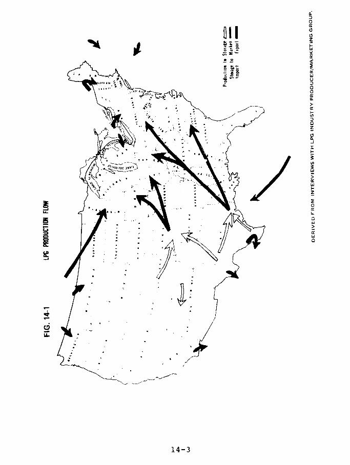
011 Z
0
fr~~~~~1l~~~~ . .~ci°E W
>.
op -= w
4-3 I
,14-3
c* -I
(/p ~ 0
5,," u.
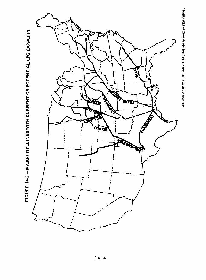
;>w
zO~~~~~~~~~~~~~~~~~~~~
d
w
zC~~~~~~~~~~~~~~~~~~~~~
w
I- >
U~~~~~~~~~~~~~~~~~~~~~
Z.
W ~~~~~~~~~~~~~~~~~~~wo
z~~~~~~~~~~~~~~~~~~~~
~~~~~~~~~~~w w
a
-II
w 0
a. 0..
P: ~~E- -- "~L I ~ 1
U~~~~~~~~~~~~~~~~~~~~~~~~~~~~~~~~~~~~~~~~U
I-
C,o
U,wz
-AJ / C-----'- - - 1"" r ' -j j~~
w
0
N
c Iw
LL~~~~~~~~~L
IIt,.
14-4

TABLE 14-1 DOMESTIC BULK TRANSPORTATION OF LPG, 1975 AND 1976
(In units of 1,000 cubic meters)
1976 Percent of Total 1975 Percent of Total
Truck 2,565 3.4 2,823 3.8
Rail 683 0.9 1,095 1.5
Pipeline-
Truck 67,679 90.6 68,9-5 91.9
Pipeline-Rail 3,404 4.6 1,9,- 2.6
Tanker orBarge* 406 0.5 168 .2
Total 74,737 100% 74,986 100%
*Approximately 90% of the volume in this category is transported by
pipelines prior to tanker or barge movement.
Source: National LP-Gas Association, "1976 LP-Gas Market Facts"
14-5
system's ability to move LPG from storage centers to
markets. The situation could have been alleviated if morestorage had been available in the Northeast.
AGRICULTURE
The regional consumption of LPG according to end use
is shown in Fig. 14-3. Agriculture is a major user of LPG(see the tables in Appendix XIV-1). Fifty-one percent (1.4
million) of all farms in the United States use LPG for avariety of purposes including crop drying and powering
poultry brooders, stock heaters, tractors, and irrigation
pumps.
Agricultural consumers along the eastern seaboard
will be the most severely affected by the decline in
domestically produced LPG unless additional supplies are
imported into the area. Historically, LPG for this region
has been transported from the major producing and storage
areas in the Midwest and Gulf Coast.
It would be cheaper to satisfy any excess Eastern
demand by importing LPG through East Coast, rather than
Gulf Coast, marine terminals.
Because existing LPG pipelines are full much of the
year, import terminals and adequate storage in consuming
areas are important. Certain underutilized natural gas
transmission lines, however, could be converted to carry
LPG. This would lessen the need for import terminals and
local storage.
14-6
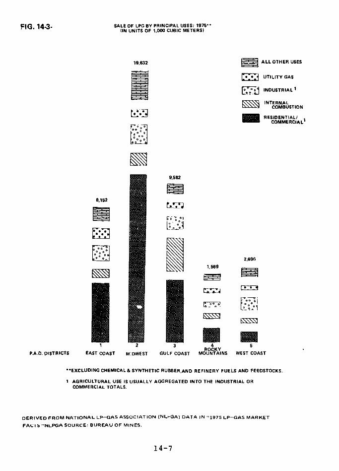
FIG. 14.3- SALE OF LPG BY PRINCIPAL USES: 1975* -
(IN UNITS OF 1,000 CUBIC METERS)
19,632 ALL OTHER USES
IEo°i INDUSTRIAL 1INTERNAL
COMBUSTION
RESIDENTIAL/COMME RCIA L'
9.582
8,152
loo -; 0
~Loo._O ~ '2,606
1.569
l 2 3 4 5ROCKY
P.A.D. DISTRICTS EAST COAST M:DWEST GULF COAST MOUNTAINS WEST COAST
**EXCLUDING CHEMICAL & SYNTHETIC RUBBER.AND REFINERY FUELS AND FEEDSTOCKS.
1 AGRICULTURAL USE IS USUALLY AGGREGATED INTO THE INDUSTRIAL ORCOMMERCIAL TOTALS.
DERIVED FROM NATIONAL LP-GAS ASSOCIATION (NLrGA) DATA IN "1975 LP-GAS MARKET
FAL I b "NLPGA SOURCE: BUREAU OF MINES.
14-7
USE AS A SUPPLEMENT TO NATURAL GAS
An increase in demand for LPG may come fromindustrial consumers whose supply of natural gas has beencurtailed. LPG can be furnished to these consumers throughthe existing natural gas pipeline system by injecting itinto the pipelines at or reasonably close to importterminals. The LPG can be introduced into the gas flow byone of three methods: (1) by first mixing it with air, (2)by breaking it down into methane and thus creating asynthetic natural gas (SNG), or (3) by injecting it in itsliquid form. The first two methods are currently in use atmany utility sites (see Appendix XIV-1).
LPG-Air
LPG is consumed as a gas although it is produced,stored, and transported as a liquid. The gas has 2.5 to ?times greater energy density (energy per unit volume) thanmethane, the largest component of natural gas. Thevaporization of the liquid and injection of air by naturalaspiration or mechanical compression dilutes LPG to anenergy density equal to that e; natural gas. Severalhundred domestic gas-air plants exist for standby andfull-time use at industrial and utility sites.
Synthetic Natural Gas
SNG is currently being produced to augment decliningnatural gas supplies by changing LPG or other petroleumbased fuels to methane. Thirteen SNG plants ranging insize from 16 MMcf/d (million cubic feet per day) to 250
14-8
MMcf/d are currently operating. Five of these use LPG as a
feedstock component and one uses propane to raise the
energy density of the output gas.
LPG Liquid Injection
A new method injects liquid LPG directly into a
natural gas pipeline. The injection must be into a
substantial flow of natural gas, such as the main
transmission lines in the Gulf Coast region. The liquid
propane is heated t¢ 'ielp it vapori2e and blend completely
into the passing gas stream. A transmission line with 1.5
MMMcf/d (billion cubic feet per day) can receive up tc
8,000 cubic meters per day of propane, or smaller amounts
of butane. The need for high volume gas lines and large
LPG storage currently limits this method to the Gulf Coast
where imports can be stored in large salt domes.
SUPPLY AND DEMAN'n
The demand for LPG in the United States varies by
region. (Figs. 1.4-4 and 14-5.) Demand is high in rural
areas because supplying natural gas to these areas by
pipelines would be too expensive. The demand may be met by
locally produced supplies or by bringing it in from other
sources. Particularly remr locations are limited to
locally produced LPG s,' '-_ because of the high cost of
movirg LPG from distant sources. (See Fig. 14-6.)
In the northern states, the principal demand for LPG
is Ln winter. The interstate pipeline system cannot fully
meet this peak demand. Consequently, inventories are built
up during the summer to help meet winter requirements.
14-9
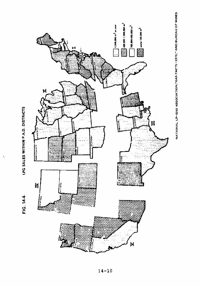
ii Im ~~~~~~~~~~~~~~I
z
LLm 0
S
4
10~~~~~~~~~~~~~~~~~~~
LU~~~~~~~~~~~~~~~~~~~~
to
1 4 - 1 0U, in
u,
U-~~~~~~~~~~~~~~~~~~~~~~~-
O~~~~~~~41
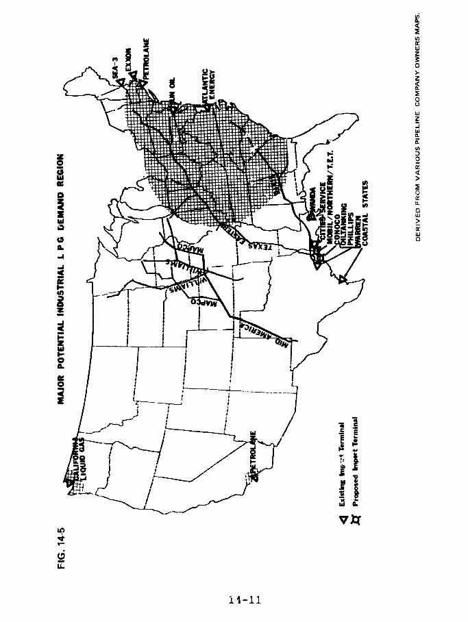
m z fiw
a al9 izlaIZ j Z j
" 'S
U
-J
I j-
ILEIP~~~~~~WL, i18 5 >t
vx I,,i.
11-11

rw ~~~~~~~~~~~~~~~~ er'~~~~~~~~~~~~~~~~~~~~
_I< w\R g 4 g b~~~w
0
.J
r~~~~ z~~ z
' s~'
0
o 3 ~~~~~~~~~~~~~~~.J
1 as1 >
ZH
i
U
z < do i [; > > c
+ S ° ,,/' " 'a f~X~J 1~10
U)U
CL4
Analyzing LPG supply and demand by P.A.D. (Petroleum
Administration for Defense) District, the following picture
emerges:
The eastern seaboard states in P.A.D. District 1 have
found it increasingly difficult in recent nears to acquire
enough domestically produced LPG. Existing marine
terminals supply that portion of demand not met by
inter-district pipeline movement, minor indigenous
prodilction, and rail car imports from Canada. Natural gas
curtailments to industry in this district have increased
the need for imports. Bureau of Mines figures indicate
that 7.7% of P.A.D. District 1 demand was met by overwater
imports.
The Midwest region (P.A.D. District 2) is the highest
LPG consuming area in the United States. Local production
supplies 47% of demand and most of the rest is met by
inter-district pipeline. Canadian imports supply 11%.
The Gulf Coast area (P.A.D. District 3) produces more
LPG than it consumes, and most (52%) of the nation's
overwater imports come into District 3. The sarplus is
piped to other Districts.
The Rocky Mountain area (P.A.D. District 4) moves its
excess summer production to the large underground storage
complex in Kansas (P.A.D. District 2). Winter demand
exceeds the District's LPG production capability and
shortages are met by rail from Canada.
14-13
In the West Coast region (P.A.D. District 5),
California and Washington have substantial production, but
the District imports 38% of its LPG from other P.A.D.
districts and from Canada.
LPG supply and demand by P.A.D. District for 1975 is
shown in Appendix XIV-1. As U.S. and Canadian LPG
production declines, more overwater imports will be
required to fill the increasing demand.
MARINE IMPORT TERMINALS
The first domestic LPG marine terminals were built in
the 1950's to receive vessels carrying no more than 30,000
cubic meters. 'he LPG was shipped between coastal ports orexported. Pipelines from storage sites to terminals were
also designed for small volume movements. Subsequently,
these terminals were adapted to import LPG, but most cannot
handle the much larger ships often used now.
Many present northeastern terminal sites have little
room to expand. When space is available, expansion often
is resisted by political, environmental, and safety
oriented groups. ?artly because of these problems, most
new LPG import terminals are being planned for the Gulf
Coast. The low priced salc dome storage in the area is
also attractive to potential LPG importer.s.
Appendix XIV-2 describes the 16 existing import
terminals, the five proposed terminals, and six potential
sites. Six of the existing terminals have physical
limitations that restrict their importation levels. The 15
major existing or proposed terminals will be capable of
receiving 35.5 million culic meters per year by 1980 and
14-14
61.4 million cubic meters per year by 1985. We estimate
overwater LPG imports of 13.5 million cubic meters in 1980
ard 26.9 million cubic meters in 1985.
Four major terminals, including two proposed
terminals, are on the Houston Ship Channel. (In addition,
Petro-Tex Chemical Corporation will receive smaller
quantities of LPG.) According to our etimates, there will
be 133 LPG ship arrivals in the Houston Ship Channel in
1980 and 188 in 1985. An average of one LPG ship per day
will be moving into or out of the Channel in 1985.
When the Federal Power Commission (FPC) staff was
assessing the proposed El Paso LNG marine terminal at Port
O'Connor, Texas, it developed criteria for suitable
navigational conditions. According o one of these
criteria, "existing ship traffic should not be so heavy
that closing down the approach channel for 2-4 hours every
2-2.5 days would impose excessive economic hardship on
other shipping activities.
The Final Environmental Impact Stztement rejected
three possible sites on the Houston Ship Channel, citing
the density of ship traffic in the channel and navigational
hazards including currents, obstructed areas in the
channel, a turn of almost 90 degrees at Pelican Island, and
a seaplane landing area located less than 0.5 miles from
one portion of the channel.
14-15
Ships are permitted, however, to routinely deliver
LPG and other highly hazardous materials to sites on the
Houston Ship Channel. This makes no sense.
Because of drafting and storage restrictions,
75,000-cubic meter LPG vessels can currently offload only
in the Gulf of Mexico and at the Sun Oil terminal at Marcus
Hook, Pa.
The East and Gulf Coasts now have about equal
offloading capacity, but if all announced terminal
construction and expansion plans occur, the Gulf Coast
offloading capacity will increase to 78% of the national
total by 1980 and will continue at that level.
Table 14-2 classifies major existing and proposed
import terminal sites by their location in relation to the
edge of a densely populated area of at least 25,000 people:
URBAN is defined as a site that is within four miles;
SEMI-URBAN as a site that is between four and twelve miles;
and RURAL as a site that is more than twelve miles. The
table also indicates whether ships enroute to a site must
pass by an urban area.
STORAGE
LPG is stored in large Aboveground refrigerated
stora;ge tanks oi, iiA -pressure, in large underground saltdomes and mined granite caverns or in small pressurized
"bullet" storage tanks. About 86 percent of the LPG i;n
bulk storage is stored underground., particularly in the
excavated natural salt deposits in Texas, Louisiana, andKansas.
14-16

to §g
o 0 00 00
o o0 A0 o 0004.5 0 0 00 0 ' 000 00 0 00 XO 00
£ ~0 ~ ~ ~ ~~ '0C C 4
0
° a)In in H- 4 H
U * o a r7 D r B O
-. A, -,-
0; ~ ~ t X o ~ .~ 0N'
4 -17
Ja $4 M 4i ( 4J
U 00
0 4)
(454)
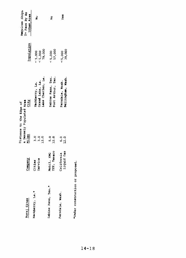
0
00 0 0
00- 00 0 0
CO
'V V V
r .4 . . .
W -44
44 E
4,
* -[' 0 .- I
0
0 0 X 0C-
04a)M C) -4
O · CO 0O 00
,
.. -> -44]
O 0
4)I) N4
N e u
VII 4
VZd~~~~ 4 Ch @ Q
14-18
The major storage centers in the United States help
to integrate Pimorts of LPG with domestic production and to
match winter demand with summer production. They also
boost supply to regions whose rate of pipeline deliveries
is inadequate during heavy demand periods.
Insufficient on-site or nearby storage often limits
the through-put capacity of import terminals. Import
terminals that have only enough on-site refrigerated
storage space for about one shipload (56,000-95,000 cubic
meters) must either adjust receiving schedules to ensure
storage space for a full cargo, or arrange for delivery to
more than one marine terminal, which substantially
increases transportation and handling costs.
The import terminals with the largest through-put
capacity have access to l-rge underground storage
complexes. The large capacity permits more timely receipt
of vessels, and may offer greater flexibility to receive
mixed or non-specification products. Underground storage
is also much more economical than refrigerated tanks to
construct and operate. Storage construction costs per
cubic meter are: washed from salt, $12.50 to $31.50; mined
(usually in granite), $41 to $88; refrigerated, $94 to
$126; pressure tanks, $200 to $226.
The problem of inadequate storage at some facilities
is compounded by insufficient pipeline capacity to deliver
the LPG from the ship to on-site or off-site storage and
then to the distribution network.
14-19
Table 14-3 shows the amount of storage available at
each of the major existing and planned import terminals.
It can be seen that almost all of the nation's connected
storage capacit, (94 percent) is in the Gulf Coast area,*
with only 4 percent on the East and West Coasts.
This enormous concentration of LPG storage capacity
reduces the flexibility of the domestic LPG distribution
system.
Figures 14-7 and 14-8 show potential areas for
underground storage complexes, Finding locations in the
Northeast and on the West Coast for import terminals that
are near potential underground storage areas is difficult.
*This does not give full weight to the terminals connected
to the large storage complex -t Mt. Belvieu, Texas,
because some of the storage is used for domesticallyproduced LPG. Only the storage directly connected to or
owned in conjunction with each individual facility is
considered.
14-20

li ? 1I11114 I
O DI O0 o C O N, k L C h L r4 0 a o
I O, O * inF~ ~D M fn u - 4 0 (m44
3 n
En w $34 u E
o). o .
ctW~~~. o N g . i d "d *N N .4
a0 a > U @ @ *d o .. @ .0 .4 pW
HA1 -- ~~~~~~~~~ C C; ZD * O0
CO d r( U c -W .v 0 N co
OC -0 .u I° S
·O R * * X W ^ " * * -u I Ni
1 4-2 1( 4 w, .U
d z co *u a *.. I £ = u .
UU 'U HI * d4-21e 0 ' V
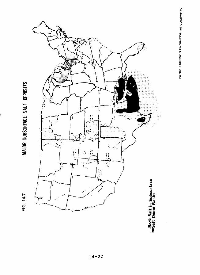
z
0.
0
'i
LJ .
MCC
14 -22

UC,Z
r~~~~~~~~~~~~~~~~~~~~~~w
UzO
LA
%~~~~~~~~~~~~~~
U..
CD,
LLJ~ ~~~~&I a c
j =~~~~~~~~~~~~~~~~~~~~A
-U 0 1 U
~~~~~~ ~~~~~~~~~~
V) LL
14 -23

FINDINGS
In 1976 the United States imported over water about1.9 million cubic meters of LPG.
Almost all of the existing LPG marine import terminalshave been built on urban sites. To reach most of the
terminals, LPG ships must pass by urban areas. Manyterminals have large aboveground refrigerated storagetanks on-site.
Lxisting and announced non-urban terminals will havethe capacity to receive 111 percent of projected LPGimports in 1985.
Several non-urban terminal sites could inject LPG
directly into natural gas pipelines to supplementdomestic supplies. On the Gulf Coast, where naturalgas transmission lines originate, volume through thepotential Pascagoula, Miss. site could approach 3million cubic meters annually. Smaller amounts (0.8million to 1.6 million cubic meters) could beinjected from each of the potential non-urban
terminals on the East and West Coasts.
RECOMMENDATION
TO THE SECRETARY OF TRANSPORTATION
We recommend that the Secretary of Transportation
develop a computer program able to analyze the capabilityof the national LPG storage and distribution system. Such aprogram should be able to determine the rate at which LPG
14-24

can be delivered - as LPG or as synthetic natural gas -
from any point to any other point and the cost to increase
this capability by any desired amount.
14-25
REFERENCE
1. Final Environmental Impact Statement for theMatagorda Bay Project, FPC, Docket No. CP77-330 etal., September, 1977.
14-26
CHAPTER 15
THE CAPACITY OF NON-URBAN SITES TO MEET TOTAL
U.S. IMPORT REQUIREMENTS FOR LNG
CONTENTS PAGE
INTRODUCTION 15-1
DISCUSSION 15-1
FINDING 15-5
AGENCY COMMENTS AND OUR EVALUATION 15-7
REFERENCES 15-8
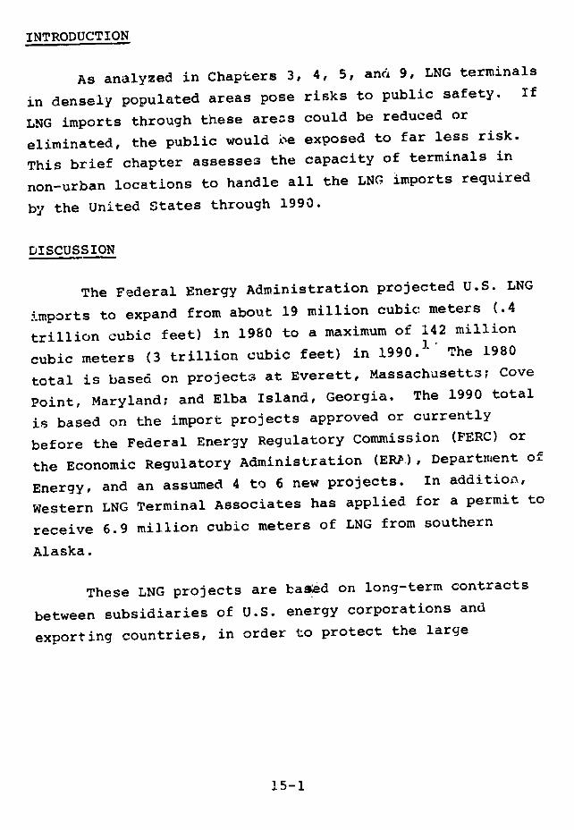
INTRODUCTION
As analyzed in Chapters 3, 4, 5, and 9, LNG terminals
in densely populated areas pose risks to public safety. If
LNG imports through these areas could be reduced or
eliminated, the public would be exposed to far less risk.
This brief chapter assesses the capacity of terminals in
non-urban locations to handle all the LNG imports required
by the United States through 1990.
DISCUSSION
The Federal Energy Administration projected U.S. LNG
imports to expand from about 19 million cubic meters (.4
trillion cubic feet) in 1980 to a maximum of 142 million
cubic meters (3 trillion cubic feet) in 1990. The 1980
total is based on projects at Everett, Massachusetts; Cove
Point, Maryland; and Elba Island, Georgia. The 1990 total
is based on the import projects approved or currently
before the Federal Energy Regulatory Commission (FERC) or
the Economic Regulatory Administration (ERP), Department of
Energy, and an assumed 4 to 6 new projects. In addition,
Western LNG Terminal Associates has applied for a permit to
receive 6.9 million cubic meters of LNG from southern
Alaska.
These LNG projects are based on long-term contracts
between subsidiaries of U.S. energy corporations and
exporting countries, in order to protect the large
15-1
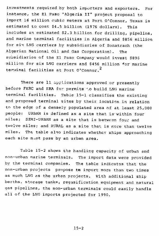
investments required by both importers and exporters. For
instance, the El Paso "Algecia II" project proposal to
import 16 million cubic meters at Port O'Connor, Texas is
estimated to cost $4.5 billion (1976 dollars). This
includes an estimated $2.3 billion for drilling, pipeline,
and marine terminal facilities in Algeria and $856 million
for six LNG carriers by subsidiaries of Sonatrach (the
Algerian National Oil and Gas Corporation). The
subsidiaries of the El Paso Company would invest $890
million for six LNG carriers and $456 million for marine
ter:minal facilities at Port O'Connor.2
There are 11 applications approved or presently
before FERC and ERA for permits t.o build LNG marine
terminal facilities. Table 15-1 classifies the existing
and proposed terminal sites by their location in relation
to the edge of a densely populated area of at least 25,000
people: URBAN is defined as a site that is within four
miles; SEMI-URBAN as a site that is between four and
twelve miles; and RURAL as a site that is more than twelve
miles. The table also indicates whether ships approaching
each site m~ast pass by an urban area.
Table 15-2 shows the handling capacity of urban and
non-urban marine terminals. The import data were provided
by the terminal companies. The table indicates that the
non-urban projects propose tz import more than two times
as much LNG as the urban projects. With additional ship
berths, storage tanks, regasification equipment and natural
gas pipelines, the non-urban terminals could easily handle
all of the LNG imports projected for 1990.
15-2
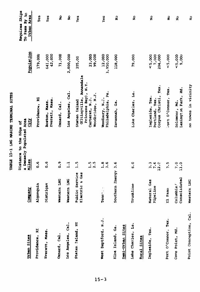
.sU 0 0 u, uA o o z0z z m m z ZEn >4 F @ Z Z > > Z Z Z Z Z
(a
i ooI oo g oo o o ggg o oo
.- o 8 8 o° o V V V
0
0 0 Y0 0 0 00 .0 0 000 0 00
n V;! u, B)(dO U m ; >'OO ,. o~m d' c; 4c( 4 .44 .- ,4 ,4 ,~ ~,.,, , ,4
0 ,0
t W 4 M . 0 la t o 0 - . .t . ..
-1 4i r0 -1 *id.I -
*l 04 U) u U) r-) E 0144~~~~~~~~~,
8r4 0~~~~~~ 0
Lin * X 4 o54-3
t z z
r 0 -HA 9 ww
14 0 1 g § g a t4 41 u4 0I U) . .-fit oIw to I A 0) Hr. fi
* U
0 *g 0 \o~, a ~ ~ ~ mu, o~r om 10
14 *r ~ CA U) 1 0(a 03 d0 0 U U) 0 Q.
I 41
15-3 Lt

-4~ CO C -I -,ICd l
9.0 0 ..
o 0, .% O
.. 0 .4. C 4 f
· ) 4
,.4
0o -, 8
~~~~~~~~~~~~~~·*
Eil > Z0 o u. B ~ 4'
twe 4 f 3 6 o r- G
P CPz qvoo0 4 0 0
.. o 5
4 0.
cd 4' o U a4r, · U z , o °-I I
O' 14 ' 4, la
c.3~ 4 0 10 0 - 0c o
Ht Na a 5' coV
> ) 0 *
15-4
-4 a 0 &. 0 W.4 4)
4i-4 4) 4.4 1-4 9) 4) 0 6 'A
NI r 4 -
I B 4 ~01.4 0
a a 0 1. ~ A -4$4 4, 44
. 2 0 go0 4e) 4 4
g* 0 4 4 I
c0000 44-v0 4)
0 4)
o .
tia uL, BU15-
If the inherent danger of living near an LEG terminal
is insufficient to keep large numbers of people from moving
nearby, a non-urban site might become an urban site over
the lifetime of a facility. Thus, it is necessary to
predict the population pattern of the site area for the
projected lifetime of the facility. The Nuclear Regulatory
Commission requ4 res such predictions for nuclear
facilities, and they have proved to be accurate.
Table 13-3 shows a regional breakdown of the existing
and proposed LNG marine terminals. The five non-urban
terminals are located in the Northeast, the Gulf Coast, and
the West Coast.
FINDING
The Federal Eiergy Administration projected maximum
U.S. LNG imports in 1990 to be 142 million cubic
meters. In aacition, Western LNG Terminal
Associates has applied to receive 6.9 million cubic
meters from southern Alaska. Non-urban LNG marine
terminals have the potential capacity to receive
180.3 million cubic meters. Thus, non-urban LNG
terminals could easily handle all of the LNG imports
projected for 1990. We have not looked at the
capacity of the main gas transmission lines to
distribute these quantities.
15-5
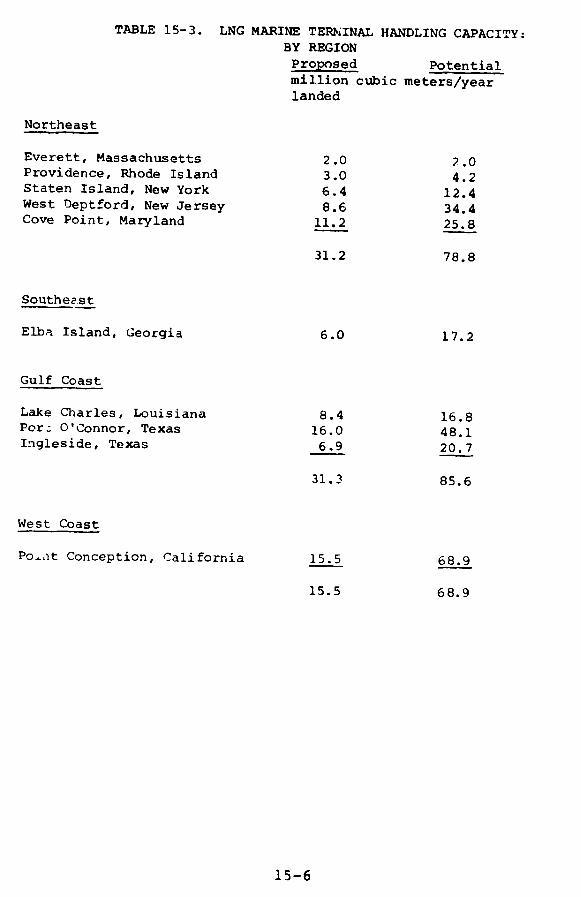
TABLE 15-3. LNG MARINE TERiINAL HANDLING CAPACITY:BY REGION
Proposed Potentialmillion cubic meters/yearlanded
Northeast
Everett, Massachusetts 2.0 2.0Providence, Rhode Island 3.0 4.2Staten Island, New York 6.4 12.4West Deptford, New Jersey 8.6 34.4Cove Point, Maryland 11.2 25.8
31.2 78.8
Southeest
Elba Island, Georgia 6.0 17.2
Gulf Coast
Lake Charles, Louisiana 8.4 16.8Pore O'Connor, Texas 16.0 48.1Ingleside, Texas 6.9 20.7
31.3 85.6
West Coast
Po.lt Conception, California 15.5 68.9
15.5 68.9
15-6
AUENCY COMMENTS AND OUR EVALUATION
The Department of Energy suggests that we should
". . Lully document the conclusion that LNG supplies
projected for 1990 could be handled in non-urban sites.
The volumes are so substantial that absent of a discussion
of ship requirements, berth facilities, etc., the
statements per se are inconclusive." Several companies
make similar comments.
We obtained our estimates for the potential LNG
imports that could be received through the marine
terminals, shown in Table 15-2, from the terminal co :,anies
involved. We mention several ways in which existing
facilities and pipelines might have to be expanded. We
have not analyzed the possible costs.
15-7
REFERENCES
1. Statement of an official of the Office of Oil andGas, Department of Energy, in a telephoneconversation on October 13, 1977.
2. Federal Energy Regulatory Commission "InitialDecision upon Applications to Import LNG fromAlgeria,n Administrative Law Judge SouthworthPresiding, October 25, 1977, pp. 4-5.
15-8
CHAPTER 16
FEDERAL, STATE, AND LOCAL REGULATIONS
CONTENTS PAGE
INTRODUCTION 16-1
THE EVOLUTION OF SAFETY STANDARDS 16-1
FEDERAL REGULATION OF LEG AND NAPHTHA SAFETY 16-6
Office:of Pipeline Safety Operations 16-8Responsibilities for LNG Faciliti(s 16-8Responsibilities for LPG and NaphthaFacilities 16-10
U.S. Coast Guard 16-11
Materials Transportation Bureau 16-12
Federal Power Commission 16-12
U.S. Army Corps of Engineers 16-13
Interstate Commerce Commission 16-13
Federal Aviation Administration 16-13
Environmental Protection Agency; Councilon Environmental Quality 16-14
The Coastal Zone Management Act 16-14
Findings 16-15
STATE AND LOCAL REGULATIONS 16-16
State Regulations 16-16
Local Regulations 16-18
Permit Granting Agencies 16-19
Airports 16-21
CONTENTS PAGE
Insurance and Liability Standards 16-21
Findings 16-22
FINDINGS OF SPECIAL ISSUES ANALYSIS 16-23
1. The Minimum Distance Required BetwaenTanks or Dikes and Residential, Social,Business, and Government Facilities. 16-23
2. The Minimum Distances Required Between LNG,LPG, and Naphtha Tanks, and Tanks HoldingOther Flammable, Explosive, Poisonous, orToxic Materials. 16-23
3. Security Requiremer.ts. 16-23
4. Diking Requirements. 16-23
5. Requirements for Resistance to NaturalPhenomena. 16-23
6. Requirements for Operating Procedures andPersonnel Training. 16-23
7. Materials Specifications for Storage Tanks. 16-23
8. Materials Specifications for Truck Trailersand Railcars. 16-23
9. Requirements for Harbor Movements andUnloading of LEG and Naphtha Tankers. 16-23
10. Requirements for Tanker Construction. 16-23
11. Liability. 16-23
12. Liability Insurance Requirements. 16-23
RECOMMENDATIONS 16-43
AGENCY COMMENTS AND OUR EVALUATION 16-45
REFERENCES 16-4716-47
INTRODUCTION
This chapter evaluates and compares safety laws and
regulations for large LEG and naphtha storage facilities,
focusing on 12 special issues. It gives an overview of
transportation regulations which are discussed more fully
in Chapters 6 and 17. Our review covered the Federal
Government, the 50 states, and 30 representative localities
listed in Table 16-1.
The survey shows that substantive regulation of the
storage and handling of bulk LNG, LPG, and naphtha remains
under the jurisdiction of the states.
Except for a few municipalities that have their own
codes, city and county authorities follow state regulations
for enforcement and inspection purposes.
Federal regulations are similar to those of the
states and municipalities because they all rely heavily cn
National Fire Protection Association (NFPA) standards.
Appendix XVI-1 lists all U. S. facilities having LNG,
LPG, or naphtha storage in excess of 23,000 cubic meters
(m3 ), or a monthly throughput greater than that figure.
Appendix XVI-2 describes 12 large LEG facilities that we
visited.
THE EVOLUTION OF SAFETY STANDARDS
Most regulations governing the siting, design,
testing, inspection, and operation of LNG, LPG, and naphtha
facilities evolved within the industry. The first
major LNG facility, constructed in Cleveland in the early
16-1
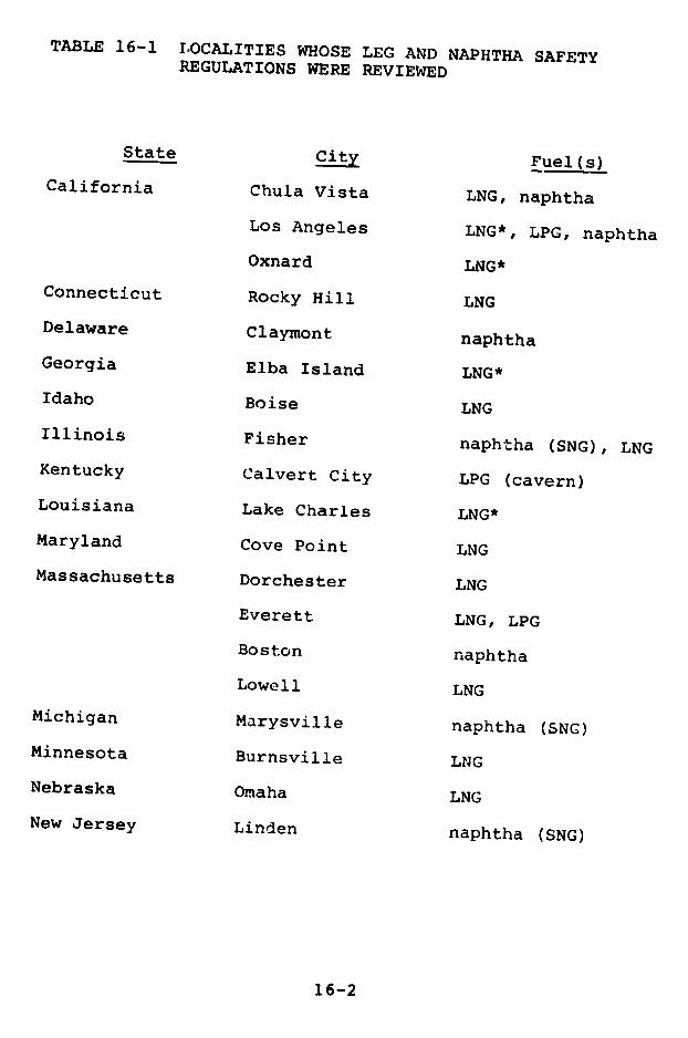
TABLE 16-1 I.OCALITIES WHOSE LEG AND NAPHTHA SAFETYREGULATIONS WERE REVIEWED
State City Fuel(s)California Chula Vista LNG, naphtha
Los Angeles LNG*, LPG, naphtha
Oxnard LNG*
Connecticut Rocky Hill LNG
Delaware Claymont naphtha
Georgia Elba Island LNG*
Idaho Boise LNG
Illinois Fisher naphtha (SNG), LNGKentucky Calvert City LPG (cavern)
Louisiana Lake Charles LNG*
Maryland Cove Point LNG
Massachusetts Dorchester LNG
Everett LNG, LPG
Boston naphtha
Lowell LNG
Michigan Marysville naphtha (SNG)
Minnesota Burnsville LNG
Nebraska Omaha LNG
New Jersey Linden naphtha (SNG)
16-2
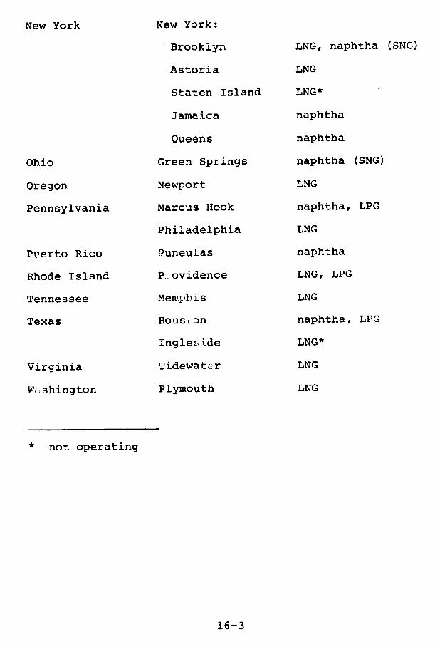
New York New York:
Brooklyn LNG, naphtha (SNG)
Astoria LNG
Staten Island LNG*
Jamaica naphtha
Queens naphtha
Ohio Green Springs naphtha (SNG)
Oregon Newport LNG
Pennsylvania Marcus Hook naphtha, LPG
Philadelphia LNG
Puerto Rico 9 uneulas naphtha
Rhode Island P.ovidence LNG, LPG
Tennessee Memphis LNG
Texas Houst:on naphtha, LPG
Ingle.ide LNG*
Virginia Tidewater LNG
W.shington Plymouth LNG
* not operating
16-3
1940's, was designed on the assumption that credible
accidents would involve leaks that were no faster than
those from a major piping accident. Present LEG codes and
standards are more stringent than those used at Cleveland,
but they are still designed to handle only the same
limited leakage.
Regulations governing LEG and naphtha storage are
based on NFPA and other professional group standards. LPG
and naphtha have been ii, widespread use for many years,
and the regulations controlling them are more nearly
uniform than those for LNG. The American Petroleum
Institute (API), the NFPA, and some localities have
special rules covering bulk storage of refrigerated LPG.
NFPA Standard 58, "Storage and Handling of Liquefied
Petroleum Gases," was first adopted in 1932. Between 1932
and 1940 the rapidly growing use of LPG led to several
separate NFPA standards for different LPG applications.
In 1940 these were combined into Standard SP. The
Standard has been revised about every two years since.
The current version is the 1974 edition. This standard is
accepted by nearly all state and local fire agencies.
NFPA Standard 59, "Storage and Handling of Liquefied
Petroleum Gases at Utility Gas Plants," was originally
developed in 1949. The 1974 version was the product of a
cooperative effort between t'he American Gas Association
and the NFPA. This standard is usually adopted by utility
regulatory bodies because of its specific application to
utility plants.
16-4

NFPA Standard 59A, "Storage and Handling of
Liquefied Natural Gas," as revised in 1972, is the common
minimum standard for LNG. The 1975 revision is now being
adopted by states and localities.
NFPA Standard 30, "Flammable and Combustible Liquids
Code," is used for naphtha. It was originally developed
in 1913 as a suggested ordinance for the storage and
handling of flammable liquids, and it has been the basis
for most subsequent regulations for liquid fuels such as
naphtha. The text was expanded over the years, and in
1957 was changed to a recommended Code in recognition of
the tendency toward statewide regulation. The current
edition was published in November, 1976.
API Standard 2510 is sometimes adopted by regulatory
groups. It doas not apply to LPG installations covered by
NFPA 58 or 59, but rather to those at marine and pipeline
terminals, refineries, or tank farms. I. some criteria
API 2510 is more stringent than NFPA 58, in others less.
API Standard 620 is entitled "Recommended Rules for
Design and Construction of Large, Welded, Low-Pressure
Storage Tanks." The sixth edition, released on July 15,
1977, has an appendix which applies specifically to LNG
tanks.
API Standard 650 (1977 ed.), "Welded Steel Tank for
Oil Storage," applies to naphtha tanks. Pressure vessels
such as non-refrigerated LPG tanks are designed to
American Society of Mechanical Engineers (ASME) pressure
vessel codes.
16-5
FEDERAL REGULATION OF LEG AND NAPHTHA SAFETY
Federal regulations covering land storage facilities
are not well coordinated for LNG and are minimal for LPG or
naphtha. The LNG regulations incorporate NFPA 59A. -There
are no specific Federal laws or regulations covering
minimum liability insurance requirements for LEG or naphtha
facilities.
In the Federal regulation of LNG storage facilities,
there have been areas where jurisdiction among agencies has
been unclear. Two DOT agencies-the Office of Pipeline
Safety Operations (OPSO), in the Materials Transportation
Bureau (MTB), and the U.S. Coast Guard-have each exercised
authority over LNG facilities adjoining the navigable
waters of the United States. The former Federal Power
Commission (FPC) also had certain responsibilities for the
safety of LNG import terminals and some peakshaving plants.
On February 7, 1978, the MTB and the Coast Guard
signed a two-page Memorandum of Understanding which
specifies the responsibilities to be carried out by each
agency. This action, which took more than three years of
negotiations, should reduce the duplication of effort and
speed the promulgation of needed regulations.
The Coast Guard will be responsible for establishing
regulatory requirements for:
(1) Facility site selection as it relates to
management of vessel traffic in and around a
facility;
16-6
(2) Fire prevention tnd fire protection equipment,
systems, and methods for use at a facility;
(3) Security of a facility; and
(4) All other matters pertaining to the facility
between the vessel and the last manifold (or
valve) immediately before the receiving
tank(s).
Except as provided in those paragraphs, the MTB
(through OPSO) will be responsible for site selection and
all other matters pertaining to the facility. This
division of responsibilities appears to De appropriate.
The two agencies agreed to cooperate in carrying out their
enforcement activities and to consult with each other
before issuing proposed and final regulations.
Appendix XVI-3 includes the full memorandum and a
discussion of the statutory authority of the two agencies.
This appendix also includes an analysis of the
relationship between OPSO and the FPC.
Several DOT offices are also responsible for setting
and maintaining safety standards for interstate trucks and
railcars carrying LuG. This chapter discusses only the
regulations issued by MTB and its Office of Hazardous
Materials Operations (OHMO). The Interstate Commerce
Commission (ICC) is also involved in LEG transportation,
since only it can revoke or suspend the certificates of
interstate carriers found to be unsafe. The Coast Guard
has Federal jurisdiction over LEG and naphtha shipping.
16-7

Office of Pipeline Safety Operations
Responsibilities for LNG Facilities
OPSO is responsible for prescribing and enforcing
Federal safety regulations for LNG storage facilities
connecting with a pipeline in or affecting interstate
commerce. See 49 CFR Parts 191 and 192. These
regulations incorporate the 1972 version of NFPA Standard
59A. The facility design regulations apply only to LNG
pipeline-connected facilities for which construction began
after January 1, 1973, but the operating and modification
provisions apply to all facilities. Currently, OPSO has
an Advance Notice of Proposed Rulemaking on "Liquefied
Natural Gas Facilities, Federal Safety Standards," which
could add a new Part 193 to Title 49, CFR (42 Fed. Reg.
20776, dated April 21, 1977). It expands on the 1975
edition of NFPA 59A, uses safety performance standards,
and includes some specific new technical requirements.
The new design standards will apply to existing facilities
only if they are modified in the future.
OPSO carries out its pipeline safety program across
the United States through its five regional offices, each
staffed by two professionals and a secretary. OPSO plans
to increase the number of professionals in the field
offices to 45, but eight will be assigned to the Alaska
cras pipeline project.
OPES mainly relies on certified state agencies for
the inspection of LNG storage facilities. (This
certification program is described below.) In 1977, OPSO
made three inspections, including the Cove Point, Md.
marine terminal- State agencies made 242 inspections of
16-8
74 LNG storage facilities in 1977. OPSO records do not
indicate the extent of the state inspections.
A more comprehensive review of OPSO's authority,
regulations, and performance is presented in GAO's report,
"Pipeline Safety--Need for a Stronger Federal Effort"
(CED-78-9 9). One of its conclusions is that OPSO's
staffing, particularly in the regional offices, is not
adequate for carrying out its present mandated
responsibilities in a comprehensive, effective, and timely
manner.
OPSO regulations require LNG storage facilities to
report at the earliest practicable moment by telephone any
leak that causes death or injury, property damage of more
than $5,000, or gas ignition. No written follow-up report
is required if the facility serves fewer than 100,000
customers. For example, the owners of the Cove Point
import terminal, whose only customers are other pipeline
companies, would not have to file a written report.
In the annual report required of all gas
transmission companies, all leaks must be described.
There is no requirement, however, by OPSO or any other
Federal agency, for the reporting of other unusual
occurrences, such as the venting of vapor from storage
tanks or the breakdown of vital machinery. Gas utility
companies do not have to identify the type of facility
where a leak occurred. It would not be clear, for
example, whether a leak occurred at an LNG peakshaving
facility or in the natural gas pipeline.
16-9

Responsibilities for LPG and Naphtha Facilities
OPSO's regulation of LPG and naphtha pipelines is
authorized under the Transportation of Explosives Act of
1908, 18 U.S.C. 831-835, and the Hazardous Materials
Transportation Act, 49 U.S.C. 1801 et seq. The Explosives
Act gives OPSO responsibilit, over interstate and foreign
commerce by these pipelines, but it does not cover
interstate pipelines and facilities that merely affect
interstate commerce. The Hazardous Materials
Transportation Act excludes interstate liquid pipelines
covered under the Explosives Act from its provisions.
OPSO further interprets ti,o Act to exclude jurisdiction
over intrastate !iquid pipelines affecting interstate
commerce. We disagree. We believe that intrastate LPG
and naphtha pipelines, including connecting import
terminals and storage complexes, affecting interstate
commerce are under OPSO's jurisdiction and that OPSO
should extend its regulations to cover these pipelines.
Under the Explosives Act, the Director of OPSO
cannot levy civil penalties for violations. In order to
penalize violators, he must initiate criminal charges. If
no death or serious injury resulted from the violation,
tile maximum penalty is $1,000 and one year imprisonment.
According to OPSC regulations, 49 CFR 195.264, LPG
and naphtha storage tanks under its jurisdiction are only
required to provide a means to contain liquid in the event
of a spill or tank failure, to protect against
unauthorized entry, and to provide normal and emergency
16-10
relief venting. These regulations do not require a
particular percentage of the liquids spilled to be
contained, or say whaL constitutes adequate protection.
against unauthorized entry.
U.S. Coast Guard
The U.S. Coast Guard regulates various aspects of
the design, construction, and harbor movements of seagoing
vessels and cargo tanks for LEG and naphtha (46 U.S.C.
391a). It has issued regulations on the design and
operation of tank vessels transporting LEG and naphtha, in
46 CFR Parts 30 to 40; and for the transportation of
liquefied flammable gases in portable containers stored on
deck for use as ships' stores and supplies, in 46 CFR Part
147. It has regulations on hull and tank construction for
liquefied gases, 46 CFR Parts 151 and 152, and for the
maintenance of standards on foreign vessels, 46 CFR Part
154. Coal tar naphtha is regulated under 46 CFR Part 153
as a Lulk liquid chemical.
In October, 1976, the Coast Guard published proposed
standards for new self-propelled vessels carrying bulk
liquefied gases. The Coast Guard has not Iromulgated
regulations directly relating to LNG land facilities but
had announced an intention to do so. Under the new
Memorandum of UnderstandinIg, the Coast Guara's rule-making
will be coordinated with OPSO's.
The Coast Guard is responsible for designating
security zones on land to guard against sabotage, and it
issues permits and maintains precautions rlelevant to the
handling of dangerous cargo in or contiguous to waterfront
facilities, pursuant to 33 CFR Parts 6 and 124-127.
16-1i

Materials Transportation Bureau
MTB has promulgated detailed regulations on thetransportation by rail, highway, air, or water, ofhazardous materials in commerce. These, set forth in 49CFR Parts 171-179, identify hazardous materials by classes(LNG and LPG are flammable gases) and require specificdesign standards for hazardous materials containers,including railcars and tank trucks. At present, however,no regulations for the design of cryogenic tank trucksexist, and MTB (through OHMO) approves LNG tank truckdesigns by exemption. The regulations in 49 CFR Parts171-179 incorporate parts of NFPA Standard 58 and otherstandards of private organizations.
Federal Power Commission
The Natural Gas Act of 1938, 15 U.S.C. Section 717et seq., authorized the Federal Power Commission toregulate the transportation and sale for resale of naturalgas in interstate commerce, including, under Section 717f,the regulation of facilities. In addition, the Commissionhas exelcised jurisdiction over import facilities underits authority to regulate imports of natural gas (15U.S.C. 717b). Regulations in 18 CFR Part 3 Appendix B,Guideline 9.4.1., which werc adopted pursuant to theNational Environmental Protection Act, require thatEnvironmental Impact Statements be prepared for LNGtransport, storage, and regasification facilities. Thesemust Include a description of compliance with the relevantOPSO and Coast Guard safety regulations.
16-12

U.S. Army Corps of Engineers
The U.S. Arny Corps of Engineers has the authority
under 33 U.S.C. Section 101 to regulate the construction of
bric.ges and wharves, and other activity or construction
which affects navigable wate-s. In this capacity, the
Corps issues permits relevant to the construction of
waterfront LNG terminals, but lacks authority to otherwise
regulate either LNG ships or terminal facilities. Permit
regulations are found in 33 CFR Part 209.
Interstate Commerce Commission
The ICC, under its basic grant of authority in 49
U.S.C. Section 1 et seq., has general authority over
interstate surface transportation. Its control over the
safety aspects of different modes of transportation and its
specific powers to regulate the transportation of dangerous
materials was transferred to DOT by the DOT Act of 1966, as
amended (49 U.S.C. 1651 et seq.).
Federal Aviation Administration
The Federal Aviation Administration has the authority
to certify airports and set standards for the storage and
inspection of fuel storage (14 CFR 139.1 et seq. and
139.51). This includes naphtha, but not LNG or LPG, since
they are not used for aircraft fuel.
16-13

Environmental Protection Agency; Council on Environmental
Quality
The Environmental Protection Agency has several
regulations which potentially affect LEG and naphtha
facilities. They arc somewhat removed, however, from the
issues which are the subject of this inquiry. Some
examples are regulations on Ambient Air Quality Standards,
40 CFR Part 50; Registration of 'uels and Fuel Additives,
40 CFR Part 79; Energy Related A-thority, 40 CFR Part 55;
and Hazardous Substances, 40 CFR Parts 116-119. The
regulations of the Council of Environmental Quality
pertinent to the National Oil and Hazardous Substances
Contingency Plan, 40 CFR Part 1510, fall in this same
category.
The Coastal Zone Management Act
The Coastal Zone Management Act of 1972, under 16
U.S.C. 1451 et seq., encourages state regulation of coastal
land use. This could have an impact on LEG import
facilities, since no license cn permit shall be granted by
a Federal agency for such an area unless the state concurs
with the applicant's certification that the proposed
activity complies with the state's approved coastal zone
management program. There is provision, however, for the
Secretary of Commerce to find, after providing a reasonable
opportunity for detailed comments from the Federal agency
involved ani the state, that the proposed activity is
consistent with the objectives of the Act or is otherwise
necessary in the interest of the national security. See 16
U.S.C. 1456(c).
16-14

Findings
Federal regulation of LNG storage facilities has not
been well coordinated. The February 1978 Memorandum
of Understanding between the U.S. Coast Guard and MTB
should reduce the duplication of effort and speed the
promulgation of needed regulation of waterfront LNG
facilities.
Prompt reporting of all unusual occurrences at LNG
facilities is needed. OPSO requires gas transmission
companies to report all spills in the annual reports
submitted to OPSO, but only major spills must be
reported by telephone immediately. A company with
fewer than 100,000 customers, such as an LNG
importing company, does not have to submit a written,
follow-up report. No Federal agency requires
companies to report other unusual occurrences such as
the venting of gas or the breakdown of vital
machinery at LNG storage facilities.
There are no Federal regulations for intrastate LPG
pipelines and connecting storage facilities that
affect interstate commerce. OPSO interprets the
Hazardous Materials Transportation Act as excluding
jurisdiction over these pipelines and storage
facilities. Under the Transportation of Explosives
Act of 1908, OPSO may initiate only criminal. charges
in court against violators of LPG interstate pipeline
regulations. No civil penalties are available.
16-15

STATE AND LOCAL REGULATIONS
State Regulations
Enabling legislation usually delegates a state's
responsibility for developing LEG and naphtha regulations
to a specific agency, which promulgates standards. Most
state agencies incorporate or follow NFPA Standards.
Appendix XVI-4 contains summaries of the state regulations.
Appendix XVI-6 includes a list of state agencies with LEG
and naphtha regulatory responsibilities.
Section 5 of the Natural Gas Pipeline Safety Act (49
U.S.C. Section 1674) authorizes OPSO to establish a
voluntary program for state agencies to assume Federal
inspection and enforcement responsibilities for intrastate
gas pipelines and connecting facilities. Agencies,
typically public service or utilities commissions, from all
50 states, the District of Columbia, and Puerto Rico are
currently participating. Almost all LNG peakshaving
facilities are regulated by the state agencies through the
OPSO program. A few states, including New York and
Massachusetts, have regulations which exceed OPSO's
requirements in some respects.
In more than half the states, the State Fire
Marshal's Office regulates liquid fuels, including LPG.
This office often is part of a larger agency charged with
overall law enforcement, policy, or public safety
responsibilities. Historically, these state offices dealt
with naphtha and other nonpressurized, usually
petroleum-based, combustible or flammable fuels.
Subsequently, regulations were developed for pressurized
LPG.
16-16

State public service or utilities commissions
participate in the OPSO certification program because they
regulate natural gas. Occasionally they have regulations
for LPG handling and storage, but only rarely for naphtha.
Other state agencies with regulations applicable to
the transr-ztation, storage, or handling of LEG or naphtha
include Departments of Labor and Industry (or Industrial
Relations, or the like). The regulations of such agencies
are often heavily oriented toward the protection of
workmen. Their safety concerns encompass only the areas of
labeling, packaging, and related requirements associated
with small amounts of fuel. In New Jersey, the Department
of Labor and Industry is the primary regulatory body for
LEG and naphtha. Many states also ' motor vehicle
transportation regulations, such as requiring trucks trans-
porting LNG to come to a full halt at railroad crossings.
Kentucky and Louisiana have LPG Commissions whose
regulations extend to bulk storage of LPG in salt dome
cavities. None of these regulations, however, covers the
seismic design of LPG caverns. Illinois covers the same
subject area under the State Environmental Protection
Agency.
In the last three years, there has been a trend at
the state level toward the formation of Energy Departments,
Energy Facilities Siting Councils or Commissions, and
Environmental Prvotection Agencies. With few exceptions,
New York for example, offices of this kind show an interest
only in the location of LNG facilities. A similar interest
is shown by the Coastal Zone Management Councils which have
been formed as the result of the Federal Coastal Zone
Management Act in states including California, Delaware,
Massachusetts, and Oregon.
16-17
The central concern of agencies of this type is inlocating facilities in harmony with energy resourceplanning, or other land use patterns. Thus, while safetyis a matter of concern, it appears at a generalized levelrather than in the context of specific requirementsaffecting construction and management. These agencieshave generally deferred to the specific standardsestablished by other state agencies.
Local Regulations
Except for a few large cities that nave detailedfire codes, city and county authorities follow stateregulations for enforcement and inspection purposes.State-imposed standards are usually followed even in thosecases where independent rulemaking authority clearlyexists at the local level. Like the state agencies, localauthorities often adopt NFPA Standards on a de fact, basiswithout the trappings of official promulgation. This isimportant, since local officials play a more significantrole than state officials in overseeing the constructionof facilities and in periodically inspecting them forcompliance with operational requirements.
Some cities have adopted official facility standardsbecause of a void in state and Federal law, as in the caseof Houston, or because of the pressure for greater safetyscrutiny arising from high population densities and theconcentration of bulk storage facilities for manyhazardous substances in a small area.
New York is the only city with comprehensive localLNG standards. When the first LNG peakshaving facility inthe New York metropolitan area was proposed in the 1960's,
16-18
the New York City Fire Department (NYCFD) became concerned
about the siting of such a facility in a congested urban
area and developed informal requirements for it. These
were later translated into a detailed set of written
regulations which exceed those of NFPA in a number of
ways. The New York State Public Service Commission later
adopted its own standards for LNG facilities, drawing on
and somewhat modifying both the NFPA standards and the
NYCFD requirements. In June, 1976, New York State enacted
the Liquefied Natural and Petroleum Gas Act making the
safety of LNG facilities the responsibility of the State
Department of Environmental Conservation.
Local building and zoning codes do not focus on LEG
facilities, as such, but building codes are used to set
design criteria for the construction of storage tanks.
Building codes are usually adopted at the state level.
These codes are fashioned after models provided by
professional organizations, such as the International
Conference of Building Officials, whose codes incorporate
some NFPA regulations. Zoning codes are primarily
land-use oriented and do not provide specific safety
criteria applicable to fuel facilities of any kind.
Permit Granting Agencies
At both state and local levels the authorization of
many governmental organizations may be required before an
LEG facility can be constructed. At the local level,
zoning boards present the most common example. At the
state level, there has recently been a proliferation of
agencies whose permits must also be obtained, causing an
overlap of authority with more traditional regulatory
bodies. For example, a proposed LNG facility might
16-19
require the permit or certification of an Environmental
Protection Agency, the Energy Facilities Siting Council
and/or a Coastal Zone Management group, as well as that of
a Fire Marshal and a Public Utilities body, and
appropriate local agencies.
The more recently created bodies tend to be
primarily concerned with land use and/or energy resource
planning. In general, specific safety issues are not an
abiding or primary concern. As a result, those agencies
have few regulations that are directly relevant to this
study. Their authority is sufficiently broad, however, to
allow issues such as compliance with NFPA or other
standards to become a part of their decision-making on a
given application. However, this pattern at the state
level is too recent to have given rise to a body of legal
precedent. At least one state, Alaska, is attempting to
consolidate the permitting structure for LNG facilities
into a single agency process.
It is not clear whether a facility plan approved by
the FPC or the Department of Energy could be blocked by
state land use groups, such as Coastal Commissions or
Energy Facilities Siting Councils. Historically, the FPC
has respected the decisions of local and state authorities
and avoided any conflict. State agencies have generally
been granted final authority over land use issues. This
point has not yet been tested in the courts since a
significant conflict has not yet arisen.
16-20

Airports
LEG bulk storage facilities are not generally located
at airports. Naphtha, however, because it is a common
component of jet fuel, is stored at airports.
Since airports are typically under both state and
local jurisdiction, any fuel facilities constructed on them
are subject to the regulatory patterns described above. In
addition, airports are subject to requirements imposed by
the FAA. However, as discussed earlier in the context of
Federal standards, these requirements are not directly
relevant to this study. Aviation or aeronautics agencies
take a similar regulatory approach. The tendency of
airport regulatory bodies is to informally adopt NFPA
standards, or to defer to the specific requirements of
other. state agencies for fuel facilities.
Insurance and Liability Standards
With the exception of New York State, which imposes
strict liability for LNG and LPG, we found no specific
state or local requirements concerning insurance or the
imposition of special liability standards which have any
arplicability to LNG facilities. Ten states have insurance
requirements for LPG transportation. However, the required
coverage is small, ranging from $10,000 per person injured
to a maximum of $100,000 per accident. This leads us t-
believe that the basic concern of these requirements is
with storage, transportation, and handling of relatively
small containers of LPG rather than bulk quantities.
16-21
Findings
Almost all state and local regulations are based on
NFPA standards. The exceptions include somewhat
more stringent regulations developed by the New York
State Public Service Commission and the New York
City Fire Department.
Most responsibility for the safety ot LEG and
naphtha has traditionally been under state and/or
local fire marshals. LEG at public utilities is
also regulated by State Public Service or Utilities
Commissions. Energy Facilities Siting Councils and
Coastal Commissions have recently been given
jurisdiction over the development of new large
energy facilities. However, such groups are too new
to have established much state law precedent.
Permit requirements are becoming increasingly
cumbersome as agencies proliferate. Some states are
attempting to simplify this problem for LNG
facilities by consolidating the process under a
single agency.
New York State imposes strict liability for LNG and
LPG facilities. In other states, LNG storage is not
subject to specific regulatory provisions imposing
liability for injury to persons or property, or
requiring that insurance be carried against whatever
liability would be imposed by courts under general
tort law.
16-22
FINDINGS OF SrECIAL ISSUES ANALYSIS
This section lists our findings for the following 12
special issues for I,NG, LPG, and naphtha:
1. The Minimum Distance Required Between the Tanks or
Dike and Residential, Social, Business, and Government
Facilities.
2. The Minimum Distances Required Between LNG, LPG, or
Naphtha Tanks and Tanks Holding Other Flammable,
ExElosive, Poisonous, or Toxic Materials.
3. Security Pequir-ments.
4. Diking Requirements.
5. Requirements For Resistance to Natural Phenomena.
6. Requirements For Operating Procedures and Personnel
Training.
7. Materials Specifications For Storage Tanks.
8. Materials Specifications For Truck Trailers and Rail
Cars.
9. Requirements For Harbor Movements and Unloading of LEG
and Naphtha Tankers.
10. Requirements For Tanker Construction.
11. Liabiity.
12. Liability Insurance Requirements.
16-23
Our detailed analyses are in Appendix XVI-5. Only
those state and local regulations which supplement or
modify the Federal regulations applying to a particular
issue are cited.
1. The Minimum Distance Required Detweer Tanks or Dikes
and Residential, Social, Business, and Government
Facilities.
One concern in siting a major energy facility is to
protect the people living and working in surrounding areas
from the consequences of credible major accidents at the
facility.
Basic protection is provided by requiring adequate
separation between the fuel storage area and any property
line that abuts other property which is in use. Additional
requirements are imposed in a few jurisdictions if the site
is located near critical occupancy buildings such as
schools, hospitals, and places of public assembly.
To obtain some idea of the range of distan-ce
requirements, an example may be helpful. If a 25,000 cubic
meter (m3 ) capacity storage tank with a diameter of 120 ft
and a 80 ft liquid height were surrounded with a 100%
capacity square dike 20 ft high, the length of one side of
a square dike would be about 210 ft. A tank with twice
that volume (50,000 m 3 ) and with the same liquid height and
dike height would require a tank diameter of 170 ft and a
dike side of 300 ft; a 100,000 m 3 tank would have a 240 ft
qiameter and dike sides of 420 ft.
16-24

For these three size tanks, Table 16-2 shows the
exclusions distances required for LNG, LPG, and naphtha by
different codes and jurisdictions.
Findings
There is a considerable variation in buffer zone
requirements. The NFPA 59A - 4;t CFR Part 192.12
standards for LNG require smaller exclusion distances
for the smaller tanks than those recommended by NFPA
59 for LPC and NFPA 30 for fixed roof tanks with
emergency relief vents. (All LNG tanks have fixed
roofs and emergency relief valves.) The LNG buffer
zones set by New York State and the New York City
Fite Department are more consistent with the
distances required for LPG and naphtha. Buffer zones
for LPG are close to those for naphtha.
A very few jurisdiction- recognize certain critical
occupancy buildings (si:-h as schools, hospitals,
places of public assembly, etc.), and require
additional separation ranging from 300 ft for naphtha
(Connecticut) to i,000 ft for LNG (NYCFD). No
consistent criteria have yet been published relating
to flammable vapor travel. Flammable vapor cloud
migration offsite is not considered per se in LPG
siting regulations. It is mentioned for LNG in the
1975 NFPA 59A, but the criteria for assessing
acceptable safety ar o vague and the suggested
computational methods are inappropriate. The NYCFD
requires submission of vapor travel analyses for LNG
facilities bul does not state methodology or
criteria.
16-25

TABLE 16-2 EXCLUSION DISTANCES FROM THE TANKS TO THEPROPERTY LINE
Exclusion Distance to Property Line
Agency Regulation 25,000 m 50,000 m 100,000 m
LNG
49 CFR 192.12 (NFPA 59A)from dike 160' 228' 320'from tank 2C0' 285' 400'
New York Statefrom dike 400' 570' 800'from tank 440' 627' 880'
NYCFDumbermed 400' 570' 800'bermed 250' 250' 300'from critical occupancy 1,000' 17000' 1 ,00'
Massachusettsfrom dike 160' 228' 320'from tank 100' 100' 100'
LPG (Refrigerated)
NFPA 59from tank 400' 400' 400'
API 2510from tank 200' 200' 200'
California-PUCto schools 500' 500' 500'from tank 50' 50' 50'
Pennsylvaniafrom tank 50' 50' 50'
NAPHTHA
NFPA 30float roof 120' 170' 175'fixed roof 350' 350' 350'
16-26
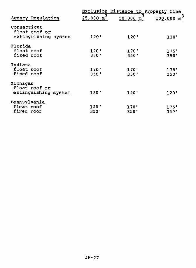
Exclusion Distance to Property Line
Agency Regulation 25,000 m 3 50,000 m 3 100,000 m
Connecticutfloat roof orextinguishing system 120' 120' 120'
Floridafloat roof 120' 170' 1'75'fixed roof 350' 350' 350'
Indianafloat roof 120' 170' 175'fixed roof 350' 350' 350'
Michiganfloat roof orextinguishing system 120' 120' 120'
Pennsylvaniafloat roof 120' 170' 175'fired roof 350' 350' 350'
16-27
In most situations, for a given volume, LPG is moredangerous than LNG and LNG is more dangerous thannaphtha. The minimum exclusion distances imposed byNFPA standards and states and localities do notreflect this. Buffer zones for naphtha' are oftenclose to or even greater than those for LPG, andbuffer zones for LNG are often substantially lessthan those for naphtha.
2. The Minimum Distances Required Between LNG, LPG, ,,ndNaphtha Tanks, and Tanks Holding Other Flammable,Explosive, Poisonous, or Toxic Materials.
The following table presents separation d-stances forthe same ti.ree sizes (,f tanks discussed in Issue One. Theseparation distance applies to two tanks of the sizeindicated.
16-28
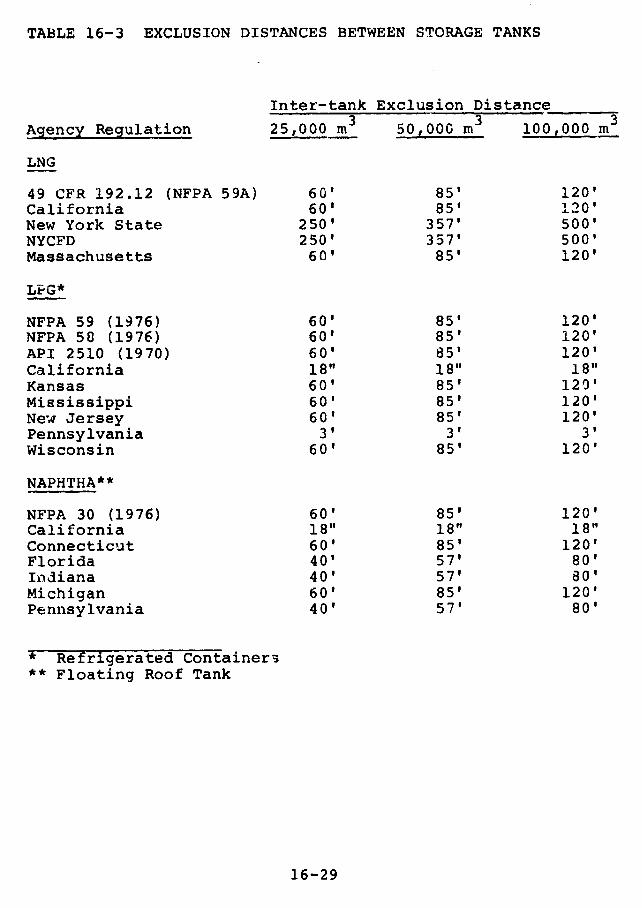
TABLE 16-3 EXCLUSION DISTANCES BETWEEN STORAGE TANKS
Inter-tank Exclusion Distance3 3 3
Agency Regulation 25,000 m 50,000 m 100,000 m
LNG
49 CFR 192.12 (NFPA 59A) 60' 85' 120'California 60' 85' 120'New York State 250' 357' 500'NYCFD 250' 357' 500'Massachusetts 60' 85' 120'
LPG*
NFPA 59 (1976) 60' 85' 120'NFPA 58 (1976) 60' 85' 120'API 2510 (1970) 60' 85' 120'California 18" 18" 18"Kansas 60' 85' 120'Mississippi 60' 85' 120'New Jersey 60' 85' 120'Pennsylvania 3' 3' 3'Wisconsin 60' 85' 120'
NAPHTHA**
NFPA 30 (1976) 60' 85' 120'California 18" 18" 18"Connecticut 60' 85' 120'Florida 40' 57' 80'Indiana 40' 57' 80'Michigan 60' 85' 120'Pennsylvania 40' 57' 80'
* Refrigerated Container3** Floating Roof Tank
16-29
Findings
Basic NFPA standards give inter-tank separation
distances of one-fourth the sum of the diameters of
adjacent tanks for LNG and LPG tanks. For naphtha
tanks the separation distance generally is one-sixth
this sum except for very large naphtha tanks with
fixed roof design and large impounding arers. API
2510 has spacing requirements for LPG tanks that are
in some cases less stringent than those of NFPA 58
and 59. State requirements generally are the same
as or less stringent than NFPA standards. The
NYCFD, howe!er, requires spacing between two LNG
tanks to be the greater of 250 ft or 1.25 tank
diameters.
The NFPA 59A LNG container spacing requirement does
not take into account the dike design or the
location of the tanks within the dikes.
Requirements for inter-tank spacing are not
logically related to the different hazards presented
by the different fuels and are frequently no more
stringent for LEG than for naphtha. They usually
are no more stringent for LPG than for LNG. They
are sometimes more stringent for naphtha than for
LPG.
16-30
3. Security Requirements.
Findings
In light of the potentially severe consequences of
sabotage, the required deterrents are weak. Most of
the codes require only fencing, without mentioning
locks, and none of the codes mentions additional
perimeter security measures. NFPA 59 requires that
any locks used be breakable (to ease the entrance of
firemen). The NYCFD requires locked gates at LNG
facilities.
4. Diking Requirements.
An important aspect of energy facility safety is to
assure that any accidental fuel releases will be contained
in limited areas on-site, preferably in impounding areas
of adequate capacity and minimum surface area. Also,
facilities should be designed so that an impounding area
fire does not jeopardize other critical parts of the
facility or its environs.
Findings
Diking is required for LNG, refrigerated LPG, and
naphtha. Pressurized LPG is not considered under
either NFPA 58 or API 2510 to need diking, although
the API Standard suggests area grading so that any
16-31
spills will flow away from the storage area to a
safe impounding location.
For LNG, refrigerated LPG, and naphtha, NFPA
standards require that dike volumes be at least
equal to the maximum storage volume of the tank they
protect. If a dike protects more than one tank, the
dike volume must at least equal that of the largest
tank contained in the dike. Any LEG outer tank
walls that might be wetted in a spill must be able
to withstand low temperature exposure.
Dike design requirements are more comprehensive in
the NFPA standard covering naphtha than in the NFPA
standards for LNG and LPG.
New York State and the New York City Fire Department
require 150% capacity diking for LNG and prohibit
multiple tanks in a single dike.
The NYCFD now allows only bermed LNG tanks
surrounded by an additional dike with height at
least half the maximum tank liquid level height.
Most other codes treat bermed tanks as tanks with
integral dikes and do not require secondary diking.
16-32
5. Requirements for Resistance to Natural Phenomena.
Hazardous facilities should be designed to withstand
any severe environmental conditions which might occ
during the lifetime of the facility. Such conditions
include high winds, tornadoes, earthquakes, floods, rapid
atmospheric temperature and pressure changes, snow loads,
etc. Building codes usually specify a design event for
these natural phenomena. Most petrochemical facilities
have been designed to meet normal building code standards.
Frequently, the design event (the event the facility is
designed to withstand without endangering the public) is
the worst occurrence in the area for the period in which
catastrophic events are documented. This amounts to a
200 - 300 year data base in most of the United States.
Often it is only the worst event in the area in' the past
50 yea3s. NRC imposes much stricter requirements on
nuclear plants.
Current OPSO standards are based on NFPA 59A (1972)
and thus do not include certain changes made in NFPA 59A
(1975) such as the need -or a detailed geotechnical site
investigation in seismic areas. There is no such
requirement for equally large tanks of LPG.
The draft LNG regulations developed for comment by
OPSO suggest a design event for each natural phenomena for
which there is only a 0.5% probability of a more severe
event occurring during a 50 year period. This is
equivalent to an average repeat interval of about 10,000
years, which seems adequate. However, if there are 50 LNG
facilities, there is a 22% chance that a larger than
design event will occur at the site of one or more of them
during a 50 year period. For 100 facilities the chance is
16-33
39%. For 100 facilities and three independent phenomena,
such as earthquakes, winds, and floods, the chance is 78%.
There are already more than 100 LEG aboveground storage
facilities, including 68 with at least 23,000 cubic meters
of storage. What is more, most of these are built to the
much lower standards of the building code.
The probability that one of the design events of the
facilities will be exceeded can be characterized by a
parameter L. L is defined as the number of sites (s),
multiplied by the number of years an avera e site is
expected tc operate (y), multiplied by --he number of
independent natural phenomena the site is designed to
resist (p), divided by the repeat interval of the
phenomena (r). In equation form we have:
L = syp/r
If we have three phenomena, such as earthquakes, winds,
and floods, and floods tend to be correlated with high
winds, then instead of p being 3 it would be between 2 and
3. If design event floods only occurred at the same time
as design event winds, then p would be 2.
Figure 16-1 gives the probability (in percent) of
having N or more events which exceed the design event, for
various values of L. For L = 100, for example, there is a
51 percent chance of at least 100 greater than design
events occurring and a 99 percent chance of having at
least 79.
16-34
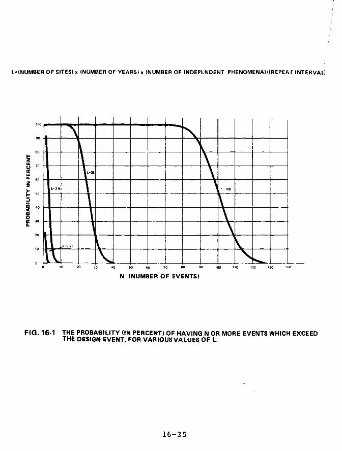
L=(NUMBER OF SITES) x (NUMBER OF YEARS) x (NUMBER OF INDEPLNDENT PHENOMENA)/(REPEA r INTERVAL)
100 I I I I I
90 a … -U 70
N NUMBER OF EVENTS
50 1
16-35
90__L-025
0 10 20 30 40 90 60 70 80 90 100 110 120 130 140
N (NUMBER OF EVENTS)
FIG. 16-1 THE PROBABILITY (IN PERCENT) OF HAVING N OR MORE EVENTS WHICH EXCEEDTHE DESIGN EVENT, FOR VARIOUS VALUES OF L.
16-3 5

In general, structures can survive stresses greater
than design load stresses (those generated by design
events). The safety factor is the ratio of the allowable
stress (the maximum stress in a structure allowed by
building codes) to the design load stress (the maximum
stress in a structure produced by the loads that the codes
require the equipment to withstand). In Chapter 3 we show
that the natural phenomena safety factors for many large
LEG tanks are quite low. This is even more disturbing
since even during the lifetime of present large LEG
facilities the design events are certain to be exceeded
many times.
The design requirements discussed above apply to
critical structures such as LNG storage and dike systems.
OPSO, for example, proposes that less important components
be designed for events with a 475 year repeat interval.
For three phenomena this gives an L close to 25.
Findings
Most LEG and naphtha facilities have been designed
to meet normal building code standards; thus, design
standards for naphtha are essentially as strong as
those for LEG.
The design event (the event the facility is designed
to withstand without endangering the public) for
each type of phenomenon (earthquakes, winds, floods,
etc.) is usually the worst occurrence in the area in
some past period. The period is 50 years for some
jurisdictions and 100-300 years in others. In a few
areas it is longer. OPSO's draft LNG regulations
16-36
use 10,000 years. NRC usually imposes even stricter
requirements on nuclear plants.
There are more than 100 LEG aboveground storage
facilities, including 68 with at least 23,000 cubic
meters of storage.
It is virtually certain that design events will be
exceeded a large number of times during the lifetime
of present large LEG facilities. This is
particularly serious because of the low safety
factors of many large LEG tanks. (See Chapter 3.)
Large scale urban area storage of hazardous
materials in facilities built according to normal
building code standards is common and highly
dangerous. Even if OPSO's guidelines are adopted
and precisely implemented, they are still not strict
enough to allow urban area siting.
6. Requirements For Operating Procedures and Personnel
Training.
Detailed operating procedures and competent and
well-trained personnel are important factors in facility
safety. All facilities have operating procedures, but
there is considerable variation in their completeness and
whether they are strictly enforced or just intended as
recommended guidelines for operating personnel.
16-37
Findings
Outside of some specific technical operating
requirements scattered through the various
regulations, there are only quite general references
to the desirability of operator qualification and
training. The NYCFD certifies LNG plant operators.
A few states certify operators at LPG facilities.
There are no comprehensive requirements for the
development of formal operating procedures and
training programs or for the review of such
procedures by jurisdictional agencies.
7. Materials Specifications for Storage Tanks.
Findings
Materials standards for a high level of structural
integrity appear to be well defined and documented
in the relevant codes. Materials standards for
metal and concrete tanks are generally well
standardized and documented in ASME and ACI Codes.
Testing and inspection procedures are also included
in the -odes to verify materials performance.
16-38
Insulation for storage tar's should be
non-flammable. Where insulation is used to protect
LrG or naphtna tanks from external fires, the
insulation should be designed to maintain its
integrity during prolonged exposure to impinging
flames.
Some states have developed extensive requirements
for corrosion control (such as coating, cathodic
protection, etc.) which supplement the basic
requirements of the design codes.
8. Materials Specifications for Truck Trailers and
Railcars.
Large quantit.es of LNG are moved by truck. Trucks
and railcars transport LPG and naphtha. The mobility of
such vehicles often brings them into areas of hi.gh
population density and increases their chance of being in
an accident.
Findings
Tank vehicle safety is largely Regulated by DOT
regulations on brakes, lights, etc., and by Federal,
state, and local standards for taik design. Naphtha
transport, like gasoline transport, is considered
routine.
16-39

A standard developed by the Compressed GasAssociation which requires 3/32-inch steel insulationjackets for LNG carriers and other requirements isgenerally followed. To date, OHMO has been extremelyslow in promulgating similar Federal standards forLNG tank vehicle design, and approves designs on anindividual basis through a special permit or
exemption process.
NOTE: LEG truck and train transpcrtation is discussed indetail in Chapters 7 and 8. The regulationsgoverning this transportation are discussed inChapter 17.
9. Requirements for Harbor Movements and Unloading of LEGand Na-htha Tankers, and
10. Requirements for Tanker Construction.
Findings
Coast Guard regulations are quite comprehensive,
covering vessel design, operation, and inspection.
At present, however, many of the detailed operating
requirements are at the discretion of the Commandantor the Captain of the Port(COTP). (See Chapter 6.)It is Coast Guard policy to follow unofficialregulations which have been published (October 1976)as proposed rules.
16-40
Naphtha is included in the general category of
flammable liquid cargoes for which there are weaker
standards for ship survivability in the event of
stranding or collision. Some cargo loss under such
conditions is not unlikely.
LEG carriers are designed to a higher standard of
survivability and are designed to contain cargo in
case of stranding or minor side damage.
Refrigerated LPG ships, however, can be single-
hulled.
The operational requirements for LEG carriers
entering U.S. ports are under the jurisdiction of
the Captain of the Port conceried. Although Coast
Guard position papers have outlined comprehensive
typical requirements for COTP's, these are
discretionary.
Liability.
Findings.
New York State imposes strict liability for offsite
damages against persons engaged in the storage,
handling, and transportation of both LNG and LPG,
but not naphtha. Maine has adopted strict liability
for injuries arising from natural gas operations
generally without specifying its applicability to
LEG or naphtha. There are no other regulatory
provisions that deal specifically with liability for
16-41
handling these fuels. As a result, the extent towhich responsible persons will be liable for offsitedamages is determined by judicial case law standardsin the various states.
12. Liability Insurance Requirements
Findings
Ten states require proof of public liabilityinsurance in amounts varying from $10,000 to$100,000 for any single accident involving LPG.There are currently no specific requirements forliability insurance for owners of LPG facilities inthe remaining 40 states. There are no insurancerequirements applicable to owners of LNG or naphthafacilities in any of the states.
16-42
RECOMMENDATIONS
TO THE CONGRESS
We recommend that the Congress:
enact legislation which prohibits, except in remote
areas, the construction of new-or the expansion in
size or use of existing--facilities for the storage
of highly dangerous materials (including LEG) unless
the storage tanks are inground with the highest level
of fluid below ground level, or built to standards
similar to those demanded for licensed nuclear
installations in remote areas.
TO THE SECRETARY OF TRANSPORTATION
We recommend that the Secretary of Transportation:
require companies hindling hazardous materials to
file routine operation summaries annually and to
report any unusual occurrences within 48 hours to the
Department of Transportation in a manner analogous to
the reports required by the Nuclear Regulatory
Commission. Reportable occurrences should include any
venting or leakage of hazardous material; any
overpressuring of tanks; any transportation
breakdown; any vital machinery breakdown; and any
attempt by unauthorized persons to erter company
premises. These reports should be available to the
public in Washingtcn, D.C. and at an appropriate
office near the site of the unusual occurrence.
16-43

form a central analysis group which would have the
staff and resources to discover patterns in the data
reported by companies handling hazardous materials.
It makes no sense to require companies to go through
the expense and trouble to submit annual operations
reports and unusual occurrence reports if they are
not going to be analyzed in sufficient depth so that
serious malfunctions can be prevented. The Accident
Analysis Branch in OHMO does not operate in this
fashion. (See Chapter 17.)
require OPSO to issue detailed standards for
operating procedures and for operator qualification
and training at LEG facilities. It should
periodically review the operation of LEG facilities
to see that they are meeting those standards.
require OPSO to extend its regulations to cover
intrastate LPG and naphtha pipelines, including
connecting import terminals and storage complexes,
affecting interstate commerc_. GAO made this
recommendation in its earlier teport on pipeline
safety, "Pipeline Safety-Need for a Stronger
Federal Effort" (CED-78-99).
require OHMO to promulgate standards for LNG vehicle
design.
16-44
AGENCY COMMENTS AND OUR EVALUATION
Comment on Special Issue 5
The Department of Transportation asks:
"How does one get from a 78 percent chance that oneof three phenomena will occur at 1 of 100 facilitiesin 50 years to virtually certain (i.e., 100 percentchance) that design events will be exceeded a "largenumber" of times?"
Our finding that it is virtually certain that design
events will be exceeded a large number of times during the
lifetime of present large LEG facilities is based on our
analysis in Chapter 3 of Uniform Building Code design
standards, as discussed elsewhere in Special Issue 5. The
78 percent chance that one of three phenomena will occur at
1 of 100 facilities in 50 years applies to the stronger
design standards in OPSO's Advance Notice of Proposed
Rulemaking.
Comment on Special Issue 9 and 10
The Department of Transportation suggests that we
delete the sentence, "Refrigerated LPG ships, however, can
be single-hulled," because they say it implies that LPG
ships are similar to conventional tankers and are somehow
less protected than LNG ships.
We disagree. The sentence is accurate, and the
implication that single-hulled vessels are less strong than
those with double hulls is justified.
16-45
Comments on Recommendations
The Department of Transportation says that our
recommendation--that OPSO issue standards specifying
operating procedures, operator qualifications, and OPSO
inspections of LEG pipeline facilities--is included in
OPSO April 1977 Advance Notice of Proposed Rulemaking for
LNG Facilities. DOT notes that additional detail may be
appropriate and will be considered.
Our recommendation addresses LEG facilities, LPG as
well as LNG. DOT does not describe any plans to
promulgate similar standards for LPG pipeline facilities.
We believe DOT should do so.
The Department of Transportation, commenting on our
recommendation that OHMO promulgate standards for LNG
vehicle design, states that these standards currently are
being developed.
The standards (hM115 "Cryogenic Liquids") were
originally published in the Federal Register as a Prop'sed
Notice of Rulemaking in March 1974. Because of the
volumes of comments, MTB revised the proposed notice to an
Advance Notice of Proposed Rulemaking in September of
1974. MT£ has not issued a new proposed notice since
then.
16-46
REFERELCES
GENERAL CODES
NBC
The National Building Code-Recommended by the
American Insurance Association, 1976 Edition.
UBC
Uniform Building Code-Enacted by the InternationalConference of Building Officials, 1973 Edition.
ASME
Section VIII of the American Society of MechanicalEngineers, "Rules for Construction of PressureVessels," Division I and II, 1974 Edition.
Section II of the American Society of MechanicalEngineers, "Material Specifications," Parts A, B,and C, 1974 Edition.
ACI
American Concrete Institute 311-64, "RecommendedPractice for Concrete Inspection," 1964 Edition.
LNG CODES AND STANDARDS
N .- 59A
National Fire Protection Association 59A, "LiquefiedNatural Gas Storage and Handling," 1972 and 1975Editions.
API 620
American Petroleum Institute 620-"Recommended Rulesfor Design and Construction of Large, Welded,Low-Pressure Storage Tanks," (1977). Appendix Q -LNG.
16-47
NY STATE PSC
State of New York Public Service Commission, Case2 6 180 -"Liquefied Natural Gas," 16 NYCRR, Part 259and revised draft.
NY--1976 LAWS
New York Liquefied Natural and Petroleum Gas Act of1976.
MASS DPU
Massachusetts Gas Distribution Code, Section 5,Department of Public Utilities, 1972 Edition.
iJYCFD
New York City Fire Deparitnent, "Rules andRegulations Governing the Manufacture, Storage,Transportation, Delivery, and Processing ofLiquefied Natural Gas," 1977 Edition.
API 2510A
API 2510A, "Design and Construction of LNGInstallations at Petroleum Terminals, Natural GasProcessing Plants, Refineries and Other IndustrialPlants."
LPG CODES AND STANDARDS
NFPA 58
NFPA 58, "Liquefied Petroleum Gases, Storage, andHandling," 1976 Edition.
NFPA 59
NFPA 59, "Liquefied Petroleum Gases at Utility GasPlants," 1976 Edition.
API 2510
API 2510, "Design and Construction of LP-GasInstallations at Marine and Pipeline Terminals,Natural Gas Processing Plants, Refineries ant TankFarms," 1970 Edition.
16-48
CAL-PUC
California Public Utilities Commission Order 94-B.
FLA-FIREM
Florida Rules of the State Fire Marshal - LPG.
GA-FIREM
Georgia Rules of the Safety Fire Commissioner - LPG.
ILL-LPG
Illinois Liquefied Petroleum Gases - Rules and
Regulations.
LA-LPG
Louisiana Liquefied Petroleum Gas Commission.
MASS-DPU
Massachusetts Department of Public Utilities.
MTSS-MV
Mississippi Motor Vehicle Comptroller Liquefied Gas
Division.
NM-LPG
New Mexico Liquefied PeLroleum Gas Rules and
Regulations.
SD-DPS
South Dakota Rules of the Department of Public
Safety LPG.
NJ-AC
New Jersey Administrative Code-Liquefied Petroleum
Gas.
NY - 1976 LAWS
New YorK Liquefied Natural and Petroleum Gas Act of
1976.
16-49

PA-DLI
Pennsylvania Department of Labor and IndustryLiquefied Petroleum Gas.
TX-RRC
Texas Railroad Commission Rules and RegulationsDivision II.
WI C-AC
V.sconsin Administrative Code Liquefied.Petroleumlases.
NAPHTHA CODES AND STANDARDS
NFPA 30
NFPA 30 - "Flammable and Combustible Liquids Code,"1976 Edition.
CAL-PUC
California Public Utilities Commission Order 94-B
CONN-SP
Connecticut Commission of State Police FlammableLiquid Regulations.
FLA-FIREM
Florida Rules of the State Fire Marshal Flammable orCombustible Liquids.
IND-FIREM
Indiana Rules of the State Fire Marshal FlammableLiquids.
MASS-DPU
Massachusetts Department of Public Utilities FireProtection Regulations.
MICH-FLAM
Michigan Flammable Liquids Regulations.
16-50

PA-SP
Pennsylvania State Police Regulations - Flammable
Liquids
PR-FS
Puerto Rico Fire Service: Storage and Handling of
Flammable Liquids.
16-51

CHAPTER 17
FEDERAL REGULATION OF LEG TRUCKS AND RAILCARS
CONTENTS PAGE
TRUCK REGULATIONS 17-1
Introduction 17-1
Federal Highway Administration,
Bureau of Motor Carrier Safety 17-2
National Highway Transportation Safety
Administration 17-4
Office of Hazardous Materials Operations 17-5
Driver Qualifications 17-7
RAIL CAR REGULATIONS 17-8
OHMO - Federal Railroad Administration 17-8
Hazardous Materials Division 17-9
FINDINGS 17-11
RECOMMENDATIONS 17-13
AGENCY COMMENTS AND OUR EVALUATION 17-14
REFERENCES 17-15
TRUCK REGULATIONS
Introduction
Several offices in the Department of Transportation
(DOT) are responsible for setting and maintaining safety
standards for interstate trucks carrying liquefied energy
gases. The Interstate Commerce Commission (ICC) is also
involved, since only it can revoke or suspend the
certificates of interstate carriers found to be unsafe.
The diffusion of responsibility among several
agencies and a lack of effective administration have
hampered the formulation of uniform safety standards and
have made enforcement difficult in three significant areas:
the design and reliability of equipment;
the safeguarding and control of LEG as it is
loaded, transported, and unloaded; and
the qualifications of LEG truck drivers.
Three DOT organizations are concerned with interstate
LEG tracking.
The Federal Highway Administraticn (FHWA)
administers the provisions of the Motor Carrier
Act of 1935 (49 U.S.C. 304) regulating
qualifications and maximum hours of service of
employees, and safety of operation and
equipment.
17-1
The National Highway Traffic Safety
Admini!;tration (NHi'SA) administers the National
Traffic and Motor Vehicle Safety Act of 1966 (15
U.S.C. 1381 et seq.), under which safety
standards for trucks and trailers are
promulgated.
The Materials Transportation Bureau's (MTB)
Office of Hazardous Materials Operations (OHMO)
prescribes regulations under the Transportation
of Explosives Act of 1908 (18 U.S.C. 831-835)
and the Hazardous Materials Transportation Act
(49 U.S.C. 1801 et seq.), regulating the
packaging, handling, and routing of hazardous
materials.
By successive delegations from the Administrator of
the FHWA, the Director of the Bureau of Motor Carrier
Safety (BMCS) issues federal motor carrier safety
regulations and enforces those of the MTB relating to
transportation of hazardous materials by highway.
Federal Highway Administration,
Bureau of Motor Carrier Safety
The FHWA is responsible for reducing interstate
commercial vehicle accidents, fatalities, injuries, and
property losses. The Administrator has delegated
responsibility to the BMCS to issue regulations applying to
drivers, facilities, and the operational safety of motor
carriers used in interstate transportation.
17-2
The Regulations Division of BMCS makes new safety
regulations and modifies old ones. Its Compliance Division
may intervene before the ICC, asking for the revocation or
suspension of the certificates of carriers violating
regulations.
BMCS and FHWA share responsibility for the 128 BMCS
inspectors who monitor more than 160,000 carriers and
3,000,000 motor carrier vehicles. They work under the
supervision of Directors of Regional Motor Carrier Safety
Offices and make inspections only at terminals or at
highway inspection stations, checking trucks which look or
sound faulty.. In 1974, 21 percent of the vehicles
inspected were so unsafe that they were declared
out-of-service.l
Of 4,112 violations reported in 1976, only 41
involved trucks carrying "flammable compressed gases", a
category which includes LPG but not LNG.
The Regional Motor Carrier Safety Directors who
supervise the inspectors have qualified as "hazardous
materials specialists" through in-house programs. Most
inspectors were formerly truck drivers or police officers,
and some have formal training in transportation, business
adminis'ration, or public administration. None have
science or engineering degrees or formal training in the
properties of cryogenic materials.
Carriers found in violation of safety regulations are
fined. Those with repeated violations, about 20 carriers
per year, are required by the FHWA to set up internal
safety organizations. Inspectors check on compliance the
next time they visit a terminal of the carrier involved.
17-3
The ultimate sanction on carriers is revocation of
their permanent ICC certificates. The FHWA has recommended
revocation eight times in five years, but none of the eight
certificates were revoked by the ICC. At the FHWA's
request, the ICC did refuse to renew "temporary authority"
or "emergency temporary authority" certificates for 140
carriers between July 1, 1975 and June 1, 1977, on the
basis of "unsatisfactory reports" filed by the BMCS.
In March 1973, the BMCS sent out an Advance Notice of
Proposed Rule Making on repair and maintenance of motor
carrier vehicles. These proposed rules would require
pre-trip and post-trip equipment inspectionls for all
interstate trucks, written records of inspections,
retention of such records in the vehicles for 30 days, and
correction of any safety-related deficiencies prior tooperation. The BMCS then hired the University of
Michigan's Highway Safety Research Institute to study theeffectiveness of preventive maintenance. The study
concluded that interstate motor carrier vehicle inspection
and preventive maintenance can reduce accidents. 3 The BMCS
issued the Notice of Proposed Rule Making on April 5, 1977.
After nearly five years, BMCS still has not incorporated
these requirements into final rules on motor carrier repair
and maintenance.
National Highway Transportation Safety Administration
NHTSA has jurisdiction over safety performance
standards for trucks and trailers. Its Office of Crash
Avoidance (OCA) has issued standards for tires and brakes.
However, these were tested only on trucks carrying the
maximum allowed loads, and their effectiveness on
overloaded trucks is not known. Our examination of bills
17-4
of lading indicates that propane trucks are sometimes
overloaded during seasons of high demand.
The brake regulations authorize anti-skid and
anti-locking "121" systems, but BMCS has not been able to
inspect for compliance because it has not published its
procedures for such inspections. Only "courtesy"
inspections of the NHTSA brake regulations are planned
through 1978.
NHTSA has not:
Set standards for under-ride protection to
prevent automobiles from going under trailers.
Crash-tested tank trailers.
Office of Hazardous Materials Operations
The Office of Hazardous Materials Operations (OHMO),
in DOT's Materials Transportation Bureau (MTB), has
authority to issue regulations governing the manufacture
and use of LEG shipping containers. OHMO sets standards
for packaging, handling, and routing, and for personnel
qualifications and training requirements. It establishes
criteria for inspections and for equipment for the
detection, warning, and control of hazardous materials.
Through the Secretary of Transportation, it may conduct
investigations and hearings, issue subpoenas, and compel
disclosure of documents.
Section 109(d) of the Hazardous Materials
Transportation Act requires the Secretary to maintain
facilities and staff to provide, within the Federal
17-5

Government, the capability to evaluate risks involved inthe transportation of hazardous materials, and to conduct a"continuing review" to determine procedures necessary forthe safe transportation of hazardous materials.
The standards for LPG trailers, however, were
developed before OHMO was established and no LNG trailer
standards nave been issued. Instead of permits, OHMO
issues "exemptions" to LNG trailer manufacturers andtransporters. Manufacturers' applications for exemptions
contain engineering drawings, but transporters do not stateproposed routes, even though OHMO has the power to regulateroste-b. The engineering drawings are considered tradesecrets and are not available to the public. Renewal ofexemptions appears to be almost automatic. No applicationf--) 'ewnewal has ever been denied, buit modifications havesometimes been imposed as a condition of renewal.
·Be, Each transporter applicant must instruct its drivers~, procedures to prevent or control overpressurization
durinJ prolonged shipping delays, but the transporters
ehzmsei~Tes decide the procedures.
OHMO's compliance staff has only three professionals
and a secretary. Three lawyers from the DOT General
Counsel's Office have recently been assigned to help,
permitting OHMO to begin enforcement efforts for the firsttime. Occasionally it inspects plants manufacturing
pressurized cylinders.
OHMO's Accident Analysis Branch has five
professionals and one secretary. It receives, processes,
and stores reports on the "release of hazardous materials."Such incidents range from the spilling of hot fluid
17-6
concrete to the release of poisonous or explosive gases.
The branch spends most of its time responding to requests
for routine information from DOT personnel and from
carriers settling damage claims.
About 1,500 reports of hazardous material releases
are received monthly, very few of which involve LEG.
Reports are required by regulation, but the branch head
estimated that only one-tenth of the actual instances are
reported. (See Chapter 7.)
OHMO has only three persons with technical competence
in cryogenic areas. Only one of them is available for
monitoring work. Only 250 inspections of trucks carrying
hazardous materials were conducted in 1976.
Driver Qualifications
FHWA regulations require road tests and physical
examinations for all interstate truck drivers. Each driver
must furnish the carrier with a written history of his
driving, and the carrier must investigate it within 30 days
of his employment. Thorough physical examinations are
given at 2 year intervals.
Drivers must either take a road test or have a state
license for the category of vehicle to be driven. The
requirement that drivers also take a written examination is
misleading. The Federal Motor Carrier Safety Regulations
state that:
17-7

The objective of the written examination is toinstruct prospective drivers in the rules andregulations established by the Federal HighwayAdministration pertaining to commercial vehiclesafety. It is an instructional tool only, and aperson's qualifications to drive a motor vehicleunder the rules in this part are not affected by hisperformance on the examination. . .
In other words, even if a driver answers every question
wrong, he is issued a license.
Intermittent or temporary drivers are excused from
the written test, road test, and background test, but they
must meet the physical requirements.
The limited data available suggest that drivers of
hazardous materials trucks may work longer hours than those
handling general carqo.4
RAILCAR REGULATIONS
Safety regulation of LPG rail transportation is the
responsibility of DOT, acting through the Federal Railroad
Administration (FPA) and through OHMO within MTB. Economic
regulation and certification for entry into the interstate
railroad industry remains with the ICC. LNG is not moved
by rail.
OHMO - Federal Railroad Administration
The FRA has general authority to investigate the
safety compliance of any applicant seeking railroad carrier
operating authority from the ICC. The FRA's safety
regulatory authority covers: safety appliances and
equipment, safety methods and systems, and hours of service
17-8
of employees. The FRA administers the Federal Railroad
Safety Act of 1970 (45 U.S.C. 421 et seq.) to reduce
accidents, deaths, injuries, and property damage by
prescribing railroad safety rules and standards to
supplement existing laws. The Act declares that laws,
rules, regulations, and orders shall be nationally uniform
to the extent practicable.
The FRA's own safety regulations cover locomotive
inspection, hours of service of employees, operating rules,
accident reporting, and standards for safety appliances,
power brakes, track safety, and freight car safety.
OHMO prescribes rules under the Transportation of
Explosives Act of 1908 and the Hazardous Materials
Transportation Act. These acts authorize regulation of the
shippers and manufacturers of containers used in or
affecting interstate transportation of hazardous materials,
including their packaging, labeling, handling, and routing.
There are regulations that specifically address LPG
railroad tank car design and operation requirements.
Hazardous Materials Division
The Federal Railroad Safety Authorization Act of 1976
divides the FRA on a geographical basis into no fewer than
8 safety offices to administer all federal railroad safety
laws. The FRA has authority to issue an order prohibiting
further use of any facility or piece of equipment in an
unsafe condition involving a hazard of death or injury.
For enforcement, the FRA has established a Hazardous
Materials Division (HMD) which has 18 full-time inspectors
and also uses the FRA's 180 general railroad inspectors on
a part-time basis. Pursuant to Federal regulations (49 CFR
17-9

179.3-179.5), HMD and the Association of American Railroads(AAR) work closely together on tank designs and testing,and on developing regulations.
Chapter 8 deals with the hazards of LPG railshipments and the effectiveness of regulations.
17-10

FINDINGS
TRUCK REGULATIONS
The Interstate Commerce Commission has never
revoked a permanent certificate because of a
Federal Highway Administration request.
Nearly five years after its Advance Notice of
Proposed Rule Making on repair and maintenance
of commercial vehicles, the Bureau of Motor
Carrier Safety has not promulgated final rules.
The National Highway Transportation Safety
Administration has not:
o been able to inspect for compliance with
its anti-skid and anti-locking brake
systems regulations, because it has not
published its procedures for such
inspections.
o set standards for under-ride protection.
o crash tested tank trailers.
The standards for LPG trailers were developed
before the Office of Hazardous Materials
Operations was established and no LNG trailer
standards have been issued.
The Office of Hazardous Materials Operations:
17-11

o issues "exemptions" instead of permits to
LNG trailer manufacturers and transporters.
No application for renewal of an exemption
has ever been denied, although
modifications have sometimes been imposed
as a condition of renewal.
o receives about 1,500 reports of hazardous
material releases monthly, very few of
which involve LEG. Reports are required by
regulation, but the head of the Accident
Analysis Branch estimated that only
one-tenth of the actual instances are
reported.
17-12

RECOMMIENDATIONS
TO THE SECRETARY OF TRANSPORTATION
We recommend that the Secretary of Transportation:
Develop standards for hazardous material trailer
manufacturers which would complement the standards
for shippers and enforce both with the same
inspection and compliance apparatus.
Impose harsh penalties on companies that fail to
report hazardous material releases.
TO THE CONGRESS
We recommend that the Congress enact legislation to
protect drivers from discharge or discrimination on account
of information or complaints they provide DOT. Drivers are
now largely excluded from protection under the Occupational
Safety and Health Act of 1970 (29 U.S.C. 660(c)).
17-13

AGENCY COMMENTS AND OUR EVALUATION
The Department of Transportation says:
"As noted in this chapter and in Chapter 7,there are very few inspectors for hazardousmaterials tank cars and trucks. Considering thenumber of Coast Guard inspectors per shipcarrying hazardous materials, it is strange thatChapter 6 calls for more Coast Guard personnel,but Chapter 17 does not do likewise for theother modes. Similarly, more training of CoastGuard inspectors is called for. yet norecommendation is made for FHWA or FRA."
LNG ships carry 3,000 times more liquefied gas than
LNG trucks, and the new LPG ships carry 650 times more L
than railcars and 1,800 times more LPG than trailer trucks.
17-14
REFERENCES
1. BMCS notice of Proposed Rule Making, April 5, 1977.
2. Docket MC-48, 39 Federal Register 7127.
3. Effect of Commercial Vehicle Systematic Preventive
Maintenance on Specific Causes of Accidents,University of Michigan Highway Safety ResearchInstitute; July 1975.
4. Canyon Research Group, Inc. "A Nationwide Survey of
Truck and Dus Drivers," BMCS Contract NO-DOT
FH-11-8817.
17-15

CHAPTER 18
THE FEDERAL POWER COMMISSION
CONTENTS PAGE
INTRODUCTION 18-1
HEARINGS 18-3
THE FPC STAFF 18-5
THE BUREAU OF NATURAL GAS 18-6
The BNG Accident Model 18-6
Support from Other Agencies 18-7
Criticism from ¢(ther Agencies 18-8
Examples of Inadequate Technical Work 18-10
ADMINISTRATIVE LAW JUDGES 18-13
FINDINGS 18-19
CONCLUSIONS 18-21
RECOMMENDAT IONS 18-24
AGENCY COMMENTS AND OUR EVALUATION 18-27
REFERENCES 18-34
INTRODULTION
This chapter discusses the former Federal Power
Commission's (FPC) role in assessing the safety of proposed
LNG projects. The FPC has inadequately assessed the
hazards of LNG shipping and storage. Safety issues have
been considered on a case-by-case basis and have often been
overshadowed by economic considerations. Decisions are
based on evidence presented at formal hearings, at which
the FPC staff testifies. The staff's testimony has often
been based on insufficient independent investigation. The
FPC has been disbanded, and its functions have been assumed
by the Federal Energy Regulatory Colmmission (FERC) and
other par' of the Department of Energy (DOE). This
chapter is written in the present tense, as if the FPC
still existed, to make it easier to read.
The FPC has statutory jurisdiction over the sale of
natural gas in interstate comnmerce for resale. It also has
statutory jurisdiction over interstate pipeline
transportation and importation of natural gaL. This
includes authority over the site, design, construction, and
operation of liquefied natural gas import and export
terminals, storage facilities, and pipelines in interstate
commerce.
FPC's authLrity to assess the safety of proposed
projects is derived from provisions in the Natulral Ga.- Act
and the National Environmental Policy Ac t. See Chapter 11.
This authority was not diminished by the Natural Gas
Dipeline Safety Act of 1968, Public Law 9>-481, 49 U.S.C.
1671, et seq. That Acc led to the creation of the Office
of Pipeline Safety Operations in the Department of
Transportation. The legislative history includes the
18-1
statement that:
". . .The Federal Power Commission p.esently hasexercised certain safety regulatory authority overinterstate transmission lines under the Natural GasAct. The Commission considers and takes action onsome elements of the safety of transmission proposalsin acting on applications for new or extendedauthority and it is not intended that the passage ofthis act will diminish that authority andresponsibility of the Commission. In order, however,that the Commission not be placed in the position ofhaving -o determine whether the construction andoperati- details of a proposed service conform tothe {DoT} Secretary's standards, an applicant maycertify to this effect and the certification will beconclusive on the Commission. .. It is notintended by the committee that this process ofcertification of compliance with the Secretary'sstandards will bar the Commission from continuing toconsider safety in the same fashion it presently doesin connection with awarding1certificates of publicconvenience and necessity."
Later amendments to the Act left the FPC's safety
responsibilities intact. (See conference report on NaturalGas Pipeline Safety Act Amendments of 1976, H.R. Rep. No.1660, 94th Cong. 2nd Sess. 7.)
The Commission's control is limited, both in law andpractice. It has no authority over intrastate facilities,iiicliding most peakshaving and satellite storage
facilities. LPG facilities do not come under FPC
jurisdiction, and only those LPG facilities that are rpartof an interstate pil'eiine are regulated by OPSO. Thus,many large LEG faoilities are not regulated by either
agency. Large LPG import terminals have been built withoutany Federal assessment of siting and safety, even though inmost situations, for a ,3i.en volume, LPG is more dangerousthan LNG.
18-2
The Commission's major concern in LNG commerce has
been economic, in accordance with its statutory mandate.
It has focused on rate questions and on the certification
of large, import facilities, built for deepwater shipping.
It has not prepared Environmental Impact Statements
for all peakshaving facilities under its jurisdiction.
Further, it has not considered the public risks from
trucking LNG to and from the storage sites it licenses and
it has not fully considered shipping hazards.
Until March 1978, the only LNG import facility in
operation was at Everett, Mass. It has operated for seven
years without final certification. An Administrative Law
Judge has ruled that its design and operation are safe, but
the Commission has never made a final safety finding.
The FPC has issued certificates for new major import
terminals at Cove Point, Md.; Elba Island, Ga.; and Lake
Charles, La. The Cove Point terminal began operating in
March, 1978, and the Elba Island terminal is expected to
begin operating later in 1978. Applications are pending
for facilities at Everett, MasF.; Providence, R.I.; Staten
Island, N.Y.; West Deptford, N.J.; 9ort O'Connor: rex.;
ingleside, Tex.; and Point Conceptio:;;, Cal. In November,
1977, WeFtern LNG Terminal Associates amended its
applicati ns, shifting ll its proposed receiving terminal
sites to Point Conception, Cal.
H ARTNGS
Under 1I CFR 1.4(d), the Commission staff is not
allowed to privately discuss a case with persons who are
parties to proceedings before the Commission. This
18-3
precludes private discussions with intervenors such as
states, local governments, and citizen groups. On March
11, 1977, the FPC amended its rules to allow ex parte
communications between the staff and intervenors and
applicants, but these are limited to requests for data and
information. The staff may discuss a case in a technical
conference, but only upon notice to all parties.
The limitations on staff contor-s do not apply until
a formal application has been filed. The staff often
discusses possible applications for a year or more before
they are filed. The staff justifies such pre-filing
conferences on the ground that they ensure the filing of a
more complete application, minimize piecemeal staff review
of often interconnected issues, and avoid regulatory
delays. During this period, however, outside parties have
no notice that a project is being planned. They learn of
an application only when it is announced in the Federal
Register. As a result, they may not have enough time to
adequately prepare for hearings.
The time and expense necessary for public
participation is further increased because:
"It is the Commission s practice to hold formal
hearinqs under the Natural Gas Act in Washington, D.C.
Occasionally the Commnission has, upon motion of a party,
decided to add local hearing sessions," in communities in
which LNC facilities are planr-d, but most witnesses who
appear at them make "statements of position" which are not
"evidence of the facts asserted" under the Commission's
rules and "cannot be used by the Commission in arriving at
its decision." The Commission has said that the purpose of
suc) hearings generally Is to allow "local citizens to
18-4

express their views by statements of position or to present
sworn testimony if they so desire." 2 Such local hearings
were held on the Everett, Staten Island, and Racoon Island
projects.
THE FPC STAFF
Despite the complex and highly technical issues which
must be considered in LNG applications, the primary
responsibility for these cases is carried out by only four
professionals in the Bureau of Natural Gas (BNG) and five
lawyers from the Office of the General Counsel. There is
also input from the Office of Pipeline and Producer
Regulation (OPPR), including its Environmental Evaluation
Branch; the Office of Reaulatory Analysis, and the Office
of Chief Accountant.
The BNG staff and the FPC lawyers prepare and present
evidence considered at formal hearings of LNG applications.
The two groups are responsible for developing, analyzing,
and presenting data in legal, economic, and technical
areas, including safety. BNG shapes the presentation. The
five lawyers present witnesses, conduct cross-examinations,
and write briefs, but have only a small role in the framing
of issues and the selection of witnesses.
The small stafi often has unreascna' le burdens placed
upon it. For example, in the Pacific Indonesia hearing on
a proposed facility at Oxnard, California, one attorney
wrote briefs orn all economic and social issues in 45 days.
He addressed questions on maritir.me transportation contracts
and rates; financing and costs of service for the proposed
facility; the proper rate treatment and market for imported
18-5

LNG; FPC jurisdiction over foreign commerce; and
environmental impact and public safety.
THE BUREAU OF NATURAL GAS
The BNG Accident Model
BNG first devoted significant attention to LNG in
1973, when Eascogas applied for certification of an LNG
import facility on Staten Island, in New York City. A
staff physicist and a consultant statistician developed,
with some assistance from the Coast Guard, a general
concept of a "maximum, credible shipping accident," and
that model, with small modification, is still in use. The
BNG has not developed models for other types of LNG
facility failure because it feels the danger involved in a
"maximum, credible shipping accident" is much greater than
in any other. As discussed elsewhere in this report, we do
not agree.
The BNG model does not consider:
Accidents involving trucks at the terminal.
Accidents involving the terminal itself.
Sabotage.
The possibility that the gaseous plume could
detonate.
18-6
The possibility that the plume density might vary
from point to point. The model's plume dispersion
component, based on Coast Guard analysis but later
modified by the staff, has never been validated in a
wind tunnel nor through large-scale experimentation.
The Coast Guard does not endorse these models.
By expressing the risk from a shipping accident in
terms of the risk per person per year, the BNG model
obscures the tctal number of possible fatalities and the
effect of the density of people and structures. These
factors are buried in the BNG calculations. This approach
makes it difficult to distinguish between the risks to
large and small communities. The risk per person per year
could be roughly the same, but the total impact of an
accident on a highly populated area would be much gr-ater.
The model of a ship accident is too ndrrow. IL
assumes that:
No more than one LNG tank on a ship will rupture.
The single rupture will not set in motion the release
of flammable or poisonous substances from nearby
vessels.
There will be no secondary fires.
The staff has not analyzed the sensitivity of its
model to variations in input and assumptions.
Support from Other Agencies
The Bureau of Natural Gas has relied on the Coast
18-7

Guard, the Environmental Protection Agency, the Bureau of
Mines, and the National Bureau of Standards for scientific
and technical assistance.
The National Bureau of Standards (NBS), a principal
source of support, depends in its reviews on plans
submitted by applicants and the application of relevant
codes and specifications. The NBS review assumes all
standards, codes, and regulations are adequate and will be
complied with and that the plant will be properly operated.
NBS reviews do not consider plume dispersion,
sabotage, or very large spill containment. No explicit
fault-tree analysis is made.
The NBS reviews we have read are competent, but far
too limited in scope to be a s;ubstitute for adequate FPC
staff work and procedures. NBS recommends that semi-annual
reports be made to FPC after operations begin. While
routine operations summaries are probably not needed mnre
than once a year, a system should be set up which requires
companies to report any unusual occurrences within 48 hours
tc. the Office of Pipeline Safety Operations. (See Chapter
I,. )
Criticismn from Other Agencies
BNG's technical work has been criticized by other
acencies as inadequate. In one case BNG first favored
construction of a terminal facility in the Delaware Valley
and then reversed itself after other Federal agencies
sharply criticized its draft Environmen!tal Impact Statement
(i:S). The Enerqy Research and Development Administration
(ERDA) said the BNG study on vapor cloud plume dispersion
18-8
"failed to evaluate the hazard realistically and to
consider the characteristics of the terrain." 4 The Nuclear
Regulatory Commission (NRC) said the draft EIS 'neglected
impacts on nearby nuclear power stations and inadequately
considered possible alternatives in design and site." The
NRC criticized the evaporation rates as "much lower than
those reported by the American Petroleum Institute for
smaller test LNG spills." It said BNG's risk analysis
"obscures the obvious fact that it is safer to conduct LNG
traffic in areas of low population than in cities." 5 The
Environmental Protection Agency (EPA) said the BNG's final
EIS "seriously underestimates the hazards of LNG shipping
on the Delaware River" and did not consider the possible
effects on a nearby oil refinery nor on the ship traffic to
another proposed LNG terminal nearby. EPA said the final
EIS ignored local accident histories, low channel depths,
the possibility that the LNG ship itself might catch fire,
tanker explosions, and the differences between spilled oil
and spilled LNG.6
The Navy filed major criticisms of the BNG draft EIS
on the Oxnard site. It noted that since no ship plans were
available the "determination of the safety of the proposed
operation. .with any exactness" is difficult. It
expressead the hope that the Comntission would be
"conservative in evaluating opinions and information not
clearly supported by factual data." It pointed out that
the Commission's vapor cloud propagation and thermal
radiation models appeared to be less conservative than
other models, such as the one used in the Coast Guard
LNG/LPG Contingency Plan for the Port of Boston. (The
Commission's predicted flammable vapor dispersion range was
a tenth to a hundredth of other model rances.)
18-9

The Navy also pointed out that by BNG's own figures,
"8.5 times as many people could be killed as the result of
a major accident at Oxnard. . . (as at). . .Point
Conception." It also noted that the possibility of
sabotage had not been considered.
In the Pacific Indonesia case BNG rejected a State of
California study which concluded that an LNG accident at
Oxnard could result in a great number of deaths.7
The staff argued tnat the study should be ignored
since it had not been introduced into evidence.
Under the hearing rules the staff could have asked
the Administrative Law Judge to reopen the hearing to admit
the study as evidence. Instead they argued that he should
not, and he didn't. In a matter involving human safety, we
have reservations whether the staff's action evidenced
disinterested concern for the protection of the public.
Examples; of Inadequate Technical Work
On September 17, 1974, the Western LNG Terminal
Company applied for . certificate to build receiving,
storage, revaporization, and send-out facilities at Point
Conception, Los Angeles, and Oxnard, California. The
Oxnard and Los Angeles sites are near heavily populated
areas. Point Conception is in an area of very low
population density. An FPC staff brief recommended, in
consonance with the California Coastal Act of 1976, that
only one of the three facilities be built initially. It
selected Oxnard, contending that safety risks there wer2
"of an acceptable level." Although the final EIS also
noted that the facility would be tied to the Oxnard
18-10
Municipal Sewer System8, it did not consider that the site
is adjacent to the city's sewer plant where large
quantities of chlorine are stored, or that LNG might flow
into the system after an accident. Every building in
Oxnard is connected to the sewer system, and since natural
gas is highly explosive in sewers and houses, a large
quantity of LNG or natural gas in the system could cause a
disaster.
The final EIS dismissed the possibility of two
on-shore tank failures at the same time as "out of the
realm of possibility" although for some causes, such as
earthquake. flood, high winds, or sabotage, the probability
of multiple tank failure is not much less than the
probability of a single tank failure.
In the hearing on the Eascogas Staten Island facility
BNG concluded that an oil tanker spill was twenty-five
times as likely as an LNG spill.9 They decided this on the
basis that LNG tankers were five times more carefully
constructed and that LNG ship spill risk; could be reduced
by another factor of five because LNG tanker crews
exercised "-xtra navigational care and safety
precautions These factors of fLve were chosen
arbitrarily, without consultation with The Coast Guard, for
example, and canr t be rigorously supported. In Chapter 6
we discussed mans needed improvements in LNG ship design
research, training requirements, and operational controls.
BNG has not adopted uniform site selection and
facility operation criteria, in spite of a petition from
several state governments that they do so. The petition,
which asked the Commission for a rule-making proceeding to
"promulgate and adopt uniform site selection and facility
18-11

operation criteria standards for Liquefied Natural Gas
marine storage terminals", was signed by the Attorney
General of the State of New Jersey, the Public Advocate ofNTew Jersey, the Attorney General of the State of New York,the Attorney General of the Commonwealth of Pennsylvania,the Attorney General of the State of Delaware, the Townshipof Woodbridge, New Jersey, and U.S. Representative
John M. Murphy. The Commission has failed to rule on thepetition.
Without uniform standards, terminal site safety isdetermined on a case-by-case basis. In the final EIS onthe Everett facility, which is already constructed in anurban area, BNG concluded that since the facility hasalready been built (before FPC certification was required),a discussion of alternatives "would be fruitless topursue."
In this regard, we are not aware that the FPC staff
has ever considered the alternative of using only non-urbansites to receive all LNG imports and developing a gasexchange program using existing pipelines to ensureappropriate distribution of gas supplies. In Chapter 15 weshow that non-urban terminals have the capacity to handlethe needed quantities.
Under present law the FPC (and its successors in DOE)have no power to require operating LNG terminals to expandto handle new LNG supplies. This prevents the completeconsideration of alternative sites for new LNG imports.
For example, in the final EIS for the El Paso
Mattqorda Bay Project, FPC said that the terminals at CovePoint, Maryland and Elba Island, Georgia "would be well
18-12

suited to expansion because more than enough land would be
available and disruption to other shipping caused by the
additional LNG carrier traffic would be minimal." The
possibility of bringing the LNG into Cove Point or Elba
Island instead of into Matagorda Bay was rejected, however,
because ". . .barriers could exist since El Paso owns
neither :hese terminals nor the gas distribution systems tr
which they are connected".1 1
Such barriers would be insufficient to bar the use of
suitable sites if DOE had the power to require certificated
sites to expand to handle new material-as long as expanded
use could be carried out economically and with adequate
safety.
The nation's ability to pick the best sites for LEG
imports, and to avoid storing and transporting large
quantities of LEG in densely populated areas, is seriously
impaired because already chosen sites cannot be required to
serve new customers. This requirement is one that all
common carriers must observe.
ADMINISTRATIVE LAW JUDGES
The key figure in LNG safety matters is the
Administrative Law Judge (ALJ) who writes the Initial
Decision recommending approval or disapproval of an
application. None of the safety findings in Initial.
Decisions on LNG facilities has been questioned in Final
Decisions issued by the Commission.
ALJ's rely on the staff for technical assistance. At
any stage of a hearing an ALJ may call for further evidence
froni any parties involved or from the staff, but the record
1&-i3
shows that in the FPC this prerogative is seldom used in
LNG cases.
Adequate resolution of complex safety issues requires
a process which insures that adequate evaluation and input
is obtained from technically qualified persons. ALJ's are
not expected to have such a background themselves and our
review of published decisions indicates that serious
questions exist regarding the adequacy of technical input
under the current FPC process.
We have discussed the need for technical input and
background with some of the ALJ's. We believe their
opinion can best b, summarized by a statement in the
Initial Decision handed down on June 28, 1977, in the
Distrigas hearing. After noting that it had been suggested
that "scientists are more able to make decisions, assumedly
even in areas outside their expertise, than others," the
ALJ responds:
"Even granting that a number of scientists may beginthe effort ahead of the decision-maker due to theirprevious scientific training, the record, includingthe scientific evidence, made for decision purposesis explicated in common English and the scientists'advantage, no matter what it may have been at thecommencement of the exercise, rapidly fades.Moreover, the decision-maker calls upon all partiesto supply that information necessary for a completerf .ord and relies upon the entire record."
Unfortunataly, our review of FPC's published Initial
Decisions show that adequate information to resolve
inconsistencies and to provide a complete record is not
always obtained. Many important questions are noc raised
by any party, and intervenors often do not have the time or
money to do the research needed to question an app'icant
18-14
properly. In an ared of new technology such as LNG where
there is little previous practical experience, it is
difficult to make logical safety findings, even with a
clear understanding of the evidence presented. If the
evidence is misunderstood or misconstrued, accurate
findings are impossible.
The demonstration of safety in LNG cases is usually
done on the basis of probabilistic arguments. What may
seem obvious, or "common Englisn," to an untrained person
may be incorrect or imprecise or both. The uncritical
acceptance by the ALJ ofr t-he LNC fatality probabilities
estimated for the proposed Oxna:cd terminal illustrates
this.
In a report prepared for the Westerr. LNG Co.'s
application, Science Applications, Inc. (SAI) stated that:
"The probability of electric shock fatalities in
electrically wired residences is 1 chance in 1 million per
person, per year for the residential population served by
electricity. Thus the fatality probability per person, per
year, within 5/8th of a mile of the site (Oxnard) due to
possible LNG accidents is only 15 percent of that for
electric customers throughout the country from electric
shock fatalities." 1 2
In Chapter 12 we have shown that S. I's fatality
probability estimate for persons living within 5/8th of a
mile of the proposed site is not supported by the SAI's own
analysis. Because neither the FPC staff nor the ALJ
realized this, the evidence went unchallenged. What is
more, the ALJ, in paraphrasing SAI's estimate in his
Initial Decision, misconstrued it. He said that the
fatality probability per person, per year, for those within
18-15
the 5/8th mile radius "was about 7 r.imes less than the riskto the same person of being electrocuted by faulty wiringwhen flicking a light switch in his residence." Thisdistorts SAI's accurate estimation of the probability ofelectrical shock fatality and is completely wrong. Mostshock victims in homes are children who are electrocuted
while playing with plugs or electric toasters and personsdoing their own electrical repairs. We have been unable tofind a single case of a person killed "by faulty wiringwhen flicking a light switch in his residence."
The need for independent analysis by the FPC isillustrated by the following examples. The InitialDecision on the application for the facility at Everett,Mass., which has metal tanks, found that "the possibilityof the type of accidental spill which would result in theformation of a vapor cloud capable of catastrophic
destruction is extremely remote." The El Paso AlaskaInitial Decision found that:
"In order to achieve the large size vapor cloudnecessary to create even measurable risks for peoplelocated some distance away, an assumption has to bemade that a huge volume of L'NG be releasedinstantaneously, but that it be done by force whichcauses no spark to ignite the escaping vapor. Theinstantaneous spill can be envisaged as a Dixie cupfilled with 10,000 cubic meters (a room about 70 feetwide x 70 feet long x 70 feet deep) suspended overthe ocean. A large hand now removes the Dixie cupand the LNG whooshes of a sudden into the ocean. Inother words, the risk analysis is not realistic; itis a textbook analysis since only in textbooks canone envisage the removal of the container, such as aship's hold or the contents of a storage tank, in themanner proposed."
Since the staff did no independent analysis, it did
not discover that the most likely mode of failure for many
18-16
metal tanks in the event of an earthquake, is tipping the
inner tank, breaking the welds which seal the sides to the
bottom, and spilling the contents as discussed in Chapter
3. Moreover, there is no evidence that LEG in a large
spill would ignite on site, confining most damage there.
Spilled LNG, as in Cleveland, may flow into sewers and
basements before igniting and exploding. We have also
shown in Chapter 9 that sabotage could cause a massive
release of fluid. There is no evidence that the sabotage
itself would necessarily ignite LEG vapors.
We are not aware that the staff or any ALJ has ever
questioned whether an.y NFPA codes used in LNG facility
design might be mistaken or inadequate, as we have shown
them to be in Chapter 5.
The danger of sabotage has not been seriously
considered by the FPC. The Initial Decision on importation
of LNG from Indonesia commenting on the California Public
Utility Commission's (CPUC) point that "risk assessment
studies have not taken into consideration the possibility
of sabotage or terrorist intervention," said:
"SAI does not believe these risks can be quantified
and no evidence was presented by any party, the CPUC
or the Commission Staff on the matter. . .Applicants,aided no doubt by the appropriate authorities, will
take all practicable measures to safeguard againstsabotage and terrorist intervention. In any event,
these risks which are probably miniscule, must not be
permitted to defeat energy projects which are in thepublic interest and required by the publicconvenience and necessity."
We agree that these risks cannot be quantified, but
the ALJ presented no argument and cited no evidence to
justify his conclusion that the risks are "probably
18-17

miniscule." In response to a GAO inquiry about the basis
for this and other conclusions in initial decisions, the
FPC Chief Administrative Law Judge stated that ". . .our
policy has always been that the initial decisions of the
Administrative Law Judges speak for themselves." We have
not been able to find a logical basis for the assertion
that the risks of sabotage are "probably miniscule". In
Chapters 6, 7, 8, 9, and 16, we have shown that applicants,
aided by appropriate authorities, do not take all
practicable measures to safeguard against sabotage and
terrorist intervention. To say that "in any event" the
risks must not be "permi.tted to defeat energy projects
whi-h are in the public interest and required by public
convenience and necessity" seems unreasonable. Since (1)
alternative, non-urban sites are available, (2) the risk
from sabotage cannot be even approximately quantified, and
(3) the consequences are so great, it is unwise to build
susceptible facilities in populated areas.
The threat to public safety from LNG ship accidents
and from sabotage was similarly discounted in the Initial
Decision on the Everett terminal:
"Giant can openers do not rip open ship bottoms whendocked, and if they do, they are not likely to do sowithout sparks that would ignite the fuel at itssource. Nor do forces blow up facilities quietly orwith spark-free explosives. ..whether from natu. alcauses or sabotage."
We believe that if the FPC had developed a better
system for assessing LNG safety, the problems we have
raised would have been addressed arl considered, rather
than dismissed as impossible or unlikely.
18-18
FINDINGS
The FPC has:
allowed LNG facilities to operate in large
cities without adequately assessing the threat
to the public from such facilities.
not sufficiently investigated the possibility
that gas exchange programs would minimize the
number of urban LNG terminals.
not considered the public risks from the trucks
and not fully considered those of ships which
make or take deliveries at LNG storage sites it
licenses.
not prepared Environmental Impact Statements and
safety analyses on all peakshaving LNG
facilities under its jurisdiction.
not set uniform criteria for site selection and
has failed to rule on a petition by the Attorney
General of the State of New Jersey, the Public
Advocate of New Jersey, the Attorne- Genera?' of
the State of New York, the Attorney General of
the Commonwealth of Pennsylvania, the Attorney
General of the State of Delaware, the Township
of Woodbridge, New Jersey, and U.S.
Representative John M. Murphy for a rule-making
proceeding to "promulgate and adopt uniform 'te
selection and facility operation cr.teria
standards for Liquefied Natural Gas marine
storage terminals."
18-19

never questioned a safety finding in an Initial
Decision.
held almost all formal hearings in Washington,
D.C., making it costly for affected local
interests to participate fully.. It is important
for hearings to be held at a place which is
convenient for the public in the area concerned
rather than at one that is convenient for the
Commission and its applicants. It is the public
that will suffer the risk and is paying for the
process and the results.
The first public notice -f applications for LNG
terminals is the formal notice in the Federal
Register, after applicants and the Commission staff
may have discussed the proposed application at
'ength. Interested outside parties do not have the
opportunity during this period to prepare theil
positions on tihe project.
Many large LEG facilities are not regulated by either
the FPC or OPSO.
The nation's abilitv to pick the best sites for LEG
imports, and to avoid storing and transporting large
quantities of LEG in densely populated areas, is
seriously impaired because already chosen sites
cannot be required to serve new customers. This
requirement is one that all common carriers must
observe.
18-20
CONCLUSIONS
The FPC system for approving LNG projects is clearly
inadequate to protect the public hdaith and safety. Some
Initial Decisions on LNG projects have been based on safety
findings which our research indicates are inaccurate.
Where these Initial Decisions have been acted upon by the
Commission, none of these safety findings has been
questioned by the Commission in its opinions.
Judgments on public safety in an area of new, complex
technology involve questions and answers which cannot be
found in the published literatire. The record indicates
that such issues cannot be adequately handled with the
level of knowledge, experience, and effort involved in tie
FPC process. The extent to which there will be any
differences in regulation under DOE is unclear. If
economic questions are included in the same 1pocess as
safety questions, as in the case of LNG, fuzzy trade-offs
between the two are inevitable.
Improvement in LNG regulation must be considered in
the context of the nation's overall approach to energy
regulation. In March 1977, GAO issued a report to the
Congress on "Energy Policy Decisionmaking, Organization and
National Energy Goals" (EMD-77-31, March 24, 1977).
In that report we stated our skepticism as to whether
health and safety, regulation could any longer be construed
as truly "not economic" in nature. In LNG as in other
areas, health and safety regulators decisions are likely to
affect the cost and timing of facilities and to have
significant impact on the options available to energy
policy makers. We also pointed out the problems irvolved
18-21
in havina regulation focus narrowly on the health and
safety aspects of individual energy sources. We supported
the idea of bringing together all energy health and safety
regulatory functions so that the trade-offs of developing
one form of energy as opposed to another could be
considered. In the years ahead, such trade-offs will
become increasingly important since almost all forms of
energy development appear to have some form o~ adverse
environmental and/or health and safety impacts.
In our earlier report, we provided three options for
Congressional consideration in the reorganization of
Federal energy regulation activities:
Include energy regulatory functions--both economic
and health and safety related-in the Department of
Energy. Under this approach, economic and health and
safety regulation could be separate entities, but
both would fall under d single Assistant Secretary.
Statutory provisions should be included to assure
maximum insulation of regulatory decisions from the
policy process.
Include only economic regulation in the Department of
Energy because of the perceived importance of
establishing energy price regulatory policies which
are consistent with other energy goals and
consolidate health and safety regulation of energy in
a separate independent Energy Health and Safety
Regulatory Agency (EHSRA). Statutory provisions
should be included to assure maximum insulation of
economic regulation from the policy process.
18-22
Continue to separate energy regulation--both economic
and health and safety related-from energy policy
formulatic.i. Should this be done, we believe that
the creation of a single energy regulatory agency is
desirable. Such an agency could provide a forum for
more carefully considering the trade-offs among
problems involved in different forms of energy
developrment.
Since our earlier report, thQ Department of Energy
Organization Act transferred FPC's responsibilities to the
new Department. No action w-s taken to consolidate energy
health and safety regulatory activities.
The shortcomings in FPC's treatment of LNG safety
questions point to the need for a single regulatory agency
to consider the complex technical issues in energy health
and safety and to balance the health and safety trade-offs
among different energy sources.
Given the inadequate consideration of such issues
under the administrative law process used by FPC, we
believe the current NRC model would more likely ensure
adequate and competent technical coverage of health and
safety questions. A typical regulatory action in NRC with
respect to a construction permit or operating license for a
facility involves nteraction among the Commissioners, the
staff, Advisory Committee on Reactor Safeguards, Atomic
safety and Licensing Board (A:LB), and Atomic SafE:ty and
Licensing Appeal Board (ASLAB).
The ASLB and ASLAB work with three-man boards whose
members have a variety of legal and technical skills
relevant to the safety problems which come before them. No
18-23

individual Administ:rative Law Judge can have such
breadth--and he must cover complicated economic issues as
well.
With a mandate to adequately protect the public
health and safety, EHSRA could assemble a technical staff
competent to investigate complicated questions raised by
others and to raise important new questions itself. It
should be able to develop a higher technical level than the
industries it regulates.
RECO[-MENDATICNS
TO THE CONGRESS
We recommend that Congress co-nsider creating ar
Energy Health and Safety Regulatory Agency (EHSRA) which
could include the Nuclear Regulatory Commission; the
pipeline safety aspects of transporting fuel on land, now
handled by the Department of Transportation; the safety
aspects of importing energy, now handled in the Department
of Energy; and all safety responsibilities carried out in
the past by the Federal Power Commission. For reasons
discussed in Chapters 7, 8, 16, and 17, additional
consideration should be given to including the safety
regulation of liquefied energy gases transported by truck
and train. (The Nuc'ear Regulatory Commission already has
responsibility for the safe transportation of nuclear
materials.) The Department of Transportation would
continue to be responsible for all otner safety regulation
-f motor carriers and railroads except those transporting
nuclear materials and liquefied energy gases. The
Environmental Protection Agency should retain the
18-24
responsibility for setting air and water quality standards,
including those impacting energy development and use, and
waste disposal.
The new agency could be completely independent of the
Department of Energy (DOE), or included in DiO7 with strong
statutory provisions to ensure its independence.
The recommendations in Chapters 7, 8, 16, and 17
should be carried out by the Secretary of Transportation
and the Interstate Commerce Commission, if liquefied energy
gases transportation safety is not included in an Ene gy
Health and Safety Regulatory Agency, or if the agenc, Ls
not formed.
OTIIER RECOMMENDATIONS
TO THE CONGRESS
We also recommend that the Congress:
enact legislation to require all large LNG and LPG
facilities to get certificates of public convenience
and necessity from the Federal Energy Regulatory
Commission.
enact legislation that allows the Department of
Energy to require certificated sites to serve new
customers-as long as the expanded use can be
accomplished safely and economically.
NOTE: The following recommendations are intended only if
an Energy Health and Safecy Regulatory Agency is not
formed, or until it is formed. The suggestions should be
carrie. out by EHSRA if it comes in existence.
18-25
TO THE SECRETARY OF ENERGY AND
THE FEDERAL ENERGY REGULATORY COMMISSION
We recommend that the Department of Energy and theFederal Energy Regulatory Commission:
hold most formal hearings :or LNG facilities near thesite of the proposed facility, rather than inWashington, D.C.
announce in the Federal Register that they have helddiscussions on a posiAble LNG site, the first timesuch a discussion occurs, so that other interestedparties can also talk to them early in the process.Such a notice should also be placed in newspapers inthe locality involved.
consider the public risks from the trucks and ships
which make or take deliveries at LNG storage sites inconsidering applications for such sites.
require a staff study of the feasibility of using
only non-urban sites to receive all LNG imports anddeveloping a gas exchange program using existingpipelines to ensure appropriate distribution of gassupplies.
18-26
AGENCY COMMENTS AND OUR EVALUATION
Department of Energy Comments
1. DOE states:
"The draft report indicates, in several places, thateconomic considerations have overshadowed safetyissues in FPC proceedings. The relative emphasisgiven to various issues depends, in part, on theproject. In all cases, both environmental, includingsafety, and economic factors have, in the past, beengiven independent and major weight in FPCproceedings. . ."
GAO response:
Our statemnt that "safety issues. . .have often been
overshadowed by economic considerations", is supported
throughout the chapt:er:
The FPC, like all Federal agencies, considers
safety as part of its responsibilities under the
National Environmental Protection Act. The
courts have stated, however, that FPC's main
responsibility under the Natural Gas Act of
1938, 15 U.S.C. 717 et seq., is economic.
(Atlartic Refining Co. v. P.S.C. of N.Y., 360
U.S. 378 (1959),)
Although the FPC frequently reverses economic
findings in its Initial Decisions, it has never
even questioned the safety finding in an Initial
Decision.
18-27
With regard to the dangers from possiblesabotage of the facility, the Initial Decisionon LNG from Indonesia says:
"Applicants, aided no doubt by theappropriate authorities, will take allpracticable measures to safeguard againstsabotage and terrorist intervention. Inany event, these risks. . must not bepermitted to defeat energy projects whichare in the public interest and requiredby the public convenience and necessity."
To say that "in any event these risks. . .mustnot be permitted to defeat energy projects. . .is an example of safety issues beingovershadowed by economic considerations. Thequote is discussed at greater length in thechapter.
Safety issues are hardly mentioned in FPC FinalDecisions. Even Initial Decisions typicallydevote only a small percentage of theirdiscussion to safety problems.
2. DOE states:
"Staff does not believe that the publication ofnotices is appropriate when an LNG site is discussedfor the first time with staff (page 23). Noticewould be premature because an application for acertificate might never be filed.
GAO response:
The public is paying for the FPC and the gas company.We believe h,-e public has a right to know about anydiscussions the FPC is having with companies about possible
18-28
LNG sites. The fact that "an application for a certificate
might never be filed" does not bear cn the public's right
to know.
3. DOE states:
"Staff has advocated combined LNG terminal projectsin a number of proceedings and has investigated thepossibility that gas exchange programs would minimizethe number of urban LNG terminals (also page 16).Three terminals have been proposed on the East Coastin urban areas. Since Everett, Massachusetts was thefirst urban terminal to be built, no exchange programwith other LNG terminals was possible. TheProvidence, Rhode Island terminal is no longer aviable application; and the Staten Island, New Yorkterminal is still in hearing and still under staffinvestigation."
GAO response:
The type of exchange program we have in mind would
not be restricted to exchanging gas between LNG terminals,
but rather among all companies in the interstate system.
The FPC comment clearly shows that such general
applications are not considered in evaluating LNG termina
applications.
4. DOE states:
"The draft report asserts that the FPC has allowedLNG facilities to operate in large cities withoutadequately assessing the threat to the public fromsuch facilities. Only one LNG import terminal hasbeen allowed to operate in or near a largecity-Everett, Massachusetts. . ."
18-29
GAO response:
Only two LNG import terminals are operating in the
United States. Only one, Everett, was operating when theFPC sent its comments to GAO. More importantly, our
statement was about all LNG facilities--most of which are
peakshaving plants--not just about marine terminals. Ourstatement is true as it stands.
5. DOE states:
"Staff has testified that the 'maximum credibleshipping accident' for an LNG vessel is the ruptureof one cargo tank. On numerous occasions the CoastGuard has also testified that the rupture of on,-cargo tank is the major credible accident for the LNGvessel. Staten Island LNG project (Docket Nos.CP73-47, et. al.). While staff presently believesthat the rupture of one cargo tank remains themaximum credible shipping accident, it will continueto assess the probability of shipping accidents. ."
GAO response:
We believe that LNG shipping is the strongest link inthe entire LNG storage and transportation system. BNG's
position is that non-shipping accidents are not even worth
including in their risk assessment model. The whole report
supports our )osition.
6. DOE states:
. .Staff's general conclusion is that spills fromequipment and/or storage tanks spills into dikedarea.s pose little or no significant hazardoff-site. ."
18-30
GAO response:
At five of the six sites we examined, more than 50
percent of the fluid in the tanks can vault over the dikes
if there is a sudden collapse or major rupture of the tank
wall. See Chapter 5.
7. DOE states:
"With respect to safety analyses at specific sites,
the draft report notes that the EIS on the Pacific
Indonesia LNG Company project (Docket Nos. CP-74-160,
et. al.) at Oxnard, California did not consider that
the site is adjacent to the city's sewer plant where
chlorine is stored or that LNG could flow into thesystem after an accident (page 10). The staff was
aware of the location of the Oxnard sewage p'ant
about 4,000 feet to the northwest of the pro )sed LNG
facility area. The staff was also aware that only
sanitary wastes from the LNG terminal would be pumped
to the treatment plant through a closed pipeline
system. No open sewers are involved. Further, the
staff was aware that the LNG storage tanks would be
enclosed by individual high-walled concrete dikes and
that the perimeter service road around the LNG plant
would provide a secondary means of dikir.g. The staff
recommended diking around the LNG unloading transfer
lines. For these reasons, spills into the sewer
system were not considered credible."
GAO response:
The following points are relevant:
There are many entrances on the site to the
closed pipe system leading to the sewer plant.
An explosion or fire in or above the closed pipe
system could lead to further large openings.
18-31

Pleasant Valley Road runs only 4,60G feet from
the tanks, and it has open storm sewers
connected to the sewer plant and the entire city
sewer system.
The high-walled concrete dikes enclosing the
storage tanks will be built to the same
standards as the tanks, and thus would be
vulnerable to failure from the same manmade or
natural events. See Chapters 3 and 9.
The nominal diking provided by the perimeter
service road would have little effect on
stopping any flow of LNG. See Chapter 5.
We have no way to tell what the staff was aware
of, but it is a fact that the EIS did not
consider the nearby presence of storm sewers or
the city sewer plant.
8. DOE states:
. .the probability of ignition of the cloudapproaches unity at a finite distancedownstream. . ."
GAO response:
Since every distance is finite, FPC'E comment seems
true. It isn't, however, since the cloud may disperse
below the flammable limit without igniting. More
important, however, is the possibility that in a fairly
strong onshore wind, the flame front may be blown through a
city rather than burn back to the site of the spill. See
Chapter 13.
18-32
9. DOT states:
"We oppose the recommendation in the report for
inclusion of the safety aspects of transporting
energy fuels in a new Energy Health and Safety
Regulatory Agency to be established in the Department
of Energy (DOE). These safety functions are now
carried cut in the Department of Transportation (DOT)
as part of an overall safety program devoted to the
transportation of hazardous materials in general,
including transportation by marine vessel. The risks
posed by energy fuels are, in many cases, not
dissimilar from other hazardous materials regulated
by DOT which move in volume in interstate and foreign
commerce. To separate and transfer the fuel aspects
of the hazardous material program, when there are
many benefits of a consolidated hazardous materials
program in terms of regulatory and enforcement
actions and R&D, would be inimIical to an efficient,
comprehensive and well coordinated national safety
program."
GAO response:
Health and safety problems connected with the
transportation of fuels can be considered under the
categories of "health and safety", "energy", or
"transportation". Because energy is currently one of our
most critical problems, we suggest the creation of an
Energy Health and Safety Regulatory Agency (EHSRA).
LNG importation and storage is lalgely regulated by
DOE already and most R&D programs in energy--including many
for energy transportation-are conducted by DOE or the
Nuclear Regulatory Commission.
18-33
REFERENCES
1. H.R. Rep. No. 1390, 90th Cong., 2d Sess. 34,35(1968). Similar language may be found in S. Rep. No.733, 90th Cong., 1st Sess. 12(1967).
2. September 1, 1977 letter from the Secretary of theFederal Power Commission.
3. Applications to the FPC for an LNG terminal on RacoonIsland, Delaware: Tenneco LNG Inc., CP 76-16, andTransco Terminal Co., CP 73-258.
4. ERDA Comments on the Federal Power Commission's DraftEnvironmental Impact Statement (DEIS), for proposedRacoon Island site, September 8, 1975.
5. NRC comments on the FPC's DEIS for proposed RacoonIsland site.
6. Letter dated August 8, 1976, to the FPC from EPA,Region II.
7. Staff brief, p. 29.
8. Final Environmental Impact Statement, PacificIndonesia Project, FPC Docket 74-160, December 1976.
9. Eascogas Hearing, 37 Tr. 4360.
10. Eascogas Hearing, 37 Tr. 4697 and 4709-10.
11. Final Environmental Impact Statement for theMatagorda Bay Project, FPC Docket CP 77-330,September, 1977.
12. SAI 75615LJ, December 22, 1975: LNG Terminal RiskAssessment for Oxnard.
18-34
CHAPTER 19
LNG USE IN JAPAN
CONTENTS PAGE
INTRODUCTION 19-1
LNG TANKERS 19-1
Harbor Safety 19-2
Unloading Precautions 19-3
LNG STORAGE TINKS 19-3
Aboveground Tanks and Dikes 19-3
Inground Tanks 19-4
FINDINGS 19-9
REFERENCE 19-11
INTRODUCTION
While the United States is shifting from natural gas
to coal, Japan, which import.~ ahmost all its energy, is
moving from coal to LNG. Of all energy sources, only
nuclear is projected to grow faster than imported LNG.
LNG, which provided only .8 percent of Japan's total energy
in 1973, will supply 5.2 percent in 1980 and 7.9 percent in
1985. Meanwhile, the use of coal and naphtha as natural
gas feedstocks will drop sharply. By 1979, 44.3 million
cubic meters of LNG will be imported annually, two-thirds
by electric utilities and about one-third by gas utilities.
The number of LNG storage tanks will increase from 46 in
1977 to 58 by 1979, with a total capacity of 3.5 milliin
cubic meters. Appendix XIX gives statistical data on
Japan's LNG receiving terminals, importation projects, and
long-range erergy supply and demand program.
While surveying Japan's facilities for importing,
handling, and storing LNG, we visited major LNG import
terminals and an LNG shipbuilding yard, and interviewed
government and industry officials.
LNG TANKERS
Japan's imported LNG is now carried by foreign-built
ships. For example, Cold Gas Trading Ltd. charters seven
French-built, 75,000 cubic meter capacity tankers to haul
LNG from Brunei. Kawasaki Heavy Industries is currently
completing construction of Japan's first LNG carrier, a
128,0)0 cubic meter Moss Rosenberg design, the type
produced by General Dynamics in Quincy, Mass. Kawasaki
already builds semi-membrane LPG tankers which typically
carry 60,770 cubic meters of propane and 15,188 cubic
19-1
meters of butane.
Harbor Safety
Before an TLG carrier over 25,000 gross tons canoperate in Japanese Ports, the ship's plans and a "SafetyAssurance Statement" must L. submitted to the MaritimeSafety Agency (MSA). On its first trip, the tanker isinspected by MSA officials. Only the vessel's papers arechecked on subsequent trips unless officials receiveinformation warranting further examination. Smallertankers require no inspection.
In some ports, pilcts are not legally required. Inthe others, private harbo- pilots, used at the captain'sdiscretion, must be on board all LEG ships above a certainsize.
LEG tankers coming into Tokyo Bay are met at themouth by an escort bo a fireboat, and tugboats. A125,000 cubic meter LNG carrier requires three or four3,000 horsepower tugboats. Smaller tugboats are often usedfor docking. A moving ship-free pocket system was droppedbecause as the number of LEG carriers increased, it beganto disrupt the normal, congested ship traffic. Once atanker is docked, the terminal managers decide whether afireboat remains. Fireboats are equipped with powder andfoam. In Tokyo Bay they are privately owned and licensedby MSA. MSA's own fireboats are stationed at Japan's sixLNG ports, and operate jointly with the required privatefireboats. The agency is responsible for all firefightingin smaller ports, but it lacks enough equipment to protectevery harbor.
19-2
LPG has occasionally leaked from tankers, the spills
in some cases igniting. When a spill does not ignite,
safety officials keep traffic away unti" t.n LPG disperses.
One striking incident occurred off the w :j- coast of Japan
in March 1976, when a 550 ton LPG tanker cracked open. Two
essurized tanks separated from the ship and floated away.
man c.-mbed down a rope ladder from a hovering MSA
helicopter and opened valves on both tanks so the LPG would
evaporate before they could drift ashore.
Unloading Precautions
At the Tokyo Gas Company's Negishi Bay Terminal, an
unloading LNG ship is connected t-, a control air duct that
runs parallel to the LNG unloading arm. If the tanker
loves more than 2 meters from. the dock, this air duct will
tear. Emergency cut-off valves at both ends of the
unloading arm immediately close and the pump on the tanker
stops.
The system seems simple, reliable, and effective, but
questions have been raised. The automatic shutdown may put
stress on the equipment because of liquid hammering in
pipes and valves. Some LNG would be spilled in the
shutdown since there would not be time to drain pipes and
hoses. After such a shutdown, it would take a long time to
resume unloading.
LNG STORAGE TANKS
Aboveground Tanks and Dikes
LNG storage tank systems in Jap..n are safer in some
ways than American systems. For example, the Japanese
19-3
require X-ray inspection of all welds in LNG tanks. Each
aboveground LNG tank in Japan must be enclosed by a
separate dike. (There is no such requirement in the United
States.) All Japanese dikes are low, vertical, made ofreinforced concrete, and hold at least 80 percent of the
tank's capacity. Those at Tokyo Gas Company's Semboku
Terminal are typical. They are double walled, three meters
high, and enclose an area 110 by 120 meters. An LNG
storage tank must be at least 120 meters away from the
nearest house. In practice, the distance is often 1 or 2
miles.
At Semboku water sprayers are installed on the dike
perimeter to speed the upward diffusion of LNG vapors in
case of a spill. High foaming firefighting equipment
(designed by Walter Kidde Co. of the U.S.) can fill the
dike with foam in 10 minutes. Dry chemical fire
extinguishers and fire trucks are stationed in and around
the plant. The trucks carry 1,300 liters of air-foam
chemical and 1,000 kilograms of dry chemical. This
firefighting equipment is more elaborate than at a typical
U.S. installation, but still could only extinguish fires
from small spills.
inground Tanks
For greater safety, many Japanese LNG storage tanks
are built in the ground. In part, this trend stems from
concern over several recent incidents in which flammable
liquids leaked Lrom storage tanks.
For example, on December 18, 1974, the wall of a
crude oil tank at the Mitsubishi Petroleum Company's
Mizashima refinery collapsed and much of the oil escaped
19-4

the surrounding dike. The fire which followed caused
considerable damage. The tank wa.l cQ llapse was caused by
an undetected oil leak into the soil beneath the side wall
of the tank. The oil weakened the soil foundation, and
that portion of the sidewall gave way. A ladder on the
side of the wall fell against the dike causing a breach.
Japanese engineering compani s told us. they believe
inground tanks are intrinsically safer than aboveground
systems because liquid spills are nearly impossible.
Moreover, they feel seismic forces will be less on inground
tanks.
Inground LNG tanks have proved completely
satisfactory in operation and cost about the same in Japan
as aboveground tank and dike installations. Inground LPG
tanks, however, are considerably more expensive than
aboveground LPG installations. Nevertheless, Japanese
construction and utility companies told us that inground
tanks are likely to be increasingly used to store higher
temperature dangerous liquids such as LPG. This prediction
was also included in a paper presented by Japanese gas
company and construction company officials at the 1976
Winter Annual Meeting in New York of the American Society
of Mechanical Engineers.l
Most of the underground LNG storage systems in Japan
were built by the Ishikawajima-Harima Heavy Industries
Company (IHI). The company's first inground tank has been
in use since 1970. The tanks range in size from 10,000 to
95,000 cubic meters. IHI's basic system consists of a
stainless steel (Austenite, SUS 304) inner tank surrounded
by polyurethane foam insulation and an outer wall of
reinforced concrete up to 3 meters thick. The 2 mm. to 2.5
19-5

mm. inner liner cannot be any thinner because of pressure
and thermal contraction.
Reliable welding procedures also require a certain
thickness of material. The welds must be able to withstand
the cyclic expansion and contraction as LNG is pumped into
and out of the tank. If there are two cycles monthly, the
welds will have to undergo 720 cycles over the 30 year life
of a tank.
There have been no problems with outer wall pressures
generated by the expansion of frozen soil. The Japanese
have found that as the freezing of the soil progresses, the
pressure reaches a maximum and then remains at that level
or decreases. It is important, however, to maintain the
temperature differential across the wall within 350°F to
keep thermal stresses from growing too great. The thermal
stress on the outer concrete wall reaches its maximum about
six months after the tank is first filled with LNG.
IHI uses three types of bases for its underground
tanks, depending on soil conditions. If the soil is
impermeable it acts as the tank floor, and the reinforced
concrete outer wall is sunk six to eight meters into the
impermeable layer. When sand is found above the
impermeable soil, a concrete shell is first sunk down ixnto
the impermeable layer and then all water is pumped out of
the sand. Finally, a ctainless steel membrane is laid on
top of the compacted sand. The polyurethane insulation
between the steel liner and outer concrete shell extends
through the sand to the impermeable soil. In sandy soil,
the bottom of the tank is made of reinforced concrete.
Either the water beneath is continuously pumped out or the
soil is heated to prevent freezing by pumping 175 F brine
19--6
through tubes installed below the tank. When soil
conditions prohibit the tank from being sunk deep enough to
keep the maximum liquid level below ground level, the
ground level is raised.
IHI inground tanks are sealed at the top by a
cone-shaped steel roof which supports a suspended aluminum
ceiling. Mineral wool is laid on top of the ceiling for
insulation. The initial boil-off rate is less than .2
percent per day. This drops to .15 percent or less a day
as the soil around the tank freezes and insulates the tank.
Mitsubishi Heavy Industries (MHI) has developed its
own LNG storage systems and has been operating a 75,000
cubic meter experimental tank filled with liquid nitrogen
since early 1971. It is also a licensee for the Conch
International Methane Ltd. inground frozen soil LNG tank
system and the Whessoe Ltd. aboveground double wall system.
The MHI inground tank is similar to the one developed by
IHI, but uses a much thicker reinforced concrete bottom
slab. In addition, the connection between the side wall
and the bottom slab has an unusual hinge to reduce any
bending moments. IHI tanks are designed to "float" upward
or downward to a certain extent. An outside gauge measures
the rise and fall.
The inground tanks developed by the Japanese have no
similarity to an earlier type which proved unsatisfactory
wherever it was used. This type of tank was built by
simply excavating a hole in the ground, freezing the sides,
and attaching a roof. Invariably, cracks appeared in the
sides of the tank when it was filled with LNG. For
example, such a tank was built in granite by the
Philadelphia Gas Company after Battelle Memorial Institute
19-7

tests indicated that only minor cracking would occur.
Unfortunately, major cracks developed in a tree-like
fashion. The tank had to be pumped out and abandoned.
The Japanese attitude toward handling of LNG involves
more than technology. We were told repeatedly that
inground LNG storage tanks are "natural". The Japanese say
that natural gas comes from under the ground and it is only
proper to store it there so that if gas spills, it will go
back to its origins. This typical Japanese stress on
harmony with nature contains a great deal of technological
wisdom.
19-8
FINDINGS
While the United States is shifting from natural gas
to coal, Japan is moving from coal to LNG.
The Japanese handling of LEG differs in several
respects from U.S. practices:
o A fireboat escorts all large LEG tankers in
Tokyo Bay.
o All welds in Japanese LNG tanks are inspected
with X-rays.
o Each aboveground LNG tank is enclosed by a
separate, vertical, reinforced concrete dike.
o Many Japanese LNG storage tanks are built in the
ground.
Japanese engineering companies told us they believe
that inground tanks are intrinsically safer than
aboveground systems because liquid spills are nearly
impossible.
Many Japanese engineers believe that seismic forces
will be less on inground tanks.
Inground LNG tanks have proven completely
satisfactory in operation and cost about the same in
Japan as aboveground tank and dike installations.
Although inground LPG tanks are considerably more
expensive than aboveground installations, n.any
19-9

Japanese gas. company and construction company
executives believe that inground LPG tanks will be
increasingly used.
19-10
REFERENCE
Experimental Study of LNG Underground Tank, byA. Kobayashi, General Manager, and T. Yamcda, SeniorProject Engineer, Ishikawojima-Harima HeavyIndustries Co., Ltd., and T. Asada, General Manager,Tokyo Gas Co., Ltd. Contributed by the ProcessIndustries Division of the American Society ofMechanical Engineers for presentation at the WinterAnnual Meeting, New York, N.Y., December 5, 1976.
19-11
CHAPTER 20
OVERALL CONCLUSIONS AND RECOMMENDATION3
CONTENTS PAGE
INTRODUCTION 20-1
STORAGE FACILITIES 20-2
Storage Tanks 20-2
Dikes 20-4
Overall Conclusions 20-5
TRANSPORTATION 20-5
Ships 20-5
Overall Conclusion 20-7
Trucks 20-8
Overall Conclusion 20-9
Trains 20-9
Overall Conclusion 20-10
EFFECTS 20-11
Overall Conclusion 20-12
LIABILITY AND COMPENSATION 20-12
Liability 20-12
Insurance 20-12
Recovery 20-13
Federal Action 20-13
Overall Conclusion 20-14
CONTENTS PAGE
RESEARCH 20-14
Present Results 20-14
C.;erall Conclusio. 20-15
Future Plans 20-15
Overall Conclusion 20-16
FEDERAL POWER COMMISSION 20-16
Overall Conclusion 20-16
CAPABILITY OF NON-URBAN SITES TO MEETTOTAL U.S. IMPORT REQUIREMENTS FOR LEG 20-16
Overall Conclusions 20-16
JAPAN 20-17
Aboveground Tanks 20-17
Inground Tanks 20-17
Overall Conclusion 20-18
FEDERAL, STATE, AND LOCAL REGULATIONS 20-18
Overall Conclusion 20-19
GENERAL OVERALL CONCLUSIONS 20-20
GENERAL OVERALL RECOMMENDATIONS 20-22
INTRODUCTION
This chapter draws overall conclusions and
recommendations fror the other chapters and appendixes.
While certain important conclusions and recommendations are
also on the chapters, it is not meant to be a general
summary of all the previous material.
The burden that the Atomic Energy Act imposes on the
Nuclear Regulatory Commission is to "adequately protect the
public health and safety". This basic burden of government
is implicitly laid upon every agency regulating or
approving potentially dangerous activity. Since the risks
associated with the large scale use of any dangerous,
modern technology cannot be rigorously quantified, the
requirement is essentially one of prudence in the face of
potential danger and uncertainty. Such prudence must be
based on skepticism of material presented by interested
parties, and a vigorous, timely, independent investigation
of the critical issues. The evidence must be evaluated by
people with the time, resources, and training to understand
it. Most important, the government must adequately and
truthfully inform the public of the benefits and dangers
involved in different choices.
Unfortunately, the Federal Government has not
acquired sufficient knowledge or competence before making
LEG decisions, and thus has been unable to adequately
communicate with the public, or to act prudently. It has
not adequately protected the public health and safety.
20-1
STORAGE FACILITIES
Storage Tanks
Natural Phenomena
Most LEG and naphtha storage tanks have metal
walls-double walls for LNG and single walls for LPG and
naphtha. They are adequately designed to meet the
requirements of the Uniform BuilAing Code (UBC) for the
area in which they are built. These standards essentially
require that the tanks be able to withstand the largest
earthquake, wind, flood, etc., experienced in the area in
the last 50, 100, or 200 years. This means that the
probability that these "design events" will be exceeded at
a particular site in a given year is low, but that it is
virtually certain that design events will be exceeded many
times during the lifetime of the 100 LEG facilities
currently operating. Because there are already many large
LEG facilities, it is virtually certain that design events
will be exceeded at many places and many times during the
lifetime of these facilities.
Because structures have safety margins beyond their
required strength, a tank will not necessarily fail when it
is subjected to a load greater than UBC standards demand it
withstand.
Although all six LEG tanks and dikes we evaluated
were adequately designed for the UBC earthquake and the
100-year maximum wind design criteria, tanks at three of
the five sites had earthquake safety margins less than 25
percent. Two of these sites (a total of three tanks), the
20-2
Distrigas LNG import terminal and the Exxon propane import
terminal are next to each other in Boston Harbor.
The outer steel walls of LNG tanks are not made of
cryogenic material. Thus, if the inner tank fails for any
reason, it is almost certain that the outer tank will
rupture from the resulting pressure an. thermal shock.
Large LEG tanks made of prestressed concrete are usually
much more resistant to natural forces than those made of
steel.
Because many large LEG tanks with small safety
margins will be impacted by winds, floods, or earthquakes
greater than those they are required to withstand, it is
likely that some of them will fail. The walls of these
tanks will probably separate from the bottoms, spilling
their contents.
Sabotage
Public utilities and petroleum companies have been
targets of sabotage. Many domestic and foreign groups have
the weapons, explosives, and ability to sabotage LEG and
naphtha facilities. Instructions for the construction and
use of appropriate explosives from easily available
materials are widely published in the open literature.
Recent advances in weaponry will eventually increase the
threat to LEG and naphtha facilities.
Security procedures and physical barriers at LEG and
naphtha facilities are generally not adequate to deter even
an untrained amateur saboteur. Most LEG and naphtha
storage tanks are highly vulnerable to sabotage which could
lead to complete catastrophic failure of the tank walls and
20-3
subsequent massive spilling of the contents. The level of
sabotage needed is within the capabilities of terrorists
groups.
Dil-es
Natural Phenomena and Sabotage
Earthen dikes are normally made of selected,
engineered backfill designed for optimum density and slope
stability, which make them highly resistant to natural
phenomena and sabotage. High, thin, concrete dikes, on the
other hand, are often designed to the same building code
standards as tanks and are highly vulnerable to sabotage.
Containment
Dikes constructed to National Fire Protection
Association safety criteria generally would not contain the
surge of liquid from a massive rupture or collapse of a
tank wall, or the spigot flows from punctures high up on
the tank. We calculated how much LEG could escape from the
dikes in six actual facilities. The figures range from 13
to 64 percent in case of a massive rupture or collapse of a
tank wall. Five of the facilities could allow more than 54
percent of the fluid to escape. The facility where only 13
percent could escape has a close, high, concrete dike which
might be brought down by the same foice which destroyed the
tank that it contains. For the reasons given in the text
we believe these estimates to be conservative, with the
possible exception uf the facility with the high, concrete
dike.
20-4
For the same six facilities we calculated that
between 0 and 46 percent could arc over the dike from a
hole in the tank if there was no friction in the hole. The
actual amount would be less, however, since any hole has
some friction.
Overall Conclusions
Both natural phenomena and sabotage can lead to the
failure of large LEG and naphtha storage tanks and massive
spilling of their contents.
Dikes for LEG and naphtha are designed to handle only
small spills, and are generally incapable of containing
large, rapid ones. The dikes at most LEG facilities could
allow more than half the fluid in the tanks they surround
to escape contaiIL-e.-t if the tank walls collapse, or suffer
a massive rupture.
Thus, many large LEG storage facilities are a very
serious hazard to the surrounding area.
TRANSPORTATION
Ships
Collisions
LNG ships are probably the least vulnerable of all
the systems involved in LNG transportation and storage.
Nevertheless, if an LNG ship is struck by a sufficiently
large vessel going fast enough, a very large spill could
result.
20-5
Unlike LNG ships, LPG and naphtha ships are not
required to have double hulls, and the stress analysis
performed is also much less than for LNG ships. Thus, LPG
and naphtha ships are much more vulnerable in collisions
than LNG ships.
Sabotage
To cause a massive spill from an LNG ship by sabotage,
it is probably necessary to use explosives onboard, or to
manipulate the ship's controls and valves to cause
overpressuring of the tanks.
LPG3 and naphtha ships with single hulls are much more
vulnerable to sabotage. Improvised limpet mines placed on
one while it is anchored or alongside a pier could result
in a massive fluid release and the sinking of the ship.
Onboard explosives could sink the ship even more easily.
Crew Traininq
Human error is a contributing factor in 85 percent of
all marine casualties and operating problems, and LEG ships
need particularly skilled operators for safe operation. We
do not believe the Coast Guard's contemplated Waterfront
Facility Regulations for LNG in Bulk are entirely adequate,
and the rules for LNG terminals proposed by the Office of
Pipeline Safety Operations cover operations only to a
limited extent. Both sets of proposed rules require
companies to have training programs, but these would not be
reviewed by the agencies. No personnel qualification
regulation of LPG waterfront facilities have been proposed.
20-6
Operations
The Coast Guard does not requ're the officers and
enlisted personnel who are involved in LEG ship operations
to attend any specialized LEG courses. Most Hazardous
Material Officers have had little training in the hazards
of LEG, and the Coast Guard has not yet even issued a
guidance document for the movement and transfer of LPG.
Coast Guard inspections of entering LNG ships do not
include the operating condition of ship control equipment.
There are no specific Coast Guard requirements to
guide a local Captain of the Port in deciding whether the
condition of an LEG ship is serious enough to warrant
keeping the ship out of the harbor.
No specific plans or equipment exist to cope with a
major LEG spill, or to partially offload and thus lighten
an LEG ship that has gone hard aground in inland waters.
Security
The Coast Guard has not used its authority to require
adequate security at LEG harbor facilities.
Overall Conclusion
LNG ships are probably the least vulnerable part of
the LNG transportation and storage system. LPG and naphtha
ships are far more vulnerable to collisions and sabotage.
LEG ship crews, terminal staff, and Coast Guard personnel
all need more training. The Coast Guard needs to carry out
better inspections, give better directions to Captains of
20-7
the Port, make much better plans to cope with potentialemergencies, and exercise its dormant authority to requireadequate security at LEG harbor facilities. To effectivelysupervise LEG cargo transfer operations in U.S. waters andports, the Coast Guard will need more money and manpower,revised regulations, and new plans and policies.
Trucks
Accidents
LNG truck trailers have a higher center of gravitythan most tank trucks, which makes them particularlysusceptible to rolling over; but they have an inner andouter tank with insulation in between and thus are quiteresistant to puncture and cargo loss. LPG trucks also havea high center of gravity, although not as high as LNGtrucks, but they are single-walled and under pressure, andthus are more vulnerable to cracks and punctures and morelikely to explode in fires.
Sabotage and Hijacking
LNG trucks are highly vulnerable to sabotage, and LPGtrucks are even more vulnerable. It would also be easy forterrorists to hijack one or many LEG trucks. Nevertheless,LEG trucking companies take no precautions to preventhijacking or sabotage. The intentional urban release ofLEG from one or more trucks by terrorists could cause acatastrophe.
20-8
Routing
Interstate Commerce Commission LEG trucking
certificates do not restrict truck routes, and LEG trucks
move routinely through large cities. Driving LEG trucks on
elevated urban highways is particularly dangerous because
one might go through the guard rail and split open on the
street below. This could fill sewers, highways, tunnels,
subways and basements with invisible, odorless explosive
gas. The 40 cubic meters of LNG from one truck, vaporized
and mixed with air in flammable proportions, are enough to
fill 110 miles of 6-foot diameter sewer line, or 15 miles
of a 16-foot diameter subway system.
Overall Conclusion
The dangers present in trucking LEG are far greater
than those involved in trucking less volatile petroleum
products such as fuel oil, naphtha, and gasoline. The
trucks are highly vulnerable to sabotage, hijacking, and
certain types of accidents. LEG trucking in densely
populated areas is very dangerous.
Trains
Accidents
Accidents involving LPG railcars are not infrequent
and often lead to deaths and injuries. In September, 1977,
the Department of Tranlsportation (DOT) issued regulations
requiring all LPG cars to make certain modifications by
December 31, 1981, which will make them less susceptible to
fires and explosions. After Congressional hearings on a
series of derailments of hazardous materials railcars in
20-9

early 1978, and recommendations by the National
Transportation Safety Board, DOT announced in May, 1978,
that it proposes to shorten the retrofit schedule--to
require shelf couplers by December 31, 1978, and to require
a tank head puncture resistance system and thermal
protection by December 31, 1980.
An adequate inspection program for LPG railcars does
not exist, and rusted tank cars holding propane under highpressure are currently being used.
Sabotage
Sabotage of LPG railcars or the trains they are part
of would not be difficult. The improvements which DOT has
mandated for future LPG cars do not significantly increase
their resistance to sabotage although they might mitigate
the consequences.
Routing
LPG railcars travel through densely populated .reas
of cities, even cities which prohibit LPG storage. If the
contents of one or more of these cars were released in acity by accident or through sabotage, it could lead to a
catastrophe.
Overall Conclusion
Although LPG railcars are vulnerable in accidents and
to sabotage, and sometimes run in rusted condition, they
travel through densely populated areas of cities even
cities which prohibit LPG storage. If the contents of one
20-10
or more LPG cars were released in a city, it could lead to
a catastrophe.
DOT officials believe that the new modificat. s on
railcars are sufficient for their safe operation. We
believe restriction of routes is also necessary.
EFFECTS
It is difficult to estimate the effect of a large LEG
spill in a city. The only such spill, in Cleveland in
1944, was quite small compared to the quantities stored in
urban areas today. Nevartheless, it killed 130 people and
injured 225 more. According to the National Fire
Protection Association, if the wind had been blowing in the
opposite direction the fire "could have destroyed a very
large part of the East Side". A spill today could involve
10 to 20 times f.s much material.
Some insight can be gotten from the June, 1977 spill
of-naphtha into the sewers of Akron, Ohio. Although
naphtha is much less dangerous than LNG or LPG and less
than 15 cubic meters was spilled, the incident caused
violent explosions more than 8 miles from the point of the
spill.
LNG and LPG vapors are highly explosive in
confinement, and propane from a pipeline break in Port
Hudson, Missouri, in 1970 caused a large detonation in the
open air. If LEG spreads across a city in sewers, subways,
or other underground conduits, or if a massive burning
cloud is blown along by a strong wind, a city may be faced
with a very large number of ignitions and explosions across
a wide area.
20-11

Overall Conclusion
Although the effect of a large spill of LEG in a big
city is uncertain, the damage might be much larger than
that caused by the Cleveland spill.
LIABILITY AND COMPENSATION
Liabilit-
LNG is imported on ships, each owned or leased by a
separate subsidiary corporation, and stored in terminals
owned by other subsidiaries. In many cases, the parent
firms are wholly-owned subsidiaries of still larger firms.
Most of the assets in the system are protected by these
corporate chains, and the top corporations, which derive
all of the profits, would generally not be liable for the
consequences of an accident. The frontline companies most
vulnerable to liability are usually the most thinly
capitalized. Most of their assets may be the ship or
terminal itself, which is unlikely to survive an accident
which does extensive offsite damage. The banks and
insurance companies which finance these ships and terminals
insist that all the companies in the corporate chain
co-sign the notes, so that in the event of a catastrophic
accident they will be protected by the assets of the whole
corporate chain. The public whose lives and property are
at risk deserves no less protection.
Insurance
Present and planned liability coverage for LNC import
terminals ranges from $50 million to $190 million per
20-12
incident. Ten states require proof of liability
insurance for LPG facilities, but the maximum required is
$100,000 per incident.
The liability of shipowners and bareboat charterers
is limited by statute to the post-accidelnt value of the
vessel plus any amounts owing for freight, if they can
prove that they did not know about the causes of the
accident. If injuries or deaths occur, however, the limit
is raised to $60 per ton of cargo. For a large LEG ship
this would be about $3,500,000.
Recovery
Claimants after a major LNG accident face ling,
complex, and expensive litigation involving potential
complications at every step in the legal process. If the
defendant corporation is foreign owned, it and its assets
may be out of reach. If the accident resulted from an act
of sabotage, or from an "act of Goc" such as an earthquake,
flood, or tornado, the company may not be liable at all.
In any case, it is not always possible to prove the primary
cause of a major accident, since critical evidence may be
destroyed in the accident itself.
Federal Action
No Federal agency considers the question of offsite
liability of LNG operations. We believe the Federal Energy
Regulatory Commission and the Economic Regulatory
Administration have an obligation to do so.
20-13

Overall Conclusion
A major LEG accident could cause damage of such
severity that injured parties could not be fully
compensated under existing arrangements. Present
corporate structures and legal limits on liability offer
great protection to the parent corporations which reap the
profits. This may diminish their incentives for safety.
RESEARCH
Present Results
The Coast Guard has been responsible for some good
quality hazard analyses, primarily on the effects of small
spills on water. Isolated pieces of research of varying
quality have been done by other government and private
laboratories around the world. All of the research has
been on a very small scale compared to present day
hazards.
Among the topics which have been insufficiently
explored are: the interaction of spilled LEG with man-made
structures such as buildings, subways, sewers, and ships;
under what conditions a large LEG cloud ignited on its
downwind edge will burn back to its source; under what
conditions LNG and LPG clouds can detonate; how far a
large LEG could can travel, under varying atmospheric
conditions, before reaching its lower flammable limit.
20-14
Overall Conclusion
LEG risk assessment studies have not reached a stage
where they give confidence in their conclusions.
Therefore, safety decisions can not logically be based on
them. Federal agencies will have to make timely, prudent
decisions with the realization that many important
questions cannot presently be answered with confidence.
Future Plans
The Federal Government's present plan is to channel
the bulk of LNG safety research through the Department of
Energy (DOE). DOE plans to support LNG research in a
manner analogous to its support of research in other areas.
This is entirely inappropriate because of the number of
facilities now under development, under construction, or in
use. The research needed for current, temporary technology
is different from that which is needed for long-term and
not yet perfected technologies. At the same time, the
organizations directly responsible for safety have
inadequate budgets and personnel to make informed technical
judgments.
DOE plans large expenditures to create facilities for
very large (1000 cubic meter) experimental spills. This is
not an appropriate way to spend LNG safety research funds.
It is unlikely that any results can be obtained in this
manner soon enough to affect the design of most facilities.
20-15

Overall Conclusion
The present plan to channel the bulk of LNG safety
research through the Department of Energy is faulty and
will not produce timely or useful safety results. Much
more thought and resources should be devoted to LPG
research.
THE FEDERAL POWER COMMISSION
The level of technical knowledge and experience found
at the Federal Power Commission was inadequate to deal with
questions of new and high technology such as LNG. In
addition, since economic questions were included in the
same process as safety questions, fuzzy trade-offs between
the two were inevitable. The extent to which procedures
will be changed unier DOE is unclear. The Initial
Decisions on LNG projects have been based on safety
findings some of which our research indicates are
inaccurate. None has been questioned by the Commission.
Overall Conclusion
The Federal Power Commission's system for approving
LNG projects was clearly inadequate to protect the public.
CAPABILITY OF NON-URBAN SITES TO MEET TOTAL U.S. IMPORT
REQUIREMENTS OF LaG
Overall Conclusions
Existing and announced non-urban terminals will have
the capacity to receive 111 percent of projected LPG
imports in 1985.
20-16
Non-urban LNG terminals could easily handle all of
the LNG imports projected between now and 1990. We have
not looked at the capacity of the main gas transmission
lines to distribute these quantities.
The nation's ability to pick the best sites for LEG
imports, and to avoid storing and transporting large
quantities of LEG in densely populated areas, is seriously
impaired because already chosen sites cannot be required to
serve new customers.
JAPAN
Japan is the world's largest importer of LNG. While
the United States is shifting from natural gas to coal,
Japan is moving from coal to LNG.
Aboveground 'ranks
Japanese LNG storage areas with aboveground tanks are
in many ways designed to higher standards than similar
installations in the United States. For example, every
weld in Japanese LNG tank is inspected with X-rays. Also,
each tank is surrounded by a separate, vnrtical, reinforced
concrete dike. Similar low dikes in the United States are
usually made of earth and are sloped.
Inground Tanks
In spite of the high quality of Jcpanese aboveground
tanks, many LNG tanks in Japan are built in the ground for
greater safety. Japanese engineering companies told us
they believe that seismic forces will be less on inground
20-17
tanks and that these tanks are intrinsically safer than
aboveground systems because liquid spills are nearly
impossible.
Overall Conclusion
According to industry officials in Japan, inground
tanks have proved completely satisfactory in operation andcost about the same there as aboveground tank and dike
installations. If inground tanks, instead of aboveground
tanks, were used in the United States, large spills would
be far loss likely.
FEDERAL, STATE, AND LOCAL REGULATIONS
Almost all state and local regulations for LEG are
based on National Fire Protection Association (NFPA)
standards some if which we have shown to be inadequate.
(See Chapter 5.) The exceptions include somewhat morestringent regulations developed by the New York StatePublic Service Commission and the New York City Fire
Department. Most responsibility for the safety of LEG andnaphtha has traditionally been under state and local fire
marshals. At public utilities, LEG and naphtha are also
regulated by state utility commissions.
Federal safety responsibilities for LEG are shared by
many departments and agencies. Federal regulation of LNG
has not been well coordinated, and there is little Federal
regulation of LPG or naphtha.
In most situations, for a given volume, LPG is more
dangerous than LNG, and LNG is more dangerous than naphtha.
Many of the regulations imposed by NFPA standards, states,
20-18
and localities do not reflect this. Buffer zones for
naphtha, for example, are often close to or even greater
than those for LPG, and buffer zones for LNG are often
substantially less than those for naphtha. The same
inconsistencies arise in the requirements for intertank
spacing. Dike design requirements are more comprehensive
in the NFPA code covering naphtha than in the NFPA
standards for LNG and LPG. In addition, since most LEG and
naphtha facilities have been designed to meet normal
building code standards, design standards for naphtha tanks
are essentially as strong as those for LEG tanks.
The requirements for security at LEG and naphtha
facilities are so slight as to provide virtually no
deterrent to potential saboteurs.
Outside of some specific operating requirements
scattered through the various regulations, there are only
quite general references to the desirability of operator
qualifications and training. New York City certifies LNG
plant operators and a few states certify operators at LPG
facilities, but there are no comprehensive requirements for
the development of formal operating procedures and training
programs, or for the review of such procedures by
jurisdictional agencies.
Overall Conclusion
The mixture of Federal, state, ical, and NFPA codes
for LNG, LPG, and naphtha reflect neither the relative
dangers from the fuels nor much consistency among
themselves. Most of the regulations are based on an
uncritical acceptance of NFPA standards.
20-19
Federal regulation and inspection of LEG importation,
transportation, and storage have not been adequate to
ensure the public safety.
GENERAL OVERALL CONCLUSIONS
No construction -f new, large LEG storage faci..ities
- or expansion in size or use of existing ones -
should be permitted except in remote areas.
If any new, large LEG storage facilities are built
in other than remote areas, all tanks should either
be inground, with the highest level of fluid below
ground level, or be built and operated to standards
similar to those applied to the construction and
operation of nuclear plants.
Existing LEG facilities in other than remote areas
need to be evaluated and any necessary steps taken to
protect the public.
LEG should not be moved through densely populated
areas if there is any other way to deliver the
material.
The safest way to move LPG is by pipeline, and
railcars are preferable to trucks.
Dikes for LEG and naphtha are designed to handle only
small spills and are incapable of containing large,
rapid ones.
No present or foreseeable equipment can put out a
very large LEG fire.
20-20

LEG and naphtha facilities have virtually noprotection against saboteurs.
More careful and comprehensive Federal regulationsfor LEG storage and transportation are needed, as aremore inspectors.
It is virtually certain that the level of naturalphenomena that LEG facilities are designed towithstand will be exceeded at a large number offacilities in the next 50 years. One or more of themwill probably fai: by the walls lifting from thefoundation, spilling the contents.
At most facilities, most of the fluid released in alarge, rapid spill will go over the dike. If thissequence of events happens in a densely populatedarea, a catastrophe may take place. The same trainof events could be started by sabotage.
A much more equitable system is needed to assignliability and compensate victims after an LEGaccident.
Many energy health and safety responsibilities shouldbe placed in a Federal Energy Health and SafetyRegulatory Agency.
20-21
GENERAL OVERALL RECOMMENDATIONS
Recommendations to Federal Agencies
1. We recommend that the Secretaries of Transportation
and Energy and the Federal Energy Regulatory Commission
take whatever steps are necessary to ensure that
All new, large LEG storage facilities are built in
remote areas.
No existing, large LEG storage facilities in other
than remote areas are expanded in size or in use.
2. It, despite our recommendation, new, large LEG
storage facilities are built in other than remote areas, or
existing ones are expanded in size or use, we recommend that:
All storage tanks be in the ground with the highest
level of fluid below ground level, or
All storage tanks be built and operated to standards
similar to those applied to the construction and
operation of nuclear plants.
3. We recommend that the Secretary of Energy evaluate
each existing, large LEG storage facility and recommend to
the President and the Congress the actions necessary to
protect the public from the hazards associated with them.
20-22
CHAPTER 21
GAO TREATMENT OF AGENCY AND COMPANY COMMENTS
INTRODUCTION
Because of the wide interest in this report, it has
undergone several reviews to ensure its accuracy and ob-
jectivity.
Prior to furnishing the draft of this repoLt to con-
cerned Federal agencies and the LEG industry, we asked a
group of past and present leaders in industry, labor,
science, law, consumer affairs, security, and government to
comment on the material developed before GAO's findings,
conclusions, and recommendations were prepared. Their com-
ments were received in writing and at an all-day meeting.
Eight Federal agencies which have jurisdiction or a
direct interest in LEG safety received a complete draft of
the report. At the same time, we sent tc companies and
private organizations those chapters of the report in which
they were mentioned, minus GAO's findings, conclusions, and
recommendations.
We received more than 500 pages of comments from
companies, organizations, and Federal agencies. The
official comments received from six Federal agencies are
reprinted in Volume 3 of this report. The comments from
private organizations and companies are available for
public review at the U.S. General Accounting Office, 441 G
Street, N.W., Washington, DC.
21-1

Many changes have been made in the report since theinitial draft - some as a result of the comments, some as aresult of further staff work.
Most of the Federal agency comments with which wedisagreed are answered at the back of the appropriate
chapters. We did not have time to comment on every suchirdustry comment, but many industry comments were similarto those received from agencies.
Where comments correctly disputed the accuracy of
specific statements, we made the appropriate corrections.The suggestions we adopted are not commented upon. Generalcomments on more general issues-such as the report'sprocedures, motivation, tone, presentation, use of certaintypes of analyses-are discussed in this chapter.
THE REVIEW PROCESS
Several companies objected to our removal of prelimi-nary findings, conclusions, and recommendations from thechapters they were sent. Others asked to review the entiredraft, not just the portions they were mentioned in. Wealso received requests for copies from many state and localagencies and private organizations which were not mentionedin, and not sent, the draft.
GAO recognized the wide public interest in this
study, but it is GAO's policy to send to private
organizations only those parts of studies in which they arediscussed. The purpose of sending those parts is to allowcompanies to review the accuracy of statements made aboutthem. Federal agencies, which are required by law to
respond to GAO recommendations, are always sent the entirereport.
21-2

MOTIVATION OF THE REPORT
Many comments complained that we had singled out LEG
for scrutiny. They named other dangerous substances which
are used in much greater quantities than LEG, such as gaso-
line and fuel oil, and others which may be more hazardous,
such as chlorine.
There are other hazardous materials used, stored, and
transported in the United States, and we do not mean to
imply that LEG is the only one worthy of public attention.
We chose LEG for examination because of its widespread and
possibly growing use, and its storage and transportation in
very large quantities in urban areas. GAO has examined the
storage and transportation of other hazardous materials in
the past-for example, nuclear materials--and may do
similar studies in the future.
Although LEG is very dangerous, we believe it can be
used in a way that does not pose undue risk to the public.
Our recommendations are pointed toward making its use
adequate"' safe. Many of our conclusions and recom-
mendatiorn may be applicable to other hazardous materials.
LEG BENEFITS
Some comments suggested that we failed to adequately
bring out the benefits of LEG. They correctly point out
that liquefying energy gases makes overseas imports
possible and often makes storage and transportation
cheaper. They also point out that its use may increase and
that a n.oratorium on LEG could impose hardships on parts of
the country.
21-3
This report was not intended to evaluate the advan-tages and disadvantages of LEG as an energy source.Rat'er, because LEG use is substantial and may greatlyincrease, we believe it is important to examine theadequacy of current practices for handlina LEG.
TONE
Some comments criticized the report for being "unob-
jective" and for attempting to "discredit the industry." Wehave a-tempted to present the matgrial in the report in alogical clear manner without inflammatory language. Wedemanded that the consultants who worked on the report havethe highest qualifications and have no financial or intel-lectual stake in the results. We believe that we have
carefully backed up our findings and conclusions, evenconducting our own basic research where necessary.
THE LEG SAFETY RECORD
Some comments accuse GAO of ignoring the "excellent"
safety record of the LNG industry. They say that, sincethe Cleveland accident in 1944, there has been no majoraccident, either at storage facilities or in land or seatransportation. They also claim that the Cleveland
accident is no longer relevant because advances incryogenic technology and engineering practices make it"impossible" for such an accident to re-occur.
Since no cause for the Cleveland catastrophe was everofficially determined, it is impossible to say whether thecause has been eliminated by the somewhat higher percentageof nickel in the tank steel and the other changes made.However, the same assurances of safety that were given
21-4
before the Cleveland accident are given now, and many of
the same design assumptions are still being made. Most
important, although the quantities spilled in Cleveland are
much smaller than those at storage sites today, the
accident illustrates the kind of phenomena that can t-ke
place in an urban spill. And very large quantities of LEG
are still stored in urban areas.
The LNG safety record has been less than rfect
since Cleveland. Although no other catastrophes have
occurred, accidents-including uncontrolled spills of
material--have happened at LNG storage facilities around
the world and from ships and trucks. There have also been
many serious accidents in all aspects of the much older and
more widespread LPG industry. Some of the ones that
happened in the United States are recounted in the chapters
on truck and train transportation, but accidents have also
occurred at storage facilities and on ships.
USE OF NUCLEAR ANALOGY
In Chapter 3 we examined the extent to which typical
LEG facilities meet the requirements of the Uniform Build-
ing Code (UBC), the least stringent code to which buildings
are built, and the requirements for nuclear plants, the
most stringent criteria applied to commercial buildings.
Many commentators condemned this juxtaposition, saying that
the short-term dangers from an LEG spill are much less than
the short- and long-term effects of a nuclear accident.
Some comments also suggested that reevaluations of nuclear
standards have implied that they may be overly stringent.
It is not obvious to us that the risk to the public
from a remotely located nuclear power plant is less than
21-5
that from a large LEG installation in an urban area, and weare not aware of any analysis which would lead to this con-clusion. This study does not address the issue of whethernuclear standards need to be more or less stringent but, aswe conclude in the report, it makes little sense to allowLEG facilities in urban areas to use much weaker standards
than nuclear facilities in rural areas.
A j! w companies pointed out that the UBC is the
minimum level earthquake and wind loading required for manyindustrial facilities which store other types ot hazardousmaterials. They also suggested that experience with LNGstorage tanks shows that large LEG tanks designed to theUBC standards can be safely built in urban areas.
Chapter 3 shows that many LEG tanks will experience
natural forces greater than the UBC standards require, andsome of these have very low safety factors.
Only in the last several years have many large LNGtanks been built, and some have had serious operating
problems. A few have been closed because of them.
LPG storage tanks have also had serious problems asindicated by the following examples. In 1977, the wall ofa 50,000 cubic meter propane storage tank in Qatar,
designed by Shell International, suddenly collapsed. Thefluid went over the dikes. The resultant explosion killedmany people and destroyed the natural gas liquids facilityin which it was located.
At the Rhone-Alpes Refinery, one of France's most
modern, eight butane and propane storage tanks exploded.The original explosion was caused when the vapor from a
21-6

leaking butane tank was ignited by a truck passing on a
road 175 yards from the tank. Eleven people died and
another 70 were injured.
We believe that this report supports the need for
substantial strengthening of the design and operation stan-
dards for LEG facilities, and for site-by-site evaluations
of existing LEG facilities in urban areas to determine ac-
tions needed to adequately protect the public.
21-7
BY THE COMPTWOLLER GENERAI
Report To The CongressOF THE UNITED STATES
Liquefied Energy Gases Safety:Appendixes
VOLUME 2 OF THREE VOLUMES
t?~~~O~ memo ~~~~~~~~EMD-78-28An_ ._11
PREFACE
This is Volume 2 of a three-volume report. Volume 1 contains the
Executive Summary and report chapters. Volume 3 contains the formal
comments provided on this report by Federal agencies.
This volume contains the appendixes that support and supplement
the report chapters. There are 14 appendixes, some consisting of more
than one part.
Append;x I contains listings of (1) the contractors and consultants
who contributed to this study, and (2) the facilities and organizations
that we visited during the study. The remaining appendixes are numbered
to correspond with the chapters that they support or supplement.
Some of the appendixes contain detailed discussions of the calcula-
tions and experiments we performed to verify certain assumptions or to
obtain answers where none were previously available. Of necessity,
these are highly technical and complex.
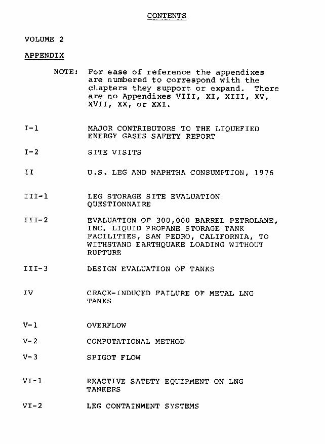
CONTENTS
VOLUME 2
APPENDIX
NOTE: For ease of reference the appendixesare numbered to correspond with thechapters they support or expand. Thereare no Appendixes VIII, XI, XIII, XV,XVII, XX, or XXI.
I-1 MAJOR CONTRIBUTORS TO THE LIQUEFIEDENERGY GASES SAFETY REPORT
I-2 SITE VISITS
II U.S. LEG AND NAPHTHA CONSUMPTION, 1976
III-1 LEG STORAGE SITE EVALUATIONQUESTIONNAIRE
III-2 EVALUATION OF 300,000 BARREL PETROLANE,INC. LIQUID PROPANE STORAGE TANKFACILITIES, SAN PEDRO, CALIFORNIA, TOWITHSTAND EARTHQUAKE LOADING WITHOUTRUPTURE
III-3 DESIGN EVALUATION OF TANKS
IV CRACK-INDUCED FAILURE OF METAL LNGTANKS
V-1 OVERFLOW
V-2 COMPUTATIONAL METHOD
V-3 SPIGOT FLOW
VI-1 REACTIVE SATETY EQUIPMENT ON LNGTANKERS
VI-2 LEG CONTAINMENT SYSTEMS
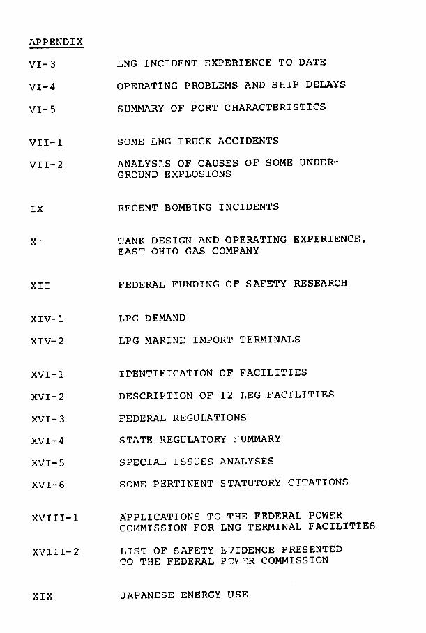
APPENDIX
VI-3 LNG INCIDENT EXPERIENCE TO DATE
VI-4 OPERATING PROBLEMS AND SHIP DELAYS
VI-5 SUMMARY OF PORT CHARACTERISTICS
VII-1 SOME LNG TRUCK ACCIDENTS
VII-2 ANALYS'.S OF CAUSES OF SOME UNDER-GROUND EXPLOSIONS
IX RECENT BOMBING INCIDENTS
XI TANK DESIGN AND OPERATING EXPERIENCE,EAST OHIO GAS COMPANY
XII FEDERAL FUNDING OF SAFETY RESEARCH
XIV-1 LPG DEMAND
XIV-2 LPG MARINE IMPORT TERMINALS
XVI-1 IDENTIFICATION OF FACILITIES
XVI-2 DESCRIPTION OF 12 LEG FACILITIES
XVI-3 FEDERAL REGULATIONS
XVI-4 STATE REGULATORY :UMMARY
XVI-5 SPECIAL ISSUES ANALYSES
XVI-6 SOME PERTINENT STATUTORY CITATIONS
XVIII-1 APPLICATIONS TO THE FEDERAL POWER
COMMISSION FOR LNG TERMINAL FACILITIES
XVIII-2 LIST OF SAFETY ElIDENCE PRESENTEDTO THE FEDERAL POV R COMMISSION
XIX JAPANESE ENERGY USE

APPENDIX I
CONTENTS PAGE
APPENDIX I-1, MAJOR CONTRIBUTORS TO THELIQUEFIED ENERGY GASES SAFETYREPORT 1
I-2, SITE VISITS 3

APPENDIX I-1
APPENDIX I-1
MAJOR CONTRIBUTORS
TO THE LIQUEFIED ENERGY GASES SAFETY REPORT
Contractors Location
S. L. Lindsey Houston, Texas
Arthur D. Little, Inc. Cambridge, Massachusetts
Marinco Ltd. Falls Church, Virginia
Maritime Institute of
Technology and Graduate
Studies Linthicum Heights, Maryland
R&D Associates Los Angeles, California
J.D. Stevenson, Consultants Cleveland, Ohio
S. Ross and Company Boston, Massachusetts
Whitfield Russell and
Associates, P.C. Washington, D.C.
Individuals Affiliation
Mr. Petter Aarrestad Maritime Institute ofTechnology and Graduate
Studies
Dr. James Austin MIT
Mr. Sheldon Bierman Attorney
Dr. Bernard Budiansky Harvard University
Mr. Angus Fraser USMC (ret.)
Ms. Irene Gordon Editorial Consultant
Dr. Harvey Greenspan MIT
Mr. Samuel Iker Editorial Consultant
Mr. Thomas Kelly Editorial Consultant
Dr. Daniel Kleitman MIT
Dr. Willem Malkus MIT
Ms. Patricia Nield Legal Consultant
Mr. Daniel Rapoport Editorial Consultant
Mr. Michael Ricinak USN (ret.)
Mr. Richard Royston R.H. Royston Co.
I
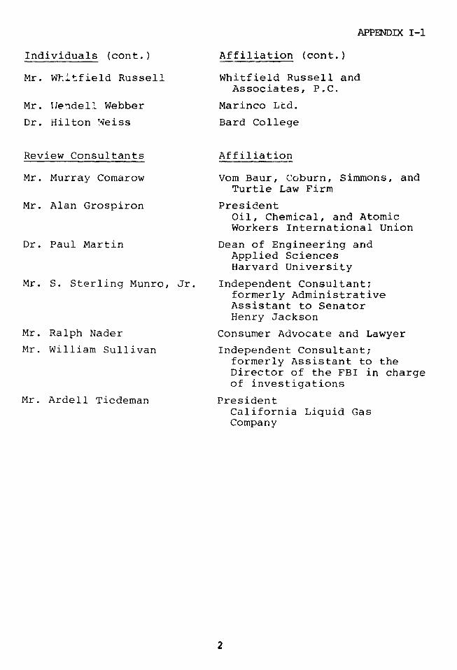
APPENDIX I-1
Individuals (cont.) Affiliation (cont.)
Mr. Whltfield Russell Whitfield Russell andAssociates, P.C.
Mr. 1Wendell Webber Marinco Ltd.
Dr. Hilton Weiss Bard College
Review Consultants Affiliation
Mr. Murray Comarow Vom Baur, Coburn, Simmons, andTurtle Law Firm
Mr. Alan Grospiron PresidentOil, Chemical, and AtomicWorkers International Union
Dr. Paul Martin Dean of Engineering andApplied SciencesHarvard University
Mr. S. Sterling Munro, Jr. Independent Consultant;formerly AdministrativeAssistant to SenatorHenry Jackson
Mr. Ralph Nader Consumer Advocate and Lawyer
Mr. William Sullivan Independent Consultant;formerly Assistant to theDirector of the FBI in chargeof investigations
Mr. Ardell Tiedeman PresidentCalifornia Liquid GasCompany
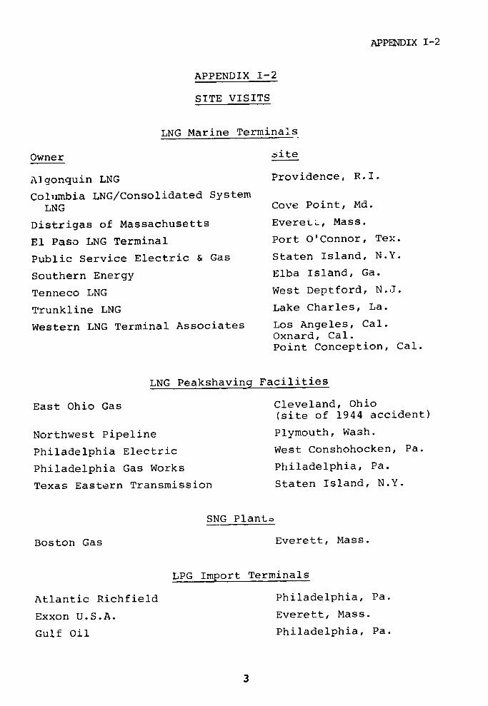
APPENDIX I-2
APPENDIX I-2
SITE VISITS
LNG Marine Terminals
Owner site
Algonquin LNG Providence, R.I.
Columbia LNG/Consolidated System
LNG Cove Point, Md.
Distrigas of Massachusetts EveretL, Mass.
El Paso LNG Terminal Port O'Connor, Tex.
Public Service Electric & Gas Staten Island, N.Y.
Southern Energy Elba Island, Ga.
Tenneco LNG West Deptford, N.J.
Trunkline LNG Lake Charles, La.
Western LNG Terminal Associates Los Angeles, Cal.Oxnard, Cal.Point Conception, Cal.
LNG Peakshaving Facilities
East Ohio Gas Cleveland, Ohio(site of 1944 accident)
Northwest Pipeline Plymouth, Wash.
Philadelphia Electric West Conshohocken, Pa.
Philadelphia Gas Works Philadelphia, Pa.
Texas Eastern Transmission Staten Island, N.Y.
SNG Planto
Boston Gas Everett, Mass.
LPG Import Terminals
Atlantic Richfield Philadelphia, Pa.
Exxon U.S.A. Everett, Mass.
Gulf Oil Philadelphia, Pa.
3
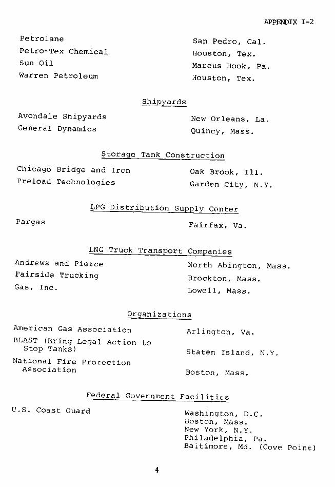
APPENDIX I-2
Petrolane San Pedro, Cal.Petro-Tex Chemical Houston, Tex.Sun Oil Marcus Hook, Pa.Warren Petroleum Houston, Tex.
Shipyards
Avondale Shipyards New Orleans, La.General Dynamics Quincy, Mass.
Storage Tank Construction
Chicago Bridge and Ircn Oak Brook, Ill.Preload Technologies Garden City, N.Y.
LPG Distribution Supply Center
Pargas Fairfax, Va.
LNG Truck Transport Companies
Andrews and Pierce North Abington, Mass.Fairside Trucking Brockton, Mass.Gas, Inc. Lowell, Mass.
Organizations
American Gas Association Arlington, Va.BLAST (Bring Legal Action to
Stop Tanks) Staten Island, N.Y.National Fire ProcectionAssociation Boston, Mass.
Federal Government Facilities
U.S. Coast Guard Washington, D.C.Boston, Mass.New York, N.Y.Philadelphia, Pa.Baltimore, Md. (Cove Point)
4
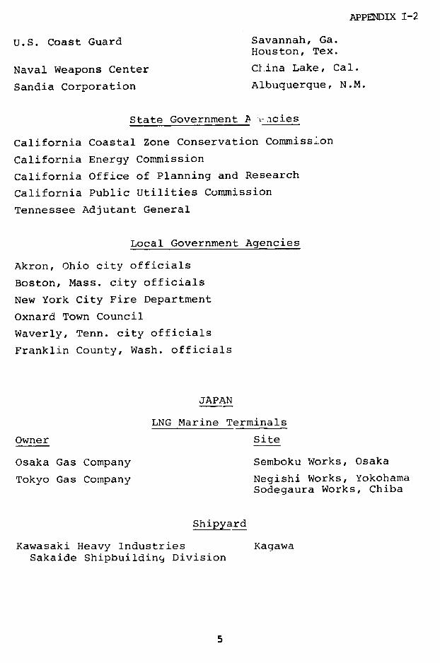
APPENDIX I-2
U.S. Coast Guard Savannah, Ga.Houston, Tex.
Naval Weapons Center Clina Lake, Cal.
Sandia Corporation Albuquerque, N.M.
State Government A ~acies
California Coastal Zone Conservation Commiss.on
California Energy Commission
California Office of Planning and Research
California Public Utilities Commission
Tennessee Adjutant General
Local Government Agencies
Akron, Ohio city officials
Boston, Mass. city officials
New York City Fire Department
Oxnard Town Council
Waverly, Tenn. city officials
Franklin County, Wash. officials
JAPAN
LNG Marine Terminals
Owner Site
Osaka Gas Company Semboku Works, Osaka
Tokyo Gas Company Negishi Works, YokohamaSodegaura Works, Chiba
Shipyard
Kawasaki Heavy Industries KagawaSakaide Shipbuilding Division
5
APPENDIX I-2
Storage Tank Construction
Ishikawajima-Harima Heavy TokyoIndustries
Mitsubishi Heavy Industries Tokyo
Organization
Japan Gas Association Tokyo
National Government
Ministry of International Trade and IndustryGas Safety DivisionPublic Utilities Bureau
Ministry of TransportationMaritime Safety Agency

APPENDIX II
ADPENDIX II
U.S. LEG AND NAPHTHA CONSUMPTION, 1976
Table II-1 U.S. Energy Consumption by Fuel
Quad (1015 Btu) %
Petroleum* 32.9 44
Natural Gas+ 20.1 27
Coal 13.7 19
Hydro-electric 3.0 4
LEG and Naphtha 2.2 3
Nuclear 2.0 3
Geothermal 0.1
Total, 1976 74.0 100
*Excludes LPG and naphtha used outside refineries and gas
plants.
+Excludes natural gas transported or stored as LNG.
Source: United States Statistical Pbstract, 1977
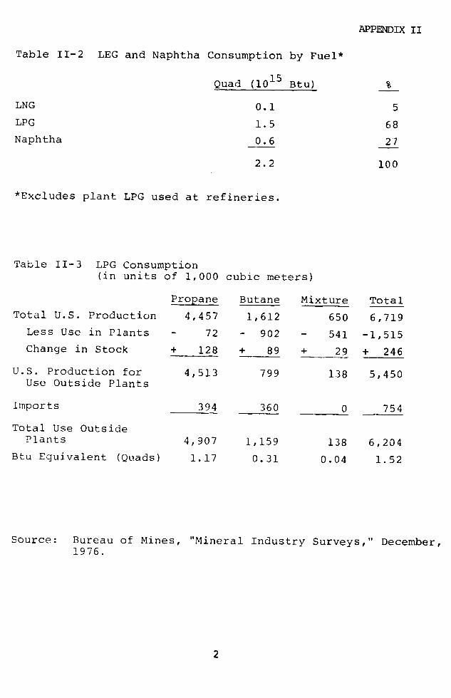
APPENDIX II
Table II-2 LEG and Naphtha Consumption by Fuel*
Quad (1015 Btu) %
LNG 0.1 5
LPG 1.5 68
Naphtha 0.6 27
2.2 100
*Excludes plant LPG used at refineries.
Table II-3 LPG Consumption(in units of 1,000 cubic meters)
Propane Butane Mixture Total
Total U.S. Production 4,457 1,612 650 6,719
Less Use in Plants - 72 - 902 - 541 -1,515
Change in Stock + 128 + 89 + 29 + 246
U.S. Production for 4,513 799 138 5,450Use Outside Plants
Imports 394 360 0 754
Total Use OutsidePlants 4,907 1,159 138 6,204
Btu Equivalent (Quads) 1.17 0.31 0.04 1.52
Source: Bureau of Mines, "Mineral Industry Surveys," December,1976.
2
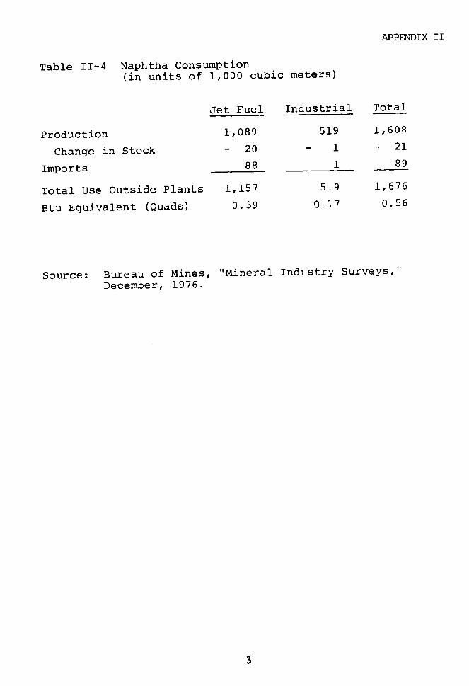
APPENDIX II
Table II-4 Naphtha Consumption
(in units of 1,000 cubic meters)
Jet Fuel Industrial Total
Production 1,089 519 1,608
Change in Stock - 20 - 1 - 21
Imports 88 1 89
Total Use Outside Plants 1,157 5_9 1,676
Btu Equivalent (Quads) 0.39 0i17 0.56
Source: Bureau of Mines, "Mineral Indu.stry Surveys,"
December, 1976.
3

APPENDIX III
CONTENTS PAGE
APPENDIX III-1, LEG STORAGE SITE EVALUATIONQUESTIONNAIRE 1
III-2, EVALUATION OF 300,000 BARRELPETROLANE, INC. LIQUID PROPANE
STORAGE TANK FACILITIES TOWITHSTAND EARTHQUAKE LOADINGWITHOUT RUPTURE 4
II1-3, DESIJN EVALUATION OF TANKS 8
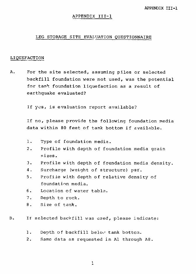
APPENDIX III-1
APPENDIX III-1
LEG STORAGE SITE EVAIUJATION QUESTIONNAIRE
LIQUEFACTION
A. For the site selected, assuming piles or selected
backfill foundation were not used, was the potential
for tank foundation liquefaction as a result of
earthquake evaluated?
If yes, is evaluation report available?
If no, please provide the following foundation media
data within 80 feet of tank bottom if available.
1. Type of foundation media.
2. Profile with depth of foundation media grain
sizes.
3. Profile with depth of foundation media dqnsity.
4. Surcharge (weight of structure) psf.
5. Profile with depth of relative density of
foundation media.
6. Location of water table.
7. Depth to rock.
8. Size of tank.
B. If selected backfill was used, please indicate:
1. Depth of backfill below tank bottom.
2. Same data as requested in Al through A8.

APPENDIX III-1
C. If piles were used:
1. Total depth of piles.
2. Type of pile - wood, concrete, steel.3. Type - bearing or friction.
4. Driving criteria.
5. Ar Dprovision for lateral loads on pile system.
FLOODTNG - COASTAL
A. For the site selected, was potential for coastalflooding or storm surge considered?
B. If yes, what was the flood height determined relativeto the bottom of the storage tank?
What probability per year or return cycle is theflood height determined for?
C. If flood height is above storage tank base height:
1. Was tank design evaluated for buoyancy forces?2. Were any water flow loads considered? If so,
how?
FLOODING - RIVER
Same questions as asked for above A through C, pluswhat is the potential for combi.ned river plus coastalflooding?
TSUNAMI
A. Was any consideration given to tsunami (tidal wave)effects?
2

APPENDIX III-1
B. If yes, is an evaluation report available?
C. If no, please give tank bottom evaluation above mean
sea level, and if possible, provide a topographical
map of the site in scale large enough to show general
shape of site shore line.
3
APPENDIX III-2
APPENDIX III-2
EVALUATION OF 300,000 BARREL
PETROLANE, INC., LIQUID PROPANE STORAGE TANK
FACILITIES, SAN PEDRO, CALIFORNIA. TO WITHSTAND
EARTHQUAKE LOADING WIThOUT RUPTURE
INTPODUCTION
The evaluation performed on the seismic capacity of
the Petrolane, Inc., propane storage tank facilities, SanPedro, California, was based on a site visit on July 26,
1977, plus a review of the design calculations performed
by Chicago Bridge & Iron Company1 and CB&I drawings:
1A Rev. 6 Contract No. 72-4145
1B Rev. 5 Contract No. 72-4145
42 Rev. 1 Contract No. 72-4145
We also reviewed the California PUC Draft Safety2
Report, and Soil and Earthquake Engineering
Investigation Report prepared by Converse, Davis, and
Associates. 3
The original seismic design analysis performed by
CB&I, which used the ground response spectrum provided byConverse, Davis, and Associates, is shown in Fig. III-1.
This response spectrum scales to 0.29g at zero period,
whicl is normally equated +o the zero period (maximum
ground acceleration) at che site. The PUC draft safety
report seems to conclude that the tanks were designed to0.4g (see p. 12-2) and compared this acceleration value
4
APPENDIX II-2
directly with accelerations associated with earthquake
magnitudes. The correlation of earthquake magnitude with
acceleration is normally done on the basis of zero period
ground acceleration and not response accle ration which
is dependent on the frequency characterisLics of the
structure being analyzed and the shape of the response
spectrum. Tile 0.4g acceleration level used in design
includes the response of the tanks. However, the
reference zero period ground acceleration defined for the
site and used in design is 0.29g, not 0.4g as indicated
in the California PUC Draft Report.
In evaluating the ultimate seismic capacity of the
tanks, the same response spectrum as originally defined
was used as shown in Figure III-1. In determining
seismic loads, the same model representation of the tank
as that described by CB&I was used. In our analysis to
determine seismic loads, we used higher modes of
response, in addition to the fund'mental mode, and
determined the dynamic characteristics of the tanks by
the finite element computer algorithm, ANSYS . A
description of the analysis performed is given below.
Except as noted, the analytical procedures used to
evaluate ultimate seismic capacity of the tanl was the
same as that used by CB&I in the original design. Final
results and comparisons are presented in Table III-1.
DYNAMIC ANALYSIS
The fundamental period (frequency) of the tank is a
key parameter in determining seismic loads. The dynamic
characteristic analysis performed by CB&I used a
proprietary computer program based on the Rayleigh-Ritz
procedure and determined a fundamental period of the tank
I;
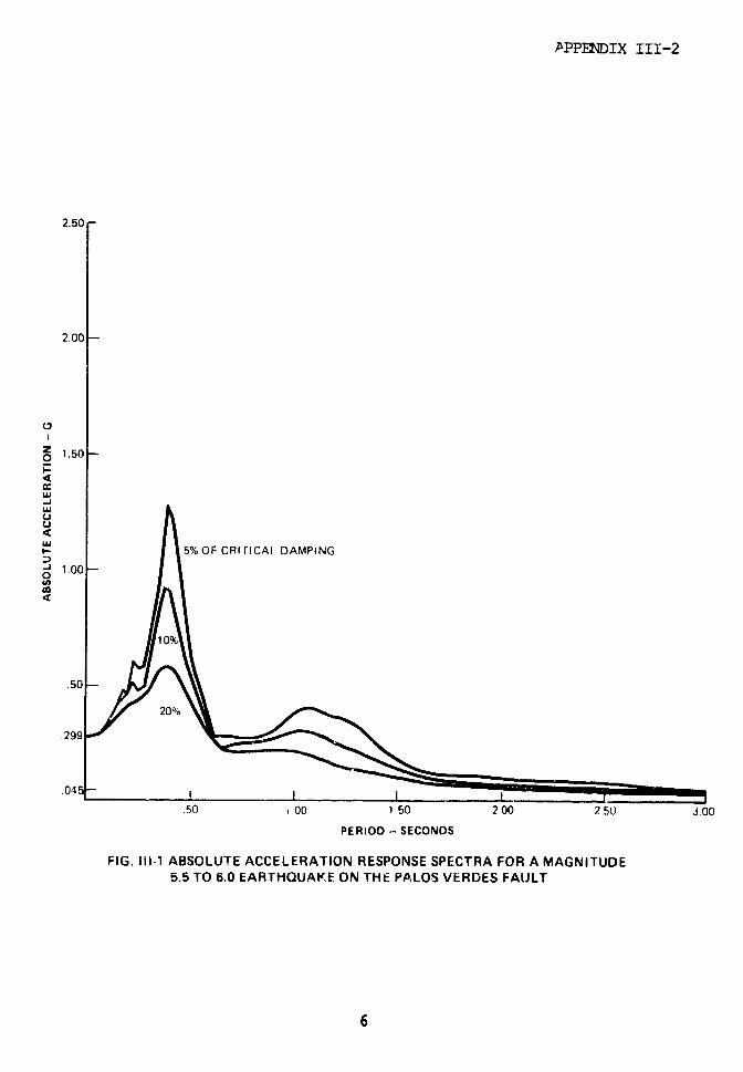
APPENDIX III-2
2.50 -
2.00
Z 1.50I-
-J
' : I 5% OF CRI rTICAL DAMPING
50
29950 .00 1.50 2.00 2
.50 0 PERIOD SECONDS
PERIOD - SECONDS
FIG. 1-15.5 ABSOLUTE ACCELERATION RESPONSE SPECTRA FOR A MAGNITUDE5,5 TO 6.0 EARTHQUAKE ON THE PALOS VERDES FAULT
APPENDIX III-2
of 0.132 seconds (7.58 Hz). Using the computer program,
ANSYS, which used a finite element consistent mass matrix
form of solution and the same model as described by CB&I,
we determined a fundamental period of 0.210 seconds (4.77
Hz).
The difference in fundamental period between CB&I's
and our solutions is larger than can normally be
accounted for by usual computer algorithm differences.
In addition to evaluating the natural period of the
tanks as cantilever beams on a rigid foundation, the
response of the structures was also evaluated using a
standard rigid body soil-structure representation as
would typically be done for surface located nuclear
stations. A comparison of the dynamic characteristics or
the three analyses is given in Table II--1.
CONCLUSION
Based on the comparison shown in Table III-1, and
assuming the response spectra shown in Fig. III-1 are
st'lM valid, the Petaolane, Inc., Liquid Propane Storage
Tr. Facilities in San Pedro should be able to
accommodate an earthquake of zero period ground
acceleration in the free field at the foundation base
level of at least
0.29 x 2.23 = 0.65g
before significant leakage or failure of the tank bottom
would be expected.
7
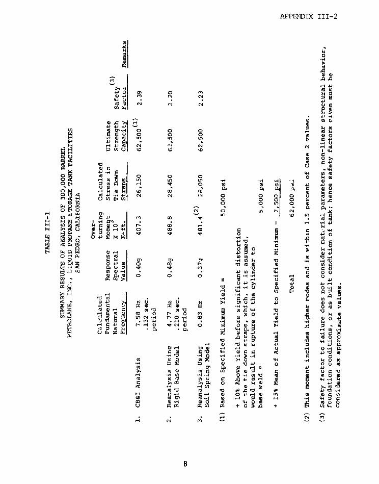
APPENSDIX III-2
6 o' A0 m to
0W U **4-40 -4
o " t,
En O O 0 H 0w1 0 lt 115 U)0 0 p 00E- ~ u4) . 4 -- *.4 )
H - - O--4
44 X gU 0.b4 4 444- ' 0
o; U < o o o e ,0 0 4 (a 4 0 0 .0 .oU
O H Eo n N Y -i rre F4 t_ u) W En k
Pk 04 N14
H H W ID ** _/-H0>0 00 0 0)
EnI~~~~~~~~~~~~~~~~~~~- O 0iH -¢U 0zE uC > II %D C E4
Ia ., cm , ; .,I .a00 MO I x ·4 O 0
i u O XEaq ,'¢ p, h ~--. ,-~ ~ ,~ c~ ~ C~0 C . -
*E 4 , a 001i z0 .-4*4 N 00 3U
C- 0 0.)C r- Uto4- 0 04
4 F-4 mO la Ili * a - ._R4 4 O O O -4 4i ·r0 r 0u
* U 4J >, 0I 4 4) ,W4,.- ,",-I
· H U x c 0 E M t U , , .H r. 4 O &
04 N U q N >· 4J vU 0 4i 0 (No
LO; ro Q) l u u'a i w r- 44 0 )u i hn-CC 0 r- o m r a
44 Ln( H r- C -4 0 04 -0 0- I ° 0 ' i
4j U ) -4 Z C 0 a 0 *aV.) -A Pi .V~Q 4 P r (' OB
'OW P4 4 c 4- 9.1 -a 9: 4
< 'a0 4i 0 °u (o
- -r n 0 .-4 ul 2 fo 0>m >1 1fi O 4*
H .4 ' _1 0) 0 4-1 1-4 (H ) 0 UnLa l to 'A : - * 1 U C
u ElQ p 2 q ° + 0o 4 + l ) U
H s ' n _i m
m I rlP1rd kgB0
APPENDIX III-2
REFERENCES
1. Design Calculations, 1710 (300 MB) Propane Tank andFoundation, San Lake City Office, CBI Contract72-4145, dated 7/17/72 for Petrolane, Inc., SanPedro, California 20 pages.
2. Safety Report on Liquified Propane Storage with LowTemperature Pipeline of Petrclane, Inc., CaliforniaPublic Utilities Commission, Utilities Division,San Francisco, California, (DRAFT) July 1977.
3. Converse, Davis, and Associates, "Soil andEarthquake Engineering Investigation, ProposedDistribution Facility - Gaffey Street Site, LosAngeles, California," for Petrolane, Inc., May1972.
4. Swanson Analysis Systems, "Computer Algorithm ANSYS- Engineering Analysis System," Elizabeth,Pennsylvania, March 1975.
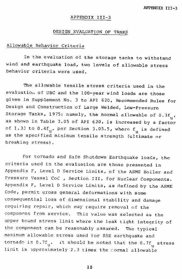
APPENDIX III-3
APPENDIX III-3
DESIGN EVALUATION OF TANKS
Allowable Behavior Criteria
In the evaluation of the storage tanks to withstand
wind and earthquake load, two levels of allowable stress
behavior criteria were used.
The allowable tensile stress criteria used in the
evaluation. of UBC and the 100-year wind loads are those
given in Supplement No. 3 to API 620, Recommended Rules for
Design and Construction of Large Welded, Low-Pressure
Storage Tanks, 1975; namely, the normal allowable of 0.3fu,
as shown in Table 3.05 of API 620, is increased by a factor
of 1.33 to 0.4fu, per Section 3.05.5, where f is defined
as the spec fied minimum tensile strength (ultimate or
breaking stress).
For tornado and Safe Shutdown Earthquake loads, the
criteria used in the evaluation are those presented in
Appendix F, Level D Service Limits, of the ASME Boiler and
Pressure Vessel CoC , Section III, for Nuclear Components.
Appendix F, Level D Service Limits, as defined by the ASME
Code, permit gross general deformations with some
consequential loss of dimensional stability and damage
requiring repair, which may require removal of the
component from service. This value was selected as the
upper bound stress limit where the leak tight integrity of
the component can be reasonably assured. The typical
maximum allowable stress used for SSE earthquake and
tornado is 0.7f . it should be noted that the 0.7f stressu ulimit is approximately 2.3 times the fnormal allowable
10
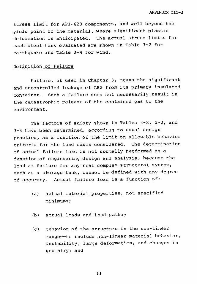
APPENDIX III-3
stress limit for API-620 components, and well beyond the
yield point of the material, where significant plastic
deformation is anticipated. The actual stress limits for
each steel tank evaluated are shown in Table 3-2 for
earthquake and Table 3-4 for wind.
Definition of Failure
Failure, as used in Chapter 3, means the significant
and uncontrolled leakage of LEG from its primary insulated
container. Such a failure does not necessarily result in
the catastrophic release of the contained gas to the
environment.
The factors of safety shown in Tables 3-2, 3-3, and
3-4 have been determined, according to usual design
practice, as a function of the limit on allowable behavior
criteria for the load cases considered. The determination
of actual failure load is not normally performed as a
function of engineering design and analysis, because the
load at failure for any real complex structural system,
such as a storage tank, cannot be defined with any degree
of accuracy. Actual failure load is a function of:
(a) actual material properties, not specified
minimums;
(b) actual loads and load paths;
(c) behavior of the structure in the non-linear
range--to include non-linear material behavior,
instability, large deformation, and changes in
geometry; and
11

APPENDIX III-3
(d) "as built" as opposed to "as designed" strength,
inertia, and stiffness properties of the
structure and its supporting media.
These specific quantities are generally not kncswn,
and it would require a very substantial experimental and
analytical program to define them for each tank.
In Chapter 3, a judgment is made as to when tank
failure might be expected to occur based on t, - limiting
behavior criteria and the nature of the load determination
for the various load cases considered.
12

APPENDIX IV
APPENDIX IV
CRACK-INDUCED FAILURE OF METAL LNG TANKS
INTRODUCTION
This appendix discusses the calculations on which
the discussion in Chapter 4 is based.
The figures may be used to estimate some crack sizes
that should be sufficient to induce extensive ruptures in
spherical, equatorially-supported tanks (Figs. IV-l, IV-2)
and in cylindrical storage tanks (Figs. IV-3, IV-4), both
Fully loaded, but not subjected to the additional design
stresses associated with inertial, thermal, or slosh
loading. In each abscissa, the crucial parameter Kc, a
material property, appears. Unfortunc;ely, the precise
magnitude of Kc for both 5083 aluminum and 9% Ni-steel
can only be estimated at present. However, plausible
estimates can be made, and are used in the numerical
examples shown below. The parameter aB, the membrane
tensile stress at the tank bottom, also appears in the
figures. This quantity, under the loading conditions
specified, will vary from one design to another, but can be
expected to be about 1/2 to 1/3 the design stress of the
material. In any event, it can be estimated by
~B = yR2/tB (spheres)
and
CB = yRH/tB (cylinders)
I

APPENDIX IV
where y is the LNG density, and tB is the shell thick-
ness at the bottom point B.
A discussion of the figures, together with a numeri-
cal example for each, follows. The derivation of numerical
results is given in the final section.
SPAERiCAL TANK - SUB-EQUATORIAL CIRCUMFERENTIAL CRACK
Probably the most crack damage that can be inflicted
on the spherical tank supported equatorially is illustrated
in Fig. IV-1. A sufficiently long-circumferential crack,
just below the reinforced equatorial region, could con-
ceivably unzip the entire bottom of the tank as it propa-
gates around in both directions. The initial crack sizes
needed for such propagation (whether or not total separa.-
tion actually will occur is beyond calculation) can be
estimated as shown by the following example for 5083
aluminum:
R = 60'
tB = 1.60"
tA = 1.45"
aB 6000 psi
K z 150 ksi* .c
where tA is the shell thickness at the start of the crack.
R/tAZ 50p0; ( i - .84
*kips per square inch (kip = 1000 pounds)
2
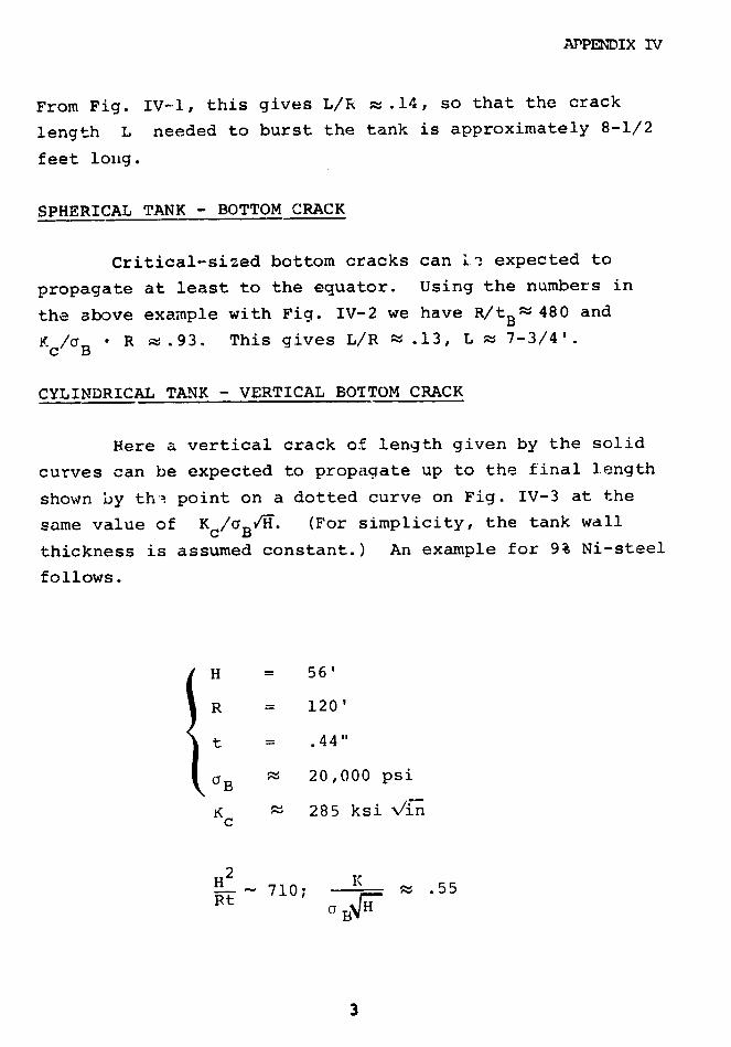
APPENDIX IV
From Fig. IV-l, this gives L/R ; .14, so that the crack
length L needed to burst the tank is approximately 8-1/2
feet long.
SPHERICAL TANK - BOTTOM CRACK
Critical-sized bottom cracks can !in expected to
propagate at least to the equator. Using the numbers in
the above example with Fig. IV-2 we have R/tB~ 480 and
Kc/a B R ~ .93. This gives L/R - .13, L K 7-3/4'.
CYLINDRICAL TANK - VERTICAL BOTTOM CRACK
Here a vertical crack of length given by the solid
curves can be expected to propagate up to the final length
shown by th ' point on a dotted curve on Fig. IV-3 at the
same value of Kc/oaBV'. (For simplicity, the tank wall
thickness is assumed constant.) An example for 9% Ni-steel
follows.
H = 56'
R = 120'
t = .44"
B 20,000 psi
K ~ 285 ksi V/inc
H2 K-- 710; - .55
Rt "' 3
3

APPENDIX IV
Hence L/N : .08, critical crack length z 4-1/2', and the
crack should propagate almost to the top of the rank.
CYIINDRICAL TANK - MID-HEIGHT VERTICAL CRACK
In this case (Fig. IV-4), the crack of critical
length will propagate to the bottom, and also reach to the
upper limit given in Fig. IV-3. With the same data,
L/H ~ .14, or L - 8' is needed.
The curves in the figures are based on simplified
analyses involving several approximations. Also, there is
considerable uncertainty about the value of Kc . For the
reasons given in Chapter 4 we believe our calculations are
conservative.
The estimates used for K are based on the extra-c
polation in Ref. 1 (pages 147 and 312) and on the burst
test of Ref. 2. More large-scale testing (difficult and
expensive) would be needed to refine these highly uncertain
estimates.
DERIVATION OF FIGURES
In the lower hemisphere, the
meridional stresses at and the e R
circumferential stresses an are
approximately (based on membrane
theory, ignoring bending)
4

APPENDIX IV
2 1 !R
s + 3(1 -cos) t- gl(
yR 1 2 oG t 2 cosp - 351-coT-- t 2
(i < <Tr)
where t is the thickness.
The K for a meridional crack of length L is
approximately
K = L (X)
where f is the curvature correction function given on
page 328 of Ref. 1. This equation ignores the influence of
bending stresses on K. Then the equation on which Fig. IV-i
is based (assuming the crack is almost equatorial) is
L f
tB 5 BR - 6(
where gl( ) = has been used.
For Fig.IV-2 we use (assuming constant thickness)
K a(TL
°BR 2(A) L f2R ( R tA-
5
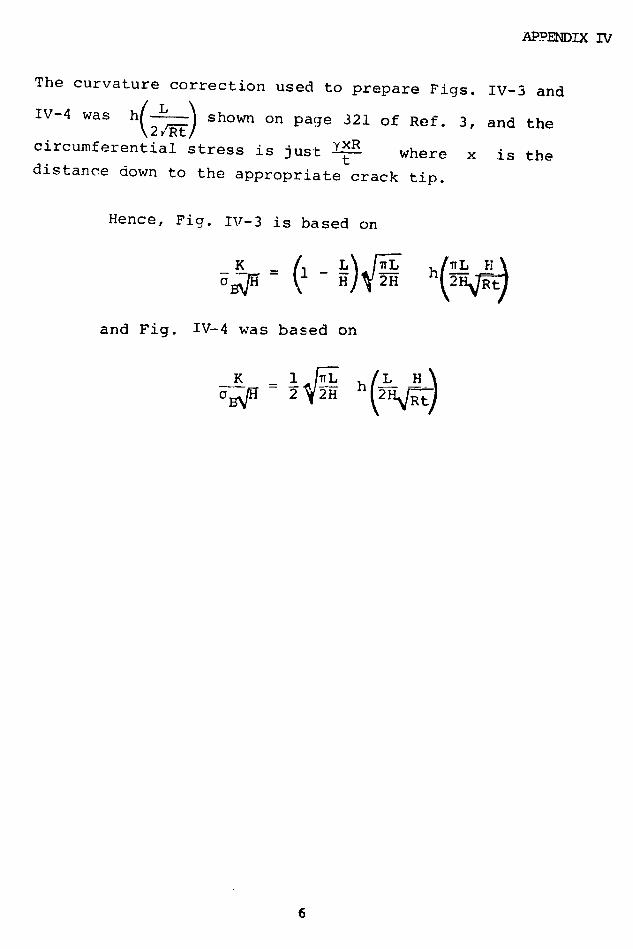
APPENDIX IV
The curvature correction used to prepare Figs. IV-3 and
IV-4 was h(2Z_) shown on page 321 of Ref. 3, and the
circumferential stress is just YXR where x is thedistance down to the appropriate crack tip.
Hence, Fig. IV-3 is based on
a H ( H rR t)
and Fig. IV-4 was based on
- =L i2 : h jL-Ht-
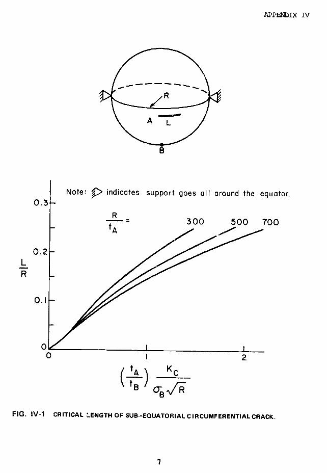
APPENDIX IV
0.3
- -300 500 700
0.2L
O. 2
0'310 1 2
tA ) KC
TB CBU ER
FIG. IV-1 CRITICAL LENGTH OF SUB-EQUATORIAL CIRCUMFERENTIALCRACK.
7

APPENDIX IV
-.. L
0.K Note: : indicates support goes all around the equator.
--- = R300 500 700
0.2
0 1 2KC
FIG. IV-2 CRITICAL LENGTH OF MERIDIANAL BOTTOM CRiACK.
a
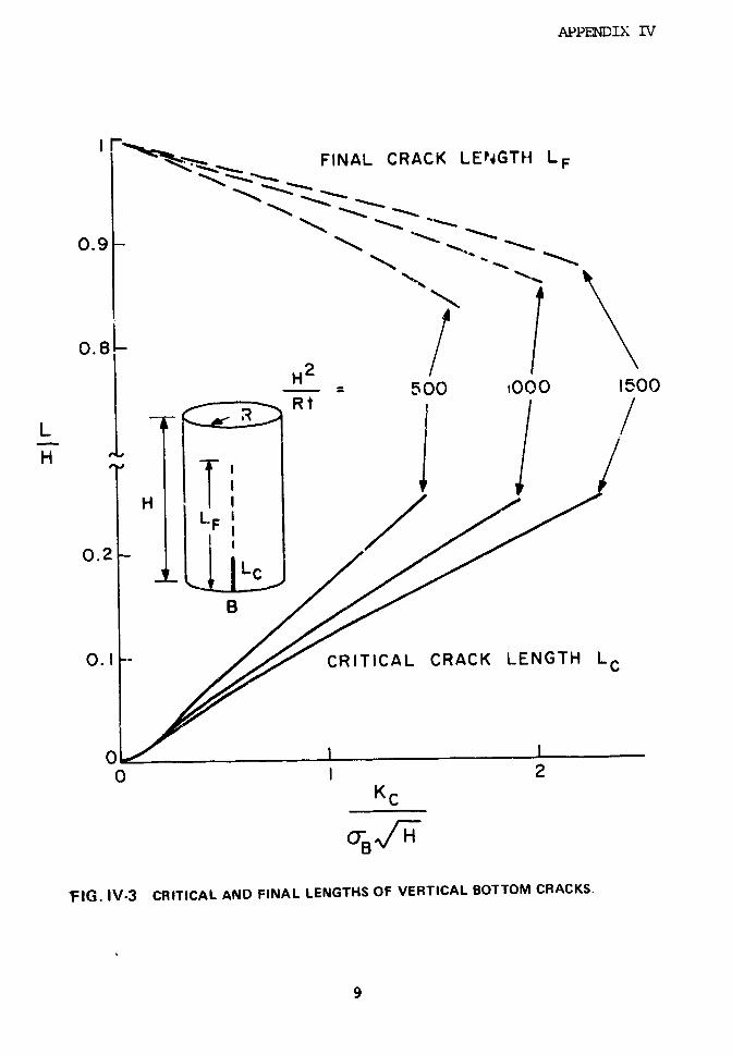
APPENDIX IV
IiaCC,-; FINAL CRACK LENIGTH LF
0.48
H 2500 1000 1500
LH 1 LHH ,-., I
LF
0.2
0. I - CRITICAL CRACK LENGTH LC
0I I0 1 2
KC
FIG. IV-3 CRITICAL AND FINAL LENGTHS OF VERTICAL BOTTOM CRACKS.
9
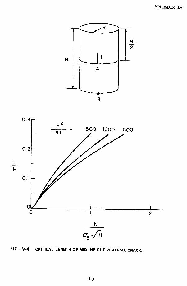
APPENDIX IV
H
H
/ -- 0o ,ooo,5o
B
0.3
_ Rt 500 1000 1500
0.2
LH
0I
0 1 2
K
FIG. IV-4 CRITICAL LENGTH OF MID-HEIGHT VERTICAL CRACK.
10

APPENDIX IV
REFERENCES
1. "Properties of Materials for Liquified Natural Gas
Tankage", ASTM STP 579, 1975.
2. Lake, Eiber, & DeMoney, Advances in Cryogenic
Engineering, Vol. 13, 1968, pp. 278-293.
3. Rooke & Cartwright, "Stress Intensity Factors", Her
Majesty's Stationery Office, London, 1976.
11
APPENDIX V
CONTENTS PAGE
APPENDIX V-, OVFRFLO1 1
V-2, COMPUTATIONAL METHOD 15
V-3, SPIGOT FLOW 26
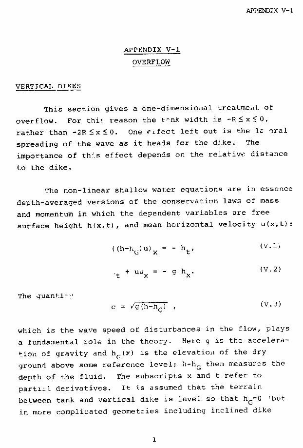
APPENDIX V-1
APPENDIX V-1
OVERFLOW
VERTICAL DIKES
This section gives a one-dimensioial treatment of
overflow. For this reason the t--nk width is -R < x < 0,
rather than -2R <x <O. One eLfect left out is the le eral
spreading of the wave as it heads for the dike. The
importance of th'.s effect depends on the relative distance
to the dike.
The non-linear shallow water equations are in essence
depth-averaged versions of the conservation laws of mass
and momentum in which the dependent variables are free
surface height h(x,t), and mean horizontal velocity u(x,t):
((h-hG)U)x = - ht, (V.lj
+ uI = - g h . (V.2)'t x x
The quantit"'
c = /g(h-hG) , (V.3)
which is the wave speed of disturbances in the flow, plays
a fundamental role in the theory. Here g is the accelera-
tion of gravity and hC(x) is the elevation of the dry
ground above some reference level; h-hG then measures the
depth of the fluid. The subscripts x and t refer to
partl.l derivatives. It is assumed that the terrain
between tank and vertical dike is level so that hG=0 'but
in more complicated geometries including inclined dike
1

APPENDIX V-1
problems, topographic variations are important and must beincluded).
The maximum fluid height in the tank H and time v/gare characteristic scales which are used to make theproblem dimensionless by the following transformations:
x - Hx; t + 7/g t; h + Hh; u + u g ; c - cgiT.
Equations (V.1) and (V.2) can then be written as
2 (ct+ucx) + cu x = 0, (V.4)
Ut + uu x + 2cc = 0. (V.5)
For t<O the quiescent fluid fills the tank, that is u=O,c=l, in -R/H< x <0. At t=O, the wall of the tank at x=O issuddenly removed and the water rushes towards the verticaldike at x=xw=L/H. During this phase, the solution ofequations (V.4) and (V.5) is
2 +u = a(1 + )
(V.6)1 xc = (2 - ).
when
R < - t < x < 2t < xW .
The free surface is as shown in Fig. V-1. (Thewater is still at rest in the region -R/H<x<-t.) Theleading edge of the fluid, which corresponds to c=O, moveswith the constant dimensionless speed 2 (i.e., twice the
2
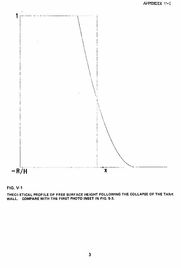
APPENDIX V\-1
-R/H x
FIG. V-1
THEOFRETICAL PROFILE OF FREE SURFACE HEIGHT FOLLOWING THE COLLAPSE OF THE TANKWALL. COMPARE WITH THE FIRST PHOTO INSET IN FIG. 5-3.
\
WALL. COMPARE WITH THE FIRST PHOTO INSET IN FIG. 5-3.
APPENDIX V-1
natural propagation speed /g/) and reaches the dike at the
time tw=xw/2. Meanwhile, a rarefaction wave propagates
through the tank and reflects off the wall x=-R/H when
t=R/H. Friction and ground resistance modify this result3
so that the liquid actually hits the dike somewhat later
than predicted. (Our experimental results on arrival time
are consistent with the data of Dressler2.) Upon collision
with the vertical wall, water accumulates rapidly and to
great height; a strong shock fo-ms and propagates, slowly
at first, back towards the tank.
Since the edge of the fluid front has zero thickness
in the inviscid theory, impact must be examined analyti-
cally, and with care, in order to provide the data to
initialize a numerical program. To this end, the shock
locus is described by xs(t) for to t w with xs(tw)=xw and
x' (t) < 0. For some time after impact the flow between the
shock and the wall of the tank is given by equation (V.6).
A solution of the basic equations is then sought in the
domain between the shock and the dike x s- x xW which
satisfies the shock conditions
cu = u - - (M2 -l)(l + -1)/2 (V.7)u+ -u (V.7)
c
S M2U x'(t) u - -M 2 (1 + )./2 (V.8)
Here subscripts -(+) refer to the region into (from) which
the shock moves in the next instant of time; U is the shock
velocity and
4
APPENDIX V-1
M - (V.9)c
is a measure of shock strength. The fluid velocity at the
barrier is zero until the water level exceeds the height of
the dike, i.e., u(xw,t)=O for h< a.
It is convenient to define space and time variables
centered at the impact position xw=2tw, given by
Xrw-X t= /
tW W
for then the flow variables in the region between shock and
the barrier,
0 < C <s = n/T 2 (V.11)
can be represented as the power series
U = T~ + T 2f1(5) + '* t (V.12)
C = Tl/2 (k + Tg 1 ( ) + '' )-
The shock locus is written as
~s = Z(T-) = Z0 + Z 1 T + '* (V.13)
and the shock velocity becomes
U =- dT d (T2Z(T)) = -(2Z 0T+3ZlT2 + .. ).
U =-s -dT(V.14)
5

APPENDIX V-1
The substitution of these series into the equations of
motion and boundary condition yields
k 2 s5/4 3- 1/2; k = - 5 3 / (2 1)9 21/4 9
52 5 52 2kl~gl = 2k + kl; f - +k (V-15)2k 1 3 k2 k
8 fl 6z Z2
27k 2
or simply
k = 1.373178,
kl = -1.054409,
ZO = 0.157135,
zl = -0.035232, (V.16)
gl(zo) = -1.063400,
fl(z 0) = -0.237886.
Examination of these formulas for x (t) and c2 shows that
water accumulates rapidly at the dike because the shock is
very slow in starting. Moreover, the free surface height
behind the bore is nearly uniform at any instant of time.
This is the basis of an analytical approximation which
enables the motion to be determined when the wall of the
dike is too high to allow any overflow. But discussion
of this aspect of theory is omitted here because the
results merely confirm the numerical calculations.
Equations (V.6), (V.12), and (V.14) give the
entire solution through impact and a short period there-
6
APPENDIX V-1
after. At this time, water is rapidly piling up at the dike
behind the shock that moves towards the tank. Soon fluid
will begin to flow over the barrier and the reflected waves
and propagating shock will interact as they reverberate
between boundaries. In these later stages, the equations
are solved numerically using as initial data the known
values of all variables at time tW+At following impact.
Only the proper boundary condition to describe overflow must
still be formulated.
If the dimensional height of the fluid at tJ - barrier
wall is hw, then the water level atop the dike at x=xW is
hw-a, and the local wave speed there is
c = /g(hw-a). (V.17)
We nssume that fluid which passes over the impounding wall
ceases to influence the main body of water still within the
containment area. This is assured by setting
u =
where u is the velocity atop the dike. (The convected
propagation velocities are then positive and no "signal" can
travel backwards.) However, the conservation of mass
requires
u hw = (h w-a). (V.18)
With co=ga, the last relationship can be expressed as
(C2-c2)3/ U = ( )3/2 H(c-co) at x = xW, (
c2
7

APPENDIX V-1
which is also the proper dimensionless form. The Heavisidefunction
H(x) = 1, x > 0
= 0, x <
is used to incorporate all the conditions at this boundaryinto one succinct formula. Therefore, for cw<co, (nooverflow) the velocity is zero, uw=O; spillage occurs afterthe water level exceeds the height of the barrier.
Numerical computation makes use of the characteristicforms of the basic equations
u + 2c = constant along the ray, ddt= u+c
(V.20)dxu - 2c = constant along the ray, -dt= u-c
The numerical program based in part on this mode ofdescription is presented in the following section.
Although there is no explicit vertical velocity in theshallow water theory the law of conservation of mass enablesthe theory to account for the actual rise of fluid after ithits the wall. The height attained by the main body offluid indicated by arrows in Fig. V-2 exceeds theoreticalprediction by about 15%. The model cannot describe theflight of particles from thie leading edge of the surge.Droplets reach a height three times that of the tank but theamount of fluid involved is small.
8
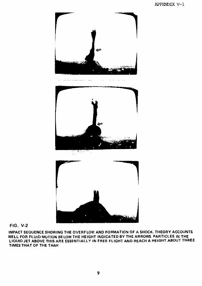
APPENDIX V-1
FIG. V-2
IMPACT SEQUENCE SHOWING THE OVERFLOW AND FORMATION OF A SHOCK. THEORY ACCOUNTSWELL FOR FLUID MOTION BELOW THE HEIGHT INDICATED BY THE ARROWS. PARTICLES IN THELIQUID JET ABOVE THIS ARE ESSENTIALLY IN FREE FLIGHT AND REACH A HEIGHT ABOUT THREETIMES THAT OF THE TANK
9
APPENDIX V-1
Shallow water theory, despite obvious limitations,does remarkably well in predicting the main features ofmotion and spillage. Presumably the results could beimproved by including ground friction and turbulence in themodel or by modifying the overflow condition.
INCLINED DIKES
A very simple model for the flow over an inclineddike leads to surprisingly accurate predictions of thespillage fraction shown in Figs. 5-10, 5-il, and 5-12.
The run-up of the liquid on the incline is a verycomplicated process marked by strong vertical accelerationand overturning, but the motion can be described in anapproximate manner by applying the conservation laws in thelarge (much like the treatment of shocks). A theoreticalestimation of the progress of the surge on the slope untilspill-over, provides the initial data for subsequentnumerical calculation.
The ground elevation with a sloping dike of inclina-tion angle 0 is given by
hG(x) = (x-xW)H(x-xw)tane for x<xT (V.21)
where
a = (xT-xw)tanO
is the height of the barrier (at x=r). For x<x h=O,indicating level ground.
10
APPENDIX V-1
At time t=tw=--, the liquid reaches the dike and
begins to move up the slope, a shock develops at the dis-
continuity in ground slope. At time t=T, the fluid over-
flows the barrier; during the interim, the leading edge of
the rushing liquid is at xF(t). For a strorg surge, the
shock is swept back along with the flow and in this case,
the velocity and free surface height at the break in
elevation are assumed to be nearly the same as for the
incoming flow described by equation (V.6):
2 + wuw = (1 + )
w T3
x (V.22)= (2 - )
The (dimensionless) conservation laws of mass and momentum
applied to the region on the slope xwS x xF(t) for t< T
imply that
xF 2t
f C 2 dx = c 2 dx (V.23)
x xw w
and
xv(t) x F
d (t)ucdx = u 2 c 2 + 1 Fc2sin0dx. (V.24)d-t w -w '
x xw w
On the dike, the variables c2 , u are approximated as linear
functions of distance for t <T:
c2 2 xF(t) - x
w xF(t) - X w
(V.25)
uF(t) - uu uw +xF (t) -w (x - XF (t))
APPENDIX V-l
where uF=x'(t). The substitution of these expressions in
equation (V.23) or (V.26) leads to an equation for
xF(t). (Since we have eliminated the shock and shock locus
from consideration in this simple treatment based on linear
profiles, only one of the conservation equations is
required to determine the position of the edge and the
approximate formulas in equation (V.25).)
Use of equation (V.23) (conservation of mass)
implies that
XF(t) = xw + t(V.26)
which indicates that the dimensionless velocity cf the
advancing edge on the dike is uF=4 as compared with the
value 2 on the level plane. We anticipate that equation
(V.26) is a reasonably accurate approximation for a
strong surge when the harrier is easily surmounted. In
other cases, when there is substantial conversion of
kinetic energy to potential energy, use of the momentum law
might be preferable and the substitution of equation
(-.25) in equation (V.24) yields
-[C2(d' + 2uw)] =6C2 (u + 12 - 3) (V.27)dT'w rw w 2 w
t t ' = 2sin (V.28)
For small T, we find that
] = c(T + 1w 2T + )..
12
APPENDIX V-1
-4 + 3(l -B)with a, = 2(/3-l), U2 =
3cl 4 4
and this expression at T=.01 is uFed to integrate the
differential equation forward in time. Here the velocity
of the front for small T is uF=1.464 which is very similarto the value obtained from mass ccnservation. As long as
the surge is strong enough to surmount the barrier and the
time T-tw is short, both approximations provide similar
starting conditions at t=T when xF=xT to initiate the
numerical integration of the full equations. In the former
case by mass conservation, T=tw+-a cot 8; in -he latter, Tmust be determined by integrating equation (V.27). It
turns out that since there is only a small amount of water
on the slope to start, the spillage factors calculated by
either of these approaches agree in all cases to three
decimal places. Spillage is rather insensitive to the
particular initial conditions on the dike. Accordingly the
more elaborate approximation theory in which both conserva-
tion equations are employed to determine frontal position
and locus and strength of a shock will not be presented
here.
At time T, approximations of the flow variables c 2, u
are given by equation (V.6) for x<x and equation
(V.25) for xw<x x T. These expressions constitute theinitial data for a numerical solution of the nonlinear
shallow water equations (V.1), (V.2) which in charac-
teristic form appropriate both to the inclined dike and the
level plane are
13
APPENDIX V-1
u + 2c + tH(x-x )tanO = constant on dt = u + c
(V.27)
u - 2c + tH(x-xw )tanO = constant on dt = u - c
where 0< x< xT and H(x) is the Heaviside function.
Continuity of both u and c at xw is required in the absence
of a shock at that exact location. ror u>c at x=xT, no
overflow condition is required since both characteristics
at that pc itior pass out of the region of physical
interest. Otherwise, we require u--c as the proper boundary
condition to describe spill over the edge. The computation
described in Section 2 proceeds forward in time. Shock
development is properly accounted for and the spillage
fraction, Q, calculatec by
Q = / UTCT2dt. (V.28)
T
The experimental results are given in Figs. 5-10, 5-11, and
5-12. Spillage factors calculated from the starting
conditions obtained from either conservation of mass or
momentum agree to three decimal places in all cases.
14

APPENDIX V-2
APPENDIX V-2
COMPUTATIONAL METHOD
VERTICAL DIKES
The hyperbolic nature of the mathematical model
allows distinct computational regions to be defined.
Fig. V-3 depicts the regions of interest in solving the
initial value problem between x=-R/H (rear wall of tank)
and x=L/H (dike position). The face of the tank at x=0 is
assumed to vanish instantaneously at t=0.
The fluid is undisturbed in Region I, i.e., c=l, u=0;
Region II does not yet have fluid, i.e., c=0. In Region III
the mction is described by the xaat solution c=(2-x/t)/3,
u=2(l+x/t)/3. On the line x=-R/H, u=O.
Regions III and IV are bounded by the line
x=2t-3(R/H) 2/3t1/3 on which c=(R/Ht)2/3, u=2(1-(R/Ht)2/3).
Region IV in front of the stLock shows the effect of
the finiteness of the tank. Here the equations, in
characteristic form, are solved numerically by integrating
forward in time from the boundary conditions at x=-R/H andR 2/3
x=2t-3(f-) t'/3. The method of characteristics is also
used in Region V which lies behind the shock. However, the
boundary conditions differ from those used in Region IV.
The shock locus forms the boundary between III and V
and between IV and V; the condition on u across this dis-
continuity is given in equation ('.7)
15
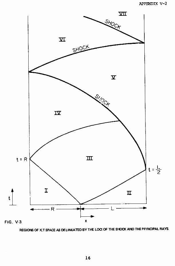
APPENDIX V-2
ME1
i< i
IIg~~~~~~~~~~It = R m
t= L
tX~I I-
4- R - L w
FIG. V-3 X
REGIONS OF XT SPACE AS DELINEATED BY THE LOCI OF THE SHOCK AND THE PPINCIPAL RAYS.
16
APPENDIX V-2
C2 C+u = u - (M2 -l)(1 + L_)1/2; M = ; (VII.29)
-/2 M2 c
and the values of u and c ahead of the shock (u ,c ) are
determined from information interior to region III or IV.
The above equation for u+ as a function of c_ is solved
simultaneously with the constraint from the minus charac-dx
teristic (u-2c=constant along u-c=d-x) which passes through
the shock boundary point of interest back into the previ-
ously solved portion of Region V.
The shock position is updated each time-step using
the shock velocity formula
2
U = - +(V.30)
The initial shock position and conditions behind the
shock are taken from the theoretical development discussed
earlier, equations (V.12) - (V.15).
The boundary condition on the line x=L/H (the dike)
which describes flow over the dike is from equation (V.19)
U = (c2_ c) 3/2 H(c-co) at x = x2 W.
The shock (i.e., the boundary between regions IV and V)
eventually reaches the back of the tank at x=-R/H. At this
point the bore reflects off the rear wall and proceeds in
the positive x direction until it reflects off the dike.
These reverberations continue until fully dissipated, or as
long as one cares to continue the computation.
17

APPENDIX V-2
The reflection of the shock from the rear wall of the
tank is determined from the shock conditions using the
known values of c_ and u_ in Region V and u+=O. The
velocity U and c+ are then given by
C+ = z cm
and (V.31)u_
z--1
where z=M2 is the solution of
u2
(z2 -1)(z-l) = 2- z, z >1. (V.32)c 2
Similarly in the shock reflection off the dike, c and u
in Region VI are known, and we must determine U, the shock
velocity, and c+ and u+ in Region VII. With z obtained
from
u 1 2 3/2C- 1 (z-l) (1+1) 1/2= l(zC) 3/2H(c-co) (V.33)
c J~Z z Z C2
it follows that c
U = u - - z(1 + 1) /2 (V. 34)
.22 /
u+ = u(z-1) (1 + (V. 35)+ 2
Note that Regions VI, VIII, X, XII, etc., are similar to
Region IV; Regions VII, IX, XI, XIII, etc., are similar to
Region V.
We now discuss details of the computation based on
18
APPENDIX V-2
the method of characteristics, and the technique for
advancing the shock position.
The calculations at time t proceed from the known
values of u and c at an earlier tivle and at the physical
boundaries x=-R/H and x=L/H. The boundary value problem
which consists of these initial and boundary conditions,
and the non-linear system of hyperbolic partial differen-
tial equations:
Ut + uUx + 2cc, = 0,
(V.36)
2 (ct + UCx) + CUx = 0 (V.36)
is then well-posed. The dependent variables are repre-
sented by values at a grid along the x-axis, using linear
interpolation to define points between nodes. The physical
positions of these node points differ at successive times
in order that the shock position is always between two
nodes, at which the values of the dependent variables
satisfy the shock conditions. The nodes within each region
are uniformly spaced; their number depends on the relative
lengths of the regions separated by the shock, and on the
total number of nodes allocated. Calculations are advanced
in time using the method of characteristics and in this
format the basic equations are
u + 2c = constant on d-= u+c (a plus-characteristic)
dx
u - 2c = constant on d= u- c (aminus-characteristic).
(V.37)
19
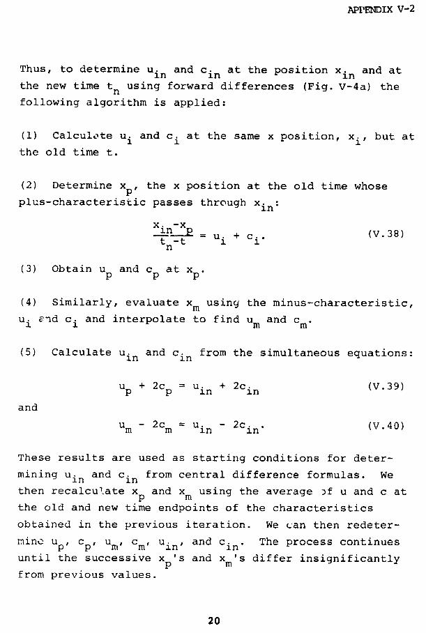
APPENDIX V-2
Thus, to determine uin and cin at the position xin and at
the new time tn using forward differences (Fig. V-4a) the
following algorithm is applied:
(1) Calculate ui and c i at the same x position, xi, but at
the old time t.
(2) Determine xp, the x position at the old time whose
plus-characteristic passes through xin:
x. -xXin p = u. + c.. (V.38)t-t ui + ci'
n
(3) Obtain up and cp at xp.
(4) Similarly, evaluate xm using the minus-characteristic,
ui and c.i and interpolate to find um and cm.
(5) Calculate uin and cin from the simultaneous equations:
U + 2cp = .in + 2cin (V.39)
and
um - in 2cm = in (V.40)
These results are used as starting conditions for deter-
mining uin and cin from central difference formulas. We
then recalculate xp and xm using the average 3f u and c at
the old and new time endpoints of the characteristics
obtained in the previous iteration. We can then redeter-
min p ur, c, u Uin and cin. The process continues
until the successive xp's and xm's differ insignificantly
from previous values.
20
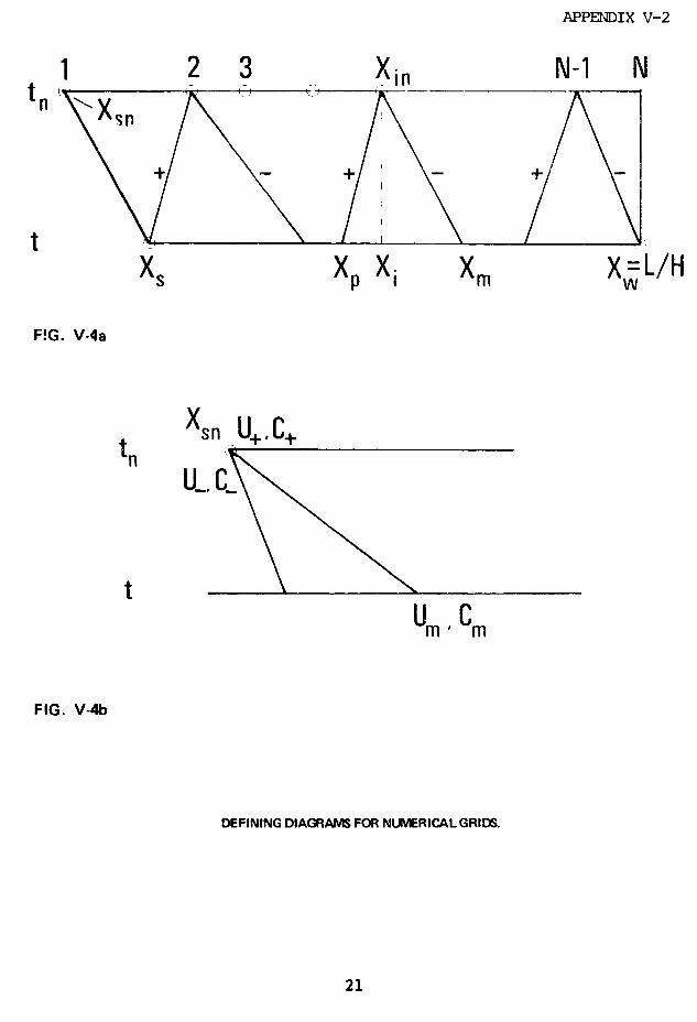
APPENDIX V-2
1 2 3 Xin N-1 NnX
t X X X X=L/HX s Xp X i Xm XwL/H
F!G. V-4a
Xsn U+,C+
tU_,
U m Cm
FIG. V-4b
DEFINING DIAGRAMS FOR NUMERICAL GRIDS.
21

APPENDIX V-2
At the dike x=xw, we require that tn-t be suffi-
ciently small that all intericr nodes at tn lie between the
plus-characteristic through the shock position at t and the
minus-characteristic through xw. In this way, problems of
interpolating along the wall or the shock are avoided.
Linear interpolations are employed using data defined at
node points along the segment between x s and xw to deter-
mine u and c at points not coinciding with nodal values
from the two adjacent nodes (Fig. V-4b)
At the shock, the shock condition, equation (V.29),
is invoked along with the minus-characteristic equation
um - 2cm =+, (V.41)
to solve for u+ and c+, using a Newton-Raphson iteration
with c+ at the previous time as a starting condition. The
values of u and c in the undisturbed side of the shock
are given by
u = (1+ )3 tand n (V.42)
1 snc - (2 - )'
n
The shock velocity is then obtained using equation (V.30) .
Initially, we locate the shock at time tn, using forward
differences
xsn = Xs + U(tn-t),
where the shock velocity at time t is used. The new shock
22
APPENDIX V-2
location is recomputed using central differences and the
average of the shock velocities; the shock conditions are
recomputed as well. This process is repeated until the
change in shock position is insignificantly small.
It should be noted that using forward differences
sometimes introduces numerical instabilities; we adopted
central differences for our computations. Few individual
computations required more than three or four iterations to
converge to the central difference.
Results were relatively insensitive to the number of
x-position nodes employed; we generally used 50 or 100.
Time steps were interpolated as necessary to insure that
the plus- and mirus-characteristics to interior nodes of
the new time depend only on information at the previous
time.
For various values of L/H and R/H, computations were
made to determine the percentage of original tank fluid
spilled over the dike. This is
T
Q = 1 ud(t)c.(t)dt (V.43)
0
where ud and cd are values at the dike. The numerical
results were discussed earlier.
INCLINED DIKES
The numerical solution for the flow over an inclined
dike was based on the method of characteristics and the
equations of motion (V.27). The starting conditions at
23
APPENDIX V-2
t=T are given by equation (V.6) for x<xw and equations
(V.25) and (V.26) for x <x<xw + a cotO. If the conser-
vation of mass equations are used to determine the initial
setting, then T=t +3a coto. Use of the conservation ofw 4momentum necessitates integration of equation (V.27)
until xF (t)=xT=xw+ a cotO. This was done by two different
methods from the IBM Scientific Subroutine Package, a Runge
Kutta Method (Subroutine RKGS) and a Hammings Modified
Predictor Corrector Method (Subroutine HPCG). The results
were in good agreement. We generally used Subroutine HPCG.
Over the flat bed, we have, as before,
dxu + 2c = constant along the ray, dt u + c
dx
u - 2c = constant along the ray. dt u - c.
Over the inclined dike we have
dxu + 2c + t tanO = constant along the ray, dt u + c
dxu - 2c + t tanO = constant along the ray, d u - c.
For a ray that crosses the line x=xw between the two
regions, we take the intermediate step of solving for
conditions at the intermediate time where the ray crosses
the boundary so that the proper characteristic equations
are used. We accumulate the spill as before
T
Q = fuT(t)c2(t)dttT
24
APPENDIX V-2
using values at the top of the dike. The calculation con-
tinues normally as long as UT>CT. We then use the condi-
tion uT=CT along with the condition along the ray dxtu+c,
disregarding the condition along the minus-characteristic.
Sometime after the UT=CT condition is enforced, a
shock forms and proceeds back towards the tank. The shock
conditions given earlier are then enforced, and the shock
velocity is used to update the shock position at the next
time.
The calculation then proceeds until uT=cT=O at which
time the total spill is known. The computed spillage is
very insensitive to the initial setting at time T, and use
of starting conditions based either on mass or momentum
conservation yields values which agree to three decimal
places.
25
APPENDIX V-3
APPENDIX V-3
SPIGOT FLOW
RESUITS
A cylindrical tank of radius R and maximum fluid
height H on a circular pedestal of height P and radius R+K
is surrounded by a circular dike of height a(=ap) at radius
R+L, as shown in Fig. V-5. The volume contnined by the
dike is equal to the volume of the tank:
HR2 = a(R + L)2 - P(R + K) 2 (V.44)
Liquid is presumed to flow from a relatively small hole in
the tank located at height z above the pedestal.
If
a + L H + P (V.45)
or, if a satisfies equation (V.44) and
I (R + L)2 P(2R 4 L + K) (L - K)(2R + L) (2R + L) L '
then the dike is adequate to contain all spigot flows.
Otherwise, it is possible for such flows to clear the
containing wall, and the conditions necessary are specified.
For a tank with no pedestal, P=O, the specifications
for an adequate dike are:
HR2 = a(L + R) 2 ; (V.44a)
26
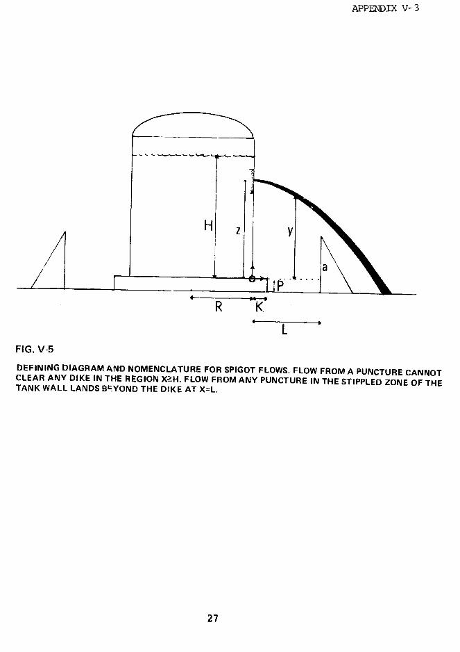
APPENDIX V- 3
R K
FIG. V-5
DEFINING DIAGRAM AND NOMENCLATURE FOR SPIGOT FLOWS. FLOW FROM A PUNCTURE CANNOTCLEAR ANY DIKE IN THE REGION X-H. FLOW FROM ANY PUNCTURE IN THE STIPPLED ZONE OF THETANK WALL LANDS B=YOND THE DIKE AT X=L.
27
APPENDIX V-3
L + a > H; (V.45a)
H (R + L)' (V.46a)(2R + L)'
and these are the results stated earlier.
CALCULATIONS
If h is the height of the liquid within the tank,
then Bernoulli's theorem implies that the fluid velocity at
the spigot is approximately
V = 2g(h - z), (V.47)
where g is the gravitational acceleration. The trajectory
from the hole is parabolic:
y = Z - 4(h - z) (V.48)
where x is the distance from the tank and y+P is the height
above level ground. The maiimum range for the spigot,
x=f1+P, occurs for h=H and z=(II-P)/2. Therefore,
L _ I! - P (V.49)
provides an absolute safety criterion for spigot flow.
For a given L, a spiqot at z max=-L/2 passes over the
barrier with maximum elevation,
y = 11 - L (V.50)Ymax
28
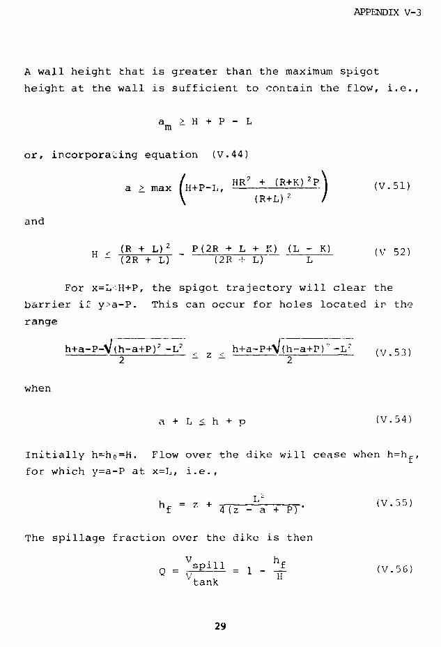
APPENDIX V-3
A wall height that is greater than the maximum spigot
height at the wall is sufficient to contain the flow, i.e.,
a > H + P - Lm
or, incorporating equation (V.44)
a > max (H+P-I. HR2 + (R+K)2P (V.51)(R+L) 7
and
H (R + L)2 P(2R + L + :.) (L - K) (V 52)(2R + L) (2R 4+ L) L
For x=L<H+P, the spigot trajectory will clear the
barrier if y>a-P. This can occur for holes located in the
range
h+a-P-V(h-a+P)2 -L h+a-P+4 (h-a+P) -L- (V.53)2 2
when
a + L h + (V.54)
Initially h-ho=H. Flow over the dike will cease when h=hf,
for which y=a-P at x=L, i.e.,
f Z + 4(z - a + P)' (V.5)
The spillage fraction over the dike is then
V hQ = spll = 1 f (V.56)
tank
29
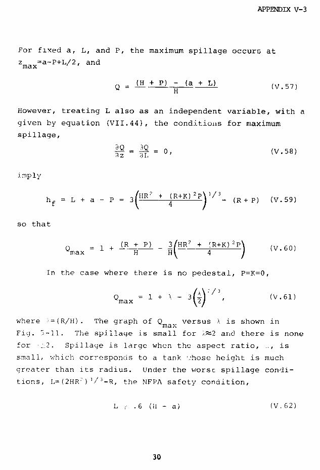
APPENDIX V-3
For fixed a, L, and P, the maximum spillage occurs at
z =a-P+L/2, andmax
(H + P) - (a + L) (V.57)H
However, treating L also as an independent variable, with a
given by equation (VII.44), the conditions for maximum
spillage,
Q - Q 0 (V.58)~z 3L
imply
hf= L + a - P 3(}IIR2 + (R+K) 2) (R+ P) (V.59)
so that
(R + P) 3HR + (V. 601+Q + KP (V.60)
max H I 4 ,
In the case where there is no pedestal, P=K=0,
Qmax = 1 + X - 3 (V.61)
where -=(R/H). The graph of Qmax versus ). is shown in
Fig. 5-11. The spillage is small for >~2 and there is none
for -2. Spillage is large when the aspect ratio, .,, is
small, which corresponds to a tank ..'hose height is much
greater than its radius. Under the worst spillage condi-
tions, L=(2HR -) I'-R, the NFPA safety condition,
L _ .6 (li - a) (V.62)
30
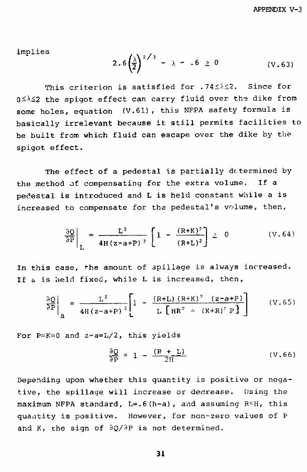
APPENDIX V-3
implies
2.6( - - .6 > 0 (V.63)
This criterion is satisfied for .74<A<2. Since for
O0X<2 the spigot effect can carry fluid over the dike from
some holes, equation (V.61), thJs NFPA safety formula is
basically irrelevant because it still permits facilities to
be built from which fluid can escape over the dike by the
spigot effect.
The effect of a pedestal is partially determined by
the method of compensating for the extra volume. If a
pedestal is introduced and L is held constant while a is
increased to compensate for the pedestal's volume, then,
IaQ= 1 0 (V.64)a -L 4H(z-a+P) 2[1 (R+L)2 J
In this case, -he amount of spillage is always increased.
If a is held fixed, while L is increased, then,
dQ P L2 1 (R+L)(R+K)2 (z-a+P) (V.65)
4H(z-a+P) 2 L L [HR2 (K+R)2 P]
For P=K=O and z-a=L/2, this yields
aQ (P + L) (.6)1p 2H(V.66)
Depending upon whether this quantity is positive or nega-
tive, the spillage will increase or decrease. Using the
maximum NFPA standard, L=.6(h-a), and assuming R<H, this
quantity is positive. However, for non-zero values of P
and K, the sign of aQ/3P is not determined.
31

APPENDIX V-3
REFERENCES
1. Henderson, F.M. (1966), Open Channel Flow, MacMillan,
NY.
2. Dressier, R.F. (1950), J. Res. Nat. Bur. Stud. 49,
217.
3. G.B. Whitham (1955), Proc. Roy. Soc. 227, 399.
32

APPENDIX VI
CONTENTS PAGE
APPENDIX VI-1, REACTIVE SAFETY EQUIPMENTON LNG TANKERS 1
VI-2, LEG CONTAINMENT SYSTEMS 4
VI-3, LNG INCIDENT EXPERIENCE TO DATE 29
VI-4, OPERATING PROBLEMS AND SHIPDELAYS 34
VI-5, SUMMARY OF PORT CHARACTERISTICS 44
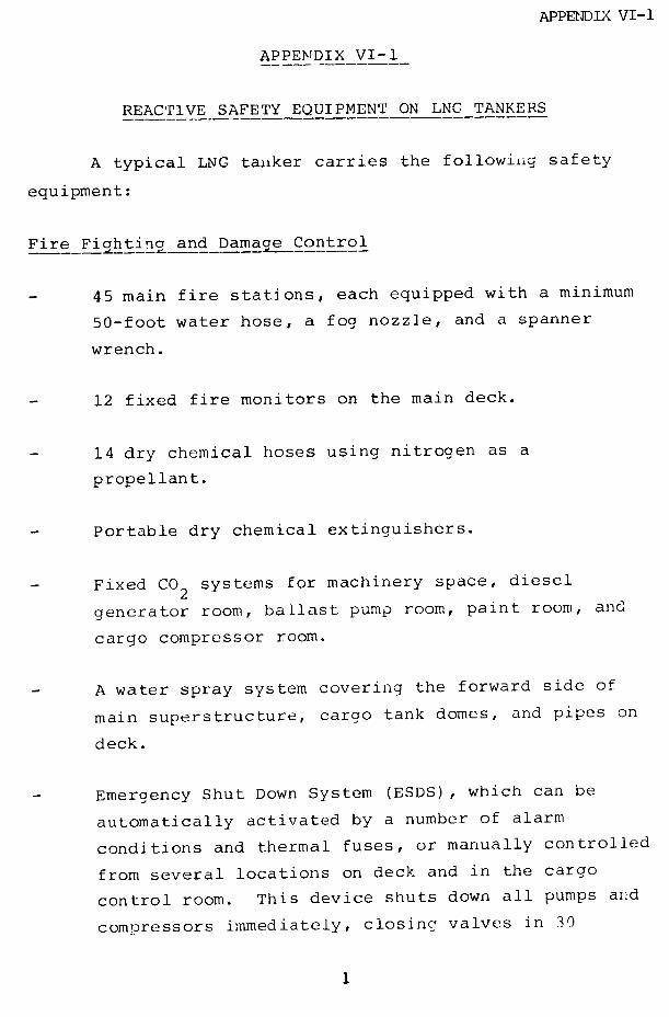
APPENDIX VI-1
APPENDIX VI-1
REACTIVE SAFETY EQUIPMENT ON LNG TANKERS
A typical LNG tanker carries the following safety
equipment:
Fire Fiahting and Damage Control
45 main fire stations, each equipped with a minimum
50-foot water hose, a fog nozzle, and a spanner
wrench.
12 fixed fire monitors on the main deck.
14 dry chemical hoses using nitrogen as a
propellant.
Portable dry chemical extinguishers.
Fixed CO 2 systems for machinery space, diesel
generator room, ballast pump room, paint room, and
cargo compressor room.
A water spray system covering the forward side of
main superstructure, cargo tank domes, and pipes on
deck.
Emergency Shut Down System (ESDS), which can be
automatically activated by a number of alarm
conditions and thermal fuses, or manually controlled
from several locations on deck and in the cargo
control room. This device shuts down all pumps and
compressors immediately, closing valves in 30

APPENDIX VI-l
seconds to prevent shock.
Explosion Hazard Suppression Equipment
Equipment to maintain an inert atmosphere in the
cargo holds containing LNG tanks. (This is
specified in the Energy Transportation Corporation's
Safety Mapual for its LNC- Ships.)
Infrared gas detection systems which take continuous
suction from all areas which gas could enter,
analyzing one point at a time.
Combustible gas detection systems which continuously
monitor all test areas.
Pressure relief valves on pipes, cargo tanks, and
cargo holds.
Explosion-proof or intrinsically safe electrical
equipment installed in hazardous locations.
Cargo vent system and accommodations ventilticn
systems, so designed that LNG vapor will be
prevented from entering accommodations and interior
working spaces.
Additional Safety Equipment
Insulated drip pans under shore connections.
Temperature sensors in critical portions of hull
structure, warning of possible insulation failures
or leaks.
2
APPENDIX VI-1
Numerous alarms indicating abnormal operating
conditions, some of which provide automatic
shut-off.
Portable safety equipment, such as protective
clothing, dry chemical and CO2 fire extinguishers,
breathing apparatus, portable gas detection
equipment, and oxygen analyzers.

APPENDIX VI-2
APPENDIX VI-2
LEG CONTAINMENT SYSTEMS
LNG SHTPS
Following are specific characteristics of the four
LNG containment systems of ships that will transport LNG to
the United States.
CONCH II DESIGN
This is a self-supporting design in which the five
single-walled prismatic cargo tanks are made of an aluminum
alloy (5083-0). Among the structural details are:
longitudinal centerline liquid-tight bulkheads, transverse
bulkheads, vertical stiffeners, and horizontal girders.
The bulkheads provide structural strength, and reduce the
forces generated by the free-surface effect of the cargo at
sea. The tank thickness at the top near the upper strake
is one-half inch. This increases to 1-1/2" at the chamfer
panels. The three middle tanks are approximately 76 feet
deep, 123 feet wide, and 124 feet long. The two end tanks
are somewhat shorter. The tanks are loca.ed by keys and
keyways at the bottom and top, allowing the necessary
contraction and expansion. The keys are made of permali, a
reinforced hardwood.
The insulation system consists of balsa/plywood frame
panels along the corners, with a sprayed-in-place high
density polyurethane covering the inner hull petween the
frames. See Fig. VI-1. The frames arc 10' long with 2'
legs and 4" thick. The foam is applied in layers with two
4
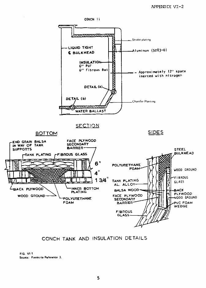
APPENDIX VI-2
CONCH I I
Strake plating
t-eLQUIDDTIGHT Aluminum (5083-0)
T EChamfer Planting
NSULATION6" PUF6" Fibrous Bat _ Approximately 12" space
incrted with nitrogen
DETAIL (a)
/E~111. /b) tChamfer Planting
WATER BALLAST
SECTIO NBOTTOM SIDES
END GRAIN BALSA FACE PLYWOOD
IN WAY OF TANK SECONDARYSUPPORTS BARRIER STEEL
TANK PLATING FIBROUS GLASS EULKHEAD
UiEN J DLI.9~ 1 3/4" TANK PLATINGS
L-BACK PLYWOOD INNER BOTTOM BALSA WOOD. CPLATINGT-AC
WOOD GROUND FACE PLYWOOD PLYWOODPOLYURETHANE SECONDARYD GROUND
FOAM BAR FOAM
FIBROUS
CONCH TANK AND INSULATION DETAILS
FIG. VIl1Source: Footnete Reference 3.
5

APPENDIX VI-2
partial and one full nylon reinforced nets integrated into
the foam, acting as crack arrestors. The foam is 6" thick.
On top of this, 6" of fiberglass is draped as additional
insulation. The 12" void space between the wall insulation
and the cargo tank is maintained inert by N 2.
The tanks are supported by balsa/plywood insulation
panels which are uniformly distributed under 30% of the
tank bottom. In general, the support panels are 5' by 10'
and 11-3/4" thick, with polyurethane foam and a fibrous
glass bat between the panels. The secondary barrier is
made of plywood and polyurethane foam.
The principal dimensions of this design are given in
Fig. VI-2. It is characterized by its complex cargo tank
construction. The many internal stiffening members make it
very difficult to get an accurate analytical determination
of stresses. The stiffening members also introduce
possible sources of crack initiation. However, a secondary
barrier is provided. The tank structure also has some
advantages. The tight centerline bulkhead reduces free
surface effects, as well as the amount of LNG spill in case
of a tank rupture. The tank is easily inspected
internally, but the facilities for insulation inspection
are very limited, particularly for the load bearing
insulation.
Some additional data are given below:
Safety Cargo Relief Valves: 2 on each tank
2 on each cargo hold
Safety Cargo Tank Relief Valve
Setting: 2.6 psig positive
6

APPENDIX VI-2
AVONDALE CONCH II
PRINICPAL CHARACTERISTCS E
Mmnc EnghuP
NMI, 25B.9 m 931.5 ILENGTH OVERALL-
931_ 5
LENGTH BETWEEN PERPENDICULARS 20.3 14042. m 1405 I
~~~~BEAMU ~_ 2_.7?m 94.0RDEPTH, AT SHIPS SIDE t o 380 11DRAFT. LOADED _.0 _ 0.740
BLOCK COEFFICIENT. AT LOADED DRAFT 0752310 h
WETTED SURFACE. AT LOADED DRAFT ___ 4.150
MACIII R S SteamPROPULSION PLANT _- _ te__ _
Crow Crrs-
ornpo- - oompurnd-
yp Delaval Delaval
BOILERS (TWO PER SHIP) .. . _ _ Top tired Top fIredDul ue ._ _ --.. DU eI
Foet Fostm
SHP I MAXIMUM CONTINUOUS POWER _ . 4,570 CV . . . .41..OHP
RPM MAXIMUM CONTINUOUS POER ,117 m ..
PROPELLER DIAMETER ___2m 25.0 I
WEHTS AND (EXCLUDIG CARGOTANK VOLUIEW CAPACITIES 72000T ____ 72,000 T
ROSS TONNAGE 5 .000 T 56.000 TNET TONNUAGE
95-.-- 06506 MT ___ .
DISPLACEMENT. AT LOADED DRAFT _965 _ T ._ 075 LT
ULGHT SHIP WEIGHT 316 MT -3,051 LT
BALLAST CAPACITY. 98 SALT WATER 53. T 0 LT
FUEL OIL CAPACITY. 98% 15 API FUEL 5._ 202 T _ ,104 LT
CARGO CONTAINENT AND ANDLNG Co
TYPE LNG CONTAINMENT SYSTEM __ Ch
NUMBER CARGO 1ANKS -- __ __-_ - S wlrg
TOTAL CARGO TANK CAPACITY, 100% COLD 127.1807 mr03.9068W
TOTAL LNG PUMP CAPACITY _____ 12,036 m/r 6__ 3.000 gpm
NUM6ER AND SIZE LOADING/DISCHAROE LINES __ 5406.4 mm 518 n
iPERATO SPNEDSODESIO' SERVICE SPEED .. 18.5 18 5 Mkt
TRIAL SPEED AT 90% SHP .0 45 L _ ,0.45 lkt
SERVICE SPEED AT O0% SHP ,_._. 1_ _5 kW-
FIG. VI-2SOURCE: "ALGERIA I," AN EL PASO INFORMATION BOOKLET.
7
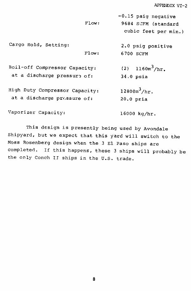
APPENDIX VI-2
-0.15 psig negative
Flow: 9684 SCFM (standard
cubic feet per min.)
Cargo Hold, Setting: 2.0 psig positive
Flow: 6700 SCFM
Boil-off Compressor Capacity: (2) 1160m 3/hr.
at a discharge pressure of: 34,0 psia
High Duty Compressor Capacity: 12800m /hr.
at a discharge pressure of: 20.0 psia
Vaporizer Capacity: 16000 kg/hr.
This design is presently being used by Avondale
Shipyard, but we expect that this yard will switch to theMoss Rosenberg design when the 3 E1l Paso ships are
completed. If this happens, these 3 ships will probably bethe only Conch II ships in the U.S. trade.
/APPD IX VI-2
MOSS ROSENBERG DESIGN
The five spnerical self-supporting aluminum alloy
(5083-0) tanks are supported by a cylindrical skirt at the
equator of the tank. See Fig. VI-3. The skirt's upper
part is made of 2-1/4" thick aluminum; the lower part is
made of modified grade A steel (8537), 1-3/8" thick and
welded to the ship's structure at the skirt-table. The
tankwall is 1.57" thick, at equator it is 7.68" thick.
The skirt is equipped with 7ertical stiffeners. The tank
has no stiffeners or internal bulkheads.
The insulation incorporates four layers of 2" thick
polyurethane installed in prefabricated panels of 4' by
6'. All panels are faced with aluminum paper on both of
the surfaces and attached to the cargo tanks by means of a
total of 13,000 stut fasteners. Foam is sorayed into the
joints to fill the gaps and bind the panels together. The
entire surface is finally sprayed with a butyl rubber
compound which acts as a vapor barrier.
No secondary barrier is required for this desiJn,
but the cargo holds are equipped with a partial secondary
barrier consisting of a splash sheet made of sta4nless
steel and an insulated catch basin nude of polyvinyl
chloride (PVC) closed cell foam, covered with a stainless
steel lining.
Principal dimensions are given in Fi.a. VI-4. The
design is characterized by the spherical tanks, which make
stress analysis easier, and provides good internal tank
and insulation inspection capabilities. The tanks' shape
and strength give them a higher collision resistance than
other designs. There are also disadvantages with this
9
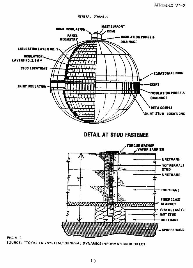
APPENDIX VI-2
GFNERAL DYNAMICS
MAST SUPPORTDOME INSULATION ASTSUOR
CPANEL INSULATION PURGE &GEOMIETR DRAINAGE
INSULATION LAYER NO. I
INSULATIONLAYERS NO. 2,3 & 4
STUD LOCATIONS
EOUATORIAL RING
SKIRT INSULATION
INSULATION PURGE &DRAINAGE
x ~ I I !/ / \ DETA COUPLE
SKIRT STUD LOCATIONS
DETAIL AT STUD FASTENER
TOROUE WASHERVAPOR BARRIER
:it I .e. 'URETHANE
IN' PERMALISTUD
URETHANE
URETHANE
FIBERGLASS
tLAHKETFIBERGLASS FIf1
"STUD
URETHANE
SPHERE WALL
FIG. VI-3SOURCE: "TOTAL LNG SYSTEM," GENERAL DYNAMICS INFORMATION BOOKLET.
10

APPENDIX VI-2
ii i~
* ~ ~~~~~~ !
a~~bE, I .
zeir~~~~~~~~~~~~~~~~~~~~~
Lai a~~~~~~~~~~~~~~~~~~~~~~~~~~~~~a
g, - i }$-;-?- .i , ,C)
-@ S
,- ~ :~.?~- kz 1-: '
-- II '
.. -" ;-
r- N
-~~~~~~~~~ "II - ! 5
St ~ ~ ~ ~ ~ ~ ', it
.R 3 - ..... --
on ~ ~ ~ ~ n
amC :_ Ii i ~--~., L
·- ., ,,~'~~~~~ --- 1l 4
~~~~~~~~~ , / i i ' ,
c~~ ~ I a I r IV
-.I I
{ F~~~~~~~~~~~~~---. ~~~~ ~ ~~~~~~~ .,- °°-
In~~~~~~~~~. ,b :: : : : 0. ,-~~~~~~~~~~~~~~~~~~~~~~~~~~~~~~~~~~~~~~~i
- '
i l l I I
-- ,. i l
C a o e- -I ·
- I '1 ' lm1ll : - ~
{-
1,,
ra - U,
V ~8: IC -I
s~~ I i ·-. ' / a~~~~~~ Zf
- rI /1~ ~ E 3B OIx I
ii I
11

APPENDIX VI-2
design. The higher center of gravity provides less
initial stability and a more restricted view from the
bridge. Forward bl 4nd range from the wheelhouse is 2244
feet and from the bludge wing 971 feet.
The tanks penetrate the main deck, providing less
precection for them and adding substantially to the
windage area.
A special feature of the spherical design is the
capability of emergency discharge by overpressurizing the
tanks in case of pump failures. To do so requires closing
the safety relief valves allowing vaporized LNG to build
up a pressure of approximately 30 psig.
Some additional operating data are given below:
Safety Relief Valves: 2 on each tank
2 on each cargo hold
Cargo Tank, Settina: 2.9 psig positive
-1.9 psig negative
Flow: 24000 SCFM at 4.73 psig
Cargo Hold, Settina: 1.2 psig positive
-0.4 psig negative
Flow: 2727 SCFM at 1.43 psig
Boil-off Compressor
Capacity: (2) 5100m3/hr.
at a discharge pressure of: 29 psia
Iiigh IDuty Compressor
Capacity: (1) 20388m3/hr.
at a discharge pressure of: 26.6 psia
12

APPENDIX VI-2
Vaporizer Capacity: (1) 24800 kg/hr.
Cargo Pump Capacity: (10) 1100m3/1,r. each
LN 2 Storage Tank: 24.8m3
LN2 Vaporizer: 764m /hr.
Bow Thruster: 2200 HP
About one third of the American LNG fleet will
probably be of spherical design, constructed by General
Dynamics (126,750 cubic meter capacity) and Avondale
(130,600 cubic meter capacity). The latter will have a
length of 943', beam of 144', depth 82', and a draft of
37'3". The insulation on the Avondale ships will be like
the original Moss Rosenberg concept: approximately 10"
thick expanded polystyrene plastic foam with a vapor
barrier of aluminum foil.
13

APPENDIX VI-2
TECHNIGAZ DESIGN
This is an integrated containment system, sometimes
called membrane, in which the primary barrier is made of
1.2mm thick, waffled or corrugated stainless steel
membrane. The tank sheets have two sets of orthogonal
corrugations to allow for contraction and expansion.
These ogival shaped corrugations cross each other by means
of special geometrical surfaces called "knots." The
distance between the corrugations measures 34 by 34cm on
all vertical and horizontal sheets and 24 by 34cm on all
45 ° angles or chamfer sheets. The overlapping sheets are
welded to each other to form the membrane, which in turn
is welded to stainless steel pieces embedded in the
insulation. The tank, having no internal bulkheads or
stiffening, departs in its upper area from a general
prismatic shape into a long trunk which serves to reduce
the free surface effect of the cargo. The tanks are
uniformly supported by a load bearing balsa/plywood
insulation system.
Working inward Lrom the inner hull of the vebsel,
the system is made up of wood grounds (75mm thick),
fastened to the hull structure. See Fig. VI-5. The
space between these grounds is filled with fiberglass
bats. The insulation panels, consisting of laminated
balsa layers totalling 165mm, are faced with 1/2" fir
plywood on the warm side and 1/8" sugar maple plywood on
the cold side. The panels are attached to the grounds,
and the joints between them filled with PVC. Finally, a
55mm balsa padding with embedded stainless steel anchor
points provides the necessary surface for the membrane.
The secondary barrier is the 1/8" sugar maple plywood.
Principal dimensions are given in Fig. VI-6. This system
14
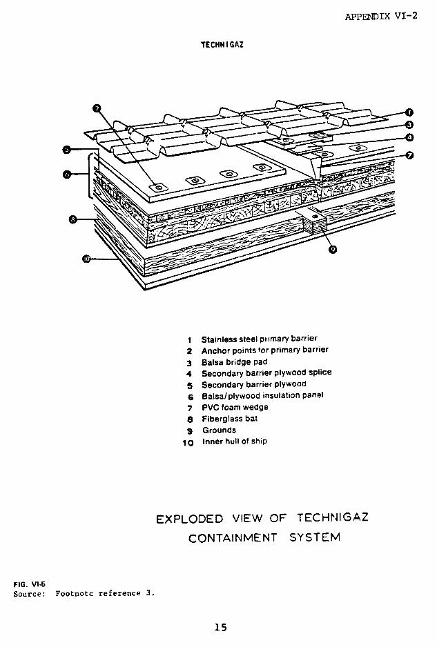
APPENDIX VI-2
TECHN I GAZ
1 Stainless steel ptimary barrier2 Anchor points for primary barrier3 Balsa bridge pad4 Secondary barrier plywood spliceS Secondary barrier plywood6 Balsa/plywood insulation panel7 PVC foam wedge8 Fiberglass bat9 Grounds
1o Inner hull of ship
EXPLODED VIEW OF TECHNIGAZ
CONTAINMENT SYSTEM
FIG. VI.5Source: Footnote reference 3.
15
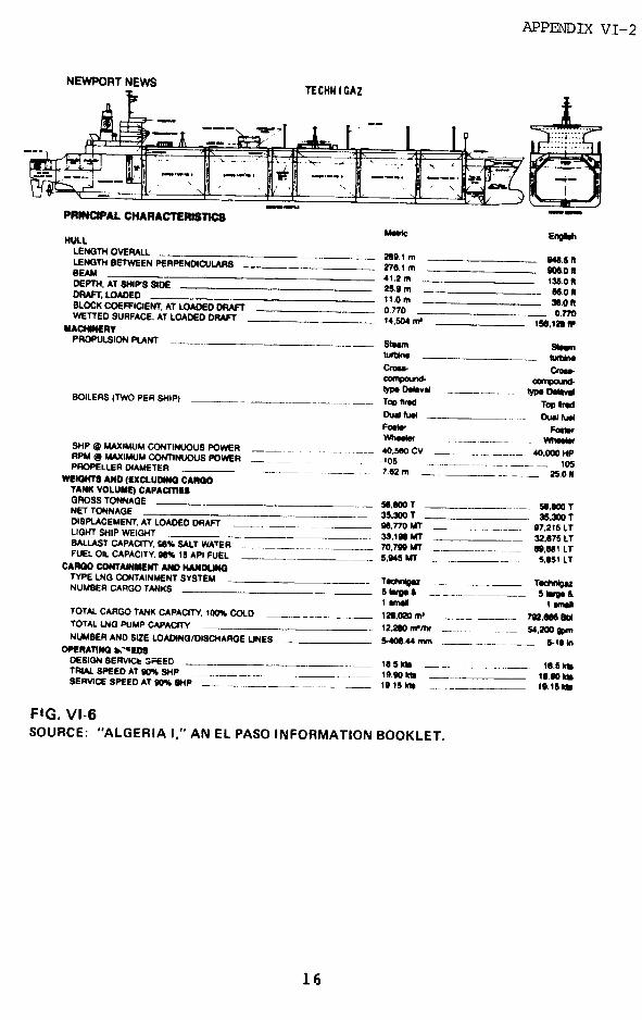
APPENDIX VI-2
NEWPORT NEWS TECHNIGAZ
PRINCIPAL CHARACTERISTICS
MMic EnglshHULLLENGTH OVERALL 289.1 m e. 48 tLENGTH BETWEEN PERPENDICULARS 276.1 m 06,0 ItBEAM 41.2 m 1t35.0 IDEPTH, AT SHIPS SIDE 25n9m _- i50rDRAFT, LOADED 1.0m 3e.0 ftBLOCK COEFFICIENT, AT LOADED DRAFT 0.770 0.770WETTED SURFACE, AT LOADED DRAFT 14.504 m* 156.120 W
MACHINERYPROPULSION PLANT num Sonwm
Cu-ro CmDompound- Gemp-udlypo Delav_ typ DmvalBOILERS (TWO PER SHIP) Top fired Top e dDual ful _ Du luaFolr FoorWhieew .- m_SHP i MAXIMUM CONTINUOUS POWER 40.50e CV 40.000 HPRPM @ MAXIMUM CONTINUOUS POWER _ 105 105PROPELLER DIAMETER 762 m 25.0 ifWEIGHTS AND (EXCLUDING CARGO
TANK VOLUME) CAPACITIESGROSS TONNAGE 5i,800 T 51,80 TNET TONNAGE 35,300 T 35,300 TDISPLACEMENT, AT LOADED DRAFT g,770IMT _ ._,___7__ 97,215 LTLIGHT SHIP WEIGHT 33,191 MT 32,875 LTBALLAST CAPACITY. 56% SALT WATER 70,799 T 60,61 LTFUEL OIL CAPACITY,. 9% 15 API FUEL 5,945 MT 5,851 LT
CARGO CONTAINMENT AND HANDUNGTYPE LNG CONTAINMENT SYSTEM TecMg TedloazNUMBER CARGO TANKS S _ A 5*5 - l
TOTAL CARGO TANK CAPACITY 100% COLD 100,020 m ____. __ 792.m8 blTOTAL LNG PUMP CAPACITY 1220 m/hr ..... 54,200 gpmNUMBER AND SIZE LOADING/DISCHARGE LINES 5-_ 40.44 mm _ 5-1 InOPERATING b."wEDDESIGN SERVIC GFSEED s1 S kt 16.5 klTRIAL SPEED AT O% SiHP ___ 10 - __ 1-.10 klSERVICE SPEED AT 90% SHP _ 15 1955kl 19.15 kb
FIG. VI-6SOURCE: "ALGERIA I," AN EL PASO INFORMATION BOOKLET.
16
APPENDIX VI-2
is characterized by its lower center of gravity; the
primary barrier is much thinner and closer to the hull.
This provides better stability, better hull utilization,
better visibility from the bridge, and a reduced windage
area.
The disadvantages with this system are (1) the
higher possibility of tank damage in a collision or
grounding, (2) difficulty in accurately calculating
stresses, which makes it difficult to calculate the danger
of fatigue failure, and (3) great difficulty in inspecting
the insulation.
Another characteristic of membrane designs is the
low tolerable differential pressure between the cargo tank
and the cargo hold (interbarrier space). A relatively low
overpressure of the cargo hold could cause buckling and
possibly rupture of the primary barrier.
Sc '- additional operational data are given below:
Safety Relief Valves: 2 on each cargo tank
2 on each cargo hold
Cargo Tank, Setting: 3.5 psig positive
-0.15 psig negative
Flow: 12850 SCFM
Cargo Hold, Setting: 0.3 psig positive
Flow: 230 SCFM
Boil-off Compressor: (2) 4000m /hr.
17
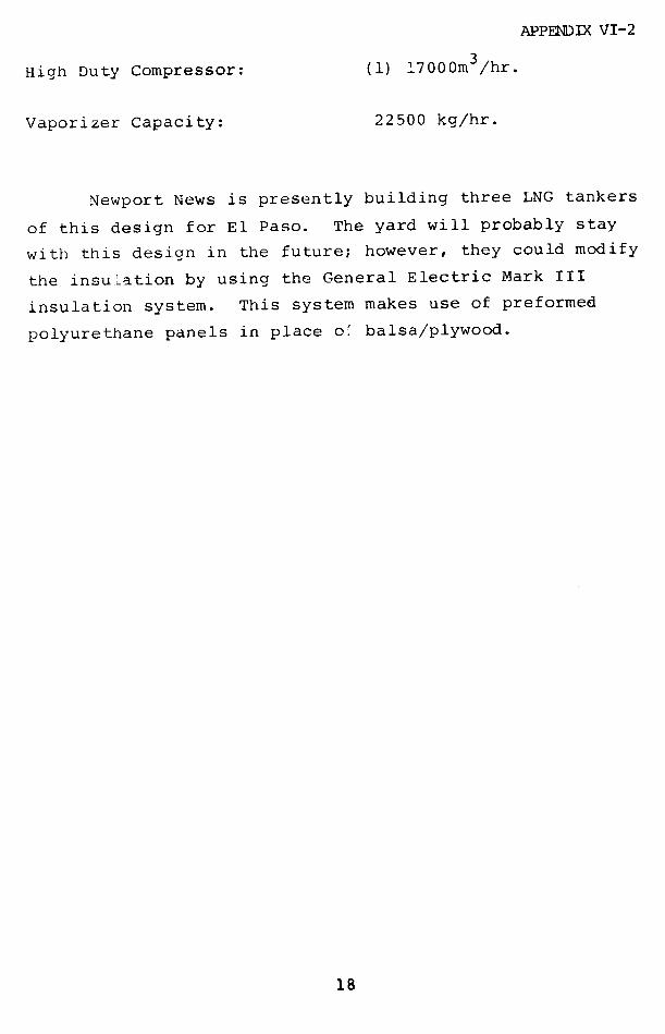
APPENDIX VI-2
High Duty Compressor: (1) 17000m3/hr.
Vaporizer Capacity: 22500 kg/hr.
Newport News is presently building three LNG tankers
of this design for El Paso. The yard will probably stay
with this design in the future; however, they could modify
the insulation by using the General Electric Mark III
insulation system. This system makes use of preformed
polyurethane panels in place o' balsa/plywood.
18
APPENDIX VI-2
GAZ TRANSPORT DESIGN
In this membrane design, both the primary and che
secondary barriers are constructed from Invar steel (36%
nickel iron alloy). This alloy has such a low coefficient
of thermal expansion (1/10 of stainless steel) that
corrugations in the barrier are unnecessary. rhe sheets,
which are 0.5mm thick, are welded alono upturned edges
around the periphery of the tank. Otherwise, the
membranes are flat, without any internal stiffening.
The loads imposed by the cargo are transmitted to
the hull through a supporting insulation made up of 200mm
thick plywood boxes filled with perlite. See Fig. VI-7.
The boxes prevent compaction of the perlite. A framework
of wood joists is installed on the inner hull. The
secondary insulation boxes are placed within this
framework and attached to the hull placting with studs and
bolts. Invar tongue strips are attached to the plywood
boxes. The secondary barrier is welded to these strips.
Next are fitted vertical channels of 9% nickel-alloy
steel, anchored to the wood framework through the
secondary barrier. The primary insulation is attached to
these vertical channels. Finally, Invar tongue strips,
fastened to the primary insulation, provide the connection
to the primary barrier. The bent-up edges of these sheets
are welded tc the tongues. Principal dimensions are shown
in Fig. VI-8.
The operational and handling characteristics are
similar to the Technigaz design, but the large number of
discontinuous pieces in the insulation system makes the
long term fatigue life of the system open to question.
19
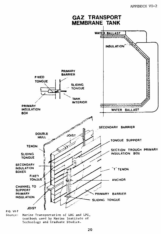
APPENDIX VI-2
GAZ TRANSPORTMEMBRANE TANK
WATER BALLAST
INSULATION
PRIMARYBARRIER
FIXEDTONGUE
SLIDINGt TONGUE
~~/ ~ TANK / INTERIOR
PRIMARYINSULATION WATER BALLASTBOX
SECONDARY BARRIER
DOUBLE ISTHULL
DOUBLE o< T r' TONGUE SUPPORT
TENON /TENON L h e I SECTION TROUGH PRIMARY
SLIDING INSULATION BOXTONGUE
SECONDARYINSULATION T TENONBOXES T TENON
FiXED ,/(:~TONGUE ANCHOR
CHANNEL TOSUPPORTPRIMARY PRIMARY BARRIERINSULATION
SLIDING TONGUE
JOIST 1-FIG. VI-7Source: Marine Transportation of LNG and LPG,
textbook used by Marine Institute of
Technology and Graduate Studies.
20
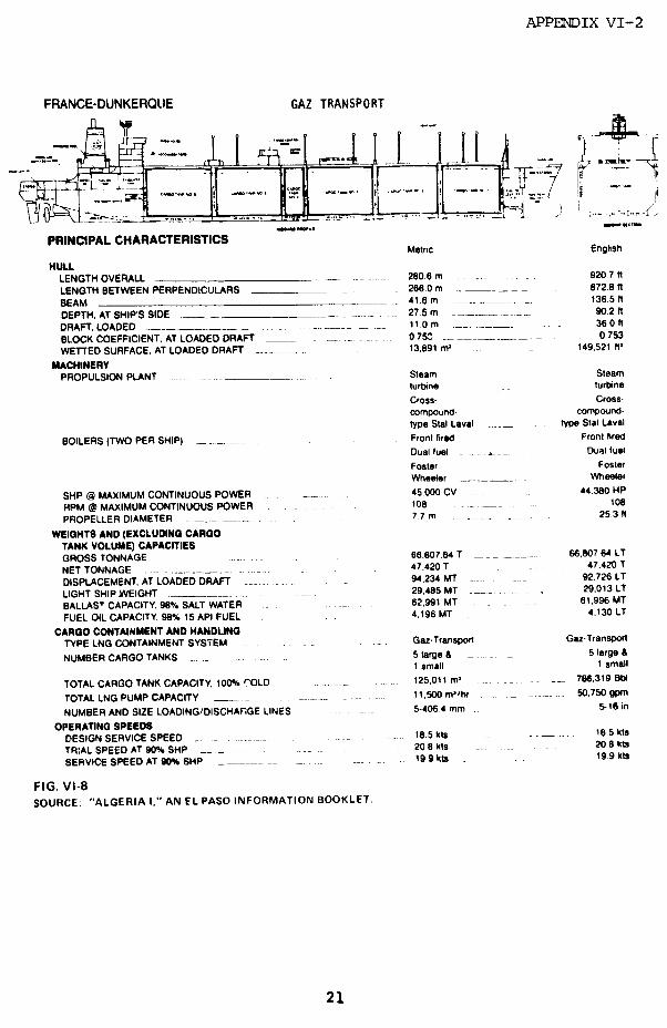
APPENDIX VI-2
FRANCE-DUNKERQUE GAZ TRANSPORT
__ s-,-.- _ _ II
PRINCIPAL CHARACTERISTICSMetric English
HULLLENGTH OVERALL _ 280.6 m . 920 7 I
LENGTH BETWEEN PERPENDICULARS _ 266 0 m _ 8728 In
BEAM _ 41.6 m ._____. _..... 136.5 I
DEPTH. AT SHIP'S SIDE ____ ._ 27.5 m _______ 902 t
DRAFT. LOADED _____ . - 11.0 m ... ___ 3601
BLOCK COEFFICIENT, AT LOADED DRAFT 0.758 ...___._. _ 0753
WETTED SURFACE, AT LOADED DRAFT . 13,891 ml 149,521 ft'
MACHINERYPROPULSION PLANT ..... __ Steam Steam
turbine turbine
Cross- Cross-compound. compound-type Stal Laval type Stal Laval
BOILERS (TWO PER SHIP) _ Front fired Front fired
Dual fuel _. Dual fuel
Foster FosterWheeler ,___. Wheeler
SHP @ MAXIMUM CONTINUOUS POWER 45,000 CV 44,380 HP
RPM @ MAXIMUM CONTINUOUS POWER . 108 108
PROPELLER DIAMETER ____. 77 m 25.3
WEIGHTS AND (EXCLUDING CARGOTANK VOLUME) CAPACITIESGROSS TONNAGE - 66.807.64 T _ . . 66,807 64 LT
NET TONNAGE 47,420 T _ 47.420 T
DISPLACEMENT, AT LOADED DRAFT . . 94,234 MT 92.726 LT
LIGHT SHIP WEIGHT 29.485 MT . . 29.013 LT
BALLAST CAPACITY. 98% SALT WATER _ 62,991 MT _ . 61.996 MT
FUEL OIL CAPACITY, 98% 15 API FUEL 4.196 MT 4.130 LT
CARGO CONTAINMENT AND HANDLINGTYPE LNG CONTAINMENT SYSTEM .. G.Transporl Gaz-TransporT
NUMBER CARGO TANKS ... 5large _ 5 large &1 small 1 small
TOTAL CARGO TANK CAPACITY, 100% COLD _ .. 125,011 m .... . 786,319 Bb
TOTAL LNG PUMP CAPACITY ............ 11.500 ml/hr 50.750 gpm
NUMBER AND SIZE LOADING/DISCHARGE LINES 5-406.4 mm. 5-16 in
OPERATING SPEEDSDESIGN SERVICE SPEED .185 kts 18 5 kts
TR:AL SPEED AT 90% SHP . 20 8 kts . . 20.8 kts
SERVICE SPEED AT 90% SHP _____... 199 kts 199 kts
FIG. VI-8SOURCE: "ALGERIA I," AN EL PASO INFORMATION BOOKLET.
21
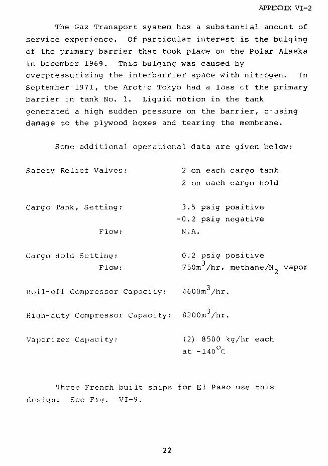
APPENDIX VI-2
The Gaz Transport system has a substantial amount of
service experience. Of particular interest is the bulging
of the primary barrier that took place on the Polar Alaska
in December 1969. This bulging was caused by
overpressurizing the interbarrier space with nitrogen. In
September 1971, the Arctic Tokyo had a loss cf the primary
barrier in tank No. 1. Liquid motion in the tank
generated a high sudden pressure on the barrier, c-asing
damage to the plywood boxes and tearing the membrane.
Some additional operational data are given below:
Safety Relief Valves: 2 on each cargo tank
2 on each cargo hold
Cargo Tank, Setting: 3.5 psig positive
-0.2 psig negative
Flow: N.A.
Cargo Hold Setting: 0.2 psig positive
Flow: 750m /hr. methane/N vapor2
Boil-off Compressor Capacity: 4600m3/hr.
High-duty Compressor Capacity: 8200m3 /hr.
Vaporizer Capacity: (2) 8500 kg/hr each
at -140°C
Three French built ships for El Paso use this
design. See Fig. VI-9.
22
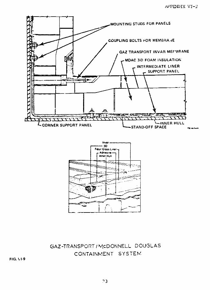
APPENDIX VI-2
MOUNTING STUDS FOR PANELS
COUPLING BOLTS FOR MEMBRA.AE
GAZ TRANSPORT INVAR MEV.BRANE
,~1~~~ Jt / / rMDAC 3-D FOAM INSULATION~ i .. / \ _INTERMEDIATE LINER
,Z . _ 1. l_@4_ / 8 \ VSUPPORT PANEL
CORNER SUPPORT PANEL L AE HSTAND-OFF SPACE , __
Inver3D
Fibar Glass L'nerAdhesiveInner Hull
GAZ-TRANSPORT/ McDONNELL DOUGLAS
CONTAINMENT SYSTEMFIG. '1-9
23
APPENDIX VI-2
Gaz Transport and McDonnell Douglas have combined
their cryogenic containment systems to produce the CT/MDC
system. This system will be used by Sun Shipyard for the
two Pacific Lighting Marine ships on order. The primary
barrier is still provided by the Gaz Transport flat Invar
membrane, but it is increased to 0.7mm in thickness. The
insulation system consists of two layers of polyurethane
foam panels, reinforced in three directions and separated
by a fiberglass reinforced layer which functions as the
secondary barrier.
The method of attaching the membrane to the
insulation has basically been retained in the new design.
24
APPENDIX VI-2
LPG CARRIERS
Avondale Shipyard offers an American designed LPG
tanker of 81,500 cubic meter capacity.
As shown in Figs. VI-10 and VI-11, the four tanks
are prismatic, self-supporting, and made of 2.5%
nickel-iron alloy, capable of withstanding -50 F,
sufficient to hold propane, propylene, butane, and
ammonia. Tank thickness is 0.4375" at top, increasing to
0.68'5" at bottom. The tanks are divided by liquid-tight
centerline bulkheads, forming eight compartments,
internally stiffened by transverse structure members.
Each tank is f tted with roll and pitch keys in very much
the same way as the Conch II LNG carrier design.
The insulation is made of 4-10" polyurethane foam,
depending on customers' boil-off specifications. The
vapor barrier is made of PVC sheeting, joined with PVC
H-shaped strips. The insulation is applied on the inner
hull, providing a cold cargo hold space. The bottom
insulation, providing tank support, is made of
balsa/p ,"wood with hardwood grounds.
The inner hull, acting in this design as the
secondary barrier, is made of 0.625" thick ARMCO LTM grade
T steel, suitable for low temperature service.
Principal characteristics are:
Length Overall: 740'0"
Length between perpendiculars: 705'0"
Beam: 126'0"
Depth: 77'6"
25
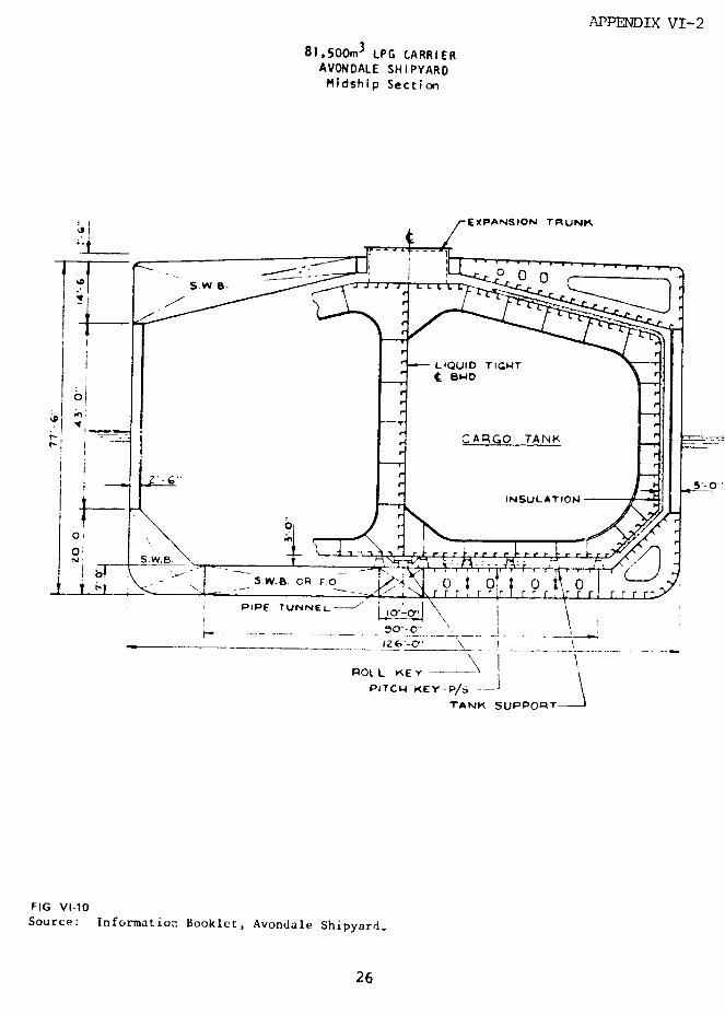
APPENDIX VI-2
81,500m3 LPG CARRIERAVONDALE SHIPYARDMidship Section
EXPANSION TRUNK,
~.1~~ !
S.W.B. L
.w.I.oRFo ' 00
\OI *r
I PePE TUItNN~EL-L.*°' p-. \'"H \
! ILR6"~ 9 - O'ri
iior
ANM SUPPORTA
FIG. Vl-1Source: Informatior. Booklet, Avondale Shipyard.
12'-0 6
ROLL KEY
TANK SUPPORT
FIG. VI-10Source: Information Booklet, Avondale Shipyard.
26

APPENDIX VI-2
ZuJ:~Mo
zw
CL _
uJ~~~~~~~~~-
U~~~~~~~~L
Ou'"- L ;
00~~~~~~2
· I 7«IJ a
W ~ ~~~~~~~~ 4
I i:. : i I /
A -J
e~~~~~Iv
~~vI g II i i~~~~~~~~~~~~~~~~ I
-, w
6: : i pP
27~~~~~~~~~~:
APPENDLX VI-2
Design Draft: 38'0"
Di'placement: 76,185 long tons
Total Deadweight: 53,500 long tons
Main Propulsion Plant (Diesel): 25,800 HP
Service Speed: 16.7 knots
Cargo Capacity: 81,500 cubic
meters
Discharge Capacity (8 Pumps): 650 cubic
meters/hr ea.
Safety Relief Valves Setting: 3.85 psig
positive
Compressor capacity is up to
customers' specifications. Two
150 ton reliquefaction plants
are suaaggested.
This size LPG ship will probably be the largest
involved in U.S. trade. None has been ordered.
28
APPENDIX VI-3
APPENDIX VI-3
LNG INCIDENT EXPERIENCE TO DATE
(E cerpted from "Fire Safety Aboard LNG Vessels."
University Engineers, Inc., January, 1976, Sponsored by
U.S. Coast Guard, NTIS ;AD-AO30619.)
Contrary to original expectation, detailed
information on all liquefied natural gas releases from LNG
tankers and barges is currently not available. In the
initial planning of this task, it was assumed that the
approximately 100 combined years of experience in marine
transport of LNC and some 50,000 hours of transfer
operations should have produced a considerable number of
releases of such consequences as to either require or
inspire documentation. The general assumptions posited
that some releases would not be documented: releases that
might occur during shakedown and those that in continued
operations were essentially matters of routine
maintenance, such as torquing flanges and packing nuts.
It was expected that other releases, however, of less
routine nature and of more consequence either in terms of
release size or repairability would have been documented,
particulirly in any cases involving failure caused by
material specification or mechanical design.
Interviews and other contacts with 48 domestic and
foreign companies involved in or knowledgeable about the
marine LNG transportation industry produced information on
only six cryogenic liquid spills. All had been previously
documented and appear to have been documented only because
they produced brittle fracture of decks. All were
29
APPENDIX VI-3
relatively small spills, under 100 gallons. Three were
spills of LNG; three were spills of liquid nitrogen:
1. Methane Progress, Voyage 14, 1 May 1965. At
disconnection of loading arms, LNG spilled from ship's
crossover line. Seating of the liquid leading valve was
prevented by a piece of a failed Teflon valve facing
lodging between valve disc and seat. The drip pan
overflowed due to water being projected onto it. A minor
deck plating crack occurred.
2. Methane Princess, Voc.age 182, 30 May 1971.
Liquid nitrogen loading line relief valve opened and
spilled liquid nitrogen through the combined vent line
onto foredeck. Some cracking in deck plating occurred.
Relief valve had been improperly reset at annual survey to
a lower than specified pressure setting.
3. Methane Progress, Voyage 193, 31 October 1971.
A liquid nitrogen storage tank was inadvertently
overfilled causing discharge through the tank vent valve
and combined vent line onto the foredeck. Main and second
deck plating were cracked.
4. Jules Verne, Voyage 2. During loading, LNG
tank was overfilled, causing a liquid spill from vent
riser. A foreign object jammed in the float track
prevented proper indication of liquid level by liquid
level gage. The tank cover and a deck stringer plate
fractured.
30
APPENDIX VI-3
5. Massachusetts, 4 June 1974. A two-'nch
ordnance coupling on the liquid nitrogen loadinL hose
fractured, spilling approximately ten gallons of liquid
nitrogen. The ordnance coupling probably had been
mechanically overloaded by repeated attempts to achieve
seal by hammering. The main and canopy decks were
fractured by the liquid nitrogen.
6. Massachusetts, 16 July 1974. A one-inch globe
valve (nitrogen purge valve) was overpressured during
cargo loading and spilled approximately 40 gallons of LNG.
The sudden pressure rise occurred when the cargo loading
valve closed because of a momentary electrical power
interruption after generator switchover. The liquefied
natural gas cracked the canopy deck.
Since the spills evoking the most concentrated
public apprehension appear to be those resulting from
failure of the primary barrier, information on any primary
barrier failure was also sought. Only four failures have
occurred, and again, all have been previously publicized.
1. Descartes, Voyage 2. A gas concentration was
observed in the space surrounding the membrane on the
aftermost tank during the second loaded voyage. A minor
fault was discovered at the connection of the membrane to
the tank dome during shipyard examination. There were no
secondary effects of this failure and release.
2. Arctic Tokyo, 2 September 1971. The INVAR
membrane (primary barrier) of Number 1 Tank was torn
during the ballast leg of the voyage due to internal
impulse forces generated by motion of slack liquid (LNG).
Some of the plywood insulation boxes crushed as a result
31
APPENDIX VI-3
of this loading. There were no secondary effects of thisfailure.
3. Polar Alaska, Ballast Voyage 1. A cable trayon the pump support column in Number 1 Tank broke away andperforated the membrane (primary barrier) in several
locations. The cable tray failure was attributed to
forces generated by motion of slack liquid (LNG). Thefailure was discovered during loading for Voyage 2. There
were no secondary effects of this failure.
4. Polar Alaska, Second Loading. During gasfreeing operations after discovery of leakage from the
primary barriers (no. 3 above), the space between theprimary and secondary barriers was inadvertently
pressurized withi nitrogen. The primary barrier wasdistorted. There were no secondary effects of this
distortion.
Only one fire aboard an LNG cargo vessel wasreported. The fire occurred on t'ie Methane Princess atthe forward vent riser during loading for Voyage 4.Ignition was caused by lightning. There were no secondary
effects of this fire. Reference was made during
interviews to random occurrence of fires in vent risers.
No information was available on frequency or on causes ofignition, since the fires were all extinguished by
automatic systems and were apparently considered
operational in nature.
One collision between an LNG vessel and another
vessel has been reported. While unloading, theMethane Princess was rammed astern by another vessel.. Nohull penetration or LN c~ release resulted from this
32
APPENDIX VI-3
unusual, but nonetheless minor, incident.
Similarly, occasional mention was made at interviews
of small liquid drips cr streams and small gas releases.
Useful information was not availa'Ue. Generally, these
small and infrequent leaks occurred at valves, flanges,
packings, and seals and were eliminated by re-torquing
fasteners and pressure nuts. No mechanical failures or
blow-out type failures were specified, other than those
mentioned above. During personal visits to operating LNG
vessels, only one LNG leak was observed. This particular
leak occurred during a loading procedure at the connection
flange and was estimated at less than 0.01 gpm,
essentially a very minor drip which was incapable of
creating a hazardous condition.
Because of the scarcity of specific information on
incidents in marine shipping of LNG, information on
incidents at land-based facilities has been reviewed. The
majority of this information has been reviewed previously,
particularly in publications from the American Gas
Association, and will not be repeated nere since the
historical approach was not feasible for determination of
failure rate probabilities and risks.
33
APPENDIX VI-4
APPENDIX VI-4
OPERATING PROBLEMS AND SHIP DELAYS
(Excerpted from "Analysis of LNG MarineTransportation for the Maritime Administration",Booz-Allen Applied Research, Inc., November, 1973, NTIS #COM-74-1168 4.)
There are insufficient data to predict a continuingfavorable out-of-service profile for these ships. Infact, there are indications that it could increase duringthe last seven contract years. Our analysis shows that 29percent of the total out-of-service time for these shipshas been experienced over the last operating year forwhich there are data. This last year represents 12.5
percent of the period sampled for the METHANE PRINCESS and13.3 percent for the METHANE PROGRESS.
It is understood that Conch is updating itsout-of-service time and intends to deliver the results tothe Maritime Administration.
The POLAR ALASKA and ARCTIC TOKYO have experiencedconsiderably more difficulty during their first 4 years ofoperation. These ships contrast sharply with otheroperating LNG ships in the following areas:
-- Until the delivery of the GADINIA in the fall of1972, these ships were 4 3-percent larger by capacitythan the next larger LNG ship (DESCARTES) operating,and 7 9 -percent larger than any LNG ship operating ina continuina long-term charter.
34
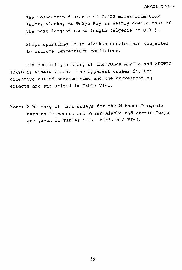
APPENDIX VI-4
The round-trip distance of 7,000 miles from Cook
Inlet, Alaska, to Tokyo Bay is nearly double that of
the next largest route length (Algeria to U.K.).
Ships operating in an Alaskan service are subjected
to extreme temperature conditions.
The operating hLstory of the POLAR ALIASKA and ARCTIC
TOKYO is widely known. The apparent causes for the
excessive out-of-service time and the corresponding
effects are summarized in Table VI-1.
Note: A history of time delays for the Methane Progress,
Methane Princess, and Polar Alaska and Arctic Tokyo
are given in Tables VI-2, VI-3, and VI-4.
35

APPENDIX VI-4
TABLE VI-1
OPERATING PROBLEMS WITH POLAR ALASKA AND ARCTIC TOKYO
General Problem Area Specific Cause Impact
Poor design of both cryogenic Faulty cable tray design Failure-41 day delayand conventional systems
Improper calculation of Damage to membranesloshing loads on extreme and insulation-22tank bulkheads during day delayballast leg
Insufficient flow of cool- Severe condensering water through main tube corrosion-15condenser days of delay to date
with retubing plannedin late 1973
Improper design of flue Soot and seawatergas scrubber carryover to feed
system resulting insystem corrosion,20-day delay
Operating problems with Generator insulationships se.'Ice generator breakdown, 16.5-day
delay
Stand-by feedpump Feed pump failsafter startup, 10-dAv delay
Boilers Boiler casingcracked, 20-daydelay
Poor burner throat re- Cracked andfractory design deteriorated, 10-day
delay
36
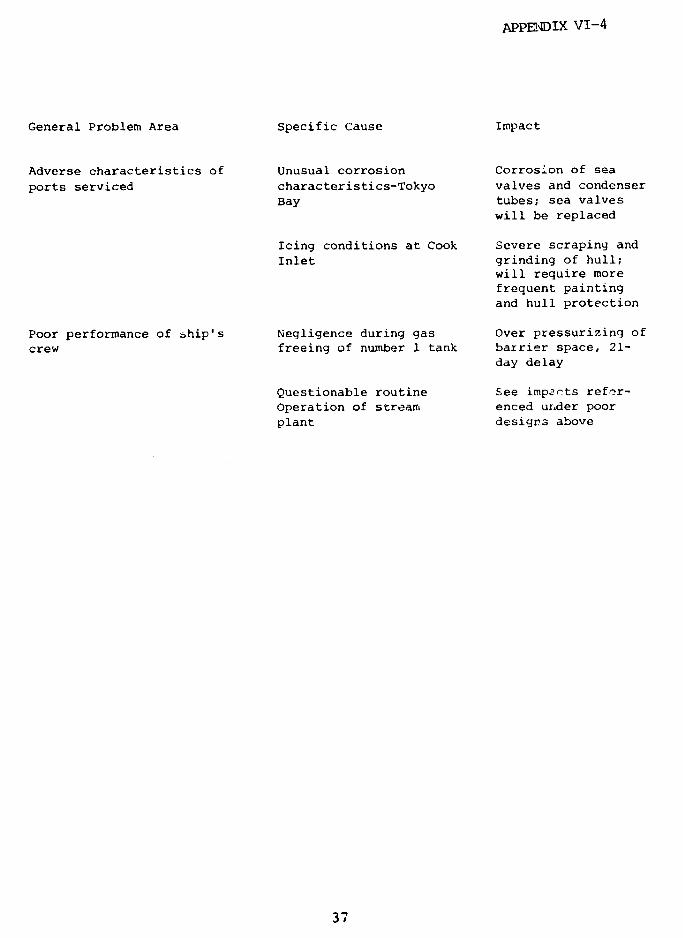
APPENDIX VI-4
General Problem Area Specific Cause Impact
Adverse characteristics of Unusual corrosion Corrosion of sea
ports serviced characteristics-Tokyo valves and condenser
Bay tubes; sea valveswill be replaced
Icing conditions at Cook Severe scraping and
Inlet grinding of hull;will require morefrequent paintingand hull protection
Poor performance of ship's Negligence during gas Over pressurizing of
crew freeing of number 1 tank barrier space, 21-day delay
Questionable routine See impacts refor-
Operation of stream enced under poorplant designs above
37
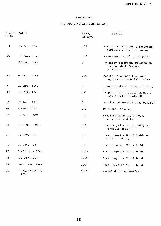
APPENDIX VI-4
TABLE VI-2
METHANE PROGRESS TIME DELAYS
Voyage Dates Delay DetailsNumber in Day!,
4 25 Dec. 1964 .25 Fire at Foru riser (lightening
strike); delay in loading
10 21 Mar. 1965 .50 Investigation of cold -pots
5/6 May 1965 0 No delay recorded; repairs to
cracked deck (cargo
spillage)
32 6 March 1966 .25 Monitor seal bar fracture
repairs: no schedule delay
37 11 Apr. 1966 0 Liquid leak; no schedule delay
42 12 July 1966 .25 Inspection of cracks in No. 3
hold steel (Lloyds/ABS)
50 26 Dec,. 1966 0 ReLairs to monitor seal barrier
68 5 act. 1 )7 .50 Cold spot foaming
7r
28 O,+. 1967 .25 Steel repairs No. 2 hold;
no schedule delay
71 9/1) Nuv. 1967 i.0 Steel repairs No. 2 hold; no
schedule dela'
73 30 Nov. 1967 .50 iteel repairs No. 2 hold; no
schedule delay
74 11 Dic. t967 .25 Steel repairs 'lo. 2 hold
75 21/22 Dec. 19'7 1.25 Steel repairs No. 2 hold
76 1/2 Jan. ;9IC 1~50 Steel repairs Nc. 2 hold
83 10/12 Mar. 19f6 1.0 Steel repairs No. 2 hold
98 17 Auq/21 --c t. 3. rJ Annual docking, Belfast
38
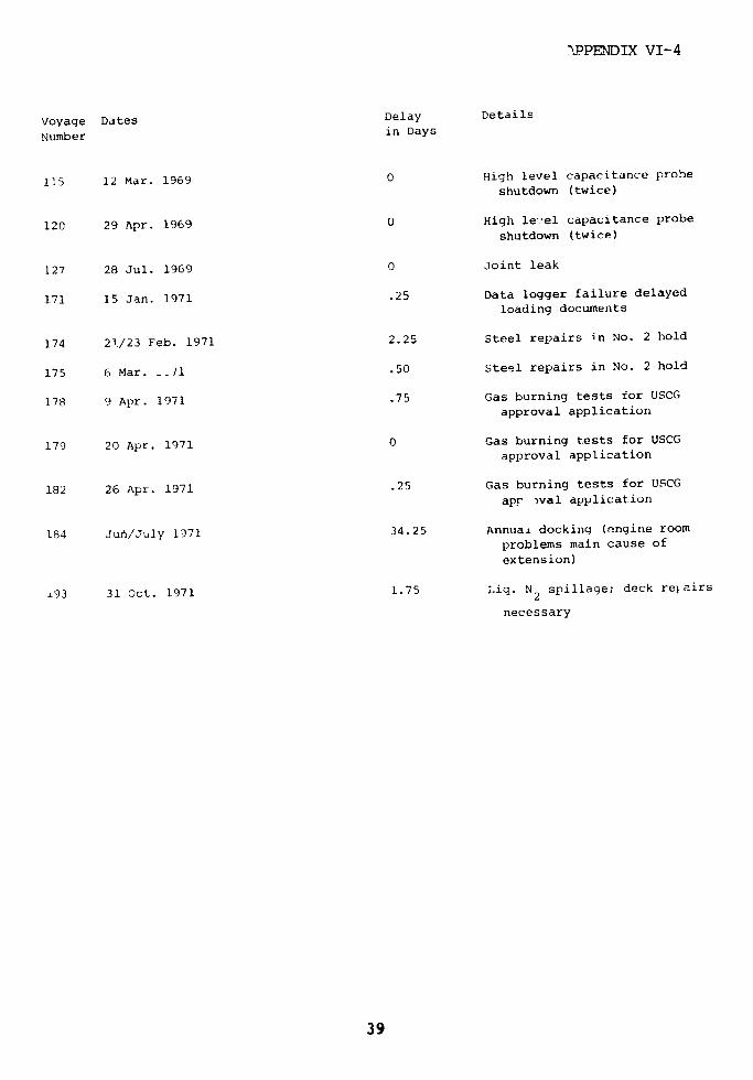
XPPENDIX VI-4
Voyage Dates Delay Details
Number in Days
115 12 Mar. 1969 0 High level capacitance probe
shutdown (twice)
120 29 Apr. 1969 0 High le'-el capacitance probe
shutdown (twice)
127 28 Jul. 1969 0 Joint leak
171 15 Jan. 1971 .25 Data logger failure delayedloading documents
174 21/23 Feb. 1971 2.25 Steel repairs in No. 2 hold
175 6 Mar. _.11 .50 Steel repairs in No. 2 hold
178 9 Apr. 1971 .75 Gas burning tests for USCG
approval application
179 20 Apr. 1971 0 Gas burning tests for USCG
approval application
182 26 Apr. 1971 .25 Gas burning tests for USCG
apr wval application
184 Jun/July 1971 34.25 Annual docking (ongine room
problems main cause of
extension)
*93 31 oct. 1971 1.75 Liq. N2 spillage; deck retairs
necessary
39

APPENDIX VI-4
tABLE:: VI-3
METHP'i.£ PMINCESS TIME DELAYS
Voyage Dates Delay DerailsNumber in Days
12 8/9 Apr. 1.0 Monitor seal bar fracture,
temporary repairs
22 June/July 1966 0 Frosting; insulation repairs;
no effective delay
15.0 Seamen strike
47 2.2 Foaming of cold spots
69 23 Oct. 1967 .75 Foamint, of cold spots;
schedule not affected
80 13 Feb. 1968 .50 Steelwork crack repairs
83 16/17 Mar. 1968 .25 Monitor seal Lemporary repair
of :rack; no schedule delay
84 26/27 Mar. 1968 0 Steelwork crack repair; no
schedule delay
93 4 Jul/P Aucl. 19f0, 34.0 mnnual docking due both
, onventionlal/cryogenir parts
111 11 Feb. 1969 .75 I'ld slpot foaminq
132 16 Sept. 1969q .25 .ihip-to,- :re safety trip fault
Dbini tai red
!34 4 Oct. 19G69 Data o: o!er Il intout fault;Aive do'ument.ltion delay
152 14 Apr. 1%)7D ;hip-to-shor-e saf ty trip
fault being repaired
171 5 Jan. 1'97] h!:-t-shlore safety triptIilt beinq repaired
174 6 Feb. 1971 25 . illi vulv: operating;il unoid fiult to repair
40

APPENDIX VI-4
Voyage Dates Delay Details
Number in Days
175 12/19 Feb. 1971 2.75 Water in No. 2 hold-steelfractur-e inspections in
repairs
176 2 Mar. 1971 .50 Cold spot foaming No. 2 hold
178 23 Mar. 1971 .25 Emergency shutdown systemfault/repair
180 9 Apr. 1971 .25 Jammed varec gauge delayedloading at Arzew
180 14 Apr. 1971 .25 Cool spot foaming No. 2 hold
182 May/June 1971 25.0 Annual docking
183 16/17 June 1971 1.50 Cold spot foaming No. 2 hold
186 23 Jul/13 Aug. 21.50 Cold spot special repairs
1971
187 17 Aug. 1971 1.0 Coollown after special repairs
191 Oct./Nov. 1971 20.25 Further special repairs to
cold spots
192 13 Nov. 1971 1.25 Cooldown after special repairs
196 11 Jan. 1972 1.50 Cold spot fuaming; noscI.edu 2 delay
197 22 Jan. 1972 3.0 Cold spot foaming continued;no schedule delay
199 17 FeF 1972 .25 Punp motor burn-out (LeHavre)No. 4 tank
200 26 ./' par. 3.25 Replacement of pump in No. 4
1972 tank
41
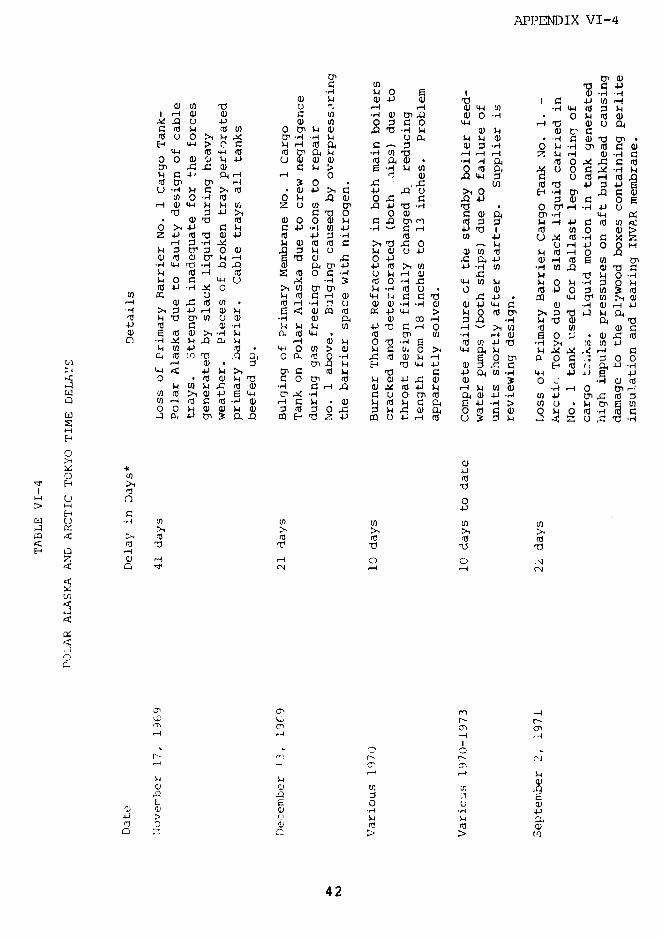
APPENDIX VI-4
( n 4 .)U)f 0 -4 1
l O I 0 ) ~:~ vj ,-~ ~- 'a ·0 I V · *·
0 0 ) ~ 04 0) U ' "-I ,0 I - ~ ~1QUl~a rd M n O .1 --I 4~~~d ~~~~d a, a ln X- " ~ u O4W d
L( -4 > a" qoa a, C: w i m t0 0 w L4 -p 0 ) O 0 - 4 M 0 0t 0
tp -C: Q0 ) -i 04) r r 4 q~
QQ0).C)l ~ fl~ .t CJ)00 .. ~0.- *Hl,-i 4 O n0~4 -4 Rr-4 -i 0 a) U r,4
,- ZU- "0 -d-H w. ,- 0-44-0 4 '> 1 3 t > m .- - U,.-3 4,,00 0 0 01-4 -) 44~4 - L4.i.U)4J * 4 'd-H~ 4-'0 I ' V W O W > iZ4-)c'd 0 ) v; Z u v, a;4-· i 0 . H 0 0 U) I
a) r2u m 0-0C 0)HIf 24) UO r0 tO atO0~-H UL4-404 H '0 ) C0
0 4-J-W $4 r> U "I ) 4- -4-Ht * ju 0 0) tO4- 0 ~)
U) - M ) 'd 0) 4 4' J 3 -4' -d (n 4 * m) 401
U)
W- tO ) * 4-H4 0)0)-H*4 0)4J4 4C 0 *HO),H--tO 4 '00 V 0 0H 0) 0 0) 4 ~0 -H u'0 ~ '
0) 2'C~~~~~~~~- H~~a 0 w4- * t4 t U) -H '40 2 U *U t
C: 4 0 o04 o I 4 ro = -
'C~~0~ 4-40U)O1 >' A (a
-414 10) *1 w CI W p M > 0w 4 '4- 4- Htn ,0 4 4-4~ (a - > 0 rO -i '0 ~41- w0U- f 4- 40 -4-~q 0 CI 0 q ~ : ( 0 .--I c. 44 (J ~4 ,.I 4~ 0 C4 -/q ~ 0 04a0 'C O040) 0 r0
(U 4 4C') -, f4 -4.0 0) tr W 4 J r-4 0) -.4-40 m
,.-I s 4 - V i0 4i 44 ol in 0*
;J 4 i Q) r i cq r 4J 4 > H 0 M 3 O ~ ·l 34Q10 C)w u ) .1 P Q4 a 00 a i 4 'O 1) 0
4-i rll a) -i ~~~~~~4 $4 ~~~4 U) 4-) 'O C: -4 0 -~~~~~~~4-
Q) a) >, -,q h. 04 3 d 4 l " l tr 4J O3i (so-I U)~ ( 0, a4 -4 l 4 0 a _4 u v) 4i c o .,I , M a) 4
-4 X :I m E 4 0 ul X h 4 u q
> 4-4 ~~~~~~~~~~~4 . W> d . 04-) 4U 4 J4 4
0 z1 (9( -H U) U U)4 ( U) 4) Cl Q
- >1~~~~~~~~~~~~~U M 1>14) 4 >1 > 4 ->1 0 0
w -4 m sm: fl a) -4 l 4 4 rl 04 · ,n o - ( tO '
0) - L -4 0 04 4 '1c 0U)(V)CI d tuOU)
O 4-) -)P O1
.- 4
>L~- - 1 00 c
T- 14 . 4
LO U, U~~) (n En U
cQ ro rd~~~~~~~a ca ·c o , c
E~~~~~~~~~~~~~~~~.~
C ( Ct >-l U)H o
42
t~ca o c ·r ul c M3 a a, LI a r: o t~~~~~ a ~~ a~cl a or a, 3 o ·rl a, a~~~~
0 Ml m a)k ~ a~ O O Y ~~~~~~ a, 1 7 o c r a,~~~~~~~>
W ; a 4a a , mu ; r u u a42~
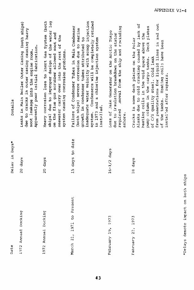
APPENDIX VI-4
4 O A .-0- ,Q 0 0 U :
.D4 U0' Wu) O O .QU *,QU) ·0 4 >l J 0 D -J O
a, 6 4 U 4 -) 0 . m -l a
o ~~ ~~~~~~~~~U
U)6 (, aC a0U)- 4 ·r( ~crlr~aa)
U~~GJ~~4 ~~0'-4W0 .H0~~4-J.H. Q 4 A-4'ra
4Jt ~ - , 4J o ·l e1 ra r , · a .,
0tr En 4 0 -i ) j4iU1 - > a) 0- 0- O
C-0 c 0 UW. U O 4 O U > 0 > W- 44J0
cn 0 4J VI i 0 w w i a)4 0-4 M 4U) 0 -W a) W u 4 u 4r4 W o
(d 4.) (d 4 o ro Ua EU). l4 4-1 Q >
· ,- 0 .M 0 O.~ e ' 0 <, W , a) -I4 q o
Lf ) w U)4- 4-H u 4-o 14 r. m u . m .4 jit0U 0 0-4 W(0U UIO 4 ' * 4i ·) r -I v
uC a W w 0 0 4-,40 4 W4 u0 * (0W : -4rt
tO O , O~0 · m- 4 dl m ' O ,O
k c0. -- 4dl va-H -4 (0 N -4 00 4W U)( 0 0( i l -H
(0Ol .d 4H (0u) -i HOO(0U U) JC3 (a >.r0 (0
·~~~~~~~~~
Q) ) -4 0) -H 1) u 0 t r a4 O O (a 4
· cl d
4U) ( 4 0 04 - 4 -W 0u 1
:] U0 ) , w ~ ~ W o
.H m, O tcn > ) 0 r : O - a 0.. a) C o U v: M 0) .4
a ~~~~0
0, q3 " )I -IU0 "'(0 N (0 i
· rl 2: (d ar u lec a a,~~() (1 w u .1 (a , o 0 ,4
(0 V l .V '$4 0 jm(I0 E 0 ( -4 '04 -4
d L r0j 0 0 , . 7 -cO)4
CI 3 Un 0 a) (a o c u 0 1a H rl U) q I
Q ( (N l U Z -4 -4 0U r. ( ina Hu C
C 4 - 1 0--I ( 0 H 4- ( 7 w 5i uj aj a m 11~O~ L r
U]
0 -4 a) Q) 4-) E r4 V 5 r- i4 0 q U) (d W Q,
~0
4J (d > 0 4-) 3 41 4.) i : 0 - - 4J tn 0 4J ca
W 0 04 vo -4 (a U) -4 0 0 (d Ul in U) Q U) (o O u0 ·
(1 U
(n (at c r
>1 ~ ~ ~ ~ ~ ~ ~ ~ ~ ~ ~ ~ ~ ~ ~ ~ ~ ~ ~ ~ ~ ~ ~ ~ ~ ~ ~~~~~~~~~~~~~4
0
10 10 ~ ~~~0 0 Lr~~) ODrda~~~~~~~d 4-'rl
· ,..I .,-. 0 m
a 0 0 ,- ~ .-©
-~~ -'~~~ 4' r-4
ct~~~~~~~~~~~~~~~
,--( ,-U ,-I 0'~ o) 0.
0' 0 , --m44 cJ
ai '4
0'
0 C '
0 .- ~~~~~~~~~~~~~~~~~0 0 (N 1-4-4
ar o
7~~~~~~~~~~~~~~~~~~~~~~~~~~~~7
4J N N -~~~~~~~~~~-1~ :Ia -N Hq -4
4 3
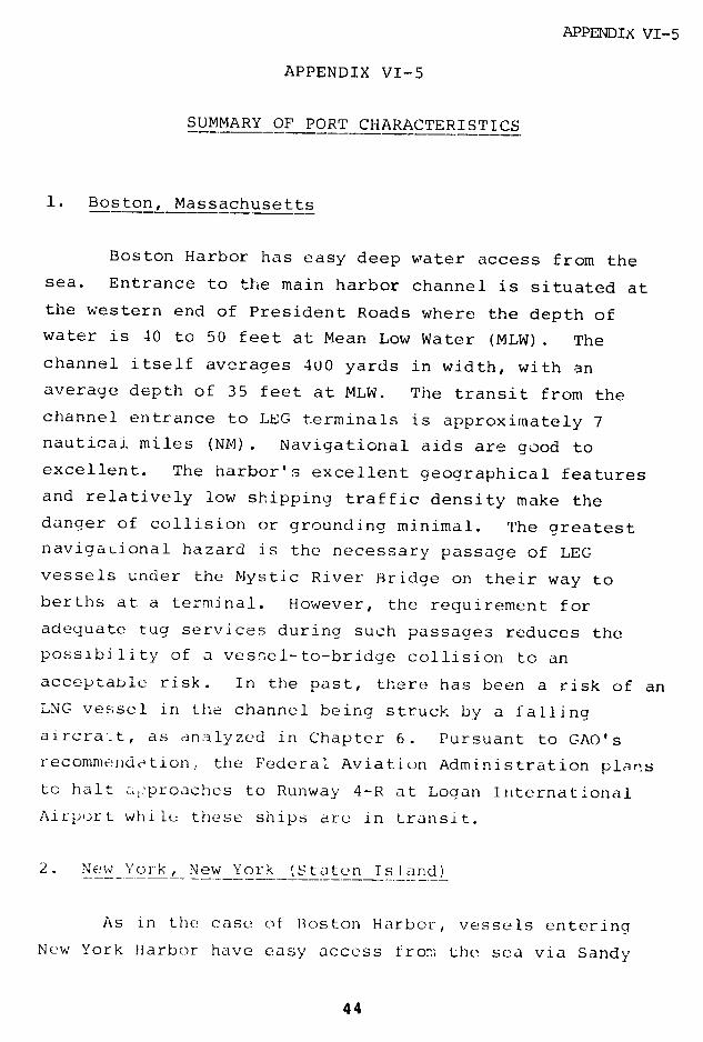
APPENDIX VI-5
APPENDIX VI-5
SUMMARY OF PORT CHARACTERISTICS
1. Boston, Massachusetts
Boston Harbor has easy deep water access from the
sea. Entrance to the main harbor channel is situated at
the western end of President Roads where the depth of
water is 40 to 50 feet at Mean Low Water (MLW). The
channel itself averages 400 yards in width, with an
average depth of 35 feet at MLW. The transit from the
channel entrance to LEG terminals is approximately 7
nautical miles (NM). Navigational aids are good to
excellent. The harbor's excellent geographical features
and relatively low shipping traffic density make the
danger of collision or grounding minimal. The greatest
navigational hazard is the necessary passage of LEG
vessels under the Mystic River Bridge on their way to
berths at a terminal. However, the requirement for
adequate tug services during such passages reduces the
possibility of a vessel-to-bridge collision to an
acceptable risk. In the past, there has been a risk of an
LNG vessel in the channel being struck by a falling
aircrat, as analyzed in Chapter 6. Pursuant to GAO's
recommendation, the Federal Aviation Administration plarts
to halt ia-proaches to Runway 4-R at Logan International
Airport while these ships are in transit.
2. New York, New York (Staten Island)
As in the case of Boston Harbor, vessels entering
New York Harbor have easy access from the sea via Sandy
44
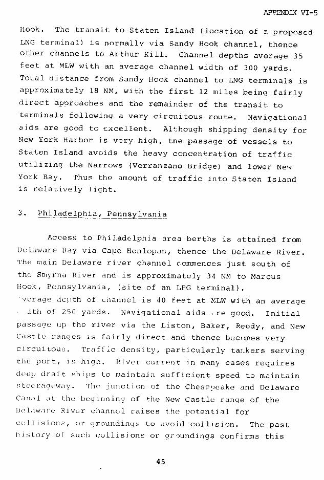
APPENDIX VI-5
Hook. The transit to Staten Island (location of - proposed
LNG terminal) is normally via Sandy Hook channel, thenceother channels to Arthur Kill. Channel depths average 35
feet at MLW with an average channel width of 300 yards.
Total distance from Sandy Hook channel to LNG terminals is
approximately 18 NM, with the first 12 miles being fairly
direct approaches and the remainder of the transit to
terminals following a very circuitous route. Navigational
aids are good to excellent. Although shipping density for
New York Harbor is very high, tne passage of vessels to
Staten Island avoids the heavy concentration of traffic
utilizing the Narrows (Verranzano Bridge) and lower New
York Bay. Thus the amount of traffic into Staten Island
is relatively light.
3. Philadelphia, Pennsylvania
Access to Philadelphia area berths is attained from
Delaware Bay via Cape Henlopen, thence the Delaware River.
The mnain Delaware river channel commences just south of
the Smyrna River and is approximately 34 NM to Marcus
Hook, Pennsylvania, (site of an LPG terminal).
:verage depth of channel is 40 feet at MLW with an average
Ith of 250 yards. Navigational aids re good. Initial
passage up the river via the Liston, Baker, Reedy, and New
Castle ranges is fairly direct and thence becomes very
circuitous. Traffic density, particularly tankers serving
the port, is high. River current in many cases requires
deep draft ships to maintain sufficient speed to mcintain
stccrageway. The junction of the Chesaeeake and Delaware
Canal. at the beginning of the New Castle range of the
DLelawarte River channeul raises the potential for
collisions, or groundinqs to avoid collision. The past
iristory of such collisions or gr)undings confirms this
45

APPENDIX VI-5
observation. Due to the relatively narrow channel, the
length of transit which increases the probability of
vessel head-on-head meeting situations, and the existing
low margin of safety available for errors in human
judgment or mechanical failure, the risk of grounding or
collision is high.
4. Cove Point, Maryland
Passage to Cove Point is made from the sea via Cape
Henry, Virginia, thence direct via Chesapeake Bay. The
Chesapeake Bay Channel is well marked with navigational
aids, and has a depth of water varying from 40 to 65 feet
at MLW. The approach to the Chesapeake Bay Chanr:el
requires crossing the approach to the Thimble Shoals
channel, which is the main access to the Hampton Roads
area (Norfolk, Newport News, and Portsmouth, Virginia) and
which has a very high density of commercial and naval
traffic. However, once a vessel bound for Cove Point
enters Chesapeake Bay channel, the only deep water ships
likely to be encountered will be primarily vessels
outbound from Baltimore, Maryland. Because of the density
of such shipping and the geographic features of Chesapeake
Bay, the risk of collision or grounding is extremely low.
Due to the wide expanse of open water at the Cove Point
terminals, high winds may sometimes create problems of
safely mooring LNG vessels.
5. Savannah, Gcoraia
The entrance from The s a to Savannah is direct via
the Savannah River Channel. The channel is 500 feet wide
and has an average depth of 35 to 40 feet at MLW.
Naviaational aids are good, but the cnannel is serpentine
46

APPENDIX VI-5
and from the sea buoy to Elba Island (site of the LNG
terminal), approximately 16 NM long. While the past
record of groundings and collisions in the channel is
excellent to outstanding, the inherent geographic features
of the channel indicate that every special precaution
should be taken for the passage of LNG vessels.
6. Houston, Texas
Access to LPG and potential LNG terminals in the
Houston area from the Gulf of Mexico is via Galveston Bay,
thence the Houston Ship channel. The channel is long and
circuitous, having a width of approximately 400 feet with
an average depth of 40 feet at MLW. Normal navigational
aids are good, and, since the installation and operation
of a Vessel Traffic Service (VTS) by the U.S. Coast Guard,
overall navigation aids are excellent. Channel traffic
density (deep water vessels as well as barge traffic! is
very high. Due to channel width and configuration and the
density of traffic, the potential for collision in
head-on-head meeting situationsor for groundings to avoid
collision is high. The past record of minor collisions in
the channel confirms this.
47
APPENDIX VII
CONTENTS PAGE
APPENDIX VII-1, SOME LNG TRUCK ACCIDENTS 1
VII-2, ANALYSIS OF CAUSES OF SOME
UNDERGROUND EXPLOSIONS 4

APPENDIX VII-1
APPENDIX VII-l
SOME LNG TRUCK ACCIDENTS
TransportDate Location Company Description
6/25/71 Waterbury, Vt. Capitol *Blowout, hitrocks by road,hole, 20%spilled, nofire, remainderdumped.
P/28/71 Warner, N.H. "Lowell Driver fatigue,Cas" (Gas, drove off road.Inc.) Rollover cracked
fittings. Smallgas leak, nofire.
10/8/71 N. Whitehall, Indianhead *Head-on colli-Wisc. sion with truck,
gasoline and tirefire, no cargoloss.
10/73 Raynham, Mass. "Andrews & Truck sidePierce" swiped parked
car. Brakeslocked &trailer over-turned. Nocargo on boardno fire.
1973 Rt. 80 & 95 Jct., Chemical Driver couldn'tN.J. Leaman negotiate turn
off. Rolloverdemolishedtractor; $40,000damage to trailer;no fire.
2/19/70 Rt. 40, Hamilton Cas, Inc. *Faulty brakesTwp., N.J. caused wheel
fire. Checkvalve cracked; 5%leaked out - the

APPENDIX VII-1
TransportDate Location Company Description
report is un-clear whetherthe LNG ignitedor not.
?,'?1/74 McKee City, N.J. Gas, Inc. *Loose valve
leaked LNG dur-ing transferoperation.
Winter Chatanooga, Tenn. LP Trans- Rollover, no1975-76 port fire, caused byJan '76 oil spill on
exit ramp. Truckrighted and con-tinued deliveryof cargo.
1Winter Dalton, Ca. LP Trans- Rollover, no1975-76 port fire. DriverNov '75 swerved to avoid
pedestrian, hitguard rail, androlled over &down 80 ft. bank.$18,000 damage totrailer.
9/16/76 Pawtucket, R.I. "Andrews & jar hit trailerPierce" at landing
wheels, roll-over, no LNGloss or fire.
3 nr Connecticut Tpk, Chemical Truck parked4/77 Conn. Leaman (with blowout)
hit bv a towtruck in rear.No leak or fire.
7/77 Waterbury, Conn. LP Trans- "Single Wall"port Lubbock hit in
rear by rFactortrailer, axleknocked off. Noloss of cargo;in this casecontrols were
2

APPENDIX VII-1
Transport
Date Location Company Description
under the tank.
Rollover.
*Accident report obtained from OHMO. Descriptions of other accident,
from interviews with LNG truckin; industry officials.
3
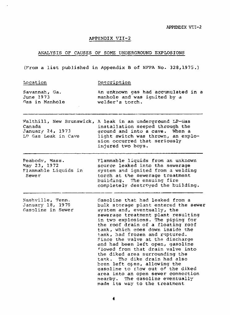
APPENDIX VII-2
APPENDIX VII-2
ANALYSIS OF CAUSES OF SOME UNDERGROUND EXPLOSIONS
(From a list published in Appendix B of NFPA No. 328,1975.)
Location Description
Savannah, Ga. An unknown gas had accumulated in aJune 1973 manhole and was ignited by anas in Manhole welder's torch.
Walthill, New Brunswick, A leak in an underground LP-GasCanada installation seeped through theJanuary 24, 1973 ground and into a cave. When aLP Gas Leak in Cave light switch was thrown, an explo--
sion occurred that seriouslyinjured two boys.
Peabody, Mass. Flammable liquids from an unknownMay 23, 1972 source leaked into the sewerageFlammable Liquids in system and ignited from a weldingSewer torch at the sewerage treatment
building. The ensuing firecompletely destroyed the building.
Nashville, Tenn. Gasoline that had leaked from aJanuary 18, 1970 bulk storage plant entered the sewerGasoline in Sewer system and, eventually, the
sewerage treatment plant resultingin two explosions. The piping forthe roof drain of a floating rooftank, which goes down inside thetank, had frozen and ruptured.Since the valve at the dischargeend had been left open, gasolineflowed from that drain valve intothe diked area surrounding thetank. The dike drain had alsobeen left open, allowing thegasoline to flow out of the dikedarea into an open sewer connectionnearby. The gasoline eventuallymade its way to the treatment
4
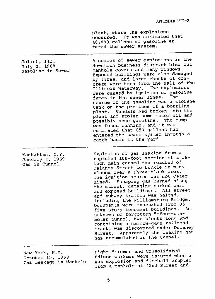
APPENDIX VII-2
plant, where the explosions
occurred. It was estimated that
46,000 gallons of gasoline en-
tered the sewer system.
Joliet, Ill. A series of sewer explosions in the
July 2, 1969 downtown business district blew out
Gasoline in Sewer manhole covers and many windows.
Exposed buildings were also damaged
by fires, and large chunks of con-
crete were torn from the wall of the
Illinois Waterway. The explosions
were caused by ignition of gasoline
fumes in the sewer lines. The
source of the gasoline was a storage
tank on the premises of a bottling
plant. Vandals had broken into the
plant and stolen some motor oil and
possibly some gasoline. The pump
was found running, and it was
estimated that 850 gallons had
entered the sewer system through a
catch basin in the yard.
Manhattan, N.Y. Explosion of gas leaking from a
Janua:*y 3, 1969 ruptured 100-foot section of a 16-
Gas in Tunnel inch main caused the roadbed of
Delaney Street to buckle in many
Dlaces over a three-block area.
The ignition source was not Ceter-
mined. Escaping gas burned a')ng
the street, damaging parked caiJ
and exposed buildings. All street
and subway traffic was halted,
including the Williamsburg Bridge.
Occupants were evacuated from 35
five-story tenement buildings. An
unknown or forgotten 5-foot-dia-
meter tunnel, two blocks long and
containing a narrow-gage railroad
track, was discovered under Delaney
Street. Apparently the leaking gas
has accumulated in the tunnel.
New York, N.Y. Eight firemen and Consolidated
October 15, 1968 Edison workmen were injured when a
Gas Leakage in Manhole gas explosion and fireball erupted
from a manhole at 42nd Street and

APPENDIX VII-2
Eighth Avenue. Subway and street
traffic was snarled, and some
buildings were evacuated. The
accident was caused by ignition of
gas leaking from a 2-inch pipe.
Ignition source was not definitely
established.
Indianapolis, Ind. After a heavy rainfall, a 6,000-
December 8, 1966 gallon gasoline tank in a service
Gasoline in Sewer station under construction settled
in the trench. The pipe connections
broke, allowing about 1,000 gallons
of gasoline to flow into the stormsewer. Explosions occurred about
1½ miles downstream, rocketing
steel manhole covers high in the
air and causing severe damage to
the sewer line. Ignition source
was not definitely determined but
might have been sparking from
electric cables in the sewerchambers.
Philadelphia, Pa. Workmen were digging a 6-foot-
Auqust 2?, 1962 diameter tunnel about 40 feet below
Vapors in Tunnel grade level for an interceptorsewer. At 8:20AM, shortly after
four workmen had descended into the
tunnel by way of a vertical access
shaft, an explosion occurred and
flames leaped high into the air
from the access shaft. While fire
fighters were getting hose lines
into operation, another blast
occurred, shortly followed by
several others. A second alarm was
Etruck.
The cause of the explosions is
thought to have been ignition of
vapor of petroleum products which
came from bulk plants along the
tunnel during the night.
6
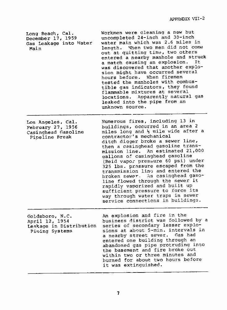
APPELNDIX VII-2
Long Beach, Cal. Workmen were cleaning a new but
December 17, 1959 uncompleted 24-inch and 30-inch
Gas Leakage into Water water main which was 2.6 miles in
Main length. When two men did not come
out at quitting time, two othersentered a nearby manhole and struck
a match causing an explosion. Itwas discovered that another explo-
sion might have occurred several
hours before. When firemen
tested the manholes with combus-
tible gas indicators, they found
flammable mixtures at several
locations. Apparently natural gas
leaked into the pipe from an
unknown source.
Los Angeles, Cal. Numerous fires, including 13 in
February 27, 1956 buildings, occurred in an area 2
Casinghead Gasoline miles long and ½ mile wide after a
Pipeline Break contractor's mechanicalditch digger broke a sewer line,
then a casinghead gasoline trans-
mission line. An estimated 21,000
gallons of casinghead gasoline
(Reid vapor pressure 60 psi) under
325 lbs. pressure escaped from the
transmission line and entered the
broken sewero As casinghead gaso-
line flowed through the sewer it
rapidly vaporized and built up
sufficient pressure to force its
way through water traps in sewer
service connections in buildings.
Goldsboro, N.C. An explosion and fire in the
April 12, 1954 business district was followed by a
Leakage in Distribution series of secondary lesser explo-
Pining Systems sions at about 5-min. intervals in
a nearby street sewter. Gas had
entered one building through an
abandoned gas pipe protruding into
the basement and fire broke out
within two or three minutes and
burned for about two hours before
it was extinguished.
7

APPENDIX VII-2
Cleveland, Ohio A tremendous underground explosion
September ll, 1953 in a combination storm and sanitary
Leakage of Flammable sewer demolished 1.2 miles of pave-
Liquids or Gases ment on West 117th Street killing
into Sewers one person and hospitalizing fifty-
eight others. The blast threw man-
hole covers high into the air and
broke out large chunks of concrete
pavement some 20 feet by 10 feet
in area. Gas mains and water lines
were ruptured. A second blast
occurred an hour later hu'.ling more
manhole covers into the air, but no
onL was hurt. At least 30 automo-
biles were heavily damaged or
demolished in the blast. (Consul-
tants hired to investigate con-
cluded that the most probable cause
was either industrial wastes or
gasoline leaking into the sewer, or
these in combination. See Chapter
5.)
Brighton, N.Y. Fires and explosions resulted in the
Septei,ber 21, 1951 loss of nineteen homes and serious
Gas Accumulation in damage to twenty-five additional
a Confined Space buildings. The initial explosion,
resulting from an accumulation of
gas, took place in a regulator vault
of the gas distribution system. The
regulators, damaged by the force of
the explosion, opened wide ar.d
allowed high pressure gas to pass
into a system designed to operate at
a lowpressure. This overloading
resulted in numerous gas leaks within
buildings which caused a series of
explosions and fires in the affected
area. The exact cause of the initial
explosion within the regulator vault
was never fully determined.
8
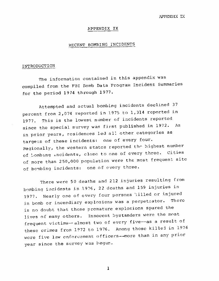
APPENDIX IX
APPENDIX IX
RECENT BOMBING INCIDENTS
INTRODUCTION
The information contained in this appendix was
compiled from the FBI Bomb Data Progranm Incident Summaries
for the period 1974 through 1977.
Attempted and actual bombing incidents declined 37
percent from 2,074 reported in 1975 to 1,314 reported in
1977. This is the lowest number of incidents reported
since the special survey was first published in 1972. As
in prior years, residences led all other categories as
targets of these incidents: one of every four.
Regionally, the western states reported th- highest number
of Lombing ±ncidents, close to one of every three. Cities
of more than 250,000 population were the most frequent site
of bombing incidents: one of every three.
There were 50 deaths and 212 injuries resulting from
bombing incidents in 1976, 22 deaths and 159 injuries in
1977. Nearly one of every four persons 'killed or injured
in bomb or incendiary explosions was a perpetrator. There
is no doubt that these premature explosions spared the
lives of many others. Innocent bystanders were the most
frequent victims--almost two of every five--as a result of
these crimes from 1972 to 1976. Among those killed in 1976
were five law enforcement officers--more than in any prior
year since the survey was begun.
I
APPENDIX IXBombings in 1977 caused property damage exceeding $8
million.
Figure IX-1 is a graph of the Bombing Incidents byTarget. Figure IX-2 is a graph of the Bombing Incidents byPopulation Group. Figure iX-3 is a graph illustratingpersonal injuries due to bombings.
2
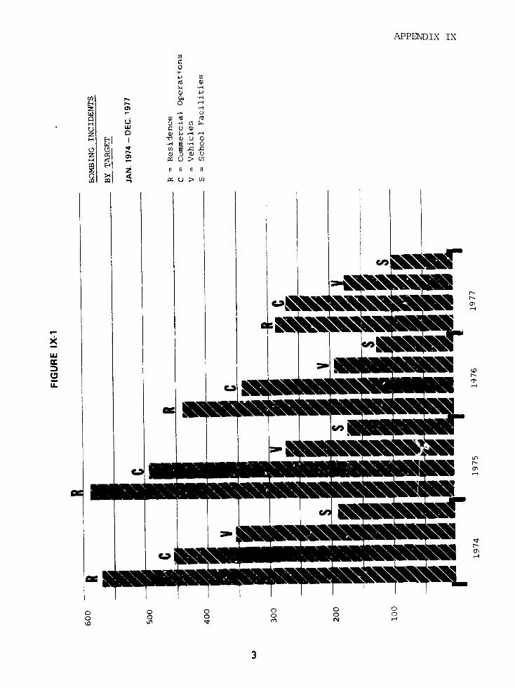
APPENDIX IX
U ,
ji t ! 1 li
r (r
z r- Q -4
Z) w C) O
CLIO~'I /q IT C C~l
iL z I II m ' m S
~~~~~~~C~~~~~~

APPENDIX IX
_' .
z.
44LLI I
f . , | I I 4~~~~cl
:w "Sw O "X Z r
ccC "" " "O Ios""""w~

APPENDIX IX
i i , WI
C90
U.
j to aXXrXXN:L<
' ' I m i : : 0 I 5
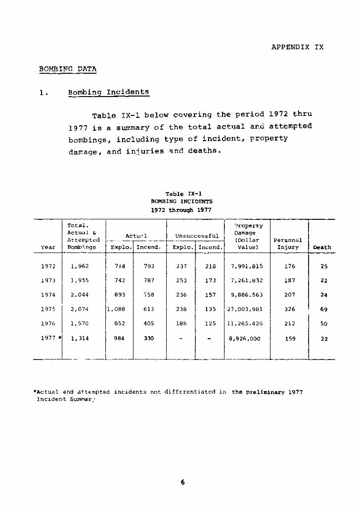
APPENDIX IX
BOMBING DATA
1. Bombing Incidents
Table IX-1 below covering the period 1972 thru
1977 is a summary of the total actual and attempted
bombings, including type of incident, property
damage, and injuries and deaths.
Table IX-1BOMBING INCIDENTS
1972 through 1977
Total, |Property
Actual & Actul Unsuccessful DamageAttempted (Dollar Personal
Year Bombings Expio. Incend. Explo. Incend. Value) Injury Death
1972 1,962 714 793 237 218 7,991,815 176 25
1973 1,955 742 787 253 173 7,261,832 187 22
1974 2,044 893 758 236 157 9,886,563 207 24
1975 2,074 1,088 613 238 135 27,003,981 326 69
1976 1,570 852 405 188 125 11,265,426 212 50
1977 * 1,314 984 330 - - 8,926,000 159 22
*Actual and attempted incidents not differentiated in the preliminary 1977
Incident Summar,
6
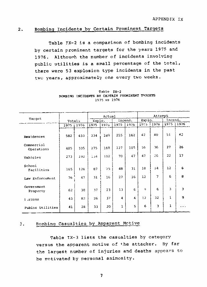
APPENDIX IX
2. Bombing Incidents by Certain Prominent Targets
Table TX-2 is a comparison of bombing incidents
by certain prominent targets for the years 1975 and
1976. Althouah the number of incidents involving
public utilities is a small percentage of the total,
there were 53 explosion type incidents in the past
two years, approximately one every two weeks.
Table IX-2
BOMBING INCIDENTS BY CEATAIN PROMINENT TYRGETS
1975 vs 1976
Target l l Actu al Attempt
ITotali Ex PO. Incend. Explo. | Tncend.
1975 1976 1975 1976 1975 1976 1997 6l97619 7 5 1976
Residences 582 433 234 189 255 162 42 40 51 4'
Commercial
Operations 485 335 275 168 127 105 56 36 27 26
Vehicles 273 192 i34 102 70 47 47 26 22 17
School
Facilities 165 126 87 75 48 31 18 14 12 6
Law Enforcement 76 47 31 16 27 16 12 7 6 8
Government
Property 62 38 37 23 13 6 9 6 3 3
.-.rsons 43 82 26 37 4 4 12 32 1 9
Public Utilities 41 28 33 20 1 5 6 3 1
3. Bombing Casualties by Apparent Motive
Table IX-3 lists the casualties by category
versus the apparent motive of t:he attacker. By far
the largest number of injuries and deaths appears to
be motivated by personal animosity.
7
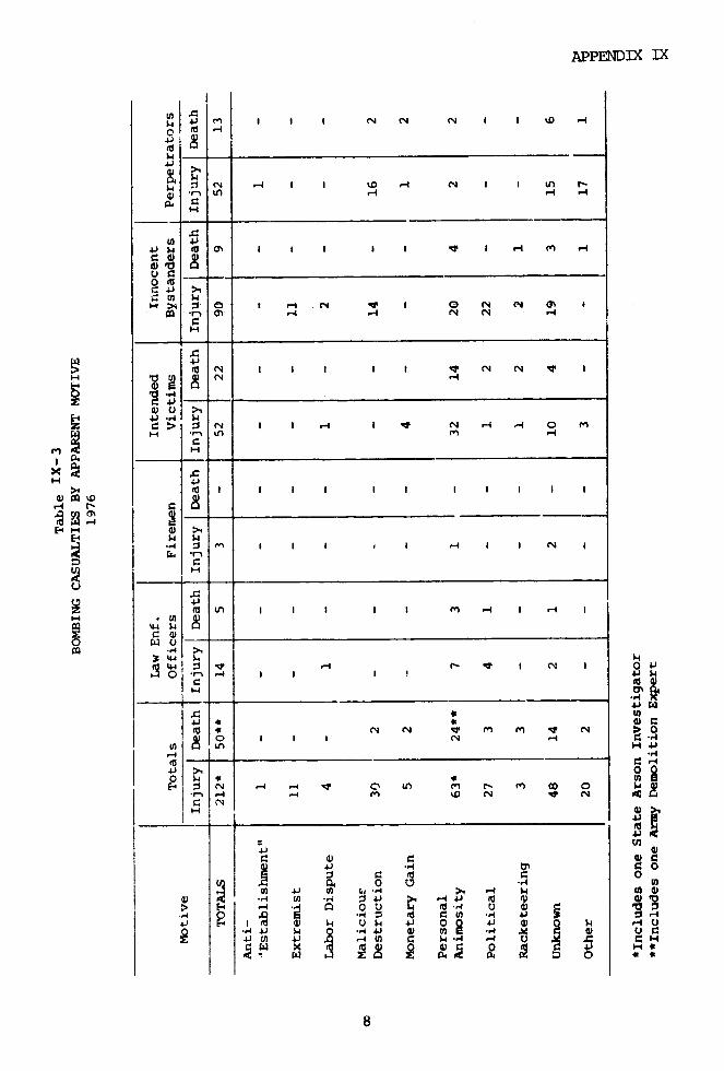
APPENDIX IX
h 4i r I I I N N N I I %D _I
U)
.C N i I I I " I -I c1 !I
U43 4
' c _I
Iza > ¢ N N 1c o\I N I I I I I I N N I I
E-m-4
1.43 1,4
Eq > N I I _-I I N rl - 0 M
-C -
n 4 -ZU LA I I I I I -4 I ~-4 I
eI *C) Nrl Nt3 N I1~ I C N >I8
O C N - 4 V L D N I ! co ,
(I _- _. _
o~ r , ,. m . v., c c u
EeCx f 8.c c > l A I g I I -4 0 o
c: ~~~~~~~~~~~~IdQH~~~Ci ~0e ~~0 4
8~~~~~~~~

APPENDIX IX
SELECTED INCIDENTS
Given below is a selected list of incidents occurring
at public utility and petroleum company facilities from
1974 through May 1977.
1. Colorado - March, 1974
The Mapleton Power Substation of the Public Service
Company of Colorado in Adams County was the target of
a bombing on March 8. A large pipe bomb or similar
device was placed next to a transformer at the
substation and detonated. Extensive damage,
estimated at $250,000, occurred.
2. Pennsylvania - June, 1974
At 9:29 p.m., June 13, the Pittsburgh Police
Department was notified of a telephone warning
received by the Gulf Oil Corporation that a bomb was
in their facility. The caller said that he was with
a tevrorist group and that a bomb was in the building
and would detonate in 17 minutes. An explosion
occurred on the 29th floor of the oil company
building, resulting in $300,000 to $500,000 damage.
A "communique" issued by the same group claimed
credit for the bombing as a reprisal for the oil
corporation operations in an African country.
3. Oregon - October, 1974
During Cctober, eleven powuer transmission towers were
discovered bombed in four different locations. Three
towers were bombed in the Maupin area, three near
9
APPENDIX IX
Brightwood, three near Parkdale, and two near Sandy.
At least three of the towers were toppled as a result
of the explosions. Damage has been estimated at over
$200,000.
A series of extortion letters, mailed to the Federal
Bureau of Investigation at Portland and to a Portland
area daily newspaper, demanded payment of $1 million
and threatened a "blackout" of Portland if demands
were not met.
4. Kentucky - December, 1974
During November and December, twenty natural gas
transmission lines and two natural gas cooling towers
belonging to a Kentucky-West Virginia gas company
were targets of bombing incidents in various areas of
Kentucky. The gas pipe lines varied in size from 2
inches to 20 inches in diameter. Dynamite bombs were
used in each of the incidents, which caused an
estimated $92,650 in damage. In many areas service
was disrupted. The motives are believed to stem from
labor disputes. There were no injuries or deaths.
5. California - March, 1975
Facilities belonging to a gas and electric company
were the targets of bombings on March 20, 27, and 29.
During the early morning of March 20, three towers at
San Bruno were bombed. Damage was slight, and
serv.ce was not interrupted.
At approximately 11:05 the same evening three more
towers were bombed in Alameda County. Pipe bombs
10
APPENDIX IX
were utilized in these bombings and damage was
estimated at $500.
Shortly after midnight on March 27, detonation of
five more pipe bombs occurred at utility stations in
San Jose. These attacks caused extensive damage to
three power transformers and two oil switches. The
resulting loss of power affected 35,000 people.
Damage was set at $80,000 to $100,000.
On March 29, a transformer at Rancho Cordova was
bombed. Twenty thousand dollars in damage resulted.
6. California - April, 1975
On April 4, at 9:00 p.m., a telephone warning was
received by a San Francisco television station that a
bomb was located in a building owned by Standard Oil
of California. A second warning was received at 9:30
p.m. by a telephone operator, during which the caller
stated that a bomb would detonate at 10:00 p.m. At
app:oximately 9:34 p.m., an explosion occurred at the
building mentioned in the threat. Damage to the
building and surrounding area has been estimated at
$300,000.
7. California - September, 1975
On September 26, a major oil company was the target
of a bombing claimed by an extremist group. An
estimated $100,000 damage was done to two
5,000-barrel oil storage tanks at an oil company
facility near Coalinga. A crude high explosive
11
APPENDIX IX
device was utilized. The tank which was closest to
the bomb contained 3,000 barrels of water.
8. Washington - December, 1975
An anonymous male caller representing an extremist
group telephoned the Seattle Police Department at
11:30 p.m., on December 31, and advised that there
were bombs at a Seattle power transformer and at a
supermarket chain office in Bellevue. At
approximately the same time, an explosion occurred at
the distribution center office building of the
supermarket chain in Bellevue. About fifteen minutes
later, a second bomb exploded next to a water tower
and pumping station near the same building. In the
same time period, an explosive device detonated at a
Seattle city light substation. All of the explosions
were caused by pipe bombs with timing devices. Total
damage at the three locations has been estimated at
$102,500. A subsequent communique from the group
stated that the attacks were in support of striking
city electrical power workers and also in support of
farm workers who had been exploited by the
supermarket chain.
9. California - May, 1976
One person was killed and one other injured while
they alledgedly attempted to place an explosive
device inside the locked, fenced area of a
hydroelectric power station. At approximately 11:00
p.m. on May 15, the two men entered the unguarded
facility with a bomb, which detonated prematurely,
resulting in the casualties. A third suspect, who
12
APPENDIX IX
escaped injury, was acting as lookout. Minor
property damage has been estimated at $1,500.
10. California - October, 1976
An extremist group's demands for assistance to poor
and working class people were demonstrated when they
attempted to bomb a gas and electric power facility
in Mill Valley on October 1, the management of which
the group accused of insensitivity to the needs of
underpriviledged persons. Two explosive devices were
found and rendered safe by the San Francisco Police.
11. California - January, 1977
On January 19, a bomb exploded at a utility company
in Sausalito. A newspaper received a communique from
the Eugene Kuhn Unit of the New World Liberation
Front (NWLF). The communique claimed that the
bombing was a retaliation for the death of an elderly
man which had resulted from his electricity being
turned off.
12. California - January, 1977
On January 22, in Olema, an improvised explosive
device damaged a local utility company. A telephone
caller said that the NWLF was responsible.
13. California - January, 1977
On January 27, in Monte Vista, a utility company was
the scene of four pipe bombings. The NWLF claimed
responsibility.
13
APPENDIX IX
14. California - February, 1977
On February 2, at Cool, an improvised explosive
device caused damage to a utility station.
15. Utah - March, 1977
On March 7, in Dutch John, a small improvised
explosive device was found on the roof of a power
plant dam.
16. New Mexico - March, 1977
On March 10, at Albuquerque, a newly installed power
transformer sustained $2,000 damage in a bombing
incident.
17. New York - April, 1977
On April 3, in New York City, a projectile was found
at an oil company facility. It was a military mortar
round and was dismantled in place by bomb
technicians.
18. California - April, 1977
In Oakland, on April 14, transformers at a utility
company substation sustained $25,000 damage caused by
a bombing. The blast caused a brief power outage.
19. California - April, 1977
In Sonoma, on April 17, four pipe bombs exploded at a
utility substation, disrupting power. The Eugene
14c

APPENDIX IX
Kuhn Unit of the NWLF claimed responsibility in an
anonymous telephone call.
20. Michigan - May, 1977
At an oil company in Birmingham, on May 2, $100,000
worth of damage was caused by a bombing in the
company parking lot. One vehicle was destroyed and
several others damaged.
15
APPENDIX X
APPENDIX X
TANK DESIGN AND OPERATING EXPERIENCE,
EAST OHIO GAS COMPANY
TANK DESIGN
The construction of the cylindrical LNG tank which
the East Ohio Gas Company (EOG) put into service in the
fall of 1943 at its Cleveland facility differed from that
of the spherical tanks in several ways. The inner shell
was supported by two concentric rings of heavy wooden
posts, and rock wool was used for insulation because cork
was unavailable during the war. (Present day tanks are
insulated with perlite or polyurethane foam.) Pittsburgh
Des Moines Steel Company (PDM) officials told the gas
company that rock wool was a satisfactory substitute and
would be used.l The decision to use rock wool was based in
part or the fact that the inner tank rested on wooden
supports rather than directly on the insulation, as in the
case of the spheres. Figures X-1 and X-2 show the general
features of bcth types of tanks.
Materials Used
The outer shells of the LNG storage tanks were built
of ordinary open hearth steel, using conventional coated
mild steel welding rod. The inner tanks, separated from
the shells by 3 feet of insulation, had to be able to stand
the -260 F temperature of LNG. A nickel alloy steel having
at least 3.5% nickel and less than .09% carbon was used in
all four inner tanks because it was thought to be
satisfactory and was less costly tlan other materials
1

APPENDIX X
OPERATING MECANISM 2-BAO PRESSURE VALV
CIl rSFENERS *-1!-. 2 RUPTURE DISC_CIRCULU STfFES O WOODEN EXPLOSION RELIEF CPOLA
* M RMUL A CORK WLAT30 5 FEET THICK
FINER SPHERICA! SHELL.. 2 / % NKOEL NORMALIZED
STIFFE.
RIN-" ,.'\ -CYLINDRICAL SHELL
I ~: i;,.!-30o" BALCONYINNER SELL - _ T 1
3-1/2 CORK INSAT
_VALVE 18 BCK PRESSURE L~g
DRAWING NO I
LIQU10 GAS HOLDEPFIG. X-1 -Dlegristiec sketch showing general features of spherical stoers tank.
SOURCE: BUREAU OF MINES REPORT OF INVESTIGATIONS 3867, MAY 30, 1945
2

APPENDIX X
r"f MANHOLES ' 4, _ VN, MANHOLES
-poo-L35'. 'R.
ROCWOOL OCKWOOL 3CCOL~IROCK WOO L P S
/ t */ / P 8- 1 6" - 6 6'
CcC
1 HOC //WOO\ 1\ ' H 30 COLUMNS
NW _/ '1/ / \\ \\' ENCLDSURE STO CAR80N STEEL CIRCULAR
~~~~~~HAL~~~F PL~~~ANCF~3 Pf OUNDATION12'
OF DRAWING 8083a, PITTSBURGH-DES MOINES STEEL CO.. PITTSBURGH, PA.)6303 C
N :S. TANK DESIGNED FOR VAPORPRESSURE
)EN POST ALL WOOD TO HE UOUGLAS FIR
HALF PLAN CF FOUNDATION
SOURCE: BUREAU OF MINES REPORT O INVESTIGATIONS 3367. MAY 30,1945.3~e~c
APPENDIX X
considered. (Present day tanks are built of 9% nickel
alloy steel.) Extensive testing had been done at the pilot
plant of the Hope Natural Gas Company to find appropriate
cryogenic materials. Mr. H. C. Cooper, President of Hope
Natural Gas, testif .ed that he thought this steel, although
not positively demonstrated as suitable for this specific
application, had appropriate properties, including welding
suitability. An outside agency inspected the welding in
the spherical tanks, but EOG did not have the cylindrical
tank welding inspected because it was not an "unfired
pressure vessel" of the type requiring such inspection.
J.O. Jackson, Chief Engineer of PDM, was aware that
the nickel alloy steel used was brittle at -2500 F, but
did not think that this should prohibit its use. After
the accident in October, 1944 the technical consultants
who investigated it for the Mayor (the Mayor's Board)
noted that the piping into Tank 4 that would be exposed
to temperatures below -500 were of nickel alloy steel,
whereas those in the spheres were copper, a superior
cryogenic material.
Stress Analysis
According to a consultant to the Mayor's Board, the
designer of the cylinder analyzed stresses under
assumptions that did not fully match the actual
construction of the vessel. The consultant also said:
"A failure might have occurred due to stress
concentration, low temperature brittleness, and
shock, as from sudden closing of a heavy vent valve;
but such effects cannot be computed mathematically."

APPENDIX X
He noted that stresses in the lower sidewall of the tank
were quite large. It was the PEoard's opinion that the
designers held primary stresses low, for safety, but lid
not produce calculations of certain secondary stresses.
Some were unduly high, producing total stresses much higier
than ordinarily allowed.
Support of LNG Storage Vessels
The outer shells of the spherical tanks were
supported by steel uprights around their circumference.
The three foot layer of cork insulation between inner and
outer shells supported and cushioned the inner shell
against shocks and stresses from outside the structure
while accommodating itself to movements caused by changes
in temperature and filling levels. Since this method could
not be followed with ock wool insulation, the Tank 4 inner
vessel was supported by two concentric rings on 90 heavy
wooden posts, fitted with metal shoes at each end. The
posts passed through the outer shell and connected the
foundation with steel airders attached to the circumference
of the inner vessel. The arrangement was designed to
permit free movement during the expansion or contraction of
the tank. After several woods were tested, Douglas fir was
chosen for the posts.
OPERATING EXPERIENCE
The Cracked Plate - An Early Problem
After completion, the cylinder was charged with water
to about half the depth of the tank. This equalled the
we-iht of a full tank of LNG. The fill was held to that
limit because the soil buaring cdpacity of the soil had
5
APPENDIX X
been determined to be only 1400 psi--which left no margin
for extra weight.
The first test intrceuction of LNG caused a crack in
a plate at the bottom of the tank. The plate was repaired
and another hydrostatic test performed. A second LNG test
was then made, preceded this time by provisions for
pre-cooling the tank and monitoring the progress of the
filling. This time no cracks were found.
Vibrations and Other Problems
Industrial activity in the area, including
substantial railway traffic, created discernible vibrations
in the earth. J.O. Jackson said that they were noticeable
in the engine room and required changes in two of the
plant's compressors. The boiler room engineer testified
that there were "awful vibrations" when trains passed on
the nearby NY Central line. These vibrations were not,
however, noticeable on the tank. While tests made during
the investigation did not indicate unusually heavy
vibrations, constant small vibrations might have caused the
rock wool insulation to settle. In fact, it was frequently
necessary to add insulation between the inner and outer
shells of the cylinder.3
Prior planning did not consider the vibrations. The
Bureau of Mines Report on the accident suggests that the
cylinder was more vulnerable than the spheres to damage
from this source because of the way it was supported. The
engineer who supervised the post-disaster vibration
measurements for the Mayor's Board S;bserved that "the
complete investigation will undoubtedly include fatigue
6
APPENDIX X
stresses of the metal and welds at extremely low
temperatures."4 He also noted the possibility that
resonances might have intensified the vibration effects.
The Bureau of Mines Report noted that the evaporation
from stored LNG is almost entirely methane. After long
storage, the mixture has a large percentage of ethane and
propane.5 The Mayor's Board said that thermal
stratification, film stagnation on the surface of the
liquid, and lowered molecular activity could ". · .very
likely cause 'ebullition lag' or superheating that could be
followed by a sudden violent ebullition (almost explosive
vaporization), a behavior commonly termed 'bumping."' The
Board thought that this kind of behavior might produce
localized cracking in brittle metal. The bumping could be
caused by the shock produced in the routine testing of
:elief valves. While the critical valves were dampened by
dashpots, it was demonstrated that their return to position
after a test could produce a shock of some magnitude.
APPENDIX X
REFERENCES
1. Report of the Technical Consult Board of Inquiry forthe Mayor of Cleveland on the East Ohio Gas CompanyFire, Cleveland, Ohio, July, 1945, p. 45.
2. Mayor's Board, p. 103.
3. adyor's Board, pp. 51, 54, 65.
4. Mayor's Board, p. 65.
5. Bureau of Mines Report of Investigations 3867, May30, 1945.
APPENDIX XII
FEDERAL FUNDING OF SAFETY RESEARCH
This appendix consists of seven tables summarizing
LEG research programs carried out or sponsored by Federal
agencies. The tables are:
TABLE XII-1 - Coast Guard, DOT, Research and Development
Relating to LNG, LPG, and Naphtha
TABLE XII-2 - Federal Railroad Administration, DOT, Research
and Development Relating to LPG
TABLE XII-3 - Other DOT Research and Development Relating to
LNG, LPG, and Naphtha
TABLE XII-4 - Maritime Administration Research andDevelopment Relating to LNG, LPG, and Naphtha
TABLE XII-5 - Federal Power Commission Research and
Development Relating to LNG
TABLE XII-6 - NASA Research and Development Relating to LNG
TABLE XII-7 - ERDA Research and Development Relating to
LNG and LPG

APPENDIX XII
FEDERAL FUNDING OF SAFETY RESEARCH
TABLE XII-1 COAST GUARD, DOT, RESEARCH AND DEVELOPMENT RELATING TO LNG, LPG, AND NAPHTHA
REPORT TITLE OR REPORT DATE TYPE OF CONTRACT COST CONTRACTOR SUMMARYPROJECT DESCRIPTION (STATUS) RESEARCH (DOLLARS)
"Hazards of LNG Spillage Feb. 1970 Basic 25,000 Bureau of Provided a basic understanding of LNG behavior on water,in Marine Transportation" Mines including boil off rates, spill spread rates and vapor(NTIS-AD-705078). dispersion. No ice formed and the energy input to the
cloud was drawn almost exclusively from the gas/airmixing. Dense cloud layering persisted until below itslower flammable limit.
"Hazards of Spillage Sept. 1972 Basic 75,000 Bureau of Continued above work in flameless explosions and vaporof LNG into Water" Mines cloud burning. Consensus that the explosion phenomenon(NTIS-AD-754498) is hydrocarbon concentration sensitive and that the
vapor cloud burning evidences a flashback tc source.
Vapor Cloud ExplosionStudy
Phase I Oct. 1974 Basic C.G.*667,000 U.S. Naval Developed a theoretical model on non-ideal explosions and"Explosion Hazards ERDA 300,C00 Weapons calculated the dispersion of a large LNG spill. Hemispherewith Spills of Large OPSO 50,000 Center at tests of flame prcpagation through unconfined vapor cloudsQuantities of AGA 75,000 China Lake, of propane were run, and an experimental plan for theHazardous Materials" California future was prepared.(NTIS-AD-A001242)
Phase II Nov. 1l77 Basic Incl. in Phase II - Hemisphere tests of various gases were con-(NTIS-AD-A047585) Phase I tinued. Explosive booster used in attempt to detonate
Costs free methane. No detonations observed. Tube investiga-tions also conducted to determine run-up distances todetonation.
Phase III In Process Basic Incl. in Phase III - Determine the fire hazards of an ignitedPhase I spreading pool of LNG on water and from the ignition ofCosts the vapors of an already spread out vapor cloud. Also
included were additional methane and methane/propanedetonation tests.
Phase IV In Process Basic 180,000 " Phase IV - Eight spills of 1500 gallons of LPG onto waterwere made in August, 1977. Four spills had immediateignition with varying spill rates, and four spills haddelayed ignition with varying spill rates.
Phase V In Process Basic AGA 300,000 " Phase V - Four tasks (a) Development of rapid responsiveNASA 50,000 methane sensor (b) Determination of solid explosiveC.G. 125,000 booster necessary to cause a steady state detonation in
unconfined methane (c) Determination of thermal radiationfrom the maximum pool fire possible at NWC facility, and(d) Verification of wind-tunnel techniques by conductingvapor dispersion spill tests.

APPENDIX XII
TABLE XII-1 COAST GUARD, DOT, RESEARCH AND DEVELOPMENT RELATING TO LNG, LPG, AND NAPHTHA (CONTINUED)
REPORT TITLE OR REPORT DATE TYPE OF CONTRACT COST CONTRACTOR SUMMARY
PROJECT DESCRIPTION (STATUS) RESEARCH (DOLLARS)
"Prediction of Lifetime March 1974 Applied 260,000 Naval Ship Development of a model to predict the extreme accelera-
Extreme Accelerations Research and tions needed for the design of the cargo tanks in LNG
for Design of LNG Cargo Development vessels. Predicted extremes were compared to the
Tanks" (NTIS-AD-779635) Center Chemical Transport Industry Advisory Committee (CTIAC)
proposed rates.
"Tanker Structural Dec. 1975 Applied 183,000 M. Rosenblatt Evaluated the phenomena that contribute to the ability
Analysis for Minor and Son, Inc. of a longitudinelly framed-ship, particularly a tanker,
Collisions" to withstand a minor collision (cargo tanks remain
(NTIS-AD-AO31031) intact).
"Recommendations for April 1976 Applied 95,000 Operations Recommended standards for the training and other
Qualifications of LNG Research, Inc. qualifications of persornel of LNG ships and barges.
Cargo Personnel" Three
Volumes (NTIS-AD-A026108,
AD-A026109, andAD-A026110)
"Chemical Hazard Re- March 1976 Applied 2,000,000 A.D. Little Provides information essential for timely decision
sponse Information System" Inc. making during emergencies involving the water transport
(CHRIS) and "Hazard Sept. 1976 of hazardous chemicals. Consequent damage to people
Assessment Computer and property were not assessed.
System" (HACS) Nine Vols.
"Predictability of LNG April 1977 Applied 50,000 In-House Analysis of 6 ruJels of LNG vapor dispersion.
Vapor Dispersion from
Catastrophic Spills onto
Water: An Assessment"
(NTIS-AD-A040525)
"Fire Safety Aboard Jan. 1976 Hazard 249,000 University Analytical examination of cargo spill and fire hazard
Vessels" Analysis Engineers, potential associated with the marine handling of LNG.
(NTIS-AD-A030619) Inc. (Emphasis on handling operations.) The maximum
and controllable fire was defined.
"Small Scale Tests on May 1976 Tested the effectiveness of water spray on vapor
Control Methods for dispersion and pool fire radiation and of dry
Somle LNG Hazards" chemicals on pool fires and obstructed pool fires.
(NTIS-AD-A033522)
"A Survey of the March 1976 Hazard 39,999 University Assessment of fire safety of marine bulk chemical
Effectiveness of Control Analysis Engineers, carriers was hampered by lack of data and the inability
Methods for Fire:; in Some Inc. to confidently scale-up small scale tests of fire
Hazardous Chemical extinguishment.
Cargoes" (NTIS-kD-A026300)
"Vulnerability Model - Ongoing Hazard 495,000 Enviro Simulation model to predict results of marine spill;
A Simulation System for Analysis Control, Inc. i.e., toxic cloud or thermal radiation from a burning
Assessing Damage pool, and estimated injuries, deaths and property losses
Resulting from Marine for a specific location. Based on CHRIS and
Spills" (NTIS-AD-A015245) IACS models.
and"Vulnerability Model May 1975
User's Guide"
TOTAL CONTRACT FUNDING 5,218,000
*C.G.: Coast Guard, ERDA: Energy Research and Development Administration, OPSO: Office of Pipeline Safety Operations, AGA: American Gas Association.
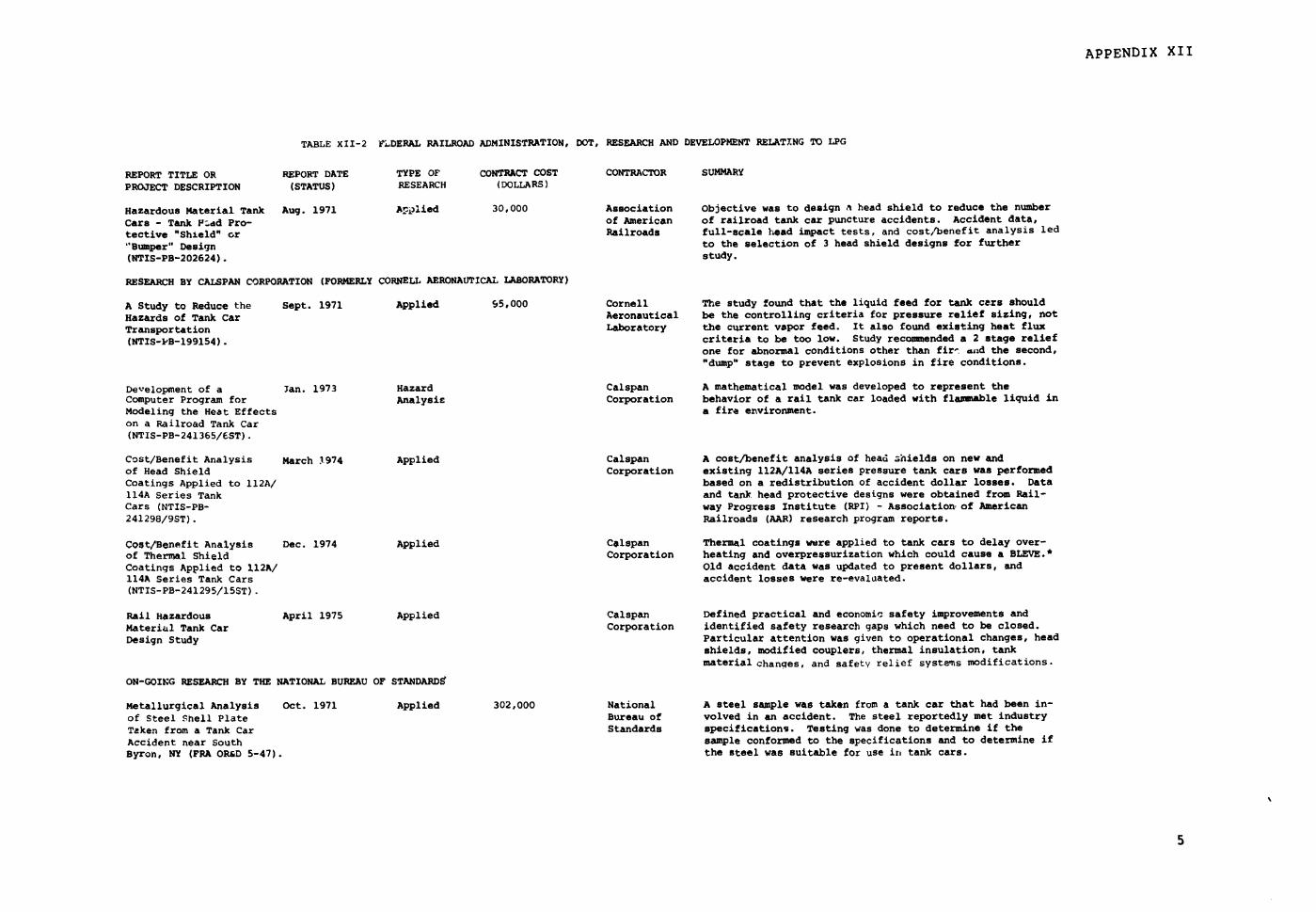
APPENDIX XII
TABLE XII-2 FLDERAL RAILROAD ADMINISTRATION, DOT, RESEARCH AND DEVELOPMENT RELAT.NG TO LPG
REPORT TITLE OR REPORT DATE TYPE OF CONTRACT COST CONTRACTOR SUMMARY
PROJECT DESCRIPTION (STATUS) RESEARCH (DOLLARS)
Hazardous Material Tank Aug. 1971 Applied 30,000 Association Objective was to design a head shield to reduce the number
Cars - Tank PYad Pro- of American of railroad tank car puncture accidents. Accident data,tective "Shield" or Railroads full-scale head impact tests, and cost/benefit analysis led
"Bumper" Design to the selection of 3 head shield designs for further
(NTIS-PB-202624). study.
RESEARCH BY CALSPAN CORPORATION (FORMERLY CORNELL AERONAUTICAL LABORATORY)
A Study to Reduce the Sept. 1971 Applied 95,000 Cornell The study found that the liquid feed for tank cars should
Hazards of Tank Car Aeronautical be the controlling criteria for pressure relief sizing, not
Transportation Laboratory the current vapor feed. It also found existing heat flux
(NTIS-PB-199154). criteria to be too low. Study recommended a 2 stage reliefone for abnormal conditions other than fire 1and the second,"dump" stage to prevent explosions in fire conditions.
Development of a Jan. 1973 Hazard Calspan A mathematical model was developed to represent theComputer Program for Analysis Corporation behavior of a rail tank car loaded with flammable liquid inModeling the Heat Effects a fire environment.on a Railroad Tank Car(NTIS-PB-241365/6ST).
Cost/Benefit Analysis March 1.974 Applied Calspan A cost/benefit analysis of head ahields on new andof Head Shield Corporation existing 112A/114A series pressure tank cars was performedCoatings Applied to 112A/ based on a redistribution of accident dollar losses. Data114A Series Tank and tank head protective designs were obtained from Rail-Cars (NTIS-PB- way Progress Institute (RPI) - Association, of American241298/9ST). Railroads (AAR) research program reports.
Cost/Benefit Analysis Dec. 1974 Applied Colspan Thermal coatings were applied to tank cars to delay over-of Thermal Shield Corporation heating and overpressurization which could cause a BLEVE.*Coatings Applied to 112A/ Old accident data was updated to present dollars, and114A Series Tank Cars accident losses were re-evaluated.(NTIS-PB-241295/15ST).
Rail Hazardous April 1975 Applied Calspan Defined practical and economic safety improvements andMaterial Tank Car Corporation identified safety research gaps which need to be closed.
Design Study Particular attention was given to operational changes, headshields, modified couplers, thermal insulation, tankmaterial changes, and safety relief systems modifications.
ON-GOING RESEARCH BY THE NATIONAL BUREAU OF STANDARDS
Metallurgical Analysis Oct. 1971 Applied 302,000 National A steel sample was taken from a tank car that had been in-of Steel Shell Plate Bureau of volved in an accident. The steel reportedly met industryTaken from a Tank Car Standards specifications. Testing was done to determine if theAccident near South sample conformed to the specifications and to determine ifByron, NY (FRA OR&D 5-47). the steel was suitable for use in tank cars.
5

APPENDIX XII
TABLE XII-2 FEDERAL RAILROAD ADMINISTRATION, DOT, RESEARCH AND DEVELOPMENT RELATING TO LPG (COtiTINUED)
REPORT TITLE OR REPORT DATE TYPE OF CONTRACT COST CONTRACTOR SUMMARYPROJECT DESCRIPTION (STATUS) RESEARCH (DOLLARS)
A Metallurgical Analysis March 1972 Applied National Five steel samples, of shell plates, head lates, and oneof Five steel Plates Bureau of combination head and shell plate, were taken from two tankTaken from a Tank Car Standards cars which were involved in the accident for a similarAccident near Crescent analysis as the above.City, Ill. (FRA-OR&D75-48).
A Metallurgical Analysis Sept. 1972 Applied National Eleven steel plate samples were taken from a tank carof Eleven Steel Plates Bureau of which was involved in an accident for a similar analysisTaken from a Tank Car Standards as the above.Accident near Callao, Mo.(FRA-OR&D 75-29).
Analysis of Findings Jan. 1975 Applied National An overview of National Bureau of Standards tests ofof Four Tank Car Bureau of accident samples is presented. Metallurgical testingAccident Reports Standards included a wide range of chemical, mechanical, and physical(NTIS-PB-251097/AS). tests.
A Metallurgical Inves- Jan. 1975 Applied National A tank car, filled with 33,000 gallons of LPG, failed aftertigation of a Full-Scale Bureau of 94 minutes of exposure to a jet fuel fire. The fragmentsInsulated Rail Tank Car Standards were examined in the field and in the laboratory.Filled with LPG Sub-jected to a Fire Environ-ment (FRA-OR&D 75-52).
Hazardous Materials 3ept. 1975 Applied National A steel sample taken from a tank car accident was metal-Tank Cars - Evaluation Bureau of lurgically tested to determine if it met specificationsof Tank Car Shell Con- Standards and how the head plate was fractured.struction Material(FRA-OR&D 75-46).
Impact Properties of June 1976 Applied National An overview is presented of the results and findings ofSteels Taken fromn Foir Bureau of impact tests of tank car materials samples taken from carsFailed Tank Cars (FRA- Standards involved in tank car accidents.OR&D 75-51).
Mechaaical Properties June 1976 Applied National Studies were done to determine the high temperatureof AAR M128-69-B Steel Bureau of mechanical properties and fracture behavior of AARPlate Samples Taken from Standards M128-B specification steel plates. The ambient tempera-insulation Fire Tested ture characteristics of the steel were also tested.Tank Car RAX 202 (rRA-OR&D 76-74).
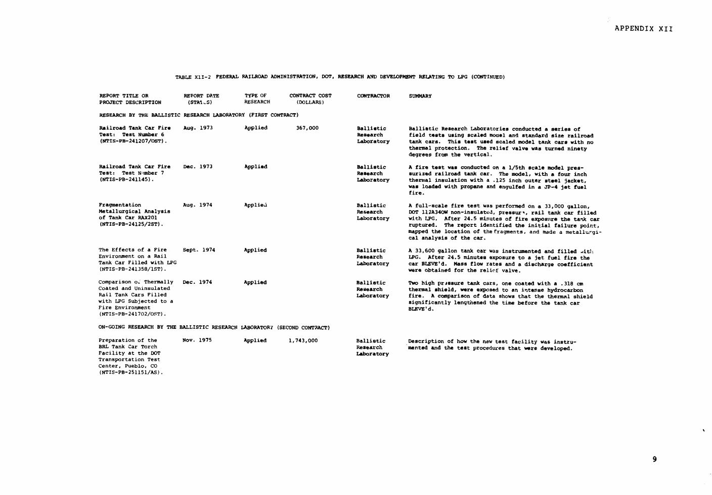
APPENDIX XII
TABLE X1I-2 FEDERAL RAILROAD ADMINISTRATION, DOT, RESEARCH AND DEVELOPMENT RELATING TO LPG (CONTINUED)
REPORT TITLE OR REPORT DATE TYPE OF CONTRACT COST CONTRACTOR SUMMARYPROJECT DESCRIPTION (STA'L-S) RESEARCH (DOLLARS)
RESEARCH BY THE BALLISTIC RESEARCH LABORATORY (FIRST CONTRACT)
Railroad Tank Car Fire Aug. 1973 Applied 367,000 Ballistic Ballistic Research Laboratories conducted a series ofTest: Test Number 6 Research field tests using scaled model and standard size railroad(NTIS-PB-241207/OST). Laboratory tank cars. This test used scaled model tank cars with no
thermal protection. The relief valve was turned ninetydegrees from the vertical.
Railroad Tank Car Fire Dec. 1973 Applied Ballistic A fire test was conducted on a 1/5th scale model pres-Test: Test N:=iber 7 Research surized railroad tank car. The model, with a four inch(NTIS-PB-241145). Laboratory thermal insulation with a .125 inch outer steel jacket,
was loaded with propane and engulfed in a JP-4 jet fuelfire.
Fragmentation Aug. 1974 Applied Ballistic A full-scale fire test was performed on a 33,000 gallon,Metallurgical Analysis Research DOT 112A340W non-insulated, pressurt, rail tank car filledof Tank Car RAX201 Laboratory with LPG. After 24.5 minutes of fire exposure the tank car(NTIS-PB-24125/2ST). ruptured. The report identified the initial failure point,
mapped the location of the fragments, and made a metallurgi-cal analysis of the car.
The Effects of a Fire Sept. 1974 Applied Ballistic A 33,600 gallon tank car was instrumented and filled ditl:Environment on a Rail Research LPG. After 24.5 minutes exposure to a jet fuel fire theTank Car Filled with LPG Laboratory car BLEVE'd. Mass flow rates and a discharge coefficient(NTIS-PB-241358/lST). were obtained for the relief valve.
Comparison oL Thermally Dec. 1974 Applied Ballistic Two high pressure tank cars, one coated with a .318 cmCoated and Uninsulated Research thermal shield, were exposed to an intense hydrocarbonRail Tank Cars Filled Laboratory fire. A comparison of data shows that the thermal shieldwith LPG Subjected to a significantly lengthened the time before the tank carFire Environment BLEVE'd.(NTIS-PB-241702/OST).
ON-GOING RESEARCH BY THE BALLISTIC RESEARCH LABORATORY (SECOND CONTRACT)
Preparation of the Nov. 1975 Applied 1,743,000 Ballistic Description of how the new test facility was instru-BRL Tank Car Torch Research mented and the test procedures that were developed.Facility at the DOT LaboratoryTransportation TestCenter, Pueblo, CO(NTIS-PB-251151/AS).
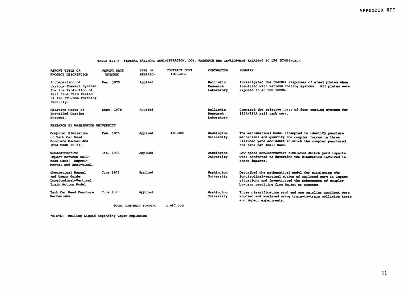
APPENDIX XII
TABLE XII-2 FEDERAL RAILROAD ADMINISTRATION, DOT, RESEARCH AND )EVELOPMENT RELATING TO LPG (CONTINUEr).
REPORT TITLE OR REPORT DATE TYPE OF CONTRACT COST CONTRACTOR SUMMARYPROJECT DESCRIPTION (STATUS) RESEARCH (DOLLARS)
A Comparison of Dec. 1975 Applied Ballistic Investigated the thermal responses of steel plates whenVarious Thermal Systems Research insulated with various coating systems. All plates werefor the Protection of Laboratory exposed to an LPG torch.Rail Tank Cars Testedat the FR, /BRL TorchingFacilitv.
Relative Costs of Sept. 1976 Applied Ballistic Compared the relative _osts of four coating systems forInstalled Coating Research 112A/114A rail tank cars.Systems. Laboratory
RESEARCH BY WASHINGTON UNIVERSITY
Computer Simulation Feb. 1975 Applied 420,000 Washington The mathematical model attempted to identify punctureof Tank Car Head University mechanisms and quantify the coupler forces in threePuncture Mechanisms railroad yard accidents in which the coupler punctured(FRA-OR&D 75-23). the tank car shell head.
Nondestructive Jan. 1976 Applied Washington Low-speed nondestructive simulated switch yard impactsImpact Between Rail- University were conducted to determine the kinematics involved inroad Cars: Experi- these impacts.mental and Analytical.
Theoretical Manual June 1976 Applied Washington Described the mathematical model for sit;ruating theand Users Guide: University longitudinal-vertical motion of railroad cars in impactLongitudinal-Vertical situations and investigated the pehnomenon of couplerTrain Action Model. by-pass resulting from impact or squeeze.
Tank Car Head Puncture June 1976 Applied Washington Three classification yard and one mainline accident wereMechanisms. University studied and analyzed using train-to-train collision tests
and impact experiments.
TOTAL CONTRACT FUNDING 2,957,000
*BLEVE: Boiling Liquid Expanding Vapor Explosion
11

APPENDIX XII
TABLE XII-3 OTHER DOT RESEARCH AND DEVELOPMENT RELATING TO LNG, LPG, AND NAPHTHA.
REPORT TITLE OR REPORT DATE TYPE OF CONTRACT COST CONTRACTOR SUMMARY
PROJECT DESCRIPTION (STATUS) RESEARCH (DOLLARS)
OFFICE OF }AZARDOUS MATERIALS OPERATIONS
Risk Analysis in March 1973 Risk 32,500 Univ. of Development of a model, using LPG data and methyl parathion
Hazardous Materials Assessment 44,500 Southern and parathion data, to compare the risks of highway
Transportation California and railroad transportation. The model was subsequently
(NTIS-FB-230 810/4). computerized and integrated with the hazardous materialsinstant reporting system.
"Emergency Services 1973 Hazard 4,400 Chemical Developed a booklet containing the potential hazards of
Guide for Selected Propulsion selected chemicals and the immediate and follow-up action.,
Hazardous Materials, Information including evacuation distances, to be taken. The booklets
Spills, Fire, Evacuation Agency were distributed to fire departments, police, carriers, and
Area." other organizations.
Hazardous Materials April 1978 Hazard 180,000 National Development of a training course for amergency services
Training Course Fire personnel to handle hazardous materials transportationProtection incidents.Association
FEDERAL HIGHWAY ADMINISTRATION
Bottom Loading of June 1977 Applied 53,400 Dynamic Reviewed devices and procedures for loading and unloading
Flammable Liquids into Science, Inc. flammable liquids and the efficacy of loading lines.
Cargo Tanks with VaporRecovery Systems,(DOT-FH-ll-9091)
Cargo Tank Integrity In June 1977 Applied 69,500 Dynamic Physical tests of tank truck rollovers to determine the
Rollover Accidents. Science, Inc. integrity of valving and piping and the potential for
iDOT-FH-11-9193) leakage.
Vehicle Handling and Final June 1978 Applied 69,000 Dynamic Study the effect of surge and high center of gravity
Control due to Cargo Science, Inc. cargoes on vehicle control and overturns.
Shifting.
OFFICE OF DEEPWATER PORTS
Offshore Liquefied Oct. 1977 Applied 70,00n Massachusetts Forecasted U.S. LNG imports to Y-2000. Identified
Natural Gas Terminals Institute of alternative design and functional configurations ofTechnology offshore LNG terminals. Based on environmental factors,
existing regulations, and DOT policy, the report maderecommendations for legislation and departmental policy
actions necessary for offshore LNG facilities.
TOTAL CONTRAC" FUNDING 523,300
13
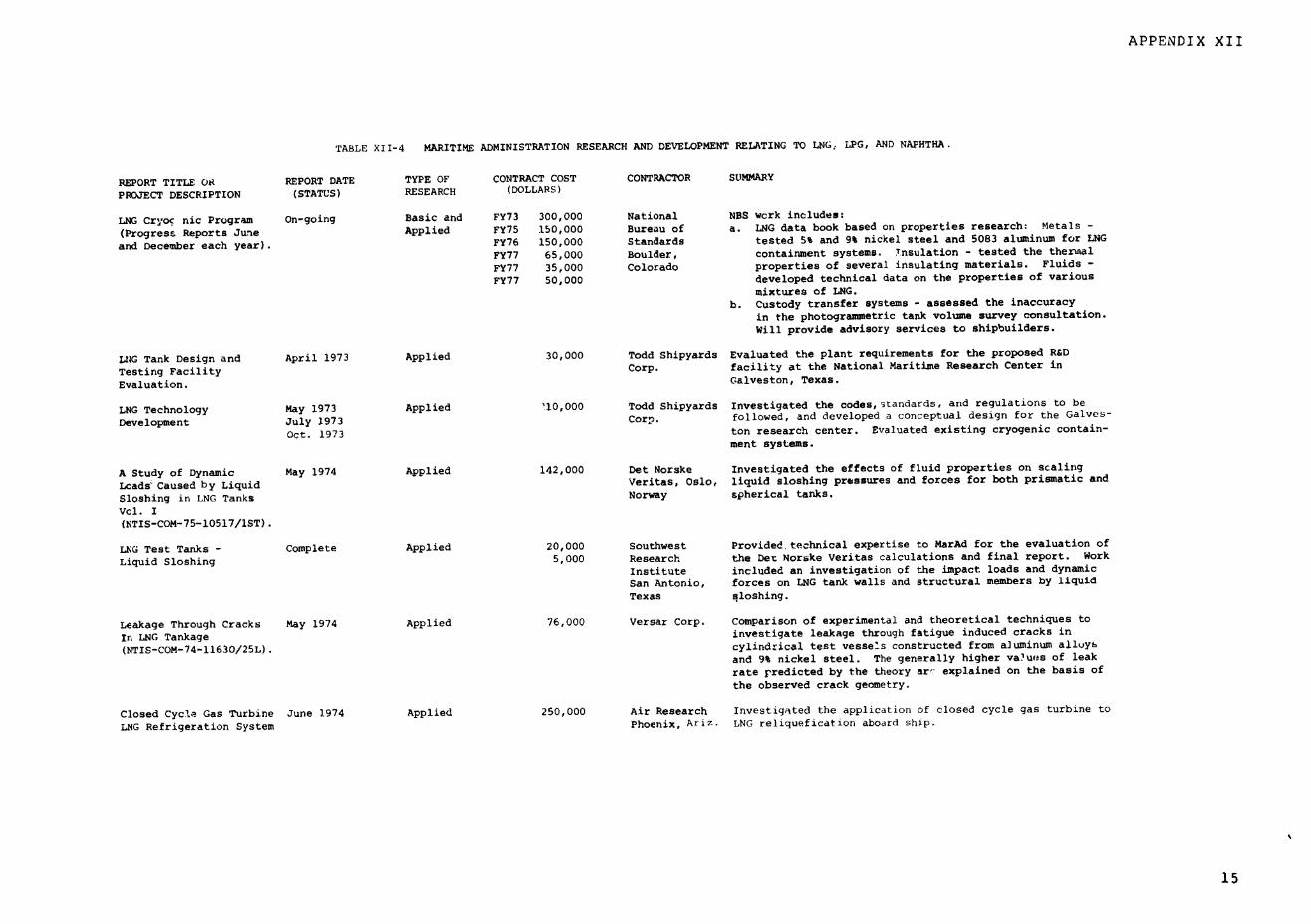
APPENDIX XII
TABLE XII-4 MARITIME ADMINISTRATION RESEARCH AND DEVELOPMENT RELATING TO LNG; LPG, AND NAPHTHA.
REPORT TITLE OR REPORT DATE TYPE OF CONTRACT COST CONTRACTOR SUMMARY
PROJECT DESCRIPTION (STATUS) RESEARCH (DOLLARS)
LNG Cryoc nic Program On-going Basic and FY73 300,000 National NBS wcrk includes:
(Progress Reports June Applied FY75 150,000 Bureau of a. LNG data book based on properties research: Metals -
and December each year). FY76 150,000 Standards tested 5% and 9% nickel steel and 5083 aluminum for LNG
FY77 65,000 Boulder, containment systems. Tnsulation - tested the thermal
FY77 35,000 Colorado properties of several insulating materials. Fluids -
FY77 50,000 developed technical data on the properties of variousmixtures of LNG.
b. Custody transfer systems - assessed the inaccuracy
in the photogrammetric tank volume survey consultation.Will provide advisory services to shipbuilders.
LOG Tank Design and April 1973 Applied 30,000 Todd Shipyards Evaluated the plant requirements for the proposed R&D
Testing Facility Corp. facility at the National Maritime Research Center in
Evaluation. Galveston, Texas.
LNG Technology May 1973 Applied '10,000 Todd Shipyards Investigated the codes,standards, and regulations to be
Development July 1973 Corp. followed, and developed a conceptual design for the Galves-
Oct. 1973 ton research center. Evaluated existing cryogenic contain-
ment systems.
A Study of Dynamic May 1974 Applied 142,000 Det Norske Investigated the effects of fluid properties on scaling
Loads Caused by Liquid Veritas, Oslo, liquid sloshing pressures and forces for both prismatic and
Sloshing in LNG Tanks Norway spherical tanks.
Vol. I(NTIS-COM-75-10517/1ST).
LNG Test Tanks - Complete Applied 20,000 Southwest Provided, technical expertise to MarAd for the evaluation of
Liquid Sloshing 5,000 Research the Det Norske Veritas calculations and final report. Work
Institute included an investigation of the impact loads and dynamic
San Antonio, forces on LNG tank walls and structural members by liquid
Texas qloshing.
Leakage Through Cracks May 1974 Applied 76,000 Versar Corp. Comparison of experimental and theoretical techniques to
In LNG Tankage investigate leakage through fatigue induced cracks in
(NTIs-COM-74-11630/25L). cylindrical test vessels constructed from aluminum alloys
and 9% nickel steel. The generally higher va'ues of leak
rate predicted by the theory arc explained on the basis of
the observed crack geometry.
Closed Cycle Gas Turbine June 1974 Applied 250,000 Air Research Investigated the application of closed cycle gas turbine to
LNG Refrigeration System Phoenix, Ariz. LNG reliquefication aboard ship.
15
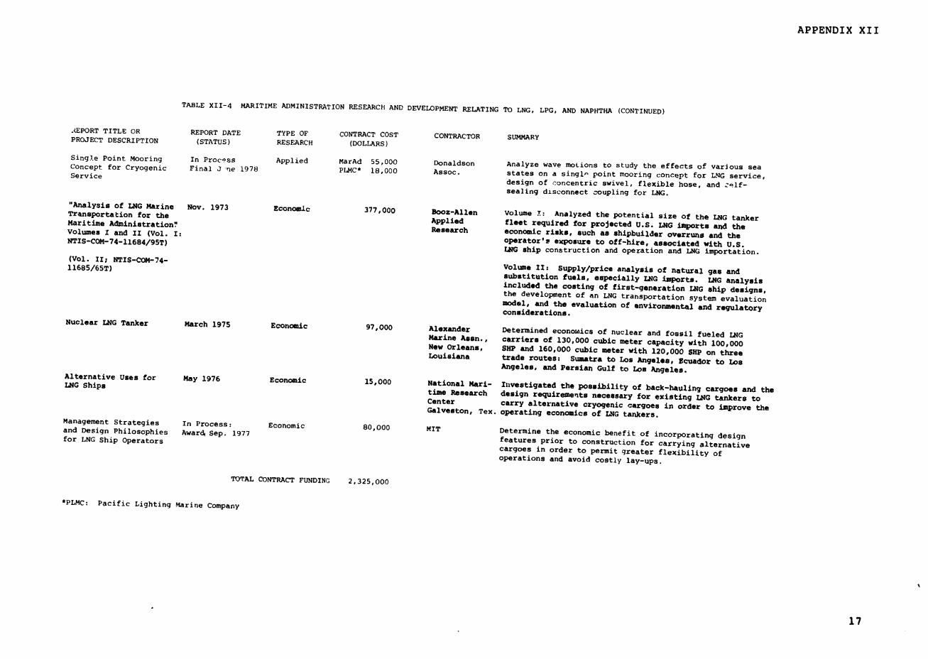
APPENDIX XII
TABLE XII-4 MARITIME ADMINISTRATION RESEARCH AND DEVELOPMENT RELATING TO LNG, LPG, AND NAPHTHA (CONTINUED)
.EPORT TITLE OR REPORT DATE TYPE OF CONTRACT COST CONTRACTOR SUMMARYPROJECT DESCRIPTION (STATUS) RESEARCH (DOLLARS)
Single Point Mooring In Process Applied MarAd 55,000 Donaldson Analyze wave motions to study the effects of various seaConcept for Cryogenic Final J ne 1978 PLMC* 18,000 Assoc. states on a singl point mooring concept for LNG service,Service design of concentric swivel, flexible hose, and a.zlf-sealing disconnect coupling for LNG.
"Analysis of LNG Marine Nov. 1973 Economic 377,000 Booz-Allen Volume T: Analyzed the potential size of the LNG tankerTransportation for the Applied fleet required for projected U.S. LNG imports and theMaritime Administration" Research economic risks, such as shipbuilder overruns and theVolumes I and II (Vol. I:
operator's exposure to off-hire, associated with U.S.NTIS-COM-74-11684/95T) LNG ship construction and operation and LNG importation.
(Vol. II; NTIS-COM-74- Volume 1: Supply/price analysis of natural gas and11685/65T) substitution fuels, especially LNG imports. LNG analysisincluded the costing of first-generation LNG ship designs,the development of an LNG transportation system evaluationmodel, and the evaluation of environmental and regulatoryconsiderations.
Nuclear LNG Tanker March 1975 Economic 97,000 Alexander Determined economics of nuclear and fossil fueled LNGMarine Assn., carriers of 130,000 cubic meter capacity with 100,000New Orleans, SHP and 160,000 cubic meter with 120,000 SHP on threeLouisiana trade routes: Sumatra to Los Angeles, Ecuador to Los
Angeles, and Persian Gulf to Los Angeles.Alternative Uses for May 1976 Economic 15,000 National Mari- Investigated the possibility of back-hauling cargoes and theLNG Ships
time Research design requirements necessary for existing LNG tankers toCenter carry alternative cryogenic cargoes in order to improve theGalveston, Tex. operating economics of LNG tankers.
Management Strategies In Process: Economic 80,000 MIT Determine the economic benefit of incorporating designand Design Philosophies Award, Sep. 1977
features prior to construction for carrying alternativefor LNG Ship Operators cargoes in order to permit greater flexibility ofoperations and avoid costly lay-ups.
TOTAL CONTRACT FUNDING 2,325,000
*PLMC: Pacific Lighting Marine Company
17
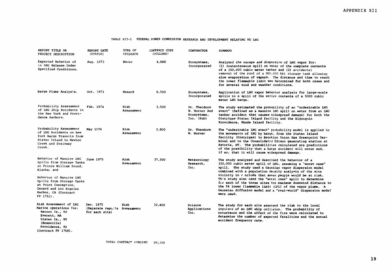
APPENDIX XII
TABLE XII-5 FEDERAL POWER COMMISSION RESEARCH AND DEVELOPMENT RELATING TO LNG
REPORT TITLE OR REPORT DATE TYPE OF CONTRACT COST CONTRACTOR SUMMARyPROJECT DESCRIPTION (STATUS) .ESEARCH (DOLLARS)
Expected Behavior of Aug. 1973 Basic 4,800 Ecosystems, Analyzed the escape and dispersion of LNG vapor fer:in LNG Release Under Incorporated (1) instantaneous spill on water of the complete contentsSpecified Conditions. of a 100,000 cubic meter tanker and (2) accidental
removal of the roof of a 900,000 bbl storage tank allowingslow evaporation of vapors. The distance and time to reachthe lower flammable limit was determined for both cases andfor several wind and weather conditions.
Barge Plume Analysis. Oct. 1973 Hazard 8,500 Ecosystems, Application of LNG vapor behavior analysis for large-scaleIncorporated spills to a spill of the entire contents of a 5000 cubic
meter LNG barge.
Probability Assessment Feb. 1974 Risk 3,500 Dr. Thecdore The study estimated the probability of an "undesirable LNGof LNG Ship Accidents in Assessment W. Horner And event" (defined as a massive LNG spill on water from an LNGthe New York and Provi- Ecosystems, tanker accident that causes widespread damage) for both thedence Harbors. Inc. (Sub) Distrigas Staten Island facility and the Algor.lin
Providence, Rhode Island facility.
Probability Assessment May 19S74 Risk 2,800 Dr. Theodore The "undesirable LNG event" probability model is applied toof LONG Accidents on New Assessment W. Horner the movements of LNG by barge, from the Staten IslandYork Barge Transits from facility (Distrigas) to Brooklyn Union Gas Green-oint Ter-Staten Island to Newton minal and to the Consolidated Edison generating station atCreek and Steinway Astoria, NY. The probabilities calculated are predictionsCreek. of the possibility that a barge accident will occur and,
if so, that it will cause widespread damage.
Behavior of Massive LNG June 1975 Risk 37,300 Meteorology The study analyzed and described the behavior of aSpills from Storage Tanks Assessment Research, 320,000 cubic meter spill of LNG, assuming a 'worst case"at Prince William Sound, Inc. spill. The study used a Gaussian vapor dispersion modelAlaska; and combined with a population density analysis of the site
vicinity to c nclude that seven people would be at risk.Behavior of Massive LNG This study also used the "worst case" spill to determineSpills from Storage Tanks fcr each of the three sites the maximum downwind distance toat Point Conception, the 5% lower flammable limit (LFL) of the vapor plume. AOxnard and Los Angeles Gaussian diffusion model and a "real-world" dispersion mode]Harbor, CA (Contract were used.FP 1751).
Risk Assessment of LNG Dec. 1975 Risk 32,400 Science The study for each site assessed the risk to the localMarine Operations for: (Separate repc,.ts Assessment Applications populace of an LNG ship collision. The probability of
Racoon Is., NJ for each site) Inc. occurrence and the effect of the fire were calculated toEverett, MA determine the number of expected fatalities and the annualStaten Is., NY accident frequency rate.(Rossville)Providence, RI
(Contract FP 1768).
TOTAL CONTRACT FUNDING 89,300
19

APPENDIX XII
TABLE XII-6 NASP. RESEARCH AND DEVELOPMENT RELATING TO LNG
REPORT TITLE OR REPORT DATE TYPE OF CONTRACT COST CONTRACTOR SUMMARYPROJECT DESCRIPTION (STATUS) RESEARCH (DOLLARS)
Risk Management Dec. 1974 Applied 171,000 Kennedy Space Work performed for the New York City Fire DepartmentTechnique for Design Center and to develop a risk management and facilities certification& Operation of LNG Boeing methodology applicable to LNG facilities.Facilities & Equipment Aerospace Co.(NASA-CR-139183).
21
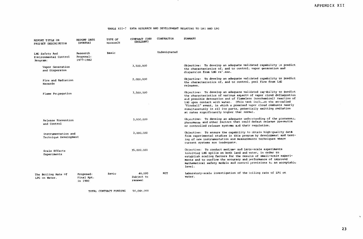
APPENDIX XII
TABLE XII-7 ERDA RESEARCH AND DEVELOPMENT RELATING TO LN' AND LPG
REPORT TITLE OR REPORT DATE TYPE OF CONTRACT COST CONTRACTOR SUMMARY
PROJELCT DESCRIPTION (STATUS) RESEARCH (DOLLARS)
LNG Safety And Research Basic Undesignated
Ervironmental Control Proposal:
Program: 1977-1982
Vapor Generation 3,500,000 Objective: To develop an adequate validated capability 'o predict
and Dispersion the characteristics of, and to control, vapor generation and
dispersion from LNG re?'ase.
Fire and Radiation 2,000,000 Objective: To develop an adequate validated capability to predict
FiHazards Radiationthe characteristics of, and to control, pool fire from LWGHazards
releases.
Flame Prcpagation 3,500,000 Objective: To develop an adequate validated caF-bility to predict
the characteristics of various aspects of vapor cloud deflagration
anid possible detonation and of flameless (nonchemical) reaction of
LNS upon contact with water. (This task inclues the so-called
"fireball" event, in which a premixed vapor cloud combusts nearly
simultaneously in all its parts, potentially emitting radiation
at rates significantly higher thar normal.
Release Prevention 3,000,000 Ob)ective: To develop an adequate understanding of the processeJ,
and Control phenomena, and other factors that could defeat release preventio
or controlled release systems aad their regulation.
Instrumentation and 3,000,000 Objective: To ensure the capability to obtain high-quality data
Technique Development from experimental studies in this program by development and test-
ing of new instrumentation and measurements techniques where
current systems are inadequate.
Scale Effects 35,000,000 Objective: To conduct medium- and large-scale experiments
Experiments involving LNG spills on both land and water, in order to
establish scaling factors for the results of small-scale experi-
ments and to confirm the accuracy and performance of improved
mathematical safety models and control provisions tu an acceptable
level.
The Boiling Rate of Proposed: Basic 46,000 MIT Laboratory-scale investigation of the boiling rate of LPG on
LPG on Water. Final Rpt. Subject to water.
in 1980 renewal
TOTAL CONTRACT FUNDING 50,046,000
23
APPENDIX XIV
CONTENTS PAGE
APPENDIX XIV-1, LPG DEMAND
XIV-2, LPG MARINE IMPORT TERMINALS 11

APPENDIX XIV-1
APPENDIX XIV-1
LPG DEMAND
TABLE XIV-1 PROJECTED OVERLAND AN.) OVERWATER LPG IMPORTS TO THE U.S.
(Million Cubic Meters)
Gas FEA Poten & Texas PaceProcessors Advisory Partners Eastern Consulting S.L.Association Committee Consultants Transmission Engineers Lindsey
1976 7.5 7.3 7.6 8.3
1978 11.3 17.8 11.7
1980 16.1 26.7 16.2 to 21.9 26.1 8.9 13.5
1985 36.2 15.1 26.9
1990 30.2
1 Includes overland imports of 6.4 million cubic meters from Canada,with declining supply beginning 1981-1982. Generally, more recentprojections of LPG imports have been s- dI downward because LPGdemand has been soft and LPG import Sn .jects have been delayed.2 Poten estimates include a higher import volume if foreign productionprices softe-.
3 Adjusted to include Canadian imports for comparison purposes.4 Does not include overland imports from Canada (estimated at 6.0 mil-lion cubic meters in 1980 and almost no imports in 1985). S.L. Lind-sey estimate was done for GAO. These projections are more likely tobe too large than too small.
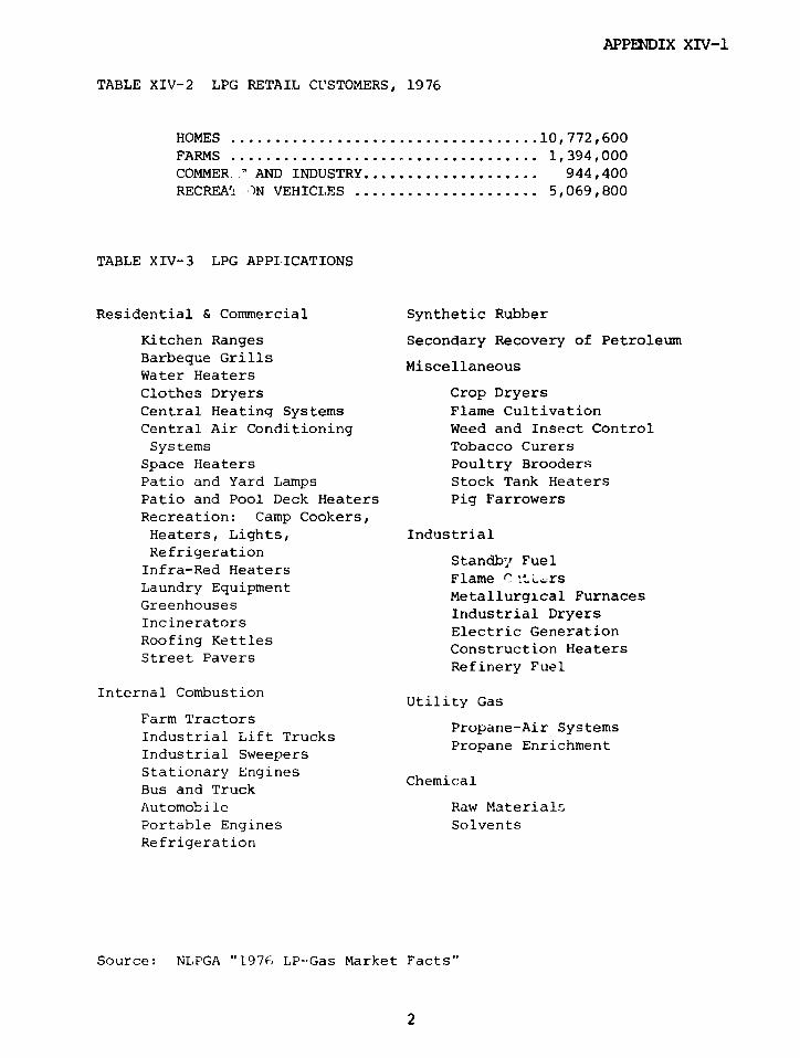
APPENDIX XIV-1
TABLE XIV-2 LPG RETAIL CUSTOMERS, 1976
HOMES .................................. 10,772,600
FARMS ................................... 1,394,000
COMMER ' AND INDUSTRY .................... 944,400RECREAI -)N VEHICLES ..................... 5,069,800
TABLE XIV-3 LPG APPLICATIONS
Residential & Commercial Synthetic Rubber
Kitchen Ranges Secondary Recovery of PetroleumBarbeque Grills MiscellaneousWater HeatersClothes Dryers Crop DryersCentral Heating Systems Flame CultivationCentral Air Conditioning Weed and Insect ControlSystems Tobacco Curers
Space Heaters Poultry BroodersPatio and Yard Lamps Stock Tank HeatersPatio and Pool Deck Heaters Pig FarrowersRecreation: Camp Cookers,Heaters, Lights, IndustrialRefrigeration Standby FuelInfra-Red Heaters Flae C tL.rs
Laundry Equipment Metallurgical FurnacesGreenhouses Industrial DryersIncinerators
Electric GenerationRoofing Kettles Construction HeatersStreet Pavers
Refinery Fuel
Internal Combustion Utility Gas
Farm TractorsPropane-Air Systems
Industrial Lift Trucks Propane EnrichmentIndustrial SweepersStationary Engines ChemicalBus and TruckAutomobile Raw MaterialsPortable Engines SolventsRefrigeration
Source: NLPGA "1976 LP--Gas Market Facts"
2
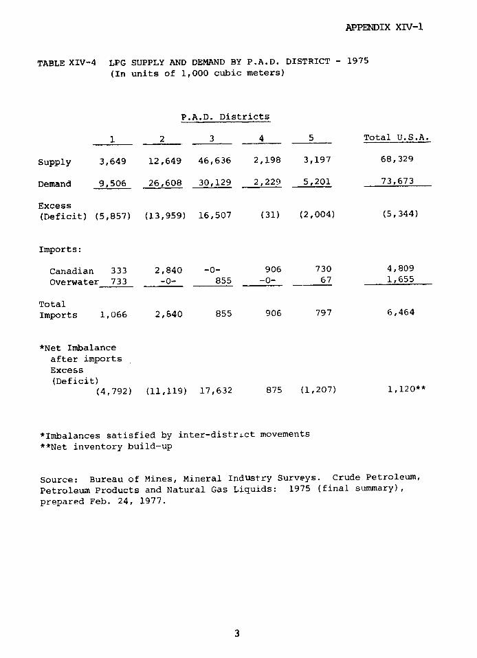
APPENDIX XIV-1
TABLE XIV-4 LPG SUPPLY AND DEMAND BY P.A.D. DISTRICT - 1975
(In units of 1,000 cubic meters)
P.A.D. Districts
1 2 3 4 5 Total U.S.A.
Supply 3,649 12,649 46,636 2,198 3,197 68,329
Demand 9,506 26,608 30,129 2,229 5,201 73,673
Excess
(Deficit) (5,857) (13,959) 16,507 (31) (2,004) (5,344)
Imports:
Canadian 333 2,840 -0- 906 730 4,809
Overwater 733 -0- 855 -0- 67 1,655
Total
Imports 1,066 2,640 855 906 797 6,464
*Net Imbalance
after imports
Excess
(Deficit)
(4,792) (11,119) 17,632 875 (1,207) 1,120**
*Imbalances satisfied by inter-district movements
**Net inventory build-up
Source: Bureau of Mines, Mineral IndUstry Surveys. Crude Petroleum,
Petroleum Products and Natural Gas Liquids: 1975 (final summary),
prepared Feb. 24, 1977.
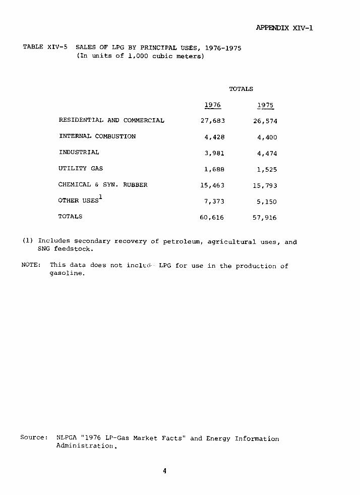
APPENDIX XIV-1
TABLE XIV-5 SALES OF LPG BY PRINCIPAL USES, 1976-1975(In units of 1,000 cubic meters)
TOTALS
1976 1975
RESIDENTIAL AND COMMERCIAL 27,683 26,574
INTERNAL COMBUSTION 4,428 4,400
INDUSTRIAL 3,981 4,474
UTILITY GAS 1,688 1,525
CHEMICAL & SYN. RUBBER 15,463 15,793
OTHER USES1 7,373 5,150
TOTALS 60,616 57,916
(1) Includes secondary recovery of petroleum, agricultural uses, andSNG feedstock.
NOTE: This data does not inclcu. LPG for use in the production ofgasoline.
Source: NLPGA "1976 LP-Gas Market Facts" and Energy InformationAdministration.
4
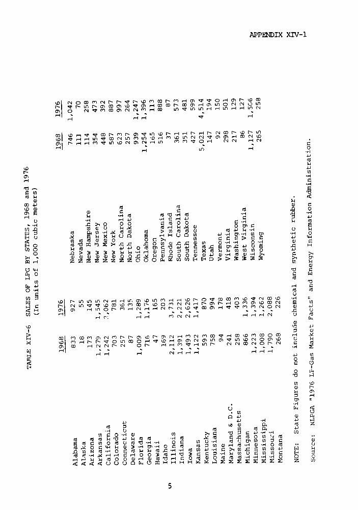
APPENDIX XIV-1
D CN 0 0 omC N N: t- 0 O0 W Nq 1- 4 g - -H O0 N D o
m 0MO U- CO n cT 03 Ci -_) :r) I 1) U1 - 1 CNH H U, ( 4
_IN 00 C° 'P t O 1N H t- N CO N- H N) ( N r N I
Ln * 00
( CC
a4
Ca cQ 0
Hk * H i 4r)- (i -<4H
aEo .: X P 4-
E -0 :: ::0 C 0U '
a) Q- U) a) a) a) 0 0 4 4 ) 4, CD -1 d Q) -- U C: >1 m :P4~~~~~ 0
U) 'PD0 - W
:> C m ~ ° _ Or n N -N rl r - -_ ~ C ' *) ) rn - Cn r
0 . hD o a 0o o N o oH H H H ~ P N o r r
oO ,-- r-c, r C4 [" C' OH F " ,- ,. ('5 : -0
0)
E-\D '4~ ~4d 4
6\ 0 0l N C~ ~ N O ~r( rl m d ri Ln r`c o o
,-I U
Hi 4-J H 4-z C
5
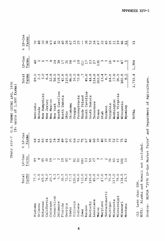
APPENDIX XIV-1
C Co m { 1 e m r-' N 0o r- . .L I 00 i " - N L i n - r-.; U > st m m IV rn M N NI *n CN N H 14 I'D Ln
U)
tn 6 co qT ~ m O v ao r co in c_ u r,~~ >-t4
? ~-4
0O 0 0~00000000 0-O OOO OOON
4 Jh (Nm( N 0NDN O r t q U 4 C4 m wO m - LOn H T -4 r T H N o - v .- , · D O N
: H T H H H N H b n
* U 444
N- - 4 J
a4 o H H u H C M W CO C . >1 0 0 0 O O C 0
Z ' ( E -U H M (a (a > w m m w M4-) H 0
H) U4 1r p r) o ° ,U a r -I U Un c- ) Z 4L-4 ( a .u D >1 . 0 U) o W U ) L 0 * o H o H a4-
O S- c 4 4 0 O 4 ~O' 4J; 0¾ 0 4_ CuE 0, -4 , 7 ¢ X (0 , -0E W > 3 3 3 3 H C o W0 W g 0C x) 00 4 W (r W a O o>, 0
4 J oo xh O e U O E-4t s) z z Z z z z z O O O4 u E :3 kH ra
U U )
(r a
U)t:~~~~~~~ ~( 4
U" U1
) E :,4
r ro U) M n4 U O U)
E -U O*: :n00 c O 4 0 0 ) o 0 0
Qr' N ' ' ' 'DNN u o m r-'cl N,-4 r r- u -4 NMm -j c N)04CL H r H 0 o
Q D1 M -- O C ra H 4 1- O 14 -1 O U O O J O 4 O O W r W CO 1- X 4
- H 4 4 3 C)Q)U)C )0 ( Co :
000 CZ o ,
< :U U U h 0 a · X *4 C rC q O x k a x

APPENDIX XTV-1
TABLE (IV-8 AGRICULTURAL CROP DRYER SHIPMENTS 1963 - 1976
GRAIN, HAY AND SEED DRYERS
Unheated
YEAR Heated Types* Air Types Totals
1963 6,161 5,446 11,607
1964 6,061 5,169 11,230
1965 11,801 8,024 19,825
1966 14,904 2,535 17,439
1967 15,278 -- 15,278
1968 17,318 925 18,243
1969 10,103 1,519 11,622
1970 7,153 2,019 9,172
1971 13,245 2,279 15,5241972 16,456 3,358 19,814
1973 23,364 12,140 35,504
1974 34,781 15,936 50,717
1975 24,540 19,586 44,1261976 25,242 22,429 47,671
*Consist of batch type, continuous flow, heated air and supplemental
heater units estimated by manufacturers to be 90% to 95% LPG fueled.
Source: NLPGA "1976 LP-Gas Market Facts" and Bureau of the Census.
7

APPENDIX XIV-1
FIG. XIV-1 AREAS USING PROPANE TO CURE TOBACCO
NORTH DAKOTA MINN
I H DAKTA'-'. - WISCOS
--- - --·----| OK-__OMA<VOW; - - - -
...... . ,,- OHIO .Z 'a -·
YU-I /lA W~ i
\ \ XS_1SISSPPI; _.
COMPILED FROM VARiOUS COMPANY FILES AND INTERVIEWS
8
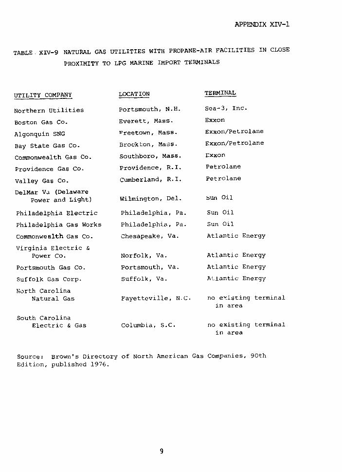
APPENDIX XIV-1
TABLE XIV-9 NATURAL GAS UTILITIES WITH PROPANE-AIR FACILITIES IN CLOSE
PROXIMITY TO LPG MARINE IMPORT TERMINALS
UTILITY COMPANY LOCATION TERMINAL
Northern Utilities Portsmouth, N.H. Sea-3, Inc.
Boston Gas Co. Everett, Mass. Exxon
Algonquin SNG Wreetown, Mass. Exxon/Petrolane
Bay State Gas Co. Brockton, Mass. Exxon/Petrolane
Commonwealth Gas Co. Southboro, Mass. Exxon
Providence Gas Co. Providence, R.I. Petrolane
Valley Gas Co. Cumberland, R.I. Petrolane
DelMar Va (DelawarePower and Light) Wilmington, Del. bun Oil
Philadelphia Electric Philadelphia, Pa. Sun Oil
Philadelphia Gas Works Philadelphia, Pa. Sun Oil
Commonwealth Gas Co. Chesapeake, Va. Atlantic Energy
Virginia Electric &Power Co. Norfolk, Va. Atlantic Energy
Portsmouth Gas Co. Portsmouth, Va. Atlantic Energy
Suffolk Gas Corp. Suffolk, Va. Atlantic Energy
North CarolinaNatural Gas Fayetteville, N.C. no existing terminal
in area
South CarolinaElectric & Gas Columbia, S.C. no existing terminal
in area
Source: Brown's Directory of North American Gas Companies, 90th
Edition, published 1976.

APPENDIX XIV-1
TABLE XIV-10 SYNTHETIC NATURAL GAS PLANTS CONNECTED BY PIPELINE TO
LPG MARINE IMPORT TERMINALS
UTILITY COMPANY LOCATION TERMINAL
Boston Gas SNG Everett, Mass. Exxon (Everett)
Commonwealth SNG Co. Chesapeake, Va. Atlantic Energy(Chesapeake)
Columbia LNG Co. Green Springs, Ohio Coastal States (CorpusChristi)
Warren Petroleum(Houston)
Phillips Petroleum(Houston) *
Oiltanking (Houston)Conoco (Atkinson Island)T.E.T./NNG/Mobil/Texaco
(Sabine Pass)*
*Planned terminal
10
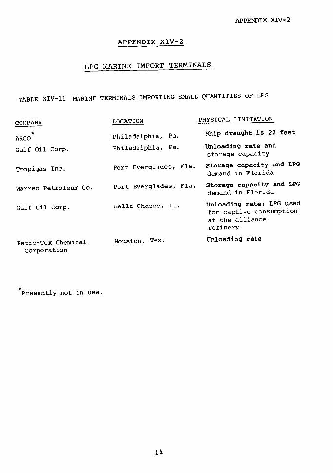
APPENDIX XIV-2
APPENDIX XIV-2
LPG i4ARINE IMPORT TERMINALS
TABLE XIV-ll MARINE TERMINALS IMPORTING SMALL QUANTITIES OF LPG
COMPANY LOCATION PHYSICAL LIMITATION
ARCO Philadelphia, Pa. Ship draught is 22 feet
Gulf Oil Corp. Philadelphia, Pa. Unloading rate and
storage capacity
Tropigas Inc. Port Everglades, Fla. Storage capacity and LPG
demand in Florida
Warren Petroleum Co. Port Everglades, Fla. Storage capacity and LPG
demand in Florida
Gulf Oil Corp. Belle Chasse, La. Unloading rate; LPG used
for captive consumption
at the alliancerefinery
Petro-Tex Chemical Houston, Tex. Unloading rate
Corporation
Presently not in use.
11

APPENDIX XIV-2
TABLE XIV-12 ANNUAL HANDLING CAPACITY OF MAJOR LPG IMPORT TERMINALS1
(In units of one million cubic meters)
LOCATION OWNER 1977 1980 1985 1990
Newington, N.H. Sea 3 0.5 1.1 1.1 1.1
Everett, Mass. Exxon .1 1.1 1.1 1.1
Providence, R.I. Petrolane 0.7 0.7 0.8 0.8
Marcus Hook, Pa. Sun Oil 0.3 1.0 5.6 5.6
Chesapeake, Va. Atlantic Energy 1.0 1.0 1.0 1.0
Plaquemine, La. Dow Chemical 0 2.9 2.9 2.9*Hackberry, La. Cities Service 0.2 4.8 4.8 4.8
Sabine Pass, Tex. Mobil/N.N.G./T.E.T./Texaco 0 0 13.5 13.5
Houston, Tex. Conoco 0 0 7.9 7.9
Houston, Tex. Oiltanking of Texas 0 7.9 7.9 7.9
Houston, Tex. Phillips Petroleum 1.0 1.2 1.2 1.2
Houston, Tex. Warren Petroleum 2.4 9.8 9.8 9.8
Corpus Christi, Tex. Coastal States 1.2 1.2 1.2 1.2
San Pedro, Cal. Petrolane 1.3 2.1 2.1 2.1
Ferndale, Wash. California Liquid Gas 0.7 o.7 0.7 0.7
Total 10.4 35.5 61.4 61.4
1. 50% of capacity if unknown
Planned LPG terminals
12

APPENDIX XIV-2
TABLE XIV-13 PROJECTED LPG MOVEMENT THROUGH MARTNE IMPORT TERMINALS
(In units of one mi lion cubic meters)
Location Owr,er 1980 1985
Newington, N.H. Sea-3 0.5 0.8
Everett, Mass. Exxon 0.8 1.0
Providence, R.I. Petrolane 0.5 0.8
Marcus Hook, Pa. Sun Oil 0.8 1.7
Chesapea!ke, Va. Atlantic Energy 0.6 0.9
Plaquemin?, La. Dow Chemical 0.2 1.4
Hackberry, La. Cities Service 1.2 2.6
Sabine Pass, Tex. TET/NNG/Mobil/Texaco - 5.A
Houston, Tex. Conoco or Oiltanking 2.8 3.8
Houston, Tex. Phillips Petroleum 0.4 1.2
Houston, Tex. Warren Petroleum 3.6 4.4
Corpus Christi, Tex. Coastal States 1.z 1.2
San Pedro, Cal. Petrolane 0.8
Ferndale, Wash. California Liquid Gas 0.3 0./
TOTAL 13.5 26.9
1. W· believe these projections are more likely to be too large than
too small.
13
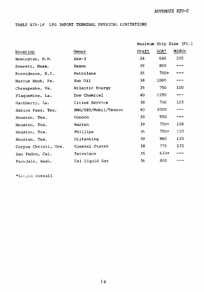
APPENDIX XIV-2
TABLE XIV-lD LPG IMPORT TERMINAL PHYSICAL LIMITATIONS
Maximum Ship Size (Ft.)
Location Owner Draft LOA* Width
Newington, N.H. Sea-3 34 640 100
Everett, Mass. Exxon 39 800 ---
Providence, R.I. Petrolane 35 700+ ---
Marcus Hook, Pa. Sun Oil 38 1000 ---
Chesapeake, Va. Atlantic Energy 35 750 110
Plaquemine, La. Dow Chemical 40 1250 ---
Hackberry, La. Cities Service 38 750 125
Sabine Pass, Tex. NNG/TET/Mobil/Texaco 40 1000 --
Houston, Tex. Conoco 39 950 ---
Houston, Tex. Warren 39 750+ 116
Houston, Tex. Phillips 36 750+ 110
Houston, Tex. Oiltanking 39 860 125
Corpus Christi, Tex. Coastal States 38 775 133
San Pedro, Cal. Petrolane 35 633+ ---
Ferndale, Wash. Cal Liquid Gas 36 800 ---
*Lenijth Overall
14

APPENDIX XIV-2
NEWINGTON, NEW HAMPSHIRE
Owner: SEA-3 Inc. (GAZOCEAN)
The Newington terminal is the northernmost site
currently receiving LPG. Although the facility is
non-urban, ships navigating the Piscataqua River pass
downtown Portsmouth. The Newington terminal serves the
local residential market when domestic supply becomes
unavailable during the winter.
There is one 63,600 cubic meter aboveground,
refrigerated LPG tank, but there is enough space to
construct another tank of the same size. Additional land
is available adjacent to the site to construct a 50 MMcf/d
SNG plant. Granite State Transmission Company, serving New
Hampshire and Maine, has a natural gas pipeline passing
within 1,000 feet of the import terminal.
Current restrictions at the terminal and on the
waterway to the site exclude ships larger than 40,000 cubic
meters.
The terminal is north of most of the New England
industrial market, and its imports thus incur an $8.00 per
cubic meter charge for truck or rail transportation. This
places the facility at a competitive disadvantage with the
Exxon and Petzolane terminals for the Boston and Providence
markets. Because of location and current winter/summer
product use ratio, the current annual capacity is 500,000
cubic meters. Outloading is through three truck spots and
six rail tank car spots which normally receive two rail
switches per day.*
*"Rail Switcn" - "One group of railrars on a train" switched into the
receiving terminal at one time; In effect, a "delivery."
15
APPENDIX XIV-2
If additional storage and either LPG-air or SNG
facilities were built, annual LPG capacity could
increase to 1 million cubic meters, limited by the
number and size of incoming vessels.
EVERETT (BOSTON), MASSACHUSETTS
Owner: Exxon Company U.S.A.
This urban site is close to the pipelines of two
major gas transmission companies, Tennessee Gas
Transmission and Algonquin.
The outloading capacity of this facility is
substantially higher than others of like size because it
supplies 1,600 cubic meters per day by pipeline to the
Boston Gas SNG plant for feedstock. There are four rail
car spots with two switches per day and three truck
spots. The maximum daily throughput capacity is 6,900
cubic meters. The annual capacity is dependent upon the
number of operational days of the SNG plant. With
normal maintenance down time at the SNG plant, the
annual handling capacity is about 1.1 million cubic
meters. Land and environmental restrictions mike it
unlikely that additional storage can be added at this
site. The existing storage is an aboteground 63,600
cubic meters refrigerated tank. The site is designed to
handle ships of up to 40,000 cubic meters, but 52,000
cubic meter ships have offloaded partial cargoes.
16

APPENDIX XIV-2
PROVIDENCE, RHODE ISLAND
Owner: Petrolane Incorporated
This terminal is located in an urban area and
delivers 800 cubic meters per day of propane by pipeline
to the Providence Gas Company. No rail car service is
available. There are three truck loading spots with
daily maximum output of 4,500 cubic meters. The site's
maximum annual handling capacity is 730,000 cubic
meters. The facility has a single 63,600 cubic meter
refrigerated aboveground stcrage tank. Due to land
limitations, there is no possibility of expanding
storage facilities.
The largest vessel to offload so far held 52,000
cubic meters, but Petrolane has a general policy
restricting incoming vessels to 30,000 cubic meters due
to the difficulty of providing adequate storage capacity
for the larger vessels on a timely basis.
The terminal serves industrial and residential
LPG users when cheaper domestically produced products
are not available. Thei ILgcnquin SNG plant in Freetown,
Mass., which uses naphtha as a feedstock, also gets
imported propane from this terminal to upgrade the
quality of its pipeline gas.
MARCUS HOOK, PENNSYLVANIA
Owner: Sun Oil Company
This terminal began to receive ships in December
1977. The rest of the facility was already operating in
conjunction with the refinery operations. The site
17
APPENDIX XIV-2
serves the eastern industrial fuel market and is near
the proposed Transcontinental Pipeline SNG plant at Twin
Oaks, Pennsylvania, which could use butane as a
feedstock.
The Sun Oil Co. is negotiating with the Texas
Eastern Transmission Corp. to use its LPG pipeline
system. Reversal of the present LPG flow (from the
Pittsburgh area to Marcus Hook) would give the Sun Oil
Terminal access to markets in western Pennsylvania,
Ohio, and upstate New York. The Marcus Hook leg of the
Texas Eastern pipeline has a daily capacity of 3,200
cubic meters. LPG from the Gulf Coast would be
displaced to markets in other regions.
The Sun LPG marine terminal has storage capacity
of 183,000 cubic meters for propane and 62,500 cubic
meters for butane. The oil refinery has storage
capacity of 76,300 cubic meters for butane and 12,000
cubic meters for propylene. All LPG is stored in
underground mined granite caverns.
Because LPG distribution from the terminal is
only by rail and truck, the current handling capability
of the facility is limited to 9,200 cubic meters per day
and 1 million cubic meters per year. With pipeline
connections to the Texas Eastern system and the proposed
Transco SNG plant, berthing would become the limiting
factor. Handling capability could be eventually
increased to 5.6 million cubic meters per year.
18
APPENDIX XIV-2
CHESAPEAKE (NORFOLK), VIRGINIA
Owner: Atlantic Energy, Inc.
This facility supplies 1,100 cubic meters of
butane per day by pipeline to the Commonwealth Natural
Gas SNG plant which serves seven industrial companies in
the Chesapeake area. Atlantic Energy, Inc., the owner
and operator of the terminal, is jointly owned by
Tropigas International and Virginia Bottled Gas of
Virginia (owned by Commonwealth). The terminal has two
38,200 cubic meter refrigerated storage tanks. One is
in butane service for the SNG plant; the other is used
for importing propane. The site is located in a
non-urban area with little surrounding population. A
second 38,200 cubic meter propane tank will probably be
in service by 1980. This will allow the facility to be
serviced by 52,000 cubic meter ships.
The outloading facilities nave seven rail car
spots with three switches per day and two truck loading
spots.
The daily maximum throughput is 5,100 cubic
meters of propane and 1,100 cubic meters of butane. The
total annual LPG handling capability is about 950,000
cubic meters. The terminal is connected to the
Commonwealth Natural Gas system, which is interconnected
to the Transcontinental Transmission line. The area it
serves has a greater demand than the Dixie LPG pipeline
can supply.
19
APPENDIX XIV-2
PLAQUEMINE, LOUISIANA
Owner: Dow Chemical Company
This facility is tied by pipeline to the Wanda
Petroleum Company (a Dow Chemical subsidiary) storage
and fractionation complexes at Napoleonville and Breaux
Bridge, Louisiana. Naphtha is now being moved through
the pipeline system. An additional line to move LPG is
not currently programmed, but is possible in the future.
The Napoleonville/Breaux Bridge complex has a
16,000 cubic meters per day fractionation facility and
827,000 cubic meters of underground salt storage. It
currently stores imported naphtha and domestic LPG. The
butane is used in local refineries and the propane is
sent via the Dixie LPG pipeline for use in the
southeastern United States.
Many natural gas transmission lines start in
this area and they could use LPG. Among them are lines
owned by Southern Natural Gas, United Gas Pipeline,
Texas Eastern Transmission, Florida Gas Transmission and
others.
HACKBERRY (LAKE CHARLES), LOUISIANA
Owner: Cities Service Company
Cities Service recently announced plans to
install by mid-1979 an LPG terminaling facility 17 miles
south of Lake Charles on the Calcasieu Ship Channel
which flows into the Gulf of Mexico.
20
APPENDIX XIV-2
Connected underground salt storage will be
provided by two new 160,000 cubic meter wells. One will
be for propane, the other for mixed butanes. The
storage is in addition to an existing 8-well (1,270,000
cubic meter) Cities Service complex located on the West
Hackberry salt dome. The storage caverns can receive
LPG at an offloading rate of 45,000 cubic meters per day
after warmup of the product. The storage complex is
connected by pipeline to natural gas liquids plants,
refineries, and the Dixie LPG pipeline, and receives
product from Mt. Belvieu. The maximum annual offloading
volume is limited by the local demand for butane and the
ability to inject propane into the Dixie pipeline at
Sulphur, Louisiana. The maximum annual volume will
increase from an initial 1.9 million cubic meters to
4.75 million cubic meters by 1985. The facility will
handle any ship of 75,000 cubic meters or less. Its
location in the natural gas producing area gives this
facility access to natural gas transmission lines owned
by Natural Gas Pipeline Co., Columbia Gulf Transmission,
Transcontinental Pipe Line, Tennessee Gas Pipeline and
Michigan Wisconsin Pipeline Co.
SABINE PASS, TEXAS
Owner: Mobil Oil/Northern Natural Gas/Texas Eastern
Transmissior/Tcxaco
A terminal at the Texas/Louisiana border has
been contemplated for some time and the owner consortium
has announced that $5 million has been allocated for an
analytical engineering study to be completed by
mid-1978.
21
APPENDIX XI7-2
The terminal would be constructed by 1983 at the
mouth of Sabine Pass on the Texas side of the river.
The vessel offloading rate of 95,000 cubic meters per
day would be the highest in the United States. The
initial 1.75 million cubic meters of underground salt
storage, to be washed from the Big Hill salt dome
located near the terminal site, would be increased to 4
million cubic meters.
The terlinal would be connected by pipeline to
the Texas Eastern LPG pipeline some 40 miles north of
the 260 acre Sabine Pass site and approximately 1.00
miles east of Houston. The terminal is designed to
accommodate vessels up to 150,000 cubic meters.
Two gas transmission lines pass through the
immediate area. One, owned by Natural Gas Pipeline Co.,
crosses the terminal property, and the Transcontinental
Gas pipeline is close by.
ATKINSON ISLAND (HOUSTON), TEXAS
Owner: Continental Oil Company
A multi-owner terminal near Baytown, Texas, at
the mouth of the Houston ship channel, has been proposed
by Conoco for ships up to 950 feet long, holding more
than 75 00 cubic meters. The facility could receive up
to 2,400 cubic meters per hour and deliver it to Mt.
Belvieu for storage.
The project has been delayed until 1982. Some
90 acres of the Barbers Hill (Mt. Belvieu) salt dome was
purchased by Conoco during 1974; potential storage in
22
APPENDIX XIV-2
the dome is 2.9 million cubic meters. Any injection
into natural gas lines would be at the Mt. Belvieu
storage area.
HOUSTON, TEXAS
Owner: Oiltanking of Texas, Inc.
This multiple purpose import terminal located on
the Houston ship channel plans to include LPG offloading
capabilities by 1978. Berthing facilities can now
accommodate vessels up to 100,000 cubic meters, but the
Houston channel has only 40 feet of water at mean low
water and thus cannot transit ships larger than 75,000
cubic meters. The terminal is adjacent to a 1,600 foot
turning basin and across the channel from the Shell Oil
Petrochemical and Refinery Plant.
The planned offloading rate for propane is 2,100
cubic meters per hour. It will be warmed with seawater
at the dockside and pumped to the Mt. Belvieu storage
complex. Butane can be simultaneously offloaded into
two 20,000 cubic meter shore tanks at the ship's pumping
rate and then pumped to Mt. Belvieu or other locations
as requested, after the propane is pumped. The annual
handling capability of 8 million cubic meters is limited
by the pumping capacity to Mt. Belvieu.
Crude, condensate, and dry bult aragonite are
also offloaded through the terminal. Three berths are
currently used and a finger pier with two berths is
available for T PG in the future.
23
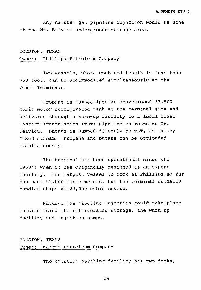
APPENDIX XIV-2
Any natural gas pipeline injection would be done
at the Mt. Belvieu underground storage area.
HOUSTON, TEXAS
Owner: Phillips Petroleum Company
Two vessels, whose combined length is less than
750 feet, can be accommodated simultaneously at the
Adiiiis Terminals.
Propane is pumped into an aboveground 27,500
cubic meter refrigerated tank at the terminal site and
delivered through a warm-up facility to a local Texas
Eastern Transmission (TET) pipeline en route to Mt.
Belvieu. Butane is pumped directly to TET, as is any
mixed stream. Propane and butane can be offloaded
simultaneously.
The terminal has been operational since the
1960's when it was originally designed as an export
facility. The largest vessel to dock at Phillips so far
has been 52,000 cubic meters, but the terminal normally
handles ships of 22,000 cubic meters.
Natural gas pipeline injection could take place
on site using the refrigerated storage, the warm-up
facility and injection pumps.
HOUSTON, TEXAS
Owner: Warren Petroleum Company
The existing berthing facility has two docks,
24

APPENDIX XIV-2
one for butane, the other for propane. It was
originally designed for loading small vessels and barges
with butane for the Northeast and has been operational
for over twenty years.
Currently, 52,000 cubic meter and smaller
vessels are using the site which is connected to the Mt.
Belvieu underground storage complex.
Warren plans to construct a new dock by mid-1978
to accommodate up to 75,000 cubic meter ships. Existing
Houston Ship Channel restrictions will have to be
modified slightly from the current 750 feet length, 116
feet beam rule to allow the 75,000 cubic meter ships.
Warren has 57,000 cubic meters of on-site
aboveground storage; however, most product is moved
directly to Mt. Belvieu as the vessel offloads. Any
natural gas pipeline injection would be done at Warren's
large underground storage complex at Mt. Belvieu.
CORPUS CHRISTI, TEXAS
Owner: Coastal States Marketing, Inc.
Vessels are offloaded at the Coastal facility
through an 8-inch line and a 12-inch line connected
directly to Coastal's underground storage and
fractionation facility located approximately 200 miles
to the northeast at Almeda, near Houston. Five 320
cubic meter tanks are used at the Corpus Christi site to
provide surge storage between the vessel and the
pipelines. The Coastal facility is capable of
offloading vessels at a rate of 560 cubic meters per
hour.
25

APPENDIX XIV-2
The Coastal facility is not equipped with
onshore facilities to warm up the LPG product to
pipeline temperature. As a result, only butane or
propane-butane mixtures are currently being offloaded,
unless the vessel is equipped with heat exchangers.
However, onshore warm-up facilities could be installed
at very minimal cost.
A new import facility is also under
consideration by Coastal States. If the venture is
undertaken, it would be located on 45 feet of water aD'
have the capability of offloading vessels of prop
butanes at rates of 2,400 to 4,000 cubic meters per
hour. The facility would be designed to handle a
minimum daily throughput of 5,500 cubic meters and a
maximum of approximately 23,800 cubic meters.
SAN PEDRO (LOS ANGELES), CALIFORNIA
Owner: Petrolane Incorporated
The offloading facility is located at a
municipal dock in the West Basin of the Harbor at San
Pedro. The propane is pumped 6,000 feet through an
underground refrigerated pipeline to two aboveground
48,000 cubic meter refrigerated tanks. Rail and truck
loading and unloading facilities are available. Only
one ship, in the fall of 1976, has delivered LPG to the
terminal. The terminal has been used for storing excess
su.-mmer product from local refineries.
Under recent contractual agreements, Petrolane
will supply Pacific Lighting Service Company with
800,000 cubic meters of imported propane annually. It
26

APPENDIX XIV-2
will be injected as propi e-air. Final approval is
pending from the California Public Utility Commission.
FERNDALE, WASHINGTON
Owner: California Liquid Gas Corporation
There is one 55,600 cubic meter aboveground
refrigerated storage tank five miles from Ferndale. The
docking facil? y is owned by F .id shared with Intalco
Allminum Company.
The facility is able to handle 52,000 cubic
meter ships and the corporation expects to use this size
when importing product. I- has the land available to
construct two additional tanks. In the early 1980's, if
major imports are necessary, the corporation plans to
constru- rdditional tanks and use 72,000 cubic meter
'hwert Pipeline Company has a natural gas
transmission line in the area.
POTENTIAL IMPORT SITF
Potential non-urban import terminal sites exist
at smaller ports which have enouqh water (35 feet) to
make them feasible for the existirn LPG fleet to
service. There has not yet been enough demand for LPG
in these areas to justify such terminals. With tl'3
current decline in domestic LPG production and the
increase in demand for imports, however, some of these
sites may become economically feasible. To be
27
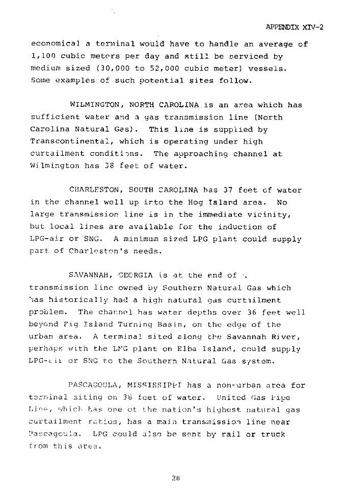
APPENDIX XIl-2
economical. a terminal would have to handle an average of
1,100 cubic meters per day and still be serviced by
medium sized (30,000 to 52,000 cubic meter) vessels.
Some examples of such potential sites follow.
WILMINGTON, NORTH CAROLINA is an area which has
sufficient water and a gas transmission line (North
Carolina Natural Gas). This line is supplied by
Transcontinental, which is operating under high
curtailment conditions. The approaching channel at
Wilmington has 38 feet of water.
CHARLESTON, SOUTH CAROLINA has 37 feet of water
in the channel well up irto the Hog Island area. No
large transmission line is in the immediate vicinity,
but local lines are available for the induction of
LPG-air or SNG. A minimum sized LPG plant could supply
part of Charleston's needs.
SAVANNAH, CECRGIA is at the end of
transmission line owned by Southern Natural Gas which
Ilas historically had a high natural gjds curtilment
prDblem. The channel has water depths over 36 feet well
beyond Fig Island Turning Basin, on the edge of the
urban area. A terminal sited along the Savannah River,
perhaps with the LNG plant on Elba Island., could supply
LPG-a ii or SNG to the Southern Natural Gas system.
PASCAGOUILA, MISSISSIPPI has a non-urban area for
terminal siting on 36 feet of water. United Gas Pice
Iie_, tlhich has one ot the nation's highest natural gas
curtailment ratios, has a main transmnission line near
2asa:cgocua. LPG could also be sent by rail or truck
_rom this area.
28

APPENDIX XIV-2
BENICIA, CALIFORNIA in the upper San Francisco
harbor has been the proposed site for an LPG import
terminal for some time. Due to several warm winters in
succession, there has been little demand for imports
and, consequently, the project has been held up.
Although located in deep water, the site is restricted
by a 38-foot bar in the approach area. Pacific Gas and
Electric has several gas mains in the area which could
service industry with LPG-air if a natural gas shortage
occurs.
LONGVIEW, WASHINGTON is located on the Columbia
River near the Northwest Natural Gas main line. A
minimum water depth of 37 feet allows access for vessels
up to 52,000 cubic meters. Many other non-urban sites
are located along the Columbia River near natural gas
pipelines.
29
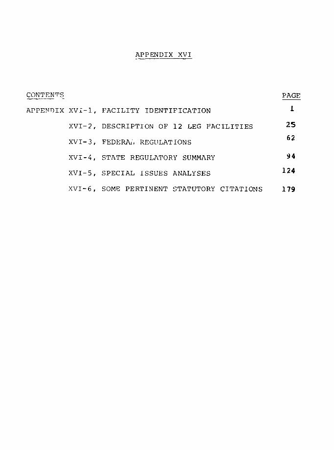
APPENDIX XVI
CONTENTS PAGE
APPENDIX XVI-1, FACILITY IDENTIFICATION 1
XVI-2, DESCRIPTION OF 12 LEG FACILITIES 25
XVI-3, FEDERA., REGULATIONS 62
XVI-4, STATE REGULATORY SUMMARY 94
XVI-5, SPECIAL ISSUES ANALYSES 124
XVI-6, SOME PERTINENT STATUTORY CITATIONS 179

APPENDIX XVI-1
APPENDIX XVI-1
FACILITY IDENTIFICATION
The following pages contair. listings of facilities in
the United States having on-site storage of LNG, LPG, or
naphtha in excess of 23,000 m or a monthly throughput of one
of these fuels in excess of 23,000 m. Naphtha listings do
not include storage at military installations nor any
naphtha to be used as solvents. The total volumes of
constructed storage capacity are indicated for each fuel
category, with total planned storage capacity indicated in
parentheses.
U.S. LNG PEAK-SHAVING FACILITIES
WITH STORAGE IN EXCESS OF 23,000 m
CAPACITYCOMPANY LOCATION (10 m3 )
Alabama Gas Corp. Pinson Highway 57Jefferson County, AL (2 tanks)
Alabama Gas Ccrp. Coosada, AL 28.5
Atlanta Gas Light Co. Macon, GA 69
Atlanta Gas Light Co. Riverdale, GA 115(2 tanks)
Baltimore Gas & Elec. Co. Baltimore, MD 23(2 tanks)
Baltimore Gas & Elec. Co.Plant No. 2 Baltimore, MD 23
Bay State Gas Co. Ludlow, MA 46
Bay State Gas Co. Easton, MA 36.8
Boston Gas Co. Dorchester, MA' 98.9
(2 tanks)
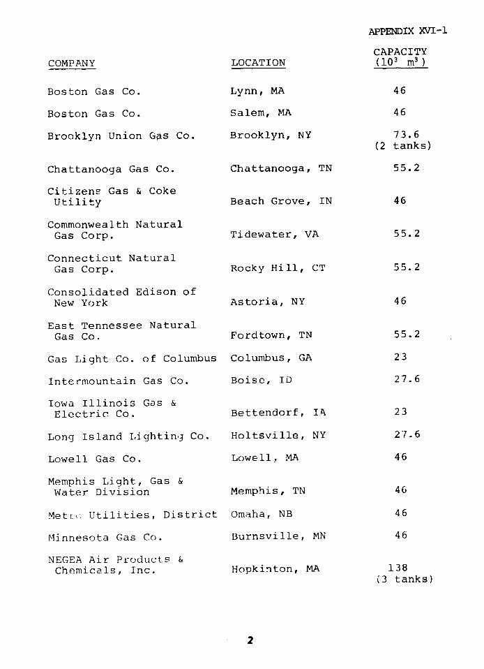
APPENDIX XVI-1
CAPACITYCOMPANY LOCATION (103 m 3 )
Boston Gas Co. Lynn, MA 46
Boston Gas Co. Salem, MA 46
Brooklyn Union Gas Co. Brooklyn, NY 73.6
(2 tanks)
Chattanooga Gas Co. Chattanooga, TN 55.2
Citizens Gas & CokeUtility Beach Grove, IN 46
Commonwealth NaturalGas Corp. Tidewater, VA 55.2
Connecticut NaturalGas Corp. Rocky Hill, CT 55.2
Consolidated Edison ofNew York Astoria, NY 46
East Tennessee NaturalGas Co. Fordtown, TN 55.2
Gas Light Co. of Columbus Columbus, GA 23
Intermountain Gas Co. Boise, ID 27.6
Iowa Illinois Gas &Electric Co. Bettendorf, IT 23
Long Island Lighting Co. Holtsville, NY 27.6
Lowell Gas Co. Lowell, MA 46
Memphis Light, Gas &
Water Division Memphis, TN 46
MetLr. Utilities, District Omaha, NB 46
Minnesota Gas Co. Burnsville, MN 46
NEGEA Air Products &
Chemicals, Inc. Hopkinton, MA 138(3 tanks)
2
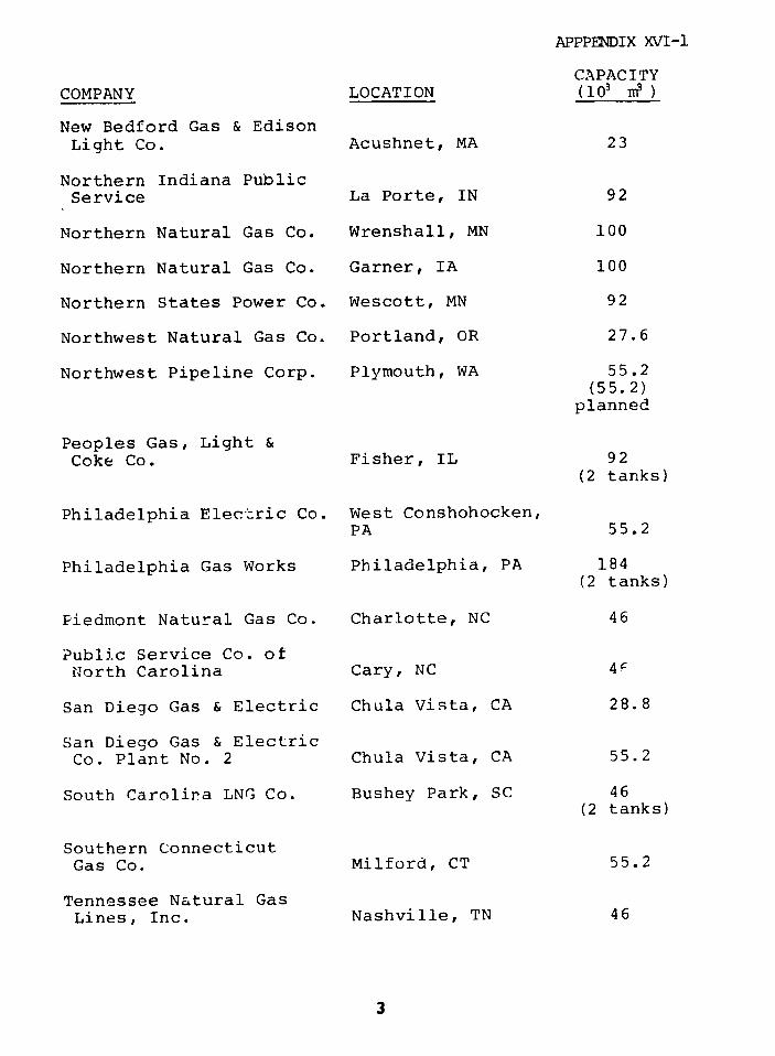
APPPENDIX XVI-1
CAPACITY
COMPANY LOCATION (103 )
New Bedford Gas & Edison
Light Co. Acushnet, MA 23
Northern Indiana PublicService La Porte, IN 92
Northern Natural Gas Co. Wrenshall, MN 100
Northern Natural Gas Co. Garner, IA 100
Northern States Power Co. Wescott, MN 92
Northwest Natural Gas Co. Portland, OR 27.6
Northwest Pipeline Corp. Plymouth, WA 55.2(55.2)
planned
Peoples Gas, Light &Coke Co. Fisher, IL 92
(2 tanks)
Philadelphia Electric Co. West Conshohocken,PA 55.2
Philadelphia Gas Works Philadelphia, PA 184(2 tanks)
Piedmont Natural Gas Co. Charlotte, NC 46
Public Service Co. ofNorth Carolina Cary, NC 4F
San Diego Gas & Electric Chula Vista, CA 28.8
San Diego Gas & ElectricCo. Plant No. 2 Chula Vista, CA 55.2
South Carolina LNG Co. Bushey Park, SC 46(2 tanks)
Southern ConnecticutGas Co. Milford, CT 55.2
Tennessee Natural GasLines, Inc. Nashville, TN 46
3
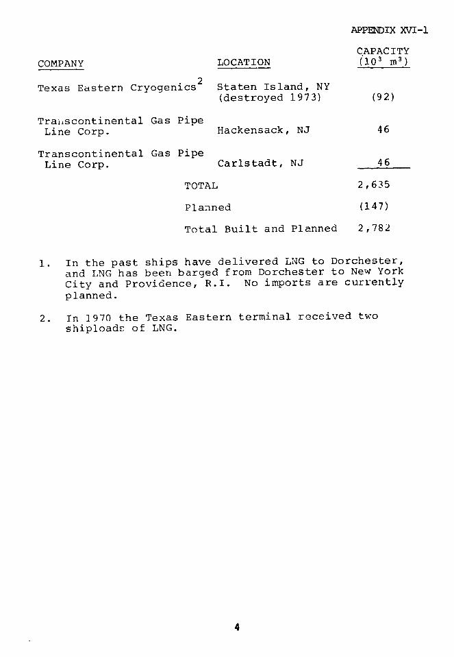
APPENDIX XVI-1
CAPACITY
COMPANY LOCATION (103 m 3)
Texas Eastern Cryogenics Staten Island, NY(destroyed 1973) (92)
Traiiscontinental Gas PipeLine Corp. Hackensack, NJ 46
Transcontinental Gas PipeLine Corp. Carlstadt, NJ 46
TOTAL 2,635
Planned (147)
Total Built and Planned 2,782
1. In the past ships have delivered LNG to Dorchester,
and LNG has been barged from Dorchester to New York
City and Providence, R.I. No imports are currently
planned.
2. In 1970 the Texas Eastern terminal received twoshiploads of LNG.
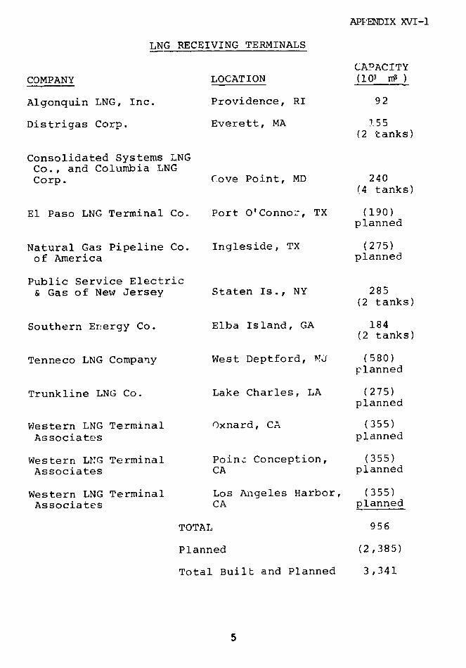
APPENDIX XVI-1
LNG RECEIVING TERMINALS
CAPACITY
COMPANY LOCATION (103 )
Algonquin LNG, Inc. Providence, RI 92
Distrigas Corp. Everett, MA *55(2 tanks)
Consolidated Systems LNGCo., and Columbia LNGCorp. Cove Point, MD 240
(4 tanks)
El Paso LNG Terminal Co. Port O'Connor, TX (190)planned
Natural Gas Pipeline Co. Ingleside, TX (275)
of America planned
Public Service Electric& Gas of New Jersey Staten Is., NY 285
(2 tanks)
Southern Energy Co. Elba Island, GA 184(2 tanks)
Tenneco LNG Company West Deptford, NJ (580)planned
Trunkline LNG Co. Lake Charles, LA (275)planned
Western LNG Terminal Oxnard, CA (355)
Associates planned
Western LNG Terminal Point Conception, (355)
Associates CA planned
Western LNG Terminal Los Angeles Harbor, (355)
Associates CA planned
TOTAL 956
Planned (2,385)
Total Built and Planned 3,341
5
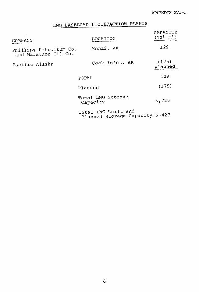
APPENDIX XVI-1
LNG BASELOAD LIQUEFACTION PLANTS
CAPACITY
COMPANY LOCATION (103 m 3)
Phillips Petroleum Co. Kenai, AK 129
and Marathon Oil Co.
Pacific Alaska Cook In!ei:, AK (175)planned
TOTAL 129
Planned (175)
Total LNG Storage
Capacity 3,720
Total LNG Tuilt and
Planned Storage Capacity 6,427
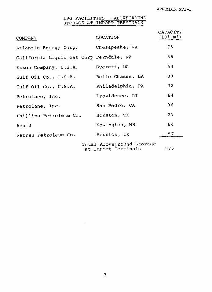
APPENDIX XVI-1
LPG FACILITIES - ABOVEGROUNDSTORAGE AT IMPORT TERMINALS
CAPACITY
COMPANY LOCATION (103 m 3)
Atlantic Energy Corp. Chesapeake, VA 76
California Liquid Gas Corp Ferndale, WA 56
Exxon Company, U.S.A. Everett, MA 64
Gulf Oil Co., U.S.A. Belle Chasse, LA 39
Gulf Oil Co., U.S.A. Philadelphia, PA 32
Petrolare, Inc. Providence. RI 64
Petrolane, Inc. San Pedro, CA 96
Phillips Petroleum Co. Houston, TX 27
Sea 3 Newington, NH 64
Warren Petroleum Co. Houston, TX 57
Total Aboveground Storageat Import Terminals 575
7

APPENDIX XVI-1
LPG - OTHER ABOVEGROUND STORAGE
CAPACITyCOMPANY LOCATION (10 m )Baltimore Gas & ElectricCo. Essex, MD 24
Dixie Pipeline Company Wake County, NC 64
Exxon Company, U.S.A. Solano County, CA 48
Florida Hydrocarbons Co. Bradford County, FL 28
Getty Oil Company Newcastle County, DE 80(frozen pit)
Northern States Power Co. Wescott, MN 45
(ethane)
Phillips Petroleum Co. Salt Lake County, UT 26
Phillips Petroleum Co. St. Clair County, IL 80
Phillips Petroleum Co. Crittenen County,AK 25
Vangas, Inc. Sacramento, CA 40
Vangas, Inc. Elk Grove, CA 40
TOTAL Other AbovegroundStorage 500
TOTAL LPG AbovegroundStorage 1,075
8
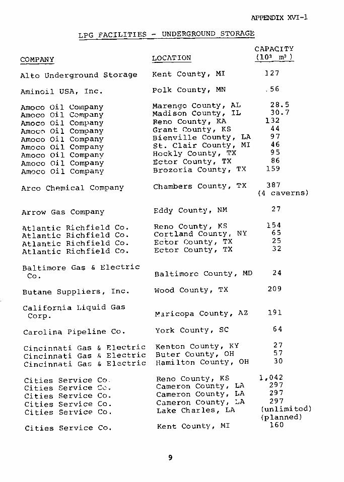
APPENDIX XVI-1
LPG FACILITIES - UNDERGROUND STORAGE
CAPACITY
COMPANY LOCATION (103 m 3 )
Alto Underground Storage Kent County, MI 127
Aminoil USA, Inc. Polk County, MN .56
Amoco Oil Company Marengo County, AL 28.5
Amoco Oil Company Madison County, IL 30.7
Amoco Oil Company Reno County, KA 132
Amoco Oil Company Grant County, KS 44
Amoco Oil Company Bienville County, LA 97
Amoco Oil Company St. Clair County, MI 46
Amoco Oil Company Hockly County, TX 95
Amoco Oil Company Ector County, TX 86
Amoco Oil Company Brozoria County, TX 159
Arco Chemical Company Chambers County, TX 387(4 caverns)
Arrow Gas Company Eddy County, NM 27
Atlantic Richfield Co. Reno County, KS 154
Atlantic Richfield Co. Cortland County, NY 65
Atlantic Richfield Co. Ector County, TX 25
Atlantic Richfield Co. Ector County, TX 32
Baltimore Gas & Electric
Co. Baltimore County, MD 24
Butane Suppliers, Inc. Wood County, TX 209
California Liquid GasCorp. Maricopa County, AZ 191
Carolina Pipeline Co. York County, SC 64
Cincinnati Gas & Electric Kenton County, KY 27
Cincinnati Gas & Electric Buter County, OH 57
Cincinnati Gas & Electric Hamilton County, OH 30
Cities Service Co. Reno County, KS 1,042
Cities Service Co. Cameron County, LA 297
Cities Service Co. Cameron County, LA 297
Cities Service Co. Cameron County, LA 297
Cities Service Co. Lake Charles, LA (unlimited)(planned)
Cities Service Co. Kent County, MI 160
9
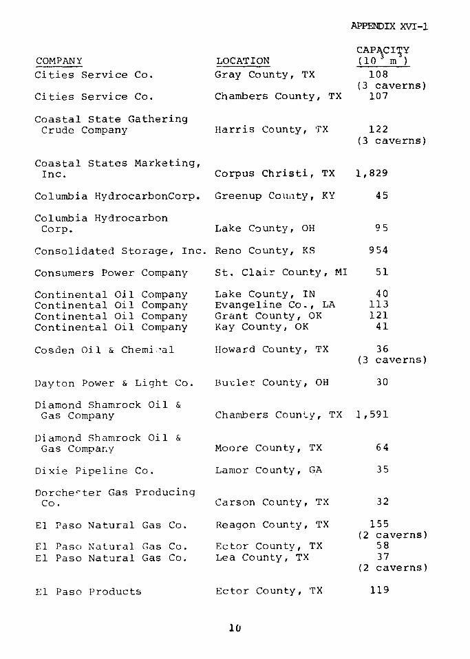
APPENDIX XVI-1
CAPACITYCOMPANY LOCATION (10 3 m )
Cities Service Co. Gray County, TX 108
(3 caverns)Cities Service Co. Chambers County, TX 107
Coastal State GatheringCrude Company Harris County, TX 122
(3 caverns)
Coastal States Marketing,Inc. Corpus Christi, TX 1,829
Columbia HydrocarbonCorp. Greenup County, KY 45
Columbia HydrocarbonCorp. Lake County, OH 95
Consolidated Storage, Inc. Reno County, KS 954
Consumers Power Company St. Clair County, MI 51
Continental Oil Company Lake County, IN 40Continental Oil Company Evangeline Co., LA 113Continental Oil Company Grant County, OK 121Continental Oil Company Kay County, OK 41
Cosden Oil & Chemic-al Howard County, TX 36(3 caverns)
Dayton Power & Light Co. Bucler County, OH 30
Diamond Shamrock Oil &Gas Company Chambers County, TX 1,591
Diamond Shamrock Oil &Gas Compa.y Moore County, TX 64
Dixie Pipeline Co. Lamor County, GA 35
Dorchester Gas ProducingCo. Carson County, TX 32
El Paso Natural Gas Co. Reagon County, TX 155(2 caverns)
El Paso Natural Gas Co. Ector County, TX 58
El Paso Natural Gas Co. Lea County, TX 37(2 caverns)
El Paso Products Ector County, TX 119
10
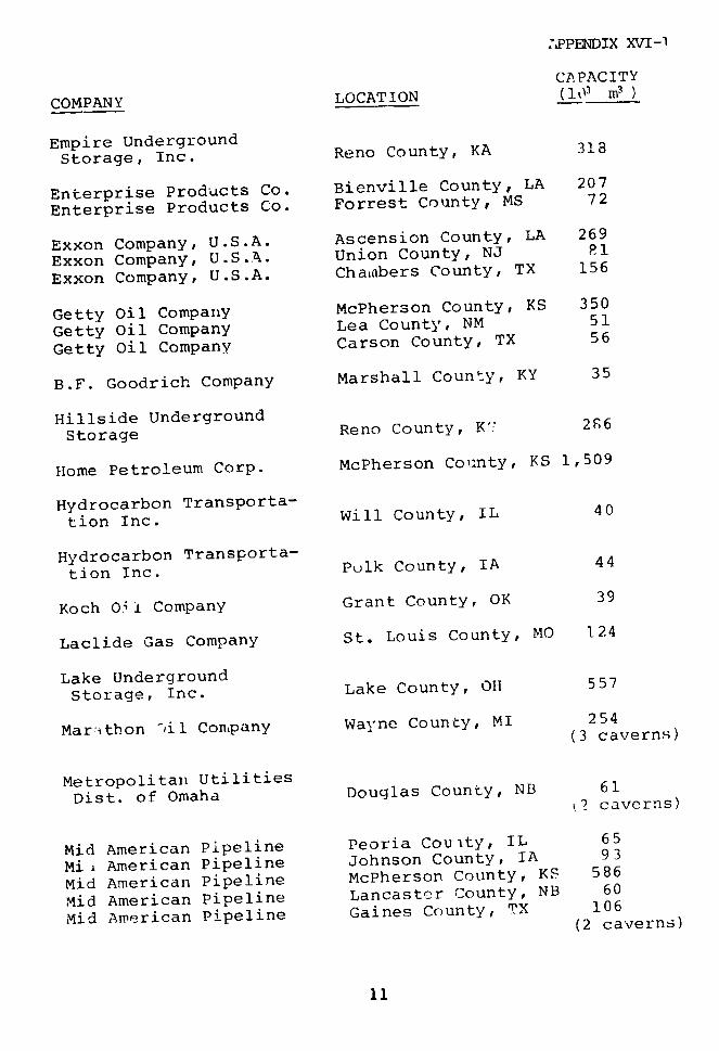
SPPENDIX XVI-1
CAPACITY
COMPANY LOCATION (1o3 m3)
Empire UndergroundStorage, Inc. Reno County, KA 318
Enterprise Products Co. Bienville County, LA 207
Enterprise Products Co. Forrest County, MS 72
Exxon Company, U.S.A. Ascension County, LA 269
Exxon Company, U.S.A. Union County, NJ P1
Exxon Company, U.S.A. Chamnbers County, TX 156
Getty Oil Company McPherson County, KS 350
Getty Oil Company Lea County, NM 51
Getty Oil Company Carson County, TX 56
B.F. Goodrich Company Marshall County, KY 35
Hillside Underground
Storage Reno County, K" 2S6
Home Petroleum Corp. McPherson Co:nty, KS 1,509
Hydrocarbon Transporta-
tion Inc. Will County, IL 40
Hydrocarbon Transporta-
tion Inc. Pulk County, IA 44
Koch O i Company Grant County, OK 39
Laclide Gas Company St. Louis County, MO 124
Lake UndergroundStorage, Inc. Lake County, OH 557
Mar~ithon Gil Company Wayne County, MI 254(3 caverns)
Metropolitan Utilities
Dist. of Omaha Douglas County, NB 617? caverns)
Mid American Pipeline Peoria Couity, IL 65
Miu American Pipeline Johnson County, IA 93
Mid American Pipeline McPherson County, KS 586
Mid American Pipeline Lancaster County, NB 60
Mid American Pipeline Gaines County, TX 106(2 caverns)
11
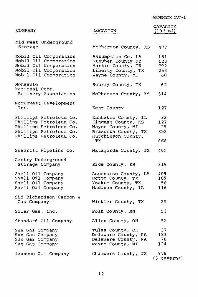
APPENDIX XVI-1
CAPACITYCOMPANY LOCATION (10 n m 3)
Mid-West UndergroundStorage McPherson County, KS 477
Mobil Oil Corporation Assumption Co. LA 151Mobil Oil Corporation Steuben County NY 120Mobil Oil Corporation Martin County, TX 792Mobil Oil Corporation Liberty County, TX 253Mobil Oil Corporation Wayne County, MI 60
Monsanto Scurry County, TX 62National Coop.Refinery Association McPherson County, KS 514
Northwest DevelopmentInc. Kent County 127
Phillips Petioleum Co. Kankakee County, IL 32Phillips Petroleum Co. Kingmanl County, KS 127Phillips Petroleum Co. Wayne County, MI 29Phillips Petroleum Co. Brazoria County, TX 852Phillips Petroleum Co. Hutchinson County,
TX 668
Seadrift Pipeline Co. Matagorda County, TX 405
Sentry UndergroundStorage Company Rice County, KS 318
Shell Oil Company Ascension County, LA 409Shell Oil Company Ector County, TX 109Shell Oil Company Yoakum County, TX 56Shell Oil Company Madison County, IL 116
Sid Richardson Carbon &Gas Company Winkler County, TX 25
Solar Gas, Inc. Polk County, MN 53
Standard Oil Company Allen County, OH 52
Sun Gas Company Tulsa County, OK 37Sun Gas Company Delaware County, PA 183Sun Gas Company Delaware County, PA 76Sun Gas Company wayne County, MI 124
Tenneco Oil Company Chambers County, TX 978(3 caverns)
12
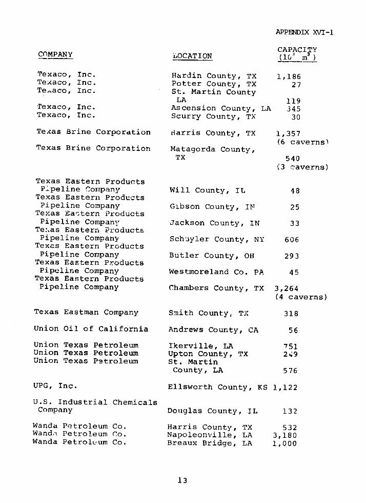
APPENDIX XVI-1
CAPACITYC(MPANY LOCATION (10A m )
Texaco, Inc. Hardin County, TX 1,186Texaco, Inc. Potter County, TX 27Texaco, Inc. St. Martin County
LA 119Texaco, Inc. Ascension County, LA 345Texaco, Inc. Scurry County, TX 30
Texas Brine Corporation Harris County, TX 1,357(6 caverns)
Texas Brine Corporation Matagorda County,TX 540
(3 caverns)
Texas Eastern ProductsPipeline Cornpany Will County, IL 48Texas Eastern ProductsPipeline Company Gibson County, IN 25
Texas Eastern ProductsPipeline Company Jackson County, IN 33
Te:.as Eastern ProductsPipeline Company Schuyler County, NY 606
Texas Eastern ProductsPipeline Company Butler County, OH 293
Texas Eastern ProductsPipeline Company Westmoreland Co. PA 45
Texas Eastern ProductsPipeline Company Chambers County, TX 3,264
(4 caverns)
Texas Eastman Company Smith County, TX 318
Union Oil of California Andrews County, CA 56
Union Texas Petroleum Ikerville, LA 751Union Texas Petroleum Upton County, TX 249Union Texas Petroleum St. Martin
County, LA 576
UPG, Inc. Ellsworth County, KS 1,122
U.S. Industrial ChemicalsCompany Douglas County, IL 132
Wanda Petroleum Co. Harris County, TX 532Wanda Petroleum Co. Napoleonville, LA 3,180Wanda Petroleum Co. Breaux Bridge, LA 1,000
13
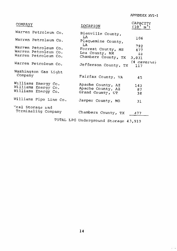
APPEN'DIX XVI-1
CAPACITYCOMPANY LOCATION (103 m 3 )
Warren Petroleum Co. Bienville County,LA 106Warren Petroleum Co. Plaquemine County,LA 792Warren Petroleum Co. Forrest County, MS 477Warren Petroleum Co. Lea County, NM 48Warren Petroleum Co. Chantmbers County, TX 3,031
(4 caverns)Warren Petroleum Co. Jefferson County, TX 117
Washington Gas LightCompany Fairfax County, VA 45
Williams Energy Co. Apache County, AZ 143Williams Energy Co. Apache County, AZ 87Williams Energy Co. Grand County, UT 38
Williams Pipe Line Co. Jasper County, MO 31
"ral Storage andTerminaling Company Chambers County, TX 477
TOTAL LPG Underground Storage 43,919
14

APPLNDIIX XVI-1
SNG PLANTS
(Note: None of these facilities have onr-site storage in
excess of 23,000 m3i)
MONTHLYTHROUGHPUT
COMPANY AND LOCATION FEEDSTOCK (10 3 m
Algonqiin SNG, Inc. Naphtha 124Freetown, MA
Ashland Cil, Inc. Naphtha 52Tonawanda, NY
Baltimore Gas & Naphtha 57Electric Co.Stollers Point, MD
Boston Gas Co. Propane 48Everett, MA
Brooklyn Union Gas Co. Naphtha 63Brooklyn, NY
Columbia LNG Corp. Propane/Butane/NGL* 330Green Springs, OH
Consumers Power Co. NGL* 240Marysville, MI
Gasco, Inc. Naphtha 14Barbers Point, Oahu, HI
Indiana Gas Co., Inc. Naphtha (50)Indianapolis, IN (planned)
Northern Illinois Gas Co. NGL* 158Minooka, IL Naphtha 76
Peoples Gas Light & Naphtha i57Coke Co.Elwood, IL
Philadelphia Gas Works Naphtha (62)Philadelphia, PA (planned)
15
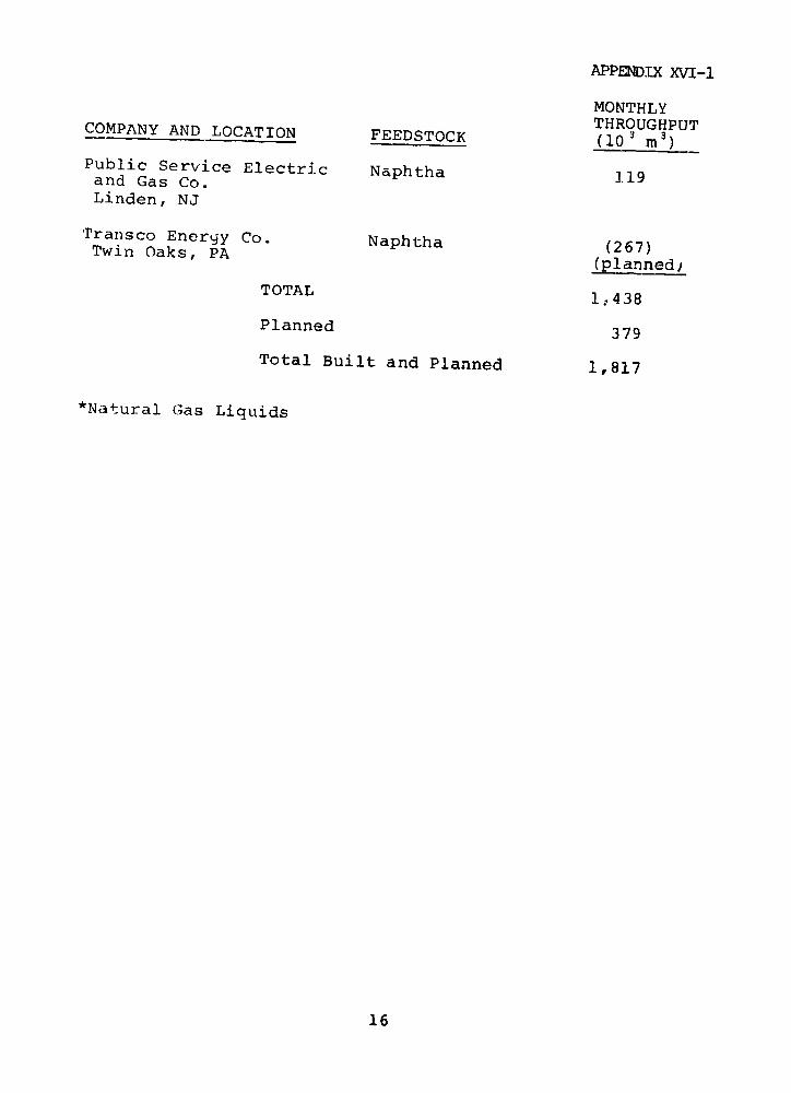
APPENDIX XVI-1
MONTHLYTHROUGHPUTCOMPANY AND LOCATION FEEDSTOCK (10 3 n3)
Public Service Electric Naphtha 119and Gas Co.Linden, NJ
Tranzsco Energy Co. Naphtha (267)Twin Oaks, PA (plannedj
TOTAL 1,438
Planned 379
Total Built and Planned 1,817
*Natural Gas Liquids
16
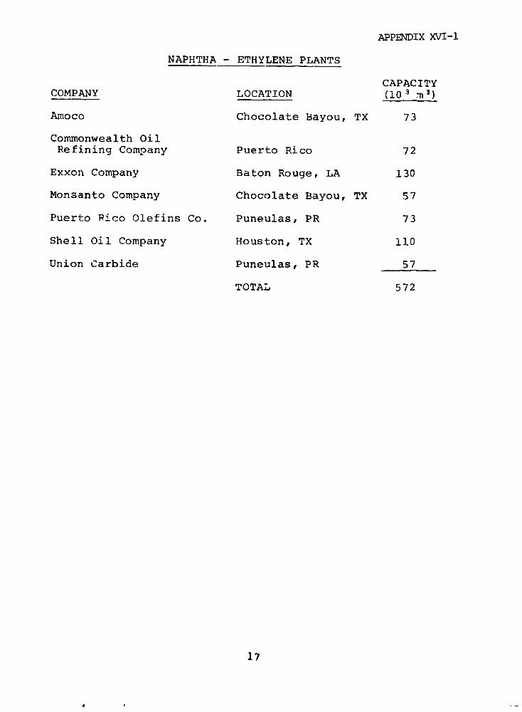
APPENDIX XVI-1
NAPHTHA - ETHYLENE PLANTS
CAPACITYCOMPANY LOCATION (10 3 m 3)
Amoco Chocolate Bayou, TX 73
Commonwealth OilRefining Company Puerto Rico 72
Exxon Company Baton Rouge, LA 130
Monsanto Company Chocolate Bayou, TX 57
Puerto Rico Olefins Co. Puneulas, PR 73
Shell Oil Company Houston, TX 110
Union Carbide Puneulas, PR 57
TOTAL 572
17
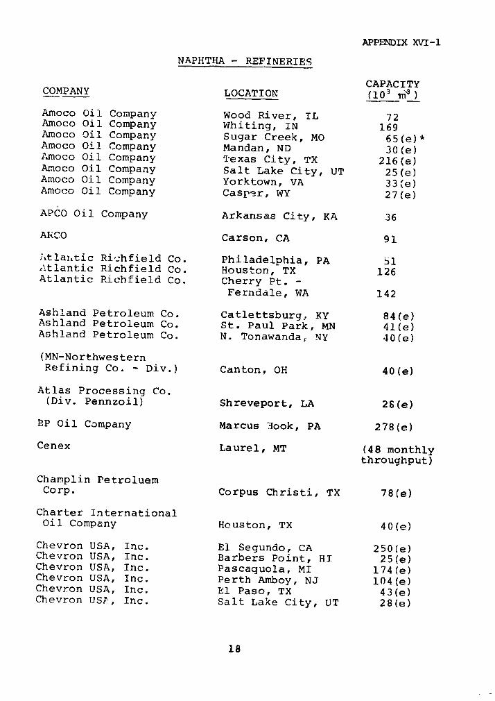
APPENDIX XVI-1
NAPHTHA - REFINERIES
CAPACITYCOMPANY LOCATION (103 i)
Amoco Oil Company Wood River, IL 72Amoco Oil Company Whiting, IN 169Amoco Oil Company Sugar Creek, MO 65(e)*Amoco Oil Company Mandan, ND 30(e)Amoco Oil Company Texas City, TX 216(e)Amoco Oil Company Salt Lake City, UT 25(e)Amoco Oil Company Yorktown, VA 33(e)Amoco Oil Company Casper, WY 27(e)
APCO Oil Company Arkansas City, KA 36
ARCO Carson, CA 91
uitlanitic Richfield Co. Philadelphia, PA 51Atlantic Richfield Co. Houston, TX 126Atlantic Richfield Co. Cherry Pt. -
Ferndale, WA 142
Ashland Petroleum Co. Catlettsburg. KY 84(e)Ashland Petroleum Co. St. Paul Park, MN 41(e)Ashland Petroleum Co. N. Tonawanda, NY 40(e)
(MN-NorthwesternRefining Co. - Div.) Canton, OH 40(e)
Atlas Processing Co.(Div. Pennzoil) Shreveport, LA 26(e)
BP Oil Company Marcus Hook, PA 278(e)
Cenex Laurel, MT (48 monthlythroughput)
Champlin PetroluemCorp. Corpus Christi, TX 78(e)
Charter InternationalOil Company Houston, TX 4 0(e)
Chevron USA, Inc. El Segundo, CA 2 5 0(e)Chevron USA, Inc. Barbers Point, HI 25(e)Chevron USA, Inc. Pascaquola, MI 174(e)Chevron USA, Inc. Perth Amboy, NJ 104(e)Chevron USA, Inc. El Paso, TX 43(e)Chevron USE, Inc. Salt Lake City, UT 28(e)
18
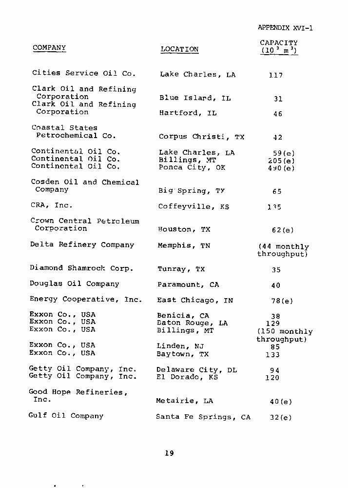
APPENDIX XVI-1
CAPACITYCOMPANY LOCATION (10 3 m 3)
Cities Service Oil Co. Lake Charles, LA 117
Clark Oil and RefiningCorporation Blue Island, IL 31
Clark Oil and RefiningCorporation Hartford, IL 46
Coastal StatesPetrochemical Co. Corpus Christi, TX 42
Continental Oil Co. Lake Charles, LA 59(e)Continental Oil Co. Billings, MT 205(e)Continental Oil Co. Ponca City, OK 490(e)
Cosden Oil and ChemicalCompany Big Spring, TY 65
CRA, Inc. Coffeyville, KS 135
Crown Central PetrcleumCorporation Houston, TX 62(e)
Delta Refinery Company Memphis, TN (44 monthlythroughput)
Diamond Shamrock Corp. Tunray, TX 35
Douglas Oil Company Paramount, CA 40
Energy Cooperative, Inc. East Chicago, IN 78(e)
Exxon Co., USA Benicia, CA 38Exxon Co., USA Baton Rouge, LA 129Exxon Co., USA Billings, MT (150 monthly
throughput)Exxon Co., USA Linden, NJ 85Exxon Co., USA Baytown, TX 133
Getty Oil Company, Inc. Delaware City, DL 94Getty Oil Company, Inc. El Dorado, KS 120
Good Hope Refineries,Inc. Metairie, LA 40(e)
Gulf Oil Company Santa Fe Springs, CA 32(e)
19
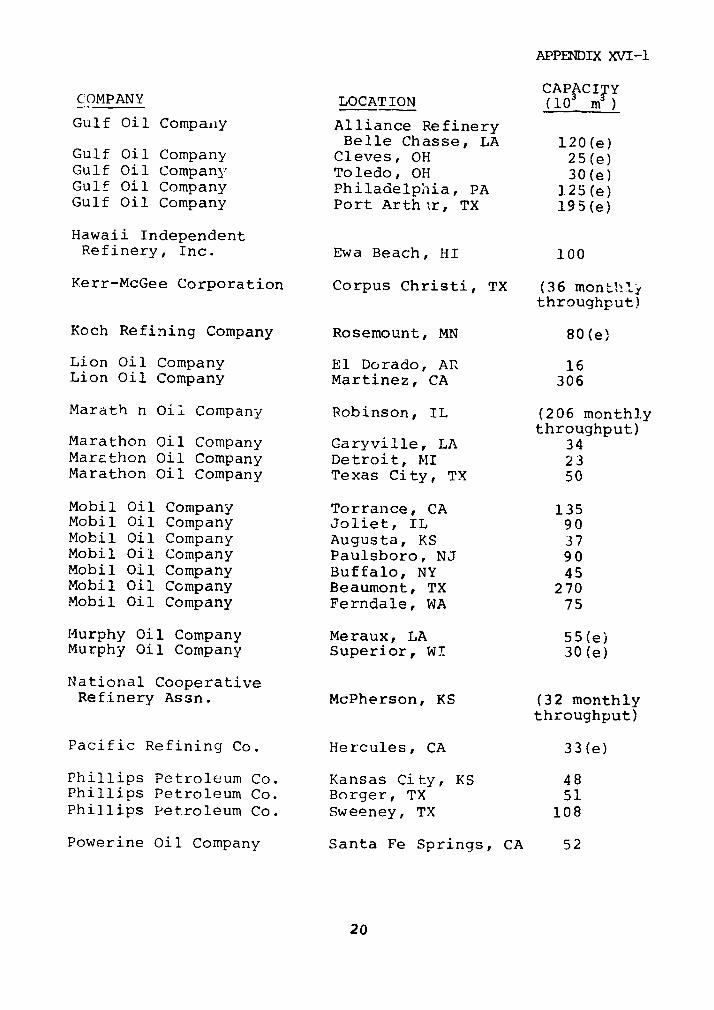
APPENDIX XVI-1
CAPACITYCOMPANY LOCATION (10 m )
Gulf Oil Compaiiy Alliance RefineryBelle Chasse, LA 120(e)
Gulf Oil Company Cleves, OH 25(e)Gulf Oil Company Toledo, OH 30(e)Gulf Oil Company Philadelphia, PA ].25(e)Gulf Oil Company Port Arthur, TX 195(e)
Hawaii IndependentRefinery, Inc. Ewa Beach, HI 100
Kerr-McGee Corporation Corpus Christi, TX (36 montLh':throughput)
Koch Refining Company Rosemount, MN 80(e)
Lion Oil Company El Dorado, AR 16Lion Oil Company Martinez, CA 306
Marath n Oil Company Robinson, IL (206 monthlythroughput)
Marathon Oil Company Garyville, LA 34Marathon Oil Company Detroit, MI 23Marathon Oil Company Texas City, TX 50
Mobil Oil Company Torrance, CA 135Mobil Oil Company Joliet, IL 90Mobil Oil Company Augusta, KS 37Mobil Oil Company Paulsboro, NJ 90Mobil Oil Company Buffalo, NY 45Mobil Oil Company Beaumont, TX 270Mobil Oil Company Ferndale, WA 75
Murphy Oil Company Meraux, LA 55(e)Murphy Oil Company Superior, WI 30(e)
National CooperativeRefinery Assn. McPherson, KS (32 monthly
throughput)
Pacific Refining Co. Hercules, CA 33(e)
Phillips Petroleum Co. Kansas City, KS 48Phillips Petroleum Co. Borger, TX 51Phillips Petroleum Co. Sweeney, TX 108
Powerine Oil Company Santa Fe Springs, CA 52
20
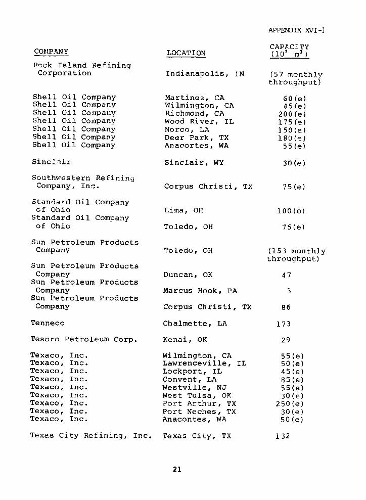
APPENDIX XVI-]
CAPACITYCOMPANY LOCATION (103 m 3 )
Peck Island RefiningCorporation Indianapolis, IN (57 monthly
throughput)
Shell Oil Company Martinez, CA 60(e)Shell Oil Company Wilmington, CA 45(e)Shell Oil Company Richmond, CA 200(e)Shell Oil Company Wood River, IL 175(e)Shell Oil Company Norco, LA 150(e)Shell Gil Company Deer Park, TX 180(e)Shell Oil Company Anacortes, WA 55(e)
Sinclair Sinclair, WY 30(e)
Southwestern RefiningjCompany, Inc. Corpus Christi, TX 75(e)
Standard Oil Companyof Ohio Lima, OH 100(e)Standard Oil Companyof Ohio Toledo, OH 75(e)
Sun Petroleum ProductsCompany Toledo, OH (153 monthly
throughput)Sun Petroleum ProductsCompany Duncan, OK 47
Sun Petroleum ProductsCompany Marcus Hook, PA 5
Sun Petroleum ProductsCompany Corpus Christi, TX 86
Tenneco Chalmette, LA 173
Tesoro Petroleum Corp. Kenai, OK 29
Texaco, Inc. Wilmington, CA 55(e)Texaco, Inc. Lawrenceville, IL 50(e)Texaco, Inc. Lockport, IL 45(e)Texaco, Inc. Convent, LA 85(e)Texaco, Inc. Westville, NJ 55(e)Texaco, Inc. West Tulsa, OK 30(e)Texaco, Inc. Port Arthur, TX 250(e)Texaco, Inc. Port Neches, TX 30(e)Texaco, Inc. Anacontes, WA 50(e)
Texas City Refining, Inc. Texas City, TX 132
21
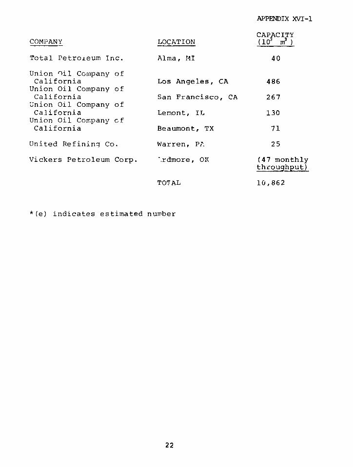
APPENDIX XVI-1
CAPACITYCOMPANY LOCATION (10 m3 )
Total Petroleum Inc. Alma, MI 40
Union Oil Company ofCalifornia Los Angeles, CA 486
Union Oil Company ofCalifornia San Francisco, CA 267Union Oil Company ofCalifornia Lemont, IL 130Union Oil Company ofCalifornia Beaumont, TX 71
United Refining Co. Warren, PA 25
Vickers Petroleum Corp. -. rdmore, OK (47 monthlythroughput)
TOTAL 10,862
*(e) indicates estimated number
22

APPENDIX XVI-1
NAPHTHA - JET FUEL STORAGE AT LARGE
COMMERCIAL AIRPORTS
None of the airports surveyed had storage or monthly
throughput in excess of 23,000 m 3 of a naphtha category fuel
such as JP-4 or 5 (primarily used by military aircraft).
Commercial jet fuel is less volatile cut in the kerosene
category. For information purposes, the following listing
is given although tnc fuel is nc'- actually a naphtha.
1976 MonthlyJet Fuel Jet* FuelStorage Throughput
City/State Airport (193 I i) (10 3 m 3)
New York/NY JFK 12 307
Chicago/IL O'Hare 35 2E'
Los Angeles/CA 22 245
San Francisco/CA 0.4 160
Dallas/Ft. Worth/TX 130
Atlanta/GA 116
Miami/FL 38 114
Honolulu/HI 109
Seattle-Tacoma/WA 88
New York/NY LaGuardia 19 80
Boston/MA Logan 17 78
Denver/CO 78
Anchorage/AL 58
Minneapolis-St.Paul/MN 55
23
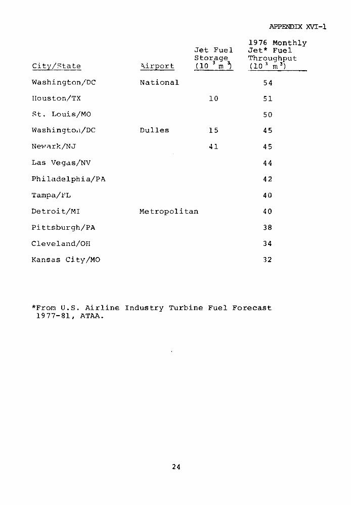
APPENDIX XVI-1
1976 MonthlyJet Fuel Jet* FuelStorage Throughput
City/State irport (10 (10 3 m 10 3)
Washington/DC National 54
Houston/TX 10 51
St. Louis/MO 50
Washingtod/DC Dulles 15 45
Nevwark/NJ 41 45
Las Vegas/NV 44
Philadelphia/PA 42
Tampa/FL 40
Detroit/MI Metropolitan 40
Pittsburgh/PA 38
Cleveland/OH 34
Kansas City/MO 32
*From U.S. Airline Industry Turbine Fuel Forecast1977-81, ATAA.
24

APPENDIX XVI-2
APPENDIX XVI-2
DESCRIPTION OF 12 LEG FACILITIES
The information contained in this appendix was
compiled from literature search, data requested from
individual gas companies, and on site visits. The
descriptions represent a comparative presentation of
information critical to an understanding of both the key
similarities and differences between LEG plant sites,
storage containers, terminals, and processing capabilities.
Because of the varying formats in which information was
received, some of the descriptions are incomplete.
Summary sheets have been prepared for the following
facilities:
LNG Marine Terminal Facilities:
Algonquin LNG, Inc., Providence, RI
Columbia LNG Corp., Cove Point, MD
Distrigas of Massachusetts, Everett, MA
Public Service Electric & Gas Co., Staten Island, NY
Southern Energy Co., Elba Island, GA
LNG Peakshaving Facilities:
Northwest Pipeline Corp., Plymcuth, VWA
Philadelphia Electric Co., Philadelphia, PA
Philadelphia Gas Works, Philadelphia, PA
Texas Eastern Transmission Corp., Staten Island, NY
25

APPENDIX XVI-2
LPG Marine Terminal Facilities:
Exxon Co., U.S.A., Everett, MA
Petrolane, Inc., San Pedro, CA
Sun Oil Company, Marcus Hook, PA
26
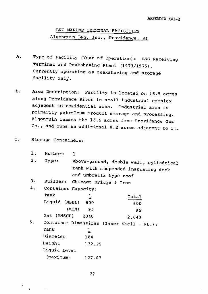
APPENDIX XVI-2
LNG MARINE TEPINAL FACILITIES
Algonquin LNG, Inc., Providence, RI
A. Type of Facility (Year of Operation): LNG ReceivingTerminal and Peakshaving Plant (1973/1975).
Currently operating as peakshaving and storagefacility only.
B. Area Description: Facility is located on 16.5 acresalong Providence River in small industrial complexadjacent to residential area. Industrial area isprimarily petroleum product storage and processing.Algonquin leases the 16.5 acres from Providence GasCo., and owns an additional 8.2 acres adjacent to it.
C. Storage Containers:
1. Number: 1
2. Type: Above-ground, double wall, cylindrical
tank with suspended insulating deck
and umbrella type roof
3. Builder: Chicago Bridge & Iron
4. Container Capacity:
Tank 1 TotalLiquid (MBBL) 600 600
(MCM) 95 95Gas (MMSCF) 2040 2,040
5. Container Dimensions (Inner Shell - Ft.):Tank 1
Diameter 184
Height 132.25
Liquid Level
(maximum) 127.67
27
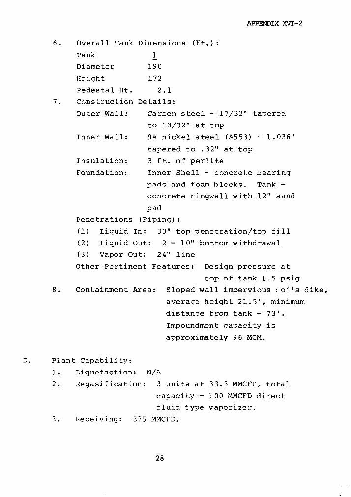
APPENDIX XVI-2
6. Overall Tank Dimensions (Ft.):
Tank 1
Diameter 190
Height 172
Pedestal Ht. 2.1
7. Construction Details:
Outer Wall: Carbon steel - 17/32" tapered
to 13/32" at top
Inner Wall: 9% nickel steel (A553) - 1.036"
tapered to .32" at top
Insulation: 3 ft. of perlite
Foundation: Inner Shell - concrete uearing
pads and foam blocks. Tank -
concrete ringwall with 12" sand
pad
Penetrations (Piping):
(1) Liquid In: 30" top penetration/top fill
(2) Liquid Out: 2 - 10" bottom withdrawal
(3) Vapor Out: 24" line
Other Pertinent Features: Design pressure at
top of tank 1.5 psig
8. Containment Area: Sloped wall impervious :o4 's dike,
average height 21.5', minimum
distance from tank - 73'.
Impoundment capacity is
approximately 96 MCM.
D. Plant Capability:
1. Liquefaction: N/A
2. Regasification: 3 units at 33.3 MMCFE, total
capacity - 100 MMCFD direct
fluid type vaporizer.
3. Receiving: 375 MMCFD.
28
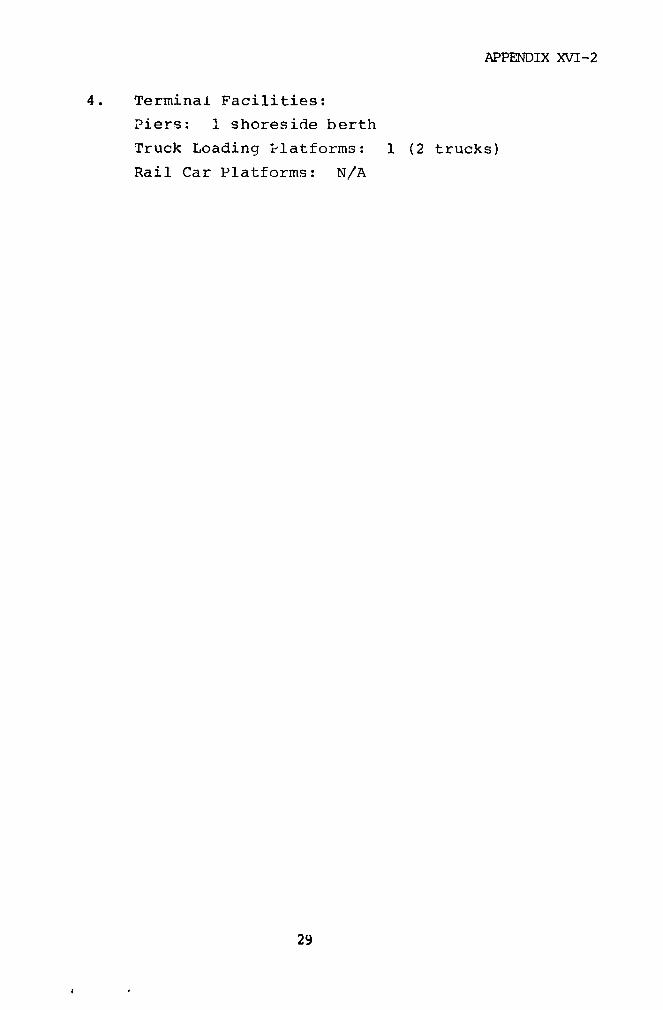
APPENDIX XVI-2
4. Terminal Facilities:
Piers: 1 shoreside berth
Truck Loading Platforms: 1 (2 trucks)
Rail Car Platforms: N/A
29
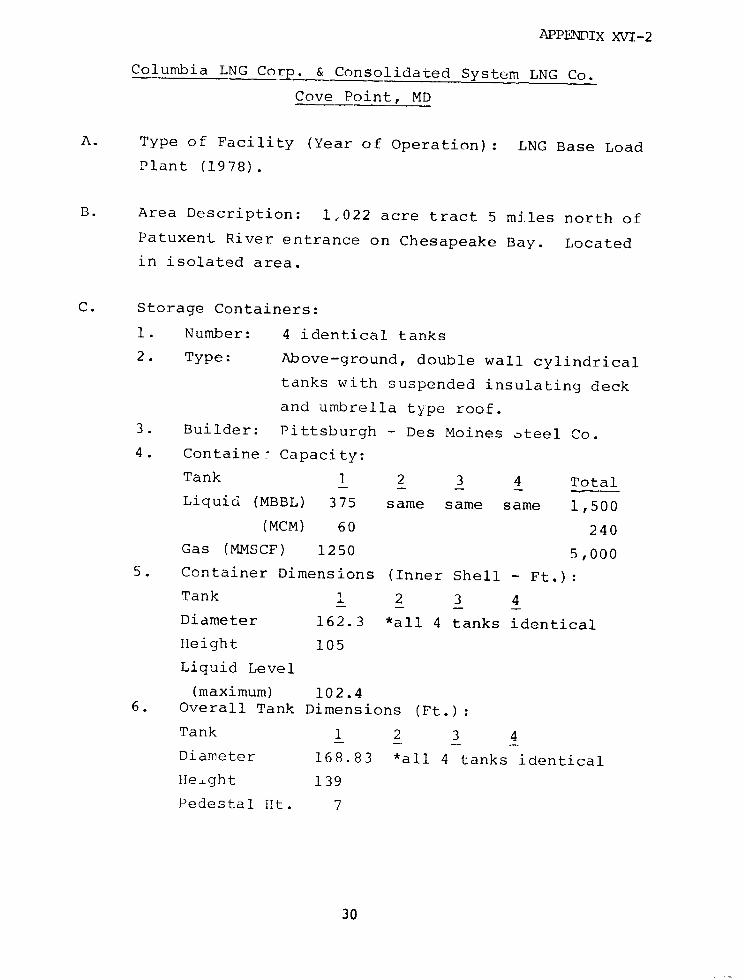
APPENDIX XVI-2
Columbia LNG Corp. & Consolidated System LNG Co.
Cove Point, MD
A. Type of Facility (Year of Operation): LNG Base Load
Plant (1978).
B. Area Description: 1,022 acre tract 5 miles north of
Patuxent River entrance on Chesapeake Bay. Located
in isolated area.
C. Storage Containers:
1. Number: 4 identical tanks
2. Type: Above-ground, double wall cylindrical
tanks with suspended insulating deck
and umbrella type roof.
3. Builder: Pittsburgh - Des Moines steel Co.
4. Containe- Capacity:
Tank 1 2 3 4 Total
Liquid (MBBL) 375 same same same 1,500
(MCM) 60 240
Gas (MMSCF) 1250 5,0005. Container Dimensions (Inner Shell - Ft.):
Tank I 2 3 4
Diameter 162.3 *all 4 tanks identical
Height 105
Liquid Level
(maximum) 102.46. Overall Tank Dimensions (Ft.):
Tank 1 2 3 4
Diameter 168.83 *all 4 tanks identical
Height 139
Pedestal Ht. 7
30
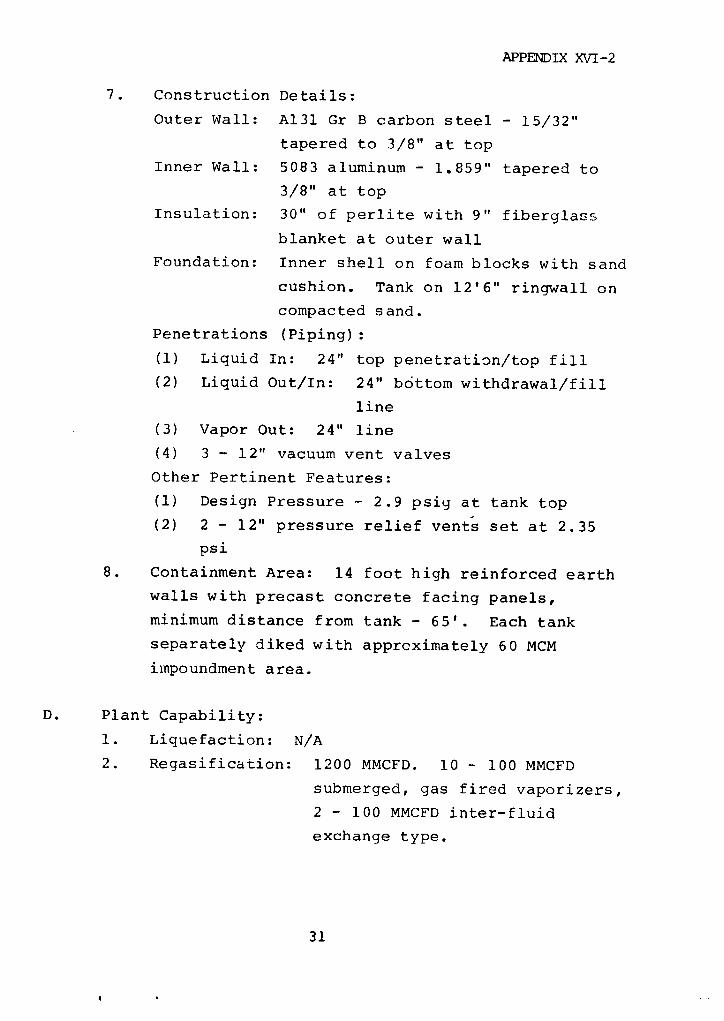
APPENDIX XVI-2
7. Construction Details:
Outer Wall: A131 Gr B carbon steel - 15/32"
tapered to 3/8" at top
Inner Wall: 5083 aluminum - 1.859" tapered to
3/8" at top
Insulation: 30" of perlite with 9" fiberglass
blanket at outer wall
Foundation: Inner shell on foam blocks with sand
cushion. Tank on 12'6" ringwall on
compacted sand.
Penetrations (Piping):
(1) Liquid In: 24" top penetration/top fill
(2) Liquid Out/In: 24" bottom withdrawal/fill
line
(3) Vapor Out: 24" line
(4) 3 - 12" vacuum vent valves
Other Pertinent Features:
(1) Design Pressure - 2.9 psig at tank top
(2) 2 - 12" pressure relief vents set at 2.35
psi
8. Containment Area: 14 foot high reinforced earth
walls with precast concrete facing panels,
minimum distance from tank - 65'. Each tank
separately diked with approximately 60 MCM
impoundment area.
D. Plant Capability:
1. Liquefaction: N/A
2. Regasification: 1200 MMCFD. 10 - 100 MMCFD
submerged, gas fired vaporizers,
2 - 100 MMCFD inter-fluid
exchange type.
31
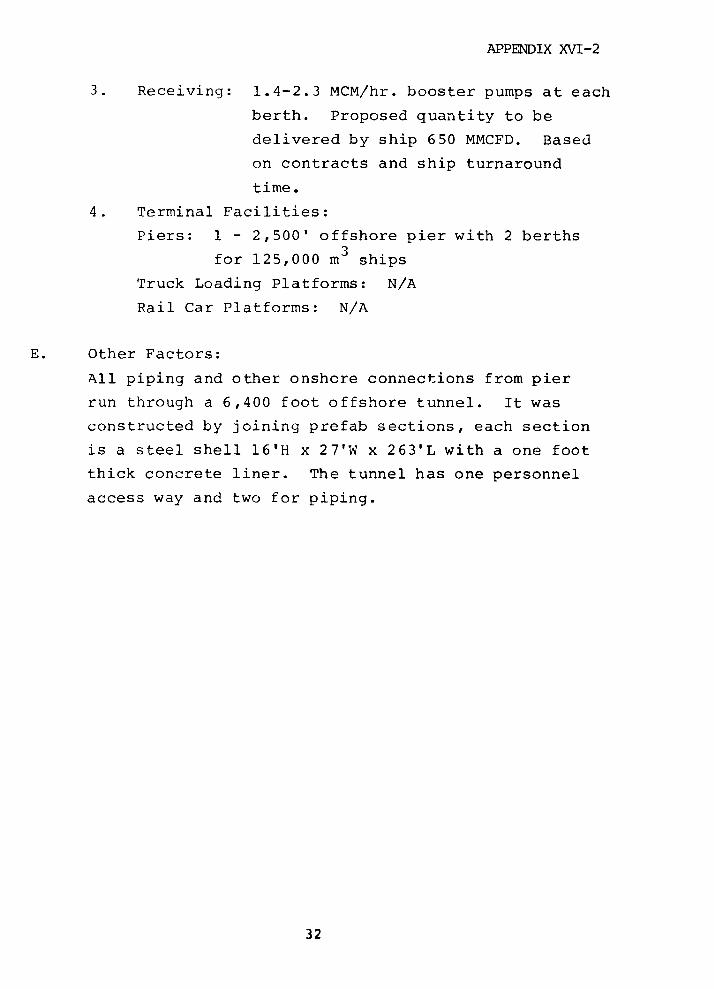
APPENDIX XVI-2
3. Receiving: 1.4-2.3 MCM/hr. booster pumps at each
berth. Proposed quantity to be
delivered by ship 650 MMCFD. Based
on contracts and ship turnaround
time.
4. Terminal Facilities:
Piers: 1 - 2,500' offshore pier with 2 berths
for 125,000 m3 ships
Truck Loading Platforms: N/A
Rail Car Platforms: N/A
E. Other Factors:
All piping and other onshcre connections from pier
run through a 6,400 foot offshore tunnel. It was
constructed by joining prefab sections, each section
is a steel shell 16'H x 27'W x 263'L with a one foot
thick concrete liner. The tunnel has one personnel
access way and two for piping.
32

APPENDIX XVI-2
Distrigas of Massachusetts Corp. (DOMAC)
Everett, MA
A. Type of Facility (Year of Operation): LNG Receiving
Terminal (1971)
B. Area Description: Located on the northern bank of the
Mystic River two miles from Boston in an area of heavy
population and industrial activity. Activity includes
petroleum and gas processing/storage, scrap yard,
electric power plant, LPG facility, etc.
C. Storage Containers:
1. Number: 2
2. Type: Above ground, double wall cylindrical
tanks with suspended insulating deck
umbrella type roof
3. Builder: Chicago Bridge and Iron
4. Container Capacity:
Tank 1 2 Total
Liquid (MBBL) 374 600 974
(MCM) 60 95 155
Gas (MMSCF) 1270 2040 3,310
5. Container Dimensions (Inner Shell - Ft.):
Tank 1 2
Diameter 150 184
Height 124 132.25
Liquid Level
(maximum) 118.8 126.7
6. Overall Tank Dimensions (Ft.):
Tank 1 2
Diameter 156 190
33

APPENDIX XVI-2
Height 131.5 138.5
Pedestal Ht. 16.2 16.9
7. Construction Details:
Outer Wall: carbon steel - 15/32" tapered to
11/32" at top
inner Wall: 9% nickel steel - .784" tapered
to 5/16" at top
Insulation: 36" perlite
Foundation: Inner shell on foam glass blocks,
standard ringwall tank foundation on
compacted silt.
Penetrations (Piping): All top penetratiors
Tank 1 2
(1) Liquid In: (top
fill) 20" 24"
(2) Liquid Out: 1-18" 2-18"
2-12" 2-12"
(3) Vapor Out: 12" 12"
Other Pertinent Features:
(1) tank operating pressure - 1.5 psig
(2) discretionary relief valve - 1.42 psig
main relief valve - 1.5 psig
8. Containment Area: Asphalt covered, stone
stabilized dikes, approximately 15 feet high -
a minimum of 65 feet from small tan)k and 105
feet from large tank. Single impounding area
for two tanks - capacity approximately 141 MCM.
D. Plant Capacity:
1. Liquefaction: 11.3 GPM Partial Reliquefaction
2. Regasification: 135 MMCFD. 3-45 MMCFD submerged
gas fired vaporizers.
3. Receiving: (Max) 20,000 GPM (4,500 m 3 ) from
34
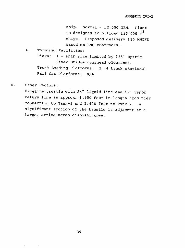
APPENDIX XVI-2
ship. Normal - 12,000 GPM. Plant
is designed to offload 125,000 m3
ships. Proposed delivery 115 MMCFD
based on LNG contracts.
4. Terminal Facilities:
Piers: 1 - ship size limited by 135' Mystic
River Bridge overhead clearance.
Truck Loading Platforms: 2 (4 truck stations)
Rail Car Platforms: N/A
E. Other Factors:
Pipeline trestle with 24" liquid line and 12" vapor
return line is approx. 1,950 feet in length from pier
connection to Tank-1 and 2,400 feet to Tank-2. A
significant section of the trestle is adjacent to a
large, active scrap disposal area.
35

APPENDIX XrV-2
Public Service Electric & Gas Company (PSE&G) of New Jersey
Staten Island, NY (Rossville Plant)
A. Type of Facility (Year of Operation): LNG Receiving
Terminal (constructed 1973-1975) - Application Pending
DOE authorization to operate under new ownership.
B. Area Description: Located in southwest section of
Staten Island on Arthur Kill Channel in low density
population area. Site is adjacent to large scrap
salvage yard.
C. Storage Containers:
1. Number: 2 identical tanks
2. Type: Above-ground, double wall, cylindrical
concrete tank with suspended insulating
deck and dome shaped roof.
3. Builder: Preloaa Technology, Inc.
4. Container Capacity:
Tank 1 2 Total
Liquid (MBBL) 900 same 1,800
(MCM) 143 same 286
Gas (MMSCF) 3060 same 6,120
5. Container Dimensions (Inner Shell - Ft.):
Tank 1 2
Diameter 243 same
Heignt 118.67
Liquid Level
(maximum) 111.75 "
6. Overall Tank Dimensions (Ft.):
Tank 1 2
Diameter 269 same
Height 145.58 same
36
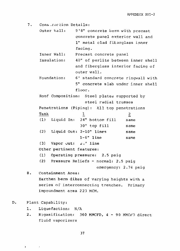
APPENDIX XVI-2
7. ConstrLIction Details:
Outer Thall: 9'8" concrete berm with precast
concrete panel exterior wall and
1" metal clad fiberglass inner
facing.
Inner Wall: Precast concrete panel
Insulation: 40" of perlite between inner shell
and fiberglass interior facing of
outer wall.
Foundation: 6' standard concrete ringwall with
5" concrete slab under inner shell
floor.
Roof Composition: Steel plates supported by
steel radial trusses
Penetrations (Piping): All top penetrations
Tank 1 2
(1) Liquid In: 24" bottom fill same
30" top fill same
(2) Liquid Out: 2-10" lines same
1-6" line same
(3) Vapor jut: z,i' line
Other pertinent features:
(1) Operating pressure: 2.5 psig
(2) Pressure Reliefs - normal: 2.5 psig
emergency: 2.74 psig
8. Containment Area:
Earthen berm dikes of varying heights with a
series of interconnecting trenches. Primary
impoundment area 223 MCM.
D. Plant Capability:
1. Liquefaction: N/A
2. Rngasification: 360 MMCFD, 4 - 90 MMCFD direct
fluid vaporizers
37

APPENDIX XVI-2
3. Receiving: Application proposed 446 MMCFD by
ship. (Average daily quantity landed, based on
ship turnaround times and delivery contract).
4. Terminal Facilities:
Piers: Shoreside pier on Arthur Kill with one
berth.
Reil Car Platforms: N/A
E. Other Factors:
Plant was designed to distribute gas to New Jersey
(PSE&G) and New York (Brooklyn Union).
38

APPENDIX XVI-2
Southern Energy Company
Elba Island, GA
A. Type of Facility (Year of Operation): LNG Base Load
Plant & Receiving Terminal (1978).
B. Area Description: Plant is located in 150 acre tract
on Elba Island (800 acres); relatively isolated area on
the Savannah Piver, 5 miles east of Savannah.
C. Storage Containers:
1. Number: 3 identical tanks
2. Type: Above-ground, double wall, cylindrical
tank with suspended insulating deck
and umbrella roof.
3. Builder: Chicago Bridge & Izon
4. Container Capacity:
Tank 1 2 3 Total
Liquid (MBBL) 400 same same 1,200
(MCM) 63 same same 190
Gas (MMSCF) 1360 same same 4,080
5. Container Dimensions (Inner Shell - Ft.):
Tank 1 2 3
Diameter 160 same same
Height 118.5 " "
Liquid Level
(maximum) 113
6. Overall Tank Dimensions (Ft.):
Tank 1 2 3
Diameter 166 same same
Height 166 (includes above-ground piling
height)
Pedestal Ht. 2
39

APPENDIX XVI-2
7. Construction Details:
Outer Wall: carbon steel - 1/2" tapered to 3/8"
at top
Inner Wall: 5083 aluminum - 2.135" tapered to
9/16" at top
Insulation: 27" perlite plus 9" resilient foam-
glass blanket against inner wall.
Foundation: Tank is supported by reinforced
concrete, step tapered piles with
normal air space of 1.5' between pile
cap and ground surface. Double
bottom is insulated with a layer
of sand and foam glass blocks on a
concrete pad.
Penetrations (Piping):
(1) Liquid In: 24" top penetration/top fill
(2) Liquid In/Out: 24" bottom fill (same bottom
18" withdrawal penetration
used)
(3) Vapor Out: 24" line
Other Pertinent Features:
(1) Operating Pressure: 0.9 psig
(2) Design Pressure: 2.0 psig
8. Containment Area:
Each storage tank is surrounded bv sloped earthen
dikes averaging 18' in height, minimum dist'nce
to tank - 110'. Entire area is interlaced with
concrete spillways leading to LNG retention areas
to control spills.
D. Plant Capability:
1. Liquefaction: N/A
2. Regasification: 540 MMCFD - 5 indirect fired,
water bath combustion vaporizers at 108 MMCFD
· 0
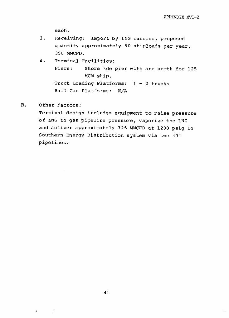
APPENDIX XVI-2
each.
3. Receiving: Import by LNG carrier, proposed
quantity approximately 50 shiploads per year,
350 MMCFD.
4. Terminal Facilities:
Piers: Shore ide pier with one berth for 125
MCM ship.
Truck Loading Platforms: 1 - 2 trucks
Rail Car Platforms: N/A
E. Other Factors:
Terminal design includes equipment to raise pressure
of LNG to gas pipeline pressure, vaporize the LNG
and deliver approximately 325 MMCFD at 1200 psig to
Southern Energy Distribution system via two 30"
pipelines.
41
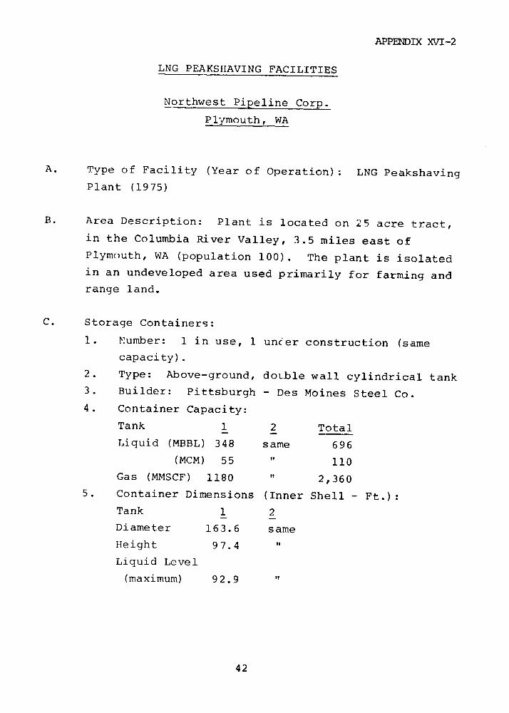
APPENDIX XVI-2
LNG PEAKSHAVING FACILITIES
Northwest Pipeline Corp.
Plymouth, WA
A. Type of Facility (Year of Operation): LNG Peakshaving
Plant (1975)
B. Area Description: Plant is located on 25 acre tract,
in the Columbia River Valley, 3.5 miles east of
Plymouth, WA (population 100). The plant is isolated
in an undeveloped area used primarily for farming and
range land.
C. Storage Containers:
1. Number: 1 in use, 1 uncer construction (same
capacity).
2. Type: Above-ground, doL.ble wall cylindrical tank
3. Builder: Pittsburgh - Des Moines Steel Co.
4. Container Capacity:
Tank 1 2 Total
Liquid (MBBL) 348 same 696
(MCM) 55 " 110
Gas (MMSCF) 1180 " 2,360
5. Container Dimensions (Inner Shell - Ft.):
Tank 1 2
Diameter 163.6 same
Height 97.4 "
Liquid Level
(maximum) 92.9 "
42

APPENDIX XVI-2
6. Overall Tank Dimensions (Ft.):
Tank 1 2
Diameter 173.3 same
Height 133.5 same
7. Construction Details:
Outer Wall: 131 C carbon steel 1/2" tapered to
7/16" at top
Inner Wall: Tank 1 - aluminum
Tank 2 - 9% nickel steel (astm 5531)
.585" tapered to .3125" at
top
Insulation: 58" of perlite/fiberglass
Foundation: Standard ringwall over compacted
sand/gravel
Penetrations (Piping)-
(1) Liquid In: 3" Lottom penetration/bottom
fill
(2) Liquid Out: 12" bottom withdrawal
(3) Vapor Out: 8" line
Other Pertinent Features:
1 - 12" vacuum vent
1 - 12" pressure relief vent
8. Containment Area: Excavated to 17' below top of
gravel and sand sloped dike walls. Common im-
poundment area displaced from tanks with spillways
from tank site. Capacity 153 MCM.
D. Plant Capability:
1. Liquefaction: 13.2 MMSCFD
2. Regasification: 300 MMSCFD
3. Receiving: From Northwest natural gas trans-
mission line during periods of low demand.
4. Terminal Facilities:
Piers: N/A
43

APPENDIX XVI-2
Truck Loading Platforms: 1 dock - load LNG1 dock - unload LPG
Rail Car Platforms: N/A
E. Other Factors.
Available land and isolation allows for unique design
of impoundment area. In theory primary area of spill
boil-off is displaced from tanks to reduce damage in
event of fire.
44
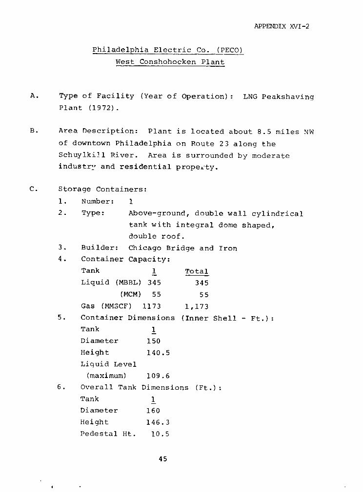
APPENDIX XVI-2
Philadelphia Electric Co. (PECO)
West Conshohocken Plant
A. Type of Facility (Year of Operation): LNG Peakshaving
Plant (1972).
B. Area Description: Plant is located about 8.5 miles NW
of downtown Philadelphia on Route 23 along the
Schuylkill River. Area is surrounded by moderate
industrI and residential propeLty.
C. Storage Containers:
1. Number: 1
2. Type: Above-ground, double wall cylindrical
tank with integral dome shaped,
double roof.
3. Builder: Chicago Bridge and Iron
4. Container Capacity:
Tank 1 Total
Liquid (MBBL) 345 345
(MCM) 55 55
Gas (MMSCF) 1173 1,173
5. Container Dimensions (Inner Shell - Ft.):
Tank 1
Diameter 150
Height 140.5
Liquid Level
(maximum) 109.6
6. Overall Tank Dimensions (Ft.):
Tank 1
Diameter 160
Height 146.3
Pedestal Ht. 10.5
45
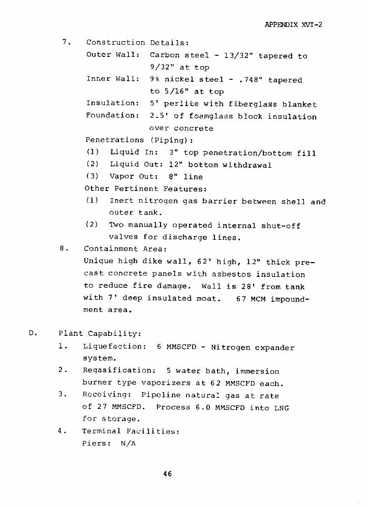
APPENDIX XVI-2
7. Construction Details:
Outer Wall: Carbon steel - 13/32" tapered to
9/32" at top
Inner Wall: 9% nickel steel - .748" tapered
to 5/16" at top
Insulation: 5' perlite with fiberglass blanket
Foundation: 2.5' of foamglass block insulation
over concrete
Penetrations (Piping):
(1) Liquid In: 3" top penetration/bottom fill
(2) Liquid Out: 12" bottom withdrawal
(3) Vapor Out: 8" line
Other Pertinent Features:
(1) Inert nitrogen gas barrier between shell and
outer tank.
(2) Two manually operated internal shut-off
valves for discharge lines.
8. Containment Area:
Unique high dike wall, 62' high, 12" thick pre-
cast concrete panels with asbestos insulation
to reduce fire damage. Wall is 28' from tank
with 7' deep insulated moat. 67 MCM impound-
ment area.
D. Plant Capability:
i. Liquefaction: 6 MMSCFD - Nitrogen expander
system.
2. Regasification: 5 water bath, immersion
burner type vaporizers at 62 MMSCFD each.
3. Receiving: Pipeline natural gas at rate
of 27 MMSCFD. Process 6.0 MMSCFD into LNG
for storage.
4. Terminal Facilities:
Piers: N/A
46

APPENDIX XVI-2
Truck Loading Platforms: 1 truck loading area
Rail Car Platforms: N/A
E. Other Factors:
The storage container is normally filled during the
April to November season, taking natural gas from the
distribution pipeline network. On days of peak demand
during the winter, LNG is vaporized and pumped back
into the network.
47

APPENDIX XVI-2
Philadelphia Gas Works
Richmond Plant
A. Type of Facility (Year of Operation): LNG Liquefaction
Plant (1969); LNG Storage and Vaporization (1974).
B. Area Description: Located in Port Richmond area on
Delaware River 0.6 miles west of Frankford Creek
entrance. Heavy industrial area with marine terminals,
sewage treatment plant and processing/storage of
petroleum products.
C. Storage Containers:
1. Number: 2 identical tanks
2. Type: Above-ground, double wall, cylindrical
concrete tank with concrete dome,
carbon steel outer shell and roof,
and 9% nickel steel floor.
3. Builder: Walsh Construction Company (Preload
Technology, Inc. - Design Engineer)
4. Container Capacity:
Tank 1 2 Total
Liquid (MBBL) 583 same 1,166
(MCM) 93 same 185
Gas (MMSCF) 1980 same 3,960
5. Container Dimensions (Inner Shell - Ft.):
Tank 1 2
Diameter 230 same
Height 81.4 "
Liquid Level
(maximum) 79 "
48

APPENDIX XVI-2
6. Overall Tank Dimensions (Ft.):
Tank 1 2
Diameter 262 same
Height 119.17 same
7. Construction Details:
Outer Wall: 10' concrete berm between outer steel
shell of tank and prestressed con-
crete exterior wall (11" tapered to
7" at top).
Inner Wall: 11" prestressed concrete tapered to
7" at top with carbon steel wrapper
(vapor barrier) on external surface.
Insulation: 4' of perlite, pressurized with
boil-off vapor.
Foundation: Reinforced concrete slab on founda-
tion pilings.
Penetrations (Piping): All top penetrations
Tank 1 2
(1) Liquid In: 6" bottom same
fill
(2) Liquid Out: 2 - 8" lines 3 - 8" lines
into 10" into 10"
header header
1 - 2" line
(3) Vapor Out: 12" line same
Other Pertinent Features:
(1) Tank operating pressure: less than 1 psig
(2) 4 Primary relief valves, one set at 0.95
psig, three set at 1.0 psig; 2 emergency
relief valves set at 1.09 psig; 3 vacuum
breakers set at minus .6125 inches water
column for each tank
8. Containment Area: Self-contained by means of
10" thick concrete berm and its outer pre-
49
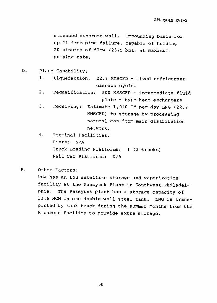
APPENDIX XV7I-2
stressed concrete wall. Impounding basin for
spill from pipe failure, capable of holding
20 minutes of flow (2575 bbl, at maximum
pumping rate.
D. Plant Capability:
1. Liquefaction: 22.7 MMSCFD - mixed refrigerant
cascade cycle.
2. Regasification: 500 MMSCFD - intermediate fluid
plate - type heat exchangers
3. Receiving: Estimate 1,040 CM per day LNG (22.7
MMSCFD) to storage by processing
natural gas from main distribution
network.
4. Terminal Facilities:
Piers: N/A
Truck Loading Platforms: 1 '2 trucks)
Rail Car Platforms: N/A
E. Other Factors:
PGW has an LNG satellite storage and vaporization
facility at the Passyunk Plant in Southwest Philadel-
phia. The Passyunk plant has a storage capacity of
11.6 MCM in one double wall steel tank. LNG is trans-
portad by tank truck during the summer months from the
Richmond facility to provide extra storage.
50
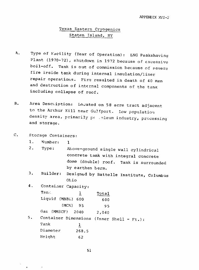
APPENDIX XI-2
Texas Eastern Cryogenics
Staten Island, NY
A. Type of Facility (Year of Operation): LNG PeakshavinaPlant (1970-72), shutdown in 1972 because of excessiveboil-off. Tank is out of commission because of severefire inside tank during internal insulation/liner
repair operations. Fire resulted in death of 40 menand destruction of internal components of the tanKincluding collapse of roof.
B. Area Description: Located on 58 acre tract adjacentto the Arthur Kill near Gulfport. Low populationidensity area, primarily p( .o)leum industry, processingand storage.
C. Storage Containers:
1. Number: 1
2. Type: Above-ground single wall cylindrical
concrete tank with integral concrete
dome (double) roof. Tank is surrounded
by earthen berm.
3. Builder: Designed by Battelle Institute, Columbus
Ohio
4. Container Capacity:
Ta ns 1 Total
Liquid (MBBi,) 600 600
(MCm) 95 95
Gas (MMSCF) 2040 2,040
5. Container Dimensions (Inner Shell - Ft.):Tank 1
Diameter 268.5
Height 62
51
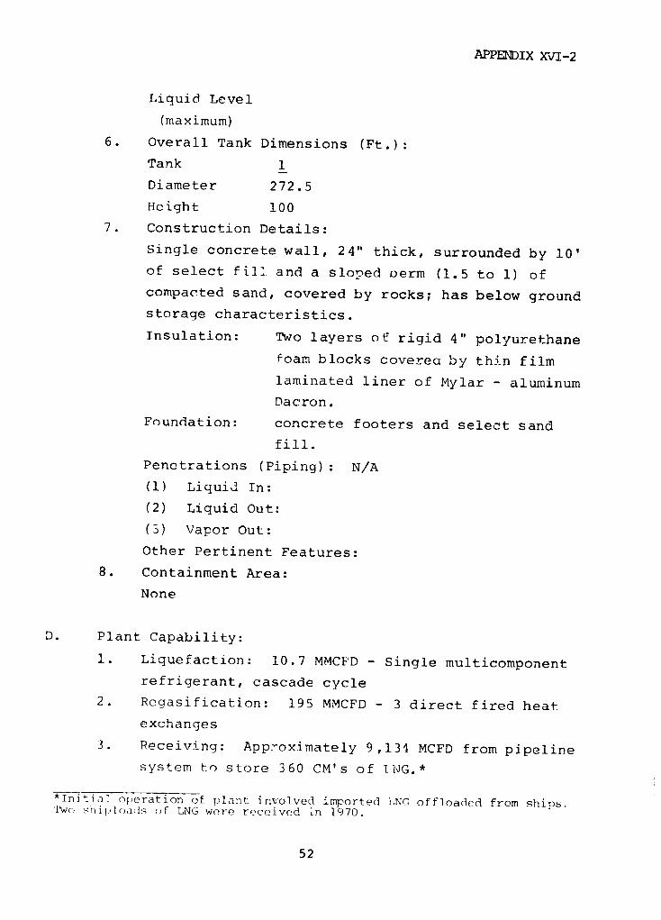
APPENDIX XVI-2
Liquid Level
(maximum)
6. Overall Tank Dimensions (Ft.):
Tank 1
Diameter 272.5
Height 100
7. Construction Details:
Single concrete wall, 24" thick, surrounded by 10'
of select fill and a sloped oerm (1.5 to 1) of
compacted sand, covered by rocks; has below ground
storage characteristics.
Insulation: Two layers of rigid 4" polyurethane
foam blocks coverea by thin film
laminated liner of Mylar - aluminum
Dacron.
Foundation: concrete footers and select sand
fill.
Penetrations (Piping): N/A
(1) Liquid In:
(2) Liquid Out:
(3) Vapor Out:
Other Pertinent Features:
8. Containment Area:
None
D. Plant Capability:
1. Liquefaction: 10.7 MMCFD - Single multicomponent
refrigerant, cascade cycle
2. Regasification: 195 MMCFD - 3 direct fired heat
exchanges
3. Receiving: Approximately 9,134 MCFD from pipeline
system to store 360 CM's of ING.*
*Initial operation of plant involv ed LNG offloaded from ships.'l'i) <hiTliooads of LNG were received in 1970.
52

APPENDIX XVI-2
4. Terminal Facilities:
Piers: None
Truck Loading Platforms: None
Rail Car Platforms: N/A
E. Other Factors: Plant designed to liquefy and store
LNG during summer months and vaporize LNG during peak
periods returning approximately 199 MMCFD to pipeline
distribution.
53
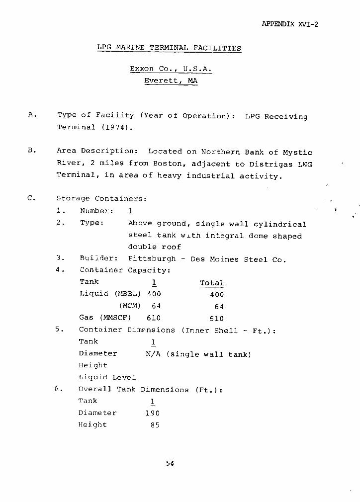
APPENDIX XVI-2
LPG MARINE TERMINAL FACILITIES
Exxon Co., U.S.A.
Everett, MA
A. Type of Facility (Year of Operation): LPG Receiving
Terminal (1974).
B. Area Description: Located on Northern Bank of Mystic
River, 2 miles from Boston, adjacent to Distrigas LNG
Terminal, in area of heavy industrial activity.
C. Storage Containers:
1. Number: 1
2. Type: Above ground, single wall cylindrical
steel tank with integral dome shaped
double roof
3. Builder: Pittsburgh - Des Moines Steel Co.
4. Container Capacity:
Tank 1 Total
Liquid (MBBL) 400 400
(MCM) 64 64
Gas (MMSCF) 610 610
5. Container Dimensions (Inner Shell - Ft.):
Tank 1
Diameter N/A (single wall tank)
Height
Liquid Level
6. Overall Tank Dimensions (Ft.):
Tank 1
Diameter 190
Height 85
54
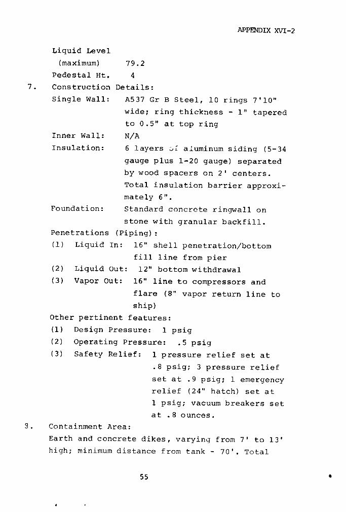
APPENDIX XVI-2
Liquid Level
(maximum) 79.2
Pedestal Ht. 4
7. Construction Details:
Single Wall: A537 Gr B Steel, 10 rings 7'10"
wide; ring thickness - 1" tapered
to 0.5" at top ring
Inner Wall: N/A
Insulation: 6 layers O£ aluminum siding (5-34
gauge plus 1-20 gauge) separated
by wood spacers on 2' centers.
Total insulation barrier approxi-
mately 6".
Foundation: Standard concrete ringwall on
stone with granular backfill.
Penetrations (Piping):
(1) Liquid In: 16" shell penetration/bottom
fill line from pier
(2) Liquid Out: 12" bottom withdrawal
(3) Vapor Out: 16" line to compressors and
flare (8" vapor return line to
ship)
Other pertinent features:
(1) Design Pressure: 1 psig
(2) Operating Pressure: .5 psig
(3) Safety Relief: 1 pressure relief set at
.8 psig; 3 pressure relief
set at .9 psig; 1 emergency
relief (24" hatch) set at
1 psig; vacuum breakers set
at .8 ounces.
3. Containment Area:
Earth and concrete dikes, varying from 7' to 13'
high; minimum distance from tank - 70'. Total
55
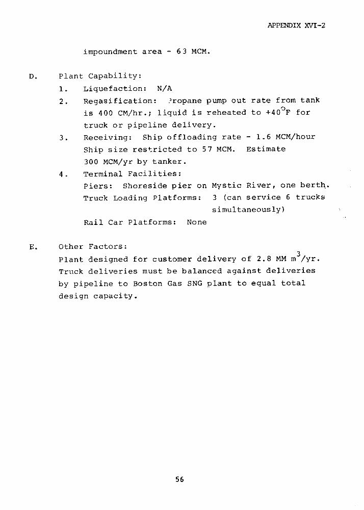
APPENDIX XVT-2
impoundment area - 63 MCM.
D. Plant Capability:
1. Liquefaction: N/A
2. Regasification: ?ropane pump out rate from tank
is 400 CM/hr.; liquid is reheated to +40 0F for
truck or pipeline delivery.
3. Receiving: Ship offloading rate - 1.6 MCM/hour
Ship size restricted to 57 MCM. Estimate
300 MCM/yr by tanker.
4. Terminal Facilities:
Piers: Shoreside pier on Mystic River, one berth,.
Truck Loading Platforms: 3 (can service 6 trucks
simultaneously)
Rail Car Platforms: None
E. Other Factors:
Plant designed for customer delivery of 2.8 MM m3/yr.
Truck deliveries must be balanced against deliveries
by pipeline to Boston Gas SNG plant to equal total
design capacity.
56
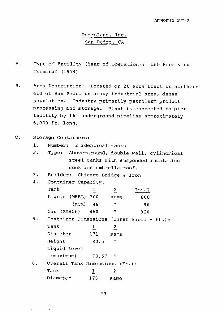
APPENDIX XVI-2
Petrolane, Inc.
San Pedro, CA
A. Type of Facility (Year of Operation): LPG Receiving
Terminal (1974)
B. Area Description: Located on 20 acre tract in northern
end of San Pedro in heavy industrial area, dense
population. Industry primarily petroleum product
processing and storage. Plant is connected to pier
facility by 16" underground pipeline approximately
6,000 ft. long.
C. Storage Containers:
1. Number: 2 identical tanks
2. Type: Above-ground, double wall, cylindrical
steel tanks with suspended insulating
deck and umbrella roof.
3. Builder: Chicago Bridge & Iron
4. Container Capacity:
Tank 1 2 Total
Liquid (MBBL) 300 same 600
(MCM) 48 " 96
Gas (MMSCF) 460 " 920
5. Container Dimensions (Inner Shell - Ft.):
Tank 1 2
Diameter 171 same
Height 80.5
Liquid Level
(mrrximum) 73.67
6. Overall Tank Dimensions (Ft.):
Tank 1 2
Diameter 175 same
57
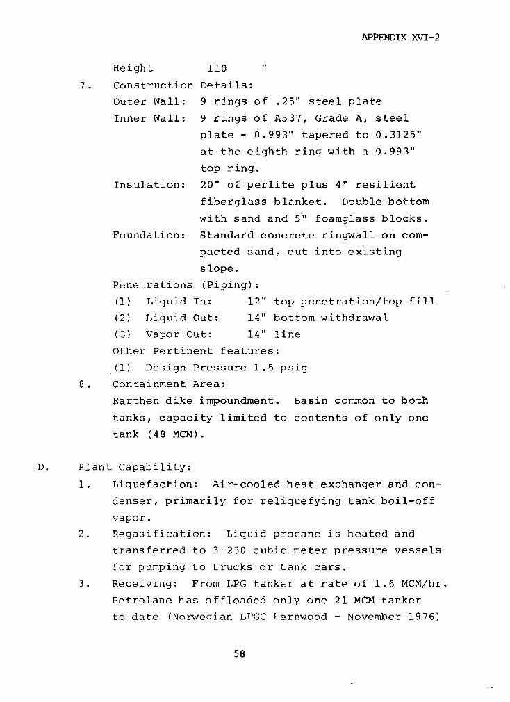
APPENDIX XVI-2
Height 110
7. Construction Details:
Outer Wall: 9 rings of .25" steel plate
Inner Wall: 9 rings of A537, Grade A, steel
plate - 0.993" tapered to 0.3125"
at the eighth ring with a 0.993"
top ring.
Insulation: 20" of perlite plus 4" resilient
fiberglass blanket. Double bottom
with sand and 5" foamglass blocks.
Foundation: Standard concrete ringwall on com-
pacted sand, cut into existing
slope.
Penetrations (Piping):
(1) Liquid In: 12" top penetration/top fill
(2) Liquid Out: 14" bottom withdrawal
(3) Vapor Out: 14" line
Other Pertinent features:
(1) Design Pressure 1.5 psig
8. Containment Area:
Earthen dike impoundment. Basin common to both
tanks, capacity limited to contents of only one
tank (48 MCM).
D. Plant Capability:
1. Liquefaction: Air-cooled heat exchanger and con-
denser, primarily for reliquefying tank boil-off
vapor.
2. Regasification: Liquid proane is heated and
transferred to 3-230 cubic meter pressure vessels
for pumping to trucks or tank cars.
3. Receiving: From LPG tanker at rate of 1.6 MCM/hr.
Petrolane has offloaded only one 21 MCM tanker
to date (Norwegian LPGC Fernwood - November 1976)
58
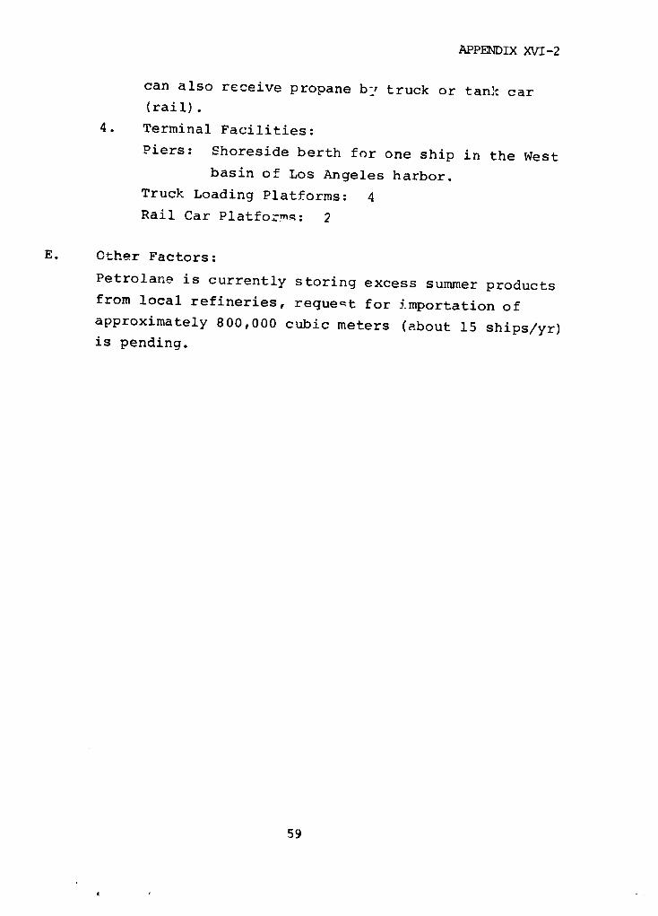
APPENDIX XVI-2
can also receive propane by truck or tank car(rail).
4. Terminal Facilities:
Piers: Shoreside berth for one ship in the Westbasin of Los Angeles harbor.
Truck Loading Platforms: 4Rail Car Platformz: 2
E. Other Factors:
Petrolane is currently storing excess summer productsfrom local refineries, request for importation ofapproximately 800,000 cubic meters (about 15 ships/yr)is pending.
59
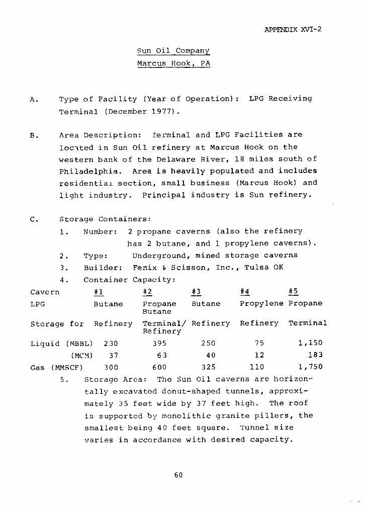
APPENDIX XVI-2
Sun Oil Company
Marcus Hook, PA
A. Type of Facility (Year of Operation): LPG Receiving
Terminal (December 1977).
B. Area Description: Terminal and LPG Facilities are
located in Sun Oil refinery at Marcus Hook on the
western bank of the Delaware River, 18 miles south of
Philadelphia. Area is heavily populated and includes
residential section, small business (Marcus Hook) and
light industry. Principal industry is Sun refinery.
C. Storage Containers:
1. Number: 2 propane caverns (also the refinery
has 2 butane, and 1 propylene caverns).
2. Type: Underground, mined storage caverns
3. Builder: Fenix & Scisson, Inc., Tulsa OK
4. Container Capacity:
Cavern #1 #2 #3 #4 #5
LPG Butane Propane Butane Propylene PropaneButane
Storage for Refinery Terminal/ Refinery Refinery TerminalRefinery
Liquid (MBBL) 230 395 250 75 1,150
(MCM) 37 63 40 12 183
Gas (MMSCF) 300 600 325 110 1,750
5. Storage Area: The Sun Oil caverns are horizon-
tally excavated donut-shaped tunnels, approxi-
mately 35 feet wide by 37 feet high. The roof
is supported by monolithic granite pillers, the
smallest being 40 feet square. Tunnel size
varies in accordance with desired capacity.
60
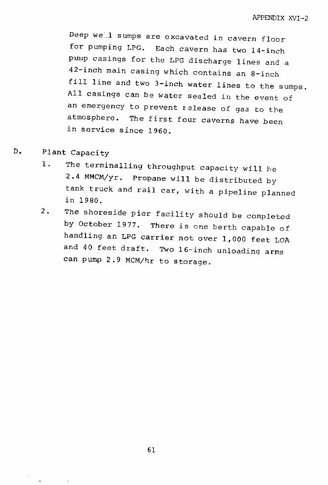
APPENDIX XVI-2
Deep we1l sumps are excavated in cavern floorfor pumping LPG. Each cavern has two 14-inchpump casings for the LPG discharge lines and a42-inch main casing which contains an 8-inchfill line and two 3-inch water lines to the sumps.All casings can be water sealed in the event ofan emergency to prevent release of gas to theatmosphere. The first four caverns have beenin service since 1960.
D. Plant Capacity
1. The terminalling throughput capacity will he2.4 MMCM/yr. Propane will be distributed bytank truck and rail car, with a pipeline plannedin 1980.
2. The shoreside pier facility should be completedby October 1977. There is one berth capable ofhandling an LPG carrier not over 1,000 feet LOAand 40 feet draft. Two 16-inch unloading armscan pump 2.9 MCM/hr to storage.
61

APPENDIX XVI-3
APPENDIX XVI-3
FEDERAL REGULATIONS
INTRODUCTION
The first section of this appendix describes the
evolution of Federal regulation of LPG and LNG storage
facilities. It focuses on the two agencies that have been
primarily responsible for the Federal regulation of these
facilities: the former Federal Power Commission (FPC)* and
the Office of Pipeline Safety Operations (OPSO) in the
Department of Transportation (DOT).
The second section covers the U.S. Coast Guard's
authority to regulate LEG shipping and waterfront
facilities.
The third section discusses the overlap in the
jurisdictions of these three agencies.
The fourth section covers the Federal regulation of
LEG truck and rail transportation by several DOT agencies.
1. FEDERAL CONTROLS ON LPG AND LNG
Liquid petroleum products transported by pipeline
were originally regulated under the Interstate Commerce Act
of 1887, as amended (49 U.S.C.1 et seq.), which generally
*The FPC was disbanded in October, 1977, when the Department of Energy
(DOE) was organized under Public Law 95-91. The distribution of
FPC's responsibilities within DOE had not been fully determined
by June, 1978. For this reason this appendix traces the evolution cZ
FPC's jurisdiction over LNG facilities.
62
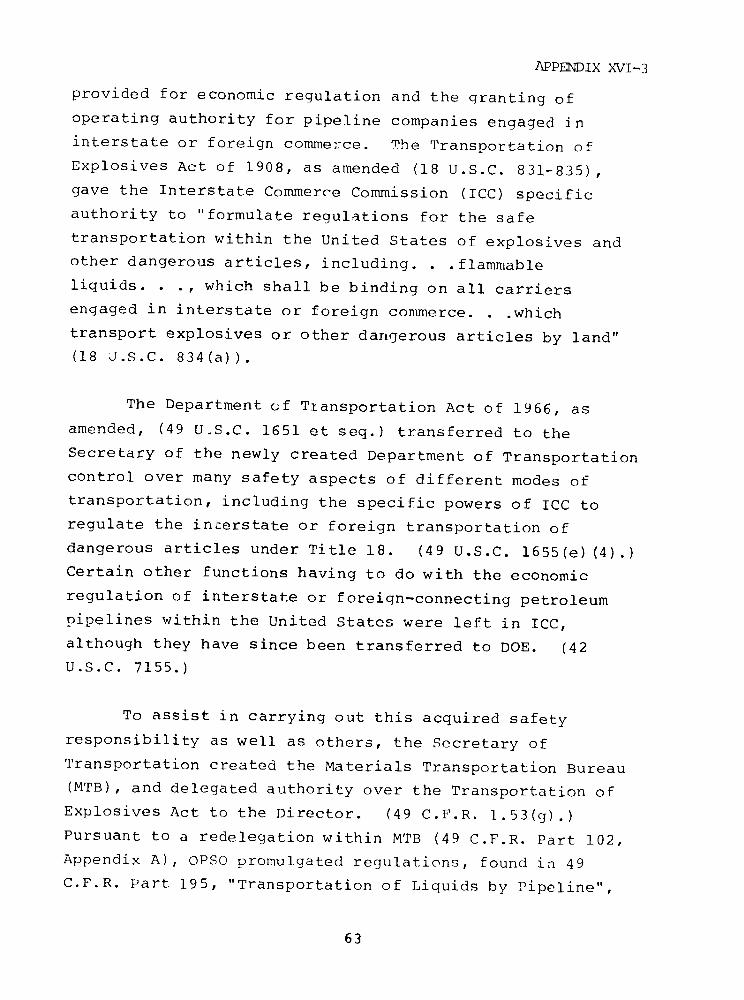
APPENDIX XVI-3
provided for economic regulation and the granting of
operating authority for pipeline companies engaged in
interstate or foreign commerce. The Transportation of
Explosives Act of 1908, as amended (18 U.S.C. 831-835),
gave the Interstate Commerce Commission (ICC) specific
authority to "formulate regulations for the safe
transportation within the United States of explosives and
other dangerous articles, including. . flammable
liquids. . ., which shall be binding on all carriers
engaged in interstate or foreign commerce. . .which
transport explosives or other dangerous articles by land"
(18 J.S.C. 834(a)).
The Department of Ttansportation Act of 1966, as
amended, (49 U.S.C. 1651 et seq.) transferred to the
Secretary of the newly created Department of Transportation
control over many safety aspects of different modes of
transportation, including the specific powers of ICC to
regulate the interstate or foreign transportation of
dangerous articles under Title 18. (49 U.S.C. 16 55(e) (4).)
Certain other functions having to do with the economic
regulation of interstate or foreign-connecting petroleum
pipelines within the United States were left in ICC,
although they have since been transferred to DOE. (42
U.S.C. 7155.)
To assist in carrying out this acquired safety
responsibility as well as others, the Secretary of
Transportation created the Materials Transportation Bureau
(MTB), and delegated authority over the Transportation of
Explosives Act to the Director. (49 C.F.R. 1.5 3 (g).)
Pursuant to a redelegation within MTB (49 C.F.R. Part 102,
Appendix A), OPSO promulgated regulations, found in 49
C.F.R. Part 195, "Transportation of Liquids by Pipeline",
63

APPENDIX XVI-3
which gove in the transportation by pipeline in interstate
or foreign commerce of petroleum, petroleum products, and
hazardous materials, including "liquefied petroleum gases".
The Federel. Power Commission
The transportation of natural gas by pipeline in
interstate or foreign commerce was first regulated under
the terms of the Natural Gas Act of 1938 (15 U.S.C. 717 et
seq.). The Act stipulated administration and enforcement
of regulation by FPC, previously established as an
independent agency in 1930, by the Federal Water Power Act.
By tha Natural Gas Act, the Commission was granted
primarily economic jurisdiction over rates and service and
over the granting of general operating authority to natural.
gas pipeline companies. FPC specifically determined LNG to
be "natural gas" within the meaning of the Natural Gas Act
and thus similarly subject to its jurisdiction (49 F.P.C.
752(1972)).
FPC has exercised this authority in the process of
granting Certificates of Public Convenience and Necessity,
which are required by companies who "engage in the
transportation or sale of natural gas--or undertake the
Construction or extension of any facilities therefor, or
acquire or operate--" any such facilities in interstate
commerce (15 U.S.C. 717f.(c)). Similar FPC authorization
has been required by anyone who would engage in the
imiportation into or the exportation from the United States
of any natural gas in foreign commerce, (1; U.S.C. 717b).
The Natural Gas Act does rot specifically address
safety, but qives the Commission power to attach to the
issuance of - certificate "such reasonable terms and
64
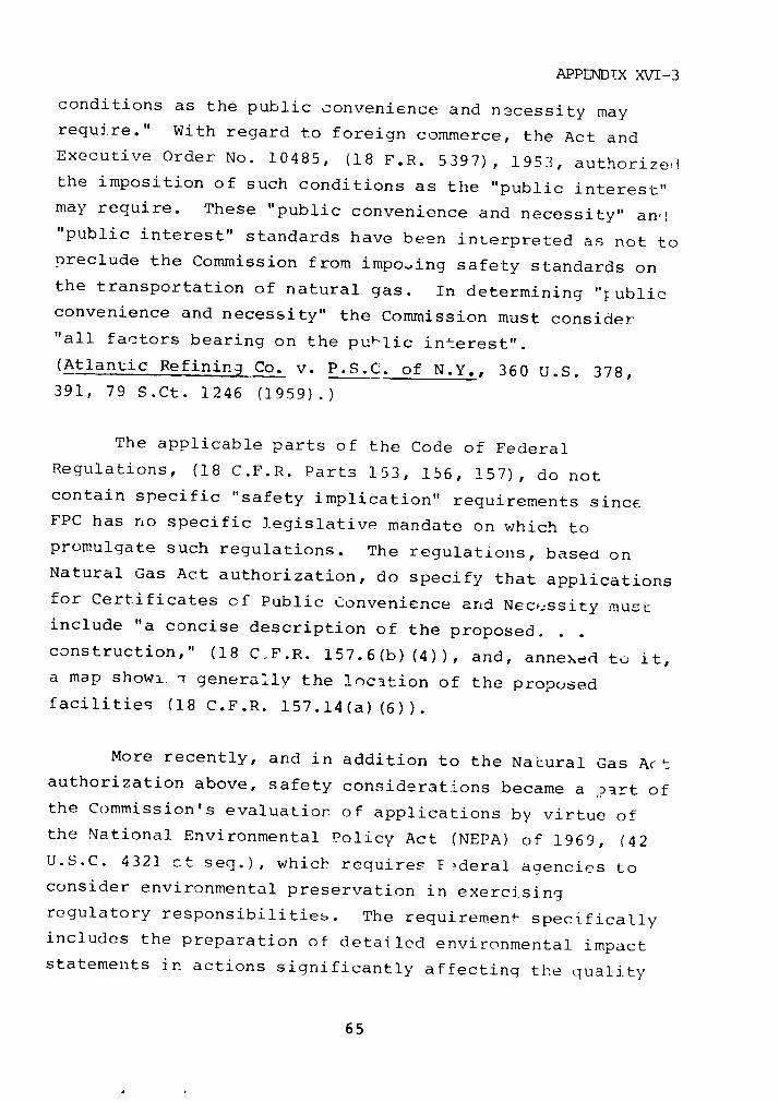
APPENDTX XVI-3
conditions as the public convenience and n3cessity mayrequire." With regard to foreign commerce, the Act andExecutive Order No. 10485, (18 F.R. 5397), 1953, authorizeir
the imposition of such conditions as the "public interest"may require. These "public convenience and necessity" an,'"public interest" standards have been interpreted as not topreclude the Commission from imposing safety standards onthe transportation of natural gas. In determining "'ublicconvenience and necessity" the Commission must consider
"all factors bearing on the pu 1 lic interest".
(Atlantic Refining Co. v. P.S.C. of N.Y., 360 U.S. 378,391, 79 S.Ct. 1246 (1959).)
The applicable parts of the Code of Federal
Regulations, (18 C.F.R. Parts 153, 156, 157), do not
contain specific "safety implication" requirements sinceFPC has no specific legislative mandate on which to
promulgate such regulations. The regulations, based onNatural Gas Act authorization, do specify that applications
for Certificates of Public Convenience and Necefssity mustinclude "a concise description of the proposed. .
construction," (18 C.F.R. 157.6(b)(4)), and, annexed to it,a map showi. generally the location of the proposed
facilities (18 C.F.R. 15 7.14(a) (6)).
More recently, and in addition to the Natural Gas Actauthorization above, safety considerations became a Dart ofthe Commission's evaluation of applications by virtue ofthe National Environmental Policy Act (NEPA) of 1969, (42
U.S.C. 4321 ct seq.), which requires F deral agencies toconsider environmental preservation in exercising
regulatory responsibilities. The requirement specifically
includes the preparation of detailed environmental impactstatements in actions significantly affecting the quality
65
APPENDIX XVI-3
of the human environment. FPC, as a Federal regulatory
agency, was therefore required to conduct its own
environmental evaluation of proposed natural gas facilities
as part of a statutory review procedure. (Calvert Cliffs
Coordinating Commiittee v. Atomic Energy Commission, 449
F.2d 1109, D.C. Cir. 1971.) Safety is one of the factors
to be considered in such an evaluation.
FPC formulated comprehensive regulations on
compliance with NEPA (18 C.F.R. 2.80-2.82 and Appendix B to
Part 2) and specifically addressed the area of "LNG
Facilities," (18 C.F.R. Part 2r Appendix B, Guideline
9.4.1). The Commission's Order No. 485 established
requirements whereby environmental aspects, including
safety, of LNG facilities could be evaluateu -or all phases
of any proposal: construction; operation, including
transportation, unloading, storage, and regasification; and
routine and emergency maintenance.
Office of Pipeline Safety Operations
After the passage of the Department of Transportation
Act in 1966, the new Department of Transportation had
safety jurisdiction over flammable and other hazardous
gases moving in interstate commerce other than by pipeline,
and safety jurisdiction over interstate pipeline movements
of most liquid commodities including petroleum, but not
natural gas. FPC was imposing conditions of compliance
with industry codes on the granting of Certificates of
Public Convenience and Necessity for interstate natural gas
pipelines and facilities, and some of the states prescribed
safety standards by legislative or state commission ac.ion
for intrastate pipelines. Natural gas pipelines were t1he
66

APPENDIX XVI-3
only significant mode of transportation beyond the reach of
effective comprehensive safety regulations.
As a result, Congress enacted the Natural Gas
Pipeline Safety Act of 1968, as amended (49 U.S.C. 1671 et
seq.) to be administered by DOT. The Secretary has
delegated the authority to promulgate regulations unde-
this Act to the Materials Transportation Bureau (49 C.F.R.
1.53(a)), and the Bureau Director delegated this authority
to the Director of OPSO (49 C.F.R. Part 102, Appendix A).
The Natural Gas Pipeline Safety Act required the
Secretary to establish minimum Federal safety standards for
the transportation of natural gas and for the safety of
pipeline and "pipeline facilities" used in such
transportation in or affecting interstate commerce. Such
standards were to be applicable to the "design,
installation, inspection, emergency plans and procedures,
testing, construction, extension, operation, replacement
and maintenance of pipeline facilities." (49 U.S.C.,
1672(b).) "Pipeline facilities" were defined to include
new and existing pipe 'its-of-way and any equipment,
facility, or building used in the transportation or
treatment of gas, although an important limitation was
added that "rights-of-way" did not include the right to
prescribe the location or routing of any pipeline or
facility. (49 U.S.C., 1671(4).) Authority to determine
the siting and routing of natural gas pipelines, therefore,
remained with FPC, and FPC's responsibilities in certifying
interstate natural gas pipelines and facilities, including
safety considerations, were not diminished. Pipelines and
appurtenant pipeline facilities were made subject to both
FPC certification and OPSO safety regulations. Areas of
shared responsibilities regarding natural gas were thus
created.
67
APPENDIX XVI-3
This shared responsibility may be illustrated by a
procedure under the Act whereby an interstate applicant may
certify to FPC that it will construct and maintain its
f: -ilities in accordance with Federal and other applicable
safity standards, and "such certification shall be binding
and conclusive upon the Commission" for purposes of
determining whether the construction and operation details
of a proposed service conform to OPSO's standards, unless
the applicant is otherwise reported to be in violation of
the regulations (49 U.S.C. 1676). Because of this
procedure the question has sometimes arisen whether FPC can
impose higher safety standards than the Federal minimum
which the applicant certifies to have met and which is
regulated and enforced by OPSO.
The legislative history of the Natural Gas Pipeline
Safety Act expressed the intent that all aspects of the
movement of gas from the wellhead to the consumer, with the
exception of certain gathering lines, were to be regarded
as either being in, or having effect on, interstate
commerce and thereby encompassed hy the Secretary's
authority. The Act provides for a voluntary program of
State Agency Certifications or Agreements to provide safety
administration and enforcement of regulations for
intrastate pipelines (49 U.S.C. 1674). Under the program,
agencies in 44 states, the District of Columbia, and Puerto
Rico have certified that they have adopted standards
equivalent to or better than the Federal minimum and that
they have the capacity for effective enforcement of
intrastate regulation. The state- may a~opt more stringent
regulations for intrastate, but not tor interstate, lines
located within their boundaries; however, OPSO retains the
overiding authority to bring Federal action against any
facility which it finds to be hazardous to life or
property.
68
APPENDIX XVI-3
The Natural Gas Pipeline Safety Act also created a
"Technical Pipeline Safe-v Standards Committee" composed of
members from government, industry, and the general public.
Each member must be qualified in safety regulation or
engineering, and the Act requires the Secretary to obtain
their counsel before formally proposing any safety
standard.
Specific ING regulation under authority of the
Natural Gas Pipeline Safety Act has developed primarily as
a regulation of appurtenant production or storage
facilities because the physical properties of LNG make it
uneconomical to pump any distance by pipeline, such as
interstate. Most of the presently proposed LNG marine
terminr.a connect into inland gas pipeline distribution
systems, which bring them under Fede :a regulation by OPSO
as appurtenant pipeline facilities. The FPC meanwhile has
had jurisdiction over marine terminals whether or not there
is a connecting inland pipeline distribution system, under
its Natural Gas Act authority over the import or export of
natural gas, including safety aspects.
OPSO's safety standards are contained in 49 C.F.R.
Parts 191 and 192: "Transportation of Natural and Other
Gas by Pipeline: Minimum Federal Safety Standards."
Specific LNG standards were created by an amendment in 1972
adding Section 192.12. This adopted as the Federal LNG
safety standards the National Fire Protection Association
(NFPA) Standard 59A (1971 e-.ition). as well as the other
applicable requirements of Part 192. Subsequently, the
1972 edition of NFPA 59A was adopted.
In response to growing concern from many sectors,
OPSO has issueC an Advance Notice of Proposed Rulemaking
69
APPENDIX XVI-3
which establishes an independent Federal code or standard
applicable to all aspects of facilities involved in the
transport, storage, liquefaction, vaporization, transfer,
and handling of LNG in conjunction with iatural gas
pipeline systems. The proposed standards are written in
the style of enforceable Federal regulations and in terms
of performance standards which address the on-going,
long-term safe operation and maintenance of LNG facilities.
Industry is left free to develop and use improved
technological means of meeting the required safety level,
and the NFPA is not pre-empted from continuing to devise
and recommend means of meeting the government standards.
OPSO's regulation of LPG and naphtha pipelines in
interstate and foreign commerce ;.s authorized under the
Transportation of Explosives Act of 1908, (18 U.S.C. 831-835).
Th'e Act does not cover intrastate pipelines and facilities
that merely .affect interstate commerce.
The Hazardous Materials Transportation Act, enacted
in 1975, excludes interstate liquid pipelines covered under
the Explosives Act from its provisions. OPSO further
interprets the Pct to exclude jurisdiction over intrastate
liquid pipelines affecting interstate commerce. No Federal
agency regulates t'. safety of LPG storage at import
terminals or at storage complexes that are not owned or
operated by interstate LPG transmission companies.
2. U.S. COAST GUARD'S REGULJATTON
C)F LEG SHIIPPING AND WATERFRONT FACTLTTTES
The U. S. Coast Guard has traditionally promulgated
regulations regarding the safe transportation of LNG and
IPI'(, ilnder the (!eneral classification ,of "liquefied gas
70

APPENDIX XVI-3
ships," in which gases are liquefied by low temperatures,
high pressures, or a combination of the two. LNG and LPG
have to date been grouped as a common hazardous cargo.
Traditional safety considerations in the
transportation of LNG/LPG by water fall into three broad
categories:
the design and construction of vessels
the design and construction of related
waterfront facilities, and
the movement of vessels in the ports and
waterways of the United States.
In addition, with the passage of the PortFs and
Waterways Safety Act of 1972. Title II, (46 U.S.C. 391a),
the concept of vessel design and construction as a safety
factor was enlarged to reflect dual objectives: (1) vessel
safety, per se, and (2) vessel safety for the purpose of
the protection of the marine environment.
Present day Coast Guard regulation of LNG/LPG vessels
and waterfront facilities is comprehensive and reflects a
broad basis of authority.
Statutory Authority
Tanker Act
One of the earliest sources of Coast Guard authority
was the Tanker Act of 1936, (46 U.S.C. 391a), applicable to
"all vessels . .that shall have on board any inflammable
71
APPENDIX XVI-3
or combustible liquid cargo in bulk." The Act authorized
the Coast Guard to establish regulations with respect to
"the design and construction, alteration, or repair of such
vessels" to "secure effective provisiun against the hazards
of life and property" created by them (46 U.S.C.
391a(2)1970).
The regulations pronimlgated, in part, under the
authority of this Act are found in 46 C.F.R. Subchapter D,
"Tank Vessels," Parts 30 to 40, inclusive. In 1966, Part
38 "Liquefied Flammable Gases" was specifically added to
the regulations (31 F.R. 15269).
Dangerous Cargo Act
An even earlier mandate in regard to vessel safety,
which the Coast Guard now administers, came from the
Dangerous Cargo Act, as amended, (46 U.S.C. 170). This Act
makes it unlawful to carry "explosives or other dangerous
articles or substances including flammable or combustible
liquids. . ." except as permitted by the regulations of the
Coast Guard (46 U.S.C. 170(6)(a)). By amendment, later
provisions of this Act specifically exempted the vessels
carrying "inflammable or combustible liquid cargo in bulk"
in their own tanks, or "tank vessels" as regulated by 46
U.S.C. 391a. above, except for one narrow provision.
The Dangerous Cargo Act applies to dangerous cargoes
carried in containers and regulates labeling, container
specifications, storage, and handling of such containers.
In the mid-1960's the transport of bulk chemicals in large
portable containers and portable tanks was becoming a
problem, and with the promulgation of the "Liquefied
Flammable Gases" regulations (46 C.F.R. Part 38), the Coast
72
APPENDIX XVI-3
Guard included regulation of the "Transportation of
portable cylinders or portable tanks containing or having
previously contained liquefied flammable gases in dry cargo
spaces," (46 C.F.R. 38.01-2). The regulations only apply
to the transportation of LNG/LPG when the containers are
carried "under deck." However, containers "under deck" as
well as "on deck" are regulated under the Hazardous
Materials Transportation Act. As a result, if LEG is
transported in containers "under deck," the vessel must
meet the requirements promulgated under the authority of
the Dangerous Cargo Act, as well as those under the
Hazardous Materials Transportation Act.
The Hazardous Materials Transportation Act also
contains specific provisions relating to investigations,
records, inspections, penalties, and specific relief for
the enforcement of safety regulations covered by the Act.
By specific delegation of authority from the Secretary of
Transportation, the Coast Guard has been empowered to
exercise such functions as they apply to the transportation
or shipment of hazardous materials by water (49 C.F.R.
1.46(u)). This delegation permits more centralization of
enforcement responsibilities within DOT for the safe
transportation of hazardous materials by water.
Magnuson Act and Executive Order 10173
Since 1950, the Coast Guard has carried out a program
for port safety under regulations initially prescribed by
the President in Executive Order 10173 (15 F.R. 7005)
pursuant to the Magnuson Act (50 U.S.C. 191). In part, the
Magnuson Act authorizes the President, upon a finding that
the security of the United States is endangered, to issue
rules and safeguard vessels, harbors, ports, and waterfront
73

APPENDIX XVI-3
facilities in the United States and waters subject to the
jurisdiction of the United States against destruction,
loss, or injury. The President made the appropriate
finding in Executive Order 10173 (1950) and prescribed
regulations which, as amended, are curlently codified in 33
C.F.R. Part 6.
The more relevant provisions of these regulations for
LEG safety are delegations of authority to the Coast Guard:
(1, "The Captain of the Port {COTP} may
supervise and control the transportation, handling,
loading, discharging, stowage, or storage. . .of
inflammable or combustible liquids in
bulk. . covered by the regulations. .governing
tank vessels (46 C.F.R. Parts 30 to 39 inclusive)."
(33 C.F.R. 6.12-1.)
(2) "The Commandant may designate
waterfront facilities {for the above}. . .and may
require the owners, operators, masters, and others
concerned to secure permits. . .conditioned upon the
fulfillment of such requirements for the safeguarding
of such waterfront facilities and vessels as the
Commandant may prescribe." (33 C.F.R. 6.12-3.)
(3) "The Commandant. . .may prescribe such
conditions and restrictions relating to the safety of
waterfront facilities and vessels in port as he finds
to be necessary under existing circumstances. Such
conditions and restrictions may extend, but shall not
be limited to, the inspection, operation,
maintenance, guarding, and manning of, and fire
74
APPENDIX XVI-3
prevention measures for, such vessels and waterfront
facilities." (33 C.F.R. 6.14-1.)
The Coast Guard, in implementing its deleqated
authority, promulgated regulations contained primarily in
33 C.F.R. Parts 124, 125, and 126. Part 124 applies to
"Control over Movement of Vessels." Part 125
("Identification Credentials for Persons Requiring Access
to Waterfront Facilities or Vessels") and Part 126
("Handling of Explosives or other Dangerous Cargoes Within
or Contiguous to Waterfront Facilities") apply to
waterfront facilities. These regulations, in conjunction
with those in Part 6, have provided the basis for the
development of local LNG/LPG contingency plans.
The COTP has, historically, determined many
jurisdictional questions raised by language stemming from
Executive Order 10173. 33 C.F.R. Part 126 refers to the
handling of dangerous cargoes at designated waterfront
facilities of particular hazard. The regulations define
"waterfront facility" as "all piers, wharves, docks, and
similar structures to which vessels may be secured; areas
of land, water, or land and water under and in immediate
proximity to them (emphasis added); buildings on such
structures or contiguous to them -rd equipment and
materials on such structures or in such buildings." (33
C.F.R. 6.01-4.) The jurisdictional limitations of how fae
inland the Coast Guard regulations and their enforcement
apply have traditionally been a matter of local
determination by the COTP, illustrating the need for
clarification of Coast Guard authority over port safety
under the Magnuson Act and Executive Order 10173, as
amended. See the discussion below of Jurisdictional
Cverlap.
75
APPENDIX XVI-3
Ports and Waterways Safety Act (PWSA)
The major source of the Coast Guard's comprehensive
regulatory authority over the safe transportation of
LNG/LPG by water stems from the Ports and Waterways Safety
Act of 1972, as amended, Title I (33 U.S.C. 1221 et seq.),
and title II (amending 46 U.S.C. 391a). This legislation
applies to the design and construction of vessels, minimum
safety equipment requirements for waterfront structures,
and the movement of vessels. In addition, the legislation
applies to all vessels entering the navigable waters of the
United States, and the goal of safety in the ports and
waterways as a result of the Act is now to reflect a
concern for the marine environment.
Title II of the PWSA is an amendment of the Tanker
Act requiring vessels to be built to higher standards of
design and construction and to be subject to higher
standards in operation. It mandated that for all vessels
documented under the laws of the United States or vessels
entering the navigable waters of the United States there be
established "minimum comprehensive standards of design,
construction, alteration, repair, maintenance, and
operation to prevent or mitigate the hazards to life,
property, and the marine environment" (emphasis added).
(46 U.S.C. 391a(1).) The rules and regulations are to
apply to the ship structure and all materials; the
machinery and manner used in handling and storage of cargo;
the fire protection provisions; the manning requirements
and qualifications of officers and crew; and the inspection
of all the foregoing (46 U.S.C. 391a(3)).
One of the most far-reaching implications of Title II
is that the authority to prescribe standards for the
76
APPENDIX XVI-3
protection of the marine environment is made explicit, and
the concept of vessel safety is to reflect design and
construction criteria to achieve that goal. The Act
mandates adoption, to the extent possible, of "standards to
improve vessel maneuvering and stopping ability and
otherwise reduce the possibility of collision, grounding,
or other accident, to reduce cargo loss following {the
above}, and to reduce damage to the marine environment by
normal vessel operations such as ballasting and
de-ballasting, cargo handling, and other activities." (46
U.S.C. 391a(7).) The goals reflected in this language also
illustrate the growing concern that safety regulation cf
the transportation of such hazardous cargoes as LNG/LPG
provide for the containment of a major spill or potentially
catastrophic event.
The present regulations for the design, construction,
inspection, manning and operation of tank vessels
pertaining to vessel safety are contained in 46 C.F.R.
Subchanter D, Parts 30-40, of which Part 38, "Liquefied
Flammable Gases," relates specially to LNG/LPG vessels.
These regulations were promulgated, in part, under the
authority of the Tanker Act and Title II of the PWSA.
In 1971 the Coast Guard had requested its Chemical
Transportation Industry Advisory Committee (CTIAC) to make
recommendations for a thorough updating of 46 C.F.R. Part
38. In conjunction with the Intergovernmental Maritime
Consultative Organization (IMCO), they completed an
international "Code for Construction and Equipment of Ships
Carrying Liquefied Gases in Bulk" for new ships, .hi--h was
adopted by IMCO in late 1975. The Coast Guard, which was
actively involved in the development of the TMCO Code,
proposed rules in October 1976 corresponding closely to the
77

APPENDIX XVI-3
IMCO Code. Also in October 1976, IMCO adopted the "IMCO
Code for Existing Ships Carrying Liquefied Gases in Bulk."
The Coast Guard published an Advance Notice of Proposed
Rulemaking for construction and equipment of existing
self-propelled vessels carrying bulk liquefied gases inJune 1977.
Vessels are not designed to withstand a major
collision or stranding without cargo release. The Coast
Guard's operational controls on vessels entering, moored,
or leaving U.S. ports lessen the possibility of collisions,
strandings, or other incidents.
Title I of the PWSA included new legislation
governing port safety "in order to prevent damage to, cr
the destruction or loss of any vessel, bridge, or other
structure on or in the navigable waters of the United
States, or any land structure or shore area immediately
adjacent to those waters" (emphasis added). (33 U.S.C.
1221.) The PWSA goes on to provide for extensive vesseltraffic services, systems, and controls over entry,
movement, mooring and restricted vessel operation in
hazardous circumstances or by virtue of hazardous cargohandling (33 U.S.C. ]_221(1),(2),(3), (4)).
In addition, waterfront facilities are specifically
covered in the limited authority to establish 'procedures,
measures, and standards for the handling, loading,
discharge, storage, stowage, and movement. . .of explosivesor other dangerous articles or substances. . .on structures
subject to this chapter" and to "prescribe minimum safety
equipment requirements for (such'} structures. . .to assureadequate protection from fire, explosion, natural
disasters, and other serious accidents or casualties." (33
78
APPENDIX XVI-3
U.S.C. 1221(6) and (7).) The PWSA, Title I, provides
permanent statutory authority for the development of
regulations regarding the safety of ports and waterways
specifically Including control over vessel movement and
minimum safety equipment requirements for waterfront
facilities.
The regulations promulcgated under PWSA Title I
regarding vessel movement a;:e contained in 33 C.F.R. PaLts
160, 161, 164, and 165. Part 16C, "Ports and Waterways
Safety-General," establishes the rcle ot the COTP, and was
recently amended to increase his authority regarding
cargoes such as LEG (42 F.R. 48022). Part 161, "Vessel
Traffic Management," refers only to the established system
operating in the Puget Sound but illustrates an extensive
traffic control system. Part 164, "Navigation Safety
Regulations," establishes a comprehensive sch a
prescribing rules for navigation procedures, preliminary
tests, and minimum equipmert for ships operation, in U.S.
ports and waterways. Part 165, "Safety Zones," prescribes
the procedures for establishing safety zones and general
regulations for such zones. These regulations have only
recently been promulgated and became effective in 1977 and
19'~.
The Coast Guard is developing regulations for
waterfront facilities for liquefied gases in bulk. A task
group similar to the one for LNG/LPG vessel design has
completed a review to expand existing port safety
regulations for such waterfront facilities. As part of
their task, this group specifically addressed LNG nimarine
terminals and prepared a proposal entitled "W-terfrbnt
Facility Regulations, Liquefied Natural Gas in Bulk" to
replace existing 33 C.F.R. Part 126. This proposal has
79
APPENDIX XVl-3
been approved by CTIAC and has been presented to the Coast
Guard for consideration. Additional proposals affecting
all other liquefied gases, including regulations for LPG
terminals, are contemplated.
Delegation of Authority
The Department of Transportation Act of 1966 (49
U.S.C. 1631 et seq.) transferred to and vested in the
Secretary of Transportation ". . all functions, powers,
and duties relating to the Coast Guard, of the Secretary of
the Treasury. . ." (49 U.S.C. 1655(b) (1).)
The Secretary of Transportation specifically
delegated to the Commandant of the Coast Guard in 49 C.F.R.
1.46(n)(4) his authority under PWSA, which includes the
historical authority vested in the Coast Guard by the
Tanker Act. In addition, the Secretary specifically
delegated his authority under the Hazardous Materials
Transportation Act and the Dangerous Cargo Act to regulate
the transportation of hazardous materials which are loaded
or carried on board a vessel without benefit of containers
or labels. (49 C.F.R. 1.46(t).) Aut!.ority under the
Hazardous Materials Transportation Act relating to
investigations, records, inspections, penalties, and
specific relief was also delegated to the Coast Guard,
insofar as the provisions apply to any transportation or
shipment of hazardous materials by water (49 C.F.R.
1.46(u)).
Within the Coast Guard, two offices heve been
ostabhlished which are responsible for the promulgation and
enfo rcement ()f safety regulations: ehe Office of Merchant
A4arlne Safety, designatce "G-M," and the Office of Marine
80
APPENDIX XVI-3
Environment and Systems, "G-W." Regulations governing the
design and construction of vessels would nrimarily
originate out of the Office of Merchant Marine Safety,
while regulations governing waterfront facilities or vessel
movement would primarily originate out of the Office of
Marine Envifonment and Systems. Such a strict division of
responsibility is not an accurate description of the
manner in which regulations are promulgated, however
because divisions within one agency at some point
participate in the development of standards that are
applied and enforced by the other.
The Safety Investigation Division cooperates with the
National Transportation Safety Board (NTSB) in accident
investigation and records '-eeping. The NTSB can make
recommendations to the Coast Guard but does not have the
authority to enforce penalties. The Coast Guard can accept
or reject the recommendations, with explanation. In
addition, the Coast Guard has several advisory committees,
the most important being CTIAC.
3. JURISDICTIONAL OVERLAP
The Coast Guard has authority over any waterfront
operation for the importation of LNG or JLPG by ship to
protect the waterfront area and the environment, whether
the facility connects into an inland distribution system
that is interstate or intrastate. Tf the marine terminal
connects into a pipeline system in or affecting interstate
commerce, OPSO also has certain safety regulatory
responsibilities, although not coterminous with those of
the Coast Guard. Moreover, FPC has certain requlatory
responsibilities over the facility if the marine terminal
is for the importation of LNG. In most instonces the
81
APPENDIX XVI-3
primary regulatory role is different, but it is important
that the agencies coordinate with one another where they
share regulatory responsibility over the same facility.
State, local, or municipal authorities may also have
requirements over and above Federal standards as long as
they are not inconsistent with them. Site selection is an
area particularly requiring agency coodination.
Site Selection
Federal responsibility for the site approval of
specific LNG import or export marine terminals has been
exercised by the FFC, although similar authority for LPG
facilities has not been assigned by law. The FPC, with
regard to LNG terminals, conducts an internal assessment of
siting considerations and requires certain environmental
impact statement information, including safety information.
During a formal hearing proceeding, evidence with respect
to this information, as well as -afety evidence of other
interested persons, can be presented. More specifically,
both OPSO and Coast Guard can present evidence with respect
to each's safety regulations and each's concern regarding
the particular site or sites for the specific terminal
under consideration. After hearing all of the evidence,
the FPC may grant a license or Certificate of Public
Convenience and Necessity for the facility at a particular
site.
For the £PC to most effectively consider the safety
of a marine terminal facility, OPSO and the Coast Guard
should have meaningful, generally applicable, safety
regulatins and should actively participate in the hearing
process, presenting any additional safety information
peculiar to the specific sites under consideration.
82
APPENDIX XVI-3
Compliance with these general safety regulations as well as
additional safety requirements peculiar tu the site may
then be imposed by the FPC as conditions of its license or
certificate.
Coast Guard's interest in siting to date has been one
of indirect control by way of operational safety,
considering such factors as the accessibility of a site and
the feasibility of safe navigation in the area.
The general mandate to secure the safety of the ports
and waterways, and the new mandate from the PWSA for the
protection of the marine environment, "including marine and
coastal ecosystems and recreational and scenic values" (46
U.S.C. 391a(l)), conceivably provide authority for the
Coast Guard to consider specific siting requirements within
its jurisdictional domain, including exclusion zone
distances and impounding areas. An unsafe condition
anywhere "immediately adjacent to the navigable waters"
could pose a threat to the port and vessels nearby.
In its proposed new regulations for LNG facilities,
OPSO also includes general regulations establishing siting
requirements.
Such actions by both the Coast Guard and OPSO need
not create jurisdictional problems between them or with the
FPC's successor, as long as there is proper coodination
amongst them.
Memorandum of Understanding
While OPSO and the Coast Guard each were developing
proposed rules for LNG facilities, the two agencies worked
83

APPENDIX XVI-3
to clarify their jurisdictions over waterfront facilities.After more than three years of negotiations, agreement wasreached on a Memorandum of Understanding, signed on
February 7, 1978 by the iATB and the Coast Guard. (See
Exhibit XVI-1.) The Memorandum spells out the specific
responsibilities of each agency. The two agencies agree tocooperate and assist each other in carrying out their
respective regulatory responsibilities, and to consult witheach other before issuing each Advance Notice of ProposedRulemaking, Notice of Proposed Rulemaking, and final
regulation affecting waterfront LNG facilities.
4. REGULATION OF LEG TRUCK/RAIL TRANSPORTATION
DOT's safety regulation of the transportation ofhazardous materials is divided between the Office of
Hazardous Materials Operations (OHMO) within the MTB and
the agencies that regulate the various modes of
transportation. OHMO prescribes regulations that are
common to the different modes of transportation. The modalagencies enforce these regulations and prescribe and
enforce regulations for their specific mode of
transportation.
OHMO prescribes regulations under the Transportation
of ;xplosives Act of 1908, (18 U.S.C. 831-835), and theHazardous Materials Transportation Act (49 U.S.C. 1801 et
seq.). The Explosives Act provides authority for
regulation of shippers, freight forwarders, and carriers onland to secure the safety in transit of explosives and
other dangerous articles, including the packaging,
handling, and routing thereof. The Hazardous Materials
Transportation Act extends that authority to reach anyhazardous material and any manufacturer of packages or
84
APPENDIX XVI-3
EXHIBIT XVI-1
MEMORANDUM OF UNDERSTANDINGBETWEEN THE UNITED STATES COAST GUARD
AND THE MATERIALS TRANSPORTATION BUREAUFOR REGULATION OF
WATERFRONT LIQUEFIED NATURAL GAS FACILITIES
I. INTRODUCTION
Within the Department of Transportation (DOT), theUniled States Coast Guard (USCG) and the Materials Trans-portation Bureau (MTB) exercise separate -na overlappingsafety regulatory authority affecting the siting, design,construction, maintenance, and operation of waterfrontliquefied natural gas (LNG) facilities adjoining the navig-able waters of the United States. The USCG derives itsauthority over such facilities from the Ports and WaterwaysSafety Act of 1972 (Pub. L. 92-340, 33 U.S.C. 1221-1227)and the Magnuson Act (50 U.S.C. 191). The regulatory auth-ority of the MTB over these same facilities (as well asnon-waterfront LNG facilities) is derived from the NaturalGas Pipeline Safety Act of 1968 (Pub. L. 90-481, 49 U.S.C.1671 et seq.) and the Hazardous Materials TransportationAct (Pub. L. 93-633, 49 U.S.C. 1801 et seq.).
In recognition of each of the parties' respectiveregulatory responsibilities, the USCG and the MTB agreethat a memorandum of understanding is needed to avoid dup-lication of regulatory efforts regarding waterfront LNGfacilities and to maximize the exchange of relevant informa-tion.
II. RESPONSIBILITIES. OF THE PARTIES
For the foregoing reasons, the USCG and the MTB agreeto the following division of regulatory responsibilitieswith respect to waterfront LNG facilities and cooperationin carrying out those responsibilities:
USCG RESPONSIBILITIES
The USCG is responsible for establishing regulatoryrequirements for--
(1) Facility site selection as it relates to manage-ment of vessel traffic in and around a facility;
85
APPENDIX XVI-3
-2-
(2) Fire prevention ard fire protection equipment,systems, and methods for use at a facility;
(3) Security of a facility; and
(4) All other matters pertaining to the facilitybetween the vessel and the last manifold (orvalve) immediately before the receiving tank(s).
MTB RESPONSIBILITIES
The MTB is responsible for establishing regulatoryrequirements for--
(1) Facility site selection except as provided byparagraph (1) of tLe "USCG Responsibilities" setforth in this Memorandum; and
(2) All other matters pertaining to the facilitybeyond (and including) the last manifold (or valve)immediately before the receiving tank(s) except asprovided by paragraphs (2) and (3) of the "USCGResponsibilities" set forth in this Memorandum.
JOINT RESPONSIBILITIES
(1) The USCG and the MTB will cooperate and assisteach other in carrying out their respective water-front LNG facility regulatory enforcement activi-ties; and
(2) The USCG and the MTB, in an effort to avoid incon-sistent regulation of similar safety matters(including as between waterfront and non-waterfrontLNG facilities), will consult with each other beforeissuing each Advance Notice of Proposed Rulemp.king,Notice of Proposed Rulemaking, and final regulationaffecting waterfront LNG facilities.
For the United States For the Materials Trans-Coast Guard Porttion Bureau
ADM Owen W. Siler .SantmanCommandant /Acting Director
Date 7 FEB 1978 Date FEB I 197
86
APPENDIX XVI-3
containers used in the transportation of hazardous
materials. The Act also authorizes the establishment of
explicit criteria for the handling of hazardous materials
including personnel requirements; detection and warning
equipment; specifications regarding the use of equipment
and facilities; and a system for monitoring safety
assurance procedures. The Act and implementing regulations
apply to transportation in or affecting interstate
commerce. It explicitly provides for Federal preemption of
state law if the-e is a conflict; however, it established a
mechanism by which a state or other political subdivision
can apply to avoid preemption upon a showing that its own
statute or regulation affords an equal or greater level of
protection and does not burden interstate commerce.
OHMO issues the regulations found in 49 C.F.R. Parts
170-179, "Hazardous Materials Regulations." Regulations
have been developed to govern tank trailers used to carry
LPG, but no regulations are yet applicable to LNG tank
trucks. Firms proposing to transport LNG file an
application for an exemption. Hazardous materials
regulations governing transportation by highway are
enforced by the Bureau of Motor Carrier Safety (BMCS)
within the Federal Highway Administration (FHWA).
Regulations governing transportation by rail are enforced
by the Federal Railroad Administration (FRA).
Two separate DOT modal agencies have safety
jurisdiction over LEG truck transportation: FHWA and the
National Highway Traffic Safety Administration (NHTSA).
Economic regulation of motor carriers, including operating
authority and entry into the interstate trucking industry,
is vested in ICC, which does not itself develop independent
safety requirements for use in its certification
procedures.
87

APPENDIX XVI-3
FHIWA has general authority to investigate the safety
compliance of any applicant seeking motor carrier operating
authority from ICC, and consults with ICC on the routing of
hazardous materials by truck. (Highway routing regulations
are issued by OHMO but are enforced through the FHWA.) FHWA
has specific authority to carry out the provisions of the
Motor Carrier Act of 1935 regulating the qualifications and
maximum hours of service of employees, and the safety of
operation and equipment for motor carriers in interstate or
foreign commerce (49 U.S.C. 304). FHWA has enforcement
authority over regulations governing hazardous materials
transportation by highway issued by OHMO. By successive
delegation of authority from the Administrator of FHWA,
BMCS issues the regulations found in 49 C.F.R. Parts
385-398, "Federal Motor Carrier Safety Regulations," and
enforces those of OHMO governing hazardous materials
transportation by highway. Regulations issued by BMCS
apply to drivers, facilities, and the operational safety of
motor vehicles used by carriers in interstate
transportation.
NHTSA has authority to carry out the National Traffic
and Motor Vehicle Safety Act of 1966, as amended (15 U.S.C.
1381 et seq.) requiring the development of minimum
standards on design, construction, and performance of motor
vehicles or equipment. The Act establishes Federal
preemption over state and local motor vehicle safety
standards. NHTSA issues the regulations found in 49 C.F.R.
Parts 501-590, including Part 571, "Federal Motor Vehicle
Safety Standards." Again, exemptions are required for
manufacturers of LNu transport vehicles. Exemption
applications require the testing of individual trucks by
desig1 n and construction specifications determined within
NHTSA.
88
APPENDIX XVI-3
BMCS governs operations and drivers of commercial
motor carriers; thus the basic organization within DOT for
the regulation of the transportation of hazardous materials
by motor carrier is that OHMO prescribes regulations
governing the manufacturers and shippers of hazardous
material containers, including the handling and routing
thereof; and NIITSA prescribes pertcrmance standards for the
design and construction of trucks. We found a number of
inadequacies. BMCS regulations impose no stiffer
requirements upon drivers of hazardous materials than upon
drivers generally. OHMO's container regulations are
enforced by BMCS, but BMCS field inspectors are not trained
to inspect manufacturers and containers. OHMO and NHTSA
standards presently apply to LPG transport, but not to LNG.
Separate regulation of hazardous materials
transportation by transportatio, mode, and even within a
mode, without adequate coordination may result in
regulatory gaps. Regulation of the transfer of hazardous
materials from the storage facility to the connecting mode
of transportation is fragmented and incomplete. DOT truck
regulations prescribe requirements for personnel and
handling procedures at trucking terminals but do not
address the design of the transfer system. The new draft
regulations by OPSO on LNG facilities carefully prescribe
the design of transfer systems, but these only apply to
pipeline connected facilities and do not apply to LPG
facilities. Consequently, there are no comprehensive
Federal standards for the design of transfer systems
affecting truck transportation of LNG and LPG.
FRA is the DOT modal agency responsible for the
safety regulation of LPG rail transportation. Economic
regulation and certification for entry into the interstate
89
APPENDIX XVI-3
railroad industry remains with ICC. New regulations,
developed by FRA and prescribed by MTB, specifically
address LPG railroad tank car specifications, (42 F.R.
46306, Sept. 15, 1977).
FRA has general authority to investigate the safety
compliance of any applicant seeking railroad carrier
operating authority from ICC, and consults with ICC on the
routing of hazardous materials by railroad. Routing
regulations may be issued by OHMO, but are enforced by FRA.
FRA has safety regulatory authority transferred from ICC
relating generally to safety appliances and equipment (45
U.S.C. 1-43), safety methods and systems (49 U.S.C. 26),
and hours of service of employees (45 U.S.C. 61-66). FRA
has subsequently acquired authority to carry out the
Federal Railroad Safety Act of 1970, as amended (45 U.S.C.
421 et seq.), to reduce accidents, deaths, injuries, and
property damage by prescribing railroad safety rules and
standards to supplement existing laws. That Act declares
that laws, rules, regulations, orders, and standards shall
be nationally uniform to the extent practicable. Finally,
FRA has enforcement authority over hazardous materials
container regulations applicable to shipments by rail, as
well as rail routing regulations, issued by OHMO.
FRA's own safety regulations are found generally in
49 C.F.R. Parts 211-236. These include locomotive
inspection, hours of service of employees, operating rules,
accident reporting, and standards for safety appliances,
power brakeF, track safety, and freight car safety. None
of these regulations specify separate standards for LPG
carriers.
90
APPENDIX XVI-'
The Federal Railroad Safety Authorization Act of 1979
divides the FRA on a geographical basis into not less than
8 safety offices to administer all Federal railroad saflty
laws. FRA has authority to issue an order prohibiting
further use of any facility or piece of equipment in an
unsafe condition involving a hazard of death or injury.
For enforcement FRA has established a Hazardous Materials
Division (HMD) which has 18 full-time inspectors and which
uses on a part-time basis the 180 general railroad
inspectors employed by F.RA
As with truck transportation, railroad safety
regulations only extend to personnel and handling
procedures at the transfer point, and not to the design of
the transfer system itself between the storage facility and
the connecting mode of transportation.
FEDERAL FIRE PREVENTION AND CONTROL
The National Fire Prevention and Control
Administration (NFPCA) in the Department of Commerce (DOC)
was established by the Federal Fire Prevention and Control
Act of '974. (15 U.S.C. 2201 et seq.) It created a
National Academy for Fire Preventirn and Control, to train
fire service personnel, and a Fire Data Center, to select,
analyze, and disseminate information. The NFPCA assists
states and their political subdivisions in developing
master plans by setting priorities, developing solutions to
common problems, and suggesting improvements in relevant
state, local, Federal, or private codes. It also is
encouraging the future development of Fire Safety
Effectiveness Statements for individual structures.
91
APPENDIX XVI-3
The 1974 Act amended the Fire Research and Safety Act
of 1968 to create the Fire Research Center in DOC's Bureau
of Standards, which conducts basic and applied research (15
U.S.C. 278f). It has a mandate to research hazards arising
from the transportation and use of combustible gases and
fluids. The results are incorporated in fire and building
codests and used to develop uniform standards.
The Academy is currently developing courses on
hazardous materials. The first 4,000 student acted
to graduate by 1979. The NFPCA has wc et
cities to develop step-by-step state aull c-
plans. It has also published a manual illustra, del
system apprach utilizing risk analysis based on ¢~t
ontefit, and is conductinq research in thk are f
fi-refiqhter safety equipment and smoke , ~e Fire
Data Center has been established, with 19 states reporting
aL the end of 1977. While a total of 19 states is
statistically adequate for national estimates, the NFPCA is
seeking the participation of all states.
The Fire Research Center has not yet carried out
specific research on the hazards of combustible gases and
fluids. The NFPCA is allocating its present funding to the
area of qreatest need. Two-thirds of national losses are
represented by residential fires; less than 5 percent is
attributable to fires in the transportation of hazardous
iateriaLs . The Administrator of the NFPCA told us,
howeover, that the Fire Research Center is the best place to
:>n(icL.t iL; t ire research, based on specific contract or
appnropriation of funds.
''Th 'I ."CA is presenf-lv construed as an information
so:cvic, wi th no mazaiciatory investiqative or regulatcry
92
APPEnDIX XVI-3
authority. The Administrator hopes to acquire
investigative authority for examination of national fire
problems. At pre. _n t, NFPCA investigator's have to be
invited to the scene of an accident by state or local
authorities.
93

APPENDIX XVI-4
APPENDIX XVI-4
STATE REGULATORY SUMMARY
INTRODUCTION
In many states, the agencies adopting specific NFPA
Standards as minimum requirements for storage and handling
of JLEG and naphtha, frequently amend the Standard to
include additional substantive and procedural amendments.
In the summaries of the states' regulations where such
substantive amlendments apply to bulk storage of LEG and
naphtha, an asterisk (*) signals that these amendments are
described in the special issues analyses (Appendix XVI-5).
The absence of al asterisk indicates that any amendments
are not relevant to thi3 study.
OPSC's STATE CERTIFICATION PROGRAM
Under Section 5(a) of the Natural Gas Pipeline Safety
Act (49 U.S.C. Section 1674), any state agency (including a
municipality) may assume Federal inspection and enforcement
responsibilities for pipelines and connectinq facilities
located within the state that are not subject to the
jurisdiction of the Federal Power Commission (FPC) under
the Natural Gas Act. States and municipalities are thus
authforized to assume requlatory responsibility for almost
all , _;(: t akshavingc facilities
Tn ,,r(aer to Jo so, the state dqeCy must cert.ify
nn1dl [i to the Secretary of TIransportation that:
,4
APPE1DIX VJI-4
1. it has regulatory jurisdiction over the safety
standards and practices of such pipeline
facilities and transportation of gas;
2. it has adopted each Federal safety standard
applicable to such pipeline facilities and
transportation of gas established under the Act
as of the date cf the certification;
3. it is enforcing each such standard;
4. it has the authority to require
record-maintenance, reporting, and inspection
substantially the same as are provided under
Section 12;
S. it has the authority to require the filing for
approval of plans of inspection and maintenance
described in Section 11; and
6. the law of the state makes provision for the
enforcement of the safety standards of such
state agency by way of injunctions and monetary
sanctions equivalent to those provided under
Sections 9 and 10.
The state agencies are required to submit annual
reports to OPSO.
Agencies in 44 states, the District of Columbia, and
Puerto Rico have certified compliance with Section 5(a) toOPSO for 1Q78. These agencies have incorporated 49 CFRPart 192.12, which incorporates NFPA Standard 59A for LNG
facilities, even though some lack an LNG site. Instead of
95
APPENDIX XVI-4
assuming inspection and enforcement. responsibilities under
Section 5(a), agencies in six states are operating under a
Section 5(X) agreement with DOT to assist OPSO in
implementing the Federal safety standards.
Both 5(a) and =(F) state agencies are eligible to
receive up to 50 percent of the cost of personnel,
equipment, and activities required to carry out their
safety programs. Table XVI-1 shows the 5(a) and 5(b) state
agencies. The table also shows the 14 states that act as
agents for OPSO for interstate gas pipelines under Section
13(c).
Table XVI-2 shows the inspections of LNG facilities
by state agencies and OPSO in 1977.
96
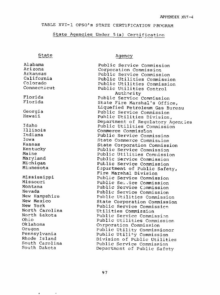
APPENDIX XV--4
TABLE XVI-1 OPSO's STATE CERTIFICATION PROGRAM
State Agencies Under 5(a) Certification
State Agency
Alabama Public Service CommissionArizona Corporation CommissionArkansas Public Service CommissionCalifornia Public Utilities CommissionColorado Public Utilities CommissionConnecticut Public Utilities Control
AutihorityFlorida Public Service CommissionFlorida State Fire Marshal's Office,
Liquefied Petroleum Gas BureauGeorgia Public Service CommissionHawaii Public Utilities Division,
Department of Regulatory AgenciesIdaho Public Utilities CommissionIllinois Commerce CommissionIndiana Public Service CommissionIowa State Commerce CommissionKansas State Corporation CommissionKentucky Public Service ComnissionMaine Public Utilities CommissionMaryland Public Service CommissionMichigan Public Service CommissionMinnesota EDpartment of Public Safety,
Fire Marshal DivisionMississippi Public Service CommissionMissouri Public Se;.ice CommissionMontana Public Service CimmissionNevada Public Service CommissionNew Hampshire Public Utilities CommissionNew Mexico State Corporation CommissionNew York Public Service CommissicnNorth Carolina Utilities CommissionNorth Dakota Public Service CommissionOhio Public Utilities CommissionOklahoma Corporation CommissionOregon Public Utility CommissionerPennsylvania Public Utility CommissionRhode Island Division of Public UtilitiesSouth Carolina Public Service CommissionSouth Dakota Department of Public Safety
97

APPENDIX XVI-4
State Agency
Tennessee Public Service CommissionTexas Railroad CommissionUtah Division of Public Utilities,
Public Service CommissionVermont Pui]ic Service BoardVirginia State Corporation CommissionWashington Utilities and Transportation
CommissionWest Virginia Public Service CommissionWisccnsin Public Service CommissionWyoming Public Service CommissionDistrict of Columbia Public Service CommissionPuerto Rico Public Service Commission
State Agencies Under 5(b) Agreement
State Agency
Alaska Public Utilities CommissionDelaware Public Service CommissionLouisiana Cffice of ConservationMassachusetts Department of Public UtilitiesNebraska State Fire MarshalNew Jersey Bcard of Public Utilities,
Department of Energy
States Acting As Agents for OPSO for Interstate GasPipelines
Arkansas Michigan VirginiaConnecticut Montana WashingtonFlorida Ohio West VirginiaIowa Rhode Island WyomingKentucky Utah
98
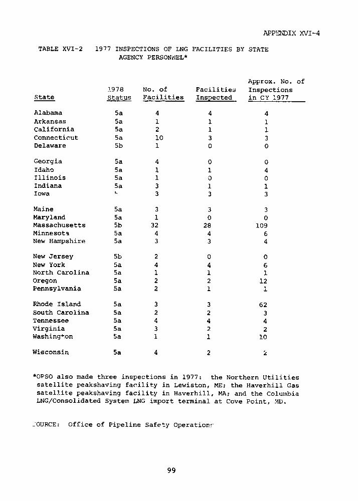
APPENDIX XVI-4
TABLE XVI-2 1977 INSPECTIONS OF LNG FACILITIES BY STATEAGENCY PERSONNEL*
Approx. No. of1978 No. of Facilities Inspections
State Status Facilities Inspected in CY 1977
Alabama 5a 4 4 4Arkansas 5a 1 1 1California 5a 2 1 1Connecticut Sa 10 3 3Delaware 5b 1 0 0
Georgia 5a 4 0 0Idaho 5a 1 1 4Illinois 5a 1 0 0Indiana 5a 3 1 1Iowa 5 3 3 3
Maine 5a 3 3 3Maryland 5a 1 0 0Massachusetts 5b 32 28 109Minnesota 5a 4 4 6New Hampshire 5a 3 3 4
New Jersey 5b 2 0 0New York 5a 4 4 6North Carolina 5a 1 1 1Oregon 5a 2 2 12Pennsylvania 5a 2 1 1
Rhode Island 5a 3 3 62South Carolina 5a 2 2 3Tennessee 5a 4 4 4Virginia 5a 3 2 2Washington 5a 1 1 10
Wisconsin 5a 4 2 2
*OPSO also made three inspections in 1977: the Northern Utilitiessatellite peakshaving facility in Lewiston, ME; the Haverhill Gassatellite peakshaving facility in Haverhill, MA; and the ColumbiaLNG/Consolidated System LNG import terminal at Cove Point, MD.
£OURCE: Office of Pipeline Safety Operations'
99
APPENDIX XVI-4
SUMMARIES OF STATE REGULATIONS
In addition to the state ag.encies participating in
the 5(a) and 5(b) programs;, a variety of state agencies
regulate the storage and handling of LEG and naphtha,
These are described in the following summaries.
ALABAMA
Bulk storage and handling of LPG are regulated by
NFPA Standard 58 as adopted by the Liquefied Petroleum Gas
Commission and by regulations of the State Fire Marshal.
Storage and handling of naphtha are regulated by the State
Fire Marshal.
ALASKA
Alaska relies primarily upon the Department of Public
Safety, Fire Protection Division, for regulating the
storage, handling, and use of all flammable, combustible,
and explosive substances. The Alaskan Administrative Code
adopts all NFPA applicable Standards, including NFPA
Standards 30, 58, 59, and 59A. In addition. the Department
of Labor requires informal compliance with NFPA Standard
59A for unfired pressure vessels containing liquefied
natural gas. The jurisdiction of t]he Department of Labor
specifically excludes the regulation of LPG. The
Department of Environmental Conservation is presently being
set up as a one-stop permit agency through which all LNG
site applicants must apply for permits on construction of
TLiG facilities.
1 00
APPENDIX XVI-4
ARI ZONA
Arizona relies chiefly upon the Fire Marshal's ?ffice
to regulate the storage and handling of LPG and naphtha.
The Arizona Fire Code adopts NFPA Standards 30, 58, and 59
as general standards with amendments that are unrelated to
bulk storage and handling. Although NFPA Standard 59A is
not specifically adopted, incorporation by the Fire Marshal
of all NFPA codes coupled with a specific chapter relating
to storage and handling of cryogenic fluids would indicate
that 59A would be considered as an ad hoc minimum
requirement for construction of LNG sites.
ARKANSAS
The Liquefied Petroleum Gas Board in Arkansas
regulates LPG by incorporating NFPA Standard 58.
The Division of Fire Prevention of Arkansas State
Police confines its regulatory powers to flammable liquids.
This presumably includes naphtha, but we have not been able
to confirm whether or not they adopt NFPA 30. Despite
enabling legislation, the Oil and Gas Commission has not
adopted regulations for LPG, LNG, and naphtha storage and
handling.
CALIFORNIA
California relies primarily upon the Public Utilities
Commission for regulation of LEG.* The Public Utilities
Commission has certified to DOT undcer Section 5(A) of the
Natural Gas Pipeline Safety Act that it meets OPSO safety
tC10
APPENDIX XVI-4
and enforcement standards. Further, under the California
LNG Terminal Act of 1977, the Public Utilities Commission
is designated as the exclusive permitting agency for LNG
terminal site locations. The Public Utilities Code has its
own administrative rules pertaining to construction of
liquid hydrocarbon vessels,* and communication with
representatives of the PUC indicate that they have adopted
NFPA Standards 58, 59 and 59A. All storage facilities
analyzed in the special issues analysis are subject to the
rules of the Public Utilities Commission.
In addition, the Division of Industrial Safety has
specific rules for storage and handling of L;PG, but must
defer, recognizing federal preemption, to the rules of the
Public Utilities Commission for gas storage at utility
plants. The Division of Industrial Safety has promulgated
rules for construction of pressure vessels used at places
of employment. Although the Fire Marshal of California has
adopted NFPA Standard 59A, his jurisdiction extends only to
land owned by the State of California.
San Diego County Airport authorities indicate that
general NFPA Standards apply to storage of jet fuel at
airports. This is informal compliance, however, and NFPA
Standard 30 would apply to storaqe of naphtha only where
local authorities have adopted NFPA Standards.
COLORADO
Colorado relies primarily on the State Inspector of
Oils for rules and regulations pertaining to storage and
handling of flammable liquids and LPC-. The State inspectoi
has adopted by reference NFPPA Standards 'O, i8, 59 and 59A.
102
APPENDIX XVT-4
CONNECTICUT
Connecticut relies chiefly upon rules and regulations
promulgated by the Commissioner of State Police with regard
to storage and handling of flammable liquids and LPG.
Those regulations basically follow NFPA Standards 30, 58,
or 59, as minimum requirements. The State Police
regulations do not pertain to LNG.
DELAWARE
Delaware relies chiefly on the State Fire Marshal's
Office and the Fire Prevention Commission for regulations
pertaining to storage and handling of LPG and naphtha.
Specifically, the State Fire Marshal has adopted NFPA
Standards 58 and 59A. The State Department of
Transportation has not adopted specific regulations for
handling or transportation of LPG, LNG, or naphtha. The
Public Service Commission requires informal compliance with
TjFPA Standard 58, and it is under a 5(b) agreement with
DOT.
FLORIDA
Florida relies primarily upon the Insurance
Commission and the State Fire Marshal's Office to
promulgate regulations dealing with storage and handling of
LPG as well as flammable and combustible liquids. NFPA
Standards 58 and 30 have been adopted as minimum
requirements with substantial technical amendments.* The
Oil and Gas Conservation Commission may tr1 involved with
permits for storage and transportation of LPG.
10l

APPENDIX XVI-4
GEORGIA
Georgia relies primarily upon the Public Service
Commission and the Fire Marshal's Office of the Public
Safety Department for the regulation of LEG. The
regulations of the Fire Marshal's Office are derived from
two separate enabling acts and adopt NFPA Standards 58, 59,
and 59A with amendments.* No other state agency has
adopted any particular rules and regulations dealing with
storage of naphtha.
HAWAII
Hawaii relies upon both the Public Utilities
Commission and the State Fire Marshal's Office for
regulating the storage and handling of flammable materials
and LPG. The Public Utilities Commission has adopted, with
unrelated amendments, NFPA Standard 59. The State Fire
Marshal's Office has adopted NFPA Standard 30. In
addition, the Coastal Zone Management Commission of Hawaii
reviews all applications for utility facilities near the
joast of Hawaii. The Coastal Zone Managemeint Commission
has promulgated no specific regulations detailing
safeguards for storage and handling of LEG or naphtha.
IDAHO
The Fire Marshal Division of the Idaho Department of
Labor and Industries is empowered to promulgate regulations
for qoneral fire prevention and, specifically, the handling
anti use of combustiblo liquids and LPG. The Fire Marshal
Division has adopted NFPA Standards q8 and 59A. Idaho
104

APPENDIX YVI-4
Senate Bill 1318, effective July 1, 1977, however, enables
local governments to adopt their own specific codes in lieu
of those of the Fire Marshal. The City of Boise, which has
an LNG facility, adopted NFPA Standards 58, 59, and 59A.
Despite enabling legislation, the Department of Law
Enforcement has not promulgated regulations for LEG or
naphtha.
ILLINOIS
Illinois relies upon the Department of Law
Enforcement which contains the Fire Protection Division,
State Fire Marshal's Office, to promulgate regulations for
storage and handling of LPG. That agency adopts as minimum
requirements NFPA standards 58 and 59.* Communications
with the Fire Marshal of Illiilois indicate that they have
also adopted 59A. The Department of Aeronautics has
adopted NFPA Standards 30, 58, and 59 for storage of LEG
and naphtha at airports.
Despite enabling legislation, the Illinois Department
of Transportation and various county boards have not
adopted regulationis for storage and handling of combustible
liquids or gases, and defer to the regulations of the Fire
Protection Division.
INDIANA
Indiana relies on the State Fire Marshal's fCffice for
all rules and regulations on storage and handling of LEG
and naphtha. NFPA Standard 58 is adopted in toto while
NFPA Standard 30 is adopted with substantial technical
105
APPENDIX XVI-4
amendments for storage and handling of naphtha.* In
addition, the Division of Oil and Gas requires permit
approval of underground gas storage, including cavern
storage of LPG; this requirement is intended to eliminate
waste in such storage, and does not involve any safety
regulations.
IOWA
Iowa relies prima i-ly upon the State Fire Marshal's
Office for regulations detailing storage and handling
safeguards for LPG and naphtha as found in the Iowa
Administrative Code. These regulations include the
adoption of NFPA Standards 58 and 30.
KANSAS
Kansas relies solely upon the State Fire Marshal's
Office, Fire Protection Division, for rules and regulations
on storage and handling of LPG. The State Fire Marshal has
adopted specific regulations for all use and storage of
LPG,* except for LPG storage at utility plants, which is
regulated by NFPA 59. Despite enabling legislation, the
Division of Oil and Gas, within the Conservation Division
of the State Corporation Conmission, has issued no other
regulations for storage and handling of LPG. We have found
no regulations for storage of naphtha.
106
APPENDIX XVI-4
KENTUCKY
Kentucky relies upon both the Public Service
Commission and the Fire Marshbl's Division under the
Commissioner of Insurance for regulation of LEG. It ;,ould
appear that there is a minor overlap since both the Public
Service Commission and the Commissioner of Insurance have
adopted NFPA Standard 59. The Fire Marshal has also
adopted NFPA 30 and 58. NFPA 59A has been adopted
specifically by the Fire Marshal regulations, and the
Public Service Commission has certified to DOT that it
meets OPSO safety standards under Section 5(a). Neither
the Airport Zoning Commissio'n nor officials of localities
containing LNG sites have adopted regulations on storage
and handling of naphtha or LNG.
LOUISIANA
The Liquefied Petroleum Gas Commission regulates the
storage and handling of LPG, adopting regulations that
supersede those of NFPA 58.* The Oil and Gas Division of
the Louisiana Conservation Commission has promulgated
regulations for the prevention of fires and conservation of
gas. These regulations concern tank storage of naphtha, aswell as underground cavern and aboveground tank storage of
LPG. There seems to be a potential for overlap between the
LPG Commission and the Oil and Gas Division regarding LPC
regulation.
As a result of the Natural Resources and Energy Act
of 1973, the Conservation Commissioner is empowered to
regulate LNG facilities as well.
107
APPENDIX XVI-4
MAINE
Maine Revised Statutes Annotated, Title 26, Section
141, et seq., creates a Board of Boiler Rules. The
statutes state that all pressure vessels used for the
transportation and storage of compressed or liquefied gases
under the jurisdiction of DOT shall not be subject to the
regulations of the Board of Boiler Rules, thus deferring toDOT.
The State Fire Marshal, by virtue of enabling
legislation empowering him to make rules for storage and
handling of petroleum products, has incorporated by
reference NFPA 58. The Vehicle Equipment Safety Commission
adopts only pertinent DOT regulations for all
transportation of flammable liquids, otherwise enforcing
traffic laws as applicab-,- to carriers of flammable
liquids.
Maine is the only state which holds natural gas
companies strictly liable for injury to persons or
property. (See M.R.S.A. Title 14, Section 165).
MARYLAND
Maryland relies primarily upon the Office of Fire
Marshal, the Fire Protection Safety Commission and the
Public Service Commission for the regulation of the storage
and use of combustible or flammable liquids or gas. NFPA
Standards 30, 58, 59, and 59A have been adopted. The
Department of Natural Resources and the' Port Administration
Authorities, with similar enabling legislation, have not
promulgated regulations for the storage and handling of
108
APPENDIX XVI-4
naphtha or LEG. The Planning Commission of Calvert Couinty,
which includes the Cove Point LNC Terminal, informally
requires compliance with NFPA 59A.
MASSACHUSETTS
The Energy Facilities Siting Council of
Massachusetts: created in December, 1975, reviews all
proposed LNG and LPG storage sites, granting approval on
the two-fold basis of establishment of need and assessment
oc environmental impact. Litigation has confirmed the
Council has authority over such issues as public safety,
applicability of its decisions to energy sites already
under construction, and concurrent jurisdiction with the
National Environmental Protection Act. The Department of
Public Utilities has adopted regulations for the
transportation, handling, and storage of LEG and naphtha,
adopting NFPA 30 and 59 and LNG regulations similar to NFPA
59A (1971).* The State Fire Marshal defers to the
Department of Public Utilities for regulations covering the
use of LEG and naphtha in public utilities, but has
promulgated regulations for the transportation and handling
of flammable liquids in vessels, bulk loading facilities,
and tank vehicles, as well as certain LPG systems. None of
these regulations adopt NFPA standards. A potential for
overlap exists between the regulations of the Department of
Public Utilities and the Fire Marshal for LPG storage and
handling. A Massachusetts Coastal Zone Management Plan is
currently being adopted, and concurrent with the powers of
the Department of Public Utilities and Energy Facilities
Siting Council, is intended to control the siting of LNG
plants. Local fire departments and zoning boards generally
defer to state authorities for regulation of LEG or naphtha
109

APPENDIX XVI-4
storage, limiting their power to granting permits and
zoning variances. Only the Massachusetts Port Authority,
in the exercise of its control over Logan International
Airport and Hanscom Field, has adopted NFPA standards with
regard to fire prevention for the storage of jet fuels.
MICHIGAN
In Michigan, the State Fire Marshal's Office within
the Department of State Police and the Public Serv-ice
Commissior have the primary responsibility for the
regulation of LEG and naphtha.* The State Police are
primarily concerned with LPG and flammable liquids while
the Public Service Commission is interested in LNG and LPG.
There is a potenti- 1 for overlap between the Public Service
Commission and State Fire Marshal in the regulation of LPG.
MINNESOTA
The State Fire Marshal has adopted regulations for
storage and nandling of LEG and naphtha, including adoption
of NFPA Standards 58 and 30. These standards are amended
with regard to procedural requirements for application and
permitting. Regulations of the Minnesota Energy Agency
require reporting of quantities for bulk storage of LEG and
naphtha.
MISSISSIPPI
Mississippi relies upon the State Fire Marshal's
Office and the Liquefied 3as Division of the Motor Vehicle
110
APPENDIX XVI-4
Comptroller for the regulation of the storage and handling
of LPG. The regulations adopt, with procedural amendments,
NFPA Standard 58.
MISSOURI
Missouri relies jointly on its Department of Reverue
and Department of Agriculture for regulations pertaining to
the storage and handling of LPG. Those regulations adopt
NFPA Standard 58, with minor technical amendments.
MONTANA
Montana relies chiefly upon the State Fire Marshal's
Office and the Department of Health and Environmental
Sciences for regulations on the storage arid handling of
volatile liquids. The State Fire Marshal's Office has
adopted NFPA Standard 30 for naphtha and NFPA Standard 58
for LPG. The Department of IP-blic Utilities has
established requirements for facility siting applications.
The Department of Oil and Gas requires identification and
quantitative reporting of storage of oil or gas within The
State of Moiitana.
NEBRASKA
In Nebraska, apart from the issuance of permits and
general zoning legislation, the only regulatory authority
for the storage, handling, and use of LEG or naphtha is the
State Fire Marshal's Office. The Fire Marshal has adopted
NFPA Standards 30, 58, 59 and 59A in totality. Despite
111
APPENDIX XVT-4
enabling legislation, neither the Tax Commissioner nor thePublic Service Commissioner has adopted regulations for thestorage and handling of LEG or naphtha other than incompliance with 49 CFR Part 192.12 for LNG, On a locallevel., the City of Omaha has adepted NFPA Standards 58, 59,and 59A.
NEVA \
Nevada relies primarily upon its Liquefied Petroleum
Gas Board to regulate The storage and handling o- LPG. TheLPG Board has adopted NFPA Standard 58 as minimumrequirements. Despite enablinigl legislation the FireMarshal's Office has not promulgated regulations for thestorage and handling oi naphtha.
NEW HAMPSHIRE
New Hampshire relies primarily upon the State FireMarshal and the State Board of Fire Control for regulationof flammable and combustible liquids. These agencies haveadopted NFPA 58 and 59A. Despite enabling legislation, theEnergy Facility Evaluation Committee has not adopted anyregulation for the storage and handling of LEG or naphtha.
NEW JERSEY
New Jersey relies primarily upon the Department ofLabor and Industry for the regulation of LPG. Theresponsibility of the State Police to regulate bulk plantstorage was transferred to the Department of Labor and
112

APPENDIX XVT-4
Industry in 1972. Sections within both Titles 12 and 13 of
the Administrative Code regulate the construction of all
sizes of LPG storage tanks, as well as the operation and
handling of LPG.* County Fire Marshals and Fire Marshals
of cities of the first class may also regulate storage of
flammables.
NEW MEXICO
The State of New Mexico relies primarily on the Fire
Marshal's Office for regulations for the storage and
handling of flammable liquids. NFPA standards are adopted
in the enabling legislation, i.r luding NFPA 30. The
Liquefied Petroleum Gas Comnission iL empowered to regulate
all storage, handling and use of LPG in New Mexico. Tne
Commission, in addition to requiring min-.mum public
liability insurance, has adopted NFPA Standard 58 with
amendments.*
NEW YORI
In 1976 Now York enacted the Liquefied Natural and
Petroleum Gas Act which gives the Department of
Environmental Conservation authority over LNG and LPG
facility siting and transportation, with an emphasis on
safety considerations. Regulations pursuant to this Act
have not yet been promulgated. Existing LNG regulations
are included in Regulation 259 of the Public Service
Commission. In addition, the City of New York through the
New York City Fire Department has promulgated its own
regulations for the storage and handling of LNG, including
NFPA 59A with comprehensive technical amendments.*
113

APPENDIX XVI-4
Regulations pertaining to storage of LPG and naphtha
are included in Public Service Commission Regulations, Part
260, entitled "Synthetic Natural Gas." All applicable NFPA
standards are adopted in the headnote to 260. The
Department of Motor Vehicles, the Department of
Transportation, and the New York Port Authority have all
adopted regulations for the transportation of dangerous
articles and/or flammable liquids by tank truck or railcar.
Also, the Navigation Law of New York contains a brief
regulation concerning transportation of naphtha and other
flammable liquids on passenger ships. All of these
regulations, however, are brief, and none adopts
requirements contained ir NFPA standards.
NORTH CAROLINA
North Carolina relies upon the Commissioner of
Insurance, the Liquefied Gas Board in the Department of
Agriculture, and the Public Utilities Commission for the
regulation of the transportation, handling, and storage of
LPG. All three agencies have adopted NFPA Standard 58 in
total. The Commissioner of Insurance and the Liquefied Gas
Board have not adopted specific regulations regarding LNG
or naphtha.
NORTH DAKOTA
North Dakota relies primarily on the State Fire
Marshal's Office for the regulation of storage and handling
of LPG and naphtha. That Office has adopted NFPA Standards
30, 58, and 59.
114
APPENDIX XVI-4
OHIO
In Ohio, the Fire Marshal's Office and the Department
of Industrial Services regulate LPG. The language in the
enabling statutes of the Fire Marshal's Office indicates
that NFPA standards may be followed on an optional basis
for flammable liquids. However, the Ohio Fire Code
regulations are extremely brief, and the regulations of the
Department of Industrial Relations just adopt NFPA Standard
58. The Oil and Gas Division has not made any specific
rules and regulations for LEG and naphtha. Communications
with the city and county authorities responsible for the
LNG site at Green Springs, Sandusky County, Ohio, indicate
that they have not adopted their own regulations and rely
on state regulations.
OKLAHOMA
Oklahoma relies primarily upon the LPG Board and LPG
Administrator to regulate the storage and handling of LPG.
Both the enabling statutes and regulations of the LPG Board
adopt NFPA Standard 58 by reference. Despite enabling
legislation, the State Fire Marshal has adopted neither
regulations nor any NFPA Standards for the storage and
handling of naphtha or LNG.
OREGON
Oregon relies on the Fire Marshal to regulate the
storage and handling of flammable liquids and LEG. The
Fire Marshal has adopted NFPA Standards 58, 59, and 59A in
toto. NFPA Standard 30 is adopted with slight technical
115
APPENDIX XVI-4
amendments for the construction of small containers and forpermitting.
The DepartmenIt of Health may have authority topromulgate regulations for LNG sites, but has not done so.Also, the Department of Public Utilities has notpromulgated specific regulations for LPG or naphtha.
The Energy Facility Siting Council has failed toobtain legislation designed to regulate LEG siting. Localand county regulatory agencies and the Energy FacilitySiting Council rely primarily on general land use planningguides and zoning permits.
PENNSYLVANIA
Four agencies are empowered to regulate the use andstorage of LEG and naphtha. The Public Utility Commissionhas certified to DOT that it meets OPSO safety standardsunder Section 5(a). The State Police regulate storage andhandling of LPG and naphtha for all but second classcounties and second class cities. Communications withrepresentatives of those political subdivisions, however,have indicated that they in turn adopt the regulations ofthe State Police. While the State Police do not havespecific regulations for LNG, they regulate LNG as aflammable liquid. The Department of Labor and Industry hasstatutory authority over the use and handling of LPG, andits regulations specifically adopt NFPA 58, with someamendments.* There is considerable opportunity for overlapbetween the State Police Fire Marshal and the Department ofLabor and Industry on the storage and handling of LPG. TheState Police regulate naphtha.
116
APPENDIX XVI-4
The Airport Zoning Commission is authorized to create
airport hazard areas within territorial limits of airports.
This authorization, however, has not resulted in the
specific regulation of jet fuel storage. Therefore, at
present, the storage and handling of jet fuel is solely
regulated by the State Police.
PUERTO RICO
All present regulations for the storage and handling
of LPG and naphtha were promulgated by the Fire Protection
Service,* except for underground jet-fuel storage tanks.
Despite enabling authority, the Oil Fuels Affairs Office
has not promulgated regulations for storage and handling of
LEG or naphtha.
RHODE ISLAND
Rhode Island regulates LEG and naphtha through the
Public Utilities Commission and the State Fire Marshal in
conjunction with local representatives of the State Fire
Marshal. Both the Public Utilities Comnmission and the
State Fire Marshal are enabled to regulate LEG adi naphtha,
and both have adopted NFPA Standards 58, 59, 59A and 30.
SOUTH CAROLINA
In South Carolina, the LPG Board and the State Fire
Marshal's Office recglate the storage and handling of LPG.
Both the State Fire Marshal's Office and the LPG Board
117
APPENDIX XVI-4
adopt NFPA Standard 58 in total. In addition, the LPG
Board requires minimum insurance coverage for any
corporation engaged in the dealing or selling of LPG.
SOUTH DAKOTA
The Fire Marshal's Office regulates the storage and
handling of LPG and naphtha in South Dakota. The State
Fire Marshal has adopted in substance NFPA Standards 30,
58, 59, with minor additions.*
TENNESSEE
Tennessee relies chiefly upon the State Fire Marshal
to promulgate regulations for the storage of LEG. Through
the LPG Safety Act and the General Safety and Health Act,
the State Fire Marshal has adopted NFPA Standards 58 and
59.
By adopting all pertinent NFPA regulations with
regard to construction of new buildings and elimination of
fire hazards, the Fire Marshal has also adopted NFPA
Standards 30 and 59A for the new construction of naphtha
and LNG facilities. The Public Service Commission has
certified to DOT that it meets OPSO safety standards for
LNG under Section 5(a) of the Natural Gas Pipeline Safety
Act. Also, the Division of Oil and Gas has to approve any
underground storage of LPG.
The City of Memphis and the County of Shelby rely on
NFPA Standard 59A for LNG storage. They adopt,
respectively, the Southern States Building Code for the
118
APPENDIX XVI-4
County and the BOCA (Builders Official Conference of
America) building code for the City of Memphis.
TEXAS
Texas relies primarily upon municipal rather than
state regulations for control and handling of LNG and
naphtha. The Railroad Commission of Texas is the only
state agency that has promulgated rules ar regulations for
the storage and handling of LEG.* Since the State Fire
Marshal has not promulgated regulations and defers to the
Railroad Commission, the only regulations existing on the
storage of naphtha are local, such as the Houston Fire
Code's adoption of NFPA 30.
The LPG site located in the City of Houston is
regulated by the Houston Fire Code which includes adopeion
of NFPA Standards 58 and 59. However, the City of
Ingleside, where an LNG facility is planned, has adopted no
particular LNG codes of its own. To a certain extent,
there is an overlap withln the City of Houston for rules
and regulations dealiig with the storage and handling of
L2G. With the exception of LPG storage facilities at
marine sites, which are clearly excluded from the rules and
regulations of the Railroad Commission, it would appear
that storage sites for LPG within the City of Houston are
subject to both the City of Houston's Fire Code as well as
the rules and regulations of the Texas Railroad Commission.
The Texas Public Safety Department has adopted the
rules and regulations of DOT for the transportation of
flammable liquids.
119

APPENDIX XVI-4
Utah relies primarily on the Utah State Fire
Prevention Board, the Fire Marshal's Office, and the Public
Service Commnission for regulations governing the storage
and handling of flammable and cowmbustible liquids and
gases. The Fire Marshal of Utah has adopted NFPA Standards
58 and 59A.
VERMONT
The Department of Public Service in Vermont
incorporates by reference NFPA Standard 58 for storage and
handling of LPG. The Motor Vehicle Equipment Commission
has additional safety standards for operation of a vehicle
carrying flammable liquids, regarding the use of flares and
reflectors at night. There are presently no regulations on
bulk storage of naphtha.
VIRGINIA
Virginia relies solely upon its State Corporation
Commission including the Office of State Fire Marshal to
tegulate the storage and handling of LEG and naphtha. The
Chief Fire Marshal has adopted NFPA 58 and 59 entirely. In
addition, the local Fire Marshal of Chesapeake, Virginia,
an LNG site, has adopted NFPA Standard 59A. The State has
also adopted the BOCA building code.
120

APPENDIX XVI-4
WASHINGTON
Under the Revised Code of Washington and the
Washington Administrative Code, the Department of Labor and
Industry has promulgated regulations for LPG, including the
adoption of the National Bureau of Fire Underwriters (NBFU)
Code No. 38 which is identical to NFPA Standard 58). The
Department also has regulations for the transportation and
storage of LPG in railcars and tank trucks. See Washington
Administrative Code S.296-42-440, detailing use of specific
loading procedures and equipment (e.g., check valve, vent
connection and bleeder line) for railcars and trucks and
trailers.
State Fire Marshals and local Fire Marshals have
general powers of inspection for premises which may be
hazardous fire locations, with the State Fire Marshal being
subordinate where local fire codes exist. The Energy
Facility Site Evaluation Council has responsibility for
approving the 3ite locations of energy facilities,
specifically LNG marine terminals receiving more LNG than
the equivalent of 100 million cubic feet of gas per day.
In addition, the State Energy Office has authority to
collect information and carry out energy-related
information gathering programs for energy facilities such
as LEG storage facilities.
WEST VIRGINIA
West Virginia relies primarily upon the State Fire
Prevention Commission, Office of the State Fire Marshal,
and the Public Service Commission for rules and regulations
governing the storage and handling of LEG. NFPA standards,
121
APPENDIX XVI--4
including 58, 59, and 53A, have been adopted generally by
the State. The State Fire Marshal does noc regulate t',e
storage and handling of naphtha fuel, as communications
indicate that he does not coisider naphtha within his
department's purview.
WISCONSIN
Wisconsin relies primarily upon the Department of
Labor and Industry for regulations on the storage and
handling of LPG. These are similar to those adopted by the
National Fire Protection AssociatJi-l, but do not
incorporate by reference any specific standards of the
NFPA.
WYOMING
Wyoming relies primarily upon the Fire Marshal's
Office and the Public Service Commission for regulation of
LPG and LNG. The Fire Ma-rshal's Of Cice has adopted NFPA
Standards 58, 59 and 59A. Wyonming Statutes Annotated
30-240, regulates storage of flammables.
The .ire Marshal's Office has not promulgated rules
for the storage and handling of naphtha. The Industrial
Devalopment Information Siting Act creates the Industrial
Siting Council which is empowered to review applications
for any industrial facility, including any facility
designed for or capable of producing 7,950 m of liquid
hydrocarbon product per day, or one capable of producing
122

APPENDIX XVI-4
one hundred million cubic feet of synthetic gas per day.The Industrial Siting Council, however, has not promulgatedregulations providing safeguards for storage and handlingof LEG or naphtha.
123
APPENDIX XVI-5
APPENDIX XVI-5
SPECIAL ISSUES ANALYSES
1. The Minimum Distance Required Between the Tanks or
Dike and Residential, Social, Business, and
Government Facilities.
LNG* (NFPA 59A Sec. 200, 210, 211, 212; NYCFD Sec. 4.1;
6.4; NY State - PSC Sec. 259; Mass-DPU Sec. 200, 210,
211, 212, 213)
NFPA 59A states that impounding areas (an area which
may be defined through the use of dikes or the topography
at the site for the purpose of containing any accidental
spill of LNG or flammable liquids) must be sited in
accordance with the formula d = 0.84/ where d is equal to
the distance, in feet, from the property line to the
nearest edge of the impounded liquid and A is equal to the
surface area, in square feet, of impounded liquid. The DPU
in Massachusetts also adopts this. Assuming this standard,
if spilled LNG within an impoundment area is ignited, there
is no wind, 50% relative humidity, and 70°F temperature,
the thermal radiation flux at the property line will be
approximately 10,000 Btu/hr ft2 . At this heat flux level,
wood may ignite without direct flame impingement and cotton
fabric mat ignite after about a 7-second exposure. The
model and assumptions used in writing the codes are not
published, but the radiation fluxes quoted are consistent
with assuming that the heat release from a pool fire
*The codes are listed in the references to Chapter 16.
124

APPENDIX XVI-5
following the release of a full tank of LNG onto its dike
is generated from a hypothetical point source at the center
of the dike. If there is a strong wind, the flame will
tilt, and the radiation levels in the direction of the wind
will be greater. If the relative humidity is less than 50%
or the temperature is more than 70 F, some objects will
catch fire easier. Presumably, under the assumptions
given, this NFPA 59A flux level restriction would prevent
fire spread beyond the property line and persons a short
distance outside the property would probably not have their
clothing ignited by thermal radiation. However, persons
exposed to heat flux levels close to a 1 nimum distance
property line might still sustain serious burn injuries to
exposed skin. The code does not consider fire from LNG or
cold natural gas that might escape the dike.
New York state employs two formulas. For an unbermed
container, d = 2.0/A where d and A are defined as in 59A.
In the case of a bermed tank, d2 = 1.25/A where d2 isequivalent to the distance in feet from the nearest edge of
impounded liqu ~- _o process equipment, buildings, etc., andA is "equivalent to the cross-sectional area of the insidediameter" of the berm. (This definition makes no sense,
but presumably the intended definition of area is the same
as in NFPA 59A.) This formula corresponds to about a 2,800Btu/hr ft 2 maximum flux at the property line. At this flux
level, bare skin will blister in around 10 to 15 seconds.
Within 1L seconds, a person could probably retreat from the
fire without permanent injury. (Motion and clothing both
offer added protection and further decrease the chance of
serious injury.)
The Nlew York City Fire Department states that the
radiation flux at the property line should not exceed 1,500
125

APPENDIX XVI-<
Btu/hr ft Large LNG containers must be surrounded by a
berm at least 10 ft. thick and thermal radiation compliance
requires siting in accordance with the following table or
by using the formula d2 = 1.25/i (whichever is greater).
NYCFD MINIMUM DISTANCE FROM IMPOUNDED LIQUID
To Distance (ft)
Critical Occupancy (Hospitals, schools,places of assembly, bridges, tunnels, etc.) 1000
Property Line or Navigable Water the greater of200' or 1-1/4tank diameters
Sewers, underground ducts, drains 50
In the event of a large unignited spill, a flammable
cloud of gas may drift across the plant site boundaries.
NFPA 59A (1975) first recognized this problem requiring
that provision be made to "minimize the possibility" of
flammable vapor from a "design spill" from reaching a
property line. Design spills are based on the assumption
that a major pipe break is the largest credible accident,
as discussed in Issue 1, Supporting Details below. The
criteria for judging whether the possibility is minimized
are not given. The suggested reference for help in
performing the calculation contains at least three separate
methods and is not actually applicable to the design spill
conditions.
The New York City Fire Department requires that a
thermal radiation and vapor dispersion study be submitted,
but does not give details on methodology.
California adopted SB 1081 which was signed into law
on 16 September 1977 authorizing construction of an LNG
126
APPENDIX XVI-5
import terminal in the state subject to a number of
restrictions. These include a restriction on population
density surrounding the terminal boundaries as of the date
terminal operation is started. The criteria are less than
an average of 10 persons per square mile within one mile of
the site perimeter and less than an average of 60 persons
per square mile within a four-mile zone. Population i.,
defined to include permanent residents and working
population not associated with the facility.
IPG (NFPA 58, Sec. 311; NFPA 59, Sec. 24, 330; API
2510 Sec. 4.1, R.4.1.; CALT-PUC Sec. 3f a;
KAN-LPG Sec. 22-8-7; LA-I,PG Sec. 2.7; MISS-MV
Sec. 2.13; NJ-AC Sec. 5.8.2; PA-DLI Rule 21;
TX-RRC Sec. 2.10; 3.1; WISC-AC Sec. 9.C5)
NFPA 58 states the minimum distance away that an
above ground or an underground container may be installed
with respect to "important buildings" or an adjoining
property line, but does not consider containers larger than
120,000 gallons (455 cubic meters). "Important buildings"
are not defined.
NFPA 59 details such distance information for
non-refrigerated and refrigerated above-grcund containers,
respectively. For containers larger than a million gallons
(3,785 cubic meters) capacity the distance from the
container to the nearest important building not associated
with the LPG plant or to an active property line is 400
feet. Lesser distances are specified for smaller
quantities.
API 2510 states the minimum distance from an
adjoining property to an LPG container for both
127
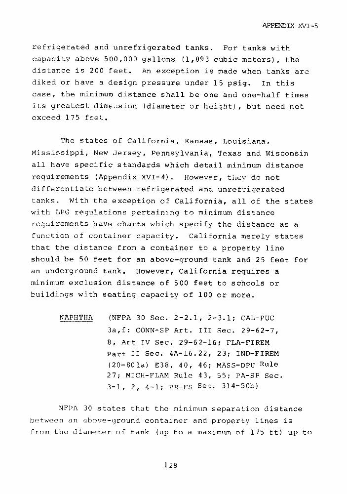
APPENDIX XVI-5
refrigerated and unrefrigerated tanks. For tanks with
capacity above 500,000 gallons (1,893 cubic meters), the
distance is 200 feet. An exception is made when tanks are
diked or have a design pressure under 15 psig. In this
case, the minimum distance shall be one and one-half times
its greatest dimension (diameter or height), but need not
exceed 175 feet.
The states of California, Kansas, Louisiana,
Mississippi, New Jersey, Pennsylvania, Texas and Wisconsin
all have specific standards which detail minimum distance
requirements (Appendix XVI-4). However, titv do not
differentiate between refrigerated and unref:igerated
tanks. With the exception of California, all of the states
with LPG regulations pertaining to minimum distance
requirements have charts which specify the distance as a
function of container capacity. California merely states
that the distance from a container to a property line
should be 50 feet for an above-ground tank and 25 feet for
an underground tank. However, California requires a
minimum exclusion distance of 500 feet to schools or
buildings with seating capacity of 100 or more.
NAPHTHA (NFPA 30 Sec. 2-2.1, 2-3.1; CAL-PUC
3a,f: CONN-SP Art. III Sec. 29-62-7,
8, Art IV Sec. 29-62-16; FLA-FIREM
Part II Sec. 4A-16.22, 23; IND-FIREM
(20-801a) E38, 40, 46; MASS-DPU Rule
27; MICH-FLAM Rule 43, 55; PA-SP Sec.
3-1, 2, 4-1; PR-FS Sec. 314-50b)
NFPA 30 states that the minimum separation distance
between an above-ground container and property lines is
from the diameter of tank (up to a maximum of 175 ft) up to
128
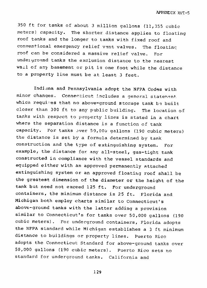
APPENDIX XVI-5
350 ft for tanks of about 3 million gallons (11,355 cubic
meters) capacity. The shorter distance applies to floating
roof tanks and the longer to tanks with fixed roof and
conventional emergency relief vent valves. The floating
roof can be considered a massive relief valve. For
undeiground tanks the exclusion distance to the nearest
wall of any basement or pit is one foot while the distance
to a property line must be at least 3 feet.
Indiana and Pennsylvania adopt the NFPA Codes withminor changes. Connecticut includes a general statementwhich requi7-es that no above-ground storage tank be builtcloser than 300 ft to any public building. The location oftanks with respect to property lines is stated in a chartwhere the separation distance is a function of tankcapacity. For tanks over 50,000 gallons (190 cubic meters)the distance is set by a formula determined by tankconstruction and the type of extinguishing system. Forexample, the distance for any all-steel, gas-tight tankconstructed in compliance with the vessel standards andequipped either with an approved permanently attachedextinguishing system or an approved floating roof shall bethe greatest dimension of the diameter or the height of thetank but need not exceed 125 ft. For undergroundcontainers, the minimum distance is 25 ft. Florida andMichigan both employ charts similar to Connecticut'sabove-ground tanks with the latter adding a provisionsimilar to Connecticut's for tanks over 50,000 gallons (190cubic meters). For underground containers, Florida adoptsthe NFPA standard while Michigan establishes a 3 ft minimumdistance to buildings or property lines. Puerto Ricoadopts the Connecticut Standard for above-ground tanks over50,000 gallons (190 cubic meters). Puerto Rico sets nostandard for underground tanks. California and
129
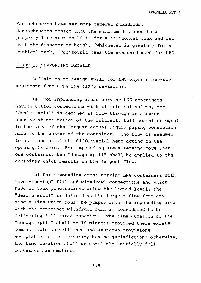
APPENDIX XVI-5
Massachusetts have set more general standards.
Massachusetts states that the minimum distance to a
property line must be 10 ft for a horizontal tank and one
half the diameter or height (whichever is greater) for a
vertical tank. California uses the standard used for LPG.
ISSUE 1, SUPPORTING DETAILS
Definition of design spill for LNG vapor dispersion
accidents from NFPA 59A (1975 revision).
(a) For impounding areas serving LNG containers
having bottom connections without internal valves, the
"design spill" is defined as flow through an assumed
opening at the bottom of the initially full container equal
to the area of the largest actual liquid piping connection
made to the bottom of the container. The flow is assumed
to continue until the differential head acting on the
opening is zero. For impounding areas serving more than
one container, the "design spill" shall be applied to the
container which results in the largest flow.
(b) For impounding areas serving LNG containers with
"over-the-top" fill and withdrawl connections and which
have no tank penetrations below the liquid level, the
"design spill" is defined as the largest flow from any
single line which could be pumped into the impounding area
with the container withdrawl pump(s) considered to be
delivering full rated capacity. The time duration of the
"design spill" shall be 10 minutes provided there exists
demonstrable surveillance and shutdown provisions
acceptable to the authority having jurisdiction; otherwise,
the time duration shall be until the initially full
container has emptied.
130

APPENDIX XVI-5
(c) For impounding areas serving LNG containers which
have all penetrations below the liquid level fitted with
internal shutoff valves in accordance with 6222, the
"design spill" may be computed from Formula 2 with the flow
"q" lasting for a period of one hour provided there exists
demonstrable surveillance and shutdown provisions
acceptable to the authority having jurisdiction; otherwise,
the time duration shall be until the initially full
container has emptied.
Formula 2
q = 4 d 2 /h
where q = flow rate, in cubic feet per minute, of
liquid
d = diameter, in inches, of largest tank
penetration below the liquid level
h = height, in feet, of liquid above
penetration in the container when the
container is full.
(d) For impounding areas serving only vaporization,
process, or LNG transfer areas, the "design spill" is
defined as flow during a 10-minute period from any single
accidental leakage source, or a lesser time period based
upon demonstrable surveillance and shutdown provisions
acceptable to the authority having jurisdiction.
131

APPENDIX XVI-5
ISSUE 1
EXCLUSION DISTANCE TO PROPERTY LINE
NAPHTHA - CONTAINERS WITH FLOATING ROOF
NFPA 30 and the states of Florida, Indiana, andPennsylvania all state that the exclusion distance shouldbe the diameter of the tank, but need not exceed 175 feet
132

APPENDIX XVi-5
.4
O -4 H4 N Ln In r- 0 o
-,Ow
(i O c VA c0 "' I,.: E4
4 V· .4 0
z m L I
· z2 0,. ~C Z o i.~ * t oHN ,-4) H '
E 1 1 I , - 0 0
o 0
·I,.I ~'1 0 4 0 r
HE4
U C C
UA>13t 0 0 IA 0 0 I 0
N~r In
F-4 Nn 0 0 0 00 0 o 0
4 _t O 0 O N tn
C N I) N I I 0
4i I_ 0 0 0 0 0Et N IA I H C O * -0O H N IA1 0 ' 0 0 1

APPF:NDIX XVT-5
o iA 0 o 0 0
O=
* 2 -z0 C
IAuL
G0 O 40
O O4
.k °
I4 0 A i CU
1 S 1 .4
O1 C 0 IA 00 U0 C 0
a ;' a CO
IA 14
0
44
4c
401 200 In a I~ctvl
-4 -4 o.~r( ( y , ,~~, r I .4
¢ O - 4 25 -.
Z¢j -* 0 4 .1 3Q
20 l V Q
0 O. o t O 4 ) 0 o. o o° o o o °o o
4 o 0' 0 N 41 r c o U
4 le O -o
0 0 - 0 0 0 0 0 0 0 0 1
I 0 u
W I f ° ° ° °.'4 .4 .- 0 0 o N h
41. .,44
0 IA 0 IA o I_to 00 I 0 0 N 0. F.
4i f W., C) 4 V -I
'0 20 0 0 0 0 C 4.4414
U m N Li U 4)
40- 0 0 0 04) 43 ~~~~~ C) 0 I 000 1
a *r a ·~13

APPENDIX XVI-5
P4
P ~~4 6 _ _ , . . _ ~ _ _ _ _
f a- r o -o o a o a o o o a
es ~ ~ ~~~~~~~~~- F- C4 N fn v @ on
l 0 0 0 0 0 0 0 0 0 0
dH N en 9w 10 0 %a 0 o - m WI0 0 ~ 1 P4 P-4 N N m n
$4
0 04J
0 r4n
-iO *dN4 M
.,,l ·r O
H H .p4 7 0 D O 0 w 0 0 0 004) H H ri N in in
r u
:n~~>
o*, oY o o
0 Ck H N in0 0 0 0 0 OC n I
H 14 HS H~u . H H N in i
4 0 oo4 I |
IO I I r4 VA a
ol ...
HEJ4 INOI 0
n H in 4 0 0 0 0 o
i S U o o o o nH H ni
W~~~~~~~ 0
vr4 > r H^ 0 H0 0 0
N O135 0 0 C 0 0
aai 0 ~~0 0 0
(d C 0 0 a nL 0 r CA0 0 0 N i0000! i 00
k~~-0 0mr 0 0 n I 0
· r( ~ II I 0 0 0(d ~ H H( 0 0 a
V) I 0 0 0 0 0 0 0Ln 0 0 0 0 0 0
N~ aI a) a 0 0 0 0 a (
135
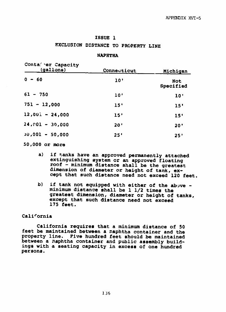
APPENDIX XVI-5
ISSUE 1
EXCLUSION DISTANCE TO PROPERTY LINE
NAPHTHA
Conta 'ser Capacity(gallons) Connecticut Michigan
0 - 60 10' NotSpecified
61 - 750 10' 10'
751 - 12,000 15' 15'
12,0ui - 24,000 15' 15'
24,001 - 30,000 20' 20'
Ju,001 - 50,000 25' 25'
50,000 or more
a) if tanks have an approved permanently attachedextinguishing system or an approved floatingroof - minimum distance shall be the greatestdimension of diameter or height of tank, ex-cept that such distance need not exceed 120 feet.
b) if tank not equipped with either of the abve -minimum distance shall be 1 1/2 times thegreatest dimension, diameter or height of tanks,except that such distance need not exceed175 feet.
California
California requires that a minimum distance of 50feet be maintained between a naphtha container and theproperty line. Five hundred feet should be maintainedbetween a naphtha container and public assembly build-ings with a seating capacity in excess of one hundredpersons.
136
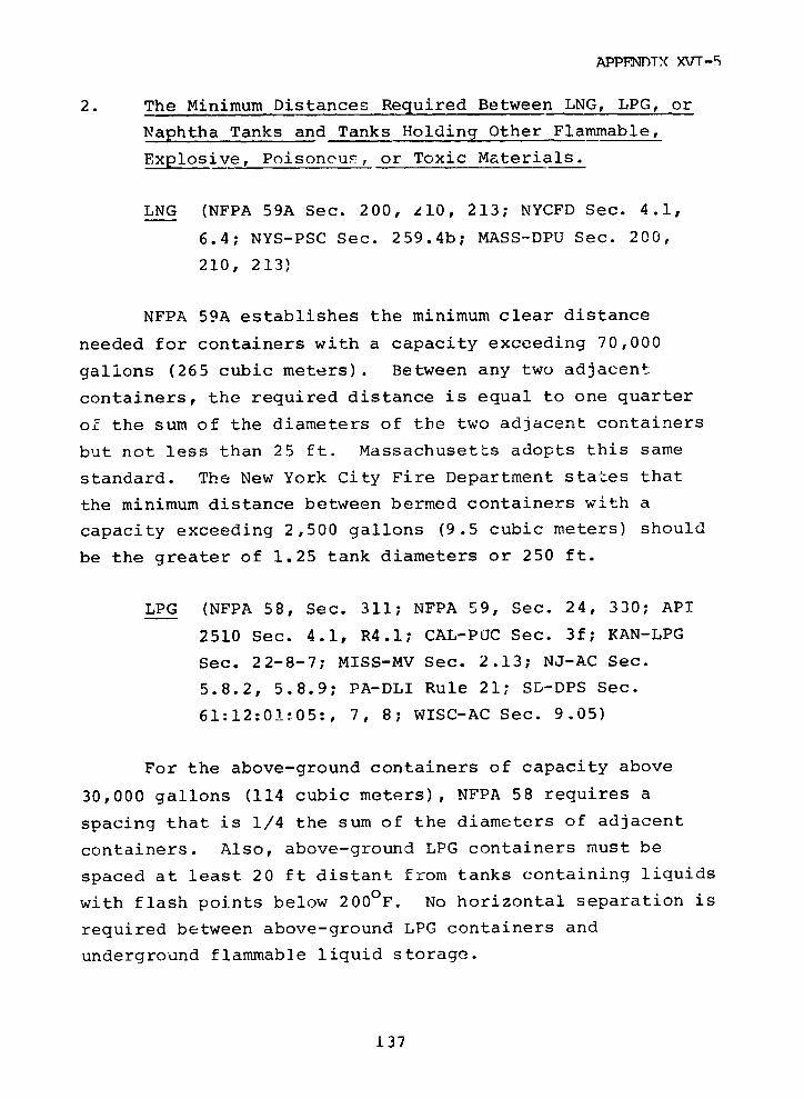
APPFNTX( XVT-5
2. The Minimum Distances Required Between LNG, LPG, or
Naphtha Tanks and Tanks Holding Other Flammable,
Explosive, Poisoncus, or Toxic Materials.
LNG (NFPA 59A Sec. 200, z10, 213; NYCFD Sec. 4.1,
6.4; NYS-PSC Sec. 259.4b; MASS-DPU Sec. 200,
210, 213)
NFPA 59A establishes the minimum clear distance
needed for containers with a capacity exceeding 70,000
gallons (265 cubic meters). Between any two adjacent
containers, the required distance is equal to one quarter
of the sum of the diameters of the two adjacent containers
but not less than 25 ft. Massachusetts adopts this same
standard. The New York City Fire Department states that
the minimum distance between bermed containers with a
capacity exceeding 2,500 gallons (9.5 cubic meters) should
be the greater of 1.25 tank diameters or 250 ft.
LPG (NFPA 58, Sec. 311; NFPA 59, Sec. 24, 330; API
2510 Sec. 4.1, R4.1; CAL-PUC Sec. 3f; KAN-LPG
Sec. 22-8-7; MISS-MV Sec. 2.13; NJ-AC Sec.
5.8.2, 5.8.9; PA-DLI Rule 21; SD-DPS Sec.
61:12:01:05:, 7, 8; WISC-AC Sec. 9.05)
For the above-ground containers of capacity above
30,000 gallons (114 cubic meters), NFPA 58 requires a
spacing that is 1/4 the sum of the diameters of adjacent
containers. Also, above-ground LPG containers must be
spaced at least 20 ft distant from tanks containing liquids
with flash points below 200 0F. No horizontal separation is
required between above-ground LPG containers and
underground flammable liquid storage.
137

APPFNDIX XVT-5
NFPA 59 requires a 50 ft separation between
non-refrigerated above-ground LPG tanks and other
above-ground storage of flammable liquids. Above-ground
refrigerated LPG containers regardless of size are to be
separated by 1/4 the sum of the diameters of adjacent
tanks.
Any number of non-refrigerated underground containers
can be installed parallel with ends in line. When
containers are placed end to end, the separation distance
should be 10 feet minimum. A 100 ft distance is required
between such tanks and the above-ground storage of
flammable liquids.
API 2510 establishes that non-refrigerated LPG
containers may be located 2 ft from other non-refrigerated
LPG containers and other pressure storage containers. A 10
ft distance must be maintained between LPG containers and
containers that operate near atmospheric pressure and
contain flammable liquids. The distance between
refrigerated LPG containers with a capacity in excess of
50,000 gallons (190 cubic meters) should be a minimum of
one-half the diameter of the smaller container. The same
distance requirement should be employed when siting
refrigerated LPG containers with a capacity of over 50,000
gallons (190 cubic meters) and other containers that
operate near atmospheric pressure and contain flammable
liquids. Ten feet is specified as the minimum distance
required between refrigerated LPG storage containers and
containers that contain LPG at pressure.
California, Kansas, Mississippi, New Jersey,
Pennsylvania. South Dakota, and Wisconsin have all
instituted regulations that deal specifically with this
138
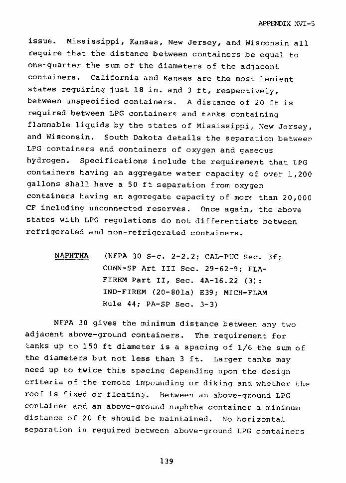
APPENDIX XVI-5
issue. Mississippi, Kansas, New Jersey, and Wisconsin all
require that the distance between containers be equal to
one-quarter the sum of the diameters of the adjacent
containers. California and Kansas are the most lenient
states requiring just 18 in. and 3 ft, respectively,
between unspecified containers. A distance of 20 ft is
required between LPG containers and tanks containing
flammable liquids by the states of Mississippi, New Jersey,and Wisconsin. South Dakota details the separation betweenLPG containers and containers of oxygen and gaseoushydrogen. Specifications include the requirement that LPGcontainers having an aggregate water capacity of over 1,200gallons shall have a 50 ft separation from oxygencontainers having an agaregate capacity of more than 20,000CF including unconnected reserves. Once again, the abovestates with LPG regulations do not differentiate betweenrefrigerated and non-refrigerated containers.
NAPHTHA (NFPA 30 S-c. 2-2.2; CAL-PUC Sec. 3f;
CONN-SP Art III Sec. 29-62-9; FLA-
FIREM Part II, Sec. 4A-16.22 (3):
IND-FIREM (20-801a) E39; MICH-FLAM
Rule 44; PA-SP Sec. 3-3)
NFPA 30 gives the minimum distance between any two
adjacent above-ground containers. The requirement for
tanks up to 150 ft diameter is a spacing of 1/6 the sum of
the diameters but not less than 3 ft. Larger tanks may
need up to twice this spacing depending upon the design
criteria of the remote impounding or diking and whether theroof is fixed or flcating. Between an above-ground LPGcontainer and an above-ground naphtha container a minimumdistance of 20 ft should be maintained. No horizontalseparation is required between above-ground LPG containers
139
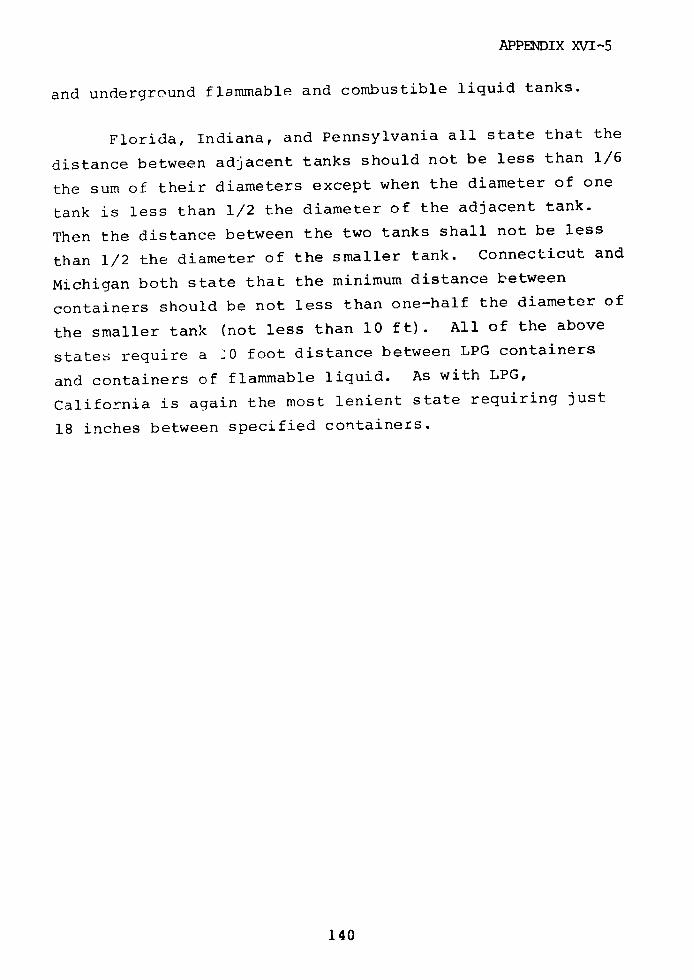
APPENDIX XVI-5
and underground flammable and combustible liquid tanks.
Florida, Indiana, and Pennsylvania all state that the
distance between adjacent tanks should not be less than 1/6
the sum of their diameters except when the diameter of one
tank is less than 1/2 the diameter of the adjacent tank.
Then the distance between the two tanks shall not be less
than 1/2 the diameter of the smaller tank. Connecticut and
Michigan both state that the minimum distance between
containers should be not less than one-half the diameter of
the smaller tank (not less than 10 ft). All of the above
states require a 20 foot distance between LPG containers
and containers of flammable liquid. As with LPG,
California is again the most lenient state requiring just
18 inches between specified containers.
140

APPENDIX XVI-5
-i .0 ,
o .4 to,
0 ~ 0 44'04 0U 0O 0 - - - U- i O O ;)
0&I W-4 a 0 i"-H ( 0O t 0o
4 A-00 v) 4 0 4) t o
04 L I A 0 0 A 4 c: > m
r,.j0 1i C 0 4 )
H S oc L
>C 0"c2
H L
z >| - 0 0 0 o .°c
0
.,4
- 0 0 o o0Oc t to o A c
· 4t - o C o0
0 N A N 4 -I 0 0 4) L' I I I o o o o 0
141
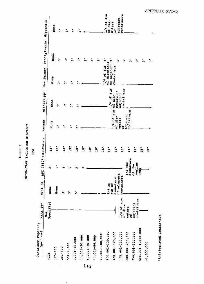
APPENDIX XVI-5
eI cS
O O ; V4 0 0o o - - -N 1
-4
C 0
.el
00* M
4, 0 0fa .~*,
~00M
..· .4 o1 4.
0 w, 5
~~a 40~~~~~l.
* 0 *r0 4r
in 44 la, 'co go gm
" CC
1 0 - -- 4'4' 4-0
Z -, o . L 4000
0
te
u '4 . . . .. .
... J _ L
a c
~~~~z N - - 0'4 /3 00c.
0
o 0~~~~~~~~r o
z C
o
1 4 I I4 In ID£ S I C
C .4 ,.- 0 4 . -4 ·- 4 4 4 . -I4 -4
-~~~~~4~~4
*1 ~ 0 o g 0 0 , ,- - . 54 , o
1 42o -4 IN A 0 I) ~ 0 0 N 0 LA V 4 N A N 'I I I 1 4 - 4 A '
a~~~~4
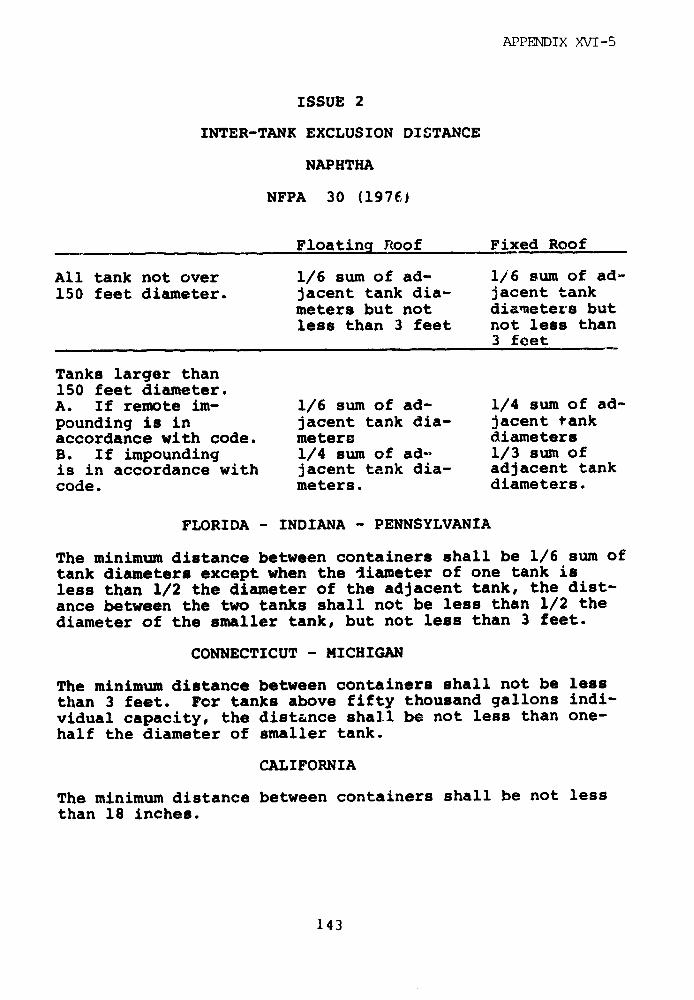
APPENDIX XVI-5
ISSUE 2
INTER-TANK EXCLUSION DISTANCE
NAPHTHA
NFPA 30 (197E)
Floating Rcoof Fixed Roof
All tank not over 1/6 sum of ad- 1/6 sum of ad-150 feet diameter. jacent tank dia- jacent tank
meters but not diameters butless than 3 feet not less than
3 feet
Tanks larger than150 feet diameter.A. If remote im- 1/6 sum of ad- 1/4 sum of ad-pounding is in jacent tank dia- jacent tankaccordance with code. meters diametersB. If impounding 1/4 sum of ad- 1/3 sum ofis in accordance with jacent tank dia- adjacent tankcode. meters. diameters.
FLORIDA - INDIANA - PENNSYLVANIA
The minimum distance between containers shall be 1/6 sum oftank diameters except when the diameter of one tank isless than 1/2 the diameter of the adjacent tank, the dist-ance between the two tanks shall not be less than 1/2 thediameter of the smaller tank, but not less than 3 feet.
CONNECTICUT - MICHIGAN
The minimum distance between containers shall not be lessthan 3 feet. For tanks above fifty thousand gallons indi-vidual capacity, the distance shall be not less than one-half the diameter of smaller tank.
CALIFORNIA
The minimum distance between containers shall be not lessthan 18 inches.
143
APPENDIX XVI-5
3. Security Requirements.
LNG (NF'PA 59A, Sec. 202, 95; NYCFD Sec. 4.5, 21.7;NY State PSC Sec. 259.11f; MASS-DPU Sec.202,95).
NFPA 59A requires the installation of a protectiveenclosure of unspecified height such as a peripheral fence,building wall, or natural barrier enclosing major facilitycomponents such as LNG storage containers, flammablerefrigerant storage tanks, on-shore loading and unloadingfacilities, etc. This enclosure may be continuous or therecan be several independent enclosures. The enclosuresshall have at least two exit gates if the area exceeds1,250 sq ft. In regard to unattended facility operation,NFPA 59A states that "if a liquefaction plant is designed
to operate unattended, it is recommended that alarmcircuits be provided which will transmit an alarm to thenearest manned company facility indicating fire, abnormalpressure, temperature, gas concentration or other symptomsof trouble." The state of Massachusetts has adopted theseNFPA 59A requirements as has New York state which adds thefollowing statement: "Especially in the case of unmannedfacilities, active liaison shall be established with thelocal fire department and utility operating personnel inregard to education in the properties of LNG and in thetechniques of fighting LNG fires." The New York City FireDepartment merely states: "A protective fence ofinconbustible material shall be erected at the propcrtyline, at least eigjt feet in heicJht, having locked gatesopenable to only authorized persons on properidentification."
144

APPENDIX XVI-5
LPG (NFPA 58, Sec. 3250; NFPA 59, Sec. 255, 347;
CAL-PUC Sec. 3B; FLA-FIREM Sec. 4A-1.03;
GA-FIREC Sec. 120-3-16-.03; ILL-LPG Sec. 7;
LA-LPG Sec. 2.17; MASS-DPU Sec. 4-255; MISS-MV
Sec. 3.7; NM-LPG Sec. A.8; SD-DPS Sec.
61:12:01:09)
NFPA 58 states that areas including container
appurtenances (items connected to container openings needed
to make a container a gas-tight entity, e.g., safety relief
devices), pumping equipment, loading and unloading
facilities and container loading facilities should be
protected by a six foot high industrial-type fence. As an
alternative to fencing, suitable devices (which shall
effectively prevent unauthorized operation of any of the
container appurtenances, system valves or equipment) can be
provided which can be locked in place. NFPA 59 includes
the same statement for both non-refrigerated and
refrigerated tanks with the added provision that breakable
locks be used. Presumably this is for fir department
access.
The states of California, Florida, Georgia, Illinois,
Louisiana, Massachusetts, Mississippi, and South Dakota
have all established regulations requiring fences, with
Massachusetts and South Dakota adding a provision identical
to that found in NFPA 59. New Mexico leaves the
construction of a fence to the discretion of the Liquefied
Petroleum Gas Commission.
NAPHTHA (CAL-PUC Sec. 3B)
The state of California has instituted a standard
which states that "all holders, vessels, and above-ground
145

APPENDIX XVI-5
piping and fittings adjacent thereto shall be properlysurrounded by adequate fencing and gates that will preventaccess by unauthorized persons."
146
APPENDIX XVI--5
4. Diking Requirements.
LNG (NFPA 59A Sec. 210, 211; NYCFD Sec. 5, 6;
NYS-PSC Sec. 2L).4a; MASS-DPU 210, 211, 212)
NFPA 59A states that for an impounding area serving a
single container, the minimum volume it can hold, V, should
be equal to the total volume of liquid in the contairr,
when the container is full. The State cf Massachusetts has
a similar code. Both New York State and the New York City
Fire Department require that the minimum capacity of the
area shall be 150% of the miaximum liquid capacity of the
container for which the area is provided. In New York
State, this percentage may be reduced to 1 .% if a dike is
designed of materials capable of withstanding LNG
temperatures, having a vertical inner wall, located at a
minimum distance from the container that coinforms with the
New York State standard, and if the company can demonstrate
the effectiveness of the design. The New York City Fire
Department further requires a 250% or greater capacity
where foarting, vigorous boiling or other expansion
phenomena may be encountered.
T'he above standards apply to unbermed containers for
NFPA 59A and the States of Massachusetts and New York. The
standards of the New York City Fire Department also apply
to bermed containers which is the, only type that they now
allow. They also require a secondary dike for bermed
containers.
Many impounding areas serve more than one container.
NFPA 59A states that the total volume of the dike, V,
should be equal to the total volume of liquid in the
largest container when it is full, provided that low
147
APPENDIX XVI-5
temperature exposure or fire exposure resulting fromleakage from any one container will not cause subsequentleakage from another container. Without such a provision,the dike volume, V, should be equal to the total volume ofliquid in all containers served assuming all containers arefull. In a less stringent standard, because it is based onthe 1971 version of NFPA 59A, the State of Massachusettsrequires that the minimum volume of the diked area shallequal the amount of liquid capacity of the largestcontainer draining into the area. Both the State of NewYork and the New York City Fire Department require that notmore than one container shall be installed in a singledike. New York State will allow an exception to this ifthe container spacing is such that a LNG spill from onecontainer will not reach other containers.
NFPA 59A and the States of Massachusetts and New Yorkall employ standards which are intended to require spacingbetween the tank and dike to be sufficient to preventliquid from a hole in the tank from jetting over the dikeregardless of the amount of friction in the hole. However,the formula on which the spacing is based is not correct,as we show in Chapter 7. The New York City Fire Departmentrequires that dike height be at least half the maximumliquid level in the tank.
An accidental LNG spill could also occur in otherplant areas. NFPA 59A states that LNG vaporization,process or transfer areas should have impounding areas witha minimum volume equal to the greatest volumLe of LNG,flammable refrigerant or flammable liquid which could bedischarged into the area during a 10-minute period from anysingle credible accidental leakage source. The largestaccident considered "credible" is a pipe break. New York
148
APPENDIX XVI-5
State adopts this NFPA 59A standard. The New York City
Fire Department applies the same dike capacity rule used
for storage containers to LNG piping and processing
equipment.
In order to contain any spilled LNG, the dike must
remain structurally sound. NFPA 59A states that dikes,
impounding walls and drainage channels for LNG shall be
made of earth, concrete, metal and/or suitable materials.
They may be independent of the container or they may be
mounded integral to or constructed against the conLainFr.
They must withstand the full hydrostatic head of impounded
LNG, the effect of rapid cooling to the temperature of the
liquid confined, any anticipated fire exposure and natural
forces such as earthquake, wind and rain.
New York State adopts NFPA 59A with the following
provision! berms shall only be used on containers having a
concrete outer shell unless it can be demonstrated that a
metallic shell can be protected against corrosion. The
State of Massachusetts requires that "dike and impounding
walls and drainage channels shall be liquid tight and
constructed of earth, steel, concrete, or other suitable
material capable of confining the liquid and of
withstanding LNG temperatures and a full hydrostatic head
of LNG which might be spilled. They shall also be able to
confine the liquid during any expected fire exposure
period."
Rain or other water in the impounding area could
accelerate vaporization should LNG spill. NFPA 59A states
that provision must be made to remaove this water although
no time requirements for water removal are given.
Automatically controlled sump pumps are permitted if
149
APPENDIX XVI-5
equipped with an automatic cutoff device which prevents
their operation when exposed to LNG temperatures. Piping,
valves, and fittings whose failure could permit liquid to
escape from the impounding area must be suitable for
continuous exposure to LNG temperatures. The State of New
York adopts this standard. The State of Massachusetts
requires that "provision shall be made to drain rain or
other water from the diked area and said drains shall be
equipped with a positive closure which shall be closed
except when manually opened for draining. The valve and
other parts of the drain system that may be subject to LNG
temperature shall be of suitable material to withstand low
temperatures (-2600 F). Such drains shall not permit
drainage of tank content to natural water courses, public
sewers or public drains. Automatically controlled sump
pumps are permitted if equipped with a device or automatic
cut-off switch which will prevent their operation to pump
LNG fro-in within the impounding area." The New York City
Fire DPPartment staces that impounding areas shall not
contain underground channels, drains, conduits, or sewers.
Storm water should be pumperd over the dikes by means of
fixed piping and manually controlled.
If LNG were to spill into an impounded area,
provision might be made to remove the spilled LNfG from the
dike. The New York City Fire Department has the only
code which specifies preparedness for such actions. It
states "Cryogenically suitable approved pump? manually
controlled and piping on combustible and cryogenically
suitable supports shall be used to return such spills to
the tank where possible."
150)
APPENDIX XVI-5
LPG (NFPA 59 Sec. 240h, 254, 330d, 343, 346; NFPA 58
Sec. 3114, 3115; API 2510 Sec. 4.2.2, R4.2.2;
KAN-LPG Sec. 22-8-7; MASS-DPU Rule 33; MISS-MV
Src. 213 j, k; NJ-AC Sec. 5.8.10, 11; WISC-AC
Sec. 9.05)
NFPA 58 states that dikes, curbs or grading should be
used to prevent the accumulation or flow of liquids having
flash points below 200 F under adjacent LPG containers.
When tanks containing flammable or combustible l.quids are
within a diked area, LPG containers of any size shall be
outside the diked area and at least 10 feet away from thecenterline of the wall of the diked area. However, it also
states that "because of the pronounced volatility of LPG ininstallations covered by this standard, dikes norially
serve no useful purpose." This statement does not make
sense although liquid accidentally released from a
pressurized LPG tank would form a gas-liquid jet and only aportion might accumulate on the ground.
NFPA 59 states that non-refriserated LPG containers
shall not be 'ocated within dikes enclosing flammable
liquid tanks or refrigerated LPG tanks. Dikes should be
used to prevent accidentally escaping flammable liquids
from flowing into LPG co.ltainer areas. Similarly,
refrigerated LPG containers shall not be located within
dikes enclosing flammable liquids. However, refrigerated
LPG containers are required to be diked, with the diked
volume at least 100 percent of the capacity of the largest
container enclosed. When more than one container is
located in a single diked area, provision must be made toprevent liquid from any one spill from contacting other
tanks if such tanks have wettable portions of their outer
shells which are not suitable for -44°F temperature
151
APPENDIX XVI-5
exposure. Further, any container foundations must be
designed to withstand fire exposure. The dikes constructed
should prevent the escape of liquid and withstand a full
hydraulic head as well as withstanding thermal shock. Dike
walls shall be no less than 5 feet i_ height except where
topography can provide suitable containment. Drainage
procedures for the dikes are specified.
For non-refrigerated containers, API 2510 states that
"because of the pronounced volatility of LPG, dikes or
firewalls around LPG tanks usually are not necessary, hence
their general requirement is not justified. Where site
conditions permit, it is desirable for the grade to be
sloped away from the container to a safe area." For
refrigerated containers exceeding 10,000 bbl (1,590 cubic
meters) capacity, dikes shall be provided, if necessary to
prevent the spread of liquid onto other property or
waterways. Capacity of the diked area, if required, shall
equal the capacity of the largest tank."
The States of Kansas, Mississippi, and Wisconsin
require that dikes, curbs or grading prevent the
accumulation of flammable liquids under adjacent LPG
containers in addition to specifying that no LPG containers
can be situated within a diked flammable liquids area. The
State of New Jersey employs the latter requirement in
addition to stating that "when above-ground containers
endancger adjacent property because of sloping ground or
local conditions, each container or group of containers
shall !be surrounded by a dike or dikes of a capacity not
less than the capacity of the container or containers in
uueo;tion." The State of Massachusetts requires a dike
having a capacity of the tank or tanks surrounded.
152

APPENDIX XVI-5
NAPHTHA 'NFPA 30 Sec. 2-2.2, 3; CONN--SP Art
IIT, Sec. 29629, 12; FLA-FIREM Part
II, Sec. 4A16.22 (3,7); IND-FIREM
(20801a) E39, 44; MICH-PLAM Rule 44,
47; PASP Sec. 33,6; PRFS Sec. 314,
50k)
NFPA 30 establishes specifications for remote
impounding (where protection of adjoining property or
waterways is by means of drainage to a distant dike or
topographical basin) in addition to impounding around the
tanks by diking. These requirements for dike design are
considerably more detailed than those for £.NG or LPG and
are presented in detail in the following section.
Florida, Indiana, and Pennsylvania all require either
drainage (remote impounding) or impounding by diking.
Florida and Indiana include detailed specifications similar
to the NFPA. Pennsylvania includes a few less specifics
for diking. In both Connecticut and Michigan, the Fire
Marshal determines the need for diking. A few basic
construction details are sp.-cified. In Puerto Rico, all
tanks exceeding 50,000 gallons (190 cubic meters) should be
diked with the dike capacity not less than equal in volume
to that of the tanks surrounded.
The States of Connecticut, Florida, Indiana,
Michigan, and Pennsylvania all require that when flammable
or combustible liquid storage tanks are within a diked
area, any LPG containers shall be outside of the diked area
and at least 10 ft away from the center line of the wall of
the diked area. More complete details cn these various
requirements are presented in the following section.
153
APPINDIX XVI-5
SPILL CONTROL REQUIREMENTS - NFPA 30 (1.976)
Remote impounding systems should comply with the
following standards: (a) A slope of not less than 1 percent
away from the tank shall be provided for at least 50 feet
toward the impounding area, (b) The impounding area shall
have a capacity not less than that of the largest tank that
can drain into it, (c) The route of the drainage system
shall be so located that, if the liquids in the drainage
system are ignited, the fire will not seriously expose
tanks or adjoining property, (d) The confines of the
impounding area shall be located so that when filled to
capacity the liquid level will not be closer than 50 feet
from any property line that is or can be built upon, or
from any tank. Requirements for impounding by diking shall
include the following: (a) A slope of not less than 1
percent away from the tank shall be provided for at least
50 feet or to the dike base, whichever is less, (b) The
volumetric capacity of the diked area shall not be less
than the greatest amount of liquid that can be released
from the largest tank within the diked area, assuming a
full tank. To allow for volume occupied by tanks, the
capacity of the diked area enclosing more than one tank
shall be calculated after deducting the volume of the
tanks, other than the largest tank, below the height of the
dike, (c) To permit access, the outside base of the dike at
ground level shall be no closer than 10 feet to any
property line that is or can be built upon, (d) Walls of
the diked area shall be of earth, steel, concrete or solid
masonry designed to be liquidtight and to withstand a full
hydrostatic head. Specifications for earthen walls are
detailed, (e) Exce!~t as provided below, the walls of the
diked area shall be restricted to an average interior
height of 6 feet above interior grade, (f) Dikes may be
154

APPENDIX XVI-5
higher than an average of 6 feet above interior grade if
provisions are made for normal access, necessary emergency
access to tanks, valves and other equipment, and safe
egress from the diked enclosure. In this case, more
detailed specifications are required, (g) Each diked area
containing two or more tanks shall be subdivided preferably
by drainage channels or at least by intermediate curbs in
order to prevent spills from endangering adjacent tanks
within the diked area. Exact requirements for doing this
are provided, (h) Where provision is made for draining
water from diked areas, such drains shall be controlled in
a manner so as to prevent flammable or combustible liquids
from entering natural water courses, public sewers, or
public drains, if their presence would constitute a hazard.
Control of drainage shall be accessible under fire
conditions from outside the dike, (i) Storage of
combustible materials, empty or full drums or barrels,
shall not be permitted within the diked area.
155
APPENDIX XVI-5
5. Requirements For Resistance to Natural Phenomena.
LNG (NFPA 59A Sec. 406, 25; NYCFD Sec. 4.2.3;
MASS-DPU Sec. 405; API 620 Sec. 304 (5),
3.05.5; NBC Sec. 906,907)
NFPA 59A cites the Uniform Building Code, Volume 1,
1973 edition as a basis for design for seismic, wind, snow,
and other forces. The 1975 edition of 59A also imposes a
requirement for a detailed geotechnical study for all LNG
sites in seismic areas (zone 2 or 3 per UBC). Although the
1972 edition which is the current Federal regulation does
not include this requirement, the gas industry generally
follows the more stringent 1975 versicn for new facilities
for insurance purposes. Pre-1975 facility designs,
however, do not generally follow this recommendation.
The State of Massachusetts simply states that "When
applicable, seismic loads shall be considered in the
design." The New York City Fire Department states "Plant
sites shall be protected from the forces of nature such as
flooding by rains, high tides or soil erosion by grading,
draining and dikes. Grass, weeds, trees or undergrowth
shall be cleared within 25 feet of any piping, container or
process equipment." In regard to the design and
construction of large, welded, low-pressure storage tanks,
API 620 (1975) states that both wind loads and earthquake
loads should be incorporated into the design so that when
design loads in addition to combined seismic and wind loads
act on the structure, stress values do not exceed 133% of
the design stress or 80% of yield stress.
LPG (NFPA 58, Sec. 31146,g; NFPA 59 Sec. 243, 250e,
253, 332, 345; CAL-PUC Sec. 4a.10, 4c.5; KAN-LPG
156
APPENDIX XVI-5
Sec. 22-8-7; LA-LPG Sec. 2.18; MISS-MV Sec.
5.8.8, 7.4.3c, 7.6.1g, 7.6.3d; PA-DLI Rule 18;
TX-RRC Div. II Sec. 2.5, 2.7; WISC-AC Sec. 905
(8))
NFPA 58 requires that containers be securely anchored
where necessary to prevent flotation due to possible high
flood waters around above-ground containers or a high water
table for those underground. It also requires that
combustible material be excluded from a 10 foot zone around
any container.
NFPA 59 includes a similar statement regarding
ignitible underbrush. It also requires that containers be
"properly painted or otherwise protected from the
elements." Secure anchorage or adequate pier height is
required to protect against container flotation wherever
high water might occur.
California, Kansas, Louisiana, Mississippi, New
Jersey, Pennsyl-ania and Wisconsin all include similar
statements requiring that the immediate area surrounding
LPG containers be kept free of ignitible material such as
weeds or dry grass. Texas states that loose fitting rain
caps be provided on all exposed safety relief valves or
discharge pipes that discharge vertically upward. Both
Texas and New Jersey require that if there is a possibility
of a manhole or housing becoming flooded on underground
installations, discharge from relief valves and regulator
vent lines should be above the possible high-water level.
If underground containers are in loose soils, firm
anchoring is required to prevent floating. New Jersey
requests secure anchorage in statements similar to the
157
APPENDIX XVT-5
NFPA.
In general, structures such as LPG tanks must be
built in conformance with local building codes so wind,
snow and seismic loads are defined by these criteria.
NAPHTHA (NFPA 30 Sec. 2-5, 6, 7 App. B; API
620 Sec. 3.04 (5), 3.05.5; CAL-PUC
Sec. 4a.10, 4c.5; CONN-SP Art. III,
Sec. 29-62-106, Art. X; FLA-FIREM1 Sec.
4A-16.25 (6) , Chap. 4A-33; IND-FIRE!M
(20-801a)-E61, E62, App. B; MICH-FLAM
Rule 45b; PA-SP Sec. 3-431, 4-31, Art. 14)
NFPA 30 has extensive precautions which should be
employed when a tank is located in an area that may be
subjected to flooding. NFPA 30 also states that in areas
subject to earthquakes, the tank supports and connections
should be designed to resist damage as a result of such
shocks. (API 620 states that both wind loads and
earthquake loads should be incorporated into the design of
large, welded, low-pressure storage tanks.)
The States of Connecticut, Florida, Indiana and
Pennsylvania have standards for flood precautions similar
to the NF'PA. Michigan merely states that "The Commissioner
may specify additional precautions which must be taken to
protect a tank to be located in an area subject to
flooding." An earthquake standard identical to that found
;r the NFPA codes has been established in Indiana. The
California codes which apply to LPG tanks also apply to
n:aphtha.,
158
APPENDIX XVI-5
6. Requirements For Operating Procedures and Personnel
Training.
LNG (NFPA 59A Sec. 103)
Although NFPA 59A has detailed specific operating
instructions scattered throughout the code, it makes only
the following vague reference to general operating
procedures: "In the interest of safety, it is important
that persons engaged in handling LNG understand the
properties of this product and that they be thoroughly
trained in sate practices for its handling." The State of
New York requires operating procedures for "(1) routine
operations and maintenance and (2) operations and
maintenance safety procedures" while acknowledging "it is
not possible to prescribe a detailed set of operating and
maintenance procedures that will encompass all cases." They
shall specify "equipment, piping, valves and other
components to be inspected or tested, the time schedule of
such inspections or tests and the program to remedy
deficiencies or failures uncovered." Included shall be
items such as the following: "fire protection systems,
dikes, operating signal devices, relief valves inspection,
structural inspection, functional inspection, pumps and
compressors, valves and operators, standby electrical
system inspection, communications equipment and
housekeeping." An emergency response plan is also
required. No reference is made to general operating
procedures in other codes examined for this report. The
NYCFD does, however, require that LNG facility operators
obtain a Certificate of Fitness based on written and oral
examinations given by the Fire Department.
159
APPENDIX XVI-5
LPG (NFPA 59 Sec. 150; NFPA 58 Sec. 150; CAL-PUC
Sec. 49.2; LA-LPG Sec. 2.20; NM-LPG Sec. A, 6A,
B)
NFPA 58 and 59 have some operating instructions for
specific processes, yet have only vague statements which
pertain to general operating procedures. NFPA 58 states
"In the interests of safety, all persons employed in
handling LP-Gases shall be trained in proper handling and
operating procedures." NFPA 59 contains a similar
statement. New Mexico and Louisiana require operators to
be certified by the State and California states that
training is necessary before an operator is delegated
responsibility.
TNAPIITIIA (CAL-PUC Sec. 4a.2)
The State of California has instituted a standard
which states "In selecting men for supervisory work at
holder or vessel yards, consideration should be given to
their carefulness, thoroughness, reliability, and ability
to assume responsibility in time of emergency. No person
shall be delegated responsibility about a holder yard until
he ha,- bD _n thoroughly acquainted with the nature of the
woe k : rout - t'aining."
160

APPENDIX XVI-5
7. Materials Specifications For Storage Tan:s.
LNG (NFPA 59A, Sec. 41, 42, 407; NYCFD Sec. 5: 10,
11, 12, 20.2, 3; NYS-PSC Sec. 259.6b, c, 259.9;
MASS-DPU Sec. 41, 42, 406; API 620 Sec. 307,
308, 313.1b, App. G, Q; ASME Codo Sec. VIII,
Div. I; DOT/USCG 46 CFR Part 38)
Present codes list the materials suitable for ruse in
LNG storage tank-. For metal containers, NFPA 59A cites
the American Petroleum Institute (API) Standard 620,
Appendix Q for LNG contain.ers operating at ?ess than 15
psig while Section VIII, Division I of the American Society
of Mechanical Engiieers (ASME) code is cited for metal
containers at more than 15 psig. For concrete containers,
NFPA 59A cites various American Concrete Institute
Standards. The States of Massachusetts and New York and
the New York City Fire Department generally follow NFPA 59A
in materials selection.
The remaining sections noted iti A.PI 620 discuss
corrosion allowance. A detailed sec. 'on on corrosion
control is contained in the New York State Regulations.
The API Standard 620 and the ASME Codes are detailed
design codes which list acceptable materials in addition to
stating design requirements, fabrication methods and
quality assura.ce specifications and techniques. The API
Standard 620 requires certain results of Charpy V-notch
tests in order to ensure metal toughness and weld
integrity.
Tank materials must retain their struength and
toughness for a long time at low temperatures to prevent
161

APPENDIX XVT-5
structural failure. The New York City Fire Department
requires that inner containers be hydropneumatically tested
every five years, or in lieu thereof samples from the metal
containers may be tested by the Charpy Impact Test. This
is done by placing various samples of the materials used in
the tank construction i.e., sheets of metal, welded
samples, etc. into a basket immersed in the LNG. The
samples are then withdrawn for testing at intervals of a
maximum of five years.
The USCG rules _equire internal inspections at eight
year intervals for LNG ship tanks.
The flammability of the insulation is also imp:.rihant.
Coast Guard regulations statc that the insulation on ship
tanks must be self-extingui;hing or incombustible. It
should be vapor-proof and enclosed. The New York City Fire
Department states that only incombustible insulation can be
used. The other codes make no specifications.
LPG (NFPA 59, Sec. 21, 22, 251d, 31; NFPA 58, Sec.
210, 211; API 2510 Sec. 5, R-5; CAL-PUC Sec.
3e, n, 4d2; FLA-FIREM Sec. 4A-1.20; GA-FIRLC
120-3-16-.06 Sec. 0; KAN-LPC Sec. 22-8-7; LA-LPG
Sec. 2.2a; MISS-MV Sec. 2.4; PA-SP Rule 561;
TX-RRC Sec. III B.7, Div. II; WISC-AC Sec.
9.03(1))
NEPA 58 cites the Regulations of the U.S. Department
of Transportation (DOT), the Rules for the Construction of
Unfired Pressure Vessels, Section VIII, Division 1, ASME
eoiler and Pressure Vessel Code and the API-ASME Code for
Unfired Pressure Vessels for Petroleum Loquids and Gases.
162
APPENDIX XVI-5
For non-refrigerated containers, NFPA 59 cites
Section VIII of the ASME Boiler and Pressure Vessel Code.It also states that containers should be adequately
protected against cor:-osion. For refrigerated containers
with a pressure of 15 psig or more, Section VIII of the
ASME Code is cited, as is AnI Standard 620. For pressures
below 15 psig, API Standard 620 is cited.
API 2510 cites Section VIII of the ASME Code for
non-refrigerated containers. For refrigerated containers,
Section VIII of the ASME Code is cited as is API Standard
620.
California, Kansas, Louisiana, Mississippi, and Texas
all cite Section VIII of the ASME Codes. Florida andGeorgia require documentation of conformance to the ASMEstandards during tank construction while Wisconsin cites
its own Boiler and Unfired Pressure Vessel Code. Tank
corrosion is addressed in the regulations of California andPennsylvania.
NAPHTHA (NFPA 30, Sec. 2 a, 2-3.3; API 620
Sec. 201, 202, App. B Sec. 307, 308,
3.13.1b, App. G; API 650 Sec. 2; CAL-PUC
Sec. 3e, n; CONN-SP Art III Sec. 29-62-13,
ART IV Sec. 29-62-19; FLA-FIREM Part II,
Sec. 4A-16.21; IND-FIREM (20-801a)-E31,
E33, E36, E48; MICH-FLAM Rule A8,58;
PA-SP Sec. 3-7, 4-4, PR-FS Sec. 314-500)
NFPA 30 states general materials specifications for
the design of storage tanks citing standards from
Underwriters Laboratories, Inc. and the American Petroleum
Institute.
163
APPENDIX XVI-5
The API Codes have been described in the discussions
for LNG.
Indic:a and Pennsylvania adopt NFPA 30 with few
changes while Florida cites N.PA 30 and standards from
Underwriters Laboratories and the American Petroleum
Institute. In addition to citing the latter two,
Connecticut has established several standards for tanks
constructed of steel or concrete. Michigan adopts API and
NFPA requirements in addition to establishing individual
specifications for steel selection. Puerto Rico lists
several brief steel specifications and has their Fire
Service determine whether the ASME codes should be
employed. Similar to LPG, California cites the ASME Codes
(Section VIII) and discusses corrosion protection.
164
APPENDIX XVI-5
8. Materials Specifications For Truck Trailers and
Rail Cars.
LNG (NFPA 59A Sec. 84, 861; Mass. - DPU Sec. 84,
861; NYCFD Sec. 19.1, 19.8)
NFPA 59A states that tank vehicles and tank cars
under the jurisdiction of the U.S. Department of
Transportation shall comply with DOT regulations. All
other tank vehicles shall compl- with LNG Tank
Vehicles-Insulated Tank Truck for Cold Liquefied Gases,
CGA-341; LPG Tank Vehicles - Storage and Handling of
Liquefied Petroleum Gases, NFPA 58; Flammable Liquid Tank
Vehicles-Tank Vehicles for Flammable and Combustible
Liquids, NFPA No. 385. Transfer piping, pumps and
compressors must be located or protected by suitable
barriers to ensure safety from damage caused by rail or
vehicle movements. Prior to loading LNG into the vessel of
a tank vehicle, the oxygen content in the container should
be determined if the tank vehicle is not in exclusive LNG
service, or if the tank vehicle does not contain a positive
pressure. If the oxygen content in either case exceeds 2
percent by volume, the container cannot be loaded with LNG
until suitably purged.
The State of Massachusetts requires that tank
vehicles and tank cars be approved for the specific service
by authorities (not specified in the code) recognized by
the Department of Public Utilities. The Department is also
responsible for approving the design of any support,
abutment or device used to protect transfer piping, pumps
and compressors from damage by rail or vehicle movements.
Once again a test and possible purging is rfequired to
ensure that there is a slight positive press-ire and lack of
165
APPENDIX XVI-5
oxygen in the container.
The New York City Fire Department states thatflammable or combustible liquids, gases or refrigerantsshall be received only by permitted trucks complying withthe specifications (not documented in standard) of the FireDepartment. Tank vehicles shall load or unload flammableor combustible liquids only after they have been inspectedand authorized by the Fire Department and when in thecharge of a person with a certificate of fitness.
About fifteen years ago the Federal Governmentinitiated the concept of special permits or exemptions.This meant that the government (under the Office ofHazardous Material Operations - OHMO) would allow themovement of LNG in a container system that was approvedunder special permits. The purpose was to generateapproval of a new type of transportation system. In theearly 1960's, the Compressed Gas Association developed aspecification known as CGA-341 (revised in 1972) which theypresented to the Federal Government. They asked that it beincorporated as the governing regulation for the movementof cryogenic fluids, making it unnecessary to obtainspecial permits. To date, this has not been incorporated.Although HM-115 was issued as a notice of proposedrulemaking by OHMO in the early 1970's it was never issued.
CGA-341 contains some important safety elements forLNG trucks. General specifications include the requirementthat the design pressure of the liquid container must notbe less than 25 psi9 nor more than 500 psig. The liquid(pressure) container must be constructed in accordance withthe ASME Code. It must be supported within the outer shellby members designed t ) withstand minimum static loadings of
166
APPENDIX XVI-5
(1) vertical downward of two (2) vertical upward of one (3)
longitudinal of one (!) lateral of one-times the weight of
the liquid container and attachments when filled to the
design weight of lading (cold liquefied gas being
transported in the liquid container) using a safety factor
of not less than four based on the room temperature
ultimate strength of the material used. The surface of the
liquid container must be insulated with a material not
subject to corrosive attack by the contents of the tank.
Tank design should be such that the total heat transfer
from the atmosphere at 700F to a lading at minus 3200F does
not exceed 0.20 Btu per hour per pound of water capacity.
The insulation must be covered with a steel shell of not
less than 3/32 inch. AumLinuim was disallowed as a tank
material for flammable cargoes because of its poor fire
resistance. The CGA-341 requirement3 result in a more
collision and rollover resistant truck. HM-115, as
proposed, inc 'used some even more stringent provisions on
hold time without venting and on design "g" loads. There
are no formal Federal LNG truck container system design
regulations at present.
LPG (NFPA 58 Sec. 6; NFPA 59 Sec. 7; KAN-LPG Sec.
22-8-16, Div4iion III, MISS-MV Div. IV; PA-DLI
Sec. VIII, T,'-RRC Sec. III, Div. IV: WISC-kC
Part IV)
NFPA 58 cites the U.S. Department of Transportation
Regulations (MC-331). TFPA 59 has requirilments which
pertain only to the handling Fnd transfer of LPG to and
from Lank vehicles. It requires that the area of tank
truck transfer be relatively 'evel. The tank truck loading
and unloading area shall be of sufficient size to
accommodate the vehicles without excessive movement or
167
APPENDIX XVI-5
turning. Tank trucks or transports unloading into the
storage containers shall be at least 10 ft. from the
container and positioned so that the shut-off valves on
both the truck and the container are readily accessible.
While trucks are loading or unloading, the wheels shall be
blocked. Kansas has instituted similar requirements.
Louisiana requires that all containers be designed,
constructed and tested in accordance with the ASME Code
specifications relating to vessel design. Kansas,
Mississippi and Wisconsin employ the ASME Codes in their
regulations to document some design specifications
required. Louisiana, Mississippi, Pennsylvania, Texas, and
Wisconsin all include specifications for such issues as
safety equipment, tank mounting and electrical equipment.
NAPHTHA (Conn-SP Art. XIII, XIV: FLA-FIREM
Part X; IND-FIREM (20-807) A275-A286;
MASS-DPU FPR-7; MICH-FLAM Rules 5-35)
NFPA 385, adopted by the NFPA at its 1974 Annual
Meeting, is a regulatory standard for tank vehicles for
flammable and combustible liquids. This standard was
prepared for issuance by enforcement authorities as a
regulatory standard.
It establishes standards for the materials used in
the design of cargo tanks used in tank vehicles. it states
that all sheet and plate material should either comply with
the ASME Codes or The requirements given. Consequently,
steel and aluminum specifications are listed. Other design
details such as thickness of sheets and heads, structural
integrity and loadings are discussed. General operating
procedures are also stated.
168

APPENDIX XVI-5
Florida and Massachusetts have adopted this code with
several minor provisions. Connecticut, Indiana, and
Michigan all include detailed material specifications in
addition to several individual requirements.
169
APPENDIX XVI-5
9. Requirements For Harbor Movements and Unloading of
LEG and Naphtha Tankers, and
10. Requirements For Tanker Construction.
(See also Chapter 6, Appendix VI, and Appendix
XVI-3.)
The U.S. Coast Guard and other groups such as the
American Bureau of Shipping have developed requirements on
tanker cinstruction and operations for a wide range of
potentially hazardous cargoes including LEG and naphtha.
Presently, the Coast Guard considers naphtha within its
regulations for general bulk combustible liquid cargo
carriers; whereas LNG and LPG are covered in a special
category for liquefied flammable gases. (The Coast Guard
has even more stringent rules for more dangerous flammable
liquids, for certain special cargoes, and for nuclear
vessels.)
LNG (COT/USCG 46 CFR Part 30-35, 38, 42, 154;
33 CFR Part 126; 6.04, 6.14)
According to 46 CFR Part 38, the primary tNG tank to
be constructed of materials meeting low temperature
toughness standards and to be self-supporting. However, it
states that special designs not contemplated by the
standards (membrane tanks, for example) can be submitted to
the Commandant for approval. A major portion of LNG ships
in service today are of the membrane type. A secondary
barrier must also be provided so that the barrier and
contiguous hull structure retain sufficient toughness at
the lowest temperature which may result from cargo leakage.
170
APPENDIX XVI-5
The regulations require that a ship be stable
(defined as wind heel angle less than either 140 or half
the freeboard) in 55 knot winds. Other stability
requirements can be imposed at the discretion of the
Commandant. The USCG has an announced policy of following
IMCO rules for LNG ships when they are consistent wiLh
proposed rules issued in October 1976 by the USCG. These
proposed rules require that the ship be designed to remain
afloat assuming damage criteria which depend on the size
and design configuration of the ship. These criteria
include a two compartment flooding scenario. Basically,
the rules are intended to make liquefied gas carriers
somewhat more collision resistant than conventional tank
ships. The ship is designed to survive stranding or minor
side damage without cargo loss. At present, rules for a
30" distance between the outer hull and the cargo system
along with practical considerations of ballasting the ships
and insulating the cargo tanks, result in LNC ships being
designed with double hulls and bottoms. This is a specific
requirement in the proposed rules.
Vapors generated by gradual warming of the cargo can
be used as ship fuel at sea, reliquefied, or be allowed to
raise tank pressure. In the latter case, thc insulation
and tank design pressure must allow a suitable safety
margin for the operating times involved. Venting is not
accepted as a normal operating mode.
Extensive fire protection system requirements are
detailed including dual dry chemical fire extinguishment
systems, and water spray systems for deluging exposed
portions of the cargo tanks and critical structures facing
the tanks.
171
APPENDIX XVI-5
Every eight years an internal examination of cargo
tanks is required and the marine inspector may also require
a hydrostatic or pneumatic pressure test of the tanks at
1-1/2 times the relief valve pressure if he considers it
necessary to determine the condition of the tank. Relief
valves must be inspected at least every two years.
Foreign LNG carriers come under USCG scrutiny via
their letter of compliance program which requires foreign
LNG vessels entering U.S. ports to obtain USCG
authorization. This involves an inspection to the
standards required by 46 CFR Part 38. When IMCO
international standards are adopted, foreign and U.S.
vessels should meet the same safety requirements.
Operating restrictions on LNG carriers and
contingency plan development are the responsibility of the
USCG Captain of the Port (COTP) in each port receiving LNG.
(33 CFR 6.04, 6.14.) The COTP can modify the rules at his
discretion. Present practice in Boston includes USCG
escort, establishment of a sliding safety zone around a
vessel during port transit, use of tugs. restriction of
transit to times of good visibility, etc.
Some requirements for personnel competence at the
shore facility are contained in 33 CFR 126.
T.PG (USCG 46 CFR Part 38)
Refrigerated LPG carriers are in the same category as
LNG carriers so that the preceding discussions for LNG also
pertain to LPG. Since LPG at atmospheric pressure has a
temperature of about -40 0 F, the secondary barrier
172
APPENDIX XVI-5
requirement can be avoided if the ship's hull is
constructed from a suitable low temperature steel.
For pressurized LPG carriers an additional
requirement is that the cargo tanks be designed .n
accordance with pressure vessel standards for design
pressures greater than 10 psig.
NAPHTHA (Mass. Dept. of Public Safety FPR-14;
Florida - State Fire Marshal Chapt.
4A-32; USCG 46 CFR Parts 30-35)
The Massachusetts and Florida regulations generally
cover operations at marine oil and refined products
terminals. Fire protection for wharf areas, conditions for
terminating transfer (electrical storm, fire in vicinity or
other emergency conditions), and control of ignition
sources in transfer area are typical of the restrictions
included.
The USCG regulations pertaining to marine transport
of naphtha permit carriage of the cargo in tanks integral
with the hull. Critical bulkheads must be designed to
withstand a one-hour fire exposure without the passing of
flame or smoke. All areas containing potential ignition
sources must be isolated from the cargo tanks. The
requirements for vessel survivability are also based on
damage criteria somewhat less stringent than for the LEG
carriers.
173

APPENDIX XJI-5
11. Liability.
LNG Maine Revised Statutes, Title 14, Section
165; New York 1976 Laws, Chap. 892, Section
23-171 7(8)
The 1976 New York Liquefied Natural and Petroleum Gas
Act imposes strict liability for any pe sonal and property
damage occasioned by LNG or LPG accidents against persons
engaged in the storage, handling and transportation of
either fuel. In addition, Maine imposes strict liability
for damages resulting from natural gas operations
generally, without specifying applicability to LNG. We
were unable to locate any comparable liability provisions
in any other state.
The absence of a specific provision with respect to
liability for accidental injury relegates the disposition
of the issue to general tort law which is determined as a
matter of judicial case law and can vary from state to
state. An analysis of the exact status of the law for any
particular state will require an examination of the
applicability of negligence standards generally and the
possible applicability of theories of strict liability
might apply to LNG circumstances. The crucial issues in
such an analysis involve the extent to which liability will
exist for losses occasioned by accidents or failures which
might occur despite the maintenance of due care and the
degree of causation which miqht be required before
liability will exist. Thus far, only New York has provided
a statutory response to these questions.
LPG
The 1976 New York statute discussed above applies
174
APPENDIX XVI-5
equally to both LNG and LtG. However, LPG hAs not been thesubject of the regulatory imposition ot liability standards
in any other state despite its long kistory and frequency
of use. Consequently, questions suiroruding liability aresubject to the same tort law consideratiorn discussed
generally above.
NAPHTHA
No state has imposed regulatory stanaards relative to
naphtha. Again, as in the case of LNG and LDG in states
other than New York, this leaves the mattcr to the existingtort law in each state. However, naphtha is considerably
less volatile than either LNG or LPG. Thus, it is lesslikely to be viewed as falling in the category of extremelyor inherently dangerous activities which tend to give riseto strict liability. Again this could vary from state to
state.
175
APPFINDIX XVI-5
]2. Liability Insurance Requirements.
Present codes and regulatiolns make no reference toinsurance requirements.
LNG
Tlherc are no specific requirements for carryinginsurance against off-site liability on the part ofcorporations involved in storage and handling of LNG.
LPG
Certain jurisdictions require insurance againstoff-site liabilities involving LPG. This is probably dueto frequent LPG accidents and the consequent awareness ofthe general public of the volatility of that fuel.
Ten of the 50 states require proof of publicliablility insurance as a pre-requisite to obtaining auermit for dealing, storage, and handling of LPG, The~estates are:
Alabama - Regs, of Ala. LPG Board, Sec. $.Arkansas - State code for LPG, Sec. 53-723 (c).Florida - LPG Rules of Insurance Commission 4A-1.17.Georgia - Georgia Code, Sec. 73-306.
Kentucky - 806 Kentucky Admin. Regs. 50.050.
Louisiana - R.S. of L. Title 40, Sec. 1847.NeCvada - Nevada LPG Board, Rules andc Regs. 13.New Mexico - N.M.S.A., Sec. 65-7-11.
South Carolina - LPG Layw 66-431.5.
Tennessee - Tenn. LPG Safety Regs. Sec. 53-3604.
176
APPENDIX XVI-5
The coverage required by law varies greatly from
state to state. In Nevadd, amounts are set on an ad hoc
basis by the secretary of the LPG Board. New Mexico,
Kentucky, and Florida require bodily and property liability
in the varying amounts of $50,000 and $25,000 respectively.
These statutes do not indicate whether these are intended
to be aggregate amounts for a single accident.
South Carolina, Georgia, Tennessee, Arkansas,
Alabama, and Louisiana require various types of liability
coverage such as contractor property damage, etc. in
varying amounts from $10,000 to $100,000 (aggregate amount
for any single accident). None of the ten states require
coverage in excess of $100,000.
The other 40 states and Puerto Rico have only
substantive regulations pertaining to the storage and
handling of LPG and do not address the issue of requiring
insurance coverage.
NAPHTHA
Naphtha is treated by state legislation in the same
way as LNG. There is no requirement for liability
insurance on the part of corporations involved in storage
and handling of naphtha.
177

bLANIK

APPENDIX ,VI-6
APPENDIX XVI-6
SOME PERTINENT STATUTORY CITATIONS
Statute Agency/Authority Regulation
ALA PivMA
Alabama Code Liquefied Petro- Rules and RegulationsTitle 26 leum Gas of LPG Commission§179(57) Commission
Alabama Code Public Service 5(a) Certificate toTitle 48 Commission OPSO§]-101(5), et seq.
Alabama Code Fire Marshal Regulation of FireTitle 55 Marshal§30, et seq.
zlabama Code Mineral Resource NoneTitle 8 Management§309 Committee
Alabama Code Coastal Area NoneTitle 8 Planning§312, et seq. Committee
ALASKA
Alaska Statutes Alaska Public 5(b) Agreement with§42.05.010, et seq. Utilities OPSOCommission
Alaska Statutes Department of 13 Alaska Admin-518.70.010, Public Safety istration Codeet seq. 50.040
Alaska Statutes Department of None§J0.25.010 Environmental
Conservation
Alaska Statutes Department of Informal compliance§18.60.210 Labor with NFPA #59A
179
APPENDIX XVI-6
ARIZONA
Arizona Revised Division of Arizona Fire Code,Statutes Annotated Safety, Fire §1.102, 15.101, et§23-401, et seq. Marshal seq.
Arizona Revised Industrial Com- Arizona Fire Code,Statutes Annotated mission §20.101 et seq.§23-121, et seq.
Arizona Revised Public Service No RegulationsStatutes Annotated Commission§40-201, et seq.
Corporation 5(a) Certificate toCommission OPSO
ARKANSAS
Arkansas State Oil & Gas No RegulationsCommission Commission§53-111, et seq.
Arkansas State LPG Board LPG BoardCommission Regulations§53-711
Arkansas State Arkansas State Regulations ofCommission Police Fire Fire Marshal§82-806, et seq. Marshal
Arkansas S':ate Public Service 5(a) Certificate toCommission Commission OPSO§73-116, et seq.
CALIFORNIA
California Public Public Utility 94B, 5(a) CertificateUtility Code Commission to OPSO§770
California Vehicle NoneCode§31300
California Health Division of 17 Cal Admin Code 14Safety Code Industrial (Petroleum Safety§7620, 7624, 7655 Safety Orders)
1P0

APPLNDIX XVI-6
California Public NoneResources Codei30,000; 30,308;
30,333
COLORADO
Colorado Revised Public Utilities 5(a) Certificate toStatutes Annotated OPSO§40-1-101§40-2-101
Colorado Revised State Inspector Regulations of StateStatutes Annotated of Oils Inspecitor of Oils,§8-20-101, et seq. conceIning LPG, and
liquid petroleumproducts
CONNECTICUT
Connecticut General Committee of State Police Com-Statutes Annotated State Police mittee Regulations§29-62 Covering Storage,
Use & Transport ofFlammable Liquids
Connecticut Committee of State Police Com-General Statutes State Police mittee RegulationsAnnotated Covering Storage,§29-72 Use & Transport of
Flammable Liquids
Connecticut Public Utilities 5(a) Certificate toGeneral Statutes Control Authority OPSOAnnotated§16-1, el seq.
DELAWART
Delaware Code State Fire Adoption of NFPAAnnotated Marshal16 §6603, 6607
Delaware Code Public Service 5(b) Agreement withAnnotated CommisJion OPSO26 §101
].81
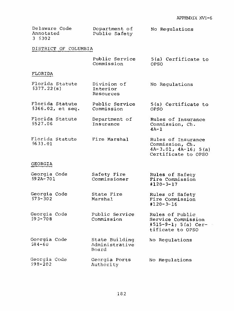
APPENDIX XVI-6
Delaware Code Department of No RegulationsAnnotated Public Safety3 §302
DISTRICT OF COLUMBIA
Public Service 5(a) Cerfificate toCommission OPSO
FLORIDA
Florida Statute Division of No Regulations§377.22(s) Interior
Resources
Florida Statute Public Service 5(a) Certificate to§366.02, et seq. Commission OPSO
Florida Statute Department of Rules of Insurance§527.06 Insurance Commission, Ch.
4A-1
Florida Statute Fire Marshal Rules of Insurance§633.01 Commission, Ch.
4A-3.01, 4A-16; 5(a)Certificate to OPSO
GEORGIA
Georgia Code Safety Fire Rules of Safety§92A-701 Commissioner Fire Commission
#120-3-17
Georgia Code State Fire Rules of Safety§73-302 Marshal Fire Commission
#120-3-16
Georgia Code Public Service Rules of Public§93-708 Commission Service Commission
#515-9-1; 5(a) Cer-tificate to OPSO
Georgia Code State Building No RegulationsS84-60 Administrative
Board
Georgia Code Georgia Ports No Regulations§98-202 Authority
182
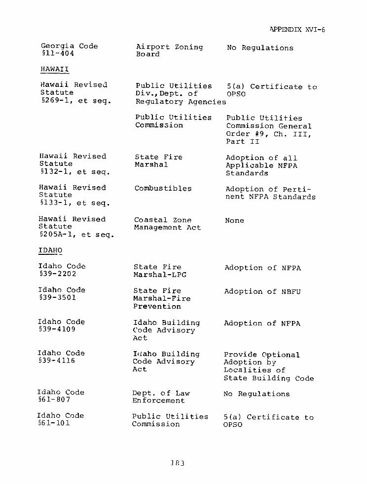
APPENDIX XVI-6
Georgia Code Airport Zoning No Regulations§11-404 Board
HAWAII
Hawaii Revised Public Utilities 5(a) Certificate toStatute Div., Dept. of OPSO§269-1, et seq. Regulatory Agencies
Public Utilities Public UtilitiesCommission Commission General
Order #9, Ch. III,Part II
Hawaii Revised State Fire Adoption of allStatute Marshal Applicable NFPA§132-1, et seq. Standards
Hawaii Revised Combustibles Adoption of Perti-Statute nent NFPA Standards§133-1, et seq.
Hawaii Revised Coastal Zone NoneStatute Management Act§205A-1, et seq.
IDAHO
Idaho Code State Fire Adoption of NFPA§39-2202 Marshal-LPG
Idaho Code State Fire Adoption of NBFU§39-3501 Marshal-Fire
Prevention
Idaho Code Idaho Building Adoption of NFPA§39-4109 Code Advisory
Act
Idaho Code Idlaho Building Provide Optional§39-4116 Code Advisory Adoption by
Act Localities ofState Building Code
Idaho Code Dept. of Law No Regulations§61-807 Enforcement
Idaho Code Public Utilities 5(a) Certificate to561-101 Commission OPSO
1.83
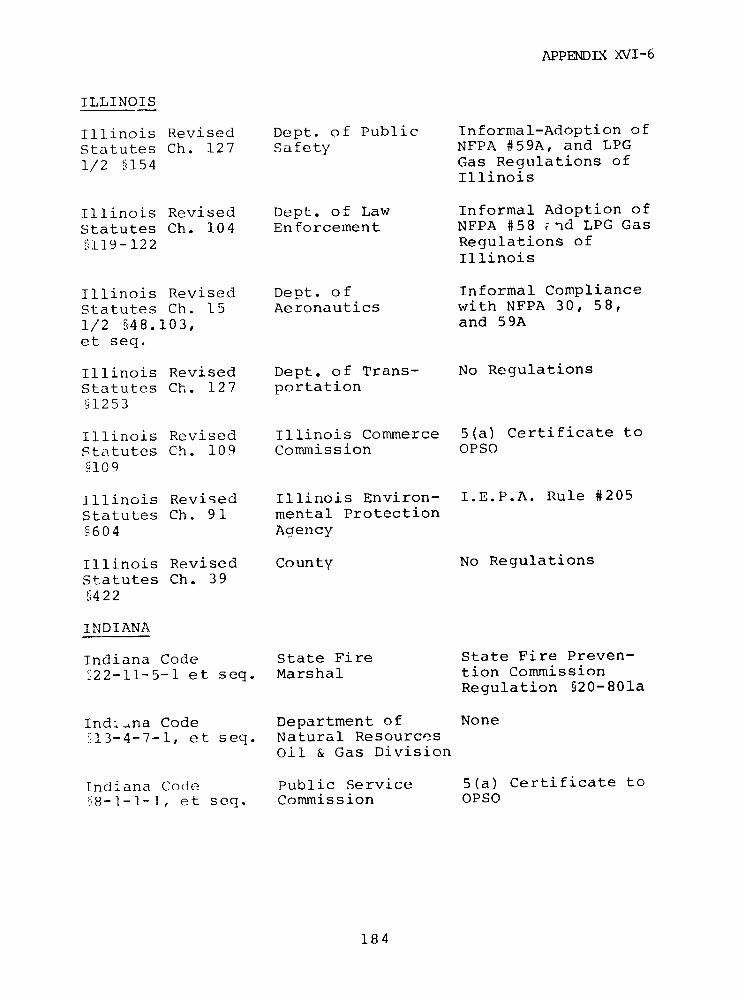
APPENDLX XVI-6
ILLINOIS
Illinois Revised Dept. of Public Informal-Adoption of
Statutes Ch. 127 Safety NFPA #59A, and LPG
1/2 §154 Gas Regulations ofIllinois
Illinois Revised Dept. of Law Informal Adoption of
Statutes Ch. 104 Enforcement NFPA #58 *nd LPG Gas
§119-122 Regulations ofIllinois
Illinois Revised Dept. of Informal Compliance
Statutes Ch. 15 Aeronautics with NFPA 30, 58,
1/2 548.103, and 59A
et seq.
Illinois Revised Dept. of Trans- No Regulations
Statutes Ch. 127 portation5!1253
Illinois Revised Illinois Commerce 5(a) Certificate to
Statutes Ch. 109 Commission OPSO
§109
Illinois Revised Illinois Environ- I.E.P.A. Rule #205
Statutes Ch. 91 mental Protection
§604 Agency
Illinois Revised County No Regulations
Statutes Ch. 39§422
INDIANA
Indiana Code State Fire State Fire Preven-
§22-11-5-1 et seq. Marshal tion CommissionRegulation §20-801a
Ind=~na Code Department of None
513-4-7-1, et seq. Natural ResourcesOil & Gas Division
Indiana Code Public Service 5(a) Certificate to
'8-1-1-1, et seq. Commission OPSO
184

APPENDIX XVI-6
IOWA
Iowa Code State Fire Marshal Iowa Administrative§100.1 et. seq. Code 680-5.250(101)
Iowa Code Liquefied I.A.C. 680-5.300(101)§101.1 et seq. Petroleum Gases
State Commerce 5(a) Certificate toCormission OPSO
KANSAS
Kansas Statutes Fire Protection LPG RegulationsAnnotated (State Fire§31-132, et seq. Marshal)
Kansas Statutes State Corporation 5(a) Certificate toAnnotated Commission OPSO§66-101, et seq.
Kansas Statutes LPG NoneAnnotated§55-1101, et seq.
Kansas Statutes Transportation NoneAnnotated and Sale of Oils§55-501, et seq. & Liquid Fuel
KENTUCKY
Kentucky Revised Public Service Kentucky Adminis-Statute Commission tration Regula-§278.040 tions 807K.A.R.
2:025; 5(a) Certifi-cate to OPSO
Kentucky Revised Commissioner of 806K.A.R. 50:010Statute Insurance, Fire§227.210-.300 Marshal
Kentucky Revised Commissioner of 806K.A.R.50:060.070Statute Insurance, Fire§234.130-.180 Marshal
Kentucky Revised Airport Zoning No RegulationsStatute Commission§183.861
185
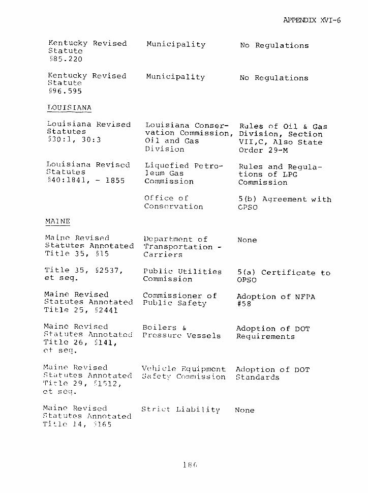
APPENDIX XVI-6
Kentucky Revised Municipality No RegulationsStatute§85.220
Kentucky Revised Municipality No RegulationsStatute§i96. 595
LOUISIANA
Louisiana Revised Louisiana Conser- Rules of Oil & GasStatutes vation Commission, Division, Section`30:1, 30:3 Oil and Gas VII,C, Also State
Division Order 29-M
Louisiana Revised Liquefied Petro- Rules and Regula-Statutes leum Gas tions of LPG§40:1841, - 1855 Commission Commission
Office of 5(b) Agreement withConservation CPSO
MAINE
Maine Revised Department of NoneStatutes Annotated Transportation -Title 35, §15 Carriers
Title 35, §2537, Public Utilities 5(a) Certificate toet seq. Commission OPSO
Maine Revised Commissioner of Adoption of NFPAStatutes Annotated Public Safety #58Title 25, §2441
Maine Revised Boilers & Adoption of DOTStatutes Annotated Pressure Vessels RequirementsTitle 26, §141,et seq.
Maine Revised Vehicle Equipment Adoption of DOTStatutes Annotated Safety Commission StandardsTitle 29, 71512,et seq.
Maine Revised Strict Liability NoneStatutes AnnotatedTitle 14, '165
I B C,

APPENDX XVI-6
MARYLAND
Maryland Annotated State Fire Rules & RegulationsCodes, Art. 38A§3, Marshal, State of the State Fire7, 8 Fire Protection Prevention Commis-
Commission sion, Marylind FirePrevention Code,Rule # 12.03.01.0812.03.01.1612.03.01.21
Maryland Annotated Municipality No RegulationsCodes, art. 32§2
Maryland Annotated Dept. of Natural No RegulationsCodes, art. Resources66C§676
Maryland Annotated MaryLand Port No RegulationsCcdes, art. 62B§5 Administration
Public Service 5(a) Certificate toCommission OPSO
MASSACHUSETTS
Massachusetts Energy Facilities ProceduralGeneral Law, Siting Council RegulationsCh. 164 69I
Massachusetts Department of Massachusetts GasGeneral Law, Public Utilities Distribution Code164,66 et seq., DPU11725f; 5(b) Agree-105A ment with OPSO
Massachusetts Department ofGeneral Law, Ch. Public Safety,148 9 et seq. Fire Marshal*
Massachusetts Department of No RegulationsGeneral Public WorksLaw, Ch. 85 2Bp 15
MICHIGAN
Michigan Compiled Dept. of State Storage, Handling &Laws Annotated Police Use of Inflammable929.3A Liquid and LPG
*Board of Fire Prevention Regulations, FPR 5,7,8,13,14, and 17.
187

APPENDIX XVI-6
Michigan Compiled Dept. of State Transportation ofLaws Annotated Police Flammable LiquidsQ29.5A and Compressed Gases
Michigan Compiled Dept. of State Storage, Handling &Laws Annotated Police Use of Inflammable§29.3A Liquids, Michigan
Administrative Code,R28.6
Michigan Compiled Dept. of State Michigan L.P.G. -Laws Annotated Police R28.3801, R28.40'§29.3A R28.561
Michigan Compiled Dept. ofi State Traffic .. :g 31 eLaws Annotated Police for Vehicles Tra..§29.5A porting Flammable
Liquids - StatePolice Corresponde -eFile: 04.i7, .1
Michigan Compiled Public Service Michigan Gas S-Laws Annotated Commiission Code, R460.14052; 5(a)§483.151 Certificate to OPSO
Michigan Compiled Aeronautics No RegulationsLaws Annotated Conumission§259.51
Michigan Compiled State Construc- No RegulationsLaws Annotated tion Code§125.1503 Comnission
MINNESOTA
Minnesota Statutes State Fire 5(a) CertificaceAnnotated Marshal to OPSO; Storage and§299F.19 Handling of LPG,
Fire MarshalRegulations 11-14
Minnesota Statutes State Fire Flammable andAnnotated Marshal Combustible:;299F.19 Liquids, Fire
Marshal Regulations20-23
1 8i ij
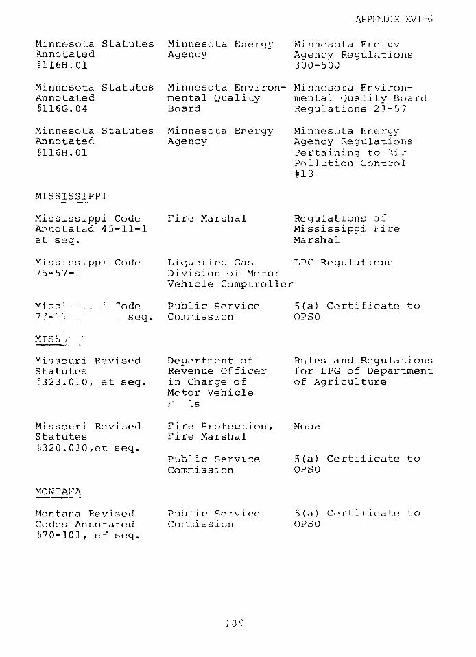
APPENDIX XV-G6
Minnesota Statutes Minnesota Energy Minnesota EnergyAnnotated Agency Agency Regultations§116H.01 300-500
Minnesota Statutes Minnesota Environ- Minnesoca Environ-Annotated mental Quality mental Quality Board§116G.04 Board Regulations 23-57
Minnesota Statutes Minnesota Energy Minnesota EnergyAnnotated Agency Agency Regulations§116H.01 Pertaining to k7ir
Pollution Control#13
MISSISSIPPI
Mississippi Code Fire Marshal Regulations ofAnnotat:d 45-11-1 Mississippi Fireet seq. Marshal
Mississippi Code Liqueried Gas LPG Regulations75-57-1 Division ot Motor
Vehicle Comptroller
M. ode Public Service 5(a) Certificate to7 7- . seq. Commission OPSO
MISS.
Missouri Revised Department of Rules and RegulationsStatutes Revenue Officer for LPG of Department§323.010, et seq. in Charge of of Agriculture
Mctor Vehicle
Missouri Revised Fire Protection, NoneStatutes Fire Marshal§320.01.0,et seq.
Public Servizce 5(a) Certificate toCommission OPSO
MONTAIIA
Montana Revised Public Service 5(a) Certiricate toCodes Annotated Comrlmission OPSO§70-101, et' seq.
:89
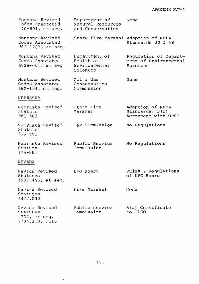
APPENDIX XVI-6
Montana Revised Department. of NoneCodes Annotated Natural ResourcesE70-801, et seq. and Conservation
Montana Revised State Fire Marshal Adoption of NFPACodes Annotated Standa-ds 30 & 58§82-1201, et seq.
Montana Revised Department of Regulation of Depart-Codes Annotated Health ar.n ment of Environmental§82A-601, et seq. Environmental Sciences
Sciences
Montana Revised Oil & Gas NoneCodes Annotated Conservation§60-124, et seq. Commission
NEBRASKA
Nebraska Revised State Fire Adoption of NFPAStatute Marshal Standards; 5(b)M81-502 Agreement with OPSO
Nebraska Revised Tax Commission No RegulationsStatute',6-501
Nebriska Revised Public Service No RegulationsStatute Comntmission§75-501
NEVADA
Nevada Revised LPG Board Rules & RegulationsStatutes of LPG Board§590.465, et seq.
Ne-,ada Revised Fire Marshal loneStatutes§477.030
Nevada Revised Public Service 5(a) CertificateStatutes Commission to ,PSO'7C3, et seq.a704.23.0, .15
J ' ()i
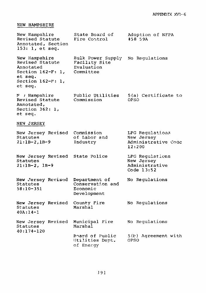
APPENDIX XVI-6
NEW HAMPSHIRE
New Hampshire State Board of Adoption of NFPARevised Statute Fire Control #58 59AAnnotated, Section153: 1, et seq.
New Hampshire Bulk Power Supply No RegulationsRevised Statute Facility SiteAnnotated EvaluationSection 162-F: 1, Committeeet seq.Section 162-F: 1,et seq.
N i Hampshire Public Utilities 5(a) Certificate toRevised Statute Commission OPSOAnnotated,Section 362: 1,et seq.
NEW JERSEY
New Jersey Revised Commission LPG Regulation3Statutes of Labor and New Jersey21:lB-2,lB-9 Industry Administrative Code
12:200
New Jersey Revised State Police LPG RegulationsStatutes New Jersey21:1B-2, 1B-9 Administrative
Code 13:52
New Jersey Revis3ed Department of No RegulationsStatutes Conservation and58:10-351 Economic
Development
New Jersey Revised County Fire No RegulationsStatutes Marshal40A:14-1
New Jersey Revised Municipal Fire No RegulationsStatutes Marshal40:174-120
Board of Public 5(b) Agreement withUtilities Dept. OPSOof Energy
191
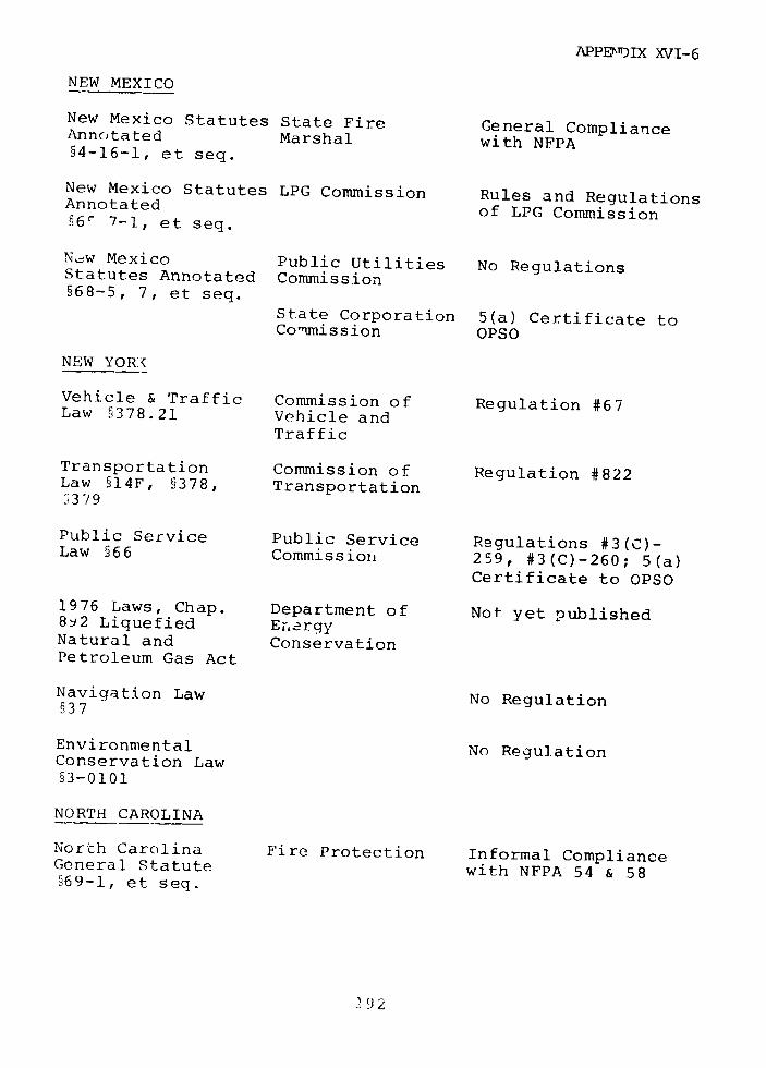
APPENDIX XVI-6
NEW MEXICO
New Mexico Statutes State Fire General ComplianceAnnotated Marshal with NFPA§4-16-1, et seq.
New Mexico Statutes LPG Commission Rules and RegulationsAnnotated of LPG Commission§6r 7-1, et seq.
New Mexico Public Utilities No RegulationsStatutes Annotated Commission§68-5, 7, et seq.
State Corporation 5(a) Certificate toCommission OPSO
NEW YOR.(
Vehicle & Traffic Commission of Regulation #67Law §378.21 Vehicle and
Traffic
Transportation Commission of Regulation #822Law §14F, §378, Transportationj3/9
Public Service Public Service Regulations #3(C)-Law §66 Commission 259, #3(C)-260; 5(a)
Certificate to OPSO
1976 Laws, Chap. Department of Not yet published8s2 Liquefied Er.ergyNatural and ConservationPetroleum Gas Act
Navigation Law No Regulation§37
Environmental No RegulationConservation Law§3-0101
NORTH CAROLINA
North Carolina Fire Protection Informal ComplianceGeneral Statute with NFPA 54 & 58§69-1, et seq.
92
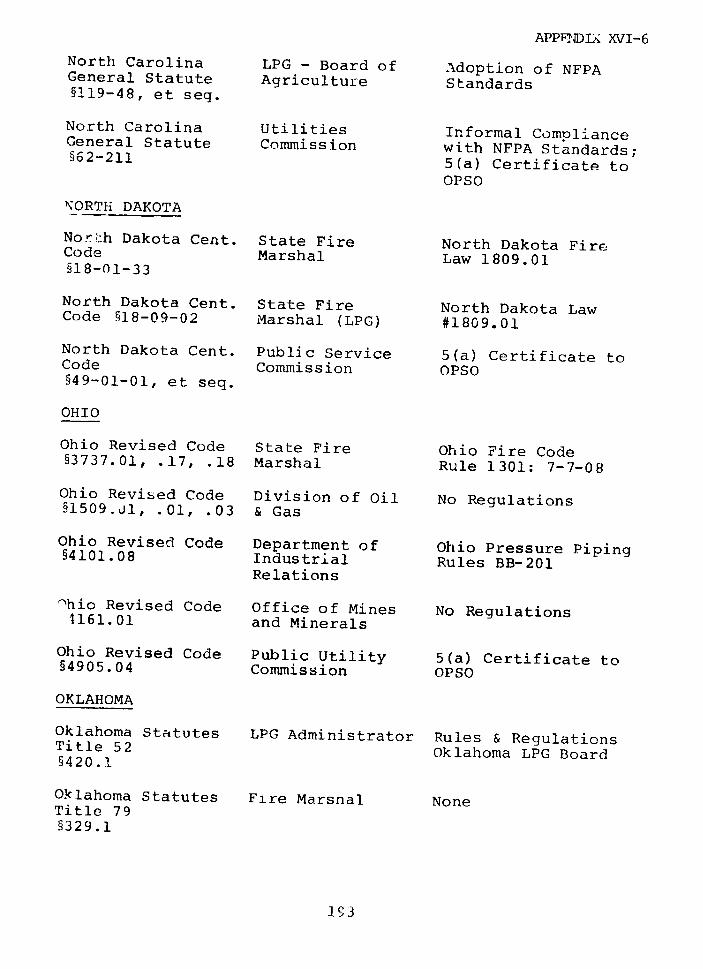
APPFenDIX XVI-6
North Carolina LPG - Board of Adoption of NFPAGeneral Statute Agriculture Standards§119-48, et seq.
North Carolina Utilities Informal ComplianceGeneral Statute Commission with NFPA Standards;§62-211 5(a) Certificate to
OPSO
NORTH DAKOTA
Nor;:h Dakota Cent. State Fire North Dakota FireCode Marshal Law 1809.01§18-01-33
North Dakota Cent. State Fire North Dakota LawCode §18-09-02 Marshal (LPG) #1809.01
North Dakota Cent. Public Service 5(a) Certificate toCode Commission OPSO§49-01-01, et seq.
OHIO
Ohio Revised Code State Fire Ohio Fire Code§3737.01, .17, .18 Marshal Rule 1301: 7-7-08
Ohio Revised Code Division of Oil No Regulations§1509.j1, .01, .03 & Gas
Ohio Revised Code Department of Ohio Pressure Piping§4101.08 Industrial Rules BB-201
Relations
Thic Revised Code Office of Mines No Regulations1161.01 and Minerals
Ohio Revised Code Public Utility 5(a) Certificate to§4905.04 Commission OPSO
OKLAHOMA
Oklahoma Statutes LPG Administrator Rules & RegulationsTitle 52 Oklahoma LPG Board§420.1
Oklahoma Statutes Fire Marshal NoneTitle 79§329.1
193
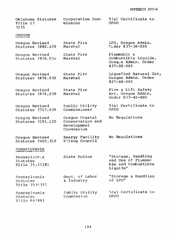
APPENDIX XVI-6
Oklahoma Statutes Corporation Com- 5(a) Certificate toTitle ]7 mission OPSO5151
OREGON
Oregon Revised State Fire LPG, Oregon Admin.Statutes 5480.420 Marsha] Older 837-30-005
Oregon Revised State Fire Flammable &Statutes §476.030 Marshal Combustible Liquids,
Oregun Admin. Order837-20-005
Oregon Revised State Fire Liquefied Natural Gas,
Statutes §476.030 Marshal Oregon Admin. Order827-80-005
Oregon Revised State Fire Fire & Lift Safety
Statutes 5476,030 Marshal Act, Oregon Admin.Order 837-40-005
Oregon Revised Public Utility 5(a) Certificate toStatutes 5757.039 Commissioner OPSO
Oregon Revised Oregon Ccastal No RegulationsStatutes §191.120 Conservation and
DevelopmentColan is sion
Oregon Revised Energy Facility No RegulationsStatutes §469.310 Siting Council
PENNSYLVANIA
Pennsylvanta State Police "Storage, HandlingStatutes and Use of Flamma-Title 35,§1181 ble and Combustible
Liquids"
Pennsylvania Dept. of Labor "Storage & HandlingStatutes & Industry of LPG"Title 35 §]321
Pennsylvania Public Utility 5(a) Certificate toStatutes Commission OPSOTitle 66§461
194
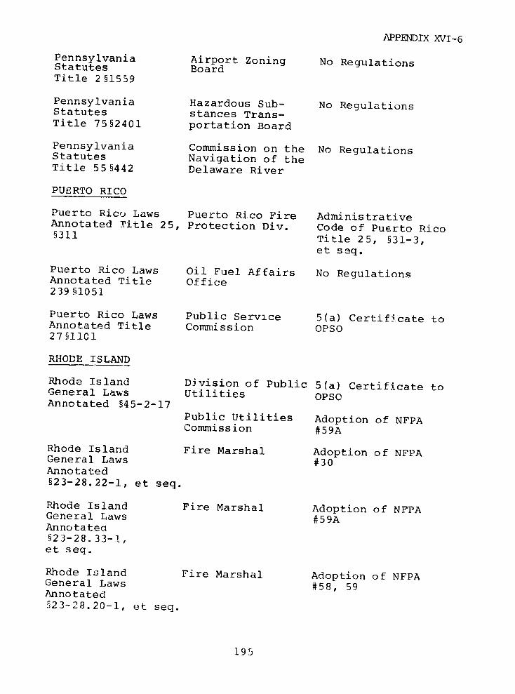
APPENDIX XVI-6
Pennsylvania Airport Zoning No RegulationsStatutes BoardTitle 2§1559
Pennsylvania Hazardous Sub- No RegulationsStatutes stances Trans-Title 75§2401 portation Board
Pennsylvania Commission on the No RegulationsStatutes Navigation of theTitle 55§442 Delaware River
PUERTO RICO
Puerto Rico Laws Puerto Rico Fire AdministrativeAnnotated Title 25, Protection Div. Code of Puerto Rico§311 Title 25, §31-3,
et seq.
Puerto Rico Laws Oil Fuel Affairs No RegulationsAnnotated Title Office239 §1051
Puerto Rico Laws Public Service 5(a) Certificate toAnnotated Title Commission OPSO27§1101
RHODE ISLAND
Rhode Island Division of Public 5(a) Certificate toGeneral Laws Utilities OPSoAnnotated §45-2-17
Public Utilities Adoption of NFPACommission #59A
Rhode Island Fire Marshal Adoption of NFPAGeneral Laws #30Annotated§23-28.22-1, et seq.
Rhode Island Fire Marshal Adoption of NFPAGeneral Laws #59AAnnotated§23-28.33-1,et seq.
Rhode Island Fire Marshal Adoption of NFPAGeneral Laws #58, 59Annotated523-28.20-1, et seq.
195
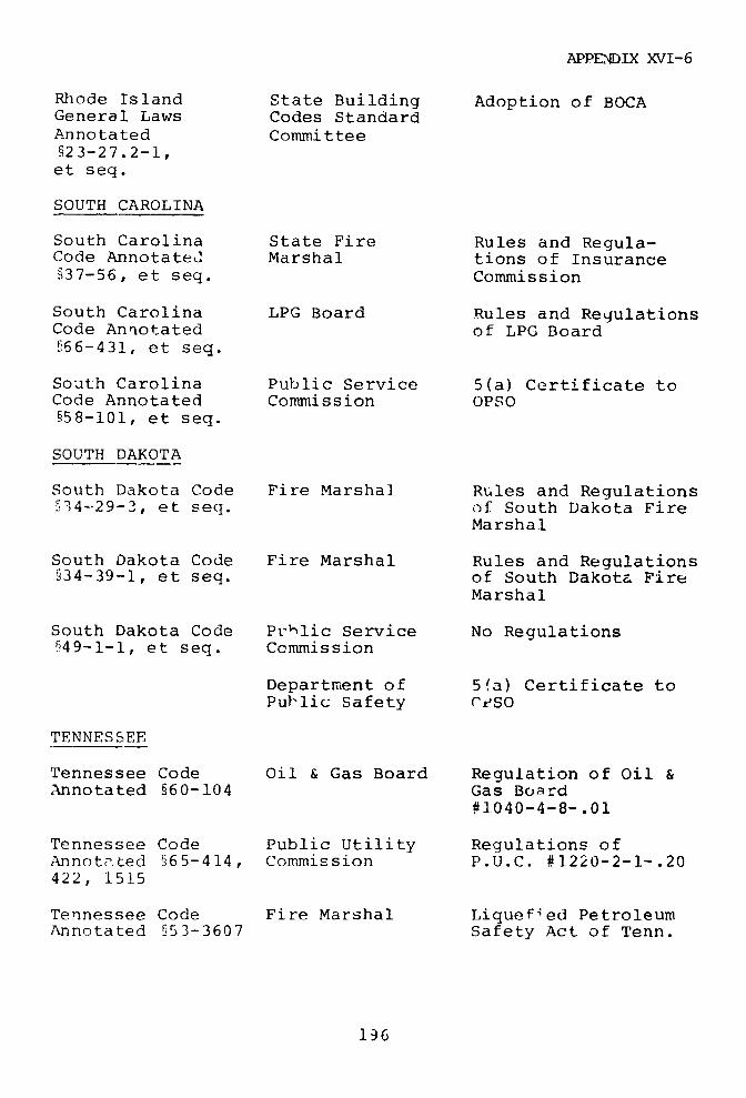
APPENDIX XVI-6
Rhode Island State Building Adoption of BOCAGeneral Laws Codes StandardAnnotated Committee§23-27.2-1,et seq.
SOUTH CAROLINA
South Carolina State Fire Rules and Regula-Code Annotated Marshal tions of InsuranceS37-56, et seq. Commission
South Carolina LPG Board Rules and RegulationsCode Annotated of LPG Board§66-431, et seq.
South Carolina Public Service 5(a) Certificate toCode Annotated Commission OPSO§58-101, et seq.
SOUTH DAKOTA
South Dakota Code Fire Marshal Rules and Regulations§34-29-3, et seq. of South Dakota Fire
Marshal
South Dakota Code Fire Marshal Rules and Regulations§34-39-1, et seq. of South Dakota Fire
Marshal
South Dakota Code Phalic Service No RegulationsA49-1-1, et seq. Commission
Department of 5fa) Certificate toPublic Safety rtSO
TENNESSEE
Tennessee Code Oil & Gas Board Regulation of Oil &Annotated §60-104 Gas Board
#1040-4-8-.01
Tennessee Code Public Utility Regulations ofAnnotated §65-414, Commission P.U.C. #1220-2-1-.20422, 1515
Tennessee Code Fire Marshal Liquefied PetroleumAnnotated §53-3607 Safety Act of Tenn.
136
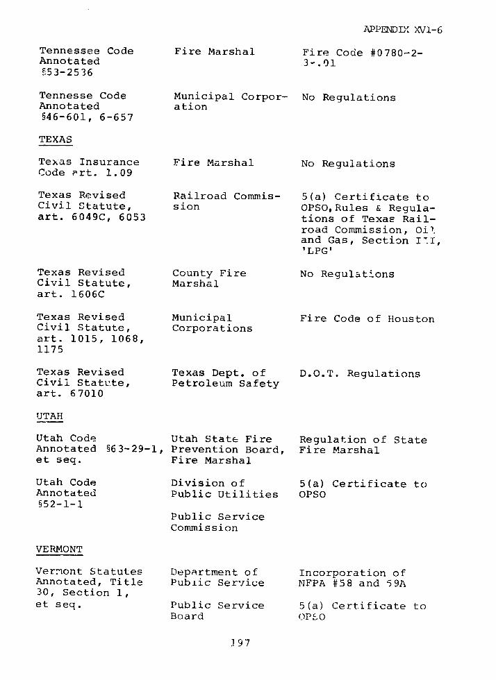
APPENDIX XVI-6
Tennessee Code Fire Marshal Fire Code #0780-2-Annotated 3-.01§53-2536
Tennesse Code Municipal Corpor- No RegulationsAnnotated ation§46-601, 6-657
TEXAS
Texas Insurance Fire Marshal No RegulationsCode art. 1.09
Texas Revised Railroad Commis- 5(a) Certificate toCivil Statute, sion OPSO,Rules & Regula-art. 6049C, 6053 tions of Texas Rail-
road Commission, Oil.and Gas, Section I'I,'LPG'
Texas Revised County Fire No RegulationsCivil Statute, Marshalart. 1606C
Texas Revised Municipal Fire Code of HoustonCivil Statute, Corporationsart. 1015, 1068,1175
Texas Revised Texas Dept. of D.O.T. RegulationsCivil Statute, Petroleum Safetyart. 67010
UTAH
Utah Code Utah State Fire Regulation of StateAnnotated §63-29-1, Prevention Board, Fire Marshalet seq. Fire Marshal
Utah Code Division of 5(a) Certificate toAnnotated Public Utilities OPSO§52-1-1
Public ServiceCommission
VERMONT
Vermont Statutes Department of Incorporation ofAnnotated, Title Pub±ic Service NFPA #58 and 59A30, Section 1,et seq. Public Service 5(a) Certificate to
Board OPSO
]97
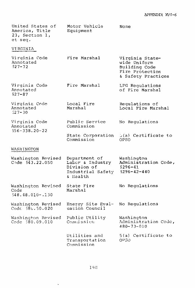
APPENDIX XVI-6
United States of Motor Vehicle NoneAmerica, Title Equipment23, Section 1,et seq.
VIRGINIA
Virginia Code Fire Marshal Virginia State-Annotated wide Uniform§27-72 Building Code
Fire Protection& Safety Practices
Virginia Code Fire Marshal LPG RegulationsAnnotated of Fire Marshal§27-87
Virginia Code Local Fire Regulations ofAnnotated Marshal Local Fire Marshal§27-30
Virginia Code Public Service No RegulationsAnnotated Commission§56-338.20-22
State Corporation ,(a) Certificate toCommission OPSO
WASHINGTON
Washington Revised Department of WashingtonCo~de §43.22.050 Labor & Industry Administration Code,
Division of §296-41Industrial Safety §296-42-440& Health
Washington Revised State Fire No RegulationsCode MarshalS48.48.010- .130
Washington Revised Energy Site Eval- No RegulationsCode §8b.50.020 uation Council
Washinqton Revised Public Utility WashingtonCode §80.09.010 Comluissicr. Administration Code,
480-73-010
Utilities and 5(a) Certificate toTransportation OPSOCommission
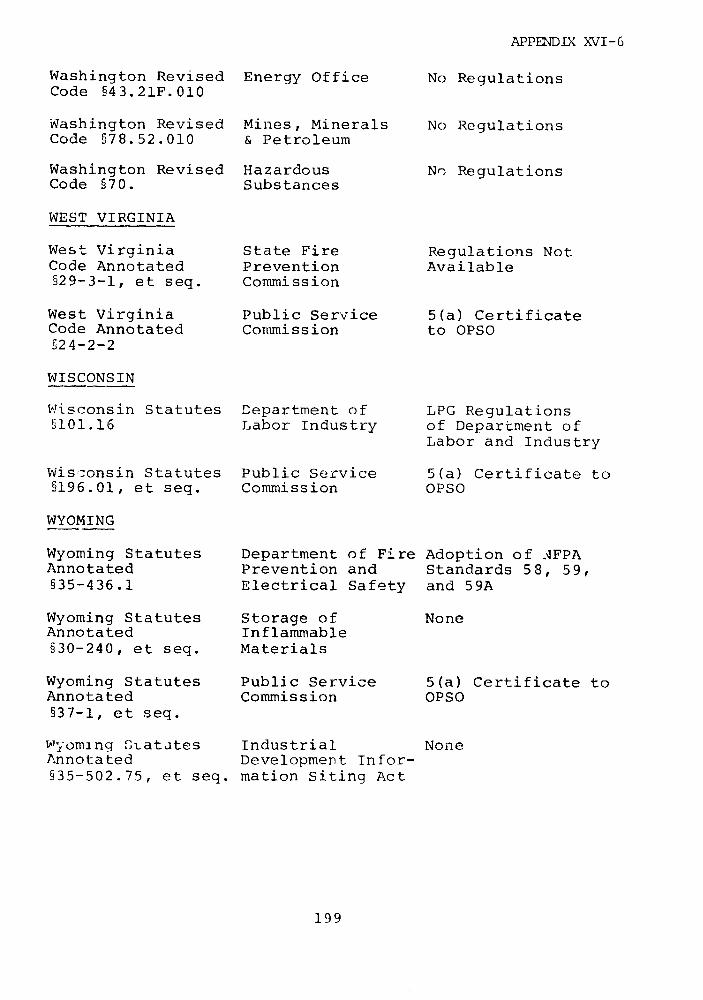
APPENDIX XVI-6
Washington Revised Energy Office No RegulationsCode §43.21F.010
Washington Revised Mines, Minerals No RegulationsCode §78.52.010 & Petroleum
Washington Revised Hazardous Nr RegulationsCode §70. Substances
WEST VIRGINIA
West Virginia State Fire Regulations NotCode Annotated Prevention Available§29-3-1, et seq. Commission
West Virginia Public Service 5(a) CertificateCode Annotated Commission to OPSO§24-2-2
WISCONSIN
Wisconsin Statutes Department of LPG Regulations§101.16 Labor Industry of Department of
Labor and Industry
Wisconsin Statutes Public Service 5(a) Certificate to§196.01, et seq. Commission OPSO
WYOMING
Wyoming Statutes Department of Fire Adoption of AFPAAnnotated Prevention and Standards 58, 59,§35-436.1 Electrical Safety and 59A
Wyoming Statutes Storage of NoneAnnotated Inflammable§30-240, et seq. Materials
Wyoming Statutes Public Service 5(a) Certificate toAnnotated Commission OPSO§37-1, et seq.
Wyoming Statates Industrial NoneAnnotated Development Infor-535-502.75, et seq. mation Siting Act
199
APPENDIX XVIII
CONTENTS PAGE
APPENDIX XVIII--1, APPLICATIONS TO THE FEDERAL POWERCOMMISSION FOR LNG TERMINALFACILITIES 1
XVIII-2, LIST OF SAFETY EVIDENCE PRESENTEDTO THE FEDERAL POWER COMMISSION 3

BLANK
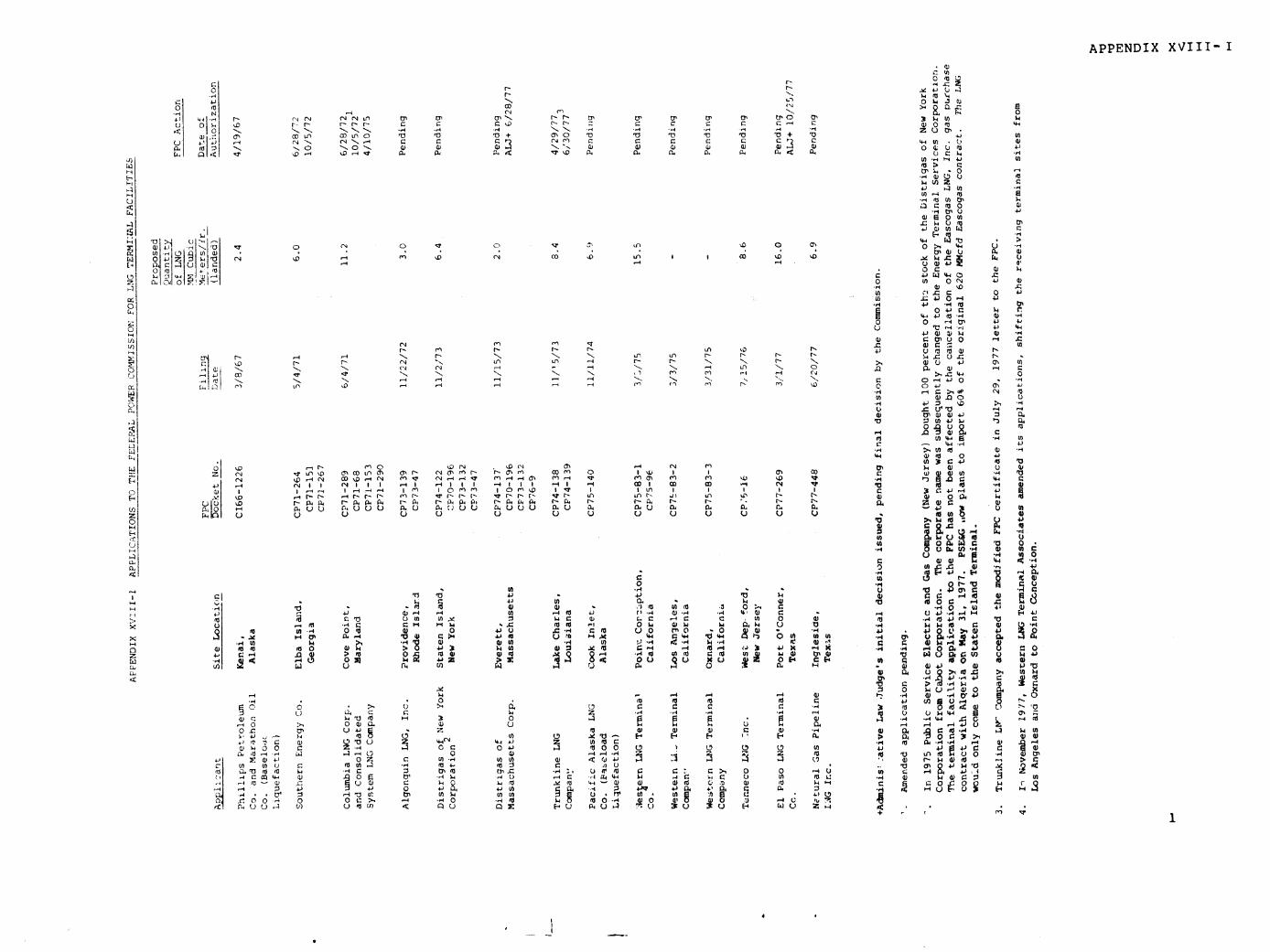
APPENDIX XVIII-I
0~~~~~~~~~~~~~~~~~~~~~~~~~~~~~~~~~~~~~~~~~~~~~~~~~~~ 0¢ . (4:~~~~~~~~~~~~~~~~~~~~~~~~~~~~~~~0~
o -o N %
'-.4 .4 -4 (N11) O4 - U
0~ OD r--r-- -- r)- T:(' 0 4' 474a aar J - NN 4: C 4N Nu N N N -'4 -'O~~4 -,4 N N *-4'. O. .q '- .G '-o4
('JN,-4 '47 'a '47+ '47 Z '-r,
4:'? 4:'? 4: U)~~~~~~~~~~U~
U4) .-4 U(n.- n~4 LO
m~~~~~~~~~~~u o-,o "no '"u ·
tozu ·(4-. ~ ~ ~ ~ r '1 -..
rO v,··r H ~~~~~~~~~~~~~~~~~~~~~~~~~~~~~~~~440U a'(3>~~~ ~ ~~-. -4:O
-43 ~ ~ ~ ~ ~ ~ ~ ~ ~ ~~{ 02 'a-- E-) 0 6; · q;O·
'0 '-4 -4~~~~~~~~~~~~~~~~~~~~~~~~~~~~~~~~~~~~~~~~~~~~~~~~~~~~~~~~~~~~~~~~~~~~~~~~~'4 ,
0L
W~~~~~~~~~~~~~~~~~~~~~~~~ m~Om
· O~ -,-q "~.
cc~~~~~~~~~~~~~~~~~~~~~~~~~~~~~~~~~~~~~~4 U)r 43f
U a) 44 >n
0 ) "44: 0C4 4ID z rq ,0 4 4
0 U] 44: U4 O
t4 l,-l U nI l
0 ICCU)~ A)
a Yi~~~~~~~~~~~~~~~~~~~~~~~~~~~~~~~~~~~~~~~~~~~~~~~~~~~~~~~~~~~~~~~~~~~~~~~~~~~~4zo O m ?-9 Io
-4M.
k~~~~~~~~~~~~~~~~~~~~~~f.-. 04 -q , 0 C ¢ 0-3 ,.,
U)~~~~~~~~~~~~~~~~~~~~~~~~~~~~~~~~~~~~~~~~~~'4- 43 -44-
Ir Ln r-~r
iD .,-i 40 or ~t1U
hrl '..D , -.,
(") (N ',,D c'a ,4D D.
Li M t'- .4: 0) 4:4: U)
(-'43 43~U. 0N
'--~~~~ N N ~~~~~ (~~~C I -4v 4 N - N 0 0-.M 4) id C4 ~ r O I D C -0' '-. a, N Nr N 1 " C) - .4 ( >.M:4
NQ-N O N '4e '- 4 1- 4 - ' N N N 0-4 Q) U .4
OI·. ~~~~~~~~ ~ ~ U ,'C4-) .. .O r
P. P4 at-,,q
O.UU A4 U U ' S ' 0
to:
.~ 1,0 I~ f~,.,) ru
4:- to-4-4~ -
LLct oUU. .
Itin~~~~~~~~ ,4 0) 0 44· 4 -
43N ~ .- ,N ("0 43(N -?~- U A)0'-4 U 0
10 PI e~~~~~~~~~~~~~~~~~~~~~~~~~~~~~~~~~~~~~~,¢= .?_,r :~,..~
.4P~~~~~~~~~~~~~~ ('4 (':I r-d-(4 -44 -I ' I W () " " X' ) U 4 U
N 43 4 I 44"4 I (') I 0"'"' U 04 MU I 4 O A I A I 4
010 (0-.. N.P0 P, n x CNO00 N- N- %- N N U)
HO 'a 'a 4j 4'
-4 ~ ~ ~ ~ ~ ~ ~ ~ ~ ~ ~ ~ ~ ~ ~ ~ ~ ~ ~ ~ ~ ~ ~~~, U)·,4C.--, ,~ 2, '¢ '";? U U M. U U)
0.~~~~~~~~~~~~~~~~~~~~~~~~~~~~~~~~~~~~~~~~~~~~~~~~~~~~4 b. I I 4'A OV· >-V4 4J', A
, ~0 0 w co -f -.4 -0 to w 0, 10 C: $4 4 U .
o
w a vrr,·rl v~~~~~~~~~~~0aw~4 " ~ 14
U) 8 9c U 0 8i t 4
>' - :*' 04 -4 .'-4~ ~~~ ~~~~~~ ~~~~ ~ ~~~~~~~ ,: : 'a ,:: U. *1 Uu ,-. 'a L) ~ ~ ~ ~ ~ 4 C34 U) o-4 4 ) 0 U ) -. 44C- 4 4
LL Alw~ ~ ~ ~ ~ ~ ~ U'4 '' ~ 4' ~ ' 'I.4 - · U-4 3 .
,)-'4 OU) U) 0 440 ¢0-4 0,., 00 4'0 U)U) * '-4 4) . 43 QL'>.U)4J~9
~, ~ ro ,~~~~~~~~~~~~~~~~~~~~~~~-44- 4
10 Z U
U)UU )~ Q. Um-4 .4 kW - -, C:Z 4-' .0) >U) 0~ U)U) )U) ~ 0.-44-,-U ~U 44.40 ').~0 4
64 'a* 4.U'-
4)30C)UU) U P.. E-. 0 r0.H0) 0 U) U) U.C~~~~~~~~~~4~~~~~~~~~0 --4 O >;
_ ., 4.) M 0 0 LD 4J 41 0)~~~~~~~~~~~~U) .
'a 4: (a W a a
14 >1 0 0 1-4U 4i~~~47 0 3U'U)
4 4,-4 -4 -44-4 .C Z O-,4 .Q4 r- r4 ,-4 I "4 A0 t3 t3 U) U) 4: 44m(0 EOU-
,9) 0C(n [* O,,3 ~,, M LQI C. : ' 4 . ,
U 4: 4: 43 Z -'43-'4 4"4 0 '4 U) 0 043444w
0)4: 43'a'U -4 1~ ~ 0 iii n 8 -4 M I U U E4 4&4 '-4 -4 -4 -4430 (L U 4r
'-40 >, 0UOo U) u uu a
U C L) U ) UU U ) U)M Z ) -40 . n U-
+ g
V ~ ~ ~ ~ ~~4 4. (9L c'7 44- 444 4- ' 4- . .O4~ ,U) Q 'a0 Z o 4 4C'4 44~~43 U)U)4: .4 U) 04.4.4 -4 0
cl~330 4 -4 - 0: 032 )0 ( (9 (9 U) 44 PJ 4 : du) U· ~ ~ ~ 4 .0-.( 0 U)·4--4* UU) V- )
i~~~40 -I a. -r-c , g E~ .
· ~ ~ 4:0' 0, 04:> "4 -.4 ·J U)-' 0)0 U) "44 U)*
Oia (f in UIX LI r 0 r r( e c In o pt a ·c(~~~~~~~~~~~~~~~~~~~~~~~~~~~~~+ (.4 (U

BLANK
APPENDIX XVIII-2
APPENDIX XVIII-2
LIST OF SAFETY EVIDENCE PRESENTED TO THE
FEDERAL POWER COMMISSION
At GA'J'S request, the Federal Power Commissionprcvided the following list of exhibits or testimony relatedto the siting and safety of LNG importation projects forwhich applications havw been filed. The projects are listedalphabetically; the descripti-ve details provided in thecitations vary. The list concludes with citations of safetyand siting exhibits or testimony related to three peak-shavingfacilities for which applications have been filed.
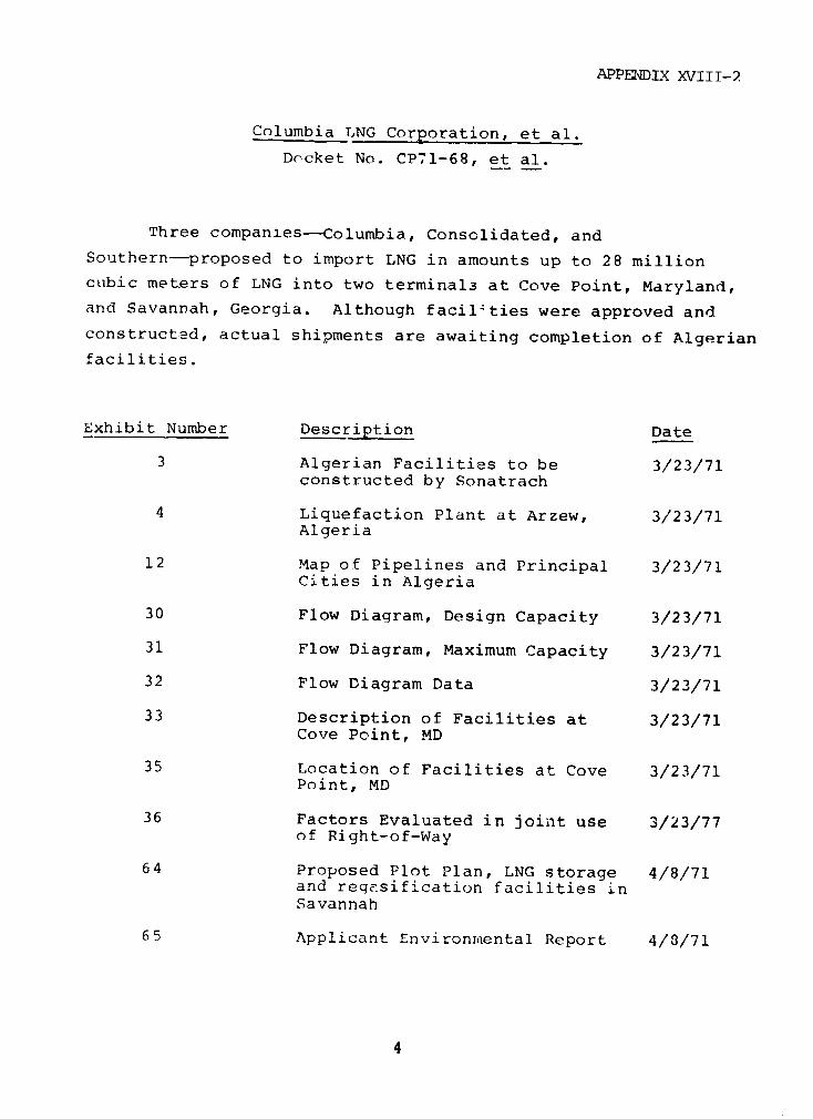
APPENDlX XVIII-2
Columbia LNG Corporation, et al.
Docket No. CP71-68, et al.
Three companies-Columbia, Consolidated, and
Southern-proposed to import LNG in amounts up to 28 million
cubic meters of LNG into two terminals at Cove Point, Maryland,
and Savannah, Georgia. Although facilities were approved and
constructed, actual shipments are awaiting completion of Algerian
facilities.
Exhibit Number Description Date
3 Algerian Facilities to be 3/23/71constructed by Sonatrach
4 Liquefaction Plant at Arzew, 3/23/71Algeria
12 Map of Pipelines and Principal 3/23/71Cities in Algeria
30 Flow Diagram, Design Capacity 3/23/71
31 Flow Diagram, Maximum Capacity 3/23/71
32 Flow Diagram Data 3/23/71
33 Description of Facilities at 3/23/71Cove Point, MD
35 Location of Facilities at Cove 3/23/71Point, MD
36 Factors Evaluated in joint use 3/23/77of Right-of-Way
64 Proposed Plot Plan, LNG storage 4/8/71and regesification facilities inSavannah
65 Applicant Environmental Report 4/8/71
4
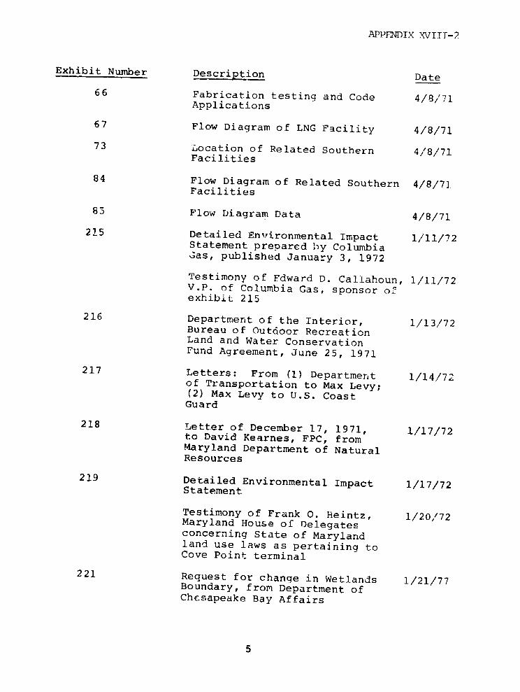
APPElNDIX XVIII-2
Exhibit Number Description Date
66 Fabrication testing and Code 4/8/71Applications
67 Flow Diagram of LNG Facility 4/8/71
73 Location of Related Southern 4/8/71Facilities
84 Flow Diagram of Related Southern 4/8/71Facilities
83 Flow Diagram Data 4/8/71
215 Detailed Environmental Impact 1/11/72Statement prepared by ColumbiaWas, published January 3, 1972
Testimony of Fdward D. Callahoun, 1/11/72V.P. of Columbia Gas, sponsor ofexhibit 215
216 Department of the Interior, 1/13/72Bureau of Outdoor RecreationLand and Water ConservationFund Agreement, June 25, 1971
217 Letters: From (1) Department 1/14/72of Transportation to Max Levy;(2) Max Levy to U.S. CoastGuard
218 Letter of December 17, 1971, 1/17/72to David Kearnes, FPC, fromMaryland Department of NaturalResources
219 Detailed Environmental Impact 1/17/72Statement
Testimony of Frank 0. Heintz, 1/20,/72Maryland House of Delegatesconcerning State of Marylandland use laws as pertaining toCove Point terminal
221 Request for change in Wetlands 1/21/77Boundary, from Department ofChesapeake Bay Affairs
APPENDIX XVIII-2
Distrigas Corporation
Docket Nos. CP70-196 and CP73-135
Distrigas proposed to import over a 20 year period
approximately 610,000 cubic meters pet year of LNG from Algeria
at its Everett, Massachusetts terminal and at a terminal on
Staten Island, New York. By Commission Opinion No. 613 issued on
March 9, 1972 (47FPC752) Distrigas proposal was approved;
however, the Everett terminal facilities were not fully declared
within the Commission'- jurisdiction until the issuance of an
order on June 14, 1977. The Staten Island terminal has never
been certificated but is involved in a pending
proceeding-EASCOGAS incorporated, et al. Docket Nos., CP73-47 et
al. The environmental and safety questions with the terminal are
presently before tbh. conunission.
Exhiibit No. or Description of ExhibitTranscript Citatior or Testimony
2 TLocation Map of LNG Marine Import Terminalat Everett, Massachusetts
3 Schematic Illustration of Facilities atEverett
4 Layout of Facilities
Cross-section of Tank Design
6 Contracts with Chicago Bridge and IronCompany and with Perini Corporation
Location of Facilities to be Constructedon Staten Island
3 Layout of Staten Island Facilities
General Layout of LNG Barge to beConstructed
Ship Arrival Schedule for 3 years
6
APPENDIX XVIII-2
Exhibit No. or Description of ExhibitTranscript Citation or Testimony
11 Inventory Profiles for Everett andStaten Island Terminals
12 Projected Construction Cost of Everettinstallation, Staten Island installation,and LNG Barge
13 Summary of Projected Operating andMaintenance Expenses for First 3 yearsof Operations. (For Everett and New York)
24 Relevant State and Local ConstructionCodes and Permits
25 Sonatrach/Alocean contract datedSeptember 10, 1970.
26 Gazocean/Alocean Contract CokveringTransportation of the LNG to be soldto Distriaas
27 Summary Description of plan forFinancing Proposed Facilities
28 English translation of LNG Sales Agreementbetween Distrigas Corp. and 'locean datedDecember 3, 1969
29 English Translation of LNG SalesAgreement between Distrigas Corporationand Alocean aated September 10, 1970
Tr. Volume R-5 Testimony of Staff Witness, John Leisson Geology
Tr. Volume R-5 Testimony of Dudley Chelton from NationalBureau of Standards
Tr. Volume R-4 Statements taken at local hearing inBoston, Massachusetts
Tr. Volume 8 Testimony of J.A. MacKay on LNG contractand construction codes and permits
Tr. Volume 10 Testimony of D.W. Oakley on LNG Policy
Tr. Volume 11 Testimony of Norton Sloan on LNG terminalfinancing
7
APPENDIX XVIII-2
Exhibit No. or Description of ExhibitTranscript Citation or Testimony
Tr. Volumes 11and 12 Testimony of Jacek Makowski on LNG
contracts
Reference E-1 Final Environmental Impact Statement
Reference E-2 NBS Cryogenic Division Report on theEverett LNG terminal engineering design
Tr. Volume R-5 Testimony of staff witness RobertArvedlund on Safety
Tr. Volume R-5 Tetimony of Staff witnesses John E. Estepand Fortunato R. Barceluna on environ-mental impact statement.
June 28, 1977 Initial Decision of Administrative LawJudge on Safety Issues
Tr. Volume 46 ofCP73-47 et al. Testimony of Captain Cassidy of Boston
Harbor
APPENDIX XVIII-2
Distrigas Corporation
Docket Nos. CP76-9 et al.
Distrigas proposed to import over an 18 month period
increased quantities of LNG from Algeria into its Everett
Massachusetts terminal. Because of difficulties in Algeria, itappears that no deliveries will ever be made under the program.
Exhibit Description
Item D Final Environmental Impact Statement
Item A Environmental Report Filed September 16,1975, Part of CP76-9 application
Item B LNS sales contract, part of CP76-280application

APPENDIX XVIII-2
Distrigas of Massachusetts Corporation
Docket Nos. CP77-216, et al.
Distriqas of Massachusett3 Corporation and Distrigas
Corporation propose to increase their imported quantities of LNGfrom Algeria to approximately 1.8 million cubic meters annuallyfor 20 years, in addition to modifying its Everett terminalfacilities. This is currently under Staff review.
Exhibit orTranscript Description
G to CP77-216 aop. Flow Diagrams
E to CP77-Z18 app. LNG Contract
Z to CP77-21C app. Environmental Report
Response todeficiency questionsfiled May 27, 1977 Additional Facility Information
Joint Hearing Testimony of Abdelmadjid Kazi Tani onTranscript 1 Algerian LNG Facilities
Joint Hearing Testimony of Tayeb Mazouni on AlgerianTranscript 2 LNG Policy
10

APPENDIX XVIII-2
Eascogas LNG Inc.
Docket No. CP73-47
Eascogas proposed to import into the United States from
Algeria an aggregate of 190 million cubic meters of liquefied
natural gas over a twenty year period to terminals constructed at
Staten Island, New York, and Providence, Rhode Island. Iiearing9
were held beginning in September of 1973; however, no final
decision has ever been made on this case since the Applicants
have continually revised, modified, or refined their proposal.
The basic LNG contract with Algeria has been mutually rescinded
but negotiations may resume towards the gcal of formulating a new
contract with a lesser volume of LNG tc be purchased.
Exhibit No. orTranscript Citation Description
Tr. Volume 1-A/161-193; Tr. Volume1; Tr. Volume 2/ Testimony of James Randel, Jr., on LNG795-848 Contract and Policy
Tr. Volume 1-A/229-254; Tr. Testimony of Bertrand L. DeFrondevellteVolume 3 on LNG shipping Services
Tr. Volume 1-A/ Testimony of David Hellstrom on229-254; Tr. environmental impact of Staten IslandVolume 4 Project
Tr. Volume 1-A/260-278; Tr. Testimony of Rolf Glasfeld on shippingVolume 4, 8 design and safety
Tr. Volume 1-A/279-300; Tr. Testimony of Captain Sorie L. Knox onVolume 5, 6 LNG shipping safety procedures
Tr. Volume 1-A/301-314; Tr. Testimony of Donald S. Allen on risksVolume 7, 8, 9, 10 of LNG cargo release
11
APPENDIX XVIII-2
Exhibit No. orTranscript Citation Description
Tr. Volume 1-A/315-325; Tr. Testimony of Jesse M. Calhoun of AFL-Volume 9 CIO on LNG shipping
Tr. Volume 1-A/ Testimony of Eugene L. McCahe of325-529 AFL-CIO on LNG shipping and
construction
Tr. Volume 1-A/393-406; Tr. Testimony of James Watson on AlgerianVolume 6, 85 LNG Supply
Tr. Volume 1-A/ Testimony of Sid Ghozali on Algerian407-414 LNG policy
Tr. Volume 1-A/ Testimony of John B. Thorn on LNG432-444; Tr. Policy relative to Providence, RhodeVolume 20 Island site
Tr. Volume l-B/ Testimony of William Coates on474-507; Tr. Providence R.I. site selectionVolume 14. 17
Tr. Volume 1-B/508-514; Tr. Testimony of Stanley Dale onVolume 15, 16 LNG risks at Providence
Tr. Volume 1-B/515-533; Tr. Testimony of David Hellstrom onVolume 14, 15 Providence environmental impact
Tr. Volume 1-B/590-609; Tr. Testimony of Galen E. Jones on en-Volume 16 vironmental impact on Providence site
Exhibit No. 9 Coast Guard Regulations Governing shipoperations
Exhibit No. 10 Summary of LNG transportation on water
Exhibit No. 11 The Collision Resistance 9 f theGeneral Dynamic 125,000 M Ship
Exhibit Nc. 12 Probabilities of Collision and DamageAifecting the General Dynamics 125,000M Ship
Exhibit No. L3 Acceptability of Risks
12
APPENDIX XVIII-2
Exhibit No. orTranscript Citation Description
Exhibit No. 14 Thermal Radiation Hazards fromn BurningPool of LNG
Exhib.t No. 34 Artist's Rendering Showing the Plant Site
Exhibit No. 35 General Plan of Providence Facility
Exhibit No, 36 Preliminary Engineering Decision forProvidence Terminal
Exhibit No. 37 Proposal 2 Tank Plan lire ProtectionSystem
Exhibit No. 38 Pertinent Codes and Standards
Item by Ref. G Report of Algonquin Company concerningNEPA
Tr. Volume 20/2620-2632; Tr.Volurre 21/12716- Testimony of R. A. Yowell of Maritime2729 Administration on CDS program
Tr. Volume 20/2633-2648; Tr. Testimony of Richard Norman ofVolume 21/2730- Maritime Administration on loan2792 Guarantee program
Tr. Volura 20/2649-26:6; Tr. Testimony of Morman Hammer ofVolume 21/2793- Maritime Administration on LNG ship2798 engineering and costs
Exhibit No. 65 Percentage of Competition of VesselsC of 9-30-73
Exhibit No. 66 Letters to Coast Guard and Replies
Item by Ref. CC Letter of Commitment MARAD
Tr. Volume 23/ Testimony of Willia:m Donahue of2825-2962 Staten Island City Planning Dept. on
LNG site environments
Exhibit No. 67 Staten Island Pictures
Exhibit No. 68 Population Estimates
13

APPENDIX XVIII-2
Exhibit No. orTranscript Citation Description
Exhibit No. 69 Map, Borough of Richmond, NY City
Tr. Volume 2412977-3096; 25/ Testimony of James A. Fay on3122-3266 LNG hazards
Tr. Volume 27/ Rebuttal testimony of D. S. Allen3410-3451 To James Fay
Tr. Volume 26Tr. Volume 28 Testimony of E. Saltz populationTr. 3461-3474 estimates of Staten Island area
Tr. Volume 30/3541-3543; Tr. Testimony of Theodore Needles ofVolume 41 FPC staff on risk analysis
Tr. Volume 30,/3544-3546; Testimony of Carl N. Shusten, Jr.Tr. Volume 33;34 on alternatives for FPC staff
Tr. Volume 30/3547-3550; Tr. Testimony of Lawrence Boesch forVolume 36 FPC Staff on LNG vapor clouds
Tr. Volume 30/ Testimony of Theodore Horner for3550-3551; Tr. FPC Staff on probability riskVolume 37, 38 assessment of LNG hazards
Tr. Volume 30/3552-3555; Tr. Testimony of Lillian Stone ofVolume 35, 36, FPC Staff on LNG Safety and risk39, 40 assessment
Tr. Volume 30/3556-3560; Tr. Testimony of R.K. Arvedlund of FPCVolume 31, 32, 36 Staff on environmental impacts and safety
Tr. Volume 30/3561-3562; Tr. Testimony of George R. Kelly of FPCVolume 33 Staff on LNG plume dispersion
Tr. Volume 30/3564-3566 Testimony of Douglas Kleinsmith of3581-1637 FPC Staff on Water Quality
14
APPENDIX XVIII-2
Exhibit No. orTranscript Citation Description
Tr. Volume 30/3568-3570; Tr. Testimony of Robert Jimesren of FPCVolume 35 Staff on Alternatives
Tr. Volume 30/3571-3574; 3627- Testimony of Jonathan D. Isaacs on3690; Tr. Vol. 31 population for FPC Staff
Exhibit No. 501 Environrental Impact Statement -Staten Island
Exhibit No. 500 Cryogenic Safety Report StatenIsland
Tr. Vol. 42, 43 Testimony uf Captain Linde andCommander Kline of Coast Guard onvessel LNG design and requirements
Tr. Volume 44 Testimony of Captain Moser of CoastGuard on LNG port Safety Laws
Tr. Volume 44,45 Testimony of William McConnaugheyof Coast Guard on LNG hazards
Tr. Volume 45 Testimony of Captain Oliver ofCoast Guard on N.Y. Port Plans
Tr. Volune 46 Testimony of Captain Oliver ofCoast Guard on Safety
Tr. Volume 46 Testimony of Captain Cassidy ofCoast Guard on Boston Point plans
Tr. Volume 48,49 Testimony of D. Kleinsmith of FPCStaff on Aquatic impact of Providenceterminal
Tr. Volume 48,50 Tastimony of Jonathan Isaacs of FPC Staffon climate, land ore, and socio-economicimpact
Tr. Volume 48,49 Testimony of R. Arverlund of FPC Staffon environmental impact of Providenceterminal
Tr. Volume 48,50 Testimony of Carl Shuster of FPC Staffon Alternatives to Providence terminal
15
APPENDIX XVIII-2
Exhibit N,. orTranscript Citation Description
Tr. Volume 48 Testimony of Geone Kelly for FPC Staff onLNG plume dispersion for Providenceterminal
Tr. Volume 48 Testimony of Lawrence Boesclh for FPCStaff on LNG spills
Tr. Volume 48,51 Testimony of Theodore Horner for FPC Staffon LNG probability risk assessment forProvidence terminal
Tr. Volume 48,50, Testimony of Theodore Needles of FPC Staff31 on Safety and risk analysis of Providenceterminal
Exhibit No. 73 Cryogenic Safety Review Providence RI
Exhibit No. 74 Final Environmental Impact Statement -Providence
Tr. Volume 52,51 Testimony of Robert Jimeson on alternativeenergy sources to Providence proposal
Tr. Volume 52 Testimony of William Coates on engineeringof Providence LNG terminal
Tr. Volume 52 Testimony of Robert Sweeney for RhodeIsland Co=sumer's Council on adverseimpact of a Providence terminal
Exhibit ?wo. 76 LNG terminal and marine facility schematic
Tr. Volume 53,55 Testimony of Thomas Ruch for New York CityFire Department
Tr. Volulme 53,55 Testimony of Augustus Beekman for NewYork City Fire Department
Tr. Volume 53,54 Testimony of James Love for New York CityFire Department
Tr. Volume 53,54 Testimony of Milton Fishkin for New York55 City Fire Department
Tr. Volume 53,57 Testimony of Paul Buzse for New York CityIncorporated Economic Development Councilfor the LNG project
16

APPENDIX XVIII-2
Exhibit No. orTranscript Citation Description
Tr. Volume 53,65 Testimony of Gerald O'Driscott on shipping
Tr. Volume 53,66 Testimony of Eugene R. Hanson on marineimpact for New York City Dept. of WaterResources
Tr. Volume 53,66 Testimony of Anthony Galande for New YorkCity on LNG barge operations
Tr, Volume 53,57 Testimony of Harold Nudelman of New YorkCity on fog
Tr. Volume 53,67 Testimony of Douglas Powell for PublicAdvocate of New Jersey on LNG risks
Tr. Volume 53, 65 Testimony of Joseph Jugan for NJ PublicAdvocate on NJ Fire Fighting Facilities
Tr. Volume 53,60 Testimony of Dr. Donovan for NJ PublicAdvocate on Safety
Tr. Volume 53,59 Testimony of Peter Hunt on siting60 analysis
Tr. Volume 53,66 Testimony of Richard Lapinski for Townof Woodbridge, NJ, on NJ environs andrisks
Tr. Volume 53,60 Testimony of Norman Hamlin on LNG shipcollision risks
Tr. Volume 53,67 Testimony of Jon Schoenhorn on U.S.Coast Guard materials
Tr. Volume 53,63 Testimony of Dr. William Fairley on64 LNG risk assessment methodology
Tr. Volume 53,61 Testimony of William Baxan on LNG riskassessment methodology
Tr. Volume 53,62 Testimony of Dr.'Borjess on environ-mental impact statement analysis
Tr. Volume 53,64 Testimony of James Fay on LNG spillsand risks
17

APPENDIX X;IIT-2
Exhibit No. orTranscript Citation Description
Tr. Volume 53 Testimony of Helen Niedham on environ-mental impact requirements
Exhibit 503 Distrigas Facility Criteria 1
Exhibit 505 Pre-Fire Plan
Exhibit 507 Pre-Fire Plan for LNG Barge Shipment
Exhibit 508 Update of Coast Guard contingency plan
Exhibit 509,510 Charts of N.Y. Harbor
Exhibits 511-515 Climatological Data
Exhibit 516 Environmental Guide for 7 ports
Exhibit 517 Industrial Development MiddlesexCounty
Exhibit 519 EPA's Comment to FEIS
Exhibit 520 Raritan Bay Hazard Zone Map
Exhibit 530 Probable Outflow from LNG vessel
Exhibit 524,525 List of Studies
Tr. Volume 54,59 Testimony of Victor Rossi for City ofNew York on vessel operations
Exhibit 542 LNG impact siting risk and impact study
Exhibit 543 Preliminary tanker collision andgrounding analysis
Item by Ref. I-R Unconfined Vapor Cloud Explosions
Exhibit 545 Comparison of Equations relating topool size and spill size
Tr. Volumes 68, Testimony at local hearing in Providence,68A, 69 Rhode Island by interested parties
Tr. Volumes 70,71 Testimony at local hearing in StatenIsland, New York by 40 interestedparties and statements by 16 interestedparties
18
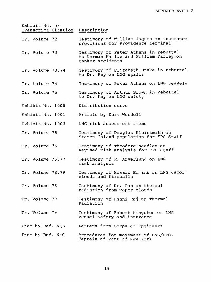
APPEIDIX XVIII-2
Exhibit No. orTranscript Citation Description
Tr. Volume 72 Testimony of William Jaques on insuranceprovisions for Providence terminal
Tr, Volume' 73 Testimony of Peter Athens in rebuttalto Norman Hamlin and William Farley ontanker accidents
Tr. Volume 73,74 Testimony of Elizabeth Drake in rebuttalto Dr. Fay on LNG spills
Tr. Volume 74 Testimony of Peter Athens on LNG vessels
Tr. Volume 75 Testimony of Arthur Brown in rebuttalto Dr. Fay on LNG safety
Exhibit No. 1000 Distribution curve
Exhibit No. 1001 Article by Kurt Wendell
Exhibit No. 1003 LNG risk assessment items
Tr. Volume 76 Testimony of Douglas Kleinsmith onStaten Island population for FPC Staff
Tr. Volume 76 Testimony of Theodore Needles onRevised risk analysis for FPC Staff
Tr. Volume 76,77 Testimony of R. Arverlund on LNGrisk analysis
Tr. Volume 78,79 Testimony of Howard Emmins on LNG vaporclouds and fireballs
Tr. Volume 78 Testimony of Dr. Pan on thermalradiation from vapor clouds
Tr. Volume 79 Testimony of Phani Raj on ThermalRadiation
Tr. Volume 79 Testimony of Robert Kingston on LNGvessel safety and insurance
Item by Ref. N-B Letters from Corps of Engineers
Item by Ref. N-C Procedures for movement of LNG/LPG,Captain of Port of New York
19

APPENDIX XVIII-2
Exhibit No. orTranscript Citation Description
Tr. Volume 81,82 Testimony of Richard Morel aboutStaten Island Terminal
Tr. Volume 83 Testimony of Campbell Anderson on shipinsurance cargo and liability
Tr. Volume 85 Testimony of Abdel Madjid on SonatrachLNG facilities
Tr. Volume 87 Testimony of Eugene Logan on StatenIsland revised project
Exhibit No. 1002 Supplement to FEIS on Staten Island
Exhibit No. 1005 Visible Flame Heights
Exhibit No. 1006 On the Burning of a large flammable vaporcloud
Exhibit No. 1007 Number of LNG vessels in operation
Exhibit No. 1008 History of LNG Transportation
Item by Ref. N-A Booz-Allen report for MaritimeAdministration
item by Ref. N-B Letters and replies involving Corps ofEngineers
Item by Ref. N-E Report of Japanese Collision
20
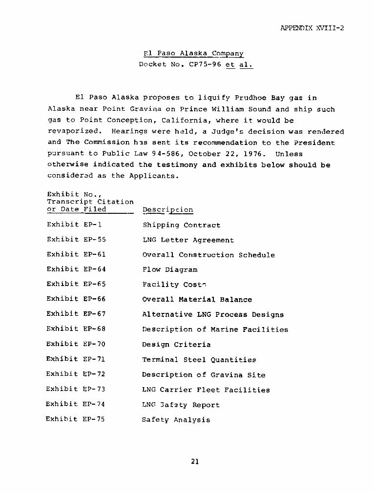
APPENDIX XVIII-2
El Paso Alaska Company
Docket No. CP75-96 et al.
El Paso Alaska proposes to liquify Prudhoe Bay gas in
Alaska near Point Gravina on Prince William Sound and ship such
gas to Point Conception, California, where it would be
revaporized. Hearings were held, a Judge's decision was rendered
and The Commission has sent its recommendation to the President
pursuant to Public Law 94-586, October 22, 1976. Unless
otherwise indicated the testimony and exhibits below should be
considered as the Applicants.
Exhibit No.,Transcript Citationor Date Filed Descripcion
Exhibit EP-1 Shipping Contract
Exhibit EP-55 LNG Letter Agreement
Exhibit EP-61 Overall Construction Schedule
Exhibit EP-64 Flow Diagram
Exhibit EP-65 Facility Costi
Exhibit EP-66 Overall Material Balance
Exhibit EP-67 Alternative LNG Process Designs
Exhibit EP-68 Description of Marine Facilities
Exhibit EP-70 Design Criteria
Exhibit EP-71 Terminal Steel Quantities
Exhibit EP-72 Description of Gravina Site
Exhibit EP-73 LNG Carrier Fleet Facilities
Exhibit EP-74 LNG 3afety Report
Exhibit EP-75 Safety Analysis
21

APPENDIX XVIII-2
Exhibit No.,Transcript Citationor Date Filed Description
Exhibit EP-76 LNG Report
Exhibit EP-77 Letter Agreement on LNG Contract
Exhibit EP-78 Economics of LNG Shipping
Exhibit EP-123,124 Flow Diagrams
Exhibit EP-125,126 LNG Technical Documents
Exhibit EP-143 LNG site slides
Exhibit EP-154 Capital and operating costs
Exhibit EP-156 Estimated steel quantities for terminal
Exhibit EP-157,158, LNG Fleet costs159, 160, 162
Exhibit EP-176,177, LNG Plant Costs, Scheduling and Manpower178, 179, 180, Requirements181, 182, 183,184, 185, 186,187 188, & 189
Exhibit EP-196 Alternative terminal design and coststhru 230
Exhibit EP-254 Financing and how lenders view the risksof the project
Exhibit AP-13 The alternatives "A Summary of ThreeProposals to Move Prudhoe Bay Gas"
Item by Ref. EP-C Net National economic benefits andrisk analysis by DOI
Exhibit ST-22 Draft Environmental Impact StatementDEIS, Volume II on LiquificationFacilities
Exhibit ST-23 DEIS on revaporization facilities
Exhibit ST-19 Final Environmental Impact StatementFEIS, Volume II on liquefactionfacilities
22

APPENDIX XVIII-2
Exhibit No.,Transcript Citationor Date Filed Description
Exhibit ST-18 FEIS Conclusions
Exhibit ST-36 Slide presentation of terminal sites
Exhibit AA-25 Earthquake Criteria Data
Exhibit AA-74 LNG Transportation Cost Analysisthru 82
Tr. Volumes 13,14 Testimony of Howard Boyd on LNG15 Plicy
Tr. Volumes 44,45 Testimony of G.H. Tseklenis on LNG93, 170 terminal engineering
Tr. Volumes 45,46 Testimony of Alfred Sacken on LNG93 liquefaction engineering
Tr. Volume 47 Testimony of Horstman G. Freytagon LNG Safety
Tr. Volumes 51,52 Testimony of Ivan W. Schmitt on LNG53, 54, 94, & 95 Marine Transportation
Tr. Volumes 54,57 Testimony of Joseph Porricelli on LNGcarrier safety
Tr. Volumes 57,60 Testimony of Robert McCollom on environ-61 mental impact and LNG site selection
Tr. Volumes 49,50 Testimony of James E. Harris on LNG siteselection
Tr. Volumes 89,90 Testimony on how lenders perceive LNG91 risks by L. Katzenback and S. Lewand
Tr. Volume 94 Testimony of Robert Gibson on designcriteria of marine terminal
Tr. Volume 94 Testimony of William Jarda on marineterminal costs
Tr. Volume 90 Testimony of Benjamin S. Hadad onshipping costs
Tr. Volume 164 Testimony of Arthur Darrow III onseismic conditions at LNG site
23
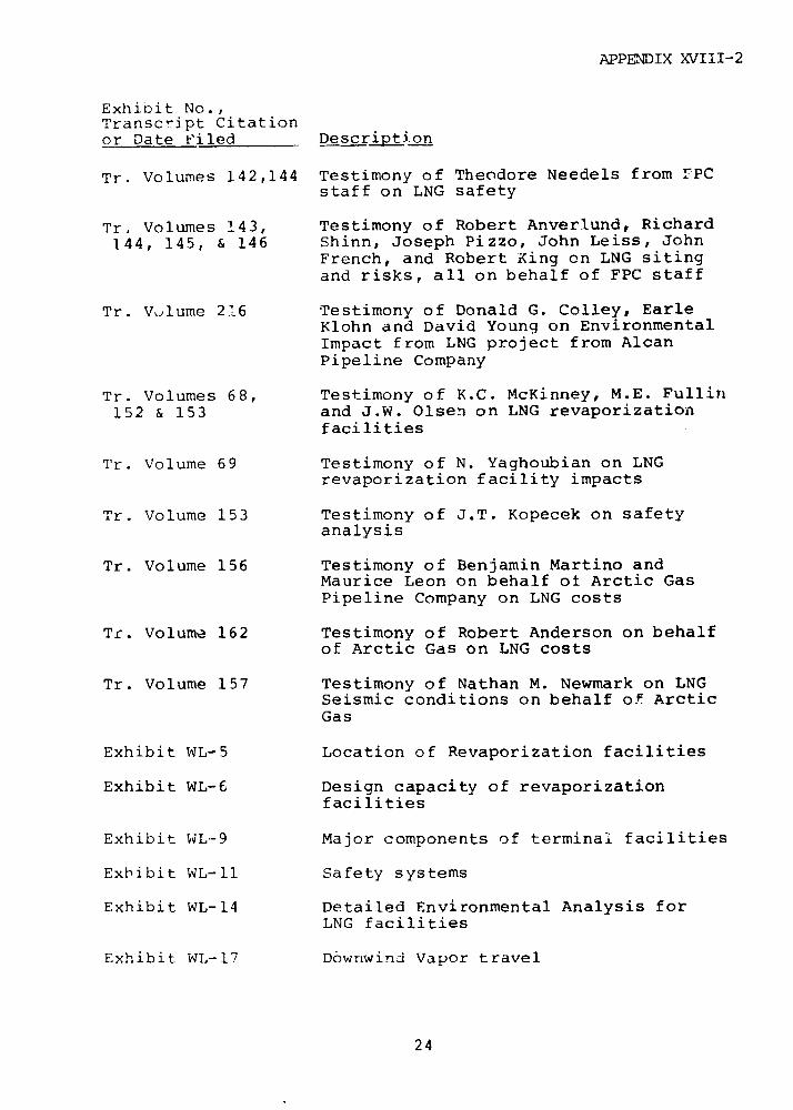
APPENDIX XVIII-2
Exhibit No.,Transcript Citationor Date Filed Description
Tr. Volumes 142,144 Testimony of Theodore Needels from rPCstaff on LNG safety
Tr. Volumes 143, Testimony of Robert Anverlund, Richard144, 145, & 146 Shinn, Joseph Pizzo, John Leiss, John
French, and Robert Xing on LNG sitingand risks, all on behalf of FPC staff
Tr. Volume 216 Testimony of Donald G. Colley, EarleKlohn and David Young on EnvironmentalImpact from LNG project from AlcanPipeline Company
Tr. Volumes 68, Testimony of K.C. McKinney, M.E. Fullin152 & 153 and J.W. Olsen on LNG revaporization
facilities
Tr. Volume 69 Testimony of N. Yaghoubian on LNGrevaporization facility impacts
Tr. Volume 153 Testimony of J.T. Kopecek on safetyanalysis
Tr. Volume 156 Testimony of Benjamin Martino andMaurice Leon on behalf ot Arctic GasPipeline Company on LNG costs
Tr. Volume 162 Testimony of Robert Anderson on behalfof Arctic Gas on LNG costs
Tr. Volume 157 Testimony of Nathan M. Newmark on LNGSeismic conditions on behalf of ArcticGas
Exhibit WL-5 Location of Revaporization facilities
Exhibit WL-6 Design capacity of revaporizationfacilities
Exhibit WL-9 Major components of terminal facilities
Exhibit WL-11 Safety systems
Exhibit WL-14 Detailed Environmental Analysis forLNG facilities
Exhibit WL-17 Downwind Vapor travel
24
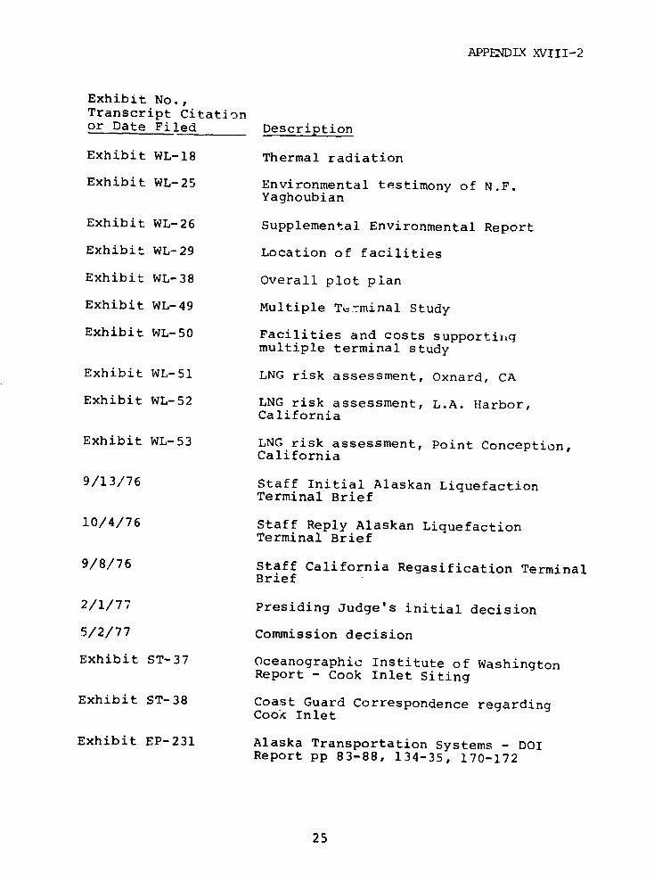
APPENDLX XVIII-2
Exhibit No.,Transcript Citationor Date Filed Description
Exhibit WL-18 Thermal radiation
Exhibit WL-25 Environmental testimony of N.F.Yaghoubian
Exhibit WL-26 Supplemental Environmental Report
Exhibit WL-29 Location of facilities
Exhibit WL-38 Overall plot plan
Exhibit WL-49 Multiple Terminal Study
Exhibit WL-50 Facilities and costs supportinqmultiple terminal study
Exhibit WL-51 LNG risk assessment, Oxnard, CA
Exhibit WL-52 LNG risk assessment, L.A. Harbor,California
Exhibit WL-53 LNG risk assessment, Point Conception,California
9/13/76 Staff Initial Alaskan LiquefactionTerminal Brief
10/4/76 Staff Reply Alaskan LiquefactionTerminal Brief
9/8/76 Staff California Regasification TerminalBrief
2/1/77 Presiding Judge's initial decision
5/2/77 Commission decision
Exhibit ST-37 Oceanographic Institute of WashingtonReport - Cook Inlet Siting
Exhibit ST-38 Coast Guard Correspondence regardingCook Inlet
Exhibit EP-231 Alaska Transportation Systems - DOIReport pp 83-88, 134-35, 170-172
25
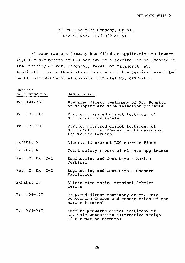
APPENDIX XVIII-2
El Pas, Eastern Company, et al.
Docket Nos. CP77-330 et al.
El Paso Eastern Company has filed an application to import
45,000 cubic meters of LNG per day to a terminal to be located in
the vicinity of Port O'Connor, Texas, on Matagorda Bay.
Application for authorization to construct the terminal was filed
by El Paso LNG Terminal Company in Docket No. CP77-269.
Exhibitor Transcript Description
Tr. 144-153 Prepared direct testimony of Mr. Schmitton shipping and site selection criteria
Tr. 206-210 Further prepared direct testimony ofMr. Schmitt on safety
Tr. 579-582 Further prepared direct testimony ofMr. Schmitt on changes in the design ofthe marine terminal
Exhibit 5 Algeria II project LNG carrier fleet
Exhibit 6 Joint safety report of El Paso applicants
Ref. E, Ex. Z-1 Engineering and Cost Data - MarineTerminal
Ref. E, Ex. Z-2 Engineering and Cost Data - OnshoreFacilities
Exhibit 17 Alternative marine terminal Schmittdesign
Tr. 154-167 Prepared direct testimony of Mr. Coleconcerning design and construction of themarine terminal
Tr. 583-587 Further prepared direct testimony ofMr. Cole concerning alternative designof the marine terminal
26

APPENDIX XVIII-2
Exhibitor Transcript Description
Tr. 174-181 Prepared direct testimony of Mr. Listerconcerning engineering and design of theonshore facilities and site selection
Tr. 592-597 Further prepared direct testimony ofMr. Lister on changes in onshore facilities
Tr. 182-88 Prepared direct testimony of Mr. Druckerconcerning process design of onshorefacilities
Tr. 588-591 Furthermore prepared direct testimony ofMr. Drucker on changes in the onshoreterminal facilities
Exhibit 20-30 Exhibits related to changes in the onshoreterminal facilities.
Tr. 211-234 Prepared direct testimony of Mr. Wesson,Mr. Porricelli, and Mr. Nair concerningsafety
Ref. G (three Joint Environmental Reportvolumes)
Tr. 308-390, Prepared direct t itimony and furtherTr. 605-626 prepared direct testimony of Mr. Craig,
Mr. Batra, Mr. Conwell, Mr. Mangarella,Mr. Robilliard, and Mr. Smith
Exh. bit 37 Seawater Intake and Discharge StudiesSupplement I: Alternative Configurations
Tr. 1175-80 Further prepared direct testimony ofMr. Hadad concerning shipping agreementwith Sonatrach
Exhibit 40 Transportation agreement for an LNGtanker between Sonatrach and El PasoAtlantic Company
27

APPENDIX XVIII-2
Pacific Alaska LNG Company
Docket No. CP75-140, et al.
Pacific Alaska LNG Company (PacAlaska) proposes to buy
natural gas in Cook Inlet from the gas production area of South
Alaska, gather the gas, liquefy and store the LNG in cryogenic
tanks at the Nikiski terminal facility, and at that facility load
the LNG for transport by LNG tanker to the Los Angeles harbor LNG
terminal facility where the gas will be unloaded, regasified and
sold into the California natural gas market. Southern California
Gas Company (SoCal) and Pacific Gas and Electric Company (PG&E)
will be the purchaser of the regasified LNG. The LNG terminal in
Los Angeles harbor is proposed to be constructed and operated by
Western LNG Terminal Associates (Western). This proposal is the
subject of Western's certificate application in Docket No.
CP75-83-2.
Exhibitor Transcript Description Date
Exhibit 1 Prepared Direct Testimony of 6/22/76Tr. Volume 5/192- K.C. McKinney, Vice President343 and General Manager of PacAlaska
and Western LNG
Exhibit 2 Additional Prepared Direct 6/22/76Testimony
Exhibit 3 (KCM-1) Liquefied Natural Gas 6/22/76Shipping Agreement BetweenPacific Alaska LNG Company andPacific Lighting Marine Co.
Exhibit 4 (KCM-2) Definitive Agreement 6/22/76for Terminal Service BetweenWestern LNG Terminal Companyand Pacific Alaska LNG Company
Exhibit 32 Prepared Direct Testimony of 6/29/76Tr. Volume 9-10/ M. E. Fuller, LNG Task Force858-1015 Manager for Pacific Alaska
28
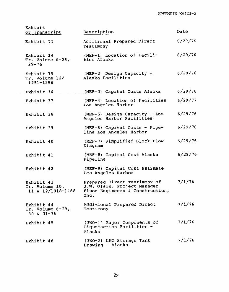
APPENDIX XVTII-2
Exhibitor Transcript Description Date
Exhibit 33 Additional Prepared Direct 6/29/76Testimony
Exhibit 34 (MEF-1) Location of Facili- 6/29/76Tr. Volume 6-28, ties Alaska29-76
Exhibit 35 (MEF-2) Design Capacity - 6/29/76Tr. Volume 12/ Alaska Facilities1251-1256
Exhibit 36 (MEF-3) Capital Costs Alaska 6/29/76
Exhibit 37 (MEF-4) Location of Facilities 6/29/77Los Angeles Harbor
Exhibit 38 (MEF-5) Design Capacity - Los 6/29/76Angeles Harbor Facilities
Exhibit 39 (MEF-6) Capital Costs - Pipe- 6/29/76line Los Angeles Harbor
Exhibit 40 (MEF-7) Simplified Block Flow 6/29/76Diagram
Exhibit 41 (MEF-8) Capital Cost Alaska 6/29/76Pipeline
Exhibit 42 (MEF-9) Capital Cost EstimateLos Angeles Harbor
Exhibit 43 Prepared Direct Testimony of 7/1/76Tr. Volume 10, J.W. Olson, Project Manager11 & 12/1018-1168 Fluor Engineers & Construction,
Inc.
Exhibit 44 Additional Prepared Direct 7/1/76Tr. Volume 6-29, Testimony30 & 31-76
Exhibit 45 (JWO-'' Major Components of 7/1/76Liquefaction Facilities -Alaska
Exhibit 46 (JWO-2) LNG Storage Tank 7/1/76Drawing - Alaska
29
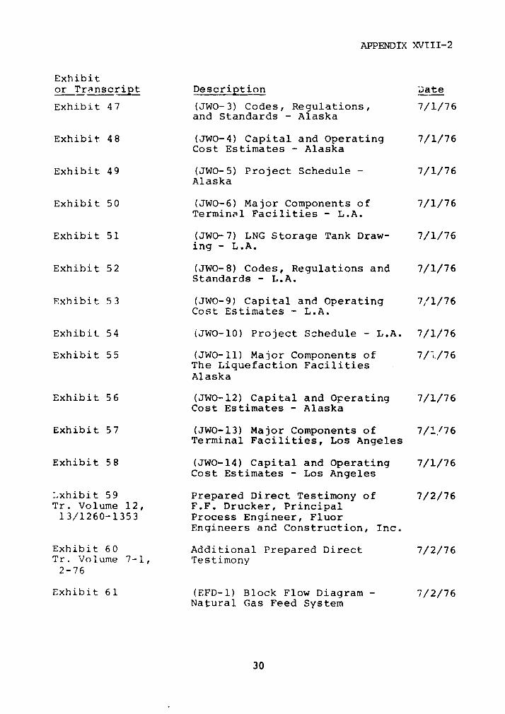
APPENDIX XVIII-2
Exhibitor Transcript Description Date
Exhibit 47 (JWO-3) Codes, Regulations, 7/1/76and Standards - Alaska
Exhibit 48 (JWO-4) Capital and Operating 7/1/76Cost Estimates - Alaska
Exhibit 49 (JWO-5) Project Schedule - 7/1/76Alaska
Exhibit 50 (JWO-6) Major Components of 7/1/76Terminal Facilities - L.A.
Exhibit 51 (JWO-7) LNG Storage Tank Draw- 7/1/76ing - L.A.
Exhibit 52 (JWO-8) Codes, Regulations and 7/1/76Standards - L.A.
Exhibit 53 (JWO-9) Capital and Operating 7,'1/76Cost Estimates - L.A.
Exhibit 54 (JWO-10) Project Schedule - L.A. 7/1/76
Exhibit 55 (JWO-ll) Major Components of 7/./76The Liquefaction FacilitiesAlaska
Exhibit 56 (JWO-12) Capital and Operating 7/1/76Cost Estimates - Alaska
Exhibit 57 (JWO-13) Major Components of 7/1./76Terminal Facilities, Los Angeles
Exhibit 58 (JWO-14) Capital and Operating 7/1/76Cost Estimates - Los Angeles
Lxhibit 59 Prepared Direct Testimony of 7/2/76Tr. Volume 12, F.F. Drucker, Principal13/1260-1353 Process Engineer, Fluor
Engineers and Construction, Inc.
Exhibit 60 Additional Prepared Direct 7/2/76Tr. Volume 7-1, Testimony2-76
Exhibit 61 (EFD-1) Block Flow Diagram - 7/2/76Natural Gas Feed System
30
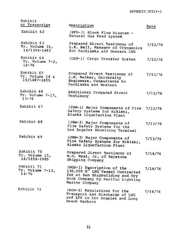
APPENDIX XVIII-2
Exhibitor Transcript Description Date
Exhibit 62 (EFD-2) Block Flow Diagram -Natural Gas Feed System
Exhibit 63 Prepared Direct Testimony of 7/12/76Tr. Volume 31, L.E. Bell, Manager of Cryogenics14/1354-1483 for PacAlaska and Western LNG
Exhibit 64 (LEB-1) Cargo Transfer System 7/12/76Tr. Volume 7-2,12-76
Exhibit 65 Prepared Direct Testimony of 7/13/76Tr. Volume 14 & J.R. Welker, University15/1487-1655 Engineers, Consultants to
PacAlaska and Western
Exhibit 66 Additional Prepared Direct 7/13/76Tr. Volume 7-12, Testimony13-76
Exhibit 67 (JRW-1) Major Components of Fire 7/13/76Safety Systems for Nikiski,Alaska Liquefaction Plant
Exhibit 68 (JRW-2) Major Components of 7/13/76Fire Safety Systems for theLos Angeles Receiving Terminal
Exhibit 69 (JRW-3) Major Components of 7/13/76Fire Safety Systems for Nikiski,Alaska Liquefaction Plant
Exhibit 70 Prepared Direct Testimony of 7/14/76Tr. Volume 15, W.G. Neal, Jr. of Keystone16/1656-1985 Shipping Company
Exhibit 71 (WGN-1) Dgscription of the 7/14/76Tr. Volume 7-13, 130,000 M LNG Vessel Contracted14-76 for at Sun Shipbuilding and Dry
Dock Company by Pacific LightingMarine Company
Exhibit 72 (WGN-2) Regulations for the 7/14/76Transport and Discharge of LNGand LPG in Los Angeles and LongBeach Harbors
31
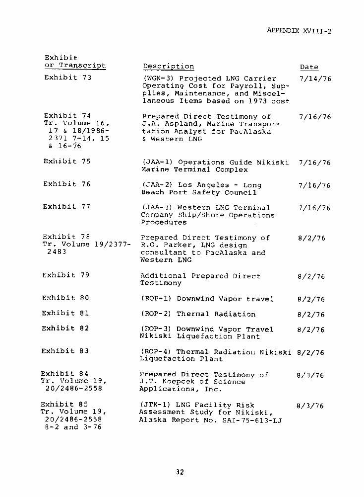
APPENDIX XVIII-2
Exhibitor Transcript Description Date
Exhibit 73 (WGN-3) Projected LNG Carrier 7/14/76Operating Cost for Payroll, Sup-plies, Maintenance, and Miscel-laneous Items based on 1973 cost
Exhibit 74 Prepared Direct Testimony of 7/16/76Tr. Volume 16, J.A. Aspland, Marine Transpor-17 & 18/1986- tation Analyst for PacAlaska2371 7-14, 15 & Western LNG& 16-76
Exhibit 75 (JAA-1) Operations Guide Nikiski 7/16/76Marine Terminal Complex
Exhibit 76 (JAA-2) Los Angeles - Long 7/16/76Beach Port Safety Council
Exhibit 77 (JAA-3) Western LNG Terminal 7/16/76Company Ship/Shore OperationsProcedures
Exhibit 78 Prepared Direct Testimony of 8/2/76Tr. Volume 19/2377- R.O. Parker, LNG design2483 consultant to PacAlaska and
Western LNG
Exhibit 79 Additional Prepared Direct 8/2/76Testimony
Exhibit 80 (ROP-1) Downwind Vapor travel 8/2/76
Exhibit 81 (ROP-2) Thermal Radiation 8/2/76
Exhibit 82 (MROP-3) Downwind Vapor Travel 8/2/76Nikiski Liquefaction Plant
Exhibit 83 (ROP-4) Thermal Radiationi Nikiski 8/2/76Liquefaction Plant
Exhibit 84 Prepared Direct Testimony of 8/3/76Tr. Volume 19, J.T. Koepcek of Science20/2486-2558 Applications, Inc.
Exhibit 85 (JTK-1) LNG Facility Risk 8/3/76Tr. Volume 19, Assessment Study for Nikiski,20/2486-2558 Alaska Report No. SAI-75-613-LJ8-2 and 3-76
32
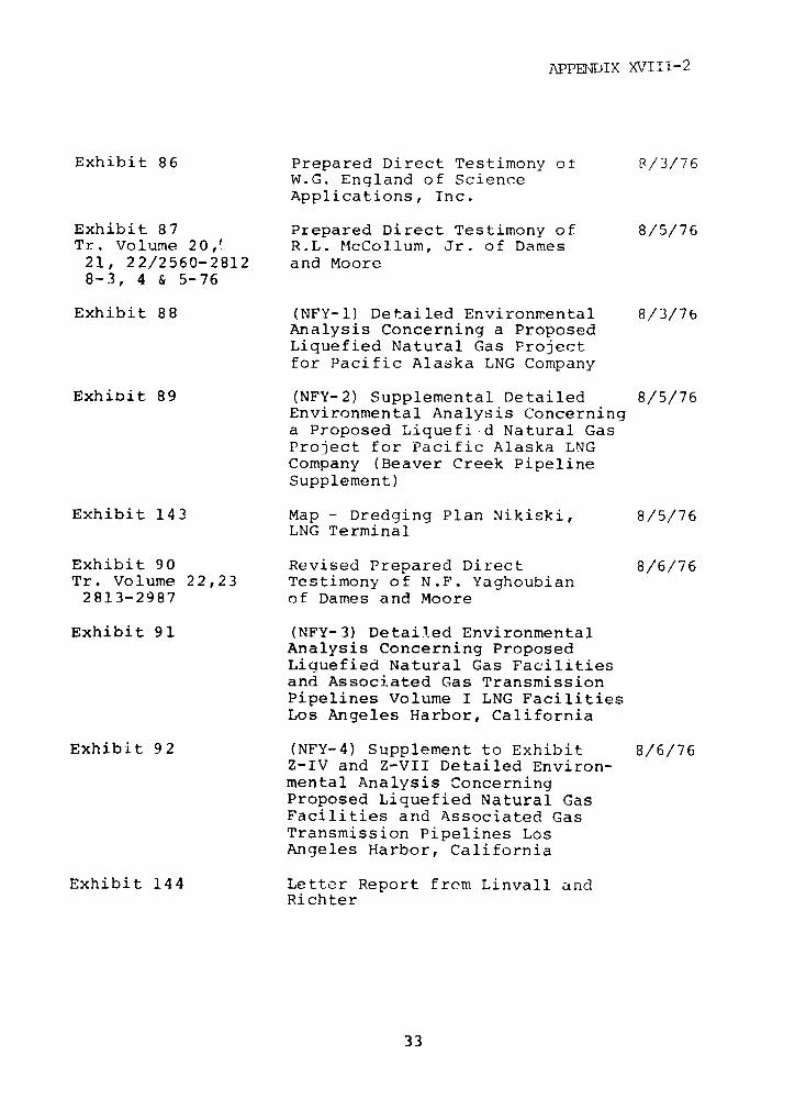
APPENDIX XVIIi-2
Exhibit 86 Prepared Direct Testimony of 8/3/76W.G. England of ScienceApplications, Inc.
Exhibit 87 Prepared Direct Testimony of 8/5/76Tr. Volume 20,' R.L. McCollum, Jr. of Dames21, 22/2560-2812 and Moore8-3, 4 & 5-76
Exhibit 88 (NFY-1) Detailed Environmental 8/3/76Analysis Concerning a ProposedLiquefied Natural Gas Projectfor Pacific Alaska LNG Company
Exhibit 89 (NFY-2) Supplemental Detailed 8/5/76Environmental Analysis Concerninga Proposed Liquefi d Natural GasProject for Pacific Alaska LNGCompany (Beaver Creek PipelineSupplement)
Exhibit 143 Map - Dredging Plan Nikiski, 8/5/76LNG Terminal
Exhibit 90 Revised Prepared Direct 8/6/76Tr. Volume 22,23 Testimony of N.F. Yaghoubian2813-2987 of Dames and Moore
Exhibit 91 (NFY-3) Detailed EnvironmentalAnalysis Concerning ProposedLiquefied Natural Gas Facilitiesand Associated Gas TransmissionPipelines Volume I LNG FacilitiesLos Angeles Harbor, California
Exhibit 92 (NFY-4) Supplement to Exhibit 8/6/76Z-IV and Z-VII Detailed Environ-mental Analysis ConcerningProposed Liquefied Natural GasFacilities arid Associated GasTransmission Pipelines LosAngeles Harbor, California
Exhibit 144 Letter Report from Linvall andRichter
33

APPENDIX XVIII-2
Pacific Indonesia Company, et al.
Docket Nos. CP74-160, et al.
Pacific Indonesia LNG Company proposes to import, in 20years, 180 million cubic meters of LNG. Pacific Indonesiaproposes in Docket No'. CP74-207 to sell the adily output at theterminal tailgate to Southern California Gas Company and PacificGas and Electric Company in equal quantities. Western LNGTerminal Associates proposes in Docket No. CP75-83-3 to constructa receiving te-minal at Oxnard, California.
Cross-Exhibit No. rxaminationand Date Accepted Date of
Into Evidence Description Hearing
Exhibit 9 Prepared direct testimony of 8/883-9431/8/76 W.G. Neal, Jr., Manager of 1/8/76Special Projects, KeystoneShipping Co., describing theregulations and design featureswhich affect the safe operationof LNG vessels at unloadingterminals.
Exhibit 10 Prepared direct testimony of 8/945-9511/9/76 M.E. Fuller, Manager of 1/4/76Facilities Engineering for 9,'955-1025Western LNG Terminal Company 1/26/76describing his exhibits.
Exhibit 11 (MEF-1) Location of Facili- 1/9/761/9/76 ties - Oxnard.
Exhibit 12 (MEF-2) Design Capacity - 1/9/761/9/76 Oxnard Facilities.
Exhibit 13 (MEF-3) Capital Costs - Oxnard 1/9/761/9/76 to La Vista Pipeline.
34

APPEI'IX XVIII-2
Cross-Exhibit No. Examinationand Date Accepted Date ofInto Evidence Description Hearing
Exhibit 14 Prepared direct testimony of 8/1627-16341/28/76 J.W. Olsen, Project Manager 1/9/76
Fluor Engineers and Con- 9/1646-1160struction Inc., describing 1/26/70his exhibits. 10/1163-1216
1267-12911/27/7611/1297-13441/28/76
Exhibit 15 (JWO-1) Major Components 1/9/761/28/76 of Terminal Facilities - - 1/28/76
Oxnard.
Exhibit 16 (JWO-2) LNG Storage Tank 1/9/76 -1/28/76 Drawing - Oxnard. 1/28/76
Exhibit 17 (JWO-3) Codes, Regulations 1/9/761/28/76 Standards - Oxnard. 1/28/76
Exhibit 18 (JWO-4) Capital and Operating 1/9/761/28/76 Cost Estimates - Oxnard. 1/28/76
Exhibit 19 (JWO-5) Project Schedule - 1/9/761/28/76 Oxnard. 1/28/76
Exhibit 20 Prepared direct testimony of 10/1218-1,'27/76 J. Poraino, President and 1267
Chief Engineer, Raymond 1/27/76Technical Facilities, Inc.,describing his exhibits.
Exhibit 21 (JP-1) Marine Facilities - 1/27/761/27/76 Oxnard.
Exhibit 22 (JP-2) Berthing Area 1/27/761/27/76 Drawing - Oxnard.
Exhibit 23 (JP-3) Capital Coat Estimates 1/27/761/27/76 Marine Facility and Trestle.
Exhibit 24 (JP-4) Project Schedule - 1/27/761/27/76 Oxnard Marine Facilities.
35
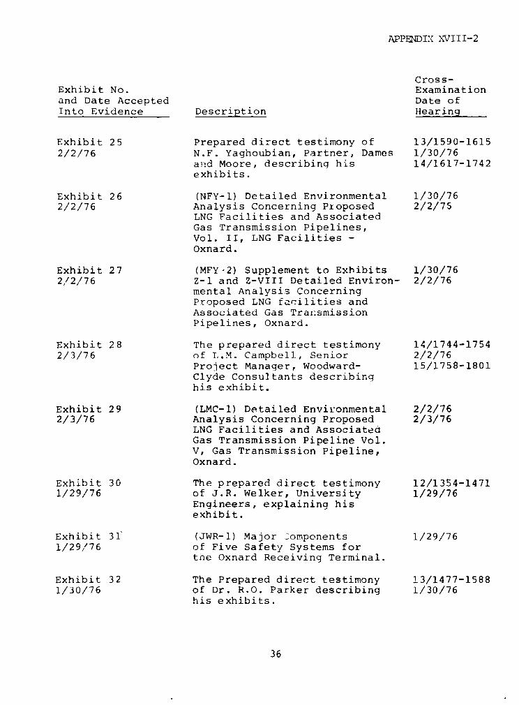
APPENDIX XVIII-2
Cross-Exhibit No. Examinationand Date Accepted Date ofInto Evidence Description Hearing
Exhibit 25 Prepared direct testimony of 13/1590-16152/2/76 N.F. Yaghoubian, Partner, Dames 1/30/76
and Moore, describing his 14/1617-1742exhibits.
Exhibit 26 (NFY-1) Detailed Environmental 1/30/762/2/76 Analysis Concerning Pioposed 2/2/75
LNG Facilities and AssociatedGas Transmission Pipelines,Vol. II, LNG Facilities -Oxnard.
Exhibit 27 (MFY-2) Supplement to Exhibits 1/30/762,/2/76 Z-1 and Z-VIII Detailed Environ- 2/2/76
mental Analysis ConcerningProposed LNG facilities andAssociated Gas Trai.smissionPipelines, Oxnard.
Exhibit 28 The prepared direct testimony 14/1744-17542/3/76 of L.M. Campbell, Senior 2/2/76
Project Manager, Woodward- 15/1758-1801Clyde Consultants describinghis exhibit.
Exhibit 29 (LMC-1) Detailed Environmental 2/2/762/3/76 Analysis Concerning Proposed 2/3/76
LNG Facilities and AssociatedGas Transmission Pipeline Vol.V, Gas Transmission Pipeline,Oxnard.
Exhibit 30 The prepared direct testimony 12/1354-14711/29/76 of J.R. Welker, University 1/29/76
Engineers, explaining hisexhibit.
Exhibit 31 (JWR-1) Major Components 1/29/761/29/76 of Five Safety Systems for
tne Oxnard Receiving Terminal.
Exhibit 32 The Prepared direct testimony 13/1477-15881/30/76 of Dr. R.O. Parker describing 1/30/76
his exhibits.
36

APPIEDIX XVIII-2
CrossExhibit No. Examinationand Date Accepted Date ofInto Evidence Description Hearing
Exhibit 33 (ROP-1) Downwind Vapor Travel. 1/30/761/30/76
Exhibit 34 (ROP-2) Thermal Radiation. 1/30//61/30/76
Exhibit 54 Prepared Direct Testimony of 8/945-9511/9/76 M.E. Fuller, Manager of 1/9/76
Facilities Engineering for 9/955-1025Western LNG Terminal Company,describing his exhibit.
Exhibit 55 (MEF-4) Capital Costs Oxnard 1/9/761/9/76 to La Vista Pipeline.
Exhibit 56 Prepared direct testimony of 1,/"6/761/28/76 J.W. Olsen, Project Manager, 1/28/76
Fluor Engineers and ConstructorsInc., describing his exhibits.
Exhibit 57 (JWO-6) Capital and Operating 1/26/761/28/76 Cost Estimates - Oxnard. 1/28/76
Exhibit 57-A Oxnard LNG Terminal, 550 MM 1/26/761/28/76 SCFD Base + 450 MM SCFD 1/28/76
Peaking, September 1975Control Estimate, CapitalCost (1979 Completion).
Exhibit 94 Material from Prior DataResponses (6 parts) (1) Reportof Foundation InvestigationProposed LNG Terminal - Oxnard,(2) Soil-Structure InteractionStudy for Oxnard Facility LNGTanks, 4/75, (3) ProjectDescription, (4) LNG StorageTank Drawings, (5) Fire and LeakDetection Safety Alarm andShutdown System, and (6)Specification SP-45 3334-00-7,Earthquake Engineering.
37
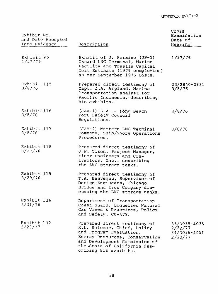
APPENDIX XVIII-2
CrossExhibit No. Examinationand Date Accepted Date ofInto Evidence Description Hearing
Exhibit 95 Exhibit of J. Peraino (JP-5) 1/27/761/27/76 Oxnard LNG Terminal, Marine
Facility and Trestle CapitalCost Estimate (1979 completion)as per September 1975 Costs.
Exhibi . 115 Prepared direct testimony of 23/2840-29313/8/76 Capt. J.A. Aspland, Marine 3/8/76
Transportation analyst forPacific Indonesia, describinghis exhibits.
Exhibit 116 (JAA-1) L.A. - Long Beach 3/8/763/8/76 Port Safety Council
Regulations.
Exhibit 117 (JAA-2) Western LNG Terminal 3/8/763/8/76 Company, Ship/Shore Operations
Procedures.
Exhibit 118 Prepared direct testimony of3/27/76 J.W. Olsen, Project Manager,
Fluor Engineers and Con-tractors, Inc., describingthe LNG storage tanks.
Exhibit 119 Prepared direct testimony of3/29/76 T.A. Benvegnu, Supervisor of
Design Engineers, ChicagoBridge and Iron Company dis-cussing the LNG storage tanks.
Exhibit 126 Department of Transportation3/31/76 Coast Guard, Liquefied Natural
Gas Views & Practices, Policyand Safety, CG-478.
Exhibit 132 Prepared direct testimony of 33/3935-40352/23/77 R.L. Solomon, Chi.ef: Policy 2/22/77
and Program Evaluation, 34/3036-4051Energy Resources, Conservation 2/23/77and Development Commission ofthe State of California des-cribing his exhibits.
38

APPENDIX XVIII-2
Cross-Exhibit No. Examinationand Date Accepted Date ofInto Evidence Description Hearing
Exhibit 133 (RLS-1) The California Coastal 2/22-23/772/23/77 Act.
Exhibit 134 (RLS-2) ERCDC Biennial 2/22-23/772/23/77 Report - Fossil Fuel Issues,
Part I: Liquefied Natural Gas.
Exhibit 135 (RLS-3) Resource Planning 2/22-23/772/23/77 Associates: LNG Decision in
California.
Exhibit 136 (RiS-4) ERCDC Resolution No. 2/22-23/772/23/77 76-1117-13.
Exhibit 137 (RLS-5) County of Santa 2/22-23/772/23/77 Barbara Letter Dated August 10,1976.
Exhibit 138 (RLS-6) Governor's Office of 2/22-23/772/23/77 Planning and Research Letter
Dated November 24, 1976.
Exhibit 139 (RLS-7) Governor's Office 2/22-23/772/23/77 of Planning and Research
Letter dated December 15, 1976.
Exhibit 140 (P-'S-8) Governor's Office of 2/22-23/772/23/77 Planning and Research Letter
dated December 16, 1976.
Exhibit 141 (RLS-9) ERCDC Letter of 2/22-23/772/23/77 November 26, 1976.
Exhibit 142 (RLS-10) United States Dept. 2/22-23/772/23/77 of Commerce, NOAA Letter
dated December 2, 1976.
Exhibit 143 (RLS-11) Statement of Chairman 2/22-23/772/23/77 Richard Maullin before theEnergy Resources Council.
Exhibit 144 (RLS-12) Statement of Senior 2/22-23/772/23/77 Counsel Frederick E. John
before the Energy ResourcesCouncil.
39
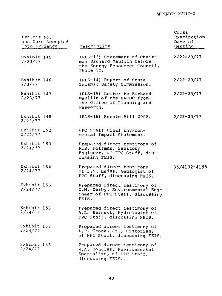
APPENDIX XVIII-2
Cross-Exhibit No. Examinationand Date Accepted Date ofInto Evidence Description Hearing
Exhibit 145 (RLS-13) Statement of Chair- 2/22-23/772/23/77 man Richard Maullin before
the Energy Resources Council,Phase II.
Exhibit 146 (RLS-14) Report of State 2/22-23/772/3/77 Seismic Safety Commission.
Exhibit 147 (RLS-15) Letter to Richard 2/22-23/772/23/77 Maullin of the ERCDC from
the Office of Planning andResearch.
Exhibit 148 (RLS-16) Senate Bill 2008. 2/22-23/772/23/77
Exhibit 152 FPC Staff Final Environ-2/24/77 mental Impact Statement.
Exhibit 153 Prepared direct testimony of2/24/77 R.R. Hoffman, Sanitory
Engineer, of FPC Staff, dis-cussing FEIS.
Exhibit 154 Prepared direct testimony 35/4132-41582/24/77 of J.S. Leiss, Geologist of
FPC Staff, discussing FEIS.
Exhibit 155 Prepared direct testimony of2/24/77 C.M. Zerby, Environmental Eng-
ineer of FPC Staff, discussingFEIS.
Exhibit 156 Prepared direct testimony of2/24/77 A.L. Barnett, Hydrologist of
FPC Staff, discussing FEIS.
Exhibit 157 Prepared direct testimony of2/Z4/77 L.R. Crook, Jr., Historian,
of FPC Staff, discussing FEIS.
Exhibit 158 Prepared direct testimony of2/24/77 W.A. Douglas, Environmental
Specialist, of FPC Staff,discussing FEIS.
40
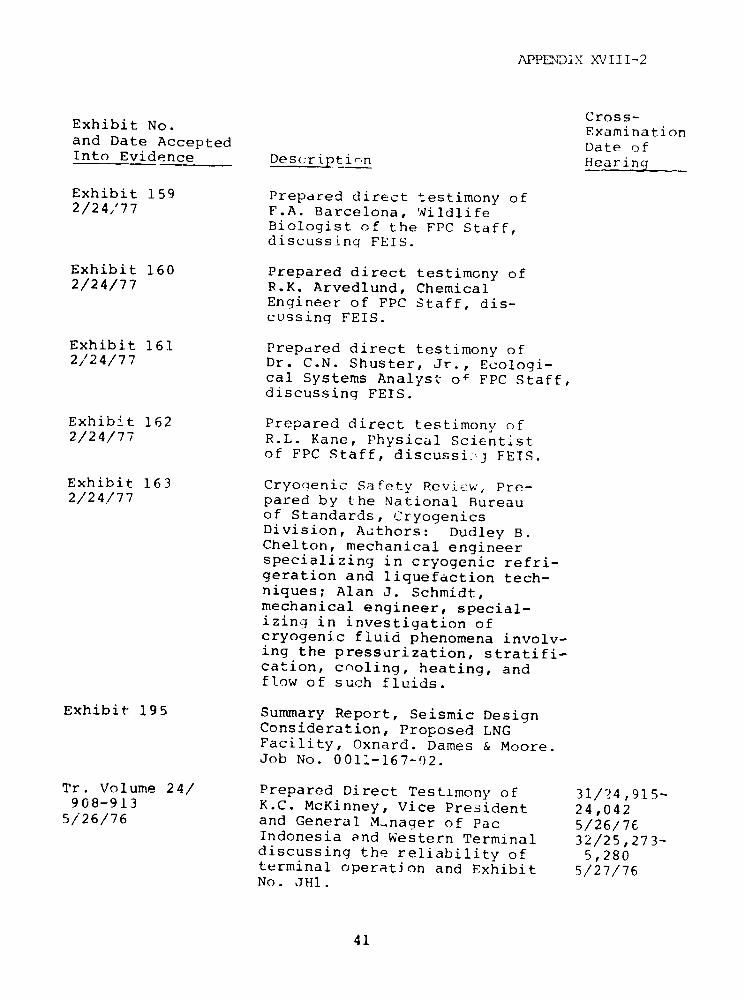
APPaTDIX XXVIII-2
Cross-Exhibit No. Examinationand Date Accepted Date ofInto Evidence Description Hearing
Exhibit 159 Prepared direct testimony of2/24,'77 F.A. Barcelona, Wildlife
Biologist of the FPC Staff,discussing FEIS.
Exhibit 160 Prepared direct testimony of2/24/77 R.K. Arvedlund, Chemical
Engineer of FPC Staff, dis-cussing FEIS.
Exhibit 161 Prepared direct testimony of2/24/77 Dr. C.N. Shuster, Jr., Ecologi-
cal Systems Analyst of FPC Staff,discussing FEIS.
Exhibit 162 Prepared direct testimony of2/24/77 R.L. Kane, Physical Scientist
of FPC Staff, discussij FEIS.
Exhibit 163 Cryoqenic Safety Review, Pre-2/24/77 pared by the National Bureau
of Standards, CryogenicsDivision, Authors: Dudley B.Chelton, mechanical engineerspecializing in cryogenic refri-geration and liquefaction tech-niques; Alan J. Schmidt,mechanical engineer, special-izing in investigation ofcryogenic fluid phenomena involv-ing the pressurization, stratifi-cation, cooling, heating, andflow of such fluids.
Exhibit 195 Summary Report, Seismic DesignConsideration, Proposed LNGFacility, Oxnard. Dames & Moore.Job No. 0011-167-!)2.
Tr. Volume 24/ Prepared Direct Testimony of 31/24,915-908-913 K.C. McKinney, Vice President 24,0425/26/76 and General M.nager of Pac 5/26/76
Indonesia and Western Terminal 32/25,273-discussing the reliability of 5,280terminal operation and Exhibit 5/27/76No. JH1.
41

APPENDIX XVIII-2
Cross--Exhibit No. Examinationand Date Accepted Date ofInto Evidence Description Hearing
Ref. JH-l (JH-l) Multiple Terminal Study.5/26/76
Tr. Volume 25/ Prepared direct testimony of 31/25,049043-049 M.E. Fuller, Manager of 25,0795/26/76 Facilities Engineeriug for 5/26/76
Western Terminal describing 32/25,081-exhibit No. JH2. 25,153
5/27/76
Ref. JH-2 (JH-2) Facilities and Cost 5/'26/765/26/76 Supporting Multiple Terminal
Safety.
Tr. Volume 25/ Prepared direct testimony of 32/25,166-156-160 J.T. Kopecek, Manager of 25,2715/27/76 the Science Application 5/27/76
Institute Safety Studies dis-cussing exhibit JH-3.
Tr. Volume 25/ Prepared direct testimony of 32/25,166-162-165 W.G. Endland, Assistant 25,2715/27/76 Manager of the Energy and 5/27/76
Environmental ServicesDivision of SAI, discussingexhibit JH-3.
Ref. JH-3 (JH-3) LNG Risk Assessment 5/27/765/27/76 Study for Oxnard, California
Report No. SAI-75-615-LJ,Decemher 22, 1975, byScience Applications, ;nc.
Item A Response to 9 questions in1/27/76 5/11/75 letter from FPC
requesting detailed engineeringsafety and environmental data.
Item B Response to 117 questions in1/27/76 8/11/75 letter from FPC requesting
detailed engineering, safety andenvironmental data.
Item C Western Terminal Control1/27/76 Estimate and Scope Definition.
42
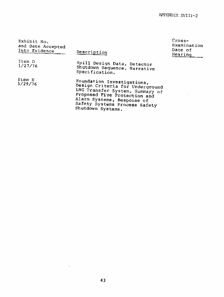
APPENDIX XVIII-2
Exhibit No. Cross-and Date Accepted ExaminationInto Evidence Description Hearingof
Item D Spill Design Data, Detector1/27/76 Shutdown Sequence, NarrativeSpecification.
Item E Foundation Investigations,1/29/76 Design Criteria for UndergroundLNG Transfer System, Summary ofProposed Five Protection andAlarm Systems, Response ofSafety Systems Process SafetyShutdown Systems.
43
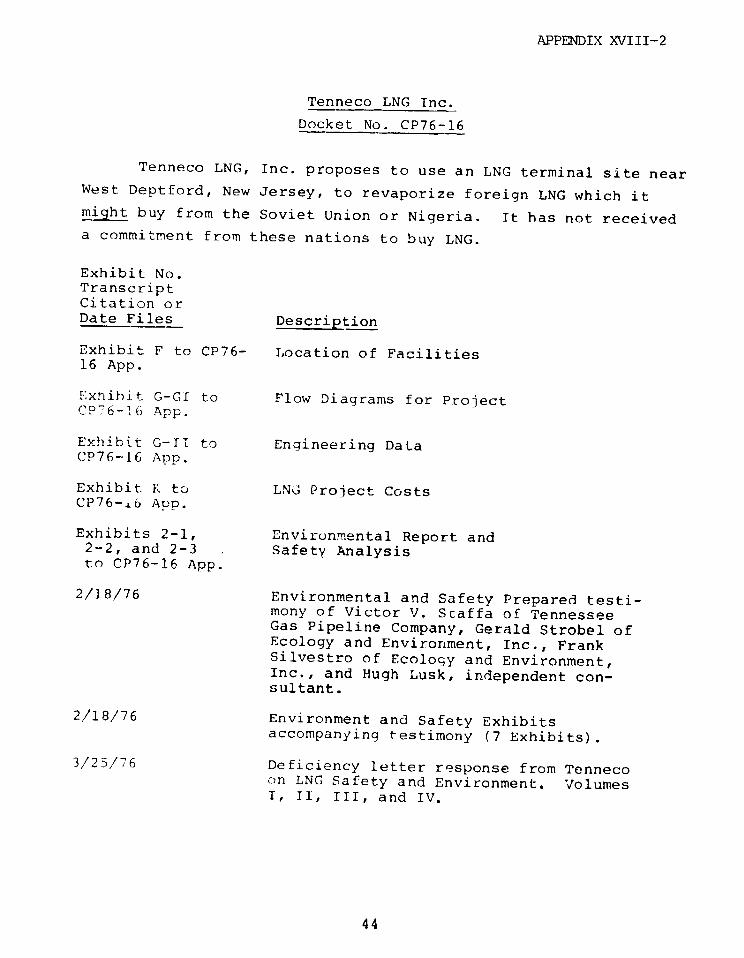
APPENDIX XVIII-2
Tenneco LNG Inc.
Docket No. CP76-16
Tenneco LNG, Inc. proposes to use an LNG terminal site nearWest Deptford, New Jersey, to revaporize foreign LNG which itmight buy from the Soviet Union or Nigeria. It has not receiveda commitment from these nations to buy LNG.
Exhibit No.TranscriptCitation orDate Files Description
Exhibit F to CP76- Location of Facilities16 App.
Exhibit G-GI to Flow Diagrams for ProjectCP76-16 App.
Exhibit G-TI to Engineering DataCP76-16 App.
Exhibit 1K to LNG Project CostsCP76-i6 Aup.
Exhibits 2-1, Envirunmental Report and2-2, and 2-3 Safety Analysisto CP76-16 App.
2/18/76 Environmental and Safety Prepared testi-mony of Victor V. Staffa of TennesseeGas Pipeline Company, Gerald Strobel ofEcology and Environment, Inc., FrankSilvestro of Ecology and Environment,Inc., and Hugh Lusk, independent con-sultant.
2/18/76 Environment and Safety Exhibitsaccompanying testimony (7 Exhibits).
3/25/76 Deficiency letter response from Tennecoon LNG Safety and Environment. VolumesI, II, III, and IV.
44
APPENDIX XVIII-2
Exhibit No.TranscriptCitation orDate Files Description
12/76 Staff Draft Environment Impact State A.
Comments were filed in response toDraft EIS from Pennsylvania Fish Com-mission; New Jersey Dept. of Public Ad-vocate; Wilmington Metro Area PlanningCoordination Committee; EPA - Region II(NY); Delaware Dept. of Natural Resourcesand Environment Control; Maryland Dept.of State Planning; Dept. of HEW, DelawareRiver Basin Council; U.S. Coast Guard;DOI; Dept. of Commerce; NRC; New JerseyDOT; Tenneco LNG, Inc.; County ofDelaware, Pennsylvania Advisory Councilon Historic Preservation; Amenipuct;ERDA.
45
APPENDIX XVIII-2
Tennessee Atlantic Pipeline Company
Docket No. CP77-100 et al.
Tennessee Atlantic Pipeline Company proposes to bring
Algerian LNG to the coast of Canada near St. John, New Brunswick,
for revaporization and subsequent transportation through Canada
into the United States across the states of Maine, New Hampshire,
Massachusetts, New York, and Pennsylvania by the construction of
a new pipeline. This is presently in hearing with an anticipated
Commission decision due December 1977, about one year from the
date when the application was filed.
Exhibit No.TranscriptCitation orDate Filed Descrition
Exhibit 1 Testimony of Roger N. Stark of TennecoLNG, Inc. on Siting Policy
Exhibit 1 Testimony of George W. White of Tennessee
Gas Pipeline Company on LNG shipping
Exhibit i Testimony of Chester L. Long of NewportNews Shipbuilding and Dry Dock Companyon LNG shipping
Exhibit 1 Testimony of Sherman H. Clark of ShermanClark Associates on LNG supply security
Exhibit 1 Testimony of Anthony V. Leness of White,Weld and Company Incorporated, JamesM. Smith, Jr., of Morgan Stanley and
Company Incorporated, and E. WayneHopkins of Tennessee Gas TransmissionCompany, all involving financing of LNG
projects and the lenders perception of
the risks involved
Tr. Volume 1 Testimony of Ewell H. Muze III of
pp. 61-69 Tennessee Gas Transmission Companyon LNG shipping arrangements
46

APPENDIX XVIII-2
Exhibit No.TranscriptCitation orDate Filed Description
Tr. Volume 1 Testimony of James A. McDonald ofpp. 102-111 Canadian Pacific Limited on LNG siting
in Canada
Tr. Volume 1 Testimony of David G. Toole of Canadianpp. 113-119 Pacific Limited terminal on LNG costs
Tr. Volume 1 Testimony of Mortimer S. Bistrisky ofpp. 120-125 Canadian Pacific Limited on Canadian
LNG regulation requirements
Tr. Volume 1 Testimony of Stephen H. Grote ofpp. 107-138 Brown and Rost, Inc. on LNG terminal
facilities and safety
Tr. Volume 1 Testimony of Frank B. Silvestro ofpp. 139-147 Ecology and Environment, Inc. on ITNG
hazards and risks
Tr. Volume 1 Testimony of Dr. Eugene Kuckun on LNGpp. 148-153 terminal environmental impacts
Tr. Volume 1 Testimony of Arthur Nesbitt of Nesbitt,pp. 154-179 Thomson and Company, Ltd. and Ronald
M. Freeman of Salomon Brothers on LNGFinancing and a lenders perception ofLNG risks
Tr. Volume 1 Testimony of John C. McMillian of thepp. 180-185 Royal Bank of Canada on Canadian
lenders perception of LNG risks
Tr. Volume 1 Responses from Secretary of Defensepp. 190-199 and State on proposed Tenneco LNG
project
Exhibit 2 Map of LNG import project
Exhibit 3 LNG contract
Exhibit 5 LNG terminal contract
Exhibit 24 LNG Schematic Volume Balance
Exhibit 25 Ocean Route Chart
47

APPENDIX XVIII-2
Exhibit No.TranscriptCitation orDate Filed Description
Exhibit 26 Simplified Schematic of LNG ShippingModel
Exhibit 27 Shipping Memorandum
Exhibit 28 Draft Shipping Contract
Exhibit 29 Shipping Costs
Exhibit 30, Shipping Contracts31, and 32
Exhibit 33, 34, LNG Shipping Equipment and Safety35, 36, 37 Apparatus
Exhibit 51, 52, LNG Shipping Costs53
Exhibit 66 Map of LNG Terminal Site
Exhibit 67, 68, LNG Terminal Cost and Maintenance69, 70, 71, 72, Costs73, 74, 75, 76,77, 78, 79, 80,81, 82
Exhibit 83 LNG Engineering Study
Exhibit 84 LNG Safety Analysis
Exhibit 85 Environmental Import Study
Joint Hearing Testimony of Kazi Tani of SonatrachTranscript Docket on Alterian LNG terminal construction,No. CP77-216 et operation, and safetyal. Volume 1, p.8-27
Joint Hearing Testimony of Tayeg Mazouni on LNGTranscript Vol. 1, sitingp. 78-84
7/11/77 Staff Draft Environmental ImpactStatement
48

APPENDLX XVIII-2
Exhibit No.TranscriptCitation orDate Filed Description
8/1/77 Northeast United States Coast LNG SiteAnalysis Phase I
Exhibit G to App. Project Flow Diagramsin Docket No.CP77-109
49
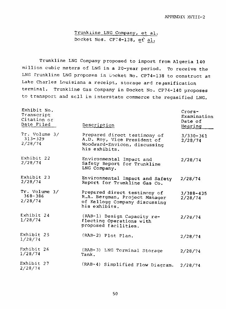
APPENDIX XVIII-2
Trunkiine LNG Company, et al.
Docket Nos. CP74-138, et' al.
Trunkline LNG Company proposed to import from Algeria 140
million cubic meters of LNG in a 20-year period. To receive theLNG rrunkline LNG proposes in Docket No. CP74-138 to construct atLake Charles Louisiana a receipt, storage ard regasification
terminal. Trunkline Gas Company in Docket No. CP74-140 proposes
to transport and sell in interstate commerce the regasified LNG.
Exhibit No. Cross-Transcript ExaminationCitation or Date ofDate Filed Description Hearing
Tr. Volume 3/ Prepared direct testimony of 3/330-361313-329 A.D. Roy, Vice President of 2/28/74
2/28/74 Woodward-Envicon, discussinghis exhibits.
Exhibit 22 Environmental Impact and 2/28/742/28/74 Safety Report for Trunkline
LNG Company.
Exhibit 23 Environmental Impact and Safety 2/28/742/28/74 Report for Trunkline Gas Co.
Tr. Volume 3/ Prepared direct testimony of 3/388-435368-386 R.A. Bergman, Project Manager 2/28/74
2/28/74 of Kellogg Company discussinghis exhibits.
Exhibit 24 (RAB-1) Design Capacity re- 2/28/741/28/74 flecting Operations with
proposed facilities.
Exhibit 25 (RAB-2) Plot Plan. 2/28/741/28/74
Exhibit 26 (RAB-3) LNG Terminal Storage 2/28/741/28/74 Tank.
Exhibit 27 (RAB-4) Simplified Flow Diagram. 2/28/742/28/74
50
APPENDIX XVIII-2
Exhibit No. Cross-Transcript ExaminationCitation or Date ofDate Filed Description Hearinqt
Exhibit 28 (RAB-5) Required Permits. 2/28/742/28/74
Exhibit 29 (RAB-6) Cost of Facilities. 2/28/742/28/74
Exhibit 30 (RAB-?) Construction Schedule. 2/28/742/28/74
Exhibit 31 (RAB-8) Fire Protection System. 2/28/742/28/74
Tr. Volume 3/ Prepared direct testimony of 3/452-474442-458 L.C. Sullivan, Assistant Chief 2/28/74
2/28/74 Engineer of Trunkline discussinghis exhibits.
Exhibit 32 (LSC-1) Location of Facilities. 2/28/742/28/74
Exhibit 33 (LSC-2) Flow Diagram. 2/28/742/28/74
Exhibit 34 (LSC-3) Flow Diagram Data. 2/28/742/28/74
Exhibit 35 (LSC-4) Cost of Facilities. 2/28/742/28/74
Tr. Volume 3/ Prepared direct testimony of 3/487-511479-485 A.W. McAnneny, Vice President 2/28/742/28/74 a=d Chief Engineer of Trunkline
discussing his exhibit.
Exhibit 36 (AWM-1) Location of Facilities. 2/23/742/28/74
Tr. Volume 11/ Prepared direct testimony of 11/1303-13271298-1301 L.C. Sullivan, Assistant Chief 10/18/7610/18/76 Engineer of Trunkline discussing
his exhibit.
Exhibit 56 (LCS-5) Cost of Facilities. 10/18/7610/18/76
51
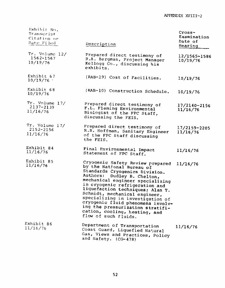
APPENDIX XVIII-2
Exhihibit No. Cross-'rariscri pr ExaminationCitation or Date ofDate F.il2e Description Hearing
Tr. Volume 12/ Prepared direct testimony of 12/1565-15861562-1567 R.A. Bergman, Project Manager 10/19/7610/19/76 Kellogg Co., discussing hisexhibits.
Exhibit 67 (RAB-]9) Cost of Facilities. 10/19/7610/19/76 -
Exhibit 68 (RAB-10) Construction Schedule. 10/19/7610/19/76
Tr. Volume 17/ Prepared direct testimony of 17/2140-21562137-2139 F.L. Fleming Environmental 11/16/7611/16/76 Biologist of the FPC Staff,discussing the FEIS.
Tr. Volume 17/ Prepared direct testimony of 17/2159-22052152-2156 R.R. Hoffman, Sanitary Engineer 11/16/7611/16/76 of the FPC Staff discussingthe FEIS.
Exhibit 84 Final Environmental Impact 11/16/7611/16/76 Statement of FPC Staff.
Exhibit 85 Cryogenic Safety Review prepared 11/16/7611/16/76 by the National Bureau ofStandards Cryogenics Division.Authors: Dudley B. Chelton,mechanical engineer specializingin cryogenic refrigeration andliquefaction techniques; Alan T.Schmidt, mechanical engineer,specializing in investigation ofcryogenic fluid phenomena involv-ing the pressurization stratifi-cation, cooling, heating, andflow of such fluids.
Exhibit 86 Department of Transportation 11/16/7611/16/76 Coast Guard, Liquefied Natural
Gas, Views and Practices, Policyand Safety. (CG-478)
52
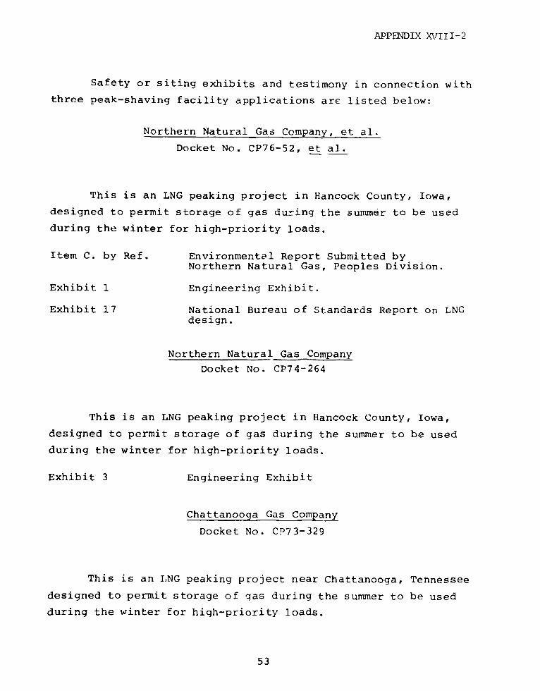
APPENDIX XVIII-2
Safety or siting exhibits and testimony in connection with
three peak-shaving facility applications are listed below:
Northern Natural Gas Company, et al.
Docket No. CP76-52, et al.
This is an LNG peaking project in Hancock County, Iowa,
designed to permit storage of gas during the summer to be used
during the winter for high-priority loads.
Item C. by Ref. Environmental Report Submitted byNorthern Natural Gas, Peoples Division.
Exhibit 1 Engineering Exhibit.
Exhibit 17 National Bureau of Standards Report on LNGdesign.
Northern Natural Gas Company
Docket No. CP74-264
This is an LNG peaking project in Hancock County, Iowa,
designed to permit storage of gas during the summer to be used
during the winter for high-priority loads.
Exhibit 3 Engineering Exhibit
Chattanooga Gas Company
Docket No. CD73-329
This is an ILNG peaking project near Chattanooga, Tennessee
designed to permit storage of gas during the summer to be used
during the winter for high-priority loads.
53

APPENDIX XVTTT-?
Exhibit 1 Testimony of T.R. Bell and Attachments.
Exhibit 1 Testimony of Kenneth Royse and hisexhibits.
54
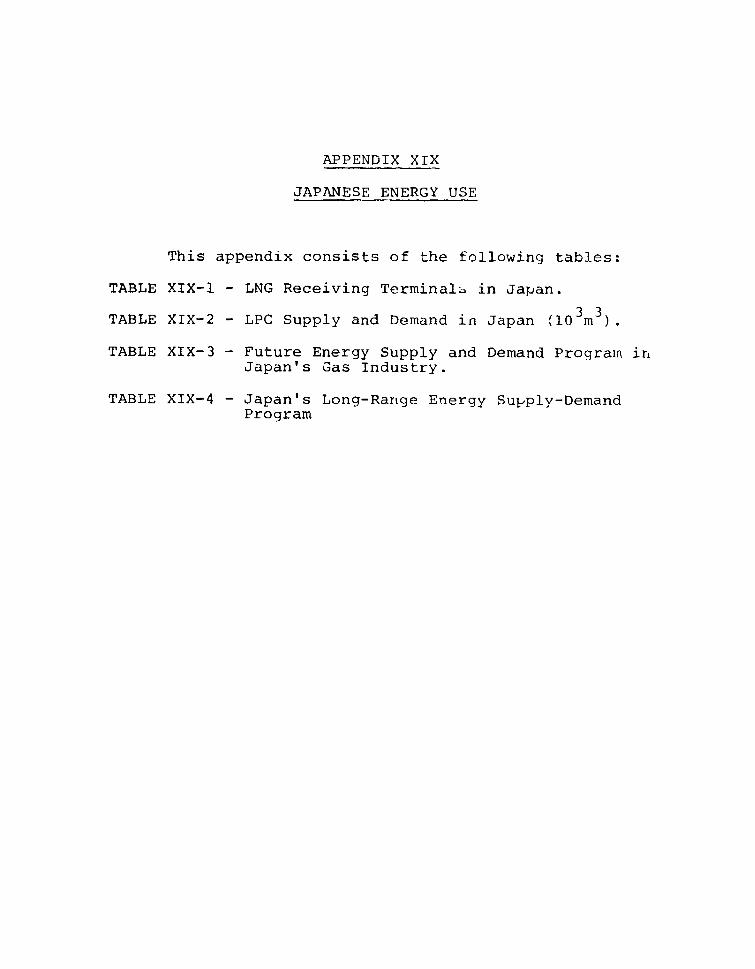
APPENDIX XIX
JAPANESE ENERGY USE
This appendix consists of the following tables:
TABLE XIX-1 - LNG Receiving Terminals in Japan.
TABLE XIX-2 - LPC Supply and Demand in Japan (10 m ).
TABLE XIX-3 - Future Energy Supply and Demand Programn inJapan's Gas Industry.
TABLE XIX-4 - Japan's Long-Range Energy Supply-DemandProgram
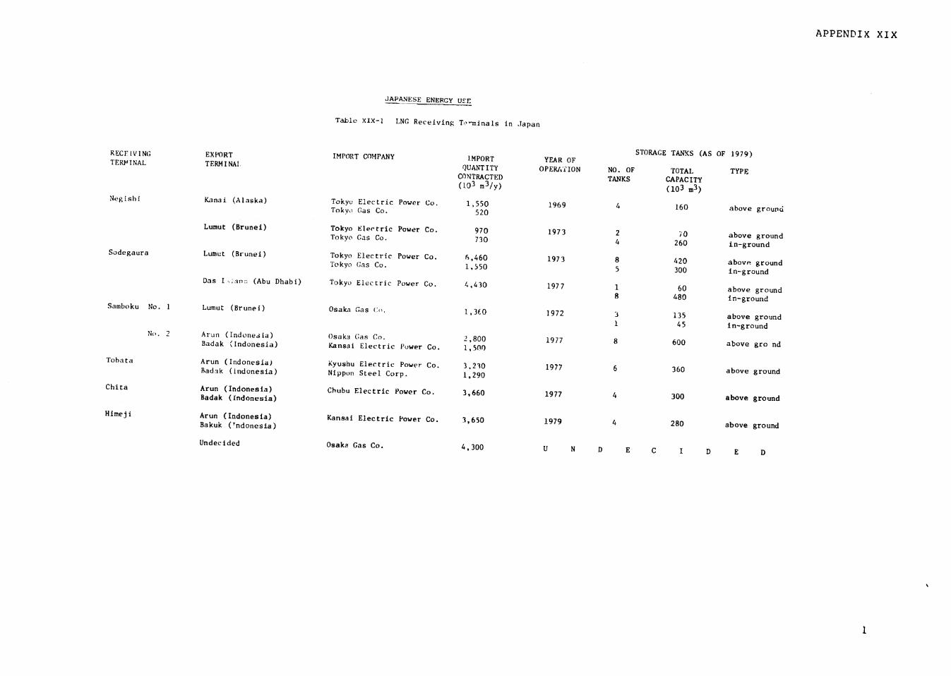
APPENDIX XIX
JAPANESE ENERGY USE
Table XIX-I LNG Receiving Tominals in Japan
STORAGE TANKS (AS OF 1979)RECFiVING EXPORT IMPORT COMPANY IMPORT YEAR OFTERMINAL TERMINAI QUANTITY OPERATION NO. OF TOTAL TYPECONTRACTED TANKS CAPACITY(103 m3 /y) (103 m3)
Negishi Kanai (Alaska) Tokyo Electric Power Co. 1,550 1969 4 160 above groundTokyo Gas Co. 520
Lumut (Brunei) Tokyo Electric Power Co. 970 1973 2 70 above groundTokyo Gas Co. 730 4 260 in-groundSodegaura Lumut (Brunei) Tokyo Electric Power Co. 6,460 1973 8 420 above groundTokyo Gas Co. 1,550 5 300 in-ground
Das I-an- (Abu Dhabi) Tokyo Electric Power Co. 4,430 1977 1 60 above ground8 480 in-ground
Samboku No. 1 Lumut (Brunei) Osaka Gas (Co, 1,3CO 1972 3 135 above ground1 45 in-ground
No. 2 Arun (Indonesia) Osaka (;as Co. 2,800 1977 8 600 above gro ndBadak (Indonesia) Kansai Electric Power Co. 1,500
Tobata Arun (Indonesia) Kyushu Electric Power Co. 3,230 1977 6 360 above groundBadak (Indonesia) Nippon Steel Corp. 1,290
Chita Arun (Indonesia) Chubu Electric Power Co. 3,660 1977 4 300 above groundBadak (Indonesia)
Himeji Arun (Indonesia) Kansai Electric Power Co. 3,650 1979 4 280 above groundBakuk (Indonesia)
Undecided Osaka Gas Co. 4,300 U N D E C I D E D
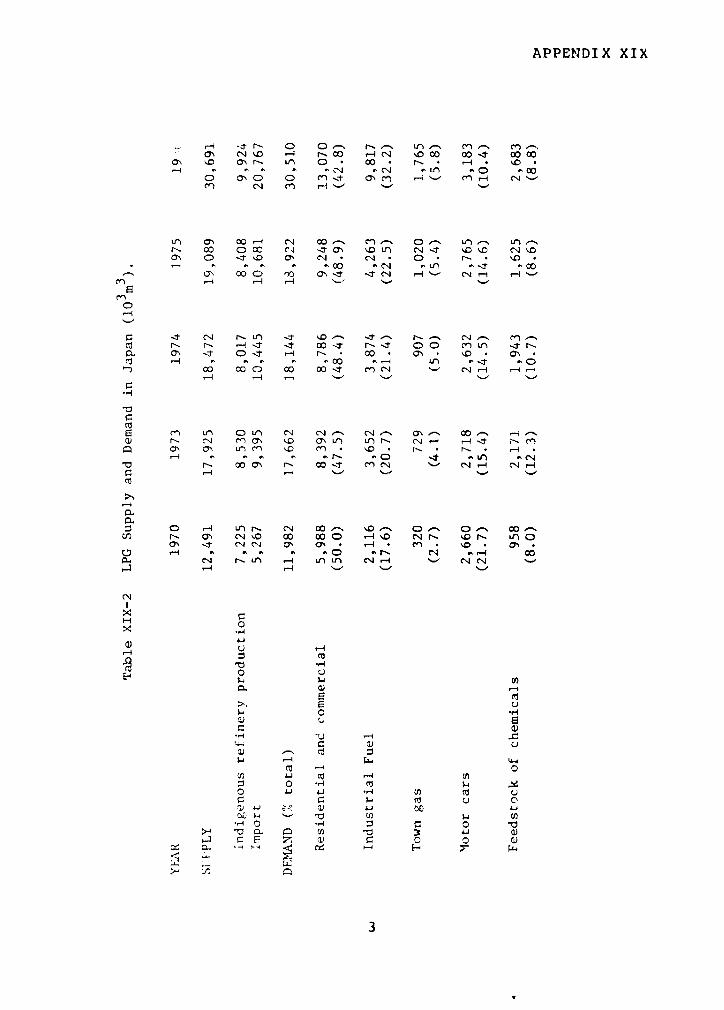
APPENDIX XIX
, ' e'Jr o o *_ r-n o c C) c_
O n '. oor L 0 * 0 r 0 O * 0 * 0 0-
0 00 0 Czt O'C ,-4'- ~ m , '-.v n
Ln all a 1-4 C 0 Mo Oh - I In e4 r- cc oc - a 0 L C4 -1 'D 'IO CIA I'DOl 0 0 - C N N i * 0 r-.
030 o * "0 * N .v 4c Hao mC IT * c' . -4 . r -)' .
.- ma Jc4 -< c 4 n .SC
Cd ~ r'- 0- CD ' 00- N--t 00 CLA r-
rz n n CN CIA _A 00 .-p. a' -< O-t N. 0 * C' * '.I * 0C' -
co x O o: oo c'4 - J-4 ,
-4Cd
0 ^4 L on D C4 00 uD 0 t> 0
r ,> o\ ay o: n cs -o 0 1 u *.c'
to r N aN .0 00oO e4 O 0 ' f o _ in N
-4 -4 r--' 'n ~ un *rl t4 ~ ~ -4 -
Cd
h0
H 0 O4 00 .0-
· " .0 'r- ~ C' .-4 C4C Q
X ·,u
.,4
oto
> r a a (V a) Fo JJ Cd
> '00 a iIa
3

BLANH
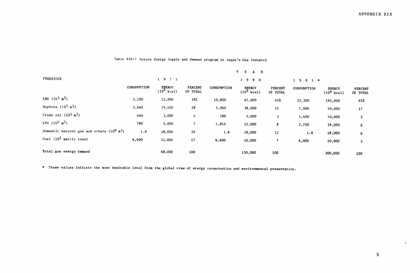
APPENDIX XIX
Table XIX-3 Future Energy Supply and Demand program in Japan's Gas Industry
Y E A R
FEEDSTOCK 1 9 7 3 1 9 8 0 1 9 8 5 *
CONSUMPTION ENERGY PERCENT CONSUMPTION ENERGY PERCENT CONSUMPTION ENERGY PERCENT(10 kcal) OF TOTAL (109 kcal) OF TOTAL (109 kcal) OF TOTAL
LNG (103 m3) 2,100 12,000 18% 10,800 67,000 45% 32,300 195,000 65%
Naphtha (103 m3) 2,660 19,000 28 5,000 38,000 25 7,000 49,000 17
Crude oil (103 m3) 460 3,000 4 700 5,000 3 1,400 10,000 3
LPG (103 m3) 780 5,000 7 1,8C0 12,000 8 2,700 18,000 6
Domestic natural gas and others (109 m3) 1.8 18,000 26 1.8 18,000 12 1.8 18,000 6
Coal (103 metric tons) 6,600 11,000 17 6,600 10,000 7 6,000 10,000 3
Total gas energy demand 68,000 100 150,000 100 300,000 100
* These values indicate the most desirable level from the global view of energy conservation and environmental preservation.
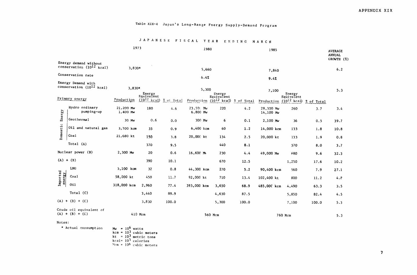
APPENDIX XIX
Table XIX-4 Japan's Long-Range Fnergy Supply-Demand Program
JAPANESE FISCAL YEAR E N D ING MARCH
1973 1980 1985 AVERAGE
ANNUALGROWTH (%)
Energy demand withoutconservation (1012 kcal) 3,830* 5,660 7,840 6.2Conservation rate 6.4% 9.
Energy Demand withconservation (1012 kcal) 3,830* 5,300 7,100 5.3
Energy lnergy FnertyEquivalent Equivalent EquivalentPrimary energy Production (1012 kcal) % t__ TotaI Production (1012 kcal) Z of Total Production (1012 kcal) % of Total
Hydro ordinary 21,200 Mw 180 4.6 23,50( Mw 220 4.2 28,300 Mw 260 3.7 3.4pumping-up 1,400 Mw 6,800 Mw 14,100 Mw
,5 Geothermal 30 Mw 0.6 0.0 300 Mw 6 0.1 2,100 Mw 36 0.5 39.7U
Oil and natural gas 3,700 kcm 35 0.9 6,400 kcm 60 1.2 14,000 kcm 133 1.8 10.8
Coal 21,680 kt 150 3.8 20,00C kt 134 2.5 20,000 kt 133 1.9 0.8
Total (A) 370 9.5 440 8.1 570 8.0 3.7
Nuclear power (B) 2,300 Mw 20 0.6 16,600 MW 230 4.4 49,000 Mw 680 9.6 32.3
(A) + (B) 390 10.1 670 12.5 1,250 17.6 10.2
LNG 5,100 kcm 32 0.8 44,300 kcm 270 5.2 90,400 kcm 560 7.9 27.1
Coal 58,000 kt 450 11.7 92,000 kt 710 13.4 102,400 kt 800 11.2 4.P
E Oil 318,000 kcm 2,960 77.4 393,000 kcm 3,650 68.9 485,00C kcm 4,490 63.3 3.5
Total (C) 3,440 89.9 4,630 87.5 5,850 82.4 4.5
(A) + (B) + (C) 3,830 100.0 5,300 100.0 7,100 100.0 5.3
Crude oil equivalent of(A) + (B) + (C) 410 Mcm 560 Mcm 760 Mcm 5.3
Notes:
* Actual consumption Mw = 106 wattskcm = 103 cubic meterskt = 103 metric tonskcal= 103 calories-cm = 106 cubic meters
BY THE' COMPTROLLER GENERAL
Report To The CongressOF THE UNITED STATES
Liquefied Energy Gases Safety:Federal Agency Comments
VOLUME 3 OF THREE VOLUMES
CF,,. ST - ,,2
A'Cdo ~ . s

PREFACE
This is Volume 3 of a three-volume report. Volume 1contains the Executive Summary and the report chapterswith conclusions and recommendations. Volume 2 containsthe appendixes that support and supplement the findingspresented in Volume 1.
In keeping with our policy, the draft of this reportwas provided for comment to all Federal agencies havingresponsibility for the matters discussed. This volumecontains the formal, written comments from:
-- Department of Commerce
-- Department of Energy
-- Department of State
-- Department of Transportation
--Interstate Commerce Commission
--National Transportation Safety Board
Due to the breadth and potential impact of the report,over 50 private companies were also provided with copiesof the report chapters in which they were discussed. Wereceived written comments from 34 companies. These areavailable for review at the U.S. General Accounting Of-fice, 441 G Street, N.W., Washington, D.C.
We agreed with many of the commen'.s and have madeappropriate revisions in the final report. We also dis-agreed with many of the specific comments, which we eval-uated at the end of the relevant chapters in Volume 1. Inaddition, chapter 21 of Volume 1 provides an overview ofthe most important concerns discussed in the report.

C o n t e n t s
Page
VOLUME 3
PREFACE
APPENDIX
I Department of Commerce 1
II Department of Energy 30
III Department of State 47
IV Department of Transportation 48U.S. Coast Guard 50Materials Transportation Bureau 110Federal Aviation Administration 151Federal Highway Administration 152Federal Railroad Administration 157
V Interstate Commerce Commission 164
VI National Transportation Safety Board 173
APPENDIX I APPENDIX I
UNITED STATES DEPARTMENT OF CnMMElr.The Assistant Secretury for Policya Whlngron. r- 20230
February !4, 1978
Mr. Henry Eschwege, DirectorCommunity and Economic DevelopmentDivision
United States General Accounting Office441 G Street, N.W.Washington, D.C. 20548
Dear Mr. Eschwege:
Attached are preliminary comments on the General Arcounting Office'sdraft report prepared for the Congress on LNG, LPG and Naptha Safety.While the comments on the report are critical of many of the findingsand the structure of the report, the Department of Commerce would hepleased to discuss these comments with the GAO staff and is willingto help in any way to support your efforts in the analysis of thisimportant issue. With additional time to evaluate the rather voluriinouisreport, the Department's comments could have been final and more s, tantive.
Several agencies of the Department of Commerce commented or variouschapters of the report. The Maritime Administration (MarAd), being activelyinvolved in the construction and operation of liquefied natural gas ships,was directed to develop and coordinate the Department of Commerce's re-sponse. In addition to MarAd's comments, a review of the draft documentwas undertaken by the Office of Ocean, Resource and Scientific PolicyCoordination (OORSPC), the National Fire Prevention and Control Administra-tion (NrPCA), and the National Oceanic and Atmospheric Administration(NOAA). Where the comments of these organizations have been incorporatedin this reply, their abbreviations are noted in parenthesis following thecomment.
In our view, this GAO draft report is misleading and should be compre-hensively reworked. Although it contains much useful material, it doesnot present the kind of balanced, objective analysis upon which rationalpolicy can be based. It is in essence a highly imaginative and alarmistcompendium of potential disasters, rather than a dispassionate review oftheir actual probability of occurrence. It ignores in large part theprocedures and technology that have been developed as safeguards againstthe kinds of incidents it describes. It should be reworked if only toplace in proper perspective thc valuable material that it does contain.
The magnitude of the GAO's comprehensive document, delving into riostall aspects of transportation, storage and distributicn of liquefierenergy gases (LEG) will invite significant conrents, debate and challengefrom other government agencies aId private industry. We assume the
1

APPENDIX I APPENDIX I
opinions of these informed sources will be permitted equal status with
this report in order to avoid any acceptance of the erroneous impressions
created by the draft document.
The Department's response is divided into two prime categories, (I)
Overall Comments and (II) Chapter Comments. A conclusion section (III)
completes the response.
Si $ erely,
/ w ./I ant / C,mes W. Curlinputy Assistant Secretary for Policy
Enclosure
2

APPENDIX I APPENDIX I
T. OVERALL COMMENTS
Character cf Report
1. The GAO draft report raises some very important questionsrelative to handling and storage of liquefied energy gasesand with some editing and tightening will serve as a veryuseful reference and source guide for discussion of thesafety issues which it raises. (OORSPC)
2. The report, at the same time, suffers from its verycompendium-type character especially in its attempt tccover all forms of energy gases, as many safety issuesas possible, and in its lack of systematic analyticaltreatment of each of the issues raised. Many questionsare raised that are not answered. An extensive number ofrecommendations are made without pros and cons beingweighed. As a survey of issues, the report is excellent;as a program for action based on reasoned and dispassionateanalysis, it is somewhat less useful. (OORSPC)
3. The GAO study lumps together LNG, LPG and naphtha forpurposes of this analysis. The validity of such an approachis recognized for the broad study that GAO has executed.However, the properties of each component of LEG may besignificantly different and may warrant different researchprojects, regulations and standards. "Federal, State andLocal Regulations" of Chapter 21 recognizes the distinctionsin discussing regulations applicable to storage facilities.(NFPCA)
As a result the report often confuses the reader byattempting to deal with LPGs and naphtha, as well asLNG. In some issue areas and chapters the discussionis entirely with reference to LNG (e.g. Chapter 13).Often the reader is not sure until late in the discussionthat reference is being made to only one particular ICG.It may have been better if the report had dealt with LNGalone. This is what most people who have aot read thereport, but who have heard of it assume to be the subiect.LNG terminal siting and terminal operations are majorpublic interest questions at the present. Hence, thevalue of a single focus. (OORSPC)
3
APPENDIX I APPENDIX I
4. The organization of the report and its reliance on a"topical" structure is also a drawback to readabilityand a disappointment to those expecting to find a coherentand systematic treatment of LNG or LPG safety issues. Asystems breakdown to include liquid gas delivery, transfer(unloading), storage, distribution, along with a discussionof the hazards and risks associated with each systemcomponent, a discussion of the empirical and experimentaldata available on each, and an estimate of ultimate riskswould have been more helpful. It is recognized that thesurvey character of the study makes this more traditionalstudy approach less appropriate, but why choose an orderof presentation that starts off with the 1944 Clevelanddisaster? One can only assume it is for psychologicalimpact. (OORSPC)
S. While the report on the whole is well written anddoes a very good job of living up to its promise to keepthe technical discussion in terms a layman can understand,it still needs considerable tightening and a singleeditorial hand. At present it seems fragmented, becauseof its length and the number of chapters and appendicesinvolved. There is also a good deal of repetition inthe device used to restate key facts and data presentedearlier in a chapter as "findings" at the end of thechapter. The uncertain use of the "headings" systemchosen (in some cases 3rd order heads seem to supersede2nd order heads) makes for confusing reading at times.(OORSPC)
Tone of the Report
i. On an overall basis the tone of the report gives thereader several erroneous impressions. First, that liquefiedgases are the most dangerous of '11 bulk commodities beingtransported in bulk today. Second. each accidental spillor discharge will result in a catas rophe. Third, presentdeign, construction and operating regulations are inadequateand are not providing a level of safety judged by the GAOstaff as being adequate -o the public.
2. It is a well recognized fact that in complex systemssuch as hazardous material transport and storage, theexposturc to the risk of an ac ident and the possibility

APPENDIX I APPENDIX I
of some form of sabotage exists. However, the potentialdangers must always be weighed against the desiredbenefits attainable through the use of these products.We should never let ourselves reach the point wherepotential dangers prevent us from functioning in a logicaland rational manner, or delude ourselves into thinkingthat because of the real or unreal potential dangers wewould be better off without the use of these energy resources.If the alarmist nature of this draft report is believed byCongress and the American people to be a correct portrayalof the dangers in handling LNG, we are in real dangerthat the above attitudes will become prevelant. For thegood of the country this report must be carefully examinedfrom an unbiased view in order that fear will not sweepus away, to the detriment of our energy needs.
Since the GAO draft report is alarmist to the extreme, itis entirely possible that those valid conclusions andrecommendations in the report will be overlooked if theoverall credibility of the report, as a whole, is questioned.It is our belief that this is a distinct possibility.
3. It is illogical to believe that government officialsfrom the many agencies that are involved in regulatingliquefied energy gases would permit participating companiesto engage in unsafe operating procedures that would proveultimately inadequate and unsafe to the public. However,this impression is given by the draft report.
4. A noted serious shortcoming of the draft report isthe lack of statistical information on marine, truckingor rail performance regarding the transportation, storageand distribution of LEG. The historical experience obtainedto date, if presented, would serve to document the safetyrecord which has been attained in recent years with re3pectto handling dangerous commodities. Vast amounts ofhazardous materials have been moved safely for years, yetthe draft report neglects to submit this data for theconsideration of Congress. Such information would tendto negate the false impression that the contingent governmentagencies are not fully concerned with the safe handlingof liquefied energy gases.
5. The tr,,e of the report is an over-reaction to thehazards of LEG with an overbearing emphasis placed uponcatastrophic scenarios. These scenarios rely primarily
5

APPENDIX I APPENDIX I
on hypothetical situation and ignore the vast amount of actualexperience in transporting or storing dangerous cargoes. Thecatastrophic scenarios are, in turn, used to derive findingsthat safety standards, regulations, practices, etc., aredeficient and incapable of providing adequate safety measures.
6. The failure to note any positive developments or improve-ments in LNG and LPG safety over the years, e.g., cryogenictechnology, metallurgy, storage techniques, tanker construction,warning and navigation systems, is a serious omission. Nomention is made of the very impressive safety record of LNGindustries here and abroad since LNG has been transportedinternationally in quantity and since some 75 peak shavingplants here in the U.S. have been in operation. The failureto say anything on the positive side contributes to the impres-sion that the report suffers from a "worst case" syndrome; orworse, that it is biased; or worse yet that it engages in"scaremongering." The problem is that this impression, falsethough it may be, diverts attention from the many veryimportant (and valid) points made, e.g., the need for increasedregulatory attention to LNG and LPG safety issues and theneed for a more focused and early-resuilts oriented researcheffort in this field. (OOPSPC)
6
APPENDIX I APPENDIX I
Sabotage
1. The detailed descriptive nature of the chapter onsabotage is unnecessary, potentially dangerous andshould be omitted in its entirety from the final reportin its present form. We strongly urge the GAO tocarefully consider the type of information presentedand its method of presentation before including thischapter in the final text. It is entirely possible, inoui opinion, that the extensive sabotage details onweapons, ammunition, methcds of sabotage, etc., coupledwith television exposure of a sensational variety, couldlead to the very sort of situation the report hopes toprevent. Irrational groups and persons who have absolutelyno conception of LEG will seize upon the possibilitythat hijacking an LNG truck, for instance, could serveas a means of attaining an objective, in a manner similarto the rash of plane hijackings which publicity had arole in expanding.
2. The report is literally inundated with the conceptof sabotage to the point where all other safety aspectsare relegated a back seat. We most seriously suggestthat a clear look be given at the role of sabotage inthe report, and while it may be included as a generaldiscussion, its dominant position should be reduced.
3. The section on sabotage presents a very provocativediscussion. Findings that a determined group of terroristscould penetrate an LEG facility are not surprising. Infact, based upon our experience, the same finding wouldhold true for marine, truck or rail terminals handlingchlorine, phosphorus, vinyl chloride, anhydrous ammonia,and other products requiring maximum protective orsignificant preventive measures from a safety standpoint.The reason these terminals could oe penetrated is relativelyfundamental, namely, a "peacetime" environment is deemedto exist throughout the U.S.
4. It would appear that the GAO would desire to installa wartime security system in order to achieve an acceptablelevel of safety. Among the numerous recommendationsput forth in the report is that the Secretary of Transportation"systematically determine the critical vulnerabilities to
7

APPENDIX IAPPENDIX I
sabotage of ships carrying hazardous materials in U.S.ports and require appropriate preventive and itigatingmeasures." Does this imply that military ships be usedto escort LNG vessels in coastal areas, or that commercialcarriers should be outfitted with degaussing systems toachieve an acceptable strategy to avoiding sabotage? Whileit is important to strive to improve safe operatingconditions, it would be inappropriate, during peacetime,to establish a system of martial law capable of thwartingall potential attacks during the transportation, storageand distribution of these commodities.
5. Assuming that weapons are available, and sabotageis attempted at a facility, if shots are fired and storagetanks punctured, this still does not necessarily meanthat a massive rupture or more important an explosionwould take place. To support this point, actual experiencecan he examined.
In November 1974, a ship collision took place at theentrance of Tokyo Bay involving the PACIFIC ARES andthe LPG tanker YOYU MARU NO. 10. The YUYO MARU reportedlywas loaded with 20,202 tons of propane, 6,442 tons ofbutane and 30,831 tons of naphtha. Although some 30 liveswere lost, primarily because of the failure of the PACIFICARES crew to abandon ship immediately, the YUYO MARU continuedto burn for some three weeks. Ultimately, the decisionwas made to sink the ship. Because of the compartmentationand safety features built into the ship, it took fourdestroyers, four frigates, four antisubmarine frigatesand finally a submarine to sink the vessel. Reportedly,they fired 857 shells, 12 rockets, depth charges and fourtorpedoes. Since the GAO study team visited Japan it issomewhat surprising that the difficult task of sinkinga large, approximately 50,000 cubic meter LPG vessel wasnot included in the report. Here, the initial fire andprobably the loss of 29 lives from the PACIFIC ARES, wasdue to the naphtha and not LPG. The report tends toconcentrate on theoretical situations, rather than mentioningactual occurrences.
The points to be learned from this occurrence was that:(1) there were no explosions with the arsenal of weaponsused, and K?) the compartmentation and safety featuresof lPG vessels are greater than GAO realized. A majortheme running throughout the report is that liquefiedenergy gases present catastrophic explosion possibilities
8
APPENDIX I APPENDIX I
through sabotage. The YUYO MARU showed it is very difficultto cause an explosion. Surely a terrorist group would notbe allowed the time and effort the Japanese spent to sinkthe vessel.
Since LNG vessels are viewed by the report as significantlyless vulnerable than LPG vessels, the possibility of theeffective use of sabotage on LNG vessels resulting in ancatastrophic occurrence is even less remote.
Liability and Compensation
1. The conclusions and recommendations with respect tostatements requiring that the companies involved insupplying LNG and LPG be liable to the full extent ofthe assets of their parent corporations would be totallyunacceptable to any corporate board of directors. Ifthe liability conditions suggested by the GAO were tobe imposed on the industry, the effect would surely bethe total withdrawal and disinvolvement of privateenterprise with LEG projects or any project that hasunlimited risk. No private corporation could assume thattype of exposure in any one element of its overallbusiness activities. Such a requirement would have thesame effect on the industry as the Cleveland disasterin 1944, which ar the report indicates virtually haltedthe use of LNG for 20-years.
2. It is very important to offer a reasonable level ofcompensation for accidents to injured parties, especiallyprivate citizens who suffer losses as an extension ofa major mishap. It would seem reasonable that beyond someacceptable level of private financial responsibility thatthe Federal Government would have to assume the role ofensuring that individuals and businesses are compensatedfor offsite damages. It would also be impractical tosuggest that the facility operators be released from totalfinancial responsibility, but there should be a ceilingestablished which places a limit on the corporate exposure;a figure that would permit activities to proceed withoutadding a prohibitive insurance expense. The cost ofmaintaining r specified level of liability insurance isa charge that the consumer will have to ultimately bear.
9
APPENDIX I APPENDIX I
3. The extensive treatment given to questions ofliability and compensation detract from the main thrustof the report -- safety issues, risk analysis and theadequacy of current regulatory arrangements in this area.Liability matters could well be the subject of a separatereport. It is almost disingenuous to justify theirinclusion in this report on the basis that withoutextensive liability potential, LNG companies may not beadequately motivated to pursue all possible safetymeasures. (OORSPC)
GAO's Conclusions
1. It is stated in the introduction to the report thatthe Federal Government has not acquired sufficientknowledge or competence regarding LEG, and therefore,because of this lack of information the Government hasbeen unable to act prudently in protecting the public'shealth and safety. Based upon the experience of thisDepartment and its relations with other governmentorganizations in shipping and shipbuilding matters theGAO's statement is improper. The Maritime Administration'sactivities require our constant association with the CoastGuard, both in Washington and in field assignments. Ithas been our experience that the Coast Guard follows veryconservative procedures to ensu:e safety in the constructionand operation of American flag LNG ships. If some uncertaintyexists, the authorized practi:es and margins of safetywill usually prove to be in excess of what is required toprovide adequate protection of life at sea and theresources in our nation's harbors.
2. The report's conclusions are slanted with a continualobsession for using hypothetical situation:s. Many "ifs,""probably," "might" and "could lead to" statements areconsidered in order to derelop catastrophic scenarios theresearch staff wishes to entertain. For exanmple, thedikes surrounding LEG facilities are critized as beingcapable of containing only one half of the fluid "if"a tank should tip over, or "if" its walls should rupture.No statistics are provided or available to verify theaccuracy of this statement.
10
APPENDIX I APPENDIX I
3. In the transport system it is argued that "if" anLNG ship is struck by a sufficiently large vessel goingfast enough, a very large spill could result. It isquestioned whether or not the GAO has made studies toaetermine how large the ship would have to be, and howfast it would have to be moving at the time of thecollision to cause the alleged very large spill. Whatconstitutes a veiy large spill? No figures are presented.
4. With respect to transportation on land, the reportindicates that because truck trailers carrying LNGhave a higher center of gravity than other tank trucks,they are susceptible to rolling over and resulting inexplosions. It would have perhaps proved interestingif GAO would have fully documented the number of instanceswhen explosions have occurred. The report in Appendix IXI - "Some LNG Truck Accidents," provides meaningful dataon experiences to date, which seems to contradict GAO'sconclusion in this area. In the twelve accidentsdocumented, including six rollovers of the trailer andone with a roll down an eighty foot embankment, no firesor explosions resulted. No catastrophe. In fact, therecord seems to indicate that present construction oftrailers is rather good and seems sufficient for theservice.
5. Truckers are critized some for not taking precautionsto prevent hijackings, yet no information with respectto how many hijackings, if any, have occurred is furnishedby the GAO.
6. Trucking accidents, such as supposing that the vehiclerams; through a guard rail and splits open on city streets,are mentioned. The disaster occurring from this isdescribed as one in which the sewers, tunnels, subways,etc., would be filled with gas vaporizing and mixing withair in flammable proportions. No actual occurrences arereferenced. It is our opinion that before reaching theseconclusions, the GAO should have statistics available tosupport the ideas and losses suggested.
11
APPENDIX IAPPENDIX I
7. These types of fabricated conclusions, along withinappropriate analogies, such as, comparing World War IITbombing raids with potential LEG accidents, indicateclearly that the draft report lacks a logical anddocumented foundation on which to build its conclusions,
LNG Shipping
1. It is particularly pleasing to find that the reportacknowledges that LNG ships are the least vulnerablesegment of all the systems involved in LNG transportationand storage. In view of the almost continuous flow ofnegative statements and lack of a presentation of thebenefits accruing from LNG, it is especially meaningfulto receive some token of praise from the GAO researchersand their independent consultants.
2. LNG transportation is still in its infancy. Containmentdesign, methods of joining dissimilar metals, specia"lcryogenic steels, electrical control circuitry and equip-
ment improvements are constantly being developed as thissegment of the shipbuilding market matures. The MaritimeAdmi.istration is proud of the role it has played inproviding financial and technical assistance enablingAmerican shipbuilders to participate in the developmentof the import market for LNG. Three American shipbuildershave built or are constructing sixteen 125,000 cubic meterclass ships and a fourth shipyard holds a contract toconstruct two other vessels.
3. It should be emphasized that before a shipyard embarkson a production schedule, detailed plans and specifications,welding procedures and essentially all elements whichaffect the ships' structural strength and safety arereviewed by or must be in compliance with the regulationsof government agencies including the U.S. Coast Guard,the Federal Communications Commission, the U.S. Departmentof Health, Education, and Welfare and the TreasuryDepartment's Bureau of Customs. Requirements of the American
12
APPENDIX I APPENDIX I
Bureau of Shipping must also be adhered to. Inspection andenforcement of quality control is maintained throughoutthe construction period by the Federal Government, theclassification body and the owner's representatives.
4. American flag vessels are built in accordance withnumerous marine construction codes prepared and testedby professional engineering organizations in addition tothe Coast Guard regulations. The Maritime Administrationhas every reason to believe that our ships are built tothe highest standards in the world and that these provenmethods applied to LNG ship construction will meet thescmitinv of any unbiased organization studying the marinemode of transportation. It is recognized that themultitude of regulations which American shipbuildersmust comply with does add significantly to the constructioncosts. However, our country is provided with a fleetof efficient and safe vessels directly under the controlof U.S. corporations. These American flag vessels willbe required to be maintained in full compliance with theoperating regulations of the Coast Guard and all otherpertinent port authorities throughout their economiclifetime.
5. The delegation of surveillance and regulating authorityand the coordination of these responsibilities isproducing a sound mode of transportation which the GAOapparently recognizes. There is no reason to believe thatsimilar responsible criteriaare not or cannot be appliedto shoreside facilities to ensure the highest level ofsafety and protection in the entire process of storingand distributing energy from liquefied energy gases toAmerican industries and to the homes of our citizens.
GAO's Recommendations
1. The draft report gives no indication what the additionalcosts will be for LNG, facilities, transport modes, orfederal and state government operations if recommendationsmade by the GAO are implemented.
13

APPENDIX I APPENDIX I
2. The GAO recommends that the Secretary of Energy andthe Chairman, Federal Energy Regulatory Commission (FERC)"reconsider their possible authority to assert jurisdictionover LNG companies." It is our understanding that FERCis no longer responsible for LNG import projects. TheEnergy Regulatory Administration, in the Department ofEnergy, has the responsibility.
We strongly oppose giving any agency of the Department ofEnergy jurisdiction over LNG tanker owners or operators.The Department of Energy has no maritime expertise. BothCoast Guard and the Maritime Administration do, andtherefore, these agencies should continue to have jurisdictionin matters related to the waterborne transport of liquefies'energy gases.
3. The creation of an overall energy safety regul -yagency may have some merit. However, there does notappear to be evidence that support has been rallied oreven if the case for such an agency has been made.
Detailed comments pertaining to specific chapters ofthe report are provided in the following section.
14
APPENDIX I APPENDIX I
II. 'CIHAPTER COMMENTS
Chapter 2 - LEG Primer
1. This cbhpcer provides a brief overview of the chalacter-istics and history of liquefied energy gases with the emphasisbeing placed on LPG and LNG. The chapter would be substantiallyreinfc -Ad if statistics were given on commodity mrovement ofnot or LNG, LPG and n" htha, but also gasoline and oti.erhazardous commodities; such as, Chlorine and phosphorus. Thelatter would serve to place in better perspective the dailymoveir:nts of hazardous materials, as opposed to LEG.
2. Information on the exports and imports of major hlazrdouschemicals for 1976 compiled by the Bureau of Census showsthat slightly more tYan 1,000,000 tons of Class 1 and 2 chem-icals (products which require maximum and significant preventivemeasures, respectively) were imported to or exported from theUnited States. Actual movement within the U.S. for 1976 wasgreater than this amount since the statistics do not showaJcts produced and consumed within the country. Neverthe-
the movement of chemicals compares with the import/exportJ75,000 tons of gasoline, 970,009 tons of propane and. 000 tons of naphtha. Propane would be considered a2 hazard, whereas, gasoline and naphtha are Class 3.iire a degree of containment) hazards.
While the GAO draft expresses concern about LNG and LPG, ther-is as great and possibly greater movement of equally hazardousmaterials being transported on a normal and routine basis. Thesignificant poirt is that large quantities of hazardous materialsare moved dail' ; and out of the country on a relatively safebasis; hence, .o-called dangers of LNG and LPG must beplaced in , ~pective with the movement of these other products.
3. The report indicates there are approximately 16,300 LPGrail tank cars and 25,000 LKC transport trucks. Statisticson the number of gasoline tru ks, chemical trucks, ':argesand railcars needs to be presented again to place the move-ment of LEG in perspective.
4. Thus far, there have been over 2,700 voyages completedby LNG tankers with a perfect safety record. The reportshould also present statistical information on the number
15
APPENDIX I APPENDIX I
of actual shipments completed by LNG trucks. Sta*isticsdocumenting actual LNG service performance have not beenassembled and would be most revealing.
5. In discussing Japan's dependence on imported LNG andEurope's importation projects since 1964, some mention ofthe safety record would be appropriate. In Japan and Europereceiving terminals, revaporizati-n plants and storagefacilities are generally located in populated or industriallydeveloped areas. For example, Yokohoma, Japan, a city witha population of about 2.6 million, has received approximately275 shioloads of LNG from Kenai, Alaska, since 19o9 with aperfect safety record.
Chapter 3 - Cleveland, 1944
1. Why start out the report with this Chapter? Why notincorporate the Cleveland disaster in Chapter 11 - "LargeUrban tires"? The point will still be made that a majoruncontrolled spill can bring catastrophic consequenses.(OCRSPC)
2. The narrative of the 1944 collapse of a LNG storagetank and the resultant fire and destruction is most illus-trative. However, this industrial accident, which tookplace 34 years ago, must be placed in the proper perspective.Technology of construction safety and cryogenics have madeenormous advances over the past 34 years as one would expectin a manner similar to ot'er technologies; such as, medicalcare, aircraft and space flight.
3. The fact that the GAO had to go back 34 years to find amajor LEG storage facility accident points out the recentsafetv record of LEG facilities resulting from the enormousadvances in cryogenic technology, LEG construction, safety,nd reliability.
4. Although alluded to in the narrative, the draft reportfails to stress the seriousness ot the oversights that con-tributed to the indu'trial accident in the ( st place.These oversights could not happen with today's technology
lb
APPENDIX I APPENDIX I
strict construction safety codes and sophisticated andredundant monitoring equipment. For example, any facilitywould be immediately shut down if frost developed on theouter tank walls, and the defect corrected.
Chapter 5 - Vulnerbility of LEG Facilities to Sabotage
1. This chapter, by the way it is written, has as its obviousresult, the unnecessary arousel of fear and worry about thetransportation and storage of liquefied energy gases. Ifsabotage is a rational design consideration. the facilitydesign and safety of other dangerous material manufacturingand storage sites must be compared to the LEG sites as ameans of assessing the danger. For example, how does theplant design and security compare with petroleum refineries,chemical plants, natural gas pipelines and storage tanksand chlorine barge systems? If such a total comparisonis not made, one can only conclude that the authors wantto arouse the fears of the readers that these are the onlytype facilities that are so dangerous that the subject needbe considered.
2. As noted in the overall comments, we strongly urge thatthis chapter either be omitted in its entirety from the finalreport or that it be rigorously rewritten. If rewritten, itshould include only a general discussion of the vulnerabilityof LEG systems, plants and storage facilities tro sabotage,without including the specifics on weapons and ,xplcsives,their damage capabilities and methods of attack.
3. The rigorous coverage of weapons, explosives and theirdamage capabilities to LEG transportation systems and storagefacilities is something that we would expect to find inmilitary or revolutionary publications and has no place ina GAO study of LEG safety. This type of information couldprovide the stimulus for radical groups to blackmail orattack existing or planned LEG facilities.
4. Assuming that weapons are available, shots fired andstorage tanks punctured, there :s no evidence in the reportwhich clearly confirms tirat a massive rupture or explosionwould take place.
17
APPENDIX IAPPENDIX I
5. We recognize That improvements can be made in security,however, even where elaborate security measures are in force,such as airports where passengers are screened or searched,airplane hijackings by single individuals or small groupsstill continue to take place.
'hapter 8 - Ship Design, Personnel and Operation
A. Ship Design
1. The GAO discussion on LNG tank ruptures due to over-pressure leaves the impression that a tank filled with LNGwould split open wit;, the slightest increase in pressure.This is not so. The settings of relief valves, as is thepressure in the tanks, is quite low. Calculations indicatethat LNG tanks will iot require venting from boil-off whenin port. Even where the safety valves were locked closed,a tank would not rupture anywhere from a few days to acouple of weeks depending on the type of containment system.The maximum time limit for not venting in port for eachtype of containment system has been established by theCoast Guard. As noted in the report, a 125,000 cubic meterLNG vessel can be unloaded in less than fifteen hours.
2. An important factor in assuring the safety and reliabilityof LNG tankers and equipment is the application of an equip-ment test and trial under actual LNG operating conditions.The Society of Naval Architects and Marine Engineers hasrecently published T&R Bulletin No. 5-2, "Gas Trials Guidefor ING Vessels," which provides definitive information ontest procedures to prove the safe and adequate operation ofall systems and their component parts involved with or per-taining to the shipboard storage and transfer of LNG. U.S.flag LNG vessels are using this guide.
H. Personrne
1. The draft report stresses the need for formal trainingof all shipboard personnel having LEG responsibilities andin this we concur. Eight criteria for training are given.While the majority of the criteria are acceptable andreason!able, we find that the references to "simulator" and
18

APPENDIX I APPENDIX i
"simulated environment" to be vague with regard to meaning.Simulators can be extremely costly, both to create and tooperate. Further, simulators, by their nature as we knowthem at present, operate in real time with direct man-machineinterface resulting in low training capacity. That is, asimulator can generally be manned only by the number ofpersons actually used in the operation and the simulationtakes as long as the real time incident. We can agree thatsimulators should be considered in devising effective train-ing systems, but their high cost and low throughput capacitymust be measured against the margin of incremental trainingeffectiveness. Simulators are currently a glamor item intraining. There is a need for extremely careful evaluationprior to committing substantial funds. It is too easy torecomme,- use of simulators without adequate study of costeffectiveness.
2. The training criteria generally are in conformance withthe current Inter-Governmental Maritime Consultative Organi-zation (IMCO) draft, "Resolution on Training and Qualificationsof Masters, Officers and Crews of Ships Carrying LiquefiedGases in Bulk," except in the a,rea of simulators. Consider-ation is being given by the U.:;. delegation to IMCO thatthis resolution be converted to mandatory form and becomea requirement as part of a convention. This trainingprocedure will then be the basis for regulations on trainingof LNG and LPG ship crews.
C. Ship Operations
1. The thrust of the GAO report on directives is that hardand fast safety rules need to be established and that theserules must be applied rigidly in all instances. We disagree.We believe that a more flexible approach with the Coast Guard'sCaptain of the Port having the final decision based on regu-lations, guidelines, experience and the events at hand isproper and has proven effective in the past.
2. The report infers ti,at the Captain of the Port would beswayed from the safe course of action by the considerationof financial interests of the owner of a vessel. We do notknow of any instance wherein the safety of a ship has beencompromised because of the owner's desire to meet a schedule.The report states that a Coast Guard officer working with
19
APPENDIX I APPENDIX I
vessel movements in the Boston Harbor indicated that theCoast Guard considers the cost to shipowners when decidingwhether to hold up a ship's entry. There are many itemsnot of major safety significance that may hold up a ship'sentry. It would be useful to have the report state whatthe instance was where the ship's safety was cumDromisedby considerations of cost to the owners.
3. The report discusses an instance wherein one LEG shiphad entered the harbor and had reached a point where ithad been predetermined that even with a loss of visibilitya ship should proceed to its berth. This is - judgmentmatter in which the dangers of attempting to have the shipturn back to sea may be greater than the dangers encounteredin proceeding to berth. This is an example of why a knowl-edgeable Captain of the Port should be able to make adecision, rather then rely upon rigid regulations.
4. The extent of control of air traffic alluded to in thereport is excessive. The fact that one aircraft crashedin making a landing should not lead to the conclusion thatit can be expected that additional crashes will happenfarther from the airport in the ship's channel.
5. The analysis of the airport situation regarding locationof LEG facilities does not sufficiently indicatc whether theBoston examaple was just that, an example, or the result ofa more comprehensive analysis of LEG siting problems. Thisshould be clarified and if the Logan Airport case is onlyan example, perhaps more potential conflicts in the otherLEG proposed sites should be presented. (NOAA,
6. We are concerned with the recommendation that the CoastGuard should: "require that the deck officer in charge ofcargo operations aboard an LEG ship have no other dutiesin handling the vessel." A non-watchstanding Chief Mateis specified as cargo officer on all currently certificatedU.S. flag LNG vessels. This should, in our opinion, satisfythis recommendation even though the Chief Mate may have otherfunctions, is part of his responsibility, occurring at timeswhen cargo ,perations are underway. In our view the narrowwording of the recommendation is not justified since it carbc interpreted to mean no other duties whatsoever regardless
20

APPENDIX I APPENDIX 1
of whether cargo operations are being undertaken. It shouldbe understood that the cargo officer, who is part of the ship'screw, can have other duties which do not interfere with hisprimary responsibility.
Chapter 11 - Large Urban Fires
1. This chapter sets forth general findings on the natureof fires caused by LEG incidents. We agree with the funda-mental concept that such fires may have many ignition pointsfar from the urban facility or location of the spill.Although we support the basic findings of the chapter, wedo not believe that its analysis extends far enough. Forexample, the chapter should consider the present ability ofmost energency services to plan and to respond to suchincidents. Studies qholi 1 be initiated for both the presentsituation and alternative approaches in the event of LEGfires. One recommendation of the studies may be that theindustry or government should be required to make resourcesand training available to all energy services which could bereasonably affected by the storage, transportation or useof LEG. (NFCA)
Chapter 12 - Liability and Compensation
1. The draft report notes that insurance clubs limit theamount of protection and indemnity coverage available fora U.S. flag ship to the value of the hull while imposingno limit for foreign-flag vessels. We believe a technicalerror has been made inasmuch as the limit is $200 millionfor U.S. Flag ships without regard to the value of thehull.
2. It is suggested by the draft report that this limit onU.S. coverage reflects the U.S. statutory limitation on theliability of shipowners and charters. However, many of theprominent maritime nations have statutory limitations onthe liability of shipowners and charters. Moreover, twointernational limitation of liat,lity conventions are currentlyin force and a third was adopted in 1976, although it is notyet in force.
21

APPENDIX I APPENDIX I
3. The report fails to discuss the generally recognizedfact that U.S. courts, in many cases, will not enforce theU.S. limitation of liability. On the other hand, it isgenerally accepted in this area of the law that foreigncourts do, in most cases, enforce limitation statutes.
4. The draft report suggests that the disparity betweenshipowner's statutory liability and available hull insurancemay encourage shipowners to keep ships in service that areof questionable safety. The Department of Comnn.erce has noinformation to indicate such a conclusion. Further, sinceexisting LNG vessels are relatively new and modern, therelevance of this suggestion is not clear.
Chapter 14 - Detonation and Flame Propagation Research
1. This chapter summarizes the research on vapor cloudsand flame propogation. We believe that the summary isthorough and may be of value even to members of the public,who are not experts in the field. (NF-PCA)
2. The critique of ERDA's LEG research activities areparticularly relevant and the GAO suggestions are valid.GAO could improve upon taie report by carrying this analysisone step further. The specific suggestion we would like tomake regarding the type of research ERDA should do (inconjunction witi, those studies recommended by GAO) is thatERDA begin a research program designed not only to describeand predict detonation and flame propagation, but also todetermine what remedial measures can best be used to fightsuch conflagrations. That is, research not only how flamesnill is likely to behave, but also research what to doabout it. (NOAA)
3. he agree there is a need for intensified and expeditedresearch and testing. It is not clear, however, why theERDA program cannot be modified to accomplish this.(OORSPC)
4. We do net agree with the lack of need for data collectionbased on large experimental LNG spills. This may be the onlygrod way to test the models now being used or proposed (i.e.,dispersir,o models.) (OORSPC)
22
APPENDIX I APPENDIX I
5. Chapters 13 and 14 (and Chapters 7 and 8) contain muchdetailed scientific information. Perhaps the report could bemore effective if these data were placed in their entiretyin an appendix. The major points extracted and placed inthese chapters would benefit decisionmakers who may notread through the complex scientific study results to getto the analytical results. (NOAA)
Chapter 18 - Japan LNG Use
1. The analysis of Japanese LEG operations is excellent.We note, however, that only findings and conclusions weremade. We suggest that the Japanese experience be furtheranalyzed and recommendations be made based upon this. Thecoverage of Japanese experience is incomplete withoutrecommendations that would enhance the treatment of LEGactivities in the United States. (NOAA)
Chapter 21 - Overall Conclusions
1. In general, many of the conclusions reached in the GAOdraft report are not substantiated by the text of ttle report.Conclusions not substantiated by fact or scientific reasoningshould be eliminated.
2. We strongly believe that both the benefits and hazardsassociated with LEG should be discussed in detail. However,one without the other does not facilitate the making ofproper or beneficial decisions. In its entirety, the GAOdraft report discusses, within the framework 7f catastrophescenarios, the apparent dangers associated with LEG. Nowherein the report is there discussed the long safety record ofLEG or the benefits that will occur through the continuedsafe import, transportation, storage and distribution ofLEG. This is a major shortcoming of the report.
3. The report states "... because many large LEG tanks withsmall safety margins will be impacted by winds, floods, orearthquakes greater than those they are required to withstand,it is likely that some of them will fail; probably by turningover on their side, immediately spilling all of their contents."
23

APPENDIX I APPENDIX I
This appears to be an overstatement of the hazard. Are fulltanks as likely to overturn as empty tanks? In order thatthis statement be substantiated, it is recommended thatexamples be used whereby similar existing storage tanks,such as petroleum, chemical, crude oil, etc., have failedunder these conditions, spilling all of their contents.
4. The methodology used by GAO to calculate overflows fromdikes should be fully described. It is important to verifythis methodology experimentally, before asserting exactlywhat will be the magnitude of an overflow. The likelihoodof massive failure or collapse should also be estimated.
The report fails to discuss or scrutinize the constructionand capacity of currently planned dikes for new LEG storagefacilities. These dikes will be capable of containing avolume greater than 100 percent of the capacity of thestorage tanks they will surround.
5. The conclusions on LNG ship transport fail to take intoconsideration the actual safety record of LNG vessel trans-portation worldwide. There have been over 2,700 LNG voyagescompleted with a perfect safety record. LNG vessels havethe most modern, sophisticated navigation and collisionavoidance equipment availa.ie today. Resprisible authoritiesworldwide have developed safety rules intended to insure thatthe LNG vessels are not involved in collisions.
6. The draft report states that "no specific plans or equip-ment exist to cope with a major LEG spill, or to partiallyoffload and thus lighten an LEG ship that has gone l.ardaground in inland water." Tne Marine Board, under jointsponsorship of the Maritime Administration, the Departmentof the Navy and U.S. Coast Guard is currently investigatingthis subject.
7. The GAO staff appears to disregard the validity of existingsmall scale experimental test results. On the other hand,the)' state DOE's plans for large expenditures to createfacilities for very large experimental spills is not anappropriate way to spend LNG safety research funds. Thisinconsistency should be corrected. Either large scale testsmust be performed, or small scale tests must be accepted asbeing va'id.
24
APPENDIX I APPENDIX I
8. In describing Japanese LNG storage areas, the reportinfers that vertical reinforced concrete dikes are superiorto sloped earthen dikes frequently used in the United States.However, in another section of the report it was impliedthat sloped dikes offer superior resistance to sabotage.Such inconsistencies should be resolved.
9. The report states that the Japanese believe that irgroundtanks are intrinsically safer than abore ground systems.What evidence of this exists? Have ar/ inground tanks beensubject to flooding or earthquakes? The conclusion thatLEG safety facilities should be inground may be premature.
Chapter 22 - Recommendations
1. The GAO draft report recommends that the Secretary ofTransportation enforce numerous security measures to protectLEG facilities against intrusion. It is suggested that thefinal GAO recommendations for the LNG/LPG industry beexpanded to apply to the entire U.S. chemical/petroleumindustry. It makes little sense to propose very strictrequirements for one segment of the U.S. industry and ignorethe 1,000,000 ton (plus) of equally hazardous materialsgoing in and our of the United States, plus the l. geamounts moving domestically.
2. The GAO recommends that the Commandant of the U.S. CoastGuard "require calculations on collision resistance for allvessels carrying hazardous cargoes." This requirement appearspremature at this time. Presently, there are no .equirementsor criteria for determining what resistance is needed. Inaddition, the assumptions concerning the structural configuration,speed, angle of incidence, and a iumber of othier factorsmake such calculations largely on academic exercise. Wewould, however, support the need for other work in the areaof collision resistance.
3. The GAO recommends that the Commandant of the U.S. CoastGuard "require precision position fixing equipment, bridgecontrol of main engine, and collision avoidance systems asa means of improving the maneuverability of gas carriers,man) of which already have this kind of equipment." We fully
2.
APPENDIX IAPPENDIX I
agree. MarAd has been leading in this area for a number ofyears. All LNG vessels built under MarAd's aid programshave or will have, when constructed, this equipment onboard.
4. The GA() recommends improved training for LEG personnel.The report notes that human error is the maJor contributingfactor in 85 percent of all marine casualities and operatingproblems. This would also hold true for truck, rail andterminal casualities regardless of industry. More rulesare not the sole path to safety as the majority of accidentsthat take place have already violated existing rules. There-fore, the GAO recommendations for improved training can beendorsed.
S. The report recommends that the Commandant of the CoastGuard "require pressure-activated switches on LNG shipsentering UI.S. waters that automatically shut off relevantequipment in case there is too high a differential pressurebetween the cargo tanks and the atmosphere or between thecargo holds and the atmosphere." We recommend that thissafety device also be included on LPG ships.
6. The GAO recommends that Congress amend the 1851 CharterAct limiting the liability of shipowners and bareboat chartersof ships by substantially raising the statutory limit forvessels carrying hazardous materials. The United Statesparticipated in the 1976 international conference whichadopted the new Convention of Maritime Limitation ofLiability. The United States, in that conference, supportednew monetary limits which would in many cases result in verysubstantial increases over the limits that would result fromapplication cf the 1851 statute.
Presumably, there would be no objection to substantial limita-tion increases in line with the availability of commercialinsurance at a cost which would not be unacceptable from abusiness point of view. Any proposed legislation should beconsistent with U.S. efforts in intenational law to developa uniform approach to liability for hazardous materials. Inthis regard, the IMCO !egal Committee has given some preliminaryconsideration to the question of how to treat hazardous materialsrelative to the concept of limitation of liability. Overall,as far as the recommendations for legislative proposals areconcerned, they would, of course, all require executive branchreview and decision prior to this Department taking anyposition on them.
26
APPENDIX I APPENDIX I
7. The GAO recommends that Congress pass legislation thatwould "allow injured parties in a hazardous material accidentto sue individually or as a class, for all damages beyondthose covered by insurance and the Fund, all of the companiesin the corporate chain." The Department of Commerce stronglyopposes this GAO recommendation as noted in the overallcomments.
27
APPENDIX I APPENDIX I
III. CONCLUSION
1. Based upon the nature of this Department's commentsit should be evident that we have serious reservationson the report. These reservations have necessitated thelength and detail of our response.
2. Liquefied natural gas and liquefied petroleum gas arehazardous commodities that require safe handling andstorage. In fact, the high energy content and cleanburning properties of these fuels are the exact reasonsfor the growing demand by U.S. cor-limers for suchenergy sources to support industria. growth and employmentfor workers, heating and lighting fcr homes and families,and all the other uses that collectively keep this nationmoving forward.
3. The overwhelming incontrovertible evidence is chatthe United States needs to continue to develop its capacityto import LEG in order to supply our nation's gaseousenergy requirements in the future decades. Without theprojects and the facilities which are currently in useand being developed to meet the demand for our nation'senergy needs time will quickly start to work against theestabi;s;!ment of properly planning for the requiredfacilities, located in isolated areas where the impactof an accident or act of sabotage would have minimaleffect on lives and offsite property. The long rangeplanning, regulatory action, and financial commitmentsto import LNG to the U.S. presently requires many yearsof effort. These undertakings should not be curtailedbecause of generalized and erroneous claims of potentiallymassive losses allegedly attributed to unsafe transportationand storage systems and the performance of federal agencies.
4. Finally, we believe that the overall safety recordof the U.S. LNG/LPG industries has been good. Certainlythe number of annual fatalities is well below the 50,000deaths cited by the GAO draft report for automobiles. While
28

APPENDIX I APPENDIX I
improvements in safety may be needed in certain areas,the GAO report does not document that public safetyhas been compromised. In fact, the LNG safety recordhas been virtually perfect and thus we must concludethat the tone of the GAO report is highly misl adinq.
29
APPENDIX II APPENDIX II
Department of EnergyWashington, D.C. 20545 1978
Mr. Morte Canfield, Jr., DirectorEnergy and Minerals DivisionU. S. General Accounting OfficeWashington, D. C. 20548
Dear Mr. Cawfield:
We appreciate the opportnmity to review and comment on your draft reportentitled "Liquified Fnergy Gases Safety." We have reviewed the draftwith members of your staff and we understand that some changes andclarifications are being made.
We generally agree with the technical content of the suggested researchtasks and note that most portions are well written and finely edited.However, we believe that the time and cost estimates developed by GADare optimistic. Also, we assume that the suggested program is not meantto be inclusive of all research and development necessary as it did notcover work such as further analyses of existing models, development of asuitable facility, conducting many small scale tests (5-1003 m) prior tolarger scale spill tests, detailed plans including complete procurementactions and the analyses of present release prevention and controlmechanisms, and the investigation of possible additional mechanismsor procedures.
Also, we believe that our present liquid energy gases safety plans ascontained in our report "An Approach to LNG Safety and EnvironmentalControl Research" contains work elements which, if completed, wouldanswer most existing LNG safety questions.
The report also states that the Department of Energy (DOE) shouldundertake an effort to establish safety standards for LNG facilities.Our offices of Natural Gas Regulations, Oil and Gas Policy, andPolicy and Program Evaluation are currently undertaking a joint effortin the area of safety and siting of LNG inport facilities. Theseoffices are developing a Programmatic Environmental Impact Statementfor imported LNG which will address many of the same issues raised inthe report. It is expected that this effort will be completed thisyear as an element of the overall development of our LNG import policy.
We note that GAO recomnends that the Congress create a new agency tohandle all energy health and safety regulations and that the agencycould be completely independent of the DOE or included in DOE withstrong statutory provisions to ensure its isolation. We do not believe
30
APPENDIX II APPENDIX II
that the report substantiates or supports the need for such arecommendation and, in our opinion, it is inappropriate in view ofthe recent establishment of the DOE.
Enclosed are more specific comments on various chapters of the report.The comments pertaining to the content of Chapter 15, "Federal PowerCommission," have been grouped into six general categories and pagenumbers cited for ease in identification. The comments on Chapter 15were prepared by staff and have not been reviewed or approved by theFederal Energy Regulatory Commission and the comments should not beconstrued as representative of the Commnission.
Sincerely,
Fred L. Hiser, DirectorDivision of GAO Liaison
Enclosure:As stated
31
APPENDIX II APPENDIX II
COMMENTS ON GAO DRAFT REPORT
"LIQUIFIED ENERGY GASES SAFETY"
CHAPTER 1
Page 1, para. 1: "Naptha .. much less dangerous material (than)LNG and LPG."
It is foreseeable that each of these commodities will be most hazardousunder a given set of circumstances. The GAO should stipulate and docu-ment the information which permits them to reach this conclusion.
CHAPTER 2
Page 3, para. 1: "Both LPG an2 LNG clouds can explode in confined spaces."A reference giving data to support this conclusion should be providedto the readers. Is any particular geometry or configuration assumed?
Page 9, para. 1: "The liquid vapor ignited . . ."A more correct statement would be "Vapor from the spilled liquidignited .
CHAPTER 5
General: We believe that this chapter had too much technical weaponsinformation that has little to do with the security issue. Itwould be sufficient to state that minimum security standardsshould be established at LNG sites.
Page 16, para 1: ". . . was enough air to dilute the rich vapor to theflash point."
The statement is not technically correct; we suggest that "flashpoint" be replaced with "flammable range."
CHAPTER 7
Page 24, NOTE:It is not clear why the spill volume percent from the Philadelphiatank was exluded from computing the average percent spill. This shouldbe documented with a reference available in the public domain.
General: Concerning LNG flow over containment dikes, remedies to thisproblem, including suggested design changes, should be spelledout.
CHAPTER 8
Page 11, para. 3: "A minor spill can escalate to a major spill Lhroughfailure to take prompt corrective action."
This point has been recognized and properly identified in the DOE
32
APPENDIX II APPENDIX II
assessment. Negotiations to initiate a project on this subject arepresently underway. Significant results are expected by December1978.
Page 41, para. 3:Same response as above
CHAPTER 11
General: No documentation or data is introduced to support claims con-cerning che effects of spills creating large urban fires.
CHAPTER 13
General: This section critizes current theoretical assumptions butproposed alternatives are not substantiated or described at all.
Page la, para. 2: ". . ., we make detailed suggestions in this and thefollowing chapter for a program that would cost muchless, take less time, and get more useful results."
The research tasks in Chapters 13 and 14 are certainly appropriate.However, the program identified is incomplete and, therefore, to someextent, misleading and perhaps even misrespresentative of the natureand extent of the problems to be solved. DOE engineering analysessuggest that the GAO time and cost estimates (given without anydocumentation) are very optimistic.
Page 8, last para: ". . . large scale experimentation is not scheduleduntil FY 1982."
Page 9, para. 2: "It is unlikely that timely useful information willcome from this program."
In reviewing the Technical Plan section of the draft DOE report, "AnApproach to LNG Safety and Environmental Control Research," the GAOapparently failed to realize that safety information will becomeavailable on a continuous basis throughout the program. If fundedin its Entirety, the program foresees many experiments in the range5-100 m before planned large scale experimentation. If fully funded,many of these tests will be completed within 2-3 years.
Page 9, para. 1: ". . . the questions may be moot since most facilitieswill have already been approved."
The safety of the existing peak shaving plants, satellite facilities,export and import terminals (approximate total of 100) should beconsidered. Construction of future additional storage facilities must
33
APPENDIX II APPENDIX II
be anticipated, especially if gas is discovered off the east coast(to be transmitted ashore as gas, then liquefied and stored for useduring periods of pead demand). Th:s is an operational option which,at this time, cannot be discounted.
Page 10, para. 1: ". . . accurate spill models could be completed byearly 1979."
At the ERDA (now DOE) sponsored LNG Workshop in December 1976, some40 persons expert and interested in LNG formed a consensus thatadditional models are not deeded at this time. The crucial problemis the determination of scaling laws. Experiments of several ordersof magnitude will be necessary to validate (or disprove) existing3models. A consensus supporting a maximum spill experiment of 1000 mwas agreed upon. Recommendations which emanated from the Workshopwere circulated to all attendees to obtain their further review andcolment. Most attendees responded promptly. It should be noted,however, that the GAO respresentative at the meeting did not providecomments. Considering the number of intermediate sized experimentsnecessary to develop appropriate scaling laws, a completion time of1979 is considered unreasonable.
Page 14, para. 5: "We believe that . . . rtsults for distance flamma-bility . . . to be five to ten times too low."The technical basis for this conclusion should be given.
Page 15, para. 1: "Testing of models and suitable improvements to themcan be made by small scale experiments along withlarger size tests of scaling. Results should beobtainable in one to two years."Existing models can be analyzed and improvements hypothesized (12-18months). Some small scale tests can be conducted to begin the processof verifying the models. However, large scale experiments are manda-tory. Large scale experiments cannot be conducted within the CAOsuggested two year time frame without sacrificing the implied safetyand sophistication needed of a series of experiments of this magnitudeif such experiments are to be meaningful.
Page 18, last para.and page 19: OPSO and the Coast Guard have studiedstudies be done by the agencies involved in regulatingthe areas."
A suggestiou of this nature mmans a continuation of the fragmentedFederal R&D effort relating to LNG, LPC, etc. It also supports thenotion that regulatory agencies should perform research (on a costsharing basis with industry). Such an arrangement raises questionsas to conflicts of interest and objectiviLy of the resultant researchand development.
34
APPENDIX II APPENDIX II
Page 20, para. 1: "The present plan to channel the bulk of LNG safetyresearch through ERDA . .
We are not aware of any such plan.
Page 13, para. 3: "Large expenditures to create facilities for very largeexperimental spills are not a sensible wcy to spend LNGsafety research funds."This statement is in conflict with other GAO statements that largeexperiments (400 m3) should be accomplished. At the present time, theonly expe ,m~ental facility designed to spill commodities such as LNG exists at ,he Naval Weapons Center, China Lake; its capacity is 5.7 m3.To conduct any 'arger experiment, whether it be 35, 100, 400, or1000 m3 , will require the preparation of a new facility.
CHAPTER 14
Page 2, para. 1: ". . ; fact that no accidental detonations are known
It is suggested that this be changed to read ".. fact that noconfirmed accidental detonations are known . . ." The positivenessof the original statement misleads the reader.
Pages 3-5: Statement of the ProblemThis section is nicely written and reflects much thought or. behalf ofthe author. The problem areas are objectively outlined.
Page 13, para. 2: ". . . the data are not extensive enough to providegood estimates of vapor cloud concentration contours."This statement points out the inadequacy of present researchinstrument capabilities. Present vapor sensors are not able to dis-criminate among the various species present in an LNG -sapor clord norare the response times adequate to determine concentration contours.A joint DOE/USCG NASA/AGA(GRI) task is presently analyzing instrumentdesigns to collect the needed data. Significant progress will beavailable by December 1978: The importance as well as the time andcost of this effort was not addres ed.
Page 15, para. 2: "For a considerable larger spill, the flame . . . maycrease its own strong inward wind . .It was for reasons such as :his th.at the attendees at the ERDA (nowDOE) sponsored Workshop generally concluded that experiments of up to1000 a- were needed.
Page 16, para. 3: "Experiments have demonstrated that . . . unconfinedmixtures of air with the LNG and LPG . . . willdetonate .
This is true for LPG. The statement relating to LNO is not true--theresults to date remain inconclusive.
35
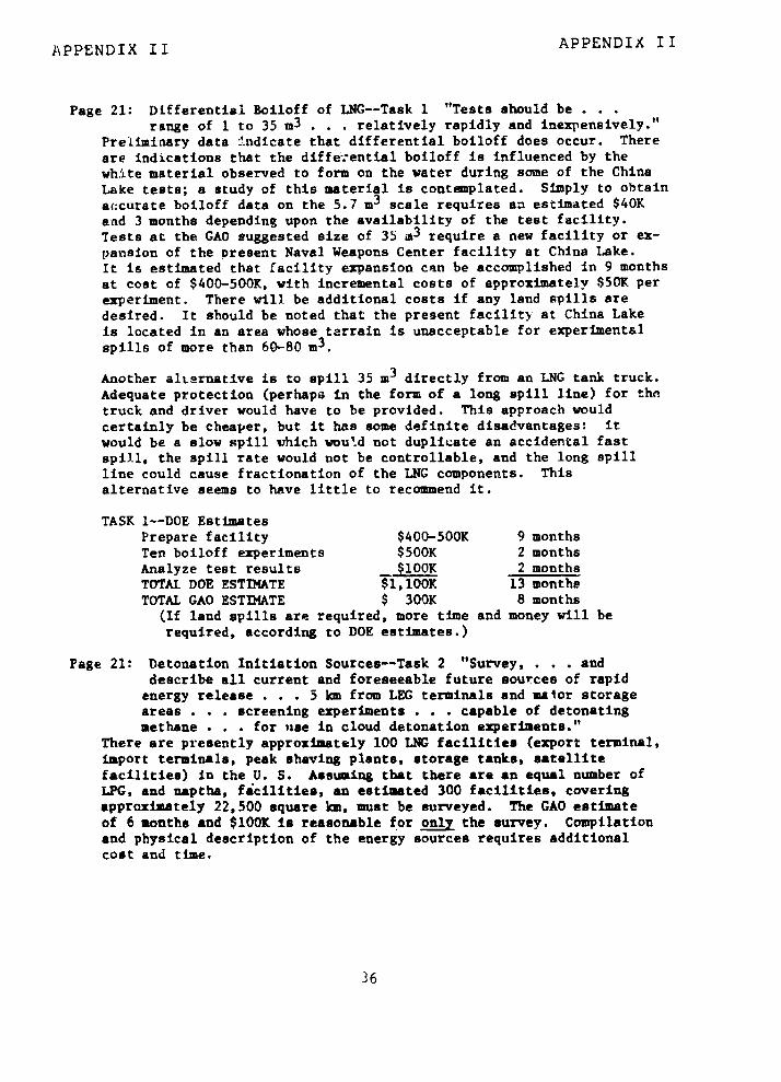
APPENDIX I I APPENDIX II
Page 21: DI)fferential Boiloff of LNG--Task 1 "Tests should berange of 1 to 35 m3 . . relatively rapidly and inexpensively."
Preliminary data indicate that differential boiloff does occur. Thereare indications that the differential boiloff is influenced by thewhite material observed to form on the water during some of the ChinaLake tests; a study of this material is contemplated. Simply to obtainaccurate boiloff data on the 5.7 m3 scale requires an estimated $40Kand 3 months depending upon the availability of the test facility.Tests at the GAO suggested size of 35 m3 require a new facility or ex-pansion of the present Naval Weapons Center facility at China Lake.It is estimated that facility expansion can be accomplished in 9 monthsat cost of $400-500K, with incremental costs of approximately $50K perexperiment. There will be additional costs if any land spills aredesired. It should be noted that the present facility at China Lakeis located in an area whose terrain is unacceptable for experimentalspills of more than 60-80 m3 .
Another alternative is to spill 35 m3 directly from an LNG tank truck.Adequate protection (perhapa in the form of a long spill line) for thetruck and driver would have to be provided. This approach wouldcertainly be cheaper, but it has some definite disadvantages: itwould be a slow spill which would not duplicate an accidental fastspill, the spill rate would not be controllable, and the long spillline could cause fractionation of the LNG components. Thisalternative seems to have little to recommend it.
TASK 1--DOE EstimatesPrepare facility $400-500K 9 monthsTen boiloff experiments $500K 2 monthsAnalyze test results _$100K 2 monthsTOTAL DOE ESTIMATE $1,100K 13 monthsTOTAL GAO ESTIMATE $ 300K 8 months
(If land spills are required, more time and money will berequired, according to DOE estimates.)
Page 21: Detonation Initiation Sources--Task 2 "Survey, . . . anddescribe all current and foreseeable future sources of rapidenergy release . . . 5 km from LEG terminals and maior storageareas . . . screening experiments . . . capable of detonatingmethane . . . for use in cloud detonation experiments."
There are presently approximately 100 LNG facilities (export terminal,import terminals, peak shaving plants, storage tanks, satellitefacilities) in the U. S. Assumring that there are an equal number ofLPG, and naptha, facilities, an estimated 300 facilities, coveringapproximately 22,500 square km, must be surveyed. The GAO estimateof 6 months and $100K is reasonable for only the survey. Compilationand physical description of the energy sources requires additionalcost and time.
36
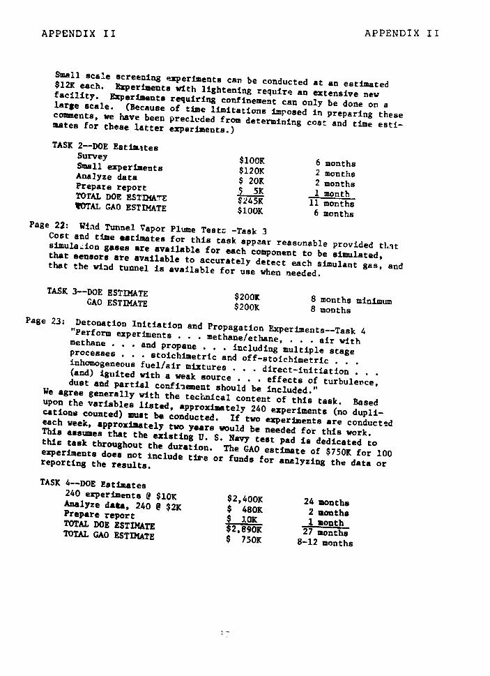
APPENDIX II APPENDIX II
Small scale screening experiments can be conducted at an estimated$12K each. Experiments with lightening require an extensive newfacility. Experiments requiring confinement can only be done on alarge scale. (Because of time limitations imposed in preparing thesecomments, we have been precluded from determining cost and time esti-mates for these latter experiments.)
TASK 2--DOE EstimatesSurvey $100K 6 monthsSmall experiments $120K 2 monthsAnalyze data $ 20K 2 monthsPrepare report $ 5R 1 monthTOTAL DOE ESTIMATE $245K 11 monthsTOTAL GAO ESTIMATE $100K 6 months
Page 22: Wind Tunnel Vapor Plume Testz -Task 3Cost and time estimates for this task appear reasonable provided tl.3tsimulation gases are available for each component to be simulated,that sensors are available to accurately detect each simulant gas, andthat the wind tunnel is available for use when needed.
TASK 3--DOE ESTIMATE $2001 8 months minimumGAO ESTIMATE $200K 8 monthsPage 23: Detonation Initiation and Propagation Experiments--Task 4"Perform experiments . . . methane/ethane, . . . air withmethane . . . and propane . . including multiple stageprocesses . . stoichimetric and off-stoichimetric . . .inhomogeneous fuel/air mixtures . . . direct-initiation(and) iguited with a weak source . . .effects of turbulence,dust and partial confinement should be included."We agree generally with the technical content of this task. Basedupon the variables listed, approximately 240 experiments (no dupli-cations counted) must be conducted. If two experiments are conductedeach week, approximately two years would be needed for this work.This assumes that the existing U. S. Navy test pad is dedicated tothis task throughout the duration. The GAO estimate of $750K for 100experiments does not include tire or funds for analyzing the data orreporting the results.
TASK 4--DOE Estimates240 experiments @ $10K $2,400K 24 monthsAnalyze dasa, 240 @ $2K $ 480K 2 monthsPrepare report $ 10K I monthTOTAL DOE ESTIMATE $2,890K 27 monthsTOTAL GAO ESTIMATE $ 750K 8-12 months

APPENDIX II APPENDIX II
Page 24: Large Vapor Count Field Experiments--Task 5 "Conduct . .experiments . . 400 m3 LNG and about 150 m3 of propaneon water and soil, and actempt to detonate . . . withinitiators . . . perhaps 10 to 20 initiators would beactivated simultaneously in each test cloud . . . repeat testswould be performed to provide an adequate statistical base . . .results . . . provide high-confidence answers . . .a programof six tests would cost about $2.5 million . . . planning isaccomplished during the first year. . program could becompleted in the second year."We are in general agreement with the technical content of this task.Results from the 9EDA Workshop provided a consensus that a maximumspill(s) of 1000 ma would be requ'red to establish appropriate scalingfactors. This included a number :f spills of lesser sizes (not men-tioned by GAO) and increasing to 1000 m3. GAO has neglected to includethe time and cost for preparing a facility at which to conduct theseexperiments. An architectural and engineering study performed for DOEhas provided an estimated cost of $16-18 million and 2 years to preparea test facility to spill intermediate as well a-- 1000 m spills atvariable spill rates on land and on water. The cost and time forpreparing sure a facility might be reduced by going to a one-purposesite designed for a stries of demonstrations.
Operating expenses for the facility, exclusive of technical personneland consumable test material, are estimated to be $10OK/month. Atest facility to spill only the GAO recommended volume (400 m3) wouldnot be 400/1000-th of $16-18 million, but rather in the neighborhoodof $10-12 million.
If detonations (10 or 20 HE initiators) are to be integral portion ofthe field program, the facility must be "hardened" to withstand theoverpressures. An estimate of costs to do this is not available.
GAO states that six experiments of this type would provide an adequatestatistical base. To establish such a base, 60 experiments (withoutany failures) are needed for a reliability of 0.95 at the 952confidence level. In addition, these six experiments cannot beaccomplished, analyzed, and reported in one year if results of oneexperiment are to be completely analyzed before doing the nextexperiment as GAO has suggested.
We feel that the entire program will involve approximately 100experiments of varying size. These experiments will consume anestimated 20,000 mJ of LNG at approximately $10/n!3.
38
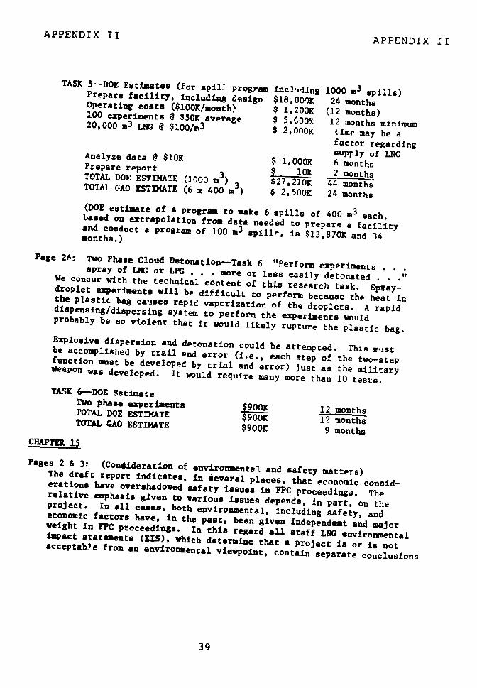
APPENDIX II APPENDIX II
TASK 5--DOE Estimates (for spilt program including 1000 m3 spills)Prepare facility, Including design $18,00K 24 monthsOperating costs ($100K/month) $ 1,20'K (12 months)100 experiments e $50K average $ 5,600K 12 months minimum20,000 m3 LNG @ $100/m3 $ 2,OOOK time may be afactor regardingsupply of LNGAnalyze data @ $10K 1000K 6 monthsPrepare report 3 10K 2 monthsTOTAL DOE ESTIMATE (1003 m )
$2 7,210K 44 monthsTOTAL GAO ESTIMATE (6 x 400 m3 ) $ 2,500K 24 months(DOE estimate of a program to make 6 spills of 400 m3 each,based on extrapolation from data needed to prepare a facility
and conduct a program of 100 m3 spillr, is $13,870K and 34months.)
Page 26: Two Phase Cloud Detonation-Task 6 "Perform experiments .spray of LNG or LPG . . . more or less easily detonatedWe concur with the technical content of this research task. Spray-droplet experiments will be difficult to perform because the heat inthe plastic bag causes rapid vaporization of the droplets. A rapiddispensing/dispersing system to perform the experiments wouldprobably be so violent that it would likely rupture the plastic bag.Explosive dispersion and detonation could be attempted. This mustbe accomplished by trail and error (i.e., each step of the two-stepfunction must be developed by trial and error) just as the militaryVeapon was developed. It would require many more than 10 tests.
TASK 6--DOE EstimateTwo phase experiments $900K 12 monthsTOTAL DOE ESTIMATE $900K 12 monthsTOTAL GAO ESTIMATE $900K 9 months
CHAPTER 15
Pages 2 & 3: (Condideration of environmental and safety matters)The draft report indicates, in several places, that economic consid-erations have overshadowed safety issues in FPC proceedings. Therelative emphasis given to various issues depends, in part, on theproject. In all cases, both environmental, including safety, andeconomic factors have, in the past, been given independmat and majorweight in FPC proceedings. In this regard all staff LNG environmentalimpact statements (EIS), which determine that a project is or is notacceptable from an environmental viewpoint, contain separate conclusions
39
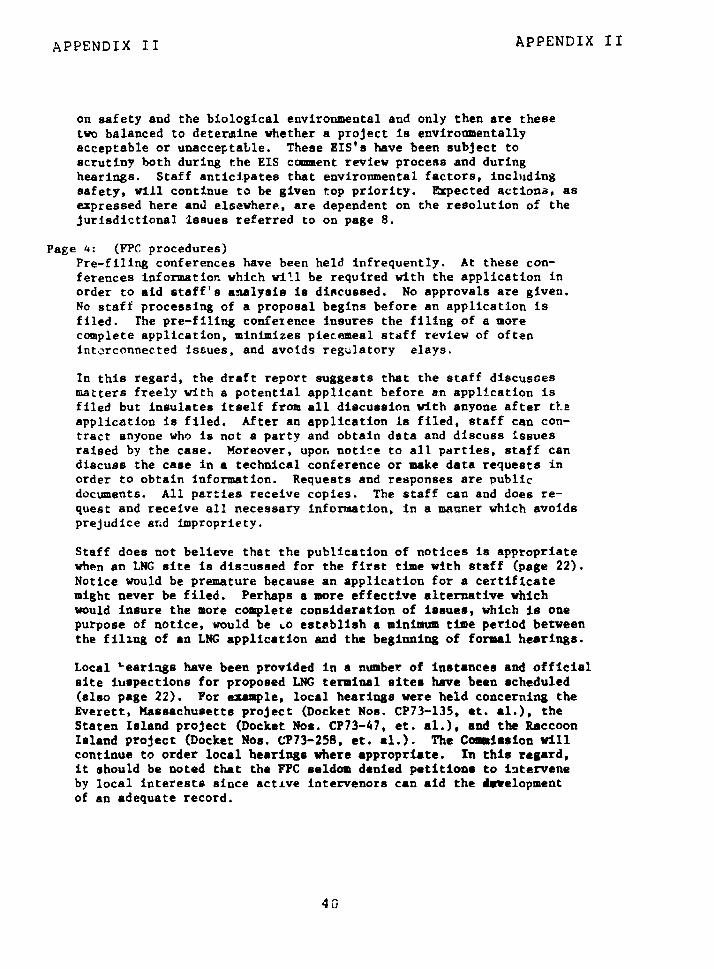
APPENDIX II APPENDIX II
on safety and the biological environmental and only then are thesetwo balanced to determine whether a project is environmentallyacceptable or unacceptable. These EIS's have been subject toscrutiny both during the EIS crmment review process and duringhearings. Staff anticipates that environmental factors, includingsafety, will continue to be given top priority. Expected actions, asexpressed here and elsewhere, are dependent on the resolution of thejurisdictional issues referred to on page 8.
Page 4: (YPC procedures)Pre-filing conferences have been held infrequently. At these con-ferences information which wi'l be required with the application inorder to aid staff's analysis is discussed. No approvals are given.No staff processing of a proposal begins before an application isfiled. The pre-filing conference insures the filing of a morecomplete application, minimizes piecemeal staff review of ofteninterconnected issues, and avoids regulatory elays.
In this regard, the draft report suggests that the staff discussesmatters freely with a potential applicant before an application isfiled but insulates itself from all discussion with anyone after tLeapplication is filed. After an application Is filed, staff can con-tract anyone who is not a party and obtain data and discuss issuesraised by the case. Moreover, upon notice to all parties, staff candiscuss the case in a technical conference or make data requests inorder to obtain information. Requests and responses are publicdocuments. All parties receive copies. The staff can and does re-quest and receive all necessary information, in a manner which avoidsprejudice and impropriety.
Staff does not believe that the publication of notices is appropriatewhen an LNG site is discussed for the first time with staff (page 22).Notice would be premature because an application for a certificatemight never be filed. Perhaps a more effective alternative whichwould insure the more complete consideration of issues, which is onepurpose of notice, would be Lo establish a minimum time period betweenthe filing of an LNG application and the beginning of formal hearings.
Local '-earings have been provided in a number of instances and officialsite iuspections for proposed LNG terminal sites have been scheduled(also page 22). For exmple, local hearings were held concerning theEverett, Massachusetts project (Docket Nos. CP73-135, et. al.), theStaten Island project (Docket Nos. CP73-47, et. al.), and the RaccoonIsland project (Docket Nos. CP73-258, et. al.). The Commission willcontinue to order local hearings where appropriate. In this regard,it should be noted that the FPC seldom denied petitions to interveneby local interests since active intervenors can aid the developmentof an adequate record.
40
APPENDIX II APPENDIX II
Pages 4 & 5: (Staffing)The draft report suggests that staffing is inadequate. It is not clearat the present time what authority the PERC will have -ver LICG ter-minals given tthe provisions of the Department of Energy OrganizationAct. Assuming that the FERC will continue to have some authority inthis area, staffing, as in the past, has been adequate to assess LNGterminal applications. Within FERC, the Office of Pipeline and PloducerRegulation (OPPR), the Office of the Chief Accountant, the Office of theGeneral Counsel, and the Office of Regulatory Analysis all have inputinto processing an application for an LNG terminal. In. tle Euviron-mental Evaluation Branch of OPPR, about 20 professional staff membersparticipate in ,nvironment&l and technical aspects of LNG cases,including safety and design considerations. In adidition, th2 staffefforts of OPPR have been aided through contracts with the NationalBureau of Standards for cryogenic safety an seismic design reviews;private contractors to study siting, safety, .gineering, and economicfea3ibi.ity; and information and data the stff obtains from otheragencies such as the U. S. Coast Guard. The Staff's ability to under-take a complete and detailed engineering, economic, and environmental,including safety, study of too alternative sites in the TAPCO project(Docket Nos. CP77-100, et. al.) is indicative of the quality andadequacy of staff efforts ccncerning LNG terminals.
Pages 5 & 6: (Risk Analysis)The draft report states that the first risk mod l developed by thestaff is, with minor modificat-ins, still in use. While we agree thatthe first model can be said to serve as a base, the staff has suh-stancially refined its risk analysis. These revisions have hadsubetantial effects on safety conclusions as noted below.
Staff continues to undate and refine its risk analysis. The staff isc'.'rently computerizing the risk mode. This will allow a detaiLedsensitivity analysis, utilizing various vapor cloud, fire radiation,and flame propagation models, in the ultimate determination of risk.Strpf is also developing a three-dimensional vapor travel modelsimilar to the Science Application, Inc. (SAI) model. In thatGAO's comments on the SAI model are being reviewed. Staff anticipatesthat this review will continue in the 'uture.
With respect to mcr- specific comments in the draft report, staff hasconsidered the longer clouds which the draft report would predict bychanging Evaporation rate, spill size, plume densities, etc. Thisanalysis has been undertaken despite the fact that the probability ofignition of the cloud approaches unity at a finite distance downstreLa.The primary question generated by changing the assumptions is: Whateffects do these longer plumes have on the conclusions to be derivedfrom the risk analysist Recent EIS's for the TAPCO and El Paso I!
41
APPENDIX II APPENDIX II
projects ask and answer this question. Risks are determined andcompared for both the staff's plume model and for cloud distances upto 16 miles, which is four miles beyond that suggested in the draftreport.
Staff has testified that the "maximum credible shipping accident" foran LNG vessel is the rupture of one cargo tank. On numerous occasionsthe Coast Guard has also testified that the rupture of one cargo tankit the major credible accident for the LNG vessel. Staten Island LNGproject (Docket Nos. CP73-47, et. al.). W-ile staff presently believesthat the rupture of one cargo tank remains the maximum credible shippingaccident, it will continue to assess the probability of shippingaccidents. It should be noted that GAO was asked by an AdministrativeLaw Judge (ALJ) to submit testimony on this and other issues but de-clined to do so. The draft report criticizes ALJ's for not callingfor further evidence.
Potential accidents a- the- terminal itself are -considered in staff'assafety analysis. Land based spills into diked areas have been con-sidered for every LNG import project. The methodology is presented inthe Calcasieu LNG project FEIS (Docket Nos. CP74-138, et. al.).Another evaluation in this area was presented in the Sta'en Island LNGproject FEIS (Docket Nos. CP73-47, et. al.). Staff's general conclusionis that spills from equipment and/or storage tank spills into dikedareas pose little or no significant hazard offsaite, particularly withthe mitigating measures which have been implemented or proposed at allsites analyzed to date or which have been accomplished through scaff'sindependent recommendations. Staff fully expects that review ofpotential accidents at the terminal will continue in the future.
The draft report suggests that the risk model does not consider thetotal number of fatalities which could be caused by a shipping accidentin a specific crowded harbor area and the effect of the density ofpeople and structure on the risk per person per year. We believe thatthis is incorrect. Reference should be made to the following EIS'swhich discuss this matter:
- Final Environmental Impact Statement for the TAPCO project,September 1977 (Docket Nos. CP77-100, et. al.).
- Final Environmental Impact Statement for the El Paso IIMatagorda Bay project, September 1977 (Docket Nos. CP77-330,et. al.).
- Final Environmental Impact Statement for the Everett,Massachusetts, project, September 1976 (Docket Nos. CP73-135,et. al.).
42

APPENDIX TI APPENDIX II
- Draft Environmental Impact Statement for the West Deptford,New Jersey, project, December 1976 (Docket No. CP76-16).
Pages 7, 8, 10 & 16: (Safety analysis of specific sites)With respect to safety analyses at specific sites, the draft reportnotes that the EIS on the Pacific Indonesia LNG Company project (DocketNos. CP-74-160, et. al.) at'Oxnard, California did not consider thatthe site is adjacent to the city's sewer plant where chlorine is storedor that LNG could flow into the system after an accident (page 10). Thestaff was aware of the location of the Oxnard sewage plant about 3,000feet to the northwest of the proposed LNG facility area. The sta'fwas also aware that only sanitary wastes from the LNG terminal would bepumped to the treatment plant through a closed pipeline system. Noopen sewers are involved. Further, the staff was aware that the LNGstorage tanks would be enclosed by individual high-walled concretedikes and'that the perimeter service road around the LNG plant wouldprovide a secondary means of diking. The staff recommended dikingaround- the ING, unloading transfer lines. For- these reasons, spillsinto the sewer system were not considered credible.
The draft report discusses the change in staff's position concerningthe construction of an LNG terminal in th? Delaware Valley (DocketNos. CP73-258, et. al.). During the course of refining the riskmodel, staff initiated a review of prior impact statements using therefined model and, of its own accord, made a decision to supplement itsimpact statement for the LNG terminal in the Delaware Valley. Thisexample demonstrates that the effects of refinements in the risk modelhave not been ninor. Furthermore, subsequent to staff's supplementalimpact statement, which concluded that the site was environmentallyunacceptable because of safety, the application for the terminal waswithdrawn. As noted above, staff anticipates additional refinementsin the risk model when warranted.
The National Bureau of Standards (NBS) and staff have made follow-upvisits to LNG facilities during construction and after operationshave begun (page 7). Visits have been made tc Staten Island, Providence,Cove Point, and Elba Island facilities during construction and to theEverett facilities during both construction and operation. Follow-upvisits have been made to many of the jurisdictional peak-shavingfacilities. The FPC has required semiannual operational reports con-cerning abnormal operating experiences or behavior of LNG terminals.Specific abnormalities are noted. Final design plans for LNGterminals are required to be submitted to the FPC before commencementof construction.
The draft report asserts that the FPC has allowed LNG facilities tooperate in large cities without adequately assessing the threat to ,he
43
APPENDIX II APPENDIX II
public from such facilities. Only one LNG import terminal has beenallowed to operate in or near a large city--Everett, Massachusetts.As noted below, the Everett, Massachusetts project has a uniquehistory among LNG terminal projects. In an event, the FEIS for thatproject provides a detailed analysis of the risks to the public.
The FEIS for the Everett, Massachusetts project also contains recom-mendations on safety which were adopted as conditions by the ALJ inhis Initial Decision. These recommendations required that contingencyplans and procedures in the event of a Major accident be outlined andsubmitted for review. Operational procedures for the storage facilitieswere outlined to alleviate rollover problems. Adequate dike heights,ditching, and land rloping were required to contain LNG in the event ofan LNG transfer line failure. The filing of semiannual operationalreports was provided for.
Page 11: (Sufficiency of environmental impact statements)The draft report asserts that no comprehensive site selection efforthas been made. Review of all staff EIS's on LNG terminals, in partic-ular, recent ones such as the TAPCO project, or the El Paso II MatagordaBay project, shows that comprehensive site studies have been performedby the staff. Potential sites along virtually the entire Gulf Coastand existing terminals along the East Coast were examined in theEl Paso II Matagorda Bay project. Alternative sites along the EastCoast between Maine and New York City were a amined in the TAPCO project.After a complete environmental and economic analysis of two sites bystaff, an alternative site was recommended by staff. This policy of de-tailed considerations of alternatives has been followed by the stafffor a number of years. Staff is presently reevaluating its analysis ofalternative sites along the West Coast. Staff expects that the analysisof alternative sites will continue and be updated as needed in thefuture.
The draft report states that no alternative sites were considered inthe EIS for the Everett, Massachusetts facility. That project isunique and is not representative of staff's consideration of alterna-tives. The facility was originally found to be nonjurisdictional bythe FPC. Therefore, the facility was operational before the EIS wasdrafted. Based on an analysis by staff, the facility wan determined tobe environmentally safe and acceptable. As noted above, visits to thisfacility have been made during both construction and operation; anddetailed safety conditions have been recommended by staff and adoptedby the ALJ.
Staff has advocated combined LNG terminal projects in a number ofproceedings and has investigated the possibility that gas exchange
44

APPENDIX II APPENDIX II
programs would minimize the number of urban LNG terminals (also rage16). Three terminals have been proposed on the East Coast in urbanareas. Since Everett, Massachusetts was the first urban terminal tobe built, no exchange program with other LNG terminals was possible.The Providence, Rhode Island terminal is no longer a viable application;and the Staten Island, New York terminal is still in hearing and stillunder staff investigation.
Staff recognizes the potential benefits of combining terminals as longas safety is not compromised. However, potential obstacles in terms ofspace availability, gas supply and exchange agreements, institutionalproblems, and legal problems will need to be resolved before gas exchangeprograms and combined terminals becomes feasible.
The draft report states that neither environmental impact statements norsafety analyses have been prepared for all jurisdictional peak-shavingfacilities (page 3). An environmental assessment and safety review ismade of all jurisdictional facilities, including, in particular, LNGpeak-shaving facilities, prior to a decision on the need for an environ-mental impact statement. If, based on that review, it is concludedthat approval of a given proposal will not be a "major Federal actionsignificantly affecting the quality of human environment" within themeaning of the National Environmental Policy Act of 1969, then anenvironmental impact statement is not required. Environmental factorsare fully considered in accordance with statutory provisions.
CHAPTER 16
Page 1:LPG does not represent one-fourth of the Nation's energy. At best, LPGcould account for only three percent.
Page 1, para. 4:The statement reading "...the costs of moving LPG are higher than thosefor coal, oil or pipeline gas" provides no documentation of how thesecosts are measured. There is a great deal of dispute, for example,of what it costs to move one Mcf of gas through a pipeline fairlydepreciated versus what it would cost an equivalent unit of energy ofLPG by pipeline, truck, etc., to an ultimate consumer.
Page 2, pura. 2:Documentation should be provided to show how 1980 non-urban termina'scould handle all import requirements for LPG. Are such items asshipping and unloading requirements, ships' turnaround time, siteavailability, etc., sufficient to handle such volumes?
45
APPENDIX II APPENDIX II
Page 3, para. 4:The statement reading "There are many empty natural gas transmissionlines" is incorrect. Pipelines may be operating at low load factorsbut they are certainly not empty.
Page 8, para. 1:Injecting LPG into a gas pipeline has technical limitations and thisshould tc indicated in the statement.
CHAPTER 17
Page 2:Table 17-1 should fully document how the conclusion that LNG suppliesprojected for 1990 coild be handled in non-urban sites. The volumes&re so substantial that absent of a discussion of ship requirements,berth facilities, etc., the statements per se are inconclusive.
46
APPENDIX III APPENDIX III
F FPARr 4 NT OF IA 4TE
February 16, 1978
Mr. J. K. FasickDirectorInternational Division11,S, General Accounting OfficeWashington, D.C.
Dear Mr. Fasick:
I am replying to your letter of January 27, 1978,which forwarded copies of Chapter 8 of the draft GAOreport: "Liquefied Gases Safety." Regarding the sugges-tion made therein that ". . . th Secretary of Stategive strong support to the Coast ;uard's efforts tobring about the adoption of new IMCO training standardsfor ship personnel, " the Department, in conjunctionwith the Coast Guard, has been instrumental in movingforward (to June-July 1978) the joint ILO/IMCO Inter-national Conference on Training and Certification ofSeafarers, which will consider such measures.
This accelerated schedule reflects the great im-.
portance accorded ship's personnel training and certifi-cation in the UoS. initiatives on tanker safety andpollution prevention (TSPP) outlined in President Carter'sMarch 17, 1977 message to Congress. More rapid entryinto force of the IMCO International Convention on Train-ing and Certification of Seafarers should bring aboutsignificant marine safety and environmental benefits farbeyond the transport of hydrocarbons alone.
Thus the combined efforts of the Coast Guard andthe Department to accelerate international action onimproved tanker crew standards and certification proced-ures would seem to have already substantially satisfiedthe cited recommendation in the draft GAO report. TheDepartment will, of course, continue to strongly supportand assist the Coast Guard in this endeavor whereverpossible.
Sincerely,
1; . Williamson, Jr.Deputy Assistant Secretaryfor Budget and Finance
47
APPENDIX IV APPENDIX IV
OFFICE OF THE SECRETARY OF TRANSPORTATIONWASHINGTON, D.C. 20590
ASSISTANT SECRETARYFOR AODMINISTRATION March 27, 1978
Mr. Henry EschwegeDirectorCommunity and Economic
Development DivisionGeneral Accounting OfficeWashington, D.C. 20548
Dear Mr. Eschwege:
We have reviewed the draft report on Liquefied Energy Gases Safety(LEG). The lack of a digest or summary in a report of this lengthand complexity has been particularly disconcerting. Because of thelarge scope and extent of the report, the task of DOT properlyreviewing and commenting on the recommendations proved to be atime-consuming task. Since the report delves deeply into the responsibilities and activities of several DOT operating elemen:ts, we areattaching their detailed comments which we expect will be includedverbatim in your final report.
We have found many of the details insufficient to support the findings,conclusions and recommendations. In some instances, the reportseems to lack a grasp of the complex technical matters addressed.
We believe the perceived threats of sabotage or risks to the publicin the transportation of LEG, and more importantly, the extensivesolutions recommended in the report are overstated. In this regard,the report tends to overlook the many more readily available hazardousmaterials targets for sabotage such as gasoline and poisons. More-over, we believe it is most unwise to include the details of howsabotage could be undertaken, in a report which will be made publicand could be unfortunately suggestive.
4R

APPENDIX IV APPENDIX IV
We oppose the recommendation in the report for inclusion of the safetyaspects of transporting energy fuels in a new 'Tr'ergy Health and SafetyRegulatory Agency to be established Ln the Dapartment of Energy (DOE).These safety functions are now carried out in tle Department ofTransportation (DOT) as part of an overa 1 safety program devoted tothe transportation of hazardous materials r general, including trans-portation by marine vessel. The risks posed by energy fuels are, inmany cases, not dissimilar from other hazardous materials regulatedby DOT which move in volume in interstate and foreign commerce.To separate and transfer the fuel aspects of the hazardous materialprogram, when there are many benefits of a consolidated hazardousmaterials program in terms of regulatory and enforcement actions andR&D, would be inimical to an efficient, comprehensive and well coordinatednational safety program.
The report understates the effectiveness of both Federal and State regu-lations, such as current Coast Guard regulations and the current regulatoryprocess on LNG plant facilities by the Materials Transportation Bureauwhich addresses most of the concerns in the report.
Given the large volume of LEG being moved, we do not feel that thereport adequately discusses the costs of implementing its recommendationsin relation to possible benefits.
As the report is controversial and its recommendations would beextremely costly, it is essential that time and effort be spent to producean accurate and comprehensive docurient. It is recommended, there-fore, that the report be redrafted to reflect the comments of the variousFederal agencies and be recirculated for final comments prior to itsrelease.
Sincerely,
Enclosures
49
APPENDIX IV APPENDIX IV
UNITED STATES GOVERNMENT DEPARTMENT OF TRANSPORTATION
2\lemor1natrm UNITED STATES COAST GUARDem orandum G-MP-15741
DATE I 0 ARIn
SUBJECT: Coast Guard Comments on GAO Draft Report, "Liquefield Energy Gases Safety"
FROM Commandau;t,U.S. Coast Guard
TO Assistant Secretary for Policy and International Affairs
1. Enclosure (1) contains specific comments on the GAO Draft Report,"Liquefied Energy Gases Safety." The following general comments concernthe report:
a. The report lacks overall organization and coordination makingit extremely difficult to study and comprehend the information that theauthors are attempting to convey.
b. The report lacks objectivity by entirely stressing the negative.First, it fails to mention at all the extensive carriage of LPG in bargeson our inland waters or the export of LNG by ships from Alaska. Bothhave a long history of safe transportation and have formed the foundationfor the design, construction and operation of the LNG/LPG ships underquestion in the GAO report. Secondly, there are only a few positivestatements made about the current Government regulations and industrystandards and practices regarding LEG safety. The accomplishments onthe part of both Government and industry appear to have been totallyignored.
c. The report mentions naphtha quite often. The introductionclaims this is done for comparison purposes, but the only comparisonis in the potential harm from sabotage. We wonder why naphtha was usedsince gasoline is more abundant, is more familiar to the layman, and ismore available to the saboteur,
d. The report addresses complex technical matters covering severaldisciplines. It is regrettable, but understandable, that the authorslacked the expertise to fully understand and therefore accurately reportall the information derived in preparing their report. For example, theauthors mistakenly report that Type A tanks on LEG ships are built tothe same standards as bulkheads in oil tankeL's. Further documentationappears in enclosure (1).
2. Since the report is likely to be controversial, recommends theexpenditure of billions of tax dollars, and questions the effective-ness of several Government agencies, it is worth the time and effort
50
APPENDIX IV APPENDIX IV
SUBJ! -Coast Guard Comments on GAO Draft Report "Liquefied Energy GasesSafety"
to produce an accurate and comprehensive document. It is recommended thatthe report be redrafted to reflect the comments of various Federal agencies,This redraft should be circulated for final comments prior to its release
W. H. STEWARTCaptan., U.S. Coant GuardActing Chief of Staft
Encl: (1) Detailed Comments on GAO Draft Report
51

APPENDIX IV APPENDIX IV
Detailed Ccmments on GAO Dratt Report
a. Cnapter 1: There is no statement as to why naphtha is
mruch less dangerous than LNG or LPG. There is no indication
as to how a comparison can be made. There is no supporting
,ji., tenent as to why LNG and LPG are to be considered "highly
dangerous."
b. Chapter 2:
(1) Table 2-2 does not show the physical properties of
naphtha (which vary wioely depending on which type of
naphtha is meant), the fuel the report suppqsedly uses for
comparison. The table, under flash point, lists methane as
a flammable gas, whereas the other entries list the flash
point. The flash point ot methane is -3060F. The heading
-ignition temperature" should be "auto-ignition
temperature."
(2) Page 5 - there is a new 100,000 m2 LPG ship. Also,
cany LNG ships can and do carry LPG.
(3) Page 6 - LPG, as shipped in the marine mode at least,
is not pure propane. Commercial propane contains up to 7S
9thane and has a boiling point closer to -55°F. There are
APPENDIX IV APPENDIX IV
two isomers of butane, one with a boiling point of 31 0F, the
other 110 F.
The tirst paragraph on page 6 suggests thaa a vessel's draft
gJverns the size of LNG/LPG ships. While this is a
c':isideration, the economic factors are more important. The
cubic capacity of a ship is determined by at least three
major tactors - length, breadth, and depth. It draft is
limited, the others may be varied to increase capacity.
The second paragraph mentions two LNG exporters, Algerla and
Brunei. The United States (Alaska) is currently a net
exporter of LNG. It is untortunate that this should be
overlooked, not only in this chapter, but in the entire
report. The report tenas to lead one to think that only
importing LNG is potentially dangerous. Between October
1969 and March 1977 there have been 249 shipments of
domestic LNG from Kenai, Alaska without incident.
In the third paragraph it should be noted that not all LNG
tanks are double-walled. The last line should read '. . .
supported by insulation liniqg the inner hdll.-
(4) Page 7 - There are no systems to warm the astorages
tanks on an LNG ship. There are vaporizers that coula be
53
APPENDIX IV APPENDIX IV
used to luject warm gas into an empty tank prior tc gas-
freeing. While it may appear obvious that one would not
warm LN. tank=s *nile liquid is in them, certain statements
in Chapter 8 (see comments below) indicate that this is not
o",i,),s to the author of the report. In addition, there are
cutreAtiy no Osystems* in use for cooling the tanks either.
The liquid is maintained at its boiling point by drawing off
vapors, but this should not be contused with a refrigeration
or reliquetaction system.
The description of the emergency shutdown system in the
second paragraph .s misleading. There is an emergency
shutdown system on a gas ship with a maximum allowable
relief valve setting (MARVS) of 10 psig or higher. It is
activated automatically whenever the power system fails or,
in the event ot tire, it is activated by the melting of
fusible plugs. It can also be operated matnually. In
addition, there is an automatic overfill shutdown to prevent
tanks from overflowing. Shore facilities may also have
emergency shutdown systems but they are usually manually
activated.
(5) Page 8 - The first paragraph indicates that dikes inthe U.S. are .able of containing 100i of the volume of the
largest tank. Ik, Chapter 18 (page 5) and other places, the
54
APPENDIX IV
report implies that t~hre are no dikes around LNG tanks in
the U.S. See also the comments on Chapter 3.
The third paragraph again ignores the exportation of LNG
front Alaiska.
(6) Page 9 - It is noted that this same accident is
repeatedly mentioned throughout the report. Tc balance the
picture, the modern record of LNG transportation and storage
should be included here. For instance, Japan has extensive
LNG shipment and, since no major accidents are reported, it
is assumed that their operation has proven safe. Also,
there have .een over 2300 shipments of LNG worldwide since
1964, and not one major accident has occurred. If one must
repeatedly refer to an accident occurring over 30 years ago,
which involvea outdated technology, it seems only tair to
point out the lack of accid' nts u'.%/.. modern technology.
See also the comments an Chapter 3.
c. Chapter 3:
(1) The inclusion of an account of the 1944 Cleveland LNG
incident in this report without stressing the fact that the
appe.rent causes of this .%isbap do not exist at today's LNG
facilitles is misleading. The 3.5S nickel all.y steel used
55
APPENDIX IV APPENDIX IV
in 1944 is no longer used for such applications. It should
be Dorle in mind that commercial cryogenics was a very new
tlele, at that time and that technology in this field has now
advanced to a state of high reliability.
(2) In the past ten years more than 150 large tanks have
been erected f r LNG service and not one of these tanus has
tailed in cryogenic service.
(3) The statement under OProvisions for Spills--Pits and
Dikes' that current LNG storage site dikes are designed to
contain only relatively slow leaks is misleading in that
design criteria have changed since 1944. See page 24 of
Chapter 19 ot the report for a more accurate description of
current dike requirements.
d. Chapter 5:
(1) This chapter refers several times to single-hull LPG
ships and compares them to conventional tankers. While it
is true that LPG ships are not required to have an inner
hull, the implication that they are similar to conventional
tankers is erroneous. LPG ships may use the outer hull as
the secondary barrier, but cargo is pot carried against the
outer hull as in conventional tankers. Thus, there are at
56

APPENDIX IV APPENDIX IV
least two "walls" and intervening insulation separating the
cargo from the sea. The majority of LPG ships use
independent, self-supporting tanks within the ship. They
are nicb more resistant to damage than the report indicates.
j2) Two incidents involving explosions in sewer systems
are mettoned; one involved qaphtha and the other weither
industrial wastes or gasoline leaking into a sewer or a
combination of these. e It was stated, with regard to
gasoline, that Oa total leakage of about 1/2 cubic meter
would have provided an explosive mixture sutficient to cause
the disaster.0 The recoLmended security measures would not
preclude terrorists from initiating similar sewer
explosions.
(3) The security measures proposed for LEG facilities, it
imposed continually, are a classic example of an *overkill#
approach to protect one Possible terrorist target while
leaving other equally desirable targets unguarded.
Furthermore, the recommended security measures would not
deter the ettective use of the mortar and rocket weapons
which the repcrt states are 4An the hands of potential
saboteurs. Neither would these precautions at LEG
facilities in any way affect the availability to saboteurs
of gasoline or their access to drains for introducing many
57
APPENDIX IV APPENDIX IV
times the required 1/2 cubic meter into every sewver system
in this country.
(4) It can be shown that a potential threat against LEG
farilL:ies exists and that the results of sabotage could
aftest large numbers ot persons; however, it should be
recognized that there are numerous other facilities handling
vast quantities ot other waterials which pose an equal or
greater threat to communities.
(5) The Federal Bureau of investigation indicates that
tnere is no known threat at this time to any LNG facilities
by terrorist organizations. The probability of a threat
against a vessel is believed to be influenced more by the
vessel's nationality than by the cargo carrier. Should
intelligence information reveal a suspected terrorist threat
to a specific facility or vessel, appropriate additional
security measures would be taken.
e. Chapter 6: The Coast Guard does not sponsor research
aimed at quantitative determination of critical crack length
for spherical and cylindrical ships cargo tanks used co
transfer LNG and LPG. However, the Coast Guard requires the
designer to determine these lengths. Tben, through
extensive non-destructive testing and inspection during the
58
APPENDIX IV APPENDIX IV
tank construction, flaws are limited to a very small size.
it , frlaw werP to grow, it would grow to a small through-
crack and allow detection of the leaked gas long before the
crack ever approached critical crack length. Laboratory
1- :t'i.n, for the aluminum spherical tanks has shown that it
would require several ship-lives of loading to grow a
fatigue crack to a length approaching critical crack length.
Technology in this area has advanced considerably beyond
what was available in 1944.
f. Chapter 8: Many ot this Chapterrs recommendations were
made basea either or, misconceptions or on isolated examples,
Although more effort was expended in reviewing this chapter
than any other, time aid not permit more than the correction
of the errors rather than a thorough explanation of the
Coast Guard's program tor satety ot liquefied gas ships.
since many ot the findings and recommendations are based on
inaccurate or misunderstood statments, they should be
reconsidered. The following specific comments apply:
(1) Page 3, paragraphs 2 and 3 - Move Osecondary
barriers- from the category areactive safety features- to
"preventive satety features" to establish their importance
and function. Providing a secondary barrier is tantamount
to having another tank outside the primary barrier; it is
59

APPENDIX IV APPENDIX IV
intended primarily to contain any leaKs which might develop
in the primary barrier rather than to combat the effects of
an accident. That fact is not brought out in the report and
the fact that a secondary barrier is required is often lett
ul-:rent4 oned. lhis change would be consistent wita the
inclusion of "secondary barrier" in the discussion of
*preventive characteristics" on pages 4 and 5.
(2) Page 5, 1st paragraph - Polyvinyl chloride and
polyurethane toam insulations may also be load bearing.
(3) Page 5, 2nd paragraph - Add at the end of the first
sentence "Current designs tar exceed the 15-day
requirement."
(4) Page 6 - The description of LPG tank design in the
second paragraph is erroneous. The IMCO Gas Code has no 'Al
type" tapr, and LPG tank resign and stress analysis has
nothing to do with "tank bulkheads in oil tankers.' The
reference to wdeep tank standards" xn Proposed 46 CFR
154.439 identities a calculation standard fo.- Type A tanks,
since their structural arrangement lends itself to this most
conservative shipboard stittened plate analysis. The tact
that the additional loads required to be analyzed are not
addressed here should be corrected. In fact, LNG and LPG
60
APP'INDIX IV APPENDIX IV
,hi.ps aJike must meet the same standards set forth in the
IMCO Gas Code. The major ditterences would result from
warmer service temperatures and higher specific gravities
for LPG cargoes. There Is no foundation for drawing a
l.s: jt ,istinction between LNG and LPG tank design
standards. Additionally, typical tank materials are 2.5%
nickel and carbcn manganese steel, not 2.5% nickel steel.
There are no "single wall" LPG ships. The outer hull may
act as tne secondary Larrier, but cargo is not carried
against the outer hull (as in most oil tankers) as the last
sentence implies.
(5) Page 7, paragraph 4 - It is not clear what would be
achieved with similar studies on other designs. The minimur
distances between outer hull and tank boundaries are, by
regulation, the same for all types. The difference lies in
some variation in probability that a tank boundary will be
involved with certain penetrations into the LEG vessel.
More information is being sought through research on
collisions for ships in general and the knowledge gained
will be useful for application to LEG vessels.
(6) Page 8, last paragraph - The reference to proposed
Coast Guard rules may imply that the design parameters
referred to were not previously considered. This is not
61

APPENDIX IV APPENDIX IV
true; the Coast Guard's Letter ot Compliance (LOC) program
has included these for many years.
(7) Page 10, last sentence of paragraph continued from
~p9'" 8 - Delete the sentence, mHowever, data on buckling of
membrane designs are not required." Membranes by definition
cannot withstand compressive loads. The design must
preclude compressive loads. Maximum allowable pressure
differential;, for memtranes are calculated and pressure
control (both pressure relief and vacuum protection) of both
sides is required.
(8) Page 10, last paragraph - The cargo rank pressure is
normally maintained by the equipment described in the
report, namely the gas compressor control system (LNG) and
the cargo reljquefaction equipment (LPG). To prevent damage
due to external overpressure, certain redundant systems are
provided as follows:
(a) Rupture discs and safety valves are provided for
the inert gas generator supply header to prevent
overpressurization of the inter-barrier and-hold spaces,
(b) Safety valves or rupture discs are provided for
the hold and inter-barrier spaces, and
62
APPENDIX IV APPENDIX IV
(c) Either vacuum relief valves are fitted on the
'dargo tanks or independent pressure switches are provided to
give an alarm ano subsequently stop all equipment taking
suction on the cargo tank before reaching the maximum
external pressure differential.
Additionally, numerous alarm systems are required on the LNG
vessel to provide early warning of conditions that might
develop into a dangerous situation.
(9) Page 11, paragraph 1 and 2 - The second paragraph
appears to exaggerate the vulnerability of LNG tanks to
sabotage by isolation. The manner in which this could be
accomplished zs oversimplified, the amount of vapor
generated is overestimated, and the importance of
calculating tank bursting pressures is overstated. The
Oblocking # ot a satety reliet valve or the Oblind-flanging
of vapor outlets" by a saboteur are neither simple nor rapi,
to eftec(t. The typical size ot a vent line is 16 inches in
diameter, adding significantly to the time required to
dismantle connections and remove obstructive sections of
piping. However, should all this be accomplished for each
tank, the cited value of 12,000 cubic meters of liquid per
hour is much larger than any reasonable estimate. A
contractual boLloff rate of . 25 of the total cargo per da
63
APPENDIX IV APPENDIX IV
is typical and a value of 0.101 per day is normally achieved
(125 to 312 cubic meters of liquid per day for a 125,000
cubic meter vessel1 . The point of the 12,000 cubic meter
value is not clearly explained, although it appears that the
potential pressure buildup rate within an isolated LNG tank
was intended. The actual values ottffer more of a margin of
safety.
The Coast Guard does not directly require bursting pressure
calculations for LNG tanks or pressure vessels. The design
of an LNG tank (or pressure vessel) inherently limits the
maximum allowable stress experienced by the tank to a
specified percentage of the ultimate strength of the tank
material, leading to a safety factor of at least tour on
tank bursting pressure. Requiring the submission of a
calculation for the actual bursting pressure would be
superfluous.
(10) Page 11 - In this discussion, a cargo tire around an
LNG ship is described while the findings mention a fire on
the LNG ship. Only the tank dome extends above the deck and
the safety valve calculations consider the fire situation.
(11) Page 14 - Change the last sentence to read - oThey
asked that the proposed regulations be amended so as not to
64
APPENDIX IV APPENDIX IV
exceed-the Code." Their complaint Yas that the U.S.
regulations were more stringent than the Code, not that they
did not ecomFly."
(12) Page 15 -
(a) The manning scales for these vessels provide for
a three watch system which, under normal circumstances, is
sufficient in limiting the crew's working hours. In
addition, on these vessels, the Chief Mate is designated as
a non-watchstander, which further reduces the workload on
all the licensed deck officers. The designation of the
First Assistant Engineer as a non-watchstander and the
granting of the authority ±or the cargo to be transferred
under his direct supervision is another plus in the
reduction of the workload.
(b) U.S. LNG ships presently certificated are
required to be manned by a Master and foar mates, and a
Chief Engineer and four assistant engineers. The Chief Mate
is designated the cargo officer and is a non-watchstander.
The First Assistant Engineer is designated the cargo system
engineer and js a non-watchstander. The transfer of cargo
is required to be under the direct supervision of the cargo
otficer and/or system engineer.
65
APPENDIX IV APPENDIX IV
In adaition, the Master, Chief Engineer, Chief Mate, and
First Assistant Engineer are required to be holders of a
Coast Guard-Certified letter attesting to their competency
in the carriage and transfer of liquefied gases. This
competency is obtained by intensive training at a company or
maritime union sponsorea school.
The designation at the Chief Mate as a non-watcastander
relieves this officer of his bridge watchstanding duties
permitting him to concentrate all his efforts towards the
loading, the mcnitoring ot cargo while underway, and
discharging. The same applies to the First Assistant
Engineer which allows him to oversee the cargo systems.
(13) Page 19, last paragraph - The criteria is now being
met by the shxpping companies in the training ot vessels'
crews prior to their joining the ship. It is realized that
not all oft these criteria are met by the proposed Tankerman
Regulations, but work is underway within IMCO to adopt a
convention on standards of training and watchkeeping. T'he
proposed training for liquetied gas ship crews is very
comprehensive.
(14) Page 21, last paragraph - Although CTIAC initially
drafted propost- LNG facility regulations, the Coast Guard
66

APPENDIX IV APPENDIX IV
has made significant revisions to the initial CTIAC dratt.
CTLAC'B.next task is not limited to LPG facilities; rather,
it will include all waterfront bulk liquefied gas
facilities.
(15) Page 22, 3rd paragraph - The Coast Guard does not
have the authority to enforce U.S. training regulations on
foreign vessels entering U.S. ports. Foreign vessels can be
boarded and examined to determine that they are manned in
accordance with the regulations of the tlag country and to
ensure that there are sufficient licensed officers aboard
for the safe operation of the vessel.
(16) Page 23, 2nd paragraph - The proposed regulations
referred to were not intended to include all of the IMCO
recommendations for liquefied gas carrier personnel, as
these recommendations haue not yet been completed. Upon the
completion of the International Convention on Training and
Certification of Seafarers in June of 1978, the regulations
will be expanded as necessary.
(17) Page 21, 2nd paragraph - While it is true that
Boston is the only active LNG import terminal, Kenai, Alaska
has been exporting LNG since 1969.
67
APPENDIX IV APPENDIX IV
(18) Page 27, 3ra paaragraph - Since Coast iuaru
regulations and operating procedures are all directed at
preventing the release of liquefied gases, it is unl ear how
the properties of LPG in the vapor phase (i.e., after
re"e*se) should influence those procedures.
(19) Page 27, 4th paragraph - The report incorrectly
indicates that the Coast Guard is concerned only about "the
peril (LNG) tanks pose to ships and docks but not to
surrounding communities." When Coast Guard personnel carry
Out waterfront facility inspections for satety purposes,
their activities result in a safer facility, port, and port
community. In addition, the Coast Guard and MTB/OPSO have
agreed upon an MOU, wnich has been signed by the Commandant
of the Coast Guard and the Director of MTb.
(20) Page 28 - The brief discussion ot the Letter of
Compliance (LOC) program does not do it justice. Extensive,
detailed review of the design, construction, and equipment
of ships carrying bulk dangerous cargoes is conducted. In
most cases, many changes are required before the ship meets
Coast Guard standards. After the Coast Guard has satisfied
itself that the ship has been built or moaified to its
standards, the ship is inspected to verify that it is in
accordance with the plans and that all safety systems are
68

APPENDIX IV APPENDIX IV
operating properly. The inspection has no time Iimit ana
may Last longer than 4 1/2 hours. The LOC is issued for a
period of two years, but may be revoked sooner if tbh ship
fails to maintain the standards under which it was approved.
Th . LOC has long been recognized as the highest standard in
the world tor shiFs of this type. I., tact, some foreign
courntries have required ships visitng their ports to save a
Coast Guard LOC. The LOC program provided the impetus for
the development ot the INCO Codes tor chemical tankers and
gas ships.
(21) Pages 28 and 29 -
(a) The report overstates the extenr to which vessel
traffic management decisions should be made in Washington
rather than at the local level. On-tbe-spvt decision-making
by COTP's with knowledge of the facts is strongly encouraged
by the Coast Guard. The alternative approach of attempting
to address all conceivable situations in advance through
Federal regulations leads to over-regulation and arbitrary
criteria.
(b) Although the CCOT Authority Update Regulation
became eftective on October 25, 1977, it was published on
September 22, 1977. Emphasis is placed on inconsistences An
%9
APPENDIX IV APPENDIX IV
policies among COTP's. Tue example cited is apparently
based on the practices of not issuing both a Local Notice to
Ma)iners and a Security Broadcast regarding restrictions
placed on navigation during a LEG ship passage. This is not
an inconsistency. It there is time, both a Local Notice to
M-iciners and a Security Broadcast are isiued. If time is of
the essence, a Security Broadcast along with Coast Guard
patrol cratt can handle the job.
(c) The report emphasizes the fact that CG-d4b
addresses only LNG and not LPG. The reason for this is the
inordinate public, Congressional, and news media interest in
LNG. The Coast Guard found it beneficial to publish this
information to satisfy repeated inquiries. The Coast Guard
is aware ot the hazards of LPG and many other liquetied
gases, but because there has not been the same overwhelming
cry for information, it has rot been deemed necessary to
publish a pamphlet for each liquefied gas carried in bulk
marine shipments.
(22) Pages 30-32 - The Coast Guard does require its
otficers and warrant oftcers to satisfactorily complete the
Marine Safety Basic Indoctriration Course upon being
assigned to any Marine Safety Unit. During this 12-week
course, the basics of LEG properties, hazards, technology,
7 0
APPENDIX IV APPENDIX IV
and Cargo operations are covered by 29 hours of direct
instruction and 27 hours of indirect training. To
supplement this basic training, the t-day Liquefied Gas
Carrier Course covers the same areas in more detail as well
at techniques of inspection and state-of-the-art
instruction. The 3-week hazardous chemical course for
officers and petty officers devotes 34 hours to direct
instruction and 23 hours of indirect training on chemical
and gas hazards, properties, technology, and cargo
operations. the 5-week Marine Safety Petty Officers Course
and its forerunners, %hile not mandatory, have processed
between 90 and 95 percent of all petty officers presently
assigned to marine safety duties. This course dedicates a
considerable amount of time concentrating on the basics of
LEG hazards, properties, and cargo operations. The
subsequent training available to officers is also available
to petty officers.
(i3) Page 34, last paragraph, reason 1 - As stated in
comments relative to coast Guard personnel craining, there
is, at present, suitable mandatory basic training of marine
safety personnel, supplemented by advanced training for key
personnel. This instruction, training, and experience
combine to provide a OOTP with sufficient expertise to make
rational decisions concerning vessel and facility safety.
71

APPENDIX IV APPENDIX IV
(2e4) Page 3b, paragraph 1, reason 2 - GAO concern with
the Coast Guard and its COTP's considering the economic
impact of their regulatory activities overlooks the PWSA
requirement to consider Neconomic impact and effects6
1c,9:¶ther with several other factors. Certainly the Coast
Guard must consider the economic consequences of its actions
- to do otherwise would be irresponsible. This does not
mean, however, that a ship that is considered unsafe would
be allowed to enter port just because of the economic
consequences. In fact, on many occassions, ships have been
denied entry or delayed until repairs are effected.
;25) Page 35, reason 3 - The Coast Guard is unaware of
"contusion in the world snipping industry as to the U.S.
Coast Guard's safety standards tor admittiLyng G ships." In
the few locations in which LNG ships have entered or shortly
will enter the U.S., t)e COTP's have conferred in detail
with all involved parties so that everyone understands what
requirements each COTP is imposing.
(26) Page 35, 2nd paragraph - The example of the LPG
carrier FARADAY does illustrate the kind of decisions the
COTP must make. The reportes analysis of it illustrates the
lack of understanding of the author. The FARADAY had made a
previous trip to the U.S. when this problem was discovered.
/I2
APPENDIX IV APPENDIX IV
Analysis of the hold space atmosphere by a gas chemist
showed that the gas causing the alarm was, in fact, C02.
The readings were monitorea to determine if there was any
increase; there was not. Since an infrared analyzer is
..:sically a "molecule counter," any LPG vapor that had
leaked into the hold space would add to the reading caused
by the C02. The COTP in Boston had been in contact with
Coast Guard Headquarters' technical staff and was aware of
the situation. The decision of the COTP was correct and did
not involve any unusual risk. The last sentence of the
paragraph is a gross overstatement leaving the impression
that a minor leak could result in catastrophic failure.
(27) Page 35, last paragraph - The tact that two relief
valve seals on the LUCIAN were broken is not a serious
problem. The Coast Guard boarding team could easily
determine the pressure in the tanks and be assured that the
pressure was not excessive. The valves on that ship have
multi He settings and the seals could easily have been
broken when changing the settings. It is not known how one
could *tampera with the valves to make them inoperable
without more visual indication than broken sealing wires.
There are high pressure alarms on the ship to indicate
excessive tank pressure. There i. no "relevant equipment"
to be shut down in the event of high pressure on the LUCIAN.
73

APPENDIX IV APPENDIX IV
Iie only equipment affecting tank pressure on the LUCIAN
serves to lower tank pressure; therefore why shut it down?
(2:' Page 37, 1st paragraph - Per aps the fact that
LUCIAN is a much smaller vessel (29,000 as compared to the
0S,000 ma DESCARIES) was considered when allowing two tugs
vice three.
(29) Page 41, 2nd paragraph - The Coast Guard does not
concur in the need to pre-position equipment to partially
oft-load an LEG ship that has gone aground in inland waters.
In situations where a grounded LEG vessel could be refloated
by off-loading cargo, there are other, practical methods
that could be employed.
(30) Pages 41-42 - COTP's do not require special vessel
traffic control systems. Vessel traffic services are
established by the Commandant through Federal regulations.
COTP's issue orders and directives affecting vessel traffic
pursuant to PWSA delegations in 33 CFR Part 160. There are
several functioning tratfic services, (not "systems"), and
not just in the Bcustcn Ship Channel. Others are in San
Francisco, Puget Sound, Prince William Sound, and New
Orleans.
74
APPENDIX IV APPENDIX IV
(31) - Aindings, pages 43-46 -
(a) The first finding is incorrect. See (4) above.
lb) Findings 3 and 4 are biasically correct, but may
be misleading. See (5) above.
(c) Finding 5 is correct, but there is an obvious
reason why buckling calculations are not required. (See (7)
above. )
(d) Finding 6 is oversimplified and indicates a
basic misunderstanding of liquefied gas ship design. There
are many ways that a gas ship could be sabotaged - just as
there are many ways that any s..ip could be sabotaged. The
method indicated is probably one of the most unlikely. It
is very difficult to tamper with relief valves to the extent
necessary to cause catastrophic destruction ot the ship.
Pressure alarms are available to alert the crew that
something is wrong. Pressure control syst ems on gas ships
are installed to reduce pressure, not increase it.
(e) Finding 2, It is unlikely that insulation,
except for that on the tank dome, would be exposed to fire
except where the bold was already breached.
75
APPENDIX IV APPENDIX IV
It) Fjnding 13. As noted in (13) above, the
proposed tankerman regulations may be hlanged upon adoption
ot the IMCO conv.ention.
tg) Finding 16 recognizes the difficulty in setting
one set of standards for all varieties of gas ships, ports,
etc., yet the report criticizes the Coast Guard for not
doing it. This is one ot the reasons for vesting control
authority in the COTP.
(h) Finding 16 is correct. Nor has the Coast Guard
issued a document similar to CG-478 for any other of the 150
or so hazardous cargoes shipped in bulk. CG-478 was issued
to save the Coast Guard time and resources in responding to
the many similar inquiries about LNG. If the public
interest had been aroused by LPG instead of LNG, then it is
likely that the Coast Guard woula have issued a pamphlet
about LPG. Some ct the guidelines included in this
publication will be incorporated into regulations but most
could not, in practice be inflexibly imposed as regulation
due to the un&que configuration, traffic patterns,
hydrographic conditions, etc., of the individual ports.
(i) Finding 19 - See (16) above.
76
APPENDIX IV APPENDIX IV
(j) Finding 20 - The Coast Guard has not established
security zones around LLG facilities, and, evidence
warranting such action as a matter of routine has not been
discovered.
(k) Finding 21 - They key word is "mandatory." The
Coast Guard does have adequate formal training programs for
ofticers and enlisted persronnel. Some courses are attended
by, all personnel. Uthe:s are available to key personnel.
(1) Finding 22 is misleading in that it indicates
that all that is required of a foreign LNG ship entering a
U.S. port is a "2-1/2 hour irspection." The inspection
referred to is a routine safety boarding conducted at the
disc etion of the COTP. The vessel is also required to have
a Letter of Compliance wAlch is much more involved than a 2-
1/2 hour inspection. See (20) above. Also, it should be
noted that all foreign tankships are given a navigation
satety examination at least once a year.
(m) Finding 2a is erroneous and misleading. See
(22) through (28) above.
77
APPENDIX IV APPENDIX IV
(n) Finding 24 is correct, but the Coast Guard does
not s.:'e the need for such equipment. Off-loading LEG is not
the only method of lightening a ship.
(0) nicling 26 - the Coast Guard District Inspection
Stttff does, in fact, conduct such inspections and
evaluations.
(32) Recommendations, pages 46-53:
(a) Recommendation 1 - The Coast Guard is conducting
research on collision resistance of ships, but it is not
limited to gas ships.
(o) Recommendaticon 2 - Analytic determination of
tank stresses is, ana has been for many years, required.
The analysis does not include tank bursting and membrane
buckling for the reasons given in (7) and (9) above.
(c) Recommendation 3 - The stress analysis of LP,.,
tanks provides a margin of safety at least as great as that
for LNG tanks.
(a) Recommendation 4 - The ways a tank might be
ruptured by pressure, except for sabotage, have already been
78
APPENDIX IV APPENDIX IV
considered and preventive measures taken. As explained
above in several [laces, requiring pressure switches to shut
off relevant equipment would reduce rather than enhance
safety.
(e) Recommenaation 5 - The Coast Guard, in
cooperation with IMCO, is developing requirements of this
type for all tankers.
(t) Recommendation 6 - Cargo containment systems are
required to be able to withstand fire exposure without
tailure. Cargo vapors, however, will be vented by relief
valves. Insulation is normally protected by steel sheathing
or the vessel's hull. The scenario the recommendation
envisions apparently is one where fire is surrounding the
ship, the inner an. outer hulls have been breached, and the
tank insulation is exposed. To design to such criteria is
not practical.
(g) Recommendations 7-14 - See (12) through (15)
above. A Coast Guard otticer serves as chairman ot the Sub-
Committee on Standards of Training and Watchkeeping of IMCO.
Through this organization the Coast Guard is promoting the
development of international training standards for officers
and crews on all liquefied gas ships. The IMO0 Sub-
79
APPENDIX IVAPPENDIX IV
comm3.tteepon Standards ot Training and Watchkeeping will
addrt:ss the subject of manning in its future work program.
(h) Recommendations 18 and 20 - The Coast Guard is
reis/iag CG 478 and will include a chapter on LPG. The
recommendations concerning making CG-478 a directive are
addressed in paragraph 31(h).
(i) Recommendations 19 and 21 through 30 have been
addressed previously in paragraphs (31) or (32) above.
g. Chapter 9: This chapter should be combined with
chapters 10 and 20 into a single chapter. This would
eliminate redundancy and ensure a consistent approach to
trucks and train tank cars. The calculations involving the
tilling of subway and sewer systems with a flammable
concentration of LNG vapors are only theoretical and could
not occur to the extent cited in real lite. It would have
been interesting to include the theoretical effects ot a
naphtha spill also as a comparison. A real accident of this
type is mentioned brieftl in Chapter 11. Since gasoline,
naphtha and other fuels are much more plentiful than
LNG/LPG, and since there have probably been a proportional
number of accidents, it is interesting that no mention is
80
APPENDIX IV APPENDIX IV
made of accidents involving these mater.ais. Sabotage ofgasoline or naphtha trucks is not seen as any more difficult
than rsabotage of LNG trucks. have there been instances of
9aSO]ine or naphtha truck sabotage?
h. Chapter 10:
(1) Page 7 - Tne generalization is made that inspection
of tank cars at 10-year intervals and safety valves every S
years is inadequate. Does data exst to support this
conclusion? Coast Guard standards require internal
inspection every eight years and relief valves every four.
It would seem that the less hostile environment of railroad
cars would allow slightly longer periods. The report also
notes that rusted LPG tanks were observed. Pictures are
included in the report and a recommendation is made to
prohibit use of rusted cars. In the absence of any
determination as to whether a corrosion allowance was
included in the design of the cars in question, and in view
of the admission that Owe did not determine the depth of the
ruste. it is irresponsible to draw conclusions about the
possible hazardous condition of the cars.
(2) Page 11 - Does the New York City Fire Department
object to the transportation of other hazardous materials
8i
APPENDIX IV APPENDIX IV
through N-ew York City? Or, are they also guilty ot singling
out LNG/LPG and ignoring other hazardous miterials?
(3) Page 13 - The recommendation for large placards
lying "fLammable gas" that can be read at considerable
distances seems inconsistent with the authors' concern about
sabotage.
i. Chapter 11: This chapter and its apperndices are
excellent exaFcile2 of the alarmist tone of the report.
Certainly, a major release ot LNG or LPG (or most other
liquid or gaseous fuels) in a city is potentially
catastrophic. Again the authors have only identified the
same major accident involving Cleveland in the infancy of
LNG storage. Comparing an LNG release to the bombing of
Tokyo and hamburg in Worla War II is misleading. As the
Appendix (but not the report) notes, those bombing raids
were carefully planned to create maximum destruction. Also,
the population density and housing construction of Tokyo
largely contributed to the destruction. One can correctly
say that if the same TNT equivalent of LNG as each bomb
dropped on Tokyo were similarly distributed throughout a
city, were detonated as afrectively and as quickly, and the
city had the same population density, housing construction,
and all other conditions as existed in Tokyo in 1945, then
82
APPENDIX IV APPENDIX IV
an LNG spill As like the bombing of Tokyo. It is felt t.at
the possibility ot an LNG/LPG spill in a city is recognized
as a potentially catastrophic event without the use of scare
tactics.
j. Chapter 1i-
(1) This chapter of the proposed GAn study is
characterized by numerous legal errors and overstatements,
most of which do not affect the Coast Guard or the final
recommendations of the study. Typicil of these errors are
the recitation of the Carriage of Goods by Sea Act
provisions (Page 28 (46 U.S.C. 13i04)) as bearing on the
vessel's lialLity to injured offset parties in a
catastrophic incident and overstatement of the principle/s
%elating to navigational errors (Page 28).
(2) This chapter has been writken on the .::u4amption that
an LNG incident will cause injuries of the same magnitude as
a serious nuclear disaster, to &hich existing legal systems
will be unable to adequately respqnd. If that assumption is
correct, then the GAO recommendations should be amended to
reflect the ±ollowizg considerations:
83

APPENDIX IV
(a) Diversity of Laws. The report indicates
correctly that a claimant may be faced with different state
and Federal laws which could complicate recovery or inhibit
claims by parties unable to afford the expenses of prolonged
L" igation. However, the report fails to discuss the most
logical approach to this problem. Due to the potential
serious impediments to recovery by victims, a comprehensive
Federal preemptive stattte is needed to eliminate the
variegated state schemes. This approach would be favored by
industry because it would provide a degree of certainty .
determining potential liability and eliminate conflicting
and burdensome state provisions.
(b) Single System. Under a single comprehensive
Federal framework, legal issues can be statutorily resolved
to eliminate uncertainty stenming tram differing statutory
and common law principles. In this way, the issues
concerning statutory strict liability, damages, defenses,
parties, and recourse aspng parties, which troubled the
writer of chapter 12, can be settled.
(c) Legislative Approach. If the assumed need fox a
new system of compensation is valid, then it should have a
sound legal basis. The risks involved in utilizing the
tenuous provisions of Section 7 of the Natural Gas Act
64
APPENDIX IVAPPENDIX IV
clearly should not be accepted when legislation is going to
be needed fox certain aspects of the program anyway. It is
quite obvious, for example, that liability limitations
established by 46 U.S.C. 183 can only be statutorily
changed. One approach to this would, rather than changing
&46 t,.C. 183, merely involve a phrase in a comprehensive
act stating that 46 O.S.C. 183 does not apply. (see e.g. 33
U.S.C. 1321(f (1), "...notwithstanding any other provision
0t law, (the owner or operator of an oil spilling vessel
shall) be liable to the U.S. government for...") Since
legislation is going to be needed, it should cover all
aspects of the problem.
(d) Extent of Liability. While the chapter only
discusses facts concerning LNG, the findings and
recommendations extend to liability and compensation for all
hazardous materials incidents. Thus, there will have to be
some clarification of the materials to be covered by this
plan. In addition, it must be noted that the chapter finds
the 3560 million liability regime for nuclear accidents to
be inadequate for hazardous materials accidents and
advocates unlimited liability. Clearly, this will require
close Congressional scrutiny and a balancing of potential
victims' needs agai/st the national interest in assisting
industry and energy sources. It is doubtful that an
85
APPENDIX IVAPPENDIX IV
unlimited liability system is feasible. Yowever, a largeFederally administered fund, such as has been proposed foroil - !lution by S. 1187, a comprehensive liability andcompensation bill, should receive serious consideration.
(e) International Considerations. The chapter dealsat some length with problems that might be encountered indealing with foreign vessels and foreign parties. However,no mention or thought has been given to internationalagreements and negotiations as a possible solution.Therefore, it is pointed out that IMCO has been holdingdiscussions on liability for hazardous materials, Thesediscussions include LNG as a hazardous material and thediscussions have specifically addressed incident preventionand compensation.
(3) A number of statements concerning liability areinaccurate or overly broad. However, it is likely thatthere is a need for a new liability and compensation system.Such a system should be established by a comprehensive
Federal statute addressing preemption, liability, liabilitylimits, creatlon of a compenstion fund, and other necessarylegal issues.
86
APPENDIX IV APPENDIX IV
Chapter 13:
(1) Pages 4, 5 - The authors should use the measuredspeed of the Blame, 6-12 mph, and delete such qualitativeexpressions as 'quickly. It could be argued that a flamespeed ot 6-12 tph is rather slow for a burning vapor cloud.The flame speed of nitromethane, for example, is on theorder of 3 miles Fer second.
(2) Page 5 - The Coast Guard has conducted LPG testsusing hemispherical balloons, pool burns, and cloud burns(reports to be issued).
(3) Page 6 - In all LNG research there ILas never been anyevidence for assuming that a very large pool fire could forma fireball.
(4) Page 6 - Sone of the Phase 1I China Lake work isapplicable to the underground conduit issue. Methane-air
propane-air, and ethylene oxide-air (not an LEG) wereignited in short shock tubes and the denlagration anddetonation properties were measured.
(5) Page 7 - Site considerations such as restricting LEGfacilities to areas with a low pqpulatica density should be
87

APPEND I X I V APPENDIX IV
augmented by provisions keeping that density low for the
lite ot the facility. Fifty years, the life span for LEG
facilties used in this report, is a long time for an area's
population density to remain constant.
(6) Page 9 - Based on the Coast Guard's extensive
experience with LEG research, the time estimate for
performing vapor dispersion research is totally inadequate.
The Department of Energy's schedule for their program is
realistic.
(7) Page 10 - Even if the GAO-proposed plan were
completed in 1979, many decisions would have already been
made on the next gqeleration of LNG terminals.
(8) Page 11 - The "Lammable vapor cloud dispersion
distance is a function of spill size. The Science
Applications, Inc. (SAI) estimate is for a spill of 37,500
ma while the cthers are tor 25,000 mas.
(9) Pages I1-15 - Sbe rejection of the SAI model is not
supported by the evidence; too many statements are given
without any pzroer supporting data or reasoning. While the
Coast Guard feels there is insufficient evidence to support
the SAI model, neither is there sufficient evidence to
88
APPENDIX IVAPPENDIX IV
reject it. For this reason our consultant, Prot. Jerry
Havens, is continuing to work in this area.
(10) Page 13 - In the SAI model, the momentum diffusivity
is modeled as a function of the vertical temperature
gradient which is not necessarily a linear function of
height; thus, the GAO statement that momentum diffusivity is
a linear function of height is not necessarily correct.
(11) Page 14 - The SAI computer model of vapor dispersion
cannot be tested sufficiently by small-scale tests. SAI
might validly say that the findings from small-scale tests
are not applicable to large-scale spills because the gravity
spread/air entrainment phenomena only operate on a large
scale. SA1Xs model, as well as several other models, have
been validated by data from small spills where gravity
spread and air entrainment occur.
(12) Page 17 - Although a single event could cause more
than one LNG tank to tail, the example given (Cleveland,
1944) is not appropriate. Certainly the failure ot the
inner wall of the cylindrical tank would directly lead to
the failure of the outer wall (not really a tank as it was
made of mild steel), given the pqrous nature of the
insulation. The tact that only one of the remaining three
89

APPENDIX IV APPENDIX IV
tanks Lailed due to tire suggests something about the tire
resistance of these relatively primitive tanks.
(13) Page 19 - Large-scale LNG importation could increase
through the early part of the 21st century as domestic
reserves of natural gas are depleted and LNG from the
Persian Gulf (now too expensive for the U.S. market) and
other areas becomes economically competitive.
(14) Page 20 - While the Coast Guard has not evaluated
LNG safety issues to "the last decimal place," if that is
possible, enough is known to permit a reasonable,
conservative evaluation. This evaluation provides
guidelines for Coast Guara regulations.
(15) Page 21 - by rating hazardous materials in order of
increasing need for research, LNG research would be placed
at a lower priority than the authors suggest.
1. Chapter 14:
(1) General Comments
(a) The emphasis ot R&D work should be shitted from
LNG to LPG and other hazardous materials. Considering the
90

APPENDIX IV APPENDIX IV
limited resources available and the considerable workalready done on LNG, it seems reasonable to now spend moretime and money on other hazardous materials.
(b) Any additional LNG R6D effort should first bedirected toward the development of a rapid response detectorfor methane, ethane, and propane since measurement of cloudconcentration variations as a tunction of time are extremelydifficult to obtain with currently available equipment.
Such an instrument would require one to two years todevelop. Also, a suitable test chamber is needed.
(C) The time and cost estimates presented by GAO areextremely optimistic based on Coast Guard experience.
(d) The report only addresses further work ondetonation and flame FropagatioA. Other problems whichaight be addressed are: rollover, underwater release,
release inside a ahip's hull, pool spread rate, the
flameless explosion phenomena, and tank car and tank truck
BLEVE's (Boiling Liquid, Expanding Vapor Explosion).
(2) Page 3 - Fractioanation is visually apparent in a pooltire.
Y1
APPENDIX IV APPENDIX IV
(3) -Page 4 - Another question to consider is whether
detonation in a confined space such as a bu.lding could
initiate a detonation in an unconfined cloud!
i4) Page 9, 1st paragraph - The 90% methane/10S propane
mixture failed to detonate with a 2kg initiator, not a 1kg
initiator. An 851 methane/15% propane mixture did detonate
with a 3kg initiator.
(5) Page 18 - Prof. R. C. Reid of MIT has shown
experimentally that fractionation exists. Since the boiling
points of methane, ethane, and propane are so diffterent,
fractionation would be expected in a pool or lani burn.
(6) Page 19 - The recommendation to the Seczetary of
Energy should include (14 (a) and (1){b) above.
(7) Page 20 - Spills on open water are extremely bard to
instrumeant without rapid response detectors. The time and
cost estimates for the experimental program are very
optimistic.
(8) Page 21 - Detonation initiation sources are to be
surveyed for the Coast Guard by the Naval Weapons Center.
92
APPENDIX IV APPENDIX IV
(9) Page 22 - Comments (1) (a) and (1) (b) apply to the
wind tunnel vapor plume tests. Note that the Coast Guard is
developing a rapid response detector for total hydrocarbon
vapor concentration. Completiorn is scheduled for the first
qgi t¢~ r 1979.
(10) Page 23 - Concerning detonation initiation and
propagation:
(a) Detonation to deflagratioo transitions should
also be studied.
(b) The possibility ot confined and unconfined
propane detonations triggering unconfined methane
detonations should be studied.
(c) The Coast Guard has found that the maximum tlame
speed for hydrocarbons occurs at concentrations of 1101 of
stoichiometric. Initial tests should be at 1105.
(d) Comment l. 1A(a) applies to this issue.
(11) Page 24 - Run-up distances to methane detonation
should be neasured for both confined and unconfined
93

APPENDIX IV APPENDIX IV
mixtures. The cost and time estimates are unrealistically
low.
(12) Pages 24-26 - Concerning the large vapor cloud field
tests, it is worth noting that the largest instrumented
spill on water has been 10ml; spilling 400 z' would require
more than two years to carry out. Practically, how would
one activate 10-20 initiators simultaneously? Thermal
radiation and tireball tests with propane would be useful,
also.
m. Chapter 15.
(1) Page 6: While the Federal Power Commission's various
models tor LNG vapor cloud dispersion may owe something to
"Coast Guard analysis," the Coast Guard does not endorse
these models.
(2) Pages 8-9: The crrent edition of the LNG/LPG
Contingency Plan for the Port of Boston does not make use of
vapor cloud propagation and thermal radiation models.
a. Chapter 1U:
94
APPENDIX IVAPPENDIX IV
(1) General - Despite the high level ot Japanese
transportation and storage of LNG/LPG, no mention is made of
theii safety record except for minor accidents with no
damage. The Japanese have mare than 150 LPG ships which are
mostly in domestic service. Since there is no mention of
serious accidents, one must assume their safety record is
excellent. Furthermore, since naphtha was supposedly used
as a comparison, it is interesting to note that a collision
in Tokyo Bay involving a LPG ship which was also carrying
naphtha was not mentioned. The LPG tanks were not breached
and did not fail during the fire. The naphtha, however,
contributed heavily to the ultimate destruction of both
vessels involved.
(2) Page 5 - As noted earlier, the statement about diking
of LNG tanks in the U.S. is inconsistent with information in
Chapter 2. The second paragraph states that an LNG plant at
Sembokur has more elaborate firefighting equipment than a
-typical' U.S. installation. Is the size, age, and
configuration of the Japanese plant equivalent to the
"typical" U.S. installation?
(3) Page 8 - The last paragraph about Japanese philosophy
is out of place in a technical paper and weakens the
credibility of the toregoing presentation.
95

APPENDIX IV APPENDIX IV
o. Chapter 19:
(1) Page 8:
(a) The current regulations otr sLips carrying LEG
and some types of naphtha are in 46 CFR Parts 30 to 40, not
35. Part 38 deals specifically with liquefied flammable
gases.
(b) Portable containers ot liquefied flammable gases
are not regulated by 46 CFR 146. 46 CFR 146 was combined
with 49 CFR 170-179. 49 CFR 170-179 is administered by the
MT B.
(c) The regulations in 46 CFR 151 cover unmanned
barges only. They do not include barges carrying the
substances involved in this report.
(d) The regulations in 46 CFR 154 definitely Ao
cover LPG. One must, however, look under ObR for butane and
NPO for propane, rather than "LO.
(e) The statement that 49 CFR 171-173 does not
include LNG is erroneous. LNG is listed under umethaneu or
"hydrocarbon gases, liquetied."
96
APPENDIX IV APPENDIX IV
tt) Coal trx naphtha is regulated under 46 CFR 153
as a bulk liquid chemical.
(g) New regulations have been dialtted for liquefied
gases shipped in bulk. The Notice of Propose,.i Rulemaking
was published in October 197b. The final rule is currertly
being circulated within the Coast Guard for final clearance.
(2) Page 13 - Design and construction of ships carrying
LEG and naphtha are developed at Coast Guard Beadquarters.
Currently, the Coast Guard has final regulations governing
the design, construction, and, to some extent, operat na of
ships carrying liquefied gases in bulk, circulating for
clearance. These are based on the Inter-Governmental
Maritime Consultative Organization's Code for liquefied gas
ships published in October 1975. Since only the local
Captain of the Port (COTP) knows and is responsible for the
local ccnditions of the ports under his jurisdiction, hbe is
in the Ilest position to develop operational controls for
vessels carrying LEG and all othezr cargoes in his port.
(3) Page 2A - This pert correctly describes the
requirements lor diking. The authors of Cnapters 2 and 3
apparently did not read Chapter 19.
97
APPENDIX IV APPENDIX IV
(4) Page 28 - The finding that "It is virtually cetl*tn
that design events will be exceeded a large number of times.
. . . ', does not appear to be consistent with the
statistical analysis on page 26. How does one get from a
IbS chance that one of three phenomena will occur at one of
100 facilities in 50 years to Ovirtualiy certain' (i.e. 100s
chance) that design events will be exceeded a "large number-
of times? In vies of the tact that there are -ore than 50
LNG facilities and 100 large LEG facilities (does the 100
LEG figure include the 50 LNG facilities, or did the author
mean 100 large LPG faciLities?), why not present the record?
How many have experienced events exceeding their design? It
is doubted that real life is bearing out either the
statistical analysis on rage 26 or the extrapolated finding
on page 28.
(5) Page 30 - Again trucks and rail cars are ment7ioned.
This same, or similar, information is included in three
other chapters. This repetition makes the report
unnecessarily long and difticult to review and follow.
(6) Page 31 - The statement that design and operating
requirements are at the discretion of the Commandant or the
COTP is misleading and overstates the case. Some design
details must be specially approved by the Commandant. This
98
APPENDIX IV APPENDIX IV
does not mean, however, that they are subject to whim as may
be implied. Some operating requirements are at the
disc5reti on of the COTP since they are dependent on local
conaitions. mOTP's do not issue design requirements.
Again, the implication is made that LPG ships are similar to
conventional tankers and are somehow less protected than LNG
ships. See the comments in d.(1) above. The last sentence
of finding 3 should be deleted.
p. Chapter 20: As noted in this chapter and in chapter 9,
there are very few inspectors for hazardous materials tank
cars and trucks. Considering the number of Coast Guard
inspectors per ship carrying hazardous materials, it is
strange that chapter 8 calls tor more Coast Guard personnel,
but chapter 20 does not do likewise for the other modes.
Sifmlarly, more training of Coast Guard inspectors is called
for, yet no recommendation is made for FHWA or FRA. If
there is a reason for this, other than that there were
different authors of the chapters, it should be given. The
accident record of the modes tends to indicate that more
effort needs to be exerted in highway and rail enforcement
rather than is the marine mode.
99

APPENDIX III APPENDIX IV
q. Chapter 21 and 22: since these chapters are a
comiilation ot the conclusions and recommendations reached
in previous chapters, a repetition of the response to each
recommendation and conclusion here would not be worthwhile.
r. Appendix ViII -1
(1) The number ot each type tire fighting equipment
suggests that the appendix is describing a typical 125,000
ms LNG ship.
(2) The Emergency Shut Down System applies only to
ships with tanks with reliet valve settings greater than 10
psig. It is not automatically activated by alarm
conditions. The valves close in 30 seconds or less, not in
30 seconds to prevent shock,* which implies they must not
close faster.
(3) There is another system to prevent overfilling
of the tanks. It consists of automatic valves that are
activat(,d by a level switch.
(4) The hold spaces around pressure vessel tanks and
spherical tanks like the ones being built by General
Dynamics do not have to be iqerted all the time. The holds
100
APPENDIX IV APPENDIX IV
around the spherical tankP can be inerted rapidly if a gas
leak is detected.
(5) The gas detection systemi does not take
contiallous suction on all spaces. The requirement is that
each sampling point be sampled within a 30 minute period.
Some detectors operate continuously, but they are ot the
catalytic combustion type and do not take suction.
s. Appendix VIII -2 - it is questioned why this chapter was
developed at all. There are a number ot excellent papers
readily available that cover the subject in detail. They
were written by recognized experts in the field and could
have been appended to the report without rewriting, thus
avoiding the introduction of error. There are several minor
errors in the appendix which the Coast Guard did not take
time to correct. There are two, however, that need to be
corrected:
(1) Page 7 - A partial secondary barrier An required
in these vessels. The text leads one to believe that a
secondary barrier is not required, but the builder installed
one anyway.
101
APPENDIX IV APPENDIX IV
42) Page 10 - To pressure off-load a spherical tank,
one does not close the relief valves. The relief valves on
these tanks have multiple settings. The highest setting
(about 30 psig) is used for pressure ott-loading.
t. Appendix XIII - Table XIIl-1:
(1) For the Vapor Cloud Explosion Study, Phase I, a
better summary is as follows: "Developed a theoretical model
on non-ideal explosions and calculated the dispersion of a
large LNG spill. Large hemisphere tests of flame
propagation through unconfined vapor clouds of propane were
run, and an experimental plan foxr the future was prepared."
(2) Prof. Jerry Ravens' study of vapor cloud
disperuion should be included. He is continuing this work
by studying computer models of vapor dispersion for the
Coast Guard. The following should be added to this Table:
(a) "Predictability of LNG Vapor Dispersion
From Catastro;hic Spills Onto Water: An Assessment" (CG-M-
09-77)
(b) April 1977
102

APPENDIX IV APPENDIX IV
(c) Applied
(d) S50,000
(e) In-House
(f) Analysis ot six models of LNG vapor
dispersion concluded that the Science Applications, Inc.
(SAL) model had the potential of being superior to the
others and thus warranted more detailed analysis.
(3) The third entry on page 2, the Operations
Research, Inc., project, is available trom the NTIS in three
volumes, AD-A026108, AD-A026109, and AD-A026110.
L. Appendix (V-1 - In this Appendix the exportation of LNG
from Alaska is not included. This has been involved in at
least two cases before the Federal Power Comaission, South
Alaskan gas to California, and North Slope gas to
California.
v. Appendix KV-2 - Page 1. The LNG exportation terminals
Jn Alaska should be included in this discussion. Page 16.
The item identitied as m Tr. Volume 16# should be attributed
to Phani Raj, not Phani Nas.
103
APPENDIX IV APPENDIX IV
w. Appendix XlX-1 - Page 5. Missing from this list is the
Boston Ses Terminal at Dorchester, MA. It has been reported
that no imports are currently planned, but ships have
delivered LNG in the past. The barge MASSACHUSETTS has
loaded ING at Dorchester and delivered LNG to New York City
and Providence, RI. Also, the damaged Texas Eastern
Cryogenics facility at Staten Island, NY, received a
shipload of LNG.
x. Appendix JXX-2 - Page 1. The Texas Eastern Transmission
Corp. Staten Island, NY, facility, referred to as Texas
Eastern Cryogenics in Appendix 19-1, aid receive a shipload
of LNG. Page 11. Since the Public Service Electric Gas
Company of New Jersey Xacllity is incomplett and has never
operated, the wYear of Operation": "1973-1915" is
inappropriate.
y. Appendix XIX -3:
(1) Page 16, 3rd and 4th sentences - The information
about the CTLAC is misleading. First, the CTLAC does not
edratt* regulations. It offers advice and recommendations
to the Coast Guard. the work started in 1972 has been
completed. Shortly after the Coast Guard asked CTIAC to
offer recommendations in revising the gas ship regulations,
134
APPENDIX IV APPENDIX IV
IMCO began work on the Code for the Construction and
Equi punt- of Ships Carrying Liquetied Gases in Bulk. The
CTIAC and Coast Guard worked very closely in developing the
U.S. input to the IMCO work. Since the Code was viewed as
tor£inq the basis for new regulations tor gas ships, further
work on revising the regulations became pointless. The IMCC
Code was completed and adopted in 1975. Since then the
Coast Guard has issued a Notice of Proposed Rulemaking
implementing the provisions of the Code. Final regulations
will be issued shortly. Therefore, the CTIAC has completed
its task and to imply that nothing has resulted from their
work is simply wrong.
(2) Page 18 - The CTIAC has approved the work of the
group on LNG marine terminals and presented its report to
the Coast Guard. Subsequent work will be on all other
liquefied gases, not just LPG.
(3) Page 19 - The Office of Merchant Marine Safety
and the Oftfice of Nirine Environment and Systems (G-M and G-
W) are not wag,:ncies." They do not operate independently and
tnere is no "strict division ot responsibility." The Cargo
and Hazardous Materials Division does not develop all
regulations governing design and construction of vessels.
In tact, several divisions withii the Coast Guard perform
105

APPENDIX IV APPENDIX IV
that function and it is untrue to say that any one division
does it 'particularly."
(4) Other corrections are as follows:
(a) 46 U.S.C. 391a contains Title II, not TztAe
1. of the Ports and Waterways Safety Art of 1972. Tank
vessel regulations are in Subcbapter D of Titla 46, not
Title 49, CFR.
(b) Coast Guard waterfront Lacility regulations
in 33 CFR Part 126 have been reissued tuaer the authority of
the Ports and Waterw, ys Safety Act of 1912 An lieu at the
Magnuson Act.
(c) An additional purpose of the ;LWSA is "to
protect the navigable waters and the resources therein from
environmental harm resulting from vessel or structure
damage, destruction, or loss.8 See 33 CFR 1221.
(d) The Secretary of Transpartation'8
delegation of PWSA authority to the Commandant ot the Coast
Guard is in 49 CFR 1.46(n) (4), not 1.46(4).
106

APPENDIX IV APPENDIX IV
(e) The Coas-t Guard does have authority "over
an LNG/LPG stprage facility that is simply located at the
water'b edge whien the facility does not import LNG/LPG by
ship.- A Coast Guard waterfront facilities Advance Notice of
Pr,,posed Rulemaking will be published covering these
terminals under the authority of the PWSA ("any land
structure or shore area imimediately adjacent to those
waters m 33 U.S.C. 1221).
(I) The GAO dratt tails to explain the
extensive delegation to rOTP t s contained in 33 CFR Part 160.
See 42 Federal Register 48022 (September 22, 1977). It also
does not retlect the Fublication of 33 CFR Part 165,
Procedures tor Establishing safety Zones (#2 FR 63368
(December 15, 1977)).
(g) The suggestion that legislation is
desirable to clarity USCG/OPSO LNG facility jurisdiction is
inappropr'iate since a Memorardum o' Understanding has been
signed by the Commandant ot the Coast Guard and the Director
of the Materials Transportation Bureau.
z. Appendix XIX-5, Special Issue No. 10.- Considering that
there is an entire chapter devoted to the Coast Guard and
its requirements tor LEG ships, it is a little surprising to
107
APPENDIX IV APPENDIX IV
find another section of the report dealing with the same
subject.
(1) It is misleading to imply that the Coast Guard
has lev , more stringent rules for more dangerous liquids"
than for LNG/LPG. The Coast Guard has different rules for
difterent cargoes depending on the nature of the cargo.
(2) Part 38 regulations do ot_ apply to aamonia.
Ammonia is regulated by 46 CFR Part 98 for ships and 46 CFR
151 for barges. ':he new regulations for liquefied gas ships
will include ammonia and will supersede Part Qb.
(3) Part 38 will shortly be superseded for liquefied
gas ships, Due to the existence of the INCO Gas Code and
proposed Coast Guard implementing regulations (46 CER Part
154), it ib not wortn discussing the specifics of Part 34.
(4) The proposed oamage stability requirements
depend on the size of the vessel and the cargo it carries,
not on its configuration.
(5) The "suitable safety margins required for tank
pressure build-up is 21 days. At present, no ship used
108
APPENDIX IV APPENDIX IV
pressure build-up as a means of cargo vapor control. Also
no LNG ship in existence uses reliquetaction,.
(6) The Letter o* Compliance program is not limited
to LtG, See 46 CFR 154 for a list of the cargoes included
in the program.
(7) There are no damage stability requirements for
ships carrying most forms of naphtha. Coal tar naphtha must
be carried in a chemical tanker that has stability standards
similar to those for gas ships. See 46 CFR 153.
109
APPENDIX IV APPENDIX IV
UNITED STATES GOVERNMENT DEPARTMENT OF TRANSPORTATION
Menorandum RESEARCH AND SPECIAL PROGRAMS DIIRECTORATEI
DATE. MAR 2 0 19;8In reply
surEcT GAO Draft Report - "Liquefied ,ol, tEnergy Gases Safety"
FoM Acting Director, MaterialsTransportation Bureau, DMT-1
TO Chief, Safety Division, P-24
Attached are the Materials Transportation Bureau's (MTB,comments on the subject report.
MTB requests adequate time for R. L. Beauregard (DCC-1) t.
review the Department's final response priox to iit mes.forwarded to GAO. Being appreciative of GAO's M- - -
deadline, MTB is submitting these comments earli,. Li&.
requested (Wednesday, March 22) to facilitate such areview.
/ L. D. Rsn a L -'
Attachment
110

APPENDIX IV APPENDIX IV
TO THE SECRETARY OF TRANSPORTATION AND THE SECrETaRY OF ENERGY
We rc mmmend that the Secretary of Transportation and theSecretary of Energy:
1 - Require that LNG and LPG tanks in populated areas bebuilt and operated under the same standards as nuclearplants.
Response:
LI plant characteristics, nature of hazards, criteria
for safeguards, and metaures -vailable to mitigate
hazard are not similar to those of nuclear facilities.
For example, when control rods are fully inserted or
fuel rods pulled, fission becomes subcritical. In this
condition when cooled, a reactor could'withstand any
conceivable seismic action and safety provided by
criteria, such as an "operating basis earthquake"
4nd a 'safe shut down earthquake." Since an LNG tank
can--ot be quickly emptied, this type of criteria is
not valid wh.n applied to LNG facilities.
Also, comp.red to the distance which a radioactive cloud
may trave yven the long distances predicted by modeling
for an LNG cloud are small. On the other hand, hazards
of radioactive exposu:e are largely time dependent.
Therefore, warning and %,scape from hazard by evacuation
or seeking shelter would likely offer protection. Time
may not be relevant in the case of a large LNG cloud,
111

APPENDIX IV APPENDIX IV
since the full extent of the hazard exists with the
presence of the cloud and its contact with an ignition
source.
For these, and many other reasons, such as variability
in size and type of LNG plants, 4his reemmendation
is not in the best interests of safety.
112
APPENDIX IV APPENDIX IV
GENERAL OVERALL RECOMMENDATIONS
TO TI._ SECRETARY OF ENERGY, THE SECRETARY OF TRANSPORTATIONAND THE CHAIrI N OF THE FEDERAL ENERGY REGULATORY COMMISSiON
We recommend that the Secretary of Energy, the Secretary ofTransportation, and the Federal Energy Regulatory Commissiontake whatever steps are necessary to insure that:
I - No new, large LEG storage facilities are built inurban areas--and no present ones are expanded.
Resonse:
The President's National Energy Plan calls for strict
siting criteria to foreclose construction of other LNG
facilities in densely populated areas. On January 4,
1978, the DOE held public hearings on this ane other
LNG issues to aid in the development of criteria and
recommendations. The siting criteria contained in
OPSO's ANPR.M would not specifically rule out new
facilities in urban areas. Rather,protcction would be
provided by appropriate exclusion zonas to limit the
population around a facility. Where land is not available
for a zone to protect against the hazards resulting
from accidental s9ills, a facility could not be built.
2 - Any new, large LEG storage facilities not built inremote areas should be inground, with the highest levelof fluid below ground level.
Response:
Under OPSO's ANPkM, if storage tanks are designed for
belowground construction, the required exclusion zone
113

APPENDIX IV APPENDIX IV
dimensions can be reduced. This trade off results in
the same level of public safety but permits construction
where land costs are high or land is not readily avail-
able. It noes not appear appropriate to mandate a
Articular method of construction where more economical
ones can be used to yield comparable safety.
114
APPENDIX IV APPENDIX IV
RECOMMENDATIONS IN THE CHAPTERS
CHAPTER 5 VULNERABILITY OF LEG ?ACILITIES TO SABOTAGE
TO THE SECRETARY Or TRANSPORTATION
We recommend that the Secretary of Transportation:
1 - Enforce the requirement, stated in 33 CFR Part12 6 .15(a), that guards provided by the owner oroperator of an LEG facility be in such numbersand of such qualifications as to assure adequatesurveillance and to prevent unlawful entrance.
Response:
If it is incended that possible group activity by
saboteurs and terriorists with explosives and military
weaponry, addressed by Chapter 5, is to be neutralized
through strict enforcement of 33 CFR 12 6 .15(a), it would
be necessary to be specific as to the number and
qualifications of guards necessary for each facility
on a case by case basis much as it is now done for
security at the far less numerous major airports
around the nation. Even whbt could be considered
a large security force for a particular facility could
be overwhelmed, or security could be breached from
remote locations based on the conditions described in
Chapter 5. Accordingly, it appears that regulations
and their associated cost, consistent with the intent
of Chapter 5 conditions, would not produce a commensurate
safety benefit.
115

APPENDIX IV APPENDIX IV
We believe that Subpart L of DOT's Advance Notice of
Proposed Rulemaking on LNG facility safety, with pos-
sible modifications, can provide a more workable
framework for the establishment of appropriate security
measures.
In particular we recommend that the Secretary make and enforce
regulations requiring:
1 - That every truck and train car is carefully checked
for weapons and explosives before it enters the
facility.
Response:
Even if a "careful check" is not meant to require a
search of the interior of the tank, a search of the
outside and undercarriage of a truck or rail car would
not be effective in light of the potential for con-
cealment and resulting lost t'me and costliness. For
trucks, driver control and identification coupled with
transportation procedures would be a smore realistic and
suitable security measure.
1) - That every driver and passenger in a vehicle is
positively identified before they enter the facility.
Picture badges should be issued to all frequent visitors.
Response:
Picture identification is desirable, particularly if
issued on compeltion of suitable training. The I.D.
should indicate the function of the bearer, and be
rigcrously cLntrolled by the issuing party for
116
APPENDIX IV APPENDIX IV
currency of function, clearance level, photographic
representation, and recovery at termination of
employment.
Alternate measures for control of unauthorized entry at
unattended facilities will be necessary.
2) - Surveillance of site boundaries and key componentson a 24-hour basis.
Response:
We essentially agree. Comparable provisions are
included in DOT's ,zossed regulations, However,
alternate requirements for unattended facilities are
needed.
3)- That devices be i'.stalled which can immediately detectunauthorized entry. These should include completelylighted fences, intrusion alarm systems which candetect if the fence is damaged or crossed, and lowlight televeision cameras which can see any area ofthe boundary.
Response:
We essentially agree. DOT's proposed regulations
would require similar intrusion devices for facilities
with 250,000 bbl storage or more. Again, however,
flexibility must be provided for small unattended
plants and designs which are intrinsically less
hazardous.
117

APPENDIX IV APPENDIX IV
4) - Battery powered redundant communications through which
security personnel at any point on the facility can
communicate to each other and to local law enforcementofficials.
Response:
We generally agree if liaison with law enforcement
officials is indirect. DOT's proposed regulations
include this provision, but alternate measures may be
more appropriate for small, remote, or unattended
facilities due to the level of hazard or communications
problems caused by topographical shielding.
5) - Employee screening and training procedures. The
training should include threat awareness, recognitionof hazardous devices, special safety precautions, and
preventive actions that can be taken.
Response:
A comparable provision is in Section 193.1123 of
DOT's proposed regulations. Additional requirements
specifically addressing these factors would be reason-
able and could Le included.
6) - A written security plan which details appropriateprocedures for all of the above and is routinelypromulgated to all employees.
Response:
Written procedures would have to be prepared and
followed under Section 193.1123 of DOT's proposed
regulations, and would address the above factors if
included as specific requirements.
118
APPENDIX IV APPENDIX IV
2 - Require that loaded LEG trucks and railroad cars not beleft unattended outside the plant area.
Response:
This proposal appears reasonable and economically
acceptable for loaded trucks in transit, since there is
little justification for the truck to be unattended
while enroute.
For railroad cars, however, the proposal appears
unjustified since mobility is limited and attendance
when moving is not practical.
3 - Determine what security, procedures are'necessarv toprevent LEG trucks from being sabotaged or hijackedand used for destruction. Particular attention shouldbe paid to unavoidable movements of LEG through denselypopulated areas.
Response:
The development of effective preventive action to
limit the sabotaging or the hijacking of an LEG truck
or railroad car and to prevent the use of either for
purposes of destruction is a highly desirable objective
which we all share. The particular measures for
accomplishing this necessarily depend on a thorough
evaluation of the various methods of sabotage, hi-
jacking, and destructive use that are possible. A
comprehensive examination to enumerate all such pos-
sibilities would appear to be the appropriate first
119
APPENDIX IV APPENDIX IV
step to be development of alternate means of preventing
or reducing the likelihood of sabotage, hijacking, or
destruction. This information should then be evaluated
on a cost benefit basis to determine the probability of
failure of the system, the resultant loss as a result
of the system failure, and the cost of the system.
Meanwhile, there are some clearly cost beneficial steps
that can be taken to reduce the risks, such as pro-
hibiting unattended vehicles in transit, use of driver-
initiated engine breakdowns controls, manual reset
wheel locks, locked valves, the installation of tire
pressure release devices, gas tank water injectors, "on
only" visual audible alarms, and automatic emergency,
signal transmitters.
Our recommendations, in this instance, are made because
terrorist activities are forecast to increase c,ter the
next decade, and while trucks may be particularly
susceptible to ad hoc terrorism, many of the hazards
may be ameliorated by simple, relatively inexpensive
deterent measures.
4 - Identify all the specific design vulnerabilities to
sabotage at each facility and determine the amount
of hardening of key components that is needed to
redvce facility vulnerability to sabotage and to
cont.rol forceful entry.
120
APPENDIX IV APPENDIX IV
Response:
The DOT's proposed LNG regulation, S193.1123, would
require that possible damage effects to critical
components be described in advance and addressed by
written procedures. Instructions reg-rding a breach of
security and other emergencies would nave to be included.
Accordingly, identification of facility vulnerabilities
and responsive courses of action, which could include
"hardening" of key components would be a prerequisite.
Although not specifically designated, consideration of
sabotage is implicit under this section.
GAO recommendations focus extensively on sabotage.
More explicit reference to potential damage from
sabotage could be reasonably included in DOT regu-
lations. However, it should be recognized that the
conceptual limits of sabotage are unbounded and
therefore cannot be predeteimined precisely. Con-
sequently, the ultimate source of protection from the
effects of sabotage is necessarily the fundamental
safety feature of a facility, such as impounding and
exclusion zones.
5 - Require that emergency generators be located away fromhazardous areas, with a fuel supply that is wellprotected from fire and explosions.
121
APPENDIX IV APPENDIX IV
Responsr
This is generally covered by Section 193.123(b) of
DOT's proposed regulations, which can be made more
specific for component separation. The recommendation
is reasonable and will be included in the NPRM.
6 - Require that automatic check valves be placed alongpipelines which run from piers to storage tanks.
Response:
The benefit from multiple check valves is questionable.
NFPA 59A, Sec. 812, has requirements for checks
located close to a Lackflow source, but back flow
control is more effectively addressed by the performance
language of proposed Section 193.607, although some
modification is needed. More effective provisions
to minimmize spill volumes are set forth in proposed
Section 193.605.
7 - Prohibit the transmission of LEG through pipelineswhose integrity is threatened by nearby offsiteindustrial activity.
Response:
We essentially agree. DOT's proposed regulations would
require that the effects of present and predictable
adjacent activities be determined (S193.105), and pro-
hibit a facility leing located where failure of a
critical component could be expected as a result
(S193.121). Although not similarly addressed under
122

APPENDIX IV APPENDIX IV
present liquid standards, this aspect will be considered
in rulemaking currently in progress for LPG.
3 - Examine the total handling and storage system at eachfacility to see if an external pipeline breach inconjunction with the misuse or disabling of appropriatesystem components could cause a major spill outsidethe containment area. DOT should require whatevermodifications are needed to make this impossible.
Response:
Although we essentially agree with the recommendation
as applied to new facilities, in the absence of any
showing of an imminent hazard, we believe the intended
retrofitting of existing facilities is unjustified, and
short of shutting down a large number of facilities,
implementation is not possible. Such action could have
a dire impact on public welfare with associated greater
risk than continued operation of the facility. Juris-
diction over LNG facilities derives from the Natural
Gas Pipelire Safety Act of 1968 (49 USC et. seq.) which
limits general regulatory authority over design,
construction, and testing to new facilities.
However, a case by case evaluation of existing facilities
invoking selective modifications on a site specific
basis to minimize the most significant hazards would
appear to be reasonable.
123
APPENDIX IV APPENDIX IV
9 - Examine all facilities near LEG storage sites to seethe consequences of simultaneous failures at severalsites from a single cause and whether failures at onefacility could cause failures at others.
Response:
As expressed, this recommendation would not serve a
useful purpose, since the consequences of a single failure
at one facility may far outweigh the consequences of
simultaneous failures at another facility. Moreover,
if it is assumed that the e -mination is to be followed
by preventive modification, the adverse impact cn public
welfare could be excessive where facilities mav be
shut down resulting in the closing of industries,
unheated dwellings, loss of cooking fuel and numerous
similar events. In light of the safety record of
existing facilities, retrofit to specific standards is
unjustified. However, limited site specific modifications
as suggested in item 8 may be reasonable.
10- Determine whether LEG or LEG vapor accumulating undera tank elevated on piles could cause an explosion thatcould rupture the tank bottom.
Response:
This is an overly simplistic and extremely costly
proposal. It is defective from both a technical and
organizational viewpoint. If included in R&D, as
appropriate, R&D costs would be greatly increased
124
APPENDIX IV APPENDIX IV
without commensurate benefit. Analysis of the results
of proposed detonation R&D can provide desireda n-formation. Moreover, safety is more effectively andefficiently served by prohibiting such des.ins of newfacilities, as provided in OPSO's proposed Section
193.535. Although not similarly addressed by exist 4nqstandards for LPG tanks, this aspe-t will be consideredin ruleraking currently in progress.
(11-14) - USCG response.
125
APPENDIX IVAPPENDIX Il
CHAPTER 8 SHIP DESIGN, PEPSONNEL, AND OPERATIONS
CREW TRAINING
TO THE SECRETARY OF TRANSPORTATION
We recommend that the Secretary of Transportation throughthe Office of Pipeline Safety Operations:
1 - Require and enforce for LEG terminal personnel thesame eight training requirements we have recommendedfor LEG ship personnel, possibly including thelicensing of supervisory personnel.
Response:
Two of the draft regulations in OPSO's Advance Notice
of Proposed Ruleraking on LNG facilities deal with the
training of plant personnel (SS193.1115 and 193.1311).
However, they do not cover the "hands-on" and "simulation"
type of training called for by criteria 4, 7, and 8
(pgs. 8-19). Since MTB believes that training is an
area in which the present regulations, NFPA 59A, may
be deficient, these additional criteria will be con-
sidered in the development of a Notice of Proposed
Rulemaking on LNG facilities.
2 - Consult with the U.S. Coast Guard about the meansboth agencies could employ to familiarize terminaland ship personnel with each other's LEG operations
Rtesponse:
The largest risk involving both ship and terminal
personnel arises during transfer operations. The OPSO
Advance Notice sets out in Subparts G and L proposes
126
APPENDIX IV APPENDIX IV
requirements for safely transferring LNG between a
.essel and the terminal, including bot', design features
and operating procedures. Compliance with many of
the procedural requirementF by terminal operators would
necessitate prior consultation with ship personnel.
Specifically, draft S193.1117(e) requires that marine
transfer may not begin until the officer in charge of
the vessel and the person in charge of the shore
terminal have met and approved transfer procedure.
This matter will be further considered in the develop-
ment of our LNG rulemaking, particularly in light of
the MOU between the MTB and the Coast Guard regarding
waterfront LNG facilities.
127
APPENDIX IV APPENDIX IV
CHAPTER 9 TRUCK SHIPMENTS
TO THE SECRETARY OF TRANSPORTATION
We recommend that the 4ecretary of Transportation:
I - Prohibit trucking of LEG through densely populatedareas and any areas that have features which are veryvulnerable to a major LEG spill 'e.g., sewer systems,tunnel openings, subways) unless delivery is otherwiseimpossible. DOT should also give particular attentionto routes with highway configurations which make tankrupture accidents likely (e.g., elevated roadways,overpasses, high-speed traffic, roadside abutments).
Response:
Highway routing is a matter which in the past has been
extensively regulated by local jurisdictions who are
thoroughly familiar with their individual local
conditions. However, the Department of Transportation
is currently examining a New York City health ordinance
which prohibits the transportation of most radioactive
materials. In order to determine what the proper relation-
ship is between that particular form of highway use
restriction and the Hazardous Materials Transportation
Act, conclusions reached in that examination may warrant
a substantial reevaluation of the relationship between
State highway use restrictions generally and requirements
under the Hazardous Materials Transportation Act.
There is no routing requirement which could be drafted
that would completely eliminate the possibility of tank
128
APPENDIX IV APPENDIX IV
rupture. The Department's motor carrier safety regu-
lations already instruct highway carriers of hazardous
materials, -w-ich include LEG, not to traverse densely
populated areas unless there is no other practicable
alternative ("practicable" does not include operating
conveniences).
The use of propane and butane, delivered by truck, as
a peak shaving tool by industries and commercial enter-
prises who are on interruptible natural gas supplies,
would of necessity require some truck Ahipment into
densely populated areas. In addition, propane and
butane are used routinely as processing materials for,
aerosol packaging, paint drying, paper fabric mill
process drying, ane other commercial activities too
numerous to list. These specialized uses of LEG also
would necessitate continued truck delivery into some
densely populated areas.
2 - Require that the relatively vulnerable front end ofLEG trailers be protected with heavier steel andcushioning material or shock absorbing equipment.
Response:
In this recommendation, only the front head is to be
protected -- most probably because of the one accident
cited in the background material. Other data shows
129

APPENDIX IV APPENDIX IV
results of rear-end collisions which can occur in
multiple vehicle accidents after an LEG trailer has
been turned onto its side. In this scenario, all areas
of the tank are subject to puncture by bridge abut-
ments, guard rail posts, fire plugs, curbing, and
following vehicles. To require the increased cargo
tank integrity necessary to protect against such an
accident is likely to result in a decreased willingness
to transport compressed gases due to unfavorable economics.
Other alternatives such as cushioning of the entire
tank to economically achieve the desired level of
plotection should be evaluated.
3 - Require that the cabinet housing the control valves ofLEG trucks and the valves themselves be kept locked.
Response:
Measures of this type, although reasonable, may serve
to deter the impromptu terrorist only. The solut'on to
the problem addressed by this recommendation may well
be found in another of GAO's recommendations that LNG
trucks must be continuously attended while in transit.
4 - Forbid LNG trucks to carry hoses. The hoses shouldremain attached to the storage facilities.
Response:
Although cryogenic hoses for LNG are appreciably more
expensive than hoses used for the transfer of LPG and
130
APPENDIX IV APPENDIX IV
other volatile liquids, the cost to implement this
recohmendation should be comparatively minor for large
facilities. For small, remote facilities, this
arrangement might be not only financially burdensome,
but since the facility could be unattended, protection
from vandalism might be actually reduced where hoses
are carried on trucks.
5 - Require LEG hoses to have positive coupling deviceswhich would override a required check valve in the exitline. The -heck valve would prevent the outflow of theliquid into anything other than the special couplinghoses.
Response:
The issue of truck vandalism may be carried to extremes.
if a truck in transit has locked discharge valves,
continuous attendance and communication contact,
deterence of vandalism should be adequate. However,
neither these factors nor this additional proposal
would deter the dedicated terrorist. Also, since some
trucks may be prohibited from carrying hoses, and where
hoses are carried, they, together with the proposed
devices, would permit discharge from the truck in a
manner the prohibition is intended to prevent, we
believe this proposal is without merit.
6 - Develop emergency procedures, teams, and equipment todeal with LEG trailer rollovers and spills. Equipmentshould include empty trailers and portable pumps suit-able for transferring LEG from a ruptured vessel.Different equipment will be needed for LNG and LPG.
131
APPENDIX IV APPENDIX IV
Response:
the development of emergency procedures is an excellent
idea. The use of specialized teams and equipment,
however, is questionable. When a spill occurs, reaction
and clean up must be immediate to prevent ignition of
the vapors. The transfer of LNG to another cargo tank
can only be accomplished if the receiving tank has been
cooled down --a process that takes time. To maintain
such a piece of equipment, for such purpose only,
within ready access to any accident, at any location
nationwide, is not a practical or viable solution.
Certainly, plans can be made to utilize other equipment
that is in service as was tried in the one example
cited by the authors of this proposal without adding
further economic burdens on the system. This practice
has been followed in many LP-gas incidents.
7 - Require LEG truck drivers to receive more extensiveinstruction on the properties of LEG, proper handlingof LEG trucks, and proper transfer procedures.
Response: (OPSO)
As indicated by our response to Chapter 5, item 2,
suitable training should be required.
8 - Require LPG trailers to be insulated to prevent explosions.
132

APPENDIX IV APPENDIX IV
Response:
Rail cars are already required to be imnlated.
A major determinant for this requiremet is that rail
cars are shipped in groups of cars andcan therefore
affect each other in an accident. A rqusrement of this
nature for LPG trailers should be revimsed to determine
the increase in transportation costs dm to loss of
capacity and the additional cost increses in new
equipment. It is suggested that insulation at best may
only delay - not prevent explosions.
9 - Require all LPG trailers to have a large, correct,secure, easily changeable sign on each side indicatingwhether or not LPG is odorized.
Response:
An 'easily changeable" sign, which, due to human error,
might incorrectly indicate that the LPS is odorized
could be a very real safety hazard. abso, it should
be noted that any LPG vapor cloud is rn visible and
the presence of visible ice or water pwticles, which
can result only if the escaping vapor kMills the
atmosphere to its dew point, does not -messarily
define t!. location of hazardous vapor_
Therefore, we believe that this proposmi is not in
the interest of safety. Odorization caorol from
suppliers should be handled by the billof lading,
133

APPENDIX IV APPENDIX IV
and all signs should state that the cargo may not be
odorized, accompanied by a warni, j to stay well clear,
upwind, and not in line with the cylinder centerline if
leakage is a likely possibility. Damage and fire control
should be part of the "suitable" training for drivers
and other responsible persons.
134
APPENDIX IV APPENDIX I'
CHAPT.R 10 TRAIN SHIPMENTS
TO THE SECRETARY OF TRANSPORTATION
We recommend that the Secretary of Transportation:
1 - Require a large increase in the size of the placardssaying "Flammable Gas" so that they can be more easilyread from a considerable distance in the jiuable andpossible fire of a train wreck.
Response:
The color of the present placard indicates flanmmability
and the symbol as well as the words denote the presence
of gas. Decause of the unique shape and current size
of the placard, it is recognizable from a distance
sufficient, in most cases, to provide safety to the
viewer.
2 - Require that all LPG cars be prominently labeled"Insulated" or "Non-Insulated" until insulation isrequired on all of them at the beginning of 1982. Thisinformation will be of great help to firemen confrontedwith a train wreck involving LPG cars and may save manylives.
Response:
This would be valuable if the firemen are fully advised
as to the relative value of insulation. A false sense
of security may develop. It must be pointed out that
the insulation may only delay the ultimate catastrophic
failure of the car.
3 - Take immediate action toward requiring stronger, toughersteel in tank cars, or additional puncture protectionfor the sides of tank cars.
135
APPENDIX IV APPENDIX IV
Respc _ee:
Although technically feasible as it relates to puncture
protection and lower transition temperature sensitivity
steels (tougher steels), it is not known whether such
requirements would produce a favorable cost-benefit
ratio. There is no need for stronger steels since
the tensile strength of steels currently in use is
adequate considering wall thickness and design pressure
of the tanks.
4&5- Take immediate action to inspect hazardous materialstank cars and remove from service thosd that areobviously not being maintained properly.
Require inspection every two years of all safety relatedfeatures of LEG tank trucks and railcars.
Response:
Regular maintenance and inspection of tank cars and
cargo tanks carrying hazardous materials are very
necessary to maintain safety in transportation.
Appearance of rust as noted in this report and a 10-
year period of time between retests is not necessarily
evidence of unsafe or inadequate maintenance and
inspection. None of the incidents cited or the ones
discussed provided any evidence that the current
regulatory requirements are inadequate or have been
causal factors in any accident situation. Rather,
136
APPENDIX IV APPENDIX IV
the incident reports recei,,ed to date support the
adequacy of the current inspection and testing regu-
latory requirements.
6 - Prohibit the travel of LPG railroad cars to or throughdensely populated areas unless it is impossible todeliver it without going through densely populatedareas.
Response:
Comments made earlier under Chapter 9 for tank trucks
apply equally to this recommendation for tank rs.
The term "densely populated area" is used repeatedly inthis report, but it is never defined. The Department
of Energy LNG Task Force, on which DOT is participating,
is presently addressing that very issue.
7 - Require that to}, Bills of Lading on any train containinghazardous materials have detailed instructions on fire-fighting and other emergency measures which should betaken in the event of a wreck. If the train is to gothrough any densely populated areas, the instructionsshould explicitly address the dangers peculiar to suchareas.
Response:
Even if each train contained only one hazardous
materials car, the practicality of this recommendation
may Le hampered by the varying reaction capabilities
of fire departments (this is especially critical in
rural cromuunities in the ev nt of large disasters). In
addition, all communities are not alike in their
exposure to hazardous materials. A train leaving
137

APPENDIX IV APPENDIX IV
a large chemical center wi.l have many hazardous
materials in many forms. It would literally take hours
to read all the "detailed instructions" on such a
train. Any instructions so detailed as to address the
dangers peculiar to all and each danger area found in
proximity to a railroad right-of-way for each hazardous
material carried on a particular train would become
useless because of time to access the information,
digest the information, and then respond to the information.
There are many sources of such information presently
available to emeigency personnel. OIMO has developed
training aides in cooperation with the National Fire
Protection Association. The Manufacturing Chemists
Association maintains a 24-hour emergency response
center known as Chemtrec. In addition, many large
chemical producers such as DuPont and Union Carbide
Corporation maintain 24-hour emergency response
centers:. ConsiderAng these aspects, instructions on
Bills of Lading referencing an information source would
be a reasonable and more effective alternative to the
recommended approach.
138
APPENDIX IV APPENDIX IV
CHAPTER 13 SAFETY RESEARCH AND DISPERSION MODELS
TO THE SECRETARY OF ENERGY AND THE SECRETARY OF TRANSPORTATION
We recommrend to the Secretary of Energy and the Secretaryof Transportation that:
1 - Tha primary goals of Federal research on hazardousmaterials be to: (1) clarify the hazards, risks, andconsequences of their use, so that appropriate regu-lations can protect the public; (2) aid in assuringthat the plans and practices of operating facilitiesare adequate to satisfy the regulations; and (3)investigate techniques to reduce the risk of theirstorage and transportation.
ResPonse:
We generally agree as indicated in OPSO', /2'9/77
letter to DOE, which suggested many modifications
in a DOE research proposal. OPSO emphasized the
need for: (1) large scale testing to obtain timely
"hazard information;" (2) development of simplified
formulae and procedures suitable for regulatory
application; and (3) greater emphasis on means to
control or mitigate hazards.
2 - An immedlate, significant research program be focusedon the interaction of hazardous substances withmanmade structures such as buildings, subways,sewers, and ships.
Response:
We agree, but this is merely one in a number of
subsidiary items in the investigation of explosion
initiation and propagation which is needed.
3 - An immediate program be started to investigate thepossibility of preventing or mitigating the effects ofsabotage on the storage and transportation of hazardousmaterials in populated areas.
139

APPENDIX IV APPENDIX IV
Response:
Although a number of security provisions recommended
by GAO, previously had been incorporated in draft
LNG regulations, and agreement with other reasonable
recommendations is indicated by our response herein,
we believe the draft report overemphasizes sabotage
as a principal safety issue. Many cf the design
requirements included in the draft LNG regulations
will serve to mitigate effects of sabotage. Moreover,
as partly discussed under Chapter 5, item 1, the extent
and nature of an act of sabotage is unbounded and
therefore indeterminate. The simple solution would
be to require that all critical components be located
belowground, but we view this course as logically
unsupportable. Accordingly, some investigation may
be justified, but with reduced emphasis.
TO THE SECRETARY OF ENERGY
We recommend that the Secretary of Energy replacwimmediately the department's present LEG safety researchplans with a less costly two-year effort focused on thesort of studies of detonation, fire characteristics, flamepropagation, vapor dispersion, crack propagation, andinteraction with manmade structures that we have outlinedin this and other chapters.
Response:
We have thoroughly reviewed the DOE Assessment Plan.
Although this plan is intended to be flexible, permitting
140

APPENDIX IV APPENDIX IV
edification as information is gained, we believe
that it should be changed now, generally in accordance
with our earlier suggestions. The Plan proposes
evaluation of models, laboratory tests, and gradual
scaling of field experimentation, incorporating all
parameter variations including precipitation. Final
large scale experimentation and model verification is
scheduled for completion in 5 years. Due to Lhe
indefiniteness and weather dependency of this project,
we believe completion incorporating all variables will
take even longer.
Even with a 5 year completion date, much needed safety'
information will not be available in time for application
to proposed facilities. Therefore, priorities should be
reordered to first develop information using only
variations in parameters needed for facility safety.
Models dealing with all parametric variations to be
used for response decisions associated with water
spills should be relegated to a subsequent phase.
We do not believe, however, that the very extensive
necessary research can be completed in tw' years at
less cost.
TO THE CONGRESS
We recommend that the Congress provide to the organl-sations directly responsible for LEG safety (OPSO, FERC, ERA,
141
APPENDIX IV APPENDIX IV
NHTSA, OHMO, Coast Guard, etc.) adequate budgets and personnelto make informed technical judgments and do research on safetyprocedures and equipmaent to be used under their jurisdiction.
Response:
Although we agree that adequate resources are fundamental
to successful research, LEG research to date has been
fragmented and often duplicative because of the inter-
related needs of the responsible agencies. Maximum
efficiency and prevention of overlap can be accomplished
only by a comprehensive, well coordinated program
that is responsive to the needs of the responsible
agencies. The program must be structured in strict
accordance with the areas of investigation and required
results presented in order of priority by each agency.
142
APPENDIX IV APPENDIX IV
CHAPTER 14 DETONATION AND FLAME PROPAGATION RESEARCH
TO T: SECRETARY OF ENERGY
The following comments relate to recommendations madeco the Secretary of Energy regarding LNG detonation researchand the several suggested experiments:
7 G Detonation Research
We agree that DOE's research efforts should answer critical
questions as quickly as possible. However, we believe the
investigation should not be restricted to detonation, but
must address all explosion phenomena to determine all levels
of hazard. Also, we believe the time and cost scales are
unrealistic in light of problem complexiti s, uncertainties,
and permutations.
Differential Boiloff of LNG Constituents
For time and cost efficiency, using appropriate instrumentation,
this effort should be included as a subsidiary element of
large scale cloud dispersion/explosion/pool burning experi-
nents. We believe the indicated scale selection is arbitrary,
and should be supported or be subject to more extensive
determinations.
Detonation Initiation Source
We agree with the intent, if potentially damaging pressure
waves from all explosion phenomena is included. This issue
is addressed in draft S193.109 of OPSO's LNG draft regulations.
143

APPENDIX IV APPENDIX IV
Wind Tunnel Vapor Plume Tests
This effort should be deferred or eliminated in favor of
the earliest possible large scale testing, (as indicated by
OPSO's letter to DOE of July 29, 1977) since residence time
may be a significant factor.
Detonation Initiation and Propagation Experilents UsingPlastic Bags
We agree, particularly with respect to confinement config-
urations for preliminary determination of boundry limits if
all damaging pressure waves are included. Large scale
tests then may possibly be restricted to "backeting" tests.
Large Vapor Cloud Field Experiements
As OPSO stated in its letter to DOE of July 29, 1977, integrated
large scale cloud tests should be given highest priority. We,
therefore, agree in essence with this proposition. However,
many problems are unresolved, particularly in instrumentation.
In our view, the cost and time effort are unrealistically
low in light of the permutations involved.
Two Phase Cloud Detonation
We believe that on a laboratory scale this test lacks tech-
nical justification since all current evidence and logic
indicate that cloud size is a primary determinant. This
testing should be conducted as part of large scale vapor
cloud testing for viable information to be acquired.
144
APPENDIX IV APPENDIX IV
CHAPTER 15 FEDERAL POWER COMMISSIOr
TO THE CONGRESS
We recommend that Congress create an Energy Health andSafety Regulatory Agency (EHSRA) to handle all energy healthand safety regulation. As described in our earlier report,the EHSRA should include the Nuclear Regulatory Commission;the Mining Enforcement Safety Administration in the Depart-ment of the Interior; the safety aspects of transporting fuelon land, now under the Department of Transportation, thesafety aspects of importing energy, now handled in theDepartment of Energy, and all safety responsibilitiescarried out in the past by the Federal Power Commission.The Environmental Protection Agenc¢ should retain theresponsibility for setting air and water quality standards,including those impacting energy development and use, andwaste disposal.
The new agency could be completely independent of the Depart-ment of Energy (DOE), or be included in DOE with strongstatutory provisions to ensure its isolation.
Response:
We oppose inclusion of the safety aspects of transporting
energy fuels in a new Energy Health and Safety Regu-
latory Agency to be established in the DOE. This
function is now carried out in the Department as part
of an overall safety program devoted to the trans-
portation of hazardous materials in general, including
transportation by marine vessel. To separate and
transfer the fuel aspects of this program, when thereare many related benefits in terms of regulatory and
enforcement actions and R&D is inimical to an efficient,
comprehensive and well coordinated national safety
program. Also, we believe the Department's safety
145

APPENDIX IV APPENDIX IV
functions are central to its mission and more closely
related to its other modal responsibilities than to the
duties of DOE.
The following recommendations are intended only if an EnergyHealth and Safety Commission is not formed, or until it isformed. The suggestions should be carried out by EHSC if itcomes into existence.
TO THE SECRETARY OF TRANSPORTATION
We recommend that the Secretary of Transportation:
1 - Require companies handling hazardous materials to fileroutine operation summaries annually and to report anyunusual occurrences within 48 hours to the Office- ofPipeline Safety Operations in a manner analogous to thereports required by NRC. Reportable occurrencesshould include any venting or leakage of hazardousmaterial; any overpressuring of tanks; any transportationbreakdown; any vital machinery breakdown; and any attemptby unauthorized persons to enter company premises.These reports should be available to the public inWashington, D.C., and at an appropriate office nearthe site of the unusual occurrence.
Response:
Operators are now required to submit under 49 CFR Part
191, incident reports on pipeline facility leaks of
LNG. Annual operating summaries (except for leaks) and
reports of unusual operating occurrences (such as
machinery breakdown) are not required. Because of the
serious risks associated with handling and storing LNG,
these additional reports may be necessary to identify
potential safety problems before leaks occur. It would
appear more effective to notify local authorities in
the event of unauthorized entry on facility property.
146
APPENDIX IV APPENDIX IV
2 - Form a central analysis group which would have thestaff and resources to discover patterns in the datareported from companies handling hazardous materials.It makes no sense to require companies to go throughthe expense and trouble to submit annual operationreports and unusual occurrence reports if they arenot going to be analyzed in sufficient depth so thatserious future malfunctions can be prevented. TheOffice of Hazardous Materials Operations' AccidentAnalysis Branch does not operate in this fashion.(See Chapter 20.)
Response:
MTB is forming a central analysis group for the purposes
stated in this recommendation for OPSO and OH10 operations.
The staff would of necessity be highly trained accidents
analysts and qualified engineers familiar with the current
standards to determine corrective actions.
147
APPENDIX IV APPENDIX IV
CHAPTER 19 FEDERAL, STATE, AND LOCAL REGULATIONS
TO THL SECRETARY OF TRANSPORTATION
We recommend that the Secretary of Transportation direct:
1 - OPSO to issue standards for detailed operating pro-cedures and for operator qualification and training.It should periodically review operating plants to seethat they are meetiny those standards.
Response:
Suggested requirements for opJrating procedures and
the qualification and training of personnel are in
OPSO's ANPRM or LNG facilities. Additional detail
may be appropriate and will be considered, but precise
detail is precluded by the wide variation in facility
types and sizes.
2 - OHMO to promulgate standards for LNG vehicle design.
Response:
These standards are being developed currently.
148
APPENDIX IV APPENDIX IV
CHAPTER 20 FEDERAL REGULATION OiF LEG TRUCK AND RAIL CARS
TO THE SECRETARY OF TRANSPORTATION
We recommend that the Secretary of Transportation:
1 - Issue through OHMO specific regulations prohibitingLEG trucking in densely populated areas, and on streetshaving underground conduits unless there is no otherway to accomplish deliveries.
Response:
The response to Recommendation 1, Chapter 9, is
applicable to this recommendation.
2 - Develop standards for hazardous material trailer manu-facturers which would complement the standards forshippers and enforce both with the same inspection andcompliance apparatus.
Response:
These standards have existed for many years in the case-
of LP-gases and other hazardous materials in 49 CFR
Part 178. Cargo tank specifications for manufacturers
of LNG equipment are being developed currently by OHMO.
The various modal administrations in the Department
such as FRA and FHWA also have enforcement capabilities
and inspection and compliance functions in place. The
NTB is reorganizing to enhance its operations in the
compliance and enforcement areas.
3 - Impose harsh penalties on companies that fail to reporthazardous material releases.
149
APPENDIX IV APPENLIX IV
Response:
The current laws under which the Department regulates
LEG safety provide the authority to impose such
penalties. MAc iv reorganizing to enlarge and increase
the effectiveness of their enforcement and compiiance
activities in all areas under the MTB control, including
incident reporting.
150
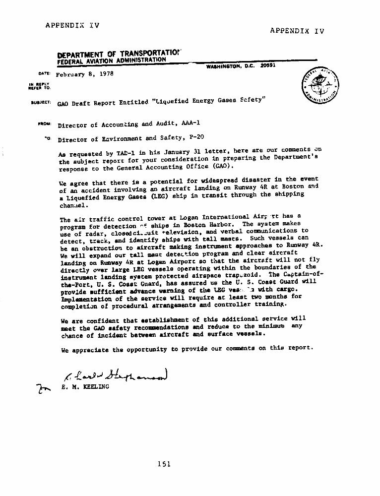
APPENDIX V APPENDIX IV
APPENDIX IV
DEPARTMENT OF TRANSPORTATIOn'FEDERAL AVIATION ADMINISTRATION
WASHINGTON, D.C. 20591
OATE: February 8, 1978
IN REPLYREFER TO;
SUuJEcT: GAO Draft Report Entitled "Liquefied Energy Gases Scfety"
now: Director of Accounting and Audit, AAA-1
o Director of Environment and Safety, P-20
As requested by TAD-1 in his January 31 letter, here are our comments on
the subject report for your consideration in preparing the Department's
response to the General Accounting Office (GAO).
We agree that there is a potential for widespread disaster in the event
of an accident involving an aircraft landing on Runway 4R at Boston and
a Liquefied Energy Gases (LEG) ship in transit through the shipping
channel.
The air traffic control tower at Logan International AirF -rt has a
program for detection '1 ships in Boston Harbor. The system makes
use of radar, closedcic.uit television, and verbal communications to
detect, track, and identify ships with tall masts. Such vessels can
be an obstruction to aircraft making instrument approaches to Runway 4R.
We will expand our tall mast detection program and clear aircraft
landing on Runway 4R at Logan Airport so that the aircraft will not fly
directly over large LEG vessels operating within the boundaries of the
instrument landing system protected airspace trapezoid. The Captain-of-
the-Port, U. S. Coast Guard, has assured us the U. S. Coast Guard will
provide sufficient advance warning of the LEG ves. .3 with cargo.
Implementation of the service will require at least two months for
completion of procedural arrangements and controller training.
We are confident that establishment of this additional service will
meet the GAD safety recommendations and reduce to the minimum any
chance of incident between aircraft and surface vessels.
We appreciate the opportunity to provide our comments on this report.
E. M. KEELING
151
APPENDIX IV APPENDIX IV
Irm FHWA 121 (Rev. 5-73)
UNITED STATES GOVERNMENT DEPARTMENT OF TRANSPORTATIONMemorandum :fRAAL HIGWAY ADMINISTRATION
Memorandum ACTION: Request for Proposed Reply to GAO DATE: MAR 2 1 1978Draft Report dated January 20, 1978,
sUqr, (Assistant Secretary Scott's memorandum ,f.r At HPR-1of January 31, 1978, copy attached)
F2oM : Deputy Administrator
TO ,Mr. Chester C. Davenport-1 i Assistant -Secretary- for Policy
and Interrnational Affairs
This is in response to the subject memorandum requestingFHWA comments on the GAO draft report, "Liquefied EnergyGases Safety."
For the record, our response was delayed because of adepartmental request to GAO for an extension of time forcompletion of DOT comments which we understand was deniedby GI.O.
Accordingly, the attached comments are offered for yourconsideration for inclusion in the departmental response.Our specific comments are limited to Chapters 9, 19, and20:, since they are directly related to FHWA's area ofresponsibility. We also have several comments on the reportas a whole.
We appreciate the opportunity to comment on this draftreport.
rl S. 3owers
Attachment
152

APPENDIX IV APPENDIX IV
FEDERAL HIGHWAY ADMINISTRATION (FHWA)
COMMENTS ON
GENERAL ACCOUNTING OFFICE (GAO)
DRAFT REPORT ON
"LIQUEFIED ENERGY GASES (LEG) SAFETY"
GENERAL COMMENTS
1. We believe the report understates the effective-ness of both Federal and State regulatory schemes.
2. We believe the extreme solution~ to perceivedthreats of sabotage or risks to the public are over-stated. If terrorists wanted to select a target forsabotage, there are many more readily availablecandidates, including tank trucks that carry gasoline,poisons, and other hazardous materials. Given thevolume of movements of hazardous materials and thedegree of exposure, the case has not been made forthe costly and complex solutions proposed.
3. We disagree with the proposal to shift Departmentof Transportation (DOT) transportation safety functionsto the Department of Energy, since the basis forforming the DOT was to consolidate transportationfunctions.
4. We believe the report does not adequately discussthe costs of its recommendations in relation topossible benefits.
S. We believe the report generalizes about accidentrisks based on single or very few reported accidents,which can be very misleading.
153

APPENDIX IV APPENDIX IV
SPECIFIC COMMENTS
I. Chapter 9 Truck Shipments
1. Page 7 - In referring to Vulnerability to Sabotage,a statement is made that "A remote controlled shutoffvalve is also built into this line, but is normallyleft in the open position." (Emphasis added) TheDepartment's Regulations governing cargo tanks requirea "self closing internal valve with remote controls"(49 CFR 178.337-11), and that the valves be closedduring transportation (49 CFR 177.840(g)). While ourinspections have found some cargo tanks being operatedwith these valves open, it has been the exception ratherthan the rule.
2. Page 18 - It is recommended by GAO that the Secretaryof Transportation "prohibit trucking of LEG throughdensely populated areas . . . with particular attentionto routes with highway configuration which make tankrupture accidents likely." The Federal Motor CarrierSafety Regulations (FMCSR), in Section 397.9, specifi-cally require that all vehicles transporting hazardousmaterials follow routes which do not go tFrough or nearheavily populated areas, places where crowds areassembled, tunnels, etc., unless there xs no practicalalternative. The subject of elevated expressways isnot addressed in the FMCSR as the FHWA feels this isbest left to the discretion of the individual munici-palities. The FMCSR do require that carriers followlaws and ordinances established by municipalities inwhich a vehicle is operated, such as truck routes.
3. Page 19 - The GAO recommends that Liquefied PetroleumGas trailer tanks be insulated to help prevent explosions.Research by the Federal Railroad Administration hasproven that insulation on a tank hcs two benefits:(1) the length of time a tank can be exposed to firebefore exploding is greatly increased; and (2) an insulatedtank explodes with less severity. Insulating a cargotank adds several hundred pounds of weight to the vehicle.Since 'otor carriers are faced with highway weightrestrictions, the amount of LEG that can be carried bya highway vehicle will be reduced by the added weight ofthe insulation. This will mean more trips by the high-way vehicle, thus more exposure to accident potential.
154

APPENDIX IV APPENDIX IV
Industry sources have estimated a cost of about $2,000to insulate a cargo tank. It would be difficult tojustify this cost against the good safety record ofthese vehicles.
II. Chapter 19 - Federal, State, and Local Regulations
1. Page 1 - The GAO states that "Federal regulationsare similar to those of the States and municipalitiesbecause of their common reliance on National FireProtection Association (NFPA) Codes." While there maybe some reliance on the NFPA Code by the States andmunicipalities for storage requirements, transportationrequirements are common among the Federal and localjurisdictions because of reliance on Federal (DOT)regulations. To date some 33 States have adopted theFederal Hazardous Materials Regulations in whole orin part. The DOT specifications for cargo tanks oftenhave a greater safety factor than do industry or NFPAstandards.
III. Chapter 20 - Federal Regulations of LEG Trucks andRail Cars
1. Page 2 - The first paragraph, below reference toMaterials iransportation Bureau, should read: "TheAdministrator of the FHWA has delegated his authorityto the Director of the Bureau of Motor Carrier Safety(EMCS) . . .
2. In the last paragraph on that page, reference ismade to the number of BMCS inspectors. The currentnumber of inspectors is 128. On this page and page 3,reference is made to the FHWA Assistant RegionalDirectors. Their correct title is Director, RegionalMotor Carrier Safety Office.
3. Page 7 - The reference to the FHWA's driver quali-fications has several errors. In the first paragraph,it is stated that ". . . the FH(W)A's physical require-ments do not apply to intermittent or temporary drivers."The second paragraph states that "All drivers must takea road test or have a State license for the category ofvehicle to be driven." The only drivers excused fromthe physical requirements are those used in a commercial
155

APPENDIX IV APPENDIX IV
zone or a city and then only if they do not transporthazardous materials, The intermittent or temporarydrivers need not have the written test, road test, orbackground test, but must meet the physical requirements.
156
APPENDIX IV APPENDIX IV
!..;'A FB II 173}
It.IrEi ID STAi L; C)OVERNv. NN1' D[ 'AI, TMLNT Or li- .' .gi, ! I
1t e l iitl'~ l e(1 1,Z^r- A .*P.,
Response to GAO Draft Report "Liquefied Energy '.In "'eSUBJFC Gases Safety" ''l tio RAD-44
FROM Feleral Railroad Administrator, ROA'1
Assistant Secretary for Policy and I'nternational Affairs, P-1
We have reviewed the subject report and prepared the attached detailed
response pursuant to your memorandum of January 31, 1978.
f?- j ,; , / ,- .,.
" JllJH N M. SULLIVAt1
Attachment
157
APPENDIX IV APPENDIX IV
FG COT f 1O.1 (140)
UNITED STATES GOVERNMENT OEPARTME;T OF TRA'ISPORTATiO:iM emoranditin (PM OF THE SECRETARY
,Men7orandnt Ortn7
Allm January 31, 1978
ACTION: Request for Proposed Reply to %."-MncT, GAO Draft Report Dated January 20, 1978 ' TAD-222
Fo' Edward W. Scott, Jr. as& Assistant Secretary for Administration
Commandant, United States Coast GuardFederal Aviation AdministratorFederal Highway AdministratorFederal Railroad AdministratorNationa! Highviay Trafi 4c Safety AdministratorActing Director, Research and Special Programs Directorate
We are requesting that you and your staff prepare comments on theGeneral Accounting Office (GAO) draft report, "liquefied EnergyGases Safety." We have asked the Assistant Secretary for Policyand International Affairs to prepare and coordinate d Departmentalreply. In order for your comments to be considered in the replythey must reach the Office of the Assistaot Secretary for Policyand International Affairs by February f3t£p.78. In order tofacilitate meeting the due date your GAO liaison officer has beenprovided with an advance copy of the report.
if you or your staff have questions concerning this request, pleasecall John Dawkins on extension 60530.
Attachment
158
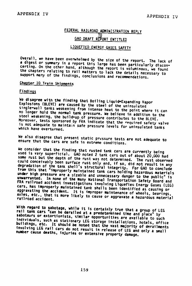
APPENDIX IV APPENDIX IV
FEDERAL RAILROAD ADMINISTRATION REPLYTO
GAO DRAFT REPORT ENTITLED
LIQUEFIED ENERGY GASES SAFETY
Overall, we have been overwhelmed by the size of the report. The lack ofa digest or summary in a report this large has been particularly discon-certing. On the other hand, although the report is voluminous, we foundthe chapters relating to rail matters to lack the details necessary tosupport many of the findings, conclusions and recommendations.
Chapter 10 Train Shipments
Findings
We disagree with the finding that Boiling Liquid-Expanding VaporExplosions (BLEVE) are caused by the steel of the uninsulatedsingle-wall tanks weakening from intense heat to the point where it canno longer hold the normal tank pressure. We believe in addition to thesteel weakening, the build-up of pressure contributes to the BLEVE.Moreover, tests sponsored by FRA indicate that the required safety valveis not adequate to maintain safe pressure levels for uninsulated tankswhich have overturned.
We also disagree that present static pressure tests are not adequate toensure that the cars are safe in extreme conditions.
We consider that the finding that rusted tank cars are currently beingused is very superficial. GAO noted 2 tank cars out of about 20,000 hadsome rust but the depth of the rust was not determined. The rust observedcould conceivably been surface rust only and, if so, did not result in anydegradation of the tank shell's structural integrity. For GAO to concludefrom this that "improperly maintained tank cars holding hazardous materialsunder high pressure are a sizable and unnecessary danger to the public" isunwarranted. In none of the many National Transportation Safety Board andFRA railroad accident investigations involving Liquefied Energy Gases (LEG)cars, has improperly maintained tank shells been identified as causing oraggravating the accident. It is improper maintenance of wheels, bearings,axles, etc., that is more likely to cause or aggravate a hazardous materialrailroad accident.
With regard to sabotage, while it is certainly true that a group of LEGrail tank cars "can be derailed at a predetermined time and place' bysaboteurs or extortionists, similar opportunities are available to suchindividuals, such as stationary LEG storage installations, hotels, officebuildings, etc. It should be noted that the vast majority of derailmentsinvolving LEG rail cars do not result in release of LEG and only a smallnumber cause deaths, injuries or extensive property damage.
159

APPENDIX IV APPENDIX IV
Recommendations
We disagree with the recommendation to increase the size of the placards.We believe there is no practical size placard that can be read safely inan accident. Train billing and other infcrmnation is used to alertemergency service personnel. The placards and product stencils assistcarriers in performing proper handling and assist in providing informationabout leakages.
We disagree with the recommendation requiring all Liquefied PetroleumGases (LPG) cars be prominen'l1 labeled "Insulated" or "Non-Insulated"since firefighters would receive no useful information.
We disagree that tougher, stronger steel should be required in tank cars.We believe existing steels are the most practical for this service.Although extremely expensive steels could improve puncture resistance,there have been few punctures that would not have been prevented byhead shields.
We also disagree with the recommendations requiring immediate actionto inspect hazardous materials tank cars and remove those not beingmaintained properly and requiring inspection every two years of allsafety related features of LEG tank trucks and railcars. Such actionin both cases is being done right now.
We disagree with the recommendation prohibiting travel of LPG carsthrough or to densely populated areas unless it is impossible to dootherwise.
We disagree with the recommendation requiring that Bills of Ladingon trains containing hazardous materials have detailed instructionson firefighting and other emergency measures in the event of a wreck.We do rnt believe there need be special information for handlingaccidents in densely populated areas. We believe the existing systemsare adequate.
Concerning the third recommendation, both Calspan and Railway ProgressInstitute/Association of American Railroads (RPI/AAR) have exploredthe cost-effectiveness of requiring either thicker steel walls ortougher steel and concluded that neither concept was cost-beneficial.RPI/AAR also considered the cost-effectiveness of a shell-shield andfound that this latter concept had a very unfavorable cost-benefitratio. It should be noted that the recommnendation could only beapplied to new cars and, therefore, it would be at least 40 yearsbefore this recommendation could be fully implemented.
160
APPENDIX IVAPPENDIX IV
Discussions within the chapter
PAGE 1,. Paragraph 1, Line 1
We believe railroads handle about 8 to 10 percent if the long distanceLPG instead of 4 percent.
Paragraph 3. Line 1
We believe all LPG railroad traffic is part of interstate commerceand not subject to local regulation.
PAGE 2. Paragraph 1, Line 1
Suggest the following rewording "The AAR's research department andthe tank car committee of the Railway Progress Institute cooperate ....
Paragraph 2
Suggest the following number changes:
Line I - 10,248 instead of 10,450
Line 2 - 158 deaths instead of 1081,282 injuries instead of 9801.54 deaths instead of 1.03
Line 3 - 12 injuries rer hundred accidents instead of 9.38
Line 4 - 2,360 accidents due to human error instead of 2,476
Line 5
"...4,260 accidents resulted from defects in railroad structure,track and roadbed, 2,174 from defective equipment, and 1,454 frommiscellaneous defects."
Paragraph 3. Line 4
20,000 evacuations instead of 10,750
PAGE 4. Paragraph 2, Line 2
850-1.000 psi instead of 500-1,250
Paragraph 2, Line 7
Suggest the following rewording: "All cars carrying LPG are requiredto be labeled with 10 1/2 square foot diamond oriented placardssaying 'Flammable Gas' and with lettering on both tank sides identifyingthe flammable gas."
161
APPENDIX IVAPPENDIX III
Paragraph 4. Line 7
We disagree that there is imminent danger when ignition is immediateand believe such a condition still possesses a high hazard.
PAGE 5, Paragraph 1, Line 6
Suggest the following rewording: "...a 45,000 poind steel section..."instead of "the 45,000."
Paragraph 2, Line 8
Suggest "at ambient temperatures" instead of "near 2200C."
PAGE 7, Paragraph 4, Line 3
Virtually no support for this statement.
Line 5
We do not believe it can be described as "rust." The cause is oxidationof white paint and the result is not diminutive of tank shell thickness.
PAGE 9, Paragraph 2, Line 4
Railroads charge shippers on a per ton basis.
Line 6
Title 49 instead of 4a
PAGE 11
In an FRA sponsored study, Calspan has investigat'ed the cost-effectivenessof imposing additional restrictions on the placement of LPG cars in atrain. Calspan concluded that these restrictions were not indicated.
In the last sentence, GAO indicated that they did not agree with FRA thatHM-144 was sufficient. This sentence should be clarified. HM-144 wasbased on an extensive research and development program which has beendocumented in numerous reports, public briefings, and notices in theFederal Register. It would be desirable if GAO included a summary of theanalysis that they have performed that leads them to conclude that HM-144Is not sufficient.
PAGES 15 and 16
In the Notice of Proposed Rulemaking for HM-144, 25 technical reportswere referenced. In the references section of the draft GAO reportonly one of these reports is cited and that particular report is theleast relevant of the 25. Many of the 24 reports GAO did not citespecifically address points raised by GAO.
162
APPENDIX IV APPENDIX IV
Chapter 19 Federal, State, and Local Regulations
Special Issues Analysis
8. Materials Specifications for Truck Trailers and Railcars
The report states that there are no requirements for periodic inspectionof rail tank cars or tracks for corrosion. However, the cars are inspectedexternally every trip and internally every 5 years. Tracks are alsoinspected periodically.
General - In listing the various regulations concerning LEG safety, thereport omits FRA regulations concerning the construction of railroademployee sleeping quarters in the immediate vicinity of switching orhumping operations. FRA has promulgated interim rules that requirerailroa,- proposing to build employee sleeping quarters within a oneahalfmile radius from a facility where a switching or humping operation occursto provide FRA with estimates of the volume of LEG shipment through thefacility.
163
APPENDIX V APPENDIX V
3nterstatt Commucrce CommifsionMla4bington, *.C. 20423
OPFICE OF THE CHAIRMAN
MAR 7 1978
Henry EschwegeDirectorUnited States GeneralAccounting Office
Washington, D. C. 20548
Dear Mr. Eschwege:
In your letter of January 20, 1978, you
request comments on a GAO draft report on Liquefied
Energy Gases (LEG) safety.
I am pleased to forward to you the attached
comments of the Commission.
If i can be of further assistance, please
contact me.
S terely y9rs,
Chai
Attachments
(Commissioner Clapp was absent and did not participate)
164
APPENDIX V APPENDIX V
C0,l'T-ii. iiS 1, '. DANI],. i' N.AvCHAIRMAN, INv i (:u' .,c: CtMI SSION(N (;AL D,', . i, TfL t'_ili
L]Qu(:i 1L) i': .:',' ;A'..';I?; :,AI:ETy
Thank you for the opportunity to, commlen,t on this vitalsafe4ty matter. We were asked to address proposals inChapters 9, 10, 12,and 19. Summarized in Chapter 22 arethe speo ific recounlendations relating to this Comlmlission.They are:
-not allow LEG to be carried under a certificatefor petroleum protlducts. It should require aapecial certificate for LNG and a separatespecial certificate for LPG. This will limitresponsibility tc fewer carriers with moreexperience.
-not allow trucking companies which are licensedto carry LNG to lease these rights to not ercompanies which have not demonstrated ?ircompetence to the ICC.
Apart from these reconrcndations, several other('o!%;t'c ::arr: ut fiu':cuSsion.
Motor carriers with authority to transportpetroleum products are authorized to transport LEG, as statLein Chapter 9 of the draft report; and '.NC can be trans-ported under liquid chemicals authority.
The recommendation that special certificatesshould be required £or the transportatioil of LEG arisesout of the drafters' conclusion that dangers in transpoitingLEO ire far greater than t.ohse in truckint petr'oleumproducts. Apparently overlooked is the fact that chcil ;icali:and petroleunm products are regul rly trz.asported by vervspecializcd carriers, Lsing sp iciil equiprit.t itr-i tr"ni lI
r,'nrslimel st.Ojoct to speci-Ut .fh , ' i,,f,:, Tb:,
c',u'-i, 'iit -:; I, l,rcJsc.2\ :,lt(h. .v tJ ,--%- , i:
165
APPENDIX V APPENDIX V
unloading, alnd line haul and ill cleaning the equipmentlUl. Thevery speciil ioi/ation of these carriers' operations is a sig-nificant factor, for it brings to the carriers in the ordinarycourse of their business many danger-us commodities, andrequires of them a special competence.
Prohibiting ICC licensed carriers from transporting LEGunder broad generic descriptions would not produce the effectsought by the GAO. The reason is that a very <ibstantialpart of interstate truck transportation in this country is in
private or exempt operations. In April 1977, the Commrissionreleased a study entitled "Enipty/Loaded Truck Miles onInterstate Highways During 1976." The study included a surveyof trucks passing certain points, and that survey as depictedin Table VIII of the report provides an insight into theimportance of non-rsgulated carriers in the liquid petroleumproducts indts3trv. Of those surveyed there were 139 petroleumproducts trucks operated under Coimission authority, 15 wereexempt from our regulation, and 154 were private carriers. Itthus appears that, even if the ICC were to take some restric-tive action as to the "petroleum" haulers, well over half thetrucks carrying petroleum products would be unaffected. Acopy of the April 1977 report is attached.
There is a serious legal obstacle to reducing the scopeof a motor carrier's ICC authority. Such a reduction wouldbe tanltalo,,nt to a partial revocation of authority subject
to Section 212 of the Interstate Commerce Act, and that sectionrequires notice and a hearing. If we attempted an industry-
wid., r,,vocat io,!l, : ~ weid! n-.c! ina St' of e'vidence to justify
the revocation. At the hec;;rivic etanv carrier. would undoubtedly
166
APPENDIX V
APPENDIX V
seek to show theat they trnalsp)ltted LLG safely for years.Nowhere in the CGAO draft report has a nexus beenestablished between the danger sought to be avoided and thetransportation of LEG by the purportedly less experiencedcarriers of petroleum products. Mere hypothesis will not doin this situation.
The GAO also should not overlook the fact that shippershave become dependent upon the services of these carriers,and would be disadvantaged if they were not able to findreplacement carriers immediately.
In the alternative, theywould be forced to appear as supporting witnesses in other
application proceedings, probably for the same carriers thathave served them previously. In the end this would resultin more paperwork for everybody, to arrive at the status quoinsofar as carriers, vehicles and operators are concerned.There are proper avenues at present for the Department ofTransportation
to recommend revocation of a certificate orpermit on the basis that a carrier has violated applicablesafety regulations.
DOT can appear as a complainant in aproceeding before the Commission and request revocation.While Chapter 20 of the report relates that this has beenrecommerdd in the past, without revocation having beenachieved, the report does not intimhae what issues or evidencewas involved in these cases, nor does it identify the cases.We have ordered carriers to suspend operations for a timebecause of a safety complaint, ns in s ederal___ Al j, tra-tion v. Safewa T, 113 M.C.C 815 (1971). And inEvnen Bro thersthInc. Co moneI CrrieA
__ 108 M.c.c.878 (1969), a motor carrier applicant a foud t fit toPP n167 t Wits fou. d not fit to
167
APPENDIX V APPENDIX VAPPENDIX V
ricivc a c'!yt if iccti uid r sI;, lty rel:lt.-l ci rculi;stinlccs.
Fin1llyv, oulr fitness flagging procedures, 49 C.F.R.
106?.1 et seoq., providce ni mtcha:nism for tihe Department
of Transportation Lo intervene in application proceedings
on the issue of an applicant's fitness to conduct
proposed operations. See 49 C.I'.R. 1067.5. The
Departmont of Transportation and the Conmmission tlave
established liaison on these issues, and cooperation
between the Lwo agelclics has cuntinucl. DOT has appeared
as an intervenor in proceedings bhefore the Commission,
and we have encouraged such intervention on matters of
Chapter 9 recomisends that the Comriission not allow
:-rucking comnialies licensed to carry LNG to "lease these
riFht-s" to o-;ler compilries which thave not demonstrated
their C:o:ptencc b cfore the Coia-isasion, Tl-is reflects
misconccpttiio. Un'ecr thc tease and interchange rules
operating ri.hts are lor leastd. lThe carrier with the
franchise in a particular territory leases the equipment
of the connecting carrier. The lease c; rights, on
the other hand, occurs normally as a preiiuainary to a
conveyance of the rights. (See 49 C.F.R. 1132.5), but
that is not the context in which the term is used in
the draft report.
Where a mCotor carrier's request for operating authorityi,:ditatL,- a t '.t )Sl.d rerular miivcment of a dangerous eCco'-pmnditv, the (,io-.;iqsi.on impos's s five-vear limiitation,, or!1, ),!i T:-h' t-,'it * s. thiat ;afety fitnsi can hbe evrlu;t',-
r ,r, cr. " ' 7 ri.,ht' riut'lsrjv ,clrc16 t8 t, is i stccii
I it l . t i _ 1 L; ' I''li'-i .lviiUO!'t'11~
t).~.' . 't'|( , , I l 't.! t ,
168
APPENDIX V APPENDIX V
There :,lt. severrlI sbort-tho t '! t: it: u:t( [n ns it,)iU ~.,ii Iit i t ,
thii tIe L.or iL itil't i, clrriCr -provildes tiI L (ipmLCnilt and diLUr , V-
a]] or part of t(l triansportat io. O1e. carrier Sny l,'
joint movement itlh another carrier (interlining), where
each holds a portion of the relevant territorial authority.
A carrier with the specified rights may lease equipment
from another carrier, and use the lessor carrior's driver;
but it is the duty of the lessee carrier to ensure that
the driver is familiar with the Motor Carrier Safety Regu-
lations of the Federal Highway Administration. See 49 CFR
1057.5(e). Owner-operators may perform short-term services
for one carrier, and eventually offer services to another
carrier.
These practices are widely employed in the trucking
industry. They arose out of the need to provide flexible
operations, to meet urgent demands for equipment, and to
eliminate deadhead r;ileage. Leasing a truck with driver
usually entails the acquisition of a person with experience
and training in handling the equipment and the lading.
As to the demand for service within the transportation
industry, it is variable in terms of quantity and location:
a.d to forbid 'he lease and interchange practices would
seriously disrupt the industry. This is especially true od
the tank-truck operations, where equipment is highly
specialized and inherently inflexible as to use. This
inflexibility is commonly recognized, and is reflected by the
relatively high empty mileage of tank-trucks. See pages 6
through 8 of Em pty/Ioaded, su .
169
APPENDIX V APPENDIX V
It ., uli : L,: L,.y LL. l.,,,I t LoL 17id f :i l.,lcuse of ::.;--t tuc k ecqupil lntl in the transporLt tion of LEG.The rIsult wotld h( bt bihctr tra;nsportat-io n cfi ts ot thisform of eneriy, which would translate into higher energycosts. And there would be no benefits in terms of s; 'ety.
Our suggestion is that a focus be put on safety regulationat thile driver-equipmentlj t level. Such a focus would be thedirect and most effective way to achieve the goals espousedby the GAO in the draft report. It would not matter whattrucking company authority was actually being used toperform the move; the important preventive focus would beon the daily operations level.
MISCELLANEOUS COMMENTARYChapter 9 of the draft report comments that certificates
issued by the Comimission are in the form of irregular route,or broad geoi naphic au h,-rity. In other words, the Commissionwould not normally specify a route ,ver which LEG was to betransported. The report correctly observes that 49 CFR 397.9governs the actual prohibition of dangerous routings and isnot within our jurisdiction. Hofwever, the draft continues bystating that "The ICC merely seeks to assure itself that would-be entrants have sufficient financial resources to meet normaloperating costs." Entrance into the interstate motor carrierindustry, and vxpansion of one's authority, requires a findingby the Comnmission that the public requires the service. Inaddition, each carrier must prove that it is fit, willing andable to comply with the Coiimiis;siton's regulations. Safetyfitness is an issue in these proceedings, as noted above, andte!,c 1(i u Lntt of Tlran'slportation can interv(,ne in a case if iti, lic(vcs thl t a1 ( i t,- ir sholuld ht o r',rda;l cd aluthority' t' .;se
i L j . i' t I , :i W 1, LI'
170
APPENDIX V APPENDIX V
The draft report also sLate:i that the CommiqssJil impo.;es
"one significont limitation" on companies transportiig, LPG,
in that they are not allowed to ship it by tzl1, ing :ub-
sidiaries. Apparently what is being addressed here is the
transportation operations for compensation or direct benefit
by one corporate entity for an affiliated company. This
issue was discussed in Intercorporate Parent-Subsidiary
Transportation, 123 M.C.C. 768 (1975), and it involves all
commodities. We fail to see what direct bearing this has on
the safety-related issues under discussion, and believe the
reference should be discarded.
At page 2 of chapter 9, specified trucking companies with
LNG certificates are said to believe the ICC should not allow
LNG to be transported under a "petroleum products" certificate.
The GAO agrees, saying the dangers involved in LNG trucking
require such a conclusion. This wording implies that the
comments of the trucking companies were based on safety factors.
In all probability those carriers were taking this stand on
economic grounds knowing their share of the business could
increase if fewer carriers were authorized to participate.
On this point the GAO report should be clarified.
CONCLUSIONS AND SUMMARY
The Department of Transportation has primary responsibility
for railroad and motor carrier safety. That is acknowledged in
the draft report. 49 U.S.C. 1655 outlines the transfer of the
safety functions from the I.C.C. to MnT. Thosefunctions cover
explosives and other dangerous articles as well as protection
of employees and travelers, hours of service, safety and
operation of transportation equipment, and appliances and
equipment on railroad engines and cars. The responsibility
171

APPENDIX V APPENDIX V
ol the Co 1l[i;sion goes primarilv to economic contrt.l,
stabil ity lnd effic iency in the transportation industry.
The Coirinission practices sought to bc changed do not
involve economic regulation. We (do not believe those prac-
tices have a direct effect on safe transportation of the
commodities under discussion nor that the proposed changes
would contribute significantly to the draft report's
objective. There is an effective mechanism through which
ICC and DOT can collaborate in improving carrier safety
and by intensified effort it can be made more effective.
Whenever safety fitness is in issue, DOT can participate
in proceedings before the Commission and even initiate
action here. Greater emphasis on that program should be
encouraged.
Fitness, including safety fitness is a threshold issue
in motor carrier licensing and adequacy of service cases.
The Commission has encouraged DOT participation in those
cases and is openly receptive to complaints and evidence
on the issue.
We do not believe wholesale revocation of operating
authority is warranted absent evidence that such an act
would accomplish positive safety goals. Plainly such is not
indiceted here and we believe the revocation would be
disruptive to carriers, shippers and the public they serve.
Again, thank you for the opportunity to comment upon
these proposals,
172

APPENDIX VI APPENDIX VI
t2ON0~~~n~ ~National TransportationSafety Board
erv' Bo1 WashingtonD C 20594
March 29, 1978
Mr. David RosenbauniUnited States General Accounting OfficeWashington, D. C. 20548
Dear Mr. Rosenbaumn:
We have not yet had an opportunity to read in detail yourrcpe rt "Liquefied C;as Fnergy. " We intend to do that in the nearfuture after which a mutually beneficial meeting could be arranged.
As I mentioned in our phone conversation, I did get to readthe conclusions and recommenditions. I found no reason to disagreewith your findings, many of which are similar to those made by theNational Transportation Safety Board. As I said, I am less able tocomment on the reconmmendations at this time. My hesitation isbased on the fact that I have not yet been able to evaluate theirpracticability and priority.
Your recommendations regarding personnel and trainingI found both important and doable. If carried out they could havea significant effect on safety -rather quickly and at minimal cost.I might add that to achieve the full impact of a personnel/trainingprogram it must have the support of professionals who understandthe need for and the means of systematically defining the criticaltrainable tasks.
In the interest in getting this to you it has not run past theBoard. Thank you for the opportunity to rc view your draft. I willbe in touch.
Since r , .
C. P. Seitz, Ph. D.Chief, Analysis DivisionBureau of i'lans and Programs
tU.S. GOVERNMENT PRINTING OFFICE: 1978-724-294/i 179-3t
173(00199)