EM Side-Channel Attacks on Commercial Contactless Smartcards Using Low-Cost Equipment
15
-
Upload
independent -
Category
Documents
-
view
2 -
download
0
Transcript of EM Side-Channel Attacks on Commercial Contactless Smartcards Using Low-Cost Equipment
EM Side-Channel Attacks on Commercial
Contactless Smartcards using Low-Cost
Equipment
Timo Kasper and David Oswald and Christof Paar
Horst Görtz Institute for IT SecurityRuhr University Bochum, Germany
[email protected], [email protected], [email protected]
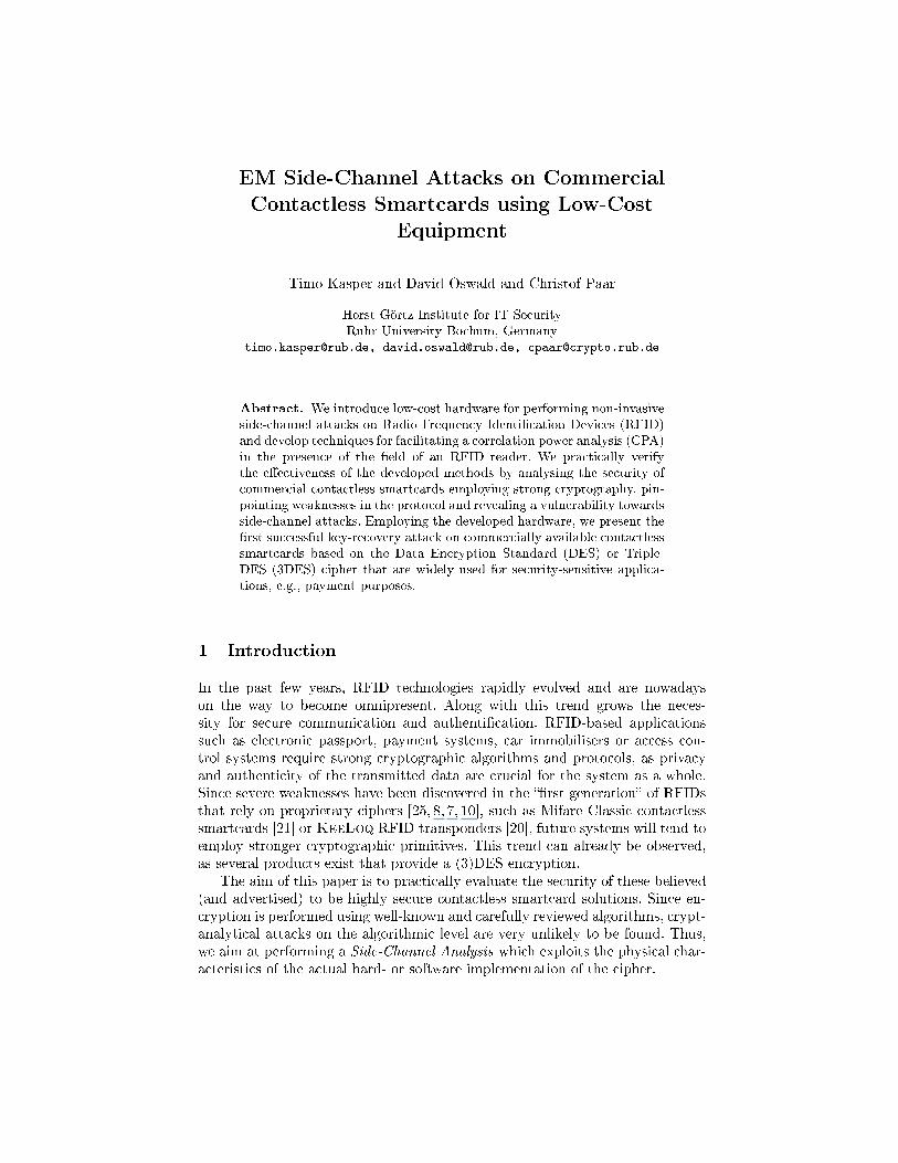
Abstract. We introduce low-cost hardware for performing non-invasiveside-channel attacks on Radio Frequency Identi�cation Devices (RFID)and develop techniques for facilitating a correlation power analysis (CPA)in the presence of the �eld of an RFID reader. We practically verifythe e�ectiveness of the developed methods by analysing the security ofcommercial contactless smartcards employing strong cryptography, pin-pointing weaknesses in the protocol and revealing a vulnerability towardsside-channel attacks. Employing the developed hardware, we present the�rst successful key-recovery attack on commercially available contactlesssmartcards based on the Data Encryption Standard (DES) or Triple-DES (3DES) cipher that are widely used for security-sensitive applica-tions, e.g., payment purposes.
1 Introduction
In the past few years, RFID technologies rapidly evolved and are nowadayson the way to become omnipresent. Along with this trend grows the neces-sity for secure communication and authenti�cation. RFID-based applicationssuch as electronic passport, payment systems, car immobilisers or access con-trol systems require strong cryptographic algorithms and protocols, as privacyand authenticity of the transmitted data are crucial for the system as a whole.Since severe weaknesses have been discovered in the ��rst generation� of RFIDsthat rely on proprietary ciphers [25, 8, 7, 10], such as Mifare Classic contactlesssmartcards [21] or KeeLoq RFID transponders [20], future systems will tend toemploy stronger cryptographic primitives. This trend can already be observed,as several products exist that provide a (3)DES encryption.
The aim of this paper is to practically evaluate the security of these believed(and advertised) to be highly secure contactless smartcard solutions. Since en-cryption is performed using well-known and carefully reviewed algorithms, crypt-analytical attacks on the algorithmic level are very unlikely to be found. Thus,we aim at performing a Side-Channel Analysis which exploits the physical char-acteristics of the actual hard- or software implementation of the cipher.
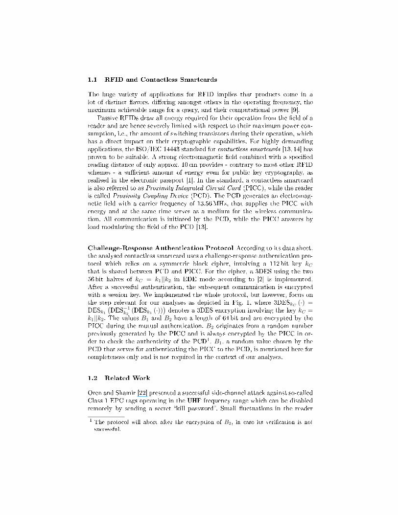
1.1 RFID and Contactless Smartcards
The huge variety of applications for RFID implies that products come in alot of distinct �avors, di�ering amongst others in the operating frequency, themaximum achievable range for a query, and their computational power [9].
Passive RFIDs draw all energy required for their operation from the �eld of areader and are hence severely limited with respect to their maximum power con-sumption, i.e., the amount of switching transistors during their operation, whichhas a direct impact on their cryptographic capabilities. For highly demandingapplications, the ISO/IEC 14443 standard for contactless smartcards [13, 14] hasproven to be suitable. A strong electromagnetic �eld combined with a speci�edreading distance of only approx. 10 cm provides - contrary to most other RFIDschemes - a su�cient amount of energy even for public key cryptography, asrealised in the electronic passport [1]. In the standard, a contactless smartcardis also referred to as Proximity Integrated Circuit Card (PICC), while the readeris called Proximity Coupling Device (PCD). The PCD generates an electromag-netic �eld with a carrier frequency of 13.56MHz, that supplies the PICC withenergy and at the same time serves as a medium for the wireless communica-tion. All communication is initiated by the PCD, while the PICC answers byload-modulating the �eld of the PCD [13].
Challenge-Response Authentication Protocol According to its data sheet,the analysed contactless smartcard uses a challenge-response authentication pro-tocol which relies on a symmetric block cipher, involving a 112 bit key kC
that is shared between PCD and PICC. For the cipher, a 3DES using the two56 bit halves of kC = k1||k2 in EDE mode according to [2] is implemented.After a successful authentication, the subsequent communication is encryptedwith a session key. We implemented the whole protocol, but however, focus onthe step relevant for our analyses as depicted in Fig. 1, where 3DESkC
(·) =DESk1
(DES−1
k2(DESk1 (·))
)denotes a 3DES encryption involving the key kC =
k1||k2. The values B1 and B2 have a length of 64 bit and are encrypted by thePICC during the mutual authentication. B2 originates from a random numberpreviously generated by the PICC and is always encrypted by the PICC in or-der to check the authenticity of the PCD1. B1, a random value chosen by thePCD that serves for authenticating the PICC to the PCD, is mentioned here forcompleteness only and is not required in the context of our analyses.
1.2 Related Work
Oren and Shamir [22] presented a successful side-channel attack against so-calledClass 1 EPC tags operating in the UHF frequency range which can be disabledremotely by sending a secret �kill password�. Small �uctuations in the reader
1 The protocol will abort after the encryption of B2, in case its veri�cation is notsuccessful.
PCD PICC
Choose B1, B2 −B1, B2
−−−−−−−−−−−−→ 3DESkC (B2)
Fig. 1. Exerpt of the authentication protocol relevant for an attack.
�eld during the communication with the tag allow to predict the password bits.However, the very limited type of RFID tag does not o�er any cryptography.
At CHES 2007, Hutter et al. [12] performed an EM attack on their own AESimplementations on a standard 8-Bit microcontroller and an AES co-processorin an RFID-like setting, i.e., the self-made devices are powered passively andbrought into the �eld of a reader. On their prototype devices the antenna andanalogue frontend are separated from the digital circuitry, while on a real RFIDtag, these components are intrinsically tied together. An arti�cially generatedtrigger signal before the attacked S-Box operation ensures perfect time align-ment. Moreover, the clock signal for the digital circuitry is generated indepen-dently from the �eld of the reader using an external oscillator, hence the carrier isuncorrelated with the power consumption of the AES and can be easily removed.
In contrast, we now face the real-world situation, i.e., have no knowledge onthe internal implementation details of the unmodi�ed contactless smartcard tobe attacked, cannot rely on arti�cial help like precise triggering for alignment,and analyse a black box with all RFID and cryptographic circuitry closely packedon one silicon die. In the following, after a brief introduction to power analysisin the context of RFID in Sect. 2.1, we will describe all relevant steps to analysean unknown RFID device in practise, starting from our special low-cost mea-surement setup in Sect. 2.3 and including the extensive pro�ling that is requiredto gain insight into the operation of the smartcard in Sect. 3, before the resultsof the actual side-channel attack are presented in Sect. 3.2.
2 Power Analysis of RFIDs
Di�erential Power Analyis (DPA) was originally proposed in [17] and has be-come one of the most powerful techniques to recover secret information fromeven small �uctuations in the power leakage of the physical implementation ofa cryptographic algorithm. In this paper, we address the popular Correlation
Power Analysis (CPA), as introduced in [4].
2.1 Traditional vs. RFID Measurement Setup
For a typical power analysis attack [8] the side-channel leakage in terms of theelectrical current consumption of the device, while executing a cryptographicoperation, is measured via a resistor inserted into the ground path of the targetIC. Since the targeted RFID smartcard circuitry including the anntenna is em-bedded in a plastic case, lacking any electrical contacts, it is di�cult to perform
a direct on-chip measurement of the power consumption. Invasive attacks, i.e.,dissolving the chip from its plastic package and separating it from the antenna,were not successful [6], maybe due to the strong carrier of the reader that is re-quired for the operation. Anyway, even a successful invasive attack is costly andcan be easily detected, hence a non-invasive approach becomes very attractivein the context of RFIDs.
Non-Invasive Analysis with DEMA A possible source of side-channel leak-age that can be exploited in a non-invasive attack scenario is the informationgathered from �uctuations of the EM �eld emanated by a device whilst perform-ing a cryptographic operation. The corresponding side-channel information forthis so-called Di�erential Electro-Magnetic Analysis (DEMA) [3] is acquired bymeans of near-�eld probes that are positioned close to the chip, and typically re-quire no physical contact to the device, i.e., leave no traces. The analogue signal,i.e., the EM leakage in case of a DEMA, is digitised and recorded as a discreteand quantised timeseries called a trace. In practice, several traces for varyinginput data are collected. In the following, let tl be the lth trace of one attackattempt, where 0 ≤ l < L, with L denoting the number of traces. Likewise, xl
denotes the associated input challenge for the lth measurement. For simplicity,we consider that all traces have the same length N .
2.2 Correlation DPA
For the actual attack, each key candidate Ks, 0 ≤ s < S, where the numberof candidates S should be small2, is input to a prediction function d (Ks, xl),establishing a link between given input data xl and the expected current con-sumption for each key candidate Ks. Often, d predicts the power consumption ofthe output of an S-Box after the key addition, modelled either based on the Ham-ming weight, i.e., the number of ones in a data word, or based on the Hammingdistance, i.e., the amount of toggling bits in a data word.
A CPA essentially relies on calculating the Normalised Correlation Coe�-
cient between the predicted and recorded values for one point in time n and a�xed key Ks:
∆ (Ks, n) =∑L−1
l=0
(tl (n)−mt(n)
) (d (Ks, xl)−md(Ks)
)√σ2
t(n)σ2d(Ks)
with mt(n), md(Ks) denoting the means of the samples, and σ2t(n), σ
2d(Ks)
the sample variances of the respective timeseries. Plotting ∆ for all n yieldsa curve indicating the correlation over time that features signi�cant peaks, ifKs is the correct key guess, and has a random distribution otherwise. Thus,by iterating over all Ks and analysing the resulting ∆ (Ks, 0) . . . ∆ (Ks, N − 1),the cryptographic secret can be revealed, given that enough traces have been
2 This is always the case when attacking single S-Boxes with few in- and outputs
acquired and that there exists a link between the side-channel leakage and theprocessed data input.
E�ciently Implementing a CPA Straightforward implementations of a CPAread all L traces, each with a length ofN samples, into memory before calculatingthe correlation coe�cient ∆ (Ks, n) (see Sect. 2.2).
This may become problematic for long traces and/or a large amount of mea-surements, e.g., L = 10 k traces with N = 350 k data points (stored as 4 bytesingle precision values) consume ≈ 13GByte of memory. Therefore, a recursive
computation of ∆ (Ks, n) becomes attractive. Instead of �rst reading and thenprocessing all data, existing values of the correlation coe�cient can be updatedwith every new trace. This approach makes use of an algorithm given in [16],originally proposed by Welford. The update equations are
mi+1 = mi +ti+1 −mi
i+ 1, M2i+1 = M2i + (ti+1 −mi) (ti+1 −mi+1)
.where the initial values are m0 = 0, M20 = 0, ti denotes the data points,
mi is the mean and σ2i = M2i
i−1 the variance after i samples. Applying this ideafor computing the correlation coe�cient of a key candidate, it su�ces to keeptrack of N trace means mt(n) andM2t(n). Analogously, md(Ks) andM2d(Ks) areupdated, however, these are independent of n and thus need to be stored onlyonce.
Besides, for evaluating Eq. 2.2, c (Ks, n) =∑L−1
l=0 tl(n)d(Ks, xl)
L−1 is stored for N
points in time and updated3 according to
ci+1 = ci +ti+1 · d (xi+1)− ci
i
with initial values c0 = t0 · d (x0) , c1 = t0 · d (x0) + t1·. ∆ (Ks, n) after Ltraces is
∆ (Ks, n) =(L− 1) · cL (Ks, n)− L ·mt(n) ·md(Ks)√
M2t(n)M2d(Ks)
The application of the recursive approach requires the storage ofO (N) valuesfor each key candidateKs. In contrast, the traditional two-pass method (read all,then process) needs O (L ·N) memory. Thus, for large L, the memory footprintof the above described computations remains constant, while a straightforwardalgorithm becomes infeasible.
Modelling the Power Consumption of RFID Devices For a simple modelof the frequencies where we would expect the EM leakage to occur, consider aband-limited power consumption p (t) that directly a�ects the amplitude of theω0 = 2π ·13.56 MHz carrier, i.e., the amplitude of the �eld will be slightly smaller
3 Note that n and Ks have been omitted for readability
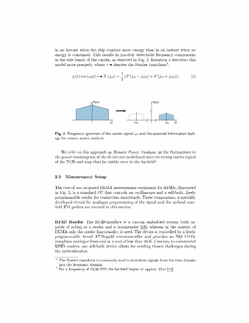
in an instant when the chip requires more energy than in an instant when noenergy is consumed. This results in possibly detectable frequency componentsin the side bands of the carrier, as depicted in Fig. 2. Equation 1 describes thismodel more precisely, where ◦−• denotes the Fourier transform4.
p (t) cos (ω0t) ◦−•X (jω) =12
(P (jω − jω0) + P (jω + jω0)) (1)
jω
P(jω)
jω
X(jω)
-ω0 ω0
1
1
Fig. 2. Frequency spectrum of the carrier signal ω0 and the assumed information leak-age for remote power analysis
We refer to this approach as Remote Power Analysis, as the �uctuations inthe power consumption of the device are modulated onto the strong carrier signalof the PCD and may thus be visible even in the far-�eld5.
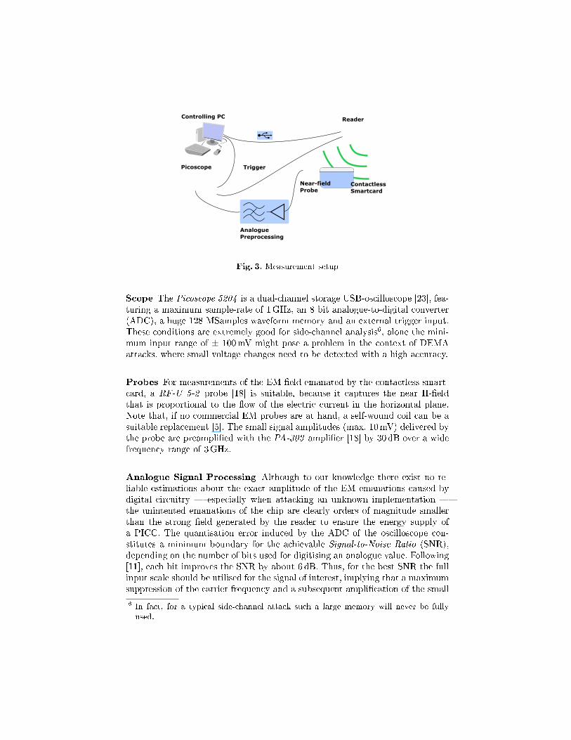
2.3 Measurement Setup
The core of our proposed DEMA measurement equipment for RFIDs, illustratedin Fig. 3, is a standard PC that controls an oscilloscope and a self-built, freelyprogrammable reader for contactless smartcards. These components, a speciallydeveloped circuit for analogue preprocessing of the signal and the utilised near-�eld EM probes are covered in this section.
RFID Reader The RFID-interface is a custom embedded system both ca-pable of acting as a reader and a transponder [15], whereas in the context ofDEMA only the reader functionality is used. The device is controlled by a freelyprogrammable Atmel ATMega32 microcontroller and provides an ISO 14443-compliant analogue front-end at a cost of less than 40 e. Contrary to commercialRFID readers, our self-built device allows for sending chosen challenges duringthe authentication.
4 The Fourier transform is commonly used to transform signals from the time domaininto the frequency domain
5 For a frequency of 13.56MHz the far-�eld begins at approx. 22m [15]
Controlling PC Reader
Picoscope
ContactlessSmartcard
Trigger
AnaloguePreprocessing
Near-fieldProbe
Fig. 3. Measurement setup
Scope The Picoscope 5204 is a dual-channel storage USB-oscilloscope [23], fea-turing a maximum sample-rate of 1GHz, an 8 bit analogue-to-digital converter(ADC), a huge 128 MSamples waveform memory and an external trigger input.These conditions are extremely good for side-channel analysis6, alone the mini-mum input range of ± 100mV might pose a problem in the context of DEMAattacks, where small voltage changes need to be detected with a high accuracy.
Probes For measurements of the EM-�eld emanated by the contactless smart-card, a RF-U 5-2 probe [18] is suitable, because it captures the near H-�eldthat is proportional to the �ow of the electric current in the horizontal plane.Note that, if no commercial EM probes are at hand, a self-wound coil can be asuitable replacement [5]. The small signal amplitudes (max. 10mV) delivered bythe probe are preampli�ed with the PA-303 ampli�er [18] by 30 dB over a widefrequency range of 3GHz.
Analogue Signal Processing Although to our knowledge there exist no re-liable estimations about the exact amplitude of the EM emanations caused bydigital circuitry � especially when attacking an unknown implementation �the unintented emanations of the chip are clearly orders of magnitude smallerthan the strong �eld generated by the reader to ensure the energy supply ofa PICC. The quantisation error induced by the ADC of the oscilloscope con-stitutes a minimum boundary for the achievable Signal-to-Noise Ratio (SNR),depending on the number of bits used for digitising an analogue value. Following[11], each bit improves the SNR by about 6 dB. Thus, for the best SNR the fullinput scale should be utilised for the signal of interest, implying that a maximumsuppression of the carrier frequency and a subsequent ampli�cation of the small
6 In fact, for a typical side-channel attack such a large memory will never be fullyused.
side-channel information must already take place in the analogue domain, beforethe digitising step.
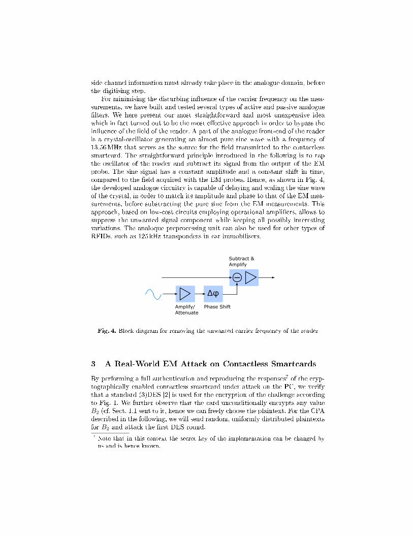
For minimising the disturbing in�uence of the carrier frequency on the mea-surements, we have built and tested several types of active and passive analogue�lters. We here present our most straightforward and most unexpensive ideawhich in fact turned out to be the most e�ective approach in order to bypass thein�uence of the �eld of the reader. A part of the analogue front-end of the readeris a crystal-oscillator generating an almost pure sine wave with a frequency of13.56MHz that serves as the source for the �eld transmitted to the contactlesssmartcard. The straightforward principle introduced in the following is to tapthe oscillator of the reader and subtract its signal from the output of the EMprobe. The sine signal has a constant amplitude and a constant shift in time,compared to the �eld acquired with the EM probes. Hence, as shown in Fig. 4,the developed analogue circuitry is capable of delaying and scaling the sine waveof the crystal, in order to match its amplitude and phase to that of the EM mea-surements, before substracting the pure sine from the EM measurements. Thisapproach, based on low-cost circuits employing operational ampli�ers, allows tosuppress the unwanted signal component while keeping all possibly interestingvariations. The analoque preprocessing unit can also be used for other types ofRFIDs, such as 125 kHz transponders in car immobilisers.
Δφ
Amplify/Attenuate
Phase Shift
Subtract &Amplify
Fig. 4. Block diagram for removing the unwanted carrier frequency of the reader
3 A Real-World EM Attack on Contactless Smartcards
By performing a full authentication and reproducing the responses7 of the cryp-tographically enabled contactless smartcard under attack on the PC, we verifythat a standard (3)DES [2] is used for the encryption of the challenge accordingto Fig. 1. We further observe that the card unconditionally encrypts any valueB2 (cf. Sect. 1.1 sent to it, hence we can freely choose the plaintext. For the CPAdescribed in the following, we will send random, uniformly distributed plaintextsfor B2 and attack the �rst DES round.
7 Note that in this context the secret key of the implementation can be changed byus and is hence known.
3.1 Trace Preprocessing
The raw traces recorded between the last bit of the command sent by the readerand the �rst bit of the answer of the card do not expose any distinctive pattern,hence, digital preprocessing is applied in order to identify interesting patternsuseful for a precise alignment of the traces. On the basis of the RFID powermodel introduced in Sect. 2.2, we assume that the power consumption of thesmartcard modulates the amplitude of the carrier wave at frequencies muchlower than the 13.56MHz carrier frequency, which is justi�ed by a preliminaryspectral analysis and the well-known fact that the on-chip components (suchas capacitances, resistors, inductances) typically imply a strong low-pass �ltercharacteristic.
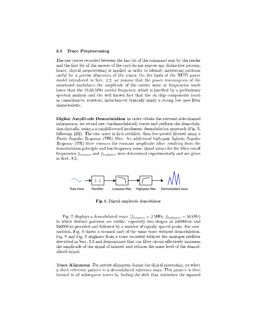
Digital Amplitude Demodulation In order obtain the relevant side-channelinformation, we record raw (undemodulated) traces and perform the demodula-tion digitally, using a straightforward incoherent demodulation approach (Fig. 5,following [26]). The raw trace is �rst recti�ed, then low-passed �ltered using aFinite Impulse Response (FIR) �lter. An additional high-pass In�nite Impulse
Response (IIR) �lter removes the constant amplitude o�set resulting from thedemodulation principle and low-frequency noise. Good values for the �lter cuto�frequencies flowpass and fhighpass were determined experimentally and are givenin Sect. 3.2.
| . |
Lowpass filterRaw trace Demodulated traceHighpass filterRectifier
Fig. 5. Digital amplitude demodulator
Fig. 7 displays a demodulated trace (flowpass = 2MHz, fhighpass = 50 kHz)in which distinct patterns are visible, especially two shapes at 240000 ns and340000 ns preceded and followed by a number of equally spaced peaks. For com-parision, Fig. 6 shows a zoomed part of the same trace without demodulation.Fig. 8 and Fig. 9 originate from a trace recorded without the analogue pre�lterdescribed in Sect. 2.3 and demonstrate that our �lter circuit e�ectively increasesthe amplitude of the signal of interest and reduces the noise level of the demod-ulated signal.
Trace Alignment For precise alignment during the digital processing, we selecta short reference pattern in a demodulated reference trace. This pattern is thenlocated in all subsequent traces by �nding the shift that minimises the squared
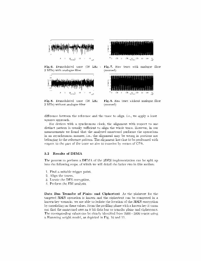
Fig. 6. Demodulated trace (50 kHz -2 MHz) with analogue �lter
Fig. 7. Raw trace with analogue �lter(zoomed)
Fig. 8. Demodulated trace (50 kHz -2 MHz) without analogue �lter
Fig. 9. Raw trace without analogue �lter(zoomed)
di�erence between the reference and the trace to align, i.e., we apply a least-squares approach.
For devices with a synchronous clock, the alignment with respect to onedistinct pattern is usually su�cient to align the whole trace. However, in ourmeasurements we found that the analysed smartcard performs the operationsin an asynchronous manner, i.e., the alignment may be wrong in portions notbelonging to the reference pattern. The alignment has thus to be performed withrespect to the part of the trace we aim to examine by means of CPA.
3.2 Results of DEMA
The process to perform a DEMA of the 3DES implementation can be split upinto the following steps, of which we will detail the latter two in this section:
1. Find a suitable trigger point.2. Align the traces.3. Locate the DES encryption.4. Perform the EM analysis.
Data Bus Transfer of Plain- and Ciphertext As the plaintext for thetargeted 3DES operation is known and the ciphertext can be computed in aknown-key scenario, we are able to isolate the location of the 3DES encryptionby correlating on these values. From the pro�ling phase with a known key it turnsout that the smartcard uses an 8 bit data bus to transfer plain- and ciphertexts.The corresponding values can be clearly identi�ed from 2000 - 5000 traces usinga Hamming weight model, as depicted in Fig. 10 and 11.
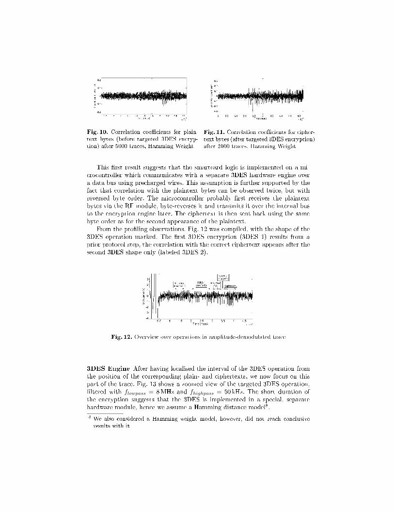
Fig. 10. Correlation coe�cients for plain-text bytes (before targeted 3DES encryp-tion) after 5000 traces, Hamming Weight
Fig. 11. Correlation coe�cients for cipher-text bytes (after targeted 3DES encryption)after 2000 traces, Hamming Weight
This �rst result suggests that the smartcard logic is implemented on a mi-crocontroller which communicates with a separate 3DES hardware engine overa data bus using precharged wires. This assumption is further supported by thefact that correlation with the plaintext bytes can be observed twice, but withreversed byte order. The microcontroller probably �rst receives the plaintextbytes via the RF module, byte-reverses it and transmits it over the internal busto the encryption engine later. The ciphertext is then sent back using the samebyte order as for the second appearance of the plaintext.
From the pro�ling observations, Fig. 12 was compiled, with the shape of the3DES operation marked. The �rst 3DES encryption (3DES 1) results from aprior protocol step, the correlation with the correct ciphertext appears after thesecond 3DES shape only (labeled 3DES 2).
Fig. 12. Overview over operations in amplitude-demodulated trace
3DES Engine After having localised the interval of the 3DES operation fromthe position of the corresponding plain- and ciphertexts, we now focus on thispart of the trace. Fig. 13 shows a zoomed view of the targeted 3DES operation,�ltered with flowpass = 8MHz and fhighpass = 50 kHz. The short duration ofthe encryption suggests that the 3DES is implemented in a special, separatehardware module, hence we assume a Hamming distance model8.
8 We also considered a Hamming weight model, however, did not reach conclusiveresults with it
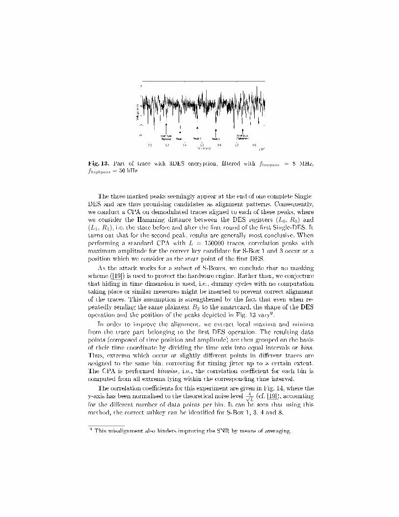
Fig. 13. Part of trace with 3DES encryption, �ltered with flowpass = 8 MHz,fhighpass = 50 kHz
The three marked peaks seemingly appear at the end of one complete Single-DES and are thus promising candidates as alignment patterns. Consequently,we conduct a CPA on demodulated traces aligned to each of these peaks, wherewe consider the Hamming distance between the DES registers (L0, R0) and(L1, R1), i.e, the state before and after the �rst round of the �rst Single-DES. Itturns out that for the second peak, results are generally most conclusive. Whenperforming a standard CPA with L = 150000 traces, correlation peaks withmaximum amplitude for the correct key candidate for S-Box 1 and 3 occur at aposition which we consider as the start point of the �rst DES.
As the attack works for a subset of S-Boxes, we conclude that no maskingscheme ([19]) is used to protect the hardware engine. Rather than, we conjecturethat hiding in time dimension is used, i.e., dummy cycles with no computationtaking place or similar measures might be inserted to prevent correct alignmentof the traces. This assumption is strengthened by the fact that even when re-peatedly sending the same plaintext B2 to the smartcard, the shape of the DESoperation and the position of the peaks depicted in Fig. 13 vary9.
In order to improve the alignment, we extract local maxima and minimafrom the trace part belonging to the �rst DES operation. The resulting datapoints (composed of time position and amplitude) are then grouped on the basisof their time coordinate by dividing the time axis into equal intervals or bins.Thus, extrema which occur at slightly di�erent points in di�erent traces areassigned to the same bin, correcting for timing jitter up to a certain extent.The CPA is performed binwise, i.e., the correlation coe�cient for each bin iscomputed from all extrema lying within the corresponding time interval.
The correlation coe�cients for this experiment are given in Fig. 14, where they-axis has been normalised to the theoretical noise level 4√
L(cf. [19]), accounting
for the di�erent number of data points per bin. It can be seen that using thismethod, the correct subkey can be identi�ed for S-Box 1, 3, 4 and 8.
9 This misalignment also hinders improving the SNR by means of averaging.
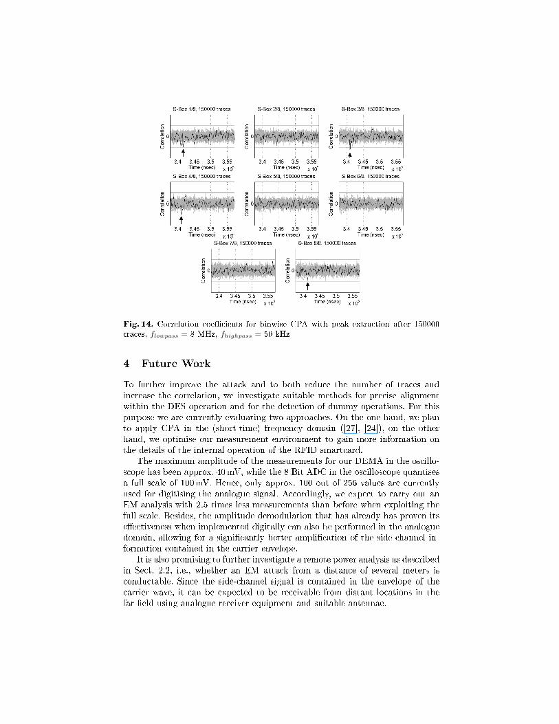
Fig. 14. Correlation coe�cients for binwise CPA with peak extraction after 150000traces, flowpass = 8 MHz, fhighpass = 50 kHz
4 Future Work
To further improve the attack and to both reduce the number of traces andincrease the correlation, we investigate suitable methods for precise alignmentwithin the DES operation and for the detection of dummy operations. For thispurpose we are currently evaluating two approaches. On the one hand, we planto apply CPA in the (short-time) frequency domain ([27], [24]), on the otherhand, we optimise our measurement environment to gain more information onthe details of the internal operation of the RFID smartcard.
The maximum amplitude of the measurements for our DEMA in the oscillo-scope has been approx. 40mV, while the 8 Bit ADC in the oscilloscope quantisesa full scale of 100mV. Hence, only approx. 100 out of 256 values are currentlyused for digitising the analogue signal. Accordingly, we expect to carry out anEM analysis with 2.5 times less measurements than before when exploiting thefull scale. Besides, the amplitude demodulation that has already has proven itse�ectiveness when implemented digitally can also be performed in the analoguedomain, allowing for a signi�cantly better ampli�cation of the side-channel in-formation contained in the carrier envelope.
It is also promising to further investigate a remote power analysis as describedin Sect. 2.2, i.e., whether an EM attack from a distance of several meters isconductable. Since the side-channel signal is contained in the envelope of thecarrier wave, it can be expected to be receivable from distant locations in thefar �eld using analogue receiver equipment and suitable antennae.
5 Conclusion
As the main result attained in this paper, we give practical contributions foranalysing the security of RFIDs via non-invasive side-channel attacks. We pre-sented a new approach for performing e�ective EM analyses, realised a corre-sponding analogue hardware and describe our resulting low-cost measurementenvironment. We detail on the relevant steps of performing practical real-worldEM attacks on commercial contactless smartcards in a black-box scenario andthereby demonstrated the potency of our �ndings.
This paper pinpoints several weaknesses in the protocol and the actual im-plementation of widespread cryptographic contactless smartcards, including avulnerability to DEMA. We investigated the leakage model applicable for thedata bus and described a CPA on the 3DES hardware implementation runningon the targeted commercial smartcard. We demonstrated the e�ectiveness ofour developed methods, that are generally applicable for analysing all kinds ofRFID devices and contactless smartcards, by detailing and performing a fullkey-recovery attack, leaving no traces, on a black box device.
References
1. Advanced Security Mechanisms for Machine Readable Travel Documents - Ex-tended Access Control (EAC), Password Authenticated Connection Establish-ment (PACE), and Restricted Identi�cation (RI). http://www.bsi.de/english/
publications/techguidelines/tr03110/TR-03110_v200.pdf.2. FIPS 46-3 Data Encryption Standard (DES). http://csrc.nist.gov/
publications/fips/fips46-3/fips46-3.pdf.3. D. Agrawal, B. Archambeault, J. R. Rao, and P. Rohatgi. The EM Side-
Channel(s). In CHES '02: Revised Papers from the 4th International Workshopon Cryptographic Hardware and Embedded Systems, pages 29�45, London, UK,2003. Springer-Verlag.
4. E. Brier, C. Clavier, and F. Olivier. Correlation Power Analysis with a LeakageModel. In M. Joye and J.-J. Quisquater, editors, Cryptographic Hardware and Em-bedded Systems - CHES 2004, volume 3156 of Lecture Notes in Computer Science,pages 16�29. Springer, 2004.
5. D. Carluccio. Electromagnetic Side Channel Analysis for Embedded Crypto De-vices. Master's thesis, Ruhr Universität Bochum, 2005.
6. D. Carluccio, K. Lemke, and C. Paar. Electromagnetic Side ChannelAnalysis of a Contactless Smart Card: First Results. RFIDSec05 Work-shop on RFID and Lightweight Crypto, July 2005. http://events.iaik.
tugraz.at/RFIDandLightweightCrypto05/RFID-SlidesandProceedings/
Carluccio-EMSideChannel.pdf.7. N. T. Courtois, K. Nohl, and S. O'Neil. Algebraic Attacks on the Crypto-1 Stream
Cipher in MiFare Classic and Oyster Cards. Cryptology ePrint Archive, Report2008/166, 2008.
8. T. Eisenbarth, T. Kasper, A. Moradi, C. Paar, M. Salmasizadeh, and M. T. M.Shalmani. On the Power of Power Analysis in the Real World: A Complete Breakof the KeeLoq Code Hopping Scheme. In Advances in Cryptology - CRYPTO 2008,volume 5157 of Lecture Notes in Computer Science, pages 203�220. Springer, 2008.

9. K. Finkenzeller. RFID-Handbuch. Hanser Fachbuchverlag, Third edition, October2002.
10. F. D. Garcia, G. de Koning Gans, R. Muijrers, P. van Rossum, R. Verdult, R. W.Schreur, and B. Jacobs. Dismantling MIFARE Classic. In S. Jajodia and J. López,editors, ESORICS 2008, volume 5283 of Lecture Notes in Computer Science, pages97�114. Springer, 2008.
11. S. Haykin. Communications Systems, chapter 8. Wiley, 2nd edition, 1983.12. M. Hutter, S. Mangard, and M. Feldhofer. Power and EM Attacks on Passive 13.56
MHz RFID Devices. In P. Paillier and I. Verbauwhede, editors, CryptographicHardware and Embedded Systems - CHES 2007, LNCS 4727, pages 320 � 330.Springer, 2007.
13. International Organization for Standardization. ISO/IEC 14443-3: Identi�cationcards - Contactless integrated circuit(s) cards - Proximity cards - Part 3: Initial-ization and anticollision, 1st edition, February 2001.
14. International Organization for Standardization. ISO/IEC 14443-4: Identi�cationcards - Contactless integrated circuit(s) cards - Proximity cards - Part 4: Trans-mission protocol, 1st edition, February 2001.
15. T. Kasper, D. Carluccio, and C. Paar. An Embedded System for Practical SecurityAnalysis of Contactless Smartcards. In WISTP, volume 4462 of LNCS, pages 150�160. Springer, 2007.
16. D. E. Knuth. The Art of Computer Programming, volume 2: Seminumerical Algo-rithms. Addison-Wesley, Boston, 3rd edition, 1998.
17. P. C. Kocher, J. Ja�e, and B. Jun. Di�erential Power Analysis. In CRYPTO '99:Proceedings of the 19th Annual International Cryptology Conference on Advancesin Cryptology, pages 388�397, London, UK, 1999. Springer-Verlag.
18. Langer EMV-Technik. Details of Near Field Probe Set RF 2. Web resource.http://www.langer-emv.de/en/produkte/prod_rf2.htm.
19. S. Mangard, E. Oswald, and T. Popp. Power analysis attacks: Revealing the secretsof smart cards. Springer-Verlag, Secaucus, NJ, USA, 2007.
20. Microchip. HCS410, KeeLoq Code Hopping Encoder and Transponder DataSheet. http://ww1.microchip.com/downloads/en/DeviceDoc/40158e.pdf.
21. NXP. Data Sheet of Mifare Classic 4k chip MF1ICS70, 2008.22. Y. Oren and A. Shamir. Remote Password Extraction from RFID Tags.
IEEE Transactions on Computers, 56(9):1292�1296, 2007. http://iss.oy.ne.
ro/RemotePowerAnalysisOfRFIDTags.23. Pico Technology. PicoScope 5200 USB PC Oscilloscopes, 2008.24. T. Plos, M. Hutter, and M. Feldhofer. Evaluation of Side-Channel Preprocessing
Techniques on Cryptographic-Enabled HF and UHF RFID-Tag Prototypes. InS. Dominikus, editor, Workshop on RFID Security 2008, pages 114 � 127, 2008.
25. H. Plötz. Mifare Classic - Eine Analyse der Implementierung. Master's thesis,Humboldt-Universität zu Berlin, 2008.
26. K. S. Shanmugam. Digital & Analog Communication Systems, chapter 8.3.2.Wiley-India, 2006.
27. C. C. Tiu. A New Frequency-Based Side Channel Attack for Embedded Systems.Master's thesis, University of Waterloo, 2005.