
Compounds fromAgeratum conyzoides: isolation, structural elucidation and insecticidal activity
Upload
uni-dortmundCategory
view
0download
0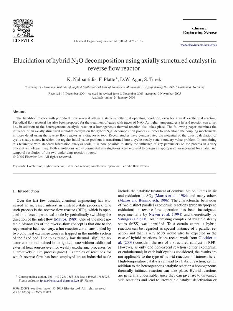
Chemical Engineering Science 61 (2006) 3176–3185www.elsevier.com/locate/ces
Elucidation of hybrid N2O decomposition using axially structured catalyst inreverse flow reactor
K. Nalpantidis, F. Platte∗, D.W. Agar, S. TurekUniversity of Dortmund, Institute of Applied Mathematics/Chair of Numerical Mathematics, Vogelpothsweg 87, 44227 Dortmund, Germany
Received 10 December 2004; received in revised form 8 November 2005; accepted 9 November 2005Available online 24 January 2006
Abstract
The fixed-bed reactor with periodical flow reversal attains a stable autothermal operating condition, even for a weak exothermal reaction.Periodical flow reversal has also been proposed for the treatment of gases with traces of N2O. At higher temperatures a hybrid reaction can arise,i.e., in addition to the heterogeneous catalytic reaction a homogeneous thermal reaction also takes place. The following paper examines theinfluence of an axially structured monolith catalyst on the hybrid N2O decomposition process in order to understand the coupling mechanismsin more detail using the reverse flow reactor as a diagnostic tool. Recent studies have demonstrated the potential of the direct calculation ofcyclic steady states, in which the regular initial-value problem is transformed into a cyclic steady-state boundary-value problem. In combiningthis technique with standard bifurcation analysis tools, it is now possible to study the influence of key parameters on the process in a veryefficient and elegant way. Both simulations and experimental investigations were required to design an appropriate arrangement for spatial andtemporal resolution of the two underlying reaction routes.� 2005 Elsevier Ltd. All rights reserved.
Keywords: Combustion; Hybrid reaction; Fixed-bed reactor; Autothermal operation; Periodic flow reversal
1. Introduction
Over the last few decades chemical engineering has wit-nessed an increased interest in unsteady-state processes. Onesuch process is the reverse flow reactor (RFR), which is oper-ated in a forced periodical mode by periodically switching thedirection of the inlet flow (Matros, 1989). One of the most no-table advantages of the reverse-flow concept is that due to theregenerative heat recovery, a hot reaction zone, surrounded bytwo cold heat exchange zones is trapped in the middle sectionof the fixed bed. Due to extremely low thermal ‘slip’, the re-actor can be maintained in an ignited state without additionalexternal heat sources even for weakly exothermic processes (oralternatively dilute process gases). Examples of reactions forwhich reverse flow has been employed on an industrial scale
∗ Corresponding author. Tel.: +49 0 231 7553153; fax: +49 0 231 7555933.E-mail address: [email protected] (F. Platte).
0009-2509/$ - see front matter � 2005 Elsevier Ltd. All rights reserved.doi:10.1016/j.ces.2005.11.017
include the catalytic treatment of combustible pollutants in airand oxidation of SO2 (Matros et al., 1984) and many others(Matros and Bunimovich, 1996). The characteristic behaviourof two distinct parallel exothermic reactions (propane/propeneoxidation) in reverse-flow operation has been investigatedexperimentally by Nieken et al. (1994) and theoretically bySalinger (1996a,b). An interesting complex of multiple steadystates (MSS) was identified. To a certain extent, a hybridreaction can be regarded as special instance of a parallel re-action and that is why MSS would also be expected in thecase of hybrid reactions. More recent work from Glöckler etal. (2003) considers the use of a structured catalyst in RFR.However, as only one non-hybrid reaction (either exothermalor endothermal) in each half cycle is considered, the results arenot applicable to the type of hybrid reactions of interest here.High-temperature catalysis can lead to a hybrid reaction, i.e., inaddition to the heterogeneous catalytic reaction a homogeneousthermally initiated reaction can take place. Hybrid reactionsare generally undesirable, since they can give rise to unwantedside reactions and lead to irreversible catalyst deactivation or

K. Nalpantidis et al. / Chemical Engineering Science 61 (2006) 3176–3185 3177
Table 1Physical and chemical parameters (for average mass fraction wN2O = 0.1,reference temperature T = 500 ◦C)
Symbol Value Unit Symbol Value Unit
av 1100.0 (m2/m3) � 0.69 —L 1.5 (m) D 0.12 (m)dhyd 2. × 10−3 (m) C0 0–0.1 (mol/m3)
Deff,g 6.91 × 10⁻³ (m2/s) cp,g 1093.0 (J/kgK)�g 0.1 (W/mK) �g 0.486 (kg/m3)
�s 1.26 (W/mK) cp, s 840.0 (J/kgK)�eff 0.85 (W/mK) �s 1645.0 (kg/m3)
kwv 30.0 (Wm2K) T amb 300.0 (K)
�HN2Or −81.6 × 10³ (J/mol) khom
0 4.4 × 10¹¹ (1/s)Ehom
A2.5 × 105 (J/mol) khet
0 3.0 × 10⁸ (1/s)Ehet
A1.5 × 105 (J/mol) R 8.3144 (J/mol K)
� 91.0 (W/m2K) �tcyc 180.–1080 (s)� 0.18 (m/s) vg 0.4 (m/s)
reactor runaway. However, in specific cases, they might haveadvantages with regard to reactor performance, yield andselectivity (Davis et al., 2000)—in catalytic combustion, for ex-ample, where very high reaction rates can be achieved withoutthermal NOx formation. Despite their importance, hybrid reac-tions, and in particular the interaction between the componentreaction routes, are still only poorly understood. In this paperwe propose using the stability behaviour of a hybrid reaction ina reverse-flow reactor as a means for obtaining insights into themechanism by which the heterogeneous catalytic and homo-geneous reaction interact—a critical feature of such systems.The difference in the propagation velocity of concentration andtemperature waves in the RFR is thus being exploited as an an-alytical tool rather than simply a means for achieving autother-mal operation. The results of experimental and computationalinvestigations on the hybrid (catalytic/thermal) decompositionof dinitrogenoxide (N2O) in a bench-scale RFR are presented.In contrast to parallel reactions, such as the propane/propenereaction, it is not possible to control or influence the reactionpathways directly by choosing a particular inlet flow ratio ofdifferent components. We therefore suggest the use of an axiallystructured catalyst bed for achieving a clear spatial and tempo-ral resolution of the catalytic and homogeneous reactions. Wewill show that an appropriate fixed-bed structure in combina-tion with suitable switching frequencies can enable one to teaseout the underlying elementary reaction steps. This behaviouris of particular interest in the design of a new process whichmight exhibit hybrid reactions. Furthermore, we demonstratethat the large amount of data obtained from such unsteady-statereactor operation may be tapped for kinetic purposes, as oneis able to understand why sub-reactions ignite or extinguish.Axially structured catalysts under periodical flow reversal op-eration can thus serve as a sensitive technique for qualitativemodel discrimination. For the operation of a bench-scale reac-tor at elevated temperature levels the assumption of adiabaticbehaviour no longer holds due to thermal radiation phenom-ena. As a result, it is essential to incorporate heat losses intothe modelling. The effects due heat losses in a RFR has been
investigated extensively by Khinast et al. (1998), by consideringadditional sink and source terms in the energy balance equation.Due to the plethora of design and operating parameters, suchas reactor length, flow rate, inlet concentration, switching timeand physical and chemical properties of the catalyst, the overallbehaviour of the entire process is very complex (Table 1). Muchresearch has been devoted to the mathematical description ofthe RFR in order to enhance the understanding of this complex-ity. Most of these models comprise one-dimensional, dynamicbalances of the convection–diffusion-reaction type. Bifurcationanalysis techniques can be applied easily if based on the station-ary formulation of the direct calculation—regardless of whethera global discretisation or shooting method is employed. Withthe aid of such techniques, extinction–ignition diagrams can begenerated and other parameter sensitivities can be establishedvery efficiently. In particular, the complete solution branchcomprising stable and unstable steady states can be obtained,which is not accessible from simple dynamic simulations.
2. RFR model and direct calculation
2.1. Principle of an RFR
The operation of a RFR is illustrated in Fig. 1. By simul-taneously opening the valve pair V1/V3 whilst closing V2/V4or vice versa, the flow direction and inlet-outlet-arrangementis reversed. The main advantage of the periodic flow reversalconcept is that a hot reaction zone is trapped in the centre ofthe reactor bed surrounded by two cold peripheral zones. Al-though this type of reactor with regenerative heat exchange wasfirst proposed in the 1930s by Cottrell (1938) it first became
Fig. 1. Schematic diagram of a reverse flow reactor. The valve pairs V1/V3and V2/V4 are opened and closed alternately.

3178 K. Nalpantidis et al. / Chemical Engineering Science 61 (2006) 3176–3185
well-known through the extensive work of Matros (Boreskov etal., 1979, 1982; Boreskov and Matros, 1983). The volumetricheat capacity of the fixed-bed, usually comprised of solid ce-ramic materials, is approximately a thousand times larger thanthe heat capacity of the gaseous reaction medium. As a result,two phenomena can be observed. Firstly, a temperature frontpropagates through the reactor in the gas flow direction at avelocity which is less than that of the gas by the same factoras the heat capacities. Secondly, the above-mentioned differ-ence in heat capacities results in a very slow transience in theapproach to the cyclic steady state.
2.2. Heat and mass balance
We chose a simple two-equation model to describe thedistribution of temperature and concentration in the reactor.The model comprises two balance equations, one a pseudo-homogeneous energy balance, the other a mass balance. Bothare usually partial differential equations (PDEs) in time and(one dimensionally) in space. Due to the dominating influ-ence of the heat balance, the mass balance is assumed tobe in pseudo-steady state. Nevertheless, since the gas phasecomposition is coupled to the solid via the reaction term, italso implicitly depends on time. The resulting system can berepresented by the following expressions:
�(�cP )g + (1 − �)(�cP )s�T
�t
= �eff�2T
�z2 − (�cP )gv�T
�z
+ k
r(T − T amb) + (−�Hr)rhyb(T , C), (1)
0 = Deff�2C
�z2 − v�C
�z− rhyb(T , C). (2)
As spatial boundary condition we used the common Danckwertsboundary conditions. At the inlet holds
�T
�z
∣∣∣∣z=0
= mcpG
A�eff[T |z=0 − T 0] (3)
and
�C
�z
∣∣∣∣z=0
= m
ADeff�G
[C|z=0 − C0]. (4)
At the outlet holds
�T
�z
∣∣∣∣z=L
= 0 (5)
and
�C
�z
∣∣∣∣z=L
= 0. (6)
As is well known, after the flow-reversal the convective termsin Eqs. (1) and (2) change their signs and the spatial boundaryconditions or switched.
2.3. Reaction kinetics
The decomposition of N2O is a rather simple reaction sys-tem to study. It is known that N2O decomposes either in a cat-alytic or a homogeneous manner. Both reactions can locally bedescribed by a simple first-order reaction kinetics according to
ri(T , C) = ki0 exp
[− Ei
A
RT
]C, (7)
where the index i ={hom, het} represent the homogeneous andheterogeneous reaction. In Galle (2001) it is shown how theparameters ki
0 and EiA have been determined. The thermal cou-
pling (TC) model is also defined in Galle (2001). This modelconsiders the two reaction pathways as being chemically inde-pendent of one another—due to the heat of reaction however,the reactions depend at least thermally on one another—thusthe overall hybrid reaction rate rhyb is simply the sum of thetwo contributions
rT Chyb (T , C) =
[av�khet(T )
av� + khet(T )+ khom(T )
]C, (8)
where the first term in brackets accounts for the mass transferlimitation through the boundary layer of the catalyst. Eq. (8)reveals that at very high temperatures only the second part hasgot influence while at very low temperature levels the secondpart is negligible.
Alternatively, the thermal-chemical coupling (TCC) modelcan be selected. This model consists of a simple two-step mech-anism for both individual reactions, namely the homogeneousand heterogeneous reaction pathways. The re-combination ofoxygen represents the sole chemical coupling mechanism con-sidered in this model. It should be stressed that there is nodefinitive verification for this model. Further information canbe found in Galle (2001). The reaction rate according to theTCC-model can be reduced to that of the TC-model augmentedby a single correction term. In the present work we use the TC-model suggested as being most appropriate by previous work.
2.4. Space–time finite-difference discretisation
The PDEs presented above are commonly discretised inspace and then integrated in time until a cyclic steady stateis reached. Regardless of the spatial discretisation techniquethat is used, this is referred to the method of lines (MOL).Unfortunately, this dynamic simulation approach suffers fromvery slow convergence because of the stiffness of the system.Sometimes as many as to several hundred cycles must be simu-lated (Unger et al., 1997). The difference in the computationaldomain for a dynamic and direct calculation is illustrated inFig. 2 where it also can be recognised that boundary conditionsin space and time are necessary. We applied a direct calculationmethod, based on global discretisation, to solve the governingequations. Alternatively, the direct calculation of cyclic steadystates can be based on a dynamic simulation embedded in ashooting technique algorithm. Both methods have their ad-vantages. We selected the global discretisation approach since
K. Nalpantidis et al. / Chemical Engineering Science 61 (2006) 3176–3185 3179
Fig. 2. Computational domain of a dynamical simulation (left) and directcalculation (right). Boundary conditions must be defined on bold lines.
we believe that it allows for better implementation of mod-ern mathematical algorithms—e.g. meshing, discretisation andsolvers—developed for two-dimensional/three-dimensionalproblems, whereby the shooting technique method is essen-tially restricted to method of lines. Earlier research clearlyshows that either approach is far more efficient than a simpledynamic simulation if only cyclic steady states are of interest(Salinger, 1996a,b). In particular, this is true for the case ofparameter studies in which hundreds of cyclic steady statesmust be calculated. Such parameter studies were necessary togenerate the desired ignition–extinction bifurcation diagrams.To save disc storage and computation time, the global discreti-sation has been applied only for a half-period and not for thefull period. To ensure a well-posed problem, in addition to theusual Danckwerts boundary conditions in space, we have de-manded mirror symmetric profiles for the temperature in time
Mirror symmetry : T (z, t) = T (L − z, t + �tcyc). (9)
It should be noted that the (mirror) symmetry condition utilisedin the direct calculation is precisely the commonly used con-vergence criterion in the dynamic simulation. The globaldiscretisation of the energy balance is the decisive simula-tion step. We chose a two-dimensional, uniformly spaced gridto discretise over the reactor length 0�z�L and switchingtime 0� t ��tcyc. Contrary to the FEM approach suggestedby Salinger (1996a) we applied a modified Finite Differencescheme (FD). In space this framework employs a standardsymmetric central difference scheme (CDS) for the diffusiveterm and a second-order linear upwinding difference scheme(LUDS) for the convective term. CDS could also be appliedfor the convective term, but we found unacceptable numericaloscillations at higher reaction rates. In time Crank-Nicolson(CN) was applied for all time steps except for the final one—forwhich the discrete form of the mirror symmetry between thetwo profiles at the beginning of the half period (t = 0) and theend (t = �tcyc) was directly formulated as
T (zi, t = 0) − T (L − zi, t = �tcyc) = 0. (10)
As a result of the quasi-steady-state behaviour of the massbalance, only spatial discretisation schemes are required. Weused the same CDS/LUDS approach described above for theenergy balance. To summarise, the presented CN-CDS/LUDS
approach is approximately second order in space and time. Theresult of the global disretisation is a large—and due to thereaction terms—coupled and non-linear system of equations
R(U)) = MU + F(U) + D = 0, (11)
where M includes the discrete transport operator while F(U)
and D account for reaction and spatial boundary conditions. Thesolution vector U contains the nodal unknown values for thetemperature and N2O concentration. We found for the examplesconsidered that about 50 grid points in time (nt ) and 100 gridpoints in space (ns) are sufficient to obtain an almost grid-independent solution. According to
neq = nsntnpde (12)
the overall number of unknowns is about 10 000. In this for-mula ns and nt depict the number of grid points in spaceand time and npde = 2 represents the number of (partial) dif-ferential equations to be solved. Since the ignition–extinctiondiagrams exhibit turning points in which simple parametercontinuation tracking algorithms fail, we used Keller’s arc-length-continuations technique in the same way as describedin Salinger (1996a). The non-linear equations were solved bythe Newton–Raphson method with a convergence criterion of‖R(U)‖2 �10−6. The linear equations arising were then solvedefficiently by the use of modern direct solvers implementedin the freeware UMFACK2.1 package (Davis and Duff, 1997).The Newton–Raphson method turned out to be quite robust inour case and usually 3–5 nonlinear iterations were required tomeet our convergence criteria. A complete solution branch wascalculated in approximately 500 steps using an empirical step-size control as described in Doedel and Tuckermann (2000).
3. Structured catalyst beds and separation of hybridreaction
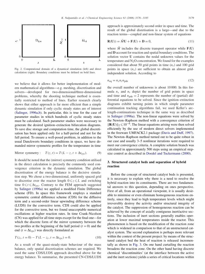
Before the concept of structured catalyst beds is presented,it is necessary to explain why there is a need to resolve thehybrid reaction into its constituents. There are two fundamen-tal answers to this question, depending on ones perspective.First of all, from an operational viewpoint, it is usually desir-able to minimise or even eliminate homogeneous reactions en-tirely, since they lead to high temperature levels which mightirreversibly destroy the activity and/or structural integrity ofthe catalyst. The suppression of homogeneous reaction can beachieved by the concept of axially contiguous inert/active sec-tions. The inclusion of inert sections generally enables oper-ation at lower maximal temperatures inside the reactor. Thisphenomenon is based on the modification of the reaction zonewhich is widened in comparison to that of an unstructured cat-alyst system. The second explanation is perhaps more relevantwithin the context of the present project: by means of the struc-tured catalyst bed the heat of reaction is released incremen-tally as shown in Fig. 3. On one hand curtailing the reactionbroadens the reaction zone. On the other hand having discretechemical ‘discontinuities’ (at the interface between the activeand the inert sections) yields a series of critical locations within
3180 K. Nalpantidis et al. / Chemical Engineering Science 61 (2006) 3176–3185
rhyb
rhet
rhom
C CT T
Fig. 3. Reaction scheme for a conventional catalyst (left) and for a structured catalyst (right). Profiles of temperature T , concentration C and reaction rates(rhyb, rhom, rhet) are shown. Grey and white areas depicts active and inert section, respectively.
the reactor (cf. Fig. 3). Forcing the stretched profiles to extendover the whole catalytic structure and in particular over thesediscontinuities assists one in further understanding the decisivechemical and thermal coupling mechanisms. In previous ex-periments and simulations of the hybrid N2O decomposition itwas found that the variation of operating parameters (switch-ing time, inlet concentration and flow rate) alone did not leadto the desired separation of the hybrid reaction routes (Galle,2001). In addition, attempting to chemically disturb the hybridreaction, e.g. by means of introducing radical suppressants, wasunsuccessful (Galle, 2001). One reason for this behaviour is al-most certainly the comparatively narrow temperature windowbetween the two reaction routes. The heat liberated in the cat-alytic reaction nearly always leads unavoidably to the ignitionof the homogeneous reaction. It was observed as a result, thatmost operating conditions lead to a spatially and temporallydispersed hybrid reaction zone. One way of circumventing thiseffect would be to impose complex temperature controls. Forexample this could be realised by incorporating cooling coilsor a sidestream purge to remove some of the heat of reactionand thus suppress the homogeneous reaction. Another muchsimpler way of achieving the same end is to utilise an axiallystructured catalyst within the RFR to isolate the stability limitsmore clearly. Alternating axially aligned active and inert mono-lithic sections having similar physical properties makes it pos-sible to establish a kind of chemical ‘switch’. Fig. 3 illustratesthe basic principle behind this idea. Considering the catalyticreaction taking place in the first active section (cf. Fig. 3, right-hand side), depending on the amount of heat produced and thetemperature level prevailing at the end of the section, the gaseither continues to react homogeneously in the downstream in-ert section or the reaction extinguishes. The number of possiblearrangements of sections for a structured catalyst bed is virtu-ally unlimited. The ‘geometric’ parameters which simulations
indicated to exert a strong influence on the hybrid reaction arelisted below:
1. Overall ratio between active and inert sections.2. Number of sections.3. Width of sections.4. Location of sections.
In combination with reverse flow operation, the concept of astructured catalyst as a diagnostic method for analysing hybridreactions becomes still more efficacious since all the fronts con-tinuously move to and fro within the monolith. Due to the in-herent time-dependency of unsteady-state fixed-bed processes,the amount of data available is naturally much greater than forsteady-state operations. Qualitative changes can now be iden-tified in both space and time (within a half-period).
4. Results and discussion
The experimental and theoretical results for an appropriatearrangement of sections in order to resolve the hybrid N2Odecomposition are presented. It is a obviously easier to varythe key parameters in the simulation than in the experimentaldeterminations. It should be emphasised that the modificationof the monolith catalyst structure is a very costly and time-consuming procedure.
4.1. Variation of geometric parameters
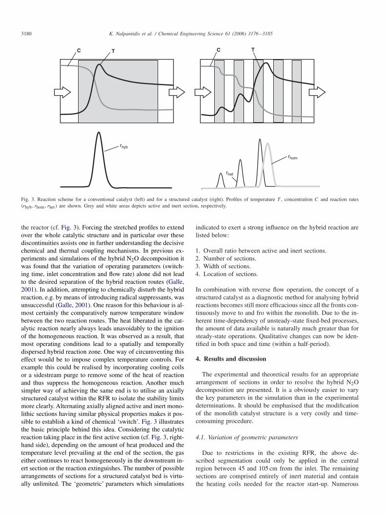
Due to restrictions in the existing RFR, the above de-scribed segmentation could only be applied in the centralregion between 45 and 105 cm from the inlet. The remainingsections are comprised entirely of inert material and containthe heating coils needed for the reactor start-up. Numerous
K. Nalpantidis et al. / Chemical Engineering Science 61 (2006) 3176–3185 3181
C I C I C I C
0 45 75 105 150
10 7.5
Fig. 4. Arrangements of structured catalyst inside the RFR. Locations in cm.
ignition–extinction diagrams were calculated for various com-binations of the geometric parameters listed above. A propor-tion of 50% passive and 50% active area seemed to be mostappropriate for an unambiguous resolution of the hybrid re-action system. Nevertheless, cases with lower overall catalystfractions (40/60 and 30/70) lead to similar results. The numberand location of the sections on the other hand had a muchstronger influence on the macroscopic behaviour observed.A higher number of sections tends to provide a superior seg-regation of the catalytic and homogeneous reactions but, froman experimental point of view, the section width should not betoo small. Fig. 4 depicts the arrangement of structured catalystthat was finally realised for the experiments. It can be seenclearly where the alternating active catalytic (C) and passiveinert zones (I ) are located. All catalytic sections have the samewidth of 7.5 cm which is roughly the size of the typical reactionzone found in earlier studies of our group (Nalpantidis, 2003).The experimental set-up is equipped with 19 thermocouplesclosely and more or less uniformly distributed along the cylin-drical axis. These thermocouples are denser in the centre ofthe reactor so as to obtain a higher resolution and to ensurethat at least one thermocouple is present in each section.
4.2. Variation of operating parameters
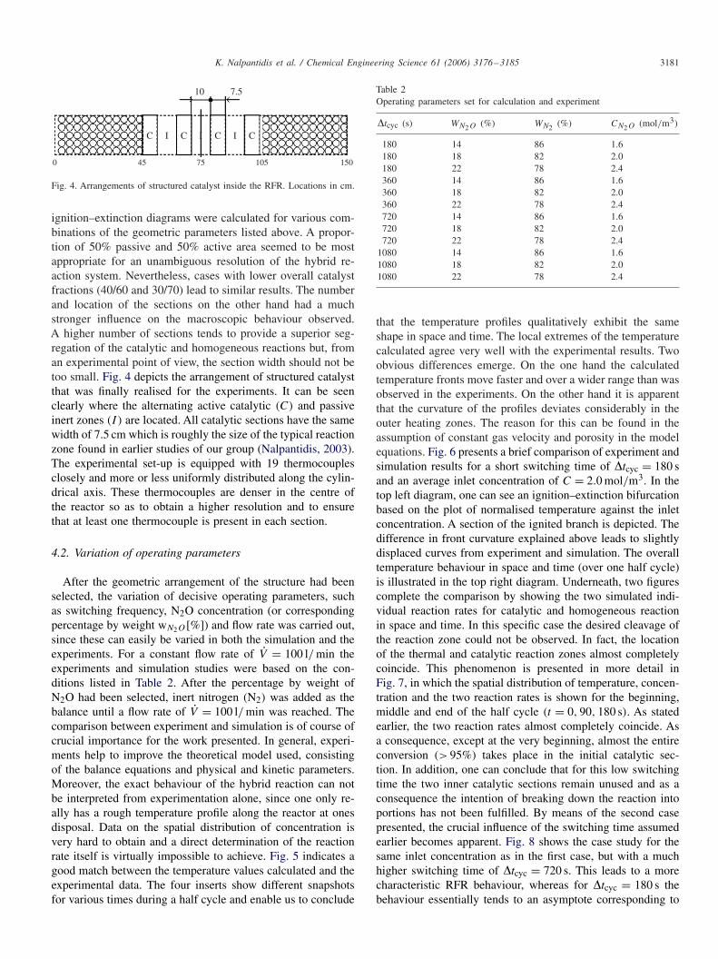
After the geometric arrangement of the structure had beenselected, the variation of decisive operating parameters, suchas switching frequency, N2O concentration (or correspondingpercentage by weight wN2O [%]) and flow rate was carried out,since these can easily be varied in both the simulation and theexperiments. For a constant flow rate of V = 100 l/ min theexperiments and simulation studies were based on the con-ditions listed in Table 2. After the percentage by weight ofN2O had been selected, inert nitrogen (N2) was added as thebalance until a flow rate of V = 100 l/ min was reached. Thecomparison between experiment and simulation is of course ofcrucial importance for the work presented. In general, experi-ments help to improve the theoretical model used, consistingof the balance equations and physical and kinetic parameters.Moreover, the exact behaviour of the hybrid reaction can notbe interpreted from experimentation alone, since one only re-ally has a rough temperature profile along the reactor at onesdisposal. Data on the spatial distribution of concentration isvery hard to obtain and a direct determination of the reactionrate itself is virtually impossible to achieve. Fig. 5 indicates agood match between the temperature values calculated and theexperimental data. The four inserts show different snapshotsfor various times during a half cycle and enable us to conclude
Table 2Operating parameters set for calculation and experiment
�tcyc (s) WN2O (%) WN2 (%) CN2O (mol/m3)
180 14 86 1.6180 18 82 2.0180 22 78 2.4360 14 86 1.6360 18 82 2.0360 22 78 2.4720 14 86 1.6720 18 82 2.0720 22 78 2.4
1080 14 86 1.61080 18 82 2.01080 22 78 2.4
that the temperature profiles qualitatively exhibit the sameshape in space and time. The local extremes of the temperaturecalculated agree very well with the experimental results. Twoobvious differences emerge. On the one hand the calculatedtemperature fronts move faster and over a wider range than wasobserved in the experiments. On the other hand it is apparentthat the curvature of the profiles deviates considerably in theouter heating zones. The reason for this can be found in theassumption of constant gas velocity and porosity in the modelequations. Fig. 6 presents a brief comparison of experiment andsimulation results for a short switching time of �tcyc = 180 sand an average inlet concentration of C = 2.0 mol/m3. In thetop left diagram, one can see an ignition–extinction bifurcationbased on the plot of normalised temperature against the inletconcentration. A section of the ignited branch is depicted. Thedifference in front curvature explained above leads to slightlydisplaced curves from experiment and simulation. The overalltemperature behaviour in space and time (over one half cycle)is illustrated in the top right diagram. Underneath, two figurescomplete the comparison by showing the two simulated indi-vidual reaction rates for catalytic and homogeneous reactionin space and time. In this specific case the desired cleavage ofthe reaction zone could not be observed. In fact, the locationof the thermal and catalytic reaction zones almost completelycoincide. This phenomenon is presented in more detail inFig. 7, in which the spatial distribution of temperature, concen-tration and the two reaction rates is shown for the beginning,middle and end of the half cycle (t = 0, 90, 180 s). As statedearlier, the two reaction rates almost completely coincide. Asa consequence, except at the very beginning, almost the entireconversion (> 95%) takes place in the initial catalytic sec-tion. In addition, one can conclude that for this low switchingtime the two inner catalytic sections remain unused and as aconsequence the intention of breaking down the reaction intoportions has not been fulfilled. By means of the second casepresented, the crucial influence of the switching time assumedearlier becomes apparent. Fig. 8 shows the case study for thesame inlet concentration as in the first case, but with a muchhigher switching time of �tcyc = 720 s. This leads to a morecharacteristic RFR behaviour, whereas for �tcyc = 180 s thebehaviour essentially tends to an asymptote corresponding to

3182 K. Nalpantidis et al. / Chemical Engineering Science 61 (2006) 3176–3185
Fig. 5. Comparison of simulation and experiment for trel = 0, 120, 180, 360 s and (switching time �tcyc = 360 s, inlet concentration C = 2.4 mol/m3).
Fig. 6. Comparison of simulation and experiment (switching time �tcyc = 180 s, inlet concentration C = 2.0 mol/m3).

K. Nalpantidis et al. / Chemical Engineering Science 61 (2006) 3176–3185 3183
Fig. 7. Behaviour at lower switching times, e.g. �tcyc = 180 s, the broad reaction front can be observed throughout the cycle. Simulated and experimentalretrieved temperature distributions (upper), concentration profiles (middle) and reaction rates (lower) are depicted.
Fig. 8. Comparison of simulation and experiment (switching time �tcyc = 720 s, concentration C = 2.0 mol/m3).
3184 K. Nalpantidis et al. / Chemical Engineering Science 61 (2006) 3176–3185
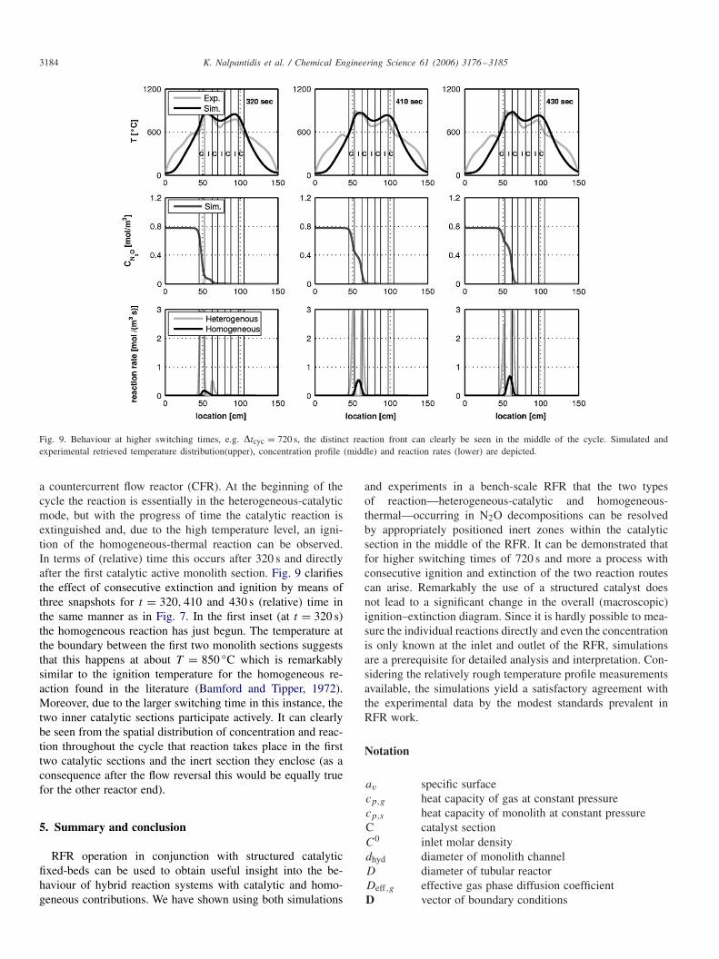
Fig. 9. Behaviour at higher switching times, e.g. �tcyc = 720 s, the distinct reaction front can clearly be seen in the middle of the cycle. Simulated andexperimental retrieved temperature distribution(upper), concentration profile (middle) and reaction rates (lower) are depicted.
a countercurrent flow reactor (CFR). At the beginning of thecycle the reaction is essentially in the heterogeneous-catalyticmode, but with the progress of time the catalytic reaction isextinguished and, due to the high temperature level, an igni-tion of the homogeneous-thermal reaction can be observed.In terms of (relative) time this occurs after 320 s and directlyafter the first catalytic active monolith section. Fig. 9 clarifiesthe effect of consecutive extinction and ignition by means ofthree snapshots for t = 320, 410 and 430 s (relative) time inthe same manner as in Fig. 7. In the first inset (at t = 320 s)the homogeneous reaction has just begun. The temperature atthe boundary between the first two monolith sections suggeststhat this happens at about T = 850 ◦C which is remarkablysimilar to the ignition temperature for the homogeneous re-action found in the literature (Bamford and Tipper, 1972).Moreover, due to the larger switching time in this instance, thetwo inner catalytic sections participate actively. It can clearlybe seen from the spatial distribution of concentration and reac-tion throughout the cycle that reaction takes place in the firsttwo catalytic sections and the inert section they enclose (as aconsequence after the flow reversal this would be equally truefor the other reactor end).
5. Summary and conclusion
RFR operation in conjunction with structured catalyticfixed-beds can be used to obtain useful insight into the be-haviour of hybrid reaction systems with catalytic and homo-geneous contributions. We have shown using both simulations
and experiments in a bench-scale RFR that the two typesof reaction—heterogeneous-catalytic and homogeneous-thermal—occurring in N2O decompositions can be resolvedby appropriately positioned inert zones within the catalyticsection in the middle of the RFR. It can be demonstrated thatfor higher switching times of 720 s and more a process withconsecutive ignition and extinction of the two reaction routescan arise. Remarkably the use of a structured catalyst doesnot lead to a significant change in the overall (macroscopic)ignition–extinction diagram. Since it is hardly possible to mea-sure the individual reactions directly and even the concentrationis only known at the inlet and outlet of the RFR, simulationsare a prerequisite for detailed analysis and interpretation. Con-sidering the relatively rough temperature profile measurementsavailable, the simulations yield a satisfactory agreement withthe experimental data by the modest standards prevalent inRFR work.
Notation
av specific surfacecp,g heat capacity of gas at constant pressurecp,s heat capacity of monolith at constant pressureC catalyst sectionC0 inlet molar densitydhyd diameter of monolith channelD diameter of tubular reactorDeff,g effective gas phase diffusion coefficientD vector of boundary conditions
K. Nalpantidis et al. / Chemical Engineering Science 61 (2006) 3176–3185 3185
EhetA activation energy of heterogeneous reaction
EhomA activation energy of homogeneous reaction
F(U) vector of reactive terms�H
N2Or reaction enthalpy for decomposition process
I inert sectionkwv heat loss constantkhet
0 rate constant of heterogeneous reactionkhom
0 rate constant of homogeneous reactionL length of reactorM discrete transport operatorr radius of reactorrhet heterogeneous reaction raterhom homogeneous reaction raterhyb hybrid reaction rateR universal gas constantR(U) vector of residualst timetrel relative time�tcyc switching timeT amb ambient temperatureU vector of unknownsvg gas velocityV volumetric flow ratez spatial coordinate
Greek letters
� heat transfer coefficient� mass transfer coefficient� void fraction�g heat conduction coefficient of gas�s heat conduction coefficient of solid�eff effective heat conduction coefficient�g gas density�s solid density�dyn computational domain of dynamical simulation�VD computational domain of global discretisation
Acknowledgements
This work was financed by the Deutsche Forschungsgemein-schaft (DFG). The author would like to thank C. Fredebeul forhis support and express his gratitude to Rafael Dyll for his as-sistance with the manuscript.
References
Bamford, C., Tipper, C., 1972. Chemical Kinetics. Elsevier, Amsterdam.Boreskov, G., Matros, Y., 1983. Unsteady-state performance of heterogeneous
catalytic reactions. Reviews in Science and Engineering 25, 551–590.Boreskov, G., Matros, Y., Kiselev, O., 1979. Catalytic processes carried out
under nonstationary conditions. Kinetika Kataliz 20, 636–641.Boreskov, G., Bunimovic, G., Matros, Y., 1982. Catalytic processes under
non-steady state conditions, II. Switching the direction for the feed of thereaction mixture to the catalyst bed, experimental results. Kinetika Kataliz23, 402–406.
Cottrell, F., 1938. Purifying gases and apparatus therefor. US Patent 2,121,733.Davis, M.B., Pawson, M.D., Veser, G., Schmidt, L., 2000. Methane oxidation
over noble metal gauzes: An life study. Combustion and Flame 123, 159.Davis, T., Duff, I., 1997. A combined unifrontal/multifrontal method for
unsymmetric sparse matrices. Technical Report TR-97-016, Computer andInformation Science and Engineering Department, University of Florida.
Doedel, E., Tuckermann, L.S., 2000. Numerical methods for bifurcationproblems and large-scale dynamical systems. Springer, New York.
Galle, M., 2001. Hybride homogene und heterogene reaktionsführung inhochtemperatursystemen am beispiel der lachgaszersetzung. Ph.D. Thesis,University of Dortmund.
Glöckler, B., Kolios, G., Eigenberger, G., 2003. Analysis of a novel reverse-flow reactor concept for autothermal methane steam reforming. ChemicalEngineering Science 58, 593–601.
Khinast, U., ans Gurumoorthy, A., Luss, D., 1998. Complex dynamic featuresof a cooled reverse-flow reactor. A.I.Ch.E. Journal 44, 1128.
Matros, Y.S., 1989. Catalytic processes under unsteady-state conditions.Studies of Surface Science and Catalysis. Elsevier, Amsterdam.
Matros, Y.S., Bunimovich, G.A., 1996. Reverse-flow operation in fixed-bedcatalytic reactors. Catalysis Reviews in Science and Engineering 38, 1–68.
Matros, Y.S., Boreskov, G.K., Lahmostov, V.S., Volkov, Y.V., Ivanov, A.A.,1984. Method of producing sulfur trioxide. US Patent 4,478,808.
Nalpantidis, K., 2003. Untersuchung der heterogen/homogen zersetzung vonN2O in einem periodisch betriebenen festbettreaktor. Master’s Thesis,University of Dortmund.
Nieken, U., Kolios, G., Eigenberger, G., 1994. Fixed-bed-reactors withperiodic flow reversal: experimental results for catalytic combustion.Catalysis Today 20, 355.
Salinger, A.G., 1996a. The direct calculation of periodic states of the reverseflow reactor—I. Methodology and propane combustion results. ChemicalEngineering Science 51, 4903–4913.
Salinger, A.G., 1996b. The direct calculation of periodic states of the reverseflow reactor—II. Multiplicity and instabiliy. Chemical Engineering Science51, 4915–4922.
Unger, J., Kolios, G., Eigenberger, G., 1997. On the efficient simulationand analysis of regenerative processes in cyclic operation. ChemicalEngineering Science 21, 167–172.
Copyright © 2022 FDOKUMEN