
Element Management System (EMS) User's Manual
312
Element Management System (EMS) User’s Manual Version 5.8 Document #: LTRT-91015 Notice In this document, the Avaya G860 Media Gateway corresponds to the Mediant 5000. Note that some features and capabilities contained in this document are not supported by Avaya. Consult your authorized Avaya Sales or Partner resource to confirm the Avaya support features.
-
Upload
khangminh22 -
Category
Documents
-
view
3 -
download
0
Transcript of Element Management System (EMS) User's Manual

Element Management System (EMS) User’s Manual
Version 5.8
Document #: LTRT-91015
Notice
In this document, the Avaya G860 Media Gateway corresponds to the Mediant 5000. Note that some features and capabilities contained in this document are not supported by Avaya. Consult your authorized Avaya Sales or Partner resource to confirm the Avaya support features.


Version 5.8 3 June 2010
EMS User's Manual Notices
Notice This User’s Manual describes the installation and use of the Element Management System (EMS).
Information contained in this document is believed to be accurate and reliable at the time of printing. However, due to ongoing product improvements and revisions, AudioCodes cannot guarantee the accuracy of printed material after the Date Published nor can it accept responsibility for errors or omissions. Updates to this document and other documents can be viewed by registered customers at www.audiocodes.com/downloads.
© 2009 AudioCodes Ltd. All rights reserved. This document is subject to change without notice.
Date Published: July 26, 2009
Note: The Element Management System supports the following products:
• Mediant 5000 Media Gateway and Mediant 8000 Media Gateway • Mediant 3000 Media Gateway • IPmedia 3000 Media Server • Mediant 2000 Media Gateway • IPmedia 2000 Media Server • Mediant 1000 Media Gateway • MediaPack • Mediant 600
Trademarks
AudioCodes, AC, AudioCoded, Ardito, CTI2, CTI², CTI Squared, HD VoIP, InTouch, IPmedia, Mediant, MediaPack, NetCoder, Netrake, Nuera, Open Solutions Network, OSN, Stretto, TrunkPack, VoicePacketizer, VoIPerfect, VoIPerfectHD, What’s Inside Matters, Your Gateway To VoIP and 3GX are trademarks or registered trademarks of AudioCodes Limited. All other products or trademarks are property of their respective owners. All other products or trademarks are the property of their respective owners.
WEEE EU Directive
Pursuant to the WEEE EU Directive, electronic and electrical waste must not be disposed of with unsorted waste. Please contact your local recycling authority for disposal of this product.
Customer Support
Customer technical support and service are provided by AudioCodes’ Distributors, Partners, and Resellers from whom the product was purchased. For Customer support for products purchased directly from AudioCodes, contact [email protected].

EMS User's Manual 4 Document #: LTRT-91015
AudioCodes Element Management System
Abbreviations and Terminology
Each abbreviation, unless widely used, is spelled out in full when first used. Only industry-standard terms are used throughout this manual. Hexadecimal notation is indicated by 0x preceding the number. When the term ‘Trunking Gateway’ is used in this manual, it refers to the Mediant 5000 Media Gateway and Mediant 8000 Media Gateway. The term ‘Media Gateway’ is used to also represent ‘Media Server’. When ‘MG’ is used in this manual, it refers to ‘media gateway’ and ‘media server’. MediaPack collectively refers to the MP-102 (FXS), MP-104 (FXS and FXO), MP-108 (FXS and FXO), MP-112 (FXS), MP-114 (FXS), MP-118 (FXS) and MP-124 (FXS). The term 'Blades' refers to the TP-260 and IPM-260 boards. 'CPE' (Customer Premises Equipment) refers to the Mediant 1000 / 2000 / 3000 Media Gateways, the IPmedia 2000 / 3000 Media Servers, and the MediaPack Media Gateways. The term 'DS3' is synonymous with the term 'T3'. The terms ‘frame’ and ‘screen’ are sometimes used interchangeably.
Related Documentation
Manual Name
Mediant 5000 / 8000 Media Gateway Installation, Operation and Maintenance Manual
Mediant 5000 / 8000 Media Gateway Release Notes
Mediant 3000 User’s Manual
IPmedia 3000 Media Server User’s Manual
Mediant 2000 User’s Manual
IPmedia 2000 Media Server User’s Manual
Mediant 1000 and Mediant 600 User's Manual
MediaPack MGCP-MEGACO User’s Manual
MediaPack User’s Manual
Element Management System (EMS) Server Installation and Maintenance Manual
Element Management System (EMS) Product Description
Element Management System (EMS) Release Notes
Element Management System (EMS) Online Help
Mediant 5000 / 8000 Media Gateway Programmer's User Manual
EMS Parameter Guide for the Mediant 5000 and Mediant 8000 Gateways
EMS Parameter Guide for Mediant 1000, Mediant 2000, Mediant 3000, IPmedia 3000 and IPmedia 2000
EMS Parameter Guide for MediaPack
Audio Provisioning Server User’s Manual – The Audio Provisioning Server (APS) is an application that is used to manage and distribute audio segments to one or more IPmedia nodes. (Document # LTRT-971xx)
Audio Provisioning Server User’s Manual: Audio Files – Details recording language variables - Document # LTRT-972xx

Version 5.8 5 June 2010
EMS User's Manual Notices
Manual Name
Mediant 5000 / 8000 Media Gateway Installation, Operation and Maintenance Manual
Co-Resident APS Installation Manual - Provides details on installing the APS software (if the AudioCodes EMS is installed) - Document # LTRT-973xx
AudioCodes Stand Alone APS Installation Manual – Document # LTRT-974xx

EMS User's Manual 6 Document #: LTRT-91015
AudioCodes Element Management System
Reader’s Notes

Version 5.8 7 June 2010
EMS User's Manual Contents
Contents 1 Introducing the AudioCodes Element Management System......................... 19
1.1 EMS within the Network........................................................................... 19 1.2 Specifications ........................................................................................... 21 1.3 Supported VoIP Equipment..................................................................... 24 1.4 Supported Versions of Managed Equipment ........................................ 26 1.5 EMS System Requirements..................................................................... 27 1.6 Characteristics.......................................................................................... 28
2 Installing the EMS Client on a PC..................................................................... 31 2.1 Running the EMS Client........................................................................... 31 2.2 Management Procedure........................................................................... 32
3 Getting Started with the EMS............................................................................ 33 3.1 Logging In ................................................................................................. 34 3.2 Getting Oriented in the EMS.................................................................... 35
3.2.1 Navigating Down and Up System Hierarchy ............................................35 3.2.2 Selecting an Interface in the Context of an Element ................................36 3.2.3 Context-Sensitive Behavior......................................................................37 3.2.4 Using Color Coding to Assess Element Status ........................................38
4 Software Manager............................................................................................... 39 4.1 Adding a New File to the Software Manager ......................................... 48 4.2 Removing Files from the Software Manager ......................................... 48 4.3 Saving File from the Software Manager................................................. 48
5 Defining VoIP Devices, Managing the MG Tree .............................................. 49 5.1 Configuring a Region ............................................................................... 49 5.2 Defining a Mediant 5000, Mediant 8000.................................................. 50
5.2.1 Defining Multiple Mediant 5000, Mediant 8000 Gateways .......................53 5.3 Predefinition or Automatic Detection..................................................... 55
5.3.1 Blades and CPE.......................................................................................55 5.3.2 Automatic Detection .................................................................................55 5.3.3 Defining a Single Blade or CPE (Mediant 1000 / 2000 / 3000 or MP) .....58 5.3.4 Defining Multiple Blades and CPE ...........................................................60
5.3.4.1 Gateways Connected to the Network ................................................ 62 5.3.4.2 Gateways NOT Connected to the Network........................................ 62
5.4 First-Time Connection Problems............................................................ 63 5.5 Mismatch Indications ............................................................................... 63 5.6 Moving a Gateway from Region to Region ............................................ 64 5.7 Moving Multiple Gateways from Region to Region .............................. 65 5.8 Removing a Gateway ............................................................................... 66 5.9 Removing Multiple Gateways.................................................................. 67 5.10 Searching for a Gateway.......................................................................... 68 5.11 Saving the EMS Tree MGs Report in an External File .......................... 70

EMS User's Manual 8 Document #: LTRT-91015
AudioCodes Element Management System
6 Monitoring Multiple Media Gateways ............................................................... 73 6.1 Regions List .............................................................................................. 73 6.2 MGs List..................................................................................................... 75 6.3 Media Gateway Level Status Pane.......................................................... 77
7 Mediant 5000/8000 and IPmedia 8000 .............................................................. 79 7.1 Mediant/IPmedia 8000 Status Pane ........................................................ 79 7.2 Mediant/IPmedia 5000 Status Pane ........................................................ 86 7.3 Mediant 5000/8000 Hardware Components Status SAT(SA/RTM1)
Board Information .................................................................................... 92 7.3.1 Mediant 8000 Hardware Components Status ..........................................92 7.3.2 Mediant 8000 6310 Hardware Components Status .................................93 7.3.3 Mediant 5000 Hardware Components Status ..........................................95 7.3.4 Mediant 5000 6310 Hardware Components Status .................................96
7.4 Navigation Buttons to Provision the Mediant 8000, Mediant 5000 ..... 98 7.4.1 MTP3 SS7 Provisioning .........................................................................100 7.4.2 V5.2 Provisioning (TP-8410) ..................................................................102
7.5 Mediant 5000, Mediant 8000 Maintenance Actions............................. 103 7.6 Accessing a TP-6310 in the Mediant 8000, Mediant 5000 and IPmedia
8000.......................................................................................................... 107 7.6.1 Signaling ................................................................................................108 7.6.2 Accessing the TP Board Level Provisioning Screen ..............................109 7.6.3 Accessing the Main Status Screens.......................................................110
7.7 Accessing a TP-8410 in the Mediant 5000 ........................................... 114 7.7.1 Signaling ................................................................................................115
7.8 SIP Provisioning of VoP Board (6310 and 8410) ................................. 116 7.8.1 SIP .........................................................................................................117 7.8.2 Trunk Groups .........................................................................................117 7.8.3 Routing...................................................................................................119 7.8.4 Manipulation...........................................................................................120
7.9 Ethernet Switch Board's Links' Status................................................. 121 7.10 Inventory Management .......................................................................... 123 7.11 IPs Summary........................................................................................... 125
8 Mediant 3000 and IPmedia 3000...................................................................... 129 8.1 Supported Configuration....................................................................... 129 8.2 Initial Configuration................................................................................ 129 8.3 Mediant 3000, IPmedia 3000 Status Pane ............................................ 129
8.3.1 Hardware Component Status in Table View ..........................................134 8.3.2 Mediant 3000 8410 SA BITS status.......................................................135
8.4 Physical and Logical Components Status and Provisioning ............ 137 8.4.1 Navigation Hierarchy..............................................................................137
8.4.1.1 Mediant 3000 8410 V5.2 Provisioning ............................................. 138 8.4.2 SONET / SDH Interfaces .......................................................................139 8.4.3 DS3 Interfaces .......................................................................................140 8.4.4 DS1 Interfaces .......................................................................................140
8.5 Executable Actions on the Mediant 3000............................................. 141

Version 5.8 9 June 2010
EMS User's Manual Contents
9 Mediant 2000 and IPmedia 2000...................................................................... 143 9.1 Mediant 2000 and IPmedia 2000 Status Pane...................................... 143 9.2 Mediant 2000 and IPmedia 2000 Provisioning..................................... 145 9.3 Executable Actions on Mediant 2000 and IPmedia 2000.................... 146
10 Mediant 1000 and Mediant 600........................................................................ 147 10.1 Mediant 1000 Status Pane ..................................................................... 147 10.2 Mediant 600 Status Pane ....................................................................... 148 10.3 Mediant 1000 and Mediant 600 Provisioning....................................... 148 10.4 Executable Actions on the Mediant 1000 and Mediant 600 ............... 149
11 MediaPack ......................................................................................................... 151 11.1 Status Pane for MediaPack ................................................................... 151 11.2 MediaPack Line Test .............................................................................. 153 11.3 Provisioning MediaPacks ...................................................................... 154 11.4 Executable Actions on MediaPacks ..................................................... 154
12 Mediant 600/1000/2000/3000/5000/8000 Trunks and Channels Status ....... 155 12.1 DS1 Trunks Status and Provisioning ................................................... 155 12.2 Trunk Channel Call Status..................................................................... 157
13 Mediant 2000 and Mediant 3000 SIP and SS7 Navigation Concepts .......... 159 13.1 SIP Provisioning Navigation Buttons................................................... 159 13.2 SS7 Provisioning Navigation Buttons.................................................. 160
14 Mediant 600/1000/2000/3000 and MediaPack Maintenance Actions ........... 161 14.1 Configuration Actions............................................................................ 161 14.2 Maintenance Actions.............................................................................. 162 14.3 Performing Actions on Multiple Gateways .......................................... 163
15 Provisioning Concepts .................................................................................... 165 15.1 Working with the EMS's Provisioning Screens................................... 165
15.1.1 Provisioning Procedure for Mediant 1000, Mediant 2000, Mediant 3000, IPmedia 2000, IPmedia 3000 and MediaPack......................................167
15.1.2 Provisioning Procedure for Mediant 5000 and Mediant 8000 ................168 15.1.3 Provisioning Procedure for Mediant 1000, Mediant 2000, Mediant 3000,
IPmedia 2000, IPmedia 3000 and MediaPack.....................................169 15.2 Parameters Provisioning Types............................................................ 170 15.3 Parameters HA Type .............................................................................. 173 15.4 Exporting, Importing an Entity Configuration as a File...................... 173 15.5 Printing an Entity's Configuration as a File......................................... 175 15.6 Provisioning Entity Profiles .................................................................. 176
15.6.1 Creating Entity Profiles ..........................................................................177 15.6.2 Loading - Attaching - an Entity Profile....................................................178 15.6.3 Detaching a Profile from an Entity..........................................................178 15.6.4 Removing a Profile.................................................................................178
15.7 Master Profile for Mediant 1000, Mediant 2000, Mediant 3000, IPmedia 2000, IPmedia 3000 and MediaPack ..................................................... 179

EMS User's Manual 10 Document #: LTRT-91015
AudioCodes Element Management System
15.7.1 Ascertaining a Device's Master Profile...................................................179 15.7.2 Creating a Master Profile .......................................................................180 15.7.3 Attaching a Master Profile to one or to Multiple Media Gateways..........182 15.7.4 Detaching a Master Profile.....................................................................184 15.7.5 Removing a Master Profile.....................................................................184
15.8 TP-6310 and TP-8410 Master Profile (Mediant 5000 Media Gateway, Mediant 8000 Media Gateway) .............................................................. 185 15.8.1 Ascertaining a TP-6310 and TP-8410 Board Master Profile .................185 15.8.2 Creating a Master Profile .......................................................................187 15.8.3 Attaching a Master Profile to TP-8410, TP-6310 Boards .......................189 15.8.4 Detaching a Master Profile from TP-8410, TP-6310 Boards..................189 15.8.5 Master Profiles Manager ........................................................................190
15.9 Offline Configuration for Mediant 1000, Mediant 2000, Mediant 3000, IPmedia 2000, IPmedia 3000 and MediaPack ...................................... 190
15.10 Configuration Verification, Download for Mediant 1000, Mediant 2000, Mediant 3000, IPmedia 2000, IPmedia 3000 and MediaPack ............. 191
15.11 Searching for a Provisioned Parameter............................................... 192 16 Gateway Installation, Software Upgrade and Regional Files Distribution . 195
16.1 Software Manager................................................................................... 195 16.2 Software Upgrade for CPE and Blades ................................................ 195 16.3 Mediant 5000, Mediant 8000 Maintenance Actions............................. 196
16.3.1 Locking and / Unlocking the Gateway....................................................198 16.3.2 License Key Update...............................................................................198 16.3.3 Online Software Upgrade Wizard...........................................................199
16.3.3.1 Rollback .......................................................................................... 202 16.3.3.2 Troubleshooting............................................................................... 202
16.3.4 Backing Up and Restoring the Media Gateway .....................................204 16.4 Mediant 5000, Mediant 8000 Startup and Shutdown .......................... 206 16.5 Collecting Log Files ............................................................................... 206 16.6 Mediant 5000, Mediant 8000 Configuration Backup Files Collection207
17 Fault Management ............................................................................................ 211 17.1 Alarm Browser ........................................................................................ 211
17.1.1 Filtering Alarms ......................................................................................213 17.1.2 Acknowledging an Alarm .......................................................................214 17.1.3 Alarms Clearing .....................................................................................214 17.1.4 Changing the Alarms Browser Views.....................................................215
17.1.4.1 Alarms View Level........................................................................... 215 17.1.4.2 Alarm Browser Columns View ......................................................... 215
17.1.5 Open Alarms History ..............................................................................216 17.1.6 Open Journal .........................................................................................216 17.1.7 Audio Indication on Receipt of Alarms ...................................................216 17.1.8 Pause Alarms Auto Refreshing..............................................................217 17.1.9 Alarms and Events Filtering and Sorting................................................217 17.1.10 Closing the Alarm Browser Pane ...........................................................217
17.2 Alarms History ........................................................................................ 218 17.3 Using Time Filters .................................................................................. 220 17.4 Using Advanced Filters.......................................................................... 221 17.5 Defining Complex Queries using a Combination of Filters ............... 225

Version 5.8 11 June 2010
EMS User's Manual Contents
17.6 Viewing, Interpreting an Alarm's Details.............................................. 226 17.7 Trap Forwarding ..................................................................................... 231
17.7.1 Trap Forwarding in Mail Format .............................................................231 17.7.2 Trap Forwarding in Mail2SMS format ....................................................233 17.7.3 Trap Forwarding in Syslog format ..........................................................235
17.8 Saving Alarms in a .csv File .................................................................. 237 18 Performance Management .............................................................................. 241
18.1 Real-Time Performance Monitoring...................................................... 242 18.2 Background (History) Performance Monitoring.................................. 246 18.3 Configuring Background Monitoring ................................................... 247 18.4 Exporting Background Monitoring Data as a File............................... 248 18.5 Viewing Historical Data.......................................................................... 249 18.6 Configuring PM Threshold Values........................................................ 251 18.7 Performance Monitoring Actions on Multiple Media Gateways ........ 252
19 Security Management ...................................................................................... 253 19.1 Network Communication Security........................................................ 253
19.1.1 SNMP Management...............................................................................255 19.1.2 Mediant 5000 and Mediant 8000 Media Gateway Security Management
..............................................................................................................255 19.1.3 CPE Security Management....................................................................256
19.1.3.1 Configuring SNMP........................................................................... 256 19.1.3.2 Defining (Cloning) SNMPv3 Users .................................................. 258 19.1.3.3 Configuring HTTPS ......................................................................... 260 19.1.3.4 Configuring Media Gateway Web Server and SSH Server User
Passwords....................................................................................... 260 19.1.3.5 Configuring IPSec ........................................................................... 261 19.1.3.6 Generating X.509 CSR and Self-Signed Certificate via EMS .......... 264 19.1.3.7 Adding Certificates to the Software Manager .................................. 266 19.1.3.8 Activating the new X.509 Certificates on the Media Gateway.......... 266
19.1.4 EMS Application Security.......................................................................266 19.1.4.1 Centralized EMS Users Authentication and Authorization via a Radius
Server ............................................................................................. 266 19.1.4.2 Setting Up the Radius Server .......................................................... 267 19.1.4.3 Provisioning Radius Server Authentication and Authorization for EMS
Users............................................................................................... 269 19.1.4.4 Local Users Management in the EMS Application........................... 271 19.1.4.5 Synchronizing EMS and Mediant 5000 / 8000 CLI users................. 272 19.1.4.6 Provisioning Password Aging Rules ................................................ 272 19.1.4.7 Accessing Users List ....................................................................... 273
19.2 Viewing Operator Actions in the Actions Journal .............................. 279 19.2.1 Viewing 'Journal Record Details'............................................................281 19.2.2 Filters Supported in the Actions Journal ................................................284 19.2.3 Saving the Data in the Actions Journal as a csv File .............................287
19.3 EMS Application Welcome Message.................................................... 288 20 Troubleshooting ............................................................................................... 291
20.1 Failure to Connect to a Media Gateway - all MGs ............................... 291 20.1.1 Failure to Reconnect to a Previously-Connected MG Whose Operation
Was Interrupted ....................................................................................294 20.1.2 Information Required When Contacting Technical Support ...................296

EMS User's Manual 12 Document #: LTRT-91015
AudioCodes Element Management System
21 Basic Configuration ......................................................................................... 297 21.1 Mediant 5000 Media Gateway, Mediant 8000 Media Gateway............ 297
21.1.1 Configuring the Gateway IP Address, Booting the Boards ....................297 21.1.1.1 Configuring a Media Gateway for the First Time ............................ 298
21.1.2 Getting Started with Provisioning a Gateway.........................................300 21.1.3 Locking a Gateway ................................................................................301 21.1.4 Provisioning a Gateway .........................................................................301 21.1.5 Unlocking a Gateway .............................................................................301
21.2 MediaPack Quick Configuration Example ........................................... 302 22 Index .................................................................................................................. 309

Version 5.8 13 June 2010
EMS User's Manual Contents
List of Figures Figure 1-1: EMS Integrated in a Network System ............................................................................... 20 Figure 3-1: Login Screen..................................................................................................................... 33 Figure 3-2: Main Screen Indicating Navigation Concepts.................................................................... 34 Figure 3-3: EMS Navigation Buttons ................................................................................................... 35 Figure 4-1: Software Manager............................................................................................................. 40 Figure 4-2: Software Manager File Details .......................................................................................... 40 Figure 4-3: Add cmp File..................................................................................................................... 42 Figure 4-4: Software Manager-Adding Auxiliary Files ......................................................................... 43 Figure 5-1: Configuring a Region ........................................................................................................ 49 Figure 5-2: MG Information ................................................................................................................. 50 Figure 5-3: MG Information - Secured Connection Enabled................................................................ 52 Figure 5-4: Add Multiple MGs.............................................................................................................. 53 Figure 5-5: Add Multiple MGs-SNMPv3 .............................................................................................. 54 Figure 5-6: MP-NAT Configuration...................................................................................................... 57 Figure 5-7: Sending SNMP Traps to EMS Server (Behind a NAT)...................................................... 57 Figure 5-8: MG Information ................................................................................................................. 58 Figure 5-9: MG Details ........................................................................................................................ 59 Figure 5-10: Add Multiple MGs-SNMPv2 ............................................................................................ 60 Figure 5-11: Add File Unicode............................................................................................................. 61 Figure 5-12: Action Report for Adding Multiple Media Gateways Result ............................................. 62 Figure 5-13: MediaPack Information Pane Indicating Mismatch.......................................................... 64 Figure 5-14: Moving Multiple MGs from Region to Region .................................................................. 65 Figure 5-15: Multiple Move from Region to Region ............................................................................. 66 Figure 5-16: Removing Multiple Media Gateways ............................................................................... 67 Figure 5-17: Search MGs (by IP Address) .......................................................................................... 68 Figure 6-1: Regions List ...................................................................................................................... 73 Figure 6-2: MGs List............................................................................................................................ 76 Figure 7-1: Mediant 8000 Media Gateway 6310 Configuration Status Screen .................................... 79 Figure 7-2: SAT Properties screen...................................................................................................... 81 Figure 7-3: Fan Tray Status ................................................................................................................ 82 Figure 7-4: 6310 Board-Active and Redundant Status ........................................................................ 83 Figure 7-5: 8410 Board-Active and Redundant Status ........................................................................ 83 Figure 7-6: 6310-LED Status............................................................................................................... 84 Figure 7-7: 8410-LED Status............................................................................................................... 84 Figure 7-8: ES Board Status ............................................................................................................... 85 Figure 7-9: PEM Status....................................................................................................................... 85 Figure 7-10: Mediant 5000 6310 Status Pane..................................................................................... 86 Figure 7-11: Mediant 5000 8410 Status Pane..................................................................................... 86 Figure 7-12: SAT Properties screen.................................................................................................... 88 Figure 7-13: Fan Tray Status .............................................................................................................. 89 Figure 7-14: 6310 Active Board Status................................................................................................ 89 Figure 7-15: 6310 Redundant Board Status........................................................................................ 89 Figure 7-16: 8410 Active Board Status................................................................................................ 90 Figure 7-17: 8410 Board Status .......................................................................................................... 90 Figure 7-18: 6310 Board-LED Status .................................................................................................. 90 Figure 7-19: 8410 Board LED Status .................................................................................................. 90 Figure 7-20: ES Board Status ............................................................................................................. 91 Figure 7-21: PEM Status..................................................................................................................... 91 Figure 7-22: Mediant 8000 SAT Board Status Information .................................................................. 92 Figure 7-23: Mediant 8000 6310 SAT Board Status Information ......................................................... 93 Figure 7-24: Mediant 8000 6310 Fans List Information ....................................................................... 94 Figure 7-25: Mediant 5000 SAT Board Status Information .................................................................. 95 Figure 7-26: Mediant 5000 6310 SAT Board Status Information ......................................................... 96 Figure 7-27: Mediant 5000 6310 Fan Status Information .................................................................... 97 Figure 7-28: Media Gateway Level Navigation Buttons....................................................................... 98 Figure 7-29: SS7 MTP3 Navigation................................................................................................... 100

EMS User's Manual 14 Document #: LTRT-91015
AudioCodes Element Management System
Figure 7-30: TP-6310, IPM-6310 Board Level................................................................................... 107 Figure 7-31: TP-6310 Board Provisioning Parameters ...................................................................... 109 Figure 7-32: TP-6310 STM1 Board Status Pane............................................................................... 110 Figure 7-33: TP-6310 DS3 Board Status Pane ................................................................................. 110 Figure 7-34: PSTN Fiber Group (SDH/STM1 Interface) Screen........................................................ 111 Figure 7-35: PSTN Fiber Group (Sonet OC3/STS Interface) Screen ................................................ 111 Figure 7-36: DS1 Carriers List Screen .............................................................................................. 112 Figure 7-37: DS1 TP-6310 Trunk Channels Status ........................................................................... 113 Figure 7-38: TP-8410, IPM-8410 Board Navigation Levels ............................................................... 114 Figure 7-39: SIP-Board Navigation Levels ........................................................................................ 116 Figure 7-40: Switch Links Status Screen........................................................................................... 121 Figure 7-41: 'Inventory' Link in Media Gateway Status Screen.......................................................... 123 Figure 7-42: Inventory Screen........................................................................................................... 124 Figure 7-43: IPS Status..................................................................................................................... 125 Figure 7-44: IPS Status..................................................................................................................... 126 Figure 8-1: Mediant 3000, IPmedia 3000 6310 Status Pane ............................................................. 130 Figure 8-2: Mediant 3000, IPmedia 3000 8410 Status Pane ............................................................. 130 Figure 8-3: TP-1610 Active ............................................................................................................... 131 Figure 8-4: 6310 Active Board Status................................................................................................ 131 Figure 8-5: 6310 Redundant Board Status........................................................................................ 131 Figure 8-6: 1610 Board Status .......................................................................................................... 131 Figure 8-7: 6310 Board-LED Status .................................................................................................. 131 Figure 8-8: 8410 Board LED Status .................................................................................................. 132 Figure 8-9: Status Screen Displaying Failed Redundant Boards and Warning Notification ............... 133 Figure 8-10: Mediant 3000, IPmedia 3000 Hardware Components Status Pane .............................. 134 Figure 8-11: Mediant 3000 SA Board Status..................................................................................... 135 Figure 8-12: Mediant 3000 BITs Module ........................................................................................... 135 Figure 8-13: Mediant 3000 SAT Status ............................................................................................. 136 Figure 8-14: Navigation Level Buttons-Mediant/IPmedia 3000-8410................................................. 137 Figure 8-15: Navigation Level Buttons-Mediant/IPmedia 3000-6310................................................. 138 Figure 8-16: SONET / SDH Table ..................................................................................................... 139 Figure 8-17: Provisioning a DS3 Interface......................................................................................... 140 Figure 8-18: Changing a MediaPack Media Gateway's Network Configuration................................. 141 Figure 8-19: Hitless Upgrade Prompt ................................................................................................ 141 Figure 9-1: Mediant 2000 and IPmedia 2000 Status Pane ................................................................ 143 Figure 9-2: Trunk List for Mediant 2000 and IPmedia 2000 Module #1 or 2 ...................................... 144 Figure 9-3: Navigation Level Buttons-Mediant/IPmedia 2000............................................................ 145 Figure 10-1: Mediant 1000 Media Gateway Status ........................................................................... 147 Figure 10-2: Mediant 1000 Media Gateway Status ........................................................................... 148 Figure 10-3: Navigation Level Buttons-Mediant 600 and Mediant 1000 ............................................ 148 Figure 11-1: MediaPack Status Pane................................................................................................ 151 Figure 11-2: MediaPack Line Test .................................................................................................... 153 Figure 11-3: Navigation Level Buttons-MediaPack............................................................................ 154 Figure 12-1: DS1 Carriers List........................................................................................................... 156 Figure 12-2: Trunk Channel Status ................................................................................................... 157 Figure 13-1: SIP Navigation Levels-Mediant 2000 and Mediant 3000............................................... 159 Figure 13-2: SS7 Navigation Levels-Mediant 2000 and Mediant 3000.............................................. 160 Figure 14-1: Configuration Actions Menu .......................................................................................... 161 Figure 14-2: Maintenance Actions Menu........................................................................................... 162 Figure 15-1: TP-6310 Board Provisioning Parameters ...................................................................... 165 Figure 15-2: System Buttons in Board Parameters Provisioning Screen........................................... 167 Figure 15-3: Trunk Parameters Provisioning screen ......................................................................... 171 Figure 15-4: Telephony Parameters Provisioning Screen ................................................................. 172 Figure 15-5: Export Configuration Screen ......................................................................................... 174 Figure 15-6: Trunk Print Format ........................................................................................................ 175 Figure 15-7: Profile Management...................................................................................................... 176 Figure 15-8: Profile Management: Show Profile's Parameters .......................................................... 177 Figure 15-9: PROFILE Column in MGs List Status Screen ............................................................... 179 Figure 15-10: Creating a Master Profile for the MediaPack............................................................... 181

Version 5.8 15 June 2010
EMS User's Manual Contents
Figure 15-11: New Master Profile Prompt ......................................................................................... 181 Figure 15-12: Selecting the MediaPacks to Which to Attach a Master Profile (in the MGs List) ........ 182 Figure 15-13: Select Master Profile Screen....................................................................................... 183 Figure 15-14: Selecting a Master Profile to Apply ............................................................................. 183 Figure 15-15: Master Profiles Manager - MediaPack ........................................................................ 184 Figure 15-16: Profile Column in the Boards List Screen.................................................................... 186 Figure 15-17: Creating a Master Profile - TP-6310............................................................................ 187 Figure 15-18: New Master Profile Prompt ......................................................................................... 188 Figure 15-19: Selecting TP-6310 Boards .......................................................................................... 189 Figure 15-20: Master Profiles Manager ............................................................................................. 190 Figure 15-21: Configuration Verification Results ............................................................................... 191 Figure 15-22: Search Provisioned Parameter ................................................................................... 192 Figure 15-23: Provisioned Parameter Search Result Screen ............................................................ 193 Figure 16-1: Maintenance Actions-Drop-down menu ........................................................................ 196 Figure 16-2: Maintenance Actions Icon and Popup Menu ................................................................. 197 Figure 16-3: License Keys Upgrade.................................................................................................. 198 Figure 16-4: Welcome to the Online Software Upgrade Wizard ........................................................ 200 Figure 16-5: Software Upgrade in Process, Managed by the System Controller ............................... 201 Figure 16-6: Upgrade Indicator ......................................................................................................... 203 Figure 16-7: Create Backup File Prompt ........................................................................................... 204 Figure 16-8: Restore Media Gateway Note ....................................................................................... 204 Figure 16-9: Select Backup File Prompt............................................................................................ 205 Figure 16-10: Collecting Log Files..................................................................................................... 206 Figure 16-11: Backup Settings .......................................................................................................... 208 Figure 16-12: Automatic Backup Setup............................................................................................. 208 Figure 16-13: Backup File Specifications .......................................................................................... 209 Figure 17-1: Alarm Browser in Main Screen...................................................................................... 212 Figure 17-2: Alarm Browser - Alarm Severity Filtration Buttons......................................................... 213 Figure 17-3: Alarm Browser .............................................................................................................. 215 Figure 17-4: Alarm History ................................................................................................................ 216 Figure 17-5: Alarms History............................................................................................................... 218 Figure 17-6: Alarms History Screen: Defining Time Filtration using Calendar ................................... 220 Figure 17-7: Alarms History Screen: Defining Time Filtration using Hour and Minutes ..................... 220 Figure 17-8: Alarms Journal .............................................................................................................. 221 Figure 17-9: Advanced Filter ............................................................................................................. 222 Figure 17-10: Advanced Filter ........................................................................................................... 225 Figure 17-11: Alarm Details............................................................................................................... 226 Figure 17-12: Alarm Details-MG Info................................................................................................. 228 Figure 17-13: Alarm Details-SNMP Info ............................................................................................ 229 Figure 17-14: Alarm Details-User Info ............................................................................................... 230 Figure 17-15: Trap Forwarding Summary ......................................................................................... 231 Figure 17-16: Trap Forwarding-Email................................................................................................ 232 Figure 17-17: Trap Forwarding Summary ......................................................................................... 233 Figure 17-18: Trap Forwarding-SMS................................................................................................. 234 Figure 17-19: Trap Forwarding Summary ......................................................................................... 235 Figure 17-20: Trap Forwarding-Syslog.............................................................................................. 236 Figure 17-21: Trap Forwarding Summary ......................................................................................... 237 Figure 18-1: Performance Monitoring Icon in the Info Pane .............................................................. 241 Figure 18-2: Display Real Time PMs................................................................................................. 242 Figure 18-3: Selecting the Frame to Display the Graph of the Entity's Performance ......................... 242 Figure 18-4: Parameter Type - Gauges............................................................................................. 243 Figure 18-5: Graph Comparing CPU, Disk and Memory Utilization of SC Boards in Media Gateways
............................................................................................................................................ 244 Figure 18-6: Graph Comparing CPU Utilization of SC Boards in Media Gateways ........................... 245 Figure 18-7: View CPU, Memory and Disk Utilization of Mediant 5000 SC Board 1.......................... 245 Figure 18-8: Display Real Time PMs................................................................................................. 246 Figure 18-9: Background Monitoring Provisioning Parameters ......................................................... 247 Figure 18-10: Background Monitoring - Generate File Options ......................................................... 248 Figure 18-11: Performance Monitoring - Historical Data.................................................................... 250

EMS User's Manual 16 Document #: LTRT-91015
AudioCodes Element Management System
Figure 18-12: Configure PM Thresholds ........................................................................................... 251 Figure 18-13: Mediant/IPmedia 2000 Performance Thresholds ........................................................ 251 Figure 18-14: Performance Monitoring Actions on Multiple Media Gateways.................................... 252 Figure 19-1: EMS Firewall Configuration Schema............................................................................. 254 Figure 19-2: MG Information - Secured Connection Enabled............................................................ 256 Figure 19-3: MG Information-New SNMPv3 User ............................................................................. 257 Figure 19-4: MG Information Screen-New SNMPv3 User ................................................................. 259 Figure 19-5: Securing Communication .............................................................................................. 260 Figure 19-6: IPSec Configuration ...................................................................................................... 262 Figure 19-7: IKE Configuration.......................................................................................................... 263 Figure 19-8: Securing Communication .............................................................................................. 264 Figure 19-9: Maintenance Action: Generate X.509 Files ................................................................... 265 Figure 19-10: Generating a CSR Request ........................................................................................ 265 Figure 19-11: Authentication and Authorization Settings-Radius....................................................... 270 Figure 19-12: EMS Authentication Settings....................................................................................... 271 Figure 19-13: Users List.................................................................................................................... 273 Figure 19-14: User Details Screen .................................................................................................... 274 Figure 19-15: Change Password....................................................................................................... 278 Figure 19-16: Alarms Journal ............................................................................................................ 279 Figure 19-17: Journal Actions ........................................................................................................... 280 Figure 19-18: Journal Record Details - Journal Information .............................................................. 281 Figure 19-19: Journal Record Details - Media Gateway Information ................................................. 282 Figure 19-20: Journal Record Details - User Info .............................................................................. 283 Figure 19-21: Filters .......................................................................................................................... 284 Figure 19-22: Advanced Filter - Search............................................................................................. 286 Figure 19-23: Journal - Search Result............................................................................................... 287 Figure 19-24: Welcome Message Settings........................................................................................ 288 Figure 19-25: Welcome Message with Login Information.................................................................. 289 Figure 20-1: Incorrectly Defined MG Information Screen .................................................................. 293 Figure 20-2: Failure to Reconnect to a Media Gateway Whose Operation was Interrupted .............. 294 Figure 21-1: Mediant 5000 Media Gateway, Mediant 8000 Media Gateway Parameters Provisioning
Screen................................................................................................................................. 300 Figure 21-2: Determining IP Address, Subnet Mask and Default Gateway of Your PC ..................... 302 Figure 21-3: Add Multiple MG - Example .......................................................................................... 303 Figure 21-4: BootP-TFTP Server - Defining 'IP address', 'Subnet' and 'Gateway' ............................. 304 Figure 21-5: Maintenance - Software Upgrade.................................................................................. 305 Figure 21-6: MediaPack Status Pane - Example............................................................................... 306 Figure 21-7: Routing - Tel to IP ......................................................................................................... 307 Figure 21-8: Endpoints - Phones....................................................................................................... 308

Version 5.8 17 June 2010
EMS User's Manual Contents
List of Tables Table 1-1: Element Management System (EMS) Specifications ......................................................... 21 Table 1-2: User Interface and External Interfaces Specifications ........................................................ 23 Table 1-3: Supported VoIP Equipment................................................................................................ 24 Table 1-4: Managed 5.8 Version Gateways and Control Protocols ..................................................... 26 Table 1-5: EMS- Minimal Platform Requirements ............................................................................... 27 Table 1-6: EMS- Software Requirements............................................................................................ 27 Table 3-1: Navigation Pane Description .............................................................................................. 35 Table 3-2: Assessing System Entity Status via Icon Color .................................................................. 38 Table 4-1: Auxiliary Files..................................................................................................................... 43 Table 6-1: Region Status and Statuses of Gateways Defined Under It ............................................... 74 Table 7-1: SAT Card Status Color Convention.................................................................................... 80 Table 7-2: External Interface Color Convention................................................................................... 80 Table 7-3: SAT Card Status Color Convention.................................................................................... 87 Table 7-4: External Interface Color Convention................................................................................... 87 Table 7-5: Board Actions................................................................................................................... 103 Table 7-6: Board Status Actions........................................................................................................ 104 Table 7-7: Board Configuration Actions............................................................................................. 104 Table 7-8: Board Maintenance Actions ............................................................................................. 105 Table 7-9: Board Performance Actions ............................................................................................. 106 Table 11-1: MediaPack Status LEDs................................................................................................. 152 Table 12-1: DS1 Trunk Alarm Status................................................................................................. 155 Table 12-2: Trunk Channel Call Status ............................................................................................. 157 Table 15-1: Provisioning Parameters in the Board Provisioning Screen – Color Codes.................... 166 Table 15-2: Indication Mapping Summary......................................................................................... 170 Table 15-3: Indication Mapping Summary-Parameters HA Type....................................................... 173 Table 17-1: Alarm Browser Buttons .................................................................................................. 213 Table 17-2: EMS and Syslog Severity Mapping ................................................................................ 237 Table 20-1: Possible First-Time Connection Problems: How to Verify Them, How to Fix Them........ 292 Table 20-2: Possible Reconnection Problems: How to Verify Them, How to Fix Them..................... 295

EMS User's Manual 18 Document #: LTRT-91015
AudioCodes Element Management System
Reader’s Notes

Version 5.8 19 June 2010
EMS User's Manual 1. Introducing the AudioCodes Element Management System
1 Introducing the AudioCodes Element Management System The AudioCodes Element Management System (EMS) is an advanced solution for standards-based management of Media Gateways within VoP networks, covering all areas vital for the efficient operation, administration, management and provisioning (OAMandP) of AudioCodes' families of Media Gateways, namely, the digital Mediant Series VoIP Media Gateways and the analog MediaPack Series VoIP Media Gateways. The EMS enables Network Equipment Providers (NEPs) and System Integrators (SIs) the ability to offer customers rapid time-to-market and inclusive, cost-effective management of next-generation networks. The standards-compliant EMS for media gateways uses distributed SNMP-based management software, optimized to support day-to-day Network Operation Center (NOC) activities, offering a feature-rich management framework. It supports fault management, configuration and security. The EMS simultaneously manages AudioCodes' full line of multiple digital media gateway systems and their modules, as well as analog VoIP media gateway Customer Premises Equipment (CPE).
1.1 EMS within the Network The Element Management System (EMS) is an advanced solution for standards-based management of media gateways within VoP networks, covering all areas vital for the efficient operation, administration, management and provisioning (OAMandP) of the AudioCodes' families of media gateways, namely, the digital Mediant Series and analog MediaPack VoIP Media Gateways, as well as the Mediant 2000, Mediant 3000 Media Gateways and the IPmedia 2000and IPmedia 3000 Media Servers. The EMS enables Network Equipment Providers (NEPs) and System Integrators (SIs) the ability to offer customers rapid time-to-market and inclusive, cost effective management of next-generation networks.

EMS User's Manual 20 Document #: LTRT-91015
AudioCodes Element Management System
The figure below shows the EMS integrated in a network system.
Figure 1-1: EMS Integrated in a Network System
Note: The above figure is representative. It applies to all VoIP equipment supplied by AudioCodes.

Version 5.8 21 June 2010
EMS User's Manual 1. Introducing the AudioCodes Element Management System
1.2 Specifications Software Version Number: 5.8 Release Date: Q2 2009 Package and Upgrade Distribution: DVD
Table 1-1: Element Management System (EMS) Specifications
Subject Description
TMN Standards ITU-T Recommendation M.3010 series FCAPS functionality support
Fault Management Alarm fields and actions, according to ITU-T Recommendation X.733, 3GPP Recommendation 3G TS 32.111-1.
Alarm processing: 30 traps per second, continuously Alarm archiving: at least a one-month history for all media
gateways (depending on disk size available). Graphical, context-sensitive Alarm History with filtering options. Application includes context-sensitive Alarm Browser with various
filtering and search options, detailed alarm description, Acknowledge and Delete actions processing, audio indication on receipt of alarms.
Carrier-Grade alarms system performing constant re-synchronization of EMS and managed GWs to make sure that all the alarms are synchronized and up to date.
Combined Alarms and Journal allows user to correlate possible influence of user actions on systems behavior and alarms.
Automatic Alarm Clearing Traps Forwarding to Northbound Interface via SNMP, Mail, SMS
or Syslog protocols. Save alarms in a csv file
Media Gateways Automatic Detection and Monitoring
When the MediaPack is connected to the network for the first time, it is automatically detected by the EMS and added to the managed gateways. Summary of all managed gateways' statuses in one screen with 'drill down' hierarchy. Color scheme shows element severity, redundant and switchover states.
Media Gateways Provisioning
Adapts rapidly to changes in new media gateway software releases
Based on hierarchy of managed objects concepts Online parameter provisioning support, with icons indicating
provisioning type Profile-based provisioning, including Master Profile for all VoIP
gateways and media servers, as well as for the TP-1610, TP-6310 and TP-8410 boards (for Mediant 3000 only).
Search provisioning parameter Configuration database of small gateways is kept inside the EMS Configuration database of large gateways is kept inside the media
gateways

EMS User's Manual 22 Document #: LTRT-91015
AudioCodes Element Management System
Table 1-1: Element Management System (EMS) Specifications
Subject Description
Security Management Complies with T1M1.5/2003-007R4 and covers two aspects: Network communication security and EMS application security. The EMS Application complies with the USA Department of Defense standard-FIPS 140-2 (FIPS-Federal Information Processing Standards-US Government Security Standards for Cryptography modules) and the JITC (Joint Interoperability Test Command) lab. Encryption and authentication related software are now implemented using FIPS compliant third party software, Therefore, all encryption modules used by the EMS application are FIPS 140-2 certified. Network Communications Security EMS server's network is configured and its ports opened during installation. Interoperation with firewalls, protecting against unauthorized access by crackers and hackers. MediaPack, Mediant 1000, Mediant 2000, Mediant 3000, IPmedia 2000 and IPmedia 3000 can be managed behind the NAT. EMS client-server communication is secured using RMI (Remote Method Invocation) protocol over SSL (Secure Sockets Layer). EMS server - Media gateway communication is secured using SNMPv2c/SNMPv3, HTTP/HTTPS, Telnet and FTP over IPSec / SSH and SCP. Application Security User Management: Using a Radius server for centralized user authentication and Authorization, or in the EMS application. EMS application: Users List. Authentication-based operator access according to user name, password, security level, login machine IP. Modification of user details and access rights, user removal, forced logout, user suspension, releasing users from suspension, user password change EMS application: Actions Journal of operators' activities, various filtering and search options. EMS Server Hardening EMS server hardening enables you to harden the Solaris 10 for enhanced security performance. The hardening protects the EMS Server from unauthorized access and hostile attack.
Performance Management Real-Time Graphics Historical Data Collection and Analysis
Media Gateways Maintenance Actions
Mediant 5000 Media Gateway, Mediant 8000 Media Gateway and Mediant 5000 Media Gateway Online software upgrade via a Wizard Gateway installation, startup and shutdown All maintenance actions (lock, unlock, switchover, add / remove
board, etc.) for each media gateway entity, via a convenient Graphical User Interface.
Various Debug tools allowing collection of the data during the troubleshooting process.

Version 5.8 23 June 2010
EMS User's Manual 1. Introducing the AudioCodes Element Management System
Table 1-1: Element Management System (EMS) Specifications
Subject Description
Mediant 1000, Mediant 2000, Mediant 3000, IPmedia 2000, IPmedia 3000 and MediaPack Software files and Regional properties files (such as Voice
Prompts, CAS and other files) can be loaded to the set of gateways.
Actions (such as Lock / Unlock, Reset, Configuration Download, Upload, etc.) can be performed to the set of gateways.
Table 1-2: User Interface and External Interfaces Specifications
Subject Description
User Access Control Local EMS application or centralized Radius users authentication and authorization
Northbound Interface Topology as CSV file, Alarms as SNMP v2c / SNMPv3 traps, PMs as CSV / XML files
Southbound Interface SNMPv2c / SNMPv3 , HTTP/HTTPS, Telnet/SSH, FTP/SCP, NTP (possible over IPSec)
Multi-Platform Java-based, JDK version 1.6
Relational Database Oracle 11g relational database is used for data storage
Internationalization Multi-language support ready application

EMS User's Manual 24 Document #: LTRT-91015
AudioCodes Element Management System
1.3 Supported VoIP Equipment Table 1-3: Supported VoIP Equipment
Supported VoIP Equipment Description
MediaPack
These analog VoIP gateways incorporate up to 24 analog ports to be connected either directly to an enterprise PBX (FXO), to phones, or to fax (FXS), supporting up to 24 simultaneous VoIP calls. (Refer to the product documentation for detailed information.)
Mediant 1000 Media Gateway
Mediant 600 Media Gateway
The Mediant 1000 Media Gateway is a convergence platform integrating an enterprise’s data and telephony (voice/fax) communications, providing a cost-effective, cutting-edge technology solution with superior voice quality and optimized packet voice streaming (voice, fax and data traffic) over the IP network. Designed to interface between TDM and IP networks in enterprises as well as in small-scale carrier locations, the Mediant 1000 Media Gateway supports multiple analog and digital modules with a variety in the number of spans, as well as mixed digital and analog configurations. The gateway supports up to 4 digital trunks (fully flexible, from a single trunk per module all the way to a single module with all 4 trunks) or as a purely analog configuration, supporting up to 24 analog ports (6 modules with 4 ports on each). (Refer to the product documentation for detailed information.)
Mediant 2000 Media Gateway IPmedia 2000 Media Server
The Mediant 2000 contains the TP-1610 cPCI VoIP communication board, an ideal building block for deploying high-density, high availability Voice over IP (VoIP) and wireless enterprise systems. The IPmedia 2000 contains the IPM-1610 cPCI VoIP communication board, an ideal building block for Voice over IP (VoIP) gateways, record and announcement servers, and conference servers, which are used in a variety of applications such as unified communications, IVR (Interactive Voice Response), IP call-centers, conferencing and voice-activated personal assistant applications and more (refer to the product documentation for detailed information). The Mediant 2000 and IPmedia 2000 each incorporates 2, 4, 8 or 16 E1 or T1 spans for connection, either directly to PSTN telephony trunks, or to an enterprise PBX, and two 10/100 Base-T Ethernet ports for redundant connection to the LAN. (Refer to the product documentation for detailed information).
Mediant 3000 Media Gateway IPmedia 3000 Media Server
The Mediant 3000 is the medium-sized member of the family of market-ready, standards-compliant, media gateway systems. Main features: Redundant common equipment (Power, Controller, Ethernet Switch); Optional N+1 protection of DSP Cards; Designed for NEBS Level 3; Optimal, cost-effective channel density; Field-proven, high voice quality; SS7/SIGTRAN Interworking (SS7/PRI); Open, scalable architecture; Flexible deployment options; Packet telephony standards-compliant; IETF and ETSI standards-compliant Applications: VoP Trunking Gateways, IP-Centrex Gateways, VoP Access Gateways

Version 5.8 25 June 2010
EMS User's Manual 1. Introducing the AudioCodes Element Management System
Table 1-3: Supported VoIP Equipment
Supported VoIP Equipment Description
Selected specifications: Up to 2,880 independent VoIP to PSTN voice calls; VoiceCoders: include G.711, G.723.1, G.726, G.728, G.729A; G.165 and G.168 compliant echo cancellation; T.38 compliant relay or fall-back to G.711 analog fax and modem support; call progress tones, VAD, CNG, dynamic programmable jitter buffer, modem detection, DTMF detection and generation. Signaling: PSTN: ISDN PRI, CAS, MFC-R2, MF-R1, SS7/M2UA/SIGTRAN Interworking, IP Transport: IETF RFC 1889, RFC 1890 RTP/IP Transport, TCP, UDP (Refer to the product documentation for detailed information).
Mediant 5000 Media Gateway
The Mediant 5000 is the medium-sized member of the family of market-ready, standards-compliant, media gateway systems. Main features: Redundant common equipment (Power, Controller, Ethernet Switch) ; Optional N+1 protection of DSP Cards; Designed for NEBS Level 3; Optimal, cost-effective channel density; Field-proven, high voice quality; SS7/SIGTRAN Interworking (SS7/PRI); Open, scalable architecture; Flexible deployment options; Packet telephony standards-compliant; IETF and ETSI standards-compliant Applications: VoP Trunking Gateways, IP-Centrex Gateways, VoP Access Gateways Selected specifications: Up to 2,880 independent VoIP to PSTN voice calls; VoiceCoders: include G.711, G.723.1, G.726, G.728, G.729A; G.165 and G.168 compliant echo cancellation; T.38 compliant relay or fall-back to G.711 analog fax and modem support; call progress tones, VAD, CNG, dynamic programmable jitter buffer, modem detection, DTMF detection and generation. Signaling: PSTN: ISDN PRI, CAS, MFC-R2, MF-R1, SS7/M2UA/SIGTRAN Interworking, IP Transport: IETF RFC 1889, RFC 1890 RTP/IP Transport, TCP, UDP (Refer to the product documentation for detailed information).
Mediant 8000 Media Gateway
The Mediant 8000 is the large-scale member of the family of market-ready, standards-compliant media gateway Voice Network Products designed for the carrier environment. The Mediant 8000 reliability features include N+1 redundancy for media gateway boards, external interface redundancy and 1+1 redundancy for common equipment. The density of the gateway allows for a much smaller footprint in central office locations where space is at a premium. Main features: Redundant common equipment (Power, Fans, Controller, Ethernet switch); Optional N+1 protection of DSP Cards; Designed for NEBS Level 3; Field-proven, high voice quality; SS7/SIGTRAN Interworking; Open, scalable architecture; Flexible deployment options; Packet telephony standards-compliant; IETF and ETSI standards-compliant Applications: VoP Trunking Gateways, IP Centrex Gateways, VoP Access Gateways Selected Specifications: Up to 7,200 independent, simultaneous LBR VoP to PSTN voice calls; Voice coders include G.711, G.723.1, G.726, G.728, G.729A, Independent dynamic vocoder selection per channel; G.165 and G.168 compliant echo cancellation; T.38 compliant relay or fall back to

EMS User's Manual 26 Document #: LTRT-91015
AudioCodes Element Management System
Table 1-3: Supported VoIP Equipment
Supported VoIP Equipment Description
G.711 analog, fax and modem support; Call progress tones, VAD, CNG, Dynamic programmable jitter buffer, Modem detection, DTMF detection and generation. (Refer to the product documentation for detailed information).
1.4 Supported Versions of Managed Equipment Mediant 5000/8000 Media Gateway and the IPmedia 5000 Media Server,
versions 5.8, 5.6, 5.4, 5.2 Mediant 3000 Media Gateways and IPmedia 3000 Media Server: version 5.8,
5.6, 5.4 Mediant 2000 Media Gateways and IPmedia 2000 Media Server: version 5.8,
5.6, 5.4 Mediant 1000: version 5.8, 5.6, 5.4 Mediant 600: version 5.8, 5.6 MediaPack Media Gateways: versions 5.8, 5.6, 5.4
Table 1-4: Managed 5.8 Version Gateways and Control Protocols
Product / Control Protocol MGCP MEGACO SIP
Mediant 8000
Mediant 5000
Mediant 3000 – 8410
Mediant 3000 – 6310
IPmedia 3000 – 6310
Mediant 2000
Mediant 1000
Mediant 600
MediaPack

Version 5.8 27 June 2010
EMS User's Manual 1. Introducing the AudioCodes Element Management System
1.5 EMS System Requirements This section lists the platform and software required to run the EMS.
Table 1-5: EMS- Minimal Platform Requirements
Resource EMS Server EMS Client
Solaris
Operating System
Linux Operating
System
Hardware Sun Fire V240 Sun™ Fire™ V215 Sun Netra T200
TBD -
Operating System Solaris™ 64-bit, version 10
CentOS-5 Windows™ / 2000 / XP / 2003
Memory 1 GB RAM 2 GB RAM 512 MB RAM
Disk space 73 GB 146 GB 300 MB
Processor 1.5 GHz UltraSPARC IIIi
TBD 600 MHz Pentium III
Swap space 2 GB 4 GB 1 GB
DVD-ROM Local Local
Table 1-6: EMS- Software Requirements
# EMS Server EMS Client
1 JDK 1.6 for Solaris™ JDK 1.6 for Windows™
2 X Server and Window Manager
3 Executable tcsh for Solaris Executable bash for LINUX

EMS User's Manual 28 Document #: LTRT-91015
AudioCodes Element Management System
1.6 Characteristics
EMS System Characteristics
The EMS features client/server architecture, enabling customers to access it from multiple, remotely located work centers and workstations. The entire system is designed in Java™, based on a consistent, vendor-neutral framework, and following recognized design patterns. Client - Server communication is implemented with Java™ RMI (Remote Method Invocation) protocol over TCP (Transmission Control Protocol). The EMS enables multiple work centers and workstations to simultaneously access the EMS server (up to 25 concurrent clients connected to the server). EMS Server, running on Sun™ Microsystems’ Solaris ™ 10 or Linux 5 (CentOS). . All management data is stored in the server, using Oracle 11g relational database software. EMS Client, running on Microsoft™ Windows™, displays the EMS GUI screens that provide operators access to system entities. The operator-friendly GUI, hierarchical organization and Microsoft™ Explorer™ paradigm increase productivity and minimize the learning curve.
Versatile System
The EMS can simultaneously manage all platforms, even while having different software versions running on these products.
FCAPS
The EMS supports FCAPS functionality: 'Fault management' on page 211 'Configuration management' on page 49 Accounting (managed by a higher-level management system such as an NMS) 'Performance Management' on page 241 'Security Management' on page 253
Open Standard Design
The open standard design of the EMS allows for a seamless flow of information within and between the layers of the Telecommunications Management Network (TMN) model, in accordance with the International Telecommunications Union (ITU) M.3010. It also enables smooth integration with existing and future network and service (NMS / Network Management System, OSS / Operation Support System) management solutions.

Version 5.8 29 June 2010
EMS User's Manual 1. Introducing the AudioCodes Element Management System
Multi-Language Support
The EMS is a globally ready application. It can be adapted to various regions and languages without requiring engineering changes. Locale-dependent data such as dates and currencies appear in formats that conform to the customer’s region and language. With the addition of localized (language) data, the same application can be used worldwide. A different locale can be selected per client application. The default locale language is English (USA). The EMS is ready to include files to support left-to-right languages.
Customizable Features
The features listed in this subsection can be modified to fall in line with a Customer’s request. Following customization, a new Client installation disc is provided the Customer who requested the customization.
The EMS was developed as an internationalization-ready application; it can easily be customized and presented in an international language besides English by the addition of locally dependent data such as textual elements and system messages translation. The EMS supports left-to-right languages.
All the texts in the application can be customizable (English to English) Menu Bar and Pop-up Menus Modifications
• The order of items listed in the menu bar and pop-up menus can be changed • Items separator can be added where required • Items can be removed from the menus and Pop-up Menus modifications.
Provisioning Frame modifications • Order of tabs can be changed • Tab can be removed from the frame
Status pane navigation buttons can be removed or their order changed.
Private Labeling
Ability to perform customization and labeling of the EMS and media gateways, according to their customer specific requirements. The private labeling feature enables telephone companies to use the EMS under their own corporate name, gateway name, logos and images. The customization procedure involves preparing files and images and rebuilding a customized CD or DVD. The private labeling procedure covers the following items: 1. The license agreement presented during the installation process. 2. The telephone company’s logos and icons. 3. The name of the telephone company, the names of its Media Gateways, and the
names of the TP boards populating the Gateways. 4. Online Help. For more information, see the OAM Integration Guide.

EMS User's Manual 30 Document #: LTRT-91015
AudioCodes Element Management System
Reader’s Notes

Version 5.8 31 June 2010
EMS User's Manual 2. Installing the EMS Client on a PC
2 Installing the EMS Client on a PC Installation of the EMS comprises installation of EMS Server and installation of EMS Client. For detailed information on installing the EMS Server, refer to the EMS Server Installation and Maintenance Manual, Document #: LTRT-941xx.
To install the EMS from the supplied DVD: 1. Insert AudioCodes' EMS installation disk. 2. Double-click the EMS Client (PC) Installation ac_ems_setup_win32.exe file and
follow the installation instructions; as a result of installation process, the EMS Client icon is added to the desktop.
To install the EMS on a client PC using JAWS: Java Web Start (JAWS) enables you to install the EMS client (compatible with your EMS server version) without using any CDs. 1. Open Internet Explorer and type the EMS Server IP in the Address field and add
/jaws as suffix, for example: http://10.7.6.5/jaws/
2. Follow the online instructions.
2.1 Running the EMS Client
To run the EMS client after DVD installation: Double click the EMS Client icon on your desktop, or run Start>Programs>EMS
Client.
To run the EMS client after JAWS installation via URL: 1. Specify the path http://<server_ip>/jaws.
An ‘EMS Login Screen’ is opened. For example: http://10.7.6.18/jaws/ • http://<server_ip>/jaws/?username=<user_name>andpassword=<password> For example: http://10.7.6.18/jaws/?username=acladminandpassword=pass_12345 • http://<server_ip>/jaws/?username=<user_name>andpassword=<password>
andshowtree=<false>andshowalarmbrowser=<false>andnodeip=<node ip> where each one of the supported arguments can be provided in any order. Upon client opening, User can change initial settings of his view by editing 'View' menu items.

EMS User's Manual 32 Document #: LTRT-91015
AudioCodes Element Management System
Supported arguments are: • username - should include the username • password - should include clear text password • (optional) nodeip - when requested the EMS client will be opened to the
requested node status screen. Default - globe view on the status screen. • (optional) showtree - two values supported: true/false. Default value is true. • (optional) showalarmbrowser - two values supported: true/false. Default
value is true. For example: http://10.7.6.18/jaws/?username=acladminandpassword=pass_12345andchallenge=nomatterandshowtree=falseandshowalarmbrowser=falseandnodeip=10.7.5.201
2.2 Management Procedure Follow this procedure when managing your VoIP equipment with the EMS: 1. Define authentication and Authorization policy (centralized or local EMS users) 2. Define and evoke your VoIP devices 3. Perform advanced provisioning 4. Monitor your VoIP devices 5. Maintain one of more VoIP devices with one action 6. Manage faults and performance 7. Manage security

Version 5.8 33 June 2010
EMS User's Manual 3. Getting Started with the EMS
3 Getting Started with the EMS To get started with the EMS: Double click the EMS Client icon on your desktop, or run Start>Programs>EMS
Client; the Login screen is displayed.
Figure 3-1: Login Screen
In case the EMS application has been enabled for HA (High Availability), and only when the EMS Servers are located in different subnets, firstly enter the Server IP Address (1st), select the Enable Geo HA checkbox and then enter the Server IP Address (2nd ). After a successful login, the EMS application will search for the active server machine and connect to it.

EMS User's Manual 34 Document #: LTRT-91015
AudioCodes Element Management System
3.1 Logging In
To log in: 1. Define fields Login Name, Password, Language and Server IP Address and click
OK; the EMS’s Main Screen opens. (Note that Login Name and Password are case-sensitive). If incorrectly defined or if the Server IP Address field is incorrectly defined, a prompt is displayed indicating that the fields must be redefined correctly.
2. After the first successful login, the EMS application requires the user to enter only their Password. The other fields are saved by the application and displayed to the user.
Note: When entering the EMS for the first time, set the fields User Name to 'acladmin' and Password to 'pass_12345. These first-time access defaults are case sensitive. The Administrator can modify these first-time access defaults later, after defining system Users.
Figure 3-2: Main Screen Indicating Navigation Concepts

Version 5.8 35 June 2010
EMS User's Manual 3. Getting Started with the EMS
3.2 Getting Oriented in the EMS This subsection acquaints operators with the EMS. Read this section to quickly orient yourself to navigating in the EMS. The section explains: 1. 'Navigating Down and Up System Hierarchy' on page 35 2. 'Selecting an Interface in the Context of an Element' on page 36 (and the concept
of context-oriented screens) 3. 'Using Color Coding to Assess Element Status' on page 37
3.2.1 Navigating Down and Up System Hierarchy The EMS's main screen is divided into the following components: 1. Menu bar (File, View, Security) - displays EMS system menus for access to
various elements in the system. 2. Navigation Buttons - located on the upper right side of the EMS status screen. 3. MG Tree - Media Gateways Tree panel located in the left pane of the main
screen. 4. Info pane – located to the right of the MG Tree. This pane provides preview
information about the selected managed object. 5. Status pane – main pane that displays the status screen of the selected MG or
internal managed object. 6. Alarm Browser – located below the status pane, at the bottom of the screen, it
displays the alarms associated with the element selected in the status pane. Use the MG Tree and Status pane to navigate down/up the system’s hierarchical layers (Globe>Region>MG>TP Board>Trunk) in the EMS. After expanding a region and selecting a media gateway in the MG Tree, the Status pane and Alarm Browser are immediately updated according to the media gateway selected. The following navigation buttons are displayed in the upper right side of the EMS Status screen:
Figure 3-3: EMS Navigation Buttons
Table 3-1: Navigation Pane Description
Navigation Icon Description
Home Click this icon to return to the main MG status screen from a lower navigation layer.
Favorites Click this icon to Add or Remove this location to the list of your favorites. Select your predefined favorite destination from the list.
Back Use this button to return to the previous screen that was viewed.
Back List To view one of the last few screens you visited, click the arrow to the side of the Back button, and then click the screen you want from the list.

EMS User's Manual 36 Document #: LTRT-91015
AudioCodes Element Management System
Table 3-1: Navigation Pane Description
Navigation Icon Description
Forward To view a screen you viewed before clicking the Back button, click the Forward button.
Forward List To view one of the last few screens you visited before Back button, click the
small down arrow beside the Forward button, and then click the screen you want from the list.
Up Button Click it to return from an element of a low hierarchical level (e.g., Trunk) up to an element of a higher hierarchical level (e.g., media gateway).
Online Help Opens the context-sensitve EMS Online Help. The topic pertaining to the specific element that the user has navigated to open.
3.2.2 Selecting an Interface in the Context of an Element
To select an interface in the context of an element: After expanding a region and navigating to the level of a media gateway in the
MG Tree, select a gateway in the MGs List; the Information Pane is immediately updated with basic information (if available) corresponding to the selected gateway.
Double-click on the gateway listed under the MGs List; the gateway level Status pane graphically representing the gateway is displayed, including the navigation buttons.
Mediant 5000 Media Gateway and Mediant 8000 Media Gateway
Click the 'Properties' link in the gateway's Info pane to access the gateway’s provisioning parameters screens.
Double-click a TP board to open that board’s Status pane, including the navigation buttons (refer to Accessing a TP-6310 in the Mediant 8000, Mediant 5000 and IPmedia 8000 on page 107). When working with the navigation buttons on the top of the Status pane at the TP board level, selecting a Trunk after clicking the Trunks navigation button (for example) or selecting an SS7 link after clicking the SS7 navigation button (as another example) changes the Info pane correspondingly. Double-clicking on these elements opens those elements’ provisioning parameters screens. The same principle applies to working with the navigation buttons on the top of the Status pane at the gateway level.
Blades and CPE
Double-click a device's module to open that module’s Status pane, including the provisioning buttons.
Click the parameters provisioning screen’s buttons on the top of the Status pane; the provisioning screen for that specific entity is displayed.

Version 5.8 37 June 2010
EMS User's Manual 3. Getting Started with the EMS
3.2.3 Context-Sensitive Behavior The Status pane as well as the navigation bar allows operators to move up and down the system hierarchy. Operators can always determine their exact location/level in the system hierarchy from the location/level indication at the top of the screen. Note that even a single click changes location/level. The Information pane always displays details regarding the current location/level. The entire EMS’s GUI is context-based, affected by any change in location/level:
Information pane shows details of the current location/level MG Tree shows the current region / media gateway, as selected Alarms displayed in the Alarm Browser are contextualized; only alarms associated
with the entity selected in the MG Tree/Status pane/Board are displayed. Any action menu like “Properties” relates to the current location. E.g., the
“Properties” link in the context of a media gateway will show that media gateway’s properties, while the “Properties” link, enabled when a Trunk is selected in the Trunk List at the TP board level, shows the properties of that Trunk.

EMS User's Manual 38 Document #: LTRT-91015
AudioCodes Element Management System
3.2.4 Using Color Coding to Assess Element Status Color codes apply to all EMS GUI screens and elements/entities represented in those screens: the Status pane, icons, alarms, LEDs, etc. Assess the status of any system entity/element in the EMS according to the following color code scheme:
Table 3-2: Assessing System Entity Status via Icon Color
System Entity Status Color Region Icon
Mediant 5000 Mediant 8000 Mediant 1000 Mediant 600
IPmedia 2000 Mediant 3000 IPmedia 3000 Mediant 2000
Icon
MediaPack Icon
Clear (OK) Green
Warning Blue
Minor Yellow
Major Orange
Critical Red
Shutting Down Gray Gradient
Locked Gray
Unable to Connect Red Gradient
Unknown entity
Note: These icons are examples. The other VoIP devices supported by the EMS use the same color convention as the icons in these examples.

Version 5.8 39 June 2010
EMS User's Manual 4. Software Manager
4 Software Manager The EMS Software Manager (Tools > Software Manager) enables operators to view, add or remove configuration files and regional files. During the Gateway definition in the EMS (Add Gateway action or Auto Detection), EMS connects to the Gateway and automatically determine its version. However, each new Gateway version, fix or software update provided to customers must be added to the Software Manager Manager to enable a Gateway Software Upgrade. The Software Manager stores files in the EMS and provides operators with the capability to load files to the VoIP device while testing and verifying file type and software version with device type. Filter check boxes in the Software Manager facilitate easy access to device-specific files. When using the Products Filtering option, note that some of the products are arranged in groups. For example, when searching for MP software files, all the MPs must be selected, as the same CMP file is suitable for all the MP gateways. The following information is displayed on each file stored in the Software Manager:
Software Type Three software types are supported: 1. Downloadable version: Media gateways of this version are recognized and
managed by the EMS and users can load the version to the media gateway. 2. Managed version: Media gateways of this version are recognized and
managed by the EMS. The version cannot be loaded to any media gateway. 3. Auxiliary file: An auxiliary file can be loaded to any MG. • File Name • File Type: cmp, tar or tar.gz, cpt, vp, cas and dat. Refer below for detailed
information. • SW Version: This column is relevant only to software files. • Protocol: This column is relevant to Mediant 1000, Mediant 2000, Mediant
3000, IPmedia 2000, IPmedia 3000 and MediaPack software versions only. Control protocols supported: MGCP, MEGACO, H.323 and SIP.
• Product Types: This column includes ‘MGs Types’ to which the listed version applies.
• File Size - the actual software file size, in bytes. Applicable for loadable versions of the software file, and Regional Files.
• Added At - the time when the software version or regional file was added. • Added By - the name of the operator who defined the software version or
regional file.

EMS User's Manual 40 Document #: LTRT-91015
AudioCodes Element Management System
• Description - a description of the file written by the operator when defining the file in the Software Manager.
Figure 4-1: Software Manager
To view additional details for each Auxiliary File, double click on an Auxiliary File entry. The following screen is displayed:
Figure 4-2: Software Manager File Details

Version 5.8 41 June 2010
EMS User's Manual 4. Software Manager
File types managed by the Software Manager are: Configuration files for Mediant 1000, Mediant 2000, Mediant 3000, IPmedia
2000, IPmedia 3000 and MediaPack • cmp file only
♦ cmp file - This is the main software image file. Load the file to change the software version (for example).
♦ Software version - automatically defined after adding the cmp file ♦ Major version - automatically defined after adding the cmp file (only ver
4.6 or ver 4.8) ♦ Select a product (corresponding to the cmp file form list):
MP-11x MP-124 Mediant 600 Mediant 1000 Mediant 2000 Mediant 3000 IPmedia 2000 IPmedia 3000
♦ Select a protocol from the list: MGCP MEGACO SIP
• cmp and ini and ems files This option is kept for backward compatibility reasons, and must be used by AudioCodes FAEs only.

EMS User's Manual 42 Document #: LTRT-91015
AudioCodes Element Management System
Figure 4-3: Add cmp File
Note: The EMS combines the above three files in one file, used for version 4.4 or for software upgrade from version 4.4, displayed as CMP in the Software Manager. When loading software to the Mediant 1000, Mediant 2000, Mediant 3000, IPmedia 2000, IPmedia 3000 and MediaPack, specify the software version file name.
For example, to upgrade your version 4.4 of the Mediant 2000 to version 4.6 or 4.8, use triplets.
Configuration files for the Mediant 5000 Media Gateway and Mediant 8000 Media
Gateway • tar or tar.gz file - This is the main software image file. Load the file to change
the software version (for example). Note that you must change the default filename sc_software.tar.gz when loading it to the Software Manager as it’s not possible for two files with the same name to be loaded in the Software Manager at the same time.
• ems file - Includes information relating to the software version. For EMS use only. The file is not loaded to the gateway.

Version 5.8 43 June 2010
EMS User's Manual 4. Software Manager
The table below summarizes the auxiliary files used for different gateways. A reset indication for the MediaPack / Mediant 1000 / Mediant 2000 / Mediant 3000 signifies that after performing a software download of an auxiliary file, the gateway must be reset for it to operate with the new file.
Auxiliary Files
Figure 4-4: Software Manager-Adding Auxiliary Files
Table 4-1: Auxiliary Files
File Type MediaPack Mediant 1000 / 2000 / 3000and IPmedia 2000 / 3000
Mediant 5000 / 8000 and
IPmedia 5000 / 8000
TP Lock / Unlock required
Call Progress Tone (All Products)
(Reset) (Reset)
Pre recorded Tones (All Products)
Voice Prompts (All Products)
APS Segments XML

EMS User's Manual 44 Document #: LTRT-91015
AudioCodes Element Management System
Table 4-1: Auxiliary Files
File Type MediaPack Mediant 1000 / 2000 / 3000and IPmedia 2000 / 3000
Mediant 5000 / 8000 and
IPmedia 5000 / 8000
TP Lock / Unlock required
(IPM2K/IPM3K)
VXML (IPM2K/IPM3K/IPM5K/IPM8K)
IPmedia 2000 / 3000
IPmedia 5000 / 8000
X509 Private Key File (All Products)
(Reset)
(Reset)
X509 Server Certificate File (All Products)
(Reset)
(Reset)
X509 Trusted Root Certificate File
(All Products)
(Reset)
(Reset)
CAS (All Digital Products)
(Lock/Unlock Trunks)
Dial Plan File (All Digital Products)
Coefficient File (Analog MP / M1K)
(Reset)
User Information (All Products SIP)
(Reset)
(Reset)
External Coders (All Products MGCP /
MEGACO)
(Reset)
(Reset)
License Keys (All Products)
INI Stand Alone (MP/M1K/M2K/M3K/
/IPM2K/IPM3K)
Alarms Properties File (M5K/M8K/IPM5K/IPM8K)
Alarm Propagation Rules (M5K/M8K/IPM5K/IPM8K
V5.2 File Mediant 3000 8410 only

Version 5.8 45 June 2010
EMS User's Manual 4. Software Manager
Tones
• Call Progress Tones (all products) - This is a region-specific, telephone exchange-dependent file. Four common Call Progress Tones are: Dial tone, Busy tone, Ringback tone and Reorder tone. Call Progress Tones provide call status/call progress to customers, operators and connected equipment. Default Tone: U.S.A.
• Pre-Recorded Tones – This dat file enhances the VoIP device’s capabilities of playing telephone exchange tones. Tones that cannot be defined in the Call Progress Tones file can be defined in this file, thereby enabling the device to offer a wide range of tones.
• Voice Prompts - Played by the VoIP device during the phone conversation on Call Agent/Gatekeeper/Proxy request. Load it if you have an application requiring Voice Prompts (All MEGACO/MGCP-configured analog and digital media gateways support Voice Prompts; the SIP-configured IPmedia 2000 also supports Voice Prompts).
Media Server • APS Segments Description file - an XML-based file, containing provisioning
information necessary to support the advanced audio packages (e.g., SIP MSCML or MEGACO H.248.9). Examples of information managed through this file are the mapping of aliases (alphanumeric identifiers) to audio segments, the full description of advanced audio container classes such as audio sets and sequences, as well as the description of multi-language variables such as the variable’s type and subtype. Note: when enabling the APS on IPmedia 2000 / 3000 Gateways, the corresponding pair of Voice Prompt (.DAT) and APS Segments Description file (.XML) created by the APS application must be downloaded to the Gateway in a single action. When performing this action, the EMS verifies whether there is sufficient storage memory on the Gateway. If the download cannot be performed on-the-fly due to insufficient space, the user is prompted to reset the Gateway.
• VXML file (IPmedia 5000/8000) - Voice Extensible Markup Language technology enables users to interact with the Internet through voice-recognition technology. This type of file can only be loaded to the IPmedia 5000/8000.
Security • X509 Private Key File –X.509 Private Key • X509 Server Certificate File –X.509 Public Certificate • X509 Trusted Root Certificate File –X.509 Public Certificate of Trusted Root
entity (CA) Digital
• Dial Plan File - The source file for the Dial Plan configuration contains a list of the known prefixes (e.g. area codes, international telephone number patterns) for the PSTN to which the gateway is connected. The gateway uses this information to detect end-of-dialing in certain CAS configuration where the end-indicator (ST) is not used.
• CAS file: Includes E1/T1 CAS signaling files, which are not required for ISDN protocols.
EMS User's Manual 46 Document #: LTRT-91015
AudioCodes Element Management System
Analog
• Coefficient file - This file (different for FXS and FXO gateways) contains telephony interface configuration data for the VoIP device. This information includes telephony interface characteristics such as DC and AC impedance, feeding current and ringing voltage. The file is specific to the type of telephony interface that the VoIP device supports. In most cases, you must load this file.
Additional Files • User Information - Defines user information (for the SIP application) • External Coders - The External Coders file defines which coders are to be
supported by the Media Gateway board. • License Keys - Customers can upgrade a single media gateway's features or
multiple media gateways’ features simultaneously by purchasing a feature key. The key is sent to customers in a license file which customers must save to their PC hard drive following receipt. To add the file to the EMS’s Software Manager and to load to the VoIP device/s, refer to 'Media Gateway Installation, Software Upgrade and Regional Files Distribution' on page 195. The new key overwrites the previous key
• INI Stand Alone: Includes initial configuration of MediaPack parameters that cannot be configured after adding (defining) the device in the EMS.
• Alarms Properties File - Used to customize the SNMP alarm's description and severities. When this file is absent (default state), the system generates SNMP alarms using the default descriptions and severities. Customers may override or modify properties of specific SNMP alarms by creating the Alarm Properties file. For additional information, refer to the Programmer’s User Guide.
• Alarm Propagation Rules File - When an alarm is raised on the MO, the Severity attribute of the MO itself is updated accordingly. In addition, the Severity attribute of the “father MO” may be updated as well. For example, when a major PSTN alarm is raised on Trunk, severity of the Trunk is set to a major and severity of the Media Gateway board where this trunk resides is set to minor. The alarm propagation behavior is tuned for each and every alarm and is not configurable.
• The V5.2 Configuration File includes V5.2 users defined for the Gateway. The file format is a CSV (coma separated file), where “;” in the beginning of the line represents a commented line. The file includes all of the V5.2 users of the Media Gateway.
When a customer wishes to add or remove users, the file must be modified and re-downloaded to the Gateway again. The file should start from file format version. File format version defined today is 1.0. The first line in the file must be as follows: ;1.0 version Each row in the file identifies the V5.2 endpoint and should include the following attributes: • Command: add or del (defined for future use). In this version, the only
applicable command is add. • V5.2 IF number: 1-30 • Port/Line number: 0-4799 • L3 Address: 0-32766

Version 5.8 47 June 2010
EMS User's Manual 4. Software Manager
Notes:
• Port/Line number and L3 Address must be unique within V5.2 IF • During File download, all the V5.2 Interfaces must be Offline • Maximal number of ports defined in the file must be 14,800 • User can define several files for a single Gateway (for example a separate
file per V5.2 Interface) and download these files to the Gateway. When managing multiple files for a single Gateway, users should select the Incremental File download option.
Below is an example of a V5.2 endpoints file: ; 1.0 version ; Command (add/del), V5.2 IF number, Port/Line number, L3 Address ; add to interface 12 line/port 35 with L3 address 4000 1, 12, 35, 4000 ;add to interface 17 line/port 22 with L3 address 2345 1,17,22,2345
Note: Auxiliary files are not connected to the media gateway software version.

EMS User's Manual 48 Document #: LTRT-91015
AudioCodes Element Management System
4.1 Adding a New File to the Software Manager
To add new files to the Software Manager: 1. Click the Add File icon (indicated with a plus sign in the upper left corner of the
Software Manager screen) or open the Actions menu and choose the option Add File; the Add Files screen (shown in the figure below) opens.
2. Click the icon of a folder located adjacent to the File Type to be added, and in the dialog box that opens, navigate to the file (saved in your PC); click OK.
3. Define fields in the Add Files screen according to your requirements and click OK; the name of the file/s is displayed defined in the File Name field in the Software Manager screen. Click OK; the files that you defined will now appear listed in the Software Manager.
4.2 Removing Files from the Software Manager
To remove a file (or files) from the Software Manager: Select it/them in the Software Manager, click the Remove File icon (indicated with
an 'x'), or open the Actions menu, choose the option Remove File and click OK; the file is removed.
Note: A file cannot be removed when another gateway is using it. When removing a cmp file, the ini file is removed with it.
4.3 Saving File from the Software Manager You may save files on the Software Manager to a location on your network.
Note: A row defined as ‘Managed Version’ cannot be saved. Downloadable and Auxiliary files can be saved.
To save a file from the Software Manager: 1. In the Software Manager, select the file you wish to Save to your network. 2. Click on the Save File icon, or open the Actions menu and choose the option
Save File and click OK. 3. In the File Location dialog, navigate to the required file location and click OK.

Version 5.8 49 June 2010
EMS User's Manual 5. Defining VoIP Devices, Managing the MG Tree
5 Defining VoIP Devices, Managing the MG Tree After installing and getting started with the EMS, you're ready to define / configure your VoIP devices in the GUI so that you'll be capable of provisioning and managing them. Each type of VoIP device is defined differently in the EMS. This section shows you how to define a VoIP device in the MG Tree, how to move it from one region to another and how to remove it from the EMS. After defining the VoIP device, refer to section 'Basic Configuration' on page 297 to perform basic initialization of the device.
5.1 Configuring a Region
To configure a region: 1. Right-click on Globe (the root) in the MG Tree and choose 'Add Region' from the
submenu; the following screen appears:
Figure 5-1: Configuring a Region
2. Define the region's name and type in an optional description 3. Click OK; the requested region is added.
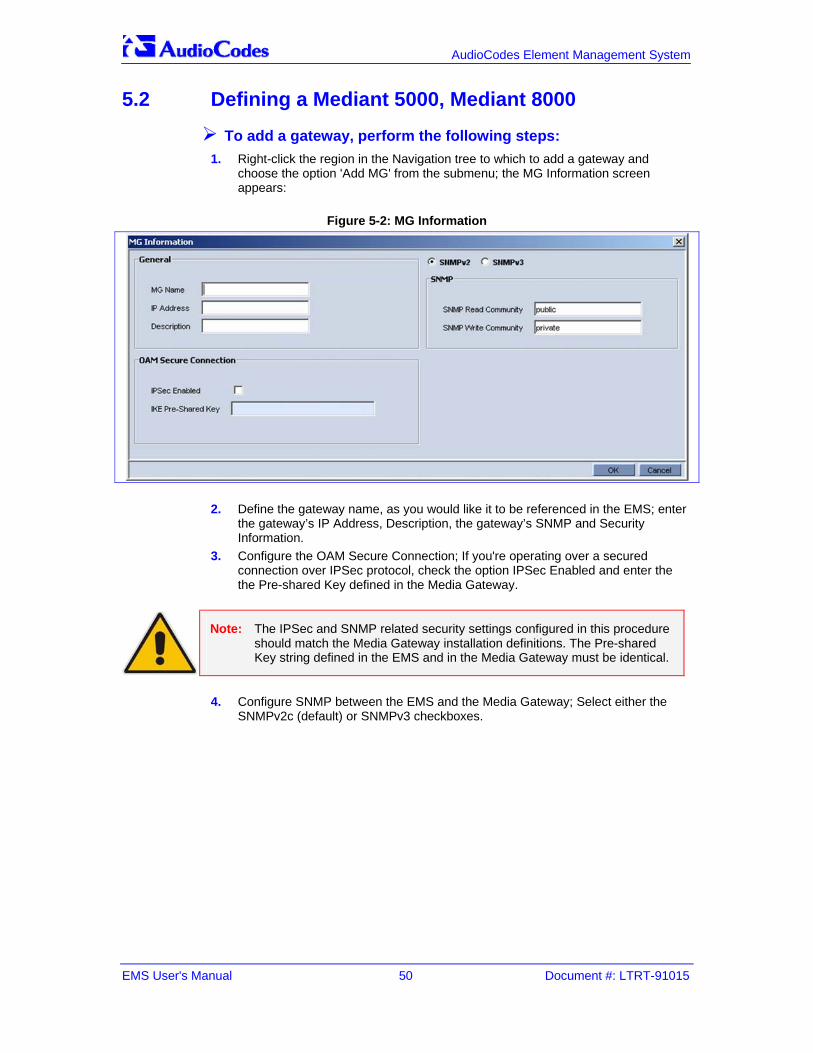
EMS User's Manual 50 Document #: LTRT-91015
AudioCodes Element Management System
5.2 Defining a Mediant 5000, Mediant 8000
To add a gateway, perform the following steps: 1. Right-click the region in the Navigation tree to which to add a gateway and
choose the option 'Add MG' from the submenu; the MG Information screen appears:
Figure 5-2: MG Information
2. Define the gateway name, as you would like it to be referenced in the EMS; enter the gateway’s IP Address, Description, the gateway’s SNMP and Security Information.
3. Configure the OAM Secure Connection; If you're operating over a secured connection over IPSec protocol, check the option IPSec Enabled and enter the the Pre-shared Key defined in the Media Gateway.
Note: The IPSec and SNMP related security settings configured in this procedure should match the Media Gateway installation definitions. The Pre-shared Key string defined in the EMS and in the Media Gateway must be identical.
4. Configure SNMP between the EMS and the Media Gateway; Select either the
SNMPv2c (default) or SNMPv3 checkboxes.

Version 5.8 51 June 2010
EMS User's Manual 5. Defining VoIP Devices, Managing the MG Tree
5. If you are configuring SNMPv2c, enter values for the SNMP Read Community
(default-public) and SNMP Write Community (default-private) fields. If you selected SNMPv3, the following screen is displayed:
6. Do the following: • In the Security Name field, enter the Security name of the SNMPv3 user. • In the Authentication Protocol field, select an authentication protocol from
the drop-down list box. The corresponding security level is displayed in the Security Level field.
• In the New Authentication Password field, enter a new Authentication Password.
• In the Privacy Protocol field, select a Privacy Protocol from the drop-down list box.
• In the New Privacy Password field, enter a new Privacy Password. 7. Click OK; the requested gateway is added to the required region. 8. Verify if the gateway is up and running (you can verify by performing a ping to its
IP address). If it is up and running, a graphic representation of it, including its LEDs, must be displayed in the EMS’s Status screen (refer to the figures of the status panes). If you do not view a graphic representation of the gateway in the Status screen, refer to 'Troubleshooting' on page 291 to resolve the issue.

EMS User's Manual 52 Document #: LTRT-91015
AudioCodes Element Management System
The gateway is added with all fields set to their default values. To change the defaults, right-click on the gateway in the MG Tree and choose ‘Details’; the MG Information screen opens (refer to the figure below).
Figure 5-3: MG Information - Secured Connection Enabled
9. Define fields ‘Root Password’ and ‘EMS Password to be used during the Software Upgrade and Auxiliary Files download procedures. The defaults of these password fields in the gateway and the EMS are identical;. If you remove/add a gateway, the passwords on the EMS side will be the defaults. If you change the default of a password on the EMS side, make sure the value in the gateway is identical, and vice-versa. To change a password, first change the password in the gateway and then open the screen ‘MG Details’ in the EMS and update the field accordingly.
10. Click OK; the requested gateway is added to the required region. Click ‘OK’; an Action Report is displayed, indicating the result of the add action for each gateway added.
11. To perform a basic configuration of the gateway, refer to 'Basic Configuration' on page 297.

Version 5.8 53 June 2010
EMS User's Manual 5. Defining VoIP Devices, Managing the MG Tree
5.2.1 Defining Multiple Mediant 5000, Mediant 8000 Gateways
To add a set of gateways simultaneously: 1. Right-click the region in the MG Tree to which to add the multiple gateways and
choose the option ‘Add MG’ from the submenu; the ‘Add Multiple MGs’ screen appears:
Figure 5-4: Add Multiple MGs
2. Check the ‘Enter IP address range’ check box, define the ‘From’ and ‘To’ fields and click OK. All devices in the defined range are added to the MG Tree with name combined as ‘Name Prefix’ + ‘IP Address’.
3. Alternately, define multiple devices by checking check box ‘Enter IP address list; in the field, define the IP addresses of the multiple gateways to be added, separating the IP address from each other with a semi colon.
4. Define the gateway name prefix as you would like it to be referenced in the EMS (a gateway’s name comprises the prefix and IP address) and the gateway’s SNMP Read and Write Community strings. If you’re operating over a secured connection, check option ‘Secured Connection Enabled’ and enter the Pre-shared Key supplied by AudioCodes. The default Pre-shared Key is same for all Media Gateways and the EMS.
5. Verify that all the gateways are successfully defined in the EMS: Firstly, check the MGs List information; secondly, enter each gateway’s status screen. Verify if the gateway is up and running (you can verify by performing a ping to its IP address). If it is up and running, a graphic representation of the gateway, including its LEDs, must be displayed in the Status screen (refer to the figures displaying gateway status under 'MediaPack' on page 151). If you do not view a graphic representation of the gateway in the Status screen, refer to 'Troubleshooting' on page 291 to resolve the issue.

EMS User's Manual 54 Document #: LTRT-91015
AudioCodes Element Management System
6. To change the default Telnet user name and password, right-click in the MGs Tree on each gateway and choose ‘Details’. Define the FTP and Telnet user and password to be used during the Software Upgrade procedure.
7. If you're operating over a secured connection over IPSec protocol, check the option IPSec Enabled and enter the IPSec Pre-shared Key defined in the Media Gateway.
Note: The IPSec and SNMP related security settings configured in this procedure should match the Media Gateway installation definitions. The Pre-shared Key string defined in the EMS and in the Media Gateway must be identical.
8. Configure SNMP between the EMS and the Media Gateway; select either the
SNMPv2c (default) or SNMPv3 checkboxes. 9. If you are configuring SNMPv2c, enter values for the SNMP Read Community
(default-public) and SNMP Write Community (default-private) fields. If you selected SNMPv3, the following screen is displayed:
Figure 5-5: Add Multiple MGs-SNMPv3

Version 5.8 55 June 2010
EMS User's Manual 5. Defining VoIP Devices, Managing the MG Tree
10. Do the following: • In the Security Name field, enter the Security name of the SNMPv3 user. • In the Authentication Protocol field, select an authentication protocol from
the drop-down list box. The corresponding security level is displayed in the Security Level field.
• In the New Authentication Password field, enter a new Authentication Password.
• In the Privacy Protocol field, select a Privacy Protocol from the drop-down list box.
• In the New Privacy Password field, enter a new Privacy Password. 11. Click OK; the requested gateway is added to the required region. Click ‘OK’; an
Action Report is displayed, indicating the result of the add action for each gateway added.
12. To perform a basic configuration, refer to 'Mediant 5000 Media Gateway and Mediant 8000 Media Gateway' on page 297
Note: The last option of defining a Serial Number, IP and Name from the file is not supported for the Mediant 5000 Media Gateway and Mediant 8000 Media Gateway.
5.3 Predefinition or Automatic Detection
5.3.1 Blades and CPE EMS users can either predefine the VoIP equipment (Mediant 1000, Mediant 2000, Mediant 3000, IPmedia 2000, IPmedia 3000 and MediaPack) or let the EMS automatically detect it.
5.3.2 Automatic Detection This section describes how to enable an automatic detection event (coldstart) to be sent to a configured SNMP Manager when a gateway device is connected to the power supply and the network at the customer’s premises is rebooted and initialized. When the MP is located inside the NAT network, it can connect to the Internet Public Network as long as the connection between the EMS server and the MP device is alive. This can be ensured by configuring the MP device to send coldStart and keepAlive traps to the EMS server, which allows the EMS to perform SNMP SET and GET commands at any time. EMS recognizes the MP device according to the sysDesc field and MAC address on the device itself, and according to the entries in the EMS database and GWs tree. The MPs default name is composed of the router’s IP address and port number. Sometimes the NAT changes the IP address and port for the MP devices. EMS recognizes these changes after the MP device is reset.

EMS User's Manual 56 Document #: LTRT-91015
AudioCodes Element Management System
To set up automatic detection: 1. Configure the following INI parameters on the Media Gateway device:
SNMPPort_0 = 161 SNMPManagerTrapPort_0 = 162 SNMPManagerIsUsed_0 = 1 SNMPManagerTrapSendingEnable_0 = 1 SNMPManagerTableIP_0 = 10.7.6.17
2. In the event that the Media Gateway is configured behind a NAT, you also need to configure the keep alive trap INI parameters on the Media Gateway as follows:
SendKeepAliveTrap = 1 KeepAliveTrapPort = 1161 NatBindingDefaultTimeout = 30
3. After the device is connected to the power supply and the network at the customer’s premises, it performs a reboot and at the end of the initialization process, sends a coldStart trap event to the pre-provisioned 'SNMP Manager' name. When the coldStart trap is received, the EMS connects the device, verifies (from the version defined in the Software Manager) that it’s AudioCodes' device, automatically defines a new Region named ‘Auto Detection’ and adds the device to this region. If the Region already exists, the device is simply added to it.
Note: Periodically check if Region ‘Auto Detection’ is created and move newly detected media gateways to the Regions appropriate to your network.
The figure below illustrates how MPs and EMS Clients and server can be located in the NAT Network:
Each MP device in each LAN i.e. a Bank Enterprise Network connects to the Internet Public Network via a NAT IP address (configured in the Applications tab in the Network Parameters Provisioning screen).
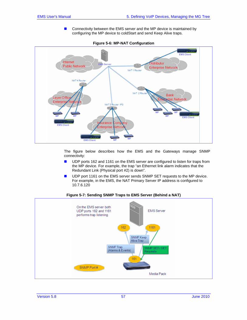
Version 5.8 57 June 2010
EMS User's Manual 5. Defining VoIP Devices, Managing the MG Tree
Connectivity between the EMS server and the MP device is maintained by configuring the MP device to coldStart and send Keep Alive traps.
Figure 5-6: MP-NAT Configuration
The figure below describes how the EMS and the Gateways manage SNMP connectivity:
UDP ports 162 and 1161 on the EMS server are configured to listen for traps from the MP device. For example, the trap “an Ethernet link alarm indicates that the Redundant Link (Physical port #2) is down”.
UDP port 1161 on the EMS server sends SNMP SET requests to the MP device. For example, in the EMS, the NAT Primary Server IP address is configured to 10.7.6.120
Figure 5-7: Sending SNMP Traps to EMS Server (Behind a NAT)

EMS User's Manual 58 Document #: LTRT-91015
AudioCodes Element Management System
5.3.3 Defining a Single Blade or CPE (Mediant 1000 / 2000 / 3000 or MP)
To add a gateway: 1. Right-click the region in the MG Tree to which to add multiple gateways and
choose option ‘Add MG’ from the submenu.
Figure 5-8: MG Information
2. Define the gateway name, as you would like it to be referenced in the EMS; enter the gateway’s IP Address, Description, and the gateway’s SNMP Read and Write Community strings (if you are configuring SNMPv2) or Security fields if you are configuring SNMPv3, in which case proceed to the next step.
3. Do the following: • In the Security Name field, enter the Security name of the SNMPv3 user. • In the Authentication Protocol field, select an authentication protocol from
the drop-down list box. The corresponding security level is displayed in the Security Level field.
• In the New Authentication Password field, enter a new Authentication Password.
• In the Privacy Protocol field, select a Privacy Protocol from the drop-down list box.
• In the New Privacy Password field, enter a new Privacy Password. 4. Verify if the gateway is up and running (you can verify by performing a ping to its
IP address). If it is up and running, a graphic representation of the gateway, including its LEDs, must be displayed in the EMS’s Status screen. If you do not view a graphic representation of the gateway in the EMS’s Status screen, refer to 'Troubleshooting' on page 291 to resolve the issue.

Version 5.8 59 June 2010
EMS User's Manual 5. Defining VoIP Devices, Managing the MG Tree
The gateway is added with HTTP communication enabled. To change the defaults, right-click on the gateway in the MG Tree and choose ‘Details’; the MG Information screen opens (refer to the figure below).
Figure 5-9: MG Details
5. If you're operating over a secured connection over IPSec protocol, check the option IPSec Enabled and enter the IPSec Pre-shared Key defined in the Media Gateway.
Note: The Pre-shared Key string defined in the EMS and in the Media Gateway must be identical.
6. Check the HTTPS Enabled option if required. 7. Click OK; the requested gateway is added to the required region.
Note: In order to perform changes in the EMS and MG connectivity related to the SNMP version, refer to section 'Security Management' on page 253.

EMS User's Manual 60 Document #: LTRT-91015
AudioCodes Element Management System
5.3.4 Defining Multiple Blades and CPE The EMS supports defining multiple devices (Multiple Mediant 600, 1000, Mediant 2000, Mediant 3000, IPmedia 2000, IPmedia 3000 and MediaPacks) in a single screen on condition that all devices have the same SNMP Read and Write Community strings. Device hardware type is detected when connecting for the first time to the gateway.
To add multiple gateways: 1. Right-click the region in the MG Tree to which to add multiple gateways and
choose option ‘Add Multiple MGs’ from the submenu.
Figure 5-10: Add Multiple MGs-SNMPv2
2. Check the ‘Enter IP address range’ check box, define the ‘From’ and ‘To’ fields and click OK. All devices in the defined range are added to the MG Tree with name combined as ‘Name Prefix’ + ‘IP Address’.
3. Alternately, define multiple devices by checking check box ‘Enter IP address list; in the field, define the IP addresses of the multiple gateways to be added, separating the IP address from each other with a semi colon.

Version 5.8 61 June 2010
EMS User's Manual 5. Defining VoIP Devices, Managing the MG Tree
4. Alternatively, define multiple devices by checking the check box ‘Define Serial, IP, Name, Region from file’, navigate to the prepared file and click OK. The figure below exemplifies a gateway predefinition file. Each gateway must have a row in the predefinition file. If you don’t know all the required information, use empty coma delimiters. The first field, Serial Number (or Mac), is optional; fields IP address, MG name and Region Name must be defined. The file must be saved in Unicode Encoding format before introducing it to the EMS Client (refer to the example below).
Figure 5-11: Add File Unicode
Note: csv file format enables you to define / edit the file in Excel. File previously saved from the EMS client or Server can be loaded.
Define the device's SNMP and IPSec related information as explained in the
above chapter 'Defining a Single Blade or CPE (Mediant 1000 / 2000 / 3000 or MP)' on page 58.

EMS User's Manual 62 Document #: LTRT-91015
AudioCodes Element Management System
Click ‘OK’; an Action Report is displayed, indicating the result of the add action for each gateway added.
Figure 5-12: Action Report for Adding Multiple Media Gateways Result
Note: Gateways can be either connected or not connected to the network at the time of predefinition.
Note: In order to perform changes in the EMS and MG connectivity related to SNMP version; refer to 'Security Management' on page 253.
5.3.4.1 Gateways Connected to the Network Verify that all gateways are successfully defined in the EMS by checking the MG Tree. If a gateway is up and running, a graphic representation of it, including its LEDs, must be displayed in the Status screen. To perform basic configuration of a gateway, refer to 'Basic Configuration' on page 297. If you encounter a problem when defining your gateways, refer to 'Troubleshooting' on page 291 to resolve the issue (or contact AudioCodes).
5.3.4.2 Gateways NOT Connected to the Network The EMS is capable of defining the gateway type before it is connected to the gateway for the first time. Until the first connection with the gateway is established, the EMS displays it in the MG Tree with an 'Unknown' sign . If MediaPacks are NOT connected to the network, the operator can predefine the type and software version and also define first-time EMS connection behavior regarding the configuration data (refer to the next section for detailed information). If you encounter problems when defining your devices, refer to 'Troubleshooting' on page 291 to resolve the issue (or contact AudioCodes).

Version 5.8 63 June 2010
EMS User's Manual 5. Defining VoIP Devices, Managing the MG Tree
5.4 First-Time Connection Problems A gateway is indicated by in one of the following cases: 1. Unknown Hardware: The Product Type, returned by the MIBII sysDescr value, is
not recognized by the EMS. The gateway cannot be managed by the EMS. 2. Unknown Software: The Software Version, returned by the MIBII sysDescr value,
is not recognized by the EMS. Either add the specified version to the EMS Software Manager or download one of the existing software versions.
5.5 Mismatch Indications Three types of mismatch between the database and gateway can occur. These mismatches can be detected when the device is connected for the first time, or during an automatic refresh performed by the EMS. Another important indication is Reset State (relevant for Mediant 1000, Mediant 2000, IPmedia 2000, Mediant 3000, IPmedia 3000 and MediaPacks). 1. Hardware Type Mismatch: If a hardware type mismatch occurs, the gateway is
indicated by a red color in the MG Tree and a message box with a mismatch explanation is presented instead of the status screen. Additionally, a hardware mismatch alarm is generated. This can occur when an operator defined the gateway as the 24-port gateway (for example) during the predefinition stage, but when connecting for the first time, the gateway type returned by the media gateway itself is the 8-port FXS gateway (for example). A hardware mismatch is the most severe of the three mismatch types.
2. Software Version Mismatch: The Information pane displays information indicating a software version mismatch and a configuration mismatch alarm is generated. A software version mismatch can occur when the gateway returns a different software version to the software version that was configured by the operator. The EMS does not change the status of a gateway whose software version is mismatched.
3. Configuration Mismatch (relevant for Mediant 1000 Mediant 2000, IPmedia 2000, Mediant 3000, IPmedia 3000 and MediaPacks): The Information pane displays information indicating that the configuration in the device and the configuration saved in the database are mismatched (refer to the figure below) and a configuration mismatch alarm is generated. To solve the problem, either perform ‘Configuration Download’ (click the link in the Information pane; refer to the figure below) or ‘Save’ the actual device configuration in the EMS database (from the appropriate Parameters Provisioning screens).

EMS User's Manual 64 Document #: LTRT-91015
AudioCodes Element Management System
4. Reset Needed (relevant for Mediant 1000 Mediant 2000, IPmedia 2000, Mediant 3000, IPmedia 3000 and MediaPacks): ‘Reset Needed’, displayed in the Information pane, indicates that configuration changes were loaded to the device but that for these changes to take effect, the device must be reset. To start working with the updated configuration, perform a ‘Reset’ by clicking the ‘Reset’ link in the Information pane (refer to the figure below).
Figure 5-13: MediaPack Information Pane Indicating Mismatch
5.6 Moving a Gateway from Region to Region
To move a media gateway from one region to another: 1. Drag the device from its current Region and drop it into the destination region 2. Alternatively, right-click on the gateway in the MG Tree and choose option ‘Move
MG’ from the pop-up menu; a list of regions pops up. 3. Select a region from the list and click OK; the gateway is moved.

Version 5.8 65 June 2010
EMS User's Manual 5. Defining VoIP Devices, Managing the MG Tree
5.7 Moving Multiple Gateways from Region to Region The EMS supports moving multiple gateways in a single screen on condition that all devices are located in the same Region.
To move multiple gateways from one region to another: 1. In the MGs Tree, right-click the Region to move from and choose option ‘Move
Multiple MGs’ from the submenu (refer to the figure below); the ‘Multiple Move’ screen is displayed (refer to the second figure below).
Figure 5-14: Moving Multiple MGs from Region to Region
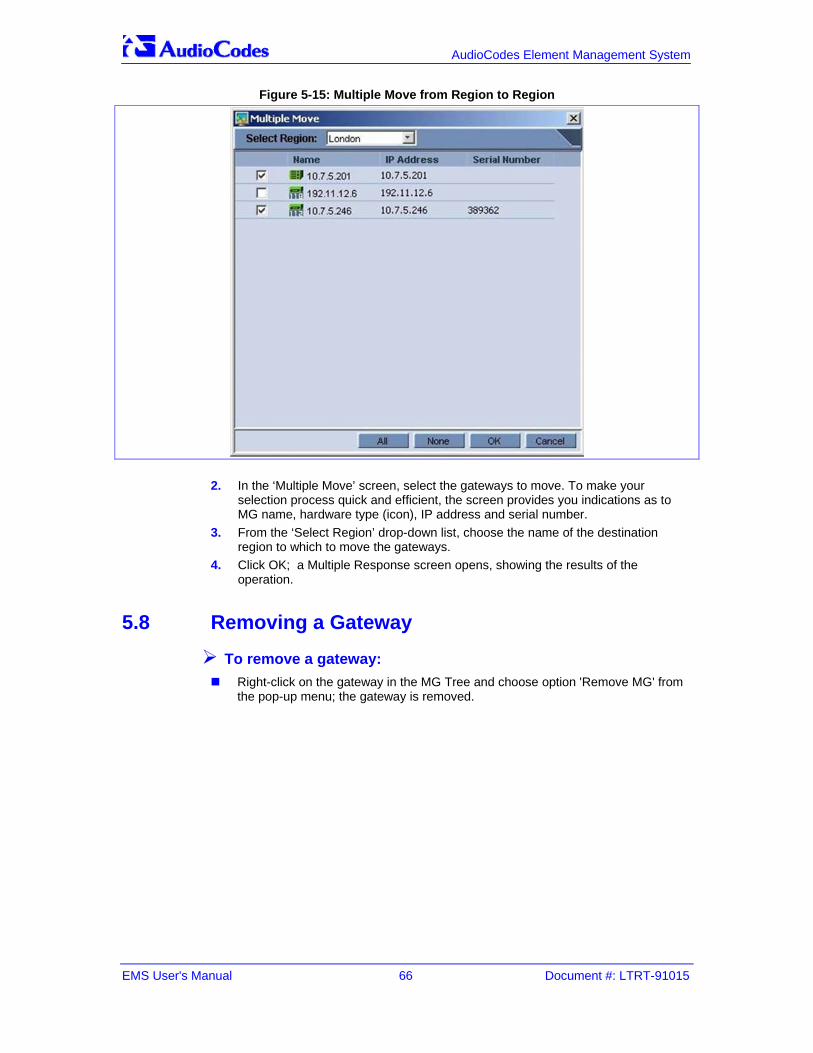
EMS User's Manual 66 Document #: LTRT-91015
AudioCodes Element Management System
Figure 5-15: Multiple Move from Region to Region
2. In the ‘Multiple Move’ screen, select the gateways to move. To make your selection process quick and efficient, the screen provides you indications as to MG name, hardware type (icon), IP address and serial number.
3. From the ‘Select Region’ drop-down list, choose the name of the destination region to which to move the gateways.
4. Click OK; a Multiple Response screen opens, showing the results of the operation.
5.8 Removing a Gateway
To remove a gateway: Right-click on the gateway in the MG Tree and choose option 'Remove MG' from
the pop-up menu; the gateway is removed.

Version 5.8 67 June 2010
EMS User's Manual 5. Defining VoIP Devices, Managing the MG Tree
5.9 Removing Multiple Gateways The EMS supports removing multiple gateways in a single screen (refer to the figure below), on condition that all devices are located in the same Region. Note that the Mediant 5000 Media Gateway and the Mediant 8000 Media Gateway must be locked prior to removal.
To remove multiple gateways: 1. Right-click the region in the MG Tree and choose option 'Remove Multiple MGs'
from the submenu; the ‘Multiple Remove’ screen is displayed:
Figure 5-16: Removing Multiple Media Gateways
2. Check the check boxes adjacent to the IP addresses of the media gateways to be removed. To remove all media gateways listed, check all check boxes by clicking the ‘All’ button, and click OK; an Action Report is displayed, indicating the result of the remove action for each gateway removed.

EMS User's Manual 68 Document #: LTRT-91015
AudioCodes Element Management System
5.10 Searching for a Gateway
To search for a media gateway: Either: 1. In the MG Tree, right-click on ‘Globe’ and select 'Search MG'.
-OR- 2. In the Tools menu, choose option ‘Search MG’); the ‘Search MGs’ screen is
displayed (refer to the figure below).
Figure 5-17: Search MGs (by IP Address)
3. Search by Product Information: Enter the media gateway’s information a. Product Type - choose a product group b. Software Version - Choose from the list of supported versions for the
products you selected. You can choose to search for all versions. c. Product Status – Choose from the list of gateway status options. You can
choose to search for all options. Click OK; if one media gateway is located, it is selected in the MG Tree and its Status screen is opened. If more than one appropriate media gateway is located, the Search Result screen is displayed.
4. Search by IP Address: Enter the media gateway’s IP address and click OK; if the media gateway is located, it is selected in the MG Tree and its Status screen is opened.
5. Search by Serial Number: Enter the media gateway’s Serial Number and click OK; if the media gateway is located, it is selected in the MG Tree and its Status screen is opened.
Version 5.8 69 June 2010
EMS User's Manual 5. Defining VoIP Devices, Managing the MG Tree
6. Search by MG Name: Enter the name of the media gateway you’re trying to locate and click OK; if more than one appropriate media gateway is located, the Search Result screen is displayed.
7. In the Search Result screen, locate the media gateway in the list and double-click it; the media gateway is selected in the MG Tree and its Status screen is opened.
Note: You can expedite your search for a media gateway (especially when searching by name) by checking the ‘Match case’ and/or ‘Match whole word only’ check boxes.
When only the ‘Match Case’ check box is checked, the EMS performs a search based on the case (upper/lower) of the letters entered by operators in the field ‘Search by MG Name’. When the ‘Match whole word only’ check box is checked, the EMS performs a search based only on the text entered by operators in the field ‘Search by MG Name’, irrespective of upper and/or lower case. When both ‘Match Case’ and ‘Match whole word only’ are checked, the EMS performs a search based on the text that the operator entered in the field ‘Search by MG Name’ as well as on the letter case.

EMS User's Manual 70 Document #: LTRT-91015
AudioCodes Element Management System
5.11 Saving the EMS Tree MGs Report in an External File The MGs Report CSV file includes configuration and status data of all gateways that are defined on the EMS Server.
Note: In addition to the MGs Report file, a Topology file can also be generated, The Topology file is a user friendly snapshot of the MGs Report file and is automatically updated upon the addition /removal of a Media Gateway or upon updates to the Media Gateway properties such as name, IP address or region modification. For more information, see the OAMP Integration Guide.
To save the MGs Report file: 1. In the Main menu, choose File -> MGs Report action. 2. In the File Chooser, navigate to the desired location, select the file name and click
OK. The File is stored in the CSV format in the required location and includes the following field columns:
Serial Number – relevant for Mediant 600/1000/2000/3000 and MP GWs (not relevant for the Mediant 5000 / 8000 GWs).
IP Address Node Name Region Name Description Product Type Software Version Connection Status – Connected / Not Connected – represent the ability of EMS
application to communicate with MG Administrative State – Locked / Unlocked / Shutting Down Operational State – Enabled / Disabled Mismatch State – No Mismatch / SW Version Unsupported / SW Mismatch / HW
Mismatch Last Change Time Performance Polling Status – Polling / Not Polling Performance Profile Protocol Type – MGCP /Megaco / SIP – relevant for Mediant 600/1000/2000/3000
and MP GWs. Not relevant for Mediant 5000 / 8000 GWs. Master Profile
Note: The MGs Report file can be used as the input file to the EMS application during the ‘Add Multiple MGs’ command.

Version 5.8 71 June 2010
EMS User's Manual 5. Defining VoIP Devices, Managing the MG Tree


Version 5.8 73 June 2010
EMS User's Manual 6. Monitoring Multiple Media Gateways
6 Monitoring Multiple Media Gateways This section describes how to monitor different media gateways. The section describes the read-only Status panes enabling operators to monitor the media gateway and its components. After a status view is selected, it's automatically updated (refreshed) every 20 seconds. Following are the EMS status components:
'Regions List' on page 73 'MGs List' on page 75
6.1 Regions List
To access the Regions List: Click the root in the MG Tree (Globe); the Main Screen displays the Regions List
pane, in which all defined regions are listed.
Figure 6-1: Regions List
The figure above displays the Regions List pane in the Main Screen. The Regions List pane lists and summarizes all regions and media gateways managed by the EMS.

EMS User's Manual 74 Document #: LTRT-91015
AudioCodes Element Management System
For each region listed in the Regions List pane, the following information is displayed:
Region name Number of digital gateways in the region (#MGs) Number of analog gateways in the region (#MPs) Number of Other (Unknown) gateways in the region Total Number of gateways in the region (digital and analog) Description
Each recognized gateway is given a Clear (OK) status; the EMS was able to connect to it and no hardware mismatch was found. An unknown gateway is given a Clear (OK) status if the EMS has not connected to it yet and it has no mismatch. Threshold: Each gateway group (digital gateways, analog MediaPacks and Unknown) has a threshold value: digital gateways = 1%, analog MediaPacks = 50%, Unknown = 50%. The table below indicates how to quickly determine the status of a region and the status of the gateways defined under it.
Note: The Administrator can change the threshold numbers in the EMS server properties file.
Table 6-1: Region Status and Statuses of Gateways Defined Under It
Region Severity
Digital Gateways
Analog MediaPacks Unknown Comment
Locked
100% Connected
100% Connected
100% Connected
All the GWs are in the Locked administrative
state.
Clear (OK)
100% Connected
100% Connected
100% Connected
The statuses of all gateways in the region are
Clear.
Indeterminate
100% Connected
100% Connected
100% Connected
Highest Mediant 5000 / 8000 GWs severity in this region is Indeterminate.
Warning
100% Connected
100% Connected
100% Connected
Highest Mediant 5000 / 8000 GWs severity in this
region is Warning.
Minor
Up to 1% failed
Up to 50% failed
Up to 50% failed
At least one of the groups has at least one gateway that has failed, but the number of failed gateways is less than the group threshold. Or the highest Mediant 5000 / 8000 GWs severity in this region is Minor.

Version 5.8 75 June 2010
EMS User's Manual 6. Monitoring Multiple Media Gateways
Table 6-1: Region Status and Statuses of Gateways Defined Under It
Region Severity
Digital Gateways
Analog MediaPacks Unknown Comment
Major
Up to 1% failed
Up to 50% failed
Up to 50% failed
At least one of the groups has one or more Gateways that has failed, However the number of failed gateways is less than the group threshold, Or, highest Mediant 5000 / 8000 GWs severity in this region is Major
Critical
1% or more failed
50% or more failed
50% or more failed
At least one of the groups has a number of failed gateways that exceeds the group threshold. Or, one or more Gateways have the Operational State Disabled, or Severity Critical.
Double-clicking on a region in the Regions List pane displays the MGs List for the gateways defined under that region (refer to the figure above); click the “Up” button in the MGs List pane to navigate up the hierarchy back to the region level.
6.2 MGs List
To access the MGs List: 1. Click a region in the MG Tree; the MGs List pane is displayed in the Status pane
of the main screen, listing all the gateways located under that region. 2. Mediant 5000 Media Gateway and Mediant 8000 Media Gateway: Right-click
on a gateway to lock or unlock it, or to access its properties (access to a gateway's properties, i.e., to the Gateway Parameter Provisioning screen, can additionally be done by clicking the 'Properties' link in the Info pane after selecting the gateway in the MGs List).
3. CPE and Blades: Right-click on the device to perform Software Download, Configuration Verification, Configuration Download, Network Configuration or Reset. Each of these actions can also be performed on a set of devices selected from the MGs List.

EMS User's Manual 76 Document #: LTRT-91015
AudioCodes Element Management System
4. Double-click a device in the MGs List; the Main Screen displays the Status pane. 5. Click the 'Up' button on the gateway level screens to return to the MGs List in the
Main Screen.
Figure 6-2: MGs List
The above figure displays the MGs List in the Status pane. The MGs List lists and summarizes all gateways located in the selected region. For each gateway, the following information is displayed:
Gateway name and status (status is indicated by the color coding) Gateway IP address SW Version Product Type ( Mediant 600, Mediant 1000, Mediant 2000, Mediant 3000,
IPmedia 2000, IPmedia 3000, Mediant 5000, Mediant 8000 or MediaPack (FXS/FXO)
Protocol (MGCP, MEGACO, SIP, H.323 or None) - relevant to Mediant 1000, Mediant 2000, Mediant 3000, IPmedia 2000, IPmedia 3000 and MediaPacks
Administrative State (Shut Down/Locked/Unlocked) - relevant to the Mediant 5000 Media Gateway and Mediant 8000 Media Gateway
Operational State (Enabled/Disabled) - relevant to the Mediant 5000 Media Gateway and Mediant 8000 Media Gateway
Master Profile (Mediant 1000, Mediant 2000, Mediant 3000, IPmedia 2000, IPmedia 3000 and MediaPack). Indicates the name of the Master Profile when a master profile is attached to the device.
PM Profile. Indicates the name of the PM (Performance Monitoring) profile when a
Version 5.8 77 June 2010
EMS User's Manual 6. Monitoring Multiple Media Gateways
profile is attached to the device. PM Polling status (Polling / Not Polling). When the status is 'Polling', background
PM data is collected from the device and stored in the EMS database according to parameters (duration, etc.) defined by the PM profile. When the status is 'Not Polling', no PM data is polled.
Alarms associated with selected gateway/s in the MGs List.
6.3 Media Gateway Level Status Pane
To access a media gateway: Either:
In the MG Tree, expand the region under which the media gateway is located and click the media gateway; a message appears indicating “Contacting Server. Please Wait;” a graphic representation of the MG is then displayed (refer to the figures below). -OR-
In the MGs List, double-click a media gateway; a message appears indicating “Contacting Server. Please Wait;” a graphic representation of the media gateway is then displayed (refer to the figures below).
Click the “Up” button in the board-level screens to navigate back up a level.

EMS User's Manual 78 Document #: LTRT-91015
AudioCodes Element Management System
Reader’s Notes
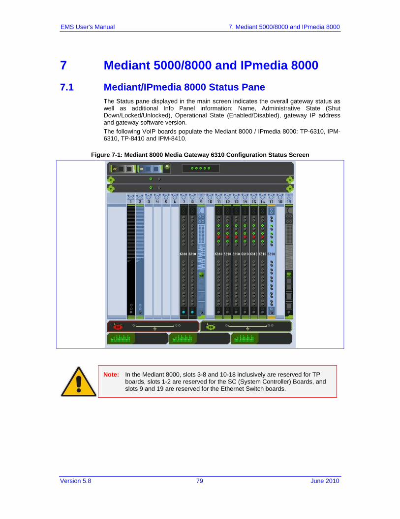
Version 5.8 79 June 2010
EMS User's Manual 7. Mediant 5000/8000 and IPmedia 8000
7 Mediant 5000/8000 and IPmedia 8000 7.1 Mediant/IPmedia 8000 Status Pane
The Status pane displayed in the main screen indicates the overall gateway status as well as additional Info Panel information: Name, Administrative State (Shut Down/Locked/Unlocked), Operational State (Enabled/Disabled), gateway IP address and gateway software version. The following VoIP boards populate the Mediant 8000 / IPmedia 8000: TP-6310, IPM-6310, TP-8410 and IPM-8410.
Figure 7-1: Mediant 8000 Media Gateway 6310 Configuration Status Screen
Note: In the Mediant 8000, slots 3-8 and 10-18 inclusively are reserved for TP boards, slots 1-2 are reserved for the SC (System Controller) Boards, and slots 9 and 19 are reserved for the Ethernet Switch boards.

EMS User's Manual 80 Document #: LTRT-91015
AudioCodes Element Management System
Status for the Mediant 8000 includes:
SAT Card status Each SAT card is represented by a bar located in the MG Status screen near the corresponding SC board (refer to the figures above). The background of the SAT card represents SAT activity (black for active; pale blue for redundant). The overall status of the SAT card is represented by its border color (Gray = Locked; Red = Disabled; Green = Enabled; Orange = Major Severity). The status of the Timing Module and External Interfaces is represented by corresponding icons in the SAT card status bar. Their color conventions are described below. Tooltips present users with relevant additional information.
The SAT card has the following color convention:
Table 7-1: SAT Card Status Color Convention
Color Convention
Green The SAT Card is locked to one of the external interfaces
Blue The SAT Card is in Hold Over state
Yellow The SAT Card is in Free Run state
Red SAT Card Error
The Timing Module has the following color convention: The Timing Module summarizes the status of the clock reference source and the SAT card. The status of the Timing module is Red=Failed or Green=OK. When you click on this icon, the System Clock Parameters Provisioning screen for the current timing mode is displayed When you click on this icon, the System Clock Parameters Provisioning screen for the current timing mode is displayed. In the Standalone mode, the icon must be green. For more information on the PSTN System Clock synchronization modes, navigate to the System Clock tab.
Note: When you navigate to the System Clock window, only events and alarms relevant to the System Clock are displayed in the Alarms Browser.
External Interfaces have following color conventions:
Table 7-2: External Interface Color Convention
Color Convention
Green with border
OK status and currently selected as the Clock source (as in the example)
Green OK status
Red Failed (alarm) status

Version 5.8 81 June 2010
EMS User's Manual 7. Mediant 5000/8000 and IPmedia 8000
Color Convention
Green with border
OK status and currently selected as the Clock source (as in the example)
Grey Status Unknown
When a SAT card does not have a Timing Module, the status icon of the Timing Module is not displayed and External Interfaces are displayed as grey
placeholders To view additional information on the status of the Timing Module and External Interfaces, double-click the SAT bar; the screen shown below is displayed.
Figure 7-2: SAT Properties screen

EMS User's Manual 82 Document #: LTRT-91015
AudioCodes Element Management System
Shelf LEDs Five LEDs summarize the gateway's status (from top to bottom): • System: Red = System Error occurred; Green = OK • Critical: Red = Critical Error occurred; Green = OK • Major: Orange = Major Error occurred; Green = OK • Minor: Yellow = Minor Error occurred; Green = OK • Shelf: Red = Critical Error occurred; Orange = Major Error occurred; Green =
OK; Gray = Off
Fan status (in the Mediant 8000) Color convention: Red = Failed; Green = OK; Orange = Major Severity
Fan status (in the Mediant 8000 6310) Fans’ two rows are read as follows: • Top Row: Upper Fan Tray • Bottom Row: Bottom Fan Tray Double-click each fan tray to view fan status Color convention: Red = Failed; Green = OK
Figure 7-3: Fan Tray Status
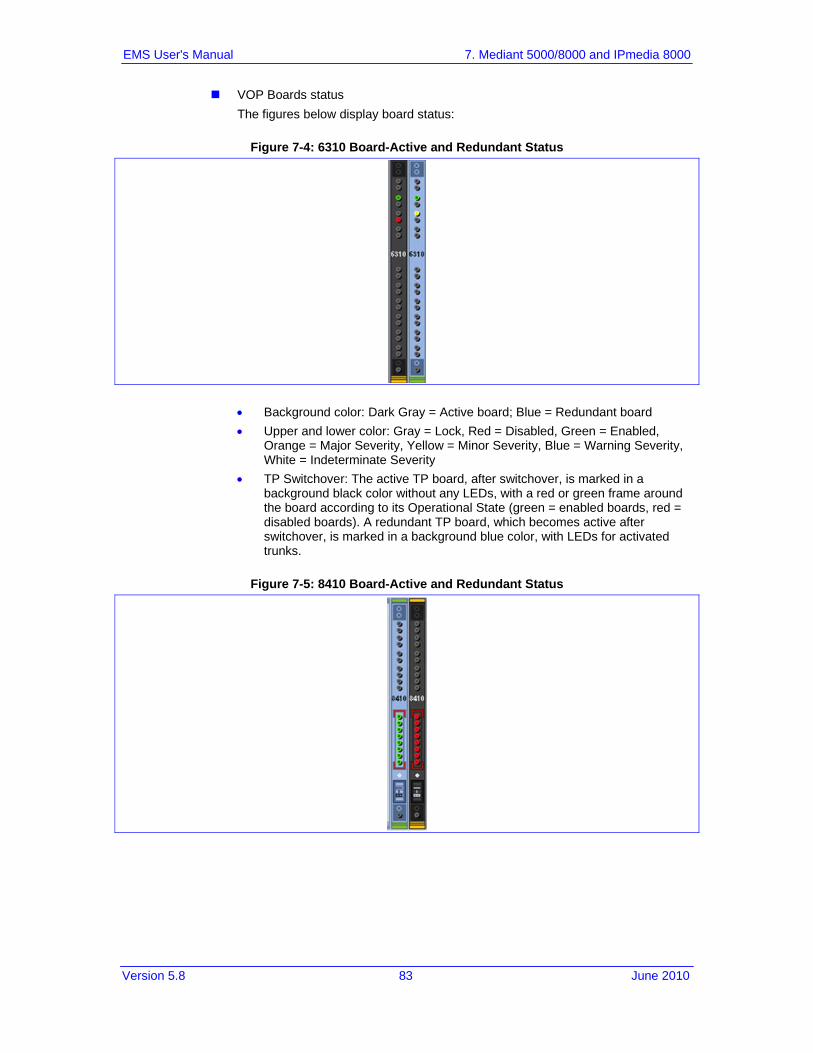
Version 5.8 83 June 2010
EMS User's Manual 7. Mediant 5000/8000 and IPmedia 8000
VOP Boards status The figures below display board status:
Figure 7-4: 6310 Board-Active and Redundant Status
• Background color: Dark Gray = Active board; Blue = Redundant board • Upper and lower color: Gray = Lock, Red = Disabled, Green = Enabled,
Orange = Major Severity, Yellow = Minor Severity, Blue = Warning Severity, White = Indeterminate Severity
• TP Switchover: The active TP board, after switchover, is marked in a background black color without any LEDs, with a red or green frame around the board according to its Operational State (green = enabled boards, red = disabled boards). A redundant TP board, which becomes active after switchover, is marked in a background blue color, with LEDs for activated trunks.
Figure 7-5: 8410 Board-Active and Redundant Status

EMS User's Manual 84 Document #: LTRT-91015
AudioCodes Element Management System
• Trunk (E1/T1) LED color convention: Red = Disabled; Green = Enabled; Gray = Locked
Figure 7-6: 6310-LED Status
Legend: 1. The first two LEDs represent the GbE (Gigabit Ethernet) status 2. Six LEDs representing PSTN Interface status (for OC3/STM1, four LEDs are
relevant; for T3, all six LEDs are relevant) 3. Twelve LEDs representing ATM Interface status (not in use)
Figure 7-7: 8410-LED Status
Legend: 1. Six LEDs representing the GbE (Gigabit Ethernet) status 2. Four LEDs representing ATM LEDs (not in use) 3. Eight LEDs representing E1/T1 LEDs

Version 5.8 85 June 2010
EMS User's Manual 7. Mediant 5000/8000 and IPmedia 8000
ES Boards and Ports status The figure below displays an ES Board Status screen
Figure 7-8: ES Board Status
ES boards can be displayed as follows: • Yellow = Minor Severity, due to unexpected ES alignment. • Blue = Warning Severity, due to the fact that some of the Uplinks are not
connected. Uplinks on the ES boards are displayed according to the Interface separation that was configured in the system. Ports properties can be viewed in the tool tip. Color convention: Red = Disabled, Green = Enabled, yellow - Minor Alarm stating that certain port should not be used.
Power Supplies Status
Color convention: Red = Failed; Green = OK PEM (Power Entry Module) status
Figure 7-9: PEM Status
Color convention: Red = Failed; Green = OK When the PEM is displayed in green, the tooltip ‘PEM is OK, Power input is OK’ appears. When the PEM is displayed in red, the tooltip indicates reason of failure. The following reasons can be displayed: ‘PEM is not responding’, ‘PEM is OK, power input is not detected’, ‘PEM is OK, power input polarity inversed’.

EMS User's Manual 86 Document #: LTRT-91015
AudioCodes Element Management System
7.2 Mediant/IPmedia 5000 Status Pane The Status pane displayed in the main screen indicates the overall gateway status as well as additional Info Pane information: Name, Administrative State (Shut Down/Locked/Unlocked), Operational State (Enabled/Disabled), gateway IP address and gateway software version. The following VoIP boards can populate the Mediant 5000 / IPmedia 5000: TP-6310, IPM-6310, TP-8410 and IPM-8410.
Figure 7-10: Mediant 5000 6310 Status Pane
Figure 7-11: Mediant 5000 8410 Status Pane
Note: In the Mediant 5000, slots 5-10 inclusively are reserved for TP boards, slots 1-2 are reserved for the SC (System Controller) Boards, and slots 3-4 are reserved for the Ethernet Switch boards.
Status for the Mediant 5000 includes:
SAT Card status Each SAT card is represented by a bar located in the MG Status screen near the corresponding SC board (refer to the figures above). The background of the SAT card represents SAT activity (black for active; pale blue for redundant). The overall status of the SAT card is represented by its border color (Gray = Locked; Red = Disabled; Green = Enabled; Orange = Major Severity).

Version 5.8 87 June 2010
EMS User's Manual 7. Mediant 5000/8000 and IPmedia 8000
The status of the Timing Module and External Interfaces is represented by corresponding icons in the SAT card status bar. Their color conventions are described below. Tooltips present users with relevant additional information.
The SAT card has following color convention:
Table 7-3: SAT Card Status Color Convention
Color Convention
Green The SAT Card is locked to one of the external interfaces
Blue The SAT Card is in Hold Over state
Yellow The SAT Card is in Free Run state
Red SAT Card Error
The status of the Timing Module and External Interfaces is represented by corresponding icons in the SAT card status bar. Their color conventions are described below. Tooltips present users with relevant additional information.
The Timing Module has the following color convention: The Timing Module summarizes the status of the clock reference source and the SAT card. The status of the Timing module is Red=Failed or Green=OK. When you click on this icon, the System Clock Parameters Provisioning screen for the current timing mode is displayed. In the Standalone mode, the icon must be green. For more information on the PSTN System Clock synchronization modes, navigate to the System Clock tab.
Note: When you navigate to the System Clock window, only events and alarms relevant to the System Clock are displayed in the Alarms Browser.
External Interfaces have following color conventions:
Table 7-4: External Interface Color Convention
Color Convention
Green with Border
OK status and currently selected as the Clock source (as in the example)
Green OK status
Red Failed (alarm) status
Grey Status Unknown
When a SAT card does not have a Timing Module, the status icon of the Timing Module is not displayed and External Interfaces are displayed as grey
placeholders .

EMS User's Manual 88 Document #: LTRT-91015
AudioCodes Element Management System
To view additional information on the status of the Timing Module and External Interfaces, double-click the SAT bar; the screen shown below is displayed.
Figure 7-12: SAT Properties screen
Shelf LEDs Five LEDs summarize the gateway's status (from top to bottom): • System: Red = System Error occurred; Green = OK • Critical: Red = Critical Error occurred; Green = OK • Major: Orange = Major Error occurred; Green = OK • Minor: Yellow = Minor Error occurred; Green = OK • Shelf: Red = Critical Error occurred; Orange = Major Error occurred; Green =
OK; Gray = Off
Fan status (in the Mediant 5000) Color convention: Red = Failed; Green = OK; Orange = Major Severity

Version 5.8 89 June 2010
EMS User's Manual 7. Mediant 5000/8000 and IPmedia 8000
Fan status (in the Mediant 5000 6310) Fans’ two rows are read as follows: • Top Row: Upper Fan Tray • Bottom Row: Bottom Fan Tray Double-click each fan tray to view fan status Color convention: Red = Failed; Green = OK
Figure 7-13: Fan Tray Status
VOP Boards status The figures below display board status: • TP-6310 Active and Redundant board:
Figure 7-14: 6310 Active Board Status
Figure 7-15: 6310 Redundant Board Status
♦ Background color: Dark Gray = Active board; Blue = Redundant board ♦ Upper and lower color: Gray = Lock, Red = Disabled, Green = Enabled,
Orange = Major Severity, Yellow = Minor Severity, Blue = Warning Severity, White = Indeterminate Severity
♦ TP Switchover: The active TP board, after switchover, is marked in a background black color without any LEDs, with a red or green frame around the board according to its Operational State (green = enabled boards, red = disabled boards). A redundant TP board, which becomes active after switchover, is marked in a background blue color, with LEDs for activated trunks.

EMS User's Manual 90 Document #: LTRT-91015
AudioCodes Element Management System
• TP-8410 Active and Redundant board:
Figure 7-16: 8410 Active Board Status
Figure 7-17: 8410 Board Status
♦ Trunk (E1/T1) LED color convention: Red = Disabled; Green = Enabled; Gray = Locked
Figure 7-18: 6310 Board-LED Status
Legend 1. The first two LEDs represent the GbE (Gigabit Ethernet) status 2. Six LEDs representing PSTN Interface status (for OC3/STM1, four LEDs are
relevant; for T3, all six LEDs are relevant) 3. Twelve LEDs representing ATM Interface status
Figure 7-19: 8410 Board LED Status

Version 5.8 91 June 2010
EMS User's Manual 7. Mediant 5000/8000 and IPmedia 8000
Legend 1. Six LEDs representing the GbE (Gigabit Ethernet) status 2. Four LEDs representing ATM LEDs which are not in use 3. Eight LEDs representing E1/T1 LEDs
ES Boards and Ports status The figure below displays an ES Board Status screen
Figure 7-20: ES Board Status
ES boards can be displayed as follows: • Yellow = Minor Severity, due to unexpected ES alignment. • Blue = Warning Severity, due to the fact that some of the Uplinks are not
connected. Uplinks on the ES boards are displayed according to the Interface separation that was configured in the system. Ports properties can be viewed in the tool tip. Color convention: Red = Disabled, Green = Enabled, yellow - Minor Alarm stating that certain port should not be used.
Power Supplies Status
Color convention: Red = Failed; Green = OK PEM (Power Entry Module) status
Figure 7-21: PEM Status
Color convention: Red = Failed; Green = OK When the PEM is displayed in green, the tooltip ‘PEM is OK, Power input is OK’ appears. When the PEM is displayed in red, the tooltip indicates reason of failure. The following reasons can be displayed: ‘PEM is not responding’, ‘PEM is OK, power input is not detected’, ‘PEM is OK, power input polarity inversed’.

EMS User's Manual 92 Document #: LTRT-91015
AudioCodes Element Management System
7.3 Mediant 5000/8000 Hardware Components Status SAT(SA/RTM1) Board Information
7.3.1 Mediant 8000 Hardware Components Status
To obtain the SAT (SA-1/RTM) board’s status details: Double-click on the SAT (SA-1/RTM) board in the Mediant 8000 status pane; the
Alarm Card Status – Information pane is displayed.
Figure 7-22: Mediant 8000 SAT Board Status Information

Version 5.8 93 June 2010
EMS User's Manual 7. Mediant 5000/8000 and IPmedia 8000
7.3.2 Mediant 8000 6310 Hardware Components Status
To obtain the SAT (SA-1/RTM) board’s status details: Double-click on the SAT (SA-1/RTM) board in the Mediant 8000 6310 status
pane; the Alarm Card Status – Information pane is displayed.
Figure 7-23: Mediant 8000 6310 SAT Board Status Information

EMS User's Manual 94 Document #: LTRT-91015
AudioCodes Element Management System
To obtain a fan tray's status details: Double-click on the fan tray in the Mediant 8000 6310 status pane; the Fans List
pane (below) is displayed.
Figure 7-24: Mediant 8000 6310 Fans List Information

Version 5.8 95 June 2010
EMS User's Manual 7. Mediant 5000/8000 and IPmedia 8000
7.3.3 Mediant 5000 Hardware Components Status
To obtain the SA-1/RTM (SAT) board’s status details: Double-click on the SA-1/RTM (SAT) board in the Mediant 5000 status pane; the
Alarm Card Status – Information pane opens.
Figure 7-25: Mediant 5000 SAT Board Status Information

EMS User's Manual 96 Document #: LTRT-91015
AudioCodes Element Management System
7.3.4 Mediant 5000 6310 Hardware Components Status
To obtain the SA-1/RTM (SAT) board’s status details: Double-click on the SA-1/RTM (SAT) board in the Mediant 5000 6310 status
pane; the Alarm Card Status – Information pane opens.
Figure 7-26: Mediant 5000 6310 SAT Board Status Information

Version 5.8 97 June 2010
EMS User's Manual 7. Mediant 5000/8000 and IPmedia 8000
Double-click on the fan tray to view its status:
Figure 7-27: Mediant 5000 6310 Fan Status Information

EMS User's Manual 98 Document #: LTRT-91015
AudioCodes Element Management System
7.4 Navigation Buttons to Provision the Mediant 8000, Mediant 5000 The figure below shows the navigation buttons used to provision the media gateway.
Figure 7-28: Media Gateway Level Navigation Buttons
Media Gateway Status Click this button to return to the gateway’s status screen.
MGCs (Media Gateway Controllers) The gateway supports numerous MGCs (Media Gateway Controllers) so that the gateway’s resources can be distributed over up to 15 simultaneous active MGCs. Click the button to evoke the MGCs List. Each listed entry represents a single MGC. To add/remove a Group, lock/unlock a Group or access a Group’s properties, right-click (or double-click) a row. The MGCs Group is a group of MGCs; one is active, all others are alternate managers in case the first fails. The group must always contain at least one MGC. One of the MGCs is assigned to be primary, while the others are the back-up MGCs. All MGCs in the same group have the same parameters in terms of managed PSTN circuits (like protocol or channels characteristics). There is always only one active MGC in a MGCs Group.

Version 5.8 99 June 2010
EMS User's Manual 7. Mediant 5000/8000 and IPmedia 8000
AMR (Adaptive Multi-Rate) Profile The AMR profile defines one or more AMR codec policies with which TP boards are capable of operating. Attach a configured AMR profile to one or more TP boards via the board provisioning screen. Note that a preconfigured AMR coder policy is supported for TP-6310/IPM-6310 boards only.
AMR Codec Policies Use this button to configure the specific AMR codec policy that defines adaptive rate change according to network performance and voice quality. Attach the corresponding AMR profile to the TP board to apply the configuration. Note that pre-configured AMR coder policy is supported for TP-6310/IPM-6310 boards only.
Networks The gateway supports up to two definitions of Networks. The aim of Networks is to work with subnets, VLANs and Interfaces separation. Each Network contains a set of its Control and Media VLANs and subnets parameters.
Redundancy Group Use this button to access Redundancy Group Table and VoP Board Redundancy Status table. Up to four Redundancy Groups can be defined. In each group two redundancy types can be defined: Warm and Hot redundancy. 1. If the redundant TP board (for example) is defined in its properties as a Hot
Redundancy type board, the calls in a failed TP are immediately transferred to the redundant board and are resumed in milliseconds. The failed TP board is automatically reset and if normal functioning is restored, the calls revert back to it.
2. If the redundant TP board is defined in its properties as a Warm Redundancy type board, the failed TP board is automatically reset and when normal functioning is restored, calls that were previously active in it are restored.
System Clock Properties Use this button to access the parameters that define the clock references for the entire media gateway (for all TP boards residing within the gateway). The slot number for the primary and secondary clock reference is defined here as well. Note that the trunk for clock reference is chosen according to the clock reference priority, defined per trunk in the Trunk List.
SS7 MTP3 Use this button to configure an MTP3 group that contains multiple SS7 Nodes, Linksets and Routesets. After completing the definition, attach the MTP3 group to the relevant TP board via the latter's provisioning screen.
FW Profile (Firewall) The firewall filters incoming traffic according to predefined rules and protects TP board from intrusion. Use this button to configure a Firewall Profile that contains one or more Firewall Rules. Attach the configured firewall profile to one or more TP boards via the latter's provisioning screen. Note that when a firewall profile is attached to the TP board, the IP addresses of the MGC and other gateways (or their corresponding IP subnet) must be manually configured in the firewall rules by the user.
FW Rule The Firewall Rule defines a specific filter applied to each incoming IP packet on the TP board. Rules are grouped into the Firewall Group to be attached to one or more TP boards.

EMS User's Manual 100 Document #: LTRT-91015
AudioCodes Element Management System
NFS (Network File Server) Profile The NFS profile contains a definition of one or more Network File Servers with which TP boards are capable of operating. Attach the configured NFS profile to one or more TP boards via the board provisioning screen.
NFS Server Use this button to configure the specific NFS Server that is allowed to access a TP board. The IP address of the server and the exact access permissions are configured. Attach the corresponding NFS Profile to the TP board to apply the configuration.
NTP Server Network Time Protocol (NTP) is used to synchronize the time and date of the EMS Server (and all its components) with other devices in the IP network. This option enables you to configure the EMS server to synchronize its clock with other devices in the IP network. These devices can be any device containing an NTP server or client, such as The Mediant 5000 or Mediant 8000 Media Gateways. Alternatively you can configure the NTP server to allow other devices to synchronize their clocks according to the EMS server clock.
Files Use this button to access the list of Auxiliary Files that can be used across the gateway configuration screens. Examples of Auxiliary Files are: Call Progress Tones file, Pre-recorded Tones file, etc. It's possible to add a new auxiliary file or to remove an existing file, unless it's currently being used by a configuration screen.
7.4.1 MTP3 SS7 Provisioning For SS7-level provisioning rules and configuration, refer to the Mediant 5000 / 8000 IO&M. The figure below shows the MTP3 SS7 navigation levels:
Figure 7-29: SS7 MTP3 Navigation

Version 5.8 101 June 2010
EMS User's Manual 7. Mediant 5000/8000 and IPmedia 8000
To provision an MTP3 group: 1. Define the SS7 Links under the TP board. 2. Provision all levels in the MTP3 hierarchy. 3. Attach the MTP3 group to the TP board by selecting the appropriate group under
the tab 'Call Control'. SS7 MTP3 Group
Use this button to configure an MTP3 group that contains multiple SS7 Nodes, Linksets and Routesets. After completing the definition, attach the MTP3 group to the relevant TP board via the latter's provisioning screen.
SS7 Nodes • Click 'SS7 Nodes'; the 'SS7 Nodes List' opens showing two 3rd-level
navigation buttons 'SS7 Linksets' and 'SS7 Routesets'. • For detailed information on provisioning the parameters, refer to AudioCodes'
EMS Parameter Guide for the Mediant 5000/8000 Media Gateway. SS7 Linksets
1. In the 'SS7 Nodes List', double-click the SS7 node whose parameters you need to provision; the 'SS7 Linkset List' opens.
2. Double-click the SS7 link set whose SS7 data link you need to provision. 3. Double-click on the SS7 data link whose parameters you need to provision.
For detailed information on provisioning the parameters, refer to AudioCodes' EMS Parameter Guide for the Mediant 5000/8000 Media Gateway.
SS7 Linkset Links List Use this screen to associate an SS7 Data Link defined on a specific TP board with an SS7 Linkset.
SS7 Routesets 1. In the 'SS7 Nodes List', double-click the SS7 node whose parameters you
need to provision; the 'SS7 Links Set List' opens. 2. Click the 2nd-level navigation button 'SS7 Route Sets'; the 'SS7 Route Set
List' opens. 3. Double-click the SS7 route set whose link set contains the SS7 route whose
parameters you need to provision; the 'SS7 Route' screen opens. For detailed information on provisioning the parameters, refer to AudioCodes' EMS Parameter Guide for the Mediant 5000/8000 Media Gateway.
SS7 Routes List Use this screen to associate an SS7 Linkset with the SS7 Routeset.
Node Redundancy Use Node Redundancy to provision internal parameters of the redundant MTP3 application. • In the ‘Node Redundancy' screen, double-click on the entry whose
parameters you want to provision; the 'Node Redundancy' screen opens. • For detailed information on provisioning the parameters, refer to the EMS
Parameter Guide for the Mediant 5000/8000 Media Gateway.

EMS User's Manual 102 Document #: LTRT-91015
AudioCodes Element Management System
SS7 Alias Point Code • In the SS7 Alias Point Code screen, double-click on the Point code whose
parameters you wish to provision; the Provisioning Screen opens. • For detailed information on provisioning the parameters, refer to the
AudioCodes' EMS Parameter Guide for the Mediant 5000/8000 Media Gateway. and the Mediant 5000/8000 IOM Guide.
SS7 Node Timers • In the 'SN Timers' screen, double-click on the timer (in the 'SN Node Timers
List') whose parameters you want to provision; the 'SS7 Node Timers' screen opens.
• For detailed information on provisioning the parameters, refer to AudioCodes' EMS Parameter Guide for the Mediant 5000/8000 Media Gateway.
SS7 Linkset Timers 1. Click the button 'SS7 Linkset Timers'; the 'SS7 Linkset Timers List' is
displayed. 2. Double-click on the timer whose parameters you want to provision; the 'SS7
Link Set Timers' screen opens. 3. For detailed information on provisioning the parameters, refer to AudioCodes'
EMS OAM Guide for the Mediant/IPmedia 5000/8000.
7.4.2 V5.2 Provisioning (TP-8410) For V5.2 applications, the following Provisioning Screens and actions are supported:
V5.2 Interfaces Table: The user may define up to 31 different V5.2 interfaces that are indexed from 0 to 30. Each row in the table represents a V5.2 interface. The following right-click actions are supported for each one of the V5.2 Interfaces: Add, Remove, Lock, Unlock, In Service, Offline, Protection Switchover, Properties.
V5.2 Links Table: At least 2 V5.2 links (one primary and one secondary) must be configured before starting a V5.2 interface. There is a 1 to 1 mapping between V5.2 links and V5.2 interfaces configured with the V5.2 protocol type. The following right-click actions are supported for each one of the V5.2 Links: Add, Remove, Lock, Unlock, Block, Unblock, Link ID Check, Properties.
For information on downloading and managing the V5.2 configuration file, see the 'Software Manager' on page 39. In order to perform correct provisioning and maintenance of the V5.2 solution, refer to the Mediant 5000/8000 IOM Guide.

Version 5.8 103 June 2010
EMS User's Manual 7. Mediant 5000/8000 and IPmedia 8000
7.5 Mediant 5000, Mediant 8000 Maintenance Actions
To add a board to an empty slot in a gateway Right-click an empty slot to add a TP board to the gateway.
Table 7-5: Board Actions
Board Type Add Board Action Action Description
Add TP-1610 Board • Gateway • SIP-Gateway
-
Add TP-6310 OC-3 / STM-1 Board • Gateway • SIP-Gateway • Media-Server • SIP-Media-Server
-
Add TP-6310 T3 Board • Gateway • SIP-Gateway • Media-Server • SIP-Media-Server
-
Add IPM-6310 OC-3 / STM-1 Board • Gateway • SIP-Gateway • Media-Server • SIP-Media-Server
-
Empty Boards
Add IPM-6310 T3 Board • Gateway • SIP-Gateway • Media-Server • SIP-Media-Server
-

EMS User's Manual 104 Document #: LTRT-91015
AudioCodes Element Management System
Board Actions:
Right-click on the board; a popup menu listing available Board Actions under three submenus is displayed: Configuration, Maintenance and Performance. Board actions are available in both the graphical and from the table view. Board actions are dependent on board type and state.
Table 7-6: Board Status Actions
Board Type Action Supported
Maintenance Actions
Action Description
DS1 Trunks List Opens the list of all the DS1 Trunks of the VoP Board
VoP Boards TP-1610 and TP-
6310
DS1 Trunks List Opens the list of all the DS1 Trunks of the VoP Board
VoP BoardsTP-8410
Trunks 1-8 Trunks 9-16 Trunks 17-24 Trunks 25 -31 Trunks 32-40 Trunks 41-42
Updates 8410 DS1 status panel on the status screen with the selected trunks LEDs
Table 7-7: Board Configuration Actions
Board Type Action Supported
Maintenance Actions
Action Description
Properties Opens the provisioning screen of the selected board
Advanced Properties
Opens the Advanced Provisioning parameters screen of the selected board
Create Master profile
Creates a Master Profile with all information related to board level and main interfaces (DS1, DS3, Fiber Group), etc.
VoP Boards
Apply Master profile
Board is locked Applies a selected master profile to one or more boards.
ES Board Properties Opens the provisioning screen of the selected board.
SC Board Properties Opens the provisioning screen of the selected board.

Version 5.8 105 June 2010
EMS User's Manual 7. Mediant 5000/8000 and IPmedia 8000
Table 7-8: Board Maintenance Actions
Board Type Action Supported
Maintenance Actions
Action Description
Lock Always Caution: This action resets the board and drops all active calls on it.
Unlock Always This action re-initializes the board.
Remove Board is Locked Removes the board with all its configuration from the chassis view.
Make Board Redundant
Board is Locked Defines the board to be redundant.
Make Board Non-Redundant
Board is Locked and redundant
Defines the redundant board to be active.
Switch Over Board is unlocked and active
Performs a switchover action from a selected board to a predefined redundant board.
Switch Back Board is switched-over
Performs a switchback action from a selected redundant board to a previously failed active board.
License Keys Update
Always Updates the License Keys of the VoIP boards to enable a new set of features.
Start Debug Recording
Board is unlocked and active
Starts debug recording according to previously defined rules for the VoP board.
VoIP Boards
Stop Debug Recording
Board is unlocked and active
Stops debug recording.
Lock Always
Unlock Always Caution: This action might cause network connectivity problems. At least one ES board must stay unlocked.
Align All Boards to me
Always All boards will be aligned to use this ES board, where the target ES is not fully operational due to unconnected uplinks.
Clear Severity Always When the ES alarm severity level is High (Warning or Major), it is manually cleared.
Enable Mirror Mode
Always Enables mirroring of Ethernet ports.
ES Board
Disable Mirror Mode
Always Disables mirroring of Ethernet ports

EMS User's Manual 106 Document #: LTRT-91015
AudioCodes Element Management System
Table 7-8: Board Maintenance Actions
Board Type Action Supported
Maintenance Actions
Action Description
Mirror to ES Eth. Port#23
Always Defines mirroring destination to be at ES Eth. Port#23
Mirror to Redundant SC Eth.Port
Always Defines mirroring destination to be Redundant SC Eth.Port
Lock On Redundant SC Board
Performs Lock of the SC Board
Unlock On Redundant SC Board
Performs Unlock of the SC Board
Switch Over When a redundant SC board is enabled
Performs a switchover from the active (selected) board to the redundant board.
SC Board
Clean Hard Disk Errors
Always This action clears all the hard disk errors and send corresponding ‘Clear’ Alarm.
Table 7-9: Board Performance Actions
Board Type PM Action Action Description
Display Real-Time PMs
Opens a real-time graph for selected PM parameters
Display Historical PMs Opens a history PM table for selected parameters
Configure MG Profile Selects the PM parameters for background (history) sampling and creates a profile
Attach MG Profile Attaches the PM profile to the board
Detach MG Profile Detaches the PM profile from the board
Stop Polling MG Stops sampling Performance Monitoring data
Start MG Polling Starts sampling Performance Monitoring data
VoIP Boards SC Board
ES Ports (RT
related actions only)
Reset RT PM Reset Real Time PM Counters. This action is available for VoP Boards only.
Note: All actions are relevant for the currently released version of the EMS. For previous versions, a partial subset of actions is released. For a detailed list of supported commands, refer to the appropriate version of the EMS User Manual.

Version 5.8 107 June 2010
EMS User's Manual 7. Mediant 5000/8000 and IPmedia 8000
7.6 Accessing a TP-6310 in the Mediant 8000, Mediant 5000 and IPmedia 8000 This section refers to the Mediant 5000 Media Gateways and Mediant 8000 Media Gateways. In the TP-6310 board’s Status pane, use the high-level navigation buttons to provision the TP-6310 board (refer to the figure below). To add a new entry, click the + sign at the top of the screen. To remove entries, select all entries to be removed and click x at the top of the screen, or right-click and select option 'Remove Rows'.
Figure 7-30: TP-6310, IPM-6310 Board Level
For detailed information on the Status screens of the interfaces (PSTN Fiber Groups, DS3 status, DS1 status), refer to 'Accessing the Main Status Screens' on page 109.

EMS User's Manual 108 Document #: LTRT-91015
AudioCodes Element Management System
7.6.1 Signaling SS7 Links
Click the 2nd-level navigation button ‘SS7 Links’; the ‘SS7 Links List’ opens. Double-click the link whose parameters you need to provision; the ‘Data Link General Info’ screen opens, with tabs to access ‘Data Link SAAL’, ‘Data Link MTP’, ‘Data Link UAL’ and ‘Data Link Tunneling’ parameters. For detailed information on provisioning the parameters, refer to AudioCodes' EMS Parameter Guide for the Mediant 5000/8000 Media Gateway.
UAL Groups After clicking the high-level navigation button ‘Signaling’, click the 2nd-level navigation button ‘UAL Groups’; the ‘UAL Groups List’ opens. Double-click the UAL group whose parameters you need to provision; the ‘General Info’ screen opens with a tab to access the ‘MGC Parameters’ screen. For detailed information on provisioning the parameters, refer to AudioCodes' EMS Parameter Guide for the Mediant 5000/8000 Media Gateway.
UAL Interfaces After clicking the high-level navigation button ‘Signaling’, click the 2nd-level navigation button ‘UAL Interfaces’; the ‘UAL Interfaces List’ opens. Double-click the UAL interface whose parameters you need to provision. For detailed information on provisioning the parameters, refer to AudioCodes' EMS Parameter Guide for the Mediant 5000/8000 Media Gateway.
M3UA Routing Groups After clicking the high-level navigation button 'Signaling’, click the 2nd-level navigation button ' M3UA Routing Groups’; the ' M3UA Routing Groups List’ opens. Double-click on the M3UA Routing Group to define M3UA Routing Contexts which belong to this group.
M3UA Routing Contexts Each M3UA Routing Context defines routing rules for M3UA messages based on their source point code and service indicator. For example, you may define that all M3UA messages from OPC 0xA be routed to ASP 1, while messages from OPC 0xB be routed to ASP 2.
MTP2 Profiles Click the button ‘MTP2 Timers’; the ‘MTP2 Timers Profile List’ is displayed. Double-click on the profile whose parameters you want to provision; the ‘MTP2 Profile’ screen opens. For detailed information, refer to AudioCodes' EMS Parameter Guide for the Mediant 5000/8000 Media Gateway.

Version 5.8 109 June 2010
EMS User's Manual 7. Mediant 5000/8000 and IPmedia 8000
7.6.2 Accessing the TP Board Level Provisioning Screen
To access the TP-6310 'Board Provisioning Parameters' screen: In the graphic representation of the gateway in the 'MG Status' screen (shown in
the figure 'MG Status Screen'), select the board and in the Info pane click the 'Properties' link; the 'TP-6310 Board Provisioning Parameters' screen is displayed.
Figure 7-31: TP-6310 Board Provisioning Parameters
For detailed information on provisioning the board parameters, refer to AudioCodes' EMS Parameter Guide for the Mediant 5000/8000.

EMS User's Manual 110 Document #: LTRT-91015
AudioCodes Element Management System
7.6.3 Accessing the Main Status Screens
To access the TP-6310 Board Status Pane: TP-6310 STM1
In the 'MG Status' screen, double-click on the board in the graphic representation of the gateway; the TP-6310 STM1 Board Status pane is displayed (refer to the figure below), showing the fiber groups and interface type (STM1 or OC3) and the other high-level navigation buttons (besides 'TP-6310 Status') used to provision the board.
Figure 7-32: TP-6310 STM1 Board Status Pane
TP-6310 DS3 In the 'MG Status' screen, double-click on the board in the graphic representation of the gateway; the TP-6310 DS3 Board Status pane is displayed (refer to the figure below), showing the status of the DS3 interfaces of the board. Double-click on each DS3 to obtain the status of its DS1 interfaces. All DS1 trunks can be viewed together in the DS1 Trunks Status pane as well.
Figure 7-33: TP-6310 DS3 Board Status Pane

Version 5.8 111 June 2010
EMS User's Manual 7. Mediant 5000/8000 and IPmedia 8000
To access the PSTN Fiber Group of the STM1 board: Click the high-level navigation button 'Board Status'; the TP-6310 Status screen is
displayed, listing the PSTN Fiber Group.
To access a PSTN Fiber Group: Double-click the row of PSTN Fiber Group 1 in the 'MG Status' screen; the PSTN
Fiber Group Status pane is displayed according to the interface type (refer to the figures 'PSTN Fiber Group (STM1 interface)' screen and the 'PSTN Fiber Group (OC3 interface)' screen below). In the pane, use the 2nd-level navigation buttons to provision the PSTN Fiber Group and DS1 Trunks. Click the button ‘DS1 Trunks’ to access the ‘DS1 Carriers List’ screen (shown in the figure 'DS1 Carriers List Screen').
Figure 7-34: PSTN Fiber Group (SDH/STM1 Interface) Screen
Figure 7-35: PSTN Fiber Group (Sonet OC3/STS Interface) Screen

EMS User's Manual 112 Document #: LTRT-91015
AudioCodes Element Management System
Figure 7-36: DS1 Carriers List Screen
DS1 Trunks Actions • Select multiple DS1 trunks and right-click; a popup menu listing available
Trunk Actions is displayed. Available actions: ♦ Configuration
Properties – View trunk-level parameters Apply Profile – allows applying a previously defined trunk profile to
one or more selected trunks. ♦ Maintenance
Lock – Lock the trunks for maintenance Unlock – Unlock the trunks Deactivate – (can only be applied when trunks are in Unlock state)-
When a trunk is deactivated, it is temporarily disabled from the PSTN network. An AIS alarm signal is sent from the Media Gateway board to the receiving end of the trunk and an RAI alarm signal is returned (displayed in the EMS Alarm Browser). Use this option for maintenance purposes. when for example, the DS1 trunk that you wish to run maintenance tasks has SS7 links on it and therefore you cannot lock it and do not wish to deactivate SS7.
Activate – (can only be applied when trunks are in Unlock state)-Activate trunks after a trunk has been deactivated. When a trunk is activated, it is reconnected to the PSTN network and the relevant AIS alarm is cleared.
♦ Performance Display Real Time PMs Display Historical PMs

Version 5.8 113 June 2010
EMS User's Manual 7. Mediant 5000/8000 and IPmedia 8000
To access the Trunks channels status of the STM1 board: Click the high-level navigation button 'Board Status'; the TP-6310 Status screen is
displayed. This screen lists the PSTN fiber groups (refer to the figure below).
Figure 7-37: DS1 TP-6310 Trunk Channels Status

EMS User's Manual 114 Document #: LTRT-91015
AudioCodes Element Management System
7.7 Accessing a TP-8410 in the Mediant 5000 The figure below shows the navigation buttons used to provision the TP-8410 board.
Figure 7-38: TP-8410, IPM-8410 Board Navigation Levels

Version 5.8 115 June 2010
EMS User's Manual 7. Mediant 5000/8000 and IPmedia 8000
7.7.1 Signaling SS7 Links
Click the 2nd-level navigation button ‘SS7 Links’; the ‘SS7 Links List’ opens. Double-click the link whose parameters you need to provision; the ‘Data Link General Info’ screen opens, with tabs to access ‘Data Link SAAL’, ‘Data Link MTP’, ‘Data Link UAL’ and ‘Data Link Tunneling’ parameters. For detailed information on provisioning the parameters, refer to AudioCodes' EMS Parameter Guide for the Mediant 5000/8000 Media Gateway.
UAL Groups After clicking the high-level navigation button ‘Signaling’, click the 2nd-level navigation button ‘UAL Groups’; the ‘UAL Groups List’ opens. Double-click the UAL group whose parameters you need to provision; the ‘General Info’ screen opens with a tab to access the ‘MGC Parameters’ screen. For detailed information on provisioning the parameters, refer to AudioCodes' EMS Parameter Guide for the Mediant 5000/8000 Media Gateway.
UAL Interfaces After clicking the high-level navigation button ‘Signaling’, click the 2nd-level navigation button ‘UAL Interfaces’; the ‘UAL Interfaces List’ opens. Double-click the UAL interface whose parameters you need to provision. For detailed information on provisioning the parameters, refer to AudioCodes' EMS Parameter Guide for the Mediant 5000/8000 Media Gateway.
MTP2 Profiles Click the button ‘MTP2 Timers’; the ‘MTP2 Timers Profile List’ is displayed. Double-click on the profile whose parameters you want to provision; the ‘MTP2 Profile’ screen opens. For detailed information, refer to AudioCodes' EMS Parameter Guide for the Mediant 5000/8000 Media Gateway.
M3UA Routing Groups After clicking the high-level navigation button 'Signaling’, click the 2nd-level navigation button ' M3UA Routing Groups’; the ' M3UA Routing Groups List’ opens. Double-click on the M3UA Routing Group to define M3UA Routing Contexts which belong to this group.
M3UA Routing Contexts Each M3UA Routing Context defines routing rules for M3UA messages based on their source point code and service indicator. For example, you may define that all M3UA messages from OPC 0xA be routed to ASP 1, while messages from OPC 0xB be routed to ASP 2.

EMS User's Manual 116 Document #: LTRT-91015
AudioCodes Element Management System
7.8 SIP Provisioning of VoP Board (6310 and 8410) The diagram below shows the SIP configuration hierarchical levels in the EMS.
Figure 7-39: SIP-Board Navigation Levels

Version 5.8 117 June 2010
EMS User's Manual 7. Mediant 5000/8000 and IPmedia 8000
7.8.1 SIP After double-clicking a SIP-configured TP board, click menu ‘SIP’; the following sub-menus are displayed:
Protocol Settings Use this menu to access the gateway’s SIP parameters and tables (with tabs General Settings, Call Security, IPmedia, DTMF Settings, PSTN Tunneling, PSTN Interworking, Fax Signaling and RADIUS).
Coders In the Coders screen, you can configure the first to fifth preferred coders (and their attributes) for the gateway. The first coder is the highest priority coder and is used by the gateway whenever possible. If the far end gateway cannot use the coder assigned as the first coder, the gateway attempts to use the next coder and so forth.
Proxy Settings The menu ‘Proxy Settings’ accesses tabs/screens ‘Proxy Options’ and ‘Registration Options’. In the screen ‘Proxy Options’, you can enable registration and configure other proxy settings. In the screen ‘Registration Options’, you can configure the IP address of the proxy server with which the gateway will operate.
Proxy Servers The screen ‘Proxy Servers’ shows a list of the defined proxy servers (N/A if a Proxy server isn’t defined), whether communication with a server is in order or whether communication has failed (no response has been received from any of the defined proxies).
SIP To ISDN Cause Map The screen ‘SIP To ISDN Cause Map’ shows a list of the defined maps. This table defines a flexible mapping of Q.850 Release Causes and SIP Responses. When a Release Cause is received (from the PSTN side), the gateway searches this mapping table for a match. If the Q.850 Release Cause is found, the SIP response assigned to it is sent to the IP side. If no match is found, the default static mapping is used.
ISDN To SIP Cause Map The screen ‘ISDN To SIP Cause Map’ shows a list of the defined maps. This table defines a flexible mapping of SIP Responses and Q.850 Release Causes. When a SIP response is received (from the IP side), the gateway searches this mapping table for a match. If the SIP response is found, the Release Cause assigned to it is sent to the PSTN. If no match is found, the default static mapping is used.
7.8.2 Trunk Groups The ‘Trunk Groups’ menu contains two sub-menus: ‘Trunk Group’ and ‘Trunk Group Settings’.
Trunk Group Shows the ‘SIP Trunk Group List’, i.e., a list of all SIP trunk groups defined, their names, IDs, starting channel, ending channel, etc.
Trunk Group Settings Use the Trunk Group table to assign trunk groups, profiles and logical telephone numbers to the gateway's E1/T1 B?channels. Trunk Groups are used for routing IP to Tel calls with common rules. Channels that are not defined are disabled.
Tel Profile

EMS User's Manual 118 Document #: LTRT-91015
AudioCodes Element Management System
Use the Tel Profile table to define up to four different Tel Profiles. These Profiles are used in the Trunk Group Table to associate different Profiles to the gateway’s channels, thereby applying different behavior to different channels.

Version 5.8 119 June 2010
EMS User's Manual 7. Mediant 5000/8000 and IPmedia 8000
7.8.3 Routing Use the ‘Routing’ menu to configure the gateway’s IP to Tel and Tel to IP routing tables and their associated parameters. The ‘Routing’ menu contains the following sub-menus:
Routing Settings The ‘Routing Settings’ screen shows the general parameters associated with SIP routing.
Tel 2 IP The Tel to IP routing table is used to route incoming Tel calls to IP addresses. This routing table associates a called / calling telephone number’s prefixes with a destination IP address or with an FQDN (Fully Qualified Domain Name). When a call is routed through the VoIP gateway (Proxy isn’t used), the called and calling numbers are compared to the list of prefixes on the IP Routing Table (up to 50 prefixes can be configured); Calls that match these prefixes are sent to the corresponding IP address. If the number dialed does not match these prefixes, the call is not made.
IP 2 Tel Used to define IP to telephone entries.
DNS The internal DNS table, similar to a DNS resolution, translates hostnames into IP addresses. This table is used when hostname translation is required (e.g., ‘Tel to IP Routing’ table). Two different IP addresses can be assigned to the same hostname. If the hostname isn’t found in this table, the gateway communicates with an external DNS server. Assigning two IP addresses to hostname can be used for alternative routing (using the ‘Tel to IP Routing’ table).
SRV To IP The Internal SRV table is used to resolve host names to DNS A-Records. Three different A-Records can be assigned to a host name. Each A-Record contains the host name, priority, weight, and port. If the Internal SRV table is configured, the gateway first tries to resolve a domain name using this table. If the domain name isn't found, the gateway performs an SRV resolution using an external DNS server.
Alternative Routing Tel 2 IP When a Tel to IP call is routed through the gateway, the call’s destination number is compared to the list of prefixes defined in the Tel to IP screen/table. The Tel to IP screen/table is scanned for the destination number’s prefix starting at the top. When an appropriate entry (destination number matches one of the prefixes) is found; the prefix’s corresponding destination IP address is checked. If the destination IP address is disallowed, an alternative route is searched for in the following table entries. Destination IP address is disallowed if no ping to the destination is available (ping is continuously initiated every 7 seconds), when an inappropriate level of QoS was detected, or when DNS host name is not resolved. The QoS level is calculated according to delay or packet loss of previously ended calls. If no call statistics are received for two minutes, the QoS information is reset.
Alternative Routing IP 2 Tel Used to define alternative IP to telephone entries.
IP Profile Use the Tel Profile table to define up to four different IP Profiles. These Profiles are used in the Tel to IP and IP to Tel Routing tables to associate different Profiles to routing rules. IP Profiles can also be used when operating with a Proxy server.
EMS User's Manual 120 Document #: LTRT-91015
AudioCodes Element Management System
7.8.4 Manipulation The gateway provides four number manipulation tables for incoming and outgoing calls. These tables are used to modify the destination and source telephone numbers so that the calls can be routed correctly. Possible uses for number manipulation can be: 1. To strip/add dialing plan digits from/to the number. For example, a user could dial
9 in front of each number to indicate an external line. This number (9) can be removed here before (after) the call is setup.
2. To assign NPI/TON to IP to Tel calls. The gateway can use a single global setting for NPI/TON classification or it can use the setting in this table on a call by call basis.
3. To allow / disallow Caller ID information to be sent according to destination / source prefixes.
The four manipulation tables/screens are: Dest IP 2 Tel
Used to define destination IP to telephone entries. Dest Tel 2 IP
Used to define destination telephone to IP entries. Src IP 2 Tel
Used to define source IP to telephone entries. Src Tel 2 IP
Used to define source telephone to IP entries.

Version 5.8 121 June 2010
EMS User's Manual 7. Mediant 5000/8000 and IPmedia 8000
7.9 Ethernet Switch Board's Links' Status Ethernet Switch boards populate slots 3 and 4 in the Mediant 5000 Media Gateway and slots 9 and 19 in the Mediant 8000 Media Gateway Each contains a maximum of 26 links, of which 19 are used internally, two externally from/to the Gigabit Ethernet link, and five can be made available if a dedicated RTM is inserted behind the ES board.
To determine the status of an Ethernet Switch board’s link: In the MG Tree, click on gateway containing the Ethernet Switch board whose link
properties you want to determine. Double-click the Ethernet Switch board; the Switch Links Status screen opens:
Figure 7-40: Switch Links Status Screen
The figure above shows the status of each link in the Switch Links Status screen of the Mediant 8000 (the screen for the Mediant 5000 is similar), mapping which link is connected to each board. The mapping differs between the two gateways. The following information is displayed for each switch board link: 1. Name and Status, where status can be either:
• Green - OK • Red - Failed • Yellow - Minor • Gray - Not connected

EMS User's Manual 122 Document #: LTRT-91015
AudioCodes Element Management System
2. Aggregation Mode, which can be 'Not Aggregated', 'Aggregated 2' or 'Aggregated 3'. This indicates that up to three up links can be aggregated together.
3. Mirror Mode: No Mirror, Ingress, Egress, Both. 4. Interface Type is always defined as EthernetCsmacd 5. Interface speed: An estimate of the interface's current bandwidth, in bits per
second. 6. Interface High Speed: The current interface bandwidth, in 1 in units of megabits. 7. Interface MTU: The size of the largest datagram which can be sent/received on
the interface, specified in octets. For interfaces used to transmit network datagrams, this is the size of the largest network datagram that can be sent on the interface.
8. Interface Mac Address 9. Admin State: Locked or Unlocked 10. Op State: Operational State, Enabled or Disabled 11. Severity: Critical, Major, Minor, Warning, Clear or Indeterminate.
Ethernet Link Actions
Select one or multiple Ethernet links and right-click; a popup menu listing available Ethernet Link Actions is displayed. Available actions are: • Change Mirror Mode
♦ No Mirror ♦ Ingress ♦ Egress ♦ Both
• Performance ♦ Display Real Time PMs

Version 5.8 123 June 2010
EMS User's Manual 7. Mediant 5000/8000 and IPmedia 8000
7.10 Inventory Management A link to the Inventory screen is placed in the Information pane of the Media Gateway main status screen, under the link 'Advanced Properties'. The Inventory screen comprises these tabs: Chassis Info (incorporating chassis hardware and software information), Boards Table (summarizing the high-level status of all boards defined in the chassis (all boards’ hardware/application/redundancy types, administrative and Operational statuses), TP Boards Table, CPU Boards Table, and Switch Boards Table, with information specific to TP, CPU and Switch boards respectively. Users can easily export all screen information to a text format file using the option 'Print Frame'.
Figure 7-41: 'Inventory' Link in Media Gateway Status Screen

EMS User's Manual 124 Document #: LTRT-91015
AudioCodes Element Management System
Figure 7-42: Inventory Screen

Version 5.8 125 June 2010
EMS User's Manual 7. Mediant 5000/8000 and IPmedia 8000
7.11 IPs Summary A link to the IP’s summary screen is placed in the Information pane of the Media Gateway main status screen, under the link 'Inventory'. The IPs Summary screen comprises of separate lists for Local IPs and Remote IPs.
Figure 7-43: IPS Status

EMS User's Manual 126 Document #: LTRT-91015
AudioCodes Element Management System
Figure 7-44: IPS Status

Version 5.8 127 June 2010
EMS User's Manual 7. Mediant 5000/8000 and IPmedia 8000
Readers Notes


Version 5.8 129 June 2010
EMS User's Manual 8. Mediant 3000 and IPmedia 3000
8 Mediant 3000 and IPmedia 3000 8.1 Supported Configuration
EMS supports the following product configuration described in this chapter: Mediant 3000 with TP-6310 boards IPmedia 3000 with IPM-6310 boards Mediant 3000 with TP-8410 boards Mediant 3000 with TP-8410 boards
8.2 Initial Configuration Please refer to the Mediant 3000 User Manual for the Gateway Initial Configuration.
8.3 Mediant 3000, IPmedia 3000 Status Pane EMS version 5.0 and above supports the Mediant 3000 Media Gateway / IPmedia 3000 Media Server: HA (1+ 1) and Simplex mode.
Hardware components status support, including chassis LEDs, fan status and speed, power supplies and PEM status. Board temperature is indicated.
TP-6310 or TP-8410 board active / redundant coloring is supported TP-6310 or TP-8410 and Alarm Card LEDs are supported

EMS User's Manual 130 Document #: LTRT-91015
AudioCodes Element Management System
Commands supported: Switchover; Reset whole chassis or each board (on TP board only).
Figure 8-1: Mediant 3000, IPmedia 3000 6310 Status Pane
Figure 8-2: Mediant 3000, IPmedia 3000 8410 Status Pane
The Status pane graphically presents the status of the gateway/media server.
HA (1+1) Mode
The Information pane indicates the Gateway’s / Server's name, IP address, software version, and control protocol type. It also includes hardware, software or configuration mismatch if any problem is detected. “Reset Needed” indicates that the operator changed offline parameters and that to apply these parameters to the gateway/server, a Reset must be performed. The Status screen representatively displays 4 boards: Alarm cards (slots 2 and 4) and the TP-6310 boards (slots 1 and 3). The Status screen also representatively displays the fan tray and fans status and the power supplies. If the connection to the active VoP module fails, the status of the gateway/server is indicated as failed. The Mediant/IPmedia 3000 Status pane includes:

Version 5.8 131 June 2010
EMS User's Manual 8. Mediant 3000 and IPmedia 3000
VOP boards status Background color: Dark Gray = Active board; Blue = Redundant board Upper and lower color: Gray = Lock, Red = Disabled, Green = Enabled, Orange = Major Severity The figures below displays board status: TP-1610 Active and TP-6310 Active/Redundant respectively.
Figure 8-3: TP-1610 Active
Figure 8-4: 6310 Active Board Status
Figure 8-5: 6310 Redundant Board Status
Background color: Dark Gray = Active board; Blue = Redundant board Upper and lower color: Gray = Lock, Red = Disabled, Green = Enabled, Orange = Major Severity, Yellow = Minor Severity, Blue = Warning Severity, White = Indeterminate Severity TP Switchover: The active TP board, after switchover, is marked in a background black color without any LEDs, with a red or green frame around the board according to its Operational State (green = enabled boards, red = disabled boards). A redundant TP board, which becomes active after switchover, is marked in a background blue color, with LEDs for activated trunks.
Figure 8-6: 1610 Board Status
All the TP-1610 LEDs above represent 16 E1/T1 interfaces: 8 in each TPM
Figure 8-7: 6310 Board-LED Status
Legend: 1. The first two LEDs represent the GbE (Gigabit Ethernet) status 2. Six LEDs representing PSTN Interface status (for OC3/STM1, four LEDs are
relevant; for T3, all six LEDs are relevant) 3. Twelve LEDs representing ATM Interface status (not in use)
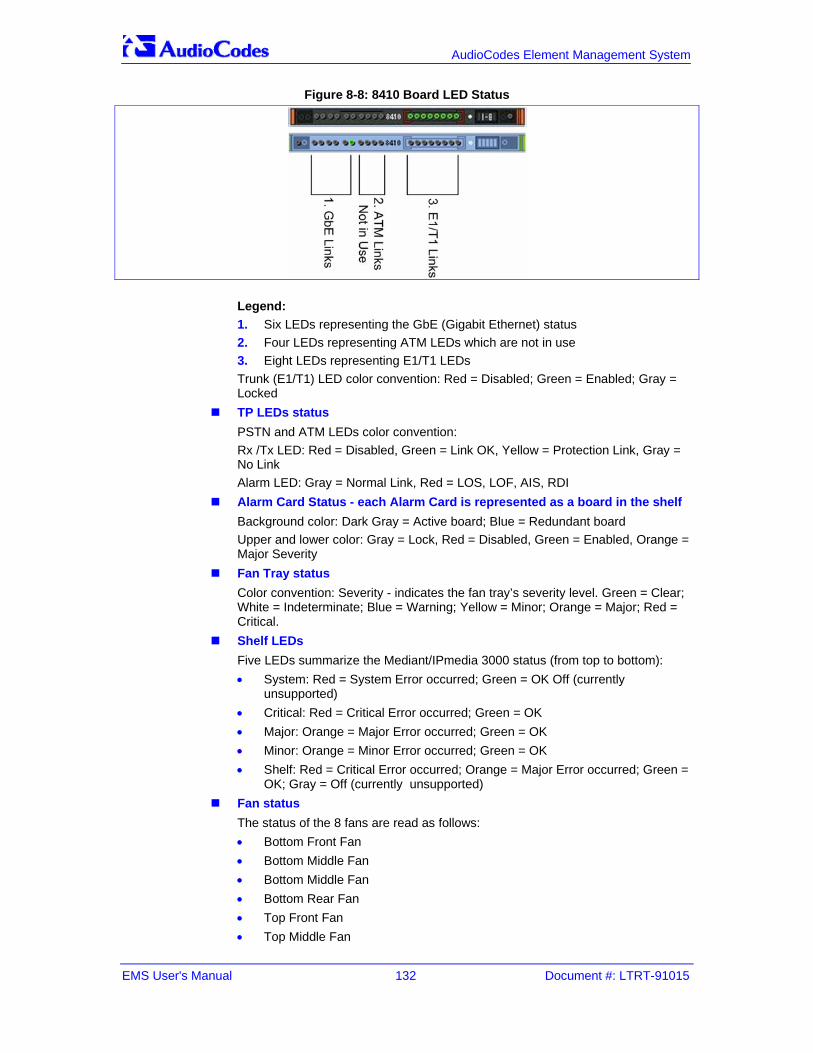
EMS User's Manual 132 Document #: LTRT-91015
AudioCodes Element Management System
Figure 8-8: 8410 Board LED Status
Legend: 1. Six LEDs representing the GbE (Gigabit Ethernet) status 2. Four LEDs representing ATM LEDs which are not in use 3. Eight LEDs representing E1/T1 LEDs Trunk (E1/T1) LED color convention: Red = Disabled; Green = Enabled; Gray = Locked
TP LEDs status PSTN and ATM LEDs color convention: Rx /Tx LED: Red = Disabled, Green = Link OK, Yellow = Protection Link, Gray = No Link Alarm LED: Gray = Normal Link, Red = LOS, LOF, AIS, RDI
Alarm Card Status - each Alarm Card is represented as a board in the shelf Background color: Dark Gray = Active board; Blue = Redundant board Upper and lower color: Gray = Lock, Red = Disabled, Green = Enabled, Orange = Major Severity
Fan Tray status Color convention: Severity - indicates the fan tray’s severity level. Green = Clear; White = Indeterminate; Blue = Warning; Yellow = Minor; Orange = Major; Red = Critical.
Shelf LEDs Five LEDs summarize the Mediant/IPmedia 3000 status (from top to bottom): • System: Red = System Error occurred; Green = OK Off (currently
unsupported) • Critical: Red = Critical Error occurred; Green = OK • Major: Orange = Major Error occurred; Green = OK • Minor: Orange = Minor Error occurred; Green = OK • Shelf: Red = Critical Error occurred; Orange = Major Error occurred; Green =
OK; Gray = Off (currently unsupported) Fan status
The status of the 8 fans are read as follows: • Bottom Front Fan • Bottom Middle Fan • Bottom Middle Fan • Bottom Rear Fan • Top Front Fan • Top Middle Fan

Version 5.8 133 June 2010
EMS User's Manual 8. Mediant 3000 and IPmedia 3000
• Top Middle Fan • Top Rear Fan Color convention: Red = Failed; Green = OK
Power Supplies Status There are 2 Power Supplies: PS Top and PS Bottom Color convention: Severity - indicates the power supply’s severity level. Green = Clear; White = Indeterminate; Blue = Warning; Yellow = Minor; Orange = Major; Red = Critical. When a Manual or Automatic switchover or a software upgrade process occurs, users view a status screen indicating that the redundant board is now failed and notifying that the configuration should not be applied to the system. The figure below shows an example of this status screen and the warning notification.
Figure 8-9: Status Screen Displaying Failed Redundant Boards and Warning Notification

EMS User's Manual 134 Document #: LTRT-91015
AudioCodes Element Management System
8.3.1 Hardware Component Status in Table View
To open the Hardware Component Status in Table View: Double-click on the hardware component (not on the active TP itself as clicking on
the active TP board opens the Trunk Tables Status table).
Figure 8-10: Mediant 3000, IPmedia 3000 Hardware Components Status Pane
The device’s Components Status pane graphically represents the status of each component using the same color conventions as those used in the Status pane, and presents additional information in the Information column.
Board status and information Board type (acMediant3000, or for Alarm Card – SA1, SA2, SA3) HA Status – active or redundant Temperature, in Celsius (only for the TP board)
Fan Tray status and information Fan tray ID and version Pre-provisioned speed
Fan status The status of the 8 fans are read as follows: For each fan: Current speed, in revolutions per minute (rpm)

Version 5.8 135 June 2010
EMS User's Manual 8. Mediant 3000 and IPmedia 3000
Power Supplies Status only PEM Status and information
There are 2 PEMs: PEM Top and PEM Bottom 1. Status: Color convention: Gray = Doesn't Exist; Red = Minor severity, power
cable is missing; Green = Clear Severity 2. Information : PEM ID and version
8.3.2 Mediant 3000 8410 SA BITS status In the current EMS version, BITS status and provisioning is supported for the Mediant 3000 8410 configuration The Mediant 3000 with TP-8410 boards which support an SA board with a BITs Timing module will have the following status screen:
Figure 8-11: Mediant 3000 SA Board Status
The LEDs are represented as follows: 1. Trunk Status represents the status of Trunk A and Trunk B status
correspondingly. 2. Active Source displays which of the Trunks is the current active BITs clock
source. In the figure above, Trunk A is the active clock source. Green represents OK status, Red represents an alarm (problem), Grey -represents OFF
Figure 8-12: Mediant 3000 BITs Module

EMS User's Manual 136 Document #: LTRT-91015
AudioCodes Element Management System
Double clicking on the SA module drills down to status screen which includes additional information regarding both SA cards and BITS modules on each one of them, and PLL Lock indications.
Figure 8-13: Mediant 3000 SAT Status

Version 5.8 137 June 2010
EMS User's Manual 8. Mediant 3000 and IPmedia 3000
8.4 Physical and Logical Components Status and Provisioning
8.4.1 Navigation Hierarchy The Gateways' provisioning parameters are divided into groups / entities. Each is represented by a button at the top of the gateway's / server's Status screen.
Figure 8-14: Navigation Level Buttons-Mediant/IPmedia 3000-8410
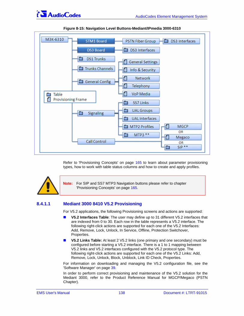
EMS User's Manual 138 Document #: LTRT-91015
AudioCodes Element Management System
Figure 8-15: Navigation Level Buttons-Mediant/IPmedia 3000-6310
Refer to 'Provisioning Concepts' on page 165 to learn about parameter provisioning types, how to work with table status columns and how to create and apply profiles.
Note: For SIP and SS7 MTP3 Navigation buttons please refer to chapter 'Provisioning Concepts' on page 165.
8.4.1.1 Mediant 3000 8410 V5.2 Provisioning For V5.2 applications, the following Provisioning screens and actions are supported:
V5.2 Interfaces Table: The user may define up to 31 different V5.2 interfaces that are indexed from 0 to 30. Each row in the table represents a V5.2 interface. The following right-click actions are supported for each one of the V5.2 Interfaces: Add, Remove, Lock, Unlock, In Service, Offline, Protection Switchover, Properties.
V5.2 Links Table: At least 2 V5.2 links (one primary and one secondary) must be configured before starting a V5.2 interface. There is a 1 to 1 mapping between V5.2 links and V5.2 interfaces configured with the V5.2 protocol type. The following right-click actions are supported for each one of the V5.2 Links: Add, Remove, Lock, Unlock, Block, Unblock, Link ID Check, Properties.
For information on downloading and managing the V5.2 configuration file, see the 'Software Manager' on page 39. In order to perform correct provisioning and maintenance of the V5.2 solution for the Mediant 3000, refer to the Product Reference Manual for MGCP/Megaco (PSTN Chapter).

Version 5.8 139 June 2010
EMS User's Manual 8. Mediant 3000 and IPmedia 3000
8.4.2 SONET / SDH Interfaces There are two SONET / SDH interfaces in the system. These interfaces act as Active / Standby, so from the perspective of provisioning, users must configure one of them - and the configuration is transferred to the other. To provision a Fiber Group, double-click a row in the table. The Sonet OC3 interface on the TP-6310 board supports mapping to three DS3 channels using STS1 (DS3 Channelization-Asynchronous DS3). The Sonet interface on the TP-6310 board supports mapping to OC3 using VT 1.5 mapping for North American T1 trunks. The SDH interface on the TP-6310 board supports mapping to STM1 using VC12 for European E1 Trunks. For more information, see 'Mediant/IPmedia 3000' on page 129 and the Mediant 5000/8000 IOM Guide.
Figure 8-16: SONET / SDH Table

EMS User's Manual 140 Document #: LTRT-91015
AudioCodes Element Management System
8.4.3 DS3 Interfaces Three DS3 interfaces feature in the system. To provision a DS3 interface, double-click each of the rows in the table.
Figure 8-17: Provisioning a DS3 Interface
8.4.4 DS1 Interfaces DS1 Trunks and Trunks Channels Status screens are described in 'MediaPack' on page 151.

Version 5.8 141 June 2010
EMS User's Manual 8. Mediant 3000 and IPmedia 3000
8.5 Executable Actions on the Mediant 3000 The following right-click options are supported for the Mediant 3000:
Configuration Actions
Network Configuration: Change the network configuration (IP Address, Subnet Mask and Default Gateway), send the changes to the device and save the settings in the EMS database.
Figure 8-18: Changing a MediaPack Media Gateway's Network Configuration
Note: Reconfiguring the network parameters might cause a loss of connection with the device. Make sure that the IP address you reconfigure is distinct from those of other devices in the tree.
Software Upgrade
Software Upgrade performs loading software or regional files. Note, that when loading a new software file, Hitless Software Upgrade is supported. EMS checks if according to From and To versions, there is a possibility to perform hitless software upgrade, and provides an EMS user with appropriate questionnaire.
Figure 8-19: Hitless Upgrade Prompt

EMS User's Manual 142 Document #: LTRT-91015
AudioCodes Element Management System
Switchover
Switchover: Each TP board can be switched over by right-clicking on it. If a switchover is in progress, the configuration cannot be applied. A warning icon and a message are viewed at the top of the Status pane: ' HA system switch-over in progress; do not apply the configuration'.
Reset MG / TP Board
Reset MG: Resets the entire chassis. Click the 'Reset' link in the Info Pane or choose the right-click 'Reset' action. To confirm the action, click OK; the gateway / media server is reset. In order to Reset each individual TP Boards, select the Reset option by right clicking on eachTP Board. For more details on the Maintenance Actions supported by digital gateways, refer 'Executable Actions on MediaPacks' on page 154.

Version 5.8 143 June 2010
EMS User's Manual 9. Mediant 2000 and IPmedia 2000
9 Mediant 2000 and IPmedia 2000 9.1 Mediant 2000 and IPmedia 2000 Status Pane
The figure below shows the 16-trunk media gateway Status pane. The Status pane for the 1, 2, 4 and 8-trunk media gateways are identical; only the number of trunks differs.
Figure 9-1: Mediant 2000 and IPmedia 2000 Status Pane

EMS User's Manual 144 Document #: LTRT-91015
AudioCodes Element Management System
The Mediant 2000 Status pane graphically presents the status of the one or two-module gateway. The IPmedia 2000 Status pane is similar. If one of the modules fails, the status of the Mediant 2000 is indicated as failed. The Mediant 2000 Status pane indicates trunk status: Green for enabled, red for disabled and gray for locked (manually out of service) mode.
Figure 9-2: Trunk List for Mediant 2000 and IPmedia 2000 Module #1 or 2
Parameters provisioning buttons for module # 1 / 2 of the Mediant 2000 and IPmedia 2000 are located along the Trunk List pane's upper bar. The Information pane indicates the media gateway's / media server's name, IP address, software version, trunks count and control protocol type. It also includes hardware, software or configuration mismatch if any problem is detected. “Reset Needed” indicates that the operator changed offline parameters and that to apply these parameters to the media gateway, a Reset must be performed. The DS1 Trunks and Trunks Channels Status screens are described in 'DS1 Interfaces' on page 140.

Version 5.8 145 June 2010
EMS User's Manual 9. Mediant 2000 and IPmedia 2000
9.2 Mediant 2000 and IPmedia 2000 Provisioning All gateway provisioning parameters are divided into groups / entities. Each is represented by a button at the top of the Media Gateway Status screen. Parameters provisioning buttons for module # 1 / 2 of the Mediant 2000 and IPmedia 2000 are located on the Trunk List pane's uppermost bar. The parameters provisioning buttons are divided into four sub-categories, each opening a different provisioning screen:
Figure 9-3: Navigation Level Buttons-Mediant/IPmedia 2000
Refer to section 'Provisioning Concepts' on page 165 to learn about parameter provisioning types, how to work with table status columns and how to create and apply profiles.

EMS User's Manual 146 Document #: LTRT-91015
AudioCodes Element Management System
9.3 Executable Actions on Mediant 2000 and IPmedia 2000 All the maintenance actions for the Mediant 2000and IPmedia 2000 are performed separately for each module. For the list of common supported maintenance actions, refer to 'Mediant 600/ Mediant 1000 / Mediant 2000 / Mediant 3000 and MediaPack Maintenance Actions' on page 161.

Version 5.8 147 June 2010
EMS User's Manual 10. Mediant 1000 and Mediant 600
10 Mediant 1000 and Mediant 600 10.1 Mediant 1000 Status Pane
The figure below shows the Mediant 1000 Status pane.
Figure 10-1: Mediant 1000 Media Gateway Status
To define new modules, physically insert them and reset the gateway. It’s not necessary to perform an ‘Insert Module’ action. The Status pane represents the Mediant 1000 Analog and Digital Modules status. For each module, its number and type (Digital, FXS, FXO, BRI or IPmedia) and status are displayed. Additionally, the status of its trunks (digital) or lines (analog) is displayed. Green = enabled, red = disabled and gray = locked. Double-clicking on the digital module opens the Trunks screen where users can view, provision and performs maintenance actions on one or more trunks. Fan and power supply status is displayed according to the following color convention: Green = enabled, red = disabled and gray = doesn’t exist. DS1 Trunks and Trunks Channels Status screens are described in 'DS1 Interfaces' on page 140.

EMS User's Manual 148 Document #: LTRT-91015
AudioCodes Element Management System
10.2 Mediant 600 Status Pane Figure 10-2: Mediant 1000 Media Gateway Status
10.3 Mediant 1000 and Mediant 600 Provisioning All media gateway provisioning parameters are divided into groups / entities. Each is represented by a button at the top of the Media Gateway Status screen.
Figure 10-3: Navigation Level Buttons-Mediant 600 and Mediant 1000
Parameters provisioning buttons are located on the Status screen's uppermost bar. The parameters provisioning buttons are divided into five sub-categories, each opening a different screen. Refer to section 'Provisioning Concepts' on page 165 to learn about provisioning parameter types, how to work with table status columns and how to create and apply profiles.

Version 5.8 149 June 2010
EMS User's Manual 10. Mediant 1000 and Mediant 600
10.4 Executable Actions on the Mediant 1000 and Mediant 600 The following maintenance actions are specific for the Mediant 1000 Gateway: Insert Module: When reinserting a previously removed module into the chassis (in the event that you performed a Remove Module’ action and you wish to insert the new module in the same slot), right-click and choose option ‘Insert Module’ from the popup menu, insert the missing board and reset the gateway. Remove Module: Before removing the existing module, right-click it, select option ‘Remove Module’, remove the module physically, and reset the gateway. For the list of common supported maintenance actions, refer to 'Mediant 600/ Mediant 1000 / Mediant 2000 / Mediant 3000 and MediaPack Maintenance Actions' on page 161.

EMS User's Manual 150 Document #: LTRT-91015
AudioCodes Element Management System
Reader’s Notes

Version 5.8 151 June 2010
EMS User's Manual 11. MediaPack
11 MediaPack 11.1 Status Pane for MediaPack
The figure below shows the 2-channel Media Gateway Status pane. The Status pane for the 4-channel, 8-channel, 24-channel Media Gateways are identical (except for the number of channels).
Figure 11-1: MediaPack Status Pane
The Status pane represents MediaPacks and their LEDs indicating channel status (green- for off-hook and gray- for on-hook), LAN and Ready LEDs (refer to the table below). Data and Control LEDs are not represented and are always colored in gray.

EMS User's Manual 152 Document #: LTRT-91015
AudioCodes Element Management System
Table 11-1: MediaPack Status LEDs
LED Type Color State Definition EMS Representation
Green ON Device powered, self-test OK
Ready LED is green
Orange Blinking Software loading/Initialization
Ready LED is green Ready Device Status
Red ON Malfunction The entire MP is red
Green ON Valid connection to 10/100 Base-T hub/switch
LAN LED is green
Red ON Malfunction The entire MP is red
Red Blinking MediaPack is receiving data packets
LAN LED is green LAN
Ethernet Link Status
Blank No traffic LAN LED is green
Green ON
The phone is off-hooked (FXS); the FXO off-hooks the line towards the PBX.
Channel LED is green
Green Blinking There's an incoming call, before answering
Channel LED is green
Red ON Line malfunction Not supported
Channels
Telephone Interface
Blank - Normal on-hook position
Channel LED is gray
Media Gateway parameters provisioning buttons are located on the top bar of the Status pane. Media Gateway module parameters are divided into 5 sub-categories (frames). The Information pane indicates the media gateway's name, IP address, software version, trunks count and control protocol type. It also includes hardware, software or configuration mismatch information, in case any problem is detected. 'Reset Needed' indicates that the operator changed offline parameters and that a reset must be performed to apply these parameters to the media gateway.
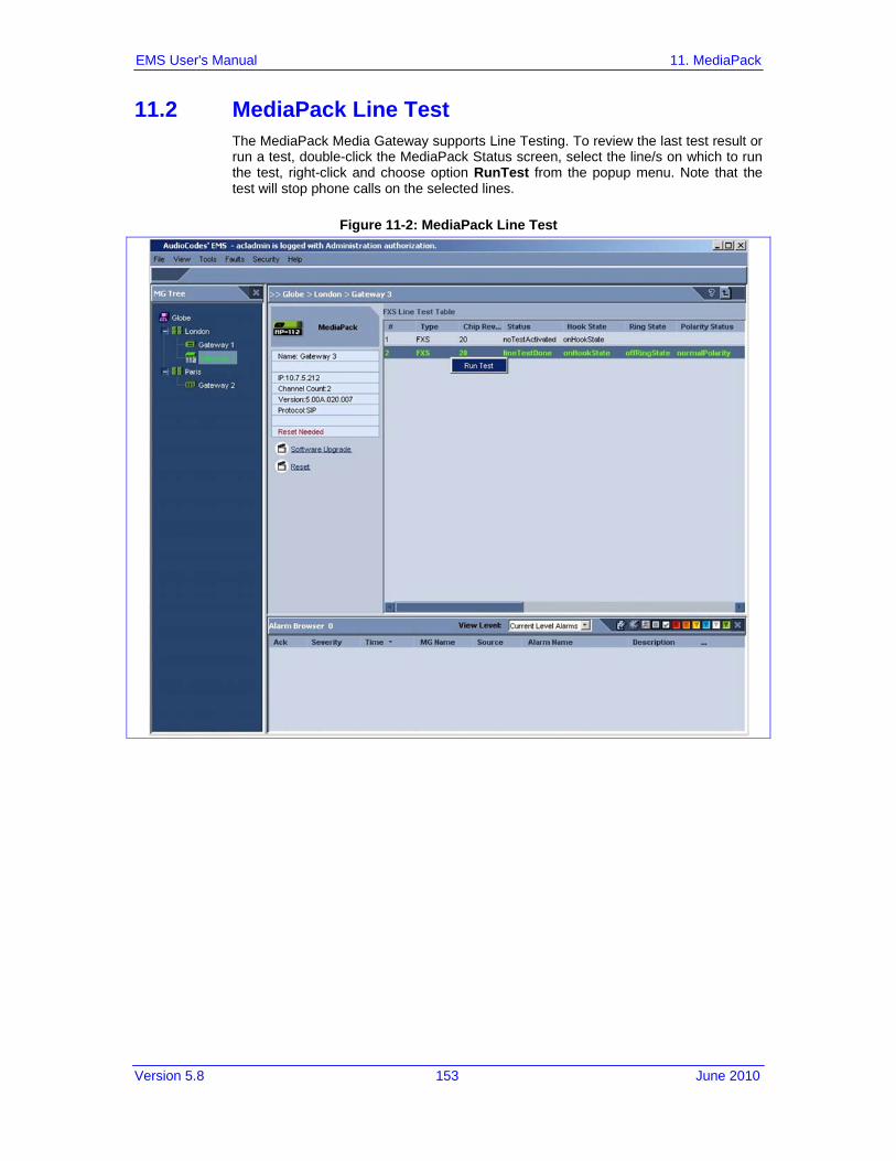
Version 5.8 153 June 2010
EMS User's Manual 11. MediaPack
11.2 MediaPack Line Test The MediaPack Media Gateway supports Line Testing. To review the last test result or run a test, double-click the MediaPack Status screen, select the line/s on which to run the test, right-click and choose option RunTest from the popup menu. Note that the test will stop phone calls on the selected lines.
Figure 11-2: MediaPack Line Test

EMS User's Manual 154 Document #: LTRT-91015
AudioCodes Element Management System
11.3 Provisioning MediaPacks The Media Gateway parameters provisioning buttons are located on the Status pane's uppermost bar. Media Gateway module parameters are divided into 5 sub-categories (frames):
Figure 11-3: Navigation Level Buttons-MediaPack
Refer to section 'Provisioning Concepts' on page 165 to learn about parameter provisioning types, how to work with table status columns and how to create and apply profiles on provisioning parameters.
11.4 Executable Actions on MediaPacks For the list of common supported configuration and maintenance actions, refer to 'Mediant 600/ Mediant 1000 / Mediant 2000 / Mediant 3000 and MediaPack Maintenance Actions' on page 161.

Version 5.8 155 June 2010
EMS User's Manual 12. Mediant 600/1000/2000/3000/5000/8000 Trunks and Channels Status
12 Mediant 600/1000/2000/3000/5000/8000 Trunks and Channels Status All the Digital Gateways have common DS1 Trunks and Trunk Channel Status screens.
12.1 DS1 Trunks Status and Provisioning The Trunk List displays basic information (status and configuration) on the trunks contained in the gateway/server. Double-clicking a trunk opens this trunk's provisioning screen. Note that most Trunk provisioning parameters require that a Trunk Lock / Unlock be performed before / after configuring each of the trunks. When performing a Lock action, all active calls are dropped and users cannot originate new calls. This mode is ‘Out Of Service’ mode. When performing a deactivate action on a trunk, all active calls are dropped and users cannot originate new calls. Configuration changes cannot be performed, only maintenance actions. You may wish to deactivate a trunk when trunk channels have SS7 links and therefore you cannot lock the trunk nor do you wish to deactivate SS7. See Trunks Channel status (section below) to determine whether a trunk channels has SS7 links. When changing 'Trunk Protocol Type' from 'None' to any other protocol, the Gateway must be reset. You're not required to reset the gateway when making subsequent changes to 'Trunk Protocol Type'. After the Gateway is reset, the trunks are automatically set to the Unlock state.
Table 12-1: DS1 Trunk Alarm Status
Trunk Color
Trunk Alarm Status
Locked
Unlocked and Disabled or Critical Alarm (Unlocked and Enabled)
Major Alarm (Unlocked and Enabled)
Minor Alarm (Unlocked and Enabled)
Warning (Unlocked and Enabled)
Indeterminate (Unlocked and Enabled)
Clear, OK (Unlocked and Enabled)

EMS User's Manual 156 Document #: LTRT-91015
AudioCodes Element Management System
Figure 12-1: DS1 Carriers List

Version 5.8 157 June 2010
EMS User's Manual 12. Mediant 600/1000/2000/3000/5000/8000 Trunks and Channels Status
12.2 Trunk Channel Call Status The Trunks Channel Status screen enables the user to view the status of each one of the channels of each Trunk of the TP board. View the trunks channels by selecting the Trunks Channel button at the top of the screen. The following color convention is used to display a trunk channels' call status:
Table 12-2: Trunk Channel Call Status
Channel Color
Channel Call Status
Active
Inactive
Non-Voice
SS7
ISDN Signaling (D-channel)
CAS Blocked
Figure 12-2: Trunk Channel Status

EMS User's Manual 158 Document #: LTRT-91015
AudioCodes Element Management System
Reader’s Notes

Version 5.8 159 June 2010
EMS User's Manual 13. Mediant 2000 and Mediant 3000 SIP and SS7 Navigation Concepts
13 Mediant 2000 and Mediant 3000 SIP and SS7 Navigation Concepts SIP and SS7 Provisioning Concepts are common for the Mediant 2000 and Mediant 3000 product family. Refer to section 'Provisioning Concepts' on page 165 for information on the parameter provisioning types, how to work with table status columns and how to create and apply profiles.
13.1 SIP Provisioning Navigation Buttons Figure 13-1: SIP Navigation Levels-Mediant 2000 and Mediant 3000

EMS User's Manual 160 Document #: LTRT-91015
AudioCodes Element Management System
13.2 SS7 Provisioning Navigation Buttons For SS7-level provisioning rules and configuration, refer to the MGCP Megaco Mediant 2000 and Mediant 3000 User manual or the Product Reference Manual for SIP Gateways and Media Servers. The figure below displays the MTP3 SS7 navigation levels:
Figure 13-2: SS7 Navigation Levels-Mediant 2000 and Mediant 3000

Version 5.8 161 June 2010
EMS User's Manual 14. Mediant 600/1000/2000/3000 and MediaPack Maintenance Actions
14 Mediant 600/1000/2000/3000 and MediaPack Maintenance Actions
14.1 Configuration Actions All the actions below are supported by right-clicking the Gateway and selecting the Configuration Menu.
Figure 14-1: Configuration Actions Menu
Download: This operation loads the entire configuration saved in the EMS Database to the Media Gateway. In addition to provisioned configuration parameters, the user can load Auxiliary files previously loaded to the same Gateway and saved in the EMS Database. Note, It is recommended to first perform the Verification action to ensure that only the required configuration is loaded to the GW,.
Upload: Reads the entire current configuration of the Media Gateway and saves it in the EMS database. Upload does not perform Auxiliary files upload and save into the EMS database. Note: It is recommended to first perform the Verification action to ensure that only the required configuration is saved in the EMS database,.
Verification: Compares the entire configuration saved in the EMS to the current configuration of the Media Gateway (provisioning parameters and auxiliary files). In the case of a mismatch, users can perform a Configuration Download, or Upload the Media Gateway configuration into the EMS database.
Default Values: Removes all user-defined configurations and restores the Media Gateway to its factory defaults. Note: EMS does not remove the user-defined configuration from the Database. Use the Verification action to review the differences. In case of a mismatch, users can perform a Configuration Download, or Upload the Media Gateway configuration into the EMS database.
Create Master Profile: Saves all profiled Media Gateway parameters as a Master Profile. For more information regarding Master Profile, refer to 'Creating a Master Profile' on page 179.
Apply Master Profile: Loads the Master Profile configuration to the Media Gateway. For more information in reference to the Master Profile, refer to 'Attaching a Master Profile to one or to Multiple Media Gateways' on page 182.

EMS User's Manual 162 Document #: LTRT-91015
AudioCodes Element Management System
14.2 Maintenance Actions All the actions below are supported via Gateway right click and select of the Maintenance Menu.
Figure 14-2: Maintenance Actions Menu
Lock / Unlock: Locking / Unlocking of the Media Gateway. Locking the Media Gateway, stops call control functionality and enters the Gateway to the maintenance state. Unlock returns it to service.
Software Upgrade: Loading a software or regional auxiliary file. Save Into Flash Memory: Saves the entire media gateway configuration in flash
memory so that after reset, no Configuration Download is required. Reset: Select Info Panel or right-click 'Reset' action. To confirm the action, click
'OK'; the media gateway is reset. Upload INI File: This option is defined for debug purposes. The INI file received
from Gateway is used to assist AudioCodes FAE to perform problem debugging. Remove File: removed auxiliary file/s from Gateway. Upon selecting this option,
the user is prompted with a list of all the files used by a specific Gateway. The user can then select those file/s they wish to remove.
All the actions below are supported via Trunk right-click menus. Lock Trunk/s. Note that if the trunk type is changed from Null or from E1 based
to T1 based (or vice versa), the media gateway must be reset at the end of the provisioning action, or else the Lock / Unlock action on the trunk will fail.
Activate / Deactivate Trunk/s • Activate (can only be applied when trunks are in Unlock state)- Activate
trunks after a trunk has been deactivated. When a trunk is activated, it is reconnected to the PSTN network and the relevant AIS alarm is cleared.
• Deactivate (can only be applied when trunks are in Unlock state)- When a trunk is deactivated, it is temporarily disabled from the PSTN network. An AIS alarm signal is sent from the Media Gateway board to the receiving end of the trunk and an RAI alarm signal is returned to the Media Gateway (displayed in the EMS Alarm Browser). Use this option for maintenance purposes. For example, the DS1 trunk that you wish to run maintenance tasks has SS7 links on it and therefore you cannot lock it and do not wish to deactivate SS7.

Version 5.8 163 June 2010
EMS User's Manual 14. Mediant 600/1000/2000/3000 and MediaPack Maintenance Actions
14.3 Performing Actions on Multiple Gateways
To perform an action on multiple gateways: 1. In the MGs Tree Status screen, select the Region under which the Media
Gateways are located. 2. Select one or more media gateways using the CTRL or Shift keys, or by using
the mouse. Verify that all Media Gateways you intend to perform the action on are selected.
3. Right-click and choose the required action option from the popup; an Action Result table is displayed showing progress and action results. Note that depending on the Media Gateway type and software version, some actions might be disabled in the right-click popup. This means that in the selected set of Media Gateways, there is one or more Media Gateways which cannot support the action that is disabled in the popup.

EMS User's Manual 164 Document #: LTRT-91015
AudioCodes Element Management System
Reader’s Notes

Version 5.8 165 June 2010
EMS User's Manual 15. Provisioning Concepts
15 Provisioning Concepts 15.1 Working with the EMS's Provisioning Screens
All screens in the EMS that enable operators to provision the media gateway, boards and trunks, in the context of these entities' interfaces, described in this section, are configured according to the same principle. The provisioning screens are easily and intuitively reached by navigating down (or up as the case may be) the system hierarchy to select the entity to be provisioned. In that entity's Info pane, click the 'Properties' link, or click the parameters provisioning screen's buttons on the top of the Status pane; the provisioning screen for that specific entity is displayed. A provisioning screen of a TP board is presented in the figure below by way of example. All entities are provisioned in exactly the same way as the board whose provisioning screen shown here is provisioned.
Figure 15-1: TP-6310 Board Provisioning Parameters

EMS User's Manual 166 Document #: LTRT-91015
AudioCodes Element Management System
The Board Provisioning screen displayed in the figure contains: Toolbar
Includes the path of the EMS-managed entity (in the case of the illustrative example shown in the figure above, Board #7 in the media gateway named M5K_21 located under the region of Beijing), as well as its Administrative State (Locked/Unlocked) and its Operational State (Enabled/Disabled). The Administrative State of the board can be changed using the Administrative State drop-down arrow.
For Mediant 1000, Mediant 2000, Mediant 3000, IPmedia 2000, IPmedia 3000 and MediaPacks, Reset State is displayed. The Reset State of the board can be changed using the Reset State drop-down arrow.
Parameters List The Parameters List is in the pane on the left side of the Provisioning screen. The Parameters List categorizes are color-coded for quick operator assessment.
The table below decodes the colors of the category buttons.
Table 15-1: Provisioning Parameters in the Board Provisioning Screen – Color Codes
Color Meaning
Red on violet Error in data as a result of operator's modification
White on violet The button was modified and all data in it is valid. Or, in case of the Mediant 1000, Mediant 2000, Mediant 3000, IPmedia 2000, IPmedia 3000 and MediaPacks, the button was modified and saved in the database but not yet loaded to the VoIP device.
Black on blue Button is not modified and all data in it is valid
Green on dark blue Currently viewed button
Green on violet Currently viewed and already modified button
Red on blue Error in data produced by the media gateway
Orange on violet/blue (in Mediant 1000, Mediant 2000, Mediant 3000, IPmedia 2000, IPmedia 3000 and MediaPacks only)
The value from the VoIP device is different to the value in the database (can be seen when the Unit Value arrow button is clicking)
Provisioning Parameters Button Each Provisioning Parameters button lists all parameters under that category. After modifying a parameter, the parameter's name color is changed to violet, and the modified category button's color is changed to violet. If a provisioned parameter is invalid, the invalid parameter is colored in red and a tool tip with the corrective instructions appears. The category button name is colored in red as well. If a parameter is not editable (read-only), its value and name are grayed (disabled).

Version 5.8 167 June 2010
EMS User's Manual 15. Provisioning Concepts
Drop-down Arrows
A drop-down arrow is adjacent to each provisioning parameters category button, and to each parameter in that category. Each drop-down combo lists two actions that operators can optionally perform (for each individual parameter and for each provisioning parameters category: 1. Undo modification/s 2. Factory default value - displays the values that the media gateway is initiated
with prior to its release. Unit Value (exists for Mediant 1000, Mediant 2000, Mediant 3000, IPmedia 2000, IPmedia 3000 and MediaPacks) – displays actual gateway values read from the gateway during the last Refresh or when the screen is opened. In case of a mismatch between the gateway's actual value and the value saved in the database, the parameter and tab name are colored in orange. To synchronize the gateway and the database, either 'Save' the media gateway's value in the database, or 'Apply' the database value to the gateway.
System Buttons At the bottom of the Board Parameters Provisioning screen are the following system buttons (refer to the figure below and to the figure above):
Figure 15-2: System Buttons in Board Parameters Provisioning Screen
Save - Save your changes in the EMS database (Mediant 1000, Mediant 2000, Mediant 3000, IPmedia 2000, IPmedia 3000 and MediaPacks). Apply - Load your changes to the gateway, save your changes in the EMS database for Mediant 1000, Mediant 2000, Mediant 3000, IPmedia 2000, IPmedia 3000 and MediaPacks. Refresh - Read the current gateway setting (replace your changes with the current data). Cancel - Cancel your changes and close the screen.
Working with tables in Provisioning Screens Table information is sometimes displayed as a tab in the provisioning screens. Note the following when working with tables: • Right-clicking on a table row and choosing an Add / Remove / Lock / Unlock
action does not then require clicking the ‘Apply’ button; the action is executed immediately.
• When you finish editing a cell in a row, you must click ‘Enter’ to finish editing. • After finishing defining table data, you must click the ‘Apply’ button. After your
change is applied, a Lock/Unlock action on table rows is required.
15.1.1 Provisioning Procedure for Mediant 1000, Mediant 2000, Mediant 3000, IPmedia 2000, IPmedia 3000 and MediaPack 1. In the Main Screen, navigate to the element/entity to provision and select it. Click
the required provisioning screen button on the top bar of the Status pane; the parameters provisioning screen for that element is displayed.
2. If the media gateway is currently not connected to the network, its Parameters Provisioning screen title bar will include a suffix indicating “Offline”.
3. Modify the required parameters using the interface-context buttons. 4. Click the “Apply” system button; your changes are downloaded to the media
gateway and saved in the database.
EMS User's Manual 168 Document #: LTRT-91015
AudioCodes Element Management System
5. When working in Offline mode, save your changes in the EMS database by clicking “Save”. After the media gateway is connected to the network, click 'Configuration Download' in the Info pane to download all changes previously saved in the EMS database to the gateway.
6. If 'Reset State' is marked as 'Reset Needed', reset the gateway by clicking Reset State 'Reset' option (refer to the text that is bulleted 'Toolbar', above) to return it to service.
7. Click the 'Cancel' button to exit the provisioning screen.
Note: After a successful 'Apply', all parameters and tabs previously colored in purple will return to their normal colors (black).
Note: If you make a mistake in the provisioning process, the system notifies you and prompts you for the corrective action.
15.1.2 Provisioning Procedure for Mediant 5000 and Mediant 8000 This section covers the Mediant 5000 Media Gateway and Mediant 8000 Media Gateways.
To provision a Mediant 5000 Media Gateway and Mediant 8000 Media Gateway, follow these procedures:
1. In the Main Screen, navigate to the element/entity to provision, select it (for a gateway, select it in the MGs List under the region; for a board, select it in the graphic representation of the gateway; and for a trunk, select it in the Trunk List), and in the Info pane click the 'Properties' link; the provisioning screen for that element is displayed.
2. Modify the required parameters using the interface-context buttons. 3. Change the managed element/entity to the 'Locked' Administrative State (refer to
the bullet 'Toolbar', above). 4. Click the 'Apply' system button; your changes are loaded to the gateway. 5. Change the managed element/entity to the 'Unlocked' Administrative State (refer
to the bullet 'Toolbar', above) to return it to service. 6. Click the 'OK' or 'Cancel' button to exit the provisioning screen.
Note: After a successful 'Apply', all parameters and tabs previously colored in purple will return to their normal colors (black).
Note: If you make a mistake in the provisioning process, the system notifies you and prompts you for the corrective action.

Version 5.8 169 June 2010
EMS User's Manual 15. Provisioning Concepts
15.1.3 Provisioning Procedure for Mediant 1000, Mediant 2000, Mediant 3000, IPmedia 2000, IPmedia 3000 and MediaPack
To provision these VoIP devices, follow these procedures: 1. In the Main Screen, navigate to the element/entity to provision and select it. Click
the required provisioning screen button on the top bar of the Status pane; the parameters provisioning screen for that element is displayed.
2. If the device is currently not connected to the network, its Parameters Provisioning screen title bar will include a suffix indicating 'Offline'.
3. Modification of single parameters: Modify the required parameters using the interface-context buttons.
4. Modification of table parameters: Some provisioning screens include Tables. a. Add Row: To define a new row in the table, right-click the table tab and select
the option 'Add Row'. b. Modify Row Data: To modify a row's data, double-click the relevant cell,
change the data and exit the cell by clicking on any object in the screen. Verify that the cell is not in focus.
c. Lock / Unlock Row: To make a row operational, unlock it by right-clicking on it and choosing option 'Unlock' from the row menu.
d. Remove Row: To remove a row, right-click on the row and choose the option 'Remove'.
e. Note that all the right-click actions are sent immediately to the device, The 'Apply' button only applies parameter changes.
5. Click the 'Apply' system button; your changes are loaded to the device and saved in the database.
6. When working in Offline mode, save your changes in the EMS database by clicking 'Save'. After the device is connected to the network, click 'Configuration Download' in the Info pane to load all changes previously saved in the EMS database to the device.
7. If 'Reset State' is marked as 'Reset Needed', reset the device by clicking Reset State 'Reset' option (refer to the text that is bulleted 'Toolbar', above) to return it to service.
8. Click the 'OK' or 'Cancel' button to exit the provisioning screen.
Note: After a successful 'Apply', all parameters and tabs previously colored in purple will return to their normal colors (black).
Note: If you make a mistake in the provisioning process, the system notifies you and prompts you for the corrective action.

EMS User's Manual 170 Document #: LTRT-91015
AudioCodes Element Management System
15.2 Parameters Provisioning Types The EMS features three provisioning parameter types: 1. Instant (changes are applied to the media gateway after clicking Apply/OK). 2. Online (the modified entity must be locked prior to applying the changes) 3. Offline (the modified entity must be locked prior to applying the changes and the
physical component (board or media gateway) must be locked. An icon indicating parameter-provisioning type is placed adjacent to the field and only applies to modifiable parameters. Each parameter displayed in a provisioning parameters screen is indicated as one of the following types (refer to the table below):
Table 15-2: Indication Mapping Summary
Parameter Provisioning Type
Indication / Gateway Type Description
Instant No indication Click 'Apply', 'OK' button to load changes to the media gateway.
Online Lock / Unlock modified entity (trunk, for example)
Trunking Gateway Lock/Unlock the physical entity within/under which the managed entity is located, and the managed entity itself
Offline
Mediant 1000 / Mediant 2000 / Mediant 3000 / IPmedia 2000 / IPmedia 3000 and MediaPack
Reset the module (TPM). In the Mediant 2000, there can be two TPMs in the case of a 16-trunk configuration)
'Online' - To configure an 'Online' mode parameter (indicated in the EMS by the icon adjacent to the parameter), you need to lock only the entity containing the parameter. You do not need to lock the board/media gateway containing the entity. The mode is called 'Online' because the parameter can be configured without resetting any board in the media gateway.
'Offline' - To configure an 'Offline' mode parameter (indicated in the EMS by the icon adjacent to the parameter), you need to lock the board/media gateway containing the entity as well as the entity in order to configure the entity's parameter. The mode is called 'Offline' because all calls active on the board/media gateway containing the entity's parameter are dropped when you lock the board/media gateway and entity in order to configure the parameter.
'Instant' - An 'Instant' mode parameter can be configured on the fly; the configuration takes effect immediately. No icon is displayed adjacent to the parameter in the EMS GUI. No locking or unlocking of the entity or of the board/media gateway is required to perform the configuration.
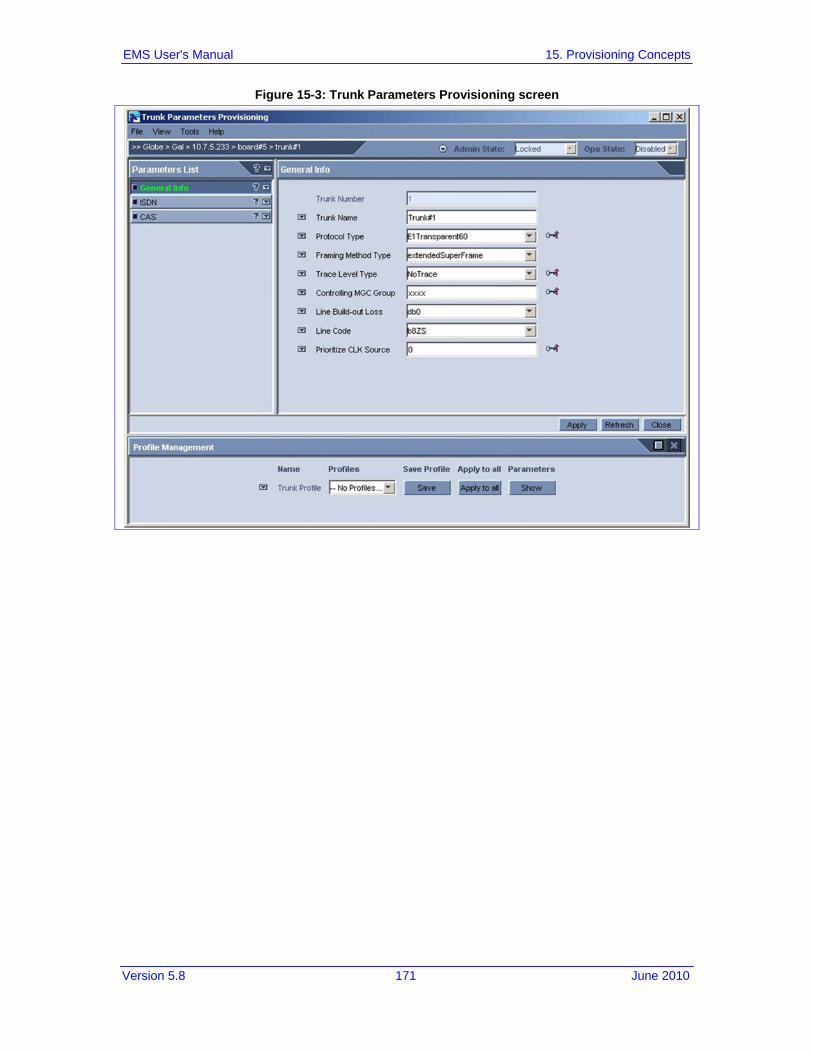
Version 5.8 171 June 2010
EMS User's Manual 15. Provisioning Concepts
Figure 15-3: Trunk Parameters Provisioning screen

EMS User's Manual 172 Document #: LTRT-91015
AudioCodes Element Management System
Figure 15-4: Telephony Parameters Provisioning Screen

Version 5.8 173 June 2010
EMS User's Manual 15. Provisioning Concepts
15.3 Parameters HA Type This sign is used for Mediant 5000 / 8000, IPmedia 5000 / 8000 Gateways. The EMS features three provisioning parameter types:
Instant (changes are applied to the media gateway after clicking Apply/OK). Online (the modified entity must be locked prior to applying the changes) Offline (the modified entity must be locked prior to applying the changes and the
physical component (board or media gateway) must be locked. An icon indicating parameter-provisioning type is placed adjacent to the field and only applies to modifiable parameters. Each parameter displayed in a provisioning parameters screen is indicated as one of the following types (refer to the table below):
Table 15-3: Indication Mapping Summary-Parameters HA Type
Parameter Provisioning Type Indication Description
No Affect on HA
No indication Modification of this parameter will not affect High Availability Feature
Affects HA Modification of these parameters will affect HA of the TP board. For more information, refer to Redundancy provisioning Frame to review affected boards.
Partially Affects HA Modification of these parameters might affect HA of the TP board. For more information, refer to Redundancy provisioning Frame to review affected boards.
15.4 Exporting, Importing an Entity Configuration as a File The EMS enables operators to export an entity's entire parameters provisioning screen as a file. The file is in readable XML format. Operators can then use this file to import the parameters provisioning screen configuration into another entity of the same type. For example, the parameters provisioning screen configuration of a board can be imported into another board, the parameters provisioning screen configuration of a trunk can be imported into another trunk, etc. The entity into which the file is imported can be in another EMS system or in the same EMS system. After the file is imported, operators can view the imported parameter configurations in the provisioning screen and decide whether to apply the configurations to the entity (by clicking the 'Apply' button) or not. After operator has imported the entity configuration file into the EMS, it is suggested to use profiles to spread the configuration over the different entities of the objects managed by same EMS.

EMS User's Manual 174 Document #: LTRT-91015
AudioCodes Element Management System
To export an entity's parameters provisioning screen as a file: 1. Open the parameters provisioning screen of the entity to be exported. 2. In the Tools menu, choose the option 'Export Configuration'; the 'Select File'
screen opens (refer to the figure below). 3. Select the folder where you want the configuration file to be saved, define the 'File
Name' field and click 'OK'; a file with the suffix .xml is created.
Figure 15-5: Export Configuration Screen
To import the .xml file into an entity: 1. Open the parameters provisioning screen of the entity into which you want to
import the xml file. 2. In the Tools menu, choose the option 'Import Configuration'; the 'Select File'
screen opens (refer to the figure above). 3. Navigate to the saved xml configuration file and double-click on it; the entity's
provisioning screen now displays the parameter configurations retrieved from the xml file; parameter configurations that differ from the previous configuration are colored in purple.

Version 5.8 175 June 2010
EMS User's Manual 15. Provisioning Concepts
15.5 Printing an Entity's Configuration as a File The EMS enables operators to export an entire entity's parameters provisioning screen as a printable and easily readable file. The file is in readable txt format. An example of a Trunk Level configuration is displayed in the figure below.
To print an entity's parameters provisioning screen as a file: 1. Open the parameters provisioning screen of the entity to be exported. 2. In the 'Tools' menu, choose option 'Print Frame'; the 'Select File' screen opens. 3. Select the folder where you want the configuration file to be saved, define the field
'File Name' and click 'OK'; a file with the suffix .txt is created.
Figure 15-6: Trunk Print Format

EMS User's Manual 176 Document #: LTRT-91015
AudioCodes Element Management System
15.6 Provisioning Entity Profiles The EMS's Profile Management enables Customers to rapidly provision values to entity parameters by loading a profile. The Profile Manager feature is located in the lowermost pane of the Parameters Provisioning screen. Customers can view all currently available profile types, select a profile type best suited to Customer application requirements, attach the profile, view a visual representation of the parameter values modified and save it as a new profile. Customers can also delete profiles from the pool of profiles. Each profile includes a specific entity's parameters displayed in that entity's parameters provisioning screen.
Figure 15-7: Profile Management

Version 5.8 177 June 2010
EMS User's Manual 15. Provisioning Concepts
15.6.1 Creating Entity Profiles
Note: Entity profiles cannot be modified.
To save an entity's parameter values in an entity profile: 1. Click the 'Show' button located in the same row as that of the profile; the 'Show
Parameters' screen is displayed on top of the parameters provisioning screen, listing all parameters that are under the requested profile and their tab location. Alternatively, you can check 'Show' icon on the 'Profile Management' pane, and Name of the profiles will be added to the profiled parameters.
Figure 15-8: Profile Management: Show Profile's Parameters
2. Edit/modify the parameter/s field/s and click the 'Save' button in the Profiles Management pane; you're prompted in the 'New Profile' prompt (field 'Provide a New Profile Name') for a new name for the profile whose parameter/s / field/s you've modified.
3. Click OK; the modified values of the parameter/s field/s are saved in the new profile and the new profile is added to the 'Profiles' drop-down list; the current media gateway's entity is now attached to the new profile.

EMS User's Manual 178 Document #: LTRT-91015
AudioCodes Element Management System
15.6.2 Loading - Attaching - an Entity Profile
To load an entity profile: 1. In the 'Choose Profile' drop-down list, select the profile to attach to the entity. 2. Click 'Apply' to load your changes to the media gateway and save the attachment.
To attach a profile to all trunks in the Trunks Parameters Provisioning screen:
1. In the 'Choose Profile' drop-down list, select the profile to attach to the trunks. 2. Click the 'Apply to All' button to attach the profile to the trunks.
15.6.3 Detaching a Profile from an Entity A profile is detached from an entity in the event that: 1. You change one of the parameters in a profile already attached to an entity.
When saving the new profile (with the modified parameter), the previous profile is detached from the entity. After clicking Save or Apply, you're prompted with a notification message indicating that the profile is detached from the entity.
2. You loaded a different profile to an entity already attached to a profile. When clicking the Save or Apply button, the entity is detached from the previous profile and attached to the new profile.
3. You delete a profile from an entity and the entity is the only entity attached to the profile.
15.6.4 Removing a Profile
To remove a profile from the profiles pool: Click the arrow adjacent to the Profile Name to choose option “Remove Current
Profile” from the pop-up.
Note: The current profile is removed if and only if no other entity is attached to this profile beside the current entity (for whom the screen is opened). If there is another entity attached to the profile, the 'Remove Profile' function fails and a list of the currently attached entities is displayed. Therefore, before removing a profile from the profiles pool, first detach it from any entity it may be attached to (refer to 'Detaching a Profile from an Entity' on page 178).

Version 5.8 179 June 2010
EMS User's Manual 15. Provisioning Concepts
15.7 Master Profile for Mediant 1000, Mediant 2000, Mediant 3000, IPmedia 2000, IPmedia 3000 and MediaPack
15.7.1 Ascertaining a Device's Master Profile In the column captioned Master Profile in the MGs List status screen, operators can ascertain whether a master profile is attached to a media gateway/media server and (in the event that a master profile is attached) the name of the master profile (refer the figure below).
Figure 15-9: PROFILE Column in MGs List Status Screen

EMS User's Manual 180 Document #: LTRT-91015
AudioCodes Element Management System
15.7.2 Creating a Master Profile
Note: All tables MUST be unlocked in order to create a master profile (Mediant 1000, Mediant 2000, Mediant 3000, IPmedia 2000, IPmedia 3000 and MediaPack).
Note: A master profile cannot be modified after it is created. Operators must instead modify the configuration of the media gateway/media server and then save the new configuration as a new master profile (to be applied to the media gateway/s / media server/s).
After finishing configuring the parameters of the media gateway/media server, operators can save the configuration as a master profile. The master file comprises five or more (depending on the control protocol configured in the device) entity profiles (for detailed information on entity profiles, refer to 'Creating Entity Profiles' on page 176). If an entity profile is created and loaded to the media gateway/media server prior to the creation of the master profile, then when the media gateway/media server configuration is saved as a master profile the master profile incorporates and uses that (previously created and loaded) entity profile.

Version 5.8 181 June 2010
EMS User's Manual 15. Provisioning Concepts
In the event that no entity profile/s was/were created and loaded prior to the creation of a master profile, the master profile is created from individual parameters (associated with each of the 5 entities).
Figure 15-10: Creating a Master Profile for the MediaPack
To create a master profile: 1. Right-click and in the configuration sub-menu, choose 'Create Master Profile'; the
prompt 'New Master Profile' appears (shown in the figure below).
Figure 15-11: New Master Profile Prompt
2. Enter a name for the master profile in the field 'Save Master Profile' and click OK.

EMS User's Manual 182 Document #: LTRT-91015
AudioCodes Element Management System
To create a master profile using an alternative procedure: 1. In the MGs List, select the media gateway/media server to which to attach a
master profile. 2. Right-click on the selected media gateway/media server and from the pop-up
menu, choose option 'Create Master Profile'; the New Master Profile prompt appears (shown in the figure above).
3. Enter a name for the master profile in the field 'Save Master Profile' and click OK.
15.7.3 Attaching a Master Profile to one or to Multiple Media Gateways
To attach a master profile to a media gateway (or to multiple media gateways of the same type, configured with the same call control protocol):
1. In the MGs List, select a (Mediant 1000, Mediant 2000, Mediant 3000, IPmedia 2000, IPmedia 3000 and MediaPack (or select multiple instances of the same device configured with the same call control protocol).
Figure 15-12: Selecting the MediaPacks to Which to Attach a Master Profile (in the MGs List)

Version 5.8 183 June 2010
EMS User's Manual 15. Provisioning Concepts
2. Right-click on the selected media gateway / media server (or on multiple selected devices) and from the pop-up menu, choose option 'Apply Master Profile'; the 'Select Master Profile' prompt appears on the screen (shown in the figure below).
Figure 15-13: Select Master Profile Screen
Figure 15-14: Selecting a Master Profile to Apply
3. Select the Master Profile you require (refer to the figure above) and click OK; the master profile you selected is attached to all selected devices.

EMS User's Manual 184 Document #: LTRT-91015
AudioCodes Element Management System
15.7.4 Detaching a Master Profile A profile is detached from a media gateway/media server in the event:
You change the configuration one of the parameters in the media gateway/media server. After clicking Save or Apply, you're prompted with a notification message indicating that the profile is detached from the media gateway/media server.
You apply a master profile to an media gateway/media server that is already attached to a master profile and the two master profiles are different. When clicking Save or Apply, the media gateway/media server is detached from the previously applied master profile and the new profile is applied.
15.7.5 Removing a Master Profile
To remove a master profile from the profiles pool: 1. In the Tools menu, choose the option 'MP Master Profiles Manager'; the MP
Master Profiles Manager screen opens (shown in the figure below).
Figure 15-15: Master Profiles Manager - MediaPack
2. Select the master profile/s that you require to be removed from the master profiles pool and click the button to remove the master profile/s you selected.
3. If a master profile is used by one or more MediaPacks, it cannot be removed.
Version 5.8 185 June 2010
EMS User's Manual 15. Provisioning Concepts
15.8 TP-6310 and TP-8410 Master Profile (Mediant 5000 Media Gateway, Mediant 8000 Media Gateway)
15.8.1 Ascertaining a TP-6310 and TP-8410 Board Master Profile A TP-6310 STM1 / IPmedia master profile is composed of the following:
The board-level configuration The trunks configuration The PSTN Fiber Group configuration The MTP2 profiles configuration
A TP-6310 DS3 master profile is composed of the following: The board-level configuration The trunks configuration The DS3 interfaces configuration The MTP2 profiles configuration
A TP-8410 DS1 master profile is composed of the following: The board-level configuration The trunks configuration The MTP2 profiles configuration
For SIP Control Protocol, the entire profiled configuration is transferred as part of the Master Profile.

EMS User's Manual 186 Document #: LTRT-91015
AudioCodes Element Management System
To ascertain whether a master profile is attached to a TP-6310 or TP-8410 board and (in the event that a master profile is attached) the name of the master profile (refer to the figure below), click the icon 'Table View' in the gateway Status screen and check the 'Profile' column.
Figure 15-16: Profile Column in the Boards List Screen

Version 5.8 187 June 2010
EMS User's Manual 15. Provisioning Concepts
15.8.2 Creating a Master Profile
Note: A master profile cannot be modified after it is created. Operators must instead modify the configuration of a TP-6310 / TP-8410 and then save the new configuration as a new master profile (to be applied to the boards).
To apply a master profile to the TP-6310 / TP-8410 board, all its trunks must be profiled. If all trunks have the same configuration, operators can use the button 'Apply to All' in the 'Trunk Properties Profile Manager' pane.
If an entity profile is created and loaded to the board prior to the creation of the master profile, the loaded profile is saved as part of master profile. In the event that no entity profile/s was/were created and loaded prior to the creation of a master profile, the master profile will automatically create entity profiles for all entities.
Figure 15-17: Creating a Master Profile - TP-6310

EMS User's Manual 188 Document #: LTRT-91015
AudioCodes Element Management System
To create a master profile: 1. In the Information pane, click the link 'Create Master Profile'; the New Master
Profile prompt appears (shown in the figure below).
Figure 15-18: New Master Profile Prompt
2. Enter a name for the master profile in the field 'Save Master Profile' and click OK.
To create a master profile using an alternative procedure: 1. In the Boards List, select the TP-6310 / TP-8410 board of which to create a
master profile. 2. Alternatively, in the Media Gateway Status pane, select the TP-8410 / TP-6310 of
which to create a master profile. 3. Right-click on the selected board and from the popup menu, choose option
'Create Master Profile'; the New Master Profile prompt appears (shown in the figure above).
4. Enter a name for the master profile in the field 'Save Master Profile' and click OK.

Version 5.8 189 June 2010
EMS User's Manual 15. Provisioning Concepts
15.8.3 Attaching a Master Profile to TP-8410, TP-6310 Boards
To attach a master profile to TP-8410/ TP-6310 board/s: 1. In the Boards List, select the TP-8410 / TP-6310 board (or select multiple
boards). Alternatively, in the Media Gateway Status pane, select the TP-8410 / TP-6310 board/s.
Figure 15-19: Selecting TP-6310 Boards
2. Right-click on the selected board (or on multiple selected boards) and from the popup menu, choose option 'Apply Master Profile'; the 'Select Master Profile' prompt appears on the screen.
3. Select the Master Profile you require and click OK; the master profile you selected is attached to all selected boards.
15.8.4 Detaching a Master Profile from TP-8410, TP-6310 Boards A profile is detached from the TP-8410/TP-6310 board in the event that:
You change the configuration of one of the profiled parameters. After clicking 'Apply', the master profile is detached from the TP-8410/TP-6310 board.
You apply a master profile to an TP-8410/TP-6310 board that is already attached to a master profile and the two master profiles are different. When clicking Apply, the TP-8410/TP-6310 is detached from the previously applied master profile and the new profile is applied.

EMS User's Manual 190 Document #: LTRT-91015
AudioCodes Element Management System
15.8.5 Master Profiles Manager
To remove a master profile from the profiles pool: 1. In the Tools menu, choose the option 'Master Profiles Manager'; the Master
Profiles Manager screen opens (shown in the figure below).
Figure 15-20: Master Profiles Manager
2. Select the master profile/s that you require to be removed from the master profiles pool and click the button to remove the master profile/s you selected.
3. If a master profile is used by one or more devices, it cannot be removed.
15.9 Offline Configuration for Mediant 1000, Mediant 2000, Mediant 3000, IPmedia 2000, IPmedia 3000 and MediaPack Configuration can be performed even if the media gateway/media server is not connected to the network. The EMS saves all configuration changes performed by the Operator in its database and loads the configuration when 'Configuration Download' is requested. This feature can be used to configure smaller media gateways prior to delivery to the Customer and connection to the network, thereby significantly reducing deployment time. To save a configuration, click 'Save' in the provisioning screen where the configuration changes were performed. Offline mode is indicated in the title of the provisioning screen.

Version 5.8 191 June 2010
EMS User's Manual 15. Provisioning Concepts
15.10 Configuration Verification, Download for Mediant 1000, Mediant 2000, Mediant 3000, IPmedia 2000, IPmedia 3000 and MediaPack Configuration Verification is a process of verifying that the configuration saved in the EMS database tallies with the actual media gateway/media server configuration. In the event of inconsistencies, Operators are notified of the mismatch, which they can then fix by working with the EMS's parameter provisioning screens. The Configuration Verification Results screen (refer to the figure below) displays all EMS-saved configuration parameters that are discrepant with the actual media gateway/media server configuration parameters. The names of discrepant parameters are listed under the 'Parameter Name' column, adjacent to which are the 'Screen Name' and 'Tab Name' columns.
Figure 15-21: Configuration Verification Results
Configuration Download is the process of loading configuration changes (performed by the operator) to the managed media gateway / media server. Each download action can be performed by clicking the 'Configuration Download' link the Information Pane, or from the MGs List. From the MGs List, each of the actions can be performed for a single media gateway / media server, or for a set of selected media gateways / media servers.

EMS User's Manual 192 Document #: LTRT-91015
AudioCodes Element Management System
15.11 Searching for a Provisioned Parameter Provisioning parameters differ from platform to platform and version to version.
To find the parameter required for a specific media gateway / media server:
1. Open the Tools menu and choose the option Search Provisioning Parameters; the Search Provisioned Parameter screen (shown in the figure below) opens.
Figure 15-22: Search Provisioned Parameter
2. Enter the Parameter Name (or part thereof) 3. Choose the Product Type and Software Version from these two fields' drop-down
lists. 4. Expedite your search for a provisioned parameter (if you need to) by checking the
'Match case' and/or 'Match whole word only' check boxes. For example, if you only recall part of the parameter name, say “IP”, you can check the 'Match case' check box and the 'Match whole word only' check box.

Version 5.8 193 June 2010
EMS User's Manual 15. Provisioning Concepts
5. Click the Search button; the Search Result screen opens, displaying a list of parameters answering the criteria you defined previously in the Search Provisioned Parameter screen, with Tab Name and Screen Name columns indicating location. Use the information under Tab Name and Frame Name to help you navigate efficiently and quickly to the EMS screen (frame) in which the parameter (whose configured value you need to view and/or reconfigure) appears.
Figure 15-23: Provisioned Parameter Search Result Screen

EMS User's Manual 194 Document #: LTRT-91015
AudioCodes Element Management System
Reader’s Notes

Version 5.8 195 June 2010
EMS User's Manual 16. Gateway Installation, Software Upgrade and Regional Files Distribution
16 Gateway Installation, Software Upgrade and Regional Files Distribution Software can be loaded to a gateway / media server in order to update the current software version and to provide the appropriate regional files. During the software upgrade process, the gateway / media server configuration is saved. For the Mediant 5000 Media Gateway / Mediant 8000 Media Gateway, online software upgrade is supported (the gateway continues its operation uninterruptedly during the software upgrade). Software loading involves two procedures: 1. Introduce new files to the EMS by adding files to the Software Manager. 2. Load the required file/s to the gateway / media server.
16.1 Software Manager Refer to 'Software Manager' on page 39.
16.2 Software Upgrade for CPE and Blades
To load software to CPE and blades, follow these procedures: 1. Either select the gateway/media server to which to load files in the MG Tree and
choose 'Software Upgrade' from the Info pane, or select multiple devices in the Regions table and choose 'Software Upgrade' from the right-click popup menu.
2. Select the set of files to load to the device/s 3. Wait for the operation result prompt; in both cases, the EMS opens the Software
Manager with a subset of software files which can be loaded to the selected entities.
Note: In the event that multiple gateways are selected and the gateways are of different types, the Software Manager only includes files that can be loaded to all the gateways together (it might be an empty list).
Note: Each time a new cmp file is downloaded, the device's flash memory is cleaned and Regional files must be loaded again (even if they were not changed).
Note: Overall size of the file loaded to the MediaPack should not exceed 7 MB.
The software distribution process is performed via HTTP. The EMS server implements the HTTP client. The (Mediant 1000, Mediant 2000, Mediant 3000, IPmedia 2000, IPmedia 3000 and MediaPack have an HTTP server.

EMS User's Manual 196 Document #: LTRT-91015
AudioCodes Element Management System
As of version 4.6, an HTTP server (SSL secured) runs on the EMS server machine. Before version 4.6, the EMS server ran an HTTP client. HTTP is secured using MD5 encryption protocol. The default password received by the VoIP device at AudioCodes is used to connect the HTTP server.
16.3 Mediant 5000, Mediant 8000 Maintenance Actions This section refers to the Mediant 5000 Media Gateway and Mediant 8000 Media Gateway. Before performing an Online Software Upgrade, refer to the Mediant 5000 Mediant 8000 IOM for detailed information on site preparation and the Online Software Upgrade process.
To perform maintenance actions: 1. In the MG Tree, select the gateway on which maintenance action is required. 2. Click the 'Maintenance Actions' icon located at the top right of the Status screen;
the popup menu opens (refer to the figure below). Select the maintenance action you require.
Figure 16-1: Maintenance Actions-Drop-down menu

Version 5.8 197 June 2010
EMS User's Manual 16. Gateway Installation, Software Upgrade and Regional Files Distribution
Figure 16-2: Maintenance Actions Icon and Popup Menu
3. For the 'Sw Upgrade' popup menu option: In the 'Software Manager' screen, select the tar or tar.gz file to load to the device and click OK; the Software Upgrade Wizard opens and guides you through the process.
The software distribution process is performed via FTP and Telnet. The EMS server implements the FTP client. The Mediant 5000 Media Gateway and Mediant 8000 Media Gateway have an FTP server.

EMS User's Manual 198 Document #: LTRT-91015
AudioCodes Element Management System
16.3.1 Locking and / Unlocking the Gateway The Operational State of the MO cannot be altered. Instead you can alter the Administrative State of the MO by performing a lock or unlock action. If the action succeeds, the Operational State is changed to the corresponding value as soon as the factual operability is updated. It may take some time for the operability state of an MO to change – e.g., it takes a few minutes for a Media Server board to complete an unlock action. In the intermediate state, the Administrative State of the corresponding MO is unlocked, but the Operational State of the MO is disabled. As soon as the Media Server board returns to service its Operational State is changed to enabled.
Note : It may take some time for the operability state of an MO to change – e.g., it takes a few minutes for a Media Server board to complete an unlock action. In the intermediate state, the Administrative State of the corresponding MO is unlocked, but the Operational State of the MO is disabled. As soon as the Media Server board returns to service its Operational State is changed to enabled.
16.3.2 License Key Update You can update the License Key for multiple TP boards managed in the same Gateway using a single file which includes all the corresponding Keys. To update the License Key: 1. In the Gateway status screen, select the Maintenance Icon drop down menu
action ‘License Key Update’. The License Keys Upgrade dialog opens.
Figure 16-3: License Keys Upgrade
2. Select an appropriate file and click the ‘Apply’ button. The Mediant 5000 / 8000 updates all the boards with the new License Keys.

Version 5.8 199 June 2010
EMS User's Manual 16. Gateway Installation, Software Upgrade and Regional Files Distribution
16.3.3 Online Software Upgrade Wizard An Online Software Upgrade is performed when the gateway is up and running. The procedure upgrades the software on all gateway components, including:
System Controller boards Media Gateway boards Ethernet Switch boards
The gateway’s configuration is preserved throughout the upgrade. Impact on service is minimized. After upgrading each major system component (e.g., the SC or gateway board) the process pauses and allows you to verify the basic functionality of the upgraded component. At these ‘stop points’, you can decide whether to proceed with the upgrade or initiate a roll-back. Roll-back enables you to return the gateway to the pre-upgrade software version and configuration in the event of a problem. The gateway continues its uninterrupted operation during the software upgrade of the SC and ES boards. However, certain calls can be affected when upgrading gateway boards, depending on the upgrade mode used. To minimize impact on gateway service, boards are upgraded one at a time. The Online Software Upgrade Wizard GUI includes 'Wizard Stages' screen section and a 'Summary Table' screen section. The Summary Table includes a summary of the Request / Response messages exchanged between the EMS server and each of the System Controller boards during the upgrade process. This screen can be used for debugging and to obtain additional information on the process. The Summary Table is saved in the EMS Client Logs files folder as a csv file. The EMS's Online Software Upgrade Wizard guides users through these steps: 1. Welcome screen
The Welcome Questionnaire includes basic questions regarding the software upgrade process. In this screen, configure the following parameters: • VoIP Board Upgrade Mechanism – preferred upgrade mechanism used for
upgrading the gateway boards. The following options are available: ♦ Hitless Upgrade – Gateway boards are upgraded via a switchover
between normal and redundant boards of board activity; all established calls are preserved.
♦ Graceful Shutdown – Gateway boards are upgraded sequentially; the mechanism minimizes the number of calls impacted.
• VoIP Board Upgrade Mode – different levels of user involvement when upgrading boards; the following options are available: ♦ Non-Interactive - the upgrade process moves to the next gateway
board without involvement on the part of the user; the user is informed when all boards complete the upgrade.
♦ Pause after the first gateway board - allows a pause after the first board is upgraded so that the user can test the system and ensure that the upgrade to the board was successful before upgrading the remaining boards
♦ Pause after each gateway board - allows a pause after each board is upgraded. The user controls the start time of each board upgrade. This option further minimizes the number of calls impacted by the upgrade.

EMS User's Manual 200 Document #: LTRT-91015
AudioCodes Element Management System
• Graceful Shutdown Period (sec) – the period of time allowed for calls to end before each board is upgraded. Inapplicable when a board is upgraded with the Hitless Upgrade option. During the time period, the board accepts no new calls. At the end of the time period, all remaining calls are dropped.
• Graceful Shutdown Period for Abort (sec) – the time period used during a rollback sequence after the user clicks the ‘Abort’ button.
Note 1: Set parameter ‘Graceful Shutdown Period’ to 0 since it directly impacts the total time of the upgrade process and new calls are not established on the specific board during this time.
Note 2: Even though you choose ‘Hitless Upgrade’ as the upgrade mechanism, some boards may be upgraded with the Graceful Shutdown mechanism). Therefore set a proper value for the Graceful Shutdown Period and estimate the worst-case required upgrade maintenance time.
Note 3: The rollback sequence always uses the ‘Graceful Shutdown’ mechanism, so always set a proper value for the Graceful Shutdown Period for the ‘Abort’ parameter.
Figure 16-4: Welcome to the Online Software Upgrade Wizard

Version 5.8 201 June 2010
EMS User's Manual 16. Gateway Installation, Software Upgrade and Regional Files Distribution
2. Secondary SC Update In the first stage, the secondary System Controller's software is upgraded. Thereafter, the secondary SC actually manages the upgrade process of the TP boards (refer to the figure below). After the secondary System Controller's software is updated, the primary System Controller is taken down and an activity switchover to the secondary System Controller is performed.
Figure 16-5: Software Upgrade in Process, Managed by the System Controller
3. VoP Boards Update Note that at this stage of the software upgrade, active calls are dropped. The secondary SC upgrades all VoP boards in the system, shutting down one at a time after a predefined graceful shutdown period.
4. ES Boards Update Ethernet Switch boards are upgraded one by one.
5. Primary SC Upgrade After the secondary SC and all TP boards are updated, the primary SC is upgraded to the new version.
6. Finish

EMS User's Manual 202 Document #: LTRT-91015
AudioCodes Element Management System
16.3.3.1 Rollback At any time during an upgrade process, users can perform a rollback to the previous software configuration by clicking the 'Abort' button in the Online Software Upgrade Wizard. A rollback may or may not affect media gateway service. It depends on how far the upgrade has progressed by the time the rollback is performed. A rollback is not service-affecting (i.e., it can be performed without impacting the calls serviced by the media gateway) until the final phase of the 'Secondary SC Upgrade' stage - up to the point that the primary Shelf Controller is shut down and an activity switchover to the secondary Shelf Controller is performed. After this point, rollback will be service-affecting and will cause a reset of all TP boards. If an upgrade fails, the EMS informs users of the failure and enables a rollback to be performed.
16.3.3.2 Troubleshooting If you experience an unexpected network or software problem during online software upgrade (e.g., if the PC, on which the EMS client runs, crashes or the network connection to the media gateway is lost) you have several options to continue the upgrade session from the same stage. If your network fails, a ‘Connect’ button appears in the Upgrade Wizard; if the Upgrade Wizard was closed, try reopen it. If the upgrade process is at a point where it can resume, a message is displayed; you can continue by clicking the ‘Next’ button. In any other case, you’d have the option to rollback from this point. If there’s a disconnection from the network during rollback, you can choose to reconnect or skip. If you skip a failed SC, you’ll roll back to a simplex state, and you must manually replace the failed SC.
Note: After performing an online software upgrade, the Performance Monitoring Data Collector is stopped by the EMS application. To resume data collection, perform the action ‘Start Polling MG’.

Version 5.8 203 June 2010
EMS User's Manual 16. Gateway Installation, Software Upgrade and Regional Files Distribution
During the upgrade process, an indicator is displayed in the main status screen (refer to the figure below). If you close the Upgrade Wizard during the upgrade process and the indicator is still displayed, reopen the Wizard and continue, or roll back. The device is vulnerable during an upgrade and it is not recommended to leave it unnecessarily in this state.
Figure 16-6: Upgrade Indicator
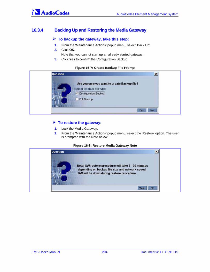
EMS User's Manual 204 Document #: LTRT-91015
AudioCodes Element Management System
16.3.4 Backing Up and Restoring the Media Gateway
To backup the gateway, take this step: 1. From the 'Maintenance Actions' popup menu, select 'Back Up'. 2. Click OK.
Note that you cannot start up an already started gateway. 3. Click Yes to confirm the Configuration Backup.
Figure 16-7: Create Backup File Prompt
To restore the gateway: 1. Lock the Media Gateway. 2. From the 'Maintenance Actions' popup menu, select the 'Restore' option. The user
is prompted with the Note below.
Figure 16-8: Restore Media Gateway Note

Version 5.8 205 June 2010
EMS User's Manual 16. Gateway Installation, Software Upgrade and Regional Files Distribution
3. Select the backup file you wish to restore: it can be either selected from the EMS server machine, or from any other location, which can be accessed via the network.
Figure 16-9: Select Backup File Prompt
Upon selecting the backup file, EMS will transfer it to both SCs and run the restore procedure.

EMS User's Manual 206 Document #: LTRT-91015
AudioCodes Element Management System
16.4 Mediant 5000, Mediant 8000 Startup and Shutdown This section refers to the Mediant 5000 Media Gateway and Mediant 8000 Media Gateway.
To reset the gateway software, take this step: From the 'Maintenance Actions' popup menu, select 'Start Up' (if you haven't
started up yet) or 'Shut Down' (if you previously started up but now want to shut down). Note that you cannot start up an already started gateway.
16.5 Collecting Log Files
To collect MG logs, take following steps: 1. From the 'Maintenance Actions' popup menu, select 'Collect Log Files' menu. 2. Select the SCs and Logs you wish to collect (see figure below), and click OK
button. The Log collection process is started, and the user is displayed with the waiting indicator. Upon log collection finish, the user is prompted with the file chooser to select a location for log file placement. The entire report is packaged as a TAR file, named according to following convention:
<GW_Name>_<GW_Global_IP>_report.tar
Figure 16-10: Collecting Log Files

Version 5.8 207 June 2010
EMS User's Manual 16. Gateway Installation, Software Upgrade and Regional Files Distribution
16.6 Mediant 5000, Mediant 8000 Configuration Backup Files Collection EMS can collect backup files (.bk files) that were created and locally stored on the Media Gateway and store them on the EMS server machine, thereby enabling a centralized backup files location for all managed Gateways. Upon file collection from the Media Gateway, an acEMSMGBackupEvent is generated and can be displayed in the Alarm Browser with file details. File name convention – <MG_Name>_<MG_OAM_IP_Address>_<m/p>_<backup_file_number>_<backup_date>. bk. Where <m/p> is a manual or periodic backup. For example: GW13_10.7.19.100_m_Backup0244-Oct-29-2007.bk Media Gateway backup files are located in the EMS Server machine under ACEMS/NBIF/mgBackup folder. File can be accessed and transferred using SSH, and SFTP.
To provision EMS to collect the Mediant 5000 / 8000 backup files, take following steps:
1. Open Tools -> MG Backup Policy Dialog 2. Set the Backup History Size. This parameter determines the number of latest
backup files that will be stored for each one of the managed GWs. Default value 30.
3. Select Yes to Enable Periodic Backup collection. 4. Define the number of retries that must be made on each connection to the Media
Gateway. Default-2.
Note: EMS periodically checks each of the Media Gateways and when a new backup file is created on the gateway, transfers it to the EMS server machine. You can define different backup file creation rules for each of the Gateways.

EMS User's Manual 208 Document #: LTRT-91015
AudioCodes Element Management System
Figure 16-11: Backup Settings
To provision backup creation policy for each individual Media Gateways, open the Media Gateway Provisioning Frame, Automatic Backup Tab. For more information, refer to the Mediant 5000 / 8000 IOM Guide.
Figure 16-12: Automatic Backup Setup

Version 5.8 209 June 2010
EMS User's Manual 16. Gateway Installation, Software Upgrade and Regional Files Distribution
To view currently stored backup files, do the following: 1. In the Tools menu, choose MG Backup Policy. 2. Select the Backup File Specification tab. 3. Right-click on an entry to save the backup file or remove it from the EMS server
storage.
Figure 16-13: Backup File Specifications

EMS User's Manual 210 Document #: LTRT-91015
AudioCodes Element Management System
Reader’s Notes

Version 5.8 211 June 2010
EMS User's Manual 17. Fault Management
17 Fault Management After service is provisioned for a subscriber under a given QoS level, the service provider must ensure that the purchased level of service is delivered. In the domain of EMSs, this process involves high-level fault and performance management of the managed entities. This section describes the fault management functionality of the EMS. High-level fault management involves monitoring managed entities to detect malfunction, preempt failures, and detect faults. After faults are discovered, the operator must troubleshoot, repair, and restore the entity as quickly as possible. Fault management ensures that service remains available. Technicians can use various EMS tools to perform a pinpoint diagnosis. EMSs provide one or more fault screens that contain detailed information on each alarm or event generated by the entities in its domain. An alarm is a specific problem indicator with predefined actions that trigger the alarm. Events are typically service provider-set thresholds that, if exceeded, send a message that appears in the alarm screen along with faults. A common use of the event mechanism is to detect degrading transmission facilities in order to alert operations personnel to a problem before it affects customers. You can view a combined table with all the alarms, events and journal records in order to correlate user activities with system behavior and responses. The combined view is opened from the Alarms Browser, Alarm History and Journal Frames. A unified Advanced Filter allows you to view the filter according to Time interval, GW Gateway IP address, User name or Action Type, Alarm Name, Source or Free text in Description Fields.
17.1 Alarm Browser The EMS's fault management functionality manages and presents all alarms and events from managed elements (received via SNMP traps) and displays them in an Alarm Browser, thereby notifying operators of problems in the system. The EMS can typically process 30 alarms/events per second continuously. When an alarm is received, it is parsed, stored in the database and immediately displayed in the GUI's Alarm Browser. The Alarm Browser displays current system faults at the top of the alarms list, allowing Operators to identify equipment and facilities most recently affected. The EMS utilizes the ability to synchronize with Media Gateways on missed alarms which could occur due to Network Connectivity or other problems. EMS will retrieve these missed alarms and add them to the Alarm Browser / History windows. Upon alarms retrieval, depending on the trap forwarding rules, alarms will also be forwarded.

EMS User's Manual 212 Document #: LTRT-91015
AudioCodes Element Management System
The Alarm Browser is context-based so that (for example) only alarms of the media gateway selected in the MGs List will be displayed in the Alarm Browser or (as another example) only alarms of the TP board selected in the graphic representation of the media gateway will be displayed in the Alarm Browser. The figure below shows the Alarm Browser, the Globe-context alarms displayed in the Alarm Browser.
Figure 17-1: Alarm Browser in Main Screen
The number of alarms currently displayed in the Alarms Browser is indicated adjacent to the pane title bar. For each alarm, the following alarm details are displayed in the Alarm Browser pane:
Ack - a check box in the left column of the Alarm Browser indicates if an alarm has been Acknowledged (checked) or Unacknowledged (unchecked). After an alarm is acknowledged, the entire row displaying the alarm and its details becomes gray (disabled).
Severity - indicates the alarm's severity level. green=Clear; white=Indeterminate; blue=Warning; yellow=Minor; orange=Major; red=Critical.
Time (Day of the Week, Month, Date in the Month, Hours:Minutes:Seconds, Time Zone, Year). Note that the Time value presented in the Alarm Browser is based on the time in EMS Server Time Zone, adjusted to the local time of the EMS client (according to the workstation machine’s clock definition). To update the Time Zone, refer to the EMS Server IOandM Manual.
MG Name Source - the source of the alarm; the failed entity that generated the alarm (in
format Board#1/Trunk#2, etc.) Alarm/Event Name (short description of the alarm) Events are indicated by the label [Event] which makes it easy for the user to sort
between alarms and events. Description (elaborated alarm details)
Note: By default, alarms are listed in the Alarm Browser in chronological order. The most recently received alarms appear at the top of the list, with the oldest alarms at the bottom.

Version 5.8 213 June 2010
EMS User's Manual 17. Fault Management
17.1.1 Filtering Alarms The Alarm Browser lists all currently active alarms in the EMS for a context selected in the Main Screen. When selecting the root (Globe) of the managed media gateways in the MG Tree, the Alarm Browser displays all alarms for all EMS -managed elements (as shown in the figure below). When selecting a region in the MG Tree, for example, the Alarm Browser displays all alarms for all media gateways under that region. Available contexts are:
Globe - all alarms in the entire system. Region - alarms of all nodes located under the region. Media Gateway - all the alarms of the media gateway TP Board and its subcomponents (Trunk, SS7, MTP2), SAT, Ethernet Switch and
System Controller boards - all the alarms of the selected entity. Additionally, operators can filter alarms according to Ack status and/or severity (using the Alarm Browser's toolbar buttons).
Figure 17-2: Alarm Browser - Alarm Severity Filtration Buttons
Table 17-1: Alarm Browser Buttons
Alarm Severity Filtration Toolbar Purpose (When Clicking on a Button on the Toolbar)
Opens the Actions Journal. For more information, refer to Viewing Operator Actions in the Actions Journal on page 266.
Opens the Alarm History. For more information, refer to Alarms History on page 220.
Enables Audio Indication on receipt of alarm. For more information, see Audio Indication on Receipt of Alarms.
Pauses Alarms / Events auto refresh.
Filters the active Alarm Browser window by only displaying alarms (events are not displayed)
Filters the active Alarm Browser window by displaying only Unacknowledged Alarms (acknowledged alarms are not displayed)
Filters the active Alarm Browser window by displaying Critical Alarms.

EMS User's Manual 214 Document #: LTRT-91015
AudioCodes Element Management System
Table 17-1: Alarm Browser Buttons
Alarm Severity Filtration Toolbar Purpose (When Clicking on a Button on the Toolbar)
Filters the active Alarm Browser window by displaying Major Alarms.
Filters the active Alarm Browser window by displaying Minor Alarms.
Filters the active Alarm Browser window by displaying Warning Alarms
Filters the active Alarm Browser window by displaying Info Alarms.
Filters the active Alarm Browser window by displaying Clear Alarms.
Close Alarm Browser
Note: By default, all Alarm Severity Filtration buttons are selected, meaning that both acknowledged and unacknowledged alarms of all severities are displayed by default. After clicking a button, the arrow (↓) ceases to be displayed on that button, meaning that alarms have been filtered for that severity level.
17.1.2 Acknowledging an Alarm Operators should acknowledge an alarm in order to inform other operators that the acknowledged alarm has been handled and troubleshooted by someone, and to communicate to other operators that it is no longer an active system alarm.
To acknowledge an alarm: Either:
Right-click on the alarm row in the Alarm Browser and select the option “Acknowledge” in the pop-up (multiple rows can be selected to be acknowledged in this way). -OR-
Check the check box under the column Ack adjacent to the alarm you need to acknowledge.
17.1.3 Alarms Clearing The Alarm Browser for each Media Gateway is cleared from all the current alarms and events upon system GW startup (cold start event). Critical, Major, Minor, Warning or Info alarms are automatically cleared from the Alarms Browser (and transferred to Alarms History) when a Clear alarm is generated by the same entity (source) and same media gateway that originally generated the Critical, Major, Minor, Warning or Info alarms. This feature prevents irrelevant alarms from congesting the Alarms Browser. Operators view the list of only the currently active alarms. Events are not automatically cleared from the Alarm Browser. When an event becomes redundant, the operator should manually delete it. All the events are marked with [Event] prefix in the ‘Alarm / Event Name’ field.

Version 5.8 215 June 2010
EMS User's Manual 17. Fault Management
After an alarm is cleared, the cleared alarm is saved in the Alarms History where its status is indicated as Automatically Cleared and notification of the time when the clearing was performed is displayed.
17.1.4 Changing the Alarms Browser Views
17.1.4.1 Alarms View Level Each user can select what alarms filtering level s/he wishes to apply in his/her Alarm Browser. The following options are supported:
Current Level Alarms (default) - users view alarms filtered according to the context they're viewing in the status pane
Node Level Alarms – users always view all alarms received from the node they're viewing, regardless of the lower level context (board, trunk) they've accessed.
Region Level Alarms – users will view all alarms at region level, regardless of the node or lower level context they've accessed.
All Alarms - users view all alarms at the globe level, regardless of the context.
17.1.4.2 Alarm Browser Columns View You can select viewed columns in the Alarm Browser and Alarms History window. You can add a new column to view the Source Description field (implemented for Mediant 5000 / 8000 and for IPmedia 5000 / 8000 GWs). The Source description field includes the object name as it defined by the user in the Name field in each one of the Provisioning Screens. Users can also decide to reduce the number of viewed columns. You can view all the available and currently viewed columns by right-clicking on the Alarms Browser and Alarms History table’s title bars.
Figure 17-3: Alarm Browser

EMS User's Manual 216 Document #: LTRT-91015
AudioCodes Element Management System
Figure 17-4: Alarm History
17.1.5 Open Alarms History To review the Alarm History records for the selected context, click the button 'Alarm History' on the Alarm Browser tool bar. For the specifications and features pertaining to the Alarm History, refer to 'Alarms History' on page 217.
17.1.6 Open Journal To review Journal records for the selected context, click button 'View Journal Actions' on the Alarm Browser tool bar. For the specifications and features pertaining to the Journal, refer to 'Viewing Operator Actions in the Actions Journal' on page 278.
17.1.7 Audio Indication on Receipt of Alarms Each time a new alarm answering context selection criteria is received and displayed in the Alarm Browser, a bell sound is played by EMS application.
To enable the bell sound: Click the button 'Alarm Sound Disabled' on the Alarm Browser toolbar.

Version 5.8 217 June 2010
EMS User's Manual 17. Fault Management
17.1.8 Pause Alarms Auto Refreshing
To stop alarms auto refreshing: Click the 'Pause' button on the Alarm Browser toolbar; Alarms received by the
EMS while Alarm Browser refreshing is paused are saved in the database and displayed to operators after re-clicking (de-selecting) the 'Pause' button.
While the pause button is selected, the alarm browser presentation is paused as well.
17.1.9 Alarms and Events Filtering and Sorting Alarms and Events can be displayed as separate graphic entities in the Alarm Browser and History screens. You can easily sort between alarms and events or filter events from the Alarm Browser and Alarm History windows.
To filter events in the Alarm and Alarm History Browser windows: In the Alarms Browser toolbar, click on the Filter Events icon. All events are
removed from the Alarm Browser display.
To sort between Alarms and Events in the Alarm and Alarm History Browser windows: In the Alarms Browser toolbar, click on the Alarm Name field. All events are
sorted to the top of the Alarm Browser view. Each event is displayed in the following format: [Event]
17.1.10 Closing the Alarm Browser Pane
To close the Alarm Browser pane: Click the 'x' button.
To reopen the Alarm Browser pane Open the View menu in the menu bar of the main screen, and choose option
'View Alarm Browser'.

EMS User's Manual 218 Document #: LTRT-91015
AudioCodes Element Management System
17.2 Alarms History All alarms received by the EMS are archived in a database. Extensive information related to the alarm is saved, together with the alarm itself: Region and media gateway location, physical attributes of failed entity. Open the Alarms History screen from Faults > Alarms History, or click the 'View Alarms History' icon (graphically representing a clock) located with the Alarm Browser's filter icons. The Alarms History screen is context-sensitive like the Alarm Browser; the context is displayed in the title of the screen. The EMS's Alarms History screen (refer to the figure below) provides operators with a view of the alarms' history over an extended period of time (a history of at least one month, depending on disk space available - 1000 alarms per day for digital media gateways, and 100 alarms per day for analog media gateways. EMS operators can time-filter alarms according to a time definition so that they are operator-organized and viewed according to operator requirements. The Alarms History screen informs operators of the actions performed on each alarm, including the alarm's current state, the last action performed on the alarm and the name of the operator who performed the last action for the alarm.
Figure 17-5: Alarms History
The Time Filtering fields enable filtering alarms along the parameters of date and time. They're located adjacent to the filter buttons on the Alarms History screen's top bar, to their left. The date and time parameters both have a 'From' and 'To' (). This filter feature functions similarly to the other Alarms Browser filters. Refer to the two figures below. The screen is a read-only screen. To refresh, choose the View menu's Refresh option, as the screen is not refreshed automatically.

Version 5.8 219 June 2010
EMS User's Manual 17. Fault Management

EMS User's Manual 220 Document #: LTRT-91015
AudioCodes Element Management System
17.3 Using Time Filters The Time Filtering fields enable filtering alarms along the parameters of date and time. They're located adjacent to the severity filter buttons on the Alarms History screen's upper bar, to their left. The date and time parameters both have a 'From' and 'To'. This filter feature functions similarly to the other Alarms Browser filters. Refer to the two figures below. To refresh (after defining a time filter), choose the View menu's Refresh option, as the screen is not refreshed automatically.
Figure 17-6: Alarms History Screen: Defining Time Filtration using Calendar
Figure 17-7: Alarms History Screen: Defining Time Filtration using Hour and Minutes
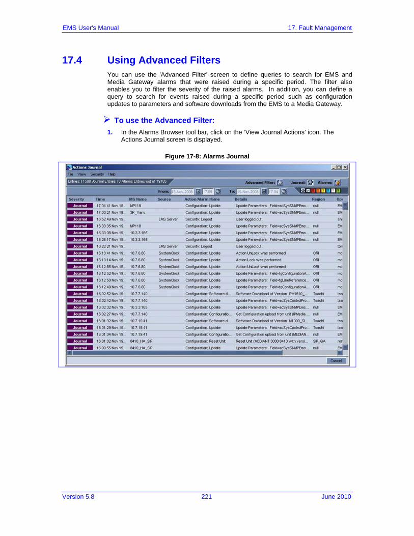
Version 5.8 221 June 2010
EMS User's Manual 17. Fault Management
17.4 Using Advanced Filters You can use the 'Advanced Filter' screen to define queries to search for EMS and Media Gateway alarms that were raised during a specific period. The filter also enables you to filter the severity of the raised alarms. In addition, you can define a query to search for events raised during a specific period such as configuration updates to parameters and software downloads from the EMS to a Media Gateway.
To use the Advanced Filter: 1. In the Alarms Browser tool bar, click on the ‘View Journal Actions’ icon. The
Actions Journal screen is displayed.
Figure 17-8: Alarms Journal

EMS User's Manual 222 Document #: LTRT-91015
AudioCodes Element Management System
2. In the Actions Journal tool bar, click on the ‘Advanced Filter’ icon. The Advanced Filter screen is displayed.
Figure 17-9: Advanced Filter

Version 5.8 223 June 2010
EMS User's Manual 17. Fault Management
General Filters
To configure general filters, click on the General Filters icon in the the General Filters pane. You can configure the following filters: • Date and Time Filter • Users Filter. An operator can select a user or a set of users whose actions
the operator needs to view. • Unit IP • Unit Source • Free Text 1 (searched in the Details filed)
Alarms Filters
To configure alarm filters, click on the Alarms Filters icon in the Alarms Filters pane. You can configure the following filters: • Includes the lists of Alarms / Events per MG type. • Alarm Severity • Alarm Ack Status • Events
Journal Filters
To configure journal filters, click on the Journal Filters icon in the Journal Filters pane. You can configure the following filters: • Actions Filter (all user actions are classified according to EMS functionality):
♦ Fault Management Actions (acknowledge, delete, prioritize alarms, change trap configuration)
♦ Configuration Management Actions (add, remove, update managed object, software upgrade, etc.)
♦ Performance Management (start, stop polling, create, attach, detach PM profile)
♦ Security Management Actions (add, remove, update operator info, login, logout)

EMS User's Manual 224 Document #: LTRT-91015
AudioCodes Element Management System
The following screen displays an example of the Alarms Filter screen:

Version 5.8 225 June 2010
EMS User's Manual 17. Fault Management
17.5 Defining Complex Queries using a Combination of Filters Using a combination of filtering options, users can easily create complex queries.
Example of Filter Use
To find all the critical and major alarms and parameters that were modified in October 2008 in Board#8 of a specific gateway, apply the following filters in the 'Advanced Alarm Filter' screen: 1. Date and Time: Define 'From date' as 'October 1, 2008' and 'To date' as
'November 1, 2008'. 2. Unit IP - Define the gateway IP address or open the Journal in the appropriate
context from the Alarm Browser for the parameter to automatically be defined. 3. Unit Source - Define 'Board#8' in the field 'Unit Source' or open the Journal in the
appropriate context from the Alarm Browser for the parameter to automatically be defined.
4. Alarm Filters: leave Critical and Major severities selected and remove Events selection.
In the 'Journal Actions' screen, select the checkbox 'Configuration: Update'.
Figure 17-10: Advanced Filter

EMS User's Manual 226 Document #: LTRT-91015
AudioCodes Element Management System
17.6 Viewing, Interpreting an Alarm's Details
To view/interpret an alarm's details: Either:
Double-click the row of the alarm listed in the Alarm Browser or in the Alarms History, whose details you need to view/interpret.
-OR- Right-click the row of the alarm listed in the Alarm Browser and select the option
“Alarm Details” from the pop-up menu. The Alarm Details screen opens.
Figure 17-11: Alarm Details

Version 5.8 227 June 2010
EMS User's Manual 17. Fault Management
The Alarm Details screen features four tabs: 1. Alarm Info (includes all the information provided by the alarm; refer to its details
below) 2. MG Info (includes details regarding the location - region - of the media gateway,
and the precise source of the alarm; refer to its details below) 3. SNMP Info (includes SNMP-related information such as Trap OID, etc.; refer to its
details below) 4. User Info (includes user-specific information such as alarm status and identifying
data fields that users can define in order to use as future reference when searching; refer to its details below).
Alarm Info Tab
Title The name of the alarm, provided in the Alarm Browser.
Date and Time Date and Time when the alarm was received by the EMS.
Source The exact alarm source, in format: “board#3/trunk#7”.
Severity Alarm Severity as displayed in Alarm Browser pane, according to- ITU X.733 standard
Unique ID Alarm Unique ID provided by the media gateway for alarm clearing and correlation purposes.
Alarm Type The alarm type can be one of the following: 1. Communication (inter-process communication alarm) 2. Quality of Service (indicates degradation in service performance) 3. Processing Error (used for internal software errors) 4. Equipment Alarm (indicates a hardware failure) 5. Environmental alarm (used to indicate environmental errors such as
temperature, power, etc.)
Note: The parameter 'Alarm Type' is based on ITU X.733, X736 standards.
Probable Cause
The probable cause of the alarm. The probable cause can be one of the following: 1. Degraded Signal for Trunk Alarm 2. Communications Protocol Error for a V5.2 Alarm 3. Underlying Resource Unavailable for a Change in a Managed Entity's
Administrative State or Operational State 4. Configuration Or Customization Error for Configuration Error Alarm 5. Heating Vent Cooling System Problem for Fan or Temperature Alarm

EMS User's Manual 228 Document #: LTRT-91015
AudioCodes Element Management System
6. Temperature Unacceptable for Temperature Alarm 7. Power Problem for Voltage Alarm
Note: The parameter 'Probable Cause' is based on ITU X.733, X736 standards.
Description
Textual description of the alarm, received as part of the alarm information Additional Info 1-3
These three fields are provided as part of the alarm information, supplying additional information on the alarm.
Alarm Details - tab MG Info
Figure 17-12: Alarm Details-MG Info
MG Region The name of the region in which the media gateway is located.
MG IP Address The IP address of the media gateway that originated the alarm.
MG Name Name of the media gateway that originated the alarm.
Source The exact alarm source, in format 'board#3/trunk#7'

Version 5.8 229 June 2010
EMS User's Manual 17. Fault Management
Alarm Details > tab SNMP Info
Figure 17-13: Alarm Details-SNMP Info
Trap OID Trap Object Identifier, as defined in the MIB.
System Up Time The time elapsed since the last system reset.
Trap Remote Port The EMS UDP remote port at which the trap was received.
Trap Community Trap Community String received as part of the Notification message.
Trap SNMP Version The SNMP version of the Call Agent that sent the trap. The SNMP version can be one of the following: • v1 for SNMPv1 • v2c for SNMPv2 • v3 for SNMPv3

EMS User's Manual 230 Document #: LTRT-91015
AudioCodes Element Management System
Alarm Details > tab User Info
Figure 17-14: Alarm Details-User Info
Status Either: • New (the alarm has recently been received by the EMS). • Ack (the alarm was manually acknowledged by a user. Refer to the other
User Info fields.) • Manually Cleared (the alarm was manually cleared (deleted) by a user. Refer
to the other User Info fields.) • Automatically Cleared (a clear alarm was received by the EMS from the
media gateway; the alarm condition no longer exists.) Last Action
The time an action was performed on the alarm. By User
The name of the user who performed the last action on the alarm. Notes
Define this field for you to use as future reference when searching.

Version 5.8 231 June 2010
EMS User's Manual 17. Fault Management
17.7 Trap Forwarding All the alarms and events issues by Media Gateways are send as SNMP Notifications. EMS can forward alarms and events in the following formats: SNMP Notifications, SMS, Mail or Syslog. Multiple Trap forwarding destinations are supported. Each line in the Trap Forwarding Table defines a specific destination. The SNMP forwarding option is usually used for EMS – NMS integration. For more information regarding SNMP Notifications forwarding, refer to the OAM Integration Guide. The section below describes how to configure Mail, SMS and Syslog trap forwarding options.
Figure 17-15: Trap Forwarding Summary
17.7.1 Trap Forwarding in Mail Format This option describes how to forward traps from EMS to a mail server host in e-mail format.
To forward traps in mail format: 1. Open the Faults->Trap configuration menu. The Destination Rule Configuration
dialog is displayed. 2. In the Actions menu, select Add Destination or click “+” in the menu bar. 3. Set the Destination Type to Email. 4. In the left-hand pane, provision the following parameters:
• 'Destination Rule Name' as you wish it to appear in the summary screen. • Select the subset of alarms and events that must be forwarded to the NMS
from the following subset (by default, all the alarms and events are selected): • EMS Alarms Forwarding

EMS User's Manual 232 Document #: LTRT-91015
AudioCodes Element Management System
• EMS Events Forwarding • MGW Alarms Forwarding • MGW Events Forwarding • Select the subset of 'Severities To Forward': severities that you wish to
receive in the NMS application (by default, all the severities are selected). Note: CLEAR alarms for selected subset of the alarms are always forwarded.
• Select the Media Gateways from which you wish to forward alarms and events.
5. In the right-hand pane, provision the following parameters: • In the 'Mail Host IP Address' field, enter the Mail Host IP address. • In the 'Mail Host Username' field, enter the mail host username. • In the 'Mail Host Password' field, enter the mail host password. • In the 'From' field, enter the the e-mail address the recipient will see when
the mail arrives. • In the 'To' field, enter the list of email addresses (coma separated) to which
you wish to send mail.
Figure 17-16: Trap Forwarding-Email
6. Click OK.

Version 5.8 233 June 2010
EMS User's Manual 17. Fault Management
Your new rule is displayed in the Trap Forwarding Configuration summary screen.
Figure 17-17: Trap Forwarding Summary
EMAIL traps are forwarded to specified destinations in the following format: EMAIL format Title: New <Alarm/Event> <Alarm Name>, received from <Node Name> with Severity <Severity> Message body: will include all the fields we have today in Alarm Item
17.7.2 Trap Forwarding in Mail2SMS format This option describes how to forward traps from EMS to a mail server host in mail2SMS format.
To forward traps in mail2SMS format: 1. Open the Faults->Trap configuration menu. The Destination Rule Configuration
dialog is displayed. 2. In the Actions menu, select Add Destination or click “+” in the menu bar. 3. Set the Destination Type to Mail2SMS. 4. In the left-hand pane, provision the following parameters:
• 'Destination Rule Name' as you wish it to appear in the summary screen. • Select the subset of alarms and events that must be forwarded to the NMS
from the following subset (by default, all the alarms and events are selected): ♦ EMS Alarms Forwarding ♦ EMS Events Forwarding ♦ MGW Alarms Forwarding ♦ MGW Events Forwarding

EMS User's Manual 234 Document #: LTRT-91015
AudioCodes Element Management System
• Select the subset of 'Severities To Forward'; severities that you wish to receive in the NMS application (by default, all the severities are selected). Note: CLEAR alarms for selected subset of the alarms are always forwarded.
• Select the Media Gateways from which you wish to forward alarms and events.
5. In the right-hand pane, provision the following parameters: • In the 'Mail Host IP Address' field, enter the Mail Host IP address. • In the 'Mail Host Username' field, enter the mail host username. • In the 'Mail Host Password' field, enter the mail host password. • In the 'From' field, enter the e-mail address the recipient will see when the
mail arrives. • In the 'To Mobile Numbers' field, enter the list of Email addresses (comma
separated) to whose corresponding mobile numbers you wish to send mail.
Figure 17-18: Trap Forwarding-SMS
6. Click OK.
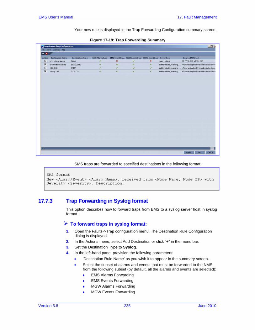
Version 5.8 235 June 2010
EMS User's Manual 17. Fault Management
Your new rule is displayed in the Trap Forwarding Configuration summary screen.
Figure 17-19: Trap Forwarding Summary
SMS traps are forwarded to specified destinations in the following format: SMS format New <Alarm/Event> <Alarm Name>, received from <Node Name, Node IP> with Severity <Severity>. Description:
17.7.3 Trap Forwarding in Syslog format This option describes how to forward traps from EMS to a syslog server host in syslog format.
To forward traps in syslog format: 1. Open the Faults->Trap configuration menu. The Destination Rule Configuration
dialog is displayed. 2. In the Actions menu, select Add Destination or click “+” in the menu bar. 3. Set the Destination Type to Syslog. 4. In the left-hand pane, provision the following parameters:
• 'Destination Rule Name' as you wish it to appear in the summary screen. • Select the subset of alarms and events that must be forwarded to the NMS
from the following subset (by default, all the alarms and events are selected): ♦ EMS Alarms Forwarding ♦ EMS Events Forwarding ♦ MGW Alarms Forwarding ♦ MGW Events Forwarding

EMS User's Manual 236 Document #: LTRT-91015
AudioCodes Element Management System
• Select the subset of 'Severities To Forward'; severities that you wish to receive in the NMS application (by default, all the severities are selected). Note: CLEAR alarms for selected subset of the alarms are always forwarded.
• Select the Media Gateways from which you wish to forward alarms and events.
5. In the right-hand pane, provision the following parameters: • Enter the Syslog Server IP Address. • Enter the Syslog Server Port.
Figure 17-20: Trap Forwarding-Syslog
6. Click OK.

Version 5.8 237 June 2010
EMS User's Manual 17. Fault Management
Your new rule is displayed in the Trap Forwarding Configuration summary screen.
Figure 17-21: Trap Forwarding Summary
Since syslog has a well defined message format structure (defined by RFC 3164), the severity levels in EMS are adjusted to the severity levels of the syslog protocol. The following table describes the severity levels mapping:
Table 17-2: EMS and Syslog Severity Mapping
EMS Severity Syslog Severity
Critical Alert
Major Critical
Minor Error
Warning Warning
Indeterminate Informational
Clear Notice
The message part of the syslog protocol will contain the following structure: Title: <Alarm/Event> <Alarm Name>, received from <Node Name, Node IP> with Severity <Severity>. Description: <Source>, <Description>
17.8 Saving Alarms in a .csv File Viewed alarms can be saved in a *.csv file (Comma Separated File) from the Alarm Browser and Alarms History screens. The alarms in a *.csv file include all alarm fields

EMS User's Manual 238 Document #: LTRT-91015
AudioCodes Element Management System
viewed in the Alarm Details screen. The saved *.csv file can be viewed in Microsoft™ Excel™, enabling all Excel features (statistics, graphs) on it.
To save 'Alarm Browser' alarms in a *.csv file: Open the 'Faults' menu and choose option 'Save Alarms' in the EMS main screen;
Alarms viewed in the Alarm Browser screens are saved (apply appropriate filters before saving alarms).
To save 'Alarms History' alarms in a *.csv file: Open the 'Faults' menu and choose option 'Save Alarms' in the Alarms History
screen. Result: a. When the number of alarms is less than 1500, the alarms viewed in the
Alarms History screen are saved in the location chosen by the user (apply appropriate filters before saving alarms)
b. When the number of alarms is 1500 (the maximum that can be displayed in the Alarm History screen), the EMS assumes that the actual number of alarms answering the selecting criteria is greater than 1500. Users are prompted whether to save all available alarms or only those alarms that they're currently viewing. If the user chooses to save all alarms, the EMS creates a .csv file in the EMS server machine installation folder, under directory 'emsFiles/Logs'. The file name is alarm_result_<date_time>, where <date_time> is the query date and time. The maximum file size is 65000 lines (due to an Excel™ limitation). If the user chooses to save only the viewed alarms, the file chooser is opened and the file is saved in the location chosen by the user.

Version 5.8 239 June 2010
EMS User's Manual 17. Fault Management
Reader’s Notes


Version 5.8 241 June 2010
EMS User's Manual 18. Performance Management
18 Performance Management After service is provisioned for a subscriber under a given QoS level, the service provider must ensure that the purchased level of service is delivered. In the domain of EMSs, this process involves high-level fault and performance management of the managed entities. This section describes the performance management functionality of the EMS. The EMS's Performance Management is composed of real-time and historical data monitoring. Real-time data monitoring can be used to troubleshoot network or system problems and to isolate a problem after it is detected by the fault management system. Historical data can be used for long-term network analysis and planning. For the exact list of all the Performance Monitoring parameters supported for each one of the Gateways, see the relevant product OAM Guide.
Note: The performance monitoring icon in the Info pane (refer to the figure below) is only displayed for relevant media gateways / managed entities. The color of the globe icon (adjacent to 'History PM') indicates whether background monitoring is running for a certain device. Green indicates that it is running; gray indicates that it is not.
Figure 18-1: Performance Monitoring Icon in the Info Pane

EMS User's Manual 242 Document #: LTRT-91015
AudioCodes Element Management System
18.1 Real-Time Performance Monitoring Real-time performance monitoring provides EMS users with the ability to perform high-frequency polling of various system parameters.
To select an entity to poll: 1. Navigate to the entity according to regular EMS navigation concepts and from the
'History PM icon drop-down list in the Info pane, select the option 'Display Real Time PMs' (refer to the figure below).
Figure 18-2: Display Real Time PMs
2. Select the frame you prefer (a new frame or an already existing frame) to view the performance graph (refer to the figure below) and click OK. Note that when choosing to open real-time monitoring graphs in the new frame, you can enter your own frame title.
Figure 18-3: Selecting the Frame to Display the Graph of the Entity's Performance
Users can open up to five separate real-time graphs in the same client application. There are two graph types that operators can use: Line Graph and Table View. In most cases, Line Graph is recommended when only a few parameters are compared. Table View is recommended when extensive data is displayed and analyzed. In each Line Graph, you can simultaneously view up to 10 parameters of the same entity (media gateway, board, and trunk) or compare the same parameters

Version 5.8 243 June 2010
EMS User's Manual 18. Performance Management
over different entities (different boards / trunks of the same or different gateways). In each Table Graph, you can simultaneously view up to 50 parameters of up to 50 entities (Table 50X50). After opening the real-time frame, you can continue selecting entities to add to it. After all entities are selected, select the parameter to poll by clicking the button 'Parameters Filter' on the top left side of the real-time frame . Only parameters available for that entity type are displayed for selection. The performance-monitoring feature supports two parameter types: Gauges and Counters. Gauges are indicated by and Counters are indicated by .
Figure 18-4: Parameter Type - Gauges
In the screen 'Real-Time Performance Measurements Display' (refer to the figures below), choose the type of view (Graph or Table). Choose the Polling Interval you require from the drop-down under the title bar and click the Start button to start polling; a real-time graph or table is displayed. You can pause the polling by clicking the pause button and restart it again by clicking the Start button. To stop polling, click the Stop button . You can view a color legend (below the graph) for entities / parameters. You can choose to save the graph as an image by clicking the Save button in the left pane . Historical data of the selected components and parameters can be viewed by clicking the ‘History’ button and then defining the History View. To view the Online Help, click the Help button .

EMS User's Manual 244 Document #: LTRT-91015
AudioCodes Element Management System
In addition, you can apply Parameters or Components filters by clicking the filter button .
Figure 18-5: Graph Comparing CPU, Disk and Memory Utilization of SC Boards in Media Gateways
In the screen 'Real-Time Performance Measurements Display' (refer to the figures below), choose the 'Polling Interval you require from the drop-down under the title bar and click the Start button to start polling; a real-time graph is displayed. At the bottom of the graph you can view a color legend for entities / parameters.
To add / remove parameters / entities from the real-time graph or to change the polling interval, take this step: Stop the current graph, perform the required configuration changes and then
restart the polling. At each stage, you can position your cursor over the nodes in the graph and view - in the tool tip - the precise information you require (the exact value of the parameter at the monitored point in time). The figures below show graphs depicting the following examples:

Version 5.8 245 June 2010
EMS User's Manual 18. Performance Management
Compare CPU utilization of System Controller boards in the Mediant 5000 and Mediant 8000 (refer to the figure below): 1. Compare CPU utilization of System Controller boards in the gateways.
Figure 18-6: Graph Comparing CPU Utilization of SC Boards in Media Gateways
2. View CPU, Memory and Disk utilization of the System Controller board #1 in the Mediant 5000 Media Gateway.
Figure 18-7: View CPU, Memory and Disk Utilization of Mediant 5000 SC Board 1

EMS User's Manual 246 Document #: LTRT-91015
AudioCodes Element Management System
18.2 Background (History) Performance Monitoring There are two main functions of the history data monitoring: Configure the EMS to collect the data and to view the collected data. Both options are available by clicking PM icon below.
Figure 18-8: Display Real Time PMs

Version 5.8 247 June 2010
EMS User's Manual 18. Performance Management
18.3 Configuring Background Monitoring
To collect historical performance data: 1. Select the option 'Configure PM Profile' in the 'Performance Monitoring' menu; the
background configuration screen opens (refer to the figure below). Note that each gateway and control protocol features a different set of available parameters. The figure below shows the gateway background monitoring provisioning parameters.
Figure 18-9: Background Monitoring Provisioning Parameters
2. Select the parameters whose data you need to collect as part of background monitoring. Save these parameters as a PM profile or alternatively select a profile from the already available previously defined profiles.
3. Click the 'Attach' button. Note that the parameters of all media gateway entities are polled. For example, trunk performance parameters are polled for all trunks of the selected media gateway. Note too that the same background configuration screen opens from every media gateway entity.
4. Select the Time Interval according to which to perform the polling (the default interval is 15 minutes) and click the polling state menu item 'Start' option. Verify that the polling status has changed to 'Polled'.
5. To change the polling interval or the PM profile, or to stop polling, click the polling state button.

EMS User's Manual 248 Document #: LTRT-91015
AudioCodes Element Management System
18.4 Exporting Background Monitoring Data as a File In addition to storing PM background monitoring data in the EMS server database, an xml or csv file can be created per time interval (starting from the Mediant 5000 Media Gateway and Mediant 8000 Media Gateway, versions 3.2). The file is created at the end of the PM polling interval in accordance with a user-defined PM profile, and stored in the EMS server under directory 'Pmfiles'. Users can choose whether or not to receive a trap when each file is created. The trap name is acEMSPmFileGenerate. The trap contains information as to the file name and the time it was created. File name - the file name contains the gateway name in the EMS, the gateway’s IP address and the time stamp of the performance data collection. File location – performance monitoring files are located in the EMS Server machine at the following location:
ACEMS/NBIF/pmFiles
Users should forward the trap to the NMS (Network Management System) (refer to 'Trap Forwarding to NB IF' on page 230).
To enable a file to be created: 1. Select the option ‘Configure PM Profile’ in the ‘Performance Monitoring’ menu. 2. Click the button ‘Configure’. 3. Continue (if needs be) to select a profile. 4. Select the file type – csv or xml. 5. Check the checkbox ‘Send trap on file generation’ to receive a trap when each file
is created. 6. Check Poll this Media Gateway.
Figure 18-10: Background Monitoring - Generate File Options

Version 5.8 249 June 2010
EMS User's Manual 18. Performance Management
Note: A performance data file cannot be created unless the media gateway is polled (refer to section 'Configuring Background Monitoring' on page 247.
The PM file icon is displayed in the ‘Configure PM Profile’ frame tool bar
xml file
xml file with trap generation after creation
csv file
csv file with trap generation after creation Retrieve the PM file from the FTP server with the NMS / OSS system. In the event
of EMS server machine hardening, use a secure FTP. The EMS keeps PM files for 24 hours (up to 96 files per gateway).
An unknown value can be received from the gateway if the TP board is locked or for some other reason information is not received from the TP board. For exact CSV and XML files format, refer to the OAM Integration Guide.
18.5 Viewing Historical Data
To view collected (historical) data: 1. Select the option 'Display Historical PMs' in the 'Performance Monitoring' menu;
the 'History PM' screen opens. 2. Continue (if needs be) to select entities to be added to the same screen. All
entities must be of the same type (trunks, or System Controller boards, or gateways of the same control protocol type). After all entities are selected, select the parameter to view by clicking the 'Parameters Filter' button; only parameters available for that entity type are displayed for selection. Note that you can select up to 15 parameters. Note that the number of entities you can select is unlimited.
3. Select the Time Interval according to which you need to review data and click 'Refresh'; after data is displayed, you can save it as a csv file by clicking the 'Save' icon. Historical data comprises two tables: The uppermost table displaying detailed data (in user-defined intervals) and the table below it displaying summarized data. Each time a sample is taken from the gateway, it is stored in the detailed table, where the entity name and index, parameter name, start, stop polling time and parameter value are specified. After every 24 hours of sampled data, the detailed table is summarized. For each entity and parameter, the start and stop summary time is stored and the average, minimal and maximal value is displayed.
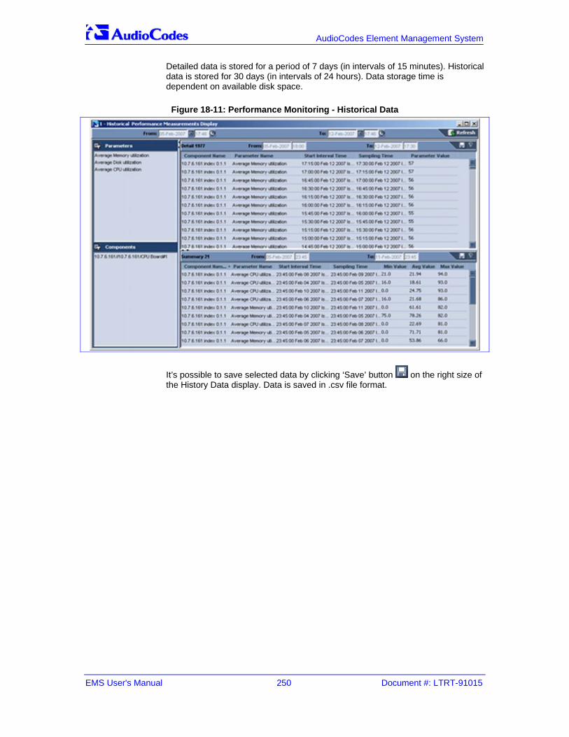
EMS User's Manual 250 Document #: LTRT-91015
AudioCodes Element Management System
Detailed data is stored for a period of 7 days (in intervals of 15 minutes). Historical data is stored for 30 days (in intervals of 24 hours). Data storage time is dependent on available disk space.
Figure 18-11: Performance Monitoring - Historical Data
It’s possible to save selected data by clicking ‘Save’ button on the right size of the History Data display. Data is saved in .csv file format.

Version 5.8 251 June 2010
EMS User's Manual 18. Performance Management
18.6 Configuring PM Threshold Values Performance Threshold definition is supported for Mediant 600 / 1000 / 2000 /3000 and MP GWs. When predefined thresholds are exceeded, an appropriate Alarm is issued by the Gateway and displayed in the EMS. For example: once ‘Lifetime in Seconds (Max)’ has exceeded the user defined ‘Lifetime High Threshold’, a Threshold exceed alarm is generated.
To provision the gateway to issue a Threshold Crossing Alarm: 1. Choose ‘Configure PM Thresholds’ menu from the Performance Monitoring drop-
down menus.
Figure 18-12: Configure PM Thresholds
The Gateway Performance Thresholds provisioning screen opens. The provisioning screen differs between gateway types and control protocols. The following screen displays an example of the Mediant 2000 Performance Monitoring screen.
Figure 18-13: Mediant/IPmedia 2000 Performance Thresholds

EMS User's Manual 252 Document #: LTRT-91015
AudioCodes Element Management System
2. To provision the required threshold parameters, click ‘Apply’. If the ‘Threshold Alarms State’ parameter is Disabled, select the ‘Enable’ option from the drop-down menu adjacent to the Maintenance icon. The gateway sends a Threshold Cross Alarm when a pre-defined threshold is crossed and a corresponding clear alarm when the measured value returns to normal.
18.7 Performance Monitoring Actions on Multiple Media Gateways
Figure 18-14: Performance Monitoring Actions on Multiple Media Gateways
Users can perform following actions on multiple gateways: a. Display Real Time / Historical PMs (refer to 'Real-Time Performance Monitoring'
on page 246) b. Attach / Detach Profile c. Start / Stop Polling
Note: For 'Display Real-Time and Historical PMs' and for 'Attach / Detach Profile', all the gateways you select must be of the same type, for example, either MediaPacks, or Mediant 2000 Media Gateways, or Mediant 5000 Media Gateways.

Version 5.8 253 June 2010
EMS User's Manual 19. Security Management
19 Security Management EMS Security Management features:
Network Communication Security (refer to 'Network Communication Security' on page 253).
EMS Application Security Local EMS Users Authentication and Authorization Centralized EMS Users Authentication and Authorization via Radius Server EMS User Activities Journal EMS Server Machine (including UNIX and Oracle related items) (refer to the
EMS Server IOandM Manual): Solaris and Oracle Database Hardening and recent security patch installation. File Integrity Checking - The File Integrity checker tool periodically verifies
whether file attributes were changed (permissions/mode, inode #, number of links, user id, group id, size, access time, modification time, creation/inode modification time). File Integrity violation problems are reported via EMS Security Events.
Intrusion Detection System - The Intrusion Detection tool scans predefined Solaris system files for specific danger patterns which might indicate whether the EMS server machine was accessed and / or modified by an external intruder. Intrusion Detection problems are reported via EMS Security Events.
19.1 Network Communication Security When installing the EMS server, you need to configure its network and open the ports required for the EMS client-server and the EMS server-media gateway communication. For more information, refer to the EMS Server Installation and Maintenance Manual. The EMS interoperates with firewalls, protecting against unauthorized access by crackers and hackers, thereby securing regular communications. Define rules in your firewall to enable communications between the EMS client, server and managed media gateways (refer to the figure below).

EMS User's Manual 254 Document #: LTRT-91015
AudioCodes Element Management System
Figure 19-1: EMS Firewall Configuration Schema
The EMS comprises EMS client and server machines, intercommunicating via RMI protocol over TCP. To secure EMS client-server communications, RMI protocol runs over Secure Socket Layer (RMI over SSL). EMS server communications with the Media Gateways is performed over the protocols described in the subsections below.

Version 5.8 255 June 2010
EMS User's Manual 19. Security Management
19.1.1 SNMP Management The SNMP protocol is used for provisioning, maintenance actions, fault and performance management between the EMS Manager and its agents (AudioCodes Media Gateways). The SNMPv3 protocol provides more sophisticated security mechanisms than SNMPv2c. It implements a user-based security model (USM), allowing both authentication and encryption of the requests sent between the EMS Manager and their agents, as well as user-based access control.
19.1.2 Mediant 5000 and Mediant 8000 Media Gateway Security Management EMS <-> Media Gateway communication is performed using SNMP, Telnet and FTP protocols which can be secured in the following way:
SNMP: use SNMPv3 instead of SNMPv2c. Telnet and FTP: use SSH and SCP. Telnet and FTP are used for installation and
upgrading software. By default EMS runs this connectivity in the secure mode using SSH and SCP. In addition, SSH and SCP communications can be secured by running them over IPSec protocol.
Overall communication: SNMPv2c, Telnet and FTP over IPSec.
To configure EMS-gateway secure communication: 1. Right-click on the Media Gateway you wish to provision in the MG Tree and
choose ‘Details’; the MG Information screen opens (refer to the figure below). 2. Choose to work with either SNMPv2c or SNMPv3:
For SNMPv2c, do the following: • It is recommended to check the Secure Connection Enabled checkbox and
enter the 'Pre-shared Key' string. This configuration can be performed either during the gateway definition stage or later. The Pre-shared Key string defined in the EMS and in the Media Gateway must be identical.
For SNMPv3, do the following: • It is recommended to check the Secure Connection Enabled checkbox and
enter the 'Pre-shared Key' string. This configuration can be performed either during the gateway definition stage or later. The Pre-shared Key string defined in the EMS and in the Media Gateway must be identical.
• In the Security Name field, enter the Security name of the SNMPv3 user • In the Authentication Protocol field, select an authentication protocol from
the drop-down list box. The corresponding security level is displayed in the Security Level field;

EMS User's Manual 256 Document #: LTRT-91015
AudioCodes Element Management System
• In the New Authentication Password field, enter a new Authentication Password; In the Privacy Protocol field, select a Privacy Protocol from the drop-down list box;
• In the New Privacy Password field, enter a new Privacy Password.
Figure 19-2: MG Information - Secured Connection Enabled
19.1.3 CPE Security Management EMS <-> MG communication is performed using SNMP and HTTP protocols
which can be secured in the following way: • SNMP: use SNMPv3 instead of SNMPv2c. SNMP is used for provisioning,
maintenance actions and fault and performance management. • HTTP: use HTTPS instead of HTTP. HTTP is used for installation and
upgrading software, and for downloading auxiliary files. • Overall communication: SNMP and HTTP over IPSec.
19.1.3.1 Configuring SNMP This section describes the SNMP Security Management features for CPE Gateways.
To configure MG and EMS to work over SNMPv3: 1. Right-click on the Media Gateway you wish to provision in the MG Tree and
choose ‘Details’; the MG Information screen opens (refer to the figure below). 2. In the Security Name field, enter the Security name of the SNMPv3 user 3. In the Authentication Protocol field, select an authentication protocol from the
drop-down list box. The corresponding security level is displayed in the Security Level field.

Version 5.8 257 June 2010
EMS User's Manual 19. Security Management
4. In the New Authentication Password field, enter a new Authentication Password; In the Privacy Protocol field, select a Privacy Protocol from the drop-down list box;
5. In the New Privacy Password field, enter a new Privacy Password.
To switch MG and EMS communication from one SNMP version to another via EMS:
1. In the Region Status screen, select one or more CPEs (multiple selections is relevant when all the gateways are updated to the same community strings / passwords).
2. Right-click Configuration -> SNMP Configuration option. The MG Information screen is displayed.
3. To switch from an SNMPv2 user to a SNMP v3 user, select the SNMPv3 button and enter the required SNMPv3 fields as described above.
4. To switch from an SNMP v3 user to a SNMP v2 user, select the SNMPv2 button and fill in the SNMP community strings.
5. Check the 'Update Media Gateway SNMP Settings' checkbox. EMS updates the EMS database and the Media Gateway. If you do not check this option, any changes performed in the MG Information screen are only updated to the EMS database.
Note: When you switch from an SNMPv2 to a SNMPv3 user and select the ‘Update Media Gateway SNMP Settings' checkbox, the EMS logs into the Media Gateway using the SNMPv2 user privileges. SNMPv3 user privileges are used the next time you connect to the Media Gateway. Sometimes this operation might take up to 3 minutes.
Figure 19-3: MG Information-New SNMPv3 User

EMS User's Manual 258 Document #: LTRT-91015
AudioCodes Element Management System
To Modify SNMPv2 community strings or SNMP v3 User Passwords in MG and EMS via EMS:
1. From the Region Status screen, select CPE/s (multiple selection is relevant when all the gateways are updated to the same community strings / passwords). Right-click Configuration -> SNMP Configuration option.
2. Update SNMPv2 community strings / or SNMPv3 Users passwords. 3. Check the Update SNMP Settings in Media Gateway checkbox.
19.1.3.2 Defining (Cloning) SNMPv3 Users According to the SNMPv3 standard, SNMPv3 users on the SNMP Agent (on the Media Gateway) cannot be added via the SNMP protocol e.g. SNMP Manager (EMS). Instead new users must be defined via User Cloning. The SNMP Manager creates a new user according to the original user permission levels.
To clone SNMPv3 Users: 1. At the top of the screen, select Network. The Network Parameters Provisioning
screen is displayed. 2. Select the user you wish to clone permission levels. 3. Click + button. The New SNMPv3 User window is opened. 4. Provide a new user name, old passwords of the user you clone permissions from
and new user passwords. 5. Select a User permission group. 6. If the new user wishes to receive traps to the predefined destination, check the
'Enable User as Trap Destination' option to provision Trap destination IP and Port. EMS adds this new user to the SNMP Trap Managers Table. It is also possible to define an additional trap destination after a new user is defined.

Version 5.8 259 June 2010
EMS User's Manual 19. Security Management
The new user is added to the SNMPv3 Users table.
Figure 19-4: MG Information Screen-New SNMPv3 User

EMS User's Manual 260 Document #: LTRT-91015
AudioCodes Element Management System
19.1.3.3 Configuring HTTPS
To configure MG and EMS to work over HTTPS: 1. Right-click on the Media Gateway you wish to provision in the MG Tree and
choose ‘Details’; the MG Information screen opens (refer to the figure below).
Figure 19-5: Securing Communication
2. For Mediant 1000 /2000 / 3000 and MP products, check the Secured HTTP Enabled HTTPS option if required.
19.1.3.4 Configuring Media Gateway Web Server and SSH Server User Passwords This section describes how to configure the Media Gateway Web Server and SSH Server user passwords via the EMS Software Manager. By default this feature is disabled from the EMS application (SNMP). In order to enable it, a standalone INI file containing the following parameter must be downloaded to the CPE via the EMS Software Manager:
WEBPasswordControlViaSNMP = 1
The example above assumes that the default user name and password are Admin / Admin and the required user name and password are Test / Test12345.
To Update the Media Gateway Web Server and SSH user passwords via EMS:
1. At the top of the screen, select Info and Security Parameters Provisioning -and select the Web Access Settings tab.
2. In the administrator row, enter User name: Admin/Admin/Test (Current User Name / Current User Password / New User Name). Select Apply. The User Name is modified. Current User name is Test.

Version 5.8 261 June 2010
EMS User's Manual 19. Security Management
3. In the administration row, enter User code (Password): Test/Admin/Test12345 (Current User Name/Current User Password /New Password).
4. Click Apply. The Password for User Test is changed to /Test12345.
19.1.3.5 Configuring IPSec
To configure MG and EMS to work over IPSec: 1. Perform IKE and IPsec tables provisioning in the MG Info and Security screen.
For the valid parameters examples set, refer to the figures below. 2. Set parameter IPSec Enable under the tab ‘IPSec Table’ to Yes. 3. Reset the Media Gateway (with burn).
Note: You must configure the IPSec and IKE parameters exactly as illustrated in the figure below:

EMS User's Manual 262 Document #: LTRT-91015
AudioCodes Element Management System
Figure 19-6: IPSec Configuration

Version 5.8 263 June 2010
EMS User's Manual 19. Security Management
Figure 19-7: IKE Configuration
4. Open the screen 'MG Information' (right-click on the device in the MGs List > option 'Details'), check the checkbox 'Secure Connection Enabled' and enter the 'Pre-shared Key' string (refer to the figure below). This configuration can be performed either during the Media Gateway definition stage or later. The Pre-

EMS User's Manual 264 Document #: LTRT-91015
AudioCodes Element Management System
shared Key string defined in the EMS and in the Media Gateway (in step 1) must be identical.
5. Right-click on the Media Gateway you wish to provision in the MG Tree and choose ‘Details’; the MG Information screen opens (refer to the figure below).
Figure 19-8: Securing Communication
6. If you're operating over a secured connection over IPSec protocol, check the option IPSec Enabled and enter the IPSec Pre-shared Key defined in the Media Gateway. Verify if the gateway is up and running (you can verify by performing a ping to its IP address). If it is up and running, a graphic representation of it, including its LEDs, must be displayed in the EMS’s Status screen (refer to the figures of the status panes). If you do not view a graphic representation of the gateway in the Status screen (refer to 'Troubleshooting' on page 291 to resolve the issue).
19.1.3.6 Generating X.509 CSR and Self-Signed Certificate via EMS A Certificate Signing Request (CSR) is a message sent from an applicant to a Certificate Authority (CA) in order to apply for a digital identity certificate. The CSR contains information identifying the applicant and the Public Key. The corresponding Private Key is not included in the CSR; however, is used to digitally sign the entire request. The CSR may be accompanied by other credentials or proof of identity required by the Certificate Authority, and the Certificate Authority may contact the applicant for further information. If the request is successful, the Certificate Authority will send back an identity certificate that has been digitally signed with the Private Key of the Certificate Authority. This certificate file, together with the certificate of the CA itself, must be added to the Media Gateway Auxiliary Files repository and configured in the Security Settings screen for the Media Gateway. You must also configure the Trusted Root Certificate file on the Media Gateway, depending on the identity of the CA who signed the certificate of the other participant (e.g. of the CA who issued the certificate for the Softswitch that communicates with the Media Gateway via SIP/TLS protocol).
Note: Never send the Private Key file to anybody. It contains the most sensitive security data and should never be disclosed. Use CSR instead as described below.

Version 5.8 265 June 2010
EMS User's Manual 19. Security Management
To Generate X.509 CSR and Self-Signed Certificate via EMS: 1. In the Info and Security Parameters Provisioning screen -> General Settings Tab,
click on the drop-down menu on the Maintenance icon in the top right-hand corner of the screen and select the ‘Generate X.509 Files’ button.
Figure 19-9: Maintenance Action: Generate X.509 Files
The Generate X.509 Files dialog is displayed.
Figure 19-10: Generating a CSR Request
2. Click OK. 3. Select the CSR button. 4. Select a Private Key to apply to the Certificate Signing Request. 5. In the Subject field, enter a brief description of the Certificate Signing Request. 6. Click OK.
The CSR file is generated and the Save As dialog is displayed. 7. Enter the name of the CSR file and choose a folder on your computer where you
wish to save it. 8. Send the CSR file to the Certificate Authority.

EMS User's Manual 266 Document #: LTRT-91015
AudioCodes Element Management System
19.1.3.7 Adding Certificates to the Software Manager After successfully generating the CSR and submitting it to the CA, you receive a digitally signed X.509 Certificate file from the CA. You should also have a certificate of the CA itself (for verification purposes) and a certificate of Trusted Root (depending on the PKI scheme that is implemented). All these files must be added to the Software Manager prior to configuring them in the Media Gateway. For more information, see 'Software Manager' on page 39.
19.1.3.8 Activating the new X.509 Certificates on the Media Gateway Once certificate files have been added to the Software Manager, take the following steps to activate the new X.509 configuration on the Media Gateway:
Apply the new X.509 configuration to the Media Gateway boards by performing the Software Upgrade action and selecting the previously added files. Click Apply to download them to the Media Gateway.
For more information, see the relevant Media Gateway User Guide.
19.1.4 EMS Application Security EMS Operator’s Authentication and Authorization can be performed using either local EMS users management tools , or using a centralized Radius Server. By default, the EMS application manages its users in the local EMS server. You can determine whether to use local or RADIUS EMS User Management in the Security menu Authentication and Authorization window. In addition, this window enables you to set the EMS users Authentication parameters. The local EMS's users management feature enables the operator with the Administrator security level to exert control over other operators' access to system resources. This ensures that sensitive system information cannot be accessed without appropriate authorization, and managed system elements cannot be disrupted by inexpert operators. User management is performed in the Security Menu Users List window. This window lists local EMS users and enables you to perform user management actions such as adding or removing a user. The EMS's user management feature enables the operator with the Administrator security level to exert control over other operators' access to system resources. In this way, sensitive system information cannot be accessed without appropriate authorization, and managed system elements cannot be disrupted by inexpert operators. Security management is carried out in the Users List screen (accessed from the Main Screen in the Security menu, option Users List) and in the Actions Journal screen (accessed from the Main Screen in the Security menu, option Actions Journal). The Actions Journal displays all logged operator actions, enabling the Administrator to verify appropriate operator access to system resources and providing the Administrator with the means to retroactively analyze actions previously carried out by operators.
19.1.4.1 Centralized EMS Users Authentication and Authorization via a Radius Server Customers may enhance the security and capabilities of logging to the EMS application by using a Remote Authentication Dial-In User Service (RADIUS) to store numerous usernames, passwords and access level attributes. This feature allows multiple user management on a centralized platform. RADIUS (RFC 2865) is a standard authentication protocol that defines a method for contacting a predefined server and verifying a given name and password pair against a remote database, in a secure manner.

Version 5.8 267 June 2010
EMS User's Manual 19. Security Management
When accessing the EMS application, users must provide a valid username and password of up to 128 Unicode characters. EMS doesn’t store the username and password; however, forwards them to the pre-configured RADIUS server for authentication (acceptance or rejection). The local EMS users and passwords defined in Users’ List can be used as a fallback mechanism in case the RADIUS servers do not respond. EMS support provisioning of up to three Radius Servers for redundancy purposes. When the first server is not responding, EMS will proceed to the second, and then to the third server. EMS will always start working with previously responded server that is indicated as ‘Current Active Radius Server’.
19.1.4.2 Setting Up the Radius Server This section describes an example of a RADIUS Server configuration. You must configure the EMS Server as a RADIUS client in order to perform authentication and authorization of EMS Users using the RADIUS server from the EMS application. The example configuration is based on FreeRADIUS, which can be downloaded from the following location: www.freeradius.org. Follow the directions on this site for information on installing and configuring the server.
Note: If you use a RADIUS server from a different vendor, refer to its appropriate documentation
To set up a RADIUS server using FreeRADIUS: 1. Define the EMS Server as an authorized client of the RADIUS server, with a
predefined ‘shared secret’ (a password used to secure communication) and a vendor ID. The figure below displays an example of the file clients.conf (FreeRADIUS client configuration). Example of the File clients.conf (FreeRADIUS Client Configuration)
# # clients.conf - client configuration directives # client 10.31.4.47 { secret = FutureRADIUS shortname = ems }

EMS User's Manual 268 Document #: LTRT-91015
AudioCodes Element Management System
2. If access levels are required, set up a VSA dictionary for the RADIUS server and set an attribute ID that represents each user's access level. The following example shows a dictionary file for FreeRADIUS that defines the attribute ‘ACL-Auth-Level’ with ID=35. Example of a Dictionary File for FreeRADIUS (FreeRADIUS Client Configuration)
Example of a Dictionary File for FreeRADIUS (FreeRADIUS Client Configuration) # # AudioCodes VSA dictionary # VENDOR AudioCodes 5003 ATTRIBUTE ACL-Auth-Level 35 integer AudioCodes VALUE ACL-Auth-Level ACL-Auth-Monitor 50 VALUE ACL-Auth-Level ACL-Auth-Operator 100 VALUE ACL-Auth-Level ACL-Auth-Admin 200
3. In the RADIUS server, define the list of users authorized to use the gateway, using one of the password authentication methods supported by the server implementation. The following example shows a user configuration file for FreeRADIUS using a plain-text password. Example of a User Configuration File for FreeRADIUS Using a Plain-Text Password
# users - local user configuration database john Auth-Type := Local, User-Password == "qwerty" Service-Type = Login-User, ACL-Auth-Level = ACL-Auth-Monitor larry Auth-Type := Local, User-Password == "123456" Service-Type = Login-User, ACL-Auth-Level = ACL-Auth-Admin
4. Record and retain the IP address, port number, ’shared secret’, vendor ID and VSA access level identifier (if access levels are used) used by the RADIUS server.
5. Provision the relevant EMS parameters according to the section below.

Version 5.8 269 June 2010
EMS User's Manual 19. Security Management
19.1.4.3 Provisioning Radius Server Authentication and Authorization for EMS Users This section describes how to provision EMS users stored on a Radius Server using the EMS application.
To provision EMS users via a Radius Server, perform the following steps:
1. In the Security menu, choose the Authentication and Authorization option. 2. Select Authentication Type to Radius Authentication. 3. For each one of the three Radius Servers, define Radius Server IP, Port and
Secret. Note, that at least one Radius Server must be provisioned. 4. Define Radius Server Retransmit Timeout and Number of Retries. Default
values are Retransmit Timeout = 3000 msec, and Number of Retries = 1. Note that these parameters will be used for each one of the Radius Servers.
5. Define if you wish to display the Radius Reply message. By default this parameter is enabled.
6. Define EMS behavior in case the Radius server does not respond. By default EMS local authentication is enabled. To provision the list of local users and their properties, refer to section “User’s List” . When the Enable Local Authentication on Radius Timeout parameter is enabled, it’s possible to select the Synchronize M5K / M8K with EMS Users option. In this case, EMS will update each one of the managed nodes upon any of the User’s List changes (add, remove, and update users). For more information, see Local Users Management in the EMS Application.
7. Define EMS behavior in the event where the Radius server response does not include Authorization Vendor Specific Element (described above). In this case, the Administrator can either deny user access or set a default security level to be granted to the User. By default, EMS provides access to the application and provisions an Operator security level to the User.

EMS User's Manual 270 Document #: LTRT-91015
AudioCodes Element Management System
Figure 19-11: Authentication and Authorization Settings-Radius

Version 5.8 271 June 2010
EMS User's Manual 19. Security Management
19.1.4.4 Local Users Management in the EMS Application This section describes how to provision and operate EMS users stored locally in the EMS Application. All the user operations can be performed by the user with the Administrator security level.
19.1.4.4.1 Provisioning Users
To provision EMS users via the EMS: 1. Open the Security menu and choose Authentication and Authorization. 2. Set the Authentication Type field to ‘EMS Authentication’.
Figure 19-12: EMS Authentication Settings

EMS User's Manual 272 Document #: LTRT-91015
AudioCodes Element Management System
19.1.4.5 Synchronizing EMS and Mediant 5000 / 8000 CLI users When selecting this option, EMS automatically updates each one of the managed Gateways with the entire user’s list defined in EMS, and synchronizes this list upon user addition, removal, password change or for any other changes in user details. For more information, see the relevant IOM Guide.
To synchronize EMS and Mediant 5000 / 8000 CLI users: In the Authorization and Authentication Settings window, select the Synchronizing M5K/M8K Users CLI with EMS Users checkbox.
19.1.4.6 Provisioning Password Aging Rules This section describes the EMS user password aging rules. Some of the rules are configured per EMS application and are applicable for all the users. Another subset of settings can be configured for each user. For more information on the user specific configuration, see the ‘User Details Screen’ descriptions. The provisioning rules below are applicable for the entire EMS application and all its users.
To provision password aging rules: In the Authorization and Authentication Settings window, set the following
parameters: • Number of Login Attempts before the EMS application suspends the user
Once the number of login attempts as defined by this parameter is reached, the user is blocked from logging into EMS and can only be unblocked by the Administrator. Default-3 attempts.
• Minimal Password Length: Default= 8 characters. The maximum supported value is 30 characters.
• Password Complexity Rule- the following options are supported: ♦ No complexity rules are applied (default) ♦ Use Plain or Capital letters, Digits and Special Characters ♦ Use Plain and Capital letters, Digits and Special Characters
• Non Repetitive Characters # From Previous Password: Default=0, where all the characters can be reused for more than one password. The maximum supported value is 10.
• Number of Not Reused Previous Passwords: Default=5. Possible values are 0-10.
• Dictionary Check For Password Cracking Simplicity: when this option is enabled, the EMS server performs a password weakness check on the EMS user password. By default, this feature is disabled.
Note: All the parameters provisioned in this window are applicable for all the users and all the gateways in the EMS application.

Version 5.8 273 June 2010
EMS User's Manual 19. Security Management
19.1.4.7 Accessing Users List This section describes how to access the EMS Users list.
To open the Users List: In the Main Screen, open the Security menu and select the option 'Users List'; the
Users List screen opens:
Figure 19-13: Users List
The EMS application supports 25 concurrent (active) EMS users. In the Users List screen (displayed in the above figure) you can:
View the list of operators defined in the EMS system View each user's status:
• ACTIVE (the user is currently connected to the EMS application) • NOT ACTIVE (the user is not connected to the EMS application) • SUSPENDED (the user was suspended by the Administrator; double-click on
the row of the user for more details). • AUTOMATICALLY SUSPENDED (the user was automatically suspended by
the EMS system. This occurs when a user exceeds the maximum number of allowed login attempts (3). An operator with Administration security level is automatically released from suspension after 1 hour. An operator with Monitoring or Operation security level will require manual release by the Administrator).
Note: A user can hold only one active session at a time. If a user is in Active state, that user cannot enter the application a second time.

EMS User's Manual 274 Document #: LTRT-91015
AudioCodes Element Management System
19.1.4.7.1 Adding an Operator
This section describes how to add an EMS Operator. To add an operator: Either:
Open the menu Actions and choose option Add User. -OR-
Click the button “Add User” on the toolbar; the User Details screen opens.
Figure 19-14: User Details Screen

Version 5.8 275 June 2010
EMS User's Manual 19. Security Management
The User Details screen (displayed in the figure above) enables you to add an
operator to the list of operators displayed in the Users List screen (refer to 'Security Management' on page 253, specifically, to the figure 'Users List').
Mandatory fields in the User Details screen are Login Name and Password. The other fields in the screen are optional.
Click 'OK' at the bottom of the screen to send your changes to the server. Parameters that can be defined during an 'Add User' operation or modified thereafter:
Changing a user's password: To modify a user's password, change the 'Password' and 'Confirm Password' fields. Both fields should have the same values.
Security Level: EMS operators can be assigned one of the following security levels: • Monitoring (viewing only) • Operation (viewing and all system provisioning operations on Media
Gateways) • Administration (viewing, all system provisioning operations on Media
Gateways, and operator security management described in this section). Valid IPs to Log In From: An IP address or list of IP addresses (separated by ;)
from which the operator is allowed to log into the EMS application. Full Name: The user's full name Phone: The user's phone number Mail: The user's mail address Pager: The user's pager Description: A description of the user's position, function and responsibilities in the
enterprise.
Account / Session Security Settings
Account Inactivity Period (Days): User accounts are suspended in case the user did not login to the EMS application during a specified period of time (according to the parameter Account Inactivity Period). Default value= 0 where this feature is disabled and User Accounts are never suspended due to account inactivity. Maximal available value is 10.000 days.
Session Inactivity Period (Minutes) - After the defined period of time (according to parameter Session Inactivity Period (minutes), the operator is notified that the session is ‘Locked’ and is prompted to enter their password in order to re-enter the EMS application. When set to the default configuration (0), no session inactivity timeout is applied. The Session inactivity period is a security mechanism designed to prevent unauthorized users from using the application while the authorized user is away from their computer.
Session Leasing Duration (Hours): After the defined period of time, the user is notified that the session is finished and is prompted to enter his/her password in order to work with the EMS. When defined as 0 (default configuration), no leasing time is applied. Leasing time is a security mechanism to permit the operator to log in to a time duration that is equal to one shift (i.e., 8 hours).

EMS User's Manual 276 Document #: LTRT-91015
AudioCodes Element Management System
Password Settings
Password Update Minimum Period (Hours): A user password cannot be changed more than once within the time specified by this parameter. Default-24 hours.
Password Validity Maximum Period (Days): A user password must be changed within a specific number of days since the last password change as defined by this parameter. Default-90 days
Password Warning Max Period (Days): The user receives a warning message a specified number of days prior to the password expiration date. Default-7 days Force Password Change on the next login: A user password must be changed on the next Login attempt, before the previously defined password expiration time has expired. Active users are not required to Logout the application until their session has ended.
Suspend Information
User suspension information: Suspension Status, Suspension Reason and Suspension Time.
Login Information
In cases where the Welcome Message Option in the Help -> Welcome Message screen is set to Optional or Disable, the Administrator can Enable / Disable the Welcome Message for each one of the specific users.
Last Login Time and client workstation IP Addresses of the latest Successful and Unsuccessful Login attempts are displayed.
19.1.4.7.2 Modifying Operator Details
This section describes how to modify EMS Operator details. To modify operator details: 1. Double-click on the name of the operator listed in the left column under Login; the
User Details screen opens. The User Details screen is identical to that displayed in the figure 'Adding an Operator' (refer to 'Adding an Operator' on page 273) with the difference that fields are configured and the first field Login Name is disabled (read-only and non-configurable). The field 'Security Level' enables the Administrator to set access rights for each operator: Administration, Operation and Monitoring. If the user is an active user (logged in), changing the security level automatically logs the user out.
2. Click 'OK' to send the modified user data to the server.

Version 5.8 277 June 2010
EMS User's Manual 19. Security Management
19.1.4.7.3 Removing an Operator
This section describes how to remove an EMS Operator. To remove an operator: 1. In the Users List screen, select the row of the operator to be removed. Multiple
rows can be selected to be removed 2. Click the 'Remove User' button or open the 'Action' menu and choose option
'Remove User'. All selected rows will be removed from the User Security Management screen.
3. Click 'OK' to send your changes to the server.
Note: At least one user with the security level of Administrator should always be defined in the EMS system. Attempted removal of the last user with the security level of Administrator will fail.
19.1.4.7.4 Forcing the Logout of a Currently Active Operator
To force the logout of a currently active operator: 1. In the 'Users List' screen, select the row of the operator who is to be logged out.
Multiple users can be selected for logout. 2. Click the icon 'Logout User' or open the 'Actions' menu and choose option 'Logout
User'; all selected rows now indicate 'NOT ACTIVE'. 3. Click OK to send your changes to the server.
19.1.4.7.5 Suspending an Operator
This section describes how to suspend an EMS operator.
To suspend an operator: 1. In the 'Users List' screen, select the row of the operator who is to be suspended.
Multiple users can be selected for suspension. 2. Click the icon 'Suspend User' or open the 'Actions' menu and choose option
'Suspend User' or double-click the user's row and check the check box 'Suspended'; all selected rows now indicate 'SUSPENDED'.
3. Open the 'User Details' screen (double-click on the row of the user) and enter the reason for the suspension of that user in the field 'Suspension Reason'.
4. Click OK to send your changes to the server. All active users are automatically logged out before suspension
Note: A user with the security level of Administrator cannot be suspended.

EMS User's Manual 278 Document #: LTRT-91015
AudioCodes Element Management System
19.1.4.7.6 Releasing an Operator from Suspension
This section describes how to release an EMS operator from suspension.
To release an operator from suspension: 1. In the 'Users List' screen, select the row of the (suspended) operator who is to be
released from suspension. Multiple users can be selected for release from suspension.
2. Click the icon 'Release User from Suspension' or open the 'Actions' menu and choose option 'Release User from Suspension', or double-click the user's row and uncheck the checkbox 'Suspended'; all selected rows now indicate 'NOT ACTIVE'.
3. Click OK to send your changes to the server.
19.1.4.7.7 Canceling Changes Made to the Users List
This section describes how to cancel changes made to the users list. To cancel changes made to the Users List screen:
Click the Cancel button (not the OK button); all changes you made are canceled.
19.1.4.7.8 Changing an Operator's Password
The following describes the conditions for changing an EMS operator’s password: Password management rules are defined both per EMS application and per specific operator. These rules are configured by the EMS Administrator.
To change an operator's password: 1. Operators can change their own password. In the 'Security' menu, choose option
'Change Password'; the 'Change Password' screen opens (refer to the figure below).
Figure 19-15: Change Password
2. Change the password previously defined in the Password field.

Version 5.8 279 June 2010
EMS User's Manual 19. Security Management
19.2 Viewing Operator Actions in the Actions Journal This section describes how to view the actions journal.
To view the Actions Journal: In the Main Screen, open the 'Security' menu and choose option 'Actions Journal';
the Actions Journal screen is displayed.
Figure 19-16: Alarms Journal
The Actions Journal screen enables the operator to track all actions performed by all users on all MGs in all Regions.
The Actions Journal can be opened either by opening menu Security > Actions Journal, or by clicking the icon 'Journal' on the Alarm Browser tool bar. When opening the Journal from the Alarm Browser, it’s opened in the context of the Alarm Browser (Status screen).
In addition to a context filter, available from the Alarm Browser tool bar, operators filter according to Users, Date and Time, and Action Type.
The Actions Journal screen is read-only and non-configurable. Data displayed in the Actions Journal can be saved in a csv file. Following are columns displayed in the Actions Journal:
a. Time - date and time of the action b. MG Name - the name of the MG on which the action was performed.

EMS User's Manual 280 Document #: LTRT-91015
AudioCodes Element Management System
c. Source - managed object on which the action was performed, for example,
'Board#8' d. Action - Action type, one of the values from the list displayed in the figure
below.
Figure 19-17: Journal Actions
e. Details - a precisely detailed description of the action, for example, parameter names and values for a Configuration Update action.
f. Operator - the name of the operator who performed the action. g. Region - the region in which the gateway resides.

Version 5.8 281 June 2010
EMS User's Manual 19. Security Management
19.2.1 Viewing 'Journal Record Details' Users can view more details by double-clicking a row containing a Journal record and opening the 'Journal Record Details' screen. The following information is displayed in the screen:
Journal Info
Figure 19-18: Journal Record Details - Journal Information

EMS User's Manual 282 Document #: LTRT-91015
AudioCodes Element Management System
MG Info
Figure 19-19: Journal Record Details - Media Gateway Information

Version 5.8 283 June 2010
EMS User's Manual 19. Security Management
User Info
Figure 19-20: Journal Record Details - User Info
Users can insert data to be saved, together with the journal record, in the Journal.

EMS User's Manual 284 Document #: LTRT-91015
AudioCodes Element Management System
19.2.2 Filters Supported in the Actions Journal The Actions Journal supports an Advanced Filter comprising the filters shown in the figure and described below. All filters can be applied simultaneously.
Figure 19-21: Filters
1. General Filters a. Date and Time Filter b. Users Filter. An operator can select a user or a set of users whose actions
the operator needs to view. c. Unit IP d. Unit Source

Version 5.8 285 June 2010
EMS User's Manual 19. Security Management
e. Free Text 1 (searched in the Details filed) f. Free Text 2 (searched in the Details filed)
2. Alarms Filters (Refer to 'Fault Management' on page 211) 3. Journal Filters
a. Actions Filter (all user actions are classified according to EMS functionality): ♦ Fault Management Actions (acknowledge, delete, prioritize alarms,
change trap configuration) ♦ Configuration Management Actions (add, remove, update managed
object, software upgrade, etc.) ♦ Performance Management (start, stop polling, create, attach, detach PM
profile) ♦ Security Management Actions (add, remove, update operator info, login,
logout)
Example of Filter Use
To find all parameters that were modified in September 2006 in Board#8 of a specific gateway, apply the following filters in the screen 'Advanced Alarm Filter': 1. Date and Time: Define 'From date' as 'September 1, 2006' and 'To date' as
'September 30 2006'. 2. Unit IP - Define the gateway IP address or open the Journal in the appropriate
context from the Alarm Browser for the parameter to automatically be defined. 3. Unit Source - Define 'Board#8' in the field 'Unit Source' or open the Journal in the
appropriate context from the Alarm Browser for the parameter to automatically be defined.
4. In the 'Journal Actions' screen, select the checkbox 'Configuration: Update'.
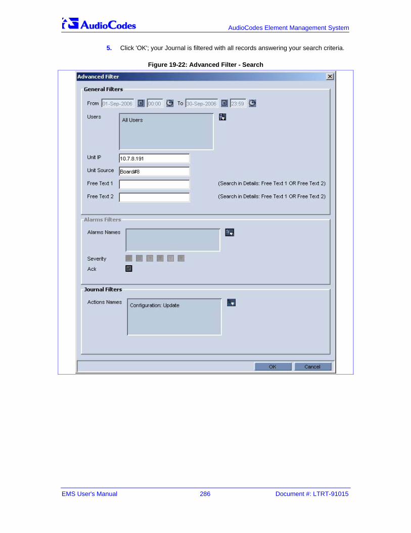
EMS User's Manual 286 Document #: LTRT-91015
AudioCodes Element Management System
5. Click 'OK'; your Journal is filtered with all records answering your search criteria.
Figure 19-22: Advanced Filter - Search
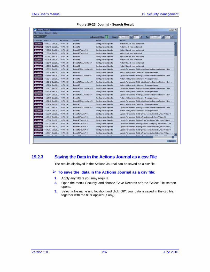
Version 5.8 287 June 2010
EMS User's Manual 19. Security Management
Figure 19-23: Journal - Search Result
19.2.3 Saving the Data in the Actions Journal as a csv File The results displayed in the Actions Journal can be saved as a csv file.
To save the data in the Actions Journal as a csv file: 1. Apply any filters you may require. 2. Open the menu 'Security' and choose 'Save Records as'; the 'Select File' screen
opens. 3. Select a file name and location and click 'OK'; your data is saved in the csv file,
together with the filter applied (if any).

EMS User's Manual 288 Document #: LTRT-91015
AudioCodes Element Management System
19.3 EMS Application Welcome Message The Welcome Screen is displayed to the user upon successful Login information validation and is composed of Administrator defined textual message and previous Successful and Unsuccessful Login Information including Date, Time, and Login Machine IP. The Administrator can set a welcome message note using the Help -> Advisory Message menu. The Administrator can define one of the following three Welcome Message Options:
Mandatory – the Welcome Message is always displayed with both Textual Message and Login Information.
Optional (default) – the Welcome Message is displayed with both Textual Message and Login Information panes. The user can disable the display of Login Information (by selecting the ‘Do Not Display Login Information on the next Login’ button) and thereby disable the entire Welcome Message starting next session.
Disable – the Welcome Message is displayed with only the Login Information pane. The user can disable the Login Information part (by selecting the ‘Do Not Display Login Information on the next Login’ button) and thereby disable the entire Welcome Message starting next session.
Figure 19-24: Welcome Message Settings

Version 5.8 289 June 2010
EMS User's Manual 19. Security Management
Figure 19-25: Welcome Message with Login Information

EMS User's Manual 290 Document #: LTRT-91015
AudioCodes Element Management System
Reader’s Notes

Version 5.8 291 June 2010
EMS User's Manual 20. Troubleshooting
20 Troubleshooting 20.1 Failure to Connect to a Media Gateway - all MGs
Failure to connect to a gateway can occur: When attempting to connect to a gateway for the first time When attempting to connect to a gateway after already having established a
connection but in the interim the gateway's operation was interrupted due to an electricity surge (for example).
There are three EMS GUI indications as to a first-time connection failure: 1. Notification of the failure to connect appears in the EMS's Status pane: “Cannot
establish connection”. 2. One of the following two question marks is displayed under the Region
instead of the gateway icon, shown in the figure 'Failure to Connect to a Media Gateway IP Address', below.
3. When selecting the Region (London, in this example), then in the Status pane under MGs List a question mark appears and UNKNOWN appears under the column Product Type.
Five possible reasons for a first-time connection failure are: 1. You've incorrectly defined the IP address of the media gateway you're
attempting to connect to (in the MG Information screen; refer to the figure 'Incorrectly Defined MG Information Screen', below)
2. An operational problem exists in the system (lack of communication with the server, for example).
3. A network problem prevents the EMS server from connecting to the media gateway. Ping the Media Gateway's IP address to verify that it exists.
4. The community string is incorrect. 5. Unrecognized software version.

EMS User's Manual 292 Document #: LTRT-91015
AudioCodes Element Management System
The table below summarizes possible first-time connection problem scenarios, the verification test that operators should perform in each scenario, and how to fix the problem.
Table 20-1: Possible First-Time Connection Problems: How to Verify Them, How to Fix Them
Possible Problem How to Verify It How to Fix It
Wrong Media Gateway IP Address defined in EMS
In the MG Tree, right-click on the gateway and choose option 'Details'; verify that the gateway IP address is correct.
Delete the gateway (right-click the question-mark icon and choose the option 'Remove MG').
Add a new gateway (refer to Adding a Single Media Gateway). Define the MG Information fields ensuring that the IP address for the gateway you're attempting to add (connect to for the first time) is the correct one, and that all other fields are correctly defined.
Wrong MG SNMP Read Community String defined in the EMS
In the MG Tree, right-click on the gateway and choose option 'Details'; verify that the SNMP Read and Write Community Strings are defined correctly.
Note that the factory default values for SNMP community strings are: read=public, write=private. Contact your system integrator to verify correct values.
The Media Gateway is not connected to the Network
In the cmd window (Start > Run), ping the gateway to verify that it is responding.
If the gateway isn't responding to the ping, check if there is a network problem or if the gateway is not operating.
The Media Gateway version is not defined in the EMS Software Manager
A message notifying you that the current gateway version is not supported by the EMS will be displayed in the status screen.
Operators can either add the missing software version to the Software Manager or load the software to the gateway of one of the EMS- supported versions.
The Media Gateway type is not supported by the EMS
In the 'MGs List' pane, an entry under the Product Type column is identified as UNKNOWN_XXX (where XXX is the product description returned by the gateway).
Contact Customer Support.

Version 5.8 293 June 2010
EMS User's Manual 20. Troubleshooting
Figure 20-1: Incorrectly Defined MG Information Screen

EMS User's Manual 294 Document #: LTRT-91015
AudioCodes Element Management System
20.1.1 Failure to Reconnect to a Previously-Connected MG Whose Operation Was Interrupted There are three EMS GUI indications as to a failure to reconnect to a gateway that was previously connected but whose operation has been subsequently interrupted: 1. A red icon of a gateway is displayed under the Region and in the Status pane
(when the Region is selected). 2. A media gateway color-coded red is displayed in the Status pane (after double-
clicking the icon color-coded red in the MGs List). 3. The Status pane's navigation buttons are disabled, shown in the figure below.
Figure 20-2: Failure to Reconnect to a Media Gateway Whose Operation was Interrupted

Version 5.8 295 June 2010
EMS User's Manual 20. Troubleshooting
The table below summarizes possible reconnection (following disconnection) problem scenarios, the verification test that operators should perform in each scenario, and how to fix the problem.
Table 20-2: Possible Reconnection Problems: How to Verify Them, How to Fix Them
Possible Problem How to Verify It How to Fix It
Network Problems Network problems can occasionally interrupt valid and quick EMS Client / EMS Server / Media Gateway communication.
Refresh by clicking F5 or View > Refresh. If the EMS cannot reestablish connection with the media gateway, ping the media gateway from the EMS client or EMS server.
Invalid modification of Community Strings
If you changed the Read Community String to an invalid value, the EMS will not be able to connect to the media gateway again. (SNMP error 22 – Timeout) will be constantly received.
Verify in the EMS's Users Journal that the media gateway Community Strings were changed. Verify that MG is up and running and you're able to connect it via PING and MIB Browser. Fix the community string problem
MG has failed and is not responding
The media gateway is not responding to ping requests.
Refer to the sections on troubleshooting the media gateway.
Note: A Media Gateway (that was previously connected but whose operation has been interrupted) is automatically reconnected by the system when its operation resumes. There is no need to attempt to manually add a new media gateway, as was the case with a first-time connection failure.

EMS User's Manual 296 Document #: LTRT-91015
AudioCodes Element Management System
20.1.2 Information Required When Contacting Technical Support 1. When contacting AudioCodes Technical Support (refer to the title page or last
page of this manual for detailed contact information), send the following information: • A description of the system configuration - including the number and type of
media gateway boards, network configuration, signaling protocols being used, exact software version, and the S/N of the failed module.
• A detailed description of the problem, including screen shots when applicable.
• Any information obtained from the troubleshooting process, suspected components, captured network traces, etc.
• Information on any changes recently made to the system and its environment, i.e., to the system configuration, networking changes, etc.
• EMS Server machine ♦ The EMS application log files located under <EMS Server installation
folder>/emsFiles/Logs and Hardening folders. ♦ Solaris OS log messages files located under /var/adm/. The file is
rotated on a daily basis. Up to 4 backup versions are preserved. ♦ Oracle Database logs alert_dbems.log located under
/ACEMS/admin/dbems/bdump/ 2. EMS Client Logs located under <EMS Server installation
folder>\EMS_Client_Files\Logs

Version 5.8 297 June 2010
EMS User's Manual 21. Basic Configuration
21 Basic Configuration 21.1 Mediant 5000 Media Gateway, Mediant 8000 Media
Gateway The section explains how to connect the EMS to an existing, pre-installed gateway and configure the mandatory parameters required to activate all modules in the chassis. Later, following this basic configuration, you’ll need to provision the gateway more comprehensively in order to prepare it for service inside a given, specific network. After performing a basic configuration, the EMS will manage the gateway and will show if the gateway hardware is operating correctly.
Note: If you encounter a problem when defining the gateway in the EMS, refer to 'Troubleshooting' on page 291.
21.1.1 Configuring the Gateway IP Address, Booting the Boards
To run the gateway with all boards identified and operating: 1. After defining each board, return up to the ‘MG Status’ screen (using the button )
and in the Info pane, click the link ‘Properties’; the ‘Media Gateway Parameters Provisioning’ screen opens. Click the tab ‘Boards Table’ and in the ‘Boards Table’ screen, enter the IP and MAC address for each TP board (click twice on the relevant cell to enable address definition).
Note: The Mediant 5000 Media Gateway and Mediant 8000 Media Gateway are delivered to customers with software pre-installed and with all boards factory pre-configured. However, due to the changed network environment following delivery, the default IP addresses of the boards are incorrect and must be reconfigured. MAC addresses remain correct and unchanged. Customers are recommended to copy the table of MAC IP addresses to an offline file and retained for reference.
EMS User's Manual 298 Document #: LTRT-91015
AudioCodes Element Management System
21.1.1.1 Configuring a Media Gateway for the First Time The Mediant 5000 and Mediant 8000 Media Gateway are delivered to customers with software pre-installed and with all boards factory pre-configured. Due to the changed network environment following delivery, some parameters (e.g., IP addresses) are incorrect and must be reconfigured.
To configure the gateway for the first time: Define all boards present in the chassis. Verify that the software configuration matches the hardware configuration. If boards must be manually added, do the following: 1. Right-click the corresponding slot and choose 'Add Board' from the popup menu;
choose the hardware and application type that matches your board. 2. Configure the IP addresses of the ES boards and unlock them. The IP addresses
of the ES boards must be re-configured to match your network environment.
To re-configure IP addresses of ES boards: Choose the ES board by clicking on it Lock it Click the link 'Properties' in the Info pane and enter the ES board's IP address Unlock the ES board
Note: The ES boards must be configured 'one by one'. Wait until the 1st ES board completes the unlock and becomes Enabled (indicated by the color green in the EMS) prior to configuring the 2nd ES board.
Configure the IP addresses of MG Boards. The IP addresses of the MG boards
must be re-configured to match your network environment. Do this in one of the following ways: • Choose a specific gateway board (by clicking on it) • Click the link 'Properties' in the Info pane • Click tab 'General Settings' tab and enter the new IP addresses. • Return up to the level of the 'MG Status' screen and in the Info pane, click
the link 'Properties'; the ‘Media Gateway Parameters Provisioning’ screen opens.
• Click the tab 'Boards Table' and in the 'Boards Table' screen, enter the IP address for each TP board (click twice on the relevant cell to enable address definition).
Note: As of version 3.0, there's no need to provision MAC addresses of gateway boards unless 'MAC Address' Board Provisioning Mode is explicitly chosen in the tab Media Gateway Properties. Boards are recognized by their geographical position (slot number) and their MAC addresses and are updated as soon as they are unlocked.

Version 5.8 299 June 2010
EMS User's Manual 21. Basic Configuration
Define the MGC for boards running MGCP or H.248 control protocols: • Click on tab MGC, define the Media Gateway Controller and configure it by
provisioning the MGC IP address, call control protocol (MGCP or H.248), etc. Configure the MG boards and attach them to the MGC
• Click the 'Properties' link for each TP board and perform basic provisioning. • Attach each board to a specific MGC via tab 'Call Control'.
Unlock the Media Gateway • Click the 'MG status' button and in the 'Maintenance Action' drop-down box,
choose the 'Unlock' action. • Alternatively, right-click the Media Gateway in the 'MGs Tree' and choose the
'Unlock' action from the pop-up. Unlock MG Boards
• Unlock all MG boards by right-clicking on them and choosing the maintenance action 'Unlock'
Verify that the gateway and all boards populating it are Unlocked and Enabled (color-coded green).

EMS User's Manual 300 Document #: LTRT-91015
AudioCodes Element Management System
21.1.2 Getting Started with Provisioning a Gateway
To get started with provisioning a gateway: 1. Select the gateway in the ‘MG Tree’; its details are graphically represented in the
MG Status pane. 2. In the Info pane, click the ‘Properties’ link; the ‘Media Gateway Parameters
Provisioning’ screen opens (shown in the figure below).
Figure 21-1: Mediant 5000 Media Gateway, Mediant 8000 Media Gateway Parameters Provisioning Screen
To provision the gateway, define the fields in the Parameters Provisioning screen (refer to the figure above) according to the parameter explanations under:
'Locking a Media Gateway' on page 301 and 'Unlocking a Media Gateway' on page 301
'Searching for a Provisioned Parameter' on page 191 EMS Parameter Guide for the Mediant 5000 Media Gateway and Mediant 8000
Media Gateway

Version 5.8 301 June 2010
EMS User's Manual 21. Basic Configuration
21.1.3 Locking a Gateway
To lock a gateway: 1. In the MG Tree, expand the region in which the gateway is located and right-click
on the gateway you want to lock. Alternatively, in the MG Tree, click on the region under which the gateway is located; the MGs List is displayed.
2. In the MGs List, select the gateway you need to lock; ensure from the identifying details that appear in the Status pane that this is indeed the gateway you need to lock.
3. Right-click on it in the MGs List and select the “Lock” option in the pop-up menu. Click “Yes” in the confirmation prompt.
4. Wait until the “lock” is finished.
21.1.4 Provisioning a Gateway To bring a gateway to a state in which all boards are recognized and operating, select it in the MGs List so that its details are displayed in the Status pane, and in the Info pane click the “Properties” link; the Media Gateway Provisioning screen opens.
To provision the gateway, define the fields in the Parameters Provisioning screen (shown above) according to provisioning parameter explanations under: 'Searching for a Provisioned Parameter' on page 191 EMS Parameter Guide for the Mediant 5000 Media Gateway and Mediant 8000
Media Gateway
21.1.5 Unlocking a Gateway
To unlock a gateway: 1. In the MG Tree, expand the region under which the gateway you need to unlock
is located, and right-click on the gateway. In the resulting pop-up, choose option “Unlocked”.
2. Alternatively, click on the region under which the gateway you need to lock is located; the MGs List is displayed. In the MGs List, right-click on the gateway to unlock and in the resulting pop-up menu, select the “Unlock” option.
3. Wait until the “unlock” process is completed.

EMS User's Manual 302 Document #: LTRT-91015
AudioCodes Element Management System
21.2 MediaPack Quick Configuration Example In this quick configuration example, two MediaPacks (MP-1xx gateways) are used.
To configure MediaPacks / phones and make a phone call: 1. Determine the IP address, Subnet Mask and Default Gateway of your PC using
'Run' command 'ipconfig'.
Figure 21-2: Determining IP Address, Subnet Mask and Default Gateway of Your PC
2. Ping IP addresses 10.13.50.50 and 10.13.50.51 (for example) (see above) to ensure that they're free; if no response is received, these can be the IP addresses to allocate to your two MediaPacks.
3. Open the EMS and add a region (right-click on 'Globe' and choose 'Add Region').

Version 5.8 303 June 2010
EMS User's Manual 21. Basic Configuration
4. Right-click on the region and choose option 'Add multiple MGs'; the 'Add Multiple MGs' screen opens.
Figure 21-3: Add Multiple MG - Example
5. Check 'Enter IP address range' and define fields 'From' (use 10.13.50.50) and 'To' (use 10.13.50.51). Define field 'Name Prefix'. Click OK.

EMS User's Manual 304 Document #: LTRT-91015
AudioCodes Element Management System
6. Run AudioCodes' BootP/TFTP Server; choose option 'Clients' from the 'Services' menu and in the 'Client Configuration' screen, define fields 'Client MAC' (refer to the label indicating the MAC address on the device), 'IP address', 'Subnet' and 'Gateway' using the information you accessed in step 1. Provide a name for the gateway. For the 2nd gateway perform the same procedure. Click 'Apply' and 'OK'.
Figure 21-4: BootP-TFTP Server - Defining 'IP address', 'Subnet' and 'Gateway'
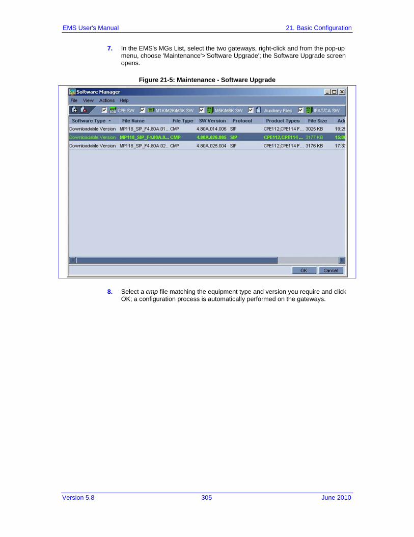
Version 5.8 305 June 2010
EMS User's Manual 21. Basic Configuration
7. In the EMS's MGs List, select the two gateways, right-click and from the pop-up menu, choose 'Maintenance'>'Software Upgrade'; the Software Upgrade screen opens.
Figure 21-5: Maintenance - Software Upgrade
8. Select a cmp file matching the equipment type and version you require and click OK; a configuration process is automatically performed on the gateways.

EMS User's Manual 306 Document #: LTRT-91015
AudioCodes Element Management System
9. In the MGs List, double-click on the 1st gateway; its 'Status' pane opens.
Figure 21-6: MediaPack Status Pane - Example
10. Click the 'Routing' button; the (SIP) Routing screen opens.

Version 5.8 307 June 2010
EMS User's Manual 21. Basic Configuration
11. In the (SIP) Routing screen, click tab 'Tel to IP'; the 'Tel to IP' pane opens.
Figure 21-7: Routing - Tel to IP
12. Right-click on row 0 and choose option 'Add Row' 13. Before routing, lock the row by right-clicking on it and choosing option 'Lock rows'
from the pop-up menu. 14. Double-click on the cell under column ''Destination phone prefix'; in the write-
enabled field, define '1'. 15. Double-click on the cell under column 'Address' and in the write-enabled field,
define 10.13.50.50. 16. Click 'Save' and 'Apply' and unlock the row. 17. Add another row, lock it, route the other telephone as '2', click 'Save' and 'Apply',
unlock the row and click 'Close'.

EMS User's Manual 308 Document #: LTRT-91015
AudioCodes Element Management System
18. In the 'Status' pane for the MediaPack whose IP address is 10.13.50.51, click button 'End Points'; the 'Phones' pane opens.
Figure 21-8: Endpoints - Phones
19. Right-click on row 0 and choose option 'Add Row'. 20. Before configuring, lock the row by right-clicking on it and choosing option 'Lock
rows' from the pop-up menu. 21. Double-click on the cell under column 'Starting channel'; in the write-enabled field,
define '1'. Double-click on the cell under column 'Last channel'; in the write-enabled field, define '4'. Double-click on the cell under column 'Starting Phone Number'; in the write-enabled field, define '200'.
22. Click 'Save' and 'Apply' and unlock the row. Click 'Close'. 23. In the MGs List, double-click on the gateway whose IP address is '10.13.50.50'
and perform the identical procedure except for field 'Starting Phone Number' which can be '100'.
24. Offhook the phone whose IP address is 10.13.50.50 and whose number is 100 and dial 200; the phone whose IP address is 10.13.50.51 rings.

Version 5.8 309 June 2010
EMS User's Manual 22. Index
22 Index A
Accessing a TP-6310 in the Mediant 8000Mediant 5000 Media Gateway Mediant 8000 Media Gateway...............................105
Accessing a TP-8410 in the Mediant 5000..112 Accessing the Main Status Screens....105, 108 Accessing the TP Board Level Provisioning
Screen .....................................................107 Acknowledging an Alarm.............................210 Adding a New File to the Software Manager .48 Adding an Operator.............................268, 270 Alarm Browser ............................................207 Alarms and Events Filtering & Sorting.........213 Alarms Clearing ..........................................210 Alarms History.....................................212, 214 Ascertaining a Device's Master Profile ........175 Ascertaining a TP-6310 and TP-8410 Board
Master Profile ..........................................181 Attaching a Master Profile to one or to Multiple
Media Gateways..............................157, 178 Attaching a Master Profile to TP-8410, TP-
6310 Boards ............................................185 Audio Indication on Receipt of Alarms.........212 Automatic Detection ......................................55
B
Background (History) Performance Monitoring........................................................240, 246
Backing Up and Restoring the Media Gateway................................................................200
Basic Configuration...................49, 52, 62, 291 Blades and CPE............................................55
C
Canceling Changes Made to the Users List 272 Centralized EMS Users Authentication and
Authorization via a Radius Server............260 Changing an Operator's Password..............272 Changing the Alarms Browser Views ..........211 Characteristics ..............................................28 Closing the Alarm Browser Pane ................213 Collecting Log Files.....................................202 Configuration Actions ..................................157 Configuration Verification, Download for
Mediant 1000, Mediant 2000, Mediant 3000, IPmedia 2000, IPmedia 3000 and MediaPack...............................................187
Configuring a Region ....................................49 Configuring Background Monitoring ....241, 243 Configuring HTTPS.....................................254 Configuring IPSec .......................................255 Configuring Media Gateway Web Server and
SSH Server User Passwords...................254
Configuring PM Threshold values ...............245 Configuring SNMP ......................................250 Configuring the Gateway IP Address, Booting
the Boards...............................................291 Context-Sensitive Behavior...........................37 CPE Security Management.........................250 Creating a Master Profile ............ 157, 176, 183 Creating Entity Profiles .......................173, 176
D
Defining a Mediant 5000, Mediant 8000........50 Defining a Single Blade or CPE (Mediant 1000
/ 2000 / 3000 or MP)............................58, 61 Defining Complex Queries using a
Combination of Filters..............................220 Defining Multiple Blades and CPE ................60 Defining Multiple Mediant 5000, Mediant 8000
Gateways ..................................................53 Defining VoIP Devices, Managing the MG Tree
............................................................28, 49 Detaching a Master Profile..........................180 Detaching a Master Profile from TP-8410, TP-
6310 Boards ............................................185 Detaching a Profile from an Entity...............174 DS1 Interfaces ............................ 136, 140, 143 DS1 Trunks Status and Provisioning...........151 DS3 Interfaces ............................................136
E EMS Application Security............................260 EMS Application Welcome Message ..........282 EMS System Requirements ..........................27 EMS within the Network ................................19 Ethernet Switch Board's Links' Status.........118 Executable Actions on Mediant 2000 and
IPmedia 2000 ..........................................142 Executable Actions on MediaPacks ....138, 150 Executable Actions on the Mediant 1000 and
Mediant 600.............................................145 Executable Actions on the Mediant 3000 ....137 Exporting Background Monitoring Data as a
File ..........................................................242 Exporting, Importing an Entity Configuration as
a File .......................................................169
F Failure to Connect to a Media Gateway - all
MGs.........................................................285 Failure to Reconnect to a Previously-
Connected MG Whose Operation Was Interrupted...............................................288
Fault Management ........................ 28, 207, 279 Filtering Alarms...........................................209 Filters Supported in the Actions Journal......278 First-Time Connection Problems...................63 Forcing the Logout of a Currently Active
Operator ..................................................271

EMS User's Manual 310 Document #: LTRT-91015
AudioCodes Element Management System
G
Gateway Installation, Software Upgrade and Regional Files Distribution .................46, 191
Gateways Connected to the Network ............62 Gateways NOT Connected to the Network ...62 Generating X.509 CSR and Self-Signed
Certificate via EMS ..................................258 Getting Oriented in the EMS .........................35 Getting Started with Provisioning a Gateway
................................................................294 Getting Started with the EMS........................33
H
Hardware Component Status in Table View130
I Information Required When Contacting
Technical Support....................................290 Initial Configuration .....................................125 Installing the EMS Client on a PC .................31 Introducing the AudioCodes Element
Management System.................................19 Inventory Management ...............................120 IPs Summary ..............................................122
L License Key Update ....................................194 Loading - Attaching - an Entity Profile .........174 Local Users Management in the EMS
Application...............................................265 Locking a Gateway..............................294, 295 Locking and / Unlocking the Gateway ........194 Logging In .....................................................34
M
Maintenance Actions...................................158 Management Procedure................................32 Master Profile for Mediant 1000, Mediant 2000,
Mediant 3000, IPmedia 2000, IPmedia 3000 and MediaPack........................................175
Master Profiles Manager .............................186 Media Gateway Level Status Pane ...............75 Mediant 1000 and Mediant 600...................143 Mediant 1000 and Mediant 600 Provisioning
................................................................144 Mediant 1000 Status Pane..........................143 Mediant 2000 and IPmedia 2000 Provisioning
................................................................141 Mediant 2000 and IPmedia 2000 Status Pane
................................................................139 Mediant 2000 and Mediant 3000 SIP and SS7
Navigation Concepts ...............................155 Mediant 2000, IPmedia 2000 ......................139 Mediant 3000 8410 SA BITS status ............131 Mediant 3000, IPmedia 3000 ..............125, 135 Mediant 3000, IPmedia 3000 Status Pane ..125 Mediant 5000 6310 Hardware Components
Status ........................................................94
Mediant 5000 and Mediant 8000 Media Gateway Security Management...............249
Mediant 5000 Hardware Components Status93 Mediant 5000 Media Gateway, Mediant 8000
Media Gateway .................................55, 291 Mediant 5000 Media Gateways, Mediant 8000
Media Gateways, IPmedia 8000 Media Servers......................................................77
Mediant 5000, Mediant 8000 Configuration Backup Files Collection ...........................203
Mediant 5000, Mediant 8000 Maintenance Actions ............................................101, 192
Mediant 5000, Mediant 8000 Startup and Shutdown ................................................202
Mediant 5000/8000 Hardware Components Status SAT(SA/RTM) Board Information) ..90
Mediant 600 / 1000 / 2000 / 3000 / 5000 / 8000 Trunks and Channels Status ...................151
Mediant 600 Status Pane............................144 Mediant 600/ Mediant 1000 / Mediant 2000 /
Mediant 3000 and MediaPack Maintenance Actions ............................ 142, 145, 150, 157
Mediant 8000 6310 Hardware Components Status ........................................................91
Mediant 8000 Hardware Components Status90 Mediant/IPmedia 5000 Status Pane..............84 Mediant/IPmedia 8000 Status Pane..............77 MediaPack .................................... 53, 136, 147 MediaPack Line Test ..................................149 MediaPack Quick Configuration Example ...296 MGs List..................................................71, 73 Mismatch Indications ....................................63 Modifying Operator Details..........................270 Monitoring Multiple Media Gateways ............71 Moving a Gateway from Region to Region....64 Moving Multiple Gateways from Region to
Region.......................................................65 MTP3 SS7 Provisioning ................................98
N
Navigating Down and Up System Hierarchy .35 Navigation Buttons to Provision the Mediant
8000, Mediant 5000...................................96 Navigation Hierarchy...................................133 Network Communication Security ...............247
O
Offline Configuration for Mediant 1000, Mediant 2000, Mediant 3000, IPmedia 2000, IPmedia 3000 and MediaPack.................186
Online Software Upgrade Wizard................195 Open Alarms History...................................212 Open Journal ..............................................212
P Parameters HA Type ..................................169 Parameters Provisioning Types ..................166 Pause Alarms Auto Refreshing ...................213 Performance Management....................28, 235

Version 5.8 311 June 2010
EMS User's Manual 22. Index
Performance Monitoring Actions on Multiple Media Gateways......................................246
Performing Actions on Multiple Gateways...159 Physical and Logical Components Status and
Provisioning.............................................133 Predefinition or Automatic Detection .............55 Printing an Entity's Configuration as a File ..171 Provisioning a Gateway ..............................295 Provisioning Concepts 134, 141, 144, 150, 155,
161 Provisioning Entity Profiles..........................172 Provisioning MediaPacks ............................150 Provisioning Procedure for Mediant 1000,
Mediant 2000, Mediant 3000, IPmedia 2000, IPmedia 3000 and MediaPacks ...............165
Provisioning Procedure for Mediant 5000 and Mediant 8000...........................................164
R
Real-Time Performance Monitoring.............236 Regions List ..................................................71 Releasing an Operator from Suspension ....272 Removing a Gateway....................................66 Removing a Master Profile ..........................180 Removing a Profile......................................174 Removing an Operator................................271 Removing Files from the Software Manager .48 Removing Multiple Gateways........................67 Rollback ......................................................198 Running the EMS Client................................31
S Saving Alarms in a .csv File ........................233 Saving File from the Software Manager ........48 Saving the Data in the Actions Journal as a csv
File ..........................................................281 Saving the EMS Tree MGs Report in an
External File ..............................................70 Searching for a Gateway...............................68 Searching for a Provisioned Parameter......188,
294, 295 Security Management ....... 28, 59, 62, 247, 269 Selecting an Interface in the Context of an
Element ...............................................35, 36 SIP Provisioning Navigation Buttons ...........155 SIP Provisioning of VoP Board (6310 and
8410) .......................................................114 SNMP Management....................................249 Software Manager......... 39, 100, 134, 191, 260 Software Upgrade for CPE and Blades .......191 SONET / SDH Interfaces ............................135 Specifications................................................21 SS7 Provisioning Navigation Buttons ..........156 Status Pane for MediaPacks.......................147 Supported Configuration .............................125 Supported Versions of Managed Equipment .26 Supported VoIP Equipment...........................24 Suspending an Operator .............................271
T TP-6310 and TP-8410 Master Profile (Mediant
5000 Media Gateway, Mediant 8000 Media Gateway).................................................181
Trap Forwarding..................................226, 242 Trap Forwarding in Mail Format ..................226 Trap Forwarding in Mail2SMS format..........228 Trap Forwarding in Syslog format ...............230 Troubleshooting . 51, 53, 58, 62, 198, 258, 285,
291 Trunk Channel Call Status ..........................153
U
Unlocking a Gateway ..........................294, 295 Using Advanced Filters ...............................216 Using Color Coding to Assess Element Status
............................................................35, 38 Using Time Filters .......................................215
V Viewing Historical Data ...............................243 Viewing 'Journal Record Details' .................275 Viewing Operator Actions in the Actions
Journal ............................................212, 273 Viewing, Interpreting an Alarm's Details......221
W
Working with the EMS's Provisioning Screens................................................................161

Element Management System (EMS) User’s Manual
Version 5.8
Document #: LTRT-91015
www.audiocodes.com