ELECTRONIC & RADIO E GIN ER - World Radio History
96
ELECTRONIC & RADIO E GIN ER Incorporating WIRELESS ENGINEER In this issue Transducer Characteristics Selective Admittance- Measuring Set Phase- Adjusting Circuits Transistor Pulse Generator JANUARY 1957 V ol 34 new series NO 1
-
Upload
khangminh22 -
Category
Documents
-
view
0 -
download
0
Transcript of ELECTRONIC & RADIO E GIN ER - World Radio History
ELECTRONIC &
RADIO E GIN ER Incorporating WIRELESS ENGINEER
In this issue
Transducer Characteristics
Selective Admittance- Measuring Set
Phase- Adjusting Circuits
Transistor Pulse Generator
JANUARY 1957 Vol 34 new series NO 1

for everq ttipe of coil
BICC
th ere's a
WINDING WIRE
USE OUR TECHNICAL ADVISORY SERVICE
If you are faced with a winding problem please ask for assistance; BICC technicians are always willing to give you the benefit of their experience. For most winding wire jobs the Publications listed will provide the data you require. They are available on request.
, 14„âB I. BRITISH INSULATED CALLENDER'S CABLES LIMITED edieje-" 21 BLOOMSBURY STREET, LONDON, W.C.1
No. 266
No. 296
No. 303
No. 328
Insulated Winding Wires and Strips " Bicaloc " Winding Wires (Self Bonding) Enamelled Oil Base Winding Wires " Fifty-Three" Enamelled Win ding Wires
Electronic ee Radio Engineer, January 195r

WIDEST RANGE IN THE WORLD? So far as we are aware, our range of A.C. Automatic Voltage Stabilisers is the largest in the World. We have a very wide range of standard models, single-phase patterns ranging from 200 VA to about 30 kVA (3-phase types up to about 90 kVA). There are 39 basic types, in six distinct
design series, and all are available in standard form or as tropicalised instru-ments. We feel that on this account there can be few, if any requirements covering Stabilisers that we are not in a position to meet economically, efficiently and promptly.
Here are very brief details of the six main series, in handy tabular form: cut this ad. out and use it as a Buying Guide; but please remember that if you do not see exactly what you require a written enquiry will probably reveal that we have a "special" to suit, or that the answer is under development. New stabilisers are regularly being added to our range. Several are at the very advanced development stage now—and we do design " specials". One such " special" (AM type 10D/20161) is illustrated (Illustrations not to scale). Nearly 100 have been supplied to Murphy Radio Ltd. for incorporation in equipment supplied by them to the Air Ministry for use on a chain of Radar Marker Beacons. 45 in slightly differing form are currently being made by us for the Air Ministry for another Radar Chain.
For complete data request our 20-Page Supplement Ref.V-549-S and its associated Special Price List, CLL Form VSP-56116.
BMVR - 1725
BAYR - 1000 & BAVR, 1000-E
DESIGN SERIES ASR ATC BAVR BAVR-E BMVR TCVR
I
Input Voltage —20% —10% —10% Depends on power:
"Swing"
—10%
to + 5% to + 10% to + 5% to + 5% typical is from
—19% to + 8.5%
Output Voltage
Stability + 2i% + 5% + 0.15% -1 0.15%
Usually
+0.5%
Usually +0.5%
Change due to load
(0-100%) NEGLIGIBLE +2.0% ±0.3% NIL NIL
Harmonics Generated NIL NIL YES YES NIL NIL
PRACTICALLY INSTANTANEOUS
Response Speed AVERAGING I V/Sec. 40V/Sec. 2-3 CYCLES 1 CYCLE
Power Ratings 1150VA 2300 VA
575VA
1150VA
200VA
500VA 1000VA
200 VA
500 VA 1000VA
1600VA to
30kVA ( 18 models)
1600VA to 12kVA ( 11 models)
* Basic Prices £24 to £34 £24 to £34 £50 to £79 £59 to £88 £75 to £237 £9 I to E I 44
* From May 1st 1956, subject to n% increase.
etaube k)otts STABILISER DIVISION
HODDESDON • ENGLAND • TEL: HODDESDON 3007 (4 LINES) • 'GRAMS: MINMETKEM, HODDESDON
BMVR - 7000 - Seroes & TCVR - 7000 - Serres
BMVR 2750 - S.58 ( AM Ref 100 20161) ,
,les..............e....-, • ' ":,,, .
BMVR 2750/VV & TCVR - 2750 VV
ASR- 1150 & ATC - 575.
Electronic ee Radio Engineer, January ¡957
Al6
1

AUTOMATIC
ANTENNA PATTERN RECORDING
THIS EQUIPMENT has -11- been developed by EKCO Electronics to automatically record the radiation patterns of any centimetric antenna. -The
antenna under test is mounted on the roof of a rotatable trailer and illuminated by a fixed trans-mitter. The amplitude of the received signal is then continu-ously plotted against the angular traverse of the trailer. EKCO ANTENNA PATTERN RECORDER type E59
All the equipment except the transmitter unit is mounted in the trailer and remote controls for the transmitter are provided. The received C.W. signal is mixed with a modulated local oscillator signal and the resultant I.F. output combined with an anti-phase modulated I.F. signal. The reference signal is derived from a 30 Mcis oscillator and servo-driven piston attenuator. The combined signals are fed via a seven-stage, low noise I.F. amplifier to a balanced modulator, and the resultant error signal applied to a servo amplifier. The output of this amplifier drives a servo motor which moves the piston attenuator in such a direction as to reduce the difference between
the reference signal and the received signal. A pen attached to the piston drive mechanism records the amplitude of the received signal in terms of the attenuation law of the standard piston which is directly calibrated in dB. Facilities are available for plotting either on Cartesian or polar co-ordinate graph paper. Piston Attenuators can be supplied to provide amplitude scales of either or both 5 and 10 bB per inch. The maximum travel is 35 or 65 dB respectively. The Cartesian co-ordinate paper can be run at rates accurately corresponding to two or five degrees per inch.
This equipment is also available to special order for installation in a permanent location
EKCO electronics
We shall be pleased to discuss this equipment with you
EKCO ELECTRONICS LTD EKCO
The Mixer section is a plug-in unit and
'X' and 'S' Band versions are available
covering the ranges 8250-10,000 Mc/s
and 2500-3300 Mc/s respectively.
Other frequency ranges can be
covered, to special order. The
Recorder can be supplied in two
forms with either a single 6 ft. (shown
above with plotting table) or a twin
4 ft. console rack shown at right.
WORKS • SOUTHEND-ON-SEA • ESSEX
2 Electronic ee Radio Engineer, January 1957

Distortion Detected -
Transmission Perfected
T.D.M.S. 54 Sends an automatic test message, or characters, or reversals at any speed between 20-80 bauds with or without distortion. The GRO has a circular time base for distortion measurements on synchronous signals only, or relay adjustment. Weight 37 lb.
The introduction of electronic techniques to the measurement and correction of telegraph distortion brings laboratory precision to the maintenance of modem line and radio telegraph circuits and all equipment, including teleprinters. The equipment described and illustrated on this page is representative of the contri-bution made by ATE to this field.
T.D.M.S. 64 For distortion measurements on working circuits without
interrupting service. Each element of a start-stop signal appears separately on the spiral time base display.
Adjustable speeds from 20-80 bauds. Weight 33 lb. Higher speed versions can be supplied to order.
REGENERATIVE REPEATER TRR.1
is a start-stop, five unit code equipment, designed to correct distortion on long line or radio telegraph circuits. It covers the speed range 45, 50 or 75 bauds, and accepts signals with up to 49% distortion.
AUTOMATIC TELEPHONE & ELECTRIC CO, LTD.
STROWGER HOUSE, ARUNDEL STREET, LONDON, W.C.2.
TELEPHONE : TEMPLE BAR 9262. CABLEGRAMS STROVVGERE ,C LONDON.
ATI4601-BX107
Electronic & Radio Engineer, January 1957

4 Electronic Ce Radio Engineer, January 1957

-
Model 1058
Single Beam
Oscillograph
Designed for laboratory use, this
new oscillograph provides
a Y amplifier with a very useful
frequency characteristic extending from
d.c. to 6 Mc/s. The display is presented on a new post deflection accelerator
tube at an amplitude of not less than 6 cm over the stated frequency band. The
maximum sensitivity of the channel is 0.25 V/cm and calibration is
effected by means of the accurate test voltage provided. The time base of the
instrument can be switched to fire repetitively from a trigger pulse of either
sign derived from the Y amplifier signal or externally. A special refinement,
of interest to the Television Engineer, is the provision for triggering from the
Frame or Line sync. pulse in a I volt D.A.P. (positive) composite video signal.
Five calibrated time base ranges are provided giving spot velocities from 30 cm/sec to
1.5 cm/microsec. An X amplifier with a maximum sensitivity of 0.5 V/cm
and bandwidth 20 c/s-25o kcs ( — 5o%) is included and allows time base expansion,
continuously variable, of up to five tunes. Time measurement is by calibrated
shift control. The instrument operates from 100-130 or 2oo-250 volt mains supplies.
Write for illustrated leaflet to :—
COSSOR INSTRUMENTS LIMITED THE INSTRUMENT COMPANY OF THE COSSOR GROUP
(Dept. 71) COSSOR HOUSE • HIGHBURY GROVE • LONDON N.5
TELEPHONE: CANonbury 1234 ( 33 lines)
TELEGRAMS: COSSOR, NORPHONE, LONDON
CABLES: COSSOR. LONDON 084
Electronic & Radio Engineer, January 1957 5

, „and better! Pl •
"Hitemp" Transformers • Operational temperatures up to 250°C.
• Suitable for high altitude operation'.
• Saving in size and weight.
Originally designed for supersonic aircraft,
the "Hitemp" range of transformers has
many applications throughout the electrical field.
Ceramic Valves
• High permissible temperature of operation.
• Ruggedised construction.
• Reduced dimensions.
The Ferranti range of Ceramic Valves
includes power rectifiers, stabiliser triodes.
and R.F. power oscillators and amplifiers.
FERRANTI LTD., FERRY ROAD, EDINBURGH • Tel: Granton 89181
Electronic & Radio Engineer,
ES/1-36
anuaiy 1957

TYPE 1303-A TWO-SIGNAL AUDIO GENERATOR ANOTHER ' FIRST' BY GENERAL RADIO
The -GENERAL RADIO" Type 1303-A Two-Signal Audio Generator is primarily a test-signal source for inter-modulation distortion measurements. It is suitable for use in measurements by all three of the usual non-linear distortion measurement methods. These are:
(1) The harmonic method. (2) The intermodulation method using a strong low-frequency tone and a weaker high-frequency tone (as standardised by the SMPTE). (3) The intermodulation method, sometimes called a double-tone test, using two tones of equal intensity (recommended by the CCIF).
Our "GENERAL RADIO" a-c operated type 736-A Wave Analyser is recommended as a detector for these distortion tests..
The Two-Signal Audio Generator is also an excellent general-purpose audio-frequency source for tests on audio-frequency lines, networks, and amplifiers; for modulating signal generators and test oscillators; and for acoustic tests, recording tests, and bridge measurements.
SOME SPECIAL FEATURES INCLUDE:
(1) Can be used as a single-frequency, beat-frequency oscillator, from 20 to 40,000 c/s. (2) Supplies combinations of two frequencies for intermodulation distortion tests. (3) The ratio of the voltages of the two frequencies is adjustable. (4) The constant-difference-frequency feature of the two-signal output is particularly convenient for the CCIF method of testing. (5) Harmonics and intermodulation products in the oscillator output are very low. (6) Output voltage is essentially constant over entire frequency range. (7) Frequency and voltage stability are high. (8) Output meter and attenuator are provided, so that the oscillator can be used as a standard-signal generator for such measurements as voltage, gain, and attenuation. (9) Reasonable price, namely £930 net delivered (U.K. only).
This instrument is fully described Pages 106/107 of the current complete Catalogue "0", a copy of which will gladly be sent to suitable applicants against written applications. Address our nearest works please.
AMPLIFIERS • BRIDGES • COAXIAL EQUIPMENT • STANDARDS OF TIME AND
FREQUENCY, ETC • STANDARD-SIGNAL GENERATORS • OSCILLATORS •
MONITORS FOR RADIO AND TELEVISION STATIONS • WAVEFORM
MEASUREMENT EQUIPMENT • LAB METERS (VTVM'S ETC) • "VARIAC"
VOLTAGE-REGULATING AUTOTRANSFORMERS, ETC • A-C AUTOMATIC
VOLTAGE STABILISERS AND INDUSTRIAL REGULATORS. ETC. ETC.
etaube jtpott$ iitb4 76 OLDHALL STREET, LIVERPOOL 3, LANCS. TELEPHONE: CENTRAL 4641 VALLEY WORKS, HODDESDON, HERTS.
TELEPHONE: HODDESDON 3007 CL27
Electronic ee Radio Engineer, January 1957

405D The only Television pattern generator with all the facilities essential for proper servicing. With this instrument the service department becomes completely independent of transmissions. A. selection of patterns enables all adjustments to be easily carried out for which Test Card C is normally used. Even varying picture content during transmissions need no longer delay the completion of a job. Definition bars up to 3 Mc/s cover the whole screen to facilitate accurate focusing. The fully synchronised TV signal is available with simultaneous sound.
The 405D and its new companion, described below, provide a perfect combination for TV fault finding and setting up.
£65 Nett Trade
or on Credit Sale
FOR BETTER TV SERVICING EQUIPMENT
Rada4 301 New PORTABLE Television Oscilloscope with many outstanding features—specially designed for the TV Engineer. The signal amplifier has a constant Band-width up to 6 Mc/s (3 db) at the maximum sensitivity of 100 mV/cm.—and a useful response to 10 Mc/s. The attenuator is frequency compensated and calibrated to allow accurate measurement of pulse amplitudes. New Miller-Multivibrator time-base circuit, triggered or repetitive, with Trace Expansion to more than 20cm. Sweep extends to 0.5 microseconds per cm. A 1 micro-second pulse can easily be opened out to 2cm. Special sync. selector circuit to ensure rigid synchronisation from small signals. Provision has been made to sync. from the frame pulses in a complete TV waveform.
Fully enclosed with storage for leads in removable door. Weight only 19 lb. Built-in tilting stand.
£52 10s. Nett Trade
or on Credit Sale
Obtain complete specifications from your wholesaler or write direct to:
PORTABLE
TV SIGNAL GENERATOR
(wave ormsD LIMITED
PORTABLE
OSCILLOSCOPE
WAVEFORMS LTD., Radar Works, Truro Road, London, N.22 Telephone BOWes Park 6641-2-3
8 Electronic Ce Radio Engineer, January 1957

\ SPECIAL pTrYoPniESPtCdAeN BE DES
TO SUIT YOUR NEEDS
BRITAIN'S FOREMOST DESIGNERS
AND MANUFACTURERS OF
An extensive range
of our standard types of
SINGLE-STAGE or PUSH-PULL
Magnetic Amplifiers
is always available forGNED ci
Full technical data and illustrated leaflets promptly
forwarded on request
ELECTRO- METHODS LTD. 22-46 CAXTON WAY, STEVENAGE, HERTS. Phone: STEVENAGE 780

Consistency of Performance
Toroidally Wound Power Potentiometers
Carbon Composition and Wirewound Potentiometers
Panclimatic High Stability Carbon Resistors
Insulated High Stability Carbon Resistors
High Voltage Composition Resistors
'Weimer Metal Film Resistors
Vitricon' Miniature Vitreous Enamelled Capacitors
The conquest of the air is no small battle, and those who plan it are seasoned campaigners—like the Bristol Aeroplane Company When this famous firm carry out flutter investigations on their
aircraft they use an analogue computer of great speed and accuracy. It is, in fact, a test within a test for the exactitude
of its components—not the least of which are 5,000 Welwyn
high stability carbon resistors and vitreous enamelled wirewound resistors. Chosen for their proven
features, these Welwyn resistors have proved their
absolute reliability in the hardest possible trial.
M MANUFACTURERS OF E LWYN ELECTRICAL COMPONENTS
WELWYN ELECTRICAL LABORATORIES LIMITED BEDLINGTON • NORTHUMBERLAND
Canada: Welwyn Canada Ltd., 1255 Brydges Street, London, Ontario
U.S.A.: Welwyn International Inc., 3355 Edgecliffe Terrace, Cleveland II, Ohio On Admiralty, Ministry of Supply (A.I.D. Approved) and Post Office Lists
-e-
10 Electronic CO Radio Engineer, January 1957

It is no
exaggeration to term
Parmeko's Leicester factories
"the most extensive specialised
small-transformer plant in Europe".
Neither is it an overstatement to say
that most electronic and electrical
engineers translate the word
ANSFORMER into
PARMEKO LIMITED, Percy Road, Leicester, England
Electronic ee Radio Engineer, January 1957

talk to TCL about ultrasonics
They know piezoelectric ceramics right from the ground floor
upwards. For T.C.L. have a fund of experience gained from established British and American research, development
and production in this field. The table shown here, which is reproduced from the new T.C.L. booklet,
gives some idea of the present range of activities
covered by T.C.L. transducers. Further applica-
tions are almost limitless. The booklet is offered
to Design Engineers and others interested in
the application of piezoelectric ceramics. Please request a copy as soon as possible.
Underwater Sound
Sonar Systems, Sound Detection, Sound Measurement, Echo Rang-ing Systems, Sound Emitters, Fathometers.
Ultrasonics
Non- Destructive Materials Test-ing, Rapid Cleaning of Machined Parts, Drilling, Cutting of Hard Materials, Flaw Detection, etc.
Medicine Vaccine Extraction, Sterilization, Diagnostic Work, Therapy, Brain Surgery.
Shock and Vibration
Accelerometers, Pressure and Blast Gauges, Displacement Gauges, Strain Gauges.
General Gramophone Pick-ups, Filters and Oscillators, Surface Gauges. TC
piezoelectric ceramics
Technical Ceramics Limited, Wood Burcote Way, Towcester, Northants Tel: Towcester 312-6 TC5a
12 Electronic & Radio Engineer, January 1957
Service van drivers, airfield truck drivers,
maintenance engineers—and a whole lot of other people too—save time and money with
Murphy VHF mobile radio telephones. Murphy radio telephones are easy to install, simple
to operate and provide clear communication over good distances. Both the fixed and mobile
transmitter/receivers are crystal controlled and are available in the usual VHF bands.
They contain effective noise limiters to deal with ignition interference.
Mobile radio telephones are just one of the things we get
up to in the Murphy Electronics Division . . .
keep in touch with murphy Aircraft navigation equipment Communications receivers Distance measuring equipment Electronic test gear Interference tracing equipment Mobile radio telephones
MURPHY RADIO LIMITED ( ELECTRONICS DIVISION) • WELWYN GARDEN CITY • HERTFORDSHIRE
CRC 291
Electronic & Radio Engineer, January 1957 13

ûet rid of INTERFEREN
"LOOK...here are some
of our large range of
Suppression Components
Whatever your interference
problems may be, it will
pay you to consult our
catalogue first !"
Itadiozpares Ltd. 4-8 MAPLE STREET • LONDON • W.I • ENGLAND
TELEPHONE: EUSton 7232-7 TELEGRAMS: RADOS1?ERES, WESDO, LONDON CABLES: RADOSPERES, LONDON
TODAY'S ORDERS DESPATCHED TODAY
14 Electronic Ce Radio Engineer, January 1957

1,0 OISfi
rfiesSELLI
'The range designed by English Electric to
to ny includes low Valve Compa
noise, voltage
amplifier and power tubes, with outputs from ire/ 10/.•
'Type Nioo5M illustrated is a low
se o a noise tube specially designed operate over a
frequency range of 36042-42oo Niels. It permits the u f r.f. mplification isi radar,
ve particulars of this tube and other units specially deegned for use in the higher tropospheric scatter and other microwave equipment.
frequency re a
bands available on application.
›: a
gi
Function
Cent
re
Freq
uenc
y (Mc/s)
Maximum
Outp
ut
Nois
e Factor
(dB)
11 eg 0:5. C.—.
Helix
'
Volt
s u. 3 0 Fo
cusing
Fiel
d (Gauss)
N. toot Power 2000 I6W - 26 2600 tlonlA 600
N. 1002 Low Noise 2000 IMW I 0 24 550 20011A 200
N. too4 Power 4000 4W - 2 I 2600 20MA 450
N. I005M Low Noise 4000 unW II 22 360 2003A 350
Voltage N. 10 13 Amplifier 2000 200MW 20 32 650 4MA 300
N.tot7M Low Noise 12oo imW JO 20 700 2oopA 200
N.tot 8M Voltage
Amplifier 4000 IOOMW 20 30 630 2mA 350
ENGLISH ELECTRIC VALVE CO. LTD.
'ENGLISH ELECTRIC' Waterhouse Lane, Chelmsford Telephone: Chelmsford 3491
AP 300,46
Electronic & Radio Engineer, January 1957 15

INDUCTANCE MEASUREMENT
One of the most outstanding technical developments of
H. W. Sullivan Limited
is the Sullivan and Griffiths Precision Inductance Bridge.
Its range 1 ,H to 100H; its direct reading accuracy 0-1% or
0.1 (quite unaffected by temperature and having good
frequency characteristics) and facilities provided for the direct
reading measurement of resistance 0.01 ohm to 10 Megohms,
capacitance 10 ,F to 1 ,,F and the inductance and losses of
iron-cored inductances with superposed direct current up
to 2 amperes .. . . make this bridge invaluable to any factory
or laboratory concerned with inductance measurement.
An advertisement of H. W. Sullivan Limited, London, SEIS. Telephone: New Cross 3225 (Private Branch Exchange)
1 6 Electronic & Radio Engineer, January 1957

ELECTRONIC &
RADIO ENGINEER incorporating WIRELESS ENGINEER
HUGH S. POCOCK M.I.E.E. Managing Editor W. T. COCKING M.I.E.E. Editor
Professor G. W. O. HOWE D.Sc., LL.D., M.I.E.E., Technical Consultant Hon. Brit. I.R.E.
Editorial Advisory Board
H. E. M. BARLOW B.Sc. (Eng), Ph.D. (Science), M.I.E.E., M.I.Mech.E. (Pender Professor of Electrical Engineering, University College, London);
E. B. MOULLIN M.A., Sn.D., M.I.E.E. (Pressor of Electrical Engineering, University of Cambridge); A. H. MUMFORD 0.B.E., B.Sc. (Eng), M.I.E.E.
(G.P.O. Engineering Department); A. R. A. RENDALL Ph.D., B.Sc., M.I.E.E. (British Broadcasting Corporation); R. L. SMITH-ROSE C.B.E., D.Sc.,
Ph.D., M.I.E.E. (Department of Scientific and Industrial Research).
CONTENTS VOLUME 34 NUMBER I JANUARY 19.57
The New Wireless Engineer 1 Editorial
Transducer Characteristics 2 by H. M. Sprat!, B.Sc.
Transistor Pulse Generator 8 by F. Rozner, B.Sc.(Eng.)
Selective Admittance-Measuring Set 11 by D. D. Crombie
Gas-Filled Voltage Stabilizers 16 by F. A. Benson, M.Eng., Ph.D.
Calculation of Capacitance 21 by D. Harrison, M.Eng., Ph.D.
Phase-Adjusting Circuits 26 by J. W. R. Griffiths, B.Sc. and J. H. Mole, Ph.D.
The Fringe of the Field 31 by Quantum
Standardization of Circuits ? 33 by M. G. Scroggie, B.Sc.
New Books 34
Correspondence 36
Standard-Frequency Transmissions 38
New Products 39
Abstracts and References A1—A18
Established 1923 Published on the fifth of each month ANNUAL SUBSCRIPTION
(including Annual Index to Abstracts and References) Home and Overseas (2 gs od Canada and U.S.A. $7.50
PUBLISHED BY ILIFFE & SONS LTD. DORSET HOUSE STAMFORD STREET LONDON S.E.I
Telephone. Waterloo 3333 (6o lines) Telegrams. Wirenger, Sedist, London
BRANCH OFFICES AT BIRMINGHAM MANCHESTER GLASGOW

HIGH • EFFICIENCY POT CORES
CAN NOW BE ADJUSTED... AFTER MOUNTING OVER AN AVERAGE RANGE OF 10%
WITH A SETTING ACCURACY OF .5%
These new Mullard izem and i8mm pot cores are completely self contained, simple to mount and easily adjusted after mounting. Unique features include single hole fixing and two or four way terminal plates.
Adjustments of inductance are made by means of a screw which varies the
position of a magnetic shunt in the centre of the core; in many cases this
eliminates the need for trimming capacitors. Designers will see from the
brief characteristics listed here that Mullard adjustable pot cores are
particularly suitable for use in high grade communications equipment,
tuned circuits and filter networks. Those requiring further technical details are invited to write to the address below.
14mm Pot cores
Four types available LA32-35 Air gaps From 0.2mm-0.5mm Frequency range 10 Kc/s— 100 Kc/s Q valves in the higher frequency range._ > 200
18mm Pot cores
Four types available LA42 — 45 Air gaps From 0.3mm-1.0mm Frequency range 10 Kc/s — 100 Kc/s Q values in the higher frequency range._ > 300
Mullard Mullard I Ticonal' permanent magnets
Magnadur ceramic magnets
Ferroxcube magnetic cores
MULLARD LTD • COMPONENT DIVISION • MULLARD HOUSE • TORRINGTON PLACE • W.C.I
MC 253a
18 Electronic & Radio Engineer, January 1957

VOLUME 34 NUMBER
ELECTRONIC &
RADIO ENGINEER JANUARY 1957 incorporating WIRELESS ENGINEER
The New ' Wireless Engineer'
W ITH this issue, Wireless Engineer appears in a new form and with a new title—Electronic e.e. Radio Engineer. There are more pages
and larger pages which, together, result in a considerable increase of editorial content. This increase is being used to broaden the scope of the journal and we have added the word 'electronic' to the title as an indication of this.
We have made the simultaneous change from 'wireless' to 'radio' with some regret, for 'wireless' has been a part of our title for 33 years. The modern trend, however, is certainly towards 'radio', especially overseas, and we have felt it desirable to adopt this word.
Apart from the obvious advantage of enabling, us to include more material, the use of a larger page enables material to be better presented. We regard this as important, because we find that presentation has quite a large effect upon the ease with which information can be assimilated. Modern developments in our field are now so complex that anything which helps towards an understanding of them is highly advantageous.
Everything to which the reader of Wireless Engineer is accustomed will still be in Electronic ee Radio Engineer in full measure. The original scientific papers, Abstracts and References, and Standard-Frequency Transmissions are being continued in full. The difference of editorial content lies in the extra space, which is being utilized to provide informa-tion of more immediate application, in a broader field, and with a less mathematical presentation. In the "Fringe of the Field" some attention will be given to non-electronic matters which impinge upon our field. Under "New Products" will be found information about some of the latest apparatus being produced commercially.
Change is in the tradition or Wireless Engineer, for this is the fourth alteration of title since it started as Experimental Wireless in October 1923. In this, it is merely keeping in step with its field, which is one in which change and development continue to progress to an unprecedented
extent.
Electronic Ce Radio Engineer, January, 1957 1

Transducer Characteristics
MEASUREMENT OF DISPLACEMENT, VELOCITY, ACCELERATION
By H. G. M. Spratt, B.Sc., M.I.E.E.
SUMMARY. The principles of transducers employed for the measurement of the vibration of and strain in mechanical bodies
are explained and some representative types are described. The quantity measured is displacement, velocity or acceleration, but any required one is obtainable by subsequent integration or diffèrentiation.
he measurement of mechanical vibrations and strains is now commonly carried out by methods which involve electronic or electrical devices and a first require-ment is a suitable form of pick-up to convert the mechanical quantity into an equivalent electrical one. Such pick-ups are commonly called transducers and exist in a large variety of types. Although they will not be discussed here, the best-known types are the micro-phone and gramophone pick-up. The principles involved in many other forms of transducer are the same and the devices differ mainly in their practical form.
Transducers normally respond primarily to displace-ment, velocity or acceleration, but are often used in conjunction with some mechanical device, to measure pressure, density, flow, etc. There are also two main categories, static and dynamic, which respond to steady strains and displacement on the one hand and vibration on the other. For example, a static transducer is used to measure unidirectional displacement or deflection taking place in a body, the displacement or deflection possibly being subject to slow variations but not to repetitive or alternating changes. It can also be used in mechanical gauging to detect and measure deviations from a standard dimension. A dynamic transducer is employed for the measurement of the amplitude, velocity or acceleration associated with continuous mechanical vibration, or caused by a single shock. Both static and dynamic types of transducer operate
by producing a voltage or current related to the quantity being measured. A device which actually generates a voltage or current (e.g., a piezo-electric element) is, surprisingly enough, referred to as a passive transducer: one whose action varies a voltage or current fed into it is known as an active transducer. A displacement transducer is required to provide, in
response to a single strain, movement or distance change, an electrical output which is related to the movement , and which does not alter so long as the displacement remains unchanged. In more familiar terms, it must be a `d.c.-operating' device and it should be pointed out at this stage that many types of movement trans-ducer do not meet this requirement.
The relationship between mechanical movement and electrical output change may or may not be linear depending upon the type of transducer employed. Since the percentage changes involved are generally small, non-linearity may not be a serious disadvantage. Dynamic transducers, which are "a.c.-operating"
devices, respond to the amplitude, velocity or accelera-tion of a sustained vibration. For instance, a strain gauge is attached rigidly to the strained body and produces a voltage proportional to the amplitude of the strain. A moving-coil pick-up produces a voltage proportional to velocity. A barium titanate accelerometer has one `pole' rigidly attached to the vibrating part and the other `pole' free but inertia-loaded. The unit is always operated below its resonant frequency where the transducing element moves as a whole. The force of acceleration is accordingly exerted across the element from one pole to the other so that the strain and voltage output are proportional to the acceleration.
Theoretically, it is of no consequence to which of the three—amplitude, velocity or acceleration—the trans-ducer responds, since velocity and acceleration are the first and second time derivatives respectively of amplitude and the well-known basic differentiating and integrating electrical networks for transforming one to another are easily realized. However, for constant vibration amplitude, the acceleration falls with decreasing fre-quency at 12 dB/octave. Hence the accelerometer with a level output/frequency characteristic will be relatively low in sensitivity at low frequencies and in that region a velocity-operating device may be preferable.
General Characteristics
Generally speaking, it is impracticable to operate an undamped transducer at its resonance point. In many cases, therefore, the unit is damped to the extent of 0•6 critical damping. There is then no hump in the fre-quency characteristic at the resonant point and it is possible to operate the transducer—but with uncertain calibration accuracy—down to, perhaps, half the resonant frequency. The application of appreciable damping produces phase shift over 2-3 octaves each
2 Electronic Ce Radio Engineer, January, 1957

side of resonance which may cause undesirable dis-tortion where the effects of single shocks or impulses ('transients') are being examined.
In the case of piezo-electric accelerometers, which are always operated below resonance and undamped, it is impossible to apply controlled damping, either mechanical or electrical, without degrading the 1.f. response. It is, however, usually possible, with the aid of circuit compensation, tó- operate to some extent up the slope of the resonance peak, but this facility is restricted by variation of the resonant point from unit to unit and by shift in any one unit due to temperature or humidity.
Transducer outputs are taken to amplifiers, bridge networks, oscillators, frequency discriminators or the like. With d.c. operation (i.e., displacement measure-ment) drift in the transducer may prove the limiting factor on the useful amplification of its output. With a.c. operation and conventional amplifying equipment, the limiting factor is more likely to be the first-circuit noise in the amplifier than that of the transducer itself and the probability is that only by the use of narrow-band amplifiers can the transducer noise be made to predominate. Overall amplifications—in terms of the ratio of the meter movement to the movement being measured—of 50,000 are not uncommon. Amplitude changes as small as 0001 mm are discernible with the aid of the most sensitive devices. The accuracy of different types will be discussed later.
Frequently the movement under examination is not solely in the direction in which the transducer is applied but may have lateral components. Most devices are sensitive to some degree to these sideways movements which can, in exceptional cases, cause damage. Where a driving probe is employed, flexible coupling may be introduced between it and the driven element to reduce these effects. In the case of seismic units (i.e., units in which the drive is applied to the housing) guides may be provided to prevent sideways movement of the moving parts. Occasionally a short section of rubber is included in a driving probe to filter out irrelevant h.f. components.
Transducers are often expected to operate under conditions well outside the severest encountered in tele-communication engineering, as, for example, on an aeroplane wing tip at high altitudes or on the casing of a jet engine. In this respect transducers differ widely. Rochelle salt, for example, must be protected against both high and low humidity and will not stand tem-peratures above 45°C: quartz on the other hand is largely indifferent to humidity—although leakage can occur through deposited moisture—and will operate at over 500°C. Certain transducer units are designed for water or compressed-air cooling. In any case, most of them show a small temperature coefficient of sensitivity. Protection against corrosion is sometimes necessary. The mechanical strength of transducers (quoted in terms of the maximum permissible acceleration) varies from 10 to 1,000 g.
Passive Transducers
PIEZO-ELECTRIC
Piezo-electric materials develop electric charges on their surfaces when subjected to mechanical stress. The resulting potential is proportional to the force applied
and since the material is elastic over a wide range it is likewise proportional to the displacement or strain. There are two distinct groups of materials exhibiting piezo-electric properties: piezo-electric crystals and ferro-electric substances. Many natural and artificially-prepared crystals are
piezo-electric, but two only have come into really wide use as movement transducers, namely quartz and Rochelle salt. Both are used as vibration pick-ups. In this application, for which the X—and 45°X—cut are favoured, they are nearly always employed as acceler-ometers ; that is to say, they are inertia-loaded with one part of the crystal firmly attàched to the vibrating body and the rest free. The crystal commonly takes the form of an X-cut rectangular plate (or two plates cemented together back to back) with three of the four corners rigidly fixed in the holder and the fourth free (see Fig. 1). The equivalent circuit of a piezo-electric crystal acting
as a mechanical-electrical transducer can be repre-sented—over the major portion of its operating range— approximately as shown in Fig. 2 and the output/
frequency characteristic by Fig. 3. The resonance peak
FREE CORNER
Fig. I. Crystal plate with 3-corner mounting for accelerometer. The sketch shows the side with the fixing
blocks
•••••••aeceeoeo•••••
Fig. 2. Simpleed equivalent circuit of crystal mechanical-electrical transducer within working frequency range
R is the external load
• • • • • • • • • • • • • • • • • • • •
Fig. 3. Output' frequency characteristic of crystal mechanical electrical transducer within working frequency
range
WORKING RANGE
FREQUENCY
2 kc/s TO OVER 50kcis DEPENDING UPON TYPE
OF CRYSTAL
Electronic 8' Radio Engineer, January, 1957 3

Fig. 4. Barium titanate strain gauge. (Courtesy G.E.C.)
Fig. 5. .&ectro-dynamic vibration pick-up. (Courtesy Philips Electrical Ltd.)
lies in the range 2-50 kc/s. It arises because of the mass of the crystal and a more accurate, but considerably more elaborate, equivalent circuit would include induct-ance. The value of C in Fig. 2 ranges from 100 pF to 0 . 0 Isf. The transducer is clearly not d.c.-operating and the fall-off at low frequencies will depend upon the time constant RC. To keep this 1.f. loss to a mini-mum it is desirable to work into the highest possible load. Rochelle salt, with a high self-capacitance, can be connected to the grid circuit of a valve through a screened cable. Quartz has a much lower self-capaci-tance and should be connected through short leads to a cathode follower.
Rochelle Salt Transducers
Rochelle salt is the piezo-electric crystal most com-monly employed, primarily because of its high sensitivity and low cost. In one representative model where it is employed as an accelerometer, the sensitivity is 500 mV per g and the unit will respond to a minimum acceleration of 0.0003 g (0.1 in/sec2). The resonance peak comes at about 2 kc/s giving a working range extending from about 2 c/s to 1 kc/s. _ Rochelle salt has, however, several serious disadvantages: first, it is mechanically weak and will shatter under accelerations substantially greater than 10 g, and secondly, it is very hygroscopic and requires careful protection from moisture although at a relative humidity below 40% it is equally likely to be damaged through loss of water of crystallization. In addition, the capacitance of the element, about 3,000 pF at 20°C, increases by about three to one from 0° to 30°C, a factor which has to be
taken into account in circuit design. The maximum operating temperature is 45°C and the minimum 0°C, below which the unit loses sensitivity. For all these weaknesses, Rochelle-salt transducers are widely used in vibration measurement of machines and structures.
Quartz Crystal Transducers
Quartz is characterized by its low sensitivity (typically 30 mV per g) and its robustness. (It will stand up to an acceleration of 500 g.) The limit of resolution is about 0•001 g. A quartz crystal accelerometer has a self-capacitance of about 100 pF and its resonance point, which is influenced appreciably by the mechanical features of the housing, will be well above 10 kc/s so that the operating range extends to about that frequency. Because of its mechanical strength, the quartz transducer is particularly suitable for the measurement of shocks arising from explosions and it therefore constitutes an important tool in coal mine research and in the design of gun breeches. Another valuable feature is its ability to operate satisfactorily up to 500°C.
Ferro-Electric Transducers
Certain non-ferrous materials, notably barium titanate, possess electrical properties which are analogous to the magnetic properties of permanent magnets. Thus, when subjected to a strong polarizing field and allowed to cool down to below their Curie point ( 125°C in the case of barium titanate), they retain a permanent electrical polarization. Under these conditions they exhibit marked piezo-electric properties. The intrinsic sensitivity of barium titanate is usually
higher than that of quartz but in the form and sizes employed it is generally of the same order; i.e., 20-30 mV per g. The value falls with time, by about 10% per annum, and units are generally aged prior to use. The working frequency range extends up to 10 kc/s or higher, the upper limit being set more by the properties of the holder, if employed, than by those of the element. With its Curie point at 125°C, it is limited to operation below 100°C but it is unaffected by temperatures as low as —50°C or by humidity. It appears to be at least as robust as quartz and is claimed to be capable of standing stresses as high as 1,000 g. Barium titanate is used chiefly in accelerometers and
a.c.-operating strain gauges. For the first purpose the element is produced in the form of a thin disc of the polarized material bonded between two brass plates, of which one has a screw-threaded extension for fixing firmly to the vibrating body: the other acts as an inertia load for increasing the stress due to acceleration. As a strain gauge, barium titanate will give an output
of 0 . 1 V for a displacement of 1 part in 10°, which is considerably more than a resistance strain gauge. As no holder is involved, the frequency range extends up to 50 kc/s. Like the accelerometer, the response falls off at about 20 c/s and unlike a resistance strain gauge it is not d.c.-operating. These strain gauges are prepared in the form of rectangular wafers of the order of î in. long by in. wide (Fig. 4). The electrode on one face is carried round the edge on to the other so as to allow both leads to be attached to one face and leave one smooth surface for intimate attachment to the vibrating body.
4 Electronic ee Radio Engineer, January, 1957

MAGNETIC TRANSDUCERS
This group works on the same principles as those applying in moving-iron and moving-coil electro-acoustic transducers. They are a.c.-operating velocity-sensitive devices, and have the advantage of high sensitivity at very low frequencies. Over their working temperature range they are essentially more stable than crystals. One electro-magnetic design consists of a housing
which contains a permanent magnet and a fixed multi-turn coil. When the transducer is brought close to the vibrating body a voltage is developed in the coil as a result of the varying reluctance—and hence of the flux of the magnetic circuit in the unit. If the vibrating body is of magnetic material, no parts additional to the pick-up are required: if it is non-magnetic, a small iron disc can be affixed to it at the point where the pick-up is to be applied. Being non-contacting, this device has negligible effect on the mechanical characteristics of the vibrating member. Its upper frequency limit extends beyond 2 kc/s: its lower limit is essentially dependent upon the amplifying and measuring equipment with which it is used. There is virtually no limit to the permissible acceleration. Since the flux variations depend upon the gap between the pick-up head and the moving part, no fixed calibration is possible. The sensitivity ranges from about 20 mV to 0.5 mV per cm/sec velocity for a gap of 1 mm and 6 mm respectively. The internal impedance of the unit is 1,000 ohms in series with 0•5 H and the coil is connected direct to the measuring instrument. The electro-dynamic type of transducer operates on
the general principle of a moving-coil loudspeaker movement in reverse but it can take a variety of forms. In some cases the unit is probe-driven: more often it is of the seismic type.
In one probe-driven type (Fig. 5) a coil supported by thin flexible diaphragms moves in the field of a per-manent magnet. A driving rod is attached at one end of the moving coil while the other end is held in contact with the vibrating body. Light weight and the absence of bearings ensure a minimum of reaction of the pick-up on the moving part. The provision of a flexible coupling between driving rod and coil enables this device to be used on vibrating parts which combine lateral with perpendicular components of movement. The sen-sitivity is of the order of 200 mV per cm/sec and its
MAGNET
Fig. 6. Dane Instruments electro-dynamic vibration pick-up
PICK-UP COIL
POLE PIECES
KNOBS FOR LOCKING COIL POSITION
SPINDLE
PIVOTED LEVER SUPPORTING COIL
Electronic & Radio Engineer, January, 057
MAGNET
Fig. 7. Multiple resistance strain gauge; the two resistances are insulated from each
other
working frequency range extends up to about 1 kc/s. Up to 500 c/s it is accurate to within ±2% and between 500-1,000 c/s ± 10%. Its internal impedance is essentially resistive and it is usually connected directly to the first grid-cathode circuit of the amplifying unit employed with it. Its maximum permissible accelera-tion is just below 100 g.
In one design of the seismic type (Fig. 6), the coil is wound on a copper former and pivoted from a spindle inside the housing. This 'movement' has a resonant frequency of about 5 c/s, but the copper former provides 0.6 critical damping and the unit operates from 10 to 1,000 c/s with an accuracy of 3%. In operation the housing (including the magnet system), being in contact with the vibrating body, will move while the coil remains virtually stationary. The sensitivity is 250 mV per cm/sec and the minimum measurable velocity is less than 0.00025 cm/sec. The maximum permissible amplitude of movement is ±075 cm and the maximum permissible acceleration 26 g.
Active Transducers
RESISTANCE STRAIN GAUGES
Resistance strain gauges are used primarily for measuring static or dynamic displacement. Such a gauge consists basically of a length of wire bonded to the part under examination. Any dimensional change in the direction of the wire is shared by it and its resistance changes as a result. The wire used is generally of eureka, nichrome or a similar alloy and the resistance of the element ranges from 50 to 2,500 ohms. The current loading varies from roughly 5 to 40 mA. The wire is bent into the form of a grid and bonded firmly to a paper base with leads spot-welded to the ends. With a normal strain gauge the paper base is rectangular in shape and ranges in size from approximately 10 x 2 mm to 50 x 15 mm. For use the gauge is cemented to the surface under examination and the leads are connected to the measuring instrument employed. With wire of the types mentioned above, the resistance change is linear with dimensional change and the gauge, or sensitivity factor (i.e., the percentage resistance change/percentage strain) is in the neighbour-hood of 2. Resistance strain gauges are reasonably sensitive and a strain of 5 parts in 108 is easily measurable. They have the advantage over all other transducers so far mentioned of responding to a static strain while at
5
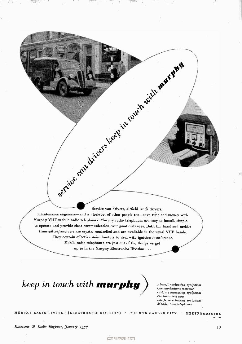
Fig. 8. Resistance pressure gauge. (Courtesy Southern Instruments Ltd.)
• 0 • • • • • • • • • • • • • • • • • •
Fig. 9. Simplified circuit diagram of transformer bridge for capacitor gauge
CAPACITOR TRANSDUCER
11-
BRIDGE INPUT
VARIABLE STANDARD CAPACITOR
BRIDGE OUTPUT
the same time they will operate satisfactorily at vibration frequencies up to several kc/s. With their trifling weight and small size, they can be attached to a light structure without affecting its natural movements. They are, however, expendible and cannot be calibrated in-dividually by the manufacturer. The gauge factor, and hence the calibration accuracy, is, however, usually guaranteed to within about +2%. Resistance strain gauges generally exhibit a slight hysteresis effect but this seldom exceeds 2%. Also, if strained beyond 2%, they are likely to take on a slight permanent set. The general method of utilizing the resistance change
of the strain gauge is to include it as one arm of a resistance bridge whose balance is upset by the resistance change. Resistance strain gauges have appreciable temperature coefficients which, in the absence of com-pensation, will give rise to errors, particularly in static measurements. Compensation for the temperature coefficient of the gauge is effected by placing a second similar gauge, not subjected to strain in the immed-iate neighbourhood of the measuring gauge. This compensating element is made a second arm of the bridge and, since temperature changes will affect both equally, the bridge balance is not upset. Too high a current through the gauge will likewise cause errors through overheating and values greater than 25 mA are generally deprecated for continuous use. The maximum working temperature is usually about 70°C. To all intents and purposes a single strain gauge is
sensitive to stresses in the direction of the wire length
Fig. 10. Water-cooled capacitor pressure gauge. (Courtesy Scuthern Instruments Ltd.)
only. If strains in more than one direction have to be determined at a particular point, it is necessary either to fix two or three separate gauges with different orientations or to employ multiple gauges as illustrated in Fig. 7.
For many applications resistance strain gauges are far superior to other types for the reasons mentioned above. Their attachment to the moving body and preparation for use is, however, delicate and tedious. The gauge is fixed in position with cement or glue on a surface which has been previously roughened to assist adhesion. Considerable care must be taken to ensure adhesion over the whole of the contact area and a drying period extending from one to five days must elapse before use. Furthermore, these gauges are highly susceptible to moisture and water-proofing is a necessary precaution.
Resistance strain gauges are frequently incorporated in special fixtures for pressure measurement. Thus they can take the form of a winding round a short length of metal tubing which can be screwed as an adaptor into the pressure system (Fig. 8). The slight increase or decrease of the tube diameter with rise or fall in pressure causes corresponding strains in the gauge wire. Such pressure gauges can be designed for ranges of 0-200 up to 0-10,000 lb/in2, but the total resistance change seldom exceeds 0 . 1%. Alternatively, a pair of resistance elements may be so attached to a pressure diaphragm or bellows that with a pressure change one is stretched while the other is compressed. Such a differential action associated with a bridge network gives greatly enhanced sensitivity. Sometimes two pairs of elements, one tensile and the other compressive, are incorporated in the unit so as to complete in themselves the four bridge arms. Used in conjunction with bellows, such gauges can be designed to cover pressure ranges as low as 0-1 lb/in2.
CAPACITOR TRANSDUCERS
These transducers have two main applications, static displacement measurement and pressure measurement. The basic law for a simple capacitor is that the capacit-
6 Electronic Ce Radio Engineer, January, 1957

ance varies inversely with d, the distance between the electrodes, but this assumes that the latter are plane-parallel and that their dimensions are considerably greater than d so that fringing flux is negligible. This seldom applies with capacitor transducers, but by providing a guard ring the effects of fringing are largely eliminated while, when the linear changes being measured are of the order of a few per cent, as is often the case, the percentage capacitance change will be nearly the same. When used for static displacement measurement and
mechanical gauging, the -transducer electrode or probe is seldom fixed rigidly in position, while the measuring equipment to which it is connected may be several feet away. The only suitable form of connector is coaxial cable, whose capacitance is likely to be several orders greater than that of the transducer and a further two or three greater than the capacitance change being measured. ' Changes in the cable capacitance due to movement or slight temperature variations will accord-ingly swamp those of the transducer and make it unworkable. * If, however, the transducer is connected as a 3-terminal device to a transformer bridge (Fig. 9), the effects of cable capacitance can be entirely eliminated and the capacitance measured is that between probe and work alone. The guard ring is connected to the cable outer and measurement of the capacitance change is effected by balancing the bridge for zero output with the standard variable capacitor in the opposite arm. If this standard is made a scaled-up version of the trans-ducer, the relationship between separation distances in the standard and in the transducer is the scale-factor squared. Dimensional changes as small as 2 x 10⁻⁶ in. can be measured in this way. Any low frequency com-patible with the input and output transformer character-istics can be used to drive the bridge. The same type of transducer and circuit can be employed for vibration measurement if an output meter is substituted for the null indicator. Under conditions where the difficulties of stray
capacitance do not arise, the transducer can be used as one arm of a simple bridge or as a circuit element of an oscillator, where the change in frequency will be a measure of the capacitance change and hence of the displacement. With the addition of a frequency dis-criminator vibration measurements can be made.
* "Industrial Applications of Transformer Bridge Circuits" R. Calvert, Brit. Commun. and Electronics. Vol. 3, No. 4, (April, 1958) p.180-3
Fig. 13. Schematic circuit diagram of Salford mechanical displacement
transducer
Fig. 11. Inductive pick-up. (Courtesy Philips Electrical Ltd.)
STYLUS MOUNTED
DIRECTLY ON END OF
ShAFT ( TEE STYLUS IS
HERE MASKED BY THE
BASE OF THE TRANSDUCER)
Fig. 12. Section through sensing unit of mechanical displacement transducer. (Courtesy Salford Electrical Instruments)
Capacitor transducers lend themselves readily to pressure measurement since a pressure diaphragm can itself form one electrode of the capacitor. They are commonly designed as units which can be screwed into the pressure system and provision is often made for water or compressed-air cooling (Fig. 10). The capacitance of the unit is of the order of 100-200 pF and the maximum change from 10 to 20 pF. They can be made to cover ranges from 0-0.25 lb/in2 to 0-10,000 lb/in2. The natural frequency of the diaphragm is of the order of 10-100 kc/s.
Electronic Ce Radio Engineer, January, 1957 7

They will operate at temperatures from below zero to +300°C, but a temperature change is invariably accompanied by a change in sensitivity.
INDUCTANCE TRANSDUCERS
Changes of inductance through mechanical movement can be effected in a variety of different ways. Of these one of the most convenient for employment in transducers is variation of coupling between coils by means of a moving iron core. Such devices can be used for either static or dynamic displacements. When connected to bridge circuits they can detect movements of 2 x 10 -6 in. over the range 0-1,000 c/s and a calibration accuracy of 1% is achievable. The maximum permissible acceleration, however, is in the region of 15-30 g, con-siderably lower than most of the other types, while the highest safe temperature is about 70°C.
In one representative design (Fig. 11) the transducer consists of three coils wound sided by side on a former with a small Ferroxcube core attached to a spring-supported driving pin. The centre coil is fed from a source whose frequency is well above the maximum frequency under examination and the two outer coils are connected into a bridge circuit followed by an amplifier and phase-sensitive demodulator. Movement of the core from its centre position alters the coil coupling and upsets the bridge balance. An entirely different type of instrument consists of a
sensing unit and an indicator which can be separated by half a mile or more of cable if desired. The former is illustrated in Fig. 12 and the complete circuit diagram in Fig. 13. In the transducer unit a magnetic core is
mounted on a spring-loaded stylus shaft between two coils L, and L, and these coils, together with the resistors R, and R, in the indicating unit, form a bridge circuit. The indicator takes the form of a moving-coil meter movement. Its yoke is wound with two coils P, and P,, one of which is driven from the a.c. mains while the other is connected to one diagonal of the bridge. The moving coil itself is connected across the other diagonal. Under quiescent conditions the bridge is balanced and no current flows through the moving coil. Longitudinal movement of the spindle in thé sensing unit shifts the core away from one coil towards the other, upsetting the bridge balance and causing current to flow in the moving coil. The latter will then turn and adjust itself to such a position that the current in it, resulting from the bridge unbalance and the voltage induced by the field flux, is in quadrature with the flux. In this position alone no torque is exerted on the coil and hence thé reading of the 'meter' is clearly a measure of the position of the transducer spindle. The instrument, which is sensitive to movements of 0 . 001 in. or less, is virtually unaffected by mains voltage or frequency variations.
Conclusion
The main types of movement transducers have been reviewed in this survey, but it would have been quite impracticable to have attempted to include all variations of these types, either commercially available or special adaptions. The writer wishes to acknowledge gratefully the considerable help received from manufacturers in the preparation of this article and particularly that from Messrs. Dawe Instruments Ltd.
Transistor Pulse Generator USE OF COMPLEMENTARY TRANSISTORS
By F. Rozner, B.Sc.(Eng.)*
SUMMARY. The use of p-n-p and n-p-n transistors in combination to generate pulses with short rise times is discussed. Use is also made of the minority carrier storage to broaden the pulse. The rise and fall times obtainable from the low-frequency medium-power transistors are of the order of 0.7 ,usec at 100-kcIs repetition frequency with a peak power output of 1 watt.
he most notable feature of progress in transistor design is the continuous extension of their frequency range. Junction transistors are now available which will produce rise times of fractions of a microsecond in switching circuits. However, their power-handling capacity is small, although they can pass high currents for very short times without ill effects.
Transistors capable of handling appreiable power are ,
8
now available, but their frequency range in the common-emitter connection does not extend beyond the audio range. In switching circuits, the result is a slow rise time and an appreciable minority-carrier storage. The latter effect takes place whenever a transistor is driven into saturation. It manifests itself as delay in response of
* Ferguson Radio Corporation Limited.
Electronic e Radio Engineer, January, 1957

100
et'
10
zN94A t t F-53.1e
o C72
elmM
0-1
0072
7" •••,.
'••
/0(m A) 10
o Fig. 1. Variations of fo and a' with collector current
0.1 00
the collector current when the drive is removed from the base. The subsequent exponential decay of the collector current is slow. A simple transient analysis of the junction transistor'
shows that the rise time can be speeded up by driving the transistor harder. The relevant expression for the rise of the collector current is:
a „ ic — a ,b(1 — E-t/T) , (1)
where i, =- collector current. , oc = emitter-collector current gain. = constant-current drive applied to the base.
1 T=
(1 — a) 2irf,›
fG, is the cut-off frequency; i.e., the frequency at which cc drops 3 dB below its low-frequency value. While this theory is far from accurate, it provides a
useful qualitative guide for the circuit designer. The expression shows that the parameters which
govern the transient response are cc and f. Both should be as high as possible for fast switching. This, inciden-tally, explains why the earthed-base configuration has no advantage over the earthed-emitter for a given driving current.2 Although the cut-off frequency of the earthed-emitter is lower by a factor of 1/(1 — a) its current gain is greater by a similar amount. The parameters cc and fo, do not remain constant over
a wide range of collector currents. The variation of fx and of a' [which is connected with a by the identity
=-- a/(1 — cc)] for transistors used in the circuits described later is shown in Fig. 1. As a result of fall in cc' and fx with increasing collector current a slow-down of transients can be expected when high current output is required.
In conventional cross-coupled circuits of the Eccles-Jordan type, th'e signal switching on a transistor is supplied from a high impedance. The resulting limita-tion of the switching speed can be avoided in a circuit shown in Fig. 2, which utilizes the complementary symmetry of transistors. Here, both the n-p-n and p-n-p transistors go into saturation together. T/ reaches this state quickly and its collector-to-emitter resistance drops to about 30 ohms. The result is a powerful drive applied to T2. In fact, peak 42 can be arranged to be as large or even larger than the final 42. Once T2 reaches saturation, no further base current is necessary to main-
H.T
Fig. 2. The principle of the circuit in Fig. 3.
tain this state until the minority carriers in the base region have been swept away. The circuit can be arranged so that T1 conducts a large current for a very short time, causing T2 to produce a pulse of similar current amplitude, but of much longer duration. It thus becomes possible to use a low-power high-frequency transistor for T1 and a medium-power low-frequency one for T2. The circuit in Fig. 2, which is arranged as a triggered
generator, incorporates the principles mentioned above. It suffers, however, from two disadvantages. One is that the pulse width is largely uncontrolled, and the other that the decay is very slow. Both disadvantages can be overcome by means of a third transistor T3 (Fig. 3).
In order to switch over a transistor from saturation to near cut-off in minimum time, it is necessary either to apply a large pulse (positive-going for p-n-p transis-tors) to the base, or to connect the base to the emitter via a very small impedance. The latter method is used in Fig. 3. As Ce2 charges, T3 begins to conduct and quickly saturates. The collector-emitter resistance of T3 in the saturated state is about 50 ohms. The circuit in Fig. 3 is designed to give an output of
100 mA peak into 100 ohms. The rise time depends on the peak current in T1 which is limited by the average permissible power dissipation. The average power dissipated in T1 during one pulse
can be calculated from the voltage and current wave-forms shown in Fig. 4 (b) and (c). It is given, approx-imately, by
Fig. 3. The complete pulse generator.
Electronic & Radio Engineer, Yanuary, 1.957 9

P 1 { ftc(Ici t)( vi — V2 t) dt ft° V2 (hi
t4 J ti o
Substituting the values from Fig. 4,
P = 340 mW per pulse.
If f is the pulse repetition frequency, then the average power dissipation becomes,
Pay = 340 (t1 t4)fs
= 44 mW, for f = 0.1 Mc/s,
i.e., the maximum permissible power dissipation of 50 mW is not exceeded.
It will be noted that the above calculation applies to the particular transistor used. For different transistors the waveforms will vary and hence the power dissipation will differ. /el can be varied by increasing C.,/ or Cbi, or decreasing
Rey The time constant Re/ Cep however, must be short enough to discharge eel completely during the cycle. That is,
4 Re1 C41 < 16 —0 µsec.
The same applies to the other time constant Re2 Ce2. The magnitude of Rt., Ct,1 is governed by the maximum
permissible drive applied to T1 and not by the charge and discharge times. During the OFF stroke, when is cut off, Cbi discharges through the diode, which acts as a d.c. restorer. The main function of Rbi is to provide some temperature stabilization. In addition, after the peak current in T1- has been reached, the continued charge of Cbi through R bl and of Cei through T1, has the effect of reverse-biasing the base—emitter diode of [Fig. 4 (d)]. As a result, T1 cuts off quickly and its average power dissipation is decreased.
(a)
(b)
(c)
(d)
Fig. 4. Waveforms of the circuit in Fig. 3.
OUTPUT WAVEFORM
0•7µsec =-- IS µsec
-= 0.6,Asec 4 = 0•6p.sec
10V
I2V 4V
I25mA
t' t dt } = f t41. 6 /el + V23 t1 e22t4).
The repetition frequency was chosen to be 100 kc/s. This restricted /e/ to 125 mA. The rise time so obtained was 0.7 µsec. If a lower repetition frequency is desired, /el can be increased up to about 150 mA and the rise time reduced to 0.5 µsec. The fall time depends upon the setting of Re2; i.e., it
varies with the pulse duration. It is about 0.6 µsec at 2.5 ,usec total pulse width, and it increases to 1 µsec when the pulse width is 5 µsec. The figures given above apply when the minimum
trigger current to cause regeneration is applied. This is about 3 mA, while the voltage depends upon the steep-ness of the waveform and magnitude of the coupling capacitor. It is of the order of 0.5 volt. The current decreases as the temperature goes up.
The reason can be seen by considering the stability of the circuit.
In the rest condition there are nominally no currents flowing anywhere in the circuit. Fig. 1 shows that at zero collector current the gain of the transistors is low. In order to initiate regeneration a disturbance must be introduced which is large enough to bring the transistors into a region where the current gains are large enough for the loop gain to exceed unity. The condition described above is modified by the
presence of the collector leakage currents 4. In the absence of adequate stabilization, these currents may increase (with temperature) to a point where the circuit becomes unstable. The transistor primarily concerned is T1, whose leakage current biases T 2. It is possible to define a stability factor3 S which relates the changes in leakage current .40 to the changes in the collector current Ic produced as a consequence. This factor assumes a constant a and cannot, therefore, be applied to T1, which is in a region where oc changes very rapidly with /el. The stability is, therefore, best determined experimentally and if found inadequate, the ratio Rbi/Rei can be lowered. The circuit so far described is of the triggered variety;
i.e., it acts as a regenerative amplifier. It can easily be made free running by connecting a resistor between the base of T1 and the positive h.t. rail. This resistor can conveniently be made variable between, say, 50 kû and 550 kg which gives a continuous frequency variation from about 30 kc/s to 100 kc/s. The shape of the pulse is the same as when triggered with a minimum trigger power. The repetition frequency is liable to drift with temperature, but this effect can be minimized by stabilizing the d.c. operating conditions against varia-tions of /ei. as indicated above.
Acknowledgments The author is indebted to the Directors of Ferguson
Radio Corporation Ltd. for permission to publish this article and to Mr. Francis Oakes for useful discussions.
REFERENCES = J. L. Moll, "Large Signal Transient Response of Junction Transistors"
Proc. Inst. Radio Engrs., Dec. 1954. • J. J. Ebers & J. L. Moll, "Large Signal Behaviour of Junction Transistors",
Proc. Inst. Radio Engrs., Dec. 1954. • R. Shea, Ed., "Principles of Transistor Circuits", John Wiley, New York.
10 Electronic ee Radio Engineer, January, 1957

Selective Admittance-Measuring Set
for use at Medium Frequencies
By D. D. Crombie*
SUMMARY. An extremely selective instrument for the measurement of admittance is described. It is intended particularly for measurements on m.f. aerials. A resonance method of determining the unknown admittance is employed, and the selectivity necessary to remove interference, which may occur when measurements are made on aerials, is obtained by using a homodyne voltmeter.
W hile attempting to improve the efficiency of a short vertical radiator operating at 129 kc/s, equipment to measure the base impedance or admittance was needed. In the absence of a suitable bridge, measurements were attempted initially with a Q, meter, and then by substi-tution methods,' Both methods were unsuccessful because of interference picked up by the aerial from nearby high-power broadcasting stations.
In order to overcome this difficulty, the instrument described here was constructed, its main feature being the extremely high selectivity attained without great circuit complication. While a final version of the instru-ment was not made, a laboratory prototype was con-structed. Because of the novel means of obtaining selectivity, it is thought that a description of the apparatus may be of interest.
Method of Measurement A resonance method of measuring admittances has
been recently described2 and this was used. The principle is shown in Fig. 1. A tuned circuit LC in series with a known conductance G is connected across a source of e.m.f. Ei of the required frequency. When the LC circuit is tuned to resonance it may be regarded as a conduc-tance GI. If a high-input impedance voltmeter is used to measure, first the input voltage, Ej, and then the output
Fig. 2. Conductance-meter calibration.
10
5
3 2
G/G 1.0
05
0•3
02
01 02 04 06 08 I 0 O.FRACTION OF FULL SCALE READING
Fig. 1. Basic admittance-measuring circuit.
voltage E0 across the tuned circuit, then
E0 G — Ei oi — G
or G 1 —
— 1 G (1)
Thus the tuned-circuit conductance G1 may be found in terms of the ratio 01 of the voltmeter readings. Let be the capacitance required for resonance. If now an unknown admittance Yx = Gx jBx is connected across the tuned circuit and resonance is re-established with a value of capacitance C2, giving a new ratio 02 of volt-meter readings, then
Thus
and
1 - 0 G 2 G 1 Gx = 2 G
02
Gx = G 2 - G 1 • • • • Bx w(C2 — C1) . .
Thus, by the use of equation ( 1) or Fig. 2, which is a plot of equation ( 1), and the use of a calibrated variable capacitor, both the conductance and susceptance of the unknown may be found. The method appears particu-larly suitable when high- Q, coils are used in the tuned circuit, but in any case the method should be compar-able to the use of a Q, meter using the same coils.
Selectivity In the method described and in the case of a Q, meter,
the effect of interfering signals depends on the selectivity
* Dominion Physical Laboratory, New Zealand.
Electronic ee. Radio Engineer, January, 1957 11

VARIABLE-FREQUENCY
OSCILLATOR
SET FULL ULULE
v,
CATHODE -FOLLOWER
of the circuit and thus on its effective Q, when the element to be measured is connected. Thus external interference is worst with low- Q, elements. A possible method of improving the selectivity would be to replace the r.f. voltmeter by a selective amplifier but this would be troublesome, and possibly difficult, because of linearity and frequency-stability requirements. An alternative method similar to one which has been dis-cussed by Tucker3 is to demodulate the signal from the measuring circuit in a homodyne demodulator by a signal obtained from the primary source. Then the overall bandwidth is determined by that of a low-pass filter following the demodulator. Since this can be small, very high selectivity is obtainable.
Let E, sin (ad + #) be the desired output of the measuring circuit, and E sin cot the demodulating signal while Ea sin pt is an interfering signal. Then for a multiplier in its linear state the output O is
Fig. 4. Circuit of admittance-measuring set.
OSCILLATOR
q, oo.O. °oil§
30k
001µ F
ZMIL
25 kn
0'1 µ
500p F
12 0•IµF
72-6N7
• 2k..o.
10k,n.
6SN7
O'01µF
2 M.(1
o-acomA o•ip,F
100 V
V2b
6SN7
Fig. 3. Block diagram.
O =- E sin cut [E, sin (cot ± 4.) ± Ea sin pt]
E E,
= 2
E Ea[cos (w — p)t — cos 2
If the post-demodulator filter passes only d.c., then all the a.c. terms are suppressed and the a.c. output is zero. If the low-pass filter passes frequencies up to Zlet)/27r and rejects all others, then interfering signals with frequen-cies within ± iico/27r of w/27r will affect the output and the effective bandwidth of the instrument will be du.)/ir. If a d.c. meter acts as the filter, then ilw/27r will be of the order of 1 c/s. When a switched-rectifier demodulator is used, the
output depends only slightly on the switching-signal amplitude E, when E is sufficiently large to switch the diodes from the fully-conducting to the non-conducting
[cos # — cos (2 cot ± #)]
1001(4
iMft
0.01mF II
MEASURING CIRCUIT
SET ZERO
SET FULL SCALE
(co P)ti • • (5)
—1
MEASURE
DEMODULATOR
12 Electronic & Radio Engineer,January,

state. Thus the demodulator output is proportional to cos #. A difficulty with this type of rectifier is that
maximum output is obtained when # = O. Thus, as shown in the Appendix, if # is not zero an error is possible because the measurement circuit may be tuned off resonance when the demodulator output is maximum. However, since the demodulator output is proportional to cos #, the response curve of the tuned circuit is approxi-mately the amplitude-response curve squared and is thus sharper than the response with an amplitude detector.
The Instrument The instrument is shown in block form in Fig. 3 and
schematically in Fig. 4. A variable-frequency oscillator Via covering the frequency range 100 kc/s-1,000 kc/s in two bands is followed by a cathode-follower buffer \Tit) whose output is connected to (a) the measuring circuit through one of two standard conductances, and (b) to the carrier-input terminals of the demodulator.
Since the demodulator carrier source must be balanced and operate over a ten-to-one frequency range, a triode phase-splitter4 V2a rather than a transformer is used. The balancing potentiometer R, is used to set the
meter to zero when the signal input to the demodulator is short-circuited by means of switch S3. The demodula-tor uses two shunt-connected diodes V3 coupled to the voltage to be measured by a cathode-follower V2o, which does not load the measuring circuit. In use, the demodulator zero is set as described above, and the input voltage to the measuring circuit is measured by the demodulator which is adjusted to read full scale by means of the variable resistance Ri in the anode supply of the oscillator. Then admittances may be measured as already described. These three operations are selected by the switch S3. Alternative conductance ranges of 100-1 p,mhos and 1,000-10 pmhos may be chosen by means of switch S2 which changes the standard con-ductances in series with the resonant circuit from 10 µmhos to 100 pmhos. In order to reduce the effect of stray capacitances in parallel with these, the switch S3 is wired as shown, while the standard conductances (I-watt carbon resistors) are mounted in earthed coaxial screens. The instrument was constructed in three screened
enclosures as indicated on the circuit diagram.
Sources of Error The main sources of errors are as follows: (a) The loading effect of the voltmeter input im-
pedance (b) Oscillator harmonics (c) Demodulator non-linearity (d) Change in admittance of the conductance stan-
dards due to parallel capacitance (e) Effect of phase shifts between the demodulator
inputs, and of the phase angle of the conductance standards.
These will be briefly discussed: (a) If the input impedance of the voltmeter is com-
parable with the impedance of the measuring circuit then it is clear that switching from "set full scale" to "measure" will upset the voltages in the measuring circuit. However, it is easy to obtain a sufficiently ,high input impedance to avoid this.
I 01
1 005
loo 32
0 995
0 990
xe(
X—
S 10 15 20 25
RELATIVE VOLTMETER READING
Fig. 5. Linearity of homodyne demodulator.
30 35
- I Ri x ..ol
stA , v
e.im -0'01 Ri/x-0
I I 1 10 8 6 4 2 0 —2 —4
PHASE SHIFT 952 ( DEGREES)
Fig. 6. Effect of reactance X1 across R1 and phase-she , #2 on the value of m in per cent.
015
010
0•05
k °
0 05
010
0 15 —10 —8 —6 —4 —2 0 2 4
PHASE SHIFT 02 ( DEGREES)
—6 —8 —10
— o
RIX, =0* 01
6 e 10
Fig. 7. Susceptance error due to stray capacitance and phase-shift.
(b) If the oscillator output contains odd harmonics, their relative proportion will differ in the "set full scale" and "measure" positions of S3 because of the tuned-circuit selectivity. Since the demodulator has some response to odd harmonics this will introduce an error.
(c) If the demodulator input/output curve is not linear, errors due to this cause can be removed by calibration. In the present case, at the signal levels used, the demodulator proved to be linear as shown in Fig. 5, which is a comparison of the demodulator output current and the readings of a valve voltmeter connected across the test circuit when the resistance across it was varied.
(d) If a stray reactance x appears across the standard conductance R, then R is changed to an impedance RIV(1 Ra/x2). Thus the conductance measurements are in error by a factor •V(1 R2/x2).
Electronic ed Radio Engineer, January, 1957 13

De etc,
Opt,
MEASURING FREQUENCY
1 HOMODYNE DEMODULATOR
2
5
O 200 250 300 350 400 450 500
INTERFERING SIGNAL FREQUENCY Oct/0
Fig. 8. Effect of interfering signals.
(e) The sources of error (a)—(d) above will be present whether a homodyne or a rectifier voltmeter is used. However, there is another source of error which occurs only with a homodyne voltmeter. When the inputs to the demodulator and the tuned circuit differ in phase, the d.c. output of the homodyne voltmeter, as the resonant circuit tuning is varied, will be a maximum at some capacitance different from that required for maximum amplitude across the tuned circuit. This is due to the maximum demodulator output occurring when the phase shift in the tuned circuit is approximately equal and opposite to the external phase shift. This source of error is discussed fully in the Appendix, where it is shown that the percentage error in conductance measurement is equal to (m — 1)/100, where
m = [cos 4,2 R sin .1e2 + V{1 ± (R1/42}]
• • (6)
R1 being the standard conductance shunted by a capacitive reactance X1, and 4,2 the total phase shift due to all other stray capacitances. Values of m for various values of Ri/L1 and /)2 are plotted in Fig. 6. It will be seen that the error due to this cause is small for reason-able values of 4,2 and Ri/X1 and, in the laboratory model, errors due to this cause were insignificant. The error in susceptance measurements is shown to be k. Gx where
k =
R1 — cos 4,2 — sin 4,2 X 1
R 2 COS fk ± 11 sin (4 + V{1 e")
2 X 1 Values of k are plotted in Fig. 7. It will be seen that
errors in susceptance may be appreciable. Some measurements were made with the experimental model to investigate this. A frequency of 1 Mc/s was chosen since the effect of stray capacitances is greatest at high frequencies. A valve voltmeter was connected across the test circuit, to act as a phase insensitive detector, and the test circuit capacitor tuned for maximum response. The process was repeated, using the homodyne demodulator, various values of conductance being connected across the test circuits. The difference between the respective capacitor readings for each conductance was taken as the error in capacitance. On the low conductance range an
(7)
Fig. 9. Equivalent circuit.
error of 0.08 pF per ,umho was found and on the high range the error was 0-03 pF per p,mho. On the high range, comparisons could not be extended above 400 mho because it became impossible to locate the point of
•resonance with the valve voltmeter, although this was still possible using the homodyne demodulator.
Effect of Interfering Signals There are two ways in which an interfering signal
may affect the performance of the device: (a) When the interfering frequency is very nearly
equal to that of the test frequency, or an odd harmonic of it, beats may be visible on the meter.
(b) If the amplitude of the interference is large, the test circuit buffer or the demodulator may be over-loaded. The effectiveness of the selective demodulator was
demonstrated by measuring the admittance of a 5,000-ohm resistance connected in series with a power signal generator giving 20 volts output at 337 kc/s, which
TO DEMODULATOR
constituted the interfering signal. A valve voltmeter was connected in parallel with this admittance. The results are shown in Fig. 8 as a function of the frequency of the interfering signal generator. It will be seen that the voltmeter readings, on which would depend the measured value of the resistance, are seriously affected, whereas the homodyne-detector readings are almost unaffected. When the frequency of the interfering signal generator was within a few cycles of the test frequency, however, large beats were seen. The small reduction in the admittance-meter readings near the test frequency is probably due to overloading as discussed above. On reduction of the interfering signal level to 10 volts this effect disappeared. The effect of noise and impulse interference is greatly
reduced by the narrow bandwidth of the device. This was strikingly demonstrated during tests in the near vicinity of a high-power radar set. When the radar aerial was pointing towards the admittance meter a valve voltmeter connected across the test terminals was unusable whereas the admittance-meter readings were quite unaffected.
Conclusion The experimental instrument described has shown
that the method of obtaining selectivity is practicable. Although it has been applied to an admittance-measur-ing instrument it would appear that the principle used is applicable in many measuring instruments where there
14 Electronic & Radio Engineer, January, 1957

is a local noise-free source which can be used as a reference demodulating signal.
APPENDIX
The Effect of Stray Phase Shifts The stray phase shifts may be divided into two types: (a) The effect of stray capacitance across the standard con-
ductance giving a phase shift Or (b) All other phase shifts 4,2 between the demodulator inputs. The equivalent circuit taking these into account is shown in Fig. 9.
R, is the resistance of the standard conductance, while X, is the reactance shunting it, Re and X, representing the tuned circuit. In the absence of X, and 91, the tuned circuit will be tuned for maximum impedance, and if its Q > > 1 this will occur when X, = CO.
Ignoring 0, for the time being, it can be shown that
E. X RS (RR' + XXI) ± XXI'? — R,X) • Xi• R, + R2 • R2 +X2
R, where R — and X -=
R, R2 ± X2
If O is the demodulator response then O
where #t = + OS.
X Rg X
Rg ± R2
[RR, + XX,) cos — (X,R — RaC) sin 21
R2 X2
In the absence of #1 and 952 the value of O is 0 — R2 R, Rg
0 X URR1 + XXI) COS ig — (X1R — RIX) sin el —
0„, ± X2
The matemum value of this, obtained by varying X2 and thus X, may be found by differentiating 8/0„, with respect to X and equating to zero.. When this is dtine it is found that the value of X required for maximum 818„, is
E,
Et cos 4,,
X' = R1 [COS 4.2 sin 4,2 + V{1 + (11)2}] — x, cos 4,2 sin #2
giving
010„, = 1 [cos R, we • yi sin 4,2 + {i (R_)2p xi = m 0,. where
= [cos + is + V {1 + (1-i-x ) 2}11
From equation (3)
C.= m. 01 — 82 1 .01 — 0, 1 insteau — . - - 81 .82 R, 01 • Os R1
in the absence of the errors being discussed. Thus the measurement of the unknown conductance due to phase-
shift is wrong by the factor m. Values of m are plotted in Fig. 6 as functions of #2 and Ri/X,. It will be seen that the errors are small for reasonable values of #2 and Ri/X2. When the circuit is tuned for maximum meter reading, the total
circuit susceptance
1 •=. - — B = _= kG X
where
R, — COS #2 — sin 0, X].
COS 02 ± G7,1) sin e2 + v {1 + (--) RI RI 2
Then for the initial measurement, B = B' -= — (G. G,).k, B. and G. being the susceptance and conductance of the in-ductance in the tuned circuit, while B' is the value of the variable standard capacitance necessary for resonance and G, is the standard conductance. When the unknown admittance G. -I- jB,, is connected and
resonance re-established, B = B" ± B.= — (G. ± G, + G.)k where B" is the value of the variable susceptance
Thus the susceptance error AB = k. G. and the value of the unknown susceptance B. is in error by an amount dependent on its conductance and on k. Values of k are plotted in Fig. 7 for various values of 95. and Rig,.
REFERENCES F. E. Terman, " Radio Engineers Handbook", p. 911, McGraw Hill, N.Y.
• W. B. Bernard, "Admittance Analyser", Electronics, Vol. 23, No. 8, P. 107. • D. G. Tucker, "A selective transmission measuring set", J. Irian. Elect.
En3";):, III, Vol. 94, p. 211. . G Tucker, "Balanced rectifier modulators without transformers" Electronic Engineering, Vol. 22, No. 287, p. 139.
CALDER HALL TELEVISION CAMERA
CABLE COUPLING
HOSE COUPLING
INLET HOLES FOR COOLING CO2
HEATER TRANSFORMER (MOULDED IN ARALDITE)
GEARBOX
CAMERA TUBE ASSEMBLY
HEAD AMPLIFIER (MOULDED IN ARALDITE)
LAMPS MIRROR
V
ROTATABLE OPTICAL SYSTEM
This Pye industrial television camera was designed to provide visual inspection of the interior of the Calder Hall atomic reactor when shut down. It must operate in the presence of nuclear radiation and an outside temperature of 200° C. In use, it is housed in a stainless-steel cylinder 40 in. long and n in. diameter. All metal parts are of stainless steel or Elektron metal and all electrical parts are "potted" to make possible decontamina-tion. The camera carries its own lighting system, and a solenoid-operated mirror provides for sideways viewing. The whole assembly can be rotated to provide all-round viewing. The associated control unit contains circuits for generating the Staticon scanning waveforms, blanking and sync pulses and power supplies.
Electronic & Radio Engineer, January, 1.957 11

Gas- Filled Voltage Stabilizers EFFECT OF TUBE PARAMETERS ON NOISE CHARACTERISTICS
By F. A. Benson, M.Eng., Ph.D., A.M.I.E.E., M.I.R.E.*
SUMMARY. Measurements have been made to determine the-effects of varying the cathode material, the gas-filling and the gas-
pressure on the noise characteristics of glow-discharge voltage-stabilizer tubes. The results of the work are presented here and discussed.
R
240 V D.C.
II
I t
AMPLIFIER
Detailed investigations have been carried out in recent years to determine the variations in the characteristics and the limitations of glow-discharge voltage-stabilizer tubes, but of the many published papers on the subject only threel 3 deal with tube noise. Two of these1,2 are concerned with peak-noise measurements and give noise—current curves for several types of commercial tube. The third paper deals with mean-noise measurements on six different types of commercial tube. Until the work described in these papers was carried out very little information was available on noise characteristics of tubes. The only other figures published are found in a few tube specifica-tions, but here a single value is usually quoted. Many tube specifications make no mention of noise characteris-tics and those which do so give no indication of the variations in noise with tube current, from tube to tube of similar or different designs, from operation to operation with a single tube, or with life. The work described in the three papers by the author,
mentioned above, showed that the noise characteristics of all tubes, at any stage in their life, follow the same general form; that is, the noise increases with decreasing
*The University of Sheffield
Fig. I. Circuit arrangement for noise measurements on glow-discharge tubes
DETECTOR
tube current. Noise increases rapidly as the region of minimum current is approached, and noise characteris-tics are found to be nearly reproducible for a given tube. High-stability reference tubes give noise voltages of the same order of magnitude as normal ones, but there are practically no changes in their noise characteristics with time. With some tubes, noise has been found to increase at all currents with life while with others it has been observed to decrease at high currents with life, increase at low currents and over a small current range to remain almost the same. The papers under consideration concluded that further work might usefully be done in an attempt to produce satisfactory voltage-regulator tubes having less noise than present ones. It was also hoped that in future all tube specifications would include information on noise characteristics, giving limits of peak and mean-noise voltages to be expected in the current range and under the preferred operating conditions.
In order to see what the possibilities of reducing tube noise are, work has now been carried out to find the influence of some tube parameters on noise characteris-tics. Measurements have already been made4,5 to determine the influence of gas filling, gas pressure and
16 Electronic Co' Radio Engineer, January, 1957

Fig. 2. Noise—current characteristics cf glow-discharge tubes with nickel and cerium-alloy cathodes and for neon/argon
and heliuml argon gas fillings
Fig. 3. Noise—current characteristics of glow-discharge tubes with cerium-alloy cathodes for both helium/argon and nen/ argon fillings and different gas pressures
240
o o °
NICKEL/HELIUM TUBES
£1 ( •"fe• 71+-- NICKEL/NEON TUBES , .. o "-es. •
•I
• —
CERIUM /HELIUM TUBES
CERIUM / NEON TUBES
*lee
e 12
TUBE CURRENT (rnA)
16 20
240
O
+.
80 -
• c>ii +
e
aa let:› (5<) a6:eP% as-'P'àee>, :10 1/4'9:: —.I 30),
+ HELIUM 50 mm • 40 RI rn O 30 min
x NEON
•
50 mm
40 min
30 nun
La
12 16 20
TUBE CURRENT ( NIA)
direct operating current on the impedance—frequency characteristics4 of tubes over the frequency range 20 c/s to 100 kc/s. Tests have also been performed on tubes differing in cathode material, gas filling, gas pressure and construction to find the effects of changing these parameters on the magnitudes and durations of the initial drifts and on the running-voltage/temperature curves5. The tubes specially manufactured for these previous investigations have been used for the present studies.
Procedure
The noise measurements were made with a calibrated amplifier-detector unit having an almost perfectly linear response over the frequency range 10 c/s to 100 kc/s. The circuit arrangement is shown in Fig. 1. The d.c. supply for the tubes was obtained from two
h.t. accumulators. A potentiometer across this source, for the purpose of varying the voltage supplied to resistor R and the tube, gave trouble by producing some noise itself although such an arrangement had previously been used with success.1-8 As numerous tapping points were available on the accumulator the potentiometer was removed and the tube current was
Electronic ee Radio Engineer, January, 1957
varied, in each case, in steps. The detector circuit consisted of a rectifier and moving-coil instrument so that it recorded mean-noise-voltage values. The noise voltages were noted for each tube as the current was varied throughout its specified range. After each change of current, time was allowed for the tube to settle down again to steady conditions before a further noise reading was taken.
Results
Fig. 2 shows the noise characteristics of tubes with nickel and cerium-alloy* cathodes and for neon and helium gas fillings. The effects of varying the percentages of neon and helium in the gas filling were also tried, but the results recorded are not shown on Fig. 2 to avoid confusion. They are, however, briefly discussed later. These particular tests were made with two groups of tubes. The first group had cerium cathodes and gas fillings of 45 mint neon, 30 mm neon -I- 10 mm helium, 27 mm neon 13 mm helium, 24 mm neon
16 mm helium, 20 mm neon -F 20 mm helium,
* The alloy used consisted of 45% cerium, 45% iron, 5% of various rare earths and 5% of impurities.
t mm refers to mm of ,mercury.
17

5
320
240
80
o
o -`,. o COPPER
\°°bsi.24,
s "s, --
NICKEL
7
-cr- s --- -- s_ o
-.di-MOLYBDENUM
----008---
TANTALUM
--u-cb-
g___•,_,
__ 9_,,a.
ZIRCONIUM ,
__«...9
4 6
TUBE CURRENT ( IOU
o \ ‘ • cY\ • COPPER
MOLYBDENUM
0...
"-- s
o ....—e--..0q-,-----•-•%:,.
--- --07- - r,
--06)-17- - -5-8--*--_-_-_,p-- 0 0
--- - TANTALUM ZIRCONIUM
10 0 2 4 6
TUBE CURRENT (mA)
8 10
Fig. 4 (left). Noise—current characteristics of glow-discharge tubes with neonlargon fillings far different cathode materials
Fig. 5 (right). Noise—current characteristics of glow-discharge tubes with helium/argon fillings for different cathode materials
Fig. 6. RUNNING- VOLTAGE/CURRENT CHARACTERISTICS OF
16 ram neon ± 24 mm helium, 12 mm neon + 28 mm helium, 8 mm neon + 32 mm helium and 40 mm helium. To the pure neon tubes 0 67% argon was added ; in all the other tubes the argon content of the gas filling was 2 5%. The second group of tubes had nickel cathodes and fillings of 40 mm neon, 30 mm neon + 10 mm helium, 20 mm neon + 20 mm helium, 10 mm neon + 30 mm helium and 40 mm helium. To each gas filling, in this case, 05% argon was added. All the tubes in both groups had a wire anode of 1-mm diameter and a concentric cylindrical cathode with sheets of mica at the ends to confine the glow to the space inside the cathode. The cathode length was 21 . 5 mm, the cathode diameter 12 . 5 mm and the gas volume about 6.9 c.c. The results obtained for both helium- and neon-filled
tubes with different gas pressures are shown in Fig. 3. All the tubes used here had cerium-alloy cathodes and the gas-filling pressures were 30, 35, 40, 45 and 50 mm. Only the results obtained for 30, 40 and 50 mm pressures are plotted on Fig. 3 for clarity. The dimensions of the tubes were the same as those given above with the exception of the cathode length which was now reduced slightly to 19.5 mm. The neon tubes had 0.67% argon in the gas filling, the helium ones 2.2%.
Figs. 4 and 5 give the noise characteristics for tubes with different cathode materials ; Fig. 4 is for neon tubes, Fig. 5 for helium ones. The cathodes are of tantalum, copper, nickel, zirconium and molybdenum, each with fillings of neon/argon 99.7/0.3% or helium/ argon 99.55/0.45%. The glass bulbs of these tubes and the anode diameters were the same sizes as for the tubes described above, but no mica sheets were used here, the cathode diameter was only 8 mm and the cathode length 10 mm.
Discussion of Results
The noise voltages of all the tubes tested follow the same general form as observed previously1-3 ; that is,
(a). 20 mm neon + 20 mm helium + 2.5% argon
the noise decreases with increasing tube current. Over most of the current range the noise does not change much, but increases rapidly as the region of minimum current is approached. This region should be avoided therefore in any tube if low-noise operation is desired. If the noise voltage is recorded for a given tube at a specified current its value is reproducible after restriking, even from day to day. The present work also confirms earlier results that the noise characteristics generally vary very little from tube to tube of a given design, a fact which may be clearly seen from Figs. 2-5.
It will be noted from the results plotted on Fig. 2 that helium-filled tubes give more noise than neon-filled ones with the same cathode material. At a current of 6 mA a nickel/helium tube produces about three times as much noise as a cerium/neon one. When helium and neon gases are mixed the resulting noise-current curves of tire tubes lie between those for helium and neon respectively. In fact, with nickel-cathodes, as might be expected, tubes with a large percentage of
18 Electronic ee Radio Engineer, January, 1957

neon have noise-current curves lying near the curve for a pure-neon tube and those with only a small amount of neon have characteristics approaching those for pure helium-filled tubes. Rather surprisingly such behaviour was not observed with cerium-cathode tubes. In this case, all tubes containing any helium, however small a percentage, gave noise characteristics near to the curves for pure helium tubes although they did give slightly less noise. It is perhaps unreasonable to compare the pure-neon tubes here with the others because they contained much less argon. Another interesting point was observed in carrying
out the tests on the cerium tubes with different gas fillings. All tubes of this type containing 50% or more neon (except those containing no helium, for which the argon content was only 0.67%) produced internal h.f. oscillations .at tube currents greater than about 12 mA. Such oscillations have been observed by the author previously on various experimental cerium tubes containing neon/helium mixtures with 2 • 5% argon and also on certain commercial stabilizers with
The aim of the photographs was to show the general shape of the curves only. The signal frequency used was 20 c/s. The exposure
time of the camera was about 1 second; i.e., the photographs show in reality about 20 characteristics superimposed on each other. Usually, there is only one stable characteristic which appears on the photograph. In some cases, however, there seem to be two or more stable characteristics. After the tube has been operating for some time, voltage and current ` jump' from one characteristic to another. Such a jump is accompanied by changes in the glow. This phenomenon has been observed mostly on tubes containing a large percentage of helium in the gas filling.
In some cases, the transfer from one characteristic to another occurs very frequently; in fact, so frequently that of the 20 traces photographed some belong to one and some to the other characteristic. Two such 'half-stable' running-voltage/current characteristics are illustrated in Fig. 8. The photograph has been obtained for a tube with a cerium-alloy cathode and
CERIUM-CATHODE TUBES EXHIBITING INTERNAL OSCILLATIONS
(b). 27 mm neon ± 13 mm helium ± 2.5 argon
pure helium plus 2.2% argon gas fillings when operated at large currents. The oscillations seem to be associated with the percentage of argon in the gas filling; they may have magnitudes of several volts peak to peak and have a frequency of the order of 105 c/s. Typical running-voltage/current characteristics of tubes exhibit-ing internal oscillations are shown on the oscillograms of Fig. 6. The development of oscillations with increasing current is shown by the photographs of tube voltage and current in Fig. 7 (the tube was fed from a d.c. supply only). When operated at a current of 10 mA the tubes exhibited no oscillations, at 15 mA the voltage oscillations had a magnitude of about 1.5 V peak to peak and at 20 mA they were much larger and their waveform was highly distorted. The characteristics shown by these photographs are,
strictly speaking, dynamic characteristics taken with a very low signal frequency. The difference between dynamic and static characteristics being very small in this range, the error introduced has been neglected,
(c). 27 mm neon + 13 mm helium + 2.5% argon
a helium gas filling, the gas pressure being 40 mm. 'Jumping' from one characteristic to another seems
to be facilitated by internal h.f. oscillations. Such a state is clearly illustrated in Fig. 6 (b). As for the thin lines on Fig. 6 (c), these belong to a characteristic which was traced only once or twice during the exposure time. The results shown in Fig. 3 for cerium tubes agree
remarkably closely with the corresponding curves of Fig. 2. This is rather surprising because the two batches of tubes were made at different times and were subjected to slightly different pumping schedules. On the other hand they had the same construction with the exception of the slight difference in cathode length mentioned earlier. The small difference in . the argon contents of the two batches of helium tubes does not appear to have affected the noise voltages. It is evident that gas-pressure variations from 30 to 50 mm play little effect in determining noise characteristics. It is interesting to see, however, that the 30-mm helium tubes produce rather less noise than the 40- and 50-mm ones, whereas
Electronic & Radio Engineer, January, 1957 19

(b) D.C. = 15 mA (a) D.C. = 10 mA
Fig. 7, (a, b, c). VOLTAGE AND CURRENT WAVEFORMS OF A CERIUM-CATHODE TUBE WHICH EXHIBITS INTERNAL
OSCILLATIONS. GAS FILLING IS 20 rem NEON -I- 20 mm HELIUM ± 2• 5% ARGON
(c) D.C. 20 mA
30-mm neon tubes give slightly more noise than the other neon ones.
There is also close agreement between the results shown in Figs. 4 and 5 for tubes with different cathode materials and again the two batches were produced at different times. It is evident that the cathode material is a very important parameter in determining noise performance. Since the discharge is maintained by electron emission caused by positive-ion bombardment at the cathode, it will be dependent on the cathode material and the state of the cathode. There is probably some correlation therefore between tube noise and the
Fig. 8. 'Half-stable' ch,araleristics obtained with cerium-alle cathode and 40-mm helium gas filling
20
secondary-emission properties of the cathode when bombarded with positive-ions. Small traces of impurities, or surface contamination, which make a great difference to secondary-emission characteristics of a metal might also effect- the magnitude of the resulting noise consider-ably. It should also be remembered that secondary emission not only varies with the surface condition and type of emitter, but also with other factors such as primary-electron impact energy and angle of incidence of the primary electrons. It is also seen from a com-parison of Figs. 2 and 4 that the curves for nickel-neon tubes do not agree, the noise voltage at a given current in Fig. 4 being a good deal higher than the corresponding voltage in Fig. 2. These results are not easy to explain because the curves of Figs. 2 and 5 for nickel-helium tubes agree quite closely. For all the tubes in Fig. 2 concerned the- percentage argon content in the gas filling is 0.5 whereas for the tubes in Fig. 4 it is 0.3 and for those in Fig. 5 it is 0.45. This seems to suggest that the change in argon content in the nickel-neon tubes from 0-5 to 0.3% may have affected the noise considerably, but then the cerium-neon tubes of Fig. 2 with an argon content of 0.67% gave much less noise than 30-mm neon -I- 10-mm helium tubes which had an argon content of 2.5%. Of course, the electrode dimensions of the tubes used to obtain Figs. 2 and 4 were quite different as mentioned earlier, but then this also applies to Figs. 2 and 5.
Acknowledgments The author wishes to thank the University of Sheffield
for facilities afforded in the laboratories of the Electrical Engineering Department. The kindness of The English Electric Valve Co. Limited in supplying all the special tubes for examination is also gratefully acknowledged.
REFERENCES Bache, H. and Benson, F. A., "Peak-Noise Characteristics of Glow-Discharge
Voltage-Regulator Tubes". Electronic Engng., 1952, Vol. 24, p. 278. Bache, H. and Benson, F. A., "Peak-Noise Characteristics of Some Glow-
Discharge Tubes", J. Sri. it:strum., 1953, Vol. 30, P. 124. 3 Bache, H. and Benson, F. A., "Mean-Noise Characteristics of Glow-Discharge
Voltage-Regulator Tubes", Electronic Engeig., 1952, Vol. 24, p. 328. Benson, F. A., and Bental, L. J., "Glow-Discharge Stabilizers—Influence
of Some Tube Parameters on Impedance-Frequency Variations", Wireless Engr. 1965, Vol. 32, p. 330.
Benson, F. A. and Bental, L. J., "Glow-Discharge Tubes—Initial Drift and Running-Voltage/Temperature Characteristics", Wireless Etigr., 1958, Vol. 33, p.êS.
Electronic ce Radio Engineer, January, 1957

Calculation of Capacitance USE OF GEOMETRICAL INVERSION
By D. HarriFon, M .Eng., Ph.D., A.M .I.E.E.*
SUMM A RY . The method of geometrical inversion is applied to the determination of the capacitance between long parallel circular conductors. Formulae are derived for the capacitance between a long cylindrical conductor and an infinite plane conductor parallel to the axis of the cylinder, between parallel cylindrical conductors and between eccentric cylinders. The application of the inversion technique to field plotting and calculation of maximum voltage gradient is described.
The application of the method of geometrical inversion to the analysis of a.c. circuits is quite well known 1,2,3, but its usefulness in the solution of certain types of capacitance and field problems does not seem to be so generally appreciated. These are usually attacked by the use of Conformal Transformation4 but, for the calculation of the capacitance between long circular conductors, the inversion method is much simpler and requires very little mathematical knowledge.
Definitions and Basic Geometry
The proofs of the basic inversion theorems need not be given here; they will be found in the standard textbooks referred to above. However, it is desirable to state certain definitions and propositions required for the practical application of the technique. (a) If a straight line OP (Fig. 1) is drawn from the
fixed point 0 to some point P, and in OP the point P, is such that OP x OP, = k2, where k2 is a constant, then P, is the inverse of P (conversely P is the inverse of PO. The point 0 is the pole or centre of inversion and Ic2 the constant of inversion. (k2 may be negative, in which case P, lies on PO produced.)
(b) If P moves on a locus PQ as shown, then P, will trace out a corresponding locus P,Q,, the inverse of PQ, so that OP x OP, = OQ x 0Q, = k2. The relationship is obviously reciprocal, PQ being the inverse of P,Q,. In particular, if the locus of P is a circle, centre Cl, the locus of P, is another circle, whose centre C, lies along OC. One of the circles may be a straight line, since this is but a circle of infinite radius (see below).
(c) When the pole 0 lies outside the circular locus PQ (Fig. 1), the inverse circle P,Q, also does not enclose 0, and the common tangents OT,T meet at O. Note that if P moves counterclockwise around its locus, P, moves clockwise around its locus. If the circle PQ, the pole 0 and the constant k2 are given, the inverse circle P,Q, may readily be drawn, since A, and B, may be located from the relation, OA X 0A1 = OB x OB, = k2.
*University of Sheffield
(d)
(e)
When the pole 0 lies on the circle (Fig. 2) the inverse locus is a straight line perpendicular to OC. This line may or may not cut the circle, depending on the constant k2. In both cases, OP x OP, = OA x OA, = k2. The converse is also true, namely that the inverse of a straight line is a circle through the pole of inversion, O. If 0 lies inside the circle (Fig. 3) the inverse of the latter is a circle also enclosing O. In Fig. 3 the circles A,B, and Al'B„' are both inverse circles to AB with different values of k2. (NOTE: in two inverse circles, centres C and C1, OC x OC, is not equal to k2, so that the centre of the inverse circle cannot be found directly.)
Fig. 1. Inversion of a circle into another circle, with pole external
Fig. 2. Inversion of a circle into a straight line
PI
A,
Electronic e.e. Radio Engineer, January, 1957 21

Fig. 3. Inversion of a circle into another, with pole internal
(f) A further geometrical proposition which is of great value in capacitance problems concerns the condi-tions under which a circle inverts into itself (Fig. 4). In this case, OP x OP„ = OA x OA, = OB x OB, OT2 = k2.
Since angle OTC = 90°, 0C2 = R2 x k2 .. (1) (If k2 is negative, 0 lies within the circle.)
Capacitance of a Tube of Force
Th q capacitance between two conductors with potential difference of V volts, with charges of + Q. and — Q coulombs is C = (2JV farad. This capacitance may be considered as the sum of the capacitances of the individual tubes of force which make up the field between the conductors. Consider such a tube, as shown in Fig. 5, with charges of +q and —q on the areas S, and S, at the ends. The capacitance of the tube is c= qlV. Within this tube are shown the two equipotential surfaces of area S, close together. Thin conducting shells can be placed along these equipotentials without affecting the field distribution, and charges of + q and —q would appear on the inner surfaces of the shells, which would have a capacitance 8c. If the charge density on these surfaces is a, q = Sa, and the intensity of the electric force, or voltage gradient is F = alK, where K is the permittivity of the medium. The p.d. between the surfaces is
8V = F8x = a8xIK and the capacitance is
8c = ql8V = KS/&x (2) Thus each small volume of the space occupied by the field may be considered to have a capacitance, and that of the tube is due to a number of such elementary capacitances in series, so that:
1/c = ( 1/K) E8x/S The total capacitance of the tubes in parallel is then
C = Ec.
Inversion of a Small Element of a Field
Suppose that AB and CD in Fig. 6 represent very small sections of equipotential lines, while DA and CB, perpendicular to AB and CD, are lines of force, in a 2-dimensional electric field, such as that between long parallel conductors. The length AB represents the area
S for unit length of conductor, and CB represents 8x, so that the capacitance of this element of the field is, by equation (2), 8c = K x AB/CB
If the curvilinear rectangle ABCD is inverted with respect to the pole 0, the curvilinear rectangle AlB,C,D, is produced. If the rectangles are small enough, their sides may be regarded as straight lines, and OA will approximate to OC, etc.
Since OB x OB, = OA x 0A,, OB/OA = 0A1/OB,, and the triangles OAB and OB,A, are similar, so that, AiBi/AB = 013,/0A. Similarly, it may be shown that, B,C,/BC = OB,/0C and since in the limit, OA = OC,
AlB,/B,C„ = A13/BC .. • • (3) Also, angle ABC = 90° = angle OBC — angle OBA
= angle OCIBI -- angle 0A,B, angle C1B,B — angle AiBIB
(in the limit.) = angle C,B,A„.
Therefore, AlB„C„D„ is a curvilinear rectangle with the same ratio of length to breadth as ABCD, and AlB, and CID1 represent the equipotentials, while C„B„ and D,A, represent the lines of force of a new electric field obtained by inverting the original field. Equation (3) shows that the capacitance of the element of field AlBiC,D, is the same as that of the element ABCD, and it is obvious that the capacitance of the whole of the fields of which A,B1C,D„ and ABCD are elements must be the same.
Fig. 4. Inversion of a circle into itself
e Fig. 5. Capacitance of an element of an electric field
Fig. 6. Inversion of an element of an electric field
22 Electronic ee. Radio Engineer, January, 1957

Therefore, to determine the capacitance between two parallel conductors, the circles which represent their cross-sections are inverted in such a way as to give two new circles which are the cross-sections of conductors whose capacitance is known or can be determined, to give the capacitance required. This method is only useful for circular conductors, which invert into other circles, the usual procedure, as illustrated by the examples given below, being to choose the pole and the constant of inversion so that concentric circles or a circle and line are produced.
In addition to the determination of the capacitance, the inversion technique may be used to plot the field distribution and to determine the dielectric stress, as indicated later.
Examples of the Application of Inversion
The following examples will serve to illustrate how the method of inversion is applied in capacitance problems.
(1) Cylinder and Plane The capacitance between a long cylindrical conductor
and an infinite plane conductor parallel to the axis of the cylinder, as shown in Fig. 7, is determined very easily as follows: A pole or centre of inversion, 0, and a constant of
inversion k2, are chosen so that the cylinder AB inverts into itself, while the plane XX inverts into the concentric cylinder OF, of radius R.
Using the proposition already enunciated, (f), oca r2 k2 . . . . . . .. (4)
and 0 must lie on the perpendicular from the centre of the circle, C, to the plane, and furthermore, 0 must also be on the circle which is the inverse of the line XX [proposition (d)], Therefore, OF x OF, = OE x 0E1 = k2 or, 2R (R — h) = k2 Eliminating k2 from (4) and (5),
R2 — 2Rh r2 = O .. .. (6)
whence, R = h ±.V(h2 — r2)
but the capacitance of concentric conductors per metre length, is C = 2nic/loge ( R/r) farad (M.K.S. system)
(K = Koff?, where Ko is the permittivity of space = 8.854/1012 and Kr is the relative permittivity of the medium, Ky being = 1 for a vacuum.) Normally the larger of the two values of R is chosen,
giving C = 2nK/loge Kh -\/(h2 — r2))/r1 farad/metre
but, if the smaller value is taken, the denominator in
the formula for C becomes loge — (h2 — r2))/r
which is equal to loge [ ri(h ,v(h2 re))] [multiply
through by h + (h2 — r2)], and is therefore equal to
loge Kh ,v r2))/r.] Therefore the smaller
value of R gives the same magnitude for C but negative. It should be noted that no assumptions are made in
the above about the relative magnitudes of r and h, the given formula for C being accurate even for small values of h, when the charge on the cylinder will not be uniformly distributed. This also applies to the examples given below.
• • (5)
Fig. 7. Capacitance between a plane and a parallel cylinder by inversion into
concentric cylinders
Fig. 8. Capacitance between parallel cylinders by inversion into concentric
cylinders
(2) Parallel Cylinders To determine the capacitance of parallel cylinders
such as shown in Fig. 8, two methods are possible, either to invert into a concentric cylinder disposition, or to invert into the equivalent cylinder and plane, and then apply the formula given above. Fig. 8 shows the arrangement for the first method. Some thought should be given to the approximate location of the pole 0, otherwise it is probable that the roots of the quadratic equation which has to be solved will turn out to be imaginary. In this particular instance, the radius R of the circle which is the inverse of AB will be larger than d, so that 0 will lie inside the circle AB [proposition (e)], as shown. The smaller circle is to be inverted into itself,
so that (d — x)2 — r12 = k2. Also, OA x OA, = (r, x) . (R — d + x) = k2 and, OB x OB, = (r, — x) . (R ± d — x) = k2 Eliminating k2 and x from these equations results in the quadratic, r2R2 (r12 7.22 — d2) R ri2r, = If b = (d2 — r,2 — r22)/2r2, R = b v(b2 r12)
and C 2 = 27rK/loge Kb + ,V(b2 — r12))/ri]
As in the previous case, the alternative smaller root of the equation gives a circle concentric with, but within
Electronic ee Radio Engineer, January, 1957
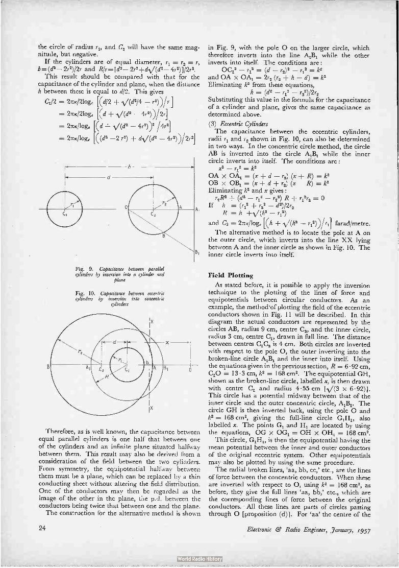
the circle of radius 7.1, and C, will have the same mag-nitude, but negative.
If the cylinders are of equal diameter, r, = r2= r, b.(d2— 2r2)/2r and RIr=[d2— 2r2-1-di./(d2— 41.2)]/2r2.
This result should be compared with that for the capacitance of the cylinder and plane, when the distance h between these is equal to d/2. This gives
C1/2 = 2ruc/2loge Kd/2 V(d2/4 — r2))/r
= 2TcK/2loge Kd V(d2 — 4r2))/2r1
= 2Tric/loge Kd (d2 — 4r2))2 /4r2]
= 27ric/loge K (d2 —2 r2) d4./(d2 — 4r2))/2r21
Fig. 9. Capacitance between parallel cylinders by inversion into a cylinder and
plane
Fig. 10. Capacitance between eccentric cylinders by inversion into concentric
cylinders
Therefore, as is well known, the capacitance between equal parallel cylinders is one half that between one of the cylinders and an infinite plane situated halfway between them. This result may also be derived from a consideration of the field between the two cylinders. From symmetry, the equipotential halfway between them must be a plane, which can be replaced by a thin conducting sheet without altering the field distribution. One of the conductors may then be regarded as the image of the other in the plane, the p.d. between the conductors being twice that between one and the plane. The construction for the alternative method is shown
24
in Fig. 9, with the pole 0 on the larger circle, which therefore inverts into the line A,B„ while the other inverts into itself. The conditions are:
OC12 r12 = (d 1.2)2 ___ r12 = k2
and OA x 0A1 = 2r2 (r2 + h — d) = k2 Eliminating k2 from these equations,
h = (d2 — r12 — r22)/2r, Substituting this value in the formula for the capacitance of a cylinder and plane, gives the same capacitance as determined above.
(3) Eccentric Cylinders The capacitance between the eccentric cylinders,
radii r„ and r, shown in Fig. 10, can also be determined in two ways. In the concentric circle method, the circle AB is inverted into the circle A,B„ while the inner circle inverts into itself. The conditions are: x2 — 7-12 = k2
OA x 0A, = (x + d — r2) (x R) = k2 OB x OB, = (x -1- d ± r2) (x — R) = k2 Eliminating k2 and x gives:
r2R2 ± (d2 — r12 — r22) R ri2r2 = If h = (r12 r22 — d2)/2r,
R = h -I- (h2 — r12)
and C3 -= 27-tic/loge Kh (h2 — 1.12))/ri]
The alternative method is to locate the pole at A on the outer circle, which inverts into the line XX lying between A and the inner circle as shown in Fig. 10. The inner circle inverts into itself.
farad/metre.
Field Plotting
As stated before, it is possible to apply the inversion technique to the plotting of the lines of force and equipotentials between circular conductors. As an example, the method'of plotting the field of the eccentric conductors shown in Fig. 11 will be described. In this diagram the actual conductors are represented by the circles AB, radius 9 cm, centre C 2, and the inner circle, radius 3 cm, centre C1, drawn in full line. The distance between centres C1C2 is 4 cm. Both circles are inverted with respect to the pole 0, the outer inverting into the broken-line circle AM, and the inner into itself. Using the equations given in the previous section, R = 6.92 cm, C10 = 13 . 3 cm, k2 = 168 cm2. The equipotential GH, shown as the broken-line circle, labelled x, is then drawn with centre C, and radius 455 cm R/(3 x 6.92)]. This circle has a potential midway between that of the inner circle and the outer concentric circle, AiBi. The circle GH is then inverted back, using the pole 0 and k2 = 168 cm2, giving the full-line circle G„H„, also labelled x. The points G, and H, are located by using the equations, OG x OG, = OH x OH, = 168 cm2.
This circle, GiH,, is then the equipotential having the mean potential between the inner and outer conductors of the original eccentric system. Other equipotentials may also be plotted by using the same procedure. The radial broken lines, `aa, bb, cc,' etc., are the lines
of force between the concentric conductors. When these are inverted with respect to 0, using k2 = 168 cm2, as before, they give the full lines `aa, bb,' etc., which are the corresponding lines of force between the original conductors. • All these lines are parts of circles passing through 0 [proposition (d)]. For caa' the centre of the
Electronic & Radio Engineer, January, r957

Fig. 11. The electric field between eccentric cylinders
Fig. 12. The maximum voltage gradient in the field between
eccentric cylinders
circle lies at C, on OCi, the radius OC, being k2/2(0C,) = 168/26.6 = 6.3 cm. To invert 'bb', OX is drawn perpendicular to 'bb' produced, the centre of the inverse circle being at CI, where OCb=k2/2(0X) cm. If angle C,OX = 0,
ox = OC, cos 0 and OCb = k2/2 (0C1 cos 0), so that OCb cos O = k2I2 (0C,) = OCa. Therefore the centres of the circles of which the lines of force are parts all lie on a line C ,Cb perpendicular to OCi. This also means that all the circles, as well as passing through 0, pass through another common point, 0, on the line OCi. In fact, the lines of force, and the equipotentials of the field between the eccentric conductors, are the same as those between very thin parallel conductors at 0 and 01. It is obviously possible to construct the lines of force by using these properties of the circles, first drawing the circle `aa', and so locating 01, and locating the other centres such as C, so as to make the circles pass through 0 and O. If the alter-native values of R, x, and k are determined from the equations given, which makes the inverse of the circle AB lie within the circle of radius r, the pole is now 0„ and k2 is negative. In the particular example R = 1.3 cm, x = 0 68 cm, k2 = — 8.54 cm2.
Similar methods of construction are used for plotting the fields of the other conductor dispositions. In every case, it will be found that the lines of force are parts of circles passing through two common points on the line joining the centres of the conductors.
Calculation of Maximum Voltage Gradient
It is often important to determine the maximum voltage gradient in the dielectric between conductors,
and the inversion technique proves useful for this purpose. It may be illustrated for the case of the eccentric conductors used in the previous example. It is usually easy to see where the maximum dielectric stress occurs, in this case at the surface of the inner conductor, point A in Fig. 12. This diagram shows the concentric circles, radii r and R, into which the original eccentric circles are inverted. The circle XY, radius (r Sr), is an equipotential near to the inner conductor, the p.d. being W = EiSr, where E1 is the voltage gradient at the surface of the inner conductor in the concentric disposition. If V is the p.d. between the conductors, E1 = V/r loge (R1r). The circle XiYi is the inverse of XY with respect to the pole 0 and with the same constant k2 used for inverting the original circles into those shown. XiYi is thus the corresponding equi-potential in the original system. Then: x2 — r2 = k2, and OY x OY, = k2, or, x2 — r2 = (x + r + Sr) . (x — r — AY,),
so that, AY1 = Sr (x — r)/(x + r Sr) = Sr (x — r)/(x r) if Sr is small.
If the maximum dielectric stress in the original conductor configuration is E, then E x AYi= 8V = E1. Sr, and therefore, E = Elar/AY1 = V (x r)/(x — r) r loge ( R/r) Since R and x are fairly complex functions of the dimensions of the conductor assembly, this formula is best left as it stands, working out each particular case as required. For the example worked out previously, E = 0.628 V volts/cm.
Conclusion
It is hoped that the foregoing will stimulate interest in the method of geometrical inversion for some capacitance and field problems. Although attention has been confined to electrostatics, the same technique could obviously be applied to current-flow, heat-flow and magnetic-field problems, where the configuration is suitable.
REFERENCES Say, M. G., "Design of Alternating Current Machines". (Pitman, London,
1949.) Warren, A. G., "Mathematics Applied to Electrical Engineering". (Chapman
and Hall, London, 1948.) Electrical Engineering Staff, Mass. Inst. of Technology, "Electric Circuits"—
Principles of Electrical Engineering Series. (John Wiley and Sons, New York, 1945.)
Walker, Miles, "Conjugate Functions for Engineers". (Oxford University Press, London. 1933.)
Electronic Ce Radio Engineer, January, 1957 25

Phase- Adjusting Circuits CONSTANT-AMPLITUDE CONDITIONS
By J. W. R. Griffiths, B.Sc., A.M.I.E.E. and J. H. Mole, Ph.D., D.I.C., A.M.I.E.E.
SUMMARY. A well-known phase-adjusting circuit is shown to be a special form of a more general type of circuit. Various other forms of this generic circuit are discussed, and shown to be of practical use under certain conditions of load, where the original circuit would not be suitable. The results are presented in a form useful for reference.
It is often desirable in both experimental and finished equipments to have a source of e.m.f., the phase of which can be varied without changing the amplitude. A well-known circuit for achieving this is shown in Fig. 1; this circuit is capable of giving a phase difference between input and output which is variable over the range 0° to 180°. In the circuit shown the output voltage will lag on the input by an angle which will increase with increase of either R or C. Reversing the phase of the transformer would give an angle which is leading and which would fall from 180° towards zero as R or C is increased. To obtain a leading angle which increases from 0° it is necessary to replace the capacitor by an inductor.
In order to obtain the full range of 180°, components which vary from zero to infinity are required; this is obviously impracticable but most of the range can be obtained with a normal variable resistor and a good proportion of the range if a variable capacitor is used. A discussion of the range of phase angle available with practical components is given later.
In Fig. 2 a circuit is shown which appears to be less generally known than the one described above although it has certain advantages. As in the previous circuit, a range of 0-180° phase change can be achieved by the variation of only one component (in this case the resis-tor), but this particular arrangement gives only a phase lag. However, by interchanging L and C a phase lead can be obtained. Although the circuits of Fig. 1 and 2 appear to have completely different modes of operation they-are derivatives of one basic form shown in Fig. 7. To assist the practical application of the results
derived here diagrams showing practical circuits (Figs. 1-6) have been separated from diagrams (Figs. 7-14) which are only needed for explaining the development of the circuits.
The Generic Circuit The circuit shown in Fig. 7 is a generalized form of
that of Fig. 2. This circuit can be redrawn separating the sources of e.m.f. to the parallel arms of the network, as shown in Fig. 8. By considering the right-hand box of
admittance j2/3 as a load and by applying Norton's theorem and the superposition theorem, we obtain the current-generator form of equivalent circuit shown in Fig. 9. This simplifies to Fig. 10 and from this we can easily write down the relation between the input and output voltages as
G — jB E-46
e G jB
where #= 2 tan-' B-(G)
= the phase lag.*
It should be noted that vle is represented as the division of one complex number by its conjugate. The resulting complex number has a constant modulus of unity and a phase angle whose value is numerically twice that of the numerator or denominator. Hence when either G or B is varied the amplitude of the voltage y is unaffected but its phase relative to e is changed.
Referring back to Fig. 2 we see that cie = 2B and B = 11(04 requiring that for correct operation we must satisfy the relation co2LC -= 2. Only at this frequency is the magnitude of the output voltage independent of the value of R. In Fig. 1, although the actual phase change produced is a function of frequency, variation of R, C or frequency leaves the magnitude of the output un-affected. Fig. 2 has however two advantages over Fig. 1:
(a) A push-pull input is not needed. (b) The susceptance of an output load can be allowed
for by modification of the value of C.
Developments of the Generic Circuit A number of other forms of practical interest can be
developed from the basic circuit of Fig. 7. In order to keep the output amplitude constant as the
phase is varied the output voltage must be representable as the quotient of a complex quantity divided by its
*Note that a positive value of 4, corresponds to a lagging phase angle. This is the normal convention and corresponds to the phase delay being given by 11/cu and the group delay by dedco.
26 Electronic ee Radio Engineer, January, 1957

I'ÉACTICAL PHASE-ADJUSTING CIRCUITS
Figs. 1-4
Fig. I. fk = 2 tan-2 (wCR)
Fig. 3. e= 2 tan-2 --(wCR 1 +a
INCREASING
C INCREASING CIRCUITS WITH BOTH LOAD AND SOURCE RESISTANCE
Figs. 5-6 (below)
Fig. 5. For constant amplitude: 1 1 — = — + 213 n 1 ± a
then e= 2 tan-l[wCR( -+1 — p)}
and rei
Fig. 2. cd
= 2 tan-2 4 R) -
e
Fig. 6. For constant amplitude: 13n (1 -I- n) 2 ± n — 1
a = = 4/3 if n = 1 fin (n — 1) + 1
then e --- 2 tan-2 () n
n 1 and ve — if n = 1
1 + a 4- n2 a/3 '= ( 1 ± 213) 2
Electronic 8' Radio Engineer, January, 1957 27

conjugate; i.e., we must have the condition illustrated by Fig. 10. If the constant-amplitude condition is to be independent of frequency then the circuit employed must either have only a single reactive arm or the reactors of the two or more arms must be of the same sign.
In Fig. 10 the current generator e(G — jB) can be replaced by two separate sources e X G and ( — e) x (jB) as indicated in Figs. 11 and 12. The admittance Y must now be so chosen that the total admittance across the output terminals is the same as before, viz.
Y G jB G jB
.•. Y = 0
Figs. 7-14 DERIVATION AND INTER-RELA-TION OF PHASE-ADJUSTING CIRCUITS
7
9
I 1
this is therefore the circuit of Fig. 1. Actually Y could be made a multiple of G ± jB and the circuit would still have similar properties, but there would be a constant attenuation between input and output. For example, if Y -= G ± jB then the output voltage is always 6 dB below the input. This particular circuit, however, would have the disadvantage of requiring a ganged resistor or capacitor.
Extending the argument we can use source e.m.fs e and — ne, with arms G and jBln as shown in Fig. 13. Equating admittances as before we must have
B Y G - j—n = G -kjB
Y jB ( 1 — -1)
8
10
12
13 14
28 Electronic ee. Radio Engineer, janua)y, 1957

By letting n = 1 + cc, we have Y = jB 1 1!F
If the admittances of all three elements of Fig. 13 are multiplied by a common factor the voltage ratio pro-vided by the circuit must remain unchanged. Hence if we multiply all elements by 1 + cc we obtain the circuit of Fig. 14. This leads to the practical circuit shown in Fig. 3. This circuit shows the modification which would have to be made to the transformer ratio of the circuit of Fig. 1 in order to compensate for a capacitive load. Conversely, if the transformer of Fig. 1 were not exactly balanced, this could be compensated by a small capaci-tance across the output. The sign of B determines whether the circuit behaves
as a phase leading or phase lagging device. Fig. 4 is a development of Fig. 14 by multiplying all the admit-tances by GUB. This would demand an inductance in the upper arm; the use of a capacitance instead of an inductance changes the sign of B and hence Fig. 4 behaves as a phase-leading circuit. The circuits of Figs. 1-3 all give phase lag. A phase change of 180° can always be inserted in the
circuits using transformers by simply reversing the input connections but this does not necessarily produce the desired result of changing a phase-leading circuit to a suitable phase-lagging circuit. For example, if the original circuit had been so designed that it gave a linear control of phase from 0-90° and a rather non-linear control from 90° to nearly 180°, the insertion of the 180° would mean that the control would be linear from 180° to 90° and non-linear from 90° downwards and would probably not reach 0°. The circuit of Fig. 4 has the advantage over Fig. 3 of
permitting the use of a single variable capacitor for phase adjustment (a more precise control), and over Fig. 1 of permitting a resistive output loa-cl.
Circuits with Finite Source Resistance It is obvious that in Fig. 4 the lower e.m.f. may be
provided by a source of finite resistance (e.g., the anode load of a valve) by subtracting this resistance from R. It is not, however, at all obvious that the upper e.m.f. may have a resistive source. Fig. 4 allows a resistive load, and the possibility of using a resistive source as well is suggested by a common network transformation. By this, the same response is obtained from networks of the same structure working between (a) a source of zero resistance and a finite load resistance and (b) source and load both of finite resistance. There are two possible ways in which source resistance
can be introduced. If a transformer is used the source resistance appears in the primary of the transformer, as in Fig. 6. If a valve is used to give the push-pull input the source resistances in the two arms of the network are independent. The derivation of the proper e.m.f. ratio for specified source resistances is given in the two appendices.
It will perhaps save the reader fruitless labour by pointing out that if a variable capacitor is employed, as in Figs. 5 and 6, then it is not possible to satisfy the constant-amplitude condition if either source or load contains reactance. Similarly if a variable resistor is employed, as in Fig. 3, both load and source may con-tain fixed reactance but neither must contain resistance.
Electronic Ce Radio Engineer, January, 1957
180°
150°
i 20°
7 á 90 °
60°
300
o 0 I 02 0•5 I•0
X
20 50
Fig. 15. Graph of çb = 2 tan -' (x) on log scale of X.
If a source of significant reactance has to be employed then the proportioning rules can be found by multiplying all impedances of Fig. 5 or 6 by J.«).
Effect of Practical Components A variable resistor can be adjusted down to virtually
zero resistance and therefore zero phase change; its maximum value can be made to give nearly 180° phase change. If the resistance changes linearly with rotation, covering this wide range would not necessarily be desirable since most of the range of phase change would be crowded at one end. This can be seen from the graph of (/) = 2 tan-1- (x) in Fig. 16. The value of x depends upon the circuit; e.g., for Fig. 1, x = u)CR. If R varies linearly with rotation a suitable value of C would be such that when R is at maximum, °JCR 3. This would give a range of about 140°. A wider range could be obtained by the use of a resistor wound so that the law relating resistance to rotation is not linear. If the resis-tance were proportional to the tangent of the angle of rotation then a linear scale would be obtained. The use of a variable resistor is limited at high
frequencies by its associated capacitance. In toroidal wire-wound variable resistors over about 300 ohms the effect of the winding inductance is negligible compared with that of its capacitance. This is about 30 pF for a 2k-inch diameter bakelite-cased resistor and is almost uniformly distributed between the winding and earth. For a constancy of output of about ± 2% this puts a lower limit of about 400 pF on the capacitance C of Fig. 3. When a capacitor is used as the variable a more
precise and reliable control is obtained but the range of variation is smaller. A typical figure for the ratio of maximum to minimum value of a variable capacitor is about 10. Since the curve 4. = 2 tan-' (x) on a logarith-mic scale of x is symmetrical about x =- 1 and has its greatest slope at this point, it can be seen that the greatest range of phase change will be obtained when x = 1 corresponds to the geometric mean of the maxi-mum and minimum values of capacitance. The maximum range when Cmax/C,,,,i,, = 10 is hence:
2{[ta. n-1 (V16) — tan-11 ))- 100°
29

180°
20°
g co°
o
700
2 3 4 7 9 10
Fig. 16. Graph of 95 = 2 tan-1 (x) on lidear scale of x.
w2LC=i
cr
18 0°
90°
0 1 • 2 3 4 5 6 7 8
RELATIVE VALUE OF CAPACITANCE
9
Cm ax
10
Fig. 17. Extension of range by addition of inductor.
Similar remarks apply to all of the circuits described since they all follow the general law ok = 2 tan-i- (x). The phase range given by a variable capacitor can be
increased by connecting an inductor in series with it. If the maximum and minimum values of the capacitor are C2 and C, the range of reactance variation is (C2 --- Ci.)/a)C1C2 and this is unaffected by the addition of the inductor. The zero point of the range can however be put anywhere along it. The two most likely cases of practical interest are (a) reactance zero at or just before the maximum capacitance is reached; (b) reactance zero in the middle of the reactance range. In case (a) a range of approximately 180° is obtainable with quite good linearity if 90° shift is made to correspond to mid-scale. This is shown in Fig. 17. In case (b) the range can be made much greater but only at the cost of linearity of control.
Conclusions A well-known variable-phase circuit and some lesser-
known ones have been shown to be derivatives of one basic form of circuit. The law relating the phase shift to the component values has been calculated for a number of cases and a variety of forms of the circuit have been discussed, each having advantages and disadvantages, the relative importance of which depend on the required conditions of use. It is shown how a finite source and
30
load resistance, and in some cases load reactance, may be accommodated by small changes in the circuit components without losing the essential feature of these circuits; i.e., the change of'phase without the concomi-tant change in amplitude.
Acknowledgment This paper is published by permission of the
Admiralty.
APPENDIX 1
Modifications required to maintain the constant-amplitude condition when a resistance is included in the capacitive arm (referring to Fig. 5). At output terminals: (a) Short-circuit current
so e 1 + ( 1 + a) (13 + jX1R)
1 - -n13 - jnXIR
- 1 + ( 1 + a) 13 + i( 1 7- a) ICIR
The constant amplitude condition requires:
1 - nfi 1 + ( 1 + a) 13
e ne - Ise
13R + jX R
(b) Admittance
1 1 a Y
13R + jX R R
Output voltage
= IseIY - e.
• 1
13R + jX R
1 1 + a -
13R + jX R
• 1 - n(fl + jXIR)
1 + a
1 1 -n - P = 1-- + P
1 1 or - = + 2/3
1 + a
Then
1
e 1 ± 213(1 ± a)
and phase change
= 2 tan-1 {( ) 1 + a X 1 + ( 1 + a)/3 R}
APPENDIX 2
Modifications required to maintain the constant-amplitude condition when a generator of finite resistance and a transformer are used. (See Fig. 6.)
It can be shown that
e jx [ 1 + 13{a + ( 1 + n) 2}} + 1 + + n2a13
jx - n
where x = - = coCR X
for constant amplitude
1 + a + n2all n -
1 + p {a ± ( 1 ± n) 2} This can be solved for n, given a and 13; usually, however, n would be fixed and it would be easier to alter a or 13 to obtain the constant-amplitude condition. If a = 4/3 then n = 1 and elv = 1 + 413 + 4/32. The significance of this is that the addition of a load resistance to the circuit of Fig. I can be compensated by the correct value of source resistance.
Electronic ee Radio Engineer, January, 1957

The Fringe of the Field
SOLAR FIELD STRENGTH
An old but always topical problem which can offer a good deal of exercise on the slide-rule is that of the orders of magnitude involved in solar radiation. In 1955 there was a conference in Arizona (where presumably they find samples of it) on the utilization of solar energy. Various appliances developed in many countries were described, including the now famous Bell silicon cell, cyclic engines working on ordinary thermodynamic principles, roof-top heat-storage systems, and solar furnaces using mirrors. What order of power-flux do we get from the sun under favourable conditions ? How does this compare with that from an ordinary radio transmitter ? The mean rate of reception of radiant energy from
the sun, corrected for atmospheric absorption and assuming perpendicular incidence, is about 2 calories per sq. cm. per minute ; this quantity is called the solar constant. The chief difficulty about its measurement is allowing for the atmosphere's absorption, which varies from about 10 per cent in the far infra-red to 45 per cent in the violet and is complete in the ultra-violet ; this is dealt with by taking observations at different altitudes.
Systematic records are maintained by the Smith-sonian Institution at Washington. The earliest figures quoted by Kaye and Laby are those obtained in 1909, but a rough value with an estimated allowance for absorption might well have been found a couple of centuries before that. The power-flux, when expressed in more familiar units, comes to nearly 1-2 kW/sq. m. We can think of this as what would be received on a mountain-top at noon at the equator; of course, in most parts of the earth at the surface the average con-ditions are very much less 'favourable than this. And the silicon cell with its efficiency of 11 per cent is at present very expensive. But the power is there to be used all right. All you need to do is to sell the Rolls and the yacht, turf the croquet lawn with silicon cells, and on any June afternoon when the sun happens to be shining you can get up ,a good fug in the library and the butler's pantry, work milady's washing machine, and watch them playing croquet on the telly, all without depleting the nation's fuel resources.
Clerk Maxwell, in the second volume of his "Treatise on Electricity and Magnetism", discussed the magnitude of the electric field-strength to be expected in full sun-light, and also forecast the order of the radiation pressure exerted by it. In modern terms, the power-flux per unit area for a plane wave is given by the Poynting vector, and the value of this is KocE2, where ico is 8.6 x 10 -12 farad per metre, c is 3 x 10⁸ m/sec nearly, and E is the maximum value of the electric field-
by Quantum
strength. Equating this to the figure above, 1,200 W/sq.m, E works out to be about 680 volts per metre. Com-pared with ordinary field-strengths encountered in radio work this is extremely high, but then it is whispered in Arizona that the sun is a pretty powerful source. Maxwell's figure for the energy falling on one square foot per second was 83.4 foot-pounds, which is indeed quite close to the 1.2 kW/sq. m nowadays accepted, and his result for E was expressed as "about 600 Daniell's cells per metre". There is, incidentally, a most business-like ring about his phrasing when he says "the mean energy in one cubic foot of sunlight is about 0.0000000882 of a foot-pound" ; if B.S.I. had tried to draw up specifica-tions for sunlight they might have done a lot worse than this. One always feels happy about energy and power
calculations, because the end of a sum ties up directly with the beginning, and no awkward questions are asked about the intervening details. But as soon as the details appear, they raise their own fresh problems. I am really not at all clear as to what this E represents in physical terms ; is it merely the answer to an impossible question ? Sir James Jeans, in a book published many years ago, worked out a figure for the solar power-flux assuming that it consisted entirely of quanta of yellow light, when there would be about ten million quanta per cubic centimetre. The value of E found above really has the same kind of status as this. It is the field-strength that we should observe if the radiation came with the same power-flux from a transmitter operating over a single narrow waveband. In G. P. Harnwell's "Principles of Electricity and Electromagnetism", Maxwell's prob-lem is set with the wording "find the r.m.s. value of the electric vector" ; if we are thinking in terms of r.m.s. values the distribution of the energy throughout the spectrum is irrelevant, but we do then realize that the result is something which cannot be measured as a field-strength by ordinary electrical methods. This probably doesn't matter very much either, for an answer in r.m.s. values really only restates the value of the solar constant in other terms. In much the same way energy considerations may tell us that the r.m.s. value of the velocity of hydrogen molecules at some tempera-ture is 1-8 km/sec ; this doesn't mean that we could measure the velocity with a suitable speedometer, but is really another way of saying that the gas is at 0°C.
If we try to think in terms of measurable quantities, things become more complicated. It is assumed, from its optical spectrum, that the distribution of the sun's radiation is very close to that of a perfectly black body at a temperature of about 6,000°K. That is, all wave-
Electronic ee Radio Engineer, January, 1957 31

lengths are represented in it, and the strongest radiation is in the yellow part of the visible spectrum. What kind of result do we get for the power-flux and the field-strength when we examine the radiation within a fairly narrow waveband ? This is quite an important matter, at least in the radio-frequency range where the technique for direct measurement is indeed available. The spectral distribution of the sun's radiation is a
problem which has in recent years been of interest to the radio-astronomer, who uses an approximate formula
Experimental solar battery comprising 432 silicon discs linked together. Developed by Bell Telephone Laboratories, the individual discs have a diameter of about 0.9 in. and the battery can provide about 20 W output
which serves accurately enough in the radio-frequency range. The Rayleigh-Jeans formula for the power emitted by a black body at wavelength A m in the
frequency interval 8f is ZekT 8f A' watts/sq. m, where k
is Boltzmann's constant, 1-38 x 10 -23 joule per degree. Applying the inverse square law, taking the radius of the sun as 6.9 x 10 km, and the earth-sun distance as 1.5 x 10⁸ km, the power-flux received at the earth
is nearly 10-27—T 8f watts/sq. m. If A is 1 metre, and Sf A2
is 2 Mc/s, this works out to about 10-17 watt/sq. m. In fact, powers very much higher than this are of course found, and the observed solar radio emission is certainly not believed to be ordinary temperature radiation originating at the 6,000°K photosphere. Now, if we apply the Rayleigh-Jeans formula to the
peak region of the solar spectrum, the yellow-green range for which A lies between 5 x 10 7 m and 6 x 10 -7 m, take A in the formula as 5 x 10 -7 m, and 8f as 10'4 per sec, we find the result to be about 2 kW/sq. m. This is a little odd, for it is more than the total reception over all wavelengths; but the Rayleigh-Jeans formula (which, when integrated over all wavelengths, would give an infinite value for the total power in any case) is known to be invalid except when A is very large (speaking in spectrum terms) and only approximate even then. The matter looks very different when the true, but
rather less simple, distribution formula is applied. This is Planck's formula, which states that the power emitted
from unit area of a black body at temperature T° K, between wavelengths A and A ± SA, is
c1 A 5 (eedAT — 1) 1 SA x 10 -3 watt/sq. m, where A is in centimetres, and the numerical values of the coefficients in c.g.s. units are c, = 4.94 x 10 15 and c, = 1.43 respectively. ,Why this sudden flight from m.k.s. to c.g.s. units, and the exchange of wave-length for frequency ? The reason is that (using Kaye and Laby) I have taken my figures as I found them, and happened to work out the result in this way. Here, both c, and c, are combinations of universal physical constants, c, being 87r hc, and c, being ch/k, where c is the speed of light in vacuo, h is Planck's constant, and k Boltzmann's constant. (One could, of course, work out c, and c, in m.k.s. units and put A in metres, when the 10-3 factor converting ergs/sq. cm/sec to watts/sq. m would disappear.) The wavelength range which at this part of the spectrum corresponds to the previous 8f is SA = 10 -5 cm. If I have indeed got through the sum without unit muddles, made no wild approximations, remembered the inverse square law, and got the fraction the right way up, the result for the power-flux at the earth's surface is not 2 kW/sq. m for this waveband, but 4 x 10⁻⁴ watt/sq. m, differing by a factor of five million. Check it for yourselves, using preferred numbers if you want to, and dealing tolerantly with the poor ill-favoured little centimetres and grams. The only way I have been able to obtain any independent figures for comparison is by working from the black-body curves for lower temperatures given in J. K. Roberts' "Heat and Thermodynamics" ; the result seems consistent with them. Going back to Jeans' quanta, this represents a power-flux of some two quanta per cubic centimetre, which is more than a million times greater than the threshold of the normal person's eye. It doesn't sound a lot, but it will do to see by, as of course it ought to if there has been no grave slip in the sum. The corre-sponding value of E is then about 10-13 of the "600 Daniell's cells", say 6 x 10 -11 volt per metre. As the power figures themselves depended on the
width chosen for the interval Sf or SA, their actual values don't perhaps really mean very much; but they do seem to furnish something a little easier to under-stand than the value of E given by using energy con-siderations like a sledge-hammer. L ought, you may say, to have known better than to apply the Rayleigh-Jeans formula in the visible region ; but I wanted to see just what it would give. What has been called its "ultra-violet catastrophe" for the shorter wavelengths is evident from its form; it was interesting to find that, in the neighbourhood of the sun's peak wavelength, it already leads to the conclusion that the part is greater than the whole!
"WIRELESS ENGINEER" EDITORIALS
An Addendum to the Index to the Wireless Engineer Editorials of Professor G. W. O. Howe has been prepared, which covers the period from May 1954 to March 1955, the date of the last Editorial written by him. This addendum will be supplied free of charge to those already possessing the Index.
Copies of the Index, covering the period January 1926 to May 1954, which includes chronological, author and subject indexes, can still be obtained, along with the addendum, from the compiler, Dr. A. J. Small, Department of Electrical Engineering, The University, Glasgow, W.2, and cost 5s., including postage.
32 Electronic ee Radio Engineer, January, 1957

Standardization of Circuits P
By M. G. Scroggie, B.Sc., M.I.E.E.
The radio and electronics industry being what it is, any hint of a move towards the standardization of circuits is perhaps likely to provoke an unfavourable first reaction among designers, on the ground that it would tend to limit their freedom and stifle progress. In any case it was undoubtedly wise of the American Bureau of Standards to make the subject of a recently issued handbook* "Preferred Circuits" rather than "Standard Circuits". If even that title does not entirely allay suspicions, one can always point out that the issue of a "preferred" list or set of specifications does not in any way limit freedom of choice, so can hardly do any harm; but, by encouraging all designers to choose from the same "preferred" list whenever there is no good reason for doing otherwise, it may well result in a useful degree of conformity being achieved and test the practicability of ultimate standardization in that field. The "preferred" idea has proved its worth with the
values of components such as resistors. On the other hand it has been markedly less successful with valves, owing presumably to their greater complexity and rate of obsolescence. One may therefore have ground for serious doubts about any attempt to bring complete circuits into such a scheme. Nevertheless, the Navaer handbook puts up a very convincing case for it, at least within the limits attempted, and deserves the careful attention of designers even outside those limits. The handbook is the result of a study of American
naval electronics equipment with the object of finding out whether the great variety of circuits for performing given functions could be substantially reduced. This preliminary study revealed that a large proportion of circuit functions could be standardized without impairing flexibility as regards equipment performance. It is argued that even partial standardization would result in considerable benefits. In the first place it should save time and expense at the design stage. Instead of design-ing and testing every section of an equipment ab initio, the designer would be able to use well-tried and tested sections based on an analysis of practice throughout the industry. This should make for greater reliability, and certainly reduce cost by minimizing the variety of parts to manufacture and stock. It is also said to result in simpler maintenance training and procedures, quicker production, and better use of technical manpower.
It is not claimed that the preferred circuits in the handbook are considerably better than others that might be devised, or even others available. But in view of the study that has been made by the Bureau of Standards of existing practice with regard to circuit functions that * "Handbook PREFERRED CIRCUITS Navy Aeronautical Electronic Equipment"
(Navaer 16-1-519). Prepared by National Bureau of Standards (U.S.A.) Department of Commerce for Bureau of Aeronautics Department of the Navy. $1.75. Obtainable through British Standards Institution, 2 Park Street, London, W.1, at 15s. 9d.
have changed little over ten years or so, it would seem fair to claim that the designs offered are at least as good as the majority of alternatives, and that consequently there is no good reason why so many alternatives should continue to exist—provided of course that manufacturers can overcome the desire to be different for the sake of being different. The present handbook specifies 32 preferred circuits,
of which the first five are voltage stabilizers for power units, the last five are detector, a.g.c. and a.£ circuits for radio receivers, and all those between are primarily for radar, including such things as a detector, a limiter, cathode followers, mixers and amplifiers, all for video signals; and also multivibrators, blocking oscillators and phantastrons. Each specification includes the circuit diagram, tolerable limits of component values, informa-tion on intended applications, and a discussion of design considerations, with performance curves. Particular attention is given to the variation of performance with component and valve tolerances and variations. A second and smaller but in some ways more interest-
ing part of the handbook is devoted to notes on the circuits, or rather some of them; the design considera-tions are discussed in greater detail, and information is given on the analysis of current practice revealed by the survey. Voltage stabilizers and video mixers come in for considerable attention; notes on the other circuits are either brief or entirely lacking, and one presumes that the work was not completely carried out at the time the handbook was prepared. The treatment can be described by taking the video
mixer as example. This device has nothing to do with the so-called mixer used for frequency changing; its function is to combine radar video signals, range markers, heading markers, etc., preferably in such a manner that the coinciding of two or more input signals does not greatly increase the signal output amplitude. The hand-book shows no fewer than 22 circuits of video mixers used in current radars, and arrives at the conclusion that most of the requirements could be met with only two types—a common-anode and a common-cathode— according to whether or not phase inversion is needed. The design considerations leading to the two preferred designs are then detailed, much of the information being in tabular form. This kind of survey and analysis is most interesting and illuminating and one would like to see it extended. The first task with voltage stabilizers was to ascertain
the fixed voltages in greatest demand. The equipments examined required a total of 57 voltage supplies at 20 different voltages from —300 to +630. The most popular were + 300 ( 11 supplies), + 150 ( 10), — 150 (5) and —300 (4). These were chosen as preferred values,
Electronic CO Radio Engineer, January, 1957 33
and five designs are offered.; three with 1% regulation and two with 0.1%. The preferred circuits that follow are, naturally, all designed for one or more of these four voltages. The handbook admits that dependence on stabilized negative supplies may be questioned, but asserts that designers are universally employing them. Since the voltage stabilizers are intended as integral parts of equipments, no provision is made for voltage variation. But much attention is devoted to performance as a function of frequency over a wide range. On the general question of "preferred circuits", a good
case seems to be made out, at least in the military field. Is it worth considering for commercial and domestic
equipment? Both benefits and practicability would seem to be more doubtful when there are vastly more customers and rapid obsolescence is regarded as a virtue. Yet there should surely be some scope for uniformity of practice, for example in computor circuit functions. A difficulty at the present time is shortage of the technical manpower that would be required to conduct surveys with the thoroughness and authority essential to the success of such a scheme. It would moreover have to be directed with great knowledge and foresight in order not to waste effort on circuity that would be obsolescent by the time the information became available. But the potential advantages justify careful consideration.
New Books
An Introduction to Cybernetics
By W. Ross ASHBY, M.A., M.D.(Cantab.), D.P.M. Pp. 295-Fix. Chapman 8t. Hall Ltd., 37 Essex Street, London, W.C.2. Price 36s. The word " cybernetics " is now qtiite a well-known one but it is
rather doubtful if many people could give a precise definition if called upon to do so hurriedly. The author quotes Wiener's definition, "the science of control and communication, in the animal and the machine". He goes on, however, to say that "Cybernetics, too, is a 'theory of machines', but it treats not things but ways of behaving. It does not ask 'what is this thing ?' but 'what does it do?' " The author goes on to say that "The truths of cybernetics are not
conditional on their being derived from some other branch of science. Cybernetics has its own foundations." He then likens it to a "framework on which all individual machines may be ordered, related and understood". He says further that "It takes as its subject-matter the domain of 'all possible machines', and is only secondarily interested if informed that some of them have not yet been made, either by Man or by Nature". The book as a whole deals largely with transformations and their
expression by a kind of algebra. Machines or systems, be they what they will, are observed to perform in a certain way. Some state A is always followed by some other state B, C is followed by D, B by E, and E by C, so that there is a sequence of states ABECD. A symbolism is developed to express this, and much more complex forms of the same kind of thing. The result is a type of algebra of discrete states which the author claims to be inclusive of the ordinary kind. The exposition is, as a whole, extremely clear and the reader is
taken along very gradually. A very valuable feature is the frequent inclusion of exercises, to which answers are given. The author says that it is necessary for the reader to work out all these exercises and it certainly is.
In spite of the clarity of the book, the engineer and, in particular, the electronic engineer, will be hindered by the frequent use of familiar terms with a subtle difference of meaning. The author does always explain what he means by them. He plays quite fairly. But, a dozen pages later, one does not always remember that his meaning is not quite the accustomed one.
Machines are discussed and mainly what are called determinate machines. One of these is defined as "that which behaves in the same way as does a closed single-valued transformation". An example is quoted of a heavy iron frame containing a number of heavy beads joined to each other and to the frame by springs. If the circumstances are constant and the beads are repeatedly forced to defined positions and then released, the movement of the beads on release will be the same every time. There is nothing very startling about that until the next chapter.
This deals with the machine with an input and the engineer is brought up very much with a jolt, for he cannot see how any machine can function at all without an input. In the "machine" consisting of an iron frame and spring-mounted beads he would call these
elements the machine and he would call the forcing of the beads to defined positions and their subsequent release the input. The author, however, appears to regard input as something
applied to a machine to alter its behaviour, as being in the nature of a switch which alters the internal connections of the "machine". The real trickiness comes with "coupling" and "feedback".
Coupling is used to denote the connection of one machine to another. A simple example is given of one "coupled" to a second so that the behaviour of the second depends on the first, but the first is not affected by the second. The author says "as when a microphone is joined to an amplifier", but this is a false analogy for, in general, the performance of the microphone is affected by the input impedance of the amplifier. The engineer will not regard this as a correct usage of "coupling"
for he regards this word as applicable to the case where each "machine" reacts on the other. The word "connection" would have been better. Just a little later, there is a reference to "coupling with feedback".
The author uses this, not only to cover cases with a true feedback loop, but the simple connection of two things so that each affects the other! A coupled pair of tuned circuits thus comes within his definition but this is most certainly not a case .of feedback in the normal usage of the word. The author does realize that he is mis-using the word, for he
gives a most unconvincing defence of it. The fact is that the word has a precise and well-known meaning in electronics. It is legitimate to borrow the word and use it in some other field in a precisely analogous manner. It is not legitimate to adopt the word and then redefine it to mean something different, especially when that some-thing is much broader. That is the way misunderstanding and confusion lie.
If the author had not been so careful to define his terms, the book would have been largely unintelligible. All this is unfortunate for other quite good words exist. For a great deal of what is referred to as "feedback" the word "interaction" would be much more suitable. As a whole, the book is very good and clearly written and, if the
reader is wide awake, the peculiar usage of certain words will not seriously mislead him. W.T.C.
Transistors I
Pp. 676 + vi. R.C.A. Laboratories, Princeton, N.J., U.S.A. British Agent: Arthur F. Bird, 66 Chandos Place, London, W.C.2. Price 40s. The recent rapid rate of progress in the field of semiconductors is
shown by the large number of papers on the subject appearing in the literature. Still more unpublished information is available in various organizations and the Radio Corporation of America felt that the best way of making their own information generally available was to publish "Transistors I". Accordingly, the volume consists of
34 Electronic et' Radio Engineer, January, 1957

31 complete, previously unpublished papers by various authors; and a measure of continuity and completeness has been achieved by the addition of 10 papers which have already appeared in journals, and abstracts of 46 other papers. The standard varies from article to article, but on the whole their calibre is high. The arrangement of the papers, which cover a very wide field, is good, and, except that some diagrams are a little too small for comfort, the book is well printed. A minor criticism is that the abstracts would have been more attractive if arranged in subject groups rather than in chrono-logical order of publication.
In a subject which is changing so rapidly, dates of the articles are of interest. The abstracts are of articles first published in the period March 1949 to September 1955, and consequently cover the majority of the important developments to date. Half of the 10 previously-published papers first appeared in 1956, three in the previous year and one each in 1954 and 1953. The work represented by the 31 new papers was probably spread over about the same period. The main body of the book is divided into six sections. The first
is entitled "General", and contains one article on basic concepts, and a second on recent advances. Nine papers make up the second section on "Materials and Techniques", and include discussions of purification, crystal growing, calculation of alloying depth, and the like. The third section, "Devices", has seven papers, in which germanium transistors for various applications, silicon and drift transistors, and diodes are described. The fourth section has one article dealing with 1/f noise in both diodes and transistors, and two discussing junction-transistor noise. Under the heading "Test and Measuring Equipment" two test sets for r.f. measurements are described, as well as a method of obtaining an accurate match between a pair of transistors to be used in a class B stage. The largest section, "Applications", contains 16 papers, and is left until the end. The most popular field is that of radio receivers, and two articles give complete designs, while specific problems are discussed in a further three articles. There are three papers on audio-amplifier design, and two on television circuits. Three articles deal with the use of transistors in switching and counting circuits.
It can be seen that the range of subjects covered by the book is very wide, and, of course, individual specialists will find only part of this field of direct interest to them. However, at this stage of development of semiconductor devices it is an advantage to have a book giving up-to-date information on the whole field, and anyone concerned with the subject will find "Transistors I" a useful publication. L.G.C.
Radio Electronics By SAMUEL SEELY. Pp. 487+vi. McGraw-Hill Publishing Company Ltd., 95 Farringdon Street, London, E.C.4. Price 52s. 6d. Electronic Engineering By SAMUEL SEELY. Pp. 525+vi. McGraw-Hill Publishing Company Ltd., 95 Farringdon Street, London, E.C.4. Price 60s. These two books have been written as companion volumes, but
may be used independently. This has been achieved by including a certain amount of common material in each, namely: Characteristics of Electron Tubes, Vacuum Triodes as Circuit Elements, Basic Amplifier Principles, Untuned Potential Amplifiers, and Oscillators. In some cases, however, the contents under these chapter headings differ. Thus, "Radio Electronics" devotes more space to LC oscillators than does "Electronic Engineering", which goes into greater detail on other types. "Electronic Engineering" has chapters on Feedback in Amplifiers, Electronic Computing Circuits, Special Electronic Circuits (e.g., limiters, d.c. restoration), Heavily Biased Relaxation Circuits, Sawtooth Sweep Generators, Special Sweep Generators, Rectifiers, Rectifier Filters and Regulators (stabilized voltage supplies), Electronic Instruments, Solid State Theory, and Transistors as Circuit Elements. "Radio Electronics" has chapters on Rectifiers and Filters, Special Amplifier Considerations (noise, feedback), Tuned Potential Amplifiers, Tuned Power Amplifiers, Amplitude Modulation, Demodulation, Frequency Modulation and Detection, and Information Theory.
Together, the two books form a revision and extension of the author's "Electron-Tube Circuits".
Frequency Modulation Receivers By J. D. JONES. Pp. 114+ ix. Heywood & Company Ltd., Drury House, Russell Street, London, W.C.2. Price 17s. 6d.
Transistors in Radio and Television By MILTON S. KIVER. Pp. 324+vii. McGraw-Hill Publishing Co. Ltd., 95 Farringdon Street, London, E.C.4. Price 37s. 6d. An elementary treatment of the method of operation of transistors
is followed by descriptions of typical circuits, new transistor devices, and servicing techniques.
Germanium Diodes By S. D. Boom. Philips Technical Library. Pp. 87+ viii. Cleaver Hume Press Ltd., 31 Wright's Lane, Kensington, London, W.8. Price 9s. 6d.
Electronic Measurements and Measuring Instruments By F. G. SPREADBURY. Pp. 459+ ix. Constable & Co. Ltd., 10 Orange Street, London, W.C.2. Price 50s.
V.H.F. Television Tuners By D. H. FISHER, A.M.I.E.E. Pp. 136+ vii. Heywood & Company Ltd., Drury House, Russell Street, London, W.C.2. Price 21s.
ABSTRACTS AND REFERENCES INDEX The Index to Abstracts and References published in Wireless
Engineer throughout 1956 is in course of preparation and will be available with the March 1957 issue of Electronic CO Radio Engineer. It will retain the Wireless Engineer format so that it can be bound with the 1956 issues. Subscribers will receive the index automatically. As usual, a selected list of the journals scanned for abstracting,
with publishers' addresses, will be included.
MEETINGS I.E.E.
_ 8th January. "A Theoretical and Experimental Investigation of Anisotropic-Dielectric-Loaded Linear Electron Accelerators", by R. B. R.-Shersby-Harvie, B.A., L. B. Mullett, B.Sc., W. Walkinshaw, M.A., J. S. Bell, B.Sc. and B. G. Loach, B.Sc.
23rd January. "Junction Transistor Bootstrap Linear Sweep Circuits", by K. P. P. Nambier and A. R. Boothroyd. "Design Considerations for Junction Transistor Oscillators for the Con-version of Power from D.C. to A.C.", by F. Oakes. "Minority Carrier Storage in Semiconductor Diodes", by J. C. Henderson, B.Sc. and J. R. Tillman, D.Sc., Ph.D.
24th January. Symposium of papers on Transatlantic Telephone Cable. Joint Meeting, linked by the cable, with the American Institute of Electrical Engineers and the Engineering Institute of Canada, to commence at 7 o'clock.
29th January. "An Experimental Study of High Permeability Nickel-Iron Alloys", by C. E. Richards, E. V. Walker, B.Sc., and A. C. Lynch, M.A., B.Sc., and "A Method for the Precise Measure-ment of Permittivity of Sheet Specimens" and "A Bridge Network for the Precise Measurement of Direct Capacitance", by A. C. Lynch, M.A., B.Sc., and "A Simple Transformer Bridge for the Measurement of Transistor Characteristics", by W. F. Lovering, M.Sc., and D. B. Britten, B.E.
30th January. "Power System Protection with particular reference to the Application of Junction Transistors to Distance Relays" and "A Dual-Comparator Mho-Unit Distance Relay Utilizing Transistors", by C. Adamson, M.Sc.(Eng.) and L. M. Wedepohl, B.Sc.(Eng.).
These meetings will be held at the Institution of Electrical Engineers, Savoy Place, Victoria Embankment, London, W.C.2, and will commence at 5.30, except where otherwise stated.
Brit. I.R.E.
9th January. A Programme of Films on Radio and Electronic Engineering.
30th January. "A.M.-F.M. Battery-Operated Receivers", by R. A. Lampitt and J. P. Hannifon.
Both of these meetings will be held at the London School of Hygiene and Tropical Medicine, .Keppel Street, Gower Street, London, W.C.1, at 6.30.
The Television Society
11th January. "Automatic Gain Control Circuits in Television Receivers", by S. N. F. Doherty, B.Sc.(Eng.) and P. L. Mothersole, to be held at 7 o'clock at the Cinematograph Exhibitors' Association, 164 Shaftesbury Avenue, London, W.C.2.
24th January. "Luminescence", The Fleming Memorial Lecture by H. G. Jenkins, M.Sc., F.Inst.P., to commence at 7 o'clock at the Royal Institution, Albemarle Street, London, W. 1. Admission by ticket only.
Society of Instrument Technology
"Electronic Automation of Machine Tools" by F. T. Lett, to be held at Mansion House, Portland Place, London, W.1, at 7 o'clock.
Electronic Ce Radio Engineer, January, 1957 35
D

Correspondence Letters to the Editor on technical subjects are always welcome. In publishing such communications the Editors do not necessarily endorse any technical or general statements which they may contain.
The New 'Wireless Engineer'
SIR,—I have learnt with probably more interest than any other reader of Wireless Engineer of the decision to widen the scope of the journal. When I conceived the idea of the magazine and founded it and
acted as its first editor in 1923, the title then being Experimental Wireless, none of us could foresee the immense progress in electronics which has been witnessed in little over thirty years. It is indeed fascinating to glance at the articles in the first issue and compare them with those appearing today. It is perhaps impossible even to hazard a guess at what may fill the pages of the journal in another thirty years. It is particularly pleasing to me to record the progress of the journal and may I wish it every continued success during the ensuing years. PAUL D. TYERS Watford. Founder and First Editor. 4th December 1956.
Tc9 Tga-4
DISPLACEMENT CURRENT TO GRID
CONVECTION CURRENT TO ANODE
Fig. 1.
Uncorrelated Grid Noise
Sta,— That the total noise introduced into a v.h.f. circuit by a negative-grid valve is complex in its origins has been ably demon-strated by Houlding and Glenniel. But although it may not be feasible for a theoretical analysis to predict quantitatively the induced grid noise at v.h.f., one would like qualitative agreement between theory and all aspects of the experimental evidence; and a factor which has appeared unsatisfactory is that although it is commonly suggested that induced grid noise ought theoretically to be correlated with shot noise, because the same electrons in transit through the valve cause both forms of noise, the careful work of Houlding and Glennie has shown conclusively that there is little such correlation. Now the expectation that grid and anode noise will be correlated
appears fundamentally to be based on the following fallacious hypotheses of Bakker':
"If the grid electrostatically is a good screen it may be assumed that the displacement current flows to the grid, while the con-vection current, carried by the electrons, passes through it."
"Since the transit time between the control grid and the succeeding grid, which is usually maintained at a large positive potential with respect to cathode, (Bakker was discussing pentodes) is much smaller than the transit time cathode-control grid, its influence shall be neglected in this paper."
In an earlier papers Bakker and de Vries had pointed out the relation between a charge moving between a pair of electrodes and the current in an external circuit connected to the electrodes, and the concept was subsequently generalized by Shockley'. So long as the charge is moving between cathode and a grid which is a good electrostatic screen, the whole current corresponding to the moving charge flows into the external circuit via the grid; and subsequently, if the electrons passes through the grid, the whole of the current which is now flowing to the anode is matched by a current from the
36
grid. In relation to input damping this idea is now well established: it is clearly illustrated in Fig. 16.9 of Spangenberg's books and is apparent in the appearance of the ratio TgaiTcg in formulae for input admittance; e.g., as given by Llewellyn and Peterson'. But Bakker's fluctuation formula appears still to be in use unmodified, since the relation
80 se — —(1-7r/4) 4 k TeCT — 9
between mean-square fluctuation current to the grid, Sis, and input conductance GT due to electron transit time, is precisely that derived by Bakker'. Qualitatively, the picture suggested by Bakker's analysis is shown in Fig. 1, though such a representation will not bear analysis. It then seems obvious that the effects of ig and ia should be fairly closely correlated. The true picture, however, is as shown in Fig. 2, still assuming that the grid is a good electrostatic screen and using the classic assumption of Tga < Ter It will be noted
Fig. 2.
.14 7- ga
that (a) the net charge collected by the grid is zero (which is the integral of current) and (b) at every instant that are two currents which sum to zero -F ig or ig la) thus ensuring the continuity of current which is formally expressed by the statement V J = O. One can see by inspection that on performing a Fourier analysis of ig and ia with origin of time at the instant of passage of the electron through the grid (cf. Spangenberg, loc. cit.) ig will be composed mainly of sine terms but ia about equally of sine and cosine terms. This differs from the traditional assumpton that the anode-current
Electronic ee Radio Engineer, January, 1957

pulse occupies the whole cathode-to-anode transit-time, in which case the Fourier components of the anode current would have been fairly precisely in quadrature with those of the grid current. It has also been customary to assume that the phase of the grid voltage which arises from the induced grid-current can be shifted 90° by making the grid-cathode circuit reactive. But this phase-shift concept is essentially related to steady sinusoidal currents. For example, with a CR grid circuit, the voltage produced will be the difference of two exponentials of time-constant CR, and this is in principle different from the anode-current pulse produced by the electron-transit to the anode.
It is also open to question whether -rga is much less than The difference of potential between grid and the positively charged anode or screen is likely to be of the order of 100 times the difference between the mean potential of the grid plane and cathode potential, so that the velocity ratio will be about 10: 1. But the grid-anode distance is usually several times the cathode-grid distance, so that the ratio of transit times may be no more than two or three to one. This does not invalidate the qualitative idea of a sine/cosine relation between grid and anode current, but it does make it more difficult to fix the central epoch of the anode current, which must be at some time during the grid-anode transit and certainly not coincident with the time of arrival at the anode. In explaining the lack of correlation between grid and anode
noise we have destroyed the basis on which Bakker constructed the prediction that the induced grid noise would be equal to thermal noise in the input conductance at a temperature 1.43 T. By analogy with Freeman's investigation of the relation between transit-time noise and conductance in a temperature-limited diode it seems likely that the general equivalence will remain true, though with some modification of the numerical factor. According to Callen and Weltons the Nyquist relation between fluctuation and the dissipative component of impedance is perfectly general for linear systems. Some numerical correction may be needed to take account of the non-linear nature of the valve impedance; but this correction is unlikely to be large. D. A. BELL Electrical Engineering Department, University of Birmingham.
7th December 1956.
REFERENCES 1 Houlding, N., and Glennie, A. E., "Experimental Investigation of Grid Noise".
Wireless Engr., 1954, Vol. 31, P. 35. • Bakker, C. J., "Fluctuations and Electron Inertia", Physiea, 1941, Vol. 8,
p. 23. • Bakker, C. J., and Vries, G. de, "Amplification of Small Alternating Tensions
by an Inductive Action of the Electrons in a Radio Valve", Physiea, 1934, Vol. 1, p. 1045. 1 Shockley, W., "Currents to Conductors Induced by a Moving Point Charge",
journ. Appt. Phys., 1938, Vol. 2, p. 835. • Spangenberg, K. R., "Vacuum Tubes". (McGraw-Hill, New York, 1948.) " Llewellyn, F. B., and Peterson, L. C., "Vacuum-Tube Networks", Proc.
Inst. Radio Engs., 1944, Vol 32, p. 144. • Freeman, J. J., "On the Relation between the Conductance and the Noise
Power Spectrum of Certain Electronic Streams", Journ. Appt. Phys., 1952, Vol. 23, P. 1223.
8 Callen, H. B.' and Welton, T. A., "Irreversibility and Generalized Noise", Phys. Rev., 1951, Vol. 83, p. 34.
Free Oscillations in Simple Distributed Circuits
SIR,—We have read Mr. A. B. Hillan's article on "Free Oscilla-tions in Simple Distributed Circuits", in the December Wireless Engineer, with great interest.
It is perhaps worth while to call the author's attention to the significance of his polynomials. P(x) in Case I is simply the Laguerre polynomial of the same order n and argument 2x. When this poly-nomial is multiplied by ex it becomes the corresponding Laguerre function of order n and argument 2x; tables and properties of these functions are given in a recent I.E.E. Monograph. (No. 183R. "Laguerre Functions: Tables and Properties", by J. W. Head and W. Proctor Wilson, June 1956.)
It follows that Table 2 is, in fact, a table of the first ten Laguerre functions; this may be readily verified. Further, equation ( 17) is that ordinarily associated with the integration of the Laguerre polynomial.
In Case II, P(x) defined by (38) and (40) is closely related to the integral of the Laguerre function of order (n-1) and argument 2x, and it turns out that Table 4 is a table of minus this integral. The values obtained agree with those in unpublished tables prepared in this Department. The recurrence relation (40) follows from ( 17) and a known finite series of Laguerre functions whose sum is the integral of a Laguerre function.
Unpublished studies of similar phenomena to those investigated by Mr. Hillan suggest that the remaining polynomials P„ in Table 5 may also be most conveniently expressed in terms of Laguerre polynomials or functions. W. PROCTOR W ILSON The British Broadcasting Corporation, J. W. HEAD Kingswood Warren, Surrey.
6th December 1956.
120
100
80
60
40
20
O
20
40
60
80
100 120
0-1
......., .••••.'
...•
..••• ...•
...-e .•••• ...,
I' .••
..• ..•
a
.•••• 0'
... ...•
•••• . « .••••
.
........"*.:,-.-.-----
..,
..., .... ..-•''.
.... ..."
... .••• ....
. . ..." ..."
..." _,
10
Rr— 0 Po— co[EQu.13] --• Ri=o [ECIUS 19 & 24]
Rr.R Re,.co [E(1115.15 & 21] RI—R Ro=f21 [ECM. 26]
Parallel-T RC Network
would like to bring to your notice an error in my article entitled "Parallel-T RC Network" which appeared in the July 1956 issue of Wireless Engineer. The error is in Fig. 5 (b) on p. 170 and a corrected diagram is given above. Mr. Minoru Higashiguchi of the Faculty of Engineering, Tokyo University, pointed this mistake out to me and has written an article on the generalized design of this network as applied to selective amplifiers, which will appear in the Journal of the Institute of Electrical Communication Engineers of Japan. I would like to apologize to readers of Wireless Engineer for the error. Harrow, Middlesex. G. V. BUCKLEY
26th November 1956.
Phase-Sensitive Discriminator
Stn,—In frequency-modulation transmission, the frequency deviation is independent of modulating frequency and depends only on its amplitude. As the higher audio-frequency components of speech and music are generally of very small amplitude, they produce a very small amount of frequenc deviation on frequency modulation (£m.) system. As a result, the signal-to-noise ratio (SIN) for these frequencies becomes very poor. Phase modulation (ph.m.) transmission has an important advantage in this respect, in that its frequency deviation is directly proportional to the modulating frequency. Hence, the high-frequency components of the modula-ting signal, though of smaller amplitude, give appreciable frequency deviation with a consequent improvement in SIN ratio. But this method, though advantageous, could not be used in practice because of the want of a proper phase-sensitive discriminator. If ph.m. signals are to be received by a frequency-sensitive discriminator (as is available at present), they have to undergo a large amount of de-emphasis to give an undistorted output, with the consequent large reduction in output power. In actual practice, however, some amount of pre-emphasis is used in £m. transmission by increasing the relative amplitudes (and hence frequency deviation) of higher modulating frequencies in the transmitter and a similar amount of de-emphasis in the receiver. This is, in fact, something between £m. and ph.m. and even this results in a gain of about 13 dB in SIN ratioi. If ph.m. could be used with a proper phase-sensitive discriminator then it would result in a further gain in SIN ratio and that also without using any pre-emphasizing or de-emphasizing network or any consequent reduction in output2. The argument against ph.m., that it requires larger bandwidth for higher modulating frequencies, is of minor importance from the practical point of view because, as stated earlier, the higher audio-
Electronic ei Radio Engineer, January, 1957 37

Ph. M SIGNAL
TRIGGER INPUT
SAWTOOTH GENERATOR
9 RC FILTER
o
Fig. I. A block-schematic diagram of the discriminator arrangement.
\\:\it t isii111111111111111 \iii' y
1 1 I
HI 111111111MM I till!
I I ll
Iilt
1111 11111111111
¡Oi ls Mil 1111 I I I I I
(a)
(b)
(c)
Fig 2. The waveforms (not to the scale) of different stages of the phase-sensitive discriminator. (a) The phase-modulated wave at the input of the sawtooth generator, (b) The output of the sawtooth generator, (c) The output
after an RC filter.
frequency components of speech and music are generally of smaller amplitude and hence they tend to produce smaller amounts of frequency deviation.
If it is possible to devise a discriminator whose output will be directly proportional to phase shift (instead of frequency deviation) of the carrier, a ph.m. signal can be directly transmitted and received undistorted without any de-emphasis. This will result in large improvement in SIN ratio (as compared to f.m.) with no loss in output power. Also ph.m. signals with crystal frequency stabilitym can be directly transmitted without employing any correcting network. One such phase-sensitive discriminator has been devised in our laboratory, the principle of which is briefly discussed below. It may be mentioned in this connection that Mr. P. Ktuidu, who has been working in this laboratory for some time on a.m.-f.m. demodulation by utilizing the slope of the clipped pulses', has developed a different technique based on the time interval between the clipped pulses for directly demodulating a phase-, frequency- and amplitude-modulated carrier'. The basic idea of this phase-sensitive discriminator is that, if a
linear sawtooth generator is triggered by a phase-modulated signal (Fig. I), then the amplitude of these sawtooth waves is proportional to the time intervals between the successive waves of the ph.m. signal and hence between their phase differences. Thus the variation in amplitude of the successive sawtooth waves is in direct proportion to the variation in phase of the triggering input (the ph.m. carrier). As such, the envelope of the sawtooth output will be a faithful reproduction of the modulating a.f. signal, which can then be easily filtered out with any suitable filter (Fig. 2). Preliminary observa-tions have shown that the output is completely undistorted within the limits of accuracy of our measurement.
It is to be noted that a large bandwidth is necessary for £m. or ph.m. signals (present frequency deviation for £m. broadcast is ± 75 kc/s). As such it requires a high carrier frequency for trans-mission and a high intermediate frequency (about 8 Mc/s) in the receiver. Since it is rather difficult to design a linear sawtooth generator of such high frequency it may be thought that a successful discriminator of the desired type is not feasible. It must be noted, however, that a high-frequency sawtooth generator is not essential for our purpose. In fact, we can quite conveniently use a linear sawtooth generator at, say, 800 kc/s and trigger it by an i.£ signal
of 8 Mc/s. The phase-modulated i.f. signal will then trigger the sawtooth generator at every tenth wave of the carrier and the envelope of the sawtooth will again give back the modulating signal. As even this sawtooth frequency is much higher than the modulating frequencies, the envelope will appear as continuous and the output signal will be an undistorted one. Due to the symmetry of the envelope waveform there can be no even-harmonic distortion in the output and the maximum modulating frequency for which the 3rd harmonic lies in the audible range is 5 kc/s. Hence, even for the worst case, the ratio, of sawtooth frequency to modulating frequency is more than 100; i.e., the sawtooth envelope will be made up of at least 100 points per a.f. cycle, joined together. This will appear continuous and distortionless for all practical purposes.
It may be mentioned in this connection that the above discrimina-tor may also be used for receiving normal £m. signals (without having any pre-emphasis), if a proper correcting network is used after discrimination. The author wishes to express his grateful thanks to Dr. H. Rakshit,
Head of the Department of Electronics and Electrical Communica-tion Engineering for his guidance, helpful suggestions and active interest in the work. B. CHATTERJEE Indian Institute of Technology, Kharagpur, India. 4th October 1956.
REFERENCES
2. C. E. Tibbs, "Frequency Modulation Engineering" (1947), p. 72. Chapman & Hall. ▪ J. M. M. Veldstra, "VHF Phase-Modulated Transmitter—Receiver for
4-Channel Telephony", Communication News, October 1965, Vol. 16, p. 22. • Reference 1, p. 165. G. S. Sanyal & B. Chatterjee, "Linear Phase Modulator", Wireless Engineer,
September 1955, Vol. ' 3_ 3D5e5itodulator", Wireless Engineer, December 1955,
Vol. 32, p. 337. o P. Kundu, "A New Method of Demodulating Phase, Frequency and Amplitude
Modulated Wave" (to be published).
STANDARD- FREQUENCY TRANSMISSIONS
(Communication from the National Physical Laboratory)
Values for November 1956
Date 1956
November
MSF 60 kc/s Frequency deviation from nominal:*
parts in 109
1 + 2 2 + 2 3 + 2 4 + 2 5 + 2 6 + 2 7 + 2 8 + 2 9 + 2 0 + 2 I + 2 2 + 2 3 + 2 4 + I 5 N.M. 6 + 1 7 + 1 8 + 1 9 0
20 + 1 21 0 22 0 23 0 24 0 25 — I 26 — I 27 — 3 28 — 2 29 — 2 30 — 2
* Nominal frequency is defined to be that frequency corresponding to a value of 9 192 631 830 cis for the N.P.L. caesium resonator. N.M. =- Not Measured.
38 Electronic ee Radio Engineer, January, 1957

New Products Glass Wool for Air Filters A special glass-wool substance for use in
air filters is now available in the U.K. The density of the fibres increases from front to back of a filter pad, the object being to trap dust through the whole thickness of the material. The glass-wool fibres are coated with an adhesive substance so that the dust particles stick fast on contact. Air Control Installations Ltd., Ruislip, Middx.
High-Temperature Non-Corrosive Solder Flux
Non-corrosive soft-soldering fluxes based upon resin tend to carbonize at compara-tively low temperatures. Thus, these safety fluxes can only be used with difficulty in the soldering of commutators or other work where high operating temperatures neces-sitate the use of solder with a melting point higher than the normal tin-lead range. The research department of Fry's Metal
Foundries Ltd., have conducted an investiga-tion on this problem and have now introduced a new flux under the title of Alcho-Re Soldering Fluid Type S.64, which allows an excess temperature of 50-1000 C above the carbon point of resin fluxes. Fry's Metal Foundries Lkl., • Tandem Works, Merton Abbey, S. W.19.
Record/Playback Head for Stereophonic Tape Recordings
Truvox Ltd. are now producing a two-channel head for use with stereophonic tape recordings on 1-in, magnetic tape. Points from the specification are as follows: gap length 0.00025 in., output voltage 1-3 mV, impedance 50 kn at 10 kcis, frequency response 50 c/s-15 kc/s. Crosstalk between channels is very small. Truvox Ltd., 15 Lyon Road, Harrow, Middlesex.
V.H.F. Signal Generator Primarily intended for use in the
alignment of narrow-band communication receivers, the new Advance signal generator type DIP/2 covers the frequency range 2-190 Mc/s in six bands. Output is monitored and
Fig. 1.
continuously-variable in the range 0. liÁV to 10 mV, and triple shielding is employed to reduce the stray field to negligible proportions. There is a built-in 2-Mc/s ± 0.01 % crystal oscillator for frequency checking, and a 1,000-c/s audio oscillator for internal amplitude modulation " if required. A cathode-follower buffer amplifier
separates the oscillator from the attenuator and prevents variation in frequency as the attenuator setting is changed. In order to prevent frequency modulation from occurring during amplitude modulation, the latter is effected after the attenuator, the arrangement being as in Fig. 1. The crystal diode forms part of the series-arm of an attenuator section. As the a.f. voltage applied to the diode varies, its resistance is modulated; hence the r.f. attenuation varies about a mean value over the audio cycle. The actual depth of modulation is set at 30% ± 2 dB. Advance Components Ltd., Roebuck Road, Hainault,
NEW SELENIUM RECTIFIERS
10 rnA Tubular Rectifiers Standard Telephones & Cables have
introduced a range of tubular metal rectifiers giving a d.c. output of I0 mA. Units consisting of stacks from 6 to 200 plates are available, the corresponding output voltages being 137 V to 4,230 V under typical operating conditions in half-wave capacitor-input circuits.
Fg. 2.
INPUT FROM L.T. RECTIFIER
Rectifier Stabilizer for 1.4 Volt Valves Portable receivers capable of operation
from dry batteries or a.c. mains are now common. When operated from the mains, the necessary 1.t. supply for the parallel-connected filaments is obtained from a metal rectifier supplied with a low voltage from a tapping on a mains transformer.
Normally, the source resistance of such a low-voltage supply and the associated smoothing circuit is sufficiently high to cause a sharp increase in the output voltage if one filament fails, with consequent
overloading of the other filaments. To prevent this, and also to provide protection against mains variations, the voltage-stabilizing circuit shown in Fig. 2 has been developed. The forward-biased rectifier which shunts
the filaments has voltage/current characteris-tics with maximum non-linearity at 1 • 3— l• 4 V. If, therefore, the output voltage tends to rise, increased current is taken, and most of the excess voltage is absorbed in the series resistor. If the output voltage falls, the rectifier takes less current and, consequently, the voltage drop across the resistor decreases. In a typical receiver, consuming 125mA filament current, the open-circuiting of one 25-mA filament causes the 1.t. voltage to rise from I • 3 V to I. 41 V. The stabilizer and 1.t. rectifier are
available as a single unit. Standard Telephones and Cables Ltd., Edinburgh Way, Harlow, Essex.
QQV02-6 (left) alongside receiving valve.
Miniature Power Valve for U.H.F. Mobile Radio
Efficient operation up to 500 Mc/s is possible with the new Mullard double r.f. tetrode QQV02-6. As a power amplifier it will deliver 3.5 W to the aerial under typical circuit conditions at 490 Mc/s when operated at maximum ratings and with anode and screen modulation. The necessary drive power of 1- 4 W can be obtained from another QQV02-6 operating as a frequency tripler. The QQV02-6 is on the noval (B9A)
base. It i; shown above (left) and is about the same size as a receiving valve (right). Its heater is centre-tapped for operation from 12.6 V or 6.3 V. Millard Ltd., Torringten Place, W.C.1.
"Liquid Metal" Plastic Bonded Compound
A heat-resistant "liquid steel" material is now available. Known as "Devcon C", it consists of approximately 80% aluminium and steel, and 20% plastic, and is in liquid form. In use, a hardening agent is added, and the material sets. It is said to be suitable for making moulds and embossing
Electronic & Radio Engineer, January, 1-957 39

dies, filling holes in castings, caulking round steel plates, etc., and to resemble aluminium in many respects. The compression strength is given as 5,000 p.s.i. at 400° F. "Devcon C" is non-conducting. E. P. Barrus (Concessionaires) Ltd., 12-16 Brunel Road, Acton, London, W.3.
Hand Stroboscope and Portable Tachometer
A new hand stroboscope (Type 5) has now been added to the range of E.M.I. stroboscopes. The Type 5 is a hand-held instrument, built on simple and robust lines, designed primarily for use in small work-shops, factories and garages. Its scale covers a range of 300 to 6,000 r.p.m., and operation is from a.c. mains of 220-240 V, 50 c/s. The portable electronic tachometer
(Type 2) is a new and versatile instrument for the measurement of rotational speed, and frequency within the limits of 2-20,000 c/s. These are covered in four ranges with an accuracy of better than 2%. .The instrument is supplied with a photo-
electric probe and is also suitable for use with other types of transducer. An output is available for driving a pen or other similar type of recorder. E.M.I. Electronics Ltd., Hayes, Middlesex.
New Instrument Cathode-Ray Tubes A new range of 34-in, electrostatic
instrument tubes, type 4GP, to replace the existing 34-in. E4412 series, is announced by the General Electric Co. Ltd. Four varieties of screen are available, with persistences ranging from 1 millisecond to 20 seconds. A further screen, suitable for radar applications, will be introduced later. The plate sensitivity of the new tube does
not vary by more than 2 % for deflections up to 75 % of the useful scan. Improved spot centring ensures that the undeflected spot will fall within a radius of 5 mm from the centre of the tube face. The deflection axes are orthogonal to within 1°. Other features are single-stage post-deflection acceleration, reduced inter-electrode capacitances, flat-plate glass screens, and 6.3-V heaters. The General Electric Co. Ltd., Magnet House, Kingsway, W.C.2.
New Range of Ultrasonic Transducers New piezoelectric transducers made by
Technical Ceramics Limited, for use in ultrasonic generators, are fabricated in ceramic made principally from barium titanate in a polycrystalline form and are claimed to be impervious to moisture and unaffected by temperature. Ceramic trans-ducers are robust and able to handle high powers. Their overall characteristics, such as coupling coefficient, dielectric constant, temperature stability, and sensitivity render them particularly suitable for ultrasonic frequencies.
In addition to simple rings, plates, discs, or cylinders, transducer shapes may be combined into dual elements, mosaic arrays, series or parallel systems and other arrangements to obtain special effects not possible with single elements working alone.
Transducers can be supplied with various protective coatings to suit individual operating conditions. Available coatings include simple waterproofing, a hard plastic
%DO
coating for moderate cavitation resistance and, in cases where corrosion under strong cavitation action has to be prevented, an extremely hard, thin glaze can be applied. Technical Ceramics Ltd., Wood Burcote Way, Towcester, Northants.
High-Voltage Regulator Valve Designed primarily for use as a voltage-
regulator for the e.h.t. supply to monitor and colour-television tubes, the Brimar 6BD4 has obvious applications in other fields where a stable high voltage at low current is needed. It is a triode on the octal base with a top-cap anode and is rated for an anode dissipation of 20 W and an anode voltage of 20 kV. The heater requires 6.3 V at 0.6 A and up to 180—V heater-cathode voltage is permissible. The valve is intended for use as a shunt
regulator in a form of circuit like Fig. 3 and, with an unregulated supply of 29.8 kV
UNREGULATED INPUT
SOURCE IMPEDANCE I M.O.
81'1111 2W
SODA
M11
REGULATED OUTPUT
having an impedance of 8 M û, the regula-tor output varies from 20 kV to 19.7 kV for a current change from zero to 1 mA. This gives an effective output impedance of 0.3/1=0. 3 M. For this performance the cathode must be tied to a supply of 500 V of lkt1 impedance. Standard Telephones and Cables Ltd., Footscray, Sidcup, Kent.
, telex
New Capacitors Three new ranges of capacitors are
announced by Plessey. A new type of tubular paper capacitor is
provided with three leads, one to the inner foil and two to the " earthy" outer foil. This enables the capacitors to be mounted in several different ways and, in addition, the spare lead can be used to earth another part of a circuit.
Subminiature electrolytic capacitors (down to in. x /78- in.) a-e available in capacitances 1-50 µF and working voltages of 1.5-70 V. They are intended for use in transistor hearing aids and similar applica-tions. New paper capacitors in the range 0 005-
1 . 0 µF, 150-1,000 V d.c. are available with tolerances of ± 20%, ± 10%, and ± 5%. Insulation resistance is 4,000 MohiF, even after prolonged storage, and the capacitors are suitable for operation under conditions of extreme humidity and temperature. The Plessey Company Ltd., Ilford, Essex.
Solenoid Operated Wafer Switch The Ledex Circuit Selector employs a
solenoid rotated by means of an inclined plane. An electromagnet attracts an armature, and as the latter is supported by three balls that travel around and down three inclined races, it is forçed to rotate until the balls have travelled to the deepest points in their respective races. Thus, conversion of linear to rotary movement is accomplished. In conjunction with wafer switches, remote-controlled switching can be effected. N.S.F. Ltd., 31-32 Alfred Place, W.C.I.
40 Electronic Ce Radio Engineer, January, 1957

Abstracts and References COMPILED BY THE RADIO RESEARCH ORGANIZATION OF THE DEPARTMENT OF SCIENTIFIC AND
INDUSTRIAL RESEARCH AND PUBLISHED BY ARRANGEMENT WITH, THAT DEPARTMENT
The abstracts are classified in accordance with the Universal Decimal Classification. They are arranged within broad subject sections in the order of the U.D.C. numbers, except that notices of book reviews are placed at the ends qf the scctions. U.D.C. numbers marked with a dagger (t) must be regarded as provisional. The abbreviations of journal titles conform generally with the style of the World List of Scientific Periodicals. An Author and Subject Index to the abstracts is published annually ; it includes a selected list of journals abstracted, the abbreviations of their titles and their publishers' addresses. Copies of articles or journals referred to are not available from Elee.ronic Cs' Radio Engineer. Application must be male to the individual publisher
concerned.
Acoustics and Audio Frequencies ..
Aerials and Transmission Lines ..
Automatic Computers
Circuits and Circuit Elements
General Physics
Geophysical and Extraterrestrial Phenomena
Location and Aids to Navigation ..
Materials and Subsidiary Techniques
Mathematics ..
Miscellaneous
ACOUSTICS AND AUDIO FREQUENCIES
534.2-14: 534.5 1 Distortion and Interaction of Acoustic
Waves with Finite Amplitude in a Viscous Medium.—G. D. Mikhailov. (C. R. Acad. Sci. U.R.S.S., 1st July 1956, Vol. 109, No. 1, pp. 68-71. In Russian.) A theoretical paper. For a note on an experimental confirmation of the results, see Zk• eksP. teor. Fiz., June 1956, Vol. 30, No. 6, p. 1142.
534.232-14-8 2 The Conversion Efficiency of a
Piezoelectric Quartz Crystal: Relation between Input Electrical Power and Frequency.—S. Parthasarathy & V. Narasimhan. (Z. Phys., 1 1 th May 1956, Vol. 145, No. 3, pp. 368-372. In English,) Experiments indicate that the conversion efficiency depends on frequency and on the nature of the liquid surrounding the crystal, but not on the input power. In a separate paper (ibid., pp. 373-376) it is reported that the conversion efficiency is higher for the fundamental than for overtones.
534.26+ [538.566: 535.42 3 Asymptotic Solution of some
Diffraction Problems.—Keller, Lewis & Seckler. (See 90.)
534.32: 534.75 4 Pitch of Inharmonic Signals.—E. de
Boer. (Nature, Land., 8th Sept. 1956, Vol. 178, No. 4532, pp. 535-536.) Brief report of a study of the dependence of the subjectively perceived pitch of a complex
Page
A
1 Measurements and Test Gear ..
1 Other Applications of Radio and Electronics..
3 Propagation of Waves
3 Reception
5 Stations and Communication Systems ..
6 Subsidiary Apparatus.. ..
8 Television and Phototelegraphy
8 Transmission ..
13 Valves and Thermionics
18
tone on the harmonic relation between the a.f. carrier and the modulating signal, the latter comprising components whose frequencies are in arithmetic progression.
534.6 Comparison of Artificial Ears.—
U. Degano. (Piccole Note 1st. super. Poste e Telecomunicagioni, March/April 1956, Vol. 5, No. 2, pp. 195-202.) An objective substitu-tion method is described, with test results for the Italian, Swiss and C.C.I.F. standards on three different telephone receivers.
5
534.61-8 6 Ultrasonic Intensity Meter.—C. A.
Wiederhielm. (Rev. sci. Instrum., July 1956, Vol. 27, No. 7, pp. 540-541.) A calori-metric method is described which does not involve disturbance of the ultrasonic field. Intensity measurements can be obtained for areas as small as 8 mini.
534.851 (083.74) 7 Disk Recording Characteristics.—
J. D. Smith. (Wireless World, Nov. 1956, Vol. 62, No. 11, pp. 526-528.) British Standard 1928: 1955 is discussed and a complete circuit diagram of a suitable replay equalizer is given.
621.395.61 8 The Design of a High-Quality
Commentators' Microphone Insensi-tive to Ambient Noise.—H. D. Harwood. (B.B.C. Engng. Div. Monographs, June 1956, No. 7, pp. 1-19.) Description of the Type-L.2 lip microphone, which was designed in 1951. Special steps are taken
Page
A
13
• 14
• 15
15
15
16
• 16
17
17
to secure correct balance between the sound emanating from the nose and that from the mouth, and to allow for the spectral distribution of the energy at short range. The transmission of low-frequency pulses produced by high-velocity air streams accompanying explosive consonants and of wind noise is avoided. The microphone is highly insensitive to interfering alternating magnetic fields.
621.395.623.7 9 The Diffaxial Speaker.—A. B. Cohen.
(Audio, June 1956, Vol. 40, No. 6, pp. 20-23..58.) A three-range loudspeaker is described consisting of a dual diaphragm for reproduction of the lower frequencies, the two sections being coupled so as to produce a mechanical crossover, together with a coaxially mounted 'tweeter'.
621.395.623.7: 676.4 10 On a Model of Paper with the
Dynamic Properties [suitable for loud. speaker cones] .—Nimura & Kido. (See 2 14.)
AERIALS AND TRANSMISSION LINES
621.315.2 11 Minimum-Resistance High-Frequency.
Cable.—H. J. Hoehnke. (NachrTech., June 1956, Vol. 6, No. 6, pp. 252-257.) The variation of the h.f. resistance of stranded tubular cable conductors with the diameter and number of the strands is investigated. The results are shown graphically; from the positions of the minima an estimate can be made of the optimum distribution of the conductor metal.
Electronic & Radio Engineer, January, 1957 Al

621.315.212: 621.372.2 12 Distortionless Coaxial Cables.—
G. Mattsson. (Ericsson Tech., 1956, Vol. 12, No. 1, pp. 25-59.) The transmission time and attenuation of coaxial cables for television and multichannel telephony are equalized by using a thin-walled tube as inner conductor, in conjunction with series loading capacitors. Suitable values of capacitance and loading distances are calculated. The characteristic impedance of the cable is equivalent to the series combina-tion of a resistance and a capacitance for all frequencies.
621.372: 538.221 : 621.318.134 13 Ferrites.—(See 203.)
621.372.2 14 Surface and Space Waves on the
Surface-Wave Transmission Line.— H. Uchida & S. Nishida. (Sci. Rep. Res. Inst. Tohoku Univ., Ser. B, 1955, Vol. 6, Nos. 3/4, pp. 217-227.) The- surface and space waves due to a magnetic current encircling a perfectly conducting wire coated with a thin loss-free dielectric film are evaluated by the saddle-point integra-tion method. The surface wave exists only near the line; further out it is cancelled by a part of the space wave.
621.372.2 15 The Shunt Reactive Element on the
Surface-Wave Transmission Line.— H. Uchida, S. Nishida, H. Uda & H. Nagasawa. (Sci. Rep. Res. Inst. Tohoku Univ., Ser. B, 1955, Vol. 6, Nos. 3/4, pp. 229-238.) A thin metal annulus or rod positioned symmetrically on a transmission line acts as a shunt capacitance; the analysis is checked by experiment.
621.372.2+621.372.8] : 537.226 16 Propagation of Microwaves along a
Solid Conductor Embedded in Three Coaxial Dielectrics.—S. K. Chatterjee & R. Chatterjee. (J. Indian Inst. Sci., Section B, July 1956, Vol. 38, No. 3, pp. 157-171.) A boundary-value treatment is presented. The field components in the three dielectric media are derived in terms of the axial power flow. The characteristic equations for the E. and H. modes are established and the special cases of (a) a solid conductor embedded in free space, (b) a dielectric rod, and (c) a dielectric tube, are investigated.
621.372.2: 621.318.134 17 A New Ferrite Isolator.—B. N.
Enander. (Proc. Inst. Radio Engrs., Oct. 1956, Vol. 44, No. 10, pp. 1421-1430.) An isolator for a helical transmission line consists basically of ferrite rings or cylinders sur-rounding the line ; these ferrite elements are pre-magnetized circumferentially, hence no applied magnetic field is required. A backward/forward loss ratio of 25: 1 is attainable at 6.5 kMc/s, with a ratio> 15: 1 corer a. 25 % frequency band. The effect of an additional axial magnetic field, such as the focusing field of a travelling-wave valve, is discussed. With suitable modifications the arrangement can also be used as a switch or a modulator.
621.372.8: 621.318.134 18 Fertite Directional Couplers.—A. D.
Berk & E. Strumwasser. (Proc. Inst. Radio
Engrs, Oct. 1956, Vol. 44, No. 10, pp. 1439-1445.) Design theory and performance figures are given for an X-band directional coupler based on the nonreciprocal scatter-ing properties of a ferrite rod which extends through a pair of crossed or parallel wave-guides.
621.372.8: 621.318.134 19 Anomalous Propagation in Ferrite-
Loaded Waveguide.—H. Seidel. (Proc. Inst. Radio Engrs, Oct. 1956, Vol. 44, No. 10, pp. 1410-1414.) " Gyromagnetic loading of waveguide structures curiously modifies the conventional modal description of propaga-tion. Among the anomalies produced is that in which propagation is found to occur in vanishingly small waveguide cross-sections at a given frequency. Another is the appear-ance of spurious resonances in an ostensibly single-mode waveguide. A physical basis of such phenomena is described employing the birefringent character of the gyromagnetic medium, and corroborating experimental evidence is offered."
621.372.8: 621.318.134 20 Birefringence of Ferrites in Circular
Waveguide.—N. Karayianis & J. C. Cacheris. (Proc. Inst. Radio Engrs, Oct. 1956, Vol. 44, No. 10, pp. 1414-1421.) " Large differential phase shifts relatively indepen-dent of frequency have been obtained with low external magnetic fields. A half-wave plate requiring an external magnetic field of 210 oersteds has been designed with a con-version loss of 3 dB or less over the frequency range 9 • 0 to 97 kMc/s."
621.396.67.002.2 21 Influence of the Precision of Manu-
facture on the Performance of Aerials. —J. Robieux. (Ann. Radioélect., Jan. 1956, Vol. 11, No. 43, pp. 29-56.) Manufacturing inaccuracies give rise to random deviations between the actual surface and the theor-etical surface of the aerial; these are characterised by two parameters, viz., the manufacturing precision e, which is the probable separation of the two surfaces at any point, and the correlation radius p, which is an indication of the mean size of irregularities. The effect of these random variations on the field is analysed, and the relations between aerial dimensions, manu-facturing details, the number of rejects, and-costs are established. Because of the reduction of gain in the main radiation direction resulting from the inaccuracies, there is a limit to the gain increase which it is possible to attain by increasing the size of the aerial.
621.396.674.3: 621.396.11 22 Low-Frequency Radiation from a
Horizontal Antenna over a Spherical Earth.—Wait. (See 253.)
621.396.674.3.029.6 23 Television Aerials with Water Filling.
—(Radio, Moscow, June 1956, No. 6, p. 37.) Brief note on short dipole aerials for indoor use, constructed by amateurs, in which part of the aerial conductor is inside a glass tube filled with water. Constructional details are given but no experimental results are quoted.
621.396.677: 523.16 24 Strip Integration in Radio Astro-
nomy.—Bracewell. (See 107.)
621.396.677.3 25 Theoretical Upper Limit of the Gain
of a Half-Wave Antenna Array.—S. Uda, Y. Mushiake & S. Adachi. (Sci. Rep. Res. Inst. Tohoku Univ., Ser. B., 1954, Vol. 6, No. 1, pp. 31-43.) Results are obtained for both side-by-side and collinear arrays, all parameters being assumed variable.
621.396.677.3: 523.16: 523.72 26 Interferometric Study of Brightness
Distributions in Radio Astronomy.— Arsac. (See 105.)
621.396.677.71 27 The Radiation Patterns and Conduct-
ances of Slots Cut on Rectangular Metal Plates.—J. R. Wait & D. G. Frood. (Proc. Inst. Radio Engrs, Oct. 1956, Vol. 44, No. 10, p. 1469.) See 2962 of 1956 (Wait & Walpole).
621.396.677.71 : 621.318.134 28 Radiation from Ferrite-Filled Aper-
tures.—D. J. Angelakos & M. M. Korman. (Proc. Inst. Radio Engrs, Oct. 1956, Vol. 44, No. 10, pp. 1463-1468.) "A rectangular waveguide terminating in the plane of an infinite ground screen and radiating into a half-space has a ferrite slab located at the aperture. With a TE10 mode of 9.365 kMc/s sent through the waveguide the far-zone radiation pattern in the H plane has been measured as a function of a transversely applied static magnetic field. It was dis-covered that for certain thicknesses of the ferrite slab the radiation lobe deviated con-siderably from the normal to the infinite screen with only small changes in the applied magnetic field. For some of these resonance points and their neighbourhoods more details investigations were carried out in order to determine: (a) the amplitude and phase distributions of the electric field in the aperture; (b) reciprocity relationships. Small holes backed with a ferrite slab also exhibit a pattern shift with applied magnetic field. When an axial magnetic field is applied to a ferrite rod protruding from an open circular guide, the radiation pattern of the rod antenna may be shifted consider-ably. This effect has cylindrical symmetry."
621.396.677.833.2 29 The 'Radiative Force' of Paraboloidal
Transmitter Aerials.—C. Micheletta. (Pkcole Note 1st. super. Poste e Telecomunica-zioni,Jan.IF eb. 1956, Vol. 5, No. 1, pp. 3-13.) The intensity of radiation and hence the directional gain can be found by direct field-strength measurement, but a correction factor is required for measurements close to the aerial; this factor is conveniently obtained by introducing the 'radiative force', defined as the product of the field strength and the distance from the effective centre of the aerial along the direction of maximum radiation.
621.396.677.7 30 New Type of Aerial with Plane
Structure.—G. Broussaud. (Ann. Radio-élect., Jan. 1956, Vol. 11, No. 43, pp. 70-88.) The basis of the design is the use of a plane perforated metal plate arranged parallel to and about A/4 from an unperforated plate. When a wave strikes this system, surface waves are produced in it and convey the
A2 Electronic Fe Radio Engineer, January, 1957
energy to the load circuit. The characteris-tics of such systems are analysed; calculated results are in good agreement with observa-tions. The design is useful for aerials with dimensions large in terms of A; the pass band decreases as the resolving power increases.
621.396.677.859: 621.317.373 31 Automatic Measurement of Phase
Retardation for Radome Analysis.— Kofoid. (See 228.)
621.372.8+621.372.413 32 Elektromagnetische Wellenleiter.
[Book Review]—G. Goubau. Publishers: Wissenschaftliche Verlagsgesellschaft, Stuttgart, 1955, 460 pp., D.M. 89. (Frequenz, May 1956, Vol. 10, No. 5, p. 162.) A comprehensive theoretical study of wave-guides, cavity resonators, and circuits including them.
AUTOMATIC COMPUTERS
681.142 + 621.397.5] : 621.395.625 33 Recording and Reproduction of
Frequencies above 100 kcis on Magnetic Media. Application to Storage Elements and to the Recording cf Television Images.—R. Charlet. (Rev. gén. June 1956, Vol. 65, No. 6, pp. 359-365.) A combined summary of papers presented at a conference on the recording of sound and information held in Paris in April 1955; current techniques are described and necessary improvements are indicated.
CIRCUITS AND CIRCUIT ELEMENTS
621.3.011.21 34 A Real Component associated with
the Impedance of a Purely Reactive Circuit.—C. Lafleur. (C. R. Acad. Sci., Paris, 13th Aug. 1956, Vol. 243, No. 7, pp. 645-647.) Analysis indicates that a purely reactive impedance always includes a real component given by a Schwartz distribution which depends on the singulari-ties in the impedance function.
621.316.86 35 The Pyrolytic Carbon Film.—
J. Bellugue. (Ann. Radioélect., Jan. 1956, Vol. II, No. 43, pp. 89-99.) A review of the technological problems involved in the production of carbon-film resistors; 60 references.
621.318.435.2: 621.375.3 36 On the Flux Control of the Saturating
Reactor for Magnetic Amplifiers.— T. Kikuchi & K. Murakami. (Technol. Rep. Tohoku Univ., 1956, Vol. 20, No. 2, pp. 165-195.) Flux-control modes are classified in the light of experimental results.
621.318.57: 621.396.96 37 The Total-Coupling Switching Tube.
—R. Jean & D. Reverdin. (Ann. Radioélect., April 1956, Vol. 11, No. 44, pp. 165-183.) A t.r. tube is discussed having a directional-coupling window in the side of a waveguide feeding a radar aerial. Ionization occurs with each radiated pulse; when the echo is received, the whole of the power passes through the window into the receiver waveguide. A detailed theoretical and
experimental investigation of the tube is reported. The Type-ACT 120 tube for the 3-cm-A band has a pass band from 8.6 to 9.5 kMc/s, with maximum insertion loss of 0.7 dB and maximum energy leakage of 50 mW.
621.372: 538.221: 621.318.134 38 Ferrites.—(See 203.)
621.372.413 39 Excitation and Separation of Pure
High-Order Modes in Large High-Q Cavides.—C. T. Zahn & W. G. Schweitzer, Jr. (1. appl. Phys., Aug. 1956, Vol. 27, No. 8, pp. 929-937.) Technique for sup-pressing undesired modes in a densely populated cavity-resonator spectrum is based on the property that the nodal surfaces of the characteristic field patterns divide the cavity space into a finite number of elementary cells. Any particular pattern if extended analytically may be regarded as a master mode pattern which defines an infinite variety of elementary cavities or cells all having one frequency in common By suitable choice of a 'complex' of these cells, devices can be designed having desired transforming and filtering properties. Using a large cylindrical cavity, a very-high-order TEMom ., mode has been separ-ated at a frequency of 20 kMc/s;, the corresponding Q. value was of the order of 106. Experiments on complex cavities with an adjustable number of cells are also reported.
621.372: 621.318.134 40 Ferrite-Tuned Resonant Cavities.—
C. E. Fay. (Proc. Inst. Radio Engrs, Oct. 1956, Vol. 44, No. 10, pp. 1446-1449.) A rectangular cavity with a ferrite slab against one end wall is discussed. Tuning is effected as a result of the change in effective r.f. permeability of the ferrite in response to changes in the applied magnetic field. Measurements on an X-band cavity show a 10% tuning range, with an unloaded Q. of 1,000 or more at 9 kMc/s. The method of calculating the Q. valtie from the loss tangent of the ferrite is outlined.
621.372.413: 621.372.54.029.6 41 Ferrite-Tunable Microwave Cavities
and the Introduction of a New Re-fiectionless, Tunable Microwave Filter. —C. E. Nelson. (Proc. Inst. Radio Engrs, Oct. 1956, Vol. 44, No. 10, pp. 1449-1455.) "Large ferrite samples are placed in micro-wave cavities with the object of achieving tunable microwave cavities. Experimental data, at X-band frequencies, on ferrite tuning of conventional band-pass and band-elimination cavities are presented. Curves of applied d.c. magnetic field vs cavity resonant frequency, bandwidth, loss, cavity Q, and window coupling coefficients are included. Of particular interest are the results obtained with a new type cavity filter. With a single circularly polarized cavity, a rejlectionless filter is achieved which couples nearly 100% of the energy from the main waveguide at the cavity resonant frequency. Experimental results, on the ferrite loading of these circularly polarized cavities, are presented, and a number of practical microwave applications are dis-cussed."
621.372.5: 517.533 42 The Application of Cauchy's Integral
Formula in Network Theory.—G. Wunsch. (NachrTech., June 1956, Vol. 6, No. 6, pp. 244-247). A relation is derived between the real and the imaginary parts of a function of complex frequency, and is applied to determine the relation between the attenuation of a quadripole and the phase and group delay characteristics. A graphical method is presented for deter-mining the phase from the attenuation characteristic. An idealized band-pass network is discussed as an example.
621.372.5 43 Synthesis of Passive Linear Electric
Circuits.—M. L. D'Atri. (Ricerca sci., June 1956, Vol. 26, No. 6, pp. 1749-1821.) The problem of synthesizing a quadripole with a given transfer function is studied, starting from fundamental considerations on two-terminal networks. Results obtained by various design methods are compared.
621.372.5: 621.318.134 44 Three New Ferrite Phase Shifters.—
H. Scharfman. (Proc. Inst. Radio Engrs, Oct. 1956, Vol. 44, No. 10, pp. 1456-1459.) One reciprocal and two nonreciprocal devices are described. The first is the 'bucking-rotator' phase shifter, comprising two ferrite rotators connected in series to produce opposing longitudinal magnetic fields. The other two, viz., the cross-polarized phase shifter and the controllable short circuit, both use a circular-polarization phase shifter between A/4 plates; by means of a reflection arrangement, the phase-shift section is used twice. The attainable bandwidth is discussed.
621.372.54 45 Evaluation and Design of Dissipative
Composite Wave Filters—J. W. Scholten. (Commun. News, May 1956, Vol. 16, No. 4, pp. 124-134.) A simplified method of calculating image attenuation and image phase shift is described which is the algebraic equivalent of Laurent's template method (see e.g. Ericsson Tech., 1937, Vol. 5, p. 87).
621.372.54: 621.318.134 46 Ferrite-Tunable Filter for Use in S
Band.—J. H. Burgess. (Proc. Inst. Radio Engrs, Oct. 1956, Vol. 44, No. 10, pp. 1460-1462.) A filter for i.f. image rejection in a 2-4-kMc/s receiver comprises a section of coaxial line in which the middle part of the inner conductor consists of a double. tapered rod of a ferrite having low saturation magnetization.
621.372.542.2: 621.396.822 47 Optimum RC Filters.—J. W. R.
Griffiths. (Wireless Engr, Nov. 1956, Vol. 33, No. 11, pp. 268-270.) Filters for separating sinusoidal signals from noise are discussed. Where a low-pass filter with a very low cut-off is involved, a RC network is com-monly used. Analysis indicates that there is an optimum time constant for such a network, the value depending on the number of sections; but even when the optimum is attained, the signal/noise ratio is less than that which would be obtained with an ideal filter.
Electronic ee Radio Engineer, January, 1957 A3

621.372.543.2 48 The Design of Band-Pass Filters
with Asymmetrical Characteristics.-G. R. Schneider. (TMC tech. J., June 1956, Vol. 7, No. 1, pp. 34-44.) A method useful for designing networks with a mini-mum number of either inductive or capacitive elements is described.
621.372.56 49 Attenuators with Mismatched Termi-
nations.-J. Altshuler. (Wireless Engr, Nov. 1956, Vol. 33, No. 11, pp. 257-258.) Simple analysis is presented and a formula is derived for the attenuation introduced under conditions of mismatch.
621.372.6 50 Network Properties of Circulators
Based on the Scattering Concept.-M. A. Treuhaft. (Proc. Inst. Radio Engrs, Oct. 1956, Vol. 44, No. 10, pp. 1394-1402.) Analysis is presented based on topological concepts in combination with theory of finite groups. It is shown that a necessary condition for a network to act as a circulator is that it should possess no symmetry properties other than those specified in the circulator group. Design applications are discussed.
621.373.421 51 Nonlinear Oscillators with Constant
Time Delay.-W. J. Cunningham. (y. Franklin Inst., May 1956, Vol. 261, No. 5, pp. 495-507.) Discussion of oscillators com-prising an amplifier and a constant-time-delay feedback path. Oscillations may occur at an infinite number of frequencies when the total phase shift round the loop is an integral multiple of 2e. The analysis uses differential-difference equations (see 217 below) and a modification of the method of variation of parameters.
621.373.423: 621.385.029.6 52 Theory of Self-Oscillations in a
Reflex Klystron.- R. V. Khokhlov. (Zh. te/ch. Fiz., Dec. 1955, Vol. 25, No. 14, pp. 2492-2500.) A theoretical investigation is carried out of the interaction of a klystron with a cavity resonator.
621.373.423.029.6 53 The Frequency Dependence of Self-
Excited Microwave Oscillators under Complex Load.-H. Paul. (Elektronische Rundschau, May & June 1956, Vol. 10, Nos. 5 & 6, pp. 146-149 & 167-170.) The problem is investigated with particular reference to magnetron oscillators; the Rieke-diagram method is used. The occurrence of instability regions with certain kinds of load is discussed. The permissible degree of mismatch for given lengths of cable is calculated, as is also the frequency behaviour of the oscillator near the stability limits.
621.373.43 54 A Double- and Sliding-Pulse Genera-
tor for Testing Electronic Instruments used in Nuclear Physics.-H. C. Hamers & A. Marseille. (Physica, June 1956, Vol. 22, No. 6, pp. 563-568.) "A pulse generator is described which delivers positive or negative single, double, or sliding pulses with a rise time of 0.06 Fs
A4
and a decay time of 5 tes. The length of the flat top is variable from 0.5 Fs up to 7 ps the amplitude is accurately measurable and variable from 0.2 mV up to 600 mV."
621.373.431.1 55 Study of Relaxation Oscillations by
the Methods of Topological Analysis: Verification for the Case of a Multi-vibrator.-F. van den Dungen, P. Hontoy & P. Janssens. (C. R. Acad. Sci., Paris, 13th Aug. 1956, Vol. 243, No. 7, pp. 627-630.)
621.373.444: 621.3.018.7 56 Effect of Driving-Pulse Shape on the
Performance of a Schmitt Trigger Circuit.-E. Fairstein. (Rev. sci. Instrum., July 1956, Vol. 27, No. 7, pp. 483-484.) The optimum pulse shape has the peak near the leading edge, followed by a linear decay; a suitable circuit for obtaining a pulse of the desired shape is shown.
621.373.52: 621.314.7 57 Design and Analysis of a Transistor
Oscillator with Voltage Feedback.-G. Ledig. (Frequenz, June 1956, Vol. 10, No. 6, pp. 178-185.) The circuit is outlined, and the conditions for oscillation are derived by means of tensor analysis (see also 2892 of 1955). An example of oscillator design is worked out in detail.
621.374.32 58 The Resolver, a Circuit for reducing
the Counting Losses of a Scaler.-R. E. Bell. (Canad. J. Phys., June 1956, Vol. 34, No. 6, pp. 563-576.) A circuit is described in which pulses that would otherwise be lost in dead time are stored and subsequently released uniformly at a safe rate for the scaler, thus providing a fast counting system without any fast active elements. In a typical case the maximum counting rate is increased by a factor of about 30. The design and performance of a circuit are described in detail.
621.374.32 59 A Simple Differential Pulse-Height
Analyser.-E. C. Park. (J. sci. Instrum., July 1956, Vol. 33, No. 7, pp. 257-260.) A Ge-diode discriminator is used, with a sensitive trigger circuit. Positive pulses of height up to 60V can be analysed; channel width is variable from 0 to 20 V.
621.374.32 60 Multichannel Systems for Pulse-
Height and Time-of-Flight Analysis.-H. L. Schultz, G. F. Pieper, & L. Rosier. (Rev. sci. Instrum., July 1956, Vol. 27, No. 7, pp. 437-445.) Increased speed of operation is obtained in analysers based on that of Hutchinson & Scarrott (604 of 1952). Data display methods for continuous visual monitoring and for permanent recording are described.
621.375.2 61 Study of Differential Amplifiers.-
Z. Abe & T. Matsuo. (Sci. Rep. Res. Inst. Tohoku Univ., Ser. B., 1954, Vol. 6, No. 2, pp. 99-115.) The conditions for obtaining the lowest possible discrimination factor combined with good stability are investi-gated theoretically and experimentally for a cathode-coupled push-pull circuit.
621.375.2: 621.374.32 62 Nonblocking Double-Line Linear
Pulse Arrkplifier.-E. Fairstein. (Rev. sci. Instrum., July 1956, Vol. 27, No. 7, pp. 475-482.) Designed to give high resolution and stability in scintillation spectrometer applications, the amplifier consists of a cathode-follower pre-amplifier, three feed-back groups, each of four stages, and a cathode-follower output stage; the clipping time is 1 . 2ps and the gain 50,000.
621.375.222.024 63 A General-Purpose Drift-Free D.C.
Amplifier.-S. Landsberg. (Philips Res. Rep., June 1956, Vol. 11, No. 3, pp. 161-171.) The output and input voltages of the amplifier are compared; the drift com-ponent is chopped and amplified in an auxiliary a.c. amplifier, and fed back to counteract the drift. An experimental amplifier has a gain of 8 000, flat from d.c. to 300 kc/s, with an input impedance of 100 Mil and stability of the order of 10 µV over a period > 5 h.
621.375.223: 621.3.018.752/.753 64 The Influence of the Lower Cut-Off
Frequency of Multistage RC Amplifiers on the Output Function for Step-Voltage and Rectangular-Wave Inputs.-W. Mansfield. (NachrTech., June 1956, Vol. 6, No. 6, pp. 274-278.)
621.375.4: 621.314.7 65 Design of Circuits using Junction
Transistors for High Frequencies.-J. P. Vasseur. (Ann. Radioélect., April 1956, Vol. 11, No. 44, pp. 125-144.) The design of linear amplifiers is analysed on the basis of the transistor 'natural' equivalent circuit developed by Zawels (607 of 1956). Some neutrodyne circuits are discussed which eliminate instability due to internal feed-back. The frequency dependence of the circuit parameters is investigated and universal curves and tables of limiting values are presented, facilitating rapid calculation of these parameters for any frequency. Power gain is discussed, and a formula is derived for its frequency variation in common-emitter circuits.
621.375.4.024: 621.314.7 66 Transistor D.C. Amplifier.-D. M.
Neale & F. Oakes. (Wireless World, Nov. 1956, Vol. 62, No. 11, pp. 529-532.) The amplifier described provides a current gain of 1 000 and power gain of 45 dB; the equivalent noise fluctuations are about 1 mµA at the input; input impedance is 5-10 k. The push-pull grounded-emitter input stage is followed by a push-pull grounded-collector stage; a fifth transistor in a negative-feedback loop limits the effects of collector leakage-current variations and by stabilizing the first-stage collector voltage restricts the effect of transistor noise. A complete circuit diagram of an amplifier using five Type-0071 transistors is given.
621.375.4.029.5: 621.314.7 67 Transistor R.F. Amplifiers.-D. D.
Jones. (Wireless World, Oct. & Nov. 1956, Vol. 62, Nos. 10 & 11, pp. 494-496 & 544-546.) The use of the Type-GET4 p-n-p transistor in a 465-kc/s if. amplifier is
Electronic Ce Radio Engineer, January, 1957

discussed, and a practical circuit with neutralization and a.g.c. is described. The gain of a two-stage amplifier is about 36 dB.
621.372.413+621.372.8 68 Elektromagnetische Wellenleiter.
[Book Review.]—Goubau. (See 32.)
GENERAL PHYSICS
535.22: 538.566.029.6 69 Microwave Determinations of the
Velocity of 'Light'.—K. D. Froome. (1. Brit. Instil Radio Engrs, Sept. 1956, Vol. 16, No. 9, pp. 497-513.) "A description is given of methods utilizing microwaves for the purpose of measuring the free-space vacuum velocity of electromagnetic waves. The cavity resonator and the microwave interferometer methods are discussed in detail; brief mention is made of the mole-cular band spectrum method. The values obtained from these methods are compared with optical values."
535.23 70 The Maximum of a Distribution or
Spectrum Function.—W. van der Bijl. (Nature, Lond., 29th Sept. 1956, Vol. 178, No. 4535, p. 691.) The general applicability of Bracewell's . arguments (398 of 1955) is emphasized and illustrated by examples.
535.6 71 Use of an Exponential Function for
establishing a Uniform Chromaticity Scale.—R. Taguti & M. Sato. (C. R. Acad. Sci., Paris, 13th Aug. 1956, Vol. 243, No. 7, pp. 654-656.)
537/538 72 What is Permeability ?—E. G. Cull-
wick. (J. Inste elect. E.grs, July 1956, Vol. 2, No. 19, pp. 416-417.) Various definitions of permeability are compared. The intro-duction of the concepts permeability and permittivity of free space is considered to be misleading. Relations between funda-mental electric and magnetic constants are presented in a form suitable for use in the M.K.S. system.
537.2 73 Charged Right-Circular Cylinder.—
W. R. Smythe. (1. appl. Phys., Aug. 1956, Vol. 27, No. 8, pp. 917-920.) "A new method permits the calculation of the electric field surrounding a charged con-ducting surface of revolution without the use of orthogonal functions. Detailed formulae show how to find the charge density on a right circular cylinder with any desired precision."
537.5 74 Elementary Electron-Recombination
Processes in Decaying Discharge Plasma.—E. Schulz-DuBois. ( Z. angew. Phys., June 1956, Vol. 8, No. 6, pp. 267-269.) Volume recombination, ambipolar diffusion and the formation of negative ions are considered.
537.5: 538.56.029.6 75 Processes in the Gas Discharge in the
Spectrochemical Identification of Non-metals by Ultra-short-Wave Excitation
using Gatterer & FrodPs Method.— D. von Bezold. (Z. angew. Phys., June 1956, Vol. 8, No. 6, pp. 269-281.)
537.52 76 Oscillating Glow-Discharge Plasma.
—A. B. Stewart. (1. appl. Phys., Aug. 1956, Vol. 27, No. 8, pp. 911-916.) Probe measurements are reported of the potential, electron temperature and electron density in the positive column of a d.c. argon glow discharge with moving striations accom-panied by al. oscillations.
537.52 77 High-Frequency Gas-Discharge
Breakdown in Neon/Argon Mixtures.— H. J. Oskam. appl. Phys., Aug. 1956, Vol. 27, No. 8, pp. 848-853.) Report of measurements at 9.5 kMc/s of the variation of the breakdown field with the percentage of argon in the mixture.
537.525 78 Pre-Breakdown Current and Vacuum
Breakdown.—W. J. R. Calvert. (Proc. phys. Soc., 1st June 1956, Vol. 69, No. 438B, pp. 651-660.) In investigating discharges between un-outgassed electrodes in strong electric fields, at pressures of the order of 10-5 mm Hg, an initial pre-breakdown stage involving the cold emission of electrons was noted at field strengths of about 105V/cm, followed by two further stages involving current pulses before complete breakdown. This characteristic development is dis-cussed in terms of the particle-exchange theory [3090 of 1947 (Trump & Van de Graaff)].
537.533: 537.534.8 79 Secondary Emission under the Action
of Positive Potassium Ions with Different Charges.—I. P. Flaks. (Zh. Se/ch. Fiz., Dec. 1955, Vol. 25, No. 14, pp. 2463-2466.) A report is presented on an experimental investigation into the second-ary emission of electrons and ions from a platinum target under the action of K+, K2+ and K2+ ions accelerated by voltages from 1 000 to 20 000 V. The secondary-emission coefficients increase with increasing charge of primary ions. The curves of secondary electron emission for various charges of primary ions are practically parallel. The increase in secondary electron emission under the action of multi-charge ions can be regarded as a result of a com-bination of field and kinetic effects.
537.533: 621.38.032.21 80 Symposium on Cathode Electronics.
—V. M. Gavrilyuk. (Uspekhifiz. Nauk, June 1956, Vol. 59, No. 2, pp. 363-374.) Report of a symposium held at Kiev in November 1955. About 40 papers were presented on thermionic, field, secondary and photo-electric emission and the operation of cathodes under ion bombardment. See also Radiotekhnika i Elektronika, March 1956, Vol. 1, No. 3, pp. 393-403 (I. M. Dykman).
537.533.8 81 The Possible Occurrence of Exciton-
Enhanced Secondary Exnission.—A. J. Dekker. (Physica, May 1956, Vol. 22, No. 5, pp. 361-366.) "A theoretical study is made of the possible occurrence of exciton-
enhanced secondary emission in insulators containing donor levels. It is assumed that the primary beam produces, besides second-ary electrons, excitons; the latter may ionize donors and thereby enhance the secondary yield. The discussion is limited to high primary energies, so that the range of the primaries is large compared to the diffusion length of the excitons. It is concluded that the enhancement may be considerable if the destruction of excitons at the surface is not too large."
537.56: 538.56 82 Electromagnetic Waves in an Ionized
Gas.—P. Rosen. (Phys. Rev., 15th July 1956, Vol. 103, No. 2, pp. 390-394.) The influence of electric field distribution on the complex conductivity of a low-pressure ionized gas is investigated theoretically. In the case of a standing wave the electron diffusion constant varies over the field; in the case of a travelling wave in an infinite ionized medium, the conductivity is independent of position.
537.56: 538.6 83 Diffusion of Charged Particles across
a Magnetic Field.—C. L. Longmire & M. N. Rosenbluth. (Phys. Rev., 1st Aug. 1956, Vol. 103, No. 3, pp. 507-510.) Analysis is presented based on a random-walk treatment. The relative importance of ion/electron and ion/ion collisions depends on the plasma density.
538.221: 621.318.134: 621.372 84 Ferrites.—(See 203.)
538.3 85 The Magnetic Fields of Isolated
Moving Charges.—H. L. Armstrong. (Elect. Engng, N.Y., June 1956, Vol. 75, No. 6, pp. 554-555.)
538.3 86 An Expansion Theorem for Electro-
magnetic Fields.—C. H. Wilcox. (Commun. pure appl. Math., May 1956, Vol. 9, No. 2, pp. 115-134.)
538.561: 621.372.413 87 Radiation from a Charged Particle
moving through Coupled Resonators.— A. I. Akhiezer, G. Ya. Lyubarski & Ya. B. Fainberg. (Zh. tekh. Fiz., Dec. 1955, Vol. 25, No. 14, pp. 2526-2534.) Cherenkov radiation from a charge moving uniformly in a periodic structure is considered. This radiation can be interpreted as a resonance between the natural vibrations of the structure and a force associated with the moving particle. A relation is derived determining the spectrum of the radiated frequencies. The Doppler effect in the case of an oscillator moving in a periodic structure is also considered.
538.561 : 621.372.413 es Interaction of Coupled Electromag-
netic Resonators with a Beam of Charged Particles.—A. I. Akhiezer & Ya B. Fainberg. (Zh. te/ch. Fiz., Dec. 1955, Vol. 25, No. 14, pp. 2516-2525.) If a beam of charged particles of velocity above a critical value passes through a chain of coupled resonators, the fluctuations of charge density and beam velocity are
Electronic & Radio Engineer, January, r957 A5

propagated in the form of waves with increasing amplitude. A relation is estab-lished between these waves and the Cherenkov radiation for the case of particles moving in a periodic structure or a dielectric.
538.566: 535.4 89 Electromagnetic Cross-Section of a
Small Circular Disk with Unidirec-tional Conductivity.—G. Toraldo di Francia. (Nuovo Cim., 1st June, 1956, Vol. 3, No. 6, pp. 1276-1284. In English.) An investigation is made of scattering by an infinitely thin screen with infinite con-ductivity in one direction and zero con-ductivity in the perpendicular direction. A physical system closely approximating these conditions is constituted by a grating of closely spaced parallel wires. The analysis is similar to that presented by Bethe (706 of 1945), with modifications to remove certain inaccuracies.
538.566: 535.42] + 534.26 90 Asymptotic Solution of some Diffrac-
tion Problems.—J. B. Keller, R. M. Lewis & B. D. Seckler. (Commun. pure appl. Math., May 1956, Vol. 9, No. 2, pp. 207-265.) An asymptotic expansion with respect to frequency is developed for a periodic solution of wave problems; the numerous cases treated individually include diffraction by wedges, cylinders, cones, paraboloids and spheres.
538.566: 535.42] + 534.26 91 Diffraction by a Wide Slit.—S. N.
Karp & A. Russek. (J. appl. Phys., Aug. 1956, Vol. 27, No. 8, pp. 886-894.) Approxi-mate expressions are derived for the diffracted field resulting from normal incidence of a plane scalar wave on a conducting plane with an infinite slit, and numerical values are calculated for slits of width 0.96-2.5A. The method takes account of the interaction between the edges, and the accuracy of the solution increases with slit width.
538.566: 535.42 92 The Problem of the Diffraction of
Electromagnetic Waves at a Circular Hole in a Plane Screen.—N. I. Akhiezer & A. N. Akhiezer. (C. R. Acad. Sri. U.R.S.S., 1st July, 1956, Vol. 109, No. 1, pp. 53-56. In Russian.) An application of results obtained by N. I. Akhiezer in a paper on 'Some Paired Integral Equations' (ibid., 1954, Vol. 98, No. 3, pp. 333-336.) The screen is assumed to be ideally conducting.
538.566: 535.42 93 Diffraction of 3.2-cm Electromagnetic
Waves by Dielectric Rods: Part 1— Lucite and Tenite 1-in.-Diameter Cylin-ders.—M. K. Subbarao & A. B. McLay. (Canad. J. Phys., June 1956, Vol. 34, No. 6, pp. 546-554.) Experiments similar to those of Wiles & McLay (3538 of 1954) are reported. The results obtained with the two loss-free dielectric rods are compared with those for conductors and for lossier dielectrics; the differences are explained in terms of transmission and/or reflection effects. Measurements on a lucite 1-k- in.-diameter cylinder and a semicylinder are discussed in Part 2 [ibid., pp. 555-562 (McLay & Subbarao)].
538.566: 535.42 94 Diffraction of a Finite Beam of
Electromagnetic Waves by a Cylindrical Obstacle.—E. L. Burshtein & L. S. Solov'ev. (C. R. Acad. Sri. U.R.S.S., 21st July 1956, Vol. 109, No. 3, pp. 473-476. In Russian.) Analysis is presented, starting with the solution of the two-dimensional problem of the diffraction of a plane wave incident normally on a cylindrical obstacle and using the method of superposition of plane waves for representing the field.
538.566: 535.42 95 Diffraction of a Plane Electromag-
netic Wave by a Conducting Cylinder. —A. S. Goryainov. (C. R. Acad. Sri. U.R.S.S., 21st July 1956, Vol. 109, No, 3, pp. 477-480. In Russian.) Analysis is presented for the case of a cylinder of radius large compared with A.
538.566: 535.43 96 Scattering of Electromagnetic Waves
by Coaxial Cylinders.—A. W. Adey. Canad. J. Phys., May 1956, Vol. 34, No. 5, pp. 510-520.) "A scattering system com-prising two coaxial, dielectric cylinders has been studied theoretically and experi-mentally. Calculations have been made of the forward and back scattered fields for several combinations of inner and outer radii. It has been found that, by covering a metal cylinder with a coaxial dielectric shield, it is possible to eliminate to some extent the deep near-field shadow. Experi-mental results obtained at a wavelength of 3.275 cm using a parallel-plate transmission line are in good agreement with calcula-tions."
538.566: 535.43: 537.226 97 Scattering of Microwaves by Long
Dielectric Cylinders.—A. W. Adey. (Wireless Engr, Nov. 1956, Vol. 33, No. 11, pp. 259-264.) Extension of previous work dealing with metal cylinders (400 of 1956). In the present case, because the field penetrates into the dielectric, resonance can occur. Damping effects due to the dielectric losses are exhibited. Experimental results are given for square and rectangular polystyrene rods.
538.569.4: 537.226 98 Transmission of Electromagnetic
Waves through Inhomogeneous Layers: Part 2—Absorption of Electromagnetic Waves.—H. G. Haddenhorst. (Z. angew. Phys., June 1956, Vol. 8, No. 6, pp. 264-267.) An investigation of techniques for obtaining surfaces with low reflection factors over a wide frequency band by means of absorbing layers of least possible thickness, using wedge or pyramidal pro-jections as described in connection with the previous work on non-absorbing layers (1035 of April). The desired loss can be produced by including graphite in a dielectric such as paraffin. Diffraction effects are avoided by suitable geometric design. Measurements made on absorbers in waveguides are reported. At 8.75 cm A, with an angle of incidence of 48 • 8° and the electric vector perpendicular to the plane of incidence, a layer with pyramidal projections can be produced having a reflection factor of 10% with an overall layer thickness of 7-8 cm.
538.569.4: 539.152.2 99 Nuclear Magnetic Resonance.— J. G.
Powles. (Sri. Progr., July 1956, Vol. 44, No. 175, pp. 449-471.) The basic ideas are presented.
538.569.4: 539.1 100 Molecular Beams. [Book Review]—
N. F. Ramsey. Publishers: Clarendon Press Oxford, and Oxford University Press, London, 1956, 466 pp., 75s. (Nature, Lond., 22nd Sept. 1956, Vol. 178, No. 4534, pp. 608-609.) A monograph presenting descriptions of the techniques of many types of experiment using molecular beams, together with the results obtained and their significance.
GEOPHYSICAL AND EXTRATERRESTRIAL
PHENOMENA
523.16 101 Galactic Radio Emission and the
Energy Released in Nuclear Collisions of Primary Cosmic-Ray Protons.— G. R. Burbridge. (Phys. Rev., 1 st July 1956, Vol. 103, No. 1, pp. 264-265.) Approximate calculations are made based on the assump-tion of a uniform distribution of cosmic-radiation energy over the galactic disk and halo with a density of about 1 eV/cm8, and of a r.f. radiation mechanism of synchrotron type. The results suggest that the r.f. radiation from our galaxy is a natural consequence of the presence of a cosmic-ray flux in the interstellar gas and magnetic field.
523.16 102 Non-ionospheric Fluctuations of the
Intensity of R.F. Radiation from Nebulae.—V. L. Ginzburg. (C. R. Acad. Sri. U.R.S.S., 1st July 1956, Vol. 109, No. 1, pp. 61-63. In Russian.) Observed fluctua-tions may be explained as an effect of the motion of the earth relative to à diffraction pattern produced by the diffraction of the r.f. radiation at the edge of a hypothetical phase screen in space, or by a screen with periodic inhomogeneity. The screen is assumed to be very much nearer to the nebula than to the earth.
523.16 103 Emission Nebulae as Radio Sources.
—B. Y. Mills, A. G. Little & K. V. Sheridan. (Aust. J. Phys., June 1956, Vol. 9, No. 2, pp. 218-227.) Results of observations on a wavelength of 3.5 m of 14 bright emission nebulae are discussed and values for electron densities and nebular masses are derived. Temperatures appear to be in the neighbourhood of 10 000°K except for the nebula NGC 6357, observed in absorption, for which a temperature of 6 500°K is estimated.
523.16: 523.42 104 Rotation Period of the Planet Venus
as determined by Radio Observations. —J. D. Kraus. (Nature, Lond., 29th Sept. 1956, Vol. 178, No. 4535, pp. 687-688.) The probable value of the rotation period deduced from the observations reported previously (3357 and 3358 of 1956) is 22 h 17 min, with an uncertainty of about ± 10 min. A tentative explanation of the
A6 Electronic CO Radio Engineer, January, 1957
observed fluctuations of the r.f. signals is based on the effect of a hypothetical ionosphere surrounding Venus.
523.16: 523.72: 621.396.677.3 105 Interferometric Study of Brightness
Distributions in Radio Astronomy.— J. Arsac. (Rev. d'Optique, Feb., March & July 1956, Vol. 35, Nos. 2, 3 & 7, pp. 65-95, 136-165 & 396-413.) The resolving power of interferometer aerial arrays is studied, the system being considered as a 'spatial-harmonics filter'; the criterion of resolving power is the highest order of harmonics to which the system responds, but the form of the `spatial pass band' must be taken into account. The influence of the resolving power on the observations of some simple brightness distributions is studied, and possible errors in measure-ments of the apparent diameters of sources are indicated. Analysis is presented for some particular incomplete arays; with four aerials, six harmonics of equal ampli-tude can be passed; with a large number K of aerials the number of harmonics is about K2/4. A fuller account is given of observ-ations of the sun's brightness at 9.35 kMc/s reported previously ( 1966 of 1955).
523.16: 551.510.535 106 Regions of the Ionosphere Respons-
ible for Radio Star Scintillations.— J. P. Wild & J. A. Roberts. (Nature, Lond., 18th Aug. 1956, Vol. 178, No. 4529, pp. 377-378.) Recent observations in Australia of radio-star scintillations have been ana-lysed. The results indicate that night-time scintillations are correlated with spread F and day-time scintillations with sporadic E. The night-time observations are con-sistent with a west-to-east component of about 80 m/s in the motion of the scintillation patterns across the ground; such a motion would be caused by the earth's rotation if the irregularities were stationary and at a height of about 500 km.
523.16: 621.396.677 107 Strip Integration in Radio Astronomy
—R. N. Bracewell. (Aust. j. Phys., June 1956, Vol. 9, No. 2, pp. 198-217.) The resolution obtainable when the sky is scanned by a strip-shaped aerial beam is discussed as a special case of two-dimensional aerial smoothing; it is shown that there is a principal solution for determining the true distribution in the scanned region, and a method is presented for reconstructing it from the observed data.
523.5: 621.396.11.029.62 108 The Duration of Forward-Scattered
Signals from Meteor Trails.—Forsyth & Vogan. (See 257.)
523.7 : 538.12 109 The General Magnetic Field of the
Sun.—R. G. Conway. (Observatory, June 1956, Vol. 76, No. 892, pp. 106-108.) From observations using a high-resolving-power interferometer system at a wavelength of 60 cm it is deduced that the magnetic field in the lower corona does not exceed a value corresponding to a surface polar field strength of 2.5 G.
523.7: 538.12 110 The Sun's General Magnetic Field.—
H. W. Babcock. (Nature, Land., 8th Sept. 1956, Vol. 178, No. 4532, p. 533.) Arguments are presented in opposition to the views expressed by Alfvén (2714 of 1956).
55: 551.5: 061.3 111 Proceedings of the Washington
Conference on Theoretical Geophysics, 1956. (J. geophys. Res., June 1956, Vol. 61, No. 2, Part 2, pp. 317-414.) Summaries are given of the papers presented, including several on the ionosphere, aurora, and atmospheric physics.
550.372: 621.396.945 112 Determination of the Electrical
Properties of Rock Strata from the Attenuation of Radio Waves.—Tarkhov. (See 258.)
550.382 113 Numerical Integration of Geomag-
netic Field Lines.— L. Block & N. Herlofson. (Tellus, May 1956, Vol. 8, No. 2, pp. 210-214.)
551.510.41 114 Infrared Evidence for the Presence
of Ozone in the Lower Atmosphere.— D. E. Burch. (1. opt. Soc. Amer., May 1956, Vol. 46, No. 5, pp. 360-361.)
551.510.535 115 A Method for the Routine Determina-
tion of the True Distribution of Electron Density in an Ionospheric Layer from Frequency-Sweep Records.—W. Becker. (Arch. elekt. Übertragung, May 1956, Vol. 10, No. 5, pp. 207-214.) The Booker-Seaton method (Phys. Rev., 15th Jan. 1940, Vol. 57, No. 2, pp. 87-94) is discussed; its accuracy is limited by neglect of the earth's magnetic field, by restriction to a parabolic distribution of electron density, and by identification of 110 with A modified method is described in which these draw-backs are removed, though the speed of operation is not appreciably reduced. Neglect of the earth's magnetic field leads to an apparent variation of the true height with critical frequency.
551.510.535 116 Sporadic E at Brisbane.—J. A. Thomas.
(Aust. j. Phys., June 1956, Vol. 9, No. 2, pp. 228-246.) The work of McNicol & Gipps (1899 of 1951) has been extended to cover a period of 11 years; the existence of two types of Es, viz, sequential and constant-height, is confirmed and details of the characteristics are presented. Tidal move-ment is regarded as the most likely cause of both types. No correlation is found with sunspot cycle, meteor occurrence, or thunderstorm activity.
551.510.535 117 Electron Diffusion in the Ionosphere.
—F. Mariani. (Ann. Geofis., April 1956, Vol. 9, No. 2, pp. 219-231.) Conditions in a nonisothermal atmosphere are considered under assumptions regarding temperature and density justified elsewhere ( 118 below); examination of a general expression derived for the electron disappearance due to attachment, recombination and diffusion
effects confirms that the latter are appreciable only in the F 2 layer [see also 415 of 1947 (Ferraro) and 1036 of 1955 (Yonezawa)), though even here they are only small, even if the earth's magnetic field, which tends to reduce diffusion, is neglected.
551.510.535 118 Temperature and Electron Density
in the Ionospheric F Region.—F. Mariani. (Ann. Geofis., April 1956, Vol. 9, No. 2, pp. 245-271. English summary pp. 268-271.) The height distribution and time variation of temperature and their effect on electron density are examined. A model of the F region is proposed to account for the behaviour of the F, and F2 layers. It is assumed that these two layers consist of a single type of ion and that their differentia-tion is due to a rapid change in the temperature/height gradient. Forecasts on this basis agree largely with observations, at least qualitatively. Experimental confirmation of the singular or dual nature of the ions is still required. See also 3727 of 1956.
551.510.535 119 A Study of 'Spread-F' Ionospheric
Echoes at Night at Brisbane.—(Aust. j. Phys., June 1956, Vol. 9, No. 2.)
Part 1—Range Spreading (Experimental). —R. W. E. McNicol, H. C. Webster & G. G. Bowman (pp. 247-271).
Part 2—Interpretation of Range Spread-ing.—R. W. E. McNicol & H. C. Webster (pp. 272-285).
Relations between virtual range, phase-path change, zenith angle, azimuth, intensity and time of spread-F echoes have been investigated. The phenomenon is nearly always caused by reflections from F-layer irregularities. These may be of various shapes, with fronts up to several hundred km long and curvatures ranging up to l0- km'. They appear to persist for 1-2 h and to be propagated through the region with a velocity of about 200 km/h, independently of any general drift.
551.510.535 120 The Interpretation of Observations
of Ionospheric Winds by the 'Fading' Method.—E. Harnischmacher St K. Rawer. (C. R. Acad. Sc., Paris, 27th Aug. 1956, Vol. 243, No. 9, pp. 747-750.) The problem is discussed in terms of fringes formed by interference between the usual ionospheric echo and the reflection from an individual irregularity. These fringes form a family of ellipses; the wind direction derived as the normal to these ellipses merely corresponds to the direction of the irregularity. The actual wind direction can only be deduced by a statistical treatment of the observations. This view is supported by analysis of observations recorded at Neuf-Brisach (Haut-Rhin) since December 1955. Further analysis reported in a separate paper (ibid., 3rd Sept. 1956, Vol. 243, No. 10, pp. 782-783) indicates that the wind vector executes two complete rotations in 24h in winter but apparently only one in summer.
551.510.535: 523.165 121 The Intensity Increase of Cosmic
Radiation on 23rd February, 1956, and Simultaneous Effects in the Lower
Electronic ee. Radio Engineer, January, 1957 A7

Ionosphere.—E. A. Lauter, G. Bartels, K. Sprenger & G. Skeib. (Z. Met., May 1956, Vol. 10, No. 5, pp. 129-131.) Observations made at Kühlungsborn are reported. The peak deviation from normal of the cosmic-ray intensity occurred shortly before 0400 GMT, i.e. before sunrise, and was accompanied by marked ionospheric effects consistent with the formation of a D layer, as inferred from long-wave and very-long-wave propagation. The variations of the level of very-long-wave atmospherics were similar to those observed at sunrise, but more rapid. There were no associated geomagnetic effects.
551.510.535: 550.385 122 Magneto-hydrodynamic Waves in
the Ionosphere and their Application to Giant Pulsations.—B. Lehnert. (Tellus, May 1956, Vol. 8, No. 2, pp. 241-251.) Analysis based on the laws of conservation of momentum and energy for an ionized gas in a magnetic field indicates that magneto-hydrodynamic waves in the E, F, and Fs layers may be responsible both for 'giant pulsations' and for rapid vibrations in the geomagnetic field in the auroral zone.
551.594.5: 550.385 123 On the Theory óf Magnetic Storms
and Aurorae.—E. Astriim. (Tellus, May 1956, Vol. 8, No. 2, pp. 239-240.) A formal proof is presented of theory developed by Alfvén (2620 of 1955).
LOCATJON AND AIDS TO NAVIGATION
621.396.93 124 Night Effect in Radio Direction
Finding.—P. Miram. (Elektronische Rundschau, June 1956, Vol. 10, No. 6, pp. 163-166.) Diffelient types of night effect and techniques for dealing with them are described. Screen displays obtained with crossed-loop and Adcock aerials under various propagation conditions are tabulated.
621.396.96: 621.318.57 125 The Total-Coupling Switching Tube.
—Jean & Reverdin. (See 37.)
621.396.969.3: 621.376.3 126 Study of Frequency Modulation
Applied to the Measurement of Distances.—H. Gutton, H. Familier & B. Ginger. (Ann. Radioélect., April 1956, Vol. 11, No. 44, pp. 107-117.) A theoretical analysis is made of the ultimate accuracy attainable with frequency-modulated radar systems. Graphs show the variation of the principal correction terms as functions of the various parameters.
MATERIALS AND • SUBSIDIARY TECHNIQUES
531.788.7: 535.5 127 Electrical Clean-Up of Gases in an
Ionization Gauge.—J. R. Young. (3. appl. Phys., Aug. 1956, Vol. 27, No. 8, pp. 926-928.) Observations have been made on a Bayard-Alpert gauge with different gases. The ion current reaching the wall is 5-10 times that reaching the ion collector; this accounts for the observed clean-up process, and is consistent with maximum pumping speeds of 0 1-0 • 2 1/s. The maximum
pumping speed for nitrogen remained un-changed at 0.1 1/s when the inner wall of the gauge was given a thin coating of metal or aquadag; for helium, the metal coating was necessary to attain the maximum pumping speed of 4 x 10⁻⁸ 1/s.
533.5 128 Ionization Pumps. Pumps using
Evaporation and Ionization.—E. Thomas. (Le Vide, May/June 1956, Vol. 11, No. 63, pp. 88-98.) A review with 26 references.
533.5 129 The Omegatron as a Leak Detector.—
R. L. Bell. (3. sci. Instrum., July 1956, Vol. 33, No. 7, pp. 269-272.) The sensitivity of the omegatron [Phys. Rev., 1st June 1951, Vol. 82, pp. 697-702 (Sommer et al.)] as a leak detector may be increased to a limit of the order of 10-841. mb/s by reducing the spéed at which the leak and detector assembly is pumped. A simple apparatus, using He as the working gas, is described.
535.215 130 Photoconductivity of HgI2 under the
Influence of Visible Light.—D. V. Chepur. (Zh. tekh. Fiz., Dec. 1955, Vol. 25, No. 14, pp. 2411-2418.)
535.215: 537.311.33: 546.817.23 131 Some Observations on the Theory of
Photoconductivity in the Lead Sulphide Group of Compounds.—C. Wood. (Proc. phys. Soc., 1st June 1956, Vol. 69, No. 438B, pp. 613-618.) The thermal activation energy of a highly sensitized evaporated film of PbSe was found to be 0.29 eV, correspon-ding to the photoconductive threshold; this value is in accordance with the 'numbers' theory of photoconductivity.
535.215: 621.396.822 132 Electronic Noise in Photoconducting
Insulators.—K. M. van Vliet iSt J. Blok. (Physica, June 1956, Vol. 22, No. 6, pp. 525-540.) Noise caused by fluctuations in the number of free electrons is computed for photoconductors of recombination type. In a model without localized levels, such as traps, the total noise is twice as large as the photo-induced noise, for all frequencies. Discussions of a model involving traps and activator centres indicates that the spectral distribution is different for the photo-induced noise and the total noise. Approxi-mate calculations are presented for the excitation of electrons from activator levels and from the valence band at low and high light intensities.
535.37 133 Number of Traps and Behaviour of
Excited Electrons in Luminescent Materials.—H. Kallmann & G. M. Spruch. (Phys. Rev., 1st July 1956, Vol. 103, No. 1, pp. 94-102.) The length of time spent by excited electrons in traps is investigated by examining the luminescence/ time characteristic under constant excita-tion by high-energy particles. Various types of phosphor were studied. Electron lifetimes > 1 week were found in some ZnCdS phosphors. Absence of phosphores-cence was attributable in some cases to the preponderance of electrons with very long lifetime, and in other cases to the radiation-
less recombination of electrons with short lifetime. The different effects of a-particle excitation and electron excitation on the filling of traps are discussed.
535.37 134 Long-Time Components in the
Emission of Luminescent Materials.— H. Kallmann & G. M. Spruch. (Phys. Rev., 1st Aug. 1956, Vol. 103, No. 3, pp. 580-584.) Continuation of investigations described previously ( 133 above). Lumines-cence decay over times ranging from 150as to 20ms is studied for ZnCdS, alkali halide and organic phosphors.
535.37: 537.226: 537.311.33 135 The Photodielectric Effect in Zinc
Sulphide and Oxide.—J. Roux. (Ann. Phys., Paris, May/June 1956, Vol. 1, pp. 493-545.) A detailed investigation has been made of the variation of the electrical properties of ZnS and ZnO phosphors under the action of phosphorescence-producing radiation. Three different effects are distinguished, one of which corresponds to a modification of the dielectric properties, associated with trapping, while the other two correspond to photoconducting varia-tions operating in conjunction with barrier potentials and crystal shape factors respectively. 79 references.
535.37: 546.472.21 136 Activator Systems in Zinc Sulphide
Phosphors.—J. S. Prener & F. E. Williams. (J. electrochem. Soc., June 1956, Vol. 103, No. 6, pp. 342-346.) Measurements on ZnS containing Cu at random Zn sites show that such isolated impurities do not contribute to liminescence. A covalent model of the compound is proposed in which the activator and coactivator im-purities act as acceptors and donors respectively, each located at substitutional sites.
535.37: 546.472.21 137 Electroluminescence and Thermo-
luminescence of ZnS Single Crystals.— G. F. Neumark. (Phys. Rev., 1st July 1956, Vol. 103, No. 1, pp. 41-46.) Measurements have been made of the electroluminescence and thermoluminescence of ZnS separately and in combination. A degree of correlation was observed between the current passed by the crystal and the increment of luminous emission observed on applying a field during thermoluminescence. The results suggest that some of the electrons released from traps contribute to the current; electrons from deeper traps appear to be more effective than those from shallower traps.
535.376: 546.472.21 138 Voltage Distribution inside Electro-
luminescent ZnS Crystals.—G. Diemer & P. Zalm. (Physica, June 1956, Vol. 22, No. 6, pp. 561-562.) Experimental results obtained by Frank! ( 1432 of 1956) are discussed and a theoretical analysis is made of the voltage distribution resulting after the build up of local voltage barriers.
537.226/.228: 546.431.824-31 139 Growing Mechanism of Barium
Meta-titanate by the Firing Process.— G. Ohara. (Sci. Rep. Res. Inst. Tohoku Univ.,
A8 Electronic ee Radio Engineer, January, 1957

Ser. B, 1954, Vol. 6, No. 2, pp. 117-136.) Report of an investigation of methods of preparing BaTiO3 for use as a ceramic in electrical applications. Chemical analysis of fired specimens indicates that the material is best prepared by firing a stoichiometric mixture of BaCO, and TiO2 for one hour at 1,300°C in the first place; moulding pressure is not important.
537.226/.228.1 140 Effect of Hydrostatic Pressure on
the Hysteresis, Loop of Guanidine Aluminium Sulphate Hexahydrate.— W. J. Merz. (Phys. Rev., 1st Aug. 1956, Vol. 103, No. 3, pp. 565-566.) Measure-ments at a frequency of 60 c/s indicate that both the spontaneous polarization and the coercive field strength of this material increase with pressure up to about 500 atm.
537.226/.227 141 Ferroelectricity in Ammonium Sul-
phate.—B. T. Matthias & J. P. Remeika. (Phys. Rev., 1st July 1956, Vol. 103, No. 1, p. 262.) A brief note reporting that (NH4)2SO4 becomes ferroelectric below its transition point at - 49 5°C.
537.226/.227 142 Dielectric Behaviour of Lead Titanate
at Low Temperature.—J. Kobayashi, S. Okamoto St R. Ueda. (Phys. Rev., 1st Aug. 1956, Vol. 103, No. 3, pp. 830-831.) Measurements made using a frequency of 1 Mc/s indicate the presence of anomalies in the dielectric-constant/temperature curve at about — 100° and — 150°C.
537.226/.227: 546.431.824-31 143 Switching Time in Ferroelectric
BaTiOs and its Dependence on Crystal Thickness.—W. J. Merz. (Y. appl. Phys., Aug. 1956, Vol. 27, No. 8, pp. 938-943.) "The switching time ts and the switching current i„,„„ have been measured as a function of applied field E and of the size of the sample. It has been observed that the `activation field' a for the nucleation of new domains is inversely proportional to the thickness of the sample. This behaviour can be explained by assuming a surface layer. The thickness of this layer has been cal-culated to be of the order of 10-4 cm. The same way we can explain the thickness dependence of the 60-c/s coercive field strength. Furthermore, it has been found that the switching time depends to a first approximation linearly on the thickness of the sample if the field E is kept constant. This can be explained by assuming a domain wall motion primarily in the forward direction or by assuming a nucleation mechanism. The maximum velocity of the domain growth was found to be of the order of the velocity of sound. The switching time does not depend on electrode area."
537.226/.227: 546.431.824-31 : 539.234 144 Time Changes in Thin Films of
BaTiOs.—C. Feldman. (y. appl. Phys., Aug. 1956, Vol. 27, No. 8, pp. 870-873.) "The decrease of dielectric constant with time under an applied alternating field, less than the coercive field, has been studied in films of BaTiO8 between I and 3µ. thick. The phenomenon may be interpreted as being
associated with the process of switching the domains to a position more nearly parallel to the applied field."
537.226/.227: 621.315.612.4 145 Infra-red Reflection Spectra of some
Thanates.—P. Turlier, L. Eyraud & C. Eyraud. (C. R. Acad. Sci., Paris, 13th Aug., 1956, Vol. 243, No. 7, pp. 659-660.)
537.226+538.22]: 538.569.4.029.6 146 Dielectric Constants and Perme-
ability of Artificial Dielectrics at 3 cm Wavelength.—E. Meyer, H. J. Schmitt & H. Severin. (Z. angew. Phys., June 1956, Vol. 8, No. 6, pp. 257-263.) An account is given of an investigation on wide-band-radiation-absorbing media cómprising mix-tures of powdered graphite, ferroxcube, etc., in paraffin. A waveguide method of measurement was used. The results are in good agreement with measurements reported by Lewis (2139 of 1947). Magnetic losses pass through a maximum value at a par-ticular value of particle size. Best results are obtained with iron and graphite; using 2 % by volume of these materials in paraffin, the attenuation at 3 cm is 75 and 45 dB/m respectively.
537.226: 546.212: 621.317.335.3.029.64 147 A New Method for Measurement of
Complex Dielectric Constant at Centi-metre Wavelengths. Application to the Study of the Adsorption of Water.— Le Bot. (See 226.)
537.311.31: 537.311.1 148 Determination of the Free Path of
Conduction Electrons from Galvano-magnetic Effects.—H. Scheffers. (Ann. Phys., Lpz., 15th May 1956, Vol. 18, Nos. 1/2, pp. 29-34.) A formula is derived for the variation of resistance of a pure univalent metal in a transverse magnetic field, and is used in conjunction with results of measure-ments on Au, Ag and Cu to determine the free path of the conduction electrons; the values found agree reasonably well with those determined e.g. from the anomalous skin effect. The results demonstrate the validity of Fermi statistics.
537.311.33 149 A Few Notes on the Statistics of the
Recombination and Trapping in Semi-conductor.—J. Nishizawa & Y. Watanabe. (Sci. Rep. Res. Inst. Tohoku Univ., Ser. B, Dec. 1955, Vol. 7, No. 3, pp. 149-170.) Improvements on the statistical theory of Shockley & Read (420 of 1953) are discussed.
537.3 I 1.33 150 Nature of an Ohmic Metal-Semi-
conductor Contact.—F. A. Kroger, G. Diemer & H. A. Klasens. (Phys. Rev., 15th July 1956, Vol. 103, No. 2, p. 279.)
537.311.33: 535.215: 538.63 151 A Simplified Model for the Study of
the Photomagnetoelectric effect [in semiconductors] in a Strong Magnetic Field.—J. Lagrenaudie & A. A. Pires de Carvalho. (Ann. Télécommun., June 1956, Vol. 11, No. 6, pp. 127-130.) The model proposed explains many of the observed phenomena, in particular the Kikoin current/ magnetic-field characteristics for the cases
Electronic ee Radio Engineer, January, 1957
when surface recombination is (a) important or (b) negligible; the theory is confirmed by the experimental work of Kurnick & Zitter (2429 of August).
537.311.33: 535.215: 538.63 152 The Photomagnetoelectric Effect [in
semiconductors].—J. Lagrenaudie. (Ann. Télécommun., June 1956, Vol. 11, No. 6, pp. 131-138.) An approximate theory is presented for the case of a weak magnetic field for constant and variable illumination. Use of the effect in determining many of the characteristics of semiconductors is discussed.
537.311.33: 537.32 153 Single-Crystal Bismuth Telluride.—
L. Ainsworth. (Proc. phys. Soc., 1st June 1956, Vol. 69, No. 438B, pp. 606-612.) Crystals about 1 cm x 2 cm x 3 cm, all of p type, were produced by pulling from the melt, in a hydrogen atmosphere; values of the thermoelectric power, energy gap and electrical and thermal conductivities have been determined.
537.311.33: [546.28+546.289 154 + 546.682.86
Range-Energy Relation for Low-Energy Alpha Particles in Si, Ge, and InSb.—G. W. Gobeli. (Phys. Rev., 15th July 1956, Vol. 103, No. 2, pp. 275-278.) Measurements of the stopping power of thin foils of Si, Ge and InSb for a particles of energies between 0.7 and 4-45 MeV are reported. Measurements on Al, Cu, Ag and Au were also made, so that the results could be compared with those obtained by other methods; good agreement was obtained. The ranges for the semiconduc-tors interpolate smoothly between those of the metals.
537.311.33: [546.28+546.289 155 Impurity-Band Conduction in
Germanium and Silicon.—E. M. Conwell. (Phys. Rev., 1st July 1956, Vol. 103, No. 1, pp. 51-61.) Theory adapted from that presented by Baltensperger ( 1451 of 1954) is used to estimate the concentrations in Ge and Si above which the impurity band merges into the conduction band; the results agree reasonably well with those obtained experimentally. An estimate is also made of the range of concentrations for which the usual band theory could be applied to electrons in the impurity band. An approximate theory of the conduction process is developed which can account for the sharp increase in impurity-band resis-tivity with decreasing impurity concentra-tion, the importance of compensation, and the order of magnitude of the resistivity.
537.311.33: [546.28+ 546:289 156 Galvanomagnetic Theory for
Electrons in Germanium and Silicon: Magnetoresistance in the High-Field Saturation Limit.—L. Gold & L. M. Roth. (Phys. Rev., 1st July 1956, Vol. 103, No. 1, pp. 61-66.) Simple theory based on a constant scattering time and ellipsoidal energy surfaces is used to derive a conducti-vity tensor. Calculated values of the saturation magnetoresistance are compared with experimental results discussed by Abeles & Meiboom ( 147 of 1955) and Shibuya (739 of 1955).
A9

537.311.33: [546.28+ 54.6.289 157 Electron Multiplication in
Germanium and Silicon.— Y. Watanabe. (Sci. Rep. Res. Inst. Tohoku Univ., Ser. B, Sept. 1955, Vol. 7, No. 2, pp. 45-66.) Published experimental results relating to carrier multiplication in Ge and Si are compared with ionization rates in gases; it is shown that the processes may be described by similar functions.
537.311.33: [546.28+546.289] : 536.21 158. Thermal Conductivity of Germanium
and Silicon at Low Temperatures.— G. K. White & S. B. Woods (Phys. Rev., 1st Aug. 1956,Vol. 103, No. 3, pp. 569-571.). Report of measurements made on high-purity n- and p-type Ge and on a single crystal of n-type Si. The results are dis-cussed in the light of theories regarding the mechanism involved.
537.311.33: [546.28+546.817.221 159 +546.722.221
Effect of the Surface Treatment on The Crystal Rectifier: Part 1.— J. Nishizawa & Y. Watanabe. (Sci. Rep. Res. Inst. Tohoku Univ., Ser. B, Sept. 1955, Vol. 7, No. 2, pp. 75-105.) Research work done from 1949 onwards on the control of the impurity concentration just below the surface of a semiconductor is discussed in the light of recent developments. The materials investigated are Si, FeS and PbS.
537.311.33: 546.28 160 Calculations on the Band Structure
of Silicon.—D. P. Jenkins (Proc. phys. Soc., 1st July 1956, Vol. 69, No. 439A, pp. 548 555.) "The electronic band structure of silicon has been calculated along two axes of momentum space. The results agree qualitatively with experiment, but quantitative values are distorted by un-certainties in the potential used. The variational cellular method used is not too laborious in application, but appears to suffer from unexpected disadvantages at low-symmetry points in momentum space."
537.311.33: 546.28 161 Quenched-In Recombination Centres
in Silicon.—G. Bemski. (Phys. Rev., 1st Aug. 1956, Vol. 103, No. 3, pp. 567-569.) "Measurements of lifetimes of minority carriers in p- and n-type silicon indicate that quenching from temperatures above 400°C introduces recombination centres. The energy of formation of these centres is about 0.6 eV. These centres anneal at temperatures in the neighbourhood of the quenching temperatures with an activation energy for annealing of about 0.8 eV."
537.311.33: 546.28 162 Polarization of Phosphorus Nuclei
in Silicon.—G. Feher & E. A. Gere. (Phys. Rev., 15th July 1956, Vol. 103, No. 2, pp. 501-503.) Report of an experimental verification of a scheme for polarizing nuclei proposed previously [1760 of June (Feher et al.)]. The polarization of the nuclei is deduced from electron-spin resonance lines which indicate the popula-tion of the energy levels.
537.311.33 : 546.28 163 Concentration Effects on the Line
Spectra of Bound Holes in Silicon.— R. Newman. (Phys. Rev., 1st July 1956,
Vol. 103, No. 1, pp. 103-106.) "The effect of impurity concentration on the line spectra of holes bound to B, Al, and Ga acceptors in silicon has been studied at 21°K. Details of the spectra ( i.e., relative positions, line shapes, intensities) differ for the different acceptors. Below an acceptor concentration of about 101e/cm8 the spectra are concentra-tion-independent under the conditions of measurement. Above 101(1/cm3 the spectral lines begin to bvoaden and by 1018/cm3 the line structure has been almost com-pletely destroyed. A qualitative discussion of the concentration effects is given."
537.311.33: 546.28 164 Avalanche Breakdown Voltage in
Silicon Diffused p-n Junctions as a Function of Impurity Gradient.—H. S. Veloric, M.B. Price & M. J. Eder. (J. appl. Phys., Aug. 1956, Vol. 27, No. 8, pp. 895-899.) "A method is presented for controlling the reverse breakdown voltage (VB) in a silicon graded junction. The significant process parameters are shown to be resistivity, time of diffusion, and temperature of diffusion. For a constant resistivity, VB increases with the fourth root of the time of diffusion and with the square root of the depth of diffusion as predicted by theory. Statistical analysis shows that the mean breakdown voltage for a large group of units can be predicted within 2%. The method fails for very low or high resistivity material."
537.311.33: 546.28 165 Spin-Spin Paramagnetic Relaxation
in a Semiconductor.—A. Abragam & J. Combrisson. (C. R. Acad. Sci., Paris, 13th Aug. 1956, Vol. 243, No. 7, pp. 650-652.) Measurements are reported on As-doped Si subjected to a magnetic field whose intensity is reduced rapidly from a high to a low value.
537.311.33: 546.289 166 Purification of GeCld by Extraction
with HCI and Chlorine.—H. C. Theuerer. (y. Metals, N.T., May 1956, Vol. 8, No. 5, Section 1, pp. 688-690.)
537.311.33: 546.289 167 Separation of Germanium and
Cadmium from Zinc Concentrates by Fuming.—H. Kenworthy, A. G. Starliper & A. 011ar. (J. Metals, N. 7., May 1956, Vol. 8, No. 5, Section 1, pp. 682-685.)
537.311.33: 546.289 168 On the Preparation and Regeneration
of Clean Germanium Surfaces.—P. H. Robinson, A. J. Rosenberg & H. C. Gatos. (J. appl. Phys., Aug. 1956, Vol. 27, No. 8, p. 962.) Brief report of experiments on the thermal regeneration of oxygenated Ge surfaces originally created by crystal cleav-age in vacuum. Effedts due to CO picked up from graphite crucibles are mentioned.
537.311.33 : 546.289 169 Structure Sensitivity of Cu Diffusion
in Ge.— A. G. Tweet & C. J. Gallagher. (Phys. Rev., 1st Aug. 1956, Vol. 103, No. 3, p. 828.) Experiments show that the diffusion depends markedly on the degree of perfection of the Ge crystals.
537.311.33: 546.289 170 Light Emission due to Recombination
via Traps in Germanium.—C. Benoit à la Guillaume. (C. R. Acad. Sci., Paris, 20th Aug. 1956, Vol. 243, No. 8, pp. 704-707.) Formulae are derived for the infra-red emission to be expected when recombination takes place (a) directly and (b) indirectly, via traps. Low-temperature measurements on n-type specimens with In or Al junctions indicate a maximum in the emission spectrum for process (b) at a wave-length of about 2 . 451.t, giving an energy level about 0.53 eV below the conduction band for the traps. No emission due to process (b) is observed at tempera-tures above 200° K.
537.311.33: 546.289: 537.52 171 Effects of Low-Energy Gas Discharges
on Evaporated Metal/Semiconductor Contacts.—P. A. Hartig & R. N. Noyce. (J. appl. Phys., Aug. 1956, Vol. 27, No. 8, pp. 843-847.) An investigation is reported of the effects on the rectification properties of changes in the states at the oxide/semi-conductor interface. Specimens of n-type Ge were exposed to discharges in various gases prior to deposition of platinum contacts. Measurements on the diodes thus formed indicated that oxygen and nitrogen lower the surface barrier, giving rise to ohmic contacts, while hydrogen and argon tend to keep the surface region highly p-type. The mechanisms responsible for these different types of behaviour are discussed.
537.311.33: 546.289: 543.23-8 172 Effect of Copper on Ultrasonic
Attenuation in Germanium.—L. J. Teutonico, A. Granato & R. Truell. (Phys. Rev., 1st Aug. 1956, Vol. 103, No. 3, pp. 832-833.) Experimental evidence indi-cates that observed variations in the magnitude of the attenuation are caused by precipitation of Cu on dislocations in the Ge.
537.311.33: 546.289: 621.396.822 173 Relaxation Time of Surface States
on Germanium.—R. H. Kingston 8t A. L. McWhorter. (Phys. Rev., 1st Aug. 1956, Vol. 103, No. 3, pp. 534-540.) Surface states associated with adsorbed ions or imperfections in the oxide layer are believed to control the position of the energy bands at the surface with respect to the Fermi level. A study of these states by the 'field-effect' method is reported; the field is applied perpendicular to the surface and the change in conductance is observed. The results indicate that the relaxation or capture time of these states is much longer than that of the interface states, and depends on the surface treatment and ambient gas. Some surface treatments produce a very wide range of time constants. The signifi-cance of the results in relation to the inverse frequency variation of excess noise is discussed.
537.311.33: 546.46.814 174 Electrical Conduction in Magnesium
Stannide at Low Temperatures.— H. P. R. Frederikse, W. R. Hosier & D. E. Roberts. (Phys. Rev., 1st July 1956, Vol. 103, No. 1, pp. 67-72.) Measurements of conductivity, Hall effect and magnetoresis-
A10 Electronic & Radio Engineer, January, 1957

tance of Mg2Sn were made at temperatures between 2° and 80° K; anomalous varia-tions are observed similar to those of Ge and other semiconductors. The results obtained at the lowest temperatures suggest that conduction takes place in a surface layer rather than at impurity levels in the bulk of the material. See also 1104 of April (Blunt et al.).
537.311.33: 546.482.21 : 537.525.8 175 The Influence of a Glow Discharge
on the Conductivity of Cadmium Sulphide Single Crystals and the Production of Ohmic Contacts.-J. Fassbender. (Z. Phys., 1 1 th May, 1956, Vol. 145, No. 3, pp. 301-318.) Both the dark conductivity and the photoconductivity are increased by several orders of magnitude as a result of exposure of the crystal to the glow discharge. The effect is attributed to reduction of the layers close to the surface, whereby sulphur vacancies occur in the lattice. The production of nonrectifying contacts result from the production of an excess boundary layer due to a high concentration of impurity centres.
537.311.33: 546.482.31 176 Crystallization of Hexagonal
Cadmium Selenide with ZuSe, InAs and In2Sea.-N. A. Goryunova, V. A. Kotovich & V. A. Frank-Kamenetski. (Zh. tekh. Fiz., Dec. 1955, Vol. 25, No. 14, pp. 2419-2421.) The synthesis was carried out by alloying stoichiometric quantities of the constituents in electric ovens. The synthesized specimens were studied by X-ray diffraction. The investigation shows that different types of forced crystallization of CdSe are obtained in the presence of crystalline phases of other substances.
537.311.33: 546.561-31 177 Electrical Conductivity of Cuprous
Oxide.-A. I. Andrievski, V. I. Volosh-chenko & M. T. Mishchenko. (Zh. tekh. Fiz., Dec. 1955, Vol. 25, No. 14, pp. 2422-2427.) Measurements were made on specimens prepared by different methods and having different grain sizes and different numbers of grains per unit surface. The results are fully reported and discussed. The conductivity is proportional to the number of grains per unit surface of the specimen, independent of the method of preparation.
537.311.33: 546.621.86 178 Electrical Properties of Aluminium
Antimonide.-F. Kover. (C. R. Acad. Sel., Paris, 13th Aug. 1956, Vol. 243, No. 7, pp. 648-650.) Measurements have been made of the Hall and Seebeck constants and the resistivity of p-type specimens of AlSb. The results are consistent with degeneracy of the specimens, indicating strong curvatrire of the valence band.
537.311.33: [546.623-31+546.47-31 179 Electrical Conductivity of Aluminium
Oxide and Zinc Oxide at High Tempera-tures.-P. T. Oreshkin. (Zh. tekh. Fiz., Dec. 1955, Vol. 25, No. 14, pp. 2447-2450.)
537.311.33 : 546.682.86 180 Cyclotron Resonance at Infra-red
Frequencies in InSb at Room Tempera-ture.-E. Burstein, G. S. Picus & H. A.
Gebbie. (Phys. Rev., 1st Aug. 1956, Vol. 103, No. 3, pp. 825-826.) Measurements have been made using magnetic fields up to 60 kG and wavelengths between 25 and 42 it. Results are presented in the form of; transmission/magnetic-field and reflection/ magnetic-field curves.
537.311.33: 546.682.86 181 Recombination Theory for Indium
Antimonide.-P. T. Landsberg & T. S. Moss. (Proc. phys. Soc., 1st June 1956, Vol. 69, No. 438B, pp. 661-669.) The theory of recombination via traps is extended to include the effect of degeneracy. Values for the radiation lifetime for specimens with various carrier concentrations are calculated.
537.311.33: 546.682.86 182 Magnetic Optical Band Gap Effect
in InSb.-E. Burstein, G. S. Picus, H. A. Gebbie & F. Blatt. (Phys. Rev., 1st Aug. 1956, Vol. 103, No. 3, pp. 826-828.) Measurements made using magnetic fields of strength up to 60 kG indicate that the field causes an appreciable shift of the absorption edge to shorter wavelengths. As an approximation, the shifts of points of fixed transmission corresponding to varia-tions of the magnetic field are taken as representing the effect on the optical energy gap. The shape of the derived energy-gap/magnetic-field curve is tentatively explained in terms of variation of the density of states in the conduction band.
537.311.33: 546.682.86:539.32 183 Elastic Moduli of Indium Anti-
inonide.-R. F. Potter. (Phys. Rev., 1st July 1956, Vol. 103, No. 1, pp. 47-50.) Measurements have been made over the temperature range 77°-700° K. The results are in good agreement with theory if nearest-neighbour interactions alone are considered.
537.311.33: 546.817.221 184 Controlled Conductivity in Lead
Sulphide Single Crystals.-J. Bloem. (Philips Res. Rep., Aug. 1956, Vol. 11, No. 4, pp. 273-336.) Single crystals, pure or doped with Ag or Bi were heated in S vapour at various pressures and tested after cooling; change from n to p type occurs, the effect of Bi and Ag being respectively to raise and lower the necessary pressure. The effective mass of electrons and of holes in PbS at room temperature is about 02-05 of the free electronic mass m; mobilities of electrons and holes are of the same order, and the thermal energy gap is about 0.3 eV. At temperatures from 800° to 1,200° K the thermal energy gap is calculated to be 0.65 ±0 • 1 eV and the effective mass of charge carriers is 0.5 ±02 of m. Vacancy concentrations and the influence of foreign ions on the p/n change are discussed and a simple model is constructed.
537.311.33: 546.817.221: 537.323 185 Measurement of the Thermoelectric
Power of Lead Sulphide.-A. A. Arafa, I. S. Shafie & F. S. A. Sultan. (Z. angew. Math. Phys., 25th May 1956, Vol. 7, No. 3, pp. 256-264. In English.) Measurements on natural specimens of PbS over the temperature range between room tempera-ture and 700° K are reported. Specimens
originally of n type remain so; with specimens originally of p type the thermo-electric power changes sign at a temperature within the range. Differences of behaviour between the specimens are discussed; one crystal exhibited metallic conduction and an extraordinarily large thermoelectric power.
537.311.33: 549.212 186 C-Axis Electrical Conductivity of
Graphite.-W. Primak. (Phys. Rev., 1st Aug. 1956, Vol. 103, No. 3, pp. 544-546.) Measurements on small crystals of natural graphite indicated the c-axis conductivity to be about 2 x 10² 0-1.cm-'. Variations in conductivity values obtained with larger, less perfect crystals may be due to. non-uniform current flow, but there is some evidence that the true c-axis conductivity may vary slightly.
537.311.33: 549.212 187 Radiation Damage to the Electrical
Conductivities of Natural Graphite CrystaIs.-W. Primak & L. H. Fuchs. (Phys. Rev., 1st Aug. 1956, Vol. 103, No. 3, pp. 541-544.) Measurements of the effects of exposure in nuclear reactors indicate that the a-axis conductivity decreases mono-tonically while the c-axis conductivity decreases up to a point and then increases slowly.
537.311.33: 621.396.822 188 Study of 1/f Noise in Semiconductor
Filaments.-L. Bess. (Phys. Rev., 1st July 1956, Vol. 103, No. 1, pp. 72-82.) A theory developed to explain the 1/f noise spectrum involves the diffusion of impurity atoms along the surface of the material and along edge dislocations in the bulk of the material. Experimental evidence is presented in support of the theory. See also 1111 of April.
537.311.33: 621.317.3: 621.396.822 189 Fluctuation Noise.-Hyde. (See 222.)
538.22 190 Magnetic Properties, Antiferromag-
netism and Ferromagnetism of MnAu2. -A. J. P. Meyer & P. Taglang. (y. Phys. Radium, June 1956, Vol. 17, No. 6, pp. 457-465.) At temperatures below 90° C, the compound behaves as an antiferro-magnetic at field strengths below a critical value whose magnitude depends on the temperature; at field strengths above this critical value the compound becomes ferromagnetic. The results give support to theory advanced by Néel (C. R. Acad. Sel., Paris, 19th March, 1956, Vol. 242, No. 12, pp. 1549-1554.)
538.22 191 On the Ferrimagnetism of some
Sulphides and Oxides.-F. K. Lotgering. (Philips Res. Rep., June & Aug. 1956, Vol. 11, Nos. 3 8t 4, pp. 190-249 & 337-350.) An experimental investigation was made, over the temperature range -180° to 800° C, of synthetic iron sulphides having the formula Fej_8S, where 0 < 6 < 0.147 ; results confirm the theory that the spontaneous magnetization of Fe7S2 is due to a fern-magnetic structure, for which a formula is given. Certain anomalies are explained. The magnetic behaviour of oxide and sulphide spinels containing Cr is shown to
Electronic Ce Radio Engineer, January, 1957 All
E

conform generally with the Yafet-Kittel theory (3414 of 1952). Magnetic measure-ments on MCo203 and MCo2S4 spinels are presented and the chemical structure of these compounds is discussed.
538.22 192 Magnetic Properties of some
Orthoferrites and Cyanides at Low Temperatures.—R. M. Bozorth, H. J. Williams & D. E. Walsh. (Phys. Rev., 1st Aug. 1956, Vol. 103, No. 3, pp. 572-578.) "The magnetization of some rare-earth orthoferrites and related com-pounds, and of some iron-group cyanides, has been investigated at temperatures between room temperature and 1.3° K. Some are ferromagnetic, some antiferro-magnetic, and some paramagnetic following the Curie-Weiss law. The compounds GdV03, GdFc08, and ErFe08 are appar-ently antiferromagnetic with Néel points of 7 • 5°, 2 . 5°, and 4.5° K, respectively. Order-ing of the Gd and Er ions at low temperatures is indicated. The compounds NdFe0,, SmFe03, YFe08, NdV03, PrV03, and SmV03 shows a rapid rise in ferromagnetic moment as the temperature is lowered below about 15° K. GdTiO3 is ferromagnetic with 0.54 Bohr magneton per molecule. Many of the cyanides of type A (BC0N6) are ferromagnetic with magnetic moments of 1 to 4 Bohr magnetons per molecule and Curie points of 3 to 50° K."
538.221 193 The Magnetic Properties of MnAs
and MnBi.—A. J. Manuel. (Proc. phys. Soc., 1st June 1956, Vol. 69, No. 438B, pp. 691-692.) The apparent transition of MnAs and MnBi from a ferromagnetic to an antiferromagnetic state with rising temperature may be explained as a change from a three-dimensional ferromagnetic order to a ferromagnetic two-dimensional network of the basal planes, the magnetic moment varying randomly from plane to plane.
538.221 194 Law of the Approach to Magnetic
Saturation.—T. Huzimura. (Sc. Rep. ses. Inst. Toholcu Univ., Ser. A, April 1956, Vol. 8, No. 2, pp. 71-78.) Experiments were made to determine the effect of deformation of ferromagnetic materials on the law of approach to magnetic saturation. the results indicate that the magnetic hard-ness is determined by the stresses due to dislocations; this confirms theory presented by Brown (e.g. 2870 of 1941).
538.221 195 The Density, Magnetic Properties,
Young's Modulus, and d E-Effect, and their Changes due to Quenching in Ferromagnetic Iron-Aluminium Alloys: Part 1—The Density and Magnetic Properties.—M. Yamamoto & S. Taniguchi. (Sci. Rep. Res. Inst. Tohoku Univ., Ser. A, April 1956, Vol. 8, No. 2, pp. 112-124.) Measurements on Fe-Al alloys containing < 17 % Al are reported.
538.221 196 Spontaneous Magnetization and
Magnetic Susceptibilities of an Anti-ferromagnetic with Foreign Ions in Only One Sublattice.—K. F. Niessen.
(Philips Res. Rep., June 1956, Vol. 11, No. 3, pp. 172-182.) A relatively small number of the original ions are assumed to be replaced by ions of another metal having a different atomic magnetic moment. The magnetiza-tion is then no longer zero ; its temperature dependence and that of the susceptibility are investigated theoretically.
538.221 197 Neutron Diffraction Studies on Iron
at High Temperatures.—M. K. Wilkinson & C. G. Shull. (Phys. Rev., 1st Aug. 1956, Vol. 103, No. 3, pp. 516-524.) An account is given of experiments made to determine the variation of the magnetic properties as the temperature is raised through the Curie point up to about 1000° C.
538.221 198 Critical Magnetic Scattering of
Neutrons by Iron.—H. A. Gersch, C. G. Shull & M. K. Wilkinson. (Phys. Rev., 1st Aug. 1956, Vol. 103, No. 3, pp. 525-534.) The experimental results of Wilkinson & Shull ( 197 above) are analysed in terms of the instantaneous correlation between pairs of spins of the iron atoms.
538.221 199 Gyromagnetic Ratios of the Iron-
Nickel Alloys.—G. G. Scott. (Phys. Rev., 1st Aug. 1956, Vol. 103, No. 3, pp. 561-563.) Results of magneto-mechanical experiments on rod specimens with Ni contents between 0 and 100% indicate that the value of the gyromagnetic ratio depends on the induced magnetic intensity.
538.221 200 Rotational Losses in 4-79 Molyb-
denum Permalloy at Low Frequencies. —J. M. Kelly. (Phys. Rev., 15th July 1956, Vol. 103, No. 2, pp. 499-450.) Results of measurements on thin discs indicate that the anomalous losses in this material are frequency independent over the range 6 c/s-1 Mc/s.
538.221: 538.569.4 201 Spin Exchange Effects in Ferro-
magnetic Resonance.—J. R. Macdonald. (Phys. Rev., 15th July 1956, Vol. 103, No. 2, pp. 280-286.) The validity of différent theories of spin exchange effects in ferro-magnetic resonance is discussed in the light of experimental results obtained on perm-alloys.
538.221: 621.318.12 202 Structure and Magnetic Properties
of Permanent-Magnet Alloys during Isothermal Precipitation Hardening: Part 1—Grain Growth, Critical Grain Size and Coercive Force.—E. Biedermann & E. Kneller. (Z. Metallkde, May 1956, Vol. 47, No. 5, pp. 289-301.) X-ray and electron-microscope observations of grain growth were made on Cu-Ni-Fe and Cu-Ni-Co alloys for different values of annealing time ; coercive-force measurements were also made, and the grain size corresponding to maximum coercive force was determined.
538.221 : 621.318.134 : 621.372 203 Ferrites.—(Proc. Inst. Radio Engrs, Oct.
1956, Vol. 44, No. 10.) The main part of this issue is devoted to a group of papers
together providing a comprehensive survey of the physical properties of ferrites and their applications in electronics. Abstracts of some of these papers are given individually; titles of the others are as follows : A Survey of the Properties and Applica-
tions of Ferrites Below Microwave Frequencies.—C. D. Owens (pp. 1234-1248). Fundamental Theory of Ferro- and
Ferri-magnetism.—J. H. Van Vleck (pp. 1248-1258). Magnetic Resonance in Ferrites.— N.
Bloembergen (pp. 1259-1269). The Nonlinear Behaviour of Ferrites at
High Microwave Signal Levels.—H. Suhl (pp. 1270-1284). Microwave Resonance Relations in Aniso-
tropic Single-Crystal Ferrites.—J. O. Aitman (pp. 1284-1293).
Dielectric Properties of and Cunductivity in Ferrites.— L. G. Van Uitert (pp. 1294-1303). Methods of Preparation and Crystal
Chemistry of Ferrites.— D. L. Fresh (pp. 1303-1311).
Intrinsic Tensor Permeabilities on Ferrite Rods, Spheres and Disks.—E. G. Spencer, L. A. Ault & R. C. LeCraw (pp. 1311-1317).
Permeability Tensor Values from Wave-guide Measurements.—E. B. Mullen & E. R. Carlson (pp. 1318-1323). Resonance Loss Properties of Ferrites in
9-kMc/s Region.—S. Sensiper (pp. 1323-1342). Anisotropy of Cobalt-Substituted Mn-
Ferrite Single Crystals.—P. E. Tannenwald & M. H. Seavey (pp. 1343-1344). The Elements of Nonreciprocal Micro-
wave Devices.—C. L. Hogan .(pp. 1345-1368). Frequency and Loss Characteristics of
Microwave Ferrite Devices.—B. Lax (pp. 1368-1386).
Ferrites as Microwave Circuit Elements.— G. S. Heller (pp. 1386-1393).
Topics in Guided-Wave Propagation in Magnetized Ferrites.— M. L. Kales (pp. 1403-1409).
538.221 : 621.385.833 204 A Study of Bitter Figures using the
Electron Microscope.—D. J. Craik. (Proc. phys. Soc., 1st June 1956, Vol. 69, No. 438B, pp. 647-650.) "The Bitter figure technique is modified to give patterns in the form of thin films which can be removed from the specimen and examined by high power phase-contrast microscopy and by electron microscopy. This makes possible the observation of extremely fine detail and direct measurement of the width of domain walls."
538.221 : 621.385.833 205 Observation of Magnetic Domains in
Electron-Shadow Photographs.—M. Blackman & E. Grünbi.um. (Nature, Lond., 15th Sept. 1956, Vol. 178, No. 4533, pp. 584-585.) A cusped-edge effect observed in the electron-shadow photograph of an unmagnetized single crystal of hexagonal cobalt is explained on the basis of the domain structure of the crystal.
539.23: 546.621-31 : 537.533.7 206 Penetration of Electrons in
Aluminium Oxide Films.—J. R. Young. (Phys. Rev., 15th July 1956, Vol. 103,
Al2 Electronic Ce Radio Engineer, January, 1957
No. 2, pp. 292-293.) Measurements on films of thickness 85-5 000 À indicate that the relation between penetration range R, in mg/cm2, and electron energy E, in keV, is expressed by R=0 .0115 E2.36.
548.5 207 The Distribution of Impurity in a
Semi-infinite Solidified Melt.-0. W. Memelink. (Philips Res. Rep., June 1956, Vol. 11, No. 3, pp. 183-189.) An expression is obtained for the transient impurity distribution in a crystal pulled from an impure melt which is identical with that derived by different methods by other workers [3675 of 1955 (Hulme) and 1758 of 1956 (Smith et al.)] ; a table and curves of calculated results are given.
621.315.61 : 537.226 208 The ‘Representivity' of Values of
Dielectric Properties of Electrical Insulating Materials in Relation to the Physical and Chemical Factors.-W. M. H. Schulze. (Schweiz. Arch. angew. Wiss. Tech., May 1956, Vol. 22, No. 5, pp. 137-149.) Apparent discrepancies between published values of dielectric properties are attributed to insufficiently close specification of the history of the material and the test conditions; an indication is given of the most important factors involved.
621.315.61 : 537.533 209 Experimental Investigation of
Insulating Surfaces by means of Field Emission.-H. Klumb & K. Neubeck. (Naturwissenschaften, June 1956, Vol. 43, No. 11, p. 247.) A thin layer of the insulating material is coated on to the tungsten point of a field-emission microscope, a monatomic layer of metal is evaporated on to it from the side, and the distribution of field emission over the surface is then observed.
621.315.612.6 210 Effect of Pressure on Glass Structure.
- O. L. Anderson. (J. appl. Phys., Aug. 1956, Vol. 27, No. 8, pp. 943-949.)
621.315.615 : 537.533 211 Controlled Field Emission in Hexane.
- W. B. Green. (J. appl. Phys., Aug. 1956, Vol. 27, No. 8, pp. 921-925.) The investiga-tion of the properties of hexane described previously (846 of 1956) has been extended to a study of the potentialities of this material as a field-emission source.
621.315.616 212 Studies on the Dielectric Polymers:
Part 1-The Electrical Properties of the Dielectric Rubber.-M. Matsudaira & K. Takei. (Sci. Rep. Res. Inst. Tohoku Univ., Ser. B, 1954, Vol. 6, No. 1, pp. 11-17.) Mixtures of various plastics with powdered BaTiOs give materials having dielectric constants of 10-200; tan 8 is < 0 • 05 at room temperature.
621.315.616.96: 621.3.002.2 213 Epoxide Resins in the Electronics
Industry.-A. G. Goodchild. (Brit. Commun. Electronics, June 1956, Vol. 3, No. 6, pp, 293-299.) Practical hints are given on the handling of epoxide resins; the properties of some typical potting compositions are tabulated.
676.4: 621.395.623.7 214 On a Model of Paper with the
Dynamic Properties [suitable for loud-speaker cones].-T. Nimura & K. Kido. (Sci. Rep. Res. Inst. Tohoku Univ., Ser. B, 1954, Vol. 6, No. 1, pp. 45-62.)
537.311.33: 621.314.7 215 Progress in Semiconductors [Book
Review].-A. F. Gibson, R. E. Burgess & P. Aigrain (Eds). Publishers: Heywood, London, 1956, 220 pp., 50s. (Nature, Loud., 8th Sept. 1956, Vol. 178, No. 4532, pp. 508-509.) Contains sections on (a) the preparation, properties and applications of Si; (b) the importance of Ge filaments in physical studies ; (c) the Seebeck effect in semiconductors ; (d) the electrical properties of phosphors; (e) the advantages of p-n-i-p and unipolar transistors relative to conven-tional types ; (f) photomagnetoelectric effects; (g) field effects.
MATHEMATICS
517.9 216 On Stability Questions for Pendulum-
Type Equations.-G. Seifert. (Z. angew. Math. Phys., 25th May 1956, Vol. 7, No. 3, pp. 238-247. In English.)
517.949.8 217 Graphical Solution of certain Non-
linear Differential-Difference Equations.-W. J. Cunningham. (1. Franklin Inst., June 1956, Vol. 261, No. 6, pp. 621-629.) Equations relevant to non-linear oscillators ( 51 above) are discussed.
517 218 Handbuch der Laplace Transforma-
tion; Band : Anwendung der Laplace-Transformation (L Abteilitmg). [Book Review]-G. Doetsch. Publishers : Birkhauser, Basel and Stuttgart, 1955, 436 pp., D.M. 56. (Arch. elekt. übertragung, May 1956, Vol. 10, No. 5, p. 223.) A clear and detailed exposition of the application of Laplace transforms in asymptotic series expansions, convergent series expansions and ordinary differential equations.
MEASUREMENTS AND TEST GEAR
531.76: 621.372.632 219 High-Resolution Millimicrosecond
Time-Interval Measurements based upon Frequency Conversion.-C. Cottini, E. Gatti & G. Giannelli. (Nuovo Cim., 1st July 1956, Vol. 4, No. 1, pp. 156-157. In English.) Two time-separated pulses respectively excite two high- Q circuits whose resonance frequencies differ by e.g. 1% at about 30 Mc/s. The resulting trains of damped oscillations are mixed in a Ge-diode ring demodulator; the time separation between the pulses is determined from the phase of the resultant oscillation.
220 621.3.018.41(083.74) + 529.786] : 621.396.91 Standard Frequencies and Time
Signals WWV and WWVH.-(Proc. Inst. Radio Engrs, Oct. 1956, Vol. 44, No. 10, pp. 1470-1473.) Details are given of routine services provided by broadcasting from the National Bureau of Standards statioris, including standard radio and audio
frequencies, standard time intervals, standard musical pitch, time signals and radio propagation forecasts. Similar information is given in Electronic Ind. & Tele-Tech., Sept. 1956, Vol. 15, No. 9, pp. 65-66..111.
621.317.3: 621.317.733 221 Errors in Bridge Measurements.-
C. G. Mayo & J. W. Head. (Wireless Engr, Nov. 1956, Vol. 33, No. 11, pp. 265-268.) "Any linear network used as a bridge can be regarded as subject to three errors which are independent of the unknown and standard impedances (or admittances) being compared. These errors (which may be complex quantities having any argument) are: (a) a ratio error, (b) an error impedance in series with the standard, (c) an error admittance in parallel with the unknown. One of these errors can be reduced to zero by adjustment; the other two can be determined by measuring two known impedances (or admittances) of different orders of magnitude."
621.317.3: 621.396.822: 537.311.33 222 Fluctuation Noise.-F. J. Hyde. ( Wire-
less Engr, Nov. 1956, Vol. 33, No. 11, pp. 271-276.) "A method of measuring the current noise generated in temperature-sensitive solid-state devices, in narrow bandwidths about frequencies chosen between 5 x 10⁻³ and 10-2 c/s is described. The central feature of the equipment is a resistance-capacitance coupled amplifier of the type originally described by Schneider [1207 of 1946]. Spurious electrical fluctua-tions arising from the circuitry and thermal fluctuations of the ambient oil surrounding the specimen were shown not to cause any error. Specification of the noise necessitates determination of the impedance of the specimen at the frequencies in question: this may be derived from measurements of the limiting small-signal resistances of the specimen at very low and very high frequencies and its thermal time-constant."
621.317.3: 621.397.6.001.4 223 A Self-Synchronizing Line Selector
for Television.-Macek. (See 277.)
621.317.328.087 224 Problems and Methods in the
Analysis of Time-Variable Levels.-W. Fritz. ( Tech. Mitt. schweiz. Telegr.-TelephVerw., 1st May 1956, Vol. 34, No. 5, pp. 209-216. In German.) Methods for the statistical evaluation of observational data are reviewed with particular reference to radio field-strength measurements and with special emphasis on simplicity and speed of operation. A newly developed automatic level analyser is described using a moving-coil meter with mirror and optical system associated with a number of photo-cells actuating counters.
621.317.333 225 High-Potential Testing of Aircraft-
Equipment Electrical Insulation.-L. B. Kilman & J. P. Dallas. (Elect. Engng, N. T., June 1956, Vol. 75, No. 6, pp. 540-544.) Insulation tests on equipment should be made with potentials only high enough to produce discharge through flaw holes and marginally thin insulation. Tracking, the gradual build-up of conductive paths through
Electronic Ce Radio Engineer, January, 1957 Al 3

holes as a result of repeated transient dis-charges, is a major cause of failure; the material of the electrodes used in testing is important.
621.317.335.3.029.64: 537.226 : 546.212 226 A New Method for Measurement of
Complex Dielectric Constant at Centi-metre Wavelengths. Application to the Study of the Adsorption of Water.-J. Le Bot. (Ann. Phys., Paris, May/June 1956, Vol. 1, pp. 463-492.) Extended account of work described previously [2310 of 1955 (Le Bot & Le Montagner) and back references].
621.317.361: 621.376.3: 621.396.61 227 : 621.396.969.3
The Calibration Problem in Frequency-Modulation Systems [for measurement cif distance].- Familier & Ginger. (See 287.)
621.317.373: 621.396.677.859 228 Automatic Measurement of Phase
Retardation for Radœne Analysis.-M. J. Kofoid. (Rev. sci. Instrum., July 1956, Vol. 27, No. 7, pp. 450-452.) Rapid and continuous measurement of the phase retardation produced by the dielectric used in radomes is achieved by use of a micro-wave interferometer.
621.317.42: 550.380.8 229 A Portable Electrical Magnetometer.
-P. H. Serson & W. L. W. Hannaford. (Gonad. J. Technol., July 1956, Vol. 34, No. 4, pp. 232-243.) An instrument of the saturated-transformer type is described, suitable for rapid survey work at any latitude.
621.317.431 230 An Instrument for the Automatic
Recording of Hysteresis Loops.-D. C. Gall & J. D. Watson. (y. sci. Inseam., July 1956, Vol. 33, No. 7, pp. 265-268.) The cycle of magnetization is carried out in about 15 min. Induction in the specimen is measured by electro-mechanical integration of the induced e.m.f. in a search coil, by a motor whose speed of rotation is accurately proportional to applied voltage. A motor-driven slide wire contact gives automatic variation of magnetizing current so that the search coil e.m.f. is always maintained within the range of the integrator motor.
621.317.7: 621.397.24 231 Frequency-Response Display Set [for
testing coaxial television transmission systems].-L. F. Dert & G. M. Haykens. (Commun. News, May 1956, Vol. 16, No. 4, pp. 145-150.)
621.317.7 (083.74) : 53.089 232 The Language of Instrument Calibra-
tion and Performance.-K. M. Greenland. (J. sci. Instrum., July 1956, Vol. 33, No. 7, pp. 249-254.) The new definitive glossary compiled by the British Standards Institution (B.S. 2643: 1955) is discussed.
621.317.763.089.6 233 Automatic Wavemeter Calibration.-
D. P. Thurnell. (Wireless World, Nov. 1956, Vol. 62, No. 11, pp. 533-535i) Automatic
Al4
equipment for calibrating and tabulating over 3 000 calibration points in about one-fifth of a day is described. Calibration frequencies provided by a frequency standard are compared with the continuously varying output frequency of the wavemeter, using a heterodyne method. The settings of the wavemeter dial, shown on a counter, are then automatically photographed at the zero-beat points. The main components and functions of the equipment are shown in a block diagram.
621.317.77 234 A Phase Meter for the Frequency
Range 50 cis to 30 Mc/s.-0. Macek. (Frequenz, May 1956, Vol. 10, No. 5, pp. 147-152.) An instrument suitable for studying transmission through networks, lines, amplifiers and complete systems makes use of Lissajous figures displayed on a c.r.o. Input voltages between 0.2 and 6 V can be dealt with. Methods of calculating the phase angle from the form of the ellipse are indicated.
621.317.77: 621.397.24 235 Portable Equipment for measuring
the Group Delay on Coaxial Television Transmission Systems.-C. G. den Hertog. (Commun. News, May 1956, Vol. 16, No. 4, pp. 135-145.) A modulated signal is used to determine the group delay, which is read on a moving-coil instrument with a scale calibrated in le. The apparatus can be used with signal frequencies ranging from 03 to 8 Mc/s.
OTHER APPLICATIONS OF RADIO AND ELECTRONICS
531.78: 621.383 236 A Photo-electro-optical Dynamo-
meter.-G. A. Dubov & V. R. Regel'. (Zh. te/ch. Fiz., Dec. 1955, Vol. 25, No. 14, pp. 2542-2544.) A dynamometer is des-cribed in which the force to be determined is applied to a transparent block and the refraction of a ray of light passing through this block is measured by a photoelectric method.
621.384.611 237 Three-Phase Radio-Frequency
System for Thomas Cyclotrons.-B. H. Smith 8c. K. R. MacKenzie. (Rev. sci. Instrum., July 1956, Vol. 27, No. 7, pp. 485-490.)
621.384.611 238 Studies with a Three-Dee Three-
Phase Proton Cyclotron.-L. Ruby, M. Heusinkveld, M. Jakobson, B. H. Smith & B. T. Wright. (Rev. sci. Instrum.,July 1956, Vol. 27, No. 7, pp. 490-493.)
621.384.611 239 Two Electron Models of a Constant-
Frequency Relativistic Cyclotron.-E. L. Kelly, R. V. Pyle, R. L. Thornton, J. R. Richardson & B. T. Wright. (Rev. sci. Instrum., July 1956, Vol. 27, No. 7, pp. 493-503.)
621.384.612 240 Motion of Electrons in Cyclic
Accelerators as a Stochastic Process.-A. N. Matveev. (C. R. Acad. Sci. U.R.S.S.,
21st July 1956, Vol. 109, No. 3, pp. 495-498. In Russian.) A stochastic theory of oscilla-tions of electrons in synchrotrons is developed.
621.385.833 241 Variation of Contrast in Electron-
Microscope Images with Size of Objective Aperture.-J. H. Coupland. (Proc. phys. So:., 1st June 1956, Vol. 69, No. 438B, pp. 642-646.) Discrepancies are noted between experimental results and current scattering theory for 10-8 < a< l0-rad, where a is the angle of scattering.
621.385.833 242 Measurement of the Image Rotations
Produced by the Lenses of a Magnetic Electron Microscope.-R. Miller & J. W. Sharpe. (.7. appl. Phys., Aug. 1956, Vol. 27, No. 8, pp. 860-862.) The amount of rotation produced is determined from observations of a metal diffraction grating.
621.385.833 243 An Adjustable Four-Electrode
Electrostatic Projection Lens.-0. Rang & W. Weitsch. (Optik, Stuttgart, 1956, Vol. 13, No. 5, pp. 201-208.) Four-electrode lenses are described in which the potentials of the second and third electrodes are independently adjustable; rafractive-index/ voltage characteristics are shown. Three different image sizes are obtainable without inversion.
621.385.833 244 Electron-Microscope Images obtained
with a Spherically Corrected Objective as designed by O. Scherzer.-G. Móllenstedt. (Optik, Stuttgart, 1956, Vol. 13, No. 5, pp. 209-215.)
621.385.833: 621.3.032.21 245 Note on the Use of Point Cathodes in
Electron Optics.- Y. Sakaki & G. Milllenstedt. (Optik, Stuttgart, 1956, Vol. 13, No. 5, pp. 193-200.) Improved and simplified methods of producing point cathodes for electron microscopes are described; conical tungsten points of diameter about 1 /.4, prepared by etching, proved most satisfactory.
651.5/.6: 621-526 246 An Automatic Micro-image File.-
(Tech. News Bull. nat. Bur. Stand., July 1956, Vol. 40, No. 7, pp. 89-90.) A machine is described permitting storage and retrieval of a large number of data units recorded as a matrix on a microfilm sheet 10 in. square. It consists essentially of a digital computer and a pair of servomechanisms for searching the two co-ordinate axes of the matrix, which is supported on a drum. The servo-mechanisms are controlled by code com-mutators on which are photo-etched 10-bit standard teletype numbers. The input is teletype tape and the output a photographic print of the required data unit.
PROPAGATION OF WAVES
538.566.029.6: 535.22 247 Microwave Determination of the
Velocity of 'Light'.-Froome (See 69.)
Electronic Ce Radio Engineer, January, 1957

621.396.11 248 Partial Reflections in Weak
Tropospheric Waveguides.-K. H. Schmelovsky. (Z. Met., Aug. 1956, Vol. 10, No. 8, pp. 239-243.) An approximate method is described for determining the propagation constants in weak ducts. Results for some special refractive-index profiles are shown graphically.
621.396.11 249 Forward Scatter of Wireless Waves.
-(Engineer, Lond., 10th Aug. 1956, Vol. 202, No. 5246, pp. 210-213.) A brief illustrated account of the experimental and theoretical investigations conducted by the U.S. National Bureau of Standards on ionospheric and tropospheric, forward scatter.
621.396.11 250 On the Propagation of Electro-
magnetic Waves in an Inhomogeneous Atmosphere: Part 1.-Y. Nomura & K. Takaku. (Sci. Rep. Res. Inst. Tohoku Univ., Ser. B, Dec. 1955, Vol. 7, No. 3, ,pp. 107-148.) The field due to a dipole source in a medium whose permittivity is an arbitrary function of the distance from the centre of the earth is derived directly from a rigorous solution of Maxwell's equations.
621.396. I 1 251 On the Theory of Electric Waves over
a Plane Surface of the Inhomogeneous Earth.- Y. Nomura. (Sci. Rep. Res. Inst. Tohoku Univ., Ser. B, 1954, Vol. 6, No. 1, pp. 19-30.) A formula for the field intensity is derived containing three terms associated respectively with the ground wave, the space wave and the diffracted wave, for propagation across a discontinuity such as a sea/land boundary; the treatment is extended to cover propagation across a number of boundaries. Divergencies from Millington's results ( 1758 of 1949) are discussed.
621.396.11: 551.510.535 252 Scattering of Radio Waves and the
Horizontal Gradient of Ionization in the Ionosphere.-S. S. Banerjee & P. G. Surange. (Sci. Co' Cult., June 1956, Vol. 21, No. 12, pp. 750-753.) It is shown that a linear P'f curve for back-scattered echoes via the Fg layer is obtained when there is no horizontal gradient of ionization ; a nonlinear P'f curve is obtained when such a gradient exists. Experimentally derived curves are presented illustrating both cases.
621.396.11: 621.396.674.3 253 Low-Frequency Radiation from a
Horizontal Antenna over a Spherical Earth.-J. R. Wait. (Canad. J. Phys., June 1956, Vol. 34, No. 6, pp. 586-595.) The problem is treated by introducing a boundary impedance characterizing the earth's surface; scalar wave functions are used in the analysis. The results indicate that, in general, both vertically and horizontally polarized ground waves are propagated, but the horizontally polarized component has negligible magnitude at low radio frequencies, as indicated by Norton (Proc. Inst. Radio Engrs, Sept. 1937, Vol. 25, No. 9, pp. 1203-1236).
621.396.11.029.5 254 Statistics of Long-Distance Night-
Time Propagation of Long and Medium Waves.-W. Ebert. (Tech. Mitt. schweiz: Telegr.-TelephVerw., 1st May 1956, Vol. 34, No. 5, pp. 198-209. In German.) The determination of the time distribution of field-strength values from a record of sky-wave measurements is described. Analysis of measurements made under the auspices of the Union Européenne de Radiodiffusion over the period 1952-1955 indicates that the mean distribution obtained from records for periods of one or two hours is fairly close to a Rayleigh distribution. The distribution of the diurnal median field-strength values and the construction of night-time propagation curves on the basis of these data are discussed.
621.396.11.029.6 255 Propagation Properties of Metre
Waves at Not Very Great Distances from the Transmitter.-J. Houtsmuller. (Tijdschr. ned. Radiogenoot., May 1956, Vol. 21, No. 3, pp. 103-144.) Propagation theory for a spherical earth is summarized, and v.h.f. service-area field-strength measure-ments made by the Netherlands Post Office are reported. Variations due to irregularities of terrain are noted, and the influence of the receiving-aerial height is studied. Field distortion at 67.5 Mc/s due to a water tower, and at 97.5 Mc/s due to a house, are illustrated. Marked seasonal effects due to vegetation were observed. The reflection coefficient of a water surface for waves of 8.8 cm A and the influence of tides are also discussed.
621.396.11.029.6 256 On the Method of Estimating Electric
Field Intensity in V.H.F. Propagation in Mountainous Region.- Y. Nomura. (Sci. Rep. Res. Inst. Tohoku Univ., Ser. B, 1955, Vol. 6, Nos. 3/4, pp. 157-166.) The theory of diffraction by parallel screens established previously (2494 of 1954) is applied; practical examples are given.
621.396.11.029.62: 523.5 257 The Duration of Forward-Scattered
Signals from Meteor Trails.-P. A. Forsyth & E. L. Vogan. (Ganad. J. Phys., June 1956, Vol. 34, No. 6, pp. 535-545.) Measurements were made over an east-west and a north-south path in Canada, both about 1 000 km long, using frequencies of about 38 and 50 Mc/s simultaneously. The duration of signals observed over the east-west path appeared to be greater than the duration of those over the north-south path. The variation with wave-length and equip-ment sensitivity is similar to that for back-scattered signals studied by McKinley (ibid., July 1953, Vol. 31, No. 5, pp. 758-767 and 1399 of 1954). While the variation with equipment sensitivity is consistent with accepted theories, the variation with wave-length has not yet been explained.
621.396.945: 550.372 258 Determination of the Electrical
Properties of Rock Strata from the Attenuation of Radio Waves.-A. G. Tarkhov. (Bull. Acad. Sci. U.R.S.S., sér. géophys., May 1956, No. 5, pp. 599-608. In Russian.) Formulae are given relating the
dielectric constant and the conductivity of the medium with the attenuation of waves at two frequencies in the range between about 104 and 10' c/s. Results of experiments involving the transmission of such waves through the earth are reported.
RECEPTION
621.396.62: 621.396.822 259 • The Improvement of Signal/Noise Ratio by Signal Repetition.-G. Gunther & G. Kraus. (Freguenz, June 1956, Vol. 10, No. 6, pp. 169-177.) The factors governing the improvement in signal/noise ratio attainable by signal repetition are examined theoretically. Experimental results are basically confirmed, although a general solution is not obtained. A more detailed analysis, including statistical considerations, shows that the improvement factor due to n-fold addition lies between Vn and n.
621.396.621.54: 621.376.33 260 U.S.W. F.M. Reception with Low
Distortion.-U. Köhler. (NachrTech., May 1956, Vol. 6, No. 5, .pp. 219-225.) The design of a receiver to have an overall distortion factor not exceeding 0.4% is discussed, the distortion being distributed equally between r.f., i.£, demodulator and a.£ stages. Detailed attention is given mainly to the i.f, and de.nodulator stages. The design developed includes four i.f. stages and a Foster-Seeley discriminator; the adjacent-channel selectivity is 28 dB, and valves can be changed without necessita-ting re-alignment.
621.396.621.54.029.55: 621.314.7 261 An Experimental All-Transistor
Communications Receiver.-C. J. Heinen. (QST, May 1956, Vol. 40, No. 5, pp. 11-16.) A superheterodyne receiver for wavelengths between about 15 and 80 m is described. The transistor types used include a surface-barrier SB-100 in the h.f. oscillator and mixer stages and 2N76 or similar in the two 455-kc/s i.£ stages and the beat frequency oscillator and a.f. stages; a Type-2N34 crystal diode is used in the second detector stage.
621.396.823: 621.315 262 Design Features of Insulators and
Transformers which Contribute to Radio Interference from Power Lines. -J. W. Orner. (Trans. S. Afr. Inst. elect. Engrs, May 1956, Vol. 47, Part 5, pp. 153-171. Discussion, pp. 171-178.) Investiga-tions indicate that interference from power lines is due mainly to the ionization of small pockets of air associated with insulating material. Methods of testing for the existence of such overstressed air gaps are suggested. Freedom from interference can theoretically be achieved on any power line, but economic considerations may constitute a limiting factor.
STATIONS AND COMMUNICATION SYSTEMS
621.39: 534.78: 621.396.61 263 A New System for Speech Trans-
mission.-P. Marcou & J. Daguet. (Ann. Télécomrnun., June 1956, Vol. 11, No. 6, pp. 118-126.) A speech signal of the form
Electronic Ce Radio Engineer, January, 1957 Al5
a(t) cos #(t) may be transformed by simple apparatus into a constant-level signal of the form cos #(t), without loss of information value. A s.s.b. radiotelephony transmitter using class-C amplification has been con-structed based on this principle; the performance is markedly superior to that of conventional transmitters of comparable power.
621.39.001.11 264 Improvement of Communication
Efficiency during a Finite Interval of Time.-N. Honda. (Sci. Rep. Res. Inst. Tohoku Univ., Ser. B, 1955, Vol. 6, Nos. 3/4, pp. 167-182.) A method is described for calculating the efficiency of coding of messages of finite length, for channels with and without noise; the results are compared with those of Shannon for messages of infinite length.
621.395.44.078 265 The Design of Automatic Pilot
Regulators.-G. Kraus. (Arch. elekt. Übertragung. May 1956, Vol. 10, No. 5, pp. 175-187.) Automatic level control and equalization for long-distance carrier-current systems is discussed.
621.396.1 266 Danger! The Radio Spectrum is
bursting at the Seams.-D. G. Fink. (1. Franklin Inst., May 1956, Vol. 261, No. 5, pp. 477-493.) Discussion of frequency-allocation problems in the U.S.A. Sugges-tions for ameliorating the position are offered. See also 2446 of 1953.
62 I .396.41 : 621.376.3: 621.396.82 267 Interference due to Echoes in F.M.
Multichamiel Radio Links.-G. Bosse & M. Wagner. (Frequenz, May 1956, Vol. 10, No. 5, pp. 137-142.) If the same frequency deviation is used in all channels, interference caused by echoes due to multipath propaga-tion or mismatch between aerial and feeder is greater in the higher-frequency channels, where path noise is also greatest. Calcula-tions are made of the improvement which can be effected in the uniformity of the distribution of interference over the channels by introducing pre-emphasis. The results are shown in families of signal/noise-ratio frequency characteristics for different values of echo time delay, with amount of pre-emphasis as parameter. Methods described by Bennett et a/. (3089 of 1955) are used.
621.396.65/.66 268 Speech-Controlled Blocking Circuits
in Radiotelephony. - K. Fischer. (Elektronische Rundschau, June 1956, Vol. 10, No. 6, pp. 158-162.) Circuits are discussed which enable the incoming and outgoing radio paths to be isolated while ensuring good transmission between both of these paths and the subscriber's line. The suitability of various available types of blocking circuit for use in different com-munication systems is assegsed from the level available at the two-wire line input in relation to the gain in the transmission path and the signal/noise ratio at the receiver output.
621.396.93 269 Equipment for Mobile and Fixed
Radio Services.-(Elektronische Rundschau,
Al6
June 1956, Vol. 10, No. 6, pp. 173-174..178.) Communication equipment shown at the 1956 German Industries Fair at Hanover is described.
SUBSIDIARY APPARATUS
621.311.6: 621.316.722.2/.3 270 Generator of Linearly Varying
Voltage.-J. Levinson. (Rev. sci. Instnim., July 1956, Vol. 27, No. 7, pp. 536-539.) A square-wave generator provides the input to a parallel feedback integrating circuit consisting of a series resistance and a capacitance in parallel with two d.c. amplifiers. Linear variation is obtained in both rising and falling half cycles; maxi-mum current in either direction is 3 A, and the cycling period is up to 1 min.
TELEVISION AND PHOTOTELEGRAPHY
621.397.3 271 On the Theory of Mertz and Gray.-
H. Schónfelder. (Frequenz, May 1956, Vol. 10, No. 5, pp. 142-147.) The theory of the television-signal spectrum developed by Mertz & Gray (Bell Syst. tech. .7., July 1934, Vol. 13, No. 3, pp. 464-515) is discussed on the basis of pulse analysis. Spectrum lines at odd multiples of half-line-frequency are absent when an odd number of scanning lines is used, in consequence of phase reversals at frame frequency. The analysis is used to examine conditions when a colour subcarrier is used, both still and moving picture subjects being considered. The correctness of the theory is confirmed for the case of a diagonal-strip picture also.
621.397.5 272 Simultaneous Television.-G. Muller.
(Television, May 1956, No. 63, pp. 119-120.) An outline is presented of a suggested system whereby all the points of the television picture could be transmitted simultaneously. A photoemissive mosaic is combined with a transparent electrode to form a capacitor comprising a multiplicity of elementary capacitors; by arranging the two plates to be nonparallel, the capacitance variations associated with different distributions of 'illumination can be given characteristic values. These capacitance variations can be used to vary the frequency or other parameter of a carrier wave. Quite a narrow band should suffice for the trans-mission.
621.397.5 273 Spectrum of Television Signals.-
D. A. Bell & G. E. D. Swann. (Wireless Engr, Nov. 1956, Vol. 33, No. 11, pp. 253-256.) Systematic measurements were made at Birmingham on the signals broadcast from the B.B.C. station at Sutton Coldfield. The video-frequency band from zero to 11 kc/s was studied using an analyser with a bandwidth of 4 c/s, and the general trend of the spectrum over the ranges 90-550 kc/s and 1.38-1.97 Mc/s was explored using a narrow-band communication receiver. The results indicate that the amplitudes of the line-frequency harmonics decrease faster than 1/n, where n is the order of the harmonic. The relation between peak-white power and
sideband power is discussed as a basis for estimating the risk of interference with other services.
621.397.5: 535.623 274 Amateur Television.-M: Barlow.
(Wireless World, Nov. 1956, Vol. 62, No. 11, pp. 548-549.) An account is given of progress made since the previous report (541 of 1954). Interesting results have been obtained with colour systems. Photoconduc-tive camera tubes are used most widely.
621.397.5+681.142]: 621.395.625 275 Recording and Reproduction of
Frequencies above 100 kc/s on Magnetic Media. Application to Storage Elements and to the Recording of Television Images.- Charlet. (See 33.)
621.397.6: 535.623 276 Directions of Improvement in
N.T.S.C. Color-Television Systems.-D. Richman. (Proc. Inst. Radio Engrs, Sept. 1956, Vol. 44, No. 9, pp. 1125-1139.) The N.T.S.C. television signal is analysed and proposals are made for modifying it so as to improve the resolution and facilitate compatibility while permitting use of a simplified receiver with equal, wide, flat pass bands.
621.397.6.001.4: 621.317.3 277 A Self-Synchronizing Line Selector
for Television.-0. Macek. (Frequenz, June 1956, Vol. 10, No. 6, pp. 193-197.) The principles of operation of a line selector are described, and details are given of an instrument suitable for use at any point in a television transmission system where the complete video waveform is available. Narrow variable-width columns as well as lines can then be displayed on a monitoring c.r.o.
621.397.61: 535.623 278 Color TV Commercials by Use of
Direct Artwork with Opaques.-P. B. Laeser. (.7. Soc. Mot. Pict. Telev. Engrs, May 1956, Vol. 65, No. 5, pp. 284-286.) Short description of flying-spot scanning equipment for dealing with material prepared on opaque cards about At in. thick, the useful area being up to 9 in. X 12 in. The pickup unit uses three photocells.
621.397.61.029.62 279 Band-I Television-Transmitter
Design, with Particular Reference to the Transmitters at Crystal Palace.-V. J. Cooper & W. J. Morcom. (Proc. Instn elect. Engrs, Part B, Sept. 1956, Vol. 103, No. 11, pp. 651-663. Discussion, pp. 663-666.) Reliability is increased by designing the equipment to operate in two parallel chains. Noise-rejection and clamp circuits are provided, thus ensuring satis-factory operation in the presence of distortion and noise in the input signal. Modulation is at high level; use of tetrodes in the output stage permits use of receiver-type valves throughout the modulator. Steps taken to make the transmitters adaptable for colour transmissions with an N.T.S.C.-type signal are indicated. Power output is 17 kW for the vision transmitter, and 41 kW for the sound transmitter.
Electronic ee Radio Engineer, January, 1957
621.397.611.2: 621.383.4 280 Transmitting Television Tube with
Photoresistor.-N. L. Artem'ev, V. K. Sokolov & S. K. Temiryazeva. (Radio-tekhnika i Elektronika, Feb. 1956, Vol. I, No. 2, pp. 245-252.) A vidicon-type camera tube using a stibnite photoconductive layer is described; its characteristics are presented graphically. With 10-50 V on the signal plate, an illumination of 5-50 lux, and a velocity of the projected image of a moving object on the screen of 3 mm/sec, the resulting signal current is 0 . 2-0.8 µA and the resolution up to 300 lines.
621.397.62 281 Four-Standards Television.-H. d'L.
Banting. ( Wireless World, Nov. 1956, Vol. 62, No. 11, pp. 559-562.) The problems of designing television receivers for use in Belgium are discussed. The four standards used are: the French 819-line system, the Belgian 625- and 819-line systems and the C.C.I.R. 625-line system with negative modulation and f.m. sound.
621.397.62: 621.385.832 282 The Television Picture Tube.-
Rothe & Gundert. (See 313.)
621.397.8 283 Contribution to the Study of Echo
Phenomena in Television.-J. Polonsky, L. Amster & G. Melchior. (Ann. Radioélect., Jan. 1956, Vol. 11, No. 43, pp. 57-69.) Methods of reducing echoes by modifying the transmitting-aerial installation are discussed. Large reductions can be obtained by using wide-band aerials with polyphase feed. Alternatively, echoes can be com-pensated by coupling two transmitters to a common aerial or by inserting an echo of opposite sense at r.f. or video frequency.
621.397.8 284 The Evaluation of Geometrical
Distortion in Television Pictures.-H. Stier. (NachrTech., June 1956, Vol. 6, No. 6, pp. 248-251.) Geometrical distortion may be determined in terms of either the variation of the spot tracing velocity or the distance of the spot from its assigned position at a particular instant. The estimates obtained by the two methods differ widely and at different rates with respect to the cause of the distortion, which may lie in the optical, electron-optical or circuit parts of the system. The permissible limits of distortion are discussed.
621.397.8: 621.396.11 285 Practical Tests of Picture Reception
in Mountainous Territory.-R. A. R.affin. (Télév. franc., June 1956, No. 131, pp. 6-8.) Tests were made of the reception of signals from the 200-W television station Lyon-Fourvière at Roanne, about 70 km away. The receiver used was a modified form of one described previously (ibid., May 1955, No. 118, p. 20) ; the i.f. band-width was reduced to 6 Mc/s, thus improving sensitivity and reducing noise, and the frame-synchronizing signal was derived by integrating rather than differentiating the rear flank of the synchronizing pulse, thus improving picture stability. Reception was possible every day, though the quality
varied with time of day and meteorological conditions. The best propagation conditions appeared to correspond to stormy or cloudy weather with a fairly high ceiling, say 1 000-1 500 m. Local variations of signal strength and the usefulness of aerial pre-amplifiers are discussed.
TRANSMISSION
621.396.61 : 534.78: 621.39 286 A New System for Speech Trans-
mission.-Marcou & Daguet. (See 263.)
621.396.61 : 621.376.3: 621.396.969.3 287 : 621.317.361
The Calibration Problem in Frequency-Modulation Systems [for measurement of distance].-H. Familier & B. Ginger. (Ann. Radiofiect., April 1956, Vol. 11, No. 44, pp. 118-124.) A system for determining the instantaneous frequency deviation of the transmitter is described. An auxiliary reference oscillator is amplitude-modulated by an oscillation whose frequency exceeds the deviation by an amount greater than the relative drift of the transmitter oscillator. The modulation side-bands constitute a pair of reference frequencies of known separation; these are mixed with the frequency-modulated signal. The time-base used to effect the f.m. also gates a counter circuit into which the mixture is fed, and a control voltage derived from the counter output is used to stabilize the deviation. The method is illustrated by examples. Ah absolute accuracy better than 1 in 108 is attainable.
VALVES AND THERMIONICS
621.314.63+621.314.7 288 Maximum Power of Semiconductor
Junction Elements.-J. P. Vasseur. (Ann. Radioélect., Jan. 1956, Vol. 11, No. 43, pp. 3-28.) Universal curves are presented from which the maximum permissible power dissipation can be determined for Ge junctions cooled by (a) conduction or (b) convection. The influence of mounting, circuit arrangement and signal waveform is discussed. The time taken to reach temperature equilibrium is investigated. Both diodes and transistors are considered.
621.314.63 289 High-Frequency Silicon-Aluminium
Alloy Junction Diodes.-M. B. Prince. (Trans. Inst. Radio Engrs, Oct. 1955, Vol. ED-2, No. 4, pp. 8-9.) A preliminary account of experiments on diodes made by alloying the point of a thin Al wire to a wafer of n-type Si; the diameter of the alloyed region is probably < 0.000 5 in. Rectification at frequencies up to 500 Mc/s has been obtained. The reverse saturation current is about 10-4' A.
621.314.63 290 N. On the Transient Behaviour of Semiconductor Rectifiers.-B. R. Gos-sick. (J. appl. Phys., Aug. 1956, Vol. 27, No. 8, pp. 905-911.) The investigation reported previously ( 1236 of 1956) is extended to cover large-amplitude transients in surface-barrier and point-contact diodes.
621.314.63: 546.28 291 Reverse Current and Carrier Life-
time as a Function of Temperature in Silicon Junction Diodes.-E. M. Pell & G. M. Roe. (J. appl. Phys., July 1956, Vol. 27, No. 7, pp. 768,-772.) Previous work on Ge diodes [3424 of 1955 (Pell)] is • extended to Si grown-junction diodes; measurements over the temperature range -190° to +200° C are reported. The lifetime becomes constant over a low-temperature range; this is consistent with published recombination theory. The results indicate that charge generation from centres about 0.5 eV deep is responsible for most. of the reverse current at temperatures up to well above room temperature.
621.314.63: 546.28 292 Silicon Wide p-n Junction.-
J. Nishizawa. (Sci. Rep. Res. Inst. Tohoku Univ., Ser. B, 1955, Vol. 6, Nos. 3/4, pp. 183-215.) The effect of the depletion layer in Si p-n junctions is investigated by determining the V// characteristics for various positions of the contact whisker using a specially prepared junction having a very wide high-resistance layer.
621.314.7 293 The Effect of Surface Treatments
on Point-Contact Transistor Char-acteristics.-J. H. Forster & L. E. Miller. (Bell Syst. tech. .7., July 1956, Vol. 35, No. 4, pp. 767-811.) The properties of formed point contacts on Ge are discussed; technique for observing the equipotentials surrounding such contacts is described. Differences between donor-free and donor. doped contacts are emphasized. Differences are also observed between unformed point contacts subjected to different surface treatments. These considerations are applied to a study of transistor point-contact forming in contemporary practice. High yields from the forming process can be expected with oxidized surfaces; the use of chemical washes to remove soluble Ge-oxide surface films greatly reduces the forming yields.
621.314.7 294 The Variation of Junction Transis-
tor Current Amplification Factor with Emitter Current.-N. H. Fletcher. (Proc. Inst. Radio Engrs, Oct. 1956, Vol. 44, No. 10, pp. 1475-1476.) A modification is suggested to the analysis presented by Webster (2798 of 1954) which brings the results into line with those of Rittner (3390 of 1954).
621.314.7 295 Some Aspects of Transistor
Progress.-H. W. Loeb. (y. Brit. Instn Radio Engrs, Sept. 1956, Vol. 16, No. 9, pp. 515-528.) Developments during the past seven years are surveyed. Transistor technology is outlined and advances in theory are illustrated by reference to the development of the equivalent circuit.
621.314.7 296 An Analysis of Transistor
Performance as a Function of Frequency and for Realistic Geometries.-J. H. O. Harries. (Quart. J. Mech. appl. Math., June 1956, Vol. 9,
Electronic Ce Radio Engineer, January, 1'957

Part 2, pp. 212-223.) "The boundary shapes of actual fused impurity transistors are not such that analytical solutions of the governing differential equations can be found for the flow of the carriers. A relaxation method is described for solving these differential equations for realistic boundary shapes and as a function of frequency. The linear small signal theory of transistor operation is used."
621.314.7 297 Inductive A.C. Admittance of
Junction Transistor.-M. Onoe & A. Ushirokawa. (Proc. Inst. Radio Engrs, Oct. 1956, Vol. 44, No. 10, p. 1475.) Experiments are briefly reported indicating that both the collector and the emitter admittances become inductive under certain conditions.
621.314.7 (47) 298 Technical Data of New [Russian]
Transistors.-(Radio, Moscow, June 1956, No. 6, p. 55.) Data are given of junction and point-contact transistors for a.f. and h.f. (up to 10 Mc/s). For other types, see 3777 of 1955.
621.314.7: 621.3.015.3 299 Theory of Transient Processes in
Semiconductor Triodes.-E. I. Adirovich & V. G. Kolotilova. (C. R. Acad. Sci. U.R.S.S., 1st June 1956, Vol. 108, No. 4, pp. 629-632. In Russian.) Expressions are derived for the transfer characteristics of a transistor operating in grounded-emitter: and grounded-collector circuits. The corresponding expression for the grounded-base circuit was given previously ( 1892 of June).
621.314.7: 621.375.4 300 Design of Circuits using Junction
Transistors for High Frequencies.-Vasseur. (See 65.)
621.314.7: 621.385 301 The Analogy between Vacuum Valves
and Transistors.-H. Beneking. (Arch. elekt. übertragung, May 1956, Vol. 10, No. 5, pp. 214-221.) Continuation of previous work (2542 of 1954) on equivalent networks for junction transistors.
621.314.7.012 302 Some Remarks on the Method of
Presenting the Transistor Characteris-tics.- Y. Watanabe & N. Honda. (Sci. Rep. Res. Inst. Tohoku Univ., Ser. B, 1954, Vol. 6, No. 2, pp. 63-98.) Equivalent circuits and various circuit parameters are derived from the /di, characteristics for fixed values of V, and the /,//, characteristics for fixed V.
621.314.7.012.8 303 A Contribution to the Mathematical
Treatment and Measurement Technique of the Transistor as a Linear Quadripole.-T. Scheler & H. W. Becke. (Frequenz, April 1956, Vol. 10, No. 4, pp. 107-116.) Matrix analysis is presented and an equivalent circuit is developed comprising a cascaded arrange-ment of a symmetrical T network, an ideal transformer and an 'ideal' transistor which is presented as an ideal power amplifier.
A18
Ou the basis of this circuit, all the important transistor data can be calculated from five measurements, one of which serves as a check. Results obtained with a particular junction transistor are reported.
621.314.7.012.8 304 A Transistor Simulator.-J. Lüscher
& P. Choquard. (Tech. Mitt. schweiz. Telegr.-TelephVerw., 1st May 1956, Vol. 34, No. 5, pp. 193-197. In French.) Discussion of a complex equivalent network useful for investigations of the parameters and response of junction transistors.
621.314.7.012.8 305 Equivalent Quadripole Networks of
the Transistor.-W. Taeger. (Frequenz, June 1956, Vol. 10, No. 6, pp. 186-189.) Two equivalent networks are examined and equations, derived by matrix methods, are given for the transistor characteristics in grounded-base and grounded-emitter circuits. The characteristics of the Type-00601 are evaluated on the basis of the manufacturer's provisional data.
62 I .383.2 306 Electron-Optical Investigations of
Composite Photocathodes.-L. N. Bykhovskaya & Yu. M. Kushnir. (Zh. tekh. Fiz., Dec. 1955, Vol. 25, No. 14, pp. 2477-2485.) The investigation was carried out using a special tube incorporating the photocathode under test, together with a cylindrical anode and a fluorescent screen. The distribution integral and spectral sensitivities over the surface of Sb-Cs, Bi-Cs and Cs-0 photocathodes were studied. The results are fully reported and discussed, and a number of electron images of the photocathodes are shown. Photoelectric fatigue was observed in caesium-oxygen cathodes.
621.383.2 307 The Photoeffect of Antimony-
Caesium Cathodes sensitized by Oxygen.-B. I. Dyatlovitskaya. (Zh. tekh. Fiz., Nov. 1955, Vol. 25, No. 13, pp. 2264-2276.) Experimental investigations indicate that the effect of the sensitization by oxygen is to lower the potential barrier without affecting the composition of the intermediate layer. Associated factors increasing the photosensitivity are discussed in detail, including the decrease in the external work function and the change in the emission depth of photoelectrons.
621.383.2 308 The Effect of the Adsorption of
Dipole Molecules of Barium Oxide on the Photoelectron Emission of an Antimony-Caesium Cathode.-V. M. Gavrilyuk. (Zh. tekh. Fiz., Dec. 1955, Vol. 25, No. 14, pp. 2469-2476.) A method is proposed for regulating the work function of an Sb-Cs photocathode by adsorption of BaO on its surface. At a concentration of 2 x 10¹⁴ BaO molecules/crn2 the work function decreases by about 0.1 eV, with a corresponding increase in the photocurrent by a factor of 2 • 5. A theoretical interpreta-tion of the phenomena is given; the changes occurring in the, photocathode during the adsorption of BaO are in many respects similar to those due to oxygen
sensitization, as investigated by Dyatlovits-kaya (307 above).
621.383.27 309 The Development of Unfocused
Secondary-Electron Multipliers.-F. Eckart. (Z. angew. Phys., June 1956, Vol. 8, No. 6, pp. 303-312.) Photomultipliers with grid- and louvre-type dynodes are con-sidered. Five-fold multiplication per stage can be attained with a voltage of 150 V using AlMg louvre-type dynodes; this high factor is partly due to the simplicity of the construction, which facilitates surveil-lance during preparation. Resolving powers of the same order as those of focused multipliers are attainable. 53 references.
621.383.27 310 Secondary-Electron Multipliers.-
G. H. Hille. (Elektronik, May 1956, Vol. 5, No. 5, pp. 117-123.) The properties of a number of commercial photomultiplier cells are described and tabulated.
621.383.4 311 The Lead Sulphide Photoconductive
Ce11.-M. Smollett & J. A. Jenkins. (Electronic Engng, Sept. 1956, Vol. 28, No. 343, pp. 373-375.) The principles and performance of PbS photocells are described, and some applications are indicated.
621.383.5 312 The Hamaker-Beezhold Effect.-G.
Blet & A. Ritti. (Rev. d'Optique, April 1956, Vol. 35, No. 4, pp. 193-214.) A report is presented of a detailed study of current build-up and decay in Se barrier-layer photocells. The results support theory based on trapping of photo-electrons. The trap density is estimated at 101° per mm2 of surface. Various methods of eliminating the time-lag effects have been tried; modulating the light beam is the only simple means found to be effective.
621.385.832: 621.397.62 313 The Television Picture Tube.-H.
Rothe & E. Gundert. (Arch. elekt. Übertragung, May 1956, Vol. 10, No. 5, pp. 188-194.) Modern cathode-ray picture tubes are reviewed with particular attention to factors affecting spot modulation and resolution.
621.314.7: 537.311.33 314 Progress in Semiconductors. [Book
Review]-Gibson, Burgess & Aigrain (Eds). (See 215.)
MISCELLANEOUS
621.37/.38] .004.5/.6 315 Reliability of Military Electronic
Equipment.-L. M. Clement. (J. Brit. huh Radio Engrs, Sept. 1956, Vol. 16, No. 9, pp. 488-495.) "Reliability is defined and the history of U.S. reliability programs discussed from the point of view of liaison between Government (user) and industry. Examples are given of reliable equipments and their success is shown to be due to the attitude of the management responsible for their production. Steps for ensuring the design and production of reliable equipment are described."
Electronic ee Radio Engineer, January, 1957

SS • •
4.0 .00
1100 am«
MINIATURE ( GLASS) L.562 (r. -iv). These miniature fuse links have
been manufactured for a considerable number of
years. They give reliable service in ratings between
50 mA and 7 A. They are designed to blow within
0.5 sec. on r00% overload. The glass body is
colour coded and the rating is marked on the'
nickel-plated caps.
1.•11. 1.111•1•1M
H.R.C. (CERAMIC) These high rupturing capacity fuse-links comply with the requirements of R.C.S. 261 and B.S. 88—made in two sizes, and a range of seven ratings in each size, as follows:— L.693. II- X i". Ratings: 0.25, 0.5, 1, 2, 3, 5 & 7A. Category of duty: B.S. 88, a.c.4. 4.40V. a.c. at 55°C. L.754. fr x -136.". Ratings: 0.025, 0.050, 0.100, 0.250, 0.500, I & 2A. Category of duty: B.S. 88, a.c.2 & d.c.2., 250V. a.c. and 230V. d.c. at
••••••
`MAG-NICKEL' DELAY FUSE now available up to 750 mA.
L.338. Our well-known range of "Mag-Nickel" delay fuse-links are now available up to 750 mA. These fuses conform to the dimensions (x x +") ind blowing require-ments of the standard L.1055 fuse, but can withstand a surge current of10/30 times their rated current for a period not exceeding 0.0 t second, without shortening of their normal length of life through embritdement. Available in 250 mA (brown), 500 mA (yellow) and 750 mA (green) ratings, the colour coding conforming to B.S. 646(B).
IIIMMMI
`MINIFUSE' MINIATURE (CERAMIC) L.754. These miniature fuse-links measuring only r x are available in ratings of .oto, .ox5 and .025 A. They are primarily designed for the protection of small meters; also test and laboratory gear, etc. "Minifuses" are designed to carry their rated current indefinitely and blow within o.ot sec. at 3k times their rated current.
All " Belling-Lee" fuse-links
undergo full inspection,
and blowing tests
are constantly carried out
on I% of production
BELLING & LEE LTD GREAT CAMBRIDGE ROAD, ENFIELD, MIDDX., ENGLAND
Telephone : Enfield 3322 • Telegrams: Radiobel. Enfield
Electronic Ce Radio Engineer, January 1957 19 FIS

BEA
OHMS? RATING? TOLERANCE? ... it's easy with Continuous Storage Units
Thousands of LAB Continuous Storage Units are daily solving the problem of control and storage of the great range of resistors. Compact, and capable of storing
up to 720 separate resistors, LABpak make selection positive, simple and speedy. Now that Ceramicaps, Histabs and Wirewound resistors have been added to
the carded range, the usefulness of LABpak storage units is enhanced.
FREE with any purchase of the LABpak range, these units are the complete answer to the storage problems of
small production units, laboratories, etc.
MAKE UP YOUR ORDER TODAY DELIVERY EX-STOCK
All LABpak resistors are carded in ohmic value, rating and tolerance, colour indexed and tabbed for easy selection.
The LAB Continuous Storage Units are available from your normal source of supply, but more detailed information and literature can be obtained from :
THE RADIO RESISTOR COMPANY LIMITED 50 ABBEY GARDENS • LONDON • N.W.8 Telephone: Ma da Vale 5522
esVe.4j
if*
5-Ase
British European Airways Corporation use V.H.F. Radio Telephones for ground control at London Airport. Providing instant contact between dispatch and various ground services, a quicker turn-round of aircraft is assured. For this important service equipment manufactured by British Communications Corporation was selected. A wise choice where fine performance and utmost reliability are vital factors.
BRITISH COMMUNICATIONS CORPORATION LIMITED Photograph repeoduced by courtesy of SEA
Telephone VVEMbley 1212 Second Way, Exhibition Grounds, Wembley, England Telegrams BEECEECEE
90 Electronic Ce Radio Engineer, January 1957

Germanium
,
ce Registered Office: Connaught House, Aldwych, London, W.C.2
...RECTIFIER V DIVISION: EDI N BURG H WAY • HARLOW • ESSEX
PHOTO ELECTRIC CELLS (Type PG40A) for sensing punched card and perforated tape
Pioneers in the United Kingdom in the
manufacture of germanium - junction
photo-electric cells, S.T.C. have developed
and produced an exceptionally small
photo-cell, type PG40A, specifically for
scanning operations in punched card and
perforated tape machines.
SenTerCel type PG40A germanium-
junction photo-electric cells, with a
diameter of only 0.093", make possible
mass grouping in the minimum space.
Hermetic sealing using glass-to-metal
seals ensures long life and stable
characteristics. Write for technical data
sheets GER/101A to:
Standard Telephones and Cables Limited
Electronic Ce Radio Engineer, January 1957 21

"Walletlex" Flexible INaveguides
FLEXIBLE and TWISTABLE
—Precision built for long and reliable service
CHECK THESE EIGHT " STAR" POINTS:—
• Two types:— Flexible—twistable Flexible—non-twistable
• The high quality of "Waveflex" waveguides is maintained because all production operations from selection of correct materials to final testing are completed within the one organisation.
• Specially produced by an exclusive method of convoluting strip metal.
• The 'Neoprene' rubber sheath which is moulded and bonded to the guide, has been specially pro-duced to give flexibility at extremely low tem-peratures.
• wG.16 twistable waveguides are designed to take a plus or minus 30 degree twist per foot.
• A standard range of "Waveflex" waveguides is made in lengths from 3-t036- fitted with standard flanges. We shall be interested to investigate • special guides to meet particular requirements.
• "Wavefiex" flexible waveguides to match rigid guides in WG. 10, 15 and 16 are in production, the final range will also include WG. 11,18 and 22.
• "Wavefiex" flexible wave-guides are approved by the Radar Research Establish-ment of the Ministry of Supply, and by the Admiralty Signals and Radar Establishment. We are fully app-roved for A.I.D. and A .R.B .
HERE ARE THE TEST DETAILS
A typical specification of WG. 16. V.S.W.R. .97 mini-mum per end termination. Attenuation .15 DB/ft. maximum. Band width 8.2 to 10.7 k.m. c/s. Monitoring tests are carried out on a unique rig which flexes and/or twists the "Waveflex" guides many hundreds of thousands of times to ensure reliability in use.
WAVEGUIDES
Full technical details from:—
GABRIEL MANUFACTURING CO. LTD. Newton Road, Torquay, Devon. Phone: Kingskerswell 2174.
One of the Tecalemit Group of Companies.
Handbook of Industrial
Electronic Control Circuits
John Markus and Vin Zeluff
A new collection of circuit diagrams and descriptions, covering the most important recent developments in industrial control engineering. The emphasis throughout is on automatic control, and the circuits are logically grouped according to function. The general nature of each circuit, its components, how it works and suggested applications for it are concisely and clearly described.
This compilation will help the busy design engineer to select and adapt circuits for a particular electronic control application without laborious research and experiment. It is a sequel to the authors' HANDBOOK OF INDUS-TRIAL ELECTRONIC CIRCUITS, published in 1948, which covered a different selection of circuits in the same way.
65s 6d
Pulse and Digital Circuits
Jacob Millman and Herbert Taub
A detailed account of the important new developments in electronics circuits over the past ten years. It begins with an analysis of the response of linear networks, both active and passive, to the types of waveforms commonly en-countered in pulse circuits. The basic non-linearities of tubes and semi-conductor devices are described and then the effects of these non-linearities on waveform trans-mission are studied. Fundamental waveform generating circuits are analysed in detail. Finally, 'the basic elements, with which the reader is now familiar, are assembled into pulse and digital systems such as radar, television or digital computers.
94s
Transistor Circuits and
Applications
John H. Carroll
A collection of detailed information on the use of transistors in various types of equipment. It describes their operating characteristics and cover a large number of typical transistor circuits. The circuits are shown with actual component values, and includes those used in portable radio sets, military communications equipment, telemeters, audio and servo amplifiers, industrial and medical instruments, computers and hearing aids.
approx 37s 6d
Mechanical Design for
Electronics Production
John H. Carroll
Written for design, mechanical and electrical engineers, this book explains the special problems encountered in manufacturing equipment which contains electron tubes and transistors. It gives information on a wide variety of processes and materials, as well as on related subjects such as mechanised assembly, modular design and the efficient packing of equipment.
49s
If you would like to be placed on our mailing list please write to us at McGraw-Hill House, London EC4
McGraw-Hill Publishing Company Ltd
•
22 Electronic £.? Radio Engineer, January 1957

DIRECT READrING
PRECISION FREQUENCY MEASURING EQUIPMENT
, u • • • ' • \ e‘ ,%fe'\ \‘% „\e,• „ , e • bs ee, ,t4 e%‘e ' ,•\,•ee
For full details write to
SALFORD ELECTRICAL INSTRUMENTS LIMITED
PEEL WORKS - SILK STREET • SALFORD 3 • LANCS.
A SUBSIDIARY OF THE GENERAL ELECTRIC CO. LTD. ENGLAND
Electronic & Radio Engineer, January 1957 23

•
• Better than S weeks! Due to increased production we can now offer
MINIATURE PLUGS and SOCKETS
• on short delivery --
• 2, 4, 6, 8, 18 ce 33 Way 3 to 4 weeks
12 ct 24 Way 5 to 6 weeks •
LOOMING FACILITIES. For the benefit of customers taking adequate • bulk quantities of these units, we can now offer facilities for fitting and making
• of connecting cords for cable forms to customers' requirements.
•
•
•
•
Also MINIATURE WIRE WOUND VITREOUS & LACQUERED RESISTORS j3- watt to 25 watt :-4
5 to 6 weeks
• ELECTRONIC COMPONENTS • WEEDON ROAD INDUSTRIAL ESTATE
NORTHAMPTON •
•
TELEPHONE: NORTHAMPTON 2467 GRAMS: "ELCOM" NORTHAMPTON
MUREX SINTERED PERMANENT MA611fTS are used in this DIFFERENTIAL PRESSURE GAUGE
m ade by BA RNET IN
LTD
Actual size
of Magnets
Murex Sintered Magnets supply
the high stable flux which
provides the drive between
pressure chamber and indicator. Pho ograph by courtesy of Barnet Instruments Ltd.
M U REX LTD. (Powder Metallurgy Division) RAINHAM • ESSEX Telephone: Rainham, Essex 3322 Telex 8632 Telegrams: Murex, Rainham-Dagenham Telex. LONDON SALES OFFICE: CENTRAL HOUSE, UPPER WOBURN PLACE, W.C.I. EUSton 8265
24 Electronic & Radio Engineer, January 1957

and the
Carpenter Polarized Relay THE PROBLEM OF PRESERVING the correct time relationships in the operation of
remote switches by short-duration d.c. impulses, is effectively solved by the Carpenter
Relay which is highly sensitive and operates at high speed with the minimum of contact
bounce.
It is equally efficient whether it is a question of operating the switch directly by closing a
mechanical contact in the energizing circuit (as in the simpler remote control systems), or
by the consecutive operation of many relays in complicated electronic switching units (as
in the latest radar systems).
The ability of the Carpenter Relay to operate quickly on extremely short impulses has
facilitated the development of electronic counting circuits (analogue computors) requiring
a rapid change-over contact for comparing two different voltage levels—the construction
of electronic stimulators for physiological treatment and biological research, requiring the
availability of several electrical pulses with adjustable time relationships—and high-speed
Telegraph and Teleprinter equipment.
If your project involves High-Speed Switching, details
of the Carpenter Relay's performance cannot fail to be
of value to you; and you will find much to interest you
in our Brochure F.3516, "Applications of the Carpenter
Polarized Relay." Write us, or telephone, now.
Manufactured by the Sole Licensees:
TELEPHONE MANUFACTURING COMPANY LTD Contractors to the Governments of the British Commonwealth and other Nations.
HOLLINGSWORTH WORKS • DULWICH • LONDON S.E.21
TELEPHONE: GIPSY HILL 2211
Electronic & Radio Engineer, January 1957 23
/e1DCOLP‘ (Reed.7%,,,,,,,i Mori)
Soldering Instruments
and ,Equipment
Comprehensive Range of Models
P.V.C. Cable Strippers
Solder Dipping Pots
Supplied in
ALL VOLT RANGES
A PRODUCT
FOR
PRODUCTION
RADIO, TV
RADAR
ELECTRONICS
TELECOMMUNICATIONS
ETC.
(Illustrated)
Protective Shield
List No. 68
ù" Detachable Bit Model
List No. 64
Traditional British Quality and Workmanship
ADCOLA PRODUCTS LIMITED Head Office, Sales and Service:
GAUDEN ROAD, CLAPHAM HIGH STREET
LONDON, S.W.4 Telephones MACAULAY 3101 & 4272
FORTIPHONE SUBMINIATURE SEALED CONNECTORS
FeA details of optional bulkhead gland
4 .381
1150" I ir '166. G.—CT-1=ED
,
eb be specii ea
The PL 20/5K. 20 connectors comprise a loaded polythene body moulded over and bonded to a polythene-insulated cable. A moulded bulkhead gland can
also be provided. The design incorporates a
unique sealing arrangement of a barbed rigid body within a re-silient plug casing, which is in-tended to be loaded with silicone grease.
contact resistance: 0.010 ohms max.
cable: 7 x 0.0076a 0.072" OD
A
250'
These connectors may be stacked and built into equip-ment as required, to provide any number of ways.
FORTIPHONE LTD—COMPONENT DIVISION 92, MIDDLESEX STREET, LONDON, E.1
e rç
eebb ee09-0C with the
LOCKWOOD Standard Loudspeaker Cabinet
The Lockwood Standard Loud-speaker Cabinet has been designed to give reproduction of a very high order and can be "tuned" to suit any combination of LS. Units.
Accepted as a standard for high-quality monitoring by broad-casting, television and recording studios throughout the world, this cabinet is also suitable in every way for the home. * THE LOCKWOOD STANDARD LOUDSPEAKER CABINET has been developed from the Monitoring Loudspeaker Cab-inet used by the B.B.C. (B.B.C. Patent No. 696,671). *Wireless World Nov. and Dec. 1950.
Two versions are available: Major Model . . £35 Minor Model. . £25
Brochure free on request. Export and Tropical Models available. Trade enquiries invited.
Demonstrations in London by City Sale and Exchange Ltd., 93/94 Fleet Street, E.C.4 Telephone FLE. 9391/2
Two new model cabinets, a Console for housing complete equipment, also a. Radio-gram cabinet will be ready during the early part of February. Enter your
name on our mailing list now, for details when ready.
LOCKWOOD Acoustically Designed Cabinets LOCKWOOD & COMPANY (Woodworkers), LTD., LOWLANDS ROAD,
HARROW, MIDDX. BYRon 3704
26 Electronic eg Radio Engineer, January 1957
'1E11'4151" Eattiel Eltsltit
teLKE„,
e°,nGes1E.fl-s
111111111EICIDEIIIEEMEZEIE11111111111111111111111111ZECIEFEIEDECIED11111
Essential reference
books for technicians
Electronic Computers Principles and Practice. Edited by T. E. Ivcz11. A non-mathematical introduction to the mechanism and application of computers employing valves and transistors. 167 pp. ass. net. By post 25s. xod.
Abacs or Nomograms By A. Giet. This book not only demonstrates the many and varied applications of the abac or nomogram, but shows how even those without highly specialised mathematical knowledge may construct their own charts. 235 pp. 35s. net. By post 35s. xod.
Laplace Transforms for Electrical Engineers By B. J. Starkey, DIPL.ING., A.M.I.E.E. A presentation of the theory of the Laplace transformation in which a physical vocabulary rather than a purely mathematical is used as far as possible. 279 pp. 3os. net. By post 318.
The Oscilloscope at Work By A. Haas and R. W. Hallows, M.A.(CANTAB.), M.I.E.E. This handbook explains the characteristics of the cathode-ray oscilloscope and its many uses in servicing radio receivers. 171 pp. Iss. net. By post x5s. iod.
Radio Interference Suppression By G. L. Stephens. Gives practical methods of locating and remedying many kinds of interference in both radio and television reception. 532 pp. 2nd Edition. los. 6d. net. By post us. id.
Radio Laboratory Handbook By M. G. Scroggie, B.Sc., M.I.E.E. A well-known practical work describing laboratory equipment and methods of opera-tion. Includes a comprehensive reference section and many photographs and diagrams. 436 pp. 6th Edition. ass. net. By post 26s. 6d.
Advanced Theory of Waveguides By S. Lewin. Sets out the various methods that have been found successful in treating the types of problems arising in waveguide work. 192 pp. 3os. net. By post 305. zod.
Radio Designer's Handbook Edited by F. Langford-Smith, B.Sc., 13.E.,
Senior Member I.R.E. (U.S.A.), A.M.I.E. (AUST.) A comprehensive reference book containing a vast amount of data in a readily accessible form. The book is intended especially for those interested in the design and application of radio receivers or audio amplifiers. 1,522 pp. 4th Edition. 42s. net. By post 44s.
Radio Data Charts By R. T. Beatty, M.A., B.E., D.SC., revised by y. McG. Sowerby, B.A., A.M.I.E.E. A series of abacs providing graphical aid to most of the calculations required in receiver design. 91 pp. 5th Edition. 7s. 6d. net. By post 8s. 3d.
Second Thoughts on Radio Theory By Cathode Ray of Wireless World This book examines various aspects of elemen-tary radio science, explains them clearly, and shows that there may be more behind them than is apparent from the usual text-book. 450 pp. 25s. net. By post 268. zd.
Television Engineering Principles and Practice By S. W. Amos, B.SC.(HONS.), A.M.I.E.E. and D. C. Birkinshaw, M.B.E., M.A., M.I.E.E. This is a comprehensive work on the funda-mentals of television theory and practice, written primarily for the instruction of B.B.C. Engineering Staff. Vol. I: Fundamentals, Camera Tubes, Tele-vision Optics. 302 pp. 30s. net. By post 318. id. Vol. II : Video-Frequency Amplification. 270 pp. 35s. net. By post 36s. Vol. III: Waveform Generation. 224 pp. 308. net. By post 3os. ud. (Ready March, 5957) Vol. IV: Miscellaneous Circuits. (In prepara-tion.)
Complete list of Ile books containing details of over zoo titles on many specialised and technical subjects obtainable free on
request.
Iliffe Technical Books from all booksellers
Iliffe and Sons Limited Dorset House Stamford Street London S.E.I
Electronic & Radio Engineer, January 1957 27
SIGNAL GENERATOR
LO 63G
FREQUENCY 10 Cys to 110 Kcis OUTPUT 20 volts into 6 000 Ohms DISTORTION less than 1% over 30 Cys ACCURACY ± ii% Or 0-5 cycle
whichever the greater OUTPUT LEVEL within •5dB over 50 Cys
FREQUENCY METER
FM 406B Mk II
RANGE Oto l00 Kc/s ACCURACY ± 1 % INPUT VOLTAGE Min. 75 mV
Max. 15 volts Provision for external recorder.
ATTENUATOR
RA 104
ATTENUATION ldB to 99dB in ldB steps ACCURACY ± 2% to 100 Mcis
± 5% to 250 Mcis INPUT VOLTAGE 3 volts maximum CHARACTERISTIC IMPEDANCE 75-ohm CONNECT IONS 75-ohm co-axial sockets
BRITISH PHYSICAL LABORATORIES
RADLETT HERTS
eV HANDBOOK OF INDUSTRIAL ELECTRONIC CONTROL CIRCUITS, by J. Markus and V. Zelaff
66s. Postage Is. 3d.
REFERENCE DATA FOR RADIO ENGINEERS. 4th Edition Compiled by International Telephone and Telegraph Corporation
50s. Postage is. 3d.
THINKING BY MACHINE, by P. De Latil 45s. Postage is.
TRANSISTOR TECHNIQUES. Gernsback Library lis. Postage 6d.
INTERNATIONAL DICTIONARY OF PHYSICS AND ELECTRONICS
£6 Postage free
ELECTRONIC COMPUTERS, by T. E. Ira!!
25s. Postage Is.
ANALOG COMPUTER TECHNIQUES, by C. L. Johnson 45s. Postage Is.
VACUUM-TUBE CIRCUITS AND TRANSISTORS, by L. B. Arguimbau
82s. Postage is.
AN INTRODUCTION TO CYBERNETICS, by W. R. Ashby 36s. Postage Is.
FIXED CAPACITORS, by G. W. A. Dummer
Vol. 3 45s. Postage is.
The MODE N 001( CO. Britain's Largest Stockists of British and American Technical Books
Write or call for our catalogue (Dept. E.)
19-23 PRAED STREET, LONDON, W.2. Phone PADdington 4185 Open 6 days 9-6 p.m.
BRA:NATE •
HIGH QUALITY TAPE RECORDING
EQUIPMENT
TAPE DESKS AVAILABLE: Model 50 (taking up to 101 in. reels) £50 0 0 Model 5C (taking up to 91 in. reels) £47 10 0 Model 5B (taking up to 7 in. reels) £42 0 0
All with two speeds, 31 and 7} I.p.s. Twin track heads. Push button control. Three heavy duty motors. Three separately shielded heads.
HALF TRACK HEADS AVAILABLE:
Model 5RP Record/Play Head £3 5 0 Model 6RP Super Fidelity Record/Play Heads £3 15 0 Model 5R Record Head (Used in conjunction with 6RP head) £3 S 0 Model 5E Erase Head £3 5 0 Commercial "friction" type mounting stems 4/- extra
Standard Heads—High Impedance, Low Impedance Heads and Special Heads made to order.
SCREENING CANS:
All Mumetal 8/6 each Composite (Steel/Mumetal) 4/6 each We specialise—that is why deck manufacturers standardise our heads.
STEREOPHONIC HEADS:
Suitable for use with the new Stereosonic pre-recorded magnetic tapes. Price £14 10s. each.
AMPLIFIERS
Our new type 10 Record/Play amplifiers have an overall frequency response of 30-15,000 cycles within 4 db unweighted. Details on application.
BRADMATIC LIMITED STATION ROAD, ASTON, BIRMINGHAM 7 Phone: EAST 2881-2 Grams: Bradmatic, Birmingham
28 Electronic Ce Radio Engineer, January 1957

Write for your FREE copy
of the latest edition of our
DATA Book No. 144/E.R.E.
containing details of our full
range" of products. It is a
publication which should be
in the hands of all Buyers of
Automatic Electrical Control
Apparatus
LONDEX LTD. ANERLEY WORKS, LONDON, 5.E.20.
* SYDenham 6258
For a regfulafr
smooth response curve
You need a PHILIPS dual-cone
loudspeaker , (Made in Holland)
MOM
elk
‘,11269 PHILIPS ELECTRICAL LTD Musical Equip-nent Departn,nt • Century House • Shaftesbury Avenue • London • W.C.2.
A special dual-cone design distinguishes Philips high fidel-ity speakers, resulting in energy transmissions that are almost independent of frequency. This ensures that, in an ordin-ary room, sound pressure within an angle of 90 degrees does not vary by more than six decibels; while the excellent spatial distribution of acoustic energy — even at the highest frequencies — is obtained by Philips choice of coupling factor between high-range and low-range cones.
The small cone acts as a high note radiator for frequencies above 10,000 cycles and also as a diffuser for frequencies below 10,000 cycles from the large
cone. The large cone itself acts as a low note radiator below 10,000 cycles, and as a reflector for the high notes above this frequency. The distribution of sound over the entire frequency range is thus much wider than on a normal loudspeaker. These loudspeakers have a very smooth response curve combined with a low resonance frequency.
The Philips dual-cone loudspeaker come., in two sizes: 8" and 12e, price 6¡ gns. (tax paid) and 10 gns. respectively. There is also a single-cone loudspeaker, available in the same two sizes: price £6.25.6d. (tax paid) and £10.0s.0d. respectively.
id .n . Any of these speakers may be used on their own or with " another suitable loudspeaker using a crossover unit.
For full details write to:
(PR437'
Electronic ee Radio Engineer, January 1957 29

MANUFACTURING PROGRAMME
AC threephase motors up to 2000 kW and 6000 Volts DC Motors up to 2600 mkg rated torque Synchron-alternators up to 2800 kVA DC Generators up to 1500 kW Converters of corresponding sizes
Punctually and at early date your cord:. motor will reach you!
- A REPRESENTATION OF OUR WOR 1 I K
WILL BE SHOWN AT THE GERMAN
INDUSTRIAL FAIR, HANOVER 28TH I APRIL TO 7TH MAY, 1957, HALL 9, I
STAND 803/1106.
CONZ ELEKTRICITATS - GESELLSCHAFT MBH • HAMBURG • BAHRENFELD Telephone: 89 68 61 - Telegr. Address: conzdynamo hamburg • Telex: 021 1364
STU
A UNIQUE SERVICE
For Laboratories and Prototype Departments
For the past two years, Specialist Switches has been fulfilling the demand for small quantities ( I to 100) of
Type " H" Rotary Wafer Switches to specification at very
short notice. Our expansion during this time has
deliberately not been for the purpose of producing larger
quantities but to enable us to maintain our record deliveries of small quantities to an increasing number of
customers.
Small quantities of wafer switches are constantly
required in the development of new equipment, for lashed-up test-gear and sometimes for a " production"
run of half a dozen or so large pieces of equipment.
Switches for these purposes are invariably wanted in a
hurry and they are seldom simple "stock lines". Specialist
Switches will make up these small orders faster because
we are specifically planned for small quantities.
DELIVERY: I TO 14 DAYS—ACCORDING TO QUANTITY
Wri:e for price list and design charts Co:
SPECIALIST SWITCHES
23 Radnor Mews, London, W.2
(AMBassador 2308)
mentioning the "Electronic & Radio Engineer".
--1111111.intuniiininutionnialimmunioniniumuilinioniuniumumunounioniumuuounilmunionionummiumimuulium
E
IIIIII
IIIIII
IIIIII
IIIIII
IIIIII
IIIIII
IIIIII
IIIIII
II
A.I.D. Approved
TRANSFORMERS of all types up to 25 KVA for Single or Three Phase operation, Phase conversion, etc.
MAINS Output and Special Purpose Transformers for Radio Equipment; Chokes, etc.
COILS for Contactors, E.M. Brakes, Air Valves, etc. and coil WINDINGS for all purposes.
SOLENOIDS for A.C. and D.C. Operation.
W. F. PARSONAGE it& Co., Ltd.
INDUCTA WORKS: Park Rd, Bloxwich, Walsall Telephone: BLOX 66464
a
a-E--E
WIWI . I r AMIlir Ar ..., .•I AIM," IF dllr AIII Alr ,ir I r IV ..MIIIII IF II•I IV dr A" IIIMMI II 41•Mr IF . 1M I • • I a l • 1
I %
i /CONSULT/ , 1 1 1 ii C.J.R. Electrical & Electronic
Development Limited for i "Individual" Industrial Î ,
Electronic Control— incorporating Electronic and Magnetic Amplifiers. Let us have your requirements.
BICKFORD RD., WITTON, BIRMINGHAM 6. Tel. East 0822
L _ AIM, AV .11.1/ Ar ABM, /11, Ar Amur Ir AMMI Air INF IF IMF. Alr
30 Electronic & Radio Engineer, January 1957

A NEW WIDE BAND TWO CHANNEL
OSCILLOSCOPE MODEL DE103A—D.C. to 10 Mc's
For the display of two high frequency variables simultaneously and under exactly comparable conditions. Ideal for monitoring input and output waveforms of a wide variety of electronic
equipment.
6 ( An Improved
Wide Band D.C. Oscilloscope
Model DE103A
DOUBLE GUN CRT 6" diameter flat faced with illuminated graticule.
SWEEP SPEEDS continuously variable calibrated times from 0•2 sec to 2 µsec per 10 cm on each channel.
TIME MEASUREMENT by direct reading dial in microseconds gives average accuracy of better than 5 per cent.
TRIGGERING circuitry of improved design operates from either negative- or positive-going pulses of great variety, and up to repeti-tion rates of 250 kc/s. Full screen sweeps from pulses as small as 50 mV.
REPETITIVE sweeps also available.
X SHIFT facilities enable the two traces to be aligned in any desired manner.
X AMPLIFIER with 3-step attenuator gives gain of 100 over D.C.-500 kt/s.
Y AMPLIFIERS provide two channels with identical rise times of 0.035 µ sec without overshoot. Response D.C. to 10 Mc/s ( — 3dB). Sensitivity- 125 mV/cm pk-pk.
VOLTAGE CALIBRATED for measurement of input signals to 5 per cent accuracy.
SIGNAL DELAY AND CATHODE FOLLOWER PROBE units available.
SINGLE SHOT CAMERA with VI •5 lens.
See what you measure!
1.111.111V LTD
1 8 AVENUE ROAD, BELMONT, SURREY
Telephone VIGilant 9161/2
NAC2A2.0
PERGAMON Science Series
ELECTRONICS AND WAVES General Editors
D. W. FRY, A.E.R.E., Harwell
W. HIGGINBOTHAM, Brookhaven
••ssI.........,e,ø.
SIGNAL NOISE AND RESOLUTION IN NUCLEAR COUNTER AMPLIFIERS
By A. B. Gillespie (A.E.R.E., Harwell) 155 pages. 58 illustrations. 25s.
SCINTILLATION COUNTERS
By J. B. Birks, B.A., Ph.D., D.Sc., F.Inst.P. 148 pages. 62 illustrations. 25s.
PROBABILITY AND INFORMATION THEORY WITH APPLICATIONS TO RADAR
By P. M. Woodward (R.R.E., Malvern) 128 pages. 20 illustrations. 25s.
PHYSICS AND APPLICATIONS
OF SECONDARY ELECTRON EMISSION
By H. Bruining (Eindhoven) 178 pages. 134 illustrations. 25s.
MILLIMICROSECOND PULSE TECHNIQUES
By I. A. D. Lewis ( R.R.E., Malvern) and
F. H. Wells (A.E.R.E., Harwell) 310 pages. 162 illustrations. 50s.
AN INTRODUCTION TO ELECTRONIC ANALOGUE COMPUTERS
By C. A. A. Wass (R.A.E., Farnborough)
247 pages. 150 illustrations. 40s.
SCATTERING AND DIFFRACTION OF RADIO WAVES
By J. R. Mentzer (Pennsylvania State University) 144 pages. 34 illustrations. 30s. $4.50
LINEAR FEEDBACK ANALYSIS
By J. G. Thomason (A.E.R.E., Harwell) 365 pages. 235 illustrations. 55s.
• • • • • • • • • • • s s CO 0 *
Copies sent on 14 days approval
PERGAMON PRESS
LONDON NEW YORK PARIS
4 and 5 Fitzroy Square, London, W.I
122 East 55th Street, New York 22, N.Y. 24 rue des Ecoles, Paris, Ve.
Electronic & Radio Engineer, January 1957 31

Leading Computer Company
Offers big new openings
LEO — the Automatic Office which
does an important part of the clerical
work, including payroll, of J. Lyons
& Company Ltd. — is the foremost
computer in Britain. This was the
first big electronic computer to goin-
to commercial use here. It opened
people's eyes to the possibilities of
computers in commerce. It literally
made its own market.
LEO Computers Ltd. are expand-
ing because of the demand for their
Automatic Office. This means a good
many new jobs to be filled. Jobs with
scope, jobs that offer unique chances
of research and experiment, jobs that
need your specialised knowledge and
experience. The qualifications? Vari-
ous. A degree in electronics, physics
or mathematics. Experience in de-
veloping radar, television, or special-
ised electronics. Experience in pulse
circuitry. A keen desire to enter the
industry. If you have got any of
these, this is an opportunity you
cannot afford to ignore. For the
prospects here are unlimited; the de-
velopments are exciting; and the pay
is generous. Write for details to: Elms
House, Brook Green. London, W.6.
WANTED
Senior Electronic Designers
Electronic Designers
Senior Computer Engineers
Junior Computer Engineers
General programmers
Mathematical programmers
Operators
COMPUTERS LTD
Elms House Brook Green, London W.6
THE WORLD'S
GREATEST
BOOKSHOP
New and
Stock
ES • FOW- HOOK S •
secondhand Books on every subject
Large Technical deportment
of over three million volumes
119-125 CHARING CROSS ROAD, LONDON, \ALC.2 Telephone GERrard 5660 ( 16 lines)
OPEN 9 A.M.-6 P.M. (INCLUDING SATURDAY)
SENIOR SCIENTIFIC and SCIENTIFIC OFFICERS, EXPERI-MENTAL and ASSISTANT EXPERIMENTAL OFFICERS, required at Government Communications Headquarters, CHELTENHAM, for telecommunications and electronic research in the following fields: V.H.F. receiver design and microwave techniques; propagation trials; applications of semi-conducting devices; high speed electronic switching; data storage and handling; computer programming; and operational research. Candidates must normally be natural born British subjects of natural born British parents. For S.S.0./.S.O., 1st or znd class bons. degree in physics, mathematics or engineering or equivalent, at least three years' post-graduate experience for S.S.O. For E.0.1A.E.O., Pass Degree, H.N.C. or near equivalent. Salaries for men (provincial rates) S.S.O. £1,075-£1,265, S.O. £565-£995 (according to age and qualifications), E.O. £875-£1,075, A.E.O. £350-£755 (according to age). Appointments unestablished but opportunities to compete for established posts. Forms from M.L.N.S., Technical and Scientific Register (K), 26 King Street, London, S.W.I, quoting A418/6A.
An
introduction
to the
mechanism
and
applications
of
computers
ELECTRONIC
Published by
lee & Sons, Ltd.
Dorset House
Stamford Street
London, S.E. I
A new book for technicians and business executives
By T. E. Ivall
A non-mathematical introduction to the
mechanism and application of computers
employing valves and transistors. Both digi-
tal and amalogue computers are covered;
the bulk of the book being devoted to des-cribing their circuitry, while their rapidly
developing applications in industry, corn-
merce and science are also outlined. In a final
chapter the future evolution of computen
is discussed
165pp. Illustrated
COMPUTERS
PRINCIPLES AND PRACTICE
NOW READY 25s. net By Post 25s 9d
from your bookseller
32 Electronic Ce Radio Engineer, January 1957

ELECTRONIC
RADIO ENGINEER
Press date
CLASSIFIED ADVERTISEMENTS Advertisement Rates. 6d. per word, minimum charge 6/-, each paragraph charged separately. Remittances payable tollà ea' Sons Ltd., Dorset Howse, Stamford Street, S.E.1. Series discount of 15% is allowed for 12 consecutive insertions. Box Numbers are available at an additional charge of 2/- to defray cost of registration and postage. Replies should be addressed Box No. 0000, do "Electronic ea' Radio Engineer", Dorset House, Stamford Street, London, S.E.1.. The Publishers are not responsible for clerical or printers' errors although every care is taken to avoid mistakes.
for February 1957 issue first post Thursday, 24th January, 1957
SITUATIONS VACANT
G. & E. BRADLEY LIMITED
urgently require
Engineers and Draughtsmen
for staff appointments in our well-equipped
DEVELOPMENT LABORATORIES
for work in the following fields: Power supplies
Pulse and sine-wave generators Electronic counters Frequency standards Frequency meten
Electronic navigational aids Microwave components
Senior Engineer WITH a minimum of 3 years' circuit design experi-v v ence.
Senior Engineer W ITH microwave measurements experience.
SALARY £9oo-£z,25o p.a.
Assistant Engineers WITH a minimum of one year's experience of test V, equipment design. SALARY £7oo-£9oo p.a.
Junior Engineers W ITH some experience, not necessarily of design.
SALARY £5oo-£700 p.a.
Senior Draughtsman
FOR design work on the above projects. Electronic equipment experience essential.
SALARY D3oo-£9oo p.a.
Apply to
MR. D. P. THUFtNELL
G. & E. BRADLEY LIMITED
Mount Pleasant, Alperton
Wembley, Middlesex [soz6
TECHNICAL Sales Representative required by 111 leading manufacturer of electronic components. Applicants must have thorough knowledge of modern circuitry, and own a reasonably modem car. Remunera-tion by straight salary, plus expenses. Pension Scheme. Write full details and salary required, Box 556i. [moo
KUWAIT OIL COMPANY require a radio Tech-nician for service in Kuwait. Candidates must
possess O.N.C. in radio engineering subjects in addition to full apprenticeship. Five years post-apprenticeship experience is essential and this should include assembly and testing of V.H.F. equipment, medium power transmitters with associated communications receivers. Duties will include supervision of operation, mainten-ance and repair of Marine and Land V.H.F. and H.F. and will involve practical work. Age 25-32. Salary according to experience plus generous allowances, pension scheme, kit allowance. Write for application form giving brief details and quoting K.2072 to Box N/74, c/o 191 Gresham House, E.C.2. [zoo8
CHIEF Technician required by Pésts and Telegraphs -,Department, Nigeria Federal Government, for one tour of 12 to 24 months in first instance, either: (a) with prospect of permanency salary scale (including Induce-ment Addition) £1,014 rising to £5,284 a year, or (b) on temporary terms salary scale (including Inducement Addition) £5,570 rising to £ 1,488 a year with gratuity at rate of £ 15o a year. Outfit allowance £60. Free passages for officer and wife. Assistance towards children's passages and grant up to £15o annually towards main-tenance in Uruted Kingdom. Liberal leave on full salary. Candidates must have had wide practical experience of modem radio technique and equipment, in particular V.H.F. equipment, and preferably also V.H.F. multi-channel equipment. Write to the Crown Agents, 4 Millbank, London, S.W.r. State age, name in block letters, full qualifications and experience and quote M2C/41905/WJ. (root
SITUATIONS VACANT SITUATIONS VACANT
FEDERAL GOVERNMENT OF NIGERIA
Senior Telecommunications Engineers POST A—To be responsible to a Principal Tele-e. communications Engineer for all engineering activities of the Posts and Telegraphs Department. in a district comprising two or more areas, including administration and control of engineering staff (African and European) telephone exchange systems (automatic and manual), 3- and ra-channel carrier systems on V.H.F. links, telegraph equipment and teleprinters, or to assist or deputise for the Principal Telecommunications Engineer at Territorial Headquarters. -POST B—To be responsible to a Principal Tele-8- communications Engineer for the efficiency of all wireless communications including M.F., H.F., and V.H.F. installations in a major departmental territory and to plan and carry out major overhauls and recon-struction of wireless installation and minor development work. pENSIONABLE appointments with salary of £ 1,920
p.a. gross or on contract with salary of £2,244 p.a. gross plus contract gratuity of £37 ros, for each three months' satisfactory service. Free passages for officer and wife. An allowance of £75 p.a. for each of two children aged under 18 maintained outside Nigeria, and refund of up to the cost of two adult fares for children's passages once in each tour of duty, when the allowance would cease. Quarters, if available, at low rental. Generous leave. ¡CANDIDATES should be A.M.I.E.E. and have had '-'not less than four years' responsible experience in tele-communications (Radio engineering experience is necessary for Post B) or alternatively have held the rank of Executive Engineer for at least two years (for Post B employed on wireless engineering) in the British Post Office. WRITE Director of Recruitment, Colonial Office, TY London, S.W.r, giving age, qualifications and experience, quoting Post A or B, BCD 108/14/028.
Doss
TRANSISTOR CIRCUIT DEVELOPMENT
SENIOR Engineers and Physicists with experience in Servo-mechanisms, Analogue computing, or other low-frequency electronic techniques, are required to develop transistor and magnetic amplifier solutions to control problems. Experience in the use of transistors and magnetic amplifiers is desirable but not necessary, and education to degree standard is essential. Please write to C. G. H. Clegg (ref. 007), Elliott Brothers (London), Limited, Borehamwood, Herts. [1013
THE MEDICAL RESEARCH COUNCIL have a vacancy for an operator to be trained in the running
of their 45' Cyclotron at Hammersmith Hospital. Duties will include supervision of the production of radioactive isotopes on the Cyclotron and co-operation with workers using the machine for medical and bio-logical research. rANDIDATES must be adaptable and willing to '-'learn --CCyyclotron techniques. Some knowledge of electronics including R.F., is essential. SALARY ia ccording to age, experience, and quali-
fications. WRITE, stating age and giving full personal details, V Y to the Senior Cyclotron Engineer, Medical Re-search Council, Hammersmith Hospital, Ducane Road, W.I2. [1012
ELECTRONICS— Graduate required in Shepherd's Bush laboratories of B.I.C.C. for the development,
design and construction of a wide range of electronic instruments, to be used in the research laboratories and for automatic control projects. Previous experience in this field is essential. Pension Fund. Five-day week. Applications giving details of age, qualifications and experience to Staff Officer, British Insulated Callender's Cables, Ltd., 21 Bloomsbury Street, London, W.C.r, reference L/68/56. [roo6
THE RANK ORGANISATION requires the services of a fully qualified Electronic Engineer to take charge of a laboratory in the London area where work on an interesting new development project is about to start. This will be a permanent appointment carrying a starting salary of £1,roo-£1,3oo according to experience and qualifications. There is a contributory pension scheme. Apply in writing giving a concise but complete account of training, qualifications and career so far to the Personnel Adviser, The Rank Organisation, ii Belgrave Road, S.W.I. ¡row
AREA ENGINEERS,
POSTS AND TELEGRAPHS DEPARTMENT FEDERATION OF NIGERIA
POST A. In addition to planning and carrying out major overhauls of wireless installations an Area Engineer will also be required to take charge of all M.F., H.F. and V.H.F. (single- and multi-channel) wireless installations in a minor Departmental territory and be responsible to a Principal Telecommunications Engineer for the efficiency of all wireless communications in the territory. OST B will be in charge of fall Posts and Telegraphs Department activities in an area, including control of
staff, telephone exchange control systems (auto and manual) three and twelve channel carrier systems on open wire line, or V.H.F. links and V.F. telegraph equipment and teleprinters. He will also be responsible to a Senior Telecommunications Engineer for the maintenance of all telegraph and telephone services in his area. PPOINTMENT is either pensionable in the salary
¿range £1,458 to £ 1,680 or on contract in the salary range £ 1,728 to £1,962 plus a gratuity of £37 ros, for each three months' satisfactory service. Free first-class passages for the officer and his wife plus an allowance of £75 for each of two children maintained in the United Kingdom and refund of cost of children's passages to Nigeria to cost of two adult fares. Generous leave. eANDIDATES must be A.M.I.E.E. and have not less '-'than two years' responsible experience in tele-communications (Wireless engineering experience is necessary for Post B). Executive Engineers in the G.P.O. or Assistant Engineers in the G.P.O. who are also A.M.I.E.E. will be considered. WRITE, Director of Recruitment, Colonial Office, V Y Great Smith Street, London, S.W.1, stating age, qualifications and experience, quoting Post A or B, BCD ro844/o5. [roo9
ENGINEERS (Electrical and Mechanical)
PHYSICISTS
and
TECHNICAL ASSISTANTS
REQUIRED for work on development, manufacture and circuit application of special radio valves,
including microwave devices. M INIMUM qualifications, Inter.B.Sc. or O.N.C.
EXPERIENCE is desirable but not essential.
INITIAL training at the research laboratories of The General Electric Company will be available for
selected candidates. THESE are progressive positions with good oppor-tunities for advancement.
APPLY quoting TC/r to:—
M.O. VALVE CO.
OSRAM WORKS
BROOK GREEN
HAMMERSMITH, W.6
MANUFACTURERS OF VALVES FOR G.E.C. [5014
r K. COLE, LTD., Malmesbury, Wilts, require -u'.two Grade r Testers with experience in communica-tions or radar equipment. Transport from outlying areas. Full canteen and welfare facilities. Applications should be made to the Personnel Manager. [roca
A PPLICATIONS are invited for the appointment of ¿"Senior Lecturer in the Department of Aircraft Electrical Engineering. Candidates should possess a university degree or equivalent in engineering and should have considerable experience of one of the following: (a) electrical machine design, (b) aircraft electrical systems, or (c) electrical power systems. Salary dependent on qualifications and experience within a range rising to £1,600 per annum with F.S.S.U. and family allowance. Successful candidate will be required to lecture at a post-graduate level on aircraft and G.W. power systems and to equip and supervise laboratories and other installations. Opportunities exist for private research work. Applications (quoting reference EP/SL) giving full particulars and the names of three referees should be forwarded to the Recorder, The College of Aero-nautics, Cranfield, Bletchley, Bucks, from whom further particulars may be obtained. [1004
Electronic & Radio Engineer, January 1957 33

Index to Advertisers
SITUATIONS VACANT
E.M.I. ELECTRONICS, LTD.
Engineering Development Division
A SENIOR Mathematical Physicist is required to work .t‘in association with a large electronic analogue computor at the FeItham laboratories of the company. His main responsibility will be to direct the effort of a medium-sized group of Physicists and Mathematicians. Considerable experience of servo systems and servo theory is necessary. Please apply in the first instance, giving full details and stating salary required, to the Personnel Department EL/E.z5, E.M.I. Electronics, Ltd., Hayes, Middx.
[1003
LIVINGSTON LABORATORIES LIMITED have vacancies in their laboratories for engineers of H.N.C.
standard, aged 22-28. The positions offer unique experience in high-grade British and American test instrumentation. Congenial working conditions and non-contributory pension scheme. APPLY for appointment to the Chief Engineer, ts.Livingston Laboratories Limited, Retcar Street, London, N.I9. Tel.: ARC 6251. [1015
SITUATIONS VACANT
HER MAJESTY'S OVERSEA CIVIL SERVICE
Radio Engineer—Posts and Telegraphs
Department—Fiji
TO be responsible for the preparation of returns required by the International Prequency Registration
Board and for overall control of Staff in Radio Stations. PENSIONABLE or contract appointment for 3-4 -11- years. Salary range £675-£1,44.1 p.a. Disturbance allowance of £36-£54. Free passages not exceeding four adult fares on first appointment and not more than three adult fares on leave. Gratuity on completion of contract. Quarters, if available, at reasonable rental. Four-five days leave for each completed month of resident service. rANDIDATES must be A.M.I.E.E. and be thoroughly •-'conversant with the installation, operation and maintenance of low-powered h.f. and v.h.f. radio stations and have a sound knowledge of the International Radio Regulations and procedure regarding frequency registration. WRITE Director of Recruitment, Colonial Office, TV London, S.W.1, giving age, qualifications and experience, quoting BCD io8/49/.22. [1007
SENIOR MECHANICAL DRAUGHTSMEN
PHILIPS ELECTRICAL INDUSTRIES LIMITED
invite applications from Mechanical Draughtsmen for a number of vacancies in the Design Laboratories of their new Radio and Television Plant at Croydon, Surrey.
These posts are concerned with manufacturing development for mass production from designers' sketches or models of radio/electronic equipment, and applicants should have experience in light engineering. Production experience would be an advantage. Starting salary up to £850 per annum according to experience and qualifications. In addition to a progressive salary policy, the Company operates a generous pension and life assurance scheme, together with extended sick-pay and holiday plans.
Applicants who are interested in these opportunities for interesting work in this extremely modern plant, are invited to write to:
The Personnel Officer, Philips Electrical Industries, Limited, Commerce Way, Purley Way, Croydon, Surrey
Please quote reference No. D.D/R.
SITUATIONS VACANT
DIRECTOR OF MICROWAVE ELECTRONICS
LABORATORY
MAJOR eastern United States university has an Iveopening for Director of a new Laboratory for research and graduate instruction in microwave electron-ics. Interest and experience is desired in such fields as high-frequency electron tubes and microwave pheno-mena in beams, gases and solids. Suburban location in centre of electronic research area. In reply give educa-tional and professional experience, degrees, publications, special interests, etc. Replies will be held in confidence and should be addressed to Box No. 5569. [loos
BOOKS, ETC.
RALLIES and Trials." By S. C. H. Davis of The " Autocar. Describes in a colourful style the author's many adventures whilst driving in rallies and trials in all parts of Britain and Europe. The Monte Carlo Rally, the exciting Alpine Trials and many other spectacular events are recalled by this world-renowned racing driver. IS. net from all booksellers, 16s. by post from Iliffe & Sons, Ltd., Dorset House, Stamford Street, London, S.E.x. "MOTOR Cycle Engines: Famous British power 1.T.I.Units Analysed." First Series. In this book sixteen
famous engines are examined by experts of The Motor Cycle Staff and the designers concerned, the mechanism of each engine being specially drawn so that even the most complicated can be readily understood. There are also drawings and facts about nine other engines. 3$. 6d. net from all booksellers, 4.t. by post from Iliffe & Sons, Ltd., Dorset House, Stamford Street, London, S.E.I. "DEVELOPMENT of the Guided Missile." znd ed. 2-"By Kenneth W. Gatland, F.R.A.S. Presents all the
main information now available on the development of guided weapons in Britain, U.S.A., Germany, U.S.S.R., and elsewhere. Other chapters discuss guided missiles as instruments of research into the upper atmosphere and outer space, and as vehicles of interplanetary travel. An appendix shows the characteristics of 130 powered missiles known to have been designed or constructed. 15s. net from all booksellers. By post 16s. rd. from Iliffe & Sons, Ltd., Dorset House, Stamford Street, London, S.E.i. "WIRELESS Servicing Manual" (9th Edition). By vy W. T. Cocking, M.I.E.E. A carefully revised
edition of the handbook known since 1936 as an in-valuable, comprehensive guide for radio servicemen and others. Completely up to date, it deals in a lucid practical way with the problems that arise in the repair, main-tenance and adjustment of modern wireless receivers. All recent developments in receiving equipment have been incorporated and the servicing of frequency-modulated v.h.f. receivers—a development of great importance to all servicemen—is thoroughly covered in a completely new chapter. Here is a work of proven value to professional and amateur, written by a widely known authority on modern radio engineering. Iv. 64. net from all booksellers, by post 18s. 6d., from The Publishing Dept., Iliffe dz Sons, Ltd., Dorset House, Stamford Street, London, S.E.i.
Write for DATA SHEETS to Dept. A.3, ANDERTON SPRINGS LTD., BINGLEY
Telephone: 2388, 2351 & 2226 Telegrams: arclips, Bingley
AID., A.R.B., I.F.V. approved
PAGE
Adcola Products, Ltd 32, 233446 Anderton Springs, Ltd 34 Appointments Vacant Automatic Telephone & Electric Co., Ltd 3
Belling & Lee, Ltd r9 Bradmatic, Ltd . t 28 British Communications Corporation, Ltd 20 British Insulated Callender's Cables, Ltd...Cover ii British Physical Laboratories 28
C.J.R. Electrical & Electronic Development, Ltd 30 Cole, E. K. (Electronics) 2 Conz Elektricitats G.m.b.H 30 Cossor Instruments, Ltd 5
Electro-Methods, Ltd 9 Electronic Components 24 ' English Electric Valve Co., Ltd 15
Ferranti, Ltd
Fortiphone, Ltd Foyle, W. & G., Ltd
PAGE 26
32
Gabriel Manufacturing Co., Ltd 22
Iliffe & Sons, Ltd 27, 32
Leland Instruments, Ltd Cover iv Lockwood & Co. (Woodworkers), Ltd 26 Londex, Ltd 29 Lyons, Claude, Ltd 1, 7
McGraw-Hill Publishing Co., Ltd 22 Modern Book Company 28 Mullard, Ltd r8 Murex, Ltd 24 Murphy Radio, Ltd 13
6 Nagard, Ltd 31
PAGE Parmeko, Ltd 2 i Parsonage, W. F. & Co., Ltd 30 Pergamon Press, Ltd 31 Philips Electrical, Ltd 29
Radiospares, Ltd 14 Radio Resistor, Ltd 20 Rola Celestion, Ltd. 4
Salford Electrical Instruments, Ltd 23 Specialist Switches 30 Standard Telephones & Cables, Ltd 21 Sullivan, H. W., Ltd 16
Technical Ceramics, Ltd Technograph Electronic Products, Ltd....Cover Yi Telephone Mfg. Co., Ltd 25
Waveforms, Ltd 8 Welwyn Laboratories, Ltd ro
Printed in Great Britain for the Publishers, Iliffe & Sons, Ltd., Dorset House, Stamford Street, London, S.E.1 by Gibbs & Bamforth, Ltd., St. Albans.
34 Electronic eg Radio Engineer, January 1957

• -e
rix
•
-%--, % _.. ,
.., • ,c)e, ,
•,. - 7,-,---il z,..- - cc
u
e
•
5. . u
o
e
-- 11 • ›...
F- - u
,• e°4''
.'
e fes
w. 7E1 •
ut...
' t ‘)
▪ ,
‘1.-1
o
ezeN••>. 43
t./..1 .Z.tc
-.'-' 4f-1
eL,
tà.à re, Z . ----
tlà . SZL
1ZS• #. •
...Ws
11.-- •
cr% ,t. e .
.e. .C)
7ftt
«)rie.
Itel
rzt
et...> -rt
rtt ri; k
1 z
• .z çz.
4. .x.., e , z $ •t1 -
-,e.-xs -.1
i 3
t' .% •
1 k_
tz._ .';.1 % %.
1.1 vri
«à'Z e:sta *Ci.‘
1. -cA v.
...) c "Z.:
1'e = `'.-*.•-% <C
> -% e /•::-t -zió3.1
eiCeeeu.,r,
\ -2
ne' Z.
U..1-zi o
(.b...------1-.
‘......,_•zz. 'e
3.-1-.e—e=
Qf - k u
1.à.à CC
L) - _..,-1e_ - t
z
1 es U
ric" • - -• -.'
%-".'•• o .z c... 'Z
Qf
""e••• Z`e•-• ›..
"Z.
.. C.3
i-
oZ
upe,,'
1=1
-D;
1= >
0
.11 rni
Z 1.1.11
el
r:e.=
eCc:le
▪ CL.
t3r :II r
h

ELECTRONIC & RADIO ENGINEER
TRANSISTOR TEST SET
'Baird cAssociates
TRANSISTOR TEST SET Here is a versatile precision instrument designed to analyse transistors at any frequency from 100 c.p.s. to I mc. in terms of well-known standard parameters. The transistor coefficients thus obtained enable the çkrcuit designer to predict the performance of amplifiers in. the AUDIO, INTERMEDIATE and LOW. RADIO FREQUENCY ranges. The Test Set is used in conjunction with an external oscillator and vacuum tube voltmeter. An oscilloscope, although not necessary, may be used to observe the noise and wave-shape of the output sirialis.
Direct measurement of transistor characteristics at any frequency in the range 100 c.p.s. to I megacycle.
Measures hybrid and equivalent-T coefficients for NPN and PNP junction and surface barrier transistors, in grounded-base or grounded-emitter configurations; also alpha or beta cut-off l ,. and collector capacitance.
Panel arrangement plus large, polarity-indicating meter permits rapid aclust-ment of test conditions.
' • Bias voltages from long- life batteries eliminate spurious noise and inaccuracies due to line-voltage fluctuations.
Extreme versatility makes this instrument suitable for use both in the laboratory and on the production line.
Model) GP
For detads of the full MAIRD ASSOCIATES range
wrac to ter Untled Ifingdoto dittrIbutors
ELAND STIR MENT$ LTD. ionic /Weise (onstdraill:s.'
TELEPHONE: VICTORIA 3243 FIVE LINES)
22R3 NILLBAÁNK • WESTMINSTER • LONDON S.W.!


![Saugu[!] Asmundar, er kalladur er Kappabani :](https://static.fdokumen.com/doc/165x107/63264a17051fac18490dae0e/saugu-asmundar-er-kalladur-er-kappabani-.jpg)