Electronic Multi-Measuring Instrument User's Manual
83
Before operating the instrument, you should first read thoroughly this operation manual for safe operation and optimized performance of the product. Deliver this user’s manual to the end user. Electronic Multi-Measuring Instrument Types ME110SSR ME110SSR-4AP ME110SSR-4APH ME110SSR-4A2P ME110SSR-C ME110SSR-CH ME110SSR-MB User’s Manual: Detailed Edition
-
Upload
khangminh22 -
Category
Documents
-
view
0 -
download
0
Transcript of Electronic Multi-Measuring Instrument User's Manual

Before operating the instrument, you should first read thoroughly this operation manual for safe operation and optimized performance of the product.Deliver this user’s manual to the end user.
Electronic Multi-Measuring InstrumentTypesME110SSRME110SSR-4APME110SSR-4APHME110SSR-4A2P
ME110SSR-CME110SSR-CHME110SSR-MB
User’s Manual: Detailed Edition

Check on your delivery
Check the following point as soon as you receive Mitsubishi Electronic Multi-Measuring Instrument :
Parts name Quantity Specifications
User’s Manual (Simplified) 1 A3 size
Attaching nuts 2 M5 belleville spring nuts (contained in a bag)
● The package is in good condition.● The product has not been damaged during transit.● The product corresponds to your order specifications.● This product has the following accessories.
1

Check on your delivery ······································································································································ 1Contents ···························································································································································· 2Safety Precaution ·············································································································································· 4EMC DIRECTIVE INSTRUCTION ····················································································································· 6Features ···························································································································································· 7
Operation
1. Display and Button Functions of Each Part ···································································································· 82. Function Modes ············································································································································· 103. Settings ·························································································································································· 11
3.1 Setting fl ow Diagram ································································································································ 113.2 Setting Menu 1: Setting the Phase Wire Method, Display Pattern, VT/Direct Voltage,
CT Primary Current, and constant for Demand Time ············································································ 133.3 Setting Menu 2: Model code, Backlight, and Display Update Time ······················································· 183.4 Setting Menu 3: Setting the Bar Graph, Unit Display, Expanded counting, and Harmonics Display ···· 193.5 Setting Menu 4: Index Indicator Setting ································································································· 213.6 Setting Menu 5: Setting the Upper/Lower Limit Alarm, Backlight Flickers During Alarms and Motor Startup Current Delay Function ············································································································· 223.7 Setting Menu 6: Setting the Analog Output and Pulse Output ······························································· 253.8 Setting Menu 7: Setting the Communication ·························································································· 30
Setting Menu 7: Setting the ModBus Communication ··········································································· 313.9 Setting Menu 8: Setting the Operating Time Display, CO2 Emission Display,
and Element Information ······················································································································· 323.10 Setting Value Confi rmation Menu 1: Confi rming the Setting Values for Setting Menu 1 ······················· 333.11 Setting Value Confi rmation Menus 2 to 8: Confi rming the Set Values for Setting Menus 2 to 8 ············ 343.12 Initializing Related Items by Changing Settings ···················································································· 353.13 Initializing All Settings ····························································································································· 353.15 Setting the Special Display Pattern P00 ································································································ 363.16 Examples of Simple Settings ················································································································· 38
4. Using Test Mode ············································································································································ 404.1 Test Menu 1: Incorrect Wiring Determination Support Display ································································ 414.2 Test Menu 2: Zero Span Adjustment for Analog Output ·········································································· 434.3 Test Menu 3: Analog Output Operation Test ···························································································· 444.4 Test Menu 4: Pulse Output Operation Test ······························································································ 454.5 Test Menu 5: Alarm Output Operation Test ······························································································ 454.6 Test Menu 6: Communication Test ·········································································································· 46
5. Operation ························································································································································ 475.1 Basic Operations ····································································································································· 47
Switching display ·································································································································· 47Switching phase ···································································································································· 47Bar graph display ·································································································································· 48Switching measurement factors displayed on bar graphs ····································································· 48Cyclic display ········································································································································ 48Harmonics display ································································································································· 49Maximum value and minimum value display ························································································ 50Display of maximum value and minimum value ···················································································· 50Clear the maximum/minimum value ····································································································· 50Active energy and reactive energy display ··························································································· 51Enlarged 3 digital fi gures. ······················································································································ 51Wh and varh zero reset ························································································································ 51Reactive energy measurement method (2 quadrant / 4 quadrant counting) ········································· 52Each measurement item display during power transmission ································································ 52Demand time and demand value ·········································································································· 52
Contents
2
5.2 Usage According to Purpose ··················································································································· 53Display and operation of the upper/lower limit alarm ············································································ 53Canceling the upper/lower limit alarm ··································································································· 54Stopping backlight fl ickering caused by upper/lower limit alarm generation ········································· 54Operation time display ························································································································· 54Clearing the operation time ··················································································································· 54CO 2 emission display ···························································································································· 55Clearing the CO 2 emission value ·········································································································· 55Display and operation of the digital input status ··················································································· 56Preventing maximum value update by motor startup current ······························································· 57Indicator display ···································································································································· 57
6. Other ······························································································································································ 586.1 Display Pattern Contents ························································································································· 586.2 Maximum Scale Value ····························································································································· 606.3 Possible Setting Range for Maximum Scale ··························································································· 626.4 Measurement Items and Correspondence between Display and Output ················································ 646.5 Measurement Characteristic ··················································································································· 666.6 Troubleshooting ······································································································································· 67
7. Warranty ························································································································································ 68
Installation
1. External Dimensions ······································································································································ 692. Mounting ························································································································································· 713. Wiring ····························································································································································· 724. Wiring Diagram ·············································································································································· 74
Specifi cations
Specifi cation ······················································································································································ 79Communication Specifi cation ···························································································································· 80Settings Table (Factory Settings and Customer Setting Note) ·········································································· 81
Contents
3
4
Safety Precaution
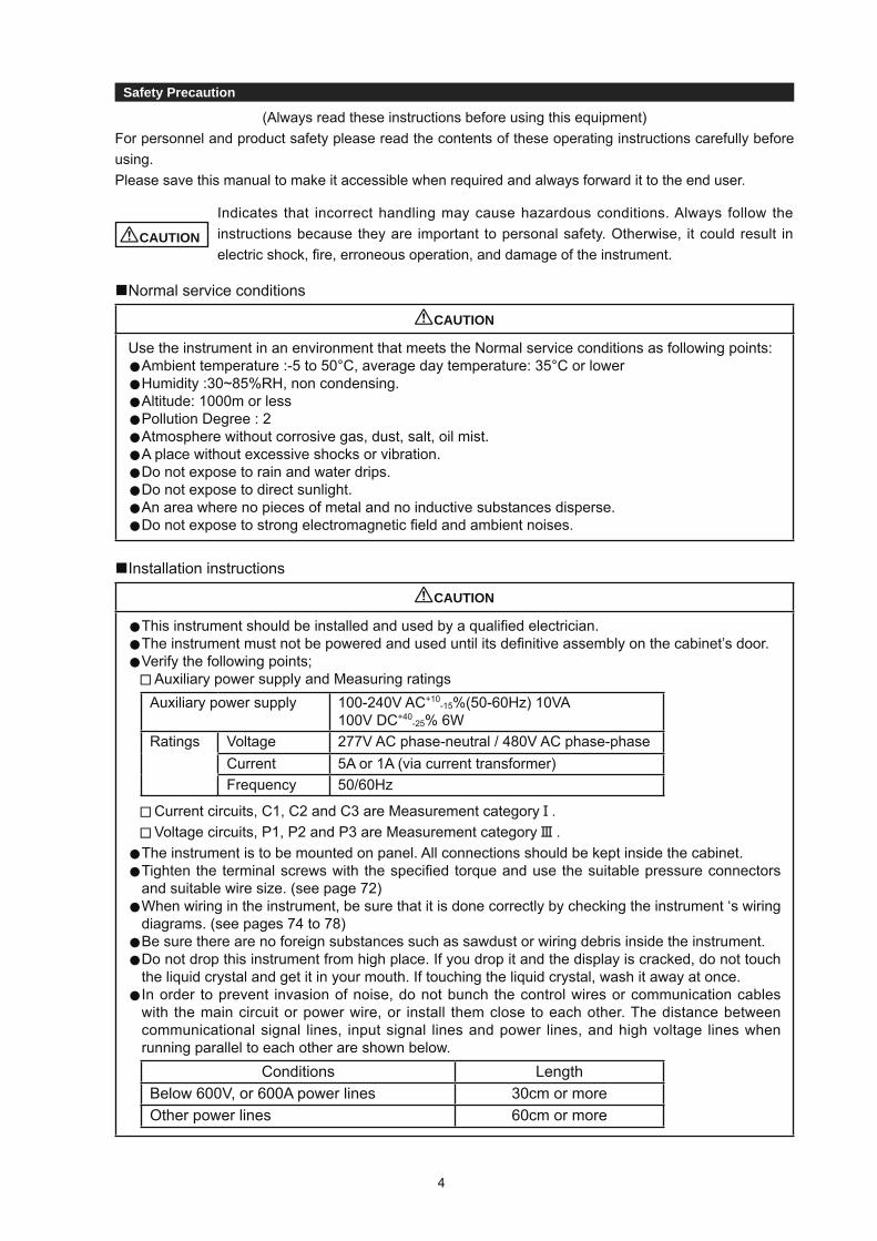
(Always read these instructions before using this equipment)For personnel and product safety please read the contents of these operating instructions carefully before using.Please save this manual to make it accessible when required and always forward it to the end user.
CAUTION
Indicates that incorrect handling may cause hazardous conditions. Always follow the instructions because they are important to personal safety. Otherwise, it could result in electric shock, fi re, erroneous operation, and damage of the instrument.
■Normal service conditions
CAUTION
Use the instrument in an environment that meets the Normal service conditions as following points:● Ambient temperature :-5 to 50°C, average day temperature: 35°C or lower● Humidity :30~85%RH, non condensing.● Altitude: 1000m or less● Pollution Degree : 2● Atmosphere without corrosive gas, dust, salt, oil mist.● A place without excessive shocks or vibration.● Do not expose to rain and water drips.● Do not expose to direct sunlight.● An area where no pieces of metal and no inductive substances disperse.● Do not expose to strong electromagnetic fi eld and ambient noises.
■Installation instructions
CAUTION
● This instrument should be installed and used by a qualifi ed electrician.● The instrument must not be powered and used until its defi nitive assembly on the cabinet’s door.● Verify the following points; Auxiliary power supply and Measuring ratings
Auxiliary power supply 100-240V AC+10-15%(50-60Hz) 10VA
100V DC+40-25% 6W
Ratings Voltage 277V AC phase-neutral / 480V AC phase-phaseCurrent 5A or 1A (via current transformer)Frequency 50/60Hz
Current circuits, C1, C2 and C3 are Measurement category . Voltage circuits, P1, P2 and P3 are Measurement category .● The instrument is to be mounted on panel. All connections should be kept inside the cabinet.● Tighten the terminal screws with the specifi ed torque and use the suitable pressure connectors
and suitable wire size. (see page 72)● When wiring in the instrument, be sure that it is done correctly by checking the instrument ‘s wiring
diagrams. (see pages 74 to 78)●Be sure there are no foreign substances such as sawdust or wiring debris inside the instrument.● Do not drop this instrument from high place. If you drop it and the display is cracked, do not touch
the liquid crystal and get it in your mouth. If touching the liquid crystal, wash it away at once.● In order to prevent invasion of noise, do not bunch the control wires or communication cables
with the main circuit or power wire, or install them close to each other. The distance between communicational signal lines, input signal lines and power lines, and high voltage lines when running parallel to each other are shown below.
Conditions LengthBelow 600V, or 600A power lines 30cm or moreOther power lines 60cm or more

5
■Operation instructions
CAUTION
● When the external terminals are connected to the external equipments, the instrument and the external equipments must not be powered and used until its defi nitive assembly on the cabinet’s door.
● The rating of the terminal of the external equipment should satisfy the rating of the external terminal of this instrument. (See Specifi cations.)
■Maintenance instructions
CAUTION
● Do not touch the terminals while all the circuits connected to this instrument are alive.● Do not disassemble or modify the instrument.● Do not allow a chemical dust cloth to be in contact with the instrument for a long time, or do not
wipe it with benzene, thinner, alcohol.
●Wipe dirt on surface with a soft dry cloth.●Check the following points, Condition of the appearance Condition of the Display Unusual sound, a smell, and generation of heat Condition of the wiring and the attachment■Storage conditions● Ambient temperature: -20 to 60°C, average day temperature: 35°C or lower● Humidity range 30~85%RH, non condensing.● Atmosphere without corrosive gas, dust, salt, oil mist.● A place without excessive shocks or vibration.● Do not expose to rain and water drips.● Do not expose to direct sunlight.● An area where no pieces of metal and no inductive substances disperse.
■Disposal● When disposing of this product , treat it as industrial waste.● The battery is not used for this product.
■GuaranteeThe period of guarantee is for 1 year from the sale date, except in the case that the failure has been caused by bad handling of the product, provided that it has been installed according to the manufacture’s instructions.

6
This section summarizes the precautions on conformance to the EMC Directive of the cabinet constructed using this Instrument.However, the method of conformance to the EMC Directive and the judgment on whether or not the cabinet conforms to the EMC Directive has to be determined fi nally by the manufacturer.
1. EMC Standards●EN 61326-1:2006●EN 61000-3-2:2006/A1:2009/A2:2009●EN 61000-3-3:2008
2. Installation (EMC directive)The instrument is to be mounted on panel of a cabinet.Therefore, the construction of a cabinet is important not only for safety but also for EMC.The instrument is examined by the following conditions.● Use a conductive cabinet.● Six faces of a cabinet have to be ensured conductivity for each other.● A cabinet has to be connected to earth by a thick wire of low impedance.● Holes on faces of cabinet have to be 10 cm or less in diameter.● The terminals for protective earth and functional earth have to be connected to earth by a thick
wire of low impedance. (A terminal for protective earth is important not only for safety but also for EMC.)
Protective earth: Maintains the safety of the instrument and improves the noise resistance.Functional earth: Improves the noise resistance.
● All connections should be kept inside the cabinet.● Wirings outside the cabinet have to be used with the shielded cable.
The following diagram shows how to provide good contact of the shielded cable. Remove part of the outer cover. Remove part of the paint musk on the cabinet. Connect those parts with the clamp.
Shield section
Paint mask
Shielded cable
Screw
Clamp fitting
EMC DIRECTIVE INSTRUCTION

7
Features
This instrument measures the load status by inputting the secondary side of the VT and CT, anddisplays various measurement values.In addition, telemonitoring can be done by a variegated output function.
■Various measurement parametersPhase wire system 3P4W 3P3W,1P3W 1P2W
Current A A1,A2,A3,AN,Aavg A1,A2,A3 A1Current Demand DA DA1,DA2,DA3,DAN,DAavg DA1,DA2,DA3 DA1
Voltage V V12,V23,V31,Vavg(L-L),V1N,V2N,V3N,Vavg(L-N) V12,V23,V31 V12
Active Power W ΣW,W1,W2,W3 ΣW ΣWActive Demand Power DW ΣDW,DW1,DW2,DW3 ΣDW ΣDW
Reactive Power var Σvar,var1,var2,var3 Σvar ΣvarApparent Power VA ΣVA,VA1,VA2,VA3 - -
Power Factor cosφ Σcosφ,cosφ1,cosφ2,cosφ3 Σcosφ ΣcosφFrequency Hz Hz
Active Energy Wh Import, Export
Reactive Energy varh Import lag, Import lead, Export lag, Export lead
Harmonic Current HIHI1, HI2, HI3, HIN HI1,HI3 HI1
THD,h1...h13(without even number)RMS value and Distortion ratio(max.100%)
Harmonic Voltage HVHV1N,HV2N,HV3N HV12,HV23 HV12
THD,h1...h13(without even number)RMS value and Distortion ratio(max.20%)
Referred to as follows in this manual:average value : avgthree phase total RMS : Σphase to phase : L-Lphase to neutral : L-N
ex) average value of current : Aavg
Three phase active power : ΣW1-phase to 2-phase voltage : V121-phase to neutral voltage : V1N
■4 measurement items appear on one displayBy combination of bar graph and digital 3-stage display, 4 measurement items can be displayed on one display. For example, voltage, current, power factor and active power can be displayed at the same time.
■RS485 interface, ModBus RTU(ME110SSR-MB)
■CC-Link communicationMeasured values can be sent to PC or PLC via CC-Link communications. (ME110SSR-C,-CH)
■Analog 4 outputs + pulse output + alarm relay output (ME110SSR-4APH)For example, the analog outputs of voltage, current, active power, and power factor, the pulse output of active energy, and the alarm output of THD can be performed by one unit.
■HarmonicsIt is equipped with harmonics current and harmonics voltage measurement function as standard one.
■Back light auto off functionIt is equipped with energy saving mode function where the back light is turned off when there is no key operation for 5 minutes.

76
35
11
13
12
1 2
4
8
9
10
14
15 16 17 18
Note: The above display is an example for explanation.
No. Segment Name Description1 LEAD status Shows direction power factor or reactive power on bar graph.
Turns on at the additional display of reactive energy.2 LAG status3 Scale of the bar graph Shows the scales at the bar graph.4 Under scale input Turns on when measuring values fall below the minimum scale.5 Over scale input Turns on when measuring values exceed the maximum scale.6 Alarm indicator When upper/lower limit alarm set, fl ickers at the limit setting value.7 Index indicator When set, turns on at the index indicator setting value.
8 Bar graph statusShows the item displayed on the bar graph.When the item is the same as a digital displayed item,indicated with “ ”,otherwise indicated with “ ”
9 Digital status Phase status, “123N” , “MAX/MIN”,demand etc. displayed.10 Digital display Measured values displayed in digital.11 Units Units of measuring value displayed.12 Multiplying factor Indicates the multiplying factor for calculating energy.13 Metering status Flickers when counting active energy.(Note.1)14 Harmonics Turns on when harmonics displayed.
15 Setup mode statusTurns on at setting mode.Flickers at setting value confi rmation mode.
16 Test mode status Turns on at the test mode.17 Upper/lower limit alarm status Flickers when upper/lower limit alarm is generated.
18 Communication status
The following are displayed for models with a transmission function.
Model On Blinking Off
ME110SSR-C
ME110SSR-CHNormal
・CC-Link compatible version mismatch
・Hardware errorHardware error
ME110SSR-MB Normal・Communication error (Such as
wrong address)Hardware error
* Products other than above don’t illuminate.
Note 1. The blinking cycle is constant regardless of the size of the measured input.
Operation 1. Display and Button Functions of Each Part
■ Display
8

5. Operation
■ Functions of operation buttons
The operation button have various functionsaccording to how they are pressed down.
Meaning of code: (Press), (press over 1 second), (press over 2 seconds), (press simultaneously) Operation
Mode
Key name
FunctionSET RESET Max/
Min PHASE DISPLAY
Ope
ratio
n m
ode
BA
SIC
Display changes.
Phase changes.
Mode changes to the max./min. display and the instantaneous display
The item expressed with the bar graph is changed.
Harmonics number changes when harmonics displayed.
Displays change cyclically. (Refer to page 48)
Phases change cyclically. (Refer to page 48)
The counting values of three digits of low rank are displayed. After pressing once again, the display returns. (Refer to page 51)
Spe
cial
Maximum values and minimum values on the display are reset to the present value. Only available for
maximum/minimum value screenAll of the Maximum values and minimum
values are reset to the present value.
All of the counting values are zero reset.
The operation time is zero veset (Screen operation time only)
An alarm condition is canceled.(Screen element is canceled) Available only when
manual cancelationis setAll alarm conditions are canceled.
(Element is canceled for all screens)
The latching data of digital input on the display is canceled.(Available only for contact point input screen)
Mod
eS
witc
h The display of Set value confi rmation mode appears.
The display of Setup mode appears.
Set
-up
mod
e/S
et v
alue
confi r
mat
ion
mod
e
Set
ting
Ope
ratio
n
The set-up items are saved, and set-up item is changed to next item.
Back to the previous item.
The values of set-up is changed.(If it presses for 1 sec or more fast forward or fast return.)
Back to the Setup display.
Spe
cial
Ope
ratio
n Returns from infrared mode to operation mode (Available only for infrared mode)
Back to the Setup display.
Returns set contents to the default settings (Only effective in CANCEL display) (Refer to page 35)
Note: While the back light is off, if the operation key is pressed, the back light is always lit. If the operation button is pressed once again, the function in the above table appears.Note: When Wh and varh are cleared to zero, the CO2 emission value is also cleared.
CAUTION
If the function of “maximum value and minimum value reset” and “Wh, varh zero reset”
are done,data will be lost. If this data is needed,please record the data before the reset operation.
If the function of “meter restart” is done, the entire measurement(measure-ment display,
alarm, analog output, pulse) stops.
Operation 1. Display and Button Functions of Each Part
SET RESET MAX/MIN PHASE DISPLAY
Set key Reset key
Maximum/minimumkey
Phase changekey
Display changekey
+/– key
9

5. Operation2. Function Modes
The following function modes are available for this Multi-Measuring instrument. Operation mode is displayed after auxiliary power turns on. It is then possible to switch to the desired mode.
Mode DescriptionReference
PagesOperation Mode This mode is for displaying each measured value using digital numerical
values and bar graphs.Operation mode contains "Current Value Display" that displays the current value, and "Maximum/Minimum Value Display" that displays old maximum/minimum values.In addition, for each display, the cyclic display function can be used to switch between the screens every 5 seconds.
P. 47 to P. 57
Setting mode This mode is for changing the setting values related to measurement and output functions.The following special operations can be executed from the "CANCEL Display" for changing/cancelling setting values.
The instrument is reset.Reset the settings to the factory defaults (Note)
P. 12 to P. 32P. 35 to P. 39
Setting value confi rmation mode
This mode is for confi rming the setting values for each setting item.(In this mode, settings cannot be changed in order to prevent accidental changing of settings.)This mode contains test functions that can be used for equipment startup.
Incorrect Wiring Determination Support Display: This displays information such as voltage and current phase angle display for determining improper wiring.
Analog Output Adjustment : Analog output can be adjusted (zero adjustment and span adjustment).
Output Test : Analog output can be switched, pulse output can be executed, and alarm contact points can be opened/closed without measurement input (voltage/current).
Communication Test : Fixed numerical data can be returned without measurement input (voltage/current).
P. 33 and P. 34P. 40 to P. 46
Note: When the purchased product already has settings, the setting values will not longer be available after this operation.■ Diagram of Each Mode
Operation mode Setting modeEND
Display
CANCELDisplay
Setting value confirmation mode
+ simultaneously for 2 secondsPressing
Test function
+ , -
Save the settings
Cancel the settings
Press for 2 seconds
When "End" is selectedfrom the menu
When "End" is selectedfrom the menu
Maximum/minimumvalue display
Current valuedisplay
SET
SET RESET
SET
SET
SET
SET
SET
SET
10

3.1 Setting Procedure
3. Settings
3.1 Setting Procedure
To measure, it is necessary to use Setting mode to set the phase wire system, VT / direct voltage, and CT primary current.From Operation mode, move to Setting mode and then set necessary items. Factory default settings will be used for items that you do not set.Only the settings in Setting menu 1 (basic set-up) are needed for normal use. For more information about the settings, refer to the following pages.For more information about the factory default settings, refer to the setting table on page 81.
CAUTIONKeep in mind that when a setting is changed, the related setting items and measurement data will be reset to the default settings.(Refer to page 35.)
Operation Mode
Setting Menu End Setting Menu 1 (Basic Set up) Setting Menu 2 Setting Menu 3
Phasewire system
DisplayPattern
Time constant foractive power demand
Time constant forcurrent demand
Primarycurrent
VT/directvoltage
Model + Optioncode
Backlightbrightness
Backlightauto off
Displayupdate time
END Display
Cancel Display
Cancel the settings.
Automatic migration.
Save the setting.
Factory defaultsetting
Model display +
Option display
Phase wire system +
Display pattern
VT secondary voltage+
VT primary voltage
CT secondary current +
CT primary current
Time constant foractive power demand
Time constant forcurrent demand
Menu 1for Setting Value
Confirmation Mode
Example of Setting Mode Example of Setting ValueConfirmation Mode
ON Blinking
Currentmaximum scale
Activepower maximum
scale
Activepower unitW/kW/MW
Reactive powermaximum scale
Reactivepower unit
Harmonics
Expandedcounting
3.1 Setting fl ow
11

3.1 Setting fl ow
3. Settings
<Setting Procedure>
Press SET and RESET simultaneously for 2
seconds to get in the set-up mode. Select a set-up menu number by or .
Use the SET key to select a set-up menu number.
Set each setting item. (Refer to page 14 and later
pages.) After completion of set-up, select ‘End’ in the set-
up menu and press SET .
When the End display appears, press SET once
again.
Setting Menu 4 Setting Menu 5 Setting Menu 6
Indicatoritem
Indicatorvalue
Alarm item
Alarm value
Alarm cancelmethod
Alarm delaytime
Back light flickersduring alarms
Motor startingcurrent delay time
Analog output1
Analog output2
Analog output3
Analog output4
Analog outputLimit
Pulse output
Power dataresolution
CC-Linkstation number
CC-Linkbaud rates
CC-Linkmodule reset
CC-Linkversion
ModBusaddress
ModBusbaud rates
ModBusparity
ModBusstop bit
ModBusmodule reset
Digitalinput setting
Digital inputcancel methad
ME110SSR-CME110SSR-CH
<ME110SSR-MB>
Enable/disable operation time display
Enable/disable CO2 display
Switch element information
Test Mode
Arrow in Figure Action Key operation
Shift from the operation mode to the set-up mode.
Memorize the setting contents, and go back tothe operation mode.
Cancel the settings.
Skip remaining setting items during setting.
Select "CANCEL."
Shift from the operation mode to the set valueconfirmation mode.
Select the menu number to set or “End” .
Get into each setting screen.Shift to the next setting item.
Go back to the previous setting item.
Select a set value.
Shift to the End screen.
Set values return to the factory default value.
Omitted infigure
SET RESET Press them simultaneouslyfor 2 seconds.
Press it for 1 second
Press it for 2 seconds
Press it for 2 seconds.
Press it several times.
Press it several times.
Press it.
Press it.
Press it.
Press it.
Press it.
Press it.
SET
SET
SET
SET
SET
SET
or
or
or
DISPLAY
RESET PHASE
1: For Setting Value Confirmation, it returns to Operation Mode.2: Repeat settings for up to 4 elements.3: Setting is only possible for ME110SSR-4AP,4APH and -4A2P.4: Setting is only possible for ME110SSR-CH.5: This is not display in Setting Mode.
Setting Menu 7 Setting Menu 8 Setting Value Confirmation Menu 9
Setting Mode or Setting Value Confirmation Mode
12

5. Operation
■ Basic Operations for set-upFunction Operation Remarks
Select a set value Press or . Fast-forward when pressed over 1 sec.
Set-up items are saved Press SET . Set-up item will be cared and shift to the next item.
Go back to the previous setting item Press DISPLAY .The set value for the setting item just before returning is still available.Skip removing setting items
during settingPress and hold SET for 1 sec.
This section is about setting the phase wire method, display pattern, VT/direct voltage, CT primary current, and
In the operation mode, after pressing SET and RESET simultaneously for 2 seconds or more, the following operation becomes available.
3. Settings
3.2 Setting Menu 1: Setting the Phase Wire System, Display Pattern, VT/Direct Voltage, CT Primary Current, and Time constant for Demand
Set the display pattern.
Set the setting menu number to “1”.
Setting Menu
Set the phase wire system. Supplemental Information: Underlined portions indicate the default values. (Same from here.)
3P33CT3P32CT3P4
: Three-phase 3-wire (3CT): Three-phase 3-wire (2CT): Three-phase 4-wire
1N2 1P3 : Single-phase 3-wire (1N2)1N3 1P3 : Single-phase 3-wire (1N3)
1P2 : Single-phase 2-wire
Additional Screen (Supplemental)
Display P
attern
Current
N phase current
demand current
N Phase demand Current
Line Voltage
Phase V
oltage
Active P
ower
Active demand Pow
er
Pow
er factor
Reactive pow
er
Frequency
Active E
nergy
Reactive Energy
Apparent pow
er
Active E
nergy(E
xported)
Reactive Energy
(Special)
Harm
onic current
N Phase Harmonic Current
Harm
onic voltage
Digital input
(DI1 to D
I3)
Operation tim
e
CO
2 Em
ission
P01P02P03P04P05P06P07P08P09P10P11P12P13P00
(a) For three-phase 4-wire
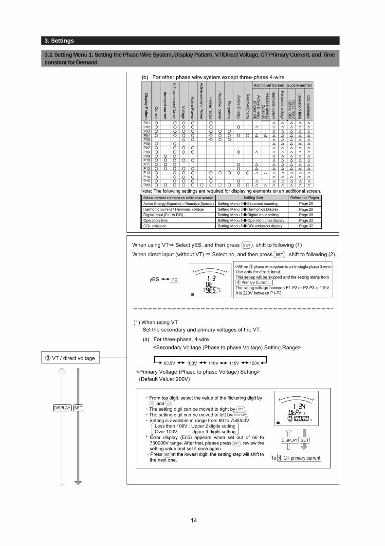
The following table shows the measurement elements that can be displayed by each display pattern. (For more details about display patterns, refer to page 62.)In addition, if there is no display pattern that you want from P01 to P13 (P14 and P15), select the special display pattern P00 to configure the screen freely.(For more information about setting the special display pattern P00.)
: Displayable at this display setting.: Set at other additional settings.: Select "P00" and set the display order and display position.
DISPLAY SET
DISPLAY SET
DISPLAY SET
Display Pattern
Phase Wire system
Measurement element on additional screen Setting itemElectric energy Power sending / reactive electric energy Special Set-up Menu 3 Electric energy Transmission power displayHarmonic current / Harmonic voltage Set-up Menu 3 Harmonics displayContact point input status (DI1 to DI3) Set-up Menu 7 Digital input settingOperation time Set-up Menu 8 Operation time displayCO2 emission Set-up Menu 8 CO2 emission display
Reference PagesPage 20Page 20Page 30Page 32Page 32
13
3. Settings
3.2 Setting Menu 1: Setting the Phase Wire System, Display Pattern, VT/Direct Voltage, CT Primary Current, and Time constant for Demand
(1) When using VTSet the secondary and primary voltages of the VT.
DISPLAY SET
Page 20Page 20Page 30Page 32Page 32
DISPLAY SET
To CT primary current
(a) For three-phase, 4-wire<Secondary Voltage (Phase to phase Voltage) Setting Range>
63.5V 100V 110V 115V 120V
<Primary Voltage (Phase to phase Voltage) Setting>(Default Value: 200V)
VT / direct voltage
(b) For other phase wire system except three-phase 4-wireAdditional Screen (Supplemental)
Display P
attern
Current
emand current
N Phase demand Current
Voltage
Active P
ower
Active demand Pow
er
Pow
er factor
Reactive pow
er
Frequency
Active E
nergy
Reactive Energy
Active E
nergy(E
xported)
Reactive Energy
(Special)
Harm
onic current
Harm
onic voltage
Digital input
(DI1 to D
I3)
Operation tim
e
CO
2 Em
ission
P01P02P03P04P05P06P07P08P09P10P11P12P13P14P15P00
Note: The following settings are required for displaying elements on an additional screen. Measurement element on additional screen Setting item
Active Energy(Exported) / Reactive(Special) Setting Menu 3 Expanded counting Harmonic current / Harmonic voltage Setting Menu 3 Harmonics Display
Digital input (DI1 to DI3) Setting Menu 7 Digital input setting Operation time
Setting Menu 8 Operation time display
CO2 emission Setting Menu 8 CO2 emission display
Reference Pages
yES no
<When phase wire system is set to single-phase 3-wire>Use only for direct input.This set-up will be skipped and the setting starts from Primary Current .The rating voltage between P1-P2 or P2-P3 is 110V.It is 220V between P1-P3
SET
SET
When using VT Select yES, and then press , shift to following (1)
When direct input (without VT) Select no, and then press , shift to following (2).
DISPLAY
SET
SET
From top digit, select the value of the flickering digit by and .
The setting digit can be moved to right by . The setting digit can be moved to left by .Setting is available in range from 60 to 750000V.
Less than 100V : Upper 2 digits setting Over 100V : Upper 3 digits setting* Error display (E05) appears when set out of 60 to
750000V range. After that, please press , review the setting value and set it once again.Press at the lowest digit, the setting step will shift to the next one.
3. Settings
14
3. Settings3. Settings
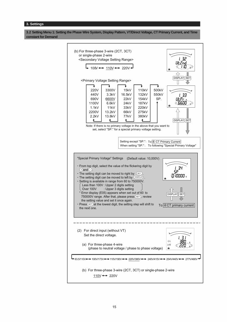
(2) For direct input (without VT)Set the direct voltage.
"Special Primary Voltage" Settings (Default value: 10,000V)
DISPLAY SET
110V 220V
100V 110V 220V
220V440V690V
1100V1.1kV
2200V2.2kV
3300V3.3kV
6600V6.6kV11kV
13.2kV13.8kV
15kV16.5kV
22kV24kV33kV66kV77kV
110kV132kV154kV187kV220kV275kV380kV
500kV550kV
SP.
DISPLAY SET
DISPLAY SET
(b) For three-phase 3-wire (2CT, 3CT) or single-phase 2-wire
(a)
(b) For three-phase 3-wire (2CT, 3CT) or single-phase 2-wire
63.5/110V 100V/173V 110V/190V 220V/380V 240V/415V 254V/440V 277V/480V
To CT Primary CurrentWhen setting "SP."Setting except "SP."
To following "Special Primary Voltage"
Note: If there is no primary voltage in the above that you want to set, select "SP." for a special primary voltage setting.
<Primary Voltage Setting Range>
<Secondary Voltage Setting Range>
To CT primary current
For three-phase 4-wire (phase to neutral voltage / phase to phase voltage)
DISPLAY
SET
SET
From top digit, select the value of the flickering digit by and .
The setting digit can be moved to right by .The setting digit can be moved to left by .Setting is available in range from 60 to 750000V.
Less than 100V : Upper 2 digits setting Over 100V : Upper 3 digits setting
* Error display (E05) appears when set out of 60 to 750000V range. After that, please press , review
the setting value and set it once again.Press at the lowest digit, the setting step will shift to the next one.
15
3.2 Setting Menu 1: Setting the Phase Wire System, Display Pattern, VT/Direct Voltage, CT Primary Current, and Time constant for Demand

3.1 Setting Procedure
3. Settings
Set the primary current of the CT you want to combine.
1A5A6A
7.5A8A
10A12A15A20A25A30A40A
50A60A75A80A
100A120A150A200A250A300A400A
500A600A750A800A
1000A1kA
1200A1.2kA
1500A1.5kA
1600A
1.6kA2000A
2kA2500A2.5kA
3000A3kA
4000A4kA
5000A5kA
6000A6kA
7500A7.5kA
8000A8kA
10kA12kA20kA25kA30kASP.
DISPLAY SET
DISPLAY SET
Primary Current Setting (Default Setting: 5A)
DISPLAY SET
CT primary current
DISPLAY SET
(a) For three-phase 4-wire
"Special Primary Current" Settings (Default Setting: 5A)
SET
SET
DISPLAY
SET
From top digit, select the value of the flickering digit by and .
The setting digit can be moved to right by the .The setting digit can be moved to left by the .Setting is available in range from 1.0A to 30000.0A
Less than 10A : Upper 2 digits setting Over 10A : Upper 3 digits setting* Error display (E05) appears when set out of 1.0 to 30000.0A range. After that, please press , review the setting value and set it once again.
Press at the lowest digit, the setting step will shift to the next one.
SET
SET
DISPLAY
SET
From top digit, select the value of the flickering digit by and .
The setting digit can be moved to right by the .The setting digit can be moved to left by the .Setting is available in range from 1.0A to 30000.0A
Less than 10A : Upper 2 digits setting Over 10A : Upper 3 digits setting* Error display (E05) appears when set out of 1.0 to 30000.0A range. After that, please press , review the setting value and set it once again.
Press at the lowest digit, the setting step will shift to the next one.
(b) For other phase wire system except Three-phase 4-wire
Note 1: If there is no primary current in the above that you want to set, select "SP." for special primary current setting.
Setting except “SP” : To When setting “SP” : To following “Special Primary Current”
Time constant for Active power demand
To Time constant for Active power demand
To Time constant for Active power demand
Note 1
16
3.2 Setting Menu 1: Setting the Phase Wire System, Display Pattern, VT/Direct Voltage, CT Primary Current, and Time constant for Demand
3. Settings
Time constantfor current demand
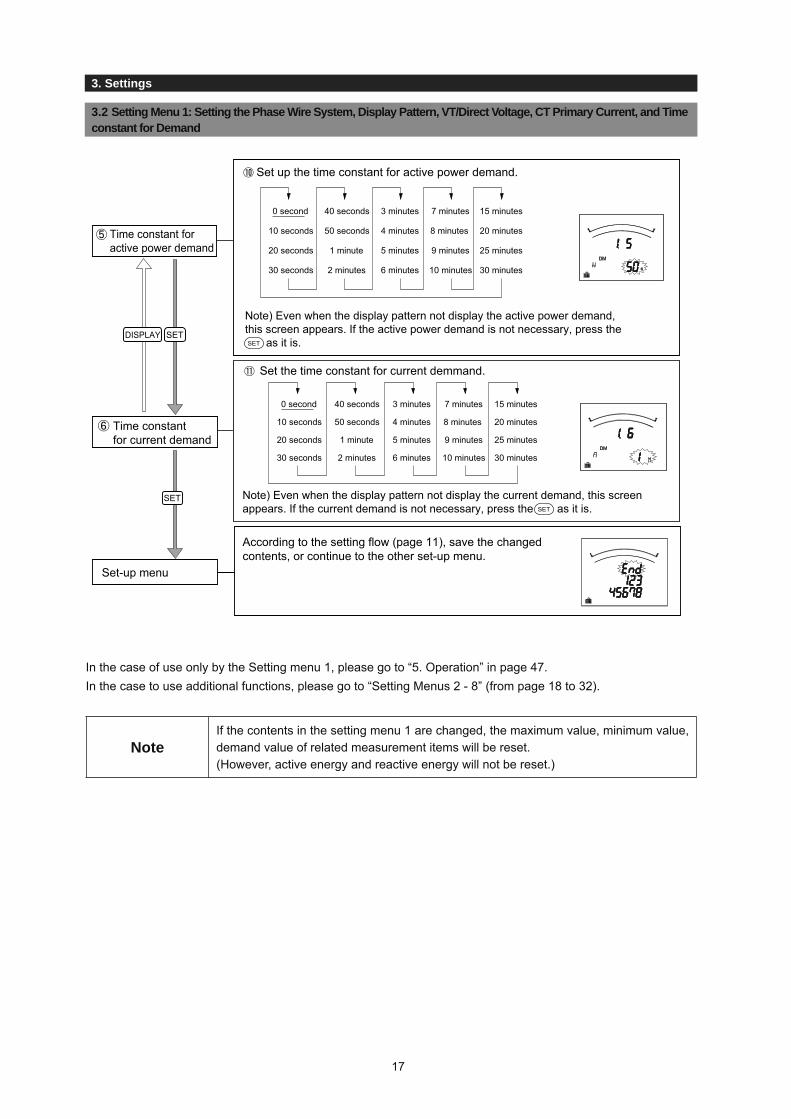
According to the setting flow (page 11), save the changedcontents, or continue to the other set-up menu.
Set-up menu
SET
Time constant foractive power demand
DISPLAY SET
Set up the time constant for active power demand.
0 second
10 seconds
20 seconds
30 seconds
40 seconds
50 seconds
1 minute
2 minutes
3 minutes
4 minutes
5 minutes
6 minutes
7 minutes
8 minutes
9 minutes
10 minutes
15 minutes
20 minutes
25 minutes
30 minutes
Note) Even when the display pattern not display the active power demand,this screen appears. If the active power demand is not necessary, press the as it is.SET
SET
Set the time constant for current demmand.
0 second
10 seconds
20 seconds
30 seconds
40 seconds
50 seconds
1 minute
2 minutes
3 minutes
4 minutes
5 minutes
6 minutes
7 minutes
8 minutes
9 minutes
10 minutes
15 minutes
20 minutes
25 minutes
30 minutes
Note) Even when the display pattern not display the current demand, this screen appears. If the current demand is not necessary, press the as it is.
In the case of use only by the Setting menu 1, please go to “5. Operation” in page 47.In the case to use additional functions, please go to “Setting Menus 2 - 8” (from page 18 to 32).
NoteIf the contents in the setting menu 1 are changed, the maximum value, minimum value, demand value of related measurement items will be reset. (However, active energy and reactive energy will not be reset.)
17
3.2 Setting Menu 1: Setting the Phase Wire System, Display Pattern, VT/Direct Voltage, CT Primary Current, and Time constant for Demand
5. Operation
3.2 Setting Menu 13.3 Setting Menu 2: Model code,Backlight,Display Update Time Setting
3. Settings
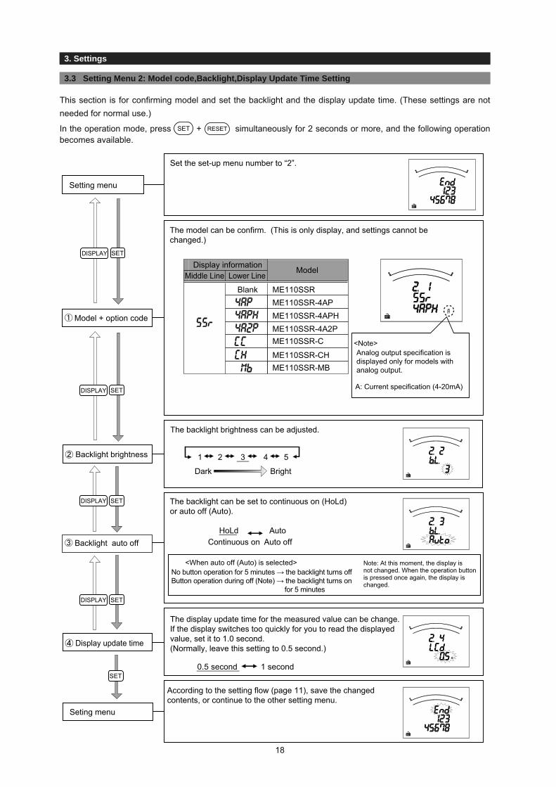
The backlight brightness can be adjusted.
Backlight brightness 1 2 3 4 5
Dark Bright
1 second
Display update time
DISPLAY SET
DISPLAY SET
DISPLAY SET
DISPLAY SET
SET
The model can be confirm. (This is only display, and settings cannot be changed.)
Display information Model
Blank ME110SSRME110SSR-4APME110SSR-4APHME110SSR-4A2PME110SSR-C
ME110SSR-MBME110SSR-CH
Model + option code
The backlight can be set to continuous on (HoLd) or auto off (Auto).
Backlight auto offHoLd Auto
Continuous on Auto off
<When auto off (Auto) is selected>No button operation for 5 minutes → the backlight turns offButton operation during off (Note) → the backlight turns on for 5 minutes
Note: At this moment, the display is not changed. When the operation button is pressed once again, the display ischanged.
Set the set-up menu number to “2”.
Setting menu
According to the setting flow (page 11), save the changedcontents, or continue to the other setting menu.
Seting menu
A: Current specification (4-20mA)
<Note>Analog output specification is displayed only for models with analog output.
Lower LineMiddle Line
0.5 second
The display update time for the measured value can be change.If the display switches too quickly for you to read the displayed value, set it to 1.0 second.(Normally, leave this setting to 0.5 second.)
This section is for confi rming model and set the backlight and the display update time. (These settings are not needed for normal use.)
In the operation mode, press SET + RESET simultaneously for 2 seconds or more, and the following operation becomes available.
18

5. Operation3. Settings
In this setting menu, you can do in detail set up for the bar-graph, unit, expanded counting, harmonics.
In the operation mode, press SET and RESET simultaneously for 2 seconds or more, and the following operation becomes available.
3.4 Setting Menu 3: Setting the Bar Graph, Unit Display, Expanded counting, and Harmonics Display
Set the single deflection / double deflection of reactive power.Single deflection is the LEAD polarity. (The default setting is double deflection.)Reactive power
maximum scale
Set the reactive power unit (var, kvar, Mvar).Reactive power unit
DISPLAY SET
DISPLAY SET
DISPLAY SET
DISPLAY SET
DISPLAY SET
DISPLAY SET
Set the set-up menu number to "3".
Setting menu
Set the current maximum scale.
Current maximumscale
Set the maximum scale of Active power, active power demand.
(1) Maximum scale value
(2) single deflection / double deflection
Active powermaximum scale
DISPLAY SET
Set Active power unit (W, kW, and MW).
Maximum scale value Setting range
1,000kW or higher 8,000kW or less
W kW
kW MW
Note: The unit cannot be changed beyond the above range.
Active power unit8,000W or less1,000W or higher
+3 STEP (About 120%) to±0 STEP (100%: Rating) to-10 STEP (About 40%)
+3 STEP (About 120%) to±0 STEP (100%: Rating) to-18 STEP (About 20%)
double deflectionsingle deflection
Note: The maximum scale value becomes the value in the table on page 62.
Note: The maximum scale value becomes the value in the table on page 63.
The setting method is same as that of Active power unit .
The setting method is same as that of Active power maximum scale .
19

5. Operation
3.4 Setting Menu 3: Setting the Bar Graph, Unit Display, Expanded counting, and Harmonics Display
Set the harmonic measurement.
When the display is set to "on," the harmonic measured value can be displayed on an additional screen of the display pattern.
Harmonics oFF on
DISPLAY SET
SET
According to the setting flow diagram (page 11), save the changedcontents, or continue to the other setting menu.
Setting menu
Set the combinations of imported / exported and lag / lead for active energy and reactive energy you want to display, and set the measurement method for reactiveenergy.
Active energy(Wh)
Reactive energy(varh)
Imported Imported Imported ImportedExported
Exported Exported Exported
I ○ ○II ○ ○III ○ ○IV ○ ○
○
○○○
○○○
Note: For more information about the measurement method for reactive energy, refer to page 52.
Combination I, II → It is suitable for the counting of equipmentwithout the private electric generator and the reactivepower of the capacitor load at the power factor = 0, generally.
Combination III, IV → It is suitable for the counting of equipment with the privateelectric generator.
Expanded counting
<Example Screen>
Note
Accuracy is defined to rated current. Although the maximum scale may display120% or more of rated current and rated voltage in order to make a scale easyto read depending on the settings of VT/direct voltage and CT primary current, current input is within 100% of rated current.
●
●
Combination (Setting value)
Combination I Combination II Combination III Combination IV
lag lag laglag(lead) lead lead lead
Reactive energymeasurementmethod(Note)
2 quadrantmeasurement
4 quadrantmeasurement
(Displayed)(Not displayed)
Even if a display pattern is selected that cannot display active power, reactive power, active energy, and reactive energy, it is possible to display the sign according to 2 quadrant / 4 quadrant measurement of the power factor and reactive power due to Expanded counting , so setting items for Expanded counting will be displayed.
3. Settings
20

3.1 Setting Procedure
3. Settings
3.5 Setting Menu 4: Index Indicator Setting
3. Settings
The Index indicator (▲) of bar graph is set here. Up to 4 measurement items can be set.
In the operation mode, press and simultaneously for 2 seconds or more, and the following operation
becomes available.
SET RESET
Set the set-up menu number to “4”.
Setting menu
Set the measurement element to be assigned to 1.
Indicator item 1
non : No indicator displayA : CurrentDA : Current demandV : VoltageW : Active powerDW : Active power demandvar : Reactive powercosφ : Power factor
Set the value of Index indicator 1. The setting range is as shown in the following table.
Measuring element Setting range Setting step (Note)A, DA 5 to 100 to 120(%) 1%V 25 to 100 to 135(%)
-120 to 100 to 120(%)-0.5 to 1 to 0.5
1%W, DW, var 1%cosφ 0.05
Note: A, DA, W, DW, and var show the percentage for the maximum scale value (±0 step) ."V" shows the percentage for the VT primary voltage (or direct voltage).
Indicator value 1
Set the measurement items to be allowed to 2 - 4.Elements that are set elsewhere cannot be set.Indicator item 2 to 4
Set the indicator value for Indicators 2 to 4. Indicator value 2 to 4
DISPLAY SET
DISPLAY SET
SET
DISPLAY SET
DISPLAY SET
According to the setting flow diagram (page 11), save the changedcontents, or continue to the other setting menu.
Setting menu
Display when "non" is selected
Display when "A" is selected
The setting method is same as that of Indicator item 1 .
The setting method is same as that of Indicator value 1 .
21

3.1 Setting Procedure
3. Settings
This section shows how to set the upper/lower limit alarm, backlight flickering during alarm, and motor starting currentdelay time.In the operation mode, press and simultaneously for 2 seconds or more, and the following operationbecomes available.
SET
For more details about each function, refer to the corresponding pages.Upper/lower limit alarm → Page 53, Motor startup current → Page 57
Set the Alarm item 1 to be allowed to measurement items.The upper/lower limit measurement values can be monitored by this setting.
Alarm item 1
Note 1. Measurement items that are not selected in the display pattern can be selected.Note 2. DA: Current demand, DAN: N-phase demand current, V (L-N): Phase to neutral voltage, V (L-L): phase to phase voltage, DW: Active power demand
nonA upper limitA lower limitDA upper limitDA lower limitV upper limitV lower limitW upper limitW lower limit
DW upper limitDW lower limitvar upper limitvar lower limitcosφ upper limitcosφ lower limitHz upper limitHz lower limitHarmonic current total RMS valueHarmonic voltage total distortion ratio
DISPLAY SET
DISPLAY SET
Set the set-up menu number to “5”.
Setting menu
Display when "A upper limit" is selected
nonA upper limitA lower limitAN upper limitDA upper limitDA lower limitDAN upper limitV (L-N) upper limitV (L-N) lower limitV (L-L) upper limitV (L-L) lower limitW upper limitW lower limit
DW upper limitDW lower limitvar upper limitvar lower limitcosφ upper limitcosφ lower limitHz upper limitHz lower limitHarmonic current total RMS value
Harmonic voltage total distortion ratio
N-phase harmonic current total RMS value
(b) For other phase wire system except three-phase 4-wire
(a) For three-phase 4-wire
RESET
Display when "non" is selected
3. Settings
22
3.6 Setting Menu 5: Setting the Upper/Lower Limit Alarm, Backlight Flickers During Alarms, and Motor Startup Current Delay Time

3.1 Setting Procedure
3. Settings
Set the alarm value for the upper/lower limit alarm items 2 to 4.
The setting method is the same as Alarm value 1 .Alarm value 2 to 4
Set the alarm mask time for when you want to prevent a momentary overload or noise alarm.When this is set, an alarm is generated only when the alarm value is over the upper/lower limit alarm value for a longer time than the delay time. On the setting screen, seconds are indicated by "s" and minutes are indicated by "M".Alarm delay time
Set the alarm cancel method at generation of alarm. (screen, relay)
Reset method(Set-up value)
Description (Refer to pages 53 and 54)
Automatic When there is no alarm generationcondition, alarm is automatically reset.
Manual (HoLd)
The alarm will continue even when the alarm generated conditions no longer exist. It is necessary to execute button operation to cancel the alarm.
Alarm cancel method
DISPLAY SET
DISPLAY SET
DISPLAY SET
Note: When all settings for Alarm item 1 and Alarm item 2 to 4 are set to "non," this setting will be skipped.
Note: When all settings for Alarm item 1 and Alarm item 2 to 4 are set to "non," this setting will be skipped.
Set the measurement element assigned to the upper/lower limit alarm items 2 to 4. Elements that are set elsewhere cannot be set.
The setting method is the same as Alarm item 1 .Alarm item 2 to 4
DISPLAY SET
DISPLAY SET
Set the alarm value for upper/lower limit alarm element 1. The following table shows the setting range.
Measuring element Setting range Setting (Note) step
A, AN, DA, DAN upper limit 5 to 100 to 120(%)3 to 10 to 95(%)25 to 110 to 135(%)20 to 70 to 95(%)-95 to 100 to 120(%)-120 to 3 to 95(%)
-0.05 to -0.5 to 0.05-0.05 to 1 to 0.05
45 to 65 (Hz)45 to 65 (Hz)1 to 35 to 120(%)1 to 35 to 120(%)0.5 to 3.5 to 20(%)
1%A, DA lower limit 1%V (L-N), V (L-L) upper limit 1%V (L-N), V (L-L) lower limit 1%W, DW, var upper limit 1%W, DW, var lower limit 1%cosφ upper limit 0.05
0.05cosφ lower limitHz upper limit 1HzHz lower limit 1Hz
Harmonic current total RMS valueN-phase harmonic current total RMS value
1%1%
Harmonic voltage total distortion ratio 0.5Note: A, AN, DA, DAN, W, DW, and var show the percentage for the maximum scale value (±0 step). "V" shows the percentage for the VT primary voltage (or direct voltage). (The "V" for 1-phase 3-wire is the percentage for 110V. Alarm monitoring is executedusing twice the value which set upper/lower limit alarm for the 12-phase and 13-phase.)
Alarm value 1
(Auto)
0 seconds5 seconds10 seconds20 seconds
30 seconds40 seconds50 seconds
1 minute
2 minutes3 minutes4 minutes5 minutes
3. Settings
3.6 Setting Menu 5: Setting the Upper/Lower Limit Alarm, Backlight Flickers During Alarms, and Motor Startup Current Delay Time
23

3.1 Setting Procedure
3. Settings3. Settings
SET
By using this setting for motor current monitoring delay time, it is possible to prevent unnecessary maximum value updating and unnecessary alarms caused by the motor startup current.
When this setting is not needed→ Select "oFF" and press , and return to the Setting Menu.SET
When this setting is executed → Select "on" and press , and go to (1) below.SET
(1) Motor starting current value.
Set the value for detecting the motor starting current.
Setting range Setting step (Note)
1%3 to 5 to 120(%)
* This is the percentage for the maximum scale value for the current (±0 step).
(2) Motor starting current delay timeAfter the motor starting current is detected, maximum value updateis not executed and an alarm is not generated for the delay time. On the setting screen, seconds are indicated by "s" and minutes are indicated by "M".
Motor starting current delay time
oFF on
DISPLAY SET
1 s3 s5 s
10 s
15 s20 s30 s45 s
1 M1.5 M
2 M3 M
4 M5 M
According to the setting flow (page 11), save the changedcontents, or continue to the other setting menu.
It is possible to make the backlight to flicker when an alarm is generated.
Backlight flickersduring alarms
oFF on
DISPLAY SET
Setting menu
(Flicker)(Not flicker)
Note: When all settings for Alarm item 1 and Alarm item 2 to 4 are set to "non," this setting will be skipped.
24
3.6 Setting Menu 5: Setting the Upper/Lower Limit Alarm, Backlight Flickers During Alarms, and Motor Startup Current Delay Time

3.1 Setting Procedure
3. Settings
3.7 setting Menu 6: Setting the Analog Output and Pulse Output
Set the measurement item to be output to analog output CH1.
Select a measurement item for output from the following table.
Analog output CH1 output item
DISPLAY SET
DISPLAY SET
DISPLAY SET
Output item of analog output, pulse output, pulse unit and so forth are set here.
In the operation mode, press and simultaneously for 2 seconds or more, and the following operation becomes available.
Setting menu
AVG: Average ∑: Total RMS value
nonA1
A2
A3
AN
AAVG (CH1)Demand A1
Demand A2
Demand A3
Demand AN
Demand AAVG
V1N
V2N
V3N
VAVG (L-N)(CH2)V12
V23
V31
VAVG (L-L)
W1
W2
W3
W∑ (CH3)Demand W1
Demand W2
Demand W3
Demand W∑ var1
var2
var3
var∑
VA1
VA2
VA3
VA∑
cosφ1
cosφ2
cosφ3
cosφ∑ (CH4)HzHarmonic A1
Harmonic A2
Harmonic A3
Harmonic AN
Harmonic V1N
Harmonic V2N
Harmonic V3N
3-phase 4-wire
SET RESET
Set the setting menu number to “6”.
Analog output specification is displayed.(Cannot be changed)
②
Analog output specification
①
For current specification(4-20mA)
3. Settings
25

3.1 Setting Procedure
3. Settings
26
3.7 Setting Menu 6: Setting the Analog Output and Pulse Output
DISPLAY
3-phase 3-wire(2CT, 3CT)
1-phase 3-wire (1N2 display)
1-phase 3-wire (1N3 display) 1-phase 2-wire
nonA1 (CH1)A2
A3Demand A1Demand A2
Demand A3
VRS (CH2)V23VT1
W (CH3)Demand Wvarcosφ (CH4)HzHarmonic A1
A2(3CT)HarmonicHarmonic A3
Harmonic V12
Harmonic V23
nonA1 (CH1)AN
A2Demand A1Demand AN
Demand A2
VRN (CH2)VN2V12
W (CH3)Demand Wvarcosφ (CH4)HzHarmonic A1Harmonic A2
Harmonic V1N
Harmonic V2N
nonA1 (CH1)AN
ATDemand A1Demand AN
Demand A3
VRN (CH2)VNTVT1
W (CH3)Demand Wvarcosφ (CH4)HzHarmonic A1Harmonic A3
Harmonic V1N
Harmonic V3N
nonA (CH1)Demand AV (CH2)W (CH3)Demand Wvarcosφ (CH4)HzHarmonic AHarmonic V
SET
Note 1:The same measurement item can be set for each analog output.Note 2:It is possible to select measurement item that are not included in the set display pattern.Note 3:Setting to "non" are minimum output. In addition, it moves to the next analog output setting.Note 4:For the harmonic current, the total RMS value is output by a scale from 0 to 60% of the rating. For the harmonic voltage, the total distortion ratic is output by scaling 0 to 20%. Note 5:Underlined portions are the factory default settings for measurement elements assigned to each analog output.

3.1 Setting Procedure
3. Settings
3.7 Setting Menu 6: Setting the Analog Output and Pulse Output
Analog output detailed set-up(The following setting can be made separately from the measurement items included in the display pattern.)(1) When the current / current demand / active power / active power demand / reactive power are set as output elements
(a) Set the measurement value for the maximum analog output value.
Output item Setting range
ADemand A
WDemand W
var
(b) Set the Singledeflection / dauble deflection / special deflection for analog output.
Output item Setting range
WDemand W
var
(c) For special deflection, set the measurement value for the minimum analog output value.
Output item Setting range
WDemand W
(2)
(3)
(4)
When voltage is set as an output item for 1-phase 3-wire Set V1N and V2N (V3N) for the maximum analog output value.
When power factor is set as an output item Set the power factor value for the maximum analog output values.
When the frequency is set as an output item Set the frequency range for analog output.
Analog output CH1detailed setting
*1. When A or Demand A are set as output items, it moves to the next analog output settings.*2. When other than special deflection is selected, it moves to the next analog output settings.*3. Detailed setting values are according to the values shown in the table on pages 62 and 63.
±0 STEP (100%: Rating)
-10 STEP (About 40%)
+3 STEP (About 120%)
±0 STEP (100%: Rating)
-18 STEP (About 20%)
+3 STEP (About 120%)
mA
41220
- 40kW 40kW0
mA
4
20
40kW0
mA
4
20
- 7.5kW 40kW0
±0
STEP (About 25%)
STEP (About 100%)
-21
-15
STEP (About 15%)
DISPLAY SET
To next CH settings
*1
*2
mA
41220
- 0.5 0.51.0
mA
41220
- 0 01
Note: V12 (V13) is fixed at 300V.
150VmA
4
20
0 150
mA
4
20
0 300
- 0.5 to 1.0 to 0.5
- 0 to 1 to 0
mA
41220
45Hz 55Hz50Hz
mA
41220
55Hz 65Hz60Hz
45 to 50 to 55(Hz)
55 to 60 to 65(Hz)
DISPLAY SET
DISPLAY SET
DISPLAY SET
*3
*3
<Dauble deflection><Single deflection> <Special deflection>
300V
<When 150V is set> <When 300V is set>
<When 50Hz is set> <When 60Hz is set>
to
to
to
to
to
to
Singledeflection
Single deflection Dauble deflection
Daubledeflection
Special deflection
3. Settings
27
3.1 Setting Procedure
3. Settings
3.7 Setting Menu 6: Setting the Analog Output and Pulse Output
DISPLAY SET
DISPLAY SET
DISPLAY SET
DISPLAY SET
DISPLAY SET
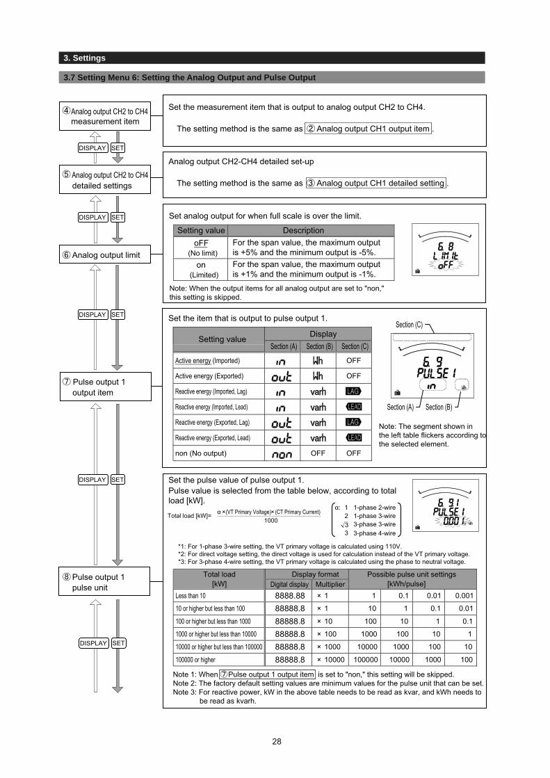
Set the measurement item that is output to analog output CH2 to CH4.
The setting method is the same as Analog output CH1 output item .
Analog output CH2 to CH4measurement item
Analog output CH2-CH4 detailed set-up
The setting method is the same as Analog output CH1 detailed setting .Analog output CH2 to CH4detailed settings
Set analog output for when full scale is over the limit.
Setting value DescriptionoFF
(No limit)For the span value, the maximum output is +5% and the minimum output is -5%.
on(Limited)
For the span value, the maximum output is +1% and the minimum output is -1%.
Note: When the output items for all analog output are set to "non," this setting is skipped.
Analog output limit
Set the item that is output to pulse output 1.
DisplaySetting valueSection (A) Section (B) Section (C)
Active energy (Imported) OFF
Active energy (Exported) OFF
Reactive energy (Imported, Lag)
Reactive energy (Imported, Lead)
Reactive energy (Exported, Lag)
Reactive energy (Exported, Lead)
non (No output) OFF OFF
Pulse output 1output item
Section (A) Section (B)
Section (C)
Note: The segment shown in the left table flickers according to the selected element.
Set the pulse value of pulse output 1.Pulse value is selected from the table below, according to totalload [kW].
(CT Primary Current)(VT Primary Voltage)αTotal load [kW]=1000
××
*1: For 1-phase 3-wire setting, the VT primary voltage is calculated using 110V.*2: For direct voltage setting, the direct voltage is used for calculation instead of the VT primary voltage.*3: For 3-phase 4-wire setting, the VT primary voltage is calculated using the phase to neutral voltage.
Display formatTotal load[kW] Digital display Multiplier
Possible pulse unit settings[kWh/pulse]
Less than 10 8888.88 × 1 1 0.1 0.01 0.001
10 or higher but less than 100 88888.8 × 1 10 1 0.1 0.01
100 or higher but less than 1000 88888.8 × 10 100 10 1 0.1
1000 or higher but less than 10000 88888.8 × 100 1000 100 10 1
10000 or higher but less than 100000 88888.8 × 1000 10000 1000 100 10
100000 or higher 88888.8 × 10000 100000 10000 1000 100
Note 1: When Pulse output 1 output item is set to "non," this setting will be skipped.Note 2: The factory default setting values are minimum values for the pulse unit that can be set.Note 3: For reactive power, kW in the above table needs to be read as kvar, and kWh needs to be read as kvarh.
Pulse output 1pulse unit
α: 1 1-phase 2-wire2
3
1-phase 3-wire
3-phase 4-wire3 3-phase 3-wire
3. Settings
28

3.1 Setting Procedure
3. Settings
3.7 Setting Menu 6: Setting the Analog Output and Pulse Output
Set the element that is output to pulse output 2. (ME110SSR-4A2P)The same elements as pulse output 1 can be set.
The setting method is the same as Pulse output 1 output item .(Factory default setting value: Reactive energy (Imported, Lag)
Pulse output 2output item
Set a pulse unit for pulse output 2. (ME110SSR-4A2P)
The setting method is the same as for Pulse output 1 pulse unit .
(Factory default setting values: Minimum possible value for pulse unit)
Pulse output 2pulse unit
DISPLAY SET
DISPLAY SET
SET
Set the pulse width for output pulse.Set according to the input pulse conditions for the receiver.
NoteWhen the pulse unit is set to the minimum value and the pulse width is set to 0.500s or 1.000s, the pulse output cannot follow if the load is too large, which can result in a decrease in the pulse output number.
Pulse width 0.125s 0.500s 1.000s
According to the setting flow (page 11), save the changedcontents, or continue to the other setting menu.
Setting menu
3. Settings
29
3.1 Setting Procedure
3. Settings
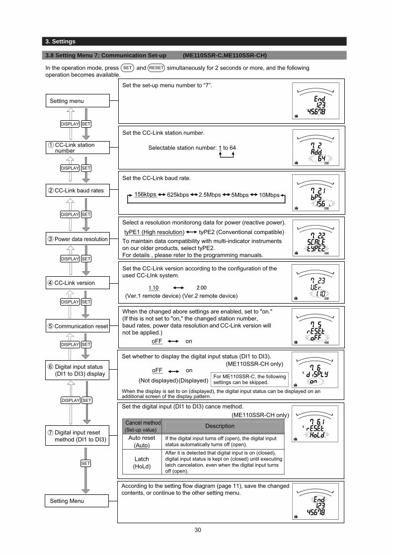
In the operation mode, press and simultaneously for 2 seconds or more, and the followingoperation becomes available.
Set the CC-Link station number.
Selectable station number: 1 to 64CC-Link stationnumber
Set the CC-Link baud rate.
Set the CC-Link version according to the configuration of theused CC-LInk system.
CC-Link baud rates 156kbps 625kbps 2.5Mbps 5Mbps 10Mbps
Select a resolution monitorong data for power (reactive power).
To maintain data compatibility with multi-indicator instruments on our older products, select tyPE2.For details , please reter to the programming manuals.
Power data resolutiontyPE1 (High resolution) tyPE2 (Conventional compatible)
When the changed abore settings are enabled, set to "on." (If this is not set to "on," the changed station number, baud rates, power data resolution and CC-Link version will not be applied.)
oFF on
DISPLAY SET
DISPLAY SET
DISPLAY SET
SET
DISPLAY SET
Set the set-up menu number to “7”.
Setting menu
According to the setting flow diagram (page 11), save the changedcontents, or continue to the other setting menu.
Setting Menu
Set whether to display the digital input status (DI1 to DI3).(ME110SSR-CH only)
When the display is set to on (displayed), the digital input status can be displayed on an additional screen of the display pattern.
Digital input status(DI1 to DI3) display oFF on
(Not displayed)(Displayed)
Set the digital input (DI1 to DI3) cance method.(ME110SSR-CH only)
Cancel method(Set-up value)
Description
Auto reset(Auto)
If the digital input turns off (open), the digital input status automatically turns off (open).
Latch(HoLd)
After it is detected that digital input is on (closed), digital input status is kept on (closed) until executing latch cancelation, even when the digital input turns off (open).
DISPLAY
DISPLAY SET
SET
DISPLAY SET
For ME110SSR-C, the following settings can be skipped.
Digital input reset method (DI1 to DI3)
SET RESET
(Ver.1 remote device) (Ver.2 remote device)
CC-Link version
Communication reset
3. Settings
3.8 Setting Menu 7: Communication Set-up (ME110SSR-C,ME110SSR-CH)
30

3.1 Setting Procedure
3. Settings
3.8 Setting Menu 7: Communication Set-up (ME110SSR-MB)
Set the ModBus address number.
Selectable addresses: 1 to 255ModBus address
Set the ModBus baud rate.
ModBus baud rates
2400bps4800bps9600bps19.2kbps38.4kbps
Set the ModBus parity.
ModBus parity
Set the ModBus stop bit.
ModBus stop bit Stop bit 1Stop bit 2
To enable the changed address, baud rate, parity, and stop bit, select "on."
If you don’t select "on", the changed address, baud rate, parity, and stop bit will not be applied.
Communication module reset
oFF on
DISPLAY SET
DISPLAY SET
DISPLAY SET
DISPLAY SET
DISPLAY SET
SET
Set the set-up menu number to “7”.
Setting menu
According to the setting flow (page 11), save the changedcontents, or continue to the other setting menu.
Setting menu
nonoddEVEn ( )
In the operation mode, press and simultaneously for 2 seconds or more, and the followingoperation becomes available.
SET RESET
3. Settings
31

3.1 Setting Procedure
3. Settings
3.9 setting Menu 8: Setting the Operating Time Display, CO2 Emission Display, and Element Information
This section shows how to set the operation time and CO2 emission display.
The current measurement time is calculated and is displayed as the load operation time. Select whether to display or not the operation time. (The operation time is calculated only when “on” is selected.)Operation time display
oFF on(Not displayed) (Displayed)
DISPLAY
DISPLAY
SET
DISPLAY SET
SET
SET
Set the set-up menu number to “8”.
Setting menu
CO2 emissions are converted based on the active energy (imported) and are displayed.When CO2 emission display is needed →
When CO2 emission display is not needed →
Set a CO2 conversion factor.(Factory default setting: 0.555kg-CO2/kWh)
CO2 emission display
DISPLAY SET
▪ Select a value using and for the blinking digit from the highest digit.
▪
▪▪▪
According to the setting flow (page 11), save the changedcontents, or continue to the other setting menu.
Setting menu
It is possible to change the line element information for displaying.
(However, bar graph display is expressed using RSTN and 123N.)
The following is element information.Switch element information
RST123 123 1N2 1N3123NUVW UVW UNV UNWUVWNRYB RYB RNY RNBRYBNABC ABC ANB ANCABCNXYZ XYZ XNY XNZXYZN
RSTN
3P4W 3P3W 1P3W(1N2 display)
1P3W(1N3 display)
RST RNS RNT
123 UVW RYB ABC XYZ
SET
SET
oFF on(Not displayed) (Displayed)
+ -
SET
DISPLAY
SET
In the operation mode, press and simultaneously for 2 seconds or more, and the followingoperation becomes available.
SET RESET
Select "on", press , and go to the following settings.Select "oFF", press , and go to the Set-up Menu.
Setting is possible within the range from 0.000 to 0.999 (kg-CO2/kWh).Use to move the setting digit (blinking digit) higher.
Use to move the setting digit (blinking digit) lower.
Press at the lowest digit to return to the Setting Menu.
3. Settings
32

3.1 Setting Procedure
3. Settings
3.10 Setting Value Confi rmation Menu 1: Confi rming the Setting Values for Setting Menu 1
This section shows how to confirm the setting values for Setting Menu 1 (phase wire system, display pattern, VT/direct voltage, CT primary current, etc.).When is pressed for at least 2 seconds in the operation mode, the following operation becomes available.
DISPLAY SET
DISPLAY SET
DISPLAY SET
Set the setting value confirmation menu number to “1”.
Setting value confirmation menu
It is possible to confirm the model. The following table shows the display contents and corresponding model.
Display informationMiddle Bottom
Model
Blank ME110SSRME110SSR-4APME110SSR-4APHME110SSR-4A2PME110SSR-C
ME110SSR-MBME110SSR-CH
Model display
It is possible to confirm the setting values for the phase wire system and display pattern.
Phase wire system + display pattern
<When the display pattern is other than P00> <When the display pattern is P00>
Phase wire system
Display pattern
Screen numberMeasurement items on the first screen from upper to lower
DISPLAY SET
DISPLAY SET
This continues according to the set number of screens. (Up to 4 screens)
<Note> Analog output specification is displayed only for models with analog output.
A: Current specification (4-20mA)
SET
3. Settings
33

3.1 Setting Procedure
3. Settings
3.10 Setting Value Confi rmation Menu 1: Confi rming the Setting Values for Setting Menu 1
It is possible to confirm the set values for VT / direct voltage.When the phase wire system is 1P3W, this screen will be skipped.<For VT settings> <For direct input>
It is possible to confirm the set values for CT secondary current (specified when ordered) and CT primary current.CT secondary current +
CT primary current
It is possible to confirm the set value for time constant foractive power demand
It is possible to confirm the set value for time constant forcarrent demand
When is pressed for at least 2 seconds in the operation mode, operation becomes possible.The screen transitions and operations are the same as for Setting Menus 2 to 8. Refer to Set-up Menus 2 to 8 (pages 18 to 32).(Note: Settings cannot be changed in the Setting value confirmation mode.)
DISPLAY SET
DISPLAY SET
DISPLAY SET
SET
Complete the set value confirmation or continue the set value confirmation using other set value confirmation menus according to the setting flow (page 13).Setting value
confirmation menu
VT / direct voltage
VT secondary voltage
VT primary voltage Direct voltage
CT secondary current
CT primary current
[For 3P4W]
SET
Time constant for activepower demand
Time constant for current demand
3.11 Setting Value Confi rmation Menus 2 to 8: Confi rming the Setting Values for Setting Menus 2 to 8
3. Settings
34

3.1 Setting Procedure
3. Settings
3.12 Initializing Related Items by Changing Settings
3.13 Initializing All Settings
When a setting value is changed, the related setting items and measurement data (maximum/minimum values) will return to the default settings. Refer to the following list.
Menu 4 Menu 5
Phase w
ire system
Display pattern
Display pattern P
00 screen configuration
VT/direct voltage
CT prim
ary current
Indicator item
Upper/low
er limit alarm
item
Phase wire systemDisplay pattern ●
●●
Display pattern P00 screen configuration ●VT/direct voltage
Current scale ●Power scale ● ● ●Power unit ●Reactive power scale ● ● ●Reactive power unit ●Indicator item ● ● ●Indicator value ● ● ● ●Upper/lower limit alarm item ●Upper/lower limit alarm value ● ●Analog output detailed settings
For A ●For DA ●For V (For 1P3W only) ●For WFor VA
●
●●
● ●● ● ●
For DW ● ● ●For var ●
●●
● ●
● ●● ●● ●● ● ●● ● ●●●
● ●● ●
● ● ●●● ●● ●
Harmonic current Maximum value
Setting item to be changed
Initialized item
Menu 1
Setting item
Menu 1
Menu 3
Menu 4
Menu 5
Menu 6 Output element
Harmonic voltage Maximum value
Measurem
ent dataCurrent Maximum/minimum valueCurrent demand Maximum/minimum valueVoltage Maximum/minimum valueActive power Maximum/minimum valueActive power demand power Maximum/minimum valueReactive power Maximum/minimum value
Power factor Maximum/minimum valueFrequency Maximum/minimum value
●: This indicates that the setting value is the default value and the measurement data is zero.*1: This is the default value changing from 3P4W to others.
When the following operations are executed, all settings are initialized to the factory defaults.Only the settings are initialized to the defaults. Adjusted values (Test Mode Menu 2) and active energy valuesare not changed.To initialize all settings to the factory defaults, execute the following operation from the CANCEL screen in thesetting mode.For more information about how to get to the CANCEL screen, refer to 3.1 Setting flow (page 11).
Setting mode Initialization completed
CANCEL screen Measurement screen
Press the +for 2 seconds.
For cosφFor Hz
Apparent power Maximum/minimum value
CT primary current
RESET PHASE
*1*1
3. Settings
35

3.1 Setting Procedure
3. Settings
3.15 Setting the Special Display Pattern P00
Select “P00” by or and press .
Even if there is no display pattern that you like in the display patterns P01 to P13 (P14, P15), individual set-up is available by the display pattern P00.This set-up is made in the setting menu 1. Explanation begins with the set “P00” in display pattern of the setting menu 1 (page 13). (Others are omitted here, so refer to the setting menu 1.)
■ The number of settable display is up to 4. And the number of measurement elements to be displayed is up to 12 items.
Upper stage:measurement item 1
Middle stage:measurement item 2
Lower stage:measurement item 3
Upper stage:measurement item 4
Middle stage:measurement item 5
Lower stage:measurement item 6
Upper stage:measurement item 7
Middle stage:measurement item 8
Lower stage:measurement item 9
Upper stage:measurement item 10
Middle stage:measurement item 11
Lower stage:measurement item 12
Screen 4-1
Screen 2-1 Screen 2-2
Screen 4-2 Screen 4-3 Screen 4-4
DISPLAY DISPLAY DISPLAY DISPLAY
■ Explanation is made with the example of the following display pattern.
■ Setting method
DISPLAY DISPLAY
Upper stage: AMiddle stage: VLower stage: Wh
Upper stage: cosφMiddle stage: DWLower stage: Not displayed
Display pattern
Set the display pattern.
1) Select “P00” .
SET
2) Set the upper stage of the display 4-1 to A.
Note: Set the stage where "►" is flickering.(This is same to the following explanations.)
3) Set the middle stage of the display 4-1 to V.
4) Set the lower stage of the display 4-1 to Wh.
SET
SET
SET
SET
Select “A” by or and press .SET
Select “V” by or and press .SET
Select “Wh” by or and press .SET
3. Settings
36
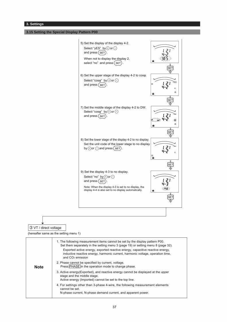
3.1 Setting Procedure
3. Settings
3.15 Setting the Special Display Pattern P00
5) Set the display of the display 4-2.
6) Set the upper stage of the display 4-2 to cosφ.
7) Set the middle stage of the display 4-2 to DW.
8) Set the lower stage of the display 4-2 to no display.Set the unit code of the lower stage to no displayby or and press .
Note: When the display 4-3 is set to no display, thedisplay 4-4 is also set to no display automatically.
When not to display the display 2, select “no” and press .
9) Set the display 4-3 to no display.
SET
SET
SET
SET
SET
VT / direct voltage(hereafter same as the setting menu 1)
1. The following measurement items cannot be set by the display pattern P00. Set them separately in the setting menu 3 (page 19) or setting menu 8 (page 32).
2. Phase cannot be specified by current, voltage. Press PHASE in the operation mode to change phase.
3. Active energy(Exported), and reactive energy cannot be displayed at the upper stage and the middle stage. Active energy (Imported) cannot be set to the top line.
4. For settings other than 3-phase 4-wire, the following measurement elements cannot be set. N-phase current, N-phase demand current, and apparent power.
Exported active energy, exported reactive energy, capacitive reactive energy,inductive reactive energy, harmonic current, harmonic voltage, operation time, and CO2 emission
Note
SET
SET
Select “yES” by or and press .SET
Select “cosφ” by or and press .SET
Select “cosφ” by or and press .SET
Select “no” by or and press .SET
37
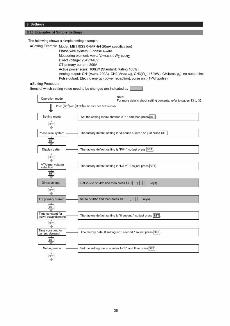
3.1 Setting Procedure
3. Set-up
3.16 Examples of Simple Settings
Setting menu
Phase wire system
SETDisplay pattern
SETVT/direct voltage selection
SET ( keys)Direct voltage
SET ( keys)CT primary current
SETTime constant for active power demand
Set the setting menu number to "6" and then press .
Model: ME110SSR-4APH(4-20mA specification)Phase wire system: 3-phase 4-wireMeasuring element: AAVG, VAVG(L-N), W∑, cosφ∑
Direct voltage: 254V/440VCT primary current: 200AActive power scale: 160kW (Standard: Rating 100%)Analog output: CH1(AAVG, 200A), CH2(VAVG(L-N)), CH3(W∑, 160kW), CH4(cos φ∑), no output limitPulse output: Electric energy (power reception), pulse unit (1kWh/pulse)
Operation mode
Setting menu
SET RESET
SET
SET
SET
SET
SET
SET
SET
SET
SET
SET
SET
Time constant for current demand
Press and at the same time for 2 seconds
■Setting ExampleThe following shows a simple setting example.
Note: For more details about setting contents, refer to pages 13 to 32.
SETSet the setting menu number to "1" and then press .
SET
The factory default setting is "P04," so just press .
The factory default setting is "No VT," so just press .
Set VL-N to "254V" and then press .
Set to "200A" and then press .
The factory default setting is "0 second," so just press .
The factory default setting is "0 second," so just press .
The factory default setting is "3-phase 4-wire," so just press .
■Setting ProcedureItems of which setting value need to be changed are indicated by .
38
3. Settings

3.1 Setting Procedure
3. Set-up
3.16 Examples of Simple Settings
SET
SET
SET
SET
SET
SET
SET
SET
SET
SET
SET
SET
SET
SET
SET
SET
Analog output 1 item
Analog output 1detailes setup
Analog output 2 item
The factory default setting is "W∑," so just press .Analog output 3 item
Analog output 3detailed setup
Analog output 3detailed setup
Analog output limit
Pulse output 1
( keys)Pulse output 1pulse unit
Pulse width
Setting menu
Press again. The changed setting are determined.End screen
Measurement begins according to the settings you changed.Operation mode
Analog output 4detailed setup
SET
SET
SET
SET
SET
SET
SET
SET
SET
SET
SET
SET
SET
SET
Analog output 4 element
Analog output specification "4-20A" is displayed, so just press .
The factory default setting is "AAVG," so just press .
This is "200.0A," so just press .
The factory default setting is "Active Energy (Imported)," so just press .
The factory default setting is "VAVG (L-N)," so just press .
This is "160.0kW," so just press .
The factory default setting is "Single deflection," so just press .
The factory default setting is "cosφ∑," so just press .
The factory default setting is "-0.5 to 1 to 0.5," so just press .
The factory default setting is "oFF," so just press .
Set to "1kWh/pulse" and then press .
The factory default setting is "0.125 second," so just press .
Set the set-up menu number to "End" and then press .
39
3. Settings
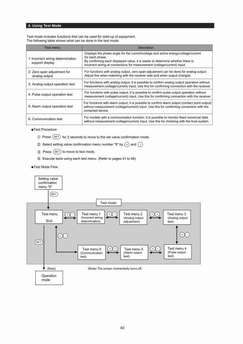
4. Using Test Mode
Test mode includes functions that can be used for start-up of equipment.The following table shows what can be done in the test mode.
Test menu Description
1. Incorrect wiring determination support display
Displays the phase angle for the current/voltage and active energy/voltage/current for each phase.By confirming each displayed value, it is easier to determine whether there is incorrect wiring at connections for measurement (voltage/current) input.
2. Zero span adjustment for analog output
For functions with analog output, zero span adjustment can be done for analog output. Adjust this when matching with the receiver side and when output changes.
3. Analog output operation test For functions with analog output, it is possible to confirm analog output operation without measurement (voltage/current) input. Use this for confirming connection with the receiver.
4. Pulse output operation test For functions with pulse output, it is possible to confirm pulse output operation without measurement (voltage/current) input. Use this for confirming connection with the receiver.
■Test Procedure
SET
SET
Press for 2 seconds to move to the set value confirmation mode.
Select setting value confirmation menu number "9" by and
to move to test mode.
Execute tests using each test menu. (Refer to pages 41 to 46)
Press
■Test Mode Flow
SET
SET
Test menu
End
Test menu 1(Incorrect wiring determination)
Test menu 2(Analog output adjustment)
Test menu 3(Analog output test)
Test menu 4(Pulse output test)
Test menu 5(Alarm output test)
Test menu 6(Communication test)
Setting value confirmationmenu "9"
Operation mode
Test mode
(Note) (Note) The screen momentarily turns off.
For models with a communication function, it is possible to monitor fixed numerical data without measurement (voltage/current) input. Use this for checking with the host system.
6. Communication test
For functions with alarm output, it is possible to confirm alarm output (contact point output) without measurement (voltage/current) input. Use this for confirming connection with the contacted device.
Alarm output operation test5.
40
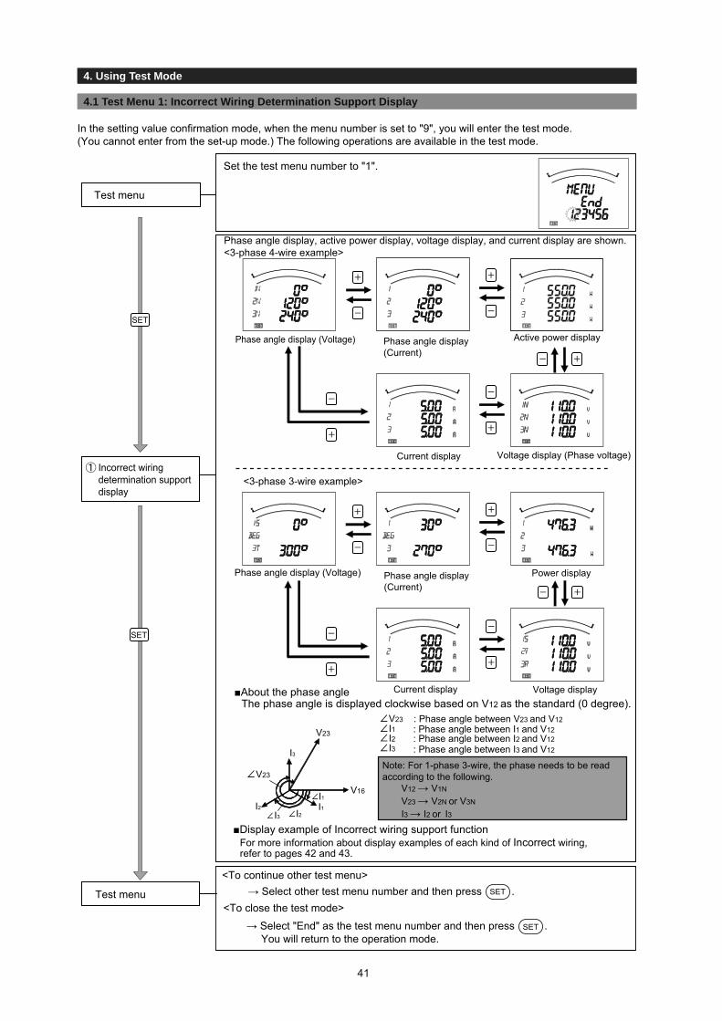
5. Operation
3.2 Setting Menu 1
4. Using Test Mode
4.1 Test Menu 1: Incorrect Wiring Determination Support Display
In the setting value confirmation mode, when the menu number is set to "9", you will enter the test mode. (You cannot enter from the set-up mode.) The following operations are available in the test mode.
Set the test menu number to "1".
Test menu
Phase angle display, active power display, voltage display, and current display are shown.<3-phase 4-wire example>
■Display example of Incorrect wiring support functionFor more information about display examples of each kind of Incorrect wiring, refer to pages 42 and 43.
V16
I1
I3
I1
I3
I2I2
SET
SET
Test menu
V12 → V1N
V23 → V2N or V3N
I3 → I2 or I3
<3-phase 3-wire example>
Current display
Power display
Active power display
Voltage display
Voltage display (Phase voltage)
Current display
Phase angle display (Current)
Phase angle display (Current)
Phase angle display (Voltage)
Phase angle display (Voltage)
■About the phase angleThe phase angle is displayed clockwise based on V12 as the standard (0 degree).
V23
V23
V23 I1I2I3 : Phase angle between I3 and V12
Note: For 1-phase 3-wire, the phase needs to be read according to the following.
: Phase angle between I2 and V12: Phase angle between I1 and V12: Phase angle between V23 and V12
<To continue other test menu>→ Select other test menu number and then press .SET
<To close the test mode>
→ Select "End" as the test menu number and then press .SETYou will return to the operation mode.
Incorrect wiringdetermination support display
41

5. Operation
3.2 Setting Menu 14.1 Test Menu 1: Improper Wiring Determination Support Display
4. Using Test Mode
4.1 Test Menu 1: Incorrect Wiring Determination Support Display
No.
Normal
1
2
3
4
5
Power Factor(Input)
LEAD 0.707
LEAD 0.866
1.000
LAG 0.866
LAG 0.707
LEAD 0.707
LEAD 0.866
1.000
LAG 0.866
LAG 0.707
LEAD 0.707
LEAD 0.866
1.000
LAG 0.866
LAG 0.707
LEAD 0.707
LEAD 0.866
1.000
LAG 0.866
LAG 0.707
LEAD 0.707
LEAD 0.866
1.000
LAG 0.866
LAG 0.707
LEAD 0.707
LEAD 0.866
1.000
LAG 0.866
LAG 0.707
Phase Angle Display
V12 V23 I1 I3 W1
225
240
270
300
315
45
60
90
120
135
45
60
90
120
135
225
240
270
300
315
345
0
30
60
75
105
120
150
180
195
345
0
30
60
75
165
180
210
240
255
165
180
210
240
255
165
180
210
240
255
225
240
270
300
315
225
240
270
300
315
W1>W 3
W1=W 3
W1<W 3
W1=W3=0
W1=0
For Balanced Loading (V12=V23, I1=I3)
Active Power Display
W3 V12 V23 V31 I1
0
0
0
0
0
0
300
60
120
300
300
300
V12 =V 23 =V 31
V12 =V 23 =V 31
V12 =V23 <V 31
V12 =V 23 =V 31
V12 =V 23 =V 31
V12 =V23 =V 31
I1=I 2 =I 3
I1=I 2 =I 3
I1=I 2 =I 3
I1=I 3 <I 2
I1=I 2 =I 3
I1=I 2 =I 3
When the P1 terminal and P2 terminal are reversed
When VT connection is reversed at side 1
When CT connection is reversed at side 1
When CT at side 1 and side 3 are switched
I2 I3
■Display Example of Incorrect Wiring Support Function Incorrect Wiring PortionDisplay example (Connection example for 3-phase 3-wire)
1 2 3
+C1
+C3
C1
P1
P2
P3
C3
K
L I
k
K
L U uv
uv
VU
V
I
k
1 2 3
+C1
+C3
C1
P1
P2
P3
C3
K
L I
k
K
L
U uv
uv
VUV
I
k
1 2 3
+C1
+C3
C1
P1
P2
P3
C3
K
L I
k
K
L
U uv
uv
VUV
I
k
1 2 3
+C1
+C3
C1
P1
P2
P3
C3
K
L I
k
K
L
U uv
uv
VUV
I
k
1 2 3
+C1
+C3
C1
P1
P2
P3
C3
K
L I
k
K
L
U uv
uv
VUV
I
k
1 2 3
+C1
+C3
C1
P1
P2
P3
C3
K
L I
k
K
L
U uv
uv
VUV
I
k
Current DisplayVoltage Display
When VT terminals are connected to the P1, P2, and P3 terminals of the measurement instrument according to the order P2, P3, and P1 respectively
=Negative value
=Positive value
W1
W3
=Negative value
=Negative value
=Negative value
=Negative value
=Negative value
=Negative value
=Negative value
W3
W3
W3
=Negative value
W1
W3
W1
W1
W1
=Positive valueW3
=Positive valueW3
W3=Positive value
=Positive valueW1
=Positive valueW1
Connection
42
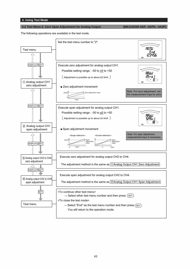
3.1 Setting Procedure
3. Set-up4. Using Test Mode
4.2 Test Menu 2: Zero Span Adjustment for Analog Output (ME110SSR-4AP, -4APH, -4A2P)
Execute zero adjustment for analog output CH1.
■ Zero adjustment movementAnalog output CH1zero adjustment
■ Span adjustment movementAnalog output CH1span adjustment
Note: For span adjustment, measurement input is necessary.
Analog output CH2 to CH4zero adjustment
DISPLAY SET
DISPLAY SET
DISPLAY SET
DISPLAY SET
SET
Set the test menu number to "2".
Test menu
The following operations are available in the test mode.
<To continue other test menu>SET
<To close the test mode>
→ Select "End" as the test menu number and then press .Test menu
Note: For zero adjustment, set the measurement input to zero.
<Single deflection> <Double deflection>
4
20mA Zero adjustment value
Input
4
0
20mA Span adjustment value
Input 0
Span adjustment value
Input
Analog output CH2 to CH4span adjustment
Execute span adjustment for analog output CH2 to CH4.
Execute zero adjustment for analog output CH2 to CH4.
SET
You will return to the operation mode.
→ Select other test menu number and then press .
Execute span adjustment for analog output CH1.
Possible setting range : -50 to ±0 to +50
Possible setting range : -50 to ±0 to +50
Adjustment is possible up to about ±0.3mA
Adjustment is possible up to about ±0.3mA
The adjustment method is the same as Analog Output CH1 Zero Adjustment .
The adjustment method is the same as Analog Output CH1 Span Adjustment .
43

3.1 Setting Procedure
3. Set-up
4.3 Test Menu 3: Analog Output Operation Test (ME110SSR-4AP, -4APH, -4A2P)
4. Using Test Mode
The following operations are available in the test mode.
Set the test menu number to "3".
Test menu
Execute the operation test for analog output CH1. (Input is not necessary.)
Output4 to 20mA 1 to 5V 0 to 5V
0% 4mA 1.00V 0.00V25% 8mA 2.00V 1.25V50% 12mA 3.00V 2.50V75% 16mA 4.00V 3.75V
100% 20mA 5.00V 5.00V
Analog output CH1operation test
Execute the operation test for analog output CH2 to CH4.Analog output CH2 to CH4operation test
DISPLAY SET
DISPLAY SET
SET <To continue other test menu>
→ Select "End" as the test menu number and then press .
Test menu
0%25%50%75%
100%
Output Specification
→ Select other test menu number and then press .SET
<To close the test mode>
SET
You will return to the operation mode.
The test method is the same as Analog output CH1 operation test .
44
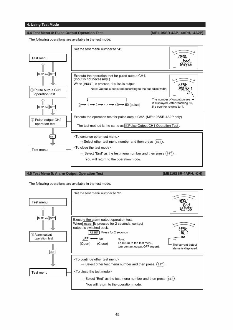
3.1 Setting Procedure
3. Set-up
4.4 Test Menu 4: Pulse Output Operation Test (ME110SSR-4AP, -4APH, -4A2P)
4. Using Test Mode
The following operations are available in the test mode.
Set the test menu number to "4".
Test menu
Execute the operation test for pulse output CH1. (Input is not necessary.)When is pressed, 1 pulse is output.
Pulse output CH1operation test
0 1 2 49 50 [pulse]
RESET
Execute the operation test for pulse output CH2. (ME110SSR-4A2P only)Pulse output CH2operation test
The following operations are available in the test mode.
Set the test menu number to "5".
Test menu
DISPLAY SET
DISPLAY SET
SET
DISPLAY SET
SET
→ Select other test menu number and then press .
<To close the test mode>Test menu
RESET
RESET
oFF on
<To close the test mode>Test menu
SET
Note: Output is executed according to the set pulse width.
Note: To return to the test menu, turn contact output OFF (open).
(Close)(Open) The current output status is displayed.
<To continue other test menu>
The number of output pulsesis displayed. After reaching 50, the counter returns to 1.
The test method is the same as Pulse Output CH1 Operation Test .
Alarm outputoperation test
Execute the alarm output operation test.When is pressed for 2 seconds, contact output is switched back.
Press for 2 seconds
<To continue other test menu>
→ Select other test menu number and then press .SET
→ Select "End" as the test menu number and then press .
You will return to the operation mode.
SET
→ Select "End" as the test menu number and then press .
You will return to the operation mode.
SET
4.5 Test Menu 5: Alarm Output Operation Test (ME110SSR-4APH, -CH)
45
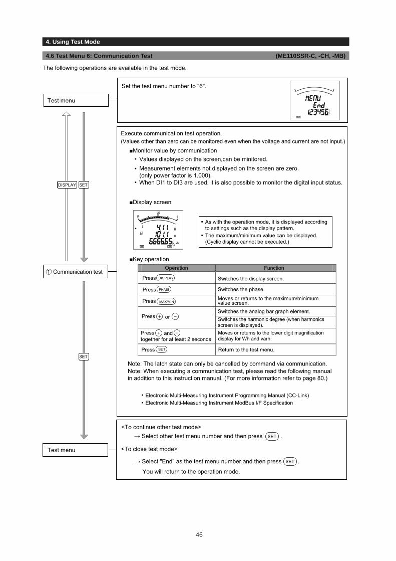
3.1 Setting Procedure
3. Set-up
4.6 Test Menu 6: Communication Test (ME110SSR-C, -CH, -MB)
4. Using Test Mode
The following operations are available in the test mode.
Test menu
DISPLAY SET
SET
Execute communication test operation.(Values other than zero can be monitored even when the voltage and current are not input.)
■Monitor value by communication▪
Measurement elements not displayed on the screen are zero.(only power factor is 1.000).
■Display screen
Note: The latch state can only be cancelled by command via communication.
▪ Electronic Multi-Measuring Instrument ModBus I/F Specification
Communication test
▪
▪
<To continue other test mode>
Test menu
Set the test menu number to "6".
→ Select other test menu number and then press .SET
→ Select "End" as the test menu number and then press .
You will return to the operation mode.
SET
<To close test mode>
As with the operation mode, it is displayed accordingto settings such as the display pattern.The maximum/minimum value can be displayed. (Cyclic display cannot be executed.)
▪ Electronic Multi-Measuring Instrument Programming Manual (CC-Link)
Press and
Press Return to the test menu.SET
together for at least 2 seconds.Moves or returns to the lower digit magnification display for Wh and varh.
orPress Switches the harmonic degree (when harmonics screen is displayed).
Switches the analog bar graph element.
Press MAX/MINMoves or returns to the maximum/minimum value screen.
Press
Press DISPLAY
PHASE
FunctionOperation
Switches the display screen.
Switches the phase.
■Key operation
Values displayed on the screen,can be minitored.
When DI1 to DI3 are used, it is also possible to monitor the digital input status.
▪
▪
Note: When executing a communication test, please read the following manualin addition to this instruction manual. (For more information refer to page 80.)
46

3.1 Setting Procedure
3. Set-up
5.1 Basic Operation
5. Operation
The following explains basic usages during operation.
●Switch display
DISPLAY DISPLAY DISPLAY
DISPLAY
<Screen 1 of 4>
Upper: CurrentMiddle: Active PowerLower: Voltage
<Screen 2 of 4>
Upper: CurrentMiddle: Active PowerLower: Power factor
<Screen 3 of 4>
Upper: CurrentMiddle: Power factorLower: Voltage
Upper: CurrentMiddle: Not displayedLower: N-phase current
PHASE
PHASE
PHASE
PHASE PHASE
PHASE PHASE
PHASE
Current phase 1Active Power phase 1Voltage phase 12
Current phase 2Active Power phase 2 Voltage phase 23
Current phase 3Active Power phase 3
Voltage phase 3N
Current phase 3Active Power phase 3Voltage phase 31
Current phase 2 Active Power phase2
Voltage phase 2N
Current phase 1Active Power phase 1
Voltage phase 1N
Current averageActive Power (total)
Voltage average (between phases)
Current averageActive Power (total)
Voltage average (between lines)
Example of phase switching (Phase wire System: 3P4W)
Screen number display
When switching screens, the left screen appears momentarily.This screen indicates the number of the next screen being displayed in the total number of screens.
Example of display switching (display pattern: P01)
Active Power, reactive power, and power factor for settings other than 3-phase 4-wire
Measurement elements without phase (Frequency)The phase cannot be switched in the following cases.
▪▪
The measurement elements for Upper, middle, and Lower are the same
When the setting is 1-phase 2-wire▪▪
Display items and the order differ depending on the phase wire method setting display pattern settings and additional screen. For more information about detailed display patterns, refer to pages 58 and 59.
By pressing , the current phase and PHASE
the voltage phase will switch over.
●Switch phase
By pressing , the measurement DISPLAY
display will switch over.
47

3.1 Setting Procedure
3. Set-up
5.1 Basic Operation
5. Operation
12
12
34
34 31
1
23
●Bar graph display
●Switching measurement factors displayed on bar graphsPress the key to switch.or
The power factor, voltage, and frequency can be displayed in the bar graph even if they are not set in the display pattern.
▪ When electric energy / reactive energy are selected
The bar graph cannot be displayed in the following cases.
▪ When a line without measurement display is selected▪ Harmonics Display Screen
For 3-phase 4-wire
(Upper)
(Middle) (Lower)
(Upper)
(Middle)(Lower)
(Lower) (Middle)
(Upper)
For 3-phase 3-wire, 1-phase 3-wire
For 1-phase 2-wire
Bar graph displays the measurement element indicated with “ ” or “ ”.
(Example) Upper element (A)displayed on bar graph
(Example) cosφ displayed on bar graph
(Clockwise rotation) (Counterclockwise rotation)
DISPLAYWhen is pressed for about 2 seconds, the cyclic display appears.When is pressed for about 2 seconds, the cyclic phase appears.PHASE
Note 1: Before shifting to the cyclic display change screen, the display flickering 3 times.Note 2: By pressing any other key than the and the it goes back to manual change.Note 3: In the maximum value and the minimum value display, cyclic display is not available.Note 4: In the cyclic display, drawing number is not displayed.
DISPLAY
Display for 5 seconds Display for 5 seconds Display for 5 seconds Display for 5 seconds
RESET
●Cyclic DisplayIn cyclic display, display and phases automatically change at every 5 seconds.
Example Cyclic Display (Display Pattern: P01)
Press for 2 seconds
48

3.1 Setting Procedure
3. Set-up5. Operation
5.1 Basic Operation
Note : Harmonic total is shown by “ALL”.
■Switching degree / phase
to switch phases.
Phase wire system Harmonic voltage
3-phase 3-wire phase 2 phase 31 phase 31
1N2 display phase N phase 121-phase 3-wire1N3 display phase N phase 31
<Example of harmonic voltage 5th display>
PHASE
3CT2CT
-
PressPress the or key to switch the degree.
■Harmonic display examples
Harmonic current
Upper: DegreeMiddle: Distortion ratio
Lower: RMS value
<Example of harmonic current total display>
Note: For harmonic measurement, the following phases are not displayed.
Distortionratio
RMSvalue
RMSvalue
RMSvalue
DegreeHarmonic current N-phase harmonic current Harmonic voltage
Harmonic total1st3rd5th7th9th11th13th
○ ○ ○ ○○ - ○ -○ ○ ○ ○○ ○ ○ ○○ ○ ○ ○○ ○ ○○ ○ ○○ ○ ○
○○-
-
------
○○○○○○
○○○
■Measurement items
Note 1: When the fundamental harmonic is 0, the distortion ratio are displayed as 0%.
Harmonic RMS value and distortion ratio can be displayed. It is necessary to set the harmonics display settings before displaying.(Refer to page 20)
●Harmonics display
Distortionratio
Distortionratio
PHASEPHASE
PHASE
PHASEPHASE
PHASE
PHASEPHASE
PHASE
PHASEPHASE
PHASE
Current total phase 1
Current 1stphase 1
Voltage total phase 1-N
Voltage 1stphase 1-N
Voltage 3rd phase 1-N
Voltage 13th phase 1-N
Current totalphase N RMS
Current 1stphase N RMS
Current 3rdphase N RMS
Current 13thphase N RMS
Current total phase 2Current total phase 3Distortion ratio/RMS
Current 1stphase 2 Current 1st
phase 3 RMS
Current 3rd phase 1Current 3rd phase 2
Current 3rd phase 3Distortion ratio/RMS
Current 13th phase 1Current 13th phase 2
Current 13th phase 3Distortion ratio/RMS
Voltage total phase 2-NVoltage total phase 3-N
Distortion ratio/RMS
Voltage 1stphase 2-N Voltage 1st
phase 3-N RMS
Voltage 3rd phase 2-NVoltage 3rd phase 3-NDistortion ratio/RMS
Voltage 13th phase 2-NVoltage 13th phase 3-NDistortion ratio/RMS
Harmonic current(phase N)
Nextdisplay
Harmonic current
,
Previousdisplay
Harmonic voltage
PHASEPHASE
PHASE
PHASEPHASE
PHASE
PHASE
PHASEPHASE
PHASE
PHASE
PHASE
DISPLAYDISPLAYDISPLAY DISPLAY
+ –
,+ –
,+ –
,+ –
,+ –
,+ –
,+ –
,+ –
,+ –
49

3.1 Setting Procedure
3. Set-up
5.1 Basic Operation
5. Operation
●Maximum value and minimum value displayFor the maximum / minimum value display screen, the maximum value, current value, and minimum value for each measurement item are displayed on one screen.
However, for harmonics only the following maximum values are displayed.
Harmonic voltage: Total distortion factor, 1st effective value, 3rd, 5th, 7th, 9th, 11th, and 13th content factors for where the phase was largest for each phase■Example Display
●Display of maximum value and minimum valueMAX/MIN
On maximum/minimum value display, the following operation is also possible as current value display.
Function
A→AN→DA→DAN→V→W→DW→var
HV←HIN←HI←Hz←cosφ←VA
The harmonic degree switch. (Only for harmonics display)
Switches to measurement item cyclic display.
Switches to phase cyclic display.
●Clear the maximum/minimum value
RESET
AN: N-phase currentDA: Demand currentDAN: N-phase demand currentDW: Demand powerHI: Harmonic currentHIN: N-phase harmonic currentHV: Harmonic voltage
Lower: Minimum value
For Current For Harmonic current
Harmonics won’t display as bar graph.
Harmonic degree
Maximum value
MAX/MIN
Present value display Maximum value and minimum value display
Key operation
Press
Press
Press or
DISPLAY
PHASE
3-phase 3-wire, single-phase 3-wire: Phase for A, DA, and V switch.single-phase 2-wire: No phase switch.
PHASE
Harmonic current: Total, 1st, 3rd, 5th, 7th, 9th, 11th, and 13th effective values for where the phase was largest for each phase
The bar graph turns on only between the maximum value and minimum value.
Upper: Maximum value
Middle: Current value
When is pressed, the display is changed into the maximum value and minimum value display.
And when is pressed, the display changes back to the present value display.MAX/MIN
Example of switching between present value display and maximum/minimum value display
Press for 2 secondsDISPLAY
Press for 2 seconds
Measurement items switch according to the following order.However, measurement items that are not included in the phase wire method display pattern setting and additional screens are not displayed.
On the maximum/minimum value display screen, press the for 2 seconds to clear the maximum/minimum value for the displayed measurement item to the present value.
RESET
On the maximum/minimum value display screen, press the and together for 2 secondsto clear all maximum/minimum values to the present value.
3-phase 4-wire: A and DA switch as
Average→1 Phase→2 Phase→3 Phase
AN, DAN, and Hz do not have phase switching.Total RMS value→1-phase→2-phase→3-phase
V switchs asVAVG(L-N)→V1N→V2N→V3N→VAVG(L-L)→V12→V23→V31
W, DW, var, VA, and cosφ switch as
50

3.1 Setting Procedure
3. Set-up
5.1 Basic Operation
5. Operation
●Active Energy / Reactive Energy Display■Display format
The following table shows the display format of active energy / reactive energy based on the total load .
α×(VT primary voltage)×(CT primary current)Total load power[kW]=1000
*1. For the 1-phase 3-wire setting, the VT primary voltage is calculated using 110V.*2.
*3.
*4. For reactive energy, the above kW is read as kvar, and kWh is read as kvarh.
Display typeTotal load[kW] Digital display Unit
Less than 10 8888.88 ×110 or higher and less than 100 88888.8 ×1
100 or higher and less than 1000 88888.8 ×101000 or higher and less than 10000 88888.8 ×100
88888.8 ×1000100000 or higher 88888.8 ×10000
kWhkvarh
α: 123
Active energy (Imported)
Active energy (exported) is also displayed on the active energy (importeding) display screen.
■Example Display
+
When and are pressed simultaneously for 2 seconds, values of active energy and reactive energy areenlarged by 3 figures.This can be used for confirming the active energy measurement.It will automatically return to normal display if no button is pressed for 5 minutes or when switchs to cyclic display.
●Wh and varh zero resetSET RESET
Electric energy measurement valueMeteringstatusMultiplier
The metering ststus blinks while the activeenergy is being counted. (Only the incoming active energy display screen)When active energy is not counted, turns ON or OFF.
Note 1: All of active energy (Wh) and reactive energy (varh) not displayed are will be reset.
When , , and are pressed simultaneously for 2 seconds, the measured values of activeenergy (Wh) and reactive energy (varh) will be reset.(This is effective only in the instaneous value Display.)
Note 1:This function is made only on active energy and reactive energy displayed.
●Enlarged 3 digital figures
Enlaged 3 digital figuness Display
Normal DisplayPress simultaneouslyfor 2 seconds
Lower digit magnification displayNormal display
Reactive energy (Exported lead)
Reactive energy (Exported lag)
Reactive energy (Imported lead)
Reactive energy (Imported lag)
Middle: Active energy (Imported)
Lower: Active energy (Exported)
Active energy (Exported)
The actual measurement value is "Measurement value = Digital display value × Multiplier".
3 3-phase 4-wire
1-phase 2-wire1-phase 3-wire3-phase 3-wire
10000 or higher and less than 100000
Multiplier
For the 3-phase 4-wire setting, the VT primary voltage and direct voltage are calculated using the phase voltage.
For the direct voltage setting, the direct voltage is used for calculation instead of the VT primary voltage.
PHASE
51

3.1 Setting Procedure
3. Set-up
5.1 Basic Operations
5. Operation
●Reactive energy counting method (2 quadrant counting / 4 quadrant counting)There are the following two types of quadrants for counting reactive energy.
The measurement method for reactive electric energy is switched using "Expanded counting"in the Set-up Menu 3. (Refer to page 20.)
●Demand time and demand valueThe demand time (to) is the time until the measurement display value (Io) displays 95% of the input (I) when a certain constant input (I) is given. To display 100% of the input (I), about three times more than the time (to) is needed.
Time (t)to
0.95
The demand value is the measurement display value with the above time characteristics, and it shows the overall average within the demand time.The demand value changes over a relatively long time, so it is not affected by input changes within a short time. Therefore, this is good for monitoring transformer overload.(Note: The active power demand measured by this measurement instrument is not for power demand managemen
●Each measurement item display during power transmission The following table shows the symbol display (±) for each measurement value according to the power reception / power sending status.
Measured items
D,DW Unsigned Unsigned
Unsigned Unsigned Unsigned Unsigned
For 2 quadrant counting
Unsigneddisplay*
“ ”sign “ ”sign
“ ”sign “ ”sign
“ ”sign “ ”sign
display* display* Unsigned
display*ver, cos
For 4 quadrant counting
Unsigneddisplay* display*
Unsigned display* display*
* Turns on when displayed on the bar graph.
Description
4 quadrant counting
2 quadrant counting
+W
-var
+var
-W
LAG
LAG
LAG
LAG
LEAD
LEAD
LEAD
LEAD
(Io)
II
A,DA,V,VA,Hz,HI,HV
<2 quadrant counting><4 quadrant counting >
It is counting (Imported lag), (Exported lead),(Imported lead) and (Exported lag) respectively as division of one.In general,it is counted by this method. However, at the boundary ofeach division, there is a dead region. It is suitable for the counting of equipment with the private electric generator.
(Imported lag) and (Exported lead) are counted as divisionof one. (Imported lead) and (Exported lag) are counted asdivision of one.The dead region is made only nearby var=0 (power factor = 1).Therefore, because the dead region is not made nearbypower factor = 0. It is suitable for the counting of equipmentwithout the private electric generator and the reactivepower of the capacitor load at the power factor = 0, generally.
Counting method
Exported Lag Exported LeadImported LeadImported LagQuadrant
(Time period)
Measurem
ent display value
+var
-var
W+W-
Exported
lag
Exported
lead
Imported
lead
Imported
lag
+var
-var
W+W-
Exported
lag
Exported
lead
Imported
lead
Imported
lag
Exportedlag
Exportedlead
Importedlead
Importedlag
52

3.1 Setting Procedure
3. Set-up
5.2 Usage According to Purpose
5. Operation
The following explains usage according to the purpose during operation.●Display and operation of the upper/lower limit alarm
When the value exceeds the upper or lower limit setting value set in advance,the display flickers and alarm can be output.(For more information about how to set the upper/lower limit alarm, refer to pages 22 and 23.)
■Alarm indicatorWhen the measurement element with an upper/lower limit alarm is displayed on the bar graph, "▲" flickers on the bar graph to indicate the upper/lower limit.
■Behavior During Alarm GenerationAlarm condition: When measurement value exceeds alarm value, display flicker and an alarm contact closes.Alarm cancel: When alarm is canceled,display flickers normally and alarm contact opens.
Note: When the alarm delay time is set, an alarm is generatde only when the alarm value is continuously beyond the upper/lower limit alarm value for the delay time.
Measurement value ≥ Upper limit value(or Measurement value ≤ Lower limit value)
Measurement value < Upper limit alarm value(or Measurement value > Lower limit alarm value)
, or blinks Normal display
Closed Opened, or flickers
(Alarm generation)
, or turns ON
(Alarm retention)
Normal display
(Alarm cancellation)Closed Closed Opened
Note 1: When the measurement element where the alarm generated exists on the display screen, the display for the digital value, unit (A, V, W, var, cosφ, Hz, %, Demand), and phase (1, 2, 3, N) will be based on the alarm status according to the following table. If it does not exist on the display screen, it does not flicker.
Digital value Unit PhaseFlickeringFlickering Flickering*
On Flickering Flickering*On On On
When the backlight flickering setting is set to ON (flicker) during alarm generation, the backlight also flickers when an alarm is generated.On the maximum/minimum value display screen, the present value (middle of the digital display) and , or blinks.Alarm contact is the batch output of the set alarm.
■Monitoring phase for upper/lower limit alarm elementThe phase that monitors the upper/lower limit alarm differs according to the measurement item. For more details, refer to the following table.
Upper/lower limit indicator
RESET
* Does not flicker when displaying phases where no alarm occurred.
Note1:
Alarm generationAlarm status
Alarm retentionAlarm cancellation
Alarm cancel method
Automatic(Auto)
Manual(HoLd)
Display
Display
Output (Alarm relay contact)
Output (Alarm relay contact)
Monitored phaseUpper/lower limit alarm element
3P4W 3P3W (3CT, 2CT) 1P3W (RNS) 1P3W (RNT)
Upper limit current, current demand
Lower limit current, current demand
Upper limit N-phase current, N-phase current demand N - - -
Lower limit N-phase current, N-phase current demand N - - -
Upper limit voltage (L-L) (Note 1)
Lower limit voltage (L-L) (Note 1)
Upper limit voltage (L-N) - - -
Lower limit voltage (L-N) - - -Upper limit power, demand active power, active power demand,power factorLower limit power, demand active power, active power demand,power factor
∑ ∑ ∑ ∑
∑ ∑ ∑ ∑
Upper limit frequency 1 1 1 1
Lower limit frequency 1 1 1 1
Harmonic current total RMS value
Harmonic voltage total distortion ratio
Harmonic current total RMS value N-phase N - - -
Note2:Only 3P3W (3CT) is measured for the phase 2 harmonic current.
Note 2:
Note 3:
Note 4:
1, 2, 3 1, 2, 3
1, 2, 3 Note 2
1, 2, 31, 2, 3
1, 2, 3
12, 23, 31 12, 23, 31 1N, 2N, 12 1N, N3, 31
1N, 2N, 3N
1N, 2N, 3N
1N, 2N 1N, N3
1N, N3, 31
1, N, 2 1, N, 3
1, 31, 2
1N, 2N, 1212, 23, 31
12, 23, 31 12, 23
12, 23, 31
1, 3 1, 3
For phase 12 (or phase 31) at 1-phase 3-wire, alarm monitoring is executed using a value that is two times the set upper/lower limit alarm value.
53
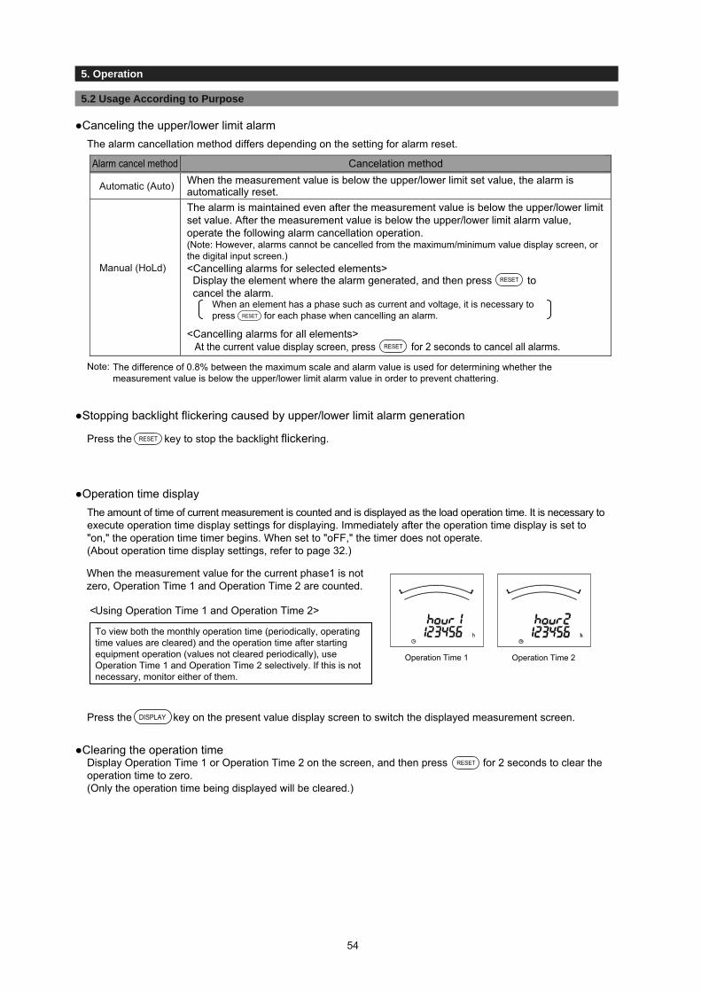
3.1 Setting Procedure
3. Set-up
5.2 Usage According to Purpose
5. Operation
●Canceling the upper/lower limit alarmThe alarm cancellation method differs depending on the setting for alarm reset.
Cancelation methodAlarm cancel methodWhen the measurement value is below the upper/lower limit set value, the alarm is automatically reset.The alarm is maintained even after the measurement value is below the upper/lower limit set value. After the measurement value is below the upper/lower limit alarm value, operate the following alarm cancellation operation.(Note: However, alarms cannot be cancelled from the maximum/minimum value display screen, or the digital input screen.)<Cancelling alarms for selected elements>Display the element where the alarm generated, and then press to cancel the alarm.
RESET
RESET
When an element has a phase such as current and voltage, it is necessary to press for each phase when cancelling an alarm.
<Cancelling alarms for all elements>At the current value display screen, press for 2 seconds to cancel all alarms.
Note: The difference of 0.8% between the maximum scale and alarm value is used for determining whether the measurement value is below the upper/lower limit alarm value in order to prevent chattering.
●Stopping backlight flickering caused by upper/lower limit alarm generation
Press the key to stop the backlight flickering.
●Operation time displayThe amount of time of current measurement is counted and is displayed as the load operation time. It is necessary to execute operation time display settings for displaying. Immediately after the operation time display is set to "on," the operation time timer begins. When set to "oFF," the timer does not operate.(About operation time display settings, refer to page 32.)
DISPLAYPress the key on the present value display screen to switch the displayed measurement screen.
●Clearing the operation timeDisplay Operation Time 1 or Operation Time 2 on the screen, and then press for 2 seconds to clear theoperation time to zero.(Only the operation time being displayed will be cleared.)
Automatic (Auto)
Manual (HoLd)
Operation Time 2
When the measurement value for the current phase1 is not zero, Operation Time 1 and Operation Time 2 are counted.
To view both the monthly operation time (periodically, operating time values are cleared) and the operation time after starting equipment operation (values not cleared periodically), use Operation Time 1 and Operation Time 2 selectively. If this is not necessary, monitor either of them.
<Using Operation Time 1 and Operation Time 2>
Operation Time 1
RESET
RESET
RESET
54

3.1 Setting Procedure
3. Set-up
5.2 Usage According to Purpose
5. Operation
CO2 emissions converted from active energy (imported) can be displayed. It is necessary to set CO2 emission display settings for displaying.(About setting, refer to page 32.)
The following table shows the display format for CO2 emission based on the total load power.
●CO2 emission display
●Clearing the CO2 emission value
Display formatTotal load power[kW] Digital display Unit
Less than 10 8888.88 kg88888.8 kg888888 kg8888.88 t88888.8 t888888 t
Press the key on the current value display screen to switch the displayed measurement screen.
When active energy is cleared to zero, the CO2 emission value is also cleared.It is not possible to clear only the CO2 emission value.(About clearing the active energy to zero, refer to page 51.)
CO2 emission
Note:
DISPLAY
10 or higher and less than 100100 or higher and less than 1000
10000 or higher and less than 1000001000 or higher and less than 10000
100000 or higher
CO2 emissions are calculated using "CO2 emission = Active energy (imported) × CO2 conversion factor setting value."This is not an counted value, so the CO2 emission value changes when the CO2 conversion factor is changed.
55
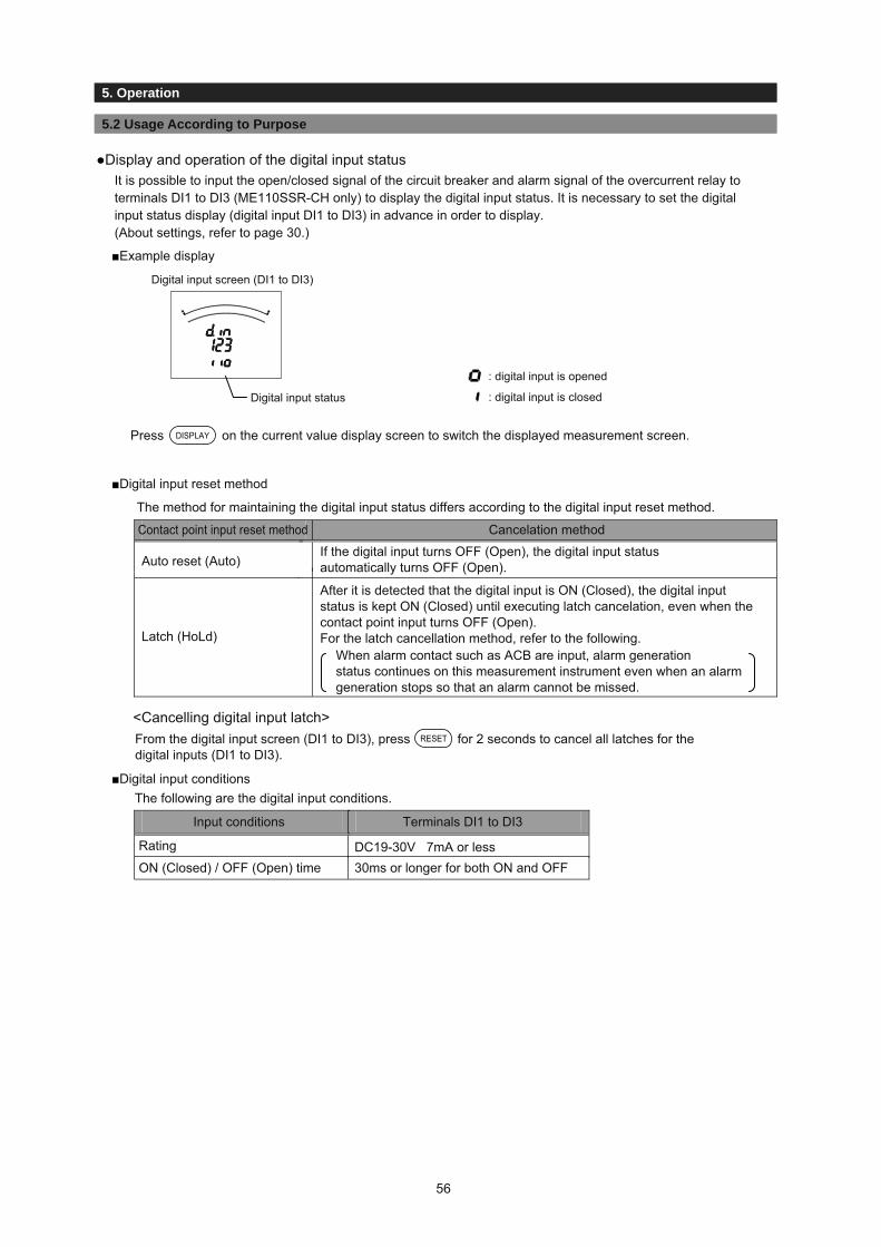
3.1 Setting Procedure
3. Set-up
5.2 Usage According to Purpose
5. Operation
●Display and operation of the digital input status
■Example display
DISPLAY
■Digital input reset method
■Digital input conditions
RESET
It is possible to input the open/closed signal of the circuit breaker and alarm signal of the overcurrent relay to terminals DI1 to DI3 (ME110SSR-CH only) to display the digital input status. It is necessary to set the digital input status display (digital input DI1 to DI3) in advance in order to display.(About settings, refer to page 30.)
Press on the current value display screen to switch the displayed measurement screen.
The method for maintaining the digital input status differs according to the digital input reset method.
Contact point input reset method
Latch (HoLd)
The following are the digital input conditions.
After it is detected that the digital input is ON (Closed), the digital inputstatus is kept ON (Closed) until executing latch cancelation, even when thecontact point input turns OFF (Open).For the latch cancellation method, refer to the following.
When alarm contact such as ACB are input, alarm generationstatus continues on this measurement instrument even when an alarm generation stops so that an alarm cannot be missed.
DC19-30V 7mA or less30ms or longer for both ON and OFFON (Closed) / OFF (Open) time
From the digital input screen (DI1 to DI3), press for 2 seconds to cancel all latches for the digital inputs (DI1 to DI3).
<Cancelling digital input latch>
Digital input status : digital input is closed
: digital input is opened
Digital input screen (DI1 to DI3)
Rating
Input conditions Terminals DI1 to DI3
If the digital input turns OFF (Open), the digital input status automatically turns OFF (Open).Auto reset (Auto)
Cancelation method
56

3.1 Setting Procedure
3. Settings
5.2 Usage According to Purpose
5. Operation
●Preventing maximum value update by motor starting currentWhen the motor current is monitored, use the motor starting current delay function to prevent maximum value update and alarm generation for the current, active power, reactive power, and power factor due to the motor starting current. It is necessary to set in advance to use the motor starting current delay function.(About settings, refer to page 24.)
■Movement when the motor starting current delay function is used
Note 1: Set the motor starting current value to a value lower than the lower limit value considering changes in the load current during operation.Note 2: When the input current is below the motor starting current value, the minimum value update stops.
●Index indicator displayThe index indicator can be displayed on the bar graph.
■Display description
"▲" turns on for the index indicator.(Note: "▲" flicker for the upper/lower limit indicator.)
■How to display
It is necessary to set the index indicator in advance. For more information about settings, refer to page 21.
Upper/lower limit indicator
Current
<Motor starting current detection>When the current is over the motor starting current value, the motor current startingcurrent delay time counter begins.
Current upper limit alarm value
Motor starting current value
<Motor starting current delay>The maximum values for the current, active power,reactive power and power factor are not updated during the motor,reactive powerand power factor starting current delay time. Also, no alarm generated even if it is over theupper limit alarm value.
Time
Motor starting current
Motor starting current delay time
Index indicator
57

3.1 Setting Procedure
3. Settings
6.1 Display Pattern Contents
6. Other
When the display pattern in the Setting menu 1 and the additional screen in the Setting menus 3, 7, and 8 are set, pressing changes the screens shown in the table below from the left to the right.DISPLAY
Screen set by display pattern Additional display (Set in the set-up menus 3, 7, 8)
No.10 No.11 No.12 No.13 No.14 No.15 No.16 No.17 No.18 No.19 No.20Displaypattern No.1 No.2 No.3 No.4 No.5 No.6 No.7 No.8 No.9
(Lead) (Lag) (Lead)DI status
(3DI)CO2
emission
A A A A d.inW W cosφ
cosφ
cosφ
- -
- - -1 2 3 hour1 hour2 CO2P01
V PF V AN statusRMSvalue
RMSvalue
RMSvalue
Operationtime
Operationtime
Operationtime 2
Operationtime 1
Emission
A A A A -
V W - WhP02
Wh Wh Wh AN
A A
cosφ
A A A A
-P03
V W var VA Hz AN
A A A A
cosφ
A A A - - - -
V W var VA cosφ
cosφ
Hz - Wh - - -P04
Wh Wh varh Wh Wh Wh AN
cosφ
cosφ
Hz VA
W W WP05
var var var
A1 V1N A A
A2 V2N - -P06
A3 V3N V AN
A A1 V1N A
V A2 V2N -P07
W A3 V3N AN
A A A1 V1N A -
V W A2 V2N - WhP08
Wh Wh A3 V3N AN
A AR DA1 V1N A DA
DA AS DA2 V2N - -P09
V AT DA3 V3N AN DAN
A A A1 DA1 V1N A DA
DA DA A2 DA2 V2N - -P10
V W A3 DA3 V3N AN DAN
A A DA1 V1N A DA -
DA V DA2 V2N - - WhP11
Wh Wh DA3 V3N AN DAN
A A A DA W A DA -
DA W V V V - - WhP12
Wh Wh Wh Wh Wh AN DAN
A1 V1N W1 var1 VA1 cosφ1 V V A - - - -
A2 V2N W2 var2 VA2 cosφ2 Hz Hz - Wh - - -P13
A3 V3N W3 var3 VA3 cosφ3 Wh varh AN
- - - -
Wh - - -P00
Note 1: When an additional screen is added, a screen number is added.Note 2: In the table, Wh indicates Imported active energy , and varh indicates Imported reactive energy (lag).
[For 3-phase 4-wire]
Upper
Middle
Lower
Upper
Middle
Lower
Upper
Middle
Lower
Upper
Middle
Lower
Upper
Middle
Lower
Upper
Middle
Lower
Upper
Middle
Lower
Upper
Middle
Lower
Upper
Middle
Lower
Upper
Middle
Lower
Upper
Middle
Lower
Upper
Middle
Lower
Upper
Middle
Lower
Upper
Middle
Lower Arbitrary Arbitrary Arbitrary Arbitrary
Arbitrary Arbitrary Arbitrary Arbitrary
Arbitrary Arbitrary Arbitrary Arbitrary
Importedreactive energy
Exported reactive energy
Exported reactive energy
(Lead) (Lag) (Lead)
Exportedactive energy
Exportedactive energy
Exportedactive energy
Exportedactive energy
Exportedactive energy
Exportedactive energy
Exportedactive energy
Exportedactive energy
Exportedactive energy
Exportedactive energy
Exportedactive energy
(Lead) (Lag) (Lead)
(Lead) (Lag) (Lead)
ditto
ditto
ditto
ditto
ditto
ditto
ditto
ditto
ditto
ditto
ditto
ditto
ditto
ditto
ditto
ditto
ditto
ditto
ditto
ditto
ditto
ditto
ditto
ditto
ditto
ditto
ditto
ditto
ditto
ditto
ditto
ditto
ditto
ditto
ditto
ditto
ditto
ditto
ditto
ditto
ditto
ditto
ditto
ditto
ditto
ditto
ditto
ditto
ditto
ditto
ditto
ditto
ditto
ditto
ditto
ditto
ditto
ditto
ditto
ditto
ditto
ditto
ditto
ditto
ditto
ditto
ditto
ditto
ditto
ditto
ditto
ditto
ditto
ditto
ditto
ditto
ditto
ditto
ditto
ditto
ditto
ditto
ditto
ditto
ditto
ditto
ditto
ditto
ditto
ditto
ditto
Degree Degree Degree
Ratio Ratio
Harmonic current
Harmonicvoltage
Harmoniccurrent
N-phase
Importedreactive energy
Importedreactive energy
Importedreactive energy
Importedreactive energy
Importedreactive energy
Importedreactive energy
58

3.1 Setting Procedure
3. Settings
6.1 Display Pattern Contents
6. Other
Screen set by display patternNo.6 No.7 No.8 No.9 No.10 No.11 No.12 No.13 No.14 No.15Display
pattern No.1 No.2 No.3 No.4 No.5 Harmonic current
Harmonic voltage
Digital input(DI1 to DI3)
Operation time 1
Operation time 2
CO2emission
Upper A A A Degree Degree d.in ― ― ―Middle W W cosφ Ratio Ratio 1 2 3 hour1 hour2 CO2P01LowerUpper
MiddleLower
Upper
Upper
Middle
Middle
Lower
UpperMiddleLower
UpperMiddleLower
UpperMiddleLower
UpperMiddleLower
UpperMiddleLower
UpperMiddleLower
UpperMiddleLower
UpperMiddle
UpperMiddle
Lower
UpperMiddleLower
UpperMiddle
UpperMiddle
Lower
Lower
Lower
Lower
V cosφ V RMS value RMS value status Operation time Operation time EmissionA A A ―V W cosφP02 ditto
ditto
ditto
ditto
ditto
ditto
ditto
ditto
ditto
ditto
ditto
ditto
ditto
ditto
ditto
ditto
ditto
ditto
ditto
ditto
ditto
ditto
ditto
ditto
ditto
ditto
ditto
ditto
ditto
ditto
ditto
ditto
ditto
ditto
ditto
ditto
ditto
ditto
ditto
ditto
ditto
ditto
ditto
ditto
ditto
ditto
ditto
ditto
ditto
ditto
ditto
ditto
ditto
ditto
ditto
ditto
ditto
ditto
ditto
ditto
ditto
ditto
ditto
ditto
ditto
ditto
ditto
ditto
ditto
ditto
ditto
ditto
ditto
ditto
ditto
ditto
ditto
ditto
ditto
ditto
ditto
ditto
ditto
ditto
ditto
ditto
ditto
ditto
ditto
ditto
A A A Acosφ cosφ cosφ cosφP03
V W var HzA A A A A ― ― ― ―V W var cosφ Hz ― ― ―P04
Wh
cosφ HzW WP05var varA1 V12 AA2 V23 ―P06A3 V31 VA A1 V12
V A2 V23P07W A3 V31
A A A1 V12 ―V W A2 V23P08
WhWh
Wh Wh Wh
Wh Wh
Wh Wh
Wh Wh Wh Wh
Wh Wh Wh Wh Wh
A3 V31
A A1 DA1 V12
DA A2 DA2 V23P09V A3 DA3 V31
A A A1 DA1 V12
DA DA A2 DA2 V23P10V W A3 DA3 V31
A A DA1 V12 ―DA V DA2 V23P11
DA3 V31
A A A DA W ―DA W V V VP12
A1 V12 W V V ― ― ― ―A2 V23 var Hz Hz ― ― ―P13A3 V31 cosφ Wh
A A A A2 fixed A2 fixedW W cosφ W cosφP14V
V
cosφ V V31 fixed V31 fixedA A A A2 fixed ―
W cosφ V31 fixedP15
― ― ― ―― ― ―P00
Arbitrary Arbitrary Arbitrary Arbitrary
Arbitrary Arbitrary Arbitrary ArbitraryArbitrary Arbitrary Arbitrary Arbitrary
Note 1: When an additional screen is added, a screen number is added.Note 2: When phase 2-wire, only phase1 (A1, DA1) is displayed for current, and only phase12 (V12) is displayed for voltage. Other phases are not displayed even when they are set in the display pattern.Note 3: The phases displayed in the display patterns of the above table are displayed on the screen according to the phase wire system setting shown in the table below.
phase wire Phase display in the table above
1P2W 1P3W(1N2) 1P3W(1N3) 3P3W (3CT, 2CT)
1 Phase not displayed 1 1 12 Measurement not displayed N N 2
Current
3 Measurement not displayed 2 3 312 Phase not displayed 1N 1N 1223 Measurement not displayed N2 N3 23
Voltage
31 Measurement not displayed 12 31 31
[For others except 3-phase 4-wire] SettingAdditional display (Set in the set-up menus 3, 7, 8)
(Lead) (Lead)(Lag)Imported
reactive energy
(Lead)Imported
reactive energy(Lag)
Importedreactive energy
Exported reactive energy
Exported reactive energyExported
active energy
Exportedactive energy
Exportedactive energy
Exportedactive energy
Exportedactive energy
Exportedactive energy
Exportedactive energy
Exportedactive energy
Exportedactive energy
Exportedactive energy
Exportedactive energy
Exportedactive energy
Exportedactive energy
Exportedactive energy
Exportedactive energy
Exportedactive energy
Exportedactive energy
Exportedactive energy
(Lead)Imported
reactive energy(Lead)Imported
reactive energy
(Lead)Imported
reactive energy
(Lag)Exported
reactive energy(Lag)
Exported reactive energy
(Lag)
(Lag)
Exported reactive energy
(Lag)Exported
reactive energy
Exported reactive energy
(Lag)Exported
reactive energy
59

3.1 Setting Procedure
3. Settings
6.2 Maximum Scale Value
6. Other
[For 3-phase 4-wire]
Settable primary voltage, primary current, and standard maximum scale value are shown in the tables below.
●Maximum scale value of each item ●Specific power value for scale calculation
Voltage
Measurement element
Phase voltage Line voltageIn the case of directvoltage setting
Maximum scale value
(Phase voltage / Line voltage)63.5V/110V100V/173V110V/190V
277V/480V
220V/380V240V/415V254V/440V
100V 150V
150V 300V
300V 600V
400V 640VIn the case of VT connected to secondary side
Primaryvoltage × 150 Primary
voltage × 150
Current
Active power
Reactive power
Apparent power
Power factor
Frequency
Primary current value
VT ratio × CT ratio × specific power (100%) kW
VT ratio × CT ratio × specific power (100%) kvar
VT ratio × CT ratio × specific power (100%) VA
At direct input
Phase line type
Rated voltage (Phase voltage)
Specific power value (100%)
Specific reactive power (100%)
1.0kW 1.0kvar
2.0kvar2.0kW
4.0kvar4.0kW
5.0kvar5.0kW1.0kvar1.0kW
2.0kvar2.0kW
63.5V direct
63.5V100V110V115V120V
100V direct110V direct220V direct240V direct254V direct277V direct
LEAD0.5 to 1 to LAG0.5
45 to 55Hz (at 50Hz)55 to 65Hz (at 60Hz)
In the casewith VT
(secondaryvoltage set
value)
*1 At direct voltage setting, VT ratio = 1. The specific power is according to the table on the right.*2 For convenience of scale, this is rounded off to the nearest whole number.
Phase wire system Three-phase 4-wire
Direct110V/190V
Direct254V/440V240V/415V
10.015.020.025.030.040.050.060.075.080.0
100.0120.0150.0200.0250.0300.0
4k6k8k
10k12k16k20k24k30k32k40k48k60k80k
100k120k
8k12k16k20k24k32k40k48k60k64k80k96k
120k160k200k240k
Direct110V/190V
Direct254V/440V240V/415V
400500600750800
10001200150020002500300040005000
160k200k240k300k320k400k480k600k800k
1000k1200k1600k2000k
320k400k480k600k640k800k960k
1200k1600k2000k2400k3000k4000k
■Maximum scale value for active power / reactive power (representative example)Unit: Active power: W, Reactive power: var
Primary voltage valuePrimary
current value(A)Primary current value(A)
Primary voltage value
Phase wire system Three-phase 4-wire
110 110*2 *2
3
*1
*1
*1
60
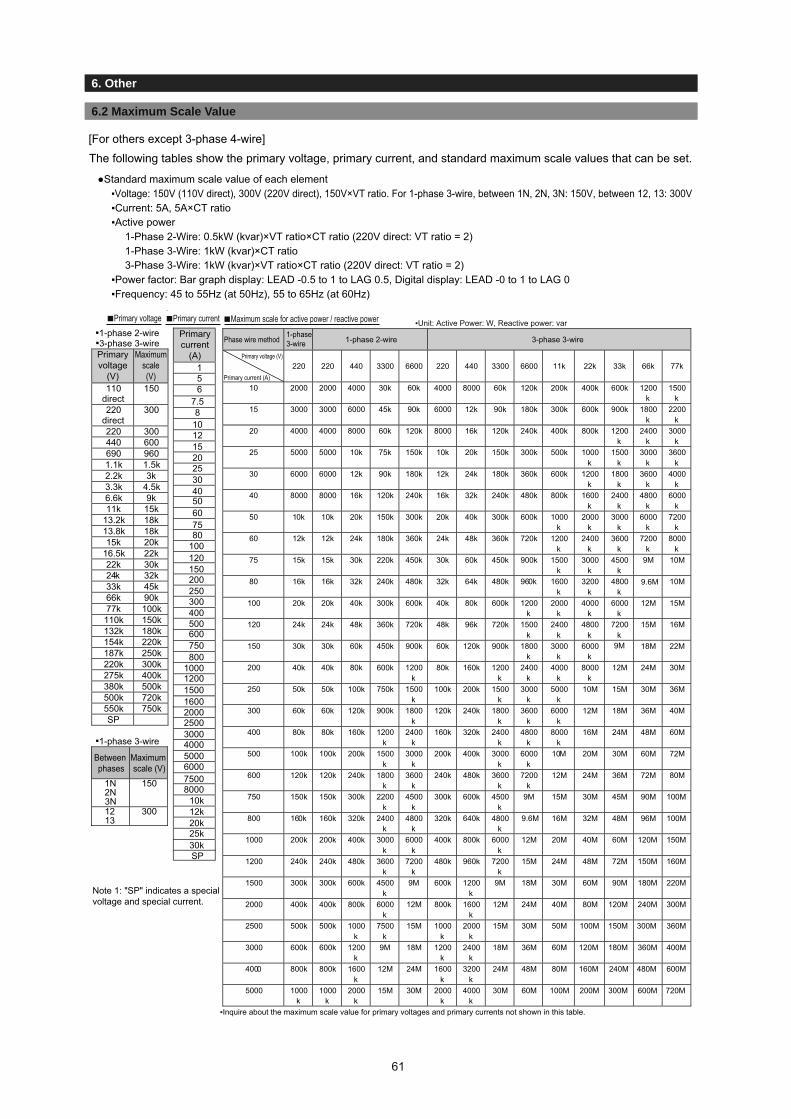
3.1 Setting Procedure
3. Settings
6.2 Maximum Scale Value
6. Other
SP
Phase wire method1-phase3-wire 1-phase 2-wire 3-phase 3-wire
Primary voltage (V)
Primary current (A)
220 220 440 3300 6600 220 440 3300 6600 11k 22k 33k 66k 77k
10 2000 2000 4000 30k 60k 4000 8000 60k 120k 200k 400k 600k 1200k
1500k
15 3000 3000 6000 45k 90k 6000 12k 90k 180k 300k 600k 900k 1800k
2200k
20 4000 4000 8000 60k 120k 8000 16k 120k 240k 400k 800k 1200k
2400k
3000k
25 5000 5000 10k 75k 150k 10k 20k 150k 300k 500k 1000k
1500k
3000k
3600k
30 6000 6000 12k 90k 180k 12k 24k 180k 360k 600k 1200k
1800k
3600k
4000k
40 8000 8000 16k 120k 240k 16k 32k 240k 480k 800k 1600k
2400k
4800k
6000k
50 10k 10k 20k 150k 300k 20k 40k 300k 600k 1000k
2000k
3000k
6000k
7200k
60 12k 12k 24k 180k 360k 24k 48k 360k 720k 1200k
2400k
3600k
7200k
8000k
75 15k 15k 30k 220k 450k 30k 60k 450k 900k 1500k
3000k
4500k
10M
80 16k 16k 32k 240k 480k 32k 64k 480k 960k 1600k
3200k
4800k
10M
100 20k 20k 40k 300k 600k 40k 80k 600k 1200k
2000k
4000k
6000k
12M 15M
120 24k 24k 48k 360k 720k 48k 96k 720k 1500k
2400k
4800k
7200k
15M 16M
150 30k 30k 60k 450k 900k 60k 120k 900k 1800k
3000k
6000k
18M 22M
200 40k 40k 80k 600k 1200k
80k 160k 1200k
2400k
4000k
8000k
12M 24M 30M
250 50k 50k 100k 750k 1500k
100k 200k 1500k
3000k
5000k
10M 15M 30M 36M
300 60k 60k 120k 900k 1800k
120k 240k 1800k
3600k
6000k
12M 18M 36M 40M
400 80k 80k 160k 1200k
2400k
160k 320k 2400k
4800k
8000k
16M 24M 48M 60M
500 100k 100k 200k 1500k
3000k
200k 400k 3000k
6000k
10M 20M 30M 60M 72M
600 120k 120k 240k 1800k
3600k
240k 480k 3600k
7200k
12M 24M 36M 72M 80M
750 150k 150k 300k 2200k
4500k
300k 600k 4500k
9M 15M 30M 45M 90M 100M
800 160k 160k 320k 2400k
4800k
320k 640k 4800k
9.6M 16M 32M 48M 96M 100M
1000 200k 200k 400k 3000k
6000k
400k 800k 6000k
12M 20M 40M 60M 120M 150M
1200 240k 240k 480k 3600k
7200k
480k 960k 7200k
15M 24M 48M 72M 150M 160M
1500 300k 300k 600k 4500k
9M 600k 1200k
9M 18M 30M 60M 90M 180M 220M
2000 400k 400k 800k 6000k
12M 800k 1600k
12M 24M 40M 80M 120M 240M 300M
2500 500k 500k 1000k
7500k
15M 1000k
2000k
15M 30M 50M 100M 150M 300M 360M
3000 600k 600k 1200k
9M 18M 1200k
2400k
18M 36M 60M 120M 180M 360M 400M
4000 800k 800k 1600k
12M 24M 1600k
3200k
24M 48M 80M 160M 240M 480M 600M
5000 1000k
1000k
2000k
15M 30M 2000k
4000k
30M 60M 100M 200M 300M 600M 720M
▪Inquire about the maximum scale value for primary voltages and primary currents not shown in this table.
10
1
8
12152025304050607580
100120150200250300400500600750800
100012001500160020002500300040005000600075008000
10k12k20k25k30k
56
7.5
▪1-phase 2-wire▪3-phase 3-wirePrimaryvoltage
(V)
Maximumscale(V)
110direct
150
220direct
300
220 300440 600690 9601.1k 1.5k2.2k 3k3.3k 4.5k6.6k 9k11k 15k
13.2k 18k13.8k 18k15k 20k
16.5k 22k22k 30k24k 32k33k 45k66k 90k77k 100k110k 150k132k 180k154k 220k187k 250k220k 300k275k 400k380k 500k500k 720k550k 750kSP
▪1-phase 3-wire
Between phases
Maximum scale (V)
1N2N3N
150
1213
300
Primarycurrent
(A)
9M
9M
9.6M
●Standard maximum scale value of each element▪Voltage: 150V (110V direct), 300V (220V direct), 150V×VT ratio. For 1-phase 3-wire, between 1N, 2N, 3N: 150V, between 12, 13: 300V▪Current: 5A, 5A×CT ratio▪Active power
1-Phase 2-Wire: 0.5kW (kvar)×VT ratio×CT ratio (220V direct: VT ratio = 2)1-Phase 3-Wire: 1kW (kvar)×CT ratio3-Phase 3-Wire: 1kW (kvar)×VT ratio×CT ratio (220V direct: VT ratio = 2)
▪Power factor: Bar graph display: LEAD -0.5 to 1 to LAG 0.5, Digital display: LEAD -0 to 1 to LAG 0▪Frequency: 45 to 55Hz (at 50Hz), 55 to 65Hz (at 60Hz)
The following tables show the primary voltage, primary current, and standard maximum scale values that can be set.[For others except 3-phase 4-wire]
■Primary voltage ▪Unit: Active Power: W, Reactive power: var■Primary current ■Maximum scale for active power / reactive power
Note 1: "SP" indicates a special voltage and special current.
61
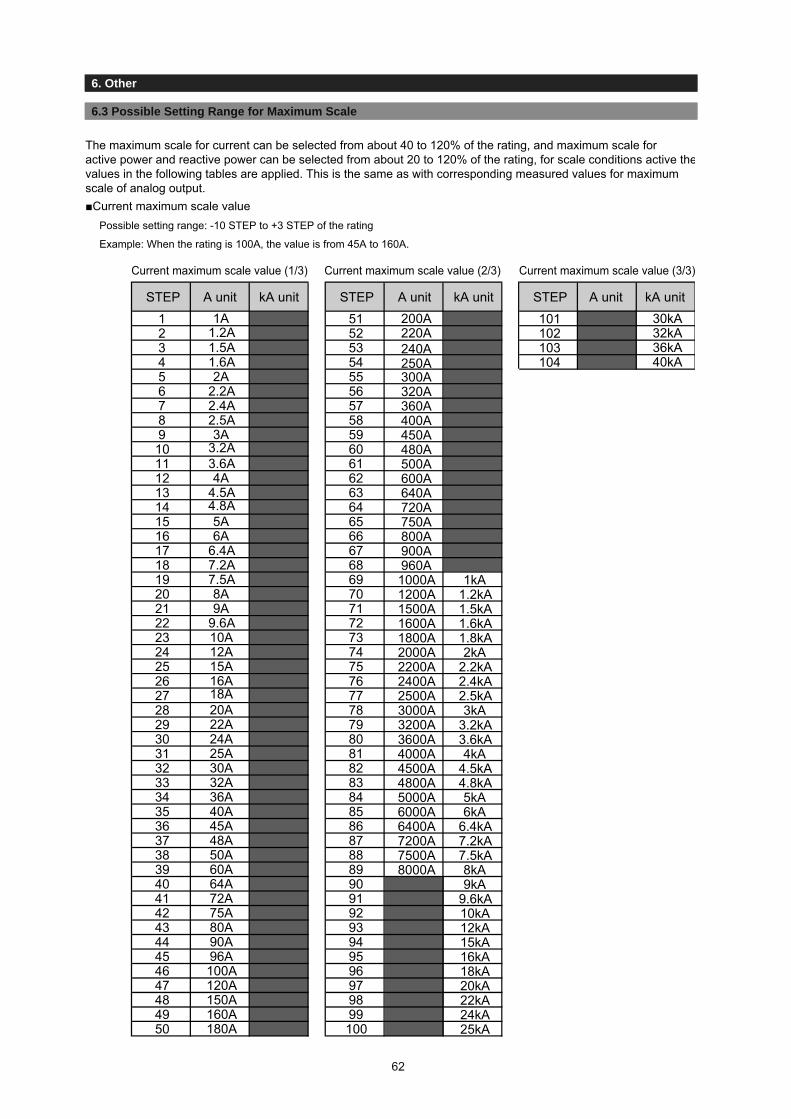
3.1 Setting Procedure
3. Settings
6.3 Possible Setting Range for Maximum Scale
6. Other
The maximum scale for current can be selected from about 40 to 120% of the rating, and maximum scale for active power and reactive power can be selected from about 20 to 120% of the rating, for scale conditions active thevalues in the following tables are applied. This is the same as with corresponding measured values for maximumscale of analog output.■Current maximum scale value
Possible setting range: -10 STEP to +3 STEP of the rating
Example: When the rating is 100A, the value is from 45A to 160A.
STEP A unit kA unit A unit kA unitSTEP1
2A
1A1.2A1.5A1.6A
51
300A
2
2.2A
52
320A
3
2.4A
53
360A
4
2.5A
54
400A
5
3A
55
450A
6
3.2A
56
480A
7
3.6A
57
500A
8
4A
58
600A
9
4.5A
59
640A
10
4.8A
60
720A
11
5A
61
750A
12
6A
62
800A
13
6.4A
63
900A
14
7.2A
64
960A
15
7.5A
65
1000A 1kA
16
8A
66
1200A 1.2kA
17
9A
67
1500A 1.5kA
18
9.6A
68
1600A 1.6kA
19
10A
69
1800A 1.8kA
20
12A
70
2000A 2kA
21
15A
71
2200A 2.2kA
22
16A
72
2400A 2.4kA
23
18A
73
2500A 2.5kA
24
20A
74
3000A 3kA
25
22A
75
3200A 3.2kA
26
24A
76
3600A 3.6kA
27
25A
77
4000A 4kA
28
30A
78
4500A 4.5kA
29
32A
79
4800A 4.8kA
30
36A
80
5000A 5kA
31
40A
81
6000A 6kA
32
45A
82
6400A 6.4kA
33
48A
83
7200A 7.2kA
34
50A
84
7500A 7.5kA
35
60A
85
8000A 8kA
36
64A
86
9kA
37
72A
87
9.6kA
38
75A
88
10kA
39
80A
89
12kA
40
90A
90
15kA
41
96A
91
16kA
42
100A
92
18kA
43
120A
93
20kA
44
150A
94
22kA
45
160A
95
24kA
46
180A
96
25kA
47
200A
97
30kA
48
220A
98
32kA
49
240A
99
36kA
50
250A
100
40kA
STEP101102103104
Current maximum scale value (1/3) Current maximum scale value (2/3) Current maximum scale value (3/3)
A unit kA unit
62
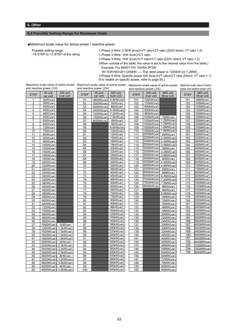
3.1 Setting Procedure
3. Settings
6.3 Possible Setting Range for Maximum Scale
6. Other
■Maximum scale value for active power / reactive power
Possible setting range: -18 STEP to +3 STEP of the rating
1-Phase 2-Wire: 0.5kW (kvar)×VT ratio×CT ratio (220V direct: VT ratio = 2)1-Phase 3-Wire: 1kW (kvar)×CT ratio3-Phase 3-Wire: 1kW (kvar)×VT ratio×CT ratio (220V direct: VT ratio = 2)(When outside of the table, the value is set to the nearest value from the table.)
Example: For 6600/110V 100/5A 3P3WW=1kW×60×20=1200kW → The rated power is 1200kW (or 1.2MW).
Maximum scale value of active powerand reactive power (1/4)
Maximum scale value of active powerand reactive power (2/4)
Maximum scale value of active powerand reactive power (3/4)
Maximum scale value of active power and reactive power (4/4)
STEP W unitvar unit
kW unitkvar unit STEP W unit
var unitkW unit
kvar unit STEP kW unitkvar unit
MW unitMvar unit STEP MW unit
Mvar unit1
80W(var)
32W(var)36W(var)40W(var)45W(var)48W(var)50W(var)60W(var)64W(var)72W(var)75W(var)
51
12kW(var)
101
2000kW(var) 2MW(var)
151
300MW(var)
2
90W(var)
52
15kW(var)
102
2200kW(var) 2.2MW(var)
152
320MW(var)
3
96W(var)
53
16kW(var)
103
2400kW(var) 2.4MW(var)
153
360MW(var)
4
100W(var)
54
18kW(var)
104
2500kW(var) 2.5MW(var)
154
400MW(var)
5
120W(var)
55
20kW(var)
105
3000kW(var) 3MW(var)
155
450MW(var)
6
150W(var)
56
22kW(var)
106
3200kW(var) 3.2MW(var)
156
480MW(var)
7
160W(var)
57
24kW(var)
107
3600kW(var) 3.6MW(var)
157
500MW(var)
8
180W(var)
58
25kW(var)
108
4000kW(var) 4MW(var)
158
600MW(var)
9
200W(var)
59
30kW(var)
109
4500kW(var) 4.5MW(var)
159
640MW(var)
10
220W(var)
60
32kW(var)
110
4800kW(var) 4.8MW(var)
160
720MW(var)
11
240W(var)
61
36kW(var)
111
5000kW(var) 5MW(var)
161
750MW(var)
12
250W(var)
62
40kW(var)
112
6000kW(var) 6MW(var)
162
800MW(var)
13
300W(var)
63
45kW(var)
113
6400kW(var) 6.4MW(var)
163
900MW(var)
14
320W(var)
64
48kW(var)
114
7200kW(var) 7.2MW(var)
164
960MW(var)
15
360W(var)
65
50kW(var)
115
7500kW(var) 7.5MW(var)
165
1000MW(var)
16
400W(var)
66
60kW(var)
116
8000kW(var) 8MW(var)
166
1200MW(var)
17
450W(var)
67
64kW(var)
117
9MW(var)
167
1500MW(var)
18
480W(var)
68
72kW(var)
118
9.6MW(var)
168
1600MW(var)
19
500W(var)
69
75kW(var)
119
10MW(var)
169
1800MW(var)
20
600W(var)
70
80kW(var)
120
12MW(var)
170
2000MW(var)
21
640W(var)
71
90kW(var)
121
15MW(var)
171
2200MW(var)
22
720W(var)
72
96kW(var)
122
16MW(var)
172
2400MW(var)
23
750W(var)
73
100kW(var)
123
18MW(var)
173
2500MW(var)
24
800W(var)
74
120kW(var)
124
20MW(var)
174
3000MW(var)
25
900W(var)
75
150kW(var)
125
22MW(var)
175
3200MW(var)
26
960W(var)
76
160kW(var)
126
24MW(var)
176
3600MW(var)
27
1000W(var) 1kW(var)
77
180kW(var)
127
25MW(var)
177
4000MW(var)
28
1200W(var) 1.2kW(var)
78
200kW(var)
128
30MW(var)
178
4500MW(var)
29
1500W(var) 1.5kW(var)
79
220kW(var)
129
32MW(var)
179
4800MW(var)
30
1600W(var) 1.6kW(var)
80
240kW(var)
130
36MW(var)
180
5000MW(var)
31
1800W(var) 1.8kW(var)
81
250kW(var)
131
40MW(var)
181
6000MW(var)
32
2000W(var) 2kW(var)
82
300kW(var)
132
45MW(var)
182
6400MW(var)
33
2200W(var) 2.2kW(var)
83
320kW(var)
133
48MW(var)
183
7200MW(var)
34
2400W(var) 2.4kW(var)
84
360kW(var)
134
50MW(var)
184
7500MW(var)
35
2500W(var) 2.5kW(var)
85
400kW(var)
135
60MW(var)
185
8000MW(var)
36
3000W(var) 3kW(var)
86
450kW(var)
136
64MW(var)
37
3200W(var) 3.2kW(var)
87
480kW(var)
137
72MW(var)
38
3600W(var) 3.6kW(var)
88
500kW(var)
138
75MW(var)
39
4000W(var) 4kW(var)
89
600kW(var)
139
80MW(var)
40
4500W(var) 4.5kW(var)
90
640kW(var)
140
90MW(var)
41
4800W(var) 4.8kW(var)
91
720kW(var)
141
96MW(var)
42
5000W(var) 5kW(var)
92
750kW(var)
142
100MW(var)
43
6000W(var) 6kW(var)
93
800kW(var)
143
120MW(var)
44
6400W(var) 6.4kW(var)
94
900kW(var)
144
150MW(var)
45
7200W(var) 7.2kW(var)
95
960kW(var)
145
160MW(var)
46
7500W(var) 7.5kW(var)
96
1000kW(var) 1MW(var)
146
180MW(var)
47
8000W(var) 8kW(var)
97
1200kW(var) 1.2MW(var)
147
200MW(var)
48
9kW(var)
98
1500kW(var) 1.5MW(var)
148
220MW(var)
49
9.6kW(var)
99
1600kW(var) 1.6MW(var)
149
240MW(var)
50
10kW(var)
100
1800kW(var) 1.8MW(var)
150
250MW(var)
186187188189190191192193194195
3-Phase 4-Wire: Specific power kW (kvar)×VT ratio×CT ratio (Direct: VT ratio = 1) (For details on specific power, refer to page 60.)
63
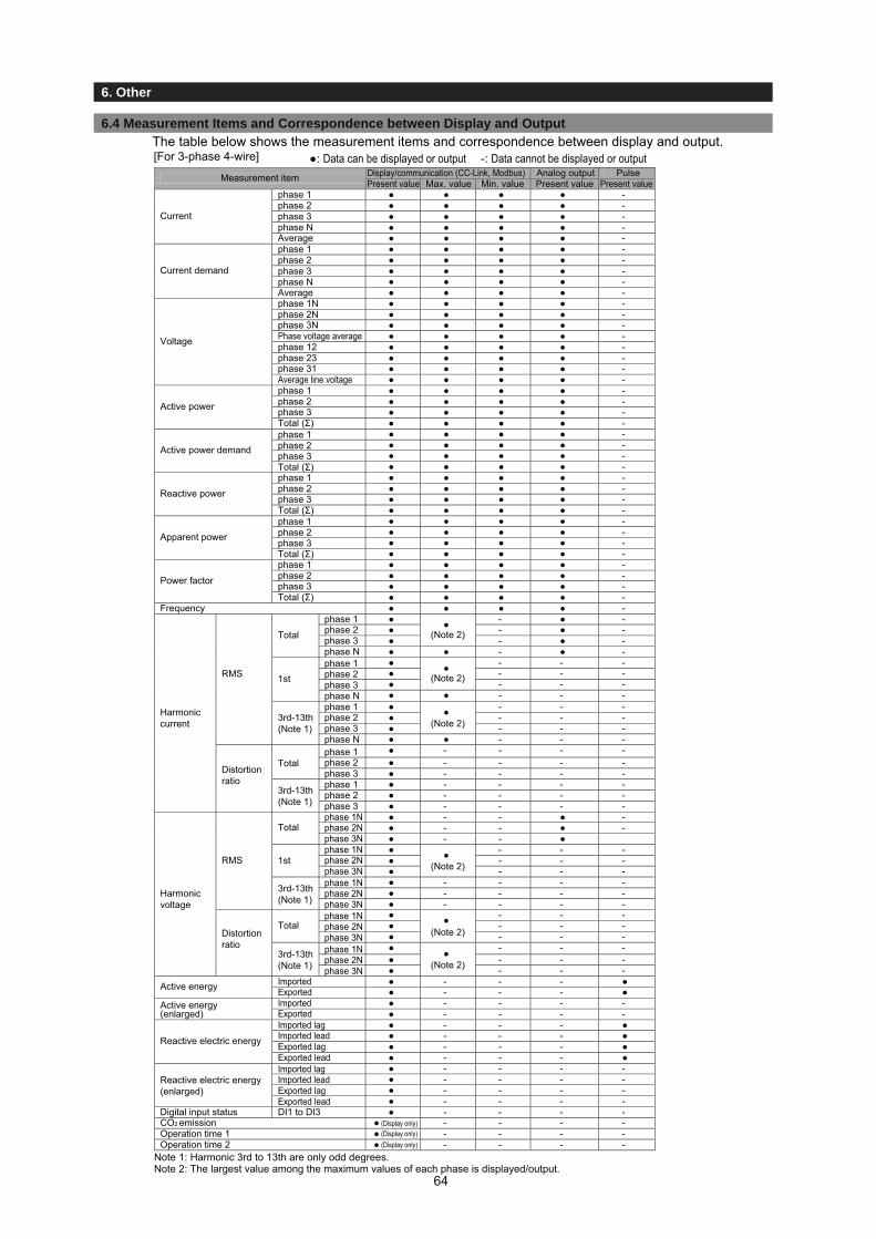
3.1 Setting Procedure
3. Settings
6.4 Measurement Items and Correspondence between Display and Output
6. Other
The table below shows the measurement items and correspondence between display and output.
Display/communication (CC-Link, Modbus) Analog output PulseMeasurement item Max. value Min. valuephase 1 ● ● ● ● -phase 2 ● ● ● ● -phase 3 ● ● ● ● -phase N ● ● ● ● -
Current
Averagephase 1phase 2phase 3phase NAverage
● ● ● ● -● ● ● ● -● ● ● ● -● ● ● ● -● ● ● ● -
Current demand
● ● ● ● -phase 1N ● ● ● ● -phase 2N ● ● ● ● -phase 3N ● ● ● ● -Phase voltage average ● ● ● ● -phase 12 ● ● ● ● -phase 23 ● ● ● ● -phase 31 ● ● ● ● -
Voltage
Average line voltage ● ● ● ● -phase 1 ● ● ● ● -phase 2 ● ● ● ● -phase 3 ● ● ● ● -Active power
Total (Σ)phase 1phase 2phase 3Total (Σ)phase 1phase 2phase 3Total (Σ)phase 1phase 2phase 3Total (Σ)phase 1phase 2phase 3Total (Σ)
● ● ● ● -● ● ● ● -● ● ● ● -● ● ● ● -Active power demand
● ● ● ● -● ● ● ● -● ● ● ● -● ● ● ● -Reactive power
● ● ● ● -● ● ● ● -● ● ● ● -● ● ● ● -Apparent power
● ● ● ● -● ● ● ● -● ● ● ● -● ● ● ● -Power factor
● ● ● ● -● ● ● ● -
phase 1 ● - ● -phase 2 ● - ● -phase 3 ●
●(Note 2)
(Note 2)
(Note 2)
(Note 2)
(Note 2)
(Note 2)
- ● -Total
Total
Total
Total
phase Nphase 1phase 2phase 3phase Nphase 1phase 2phase 3
phase 1phase 2phase 3phase 1phase 2phase 3
phase N
● ● - ● -● - - -● - - -●
●
- - -1st
1st
● ● - - -● - - -● - - -●
●
- - -3rd-13th (Note 1)
3rd-13th (Note 1)
3rd-13th (Note 1)
3rd-13th (Note 1)
● ● - - -● - - - -● - - - -● - - - -● - - - -● - - - -
Harmonic current
Distortion ratio
● - - - -phase 1N ● - - ● -phase 2N ● - - ● -phase 3Nphase 1Nphase 2Nphase 3Nphase 1Nphase 2Nphase 3Nphase 1Nphase 2Nphase 3Nphase 1Nphase 2Nphase 3N
● - - ●● - - -● - - -●
●
- - -● - - - -● - - - -
RMS
RMS
● - - - -● - - -● - - -●
●
- - -● - - -● - - -
Harmonic voltage
Distortion ratio
●
●
- - -Imported ● - - - ●Active energy ExportedImported Exported
● - - - ●● - - - -Active energy
(enlarged) ● - - - -Imported lag ● - - - ●Imported lead ● - - - ●Exported lag ● - - - ●Reactive electric energy
Exported leadImported lagImported leadExported lagExported lead
● - - - ●● - - - -● - - - -● - - - -
Reactive electric energy (enlarged)
● - - - -Digital input status DI1 to DI3 ● - - - -CO2 emission ● - - - -Operation time 1 ● - - - -Operation time 2 ● - - - -
[For 3-phase 4-wire] ●: Data can be displayed or output -: Data cannot be displayed or output
Note 1: Harmonic 3rd to 13th are only odd degrees.Note 2: The largest value among the maximum values of each phase is displayed/output.
(Display only)(Display only)(Display only)
Frequency
Present valuePresent valuePresent value
64

3.1 Setting Procedure
3. Settings
6.4 Measurement Items and Correspondence between Display and Output
6. Other
●: Data can be displayed or output -: Data cannot be displayed or output
3P3W 1P3W 1P2W
phase 1 ● ● ● ● ● ● ● ● ● ● ● ● -phase 2 ● ● ● ● ● ● - - - ● ● - -phase 3 ● ● ● ● ● ● - - - ● ● - -phase 1 ● ● ● ● ● ● ● ● ● ● ● ● -phase 2 ● ● ● ● ● ● - - - ● ● - -phase 3 ● ● ● ● ● ● - - - ● ● - -phase 12 ● ● ● ● ● ● ● ● ● ● ● ● -phase 23 ● ● ● ● ● ● - - - ● ● - -phase 31 ● ● ● ● ● ● - - - ● ● - -
● ● ● ● ● ● ● ● ● ● ● ● -Total (Σ) ● ● ● ● ● ● ● ● ● ● ● ● -Total (Σ) ● ● ● ● ● ● ● ● ● ● ● ● -Total (Σ) ● ● ● ● ● ● ● ● ● ● ● ● -
● ● ● ● ● ● ● ● ● ● ● ● -● - ● - ● ● - ● ● ● -● - ● - - - - ● ● - -● - ● - ● ● - - - - -● - ● - - - - - - - -● - ● - ● ● - - - - -● - ● - - - - - - - -● - - ● - - ● - - - - - -● - - ● - - - - - - - - -● - - ● - - ● - - - - - -● - - ● - - - - - - - - -● - - ● - - ● - - - - - -● - - ● - - - - - - - - -● - ● - ● ● - - - - -● - ● - - - - - - - -● - - ● - - ● - - - - - -● - - ● - - - - - - - - -● - ● - ● ● - ● ● ● -● - ● - - - - ● ● - -● - ● - ● ● - - - - -● - ● - - - - - - - -
Imported ● - - ● - - ● - - - - - ●ExportedImportedExported
● - - ● - - ● - - - - - ●● - - ● - - ● - - - - - -● - - ● - - ● - - - - - -
Imported lag ● - - ● - - ● - - - - - ●Imported lead ● - - ● - - ● - - - - - ●Exported lag ● - - ● - - ● - - - - - ●Exported lead ● - - ● - - ● - - - - - ●
● - - ● - - ● - - - - - -● - - ● - - ● - - - - - -● - - ● - - ● - - - - - -● - - ● - - ● - - - - - -● - - ● - - ● - - - - - -
● - - - - - - - - - -● - - - - - - - - - -● - - - - - - - - - -
Operation time 1Operation time 2
Digital input status DI1 to DI3CO2 emission
Active energy
Active energy (enlarged)
Reactive electric energy
Reactive electric energy (enlarged)
● ●
Total ● ●
3rd-13th (Note 2)
● ●
Harmonic voltage
Total
1st
●
Distortion ratio
Total
●
1st ● ●
Harmonic current
RMS value
Total ●
●
Active power demand Reactive powerPower factorFrequency
Current
Demand current
Voltage
Active power
Measurement item (Note 1)Display / communication ( CC-Link, ModBus) Analog output Pulse3P3W 1P3W 1P2W
Note 1: When 1P3W is selected, read the phase for the measurement item according to the following table.
Phase wire method 1-phase 2-phase 3-phase 12-phase 23-phase 31-phase
1P3W(1N2) phase 1 phase N phase 2 phase 1N phase 2N phase 12
1P3W(1N3) phase 1 phase N phase 3 phase 2N phase 3N phase 13
Note 2: Harmonic 3rd to 13th are only odd degrees.Note 3: The largest value among the maximum values of each phase is displayed/output.
[For others except for 3-phase 4-wire]
(Display only)
(Display only)
(Display only)
●●●
(Display only)
(Display only)
(Display only)
●●●
(Display only)
(Display only)
(Display only)
Present valuePresent valuePresent value Present value Present value Present value Present valueMax. value Min. value Max. value Min. value Max. value Min. value
Distortion ratio
RMS value
phase 1phase 3phase 1phase 3phase 1phase 3phase 1phase 3phase 1phase 3phase 12phase 23phase 12phase 23phase 12phase 23phase 12phase 23phase 12phase 23
Imported lagImported leadExported lagExported lead
Total (Σ)
3rd-13th (Note 2)
3rd-13th (Note 2)
3rd-13th (Note 2)
(Note 3)(Note 3)
(Note 3)(Note 3)
(Note 3)(Note 3)
(Note 3)(Note 3)
(Note 3)(Note 3)
(Note 3)(Note 3)
65

3.1 Setting Procedure
3. Settings
6.5 Measurement Characteristic
6. Other
■Metering actions in other than operation mode
■Metering actions in input status
■Analog output action
Status Measurement Display Analog output Alarm contact point Pulse outputSeveral seconds justafter turning on theauxiliary power supply(Backlight is lit, andLCD is not lit.)
No measurement
No measurement
No display
No display
No output
No output No output
Output overabout 100% may be made until internal voltage becomes stable.
Opened
Opened
Set-up mode,Set value confirmationmode
Same actionsas in operationmode
No display ofmeasuredvalue
Same actionsas in operationmode
Status before getting into set-up mode and set value confirmationmode is kept.
Same actionsas in operationmode
During power failure
Measurement items ActionsCurrent (A) Current demand (DA)
For rated current of 5A (Standard): 0A when the input current is less than 0.02A.
Voltage (V) 0V when the input voltage (line voltage) is less than 11V.For 1P3W, 0V when the voltage between P1-P3 is less than 22V.For 3P4W, 0V when the phase voltage is less than 11V.
For rated current of 1A (Special): 0A when the input current is less than 0.008A.
When it is over the upper limit of the possible display range (9999), the upper limit of the possible display range (9999) is displayed.
When it is over the upper limit of the possible display range (9999), the upper limit of the possible display range (9999) is displayed.
When it is over the upper limit of the possible display range (9999), the upper limit of the possible display range (9999) is displayed.For direct measurement, when it is over 655.35V, 655.35V is displayed.
Active power (W)Reactive power (var)Active power demand (DW)Apparent power (VA)
0W, 0var, and 0VA when the current and the voltage are 0A and 0V for all 3 phases.
Power factor (cosφ)Frequency (Hz)
1.0 when the current and the voltage are 0A and 0V for all 3 phases.
When the voltage of phase1 is 0V, ---- is displayed.
When the frequency is less than 44.5Hz or over 99.9Hz, ---- is displayed.
Voltageharmonics
Currentharmonics
For effective value measurement: When the voltage of one phase is 0V, ---- is displayed. : When the voltage is 0V, 0V is displayed. (Each phase): When the frequency is less than 44.5Hz, ---- is displayed for all phases.
For effective value measurement: When the voltage of phase1 is 0V, 0A is displayed.: When the frequency is less than 44.5Hz, ---- is displayed for all phases.
For content factor measurement: When the voltage of one phase is 0V, ---- is displayed. : When the voltage is 0V, 0% is displayed. (Each phase): When the frequency is less than 44.5Hz, ---- is displayed for all phases.
For content factor measurement: When the voltage of phase1 is 0V, 0% is displayed.: When the frequency is less than 44.5Hz, ---- is displayed for all phases.
Output rangeOutput limit setting is “ON”Output limit setting is “OFF”
-1% to 101% of span-5% to 105% of span
Note: Input current, input voltage, and input power mean input to mstrument. They are not to primary sides of VT, CT.
66

3.1 Setting Procedure
3. Settings
6.6 Troubleshooting
6. Other
67
In the case of abnormal noise, odor, smoke, or heat generation from this instrument, turn it off at once. Check the followings before you ask for repair.
Condition Possible cause Solution
Display
The display is not lit. Auxiliary power supply is not impressed on MA and MB terminals.
Impress auxiliary power supply.
When the auxiliary power supply is impressed, display is not lit soon.
This is not an error. For about a few seconds after auxiliary power source is charged, initialization of internal circuit is carried out.
Use it as it is.
The back light is not lit. The back light may be set to auto off (Auto). (If it turns on after you press an operation key, it means the backlight is set to auto off.)
When the auto off is enabled, it automatically turns off in 5 minutes.Continue using it as it is or change the setting to HoLd (it stays on). (Refer to page 18)
The display becomes black. It may become black owing to static electricity. It goes off after a while.“End” display remains. The product is still in the set-up mode. Press SET .
Measurem
ent error
The current and voltage have large errors.
The settings for VT / direct voltage and CT primary current may be incorrect.
Please check the set values for VT / direct voltage and CT primary current.
The current and voltage are correct, but the active power, reactive power, and power factor have large errors.
The wiring for VT/CT or for the measurement instrument may be incorrect.
Please check the wiring for VT/CT and for the measurement instrument.
Measured values of cosφ is including large error.
If the input current is smaller than the rating, error becomes large.(about 5% or below of rated current)
This is not an error, or use it as it is, or if error is troublesome, change the CT according to the actual current to be used.
The displayed active power is different from the active power that is calculated by multiplying the displayed current, voltage, and power factor.
If the AC of the current and voltage deteriorate due to harmonics, it will not be the same as the calculated value. (For AC without harmonics, the calculated value will match with the displayed value.)
Please continue using the instrument as it is.
The total effective harmonics value from the harmonic current is very different from the current value.
The distortion factor (content factor) is way over 100%. (Such as measurement of the inverter secondary side output)
Please check the measured item.
The current measured by another measurement instrument (such as a clamp meter) is different from the current measured by this instrument. (More than the tolerance)
If another measurement instrument uses the average method for measuring, the measurement instrument used will have a larger error when the AC deteriorates due to harmonics. (This measurement instrument uses the RMS value method.)
Please compare the currents using a measurement instrument that uses the RMS value method.
Analog output has a large error. If the wiring to receptor is long, the error may increase.
Perform the zero and span adjustment for analog output. (Refer to page 43.)
Pulse output has a large error. When the pulse unit is set to the minimum value and the pulse width is set to 0.500s or 1.000s, the pulse output cannot follow if the load is too large, which can result in a decrease in the pulse output number.
Review the pulse unit or pulse width setting (refer to pages 29).
On the maximum/minimum value display screen, a present value that is outside of the maximum/minimum range is displayed.
During the starting current delay time, the maximum value is not updated, so the present value that is over the maximum value may be displayed.
Please continue using the instrument as it is.
Operation
Cannot change the settings in the set-up mode.
If at the bottom of the screen is blinking, you are in the set value confi rmation mode. Settings cannot be changed in this mode.
Please go to the set-up mode to change settings.
Other
Maximum value and minimum value changed.
These are cleared if the settings for the phase wire , VT/direct voltage, and CT primary current are changed.
Make a note of the values before changing the settings
The values of the setting items that were not supposed to change have changed.
Some setting items return to the default values when settings for the phase wire method, VT/direct voltage, and CT primary current are changed.
Please refer to “Initializing Related Items by Changing Settings” (page 35) and reconfi gure the setting items that returned to their default values.

Installation 1. External Dimensions7. Warranty
If you have any question or technical troubles in using the product, contact Mitsubishi Electric System & Service or your nearest branch of Mitsubishi Electric Corporation. (Refer to the end of this instruction manual for details.)
● The product is under free warranty for one year from purchase or 18 months after production, whichever comes first.
● The charge-free warranty applies to the cases where the product has a failure within the warranty period provided that the product has been used properly in the conditions, with the methods, and under the environment in accordance with the terms and precautions described in the catalogue, instruction manual, etc.
● In the following cases, the product is repaired on a chargeable basis even within the charge-free warranty period.
Failures due to improper storage, improper handling, carelessness, or negligence of the user
Failures due to improper installation
Failures due to improper usage and unauthorized modifications
Failures due to external factors such as fire and abnormal voltage, and force majeure such as an earthquake, wind, and flood.
Failures due to matters unpredictable based on the level of science technology at the time of the shipment of the product.
● Regardless of the gratis warranty term,Mitsubishi shall not be liable for compensation of damages caused by any caufound not to be the responsibility of Mitubishi,loss in opportunity,lost profits incurred to the user by Failures of Mitsubproducts,special damages and secondary damages whether foreseeable or not,compensation for accidents,andcompensation for damages to products other than Mitsubishi products,and other tasks.
68
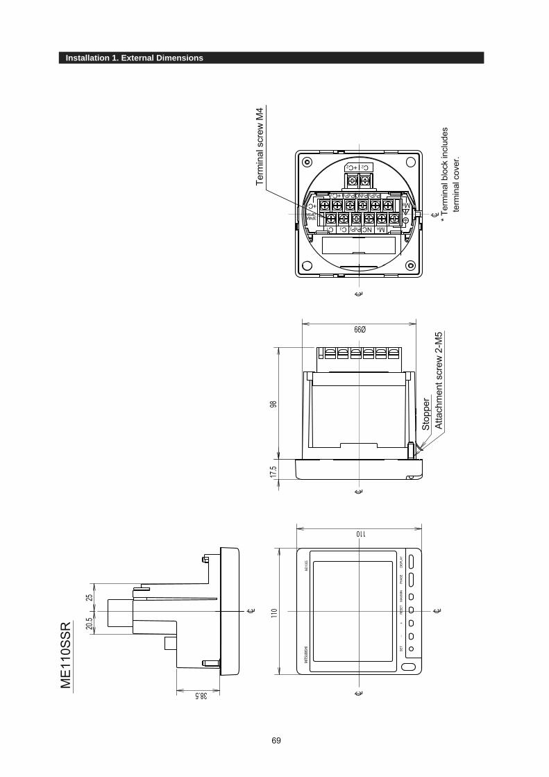
Installation 1. External Dimensions
69
Stop
per
Atta
chm
ent s
crew
2-M
5
Term
inal
scr
ew M
4
* Ter
min
al b
lock
incl
udes
term
inal
cov
er.
ME1
10SS
R
25
17.5
98
Ø99
38.520
.5
MA
MB
C3
C2+C2
C1
+C1
+C3
P0(P2)
P1(P1) P3(P3)P2(NC)
NC3P4W(3P3W)
MIT
SUBI
SHI
ME1
10SS
110
110
SET
RESE
TM
AX/M
INPH
ASE
DISP
LAY

Installation 1. External Dimensions
70
ME110SSR-4AP, ME110SSR-4APH, ME110SSR-4A2PME110SSR-C, ME110SSR-CH
Terminal screw M4
StopperAttachment screw 2-M5 Terminal screw M3 * Terminal block includes terminal cover.
20.545
68
17.5 98
Ø99
MA
C3
C1
+C1
C2
+C2
+C3
P0(P
2) P1(P
1)P3
(P3)
P2(N
C)
NC
3P4W
(3P3
W)
MB
ME110SSR-MB
Terminal screw M4
StopperAttachment screw 2-M5 Terminal screw M3 * Terminal block includes terminal cover.
MA
C3
C1
+C
C2
+C2
+C3
P0(P
2) P1(P
1)P3
(P3)
P2(N
C)
NC
3P4W
(3P3
W)
MB
20.545.517.5
67
98
Ø99
SLD
Ter
T/RT/R
NCER
ROR
+-

5. Operation Installation 2. Mounting
1. Dimensions of hole panelThe panel hole dimensions are as shown below. And itcan be attached to a panel of thickness 1.6 - 4.5mm.
Panel hole dimensions(Viewed from the front of panel)
2. View angleThe contrast of the display changes at view angles. Therefore, install it at the best position for viewing.
3. AttachmentWhen inserting the main body into the panel hole, insert it slowly until the stopper at the bottom of the main body goes into the panel. Maneuver the body during insertion so that the terminal block does not contact the panel. After insertion, the stopper prevents the main body from dropping off even when releasing your hand from it.
Fasten the attachment nut (M5 nut with bellevillespring) with torque about 1.47 - 1.96Nm.
Panel
Stopper
Nut with bellevillespring
● Notes in assembling to the panel and detaching from itIn the meter with output functions, part of its terminal block protrudes from the cylindrical main body, to which pay attention in attaching and detaching.
A protective sheet is attached to the display for protection against scratch at attachment to panel. Please remove the protective sheet when starting operation. After removed the display may be lit owing to generation of static electricity, but it is not an error. It goes off by natural discharge after a while.
In the case to attach it to the end of the panel, check the wiring work space and decide the attachment position.
Protective sheet
Attachment position
(Viewed from the side) (Viewed from the top)
60°
60°60° 60°
90±1
90±1
φ104±
2
2-φ6
Note
Stopper
Insert or take out the meter main body right diagonally.
71
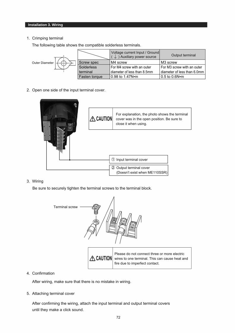
5. Operation Installation 3. Wiring
(ME110SS
1. Crimping terminal
2. Open one side of the input terminal cover.
Be sure to securely tighten the terminal screws to the terminal block.
4. Confirmation
After wiring, make sure that there is no mistake in wiring.
5. Attaching terminal cover
After confirming the wiring, attach the input terminal and output terminal covers until they make a click sound.
The following table shows the compatible solderless terminals.
Screw specSolderless terminalFasten torque
M4 screwFor M4 screw with an outer diameter of less than 8.5mm0.98 to 1.47N▪m
M3 screwFor M3 screw with an outer diameter of less than 6.0mm0.5 to 0.6N▪m
Voltage current Input / Ground ( ) Auxiliary power source Output terminal
For explanation, the photo shows the terminal cover was in the open position. Be sure to close it when using.
Input terminal cover
Terminal screw
Please do not connect three or more electric wires to one terminal. This can cause heat and fire due to imperfect contact.
CAUTION
CAUTION
Output terminal cover (Doesn’t exist when ME110SSR)
3. Wiring
Outer Diameter
72

5. Operation Installation 3. Wiring
Do not work with hot-line jobs
Do not open the secondary side of the CT circuit
Do not short the secondary side of the VT circuit
Make sure connections to the connection terminals are tight
Remember the crossover between C1 and C3
Do not use improper electrical wires
Do not pull the connection wires with force
Make sure the terminal cover is secure
Do not apply an abnormal voltage
Do not connect hot-line jobs. It may cause electric shock, burns, device burnout,or fire. It is recommended that a protection fuse be used for VT and the auxiliarypower source.
Connect the CT secondary side signal correctly to the terminal for CT connection.If the CT is not connected properly or if the secondary side of the CT is open, it may result in high voltage on the secondary side of the CT, the insulation of the secondary winding wire may be damaged, and burnout may be caused.
Connect the VT secondary side signal correctly to the terminal for VT connection.If the VT is not connected properly or if the secondary side of the VT shorts, overcurrent may flow to the secondary side of the VT, which can burn out the secondary winding wire. If the secondary winding wire burns out, it can damage the insulation of the primary winding wire, resulting in a short between phases.
Electrical wires must be properly tightened to the connection terminal. Otherwise, heat and measurement errors may be caused.
When the L side of CT circuit is common wire in 3 phase 4-wire, it is necessary toshortcircuit “C1”,“C2” and “C3” terminal of this device. In the case of 3 phase 3-wire,“C1” and “C3” should be short circuited.
Make sure that the electrical wires have the proper rating for current and voltage.If inappropriate electrical wires are used, fire may be caused.
If the terminal wiring is pulled with a strong force, the output portion may detach.(Tensile load: 39.2N or less)
Make sure the terminal cover is securely attached. Using the unit without the covermay cause electric shock.
Use the proper voltage for the auxiliary power source terminal. If an improper voltage is used, the instrument may be damaged or fire may becaused.
If a pressure test is given to a high-pressure device, a ground must be used in orderto avoid damaging this measurement instrument. If a high voltage of AC2000V isapplied for over one minute to the measurement instrument, damage may occur.
Auxiliary power source
Use the proper voltage for the auxiliary power source
CAUTION
CAUTION
73

Installation 1. External Dimensions Installation 4. Wiring Diagram
Auxiliary power supplyAC100-240V or DC100VFuses gG type(IEC269) or M type rated between 0.5 and 5A1: For low voltage circuits,grounding of the secondary side of VT and CT is not necessary. 2: Do not connect to NC terminal. 3: The parentheses in the figure indicate that the terminals are for 3P3W, 1P3W, and 1P2W.
Alarm output
Three phase 4-wire type : Example of ME110SSR-4APH (with VT)
k
lk
l
kl
KL
KL
KL
u
u
u
v
v
v
U
V
U
V
U
V
Pulse output
Analog output CH2
Analog output CH3
Analog output CH4
Analog output CH1
LOAD
{{{{{{
Three phase 4-wire type : Example of ME110SSR-4APH (for direct input)
Pulse output
Alarm output
Analog output CH2
Analog output CH3
Analog output CH4
Analog output CH1
LOAD
k
k
k
l
l
l
K
K
KL
L
L{{{{{{
74

Installation 1. External Dimensions Installation 4. Wiring Diagram
75
Auxiliary power supplyAC100-240V or DC100VFuses gG type(IEC269) or M type rated between 0.5 and 5A1: For low voltage circuits,grounding of the secondary side of VT and CT is not necessary. 2: Do not connect to NC terminal. 3: The parentheses in the figure indicate that the terminals are for 3P3W, 1P3W, and 1P2W.
Three phase 3-wire(3CT) type :Example of ME110SSR-4AP (with VT)
Analog output CH1
Analog output CH2
Analog output CH3
Analog output CH4
{{{{{Alarm output
k
l
l
LKL
u
v
U
V
k
kl
KL
K
u
v
U
V
LOAD
{{{{{
Analog output CH1
Analog output CH2
Analog output CH3
Analog output CH4
Pulse output
Three phase 3-wire(2CT) type : Example of ME110SSR-4AP (with VT)
l L
LOAD
u
v
U
V
k
kl
KL
K
u
v
U
V
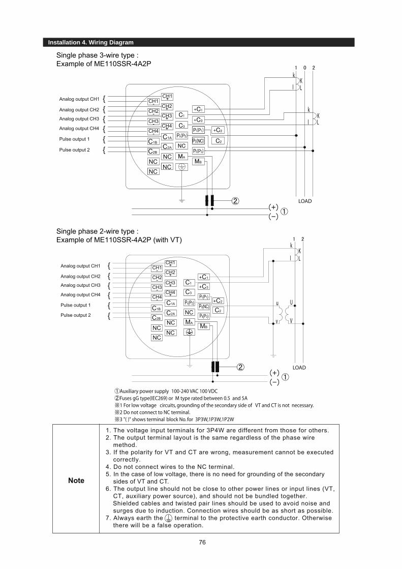
Installation 1. External Dimensions Installation 4. Wiring Diagram
Note
Analog output CH1
Analog output CH2
Analog output CH3
Analog output CH4
Pulse output 1
Pulse output 2
{{{{{{
CH1-CH2-CH3-CH4-
CH1+CH2+CH3+CH4+
C1A
C2AC1B
C2B
C3
C1
C2
+C2
NC
NC
MA MB
NCNC
NC
+C1
+C3
P2(NC)Po(P2)
P1(P1)
P3(P3)
1. The voltage input terminals for 3P4W are different from those for others. 2. The output terminal layout is the same regardless of the phase wire
method.3. If the polarity for VT and CT are wrong, measurement cannot be executed
correctly.4. Do not connect wires to the NC terminal.5. In the case of low voltage, there is no need for grounding of the secondary
sides of VT and CT.6. The output line should not be close to other power lines or input lines (VT,
CT, auxiliary power source), and should not be bundled together. Shielded cables and twisted pair lines should be used to avoid noise and
surges due to induction. Connection wires should be as short as possible.7. Always earth the terminal to the protective earth conductor. Otherwise
there will be a false operation.
Auxiliary power supply 100-240 VAC 100 VDCFuses gG type(IEC269) or M type rated between 0.5 and 5A1 For low voltage circuits, grounding of the secondary side of VT and CT is not necessary.2 Do not connect to NC terminal.3 "( )" shows terminal block No. for 3P3W,1P3W,1P2W
Single phase 2-wire type :Example of ME110SSR-4A2P (with VT)
Analog output CH1
Analog output CH2
Analog output CH3
Analog output CH4
Pulse output 1
Pulse output 2
CH1-CH2-CH3-CH4-
CH1+CH2+CH3+CH4+
C1A
C2AC1B
C2B
NCNC
NC
NC
{{{{{{
Single phase 3-wire type :Example of ME110SSR-4A2P
k
k
l
l
KL
KL
LOAD
k
lKL
u U
v V
LOAD
76

Installation 1. External Dimensions Installation 4. Wiring Diagram
1.
2.
3.
4.
5.
As for CC-link cable, use the designated cable. (Refer to page 80.) Ver.1.10-compatible CC-Link dedicated cables,CC-Link dedicated cables(Ver.1.00)and CC-Link dedicated high-performance cables cannot be used together.If uesd together, correct data transmission will not be guaranteed.Also attach the terminatingresister which matches the kind of the cable. Connect the shielded wire of the CC-Link dedicated cable to “SLD” of each module,and ground both ends of the shielded wire using grounding via “FG” .The SLD and FG are connected within the module.Because the CC-Link transmission line is a small signal circuit, it should beseparated from any strong-current circuit by 10cm or more.However,if it is laidparalle for a long distance,it must be laid at least 30cm away.The terminal must be grounded before using.The CC-Link transmission line should use an exclusive line that meets the requirements for total wiring length, distance between stations, and termination resistance values according to the communication speed. If you do not use an exclusive line or observe the wiring requirements, communication may fail. (Refer to the “CC-Link Cable Wiring Manual” about the exclusive line and wiringrequirements.)Connect the supplied “terminal resister” to each module at both ends of the CC-Linksystem.Connect the terminal resistors between “DA” and “DB” .
Note
CC-Linkcommunication
Alarm output {
DC24V
CC-Linkcommunication
Output terminal block of ME110SSR-C
Output terminal block of ME110SSR-CH
77

Installation 1. External Dimensions Installation 4. Wiring Diagram
1.
2.
3.4.
Note
Output terminal block of ME110SSR-MB
Use the shielded twisted pair cable.(Recommended cables: Refer to page 80.)To the units at both ends of the link, the 120-ohm resistance has to be attached. This instrument can perform a 120-ohm termination by short-circuiting the terminal of T/R- and Ter.The earthing has to be connected to earth by a thick wire of low impedance.Keep the distance between Modbus link to power line.
ModBus is the registered trademark of Schneider Automation Inc.
78

Specifi cations
Specifi cation
79
Item Specification
Type ME110SSR,ME110SSR-4AP,ME110SSR-4APH,ME110SSR-4A2P,ME110SSR-C,ME110SSR-CH,ME110SSR-MB
Phase wire system Three phase 4-wire(3P4W),Three phase 3-wire(3P3W),Single phase3-wire(1P3W),Single phase 2-wire(1P2W)
Rating
Current 5AAC , 1AAC (1AAC is special-purpose item)
Voltage3P4W: max277/480VAC3P3W,1P2W: 110VAC,220VAC1P3W, 220VAC (110/220VAC)
Frequency 50-60HzMeasuring Items and accuracy
3P4W 3P3W,1P3W 1P2W Display OutputCurrent (A) A1, A2, A3, AN, Aavg A1, A2, A3 A1
0.5% 0.5%
Current Demand (DA) DA1, DA2, DA3, DAN, DAavg DA1, DA2, DA3 DA1
Voltage (V) V12, V23, V31, Vavg(L-L),V1N, V2N, V3N, Vavg(L-N) V12, V23, V31 V12
Active Power (W) ΣW, W1, W2, W3 ΣW ΣWActive Demand Power (DW) Σ DW, DW1, DW2, DW3 ΣDW ΣDWReactive Power (var) Σ var, var1, var2, var3 Σvar ΣvarApparent Power (VA) ΣVA, VA1, VA2, VA3 - -Power Factor (cosφ) Σcosφ, cosφ1, cosφ2, cosφ3 Σcosφ Σcosφ 2.0% 2.0%Frequency (Hz) Hz 0.5% 0.5%Active Energy (Wh) Import, Export 2.0% 2.0%
Reactive Energy (varh) Import Capacitive, Import Inductive,Export Capacitive, Export Inductive 2.0% 2.0%
Harmonics Current (HI)HI1, HI2, HI3, HIN HI1,HI3 HI1 2.5%
THD, h1...h13 (without even number)RMS value and Distortion ratio (max.100%)
(Total RMS,0 to Rated x 60%)
Harmonics Voltage (HV)HV1N, HV2N, HV3N HV12, HV23 HV12 2.5%
THD, h1...h13 (without even number)RMS value and Distortion ratio (max.20%) (THD,0 to 20%)
MeasuringMethod
Instantaneous Value A,V: RMS calculation, W,var,VA,Wh,varh: Digital multiplication, cosφ:Power ratio calculationHz: Zero-cross, HV,HI: FTT
Demand Value Thermal type calculation
Display
Type LCD with backlight
Number of display digitsA,DA,V,W,DW,var,VA,cosφ: 4 digitsHz,HI,HV: 3 digitsWh,varh: 6 digits
Bar graph 21 Segment-Bar graph, 22 Segment-IndicatorDisplay updating time interval 0.5s / 1s
Response time Display: 4s or less, Analog output: 4s or lessIn HI and HV, 10s or less
Analog output(ME110SSR-4AP/-4APH/-4A2P)
Range 4~20mA DCLoad resistance 600Ω max
Alarm output(ME110SSR-4APH/-CH)
No-voltage ‘a’ contact35VDC, 0.2A
Pulse output(ME110SSR-4AP/-4APH)Digital input(ME110SSR-CH)
No-voltage ‘a’ contact35VDC, 0.1A
Power Failure Compensation Non volatile memory (Items: setting value, max/min value, active/reactive energy)
Rated 24VDC(19 to 30VDC)
VAConsumption
VT 0.1VA/phase, 0.2VA/phase (at direct input)CT 0.1VA/phaseAuxiliary power 8VA at 110VAC, 9VA at 220VAC, 6W at 100VDCDigital input DC19-30V, under 7mA
Auxiliary power 100 to 240VAC (+10%,-15%) 50/60Hz100VDC (+10%,-30%)
Weight 0.5kgDimension 110(H)x110(W)x98(D)Enclosure Thermoplastic self-extinguish (UL94V0)Operating temperature -5~50°C (average operating temperature ; 35°C or less per day)Operating humidity 85%RHmax, non condensingStorage temperature -20~60°CStandard EMC:EN61326-1:2006LVD:EN61010-1/2001
Note1: Accuracy is specified according to the maximum scales value of rated value.Note2: Measurement of harmonics which its distortion ratio is exceeded 100% may exceed the accuracy.Note3: Harmonics cannot be measured without voltage input.

Specifi cations
Communication Specifi cation
80
ME110SSR-C,ME110SSR-CHItem Specifications
CC-Link station type Remote device station (ver. 1 remote device station or ver. 2 remote device station)
Number of occupied stations
Ver. 1 remote device station (ver. 1 compatible slave station) setting:1 stationVer. 2 remote device station (ver. 2 compatible slave station) setting:1 station (Expanded cyclic setting: Octuple)
CC-Link version CC-Link Ver 1.10 / 2.00Transmission speed Can select from 156 kbps/ 625 kbps/ 2.5 Mbps/ 5 Mbps/ 10 MbpsMaximum number of connected stat ions
If the system is configured by only this instrument, up to 42 units can be connected.(note 1)
note1: As for details, refer to the following manuals.
Manual Name Manual Number(Model Code)
CC-Link System Master/Local Module User’s Manual type QJ61BT11NDescribes the system configuration, performance specifications, functions, handling, wiring andtroubleshooting of the QJ61BT11N. (Optionally available)
SH-080394E(13JR64)
■CC-Link Dedicated CableUse the CC-Link dedicated cables for the CC-Link system. If a cable other than the CC-Link dedicated cable is used, the performance of the CC-Link system cannot be guaranteed.For the specifications of the CC-Link dedicated cables or any other inquiries, visit the following website:CC-Link Partner Association:http://www.CC-Link.org/ REMARKFor details, refer to the CC-Link cable wiring manual issued by CC-Link PartnerAssociation ■ About Programming
In addition to this manual, read the following documents too.● Electronic multi-Measuring Instrument programming manual (CC-Link) ................................................................ LAN040503● Electronic multi-Measuring Instrument programming manual (CC-Link) (For ver.2 remote device station)............ LAN110300
ME110SSR-MBItem Specifications
Interface RS485, 2 wires half duplexProtocol ModBus RTU (binary data)Speed 2400, 4800, 9600, 19200, 38400bpsDistance 1000maddress 1-255Station number 31Resistance at end of the link 120Ω 1/2WRecommended cables Shielded twisted pair, AWG26 (or wider) gaugeAs for details of ModBus communication, refer to “Modbus. org.Website” “Modbus. org.Website”: http://www.modbus.org
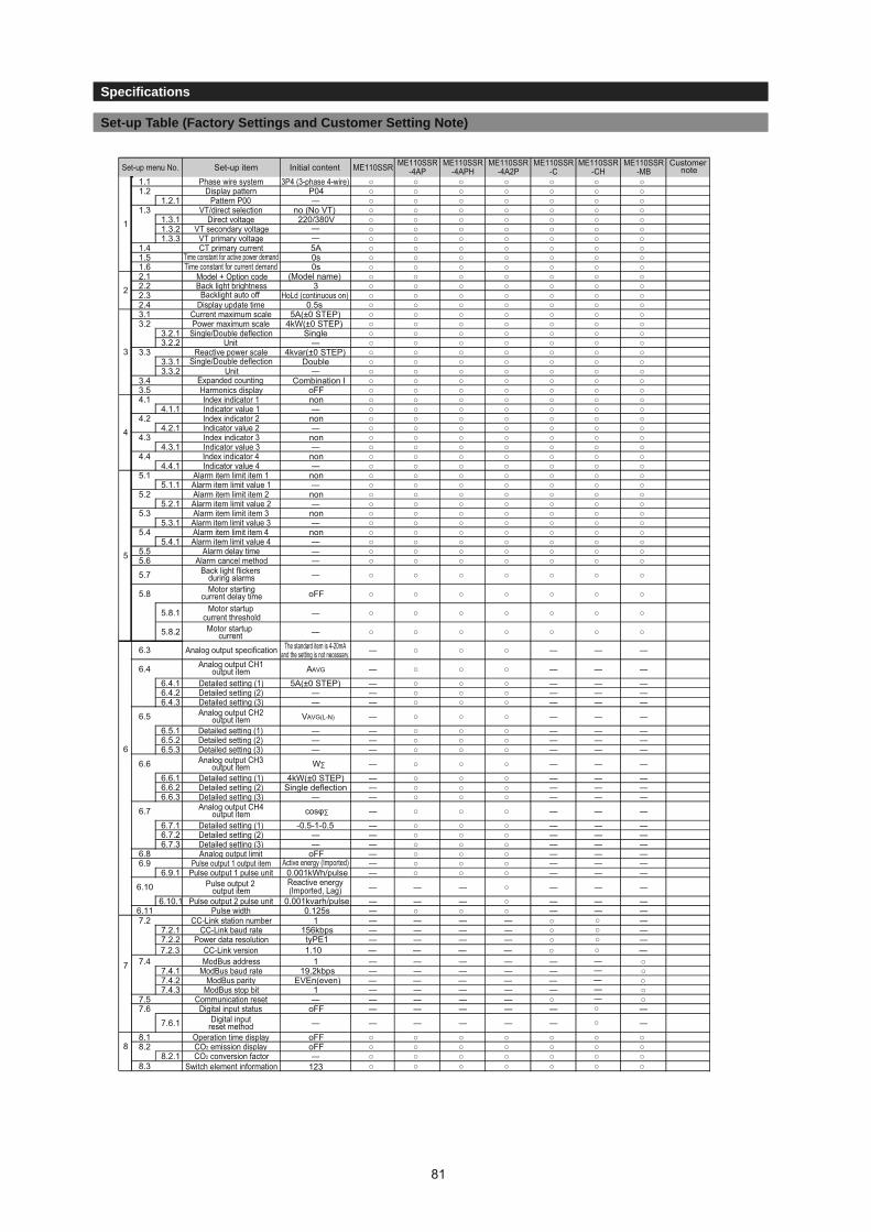
3.1 Setting Procedure
3. SettingsSpecifi cations
Set-up Table (Factory Settings and Customer Setting Note)
Set-up menu No. Set-up item Initial content ME110SSR ME110SSR-4AP
ME110SSR-4APH
ME110SSR-4A2P
ME110SSR-C
ME110SSR-CH
ME110SSR-MB
Customer note
1.1 Phase wire system 3P4 (3-phase 4-wire) ○ ○ ○ ○ ○ ○ ○1.2 Display pattern P04 ○ ○ ○ ○ ○ ○ ○
1.2.1 Pattern P00 ―
――
○ ○ ○ ○ ○ ○ ○1.3 VT/direct selection no (No VT) ○ ○ ○ ○ ○ ○ ○
1.3.1 Direct voltage 220/380V ○ ○ ○ ○ ○ ○ ○1.3.2 VT secondary voltage ○ ○ ○ ○ ○ ○ ○1.3.3 VT primary voltage ○ ○ ○ ○ ○ ○ ○
1.4 CT primary current 5A ○ ○ ○ ○ ○ ○ ○1.5 Time constant for active power demand
Time constant for current demand0s ○ ○ ○ ○ ○ ○ ○
1.6 0s ○ ○ ○ ○ ○ ○ ○2.1 (Model name) ○ ○ ○ ○ ○ ○ ○2.2 Back light brightness 3 ○ ○ ○ ○ ○ ○ ○2.3 Backlight auto off HoLd (continuous on) ○ ○ ○ ○ ○ ○ ○2.4 Display update time 0.5s ○ ○ ○ ○ ○ ○ ○3.1 Current maximum scale 5A(±0 STEP) ○ ○ ○ ○ ○ ○ ○3.2 Power maximum scale 4kW(±0 STEP) ○ ○ ○ ○ ○ ○ ○
3.2.1 Single/Double deflection
Single/Double deflection
Single ○ ○ ○ ○ ○ ○ ○3.2.2 Unit ― ○ ○ ○ ○ ○ ○ ○
3.3 Reactive power scale 4kvar(±0 STEP) ○ ○ ○ ○ ○ ○ ○3.3.1 Double ○ ○ ○ ○ ○ ○ ○3.3.2 Unit ― ○ ○ ○ ○ ○ ○ ○
3.4 Combination I ○ ○ ○ ○ ○ ○ ○3.5 Harmonics display oFF ○ ○ ○ ○ ○ ○ ○4.1 Index indicator 1 non ○ ○ ○ ○ ○ ○ ○
4.1.1 Indicator value 1 ― ○ ○ ○ ○ ○ ○ ○4.2 Index indicator 2 non ○ ○ ○ ○ ○ ○ ○
4.2.1 Indicator value 2 ― ○ ○ ○ ○ ○ ○ ○4.3 Index indicator 3 non ○ ○ ○ ○ ○ ○ ○
4.3.1 Indicator value 3 ― ○ ○ ○ ○ ○ ○ ○4.4 Index indicator 4 non ○ ○ ○ ○ ○ ○ ○
4.4.1 Indicator value 4 ― ○ ○ ○ ○ ○ ○ ○5.1 Alarm item limit item 1 non ○ ○ ○ ○ ○ ○ ○
5.1.1 Alarm item limit value 1 ― ○ ○ ○ ○ ○ ○ ○5.2 Alarm item limit item 2 non ○ ○ ○ ○ ○ ○ ○
5.2.1 Alarm item limit value 2 ― ○ ○ ○ ○ ○ ○ ○5.3 Alarm item limit item 3 non ○ ○ ○ ○ ○ ○ ○
5.3.1 Alarm item limit value 3 ― ○ ○ ○ ○ ○ ○ ○5.4 Alarm item limit item 4 non ○ ○ ○ ○ ○ ○ ○
5.4.1 Alarm item limit value 4 ― ○ ○ ○ ○ ○ ○ ○5.5 Alarm delay time ― ○ ○ ○ ○ ○ ○ ○5.6 Alarm cancel method ― ○ ○ ○ ○ ○ ○ ○5.7 ― ○ ○ ○ ○ ○ ○ ○
5.8 oFF ○ ○ ○ ○ ○ ○ ○
5.8.1 Motor startup current threshold ― ○ ○ ○ ○ ○ ○ ○
5.8.2 Motor startup current ― ○ ○ ○ ○ ○ ○ ○
6.3 Analog output specification ― ○ ○ ○ ― ― ―
6.4 Analog output CH1output item AAVG ― ○ ○ ○ ― ― ―
6.4.1 Detailed setting (1) 5A(±0 STEP) ― ○ ○ ○ ― ― ―6.4.2 Detailed setting (2) ― ― ○ ○ ○ ― ― ―6.4.3 Detailed setting (3) ― ― ○ ○ ○ ― ― ―
6.5 Analog output CH2output item VAVG(L-N) ― ○ ○ ○ ― ― ―
6.5.1 Detailed setting (1) ― ― ○ ○ ○ ― ― ―6.5.2 Detailed setting (2) ― ― ○ ○ ○ ― ― ―6.5.3 Detailed setting (3) ― ― ○ ○ ○ ― ― ―
6.6 Analog output CH3output item W∑ ― ○ ○ ○ ― ― ―
6.6.1 Detailed setting (1) 4kW(±0 STEP) ― ○ ○ ○ ― ― ―6.6.2 Detailed setting (2) Single deflection ― ○ ○ ○ ― ― ―6.6.3 Detailed setting (3) ― ― ○ ○ ○ ― ― ―
6.7 Analog output CH4output item cosφ∑ ― ○ ○ ○ ― ― ―
6.7.1 Detailed setting (1) -0.5-1-0.5 ― ○ ○ ○ ― ― ―6.7.2 Detailed setting (2) ― ― ○ ○ ○ ― ― ―6.7.3 Detailed setting (3) ― ― ○ ○ ○ ― ― ―
6.8 Analog output limit oFF ― ○ ○ ○ ― ― ―6.9 Pulse output 1 output item Active energy (Imported) ― ○ ○ ○ ― ― ―
6.9.1 Pulse output 1 pulse unit 0.001kWh/pulse ― ○ ○ ○ ― ― ―6.10 Pulse output 2
output itemReactive energy(Imported, Lag) ― ― ― ○ ― ― ―
6.10.1 Pulse output 2 pulse unit 0.001kvarh/pulse ― ― ― ○ ― ― ―6.11 Pulse width 0.125s ― ○ ○ ○ ― ― ―
○○○
7.2 CC-Link station number 1 ― ― ― ― ○ ―7.2.1 CC-Link baud rate 156kbps ― ― ― ― ○ ―7.2.2 Power data resolution ― ― ― ― ○ ―
7.4 ModBus address 1 ― ― ― ― ― ○―7.4.1 ModBus baud rate 19.2kbps ― ― ― ― ― ○―7.4.2 ModBus parity EVEn(even) ― ― ― ― ― ○―7.4.3 ModBus stop bit 1 ― ― ― ― ― ○―
7.5 Communication reset ― ― ― ― ― ○ ○―7.6 Digital input status oFF
123
― ― ― ― ― ―○
7.6.1 Digital inputreset method ― ― ― ― ― ― ―○
8.1 Operation time display
Switch element information
oFF ○ ○ ○ ○ ○ ○ ○8.2
8.3
CO2 emission display oFF ○ ○ ○ ○ ○ ○ ○8.2.1 CO2 conversion factor ― ○
○○○
○○
○○
○○
○ ○○ ○
1
8
7
6
5
4
3
2
tyPE1○7.2.3 CC-Link version ― ― ― ― ○ ―1.10
The standard item is 4-20mA and the setting is not necessary.
Model + Option code
Expanded counting
Back light flickers during alarmsMotor starting
current delay time
81

IB63660A
Electronic Multi-Measuring Instrument
HEAD OFFICE: TOKYO BUILDING, 2-7-3, MARUNOUCHI, CHIYODA-KU, TOKYO 100-830, JAPAN
Service NetworkCountry/Region Corporation Name Address Telephone
Australia Mitsubishi Electric Australia Pty. Ltd. 348 Victoria Road, Rydalmere, N.S.W. 2116, Australia +61-2-9684-7777 Bangladesh PROGRESSIVE TRADING CORPORATION HAQUE TOWER,2ND FLOOR,610/11,JUBILEE ROAD, CHITTAGONG,
BANGLADESH +880-31-624307
ELECTRO MECH AUTOMATION& ENGINEERING LTD.
SHATABDI CENTER, 12TH FLOOR, SUITES 12-B, 292, INNER CIRCULAR ROAD, FAKIRA POOL, MOTIJHEEL, DHAKA-1000, BANGLADESH
+88-02-7192826
Belarus Tehnikon Oktyabrskaya 19, Off. 705, BY-220030 Minsk, Belarus +375 (0)17 / 210 46 26 Belgium Koning & Hartman B.V. Woluwelaan 31, BE-1800 Vilvoorde, Belgium +32 (0)2 / 2570240 Brazil Mitsubishi Electric Do Brasil Comercio E Servicos
Ltda. Av. Adelino Cardana, 293 -21 and. - Bethaville, 06401-147, Barueri/SP - Brasil +55-11-4689-3000
Cambodia DHINIMEX CO.,LTD #245, St. Tep Phan, Phnom Penh, Cambodia +855-23-997-725 Chile Rhona S.A. Vte. Agua Santa 4211 Casilla 30-D (P.O. Box) Vina del Mar, Chile +56-32-2-320-600China Mitsubishi Electric Automation (China) Ltd. Mitsubishi Electric Automation Building, No.1386 Hongqiao Road, Shanghai,200336 +86-21-2322-3030
Mitsubishi Electric Automation (China) Ltd. North China Branch
9/F, Office Tower1 Henderson Centre 18 Jianguomennei Dajie DongCheng district BeiJing 100005
+86-10-6518-8830
Mitsubishi Electric Automation (China) Ltd. NorthEast China Branch
Room2302,President Building Tower C,No.69 Heping North Avenue, HepingDistrict, Shenyang,110003
+86-24-2259-8830
Mitsubishi Electric Automation (China) Ltd. South China Branch
Room 2512--2516, Great China International Exchange Square, Jintian Rd.S., Futian District, Shenzhen, 518034
+86-755-2399-8272
Mitsubishi Electric Automation (China) Ltd. South China Branch
Room 1609, North Tower, The Hub Center, No.1068, Xing Gang East Road, Haizhu District, GuangZhou, China 510335
+86-20-8923-6730
Mitsubishi Electric Automation (China) Ltd. SouthWest China Branch
1501,1502,1503,15F,Guang-hua Centre,Block C,NO.98 Guang Hua North 3th Road Chengdu, 610000
+86-28-8446-8030
Mitsubishi Electric Automation (Hong Kong) Ltd. 20/F, Cityplaza One, 1111 king's Road, Taikoo shing, Hong Kong +852-2510-0555 Colombia Proelectrico Representaciones S.A. Carrera 42 # 75-367 Bod 109 Itagui Colombia +57-4-4441284Czech Republic AUTOCONT CONTROL SYSTEMS S.R.O Technologická 374/6, CZ-708 00 Ostrava - Pustkovec +420 595 691 150Denmark BEIJER ELECTRONICS A/S LYKKEGARDSVEJ 17, DK-4000 ROSKILDE +45 (0)46/ 75 76 66Egypt Cairo Electrical Group 9, Rostoum St. Garden City P.O. Box 165-11516 Maglis El-Shaab,Cairo - Egypt +20-2-27961337 France Mitsubishi Electric Europe B.V. 25, Boulevard des Bouvets, F-92741 Nanterre Cedex +33 (0) 1 / 55 68 55 68 Germany Mitsubishi Electric Europe B.V. Mitsubishi-Electric-Platz 1, 40882 Ratingen, Germany +49 (2102) 4860 Greece KALAMARAKIS- SAPOUNAS S.A. IONIAS & NEROMILOU STR., CHAMOMILOS ACHARNES, ATHENS, 13678 Greece +30-2102 406000
UTECO 5, MAVROGENOUS STR., 18542 PIRAEUS, Greece +30-211-1206-900Hungary Meltrade Ltd. Fertö utca 14. HU-1107 Budapest, Hungary +36 (0)1-431-9726 India Mitsubishi Electric India Private Limited 2nd Floor, Tower A&B, Cyber Greens, DLF Cyber City, DLF Phase - III, Gurgaon - 122
022 Haryana, India +91-124-4630300
Indonesia PT.Mitsubishi Electric Indonesia Gedung Jaya 8th floor, JL.MH. Thamrin No.12 Jakarta Pusat 10340, Indonesia +62-21-3192-6461P. T. Sahabat Indonesia P.O.Box 5045 Kawasan Industri Pergudangan, Jakarta, Indonesia +62-(0)21-6610651-9
Ireland Mitsubishi Electric Europe B.V. Westgate Business Park, Ballymount, IRL-Dublin 24, Ireland +353 (0)1-4198800 Israel Gino Industries Ltd. 26, Ophir Street IL-32235 Haifa, Israel +972 (0)4-867-0656 Italy Mitsubishi Electric Europe B.V. Viale Colleoni 7, I-20041 Agrate Brianza (MI), Italy +39 039-60531Kazakhstan Kazpromavtomatika ul. Zhambyla 28, KAZ- 100017 Karaganda +7-7212-501000 Korea Mitsubishi Electric Automation Korea Co., Ltd 9F Gangseo Hangang xi-tower, 401 Yangcheon-ro, Gangseo-gu, Seoul 07528 Korea +82-2-3660-9572Laos AROUNKIT CORPORATION IMPORT- EXPORT
SOLE CO.,LTDSAPHANMO VILLAGE. SAYSETHA DISTRICT, VIENTIANE CAPITAL, LAOS +856-20-415899
Lebanon Comptoir d'Electricite Generale-Liban Cebaco Center- Block A Autostrade Dora, P.O. Box 11-2597 Beirut - Lebanon +961-1-240445 Lithuania Rifas UAB Tinklu 29A, LT-5300 Panevezys, Lithuania +370 (0)45-582-728 Malaysia Mittric Sdn Bhd No. 5 Jalan Pemberita U1/49, Temasya Industrial Park, Glenmarie 40150 Shah
Alam,Selangor, Malaysia +603-5569-3748
Malta ALFATRADE LTD 99 PAOLA HILL, PAOLA PLA 1702, Malta +356 (0)21-697-816Maroco SCHIELE MAROC KM 7,2 NOUVELLE ROUTE DE RABAT AIN SEBAA, 20600 Casablanca, Maroco +212 661 45 15 96 Mexico Mitsubishi Electric Automation, Inc. Mariano Escobedo 69, Col. Zona Industrial, Tlalnepantla, MEX- 54030 - MX +55-3067-7500 Myanmar Peace Myanmar Electric Co.,Ltd. NO137/139 Botahtaung Pagoda Road, Botahtaung Town Ship 11161,Yangon,Myanmar +95-(0)1-202589Nepal Watt&Volt House KHA 2-65,Volt House Dillibazar Post Box:2108,Kathmandu,Nepal +977-1-4411330Netherlands Imtech Marine & Offshore B.V. Sluisjesdijk 155, NL-3087 AG Rotterdam, Netherlands +31 (0)10-487-19 11 North America Mitsubishi Electric Automation, Inc. 500 Corporate Woods Parkway, Vernon Hills, IL 60061 USA +847-478-2100 Norway Scanelec AS Leirvikasen 43B, NO-5179 Godvik, Norway +47 (0)55-506000Middle EastArab Countries & Cyprus
Comptoir d'Electricite Generale-International-S.A.L. Cebaco Center- Block A Autostrade Dora P.O. Box 11-1314 Beirut - Lebanon +961-1-240430
Pakistan Prince Electric Co. 2-P GULBERG II, LAHORE, 54600, PAKISTAN +92-42-575232, 5753373AL-KAMAL GROUP OFFICE NO.7&8, 1ST FLOOR, BARKAT ALI KHAN CENTER, 101, CIRCULAR
ROAD, LAHORE. PAKISTAN +92-42-37631632
Philippines Edison Electric Integrated, Inc. 24th Fl. Galleria Corporate Center, Edsa Cr. Ortigas Ave., Quezon City Metro Manila, Philippines
+63-(0)2-634-8691
Poland Mitsubishi Electric Europe B.V. Polish Branch Krakowska 50, 32-083 Balice, Poland +48 (0) 12 630 47 00 Republic of Moldova Intehsis SRL bld. Traian 23/1, MD-2060 Kishinev, Moldova +373 (0)22-66-4242 Romania Sirius Trading & Services SRL RO-060841 Bucuresti, Sector 6 Aleea Lacul Morii Nr. 3 +40-(0)21-430-40-06 Russia Mitsubishi Electric Europe B.V. Moscow Branch 52, bld. 3 Kosmodamianskaya Nab. 115054, Moscow, Russia +7 495 721-2070Saudi Arabia Center of Electrical Goods Al-Shuwayer St. Side way of Salahuddin Al-Ayoubi St. P.O. Box 15955 Riyadh 11454 -
Saudi Arabia +966-1-4770149
Singapore Mitsubishi Electric Asia Pte. Ltd. 307 Alexandra Road, Mitsubishi Electric Building, Singapore 159943 +65-6473-2308Slovakia PROCONT, Presov Kupelna 1/, SK- 08001 Presov, Slovakia +421 (0)51-7580 611
SIMAP Jana Derku 1671, SK- 91101 Trencin, Slovakia + 421 (0)32 743 04 72Slovenia Inea RBT d.o.o. Stegne 11, SI-1000 Ljubljana, Slovenia +386 (0)1-513-8116 South Africa CBI-electric: low voltage Private Bag 2016, ZA-1600 Isando Gauteng, South Africa +27-(0)11-9282000 Spain Mitsubishi Electric Europe B.V. Spanish Branch Carretera de Rubí 76-80, E-08190 Sant Cugat del Vallés (Barcelona), Spain +34 (0)93-565-3131Sweden Euro Energy Components AB Järnvägsgatan 36, S-434 24 Kungsbacka, Sweden +46 (0)300-690040 Switzerland TriElec AG Muehlentalstrasse 136, CH-8201 Schaffhausen +41-(0)52-6258425 Taiwan Setsuyo Enterprise Co., Ltd 5th Fl., No.105, Wu Kung 3rd, Wu-Ku Hsiang, Taipei, Taiwan, R.O.C. +886-(0)2-2298-8889 Thailand United Trading & Import Co., Ltd. 77/12 Bamrungmuang Road,Klong Mahanak Pomprab Bangkok Thailand +66-223-4220-3 Tunisia MOTRA Electric 3, Résidence Imen, Avenue des Martyrs Mourouj III, 2074- El Mourouj III Ben Arous,
Tunisia +216-71 474 599
Turkey GTS Bayraktar Bulvarı Nutuk Sok. No:5, Posta Kutusu34384, TR-34775 Yukan Dudullu -Uemraniye, Istanbul, Turkey
+90 (0)216 526 3990
United Kingdom Mitsubishi Electric Europe B.V. Travellers Lane, UK-Hatfield, Herts. AL10 8XB, United Kingdom +44 (0)1707-276100 Uruguay Fierro Vignoli S.A. Avda. Uruguay 1274 Montevideo Uruguay +598-2-902-0808 Venezuela Adesco S.A. Calle 7 La Urbina Edificio Los Robles Locales C y D Planta Baja, Caracas- Venezuela +58-212-241-9952 Vietnam Mitsubishi Electric Vietnam Co.,Ltd. Head Office Unit01-04, 10th Floor, Vincom Center, 72 Le Thanh Ton Street, District 1, Ho Chi
Minh City, Vietnam +84-8-3910-5945
Mitsubishi Electric Vietnam Co.,Ltd. Hanoi Branch 6th Floor, Detech Tower, 8 Ton That Thuyet Street, My Dinh 2 Ward, Nam Tu Liem District, Hanoi City, Vietnam
+84-4-3937-8075
82