Electron Losses and Fields Investigation - UCLA IGPP
91
1 Electron Losses and Fields Investigation Subsystem PDR Attitude Determination and Control Ryan Baker, Oliver Wang Los Angeles, California December 5, 2014 ELFIN ADCS Peer PDR – December 5, 2014
-
Upload
khangminh22 -
Category
Documents
-
view
1 -
download
0
Transcript of Electron Losses and Fields Investigation - UCLA IGPP
1
Electron Losses and Fields Investigation
Subsystem PDRAttitude Determination and Control
Ryan Baker, Oliver Wang
Los Angeles, CaliforniaDecember 5, 2014
ELFIN ADCS Peer PDR – December 5, 2014

2
REVIEW BOARD MEMBERS
Name Organization
Marcin Pilinski Atmospheric & Space Technology Research Associates
Rick Schnurr NASA Goddard Space Flight Center
Hannes Leinweber UCLA IGPP
ELFIN ADCS Peer PDR – December 5, 2014

Primary objective: To ensure that the design meets requirements
Objectives for ADCS design team: Clearly define the subsystem scope and responsibilities Clearly ensure personnel roles and responsibilities Expose design to experts in an open and relaxed
environment where technical discussions can take place Identify potential engineering and implementation flaws to
increase probability of success Provide feedback on the detailed design of the subsystem
3
OBJECTIVE AND SCOPE OF PDR
ELFIN ADCS Peer PDR – December 5, 2014
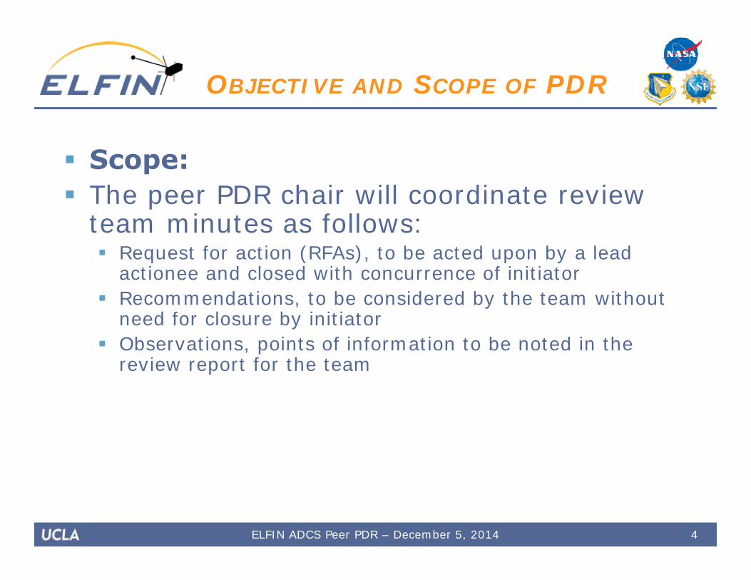
Scope: The peer PDR chair will coordinate review
team minutes as follows: Request for action (RFAs), to be acted upon by a lead
actionee and closed with concurrence of initiator Recommendations, to be considered by the team without
need for closure by initiator Observations, points of information to be noted in the
review report for the team
4
OBJECTIVE AND SCOPE OF PDR
ELFIN ADCS Peer PDR – December 5, 2014
5
TABLE OF CONTENTS
ELFIN ADCS Peer PDR – December 5, 2014
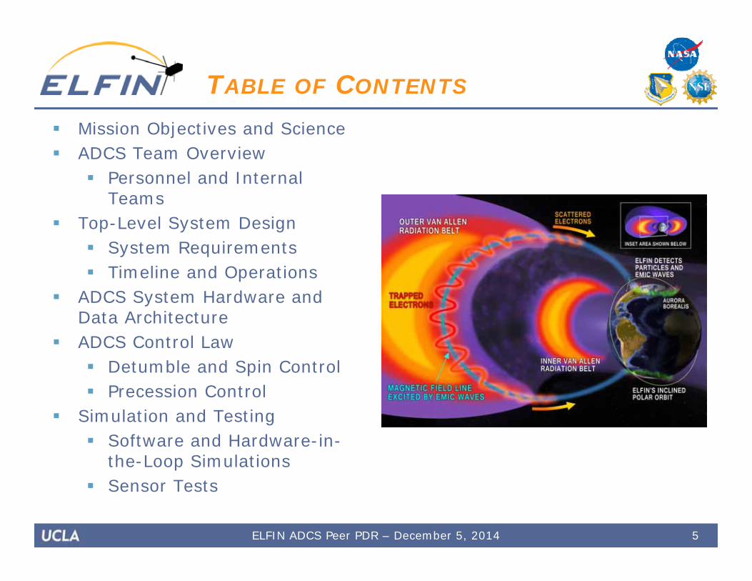
Mission Objectives and Science ADCS Team Overview
Personnel and Internal Teams
Top-Level System Design System Requirements Timeline and Operations
ADCS System Hardware and Data Architecture
ADCS Control Law Detumble and Spin Control Precession Control
Simulation and Testing Software and Hardware-in-
the-Loop Simulations Sensor Tests
6
ADCS Team Overview
ELFIN ADCS Peer PDR – December 5, 2014
7
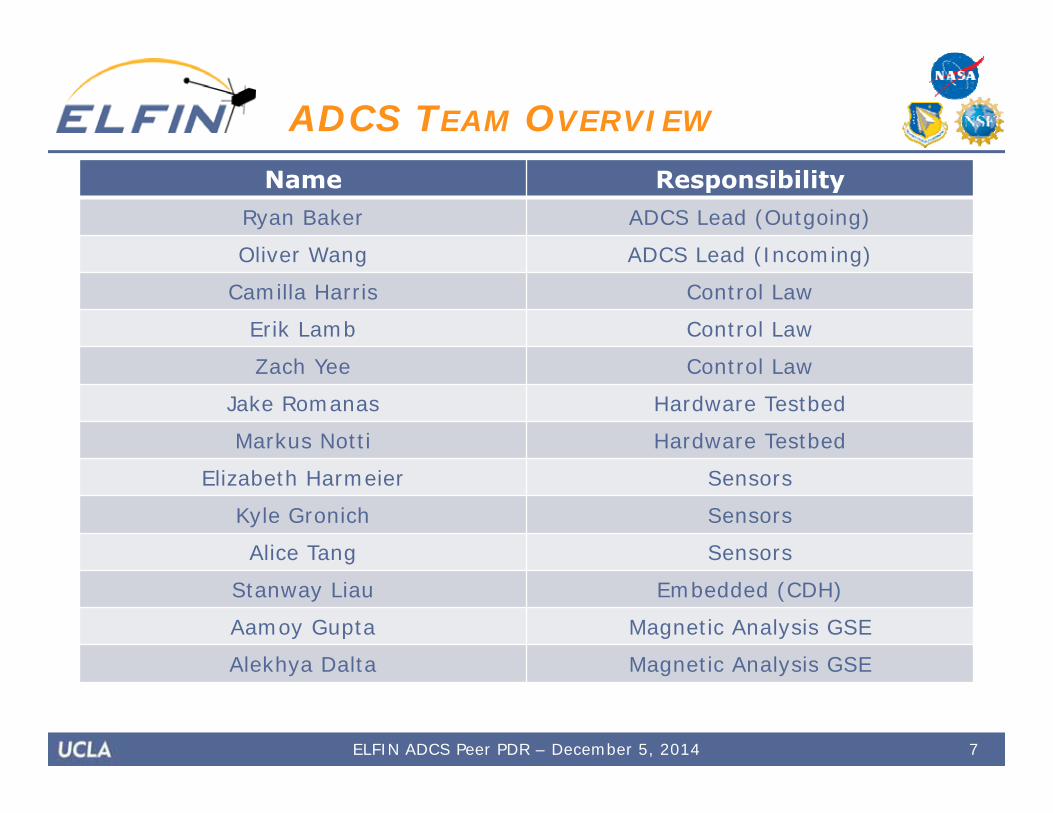
ADCS TEAM OVERVIEW
Name ResponsibilityRyan Baker ADCS Lead (Outgoing)
Oliver Wang ADCS Lead (Incoming)
Camilla Harris Control Law
Erik Lamb Control Law
Zach Yee Control Law
Jake Romanas Hardware Testbed
Markus Notti Hardware Testbed
Elizabeth Harmeier Sensors
Kyle Gronich Sensors
Alice Tang Sensors
Stanway Liau Embedded (CDH)
Aamoy Gupta Magnetic Analysis GSE
Alekhya Dalta Magnetic Analysis GSE
ELFIN ADCS Peer PDR – December 5, 2014
8
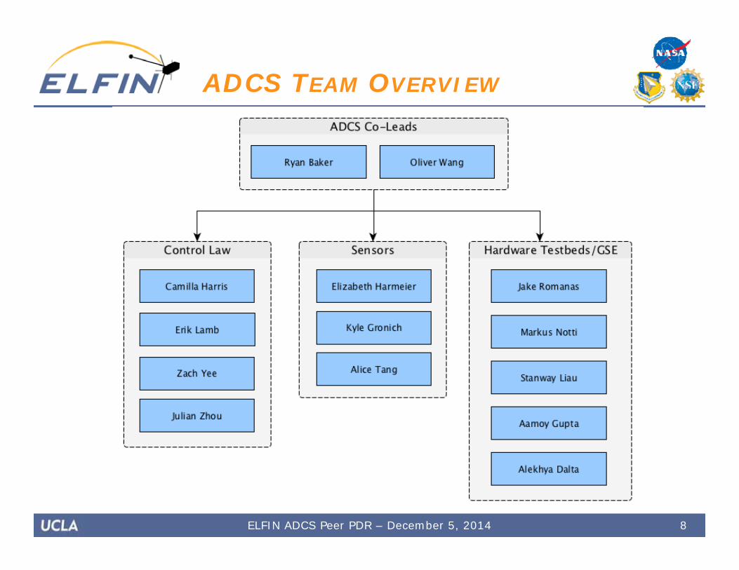
ADCS TEAM OVERVIEW
ELFIN ADCS Peer PDR – December 5, 2014

Top-Level System Design
• Subsystem Requirements• Overview• Mission Timeline• ADCS Operations
9ELFIN ADCS Peer PDR – December 5, 2014

10
SUBSYSTEM REQUIREMENTS
ELFIN ADCS Peer PDR – December 5, 2014
REQ ID Requirement Status
ADCS-01 The ADC subsystem shall be capable of producing and maintaining a spin rate between 10 and 30 rpm to within ±2 rpm
• Demonstrated in simulation• Microcontroller implementation
completed• Hardware tests in progress
ADCS-02 The ADC subsystem shall be capable of ±5 degrees of attitude control
• Demonstrated in simulation• Microcontroller implementation
being developed
ADCS-03 The ADC subsystem shall be capable of ±3 degrees of attitude knowledge
• Attitude determination algorithms still in development
• Simulation has not yet been modified to include attitude determination
ADCS-04 The ADC system shall be capable of detumbling and spinning up ELFIN after deployment from the P-POD
• Demonstrated in simulation• Microcontroller implementation
completed• Hardware tests in progress
ADCS-05 The integration time of all ADCS sensors shall be sufficiently low so that they are capable of operating while the spacecraft is spinning at rate of up to 30 rpm
• Sensor selection driven by requirement
• Sensor tests currently in progress

11
SUBSYSTEM REQUIREMENTS
ELFIN ADCS Peer PDR – December 5, 2014
REQ ID Requirement Status
ADCS-06 The ADC subsystem shall have at least two separate sensors capable of being processed onboard for maneuvers
• System design satisfies requirement
• Magnetometer CDH software developed
• Testing of both magnetometers yet to be completed
ADCS-07 The ADC subsystem shall be capable of running a deperm cycle after maneuvers to ensure the magnetic moment of the spacecraft at 75 cm as measured by the magnetometer is less than 1 nT
• Operational concept developed• H-bridge driver controller is
complete, but no hardware demo has been developed yet
ADCS-10 The ADC subsystem shall not exceed the mass allocated by Systems
• System design driven by requirement
• Some components have been weighed
• Conservative estimates for CBE
ADCS-11 The ADC subsystem shall not exceed the power allocated in the ELFIN system power budget
• System design driven by requirement
• Verification via hardware testing yet to be completed
12
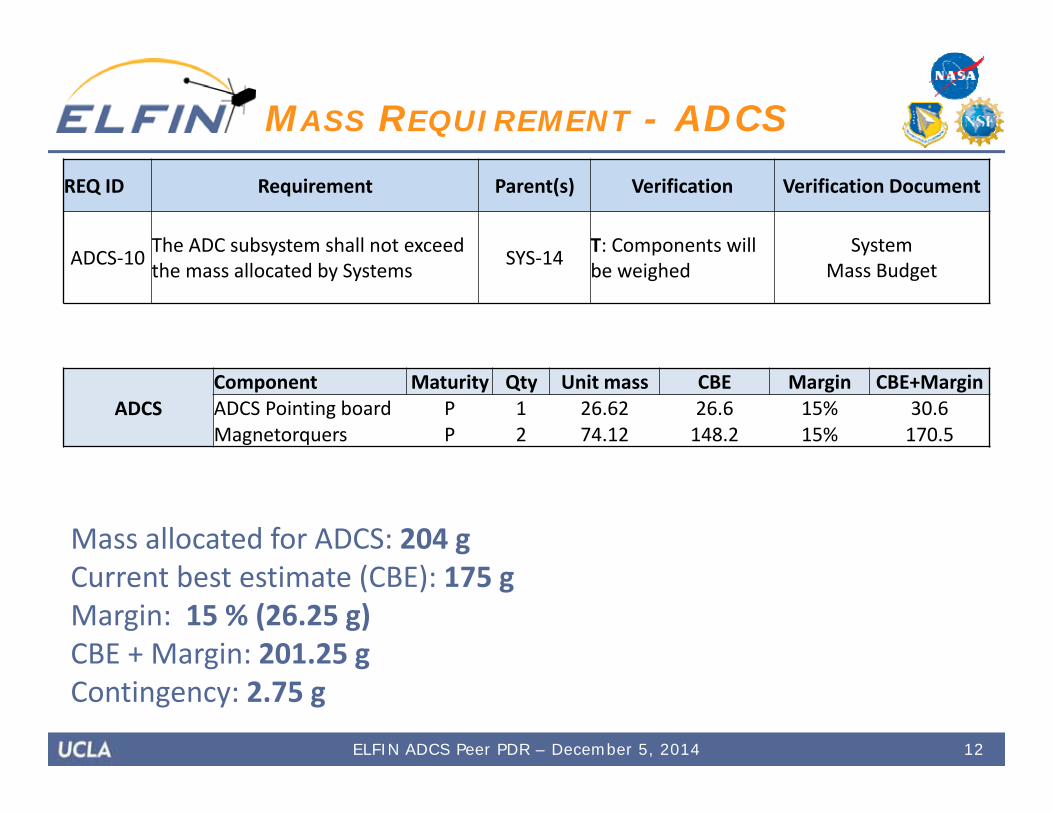
MASS REQUIREMENT - ADCSREQ ID Requirement Parent(s) Verification Verification Document
ADCS‐10 The ADC subsystem shall not exceed the mass allocated by Systems SYS‐14 T: Components will
be weighedSystem
Mass Budget
Mass allocated for ADCS: 204 gCurrent best estimate (CBE): 175 gMargin: 15 % (26.25 g)CBE + Margin: 201.25 gContingency: 2.75 g
ADCSComponent Maturity Qty Unit mass CBE Margin CBE+MarginADCS Pointing board P 1 26.62 26.6 15% 30.6Magnetorquers P 2 74.12 148.2 15% 170.5
ELFIN ADCS Peer PDR – December 5, 2014
13
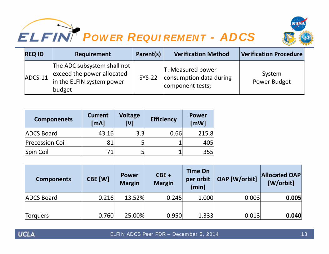
POWER REQUIREMENT - ADCSREQ ID Requirement Parent(s) Verification Method Verification Procedure
ADCS‐11
The ADC subsystem shall not exceed the power allocated in the ELFIN system power budget
SYS‐22T: Measured power consumption data during component tests;
System Power Budget
ELFIN ADCS Peer PDR – December 5, 2014
Componenets Current [mA]
Voltage [V] Efficiency Power
[mW]ADCS Board 43.16 3.3 0.66 215.8Precession Coil 81 5 1 405Spin Coil 71 5 1 355
Components CBE [W] Power Margin
CBE + Margin
Time On per orbit (min)
OAP [W/orbit] Allocated OAP [W/orbit]
ADCS Board 0.216 13.52% 0.245 1.000 0.003 0.005
Torquers 0.760 25.00% 0.950 1.333 0.013 0.040

14
ELFIN EXPLODED VIEW
ELFIN ADCS Peer PDR – December 5, 2014
ELFIN MOIs (kg m2) xx yy zz Stability Ratio
Stowed Configuration 0.006 0.030 0.034 1.13
Deployed Configuration 0.080 0.030 0.114 1.41
FGE
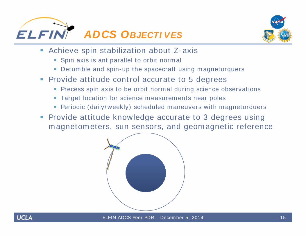
Achieve spin stabilization about Z-axis Spin axis is antiparallel to orbit normal Detumble and spin-up the spacecraft using magnetorquers
Provide attitude control accurate to 5 degrees Precess spin axis to be orbit normal during science observations Target location for science measurements near poles Periodic (daily/weekly) scheduled maneuvers with magnetorquers
Provide attitude knowledge accurate to 3 degrees using magnetometers, sun sensors, and geomagnetic reference
15
ADCS OBJECTIVES
ELFIN ADCS Peer PDR – December 5, 2014

16
ADCS OVERVIEW:SUBSYSTEM COMPONENTS
ELFIN ADCS Peer PDR – December 5, 2014

17
ADCS OVERVIEW:CLOSED-LOOP CONTROL
ELFIN ADCS Peer PDR – December 5, 2014
2 weeks
6 weeks
3 months
End ofMission
18
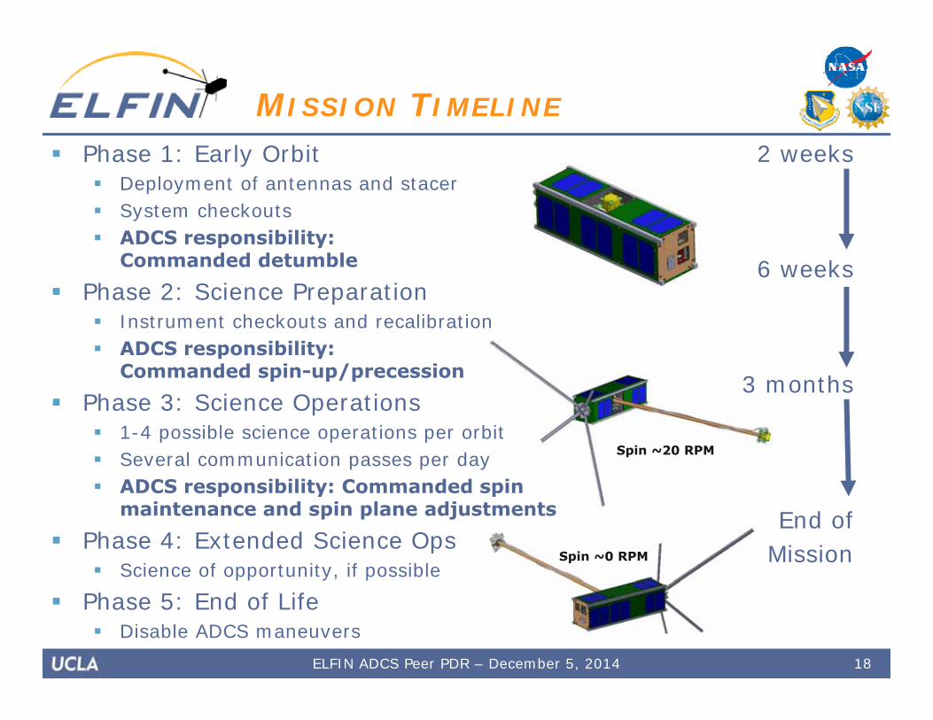
MISSION TIMELINE
Phase 1: Early Orbit Deployment of antennas and stacer System checkouts ADCS responsibility:
Commanded detumble
Phase 2: Science Preparation Instrument checkouts and recalibration ADCS responsibility:
Commanded spin-up/precession
Phase 3: Science Operations 1-4 possible science operations per orbit Several communication passes per day ADCS responsibility: Commanded spin
maintenance and spin plane adjustments
Phase 4: Extended Science Ops Science of opportunity, if possible
Phase 5: End of Life Disable ADCS maneuvers
Spin ~0 RPM
ELFIN ADCS Peer PDR – December 5, 2014
Spin ~20 RPM
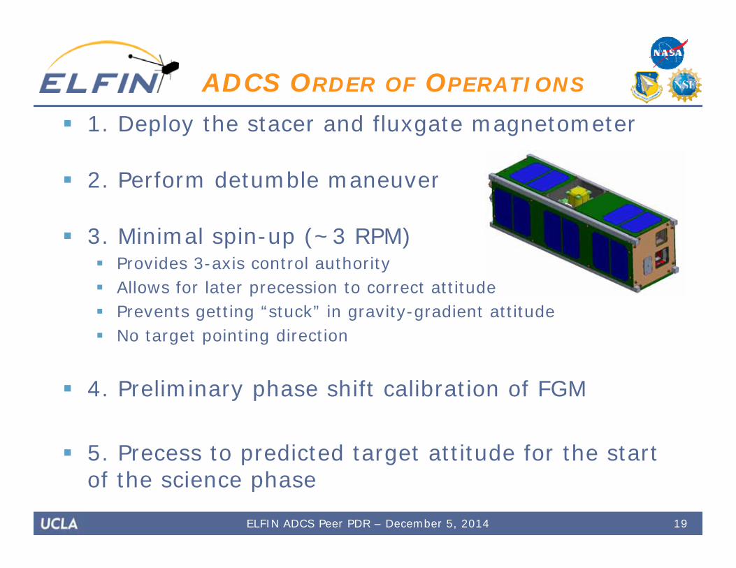
1. Deploy the stacer and fluxgate magnetometer
2. Perform detumble maneuver
3. Minimal spin-up (~3 RPM) Provides 3-axis control authority Allows for later precession to correct attitude Prevents getting “stuck” in gravity-gradient attitude No target pointing direction
4. Preliminary phase shift calibration of FGM
5. Precess to predicted target attitude for the start of the science phase
19
ADCS ORDER OF OPERATIONS
ELFIN ADCS Peer PDR – December 5, 2014
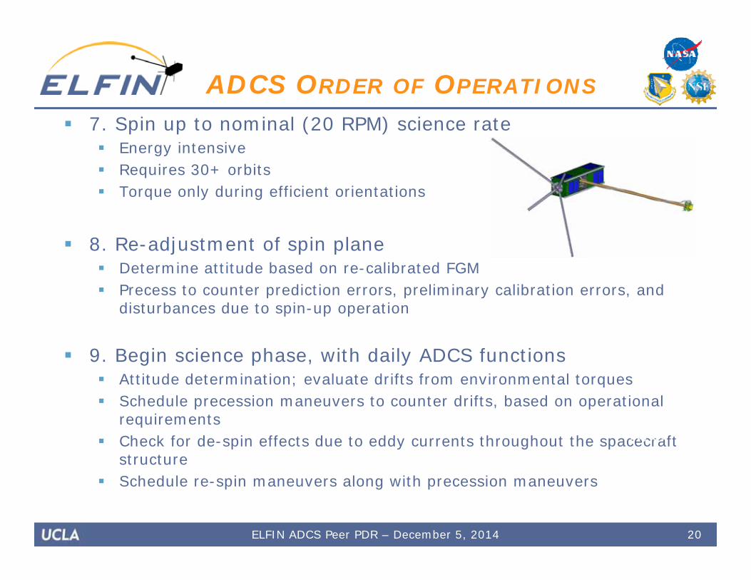
7. Spin up to nominal (20 RPM) science rate Energy intensive Requires 30+ orbits Torque only during efficient orientations
8. Re-adjustment of spin plane Determine attitude based on re-calibrated FGM Precess to counter prediction errors, preliminary calibration errors, and
disturbances due to spin-up operation
9. Begin science phase, with daily ADCS functions Attitude determination; evaluate drifts from environmental torques Schedule precession maneuvers to counter drifts, based on operational
requirements Check for de-spin effects due to eddy currents throughout the spacecraft
structure Schedule re-spin maneuvers along with precession maneuvers
20
ADCS ORDER OF OPERATIONS
Day 160
ELFIN ADCS Peer PDR – December 5, 2014

ADCS Components• Magnetorquers• Magnetometers• Fine Sun Sensors• Coarse Sun Sensors• Data Architecture
21ELFIN ADCS Peer PDR – December 5, 2014
22
Magnetorquers
ELFIN ADCS Peer PDR – December 5, 2014
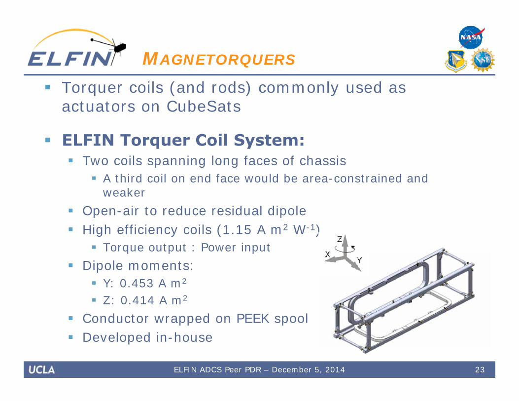
Torquer coils (and rods) commonly used as actuators on CubeSats
ELFIN Torquer Coil System: Two coils spanning long faces of chassis
A third coil on end face would be area-constrained and weaker
Open-air to reduce residual dipole High efficiency coils (1.15 A m2 W-1)
Torque output : Power input Dipole moments:
Y: 0.453 A m2
Z: 0.414 A m2
Conductor wrapped on PEEK spool Developed in-house
23
MAGNETORQUERS
ELFIN ADCS Peer PDR – December 5, 2014

System Trade: Coil Conductor Material Copper
Higher conductivity, greater magnetic moment Higher mass
Aluminum Lower mass Longer delta T to impart impulse Similar efficiency (within 5% of copper) Lower moment ADCS maneuvers take longer
Selection: Aluminum Copper remains late upscope option Concerns:
Thermal fatigue susceptibility (lower tensile strength) Electrical contact reliability
24
MAGNETORQUERS
ELFIN ADCS Peer PDR – December 5, 2014
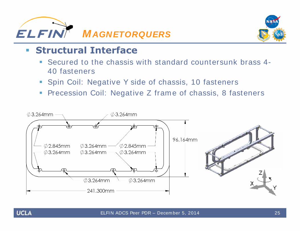
Structural Interface Secured to the chassis with standard countersunk brass 4-
40 fasteners Spin Coil: Negative Y side of chassis, 10 fasteners Precession Coil: Negative Z frame of chassis, 8 fasteners
25ELFIN ADCS Peer PDR – December 5, 2014
MAGNETORQUERS
26
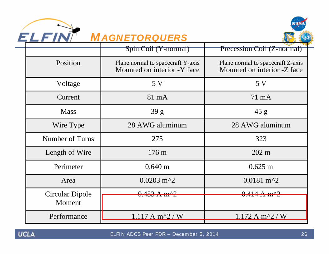
MAGNETORQUERS Spin Coil (Y-normal) Precession Coil (Z-normal)
Position Plane normal to spacecraft Y-axis Mounted on interior -Y face
Plane normal to spacecraft Z-axis Mounted on interior -Z face
Voltage 5 V 5 V
Current 81 mA 71 mA
Mass 39 g 45 g
Wire Type 28 AWG aluminum 28 AWG aluminum
Number of Turns 275 323
Length of Wire 176 m 202 m
Perimeter 0.640 m 0.625 m
Area 0.0203 m^2 0.0181 m^2
Circular Dipole Moment
0.453 A m^2 0.414 A m^2
Performance 1.117 A m^2 / W 1.172 A m^2 / W
ELFIN ADCS Peer PDR – December 5, 2014
27
ADCS Magnetometers
ELFIN ADCS Peer PDR – December 5, 2014

Magnetoresistive magnetometers (MRM) Enable low-field magnetic sensing Primary sensor to determine orientation
relative to Earth’s magnetic field Only sensor type within closed-loop controller
Honeywell HMC5883L 3-Axis Digital Compass 1 unit on ADCS control board and 1 unit on
IDPU board Low power consumption Self-test and temperature compensation
capability Digital interface to ADCS peripheral controller
28
ADCS MAGNETOMETERS
ELFIN ADCS Peer PDR – December 5, 2014
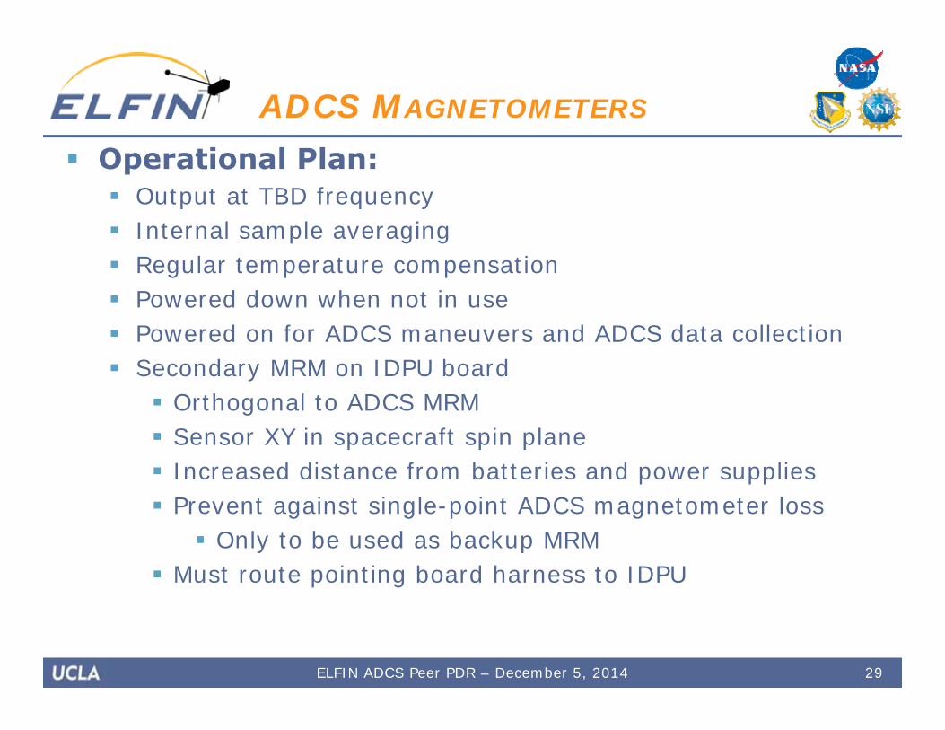
Operational Plan: Output at TBD frequency Internal sample averaging Regular temperature compensation Powered down when not in use Powered on for ADCS maneuvers and ADCS data collection Secondary MRM on IDPU board
Orthogonal to ADCS MRM Sensor XY in spacecraft spin plane Increased distance from batteries and power supplies Prevent against single-point ADCS magnetometer loss
Only to be used as backup MRM Must route pointing board harness to IDPU
29
ADCS MAGNETOMETERS
ELFIN ADCS Peer PDR – December 5, 2014
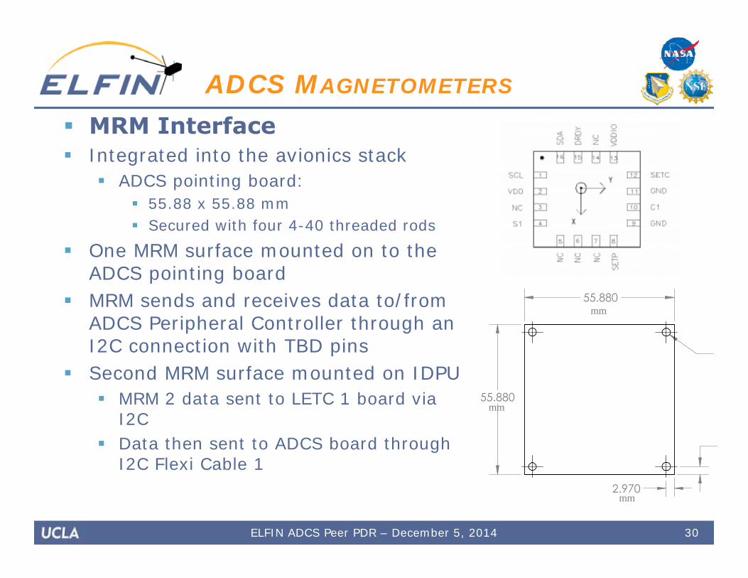
MRM Interface Integrated into the avionics stack
ADCS pointing board: 55.88 x 55.88 mm Secured with four 4-40 threaded rods
One MRM surface mounted on to the ADCS pointing board
MRM sends and receives data to/from ADCS Peripheral Controller through an I2C connection with TBD pins
Second MRM surface mounted on IDPU MRM 2 data sent to LETC 1 board via
I2C Data then sent to ADCS board through
I2C Flexi Cable 1
30
ADCS MAGNETOMETERS
ELFIN ADCS Peer PDR – December 5, 2014
mm
mm
mm
31ELFIN ADCS Peer PDR – December 5, 2014
ADCS MAGNETOMETERS
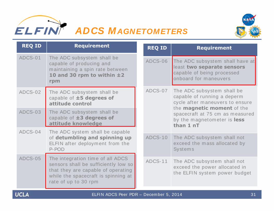
REQ ID Requirement
ADCS-01 The ADC subsystem shall be capable of producing and maintaining a spin rate between 10 and 30 rpm to within ±2 rpm
ADCS-02 The ADC subsystem shall be capable of ±5 degrees of attitude control
ADCS-03 The ADC subsystem shall be capable of ±3 degrees of attitude knowledge
ADCS-04 The ADC system shall be capable of detumbling and spinning upELFIN after deployment from the P-POD
ADCS-05 The integration time of all ADCS sensors shall be sufficiently low so that they are capable of operating while the spacecraft is spinning at rate of up to 30 rpm
REQ ID Requirement
ADCS-06 The ADC subsystem shall have at least two separate sensorscapable of being processed onboard for maneuvers
ADCS-07 The ADC subsystem shall be capable of running a depermcycle after maneuvers to ensure the magnetic moment of the spacecraft at 75 cm as measured by the magnetometer is less than 1 nT
ADCS-10 The ADC subsystem shall not exceed the mass allocated by Systems
ADCS-11 The ADC subsystem shall not exceed the power allocated in the ELFIN system power budget
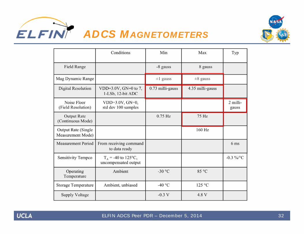
32
ADCS MAGNETOMETERS
ELFIN ADCS Peer PDR – December 5, 2014

33
Fine Sun Sensor (FSS)
ELFIN ADCS Peer PDR – December 5, 2014

Sensor: SD085 Quadphotodiode Primary purpose is to detect sun to
prevent oversaturation of EPD-I Not part of closed-loop ADCS
controller Aids in determining spacecraft
attitude during ground-side analysis
34
FINE SUN SENSOR (FSS)
ELFIN ADCS Peer PDR – December 5, 2014
35
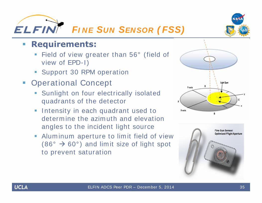
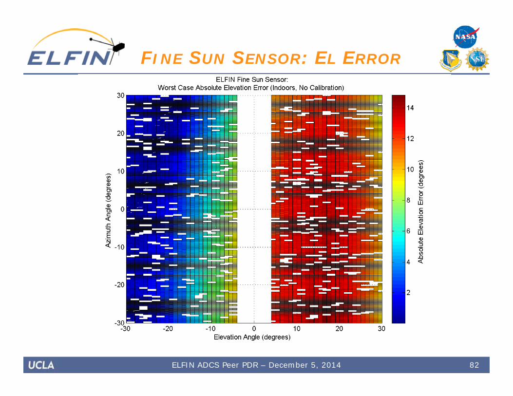
FINE SUN SENSOR (FSS) Requirements:
Field of view greater than 56° (field of view of EPD-I)
Support 30 RPM operation Operational Concept
Sunlight on four electrically isolated quadrants of the detector
Intensity in each quadrant used to determine the azimuth and elevation angles to the incident light source
Aluminum aperture to limit field of view (86° 60°) and limit size of light spot to prevent saturation
ELFIN ADCS Peer PDR – December 5, 2014

Interface Quadphotodiode (SD085) with ADC (ADS1115) Custom aluminum aperture Mounted to positive X face w/ 2 standard 2-56 brass screws Connects directly to IDPU via a 10 contact card edge (uses 6
edges)
36
FINE SUN SENSOR (FSS)
ELFIN ADCS Peer PDR – December 5, 2014
37
Coarse Sun Sensors
ELFIN ADCS Peer PDR – December 5, 2014

Operational Concept: Simple photodiodes to provide additional attitude
information (not used in closed-loop controller) Redundancy for information about illumination of solar
panels Much lower resolution than FSS, but higher coverage
Simple photodiode vs. 4-quadrant sensor 2 photodiodes on +Z, 2 photodiodes on –Z 1 photodiode on +Y, 1 photodiode on –Y (in spin plane)
Interface: Surface mounted to interior surface of each exterior panel Mounted along with ADCs (ADS1115S) Connected to ADCS board with Kapton flexi cable
38
COARSE SUN SENSORS
ELFIN ADCS Peer PDR – December 5, 2014
ADCS Data Architecture
39ELFIN ADCS Peer PDR – December 5, 2014

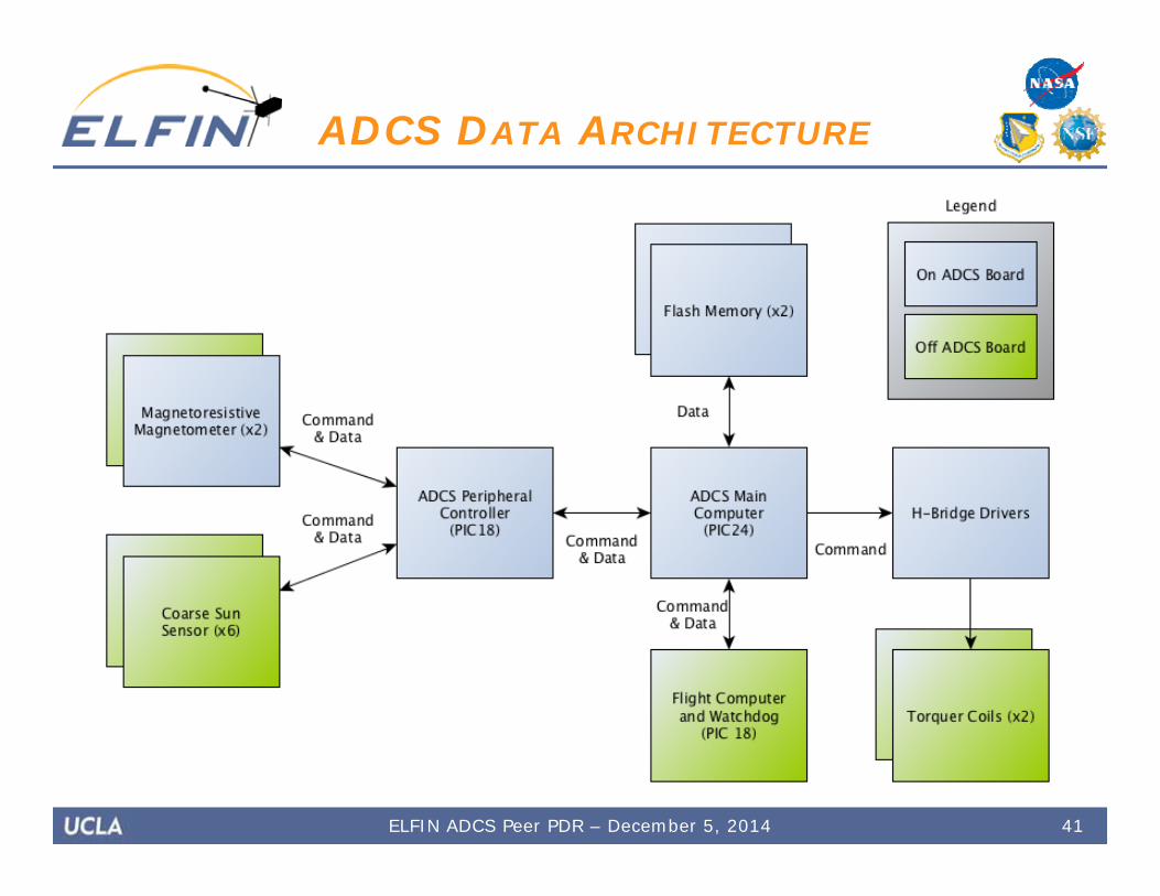
ADCS subsystem interfaces with the flight computer and watchdog UART connections on ADCS Main (PIC24)
Connection has interrupt capabilities
ADCS board connects to boards in the avionics stack ADCS Main (PIC24) connects to:
ADCS Peripheral Controller (PIC18) Connected by UART with interrupt capabilities
Two sets of flash memory (AT45) via SPI Two torquer coils
H-Bridges to allow the current flow to be reversed
Torquer current sensor Analog connection to ADCS Main
ADCS Peripheral Controller connects to sensors (I2C)
40
ADCS DATA ARCHITECTURE
ELFIN ADCS Peer PDR – December 5, 2014
41
ADCS DATA ARCHITECTURE
ELFIN ADCS Peer PDR – December 5, 2014

42
ADCS DATA ARCHITECTURE
ELFIN ADCS Peer PDR – December 5, 2014
ADCS Control Logic
• Detumble and Spin-Up• Precession Control• Control Analyses• Closed-Loop Controller
43ELFIN ADCS Peer PDR – December 5, 2014
Detumble and Spin-Up
44ELFIN ADCS Peer PDR – December 5, 2014
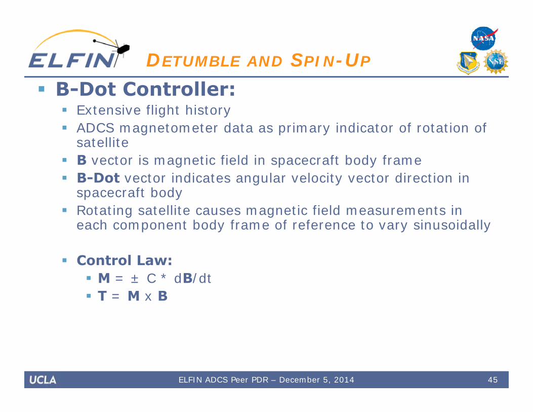
B-Dot Controller: Extensive flight history ADCS magnetometer data as primary indicator of rotation of
satellite B vector is magnetic field in spacecraft body frame B-Dot vector indicates angular velocity vector direction in
spacecraft body Rotating satellite causes magnetic field measurements in
each component body frame of reference to vary sinusoidally
Control Law: M = ± C * dB/dt T = M x B
45
DETUMBLE AND SPIN-UP
ELFIN ADCS Peer PDR – December 5, 2014

Detumble M = - C * dB/dt T = M x B Control brings the rate of change of B in the spacecraft
body frame to zero Energy is removed from the system Initial detumble and spin maintenance (dampening of
incurred rates in X and Y)
Image source: B. Young, Design and Specification of an Attitude Control System for the DANDE Mission
46
DETUMBLE AND SPIN-UP
ELFIN ADCS Peer PDR – December 5, 2014

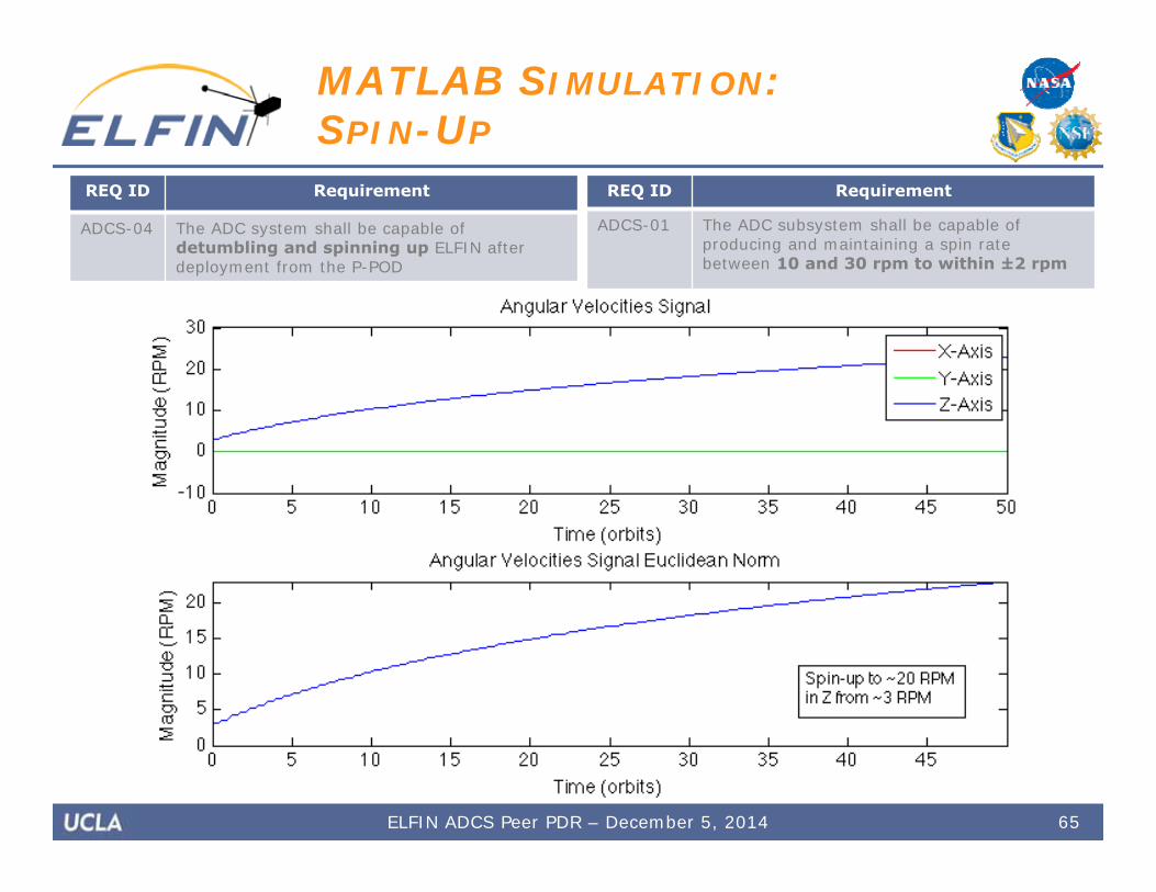
Spin-Up M = + C * dB/dt T = M x B Control increases the rate of change of B in the spacecraft
body frame Energy is added to the system Initial spin-up to nominal rate and spin maintenance
(restoring Z rate after gradual dampening)
47
DETUMBLE AND SPIN-UP
Image source: B. Young, Design and Specification of an Attitude Control System for the DANDE Mission
ELFIN ADCS Peer PDR – December 5, 2014
Precession Control
48ELFIN ADCS Peer PDR – December 5, 2014
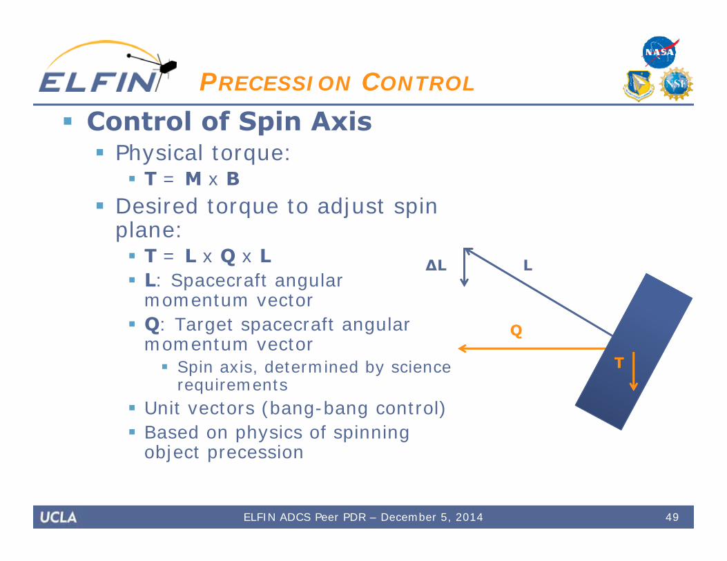
Control of Spin Axis Physical torque:
T = M x B Desired torque to adjust spin
plane: T = L x Q x L L: Spacecraft angular
momentum vector Q: Target spacecraft angular
momentum vector Spin axis, determined by science
requirements Unit vectors (bang-bang control) Based on physics of spinning
object precession
49
PRECESSION CONTROL
L∆L
Q
T
ELFIN ADCS Peer PDR – December 5, 2014
Control of Spin Axis Operational concept:
Ground-based calculation of phase offset to torque Dogleg maneuver if necessary Push complexity to the ground
Attitude determination Spin axis control
Analytical and simulation methods to calculate offsets Transmit phase offsets relative to zero crossing to
spacecraft during comm pass Decrease complexity of on-board software
Control logic remains simple and general Same fundamental zero-crossing detection code as B-Dot
Timing parameters utilized to generalize control law Time delay from zero crossing to torque Torque time
50
PRECESSION CONTROL
ELFIN ADCS Peer PDR – December 5, 2014

Control Analyses
51ELFIN ADCS Peer PDR – December 5, 2014
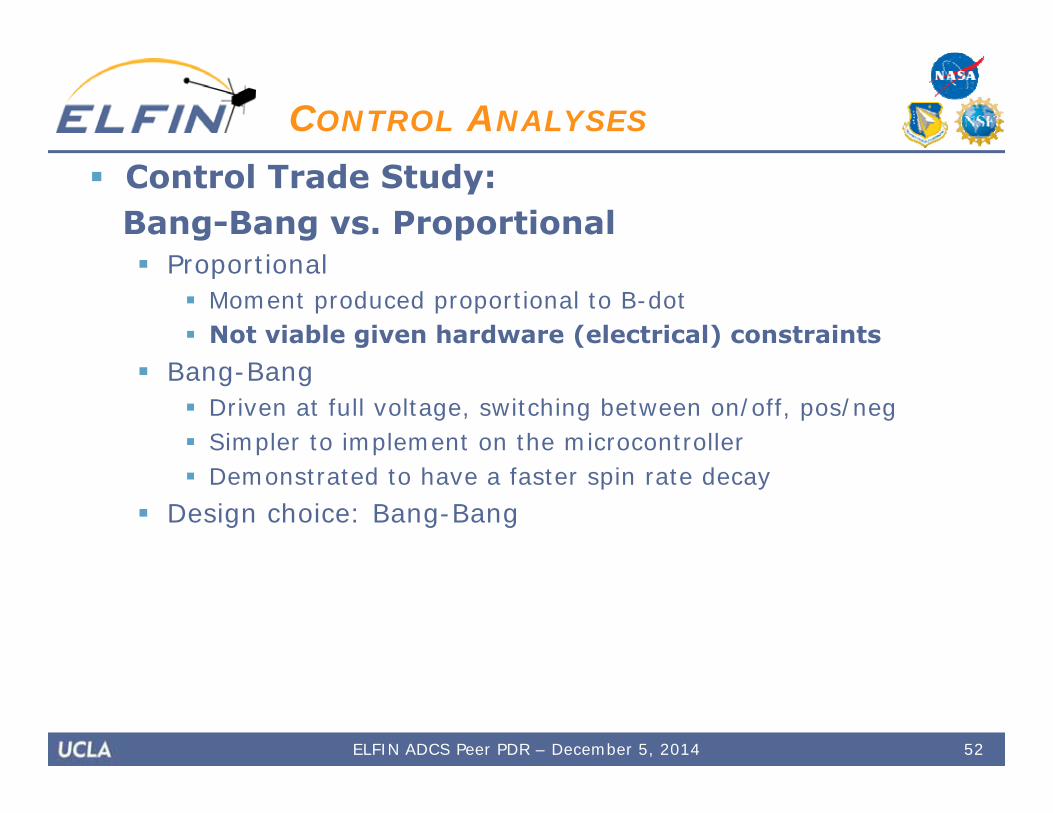
Control Trade Study: Bang-Bang vs. Proportional Proportional
Moment produced proportional to B-dot Not viable given hardware (electrical) constraints
Bang-Bang Driven at full voltage, switching between on/off, pos/neg Simpler to implement on the microcontroller Demonstrated to have a faster spin rate decay
Design choice: Bang-Bang
52
CONTROL ANALYSES
ELFIN ADCS Peer PDR – December 5, 2014

Control Trade Study: Three-Axis vs. Two-Axis Three-Axis
One additional dimension in the space of possible dipole moments produced by magnetorquers (simpler control)
Third coil would be inefficient due to the geometry limitations of the 3U CubeSat
Volume constraints in ELFIN spacecraft limit feasibility of third coil
Two-Axis Control mechanism is still viable
Can use dogleg maneuver to re-orient Both coils are power efficient Space efficient
Design choice: Two-Axis
53
CONTROL ANALYSES
ELFIN ADCS Peer PDR – December 5, 2014

Viability of Two-Axis Control T = M x B Each coil can produce a torque in its
plane Between the two coils, the torque-
space is all 3 dimensions (dependent on B geometry)
B geometry changes over an orbit B geometry within s/c reference
frame constantly changes with spin A torque can always be produced
If B is parallel with one axis, it is perpendicular to another
If B is parallel to X-axis, either coil can be used to effectively torque
54
CONTROL ANALYSES
ELFIN ADCS Peer PDR – December 5, 2014
ADCS Simulations
• MATLAB & Simulink Simulation• Hardware LabVIEW Simuation• Sensor Testing
55ELFIN ADCS Peer PDR – December 5, 2014
MATLAB & Simulink Simulation
56ELFIN ADCS Peer PDR – December 5, 2014
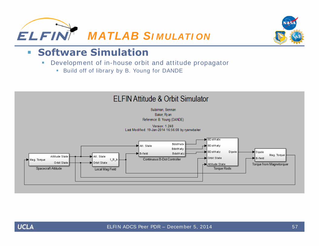
Software Simulation Development of in-house orbit and attitude propagator
Build off of library by B. Young for DANDE
57
MATLAB SIMULATION
ELFIN ADCS Peer PDR – December 5, 2014

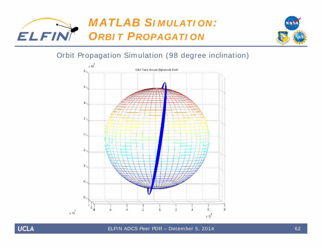
Orbit Propagation Propagate R and V vectors dR/dt = V dV/dt is a result of various effects
Gravitational motion (two body problem) Oblateness of earth (non-spherically symmetric field) Atmospheric drag
58
MATLAB SIMULATION
ELFIN ADCS Peer PDR – December 5, 2014

Attitude Propagation Propagated state vector:
Attitude quaternion Characterizes rotation from ECI to
body frame Angular velocity
Quaternion mathematics: Scalar element coupled with a
3D vector Convenient computationally Excellent representation of
rotations in 3D space Model: Euler’s equations of motion
for a rigid body Solved numerically with ode45
Runge-Kutta solver, variable time step
59
MATLAB SIMULATION
ELFIN ADCS Peer PDR – December 5, 2014
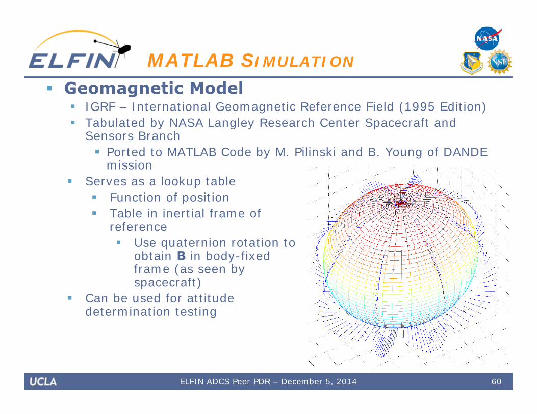
Geomagnetic Model IGRF – International Geomagnetic Reference Field (1995 Edition) Tabulated by NASA Langley Research Center Spacecraft and
Sensors Branch Ported to MATLAB Code by M. Pilinski and B. Young of DANDE
mission Serves as a lookup table
Function of position Table in inertial frame of
reference Use quaternion rotation to
obtain B in body-fixedframe (as seen byspacecraft)
Can be used for attitudedetermination testing
60
MATLAB SIMULATION
ELFIN ADCS Peer PDR – December 5, 2014

Control Block Processing of sensor data & control law logic Implements B-Dot Control and Precession Control
Continuous time: transfer function w/ low-pass filter Discretized for controller implementation
Additional features: “Half duplex” cycle, noise, discretization of signal Latitude threshold: torque only near the equator Constant dipole moment amplitude from coils
61
MATLAB SIMULATION
ELFIN ADCS Peer PDR – December 5, 2014
62
MATLAB SIMULATION:ORBIT PROPAGATION
ELFIN ADCS Peer PDR – December 5, 2014
Orbit Propagation Simulation (98 degree inclination)

63
MATLAB SIMULATION:MAGNETOMETER READINGS
ELFIN ADCS Peer PDR – December 5, 2014
Magnetic Field
B-Dot Reading
B-Dot Estimate
Coordinate system: spacecraft body frame
Magnetometer Reading Simulation, Noiseless

MATLAB SIMULATION: DETUMBLE
64
REQ ID Requirement
ADCS-04 The ADC system shall be capable of detumbling and spinning up ELFIN after deployment from the P-POD
ELFIN ADCS Peer PDR – December 5, 2014
MATLAB SIMULATION:SPIN-UP
65ELFIN ADCS Peer PDR – December 5, 2014
REQ ID Requirement
ADCS-04 The ADC system shall be capable of detumbling and spinning up ELFIN after deployment from the P-POD
REQ ID Requirement
ADCS-01 The ADC subsystem shall be capable of producing and maintaining a spin rate between 10 and 30 rpm to within ±2 rpm
MATLAB SIMULATION:SPIN RATE MAINTENANCE
66ELFIN ADCS Peer PDR – December 5, 2014
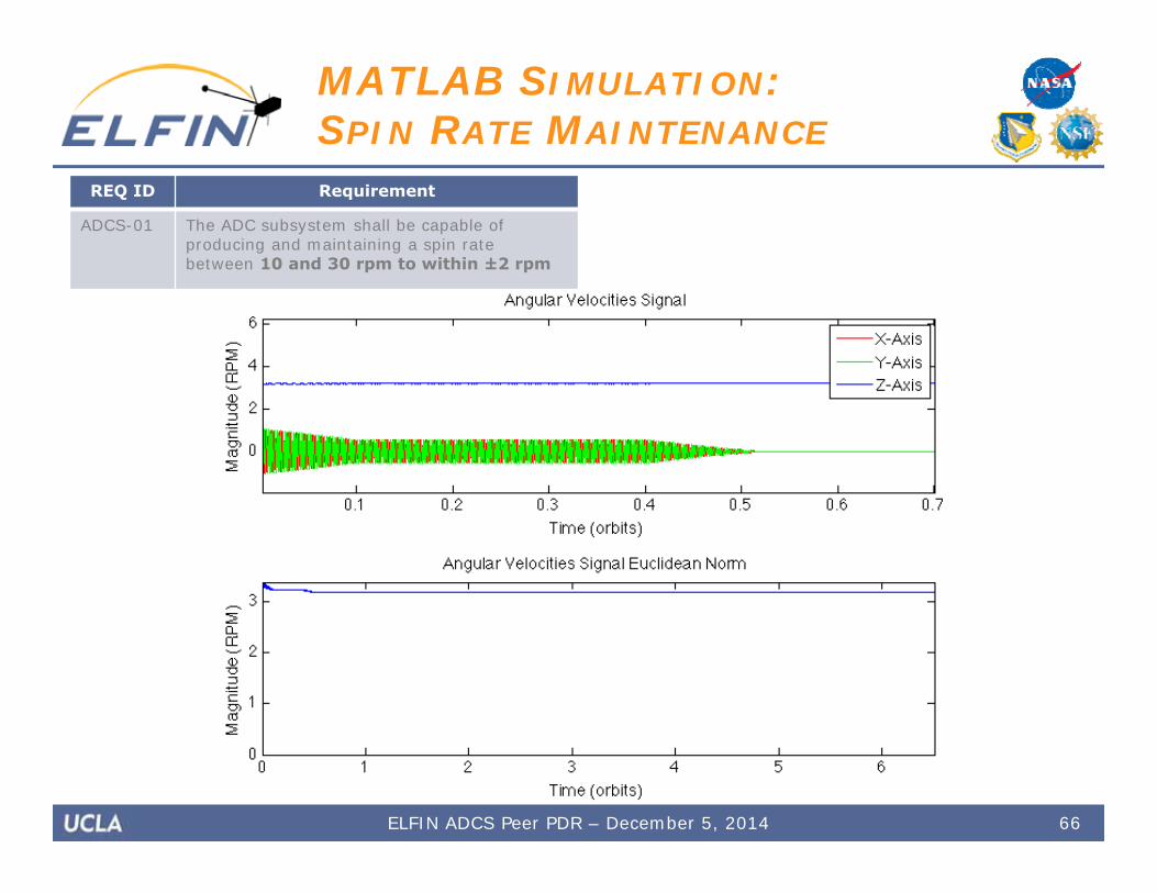
REQ ID Requirement
ADCS-01 The ADC subsystem shall be capable of producing and maintaining a spin rate between 10 and 30 rpm to within ±2 rpm
67ELFIN ADCS Peer PDR – December 5, 2014
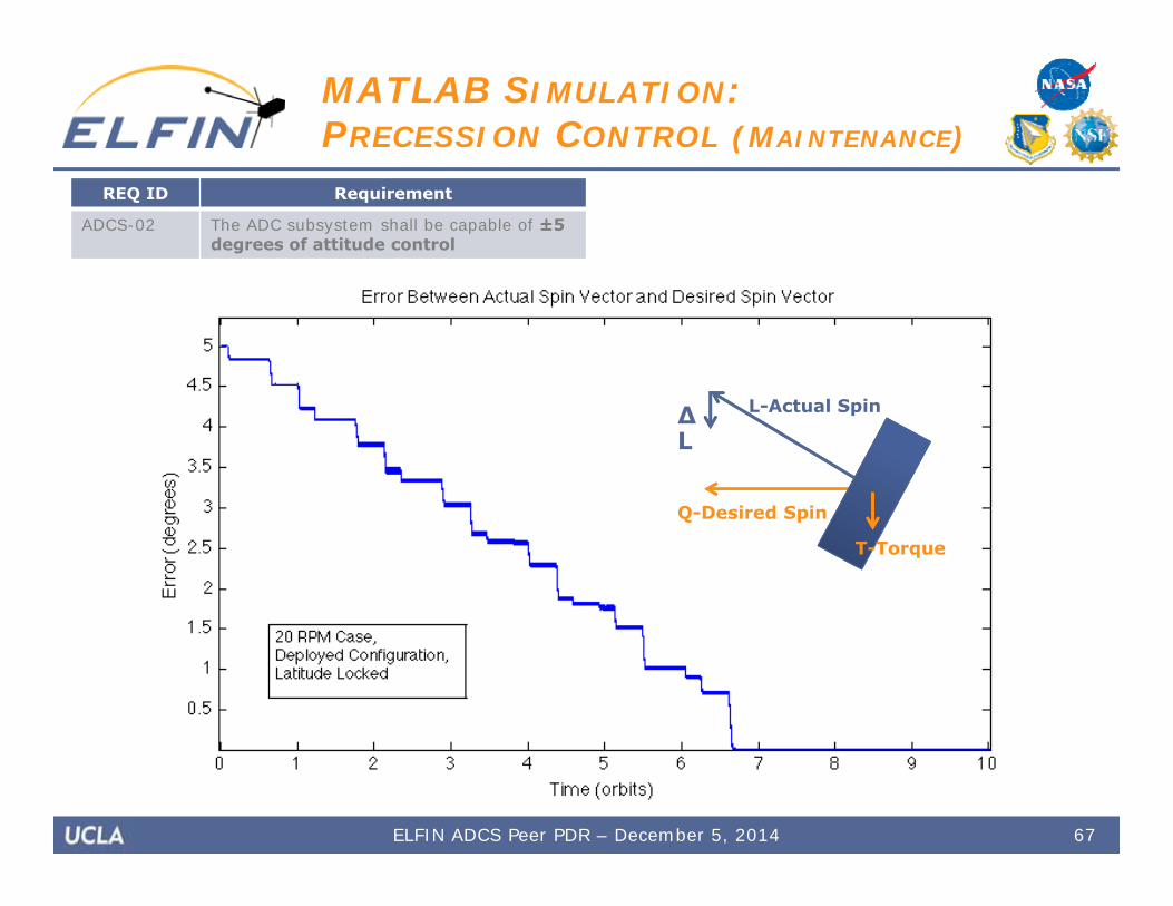
MATLAB SIMULATION:PRECESSION CONTROL (MAINTENANCE)
REQ ID Requirement
ADCS-02 The ADC subsystem shall be capable of ±5 degrees of attitude control
L-Actual Spin∆L
Q-Desired Spin
T-Torque

MATLAB SIMULATION:PRECESSION CONTROL (LARGE ANGLE)
68
L-Actual Spin∆L
Q-Desired Spin
T-Torque
ELFIN ADCS Peer PDR – December 5, 2014
REQ ID Requirement
ADCS-02 The ADC subsystem shall be capable of ±5 degrees of attitude control
69ELFIN ADCS Peer PDR – December 5, 2014
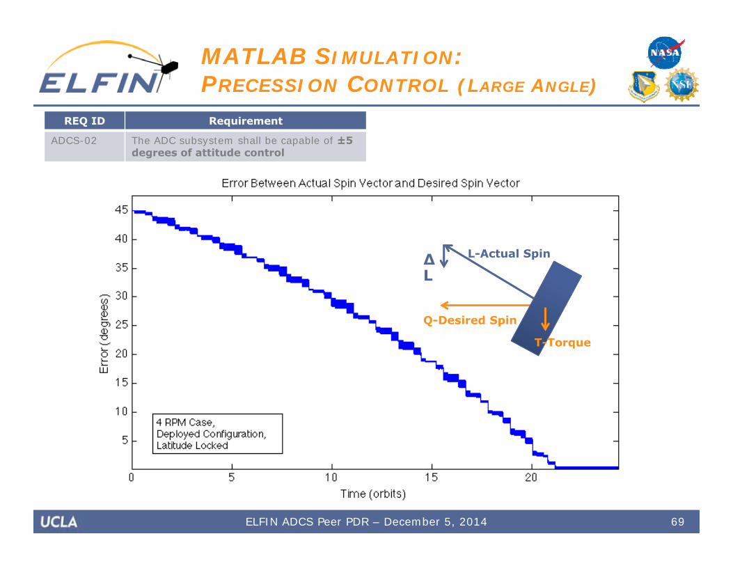
MATLAB SIMULATION:PRECESSION CONTROL (LARGE ANGLE)
REQ ID Requirement
ADCS-02 The ADC subsystem shall be capable of ±5 degrees of attitude control
L-Actual Spin∆L
Q-Desired Spin
T-Torque

Hardware-in-the-Loop Simulations
70ELFIN ADCS Peer PDR – December 5, 2014
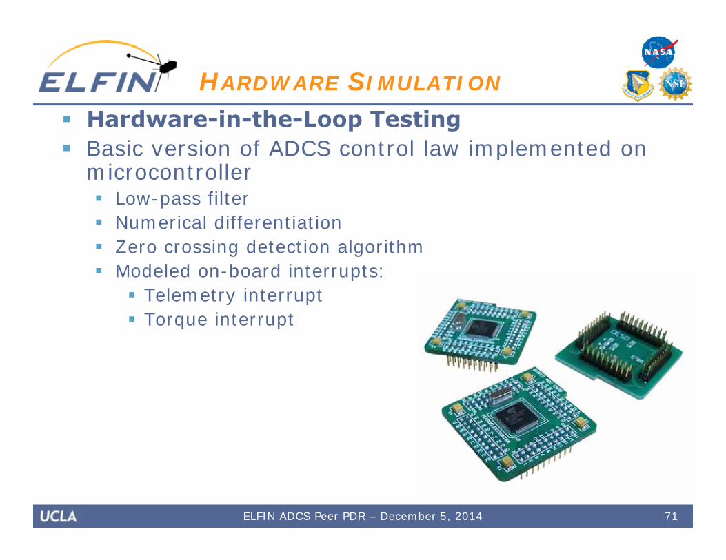
Hardware-in-the-Loop Testing Basic version of ADCS control law implemented on
microcontroller Low-pass filter Numerical differentiation Zero crossing detection algorithm Modeled on-board interrupts:
Telemetry interrupt Torque interrupt
71
HARDWARE SIMULATION
ELFIN ADCS Peer PDR – December 5, 2014
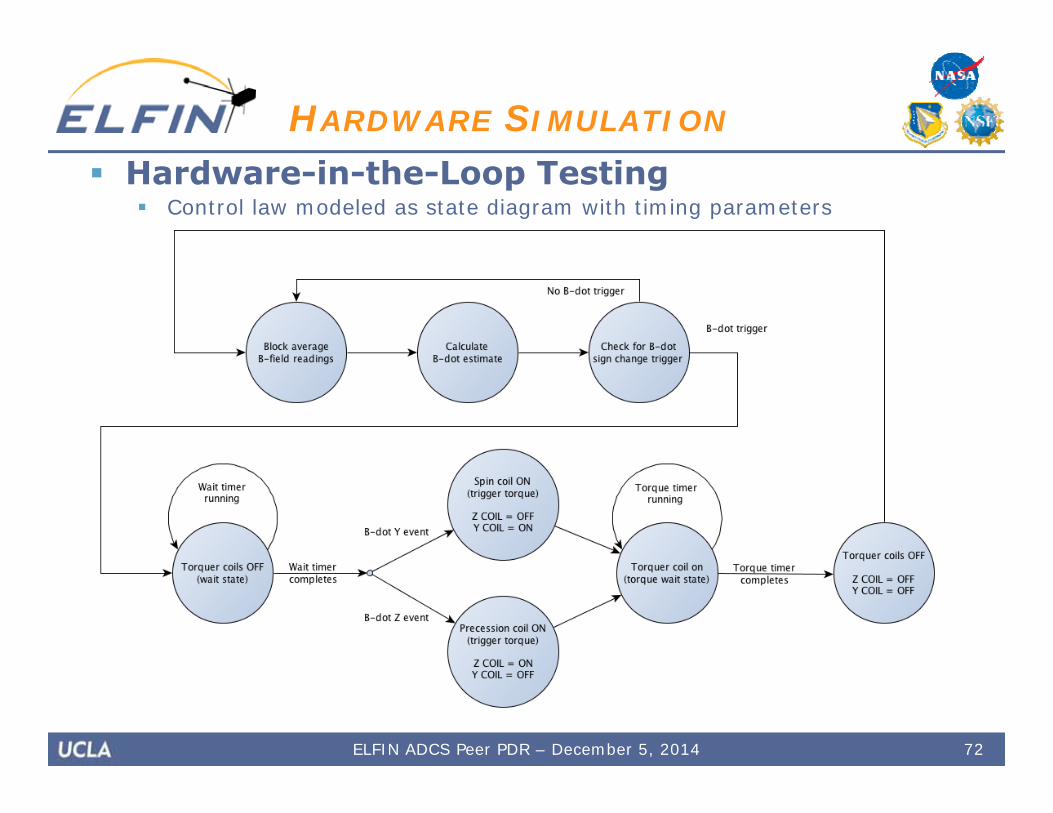
Hardware-in-the-Loop Testing Control law modeled as state diagram with timing parameters
72
HARDWARE SIMULATION
ELFIN ADCS Peer PDR – December 5, 2014
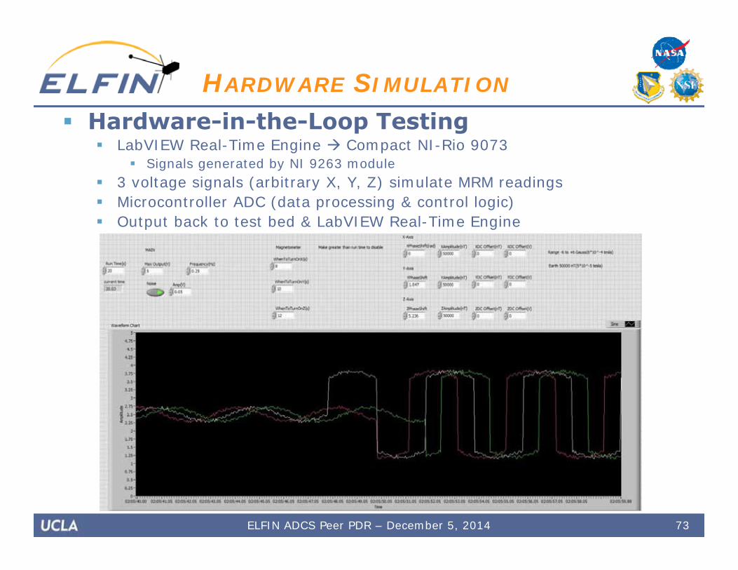
Hardware-in-the-Loop Testing LabVIEW Real-Time Engine Compact NI-Rio 9073
Signals generated by NI 9263 module 3 voltage signals (arbitrary X, Y, Z) simulate MRM readings Microcontroller ADC (data processing & control logic) Output back to test bed & LabVIEW Real-Time Engine
73
HARDWARE SIMULATION
ELFIN ADCS Peer PDR – December 5, 2014
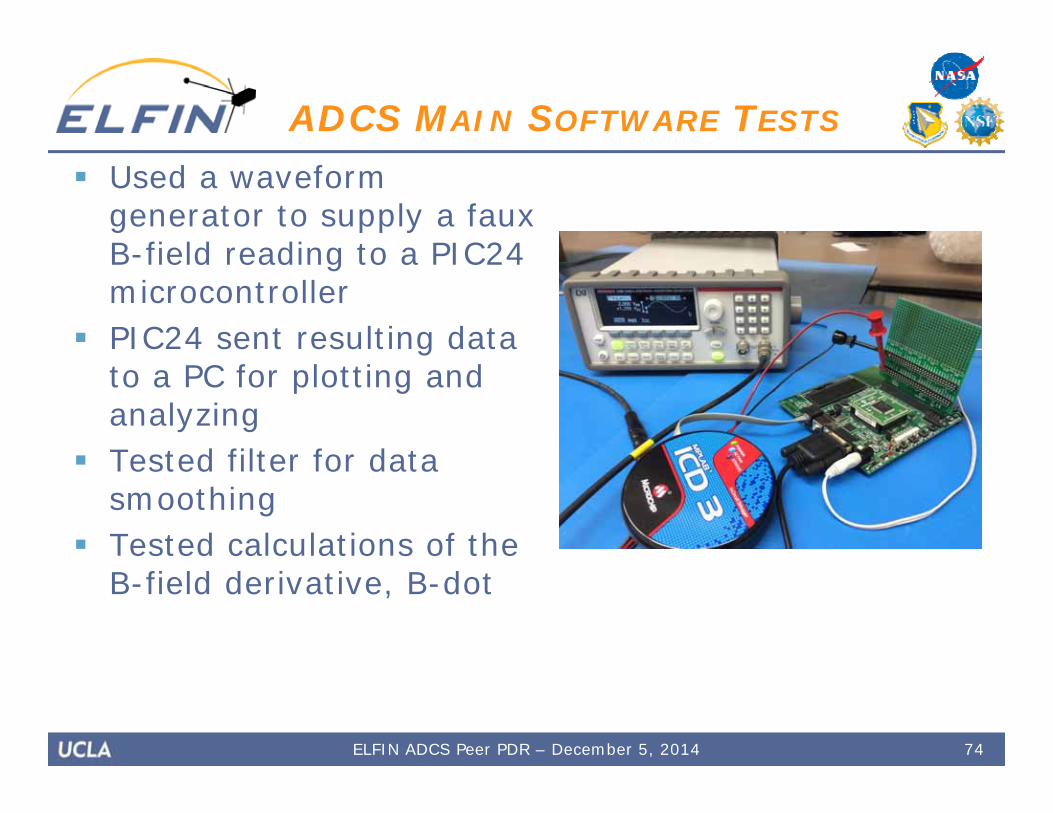
ADCS MAIN SOFTWARE TESTS
Used a waveform generator to supply a faux B-field reading to a PIC24 microcontroller
PIC24 sent resulting data to a PC for plotting and analyzing
Tested filter for data smoothing
Tested calculations of the B-field derivative, B-dot
ELFIN ADCS Peer PDR – December 5, 2014 74
75
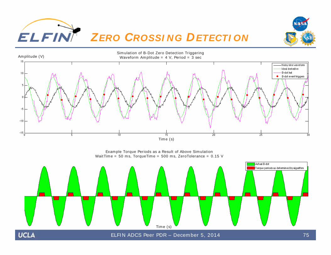
ZERO CROSSING DETECTION
ELFIN ADCS Peer PDR – December 5, 2014
Time (s)
Amplitude (V)
Time (s)
Example Torque Periods as a Result of Above SimulationWaitTime = 50 ms, TorqueTime = 500 ms, ZeroTolerance = 0.15 V
Simulation of B-Dot Zero Detection TriggeringWaveform Amplitude = 4 V, Period = 3 sec
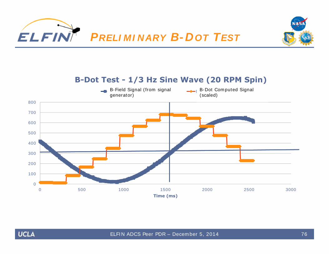
PRELIMINARY B-DOT TEST
0 500 1000 1500 2000 2500 30000
100
200
300
400
500
600
700
800
Time (ms)
B-Dot Test - 1/3 Hz Sine Wave (20 RPM Spin)Faux B-field reading (smoothed) B-dot (scaked)B-Field Signal (from signal generator)
B-Dot Computed Signal (scaled)
ELFIN ADCS Peer PDR – December 5, 2014 76
Sensor Testing
77ELFIN ADCS Peer PDR – December 5, 2014
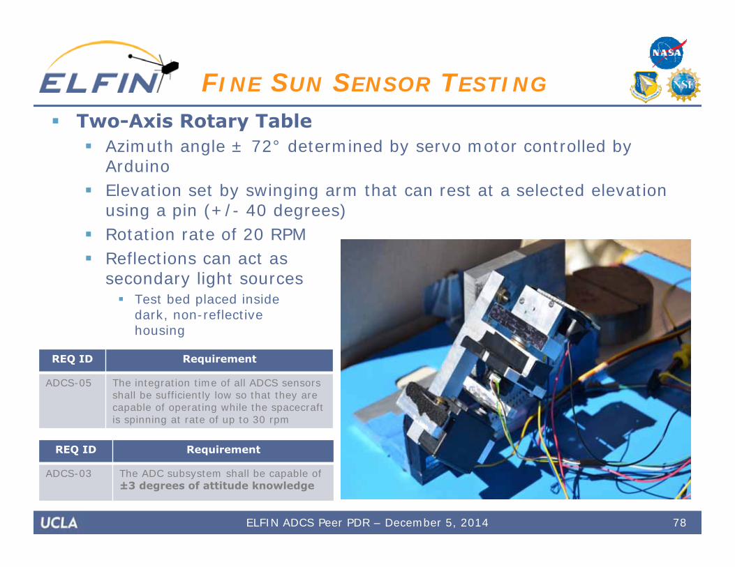
Two-Axis Rotary Table Azimuth angle ± 72° determined by servo motor controlled by
Arduino Elevation set by swinging arm that can rest at a selected elevation
using a pin (+/- 40 degrees) Rotation rate of 20 RPM Reflections can act as
secondary light sources Test bed placed inside
dark, non-reflectivehousing
78
FINE SUN SENSOR TESTING
ELFIN ADCS Peer PDR – December 5, 2014
REQ ID Requirement
ADCS-05 The integration time of all ADCS sensors shall be sufficiently low so that they are capable of operating while the spacecraft is spinning at rate of up to 30 rpm
REQ ID Requirement
ADCS-03 The ADC subsystem shall be capable of ±3 degrees of attitude knowledge
79
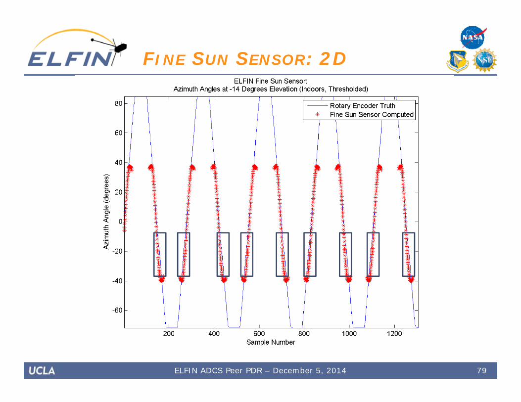
FINE SUN SENSOR: 2D
ELFIN ADCS Peer PDR – December 5, 2014
80
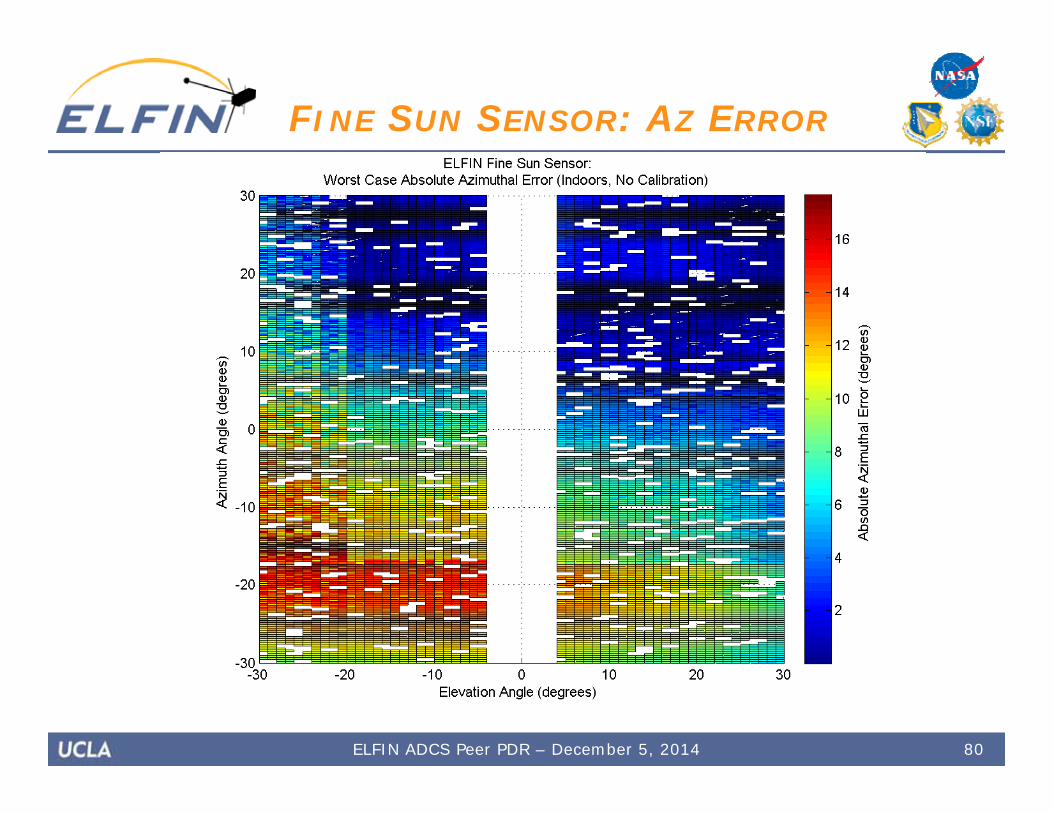
FINE SUN SENSOR: AZ ERROR
ELFIN ADCS Peer PDR – December 5, 2014
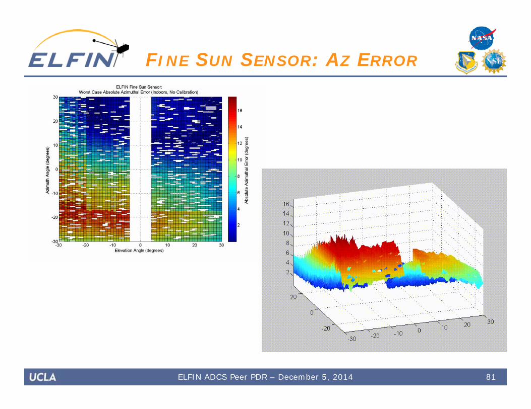
81
FINE SUN SENSOR: AZ ERROR
ELFIN ADCS Peer PDR – December 5, 2014
82
FINE SUN SENSOR: EL ERROR
ELFIN ADCS Peer PDR – December 5, 2014
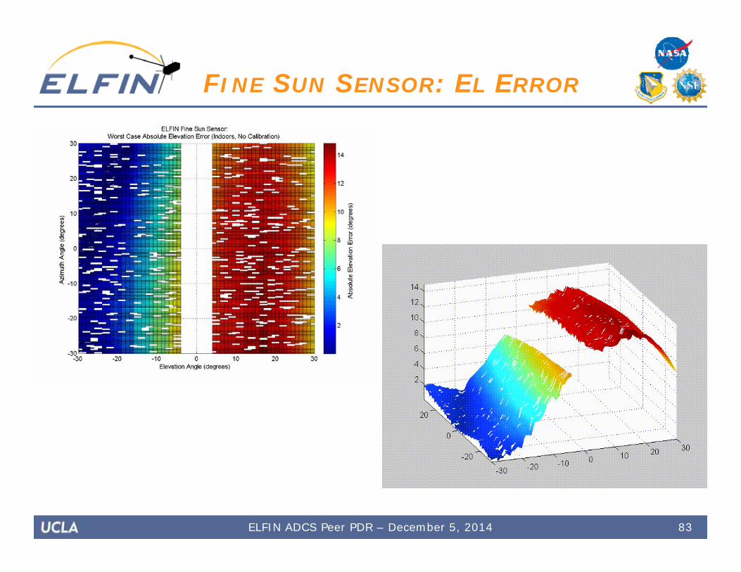
83
FINE SUN SENSOR: EL ERROR
ELFIN ADCS Peer PDR – December 5, 2014

84
ADCS Schedule andFuture Testing
ELFIN ADCS Peer PDR – December 5, 2014

85
ADCS FUTURE WORK
Day 160
Additional hardware-in-the-loop testing Quantitative analysis of microcontroller implementation of
control algorithms using testbed Implement closed-loop feedback in testbed
Stim testing including use of Helmholtz coil, adding ADCS magnetometer to the test loop
Continue developing sensor test platform to investigate ability of hardware to handle 30 RPM case
Sun sensor testing with full automation FCR Demo NASA Marshall Brain in a Jar Testing EyasSat Hamster Ball Testing
ELFIN ADCS Peer PDR – December 5, 2014

86
ADCS FUTURE WORK
FCR Demo:
ELFIN ADCS Peer PDR – December 5, 2014
87
ADCS FUTURE WORK
Day 160
NASA Marshall Brain in a Jar Testing: LabVIEW and STK package (physical box) Attitude and orbit propagator built in Visualizations and fault conditions incorporated Output is IMU data
Extract magnetometer data Plug in via I2C to ADCS pointing board
Output from ADCS pointing board Input to package to incorporate torquer coil feedback
Free, but on loan Would have to schedule with NASA Marshall and adapt to
their system
ELFIN ADCS Peer PDR – December 5, 2014
88
ADCS FUTURE WORK
Day 160
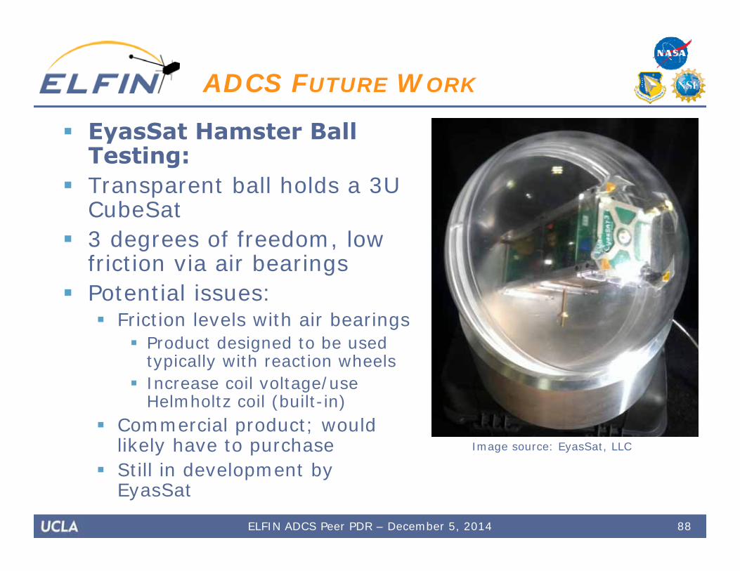
EyasSat Hamster Ball Testing:
Transparent ball holds a 3U CubeSat
3 degrees of freedom, low friction via air bearings
Potential issues: Friction levels with air bearings
Product designed to be used typically with reaction wheels
Increase coil voltage/use Helmholtz coil (built-in)
Commercial product; would likely have to purchase
Still in development by EyasSat
ELFIN ADCS Peer PDR – December 5, 2014
Image source: EyasSat, LLC
89
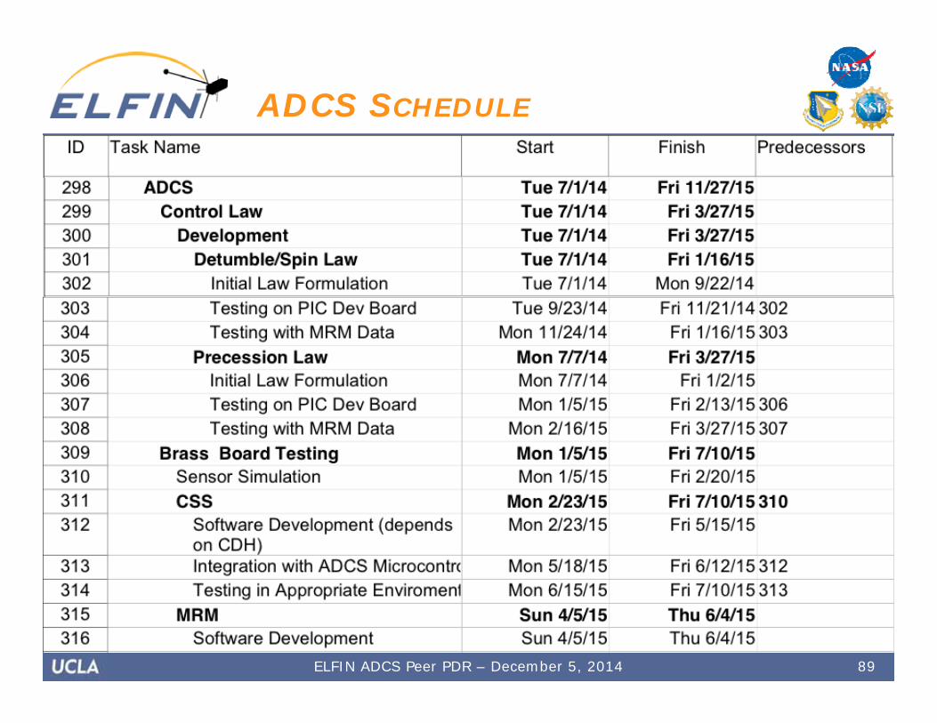
ADCS SCHEDULE
Day 160
ELFIN ADCS Peer PDR – December 5, 2014
90
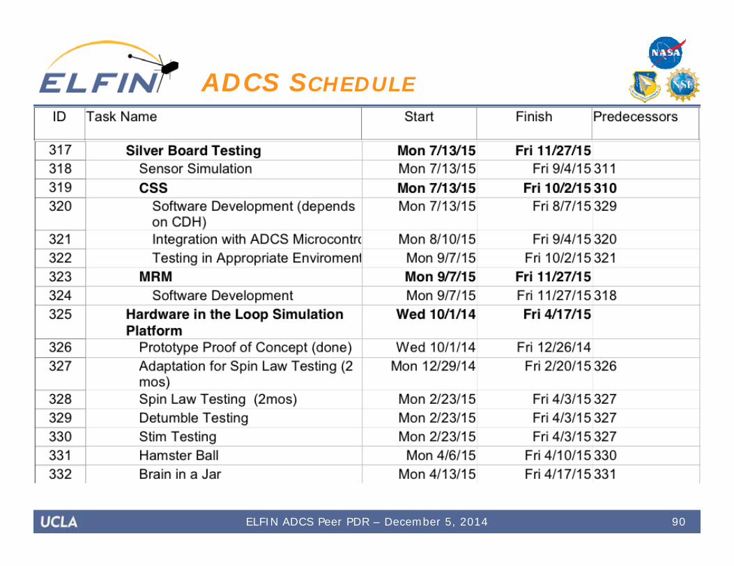
ADCS SCHEDULE
Day 160
ELFIN ADCS Peer PDR – December 5, 2014
Thank you to all of our sponsors, stakeholders,and contributors
Shaun Murphy @ Northrop GrummanKatharine Gamble @ UT Austin
Jim White WD0E @ Colorado Satellite ServicesMark Spencer WA8SME @ ARRL
Tony Monteiro AA2TX & Bob Davis KF4KSS @ AMSAT-NA
91
ACKNOWLEDGEMENTS
ELFIN ADCS Peer PDR – December 5, 2014