Electrochemical Studies on Glucose Oxidation in an Enzymatic Fuel Cell with Enzyme Immobilized on to...
11
DOI: 10.1002/elan.201400245 Electrochemical Studies on Glucose Oxidation in an Enzymatic Fuel Cell with Enzyme Immobilized on to Reduced Graphene Oxide Surface Debalina Das, [a] Susanta Ghosh, [b] and I. Basumallick* [a] 1 Introduction Enzyme fuel cells (EFCs) are the next generation greener devices with numerous applications. In recent years, there is a growing interest [1–3] on the use of enzyme fuel cells (EFC) as an alternative energy sources in various sectors such as in implantable devices [4], waste water treatment [5], drug delivery [6] and biosensors [7]. EFCs have many advantages over conventional fuel cells such as low oper- ating temperature, selectivity of the enzymes over fuels, feasible working conditions in physiological pH and use of renewable bio-energy sources such as sugars, organic acids, and most often glucose [8, 9]. EFCs are simpler and user-friendly approach for fuel oxidation under an anae- robic condition. There are two major types of EFCs with mediated electron transfer and mediator less electron transfer between the electrode and the active site of the enzyme which is deeply buried into the protein chains [10]. In mediated electron transfer, mediators help coor- dinating electron transfer between enzymes and fuel mol- ecules. Typical mediators used in EFCs are nanoparticles, miceller aggregates and redox polymers [11, 12]. Glucose oxidase (GOx) is a major catalyst which is widely used in EFCs [13]. Glucose oxidase (GOx) is a ho- modimeric glycoprotein of molecular weight approxi- mately 160 kDa, in which each subunit contains one non- covalently bound flavin adenine dinucleotide (FAD) co- factor. To enhance efficiency of enzyme electrode, one has to overcome the long electron-tunneling distance be- tween the enzyme active site and the electrode, as in GOx, the redox-active cofactor, FAD, is deeply situated into the protein core, hence it become unavailable for direct communication with electrode [14]. EFCs with im- mobilized enzymes on to gold nanoparticles (AuNps) have been extensively studied by different researchers [15, 16]. In our earlier study [15] on oxidation of starch by yeast immobilized onto AuNps/C-felt support we found that yeast immobilized onto AuNps was better than bare C-felt system. The support material plays a significant role in improv- ing the activity of the catalyst, to minimize the use of pre- cious metal-catalyst and for the better attachment of the substrate onto electrode surface. The support materials must have high specific surface area, good electronic con- ductivity and anti corrosion property [17]. For example, graphene or reduced graphene-oxide possesses all these qualities, hence it is considered as an ideal support mate- rial [18, 19]. In recent years, graphene and reduced graphene oxide (rGO) modified electrodes are drawing attention in the field of EFCs due to their high surface area, with unique Abstract : The present study reports fabrication and char- acterization of glucose oxidase (GOx) immobilized re- duced graphene oxide (rGO), gold nanoparticles (AuNp) and rGO/AuNp composite electrodes. The study further evaluated their electrochemical behaviors using cyclic vol- tammetry (CV) at different scan rates (10–150 mV/s) and different glucose concentrations (0.1–0.9 M) in phosphate buffer solution (PBS) at pH 7.4. Electron transfer rate constants (k s ) for glucose oxidation onto these enzyme immobilized electrodes have been calculated from the plot of E p vs. log n ( peak potential vs. log of scan rate) which showed faster electron transfer rate onto rGO/ AuNp composite surface compared to AuNp or rGO sur- faces alone. A laboratory model enzymatic fuel cell (EFC) was constructed by coupling the anode with a po- tassium ferrocyanide-ferricyanide cathode under argon at- mosphere. From the discharge studies, the rGO/AuNp/ GOx/C-felt electrode was found to be better than AuNp/ GOx/C-felt or rGO/GOx/C-felt electrodes. This better performance in rGO/AuNp/GOx/C-felt electrode has been related to the enhanced attachment of GOx enzyme onto AuNp surface through “S” atoms of sulfur contain- ing amino acids and better electronic conductivity of rGO surface. Hence, the current study concluded that the rGO/AuNp/GOx/C-felt electrode is a promising electrode for glucose oxidation in EFCs. Keywords: Bio-fuel cell · Glucose-oxidase · Glucose oxidation · Gold nanoparticles · Reduced graphene-oxide Topical Issue INDIA [a] D. Das, I. Basumallick Electrochemistry Laboratory, Department of Chemistry, Visva-Bharati University Santiniketan-731235, India *e-mail: [email protected] [b] S. Ghosh Integrated Science and Research, Visva-Bharati University Santiniketan-731235, India www.electroanalysis.wiley-vch.de # 2014 Wiley-VCH Verlag GmbH & Co. KGaA, Weinheim Electroanalysis 2014, 26, 2408 – 2418 2408 Full Paper
-
Upload
independent -
Category
Documents
-
view
0 -
download
0
Transcript of Electrochemical Studies on Glucose Oxidation in an Enzymatic Fuel Cell with Enzyme Immobilized on to...
DOI: 10.1002/elan.201400245
Electrochemical Studies on Glucose Oxidation in anEnzymatic Fuel Cell with Enzyme Immobilized on toReduced Graphene Oxide SurfaceDebalina Das,[a] Susanta Ghosh,[b] and I. Basumallick*[a]
1 Introduction
Enzyme fuel cells (EFCs) are the next generation greenerdevices with numerous applications. In recent years, thereis a growing interest [1–3] on the use of enzyme fuel cells(EFC) as an alternative energy sources in various sectorssuch as in implantable devices [4], waste water treatment[5], drug delivery [6] and biosensors [7]. EFCs have manyadvantages over conventional fuel cells such as low oper-ating temperature, selectivity of the enzymes over fuels,feasible working conditions in physiological pH and useof renewable bio-energy sources such as sugars, organicacids, and most often glucose [8, 9]. EFCs are simpler anduser-friendly approach for fuel oxidation under an anae-robic condition. There are two major types of EFCs withmediated electron transfer and mediator less electrontransfer between the electrode and the active site of theenzyme which is deeply buried into the protein chains[10]. In mediated electron transfer, mediators help coor-dinating electron transfer between enzymes and fuel mol-ecules. Typical mediators used in EFCs are nanoparticles,miceller aggregates and redox polymers [11,12].
Glucose oxidase (GOx) is a major catalyst which iswidely used in EFCs [13]. Glucose oxidase (GOx) is a ho-modimeric glycoprotein of molecular weight approxi-mately 160 kDa, in which each subunit contains one non-covalently bound flavin adenine dinucleotide (FAD) co-factor. To enhance efficiency of enzyme electrode, onehas to overcome the long electron-tunneling distance be-tween the enzyme active site and the electrode, as in
GOx, the redox-active cofactor, FAD, is deeply situatedinto the protein core, hence it become unavailable fordirect communication with electrode [14]. EFCs with im-mobilized enzymes on to gold nanoparticles (AuNps)have been extensively studied by different researchers[15,16]. In our earlier study [15] on oxidation of starch byyeast immobilized onto AuNps/C-felt support we foundthat yeast immobilized onto AuNps was better than bareC-felt system.
The support material plays a significant role in improv-ing the activity of the catalyst, to minimize the use of pre-cious metal-catalyst and for the better attachment of thesubstrate onto electrode surface. The support materialsmust have high specific surface area, good electronic con-ductivity and anti corrosion property [17]. For example,graphene or reduced graphene-oxide possesses all thesequalities, hence it is considered as an ideal support mate-rial [18,19].
In recent years, graphene and reduced graphene oxide(rGO) modified electrodes are drawing attention in thefield of EFCs due to their high surface area, with unique
Abstract : The present study reports fabrication and char-acterization of glucose oxidase (GOx) immobilized re-duced graphene oxide (rGO), gold nanoparticles (AuNp)and rGO/AuNp composite electrodes. The study furtherevaluated their electrochemical behaviors using cyclic vol-tammetry (CV) at different scan rates (10–150 mV/s) anddifferent glucose concentrations (0.1–0.9 M) in phosphatebuffer solution (PBS) at pH 7.4. Electron transfer rateconstants (ks) for glucose oxidation onto these enzymeimmobilized electrodes have been calculated from theplot of Ep vs. log n ( peak potential vs. log of scan rate)which showed faster electron transfer rate onto rGO/AuNp composite surface compared to AuNp or rGO sur-
faces alone. A laboratory model enzymatic fuel cell(EFC) was constructed by coupling the anode with a po-tassium ferrocyanide-ferricyanide cathode under argon at-mosphere. From the discharge studies, the rGO/AuNp/GOx/C-felt electrode was found to be better than AuNp/GOx/C-felt or rGO/GOx/C-felt electrodes. This betterperformance in rGO/AuNp/GOx/C-felt electrode hasbeen related to the enhanced attachment of GOx enzymeonto AuNp surface through “S” atoms of sulfur contain-ing amino acids and better electronic conductivity of rGOsurface. Hence, the current study concluded that therGO/AuNp/GOx/C-felt electrode is a promising electrodefor glucose oxidation in EFCs.
Keywords: Bio-fuel cell · Glucose-oxidase · Glucose oxidation · Gold nanoparticles · Reduced graphene-oxide
Topic
alIssu
eIN
DIA
[a] D. Das, I. BasumallickElectrochemistry Laboratory, Department of Chemistry,Visva-Bharati UniversitySantiniketan-731235, India*e-mail: [email protected]
[b] S. GhoshIntegrated Science and Research, Visva-Bharati UniversitySantiniketan-731235, India
www.electroanalysis.wiley-vch.de � 2014 Wiley-VCH Verlag GmbH & Co. KGaA, Weinheim Electroanalysis 2014, 26, 2408 – 2418 2408
Full Paper
graphitized basal plane structure having excellent electri-cal, mechanical and thermal properties [20,21]. Recently,Chen et al. [22] reported GOx loaded MWCNT and rGOfor glucose/O2 bio fuel cell (BFC) [22]. These modifiedelectrodes exhibit good catalytic activity towards glucoseoxidation. Liu et al. [23] constructed a miniaturized mem-brane less glucose/O2 bio fuel cell based on the surfaceengineering of graphene-GOx composite [23]. Li et al.[24] Fabricated a silica sol�gel immobilized graphenesheets composite as a matrix for the immobilization ofenzymes in both anode and cathode platform [24]. Itsperformance was compared with single walled carbonnanotubes (SWCNTs) and found that graphene based biofuel cell exhibited nearly two times greater power densitythan that of the SWCNTs bio fuel cell.
The current study aims to immobilize GOx onto re-duced graphene oxide (rGO) coated C-felt, gold nanopar-ticle (AuNp) impregnated C-felt and rGO/AuNp compo-site C-felt electrode surfaces. Further, the study had beencarried out for understanding their electroanalytical be-haviors such as electron transfer rate constant and dis-charge behavior towards glucose oxidation.
2 Experimental
2.1 Materials and Reagents
Glucose oxidase, graphite powder, gold chloride, sodium-citrate was obtained from Alfa-Aeser (India), d-glucose,KMnO4 and NaNO3, H2SO4, HCl, and 30% H2O2 wereobtained from Merck (India).
2.2 Preparation of Graphite Oxide and Graphene Oxide(GO)
2.2.1 Preparation of Graphite Oxide
Graphite oxide was prepared in the laboratory by follow-ing Hummer�s Method [25]. 3 g of Graphite flakes weremixed with 1.5 g NaNO3 and 69 mL of sulfuric acid ina beaker and stirred vigorously. This mixture was kept at0 8C in an ice bath for 5 minutes. To the above mixture9 g KMnO4 was added at small intervals time and reac-tion temperature was kept below 20 8C during the addi-tion. The temperature was raised to 30–35 8C and main-tained for 30 minutes. The mixture gradually becamepasty and small amount of gas was evolved. 20 mL ofwater was added and the temperature was further in-creased to 98 8C and stirred for another 15 minutes.40 mL of water and 3 mL of 30% H2O2 were added toensure reduction of residual permanganate and MnO2 tocolorless soluble manganese sulfate. The suspension wasfiltered; residue was collected and washed properly withdeionized water (DI) water, EtOH and 3 % HCl. Afterwashing, the residue was dried in the oven at 40 8C over-night.
2.2.2 Preparation of Graphene Oxide (GO)
Graphene oxide was prepared by suspending 0.025 ggraphite oxide in 50 mL DI water and ultrasonicated for1 hour for exfoliation. The homogeneous mixture wascentrifuged at 3000 rpm for 30 minutes to get non-sedi-ment supernatant solution [26]. Fourier transform infra-red (FTIR) spectroscopy of GO was carried out usingShimadzu FT-IR 8400 S (Figure 1a).
2.3 Preparation of rGO from GO
GO was sprayed by using sprayer over carbon felt (C-felt) surface (1 cm length�1 cm width, ca. 2.4 mm thick-ness, 0.95 porosity, mean fiber diameter of ca. 20 mm,electrical conductivity10 S/m) and vacuum dried over-night. The loading of GO was approximately 1 %. GOwas reduced to rGO electrochemically in a bath of 0.5 MH2SO4 solution, by passing a current of 1 mA/cm2 for30 minutes, and washed thoroughly by DI water. Fouriertransform infrared (FTIR) spectroscopy of rGO was car-ried out using Shimadzu FT-IR 8400 S (Figure 1b).
2.4 Preparation of Gold Nanoparticles
10 mL aqueous solution of HAuCl4 (0.0005 M) and 5 mLaqueous solution of sodium citrate (0.1 M) were mixedunder vigorous stirring at 25 8C. After the addition ofsodium citrate the color of the gold solution (yellow)became transparent. After 1 hour of stirring, 0.5 mL ofcold, aqueous solution of NaBH4 (0.1 M) was added dropwise (2–3 drops) for reduction of Au (III) ions. Stirringwas continued for an hour. During stirring, appearance oflight pink color indicated the formation of gold nanopar-ticles. The formation of gold nanoparticle was furtherconfirmed by using UV-visible spectra (Shimadzu UV3101 PC UV-visible NIR) at an absorbance of 532 nm.
2.5 Fabrication and Electroanalytical Studies of WorkingElectrodes
The impregnation of AuNp onto C-felt had been done byimmersing the C-felt overnight into the AuNp solution asdescribed by Ghosh et al. [15]. The rGO loaded C-felt,AuNp loaded C-felt and rGO/AuNp composite C-felt wasdipped overnight in GOx enzyme in 0.1 M PBS (pH 7.4).It was vacuum dried and used as the working electrode inEFC. The electro catalytic activity of rGO/GOx/C-felt,rGO/AuNp/GOx/C-felt and AuNp/GOx/C-felt were eval-uated for glucose oxidation by studying cyclic voltamme-try (CVs) at different scan rates (10–150 mV/s), differentfuel concentrations (0.1–0.9 M). The discharge behaviorof these three electrodes was carried out in 0.5 M dex-trose and 0.1 M PBS using potassium ferrocyanide/ferri-cyanide as cathode. The discharge behavior was studiedby drawing 10 mA current for 3000 seconds.
Topic
alIssu
eIN
DIA
www.electroanalysis.wiley-vch.de � 2014 Wiley-VCH Verlag GmbH & Co. KGaA, Weinheim Electroanalysis 2014, 26, 2408 – 2418 2409
Full Paper

2.6 Instrumental
The surface morphology of the electrodes was carried outby high resolution transmission electron microscope(HRTEM) (FEI TECNAI 200 KV) (Figure 2). For TEManalysis, GO/GOx/C-felt, r GO/AuNp/GOx/C-felt andAuNp/GOx/C-felt electrodes were dispersed in ethanoland ultrasonicated for 10 minutes and filtered to removethe C-felt support. A few drops of the suspensions weredeposited onto TEM grid and evacuated before analysis.
The amount of GOx enzyme immobilized onto threedifferent electrodes (Figure 5) was determined by usingUV-Vis spectra (Shimadzu UV 3101 PC UV-visible NIR)and fluorescence spectra (LS 55 Luminescence Spectrom-eter, 220 VAC). Electrochemical measurements weredone using a three electrode cell potentiostat�galovano-stat (PAR VersaStatTM II). A Pt-foil was used (1 cm2) asa counter electrode, a saturated calomel electrode as ref-erence electrode, and the working electrodes, as preparedin the laboratory respectively. Cyclic voltammetry experi-
Topic
alIssu
eIN
DIA
Fig. 1. FT-IR spectra of a) graphene oxide (GO), b) reduced graphene oxide (rGO).
www.electroanalysis.wiley-vch.de � 2014 Wiley-VCH Verlag GmbH & Co. KGaA, Weinheim Electroanalysis 2014, 26, 2408 – 2418 2410
Full Paper

ments were carried out at scan rates: 10, 30, 50, 70, 90,110, 130, 150 mV/s and different fuel concentrations atroom temperature.
3 Results and Discussion
3.1 FT-IR Spectra of GO and rGO:
FT-IR spectra of graphene oxide (GO) is shown in Fig-ure 1(a). From Figure 1 a, it was confirmed that appear-ance of peaks at 3600–3400 cm�1 (�OH stretching vibra-tions), 1753 cm�1 (C=O stretching vibration), 1581 cm�1
(skeletal vibration from un-oxidized graphitic domains),1421 cm�1 (aromatic C=C stretching), 1226 cm�1 (C�OHstretching vibrations), 839 cm�1 (epoxy) indicates the for-mation of graphene oxide [27]. FTIR spectra of rGOwere shown in Figure 1 b. By comparing the FT-IR spec-tra of graphene oxide and rGO, it was clear that the�OH
stretching vibrations (3600–3400 cm�1) were noticeablysuppressed and �C=O stretching vibration (1753 cm�1)was almost disappeared in the case of rGO [28]. In rGO,the C=C stretching vibrations (1620–1680 cm�1) were in-dicating the partial recovery of sp2 graphitic network. Thepeaks at 1050–1150 cm�1 may be due to the C�O stretch-ing vibration of the hydroxyl moiety. From the FT-IRstudies, it was well understood that graphene oxide is par-tially reduced to rGO by the electrochemical method.
3.2 HR-TEM Images and EDX Spectra
The high resolution transmission electron microscopy(HR-TEM) images of the GOx immobilized onto rGO/C-felt, AuNp/C-felt, rGO/AuNp/C-felt composite and exfo-liated rGO were shown in Figure 2a–d. From the surfacemorphology study, it can be inferred that GOx incorpo-rated onto rGO or AuNp/rGO composite showed differ-
Topic
alIssu
eIN
DIA
Fig. 2. HR-TEM images of GOx immobilized onto a) rGO, b) AuNp, c) rGO/AuNp surfaces, and d) exfoliated GO.
www.electroanalysis.wiley-vch.de � 2014 Wiley-VCH Verlag GmbH & Co. KGaA, Weinheim Electroanalysis 2014, 26, 2408 – 2418 2411
Full Paper

ent morphology compared to GOx immobilized ontoAuNps. The HR-TEM image rGO/AuNp/GOx seems thatGOx molecules were almost uniformly distributed on thesurface of the rGO/AuNp composite electrode
Figure 3a–c represent energy dispersive x-ray (EDX)spectra of rGO/GOx, AuNp/GOx and rGO/AuNp/GOxcomposites.
3.3 UV-Visible and Fluorescence Spectra
The UV-Visible spectrum of the gold nanosolution wasshown in the Figure 4. Figure 4 represented the adsorp-tion of AuNps on to C-felt and rGO/C-felt surfaces. Ap-pearance of a peak at 532 nm [curve (a)] clearly indicatedformation of nanogold particles in solution, which is char-acteristic of metallic gold nanoparticles [29]. By compar-ing, the curve (a) with curve (b) and curve (c), it could bestated that the peak for the gold nanoparticles at 532 nmwas noticeably reduced after impregnation onto bare C-felt surface and totally vanished after impregnating ontorGO/C-felt surface. This was an indication of adsorptionof the gold nanoparticles onto C-felt and rGO/C-felt sur-faces [15].
The rGO/C-felt, AuNp/C-felt and rGO/AuNp compo-site C-felt were individually kept immersed overnight in2 mL GOx solution in PBS. Studies of fluorescence spec-tra (Figure 5) of the pure and remaining enzyme solutionsleft after overnight adsorption in PBS were carried out atan excitation wavelength of 280 nm [30]. The resultshowed that compared to rGO/C-felt, rGO/AuNp/C-feltelectrode, a slightly larger extent of enzymes were immo-bilized onto AuNp/C-felt surface. A higher surface cover-age of GOx onto AuNp/C-felt surface may be due to theeffect of physisorption of the enzyme on to an increasedsurface area in the presence of rGO.
3.4 Electrochemical Studies
3.4.1 Electrochemical Studies of the AuNp, rGO, andrGO/AuNp Modified GOx Immobilized Electrodes
Cyclic voltammograms were used to assess the bio cata-lytic activity of immobilized enzyme. It is well establishedfact that GOx catalyzes the oxidation of b-d-glucose intob-d-glucono lactone, according to the following reaction:
Topic
alIssu
eIN
DIA
Fig. 3. EDX spectra of a) rGO/GOx b) AuNp/GOx c) rGO/AuNp/GOx composites.
Fig. 4. UV-Vis spectra of a) pure AuNps, b) AuNps after im-pregnation onto the C-felt surface c) after impregnation onto therGO/C-felt surface.
www.electroanalysis.wiley-vch.de � 2014 Wiley-VCH Verlag GmbH & Co. KGaA, Weinheim Electroanalysis 2014, 26, 2408 – 2418 2412
Full Paper

C6H12O6GOx��!C6H10O6þH2O2
H2O2 ! O2þ2Hþþ2e
Figure 6a showed the comparative CVs of rGO/GOx/C-felt, AuNp/GOx/C-felt and rGO/AuNp/GOx/C-felt ata scan rate of 150 mV/s. A pair of redox peaks for rGO/GOx/C-felt and rGO/AuNp/GOx/C-felt had been ob-served. There was no prominent redox peaks found whilerGO/C-felt was used as working electrode (without anyenzyme) (Figure 6 b).The observed redox peaks are likelydue to hydrogen per-oxide oxidation and O2 reduction asmentioned by Mecheri et al. [31] and Shan et al.[32].These two curves indicate quasi reversible nature forglucose oxidation onto both rGO/GOx/C-felt and rGO/AuNp/GOx/C-felt electrode surfaces. However in AuNp/
GOx/C-felt, the CV was almost irreversible in nature. Inthe case of rGO/AuNp/GOx/C-felt composite electrode,from the quasi-reversible nature of the CV of glucose oxi-dation onto rGO/AuNp/GOx/C-felt composite surface, itmay be concluded that rGO improves the catalytic activi-ty of the enzyme.
3.4.2 Effect of Scan Rate
Figure 6c–e showed the CVs of rGO/GOx/C-felt, AuNp/GOx/C-felt, rGO/AuNp/GOx/C-felt in 0.5 M dextroseand 0.1 M PBS solution at scan rates 10, 30, 50, 70, 90,110, 130 and 150 mV/s. The influence of the scan rate onthe cyclic voltammetric performance of these three elec-trodes had been investigated (Figure 6c–e).The redox pro-cesses of the rGO/GOx/C-felt and rGO/AuNp/GOx/C-felt gave roughly symmetric anodic and cathodic peaks atrelatively slow scan rates. When the scan rate increases,the redox potentials (Epa and Epc) of GOx shift slightly.The DEp, also increases with increasing scan rate. It canbe also seen from the plots of peak current (Ipa and Ipc )vs. scan rate (v), the redox peak currents increases linear-ly with increase of scan rates (Figure 7, a–c). All thesecharacteristics suggest that the redox reaction of GOxonto rGO/C-felt and rGO/AuNp/C-felt composite elec-trode is a quasi-reversible surface-controlled electrochem-ical process and indicated the direct electron transfer re-action of GOx onto these surfaces. This phenomenon waswell established in the works of Xinhuang Kang et al. [33]
3.4.3 Electron Transfer Rate Constant (ks) Calculation
The electron transfer rate constant ks (s�1) of the enzyme(GOx) onto the rGO/C-felt, AuNp/C-felt and rGO/AuNp/C-felt electrode surfaces had be calculated fromthe well known Laviron Equation 1 [34].
log ks ¼ a log ð1�aÞ þ ð1�aÞ log a�log ðRT=nFvÞ�a ð1�aÞ ðnFDEp=2:3RTÞ
ð1Þ
Where a is the charge transfer coefficient, the con-stants R, T and F represent their usual meanings (R=8.314 J K�1 mol�1, T=298 K, F=96485 C mol�1), no ofelectron transfer n=2, n= scan rate (150 mV/s), DEp =Epa�Epc.
Plots of the Epa and Epc vs. the logarithm of the scanrates produce two straight lines with slops of2.3RT/(1�a)nF and �2.3RT/anF [35] at high scan rates(Figure 7, d–f). From the slopes, a was estimated to be0.5. The ks values at rGO/GOx/C-felt, AuNp/GOx/C-feltand rGO/AuNp/GOx/C-felt had been calculated and theks values were found to be 0.6, 1.5 and 1.7/s (Table 1).The ks values are compatible with those reported previ-ously on MWCNTs paper (1.7 s�1) reported by Guiseppi-Elie et al., [36] on MWCNTs/chitosan (1.08 s�1) by Luoet al. , [37] on boron-doped MWCNTs (1.56 s�1) by Denget al. , [38] and on MWCNTs-CTAB (1.53 s�1) reported by
Fig. 5. i) UV-Vis spectra and ii) Fluorescence spectra of a) pureGOx, remaining solution of GOx after immobilization onto b)rGO/C-felt c) AuNp/C-felt and d) rGO/AuNp/C-felt.
Topic
alIssu
eIN
DIA
www.electroanalysis.wiley-vch.de � 2014 Wiley-VCH Verlag GmbH & Co. KGaA, Weinheim Electroanalysis 2014, 26, 2408 – 2418 2413
Full Paper
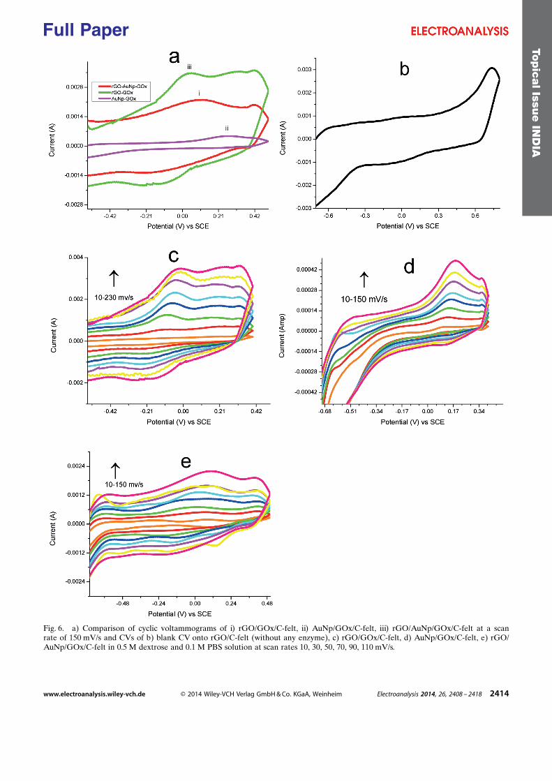
Fig. 6. a) Comparison of cyclic voltammograms of i) rGO/GOx/C-felt, ii) AuNp/GOx/C-felt, iii) rGO/AuNp/GOx/C-felt at a scanrate of 150 mV/s and CVs of b) blank CV onto rGO/C-felt (without any enzyme), c) rGO/GOx/C-felt, d) AuNp/GOx/C-felt, e) rGO/AuNp/GOx/C-felt in 0.5 M dextrose and 0.1 M PBS solution at scan rates 10, 30, 50, 70, 90, 110 mV/s.
Topic
alIssu
eIN
DIA
www.electroanalysis.wiley-vch.de � 2014 Wiley-VCH Verlag GmbH & Co. KGaA, Weinheim Electroanalysis 2014, 26, 2408 – 2418 2414
Full Paper

Cai and Chen, [39] modified electrodes The larger rateconstant on AuNp/rGO/GOx/C-felt electrode indicateda faster electron shuttling between redox active sites of
enzyme and AuNp/rGO composite. This faster electronshuttling may be correlated due to high conductivity andlarge surface area of the rGO and a better attachment of
Fig. 7. Plots of Ip vs. n of a) rGO/GOx/C-felt, b) AuNp/GOx/C-felt, c) rGO/AuNp/GOx/C-felt, and Plots of Ep vs. log n d) rGO/GOx/C-felt, e) AuNp/GOx/C-felt, f) rGO/AuNp/GOx/C-felt.
Topic
alIssu
eIN
DIA
www.electroanalysis.wiley-vch.de � 2014 Wiley-VCH Verlag GmbH & Co. KGaA, Weinheim Electroanalysis 2014, 26, 2408 – 2418 2415
Full Paper
“S” atoms in amino acids of enzyme with the gold nano-particles which helps better electron transfer between theredox centre of the enzyme and the surface of electrodes.
3.4.4 Effect of Dextrose Concentration
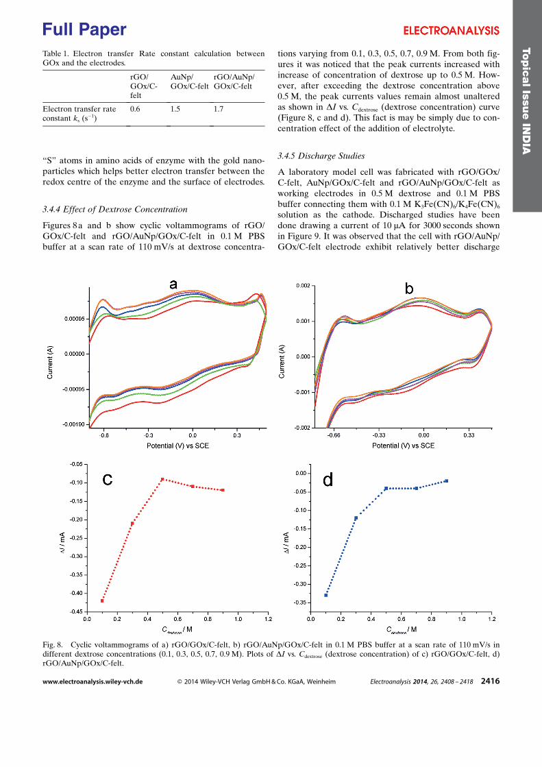
Figures 8 a and b show cyclic voltammograms of rGO/GOx/C-felt and rGO/AuNp/GOx/C-felt in 0.1 M PBSbuffer at a scan rate of 110 mV/s at dextrose concentra-
tions varying from 0.1, 0.3, 0.5, 0.7, 0.9 M. From both fig-ures it was noticed that the peak currents increased withincrease of concentration of dextrose up to 0.5 M. How-ever, after exceeding the dextrose concentration above0.5 M, the peak currents values remain almost unalteredas shown in DI vs. Cdextrose (dextrose concentration) curve(Figure 8, c and d). This fact is may be simply due to con-centration effect of the addition of electrolyte.
3.4.5 Discharge Studies
A laboratory model cell was fabricated with rGO/GOx/C-felt, AuNp/GOx/C-felt and rGO/AuNp/GOx/C-felt asworking electrodes in 0.5 M dextrose and 0.1 M PBSbuffer connecting them with 0.1 M K3Fe(CN)6/K4Fe(CN)6
solution as the cathode. Discharged studies have beendone drawing a current of 10 mA for 3000 seconds shownin Figure 9. It was observed that the cell with rGO/AuNp/GOx/C-felt electrode exhibit relatively better discharge
Fig. 8. Cyclic voltammograms of a) rGO/GOx/C-felt, b) rGO/AuNp/GOx/C-felt in 0.1 M PBS buffer at a scan rate of 110 mV/s indifferent dextrose concentrations (0.1, 0.3, 0.5, 0.7, 0.9 M). Plots of DI vs. Cdextrose (dextrose concentration) of c) rGO/GOx/C-felt, d)rGO/AuNp/GOx/C-felt.
Table 1. Electron transfer Rate constant calculation betweenGOx and the electrodes.
rGO/GOx/C-felt
AuNp/GOx/C-felt
rGO/AuNp/GOx/C-felt
Electron transfer rateconstant ks (s�1)
0.6 1.5 1.7
Topic
alIssu
eIN
DIA
www.electroanalysis.wiley-vch.de � 2014 Wiley-VCH Verlag GmbH & Co. KGaA, Weinheim Electroanalysis 2014, 26, 2408 – 2418 2416
Full Paper
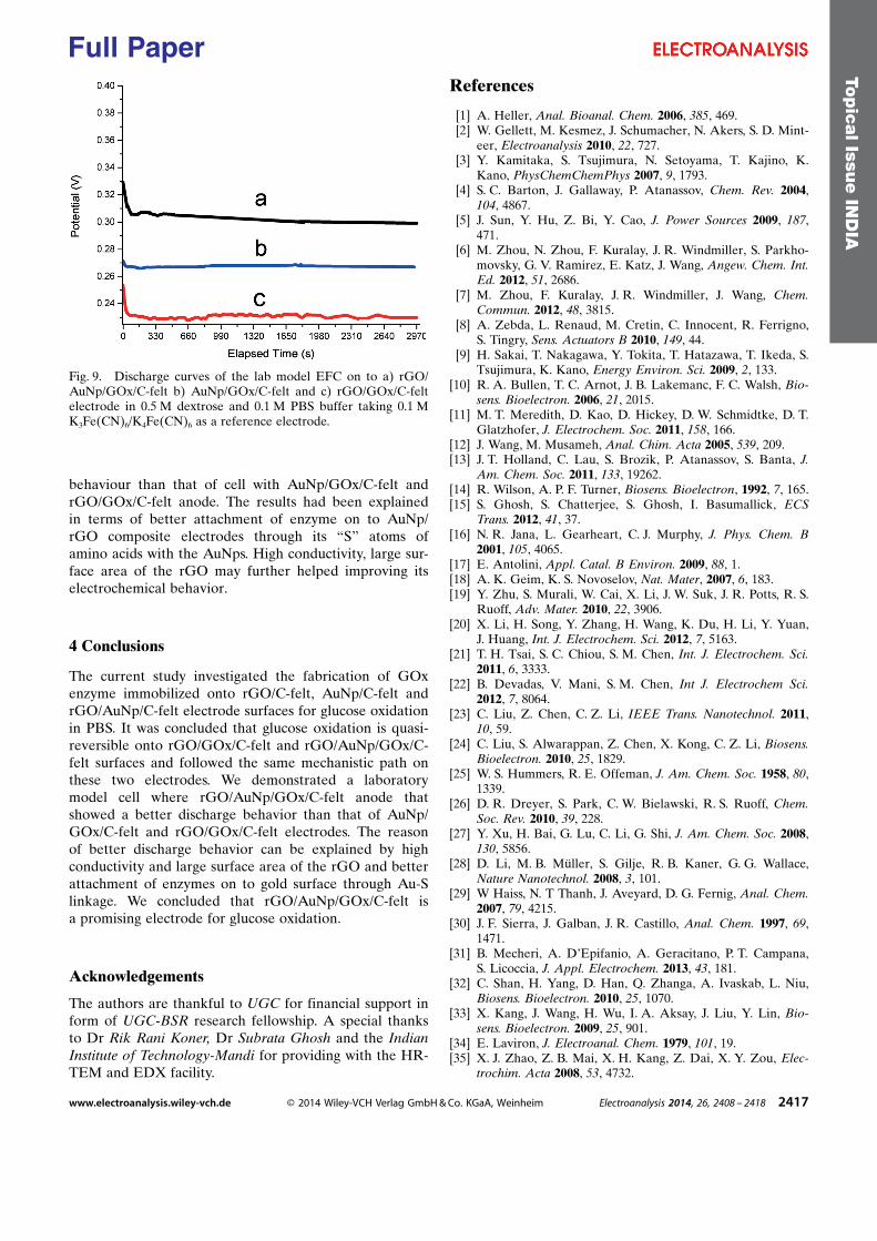
behaviour than that of cell with AuNp/GOx/C-felt andrGO/GOx/C-felt anode. The results had been explainedin terms of better attachment of enzyme on to AuNp/rGO composite electrodes through its “S” atoms ofamino acids with the AuNps. High conductivity, large sur-face area of the rGO may further helped improving itselectrochemical behavior.
4 Conclusions
The current study investigated the fabrication of GOxenzyme immobilized onto rGO/C-felt, AuNp/C-felt andrGO/AuNp/C-felt electrode surfaces for glucose oxidationin PBS. It was concluded that glucose oxidation is quasi-reversible onto rGO/GOx/C-felt and rGO/AuNp/GOx/C-felt surfaces and followed the same mechanistic path onthese two electrodes. We demonstrated a laboratorymodel cell where rGO/AuNp/GOx/C-felt anode thatshowed a better discharge behavior than that of AuNp/GOx/C-felt and rGO/GOx/C-felt electrodes. The reasonof better discharge behavior can be explained by highconductivity and large surface area of the rGO and betterattachment of enzymes on to gold surface through Au-Slinkage. We concluded that rGO/AuNp/GOx/C-felt isa promising electrode for glucose oxidation.
Acknowledgements
The authors are thankful to UGC for financial support inform of UGC-BSR research fellowship. A special thanksto Dr Rik Rani Koner, Dr Subrata Ghosh and the IndianInstitute of Technology-Mandi for providing with the HR-TEM and EDX facility.
References
[1] A. Heller, Anal. Bioanal. Chem. 2006, 385, 469.[2] W. Gellett, M. Kesmez, J. Schumacher, N. Akers, S. D. Mint-
eer, Electroanalysis 2010, 22, 727.[3] Y. Kamitaka, S. Tsujimura, N. Setoyama, T. Kajino, K.
Kano, PhysChemChemPhys 2007, 9, 1793.[4] S. C. Barton, J. Gallaway, P. Atanassov, Chem. Rev. 2004,
104, 4867.[5] J. Sun, Y. Hu, Z. Bi, Y. Cao, J. Power Sources 2009, 187,
471.[6] M. Zhou, N. Zhou, F. Kuralay, J. R. Windmiller, S. Parkho-
movsky, G. V. Ramirez, E. Katz, J. Wang, Angew. Chem. Int.Ed. 2012, 51, 2686.
[7] M. Zhou, F. Kuralay, J. R. Windmiller, J. Wang, Chem.Commun. 2012, 48, 3815.
[8] A. Zebda, L. Renaud, M. Cretin, C. Innocent, R. Ferrigno,S. Tingry, Sens. Actuators B 2010, 149, 44.
[9] H. Sakai, T. Nakagawa, Y. Tokita, T. Hatazawa, T. Ikeda, S.Tsujimura, K. Kano, Energy Environ. Sci. 2009, 2, 133.
[10] R. A. Bullen, T. C. Arnot, J. B. Lakemanc, F. C. Walsh, Bio-sens. Bioelectron. 2006, 21, 2015.
[11] M. T. Meredith, D. Kao, D. Hickey, D. W. Schmidtke, D. T.Glatzhofer, J. Electrochem. Soc. 2011, 158, 166.
[12] J. Wang, M. Musameh, Anal. Chim. Acta 2005, 539, 209.[13] J. T. Holland, C. Lau, S. Brozik, P. Atanassov, S. Banta, J.
Am. Chem. Soc. 2011, 133, 19262.[14] R. Wilson, A. P. F. Turner, Biosens. Bioelectron, 1992, 7, 165.[15] S. Ghosh, S. Chatterjee, S. Ghosh, I. Basumallick, ECS
Trans. 2012, 41, 37.[16] N. R. Jana, L. Gearheart, C. J. Murphy, J. Phys. Chem. B
2001, 105, 4065.[17] E. Antolini, Appl. Catal. B Environ. 2009, 88, 1.[18] A. K. Geim, K. S. Novoselov, Nat. Mater, 2007, 6, 183.[19] Y. Zhu, S. Murali, W. Cai, X. Li, J. W. Suk, J. R. Potts, R. S.
Ruoff, Adv. Mater. 2010, 22, 3906.[20] X. Li, H. Song, Y. Zhang, H. Wang, K. Du, H. Li, Y. Yuan,
J. Huang, Int. J. Electrochem. Sci. 2012, 7, 5163.[21] T. H. Tsai, S. C. Chiou, S. M. Chen, Int. J. Electrochem. Sci.
2011, 6, 3333.[22] B. Devadas, V. Mani, S. M. Chen, Int J. Electrochem Sci.
2012, 7, 8064.[23] C. Liu, Z. Chen, C. Z. Li, IEEE Trans. Nanotechnol. 2011,
10, 59.[24] C. Liu, S. Alwarappan, Z. Chen, X. Kong, C. Z. Li, Biosens.
Bioelectron. 2010, 25, 1829.[25] W. S. Hummers, R. E. Offeman, J. Am. Chem. Soc. 1958, 80,
1339.[26] D. R. Dreyer, S. Park, C. W. Bielawski, R. S. Ruoff, Chem.
Soc. Rev. 2010, 39, 228.[27] Y. Xu, H. Bai, G. Lu, C. Li, G. Shi, J. Am. Chem. Soc. 2008,
130, 5856.[28] D. Li, M. B. M�ller, S. Gilje, R. B. Kaner, G. G. Wallace,
Nature Nanotechnol. 2008, 3, 101.[29] W Haiss, N. T Thanh, J. Aveyard, D. G. Fernig, Anal. Chem.
2007, 79, 4215.[30] J. F. Sierra, J. Galban, J. R. Castillo, Anal. Chem. 1997, 69,
1471.[31] B. Mecheri, A. D�Epifanio, A. Geracitano, P. T. Campana,
S. Licoccia, J. Appl. Electrochem. 2013, 43, 181.[32] C. Shan, H. Yang, D. Han, Q. Zhanga, A. Ivaskab, L. Niu,
Biosens. Bioelectron. 2010, 25, 1070.[33] X. Kang, J. Wang, H. Wu, I. A. Aksay, J. Liu, Y. Lin, Bio-
sens. Bioelectron. 2009, 25, 901.[34] E. Laviron, J. Electroanal. Chem. 1979, 101, 19.[35] X. J. Zhao, Z. B. Mai, X. H. Kang, Z. Dai, X. Y. Zou, Elec-
trochim. Acta 2008, 53, 4732.
Fig. 9. Discharge curves of the lab model EFC on to a) rGO/AuNp/GOx/C-felt b) AuNp/GOx/C-felt and c) rGO/GOx/C-feltelectrode in 0.5 M dextrose and 0.1 M PBS buffer taking 0.1 MK3Fe(CN)6/K4Fe(CN)6 as a reference electrode.
Topic
alIssu
eIN
DIA
www.electroanalysis.wiley-vch.de � 2014 Wiley-VCH Verlag GmbH & Co. KGaA, Weinheim Electroanalysis 2014, 26, 2408 – 2418 2417
Full Paper

[36] A. Guiseppi-Elie, C. Lei, R. H. Baughman, Nanotechnology2002, 13, 559.
[37] X. Luo, A. J. Killard, M. R. Smyth, Electroanalysis 2006, 18,1131.
[38] C. Deng, J. H. Chen, X. L. Chen, C. H. Xiao, L. H. Nie,S. Z. Yao, Biosens. Bioelectron. 2008, 23, 1272.
[39] C. X. Cai, J. Chen, Anal. Biochem. 2004, 332, 75.
Received: May 15, 2014Accepted: August 18, 2014
Published online: September 18, 2014
Topic
alIssu
eIN
DIA
www.electroanalysis.wiley-vch.de � 2014 Wiley-VCH Verlag GmbH & Co. KGaA, Weinheim Electroanalysis 2014, 26, 2408 – 2418 2418
Full Paper