ELECTRIC POINT MACHINE 143 MM THROW WITH ...
11
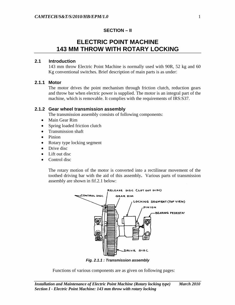
CAMTECH/S&T/S/2010/HB/EPM/1.0 Installation and Maintenance of Electric Point Machine (Rotary locking type) March 2010 Section I - Electric Point Machine: 143 mm throw with rotary locking 1 SECTION – II ELECTRIC POINT MACHINE 143 MM THROW WITH ROTARY LOCKING 2.1 Introduction 143 mm throw Electric Point Machine is normally used with 90R, 52 kg and 60 Kg conventional switches. Brief description of main parts is as under: 2.1.1 Motor The motor drives the point mechanism through friction clutch, reduction gears and throw bar when electric power is supplied. The motor is an integral part of the machine, which is removable. It complies with the requirements of IRS:S37. 2.1.2 Gear wheel transmission assembly The transmission assembly consists of following components: • Main Gear Rim • Spring loaded friction clutch • Transmission shaft • Pinion • Rotary type locking segment • Drive disc • Lift out disc • Control disc The rotary motion of the motor is converted into a rectilinear movement of the toothed driving bar with the aid of this assembly. Various parts of transmission assembly are shown in fif.2.1 below: Fig. 2.1.1 : Transmission assembly Functions of various components are as given on following pages:
-
Upload
khangminh22 -
Category
Documents
-
view
2 -
download
0
Transcript of ELECTRIC POINT MACHINE 143 MM THROW WITH ...
CAMTECH/S&T/S/2010/HB/EPM/1.0
Installation and Maintenance of Electric Point Machine (Rotary locking type) March 2010 Section I - Electric Point Machine: 143 mm throw with rotary locking
1
SECTION – II
ELECTRIC POINT MACHINE 143 MM THROW WITH ROTARY LOCKING
2.1 Introduction
143 mm throw Electric Point Machine is normally used with 90R, 52 kg and 60 Kg conventional switches. Brief description of main parts is as under:
2.1.1 Motor
The motor drives the point mechanism through friction clutch, reduction gears and throw bar when electric power is supplied. The motor is an integral part of the machine, which is removable. It complies with the requirements of IRS:S37.
2.1.2 Gear wheel transmission assembly The transmission assembly consists of following components:
• Main Gear Rim • Spring loaded friction clutch • Transmission shaft • Pinion • Rotary type locking segment • Drive disc • Lift out disc • Control disc
The rotary motion of the motor is converted into a rectilinear movement of the toothed driving bar with the aid of this assembly. Various parts of transmission assembly are shown in fif.2.1 below:
Fig. 2.1.1 : Transmission assembly
Functions of various components are as given on following pages:
CAMTECH/S&T/S/2010/HB/EPM/1.0
Installation and Maintenance of Electric Point Machine (Rotary locking type) March 2010 Section I - Electric Point Machine: 143 mm throw with rotary locking
2
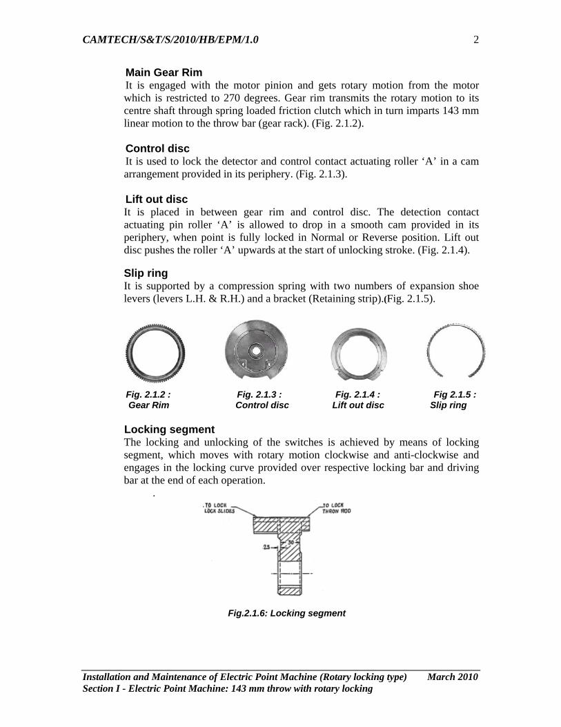
Main Gear Rim It is engaged with the motor pinion and gets rotary motion from the motor
which is restricted to 270 degrees. Gear rim transmits the rotary motion to its centre shaft through spring loaded friction clutch which in turn imparts 143 mm linear motion to the throw bar (gear rack). (Fig. 2.1.2).
Control disc It is used to lock the detector and control contact actuating roller ‘A’ in a cam
arrangement provided in its periphery. (Fig. 2.1.3). Lift out disc It is placed in between gear rim and control disc. The detection contact
actuating pin roller ‘A’ is allowed to drop in a smooth cam provided in its periphery, when point is fully locked in Normal or Reverse position. Lift out disc pushes the roller ‘A’ upwards at the start of unlocking stroke. (Fig. 2.1.4).
Slip ring It is supported by a compression spring with two numbers of expansion shoe levers (levers L.H. & R.H.) and a bracket (Retaining strip).(Fig. 2.1.5).
Fig. 2.1.2 : Fig. 2.1.3 : Fig. 2.1.4 : Fig 2.1.5 : Gear Rim Control disc Lift out disc Slip ring Locking segment
The locking and unlocking of the switches is achieved by means of locking segment, which moves with rotary motion clockwise and anti-clockwise and engages in the locking curve provided over respective locking bar and driving bar at the end of each operation.
.
Fig.2.1.6: Locking segment
CAMTECH/S&T/S/2010/HB/EPM/1.0
Installation and Maintenance of Electric Point Machine (Rotary locking type) March 2010 Section I - Electric Point Machine: 143 mm throw with rotary locking
3
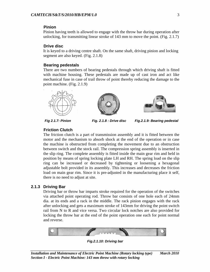
Pinion Pinion having teeth is allowed to engage with the throw bar during operation after
unlocking, for transmitting linear stroke of 143 mm to move the point. (Fig. 2.1.7) Drive disc It is keyed to a driving centre shaft. On the same shaft, driving pinion and locking
segment are also keyed. (Fig. 2.1.8)
Bearing pedestals There are two numbers of bearing pedestals through which driving shaft is fitted with machine housing. These pedestals are made up of cast iron and act like mechanical fuse in case of trail throw of point thereby reducing the damage to the point machine. (Fig. 2.1.9)
Fig 2.1.7: Pinion Fig. 2.1.8 : Drive disc Fig.2.1.9: Bearing pedestal Friction Clutch
The friction clutch is a part of transmission assembly and it is fitted between the motor and the mechanism to absorb shock at the end of the operation or in case the machine is obstructed from completing the movement due to an obstruction between switch and the stock rail. The compression spring assembly is inserted in the slip ring. The complete assembly is fitted inside the main gear rim and held in position by means of spring locking plate LH and RH. The spring load on the slip ring can be increased or decreased by tightening or loosening a hexagonal adjustable bolt provided in its assembly. This increases and decreases the friction load on main gear rim. Since it is pre-adjusted in the manufacturing place it self, there is no need to adjust at site.
2.1.3 Driving Bar Driving bar or throw bar imparts stroke required for the operation of the switches via attached point operating rod. Throw bar consists of one hole each of 24mm dia. at its ends and a rack in the middle. The rack pinion engages with the rack after unlocking and gets a maximum stroke of 143mm for driving the point switch rail from N to R and vice versa. Two circular lock notches are also provided for locking the throw bar at the end of the point operation one each for point normal and reverse.
Fig.2.1.10: Driving bar
CAMTECH/S&T/S/2010/HB/EPM/1.0
Installation and Maintenance of Electric Point Machine (Rotary locking type) March 2010 Section I - Electric Point Machine: 143 mm throw with rotary locking
4
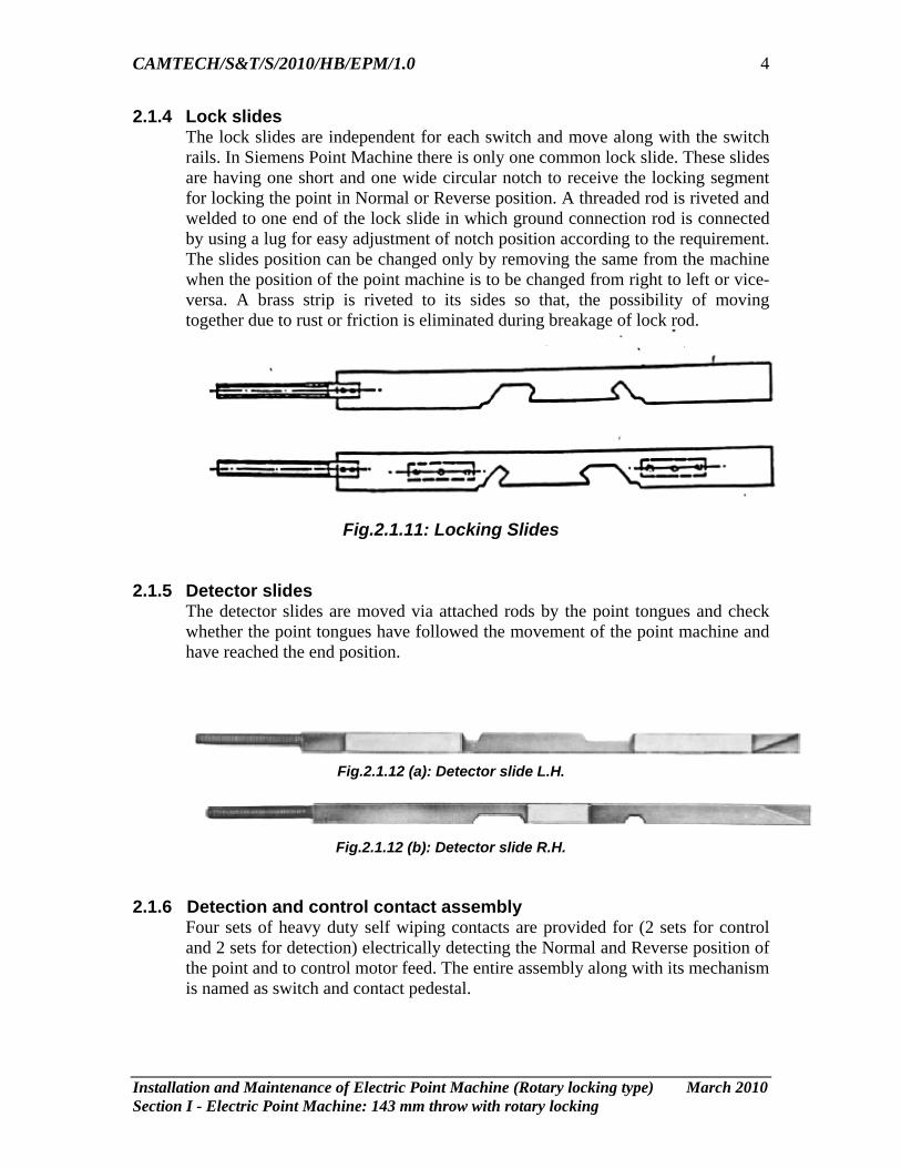
2.1.4 Lock slides The lock slides are independent for each switch and move along with the switch rails. In Siemens Point Machine there is only one common lock slide. These slides are having one short and one wide circular notch to receive the locking segment for locking the point in Normal or Reverse position. A threaded rod is riveted and welded to one end of the lock slide in which ground connection rod is connected by using a lug for easy adjustment of notch position according to the requirement. The slides position can be changed only by removing the same from the machine when the position of the point machine is to be changed from right to left or vice-versa. A brass strip is riveted to its sides so that, the possibility of moving together due to rust or friction is eliminated during breakage of lock rod.
Fig.2.1.11: Locking Slides
2.1.5 Detector slides
The detector slides are moved via attached rods by the point tongues and check whether the point tongues have followed the movement of the point machine and have reached the end position.
Fig.2.1.12 (a): Detector slide L.H.
Fig.2.1.12 (b): Detector slide R.H.
2.1.6 Detection and control contact assembly
Four sets of heavy duty self wiping contacts are provided for (2 sets for control and 2 sets for detection) electrically detecting the Normal and Reverse position of the point and to control motor feed. The entire assembly along with its mechanism is named as switch and contact pedestal.
CAMTECH/S&T/S/2010/HB/EPM/1.0
Installation and Maintenance of Electric Point Machine (Rotary locking type) March 2010 Section I - Electric Point Machine: 143 mm throw with rotary locking
5
Control contacts The control contacts (outer ones) are named as Normal control contacts and
Reverse control contacts. When point is set and locked in Normal position, the Normal control contacts open. Similarly when point is set and locked in Reverse position, the Reverse control contacts open. The position of these contacts depends upon the type of turnout i.e. LH or RH.
Detection contacts The inner contacts are named as Normal and detection contacts. These contacts
are allowed to make only when point is fully set and locked in the respective position.
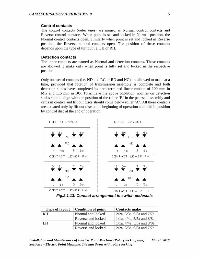
Only one set of contacts (i.e. ND and RC or RD and NC) are allowed to make at a
time, provided that rotation of transmission assembly is complete and both detection slides have completed its predetermined linear motion of 100 mm in MG and 115 mm in BG. To achieve the above condition, notches on detection slides should align with the position of the roller ‘B’ in the pedestal assembly and cams in control and lift out discs should come below roller ‘A’. All these contacts are actuated only by lift out disc at the beginning of operation and held in position by control disc at the end of operation.
Fig.2.1.13: Contact arrangement in switch pedestals
Type of layout Condition of point Contacts make Normal and locked 2/2a, 3/3a, 6/6a and 7/7a RH Reverse and locked 1/1a, 4/4a, 5/5a and 8/8a Normal and locked 1/1a, 4/4a, 5/5a and 8/8a LH Reverse and locked 2/2a, 3/3a, 6/6a and 7/7a

CAMTECH/S&T/S/2010/HB/EPM/1.0
Installation and Maintenance of Electric Point Machine (Rotary locking type) March 2010 Section I - Electric Point Machine: 143 mm throw with rotary locking
6
Sequential operation of detection and control contacts of switch pedestal in the machine:
In case of DC machine, when the motor starts operation, its detection contacts break first and then the control contacts make. Similarly at the end of operation the control contacts break after which the corresponding detection contacts make. Thus the detection contacts and the corresponding control contacts (ND and NC or RD and RC) cannot make simultaneously at any instant.
Sr. No.
Position/Setting of point Position of Control/Detection contacts
1. Point is Normal (N) and locked ND Make RC Make 2. While starting the operation from N to R NC Make after ND Break 3. During operation from N to R RC Make NC Make 4. At the end of N to R operation RD Make after RC Break 5. Point is Reverse (R) and locked RD Make NC Make 6. While starting the operation from R to N RC Make after RD Break 7. During operation from R to N ND Make RC Make 8. At the end of R to N operation ND Make after NC Make
2.2 Electric Point Machines complying to RDSO specification
Normally all point machines comply RDSO specification and RDSO drawings except Siemens Electric Point Machine, which has certain deviations. The main variations in design of Siemens point machine from that manufactured as per RDSO drawings are as under: • Siemens Point Machine is of manufacture’s own design. The machine
complies IRS:S-24 and is evaluated as per this specification. • Siemens point machine has common lock rod for locking both the switch rails. • Fixing arrangement of point motor in Siemens point machine is different i.e
point motor is fixed on 2 bolts in Siemens point machine against 4 bolts in RDSO design.
• Shaft of the point motor is also not held through bracket in Siemens point machine.
• Gear ratio of Motor pinion and main gear of Siemens point machine is 16:88 against 12:92 in RDSO design.
For comparative study an overview of IRS point machine and Siemens Point machine along with vital parameters is given in clause 2.2.1 and 2.2.2:
CAMTECH/S&T/S/2010/HB/EPM/1.0
Installation and Maintenance of Electric Point Machine (Rotary locking type) March 2010 Section I - Electric Point Machine: 143 mm throw with rotary locking
7
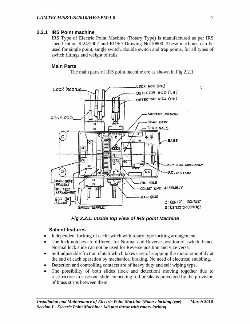
2.2.1 IRS Point machine IRS Type of Electric Point Machine (Rotary Type) is manufactured as per IRS specification S-24/2002 and RDSO Drawing No.10800. These machines can be used for single point, single switch, double switch and trap points, for all types of switch fittings and weight of rails. Main Parts
The main parts of IRS point machine are as shown in Fig.2.2.1.
Fig 2.2.1: Inside top view of IRS point Machine
Salient features
• Independent locking of each switch with rotary type locking arrangement. • The lock notches are different for Normal and Reverse position of switch, hence
Normal lock slide can not be used for Reverse position and vice versa. • Self adjustable friction clutch which takes care of stopping the motor smoothly at
the end of each operation by mechanical braking. No need of electrical snubbing. • Detection and controlling contacts are of heavy duty and self wiping type. • The possibility of both slides (lock and detection) moving together due to
rust/friction in case one slide connecting rod breaks is prevented by the provision of brass strips between them.
CAMTECH/S&T/S/2010/HB/EPM/1.0
Installation and Maintenance of Electric Point Machine (Rotary locking type) March 2010 Section I - Electric Point Machine: 143 mm throw with rotary locking
8
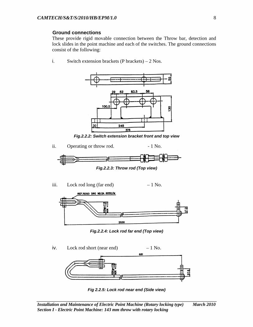
Ground connections These provide rigid movable connection between the Throw bar, detection and lock slides in the point machine and each of the switches. The ground connections consist of the following: i. Switch extension brackets (P brackets) – 2 Nos.
Fig.2.2.2: Switch extension bracket front and top view
ii. Operating or throw rod. - 1 No.
Fig.2.2.3: Throw rod (Top view)
iii. Lock rod long (far end) – 1 No.
Fig.2.2.4: Lock rod far end (Top view)
iv. Lock rod short (near end) – 1 No.
Fig 2.2.5: Lock rod near end (Side view)
CAMTECH/S&T/S/2010/HB/EPM/1.0
Installation and Maintenance of Electric Point Machine (Rotary locking type) March 2010 Section I - Electric Point Machine: 143 mm throw with rotary locking
9
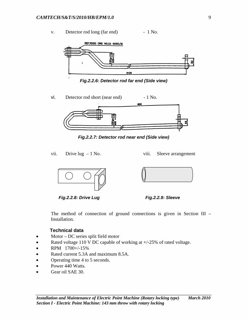
v. Detector rod long (far end) - 1 No.
Fig.2.2.6: Detector rod far end (Side view)
vi. Detector rod short (near end) - 1 No.
Fig.2.2.7: Detector rod near end (Side view)
vii. Drive lug – 1 No. viii. Sleeve arrangement
Fig.2.2.8: Drive Lug Fig.2.2.9: Sleeve The method of connection of ground connections is given in Section III –
Installation. Technical data • Motor – DC series split field motor • Rated voltage 110 V DC capable of working at +/-25% of rated voltage. • RPM 1700+/-15% • Rated current 5.3A and maximum 8.5A. • Operating time 4 to 5 seconds. • Power 440 Watts. • Gear oil SAE 30.
CAMTECH/S&T/S/2010/HB/EPM/1.0
Installation and Maintenance of Electric Point Machine (Rotary locking type) March 2010 Section I - Electric Point Machine: 143 mm throw with rotary locking
10
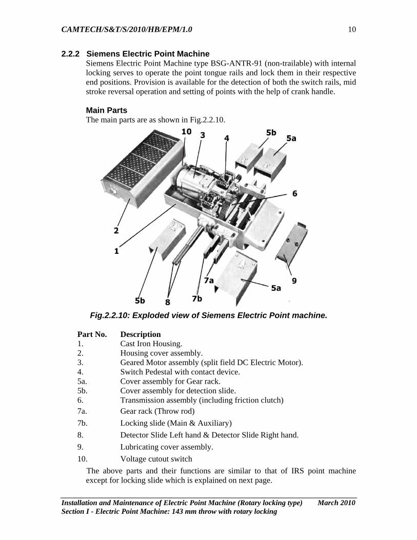
2.2.2 Siemens Electric Point Machine Siemens Electric Point Machine type BSG-ANTR-91 (non-trailable) with internal locking serves to operate the point tongue rails and lock them in their respective end positions. Provision is available for the detection of both the switch rails, mid stroke reversal operation and setting of points with the help of crank handle.
Main Parts The main parts are as shown in Fig.2.2.10.
Fig.2.2.10: Exploded view of Siemens Electric Point machine.
Part No. Description 1. Cast Iron Housing. 2. Housing cover assembly. 3. Geared Motor assembly (split field DC Electric Motor). 4. Switch Pedestal with contact device. 5a. Cover assembly for Gear rack. 5b. Cover assembly for detection slide. 6. Transmission assembly (including friction clutch) 7a. Gear rack (Throw rod) 7b. Locking slide (Main & Auxiliary) 8. Detector Slide Left hand & Detector Slide Right hand. 9. Lubricating cover assembly. 10. Voltage cutout switch
The above parts and their functions are similar to that of IRS point machine except for locking slide which is explained on next page.
CAMTECH/S&T/S/2010/HB/EPM/1.0
Installation and Maintenance of Electric Point Machine (Rotary locking type) March 2010 Section I - Electric Point Machine: 143 mm throw with rotary locking
11
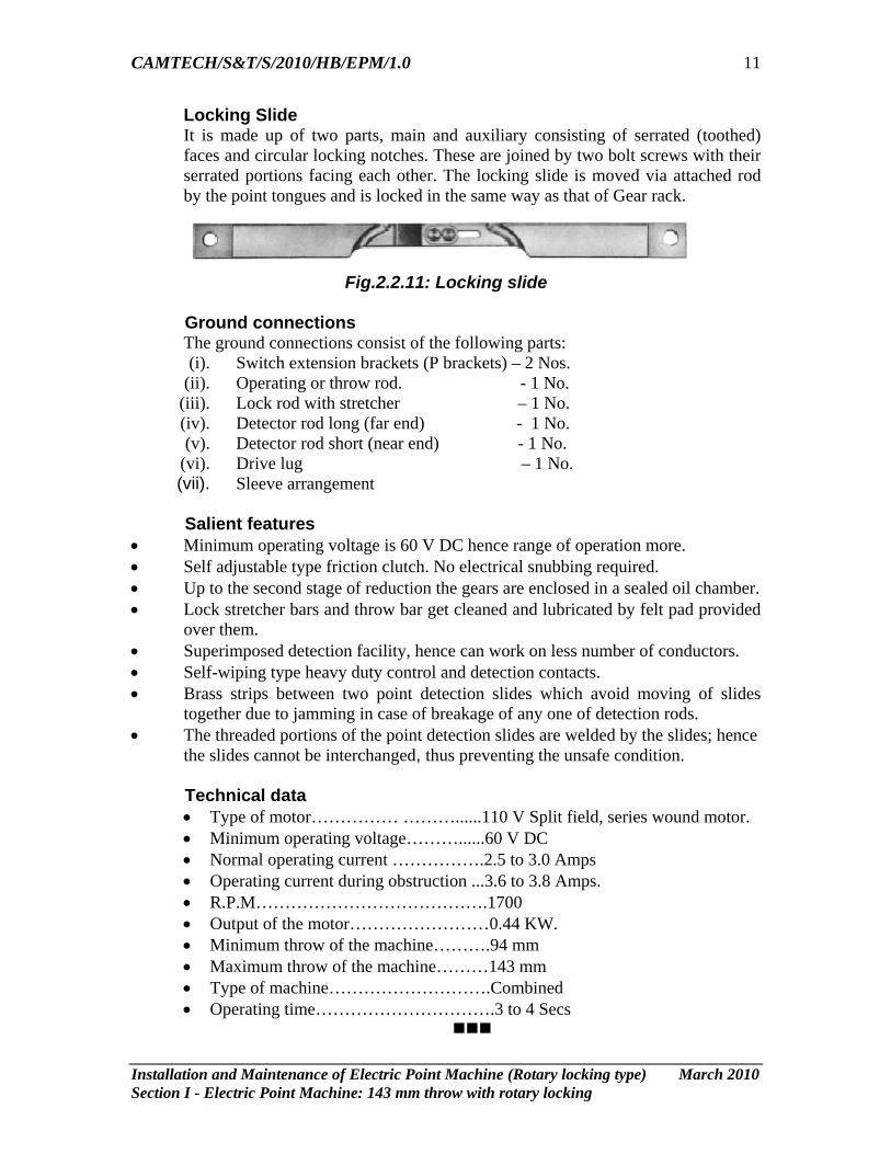
Locking Slide It is made up of two parts, main and auxiliary consisting of serrated (toothed) faces and circular locking notches. These are joined by two bolt screws with their serrated portions facing each other. The locking slide is moved via attached rod by the point tongues and is locked in the same way as that of Gear rack.
Fig.2.2.11: Locking slide
Ground connections
The ground connections consist of the following parts: (i). Switch extension brackets (P brackets) – 2 Nos.
(ii). Operating or throw rod. - 1 No. (iii). Lock rod with stretcher – 1 No. (iv). Detector rod long (far end) - 1 No. (v). Detector rod short (near end) - 1 No.
(vi). Drive lug – 1 No. (vii). Sleeve arrangement
Salient features • Minimum operating voltage is 60 V DC hence range of operation more. • Self adjustable type friction clutch. No electrical snubbing required. • Up to the second stage of reduction the gears are enclosed in a sealed oil chamber. • Lock stretcher bars and throw bar get cleaned and lubricated by felt pad provided
over them. • Superimposed detection facility, hence can work on less number of conductors. • Self-wiping type heavy duty control and detection contacts. • Brass strips between two point detection slides which avoid moving of slides
together due to jamming in case of breakage of any one of detection rods. • The threaded portions of the point detection slides are welded by the slides; hence
the slides cannot be interchanged, thus preventing the unsafe condition.
Technical data • Type of motor…………… ………......110 V Split field, series wound motor. • Minimum operating voltage………......60 V DC • Normal operating current …………….2.5 to 3.0 Amps • Operating current during obstruction ...3.6 to 3.8 Amps. • R.P.M………………………………….1700 • Output of the motor……………………0.44 KW. • Minimum throw of the machine……….94 mm • Maximum throw of the machine………143 mm • Type of machine……………………….Combined • Operating time………………………….3 to 4 Secs