There is No ‘I’ in Recovery: Managements’ Perspective of Service Recovery
Upload
independentCategory
view
0download
0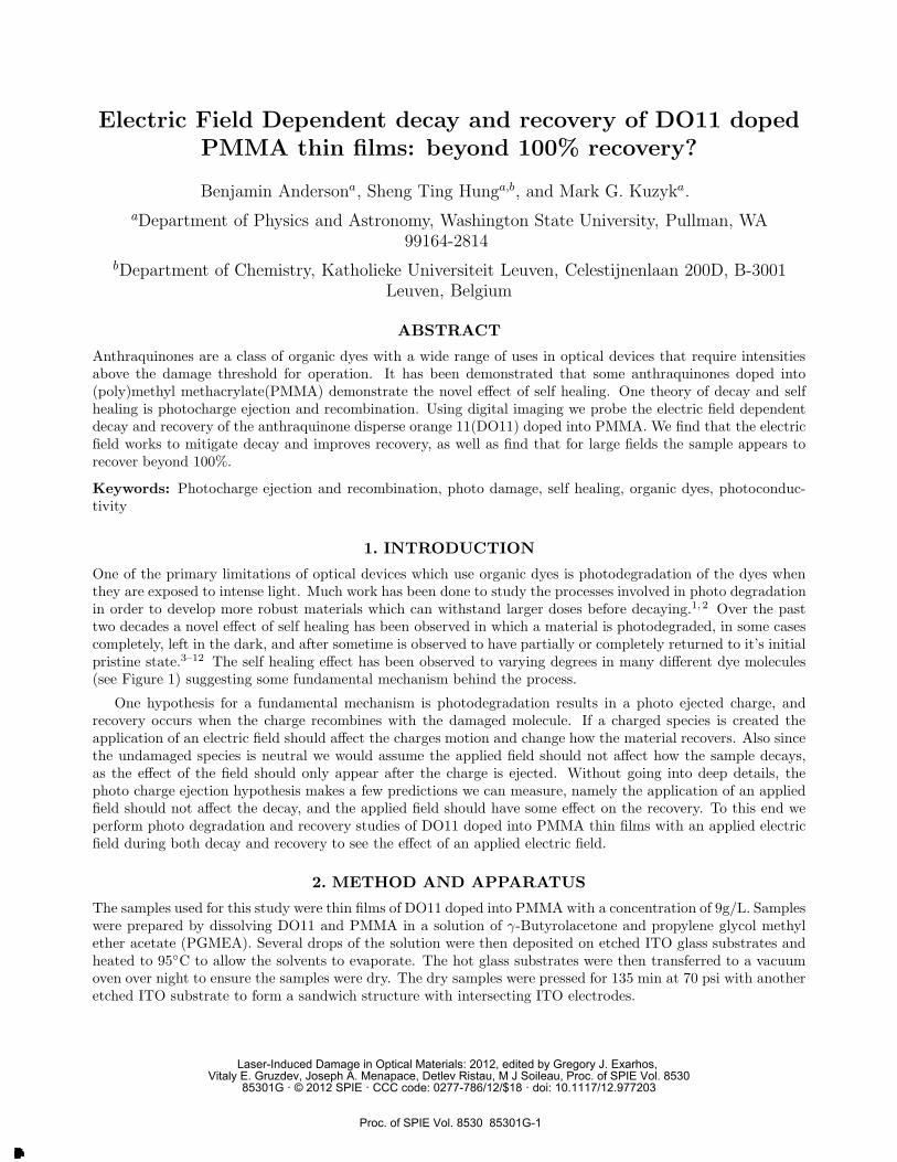
Electric Field Dependent decay and recovery of DO11 doped
PMMA thin films: beyond 100% recovery?
Benjamin Andersona, Sheng Ting Hunga,b, and Mark G. Kuzyka.
aDepartment of Physics and Astronomy, Washington State University, Pullman, WA
99164-2814
bDepartment of Chemistry, Katholieke Universiteit Leuven, Celestijnenlaan 200D, B-3001
Leuven, Belgium
ABSTRACT
Anthraquinones are a class of organic dyes with a wide range of uses in optical devices that require intensitiesabove the damage threshold for operation. It has been demonstrated that some anthraquinones doped into(poly)methyl methacrylate(PMMA) demonstrate the novel effect of self healing. One theory of decay and selfhealing is photocharge ejection and recombination. Using digital imaging we probe the electric field dependentdecay and recovery of the anthraquinone disperse orange 11(DO11) doped into PMMA. We find that the electricfield works to mitigate decay and improves recovery, as well as find that for large fields the sample appears torecover beyond 100%.
Keywords: Photocharge ejection and recombination, photo damage, self healing, organic dyes, photoconduc-tivity
1. INTRODUCTION
One of the primary limitations of optical devices which use organic dyes is photodegradation of the dyes whenthey are exposed to intense light. Much work has been done to study the processes involved in photo degradationin order to develop more robust materials which can withstand larger doses before decaying.1, 2 Over the pasttwo decades a novel effect of self healing has been observed in which a material is photodegraded, in some casescompletely, left in the dark, and after sometime is observed to have partially or completely returned to it’s initialpristine state.3–12 The self healing effect has been observed to varying degrees in many different dye molecules(see Figure 1) suggesting some fundamental mechanism behind the process.
One hypothesis for a fundamental mechanism is photodegradation results in a photo ejected charge, andrecovery occurs when the charge recombines with the damaged molecule. If a charged species is created theapplication of an electric field should affect the charges motion and change how the material recovers. Also sincethe undamaged species is neutral we would assume the applied field should not affect how the sample decays,as the effect of the field should only appear after the charge is ejected. Without going into deep details, thephoto charge ejection hypothesis makes a few predictions we can measure, namely the application of an appliedfield should not affect the decay, and the applied field should have some effect on the recovery. To this end weperform photo degradation and recovery studies of DO11 doped into PMMA thin films with an applied electricfield during both decay and recovery to see the effect of an applied electric field.
2. METHOD AND APPARATUS
The samples used for this study were thin films of DO11 doped into PMMA with a concentration of 9g/L. Sampleswere prepared by dissolving DO11 and PMMA in a solution of γ-Butyrolacetone and propylene glycol methylether acetate (PGMEA). Several drops of the solution were then deposited on etched ITO glass substrates andheated to 95◦C to allow the solvents to evaporate. The hot glass substrates were then transferred to a vacuumoven over night to ensure the samples were dry. The dry samples were pressed for 135 min at 70 psi with anotheretched ITO substrate to form a sandwich structure with intersecting ITO electrodes.
Laser-Induced Damage in Optical Materials: 2012, edited by Gregory J. Exarhos, Vitaly E. Gruzdev, Joseph A. Menapace, Detlev Ristau, M J Soileau, Proc. of SPIE Vol. 8530
85301G · © 2012 SPIE · CCC code: 0277-786/12/$18 · doi: 10.1117/12.977203
Proc. of SPIE Vol. 8530 85301G-1
Downloaded From: http://proceedings.spiedigitallibrary.org/ on 01/16/2013 Terms of Use: http://spiedl.org/terms
`
^
~
PowerSupply
Cyl. Lens
Obj. n BS
I ILED Source
CCD
LiSam.
Mirror
P. Ammeter
Beam Stop
ArKr Laser
Figure 1: Various molecules observed to display self healing. a: AF455, b: Rhodamine, c: Anthraquinone, d:Pyrromethene
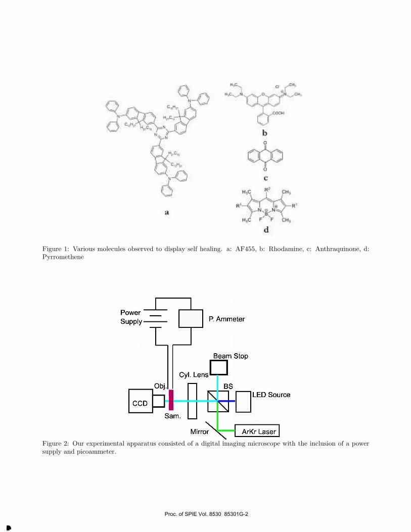
Figure 2: Our experimental apparatus consisted of a digital imaging microscope with the inclusion of a powersupply and picoammeter.
Proc. of SPIE Vol. 8530 85301G-2
Downloaded From: http://proceedings.spiedigitallibrary.org/ on 01/16/2013 Terms of Use: http://spiedl.org/terms
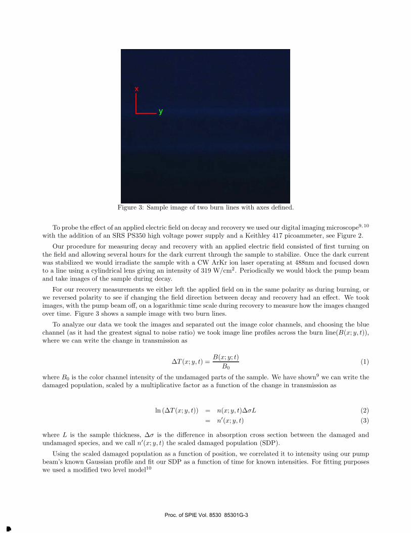
Figure 3: Sample image of two burn lines with axes defined.
To probe the effect of an applied electric field on decay and recovery we used our digital imaging microscope9, 10
with the addition of an SRS PS350 high voltage power supply and a Keithley 417 picoammeter, see Figure 2.
Our procedure for measuring decay and recovery with an applied electric field consisted of first turning onthe field and allowing several hours for the dark current through the sample to stabilize. Once the dark currentwas stabilized we would irradiate the sample with a CW ArKr ion laser operating at 488nm and focused downto a line using a cylindrical lens giving an intensity of 319 W/cm2. Periodically we would block the pump beamand take images of the sample during decay.
For our recovery measurements we either left the applied field on in the same polarity as during burning, orwe reversed polarity to see if changing the field direction between decay and recovery had an effect. We tookimages, with the pump beam off, on a logarithmic time scale during recovery to measure how the images changedover time. Figure 3 shows a sample image with two burn lines.
To analyze our data we took the images and separated out the image color channels, and choosing the bluechannel (as it had the greatest signal to noise ratio) we took image line profiles across the burn line(B(x; y, t)),where we can write the change in transmission as
ΔT (x; y, t) =B(x; y; t)
B0(1)
where B0 is the color channel intensity of the undamaged parts of the sample. We have shown9 we can write thedamaged population, scaled by a multiplicative factor as a function of the change in transmission as
ln (ΔT (x; y, t)) = n(x; y, t)ΔσL (2)
= n′(x; y, t) (3)
where L is the sample thickness, Δσ is the difference in absorption cross section between the damaged andundamaged species, and we call n′(x; y, t) the scaled damaged population (SDP).
Using the scaled damaged population as a function of position, we correlated it to intensity using our pumpbeam’s known Gaussian profile and fit our SDP as a function of time for known intensities. For fitting purposeswe used a modified two level model10
Proc. of SPIE Vol. 8530 85301G-3
Downloaded From: http://proceedings.spiedigitallibrary.org/ on 01/16/2013 Terms of Use: http://spiedl.org/terms
0.16
0.14
0.12
0.10
0.08
0.06
0.04
0.02
0.00
-E = 0 V/µm-E = 0.75 V/µm
E = 1.25 V/Nm-E = 1.875 V/tim-E = 2.5 V/µm
0 5 10 15
t(min)
20
0.16
0.14
0.12
0.10
0.08
0.06
0.04
0.02
0.00
10 100 1000
t(min)
-E = 0 Wpm-E = 0.75 Wpm-E = 1.25 V/µm-E = 1.875 V/µm-E = 2.5 V/µm
2 3 456 2 3 456 2 3
ndecay(I, t) = A(I)(1 − e−(β+αI)t
)(4)
nrec(t) = nIR + nRe−βt (5)
where A(I) is an intensity dependent amplitude–which we call the equilibrium scaled damage population– β isthe recovery rate, α is the decay rate parameter, nIR is the portion of the population which does not recover,and nR is the portion of the population that does recovery. Using the irrecoverable and recoverable populationswe can define the recovery percent as
Rec % =nR
nIR + nR
(6)
For the purposes of comparing the various applied fields we will consider the recovery percent as well as theequilibrium scaled damaged population, the recovery rate, and the damage rate parameter.
3. RESULTS AND DISCUSSION
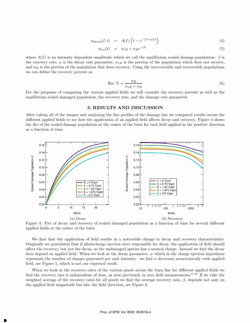
After taking all of the images and analyzing the line profiles of the damage line we compared results across thedifferent applied fields to see how the application of an applied field affects decay and recovery. Figure 4 showsthe fits of the scaled damage population at the center of the burn for each field applied in the positive directionas a function of time.
(a) Decay (b) Recovery
Figure 4: Fits of decay and recovery of scaled damaged population as a function of time for several differentapplied fields at the center of the burn
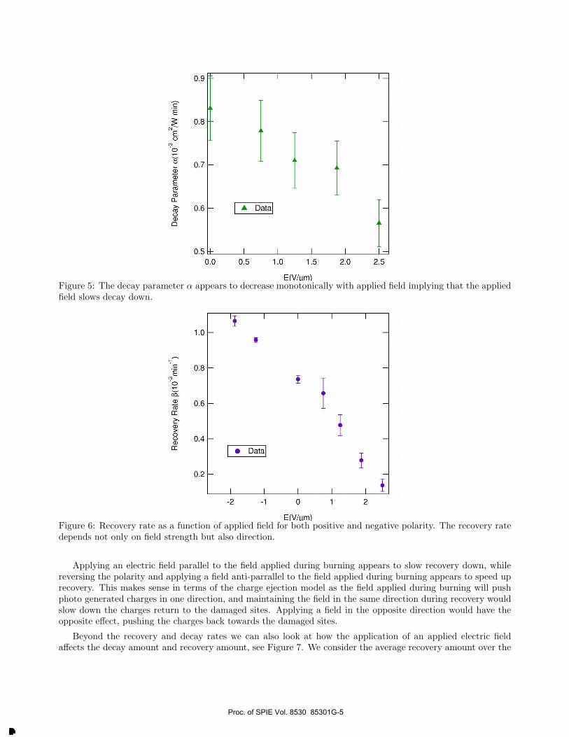
We find that the application of field results in a noticeable change in decay and recovery characteristics.Originally we postulated that if photocharge ejection were responsible for decay, the application of field shouldaffect the recovery, but not the decay, as the undamaged species has a neutral charge. Instead we find the decaydoes depend on applied field. When we look at the decay parameter, α–which in the charge ejection hypothesisrepresents the number of charges generated per unit intensity– we find α decreases monotonically with appliedfield, see Figure 5, which is not our expected result.
When we look at the recovery rates of the various pixels across the burn line for different applied fields wefind the recovery rate is independent of dose, as seen previously in zero field measurements.9, 10 If we take theweighted average of the recovery rates for all pixels we find the average recovery rate, β, depends not only onthe applied field magnitude but also the field direction, see Figure 6.
Proc. of SPIE Vol. 8530 85301G-4
Downloaded From: http://proceedings.spiedigitallibrary.org/ on 01/16/2013 Terms of Use: http://spiedl.org/terms
0.9
CE
0.8
U
O
0.7Z15
4)E(tl
d0.6
U4)
o
05
A
A Data
0.0 0.5 1.0 1.5
E(V/um)
2.0 25
mo
o N
Rec
over
y R
ate
13(1
0 3m
in 1
)
o0
0 Co
II
II
I
IM
-H
H-
Fi
Figure 5: The decay parameter α appears to decrease monotonically with applied field implying that the appliedfield slows decay down.
Figure 6: Recovery rate as a function of applied field for both positive and negative polarity. The recovery ratedepends not only on field strength but also direction.
Applying an electric field parallel to the field applied during burning appears to slow recovery down, whilereversing the polarity and applying a field anti-parrallel to the field applied during burning appears to speed uprecovery. This makes sense in terms of the charge ejection model as the field applied during burning will pushphoto generated charges in one direction, and maintaining the field in the same direction during recovery wouldslow down the charges return to the damaged sites. Applying a field in the opposite direction would have theopposite effect, pushing the charges back towards the damaged sites.
Beyond the recovery and decay rates we can also look at how the application of an applied electric fieldaffects the decay amount and recovery amount, see Figure 7. We consider the average recovery amount over the
Proc. of SPIE Vol. 8530 85301G-5
Downloaded From: http://proceedings.spiedigitallibrary.org/ on 01/16/2013 Terms of Use: http://spiedl.org/terms
0.6
0.5
0.4
a9 0.3i0.2
0.1
0.0
- I 1
Average RecoveryPeak no i
-
I I
-2 -1 0
E (V/uml
1 2
0.165
0.160
0.155
0.150
0.145
0.140
0.135
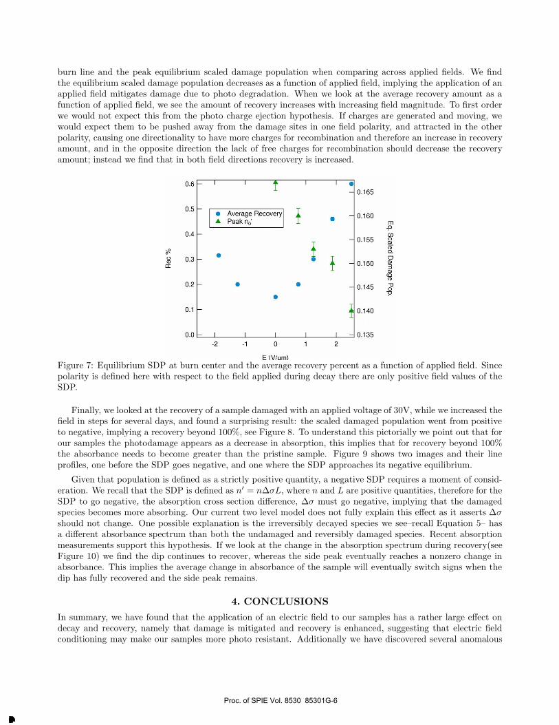
burn line and the peak equilibrium scaled damage population when comparing across applied fields. We findthe equilibrium scaled damage population decreases as a function of applied field, implying the application of anapplied field mitigates damage due to photo degradation. When we look at the average recovery amount as afunction of applied field, we see the amount of recovery increases with increasing field magnitude. To first orderwe would not expect this from the photo charge ejection hypothesis. If charges are generated and moving, wewould expect them to be pushed away from the damage sites in one field polarity, and attracted in the otherpolarity, causing one directionality to have more charges for recombination and therefore an increase in recoveryamount, and in the opposite direction the lack of free charges for recombination should decrease the recoveryamount; instead we find that in both field directions recovery is increased.
Figure 7: Equilibrium SDP at burn center and the average recovery percent as a function of applied field. Sincepolarity is defined here with respect to the field applied during decay there are only positive field values of theSDP.
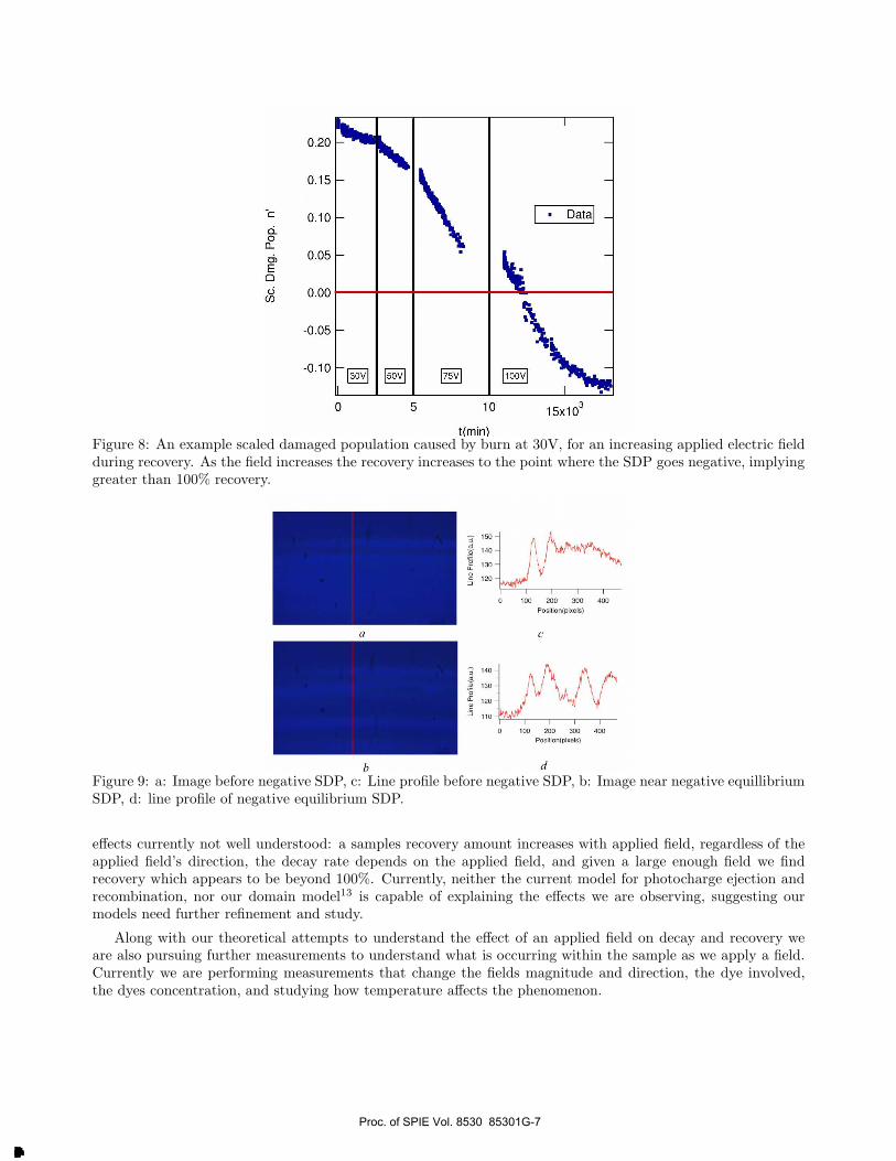
Finally, we looked at the recovery of a sample damaged with an applied voltage of 30V, while we increased thefield in steps for several days, and found a surprising result: the scaled damaged population went from positiveto negative, implying a recovery beyond 100%, see Figure 8. To understand this pictorially we point out that forour samples the photodamage appears as a decrease in absorption, this implies that for recovery beyond 100%the absorbance needs to become greater than the pristine sample. Figure 9 shows two images and their lineprofiles, one before the SDP goes negative, and one where the SDP approaches its negative equilibrium.
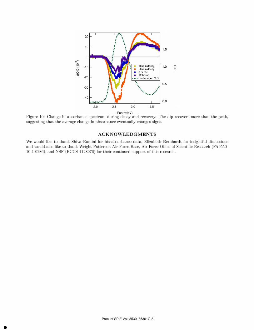
Given that population is defined as a strictly positive quantity, a negative SDP requires a moment of consid-eration. We recall that the SDP is defined as n′ = nΔσL, where n and L are positive quantities, therefore for theSDP to go negative, the absorption cross section difference, Δσ must go negative, implying that the damagedspecies becomes more absorbing. Our current two level model does not fully explain this effect as it asserts Δσ
should not change. One possible explanation is the irreversibly decayed species we see–recall Equation 5– hasa different absorbance spectrum than both the undamaged and reversibly damaged species. Recent absorptionmeasurements support this hypothesis. If we look at the change in the absorption spectrum during recovery(seeFigure 10) we find the dip continues to recover, whereas the side peak eventually reaches a nonzero change inabsorbance. This implies the average change in absorbance of the sample will eventually switch signs when thedip has fully recovered and the side peak remains.
4. CONCLUSIONS
In summary, we have found that the application of an electric field to our samples has a rather large effect ondecay and recovery, namely that damage is mitigated and recovery is enhanced, suggesting that electric fieldconditioning may make our samples more photo resistant. Additionally we have discovered several anomalous
Proc. of SPIE Vol. 8530 85301G-6
Downloaded From: http://proceedings.spiedigitallibrary.org/ on 01/16/2013 Terms of Use: http://spiedl.org/terms
0.20
0.15
0.10
0.05
0.00
-0.05
-0.10
1 I
Data _
ik.
-
150V1 I75v
hsb. -
30V 100V
1 1
0 5 10
t(min)
15x103
Une Pro9le(a.u.)
A
Line Profile(a.u.)
óióó
Figure 8: An example scaled damaged population caused by burn at 30V, for an increasing applied electric fieldduring recovery. As the field increases the recovery increases to the point where the SDP goes negative, implyinggreater than 100% recovery.
Figure 9: a: Image before negative SDP, c: Line profile before negative SDP, b: Image near negative equillibriumSDP, d: line profile of negative equilibrium SDP.
effects currently not well understood: a samples recovery amount increases with applied field, regardless of theapplied field’s direction, the decay rate depends on the applied field, and given a large enough field we findrecovery which appears to be beyond 100%. Currently, neither the current model for photocharge ejection andrecombination, nor our domain model13 is capable of explaining the effects we are observing, suggesting ourmodels need further refinement and study.
Along with our theoretical attempts to understand the effect of an applied field on decay and recovery weare also pursuing further measurements to understand what is occurring within the sample as we apply a field.Currently we are performing measurements that change the fields magnitude and direction, the dye involved,the dyes concentration, and studying how temperature affects the phenomenon.
Proc. of SPIE Vol. 8530 85301G-7
Downloaded From: http://proceedings.spiedigitallibrary.org/ on 01/16/2013 Terms of Use: http://spiedl.org/terms
M'oó4
20
10
0
-10
-20
-30
-40
10 min decay20 min decay2 hr rec12hrrecUndamaged O.D.
2.0 2.5 3.0
Energy(eV)
3.5
1.5
1.0 Ob
0.5
0.0
Figure 10: Change in absorbance spectrum during decay and recovery. The dip recovers more than the peak,suggesting that the average change in absorbance eventually changes signs.
ACKNOWLEDGMENTS
We would like to thank Shiva Ramini for his absorbance data, Elizabeth Bernhardt for insightful discussionsand would also like to thank Wright Patterson Air Force Base, Air Force Office of Scientific Research (FA9550-10-1-0286), and NSF (ECCS-1128076) for their continued support of this research.
Proc. of SPIE Vol. 8530 85301G-8
Downloaded From: http://proceedings.spiedigitallibrary.org/ on 01/16/2013 Terms of Use: http://spiedl.org/terms
REFERENCES
[1] Exarhos, G. J., Guenther, A. H., Kozlowski, M. R., and Soileau, M. J., [Laser-Induced Damage in Optical
Materials ], SPIE, Bellevue (1998).
[2] Wood, R. M., [Laser-Induced Damage of Optical Materials ], Series in Optics and Optoelectronics, Taylor &Francis, Boca Raton (2003).
[3] Peng, G. D., Xiong, Z., and Chu, P. L., “Fluorescence Decay and Recovery in Organic Dye-Doped PolymerOptical Fibers,” J. Lightwave Technol. 16(12), 2365–2372 (1998).
[4] Howell, B. and Kuzyk, M. G., “Amplified Spontaneous Emission and Recoverable Photodegradation inDisperse-Orange-11-Doped-Polymer,” J. Opt. Soc. Am. B 19(8), 1790 (2002).
[5] Howell, B. and Kuzyk, M. G., “Lasing Action and Photodegradation of Disperse Orange 11 Dye in LiquidSolution,” Appl. Phys. Lett. 85, 1901–1903 (2004).
[6] Zhu, Y., Zhou, J., and Kuzyk, M. G., “Two-photon fluorescence measurements of reversible photodegrada-tion in a dye-doped polymer,” Opt. Lett. 32, 958–960 (2007).
[7] Zhu, Y., Zhou, J., and Kuzyk, M. G., “Self-Healing and Laser Hardening of Nonlinear-Optical Materials,”Optics and Photonics News 18(12), 31–31 (2007).
[8] Embaye, N., Ramini, S. K., and Kuzyk, M. G., “Mechanisms of reversible photodegradation in disperseorange 11 dye doped in PMMA polymer,” J. Chem. Phys. 129, 054504 (2008).
[9] Anderson, B., Ramini, S. K., and Kuzyk, M. G., “Imaging studies of photodamage and self-healing indisperse orange 11 dye-doped pmma,” J. Opt. Soc. Am. B 28, 528–32 (2011).
[10] Benjamin Anderson, S. K. R. . M. G. K., “Imaging studies of photodamage and self- healing of an-thraquinone derivative dye doped polymers.,” in [SPIE Laser Damage Symposium Proc. ], Exarhos, G.,ed., SPIE (September 2011).
[11] Shiva K. Ramini, B. A. . M. G. K., “Recent progress in reversible photodegradation of disperse orange 11when doped in pmma.,” in [SPIE Laser Damage Symposium Proc. ], Exarhos, G., ed., SPIE (September2011).
[12] Shiva K. Ramini, N. D. and Kuzyk, M. G., “Testing the diffusion hypothesis as a mechanism of self-healingin disperse orange 11 doped into poly(methyl methacrylate),” J. Opt. Soc Am. B 28, 2408–2412 (2011).
[13] Ramini, S. K. and Kuzyk, M. G., “A self healing model based on polymer-mediated chromophore coerrela-tions,” arXiv:1205.0481v1 (2012).
Proc. of SPIE Vol. 8530 85301G-9
Downloaded From: http://proceedings.spiedigitallibrary.org/ on 01/16/2013 Terms of Use: http://spiedl.org/terms

(8530-25) “ Electric field dependent decay and recovery of anthroquinones doped into PMMA thin films:
beyond 100% recovery” 85301G
Questions and Answers
Q. Are you considering any birefringence effects due to the domain phase ordering from stretching of your polymer or therefore polarization effects? A. We haven’t looked into those yet. We did polarization studies for no field applied and we found there was no birefringence. There was no difference when we changed the polarization. But that is a future consideration and we will pursue this. When we apply the field, what happens with regard to the polarization, so,… Q. Like for your imaging, if you’re doing some polarized microscopy, you might discover domain order in terms of your polymer axes. A. Yes. Q. In the material, is the molecule moving due to the electric field. A. Yes.
Proc. of SPIE Vol. 8530 85301G-10
Downloaded From: http://proceedings.spiedigitallibrary.org/ on 01/16/2013 Terms of Use: http://spiedl.org/terms

(8530-25) “ Electric field dependent decay and recovery of anthroquinones doped into PMMA thin films:
beyond 100% recovery” 85301G
Questions and Answers
Q. Are you considering any birefringence effects due to the domain phase ordering from stretching of your polymer or therefore polarization effects? A. We haven’t looked into those yet. We did polarization studies for no field applied and we found there was no birefringence. There was no difference when we changed the polarization. But that is a future consideration and we will pursue this. When we apply the field, what happens with regard to the polarization, so,… Q. Like for your imaging, if you’re doing some polarized microscopy, you might discover domain order in terms of your polymer axes. A. Yes. Q. In the material, is the molecule moving due to the electric field. A. Yes.
Proc. of SPIE Vol. 8530 85301G-11
Downloaded From: http://proceedings.spiedigitallibrary.org/ on 01/16/2013 Terms of Use: http://spiedl.org/terms
Copyright © 2022 FDOKUMEN